S-GW Administration Guide, StarOS Release 21.27 - Cisco
440
S-GW Administration Guide, StarOS Release 21.27 First Published: 2022-04-14 Americas Headquarters Cisco Systems, Inc. 170 West Tasman Drive San Jose, CA 95134-1706 USA http://www.cisco.com Tel: 408 526-4000 800 553-NETS (6387) Fax: 408 527-0883
-
Upload
khangminh22 -
Category
Documents
-
view
4 -
download
0
Transcript of S-GW Administration Guide, StarOS Release 21.27 - Cisco

S-GW Administration Guide, StarOS Release 21.27First Published: 2022-04-14
Americas HeadquartersCisco Systems, Inc.170 West Tasman DriveSan Jose, CA 95134-1706USAhttp://www.cisco.comTel: 408 526-4000
800 553-NETS (6387)Fax: 408 527-0883

THE SPECIFICATIONS AND INFORMATION REGARDING THE PRODUCTS IN THIS MANUAL ARE SUBJECT TO CHANGE WITHOUT NOTICE. ALL STATEMENTS,INFORMATION, AND RECOMMENDATIONS IN THIS MANUAL ARE BELIEVED TO BE ACCURATE BUT ARE PRESENTED WITHOUT WARRANTY OF ANY KIND,EXPRESS OR IMPLIED. USERS MUST TAKE FULL RESPONSIBILITY FOR THEIR APPLICATION OF ANY PRODUCTS.
THE SOFTWARE LICENSE AND LIMITED WARRANTY FOR THE ACCOMPANYING PRODUCT ARE SET FORTH IN THE INFORMATION PACKET THAT SHIPPED WITHTHE PRODUCT AND ARE INCORPORATED HEREIN BY THIS REFERENCE. IF YOU ARE UNABLE TO LOCATE THE SOFTWARE LICENSE OR LIMITED WARRANTY,CONTACT YOUR CISCO REPRESENTATIVE FOR A COPY.
The Cisco implementation of TCP header compression is an adaptation of a program developed by the University of California, Berkeley (UCB) as part of UCB's public domain version ofthe UNIX operating system. All rights reserved. Copyright © 1981, Regents of the University of California.
NOTWITHSTANDING ANY OTHERWARRANTY HEREIN, ALL DOCUMENT FILES AND SOFTWARE OF THESE SUPPLIERS ARE PROVIDED “AS IS" WITH ALL FAULTS.CISCO AND THE ABOVE-NAMED SUPPLIERS DISCLAIM ALL WARRANTIES, EXPRESSED OR IMPLIED, INCLUDING, WITHOUT LIMITATION, THOSE OFMERCHANTABILITY, FITNESS FOR A PARTICULAR PURPOSE AND NONINFRINGEMENT OR ARISING FROM A COURSE OF DEALING, USAGE, OR TRADE PRACTICE.
IN NO EVENT SHALL CISCO OR ITS SUPPLIERS BE LIABLE FOR ANY INDIRECT, SPECIAL, CONSEQUENTIAL, OR INCIDENTAL DAMAGES, INCLUDING, WITHOUTLIMITATION, LOST PROFITS OR LOSS OR DAMAGE TO DATA ARISING OUT OF THE USE OR INABILITY TO USE THIS MANUAL, EVEN IF CISCO OR ITS SUPPLIERSHAVE BEEN ADVISED OF THE POSSIBILITY OF SUCH DAMAGES.
Any Internet Protocol (IP) addresses and phone numbers used in this document are not intended to be actual addresses and phone numbers. Any examples, command display output, networktopology diagrams, and other figures included in the document are shown for illustrative purposes only. Any use of actual IP addresses or phone numbers in illustrative content is unintentionaland coincidental.
All printed copies and duplicate soft copies of this document are considered uncontrolled. See the current online version for the latest version.
Cisco has more than 200 offices worldwide. Addresses and phone numbers are listed on the Cisco website at www.cisco.com/go/offices.
The documentation set for this product strives to use bias-free language. For purposes of this documentation set, bias-free is defined as language that does not imply discrimination based onage, disability, gender, racial identity, ethnic identity, sexual orientation, socioeconomic status, and intersectionality. Exceptions may be present in the documentation due to language thatis hardcoded in the user interfaces of the product software, language used based on standards documentation, or language that is used by a referenced third-party product.
Cisco and the Cisco logo are trademarks or registered trademarks of Cisco and/or its affiliates in the U.S. and other countries. To view a list of Cisco trademarks, go to this URL:https://www.cisco.com/c/en/us/about/legal/trademarks.html. Third-party trademarks mentioned are the property of their respective owners. The use of the word partner does not imply apartnership relationship between Cisco and any other company. (1721R)
© 2022 Cisco Systems, Inc. All rights reserved.

C O N T E N T S
About this Guide xxiiiP R E F A C E
Conventions Used xxiv
Supported Documents and Resources xxv
Related Common Documentation xxv
Related Product Documentation xxvi
Obtaining Documentation xxvi
Contacting Customer Support xxvi
Serving Gateway Overview 1C H A P T E R 1
Product Description 1
Platform Requirements 4
Licenses 4
Network Deployment(s) 4
Serving Gateway in the E-UTRAN/EPC Network 4
Supported Logical Network Interfaces (Reference Points) 5
Features and Functionality - Base Software 9
3GPP Release 12 Cause-Code IE Support 10
Abnormal Bearer Termination Cause in CDR 10
ANSI T1.276 Compliance 10
APN-level Traffic Policing 11
Backup and Recovery of Key KPI Statistics 11
Bulk Statistics Support 11
CDR Support for Including LAPI (Signaling Priority) 12
Circuit Switched Fall Back (CSFB) Support 12
Closed Subscriber Group Support 13
Collision Counter Support in the GTP Layer 13
S-GW Administration Guide, StarOS Release 21.27iii
Congestion Control 14
Dedicated Bearer Timeout Support on the S-GW 15
Downlink Delay Notification 15
Value Handling 15
Throttling 15
EPS Bearer ID and ARP Support 15
DSCP Ingress and Egress and DSCP Marking at the APN Profile 16
Dynamic GTP Echo Timer 16
Event-Based Idle Second Micro-Check Point Generation for the S-GW 16
Event Reporting 16
Idle-mode Signaling Reduction Support 17
IMSI/IMEI Available in System Event Logs of Type Error and Critical 17
IP Access Control Lists 19
IPv6 Capabilities 20
LIPA Support 20
Location Reporting 21
Mapping High Throughput Sessions on Session Managers 21
MME Restoration Support 22
S-GW NTSR Enhancement 22
Multiple PDN Support 23
Node Functionality GTP Echo 23
Online/Offline Charging 24
Offline: Gz Reference Interface 24
Operator Policy Support 24
Optimization for egtpinmgr Recovery 25
Peer GTP Node Profile Configuration Support 25
P-GW Restart Notification Support 26
QoS Bearer Management 26
Removal of Private Extension-based Overcharging Support 27
Rf Diameter Accounting 30
S-GW Collision Handling 31
Viewing S-GW Collision Statistics 31
S-GW Session Idle Timer 32
Subscriber Level Trace 32
S-GW Administration Guide, StarOS Release 21.27iv
Contents
Support for One Million S1-U Peers on the S-GW 33
Threshold Crossing Alerts (TCA) Support 34
ULI Enhancements 35
Features and Functionality - Optional Enhanced Feature Software 35
128k eNodeB Support 36
Direct Tunnel 36
Intelligent Paging for ISR 37
Inter-Chassis Session Recovery 37
IP Security (IPSec) Encryption 38
Lawful Intercept 38
Layer 2 Traffic Management (VLANs) 39
New Call Policy for Stale Sessions 39
New Standard QCI Support 39
Overcharging Protection Support 39
Paging Policy Differentiation 40
3GPP Release 12 Load and Overload Support 41
Operation 42
Separate Paging for IMS Service Inspection 42
Session Recovery Support 42
S-GW Paging Enhancements 43
How the Serving Gateway Works 44
GTP Serving Gateway Call/Session Procedures in an LTE-SAE Network 44
Subscriber-initiated Attach (initial) 44
Subscriber-initiated Detach 48
Supported Standards 49
3GPP References 50
Release 12 3GPP References 50
Release 11 3GPP References 50
Release 10 3GPP References 50
Release 9 Supported Standards 51
Release 8 Supported Standards 51
3GPP2 References 52
IETF References 52
Object Management Group (OMG) Standards 53
S-GW Administration Guide, StarOS Release 21.27v
Contents
Serving Gateway Configuration 55C H A P T E R 2
Configuring the System as a Standalone eGTP S-GW 55
Information Required 55
Required Local Context Configuration Information 55
Required S-GW Ingress Context Configuration Information 56
Required S-GW Egress Context Configuration Information 58
How This Configuration Works 59
eGTP S-GW Configuration 60
Initial Configuration 61
eGTP Configuration 63
Verifying and Saving the Configuration 64
Configuring Optional Features on the eGTP S-GW 64
Configuring the GTP Echo Timer 64
Configuring GTPP Offline Accounting on the S-GW 69
Configuring Diameter Offline Accounting on the S-GW 71
Configuring APN-level Traffic Policing on the S-GW 72
Configuring X.509 Certificate-based Peer Authentication 72
Configuring Dynamic Node-to-Node IP Security on the S1-U and S5 Interfaces 73
Configuring ACL-based Node-to-Node IP Security on the S1-U and S5 Interfaces 76
Configuring 3GPP Release 12 Load Control Support 79
Configuring 3GPP Release 12 Overload Control Support 79
Configuring S4 SGSN Handover Capability 80
Monitoring the Service 81C H A P T E R 3
Monitoring System Status and Performance 81
Configuring the S-GW to Include IMSI/IMEI in Logging Events 83
Configuring S-GW to Include IMSI/IMEI in Event Logs 85
Clearing Statistics and Counters 86
5G Non Standalone 87C H A P T E R 4
Feature Summary and Revision History 87
Feature Description 88
S-GW Administration Guide, StarOS Release 21.27vi
Contents
Collision Handling on the P-GW/SAEGW/S-GW 95C H A P T E R 5
Feature Description 95
Relationships to Other Features 95
How It Works 95
Collision Handling 95
Example Collision Handling Scenarios 96
Limitations 97
Standards Compliance 98
Configuring Collision Handling 98
Configuring DBcmd Message Behavior 98
Verifying the Configuration 98
Monitoring the Collision Handling Feature 98
Collision Handling Show Command(s) and/or Outputs 99
show configuration 99
show egtp-service all 99
show egtp statistics verbose 99
Session Tracing 101C H A P T E R 6
Session Tracing Overview 101
Session Trace Types 102
Session Trace Activation 103
Session Trace Deactivation 103
Data Collection 104
Data Forwarding 104
Supported Standards 104
Configuring Session Trace Functionality 105
Enabling Session Tracing 105
Verifying that Session Tracing is Enabled 106
Disabling Session Trace Functionality 106
Configuring a Session Trace Template for the Management Trace Function 106
Verifying the Session Trace Template Configuration 109
Disabling the Session Trace Template Configuration 109
Disabling the Session Trace Template Configuration per Network Element and Subscriber 110
S-GW Administration Guide, StarOS Release 21.27vii
Contents
Configuring a Management Session Trace 110
Verifying the Management Trace Configuration 111
Disabling the Management Trace Configuration 111
Configuring a Signaling Session Trace 111
Verifying the Signaling Session Trace Configuration 112
Disabling the Signaling Session Trace 112
Configuring a Random Trace 112
Verifying the Random Trace Configuration 115
Disabling the Random Trace for a Specific Network Element 115
Monitoring the Session Trace Functionality 115
Supported SAEGW Session Trace Configurations 116
Session Trace File Example 119
Backup and Recovery of Key KPI Statistics 123C H A P T E R 7
Feature Description 123
How It Works 123
Architecture 124
Limitations 125
Configuring Backup Statistics Feature 125
Configuration 125
Verifying the Backup Statistics Feature Configuration 126
Bulkstats for GTP-C Messages by ARP Value 127C H A P T E R 8
Feature Description 127
Limitations 128
Licensing 128
Performance Indicator Changes 128
S-GW Ingress S4 Interface 128
S-GW Ingress S11 Interface 129
S-GW Egress GTP-based S5/S8 Interface 130
P-GW Ingress GTP-based S5/S8 Interface 131
clear egtpc 131
P-GW eGTP-C S5/S8 Schema 132
eGTP-C Schema 132
S-GW Administration Guide, StarOS Release 21.27viii
Contents
Disable Cause Source Enhancement 135C H A P T E R 9
Feature Summary and Revision History 135
Feature Description 136
Configuring cause-source 136
Monitoring and Troubleshooting 136
Show Commands and/or Outputs 136
show egtp-service name egtp 136
Troubleshooting 136
Direct Tunnel for 4G (LTE) Networks 139C H A P T E R 1 0
Direct Tunnel for 4G Networks - Feature Description 139
How It Works 142
DT Establishment Logic 142
Establishment of Direct Tunnel 143
Direct Tunnel Activation for Primary PDP Context 144
Direct Tunnel Activation for UE Initiated Secondary PDP Context 144
RAB Release with Direct Tunnel 145
Iu Release with Direct Tunnel 146
Service Request with Direct Tunnel 147
Downlink Data Notification with Direct Tunnel when UE in Connected State 148
Downlink Data Notification with Direct Tunnel when UE in Idle State 148
Intra SGSN Routing Area Update without SGW Change 149
Routing Area Update with S-GW Change 154
Intra SRNS with S-GW Change 159
Intra SRNS without S-GW Change 159
New SRNS with S-GW Change and Direct Data Transfer 162
New SRNS with S-GW Change and Indirect Data Transfer 162
Old SRNS with Direct Data Transfer 165
Old SRNS with Indirect Data Transfer 166
Network Initiated Secondary PDP Context Activation 169
PGW Init Modification when UE is Idle 169
Limitations 170
Standards Compliance 171
S-GW Administration Guide, StarOS Release 21.27ix
Contents

Configuring Support for Direct Tunnel 171
Configuring Direct Tunnel on an S4-SGSN 171
Enabling Setup of GTP-U Direct Tunnel 171
Enabling Direct Tunnel to RNCs 172
Restricting Direct Tunnels 172
Verifying the Call-Control Profile Configuration 173
Verifying the RNC Configuration 173
Configuring S12 Direct Tunnel Support on the S-GW 173
Monitoring and Troubleshooting Direct Tunnel 174
show subscribers sgsn-only 174
show gmm-sm statistics sm-only 175
Direct Tunnel Bulk Statistics 175
Embed IMSI into Session Id 177C H A P T E R 1 1
Feature Summary and Revision History 177
Feature Description 178
How It Works 178
Limitations 178
Configuring Diameter Accounting Interim Interval 179
Monitoring and Troubleshooting 180
Show Commands and Outputs 180
show configuration 180
show configuration [ verbose ] 180
Expanded Prioritization for VoLTE/Emergency Calls 181C H A P T E R 1 2
Feature Description 181
Relationships to Other Features 181
Licensing 182
How It Works 183
Configuring Expanded Prioritization for VoLTE/Emergency Calls 184
Configuring eMPS Profile and its Associated Attributes 184
Associating an eMPS Profile with P-GW Service 185
Associating an eMPS Profile with S-GW Service 185
Monitoring and Troubleshooting the Expanded Prioritization for VoLTE/Emergency Calls 186
S-GW Administration Guide, StarOS Release 21.27x
Contents
Show Command(s) and/or Outputs 186
Bulkstats for Expanded Prioritization for VoLTE/Emergency Calls 190
Extended QCI Options 193C H A P T E R 1 3
Per QCI Packet Drop Counters and ARP Granularity for QCI Level Counters 193
Feature Description 193
Configuring ARP Granularity for QCI Level Counters 194
Create a Stats Profile 194
Enable the Collection of Packet Drop Statistics 195
Enable the Collection of QCI/ARP Level Statistics 195
Associate a Stats Profile with an APN 196
Verify the Configuration 196
Monitoring Per QCI Packet Drop Counters and ARP Granularity for QCI Level Counters 197
Bulk Statistics 197
Show Commands 198
DSCP Marking Based on Both QCI and ARP Values 206
Feature Description 206
Relationships to Other Features 207
Licensing 207
How It Works 207
Configuring DSCP Marking Based on Both QCI and ARP Values 208
Configuring QCI-QoS Mapping 208
Associating QCI-QoS Mapping Configuration 208
Configuring CS5 Marking for GTP-C 209
Verifying the Configuration 209
Monitoring DSCP Marking Based on Both QCI and ARP Values 209
Output of Show Commands 209
New Standard QCI Support 209
Feature Description 210
Licensing 210
How it Works 210
Expected Call Flow Output 211
Configuring New Standard QCIs 219
Configuring QCI-QoS Mapping 219
S-GW Administration Guide, StarOS Release 21.27xi
Contents

Configuring Local QCI Mapping for Gn/Gp QoS Support 220
Configuring Transaction Rate Network Initiated Setup/Teardown Events 220
Enable Mission Critical QCIs 221
Verifying the Configuration 221
Monitoring the Feature 221
Bulk Statistics 221
Show Commands 237
Non-standard QCI Support 246
Feature Description 246
Licensing 246
How It Works 246
Limitations 246
Standards Compliance 246
Configuring Non-standard QCI Support 246
Configuring Non-standard QCI Support in P-GW 247
Monitoring Non-standard QCI Support 248
Bulk Statistics 248
Output of Show Commands 248
GGSN UPC Collision Handling 249C H A P T E R 1 4
GGSN UPC Collision Handling 249
Feature Description 249
Limitations 249
Configuring GGSN UPC Collision Handling 250
gtpc handle-collision 250
Verifying the Configuration 251
Monitoring and Troubleshooting GGSN UPC Collision Handling 251
Show Commands for GGSN UPC Collision Handling 251
3GPP R12 GTP-C Load and Overload Control Support on the P-GW, SAEGW, and S-GW 253C H A P T E R 1 5
Feature Description 253
Relationships to Other Features 254
How It Works 254
Creating and Configuring a 3GPP R12 GTP-C Load Control Profile 255
S-GW Administration Guide, StarOS Release 21.27xii
Contents
Configuration Overview 255
Creating the GTPP R12 Load Control Profile 255
Configuring the 3GPP R12 Load Control Profile Weightage Settings 256
Configuring the 3GPP R12 Load Control Profile Inclusion Frequency 256
Configuring the 3GPP R12 Load Control Threshold 257
Configuring 3GPP R12 Load Control Information Handling 257
Configuring 3GPP R12 Load Control Information Publishing 257
Configuring the 3GPP R12 GTP-C Polling Parameter Interval 258
Associating the 3GPP R12 Load Control Profile with a P-GW, SAEGW, or S-GW Service. 258
Verifying the 3GPP R12 Load Control Configuration 259
Saving the Configuration 260
Creating and Configuring a 3GPP R12 GTP-C Overload Control Profile 260
Configuration Overview 260
Creating the GTPP R12 Overload Control Profile 260
Configuring 3GPP R12 Overload Control Weightage Settings 261
Configuring the 3GPP R12 Overload Control Inclusion Frequency 261
Configuring the 3GPP R12 Overload Control Validity Period 262
Configuring 3GPP R12 Overload Control Tolerance Limits 262
Configuring 3GPP R12 Overload Control Throttling Behavior 263
Configuring 3GPP R12 Overload Control Message Prioritization 264
Configuring 3GPP R12 Overload Control Self-Protection Behavior 264
Configuring 3GPP R12 Overload Control Information Handling 265
Configuring 3GPP R12 Overload Control Information Publishing 265
Configuring the 3GPP R12 GTP-C Polling Parameter Interval 265
Associating the 3GPP R12 Overload Control Configuration with a P-GW, SAEGW, or S-GWService 266
Verifying the 3GPP R12 Overload Control Configuration 267
Saving the 3GPP R12 Overload Control Configuration 267
Monitoring and Troubleshooting the 3GPP R12 GTP-C Load and Overload Control Feature 267
3GPP R12 GTP-C Load and Overload Show Commands 268
show egtpc statistics egtp-service <egtp-service name> 268
show gtpc-load-control-profile full all 268
show gtpc-load-control-profile full name <name> 268
show gtpc-overload-control-profile full all 268
S-GW Administration Guide, StarOS Release 21.27xiii
Contents

show gtpc-overload-control full name <name> 268
show pgw-service all 268
show sgw-service all 268
eGTP-C Bulk Statistics 268
Intelligent RAT Paging for ISR on the S-GW 269C H A P T E R 1 6
Feature Description 269
Relationships to Other Features 270
How it Works 270
Intelligent RAT Paging for ISR on the S-GW 270
Licenses 270
Limitations 270
Flows 271
Configuring Intelligent RAT Paging for ISR on the S-GW 273
Configuring the Intelligent RAT Paging for ISR Feature 273
Verifying the Intelligent RAT Paging for ISR Configuration 274
LTE-M RAT Type Support on SAEGW, P-GW, and S-GW Services 275C H A P T E R 1 7
Feature Summary and Revision History 275
Feature Description 276
How it Works 277
Architecture 277
Limitations 278
Supported Standards 278
Configuring Virtual-APN 279
Configuring qci-qos-mapping 279
Monitoring and Troubleshooting 280
Show Commands and Output 280
show apn name 280
show apn all 281
show qci-qos-mapping table all 281
show configuration 281
show subscribers full 282
show subcscribers full all 282
S-GW Administration Guide, StarOS Release 21.27xiv
Contents
show subs pgw-only full / show subs pgw-only full all 282
show subs sgw-only full / show subs sgw-only full all 282
show subs saegw-only full / show subs saegw-only full all 283
show subs pgw-only all 283
show subs sgw-only all 283
show subs saegw-only all 283
show subscribers callid 283
show session subsystem 284
show session subsystem verbose 284
show session summary 284
show subscribers subscription full 284
show subscribers activity all 285
show apn statistics all-name 285
show saegw-service statistics all-name 285
show pgw-service statistics all-name 285
show sgw-service statistics 286
Bulk Statistics 286
APN Schema 286
P-GW Schema 286
S-GW Schema 286
SAEGW Schema 287
Maximum Receive Unit Configuration Support 289C H A P T E R 1 8
Feature Summary and Revision History 289
Feature Description 290
How It Works 290
Configuring the MRU Feature 290
Configuring MRU 290
Verifying the Configured MRU 291
Multiple IP Versions Support 293C H A P T E R 1 9
Feature Summary and Revision History 293
Feature Description 294
How it Works 294
S-GW Administration Guide, StarOS Release 21.27xv
Contents

Configuring Multiple IP Version Support 296
Monitoring and Troubleshooting 297
Show Commands and Outputs 297
show configuration 297
show egtp-service all 297
Operator Policy 299C H A P T E R 2 0
What Operator Policy Can Do 299
A Look at Operator Policy on an SGSN 299
A Look at Operator Policy on an S-GW 300
The Operator Policy Feature in Detail 300
Call Control Profile 300
APN Profile 301
IMEI-Profile (SGSN only) 302
APN Remap Table 302
Operator Policies 303
IMSI Ranges 304
How It Works 304
Operator Policy Configuration 304
Call Control Profile Configuration 305
Configuring the Call Control Profile for an SGSN 305
Configuring the Call Control Profile for an MME or S-GW 306
APN Profile Configuration 306
IMEI Profile Configuration - SGSN only 307
APN Remap Table Configuration 307
Operator Policy Configuration 308
IMSI Range Configuration 308
Configuring IMSI Ranges on the MME or S-GW 308
Configuring IMSI Ranges on the SGSN 309
Associating Operator Policy Components on the MME 309
Configuring Accounting Mode for S-GW 309
Verifying the Feature Configuration 310
Overcharging Protection Support 311C H A P T E R 2 1
S-GW Administration Guide, StarOS Release 21.27xvi
Contents

Overcharging Protection Feature Overview 311
License 312
Configuring Overcharging Protection Feature 312
Configuring Overcharging Support on the P-GW 312
Configuring Overcharging Support on the S-GW 313
Monitoring and Troubleshooting 314
P-GW Schema 314
show apn statistics all 314
show pgw-service all 314
show pgw-service statistics all 314
show sgw-service statistics name <sgw_service_name> 314
show subscribers full 314
show subscribers pgw-only full all 315
show subscribers summary 315
Paging Policy Differentiation 317C H A P T E R 2 2
Feature Description 317
Relationships 317
License 318
How It Works 318
Architecture 318
Relationships to Other Features 319
Standards Compliance 319
Configuring Paging Policy Differentiation Feature 319
Configuration 319
Monitoring and Troubleshooting Paging Policy Differentiation 320
P-GW Show Commands 321
show apn name <apn_name> 321
show subscribers pgw-only full all 321
SAEGW Show Commands 321
show subscribers saegw-only full all 321
S-GW Show Commands 321
show sgw-service name <service_name> 321
S-GW Administration Guide, StarOS Release 21.27xvii
Contents

Presence Reporting Area 323C H A P T E R 2 3
Feature Summary and Revision History 323
Feature Description 324
How It Works 324
Multiple Presence Reporting Area 327
Configuring Presence Reporting Area 328
Configuring PRA 328
Configuring Multiple-PRA 328
Monitoring and Troubleshooting 329
Show Commands and Outputs 329
show ims-authorization service name <service-name> 329
show ims-authorization sessions full all 329
show ims-authorization service statistics 330
show subscribers pgw-only full all 331
show subs saegw-only full all 331
Revised Marking for Subscriber Traffic 333C H A P T E R 2 4
Feature Summary and Revision History 333
Feature Description 334
Limitations 334
How It Works 334
Behavior Changes for Different Services 334
Configuring Revised Marking for Subscriber Traffic 335
Configuring Internal Priority 335
Verifying the Configuration 336
Configuring 802.1p and MPLS EXP Marking for User Data Traffic 336
Configure ip-dscp-iphb-mapping 336
Configure L2-mapping 337
Configure qci-qos 337
Associate L2-mapping table 338
Associate internal-qos-data in a P-GW and S-GW Service 338
Monitoring and Troubleshooting Revised Marking for Subscriber Traffic 339
Internal Priority Show Commands 339
S-GW Administration Guide, StarOS Release 21.27xviii
Contents

show configuration 339
show service-type { all | name service_name } 339
Rf Interface Support 341C H A P T E R 2 5
Introduction 341
Offline Charging Architecture 342
Charging Collection Function 343
Charging Trigger Function 343
Dynamic Routing Agent 343
License Requirements 344
Supported Standards 344
Feature Summary and Revision History 344
Features and Terminology 345
Offline Charging Scenarios 345
Basic Principles 345
Event Based Charging 347
Session Based Charging 347
Diameter Base Protocol 347
Timer Expiry Behavior 348
Rf Interface Failures/Error Conditions 348
DRA/CCF Connection Failure 348
No Reply from CCF 348
Detection of Message Duplication 349
CCF Detected Failure 349
Rf-Gy Synchronization Enhancements 349
Cessation of Rf Records When UE is IDLE 350
QoS Change Scenarios 350
Diameter Rf Duplicate Record Generation 350
Feature Description 350
Configuring Rf Duplicate Record Generation 352
Monitoring and Troubleshooting the Rf Duplicate Record Generation 354
Truncation of Virtual APN for Rf Records 354
Feature Description 355
Configuring Virtual APN Truncation for Rf Records 355
S-GW Administration Guide, StarOS Release 21.27xix
Contents

Monitoring and Troubleshooting the Virtual APN Truncation 357
Accounting Record Stop Location Report 358
How it Works 358
Configuring Rf Interface Support 360
Enabling Rf Interface in Active Charging Service 361
Configuring GGSN / P-GW Rf Interface Support 362
Configuring P-CSCF/S-CSCF Rf Interface Support 377
Gathering Statistics 377
Secondary RAT Usage Report in CDR Records 381C H A P T E R 2 6
Feature Summary and Revision History 381
Feature Description 382
Behavior Matrix 382
Relationship to Other Features 384
Limitations 384
Configuring Secondary RAT Usage Report through GTPP 385
Enabling or Disabling the Secondary RAT Usage Report 385
Controlling the Maximum Number of Entries 385
Suppressing Zero-Volume Secondary RAT Usage Report 388
Monitoring and Troubleshooting 388
Show Commands and Outputs 388
show config 388
show config verbose 389
show gtpp group 389
show gtpp statistics group 389
S-GW Event Reporting 391C H A P T E R 2 7
S-GW Event Reporting 391
Event Record Triggers 391
Event Record Elements 392
Active-to-Idle Transitions 394
3GPP 29.274 Cause Codes 395
S-GW Paging Enhancements 399C H A P T E R 2 8
S-GW Administration Guide, StarOS Release 21.27xx
Contents

Feature Description 399
Licensing 400
How It Works 400
High Priority DDN at S-GW 400
MBR-DDN Collision Handling 401
Limitations 401
Configuring High Priority DDN Interaction Feature 402
Configuring mbr-guard-timer 402
Verifying the Configuration 403
Monitoring and Troubleshooting High Priority DDN Interaction Feature 403
Show Commands for High Priority DDN Interaction Feature 403
show sgw-service [name <service-name> | all ] 403
show sgw-service statistics all 404
show saegw-service statistics all function sgw 405
Support for One Million S1-U Peer-to-Peer Connections 407C H A P T E R 2 9
Feature Description 407
How it Works 407
Recovery/ICSR Considerations 408
Configuration and Restrictions 408
Configuring the Feature 408
gtpu peer statistics threshold 408
Show Command Output 409
clear gtpu statistics peer-address 409
show gtpu statistics 409
show session subsystem facility sessmgr 409
S-GW Engineering Rules 411A P P E N D I X A
Interface and Port Rules 411
Assumptions 411
S1-U/S11 Interface Rules 412
S5/S8 Interface Rules 412
MAG to LMA Rules 412
S-GW Service Rules 412
S-GW Administration Guide, StarOS Release 21.27xxi
Contents

S-GW Subscriber Rules 413
S-GW Administration Guide, StarOS Release 21.27xxii
Contents

About this Guide
Control andUser Plane Separation (CUPS) represents a significant architectural change in the way StarOS-basedproducts are deployed in the 3G, 4G, and 5G networks. Unless otherwise specified, it should not be assumedthat any constructs (including, but not limited to, commands, statistics, attributes, MIB objects, alarms, logs,services) referenced in this document imply functional parity with CUPS products. References to any CUPSproducts or features are for informational purposes only. Please contact your Cisco Account or Supportrepresentative for any questions about parity between this product and any CUPS products.
Note
The documentation set for this product strives to use bias-free language. For purposes of this documentationset, bias-free is defined as language that does not imply discrimination based on age, disability, gender, racialidentity, ethnic identity, sexual orientation, socioeconomic status, and intersectionality. Exceptions may bepresent in the documentation due to language that is hardcoded in the user interfaces of the product software,language used based on RFP documentation, or language that is used by a referenced third-party product.
Note
The HA, HSGW, PDSN, and SecGW products have reached end of life and are not supported in this release.Any references to these products (specific or implied) their components or functions including CLI commandsand parameters in this document are coincidental and are not supported. Full details on the end of life for theseproducts are available athttps://www.cisco.com/c/en/us/products/collateral/wireless/asr-5000-series/eos-eol-notice-c51-740422.html.
Note
This preface describes the S-GW Administration Guide, how it is organized and its document conventions.
The Serving Gateway (S-GW) routes and forwards data packets from the UE and acts as the mobility anchorduring inter-eNodeB handovers. Signals controlling the data traffic are received on the S-GW from the MMEwhich determines the S-GW that will best serve the UE for the session. Every UE accessing the EPC isassociated with a single S-GW. This document provides feature descriptions, configuration procedures andmonitoring and troubleshooting information.
• Conventions Used, on page xxiv• Supported Documents and Resources, on page xxv• Contacting Customer Support, on page xxvi
S-GW Administration Guide, StarOS Release 21.27xxiii
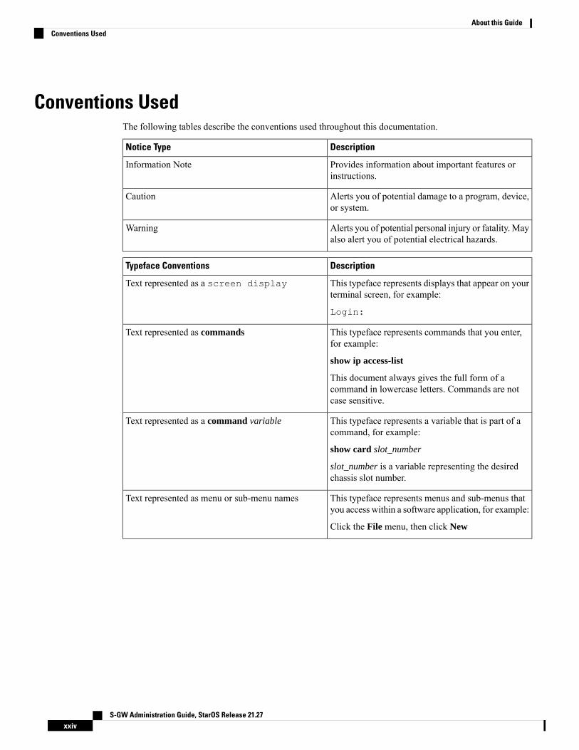
Conventions UsedThe following tables describe the conventions used throughout this documentation.
DescriptionNotice Type
Provides information about important features orinstructions.
Information Note
Alerts you of potential damage to a program, device,or system.
Caution
Alerts you of potential personal injury or fatality. Mayalso alert you of potential electrical hazards.
Warning
DescriptionTypeface Conventions
This typeface represents displays that appear on yourterminal screen, for example:
Login:
Text represented as a screen display
This typeface represents commands that you enter,for example:
show ip access-list
This document always gives the full form of acommand in lowercase letters. Commands are notcase sensitive.
Text represented as commands
This typeface represents a variable that is part of acommand, for example:
show card slot_number
slot_number is a variable representing the desiredchassis slot number.
Text represented as a command variable
This typeface represents menus and sub-menus thatyou access within a software application, for example:
Click the File menu, then click New
Text represented as menu or sub-menu names
S-GW Administration Guide, StarOS Release 21.27xxiv
About this GuideConventions Used
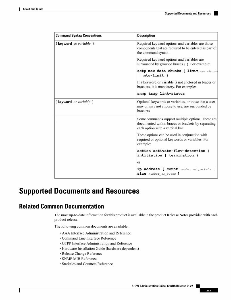
DescriptionCommand Syntax Conventions
Required keyword options and variables are thosecomponents that are required to be entered as part ofthe command syntax.
Required keyword options and variables aresurrounded by grouped braces { }. For example:
sctp-max-data-chunks { limit max_chunks
| mtu-limit }
If a keyword or variable is not enclosed in braces orbrackets, it is mandatory. For example:
snmp trap link-status
{ keyword or variable }
Optional keywords or variables, or those that a usermay or may not choose to use, are surrounded bybrackets.
[ keyword or variable ]
Some commands support multiple options. These aredocumented within braces or brackets by separatingeach option with a vertical bar.
These options can be used in conjunction withrequired or optional keywords or variables. Forexample:
action activate-flow-detection {intitiation | termination }
or
ip address [ count number_of_packets |size number_of_bytes ]
|
Supported Documents and Resources
Related Common DocumentationThe most up-to-date information for this product is available in the product Release Notes provided with eachproduct release.
The following common documents are available:
• AAA Interface Administration and Reference• Command Line Interface Reference• GTPP Interface Administration and Reference• Hardware Installation Guide (hardware dependent)• Release Change Reference• SNMP MIB Reference• Statistics and Counters Reference
S-GW Administration Guide, StarOS Release 21.27xxv
About this GuideSupported Documents and Resources

• System Administration Guide (hardware dependent)• Thresholding Configuration Guide
Related Product DocumentationThe following product documents are also available and work in conjunction with the S-GW:
• GGSN Administration Guide
• IPSec Reference
• MME Administration Guide
• P-GW Administration Guide
• SAEGW Administration Guide
• SGSN Administration Guide
Obtaining DocumentationThe most current Cisco documentation is available on the following website:
http://www.cisco.com/cisco/web/psa/default.html
Use the following path selections to access the S-GW documentation:
Products > Wireless > Mobile Internet> Network Functions > Cisco SGW Serving Gateway
Contacting Customer SupportUse the information in this section to contact customer support.
Refer to the support area of http://www.cisco.com for up-to-date product documentation or to submit a servicerequest. A valid username and password are required to access this site. Please contact your Cisco sales orservice representative for additional information.
S-GW Administration Guide, StarOS Release 21.27xxvi
About this GuideRelated Product Documentation
C H A P T E R 1Serving Gateway Overview
The Cisco® ASR 5500 core platform provides wireless carriers with a flexible solution that functions as aServing Gateway (S-GW) in Long Term Evolution-System Architecture Evolution (LTE-SAE) wireless datanetworks.
• Product Description, on page 1• Network Deployment(s), on page 4• Features and Functionality - Base Software, on page 9• Features and Functionality - Optional Enhanced Feature Software, on page 35• How the Serving Gateway Works, on page 44• Supported Standards, on page 49
Product DescriptionThe Serving Gateway routes and forwards data packets from the UE and acts as the mobility anchor duringinter-eNodeB handovers. Signals controlling the data traffic are received on the S-GW from the MME whichdetermines the S-GW that will best serve the UE for the session. Every UE accessing the EPC is associatedwith a single S-GW.
S-GW Administration Guide, StarOS Release 21.271
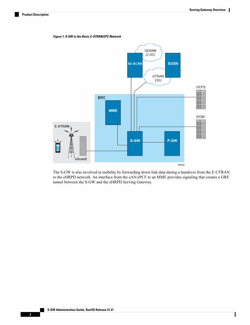
Figure 1: S-GW in the Basic E-UTRAN/EPC Network
The S-GW is also involved in mobility by forwarding down link data during a handover from the E-UTRANto the eHRPD network. An interface from the eAN/ePCF to an MME provides signaling that creates a GREtunnel between the S-GW and the eHRPD Serving Gateway.
S-GW Administration Guide, StarOS Release 21.272
Serving Gateway OverviewProduct Description

Figure 2: S-GW in the Basic E-UTRAN/EPC and eHRPD Network
The functions of the S-GW include:
• packet routing and forwarding.
• providing the local mobility anchor (LMA) point for inter-eNodeB handover and assisting the eNodeBreordering function by sending one or more "end marker" packets to the source eNodeB immediatelyafter switching the path.
• mobility anchoring for inter-3GPP mobility (terminating the S4 interface from an SGSN and relayingthe traffic between 2G/3G system and a PDN gateway.
• packet buffering for ECM-IDLE mode downlink and initiation of network triggered service requestprocedure.
• replicating user traffic in the event that Lawful Interception (LI) is required.
• transport level packet marking.
• user accounting and QoS class indicator (QCI) granularity for charging.
• uplink and downlink charging per UE, PDN, and QCI.
• reporting of user location information (ULI).
• support of circuit switched fallback (CSFB) for re-using deployed CS domain access for voice and otherCS domain services.
S-GW Administration Guide, StarOS Release 21.273
Serving Gateway OverviewProduct Description

Platform RequirementsThe S-GW service runs on a Cisco®ASR 5500 Series chassis running StarOS. The chassis can be configuredwith a variety of components to meet specific network deployment requirements. For additional information,refer to the Installation Guide for the chassis and/or contact your Cisco account representative.
LicensesThe S-GW is a licensed Cisco product. Separate session and feature licenses may be required. Contact yourCisco account representative for detailed information on specific licensing requirements. For information oninstalling and verifying licenses, refer to the Managing License Keys section of the Software ManagementOperations chapter in the System Administration Guide.
Network Deployment(s)This section describes the supported interfaces and the deployment scenarios of a Serving Gateway.
Serving Gateway in the E-UTRAN/EPC NetworkThe following figure displays the specific network interfaces supported by the S-GW. Refer to SupportedLogical Network Interfaces (Reference Points), on page 5 for detailed information about each interface.
Figure 3: Supported S-GW Interfaces in the E-UTRAN/EPC Network
S-GW Administration Guide, StarOS Release 21.274
Serving Gateway OverviewPlatform Requirements
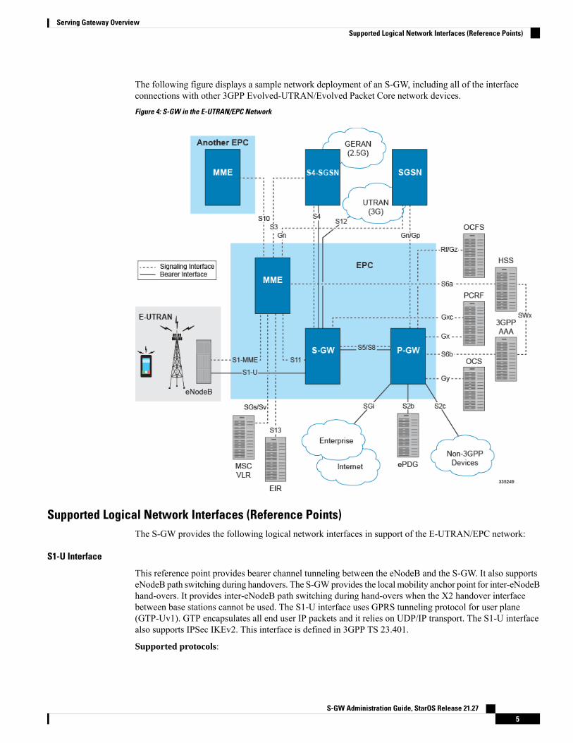
The following figure displays a sample network deployment of an S-GW, including all of the interfaceconnections with other 3GPP Evolved-UTRAN/Evolved Packet Core network devices.
Figure 4: S-GW in the E-UTRAN/EPC Network
Supported Logical Network Interfaces (Reference Points)The S-GW provides the following logical network interfaces in support of the E-UTRAN/EPC network:
S1-U Interface
This reference point provides bearer channel tunneling between the eNodeB and the S-GW. It also supportseNodeB path switching during handovers. The S-GWprovides the local mobility anchor point for inter-eNodeBhand-overs. It provides inter-eNodeB path switching during hand-overs when the X2 handover interfacebetween base stations cannot be used. The S1-U interface uses GPRS tunneling protocol for user plane(GTP-Uv1). GTP encapsulates all end user IP packets and it relies on UDP/IP transport. The S1-U interfacealso supports IPSec IKEv2. This interface is defined in 3GPP TS 23.401.
Supported protocols:
S-GW Administration Guide, StarOS Release 21.275
Serving Gateway OverviewSupported Logical Network Interfaces (Reference Points)
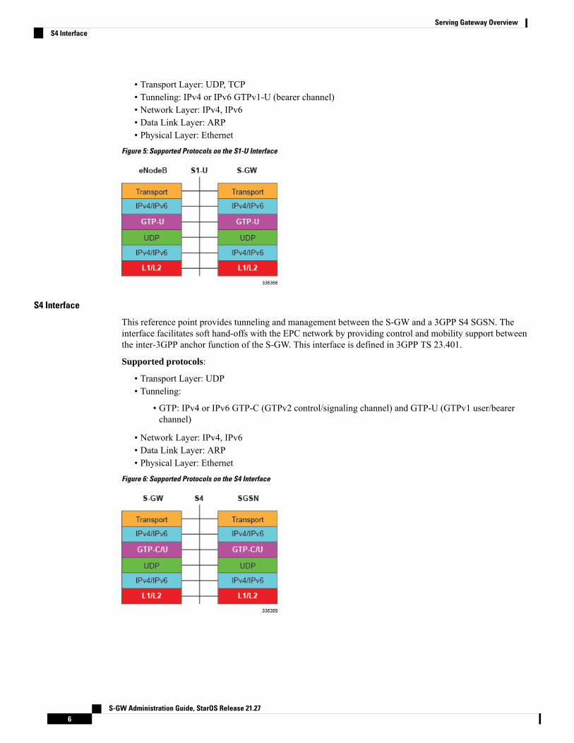
• Transport Layer: UDP, TCP• Tunneling: IPv4 or IPv6 GTPv1-U (bearer channel)• Network Layer: IPv4, IPv6• Data Link Layer: ARP• Physical Layer: Ethernet
Figure 5: Supported Protocols on the S1-U Interface
S4 Interface
This reference point provides tunneling and management between the S-GW and a 3GPP S4 SGSN. Theinterface facilitates soft hand-offs with the EPC network by providing control and mobility support betweenthe inter-3GPP anchor function of the S-GW. This interface is defined in 3GPP TS 23.401.
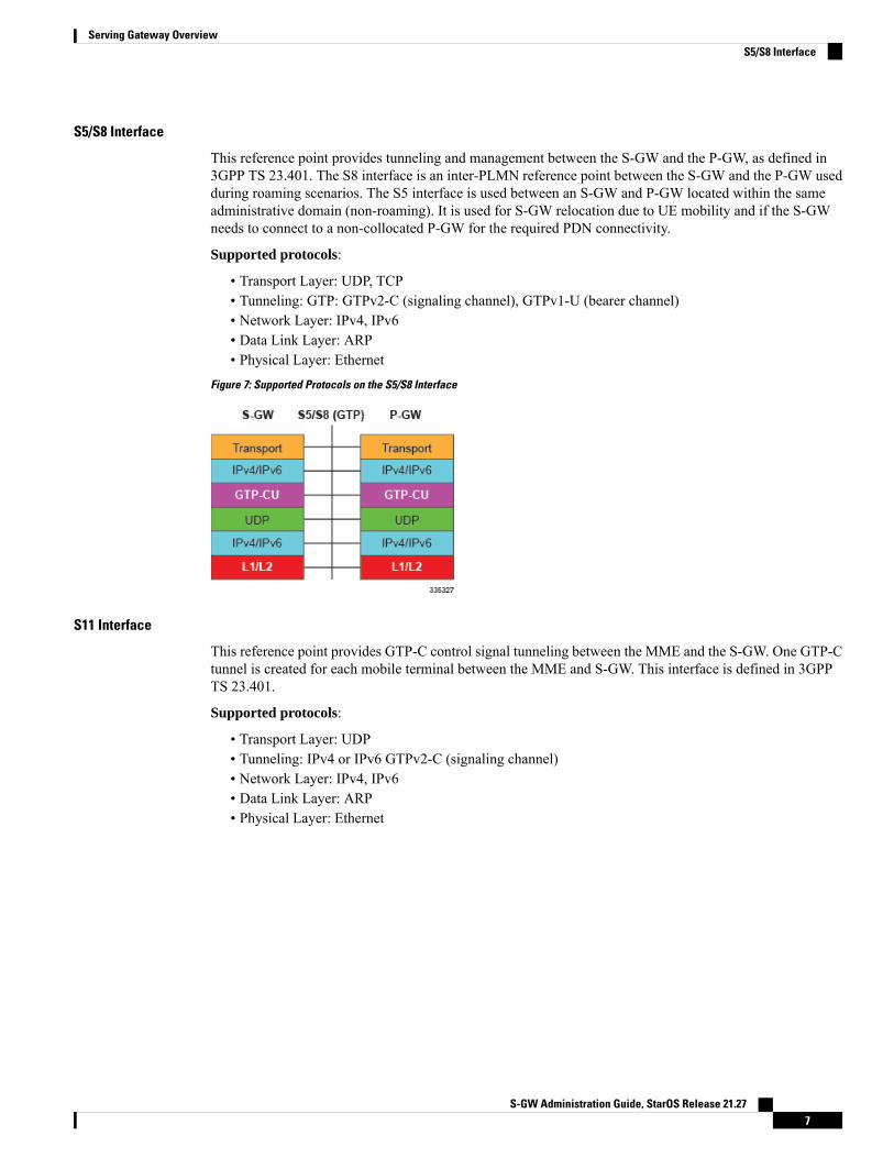
Supported protocols:
• Transport Layer: UDP• Tunneling:
• GTP: IPv4 or IPv6 GTP-C (GTPv2 control/signaling channel) and GTP-U (GTPv1 user/bearerchannel)
• Network Layer: IPv4, IPv6• Data Link Layer: ARP• Physical Layer: Ethernet
Figure 6: Supported Protocols on the S4 Interface
S-GW Administration Guide, StarOS Release 21.276
Serving Gateway OverviewS4 Interface
S5/S8 Interface
This reference point provides tunneling and management between the S-GW and the P-GW, as defined in3GPP TS 23.401. The S8 interface is an inter-PLMN reference point between the S-GW and the P-GW usedduring roaming scenarios. The S5 interface is used between an S-GW and P-GW located within the sameadministrative domain (non-roaming). It is used for S-GW relocation due to UE mobility and if the S-GWneeds to connect to a non-collocated P-GW for the required PDN connectivity.
Supported protocols:
• Transport Layer: UDP, TCP• Tunneling: GTP: GTPv2-C (signaling channel), GTPv1-U (bearer channel)• Network Layer: IPv4, IPv6• Data Link Layer: ARP• Physical Layer: Ethernet
Figure 7: Supported Protocols on the S5/S8 Interface
S11 Interface
This reference point provides GTP-C control signal tunneling between the MME and the S-GW. One GTP-Ctunnel is created for each mobile terminal between the MME and S-GW. This interface is defined in 3GPPTS 23.401.
Supported protocols:
• Transport Layer: UDP• Tunneling: IPv4 or IPv6 GTPv2-C (signaling channel)• Network Layer: IPv4, IPv6• Data Link Layer: ARP• Physical Layer: Ethernet
S-GW Administration Guide, StarOS Release 21.277
Serving Gateway OverviewS5/S8 Interface
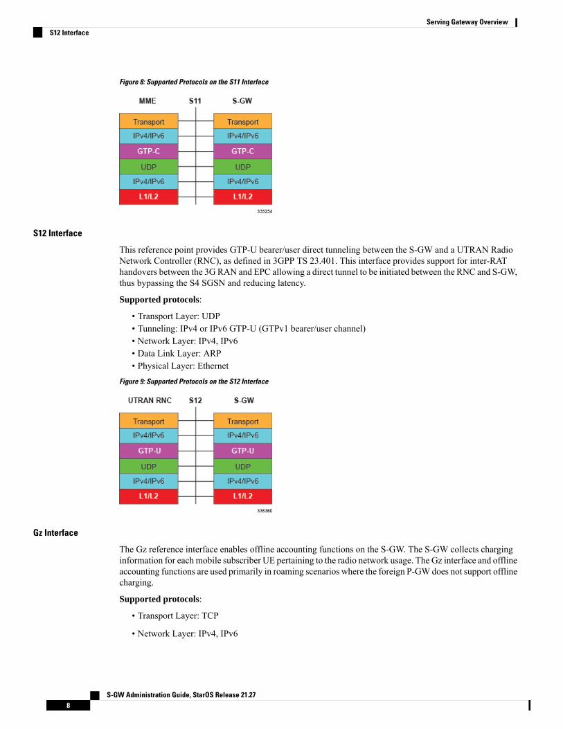
Figure 8: Supported Protocols on the S11 Interface
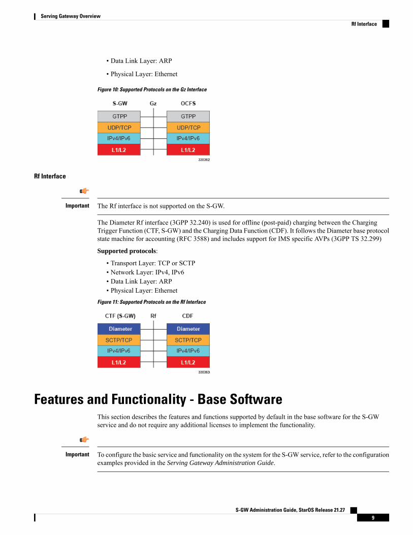
S12 Interface
This reference point provides GTP-U bearer/user direct tunneling between the S-GW and a UTRAN RadioNetwork Controller (RNC), as defined in 3GPP TS 23.401. This interface provides support for inter-RAThandovers between the 3G RAN and EPC allowing a direct tunnel to be initiated between the RNC and S-GW,thus bypassing the S4 SGSN and reducing latency.
Supported protocols:
• Transport Layer: UDP• Tunneling: IPv4 or IPv6 GTP-U (GTPv1 bearer/user channel)• Network Layer: IPv4, IPv6• Data Link Layer: ARP• Physical Layer: Ethernet
Figure 9: Supported Protocols on the S12 Interface
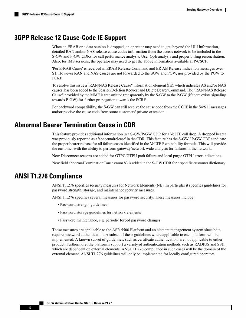
Gz Interface
The Gz reference interface enables offline accounting functions on the S-GW. The S-GW collects charginginformation for each mobile subscriber UE pertaining to the radio network usage. The Gz interface and offlineaccounting functions are used primarily in roaming scenarios where the foreign P-GW does not support offlinecharging.
Supported protocols:
• Transport Layer: TCP
• Network Layer: IPv4, IPv6
S-GW Administration Guide, StarOS Release 21.278
Serving Gateway OverviewS12 Interface
• Data Link Layer: ARP
• Physical Layer: Ethernet
Figure 10: Supported Protocols on the Gz Interface
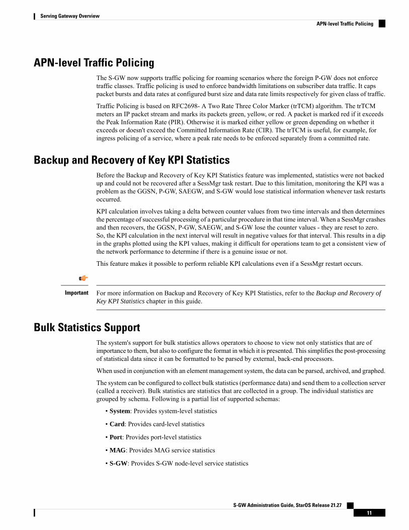
Rf Interface
The Rf interface is not supported on the S-GW.Important
The Diameter Rf interface (3GPP 32.240) is used for offline (post-paid) charging between the ChargingTrigger Function (CTF, S-GW) and the Charging Data Function (CDF). It follows the Diameter base protocolstate machine for accounting (RFC 3588) and includes support for IMS specific AVPs (3GPP TS 32.299)
Supported protocols:
• Transport Layer: TCP or SCTP• Network Layer: IPv4, IPv6• Data Link Layer: ARP• Physical Layer: Ethernet
Figure 11: Supported Protocols on the Rf Interface
Features and Functionality - Base SoftwareThis section describes the features and functions supported by default in the base software for the S-GWservice and do not require any additional licenses to implement the functionality.
To configure the basic service and functionality on the system for the S-GW service, refer to the configurationexamples provided in the Serving Gateway Administration Guide.
Important
S-GW Administration Guide, StarOS Release 21.279
Serving Gateway OverviewRf Interface
3GPP Release 12 Cause-Code IE SupportWhen an ERAB or a data session is dropped, an operator may need to get, beyond the ULI information,detailed RAN and/or NAS release cause codes information from the access network to be included in theS-GW and P-GW CDRs for call performance analysis, User QoE analysis and proper billing reconciliation.Also, for IMS sessions, the operator may need to get the above information available at P-CSCF.
'Per E-RAB Cause' is received in ERAB Release Command and ER AB Release Indication messages overS1. However RAN and NAS causes are not forwarded to the SGW and PGW, nor provided by the PGW toPCRF.
To resolve this issue a "RAN/NAS Release Cause" information element (IE), which indicates AS and/or NAScauses, has been added to the Session Deletion Request and Delete Bearer Command. The "RAN/NASReleaseCause" provided by the MME is transmitted transparently by the S-GW to the P-GW (if there exists signalingtowards P-GW) for further propagation towards the PCRF.
For backward compatibility, the S-GW can still receive the cause code from the CC IE in the S4/S11 messagesand/or receive the cause code from some customers' private extension.
Abnormal Bearer Termination Cause in CDRThis feature provides additional information in a S-GW/P-GWCDR for a VoLTE call drop. A dropped bearerwas previously reported as a 'abnormalrelease' in the CDR. This feature has the S-GW / P-GWCDRs indicatethe proper bearer release for all failure cases identified in the VoLTE Retainability formula. This will providethe customer with the ability to perform gateway/network wide analysis for failures in the network.
New Disconnect reasons are added for GTPC/GTPU path failure and local purge GTPU error indications.
New field abnormalTerminationCause enum 83 is added in the S-GWCDR for a specific customer dictionary.
ANSI T1.276 ComplianceANSI T1.276 specifies security measures for Network Elements (NE). In particular it specifies guidelines forpassword strength, storage, and maintenance security measures.
ANSI T1.276 specifies several measures for password security. These measures include:
• Password strength guidelines
• Password storage guidelines for network elements
• Password maintenance, e.g. periodic forced password changes
These measures are applicable to the ASR 5500 Platform and an element management system since bothrequire password authentication. A subset of these guidelines where applicable to each platform will beimplemented. A known subset of guidelines, such as certificate authentication, are not applicable to eitherproduct. Furthermore, the platforms support a variety of authentication methods such as RADIUS and SSHwhich are dependent on external elements. ANSI T1.276 compliance in such cases will be the domain of theexternal element. ANSI T1.276 guidelines will only be implemented for locally configured operators.
S-GW Administration Guide, StarOS Release 21.2710
Serving Gateway Overview3GPP Release 12 Cause-Code IE Support
APN-level Traffic PolicingThe S-GW now supports traffic policing for roaming scenarios where the foreign P-GW does not enforcetraffic classes. Traffic policing is used to enforce bandwidth limitations on subscriber data traffic. It capspacket bursts and data rates at configured burst size and data rate limits respectively for given class of traffic.
Traffic Policing is based on RFC2698- A Two Rate Three Color Marker (trTCM) algorithm. The trTCMmeters an IP packet stream and marks its packets green, yellow, or red. A packet is marked red if it exceedsthe Peak Information Rate (PIR). Otherwise it is marked either yellow or green depending on whether itexceeds or doesn't exceed the Committed Information Rate (CIR). The trTCM is useful, for example, foringress policing of a service, where a peak rate needs to be enforced separately from a committed rate.
Backup and Recovery of Key KPI StatisticsBefore the Backup and Recovery of Key KPI Statistics feature was implemented, statistics were not backedup and could not be recovered after a SessMgr task restart. Due to this limitation, monitoring the KPI was aproblem as the GGSN, P-GW, SAEGW, and S-GW would lose statistical information whenever task restartsoccurred.
KPI calculation involves taking a delta between counter values from two time intervals and then determinesthe percentage of successful processing of a particular procedure in that time interval. When a SessMgr crashesand then recovers, the GGSN, P-GW, SAEGW, and S-GW lose the counter values - they are reset to zero.So, the KPI calculation in the next interval will result in negative values for that interval. This results in a dipin the graphs plotted using the KPI values, making it difficult for operations team to get a consistent view ofthe network performance to determine if there is a genuine issue or not.
This feature makes it possible to perform reliable KPI calculations even if a SessMgr restart occurs.
For more information on Backup and Recovery of Key KPI Statistics, refer to the Backup and Recovery ofKey KPI Statistics chapter in this guide.
Important
Bulk Statistics SupportThe system's support for bulk statistics allows operators to choose to view not only statistics that are ofimportance to them, but also to configure the format in which it is presented. This simplifies the post-processingof statistical data since it can be formatted to be parsed by external, back-end processors.
When used in conjunction with an element management system, the data can be parsed, archived, and graphed.
The system can be configured to collect bulk statistics (performance data) and send them to a collection server(called a receiver). Bulk statistics are statistics that are collected in a group. The individual statistics aregrouped by schema. Following is a partial list of supported schemas:
• System: Provides system-level statistics
• Card: Provides card-level statistics
• Port: Provides port-level statistics
• MAG: Provides MAG service statistics
• S-GW: Provides S-GW node-level service statistics
S-GW Administration Guide, StarOS Release 21.2711
Serving Gateway OverviewAPN-level Traffic Policing
• IP Pool: Provides IP pool statistics
• APN: Provides Access Point Name statistics
The system supports the configuration of up to four sets (primary/secondary) of receivers. Each set can beconfigured with to collect specific sets of statistics from the various schemas. Statistics can be pulled manuallyfrom the system or sent at configured intervals. The bulk statistics are stored on the receiver(s) in files.
The format of the bulk statistic data files can be configured by the user. Users can specify the format of thefile name, file headers, and/or footers to include information such as the date, system host name, systemuptime, the IP address of the system generating the statistics (available for only for headers and footers),and/or the time that the file was generated.
An element management system is capable of further processing the statistics data through XML parsing,archiving, and graphing.
The Bulk Statistics Server component of an element management system parses collected statistics and storesthe information in its PostgreSQL database. It can also generate XML output and can send it to a NorthboundNMS or an alternate bulk statistics server for further processing.
Additionally, the Bulk Statistics server can archive files to an alternative directory on the server. The directorycan be on a local file system or on an NFS-mounted file system on an element management system server.
For more information on bulk statistic configuration, refer to the Configuring and Maintaining Bulk Statisticschapter in the System Administration Guide.
Important
CDR Support for Including LAPI (Signaling Priority)This feature is related to M2M support. 3GPP has added the LAPI (signaling priority) indication being sentin the GTP messages, to indicate that the PDN is a low priority bearer and thus can be treated accordingly.APN backoff timer support based on LAPI indication is not yet supported.
3GPP has also added a new AVP in CDR defined in TS 32.298 named "lowPriorityIndicator". If the S-GWreceives the LAPI indicator in GTP, the SGW-CDR and generated will contain the LAPI indication.
The benefit of this feature is that it provides support for carrying the LAPI attribute in SGW-CDR andPGW-CDR, so that billing system can then accordingly bill for that PDN.
Circuit Switched Fall Back (CSFB) SupportCircuit Switched Fall Back (CSFB) enables the UE to camp on an EUTRAN cell and originate or terminatevoice calls through a forced switchover to the circuit switched (CS) domain or other CS-domain services (forexample, Location Services (LCS) or supplementary services). Additionally, SMS delivery via the CS corenetwork is realized without CSFB. Since LTE EPC networks were not meant to directly anchor CS connections,when any CS voice services are initiated, any PS based data activities on the EUTRAN network will betemporarily suspended (either the data transfer is suspended or the packet switched connection is handed overto the 2G/3G network).
CSFB provides an interim solution for enabling telephony and SMS services for LTE operators that do notplan to deploy IMS packet switched services at initial service launch.
The S-GW supports CSFB messaging over the S11 interface over GTP-C. Supported messages are:
S-GW Administration Guide, StarOS Release 21.2712
Serving Gateway OverviewCDR Support for Including LAPI (Signaling Priority)

• Suspend Notification
• Suspend Acknowledge
• Resume Notification
• Resume Acknowledgement
The S-GW forwards Suspend Notificationmessages towards the P-GW to suspend downlink data for non-GBRtraffic; the P-GW then drops all downlink packets. Later, when the UE finishes with CS services and movesback to E-UTRAN, theMME sends a ResumeNotification message to the S-GWwhich forwards the messageto the P-GW. The downlink data traffic then resumes.
Closed Subscriber Group SupportThe S-GW supports the following Closed Subscriber Group (CSG) Information Elements (IEs) and Call DetailRecord:
• User CSG Information (UCI) IE in S5/S8• CSG Information Reporting Action IE and functionality in S5/S8• An SGW-CDR that includes a CSG record
Collision Counter Support in the GTP LayerGTPv2 message collisions occur in the network when a node is expecting a particular procedure messagefrom a peer node but instead receives a different procedure message from the peer. The S-GW software hasbeen enhanced so that these collisions are now tracked by statistics and handled based on a pre-defined actionfor each message collision type.
If the SAEGW is configured as a pure P-GW or a pure S-GW, operators will still see the respective collisionstatistics if they occur.
The output of the show egtp statistics verbose command has been enhanced to provide information on GTPv2message collisions, including:
• Interface: The interface on which the collision occurred: SGW (S4/S11), SGW (S5), or PGW (S5).• Old Proc (Msg Type): Indicates the ongoing procedure at eGTP-C when a new message arrived at theinterface which caused the collision. The Msg Type in brackets specifies which message triggered thisongoing procedure.
• New Proc (Msg Type): The new procedure and message type.• Action: The pre-defined action taken to handle the collision. The action can be one of:
• No Collision Detected• Suspend Old: Suspend processing of the original (old) message, process the new message, thenresume old message handling.
• Abort Old: Abort the original message handling and processes the new message.• Reject New: The new message is rejected, and the original (old) message is processed.• Silent Drop New: Drop the new incoming message, and the old message is processed.• Parallel Hndl: Both the original (old) and new messages are handled in parallel.• Buffer New: The newmessage is buffered and processed once the original (old) message processingis done.
• Counter: The number of times each collision type has occurred.
S-GW Administration Guide, StarOS Release 21.2713
Serving Gateway OverviewClosed Subscriber Group Support
The Message Collision Statistics section of the command output only appears if any of the collision statisticshave a counter total that is greater than zero.
Important
Sample output:Message Collision StatisticsInterface Old Proc (Msg Type) New Proc (Msg Type) Action CounterSGW(S5) NW Init Bearer Create (95) NW Init PDN Delete (99) Abort Old 1
In this instance, the output states that at the S-GW egress interface (S5) a Bearer creation procedure is goingon due to a CREATE BEARER REQUEST(95) message from the P-GW. Before its response comes to theS-GW from the MME, a new procedure PDNDelete is triggered due to a DELETE BEARER REQUEST(99)message from the P-GW.
The action that is carried out due to this collision at eGTP-C is to abort (Abort Old) the Bearer Creationprocedure and carry on normally with the PDN Delete procedure. The Counter total of 1 indicates that thiscollision happened only once.
Congestion ControlThe congestion control feature allows you to set policies and thresholds and specify how the system reactswhen faced with a heavy load condition.
Congestion control monitors the system for conditions that could potentially degrade performance when thesystem is under heavy load. Typically, these conditions are temporary (for example, high CPU or memoryutilization) and are quickly resolved. However, continuous or large numbers of these conditions within aspecific time interval may have an impact the system's ability to service subscriber sessions. Congestioncontrol helps identify such conditions and invokes policies for addressing the situation.
Congestion control operation is based on configuring the following:
• Congestion Condition Thresholds: Thresholds dictate the conditions for which congestion control isenabled and establish limits for defining the state of the system (congested or clear). These thresholdsfunction in a way similar to operational thresholds that are configured for the system as described in theThresholding Configuration Guide. The primary difference is that when congestion thresholds are reached,a service congestion policy and an SNMP trap, starCongestion, are generated.
A threshold tolerance dictates the percentage under the configured threshold that must be reached inorder for the condition to be cleared. An SNMP trap, starCongestionClear, is then triggered.
• Port Utilization Thresholds: If you set a port utilization threshold, when the average utilizationof all ports in the system reaches the specified threshold, congestion control is enabled.
• Port-specific Thresholds: If you set port-specific thresholds, when any individual port-specificthreshold is reached, congestion control is enabled system-wide.
• Service Congestion Policies: Congestion policies are configurable for each service. These policiesdictate how services respond when the system detects that a congestion condition threshold has beencrossed.
S-GW Administration Guide, StarOS Release 21.2714
Serving Gateway OverviewCongestion Control

For more information on congestion control, refer to the Congestion Control chapter in the SystemAdministration Guide.
Important
Dedicated Bearer Timeout Support on the S-GWThe S-GW has been enhanced to support a bearer inactivity timeout for GBR and non-GBR S-GW bearertype sessions per Qos Class Identifier (QCI). This enables the deletion of bearers experiencing less data trafficthan the configured threshold value. Operators now can configure a bearer inactivity timeout for GBR andnon-GBR bearers for more efficient use of system resources.
Downlink Delay NotificationThis feature is divided between the following:
• Value Handling• Throttling• EPS Bearer ID and ARP Support
Value HandlingThis feature provides for the handling of delay value information elements (IEs) at the S-GW. When a delayvalue is received at the S-GW from a particular MME, the S-GW delays sending data notification requestsfor all idle calls belonging to that particular MME. Once the timer expires, requests can be sent. The delayvalue at the S-GW is determined by the factor received in the delay value IE (as a part of either a ModifyBearer Request or a Data Downlink Notification Request) and a hard-coded base factor of 50 ms at the S-GW
ThrottlingThis feature provides additional controls allowing the S-GW to set factors that "throttle" the continuous sendingand receiving of DDN messages. A single command configures the throttling parameters supporting thisfeature,
A description of the ddn throttle command is located in the S-GW Service Configuration Mode Commandschapter in the Command Line Interface Reference.
EPS Bearer ID and ARP SupportThis feature allows support for Priority Paging support in the network. This is mainly needed forMPS subscribersupport. The paging priority in the paging message is set by MME based on ARP received in Downlink DataNotification message.
In order to support MPS requirement for Priority Paging in the network for MPS subscriber, DDN messagehas been enhanced to support passing ARP and EBI information. When the S-GW sends a Downlink DataNotification message, it shall include both EPS Bearer ID and ARP. If the Downlink Data Notification istriggered by the arrival of downlink data packets at the S-GW, the S-GW shall include the EPS Bearer ID andARP associated with the bearer on which the downlink data packet was received. If the Downlink DataNotification is triggered by the arrival of control signaling, the S-GW shall include the EPS Bearer ID andARP, if present in the control signaling. If the ARP is not present in the control signaling, the S-GW shallinclude the ARP in the stored EPS bearer context. If multiple EPS Bearers IDs are reported in the Downlink
S-GW Administration Guide, StarOS Release 21.2715
Serving Gateway OverviewDedicated Bearer Timeout Support on the S-GW
Data Notification message, the S-GW shall include all the EBI values and the ARP associated with the bearerwith the highest priority (lowest ARP value). For more information, see TS 23.401 (section 5.3.4.3) and 29.274(section 7.2.11). Details are discussed in CR-859 of 3GPP specifications.
DSCP Ingress and Egress and DSCP Marking at the APN ProfileThis feature will provide an operator with a configuration to set the DSCP value per APN profile, so differentAPNs can have different DSCPmarkings as per QOS requirements for traffic carried by the APN. In addition,the qci-qos mapping table is updated with the addition of a copy-outer for copying the DSCP value comingin the encapsulation header from the S1u interface to the S5 interface and vice-versa.
Dynamic GTP Echo TimerThe Dynamic GTP Echo Timer enables the eGTP and GTP-U services to better manage GTP paths duringnetwork congestion. As opposed to the default echo timer which uses fixed intervals and retransmission timers,the dynamic echo timer adds a calculated round trip timer (RTT) that is generated once a full request/responseprocedure has completed. Amultiplier can be added to the calculation for additional support during congestionperiods.
For more information, refer to theConfiguring the GTP Echo Timer section located in theConfiguring OptionalFeatures on the eGTP S-GW section of the Serving Gateway Configuration chapter.
Event-Based Idle Second Micro-Check Point Generation for the S-GWMicro-checkpoints were configurable only with themicro-checkpoint-periodicity option in the timeout idlecommand in APN Configuration Mode.
The S-GW can be configured to send an idlesec micro-checkpoint from an Active to Standby chassis whenthe session state changes from active to idle or from idle to active. The micro-checkpoint carries informationabout the time when the session became active or idle. Upon receipt of the micro-checkpoint, the Standbychassis updates the active/idle time. This process enables the Active and Standby chassis to be synchronizedwith respect to when a particular session became active or idle.
Since this feature is event-based, it enables the chassis to send micro-checkpoints only when an event occurs,as opposed to sending micro-check points based on a configured time duration, which sends themicro-checkpoints regardless of whether a session state change occurred or not.
To enable this functionality, use the micro-checkpoint-deemed-idle keyword in the timeout idle commandin APN Configuration Mode.
Event ReportingThe S-GW can be configured to send a stream of user event data to an external server. As users attach, detach,and move throughout the network, they trigger signaling events, which are recorded and sent to an externalserver for processing. Reported data includes failure reasons, nodes selected, user information (IMSI, IMEI,MSISDN), APN, failure codes (if any) and other information on a per PDN-connection level. Event data isused to track the user status via near real time monitoring tools and for historical analysis of major networkevents.
The S-GW Event Reporting chapter at the end of this guide describes the trigger mechanisms and event recordelements used for event reporting.
S-GW Administration Guide, StarOS Release 21.2716
Serving Gateway OverviewDSCP Ingress and Egress and DSCP Marking at the APN Profile
The SGW sends each event record in comma separated values (CSV) format. The record for each event issent to the external server within 60 seconds of its occurrence. The session-event-module command in theContext Configuration mode allows an operator to set the method and destination for transferring event files,as well as the format and handling characteristics of event files. For a detailed description of this command,refer to the Command Line Interface Reference.
Idle-mode Signaling Reduction SupportThe S-GW now supports Idle-mode Signaling Reduction (ISR) allowing for a control connection to existbetween an S-GW and anMME and S4-SGSN. The S-GW stores mobility management parameters from bothnodes while the UE stores session management contexts for both the EUTRAN and GERAN/UTRAN. Thisallows a UE, in idle mode, to move between the two network types without needing to perform racking areaupdate procedures, thus reducing the signaling previously required. ISR support on the S-GW is embeddedand no configuration is required however, an optional feature license is required to enable this feature.
ISR support on the S-GW is embedded and no configuration is required, however, an optional feature licensemust be purchased to enable this feature.
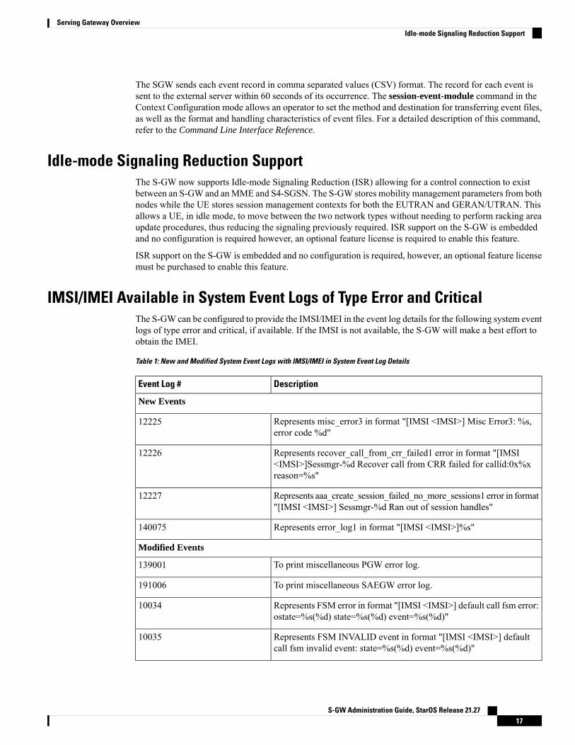
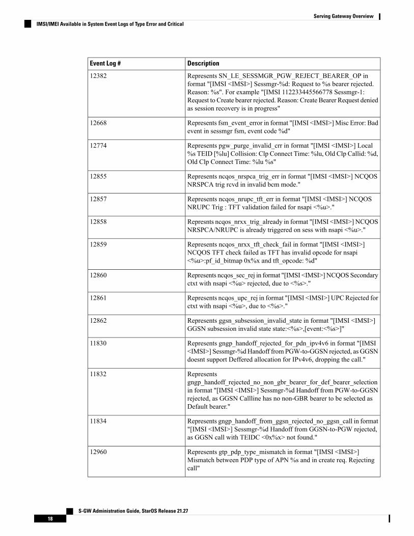
IMSI/IMEI Available in System Event Logs of Type Error and CriticalThe S-GW can be configured to provide the IMSI/IMEI in the event log details for the following system eventlogs of type error and critical, if available. If the IMSI is not available, the S-GW will make a best effort toobtain the IMEI.
Table 1: New and Modified System Event Logs with IMSI/IMEI in System Event Log Details
DescriptionEvent Log #
New Events
Represents misc_error3 in format "[IMSI <IMSI>] Misc Error3: %s,error code %d"
12225
Represents recover_call_from_crr_failed1 error in format "[IMSI<IMSI>]Sessmgr-%d Recover call from CRR failed for callid:0x%xreason=%s"
12226
Represents aaa_create_session_failed_no_more_sessions1 error in format"[IMSI <IMSI>] Sessmgr-%d Ran out of session handles"
12227
Represents error_log1 in format "[IMSI <IMSI>]%s"140075
Modified Events
To print miscellaneous PGW error log.139001
To print miscellaneous SAEGW error log.191006
Represents FSM error in format "[IMSI <IMSI>] default call fsm error:ostate=%s(%d) state=%s(%d) event=%s(%d)"
10034
Represents FSM INVALID event in format "[IMSI <IMSI>] defaultcall fsm invalid event: state=%s(%d) event=%s(%d)"
10035
S-GW Administration Guide, StarOS Release 21.2717
Serving Gateway OverviewIdle-mode Signaling Reduction Support
DescriptionEvent Log #
Represents SN_LE_SESSMGR_PGW_REJECT_BEARER_OP informat "[IMSI <IMSI>] Sessmgr-%d: Request to %s bearer rejected.Reason: %s". For example "[IMSI 112233445566778 Sessmgr-1:Request to Create bearer rejected. Reason: Create Bearer Request deniedas session recovery is in progress"
12382
Represents fsm_event_error in format "[IMSI <IMSI>]Misc Error: Badevent in sessmgr fsm, event code %d"
12668
Represents pgw_purge_invalid_crr in format "[IMSI <IMSI>] Local%s TEID [%lu] Collision: Clp Connect Time: %lu, Old Clp Callid: %d,Old Clp Connect Time: %lu %s"
12774
Represents ncqos_nrspca_trig_err in format "[IMSI <IMSI>] NCQOSNRSPCA trig rcvd in invalid bcm mode."
12855
Represents ncqos_nrupc_tft_err in format "[IMSI <IMSI>] NCQOSNRUPC Trig : TFT validation failed for nsapi <%u>."
12857
Represnts ncqos_nrxx_trig_already in format "[IMSI <IMSI>] NCQOSNRSPCA/NRUPC is already triggered on sess with nsapi <%u>."
12858
Represents ncqos_nrxx_tft_check_fail in format "[IMSI <IMSI>]NCQOS TFT check failed as TFT has invalid opcode for nsapi<%u>:pf_id_bitmap 0x%x and tft_opcode: %d"
12859
Represents ncqos_sec_rej in format "[IMSI <IMSI>]NCQOSSecondaryctxt with nsapi <%u> rejected, due to <%s>."
12860
Represents ncqos_upc_rej in format "[IMSI <IMSI>] UPCRejected forctxt with nsapi <%u>, due to <%s>."
12861
Represents ggsn_subsession_invalid_state in format "[IMSI <IMSI>]GGSN subsession invalid state state:<%s>,[event:<%s>]"
12862
Represents gngp_handoff_rejected_for_pdn_ipv4v6 in format "[IMSI<IMSI>] Sessmgr-%dHandoff from PGW-to-GGSN rejected, as GGSNdoesnt support Deffered allocation for IPv4v6, dropping the call."
11830
Representsgngp_handoff_rejected_no_non_gbr_bearer_for_def_bearer_selectionin format "[IMSI <IMSI>] Sessmgr-%d Handoff from PGW-to-GGSNrejected, as GGSN Callline has no non-GBR bearer to be selected asDefault bearer."
11832
Represents gngp_handoff_from_ggsn_rejected_no_ggsn_call in format"[IMSI <IMSI>] Sessmgr-%d Handoff from GGSN-to-PGW rejected,as GGSN call with TEIDC <0x%x> not found."
11834
Represents gtp_pdp_type_mismatch in format "[IMSI <IMSI>]Mismatch between PDP type of APN %s and in create req. Rejectingcall"
12960
S-GW Administration Guide, StarOS Release 21.2718
Serving Gateway OverviewIMSI/IMEI Available in System Event Logs of Type Error and Critical

DescriptionEvent Log #
Represents pcc_intf_error_info in format "[IMSI <IMSI>] %s"11282
Represents collision_error in format "[IMSI <IMSI>] Collision Error:Temp Failure Handling Delayed Pending Active Transaction: , errorcode %d"
11293
Represents rcvd_invalid_bearer_binding_req_from_acs in format "[IMSI<IMSI>] Sessmgr %d: Received invalid bearer binding request fromACS."
11917
Represents saegw_uid_error in format "[IMSI <IMSI>] %s"11978
Represents unwanted_pcc_intf_setup_req error in format "[IMSI<IMSI>] GGSN_INITIATE_SESS_SETUP_REQ is already fwded toPCC interface "
11994
Represents ue_fsm_illegal_event in format "[IMSI <IMSI>]Invalid/unhandled UE event <%s> in state <%s>"
140005
Represents pdn_fsm_illegal_event in format "[IMSI <IMSI>]Invalid/unhandled PDN event <%s> in state <%s>"
140006
Represents epsb_fsm_illegal_event in format "[IMSI <IMSI>]Invalid/unhandled EPSB event <%s> in state <%s>"
140007
Represents saegwdrv_generic_error "[IMSI <IMSI>] %s"10726
Enable this functionality by using the logging include-ueid command in Global Configuration Mode. Whenenabled, the previously mentioned system events of type error and critical will provide the IMSI/IMEI in thelogging details, if available.
IP Access Control ListsIP access control lists allow you to set up rules that control the flow of packets into and out of the systembased on a variety of IP packet parameters.
IP access lists, or Access Control Lists (ACLs) as they are commonly referred to, control the flow of packetsinto and out of the system. They are configured on a per-context basis and consist of "rules" (ACL rules) orfilters that control the action taken on packets that match the filter criteria. Once configured, an ACL can beapplied to any of the following:
• An individual interface
• All traffic facilitated by a context (known as a policy ACL)
• An individual subscriber
• All subscriber sessions facilitated by a specific context
S-GW Administration Guide, StarOS Release 21.2719
Serving Gateway OverviewIP Access Control Lists

The S-GW supports interface-based ACLs only. For more information on IP access control lists, refer to theIP Access Control Lists chapter in the System Administration Guide.
Important
IPv6 CapabilitiesIPv6 enables increased address efficiency and relieves pressures caused by rapidly approaching IPv4 addressexhaustion problem.
The S-GW platform offers the following IPv6 capabilities:
IPv6 Connections to Attached Elements
IPv6 transport and interfaces are supported on all of the following connections:
• Diameter Gxc policy signaling interface
• Diameter Rf offline charging interface
• Lawful Intercept (X1, X2 interfaces)
The Diameter Rf offline charging interface is not supported on the S-GW.Important
Routing and Miscellaneous Features
• OSPFv3
• MP-BGP v6 extensions
• IPv6 flows (Supported on all Diameter QoS and Charging interfaces as well as Inline Services (forexample, ECS, P2P detection, Stateful Firewall, etc.)
LIPA SupportA LIPA (Local IP Access) PDN is a PDN Connection for local IP access for a UE connected to a HeNB. TheLIPA architecture includes a Local Gateway (LGW) acting as an S-GW GTPv2 peer. The LGW is collocatedwith HeNB in the operator network behaves as a PGW from SGW perspective. Once the default bearer forthe LIPA PDN is established, then data flows directly to the LGW and from there into the local networkwithout traversing the core network of the network operator.
In order to support millions of LIPAGTPC peers, S-GWmemorymanagement has been enhanced with regardsto GTPv2 procedures and as well as to support the maintenance of statistics per peer node.
Establishment of LIPA PDN follows a normal call flow similar to that of a normal PDN as per 23.401; thespecification does not distinguish between a LGW and a PGW call. As a result, the S-GW supports a newconfiguration option to detect a LIPA peer. As a fallback mechanism, heuristic detection of LIPA peer basedon data flow characteristics of a LIPA call is also supported.
Whenever a peer is detected as a LIPA peer, the S-GW will disable GTPC echo mechanism towards thatparticular peer and stop maintaining some statistics for that peer.
S-GW Administration Guide, StarOS Release 21.2720
Serving Gateway OverviewIPv6 Capabilities

A configuration option in APN profile explicitly indicates that all the PDN's for that APN are LIPA PDN's,so all GTPC peers on S5 for that APN are treated as LGW, and thus no any detection algorithm is applied todetect LGW.
Location ReportingLocation reporting can be used to support a variety of applications including emergency calls, lawful intercept,and charging. This feature reports user location information (ULI).
ULI data reported in GTPv2 messages includes:
• TAI-ID: Tracking Area Identity
• MCC: MNC: Mobile Country Code, Mobile Network Code
• TAC: Tracking Area Code
The S-GW stores the ULI and also reports the information to the accounting framework. This may lead togeneration of Gz and Rf Interim records. The S-GW also forwards the received ULI to the P-GW. If the S-GWreceives the UE time zone IE from theMME, it forwards this IE towards the P-GW across the S5/S8 interface.
Mapping High Throughput Sessions on Session ManagersSession managers are upgraded to manage several high throughput sessions without sharing the core andwithout creating a bottleneck on the CPU load.
The gateway – S-GW, SAEGW or P-GW, classifies a session as a high throughput session based on a DCNRflag present in the IE: FLAGS FOR USER PLANE FUNCTION (UPF) SELECTION INDICATION, in theCreate Session Request. This DCNR flag is checkpointed and recovered by the gateway.
A high throughput session is placed on a session manager that has no other high throughput session. If allsession manager are handling a high throughput session then these sessions are allocated using theRound-Robbin method.
• The selection of session managers for non-high throughput sessions remains the same in the existingsetup.
• Non-high throughput sessions are placed along with the high throughput sessions on the same sessionmanager.
Note
Limitations
Managing high throughput sessions on a session manager has the following limitations:
• The following scenarios may result in placing two high throughput sessions on a session manager:
• Initial attach from eHRPD/2G/3G sessions.
• IP addresses – both IPv4 and IPv6, are placed on the same session manager.
• For an S-GW, the second Create Session Request (PDN) from a UE lands directly on a sessionmanager which has the first PDN of the same UE.
S-GW Administration Guide, StarOS Release 21.2721
Serving Gateway OverviewLocation Reporting

• For a collapsed call, the second Create Session Request (PDN) from aUE lands directly on a sessionmanager which has the first PDN of the same UE.
• In a Multi-PDN call from a UE that is capable of DCNR. For example: VoLTE and Internet capableof DCN will be placed on the same session manager.
• The DCNR flag is not defined by 3GPP for Wi-Fi. Therefore, a session cannot be assigned to a sessionmanager during a Wi-Fi to LTE handover with the DCNR flag set.
• This feature manages and supports distribution of high throughput sessions on a session manager butdoes not guarantee high throughput for a subscriber.
• In some cases, the round robin mechanism could place a high throughput session on a session managerthat was already loaded with other high throughput sessions.
MME Restoration SupportMME restoration is a 3GPP specification-based feature designed to gracefully handle the sessions at S-GWonce S-GW detects that the MME has failed or restarted. If the S-GW detects an MME failure based on adifferent restart counter in the Recovery IE in any GTP Signaling message or Echo Request / Response, itwill terminate sessions and not maintain any PDN connections.
As a part of this feature, if a S-GW detects that a MME or S4-SGSN has restarted, instead of removing allthe resources associated with the peer node, the S-GW shall maintain the PDN connection table data and MMbearer contexts for some specific S5/S8 bearer contexts eligible for network initiated service restoration, andinitiate the deletion of the resources associated with all the other S5/S8 bearers.
The S5/S8 bearers eligible for network initiated service restoration are determined by the S-GW based onoperator's policy, for example, based on the QCI and/or ARP and/or APN.
The benefit of this feature is that it provides support for the geo-redundant pool feature on the S4-SGSN/MME.In order to restore session when the MME receives a DDN, the S-GW triggers restoration when the servingMME is unavailable, by selecting another MME and sending DDN. This helps in faster servicerestoration/continuity in case of MME/S4-SGSN failures.
MME Restoration Standards Extension
The solution to recover from MME node failures proposed in the 3GPP standards rely on the deployment ofMME pools where each pool services a coverage area. Following an MME failure, the S-GW and MSC/VLRnodes may select the same MME that used to service a UE, if it has restarted, or an alternate MME in thesame pool to process Network-initiated signaling that it received in accordance with the NTSR proceduresdefined in 3GPP TS 23.007 Release 11.
For a failed MME, the S-GW will select an alternate MME from the associated NTSR pool in round robinfashion in each sessmgr instance.
S-GW NTSR EnhancementWhen the Network Triggered Service Restoration (NTSR) feature is enabled on the S-GW and it detects anMME failure. If the subscriber served by the failed MME receives any downlink data packets, then the S-GWselects an alternate MME from the NTSR pool in round-robin fashion. The S-GW then sends a DownlinkData Notification (DDN) to the selectedMME. This round robin selection of anMME is per sessmgr instanceand not system wide.
S-GW Administration Guide, StarOS Release 21.2722
Serving Gateway OverviewMME Restoration Support
Previously, operators could configure a maximum of five MME IP addresses in an NTSR pool. To efficientlyinteroperate with networks containing more than five MMEs, the S-GW has been enhanced so that 10 MMEIP addresses can be configured in the NTSR pool. The configured MME IP addresses can be IPv4, IPv6, ora combination of both IPv4 and IPv6.
This feature improves load balancing of DDN messages in the network during an MME failure.
The existing ntsr-pool command in Global Configuration Mode is used to configure the MME peer IPaddresses. The maximum number ofMMEs that can be configured has been increased from five to a maximumof 10.
The existing show ntsr-pool full all command in Exec Mode is used to view the configured NTSR pool-id,the NTSR Pool type, and the IP addresses of theMME peers. The command output will now show amaximumof 10 MME peer IP addresses.
Multiple PDN SupportEnables an APN-based user experience that enables separate connections to be allocated for different servicesincluding IMS, Internet, walled garden services, or offdeck content services.
The Mobile Access Gateway (MAG) function on the S-GW can maintain multiple PDN or APN connectionsfor the same user session. The MAG runs a single node level Proxy Mobile IPv6 (PMIP) tunnel for all usersessions toward the Local Mobility Anchor (LMA) function of the P-GW.
When a user wants to establish multiple PDN connections, the MAG brings up the multiple PDN connectionsover the same PMIPv6 session to one or more P-GWLMAs. The P-GW in turn allocates separate IP addresses(Home Network Prefixes) for each PDN connection and each one can run one or multiple EPC default anddedicated bearers. To request the various PDN connections, theMAG includes a commonMN-ID and separateHomeNetwork Prefixes, APNs and a Handover Indication Value equal to one in the PMIPv6 Binding Updates.
Up to 11 multiple PDN connections are supported.Important
Node Functionality GTP EchoThis feature helps exchange capabilities of two communicating GTP nodes, and uses the new feature basedon whether it is supported by the other node.
This feature allows the S-GW to exchange its capabilities (MABR, PRN, NTSR) with the peer entities throughECHO messages. By this, if both the peer nodes support some common features, then they can make use ofnew messages to communicate with each other.
With new "node features" IE support in ECHO request/response message, each node can send its supportedfeatures (MABR, PRN, NTSR). This way, S-GW can learn the peer node's supported features. S-GW'ssupported features can be configured by having some configuration at the service level.
Note that the S-GW does not support MABR functionality.Important
If S-GW wants to use new message, such as P-GW Restart Notification, then S-GW should check if the peernode supports this new feature or not. If the peer does not support it, then S-GW should fall back to oldbehavior.
S-GW Administration Guide, StarOS Release 21.2723
Serving Gateway OverviewMultiple PDN Support

If S-GW receives a new message from the peer node, and if S-GW does not support this new message, thenS-GW should ignore it. If S-GW supports the particular feature, then it should handle the new message as perthe specification.
Online/Offline Charging
Offline Charging is not supported on the S-GW.Important
Online Charging is not supported on the S-GW.Important
The Cisco EPC platforms support offline charging interactions with external OCS and CGF/CDF servers. Toprovide subscriber level accounting, the Cisco EPC platform supports integrated Charging Transfer Function(CTF) and Charging Data Function (CDF) / Charging Gateway Function (CGF). Each gateway usesCharging-IDs to distinguish between default and dedicated bearers within subscriber sessions.
The ASR 5500 platform offers a local directory to enable temporary file storage and buffer charging recordsin persistent memory located on a pair of dual redundant RAID hard disks.
The offline charging implementation offers built-in heart beat monitoring of adjacent CGFs. If the CiscoP-GW has not heard from the neighboring CGF within the configurable polling interval, it will automaticallybuffer the charging records on the local drives until the CGF reactivates itself and is able to begin pulling thecached charging records.
Offline: Gz Reference InterfaceThe Cisco P-GW and S-GW support 3GPP Release 8 compliant offline charging as defined in TS 32.251,TS32.297 and 32.298. Whereas the S-GW generates SGW-CDRs to record subscriber level access to PLMNresources, the P-GW creates PGW-CDRs to record user access to external networks. Additionally when Gn/Gpinterworking with SGSNs is enabled, the GGSN service on the P-GW records G-CDRs to record user accessto external networks.
To provide subscriber level accounting, the Cisco S-GW supports integrated Charging Transfer Function(CTF) and Charging Data Function (CDF). Each gateway uses Charging-IDs to distinguish between defaultand dedicated bearers within subscriber sessions.
The Gz reference interface between the CDF and CGF is used to transfer charging records via the GTPPprotocol. In a standards based implementation, the CGF consolidates the charging records and transfers themvia an FTP or SFTP connection over the Bm reference interface to a back-end billing mediation server. TheCisco EPC gateways also offer the ability to transfer charging records between the CDF and CGF serve viaFTP or SFTP. CDR records include information such as Record Type, Served IMSI, ChargingID, APNName,TimeStamp, Call Duration, Served MSISDN, PLMN-ID, etc.
Operator Policy SupportThe operator policy provides mechanisms to fine tune the behavior of subsets of subscribers above and beyondthe behaviors described in the user profile. It also can be used to control the behavior of visiting subscribersin roaming scenarios, enforcing roaming agreements and providing a measure of local protection againstforeign subscribers.
S-GW Administration Guide, StarOS Release 21.2724
Serving Gateway OverviewOnline/Offline Charging
An operator policy associates APNs, APN profiles, an APN remap table, and a call-control profile to rangesof IMSIs. These profiles and tables are created and defined within their own configuration modes to generatesets of rules and instructions that can be reused and assigned to multiple policies. In this manner, an operatorpolicy manages the application of rules governing the services, facilities, and privileges available to subscribers.These policies can override standard behaviors and provide mechanisms for an operator to get around thelimitations of other infrastructure elements, such as DNS servers and HSSs.
The operator policy configuration to be applied to a subscriber is selected on the basis of the selection criteriain the subscriber mapping at attach time. A maximum of 1,024 operator policies can be configured. If a UEwas associated with a specific operator policy and that policy is deleted, the next time the UE attempts toaccess the policy, it will attempt to find another policy with which to be associated.
A default operator policy can be configured and applied to all subscribers that do not match any of theper-PLMN or IMSI range policies.
The S-GW uses operator policy to set the Accounting Mode - GTPP (default), RADIUS/Diameter or none.However, the accounting mode configured for the call-control profile will override this setting.
Changes to the operator policy take effect when the subscriber re-attaches and subsequent EPS Beareractivations.
Optimization for egtpinmgr RecoveryRestarting the egtpinmgr task took a significant amount of time for recovery. Hence, the outage time whenthe GGSN, P-GW, SAEGW, and S-GW were unable to accept any new calls during egtpinmgr recovery washigh.
The software is enhanced to optimize the recovery outage window in the event of an egtpinmgr task restart;this has been achieved by optimizing the internal algorithms of egtpinmgr recovery and the data structuresrequired. In addition, recovery time now is dependent only on the number of unique IMSIs and not on thenumber of sessions for an IMSI.
Peer GTP Node Profile Configuration SupportProvides flexibility to the operators to have different configuration for GTP-C and Lawful Intercept, basedon the type of peer or the IP address of the peer
Peer profile feature allows flexible profile based configuration to accommodate growing requirements ofcustomizable parameters with default values and actions for peer nodes of S-GW. With this feature,configuration of GTP-C parameters and disabling/enabling of Lawful Intercept per MCC/MNC or IP addressbased on rules defined.
A new framework of peer-profile and peer-map is introduced. Peer-profile configuration captures the GTP-Cspecific configuration and/or Lawful Intercept enable/disable configuration. GTP-C configuration coversGTP-C retransmission (maximum number of retries and retransmission timeout) and GTP echo configuration.Peer-map configuration matches the peer-profile to be applied to a particular criteria. Peer-map supportscriteria like MCC/MNC (PLMN-ID) of the peer or IP-address of the peer. Peer-map can then be associatedwith S-GW service.
Intent of this feature is to provide flexibility to operators to configure a profile which can be applied to aspecific set of peers. For example, have a different retransmission timeout for foreign peers as compared tohome peers.
S-GW Administration Guide, StarOS Release 21.2725
Serving Gateway OverviewOptimization for egtpinmgr Recovery
P-GW Restart Notification SupportThis procedure optimizes the amount of signaling involved on S11/S4 interface when P-GW failure is detected.
P-GW Restart Notification Procedure is a standards-based procedure supported on S-GW to notify detectionof P-GW failure to MME/S4-SGSN. P-GW failure detection will be done at S-GW when it detects that theP-GW has restarted (based on restart counter received from the restarted P-GW) or when it detects that P-GWhas failed but not restarted (based on path failure detection). When an S-GW detects that a peer P-GW hasrestarted, it shall locally delete all PDN connection table data and bearer contexts associated with the failedP-GW and notify the MME via P-GW Restart Notification. S-GW will indicate in the echo request/responseon S11/S4 interface that the P-GW Restart Notification procedure is supported.
P-GW Restart Notification Procedure is an optional procedure and is invoked only if both the peers,MME/S4-SGSN and S-GW, support it. This procedure optimizes the amount of signaling involved on S11/S4interface when P-GW failure is detected. In the absence of this procedure, S-GW will initiate the Deleteprocedure to clean up all the PDNs anchored at that failed P-GW, which can lead to flooding of GTPmessageson S11/S4 if there are multiple PDNs using that S-GW and P-GW.
QoS Bearer ManagementProvides a foundation for contributing towards improved Quality of User Experience (QoE) by enablingdeterministic end-to-end forwarding and scheduling treatments for different services or classes of applicationspursuant to their requirements for committed bandwidth resources, jitter and delay. In this way, each applicationreceives the service treatment that users expect.
An EPS bearer is a logical aggregate of one or more Service Data Flows (SDFs), running between a UE anda P-GW in case of GTP-based S5/S8, and between a UE and HSGW in case of PMIP-based S2a connection.An EPS bearer is the level of granularity for bearer level QoS control in the EPC/E-UTRAN. The Cisco P-GWmaintains one or more Traffic Flow Templates (TFTs) in the downlink direction for mapping inbound ServiceData Flows (SDFs) to EPS bearers. The P-GW maps the traffic based on the downlink TFT to the S5/S8bearer. The Cisco P-GW offers all of the following bearer-level aggregate constructs:
QoS Class Identifier (QCI): An operator provisioned value that controls bearer level packet forwardingtreatments (for example, scheduling weights, admission thresholds, queue management thresholds, link layerprotocol configuration, etc). Cisco EPC gateways also support the ability to map the QCI values to DiffServcodepoints in the outer GTP tunnel header of the S5/S8 connection. Additionally, the platform also providesconfigurable parameters to copy the DSCP marking from the encapsulated payload to the outer GTP tunnelheader.
The S-GW does not support non-standard QCI values. QCI values 1 through 9 are standard values and aredefined in 3GPP TS 23.203; the S-GW supports these standard values.
Important
Guaranteed Bit Rate (GBR): A GBR bearer is associated with a dedicated EPS bearer and provides aguaranteed minimum transmission rate in order to offer constant bit rate services for applications such asinteractive voice that require deterministic low delay service treatment.
Maximum Bit Rate (MBR): The MBR attribute provides a configurable burst rate that limits the bit rate thatcan be expected to be provided by a GBR bearer (e.g. excess traffic may get discarded by a rate shapingfunction). The MBR may be greater than or equal to the GBR for a given dedicated EPS bearer.
Aggregate Maximum Bit Rate (AMBR): AMBR denotes a bit rate of traffic for a group of bearers destinedfor a particular PDN. The Aggregate MaximumBit Rate is typically assigned to a group of Best Effort service
S-GW Administration Guide, StarOS Release 21.2726
Serving Gateway OverviewP-GW Restart Notification Support

data flows over the Default EPS bearer. That is, each of those EPS bearers could potentially utilize the entireAMBR, e.g. when the other EPS bearers do not carry any traffic. The AMBR limits the aggregate bit rate thatcan be expected to be provided by the EPS bearers sharing the AMBR (e.g. excess traffic may get discardedby a rate shaping function). AMBR applies to all Non-GBR bearers belonging to the same PDN connection.GBR bearers are outside the scope of AMBR.
Policing and Shaping: The Cisco S-GW offers a variety of traffic conditioning and bandwidth managementcapabilities. These tools enable usage controls to be applied on a per-subscriber, per-EPS bearer orper-PDN/APN basis. It is also possible to apply bandwidth controls on a per-APN AMBR capacity. Theseapplications provide the ability to inspect and maintain state for user sessions or Service Data Flows (SDF's)within them using shallow L3/L4 analysis or high touch deep packet inspection at L7.Metering of out-of-profileflows or sessions can result in packet discards or reducing the DSCP marking to Best Effort priority. Whentraffic shaping is enabled the S-GW enqueues the non-conforming session to the provisioned memory limitfor the user session. When the allocated memory is exhausted, the inbound/outbound traffic for the user canbe transmitted or policed in accordance with operator provisioned policy.
Removal of Private Extension-based Overcharging SupportPrior to StarOS release 21.0, the Cisco P-GW and S-GW supported the sending and receiving of overchargingprotection data via both a non-3GPP Private Extension Information Element (IE), and a 3GPP Indication IE.
However, since 3GPP support to exchange overcharging protection data exists, no operators were using theOvercharging Private Extension (OCP) based solution. It was also reported by some operators that the PrivateExtension IE carrying overcharging protection data sent by the P-GWwas leading to issues at S-GWs of othervendors.
As a result, support for Private Extension-based Overcharging Support is being removed from the Cisco P-GWand S-GW. This has the benefit of preventing unexpected scenarios occurring due to the decoding of a PrivateExtension ID carrying overcharging protection data at the P-GW/S-GW of other vendors.
Previous and New Behavior for the P-GW
The following table describes the previous and new behavior at the P-GW for Create Session Request (CSReq)and Create Session Response (CSRsp) messages due to the removal of Private Extension OverchargingSupport.
Table 2: Previous and New Behavior: CSReq and CSRsp Messages at P-GW Due to Removal of Private Extension Overcharging Support
New Behavior: IE Carrying OCPCapability Sent to S-GW in CSRsp
Old Behavior: IE carrying OCPCapability Sent to S-GW inCSRsp
IE Carrying OCP CapabilityReceived from S-GW inCSReq
ScenarioNo.
No change. Indication IE will be sentin CSRsp.
Indication IEIndication IE1
Private Extension IE received fromS-GW is ignored. Indication IE issent in CSRsp.
Both Private Extension andIndication IEs.
Private Extension IE2
Only Indication IE is sent in CSRsp.Both Private Extension andIndication IEs.
None3
S-GW Administration Guide, StarOS Release 21.2727
Serving Gateway OverviewRemoval of Private Extension-based Overcharging Support
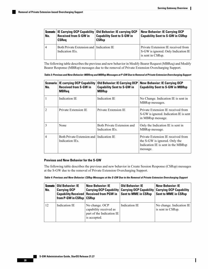
New Behavior: IE Carrying OCPCapability Sent to S-GW in CSRsp
Old Behavior: IE carrying OCPCapability Sent to S-GW inCSRsp
IE Carrying OCP CapabilityReceived from S-GW inCSReq
ScenarioNo.
Private Extension IE received fromS-GW is ignored. Only Indication IEis sent in CSRsp.
Indication IEBoth Private Extension andIndication IEs.
4
The following table describes the previous and new behavior inModify Bearer Request (MBReq) andModifyBearer Response (MBRsp) messages due to the removal of Private Extension Overcharging Support.
Table 3: Previous and New Behavior: MBRreq and MBRsp Messages at P-GW Due to Removal of Private Extension Overcharging Support
New Behavior: IE Carrying OCPCapability Sent to S-GW in MBRsp
Old Behavior: IE Carrying OCPCapability Sent to S-GW inMBRsp
IE carrying OCP CapabilityReceived from S-GW inMBReq
ScenarioNo.
No Change. Indication IE is sent inMBRsp messages.
Indication IEIndication IE1
Private Extension IE received fromS-GW is ignored. Indication IE is sentin MBRsp message.
Private Extension IEPrivate Extension IE2
Only the Indication IE is sent inMBRsp message.
Both Private Extension andIndication IEs.
None3
Private Extension IE received fromthe S-GW is ignored. Only theIndication IE is sent in the MBRspmessage.
Indication IEBoth Private Extension andIndication IEs.
4
Previous and New Behavior for the S-GW
The following table describes the previous and new behavior in Create Session Response (CSRsp) messagesat the S-GW due to the removal of Private Extension Overcharging Support.
Table 4: Previous and New Behavior: CSRsp Messages at the S-GW Due to the Removal of Private Extension Overcharging Support
New Behavior: IECarrying OCP CapabilitySent to MME in CSRsp
Old Behavior: IECarrying OCP CapabilitySent to MME in CSRsp
New Behavior: IECarrying OCP CapabilityReceived from PGW inCSRsp
Old Behavior: IECarrying OCPCapability Receivedfrom P-GW in CSRsp
ScenarioNo.
No change. Indication IEis sent in CSRsp.
Indication IENo change. OCPcapability received aspart of the Indication IEis accepted.
Indication IE12
S-GW Administration Guide, StarOS Release 21.2728
Serving Gateway OverviewRemoval of Private Extension-based Overcharging Support

New Behavior: IECarrying OCP CapabilitySent to MME in CSRsp
Old Behavior: IECarrying OCP CapabilitySent to MME in CSRsp
New Behavior: IECarrying OCP CapabilityReceived from PGW inCSRsp
Old Behavior: IECarrying OCPCapability Receivedfrom P-GW in CSRsp
ScenarioNo.
Since the CLI commandis deprecated, then thePrivate Extension IE isforwarded to theMME inCSRsp as would be donefor any unknown PrivateExtension IE.
If gtpc private-extensionovercharge-protection isdisabled at egtpc servicelevel:Private ExtensionIE.
If gtpc private-extensionovercharge-protection isenabled at egtpc servicelevel: Indication IE.
OCP capability receivedas part of PrivateExtension IE is ignored.
Private Extension IE2
Since the CLI commandis deprecated, then thePrivate Extension IE isforwarded to theMME inCSRsp as would be donefor any unknown PrivateExtension IE.
If gtpc private-extensionovercharge-protection isdisabled at egtpc servicelevel:Private ExtensionIE and Indication IE.
If gtpc private-extensionovercharge-protection isenabled at egtpc servicelevel: Indication IE.
OCP capability receivedas part of the PrivateExtension IE is ignored.Only OCP capabilityreceived as a part of theIndication IE isaccepted.
Both PrivateExtension IE andIndication IE
3
No change.NoneNo change.None4
The following table describes the previous and new behavior in Modify Bearer Response (MBRsp) messagesat the S-GW due to the removal of Private Extension Overcharging Support.
Table 5: Previous Behavior and New Behavior: MBRsp Messages at the S-GW Due to the Removal of Private Extension OverchargingSupport
New Behavior: IECarrying OCPCapability Sent to MMEin MBRsp
Old Behavior: IECarrying OCP CapabilitySent to MME in MBRsp
New Behavior: IECarrying OCP CapabilityReceived from P-GW inMBRsp
Old Behavior: IECarrying OCPCapability Receivedfrom P-GW in MBRsp
ScenarioNo.
No change. IndicationIE is sent in MBRsp.
Indication IENo change. OCPcapability received as partof Indication IE isaccepted.
Indication IE1
S-GW Administration Guide, StarOS Release 21.2729
Serving Gateway OverviewRemoval of Private Extension-based Overcharging Support

New Behavior: IECarrying OCPCapability Sent to MMEin MBRsp
Old Behavior: IECarrying OCP CapabilitySent to MME in MBRsp
New Behavior: IECarrying OCP CapabilityReceived from P-GW inMBRsp
Old Behavior: IECarrying OCPCapability Receivedfrom P-GW in MBRsp
ScenarioNo.
Since the CLIcommand isdeprecated, neither oneof the two IEs is sent inthe MBRsp to theMME for the OCPcapability.
If gtpcprivate-extensionovercharge-protectionis disabled at egtpcservice level: None.
If gtpcprivate-extensionovercharge-protectionis enabled at egtpcservice level:Indication IE.
OCP capability receivedas part of PrivateExtension IE is ignored.
Private Extension IE2
No change. IndicationIE is sent in MBRsp.
Indication IEOCP capability receivedas part of the PrivateExtension IE is ignored.Only the OCP capabilityreceived as part of theIndication IE is accepted.
Both PrivateExtension ID andIndication IE
3
No change.NoneNoneNone4
In StarOS releases 21.0 and later, the S-GW will send a MBReq message with only the indication IE for thePause/Start Charging procedure. The private extension IE is not sent.
Important
If the S-GW receives only the private extension IE from the P-GW in the CSRsp/MBRsp message, then theS-GW ignores the private extension IE. As a result, the S-GW assumes that Overcharging Protection is NOTenabled for the P-GW. So, in this scenario, even if the overcharging condition is met at the S-GW, the S-GWwill not send a MBReq message for Charging pause to the P-GW.
Important
Rf Diameter Accounting
Rf Diameter Accounting is not supported on the S-GW.Important
Provides the framework for offline charging in a packet switched domain. The gateway support nodes usethe Rf interface to convey session related, bearer related or service specific charging records to the CGF andbilling domain for enabling charging plans.
The Rf reference interface enables offline accounting functions on the HSGW in accordance with 3GPPRelease 8 specifications. In an LTE application the same reference interface is also supported on the S-GW
S-GW Administration Guide, StarOS Release 21.2730
Serving Gateway OverviewRf Diameter Accounting
and P-GW platforms. The Cisco gateways use the Charging Trigger Function (CTF) to transfer offlineaccounting records via a Diameter interface to an adjunct Charging Data Function (CDF) / Charging GatewayFunction (CGF). The HSGW and Serving Gateway collect charging information for each mobile subscriberUE pertaining to the radio network usage while the P-GW collects charging information for each mobilesubscriber related to the external data network usage.
The S-GW collects information per-user, per IP CAN bearer or per service. Bearer charging is used to collectcharging information related to data volumes sent to and received from the UE and categorized by QoS trafficclass. Users can be identified by MSISDN or IMSI.
FlowData Records (FDRs) are used to correlate application charging data with EPC bearer usage information.The FDRs contain application level charging information like service identifiers, rating groups, IMS chargingidentifiers that can be used to identify the application. The FDRs also contain the authorized QoS information(QCI) that was assigned to a given flow. This information is used correlate charging records with EPC bearers.
S-GW Collision HandlingGTPv2 message collisions occur in the network when a node is expecting a particular procedure messagefrom a peer node but instead receives a different procedure message from the peer. The S-GW has beenenhanced to process collisions at the S-GW ingress interface for:
1. Create Bearer Request or Update Bearer Request messages with Inter-MME/Inter-RAT Modify BearerRequest messages (with and without a ULI change).
2. Downlink Data Notification(DDN) message with Create Bearer Request or Update Bearer Request.
The enhanced behavior is as follows:
1. A CBReq and MBReq [(Inter MME/Inter RAT (with or without ULI change)] collision at the S-GWingress interface results in the messages being handled in parallel. The CBReq will wait for a CreateBearer Response (CBRsp) from the peer. Additionally, an MBReq is sent in parallel to the P-GW.
2. An UBReq and MBReq [(Inter MME/Inter RAT (with or without a ULI change)] collision at the SGWingress interface is handled with a suspend and resume procedure. The UBReq would be suspended andthe MBReq would be processed. Once the MBRsp is sent to the peer from the SGW ingress interface, theUBReq procedure is resumed.
3. The Downlink Data Notification (DDN) message transaction is dis-associated from bearers. So CreateBearer Request (CBR) or Update Bearer Request (UBR)with DownlinkData Notification (DDN)messagesare handled parallel.
As a result of this enhancement no S-GW initiated Cause Code message 110 (Temporarily rejected due tohandover procedure in progress) will be seen as a part of such collisions. Collisions will be handled in parallel.
Viewing S-GW Collision StatisticsThe output of the show egtpc statistics verbose command has been enhanced to provide information onGTPv2 message collisions at the S-GW ingress interface, including:
• Interface: The interface on which the collision occurred: SGW (S4/S11), SGW (S5).• Old Proc (Msg Type): Indicates the ongoing procedure at eGTP-C when a new message arrived at theinterface which caused the collision. The Msg Type in brackets specifies which message triggered thisongoing procedure.
• New Proc (Msg Type): The new procedure and message type.• Action: The pre-defined action taken to handle the collision. The action can be one of:
• No Collision Detected
S-GW Administration Guide, StarOS Release 21.2731
Serving Gateway OverviewS-GW Collision Handling

• Suspend Old: Suspend processing of the original (old) message, process the new message, thenresume old message handling.
• Abort Old: Abort the original message handling and processes the new message.• Reject New: The new message is rejected, and the original (old) message is processed.• Silent Drop New: Drop the new incoming message, and the old message is processed.• Parallel Hndl: Both the original (old) and new messages are handled in parallel.• Buffer New: The newmessage is buffered and processed once the original (old) message processingis done.
• Counter: The number of times each collision type has occurred.
The Message Collision Statistics section of the command output appears only if any of the collision statisticshave a counter total that is greater than zero.
Important
S-GW Session Idle TimerA session idle timer has been implemented on the S-GW to remove stale sessions in those cases where thesession is removed on the other nodes but due to some issue remains on the S-GW. Once configured, thesession idle timer will tear down those sessions that remain idle for longer than the configured time limit. Theimplementation of the session idle timer allows the S-GW to more effectively utilize system capacity.
The session idle timer feature will not work if the Fast Data Path feature is enabled.Important
Subscriber Level TraceProvides a 3GPP standards-based session level trace function for call debugging and testing new functionsand access terminals in an LTE environment.
As a complement to Cisco's protocol monitoring function, the S-GW supports 3GPP standards based sessionlevel trace capabilities to monitor all call control events on the respective monitored interfaces including S1-U,S11, S5/S8, and Gxc. The trace can be initiated using multiple methods:
• Management initiation via direct CLI configuration
• Management initiation at HSS with trace activation via authentication response messages over S6areference interface
• Signaling based activation through signaling from subscriber access terminal
Note: Once the trace is provisioned it can be provisioned through the access cloud via various signalinginterfaces.
The session level trace function consists of trace activation followed by triggers. The EPC network elementbuffers the trace activation instructions for the provisioned subscriber in memory using camp-on monitoring.Trace files for active calls are buffered as XML files using non-volatile memory on the local dual redundanthard drives on the ASR 5500 platform. The Trace Depth defines the granularity of data to be traced. Six levelsare defined including Maximum, Minimum and Medium with ability to configure additional levels based onvendor extensions.
S-GW Administration Guide, StarOS Release 21.2732
Serving Gateway OverviewS-GW Session Idle Timer
All call control activity for active and recorded sessions is sent to an off-line Trace Collection Entity (TCE)using a standards-based XML format over an FTP or secure FTP (SFTP) connection. In the current releasethe IPv4 interfaces are used to provide connectivity to the TCE. Trace activation is based on IMSI or IMEI.
Once a subscriber level trace request is activated it can be propagated via the S5/S8 signaling to provision thecorresponding trace for the same subscriber call on the P-GW. The trace configuration will only be propagatedif the P-GW is specified in the list of configured Network Element types received by the S-GW. Traceconfiguration can be specified or transferred in any of the following message types:
• S11: Create Session Request
• S11: Trace Session Activation
• S11: Modify Bearer Request
As subscriber level trace is a CPU intensive activity the maximum number of concurrently monitored tracesessions per Cisco S-GW is 32. Use in a production network should be restricted to minimize the impact onexisting services.
Caution
Support for One Million S1-U Peers on the S-GWDue to customer business requirements and production forecasts, support has been added to the StarOS forone million S1-U connections on a single S-GW.
The S1-U interface is the user plane interface carrying user data between an eNodeB and an S-GW receivedfrom the terminal. The StarOS now has the capability to scale the number of S1-U peers to one million perVPN context.
A new CLI command has been added to enable operators to set the number of S1-U peers for which statisticsshould be collected. The limit is restricted to less than one million peers (128k) due to StarOS memorylimitations.
How it Works
The gtpumgr uses the following guidelines while allocating peers:
• When a session installation comes from the SessionManager, a peer is created. If statistics are maintainedat the Session Manager, the gtpumgr also creates the peer record with the statistics.
• Peer records are maintained per service.
• The number of peers is maintained at the gtpumgr instance level. The limit is one million S1-U peersper gtpumgr instance.
• If the limit of one million peers is exceeded, then peer creation fails. It causes a call installation failurein the gtpumgr, which leads to an audit failure if an audit is triggered.
The feature changes impact all the interfaces/services using the gtpu-service includingGGSN/S4-SGSN/SGW/PGW/SAEGW/ePDG/SaMOG/HNB-GW/HeNB-GW for:
• The Gn and Gp interfaces of the General Packet Radio Service (GPRS)
• The Iu, Gn, and Gp interfaces of the UMTS system
S-GW Administration Guide, StarOS Release 21.2733
Serving Gateway OverviewSupport for One Million S1-U Peers on the S-GW

• The S1-U, S2a, S2b, S4, S5, S8, and S12 interfaces of the Evolved Packet System (EPS)
Recovery/ICSR Considerations
• After a session manager/gtpumgr recovery or after an ICSR switchover, the same set of peers configuredfor statistics collection is recovered.
• Peers with 0 sessions and without statistics are not recovered.
• Peers with 0 sessions and with statistics are recovered.
• Peers with Extension Header Support disabled are recovered.
• While upgrading from a previous release, ensure the newer release chassis gtpu peer statistics thresholdis equal to or greater than the previous release. This ensures that the GTPU peer statistics are preservedduring the upgrade. For example, if you are upgrading from release 19.0 to 20.2, and the 19.0 systemhas 17,000 GTPU sessions, then configure the threshold on the 20.2 chassis to 17,000 as well.
Configuration/Restrictions
• Due to the large number of GTP-U entities connecting to the StarOS, Cisco recommends disabling theGTP-U Path Management feature.
• The configured threshold is not the hard upper limit for statistics allocation because of the distributednature of system. It is possible that total GTP-U peers with statistics exceeds the configured thresholdvalue to some extent.
• It is assumed that all 1,000,000 peers are not connected to the node in a point-to-point manner. They areconnected through routers.
• There will not be any ARP table size change for the StarOS to support this feature.
Threshold Crossing Alerts (TCA) SupportThresholding on the system is used to monitor the system for conditions that could potentially cause errorsor outage. Typically, these conditions are temporary (i.e high CPU utilization, or packet collisions on anetwork) and are quickly resolved. However, continuous or large numbers of these error conditions within aspecific time interval may be indicative of larger, more severe issues. The purpose of thresholding is to helpidentify potentially severe conditions so that immediate action can be taken to minimize and/or avoid systemdowntime.
The system supports Threshold Crossing Alerts for certain key resources such as CPU, memory, IP pooladdresses, etc. With this capability, the operator can configure threshold on these resources whereby, shouldthe resource depletion cross the configured threshold, a SNMP Trap would be sent.
The following thresholding models are supported by the system:
• Alert: A value is monitored and an alert condition occurs when the value reaches or exceeds the configuredhigh threshold within the specified polling interval. The alert is generated then generated and/or sent atthe end of the polling interval.
• Alarm: Both high and low threshold are defined for a value. An alarm condition occurs when the valuereaches or exceeds the configured high threshold within the specified polling interval. The alert isgenerated then generated and/or sent at the end of the polling interval.
S-GW Administration Guide, StarOS Release 21.2734
Serving Gateway OverviewThreshold Crossing Alerts (TCA) Support

Thresholding reports conditions using one of the following mechanisms:
• SNMP traps: SNMP traps have been created that indicate the condition (high threshold crossing andclear) of each of the monitored values.
Generation of specific traps can be enabled or disabled on the chassis. Ensuring that only important faultsget displayed. SNMP traps are supported in both Alert and Alarm modes.
• Logs: The system provides a facility called threshold for which active and event logs can be generated.As with other system facilities, logs are generated Logmessages pertaining to the condition of a monitoredvalue are generated with a severity level of WARNING.
Logs are supported in both the Alert and the Alarm models.
• Alarm System: High threshold alarms generated within the specified polling interval are consideredoutstanding until a the condition no longer exists or a condition clear alarm is generated. Outstandingalarms are reported to the system's alarm subsystem and are viewable through the Alarm Managementmenu in an element management system.
The Alarm System is used only in conjunction with the Alarm model.
For more information on threshold crossing alert configuration, refer to the Thresholding Configuration Guide.Important
ULI EnhancementsVoLTE carriers need the last cell/sector updates within the IMS CDRs to assist in troubleshooting customercomplaints due to dropped calls as well as LTE network analysis, performance, fraud detection, and operationalmaintenance. The ultimate objective is to get the last cell sector data in the IMS CDR records in addition tothe ULI reporting for session establishment.
To address this issue, the S-GW now supports the following:
• RAN/NAS Cause IE within bearer context of Delete Bearer Command message.• The S-GW ignores the ULI received as call is going down so there is no point in updating the CDR.
Support for ULI and ULI Timestamp in Delete Bearer Command message had already been added.
Now, when a new ULI is received in the Delete Bearer Command message, a S-GW CDR is initiated.
Features and Functionality - Optional Enhanced FeatureSoftware
This section describes the optional enhanced features and functions for the S-GW service.
Each of the following features require the purchase of an additional license to implement the functionalitywith the S-GW service.
S-GW Administration Guide, StarOS Release 21.2735
Serving Gateway OverviewULI Enhancements
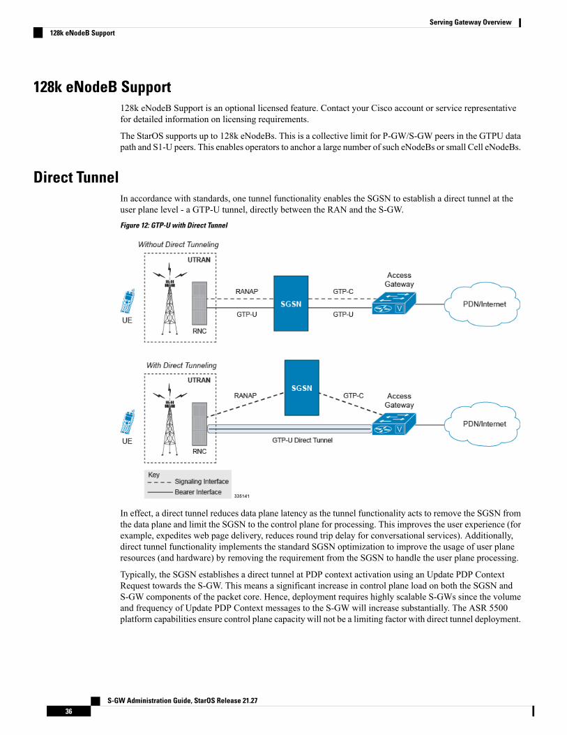
128k eNodeB Support128k eNodeB Support is an optional licensed feature. Contact your Cisco account or service representativefor detailed information on licensing requirements.
The StarOS supports up to 128k eNodeBs. This is a collective limit for P-GW/S-GW peers in the GTPU datapath and S1-U peers. This enables operators to anchor a large number of such eNodeBs or small Cell eNodeBs.
Direct TunnelIn accordance with standards, one tunnel functionality enables the SGSN to establish a direct tunnel at theuser plane level - a GTP-U tunnel, directly between the RAN and the S-GW.
Figure 12: GTP-U with Direct Tunnel
In effect, a direct tunnel reduces data plane latency as the tunnel functionality acts to remove the SGSN fromthe data plane and limit the SGSN to the control plane for processing. This improves the user experience (forexample, expedites web page delivery, reduces round trip delay for conversational services). Additionally,direct tunnel functionality implements the standard SGSN optimization to improve the usage of user planeresources (and hardware) by removing the requirement from the SGSN to handle the user plane processing.
Typically, the SGSN establishes a direct tunnel at PDP context activation using an Update PDP ContextRequest towards the S-GW. This means a significant increase in control plane load on both the SGSN andS-GW components of the packet core. Hence, deployment requires highly scalable S-GWs since the volumeand frequency of Update PDP Context messages to the S-GW will increase substantially. The ASR 5500platform capabilities ensure control plane capacity will not be a limiting factor with direct tunnel deployment.
S-GW Administration Guide, StarOS Release 21.2736
Serving Gateway Overview128k eNodeB Support

For more information on direct tunnel support, refer to the Direct Tunnel for 4G (LTE) Networks chapter inthis guide.
Important
Intelligent Paging for ISRIn case of Idle-mode Signaling Reduction (ISR) active and UE is idle, the S-GW will send Downlink DataNotification (DDN) Message to both the MME and the S4-SGSN if it receives the downlink data or networkinitiated control message for this UE. In turn, the MME and the S4-SGSN would do paging in parallelconsuming radio resources.
To optimize the radio resource, the S-GW will now perform intelligent paging. When configured at S-GWservice level for each APN, the S-GW will page in a semi-sequential fashion (one by one to peer MME orS4-SGSN based on last known RAT type) or parallel to both the MME and S4-SGSN.
Inter-Chassis Session RecoveryThe ASR 5500 platform provide industry leading carrier class redundancy. The systems protects against allsingle points of failure (hardware and software) and attempts to recover to an operational state when multiplesimultaneous failures occur.
The system provides several levels of system redundancy:
• Under normal N+1 packet processing card hardware redundancy, if a catastrophic packet processing cardfailure occurs all affected calls are migrated to the standby packet processing card if possible. Calls whichcannot be migrated are gracefully terminated with proper call-termination signaling and accountingrecords are generated with statistics accurate to the last internal checkpoint
• If the Session Recovery feature is enabled, any total packet processing card failure will cause a packetprocessing card switchover and all established sessions for supported call-types are recovered withoutany loss of session.
Even though Cisco provides excellent intra-chassis redundancy with these two schemes, certain catastrophicfailures which can cause total chassis outages, such as IP routing failures, line-cuts, loss of power, or physicaldestruction of the chassis, cannot be protected by this scheme. In such cases, the MME Inter-Chassis SessionRecovery (ICSR) feature provides geographic redundancy between sites. This has the benefit of not onlyproviding enhanced subscriber experience even during catastrophic outages, but can also protect other systemssuch as the RAN from subscriber re-activation storms.
ICSR allows for continuous call processing without interrupting subscriber services. This is accomplishedthrough the use of redundant chassis. The chassis are configured as primary and backup with one being activeand one in recovery mode. A checkpoint duration timer is used to control when subscriber data is sent fromthe active chassis to the inactive chassis. If the active chassis handling the call traffic goes out of service, theinactive chassis transitions to the active state and continues processing the call traffic without interrupting thesubscriber session. The chassis determines which is active through a propriety TCP-based connection calleda redundancy link. This link is used to exchange Hello messages between the primary and backup chassis andmust be maintained for proper system operation.
Interchassis Communication
Chassis configured to support ICSR communicate using periodic Hello messages. These messages are sentby each chassis to notify the peer of its current state. The Hello message contains information about the chassis
S-GW Administration Guide, StarOS Release 21.2737
Serving Gateway OverviewIntelligent Paging for ISR
such as its configuration and priority. A dead interval is used to set a time limit for a Hello message to bereceived from the chassis' peer. If the standby chassis does not receive a Hello message from the active chassiswithin the dead interval, the standby chassis transitions to the active state. In situations where the redundancylink goes out of service, a priority scheme is used to determine which chassis processes the session. Thefollowing priority scheme is used:
• router identifier
• chassis priority
• chassis MAC address
Checkpoint Messages
Checkpoint messages are sent from the active chassis to the inactive chassis. Checkpoint messages are sentat specific intervals and contain all the information needed to recreate the sessions on the standby chassis, ifthat chassis were to become active. Once a session exceeds the checkpoint duration, checkpoint data is collectedon the session. The checkpoint parameter determines the amount of time a session must be active before it isincluded in the checkpoint message.
For more information on inter-chassis session recovery support, refer to the Interchassis Session Recoverychapter in System Administration Guide.
Important
IP Security (IPSec) EncryptionEnables network domain security for all IP packet switched LTE-EPC networks in order to provideconfidentiality, integrity, authentication, and anti-replay protection. These capabilities are insured throughuse of cryptographic techniques.
The Cisco S-GW supports IKEv1 and IPSec encryption using IPv4 addressing. IPSec enables the followingtwo use cases:
• Encryption of S8 sessions and EPS bearers in roaming applications where the P-GW is located in aseparate administrative domain from the S-GW
• IPSec ESP security in accordance with 3GPP TS 33.210 is provided for S1 control plane, S1 bearer planeand S1 management plane traffic. Encryption of traffic over the S1 reference interface is desirable incases where the EPC core operator leases radio capacity from a roaming partner's network.
You must purchase an IPSec license to enable IPSec. For more information on IPSec support, refer to theIPSec Reference.
Important
Lawful InterceptThe Cisco Lawful Intercept feature is supported on the S-GW. Lawful Intercept is a licensed-enabled,standards-based feature that provides telecommunications service providers with a mechanism to assist lawenforcement agencies in monitoring suspicious individuals for potential illegal activity. For additionalinformation and documentation on the Lawful Intercept feature, contact your Cisco account representative.
S-GW Administration Guide, StarOS Release 21.2738
Serving Gateway OverviewIP Security (IPSec) Encryption

Layer 2 Traffic Management (VLANs)Virtual LANs (VLANs) provide greater flexibility in the configuration and use of contexts and services.
VLANs are configured as tags on a per-port basis and allow more complex configurations to be implemented.The VLAN tag allows a single physical port to be bound to multiple logical interfaces that can be configuredin different contexts. Therefore, each Ethernet port can be viewed as containing many logical ports whenVLAN tags are employed.
For more information on VLAN support, refer to the VLANs chapter in the System Administration Guide.Important
New Call Policy for Stale SessionsUse of new call policy for stale sessions requires that a valid license key be installed. Contact your CiscoAccount or Support representative for information on how to obtain a license.
If the newcall policy is set to reject release-existing-session and there are pre-existing sessions for theIMSI/IMEI received in Create Session Req, they will be deleted. This allows for no hung sessions on nodewith newcall policy reject release configured.When S-GW releases the existing call, it follows a proper releaseprocess of sending Accounting Stop, sending CCR-T to PCRF/OCS, and generating CDR(s).
New Standard QCI SupportNew Standard QCI Support is a license-controlled feature. Contact your Cisco account or support representativefor licensing details.
The P-GW/SAEGW/S-GW support additional new 3GPP-defined standard QCIs. QCIs 65, 66, 69, and 70are now supported for Mission Critical and Push-to-Talk (MC/PTT) applications. These new standard QCIsare supported in addition to the previously supported QCIs of 1 through 9, and operator-defined QCIs 128through 254.
The StarOS will continue to reject QCIs 10 through 127 sent by the PCRF.
For detailed information on this feature, refer to the New Standard QCI Support chapter in this guide.
Overcharging Protection SupportUse of Overcharging Protection requires that a valid license key be installed. Contact your Cisco accountrepresentative for information on how to obtain a license.
Overcharging Protection helps in avoiding charging the subscribers for dropped downlink packets while theUE is in idle mode. In some countries, it is a regulatory requirement to avoid such overcharging, so it becomesa mandatory feature for operators in such countries. Overall, this feature helps ensure subscriber are notovercharged while the subscriber is in idle mode.
This feature is supported on the P-GW, and S-GW. Overcharging Protection is supported on the SAEGWonly if the SAEGW is configured for Pure P or Pure S functionality.
Important
S-GW Administration Guide, StarOS Release 21.2739
Serving Gateway OverviewLayer 2 Traffic Management (VLANs)
P-GW will never be aware of UE state (idle or connected mode). Charging for downlink data is applicable atP-GW, even when UE is in idle mode. Downlink data for UE may be dropped at S-GW when UE is in idlemode due to buffer overflow or delay in paging. Thus, P-GW will charge the subscriber for the droppedpackets, which isn't desired. To address this problem, with Overcharging Protection feature enabled, S-GWwill inform P-GW to stop or resume charging based on packets dropped at S-GW and transition of UE fromidle to active state.
If the S-GW supports the Overcharging Protection feature, then it will send a CSReq with the PDN PauseSupport Indication flag set to 1 in an Indication IE to the P-GW.
If the PGW supports the Overcharging Protection feature then it will send a CSRsp with the PDN PauseSupport Indication flag set to 1 in Indication IE and/or private extension IE to the S-GW.
Once the criterion to signal "stop charging" is met, S-GW will send Modify Bearer Request (MBReq) toP-GW. MBReq would be sent for the PDN to specify which packets will be dropped at S-GW. The MBReqwill have an indication IE and/or a new private extension IE to send "stop charging" and "start charging"indication to P-GW. For Pause/Start Charging procedure (S-GW sends MBReq), MBRes from P-GW willhave indication and/or private extension IE with Overcharging Protection information.
When the MBReq with stop charging is received from a S-GW for a PDN, P-GW will stop charging fordownlink packets but will continue sending the packets to S-GW.
P-GW will resume charging downlink packets when either of these conditions is met:
• When the S-GW (which had earlier sent "stop charging" in MBReq) sends "start charging" in MBReq.• When the S-GW changes (which indicates that maybe UE has relocated to new S-GW).
This feature aligns with the 3GPP TS 29.274: 3GPP Evolved Packet System (EPS); Evolved General PacketRadio Service (GPRS) Tunneling Protocol for Control plane (GTPv2-C) specification.
For more information on this feature, refer to the Overcharging Protection Support chapter in this guide.
Paging Policy DifferentiationThis feature requires that a valid license key be installed. Contact your Cisco Account or Support representativefor information on how to obtain a license.
S-GW/P-GW provide configuration control to change the DSCP value of the user-datagram packet and outerIP packet (GTP-U tunnel IP header). DSCP marking is done at various levels depending on the configuration.When the Paging Policy Differentiation (PPD) feature is enabled, however, the user-datagram packet DSCP(tunneled IP packet) marking does not change.
Currently, standards specify QCI to DSCP marking of outer GTP-U header only. All configurations presentat ECS, P-GW, and S-GW to change the user-datagram packet DSCP value are non-standard. Thestandards-based PPD feature dictates that P-CSCF or similar Gi entity marks the DSCP of user-datagrampacket. This user-datagram packet DSCP value is sent in DDN message by S-GW to MME/S4-SGSN.MME/S4-SGSN uses this DSCP value to give paging priority.
P-GW and S-GW should apply the PPD feature for both Default and Dedicated bearers. As per thespecifications, P-GW transparently passes the user-datagram packet towards S-GW. This means, if PPDfeature is enabled, operator can't apply different behavior for Default and Dedicated bearers.
Important
S-GW Administration Guide, StarOS Release 21.2740
Serving Gateway OverviewPaging Policy Differentiation

For more information on paging policy differentiation, refer to the Paging Policy Differentiation chapter inthis guide.
Important
3GPP Release 12 Load and Overload SupportUse of 3GPP Release 12 (R12) Load and Overload Support requires that a valid license key be installed.Contact your Cisco account representative for information on how to obtain a license.
3GPP R12 GTP-C Load and Overload Control feature is an optional feature which allows a GTP control planenode to send its Load Information to a peer GTP control plane node which the receiving GTP control planepeer node uses to augment existing GW selection procedure for the P-GW and S-GW. Load Informationreflects the operating status of the resources of the originating GTP control plane node.
Nodes using GTP control plane signaling may support communication of Overload control Information inorder to mitigate overload situation for the overloaded node through actions taken by the peer node(s). Thisfeature is supported over the S5 and S8 interfaces via the GTPv2 control plane protocol.
A GTP-C node is considered to be in overload when it is operating over its nominal capacity resulting indiminished performance (including impacts to handling of incoming and outgoing traffic). Overload controlInformation reflects an indication of when the originating node has reached such a situation. This information,when transmitted between GTP-C nodes may be used to reduce and/or throttle the amount of GTP-C signalingtraffic between these nodes. As such, the Overload control Information provides guidance to the receivingnode to decide actions, which leads to mitigation towards the sender of the information.
In brief, load control and overload control can be described in this manner:
• Load control enables a GTP-C entity (for example, an S-GW/P-GW) to send its load information to aGTP-C peer (e.g. an MME/SGSN, ePDG, TWAN) to adaptively balance the session load across entitiessupporting the same function (for example, an S-GW cluster) according to their effective load. The loadinformation reflects the operating status of the resources of the GTP-C entity.
• Overload control enables a GTP-C entity becoming or being overloaded to gracefully reduce its incomingsignaling load by instructing its GTP-C peers to reduce sending traffic according to its available signalingcapacity to successfully process the traffic. A GTP-C entity is in overload when it operates over itssignaling capacity, which results in diminished performance (including impacts to handling of incomingand outgoing traffic).
A maximum of 64 different load and overload profiles can be configured.
3GPP R12 Load and Overload Support is a license-controlled feature. Contact your Cisco representative formore information on licensing requirements.
Important
For more information on this feature, refer to the GTP-C Load and Overload Control Support on the P-GW,SAEGW, and S-GW chapter in this guide.
Important
S-GW Administration Guide, StarOS Release 21.2741
Serving Gateway Overview3GPP Release 12 Load and Overload Support

3GPP R12 Load and Overload Factor Calculation Enhancement
In capacity testing and also in customer deployments it was observed that the chassis load factor for the 3GPPR12 Load and Overload Support feature was providing incorrect values even when the sessmgr card CPUutilization was high. The root cause is that when the load factor was calculated by taking an average of CPUutilization of sessmgr and demux cards, the demux card CPU utilization never increased more than the sessmgrcard CPU utilization. As a result, the system did not go into the overload state even when the sessmgr cardCPU utilization was high.
The 3GPP R12 Load/Overload Control Profile feature has been enhanced to calculate the load factor basedon the higher value of similar types of cards for CPU load and memory. If the demux card's CPU utilizationvalue is higher than the sessmgr card's CPU utilization value, then the demux card CPU utilization value isused for the load factor calculation.
A new CLI command is introduced to configure different polling intervals for the resource manager so thatthe demuxmgr can calculate the load factor based on different system requirements.
OperationThe node periodically fetches various parameters (for example, License-Session-Utilization,System-CPU-Utilization and System-Memory-Utilization), which are required for Node level load controlinformation. The node then calculates the load control information itself either based on the weighted factorprovided by the user or using the default weighted factor.
Node level load control information is calculated every 30 seconds. The resource manager calculates thesystem-CPU-utilization and System-Memory-Utilization at a systems level.
For each configured service, load control information can be different. This can be achieved by providing aweightage to the number of active session counts per service license, for example, ((number of active sessionsper service / max session allowed for the service license) * 100 ).
The node's resource manager calculates the system-CPU-utilization and System-Memory-Utilization at asystems level by averaging CPU and Memory usage for all cards and which might be different from thatcalculated at the individual card level.
Separate Paging for IMS Service InspectionUse of Separate Paging for IMS Service Inspection requires that a valid license key be installed. Contact yourCisco account representative for information on how to obtain a license.
When some operators add an additional IMS service besides VoLTE such as RCS, they can use the same IMSbearer between the two services. In this case, separate paging is supported at the MME using an ID whichcan be assigned from the S-GW according to the services, where the S-GW distinguishes IMS services usinga small DPI function to inspect where the traffic comes from using an ID which is assigned from SGWaccording to the services. The S-GW distinguishes IMS services using a small DPI function to inspect wherethe traffic comes from (for example IP, Port and so on). After the MME receives this ID from the S-GW afterIMS service inspection, the MME will do classified separate paging for each of the services as usual.
Session Recovery SupportProvides seamless failover and reconstruction of subscriber session information in the event of a hardware orsoftware fault within the system preventing a fully connected user session from being disconnected.
S-GW Administration Guide, StarOS Release 21.2742
Serving Gateway OverviewOperation
In the telecommunications industry, over 90 percent of all equipment failures are software-related.With robusthardware failover and redundancy protection, any card-level hardware failures on the system can quickly becorrected. However, software failures can occur for numerous reasons, many times without prior indication.StarOS has the ability to support stateful intra-chassis session recovery (ICSR) for S-GW sessions.
When session recovery occurs, the system reconstructs the following subscriber information:
• Data and control state information required to maintain correct call behavior
• Subscriber data statistics that are required to ensure that accounting information is maintained
• A best-effort attempt to recover various timer values such as call duration, absolute time, and others
Session recovery is also useful for in-service software patch upgrade activities. If session recovery is enabledduring the software patch upgrade, it helps to preserve existing sessions on the active packet services cardduring the upgrade process.
For more information on session recovery support, refer to the Session Recovery chapter in the SystemAdministration Guide.
Important
S-GW Paging EnhancementsUse of S-GW Paging requires that a valid license key be installed. Contact your Cisco account representativefor information on how to obtain a license.
S-GW Paging includes the following scenarios:
Scenario 1: S-GW sends a DDN message to the MME/S4-SGSN nodes. MME/S4-SGSN responds to theS-GW with a DDN Ack message. While waiting for the DDN Ack message from the MME/S4-SGSN, if theS-GW receives a high priority downlink data, it does not resend a DDN to the MME/S4-SGSN.
Scenario 2: If a DDN is sent to an MME/S4-SGSN and TAU/RAU MBR is received from anotherMME/S4-SGSN, S-GW does not send DDN.
Scenario 3: DDN is sent to an MME/S4-SGSN and DDN Ack with Cause #110 is received. DDN Ack withcause 110 is treated as DDN failure and standard DDN failure action procedure is initiated.
To handle these scenarios, the following two enhancements have been added to the DDN functionality:
• High Priority DDN at S-GW
• MBR-DDN Collision Handling
These enhancements support the following:
• Higher priority DDN on S-GW and SAEGW, which helps MME/S4-SGSN to prioritize paging.
• Enhanced paging KPI and VoLTE services.
• DDN message and mobility procedure so that DDN is not lost.
• MBR guard timer, which is started whenDDNAckwith temporary HO is received. A newCLI commandddn temp-ho-rejection mbr-guard-timer has been introduced to enable the guard timer to wait forMBR once the DDN Ack with cause #110 (Temporary Handover In Progress) is received.
• TAU/RAU with control node change triggered DDNs.
S-GW Administration Guide, StarOS Release 21.2743
Serving Gateway OverviewS-GW Paging Enhancements

In addition to the above functionality, to be compliant with 3GPP standards, support has been enhanced forDownlink Data Notification message and Mobility procedures. As a result, DDN message and downlink datawhich triggers DDN is not lost. This helps improve paging KPI and VoLTE success rates in scenarios whereDDN is initiated because of SIP invite data.
For more information on this functionality, refer to the S-GW Paging Enhancements chapter in this guide.Important
How the Serving Gateway WorksThis section provides information on the function of the S-GW in an EPC E-UTRAN network and presentscall procedure flows for different stages of session setup and disconnect.
The S-GW supports the following network flows:
• GTP Serving Gateway Call/Session Procedures in an LTE-SAE Network, on page 44
GTP Serving Gateway Call/Session Procedures in an LTE-SAE NetworkThe following topics and procedure flows are included:
• Subscriber-initiated Attach (initial), on page 44• Subscriber-initiated Detach, on page 48
Subscriber-initiated Attach (initial)This section describes the procedure of an initial attach to the EPC network by a subscriber.
S-GW Administration Guide, StarOS Release 21.2744
Serving Gateway OverviewHow the Serving Gateway Works

Figure 13: Subscriber-initiated Attach (initial) Call Flow
Table 6: Subscriber-initiated Attach (initial) Call Flow Description
DescriptionStep
The UE initiates the Attach procedure by thetransmission of an Attach Request (IMSI or old GUTI,last visited TAI (if available), UENetwork Capability,PDN Address Allocation, Protocol ConfigurationOptions, Attach Type) message together with anindication of the Selected Network to the eNodeB.IMSI is included if the UE does not have a valid GUTIavailable. If the UE has a valid GUTI, it is included.
1
S-GW Administration Guide, StarOS Release 21.2745
Serving Gateway OverviewSubscriber-initiated Attach (initial)

DescriptionStep
The eNodeB derives the MME from the GUTI andfrom the indicated Selected Network. If that MME isnot associated with the eNodeB, the eNodeB selectsan MME using an MME selection function. TheeNodeB forwards the Attach Request message to thenew MME contained in a S1-MME control message(Initial UE message) together with the SelectedNetwork and an indication of the E-UTRAN Areaidentity, a globally unique E-UTRAN ID of the cellfromwhere it received the message to the newMME.
2
If the UE is unknown in the MME, the MME sendsan Identity Request to the UE to request the IMSI.
3
The UE responds with Identity Response (IMSI).4
If no UE context for the UE exists anywhere in thenetwork, authentication is mandatory. Otherwise thisstep is optional. However, at least integrity checkingis started and the ME Identity is retrieved from theUE at Initial Attach. The authentication functions, ifperformed this step, involves AKA authentication andestablishment of a NAS level security association withthe UE in order to protect further NAS protocolmessages.
5
The MME sends an Update Location (MME Identity,IMSI, ME Identity) to the HSS.
6
The HSS acknowledges the Update Locationmessageby sending an Update Location Ack to theMME. Thismessage also contains the Insert Subscriber Data(IMSI, Subscription Data) Request. The SubscriptionData contains the list of all APNs that the UE ispermitted to access, an indication about which of thoseAPNs is the Default APN, and the EPS subscribedQoS profile for each permitted APN. If the UpdateLocation is rejected by the HSS, the MME rejects theAttach Request from the UE with an appropriatecause.
7
The MME selects an S-GW using the Serving GWselection function and allocates an EPSBearer Identityfor the Default Bearer associated with the UE. If thePDN subscription context contains no P-GW addressthe MME selects a P-GW as described in clause PDNGW selection function. Then it sends a Create DefaultBearer Request (IMSI, MME Context ID, APN, RATtype, Default Bearer QoS, PDN Address Allocation,AMBR, EPS Bearer Identity, Protocol ConfigurationOptions, ME Identity, User Location Information)message to the selected S-GW.
8
S-GW Administration Guide, StarOS Release 21.2746
Serving Gateway OverviewSubscriber-initiated Attach (initial)

DescriptionStep
The S-GW creates a new entry in its EPS Bearer tableand sends a Create Default Bearer Request (IMSI,APN, S-GWAddress for the user plane, S-GWTEIDof the user plane, S-GW TEID of the control plane,RAT type, Default Bearer QoS, PDN AddressAllocation, AMBR, EPS Bearer Identity, ProtocolConfiguration Options, ME Identity, User LocationInformation) message to the P-GW.
9
If dynamic PCC is deployed, the P-GW interacts withthe PCRF to get the default PCC rules for the UE. TheIMSI, UE IP address, User Location Information,RAT type, AMBR are provided to the PCRF by theP-GW if received by the previous message.
10
The P-GW returns a Create Default Bearer Response(P-GW Address for the user plane, P-GW TEID ofthe user plane, P-GWTEID of the control plane, PDNAddress Information, EPS Bearer Identity, ProtocolConfiguration Options) message to the S-GW. PDNAddress Information is included if the P-GWallocateda PDN address Based on PDN Address Allocationreceived in the Create Default Bearer Request. PDNAddress Information contains an IPv4 address forIPv4 and/or an IPv6 prefix and an Interface Identifierfor IPv6. The P-GW takes into account the UE IPversion capability indicated in the PDN AddressAllocation and the policies of operator when theP-GW allocates the PDN Address Information.Whether the IP address is negotiated by the UE aftercompletion of the Attach procedure, this is indicatedin the Create Default Bearer Response.
11
The Downlink (DL) Data can start flowing towardsS-GW. The S-GW buffers the data.
12
The S-GW returns a Create Default Bearer Response(PDN Address Information, S-GW address for UserPlane, S-GW TEID for User Plane, S-GW ContextID, EPS Bearer Identity, Protocol ConfigurationOptions) message to the new MME. PDN AddressInformation is included if it was provided by theP-GW.
13
The newMME sends an Attach Accept (APN, GUTI,PDN Address Information, TAI List, EPS BearerIdentity, Session Management Configuration IE,Protocol Configuration Options) message to theeNodeB.
14
S-GW Administration Guide, StarOS Release 21.2747
Serving Gateway OverviewSubscriber-initiated Attach (initial)
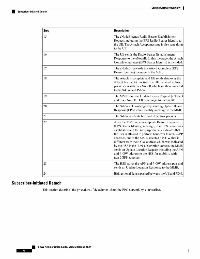
DescriptionStep
The eNodeB sends Radio Bearer EstablishmentRequest including the EPS Radio Bearer Identity tothe UE. The Attach Accept message is also sent alongto the UE.
15
The UE sends the Radio Bearer EstablishmentResponse to the eNodeB. In this message, the AttachComplete message (EPS Bearer Identity) is included.
16
The eNodeB forwards the Attach Complete (EPSBearer Identity) message to the MME.
17
The Attach is complete and UE sends data over thedefault bearer. At this time the UE can send uplinkpackets towards the eNodeB which are then tunneledto the S-GW and P-GW.
18
The MME sends an Update Bearer Request (eNodeBaddress, eNodeB TEID) message to the S-GW.
19
The S-GW acknowledges by sending Update BearerResponse (EPSBearer Identity) message to theMME.
20
The S-GW sends its buffered downlink packets.21
After the MME receives Update Bearer Response(EPS Bearer Identity) message, if an EPS bearer wasestablished and the subscription data indicates thatthe user is allowed to perform handover to non-3GPPaccesses, and if the MME selected a P-GW that isdifferent from the P-GW address which was indicatedby the HSS in the PDN subscription context, theMMEsends an Update Location Request including the APNand P-GW address to the HSS for mobility withnon-3GPP accesses.
22
The HSS stores the APN and P-GW address pair andsends an Update Location Response to the MME.
23
Bidirectional data is passed between the UE and PDN.24
Subscriber-initiated DetachThis section describes the procedure of detachment from the EPC network by a subscriber.
S-GW Administration Guide, StarOS Release 21.2748
Serving Gateway OverviewSubscriber-initiated Detach

Figure 14: Subscriber-initiated Detach Call Flow
Table 7: Subscriber-initiated Detach Call Flow Description
DescriptionStep
The UE sends NAS message Detach Request (GUTI,Switch Off) to the MME. Switch Off indicateswhether detach is due to a switch off situation or not.
1
The active EPS Bearers in the S-GW regarding thisparticular UE are deactivated by the MME sending aDelete Bearer Request (TEID) message to the S-GW.
2
The S-GW sends a Delete Bearer Request (TEID)message to the P-GW.
3
The P-GW acknowledges with a Delete BearerResponse (TEID) message.
4
The P-GWmay interact with the PCRF to indicate tothe PCRF that EPS Bearer is released if PCRF isapplied in the network.
5
The S-GW acknowledges with a Delete BearerResponse (TEID) message.
6
If Switch Off indicates that the detach is not due to aswitch off situation, the MME sends a Detach Acceptmessage to the UE.
7
TheMME releases the S1-MME signaling connectionfor the UE by sending an S1 Release command to theeNodeB with Cause = Detach.
8
Supported StandardsThe S-GW service complies with some of the standards in the following standards categories:
S-GW Administration Guide, StarOS Release 21.2749
Serving Gateway OverviewSupported Standards

• 3GPP References, on page 50• 3GPP2 References, on page 52• IETF References, on page 52• Object Management Group (OMG) Standards, on page 53
3GPP References
Release 12 3GPP References
The S-GW currently supports the following Release 12 3GPP specifications. Most 3GPP specifications arealso used for 3GPP2 support; any specifications that are unique to 3GPP2 are listed under 3GPP2 References.
Important
• 3GPP TS 23.007: Restoration procedures
• 3GPP TS 23.401: General Packet Radio Service (GPRS) enhancements for Evolved Universal TerrestrialRadio Access Network (E-UTRAN) access
• 3GPP TS 29.274: 3GPP Evolved Packet System (EPS); Evolved General Packet Radio Service (GPRS)Tunneling Protocol for Control plane (GTPv2-C); Stage 3
• 3GPP TS 29.281: General Packet Radio System (GPRS) Tunneling Protocol User Plane (GTPv1-U)
Release 11 3GPP References
The S-GW currently supports the following Release 11 3GPP specifications. Most 3GPP specifications arealso used for 3GPP2 support; any specifications that are unique to 3GPP2 are listed under 3GPP2 References.
Important
• 3GPP TS 23.007: Restoration procedures
• 3GPP TS 23.401: General Packet Radio Service (GPRS) enhancements for Evolved Universal TerrestrialRadio Access Network (E-UTRAN) access
• 3GPP TS 29.274: 3GPP Evolved Packet System (EPS); Evolved General Packet Radio Service (GPRS)Tunneling Protocol for Control plane (GTPv2-C); Stage 3
• 3GPP TS 29.281: General Packet Radio System (GPRS) Tunneling Protocol User Plane (GTPv1-U)
• 3GPP TS 32.423: Telecommunicationmanagement; Subscriber and equipment trace; Trace data definitionand management.
• 3GPP TS 36.414: Evolved Universal Terrestrial Radio Access Network (E-UTRAN); S1 data transport
Release 10 3GPP References
The S-GW currently supports the following Release 10 3GPP specifications. Most 3GPP specifications arealso used for 3GPP2 support; any specifications that are unique to 3GPP2 are listed under 3GPP2 References.
Important
S-GW Administration Guide, StarOS Release 21.2750
Serving Gateway Overview3GPP References

• 3GPP TS 23.007: Restoration procedures
• 3GPP TS 23.401: General Packet Radio Service (GPRS) enhancements for Evolved Universal TerrestrialRadio Access Network (E-UTRAN) access
• 3GPP TS 29.274: 3GPP Evolved Packet System (EPS); Evolved General Packet Radio Service (GPRS)Tunneling Protocol for Control plane (GTPv2-C); Stage 3
• 3GPP TS 29.281: General Packet Radio System (GPRS) Tunneling Protocol User Plane (GTPv1-U)
Release 9 Supported Standards• 3GPP TS 23.007: Restoration procedures
• 3GPP TS 23.060. General Packet Radio Service (GPRS); Service description; Stage 2
• 3GPP TS 23.216: Single Radio Voice Call Continuity (SRVCC); Stage 2 (Release 9)• 3GPP TS 23.401: General Packet Radio Service (GPRS) enhancements for Evolved Universal TerrestrialRadio Access Network (E-UTRAN) access
• 3GPP TS 29.274: 3GPP Evolved Packet System (EPS); Evolved General Packet Radio Service (GPRS)Tunneling Protocol for Control plane (GTPv2-C); Stage 3 (Release 9)
• 3GPP TS 29.281: General Packet Radio System (GPRS) Tunneling Protocol User Plane (GTPv1-U)
• 3GPP TS 33.106: 3G Security; Lawful Interception Requirements
• 3GPP TS 36.414: Evolved Universal Terrestrial Radio Access Network (E-UTRAN); S1 data transport
Release 8 Supported Standards• 3GPP TR 21.905: Vocabulary for 3GPP Specifications
• 3GPP TS 23.003: Numbering, addressing and identification
• 3GPP TS 23.007: Restoration procedures
• 3GPP TS 23.107: Quality of Service (QoS) concept and architecture
• 3GPP TS 23.203: Policy and charging control architecture
• 3GPP TS 23.401: General Packet Radio Service (GPRS) enhancements for Evolved Universal TerrestrialRadio Access Network (E-UTRAN) access
• 3GPP TS 23.402: Architecture Enhancements for non-3GPP accesses
• 3GPP TS 23.060. General Packet Radio Service (GPRS); Service description; Stage 2
• 3GPP TS 24.008: Mobile radio interface Layer 3 specification; Core network protocols
• 3GPP TS 24.229: IP Multimedia Call Control Protocol based on SIP and SDP; Stage 3
• 3GPP TS 29.210. Gx application
• 3GPP TS 29.212: Policy and Charging Control over Gx reference point
• 3GPP TS 29.213: Policy and Charging Control signaling flows and QoS
• 3GPP TS 29.214: Policy and Charging Control over Rx reference point
S-GW Administration Guide, StarOS Release 21.2751
Serving Gateway OverviewRelease 9 Supported Standards
• 3GPP TS 29.274 V8.1.1 (2009-03): 3GPP Evolved Packet System (EPS); Evolved General Packet RadioService (GPRS) Tunneling Protocol for Control plane (GTPv2-C); Stage 3 (Release 8)
• 3GPP TS 29.274: Evolved GPRS Tunneling Protocol for Control plane (GTPv2-C), version 8.2.0 (bothversions are intentional)
• 3GPP TS 29.275: Proxy Mobile IPv6 (PMIPv6) based Mobility and Tunneling protocols, version 8.1.0
• 3GPP TS 29.281: GPRS Tunneling Protocol User Plane (GTPv1-U)
• 3GPP TS 32.251: Telecommunicationmanagement; Chargingmanagement; Packet Switched (PS) domaincharging
• 3GPP TS 32.295: Charging management; Charging Data Record (CDR) transfer
• 3GPP TS 32.298: Telecommunication management; Charging management; Charging Data Record(CDR) encoding rules description
• 3GPP TS 32.299: Charging management; Diameter charging applications
• 3GPP TS 33.106: 3G Security; Lawful Interception Requirements
• 3GPP TS 36.107: 3G security; Lawful interception architecture and functions
• 3GPPTS 36.300: EvolvedUniversal Terrestrial RadioAccess (E-UTRA) and EvolvedUniversal TerrestrialRadio Access Network (E-UTRAN); Overall description
• 3GPP TS 36.412. EUTRAN S1 signaling transport
• 3GPP TS 36.413: Evolved Universal Terrestrial Radio Access (E-UTRA); S1 Application Protocol(S1AP)
• 3GPP TS 36.414: Evolved Universal Terrestrial Radio Access Network (E-UTRAN); S1 data transport
3GPP2 References• X.P0057-0 v0.11.0 E-UTRAN - eHRPD Connectivity and Interworking: Core Network Aspects
IETF References• RFC 768: User Datagram Protocol (STD 6).
• RFC 791: Internet Protocol (STD 5).
• RFC 2131: Dynamic Host Configuration Protocol
• RFC 2460: Internet Protocol, Version 6 (IPv6) Specification
• RFC 2698: A Two Rate Three Color Marker
• RFC 2784: Generic Routing Encapsulation (GRE)
• RFC 2890: Key and Sequence Number Extensions to GRE
• RFC 3319: Dynamic Host Configuration Protocol (DHCPv6) Options for Session Initiation Protocol(SIP) Servers
S-GW Administration Guide, StarOS Release 21.2752
Serving Gateway Overview3GPP2 References
• RFC 3588: Diameter Base Protocol
• RFC 3775: Mobility Support in IPv6
• RFC 3646: DNS Configuration options for Dynamic Host Configuration Protocol for IPv6 (DHCPv6)
• RFC 4006: Diameter Credit-Control Application
• RFC 4282: The Network Access Identifier
• RFC 4283: Mobile Node Identifier Option for Mobile IPv6 (MIPv6)
• RFC 4861: Neighbor Discovery for IP Version 6 (IPv6)
• RFC 4862: IPv6 Stateless Address Autoconfiguration
• RFC 5094: Mobile IPv6 Vendor Specific Option
• RFC 5213: Proxy Mobile IPv6
• Internet-Draft: Proxy Mobile IPv6
• Internet-Draft: GRE Key Option for Proxy Mobile IPv6, work in progress
• Internet-Draft: Binding Revocation for IPv6 Mobility, work in progress
Object Management Group (OMG) Standards• CORBA 2.6 Specification 01-09-35, Object Management Group
S-GW Administration Guide, StarOS Release 21.2753
Serving Gateway OverviewObject Management Group (OMG) Standards

S-GW Administration Guide, StarOS Release 21.2754
Serving Gateway OverviewObject Management Group (OMG) Standards
C H A P T E R 2Serving Gateway Configuration
This chapter provides configuration information for the Serving Gateway (S-GW).
Information about all commands in this chapter can be found in the Command Line Interface Reference.Important
Because each wireless network is unique, the system is designed with a variety of parameters allowing it toperform in various wireless network environments. In this chapter, only the minimum set of parameters areprovided to make the system operational. Optional configuration commands specific to the S-GW productare located in the Command Line Interface Reference.
This chapter includes the following topics:
• Configuring the System as a Standalone eGTP S-GW, on page 55
Configuring the System as a Standalone eGTP S-GWThis section provides a high-level series of steps and the associated configuration file examples for configuringthe system to perform as a eGTP S-GW in a test environment.
Information RequiredThe following sections describe the minimum amount of information required to configure and make theS-GW operational on the network. To make the process more efficient, you should have this informationavailable prior to configuring the system.
There are additional configuration parameters that are not described in this section. These parameters dealmostly with fine-tuning the operation of the S-GW in the network. Information on these parameters can befound in the appropriate sections of the Command Line Interface Reference.
Required Local Context Configuration InformationThe following table lists the information that is required to configure the local context on an eGTP S-GW.
S-GW Administration Guide, StarOS Release 21.2755

Table 8: Required Information for Local Context Configuration
DescriptionRequired Information
Management Interface Configuration
An identification string between 1 and 79 characters(alpha and/or numeric) by which the interface will berecognized by the system.
Multiple names are needed if multiple interfaces willbe configured.
Interface name
IPv4 addresses assigned to the interface.
Multiple addresses and subnets are needed if multipleinterfaces will be configured.
IP address and subnet
The physical port to which the interface will be bound.Ports are identified by the chassis slot number wherethe line card resides followed by the number of thephysical connector on the card. For example, port 17/1identifies connector number 1 on the card in slot 17.
A single physical port can facilitate multipleinterfaces.
Physical port number
Used when configuring static IP routes from themanagement interface(s) to a specific network.
Gateway IP address
The name or names of the security administrator withfull rights to the system.
Security administrator name
Open or encrypted passwords can be used.Security administrator password
The type of remote access that will be used to accessthe system such as telnetd, sshd, and/or ftpd.
Remote access type(s)
Required S-GW Ingress Context Configuration InformationThe following table lists the information that is required to configure the S-GW ingress context on an eGTPS-GW.
Table 9: Required Information for S-GW Ingress Context Configuration
DescriptionRequired Information
An identification string from 1 to 79 characters (alphaand/or numeric) by which the S-GW ingress contextis recognized by the system.
S-GW ingress context name
S-GW Administration Guide, StarOS Release 21.2756
Serving Gateway ConfigurationRequired S-GW Ingress Context Configuration Information

DescriptionRequired Information
An identification string from 1 to 63 characters (alphaand/or numeric) by which the accounting policy isrecognized by the system. The accounting policy isused to set parameters for the Rf (off-line charging)interface.
Accounting policy name
S1-U/S11 Interface Configuration (To/from eNodeB/MME)
The configuration provided in this guide assumes a shared S1-U/S11 interface. These interfacescan be separated to support a different network architecture. The information below applies toboth.
Note
An identification string between 1 and 79 characters(alpha and/or numeric) by which the interface isrecognized by the system.
Multiple names are needed if multiple interfaces willbe configured.
Interface name
IPv4 or IPv6 addresses assigned to the interface.
Multiple addresses and subnets are needed if multipleinterfaces will be configured.
IP address and subnet
The physical port to which the interface will be bound.Ports are identified by the chassis slot number wherethe line card resides followed by the number of thephysical connector on the card. For example, port 17/1identifies connector number 1 on the card in slot 17.
A single physical port can facilitate multipleinterfaces.
Physical port number
Used when configuring static IP routes from theinterface(s) to a specific network.
Gateway IP address
Used when configuring static IP routes from theinterface(s) to a specific network.
Gateway IP address
GTP-U Service Configuration
An identification string from 1 to 63 characters (alphaand/or numeric) by which the GTP-U service boundto the S1-U/S11 interface will be recognized by thesystem.
GTP-U service name (for S1-U/S11 interface)
S1-U/S11 interface IPv4 or IPv6 address.IP address
S-GW Service Configuration
S-GW Administration Guide, StarOS Release 21.2757
Serving Gateway ConfigurationRequired S-GW Ingress Context Configuration Information
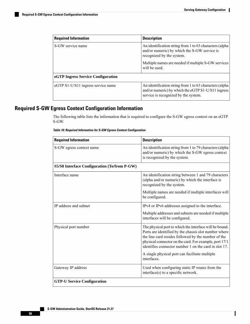
DescriptionRequired Information
An identification string from 1 to 63 characters (alphaand/or numeric) by which the S-GW service isrecognized by the system.
Multiple names are needed if multiple S-GW serviceswill be used.
S-GW service name
eGTP Ingress Service Configuration
An identification string from 1 to 63 characters (alphaand/or numeric) by which the eGTP S1-U/S11 ingressservice is recognized by the system.
eGTP S1-U/S11 ingress service name
Required S-GW Egress Context Configuration InformationThe following table lists the information that is required to configure the S-GW egress context on an eGTPS-GW.
Table 10: Required Information for S-GW Egress Context Configuration
DescriptionRequired Information
An identification string from 1 to 79 characters (alphaand/or numeric) by which the S-GW egress contextis recognized by the system.
S-GW egress context name
S5/S8 Interface Configuration (To/from P-GW)
An identification string between 1 and 79 characters(alpha and/or numeric) by which the interface isrecognized by the system.
Multiple names are needed if multiple interfaces willbe configured.
Interface name
IPv4 or IPv6 addresses assigned to the interface.
Multiple addresses and subnets are needed if multipleinterfaces will be configured.
IP address and subnet
The physical port to which the interface will be bound.Ports are identified by the chassis slot number wherethe line card resides followed by the number of thephysical connector on the card. For example, port 17/1identifies connector number 1 on the card in slot 17.
A single physical port can facilitate multipleinterfaces.
Physical port number
Used when configuring static IP routes from theinterface(s) to a specific network.
Gateway IP address
GTP-U Service Configuration
S-GW Administration Guide, StarOS Release 21.2758
Serving Gateway ConfigurationRequired S-GW Egress Context Configuration Information
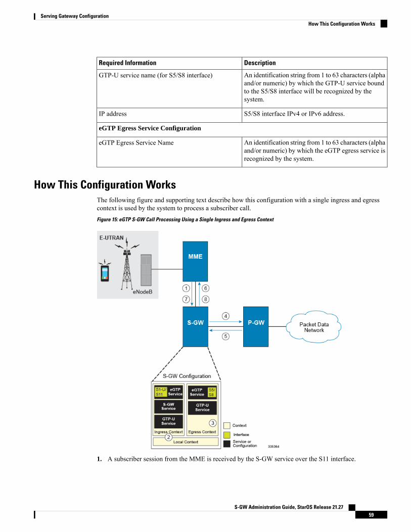
DescriptionRequired Information
An identification string from 1 to 63 characters (alphaand/or numeric) by which the GTP-U service boundto the S5/S8 interface will be recognized by thesystem.
GTP-U service name (for S5/S8 interface)
S5/S8 interface IPv4 or IPv6 address.IP address
eGTP Egress Service Configuration
An identification string from 1 to 63 characters (alphaand/or numeric) by which the eGTP egress service isrecognized by the system.
eGTP Egress Service Name
How This Configuration WorksThe following figure and supporting text describe how this configuration with a single ingress and egresscontext is used by the system to process a subscriber call.
Figure 15: eGTP S-GW Call Processing Using a Single Ingress and Egress Context
1. A subscriber session from the MME is received by the S-GW service over the S11 interface.
S-GW Administration Guide, StarOS Release 21.2759
Serving Gateway ConfigurationHow This Configuration Works

2. The S-GW service determines which context to use to access PDN services for the session. This processis described in the How the System Selects Contexts section located in the Understanding the SystemOperation and Configuration chapter of the System Administration Guide.
3. S-GW uses the configured egress context to determine the eGTP service to use for the outgoing S5/S8connection.
4. The S-GW establishes the S5/S8 connection by sending a create session request message to the P-GW.
5. The P-GW responds with a Create Session Response message that includes the PGW S5/S8 Address forcontrol plane and bearer information.
6. The S-GW conveys the control plane and bearer information to the MME in a Create Session Responsemessage.
7. The MME responds with a Create Bearer Response and Modify Bearer Request message.
8. The S-GW sends a Modify Bearer Response message to the MME.
eGTP S-GW ConfigurationTo configure the system to perform as a standalone eGTP S-GW, review the following graphic and subsequentsteps.
Figure 16: eGTP S-GW Configurable Components
Step 1 Set system configuration parameters such as activating PSCs by applying the example configurations found in the SystemAdministration Guide.
S-GW Administration Guide, StarOS Release 21.2760
Serving Gateway ConfigurationeGTP S-GW Configuration

Step 2 Set initial configuration parameters such as creating contexts and services by applying the example configurations foundin theInitial Configuration, on page 61.
Step 3 Configure the system to perform as an eGTP S-GW and set basic S-GW parameters such as eGTP interfaces and an IProute by applying the example configurations presented in the eGTP Configuration, on page 63.
Step 4 Verify and save the configuration by following the instruction in the Verifying and Saving the Configuration, on page64.
Initial Configuration
Step 1 Set local system management parameters by applying the example configuration in the Modifying the Local Context, onpage 61.
Step 2 Create an ingress context where the S-GW and eGTP ingress service will reside by applying the example configurationin the Creating an S-GW Ingress Context, on page 62.
Step 3 Create an eGTP ingress service within the newly created ingress context by applying the example configuration in theCreating an eGTP Ingress Service, on page 62.
Step 4 Create an S-GW egress context where the eGTP egress services will reside by applying the example configuration in theCreating an S-GW Egress Context, on page 62.
Step 5 Create an eGTP egress service within the newly created egress context by applying the example configuration in theCreating an eGTP Egress Service, on page 63.
Step 6 Create a S-GW service within the newly created ingress context by applying the example configuration in the Creatingan S-GW Service, on page 63.
Modifying the Local Context
Use the following example to set the default subscriber and configure remote access capability in the localcontext:
configurecontext local
interface <lcl_cntxt_intrfc_name>
ip address <ip_address> <ip_mask>
exitserver ftpd
exitserver telnetd
exitsubscriber default
exitadministrator <name> encrypted password <password> ftpip route <ip_addr/ip_mask> <next_hop_addr> <lcl_cntxt_intrfc_name>
exitport ethernet <slot/port>
no shutdownbind interface <lcl_cntxt_intrfc_name> localend
S-GW Administration Guide, StarOS Release 21.2761
Serving Gateway ConfigurationInitial Configuration

Creating an S-GW Ingress Context
Use the following example to create an S-GW ingress context and Ethernet interfaces to anMME and eNodeB,and bind the interfaces to configured Ethernet ports.
configurecontext <ingress_context_name> -noconfirm
subscriber defaultexit
interface <s1u-s11_interface_name>
ip address <ipv4_address_primary>
ip address <ipv4_address_secondary>
exitip route 0.0.0.0 0.0.0.0 <next_hop_address> <sgw_interface_name>
exitport ethernet <slot_number/port_number>
no shutdownbind interface <s1u-s11_interface_name> <ingress_context_name>
end
Notes:
• This example presents the S1-U/S11 connections as a shared interface. These interfaces can be separatedto support a different network architecture.
• The S1-U/S11 interface IP address(es) can also be specified as IPv6 addresses using the ipv6 addresscommand.
Creating an eGTP Ingress Service
Use the following configuration example to create an eGTP ingress service:
configurecontext <ingress_context_name>
egtp-service <egtp_ingress_service_name> -noconfirmend
Creating an S-GW Egress Context
Use the following example to create an S-GW egress context and Ethernet interface to a P-GW and bind theinterface to configured Ethernet ports.
configurecontext <egress_context_name> -noconfirm
interface <s5s8_interface_name> tunnelipv6 address <address>
tunnel-mode ipv6ipsource interface <name>
destination address <ipv4 or ipv6 address>
endconfigure
port ethernet <slot_number/port_number>
no shutdownbind interface <s5s8_interface_name> <egress_context_name>
end
S-GW Administration Guide, StarOS Release 21.2762
Serving Gateway ConfigurationCreating an S-GW Ingress Context

Notes:
• The S5/S8 interface IP address can also be specified as an IPv4 address using the ip address command.
Creating an eGTP Egress Service
Use the following configuration example to create an eGTP egress service in the S-GW egress context:
configurecontext <egress_context_name>
egtp-service <egtp_egress_service_name> -noconfirmend
Creating an S-GW Service
Use the following configuration example to create the S-GW service in the ingress context:
configurecontext <ingress_context_name>
sgw-service <sgw_service_name> -noconfirmend
eGTP Configuration
Step 1 Set the system's role as an eGTP S-GW and configure eGTP service settings by applying the example configuration inthe Setting the System's Role as an eGTP S-GW and Configuring GTP-U and eGTP Service Settings, on page 63.
Step 2 Configure the S-GW service by applying the example configuration in the Configuring the S-GW Service, on page 64.Step 3 Specify an IP route to the eGTP Serving Gateway by applying the example configuration in the Configuring an IP Route,
on page 64.
Setting the System's Role as an eGTP S-GW and Configuring GTP-U and eGTP Service Settings
Use the following configuration example to set the system to perform as an eGTP S-GW and configure theGTP-U and eGTP services:
configurecontext <sgw_ingress_context_name>
gtpp group defaultexit
gtpu-service <gtpu_ingress_service_name>
bind ipv4-address <s1-u_s11_interface_ip_address>
exitegtp-service <egtp_ingress_service_name>
interface-type interface-sgw-ingressvalidation-mode defaultassociate gtpu-service <gtpu_ingress_service_name>
gtpc bind address <s1u-s11_interface_ip_address>
exitexit
context <sgw_egress_context_name>
gtpu-service <gtpu_egress_service_name>
S-GW Administration Guide, StarOS Release 21.2763
Serving Gateway ConfigurationCreating an eGTP Egress Service
bind ipv4-address <s5s8_interface_ip_address>
exitegtp-service <egtp_egress_service_name>
interface-type interface-sgw-egressvalidation-mode defaultassociate gtpu-service <gtpu_egress_service_name>
gtpc bind address <s5s8_interface_ip_address>
end
Notes:
• The bind command in the GTP-U ingress and egress service configuration can also be specified as anIPv6 address using the ipv6-address command.
Configuring the S-GW Service
Use the following example to configure the S-GW service:
configurecontext <ingress_context_name>
sgw-service <sgw_service_name> -noconfirm
associate ingress egtp-service <egtp_ingress_service_name>
associate egress-proto gtp egress-context <egress_context_name>
qci-qos-mapping <map_name>
end
Configuring an IP Route
Use the following example to configure an IP Route for control and user plane data communication with aneGTP PDN Gateway:
configurecontext <egress_context_name>
ip route <pgw_ip_addr/mask> <sgw_next_hop_addr> <sgw_intrfc_name>
end
Verifying and Saving the ConfigurationSave your configuration to flash memory, an external memory device, and/or a network location using theExec mode command save configuration. For additional information on how to verify and save configurationfiles, refer to the System Administration Guide and the Command Line Interface Reference.
Configuring Optional Features on the eGTP S-GWThe configuration examples in this section are optional and provided to cover the most common uses of theeGTP S-GW in a live network. The intent of these examples is to provide a base configuration for testing.
Configuring the GTP Echo TimerThe GTP echo timer on the ASR 5500 S-GW can be configured to support two different types of pathmanagement: default and dynamic. This timer can be configured on the GTP-C and/or the GTP-U channels.
S-GW Administration Guide, StarOS Release 21.2764
Serving Gateway ConfigurationConfiguring the S-GW Service

Default GTP Echo Timer Configuration
The following examples describe the configuration of the default eGTP-C and GTP-U interface echo timers:
eGTP-C
configurecontext <context_name>
egtp-service <egtp_service_name>
gtpc echo-interval <seconds>
gtpc echo-retransmission-timeout <seconds>
gtpc max-retransmissions <num>
end
Notes:
• This configuration can be used in either the ingress context supporting the S1-U and/or S11 interfaceswith the eNodeB and MME respectively; and the egress context supporting the S5/S8 interface with theP-GW.
• The following diagram describes a failure and recovery scenario using default settings of the three gtpccommands in the example above:
Figure 17: Failure and Recovery Scenario: Example 1
• The multiplier (x2) is system-coded and cannot be configured.
S-GW Administration Guide, StarOS Release 21.2765
Serving Gateway ConfigurationDefault GTP Echo Timer Configuration

GTP-U
configurecontext <context_name>
gtpu-service <gtpu_service_name>
echo-interval <seconds>
echo-retransmission-timeout <seconds>
max-retransmissions <num>
end
Notes:
• This configuration can be used in either the ingress context supporting the S1-U interfaces with theeNodeB and the egress context supporting the S5/S8 interface with the P-GW.
• The following diagram describes a failure and recovery scenario using default settings of the three GTP-Ucommands in the example above:
Figure 18: Failure and Recovery Scenario: Example 2
• The multiplier (x2) is system-coded and cannot be configured.
Dynamic GTP Echo Timer Configuration
The following examples describe the configuration of the dynamic eGTP-C and GTP-U interface echo timers:
S-GW Administration Guide, StarOS Release 21.2766
Serving Gateway ConfigurationGTP-U
eGTP-C
configurecontext <context_name>
egtp-service <egtp_service_name>
gtpc echo-interval <seconds> dynamic smooth-factor <multiplier>
gtpc echo-retransmission-timeout <seconds>
gtpc max-retransmissions <num>
end
Notes:
• This configuration can be used in either the ingress context supporting the S1-U and/or S11 interfaceswith the eNodeB and MME respectively; and the egress context supporting the S5/S8 interface with theP-GW.
• The following diagram describes a failure and recovery scenario using default settings of the three gtpccommands in the example above and an example round trip timer (RTT) of six seconds:
S-GW Administration Guide, StarOS Release 21.2767
Serving Gateway ConfigurationeGTP-C
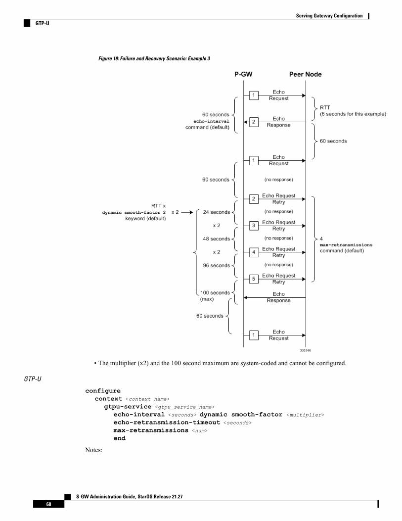
Figure 19: Failure and Recovery Scenario: Example 3
• The multiplier (x2) and the 100 second maximum are system-coded and cannot be configured.
GTP-U
configurecontext <context_name>
gtpu-service <gtpu_service_name>
echo-interval <seconds> dynamic smooth-factor <multiplier>
echo-retransmission-timeout <seconds>
max-retransmissions <num>
end
Notes:
S-GW Administration Guide, StarOS Release 21.2768
Serving Gateway ConfigurationGTP-U

• This configuration can be used in either the ingress context supporting the S1-U interfaces with theeNodeB and the egress context supporting the S5/S8 interface with the P-GW.
• The following diagram describes a failure and recovery scenario using default settings of the three gtpccommands in the example above and an example round trip timer (RTT) of six seconds:
Figure 20: Failure and Recovery Scenario: Example 4
• The multiplier (x2) and the 100 second maximum are system-coded and cannot be configured.
Configuring GTPP Offline Accounting on the S-GWBy default the S-GW service supports GTPP accounting. To provide GTPP offline charging during, forexample, scenarios where the foreign P-GW does not, configure the S-GW with the example parametersbelow:
S-GW Administration Guide, StarOS Release 21.2769
Serving Gateway ConfigurationConfiguring GTPP Offline Accounting on the S-GW

configuregtpp single-source
context <ingress_context_name>
subscriber defaultaccounting mode gtppexit
gtpp group defaultgtpp charging-agent address <gz_ipv4_address>
gtpp echo-interval <seconds>
gtpp attribute diagnosticsgtpp attribute local-record-sequence-numbergtpp attribute node-id-suffix <string>
gtpp dictionary <name>
gtpp server <ipv4_address> priority <num>
gtpp server <ipv4_address> priority <num> node-alive enable
exitpolicy accounting <gz_policy_name>
accounting-level {type}
operator-string <string>
cc profile <index> buckets <num>
cc profile <index> interval <seconds>
cc profile <index> volume total <octets>
exitsgw-service <sgw_service_name>
accounting context <ingress_context_name> gtpp group defaultassociate accounting-policy <gz_policy_name>
exitexit
context <ingress_context_name>
interface <gz_interface_name>
ip address <address>
exitexit
port ethernet <slot_number/port_number>
no shutdownbind interface <gz_interface_name> <ingress_context_name>
end
Notes:
• gtpp single-source is enabled to allow the system to generate requests to the accounting server using asingle UDP port (by way of a AAA proxy function) rather than each AAA manager generating requestson unique UDP ports.
• gtpp is the default option for the accounting mode command.
• An accounting mode configured for the call-control profile will override this setting.
• accounting-level types are: flow, PDN, PDN-QCI, QCI, and subscriber. Refer to the Accounting ProfileConfigurationMode Commands chapter in theCommand Line Interface Reference for more informationon this command.
S-GW Administration Guide, StarOS Release 21.2770
Serving Gateway ConfigurationConfiguring GTPP Offline Accounting on the S-GW

Configuring Diameter Offline Accounting on the S-GWBy default the S-GW service supports GTPP accounting. You can enable accounting via RADIUS/Diameter(Rf) for the S-GW service. To provide Rf offline charging during, for example, scenarios where the foreignP-GW does not, configure the S-GW with the example parameters below:
Diameter Offline Accounting is not supported on the S-GW.Important
configureoperator-policy name <policy_name>
associate call-control-profile <call_cntrl_profile_name>
exitcall-control-profile <call_cntrl_profile_name>
accounting mode radius-diameterexit
lte-policysubscriber-map <map_name>
precendence <number> match-criteria all operator-policy-name<policy_name>
exitexit
context <ingress_context_name>
policy accounting <rf_policy_name>
accounting-level {type}
operator-string <string>
exitsgw-service <sgw_service_name>
associate accounting-policy <rf_policy_name>
associate subscriber-map <map_name>
exitaaa group <rf-radius_group_name>
radius attribute nas-identifier <id>
radius accounting interim interval <seconds>
radius dictionary <name>
radius mediation-device accounting server <address> key <key>
diameter authentication dictionary <name>
diameter accounting dictionary <name>
diameter accounting endpoint <rf_cfg_name>
diameter accounting server <rf_cfg_name> priority <num>
exitdiameter endpoint <rf_cfg_name>
use-proxyorigin realm <realm_name>
origin host <name> address <rf_ipv4_address>
peer <rf_cfg_name> realm <name> address <ofcs_ipv4_or_ipv6_addr>
route-entry peer <rf_cfg_name>
exitexit
context <ingress_context_name>
interface <rf_interface_name>
S-GW Administration Guide, StarOS Release 21.2771
Serving Gateway ConfigurationConfiguring Diameter Offline Accounting on the S-GW
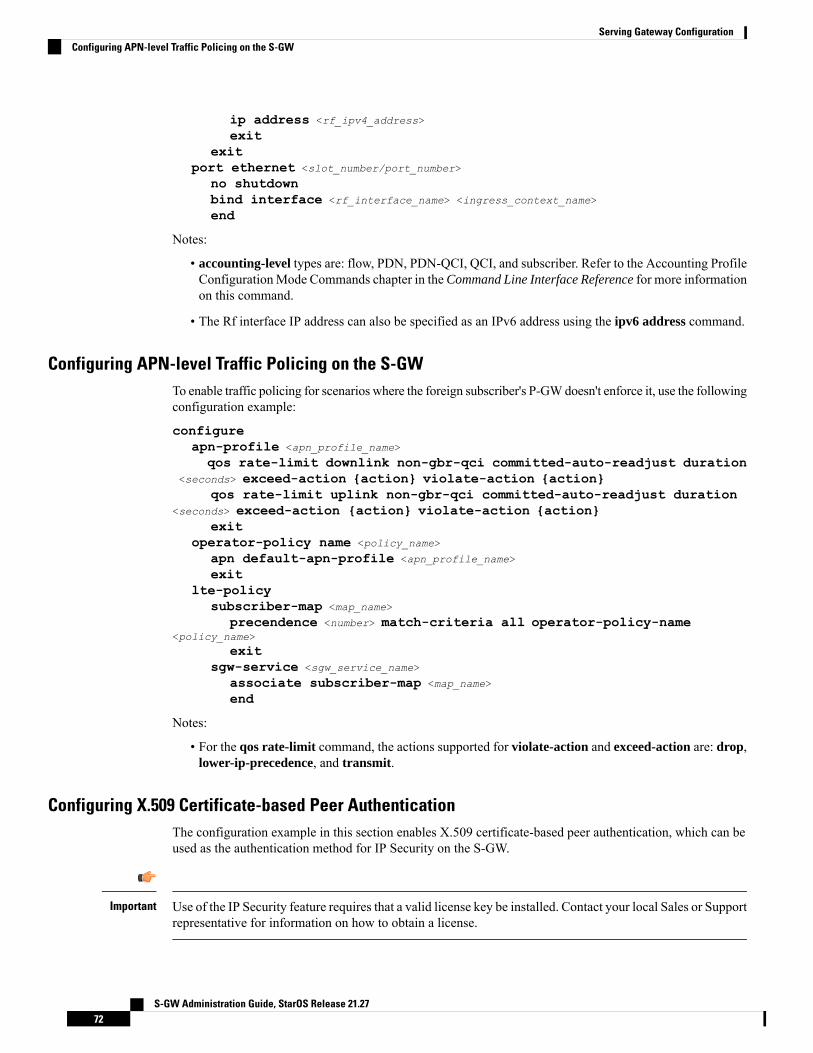
ip address <rf_ipv4_address>
exitexit
port ethernet <slot_number/port_number>
no shutdownbind interface <rf_interface_name> <ingress_context_name>
end
Notes:
• accounting-level types are: flow, PDN, PDN-QCI, QCI, and subscriber. Refer to the Accounting ProfileConfigurationMode Commands chapter in theCommand Line Interface Reference for more informationon this command.
• The Rf interface IP address can also be specified as an IPv6 address using the ipv6 address command.
Configuring APN-level Traffic Policing on the S-GWTo enable traffic policing for scenarios where the foreign subscriber's P-GWdoesn't enforce it, use the followingconfiguration example:
configureapn-profile <apn_profile_name>
qos rate-limit downlink non-gbr-qci committed-auto-readjust duration<seconds> exceed-action {action} violate-action {action}
qos rate-limit uplink non-gbr-qci committed-auto-readjust duration<seconds> exceed-action {action} violate-action {action}
exitoperator-policy name <policy_name>
apn default-apn-profile <apn_profile_name>
exitlte-policy
subscriber-map <map_name>
precendence <number> match-criteria all operator-policy-name<policy_name>
exitsgw-service <sgw_service_name>
associate subscriber-map <map_name>
end
Notes:
• For the qos rate-limit command, the actions supported for violate-action and exceed-action are: drop,lower-ip-precedence, and transmit.
Configuring X.509 Certificate-based Peer AuthenticationThe configuration example in this section enables X.509 certificate-based peer authentication, which can beused as the authentication method for IP Security on the S-GW.
Use of the IP Security feature requires that a valid license key be installed. Contact your local Sales or Supportrepresentative for information on how to obtain a license.
Important
S-GW Administration Guide, StarOS Release 21.2772
Serving Gateway ConfigurationConfiguring APN-level Traffic Policing on the S-GW

The following configuration example enables X.509 certificate-based peer authentication on the S-GW.
In Global Configuration Mode, specify the name of the X.509 certificate and CA certificate, as follows:
configurecertificate name <cert_name> pem url <cert_pem_url> private-key pem url
<private_key_url>ca-certificate name <ca_cert_name> pem url <ca_cert_url>
end
Notes:
• The certificate name and ca-certificate list ca-cert-name commands specify the X.509 certificate andCA certificate to be used.
• The PEM-formatted data for the certificate and CA certificate can be specified, or the information canbe read from a file via a specified URL as shown in this example.
When creating the crypto template for IPSec in Context Configuration Mode, bind the X.509 certificate andCA certificate to the crypto template and enable X.509 certificate-based peer authentication for the local andremote nodes, as follows:
configurecontext <sgw_context_name>
crypto template <crypto_template_name> ikev2-dynamiccertificate name <cert_name>
ca-certificate list ca-cert-name <ca_cert_name>
authentication local certificateauthentication remote certificateend
Notes:
• A maximum of sixteen certificates and sixteen CA certificates are supported per system. One certificateis supported per service, and a maximum of four CA certificates can be bound to one crypto template.
• The certificate name and ca-certificate list ca-cert-name commands bind the certificate and CAcertificate to the crypto template.
• The authentication local certificate and authentication remote certificate commands enable X.509certificate-based peer authentication for the local and remote nodes.
Configuring Dynamic Node-to-Node IP Security on the S1-U and S5 InterfacesThe configuration example in this section creates IPSec/IKEv2 dynamic node-to-node tunnel endpoints onthe S1-U and S5 interfaces.
Use of the IP Security feature requires that a valid license key be installed. Contact your local Sales or Supportrepresentative for information on how to obtain a license.
Important
Creating and Configuring an IPSec Transform Set
The following example configures an IPSec transform set, which is used to define the security associationthat determines the protocols used to protect the data on the interface:
S-GW Administration Guide, StarOS Release 21.2773
Serving Gateway ConfigurationConfiguring Dynamic Node-to-Node IP Security on the S1-U and S5 Interfaces

configurecontext <sgw_context_name>
ipsec transform-set <ipsec_transform-set_name>
encryption aes-cbc-128group nonehmac sha1-96mode tunnelend
Notes:
• The encryption algorithm, aes-cbc-128, or Advanced Encryption Standard Cipher Block Chaining, isthe default algorithm for IPSec transform sets configured on the system.
• The group none command specifies that no crypto strength is included and that Perfect Forward Secrecyis disabled. This is the default setting for IPSec transform sets configured on the system.
• The hmac command configures the Encapsulating Security Payload (ESP) integrity algorithm. Thesha1-96 keyword uses a 160-bit secret key to produce a 160-bit authenticator value. This is the defaultsetting for IPSec transform sets configured on the system.
• The mode tunnel command specifies that the entire packet is to be encapsulated by the IPSec header,including the IP header. This is the default setting for IPSec transform sets configured on the system.
Creating and Configuring an IKEv2 Transform Set
The following example configures an IKEv2 transform set:
configurecontext <sgw_context_name>
ikev2-ikesa transform-set <ikev2_transform-set_name>
encryption aes-cbc-128group 2hmac sha1-96lifetime <sec>
prf sha1end
Notes:
• The encryption algorithm, aes-cbc-128, or Advanced Encryption Standard Cipher Block Chaining, isthe default algorithm for IKEv2 transform sets configured on the system.
• The group 2 command specifies the Diffie-Hellman algorithm as Group 2, indicating medium security.The Diffie-Hellman algorithm controls the strength of the crypto exponentials. This is the default settingfor IKEv2 transform sets configured on the system.
• The hmac command configures the Encapsulating Security Payload (ESP) integrity algorithm. Thesha1-96 keyword uses a 160-bit secret key to produce a 160-bit authenticator value. This is the defaultsetting for IKEv2 transform sets configured on the system.
• The lifetime command configures the time the security key is allowed to exist, in seconds.
• The prf command configures the IKE Pseudo-random Function, which produces a string of bits thatcannot be distinguished from a random bit string without knowledge of the secret key. The sha1 keyword
S-GW Administration Guide, StarOS Release 21.2774
Serving Gateway ConfigurationCreating and Configuring an IKEv2 Transform Set

uses a 160-bit secret key to produce a 160-bit authenticator value. This is the default setting for IKEv2transform sets configured on the system.
Creating and Configuring a Crypto Template
The following example configures an IKEv2 crypto template:
configurecontext <sgw_context_name>
crypto template <crypto_template_name> ikev2-dynamicikev2-ikesa transform-set list <name1> . . . <name6>
ikev2-ikesa rekeypayload <name> match childsa match ipv4
ipsec transform-set list <name1> . . . <name4>
rekeyend
Notes:
• The ikev2-ikesa transform-set list command specifies up to six IKEv2 transform sets.
• The ipsec transform-set list command specifies up to four IPSec transform sets.
Binding the S1-U and S5 IP Addresses to the Crypto Template
The following example configures the binding of the S1-U and S5 interfaces to the crypto template.
configurecontext <sgw_ingress_context_name>
gtpu-service <gtpu_ingress_service_name>
bind ipv4-address <s1-u_interface_ip_address> crypto-template<enodeb_crypto_template>
exitegtp-service <egtp_ingress_service_name>
interface-type interface-sgw-ingressassociate gtpu-service <gtpu_ingress_service_name>
gtpc bind address <s1u_interface_ip_address>
exitexit
context <sgw_egress_context_name>
gtpu-service <gtpu_egress_service_name>
bind ipv4-address <s5_interface_ip_address> crypto-template<enodeb_crypto_template>
exitegtp-service <egtp_egress_service_name>
interface-type interface-sgw-egressassociate gtpu-service <gtpu_egress_service_name>
gtpc bind address <s5_interface_ip_address>
exitexit
context <sgw_ingress_context_name>
sgw-service <sgw_service_name> -noconfirmegtp-service ingress service <egtp_ingress_service_name>
S-GW Administration Guide, StarOS Release 21.2775
Serving Gateway ConfigurationCreating and Configuring a Crypto Template
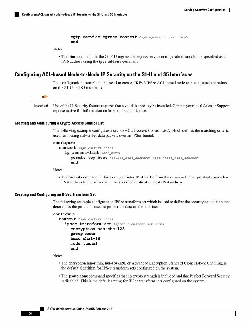
egtp-service egress context <sgw_egress_context_name>
end
Notes:
• The bind command in the GTP-U ingress and egress service configuration can also be specified as anIPv6 address using the ipv6-address command.
Configuring ACL-based Node-to-Node IP Security on the S1-U and S5 InterfacesThe configuration example in this section creates IKEv2/IPSec ACL-based node-to-node tunnel endpointson the S1-U and S5 interfaces.
Use of the IP Security feature requires that a valid license key be installed. Contact your local Sales or Supportrepresentative for information on how to obtain a license.
Important
Creating and Configuring a Crypto Access Control List
The following example configures a crypto ACL (Access Control List), which defines the matching criteriaused for routing subscriber data packets over an IPSec tunnel:
configurecontext <sgw_context_name>
ip access-list <acl_name>
permit tcp host <source_host_address> host <dest_host_address>
end
Notes:
• The permit command in this example routes IPv4 traffic from the server with the specified source hostIPv4 address to the server with the specified destination host IPv4 address.
Creating and Configuring an IPSec Transform Set
The following example configures an IPSec transform set which is used to define the security association thatdetermines the protocols used to protect the data on the interface:
configurecontext <sgw_context_name>
ipsec transform-set <ipsec_transform-set_name>
encryption aes-cbc-128group nonehmac sha1-96mode tunnelend
Notes:
• The encryption algorithm, aes-cbc-128, or Advanced Encryption Standard Cipher Block Chaining, isthe default algorithm for IPSec transform sets configured on the system.
• The group none command specifies that no crypto strength is included and that Perfect Forward Secrecyis disabled. This is the default setting for IPSec transform sets configured on the system.
S-GW Administration Guide, StarOS Release 21.2776
Serving Gateway ConfigurationConfiguring ACL-based Node-to-Node IP Security on the S1-U and S5 Interfaces

• The hmac command configures the Encapsulating Security Payload (ESP) integrity algorithm. Thesha1-96 keyword uses a 160-bit secret key to produce a 160-bit authenticator value. This is the defaultsetting for IPSec transform sets configured on the system.
• The mode tunnel command specifies that the entire packet is to be encapsulated by the IPSec headerincluding the IP header. This is the default setting for IPSec transform sets configured on the system.
Creating and Configuring an IKEv2 Transform Set
The following example configures an IKEv2 transform set:
configurecontext <sgw_context_name>
ikev2-ikesa transform-set <ikev2_transform-set_name>
encryption aes-cbc-128group 2hmac sha1-96lifetime <sec>
prf sha1end
Notes:
• The encryption algorithm, aes-cbc-128, or Advanced Encryption Standard Cipher Block Chaining, isthe default algorithm for IKEv2 transform sets configured on the system.
• The group 2 command specifies the Diffie-Hellman algorithm as Group 2, indicating medium security.The Diffie-Hellman algorithm controls the strength of the crypto exponentials. This is the default settingfor IKEv2 transform sets configured on the system.
• The hmac command configures the Encapsulating Security Payload (ESP) integrity algorithm. Thesha1-96 keyword uses a 160-bit secret key to produce a 160-bit authenticator value. This is the defaultsetting for IKEv2 transform sets configured on the system.
• The lifetime command configures the time the security key is allowed to exist, in seconds.
• The prf command configures the IKE Pseudo-random Function which produces a string of bits thatcannot be distinguished from a random bit string without knowledge of the secret key. The sha1 keyworduses a 160-bit secret key to produce a 160-bit authenticator value. This is the default setting for IKEv2transform sets configured on the system.
Creating and Configuring a Crypto Map
The following example configures an IKEv2 crypto map and applies it to the S1-U interface:
configurecontext <sgw_ingress_context_name>
crypto map <crypto_map_name> ikev2-ipv4match address <acl_name>
peer <ipv4_address>
authentication local pre-shared-key key <text>
authentication remote pre-shared-key key <text>
ikev2-ikesa transform-set list <name1> . . . <name6>
payload <name> match ipv4lifetime <seconds>
S-GW Administration Guide, StarOS Release 21.2777
Serving Gateway ConfigurationCreating and Configuring an IKEv2 Transform Set
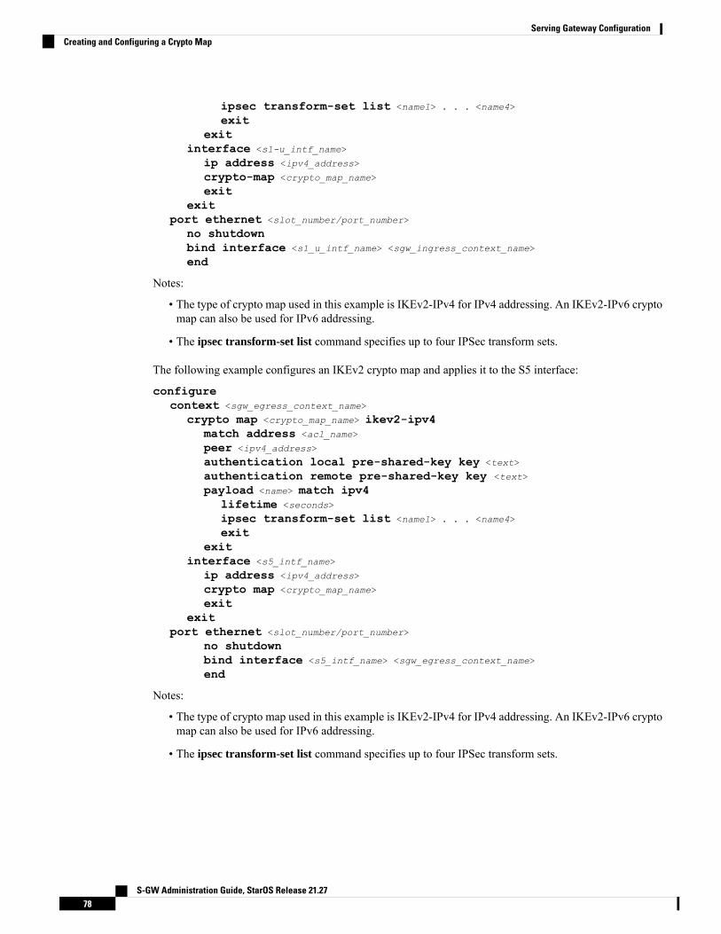
ipsec transform-set list <name1> . . . <name4>
exitexit
interface <s1-u_intf_name>
ip address <ipv4_address>
crypto-map <crypto_map_name>
exitexit
port ethernet <slot_number/port_number>
no shutdownbind interface <s1_u_intf_name> <sgw_ingress_context_name>
end
Notes:
• The type of crypto map used in this example is IKEv2-IPv4 for IPv4 addressing. An IKEv2-IPv6 cryptomap can also be used for IPv6 addressing.
• The ipsec transform-set list command specifies up to four IPSec transform sets.
The following example configures an IKEv2 crypto map and applies it to the S5 interface:
configurecontext <sgw_egress_context_name>
crypto map <crypto_map_name> ikev2-ipv4match address <acl_name>
peer <ipv4_address>
authentication local pre-shared-key key <text>
authentication remote pre-shared-key key <text>
payload <name> match ipv4lifetime <seconds>
ipsec transform-set list <name1> . . . <name4>
exitexit
interface <s5_intf_name>
ip address <ipv4_address>
crypto map <crypto_map_name>
exitexit
port ethernet <slot_number/port_number>
no shutdownbind interface <s5_intf_name> <sgw_egress_context_name>
end
Notes:
• The type of crypto map used in this example is IKEv2-IPv4 for IPv4 addressing. An IKEv2-IPv6 cryptomap can also be used for IPv6 addressing.
• The ipsec transform-set list command specifies up to four IPSec transform sets.
S-GW Administration Guide, StarOS Release 21.2778
Serving Gateway ConfigurationCreating and Configuring a Crypto Map

Configuring 3GPP Release 12 Load Control Support3GPP R12 Load Control enables a GTP-C entity (for example, an S-GW/P-GW) to send its load informationto a GTP-C peer (e.g. an MME/SGSN, ePDG, TWAN) to adaptively balance the session load across entitiessupporting the same function (for example, an S-GW cluster) according to their effective load. The loadinformation reflects the operating status of the resources of the GTP-C entity.
Use the following example to configure this feature:
configuregtpc-load-control-profile profile_name
inclusion-frequency advertisement-interval interval_in_seconds
weightage system-cpu-utilization percentage system-memory-utilizationpercentage license-session-utilization percentage
endconfigure
context context_name
sgw-service sgw_service_name
associate gtpc-load-control-profile profile_name
end
Notes:
• The inclusion-frequency parameter determines how often the Load control information element is sentto the peer(s).
• The total of the three weightage parameters should not exceed 100.• The associate command is used to associate the Load Control Profile with an existing S-GW service.
Configuring 3GPP Release 12 Overload Control Support3GPP R12 Overload Control enables a GTP-C entity becoming or being overloaded to gracefully reduce itsincoming signalling load by instructing its GTP-C peers to reduce sending traffic according to its availablesignaling capacity to successfully process the traffic. A GTP-C entity is in overload when it operates over itssignaling capacity, which results in diminished performance (including impacts to handling of incoming andoutgoing traffic).
Use the following example to configure this feature.
configuregtpc-overload-control-profile profile_name
inclusion-frequency advertisement-interval interval_in_seconds
weightage system-cpu-utilization percentage system-memory-utilizationpercentage license-session-utilization percentage
throttling-behavior emergency-events excludetolerance threshold report-reduction-metric percentage
self-protection-limit percentage
validity-period seconds
endconfigure
context context_name
sgw-service sgw_service_name
associate gtpc-overload-control-profile profile_name
end
Notes:
S-GW Administration Guide, StarOS Release 21.2779
Serving Gateway ConfigurationConfiguring 3GPP Release 12 Load Control Support

• The inclusion-frequency parameter determines how often the Overload control information element issent to the peer(s).
• The total of the three weightage parameters should not exceed 100.• validity-period configures how long the overload control information is valid. Valid entries are from 1to 3600 seconds. The default is 600 seconds.
• The associate command is used to associate the Overload Control Profile with an existing S-GW service.
Configuring S4 SGSN Handover CapabilityThis configuration example configures an S4 interface supporting inter-RAT handovers between the S-GWand an S4 SGSN.
Use the following example to configure this feature:
configurecontext <ingress_context_name> -noconfirm
interface <s4_interface_name>
ip address <ipv4_address_primary>
ip address <ipv4_address_secondary>
exitexit
port ethernet <slot_number/port_number>
no shutdownbind interface <s4_interface_name> <ingress_context_name>
exitcontext <ingress_context_name> -noconfirm
gtpu-service <s4_gtpu_ingress_service_name>
bind ipv4-address <s4_interface_ip_address>
exitegtp-service <s4_egtp_ingress_service_name>
interface-type interface-sgw-ingressvalidation-mode defaultassociate gtpu-service <s4_gtpu_ingress_service_name>
gtpc bind address <s4_interface_ip_address>
exitsgw-service <sgw_service_name> -noconfirm
associate ingress egtp-service <s4_egtp_ingress_service_name>
end
Notes:
• The S4 interface IP address(es) can also be specified as IPv6 addresses using the ipv6 address command.
S-GW Administration Guide, StarOS Release 21.2780
Serving Gateway ConfigurationConfiguring S4 SGSN Handover Capability
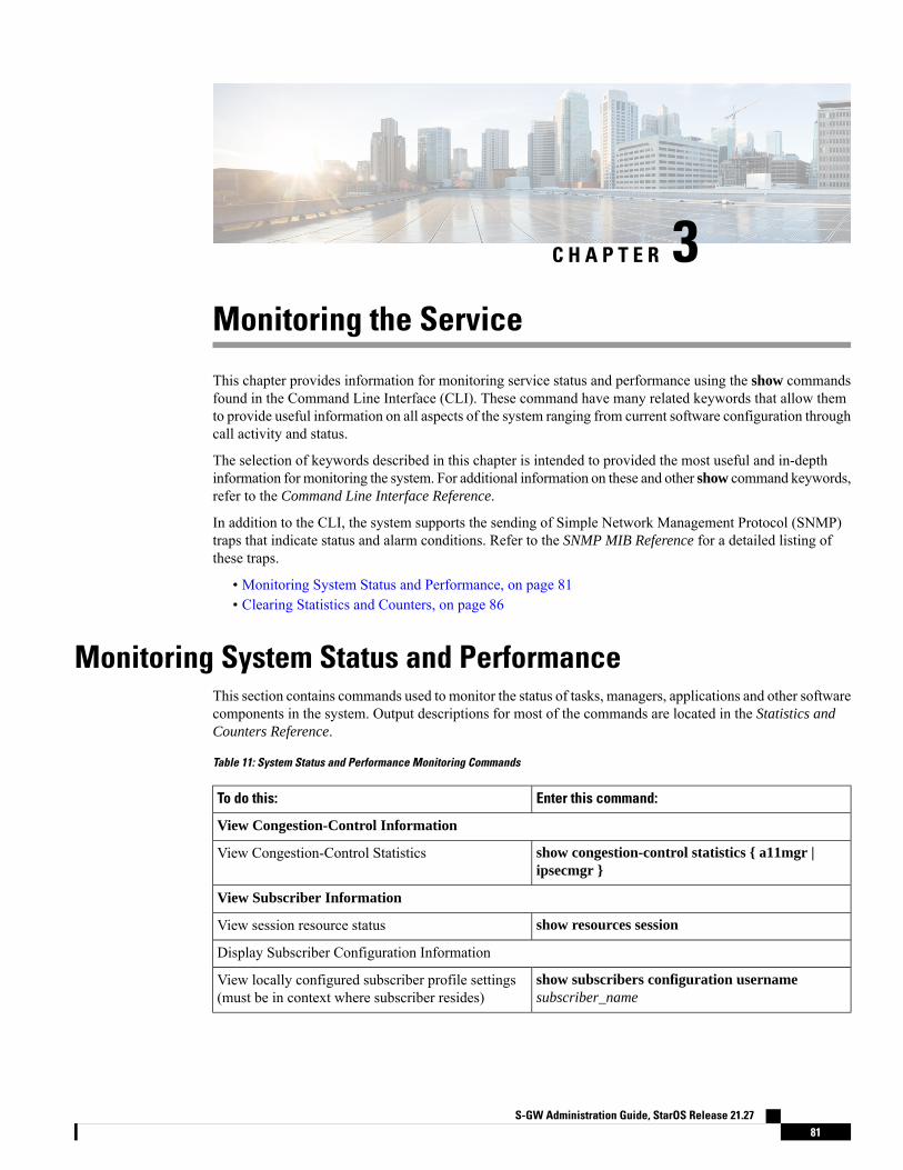
C H A P T E R 3Monitoring the Service
This chapter provides information for monitoring service status and performance using the show commandsfound in the Command Line Interface (CLI). These command have many related keywords that allow themto provide useful information on all aspects of the system ranging from current software configuration throughcall activity and status.
The selection of keywords described in this chapter is intended to provided the most useful and in-depthinformation for monitoring the system. For additional information on these and other show command keywords,refer to the Command Line Interface Reference.
In addition to the CLI, the system supports the sending of Simple Network Management Protocol (SNMP)traps that indicate status and alarm conditions. Refer to the SNMP MIB Reference for a detailed listing ofthese traps.
• Monitoring System Status and Performance, on page 81• Clearing Statistics and Counters, on page 86
Monitoring System Status and PerformanceThis section contains commands used to monitor the status of tasks, managers, applications and other softwarecomponents in the system. Output descriptions for most of the commands are located in the Statistics andCounters Reference.
Table 11: System Status and Performance Monitoring Commands
Enter this command:To do this:
View Congestion-Control Information
show congestion-control statistics { a11mgr |ipsecmgr }
View Congestion-Control Statistics
View Subscriber Information
show resources sessionView session resource status
Display Subscriber Configuration Information
show subscribers configuration usernamesubscriber_name
View locally configured subscriber profile settings(must be in context where subscriber resides)
S-GW Administration Guide, StarOS Release 21.2781

Enter this command:To do this:
show subscribers aaa-configuration usernamesubscriber_name
View remotely configured subscriber profile settings
View Subscribers Currently Accessing the System
show subscribers allView a listing of subscribers currently accessing thesystem
View Statistics for Subscribers using S-GW Services on the System
show subscribers sgw-only fullView statistics for subscribers using any S-GW serviceon the system
show subscribers sgw-service service_nameView statistics for subscribers using a specific S-GWservice on the system
View Statistics for Subscribers using MAG Services on the System
show subscribers mag-only fullView statistics for subscribers using anyMAG serviceon the system
show subscribers mag-service service_nameView statistics for subscribers using a specific MAGservice on the system
View Session Subsystem and Task Information
Display Session Subsystem and Task Statistics
Refer to the StarOS Tasks appendix in the System Administration Guide for additional informationon the Session subsystem and its various manager tasks.
Important
show session subsystem facility aaamgr allView AAA Manager statistics
show session subsystem facility aaaproxy allView AAA Proxy statistics
show session subsystem facility sessmgr allView Session Manager statistics
show session subsystem facility magmgr allView MAG Manager statistics
View Session Recovery Information
show session recovery status [ verbose ]View session recovery status
View Session Disconnect Reasons
show session disconnect-reasonsView session disconnect reasons with verbose output
View S-GW Service Information
show sgw-service statistics allView S-GW service statistics
context sgw_context_name
show sgw-service all |grep Status
show mag-service all |grep Status
Verify S-GW services
View GTP Information
show egtpc statistics egtpc-service nameView eGTP-C service statistics for a specific service
S-GW Administration Guide, StarOS Release 21.2782
Monitoring the ServiceMonitoring System Status and Performance
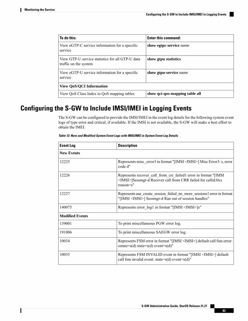
Enter this command:To do this:
show egtpc-service nameView eGTP-C service information for a specificservice
show gtpu statisticsView GTP-U service statistics for all GTP-U datatraffic on the system
show gtpu-service nameView eGTP-U service information for a specificservice
View QoS/QCI Information
show qci-qos-mapping table allView QoS Class Index to QoS mapping tables
Configuring the S-GW to Include IMSI/IMEI in Logging EventsThe S-GW can be configured to provide the IMSI/IMEI in the event log details for the following system eventlogs of type error and critical, if available. If the IMSI is not available, the S-GW will make a best effort toobtain the IMEI.
Table 12: New and Modified System Event Logs with IMSI/IMEI in System Event Log Details
DescriptionEvent Log
New Events
Represents misc_error3 in format "[IMSI <IMSI>]Misc Error3: s, errorcode d"
12225
Represents recover_call_from_crr_failed1 error in format "[IMSI<IMSI>]Sessmgr-d Recover call from CRR failed for callid:0xxreason=s"
12226
Represents aaa_create_session_failed_no_more_sessions1 error in format"[IMSI <IMSI>] Sessmgr-d Ran out of session handles"
12227
Represents error_log1 in format "[IMSI <IMSI>]s"140075
Modified Events
To print miscellaneous PGW error log.139001
To print miscellaneous SAEGW error log.191006
Represents FSM error in format "[IMSI <IMSI>] default call fsm error:ostate=s(d) state=s(d) event=s(d)"
10034
Represents FSM INVALID event in format "[IMSI <IMSI>] defaultcall fsm invalid event: state=s(d) event=s(d)"
10035
S-GW Administration Guide, StarOS Release 21.2783
Monitoring the ServiceConfiguring the S-GW to Include IMSI/IMEI in Logging Events

DescriptionEvent Log
Represents SN_LE_SESSMGR_PGW_REJECT_BEARER_OP informat "[IMSI <IMSI>] Sessmgr-d: Request to s bearer rejected. Reason:s". For example "[IMSI 112233445566778 Sessmgr-1: Request to Createbearer rejected. Reason: Create Bearer Request denied as sessionrecovery is in progress"
12382
Represents fsm_event_error in format "[IMSI <IMSI>]Misc Error: Badevent in sessmgr fsm, event code d"
12668
Represents pgw_purge_invalid_crr in format "[IMSI <IMSI>] Local sTEID [lu] Collision: Clp Connect Time: lu, Old Clp Callid: d, Old ClpConnect Time: lu s"
12774
Represents ncqos_nrspca_trig_err in format "[IMSI <IMSI>] NCQOSNRSPCA trig rcvd in invalid bcm mode."
12855
Represents ncqos_nrupc_tft_err in format "[IMSI <IMSI>] NCQOSNRUPC Trig : TFT validation failed for nsapi <u>."
12857
Represnts ncqos_nrxx_trig_already in format "[IMSI <IMSI>] NCQOSNRSPCA/NRUPC is already triggered on sess with nsapi <u>."
12858
Represents ncqos_nrxx_tft_check_fail in format "[IMSI <IMSI>]NCQOS TFT check failed as TFT has invalid opcode for nsapi<u>:pf_id_bitmap 0xx and tft_opcode: d"
12859
Represents ncqos_sec_rej in format "[IMSI <IMSI>]NCQOSSecondaryctxt with nsapi <u> rejected, due to <s>."
12860
Represents ncqos_upc_rej in format "[IMSI <IMSI>] UPCRejected forctxt with nsapi <u>, due to <s>."
12861
Represents ggsn_subsession_invalid_state in format "[IMSI <IMSI>]GGSN subsession invalid state state:<s>,[event:<s>]"
12862
Represents gngp_handoff_rejected_for_pdn_ipv4v6 in format "[IMSI<IMSI>] Sessmgr-d Handoff from PGW-to-GGSN rejected, as GGSNdoesnt support Deffered allocation for IPv4v6, dropping the call."
11830
Representsgngp_handoff_rejected_no_non_gbr_bearer_for_def_bearer_selectionin format "[IMSI <IMSI>] Sessmgr-d Handoff from PGW-to-GGSNrejected, as GGSN Callline has no non-GBR bearer to be selected asDefault bearer."
11832
Represents gngp_handoff_from_ggsn_rejected_no_ggsn_call in format"[IMSI <IMSI>] Sessmgr-d Handoff from GGSN-to-PGW rejected, asGGSN call with TEIDC <0xx> not found."
11834
Represents gtp_pdp_type_mismatch in format "[IMSI <IMSI>]Mismatch between PDP type of APN s and in create req. Rejecting call"
12960
S-GW Administration Guide, StarOS Release 21.2784
Monitoring the ServiceConfiguring the S-GW to Include IMSI/IMEI in Logging Events
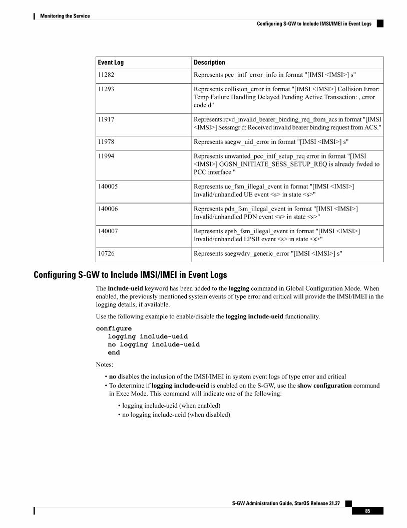
DescriptionEvent Log
Represents pcc_intf_error_info in format "[IMSI <IMSI>] s"11282
Represents collision_error in format "[IMSI <IMSI>] Collision Error:Temp Failure Handling Delayed Pending Active Transaction: , errorcode d"
11293
Represents rcvd_invalid_bearer_binding_req_from_acs in format "[IMSI<IMSI>] Sessmgr d: Received invalid bearer binding request fromACS."
11917
Represents saegw_uid_error in format "[IMSI <IMSI>] s"11978
Represents unwanted_pcc_intf_setup_req error in format "[IMSI<IMSI>] GGSN_INITIATE_SESS_SETUP_REQ is already fwded toPCC interface "
11994
Represents ue_fsm_illegal_event in format "[IMSI <IMSI>]Invalid/unhandled UE event <s> in state <s>"
140005
Represents pdn_fsm_illegal_event in format "[IMSI <IMSI>]Invalid/unhandled PDN event <s> in state <s>"
140006
Represents epsb_fsm_illegal_event in format "[IMSI <IMSI>]Invalid/unhandled EPSB event <s> in state <s>"
140007
Represents saegwdrv_generic_error "[IMSI <IMSI>] s"10726
Configuring S-GW to Include IMSI/IMEI in Event LogsThe include-ueid keyword has been added to the logging command in Global Configuration Mode. Whenenabled, the previously mentioned system events of type error and critical will provide the IMSI/IMEI in thelogging details, if available.
Use the following example to enable/disable the logging include-ueid functionality.
configurelogging include-ueidno logging include-ueidend
Notes:
• no disables the inclusion of the IMSI/IMEI in system event logs of type error and critical• To determine if logging include-ueid is enabled on the S-GW, use the show configuration commandin Exec Mode. This command will indicate one of the following:
• logging include-ueid (when enabled)• no logging include-ueid (when disabled)
S-GW Administration Guide, StarOS Release 21.2785
Monitoring the ServiceConfiguring S-GW to Include IMSI/IMEI in Event Logs

Clearing Statistics and CountersIt may be necessary to periodically clear statistics and counters in order to gather new information. The systemprovides the ability to clear statistics and counters based on their grouping (PPP, MIPHA, MIPFA, etc.).
Statistics and counters can be cleared using the CLI clear command. Refer to the Command Line Referencefor detailed information on using this command.
S-GW Administration Guide, StarOS Release 21.2786
Monitoring the ServiceClearing Statistics and Counters
C H A P T E R 45G Non Standalone
This chapter describes the 5G Non Standalone (NSA) feature in the following sections:
• Feature Summary and Revision History, on page 87• Feature Description, on page 88
Feature Summary and Revision HistorySummary Data
• P-GW
• S-GW
• SAEGW
Applicable Product(s) or Functional Area
• ASR 5000
• ASR 5500
• VPC-DI
• VPC-SI
Applicable Platform(s)
Disabled - Configuration RequiredFeature Default
Not applicableRelated Changes in This Release
• 5G Non Standalone Solution Guide
• AAA Interface Administration and Reference
• Command Line Interface Reference
• P-GW Administration Guide
• S-GW Administration Guide
• SAEGW Administration Guide
• Statistics and Counters Reference
Related Documentation
S-GW Administration Guide, StarOS Release 21.2787
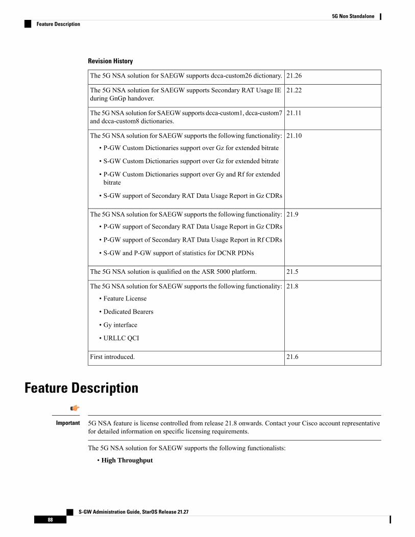
Revision History
21.26The 5G NSA solution for SAEGW supports dcca-custom26 dictionary.
21.22The 5G NSA solution for SAEGW supports Secondary RAT Usage IEduring GnGp handover.
21.11The 5GNSA solution for SAEGWsupports dcca-custom1, dcca-custom7and dcca-custom8 dictionaries.
21.10The 5GNSA solution for SAEGW supports the following functionality:
• P-GW Custom Dictionaries support over Gz for extended bitrate
• S-GW Custom Dictionaries support over Gz for extended bitrate
• P-GW Custom Dictionaries support over Gy and Rf for extendedbitrate
• S-GW support of Secondary RAT Data Usage Report in Gz CDRs
21.9The 5GNSA solution for SAEGW supports the following functionality:
• P-GW support of Secondary RAT Data Usage Report in Gz CDRs
• P-GW support of Secondary RAT Data Usage Report in Rf CDRs
• S-GW and P-GW support of statistics for DCNR PDNs
21.5The 5G NSA solution is qualified on the ASR 5000 platform.
21.8The 5GNSA solution for SAEGW supports the following functionality:
• Feature License
• Dedicated Bearers
• Gy interface
• URLLC QCI
21.6First introduced.
Feature Description
5G NSA feature is license controlled from release 21.8 onwards. Contact your Cisco account representativefor detailed information on specific licensing requirements.
Important
The 5G NSA solution for SAEGW supports the following functionalists:
• High Throughput
S-GW Administration Guide, StarOS Release 21.2788
5G Non StandaloneFeature Description
5G NR offers downlink data throughput up to 20 Gbps and uplink data throughput up to 10 Gbps. Someinterfaces in EPC have the support to handle (encode/decode) 5G throughput. For example, NAS supportsup to 65.2 Gbps (APN-AMBR) and S5/S8/S10/S3 (GTP-v2 interfaces) support up to 4.2 Tbps. Thediameter interfaces S6a and Gx support only up to 4.2Gbps throughput, S1-AP supports only up to 10Gbps and NAS supports up to 10 Gbps (MBR, GBR). New AVP/IE have been introduced in S6a, Gx ,S1-AP, and NAS interfaces to support 5G throughput. See theHow It Works section for more information.
• DCNR Support on P-GW:
Supports configuration of DCNR feature at the P-GW-service, by configuring “Extended-BW-NR”feature in IMSA service. Advertises the DCNR feature support by sending “Extended-BW-NR” featurebit in “Feature-List-ID-2” towards PCRF. Forwards AVP "Extended-APN-AMBR-UL" and"Extended-APN-AMBR-DL" in CCRmessageswhen it receivesAPN-AMBRvalues greater than 4.2Gbpsfrom MME/S-GW. Decodes the extended AVP "Extended-APN-AMBR-UL" and"Extended-APN-AMBR-DL" when it is received from PCRF.
• Sends AVP "Extended-Max-Requested-BW-UL", "Extended-Max-Requested-BW-DL","Extended-GBR-UL" and "Extended-GBR-DL" when it receives MBR and GBR values greater than4.2Gbps from MME/S-GW. Decodes the AVP "Extended-Max-Requested-BW-UL","Extended-Max-Requested-BW-DL", "Extended-GBR-UL" and "Extended-GBR-DL" when receivedfrom PCRF. Supports dedicated bearer establishment with extended QoS. Sends AVPExtended-Max-Requested-BW-UL and "Extended-Max-Requested-BW-DL" in Gy records.
• Ultra Low Latency Support:
Supports 5G requirements of Ultra-Reliable and Low Latency Communications (URLLC). 3GPPintroduced URLCC QCI 80 (Non-GBR resource type), QCI 82 and 83 (GBR resource type). P-GWestablishes default bearers with URLLC QCI 80, which is typically used by low latency eMBBapplications. P-GW establishes dedicated bearers with URLLC QCI 82 and 83 (also with QCI 80 ifdedicated bearers of Non-GBR type to be established), which is typically used by discrete automationservices (industrial automation).
• ICSR Support
With release 21.10 onwards ICSR for 5G NSA on SAEGW is supported.
• Dynamic S-GW and P-GW selection by MME for DCNR capable UE
When DCNR capable UE attempts to register in MME and when all DCNR validations are successful(for example DCNR feature configuration on MME, HSS not sending access-restriction for NR, and sonon), the MME sets “UP Function Selection Indication Flags” IE with DCNR flag set to 1 in “CreateSession Request” message. This feature is relevant for CUPS architecture to help SGW-C and PGW-Cto select SGW-U and PGW-U which supports dual connectivity with NR. When S-GW receives this IEover S11, it sends this IE over S5 to P-GW. S-GW ignores IE if it receives it in Non-CUPS deployment.
• P-GW Secondary RAT Usage Data Report Handling:
P-GW supports custom24 and custom44 for Gz and aaa-custom3, aaa-custom4 and aaa-custom6dictionaries for Rf to support Secondary RAT Data Usage Report in CDRs.
Support for Secondary RAT Usage During GnGp Handover
This feature supports the Secondary RAT usage reported in change notification request during 4G to 3Ghandover. The support is for handling the change notification with Secondary RAT Usage during the GnGphandover. Step 13 is added in the following diagram in support of this feature. The usage must be reportedin next CDR generation.
S-GW Administration Guide, StarOS Release 21.2789
5G Non StandaloneFeature Description
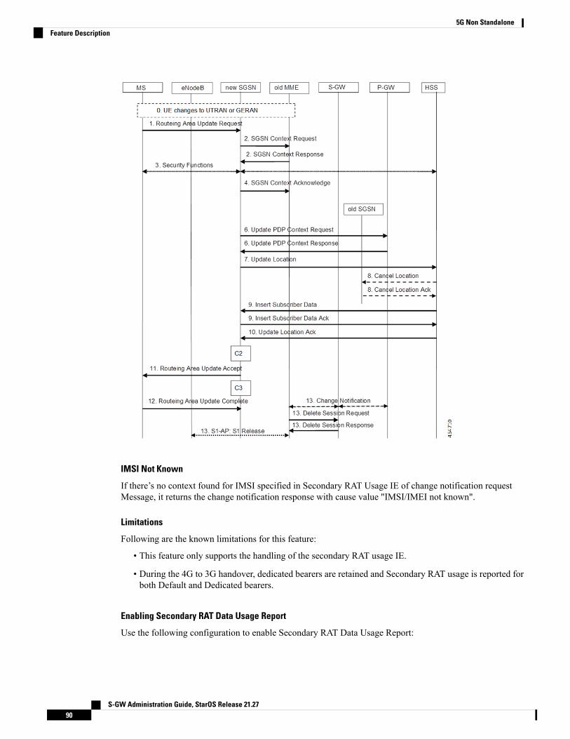
IMSI Not Known
If there’s no context found for IMSI specified in Secondary RAT Usage IE of change notification requestMessage, it returns the change notification response with cause value "IMSI/IMEI not known".
Limitations
Following are the known limitations for this feature:
• This feature only supports the handling of the secondary RAT usage IE.
• During the 4G to 3G handover, dedicated bearers are retained and Secondary RAT usage is reported forboth Default and Dedicated bearers.
Enabling Secondary RAT Data Usage Report
Use the following configuration to enable Secondary RAT Data Usage Report:
S-GW Administration Guide, StarOS Release 21.2790
5G Non StandaloneFeature Description
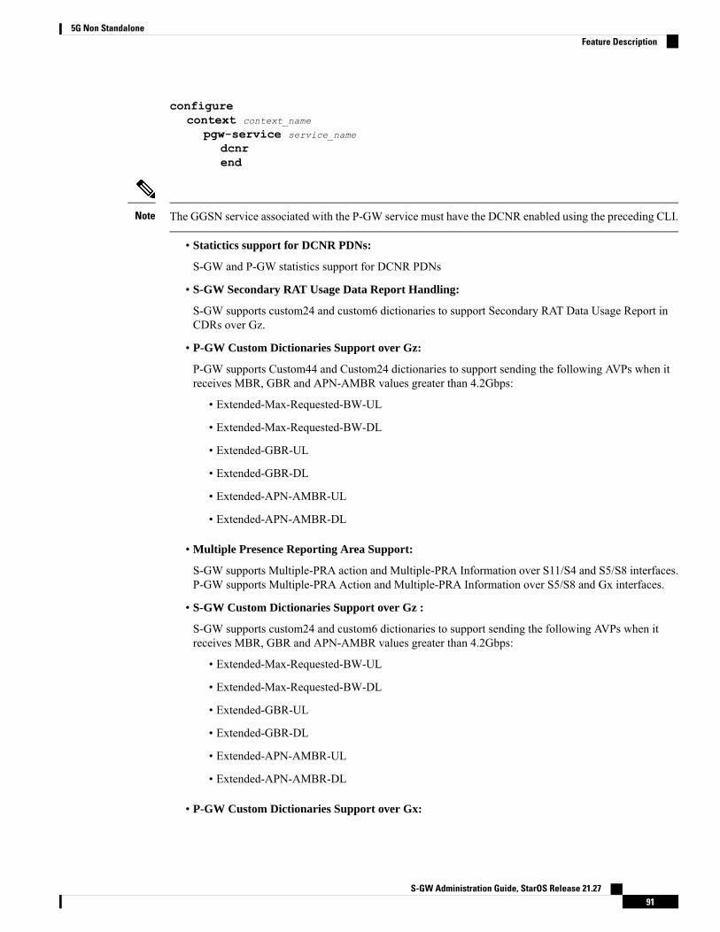
configurecontext context_name
pgw-service service_name
dcnrend
The GGSN service associated with the P-GW service must have the DCNR enabled using the preceding CLI.Note
• Statictics support for DCNR PDNs:
S-GW and P-GW statistics support for DCNR PDNs
• S-GW Secondary RAT Usage Data Report Handling:
S-GW supports custom24 and custom6 dictionaries to support Secondary RAT Data Usage Report inCDRs over Gz.
• P-GW Custom Dictionaries Support over Gz:
P-GW supports Custom44 and Custom24 dictionaries to support sending the following AVPs when itreceives MBR, GBR and APN-AMBR values greater than 4.2Gbps:
• Extended-Max-Requested-BW-UL
• Extended-Max-Requested-BW-DL
• Extended-GBR-UL
• Extended-GBR-DL
• Extended-APN-AMBR-UL
• Extended-APN-AMBR-DL
• Multiple Presence Reporting Area Support:
S-GW supports Multiple-PRA action and Multiple-PRA Information over S11/S4 and S5/S8 interfaces.P-GW supports Multiple-PRA Action and Multiple-PRA Information over S5/S8 and Gx interfaces.
• S-GW Custom Dictionaries Support over Gz :
S-GW supports custom24 and custom6 dictionaries to support sending the following AVPs when itreceives MBR, GBR and APN-AMBR values greater than 4.2Gbps:
• Extended-Max-Requested-BW-UL
• Extended-Max-Requested-BW-DL
• Extended-GBR-UL
• Extended-GBR-DL
• Extended-APN-AMBR-UL
• Extended-APN-AMBR-DL
• P-GW Custom Dictionaries Support over Gx:
S-GW Administration Guide, StarOS Release 21.2791
5G Non StandaloneFeature Description

P-GW supports dpca-custom15, dpca-custom11, dpca-custom23, dpca-custom19 and dpca-custom17,dictionaries to support sending the following AVPs when it receives GBR and APN-AMBR valuesgreater than 4.2Gbps:
• Extended-Max-Requested-BW-UL
• Extended-Max-Requested-BW-DL
• Extended-GBR-DL
• Extended-GBR-UL
• Extended-APN-AMBR-UL
• Extended-APN-AMBR-DL
• P-GW Custom Dictionaries Support over Gy:
P-GW supports dcca-custom1, dcca-custom7, dcca-custom8, dcca-custom13 and dcca-custom26dictionaries to support sending the following AVPs when it receives GBR and APN-AMBR valuesgreater than 4.2Gbps:
• Extended-Max-Requested-BW-UL
• Extended-Max-Requested-BW-DL
• Extended-GBR-DL
• Extended-GBR-UL
• Extended-APN-AMBR-UL
• Extended-APN-AMBR-DL
• P-GW Custom Dictionaries Support over Rf:
P-GW supports aaa-custom3, aaa-custom4 and aaa-custom6 dictionaries to support sending the followingAVPs when it receives GBR and APN-AMBR values greater than 4.2Gbps:
• Extended-Max-Requested-BW-UL
• Extended-Max-Requested-BW-DL
• Extended-GBR-UL
• Extended-GBR-DL
• Extended-APN-AMBR-UL
• Extended-APN-AMBR-DL
Multiple Presence Reporting Area
P-GW supports negotiation ofMultiple-Presence Reporting Area feature in Feature-List-ID 2 over Gx interfacewith PCRF. The CNO-ULI feature will be used only when the P-GW and/or the PCRF does not supportMultiple-PRA and both P-GW and PCRF support CNO-ULI.
S-GW Administration Guide, StarOS Release 21.2792
5G Non StandaloneFeature Description

This feature is introduced in release 21.9.1. For more information, refer to the Presence Reporting Area chapterin the P-GW Administration Guide.
Note
S-GW Administration Guide, StarOS Release 21.2793
5G Non StandaloneFeature Description

S-GW Administration Guide, StarOS Release 21.2794
5G Non StandaloneFeature Description

C H A P T E R 5Collision Handling on the P-GW/SAEGW/S-GW
• Feature Description, on page 95• How It Works, on page 95• Configuring Collision Handling, on page 98• Monitoring the Collision Handling Feature, on page 98
Feature DescriptionGTPv2 message collisions occur in the network when a node is expecting a particular procedure messagefrom a peer node but instead receives a different procedure message from the peer. GTP procedure collisionsare quite common in the network; especially with dynamic Policy and Charging Control, the chances ofcollisions happening in the network are very high.
These collisions are tracked by statistics and processed based on a pre-defined action for eachmessage collisiontype. These statistics assist operators in debugging network issues.
If the SAEGW is configured as a pure P-GW or a pure S-GW, operators will see the respective collisionstatistics if they occur.
Important
Relationships to Other Features• This feature is a part of the base software license for the P-GW/SAEGW/S-GW. No additional licenseis required.
• A P-GW, S-GW, or SAEGW service must be configured to view GTPv2 collision statistics.
How It Works
Collision HandlingAs GTPv2 message collisions occur, they are processed by the P-GW, SAEGW, and S-GW. They are alsotracked by statistics and with information on how the collision was handled.
S-GW Administration Guide, StarOS Release 21.2795
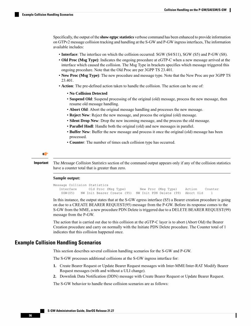
Specifically, the output of the show egtpc statistics verbose command has been enhanced to provide informationon GTPv2message collision tracking and handling at the S-GW and P-GW ingress interfaces, The informationavailable includes:
• Interface: The interface on which the collision occurred: SGW (S4/S11), SGW (S5) and P-GW (S8).• Old Proc (Msg Type): Indicates the ongoing procedure at eGTP-C when a new message arrived at theinterface which caused the collision. The Msg Type in brackets specifies which message triggered thisongoing procedure. Note that the Old Proc are per 3GPP TS 23.401.
• New Proc (Msg Type): The new procedure and message type. Note that the New Proc are per 3GPP TS23.401.
• Action: The pre-defined action taken to handle the collision. The action can be one of:
• No Collision Detected• Suspend Old: Suspend processing of the original (old) message, process the new message, thenresume old message handling.
• Abort Old: Abort the original message handling and processes the new message.• Reject New: Reject the new message, and process the original (old) message.• Silent Drop New: Drop the new incoming message, and the process the old message.• Parallel Hndl: Handle both the original (old) and new messages in parallel.• Buffer New: Buffer the new message and process it once the original (old) message has beenprocessed.
• Counter: The number of times each collision type has occurred.
The Message Collision Statistics section of the command output appears only if any of the collision statisticshave a counter total that is greater than zero.
Important
Sample output:
Message Collision StatisticsInterface Old Proc (Msg Type) New Proc (Msg Type) Action CounterSGW(S5) NW Init Bearer Create (95) NW Init PDN Delete (99) Abort Old 1
In this instance, the output states that at the S-GW egress interface (S5) a Bearer creation procedure is goingon due to a CREATE BEARER REQUEST(95) message from the P-GW. Before its response comes to theS-GW from the MME, a new procedure PDNDelete is triggered due to a DELETE BEARER REQUEST(99)message from the P-GW.
The action that is carried out due to this collision at the eGTP-C layer is to abort (Abort Old) the BearerCreation procedure and carry on normally with the Initiate PDN Delete procedure. The Counter total of 1indicates that this collision happened once.
Example Collision Handling ScenariosThis section describes several collision handling scenarios for the S-GW and P-GW.
The S-GW processes additional collisions at the S-GW ingress interface for:
1. Create Bearer Request or Update Bearer Request messages with Inter-MME/Inter-RAT Modify BearerRequest messages (with and without a ULI change).
2. Downlink Data Notification (DDN) message with Create Bearer Request or Update Bearer Request.
The S-GW behavior to handle these collision scenarios are as follows:
S-GW Administration Guide, StarOS Release 21.2796
Collision Handling on the P-GW/SAEGW/S-GWExample Collision Handling Scenarios

1. A CBReq and MBReq [(Inter MME/Inter RAT (with or without ULI change)] collision at the S-GWingress interface results in the messages being handled in parallel. The CBReq will wait for a CreateBearer Response (CBRsp) from the peer. Additionally, an MBReq is sent in parallel to the P-GW.
2. An UBReq and MBReq [(Inter MME/Inter RAT (with or without a ULI change)] collision at the SGWingress interface is handled with a suspend and resume procedure. The UBReq would be suspended andthe MBReq would be processed. Once the MBRsp is sent to the peer from the SGW ingress interface, theUBReq procedure is resumed.
3. Create Bearer Request (CBR) or Update Bearer Request (UBR) with Downlink Data Notification (DDN)messages are handled parallel.
As a result, no S-GW initiated Cause Code message 110 (Temporarily rejected due to handover procedure inprogress) will be seen as a part of such collisions. Collisions will be handled in parallel.
The following GTP-C example collision handling scenarios may also be seen on the P-GW:
DBCmd/MBreq Collision Handling:
The P-GW enables operators to configure the behavior of the P-GW for collision handling of the Delete Bearercommand (DBcmd) message when the Modify Bearer Request (MBreq) message for the default bearer ispending at the P-GW.
There are three CLI-controlled options to handle the collision between the DBCmd and MBReq messages:
• Queue the DBcmd message when the MBreq message is pending. The advantage of this option is thatthe DBCmd message is not lost for most of the collisions. It will remain on the P-GW until the MBRspis sent out.
• Drop the DBCmd message when the MBreq message is pending. Note that with this option the S-GWmust retry the DBCmd.
• Use pre-StarOS 19.0 behavior: abort theMBreqmessage and handle the DBcmdmessage. The advantageof this option is that it provides backward compatibility if the operator wants to retain pre-StarOS 19.0functionality.
The CLI command collision handling provides more flexibility in configuring the handling of the DBCmdmessage and MBReq message collision scenario. Also refer to Configuring DBcmd Message Behavior, onpage 98 in this document for instructions on how to configure the behavior for this collision handling scenario.
MBReq/CBreq Parallel Processing; Handling CBRsp:
The P-GW/S-GW has handles the following example collision scenario:
The node queues the CBRsp message and feeds the CBRsp message to the P-GW/S-GW session managerwhen the MBRsp is sent out. As a result, operators will see no retransmission of CBRsp messages from theMME.
Handling UBrsp when Transaction is Suspended:
The P-GW/S-GW handles the following example collision scenario:
When the P-GW/S-GW receives an UBRsp message, then the P-GW/S-GW handles the UBRsp message forthe suspended transaction. As a result, The UBRsp message will be buffered until the MBRsp message is sentout.
LimitationsThere are no known limitations to the collision handling feature on the P-GW/SAEGW/S-GW.
S-GW Administration Guide, StarOS Release 21.2797
Collision Handling on the P-GW/SAEGW/S-GWLimitations
Standards ComplianceSpecifications and standards do not specify any hard rules for collision handling cases.
Configuring Collision HandlingOperators can use the Command Line Interface (CLI) to configure the behavior of the P-GW for handling thefollowing GTPv2 message collision:
• DBcmd Message when the MBreq Message for the Default Bearer is pending at the P-GW
Configuration via the CLI is not required for all other P-GW and S-GW collision handling scenarios.Important
Configuring DBcmd Message BehaviorUse the following example to configure the collision handling behavior for the Delete Bearer commandmessage when the Modify Bearer Request message for the Default Bearer is pending at the P-GW.
configurecontext context_name
egtp-service egtp_service_name
collision-handling dbcmd-over-mbreq { drop | queue }{ default | no } collision-handling dbcmd-over-mbreqend
Notes:
• drop: Drop the DBcmd message when the MBreq message is pending.• queue: Queue the DBcmd message when the MBreq is message is pending.• The default behavior is to abort the MBReq message and handle the DBcmd message.
Verifying the ConfigurationTo verify the DBcmd Message when the MBreq Message for the Default Bearer is pending at the P-GWconfiguration, use the following command in Exec Mode:
show egtpc service allCollision handling: DBcmd when MBreq pending: <Queue DBcmd>, <Drop DBcmd>, or <Abort
MBreq and handle Dbcmd>
Monitoring the Collision Handling FeatureThis section describes how to monitor the collision handling feature.
S-GW Administration Guide, StarOS Release 21.2798
Collision Handling on the P-GW/SAEGW/S-GWStandards Compliance
Collision Handling Show Command(s) and/or OutputsThis section provides information regarding show commands and/or their outputs in support of the collisionhandling on the P-GW/SAEGW/S-GW feature.
show configurationThe output of this command indicates if collision handling for the DBcmd message when the MBreq messageis pending is enabled or disabled.
• collision-handling dbcmd-over-mbreq queue• no collision-handling dbcmd-over-mbreq queue
show egtp-service allThe output of this command indicates how the P-GW is configured to handle the DBcmd Message when theMBreq Message for the Default Bearer is pending at the P-GW.
• Collision handling:
• DBcmd when MBreq pending: <Queue DBcmd>, <Drop DBcmd>, or <Abort MBreq and handleDbcmd>
show egtp statistics verboseThe output of this command has been enhanced to provide detailed information for all supported GTPv2message collisions at the P-GW/S-GW ingress interface, including:
• The interface on which the collision occurred.• The ongoing procedure at eGTP-Cwhen a newmessage arrived at the interface which caused the collision.The Msg Type in brackets specifies which message triggered this ongoing procedure.
• The new procedure and message type.• The pre-defined action taken to handle the collision.• The number of times each collision type has occurred.
The Message Collision Statistics section of the command output appears only if any of the collision statisticshave a counter total that is greater than zero.
Important
S-GW Administration Guide, StarOS Release 21.2799
Collision Handling on the P-GW/SAEGW/S-GWCollision Handling Show Command(s) and/or Outputs

S-GW Administration Guide, StarOS Release 21.27100
Collision Handling on the P-GW/SAEGW/S-GWshow egtp statistics verbose

C H A P T E R 6Session Tracing
This chapter provides information on subscriber session trace functionality that allows an operator to tracesubscriber activity at various points in the network and at various level of detail. Subscriber session tracingis supported on the following UMTS/EPC GW network elements:
• GGSN• P-GW• SAEGW• S-GW
For detailed information for session tracing on the MME, refer to the MME Administration Guide.Important
The product Administration Guides provide examples and procedures for configuration of basic services onthe system. It is recommended that you select the configuration example that best meets your service model,and configure the required elements for that model, as described in the respective product AdministrationGuide, before using the procedures in this chapter.
This chapter includes a feature description, configuration procedures, monitoring commands, and a sessiontracing file example.
• Session Tracing Overview, on page 101• Configuring Session Trace Functionality, on page 105• Monitoring the Session Trace Functionality, on page 115• Supported SAEGW Session Trace Configurations, on page 116• Session Trace File Example, on page 119
Session Tracing OverviewSession Trace capability enables an operator to trace subscriber activity at various points in the network andat various levels of detail. The trace can be subscriber initiated (that is, signaling based) or managementinitiated from the CLI (Command Line Interface) and can be propagated throughout the access cloud via thevarious signaling interfaces available to the UMTS/EPC network element.
Essentially, the Session Trace capability records and forwards all control activity for the monitored subscriberon the monitored interfaces. This is typically all the signaling and authentication/subscriber services messagesthat flow when a User Equipment (UE) connects to the access network.
S-GW Administration Guide, StarOS Release 21.27101

All monitored activity is sent to an off-line Trace Collection Entity (TCE) using a standards-based XMLformat over a File Transfer Protocol (FTP) or secure FTP (sFTP) connection.
Session tracing is a resource intensive application in terms of CPU utilization and will affect call rates anddata throughput when in use. The use of this feature in a production network should be restricted to minimizethe impact on existing services.
Important
Only the SFTP option supports for Session Trace function. FTP does not support for the Session Trace function.Important
As can be seen in the following illustration, of the three Network Elements (NEs) shown, one NE is activelytracing data on one or more interfaces. All data collected is stored as files in an XML format and then transferredto the collection entity using (S)FTP or FTP. Note that IPv4 or IPv6 connectivity is required between the NEand the TCE in order to transfer the files.
Figure 21: Session Tracing Architecture
Session Trace TypesThere are three types of session trace functions available.
S-GW Administration Guide, StarOS Release 21.27102
Session TracingSession Trace Types
• Management Trace: The operator sends an activation request via the CLI directly to the UMTS/EPCnetwork element where the trace is to be initiated. The network element establishes the trace session andwaits for a configured trigger event to start actively tracing.When management-initiated trace activationsare executed at the network element, they are never propagated to other NEs whether or not it is involvedin the actual recording of the call.
• Random Trace: Enables or disables the subscriber session trace functionality based on a the randomtrace on the UMTS/EPC network element. The trace control and configuration parameters are configureddirectly in the specified network element through the random trace CLI command. There is nopropagation of trace parameters in random based trace activation. This NE shall not propagate the receiveddata to any other NEs whether or not it is involved in the actual recording of the call. If enabled, thesubscriber selection will be based on random logic all instances of session on the specified UMTS/EPCnetwork element.
• Signaling Trace: With a signaling based activation, the trace session is indicated to the UMTS/EPCnetwork element across a signaling interface via a trace invocation message. This message can either bepiggybacked with an existing bearer setup message (in order to trace all control messages) or by sendinga separate trace invocation message (if the user is already active). Signaling based activations are alwayspropagated to neighboring NEs even if the current NE does not participate in the trace (either they notenabled by configuration or not present in the configured trace parameters).
Note that the maximum number of unique International Mobile Subscriber Identification (IMSI) numbers orInternationalMobile Equipment Identification (IMEI) numbers cannot exceed 32; however, each NE can traceall 32 unique IMSI/IMEIs.
Important
Session tracing is a resource intensive application in terms of CPU utilization and will affect call rates anddata throughput when in use. The use of this feature in a production network should be restricted to minimizethe impact on existing services.
Caution
Session Trace ActivationActivation of a trace is similar whether it be via the management interface or via a signaling interface. In bothcases, a trace session state block is allocated which stores all configuration and state information for the tracesession. In addition, an (S)FTP connection to the Trace Collection Entity (TCE) is established if one does notalready exist. The NE will store up to 2 MB of XML data on its local disk to allow for the (S)FTP connectionto be established and the files to be pushed to or pulled from the TCE.
If the session to be traced is already active, tracing may begin immediately. Otherwise, tracing activity waitsuntil the start trigger occurs (typically when the subscriber/UE under trace initiates a connection). A failureto activate a trace (due to the maximum being exceeded or some other failure reason) results in a notificationbeing sent to the TCE indicating the failure.
Session Trace DeactivationDeactivation of a Trace Session is similar whether it was management or signaling activated. In either case,a deactivation request is received by the NE that contains valid trace reference results in the de-allocation ofthe trace session state block and a flushing of any pending trace data. In addition, if this is the last trace session
S-GW Administration Guide, StarOS Release 21.27103
Session TracingSession Trace Activation
to a particular TCE, the (S)FTP connection to the TCE is released after the last trace file is successfullytransferred to the TCE.
Data CollectionData collection is done inline by each of the NEs. In order to reduce the overhead on a per-control packetbasis, a copy of the entire packet is made and stored into an internal database (DB) of packets.
The local internal path for the trace database is /hd-raid/trace.
This storage is done regardless of the trace depth. After xx bytes (or xx messages) have been stored or aconfigurable number of seconds have elapsed, all cached data is encoded in the standard XML format andwritten out to a file to be forwarded to/pulled from the TCE. If there is no TCE active, the UMTS/EPC networkelement will continue to cache data and create trace files as long as there is space available before stoppingthe trace recording session. Once the connection to the TCE becomes active, all cached data will be sentimmediately to the TCE.
Data ForwardingWhen a session is activated, the IP address of the TCE is supplied in the session activation request. Uponactivation and if the push mode is used, a check is made to see if there is already an (S)FTP connection to theTCE. If so, it is used for all traffic associated with this trace session. If not, an (S)FTP connection is made tothe TCE using the supplied IP address. Data is buffered locally and trace files generated until the connectionis established. Once the connection is established, all previously created trace files are sent to the TCE. Notethat the (S)FTP connection is established to the TCE at session activation regardless of whether or not a tracerecording session has been triggered. The (S)FTP connection is maintained until the trace session is deactivated.
Note the following:
• If a default TCE IP Address is supplied when the trace capability is configured, a default (S)FTPconnection is made to the remote TCE.
• The TCE can be reachable either via IPv4 or IPv6 addressing. The supplied TCE address indicates theversion.
• If the push mode is not used, the files are stored on the local hard drive (/hd-raid/trace) and must bepulled off by the TCE using FTP or SFTP.
Supported StandardsSupport for the following standards and requests for comments (RFCs) have been added for the Session Tracefeature:
• 3GPP TS 32.421 V8.5.0 (2009-06): 3rd Generation Partnership Project; Technical Specification GroupServices and System Aspects; Telecommunication management; Subscriber and equipment trace: Traceconcepts and requirements (Release 8)
• 3GPP TS 32.422 V8.6.0 (2009-09): 3rd Generation Partnership Project; Technical Specification GroupServices and System Aspects; Telecommunication management; Subscriber and equipment trace; Tracecontrol and configuration management (Release 8)
• 3GPP TS 32.423 V8.2.0 (2009-09): 3rd Generation Partnership Project; Technical Specification GroupServices and System Aspects; Telecommunication management; Subscriber and equipment trace: Tracedata definition and management (Release 8)
S-GW Administration Guide, StarOS Release 21.27104
Session TracingData Collection
Configuring Session Trace FunctionalityConfiguring Session Trace on the UMTS/EPC network element consists of the following:
1. Enabling Session Tracing, on page 1052. Configuring a Session Trace Template for the Management Trace Function, on page 1063. Configuring a Management Session Trace, on page 1104. Configuring a Signaling Session Trace, on page 1115. Configuring a Random Trace, on page 112
The trace files can be stored locally, or pushed to a Trace Collection Entity (TCE) specified in the varioustrace commands.
Not all combinations of Session Trace configuration types are allowed on the SAEGW. For details on thesupported session trace configuration types, refer to Supported SAEGW Session Trace Configurations, onpage 116 in this document.
Important
Enabling Session TracingSession Tracing functionality must first be enabled before a specific management, random, or signaling sessiontrace can be configured.
The following commands enable or disable the subscriber session trace functionality based on a specifiedsubscriber device or ID on one or all instances of a session on a specified UMTS/EPC network element.
Use the following example to enable session tracing on the UMTS/EPC network element:
configsession trace network-element { all | ggsn | hnbgw | mme | pgw | saegw
| sgw } [ file-type <a-type | b-type> ] tce-mode none | push transportftp | sftp username username encrypted password password path directory_path
collection timer ctimer_value
end
Notes:
• session trace network-element : Enables Session Tracing functionality on the specified network element.To enable session tracing for all supported network elements, enter all.
• file-type { a-type | b-type }: Specifies which type of XML file is generated by the session trace. Optionsinclude an A-type file and B-type file. When B-type XML files are used, multiple trace recording sessionelements will be encoded in a single XML file. Note that different trace recording sessions may beassociated with different TCEs, according to the TCE IP address specified during activation. As expected,each Type-B XML file will contain traceRecSession elements that pertain only to the same target TCE.There will be different XML Type-B files created for different TCEs and they will be placed in differenttce_x directories for transmission to the target TCEs. The default is a-type.
• tce-mode : Specifies that trace files are stored locally and must be pulled by the TCE (none) or tracefiles are pushed to the TCE (push). The default is none.
• transport : Specifies the method by which the trace files are pushed to the TCE (either ftp or sftp.) Thedefault is sftp.
S-GW Administration Guide, StarOS Release 21.27105
Session TracingConfiguring Session Trace Functionality
• username: Must be specified if the tce-mode is push.• password: Must be specified if the tce-mode is push.• encrypted: Specifies that the password used to push files to the TCE server will be encrypted.• password: Specifies the password to use to push files to the TCE server. The user name can be from 1to 31 alphanumeric characters.
• collection-timer: Specifies the amount of time, in seconds, to wait from initial activation/data collectionbefore data is reported to TCE. The default is 10 seconds.
• retry-timer: Specifies the amount of time, in seconds, to wait before retrying a file transfer if the previoustransfer failed. The default is 60 seconds.
Example:session trace network-element saegw tce-mode push transport sftp path /SessionTrace usernameroot encrypted password 5c4a38dc2ff61f72 collection-timer 5
Verifying that Session Tracing is EnabledUse the following example to verify that session tracing functionality is enabled on the UMTS/EPC networkelement:
show session trace statistics
The output indicates for which NEs session tracing is enabled, and also indicates the configured trace type,where applicable. For example:Network element status:
MME: Enabled Cell-Trace: DisabledS-GW: Enabled
SAEGW EnabledPGW: Trace-Type: NoneSGW: Trace-Type: None
Disabling Session Trace FunctionalityUse the following example to disable session tracing functionality:
configno session trace network-element { all | ggsn | hnbgw | mme | pgw
| saegw | sgw }end
Configuring a Session Trace Template for the Management Trace FunctionOperators must create a template for a management trace in Global Configuration Mode. Management tracesexecuted in Exec mode will use the template. Once created, the template can be associated with differentsubscribers to trace the interfaces configured in the template.
Note that to activate subscriber session traces for specific IMSI/IMEI, the operator will use the Exec modesession trace subscriber command specifying a pre-configured template and the IMSI/IMEI, trace reference,and TCE address.
Use the following example to configure a template for use with the session trace subscriber command:
configtemplate-session-trace network-element { ggsn | hnbgw | mme | pgw |
saegw | sgw } template-name template_name
S-GW Administration Guide, StarOS Release 21.27106
Session TracingVerifying that Session Tracing is Enabled
Once this command is entered, the user is placed in Session Trace Template Configuration Mode. In thismode, the operator selects the interfaces to be traced for the selected network element.
The options available in Session Trace Template Configuration Mode are dependent on the network elementselected in the previous command.
Important
For the GGSN, MME, P-GW and S-GW, enter the following command in Session Trace TemplateConfiguration Mode:
interface interface_name
end
For the SAEGW, enter the following command in Session Trace Template Configuration Mode:
{ func-pgw | func-sgw } interface interface_name
end
• Notes: The available UMTS/EPC network elements provide various interface options for the sessiontrace template.
GGSN
Available ggsn interfaces include:
• all: Specifies that all available GGSN interfaces are to be traced.• gi: Specifies that the interface where the trace will be performed is the Gi interface between the GGSNand RADIUS server.
• gmb: Specifies that the interface where the trace will be performed is the Gmb interface between theGGSN and BM-SC.
• gn: Specifies that the interface where the trace will be performed is the Gn interface between the GGSNand the SGSN.
• gx: Specifies that the interface where the trace will be performed is the Gx interface between the GGSNand PCRF.
• gy: Specifies that the interface where the trace will be performed is the Gx interface between the GGSNand PCRF.
HNBGW
Available hnbgw interfaces are:
• all: Specifies that all hnbgw interfaces are to be traced.• iucs: Specifies that the interface where the trace will be performed is the iucs interface between theHNB-GW and the Mobile Switching Center (3G MSC) in a 3G UMTS Femtocell Access Network.
• iups: Specifies that the interface where the trace will be performed is the iups interface between theHNB-GW and the SGSN.
MME
Available mme interfaces include:
• all: Specifies that all MME interfaces are to be traced.• s10: Specifies that the interface where the trace will be performed is the S10 interface between the MMEand another MME.
• s11: Specifies that the interface where the trace will be performed is the S11 interface between the MMEand the S-GW.
S-GW Administration Guide, StarOS Release 21.27107
Session TracingConfiguring a Session Trace Template for the Management Trace Function
• s13: Specifies that the interface where the trace will be performed is the S13 interface between the MMEand the EIR.
• s1mme: Specifies that the interface where the trace will be performed is the S1-MME interface betweenthe MME and the eNodeB.
• s3: Specifies that the interface where the trace will be performed is the S3 interface between the MMEand an SGSN.
• s6a: Specifies that the interface where the trace will be performed is the S6a interface between the MMEand the HSS.
P-GW
Available pgw interfaces are:
• all: Specifies that all available P-GW interfaces are to be traced.• gx: Specifies that the interface where the trace will be performed is the Gx interface between the P-GWand the PCRF.
• gy: Specifies that the interface where the trace will be performed is the Gy interface between the P-GWand OCS.
• s2a: Specifies that the interface where the trace will be performed is the S2a interface between the P-GWand the HSGW.
• s2b: Specifies that the interface where the trace will be performed is the S2b interface between the P-GWand an ePDG.
• s2c: Specifies that the interface where the trace will be performed is the S2c interface between the P-GWand a trusted, non-3GPP access device.
• s5: Specifies that the interface where the trace will be performed is the S5 interface between an S-GWand P-GW located within the same administrative domain (non-roaming).
• s6b: Specifies that the interface where the trace will be performed is the S6b interface between the P-GWand the 3GPP AAA server.
• s8: Specifies that the interface where the trace will be performed is the S8 interface -- an inter-PLMNreference point between the S-GW and the P-GW used during roaming scenarios.
• sgi: Specifies that the interface where the trace will be performed is the SGi interface between the P-GWand the PDN.
SAEGW
The interfaces that can be traced on the SAEGW are broken down by the interfaces available on a P-GWconfigured under an SAEGW (func-pgw), and the interfaces available on a S-GW configured under anSAEGW (func-sgw).
• Available func-pgw interface options are:
• all: Specifies that all available func-pgw interfaces are to be traced.• gx: Specifies that the interface where the trace will be performed is the Gx interface between theP-GW and the PCRF.
• gy: Specifies that the interface where the trace will be performed is the GTPP based online charginginterface between P-GW and online charging system.
• s2a: Specifies that the interface where the trace will be performed is the S2a interface between thePGW and the HSGW.
• s2b: Specifies that the interface where the trace will be performed is the S2b interface between thePGW and an ePDG.
• s2c: Specifies that the interface where the trace will be performed is the S2c interface between thePGW and a trusted, non-3GPP access device.
S-GW Administration Guide, StarOS Release 21.27108
Session TracingConfiguring a Session Trace Template for the Management Trace Function
• s5: Specifies that the interface where the trace will be performed is the S5 interface between theP-GW and the S-GW.
• s6b: Specifies that the interface where the trace will be performed is the S6b interface between thePGW and the 3GPP AAA server.
• s8: Specifies that the interface where the trace will be performed is the S8b interface between thePGW and the S-GW.
• sgi: Specifies that the interface where the trace will be performed is the SGi interface between thePGW and the PDN.
• Available func-sgw interface options are:
• all: Specifies that all available func-sgw interfaces are to be traced.• gxc: Specifies that the interface where the trace will be performed is the Gx interface between theP-GW and the PCRF.
• s11: Specifies that the interface where the trace will be performed is the S11 interface between theMME and the S-GW.
• s4: Specifies that the interface where the trace will be performed is the S4 interface between theS-GW and an SGSN.
• s5: Specifies that the interface where the trace will be performed is the S5 interface between theS-GW and the P-GW.
• s8: Specifies that the interface where the trace will be performed is the S8b interface between theS-GW and the P-GW.
S-GW
The available sgw interfaces are:
• all: Specifies that all available S-GW interfaces are to be traced.• gxc: Specifies that the interface where the trace will be performed is the Gxc interface between the S-GWand the PCRF.
• s11: Specifies that the interface where the trace will be performed is the S11 interface between the S-GWand the MME.
• s4: Specifies that the interface where the trace will be performed is the S4 interface between the S-GWand an SGSN.
• s5: Specifies that the interface where the trace will be performed is the S5 interface between the S-GWand the P-GW.
• s8: Specifies that the interface where the trace will be performed is the S8 interface between the S-GWand the P-GW.
Verifying the Session Trace Template ConfigurationTo verify the session trace configuration, enter the following command in Exec Mode.
show session trace template network-element { ggsn | hnbgw | mme | pgw |saegw | sgw } all
The output provides the template name, the NE type, and all interfaces configured for tracing.
Disabling the Session Trace Template ConfigurationUse the following example to disable the session trace template configuration:
S-GW Administration Guide, StarOS Release 21.27109
Session TracingVerifying the Session Trace Template Configuration

no template-session-trace network-element { ggsn | hnbgw | mme | pgw |saegw | sgw }
Disabling the Session Trace Template Configuration per Network Element and SubscriberTo disable the session trace template per network element and subscriber:
no session trace subscriber network-element { ggsn | hnbgw | mme | pgw |saegw | sgw } template-name template_name { imsi id | imei id } trace-reftrace_ref_value collection-entity ip_address
Configuring a Management Session TraceSession tracing functionality must be enabled before a management trace can be configured. Refer to EnablingSession Tracing, on page 105 for the procedure.
To configure a management session trace on the UMTS/EPC network element from Exec Mode:
session trace subscriber network-element { ggsn | hnbgw | mme | pgw |saegw | sgw } template-name template_name { imei id | imsi id } { all |interface } } trace-ref id collection-entity ip_address
Notes:
• template-name: Specifies the name of the session trace template to use for this session trace. Sessiontrace templates are configured inGlobal Configuration Mode using the template-session-trace command.Management traces executed in Exec mode will use the specified template.
• imsi id: Specifies the International Mobile Subscriber Identification Number for the subscriber.• imei id: Specifies the International Mobile Equipment Identification number for the subscriber.• trace-ref: Specifies the Trace Reference for this subscriber management trace. It must be composed ofthe Mobile Country Code (MCC) + the Mobile Network Code (MNC) + a 3 byte octet string Trace ID.Example: 31001212349.
• collection-entity: Specifies the IP address of the Trace Collection Entity (TCE) to which the trace filegenerated will be sent. The IP address must be in IPv4 format.
Example:
This following is a complete example showing the configuration of a subscriber management trace for allS-GW and P-GW interfaces. It consists of enabling session tracing on the SAEGW, creating the session tracetemplate for all S-GW and P-GW interfaces, and then executing the subscriber management trace for a specificIMSI using the template.
configsession trace network-element saegw
endconfig
template-session-trace network-element saegw template-name saegw_all
func-pgw interface allfunc-sgw interface allend
session trace subscriber network-element saegw template-name saegw_all imsi123456789012345 trace-ref 123456789012 collection-entity 1.1.1.1
S-GW Administration Guide, StarOS Release 21.27110
Session TracingDisabling the Session Trace Template Configuration per Network Element and Subscriber

Verifying the Management Trace ConfigurationTo verify that the management trace configuration for the subscriber is enabled, enter the show session tracestatistics command from Exec Mode. Verify that the correct NE(s) show their Network element status asEnabled. For example:SAEGW Enabled
PGW: Trace-Type: MSGW: Trace-Type: M
Use the following example to verify that specific parameters have been activated for the subscriber managementtrace:
show session trace subscriber network-element { ggsn | hnbgw | mme | pgw| saegw | sgw } trace-ref trace_ref_value
The output fields show the NE Type and the Trace Type configured for each network element. Below issample output for an SAEGW management trace configuration:NE Type: SAEGW
PGW: Trace-Type: MSGW: Trace-Type: M
......Traced Interfaces:PGW:
<P-GW interfaces configured for the trace.>SGW:
<S-GW interfaces configured for the trace.>
Disabling the Management Trace ConfigurationTo disable the management trace configuration from Exec Mode:
no session trace subscriber network element { ggsn | hnbgw | mme | pgw |saegw | sgw } trace ref trace_ref_value
Configuring a Signaling Session TraceSession trace functionality must be enabled before a signaling session trace can be configured. Refer toEnabling Session Tracing, on page 105 for the procedure.
To configure a signaling session trace:
session trace signaling network-element { ggsn | hnbgw | mme | pgw | saegw[ func-pgw | func-sgw ] | sgw }
Notes:
• func-pgwEnables tracing of the P-GW signaling under the SAEGW• func-sgw: Enables tracing of the S-GW signaling under the SAEGW• If neither func-sgw or func-pgw is specified, then the signaling trace will be performed for all P-GWand S-GW interfaces of the SAEGW.
• collection-entity: Specifies the IPv4 or IPv6 address of the Trace Collection Entity (TCE) to which thetrace files are sent.
Example:
This example configures a signaling session trace for all S-GW and P-GW interfaces under an SAEGW:
session trace signaling network-element saegw
S-GW Administration Guide, StarOS Release 21.27111
Session TracingVerifying the Management Trace Configuration

Verifying the Signaling Session Trace ConfigurationTo verify the signaling session trace configuration:
show session trace statistics
Look for the following fields to verify the signaling trace configuration. For example:Network element status:......SAEGW Enabled
PGW: Trace-Type: SSGW: Trace-Type: S
Disabling the Signaling Session TraceTo deactivate signaling trace on the SAEGW:
no session trace signaling network-element { ggsn | hnbgw | mme | pgw |saegw [ func-pgw | func-sgw ] | sgw }
Configuring a Random TraceSession trace functionality first must be enabled on the UMTS/EPC network element before a random tracecan be configured. Refer to Enabling Session Tracing, on page 105 in this chapter for the procedure.
The following command enables or disables the subscriber session trace functionality based on a random traceon the UMTS/EPC network element. If enabled, the subscriber selection will be based on random logic forall instances of session on a specified network element.
To configure a random session trace:
session trace random range network-element { ggsn | hnbgw | pgw | saegw |sgw [ func-pgw | func-sgw ] } interface [ all | interface }collection-entity ipv4_address
Notes:
• session trace random range: Enables a random trace for a specified number of subscribers. Valid entriesare from 1 to 1000 subscribers.
• { ggsn | hnbgw | pgw | saegw | sgw [ func-pgw | func-sgw ] }: Specifies that the random trace is enabledfor the selected network element.
• func-pgw: Enables random tracing of the P-GW interfaces under the SAEGW.• func-sgw: Enables random tracing of the S-GW interfaces under the SAEGW.• If neither func-pgw or func-sgw are specified, random tracing will occur for both the P-GW and S-GW.• interface: Specifies the network interfaces for the random trace. Interfaces available depend on thenetwork element type selected.
GGSN
Available ggsn interfaces are:
• all: Specifies that all available GGSN interfaces are to be traced.• gi: Specifies that the interface where the trace will be performed is the Gi interface between the GGSNand RADIUS server.
• gmb: Specifies that the interface where the trace will be performed is the Gmb interface between theGGSN and BM-SC.
S-GW Administration Guide, StarOS Release 21.27112
Session TracingVerifying the Signaling Session Trace Configuration

• gn: Specifies that the interface where the trace will be performed is the Gn interface between the GGSNand the SGSN.
• gx: Specifies that the interface where the trace will be performed is the Gx interface between the GGSNand PCRF.
• gy: Specifies that the interface where the trace will be performed is the Gx interface between the GGSNand PCRF.
HNBGW
Available hnbgw interfaces are:
• all: Specifies that all hnbgw interfaces are to be traced.• iucs: Specifies that the interface where the trace will be performed is the iucs interface between theHNB-GW and the Mobile Switching Center (3G MSC) in a 3G UMTS Femtocell Access Network.
• iups: Specifies that the interface where the trace will be performed is the iups interface between theHNB-GW and the SGSN.
P-GW
Available P-GW interfaces are:
• all: Specifies that all interfaces are to be traced.• gx: Specifies that the interface where the trace will be performed is the Gx interface between the P-GWand the PCRF.
• gy: Specifies that the interface where the trace will be performed is the Gy interface between the P-GWand OCS.
• s2a: Specifies that the interface where the trace will be performed is the S2a interface between the P-GWand the HSGW.
• s2b: Specifies that the interface where the trace will be performed is the S2b interface between the P-GWand an ePDG.
• s2c: Specifies that the interface where the trace will be performed is the S2c interface between the P-GWand a trusted, non-3GPP access device.
• s5: Specifies that the interface where the trace will be performed is the S5 interface between an S-GWand P-GW located within the same administrative domain (non-roaming).
• s6b: Specifies that the interface where the trace will be performed is the S6b interface between the P-GWand the 3GPP AAA server.
• s8: Specifies that the interface where the trace will be performed is the S8 interface -- an inter-PLMNreference point between the S-GW and the P-GW used during roaming scenarios.
• sgi: Specifies that the interface where the trace will be performed is the SGi interface between the P-GWand the PDN.
SAEGW
The interfaces that can be traced on the SAEGW are broken down by the interfaces available on a P-GWconfigured under an SAEGW (func-pgw), and the interfaces available on a S-GW configured under anSAEGW (func-sgw).
Available SAEGW func-pgw interface options are:
• all: Specifies that all func-pgw interfaces configured under an SAEGW are to be traced.• gx: Specifies that the interface where the trace will be performed is the Gx interface between the P-GWand the PCRF.
• s2a: Specifies that the interface where the trace will be performed is the S2a interface between the PGWand the HSGW.
S-GW Administration Guide, StarOS Release 21.27113
Session TracingConfiguring a Random Trace
• s2b: Specifies that the interface where the trace will be performed is the S2b interface between the PGWand an ePDG.
• s2c: Specifies that the interface where the trace will be performed is the S2c interface between the PGWand a trusted, non-3GPP access device.
• s5: Specifies that the interface where the trace will be performed is the S5 interface between the P-GWand the S-GW.
• s6b: Specifies that the interface where the trace will be performed is the S6b interface between the PGWand the 3GPP AAA server.
• s8: Specifies that the interface where the trace will be performed is the S8b interface between the PGWand the S-GW.
• sgi: Specifies that the interface where the trace will be performed is the SGi interface between the PGWand the PDN.
• gy: Specifies that the interface where the trace will be performed is the GTPP based online charginginterface between P-GW and online charging system.
Available SAEGW func-sgw interfaces are:
• all: Specifies that all available func-sgw interfaces under an SAEGW are to be traced.• gxc: Specifies that the interface where the trace will be performed is the Gx interface between the P-GWand the PCRF.
• s11: Specifies that the interface where the trace will be performed is the S11 interface between the MMEand the S-GW.
• s4: Specifies that the interface where the trace will be performed is the S4 interface between the S-GWand an SGSN.
• s5: Specifies that the interface where the trace will be performed is the S5 interface between the S-GWand the P-GW.
• s8: Specifies that the interface where the trace will be performed is the S8b interface between the S-GWand the P-GW.
S-GW: Available sgw interfaces are:
• all: Specifies that all interfaces are to be traced.• gxc: Specifies that the interface where the trace will be performed is the Gxc interface between the S-GWand the PCRF.
• s11: Specifies that the interface where the trace will be performed is the S11 interface between the S-GWand the MME.
• s4: Specifies that the interface where the trace will be performed is the S4 interface between the S-GWand an SGSN.
• s5: Specifies that the interface where the trace will be performed is the S5 interface between the S-GWand the P-GW.
• s8: Specifies that the interface where the trace will be performed is the S8 interface between the S-GWand the P-GW.
• collection-entity specifies the IPv4 address of the Trace Collection Entity (TCE)
Example:
To enable random tracing on a range of 40 SAEGW subscribers on all S-GW interfaces and the s5 interfaceof the P-GW in the SAEGW, enter the following sample command:
session trace random 40 network-element saegw func-pgw interface s5 func-sgwinterface all collection-entity 1.1.1.1
S-GW Administration Guide, StarOS Release 21.27114
Session TracingConfiguring a Random Trace
Verifying the Random Trace ConfigurationTo verify the random session trace configuration:
show session trace statistics
Look for the fields that verify that Random Session Trace has been enabled for the network element. Forexample:Network element status:...SAEGW Enabled
PGW: Trace-Type: RSGW: Trace-Type: R Configured-Random: 40
Disabling the Random Trace for a Specific Network ElementTo disable random session tracing for a specific network element:
no session trace random network-element { ggsn | hnbgw | pgw | saegw |sgw [ func-pgw | func-sgw ] }
Monitoring the Session Trace FunctionalityThis section provides information on commands you can use to monitor the session trace functionality
show session trace statistics
This command provides high-level statistics on the current use of the session trace functionality, including:
• Number of current trace sessions• Number of total trace sessions• Total sessions activated• Number of activation failures• Number of sessions triggered• Total messages traced• Number of current TCE connections• Total number of TCE connections• Total number of files uploaded to all TCEs
show session trace subscriber network-element trace-ref
This command shows detailed information about a specific trace, based on the trace-ref value of the sessionand network element type. It includes activation time, IMSI, start time, number of trace messages, and totalnumber of files created. It also lists the interfaces that this session trace is configured to trace.
show session trace trace-summary
This command provides the trace-ref value of all session traces, broken down my network element type.
show session trace tce-summary
This command provides the IP address and index information for all configured TCEs.
S-GW Administration Guide, StarOS Release 21.27115
Session TracingVerifying the Random Trace Configuration
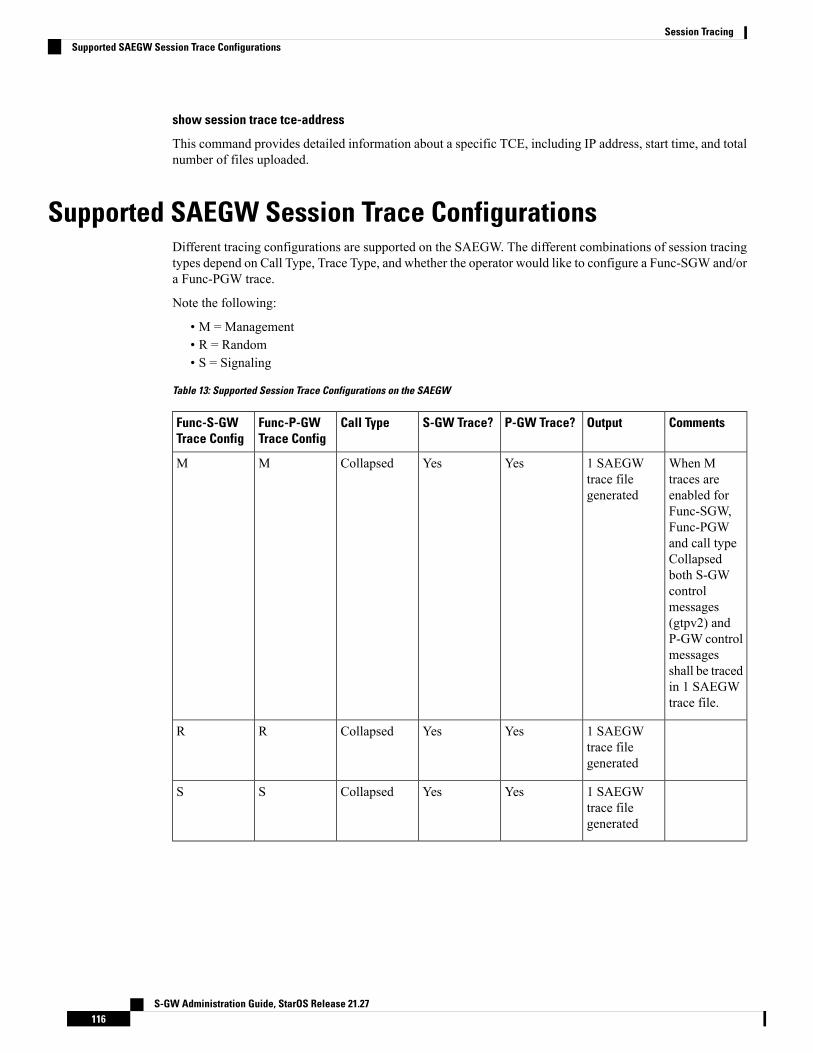
show session trace tce-address
This command provides detailed information about a specific TCE, including IP address, start time, and totalnumber of files uploaded.
Supported SAEGW Session Trace ConfigurationsDifferent tracing configurations are supported on the SAEGW. The different combinations of session tracingtypes depend on Call Type, Trace Type, and whether the operator would like to configure a Func-SGW and/ora Func-PGW trace.
Note the following:
• M = Management• R = Random• S = Signaling
Table 13: Supported Session Trace Configurations on the SAEGW
CommentsOutputP-GW Trace?S-GW Trace?Call TypeFunc-P-GWTrace Config
Func-S-GWTrace Config
When Mtraces areenabled forFunc-SGW,Func-PGWand call typeCollapsedboth S-GWcontrolmessages(gtpv2) andP-GW controlmessagesshall be tracedin 1 SAEGWtrace file.
1 SAEGWtrace filegenerated
YesYesCollapsedMM
1 SAEGWtrace filegenerated
YesYesCollapsedRR
1 SAEGWtrace filegenerated
YesYesCollapsedSS
S-GW Administration Guide, StarOS Release 21.27116
Session TracingSupported SAEGW Session Trace Configurations
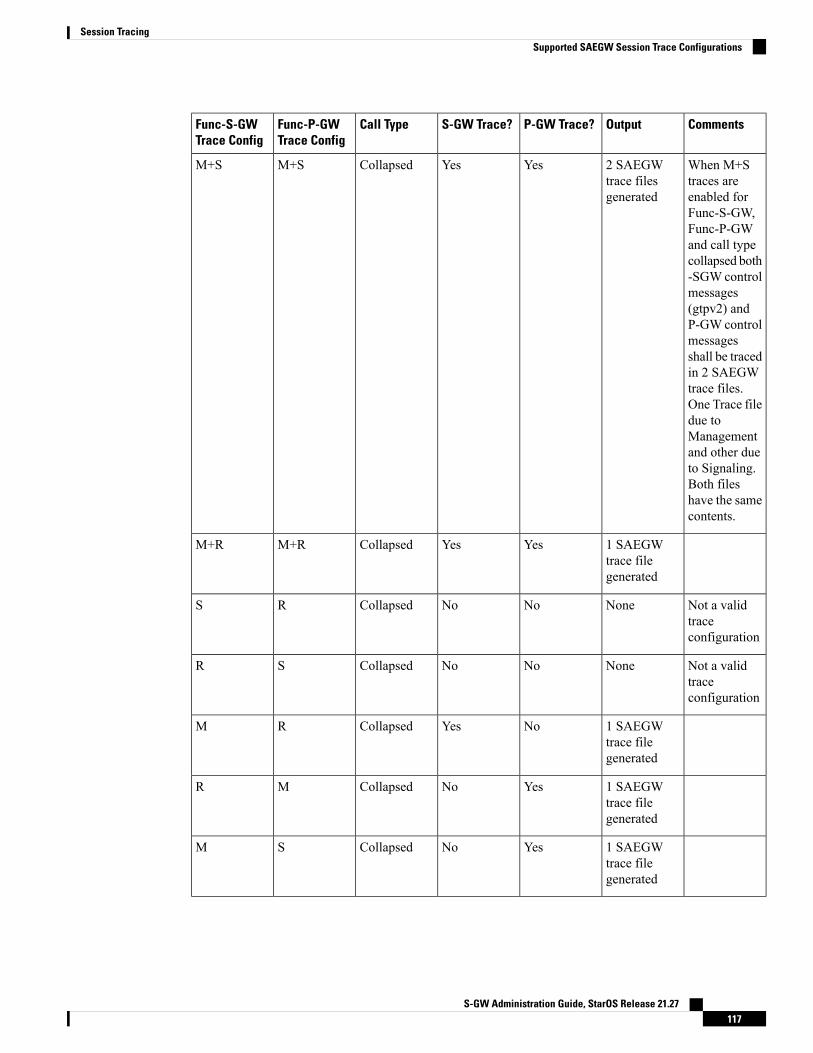
CommentsOutputP-GW Trace?S-GW Trace?Call TypeFunc-P-GWTrace Config
Func-S-GWTrace Config
When M+Straces areenabled forFunc-S-GW,Func-P-GWand call typecollapsed both-SGW controlmessages(gtpv2) andP-GW controlmessagesshall be tracedin 2 SAEGWtrace files.One Trace filedue toManagementand other dueto Signaling.Both fileshave the samecontents.
2 SAEGWtrace filesgenerated
YesYesCollapsedM+SM+S
1 SAEGWtrace filegenerated
YesYesCollapsedM+RM+R
Not a validtraceconfiguration
NoneNoNoCollapsedRS
Not a validtraceconfiguration
NoneNoNoCollapsedSR
1 SAEGWtrace filegenerated
NoYesCollapsedRM
1 SAEGWtrace filegenerated
YesNoCollapsedMR
1 SAEGWtrace filegenerated
YesNoCollapsedSM
S-GW Administration Guide, StarOS Release 21.27117
Session TracingSupported SAEGW Session Trace Configurations
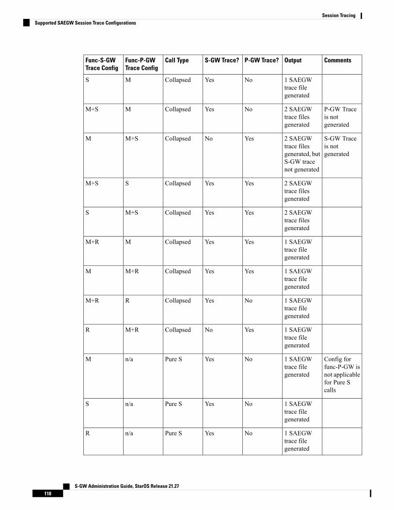
CommentsOutputP-GW Trace?S-GW Trace?Call TypeFunc-P-GWTrace Config
Func-S-GWTrace Config
1 SAEGWtrace filegenerated
NoYesCollapsedMS
P-GW Traceis notgenerated
2 SAEGWtrace filesgenerated
NoYesCollapsedMM+S
S-GW Traceis notgenerated
2 SAEGWtrace filesgenerated, butS-GW tracenot generated
YesNoCollapsedM+SM
2 SAEGWtrace filesgenerated
YesYesCollapsedSM+S
2 SAEGWtrace filesgenerated
YesYesCollapsedM+SS
1 SAEGWtrace filegenerated
YesYesCollapsedMM+R
1 SAEGWtrace filegenerated
YesYesCollapsedM+RM
1 SAEGWtrace filegenerated
NoYesCollapsedRM+R
1 SAEGWtrace filegenerated
YesNoCollapsedM+RR
Config forfunc-P-GW isnot applicablefor Pure Scalls
1 SAEGWtrace filegenerated
NoYesPure Sn/aM
1 SAEGWtrace filegenerated
NoYesPure Sn/aS
1 SAEGWtrace filegenerated
NoYesPure Sn/aR
S-GW Administration Guide, StarOS Release 21.27118
Session TracingSupported SAEGW Session Trace Configurations
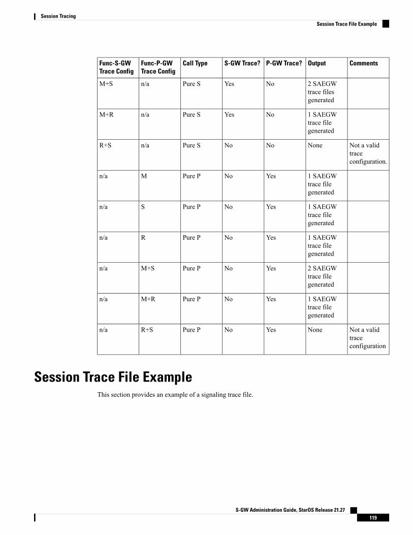
CommentsOutputP-GW Trace?S-GW Trace?Call TypeFunc-P-GWTrace Config
Func-S-GWTrace Config
2 SAEGWtrace filesgenerated
NoYesPure Sn/aM+S
1 SAEGWtrace filegenerated
NoYesPure Sn/aM+R
Not a validtraceconfiguration.
NoneNoNoPure Sn/aR+S
1 SAEGWtrace filegenerated
YesNoPure PMn/a
1 SAEGWtrace filegenerated
YesNoPure PSn/a
1 SAEGWtrace filegenerated
YesNoPure PRn/a
2 SAEGWtrace filegenerated
YesNoPure PM+Sn/a
1 SAEGWtrace filegenerated
YesNoPure PM+Rn/a
Not a validtraceconfiguration
NoneYesNoPure PR+Sn/a
Session Trace File ExampleThis section provides an example of a signaling trace file.
S-GW Administration Guide, StarOS Release 21.27119
Session TracingSession Trace File Example
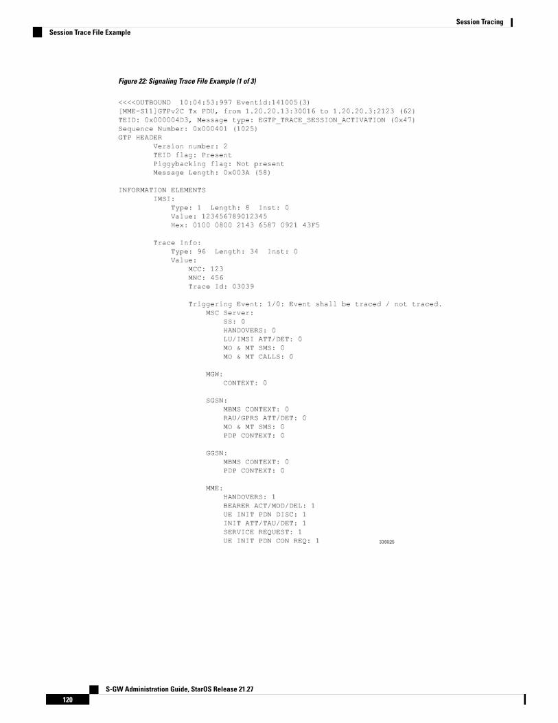
Figure 22: Signaling Trace File Example (1 of 3)
S-GW Administration Guide, StarOS Release 21.27120
Session TracingSession Trace File Example
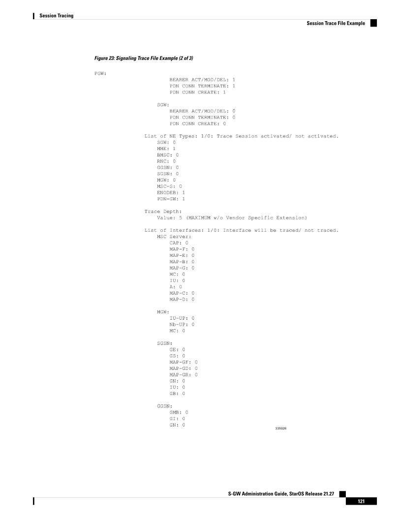
Figure 23: Signaling Trace File Example (2 of 3)
S-GW Administration Guide, StarOS Release 21.27121
Session TracingSession Trace File Example
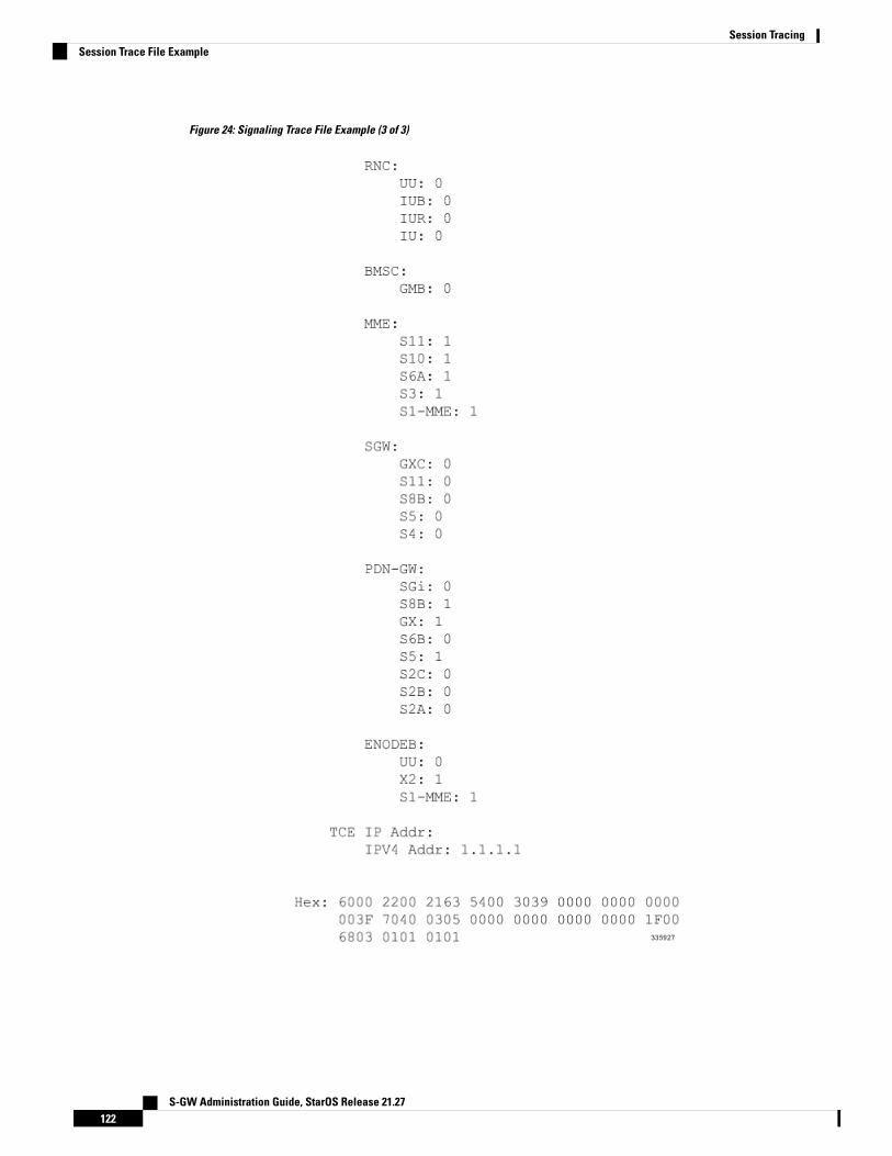
Figure 24: Signaling Trace File Example (3 of 3)
S-GW Administration Guide, StarOS Release 21.27122
Session TracingSession Trace File Example
C H A P T E R 7Backup and Recovery of Key KPI Statistics
This feature allows the backup of GGSN, P-GW, SAEGW, and/or S-GW counters for recovery of key KPIcounter values after a session manager (SessMgr) restart.
This chapter includes the following information:
• Feature Description, on page 123• How It Works, on page 123• Configuring Backup Statistics Feature, on page 125
Feature DescriptionBefore the Backup and Recovery of Key KPI Statistics feature was implemented, statistics were not backedup and could not be recovered after a SessMgr task restart. Due to this limitation, monitoring the KPI was aproblem as the GGSN, P-GW, SAEGW, and S-GW would lose statistical information whenever task restartsoccurred.
KPI calculation involves taking a delta between counter values from two time intervals and then determinesthe percentage of successful processing of a particular procedure in that time interval. When a SessMgr crashesand then recovers, the GGSN, P-GW, SAEGW, and S-GW lose the counter values - they are reset to zero.So, the KPI calculation in the next interval will result in negative values for that interval. This results in a dipin the graphs plotted using the KPI values, making it difficult for operations team to get a consistent view ofthe network performance to determine if there is a genuine issue or not.
This feature makes it possible to perform reliable KPI calculations even if a SessMgr restart occurs.
How It WorksA key set of counters used in KPI computation will be backed up for recovery if a SessMgr task restarts. Thecounters that will be backed up are determined by the KPIs typically used in several operator networks.
The backup of counters is enabled or disabled via configuration. The configuration specifies the product(GGSN, P-GW, SAEGW, and/or S-GW) for which counters will be backed up and also a time interval forthe backup of the counters.
S-GW Administration Guide, StarOS Release 21.27123
ArchitectureWhen this feature is enabled (see Configuring Backup Statistics Feature below), the GGSN, P-GW, SAEGW,and/or S-GW only backs up the counters maintained at the SessMgr. The recovery function does not need tobe configured or started as it occurs automatically as needed when the feature is enabled.
The counters are backed up to the AAAMgr that is paired with the SessMgr.
Checkpointing
Node-level statistics are checkpointed at AAAMgr. Once statistics are backed up for a specific product, allthe associated services, such as eGTP-C and GTP-U statistics, are also checkpointed.
Recovery
When SessMgr restarts, recovery is performed by receiving all the stored statistics from the mapped AAAMgrand the recovered values are added to the backup counters maintained at per-service level. This will not impactsession recovery time as the backed up counters are pushed to SessMgr only after session recovery is complete.
Since session recovery is complete, the session managers may start processing calls. In such cases, the counterswill continue to be incremented. The recovered values of the corresponding counters will always be added tothe existing counters. Gauge counters are checkpointed but not recovered.
Order of Statistics Collection
The upper limit of checkpoint messaging is a maximum of 1 MB. Before picking any node to checkpoint,available memory is checked. If memory is insufficient, the whole node is discarded.
Since there is 1 MB limit, nodes/statistics to checkpoint are prioritized as follows:
1. SAEGW statistics:
• P-GW and S-GW service node-level statistics collected
2. P-GW service node configuration will store the following statistics:
• P-GW, eGTP-C ingress, GTP-U ingress, per-interface (s2a, s2b, s5s8), and GGSN (if associated)statistics collected
• SAEGW associated P-GW service statistics not collected
3. S-GW service node configuration will store the following statistics:
• S-GW, eGTP-C ingress/egress, and GTP-U ingress/egress statistics collected
• SAEGW associated S-GW service statistics not collected
4. GGSN statistics:
• GGSN service statistics, if not associated with P-GW service, collected
5. Session disconnect reasons collected if GGSN/P-GW/SAEGW/S-GW is enabled
Error Handling
If adding new statistics is going to cause overflow of 1 MB buffer, that service and the corresponding nodewill not be included. Checkpointing of any further nodes will also be stopped. Error level log will be flaggedif total memory requirement goes above 1 MB.
S-GW Administration Guide, StarOS Release 21.27124
Backup and Recovery of Key KPI StatisticsArchitecture

Limitations• A backup interval must be specified and counters are backed up only at the specified interval. For example,if the backup interval is specified as 5 minutes, then counters are backed up every 5 minutes. Supposebackup happened at Nth minute and the configured backup interval is for every 5 minutes, then if a taskcrash happens at N+4 minutes, the GGSN, P-GW, SAEGW, and/or S-GW recovers only the valuesbacked up at Nth minute and the data for the past 4 minutes is lost.
• Only statistics maintained at the SessMgr are backed up. Statistics at other managers are not backed upor recovered.
• The following statistics are not considered for backup:
• APN-level statistics
• eGTP-C APN-QCI statistics
• DemuxMgr statistics
• The CLI command clear statistics will not trigger checkpoint to delete the node statistics on AAAMgr.New checkpoint after timer expiry will overwrite the statistics.
• Maximum of 1 MB of statistics will be stored on AAAMgr. Services after the maximum size limit arenot backed up.
• Setting the backup interval to shorter periods of time causes higher system overhead for checkpointing.Alternately, setting the backup interval to longer periods of time results in lower system overhead forcheckpointing but higher probability of hitting the 1 MB storage limit.
• If SessMgr restarts and AAAMgr restarts before SessMgr recovers statistics fromAAAMgr, then backedup statistics are lost.
• This feature is not applicable for ICSR.
Configuring Backup Statistics FeatureFor the Backup and Recovery of Key KPI Statistics feature to work, it must be enabled by configuring thebackup of statistics for the GGSN, P-GW, SAEGW, and/or S-GW.
ConfigurationThe following CLI commands are used to manage the functionality for the backing up of the key KPI statisticsfeature.
Enabling
The following configures the backup of statistics for the GGSN, P-GW, SAEGW, and/or S-GW and enablesthe Backup and Recovery of Key KPI Statistics feature.
configurestatistics-backup { ggsn | pgw | saegw | sgw }exit
S-GW Administration Guide, StarOS Release 21.27125
Backup and Recovery of Key KPI StatisticsLimitations
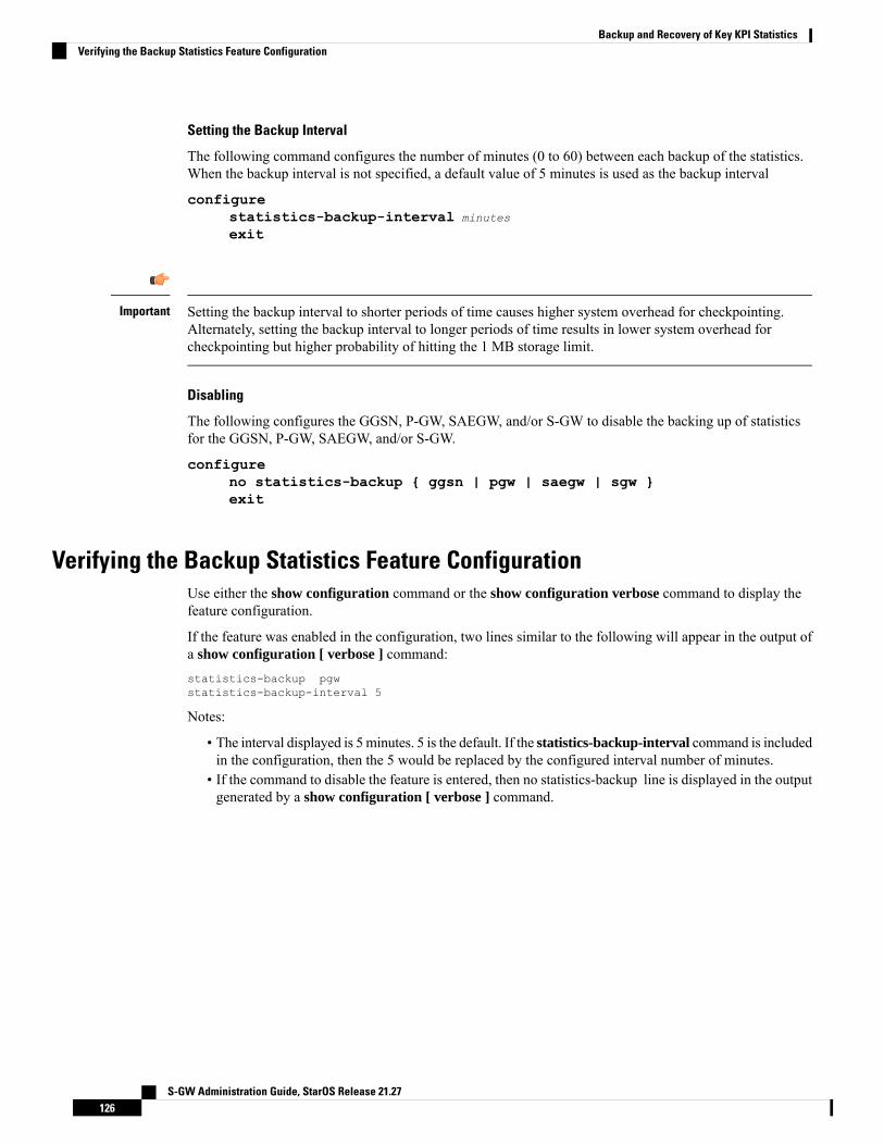
Setting the Backup Interval
The following command configures the number of minutes (0 to 60) between each backup of the statistics.When the backup interval is not specified, a default value of 5 minutes is used as the backup interval
configurestatistics-backup-interval minutes
exit
Setting the backup interval to shorter periods of time causes higher system overhead for checkpointing.Alternately, setting the backup interval to longer periods of time results in lower system overhead forcheckpointing but higher probability of hitting the 1 MB storage limit.
Important
Disabling
The following configures the GGSN, P-GW, SAEGW, and/or S-GW to disable the backing up of statisticsfor the GGSN, P-GW, SAEGW, and/or S-GW.
configureno statistics-backup { ggsn | pgw | saegw | sgw }exit
Verifying the Backup Statistics Feature ConfigurationUse either the show configuration command or the show configuration verbose command to display thefeature configuration.
If the feature was enabled in the configuration, two lines similar to the following will appear in the output ofa show configuration [ verbose ] command:statistics-backup pgwstatistics-backup-interval 5
Notes:
• The interval displayed is 5 minutes. 5 is the default. If the statistics-backup-interval command is includedin the configuration, then the 5 would be replaced by the configured interval number of minutes.
• If the command to disable the feature is entered, then no statistics-backup line is displayed in the outputgenerated by a show configuration [ verbose ] command.
S-GW Administration Guide, StarOS Release 21.27126
Backup and Recovery of Key KPI StatisticsVerifying the Backup Statistics Feature Configuration

C H A P T E R 8Bulkstats for GTP-C Messages by ARP Value
This chapter describes StarOS support for the Bulkstats for GTP-C Messages by ARP Value feature on theP-GW, SAE-GW, and S-GW.
• Feature Description, on page 127• Performance Indicator Changes, on page 128
Feature DescriptionTo comply with the “Long Term Evolution (LTE) Access Network Government Industry Requirements (GIR)for National Security/Emergency Preparedness (NS/EP) Next Generation Network (NGN) Priority” to supportemergency calls over Voice over LTE (VoLTE), several Key Performance Indicators (KPIs) have beenintroduced with this feature. This feature is utilized to collect statistics for total number of GTP-C messagesreceived for Enhanced Multimedia Priority Service (eMPS) session for specified interval (in minutes). Thelist of GTP-C messages are defined in accordance with the GIR document. As part of this feature:
• The S-GW will generate peg counts of the total number of received GTP-C messages containing anAllocation and Retention Priority (ARP), chosen from the set of values allocated for NS/EP NGN-PSuse, for a specified interval (in minutes). This peg count is administered at the S-GW level.
• The P-GWwill generate peg counts of the total number of received GTP-Cmessages containing an ARP,chosen from the set of values allocated for NS/EP NGN-PS use, for a specified interval (in minutes).This peg count is administered at the specific P-GW level.
• The peg counts for GTP-Cmessages are broken down bymessage type similar to existing GTP-Cmessagecounters. The bulkstats are broken down by applicable S-GW and P-GW service and S5, S8, S11, andS4 interfaces.
Bulkstats are added for eMPS session/message.
Piggy-back Message
For piggy-back messages, if either of the messages have matching ARP or result into converting non-eMPSsession to eMPS session, then both messages are counted as eMPS message and corresponding statistics forboth messages are incremented.
If Modify Bearer Request is piggy-backed with Create Bearer Response on S11 interface of S-GW and CreateBearer Response result into converting non-eMPS session into eMPS session, then Modify Bearer Responsestatistics will not increment for this Modify Bearer Request.
S-GW Administration Guide, StarOS Release 21.27127

Bulkstats Collection and Reset
Bulkstats are added under eGTP-C Schema and pgw-egtpc-s5s8 Schema. These eMPS bulkstats in eGTP-CSchema and pgw-egtpc-s5s8 Schema holds value only for a bulkstat interval, that is, value of these bulkstatsshows number of eMPS messages exchanged during the bulkstat interval.
LimitationsThis section identifies the known limitations of the feature:
• Peer level and APN level statistics are not collected.
• MPS statistics recovery is not supported.
• MPS statistics are not collected for CSReq, DDNReq, and change notification messages rejected bydemux with ARP for eMPS sessions.
• MPS statistics are not collected for retried/re-transmitted messages.
Licensing
Bulkstats for GTP-C Messages by ARP Value feature requires that a valid license key be installed. Contactyour Cisco Account or Support representative for information on how to obtain a license.
Important
Performance Indicator Changes
S-GW Ingress S4 InterfaceThe following CLI commands are modified to display the eMPS session related GTP-C message statistics forS4 interface of S-GW Ingress:
• show egtpc statistics interface sgw-ingress interface-type s4
• interface-type: Displays interface level GTP-C message statistics
• s4: Displays interface level GTP-C message statistics for S4 interface
• show egtpc statistics egtp-service sgw_egtpc_service_name interface-type s4
• s4: Interface type S4 for S-GW eGTP-C interface
The output of the above CLI commands displays the following new parameters:
• Total eMPS Statistics: Cumulative GTP-C message statistics for messages received/transmitted oneMPS Sessions.
• Current interval eMPS Statistics: GTP-C message statistics for messages received/transmitted oneMPS Sessions for current statistics collection interval. Statistics collection interval will be same as
S-GW Administration Guide, StarOS Release 21.27128
Bulkstats for GTP-C Messages by ARP ValueLimitations
bulkstats collection interval. If bulk stats collection is not configured, then Current MPS Statistics willbe same as Total MPS Statistics.
• Create Session Request (Total RX): This counter will be incremented by S-GWwhen it receives Createsession request message on S4 interface containing an ARP value configured in MPS Profile.
• Create Session Response (Total TX): This counter will be incremented by S-GW when it transmitsCreate session response message on S4 interface containing an ARP value configured in MPS Profile.
S-GW Ingress S11 InterfaceThe following CLI commands are modified to display the eMPS session related GTP-C message statistics forS11 interface of S-GW Ingress:
• show egtpc statistics interface sgw-ingress interface-type s11
• interface-type: Displays interface level GTP-C message statistics
• s11: Displays interface level GTP-C message statistics for S11 interface
• show egtpc statistics egtp-service sgw_egtpc_service_name interface-type s11
• s11: Interface type S11 for S-GW eGTP-C interface
The output of the above CLI commands displays the following new parameters:
• Total eMPS Statistics: Cumulative GTP-C message statistics for messages received/transmitted oneMPS Sessions.
• Current interval eMPS Statistics: GTP-C message statistics for messages received/transmitted oneMPS Sessions for current statistics collection interval. Statistics collection interval will be same asbulkstats collection interval. If bulk stats collection is not configured, then Current MPS Statistics willbe same as Total MPS Statistics.
• Create Session Request (Total RX): This counter will be incremented by S-GWwhen it receives Createsession request message on S11 interface containing an ARP value configured in MPS Profile.
• Create Session Response (Total TX): This counter will be incremented by S-GW when it transmitsCreate session response message on S11 interface containing an ARP value configured in MPS Profile.
• Modify Bearer Request (Total RX): This counter will be incremented by S-GWwhen it receivesModifyBearer request message on S11 interface containing an ARP value configured in MPS Profile.
• Modify Bearer Response (Total TX): This counter will be incremented by S-GW when it transmitsModify Bearer response message on S11 interface containing an ARP value configured in MPS Profile.
• Create Bearer Request (Total TX): This counter will be incremented by S-GWwhen it transmits CreateBearer request message on S11 interface containing an ARP value configured in MPS Profile.
• Create Bearer Response (Total RX): This counter will be incremented by S-GW when it receivesCreate Bearer response message on S11 interface containing an ARP value configured in MPS Profile.
• Downlink Data Notification (Total TX): This counter will be incremented by S-GW when it transmitsDownlink Data Notification message on S11 interface containing an ARP value configured in MPSProfile.
S-GW Administration Guide, StarOS Release 21.27129
Bulkstats for GTP-C Messages by ARP ValueS-GW Ingress S11 Interface
• Downlink Data Notification Ack (Total RX): This counter will be incremented by S-GW when itreceives Downlink Data Notification Ack message on S11 interface containing an ARP value configuredin MPS Profile.
• Update Bearer Request (Total TX): This counter will be incremented by S-GW when it transmitsUpdate Bearer request message on S11 interface containing an ARP value configured in MPS Profile.
• Update Bearer Response (Total RX): This counter will be incremented by S-GW when it receivesUpdate Bearer response message on S11 interface containing an ARP value configured in MPS Profile.
S-GW Egress GTP-based S5/S8 InterfaceThe following CLI commands are modified to display the eMPS session related GTP-C message statistics forS5/S8 interface of S-GW Egress:
• show egtpc statistics interface sgw-egress interface-type s5s8
• interface-type: Displays interface level GTP-C message statistics
• s5s8: Displays interface level GTP-C message statistics for S5/S8 interface
• show egtpc statistics egtp-service sgw_egtpc_service_name interface-type sgw-s5s8
• sgw-s5s8: Interface type S5/S8 for S-GW eGTP-C interface
The output of the above CLI commands displays the following new parameters:
• Total eMPS Statistics: Cumulative GTP-C message statistics for messages received/transmitted oneMPS Sessions.
• Current interval eMPS Statistics: GTP-C message statistics for messages received/transmitted oneMPS Sessions for current statistics collection interval. Statistics collection interval will be same asbulkstats collection interval. If bulk stats collection is not configured, then Current MPS Statistics willbe same as Total MPS Statistics.
• Create Session Request (Total TX): This counter will be incremented by S-GW when it transmitsCreate session request message on S5/S8 interface containing an ARP value configured in MPS Profile.
• Create Session Response (Total RX): This counter will be incremented by S-GW when it receivesCreate session response message on S5/S8 interface containing an ARP value configured inMPS Profile.
• Modify Bearer Request (Total TX): This counter will be incremented by S-GW when it transmitsModify Bearer request message on S5/S8 interface containing an ARP value configured in MPS Profile.
• Modify Bearer Response (Total RX): This counter will be incremented by S-GW when it receivesModify Bearer response message on S5/S8 interface containing an ARP value configured inMPS Profile.
• Create Bearer Request (Total RX): This counter will be incremented by S-GWwhen it receives CreateBearer request message on S5/S8 interface containing an ARP value configured in MPS Profile.
• Create Bearer Response (Total TX): This counter will be incremented by S-GW when it transmitsCreate Bearer response message on S5/S8 interface containing an ARP value configured in MPS Profile.
• Update Bearer Request (Total RX): This counter will be incremented by S-GWwhen it receives UpdateBearer request message on S5/S8 interface containing an ARP value configured in MPS Profile.
S-GW Administration Guide, StarOS Release 21.27130
Bulkstats for GTP-C Messages by ARP ValueS-GW Egress GTP-based S5/S8 Interface
• Update Bearer Response (Total TX): This counter will be incremented by S-GW when it transmitsUpdate Bearer responsemessage on S5/S8 interface containing an ARP value configured inMPS Profile.
P-GW Ingress GTP-based S5/S8 InterfaceThe following CLI commands are modified to display the eMPS session related GTP-C message statistics forS5/S8 interface of P-GW Ingress:
• show egtpc statistics interface pgw-ingress interface-type s5s8
• show egtpc statistics egtp-service pgw_egtpc_service_name interface-type s5s8
• s5s8: Interface type S5/S8 for P-GW eGTP-C interface.
The output of the above CLI commands displays the following new parameters:
• Total eMPS Statistics: Cumulative GTP-C message statistics for messages received/transmitted oneMPS Sessions.
• Current interval eMPS Statistics: GTP-C message statistics for messages received/transmitted oneMPS Sessions for current statistics collection interval. Statistics collection interval will be same asbulkstats collection interval. If bulk stats collection is not configured, then Current MPS Statistics willbe same as Total MPS Statistics.
• Create Session Request (Total RX): This counter will be incremented by P-GWwhen it receives Createsession request message on S5/S8 interface containing an ARP value configured in MPS Profile.
• Create Session Response (Total TX): This counter will be incremented by P-GW when it transmitsCreate session response message on S5/S8 interface containing an ARP value configured inMPS Profile.
• Modify Bearer Request (Total RX): This counter will be incremented by P-GWwhen it receivesModifyBearer request message on S5/S8 interface containing an ARP value configured in MPS Profile.
• Modify Bearer Response (Total TX): This counter will be incremented by P-GW when it transmitsModify Bearer response message on S5/S8 interface containing an ARP value configured inMPS Profile.
• Create Bearer Request (Total TX): This counter will be incremented by P-GWwhen it receives CreateBearer request message on S5/S8 interface containing an ARP value configured in MPS Profile.
• Create Bearer Response (Total RX): This counter will be incremented by P-GW when it receivesCreate Bearer response message on S5/S8 interface containing an ARP value configured in MPS Profile.
• Update Bearer Request (Total TX): This counter will be incremented by P-GW when it transmitsUpdate Bearer request message on S5/S8 interface containing an ARP value configured in MPS Profile.
• Update Bearer Response (Total RX): This counter will be incremented by P-GW when it receivesUpdate Bearer responsemessage on S5/S8 interface containing an ARP value configured inMPS Profile.
clear egtpcThe following CLI commands are modified to clear eMPS statistics at interface level and eGTP-C servicelevel:
S-GW Administration Guide, StarOS Release 21.27131
Bulkstats for GTP-C Messages by ARP ValueP-GW Ingress GTP-based S5/S8 Interface

• clear egtpc statistics interface-type interface-pgw-ingress interface s5s8: Clears interface statisticsalong with eMPS statistics for all eGTP-C services of P-GW Ingress type and S5/S8 interface.
• clear egtpc statistics interface-type [ interface-sgw-ingress | interface-sgw-egress ] interface [ s4 |s11 | sgw-s5s8 ]: Clears interface statistics along with eMPS statistics for all eGTP-C services of S-GWIngress type and S4 or S11 interface/S-GW Egress type and S5/S8 interface.
• clear egtpc statistics egtp-service pgw_egtpc_service_name interface [ s5s8 ]: Clears interface statisticsalong with eMPS statistics for all P-GW eGTP-C services and S5/S8 interface.
• clear egtpc statistics egtp-service sgw_egptc_service_name interface [ s11 | s4 | sgw-s5s8 ]: Clearsinterface statistics along with eMPS statistics for all S-GW eGTP-C services and S4 or S11 or S5/S8interface.
P-GW eGTP-C S5/S8 SchemaThe following new bulk statistics variables are added to the P-GW eGTP-C S5/S8 schema in support of thisfeature:
• tun-recv-cresessreq-emps – The total number of tunnel - create session request - messages received bythe system for eMPS subscriber on interface s5s8. This stat is for current bulkstat interval only.
• tun-sent-cresessresp-emps – The total number of tunnel - create session response - messages sent by thesystem for eMPS subscriber on interface s5s8. This stat is for current bulkstat interval only.
• tun-recv-modbearerreq-emps – The total number of tunnel - modify bearer request - messages receivedby the system for eMPS subscriber on interface s5s8. This stat is for current bulkstat interval only.
• tun-sent-modbearerresp-emps – The total number of tunnel - modify bearer response - messages sent bythe system for eMPS subscriber on interface s5s8. This stat is for current bulkstat interval only.
• tun-sent-crebearerreq-emps – The total number of tunnel - create bearer request - messages sent by thesystem for eMPS subscriber on interface s5s8. This stat is for current bulkstat interval only.
• tun-recv-crebearerresp-emps – The total number of tunnel - create bearer response - messages receivedby the system for eMPS subscriber on interface s5s8. This stat is for current bulkstat interval only.
• tun-sent-updbearerreq-emps – The total number of tunnel - update bearer request - messages sent by thesystem for eMPS subscriber on interface s5s8. This stat is for current bulkstat interval only.
• tun-recv-updbearerresp-emps – The total number of tunnel - update bearer response - messages receivedby the system for eMPS subscriber on interface s5s8. This stat is for current bulkstat interval only.
eGTP-C SchemaThe following new bulk statistics variables are added to the eGTP-C schema in support of this feature:
• s11-tun-recv-cresessreq-emps – The total number of tunnel - create session request - messages receivedby the system for eMPS subscriber on interface s11. This stat is for current bulkstat interval only.
• s11-tun-sent-cresessresp-emps – The total number of tunnel - create session response - messages sentby the system for eMPS subscriber on interface s11. This stat is for current bulkstat interval only.
S-GW Administration Guide, StarOS Release 21.27132
Bulkstats for GTP-C Messages by ARP ValueP-GW eGTP-C S5/S8 Schema
• s11-tun-recv-modbearerreq-emps – The total number of tunnel - modify bearer request - messagesreceived by the system for eMPS subscriber on interface s11. This stat is for current bulkstat intervalonly.
• s11-tun-sent-modbearerresp-emps – The total number of tunnel - modify bearer response - messagessent by the system for eMPS subscriber on interface s11. This stat is for current bulkstat interval only.
• s11-tun-sent-crebearerreq-emps – The total number of tunnel - create bearer request - messages sent bythe system for eMPS subscriber on interface s11. This stat is for current bulkstat interval only.
• s11-tun-recv-crebearerresp-emps – The total number of tunnel - create bearer response - messages receivedby the system for eMPS subscriber on interface s11. This stat is for current bulkstat interval only.
• s11-tun-sent-updbearerreq-emps – The total number of tunnel - update bearer request - messages sentby the system for eMPS subscriber on interface s11. This stat is for current bulkstat interval only.
• s11-tun-recv-updbearerresp-emps – The total number of tunnel - update bearer response - messagesreceived by the system for eMPS subscriber on interface s11. This stat is for current bulkstat intervalonly.
• s11-tun-sent-ddnreq-emps – The total number of downlink data notification - messages sent by the systemfor eMPS subscriber on interface s11. This stat is for current bulkstat interval only.
• s11-tun-recv-ddnack-emps – The total number of downlink data notificatino acknowledge - messagesreceived by the system for eMPS subscriber on interface s11. This stat is for current bulkstat intervalonly.
• s4-tun-recv-cresessreq-emps – The total number of tunnel - create session request - messages receivedby the system for eMPS subscriber on interface s4. This stat is for current bulkstat interval only.
• s4-tun-sent-cresessresp-emps – The total number of tunnel - create session response - messages sent bythe system for eMPS subscriber on interface s4. This stat is for current bulkstat interval only.
• tun-sent-cresessreq-emps – The total number of tunnel - create session request - messages sent by thesystem for eMPS subscriber on interface s5s8. This stat is for current bulkstat interval only.
• tun-recv-cresessresp-emps – The total number of tunnel - create session response - messages receivedby the system for eMPS subscriber on interface s5s8. This stat is for current bulkstat interval only.
• tun-sent-modbearerreq-emps – The total number of tunnel - modify bearer request - messages sent bythe system for eMPS subscriber on interface s5s8. This stat is for current bulkstat interval only.
• tun-recv-modbearerresp-emps – The total number of tunnel - modify bearer response - messages receivedby the system for eMPS subscriber on interface s5s8. This stat is for current bulkstat interval only.
• tun-recv-crebearerreq-emps – The total number of tunnel - create bearer request - messages received bythe system for eMPS subscriber on interface s5s8. This stat is for current bulkstat interval only.
• tun-sent-crebearerresp-emps – The total number of tunnel - create bearer response - messages sent bythe system for eMPS subscriber on interface s5s8. This stat is for current bulkstat interval only.
• tun-recv-updbearerreq-emps – The total number of tunnel - update bearer request - messages receivedby the system for eMPS subscriber on interface s5s8. This stat is for current bulkstat interval only.
• tun-sent-updbearerresp-emps – The total number of tunnel - update bearer response - messages sent bythe system for eMPS subscriber on interface s5s8. This stat is for current bulkstat interval only.
S-GW Administration Guide, StarOS Release 21.27133
Bulkstats for GTP-C Messages by ARP ValueeGTP-C Schema

S-GW Administration Guide, StarOS Release 21.27134
Bulkstats for GTP-C Messages by ARP ValueeGTP-C Schema
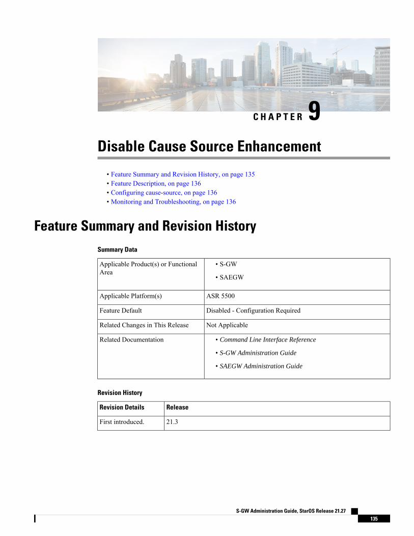
C H A P T E R 9Disable Cause Source Enhancement
• Feature Summary and Revision History, on page 135• Feature Description, on page 136• Configuring cause-source, on page 136• Monitoring and Troubleshooting, on page 136
Feature Summary and Revision HistorySummary Data
• S-GW
• SAEGW
Applicable Product(s) or FunctionalArea
ASR 5500Applicable Platform(s)
Disabled - Configuration RequiredFeature Default
Not ApplicableRelated Changes in This Release
• Command Line Interface Reference
• S-GW Administration Guide
• SAEGW Administration Guide
Related Documentation
Revision History
ReleaseRevision Details
21.3First introduced.
S-GW Administration Guide, StarOS Release 21.27135
Feature DescriptionThis feature introduces configuration changes that would allow you to configure the S-GW, including SAEGWinstances, to disable the Cause Source bit functionality in Cause IE. If this configuration is enabled, S-GWand SAEGW always set the Cause Source Bit in Cause IE to zero.
Configuring cause-sourceThe gtpc disable cause source command has been introduced in support of this feature.
configurecontext context_name
egtp-service egtp_service_name
[ no | default ] gtpc disable cause-sourceend
Notes:
• disable: Disables functionality at egtpc level
• cause-source: Disables cause source Bit in Cause IE.
Monitoring and TroubleshootingThis section provides information on how tomonitor and troubleshoot using show commands and bulk statisticsavailable to support of this feature.
Show Commands and/or OutputsThis section provides information regarding show commands and their outputs for the Disable Cause Sourcefeature.
show egtp-service name egtpThis command displays the following output:
Service name : egtp_sgwi1….Reject S2b HO(No UE Context) : DisabledGTPC Cause Source bit in Cause IE : [Enabled/Disabled]
TroubleshootingThe following commands can be used for troubleshooting:
• The following commands can be used for checking current status of this feature:
show egtp-service name service_name
S-GW Administration Guide, StarOS Release 21.27136
Disable Cause Source EnhancementFeature Description

• Monitor protocol CLI can be enabled to check GTPV2 protocol trace. In the protocol trace output causesource bit in Cause IE can be checked.
S-GW Administration Guide, StarOS Release 21.27137
Disable Cause Source EnhancementTroubleshooting

S-GW Administration Guide, StarOS Release 21.27138
Disable Cause Source EnhancementTroubleshooting

C H A P T E R 10Direct Tunnel for 4G (LTE) Networks
This chapter briefly describes support for direct tunnel (DT) functionality over an S12 interface for a 4G(LTE) network to optimize packet data traffic.
Cisco LTE devices (per 3GPP TS 23.401 v8.3.0) supporting direct tunnel include:
• Serving GPRS Support Node (S4-SGSN)
• Serving Gateway (S-GW)
• PDN Gateway (P-GW)
Direct Tunnel is a licensed Cisco feature. A separate feature license is required for configuration. Contactyour Cisco account representative for detailed information on specific licensing requirements. For informationon installing and verifying licenses, refer to the Managing License Keys section of the Software ManagementOperations chapter in the System Administration Guide.
Important
The following sections are included in this chapter:
• Direct Tunnel for 4G Networks - Feature Description , on page 139• How It Works, on page 142• Configuring Support for Direct Tunnel, on page 171• Monitoring and Troubleshooting Direct Tunnel, on page 174
Direct Tunnel for 4G Networks - Feature DescriptionThe amount of user plane data will increase significantly during the next few years because of High SpeedPacket Access (HSPA) and IPMultimedia Subsystem technologies. Direct tunneling of user plane data betweenthe RNC and the S-GW can be employed to scale UMTS system architecture to support higher traffic rates.
Direct Tunnel (DT) offers a solution that optimizes core architecture without impact to UEs and can bedeployed independently of the LTE/SAE architecture.
S-GW Administration Guide, StarOS Release 21.27139
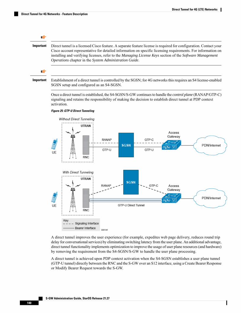
Direct tunnel is a licensed Cisco feature. A separate feature license is required for configuration. Contact yourCisco account representative for detailed information on specific licensing requirements. For information oninstalling and verifying licenses, refer to the Managing License Keys section of the Software ManagementOperations chapter in the System Administration Guide.
Important
Establishment of a direct tunnel is controlled by the SGSN; for 4G networks this requires an S4 license-enabledSGSN setup and configured as an S4-SGSN.
Important
Once a direct tunnel is established, the S4-SGSN/S-GWcontinues to handle the control plane (RANAP/GTP-C)signaling and retains the responsibility of making the decision to establish direct tunnel at PDP contextactivation.
Figure 25: GTP-U Direct Tunneling
A direct tunnel improves the user experience (for example, expedites web page delivery, reduces round tripdelay for conversational services) by eliminating switching latency from the user plane. An additional advantage,direct tunnel functionality implements optimization to improve the usage of user plane resources (and hardware)by removing the requirement from the S4-SGSN/S-GW to handle the user plane processing.
A direct tunnel is achieved upon PDP context activation when the S4-SGSN establishes a user plane tunnel(GTP-U tunnel) directly between the RNC and the S-GWover an S12 interface, using a Create Bearer Responseor Modify Bearer Request towards the S-GW.
S-GW Administration Guide, StarOS Release 21.27140
Direct Tunnel for 4G (LTE) NetworksDirect Tunnel for 4G Networks - Feature Description
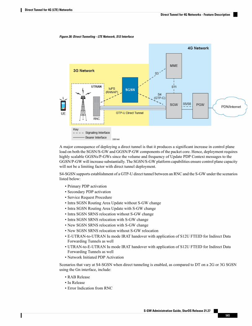
Figure 26: Direct Tunneling - LTE Network, S12 Interface
A major consequence of deploying a direct tunnel is that it produces a significant increase in control planeload on both the SGSN/S-GW and GGSN/P-GW components of the packet core. Hence, deployment requireshighly scalable GGSNs/P-GWs since the volume and frequency of Update PDP Context messages to theGGSN/P-GWwill increase substantially. The SGSN/S-GWplatform capabilities ensure control plane capacitywill not be a limiting factor with direct tunnel deployment.
S4-SGSN supports establishment of a GTP-U direct tunnel between an RNC and the S-GWunder the scenarioslisted below:
• Primary PDP activation• Secondary PDP activation• Service Request Procedure• Intra SGSN Routing Area Update without S-GW change• Intra SGSN Routing Area Update with S-GW change• Intra SGSN SRNS relocation without S-GW change• Intra SGSN SRNS relocation with S-GW change• New SGSN SRNS relocation with S-GW change• New SGSN SRNS relocation without S-GW relocation• E-UTRAN-to-UTRAN Iu mode IRAT handover with application of S12U FTEID for Indirect DataForwarding Tunnels as well
• UTRAN-to-E-UTRAN Iu mode IRAT handover with application of S12U FTEID for Indirect DataForwarding Tunnels as well
• Network Initiated PDP Activation
Scenarios that vary at S4-SGSN when direct tunneling is enabled, as compared to DT on a 2G or 3G SGSNusing the Gn interface, include:
• RAB Release• Iu Release• Error Indication from RNC
S-GW Administration Guide, StarOS Release 21.27141
Direct Tunnel for 4G (LTE) NetworksDirect Tunnel for 4G Networks - Feature Description
• Downlink Data Notification from S-GW• Downlink Data Error Indication from S-GW• MS Initiated PDP Modification• P-GW Initiated PDP Modification while the UE is IDLE• HLR/HSS Initiated PDP Modification• Session Recovery with Direct Tunnel
The above scenarios exhibit procedural differences in S4-SGSN when a direct tunnel is established.
How It WorksDT functionality enables direct user plane tunnel between RNC and SGW within the PS domain. With directtunneling the S4-SGSN provides the RNC with the TEID and user plane address of the S-GW, and alsoprovides the S-GW with the TEID and user plane address of the RNC.
The SGSN handles the control plane signaling and makes the decision when to establish the direct tunnelbetween RNC and S-GW, or use two tunnels for this purpose (based on configuration).
DT Establishment LogicThe following figure illustrates the logic used within the S4-SGSN/S-GW to determine if a direct tunnel willbe setup.
S-GW Administration Guide, StarOS Release 21.27142
Direct Tunnel for 4G (LTE) NetworksHow It Works
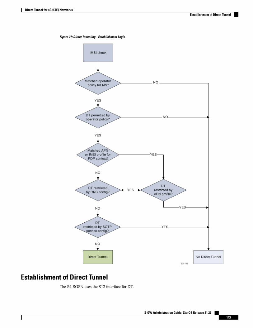
Figure 27: Direct Tunneling - Establishment Logic
Establishment of Direct TunnelThe S4-SGSN uses the S12 interface for DT.
S-GW Administration Guide, StarOS Release 21.27143
Direct Tunnel for 4G (LTE) NetworksEstablishment of Direct Tunnel

Direct Tunnel Activation for Primary PDP ContextFor the PDP Context Activation procedure this solution uses new information elements (IEs) for the GPRSTunnelling Protocol v2 (GTPv2) as defined in TS 29.274. SGSN provides the user plane addresses for RNCand S-GW as S12U FTEIDs as illustrated in the figure below.
The sequence for establishing a direct tunnel between the RNC and S-GW during PDP activation is as follows:
• SGSN sends a Create Session Request to the S-GW with the indication flag DTF (direct tunnel flag) bitset
• In its Create Session Response, the S-GW sends the SGSN an S12U FTEID (Fully Qualified TunnelEndpoint Identifier).
• The SGSN forwards the S-GW S12U to the RNC during the RAB Assignment Request.• In its RAB Assignment Response, the RNC sends the SGSN its transport address and Tunnel EndpointID (TEID).
• The SGSN forward the RNC S12 U FTEID o the S-GW via a Modify Bearer Request.
Figure 28: Primary PDP Activation with Direct Tunnel
Direct Tunnel Activation for UE Initiated Secondary PDP ContextThe following is the general sequence for establishing a direct tunnel for a Secondary PDP Context Activation:
• The SGSN sends a Bearer Resource Command to the S-GW with no flags set. (S-GW already knowsDirect Tunnel is enabled for primary.)
• The S-GW sends a Create Bearer Response that includes the S12U FTEID to the SGSN.• The SGSN forwards the S-GW S12U to RNC via a RAB Assignment Request.• In its RAB Assignment Response, the RNC sends its transport address and TEID to the SGSN.• The SGSN forwards the S12U TEID received from the RNC to the S-GW via a Create Bearer Response.
S-GW Administration Guide, StarOS Release 21.27144
Direct Tunnel for 4G (LTE) NetworksDirect Tunnel Activation for Primary PDP Context
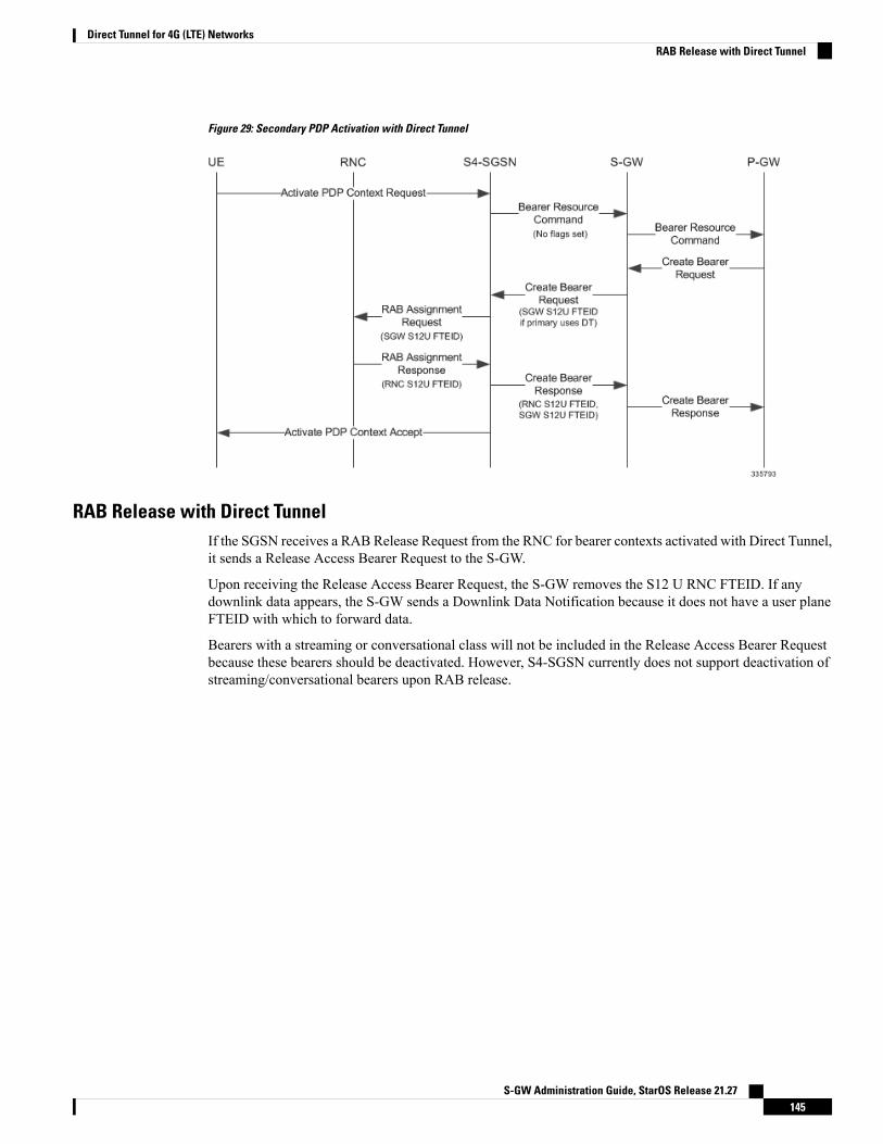
Figure 29: Secondary PDP Activation with Direct Tunnel
RAB Release with Direct TunnelIf the SGSN receives a RAB Release Request from the RNC for bearer contexts activated with Direct Tunnel,it sends a Release Access Bearer Request to the S-GW.
Upon receiving the Release Access Bearer Request, the S-GW removes the S12 U RNC FTEID. If anydownlink data appears, the S-GW sends a Downlink Data Notification because it does not have a user planeFTEID with which to forward data.
Bearers with a streaming or conversational class will not be included in the Release Access Bearer Requestbecause these bearers should be deactivated. However, S4-SGSN currently does not support deactivation ofstreaming/conversational bearers upon RAB release.
S-GW Administration Guide, StarOS Release 21.27145
Direct Tunnel for 4G (LTE) NetworksRAB Release with Direct Tunnel
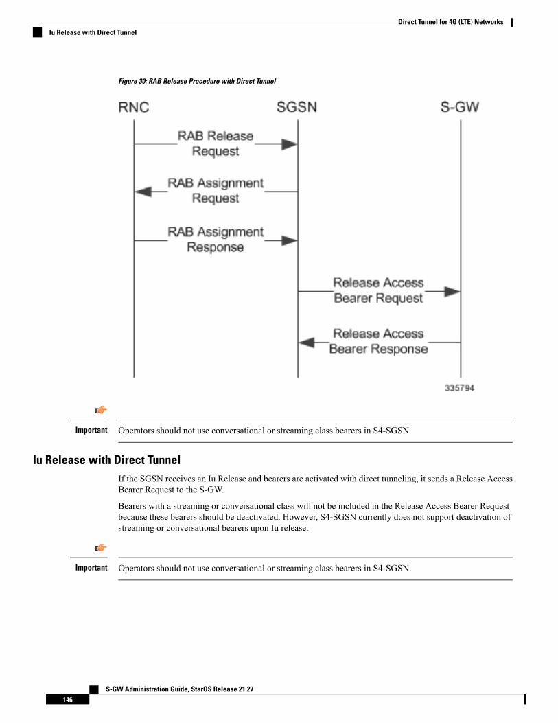
Figure 30: RAB Release Procedure with Direct Tunnel
Operators should not use conversational or streaming class bearers in S4-SGSN.Important
Iu Release with Direct TunnelIf the SGSN receives an Iu Release and bearers are activated with direct tunneling, it sends a Release AccessBearer Request to the S-GW.
Bearers with a streaming or conversational class will not be included in the Release Access Bearer Requestbecause these bearers should be deactivated. However, S4-SGSN currently does not support deactivation ofstreaming or conversational bearers upon Iu release.
Operators should not use conversational or streaming class bearers in S4-SGSN.Important
S-GW Administration Guide, StarOS Release 21.27146
Direct Tunnel for 4G (LTE) NetworksIu Release with Direct Tunnel
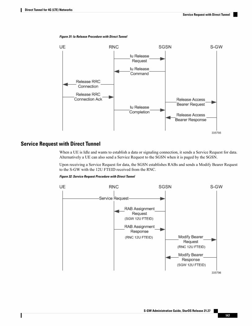
Figure 31: Iu Release Procedure with Direct Tunnel
Service Request with Direct TunnelWhen a UE is Idle and wants to establish a data or signaling connection, it sends a Service Request for data.Alternatively a UE can also send a Service Request to the SGSN when it is paged by the SGSN.
Upon receiving a Service Request for data, the SGSN establishes RABs and sends a Modify Bearer Requestto the S-GW with the 12U FTEID received from the RNC.
Figure 32: Service Request Procedure with Direct Tunnel
S-GW Administration Guide, StarOS Release 21.27147
Direct Tunnel for 4G (LTE) NetworksService Request with Direct Tunnel

Downlink Data Notification with Direct Tunnel when UE in Connected StateWhen RABs are released (but UE retains an Iu connection with the SGSN), the SGSN notifies the S-GW torelease the RNC side TEIDs via a Release Access Bearer Request.
If the S-GW receives any downlink GTPU data from the P-GW after receiving the Release Access BearerRequest, it knows neither the RNC TEID nor SGSN user plane TEID to which to forward the data. So itsignals the SGSN to establish the RABs. This signaling message is a Downlink Data Notification messagefrom the S-GW.
If the Downlink Data Notification is received from the S-GW, all of the missing RABs are established and aModify Bearer Request is sent to the S-GW with the RNC S12U FTEID
Figure 33: Downlink Data Notification with Direct Tunnel
Downlink Data Notification with Direct Tunnel when UE in Idle StateWhen an Iu is released the UE goes IDLE. The SGSN informs the S-GW to release the RNC side TEIDs bysending a Release Access Bearer Request. After this point if the S-GW receives any downlink GTPU datafrom the P-GW, it knows neither the RNC TEID nor SGSN user plane TEID to which to forward the data.
If the S-GW receives any downlink GTPU data after receiving the Release Access Bearer Request, it knowsneither the RNC TEID nor SGSN user plane TEID to which to forward the data. So it signals the SGSN toestablish the RABs. This signaling message is a Downlink Data Notification from the S-GW. If a DownlinkData Notification is received from S-GW when the UE is idle, the SGSN pages the UE before establishingthe RABs. The SGSN sends a Modify Bearer Request to the S-GW with the RNC S12U FTEID.
S-GW Administration Guide, StarOS Release 21.27148
Direct Tunnel for 4G (LTE) NetworksDownlink Data Notification with Direct Tunnel when UE in Connected State
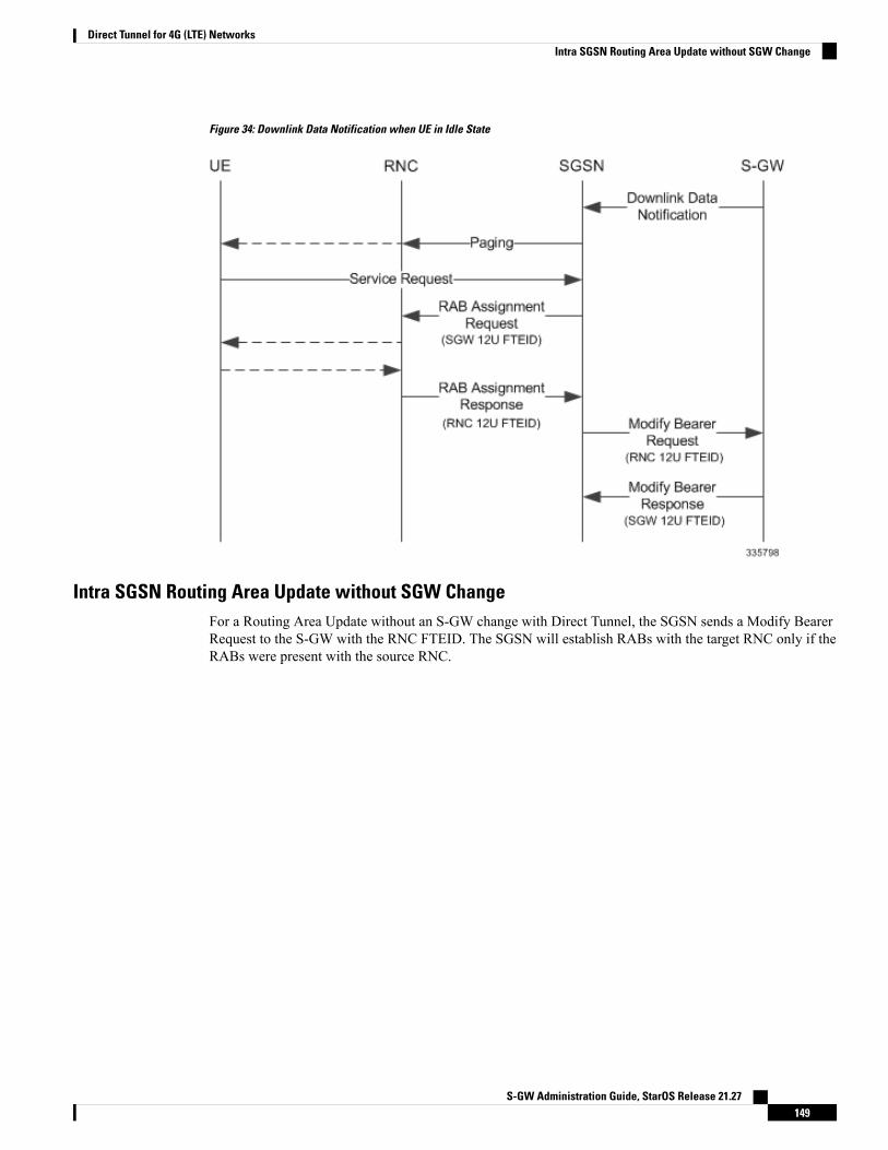
Figure 34: Downlink Data Notification when UE in Idle State
Intra SGSN Routing Area Update without SGW ChangeFor a Routing Area Update without an S-GW change with Direct Tunnel, the SGSN sends a Modify BearerRequest to the S-GW with the RNC FTEID. The SGSN will establish RABs with the target RNC only if theRABs were present with the source RNC.
S-GW Administration Guide, StarOS Release 21.27149
Direct Tunnel for 4G (LTE) NetworksIntra SGSN Routing Area Update without SGW Change
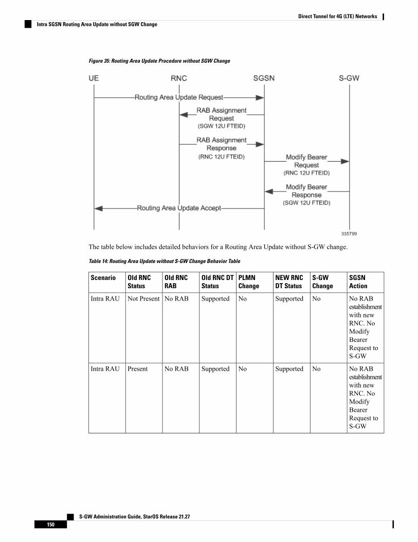
Figure 35: Routing Area Update Procedure without SGW Change
The table below includes detailed behaviors for a Routing Area Update without S-GW change.
Table 14: Routing Area Update without S-GW Change Behavior Table
SGSNAction
S-GWChange
NEW RNCDT Status
PLMNChange
Old RNC DTStatus
Old RNCRAB
Old RNCStatus
Scenario
No RABestablishmentwith newRNC. NoModifyBearerRequest toS-GW
NoSupportedNoSupportedNo RABNot PresentIntra RAU
No RABestablishmentwith newRNC. NoModifyBearerRequest toS-GW
NoSupportedNoSupportedNo RABPresentIntra RAU
S-GW Administration Guide, StarOS Release 21.27150
Direct Tunnel for 4G (LTE) NetworksIntra SGSN Routing Area Update without SGW Change
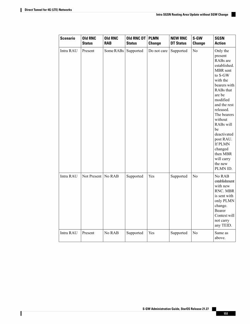
SGSNAction
S-GWChange
NEW RNCDT Status
PLMNChange
Old RNC DTStatus
Old RNCRAB
Old RNCStatus
Scenario
Only thepresentRABs areestablished.MBR sentto S-GWwith thebearers withRABs thatare bemodifiedand the restreleased.The bearerswithoutRABs willbedeactivatedpost RAU.If PLMNchangedthen MBRwill carrythe newPLMN ID.
NoSupportedDo not careSupportedSomeRABsPresentIntra RAU
No RABestablishmentwith newRNC. MBRis sent withonly PLMNchange.BearerContext willnot carryany TEID.
NoSupportedYesSupportedNo RABNot PresentIntra RAU
Same asabove.
NoSupportedYesSupportedNo RABPresentIntra RAU
S-GW Administration Guide, StarOS Release 21.27151
Direct Tunnel for 4G (LTE) NetworksIntra SGSN Routing Area Update without SGW Change
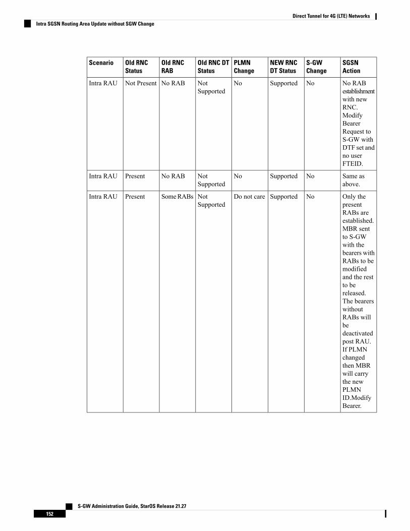
SGSNAction
S-GWChange
NEW RNCDT Status
PLMNChange
Old RNC DTStatus
Old RNCRAB
Old RNCStatus
Scenario
No RABestablishmentwith newRNC.ModifyBearerRequest toS-GW withDTF set andno userFTEID.
NoSupportedNoNotSupported
No RABNot PresentIntra RAU
Same asabove.
NoSupportedNoNotSupported
No RABPresentIntra RAU
Only thepresentRABs areestablished.MBR sentto S-GWwith thebearers withRABs to bemodifiedand the restto bereleased.The bearerswithoutRABs willbedeactivatedpost RAU.If PLMNchangedthen MBRwill carrythe newPLMNID.ModifyBearer.
NoSupportedDo not careNotSupported
SomeRABsPresentIntra RAU
S-GW Administration Guide, StarOS Release 21.27152
Direct Tunnel for 4G (LTE) NetworksIntra SGSN Routing Area Update without SGW Change
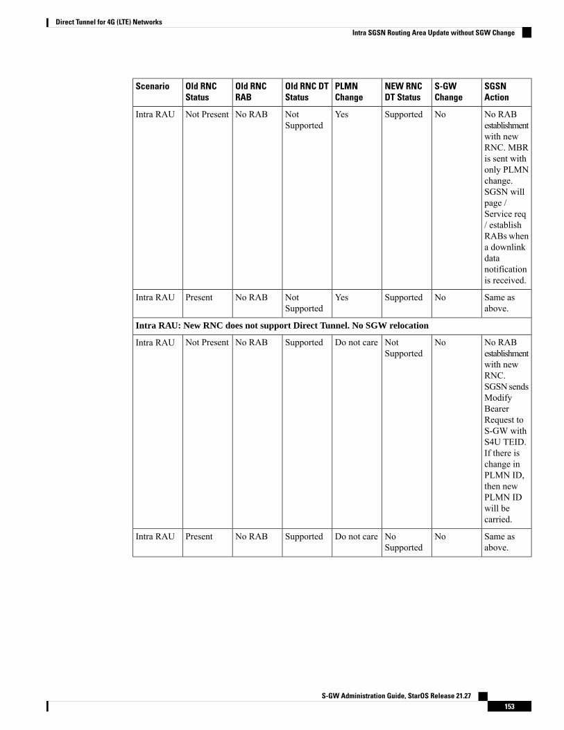
SGSNAction
S-GWChange
NEW RNCDT Status
PLMNChange
Old RNC DTStatus
Old RNCRAB
Old RNCStatus
Scenario
No RABestablishmentwith newRNC. MBRis sent withonly PLMNchange.SGSN willpage /Service req/ establishRABs whena downlinkdatanotificationis received.
NoSupportedYesNotSupported
No RABNot PresentIntra RAU
Same asabove.
NoSupportedYesNotSupported
No RABPresentIntra RAU
Intra RAU: New RNC does not support Direct Tunnel. No SGW relocation
No RABestablishmentwith newRNC.SGSNsendsModifyBearerRequest toS-GW withS4U TEID.If there ischange inPLMN ID,then newPLMN IDwill becarried.
NoNotSupported
Do not careSupportedNo RABNot PresentIntra RAU
Same asabove.
NoNoSupported
Do not careSupportedNo RABPresentIntra RAU
S-GW Administration Guide, StarOS Release 21.27153
Direct Tunnel for 4G (LTE) NetworksIntra SGSN Routing Area Update without SGW Change
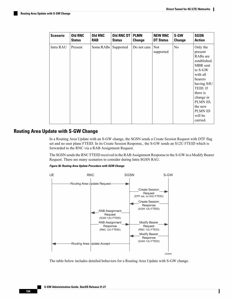
SGSNAction
S-GWChange
NEW RNCDT Status
PLMNChange
Old RNC DTStatus
Old RNCRAB
Old RNCStatus
Scenario
Only thepresentRABs areestablished.MBR sentto S-GWwith allbearershaving S4UTEID. Ifthere ischange inPLMN ID,the newPLMN IDwill becarried.
NoNotsupported
Do not careSupportedSomeRABsPresentIntra RAU
Routing Area Update with S-GW ChangeIn a Routing Area Update with an S-GW change, the SGSN sends a Create Session Request with DTF flagset and no user plane FTEID. In its Create Session Response,. the S-GW sends an S12U FTEID which isforwarded to the RNC via a RAB Assignment Request.
The SGSN sends the RNCFTEID received in the RABAssignment Response to the S-GW in aModify BearerRequest. There are many scenarios to consider during Intra SGSN RAU.
Figure 36: Routing Area Update Procedure with SGW Change
The table below includes detailed behaviors for a Routing Area Update with S-GW change.
S-GW Administration Guide, StarOS Release 21.27154
Direct Tunnel for 4G (LTE) NetworksRouting Area Update with S-GW Change
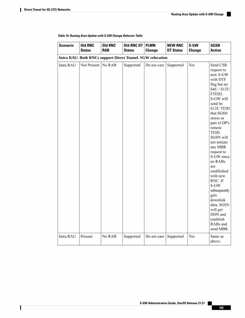
Table 15: Routing Area Update with S-GW Change Behavior Table
SGSNAction
S-GWChange
NEW RNCDT Status
PLMNChange
Old RNC DTStatus
Old RNCRAB
Old RNCStatus
Scenario
Intra RAU: Both RNCs support Direct Tunnel. SGW relocation
Send CSRrequest tonew S-GWwith DTFflag but noS4U / S12UFTEID.S-GW willsend itsS12U TEIDthat SGSNstores aspart of DP'sremoteTEID.SGSN willnot initiateany MBRrequest toS-GW sinceno RABsareestablishedwith newRNC. IfS-GWsubsequentlygetsdownlinkdata, SGSNwill getDDN andestablishRABs andsend MBR.
YesSupportedDo not careSupportedNo RABNot PresentIntra RAU
Same asabove.
YesSupportedDo not careSupportedNo RABPresentIntra RAU
S-GW Administration Guide, StarOS Release 21.27155
Direct Tunnel for 4G (LTE) NetworksRouting Area Update with S-GW Change

SGSNAction
S-GWChange
NEW RNCDT Status
PLMNChange
Old RNC DTStatus
Old RNCRAB
Old RNCStatus
Scenario
Send CSRrequest tonew S-GWwith DTFflag but noS4U / S12UFTEID.S-GWsendsits S12UTEID.RABs thatare presentwill beestablishedwith newRNC. MBRwill beinitiatedonly withthose RABsthat arepresent restof bearers tobe removed.
YesSupportedDo not careSupportedSomeRABsPresentIntra RAU
Intra RAU: Old RNC does not support Direct Tunnel. SGW relocation
S-GW Administration Guide, StarOS Release 21.27156
Direct Tunnel for 4G (LTE) NetworksRouting Area Update with S-GW Change

SGSNAction
S-GWChange
NEW RNCDT Status
PLMNChange
Old RNC DTStatus
Old RNCRAB
Old RNCStatus
Scenario
Send CSRrequest tonew S-GWwith DTFflag but noS4U / S12UFTEID.S-GWsendsits S12UTEID thatSGSNstores aspart of ourDP's remoteTEID.SGSN willnot initiateany MBRrequest toS-GW sinceno RABsareestablishedwith newRNC. IfS-GWsubsequentlygetsdownlinkdata, SGSNgets DDNandestablishesRABs andsendsMBR.
YesSupportedDo not careNotSupported
No RABNot PresentIntra RAU
Same asabove.
YesSupportedDo not careNotSupported
No RABpresentIntra RAU
S-GW Administration Guide, StarOS Release 21.27157
Direct Tunnel for 4G (LTE) NetworksRouting Area Update with S-GW Change

SGSNAction
S-GWChange
NEW RNCDT Status
PLMNChange
Old RNC DTStatus
Old RNCRAB
Old RNCStatus
Scenario
Send CSRrequest tonew S-GWwith DTFflag but noS4U / S12UFTEID.S-GWsendsits S12UTEID.RABs thatare presentwill beestablishedwith newRNC andMBR willbe initiatedonly withthose RABsthat arepresent andthe rest asbearers tobe removed.
YesSupportedDo not careNotSUpported
SomeRABsPresentIntra RAU
Intra RAU: New RNC does not support Direct Tunnel. SGW relocation
CSR requestwithoutDTF flagand withS4UFTEID.
YesNotSupported
Do not careSupportedNo RABNot PresentIntra RAU
CSR requestwithoutDTF flagand withS4UFTEID.
YesNotSupported
Do not careSupportedNo RABPresentIntra RAU
CSR requestwithoutDTF flagand withS4UFTEID. Nodeactivationof PDPs.
YesNotSupported
Do not careSupportedSome rABsPresentIntra RAU
S-GW Administration Guide, StarOS Release 21.27158
Direct Tunnel for 4G (LTE) NetworksRouting Area Update with S-GW Change

Intra SRNS with S-GW ChangeIn Intra SRNS (Serving Radio Network Subsystem) with S-GW change, the SGSN sends a Create SessionRequest with DTF flag set and no user plane FTEID. The Create Session Response from the new S-GWcontains the SGW S12U FTEID which the SGSN forwards to the Target RNC in a Relocation Request.
The SGSN sends the RNC S12U FTEID to the new S-GW in a Modify Bearer Request.
Figure 37: Intra SRNS with S-GW Change
The table below includes detailed behaviors for intra SRNS scenarios.
Intra SRNS without S-GW ChangeIn Intra SRNS without S-GW change, a Relocation Request is sent with SGW S12U FTEID. The RNC S12UFTEID received is forwarded to the S-GW in a Modify Bearer Request.
S-GW Administration Guide, StarOS Release 21.27159
Direct Tunnel for 4G (LTE) NetworksIntra SRNS with S-GW Change
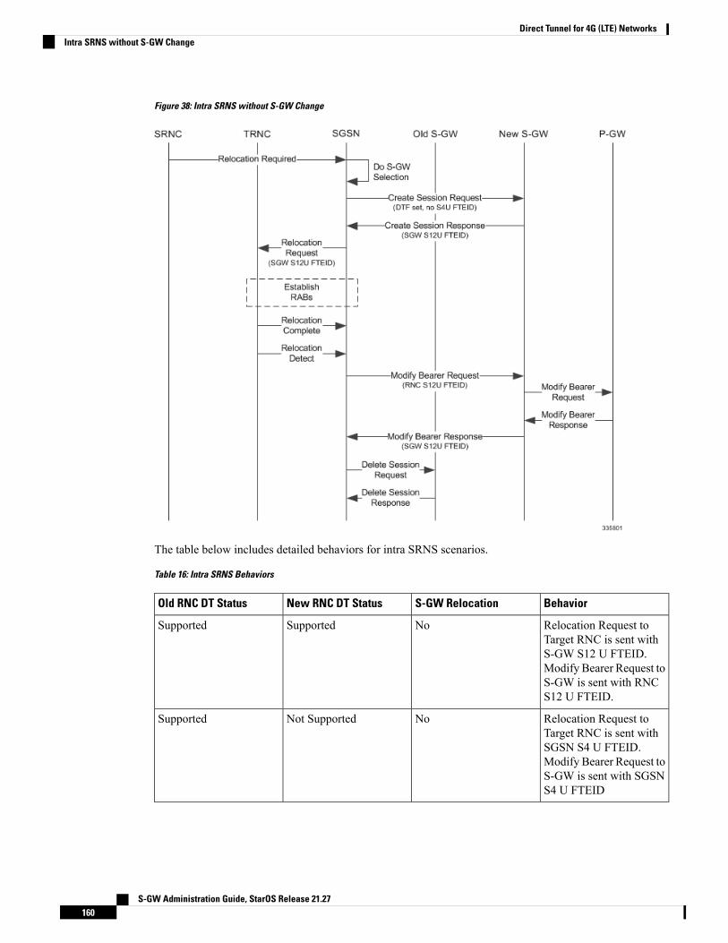
Figure 38: Intra SRNS without S-GW Change
The table below includes detailed behaviors for intra SRNS scenarios.
Table 16: Intra SRNS Behaviors
BehaviorS-GW RelocationNew RNC DT StatusOld RNC DT Status
Relocation Request toTarget RNC is sent withS-GW S12 U FTEID.Modify Bearer Request toS-GW is sent with RNCS12 U FTEID.
NoSupportedSupported
Relocation Request toTarget RNC is sent withSGSN S4 U FTEID.Modify Bearer Request toS-GW is sent with SGSNS4 U FTEID
NoNot SupportedSupported
S-GW Administration Guide, StarOS Release 21.27160
Direct Tunnel for 4G (LTE) NetworksIntra SRNS without S-GW Change
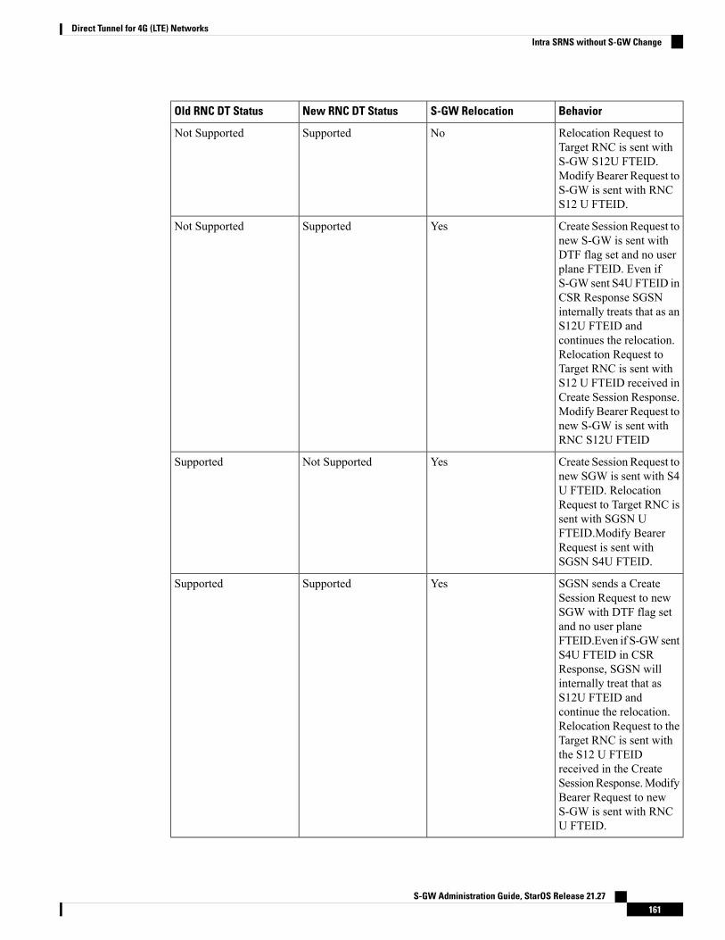
BehaviorS-GW RelocationNew RNC DT StatusOld RNC DT Status
Relocation Request toTarget RNC is sent withS-GW S12U FTEID.Modify Bearer Request toS-GW is sent with RNCS12 U FTEID.
NoSupportedNot Supported
Create Session Request tonew S-GW is sent withDTF flag set and no userplane FTEID. Even ifS-GW sent S4U FTEID inCSR Response SGSNinternally treats that as anS12U FTEID andcontinues the relocation.Relocation Request toTarget RNC is sent withS12 U FTEID received inCreate Session Response.Modify Bearer Request tonew S-GW is sent withRNC S12U FTEID
YesSupportedNot Supported
Create Session Request tonew SGW is sent with S4U FTEID. RelocationRequest to Target RNC issent with SGSN UFTEID.Modify BearerRequest is sent withSGSN S4U FTEID.
YesNot SupportedSupported
SGSN sends a CreateSession Request to newSGW with DTF flag setand no user planeFTEID.Even if S-GWsentS4U FTEID in CSRResponse, SGSN willinternally treat that asS12U FTEID andcontinue the relocation.Relocation Request to theTarget RNC is sent withthe S12 U FTEIDreceived in the CreateSessionResponse.ModifyBearer Request to newS-GW is sent with RNCU FTEID.
YesSupportedSupported
S-GW Administration Guide, StarOS Release 21.27161
Direct Tunnel for 4G (LTE) NetworksIntra SRNS without S-GW Change

New SRNS with S-GW Change and Direct Data TransferThe new SGSN sends a Create Session Request with DTF flag set and no user plane FTEID to the new S-GW.The new SGSN sends the SGW S12U FTEID received in the Create Session Response in Relocation Requestto the Target RNC. The new SGSN sends the RNC S12U FTEID received in a Relocation Request Ack tothe new S-GW in a Modify Bearer Request.
Figure 39: New SRNS with S-GW Change with Data Transfer
The table below includes detailed behaviors for New SRNS scenarios.
New SRNS with S-GW Change and Indirect Data TransferIndirect Data Transfer (IDFT) during a new SGSN SRNS happens during E-UTRAN-to-UTRAN connectedmode IRAT handover. See the figure below for a detailed call flow.
S-GW Administration Guide, StarOS Release 21.27162
Direct Tunnel for 4G (LTE) NetworksNew SRNS with S-GW Change and Direct Data Transfer

Figure 40: New SRNS with S-GW Change and Indirect Data Transfer
The table below includes detailed behaviors for New SRNS scenarios.
S-GW Administration Guide, StarOS Release 21.27163
Direct Tunnel for 4G (LTE) NetworksNew SRNS with S-GW Change and Indirect Data Transfer
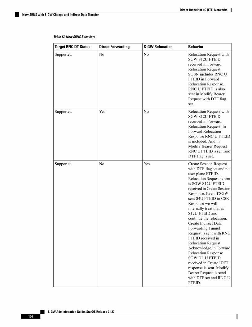
Table 17: New SRNS Behaviors
BehaviorS-GW RelocationDirect ForwardingTarget RNC DT Status
Relocation Request withSGW S12U FTEIDreceived in ForwardRelocation Request.SGSN includes RNC UFTEID in ForwardRelocation Response.RNC U FTEID is alsosent in Modify BearerRequest with DTF flagset.
NoNoSupported
Relocation Request withSGW S12U FTEIDreceived in ForwardRelocation Request. InForward RelocationResponse RNC U FTEIDis included. And inModify Bearer RequestRNCUFTEID is sent andDTF flag is set.
NoYesSupported
Create Session Requestwith DTF flag set and nouser plane FTEID.Relocation Request is sentis SGW S12U FTEIDreceived in Create SessionResponse. Even if SGWsent S4U FTEID in CSRResponse we willinternally treat that asS12U FTEID andcontinue the relocation.Create Indirect DataForwarding TunnelRequest is sent with RNCFTEID received inRelocation RequestAcknowledge.In ForwardRelocation ResponseSGW DL U FTEIDreceived in Create IDFTresponse is sent. ModifyBearer Request is sendwith DTF set and RNC UFTEID.
YesNoSupported
S-GW Administration Guide, StarOS Release 21.27164
Direct Tunnel for 4G (LTE) NetworksNew SRNS with S-GW Change and Indirect Data Transfer

BehaviorS-GW RelocationDirect ForwardingTarget RNC DT Status
Create Session Requestwith DTF flag set and nouser plane FTEID.Relocation Request is sentwith SGW S12U FTEIDreceived in Create SessionResponse. Even if SGWsent S4U FTEID in CSRResponse we willinternally treat that asS12U FTEID andcontinue the relocation. InForward RelocationResponse RNC FTEID issent and Modify BearerRequest is sent with DTFflag set and RNC UFTEID
YesYesSupported
Old SRNS with Direct Data TransferThis scenario includes SRNS relocation between two SGSNs and hence IDFT is not applicable. Data will beforwarded between the source and target RNCs directly. Forward Relocation Request is sent with S12UFTEID.
S-GW Administration Guide, StarOS Release 21.27165
Direct Tunnel for 4G (LTE) NetworksOld SRNS with Direct Data Transfer

Figure 41: Old SRNS with Direct Data Transfer
The table below includes detailed behaviors for Old SRNS.
Old SRNS with Indirect Data TransferIndirect Data Transfer (IDFT) during Old SGSN SRNS happens during UTRAN-to-E-UTRAN connectedmode IRAT handover. A Forward Relocation Request is sent with SGW S12U FTEID.
S-GW Administration Guide, StarOS Release 21.27166
Direct Tunnel for 4G (LTE) NetworksOld SRNS with Indirect Data Transfer
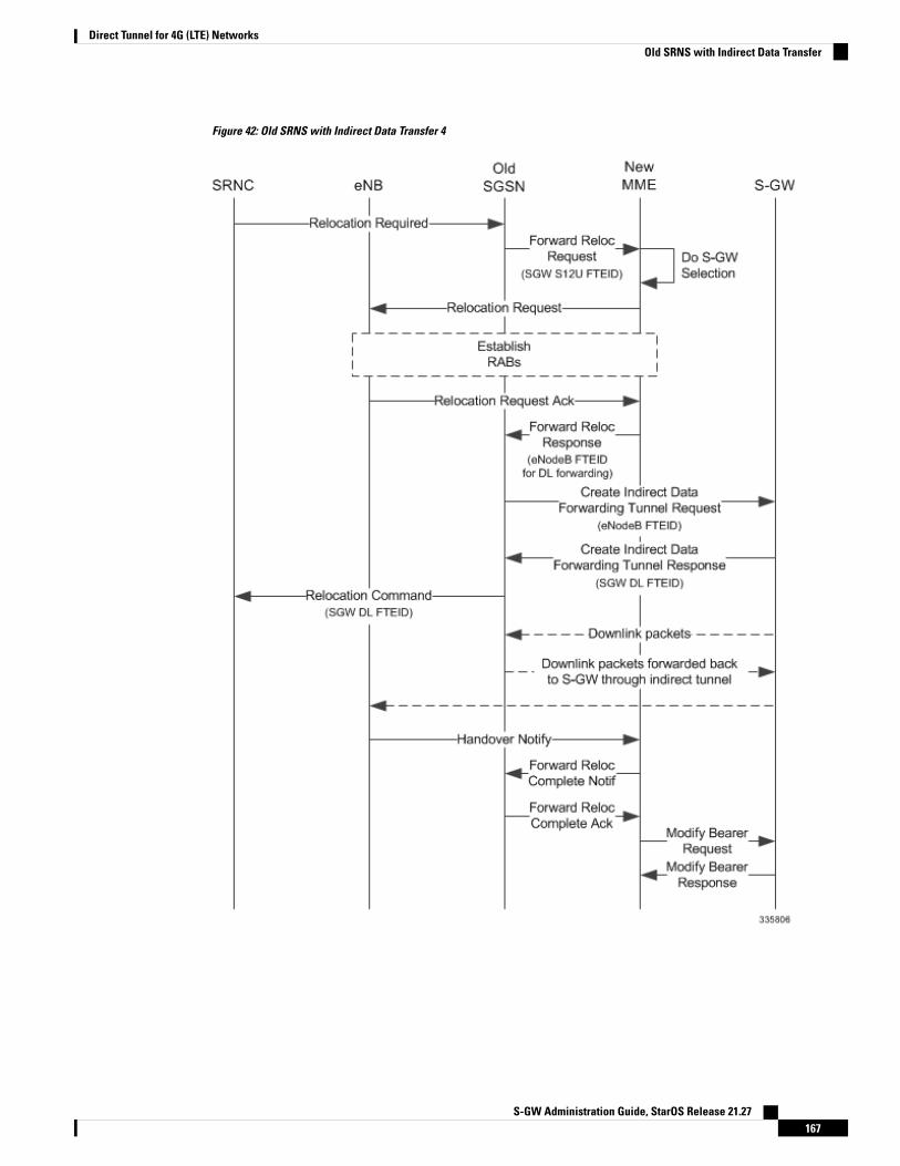
Figure 42: Old SRNS with Indirect Data Transfer 4
S-GW Administration Guide, StarOS Release 21.27167
Direct Tunnel for 4G (LTE) NetworksOld SRNS with Indirect Data Transfer
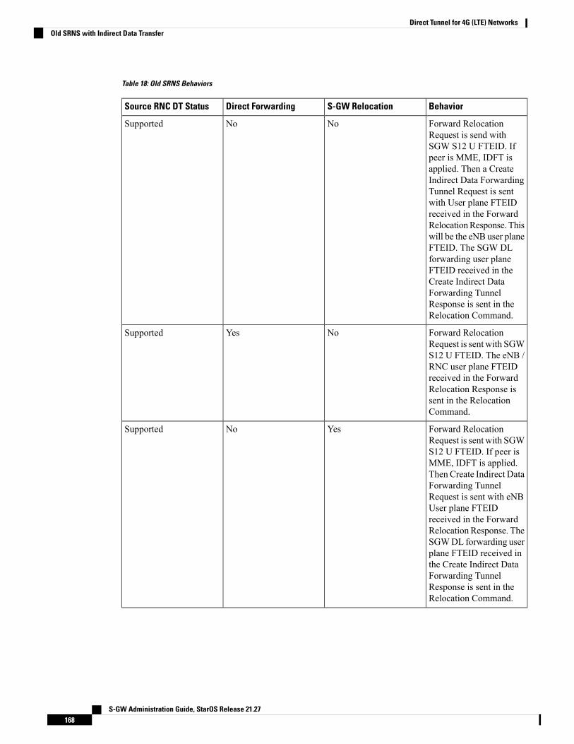
Table 18: Old SRNS Behaviors
BehaviorS-GW RelocationDirect ForwardingSource RNC DT Status
Forward RelocationRequest is send withSGW S12 U FTEID. Ifpeer is MME, IDFT isapplied. Then a CreateIndirect Data ForwardingTunnel Request is sentwith User plane FTEIDreceived in the ForwardRelocationResponse. Thiswill be the eNB user planeFTEID. The SGW DLforwarding user planeFTEID received in theCreate Indirect DataForwarding TunnelResponse is sent in theRelocation Command.
NoNoSupported
Forward RelocationRequest is sent with SGWS12 U FTEID. The eNB /RNC user plane FTEIDreceived in the ForwardRelocation Response issent in the RelocationCommand.
NoYesSupported
Forward RelocationRequest is sent with SGWS12 U FTEID. If peer isMME, IDFT is applied.Then Create Indirect DataForwarding TunnelRequest is sent with eNBUser plane FTEIDreceived in the ForwardRelocation Response. TheSGWDL forwarding userplane FTEID received inthe Create Indirect DataForwarding TunnelResponse is sent in theRelocation Command.
YesNoSupported
S-GW Administration Guide, StarOS Release 21.27168
Direct Tunnel for 4G (LTE) NetworksOld SRNS with Indirect Data Transfer
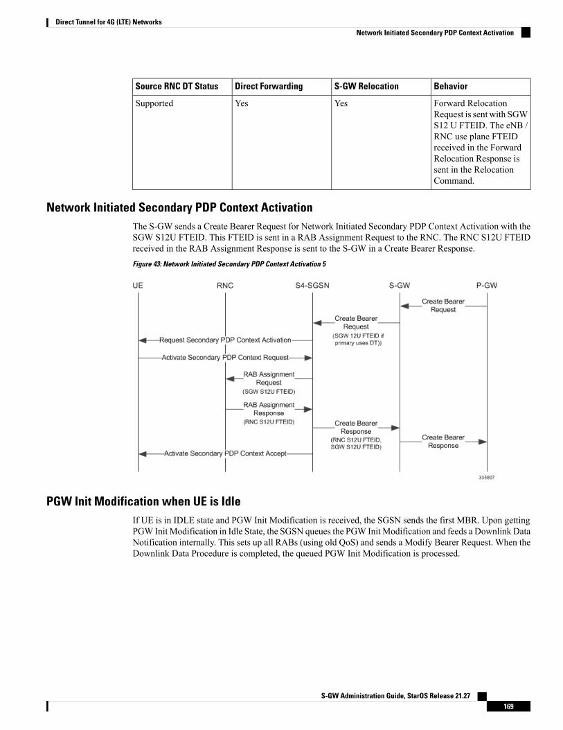
BehaviorS-GW RelocationDirect ForwardingSource RNC DT Status
Forward RelocationRequest is sent with SGWS12 U FTEID. The eNB /RNC use plane FTEIDreceived in the ForwardRelocation Response issent in the RelocationCommand.
YesYesSupported
Network Initiated Secondary PDP Context ActivationThe S-GW sends a Create Bearer Request for Network Initiated Secondary PDP Context Activation with theSGW S12U FTEID. This FTEID is sent in a RAB Assignment Request to the RNC. The RNC S12U FTEIDreceived in the RAB Assignment Response is sent to the S-GW in a Create Bearer Response.
Figure 43: Network Initiated Secondary PDP Context Activation 5
PGW Init Modification when UE is IdleIf UE is in IDLE state and PGW Init Modification is received, the SGSN sends the first MBR. Upon gettingPGW Init Modification in Idle State, the SGSN queues the PGW Init Modification and feeds a Downlink DataNotification internally. This sets up all RABs (using old QoS) and sends a Modify Bearer Request. When theDownlink Data Procedure is completed, the queued PGW Init Modification is processed.
S-GW Administration Guide, StarOS Release 21.27169
Direct Tunnel for 4G (LTE) NetworksNetwork Initiated Secondary PDP Context Activation
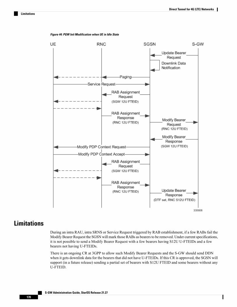
Figure 44: PGW Init Modification when UE in Idle State
LimitationsDuring an intra RAU, intra SRNS or Service Request triggered by RAB establishment, if a few RABs fail theModify Bearer Request the SGSNwill mark those RABs as bearers to be removed. Under current specifications,it is not possible to send a Modify Bearer Request with a few bearers having S12U U-FTEIDs and a fewbearers not having U-FTEIDs.
There is an ongoing CR at 3GPP to allow such Modify Bearer Requests and the S-GW should send DDNwhen it gets downlink data for the bearers that did not have U-FTEIDs. If this CR is approved, the SGSN willsupport (in a future release) sending a partial set of bearers with S12U FTEID and some bearers without anyU-FTEID.
S-GW Administration Guide, StarOS Release 21.27170
Direct Tunnel for 4G (LTE) NetworksLimitations
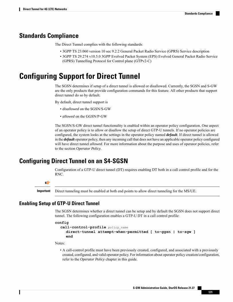
Standards ComplianceThe Direct Tunnel complies with the following standards:
• 3GPP TS 23.060 version 10 sec 9.2.2 General Packet Radio Service (GPRS) Service description• 3GPP TS 29.274 v10.5.0 3GPP Evolved Packet System (EPS) Evolved General Packet Radio Service(GPRS) Tunnelling Protocol for Control plane (GTPv2-C)
Configuring Support for Direct TunnelThe SGSN determines if setup of a direct tunnel is allowed or disallowed. Currently, the SGSN and S-GWare the only products that provide configuration commands for this feature. All other products that supportdirect tunnel do so by default.
By default, direct tunnel support is
• disallowed on the SGSN/S-GW
• allowed on the GGSN/P-GW
The SGSN/S-GW direct tunnel functionality is enabled within an operator policy configuration. One aspectof an operator policy is to allow or disallow the setup of direct GTP-U tunnels. If no operator policies areconfigured, the system looks at the settings in the operator policy named default. If direct tunnel is allowedin the default operator policy, then any incoming call that does not have an applicable operator policy configuredwill have direct tunnel allowed. For more information about the purpose and uses of operator policies, referto the section Operator Policy.
Configuring Direct Tunnel on an S4-SGSNConfiguration of a GTP-U direct tunnel (DT) requires enabling DT both in a call control profile and for theRNC.
Direct tunneling must be enabled at both end points to allow direct tunneling for the MS/UE.Important
Enabling Setup of GTP-U Direct TunnelThe SGSN determines whether a direct tunnel can be setup and by default the SGSN does not support directtunnel. The following configuration enables a GTP-U DT in a call control profile:
configcall-control-profile policy_name
direct-tunnel attempt-when-permitted [ to-ggsn | to-sgw ]end
Notes:
• A call-control profile must have been previously created, configured, and associated with a previouslycreated, configured, and valid operator policy. For information about operator policy creation/configuration,refer to the Operator Policy chapter in this guide.
S-GW Administration Guide, StarOS Release 21.27171
Direct Tunnel for 4G (LTE) NetworksStandards Compliance

• to-ggsn and to-sgw options are added to the direct-tunnel command to enable the operator to select theinterface the SGSN will use for its direct tunnel. For a collocated Gn/GP-SGSN and an S4-SGSN,
• Use the keyword attempt-when-permitted without a filter to enable both interface types: GTP-Utowards the GGSN and S12 towards the SGW.
• Use the keyword attempt-when-permitted with the to-ggsn keyword filter to enable only theGTP-U interface between the RNC and the GGSN.
• Use the keyword attempt-when-permitted with the to-sgw keyword filter to enable only the S4'sS12 interface between the RNC and the SGW.
• To remove the direct tunnel settings from the configuration, use the following command: direct-tunnelattempt-when-permitted [ to-ggsn | to-sgw ]
• Direct tunnel is allowed on the SGSN but will only setup if allowed on both the destination node and theRNC.
Enabling Direct Tunnel to RNCsSGSN access to radio access controllers (RNCs) is configured in the IuPS service. Each IuPS service caninclude multiple RNC configurations that determine communications and features depending on the RNC.By default, DT functionality is enabled for all RNCs.
The following configuration sequence enables DT to a specific RNC that had been previously disabled fordirect tunneling:
configcontext ctxt_name
iups-service service_name
rnc id rnc_id
default direct-tunnelend
Notes:
• An IuPS service must have been previously created, and configured.• An RNC configuration must have been previously created within an IuPS service configuration.• Command details for configuration can be found in the Command Line Interface Reference.
Restricting Direct TunnelsThe following configuration scenario prohibits the S4-SGSN to setup direct tunneling over the S12 interfaceduring Inter SGSN RAUs:
configcall-control-profile profile_name
rau-inter avoid-s12-direct-tunnelend
Restrict direct tunneling by a specific RNC. The following configuration scenario restricts the SGSN fromattempting to setup a direct tunnel when a call originates from a specific RNC.
S-GW Administration Guide, StarOS Release 21.27172
Direct Tunnel for 4G (LTE) NetworksEnabling Direct Tunnel to RNCs
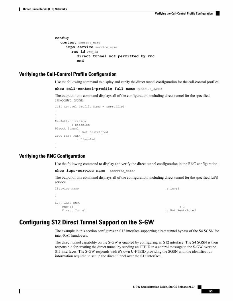
configcontext context_name
iups-service service_name
rnc id rnc_id
direct-tunnel not-permitted-by-rncend
Verifying the Call-Control Profile ConfigurationUse the following command to display and verify the direct tunnel configuration for the call-control profiles:
show call-control-profile full name <profile_name>
The output of this command displays all of the configuration, including direct tunnel for the specifiedcall-control profile.Call Control Profile Name = ccprofile1...Re-Authentication
: DisabledDirect Tunnel
: Not RestrictedGTPU Fast Path
: Disabled..
Verifying the RNC ConfigurationUse the following command to display and verify the direct tunnel configuration in the RNC configuration:
show iups-service name <service_name>
The output of this command displays all of the configuration, including direct tunnel for the specified IuPSservice.IService name : iups1...Available RNC:
Rnc-Id : 1Direct Tunnel : Not Restricted
Configuring S12 Direct Tunnel Support on the S-GWThe example in this section configures an S12 interface supporting direct tunnel bypass of the S4 SGSN forinter-RAT handovers.
The direct tunnel capability on the S-GW is enabled by configuring an S12 interface. The S4 SGSN is thenresponsible for creating the direct tunnel by sending an FTEID in a control message to the S-GW over theS11 interfaces. The S-GW responds with it's own U-FTEID providing the SGSN with the identificationinformation required to set up the direct tunnel over the S12 interface.
S-GW Administration Guide, StarOS Release 21.27173
Direct Tunnel for 4G (LTE) NetworksVerifying the Call-Control Profile Configuration
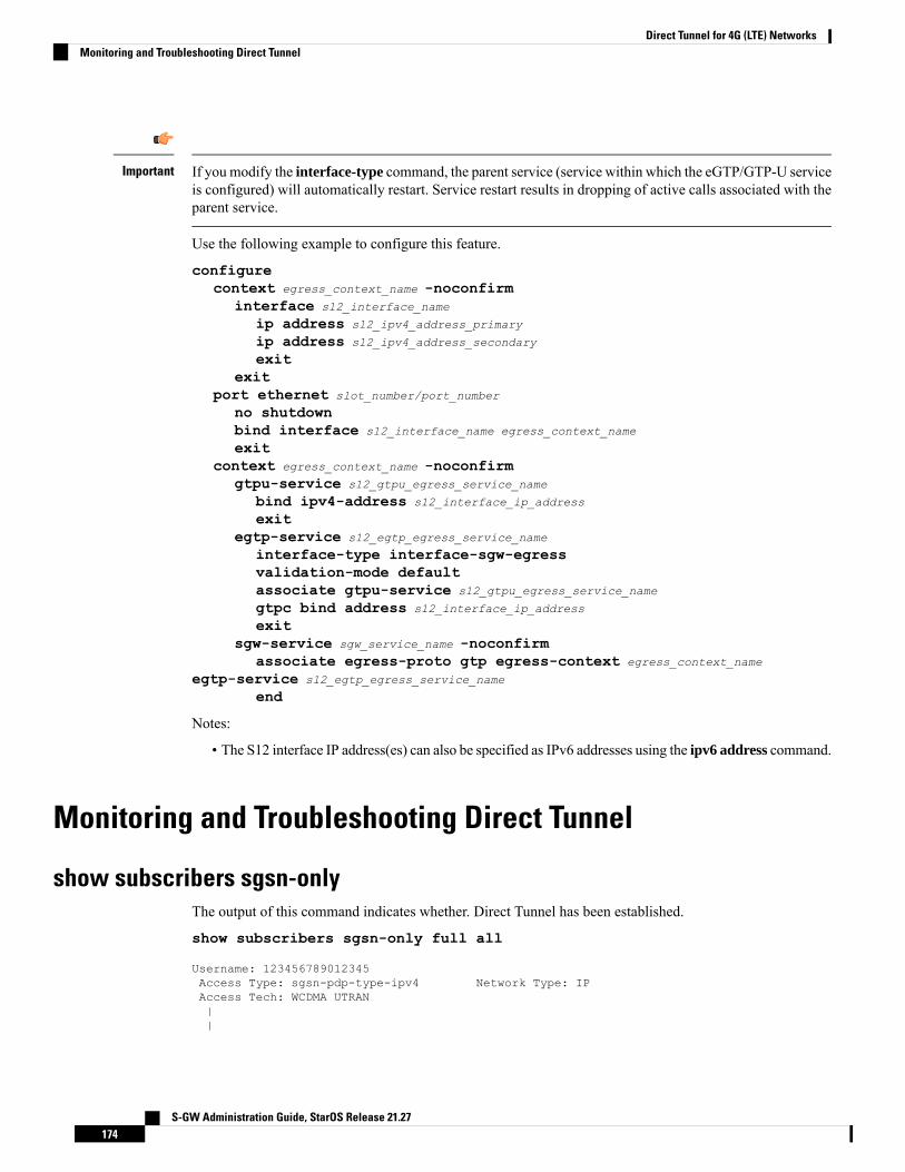
If you modify the interface-type command, the parent service (service within which the eGTP/GTP-U serviceis configured) will automatically restart. Service restart results in dropping of active calls associated with theparent service.
Important
Use the following example to configure this feature.
configurecontext egress_context_name -noconfirm
interface s12_interface_name
ip address s12_ipv4_address_primary
ip address s12_ipv4_address_secondary
exitexit
port ethernet slot_number/port_number
no shutdownbind interface s12_interface_name egress_context_name
exitcontext egress_context_name -noconfirm
gtpu-service s12_gtpu_egress_service_name
bind ipv4-address s12_interface_ip_address
exitegtp-service s12_egtp_egress_service_name
interface-type interface-sgw-egressvalidation-mode defaultassociate gtpu-service s12_gtpu_egress_service_name
gtpc bind address s12_interface_ip_address
exitsgw-service sgw_service_name -noconfirm
associate egress-proto gtp egress-context egress_context_name
egtp-service s12_egtp_egress_service_name
end
Notes:
• The S12 interface IP address(es) can also be specified as IPv6 addresses using the ipv6 address command.
Monitoring and Troubleshooting Direct Tunnel
show subscribers sgsn-onlyThe output of this command indicates whether. Direct Tunnel has been established.
show subscribers sgsn-only full all
Username: 123456789012345Access Type: sgsn-pdp-type-ipv4 Network Type: IPAccess Tech: WCDMA UTRAN||
S-GW Administration Guide, StarOS Release 21.27174
Direct Tunnel for 4G (LTE) NetworksMonitoring and Troubleshooting Direct Tunnel

NSAPI: 05 Context Type: PrimaryContext initiated by: MSDirect Tunnel : Established
show gmm-sm statistics sm-onlyThe output of this command indicates the number of total active PDP contexts with direct tunnels.
show gmm-sm statistics sm-onlyActivate PDP Contexts:Total Actv PDP Ctx:3G-Actv Pdp Ctx: 1 2G-Avtv Pdp Ctx: 0Gn Interface: 1 Gn Interface: 0S4 Interface: 1 S4 Interface: 0Total Actv Pdp Ctx:with Direct Tunnel: 1
Direct Tunnel Bulk StatisticsCurrently there are no bulk statistics available to monitor the number of PDP contexts with Direct Tunnel.
Bulk statistics under the EGTPC schema are applicable for both Direct Tunnel and Idle Mode SignallingReduction (ISR) [3G and 2G]. The following statistics track the release access bearer request and responsemessages which are sent by the SGSN to the S-GW upon Iu or RAB release when either a direct tunnel orISR is active:
• tun-sent-relaccbearreq• tun-sent-retransrelaccbearreq• tun-recv-relaccbearresp• tun-recv-relaccbearrespDiscard• tun-recv-relaccbearrespaccept• tun-recv-relaccbearrespdenied
The following bulkstats under EGTPC schema track Downlink Data Notification (DDN) Ack and failuremessages between the S-GW and the SGSN when either direct tunnel or ISR is active:
• tun-recv-dlinknotif• tun-recv-dlinknotifDiscard• tun-recv-dlinknotifNorsp• tun-recv-retransdlinknotif• tun-sent-dlinknotifackaccept• tun-sent-dlinknotifackdenied• tun-sent-dlinkdatafail
For complete descriptions of these variables, see the EGTPC Schema Statistics chapter in the Statistics andCounters Reference.
S-GW Administration Guide, StarOS Release 21.27175
Direct Tunnel for 4G (LTE) Networksshow gmm-sm statistics sm-only

S-GW Administration Guide, StarOS Release 21.27176
Direct Tunnel for 4G (LTE) NetworksDirect Tunnel Bulk Statistics
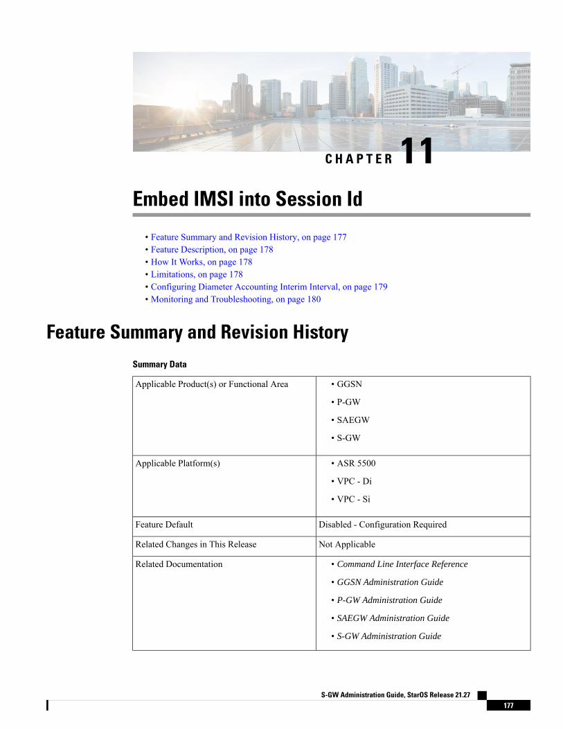
C H A P T E R 11Embed IMSI into Session Id
• Feature Summary and Revision History, on page 177• Feature Description, on page 178• How It Works, on page 178• Limitations, on page 178• Configuring Diameter Accounting Interim Interval, on page 179• Monitoring and Troubleshooting, on page 180
Feature Summary and Revision HistorySummary Data
• GGSN
• P-GW
• SAEGW
• S-GW
Applicable Product(s) or Functional Area
• ASR 5500
• VPC - Di
• VPC - Si
Applicable Platform(s)
Disabled - Configuration RequiredFeature Default
Not ApplicableRelated Changes in This Release
• Command Line Interface Reference
• GGSN Administration Guide
• P-GW Administration Guide
• SAEGW Administration Guide
• S-GW Administration Guide
Related Documentation
S-GW Administration Guide, StarOS Release 21.27177
Revision History
ReleaseRevision Details
21.3First introduced.
Feature DescriptionFor troubleshooting and investigating network issues related to the Diameter interface, it is important to filterthe subscriber or UE specific Diameter traffic. Any traffic associated with a particular IMSI can be easilyfiltered, even without knowing the Diameter session ID, if the IMSI information is embedded into the DiameterSession ID AVP. This feature allows the operator to filter the subscriber or UE specific Diameter traffic.
This feature introduces a new CLI command session-id include imsi under the diameter endpointconfiguration mode to embed IMSI into Diameter session ID AVP over the Gx, Gy, and Gz (Rf) interface.
This feature is license controlled. Contact your Cisco account representative for information on how to obtaina license.
Important
How It WorksA new CLI command session-id include imsi has been added under the diameter endpoint configurationmode to enable/disable inclusion of IMSI in Session-Id AVP for all Diameter sessions associated with thatDiameter endpoint. Operators can enable only the required Diameter endpoints and control the inclusion ofIMSI in the Session-ID AVP. IMSI information is included in the Diameter Session-ID AVP over the Gx,Gy, and Gz (Rf) interface, if the session-id include imsi is enabled on respective Diameter endpoints.
For emergency call with "only IMEI", IMSI information is not available for that emergency PDN. Hence, thisIMSI information is not included in Diameter Session-ID at Gx, Gy, and Gz interface, when session-idinclude imsi is enabled. Configuring session-id include imsi impacts only new PDN connection and doesnot have any impact on existing PDN connection behavior (Gx, Gy, and Gz (Rf)) interface. For example, ifthe CLI command to include IMSI is enabled for the Gy Diameter endpoint after PDN creation. If a newdedicated bearer is created after this configuration change, then in this case Gy session established for a newdedicated bearer is not included IMSI in Gy Diameter session ID.
There is no impact of session manager recovery/ICSR on the session-ID AVP. Session-ID associated withGx, Gy, and Gz (Rf) session is recovered transparently (which is irrespective of latest endpoint configuration).New sessions come up with session IDs as per the configuration on the newly active chassis.
LimitationsFollowing are the known limitations of this feature:
• Assuming IMSI information as sensitive information, operator must consider security aspects beforeenabling this CLI option.
S-GW Administration Guide, StarOS Release 21.27178
Embed IMSI into Session IdFeature Description

• For an emergency call with "Only IMEI", IMSI information is not available for the emergency PDN,hence it is not included in the diameter Session-ID at Gx, Gy, and Gz (Rf) interface.
• During ICSR upgrade scenario, it is assumed that the new CLI option must be enabled only when theupgraded chassis is in stable state and there exists no chances of ICSR downgrade.
• If new CLI is enabled in the newer version of chassis, ICSR Downgrade is not recommended.
• As new CLI option is not available in old software versions, hence ICSR downgrade is not recommended.Performing ICSR downgrade should have the following impact on the diameter sessions, which haveIMSI, included as part of Session-ID.
• Gx and Gy: Existing diameter session (Gx, Gy) should be downgraded with old format of Session-Id.In that case, both P-GW and PCRF are out of sync leading to hanging session at P-GWor/and PCRF.Any communication from PCRF (RAR)/P-GW (CCR-U) can lead to stale session deletion.
• Gz (Rf): However, Rf sessions should be recovered properly and any Rf signaling is sent out to Rfservers properly but responses cannot be processed as diamproxy cannot parse the new formatsession id which again puts Rf sessions into stale state until purged.
Configuring Diameter Accounting Interim IntervalThe following CLI command has been added under the diameter endpoint configuration mode to includeIMSI in Diameter session-ID per Diameter endpoint at Gx, Gy, and Gz (Rf). Configuration changes will beapplicable only to new Sessions at Gx, Gy and Rf. Configuration changes will not have any impact on existingsessions behavior at Gx, Gy, and Rf. For Gy, multiple Diameter sessions can be initiated per subscriber andthe session ID format setting will bind to the subscriber. The setting will be taken to effect when the firstDiameter session is established and following Gy sub sessions will keep using the session ID format used infirst session.
configurecontext context_name
diameter endpoint endpoint_name
[no] session-id include imsiend
Notes:
• session-id: Describes Diameter Session-ID format
• include: Includes configured information in Diameter Session-ID
• imsi: Includes International Mobile Subscriber Identification (IMSI) in Diameter Session-ID
• no: Disables this feature, that is, IMSI is not included in the Diameter Session-ID, which is the defaultbehavior.
• By default, CLI is disabled, hence IMSI will not be populated in Diameter Session-ID.
S-GW Administration Guide, StarOS Release 21.27179
Embed IMSI into Session IdConfiguring Diameter Accounting Interim Interval
Monitoring and TroubleshootingThe following sections describe commands available to monitor the feature.
Show Commands and OutputsThis section provides information regarding show commands and their outputs in support of the feature.
show configurationThe output of the above command is modified to display the following new field depending on whether theCLI is enabled or disabled:
• session-id include imsi
• no session-id include imsi
show configuration [ verbose ]The output of the above command is modified to display the following new field depending on whether theCLI is enabled or disabled:
• session-id include imsi
• no session-id include imsi
S-GW Administration Guide, StarOS Release 21.27180
Embed IMSI into Session IdMonitoring and Troubleshooting

C H A P T E R 12Expanded Prioritization for VoLTE/EmergencyCalls
This chapter describes the StarOS support for the Expanded Prioritization for VoLTE/Emergency Calls featureon the P-GW, SAE-GW, and S-GW.
• Feature Description, on page 181• How It Works, on page 183• Configuring Expanded Prioritization for VoLTE/Emergency Calls, on page 184• Monitoring and Troubleshooting the Expanded Prioritization for VoLTE/Emergency Calls, on page 186
Feature DescriptionThe National Security/Emergency Preparedness (NS/EP) Next Generation Network (NGN) Priority Services(NGN-PS) (formerly called NGN Government Emergency Telecommunications Service (GETS)) is a set ofvoice, video and data services that are based on services available from public packet-switched ServiceProviders. The NS/EP NGN-PS provides priority treatment for a Service User’s NS/EP communications andis particularly needed when the Service Providers’ networks are impaired due to congestion and/or damagefrom natural disasters (such as floods, earthquakes and hurricanes) and man-made disasters (such as physical,cyber or other forms of terrorist attacks).
The DSCP marking of control message from P-GW and S-GW was based on associated egtpc-serviceconfiguration.
For control message belonging to eMPS session or containing Allocation and Retention Priority (ARP)associated with eMPS profile, the DSCP marking is based on eMPS profile configured DSCP value.
As part of this enhancement, support is also added for marking of certain GTP-C message at the P-GW andS-GW for priority treatment as defined in the Government Industry Requirements (GIR) NS/EP NGN.
Relationships to Other FeaturesBulkstats for GTP-C Messages by ARP Value: The S-GW/P-GW will generate peg counts of the totalnumber of received GTP-C messages containing an ARP, chosen from the set of values allocated for NS/EPNGN-PS use, for a specified interval (in minutes). This peg count is administered at the S-GW/P-GW level.
S-GW Administration Guide, StarOS Release 21.27181
To prevent throttling of GTP-C messages corresponding to eMPS PDNs or messages containing ARP fromset of configured ARP(PL) reserved for NS/EP NGN priority service, following configuration are to beconsidered:
1. Load Overload control
In overload control profile, the set of ARPs reserved for NS/EP NGN-PS use for eMPS services shouldalso be defined under throttling-behavior exclude and self-protection-behavior excludeCLI commands.This will ensure that incoming GTP-C messages for eMPS PDN or containing ARP from set of reservedARP for eMPS use are not throttled. Example of configuring Load Overload configuration:
configuregtpc-overload-control-profile profile_name
throttling-behavior { earp { 1...15 } * } { exclude }self-protection-behavior { earp { 1...15 } * } { exclude }end
2. For Prioritized handling of calls under Congestion condition
ARP reserved under NS/EPNGN-PS for eMPS services is recommended to be configured under followingcongestion control CLI command. This will ensure that new call requests are not throttled during congestioncondition defined by the congestion-control CLI command at context level:
configurecontext context_name
egtp-service service_name
gtpc allow-on-congestion arp arp_value
end
3. GTP-C RLF Throttling
• If GTP-C RLF Throttling feature is enabled, then gtpc overload-protection egressthrottling-override-policy CLI command should be configured with ARP(PL), reserved for NS/EPNGN-PS use, for eMPS services to bypass RLF throttling.
• If GTP-C RLF Throttling for incoming messages is configured using gtpc overload-protectioningress msg-rate message_rate CLI command, then eMPS related messages can get throttled.Currently, there is no bypass policy for incoming RLF throttling.
Any existing features which works on ARP (PL) configurations will continue to work as before irrespectiveof whether ARP values configured are same as reserved under NS/EP NGN-PS for eMPS services. If existingfeatures need to work with eMPS requirements, then same ARP (PL) values should be configured as reservedNS/EP NGN-PS for eMPS services.
Important
LicensingThe DSCP marking capability requires that a valid license key be installed. Contact your Cisco Account orSupport representative for information on how to obtain a license.
S-GW Administration Guide, StarOS Release 21.27182
Expanded Prioritization for VoLTE/Emergency CallsLicensing

How It WorksGIR Document References
The following table describes the requirements of this feature as per the GIR document.
DescriptionRequirement No.
[202] The S-GW shall transmit with priority a GTP-C “Downlink DataNotification” message or a GTP-C “Create Bearer Request” message or aGTP-C “Update Bearer Request” message, any of which contains an ARPchosen from the set allocated by the Service Provider for use by NS/EPNGN-PS.
R-127
[204] The S-GW shall mark for priority treatment the S11 “Create SessionResponse” message from the S-GW to the MME which contains requestto establish a bearer or bearers with an ARP corresponding to an NS/EPNGN-PS call/session.
R-130
[205] The S-GW shall mark for priority treatment the S11 “Create BearerRequest” and S11 “Update Bearer Request” messages from the SGW tothe MME which contains an indication that a UE currently has anestablished/updated bearer or bearers for NS/EP NGN-PS service.
R-132
[206] In the case where the S5/S8 Interface is GTP-based, the S-GW shallmark for priority treatment the S5/S8 “Create Session Request” messagefrom the S-GW to the PDN-GW which contains an indication that a UEwill establish a bearer or bearers for NS/EP NGN-PS.
R-134
[207] In the case where the S5/S8 Interface is GTP-based, the S-GW shallmark for priority treatment the S5/S8 “Create Bearer Response” and “UpdateBearer Response”messages from the S-GW to the PDN-GWwhich containan indication that a UE currently has established / updated a bearer orbearers for NS/EP NGN-PS.
R-137
[213] In the case where the S5/S8 Interface is GTP-based, the PDN-GWshall mark for priority treatment the S5/S8 “Create Session Response”message from the PDN-GW to the S-GW which contains a request toestablish a bearer or bearers with an ARP corresponding to an NS/EPNGN-PS call/session.
R-143
[216] In the case where the S5/S8 Interface is GTP- based, the PDN-GWshall mark for priority treatment the S5/S8 “Create Bearer Request” and“Update Bearer Request” messages from the PDN-GW to the S-GWwhichcontain an indication that a UE currently has an established/updated beareror bearers for NS/EP NGN-PS.
R-146
S-GW Administration Guide, StarOS Release 21.27183
Expanded Prioritization for VoLTE/Emergency CallsHow It Works

Configuring Expanded Prioritization for VoLTE/Emergency CallsThe following section provides the configuration commands to enable the feature.
Configuring eMPS Profile and its Associated AttributesAt ConfigurationMode level, CLI command option is introduced to define an eMPS profile and its associatedattributes like:
• eARP configuration: This configuration is used for marking a bearer/PDN as an eMPS.
• DSCP configuration: This configuration is used at S-GW/P-GW to mark various outgoing GTP-Cmessages associated with an eMPS PDN with configured DSCP marking.
configure[ no ] emps-profile emps_profile_name -noconfirm[ no ] earp { [ 1...15 ] { [ 1...15 ] { [ 1...15 ] } } }[ no ] dscp-marking dscp_value
end
Notes:
• emps-profile emps_profile_name: Configures eMPS profile for defining attributes of an eMPS session.The emps_profile_name is a string of size from 1 to 63.
• earp: Configures a maximum of 3 eARP priority level (PL) values so that sessions with configured eARPpriority values can be marked as eMPS sessions.
• -noconfirm: Creates a new eMPS profile without prompting for confirmation.
• dscp-marking dscp_value: Specifies the DSCP value to be applied to eMPS sessions. The dscp_valueis a hexadecimal number between 0x0 and 0x3F.
• Maximum of 3 eARP values can be configured under an eMPS profile. The above CLI syntax providesflexibility to configure one or more (max 3) eARP values in a single command. For example:
earp 1 2 3
-Or-
earp 4
• The latest set of eARP values configured will overwrite the previous configuration. For example: Invokingbelow two commands in sequence will configure only eARP value 4.
earp 1 2 3
earp 4
• eMPS profile name should be unique and is treated case insensitive across context.
• The no earp command can be used to disable all configured eARP values. However, this will not deletethe corresponding eMPS profile. The no emps-profile emps_profile_name CLI command will deletethe profile.
S-GW Administration Guide, StarOS Release 21.27184
Expanded Prioritization for VoLTE/Emergency CallsConfiguring Expanded Prioritization for VoLTE/Emergency Calls
• Warning message: When no of a non-existent eMPS profile is executed, a warning message is displayed.For example:no emps-profile xyz
eMPS Profile : xyz does not exist
There will be no warning message if no of an un-configured eARP is executed.
• There will be a warning and confirmation message when existing profile is deleted:This operation will result in deletion of this eMPS Profile.
Are you sure? [Yes|No]:
• Maximum of 64 different eMPS profiles can be configured.
Associating an eMPS Profile with P-GW ServiceThe commands illustrated below associates an eMPS profile to P-GW service.
configurecontext context_name
pgw-service service_name
associate emps-profile emps_profile_name
end
Notes:
• no associate emps-profile: Disables the feature.
• emps-profile emps_profile_name: Associates an eMPS profile with the P-GW service. Theemps_profile_name is a string of size 1 to 63.
• The eMPS profile name in input is treated as case insensitive.
• By default, no eMPS profile is associated with pgw-service.
• For SAE-GW associated P-GW service, the eMPS profiles should be same as configured in associatedS-GW service. In case of any discrepancy, it will be reported in the show configuration error CLIcommand output.
Associating an eMPS Profile with S-GW ServiceThe commands illustrated below associates an eMPS profile to S-GW service.
configurecontext context_name
sgw-service service_name
associate emps-profile emps_profile_name
end
Notes:
• no associate emps-profile: Disables the feature.
• emps-profile emps_profile_name: Associates an eMPS profile with the S-GW service. Theemps_profile_name is a string of size 1 to 63.
S-GW Administration Guide, StarOS Release 21.27185
Expanded Prioritization for VoLTE/Emergency CallsAssociating an eMPS Profile with P-GW Service

• The eMPS profile name in input is treated as case insensitive.
• By default, no eMPS profile is associated with sgw-service.
• For SAE-GW associated S-GW service, the eMPS profiles should be same as configured in associatedP-GW service. In case of any discrepancy, it will be reported in the show configuration error CLIcommand output.
Monitoring and Troubleshooting the Expanded Prioritizationfor VoLTE/Emergency Calls
This section provides information regarding show commands and/or their outputs in support of thisenhancement.
Show Command(s) and/or Outputs
show emps-profile { all | name <emps_profile_name> }
The above CLI command is introduced to see a particular or all eMPS profile(s) configured with its associatedattributes. Also, the output of an existing show config [ verbose ] CLI command is modified to reflect aneMPS configuration:
• earp configured: <earp_value>
• dscp-marking configured: <dscp-value>
These CLI commands can be used to verify if the configuration is appropriate.
show pgw-service { name <name> | all }
The output of this command is modified to reflect the eMPS profile associated with the P-GW service:
• eMPS Profile Name : <emps_profile_name>
Maximum of one eMPS profile can be associated with P-GW service at a time; the latest configuration willoverwrite the previously associated configuration.
Important
show sgw-service { name <name> | all }
The output of this command is modified to reflect the eMPS profile associated with the S-GW service:
• eMPS Profile Name : <emps_profile_name>
Maximum of one eMPS profile can be associated with S-GW service at a time; the latest configuration willoverwrite the previously associated configuration.
Important
S-GW Administration Guide, StarOS Release 21.27186
Expanded Prioritization for VoLTE/Emergency CallsMonitoring and Troubleshooting the Expanded Prioritization for VoLTE/Emergency Calls

show subscribers pgw-only full all
The output of this command is modified to reflect whether the session is eMPS or not. For example:Username: 0123456789@usernameSubscriber Type : VisitorStatus : Online/ActiveState : ConnectedConnect Time : Wed Sep 7 07:02:49 2016Auto Delete : NoIdle time : 00h00m08sMS TimeZone : n/a Daylight Saving Time: n/aAccess Type: gtp-pdn-type-ipv4 Network Type: IPAccess Tech: eUTRAN pgw-service-name: pgw_serviceCallid: 00004e21 IMSI: 123456789012341MSISDN: 0123456789Interface Type: S5S8GTP Low Access Priority: N/ATWAN Mode: N/AeMPS Bearer: YesEmergency Bearer Type: N/AIMS-media Bearer: No
show subscribers saegw-only full all
The output of this command is modified to reflect whether the session is eMPS or not. For example:Username: 0123456789@usernameSAEGW Call mode : Co-locatedSubscriber Type : Home...MSISDN: 0123456789TWAN Mode: N/AeMPS Bearer: YesMS TimeZone : Daylight Saving Time: n/aMEI : 1122334455667788 Accounting mode : GTPP
show pgw-service statistics
The output of this command is modified to display the eMPS PDN statistics information. For example:PDNs By Emergency-Type:Emergency PDNs:Active: 0 Setup: 0Authentic IMSI: 0 Authentic IMSI: 0
.
.
.eMPS PDNs:Current Active: 1 Cumulative Activated: 1Cumulative De-activated: 1
IPv4v6 PDN-Type Received with DAF False : 0
Where:
• Current Active: Increments when any PDN is setup as an eMPS PDN or upgraded to eMPS PDN.Decrements when an eMPS PDN is released or when it degrades to a non-eMPS PDN.
• Cumulative Activated: Increments when any PDN is setup as an eMPS PDN or upgrades to an eMPSPDN.
S-GW Administration Guide, StarOS Release 21.27187
Expanded Prioritization for VoLTE/Emergency CallsShow Command(s) and/or Outputs

• Cumulative De-activated: Increments when an eMPS PDN is released or when it degrades to a non-eMPSPDN.
show saegw-service statistics all function pgw
The output of this command is modified to display the eMPS PDN statistics information. For example:PDNs By Emergency-Type:Emergency PDNs:Active: 0 Setup: 0Authentic IMSI: 0 Authentic IMSI: 0
.
.
.eMPS PDNs:Current Active: 1 Cumulative Activated: 1Cumulative De-activated: 1
IPv4v6 PDN-Type Received with DAF False : 0
Where:
• Current Active: Increments when any PDN is setup as an eMPS PDN or upgraded to eMPS PDN.Decrements when an eMPS PDN is released or when it degrades to a non-eMPS PDN.
• Cumulative Activated: Increments when any PDN is setup as an eMPS PDN or upgrades to an eMPSPDN.
• Cumulative De-activated: Increments when an eMPS PDN is released or when it degrades to a non-eMPSPDN.
show saegw-service statistics
The output of this command is modified to display the eMPS statistics for PGW-Anchored/SGW-AnchoredPDNs associated with the saegw-service. For example:PDNs By Emergency-Type:Emergency PDNs:Active: 0 Setup: 0Released: 0...eMPS PDNs:Colocated PDNs:Current Active: 1 Cumulative Activated: 1Cumulative De-activated: 0PGW-Anchor PDNs:Current Active: 1 Cumulative Activated: 1Cumulative De-activated: 0SGW-Anchor PDNs:Current Active: 1 Cumulative Activated: 1Cumulative De-activated: 0
The above statistics information are further classified based on SAE-GW call types:
• Colocated eMPS PDNs: It reflects the eMPS PDN statistics information for collapsed PDNs.
• PGW-Anchor eMPS PDNs: It reflects the eMPS PDN statistics information for PGW-Anchor PDNs.
S-GW Administration Guide, StarOS Release 21.27188
Expanded Prioritization for VoLTE/Emergency CallsShow Command(s) and/or Outputs
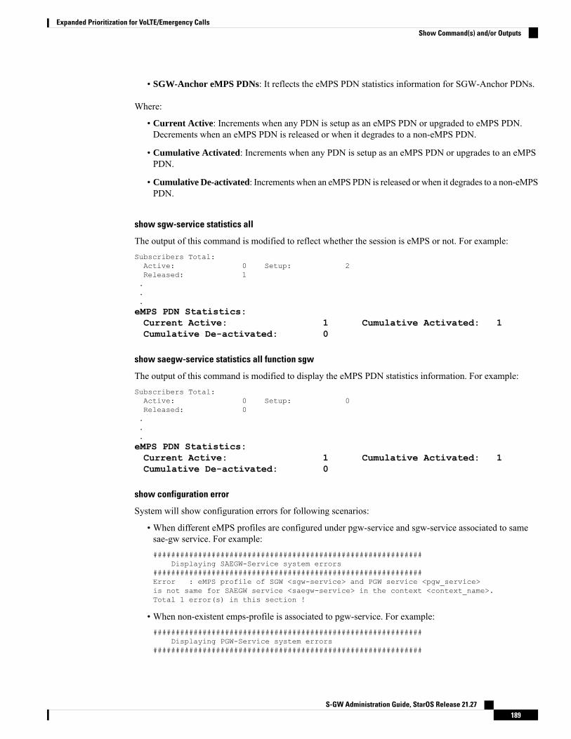
• SGW-Anchor eMPS PDNs: It reflects the eMPS PDN statistics information for SGW-Anchor PDNs.
Where:
• Current Active: Increments when any PDN is setup as an eMPS PDN or upgraded to eMPS PDN.Decrements when an eMPS PDN is released or when it degrades to a non-eMPS PDN.
• Cumulative Activated: Increments when any PDN is setup as an eMPS PDN or upgrades to an eMPSPDN.
• Cumulative De-activated: Increments when an eMPS PDN is released or when it degrades to a non-eMPSPDN.
show sgw-service statistics all
The output of this command is modified to reflect whether the session is eMPS or not. For example:Subscribers Total:Active: 0 Setup: 2Released: 1...eMPS PDN Statistics:Current Active: 1 Cumulative Activated: 1Cumulative De-activated: 0
show saegw-service statistics all function sgw
The output of this command is modified to display the eMPS PDN statistics information. For example:Subscribers Total:Active: 0 Setup: 0Released: 0...eMPS PDN Statistics:Current Active: 1 Cumulative Activated: 1Cumulative De-activated: 0
show configuration error
System will show configuration errors for following scenarios:
• When different eMPS profiles are configured under pgw-service and sgw-service associated to samesae-gw service. For example:############################################################
Displaying SAEGW-Service system errors############################################################Error : eMPS profile of SGW <sgw-service> and PGW service <pgw_service>is not same for SAEGW service <saegw-service> in the context <context_name>.Total 1 error(s) in this section !
• When non-existent emps-profile is associated to pgw-service. For example:############################################################
Displaying PGW-Service system errors############################################################
S-GW Administration Guide, StarOS Release 21.27189
Expanded Prioritization for VoLTE/Emergency CallsShow Command(s) and/or Outputs

Error : eMPS Profile <emps_profile_pgw> configured for PGW service <pgw_service>is not present in the systemTotal 1 error(s) in this section !
• When non-existent emps-profile is associated to sgw-service. For example:############################################################
Displaying SGW-Service system errors############################################################Error : eMPS Profile <emps_profile_sgw> configured for SGW service <sgw_service>is not present in the systemTotal 1 error(s) in this section !
Bulkstats for Expanded Prioritization for VoLTE/Emergency Calls
PGW Schema
The following bulk statistics have been added to the P-GW schema as part of this enhancement:
• sessstat-pdn-emps-current-active – The total number of currently active P-GW eMPS PDNs.
• sessstat-pdn-emps-cumulative-activated – The total number of P-GW PDNs that are either setup as aneMPS PDN or upgrades to an eMPS PDN.
• sessstat-pdn-emps-cumulative-deactivated – The total number of P-GW PDNs that were either releasedor degrades to a non-eMPS PDN.
SGW Schema
The following bulk statistics have been added to the S-GW schema as part of this enhancement:
• sessstat-pdn-emps-current-active – The total number of currently active S-GW eMPS PDNs.
• sessstat-pdn-emps-cumulative-activated – The total number of S-GW PDNs that are either setup as aneMPS PDN or upgrades to an eMPS PDN.
• sessstat-pdn-emps-cumulative-deactivated – The total number of S-GW PDNs that were either releasedor degrades to a non-eMPS PDN.
SAEGW Schema
The following bulk statistics have been added to the SAE-GW schema as part of this enhancement:
• pgw-anchor-pdns-emps-current-active – The total number of currently active P-GW anchored eMPSPDNs.
• pgw-anchor-pdns-emps-cumulative-activated – The total number of P-GW anchored PDNs that are eithersetup as an eMPS PDN or upgrades to an eMPS PDN.
• pgw-anchor-pdns-emps-cumulative-deactivated – The total number of P-GW anchored PDNs that wereeither released or degrades to a non-eMPS PDN.
• saegw-colocated-pdns-emps-current-active – The total number of currently active SAE-GW collapsedeMPS PDNs.
• saegw-colocated-pdns-emps-cumulative-activated – The total number of SAE-GW collapsed PDNs thatare either setup as an eMPS PDN or upgrades to an eMPS PDN.
S-GW Administration Guide, StarOS Release 21.27190
Expanded Prioritization for VoLTE/Emergency CallsBulkstats for Expanded Prioritization for VoLTE/Emergency Calls

• saegw-colocated-pdns-emps-cumulative-deactivated – The total number of SAE-GW collapsed PDNsthat were either released or degrades to a non-eMPS PDN.
• sgw-anchor-pdns-emps-current-active – The total number of currently active S-GW anchored eMPSPDNs.
• sgw-anchor-pdns-emps-cumulative-activated – The total number of S-GW anchored PDNs that are eithersetup as an eMPS PDN or upgrades to an eMPS PDN.
• sgw-anchor-pdns-emps-cumulative-deactivated – The total number of S-GW anchored PDNs that wereeither released or degrades to a non-eMPS PDN.
S-GW Administration Guide, StarOS Release 21.27191
Expanded Prioritization for VoLTE/Emergency CallsBulkstats for Expanded Prioritization for VoLTE/Emergency Calls

S-GW Administration Guide, StarOS Release 21.27192
Expanded Prioritization for VoLTE/Emergency CallsBulkstats for Expanded Prioritization for VoLTE/Emergency Calls
C H A P T E R 13Extended QCI Options
This chapter describes extended QCI functionality.
• Per QCI Packet Drop Counters and ARP Granularity for QCI Level Counters, on page 193• DSCP Marking Based on Both QCI and ARP Values, on page 206• New Standard QCI Support, on page 209• Non-standard QCI Support, on page 246
Per QCI Packet Drop Counters and ARP Granularity for QCI LevelCounters
This section describes the Per QCI Packet Drop Counters and ARPGranularity for QCI Level Counters feature.
Feature DescriptionThis section describes the Per QCI Packet Drop Counters and ARPGranularity for QCI Level Counters feature.
Support for QCI and ARP Visibility
As of StarOS release 20.2, the software has been enhanced to support the viewing of QoS statistics on aQuality of Service Class Index (QCI) and Allocation and Retention Priority (ARP) basis.
ARP is a 3GPPmechanism for dropping or downgrading lower-priority bearers in situations where the networkbecomes congested. The network looks at the ARP when determining if new dedicated bearers can beestablished through the radio base station. QCI is an operator provisioned value that controls bearer levelpacket forwarding treatments.
This enhancement enables operators to monitor QoS statistics that identify multiple services running with thesame QCI value. In addition, packet drop counters have been introduced to provide the specific reason theEnhanced Charging Service (ECS) dropped a packet. The packet drop counters provide output on a per ARPbasis. This provides additional information that operators can use to troubleshoot and identify network issuesthat may be affecting service.
S-GW Administration Guide, StarOS Release 21.27193

For the ARP value only the priority level value in the Allocation/Retention Priority (ARP) Information Element(IE) is considered. Pre-emption Vulnerability (PVI) and Pre-emption Capability (PCI) flags in the ARP IEare not considered.
Important
The existing show apn statistics name apn-name and show apn statistics Exec Mode CLI commands havebeen enhanced. The output of these commands now provides visibility for QoS statistics on a QCI/ARP basis.
Licensing
ARP Granularity for QCI Level Counters is a license-controlled feature. Per QCI Packet Drop Countersfunctionality does not require a license. Contact your Cisco account or support representative for licensingdetails.
Important
Configuring ARP Granularity for QCI Level CountersThis section describes how to configure the ARP Granularity for QCI Level Counters feature.
ARP Granularity for QCI Level Counters is a license-controlled feature. Per QCI Packet Drop Countersfunctionality does not require a license. Contact your Cisco account or support representative for licensingdetails.
Important
Configuring the feature consists of the following tasks:
1. Create a Stats Profile.
2. Enable the Collection of Per QCI Packet Drop Counters.
3. Enable the Collection of QCI/ARP Level Statistics.
4. Associate a Stats Profile with an APN.
5. Verify the Configuration.
Create a Stats ProfileUse the following example to access Global Configuration Mode and create a Stats Profile:
configurestats-profile stats_profile_name
end
Notes:
• stats_profile_name must be an alphanumeric string from 1 to 63 characters in length.
S-GW Administration Guide, StarOS Release 21.27194
Extended QCI OptionsConfiguring ARP Granularity for QCI Level Counters
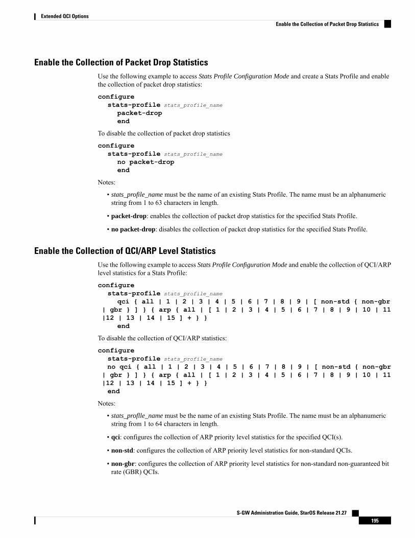
Enable the Collection of Packet Drop StatisticsUse the following example to access Stats Profile Configuration Mode and create a Stats Profile and enablethe collection of packet drop statistics:
configurestats-profile stats_profile_name
packet-dropend
To disable the collection of packet drop statistics
configurestats-profile stats_profile_name
no packet-dropend
Notes:
• stats_profile_name must be the name of an existing Stats Profile. The name must be an alphanumericstring from 1 to 63 characters in length.
• packet-drop: enables the collection of packet drop statistics for the specified Stats Profile.
• no packet-drop: disables the collection of packet drop statistics for the specified Stats Profile.
Enable the Collection of QCI/ARP Level StatisticsUse the following example to access Stats Profile Configuration Mode and enable the collection of QCI/ARPlevel statistics for a Stats Profile:
configurestats-profile stats_profile_name
qci { all | 1 | 2 | 3 | 4 | 5 | 6 | 7 | 8 | 9 | [ non-std { non-gbr| gbr } ] } { arp { all | [ 1 | 2 | 3 | 4 | 5 | 6 | 7 | 8 | 9 | 10 | 11|12 | 13 | 14 | 15 ] + } }
end
To disable the collection of QCI/ARP statistics:
configurestats-profile stats_profile_name
no qci { all | 1 | 2 | 3 | 4 | 5 | 6 | 7 | 8 | 9 | [ non-std { non-gbr| gbr } ] } { arp { all | [ 1 | 2 | 3 | 4 | 5 | 6 | 7 | 8 | 9 | 10 | 11|12 | 13 | 14 | 15 ] + } }end
Notes:
• stats_proflle_name must be the name of an existing Stats Profile. The name must be an alphanumericstring from 1 to 64 characters in length.
• qci: configures the collection of ARP priority level statistics for the specified QCI(s).
• non-std: configures the collection of ARP priority level statistics for non-standard QCIs.
• non-gbr: configures the collection of ARP priority level statistics for non-standard non-guaranteed bitrate (GBR) QCIs.
S-GW Administration Guide, StarOS Release 21.27195
Extended QCI OptionsEnable the Collection of Packet Drop Statistics
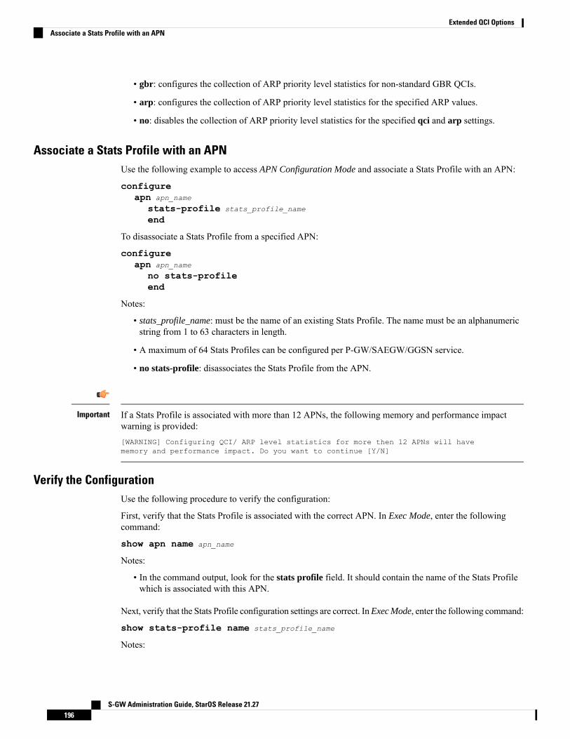
• gbr: configures the collection of ARP priority level statistics for non-standard GBR QCIs.
• arp: configures the collection of ARP priority level statistics for the specified ARP values.
• no: disables the collection of ARP priority level statistics for the specified qci and arp settings.
Associate a Stats Profile with an APNUse the following example to access APN Configuration Mode and associate a Stats Profile with an APN:
configureapn apn_name
stats-profile stats_profile_name
end
To disassociate a Stats Profile from a specified APN:
configureapn apn_name
no stats-profileend
Notes:
• stats_profile_name: must be the name of an existing Stats Profile. The name must be an alphanumericstring from 1 to 63 characters in length.
• A maximum of 64 Stats Profiles can be configured per P-GW/SAEGW/GGSN service.
• no stats-profile: disassociates the Stats Profile from the APN.
If a Stats Profile is associated with more than 12 APNs, the following memory and performance impactwarning is provided:[WARNING] Configuring QCI/ ARP level statistics for more then 12 APNs will havememory and performance impact. Do you want to continue [Y/N]
Important
Verify the ConfigurationUse the following procedure to verify the configuration:
First, verify that the Stats Profile is associated with the correct APN. In Exec Mode, enter the followingcommand:
show apn name apn_name
Notes:
• In the command output, look for the stats profile field. It should contain the name of the Stats Profilewhich is associated with this APN.
Next, verify that the Stats Profile configuration settings are correct. InExec Mode, enter the following command:
show stats-profile name stats_profile_name
Notes:
S-GW Administration Guide, StarOS Release 21.27196
Extended QCI OptionsAssociate a Stats Profile with an APN
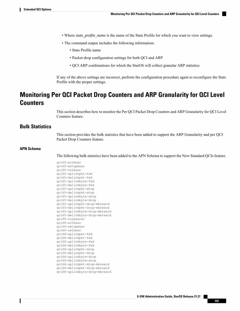
• Where stats_profile_name is the name of the Stats Profile for which you want to view settings.
• The command output includes the following information:
• Stats Profile name
• Packet-drop configuration settings for both QCI and ARP
• QCI ARP combinations for which the StarOS will collect granular ARP statistics
If any of the above settings are incorrect, perform the configuration procedure again to reconfigure the StatsProfile with the proper settings.
Monitoring Per QCI Packet Drop Counters and ARP Granularity for QCI LevelCounters
This section describes how to monitor the Per QCI Packet Drop Counters and ARP Granularity for QCI LevelCounters feature.
Bulk StatisticsThis section provides the bulk statistics that have been added to support the ARP Granularity and per QCIPacket Drop Counters feature.
APN Schema
The following bulk statistics have been added to the APN Schema to support the New Standard QCIs feature.qci65-actbearqci65-setupbearqci65-relbearqci65-uplinkpkt-fwdqci65-dwlinkpkt-fwdqci65-uplinkbyte-fwdqci65-dwlinkbyte-fwdqci65-uplinkpkt-dropqci65-dwlinkpkt-dropqci65-uplinkbyte-dropqci65-dwlinkbyte-dropqci65-uplinkpkt-drop-mbrexcdqci65-dwlinkpkt-drop-mbrexcdqci65-uplinkbyte-drop-mbrexcdqci65-dwlinkbyte-drop-mbrexcdqci65-rejbearerqci66-actbearqci66-setupbearqci66-relbearqci66-uplinkpkt-fwdqci66-dwlinkpkt-fwdqci66-uplinkbyte-fwdqci66-dwlinkbyte-fwdqci66-uplinkpkt-dropqci66-dwlinkpkt-dropqci66-uplinkbyte-dropqci66-dwlinkbyte-dropqci66-uplinkpkt-drop-mbrexcdqci66-dwlinkpkt-drop-mbrexcdqci66-uplinkbyte-drop-mbrexcd
S-GW Administration Guide, StarOS Release 21.27197
Extended QCI OptionsMonitoring Per QCI Packet Drop Counters and ARP Granularity for QCI Level Counters

qci66-dwlinkbyte-drop-mbrexcdqci66-rejbearerqci69-actbearqci69-setupbearqci69-relbearqci69-uplinkpkt-fwdqci69-dwlinkpkt-fwdqci69-uplinkbyte-fwdqci69-dwlinkbyte-fwdqci69-uplinkpkt-dropqci69-dwlinkpkt-dropqci69-uplinkbyte-dropqci69-dwlinkbyte-dropqci69-uplinkpkt-drop-mbrexcdqci69-dwlinkpkt-drop-mbrexcdqci69-uplinkbyte-drop-mbrexcdqci69-dwlinkbyte-drop-mbrexcdqci69-rejbearerqci70-actbearqci70-setupbearqci70-relbearqci70-uplinkpkt-fwdqci70-dwlinkpkt-fwdqci70-uplinkbyte-fwdqci70-dwlinkbyte-fwdqci70-uplinkpkt-dropqci70-dwlinkpkt-dropqci70-uplinkbyte-dropqci70-dwlinkbyte-dropqci70-uplinkpkt-drop-mbrexcdqci70-dwlinkpkt-drop-mbrexcdqci70-uplinkbyte-drop-mbrexcdqci70-dwlinkbyte-drop-mbrexcdqci70-rejbearersessstat-bearrel-ded-admin-clear-qci65sessstat-bearrel-ded-admin-clear-qci66sessstat-bearrel-ded-admin-clear-qci69sessstat-bearrel-ded-admin-clear-qci70
Show CommandsThis section provides the Exec Mode show commands that are available to support the Per Packet QCI DropCounters and ARP Granularity for QCI Level Counters feature.
show apn statistics
The qci and arp keywords have been added to this command. The new keywords enable operators to viewoutput for four basic scenarios that apply to the Per QCI Packet Drop Counters and ARP Granularity for QCILevel Counters feature.
Scenario 1
View packet drop counters with granularity at the QCI/ARP level for a single APN. The output of this commandis useful for isolating network issues that may be affecting packet drops.
show apn statistics name apn_name qci { all | 1-9 | non-std { gbr | non-gbr} } arp { all | 1-15 }
Notes:
• apn_name: must be the name of a configured APN created in APN Configuration Mode.
S-GW Administration Guide, StarOS Release 21.27198
Extended QCI OptionsShow Commands
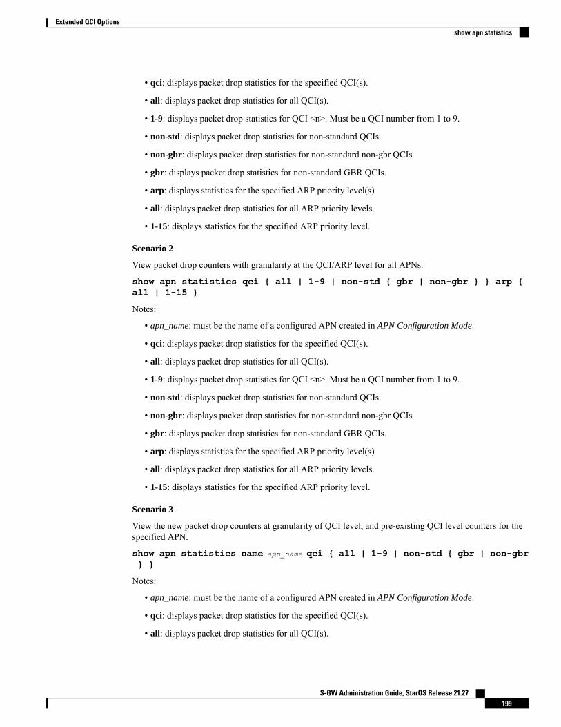
• qci: displays packet drop statistics for the specified QCI(s).
• all: displays packet drop statistics for all QCI(s).
• 1-9: displays packet drop statistics for QCI <n>. Must be a QCI number from 1 to 9.
• non-std: displays packet drop statistics for non-standard QCIs.
• non-gbr: displays packet drop statistics for non-standard non-gbr QCIs
• gbr: displays packet drop statistics for non-standard GBR QCIs.
• arp: displays statistics for the specified ARP priority level(s)
• all: displays packet drop statistics for all ARP priority levels.
• 1-15: displays statistics for the specified ARP priority level.
Scenario 2
View packet drop counters with granularity at the QCI/ARP level for all APNs.
show apn statistics qci { all | 1-9 | non-std { gbr | non-gbr } } arp {all | 1-15 }
Notes:
• apn_name: must be the name of a configured APN created in APN Configuration Mode.
• qci: displays packet drop statistics for the specified QCI(s).
• all: displays packet drop statistics for all QCI(s).
• 1-9: displays packet drop statistics for QCI <n>. Must be a QCI number from 1 to 9.
• non-std: displays packet drop statistics for non-standard QCIs.
• non-gbr: displays packet drop statistics for non-standard non-gbr QCIs
• gbr: displays packet drop statistics for non-standard GBR QCIs.
• arp: displays statistics for the specified ARP priority level(s)
• all: displays packet drop statistics for all ARP priority levels.
• 1-15: displays statistics for the specified ARP priority level.
Scenario 3
View the new packet drop counters at granularity of QCI level, and pre-existing QCI level counters for thespecified APN.
show apn statistics name apn_name qci { all | 1-9 | non-std { gbr | non-gbr} }
Notes:
• apn_name: must be the name of a configured APN created in APN Configuration Mode.
• qci: displays packet drop statistics for the specified QCI(s).
• all: displays packet drop statistics for all QCI(s).
S-GW Administration Guide, StarOS Release 21.27199
Extended QCI Optionsshow apn statistics
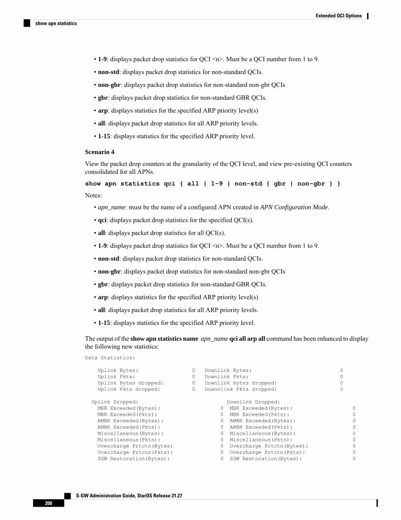
• 1-9: displays packet drop statistics for QCI <n>. Must be a QCI number from 1 to 9.
• non-std: displays packet drop statistics for non-standard QCIs.
• non-gbr: displays packet drop statistics for non-standard non-gbr QCIs
• gbr: displays packet drop statistics for non-standard GBR QCIs.
• arp: displays statistics for the specified ARP priority level(s)
• all: displays packet drop statistics for all ARP priority levels.
• 1-15: displays statistics for the specified ARP priority level.
Scenario 4
View the packet drop counters at the granularity of the QCI level, and view pre-existing QCI countersconsolidated for all APNs.
show apn statistics qci { all | 1-9 | non-std { gbr | non-gbr } }
Notes:
• apn_name: must be the name of a configured APN created in APN Configuration Mode.
• qci: displays packet drop statistics for the specified QCI(s).
• all: displays packet drop statistics for all QCI(s).
• 1-9: displays packet drop statistics for QCI <n>. Must be a QCI number from 1 to 9.
• non-std: displays packet drop statistics for non-standard QCIs.
• non-gbr: displays packet drop statistics for non-standard non-gbr QCIs
• gbr: displays packet drop statistics for non-standard GBR QCIs.
• arp: displays statistics for the specified ARP priority level(s)
• all: displays packet drop statistics for all ARP priority levels.
• 1-15: displays statistics for the specified ARP priority level.
The output of the show apn statistics name apn_name qci all arp all command has been enhanced to displaythe following new statistics:Data Statistics:
Uplink Bytes: 0 Downlink Bytes: 0Uplink Pkts: 0 Downlink Pkts: 0Uplink Bytes dropped: 0 Downlink Bytes dropped: 0Uplink Pkts dropped: 0 Downnlink Pkts dropped: 0
Uplink Dropped: Downlink Dropped:MBR Exceeded(Bytes): 0 MBR Exceeded(Bytes): 0MBR Exceeded(Pkts): 0 MBR Exceeded(Pkts): 0AMBR Exceeded(Bytes): 0 AMBR Exceeded(Bytes): 0AMBR Exceeded(Pkts): 0 AMBR Exceeded(Pkts): 0Miscellaneous(Bytes): 0 Miscellaneous(Bytes): 0Miscellaneous(Pkts): 0 Miscellaneous(Pkts): 0Overcharge Prtctn(Bytes) 0 Overcharge Prtctn(Bytes): 0Overcharge Prtctn(Pkts): 0 Overcharge Prtctn(Pkts): 0SGW Restoration(Bytes): 0 SGW Restoration(Bytes): 0
S-GW Administration Guide, StarOS Release 21.27200
Extended QCI Optionsshow apn statistics
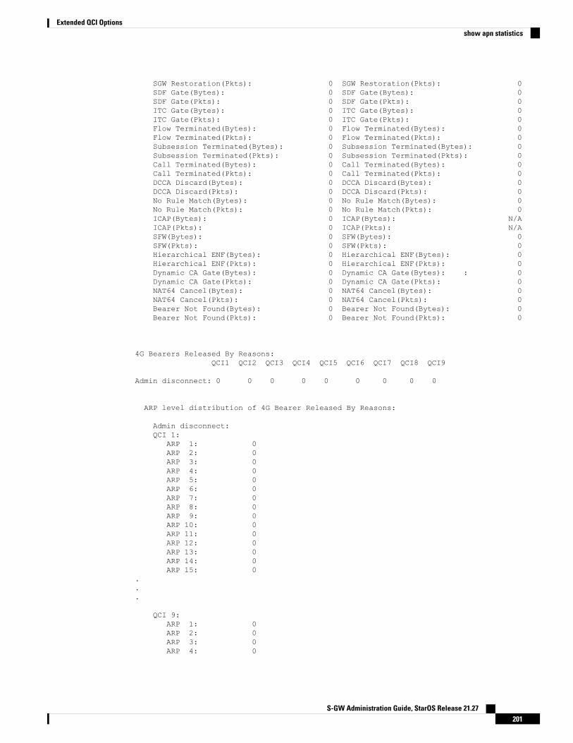
SGW Restoration(Pkts): 0 SGW Restoration(Pkts): 0SDF Gate(Bytes): 0 SDF Gate(Bytes): 0SDF Gate(Pkts): 0 SDF Gate(Pkts): 0ITC Gate(Bytes): 0 ITC Gate(Bytes): 0ITC Gate(Pkts): 0 ITC Gate(Pkts): 0Flow Terminated(Bytes): 0 Flow Terminated(Bytes): 0Flow Terminated(Pkts): 0 Flow Terminated(Pkts): 0Subsession Terminated(Bytes): 0 Subsession Terminated(Bytes): 0Subsession Terminated(Pkts): 0 Subsession Terminated(Pkts): 0Call Terminated(Bytes): 0 Call Terminated(Bytes): 0Call Terminated(Pkts): 0 Call Terminated(Pkts): 0DCCA Discard(Bytes): 0 DCCA Discard(Bytes): 0DCCA Discard(Pkts): 0 DCCA Discard(Pkts): 0No Rule Match(Bytes): 0 No Rule Match(Bytes): 0No Rule Match(Pkts): 0 No Rule Match(Pkts): 0ICAP(Bytes): 0 ICAP(Bytes): N/AICAP(Pkts): 0 ICAP(Pkts): N/ASFW(Bytes): 0 SFW(Bytes): 0SFW(Pkts): 0 SFW(Pkts): 0Hierarchical ENF(Bytes): 0 Hierarchical ENF(Bytes): 0Hierarchical ENF(Pkts): 0 Hierarchical ENF(Pkts): 0Dynamic CA Gate(Bytes): 0 Dynamic CA Gate(Bytes): : 0Dynamic CA Gate(Pkts): 0 Dynamic CA Gate(Pkts): 0NAT64 Cancel(Bytes): 0 NAT64 Cancel(Bytes): 0NAT64 Cancel(Pkts): 0 NAT64 Cancel(Pkts): 0Bearer Not Found(Bytes): 0 Bearer Not Found(Bytes): 0Bearer Not Found(Pkts): 0 Bearer Not Found(Pkts): 0
4G Bearers Released By Reasons:QCI1 QCI2 QCI3 QCI4 QCI5 QCI6 QCI7 QCI8 QCI9
Admin disconnect: 0 0 0 0 0 0 0 0 0
ARP level distribution of 4G Bearer Released By Reasons:
Admin disconnect:QCI 1:
ARP 1: 0ARP 2: 0ARP 3: 0ARP 4: 0ARP 5: 0ARP 6: 0ARP 7: 0ARP 8: 0ARP 9: 0ARP 10: 0ARP 11: 0ARP 12: 0ARP 13: 0ARP 14: 0ARP 15: 0
.
.
.
QCI 9:ARP 1: 0ARP 2: 0ARP 3: 0ARP 4: 0
S-GW Administration Guide, StarOS Release 21.27201
Extended QCI Optionsshow apn statistics

ARP 5: 0ARP 6: 0ARP 7: 0ARP 8: 0ARP 9: 0ARP 10: 0ARP 11: 0ARP 12: 0ARP 13: 0ARP 14: 0ARP 15: 0
Subscriber QoS Statistics:
4G Bearers Released By Reasons:QCI1 QCI2 QCI3 QCI4 QCI5 QCI6 QCI7 QCI8 QCI9
Admin disconnect: 0 0 0 0 0 0 0 0 0
ARP level distribution of 4G Bearer Released By Reasons:
Admin disconnect:QCI 1:
ARP 1: 0ARP 2: 0ARP 3: 0ARP 4: 0ARP 5: 0ARP 6: 0ARP 7: 0ARP 8: 0ARP 9: 0ARP 10: 0ARP 11: 0ARP 12: 0ARP 13: 0ARP 14: 0ARP 15: 0
.
.
.
QCI 9:ARP 1: 0ARP 2: 0ARP 3: 0ARP 4: 0ARP 5: 0ARP 6: 0ARP 7: 0ARP 8: 0ARP 9: 0ARP 10: 0ARP 11: 0ARP 12: 0ARP 13: 0ARP 14: 0ARP 15: 0
QCI 1:
S-GW Administration Guide, StarOS Release 21.27202
Extended QCI Optionsshow apn statistics

ARP 1:Bearer Active: 0 Bearer setup: 2Bearer Released: 2 Bearer Rejected: 0
Uplink Bytes forwarded: 0 Downlink Bytes forwarded: 0Uplink Pkts forwarded: 0 Downlink Pkts forwarded: 0Uplink Bytes dropped: 0 Downlink Bytes dropped: 0Uplink Pkts dropped: 0 Downlink Pkts dropped: 0
Uplink Dropped: Downlink Dropped:MBR Exceeded(Bytes): 0 MBR Exceeded(Bytes): 0MBR Exceeded(Pkts): 0 MBR Exceeded(Pkts): 0AMBR Exceeded(Bytes): 0 AMBR Exceeded(Bytes): 0AMBR Exceeded(Pkts): 0 AMBR Exceeded(Pkts): 0Miscellaneous(Bytes): 0 Miscellaneous(Bytes): 0Miscellaneous(Pkts): 0 Miscellaneous(Pkts): 0Overcharge Prtctn(Bytes) 0 Overcharge Prtctn(Bytes): 0Overcharge Prtctn(Pkts): 0 Overcharge Prtctn(Pkts): 0SGW Restoration(Bytes): 0 SGW Restoration(Bytes): 0SGW Restoration(Pkts): 0 SGW Restoration(Pkts): 0SDF Gate(Bytes): 0 SDF Gate(Bytes): 0SDF Gate(Pkts): 0 SDF Gate(Pkts): 0ITC Gate(Bytes): 0 ITC Gate(Bytes): 0ITC Gate(Pkts): 0 ITC Gate(Pkts): 0Flow Terminated(Bytes): 0 Flow Terminated(Bytes): 0Flow Terminated(Pkts): 0 Flow Terminated(Pkts): 0Subsession Terminated(Bytes): 0 Subsession Terminated(Bytes): 0Subsession Terminated(Pkts): 0 Subsession Terminated(Pkts): 0Call Terminated(Bytes): 0 Call Terminated(Bytes): 0Call Terminated(Pkts): 0 Call Terminated(Pkts): 0DCCA Discard(Bytes): 0 DCCA Discard(Bytes): 0DCCA Discard(Pkts): 0 DCCA Discard(Pkts): 0No Rule Match(Bytes): 0 No Rule Match(Bytes): 0No Rule Match(Pkts): 0 No Rule Match(Pkts): 0ICAP(Bytes): 0 ICAP(Bytes): N/AICAP(Pkts): 0 ICAP(Pkts): N/ASFW(Bytes): 0 SFW(Bytes): 0SFW(Pkts): 0 SFW(Pkts): 0Hierarchical ENF(Bytes): 0 Hierarchical ENF(Bytes): 0Hierarchical ENF(Pkts): 0 Hierarchical ENF(Pkts): 0Dynamic CA Gate(Bytes): 0 Dynamic CA Gate(Bytes): : 0Dynamic CA Gate(Pkts): 0 Dynamic CA Gate(Pkts): 0NAT64 Cancel(Bytes): 0 NAT64 Cancel(Bytes): 0NAT64 Cancel(Pkts): 0 NAT64 Cancel(Pkts): 0Bearer Not Found(Bytes): 0 Bearer Not Found(Bytes): 0Bearer Not Found(Pkts): 0 Bearer Not Found(Pkts): 0
QCI 1:ARP 2:Bearer Active: 0 Bearer setup: 2Bearer Released: 2 Bearer Rejected: 0
Uplink Bytes forwarded: 0 Downlink Bytes forwarded: 0Uplink Pkts forwarded: 0 Downlink Pkts forwarded: 0Uplink Bytes dropped: 0 Downlink Bytes dropped: 0Uplink Pkts dropped: 0 Downlink Pkts dropped: 0
Uplink Dropped: Downlink Dropped:MBR Exceeded(Bytes): 0 MBR Exceeded(Bytes): 0MBR Exceeded(Pkts): 0 MBR Exceeded(Pkts): 0AMBR Exceeded(Bytes): 0 AMBR Exceeded(Bytes): 0AMBR Exceeded(Pkts): 0 AMBR Exceeded(Pkts): 0Miscellaneous(Bytes): 0 Miscellaneous(Bytes): 0Miscellaneous(Pkts): 0 Miscellaneous(Pkts): 0Overcharge Prtctn(Bytes) 0 Overcharge Prtctn(Bytes): 0Overcharge Prtctn(Pkts): 0 Overcharge Prtctn(Pkts): 0SGW Restoration(Bytes): 0 SGW Restoration(Bytes): 0
S-GW Administration Guide, StarOS Release 21.27203
Extended QCI Optionsshow apn statistics

SGW Restoration(Pkts): 0 SGW Restoration(Pkts): 0SDF Gate(Bytes): 0 SDF Gate(Bytes): 0SDF Gate(Pkts): 0 SDF Gate(Pkts): 0ITC Gate(Bytes): 0 ITC Gate(Bytes): 0ITC Gate(Pkts): 0 ITC Gate(Pkts): 0Flow Terminated(Bytes): 0 Flow Terminated(Bytes): 0Flow Terminated(Pkts): 0 Flow Terminated(Pkts): 0Subsession Terminated(Bytes): 0 Subsession Terminated(Bytes): 0Subsession Terminated(Pkts): 0 Subsession Terminated(Pkts): 0Call Terminated(Bytes): 0 Call Terminated(Bytes): 0Call Terminated(Pkts): 0 Call Terminated(Pkts): 0DCCA Discard(Bytes): 0 DCCA Discard(Bytes): 0DCCA Discard(Pkts): 0 DCCA Discard(Pkts): 0No Rule Match(Bytes): 0 No Rule Match(Bytes): 0No Rule Match(Pkts): 0 No Rule Match(Pkts): 0ICAP(Bytes): 0 ICAP(Bytes): N/AICAP(Pkts): 0 ICAP(Pkts): N/ASFW(Bytes): 0 SFW(Bytes): 0SFW(Pkts): 0 SFW(Pkts): 0Hierarchical ENF(Bytes): 0 Hierarchical ENF(Bytes): 0Hierarchical ENF(Pkts): 0 Hierarchical ENF(Pkts): 0Dynamic CA Gate(Bytes): 0 Dynamic CA Gate(Bytes): : 0Dynamic CA Gate(Pkts): 0 Dynamic CA Gate(Pkts): 0NAT64 Cancel(Bytes): 0 NAT64 Cancel(Bytes): 0NAT64 Cancel(Pkts): 0 NAT64 Cancel(Pkts): 0Bearer Not Found(Bytes): 0 Bearer Not Found(Bytes): 0Bearer Not Found(Pkts): 0 Bearer Not Found(Pkts): 0
The output of the show apn statistics name apn_name qci all command has been enhanced to display thefollowing new statistics:Data Statistics:
Uplink Bytes: 0 Downlink Bytes: 0Uplink Pkts: 0 Downlink Pkts: 0Uplink Bytes dropped: 0 Downlink Bytes dropped: 0Uplink Pkts dropped: 0 Downnlink Pkts dropped: 0
Uplink Dropped: Downlink Dropped:MBR Exceeded(Bytes): 0 MBR Exceeded(Bytes): 0MBR Exceeded(Pkts): 0 MBR Exceeded(Pkts): 0AMBR Exceeded(Bytes): 0 AMBR Exceeded(Bytes): 0AMBR Exceeded(Pkts): 0 AMBR Exceeded(Pkts): 0Miscellaneous(Bytes): 0 Miscellaneous(Bytes): 0Miscellaneous(Pkts): 0 Miscellaneous(Pkts): 0Overcharge Prtctn(Bytes) 0 Overcharge Prtctn(Bytes): 0Overcharge Prtctn(Pkts): 0 Overcharge Prtctn(Pkts): 0SGW Restoration(Bytes): 0 SGW Restoration(Bytes): 0SGW Restoration(Pkts): 0 SGW Restoration(Pkts): 0SDF Gate(Bytes): 0 SDF Gate(Bytes): 0SDF Gate(Pkts): 0 SDF Gate(Pkts): 0ITC Gate(Bytes): 0 ITC Gate(Bytes): 0ITC Gate(Pkts): 0 ITC Gate(Pkts): 0Flow Terminated(Bytes): 0 Flow Terminated(Bytes): 0Flow Terminated(Pkts): 0 Flow Terminated(Pkts): 0Subsession Terminated(Bytes): 0 Subsession Terminated(Bytes): 0Subsession Terminated(Pkts): 0 Subsession Terminated(Pkts): 0Call Terminated(Bytes): 0 Call Terminated(Bytes): 0Call Terminated(Pkts): 0 Call Terminated(Pkts): 0DCCA Discard(Bytes): 0 DCCA Discard(Bytes): 0DCCA Discard(Pkts): 0 DCCA Discard(Pkts): 0No Rule Match(Bytes): 0 No Rule Match(Bytes): 0No Rule Match(Pkts): 0 No Rule Match(Pkts): 0ICAP(Bytes): 0 ICAP(Bytes): N/AICAP(Pkts): 0 ICAP(Pkts): N/A
S-GW Administration Guide, StarOS Release 21.27204
Extended QCI Optionsshow apn statistics
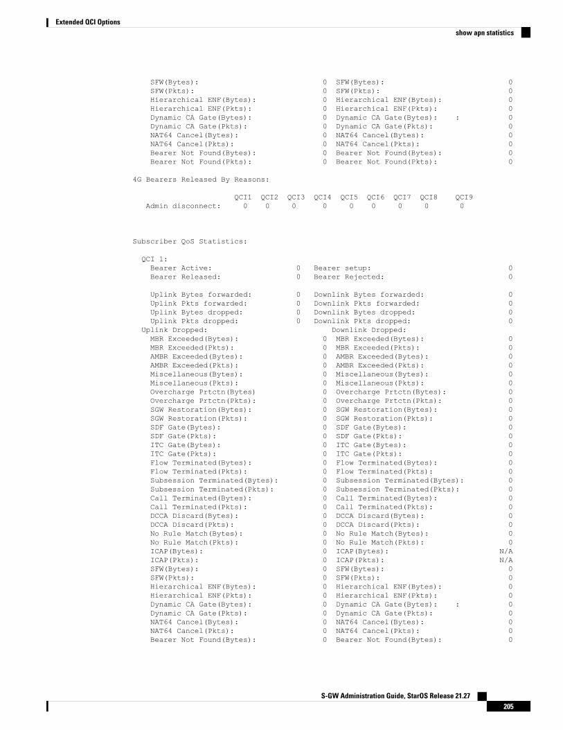
SFW(Bytes): 0 SFW(Bytes): 0SFW(Pkts): 0 SFW(Pkts): 0Hierarchical ENF(Bytes): 0 Hierarchical ENF(Bytes): 0Hierarchical ENF(Pkts): 0 Hierarchical ENF(Pkts): 0Dynamic CA Gate(Bytes): 0 Dynamic CA Gate(Bytes): : 0Dynamic CA Gate(Pkts): 0 Dynamic CA Gate(Pkts): 0NAT64 Cancel(Bytes): 0 NAT64 Cancel(Bytes): 0NAT64 Cancel(Pkts): 0 NAT64 Cancel(Pkts): 0Bearer Not Found(Bytes): 0 Bearer Not Found(Bytes): 0Bearer Not Found(Pkts): 0 Bearer Not Found(Pkts): 0
4G Bearers Released By Reasons:
QCI1 QCI2 QCI3 QCI4 QCI5 QCI6 QCI7 QCI8 QCI9Admin disconnect: 0 0 0 0 0 0 0 0 0
Subscriber QoS Statistics:
QCI 1:Bearer Active: 0 Bearer setup: 0Bearer Released: 0 Bearer Rejected: 0
Uplink Bytes forwarded: 0 Downlink Bytes forwarded: 0Uplink Pkts forwarded: 0 Downlink Pkts forwarded: 0Uplink Bytes dropped: 0 Downlink Bytes dropped: 0Uplink Pkts dropped: 0 Downlink Pkts dropped: 0
Uplink Dropped: Downlink Dropped:MBR Exceeded(Bytes): 0 MBR Exceeded(Bytes): 0MBR Exceeded(Pkts): 0 MBR Exceeded(Pkts): 0AMBR Exceeded(Bytes): 0 AMBR Exceeded(Bytes): 0AMBR Exceeded(Pkts): 0 AMBR Exceeded(Pkts): 0Miscellaneous(Bytes): 0 Miscellaneous(Bytes): 0Miscellaneous(Pkts): 0 Miscellaneous(Pkts): 0Overcharge Prtctn(Bytes) 0 Overcharge Prtctn(Bytes): 0Overcharge Prtctn(Pkts): 0 Overcharge Prtctn(Pkts): 0SGW Restoration(Bytes): 0 SGW Restoration(Bytes): 0SGW Restoration(Pkts): 0 SGW Restoration(Pkts): 0SDF Gate(Bytes): 0 SDF Gate(Bytes): 0SDF Gate(Pkts): 0 SDF Gate(Pkts): 0ITC Gate(Bytes): 0 ITC Gate(Bytes): 0ITC Gate(Pkts): 0 ITC Gate(Pkts): 0Flow Terminated(Bytes): 0 Flow Terminated(Bytes): 0Flow Terminated(Pkts): 0 Flow Terminated(Pkts): 0Subsession Terminated(Bytes): 0 Subsession Terminated(Bytes): 0Subsession Terminated(Pkts): 0 Subsession Terminated(Pkts): 0Call Terminated(Bytes): 0 Call Terminated(Bytes): 0Call Terminated(Pkts): 0 Call Terminated(Pkts): 0DCCA Discard(Bytes): 0 DCCA Discard(Bytes): 0DCCA Discard(Pkts): 0 DCCA Discard(Pkts): 0No Rule Match(Bytes): 0 No Rule Match(Bytes): 0No Rule Match(Pkts): 0 No Rule Match(Pkts): 0ICAP(Bytes): 0 ICAP(Bytes): N/AICAP(Pkts): 0 ICAP(Pkts): N/ASFW(Bytes): 0 SFW(Bytes): 0SFW(Pkts): 0 SFW(Pkts): 0Hierarchical ENF(Bytes): 0 Hierarchical ENF(Bytes): 0Hierarchical ENF(Pkts): 0 Hierarchical ENF(Pkts): 0Dynamic CA Gate(Bytes): 0 Dynamic CA Gate(Bytes): : 0Dynamic CA Gate(Pkts): 0 Dynamic CA Gate(Pkts): 0NAT64 Cancel(Bytes): 0 NAT64 Cancel(Bytes): 0NAT64 Cancel(Pkts): 0 NAT64 Cancel(Pkts): 0Bearer Not Found(Bytes): 0 Bearer Not Found(Bytes): 0
S-GW Administration Guide, StarOS Release 21.27205
Extended QCI Optionsshow apn statistics

Bearer Not Found(Pkts): 0 Bearer Not Found(Pkts): 0
.
.
.QCI 9:
Bearer Active: 0 Bearer setup: 0Bearer Released: 0 Bearer Rejected: 0
Uplink Bytes forwarded: 0 Downlink Bytes forwarded: 0Uplink Pkts forwarded: 0 Downlink Pkts forwarded: 0Uplink Bytes dropped: 0 Downlink Bytes dropped: 0Uplink Pkts dropped: 0 Downlink Pkts dropped:
show configuration
The output of this command has been enhanced to show the Stats Profile configuration settings.
• stats-profile <stats_profile_name>
• qci <qci number> arp <arp number>
• packet-drop (if packet-drop is enabled)
show stats-profile name
This new command in Exec Mode shows the configuration settings for the specified Stats Profile.
• Stats Profile Name: <stats_profile_name>
• qci <qci number> arp <arp_number(s)>
• packet-drop <if packet drop is enabled>
DSCP Marking Based on Both QCI and ARP Values
Feature DescriptionP-GW allows users to perform DSCP marking based on QoS Class Identifier (QCI) values. This functionalityhas been expanded to include the Priority Level (PL) values 1-15 of Allocation and Retention Priority (ARP),which allows users to assign different DSCP values for bearers with the same QCI but different ARP priorityvalues. For example, the ability to assign DSCP values based on QCI+ARP could be used to meet complianceon priority and emergency calling via VoLTE.
Applies to the P-GW for the following interfaces:
• S5
• S8
• SGi
• S2b
Applies to the S-GW for the following interfaces:
S-GW Administration Guide, StarOS Release 21.27206
Extended QCI Optionsshow configuration

• S1-U
• S5
• S8
• S11
• S4
Relationships to Other FeaturesECS populates the DSCP values in inner IP header. These values are fetched from the DSCP table by meansof a sessmanager API. Since DSCP values are now available for QCI-ARP combination, the API is replacedby a wrapper API that will accept both QCI and ARP and provide the DSCP values to ECS in a new datastructure.
The API will return correct values in the following scenarios:
1. QCI-DSCP table is not configured, or it is not associated for this session.
API will return an indication to ECS that table was not found.
2. Table is configured, but entry for the given QCI value is not present in the table.
API will not populate the structure and keep the same unaltered.
3. Entry for given QCI is present, but it is not available for the given QCI-ARP pair.
The default DSCP values for that particular QCI will be populated in the return structure.
4. Entry for given QCI-ARP combination is present.
The DSCP values for given QCI-ARP combination will be populated in the return structure.
Once values are received from SM, ECS caches these values and uses the cached values for marking thefurther packets. Another lookup into the table is done only when there is a mismatch between the currentlycached QCI-ARP value and the current packet's QCI-ARP value. Therefore, any change in the QCI-ARP tablewould be affected for inner DSCP marking on existing flows only in case of QCI or ARP change.
LicensingDSCPmarking capability requires that a valid license key be installed. Contact your Cisco Account or Supportrepresentative for information on how to obtain a license.
How It WorksThe expansion of functionality to allow assigning different DSCP values for bearers with the same QCI, butdifferent APR values, works as follows.
• DSCP marking of packets based on QCI+ARP combination allowed
• QCI + ARP configuration will override any DSCP entry for that QCI+ARP combination
• QCI only DSCP entry will override all existing QCI+ARP configuration
• Applying associated DSCPmarking for QCI+ARP for Uplink and Downlink functionality is also allowed
S-GW Administration Guide, StarOS Release 21.27207
Extended QCI OptionsRelationships to Other Features
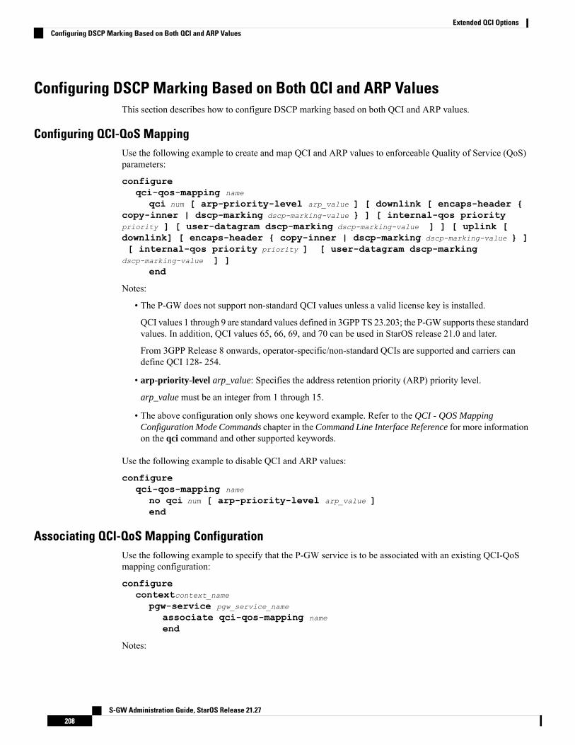
Configuring DSCP Marking Based on Both QCI and ARP ValuesThis section describes how to configure DSCP marking based on both QCI and ARP values.
Configuring QCI-QoS MappingUse the following example to create and map QCI and ARP values to enforceable Quality of Service (QoS)parameters:
configureqci-qos-mapping name
qci num [ arp-priority-level arp_value ] [ downlink [ encaps-header {copy-inner | dscp-marking dscp-marking-value } ] [ internal-qos prioritypriority ] [ user-datagram dscp-marking dscp-marking-value ] ] [ uplink [downlink] [ encaps-header { copy-inner | dscp-marking dscp-marking-value } ][ internal-qos priority priority ] [ user-datagram dscp-marking
dscp-marking-value ] ]end
Notes:
• The P-GW does not support non-standard QCI values unless a valid license key is installed.
QCI values 1 through 9 are standard values defined in 3GPP TS 23.203; the P-GW supports these standardvalues. In addition, QCI values 65, 66, 69, and 70 can be used in StarOS release 21.0 and later.
From 3GPP Release 8 onwards, operator-specific/non-standard QCIs are supported and carriers candefine QCI 128- 254.
• arp-priority-level arp_value: Specifies the address retention priority (ARP) priority level.
arp_value must be an integer from 1 through 15.
• The above configuration only shows one keyword example. Refer to the QCI - QOS MappingConfiguration Mode Commands chapter in the Command Line Interface Reference for more informationon the qci command and other supported keywords.
Use the following example to disable QCI and ARP values:
configureqci-qos-mapping name
no qci num [ arp-priority-level arp_value ]end
Associating QCI-QoS Mapping ConfigurationUse the following example to specify that the P-GW service is to be associated with an existing QCI-QoSmapping configuration:
configurecontextcontext_name
pgw-service pgw_service_name
associate qci-qos-mapping name
end
Notes:
S-GW Administration Guide, StarOS Release 21.27208
Extended QCI OptionsConfiguring DSCP Marking Based on Both QCI and ARP Values

• QCI-QoS mapping configurations are created in the AAA context.
Use the following example to specify that the S-GW service is to be associated with an existing QCI-QoSmapping configuration:
configurecontextcontext_name
sgw-service sgw_service_name
associate qci-qos-mapping name
end
Notes:
• QCI-QoS mapping configurations are created in the AAA context.
Configuring CS5 Marking for GTP-CUse the following example to mark DSCP precedence CS5 on control packets:
configurecontextcontext_name
ggsn-service ggsn_service_name
ip qos-dscp gtpc cs5end
Notes:
• Designates Class Selector 5 DSCP precedence for GTP-C packets.
Verifying the ConfigurationUse the following command in Exec mode to display/verify the configuration.
show configuration
Monitoring DSCP Marking Based on Both QCI and ARP Values
Output of Show CommandsThis section provides information regarding show commands and/or their outputs in support of DSCPmarkingbased on both QCI and ARP values.
show qci-qos-mapping table all
The output of this command has been enhanced to show the ARP value:
• arp-priority-level
New Standard QCI SupportCDETS: CSCuy20910 - Support of new standard QCIs (65, 66, 69, 70)
Applicable Products: P-GW, SAEGW, S-GW
S-GW Administration Guide, StarOS Release 21.27209
Extended QCI OptionsConfiguring CS5 Marking for GTP-C
Feature DescriptionThe P-GW/SAEGW/S-GW support additional new 3GPP-defined standard QCIs. QCIs 65, 66, 69, and 70are now supported for Mission Critical and Push-to-Talk (MCPTT) applications. These new standard QCIsare supported in addition to the previously supported QCIs of 1 through 9, and operator-defined QCIs 128through 254.
The StarOS will continue to reject QCIs 10 through 127 sent by the PCRF.
Licensing
New Standard QCI Support is a licensed feature. Contact your Cisco account or support representative forlicensing details.
Important
How it WorksAlthough the 3GPP specification mentions that only QCIs 65 and 69 can co-exist, there is no hard restrictionon the QCIs in the StarOS implementation of this feature, as that is applicable to the PCRF. The P-GW actsas a pass-through node and allows QCIs 65 and 69 if a different QCI combination is requested from PCRF.
With support for standard QCIs 65, 66, 69, and 70 present, the implementation has also added support acrossthe following StarOS interfaces:
• Gx: Gx processes Default Bearer QoS and Rule Validation allowing the newMission Critical (MC)/Pushto Talk (PTT) QCIs. When the MC/PTT bit is not negotiated with the PCRF, the PCEF will reject thecreation of a bearer or reject call setup.
• sessmgr: The P-GW sessmgr now processes the updating and modification of QoS. The P-GW rejectsall UE initiated BRC creation for the new standard QCIs.
• ECS: ECS accepts the new standard QCIs when received from the PCRF and will reject them wheneither the license is not configured or the same is received in 3G. The ECS is able to update a Defaultbearer with this QoS change or create a Dedicated Bearer for the new standard QCIs.
Handoff Behavior
For Gn/Gp handoffs, local mapping via the CLI is supported so that the P-GW/SAEGW/S-GW is in sync withthe MME-to-SGSN context transfer. The following scenarios are supported:
No Local QoS Mapping Present: When no local mapping is present for the new QCIs, a call handoff from4G to 3G will be rejected.
Local QoS Mapping Present: Three scenarios are supported when local mapping is present:
• Local Mapping present for MME-SGSN and PCRF Out of Synchronization: When local mappingis present it is assumed that the QoS mapping in the P-GW is in sync with the mapping from the MMEto SGSN. Even if the QoS mapping for one of the transferred PDPs during a Gn/Gp handoff is not insync with MME-SGSN mapping, the P-GW/SAEGW/S-GW still continues with the handoff with thelocal mapping present. However, the CDR generated while waiting for the PCRF response during thehandoff would be out of sync with the CDR's received after the handoff.
S-GW Administration Guide, StarOS Release 21.27210
Extended QCI OptionsFeature Description
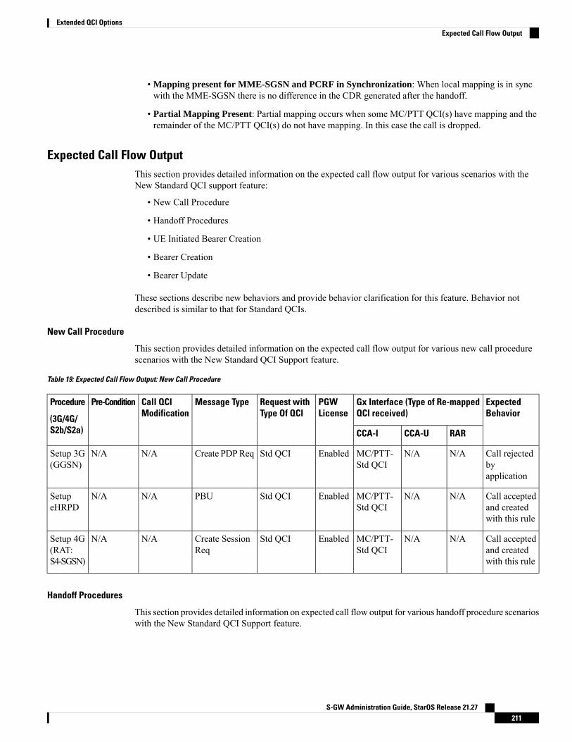
• Mapping present for MME-SGSN and PCRF in Synchronization: When local mapping is in syncwith the MME-SGSN there is no difference in the CDR generated after the handoff.
• Partial Mapping Present: Partial mapping occurs when some MC/PTT QCI(s) have mapping and theremainder of the MC/PTT QCI(s) do not have mapping. In this case the call is dropped.
Expected Call Flow OutputThis section provides detailed information on the expected call flow output for various scenarios with theNew Standard QCI support feature:
• New Call Procedure
• Handoff Procedures
• UE Initiated Bearer Creation
• Bearer Creation
• Bearer Update
These sections describe new behaviors and provide behavior clarification for this feature. Behavior notdescribed is similar to that for Standard QCIs.
New Call Procedure
This section provides detailed information on the expected call flow output for various new call procedurescenarios with the New Standard QCI Support feature.
Table 19: Expected Call Flow Output: New Call Procedure
ExpectedBehavior
Gx Interface (Type of Re-mappedQCI received)
PGWLicense
Request withType Of QCI
Message TypeCall QCIModification
Pre-ConditionProcedure
(3G/4G/S2b/S2a) RARCCA-UCCA-I
Call rejectedbyapplication
N/AN/AMC/PTT-Std QCI
EnabledStd QCICreate PDPReqN/AN/ASetup 3G(GGSN)
Call acceptedand createdwith this rule
N/AN/AMC/PTT-Std QCI
EnabledStd QCIPBUN/AN/ASetupeHRPD
Call acceptedand createdwith this rule
N/AN/AMC/PTT-Std QCI
EnabledStd QCICreate SessionReq
N/AN/ASetup 4G(RAT:S4-SGSN)
Handoff Procedures
This section provides detailed information on expected call flow output for various handoff procedure scenarioswith the New Standard QCI Support feature.
S-GW Administration Guide, StarOS Release 21.27211
Extended QCI OptionsExpected Call Flow Output
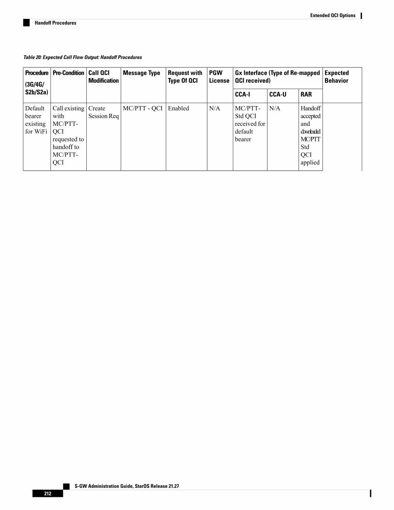
Table 20: Expected Call Flow Output: Handoff Procedures
ExpectedBehavior
Gx Interface (Type of Re-mappedQCI received)
PGWLicense
Request withType Of QCI
Message TypeCall QCIModification
Pre-ConditionProcedure
(3G/4G/S2b/S2a) RARCCA-UCCA-I
HandoffacceptedanddownloadedMC/PTTStdQCIapplied
N/AMC/PTT-Std QCIreceived fordefaultbearer
N/AEnabledMC/PTT - QCICreateSessionReq
Call existingwithMC/PTT-QCIrequested tohandoff toMC/PTT-QCI
Defaultbearerexistingfor WiFi
S-GW Administration Guide, StarOS Release 21.27212
Extended QCI OptionsHandoff Procedures
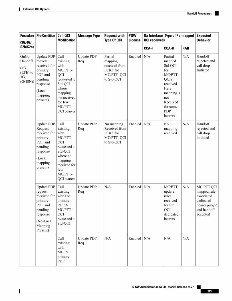
ExpectedBehavior
Gx Interface (Type of Re-mappedQCI received)
PGWLicense
Request withType Of QCI
Message TypeCall QCIModification
Pre-ConditionProcedure
(3G/4G/S2b/S2a) RARCCA-UCCA-I
Handoffrejected andcall dropInitiated
N/APartialmappedStd QCIforMC/PTT-QCIsreceived.Heremapping isnotReceivedfor somePDPbearers .
N/AEnabledPartialmappingreceived fromPCRF forMC/PTT-QCIto Std-QCI
Update PDPReq
CallexistingwithMC/PTT-QCIrequested toStd-QCIwheremappingnot receivedfor fewMC/PTT-QCI bearers
Update PDPrequestreceived forprimaryPDP andpendingresponse
(Localmappingpresent)
GnGpHandoff
(4G(LTE) to3G(GGSN))
Handoffrejected andcall dropinitiated
N/ANomappingreceived
N/AEnabledNo mappingReceived fromPCRF forMC/PTT-QCIto Std-QCI
Update PDPReq
CallexistingwithMC/PTT-QCIrequested toStd-QCIwhere nomappingreceived forfewMC/PTT-QCI bearers
Update PDPRequestreceived forprimaryPDP andpendingresponse
(Localmappingpresent)
MC/PTTQCImapped ruleassociateddedicatedbearer purgedand handoffaccepted
N/AMC/PTTupdaterulesreceivedfor StdQCIdedicatedbearers
N/AEnabledN/AUpdate PDPReq
Callexistingwith StdprimaryPDP &MC/PTT-QCIrequested toStd-QCI
Update PDPrequestreceived forprimaryPDP andpendingresponse
(No-LocalMappingPresent)
N/AN/AN/AEnabledN/AUpdate PDPReq
CallexistingwithMC/PTTprimaryPDP
S-GW Administration Guide, StarOS Release 21.27213
Extended QCI OptionsHandoff Procedures

ExpectedBehavior
Gx Interface (Type of Re-mappedQCI received)
PGWLicense
Request withType Of QCI
Message TypeCall QCIModification
Pre-ConditionProcedure
(3G/4G/S2b/S2a) RARCCA-UCCA-I
Update PDPRequestreceived forprimaryPDP andpendingresponse
(No-localmappingpresent)
Handoffrejected andcall dropInitiated(droppedbeforeInitiatingCCA-U forhandoff)
Handoffrejected andcall dropinitiated
N/ANoresponsefromPCRF /CCA-Utimeout
N/AEnabledPCRFTimeout NoResponsereceived
Update PDPReq
CallexistingwithMC/PTT-QCIrequested toStd-QCI
Update PDPRequestreceived forprimaryPDP andpendingresponse
(Localmappingpresent)
Handoffaccepted
N/AAllmappingreceivedfromPCRF
N/AEnabledMappingreceived fromPCRF forMC/PTT-QCIto Std-QCI
Update PDPReq
CallexistingwithMC/PTT-QCIrequested toStd-QCI
Update PDPRequestreceived forprimaryPDP andpendingresponse.BCM modeis mixed.
(Localmappingpresent andsame aswhat QCIvaluescomes inUPC duringHO)
Handoffrejected andcall dropinitiated
N/AN/AN/AEnabledN/AUpdate PDPReq
S-GW Administration Guide, StarOS Release 21.27214
Extended QCI OptionsHandoff Procedures
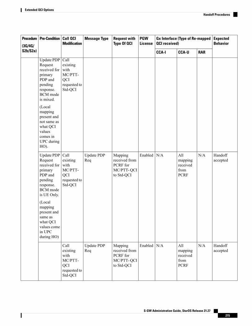
ExpectedBehavior
Gx Interface (Type of Re-mappedQCI received)
PGWLicense
Request withType Of QCI
Message TypeCall QCIModification
Pre-ConditionProcedure
(3G/4G/S2b/S2a) RARCCA-UCCA-I
Update PDPRequestreceived forprimaryPDP andpendingresponse.BCM modeis mixed.
(Localmappingpresent andnot same aswhat QCIvaluescomes inUPC duringHO).
CallexistingwithMC/PTT-QCIrequested toStd-QCI
Handoffaccepted
N/AAllmappingreceivedfromPCRF
N/AEnabledMappingreceived fromPCRF forMC/PTT-QCIto Std-QCI
Update PDPReq
CallexistingwithMC/PTT-QCIrequested toStd-QCI
Update PDPRequestreceived forprimaryPDP andpendingresponse.BCM modeis UE Only.
(Localmappingpresent andsame aswhat QCIvalues comein UPCduring HO)
Handoffaccepted
N/AAllmappingreceivedfromPCRF
N/AEnabledMappingreceived fromPCRF forMC/PTT-QCIto Std-QCI
Update PDPReq
CallexistingwithMC/PTT-QCIrequested toStd-QCI
S-GW Administration Guide, StarOS Release 21.27215
Extended QCI OptionsHandoff Procedures

ExpectedBehavior
Gx Interface (Type of Re-mappedQCI received)
PGWLicense
Request withType Of QCI
Message TypeCall QCIModification
Pre-ConditionProcedure
(3G/4G/S2b/S2a) RARCCA-UCCA-I
Update PDPRequestreceived forprimaryPDP andpendingresponse.BCM modeis UE Only.
(Localmappingpresent andnot same aswhat QCIvalues comein UPCduring HO.)
Handoffrejected andcall dropinitiated
N/AN/AN/AEnabledN/AUpdate PDPReq
CallexistingwithMC/PTT-QCIrequested toStd-QCI.Alsosuppress-NRUPCUPC isconfiguredat theGGSNservicelevel.
Update PDPRequestreceived forprimaryPDP andpendingresponse
(Localmappingpresent/notpresent)
Handoffaccepted
N/AAllmappedStd QCIforMC/PTT-QCI
N/AEnabledCompletemappingReceived fromPCRF forMC/PTT-QCIto Std-QCI (asper LocalMC/PTT toStd QCImapping)
Update PDPReq
CallexistingwithMC/PTT-QCIrequested toStd-QCImappingreceived forAllMC/PTT-QCI bearers
Update PDPRequestreceived forprimaryPDP andresponsesent
(Localmappingpresent)
S-GW Administration Guide, StarOS Release 21.27216
Extended QCI OptionsHandoff Procedures
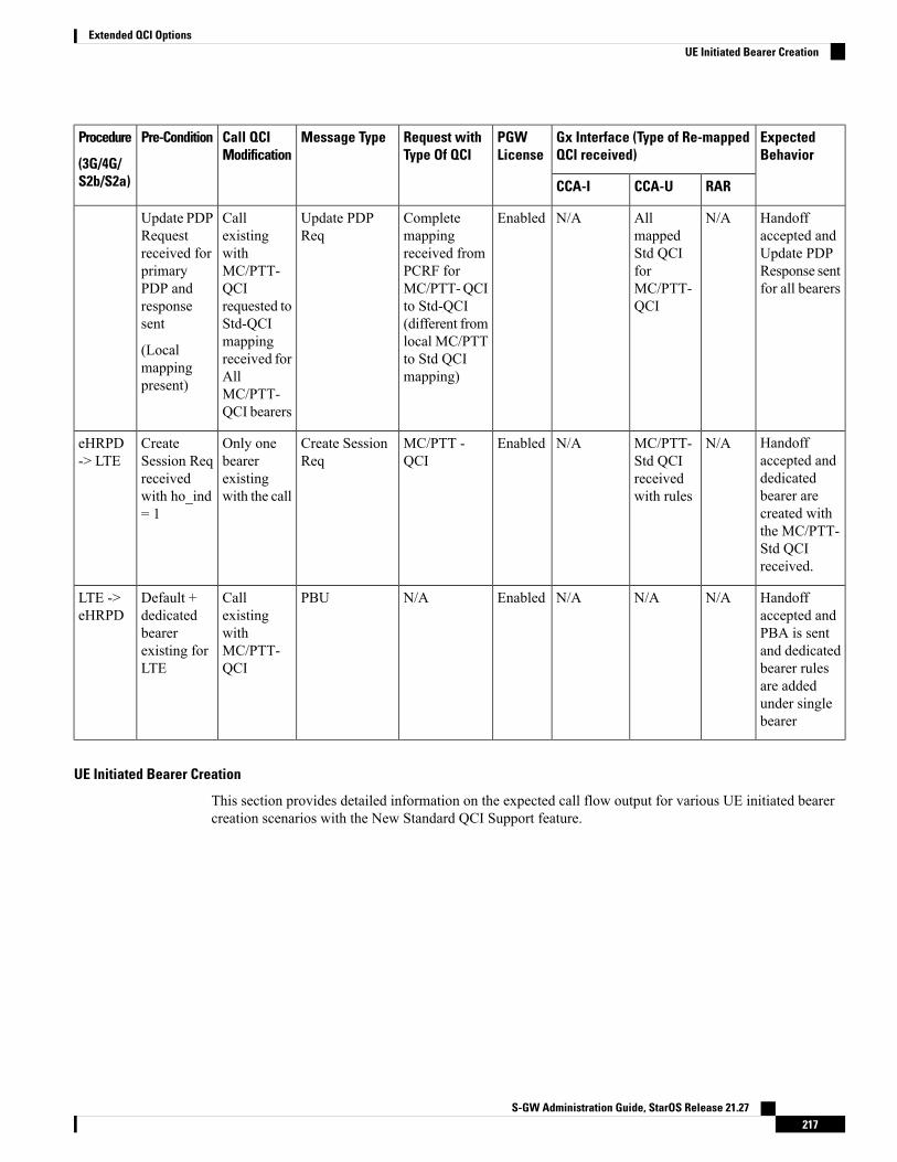
ExpectedBehavior
Gx Interface (Type of Re-mappedQCI received)
PGWLicense
Request withType Of QCI
Message TypeCall QCIModification
Pre-ConditionProcedure
(3G/4G/S2b/S2a) RARCCA-UCCA-I
Handoffaccepted andUpdate PDPResponse sentfor all bearers
N/AAllmappedStd QCIforMC/PTT-QCI
N/AEnabledCompletemappingreceived fromPCRF forMC/PTT-QCIto Std-QCI(different fromlocal MC/PTTto Std QCImapping)
Update PDPReq
CallexistingwithMC/PTT-QCIrequested toStd-QCImappingreceived forAllMC/PTT-QCI bearers
Update PDPRequestreceived forprimaryPDP andresponsesent
(Localmappingpresent)
Handoffaccepted anddedicatedbearer arecreated withthe MC/PTT-Std QCIreceived.
N/AMC/PTT-Std QCIreceivedwith rules
N/AEnabledMC/PTT -QCI
Create SessionReq
Only onebearerexistingwith the call
CreateSession Reqreceivedwith ho_ind= 1
eHRPD-> LTE
Handoffaccepted andPBA is sentand dedicatedbearer rulesare addedunder singlebearer
N/AN/AN/AEnabledN/APBUCallexistingwithMC/PTT-QCI
Default +dedicatedbearerexisting forLTE
LTE ->eHRPD
UE Initiated Bearer Creation
This section provides detailed information on the expected call flow output for various UE initiated bearercreation scenarios with the New Standard QCI Support feature.
S-GW Administration Guide, StarOS Release 21.27217
Extended QCI OptionsUE Initiated Bearer Creation
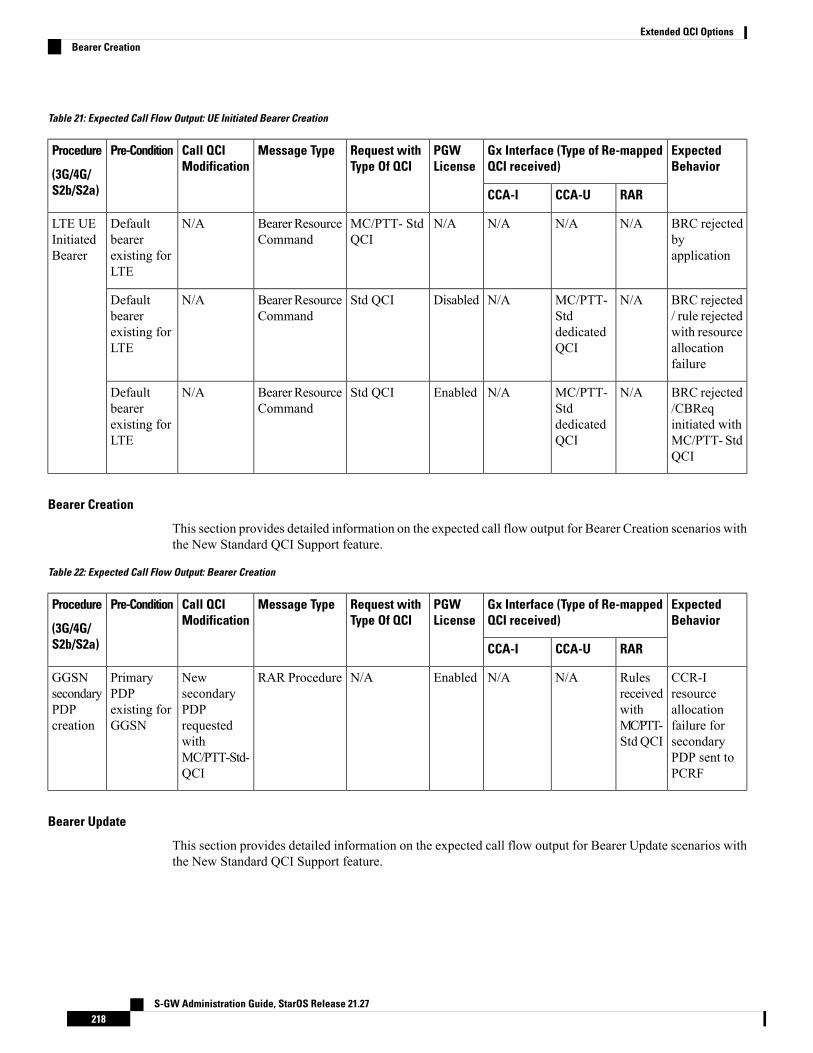
Table 21: Expected Call Flow Output: UE Initiated Bearer Creation
ExpectedBehavior
Gx Interface (Type of Re-mappedQCI received)
PGWLicense
Request withType Of QCI
Message TypeCall QCIModification
Pre-ConditionProcedure
(3G/4G/S2b/S2a) RARCCA-UCCA-I
BRC rejectedbyapplication
N/AN/AN/AN/AMC/PTT- StdQCI
BearerResourceCommand
N/ADefaultbearerexisting forLTE
LTE UEInitiatedBearer
BRC rejected/ rule rejectedwith resourceallocationfailure
N/AMC/PTT-StddedicatedQCI
N/ADisabledStd QCIBearerResourceCommand
N/ADefaultbearerexisting forLTE
BRC rejected/CBReqinitiated withMC/PTT- StdQCI
N/AMC/PTT-StddedicatedQCI
N/AEnabledStd QCIBearerResourceCommand
N/ADefaultbearerexisting forLTE
Bearer Creation
This section provides detailed information on the expected call flow output for Bearer Creation scenarios withthe New Standard QCI Support feature.
Table 22: Expected Call Flow Output: Bearer Creation
ExpectedBehavior
Gx Interface (Type of Re-mappedQCI received)
PGWLicense
Request withType Of QCI
Message TypeCall QCIModification
Pre-ConditionProcedure
(3G/4G/S2b/S2a) RARCCA-UCCA-I
CCR-Iresourceallocationfailure forsecondaryPDP sent toPCRF
RulesreceivedwithMC/PTT-Std QCI
N/AN/AEnabledN/ARAR ProcedureNewsecondaryPDPrequestedwithMC/PTT-Std-QCI
PrimaryPDPexisting forGGSN
GGSNsecondaryPDPcreation
Bearer Update
This section provides detailed information on the expected call flow output for Bearer Update scenarios withthe New Standard QCI Support feature.
S-GW Administration Guide, StarOS Release 21.27218
Extended QCI OptionsBearer Creation

Table 23: Expected Call Flow Output: Bearer Update
ExpectedBehavior
Gx Interface (Type of Re-mappedQCI received)
PGWLicense
Request withType Of QCI
Message TypeCall QCIModification
Pre-ConditionProcedure
(3G/4G/S2b/S2a) RARCCA-UCCA-I
CCR-I QoSmodificationfailure forprimary PDPQoSmodificationrejected
MC/PTT-Std QCIforprimaryPDPreceived
N/AN/AEnabledMC/PTT- StdQCI
RAR ProcedureCall existingwithStd-QCIrequested toMC/PTT-Std QCImodification
PrimaryPDPexisting forGGSN
GGSNPrimaryPDPQoSmodification
CCR-Iresourceallocationfailure forsecondaryPDP QoSmodificationsent
MC/PTT-Std QCIforsecondaryPDPwithrulesreceived
N/AN/AEnabledMC/PTT- StdQCI
RAR ProcedureCall existingwithStd-QCIrequested toMC/PTT-Std QCImodificationforsecondaryPDP
PrimaryPDP &secondaryPDPexisting forGGSN
GGSNSecondaryPDP QosModification
Configuring New Standard QCIsConfiguring New Standard QCIs consists of the following tasks:
• Configuring QCI-QoS Mapping
• Configuring Local Mapping for Gn/Gp Support
• Configuring Transaction Rate Network Initiated Setup/Teardown Events
• Enable Mission Critical QCIs
Configuring QCI-QoS MappingStandard QCI options 65, 66, 69, and 70 have been added to the qci command in QCI-QoS MappingConfiguration Mode.
To configure QCI-QoS Mapping for new standard QCIs:
configureqci-qos-mapping qci_qos_map_name
qci { 1-9 | 65 | 66 | 69 | 70 }end
To disable new QCI-QoS mapping for new standard QCIs:
configureqci-qos-mapping qci_qos_map_name
S-GW Administration Guide, StarOS Release 21.27219
Extended QCI OptionsConfiguring New Standard QCIs
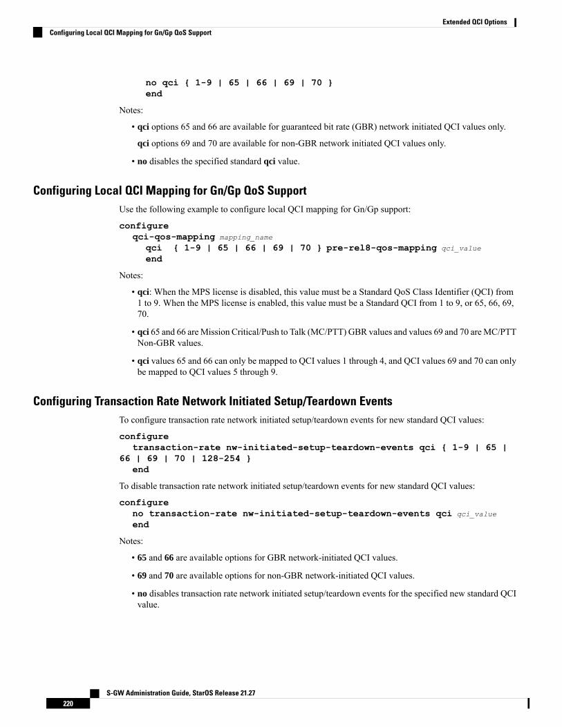
no qci { 1-9 | 65 | 66 | 69 | 70 }end
Notes:
• qci options 65 and 66 are available for guaranteed bit rate (GBR) network initiated QCI values only.
qci options 69 and 70 are available for non-GBR network initiated QCI values only.
• no disables the specified standard qci value.
Configuring Local QCI Mapping for Gn/Gp QoS SupportUse the following example to configure local QCI mapping for Gn/Gp support:
configureqci-qos-mapping mapping_name
qci { 1-9 | 65 | 66 | 69 | 70 } pre-rel8-qos-mapping qci_value
end
Notes:
• qci: When the MPS license is disabled, this value must be a Standard QoS Class Identifier (QCI) from1 to 9. When the MPS license is enabled, this value must be a Standard QCI from 1 to 9, or 65, 66, 69,70.
• qci 65 and 66 areMission Critical/Push to Talk (MC/PTT) GBR values and values 69 and 70 areMC/PTTNon-GBR values.
• qci values 65 and 66 can only be mapped to QCI values 1 through 4, and QCI values 69 and 70 can onlybe mapped to QCI values 5 through 9.
Configuring Transaction Rate Network Initiated Setup/Teardown EventsTo configure transaction rate network initiated setup/teardown events for new standard QCI values:
configuretransaction-rate nw-initiated-setup-teardown-events qci { 1-9 | 65 |
66 | 69 | 70 | 128-254 }end
To disable transaction rate network initiated setup/teardown events for new standard QCI values:
configureno transaction-rate nw-initiated-setup-teardown-events qci qci_value
end
Notes:
• 65 and 66 are available options for GBR network-initiated QCI values.
• 69 and 70 are available options for non-GBR network-initiated QCI values.
• no disables transaction rate network initiated setup/teardown events for the specified new standard QCIvalue.
S-GW Administration Guide, StarOS Release 21.27220
Extended QCI OptionsConfiguring Local QCI Mapping for Gn/Gp QoS Support
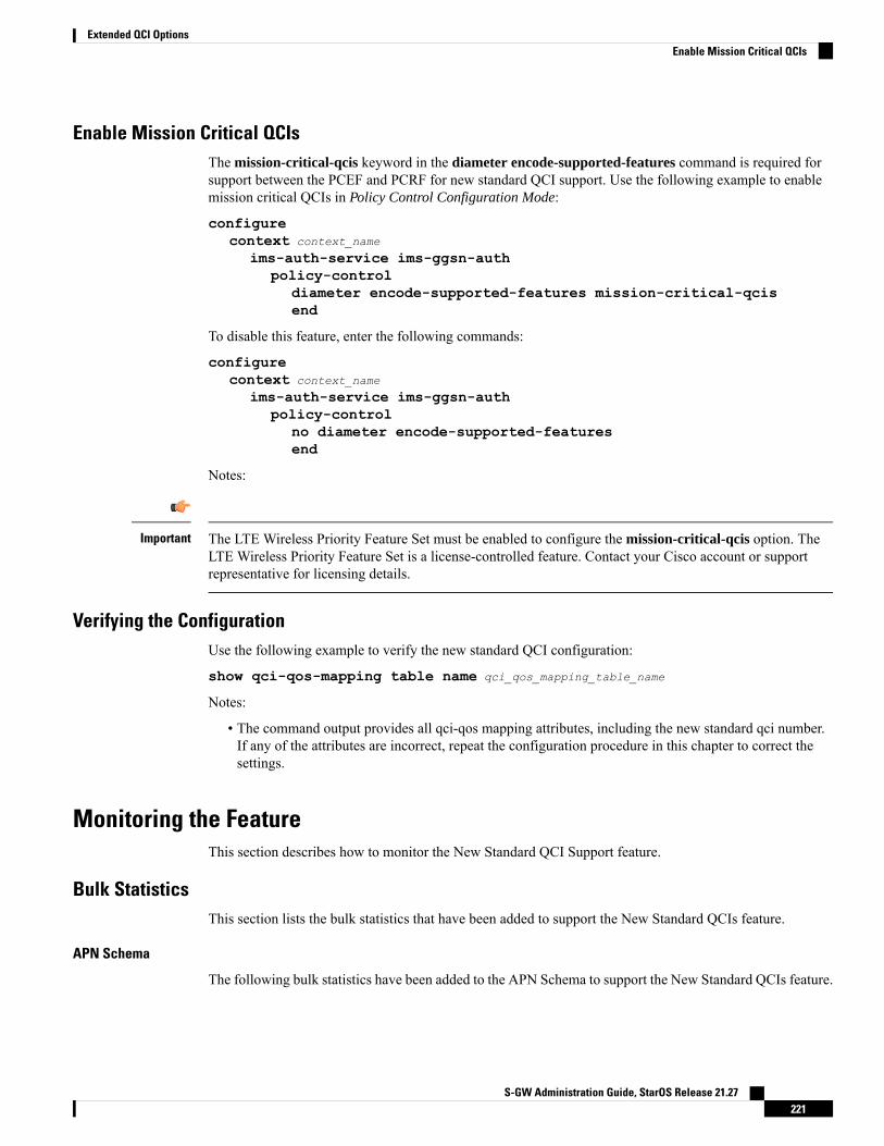
Enable Mission Critical QCIsThe mission-critical-qcis keyword in the diameter encode-supported-features command is required forsupport between the PCEF and PCRF for new standard QCI support. Use the following example to enablemission critical QCIs in Policy Control Configuration Mode:
configurecontext context_name
ims-auth-service ims-ggsn-authpolicy-control
diameter encode-supported-features mission-critical-qcisend
To disable this feature, enter the following commands:
configurecontext context_name
ims-auth-service ims-ggsn-authpolicy-control
no diameter encode-supported-featuresend
Notes:
The LTE Wireless Priority Feature Set must be enabled to configure the mission-critical-qcis option. TheLTE Wireless Priority Feature Set is a license-controlled feature. Contact your Cisco account or supportrepresentative for licensing details.
Important
Verifying the ConfigurationUse the following example to verify the new standard QCI configuration:
show qci-qos-mapping table name qci_qos_mapping_table_name
Notes:
• The command output provides all qci-qos mapping attributes, including the new standard qci number.If any of the attributes are incorrect, repeat the configuration procedure in this chapter to correct thesettings.
Monitoring the FeatureThis section describes how to monitor the New Standard QCI Support feature.
Bulk StatisticsThis section lists the bulk statistics that have been added to support the New Standard QCIs feature.
APN Schema
The following bulk statistics have been added to the APN Schema to support the New Standard QCIs feature.
S-GW Administration Guide, StarOS Release 21.27221
Extended QCI OptionsEnable Mission Critical QCIs

qci65-actbearqci65-setupbearqci65-relbearqci65-uplinkpkt-fwdqci65-dwlinkpkt-fwdqci65-uplinkbyte-fwdqci65-dwlinkbyte-fwdqci65-uplinkpkt-dropqci65-dwlinkpkt-dropqci65-uplinkbyte-dropqci65-dwlinkbyte-dropqci65-uplinkpkt-drop-mbrexcdqci65-dwlinkpkt-drop-mbrexcdqci65-uplinkbyte-drop-mbrexcdqci65-dwlinkbyte-drop-mbrexcdqci65-rejbearerqci66-actbearqci66-setupbearqci66-relbearqci66-uplinkpkt-fwdqci66-dwlinkpkt-fwdqci66-uplinkbyte-fwdqci66-dwlinkbyte-fwdqci66-uplinkpkt-dropqci66-dwlinkpkt-dropqci66-uplinkbyte-dropqci66-dwlinkbyte-dropqci66-uplinkpkt-drop-mbrexcdqci66-dwlinkpkt-drop-mbrexcdqci66-uplinkbyte-drop-mbrexcdqci66-dwlinkbyte-drop-mbrexcdqci66-rejbearerqci69-actbearqci69-setupbearqci69-relbearqci69-uplinkpkt-fwdqci69-dwlinkpkt-fwdqci69-uplinkbyte-fwdqci69-dwlinkbyte-fwdqci69-uplinkpkt-dropqci69-dwlinkpkt-dropqci69-uplinkbyte-dropqci69-dwlinkbyte-dropqci69-uplinkpkt-drop-mbrexcdqci69-dwlinkpkt-drop-mbrexcdqci69-uplinkbyte-drop-mbrexcdqci69-dwlinkbyte-drop-mbrexcdqci69-rejbearerqci70-actbearqci70-setupbearqci70-relbearqci70-uplinkpkt-fwdqci70-dwlinkpkt-fwdqci70-uplinkbyte-fwdqci70-dwlinkbyte-fwdqci70-uplinkpkt-dropqci70-dwlinkpkt-dropqci70-uplinkbyte-dropqci70-dwlinkbyte-dropqci70-uplinkpkt-drop-mbrexcdqci70-dwlinkpkt-drop-mbrexcdqci70-uplinkbyte-drop-mbrexcdqci70-dwlinkbyte-drop-mbrexcdqci70-rejbearer
S-GW Administration Guide, StarOS Release 21.27222
Extended QCI OptionsAPN Schema
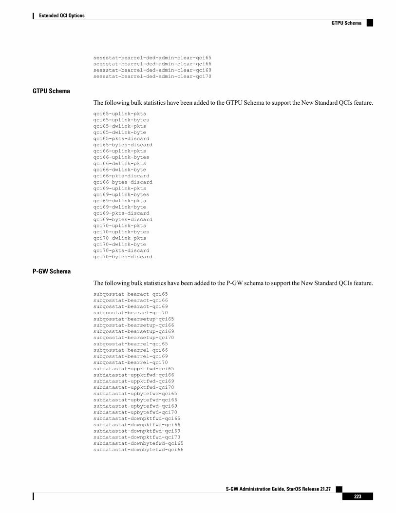
sessstat-bearrel-ded-admin-clear-qci65sessstat-bearrel-ded-admin-clear-qci66sessstat-bearrel-ded-admin-clear-qci69sessstat-bearrel-ded-admin-clear-qci70
GTPU Schema
The following bulk statistics have been added to the GTPU Schema to support the New Standard QCIs feature.qci65-uplink-pktsqci65-uplink-bytesqci65-dwlink-pktsqci65-dwlink-byteqci65-pkts-discardqci65-bytes-discardqci66-uplink-pktsqci66-uplink-bytesqci66-dwlink-pktsqci66-dwlink-byteqci66-pkts-discardqci66-bytes-discardqci69-uplink-pktsqci69-uplink-bytesqci69-dwlink-pktsqci69-dwlink-byteqci69-pkts-discardqci69-bytes-discardqci70-uplink-pktsqci70-uplink-bytesqci70-dwlink-pktsqci70-dwlink-byteqci70-pkts-discardqci70-bytes-discard
P-GW Schema
The following bulk statistics have been added to the P-GW schema to support the New Standard QCIs feature.subqosstat-bearact-qci65subqosstat-bearact-qci66subqosstat-bearact-qci69subqosstat-bearact-qci70subqosstat-bearsetup-qci65subqosstat-bearsetup-qci66subqosstat-bearsetup-qci69subqosstat-bearsetup-qci70subqosstat-bearrel-qci65subqosstat-bearrel-qci66subqosstat-bearrel-qci69subqosstat-bearrel-qci70subdatastat-uppktfwd-qci65subdatastat-uppktfwd-qci66subdatastat-uppktfwd-qci69subdatastat-uppktfwd-qci70subdatastat-upbytefwd-qci65subdatastat-upbytefwd-qci66subdatastat-upbytefwd-qci69subdatastat-upbytefwd-qci70subdatastat-downpktfwd-qci65subdatastat-downpktfwd-qci66subdatastat-downpktfwd-qci69subdatastat-downpktfwd-qci70subdatastat-downbytefwd-qci65subdatastat-downbytefwd-qci66
S-GW Administration Guide, StarOS Release 21.27223
Extended QCI OptionsGTPU Schema

subdatastat-downbytefwd-qci69subdatastat-downbytefwd-qci70subdatastat-uppktdrop-qci65subdatastat-uppktdrop-qci66subdatastat-uppktdrop-qci69subdatastat-uppktdrop-qci70subdatastat-upbytedrop-qci65subdatastat-upbytedrop-qci66subdatastat-upbytedrop-qci69subdatastat-upbytedrop-qci70subdatastat-downpktdrop-qci65subdatastat-downpktdrop-qci66subdatastat-downpktdrop-qci69subdatastat-downpktdrop-qci70subdatastat-downbytedrop-qci65subdatastat-downbytedrop-qci66subdatastat-downbytedrop-qci69subdatastat-downbytedrop-qci70subdatastat-uppktdropmbrexc-qci65subdatastat-uppktdropmbrexc-qci66subdatastat-uppktdropmbrexc-qci69subdatastat-uppktdropmbrexc-qci70subdatastat-upbytedropmbrexc-qci65subdatastat-upbytedropmbrexc-qci66subdatastat-upbytedropmbrexc-qci69subdatastat-upbytedropmbrexc-qci70subdatastat-downpktdropmbrexc-qci65subdatastat-downpktdropmbrexc-qci66subdatastat-downpktdropmbrexc-qci69subdatastat-downpktdropmbrexc-qci70subdatastat-downbytedropmbrexc-qci65subdatastat-downbytedropmbrexc-qci66subdatastat-downbytedropmbrexc-qci69subdatastat-downbytedropmbrexc-qci70
SAEGW Schema
The following bulk statistics have been added to the SAEGW Schema to support the New Standard QCIsfeature.sgw-totepsbearact-qci65sgw-totepsbearact-qci66sgw-totepsbearact-qci69sgw-totepsbearact-qci70sgw-totepsbearset-qci65sgw-totepsbearset-qci66sgw-totepsbearset-qci69sgw-totepsbearset-qci70sgw-totepsbearrel-qci65sgw-totepsbearrel-qci66sgw-totepsbearrel-qci69sgw-totepsbearrel-qci70sgw-totepsbearmod-qci65sgw-totepsbearmod-qci66sgw-totepsbearmod-qci69sgw-totepsbearmod-qci70sgw-totepsbearrel-dedrsn-pgw-qci65sgw-totepsbearrel-dedrsn-pgw-qci66sgw-totepsbearrel-dedrsn-pgw-qci69sgw-totepsbearrel-dedrsn-pgw-qci70sgw-totepsbearrel-dedrsn-s1err-qci65sgw-totepsbearrel-dedrsn-s1err-qci66sgw-totepsbearrel-dedrsn-s1err-qci69sgw-totepsbearrel-dedrsn-s1err-qci70
S-GW Administration Guide, StarOS Release 21.27224
Extended QCI OptionsSAEGW Schema

sgw-totepsbearrel-dedrsn-s5err-qci65sgw-totepsbearrel-dedrsn-s5err-qci66sgw-totepsbearrel-dedrsn-s5err-qci69sgw-totepsbearrel-dedrsn-s5err-qci70sgw-totepsbearrel-dedrsn-s4err-qci65sgw-totepsbearrel-dedrsn-s4err-qci66sgw-totepsbearrel-dedrsn-s4err-qci69sgw-totepsbearrel-dedrsn-s4err-qci70sgw-totepsbearrel-dedrsn-s12err-qci65sgw-totepsbearrel-dedrsn-s12err-qci66sgw-totepsbearrel-dedrsn-s12err-qci69sgw-totepsbearrel-dedrsn-s12err-qci70sgw-totepsbearrel-dedrsn-local-qci65sgw-totepsbearrel-dedrsn-local-qci66sgw-totepsbearrel-dedrsn-local-qci69sgw-totepsbearrel-dedrsn-local-qci70sgw-totepsbearrel-dedrsn-pdn-qci65sgw-totepsbearrel-dedrsn-pdn-qci66sgw-totepsbearrel-dedrsn-pdn-qci69sgw-totepsbearrel-dedrsn-pdn-qci70sgw-totepsbearrel-dedrsn-pathfail-s1-u-qci65sgw-totepsbearrel-dedrsn-pathfail-s1-u-qci66sgw-totepsbearrel-dedrsn-pathfail-s1-u-qci69sgw-totepsbearrel-dedrsn-pathfail-s1-u-qci70sgw-totepsbearrel-dedrsn-pathfail-s5-u-qci65sgw-totepsbearrel-dedrsn-pathfail-s5-u-qci66sgw-totepsbearrel-dedrsn-pathfail-s5-u-qci69sgw-totepsbearrel-dedrsn-pathfail-s5-u-qci70sgw-totepsbearrel-dedrsn-pathfail-s5-qci65sgw-totepsbearrel-dedrsn-pathfail-s5-qci66sgw-totepsbearrel-dedrsn-pathfail-s5-qci69sgw-totepsbearrel-dedrsn-pathfail-s5-qci70sgw-totepsbearrel-dedrsn-pathfail-s11-qci65sgw-totepsbearrel-dedrsn-pathfail-s11-qci66sgw-totepsbearrel-dedrsn-pathfail-s11-qci69sgw-totepsbearrel-dedrsn-pathfail-s11-qci70sgw-totepsbearrel-dedrsn-pathfail-s12-qci65sgw-totepsbearrel-dedrsn-pathfail-s12-qci66sgw-totepsbearrel-dedrsn-pathfail-s12-qci69sgw-totepsbearrel-dedrsn-pathfail-s12-qci70sgw-totepsbearrel-dedrsn-pathfail-s4-u-qci65sgw-totepsbearrel-dedrsn-pathfail-s4-u-qci66sgw-totepsbearrel-dedrsn-pathfail-s4-u-qci69sgw-totepsbearrel-dedrsn-pathfail-s4-u-qci70sgw-totepsbearrel-dedrsn-inactivity-timeout-qci65sgw-totepsbearrel-dedrsn-inactivity-timeout-qci66sgw-totepsbearrel-dedrsn-inactivity-timeout-qci69sgw-totepsbearrel-dedrsn-inactivity-timeout-qci70sgw-totepsbearrel-dedrsn-other-qci65sgw-totepsbearrel-dedrsn-other-qci66sgw-totepsbearrel-dedrsn-other-qci69sgw-totepsbearrel-dedrsn-other-qci70sgw-datastat-ul-qci65totbytesgw-datastat-ul-qci65totpktsgw-datastat-ul-qci66totbytesgw-datastat-ul-qci66totpktsgw-datastat-ul-qci69totbytesgw-datastat-ul-qci69totpktsgw-datastat-ul-qci70totbytesgw-datastat-ul-qci70totpktsgw-datastat-ul-dropstat-qci65totbytesgw-datastat-ul-dropstat-qci65totpktsgw-datastat-ul-dropstat-qci66totbytesgw-datastat-ul-dropstat-qci66totpkt
S-GW Administration Guide, StarOS Release 21.27225
Extended QCI OptionsSAEGW Schema
sgw-datastat-ul-dropstat-qci69totbytesgw-datastat-ul-dropstat-qci69totpktsgw-datastat-ul-dropstat-qci70totbytesgw-datastat-ul-dropstat-qci70totpktsgw-datastat-dl-qci65totbytesgw-datastat-dl-qci65totpktsgw-datastat-dl-qci66totbytesgw-datastat-dl-qci66totpktsgw-datastat-dl-qci69totbytesgw-datastat-dl-qci69totpktsgw-datastat-dl-qci70totbytesgw-datastat-dl-qci70totpktsgw-datastat-dl-dropstat-qci65totbytesgw-datastat-dl-dropstat-qci65totpktsgw-datastat-dl-dropstat-qci66totbytesgw-datastat-dl-dropstat-qci66totpktsgw-datastat-dl-dropstat-qci69totbytesgw-datastat-dl-dropstat-qci69totpktsgw-datastat-dl-dropstat-qci70totbytesgw-datastat-dl-dropstat-qci70totpktsgw-s1u-ul-qci65totbytesgw-s1u-ul-qci65totpktsgw-s1u-ul-qci66totbytesgw-s1u-ul-qci66totpktsgw-s1u-ul-qci69totbytesgw-s1u-ul-qci69totpktsgw-s1u-ul-qci70totbytesgw-s1u-ul-qci70totpktsgw-s1u-ul-drop-qci65totbytesgw-s1u-ul-drop-qci65totpktsgw-s1u-ul-drop-qci66totbytesgw-s1u-ul-drop-qci66totpktsgw-s1u-ul-drop-qci69totbytesgw-s1u-ul-drop-qci69totpktsgw-s1u-ul-drop-qci70totbytesgw-s1u-ul-drop-qci70totpktsgw-s1u-dl-qci65totbytesgw-s1u-dl-qci65totpktsgw-s1u-dl-qci66totbytesgw-s1u-dl-qci66totpktsgw-s1u-dl-qci69totbytesgw-s1u-dl-qci69totpktsgw-s1u-dl-qci70totbytesgw-s1u-dl-qci70totpktsgw-s1u-dl-drop-qci65totbytesgw-s1u-dl-drop-qci65totpktsgw-s1u-dl-drop-qci66totbytesgw-s1u-dl-drop-qci66totpktsgw-s1u-dl-drop-qci69totbytesgw-s1u-dl-drop-qci69totpktsgw-s1u-dl-drop-qci70totbytesgw-s1u-dl-drop-qci70totpktsgw-s4u-ul-qci65totbytesgw-s4u-ul-qci65totpktsgw-s4u-ul-qci66totbytesgw-s4u-ul-qci66totpktsgw-s4u-ul-qci69totbytesgw-s4u-ul-qci69totpktsgw-s4u-ul-qci70totbytesgw-s4u-ul-qci70totpktsgw-s4u-ul-drop-qci65totbytesgw-s4u-ul-drop-qci65totpktsgw-s4u-ul-drop-qci66totbytesgw-s4u-ul-drop-qci66totpkt
S-GW Administration Guide, StarOS Release 21.27226
Extended QCI OptionsSAEGW Schema

sgw-s4u-ul-drop-qci69totbytesgw-s4u-ul-drop-qci69totpktsgw-s4u-ul-drop-qci70totbytesgw-s4u-ul-drop-qci70totpktsgw-s4u-dl-qci65totbytesgw-s4u-dl-qci65totpktsgw-s4u-dl-qci66totbytesgw-s4u-dl-qci66totpktsgw-s4u-dl-qci69totbytesgw-s4u-dl-qci69totpktsgw-s4u-dl-qci70totbytesgw-s4u-dl-qci70totpktsgw-s4u-dl-drop-qci65totbytesgw-s4u-dl-drop-qci65totpktsgw-s4u-dl-drop-qci66totbytesgw-s4u-dl-drop-qci66totpktsgw-s4u-dl-drop-qci69totbytesgw-s4u-dl-drop-qci69totpktsgw-s4u-dl-drop-qci70totbytesgw-s4u-dl-drop-qci70totpktsgw-s12-ul-qci65totbytesgw-s12-ul-qci65totpktsgw-s12-ul-qci66totbytesgw-s12-ul-qci66totpktsgw-s12-ul-qci69totbytesgw-s12-ul-qci69totpktsgw-s12-ul-qci70totbytesgw-s12-ul-qci70totpktsgw-s12-ul-drop-qci65totbytesgw-s12-ul-drop-qci65totpktsgw-s12-ul-drop-qci66totbytesgw-s12-ul-drop-qci66totpktsgw-s12-ul-drop-qci69totbytesgw-s12-ul-drop-qci69totpktsgw-s12-ul-drop-qci70totbytesgw-s12-ul-drop-qci70totpktsgw-s12-dl-qci65totbytesgw-s12-dl-qci65totpktsgw-s12-dl-qci66totbytesgw-s12-dl-qci66totpktsgw-s12-dl-qci69totbytesgw-s12-dl-qci69totpktsgw-s12-dl-qci70totbytesgw-s12-dl-qci70totpktsgw-s12-dl-drop-qci65totbytesgw-s12-dl-drop-qci65totpktsgw-s12-dl-drop-qci66totbytesgw-s12-dl-drop-qci66totpktsgw-s12-dl-drop-qci69totbytesgw-s12-dl-drop-qci69totpktsgw-s12-dl-drop-qci70totbytesgw-s12-dl-drop-qci70totpktsgw-s5-ul-qci65totbytesgw-s5-ul-qci65totpktsgw-s5-ul-qci66totbytesgw-s5-ul-qci66totpktsgw-s5-ul-qci69totbytesgw-s5-ul-qci69totpktsgw-s5-ul-qci70totbytesgw-s5-ul-qci70totpktsgw-s5-ul-drop-qci65totbytesgw-s5-ul-drop-qci65totpktsgw-s5-ul-drop-qci66totbytesgw-s5-ul-drop-qci66totpkt
S-GW Administration Guide, StarOS Release 21.27227
Extended QCI OptionsSAEGW Schema

sgw-s5-ul-drop-qci69totbytesgw-s5-ul-drop-qci69totpktsgw-s5-ul-drop-qci70totbytesgw-s5-ul-drop-qci70totpktsgw-s5-dl-qci65totbytesgw-s5-dl-qci65totpktsgw-s5-dl-qci66totbytesgw-s5-dl-qci66totpktsgw-s5-dl-qci69totbytesgw-s5-dl-qci69totpktsgw-s5-dl-qci70totbytesgw-s5-dl-qci70totpktsgw-s5-dl-drop-qci65totbytesgw-s5-dl-drop-qci65totpktsgw-s5-dl-drop-qci66totbytesgw-s5-dl-drop-qci66totpktsgw-s5-dl-drop-qci69totbytesgw-s5-dl-drop-qci69totpktsgw-s5-dl-drop-qci70totbytesgw-s5-dl-drop-qci70totpktsgw-s8-ul-qci65totbytesgw-s8-ul-qci65totpktsgw-s8-ul-qci66totbytesgw-s8-ul-qci66totpktsgw-s8-ul-qci69totbytesgw-s8-ul-qci69totpktsgw-s8-ul-qci70totbytesgw-s8-ul-qci70totpktsgw-s8-ul-drop-qci65totbytesgw-s8-ul-drop-qci65totpktsgw-s8-ul-drop-qci66totbytesgw-s8-ul-drop-qci66totpktsgw-s8-ul-drop-qci69totbytesgw-s8-ul-drop-qci69totpktsgw-s8-ul-drop-qci70totbytesgw-s8-ul-drop-qci70totpktsgw-s8-dl-qci65totbytesgw-s8-dl-qci65totpktsgw-s8-dl-qci66totbytesgw-s8-dl-qci66totpktsgw-s8-dl-qci69totbytesgw-s8-dl-qci69totpktsgw-s8-dl-qci70totbytesgw-s8-dl-qci70totpktsgw-s8-dl-drop-qci65totbytesgw-s8-dl-drop-qci65totpktsgw-s8-dl-drop-qci66totbytesgw-s8-dl-drop-qci66totpktsgw-s8-dl-drop-qci69totbytesgw-s8-dl-drop-qci69totpktsgw-s8-dl-drop-qci70totbytesgw-s8-dl-drop-qci70totpktsgw-s5s8-ul-qci65totbytesgw-s5s8-ul-qci65totpktsgw-s5s8-ul-qci66totbytesgw-s5s8-ul-qci66totpktsgw-s5s8-ul-qci69totbytesgw-s5s8-ul-qci69totpktsgw-s5s8-ul-qci70totbytesgw-s5s8-ul-qci70totpktsgw-s5s8-ul-drop-qci65totbytesgw-s5s8-ul-drop-qci65totpktsgw-s5s8-ul-drop-qci66totbytesgw-s5s8-ul-drop-qci66totpkt
S-GW Administration Guide, StarOS Release 21.27228
Extended QCI OptionsSAEGW Schema

sgw-s5s8-ul-drop-qci69totbytesgw-s5s8-ul-drop-qci69totpktsgw-s5s8-ul-drop-qci70totbytesgw-s5s8-ul-drop-qci70totpktsgw-s5s8-dl-qci65totbytesgw-s5s8-dl-qci65totpktsgw-s5s8-dl-qci66totbytesgw-s5s8-dl-qci66totpktsgw-s5s8-dl-qci69totbytesgw-s5s8-dl-qci69totpktsgw-s5s8-dl-qci70totbytesgw-s5s8-dl-qci70totpktsgw-s5s8-dl-drop-qci65totbytesgw-s5s8-dl-drop-qci65totpktsgw-s5s8-dl-drop-qci66totbytesgw-s5s8-dl-drop-qci66totpktsgw-s5s8-dl-drop-qci69totbytesgw-s5s8-dl-drop-qci69totpktsgw-s5s8-dl-drop-qci70totbytesgw-s5s8-dl-drop-qci70totpktpgw-subqosstat-bearact-qci65pgw-subqosstat-bearact-qci66pgw-subqosstat-bearact-qci69pgw-subqosstat-bearact-qci70pgw-subqosstat-bearset-qci65pgw-subqosstat-bearset-qci66pgw-subqosstat-bearset-qci69pgw-subqosstat-bearset-qci70pgw-subqosstat-bearrel-qci65pgw-subqosstat-bearrel-qci66pgw-subqosstat-bearrel-qci69pgw-subqosstat-bearrel-qci70pgw-subdatastat-ulpktfwd-qci65pgw-subdatastat-ulpktfwd-qci66pgw-subdatastat-ulpktfwd-qci69pgw-subdatastat-ulpktfwd-qci70pgw-subdatastat-ulbytefwd-qci65pgw-subdatastat-ulbytefwd-qci66pgw-subdatastat-ulbytefwd-qci69pgw-subdatastat-ulbytefwd-qci70pgw-subdatastat-dlpktfwd-qci65pgw-subdatastat-dlpktfwd-qci66pgw-subdatastat-dlpktfwd-qci69pgw-subdatastat-dlpktfwd-qci70pgw-subdatastat-dlbytefwd-qci65pgw-subdatastat-dlbytefwd-qci66pgw-subdatastat-dlbytefwd-qci69pgw-subdatastat-dlbytefwd-qci70pgw-subdatastat-ulpktdrop-qci65pgw-subdatastat-ulpktdrop-qci66pgw-subdatastat-ulpktdrop-qci69pgw-subdatastat-ulpktdrop-qci70pgw-subdatastat-ulbytedrop-qci65pgw-subdatastat-ulbytedrop-qci66pgw-subdatastat-ulbytedrop-qci69pgw-subdatastat-ulbytedrop-qci70pgw-subdatastat-dlpktdrop-qci65pgw-subdatastat-dlpktdrop-qci66pgw-subdatastat-dlpktdrop-qci69pgw-subdatastat-dlpktdrop-qci70pgw-subdatastat-dlbytedrop-qci65pgw-subdatastat-dlbytedrop-qci66pgw-subdatastat-dlbytedrop-qci69pgw-subdatastat-dlbytedrop-qci70
S-GW Administration Guide, StarOS Release 21.27229
Extended QCI OptionsSAEGW Schema
pgw-subdatastat-ulpktdropmbrexc-qci65pgw-subdatastat-ulpktdropmbrexc-qci66pgw-subdatastat-ulpktdropmbrexc-qci69pgw-subdatastat-ulpktdropmbrexc-qci70pgw-subdatastat-ulbytedropmbrexc-qci65pgw-subdatastat-ulbytedropmbrexc-qci66pgw-subdatastat-ulbytedropmbrexc-qci69pgw-subdatastat-ulbytedropmbrexc-qci70pgw-subdatastat-dlpktdropmbrexc-qci65pgw-subdatastat-dlpktdropmbrexc-qci66pgw-subdatastat-dlpktdropmbrexc-qci69pgw-subdatastat-dlpktdropmbrexc-qci70pgw-subdatastat-dlbytedropmbrexc-qci65pgw-subdatastat-dlbytedropmbrexc-qci66pgw-subdatastat-dlbytedropmbrexc-qci69pgw-subdatastat-dlbytedropmbrexc-qci70collapsed-subdatastat-ulpktfwd-qci65collapsed-subdatastat-ulpktfwd-qci66collapsed-subdatastat-ulpktfwd-qci69collapsed-subdatastat-ulpktfwd-qci70collapsed-subdatastat-ulbytefwd-qci65collapsed-subdatastat-ulbytefwd-qci66collapsed-subdatastat-ulbytefwd-qci69collapsed-subdatastat-ulbytefwd-qci70collapsed-subdatastat-dlpktfwd-qci65collapsed-subdatastat-dlpktfwd-qci66collapsed-subdatastat-dlpktfwd-qci69collapsed-subdatastat-dlpktfwd-qci70collapsed-subdatastat-dlbytefwd-qci65collapsed-subdatastat-dlbytefwd-qci66collapsed-subdatastat-dlbytefwd-qci69collapsed-subdatastat-dlbytefwd-qci70collapsed-subdatastat-ulpktdrop-qci65collapsed-subdatastat-ulpktdrop-qci66collapsed-subdatastat-ulpktdrop-qci69collapsed-subdatastat-ulpktdrop-qci70collapsed-subdatastat-ulbytedrop-qci65collapsed-subdatastat-ulbytedrop-qci66collapsed-subdatastat-ulbytedrop-qci69collapsed-subdatastat-ulbytedrop-qci70collapsed-subdatastat-dlpktdrop-qci65collapsed-subdatastat-dlpktdrop-qci66collapsed-subdatastat-dlpktdrop-qci69collapsed-subdatastat-dlpktdrop-qci70collapsed-subdatastat-dlbytedrop-qci65collapsed-subdatastat-dlbytedrop-qci66collapsed-subdatastat-dlbytedrop-qci69collapsed-subdatastat-dlbytedrop-qci70collapsed-subqosstat-bearact-qci65collapsed-subqosstat-bearact-qci66collapsed-subqosstat-bearact-qci69collapsed-subqosstat-bearact-qci70collapsed-subqosstat-bearset-qci65collapsed-subqosstat-bearset-qci66collapsed-subqosstat-bearset-qci69collapsed-subqosstat-bearset-qci70collapsed-subqosstat-bearrel-qci65collapsed-subqosstat-bearrel-qci66collapsed-subqosstat-bearrel-qci69collapsed-subqosstat-bearrel-qci70saegw-ggsn-subqosstat-bearact-qci65saegw-ggsn-subqosstat-bearact-qci66saegw-ggsn-subqosstat-bearact-qci69saegw-ggsn-subqosstat-bearact-qci70
S-GW Administration Guide, StarOS Release 21.27230
Extended QCI OptionsSAEGW Schema

saegw-ggsn-subqosstat-bearset-qci65saegw-ggsn-subqosstat-bearset-qci66saegw-ggsn-subqosstat-bearset-qci69saegw-ggsn-subqosstat-bearset-qci70saegw-ggsn-subqosstat-bearrel-qci65saegw-ggsn-subqosstat-bearrel-qci66saegw-ggsn-subqosstat-bearrel-qci69saegw-ggsn-subqosstat-bearrel-qci70saegw-ggsn-subdatastat-ulpktfwd-qci65saegw-ggsn-subdatastat-ulpktfwd-qci66saegw-ggsn-subdatastat-ulpktfwd-qci69saegw-ggsn-subdatastat-ulpktfwd-qci70saegw-ggsn-subdatastat-ulbytefwd-qci65saegw-ggsn-subdatastat-ulbytefwd-qci66saegw-ggsn-subdatastat-ulbytefwd-qci69saegw-ggsn-subdatastat-ulbytefwd-qci70saegw-ggsn-subdatastat-dlpktfwd-qci65saegw-ggsn-subdatastat-dlpktfwd-qci66saegw-ggsn-subdatastat-dlpktfwd-qci69saegw-ggsn-subdatastat-dlpktfwd-qci70saegw-ggsn-subdatastat-dlbytefwd-qci65saegw-ggsn-subdatastat-dlbytefwd-qci66saegw-ggsn-subdatastat-dlbytefwd-qci69saegw-ggsn-subdatastat-dlbytefwd-qci70saegw-ggsn-subdatastat-ulpktdrop-qci65saegw-ggsn-subdatastat-ulpktdrop-qci66saegw-ggsn-subdatastat-ulpktdrop-qci69saegw-ggsn-subdatastat-ulpktdrop-qci70saegw-ggsn-subdatastat-ulbytedrop-qci65saegw-ggsn-subdatastat-ulbytedrop-qci66saegw-ggsn-subdatastat-ulbytedrop-qci69saegw-ggsn-subdatastat-ulbytedrop-qci70saegw-ggsn-subdatastat-dlpktdrop-qci65saegw-ggsn-subdatastat-dlpktdrop-qci66saegw-ggsn-subdatastat-dlpktdrop-qci69saegw-ggsn-subdatastat-dlpktdrop-qci70saegw-ggsn-subdatastat-dlbytedrop-qci65saegw-ggsn-subdatastat-dlbytedrop-qci66saegw-ggsn-subdatastat-dlbytedrop-qci69saegw-ggsn-subdatastat-dlbytedrop-qci70saegw-ggsn-subdatastat-ulpktdropmbrexc-qci65saegw-ggsn-subdatastat-ulpktdropmbrexc-qci66saegw-ggsn-subdatastat-ulpktdropmbrexc-qci69saegw-ggsn-subdatastat-ulpktdropmbrexc-qci70saegw-ggsn-subdatastat-ulbytedropmbrexc-qci65saegw-ggsn-subdatastat-ulbytedropmbrexc-qci66saegw-ggsn-subdatastat-ulbytedropmbrexc-qci69saegw-ggsn-subdatastat-ulbytedropmbrexc-qci70saegw-ggsn-subdatastat-dlpktdropmbrexc-qci65saegw-ggsn-subdatastat-dlpktdropmbrexc-qci66saegw-ggsn-subdatastat-dlpktdropmbrexc-qci69saegw-ggsn-subdatastat-dlpktdropmbrexc-qci70saegw-ggsn-subdatastat-dlbytedropmbrexc-qci65saegw-ggsn-subdatastat-dlbytedropmbrexc-qci66saegw-ggsn-subdatastat-dlbytedropmbrexc-qci69saegw-ggsn-subdatastat-dlbytedropmbrexc-qci70
S-GW Schema
The following bulk statistics have been added to the S-GW schema to support the New Standard QCIs feature.totepsbearactive-qci65totepsbearactive-qci66totepsbearactive-qci69
S-GW Administration Guide, StarOS Release 21.27231
Extended QCI OptionsS-GW Schema

totepsbearactive-qci70totepsbearsetup-qci65totepsbearsetup-qci66totepsbearsetup-qci69totepsbearsetup-qci70totepsbearrel-qci65totepsbearrel-qci66totepsbearrel-qci69totepsbearrel-qci70totepsbearmod-qci65totepsbearmod-qci66totepsbearmod-qci69totepsbearmod-qci70totepsbearrel-dedrsn-pgw-qci65totepsbearrel-dedrsn-pgw-qci66totepsbearrel-dedrsn-pgw-qci69totepsbearrel-dedrsn-pgw-qci70totepsbearrel-dedrsn-s1err-qci65totepsbearrel-dedrsn-s1err-qci66totepsbearrel-dedrsn-s1err-qci69totepsbearrel-dedrsn-s1err-qci70totepsbearrel-dedrsn-s5err-qci65totepsbearrel-dedrsn-s5err-qci66totepsbearrel-dedrsn-s5err-qci69totepsbearrel-dedrsn-s5err-qci70totepsbearrel-dedrsn-s4err-qci65totepsbearrel-dedrsn-s4err-qci66totepsbearrel-dedrsn-s4err-qci69totepsbearrel-dedrsn-s4err-qci70totepsbearrel-dedrsn-s12err-qci65totepsbearrel-dedrsn-s12err-qci66totepsbearrel-dedrsn-s12err-qci69totepsbearrel-dedrsn-s12err-qci70totepsbearrel-dedrsn-local-qci65totepsbearrel-dedrsn-local-qci66totepsbearrel-dedrsn-local-qci69totepsbearrel-dedrsn-local-qci70totepsbearrel-dedrsn-pdn-qci65totepsbearrel-dedrsn-pdn-qci66totepsbearrel-dedrsn-pdn-qci69totepsbearrel-dedrsn-pdn-qci70totepsbearrel-dedrsn-pathfail-s1-u-qci65totepsbearrel-dedrsn-pathfail-s1-u-qci66totepsbearrel-dedrsn-pathfail-s1-u-qci69totepsbearrel-dedrsn-pathfail-s1-u-qci70totepsbearrel-dedrsn-pathfail-s5-u-qci65totepsbearrel-dedrsn-pathfail-s5-u-qci66totepsbearrel-dedrsn-pathfail-s5-u-qci69totepsbearrel-dedrsn-pathfail-s5-u-qci70totepsbearrel-dedrsn-pathfail-s5-qci65totepsbearrel-dedrsn-pathfail-s5-qci66totepsbearrel-dedrsn-pathfail-s5-qci69totepsbearrel-dedrsn-pathfail-s5-qci70totepsbearrel-dedrsn-pathfail-s11-qci65totepsbearrel-dedrsn-pathfail-s11-qci66totepsbearrel-dedrsn-pathfail-s11-qci69totepsbearrel-dedrsn-pathfail-s11-qci70totepsbearrel-dedrsn-pathfail-s12-qci65totepsbearrel-dedrsn-pathfail-s12-qci66totepsbearrel-dedrsn-pathfail-s12-qci69totepsbearrel-dedrsn-pathfail-s12-qci70totepsbearrel-dedrsn-pathfail-s4-u-qci65totepsbearrel-dedrsn-pathfail-s4-u-qci66totepsbearrel-dedrsn-pathfail-s4-u-qci69
S-GW Administration Guide, StarOS Release 21.27232
Extended QCI OptionsS-GW Schema

totepsbearrel-dedrsn-pathfail-s4-u-qci70totepsbearrel-dedrsn-inactivity-timeout-qci65totepsbearrel-dedrsn-inactivity-timeout-qci66totepsbearrel-dedrsn-inactivity-timeout-qci69totepsbearrel-dedrsn-inactivity-timeout-qci70totepsbearrel-dedrsn-other-qci65totepsbearrel-dedrsn-other-qci66totepsbearrel-dedrsn-other-qci69totepsbearrel-dedrsn-other-qci70datastat-uplink-qci65totbytedatastat-uplink-qci65totpktdatastat-uplink-qci66totbytedatastat-uplink-qci66totpktdatastat-uplink-qci69totbytedatastat-uplink-qci69totpktdatastat-uplink-qci70totbytedatastat-uplink-qci70totpktdatastat-uplink-dropstat-qci65totbytedatastat-uplink-dropstat-qci65totpktdatastat-uplink-dropstat-qci66totbytedatastat-uplink-dropstat-qci66totpktdatastat-uplink-dropstat-qci69totbytedatastat-uplink-dropstat-qci69totpktdatastat-uplink-dropstat-qci70totbytedatastat-uplink-dropstat-qci70totpktdatastat-downlink-qci65totbytedatastat-downlink-qci65totpktdatastat-downlink-qci66totbytedatastat-downlink-qci66totpktdatastat-downlink-qci69totbytedatastat-downlink-qci69totpktdatastat-downlink-qci70totbytedatastat-downlink-qci70totpktdatastat-downlink-dropstat-qci65totbytedatastat-downlink-dropstat-qci65totpktdatastat-downlink-dropstat-qci66totbytedatastat-downlink-dropstat-qci66totpktdatastat-downlink-dropstat-qci69totbytedatastat-downlink-dropstat-qci69totpktdatastat-downlink-dropstat-qci70totbytedatastat-downlink-dropstat-qci70totpkts1u-uplnk-qci65totbytes1u-uplnk-qci65totpkts1u-uplnk-qci66totbytes1u-uplnk-qci66totpkts1u-uplnk-qci69totbytes1u-uplnk-qci69totpkts1u-uplnk-qci70totbytes1u-uplnk-qci70totpkts1u-uplnk-drop-qci65totbytes1u-uplnk-drop-qci65totpkts1u-uplnk-drop-qci66totbytes1u-uplnk-drop-qci66totpkts1u-uplnk-drop-qci69totbytes1u-uplnk-drop-qci69totpkts1u-uplnk-drop-qci70totbytes1u-uplnk-drop-qci70totpkts1u-downlnk-qci65totbytes1u-downlnk-qci65totpkts1u-downlnk-qci66totbytes1u-downlnk-qci66totpkts1u-downlnk-qci69totbytes1u-downlnk-qci69totpkts1u-downlnk-qci70totbyte
S-GW Administration Guide, StarOS Release 21.27233
Extended QCI OptionsS-GW Schema
s1u-downlnk-qci70totpkts1u-downlnk-drop-qci65totbytes1u-downlnk-drop-qci65totpkts1u-downlnk-drop-qci66totbytes1u-downlnk-drop-qci66totpkts1u-downlnk-drop-qci69totbytes1u-downlnk-drop-qci69totpkts1u-downlnk-drop-qci70totbytes1u-downlnk-drop-qci70totpkts4u-uplnk-qci65totbytes4u-uplnk-qci65totpkts4u-uplnk-qci66totbytes4u-uplnk-qci66totpkts4u-uplnk-qci69totbytes4u-uplnk-qci69totpkts4u-uplnk-qci70totbytes4u-uplnk-qci70totpkts4u-uplnk-drop-qci65totbytes4u-uplnk-drop-qci65totpkts4u-uplnk-drop-qci66totbytes4u-uplnk-drop-qci66totpkts4u-uplnk-drop-qci69totbytes4u-uplnk-drop-qci69totpkts4u-uplnk-drop-qci70totbytes4u-uplnk-drop-qci70totpkts4u-downlnk-qci65totbytes4u-downlnk-qci65totpkts4u-downlnk-qci66totbytes4u-downlnk-qci66totpkts4u-downlnk-qci69totbytes4u-downlnk-qci69totpkts4u-downlnk-qci70totbytes4u-downlnk-qci70totpkts4u-downlnk-drop-qci65totbytes4u-downlnk-drop-qci65totpkts4u-downlnk-drop-qci66totbytes4u-downlnk-drop-qci66totpkts4u-downlnk-drop-qci69totbytes4u-downlnk-drop-qci69totpkts4u-downlnk-drop-qci70totbytes4u-downlnk-drop-qci70totpkts12-uplnk-qci65totbytes12-uplnk-qci65totpkts12-uplnk-qci66totbytes12-uplnk-qci66totpkts12-uplnk-qci69totbytes12-uplnk-qci69totpkts12-uplnk-qci70totbytes12-uplnk-qci70totpkts12-uplnk-drop-qci65totbytes12-uplnk-drop-qci65totpkts12-uplnk-drop-qci66totbytes12-uplnk-drop-qci66totpkts12-uplnk-drop-qci69totbytes12-uplnk-drop-qci69totpkts12-uplnk-drop-qci70totbytes12-uplnk-drop-qci70totpkts12-downlnk-qci65totbytes12-downlnk-qci65totpkts12-downlnk-qci66totbytes12-downlnk-qci66totpkts12-downlnk-qci69totbytes12-downlnk-qci69totpkts12-downlnk-qci70totbyte
S-GW Administration Guide, StarOS Release 21.27234
Extended QCI OptionsS-GW Schema

s12-downlnk-qci70totpkts12-downlnk-drop-qci65totbytes12-downlnk-drop-qci65totpkts12-downlnk-drop-qci66totbytes12-downlnk-drop-qci66totpkts12-downlnk-drop-qci69totbytes12-downlnk-drop-qci69totpkts12-downlnk-drop-qci70totbytes12-downlnk-drop-qci70totpkts5-uplnk-qci65totbytes5-uplnk-qci65totpkts5-uplnk-qci66totbytes5-uplnk-qci66totpkts5-uplnk-qci69totbytes5-uplnk-qci69totpkts5-uplnk-qci70totbytes5-uplnk-qci70totpkts5-uplnk-drop-qci65totbytes5-uplnk-drop-qci65totpkts5-uplnk-drop-qci66totbytes5-uplnk-drop-qci66totpkts5-uplnk-drop-qci69totbytes5-uplnk-drop-qci69totpkts5-uplnk-drop-qci70totbytes5-uplnk-drop-qci70totpkts5-downlnk-qci65totbytes5-downlnk-qci65totpkts5-downlnk-qci66totbytes5-downlnk-qci66totpkts5-downlnk-qci69totbytes5-downlnk-qci69totpkts5-downlnk-qci70totbytes5-downlnk-qci70totpkts5-downlnk-drop-qci65totbytes5-downlnk-drop-qci65totpkts5-downlnk-drop-qci66totbytes5-downlnk-drop-qci66totpkts5-downlnk-drop-qci69totbytes5-downlnk-drop-qci69totpkts5-downlnk-drop-qci70totbytes5-downlnk-drop-qci70totpkts8-uplnk-qci65totbytes8-uplnk-qci65totpkts8-uplnk-qci66totbytes8-uplnk-qci66totpkts8-uplnk-qci69totbytes8-uplnk-qci69totpkts8-uplnk-qci70totbytes8-uplnk-qci70totpkts8-uplnk-drop-qci65totbytes8-uplnk-drop-qci65totpkts8-uplnk-drop-qci66totbytes8-uplnk-drop-qci66totpkts8-uplnk-drop-qci69totbytes8-uplnk-drop-qci69totpkts8-uplnk-drop-qci70totbytes8-uplnk-drop-qci70totpkts8-downlnk-qci65totbytes8-downlnk-qci65totpkts8-downlnk-qci66totbytes8-downlnk-qci66totpkts8-downlnk-qci69totbytes8-downlnk-qci69totpkts8-downlnk-qci70totbyte
S-GW Administration Guide, StarOS Release 21.27235
Extended QCI OptionsS-GW Schema

s8-downlnk-qci70totpkts8-downlnk-drop-qci65totbytes8-downlnk-drop-qci65totpkts8-downlnk-drop-qci66totbytes8-downlnk-drop-qci66totpkts8-downlnk-drop-qci69totbytes8-downlnk-drop-qci69totpkts8-downlnk-drop-qci70totbytes8-downlnk-drop-qci70totpkts5s8-uplnk-qci65totbytes5s8-uplnk-qci65totpkts5s8-uplnk-qci66totbytes5s8-uplnk-qci66totpkts5s8-uplnk-qci69totbytes5s8-uplnk-qci69totpkts5s8-uplnk-qci70totbytes5s8-uplnk-qci70totpkts5s8-uplnk-drop-qci65totbytes5s8-uplnk-drop-qci65totpkts5s8-uplnk-drop-qci66totbytes5s8-uplnk-drop-qci66totpkts5s8-uplnk-drop-qci69totbytes5s8-uplnk-drop-qci69totpkts5s8-uplnk-drop-qci70totbytes5s8-uplnk-drop-qci70totpkts5s8-downlnk-qci65totbytes5s8-downlnk-qci65totpkts5s8-downlnk-qci66totbytes5s8-downlnk-qci66totpkts5s8-downlnk-qci69totbytes5s8-downlnk-qci69totpkts5s8-downlnk-qci70totbytes5s8-downlnk-qci70totpkts5s8-downlnk-drop-qci65totbytes5s8-downlnk-drop-qci65totpkts5s8-downlnk-drop-qci66totbytes5s8-downlnk-drop-qci66totpkts5s8-downlnk-drop-qci69totbytes5s8-downlnk-drop-qci69totpkts5s8-downlnk-drop-qci70totbytes5s8-downlnk-drop-qci70totpkt
System Schema
The following bulk statistics have been added to the System Schema to support the New Standard QCIsfeature.sess-bearerdur-5sec-qci65sess-bearerdur-10sec-qci65sess-bearerdur-30sec-qci65sess-bearerdur-1min-qci65sess-bearerdur-2min-qci65sess-bearerdur-5min-qci65sess-bearerdur-15min-qci65sess-bearerdur-30min-qci65sess-bearerdur-1hr-qci65sess-bearerdur-4hr-qci65sess-bearerdur-12hr-qci65sess-bearerdur-24hr-qci65sess-bearerdur-over24hr-qci65sess-bearerdur-2day-qci65sess-bearerdur-4day-qci65sess-bearerdur-5day-qci65sess-bearerdur-5sec-qci66
S-GW Administration Guide, StarOS Release 21.27236
Extended QCI OptionsSystem Schema

sess-bearerdur-10sec-qci66sess-bearerdur-30sec-qci66sess-bearerdur-1min-qci66sess-bearerdur-2min-qci66sess-bearerdur-5min-qci66sess-bearerdur-15min-qci66sess-bearerdur-30min-qci66sess-bearerdur-1hr-qci66sess-bearerdur-4hr-qci66sess-bearerdur-12hr-qci66sess-bearerdur-24hr-qci66sess-bearerdur-over24hr-qci66sess-bearerdur-2day-qci66sess-bearerdur-4day-qci66sess-bearerdur-5day-qci66sess-bearerdur-5sec-qci69sess-bearerdur-10sec-qci69sess-bearerdur-30sec-qci69sess-bearerdur-1min-qci69sess-bearerdur-2min-qci69sess-bearerdur-5min-qci69sess-bearerdur-15min-qci69sess-bearerdur-30min-qci69sess-bearerdur-1hr-qci69sess-bearerdur-4hr-qci69sess-bearerdur-12hr-qci69sess-bearerdur-24hr-qci69sess-bearerdur-over24hr-qci69sess-bearerdur-2day-qci69sess-bearerdur-4day-qci69sess-bearerdur-5day-qci69sess-bearerdur-5sec-qci70sess-bearerdur-10sec-qci70sess-bearerdur-30sec-qci70sess-bearerdur-1min-qci70sess-bearerdur-2min-qci70sess-bearerdur-5min-qci70sess-bearerdur-15min-qci70sess-bearerdur-30min-qci70sess-bearerdur-1hr-qci70sess-bearerdur-4hr-qci70sess-bearerdur-12hr-qci70sess-bearerdur-24hr-qci70sess-bearerdur-over24hr-qci70sess-bearerdur-2day-qci70sess-bearerdur-4day-qci70sess-bearerdur-5day-qci70
Show CommandsThis section describes the show commands available to monitor the New Standard QCIs feature.
show apn statistics all
The output of this command has been enhanced to show administrative disconnects and bearer statistics forthe new standard QCIs 65, 66, 69, and 70. New statistics are highlighted in italics....
4G Bearers Released By Reasons:
QCI1 QCI2 QCI3 QCI4 QCI5 QCI6 QCI7 QCI8 QCI9Admin disconnect: 0 0 0 0 0 0 0 0
S-GW Administration Guide, StarOS Release 21.27237
Extended QCI OptionsShow Commands

QCI65 QCI66 QCI69 QCI70Admin disconnect: 0 0 0 0
...
QCI 65:Bearer Active: 0 Bearer setup: 0Bearer Released: 0 Bearer Rejected: 0
Uplink Bytes forwarded: 0 Downlink Bytes forwarded: 0Uplink pkts forwarded: 0 Downlink pkts forwarded: 0Uplink Bytes dropped: 0 Downlink Bytes dropped: 0Uplink pkts dropped: 0 Downlink pkts dropped: 0Uplink Bytes dropped(MBR Excd): 0 Downlink Bytes dropped(MBR Excd): 0Uplink pkts dropped(MBR Excd): 0 Downlink pkts dropped(MBR Excd): 0
QCI 66:Bearer Active: 0 Bearer setup: 0Bearer Released: 0 Bearer Rejected: 0
Uplink Bytes forwarded: 0 Downlink Bytes forwarded: 0Uplink pkts forwarded: 0 Downlink pkts forwarded: 0Uplink Bytes dropped: 0 Downlink Bytes dropped: 0Uplink pkts dropped: 0 Downlink pkts dropped: 0Uplink Bytes dropped(MBR Excd): 0 Downlink Bytes dropped(MBR Excd): 0Uplink pkts dropped(MBR Excd): 0 Downlink pkts dropped(MBR Excd): 0
QCI 69:Bearer Active: 0 Bearer setup: 0Bearer Released: 0 Bearer Rejected: 0
Uplink Bytes forwarded: 0 Downlink Bytes forwarded: 0Uplink pkts forwarded: 0 Downlink pkts forwarded: 0Uplink Bytes dropped: 0 Downlink Bytes dropped: 0Uplink pkts dropped: 0 Downlink pkts dropped: 0Uplink Bytes dropped(MBR Excd): 0 Downlink Bytes dropped(MBR Excd): 0Uplink pkts dropped(MBR Excd): 0 Downlink pkts dropped(MBR Excd): 0
QCI 70:Bearer Active: 0 Bearer setup: 0Bearer Released: 0 Bearer Rejected: 0
Uplink Bytes forwarded: 0 Downlink Bytes forwarded: 0Uplink pkts forwarded: 0 Downlink pkts forwarded: 0Uplink Bytes dropped: 0 Downlink Bytes dropped: 0Uplink pkts dropped: 0 Downlink pkts dropped: 0Uplink Bytes dropped(MBR Excd): 0 Downlink Bytes dropped(MBR Excd): 0Uplink pkts dropped(MBR Excd): 0 Downlink pkts dropped(MBR Excd): 0
0...
show gtpu statistics
The output of this command has been enhanced to provide packet and byte information for QCI values 65,66, 69, and 70. New statistics are in italics.
...QCI 9:
Uplink Packets: 0 Uplink Bytes: 0Downlink Packets: 0 Downlink Bytes: 0Packets Discarded: 0 Bytes Discarded: 0
QCI 65:Uplink Packets: 0 Uplink Bytes: 0
S-GW Administration Guide, StarOS Release 21.27238
Extended QCI Optionsshow gtpu statistics
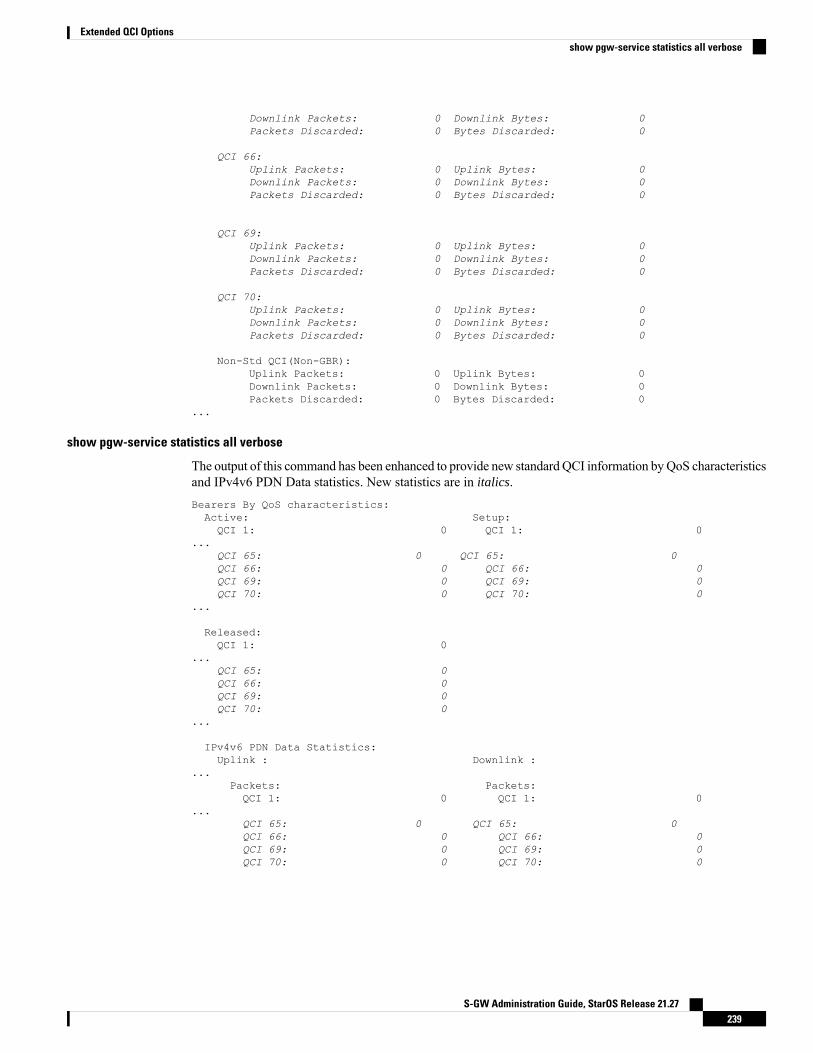
Downlink Packets: 0 Downlink Bytes: 0Packets Discarded: 0 Bytes Discarded: 0
QCI 66:Uplink Packets: 0 Uplink Bytes: 0Downlink Packets: 0 Downlink Bytes: 0Packets Discarded: 0 Bytes Discarded: 0
QCI 69:Uplink Packets: 0 Uplink Bytes: 0Downlink Packets: 0 Downlink Bytes: 0Packets Discarded: 0 Bytes Discarded: 0
QCI 70:Uplink Packets: 0 Uplink Bytes: 0Downlink Packets: 0 Downlink Bytes: 0Packets Discarded: 0 Bytes Discarded: 0
Non-Std QCI(Non-GBR):Uplink Packets: 0 Uplink Bytes: 0Downlink Packets: 0 Downlink Bytes: 0Packets Discarded: 0 Bytes Discarded: 0
...
show pgw-service statistics all verbose
The output of this command has been enhanced to provide new standardQCI information byQoS characteristicsand IPv4v6 PDN Data statistics. New statistics are in italics.Bearers By QoS characteristics:Active: Setup:QCI 1: 0 QCI 1: 0
...QCI 65: 0 QCI 65: 0QCI 66: 0 QCI 66: 0QCI 69: 0 QCI 69: 0QCI 70: 0 QCI 70: 0
...
Released:QCI 1: 0
...QCI 65: 0QCI 66: 0QCI 69: 0QCI 70: 0
...
IPv4v6 PDN Data Statistics:Uplink : Downlink :
...Packets: Packets:QCI 1: 0 QCI 1: 0
...QCI 65: 0 QCI 65: 0QCI 66: 0 QCI 66: 0QCI 69: 0 QCI 69: 0QCI 70: 0 QCI 70: 0
S-GW Administration Guide, StarOS Release 21.27239
Extended QCI Optionsshow pgw-service statistics all verbose
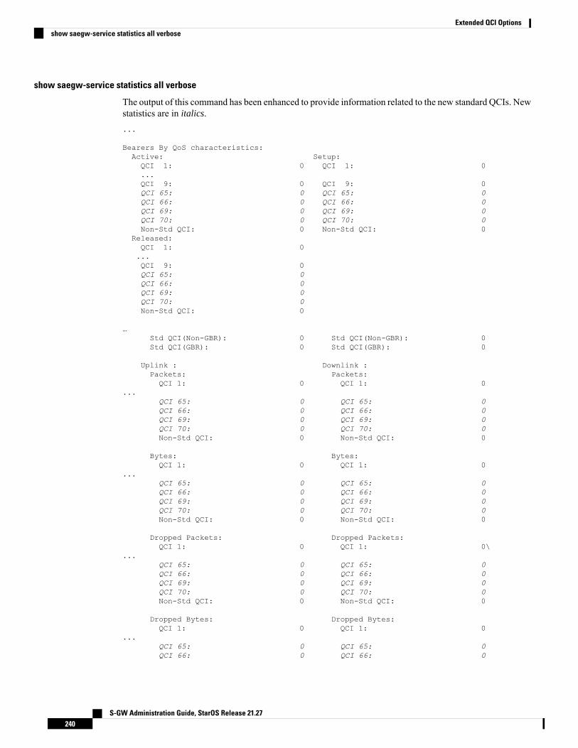
show saegw-service statistics all verbose
The output of this command has been enhanced to provide information related to the new standard QCIs. Newstatistics are in italics....
Bearers By QoS characteristics:Active: Setup:QCI 1: 0 QCI 1: 0...QCI 9: 0 QCI 9: 0QCI 65: 0 QCI 65: 0QCI 66: 0 QCI 66: 0QCI 69: 0 QCI 69: 0QCI 70: 0 QCI 70: 0Non-Std QCI: 0 Non-Std QCI: 0
Released:QCI 1: 0...QCI 9: 0QCI 65: 0QCI 66: 0QCI 69: 0QCI 70: 0Non-Std QCI: 0
…Std QCI(Non-GBR): 0 Std QCI(Non-GBR): 0Std QCI(GBR): 0 Std QCI(GBR): 0
Uplink : Downlink :Packets: Packets:QCI 1: 0 QCI 1: 0
...QCI 65: 0 QCI 65: 0QCI 66: 0 QCI 66: 0QCI 69: 0 QCI 69: 0QCI 70: 0 QCI 70: 0Non-Std QCI: 0 Non-Std QCI: 0
Bytes: Bytes:QCI 1: 0 QCI 1: 0
...QCI 65: 0 QCI 65: 0QCI 66: 0 QCI 66: 0QCI 69: 0 QCI 69: 0QCI 70: 0 QCI 70: 0Non-Std QCI: 0 Non-Std QCI: 0
Dropped Packets: Dropped Packets:QCI 1: 0 QCI 1: 0\
...QCI 65: 0 QCI 65: 0QCI 66: 0 QCI 66: 0QCI 69: 0 QCI 69: 0QCI 70: 0 QCI 70: 0Non-Std QCI: 0 Non-Std QCI: 0
Dropped Bytes: Dropped Bytes:QCI 1: 0 QCI 1: 0
...QCI 65: 0 QCI 65: 0QCI 66: 0 QCI 66: 0
S-GW Administration Guide, StarOS Release 21.27240
Extended QCI Optionsshow saegw-service statistics all verbose
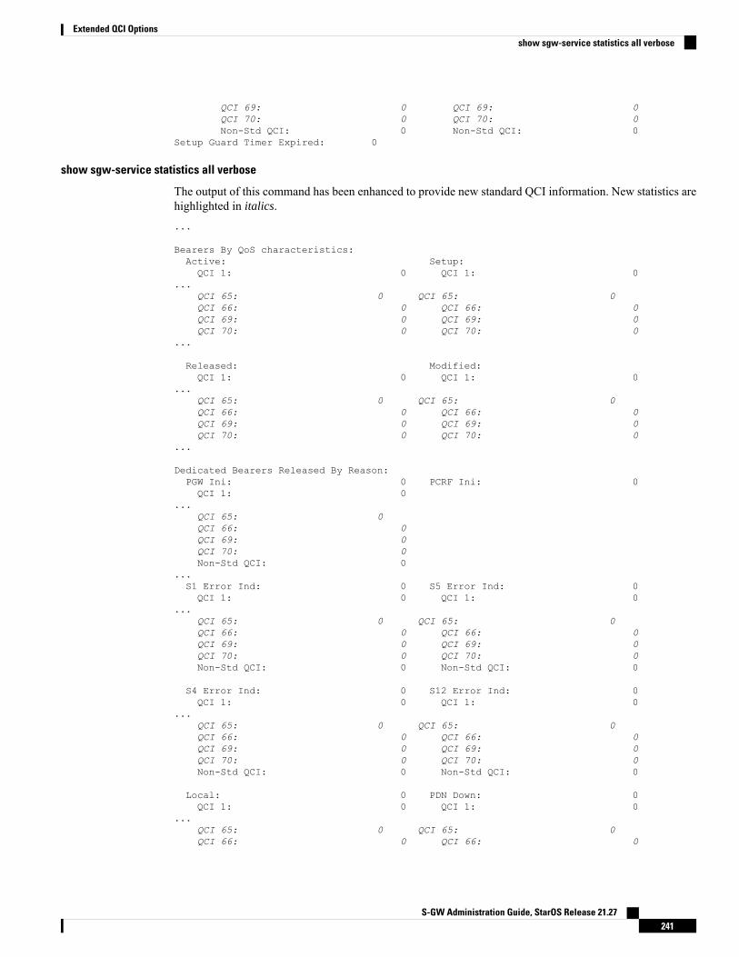
QCI 69: 0 QCI 69: 0QCI 70: 0 QCI 70: 0Non-Std QCI: 0 Non-Std QCI: 0
Setup Guard Timer Expired: 0
show sgw-service statistics all verbose
The output of this command has been enhanced to provide new standard QCI information. New statistics arehighlighted in italics....
Bearers By QoS characteristics:Active: Setup:QCI 1: 0 QCI 1: 0
...QCI 65: 0 QCI 65: 0QCI 66: 0 QCI 66: 0QCI 69: 0 QCI 69: 0QCI 70: 0 QCI 70: 0
...
Released: Modified:QCI 1: 0 QCI 1: 0
...QCI 65: 0 QCI 65: 0QCI 66: 0 QCI 66: 0QCI 69: 0 QCI 69: 0QCI 70: 0 QCI 70: 0
...
Dedicated Bearers Released By Reason:PGW Ini: 0 PCRF Ini: 0QCI 1: 0
...QCI 65: 0QCI 66: 0QCI 69: 0QCI 70: 0Non-Std QCI: 0
...S1 Error Ind: 0 S5 Error Ind: 0QCI 1: 0 QCI 1: 0
...QCI 65: 0 QCI 65: 0QCI 66: 0 QCI 66: 0QCI 69: 0 QCI 69: 0QCI 70: 0 QCI 70: 0Non-Std QCI: 0 Non-Std QCI: 0
S4 Error Ind: 0 S12 Error Ind: 0QCI 1: 0 QCI 1: 0
...QCI 65: 0 QCI 65: 0QCI 66: 0 QCI 66: 0QCI 69: 0 QCI 69: 0QCI 70: 0 QCI 70: 0Non-Std QCI: 0 Non-Std QCI: 0
Local: 0 PDN Down: 0QCI 1: 0 QCI 1: 0
...QCI 65: 0 QCI 65: 0QCI 66: 0 QCI 66: 0
S-GW Administration Guide, StarOS Release 21.27241
Extended QCI Optionsshow sgw-service statistics all verbose
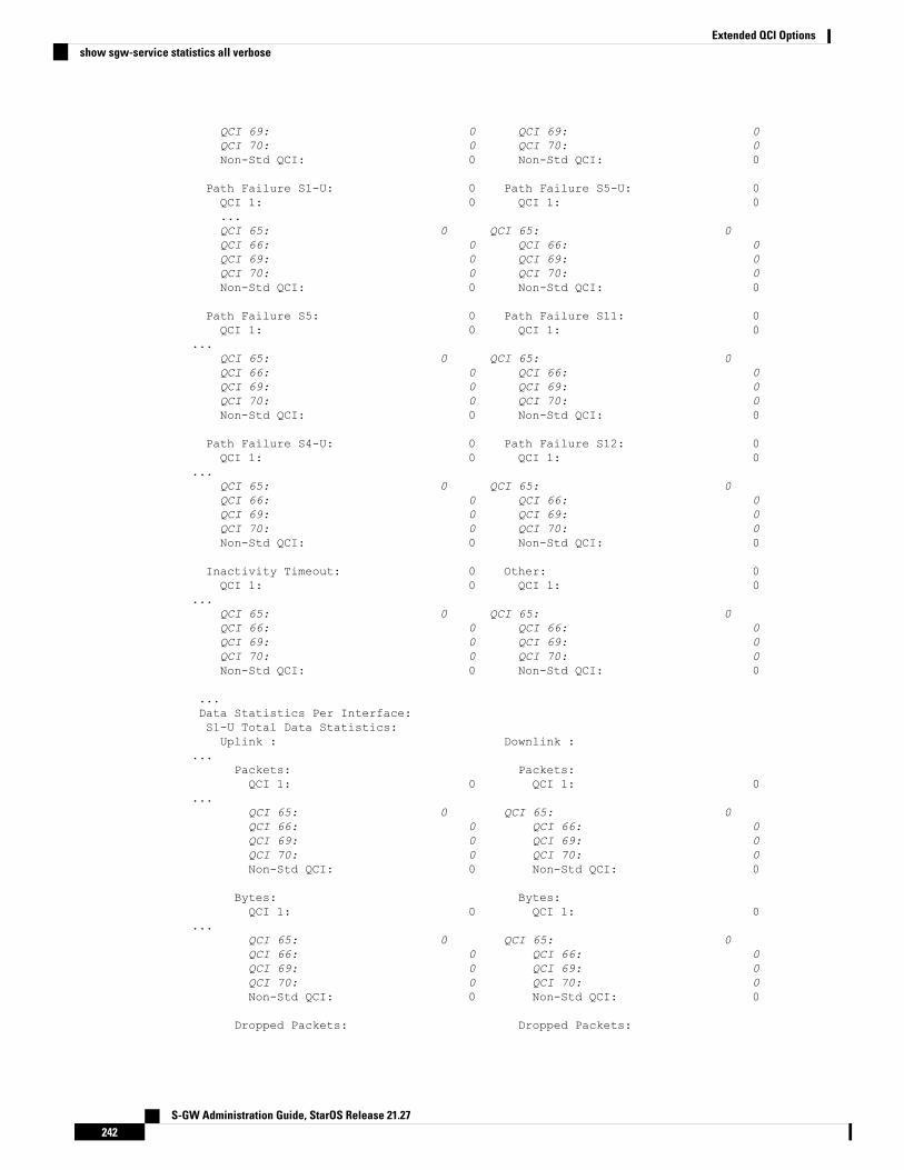
QCI 69: 0 QCI 69: 0QCI 70: 0 QCI 70: 0Non-Std QCI: 0 Non-Std QCI: 0
Path Failure S1-U: 0 Path Failure S5-U: 0QCI 1: 0 QCI 1: 0...QCI 65: 0 QCI 65: 0QCI 66: 0 QCI 66: 0QCI 69: 0 QCI 69: 0QCI 70: 0 QCI 70: 0Non-Std QCI: 0 Non-Std QCI: 0
Path Failure S5: 0 Path Failure S11: 0QCI 1: 0 QCI 1: 0
...QCI 65: 0 QCI 65: 0QCI 66: 0 QCI 66: 0QCI 69: 0 QCI 69: 0QCI 70: 0 QCI 70: 0Non-Std QCI: 0 Non-Std QCI: 0
Path Failure S4-U: 0 Path Failure S12: 0QCI 1: 0 QCI 1: 0
...QCI 65: 0 QCI 65: 0QCI 66: 0 QCI 66: 0QCI 69: 0 QCI 69: 0QCI 70: 0 QCI 70: 0Non-Std QCI: 0 Non-Std QCI: 0
Inactivity Timeout: 0 Other: 0QCI 1: 0 QCI 1: 0
...QCI 65: 0 QCI 65: 0QCI 66: 0 QCI 66: 0QCI 69: 0 QCI 69: 0QCI 70: 0 QCI 70: 0Non-Std QCI: 0 Non-Std QCI: 0
...Data Statistics Per Interface:S1-U Total Data Statistics:Uplink : Downlink :
...Packets: Packets:QCI 1: 0 QCI 1: 0
...QCI 65: 0 QCI 65: 0QCI 66: 0 QCI 66: 0QCI 69: 0 QCI 69: 0QCI 70: 0 QCI 70: 0Non-Std QCI: 0 Non-Std QCI: 0
Bytes: Bytes:QCI 1: 0 QCI 1: 0
...QCI 65: 0 QCI 65: 0QCI 66: 0 QCI 66: 0QCI 69: 0 QCI 69: 0QCI 70: 0 QCI 70: 0Non-Std QCI: 0 Non-Std QCI: 0
Dropped Packets: Dropped Packets:
S-GW Administration Guide, StarOS Release 21.27242
Extended QCI Optionsshow sgw-service statistics all verbose

QCI 1: 0 QCI 1: 0...
QCI 65: 0 QCI 65: 0QCI 66: 0 QCI 66: 0QCI 69: 0 QCI 69: 0QCI 70: 0 QCI 70: 0Non-Std QCI: 0 Non-Std QCI: 0
Dropped Bytes: Dropped Bytes:QCI 1: 0 QCI 1: 0
...QCI 65: 0 QCI 65: 0QCI 66: 0 QCI 66: 0QCI 69: 0 QCI 69: 0QCI 70: 0 QCI 70: 0Non-Std QCI: 0 Non-Std QCI: 0
S4-U Total Data Statistics:Uplink : Downlink :Total Pkts: 0 Total Pkts: 0Total Bytes: 0 Total Bytes: 0Dropped Pkts: 0 Dropped Pkts: 0Dropped Bytes: 0 Dropped Bytes: 0
Packets: Packets:QCI 1: 0 QCI 1: 0
...QCI 65: 0 QCI 65: 0QCI 66: 0 QCI 66: 0QCI 69: 0 QCI 69: 0QCI 70: 0 QCI 70: 0Non-Std QCI: 0 Non-Std QCI: 0
Bytes: Bytes:QCI 1: 0 QCI 1: 0
...QCI 65: 0 QCI 65: 0QCI 66: 0 QCI 66: 0QCI 69: 0 QCI 69: 0QCI 70: 0 QCI 70: 0Non-Std QCI: 0 Non-Std QCI: 0
Dropped Packets: Dropped Packets:QCI 1: 0 QCI 1: 0
...QCI 65: 0 QCI 65: 0QCI 66: 0 QCI 66: 0QCI 69: 0 QCI 69: 0QCI 70: 0 QCI 70: 0Non-Std QCI: 0 Non-Std QCI: 0
Dropped Bytes: Dropped Bytes:QCI 1: 0 QCI 1: 0
...QCI 65: 0 QCI 65: 0QCI 66: 0 QCI 66: 0QCI 69: 0 QCI 69: 0QCI 70: 0 QCI 70: 0Non-Std QCI: 0 Non-Std QCI: 0
S12 Total Data Statistics:Uplink : Downlink :Total Pkts: 0 Total Pkts: 0Total Bytes: 0 Total Bytes: 0
S-GW Administration Guide, StarOS Release 21.27243
Extended QCI Optionsshow sgw-service statistics all verbose
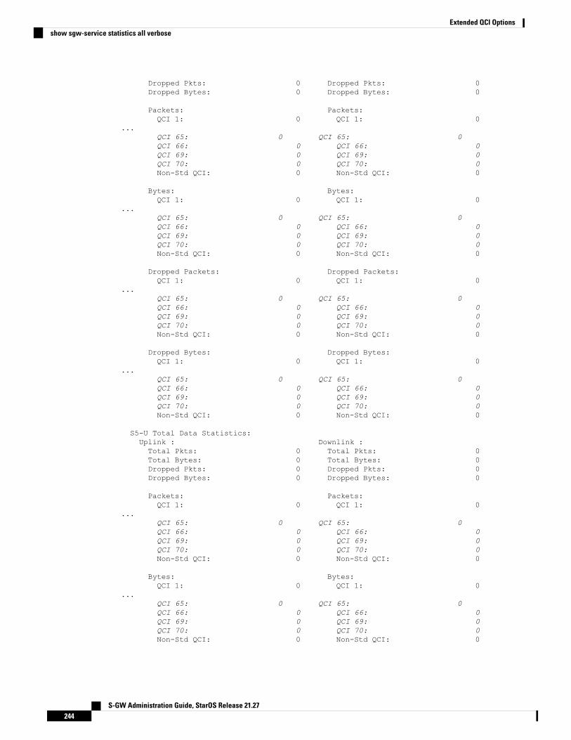
Dropped Pkts: 0 Dropped Pkts: 0Dropped Bytes: 0 Dropped Bytes: 0
Packets: Packets:QCI 1: 0 QCI 1: 0
...QCI 65: 0 QCI 65: 0QCI 66: 0 QCI 66: 0QCI 69: 0 QCI 69: 0QCI 70: 0 QCI 70: 0Non-Std QCI: 0 Non-Std QCI: 0
Bytes: Bytes:QCI 1: 0 QCI 1: 0
...QCI 65: 0 QCI 65: 0QCI 66: 0 QCI 66: 0QCI 69: 0 QCI 69: 0QCI 70: 0 QCI 70: 0Non-Std QCI: 0 Non-Std QCI: 0
Dropped Packets: Dropped Packets:QCI 1: 0 QCI 1: 0
...QCI 65: 0 QCI 65: 0QCI 66: 0 QCI 66: 0QCI 69: 0 QCI 69: 0QCI 70: 0 QCI 70: 0Non-Std QCI: 0 Non-Std QCI: 0
Dropped Bytes: Dropped Bytes:QCI 1: 0 QCI 1: 0
...QCI 65: 0 QCI 65: 0QCI 66: 0 QCI 66: 0QCI 69: 0 QCI 69: 0QCI 70: 0 QCI 70: 0Non-Std QCI: 0 Non-Std QCI: 0
S5-U Total Data Statistics:Uplink : Downlink :Total Pkts: 0 Total Pkts: 0Total Bytes: 0 Total Bytes: 0Dropped Pkts: 0 Dropped Pkts: 0Dropped Bytes: 0 Dropped Bytes: 0
Packets: Packets:QCI 1: 0 QCI 1: 0
...QCI 65: 0 QCI 65: 0QCI 66: 0 QCI 66: 0QCI 69: 0 QCI 69: 0QCI 70: 0 QCI 70: 0Non-Std QCI: 0 Non-Std QCI: 0
Bytes: Bytes:QCI 1: 0 QCI 1: 0
...QCI 65: 0 QCI 65: 0QCI 66: 0 QCI 66: 0QCI 69: 0 QCI 69: 0QCI 70: 0 QCI 70: 0Non-Std QCI: 0 Non-Std QCI: 0
S-GW Administration Guide, StarOS Release 21.27244
Extended QCI Optionsshow sgw-service statistics all verbose
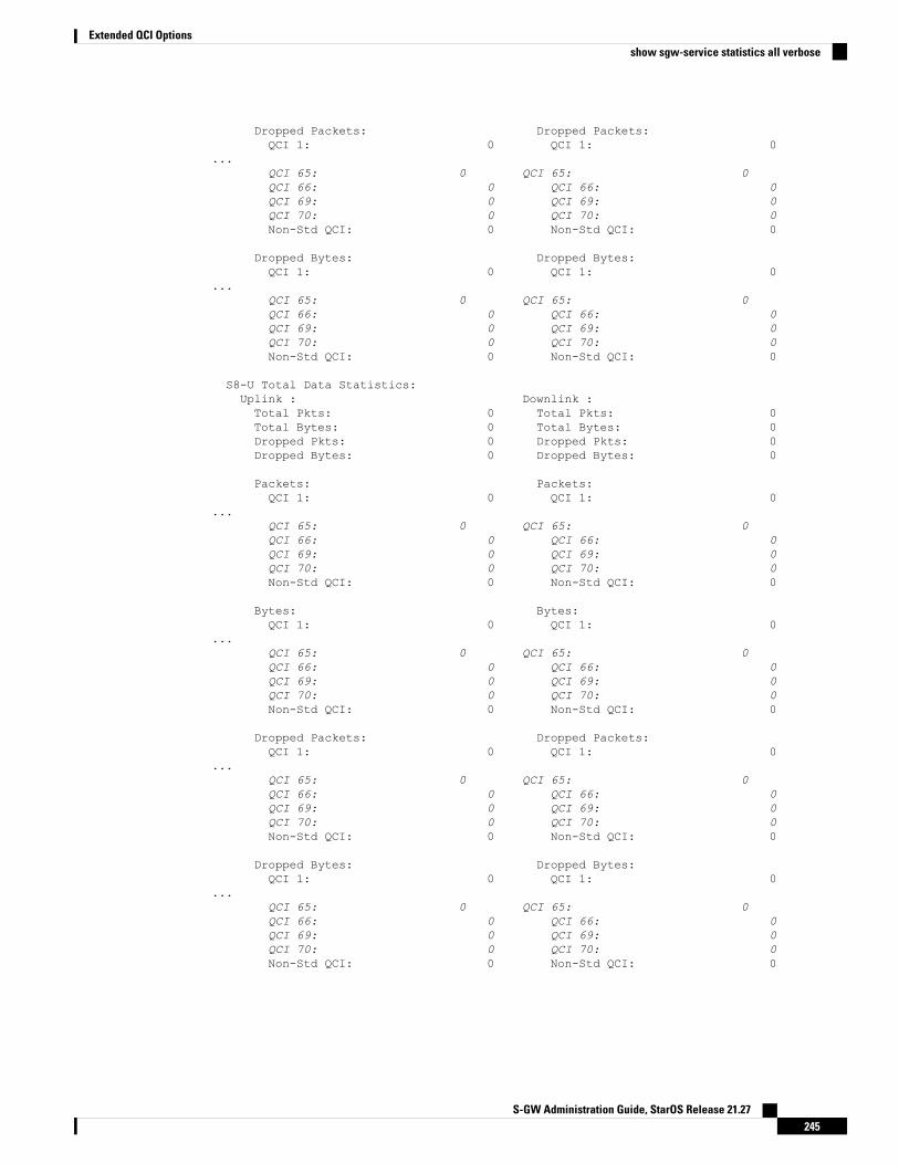
Dropped Packets: Dropped Packets:QCI 1: 0 QCI 1: 0
...QCI 65: 0 QCI 65: 0QCI 66: 0 QCI 66: 0QCI 69: 0 QCI 69: 0QCI 70: 0 QCI 70: 0Non-Std QCI: 0 Non-Std QCI: 0
Dropped Bytes: Dropped Bytes:QCI 1: 0 QCI 1: 0
...QCI 65: 0 QCI 65: 0QCI 66: 0 QCI 66: 0QCI 69: 0 QCI 69: 0QCI 70: 0 QCI 70: 0Non-Std QCI: 0 Non-Std QCI: 0
S8-U Total Data Statistics:Uplink : Downlink :Total Pkts: 0 Total Pkts: 0Total Bytes: 0 Total Bytes: 0Dropped Pkts: 0 Dropped Pkts: 0Dropped Bytes: 0 Dropped Bytes: 0
Packets: Packets:QCI 1: 0 QCI 1: 0
...QCI 65: 0 QCI 65: 0QCI 66: 0 QCI 66: 0QCI 69: 0 QCI 69: 0QCI 70: 0 QCI 70: 0Non-Std QCI: 0 Non-Std QCI: 0
Bytes: Bytes:QCI 1: 0 QCI 1: 0
...QCI 65: 0 QCI 65: 0QCI 66: 0 QCI 66: 0QCI 69: 0 QCI 69: 0QCI 70: 0 QCI 70: 0Non-Std QCI: 0 Non-Std QCI: 0
Dropped Packets: Dropped Packets:QCI 1: 0 QCI 1: 0
...QCI 65: 0 QCI 65: 0QCI 66: 0 QCI 66: 0QCI 69: 0 QCI 69: 0QCI 70: 0 QCI 70: 0Non-Std QCI: 0 Non-Std QCI: 0
Dropped Bytes: Dropped Bytes:QCI 1: 0 QCI 1: 0
...QCI 65: 0 QCI 65: 0QCI 66: 0 QCI 66: 0QCI 69: 0 QCI 69: 0QCI 70: 0 QCI 70: 0Non-Std QCI: 0 Non-Std QCI: 0
S-GW Administration Guide, StarOS Release 21.27245
Extended QCI Optionsshow sgw-service statistics all verbose

Non-standard QCI SupportThis section describes the Non-standard QCI Support feature.
Feature DescriptionUsually, only standards-basedQCI values of 1 through 9 are supported onGGSN/P-GW/SAEGW/S-GW/ePDG.A license, however, allows non-standard QCIs (128-254) to be used on P-GW/GGSN (not standalone GGSN).
LicensingUse of non-standard QCIs require that a valid license key be installed. Contact your Cisco Account or Supportrepresentative for information on how to obtain a license.
How It WorksFrom 3GPP Release 8 onwards, operator-specific/non-standard QCIs can be supported and carriers can defineQCI 128-254. QCI values 0 and 10 to 255 are defined as follows:
• 0: Reserved• 10-127: Reserved• 128-254: Operator-specific/Non-standard QCI• 255: Reserved
Unique operator-specific QCIs (128-254) can be used to differentiate between various services/applicationscarriers provide to the end users in their network.
Limitations• Non-standard QCIs can only be supported with S5/S8/S2a/S2b interfaces.
• The Gn interface is not supported.
Standards Compliance• 3GPP Specification TS 23.203: Policy and charging control architecture
• 3GPP Specification TS 29.212: Policy and Charging Control over Gx reference point
Configuring Non-standard QCI SupportThe operator-defined-qci command in theQCI-QoSMappingConfigurationMode configures the non-standardQCIs in P-GW so that calls can be accepted when non-standard QCI values are received from UE or PCRF.Unique DSCP parameters (uplink and downlink) and GBR or Non-GBR can also be configured.
As non-standard QCIs are not supported in GGSN, pre-rel8-qos-mapping is used as a reference for mappingthe non-standard QCI values to pre-rel8 QoS values during 3G calls or GnGp handovers.
S-GW Administration Guide, StarOS Release 21.27246
Extended QCI OptionsNon-standard QCI Support

Configuring Non-standard QCI Support in P-GWUse the following command to configure non-standard QCI support in P-GW so that calls can be acceptedwhen non-standard QCI values are received from UE or PCRF.
configureqci-qos-mapping name
operator-defined-qci num { gbr | non-gbr } [ { downlink |uplink } [ encaps-header { copy-inner | copy-outer | dscp-markingdscp-marking-value } [ internal-qos priority priority ] | internal-qos prioritypriority | user-datagram dscp-marking dscp-marking-value [ encaps-header {copy-inner | copy-outer | dscp-marking dscp-marking-value } [ internal-qospriority priority ] ] | pre-rel8-qos-mapping num ]
no operator-defined-qci num
end
Notes:
• This command is only visible if the license key supporting non-standard QCIs is installed. Contact yourCisco Account or Support representative for information on how to obtain a license.
• operator-defined-qci num: Specifies the operator-defined QCI value to be enabled.
num must be an integer from 128 through 254.
Standards-based QCI values 1 through 9 are configured through the qci command.
• pre-rel8-qos-mapping num: Maps non-standard QCI to a standard QCI that has the characteristics (TC,THP, SI, TD, SSD) similar to desired pre-rel8 standard QoS values during 3G call or GnGp handover.
num must be an integer from 1 through 4 for GBR and 5 through 9 for non-GBR. QCI values 1 through9 are defined in 3GPP Specification TS 23.203 "Policy and charging control architecture".
3G GGSN Call
If the pre-rel8-qos-mapping field is not configured for the non-standard QCI under P-GW which isassociated with a GGSN, then the 3G call would be rejected.
GnGp Handoff
1. If the pre-rel8-qos-mapping field is not configured for the non-standard QCI for default bearer,then the handoff would be rejected.
2. If the pre-rel8-qos-mapping field is not configured for the non-standard QCI for dedicated bearer,then only that bearer would be rejected during handoff.
3. In the following scenario:
• default bearer with standard QCI or non-standard QCI (with pre-rel8-qos-mapping configured)• more than one dedicated bearer (some with standard QCI, some with non-standard QCI with
pre-rel8-qos-mapping configured, and some with non-standard QCI with no mapping)
During LTE-to-GnGp handoff:
• UPC Request for all the dedicated bearers with non-standard QCI with no mapping would berejected
• handoff will be successful for the remaining bearers
S-GW Administration Guide, StarOS Release 21.27247
Extended QCI OptionsConfiguring Non-standard QCI Support in P-GW
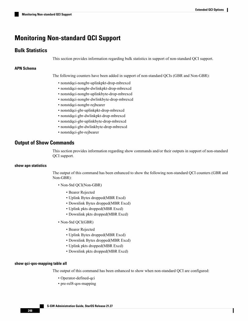
Monitoring Non-standard QCI Support
Bulk StatisticsThis section provides information regarding bulk statistics in support of non-standard QCI support.
APN Schema
The following counters have been added in support of non-standard QCIs (GBR and Non-GBR):
• nonstdqci-nongbr-uplinkpkt-drop-mbrexcd• nonstdqci-nongbr-dwlinkpkt-drop-mbrexcd• nonstdqci-nongbr-uplinkbyte-drop-mbrexcd• nonstdqci-nongbr-dwlinkbyte-drop-mbrexcd• nonstdqci-nongbr-rejbearer• nonstdqci-gbr-uplinkpkt-drop-mbrexcd• nonstdqci-gbr-dwlinkpkt-drop-mbrexcd• nonstdqci-gbr-uplinkbyte-drop-mbrexcd• nonstdqci-gbr-dwlinkbyte-drop-mbrexcd• nonstdqci-gbr-rejbearer
Output of Show CommandsThis section provides information regarding show commands and/or their outputs in support of non-standardQCI support.
show apn statistics
The output of this command has been enhanced to show the following non-standard QCI counters (GBR andNon-GBR):
• Non-Std QCI(Non-GBR)
• Bearer Rejected• Uplink Bytes dropped(MBR Excd)• Downlink Bytes dropped(MBR Excd)• Uplink pkts dropped(MBR Excd)• Downlink pkts dropped(MBR Excd)
• Non-Std QCI(GBR)
• Bearer Rejected• Uplink Bytes dropped(MBR Excd)• Downlink Bytes dropped(MBR Excd)• Uplink pkts dropped(MBR Excd)• Downlink pkts dropped(MBR Excd)
show qci-qos-mapping table all
The output of this command has been enhanced to show when non-standard QCI are configured:
• Operator-defined-qci• pre-rel8-qos-mapping
S-GW Administration Guide, StarOS Release 21.27248
Extended QCI OptionsMonitoring Non-standard QCI Support

C H A P T E R 14GGSN UPC Collision Handling
• GGSN UPC Collision Handling, on page 249
GGSN UPC Collision Handling
Feature DescriptionDuring collision between SGSN-initiated UPC request and GGSN-initiated UPC Request, SGSN-initiatedUPC request gets higher priority over Network Operated (NRUPC).With the UPCCollision Handling feature,there is no call or data loss during call establishment or during mid-call phase. This feature can be enabled ordisabled using a CLI and is enabled by default.
• WhenGGSN detects collision between SGSN initiatedUPC request andNRUPC on primary PDP context,NRUPC is retried (with different sequence number) after sending UPC Response.
• When GGSN detects collision between SGSN initiated UPC request for Inter-SGSN handoff and NRUPCwith TFT and after handoff BCM mode is changed from Mixed mode to MS-Only mode, NRUPC isretried (with different sequence number) after sending UPC Response, but without TFT.
• When GGSN detects collision between an SGSN initiated UPC and a NRUPC on secondary PDP context,NRUPC is aborted and PCRF is notified. When multiple CCR-U support is not enabled on GGSN,CCR-U for aborted NRUPC (on secondary PDP context) is not informed to PCRF. In this case, PCRFwill not be aware of this aborted transaction (rule failure).
During S2bGTP to LTE handoff procedure, when there is already a pending transaction and a Handoff requestis received by SAE-GW, Handoff is rejected with a following message:
Rejecting S2b/LTE Handoff as only one pending transaction is supported
Note
Limitations• Behavior for GnGpGGSN has been modified for this feature, in this release. Behavior for GGSN remainsunaltered.
S-GW Administration Guide, StarOS Release 21.27249
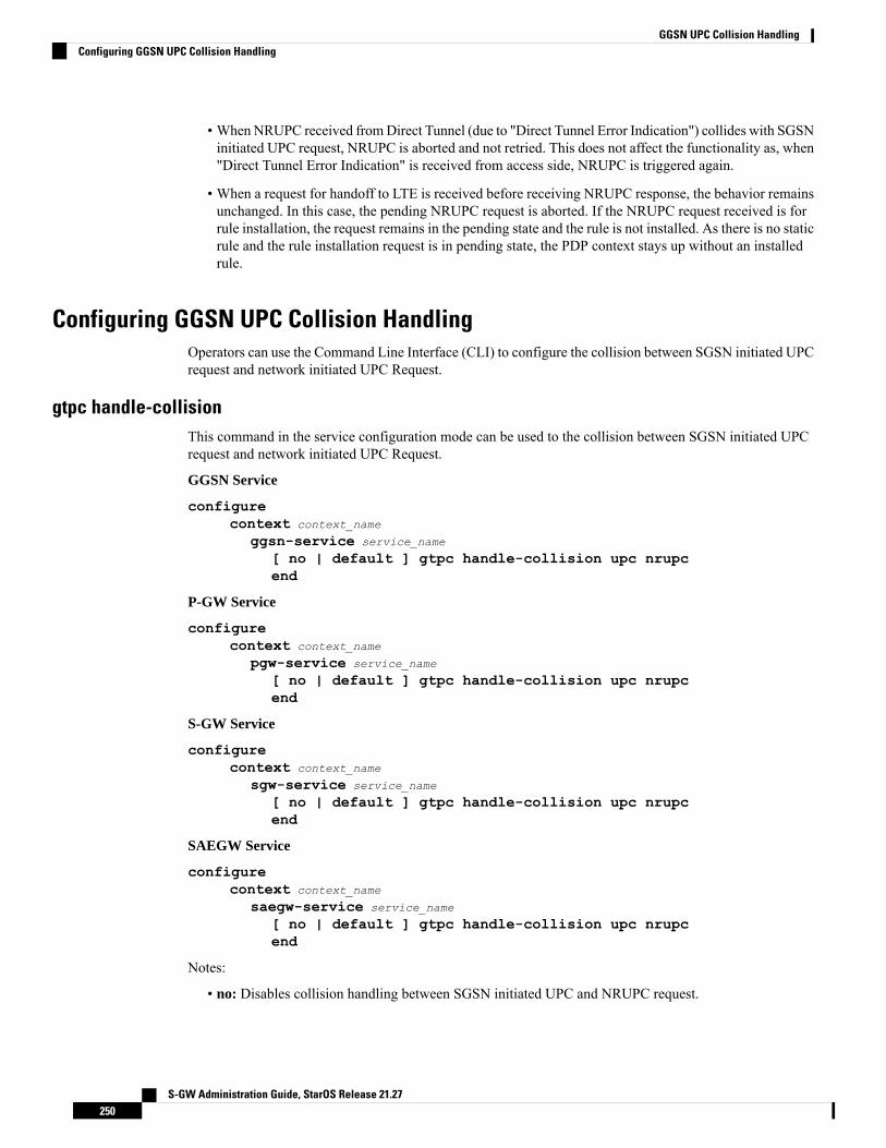
• When NRUPC received fromDirect Tunnel (due to "Direct Tunnel Error Indication") collides with SGSNinitiated UPC request, NRUPC is aborted and not retried. This does not affect the functionality as, when"Direct Tunnel Error Indication" is received from access side, NRUPC is triggered again.
• When a request for handoff to LTE is received before receiving NRUPC response, the behavior remainsunchanged. In this case, the pending NRUPC request is aborted. If the NRUPC request received is forrule installation, the request remains in the pending state and the rule is not installed. As there is no staticrule and the rule installation request is in pending state, the PDP context stays up without an installedrule.
Configuring GGSN UPC Collision HandlingOperators can use the Command Line Interface (CLI) to configure the collision between SGSN initiated UPCrequest and network initiated UPC Request.
gtpc handle-collisionThis command in the service configuration mode can be used to the collision between SGSN initiated UPCrequest and network initiated UPC Request.
GGSN Service
configurecontext context_name
ggsn-service service_name
[ no | default ] gtpc handle-collision upc nrupcend
P-GW Service
configurecontext context_name
pgw-service service_name
[ no | default ] gtpc handle-collision upc nrupcend
S-GW Service
configurecontext context_name
sgw-service service_name
[ no | default ] gtpc handle-collision upc nrupcend
SAEGW Service
configurecontext context_name
saegw-service service_name
[ no | default ] gtpc handle-collision upc nrupcend
Notes:
• no: Disables collision handling between SGSN initiated UPC and NRUPC request.
S-GW Administration Guide, StarOS Release 21.27250
GGSN UPC Collision HandlingConfiguring GGSN UPC Collision Handling
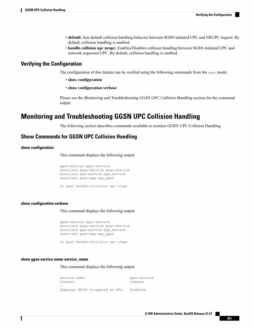
• default: Sets default collision handling behavior between SGSN initiated UPC and NRUPC request. Bydefault, collision handling is enabled.
• handle-collision upc nrupc: Enables/Disables collision handling between SGSN initiated UPC andnetwork requested UPC. By default, collision handling is enabled.
Verifying the ConfigurationThe configuration of this feature can be verified using the following commands from the exec mode:
• show configuration
• show configuration verbose
Please see the Monitoring and Troubleshooting GGSN UPC Collision Handling section for the commandoutput.
Monitoring and Troubleshooting GGSN UPC Collision HandlingThe following section describes commands available to monitor GGSN UPC Collision Handling.
Show Commands for GGSN UPC Collision Handling
show configuration
This command displays the following output:
ggsn-service ggsn-serviceassociate gtpu-service gtpu-serviceassociate pgw-service pgw_serviceassociate peer-map map_ggsn
no gtpc handle-collision upc nrupc
show configuration verbose
This command displays the following output:
ggsn-service ggsn-serviceassociate gtpu-service gtpu-serviceassociate pgw-service pgw_serviceassociate peer-map map_ggsn
no gtpc handle-collision upc nrupc
show ggsn-service name service_name
This command displays the following output:
Service name: ggsn-serviceContext: ingress…Suppress NRUPC triggered by UPC: Disabled
S-GW Administration Guide, StarOS Release 21.27251
GGSN UPC Collision HandlingVerifying the Configuration

Collision handling for UPC-NRUPC: Enabled/Disabled
show gtpc statistics
This command displays the number of NRUPC and SGSN initiated UPC collisions happening for primaryand secondary PDP context for a GGSN service. This command displays the following output:Active Subscribers:Total: 12G: 03G: 1
……MS Info Change Reporting Messages:MS Info Chng Notif Req: 0 Accepted: 0Denied: 0 Discarded: 0
NRUPC UPC Collision:Primary PDP ctxt: 3 Secondary PDP ctxt: 0
QoS negotiation:CPC QoS Accepted: 3 CPC QoS Downgraded: 0UPC QoS Accepted: 3 UPC QoS Downgraded: 0
show gtpc statistics [ format1 | ggsn-service service_name | verbose ]
This command displays the number of NRUPC and SGSN initiated UPC collisions happening for primaryand secondary PDP context for a GGSN service. This command displays the following output:Active Subscribers:Total: 12G: 03G: 1
……MS Info Change Reporting Messages:MS Info Chng Notif Req: 0 Accepted: 0Denied: 0 Discarded: 0
NRUPC UPC Collision:Primary PDP ctxt: 3 Secondary PDP ctxt: 0
QoS negotiation:CPC QoS Accepted: 3 CPC QoS Downgraded: 0UPC QoS Accepted: 3 UPC QoS Downgraded: 0
S-GW Administration Guide, StarOS Release 21.27252
GGSN UPC Collision Handlingshow gtpc statistics
C H A P T E R 153GPP R12 GTP-C Load and Overload ControlSupport on the P-GW, SAEGW, and S-GW
This chapter describes the 3GPPRelease 12 GTP-C Load and Overload Control feature on the P-GW, SAEGW,and S-GW.
• Feature Description, on page 253• How It Works, on page 254• Creating and Configuring a 3GPP R12 GTP-C Load Control Profile, on page 255• Creating and Configuring a 3GPP R12 GTP-C Overload Control Profile, on page 260• Monitoring and Troubleshooting the 3GPP R12 GTP-C Load and Overload Control Feature, on page 267
Feature DescriptionThis section describes the 3GPP R12 GTP-C Load and Overload Control feature.
Use of the 3GPP R12 Load and Overload Control feature requires that a valid license key be installed. Contactyour Cisco account or support representative for information on how to obtain a license.
Important
The 3GPP R12 GTP-C Load and Overload Control feature is a licensed, optional feature which allows a GTPcontrol plane node to send its load information to a peer GTP control plane node which the receiving GTPcontrol plane peer node uses to augment existing GW selection procedure for the P-GW and S-GW. Loadinformation reflects the operating status of the resources of the originating GTP control plane node.
Nodes using GTP control plane signaling may support communication of overload control information inorder to mitigate overload situations for the overloaded node through actions taken by the peer node(s). Thisfeature is supported over the S4, S11, S5 and S8 interfaces via the GTPv2 control plane protocol.
A GTP-C node is considered to be in overload when it is operating over its nominal capacity resulting indiminished performance (including impacts to handling of incoming and outgoing traffic). Overload controlinformation reflects an indication of when the originating node has reached such a situation. This information,when transmitted between GTP-C nodes, may be used to reduce and/or throttle the amount of GTP-C signalingtraffic between these nodes. As such, the overload control information provides guidance to the receivingnode to decide upon the correct actions, which leads to mitigation towards the sender of the information.
To summarize, load control and overload control can be described in this manner:
S-GW Administration Guide, StarOS Release 21.27253

• Load Control: Load control enables a GTP-C entity (for example, an P-GW/SAEGW/S-GW) to sendits load information to a GTP-C peer (for example, anMME/SGSN, ePDG, TWAN) to adaptively balancethe session load across entities supporting the same function (for example, an S-GW cluster) accordingto their effective load. The load information reflects the operating status of the resources of the GTP-Centity.
• Overload Control: Overload control enables a GTP-C entity becoming or being overloaded to gracefullyreduce its incoming signaling load by instructing its GTP-C peers to reduce sending traffic according toits available signaling capacity to successfully process the traffic. A GTP-C entity is in overload whenit operates over its signaling capacity, which results in diminished performance (including impacts tohandling of incoming and outgoing traffic).
Load and Overload Factor Calculation Enhancement
In capacity testing and also in customer deployments it was observed that the chassis load factor for the 3GPPR12 Load and Overload Support feature was providing incorrect values even when the sessmgr card CPUutilization was high. The root cause is that when the load factor was calculated by taking an average of CPUutilization of sessmgr and demux cards, the demux card CPU utilization never increased more than the sessmgrcard CPU utilization. As a result, the system did not go into the overload state even when the sessmgr cardCPU utilization was high.
The 3GPP R12 Load/Overload Control Profile feature has been enhanced to calculate the load factor basedon the higher value of similar types of cards for CPU load and memory. If the demux card's CPU utilizationvalue is higher than the sessmgr card's CPU utilization value, then the demux card CPU utilization value isused for the load factor calculation.
A new CLI command, gtpc-system-param-poll interval, is introduced to configure different polling intervalsfor the resource manager so that the demuxmgr can calculate the load factor based on different systemrequirements.
Relationships to Other FeaturesNote the following before configuring the GTPP R12 GTP-C Load and Overload Control feature:
• One of the following services must be configured on the node before GTP-C Load and Overload Controlcan be configured.
• P-GW• SAEGW• S-GW
• Once configured, the GTP-C Load and Overload Control profiles must be associated with a P-GW,SAEGW, or S-GW service to function properly in the network.
How It WorksThe node periodically fetches various parameters (for example, License-Session-Utilization,System-CPU-Utilization, and System-Memory-Utilization), which are required for Node level load controlinformation. The node then calculates the load/overload control information itself either based on the weightedfactor provided by the user or using the default weighted factor.
Node level load control information is calculated every 30 seconds. The resource manager calculates thesystem-CPU-utilization and System-Memory-Utilization at a systems level.
S-GW Administration Guide, StarOS Release 21.27254
3GPP R12 GTP-C Load and Overload Control Support on the P-GW, SAEGW, and S-GWRelationships to Other Features

For each configured service, load control information can be different. This can be achieved by providing aweightage to the number of active session counts per service license, for example, [(number of active sessionsper service / max session allowed for the service license) * 100].
The node's resource manager calculates the system-CPU-utilization and System-Memory-Utilization at asystems level by averaging CPU and Memory usage for all cards and which might be different from thatcalculated at the individual card level.
Creating and Configuring a 3GPP R12 GTP-C Load Control ProfileThis section describes how to create and configure a 3GPP R12 GTP-C load control profile.
Configuration OverviewCreating and configuring a 3GPP R12 GTP-C load control profile consists of the following procedures:
Step 1 Create a load control profile. Refer to Creating the GTPP R12 Load Control Profile, on page 255.Step 2 Configure the load control weightage settings. Refer to Configuring the 3GPP R12 Load Control Profile Weightage
Settings, on page 256.Step 3 Configure the load control inclusion frequency. Refer to Configuring the 3GPP R12 Load Control Profile Inclusion
Frequency, on page 256.Step 4 P-GW Only. Configure the load control threshold. Refer to Configuring the 3GPP R12 Load Control Threshold, on
page 257.Step 5 Configure load control information handling. Refer to Configuring 3GPP R12 Load Control Information Handling, on
page 257.Step 6 Configure load control information publishing. Refer to Configuring 3GPP R12 Load Control Information Publishing,
on page 257.Step 7 Configure the 3GPP R12 GTP-C Polling Parameter Interval. Refer to Configuring the 3GPP R12 GTP-C Polling
Parameter Interval, on page 258Step 8 Associate the load control profile with a P-GW, SAEGW, or S-GW service. Refer to Associating the 3GPP R12 Load
Control Profile with a P-GW, SAEGW, or S-GW Service., on page 258.Step 9 Verify the configuration settings. Refer to Verifying the 3GPP R12 Load Control Configuration , on page 259.Step 10 Save the configuration. Refer to Saving the Configuration, on page 260.
Creating the GTPP R12 Load Control ProfileUse the following example to create a load control profile on the P-GW/SAEGW/S-GW:
configgtpc-load-control-profile profile_name
end
Notes:
• The profile name must be an alphanumeric string from 1 to 64 characters in length.
S-GW Administration Guide, StarOS Release 21.27255
3GPP R12 GTP-C Load and Overload Control Support on the P-GW, SAEGW, and S-GWCreating and Configuring a 3GPP R12 GTP-C Load Control Profile
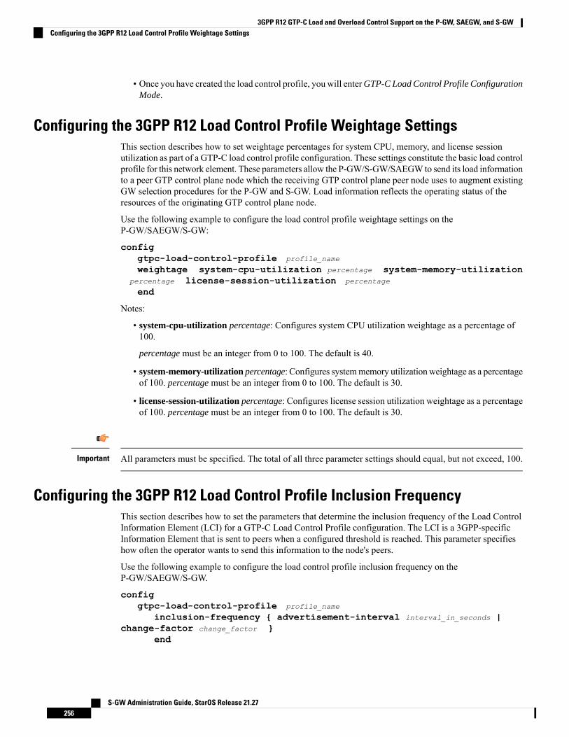
• Once you have created the load control profile, you will enterGTP-C Load Control Profile ConfigurationMode.
Configuring the 3GPP R12 Load Control Profile Weightage SettingsThis section describes how to set weightage percentages for system CPU, memory, and license sessionutilization as part of a GTP-C load control profile configuration. These settings constitute the basic load controlprofile for this network element. These parameters allow the P-GW/S-GW/SAEGW to send its load informationto a peer GTP control plane node which the receiving GTP control plane peer node uses to augment existingGW selection procedures for the P-GW and S-GW. Load information reflects the operating status of theresources of the originating GTP control plane node.
Use the following example to configure the load control profile weightage settings on theP-GW/SAEGW/S-GW:
configgtpc-load-control-profile profile_name
weightage system-cpu-utilization percentage system-memory-utilizationpercentage license-session-utilization percentage
end
Notes:
• system-cpu-utilization percentage: Configures system CPU utilization weightage as a percentage of100.
percentage must be an integer from 0 to 100. The default is 40.
• system-memory-utilization percentage: Configures systemmemory utilizationweightage as a percentageof 100. percentage must be an integer from 0 to 100. The default is 30.
• license-session-utilization percentage: Configures license session utilization weightage as a percentageof 100. percentage must be an integer from 0 to 100. The default is 30.
All parameters must be specified. The total of all three parameter settings should equal, but not exceed, 100.Important
Configuring the 3GPP R12 Load Control Profile Inclusion FrequencyThis section describes how to set the parameters that determine the inclusion frequency of the Load ControlInformation Element (LCI) for a GTP-C Load Control Profile configuration. The LCI is a 3GPP-specificInformation Element that is sent to peers when a configured threshold is reached. This parameter specifieshow often the operator wants to send this information to the node's peers.
Use the following example to configure the load control profile inclusion frequency on theP-GW/SAEGW/S-GW.
configgtpc-load-control-profile profile_name
inclusion-frequency { advertisement-interval interval_in_seconds |change-factor change_factor }
end
S-GW Administration Guide, StarOS Release 21.27256
3GPP R12 GTP-C Load and Overload Control Support on the P-GW, SAEGW, and S-GWConfiguring the 3GPP R12 Load Control Profile Weightage Settings

Notes:
• inclusion frequency: Configures parameters to determine the inclusion frequency of the LCI.• advertisement-interval interval_in_seconds: Configures advertisement-interval for the LCI in seconds.This specifies how often load control information should be sent to the peers. If configured to 0, the nodewill send load control information in each and every outgoing message to the peers. interval_in_secondsmust be an integer from 0 to 3600. The default is 300.
• change-factor change_factor: Configures the change factor for the load control profile. If the load controlchange factor changes by the configured factor, whether it is an increase or decrease in load, the loadcontrol information is sent to the peers. This information is only sent to the peers when the load factorchanges by the factor configured. change_factor must be an integer from 1 to 20. The default is 5.
Configuring the 3GPP R12 Load Control ThresholdThis section describes how to configure the minimum threshold value above which P-GW-provided loadcontrol information should be utilized for calculating the P-GW effective weight during initial node selection.
Use the following example to configure Load Control Profile threshold on the P-GW.
configgtpc-load-control-profile profile_name
threshold time_in_seconds
end
Notes:
• The default threshold value is 50.
Configuring 3GPP R12 Load Control Information HandlingThe handling of load control information for the home or visited PLMN can be enabled/disabled via thisprocedure.
Use the following example to enable/disable load control profile information handling on theSAEGW/S-GW/P-GW.
configgtpc-load-control-profile profile_name
load-control-handling { home | visited }no load-control-handling { home | visited }end
Notes:
• no disables load-control-handling for the specified option.
Configuring 3GPP R12 Load Control Information PublishingThe publishing of load control information can be enabled/disabled for the home or visited PLMN.
Use the following example to enable/disable load control profile information publishing on theP-GW/SAEGW/S-GW.
S-GW Administration Guide, StarOS Release 21.27257
3GPP R12 GTP-C Load and Overload Control Support on the P-GW, SAEGW, and S-GWConfiguring the 3GPP R12 Load Control Threshold
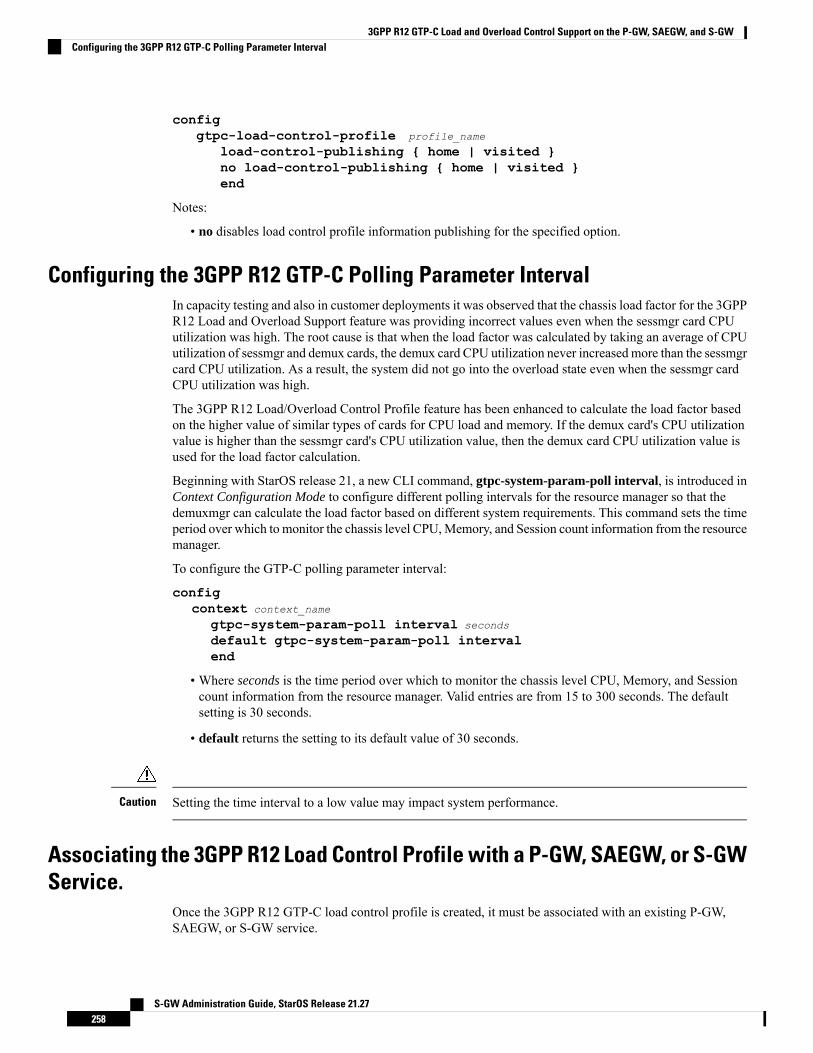
configgtpc-load-control-profile profile_name
load-control-publishing { home | visited }no load-control-publishing { home | visited }end
Notes:
• no disables load control profile information publishing for the specified option.
Configuring the 3GPP R12 GTP-C Polling Parameter IntervalIn capacity testing and also in customer deployments it was observed that the chassis load factor for the 3GPPR12 Load and Overload Support feature was providing incorrect values even when the sessmgr card CPUutilization was high. The root cause is that when the load factor was calculated by taking an average of CPUutilization of sessmgr and demux cards, the demux card CPU utilization never increased more than the sessmgrcard CPU utilization. As a result, the system did not go into the overload state even when the sessmgr cardCPU utilization was high.
The 3GPP R12 Load/Overload Control Profile feature has been enhanced to calculate the load factor basedon the higher value of similar types of cards for CPU load and memory. If the demux card's CPU utilizationvalue is higher than the sessmgr card's CPU utilization value, then the demux card CPU utilization value isused for the load factor calculation.
Beginning with StarOS release 21, a new CLI command, gtpc-system-param-poll interval, is introduced inContext Configuration Mode to configure different polling intervals for the resource manager so that thedemuxmgr can calculate the load factor based on different system requirements. This command sets the timeperiod over which to monitor the chassis level CPU,Memory, and Session count information from the resourcemanager.
To configure the GTP-C polling parameter interval:
configcontext context_name
gtpc-system-param-poll interval seconds
default gtpc-system-param-poll intervalend
• Where seconds is the time period over which to monitor the chassis level CPU, Memory, and Sessioncount information from the resource manager. Valid entries are from 15 to 300 seconds. The defaultsetting is 30 seconds.
• default returns the setting to its default value of 30 seconds.
Setting the time interval to a low value may impact system performance.Caution
Associating the 3GPP R12 Load Control Profile with a P-GW, SAEGW, or S-GWService.
Once the 3GPP R12 GTP-C load control profile is created, it must be associated with an existing P-GW,SAEGW, or S-GW service.
S-GW Administration Guide, StarOS Release 21.27258
3GPP R12 GTP-C Load and Overload Control Support on the P-GW, SAEGW, and S-GWConfiguring the 3GPP R12 GTP-C Polling Parameter Interval

Use the following examples to associate the GTP-C load control profile with an existing P-GW, SAEGW, orS-GW service.
P-GW Service Association:
configurecontext context_name
pgw-service pgw_service_name
associate gtpc-load-control-profile profile_name
no associate gtpc-load-control-profileend
Notes:
• no disables the service association for the GTP-C Load Control Profile.
S-GW Service Association:
configurecontext context_name
sgw-service sgw_service_name
associate gtpc-load-control-profile profile_name
no associate gtpc-load-control-profileend
Notes:
• no disables the service association for the GTP-C Load Control Profile.
SAEGW Service Association::
configurecontext context_name
sgw-service sgw_service_name
associate gtpc-load-control-profile profile_name
exitpgw-service pgw_service_name
associate gtpc-load-control-profile profile_name
exitsaegw-service saegw_service_name
associate sgw-service sgw_service_name
associate pgw-service pgw_service_name
exit
Verifying the 3GPP R12 Load Control ConfigurationUse the following command to view the load control profile configuration settings:
show gtpc-overload-control-profile full name load_control_profile_name
The output of this command provides the configuration settings of all load control parameters, including:
• Weightage• Inclusion Frequency• Load control information handling• Load control information publishing• Load threshold
S-GW Administration Guide, StarOS Release 21.27259
3GPP R12 GTP-C Load and Overload Control Support on the P-GW, SAEGW, and S-GWVerifying the 3GPP R12 Load Control Configuration
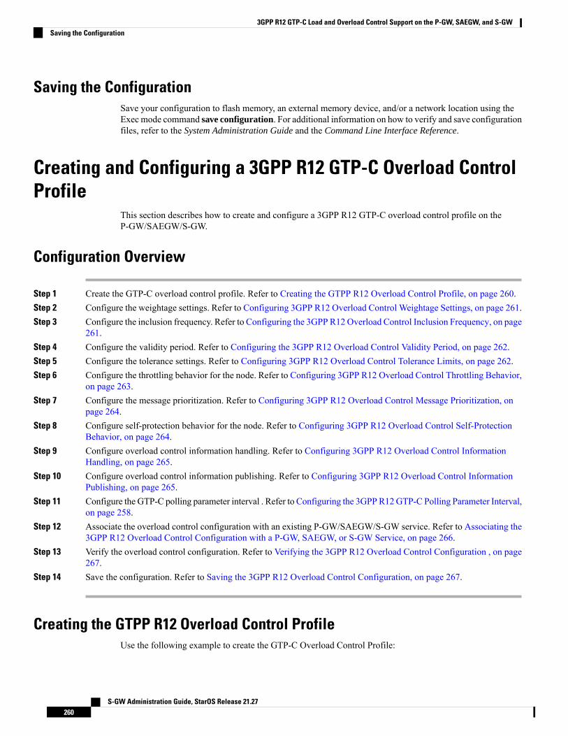
Saving the ConfigurationSave your configuration to flash memory, an external memory device, and/or a network location using theExec mode command save configuration. For additional information on how to verify and save configurationfiles, refer to the System Administration Guide and the Command Line Interface Reference.
Creating and Configuring a 3GPP R12 GTP-C Overload ControlProfile
This section describes how to create and configure a 3GPP R12 GTP-C overload control profile on theP-GW/SAEGW/S-GW.
Configuration Overview
Step 1 Create the GTP-C overload control profile. Refer to Creating the GTPP R12 Overload Control Profile, on page 260.Step 2 Configure the weightage settings. Refer to Configuring 3GPP R12 Overload Control Weightage Settings, on page 261.Step 3 Configure the inclusion frequency. Refer to Configuring the 3GPP R12 Overload Control Inclusion Frequency, on page
261.Step 4 Configure the validity period. Refer to Configuring the 3GPP R12 Overload Control Validity Period, on page 262.Step 5 Configure the tolerance settings. Refer to Configuring 3GPP R12 Overload Control Tolerance Limits, on page 262.Step 6 Configure the throttling behavior for the node. Refer to Configuring 3GPP R12 Overload Control Throttling Behavior,
on page 263.Step 7 Configure the message prioritization. Refer to Configuring 3GPP R12 Overload Control Message Prioritization, on
page 264.Step 8 Configure self-protection behavior for the node. Refer to Configuring 3GPP R12 Overload Control Self-Protection
Behavior, on page 264.Step 9 Configure overload control information handling. Refer to Configuring 3GPP R12 Overload Control Information
Handling, on page 265.Step 10 Configure overload control information publishing. Refer to Configuring 3GPP R12 Overload Control Information
Publishing, on page 265.Step 11 Configure the GTP-C polling parameter interval . Refer to Configuring the 3GPP R12GTP-C Polling Parameter Interval,
on page 258.Step 12 Associate the overload control configuration with an existing P-GW/SAEGW/S-GW service. Refer to Associating the
3GPP R12 Overload Control Configuration with a P-GW, SAEGW, or S-GW Service, on page 266.Step 13 Verify the overload control configuration. Refer to Verifying the 3GPP R12 Overload Control Configuration , on page
267.Step 14 Save the configuration. Refer to Saving the 3GPP R12 Overload Control Configuration, on page 267.
Creating the GTPP R12 Overload Control ProfileUse the following example to create the GTP-C Overload Control Profile:
S-GW Administration Guide, StarOS Release 21.27260
3GPP R12 GTP-C Load and Overload Control Support on the P-GW, SAEGW, and S-GWSaving the Configuration
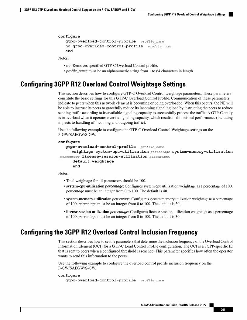
configuregtpc-overload-control-profile profile_name
no gtpc-overload-control-profile profile_name
end
Notes:
• no: Removes specified GTP-C Overload Control profile.• profile_name must be an alphanumeric string from 1 to 64 characters in length.
Configuring 3GPP R12 Overload Control Weightage SettingsThis section describes how to configure GTP-C Overload Control weightage parameters. These parametersconstitute the basic settings for this GTP-C Overload Control Profile. Communication of these parametersindicate to peers when this network element is becoming or being overloaded. When this occurs, the NE willbe able to instruct its peers to gracefully reduce its incoming signaling load by instructing the peers to reducesending traffic according to its available signaling capacity to successfully process the traffic. A GTP-C entityis in overload when it operates over its signaling capacity, which results in diminished performance (includingimpacts to handling of incoming and outgoing traffic).
Use the following example to configure the GTP-C Overload Control Weightage settings on theP-GW/SAEGW/S-GW.
configuregtpc-overload-control-profile profile_name
weightage system-cpu-utilization percentage system-memory-utilizationpercentage license-session-utilization percentage.
default weightageend
Notes:
• Total weightage for all parameters should be 100.• system-cpu-utilization percentage: Configures system cpu utilization weightage as a percentage of 100.
percentage must be an integer from 0 to 100. The default is 40.
• system-memory-utilization percentage: Configures systemmemory utilizationweightage as a percentageof 100. percentage must be an integer from 0 to 100. The default is 30.
• license-session utilization percentage: Configures license session utilization weightage as a percentageof 100. percentage must be an integer from 0 to 100. The default is 30.
Configuring the 3GPP R12 Overload Control Inclusion FrequencyThis section describes how to set the parameters that determine the inclusion frequency of the Overload ControlInformation Element (OCI) for a GTP-C Load Control Profile configuration. The OCI is a 3GPP-specific IEthat is sent to peers when a configured threshold is reached. This parameter specifies how often the operatorwants to send this information to the peers.
Use the following example to configure the overload control profile inclusion frequency on theP-GW/SAEGW/S-GW.
configuregtpc-overload-control-profile profile_name
S-GW Administration Guide, StarOS Release 21.27261
3GPP R12 GTP-C Load and Overload Control Support on the P-GW, SAEGW, and S-GWConfiguring 3GPP R12 Overload Control Weightage Settings
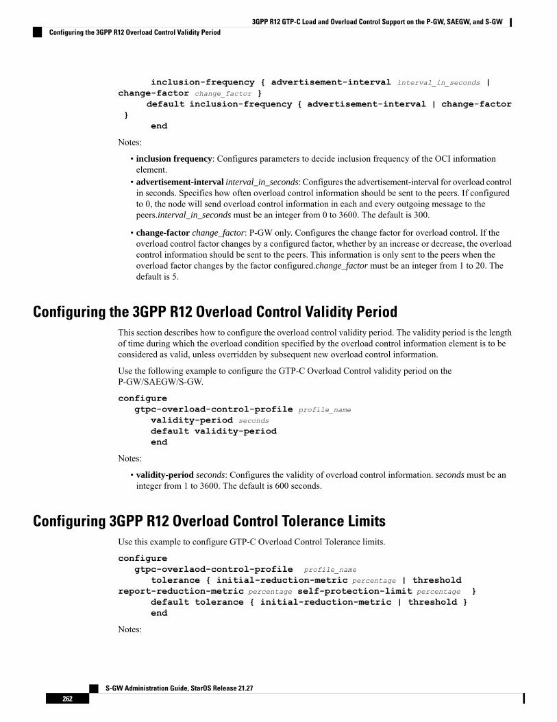
inclusion-frequency { advertisement-interval interval_in_seconds |change-factor change_factor }
default inclusion-frequency { advertisement-interval | change-factor}
end
Notes:
• inclusion frequency: Configures parameters to decide inclusion frequency of the OCI informationelement.
• advertisement-interval interval_in_seconds: Configures the advertisement-interval for overload controlin seconds. Specifies how often overload control information should be sent to the peers. If configuredto 0, the node will send overload control information in each and every outgoing message to thepeers.interval_in_seconds must be an integer from 0 to 3600. The default is 300.
• change-factor change_factor: P-GW only. Configures the change factor for overload control. If theoverload control factor changes by a configured factor, whether by an increase or decrease, the overloadcontrol information should be sent to the peers. This information is only sent to the peers when theoverload factor changes by the factor configured.change_factor must be an integer from 1 to 20. Thedefault is 5.
Configuring the 3GPP R12 Overload Control Validity PeriodThis section describes how to configure the overload control validity period. The validity period is the lengthof time during which the overload condition specified by the overload control information element is to beconsidered as valid, unless overridden by subsequent new overload control information.
Use the following example to configure the GTP-C Overload Control validity period on theP-GW/SAEGW/S-GW.
configuregtpc-overload-control-profile profile_name
validity-period seconds
default validity-periodend
Notes:
• validity-period seconds: Configures the validity of overload control information. seconds must be aninteger from 1 to 3600. The default is 600 seconds.
Configuring 3GPP R12 Overload Control Tolerance LimitsUse this example to configure GTP-C Overload Control Tolerance limits.
configuregtpc-overlaod-control-profile profile_name
tolerance { initial-reduction-metric percentage | thresholdreport-reduction-metric percentage self-protection-limit percentage }
default tolerance { initial-reduction-metric | threshold }end
Notes:
S-GW Administration Guide, StarOS Release 21.27262
3GPP R12 GTP-C Load and Overload Control Support on the P-GW, SAEGW, and S-GWConfiguring the 3GPP R12 Overload Control Validity Period
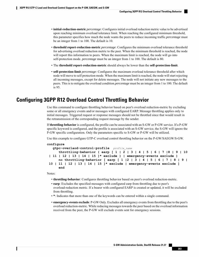
• initial-reduction-metric percentage: Configures initial overload reduction metric value to be advertisedupon reaching minimum overload tolerance limit. When reaching the configured minimum threshold,this parameter specifies how much the node wants the peers to reduce incoming traffic.percentage mustbe an integer from 1 to 100. The default is 10.
• threshold report-reduction-metric percentage: Configures the minimum overload tolerance thresholdfor advertising overload reduction metric to the peer. When the minimum threshold is reached, the nodewill report this information to peers. When the maximum limit is reached, the node will go intoself-protection mode. percentage must be an integer from 1 to 100. The default is 80.
• The threshold report-reduction-metric should always be lower than the self-protection-limit.
• self-protection-limit percentage: Configures the maximum overload tolerance threshold after whichnode will move to self protection mode.When the maximum limit is reached, the node will start rejectingall incoming messages, except for delete messages. The node will not initiate any new messages to thepeers. This is to mitigate the overload condition.percentagemust be an integer from 1 to 100. The defaultis 95.
Configuring 3GPP R12 Overload Control Throttling BehaviorUse this command to configure throttling behavior based on peer's overload reduction-metric by excludingsome or all emergency events and/or messages with configured EARP. Message throttling applies only toinitial messages. Triggered request or response messages should not be throttled since that would result inthe retransmission of the corresponding request message by the sender.
If throttling-behavior is configured, the profile can be associated with an S-GW or P-GW service. If a P-GWspecific keyword is configured, and the profile is associated with an S-GW service, the S-GW will ignore theP-GW specific configuration. Only the parameters specific to S-GW or P-GW will be utilized.
Use this example to configure GTP-C overload control throttling behavior on the P-GW/SAEGW/S-GW.
configuregtpc-overlaod-control-profile profile_name
throttling-behavior { earp [ 1 | 2 | 3 | 4 | 5 | 6 | 7 |8 | 9 | 10| 11 | 12 | 13 | 14 | 15 ]* exclude } | emergency-events exclude }
no throttling-behavior [ earp [ 1 |2 | 3 | 4 | 5 | 6 | 7 | 8 | 9 |10 | 11 | 12 | 13 | 14 | 15 ]* exclude | emergency-events exclude ]
end
Notes:
• throttling-behavior: Configures throttling behavior based on peer's overload reduction-metric.• earp: Excludes the specified messages with configured earp from throttling due to peer'soverload-reduction metric. If a bearer with configured EARP is created or updated, it will be excludedfrom throttling.
• *: Indicates that more than one of the keywords can be entered within a single command.
• emergency-events exclude: P-GWOnly. Excludes all emergency events from throttling due to the peer'soverload reduction-metric.While reducing messages towards the peer based on the overload informationreceived from the peer, the P-GW will exclude events sent for emergency sessions.
S-GW Administration Guide, StarOS Release 21.27263
3GPP R12 GTP-C Load and Overload Control Support on the P-GW, SAEGW, and S-GWConfiguring 3GPP R12 Overload Control Throttling Behavior
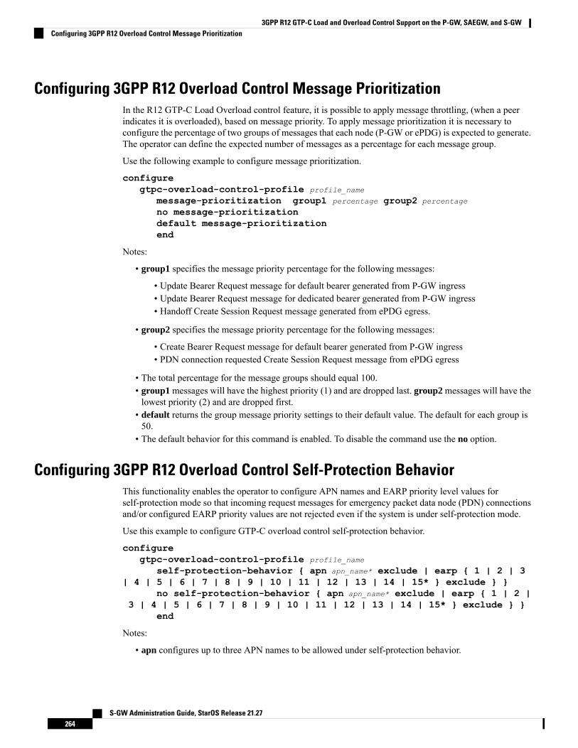
Configuring 3GPP R12 Overload Control Message PrioritizationIn the R12 GTP-C Load Overload control feature, it is possible to apply message throttling, (when a peerindicates it is overloaded), based on message priority. To apply message prioritization it is necessary toconfigure the percentage of two groups of messages that each node (P-GW or ePDG) is expected to generate.The operator can define the expected number of messages as a percentage for each message group.
Use the following example to configure message prioritization.
configuregtpc-overload-control-profile profile_name
message-prioritization group1 percentage group2 percentage
no message-prioritizationdefault message-prioritizationend
Notes:
• group1 specifies the message priority percentage for the following messages:
• Update Bearer Request message for default bearer generated from P-GW ingress• Update Bearer Request message for dedicated bearer generated from P-GW ingress• Handoff Create Session Request message generated from ePDG egress.
• group2 specifies the message priority percentage for the following messages:
• Create Bearer Request message for default bearer generated from P-GW ingress• PDN connection requested Create Session Request message from ePDG egress
• The total percentage for the message groups should equal 100.• group1 messages will have the highest priority (1) and are dropped last. group2 messages will have thelowest priority (2) and are dropped first.
• default returns the group message priority settings to their default value. The default for each group is50.
• The default behavior for this command is enabled. To disable the command use the no option.
Configuring 3GPP R12 Overload Control Self-Protection BehaviorThis functionality enables the operator to configure APN names and EARP priority level values forself-protection mode so that incoming request messages for emergency packet data node (PDN) connectionsand/or configured EARP priority values are not rejected even if the system is under self-protection mode.
Use this example to configure GTP-C overload control self-protection behavior.
configuregtpc-overload-control-profile profile_name
self-protection-behavior { apn apn_name* exclude | earp { 1 | 2 | 3| 4 | 5 | 6 | 7 | 8 | 9 | 10 | 11 | 12 | 13 | 14 | 15* } exclude } }
no self-protection-behavior { apn apn_name* exclude | earp { 1 | 2 |3 | 4 | 5 | 6 | 7 | 8 | 9 | 10 | 11 | 12 | 13 | 14 | 15* } exclude } }
end
Notes:
• apn configures up to three APN names to be allowed under self-protection behavior.
S-GW Administration Guide, StarOS Release 21.27264
3GPP R12 GTP-C Load and Overload Control Support on the P-GW, SAEGW, and S-GWConfiguring 3GPP R12 Overload Control Message Prioritization

• earp configures up to three EARP priority level values so that incoming request messages for theconfigured evolved ARP priority values are not rejected even if the system is under self-protectionmode.
• no disables the specified options.
Configuring 3GPP R12 Overload Control Information HandlingUse this command to enable/disable the handling of overload control information for the home or visitedPLMN.
configuregtpc-load-control-profile profile_name
overload-control-handling { home | visited }no overload-control-handling { home | visited }default overload-control-handlingend
Notes:
• home: Enables the handling of load control information for the home PLMN.• visited enables the handling of load control information for the visited PLMN.• default: Returns load control handling to its default behavior (enabled).
Configuring 3GPP R12 Overload Control Information PublishingEnables or disables the publishing of load control information towards the home or visited PLMN.
configuregtpc-overload-control-profile profile_name
overload-control-publishing { home | visited }no overload-control-publishing { home | visited }default overload-control-publishingend
Notes:
• home: Enables the publishing of load control information towards the home PLMN.• visited: Enables the publishing of load control information towards the visited PLMN.• default: Returns load control handling to its default behavior (enabled).
Configuring the 3GPP R12 GTP-C Polling Parameter IntervalIn capacity testing and also in customer deployments it was observed that the chassis load factor for the 3GPPR12 Load and Overload Support feature was providing incorrect values even when the sessmgr card CPUutilization was high. The root cause is that when the load factor was calculated by taking an average of CPUutilization of sessmgr and demux cards, the demux card CPU utilization never increased more than the sessmgrcard CPU utilization. As a result, the system did not go into the overload state even when the sessmgr cardCPU utilization was high.
The 3GPP R12 Load/Overload Control Profile feature has been enhanced to calculate the load factor basedon the higher value of similar types of cards for CPU load and memory. If the demux card's CPU utilizationvalue is higher than the sessmgr card's CPU utilization value, then the demux card CPU utilization value isused for the load factor calculation.
S-GW Administration Guide, StarOS Release 21.27265
3GPP R12 GTP-C Load and Overload Control Support on the P-GW, SAEGW, and S-GWConfiguring 3GPP R12 Overload Control Information Handling
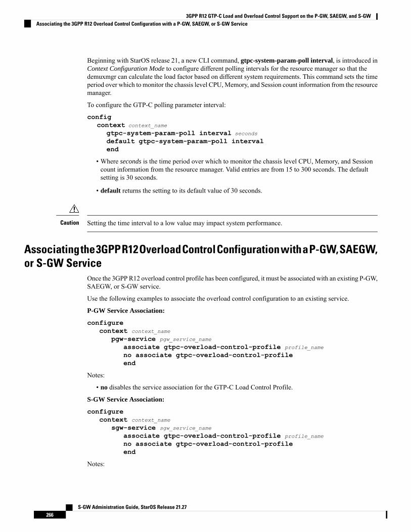
Beginning with StarOS release 21, a new CLI command, gtpc-system-param-poll interval, is introduced inContext Configuration Mode to configure different polling intervals for the resource manager so that thedemuxmgr can calculate the load factor based on different system requirements. This command sets the timeperiod over which to monitor the chassis level CPU,Memory, and Session count information from the resourcemanager.
To configure the GTP-C polling parameter interval:
configcontext context_name
gtpc-system-param-poll interval seconds
default gtpc-system-param-poll intervalend
• Where seconds is the time period over which to monitor the chassis level CPU, Memory, and Sessioncount information from the resource manager. Valid entries are from 15 to 300 seconds. The defaultsetting is 30 seconds.
• default returns the setting to its default value of 30 seconds.
Setting the time interval to a low value may impact system performance.Caution
Associatingthe3GPPR12OverloadControlConfigurationwithaP-GW,SAEGW,or S-GW Service
Once the 3GPP R12 overload control profile has been configured, it must be associated with an existing P-GW,SAEGW, or S-GW service.
Use the following examples to associate the overload control configuration to an existing service.
P-GW Service Association:
configurecontext context_name
pgw-service pgw_service_name
associate gtpc-overload-control-profile profile_name
no associate gtpc-overload-control-profileend
Notes:
• no disables the service association for the GTP-C Load Control Profile.
S-GW Service Association:
configurecontext context_name
sgw-service sgw_service_name
associate gtpc-overload-control-profile profile_name
no associate gtpc-overload-control-profileend
Notes:
S-GW Administration Guide, StarOS Release 21.27266
3GPP R12 GTP-C Load and Overload Control Support on the P-GW, SAEGW, and S-GWAssociating the 3GPP R12 Overload Control Configuration with a P-GW, SAEGW, or S-GW Service

• no disables the service association for the GTP-C Load Control Profile.
SAEGW Service Association::
configurecontext context_name
sgw-service sgw_service_name
associate gtpc-overload-control-profile profile_name
exitpgw-service pgw_service_name
associate gtpc-overload-control-profile profile_name
exitsaegw-service saegw_service_name
associate sgw-service sgw_service_name
associate pgw-service pgw_service_name
exit
Verifying the 3GPP R12 Overload Control ConfigurationUse the following command to view the overload control configuration settings.
show gtpc-overload-control-profile full name overload_control_profile_name
The output of this command provides all overload control profile configuration settings, including:
• Weightage• Tolerance• Inclusion Frequency• Validity Period• Throttling Profile• Self-Protection Behavior• Overload control information Handling• Overload control information Publishing• Message Prioritization
Saving the 3GPP R12 Overload Control ConfigurationSave your configuration to flash memory, an external memory device, and/or a network location using theExec mode command save configuration. For additional information on how to verify and save configurationfiles, refer to the System Administration Guide and the Command Line Interface Reference.
Monitoring and Troubleshooting the 3GPP R12 GTP-C Load andOverload Control Feature
This section provides information to assist operators in monitoring the 3GPP R12 GTP-C Load and OverloadControl feature.
S-GW Administration Guide, StarOS Release 21.27267
3GPP R12 GTP-C Load and Overload Control Support on the P-GW, SAEGW, and S-GWVerifying the 3GPP R12 Overload Control Configuration
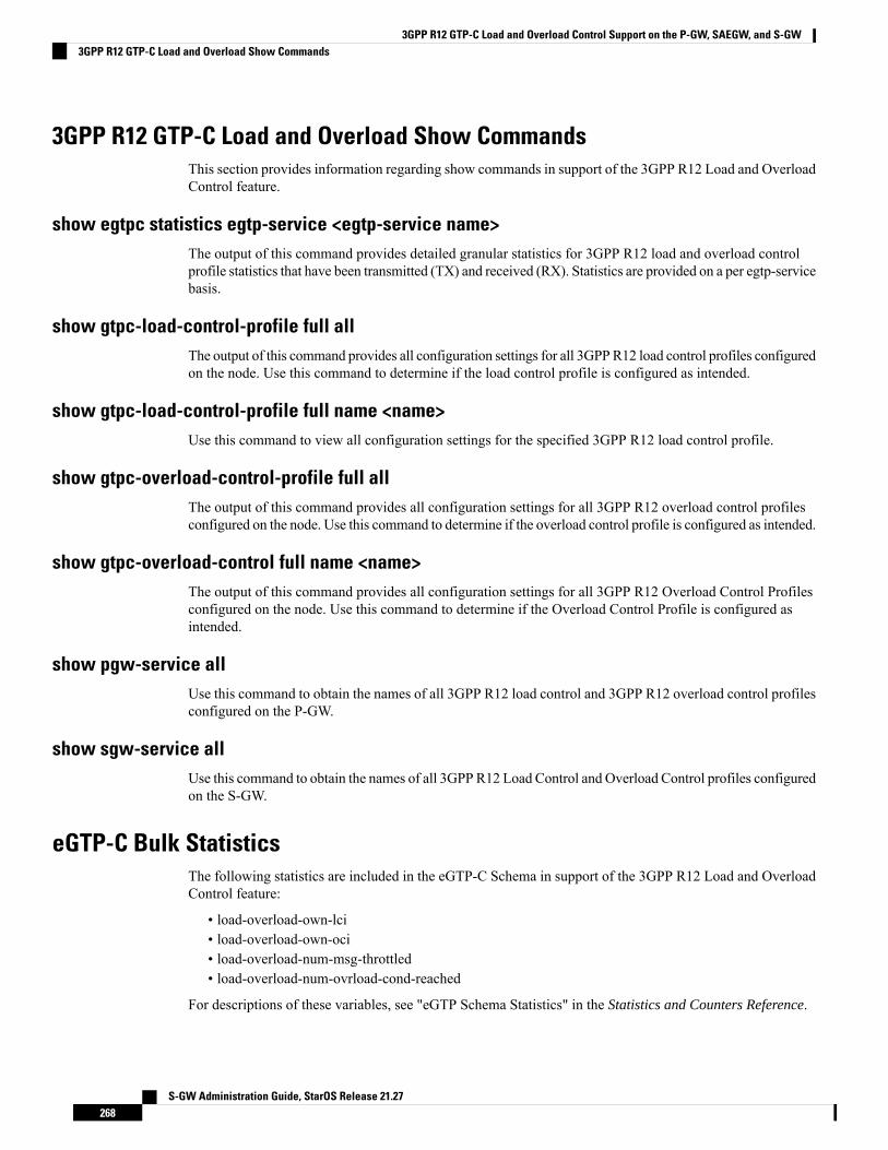
3GPP R12 GTP-C Load and Overload Show CommandsThis section provides information regarding show commands in support of the 3GPP R12 Load and OverloadControl feature.
show egtpc statistics egtp-service <egtp-service name>The output of this command provides detailed granular statistics for 3GPP R12 load and overload controlprofile statistics that have been transmitted (TX) and received (RX). Statistics are provided on a per egtp-servicebasis.
show gtpc-load-control-profile full allThe output of this command provides all configuration settings for all 3GPPR12 load control profiles configuredon the node. Use this command to determine if the load control profile is configured as intended.
show gtpc-load-control-profile full name <name>Use this command to view all configuration settings for the specified 3GPP R12 load control profile.
show gtpc-overload-control-profile full allThe output of this command provides all configuration settings for all 3GPP R12 overload control profilesconfigured on the node. Use this command to determine if the overload control profile is configured as intended.
show gtpc-overload-control full name <name>The output of this command provides all configuration settings for all 3GPP R12 Overload Control Profilesconfigured on the node. Use this command to determine if the Overload Control Profile is configured asintended.
show pgw-service allUse this command to obtain the names of all 3GPP R12 load control and 3GPP R12 overload control profilesconfigured on the P-GW.
show sgw-service allUse this command to obtain the names of all 3GPP R12 Load Control and Overload Control profiles configuredon the S-GW.
eGTP-C Bulk StatisticsThe following statistics are included in the eGTP-C Schema in support of the 3GPP R12 Load and OverloadControl feature:
• load-overload-own-lci• load-overload-own-oci• load-overload-num-msg-throttled• load-overload-num-ovrload-cond-reached
For descriptions of these variables, see "eGTP Schema Statistics" in the Statistics and Counters Reference.
S-GW Administration Guide, StarOS Release 21.27268
3GPP R12 GTP-C Load and Overload Control Support on the P-GW, SAEGW, and S-GW3GPP R12 GTP-C Load and Overload Show Commands

C H A P T E R 16Intelligent RAT Paging for ISR on the S-GW
This chapter provides detailed feature information for the Intelligent RAT Paging for Idle Mode SignalingReduction (ISR) feature on the S-GW.
• Feature Description, on page 269• How it Works, on page 270• Configuring Intelligent RAT Paging for ISR on the S-GW , on page 273
Feature DescriptionThis section describes the Intelligent RAT Paging for ISR feature on the S-GW.
When Idle Mode Signaling Reduction (ISR) is active, and a UE is in idle mode with control plane connectionsto both the MME and the S4-SGSN, and the S-GW receives downlink data for that UE, it sendsDownlink-Data-Notification-Requests (requests to page UEs) to both the S4-SGSN and MME in parallel.This scenario causes the following problems:
• Both theMME and S4-SGSN perform paging in parallel, thereby resulting in an overuse of radio resources.The UE can be camped on either the MME or S4-SGSN, and respond to the paging of either the MMEor S4-SGSN, so the radio resource of one node is not used effectively.
• If the S-GW tries to send DDN messages to both nodes sequentially, there can be a delay in call setupand establishment.
The Intelligent RAT Paging for ISR feature reduces both the radio resource usage due to paging and theinternal load on the MME/S4-SGSN nodes.
The S-GW intelligently determines when to perform sequential paging as opposed to parallel paging byidentifying the APN and its configuration (in the apn-profile configuration) for the downlink packet for whichpaging is originated. This provides the following benefits:
• More efficient utilization of radio resources used for paging when the incoming packet is not delaysensitive.
• Reduction in the delay of call establishment due to parallel paging when the incoming packet is delaysensitive.
This feature is useful for ISR enabled Networks to reduce the radio resource usage due to paging.
S-GW Administration Guide, StarOS Release 21.27269

Relationships to Other FeaturesBefore configuring the Intelligent RAT Paging for ISR feature on the S-GW, be aware of the followingrequirements and relationships to other features:
• This feature is useful if the peer MME and S4-SGSN also support ISR.• If operators want to have the ISR paging method recovered for a given PDN, the Session Recoveryfeature must be configured on the S-GW.
How it Works
Intelligent RAT Paging for ISR on the S-GWDepending on the situation, the S-GW uses one of two methods to perform Intelligent RAT Paging for ISR:
• Sequential Paging (pages both nodes one after the other). This method optimizes radio resource utilization.If quick call setup time is not indicated, the S-GW will perform sequential paging and it will page theS4-SGSN and MME one after the other. It first will page to the node of the last known RAT type of theUE.
• Parallel Paging (pages both the nodes in parallel). This method results in quick paging response timeand faster call setup time. If the DDN is initiated for an APN that requires the quick call setup time (forexample, VoLTE APN) then the S-GW performs parallel paging.
For intelligent paging, the S-GW has to determine whether to perform radio resource optimization or to usea quick call establishment procedure. The S-GWmakes the decision to determine whether to perform sequentialpaging or parallel paging based on the configuration of the APN (through apn-profile applied for the APN).
The S-GW finds the APN of the particular bearer, and it checks to see if it received the downlink data. Ifisr-sequential-paging is configured for this APN on the S-GW, the S-GW initiates a DDN message to onenode (MME or S4-SGSN) and waits for the service request procedure from that node within a configuredtime. If the S-GW does not receive the service request procedure within configured time, it initiates the DDNmessage towards the other node.
The node which was last sent the Modify Bearer Request to the S-GW (that is, the last known RAT type) isselected first to send the DDN messages.
Intelligent RAT Paging for ISR requires manual configuration through the Command Line Interface (CLI).
LicensesIntelligent RAT Paging for ISR is a licensed-controlled Cisco feature. A separate feature license may berequired. Contact your Cisco account representative for detailed information on specific licensing requirements.For information on installing and verifying licenses, refer to theManaging License Keys section of the SoftwareManagement Operations chapter in the System Administration Guide.
LimitationsThe Intelligent RAT Paging for ISR feature has the following restrictions and limitations:
1. The S-GW performs sequential paging (if configured) only for Downlink data triggered Downlink DataNotification (DDN) messages. All control event triggered DDN messages are treated as high priority
S-GW Administration Guide, StarOS Release 21.27270
Intelligent RAT Paging for ISR on the S-GWRelationships to Other Features

DDNmessages and the S-GW always performs parallel paging for control event triggered DDNmessages.No DDN-Throttling and DDN-Delay shall be applicable only to Downlink data triggered DDNmessages.
2. S-GW Intelligent RAT Paging for ISR is supported on the S-GW only. It is not supported on the SAE-GW.
FlowsThis section provides descriptive call flows for the Intelligent RAT Paging for ISR feature. It includes callflows for both sequential and parallel paging procedures.
Figure 45: Intelligent RAT Paging for ISR: Sequential Paging Procedure
Table 24: Intelligent RAT Paging for ISR: Sequential Paging Procedure Description
DescriptionStep
The S-GW receives the downlink data packet for anidle UE which has ISR active and the S-GW isconfigured to initiate sequential paging for this APN.The Last known RAT Type for this UE is E-UTRAN.
1
S-GW Administration Guide, StarOS Release 21.27271
Intelligent RAT Paging for ISR on the S-GWFlows

DescriptionStep
The S-GW initiates Downlink Data Notificationtowards the MME and starts the timer tp.
2
The MME replies with a Downlink Data NotificationAckmessage. If theMME initiates the service requestprocedure for this UE within time tp, then the S-GWwill stop the timer tp and process the service requestprocedure. The S-GW will not initiate the DownlinkData Notification towards S4-SGSN (in a differentRAT). Therefore, the system saves the paging attemptand the radio resource of the S4-SGSN.
3
If the MME does not initiates the service requestprocedure for this UEwithin time tp then upon expiryof timer tp, the S-GWwill initiate the Downlink DataNotification towards the S4-SGSN.
4
The S4-SGSN replies with a Downlink DataNotification Ack message. The S4-SGSN attempts topage the UE. The S-GW will receive the servicerequest procedure from S4-SGSN.
5
Figure 46: Intelligent RAT Paging for ISR: Parallel Paging Procedure
S-GW Administration Guide, StarOS Release 21.27272
Intelligent RAT Paging for ISR on the S-GWFlows
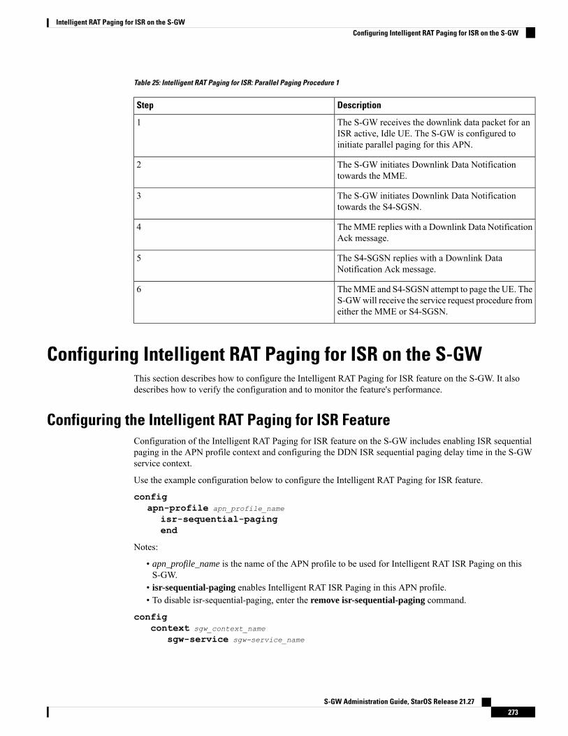
Table 25: Intelligent RAT Paging for ISR: Parallel Paging Procedure 1
DescriptionStep
The S-GW receives the downlink data packet for anISR active, Idle UE. The S-GW is configured toinitiate parallel paging for this APN.
1
The S-GW initiates Downlink Data Notificationtowards the MME.
2
The S-GW initiates Downlink Data Notificationtowards the S4-SGSN.
3
The MME replies with a Downlink Data NotificationAck message.
4
The S4-SGSN replies with a Downlink DataNotification Ack message.
5
TheMME and S4-SGSN attempt to page the UE. TheS-GWwill receive the service request procedure fromeither the MME or S4-SGSN.
6
Configuring Intelligent RAT Paging for ISR on the S-GWThis section describes how to configure the Intelligent RAT Paging for ISR feature on the S-GW. It alsodescribes how to verify the configuration and to monitor the feature's performance.
Configuring the Intelligent RAT Paging for ISR FeatureConfiguration of the Intelligent RAT Paging for ISR feature on the S-GW includes enabling ISR sequentialpaging in the APN profile context and configuring the DDN ISR sequential paging delay time in the S-GWservice context.
Use the example configuration below to configure the Intelligent RAT Paging for ISR feature.
configapn-profile apn_profile_name
isr-sequential-pagingend
Notes:
• apn_profile_name is the name of the APN profile to be used for Intelligent RAT ISR Paging on thisS-GW.
• isr-sequential-paging enables Intelligent RAT ISR Paging in this APN profile.• To disable isr-sequential-paging, enter the remove isr-sequential-paging command.
configcontext sgw_context_name
sgw-service sgw-service_name
S-GW Administration Guide, StarOS Release 21.27273
Intelligent RAT Paging for ISR on the S-GWConfiguring Intelligent RAT Paging for ISR on the S-GW

ddn isr-sequential-paging delay time duration_msecs
end
Notes:
• sgw_context_name is the name of the context in which the S-GW service is configured.• sgw_service_name is the name of the configured S-GW service.• ddn isr-sequential-paging delay time specifies the time delay between the paging of different RATtypes. This value is entered in increments of 100milliseconds (where 1 = 100milliseconds). Valid entriesare from 1 to 255. The default setting is 10 (1 second).
Verifying the Intelligent RAT Paging for ISR ConfigurationThis section describes how to verify the Intelligent RAT Paging for ISR configuration settings.
To verify that Intelligent RAT Paging for ISR is enabled in the APN profile for this S-GW, enter the followingcommand from Exec Mode:
show apn-profile full name apn_profile_name...LIPA-APN :DisabledISR-SEQUENTIAL-PAGING :EnabledLocal Offload :DisabledOvercharging protection :Disabled...
To verify that the ISR sequential delay time is configured properly, enter the following command from ExecMode:
show sgw-service name sgw_service_name...Service name...
GTPU Error Indication Handling:...
S4U-Interface: local-purgeddn failure-action pkt-drop-time: 300ddn isr-sequential-paging delay-time: 1Idle timeout :n/a
...
S-GW Administration Guide, StarOS Release 21.27274
Intelligent RAT Paging for ISR on the S-GWVerifying the Intelligent RAT Paging for ISR Configuration

C H A P T E R 17LTE-M RAT Type Support on SAEGW, P-GW, andS-GW Services
• Feature Summary and Revision History, on page 275• Feature Description, on page 276• How it Works, on page 277• Configuring Virtual-APN, on page 279• Configuring qci-qos-mapping, on page 279• Monitoring and Troubleshooting, on page 280
Feature Summary and Revision HistorySummary Data
• S-GW
• P-GW
• SAEGW
Applicable Product(s) or Functional Area
• ASR 5500
• VPC-DI
• VPC-SI
Applicable Platform(s)
Enabled-Always-OnDefault Setting
Not ApplicableRelated Changes in This Release
• Command Line Interface Reference
• P-GW Administration Guide
• S-GW Administration Guide
• SAEGW Administartion Guide
Related Documentation
S-GW Administration Guide, StarOS Release 21.27275
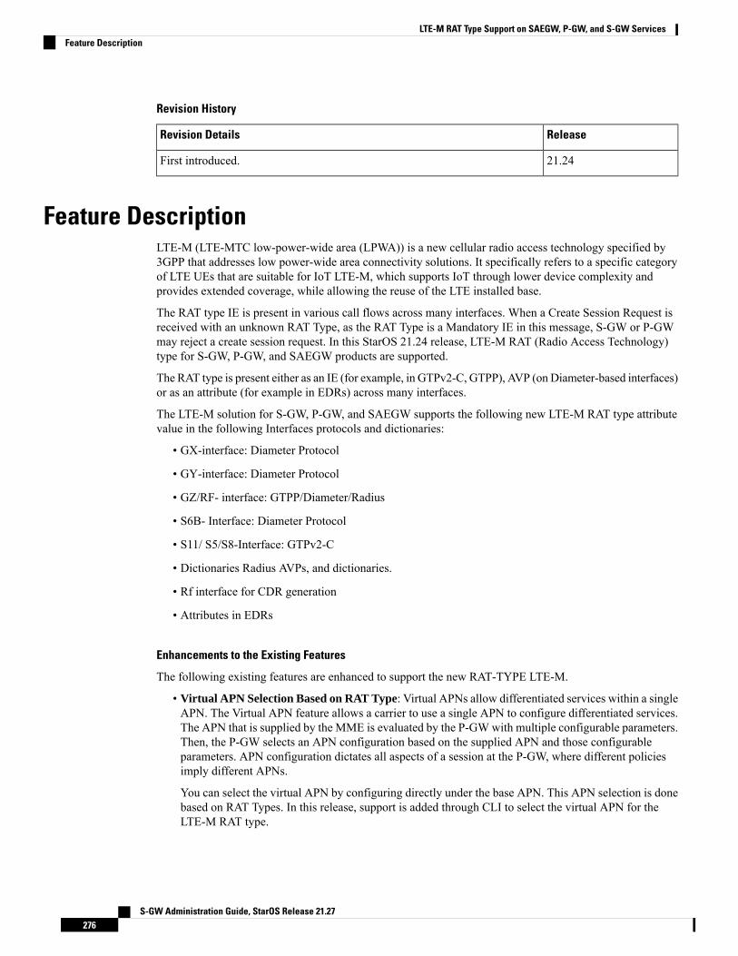
Revision History
ReleaseRevision Details
21.24First introduced.
Feature DescriptionLTE-M (LTE-MTC low-power-wide area (LPWA)) is a new cellular radio access technology specified by3GPP that addresses low power-wide area connectivity solutions. It specifically refers to a specific categoryof LTE UEs that are suitable for IoT LTE-M, which supports IoT through lower device complexity andprovides extended coverage, while allowing the reuse of the LTE installed base.
The RAT type IE is present in various call flows across many interfaces. When a Create Session Request isreceived with an unknown RAT Type, as the RAT Type is a Mandatory IE in this message, S-GW or P-GWmay reject a create session request. In this StarOS 21.24 release, LTE-M RAT (Radio Access Technology)type for S-GW, P-GW, and SAEGW products are supported.
The RAT type is present either as an IE (for example, in GTPv2-C, GTPP), AVP (on Diameter-based interfaces)or as an attribute (for example in EDRs) across many interfaces.
The LTE-M solution for S-GW, P-GW, and SAEGW supports the following new LTE-M RAT type attributevalue in the following Interfaces protocols and dictionaries:
• GX-interface: Diameter Protocol
• GY-interface: Diameter Protocol
• GZ/RF- interface: GTPP/Diameter/Radius
• S6B- Interface: Diameter Protocol
• S11/ S5/S8-Interface: GTPv2-C
• Dictionaries Radius AVPs, and dictionaries.
• Rf interface for CDR generation
• Attributes in EDRs
Enhancements to the Existing Features
The following existing features are enhanced to support the new RAT-TYPE LTE-M.
• Virtual APN Selection Based on RAT Type: Virtual APNs allow differentiated services within a singleAPN. The Virtual APN feature allows a carrier to use a single APN to configure differentiated services.The APN that is supplied by the MME is evaluated by the P-GWwith multiple configurable parameters.Then, the P-GW selects an APN configuration based on the supplied APN and those configurableparameters. APN configuration dictates all aspects of a session at the P-GW, where different policiesimply different APNs.
You can select the virtual APN by configuring directly under the base APN. This APN selection is donebased on RAT Types. In this release, support is added through CLI to select the virtual APN for theLTE-M RAT type.
S-GW Administration Guide, StarOS Release 21.27276
LTE-M RAT Type Support on SAEGW, P-GW, and S-GW ServicesFeature Description

• Qci and Qos Mapping: P-GW supports QCI and QoS mapping association with APN based on RATtype LTE-M. This QCI and QoS mapping allow you to perform quick actions on the QoS Class Index(QCI) to QoS Mapping Configuration Mode, which is used to map QoS Class Indexes to enforceableQoS parameters. Mapping can occur in Serving Gateway (S-GW), and/or the PDN Gateway (P-GW) inan LTE network.
• PCRF-based Handling: P-GW informs the RAT type changes to PCRF through Credit Control Request-Initial and Updated messages, and PCRF provides a new PCC rule. Allows you to create a Bearer byenforcing a new Policy and Charging Control (PCC) rule from Policy and Charging Rules Function(PCRF).
How it Works
ArchitectureThe following table specifies the field and its value for various interfaces with support of LTE-M RAT type.Only Standard dictionaries and customized dictionaries are modified.
Table 26:
MessagesAVP AttributeFieldInterface
P-GW Product
• Credit ControlRequest-Initial
• Credit ControlRequest - Updated
LTE-M (1007)RAT-Type (1032)
Diameter
Gx
• Credit ControlRequest-Initial
• Credit ControlRequest - Updated
LTE-M (9)3GPP RAT-Type (21)
Diameter
Gy
• Accounting Request-Start
• AccountingRequest-Stop
• Account request-Interim
LTE-M (9)3GPP RAT-Type (21)RADIUS
S-GW Administration Guide, StarOS Release 21.27277
LTE-M RAT Type Support on SAEGW, P-GW, and S-GW ServicesHow it Works
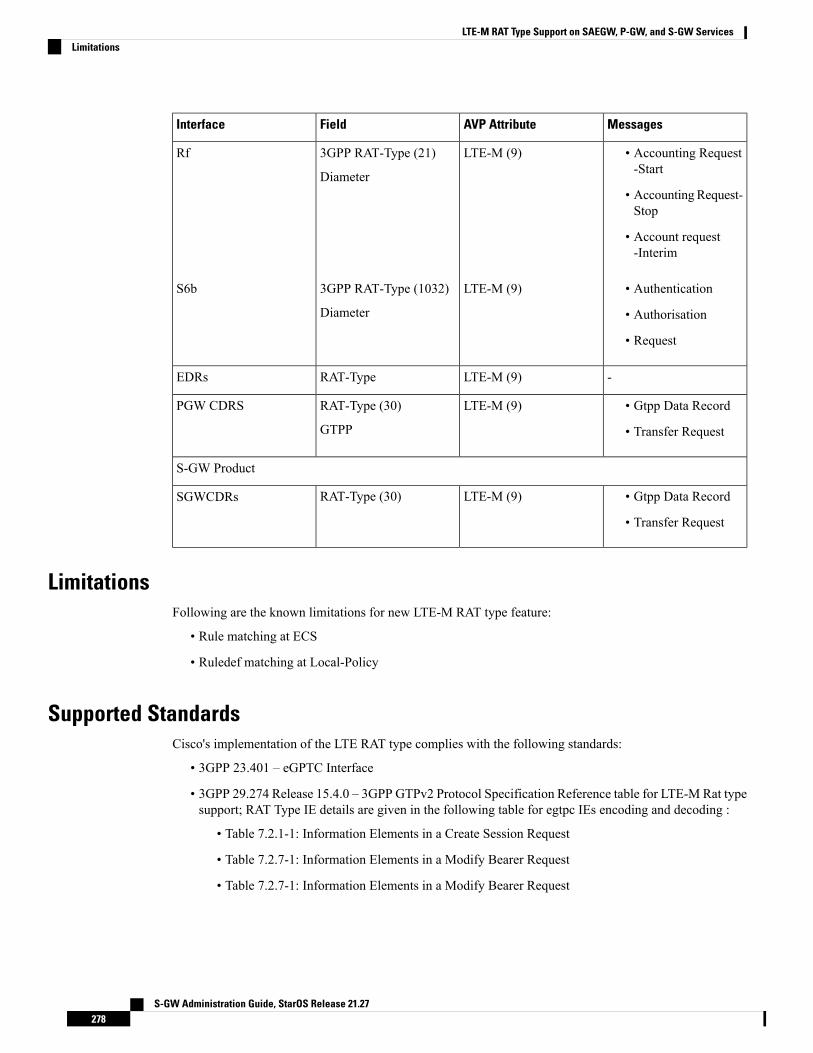
MessagesAVP AttributeFieldInterface
• Accounting Request-Start
• AccountingRequest-Stop
• Account request-Interim
LTE-M (9)3GPP RAT-Type (21)
Diameter
Rf
• Authentication
• Authorisation
• Request
LTE-M (9)3GPP RAT-Type (1032)
Diameter
S6b
-LTE-M (9)RAT-TypeEDRs
• Gtpp Data Record
• Transfer Request
LTE-M (9)RAT-Type (30)
GTPP
PGW CDRS
S-GW Product
• Gtpp Data Record
• Transfer Request
LTE-M (9)RAT-Type (30)SGWCDRs
LimitationsFollowing are the known limitations for new LTE-M RAT type feature:
• Rule matching at ECS
• Ruledef matching at Local-Policy
Supported StandardsCisco's implementation of the LTE RAT type complies with the following standards:
• 3GPP 23.401 – eGPTC Interface
• 3GPP 29.274 Release 15.4.0 – 3GPP GTPv2 Protocol Specification Reference table for LTE-M Rat typesupport; RAT Type IE details are given in the following table for egtpc IEs encoding and decoding :
• Table 7.2.1-1: Information Elements in a Create Session Request
• Table 7.2.7-1: Information Elements in a Modify Bearer Request
• Table 7.2.7-1: Information Elements in a Modify Bearer Request
S-GW Administration Guide, StarOS Release 21.27278
LTE-M RAT Type Support on SAEGW, P-GW, and S-GW ServicesLimitations
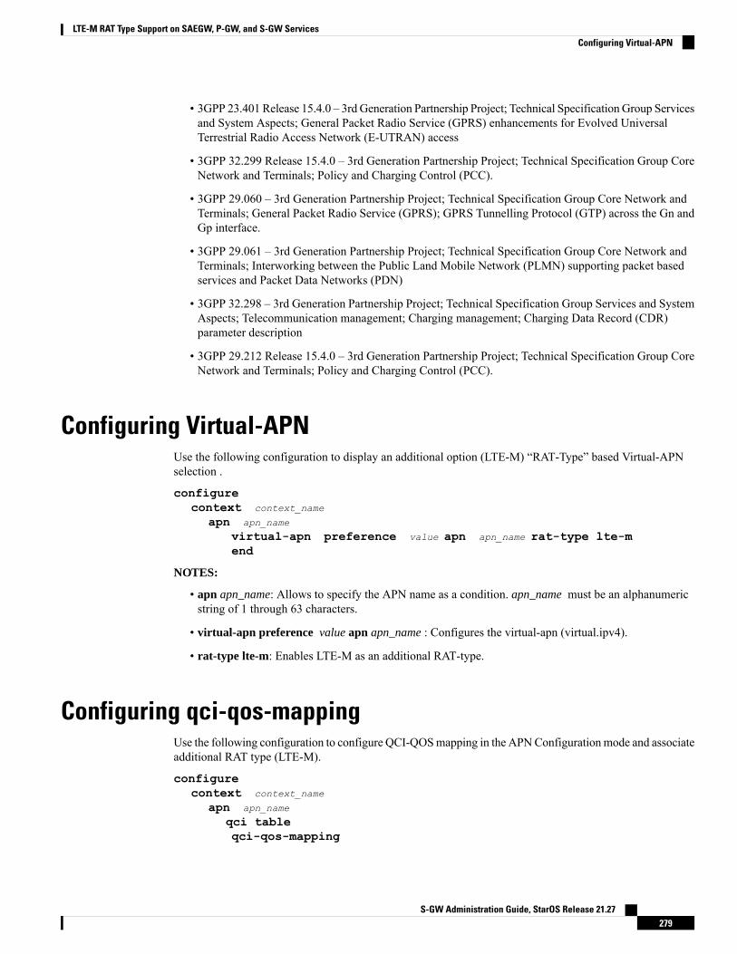
• 3GPP 23.401 Release 15.4.0 – 3rd Generation Partnership Project; Technical SpecificationGroup Servicesand System Aspects; General Packet Radio Service (GPRS) enhancements for Evolved UniversalTerrestrial Radio Access Network (E-UTRAN) access
• 3GPP 32.299 Release 15.4.0 – 3rd Generation Partnership Project; Technical Specification Group CoreNetwork and Terminals; Policy and Charging Control (PCC).
• 3GPP 29.060 – 3rd Generation Partnership Project; Technical Specification Group Core Network andTerminals; General Packet Radio Service (GPRS); GPRS Tunnelling Protocol (GTP) across the Gn andGp interface.
• 3GPP 29.061 – 3rd Generation Partnership Project; Technical Specification Group Core Network andTerminals; Interworking between the Public Land Mobile Network (PLMN) supporting packet basedservices and Packet Data Networks (PDN)
• 3GPP 32.298 – 3rd Generation Partnership Project; Technical Specification Group Services and SystemAspects; Telecommunication management; Charging management; Charging Data Record (CDR)parameter description
• 3GPP 29.212 Release 15.4.0 – 3rd Generation Partnership Project; Technical Specification Group CoreNetwork and Terminals; Policy and Charging Control (PCC).
Configuring Virtual-APNUse the following configuration to display an additional option (LTE-M) “RAT-Type” based Virtual-APNselection .
configurecontext context_name
apn apn_name
virtual-apn preference value apn apn_name rat-type lte-mend
NOTES:
• apn apn_name: Allows to specify the APN name as a condition. apn_name must be an alphanumericstring of 1 through 63 characters.
• virtual-apn preference value apn apn_name : Configures the virtual-apn (virtual.ipv4).
• rat-type lte-m: Enables LTE-M as an additional RAT-type.
Configuring qci-qos-mappingUse the following configuration to configure QCI-QOSmapping in the APNConfigurationmode and associateadditional RAT type (LTE-M).
configurecontext context_name
apn apn_name
qci tableqci-qos-mapping
S-GW Administration Guide, StarOS Release 21.27279
LTE-M RAT Type Support on SAEGW, P-GW, and S-GW ServicesConfiguring Virtual-APN

qci qci_val non-gbr { downlink user-datagram dscp-marking value
}end
NOTES:
• apn apn_name: Allows to specify the APN name as a condition. apn_name must be an alphanumericstring of 1 through 63 characters.
• qci-qos-mapping: Configures the qci-qos-mapping for APN.
• qci qci_val: Specifies the QoS Class Identifier. qci_val must be an integer between 1 to 9, 80, 82, and83.
• downlink: Specifies the direction of traffic on which this QoS configuration needs to be applied.
Associate Qci-Qos-Mapping
Use the configuration to select the qci-qos-mapping RAT Type.
configurecontext context_name
apn apn_name
associate qci-qos-mapping table rat-type lte-mend
NOTES:
• associate qci-qos-mapping table rat-type lte-m : Associates apn qci-qos-mapping based on the RATtype.
Monitoring and TroubleshootingThis section provides information regarding commands available to monitor and troubleshoot the LTE-MRAT Type support on the SAEGW, P-GW and S-GW Services.
Show Commands and OutputThis section provides information on show commands and their corresponding outputs for the LTE-M RATtype feature.
show apn nameThe following output is displayed if the Virtual-APN is selected based on the RAT-Type, during theSession-Setup.
Output:
show apn name <>Virtual APN Configuration:Preference Selected-APN Rule-Definition10 verizon.ipv4 CC Profile Index = 3RAT Type = lte-m [local]qvpc-si# show configuration
S-GW Administration Guide, StarOS Release 21.27280
LTE-M RAT Type Support on SAEGW, P-GW, and S-GW ServicesMonitoring and Troubleshooting
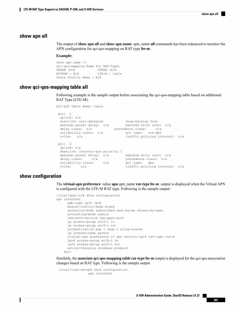
show apn allThe output of show apn all and show apn name apn_name all commands has been enhanced to monitor theAPN configuration for qci-qos-mapping on RAT type lte-m:
Example:
show apn name <>qci-qos-mapping Name for RAT-Type:GERAN :N/A UTRAN :N/AEUTRAN : N/A LTE-M : tableStats Profile Name : N/A
show qci-qos-mapping table allFollowing example is the sample output before associating the qci-qos-mapping table based on additionalRAT Type (LTE-M).QCI-QOS Table Name: table
Qci: 1uplink: n/adownlink: user-datagram dscp-marking 0x3emaximum packet delay: n/a maximum error rate: n/adelay class: n/a precedence class: n/areliability class: n/a qci type: non-gbrvolte: n/a traffic policing interval: n/a
Qci: 2uplink: n/adownlink: internal-qos priority 1maximum packet delay: n/a maximum error rate: n/adelay class: n/a precedence class: n/areliability class: n/a qci type: gbrvolte: n/a traffic policing interval: n/a
show configurationThe virtual-apn preference value apn apn_name rat-type lte-m output is displayed when the Virtual APNis configured with the LTE-M RAT type. Following is the sample output:[local]qvpc-si# show configurationapn intershat
pdp-type ipv4 ipv6bearer-control-mode mixedselection-mode subscribed sent-by-ms chosen-by-sgsnaccounting-mode radiusims-auth-service ims-ggsn-authip access-group acl4-1 inip access-group acl4-1 outauthentication pap 1 chap 2 allow-noauthip context-name egressvirtual-apn preference 10 apn verizon.ipv4 rat-type lte-mipv6 access-group acl6-1 inipv6 access-group acl6-1 outactive-charging rulebase prepaid
exit
Similarly, the associate qci-qos-mapping table rat-type lte-m output is displayed for the qci-qos associationchanges based on RAT type. Following is the sample output[local]laas-setup# show configuration
apn intershat
S-GW Administration Guide, StarOS Release 21.27281
LTE-M RAT Type Support on SAEGW, P-GW, and S-GW Servicesshow apn all

context ingresssubscriber defaultnexthop-forwarding-addressexitapn intershatassociate qci-qos-mapping table rat-type lte-mexit
show subscribers fullThe output of this show command is used for monitoring the subscriber call. The RAT type of the call isdisplayed as LTE-M. A new fieldLTE-M is added under Access Technology. Following is the sample output:[local]laas-setup# show subscribers allAccess (X) - CDMA 1xRTT (E) - GPRS GERAN (I) - IP|| Tech: (D) - CDMA EV-DO (U) - WCDMA UTRAN (W) - Wireless LAN|| (A) - CDMA EV-DO REVA (G) - GPRS Other (M) - WiMax|| (C) - CDMA Other (J) - GAN (O) - Femto IPSec|| (P) - PDIF (S) - HSPA (L) - eHRPD|| (T) - eUTRAN (B) - PPPoE (F) - FEMTO UTRAN|| (N) - NB-IoT (Q) - WSG (R)- LTE-M
(.) - Other/Unknown
show subcscribers full allThe output of the following show commands are used for monitoring the subscriber call. TheAccess Technologyof the call is displayed as LTE-M.Username: 9890098900 Status: Online/ActiveAccess Type: sgw-pdn-type-ipv4-ipv6 Network Type: IPV4+IPv6Access Tech: LTE-M Access Network Peer ID: n/acallid: 02fb3ea1 msid: 404005123456789Card/Cpu: 1/0 Sessmgr Instance: 11state: Connectedconnect time: Tue Mar 23 04:33:55 2021 call duration: 00h00m46sidle time: 00h00m40s idle time left: n/a
show subs pgw-only full / show subs pgw-only full allThe show subs pgw-only full / show subs pgw-only full all commands display the Access Technology ofthe call as LTE-M. Following is the sample output:
Access Type: gtp-pdn-type-ipv4-ipv6 Network Type: IPV4+IPv6Access Tech: LTE-M pgw-service-name: PGW21Callid: 02fb3ea2 IMSI: 404005123456789MSISDN: 9890098900 External ID: n/aInterface Type: S5S8GTP Low Access Priority: N/ATWAN Mode: N/AeMPS Bearer: NoEmergency Bearer Type: N/AIMS-media Bearer: NoS6b Auth Status: N/A
show subs sgw-only full / show subs sgw-only full allThe show subs sgw-only full / show subs sgw-only full all scommands display the Access Technology ofthe call as LTE-M. Following is the sample output:Card/Cpu : 1/0 Sessmgr Instance : 11Idle time : 00h05m47s
S-GW Administration Guide, StarOS Release 21.27282
LTE-M RAT Type Support on SAEGW, P-GW, and S-GW Servicesshow subscribers full

MS TimeZone : n/a Daylight Saving Time: n/a
Access Type: sgw-pdn-type-ipv4-ipv6 Network Type: IPV4+IPv6Access Tech: LTE-M sgw-service-name: SGW21Callid: 02fb3ea1 IMSI: 404005123456789MSISDN: 9890098900eMPS Bearer: No
show subs saegw-only full / show subs saegw-only full allThe show subs saegw-only full / show subs saegw-only full all commands display the Access Technologyof the call as LTE-M. Following is the sample output:Callid : 02fb3ea3 IMSI : 404005123456789Card/Cpu : 1/0 Sessmgr Instance : 11Source context : EPC2 Destination context : ISP1Bearer Type : Default Bearer-Id : 5Access Type : gtp-pdn-type-ipv4-ipv6 Network Type : IPV4+IPv6Access Tech : LTE-M saegw-service-name : SAEGW21MSISDN : 9890098900 External ID : n/aTWAN Mode : N/AeMPS Bearer : NoWPS Bearer : No
show subs pgw-only allThe show subs pgw-only all command displays the following output:.|+------Access (U) - UTRAN (G) - GERAN|| Tech: (W) - WLAN (J) - GAN|| (U) - HSPA Evolution (E) - eUTRAN|| (H) - eHRPD (.) - Unknown|| (N) - NB-IoT (R) - LTE-M
show subs sgw-only allThe show subs sgw-only all command displays the following output:|+----Access (U) - UTRAN (G) - GERAN (W) - WLAN|| Tech: (J) - GAN (S) - HSPA Evolution (E) - eUTRAN|| (.) - Unknown (N) - NB-IoT (R) - LTE-M
||
show subs saegw-only allThe show subs saegw-only all command displays the following output:|+----Access (U) - UTRAN (G) - GERAN (W) - WLAN|| Tech: (J) - GAN (S) - HSPA Evolution (E) - eUTRAN|| (H) - eHRPD (.) - Unknown (N) - NB-IoT|| (R) - LTE-M
show subscribers callidThe show subscribers callid callidcommand displays the Access Technology of the call as LTE-M. Followingis the sample output:|+----Access (X) - CDMA 1xRTT(E) - GPRS GERAN (I) - IP|| Tech: (D) - CDMA EV-DO (U) - WCDMA UTRAN (W) - Wireless LAN|| (A) - CDMA EV-DO REVA (G) - GPRS Other (M) - WiMax|| (C) - CDMA Other (J) - GAN (O) - Femto IPSec
S-GW Administration Guide, StarOS Release 21.27283
LTE-M RAT Type Support on SAEGW, P-GW, and S-GW Servicesshow subs saegw-only full / show subs saegw-only full all
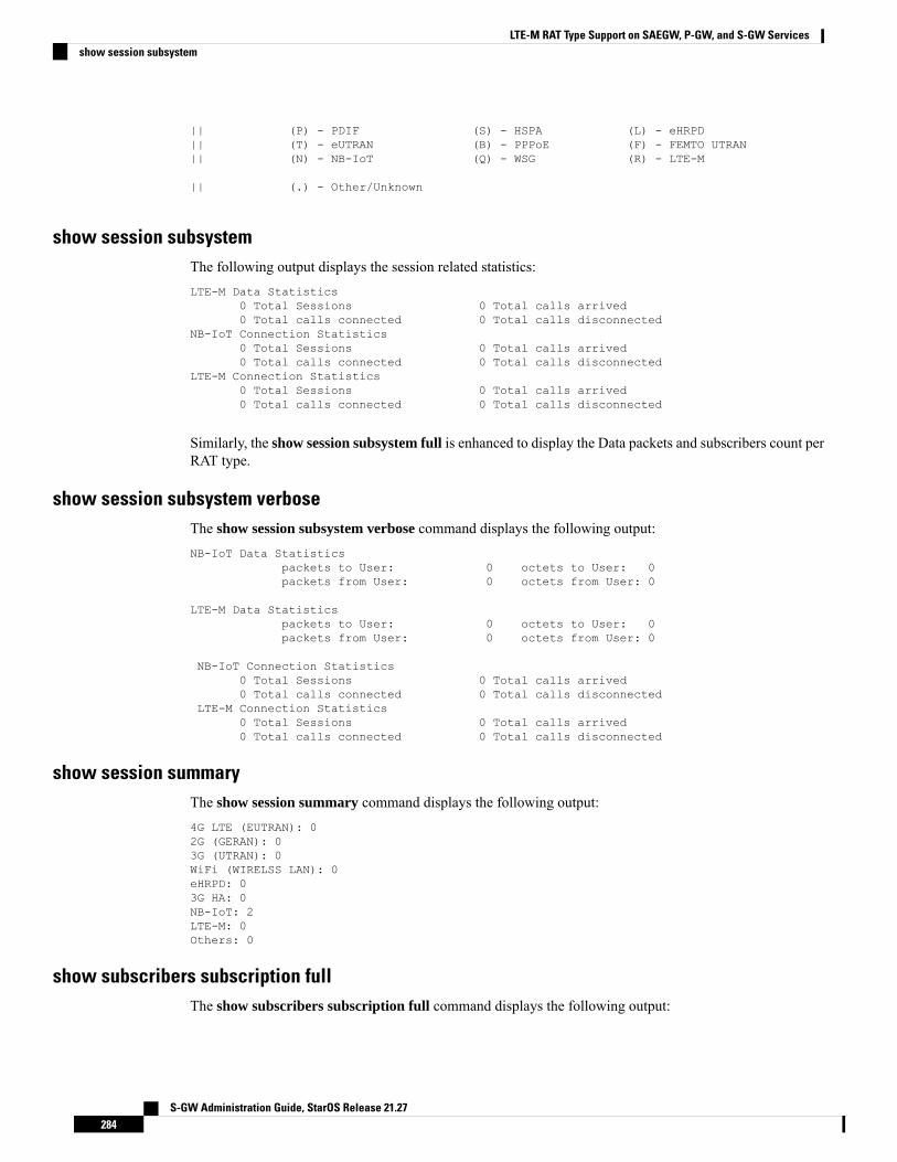
|| (P) - PDIF (S) - HSPA (L) - eHRPD|| (T) - eUTRAN (B) - PPPoE (F) - FEMTO UTRAN|| (N) - NB-IoT (Q) - WSG (R) - LTE-M
|| (.) - Other/Unknown
show session subsystemThe following output displays the session related statistics:LTE-M Data Statistics
0 Total Sessions 0 Total calls arrived0 Total calls connected 0 Total calls disconnected
NB-IoT Connection Statistics0 Total Sessions 0 Total calls arrived0 Total calls connected 0 Total calls disconnected
LTE-M Connection Statistics0 Total Sessions 0 Total calls arrived0 Total calls connected 0 Total calls disconnected
Similarly, the show session subsystem full is enhanced to display the Data packets and subscribers count perRAT type.
show session subsystem verboseThe show session subsystem verbose command displays the following output:NB-IoT Data Statistics
packets to User: 0 octets to User: 0packets from User: 0 octets from User: 0
LTE-M Data Statisticspackets to User: 0 octets to User: 0packets from User: 0 octets from User: 0
NB-IoT Connection Statistics0 Total Sessions 0 Total calls arrived0 Total calls connected 0 Total calls disconnected
LTE-M Connection Statistics0 Total Sessions 0 Total calls arrived0 Total calls connected 0 Total calls disconnected
show session summaryThe show session summary command displays the following output:4G LTE (EUTRAN): 02G (GERAN): 03G (UTRAN): 0WiFi (WIRELSS LAN): 0eHRPD: 03G HA: 0NB-IoT: 2LTE-M: 0Others: 0
show subscribers subscription fullThe show subscribers subscription full command displays the following output:
S-GW Administration Guide, StarOS Release 21.27284
LTE-M RAT Type Support on SAEGW, P-GW, and S-GW Servicesshow session subsystem
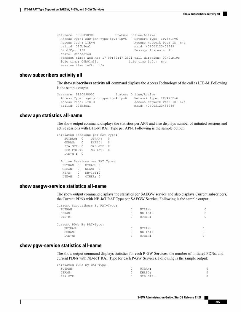
Username: 9890098900 Status: Online/ActiveAccess Type: sgw-pdn-type-ipv4-ipv6 Network Type: IPV4+IPv6Access Tech: LTE-M Access Network Peer ID: n/acallid: 02fb3ea1 msid: 404005123456789Card/Cpu: 1/0 Sessmgr Instance: 11state: Connectedconnect time: Wed Mar 17 09:59:47 2021 call duration: 00h01m19sidle time: 00h01m13s idle time left: n/asession time left: n/a
show subscribers activity allThe show subscribers activity all command displays the Access Technology of the call as LTE-M. Followingis the sample output:Username: 9890098900 Status: Online/ActiveAccess Type: sgw-pdn-type-ipv4-ipv6 Network Type: IPV4+IPv6Access Tech: LTE-M Access Network Peer ID: n/acallid: 02fb3ea1 msid: 404005123456789
show apn statistics all-nameThe show output command displays the statistics per APN and also displays number of initiated sessions andactive sessions with LTE-M RAT Type per APN. Following is the sample output:Initiated Sessions per RAT Type:
EUTRAN: 0 UTRAN: 0GERAN: 0 EHRPD: 0S2A GTP: 0 S2B GTP: 0S2B PMIP:0 NB-IoT: 0LTE-M : 0
Active Sessions per RAT Type:EUTRAN: 0 UTRAN: 0GERAN: 0 WLAN: 0HSPA: 0 NB-IoT:0LTE-M: 0 OTHER: 0
show saegw-service statistics all-nameThe show output command displays the statistics per SAEGW service and also displays Current subscribers,the Current PDNs with NB-IoT RAT Type per SAEGW Service. Following is the sample output:Current Subscribers By RAT-Type:EUTRAN: 0 UTRAN: 0GERAN: 0 NB-IoT: 0LTE-M: 0 OTHER: 0
Current PDNs By RAT-Type:EUTRAN: 0 UTRAN: 0GERAN: 0 NB-IoT: 0LTE-M: 0 OTHER: 0
show pgw-service statistics all-nameThe show output command displays statistics for each P-GW Services, the number of initiated PDNs, andcurrent PDNs with NB-IoT RAT Type for each P-GW Services. Following is the sample output:Initiated PDNs By RAT-Type:EUTRAN: 0 UTRAN: 0GERAN: 0 EHRPD: 0S2A GTP: 0 S2B GTP: 0
S-GW Administration Guide, StarOS Release 21.27285
LTE-M RAT Type Support on SAEGW, P-GW, and S-GW Servicesshow subscribers activity all

S2B PMIP: 0 NB-IoT: 0LTE-M 0
Current PDNs By RAT-Type:EUTRAN: 0 UTRAN: 0GERAN: 0 WLAN: 0NB-IoT: 0 LTE-M 0OTHER: 0
show sgw-service statisticsThis show command displays statistics for each S-GW Services. This CLI is enhanced to display CurrentSubscribers and Current PDNs with NB-IoT RAT type for each S-GW Services. Following is the sampleoutput:Current Subscribers By RAT-Type:EUTRAN: 0 UTRAN: 0GERAN: 0 NB-IoT: 0LTE-M: 0 OTHER: 0
Current PDNs By RAT-Type:EUTRAN: 0 UTRAN: 0GERAN: 0 NB-IoT: 0LTE-M: 0 OTHER: 0
Bulk StatisticsThe following statistics are added in support of the LTE-M RAT type feature
APN SchemaThe following LTE-M RAT type feature-related bulk statistics are available in the APN schema.
DescriptionBulk Statistics
The total number of active LTE-M sessions per APNwith RAT type LTE-M.
active-lte-m-sessions
The total number of initiated LTE-M sessions.initiated-lte-m-sessions
P-GW SchemaThe following LTE-M RAT type feature related bulk statistics available in the P-GW schema.
DescriptionBulk Statistics
The total number of active PDN Type Statistics –LTE-M.
sesstat-pdn-rat-lte-m
The total number of initiated LTE-M PDNs (withRAT Type LTE-M).
sessstat-rat-init-lte-m
S-GW SchemaThe following LTE-M RAT type feature related bulk statistics available in the S-GW schema.
S-GW Administration Guide, StarOS Release 21.27286
LTE-M RAT Type Support on SAEGW, P-GW, and S-GW Servicesshow sgw-service statistics
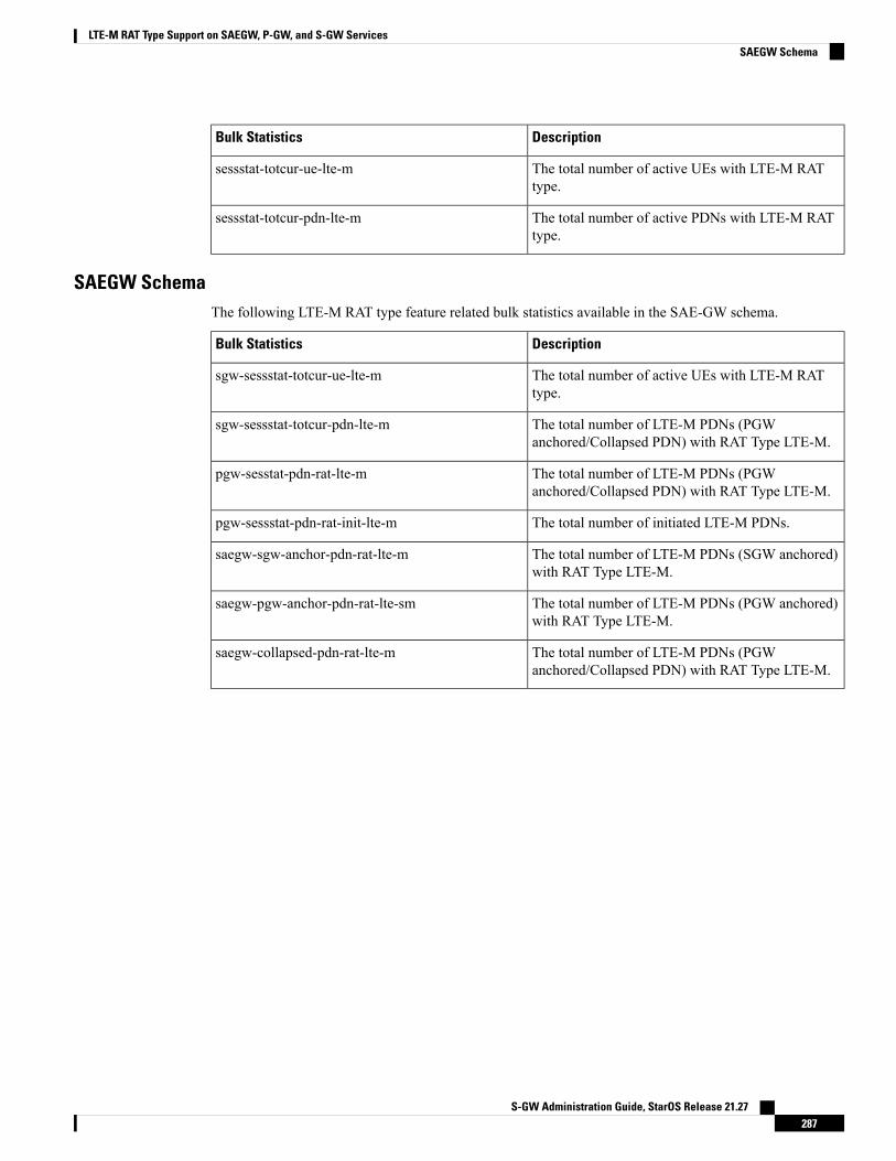
DescriptionBulk Statistics
The total number of active UEs with LTE-M RATtype.
sessstat-totcur-ue-lte-m
The total number of active PDNs with LTE-M RATtype.
sessstat-totcur-pdn-lte-m
SAEGW SchemaThe following LTE-M RAT type feature related bulk statistics available in the SAE-GW schema.
DescriptionBulk Statistics
The total number of active UEs with LTE-M RATtype.
sgw-sessstat-totcur-ue-lte-m
The total number of LTE-M PDNs (PGWanchored/Collapsed PDN) with RAT Type LTE-M.
sgw-sessstat-totcur-pdn-lte-m
The total number of LTE-M PDNs (PGWanchored/Collapsed PDN) with RAT Type LTE-M.
pgw-sesstat-pdn-rat-lte-m
The total number of initiated LTE-M PDNs.pgw-sessstat-pdn-rat-init-lte-m
The total number of LTE-M PDNs (SGW anchored)with RAT Type LTE-M.
saegw-sgw-anchor-pdn-rat-lte-m
The total number of LTE-M PDNs (PGW anchored)with RAT Type LTE-M.
saegw-pgw-anchor-pdn-rat-lte-sm
The total number of LTE-M PDNs (PGWanchored/Collapsed PDN) with RAT Type LTE-M.
saegw-collapsed-pdn-rat-lte-m
S-GW Administration Guide, StarOS Release 21.27287
LTE-M RAT Type Support on SAEGW, P-GW, and S-GW ServicesSAEGW Schema

S-GW Administration Guide, StarOS Release 21.27288
LTE-M RAT Type Support on SAEGW, P-GW, and S-GW ServicesSAEGW Schema
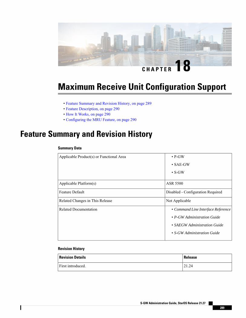
C H A P T E R 18Maximum Receive Unit Configuration Support
• Feature Summary and Revision History, on page 289• Feature Description, on page 290• How It Works, on page 290• Configuring the MRU Feature, on page 290
Feature Summary and Revision HistorySummary Data
• P-GW
• SAE-GW
• S-GW
Applicable Product(s) or Functional Area
ASR 5500Applicable Platform(s)
Disabled - Configuration RequiredFeature Default
Not ApplicableRelated Changes in This Release
• Command Line Interface Reference
• P-GW Administration Guide
• SAEGW Administration Guide
• S-GW Administration Guide
Related Documentation
Revision History
ReleaseRevision Details
21.24First introduced.
S-GW Administration Guide, StarOS Release 21.27289
Feature DescriptionPrior to MRU Configuration support, the Maximum Receive Unit (MRU) setting was equal to the MaximumTransmission Unit (MTU).
When the MTU of eNB on the S1-U interface was increased to 2000 bytes but no changes were made on theMTU on S1-U interface on SAE-GW, packets were received at SAE-GW with size more than 1500 bytes.This resulted into those packets getting dropped at the S1-U interface on the SAE-GW withLport_MRU_exceeded exception. This was affecting UEs that were trying to set up IKE Tunnels.
This Configure MRU feature allows you to configure MRU separately from MTU.
How It WorksTo handle MRU independently of MTU, changes are made in Network Processing Unit (NPU), NPUSIM,NPUMGR, and CLI.
Configuring the MRU FeatureThis section describes how to configure the MRU of the IP interface along with MTU using the ip mtukeyword under interface configuration.
Configuring MRUTo configure the MTU and MRU in the Ethernet Interface Configuration mode, use the following sampleconfiguration.
configcontext context_name
interface interface_name broadcastip mtu mtu_size [ mru mru_size ]end
NOTES:
• ip mtu mtu_size: Specify the MTU size. mtu_size must be an integer in the range of 5762048 bytes.
• mru mru_size: Specify the MRU size. mru_size must be an integer in the range of 5762048 bytes.
• Use the no ip mtu command to disable the MTU configuration.
• The maximum configurable value for MTU is 2048 bytes.. If MTU is not configured, the default valueis 1500 bytes.
• MRU attribute is optional and when it is not configured, MRU is set to the same value as MTU.
• MRU optional attribute is not applicable to VPC-DI and VPC-SI platforms. This attribute is only visibleon ASR 5500.
• On CUPS or ICUPS, the following error is displayed you when you try to configureMRU on an interface.
S-GW Administration Guide, StarOS Release 21.27290
Maximum Receive Unit Configuration SupportFeature Description

Failure: Configure MRU Feature is not supported when ICUPS/CUPS isenabled!
• Although the product allows configuring asymmetric MTU and MRU values on the same interface isnot advised as it may result into undesirable behavior on the network.
Configuring the MRU Feature when no MTU is specified
MTU = default MTU, MRU = default MTU
For example:configure
interface SGi-VLAN400logical-port-statisticsip address 172.26.96.3 255.255.255.248ipv6 address 2600:300:2030:1104::3/64 secondarybfd interval 300 min_rx 300 multiplier 3#exit
#exit
Configuring the MTU Feature when no MRU is specified
MRU = Configured MTU for backward compatibility. MRU = MTU = 1970 bytes.
For example:configure
interface SGi-VLAN400logical-port-statisticsip address 172.26.96.3 255.255.255.248ipv6 address 2600:300:2030:1104::3/64 secondaryip mtu 1970bfd interval 300 min_rx 300 multiplier 3
#exit
Configuring the MTU Feature when both MTU and MRU are specified
MTU = default MTU, MRU = default MTU
For example:configure
interface SGi-VLAN400logical-port-statisticsip address 172.26.96.3 255.255.255.248ipv6 address 2600:300:2030:1104::3/64 secondaryip mtu 1600 mru 1700bfd interval 300 min_rx 300 multiplier 3
#exit
Verifying the Configured MRUThe output of the is enhanced to display the configured MRU value.
For example:[EPC2]26kl-chassis# config[EPC2]26kl-chassis(config)# context EPC2[EPC2]26kl-chassis(config-ctx)# interface TO-EPC2-SGW-INGRESS[EPC2]26kl-chassis(config-if-eth)# ip mtu 1500 mru 1970
S-GW Administration Guide, StarOS Release 21.27291
Maximum Receive Unit Configuration SupportVerifying the Configured MRU

[EPC2]26kl-chassis(config-if-eth)# end[EPC2]26kl-chassis# show ipv6 interfaceIntf Name: TO-EPC1-SGW-INGRESSIntf Type: BroadcastDescription:VRF: NoneIP State: UP (Bound to 5/20 vlan id 190, 802.1P prior 0, ifIndex 85196802)Router Advertisement: disabled MTU: 1500 MRU: 1970IPv6 Link-Local Address: fe80::d272:dcff:fea3:8543/64IPv6 Global Unicast Address: 2001::1:21/64L3 monitor LC-port switchover: DisabledNumber of Secondary Addresses: 5IPv6 Address: 2001::1:31/64IPv6 Address: 2001::1:205/64IP Address: 10.10.10.21 Subnet Mask: 255.255.255.0IP Address: 10.10.10.31 Subnet Mask: 255.255.255.0IP Address: 10.10.10.200 Subnet Mask: 255.255.255.0
NOTES:
• Use the show ipv6 interface command to verify if the Configurable MTU configuration is enabled ordisabled.
• no ip mtu: Disables the Configurable MTU configuration.
S-GW Administration Guide, StarOS Release 21.27292
Maximum Receive Unit Configuration SupportVerifying the Configured MRU
C H A P T E R 19Multiple IP Versions Support
This chapter describes the following topics:
• Feature Summary and Revision History, on page 293• Feature Description, on page 294• How it Works, on page 294• Configuring Multiple IP Version Support, on page 296• Monitoring and Troubleshooting, on page 297
Feature Summary and Revision HistorySummary Data
• P-GW
• S-GW
• SAEGW
Applicable Product(s) or Functional Area
• ASR 5500
• VPC - DI
• VPC - SI
Applicable Platform(s)
Disabled - Configuration RequiredFeature Default
Not applicableRelated Changes in This Release
• Command Line Interface Reference
• P-GW Administration Guide
• S-GW Administration Guide
• SAEGW Administration Guide
Related Documentation
S-GW Administration Guide, StarOS Release 21.27293
Revision History
Revision history details are not provided for features introduced before release 21.2 and N5.1.Important
ReleaseRevision Details
21.8This feature enables P-GW, S-GW, and SAEGW nodes to support the controlmessages received on all the transport addresses exchanged during the session setup.
Pre 21.2First introduced.
Feature DescriptionThis feature enables P-GW, S-GW, and SAEGW nodes to support the control messages received on all thetransport addresses exchanged during the session setup.
A new CLI command has been introduced at the egtp-service level to control the behavior of the BRCmd,MBCmd, and DBCmd messages.
How it WorksThis section describes the working of this feature. Following is the sample call flow for MBCmd.
The following figure illustrates call flow when the feature is disabled:
S-GW Administration Guide, StarOS Release 21.27294
Multiple IP Versions SupportFeature Description
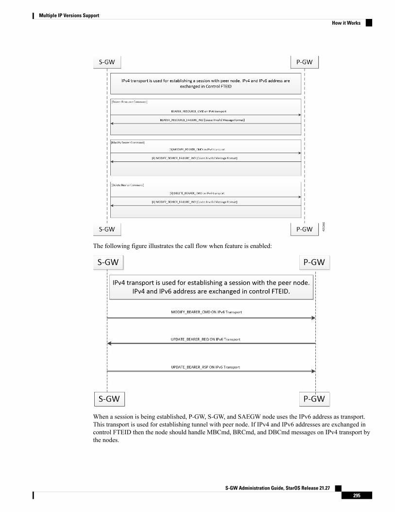
The following figure illustrates the call flow when feature is enabled:
When a session is being established, P-GW, S-GW, and SAEGW node uses the IPv6 address as transport.This transport is used for establishing tunnel with peer node. If IPv4 and IPv6 addresses are exchanged incontrol FTEID then the node should handle MBCmd, BRCmd, and DBCmd messages on IPv4 transport bythe nodes.
S-GW Administration Guide, StarOS Release 21.27295
Multiple IP Versions SupportHow it Works
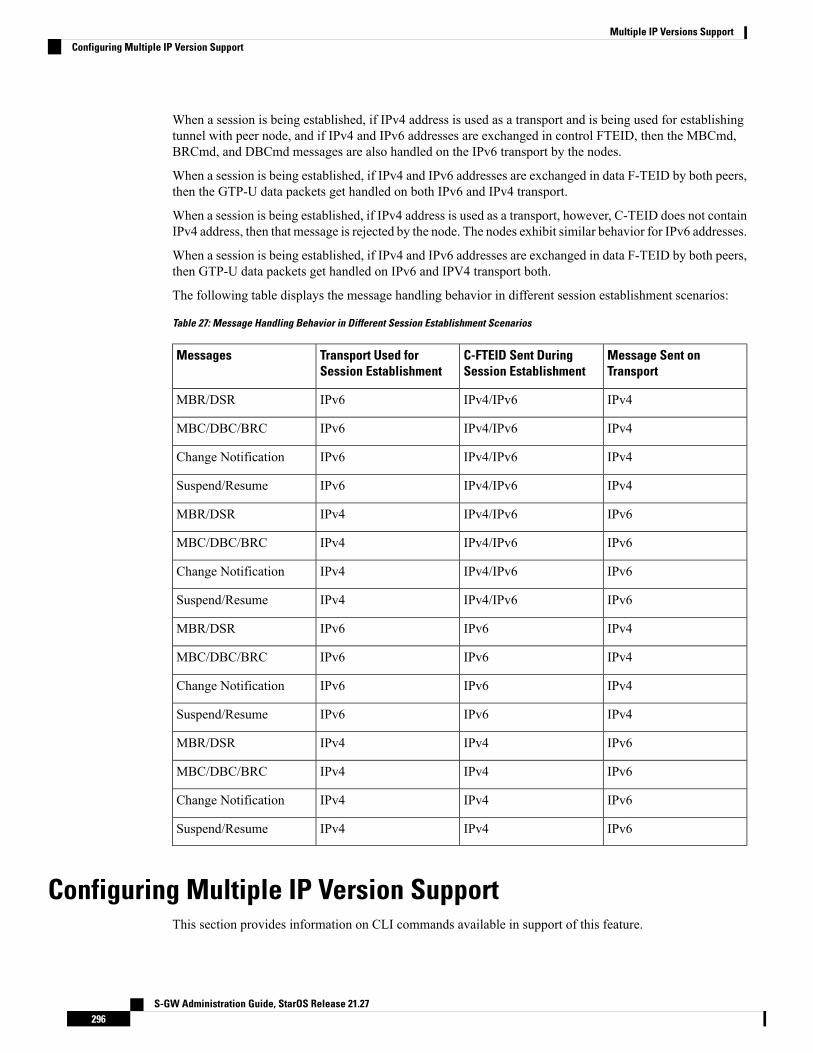
When a session is being established, if IPv4 address is used as a transport and is being used for establishingtunnel with peer node, and if IPv4 and IPv6 addresses are exchanged in control FTEID, then the MBCmd,BRCmd, and DBCmd messages are also handled on the IPv6 transport by the nodes.
When a session is being established, if IPv4 and IPv6 addresses are exchanged in data F-TEID by both peers,then the GTP-U data packets get handled on both IPv6 and IPv4 transport.
When a session is being established, if IPv4 address is used as a transport, however, C-TEID does not containIPv4 address, then that message is rejected by the node. The nodes exhibit similar behavior for IPv6 addresses.
When a session is being established, if IPv4 and IPv6 addresses are exchanged in data F-TEID by both peers,then GTP-U data packets get handled on IPv6 and IPV4 transport both.
The following table displays the message handling behavior in different session establishment scenarios:
Table 27: Message Handling Behavior in Different Session Establishment Scenarios
Message Sent onTransport
C-FTEID Sent DuringSession Establishment
Transport Used forSession Establishment
Messages
IPv4IPv4/IPv6IPv6MBR/DSR
IPv4IPv4/IPv6IPv6MBC/DBC/BRC
IPv4IPv4/IPv6IPv6Change Notification
IPv4IPv4/IPv6IPv6Suspend/Resume
IPv6IPv4/IPv6IPv4MBR/DSR
IPv6IPv4/IPv6IPv4MBC/DBC/BRC
IPv6IPv4/IPv6IPv4Change Notification
IPv6IPv4/IPv6IPv4Suspend/Resume
IPv4IPv6IPv6MBR/DSR
IPv4IPv6IPv6MBC/DBC/BRC
IPv4IPv6IPv6Change Notification
IPv4IPv6IPv6Suspend/Resume
IPv6IPv4IPv4MBR/DSR
IPv6IPv4IPv4MBC/DBC/BRC
IPv6IPv4IPv4Change Notification
IPv6IPv4IPv4Suspend/Resume
Configuring Multiple IP Version SupportThis section provides information on CLI commands available in support of this feature.
S-GW Administration Guide, StarOS Release 21.27296
Multiple IP Versions SupportConfiguring Multiple IP Version Support

By default, this feature is enabled.
configurecontext context_name
egtp-service service_name
[no] gtpc command-messages dual-ip-stack-supportend
NOTES:
• no: Disables the feature.
• command-messages: Configures MBC or DBC or BRC messages on S-GW and P-GW.
• dual-ip-stack-support: Enables P-GW, S-GW, SAEGW nodes to handle command messages on bothIPv4/IPv6 transport, if supported.
Monitoring and TroubleshootingThis section provides information on how to monitor and troubleshoot the Override Control Enhancementfeature.
Show Commands and OutputsThis section provides information on show commands and their corresponding outputs for the Override ControlEnhancement feature.
show configurationThe following new fields are added to the output of this command:
• gtpc command-messages dual-ip-stack-support - Specifies the command messages on both IPv4/IPv6transport if supported.
show egtp-service allThe following new fields are added to the output of this command:
• GTPC Command Messages Dual IP Support - Specifies the command messages on both IPv4/IPv6transport if supported.
S-GW Administration Guide, StarOS Release 21.27297
Multiple IP Versions SupportMonitoring and Troubleshooting

S-GW Administration Guide, StarOS Release 21.27298
Multiple IP Versions Supportshow egtp-service all

C H A P T E R 20Operator Policy
The proprietary concept of an operator policy, originally architected for the exclusive use of an SGSN, isnon-standard and currently unique to the ASR 5500. This optional feature empowers the carrier with flexiblecontrol to manage functions that are not typically used in all applications and to determine the granularity ofthe implementation of any operator policy: to groups of incoming calls or to simply one single incoming call.
The following products support the use of the operator policy feature:
• MME (Mobility Management Entity - LTE)• SGSN (Serving GPRS Support Node - 2G/3G/LTE)• S-GW (Serving Gateway - LTE)
This document includes the following information:
• What Operator Policy Can Do, on page 299• The Operator Policy Feature in Detail, on page 300• How It Works, on page 304• Operator Policy Configuration, on page 304• Verifying the Feature Configuration, on page 310
What Operator Policy Can DoOperator policy enables the operator to specify a policy with rules governing the services, facilities andprivileges available to subscribers.
A Look at Operator Policy on an SGSNThe following is only a sampling of what working operator policies can control on an SGSN:
• APN information included in call activation messages are sometimes damaged, misspelled, missing. Insuch cases, the calls are rejected. The operator can ensure calls aren't rejected and configure a range ofmethods for handling APNs, including converting incoming APNs to preferred APNs and this controlcan be used in a focused fashion or defined to cover ranges of subscribers.
• In another example, it is not unusual for a blanket configuration to be implemented for all subscriberprofiles stored in the HLR. This results in a waste of resources, such as the allocation of the defaulthighest QoS setting for all subscribers. An operator policy provides the opportunity to address such issuesby allowing fine-tuning of certain aspects of profiles fetched from HLRs and, if desired, overwrite QoSsettings received from HLR.
S-GW Administration Guide, StarOS Release 21.27299

A Look at Operator Policy on an S-GWThe S-GW operator policy provides mechanisms to fine tune the behavior for subsets of subscribers. It alsocan be used to control the behavior of visiting subscribers in roaming scenarios by enforcing roaming agreementsand providing a measure of local protection against foreign subscribers.
The S-GW uses operator policy in the SGW service configuration to control the accounting mode. The defaultaccounting mode is GTPP, but RADIUS/Diameter and none are options. The accounting mode value fromthe call control profile overrides the value configured in SGW service. If the accounting context is notconfigured in the call control profile, it is taken from SGW service. If the SGW service does not have therelevant configuration, the current context or default GTPP group is assumed.
The Operator Policy Feature in DetailThis flexible feature provides the operator with a range of control to manage the services, facilities andprivileges available to subscribers.
Operator policy definitions can depend on factors such as (but not limited to):
• roaming agreements between operators,• subscription restrictions for visiting or roaming subscribers,• provisioning of defaults to override standard behavior.
These policies can override standard behaviors and provide mechanisms for an operator to circumvent thelimitations of other infrastructure elements such as DNS servers and HLRs in 2G/3G networks.
By configuring the various components of an operator policy, the operator fine-tunes any desired restrictionsor limitations needed to control call handling and this can be done for a group of callers within a defined IMSIrange or per subscriber.
Re-Usable Components - Besides enhancing operator control via configuration, the operator policy featureminimizes configuration by drastically reducing the number of configuration lines needed. Operator policymaximizes configurations by breaking them into the following reusable components that can be shared acrossIMSI ranges or subscribers:
• call control profiles• IMEI profiles (SGSN only)• APN profiles• APN remap tables• operator policies• IMSI ranges
Each of these components is configured via a separate configuration mode accessed through the GlobalConfiguration mode.
Call Control ProfileA call control profile can be used by the operator to fine-tune desired functions, restrictions, requirements,and/or limitations needed for call management on a per-subscriber basis or for groups of callers across IMSIranges. For example:
• setting access restriction cause codes for rejection messages• enabling/disabling authentication for various functions such as attach and service requests
S-GW Administration Guide, StarOS Release 21.27300
Operator PolicyA Look at Operator Policy on an S-GW
• enabling/disabling ciphering, encryption, and/or integrity algorithms• enabling/disabling of packet temporary mobile subscriber identity (P-TMSI) signature allocation (SGSNonly)
• enabling/disabling of zone code checking• allocation/retention priority override behavior (SGSN only)• enabling/disabling inter-RAT, 3G location area, and 4G tracking area handover restriction lists (MMEand S-GW only)
• setting maximum bearers and PDNs per subscriber (MME and S-GW only)
Call control profiles are configured with commands in the Call Control Profile configuration mode. A singlecall control profile can be associated with multiple operator policies
For planning purposes, based on the system configuration, type of packet services cards, type of network (2G,3G, 4G, LTE), and/or application configuration (single, combo, dual access), the following call control profileconfiguration rules should be considered:
• 1 (only one) - call control profile can be associated with an operator policy• 1000 - maximum number of call control profiles per system (e.g., an SGSN).• 15 - maximum number of equivalent PLMNs for 2G and 3G per call control profile
• 15 - maximum number of equivalent PLMNs for 2G per ccprofile.• 15 - maximum number of supported equivalent PLMNs for 3G per ccprofile.
• 256 - maximum number of static SGSN addresses supported per PLMN• 5 - maximum number of location area code lists supported per call control profile.• 100 - maximum number of LACs per location area code list supported per call control profile.• unlimited number of zone code lists can be configured per call control profile.• 100 - maximum number of LACs allowed per zone code list per call control profile.• 2 - maximum number of integrity algorithms for 3G per call control profile.• 3 - maximum number of encryption algorithms for 3G per call control profile.
APN ProfileAn APN profile groups a set of access point name (APN)-specific parameters that may be applicable to oneor more APNs. When a subscriber requests an APN that has been identified in a selected operator policy, theparameter values configured in the associated APN profile will be applied.
For example:
• enable/disable a direct tunnel (DT) per APN. (SGSN)• define charging characters for calls associated with a specific APN.• identify a specific GGSN to be used for calls associated with a specific APN (SGSN).• define various quality of service (QoS) parameters to be applied to calls associated with a specific APN.• restrict or allow PDP context activation on the basis of access type for calls associated with a specificAPN.
APN profiles are configured with commands in the APN Profile configuration mode. A single APN profilecan be associated with multiple operator policies.
For planning purposes, based on the system configuration, type of packet processing cards and 2G, 3G, 4G,and/or dual access, the following APN profile configuration rules should be considered:
• 50 - maximum number of APN profiles that can be associated with an operator policy.
S-GW Administration Guide, StarOS Release 21.27301
Operator PolicyAPN Profile
• 1000 - maximum number of APN profiles per system (e.g., an SGSN).• 116 - maximum gateway addresses (GGSN addresses) that can be defined in a single APN profile.
IMEI-Profile (SGSN only)The IMEI is a unique international mobile equipment identity number assigned by the manufacturer that isused by the network to identify valid devices. The IMEI has no relationship to the subscriber.
An IMEI profile group is a set of device-specific parameters that control SGSN behavior when one of varioustypes of Requests is received from a UE within a specified IMEI range. These parameters control:
• Blacklisting devices• Identifying a particular GGSN to be used for connections for specified devices• Enabling/disabling direct tunnels to be used by devices
IMEI profiles are configured with commands in the IMEI Profile configuration mode. A single IMEI profilecan be associated with multiple operator policies.
For planning purposes, based on the system configuration, type of packet processing cards, type of network(2G, 3G, 4G, LTE), and/or application configuration (single, combo, dual access), the following IMEI profileconfiguration rules should be considered:
• 10 - maximum number of IMEI ranges that can be associated with an operator policy.• 1000 - maximum number of IMEI profiles per system (such as an SGSN).
APN Remap TableAPN remap tables allow an operator to override an APN specified by a user, or the APN selected during thenormal APN selection procedure, as specified by 3GPP TS 23.060. This atypical level of control enablesoperators to deal with situations such as:
• An APN is provided in the Activation Request that does not match with any of the subscribed APNseither a different APN was entered or the APN could have been misspelled. In such situations, the SGSNwould reject the Activation Request. It is possible to correct the APN, creating a valid name so that theActivation Request is not rejected.
• In some cases, an operator might want to force certain devices/users to use a specific APN. For example,all iPhone4 users may need to be directed to a specific APN. In such situations, the operator needs to beable to override the selected APN.
An APN remap table group is a set of APN-handling configurations that may be applicable to one or moresubscribers. When a subscriber requests an APN that has been identified in a selected operator policy, theparameter values configured in the associated APN remap table will be applied. For example, an APN remaptable allows configuration of the following:
• APN aliasing - maps incoming APN to a different APN based on partial string match (MME and SGSN)or matching charging characteristic (MME and SGSN).
• Wildcard APN - allows APN to be provided by the SGSN when wildcard subscription is present and theuser has not requested an APN.
• Default APN - allows a configured default APN to be used when the requested APN cannot be used forexample, the APN is not part of the HLR subscription. In 21.4 and later releases, the configuration toenable default APN on failure of DNS query is enhanced to support S4-SGSN. When wildcard APN is
S-GW Administration Guide, StarOS Release 21.27302
Operator PolicyIMEI-Profile (SGSN only)
received in subscription, the DNS request is tried with the MS requested APN and on failure of DNS, itis retried with the APN value configured in the APN remap table.
APN remap tables are configured with commands in the APN Remap Table configuration mode. A singleAPN remap table can be associated withmultiple operator policies, but an operator policy can only be associatedwith a single APN remap table.
For planning purposes, based on the system configuration, type of packet processing cards, type of network(2G, 3G, 4G, LTE), and/or application configuration (single, combo, dual access), the following APN remaptable configuration rules should be considered:
• 1 - maximum number of APN remap tables that can be associated with an operator policy.
• 1000 - maximum number of APN remap tables per system (such as an SGSN).
• 100 - maximum remap entries per APN remap table.
Operator PoliciesThe profiles and tables are created and defined within their own configuration modes to generate sets of rulesand instructions that can be reused and assigned to multiple policies. An operator policy binds the variousconfiguration components together. It associates APNs, with APN profiles, with an APN remap table, witha call control profile, and/or an IMEI profile (SGSN only) and associates all the components with filteringranges of IMSIs.
In this manner, an operator policy manages the application of rules governing the services, facilities, andprivileges available to subscribers.
Operator policies are configured and the associations are defined via the commands in the Operator Policyconfiguration mode.
The IMSI ranges are configured with the command in the SGSN-Global configuration mode.
For planning purposes, based on the system configuration, type of packet processing cards, type of network(2G, 3G, 4G, LTE), and/or application configuration (single, combo, dual access), the following operatorpolicy configuration rules should be considered:
• 1 maximum number of call control profiles associated with a single operator policy.• 1 maximum number of APN remap tables associated with a single operator policy.• 10 maximum number of IMEI profiles associated with a single operator policy (SGSN only)• 50 maximum number of APN profiles associated with a single operator policy.• 1000 maximum number of operator policies per system (e.g., an SGSN) this number includes the singledefault operator policy.
• 1000 maximum number of IMSI ranges defined per system (e.g., an SGSN).
SGSN operator policy configurations can be converted to enable them to work with an SGSN. Your CiscoAccount Representative can accomplish this conversion for you.
Important
S-GW Administration Guide, StarOS Release 21.27303
Operator PolicyOperator Policies

IMSI RangesRanges of international mobile subscriber identity (IMSI) numbers, the unique number identifying a subscriber,are associated with the operator policies and used as the initial filter to determine whether or not any operatorpolicy would be applied to a call. The range configurations are defined by theMNC,MCC, a range of MSINs,and optionally the PLMN ID. The IMSI ranges must be associated with a specific operator policy.
IMSI ranges are defined differently for each product supporting the operator policy feature.
How It WorksThe specific operator policy is selected on the basis of the subscriber's IMSI at attach time, and optionally thePLMN ID selected by the subscriber or the RANnode's PLMN ID. Unique, non-overlapping, IMSI + PLMN-IDranges create call filters that distinguish among the configured operator policies.
The following flowchart maps out the logic applied for the selection of an operator policy:
Figure 47: Operator Policy Selection Logic
Operator Policy ConfigurationThis section provides a high-level series of steps and the associated configuration examples to configure anoperator policy. By configuring an operator policy, the operator fine-tunes any desired restrictions or limitationsneeded to control call handling per subscriber or for a group of callers within a defined IMSI range.
Most of the operator policy configuration components are common across the range of products supportingoperator policy. Differences will be noted as they are encountered below.
S-GW Administration Guide, StarOS Release 21.27304
Operator PolicyIMSI Ranges
This section provides a minimum instruction set to implement operator policy. For this feature to be operational,youmust first have completed the system-level configuration as described in the System Administration Guideand the service configuration described in your product's administration guide.
Important
The components can be configured in any order. This example begins with the call control profile:
Step 1 Create and configure a call control profile, by applying the example configuration presented in the Call Control ProfileConfiguration section.
Step 2 Create and configure an APN profile, by applying the example configuration presented in the APN Profile Configurationsection.
It is not necessary to configure both an APN profile and an IMEI profile. You can associate either type of profilewith a policy. It is also possible to associate one or more APN profiles with an IMEI profile for an operatorpolicy (SGSN only).
Note
Step 3 Create and configure an IMEI profile by applying the example configuration presented in the IMEI Profile Configurationsection (SGSN only).
Step 4 Create and configure an APN remap table by applying the example configuration presented in the APN Remap TableConfiguration section.
Step 5 Create and configure an operator policy by applying the example configuration presented in the Operator PolicyConfiguration section.
Step 6 Configure an IMSI range by selecting and applying the appropriate product-specific example configuration presented inthe IMSI Range Configuration sections below.
Step 7 Associate the configured operator policy components with each other and a network service by applying the exampleconfiguration in the Operator Policy Component Associations section.
Step 8 Save your configuration to flash memory, an external memory device, and/or a network location using the Exec modecommand save configuration. For additional information on how to verify and save configuration files, refer to theSystem Administration Guide .
Step 9 Verify the configuration for each component separately by following the instructions provided in the Verifying the FeatureConfiguration section of this chapter.
Call Control Profile ConfigurationThis section provides the configuration example to create a call control profile and enter the configurationmode.
Use the call control profile commands to define call handling rules that will be applied via an operator policy.Only one call control profile can be associated with an operator policy, so it is necessary to use (and repeatas necessary) the range of commands in this mode to ensure call-handling is sufficiently managed.
Configuring the Call Control Profile for an SGSNThe example below includes some of the more commonly configured call control profile parameters withsample variables that you will replace with your own values.
S-GW Administration Guide, StarOS Release 21.27305
Operator PolicyCall Control Profile Configuration

configurecall-control-profile profile_name>
attach allow access-type umts location-area-list instance list_id
authenticate attachlocation-area-list instance instance area-code area_code
sgsn-number E164_number
end
Notes:
• Refer to the Call Control Profile Configuration Mode chapter in the Command Line Interface Referencefor command details and variable options.
• This profile will only become valid when it is associated with an operator policy.
Configuring the Call Control Profile for an MME or S-GWThe example below includes some of the more commonly configured call control profile parameters withsample variables that you will replace with your own values.
configurecall-control-profile profile_name
associate hss-peer-service service_name s6a-interfaceattach imei-query-type imei verify-equipment-identityauthenticate attachdns-pgw context mme_context_name
dns-sgw context mme_context_name
end
Notes:
• Refer to the Call Control Profile Configuration Mode chapter in the Command Line Interface Referencefor command details and variable options.
• This profile will only become valid when it is associated with an operator policy.
APN Profile ConfigurationThis section provides the configuration example to create an APN profile and enter the apn-profile configurationmode.
Use the apn-profile commands to define how calls are to be handled when the requests include an APN.Morethan one APN profile can be associated with an operator policy.
The example below includes some of the more commonly configured profile parameters with sample variablesthat you will replace with your own values.
configureapn-profile profile_name
gateway-address 123.123.123.1 priority 1(SGSN only)
direct-tunnel not-permitted-by-ggsn (SGSN only)
idle-mode-acl ipv4 access-group station7 (S-GW only)
end
Notes:
S-GW Administration Guide, StarOS Release 21.27306
Operator PolicyConfiguring the Call Control Profile for an MME or S-GW
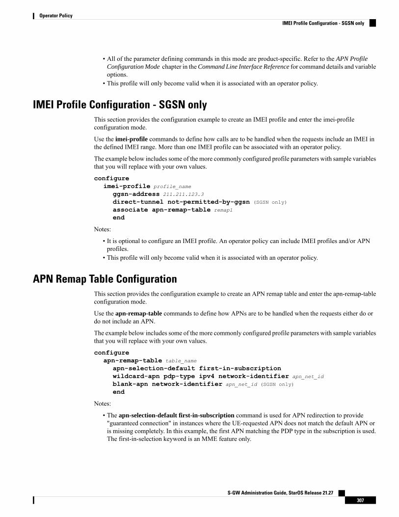
• All of the parameter defining commands in this mode are product-specific. Refer to the APN ProfileConfiguration Mode chapter in theCommand Line Interface Reference for command details and variableoptions.
• This profile will only become valid when it is associated with an operator policy.
IMEI Profile Configuration - SGSN onlyThis section provides the configuration example to create an IMEI profile and enter the imei-profileconfiguration mode.
Use the imei-profile commands to define how calls are to be handled when the requests include an IMEI inthe defined IMEI range. More than one IMEI profile can be associated with an operator policy.
The example below includes some of the more commonly configured profile parameters with sample variablesthat you will replace with your own values.
configureimei-profile profile_name
ggsn-address 211.211.123.3
direct-tunnel not-permitted-by-ggsn (SGSN only)
associate apn-remap-table remap1
end
Notes:
• It is optional to configure an IMEI profile. An operator policy can include IMEI profiles and/or APNprofiles.
• This profile will only become valid when it is associated with an operator policy.
APN Remap Table ConfigurationThis section provides the configuration example to create an APN remap table and enter the apn-remap-tableconfiguration mode.
Use the apn-remap-table commands to define how APNs are to be handled when the requests either do ordo not include an APN.
The example below includes some of the more commonly configured profile parameters with sample variablesthat you will replace with your own values.
configureapn-remap-table table_name
apn-selection-default first-in-subscriptionwildcard-apn pdp-type ipv4 network-identifier apn_net_id
blank-apn network-identifier apn_net_id (SGSN only)
end
Notes:
• The apn-selection-default first-in-subscription command is used for APN redirection to provide"guaranteed connection" in instances where the UE-requested APN does not match the default APN oris missing completely. In this example, the first APN matching the PDP type in the subscription is used.The first-in-selection keyword is an MME feature only.
S-GW Administration Guide, StarOS Release 21.27307
Operator PolicyIMEI Profile Configuration - SGSN only

• Some of the commands represented in the example above are common and some are product-specific.Refer to the APN-Remap-Table Configuration Mode chapter in the Command Line Interface Referencefor command details and variable options.
• This profile will only become valid when it is associated with an operator policy.
Operator Policy ConfigurationThis section provides the configuration example to create an operator policy and enter the operator policyconfiguration mode.
Use the commands in this mode to associate profiles with the policy, to define and associate APNs with thepolicy, and to define and associate IMEI ranges. Note: IMEI ranges are supported for SGSN only.
The example below includes sample variable that you will replace with your own values.
configureoperator-policy policy_name
associate call-control-profile profile_name
apn network-identifier apn-net-id_1 apn-profile apn_profile_name_1
apn network-identifier apn-net-id_2 apn-profile apn_profile_name_1
imei range <imei_number to imei_number imei-profile name profile_name
associate apn-remap-table table_name
end
Notes:
• Refer to the Operator-Policy Configuration Mode chapter in the Command Line Interface Reference forcommand details and variable options.
• This policy will only become valid when it is associated with one or more IMSI ranges (SGSN) orsubscriber maps (MME and S-GW).
IMSI Range ConfigurationThis section provides IMSI range configuration examples for each of the products that support operator policyfunctionality.
Configuring IMSI Ranges on the MME or S-GWIMSI ranges on an MME or S-GW are configured in the Subscriber Map Configuration Mode. Use thefollowing example to configure IMSI ranges on an MME or S-GW:
configuresubscriber-map name
lte-policyprecedence number match-criteria imsi mcc mcc_number mnc mnc_number msin
first start_range last end_range operator-policy-name policy_name
end
Notes:
• The precedence number specifies the order in which the subscriber map is used. 1 has the highestprecedence.
• The operator policy name identifies the operator policy that will be used for subscribers that match theIMSI criteria and fall into the MSIN range.
S-GW Administration Guide, StarOS Release 21.27308
Operator PolicyOperator Policy Configuration

Configuring IMSI Ranges on the SGSNThe example below is specific to the SGSN and includes sample variables that you will replace with yourown values.
configuresgsn-global
imsi-range mcc 311 mnc 411 operator-policy oppolicy1
imsi-range mcc 312 mnc 412 operator-policy oppolicy2
imsi-range mcc 313 mnc 413 operator-policy oppolicy3
imsi-range mcc 314 mnc 414 operator-policy oppolicy4
imsi-range mcc 315 mnc 415 operator-policy oppolicy5
end
Notes:
• Operator policies are not valid until IMSI ranges are associated with them.
Associating Operator Policy Components on the MMEAfter configuring the various components of an operator policy, each component must be associated with theother components and, ultimately, with a network service.
The MME service associates itself with a subscriber map. From the subscriber map, which also contains theIMSI ranges, operator policies are accessed. From the operator policy, APN remap tables and call controlprofiles are accessed.
Use the following example to configure operator policy component associations:
configureoperator-policy name
associate apn-remap-table table_name
associate call-control-profile profile_name
exitlte-policy
subscriber-map name
precedence match-criteria all operator-policy-name policy_name
exitexit
context mme_context_name
mme-service mme_svc_name
associate subscriber-map name
end
Notes:
• The precedence command in the subscriber map mode has other match-criteria types. The all type isused in this example.
Configuring Accounting Mode for S-GWThe accounting mode command configures the mode to be used for the S-GW service for accounting, eitherGTPP (default), RADIUS/Diameter, or None.
S-GW Administration Guide, StarOS Release 21.27309
Operator PolicyConfiguring IMSI Ranges on the SGSN

Use the following example to change the S-GW accounting mode from GTPP (the default) toRADIUS/Diameter:
configurecontext sgw_context_name
sgw-service sgw_srv_name
accounting mode radius-diameterend
Notes:
• An accounting mode configured for the call control profile will override this setting.
Verifying the Feature ConfigurationThis section explains how to display the configurations after saving them in a .cfg file as described in theSystem Administration Guide.
All commands listed here are under Exec mode. Not all commands are available on all platforms.Important
Verify that the operator policy has been created and that required profiles have been associated and configured properlyby entering the following command in Exec Mode:
show operator-policy full name oppolicy1
The output of this command displays the entire configuration for the operator policy configuration.show operator-policy full name oppolicy1Operator Policy Name = oppolicy1Call Control Profile Name : ccprofile1
Validity : ValidAPN Remap Table Name : remap1
Validity : ValidIMEI Range 711919739 to 711919777
IMEI Profile Name : imeiprof1Include/Exclude : IncludeValidity : Valid
APN NI homers1APN Profile Name : apn-profile1
Validity : Valid
Notes:
• If the profile name is shown as "Valid", the profile has actually been created and associated with the policy. If theProfile name is shown as "Invalid", the profile has not been created/configured.
• If there is a valid call control profile, a valid APN profile and/or valid IMEI profile, and a valid APN remap table,the operator policy is valid and complete if the IMSI range has been defined and associated.
S-GW Administration Guide, StarOS Release 21.27310
Operator PolicyVerifying the Feature Configuration

C H A P T E R 21Overcharging Protection Support
This chapter describes the Overcharging Protection Support feature and explains how it is configured. Theproduct administration guides provide examples and procedures for configuration of basic services on thesystem. It is recommended that you select the configuration example that best meets your service model andconfigure the required elements for that model, as described in the P-GW Administration Guide, the S-GWAdministration Guide, or the SAEGW Administration Guide before using the procedures in this chapter.
This chapter includes the following sections:
• Overcharging Protection Feature Overview, on page 311• License, on page 312• Configuring Overcharging Protection Feature, on page 312• Monitoring and Troubleshooting , on page 314
Overcharging Protection Feature OverviewOvercharging Protection helps in avoiding charging the subscribers for dropped downlink packets while theUE is in idle mode. In some countries, it is a regulatory requirement to avoid such overcharging, so it becomesa mandatory feature for operators in such countries. Overall, this feature helps ensure subscriber are notovercharged while the subscriber is in idle mode.
This feature is supported on the P-GW, and S-GW. Overcharging Protection is supported on the SAEGWonly if the SAEGW is configured for Pure P or Pure S functionality.
Important
P-GW will never be aware of UE state (idle or connected mode). Charging for downlink data is applicable atP-GW, even when UE is in idle mode. Downlink data for UE may be dropped at S-GW when UE is in idlemode due to buffer overflow or delay in paging. Thus, P-GW will charge the subscriber for the droppedpackets, which isn't desired. To address this problem, with Overcharging Protection feature enabled, S-GWwill inform P-GW to stop or resume charging based on packets dropped at S-GW and transition of UE fromidle to active state.
If the S-GW supports the Overcharging Protection feature, then it will send a CSReq with the PDN PauseSupport Indication flag set to 1 in an Indication IE to the P-GW.
If the P-GW supports the Overcharging Protection feature then it will send a CSRsp with the PDN PauseSupport Indication flag set to 1 in Indication IE and/or private extension IE to the S-GW.
S-GW Administration Guide, StarOS Release 21.27311

Once the criterion to signal "stop charging" is met, S-GW will send Modify Bearer Request (MBReq) toP-GW. MBReq would be sent for the PDN to specify which packets will be dropped at S-GW. The MBReqwill have an indication IE and/or a new private extension IE to send "stop charging" and "start charging"indication to P-GW. For Pause/Start Charging procedure (S-GW sends MBReq), MBRes from P-GW willhave indication and/or private extension IE with Overcharging Protection information.
When the MBReq with stop charging is received from a S-GW for a PDN, P-GW will stop charging fordownlink packets but will continue sending the packets to S-GW.
P-GW will resume charging downlink packets when either of these conditions is met:
• When the S-GW (which had earlier sent "stop charging" in MBReq) sends "start charging" in MBReq.• When the S-GW changes (which indicates that maybe UE has relocated to new S-GW).
This feature aligns with the 3GPP TS 29.274: 3GPP Evolved Packet System (EPS); Evolved General PacketRadio Service (GPRS) Tunneling Protocol for Control plane (GTPv2-C) specification.
When Overcharging Protection feature is configured at both P-GW service and APN, configuration at APNtakes priority.
Important
LicenseOvercharging Protection is a license enabled feature and a new license key has been introduced for OverchargingProtection for P-GW functionality.
Contact your Cisco account representative for information on how to obtain a license.Important
Configuring Overcharging Protection FeatureThis section describes how to configure overcharging protection support on the P-GW and S-GW.
Configuring Overcharging Support on the P-GWThis command enables overcharge protection for APNs controlled by this APN profile and configuresovercharging protection by temporarily not charging during loss of radio coverage. Each overchargingprotection option is a standalone configuration and it does not override the previous option set, if any. Usethis command to specify P-GW to pause charging on abnormal-s1-release, DDN failure notification, or if thenumber of packets or bytes dropped exceeds the configured limit.
This configuration sequence is valid for the P-GW only.Important
configureapn-profile apn_profile_name
S-GW Administration Guide, StarOS Release 21.27312
Overcharging Protection SupportLicense
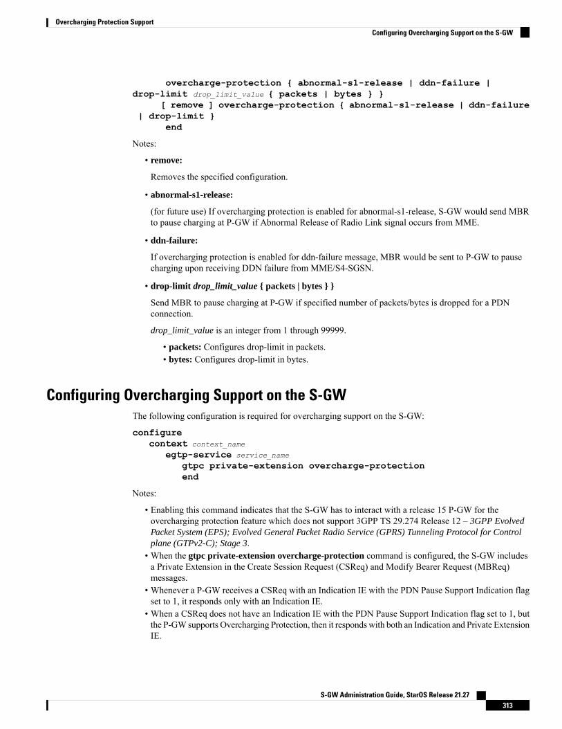
overcharge-protection { abnormal-s1-release | ddn-failure |drop-limit drop_limit_value { packets | bytes } }
[ remove ] overcharge-protection { abnormal-s1-release | ddn-failure| drop-limit }
end
Notes:
• remove:
Removes the specified configuration.
• abnormal-s1-release:
(for future use) If overcharging protection is enabled for abnormal-s1-release, S-GW would send MBRto pause charging at P-GW if Abnormal Release of Radio Link signal occurs from MME.
• ddn-failure:
If overcharging protection is enabled for ddn-failure message, MBR would be sent to P-GW to pausecharging upon receiving DDN failure from MME/S4-SGSN.
• drop-limit drop_limit_value { packets | bytes } }
Send MBR to pause charging at P-GW if specified number of packets/bytes is dropped for a PDNconnection.
drop_limit_value is an integer from 1 through 99999.
• packets: Configures drop-limit in packets.• bytes: Configures drop-limit in bytes.
Configuring Overcharging Support on the S-GWThe following configuration is required for overcharging support on the S-GW:
configurecontext context_name
egtp-service service_name
gtpc private-extension overcharge-protectionend
Notes:
• Enabling this command indicates that the S-GW has to interact with a release 15 P-GW for theovercharging protection feature which does not support 3GPP TS 29.274 Release 12 – 3GPP EvolvedPacket System (EPS); Evolved General Packet Radio Service (GPRS) Tunneling Protocol for Controlplane (GTPv2-C); Stage 3.
• When the gtpc private-extension overcharge-protection command is configured, the S-GW includesa Private Extension in the Create Session Request (CSReq) and Modify Bearer Request (MBReq)messages.
• Whenever a P-GW receives a CSReq with an Indication IE with the PDN Pause Support Indication flagset to 1, it responds only with an Indication IE.
• When a CSReq does not have an Indication IE with the PDN Pause Support Indication flag set to 1, butthe P-GW supports Overcharging Protection, then it responds with both an Indication and Private ExtensionIE.
S-GW Administration Guide, StarOS Release 21.27313
Overcharging Protection SupportConfiguring Overcharging Support on the S-GW

Monitoring and Troubleshooting
P-GW SchemaThe following bulk statistics have been added to the P-GW schema for Overcharging Protection:
For descriptions of these variables, see the Statistics and Counters Reference guide.
• sessstat-ovrchrgprtctn-uplkpktdrop• sessstat-ovrchrgprtctn-uplkbytedrop• sessstat-ovrchrgprtctn-dnlkpktdrop• sessstat-ovrchrgprtctn-dnlkbytedrop
show apn statistics allThe following counters display overcharging protection stats for this APN:
• UL Ovrchrg Prtctn byte drop• UL Ovrchrg Prtctn pkt drop• DL Ovrchrg Prtctn byte drop• DL Ovrchrg Prtctn pkt drop
show pgw-service allThe following field display configuration information for Overcharging Protection on this P-GW service:
• EGTP Overcharge Protection
show pgw-service statistics allThe following counters display Overcharging Protection for this P-GW node:
• Drops Due To Overcharge Protection
• Packets• Bytes
show sgw-service statistics name <sgw_service_name>The output of this command shows the total number of PDNs where charging was paused:
• PDNs Total:
• Paused Charging: <Total number of PDNs where charging was paused>
show subscribers fullThe following counters display Overcharging Protection for all subscribers:
S-GW Administration Guide, StarOS Release 21.27314
Overcharging Protection SupportMonitoring and Troubleshooting

• in packet dropped overcharge protection• in bytes dropped overcharge protection• out packet dropped overcharge protection• out bytes dropped overcharge protection
When a session is in overcharge protection state, not all the downlink packets will be dropped; however,downlink packets will be rate limited. Current configuration allows one downlink packet per minute towardsS-GW without charging it, if any downlink packets come to P-GW. P-GW will not generate any packets ofits own.; separate debug stats have been added for P-GW.
Important
show subscribers pgw-only full allThe following field and counters display Overcharging Protection:
• Bearer State
• in packet dropped overcharge protection• in bytes dropped overcharge protection• out packet dropped overcharge protection• out bytes dropped overcharge protection
show subscribers summaryThe following counters display overcharging protection for all subscribers:
• in bytes dropped ovrchrgPtn• in packet dropped ovrchrgPtn• out bytes dropped ovrchrgPtn• out packet dropped ovrchrgPtn
When a session is in overcharge protection state, not all the downlink packets will be dropped; however,downlink packets will be rate limited. Current configuration allows one downlink packet per minute towardsS-GW without charging it, if any downlink packets come to P-GW. P-GW will not generate any packets ofits own; separate debug stats have been added for P-GW.
Important
S-GW Administration Guide, StarOS Release 21.27315
Overcharging Protection Supportshow subscribers pgw-only full all

S-GW Administration Guide, StarOS Release 21.27316
Overcharging Protection Supportshow subscribers summary

C H A P T E R 22Paging Policy Differentiation
This chapter describes the Paging Policy Differentiation feature and explains how it is configured. The productadministration guides provide examples and procedures for configuration of basic services on the system. Itis recommended that you select the configuration example that best meets your service model and configurethe required elements for that model, as described in the P-GW Administration Guide, the S-GW AdministrationGuide, or the SAEGW Administration Guide before using the procedures in this chapter.
This chapter includes the following sections:
• Feature Description, on page 317• How It Works, on page 318• Configuring Paging Policy Differentiation Feature, on page 319• Monitoring and Troubleshooting Paging Policy Differentiation, on page 320
Feature DescriptionS-GW/P-GW provide configuration control to change the DSCP value of the user-datagram packet and outerIP packet (GTP-U tunnel IP header). DSCP marking is done at various levels depending on the configuration.When the Paging Policy Differentiation (PPD) feature is enabled, however, the user-datagram packet DSCP(tunneled IP packet) marking does not change.
Currently, standards specify QCI to DSCP marking of outer GTP-U header only. All configurations presentat ECS, P-GW, and S-GW to change the user-datagram packet DSCP value are non-standard. Thestandards-based PPD feature dictates that P-CSCF or similar Gi entity marks the DSCP of user-datagrampacket. This user-datagram packet DSCP value is sent in DDN message by S-GW to MME/S4-SGSN.MME/S4-SGSN uses this DSCP value to give paging priority.
P-GW and S-GW should apply the PPD feature for both Default and Dedicated bearers. As per thespecifications, P-GW transparently passes the user-datagram packet towards S-GW. This means, if PPDfeature is enabled, operator can't apply different behavior for Default and Dedicated bearers.
Important
RelationshipsSince P-GW/S-GW support non-standard based DSCP marking, there is a conflict when both standard basedPPD feature and non-standard based user-datagram packet DSCP configuration is enabled. To avoid thisconflict:
S-GW Administration Guide, StarOS Release 21.27317

• APN and service level configuration is ignored if PPD feature is enabled.
• S-GW/P-GW can alter the outer GTP-U header DSCP value, even if PPD feature is enabled.
• User-datagram packet DSCP value is unaltered by ECS, P-GW, and S-GW if PPD feature is enabled.
• At P-GW, APN-level configuration is added to enable/disable the PPD feature.
• At S-GW, service-level configuration is added to enable/disable the PPD feature. This is to send DSCPin Paging and Service Information IE of all the DDN messages triggered by either IMS-PDN orInternet-PDN, etc.
It is up toMME/S4-SGSN to use the Paging and Service InformationIE of DDN message.
Important
• Separate Paging feature and PPD feature co-exist in system. That means, if both features are enabled,both Paging and Service Information IE and Separate-paging IE are sent in DDN.
• Currently on P-GW, the DSCP configuration is getting applied at sub-session level during call setuptime. So, when the PPD CLI is enabled for P-GW, it is applicable for new calls.
• Currently on S-GW, the DSCP configuration is getting applied at S-GW service level. So, when PPDCLI is enabled in S-GW service, it is applicable for both new and existing calls.
• Once the PPD CLI is enabled, it exists even after Session Recovery and ICSR switch over.
• The Paging and Service Information IE is used to carry per bearer paging and service information.
LicensePPD is a license enabled feature. S-GW Paging Profile license key is required to enable PPD functionalityfor P-GW, S-GW, and SAEGW.
Contact your Cisco account representative for information on how to obtain a license.Important
How It Works
ArchitectureS-GW
When S-GW supports the PPD feature, it shall include new Paging and Service Information IE in the DownlinkData Notification message triggered by the arrival of downlink data packets at the S-GW. The Paging PolicyIndication value within this IE will contain the value of the DSCP in TOS (IPv4) or TC (IPv6) informationreceived in the IP payload of the GTP-U packet from the P-GW.
At S-GW, service-level configuration enables/disables the PPD feature. Once the PPD is configured, thefeature is enabled and applicable for both existing and new calls.
S-GW Administration Guide, StarOS Release 21.27318
Paging Policy DifferentiationLicense

P-GW
User-datagram packet DSCP value is unaltered by P-GW for downlink data. The PPD feature is supportedonly for S5/S8 interface. For all Handoff scenarios from other interface to S5/S8 interface, the PPD featurewill get enabled if APN had it during its call setup time at that interface.
At P-GW, APN-level configuration enables/disables the PPD feature. If PPD feature is enabled for the calland handoff happens from S5/S8 interface to any other interface, PPD feature should get disabled. Now, ifhandoff happens and this call will come back to S5/S8 interface, PPD feature should become enabled.
SAEGW
To support PPD feature in SAEGW, both S-GW and P-GW configuration is required.
Relationships to Other Features• The PPD feature is license controlled under the license for S-GW Paging Profile. Once the license isenabled, both features co-exist together and work independently. That means, DDNmessage might carryboth DSCPmarking specified by PPD feature and Priority DDN value specified by S-GWPaging Profilefeature.
• At S-GW, the user-datagram packet DSCP value is used to send in DDN. S-GW can't change the DSCP,as per the local configuration (APN profile or service level). At eNodeB, the scheduling of the packet isbased on the QCI instead of DSCP, however, any EPC node should not change/modify the inner DSCPvalue.
• If the PPD feature is enabled, none of the EPS nodes should change the user-datagram packet DSCPvalue. Therefore, ECS should avoid overwriting DSCP value of user-datagram packet when PPD isenabled.
Standards ComplianceThe PPD functionality complies with the following standards:
• 29.274, CR-1565, "Paging Policy Indication in Downlink Data Notification Message"
• 23.401, CR-2731 "Paging policy differentiation for IMS voice"
Configuring Paging Policy Differentiation FeatureFor the PPD feature to work, it must be enabled for P-GW and S-GW.
Both P-GW and S-GW services apply PPD configuration independently. Therefore, for any downlink datapacket from an APN, there could be a case where P-GW does not have PPD configuration but S-GW has PPDconfiguration. To avoid such a conflict, you must configure the PPD functionality on both P-GW (APN levelgranularity) and S-GW (service level granularity).
ConfigurationThe following CLI commands are used to manage the functionality for the PPD feature.
S-GW Administration Guide, StarOS Release 21.27319
Paging Policy DifferentiationRelationships to Other Features
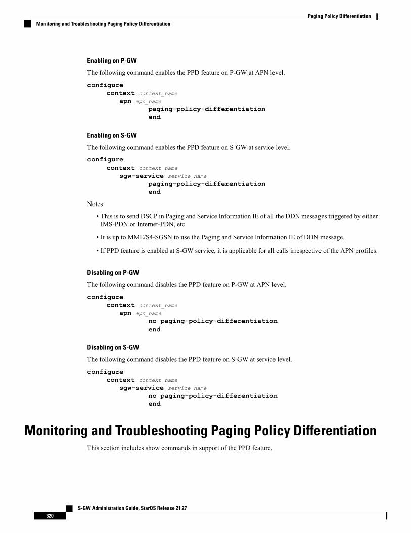
Enabling on P-GW
The following command enables the PPD feature on P-GW at APN level.
configurecontext context_name
apn apn_name
paging-policy-differentiationend
Enabling on S-GW
The following command enables the PPD feature on S-GW at service level.
configurecontext context_name
sgw-service service_name
paging-policy-differentiationend
Notes:
• This is to send DSCP in Paging and Service Information IE of all the DDN messages triggered by eitherIMS-PDN or Internet-PDN, etc.
• It is up to MME/S4-SGSN to use the Paging and Service Information IE of DDN message.
• If PPD feature is enabled at S-GW service, it is applicable for all calls irrespective of the APN profiles.
Disabling on P-GW
The following command disables the PPD feature on P-GW at APN level.
configurecontext context_name
apn apn_name
no paging-policy-differentiationend
Disabling on S-GW
The following command disables the PPD feature on S-GW at service level.
configurecontext context_name
sgw-service service_name
no paging-policy-differentiationend
Monitoring and Troubleshooting Paging Policy DifferentiationThis section includes show commands in support of the PPD feature.
S-GW Administration Guide, StarOS Release 21.27320
Paging Policy DifferentiationMonitoring and Troubleshooting Paging Policy Differentiation

P-GW Show CommandsThis section provides information regarding P-GW show commands and/or their outputs in support of thePPD feature.
show apn name <apn_name>The following counter has been added to display PPD functionality.Paging Policy Differentiation : Enabled
show subscribers pgw-only full allThe following counter has been added to display PPD functionality.Paging Policy Differentiation : Enabled
SAEGW Show CommandsThis section provides information regarding SAEGW show commands and/or their outputs in support of thePPD feature.
show subscribers saegw-only full allThe following counter has been added to display PPD functionality.Paging Policy Differentiation : Enabled
S-GW Show CommandsThis section provides information regarding S-GW show commands and/or their outputs in support of thePPD feature.
show sgw-service name <service_name>The following counter has been added to display PPD functionality.Paging Policy Differentiation : Enabled
S-GW Administration Guide, StarOS Release 21.27321
Paging Policy DifferentiationP-GW Show Commands

S-GW Administration Guide, StarOS Release 21.27322
Paging Policy Differentiationshow sgw-service name <service_name>

C H A P T E R 23Presence Reporting Area
This chapter describes the following topics:
• Feature Summary and Revision History, on page 323• Feature Description, on page 324• How It Works, on page 324• Multiple Presence Reporting Area, on page 327• Configuring Presence Reporting Area, on page 328• Monitoring and Troubleshooting, on page 329
Feature Summary and Revision HistorySummary Data
• P-GW
• SAEGW
• S-GW
Applicable Product(s) or Functional Area
ASR 5500Applicable Platform(s)
Disabled - Configuration RequiredFeature Default
Not ApplicableRelated Changes in This Release
• Command Line Interface Reference
• P-GW Administration Guide
• SAEGW Administration Guide
• S-GW Administration Guide
Related Documentation
S-GW Administration Guide, StarOS Release 21.27323
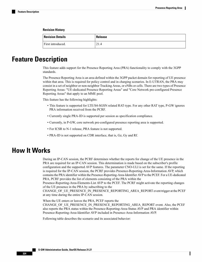
Revision History
ReleaseRevision Details
21.4First introduced.
Feature DescriptionThis feature adds support for the Presence Reporting Area (PRA) functionality to comply with the 3GPPstandards.
The Presence Reporting Area is an area defined within the 3GPP packet domain for reporting of UE presencewithin that area. This is required for policy control and in charging scenarios. In E-UTRAN, the PRA mayconsist in a set of neighbor or non-neighbor Tracking Areas, or eNBs or cells. There are two types of PresenceReporting Areas: "UE-dedicated Presence Reporting Areas" and "Core Network pre-configured PresenceReporting Areas" that apply to an MME pool.
This feature has the following highlights:
• This feature is supported for LTE/S4-SGSN related RAT-type. For any other RAT type, P-GW ignoresPRA information received from the PCRF.
• Currently single PRA-ID is supported per session as specification compliance.
• Currently, in P-GW, core network pre-configured presence reporting area is supported.
• For ICSR to N-1 release, PRA feature is not supported.
• PRA-ID is not supported on CDR interface, that is, Gz, Gy and Rf.
How It WorksDuring an IP-CAN session, the PCRF determines whether the reports for change of the UE presence in thePRA are required for an IP-CAN session. This determination is made based on the subscriber's profileconfiguration and the supported AVP features. The parameter CNO-ULI is set for the same. If the reportingis required for the IP-CAN session, the PCRF provides Presence-Reporting-Area-Information AVP, whichcontains the PRA identifier within the Presence-Reporting-Area-Identifier AVP to the PCEF. For a UE-dedicatedPRA, PCRF provides the list of elements consisting of the PRA within thePresence-Reporting-Area-Elements-List AVP to the PCEF. The PCRF might activate the reporting changesof the UE presence in the PRA by subscribing to theCHANGE_OF_UE_PRESENCE_IN_PRESENCE_REPORTING_AREA_REPORT event trigger at the PCEFat any time during the entire IP-CAN session.
When the UE enters or leaves the PRA, PCEF reports theCHANGE_OF_UE_PRESENCE_IN_PRESENCE_REPORTING_AREA_REPORT event. Also, the PCEFalso reports the PRA status within the Presence-Reporting-Area-Status AVP and PRA identifier withinPresence-Reporting-Area-Identifier AVP included in Presence-Area-Information AVP.
Following table describes the scenario and its associated behavior:
S-GW Administration Guide, StarOS Release 21.27324
Presence Reporting AreaFeature Description

BehaviorScenario
• P-GW receives the new PRA ID during the initial call setup andstores the PRA ID information.
• In RAR, the PRA_EVENT_TRIGGER is registered.
• P-GW send PRA_ACTION PRA ID="A", ACTION=start.
• In CCA-U, a new PRA ID is received.
• P-GW stores new PRA ID information
• P-GW sends PRA_ACTION PRA ID = "B", Action=start butdoes not send Action=stop for the earlier PRA.
Ideally, in above condition, PCRF disables the eventtriggers first and sends a new PRA-ID=B and enables theevent trigger in subsequent message.
Important
When PCRF sends a new PRA IDdifferent than the initial call setup.
PRA ID does not send any PRA Action toward S-GW and P-GWignores this.
When PCRF sends a new PRA IDwhich is same as the initial call setup.
If PRA ID received is "core network pre-configured presence reportingarea", then, P-GW ignores the "Element List" coming from PCRF.Otherwise, if PRA ID is "UE-dedicated Presence Reporting Area",then, P-GW parses the "Element List" and forwards it toward theaccess side.
PRA ID Decode Behavior
MSB of the value received from the PCRF is evaluated to find thePRA type. While encoding, GTPC side zeros are prepended to makeit 3 octets.
For example, if PRA ID = FC (1111 1100) is received from PCRF itis considered as UE-dedicated PRA and while decoding it is decodedas 00 00 FC.
P-GW forwards PRA information toward the roaming subscriber if itis received from the PCRF or from UE.
Change of UE presence in the Presence Reporting Areareporting does not apply to the roaming scenario.
Important
If PRA ID values from PCRF are 1octet, 2 octets, and 3 octets.
Change of UE presence in the Presence Reporting Area reporting doesnot apply to the roaming scenario.
When the serving EPC node (MME, S4-SGSN) is changed, thePresence Reporting Area identifier is transferred for all PDNconnections as part of the MM Context information to the targetserving node during the mobility procedure. The list of PresenceReporting Area elements are also transferred if they are provided bythe P-GW.
Roaming Scenario
S-GW Administration Guide, StarOS Release 21.27325
Presence Reporting AreaHow It Works

BehaviorScenario
MME/S4-SGSN gets the PRA Identifier from sourceMME/S4-SGSNas part of MM Context information.
When the serving EPC node (MME, S4-SGSN) is changed, thePresence Reporting Area identifier is transferred for all PDNconnections as part of the MM Context information to the targetserving node during the mobility procedure. The list of PresenceReporting Area elements are also transferred if they are provided bythe P-GW.
Handover Behavior: How the PRAidentifier is communicated fromsource MME/S4-SGSN to targetMME/S4-SGSN.
Depending on the access type and internal configuration PCRFdeactivates the PRA, if the new access PRA is not supported.
During an IP-CAN session, P-GW notifies the PCRF that the UE islocated in an access type, where local PCRF configuration is such thatthe reporting changes of the UE presence in the PRA are not supported.The PCRF unsubscribes to the change of UE presence in the PRA, ifpreviously activated.
Handoff Behavior: How PRA isdisabled when the new access type isnot supported PRA.
If PRA is enabled from PCRF, then EPC nodes supports it. If all nodesare not supported, then PRA PCRF activates the Location ChangeReporting.
For E-UTRAN access, homogeneous support of reportingchanges of UE presence in a Presence Reporting Area in anetwork is assumed. When the PCRF configurationindicates that reporting changes of the UE presence in aPRA is supported for E-UTRAN, this means all P-GWs,all MME, and all S-GW support it, including theMME andS-GWworking in the network sharing mode. If the changeof UE presence in the PRA reporting is not supported, thePCRF may instead activate the location change reportingat the cell or serving area level.
Important
Behavior if for E-UTRAN somenodes do not support PRA.
In Update or Create bearer procedure failure where the PRA actionwas sent in the request message and if PRA information was notreceived in response message, P-GW attempts to send the PRA actionin next control procedure toward the remote peer.
In Update or Create bearer procedure failure where PRA action wassent in the request message and if PRA information was not receivedin the response message, P-GW assumes it as PRA action wassuccessfully communicated toward the remote peer.
In the Update or Create bearer collision scenario where PRA actionwas sent in the request message and Update or Create procedure gotaborted, P-GW attempts to send the PRA action in next controlprocedure toward the remote peer.
When access side procedure failureor collision occurs (Create or UpdateBearer procedure)
S-GW Administration Guide, StarOS Release 21.27326
Presence Reporting AreaHow It Works

Multiple Presence Reporting Area
This feature is introduced in release 21.9.1.Important
P-GW supports negotiation ofMultiple-Presence Reporting Area feature in Feature-List-ID 2 over Gx interfacewith PCRF. The CNO-ULI feature will be used only when the P-GW and/or the PCRF does not supportMultiple-PRA and both P-GW and PCRF support CNO-ULI.
When the Multiple-PRA feature is supported during the lifetime of the IP-CAN session P-GW handles thechange of UE Presence in Reporting Area(s) request from PCRF in PRA-Install AVP including thePresence-Reporting-Area-Information AVP(s) which each contains the Presence Reporting Area Identifierwithin the Presence-Reporting-Area-Identifier AVP.
P-GW Handling the Event Trigger
CHANGE_OF_UE_PRESENCE_IN_PRESENCE_REPORTING_AREA_REPORT from PCRF for theactivation of the reporting changes of UE presence in Presence Reporting Area(s).
P-GW handles the PRA Identifier(s) modify request from PCRF with the new PRA within the PRA-InstallAVP as described above and/or by removing the existing PRA(s) within the PRA-Remove AVP. In this case,the Presence-Reporting-Area-Identifier AVP of the removed PRA must be included within thePresence-Reporting-Area-Information AVP(s).
P-GW supports PRA-Install and PRA-Remove AVPs from PCRF in the following messages:
• CC-Answer (CCA) Command
• Re-Auth-Request (RAR) Command
The P-GWhandles the request from PCRF to unsubscribe to the change of UE presence in Presence ReportingArea wherein PCRF provides the Event-Trigger AVP with the valueCHANGE_OF_UE_PRESENCE_IN_PRESENCE_REPORTING_AREA_REPORT(48) removed, if previouslyactivated.
P-GW supports the maximum of 4 PRA(s) for a IP-CAN session at any given point of time. The maximumnumber of PRAs is configurable in PCRF and must be capped to 4. P-GWwill ignore the Presence ReportingArea Identifiers entries beyond 4.
When the P-GW receives the presence reporting area information from the serving node over S5/S8 interfaceindicating that the UE is inside or outside of one or more presence reporting areas or any of the presencereporting areas is set to inactive, the P-GW will check if the reported presence reported area identifiercorresponds to a presence reporting area that is relevant for the PCRF. In that case, the P-GW reports theCHANGE_OF_UE_PRESENCE_IN_PRESENCE_REPORTING_AREA_REPORTevent in theEvent-TriggerAVP additionally, the P-GW also reports the presence reporting area status within thePresence-Reporting-Area-Status AVP and presence reporting area identifier withinPresence-Reporting-Area-Identifier AVP included in Presence-Reporting-Area-Information AVP(s) for eachof the presence reporting areas reported by the serving node.
The P-GW de-activates the relevant IP-CAN specific procedure for reporting change of UE presence inPresence Reporting Area, when the PCRF and OCS unsubscribe to change of UE presence in PresenceReporting Area.
PRA-Install AVP (3GPP-EPS access type) Definition
S-GW Administration Guide, StarOS Release 21.27327
Presence Reporting AreaMultiple Presence Reporting Area
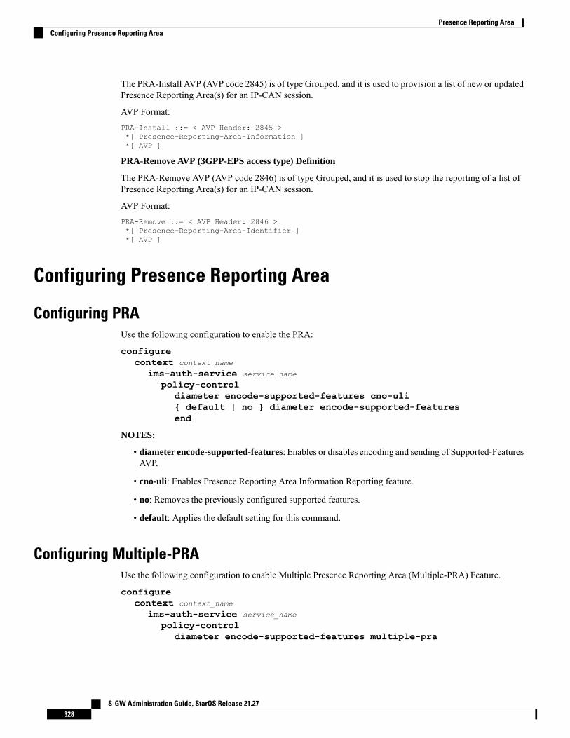
The PRA-Install AVP (AVP code 2845) is of type Grouped, and it is used to provision a list of new or updatedPresence Reporting Area(s) for an IP-CAN session.
AVP Format:PRA-Install ::= < AVP Header: 2845 >*[ Presence-Reporting-Area-Information ]*[ AVP ]
PRA-Remove AVP (3GPP-EPS access type) Definition
The PRA-Remove AVP (AVP code 2846) is of type Grouped, and it is used to stop the reporting of a list ofPresence Reporting Area(s) for an IP-CAN session.
AVP Format:PRA-Remove ::= < AVP Header: 2846 >*[ Presence-Reporting-Area-Identifier ]*[ AVP ]
Configuring Presence Reporting Area
Configuring PRAUse the following configuration to enable the PRA:
configurecontext context_name
ims-auth-service service_name
policy-controldiameter encode-supported-features cno-uli{ default | no } diameter encode-supported-featuresend
NOTES:
• diameter encode-supported-features: Enables or disables encoding and sending of Supported-FeaturesAVP.
• cno-uli: Enables Presence Reporting Area Information Reporting feature.
• no: Removes the previously configured supported features.
• default: Applies the default setting for this command.
Configuring Multiple-PRAUse the following configuration to enable Multiple Presence Reporting Area (Multiple-PRA) Feature.
configurecontext context_name
ims-auth-service service_name
policy-controldiameter encode-supported-features multiple-pra
S-GW Administration Guide, StarOS Release 21.27328
Presence Reporting AreaConfiguring Presence Reporting Area
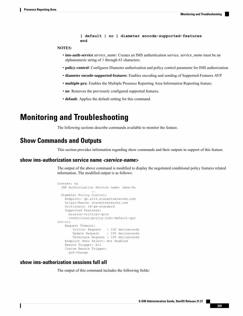
{ default | no } diameter encode-supported-featuresend
NOTES:
• ims-auth-service service_name: Creates an IMS authentication service. service_name must be analphanumeric string of 1 through 63 characters.
• policy-control: Configures Diameter authorization and policy control parameter for IMS authorization.
• diameter encode-supported-features: Enables encoding and sending of Supported-Features AVP.
• multiple-pra: Enables the Multiple Presence Reporting Area Information Reporting feature.
• no: Removes the previously configured supported features.
• default: Applies the default setting for this command.
Monitoring and TroubleshootingThe following sections describe commands available to monitor the feature.
Show Commands and OutputsThis section provides information regarding show commands and their outputs in support of this feature.
show ims-authorization service name <service-name>The output of the above command is modified to display the negotiated conditional policy features relatedinformation. The modified output is as follows:
Context: haIMS Authorization Service name: imsa-Gx
……Diameter Policy Control:Endpoint: gx.st16.starentnetworks.comOrigin-Realm: starentnetworks.comDictionary: r8-gx-standardSupported Features:mission-critical-qcisconditional-policy-info-default-qos
cno-uliRequest Timeout:
Initial Request : 100 decisecondsUpdate Request : 100 decisecondsTerminate Request : 100 deciseconds
Endpoint Peer Select: Not EnabledReauth Trigger: AllCustom Reauth Trigger:QoS-Change
show ims-authorization sessions full allThe output of this command includes the following fields:
S-GW Administration Guide, StarOS Release 21.27329
Presence Reporting AreaMonitoring and Troubleshooting
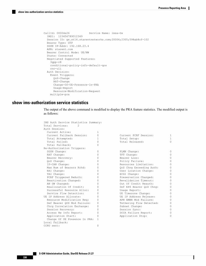
CallId: 00004e26 Service Name: imsa-GxIMSI: 123456789012349Session ID: gx.st16.starentnetworks.com;20006;2305;598ab8cf-102Bearer Type: GTPSGSN IP-Addr: 192.168.23.4APN: starent.comBearer Control Mode: UE/NWState: ConnectedNegotiated Supported Features:3gpp-r8conditional-policy-info-default-qoscno-uli
Auth Decision:Event Triggers:QoS-ChangeRAT-ChangeChange-Of-UE-Presence-In-PRAUsage-ReportResource-Modification-Request
multiple-pra
show ims-authorization service statisticsThe output of the above command is modified to display the PRA feature statistics. The modified output isas follows:
IMS Auth Service Statistics Summary:Total Services: 2Auth Session:Current Active: 1Current Fallback Session: 0 Current PCRF Session: 1Total Attempted: 1 Total Setup: 1Total Failed: 0 Total Released: 0Total Fallback: 0
Re-Authorization Triggers:SGSN Change: 0 PLMN Change: 0RAT Change: 0 TFT Change: 0Bearer Recovery: 0 Bearer Loss: 0QoS Change: 0 Policy Failure: 0IP-CAN Change: 0 Resources Limitation: 0Max Num of Bearers Rchd: 0 QoS Chng Exceeding Auth: 0RAI Change: 0 User Location Change: 0TAI Change: 0 ECGI Change: 0PCRF Triggered ReAuth: 0 Preservation Changed: 0Reactivation Changed: 0 Revalidation Timeout: 0AN GW Changed: 0 Out Of Credit Reauth: 0Reallocation Of Credit: 0 Def EPS Bearer QoS Chng: 0Successful Resource Alloc: 0 Usage Report: 0Service Flow Detection: 0 UE Timezone Change: 0
UE IP Address Allocate: 0 UE IP Address Release: 0Resource Modification Req: 0 APN AMBR Mod Failure: 0Def Bearer QOS Mod Failure: 0 Tethering Flow Detected: 0Chrg Correlation Exchange: 0 Subnet Change: 0Session Recovery: 0 Session Sync: 0Access Nw Info Report: 0 DCCA Failure Report: 0Application Start: 0 Application Stop: 0Change Of UE Presence In PRA: 1
Local Fallback:CCRU sent: 0
S-GW Administration Guide, StarOS Release 21.27330
Presence Reporting Areashow ims-authorization service statistics

show subscribers pgw-only full allThe output of this command includes the following fields:
Username : xyzSubscriber Type : VisitorStatus : Online/ActiveState : ConnectedConnect Time : Mon Aug 28 07:32:13 2017Auto Delete : NoIdle time : 00h00m06sMS TimeZone : n/a Daylight Saving Time: n/aAccess Type: gtp-pdn-type-ipv4 Network Type: IPAccess Tech: eUTRAN pgw-service-name: pgw1Callid: 00004e23 IMSI: 123456789012349MSISDN: 9326737733Interface Type: S5S8GTP Low Access Priority: N/ATWAN Mode: N/AeMPS Bearer: NoEmergency Bearer Type: N/AIMS-media Bearer: NoS6b Auth Status: EnabledAccess Peer Profile: defaultAcct-session-id (C1): C0A8170100000003ThreeGPP2-correlation-id (C2): 00500660 / 002shwI-Card/Cpu: 2/0 Sessmgr Instance: 1ULI:TAI-ID:MCC: 214 MNC: 365TAC: 0x6789ECGI-ID:MCC: 214 MNC: 365ECI: 0x1234567
PRA Information:PRA-ID: 0x801204 Action: Start Status: InPRA Information:PRA-ID: 0xA11202 Action: Start Status: N/A
show subs saegw-only full allThe output of the above command is modified to include the PRA Information such as PRA-ID, PRA Status,and PRA Action. The modified output is as follows:
Username : xyzSAEGW Call mode : Co-locatedSubscriber Type : VisitorStatus : Online/ActiveState : ConnectedBearer State : ActiveConnect Time : Mon Aug 28 08:21:45 2017
SAEGW UID : 10001Idle time : 00h00m19sAuto Delete : NoCallid : 4e25 IMSI : 241460144418770Card/Cpu : 2/0 Sessmgr Instance : 1Source context : ingress Destination context : egressBearer Type : Default Bearer-Id : 5Access Type : gtp-pdn-type-ipv4 Network Type : IPAccess Tech : eUTRAN saegw-service-name : saegwMSISDN : 9326737733
S-GW Administration Guide, StarOS Release 21.27331
Presence Reporting Areashow subscribers pgw-only full all
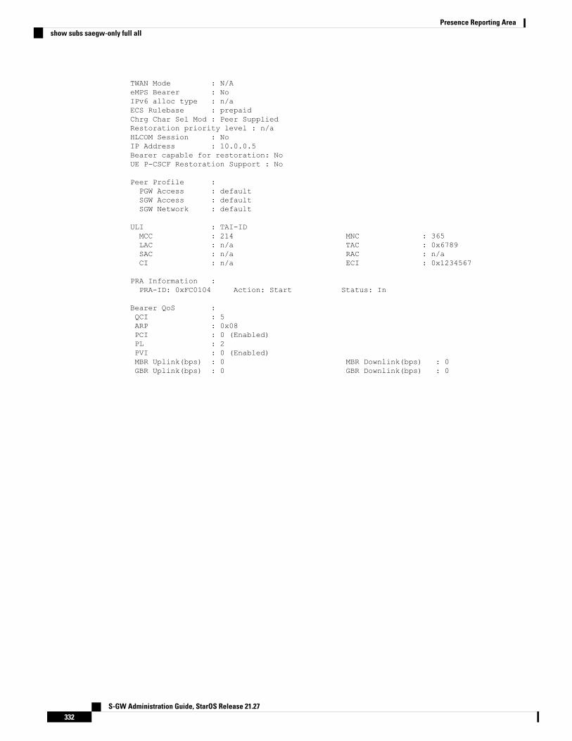
TWAN Mode : N/AeMPS Bearer : NoIPv6 alloc type : n/aECS Rulebase : prepaidChrg Char Sel Mod : Peer SuppliedRestoration priority level : n/aHLCOM Session : NoIP Address : 10.0.0.5Bearer capable for restoration: NoUE P-CSCF Restoration Support : No
Peer Profile :PGW Access : defaultSGW Access : defaultSGW Network : default
ULI : TAI-IDMCC : 214 MNC : 365LAC : n/a TAC : 0x6789SAC : n/a RAC : n/aCI : n/a ECI : 0x1234567
PRA Information :PRA-ID: 0xFC0104 Action: Start Status: In
Bearer QoS :QCI : 5ARP : 0x08PCI : 0 (Enabled)PL : 2PVI : 0 (Enabled)MBR Uplink(bps) : 0 MBR Downlink(bps) : 0GBR Uplink(bps) : 0 GBR Downlink(bps) : 0
S-GW Administration Guide, StarOS Release 21.27332
Presence Reporting Areashow subs saegw-only full all

C H A P T E R 24Revised Marking for Subscriber Traffic
• Feature Summary and Revision History, on page 333• Feature Description, on page 334• How It Works, on page 334• Configuring Revised Marking for Subscriber Traffic, on page 335• Configuring 802.1p and MPLS EXP Marking for User Data Traffic, on page 336• Monitoring and Troubleshooting Revised Marking for Subscriber Traffic, on page 339
Feature Summary and Revision HistorySummary Data
P-GWApplicable Product(s) or FunctionalArea
• ASR 5500
• VPC-DI
• VPC-SI
Applicable Platform(s)
• Disabled - Configuration RequiredFeature Default
Not applicableRelated Changes in This Release
• Command Line Interface Reference
• P-GW Administration Guide
Related Documentation
Revision History
ReleaseRevision Details
21.20.2P-GW supports configuration of 802.1p andMPLS Experimental (EXP) bits markingfor user data traffic. This feature is fully qualified in this release.
S-GW Administration Guide, StarOS Release 21.27333
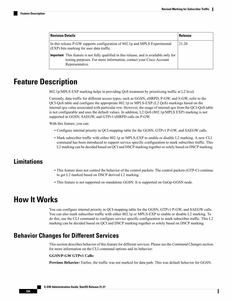
ReleaseRevision Details
21.20In this release P-GW supports configuration of 802.1p and MPLS Experimental(EXP) bits marking for user data traffic.
This feature is not fully qualified in this release, and is available only fortesting purposes. For more information, contact your Cisco AccountRepresentative.
Important
Feature Description802.1p/MPLS EXP marking helps in providing QoS treatment by prioritizing traffic at L2 level.
Currently, data traffic for different access types, such as GGSN, eHRPD, P-GW, and S-GW, refer to theQCI-QoS table and configure the appropriate 802.1p or MPLS-EXP (L2 QoS) markings based on theinternal-qos value associated with particular row. However, the usage of internal-qos from the QCI-QoS tableis not configurable and uses the default values. In addition, L2 QoS (802.1p/MPLS EXP) marking is notsupported in GGSN, SAEGW, and GTPv1/eHRPD calls on P-GW.
With this feature, you can:
• Configure internal priority in QCI-mapping table for the GGSN, GTPv1 P-GW, and SAEGW calls.
• Mark subscriber traffic with either 802.1p or MPLS-EXP to enable or disable L2 marking. A new CLIcommand has been introduced to support service specific configuration to mark subscriber traffic. ThisL2marking can be decided based on QCI and DSCPmarking together or solely based on DSCPmarking.
Limitations• This feature does not control the behavior of the control packets. The control packets (GTP-C) continueto get L2 marked based on DSCP derived L2 marking.
• This feature is not supported on standalone GGSN. It is supported on GnGp-GGSN node.
How It WorksYou can configure internal priority in QCI-mapping table for the GGSN, GTPv1 P-GW, and SAEGW calls.You can also mark subscriber traffic with either 802.1p or MPLS-EXP to enable or disable L2 marking. Todo this, use the CLI command to configure service specific configuration to mark subscriber traffic. This L2marking can be decided based on QCI and DSCP marking together or solely based on DSCP marking.
Behavior Changes for Different ServicesThis section describes behavior of this feature for different services. Please see theCommand Changes sectionfor more information on the CLI command options and its behavior:
GGSN/P-GW GTPv1 Calls:
Previous Behavior: Earlier, the traffic was not marked for data path. This was default behavior for GGSN.
S-GW Administration Guide, StarOS Release 21.27334
Revised Marking for Subscriber TrafficFeature Description
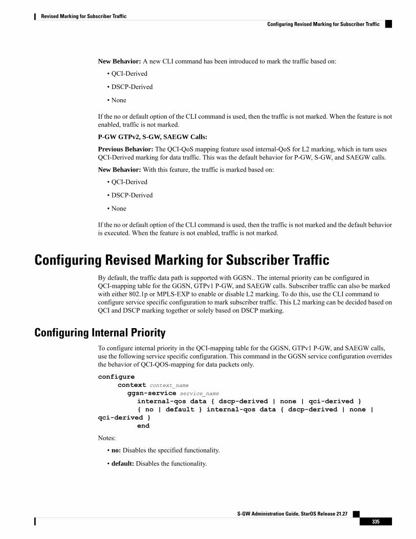
New Behavior: A new CLI command has been introduced to mark the traffic based on:
• QCI-Derived
• DSCP-Derived
• None
If the no or default option of the CLI command is used, then the traffic is not marked. When the feature is notenabled, traffic is not marked.
P-GW GTPv2, S-GW, SAEGW Calls:
Previous Behavior: The QCI-QoS mapping feature used internal-QoS for L2 marking, which in turn usesQCI-Derived marking for data traffic. This was the default behavior for P-GW, S-GW, and SAEGW calls.
New Behavior: With this feature, the traffic is marked based on:
• QCI-Derived
• DSCP-Derived
• None
If the no or default option of the CLI command is used, then the traffic is not marked and the default behavioris executed. When the feature is not enabled, traffic is not marked.
Configuring Revised Marking for Subscriber TrafficBy default, the traffic data path is supported with GGSN.. The internal priority can be configured inQCI-mapping table for the GGSN, GTPv1 P-GW, and SAEGW calls. Subscriber traffic can also be markedwith either 802.1p or MPLS-EXP to enable or disable L2 marking. To do this, use the CLI command toconfigure service specific configuration to mark subscriber traffic. This L2 marking can be decided based onQCI and DSCP marking together or solely based on DSCP marking.
Configuring Internal PriorityTo configure internal priority in the QCI-mapping table for the GGSN, GTPv1 P-GW, and SAEGW calls,use the following service specific configuration. This command in the GGSN service configuration overridesthe behavior of QCI-QOS-mapping for data packets only.
configurecontext context_name
ggsn-service service_name
internal-qos data { dscp-derived | none | qci-derived }{ no | default } internal-qos data { dscp-derived | none |
qci-derived }end
Notes:
• no: Disables the specified functionality.
• default: Disables the functionality.
S-GW Administration Guide, StarOS Release 21.27335
Revised Marking for Subscriber TrafficConfiguring Revised Marking for Subscriber Traffic
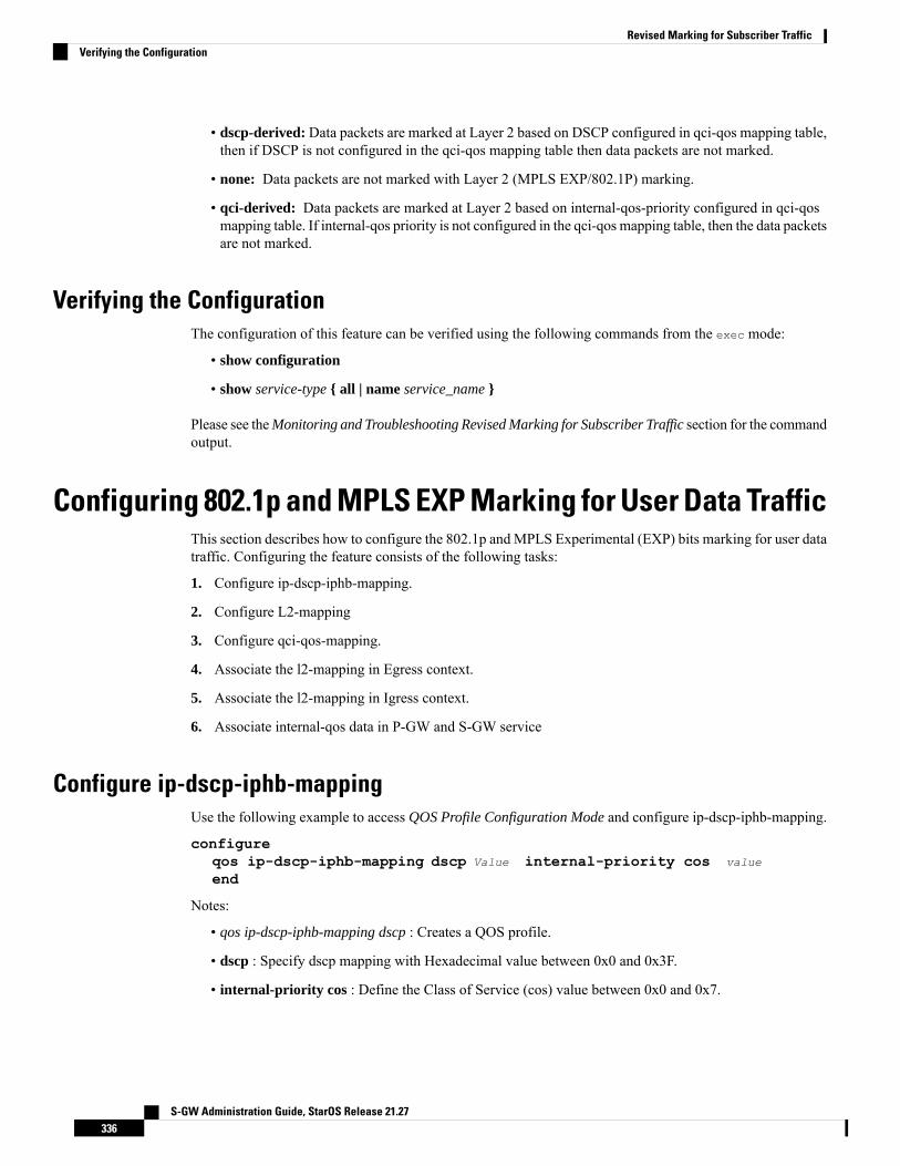
• dscp-derived: Data packets are marked at Layer 2 based on DSCP configured in qci-qos mapping table,then if DSCP is not configured in the qci-qos mapping table then data packets are not marked.
• none: Data packets are not marked with Layer 2 (MPLS EXP/802.1P) marking.
• qci-derived: Data packets are marked at Layer 2 based on internal-qos-priority configured in qci-qosmapping table. If internal-qos priority is not configured in the qci-qos mapping table, then the data packetsare not marked.
Verifying the ConfigurationThe configuration of this feature can be verified using the following commands from the exec mode:
• show configuration
• show service-type { all | name service_name }
Please see theMonitoring and Troubleshooting Revised Marking for Subscriber Traffic section for the commandoutput.
Configuring 802.1p and MPLS EXP Marking for User Data TrafficThis section describes how to configure the 802.1p and MPLS Experimental (EXP) bits marking for user datatraffic. Configuring the feature consists of the following tasks:
1. Configure ip-dscp-iphb-mapping.
2. Configure L2-mapping
3. Configure qci-qos-mapping.
4. Associate the l2-mapping in Egress context.
5. Associate the l2-mapping in Igress context.
6. Associate internal-qos data in P-GW and S-GW service
Configure ip-dscp-iphb-mappingUse the following example to access QOS Profile Configuration Mode and configure ip-dscp-iphb-mapping.
configureqos ip-dscp-iphb-mapping dscp Value internal-priority cos value
end
Notes:
• qos ip-dscp-iphb-mapping dscp : Creates a QOS profile.
• dscp : Specify dscp mapping with Hexadecimal value between 0x0 and 0x3F.
• internal-priority cos : Define the Class of Service (cos) value between 0x0 and 0x7.
S-GW Administration Guide, StarOS Release 21.27336
Revised Marking for Subscriber TrafficVerifying the Configuration
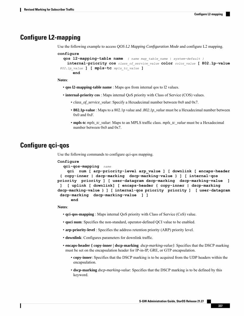
Configure L2-mappingUse the following example to access QOS L2 Mapping Configuration Mode and configure L2 mapping.
configureqos l2-mapping-table name { name map_table_name | system-default }
internal-priority cos class_of_service_value color color_value [ 802.1p-value802.1p_value ] [ mpls-tc mpls_tc_value ]
end
Notes:
• qos l2-mapping-table name : Maps qos from internal qos to l2 values.
• internal-priority cos : Maps internal QoS priority with Class of Service (COS) values.
• class_of_service_value: Specify a Hexadecimal number between 0x0 and 0x7.
• 802.1p-value : Maps to a 802.1p value and .802.1p_value must be a Hexadecimal number between0x0 and 0xF.
• mpls-tc mpls_tc_value: Maps to an MPLS traffic class. mpls_tc_value must be a Hexadecimalnumber between 0x0 and 0x7.
Configure qci-qosUse the following commands to configure qci-qos mapping.
Configureqci-qos-mapping name
qci num [ arp-priority-level arp_value ] [ downlink [ encaps-header{ copy-inner | dscp-marking dscp-marking-value } ] [ internal-qospriority priority ] [ user-datagram dscp-marking dscp-marking-value ]] [ uplink [ downlink] [ encaps-header { copy-inner | dscp-markingdscp-marking-value } ] [ internal-qos priority priority ] [ user-datagramdscp-marking dscp-marking-value ] ]
end
Notes:
• qci-qos-mapping : Maps internal QoS priority with Class of Service (CoS) value.
• quci num: Specifies the non-standard, operator-defined QCI value to be enabled.
• arp-priority-level : Specifies the address retention priority (ARP) priority level.
• downlink: Configures parameters for downlink traffic.
• encaps-header { copy-inner | dscp-marking dscp-marking-value}: Specifies that the DSCP markingmust be set on the encapsulation header for IP-in-IP, GRE, or GTP encapsulation.
• copy-inner: Specifies that the DSCP marking is to be acquired from the UDP headers within theencapsulation.
• dscp-marking dscp-marking-value: Specifies that the DSCP marking is to be defined by thiskeyword.
S-GW Administration Guide, StarOS Release 21.27337
Revised Marking for Subscriber TrafficConfigure L2-mapping
dscp-marking-value is expressed as a hexadecimal number from 0x00 through 0x3F.
• uplink: Configures parameters for uplink traffic.
• internal-qos priority priority : Sets the internal QoS. These get resolved in L2 values.
• user-datagram dscp-marking dscp-marking-value: Specifies that the IP DSCPmarking is to be definedby this keyword.dscp-marking-value is expressed as a hexadecimal number from 0x00 through 0x3F.
Associate L2-mapping tableUse the following commands to associate L2 mapping table in egress context and ingress context.
configurecontextegress context_name | ingress context_name
associate l2-mapping-table { name table_name
exitcontext ingress context_name
associate l2-mapping-table { name table_name
end
• associate l2-mapping-table: Maps qos from internal qos to l2 values.
• { name table_name : Specifies the name of table to map qos from internal qos to l2 values. table_namemust be a alphanumeric string of size 1 to 80.
Associate internal-qos-data in a P-GW and S-GW ServiceUse the following commands to associate internal-qos-data in a P-GW and S-GW service.
configurecontext context_name
pgw-service service_name
internal-qos data { qci-derived | dscp-derived | none }{ no | default } internal-qos data { dscp-derived | none |
qci-derived }exit
sgw-service service_name
internal-qos data { qci-derived | dscp-derived | none }{ no | default } internal-qos data { dscp-derived | none |
qci-derived }end
Notes:
• no: : Disables the specified functionality.
• default : Disables the functionality.
• dscp-derived: Data packets are marked at Layer 2 based on DSCP configured in qci-qos mapping table,then if DSCP is not configured in the qci-qos mapping table then data packets are not marked.
• none: Data packets are not marked with Layer 2 (MPLS EXP/802.1P) marking.
S-GW Administration Guide, StarOS Release 21.27338
Revised Marking for Subscriber TrafficAssociate L2-mapping table
• qci-derived: Data packets are marked at Layer 2 based on internal-qos-priority configured in qci-qosmapping table. If internal-qos priority is not configured in the qci-qos mapping table, then the data packetsare not marked.
MonitoringandTroubleshootingRevisedMarkingforSubscriberTraffic
The following section describes commands available to monitor Revised Marking for Subscriber Traffic.
Internal Priority Show CommandsThe following section describes commands available to monitor Internal Priority.
show configurationThis command displays the following output:
• When internal-qos data is configured as none:internal-qos data none
• When internal-qos data is configured as qci-derived:internal-qos data qci-derived
• When internal-qos data is configured as dscp-derived:internal-qos data dscp-ds-derived
• When internal-qos data is not configured:no internal-qos data
show service-type { all | name service_name }This command displays the following output:
• When internal-qos data is configured as none:
Internal QOS Application: EnabledInternal QoS Policy: None
• When internal-qos data is configured as qci-derived:
Internal QOS Application: EnabledInternal QOS Policy: QCI Derived
• When internal-qos data is configured as dscp-derived:
Internal QOS Application: EnabledInternal QOS Policy: DSCP Derived
• When internal-qos data is not configured:
S-GW Administration Guide, StarOS Release 21.27339
Revised Marking for Subscriber TrafficMonitoring and Troubleshooting Revised Marking for Subscriber Traffic

Internal QOS Application: Backward-compatible
S-GW Administration Guide, StarOS Release 21.27340
Revised Marking for Subscriber Trafficshow service-type { all | name service_name }

C H A P T E R 25Rf Interface Support
This chapter provides an overview of the Diameter Rf interface and describes how to configure the Rf interface.
Rf interface support is available on the Cisco system for the following products:
• Gateway GPRS Support Node (GGSN)• Proxy Call Session Control Function (P-CSCF)• Packet Data Network Gateway (P-GW)• Serving Call Session Control Function (S-CSCF)
The Rf interface is not supported on the S-GW.Important
It is recommended that before using the procedures in this chapter you select the configuration example thatbest meets your service model, and configure the required elements for that model as described in theadministration guide for the product that you are deploying.
This chapter includes the following topics:
• Introduction, on page 341• Feature Summary and Revision History, on page 344• Features and Terminology, on page 345• How it Works, on page 358• Configuring Rf Interface Support, on page 360
IntroductionThe Rf interface is the offline charging interface between the Charging Trigger Function (CTF) (for example,P-GW, P-CSCF) and the Charging Collection Function (CCF). The Rf interface specification forLTE/GPRS/eHRPD offline charging is based on 3GPP TS 32.299 V8.6.0, 3GPP TS 32.251 V8.5.0 and other3GPP specifications. The Rf interface specification for IP Multimedia Subsystem (IMS) offline charging isbased on 3GPP TS 32.260 V8.12.0 and 3GPP TS 32.299 V8.13.0.
Offline charging is used for network services that are paid for periodically. For example, a user may have asubscription for voice calls that is paid monthly. The Rf protocol allows the CTF (Diameter client) to issueoffline charging events to a Charging Data Function (CDF) (Diameter server). The charging events can eitherbe one-time events or may be session-based.
S-GW Administration Guide, StarOS Release 21.27341

The system provides a Diameter Offline Charging Application that can be used by deployed applications togenerate charging events based on the Rf protocol. The offline charging application uses the base Diameterprotocol implementation, and allows any application deployed on chassis to act as CTF to a configured CDF.
In general, accounting information from core network elements is required to be gathered so that the billingsystem can generate a consolidated record for each rendered service.
The CCF with the CDF and Charging Gateway Function (CGF) will be implemented as part of the corenetwork application. The CDF function collects and aggregates Rf messages from the various CTFs andcreates CDRs. The CGF collects CDRs from the CDFs and generates charging data record files for the datamediation/billing system for billing.
Offline Charging ArchitectureThe following diagram provides the high level charging architecture as specified in 3GPP 32.240. The interfacebetween CSCF, P-GW and GGSN with CCF is Rf interface. Rf interface for EPC domain is as per 3GPPstandards applicable to the PS Domain (e.g. 32.240, 32.251, 32.299, etc.).
Figure 48: Charging Architecture
The following figure shows the Rf interface between CTF and CDF.
S-GW Administration Guide, StarOS Release 21.27342
Rf Interface SupportOffline Charging Architecture
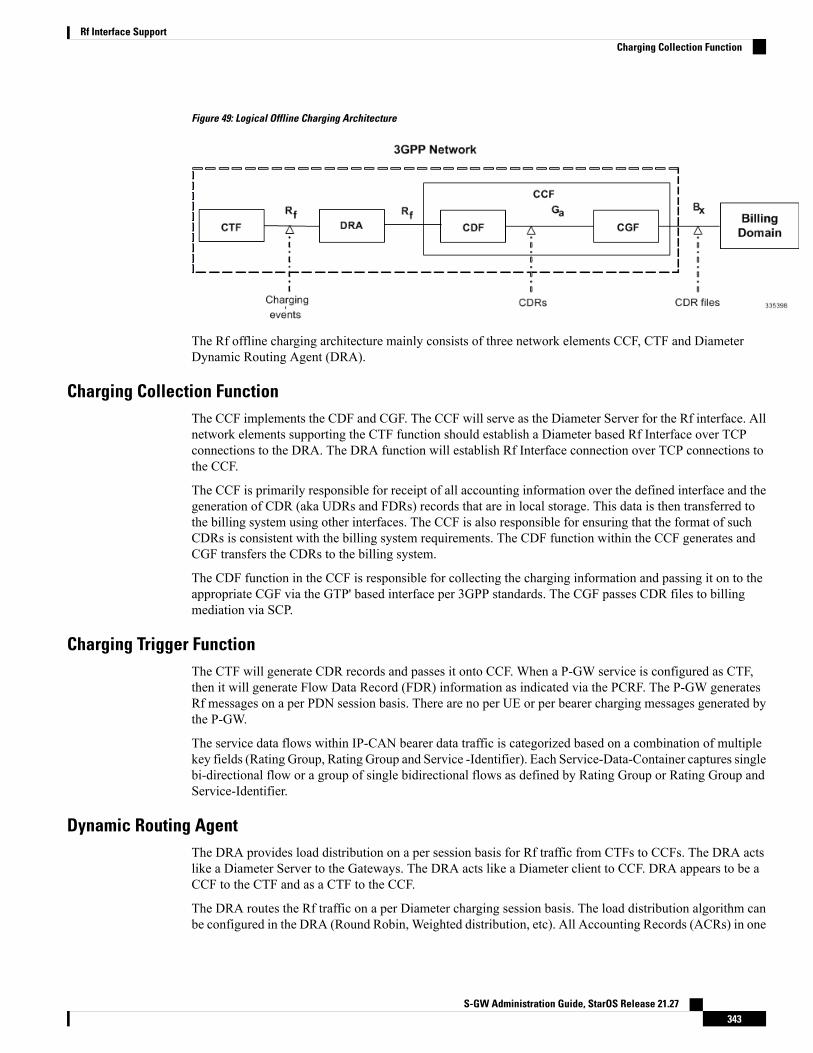
Figure 49: Logical Offline Charging Architecture
The Rf offline charging architecture mainly consists of three network elements CCF, CTF and DiameterDynamic Routing Agent (DRA).
Charging Collection FunctionThe CCF implements the CDF and CGF. The CCF will serve as the Diameter Server for the Rf interface. Allnetwork elements supporting the CTF function should establish a Diameter based Rf Interface over TCPconnections to the DRA. The DRA function will establish Rf Interface connection over TCP connections tothe CCF.
The CCF is primarily responsible for receipt of all accounting information over the defined interface and thegeneration of CDR (aka UDRs and FDRs) records that are in local storage. This data is then transferred tothe billing system using other interfaces. The CCF is also responsible for ensuring that the format of suchCDRs is consistent with the billing system requirements. The CDF function within the CCF generates andCGF transfers the CDRs to the billing system.
The CDF function in the CCF is responsible for collecting the charging information and passing it on to theappropriate CGF via the GTP' based interface per 3GPP standards. The CGF passes CDR files to billingmediation via SCP.
Charging Trigger FunctionThe CTF will generate CDR records and passes it onto CCF. When a P-GW service is configured as CTF,then it will generate Flow Data Record (FDR) information as indicated via the PCRF. The P-GW generatesRf messages on a per PDN session basis. There are no per UE or per bearer charging messages generated bythe P-GW.
The service data flows within IP-CAN bearer data traffic is categorized based on a combination of multiplekey fields (Rating Group, Rating Group and Service -Identifier). Each Service-Data-Container captures singlebi-directional flow or a group of single bidirectional flows as defined by Rating Group or Rating Group andService-Identifier.
Dynamic Routing AgentThe DRA provides load distribution on a per session basis for Rf traffic from CTFs to CCFs. The DRA actslike a Diameter Server to the Gateways. The DRA acts like a Diameter client to CCF. DRA appears to be aCCF to the CTF and as a CTF to the CCF.
The DRA routes the Rf traffic on a per Diameter charging session basis. The load distribution algorithm canbe configured in the DRA (Round Robin, Weighted distribution, etc). All Accounting Records (ACRs) in one
S-GW Administration Guide, StarOS Release 21.27343
Rf Interface SupportCharging Collection Function

Diameter charging session will be routed by the DRA to the same CCF. Upon failure of one CCF, the DRAselects an alternate CCF from a pool of CCFs.
License RequirementsThe Rf interface support is a licensed Cisco feature. A separate feature license may be required. Contact yourCisco account representative for detailed information on specific licensing requirements. For information oninstalling and verifying licenses, refer to the Managing License Keys section of the Software ManagementOperations chapter in the System Administration Guide.
Supported StandardsRf interface support is based on the following standards:
• IETF RFC 4006: Diameter Credit Control Application; August 2005
• 3GPP TS 32.299 V9.6.0 (2010-12) 3rd Generation Partnership Project; Technical Specification GroupServices and System Aspects; Telecommunication management; Charging management; Diametercharging applications (Release9)
Feature Summary and Revision HistorySummary Data
P-GWApplicable Product(s) or Functional Area
• ASR 5500
• VPC-DI
• VPC-SI
Applicable Platform(s)
Disabled - Configuration RequiredFeature Default
Not ApplicableRelated Changes in This Release
• 5G Non Standalone Solution Guide
• AAA Interface Administration and Reference
• Command Line Interface Reference
• MME Administration Guide
• Statistics and Counters Reference
Related Documentation
S-GW Administration Guide, StarOS Release 21.27344
Rf Interface SupportLicense Requirements
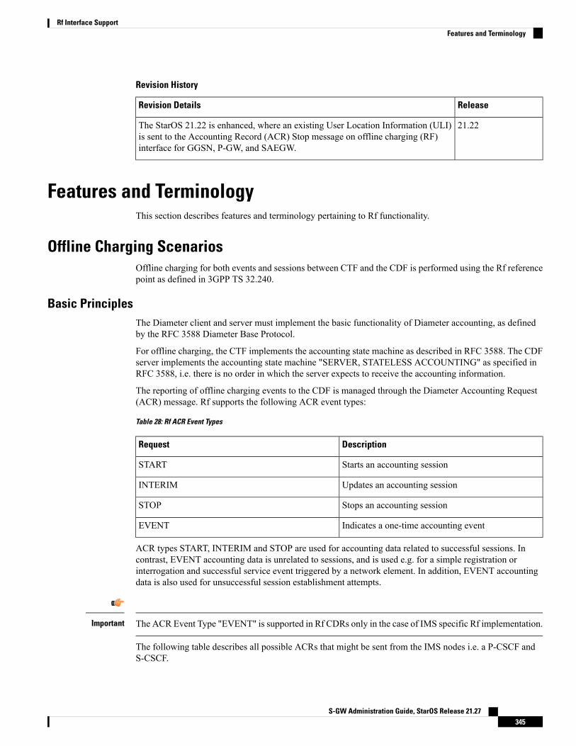
Revision History
ReleaseRevision Details
21.22The StarOS 21.22 is enhanced, where an existing User Location Information (ULI)is sent to the Accounting Record (ACR) Stop message on offline charging (RF)interface for GGSN, P-GW, and SAEGW.
Features and TerminologyThis section describes features and terminology pertaining to Rf functionality.
Offline Charging ScenariosOffline charging for both events and sessions between CTF and the CDF is performed using the Rf referencepoint as defined in 3GPP TS 32.240.
Basic PrinciplesThe Diameter client and server must implement the basic functionality of Diameter accounting, as definedby the RFC 3588 Diameter Base Protocol.
For offline charging, the CTF implements the accounting state machine as described in RFC 3588. The CDFserver implements the accounting state machine "SERVER, STATELESS ACCOUNTING" as specified inRFC 3588, i.e. there is no order in which the server expects to receive the accounting information.
The reporting of offline charging events to the CDF is managed through the Diameter Accounting Request(ACR) message. Rf supports the following ACR event types:
Table 28: Rf ACR Event Types
DescriptionRequest
Starts an accounting sessionSTART
Updates an accounting sessionINTERIM
Stops an accounting sessionSTOP
Indicates a one-time accounting eventEVENT
ACR types START, INTERIM and STOP are used for accounting data related to successful sessions. Incontrast, EVENT accounting data is unrelated to sessions, and is used e.g. for a simple registration orinterrogation and successful service event triggered by a network element. In addition, EVENT accountingdata is also used for unsuccessful session establishment attempts.
The ACR Event Type "EVENT" is supported in Rf CDRs only in the case of IMS specific Rf implementation.Important
The following table describes all possible ACRs that might be sent from the IMS nodes i.e. a P-CSCF andS-CSCF.
S-GW Administration Guide, StarOS Release 21.27345
Rf Interface SupportFeatures and Terminology
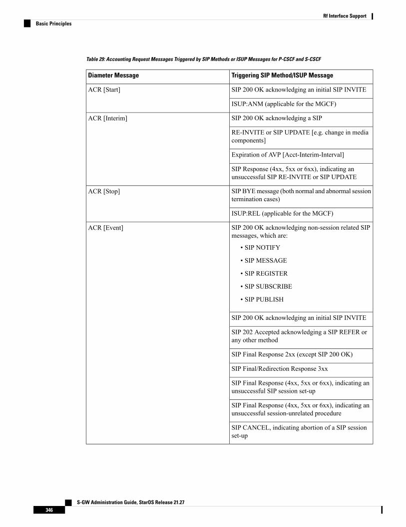
Table 29: Accounting Request Messages Triggered by SIP Methods or ISUP Messages for P-CSCF and S-CSCF
Triggering SIP Method/ISUP MessageDiameter Message
SIP 200 OK acknowledging an initial SIP INVITEACR [Start]
ISUP:ANM (applicable for the MGCF)
SIP 200 OK acknowledging a SIPACR [Interim]
RE-INVITE or SIP UPDATE [e.g. change in mediacomponents]
Expiration of AVP [Acct-Interim-Interval]
SIP Response (4xx, 5xx or 6xx), indicating anunsuccessful SIP RE-INVITE or SIP UPDATE
SIP BYEmessage (both normal and abnormal sessiontermination cases)
ACR [Stop]
ISUP:REL (applicable for the MGCF)
SIP 200 OK acknowledging non-session related SIPmessages, which are:
• SIP NOTIFY
• SIP MESSAGE
• SIP REGISTER
• SIP SUBSCRIBE
• SIP PUBLISH
ACR [Event]
SIP 200 OK acknowledging an initial SIP INVITE
SIP 202 Accepted acknowledging a SIP REFER orany other method
SIP Final Response 2xx (except SIP 200 OK)
SIP Final/Redirection Response 3xx
SIP Final Response (4xx, 5xx or 6xx), indicating anunsuccessful SIP session set-up
SIP Final Response (4xx, 5xx or 6xx), indicating anunsuccessful session-unrelated procedure
SIP CANCEL, indicating abortion of a SIP sessionset-up
S-GW Administration Guide, StarOS Release 21.27346
Rf Interface SupportBasic Principles

Event Based ChargingIn the case of event based charging, the network reports the usage or the service rendered where the serviceoffering is rendered in a single operation. It is reported using the ACR EVENT.
In this scenario, CTF asks the CDF to store event related charging data.
Session Based ChargingSession based charging is the process of reporting usage reports for a session and uses the START, INTERIM&STOP accounting data. During a session, a network element may transmit multiple ACR Interims' dependingon the proceeding of the session.
In this scenario, CTF asks the CDF to store session related charging data.
Diameter Base ProtocolTheDiameter Base Protocol maintains the underlying connection between the Diameter Client and the DiameterServer. The connection between the client and server is TCP based.
In order for the application to be compliant with the specification, state machines should be implemented atsome level within the implementation.
Diameter Base supports the following Rf message commands that can be used within the application.
Table 30: Diameter Rf Messages
AbbreviationDestinationSourceCommand Name
ACRCDFCTFAccounting-Request
ACACTFCDFAccounting-Answer
There are a series of other Diameter messages exchanged to check the status of the connection and thecapabilities.
• Capabilities Exchange Messages: Capabilities Exchange Messages are exchanged between the diameterpeers to know the capabilities of each other and identity of each other.
• Capabilities Exchange Request (CER): This message is sent from the client to the server to knowthe capabilities of the server.
• Capabilities Exchange Answer (CEA): This message is sent from the server to the client in responseto the CER message.
• Device Watchdog Request (DWR): After the CER/CEA messages are exchanged, if there is no moretraffic between peers for a while, to monitor the health of the connection, DWR message is sent fromthe client. The Device Watchdog timer (Tw) is configurable and can vary from 6 through 30 seconds. Avery low value will result in duplication of messages. The default value is 30 seconds. On two consecutiveexpiries of Tw without a DWA, the peer is considered to be down.
S-GW Administration Guide, StarOS Release 21.27347
Rf Interface SupportEvent Based Charging

DWR is sent only after Tw expiry after the last message that camefrom the server. Say if there is continuous exchange of messagesbetween the peers, DWR might not be sent if (Current Time - Lastmessage received time from server) is less than Tw.
Important
• Device Watchdog Answer (DWA): This is the response to the DWR message from the server. This isused to monitor the connection state.
• Disconnect Peer Request (DPR): This message is sent to the peer to inform to shutdown the connection.There is no capability currently to send the message to the Diameter server.
• Disconnect Peer Answer (DPA): This message is the response to the DPR request from the peer. Onreceiving the DPR, the peer sends DPA and puts the connection state to "DO NOT WANT TO TALKTO YOU" state and there is no way to get the connection back except for reconfiguring the peer again.
A timeout value for retrying the disconnected peer must be provided.
Timer Expiry BehaviorUpon establishing the Diameter connection, an accounting interim timer (AII) is used to indicate the expirationof a Diameter accounting session, and is configurable at the CTF. The CTF indicates the timer value in theACR-Start, in the Acct-Interim-Interval AVP. The CDF responds with its own AII value (through the DRA),which must be used by the CTF to start a timer upon whose expiration an ACR INTERIM message must besent. An instance of the AII timer is started in the CCF at the beginning of the accounting session, reset onthe receipt of an ACR-Interim and stopped on the receipt of the ACR-Stop. After expiration of the AII timer,ACR INTERIM message will be generated and the timer will be reset and the accounting session will becontinued.
Rf Interface Failures/Error ConditionsThe current architecture allows for primary and secondary connections or Active-Active connections for eachnetwork element with the CDF elements.
DRA/CCF Connection FailureWhen the connection towards one of the primary/Active DRAs in CCF becomes unavailable, the CTF picksthe Secondary/Active IP address and begins to use that as a Primary.
If no DRA (and/or the CCF) is reachable, the network element must buffer the generated accounting data innon-volatile memory. Once the DRA connection is up, all accounting messages must be pulled by the CDFthrough offline file transfer.
No Reply from CCFIn case the CTF/DRA does not receive an ACA in response to an ACR, it may retransmit the ACR message.The waiting time until a retransmission is sent, and the maximum number of repetitions are both configurableby the operator. When the maximum number of retransmissions is reached and still no ACA reply has beenreceived, the CTF/DRA sends the ACRs to the secondary/alternate DRA/CCF.
S-GW Administration Guide, StarOS Release 21.27348
Rf Interface SupportTimer Expiry Behavior

Detection of Message DuplicationThe Diameter client marks possible duplicate request messages (e.g. retransmission due to the link failoverprocess) with the T-flag as described in RFC 3588.
If the CDF receives a message that is marked as retransmitted and this message was already received, then itdiscards the duplicate message. However, if the original of the re-transmitted message was not yet received,it is the information in the marked message that is taken into account when generating the CDR. The CDRsare marked if information from duplicated message(s) is used.
CCF Detected FailureThe CCF closes a CDR when it detects that expected Diameter ACRs for a particular session have not beenreceived for a period of time. The exact behavior of the CCF is operator configurable.
Rf-Gy Synchronization EnhancementsBoth Rf (OFCS) and Gy (OCS) interfaces are used for reporting subscriber usage and billing. Since eachinterface independently updates the subscriber usage, there are potential scenarios where the reportedinformation is not identical. Apart from Quota enforcement, OCS is utilized for Real Time Reporting (RTR),which provides a way to the user to track the current usage and also get notifications when a certain thresholdis hit.
In scenarios where Rf (OFCS) and Gy (OCS) have different usage information for a subscriber session, it ispossible that the subscriber is not aware of any potential overages until billed (scenario when Rf is more thanGy) or subscriber believes he has already used up the quota whereas his actual billing might be less (scenariowhen Gy is more than Rf). In an attempt to align both the Rf and Gy reported usage values, release 12.3introduced capabilities to provide a way to get the reported values on both the interfaces to match as much aspossible. However, some of the functionalities were deferred and this feature implements the additionalenhancements.
When time/volume quota on the Gy interface gets exhausted, Gy triggers "Service Data Volume Limit" and"Service Data Time Limit". Now in 16.0 via this feature, this behavior is CLI controlled. Based on the CLIcommand " trigger-type { gy-sdf-time-limit { cache | immediate } | gy-sdf-unit-limit { cache | immediate} | gy-sdf-volume-limit { cache | immediate } }" the behavior will be decided whether to send the ACR-Interimimmediately or to cache the containers for future transactions. If the CLI for the event-triggers received viaGy is not configured, then those ACR-Interims will be dropped.
The CLI configuration options are provided in policy accounting configuration to control the various Rfmessages (ACRs) triggered for sync on this feature.
This release supports the following enhancements:
• Caches containers in scenarios when ACR-I could not be sent and reported to OFCS.
• Triggers ACR to the OFCS when the CCR to the OCS is sent instead of the current implementation ofwaiting for CCA from OCS.
If an ACR-I could not be sent to the OFCS, the PCEF caches the container record and sends it in the nexttransaction to the OFCS.
Once a CCR-U was sent out over Gy interface, the containers are closed only after receiving CCA-Usuccessfully. That is, Rf trigger will be sent only after receiving CCA-U message.
S-GW Administration Guide, StarOS Release 21.27349
Rf Interface SupportDetection of Message Duplication

For more information on the command associated with this feature, see the Accounting Policy ConfigurationMode Commands chapter of the Command Line Interface Reference.
A common timer based approach is implemented for Rf and Gy synchronization. As part of the new design,Gy and Rf will be check-pointed at the same point of time for periodic as well as for full check-pointing.Thus, the billing records will always be in sync at all times regardless of during an ICSR switchover event,internal events, session manager crashes, inactive Rf/Gy link, etc. This in turn avoids any billing discrepancies.
Cessation of Rf Records When UE is IDLEThe P-GW is not generating Rf records when the UE was identified to be in IDLE state and not sending anydata. New CLI configuration command "session idle-mode suppress-interim" is provided to enable/disablethe functionality at the ACR level to control the behavior of whether an ACR-I needs to be generated or notwhen the UE is idle and no data is transferred.
That is, this CLI configuration is used to control sending of ACR-I records when the UE is in idle mode andwhen there is no data to report.
For more information on the command, see the Accounting Policy Configuration Mode Commands chapterof the Command Line Interface Reference.
QoS Change Scenarios
QOS_CHANGE Trigger in Rf Records During eHRPD-LTE Handoff
The SDC in the generated Rf record does not include QOS_CHANGE trigger during handoff from eHRPDto LTE.
QoS Change for Default Bearer
For a change in the QoS of default bearer, NR SDV containers will not be seen unless the correspondingbearer is torn down. Only QoS change containers are closed/released for the bearer that underwent QoSChange, i.e. the default bearer.
Diameter Rf Duplicate Record GenerationThis section describes the overview and implementation of Rf Duplicate Record Generation feature.
This section discusses the following topics for this feature:
• Feature Description, on page 350
• Configuring Rf Duplicate Record Generation, on page 352
• Monitoring and Troubleshooting the Rf Duplicate Record Generation, on page 354
Feature DescriptionThis feature is introduced to support creation and communication of duplicate Rf records to secondary AAAgroup servers configured for the Rf interface.
To achieve this functionality, the following configurations must be enabled –
S-GW Administration Guide, StarOS Release 21.27350
Rf Interface SupportCessation of Rf Records When UE is IDLE

• aaa groupCLI command under APN to configure amaximum of 2AAAgroups - primary and secondaryAAA groups, or two different endpoints for Rf Diameter accounting servers
• diameter accounting duplicate-record under AAA group to allow Rf duplicate record creation
The diameter accounting duplicate-record is a new CLI command introduced in this release for duplicatingthe Rf START, INTERIM and STOP accounting records.
This is a license-controlled CLI command. For more information, contact your Cisco account representative.Important
In releases prior to 21, gateway allows only one AAA group configuration per APN for Rf accounting. TheAAA group is configured to load balance across multiple servers to pass the Rf traffic and also expect anaccounting answer. Note that the secondary AAA group configuration is allowed currently but is restrictedto only RADIUS accounting.
In release 21 and beyond, the gateway is provided with the ability to configure a secondary AAA group perAPN for the Rf interface, and send the duplicate Diameter Rf accounting records to the secondary AAA groupservers. The secondary AAA group is used for non-billing purposes only.
The failed duplicate records will neither be written to HDD nor added to the archival list.Important
There is no change in the current behavior with the primary AAA group messages. The primary AAA groupis independent of the secondary AAA group, and it has multiple Rf servers configured. When the Rf serversdo not respond even after multiple retries as per the applicable configuration, the Rf records are archived andstored in HDD. This behavior continues as is irrespective of the configuration of secondary aaa-group.
Secondary aaa group has a very similar configuration as the primary aaa group except that the new CLIcommand diameter accounting duplicate-record is additionally included to configure the secondary aaa-group.It is also important to note that different Diameter endpoints and a separate set of Rf servers should beprovisioned for both primary and secondary AAA groups.
If all the configured servers are down, the request message will be discarded without writing it in HDD orarchiving at aaamgr.
The original and duplicate Rf messages use two different aaa-groups and two different Diameter endpoints.Hence, the values for Session-ID AVP will be different. Based on the configuration of primary and secondaryendpoints the values for Origin-Host, Origin-Realm, Destination-Realm, and Destination-Host AVPs may bedifferent. Also based on the configuration under policy accounting for inclusion of virtual/gn apn name forsecondary group Called-Station-ID AVP might change. All other AVPs will have the same values as with theprimary aaa group Rf message.
Also, note that the values such as Acct-Interim-Interval (AII) interval received in ACA from secondary groupof AAA servers will be ignored.
Relationships to Other Features
This feature can be used in conjunction with Virtual APN Truncation feature to achieve the desired results.
The Virtual APN Truncation feature is new in release 21. For more information on this feature, see theadministration guide for the product you are deploying.
S-GW Administration Guide, StarOS Release 21.27351
Rf Interface SupportFeature Description
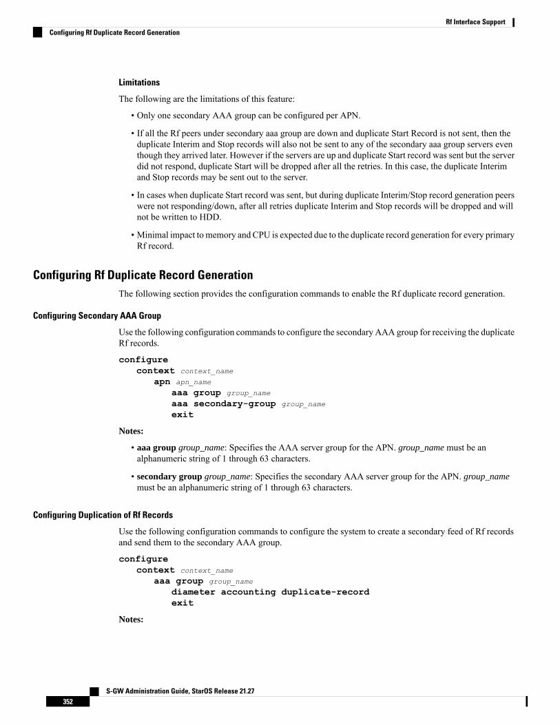
Limitations
The following are the limitations of this feature:
• Only one secondary AAA group can be configured per APN.
• If all the Rf peers under secondary aaa group are down and duplicate Start Record is not sent, then theduplicate Interim and Stop records will also not be sent to any of the secondary aaa group servers eventhough they arrived later. However if the servers are up and duplicate Start record was sent but the serverdid not respond, duplicate Start will be dropped after all the retries. In this case, the duplicate Interimand Stop records may be sent out to the server.
• In cases when duplicate Start record was sent, but during duplicate Interim/Stop record generation peerswere not responding/down, after all retries duplicate Interim and Stop records will be dropped and willnot be written to HDD.
• Minimal impact to memory and CPU is expected due to the duplicate record generation for every primaryRf record.
Configuring Rf Duplicate Record GenerationThe following section provides the configuration commands to enable the Rf duplicate record generation.
Configuring Secondary AAA Group
Use the following configuration commands to configure the secondary AAA group for receiving the duplicateRf records.
configurecontext context_name
apn apn_name
aaa group group_name
aaa secondary-group group_name
exit
Notes:
• aaa group group_name: Specifies the AAA server group for the APN. group_name must be analphanumeric string of 1 through 63 characters.
• secondary group group_name: Specifies the secondary AAA server group for the APN. group_namemust be an alphanumeric string of 1 through 63 characters.
Configuring Duplication of Rf Records
Use the following configuration commands to configure the system to create a secondary feed of Rf recordsand send them to the secondary AAA group.
configurecontext context_name
aaa group group_name
diameter accounting duplicate-recordexit
Notes:
S-GW Administration Guide, StarOS Release 21.27352
Rf Interface SupportConfiguring Rf Duplicate Record Generation

• duplicate-record: Sends duplicate Rf records to configured secondary AAA group. This keyword islicense dependent. For more information, contact your Cisco account representative.
• The default configuration is no diameter accounting duplicate-record. By default, this feature isdisabled.
• The secondary aaa groupmust be configured under APN configurationmode before enabling the diameteraccounting duplicate-record CLI command.
Verifying the Rf Duplicate Record Generation Configuration
Use the following commands to verify the configuration status of this feature.
show configuration
show aaa group all
- or -
show aaa group group_name
group_name must be the name of the AAA group specified during the configuration.
This command displays all the configurations that are enabled within the specified AAA group.
The following is a sample configuration of this feature.
configurecontext source
apn domainname.com
associate accounting-policy policy_accounting_name
aaa group group1
aaa secondary-group group2
exitaaa group group1
diameter accounting dictionary aaa-custom4diameter accounting endpoint rf_endpoint1
diameter accounting server rf_server1 priority 1
diameter accounting server rf_server2 priority 2
exitaaa group group2
diameter accounting dictionary aaa-custom4diameter accounting endpoint rf_endpoint2
diameter accounting duplicate-recorddiameter accounting server rf_server3 priority 3
diameter accounting server rf_server4 priority 4
exitdiameter endpoint rf-endpoint1
use-proxyorigin host rf-endpoint1.carrier.com address 192.50.50.3
no watchdog-timeoutresponse-timeout 20
connection retry-timeout 5
peer rf_server1 realm domainname.com address 192.50.50.4 port 4872
peer rf_server2 realm domainname.com address 192.50.50.4 port 4873
exit
S-GW Administration Guide, StarOS Release 21.27353
Rf Interface SupportVerifying the Rf Duplicate Record Generation Configuration

diameter endpoint rf-endpoint2
use-proxyorigin host rf-endpoint2.carrier.com address 192.50.50.2
no watchdog-timeoutresponse-timeout 20
connection retry-timeout 5
peer rf_server3 realm domainname.com address 192.50.50.5 port 4892
peer rf_server4 realm domainname.com address 192.50.50.5 port 4893
end
Notes:
• The diameter accounting duplicate-record CLI is license specific. So, the corresponding license mustbe enabled for the CLI command to be configured.
• Both primary and secondary aaa groups are preferred to have different accounting endpoint names.
Monitoring and Troubleshooting the Rf Duplicate Record GenerationThis section provides information regarding show commands and/or their outputs in support of this feature.
The following operations can be performed to troubleshoot any failure related to this feature:
• Verify if the feature is enabled using show configuration or show aaa group all CLI command. If notenabled, configure the diameter accounting duplicate-record CLI command and check if it works.
• Collect the output of show diameter aaa statistics command and analyze the debug statistics. Also,check the reported logs, if any. For further analysis, contact Cisco account representative.
show diameter aaa-statistics
The following statistics are added to the output of this show command for duplicate Rf records which weredropped because of the failure in sending the Accounting records instead of adding them to HDD or archivallist.
• Duplicate Accounting Records Stats
• ACR-Start Dropped
• ACR-Interim Dropped
• ACR-Stop Dropped
These statistics are maintained per aaamgr instance level. For descriptions of these statistics, see the Statisticsand Counters Reference guide.
These statistics can also be collected per group basis/server basis for duplicate records i.e. through showdiameter aaa-statistics group <group_name> and show diameter aaa-statistics server <server_name>CLI commands.
Truncation of Virtual APN for Rf RecordsThis feature enables the truncation of Virtual APN (VAPN) returned by S6b server to be sent to Gx, Gy andRf interfaces.
S-GW Administration Guide, StarOS Release 21.27354
Rf Interface SupportMonitoring and Troubleshooting the Rf Duplicate Record Generation

Feature DescriptionCurrently there is no way to quickly turn on the Rf accounting to the Data Streaming Service (DSS) serverper Virtual APN (S6b-VAPN) without reaching all nodes in the network and provision the Virtual APN oneach of them. This feature is implemented to truncate the virtual APN name returned by S6b server with theconfigured standard delimiters. In this way a single configuration per node can be utilized for all enterprisesbased on a virtual APN. This approach will significantly reduce the size and time to provision new enterpriseswith the requested feature.
To achieve this functionality, a configuration is added per APN to enable truncation of S6b-VAPN and alsoto configure the delimiter(s) where the APN name is to be truncated. Standard delimiters like (.) and (-) areused since APN name supports only these two characters apart from the alphanumeric ones.
If AAA server returns both hyphen and dot delimiters or the same delimiter twice or more as a virtual-apn,then the first delimiter will be considered as a separator. For example, if the AAA server returns the virtual-apnas xyz-cisco.com, then hyphen is the separator.
AAAmanager performs the truncation of the Virtual APN name based on the APN configuration and providesthe correct APN profile for the truncated APN name. If the truncation is successful, the full virtual APN namewill be sent to Gx, Gy and Rf interfaces.
Accounting records are required to support real-time usage notification and device management functionality.So, the apn-name-to-be-includedCLI command is extended to enable actual APN (Gn-APN) or virtual APN(S6b returned virtual APN) name to be included in Called-Station-ID AVP in the secondary Rf accountingrecords (secondary server group) under policy accounting configuration. Currently, policy accountingconfiguration supports sending the Gn-APN/S6b-VAPN in Called-Station-ID for primary Rf server. Withthis CLI command, this functionality is extended for the secondary Rf server.
A new AAA attribute “Secondary-Called-Station-ID” is added to support sending Gn/Virtual APN name inthe Called-Station-ID AVP for duplicate Rf records sent to secondary group Rf server.
Configuring Virtual APN Truncation for Rf RecordsThe following section provides the configuration commands to enable the Virtual APN Truncation featurefor Rf records.
Configuring Gn-APN/VAPN for Rf Accounting
Use the following configuration commands to configure the actual APN or Virtual APN (VAPN) for Rfaccounting.
configurecontext context_name
policy accounting policy_name
apn-name-to-be-included { gn | virtual } [ secondary-group { gn |virtual } ]
end
Notes:
• apn-name-to-be-included: Configures the APN name to be included in the Rf messages for primaryserver group.
• secondary-group { gn | virtual }: Configures the APN name to be included in the Rf messages forsecondary server group.
• gn: Configures the Gn APN name to be included in the Rf messages.
S-GW Administration Guide, StarOS Release 21.27355
Rf Interface SupportFeature Description
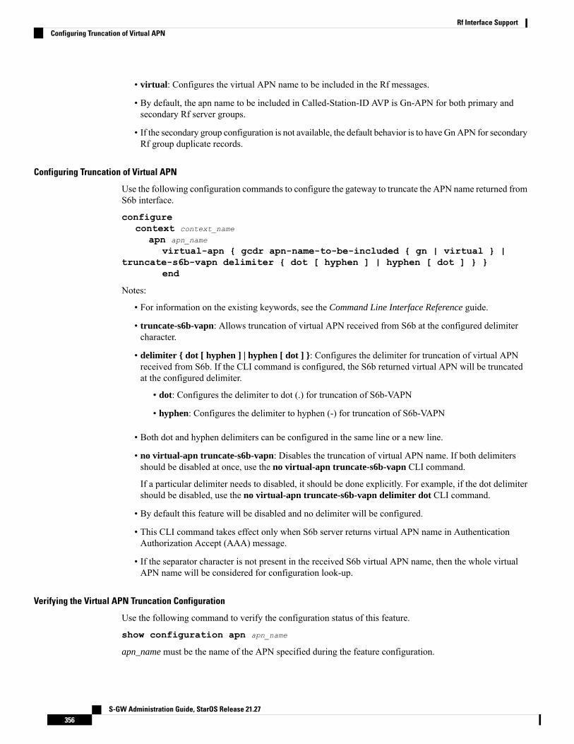
• virtual: Configures the virtual APN name to be included in the Rf messages.
• By default, the apn name to be included in Called-Station-ID AVP is Gn-APN for both primary andsecondary Rf server groups.
• If the secondary group configuration is not available, the default behavior is to have GnAPN for secondaryRf group duplicate records.
Configuring Truncation of Virtual APN
Use the following configuration commands to configure the gateway to truncate the APN name returned fromS6b interface.
configurecontext context_name
apn apn_name
virtual-apn { gcdr apn-name-to-be-included { gn | virtual } |truncate-s6b-vapn delimiter { dot [ hyphen ] | hyphen [ dot ] } }
end
Notes:
• For information on the existing keywords, see the Command Line Interface Reference guide.
• truncate-s6b-vapn: Allows truncation of virtual APN received from S6b at the configured delimitercharacter.
• delimiter { dot [ hyphen ] | hyphen [ dot ] }: Configures the delimiter for truncation of virtual APNreceived from S6b. If the CLI command is configured, the S6b returned virtual APN will be truncatedat the configured delimiter.
• dot: Configures the delimiter to dot (.) for truncation of S6b-VAPN
• hyphen: Configures the delimiter to hyphen (-) for truncation of S6b-VAPN
• Both dot and hyphen delimiters can be configured in the same line or a new line.
• no virtual-apn truncate-s6b-vapn: Disables the truncation of virtual APN name. If both delimitersshould be disabled at once, use the no virtual-apn truncate-s6b-vapn CLI command.
If a particular delimiter needs to disabled, it should be done explicitly. For example, if the dot delimitershould be disabled, use the no virtual-apn truncate-s6b-vapn delimiter dot CLI command.
• By default this feature will be disabled and no delimiter will be configured.
• This CLI command takes effect only when S6b server returns virtual APN name in AuthenticationAuthorization Accept (AAA) message.
• If the separator character is not present in the received S6b virtual APN name, then the whole virtualAPN name will be considered for configuration look-up.
Verifying the Virtual APN Truncation Configuration
Use the following command to verify the configuration status of this feature.
show configuration apn apn_name
apn_name must be the name of the APN specified during the feature configuration.
S-GW Administration Guide, StarOS Release 21.27356
Rf Interface SupportConfiguring Truncation of Virtual APN
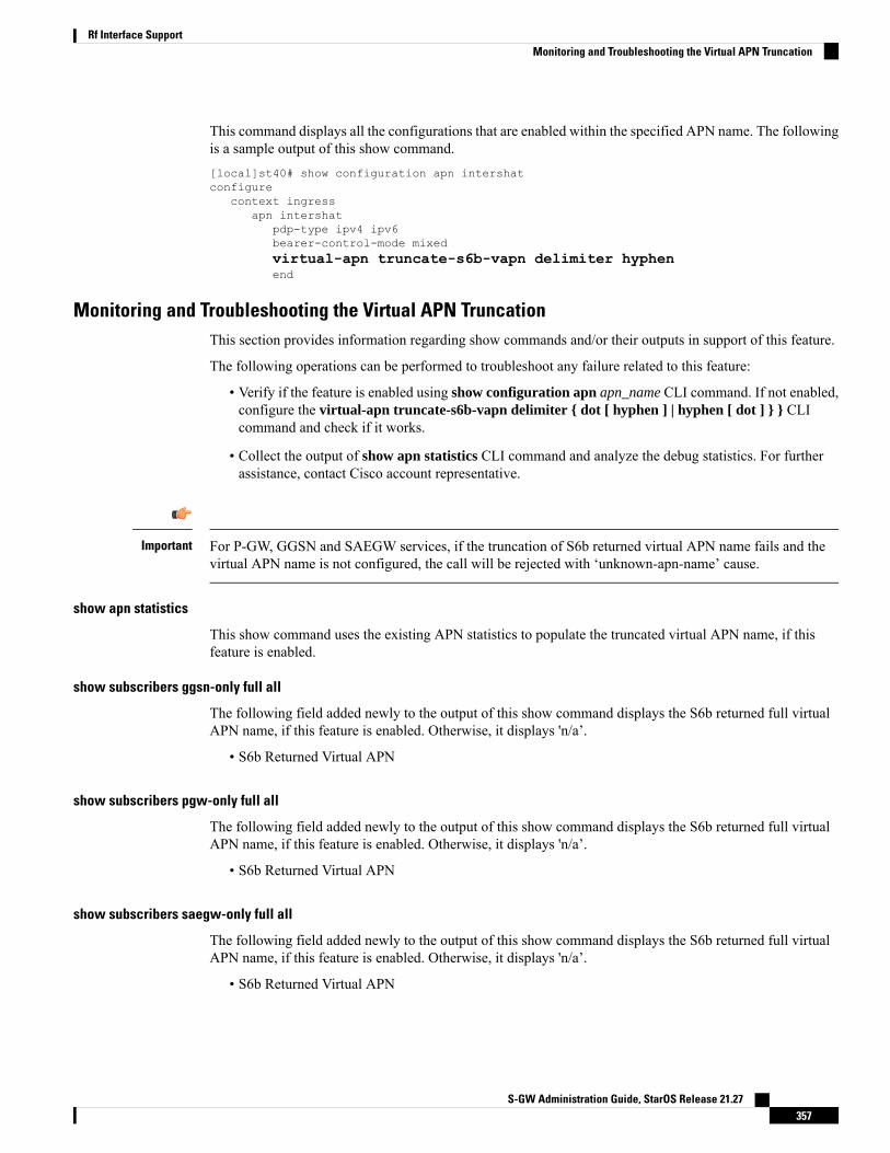
This command displays all the configurations that are enabled within the specified APN name. The followingis a sample output of this show command.[local]st40# show configuration apn intershatconfigure
context ingressapn intershat
pdp-type ipv4 ipv6bearer-control-mode mixedvirtual-apn truncate-s6b-vapn delimiter hyphenend
Monitoring and Troubleshooting the Virtual APN TruncationThis section provides information regarding show commands and/or their outputs in support of this feature.
The following operations can be performed to troubleshoot any failure related to this feature:
• Verify if the feature is enabled using show configuration apn apn_name CLI command. If not enabled,configure the virtual-apn truncate-s6b-vapn delimiter { dot [ hyphen ] | hyphen [ dot ] } } CLIcommand and check if it works.
• Collect the output of show apn statistics CLI command and analyze the debug statistics. For furtherassistance, contact Cisco account representative.
For P-GW, GGSN and SAEGW services, if the truncation of S6b returned virtual APN name fails and thevirtual APN name is not configured, the call will be rejected with ‘unknown-apn-name’ cause.
Important
show apn statistics
This show command uses the existing APN statistics to populate the truncated virtual APN name, if thisfeature is enabled.
show subscribers ggsn-only full all
The following field added newly to the output of this show command displays the S6b returned full virtualAPN name, if this feature is enabled. Otherwise, it displays 'n/a’.
• S6b Returned Virtual APN
show subscribers pgw-only full all
The following field added newly to the output of this show command displays the S6b returned full virtualAPN name, if this feature is enabled. Otherwise, it displays 'n/a’.
• S6b Returned Virtual APN
show subscribers saegw-only full all
The following field added newly to the output of this show command displays the S6b returned full virtualAPN name, if this feature is enabled. Otherwise, it displays 'n/a’.
• S6b Returned Virtual APN
S-GW Administration Guide, StarOS Release 21.27357
Rf Interface SupportMonitoring and Troubleshooting the Virtual APN Truncation

Accounting Record Stop Location ReportPrevious Behavior: When P-GW or S-GW sends new User Location Information (ULI) message in an ACRstop message to Offline Charging System (OFCS) through the Rf interface, the reported location at the endof sessions was not aligning with the expected location reporting. The location used in the Accounting StopRecord (ACR Stop) was inconsistent and during location reporting it caused an ACR stop interim messagesrather than the location before the ACR was sent
New Behavior: In the StarOS 21.22 and later releases, an existing User Location Information (ULI) is sentto the Accounting Record (ACR) Stop message on offline charging (RF) interface for GGSN, P-GW, andSAEGW when Delete Session Request is received with a New ULI.
How it WorksThis section describes how offline charging for subscribers works with Rf interface support inGPRS/eHRPD/LTE/IMS networks.
The following figure and table explain the transactions that are required on the Diameter Rf interface in orderto perform event based charging. The operation may alternatively be carried out prior to, concurrently withor after service/content delivery.
Figure 50: Rf Call Flow for Event Based Charging
Table 31: Rf Call Flow Description for Event Based Charging
DescriptionStep
The network element (CTF) receives indication thatservice has been used/delivered.
1
The CTF (acting as Diameter client) sendsAccounting-Request (ACR) withAccounting-Record-Type AVP set toEVENT_RECORD to indicate service specificinformation to the CDF (acting as Diameter server).
2
The CDF receives the relevant service chargingparameters and processes accounting request.
3
S-GW Administration Guide, StarOS Release 21.27358
Rf Interface SupportAccounting Record Stop Location Report

DescriptionStep
TheCDF returnsAccounting-Answer (ACA)messagewith Accounting-Record-Type AVP set toEVENT_RECORD to the CTF in order to inform thatcharging information was received.
4
The following figure and table explain the simple Rf call flow for session based charging.
Figure 51: Rf Call Flow for Session Based Charging
Table 32: Rf Call Flow Description for Session Based Charging
DescriptionStep
The CTF receives a service request. The servicerequest may be initiated either by the user or the othernetwork element.
1
In order to start accounting session, the CTF sends aAccounting-Request (ACR) withAccounting-Record-Type AVP set toSTART_RECORD to the CDF.
2
S-GW Administration Guide, StarOS Release 21.27359
Rf Interface SupportHow it Works

DescriptionStep
The session is initiated and the CDF opens a CDR forthe current session.
3
TheCDF returnsAccounting-Answer (ACA)messagewith Accounting-Record-Type set toSTART_RECORD to the CTF and possiblyAcct-Interim-Interval AVP (AII) set to non-zero valueindicating the desired intermediate charging interval.
4
When either AII elapses or charging condition changesare recognized at CTF, the CTF sends anAccounting-Request (ACR) withAccounting-Record-Type AVP set toINTERIM_RECORD to the CDF.
5
The CDF updates the CDR in question.6
TheCDF returnsAccounting-Answer (ACA)messagewith Accounting-Record-Type set toINTERIM_RECORD to the CTF.
7
The service is terminated.8
The CTF sends a Accounting-Request (ACR) withAccounting-Record-Type AVP set toSTOP_RECORD to the CDF.
9
The CDF updates the CDR accordingly and closesthe CDR.
10
TheCDF returnsAccounting-Answer (ACA)messagewithAccounting-Record-Type set to STOP_RECORDto the CTF.
11
Configuring Rf Interface SupportTo configure Rf interface support:
1. Configure the core network service as described in this Administration Guide.
2. Enable Active Charging Service (ACS) and create ACS as described in the Enhanced Charging ServicesAdministration Guide.
The procedures in this section assume that you have installed and configured your chassis includingthe ECS installation and configuration as described in the Enhanced Charging ServicesAdministration Guide.
Important
S-GW Administration Guide, StarOS Release 21.27360
Rf Interface SupportConfiguring Rf Interface Support

3. Enable Rf accounting in ACS as described in Enabling Rf Interface in Active Charging Service, on page361.
4. Configure Rf interface support as described in the relevant sections:
• Configuring GGSN / P-GW Rf Interface Support, on page 362• Configuring P-CSCF/S-CSCF Rf Interface Support, on page 377
In StarOS versions 19 and later, the Rf interface is not supported on the S-GW.Important
5. Save your configuration to flash memory, an external memory device, and/or a network location usingthe Exec mode command save configuration. For additional information on how to verify and saveconfiguration files, refer to the System Administration Guide and the Command Line Interface Reference.
Commands used in the configuration examples in this section provide base functionality to the extent that themost common or likely commands and/or keyword options are presented. In many cases, other optionalcommands and/or keyword options are available. Refer to theCommand Line Interface Reference for completeinformation regarding all commands.
Important
Enabling Rf Interface in Active Charging ServiceTo enable the billing record generation and Rf accounting, use the following configuration:
configureactive-charging service <service_name>
rulebase <rulebase_name>
billing-records rfactive-charging rf { rating-group-override | service-id-override
}end
Notes:
• Prior to creating the Active Charging Service (ACS), the require active-charging command should beconfigured to enable ACS functionality.
• The billing-records rf command configures Rf record type of billing to be performed for subscribersessions. Rf accounting is applicable only for dynamic and predefined ACS rules.
For more information on the rules and its configuration, refer to the ACS Charging Action ConfigurationMode Commands chapter in the Command Line Interface Reference.
• The active-charging rf command is used to enforce a specific rating group / service identifier on allPCC rules, predefined ACS rules, and static ACS rules for Rf-based accounting. As this CLI configurationis applied at the rulebase level, all the APNs that have the current rulebase defined will inherit theconfiguration.
For more information on this command, refer to the ACS Rulebase Configuration Mode Commandschapter in the Command Line Interface Reference.
S-GW Administration Guide, StarOS Release 21.27361
Rf Interface SupportEnabling Rf Interface in Active Charging Service

Configuring GGSN / P-GW Rf Interface SupportTo configure the standard Rf interface support for GGSN/P-GW, use the following configuration:
configurecontext <context_name>
apn <apn_name>
associate accounting-policy <policy_name>
exitpolicy accounting <policy_name>
accounting-event-trigger { cgi-sai-change | ecgi-change |flow-information-change | interim-timeout | location-change | rai-change| tai-change } action { interim | stop-start }
accounting-keys qciaccounting-level { flow | pdn | pdn-qci | qci | sdf | subscriber }
cc profile index { buckets num | interval seconds | sdf-intervalseconds | sdf-volume { downlink octets { uplink octets } | total octets |uplink octets { downlink octets } } | serving-nodes num | tariff time1 min
hrs [ time2 min hrs...time4 min hrs ] | volume { downlink octets { uplink octets
} | total octets | uplink octets { downlink octets } } }max-containers { containers | fill-buffer }end
Notes:
• The policy can be configured in any context.
• For information on configuring accounting levels/policies/modes/event triggers, refer to the AccountingPolicy Configuration Mode Commands chapter in the Command Line Interface Reference.
• Depending on the triggers configured, the containers will either be cached or released. In the case ofGGSN/P-GW, the containers will be cached when the event trigger is one of the following:
• QOS_CHANGE• FLOW_INFORMATION_CHANGE• LOCATION_CHANGE• SERVING_NODE_CHANGE• SERVICE_IDLE• SERVICE_DATA_VOLUME_LIMIT• SERVICE_DATA_TIME_LIMIT• IP_FLOW_TERMINATION• TARIFF_CHANGE
If the event trigger is one of the following, the containers will be released:
• VOLUME_LIMIT• TIME_LIMIT• RAT_CHANGE• TIMEZONE_CHANGE• PLMN_CHANGE
Currently, SDF and flow level accounting are supported in P-GW.Important
S-GW Administration Guide, StarOS Release 21.27362
Rf Interface SupportConfiguring GGSN / P-GW Rf Interface Support
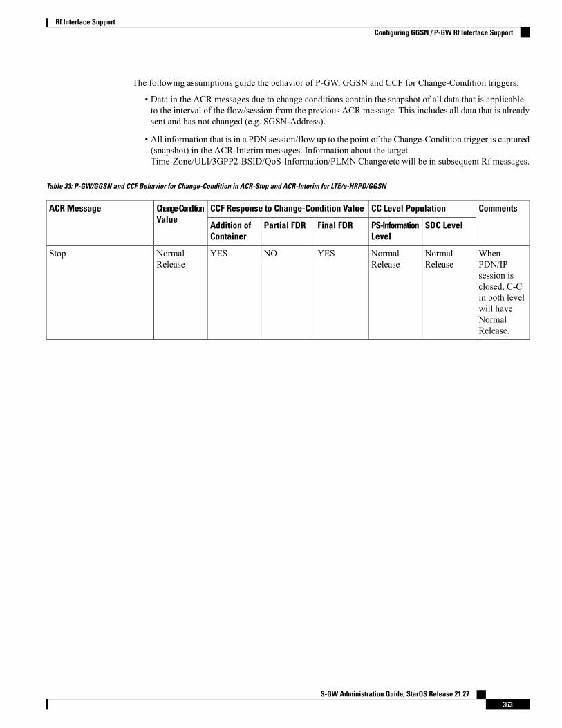
The following assumptions guide the behavior of P-GW, GGSN and CCF for Change-Condition triggers:
• Data in the ACR messages due to change conditions contain the snapshot of all data that is applicableto the interval of the flow/session from the previous ACR message. This includes all data that is alreadysent and has not changed (e.g. SGSN-Address).
• All information that is in a PDN session/flow up to the point of the Change-Condition trigger is captured(snapshot) in the ACR-Interim messages. Information about the targetTime-Zone/ULI/3GPP2-BSID/QoS-Information/PLMN Change/etc will be in subsequent Rf messages.
Table 33: P-GW/GGSN and CCF Behavior for Change-Condition in ACR-Stop and ACR-Interim for LTE/e-HRPD/GGSN
CommentsCC Level PopulationCCF Response to Change-Condition ValueChange-ConditionValue
ACR Message
SDC LevelPS-InformationLevel
Final FDRPartial FDRAddition ofContainer
WhenPDN/IPsession isclosed, C-Cin both levelwill haveNormalRelease.
NormalRelease
NormalRelease
YESNOYESNormalRelease
Stop
S-GW Administration Guide, StarOS Release 21.27363
Rf Interface SupportConfiguring GGSN / P-GW Rf Interface Support

CommentsCC Level PopulationCCF Response to Change-Condition ValueChange-ConditionValue
ACR Message
SDC LevelPS-InformationLevel
Final FDRPartial FDRAddition ofContainer
Flow isclosed, SDCCC ispopulatedand closedcontainer isadded torecord. Thecontainer forthis changeconditionwill becached bytheP-GW/GGSNand thecontainerwill be in aACRInterim/Stopsent forpartial record(Interim),final Record(Stop) or AIItrigger(Interim)trigger.
NormalRelease
N/ANONOYESNormalRelease
None (as this changecondition is a counter for theMax Number of Changes inCharging Conditions).
WhenPDN/IPsession isclosed, C-Cin both levelwill haveAbnormalRelease.
AbnormalRelease
AbnormalRelease
YESNOYESAbnormalRelease
Stop
S-GW Administration Guide, StarOS Release 21.27364
Rf Interface SupportConfiguring GGSN / P-GW Rf Interface Support
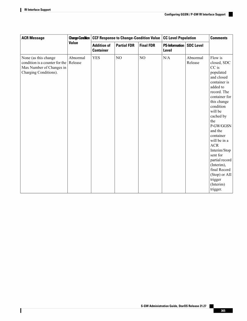
CommentsCC Level PopulationCCF Response to Change-Condition ValueChange-ConditionValue
ACR Message
SDC LevelPS-InformationLevel
Final FDRPartial FDRAddition ofContainer
Flow isclosed, SDCCC ispopulatedand closedcontainer isadded torecord. Thecontainer forthis changeconditionwill becached bytheP-GW/GGSNand thecontainerwill be in aACRInterim/Stopsent forpartial record(Interim),final Record(Stop) or AIItrigger(Interim)trigger.
AbnormalRelease
N/ANONOYESAbnormalRelease
None (as this changecondition is a counter for theMax Number of Changes inCharging Conditions).
S-GW Administration Guide, StarOS Release 21.27365
Rf Interface SupportConfiguring GGSN / P-GW Rf Interface Support
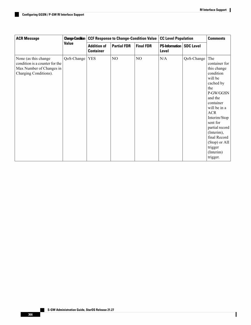
CommentsCC Level PopulationCCF Response to Change-Condition ValueChange-ConditionValue
ACR Message
SDC LevelPS-InformationLevel
Final FDRPartial FDRAddition ofContainer
Thecontainer forthis changeconditionwill becached bytheP-GW/GGSNand thecontainerwill be in aACRInterim/Stopsent forpartial record(Interim),final Record(Stop) or AIItrigger(Interim)trigger.
QoS-ChangeN/ANONOYESQoS-ChangeNone (as this changecondition is a counter for theMax Number of Changes inCharging Conditions).
S-GW Administration Guide, StarOS Release 21.27366
Rf Interface SupportConfiguring GGSN / P-GW Rf Interface Support
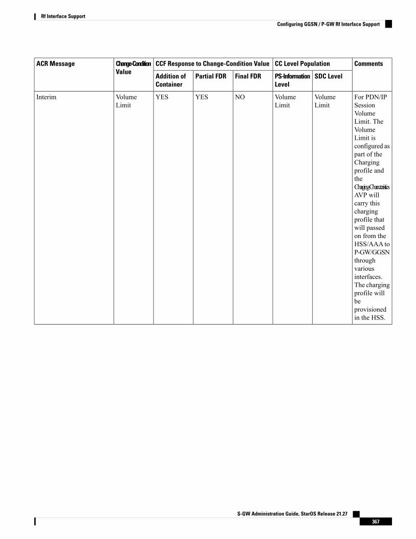
CommentsCC Level PopulationCCF Response to Change-Condition ValueChange-ConditionValue
ACR Message
SDC LevelPS-InformationLevel
Final FDRPartial FDRAddition ofContainer
For PDN/IPSessionVolumeLimit. TheVolumeLimit isconfigured aspart of theChargingprofile andtheCharging-CharacteristicsAVP willcarry thischargingprofile thatwill passedon from theHSS/AAA toP-GW/GGSNthroughvariousinterfaces.The chargingprofile willbeprovisionedin the HSS.
VolumeLimit
VolumeLimit
NOYESYESVolumeLimit
Interim
S-GW Administration Guide, StarOS Release 21.27367
Rf Interface SupportConfiguring GGSN / P-GW Rf Interface Support
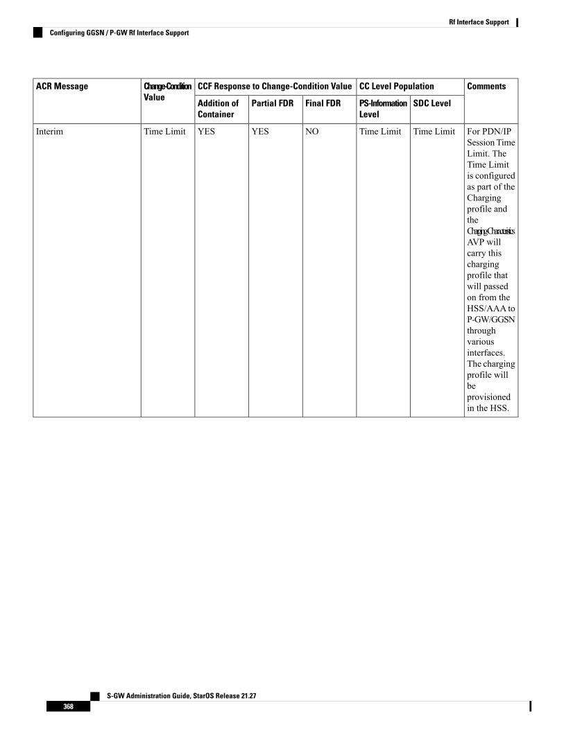
CommentsCC Level PopulationCCF Response to Change-Condition ValueChange-ConditionValue
ACR Message
SDC LevelPS-InformationLevel
Final FDRPartial FDRAddition ofContainer
For PDN/IPSession TimeLimit. TheTime Limitis configuredas part of theChargingprofile andtheCharging-CharacteristicsAVP willcarry thischargingprofile thatwill passedon from theHSS/AAA toP-GW/GGSNthroughvariousinterfaces.The chargingprofile willbeprovisionedin the HSS.
Time LimitTime LimitNOYESYESTime LimitInterim
S-GW Administration Guide, StarOS Release 21.27368
Rf Interface SupportConfiguring GGSN / P-GW Rf Interface Support
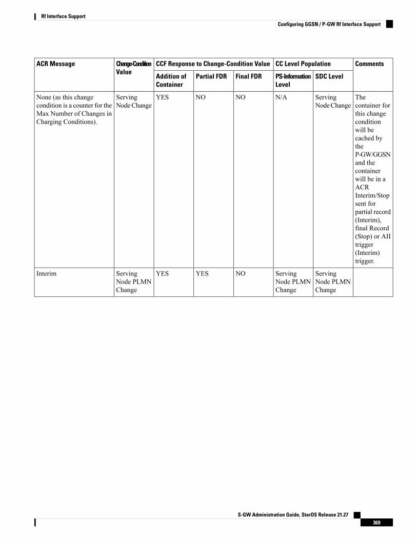
CommentsCC Level PopulationCCF Response to Change-Condition ValueChange-ConditionValue
ACR Message
SDC LevelPS-InformationLevel
Final FDRPartial FDRAddition ofContainer
Thecontainer forthis changeconditionwill becached bytheP-GW/GGSNand thecontainerwill be in aACRInterim/Stopsent forpartial record(Interim),final Record(Stop) or AIItrigger(Interim)trigger.
ServingNodeChange
N/ANONOYESServingNodeChange
None (as this changecondition is a counter for theMax Number of Changes inCharging Conditions).
ServingNode PLMNChange
ServingNode PLMNChange
NOYESYESServingNode PLMNChange
Interim
S-GW Administration Guide, StarOS Release 21.27369
Rf Interface SupportConfiguring GGSN / P-GW Rf Interface Support

CommentsCC Level PopulationCCF Response to Change-Condition ValueChange-ConditionValue
ACR Message
SDC LevelPS-InformationLevel
Final FDRPartial FDRAddition ofContainer
This is BSIDChange ineHRPD. Thecontainer forthis changeconditionwill becached bytheP-GW/GGSNand thecontainerwill be in aACRInterim/Stopsent forpartial record(Interim),final Record(Stop) or AIItrigger(Interim)trigger.
UserLocationChange
N/ANONOYESUserLocationChange
None (as this changecondition is a counter for theMax Number of Changes inCharging Conditions).
RAT ChangeRAT ChangeNOYESYESRAT ChangeInterim
This is notapplicablefor eHRPD.
UETimezonechange
UETimezonechange
NOYESYESUETimezoneChange
Interim
S-GW Administration Guide, StarOS Release 21.27370
Rf Interface SupportConfiguring GGSN / P-GW Rf Interface Support
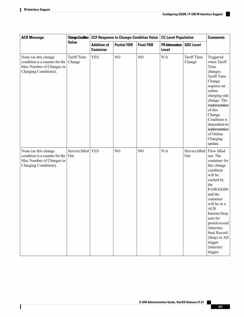
CommentsCC Level PopulationCCF Response to Change-Condition ValueChange-ConditionValue
ACR Message
SDC LevelPS-InformationLevel
Final FDRPartial FDRAddition ofContainer
Triggeredwhen TariffTimechanges.Tariff TimeChangerequires anonlinecharging sidechange. Theimplementationof thisChangeCondition isdependent onimplementationof OnlineChargingupdate.
Tariff TimeChange
N/ANONOYESTariff TimeChange
None (as this changecondition is a counter for theMax Number of Changes inCharging Conditions).
Flow Idledout. Thecontainer forthis changeconditionwill becached bytheP-GW/GGSNand thecontainerwill be in aACRInterim/Stopsent forpartial record(Interim),final Record(Stop) or AIItrigger(Interim)trigger.
Service IdledOut
N/ANONOYESService IdledOut
None (as this changecondition is a counter for theMax Number of Changes inCharging Conditions).
S-GW Administration Guide, StarOS Release 21.27371
Rf Interface SupportConfiguring GGSN / P-GW Rf Interface Support

CommentsCC Level PopulationCCF Response to Change-Condition ValueChange-ConditionValue
ACR Message
SDC LevelPS-InformationLevel
Final FDRPartial FDRAddition ofContainer
VolumeLimitreached for aspecific flow.Thecontainer forthis changeconditionwill becached bytheP-GW/GGSNand thecontainerwill be in aACRInterim/Stopsent forpartial record(Interim),final Record(Stop) or AIItrigger(Interim)trigger.
Service DataVolumeLimit
N/ANONOYESService DataVolumeLimit
None (as this changecondition is a counter for theMax Number of Changes inCharging Conditions).
S-GW Administration Guide, StarOS Release 21.27372
Rf Interface SupportConfiguring GGSN / P-GW Rf Interface Support
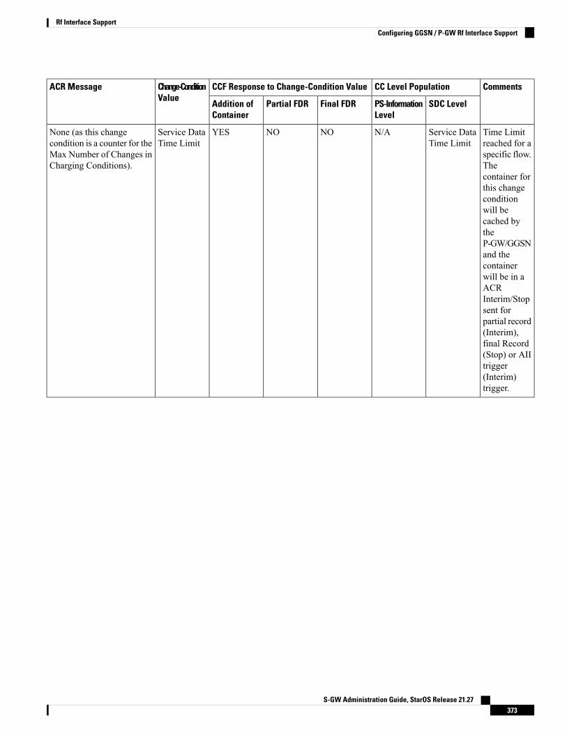
CommentsCC Level PopulationCCF Response to Change-Condition ValueChange-ConditionValue
ACR Message
SDC LevelPS-InformationLevel
Final FDRPartial FDRAddition ofContainer
Time Limitreached for aspecific flow.Thecontainer forthis changeconditionwill becached bytheP-GW/GGSNand thecontainerwill be in aACRInterim/Stopsent forpartial record(Interim),final Record(Stop) or AIItrigger(Interim)trigger.
Service DataTime Limit
N/ANONOYESService DataTime Limit
None (as this changecondition is a counter for theMax Number of Changes inCharging Conditions).
S-GW Administration Guide, StarOS Release 21.27373
Rf Interface SupportConfiguring GGSN / P-GW Rf Interface Support

CommentsCC Level PopulationCCF Response to Change-Condition ValueChange-ConditionValue
ACR Message
SDC LevelPS-InformationLevel
Final FDRPartial FDRAddition ofContainer
YES, Willinclude SDCthatcorreponds tothe CCs thatoccurred(NormalRelease ofFlow,AbnormalRelease ofFlow,QoS-Change,ServingNodeChange,UserLocationChange,Tariff TimeChange,Service IdledOut, ServiceDataVolunmeLimt, ServiceData TimeLimit)
YESNOYESYESMaxNumberof Changesin ChargingConditions
Interim
S-GW Administration Guide, StarOS Release 21.27374
Rf Interface SupportConfiguring GGSN / P-GW Rf Interface Support
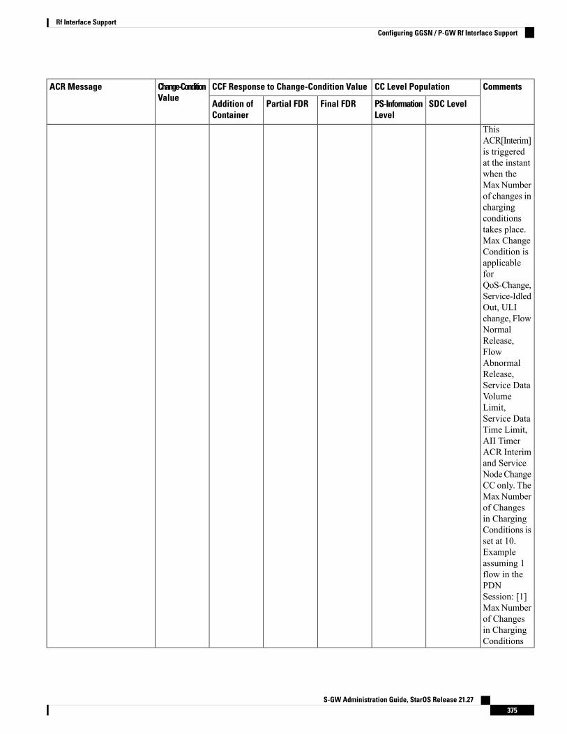
CommentsCC Level PopulationCCF Response to Change-Condition ValueChange-ConditionValue
ACR Message
SDC LevelPS-InformationLevel
Final FDRPartial FDRAddition ofContainer
ThisACR[Interim]is triggeredat the instantwhen theMaxNumberof changes inchargingconditionstakes place.Max ChangeCondition isapplicableforQoS-Change,Service-IdledOut, ULIchange, FlowNormalRelease,FlowAbnormalRelease,Service DataVolumeLimit,Service DataTime Limit,AII TimerACR Interimand ServiceNodeChangeCC only. TheMaxNumberof Changesin ChargingConditions isset at 10.Exampleassuming 1flow in thePDNSession: [1]MaxNumberof Changesin ChargingConditions
S-GW Administration Guide, StarOS Release 21.27375
Rf Interface SupportConfiguring GGSN / P-GW Rf Interface Support
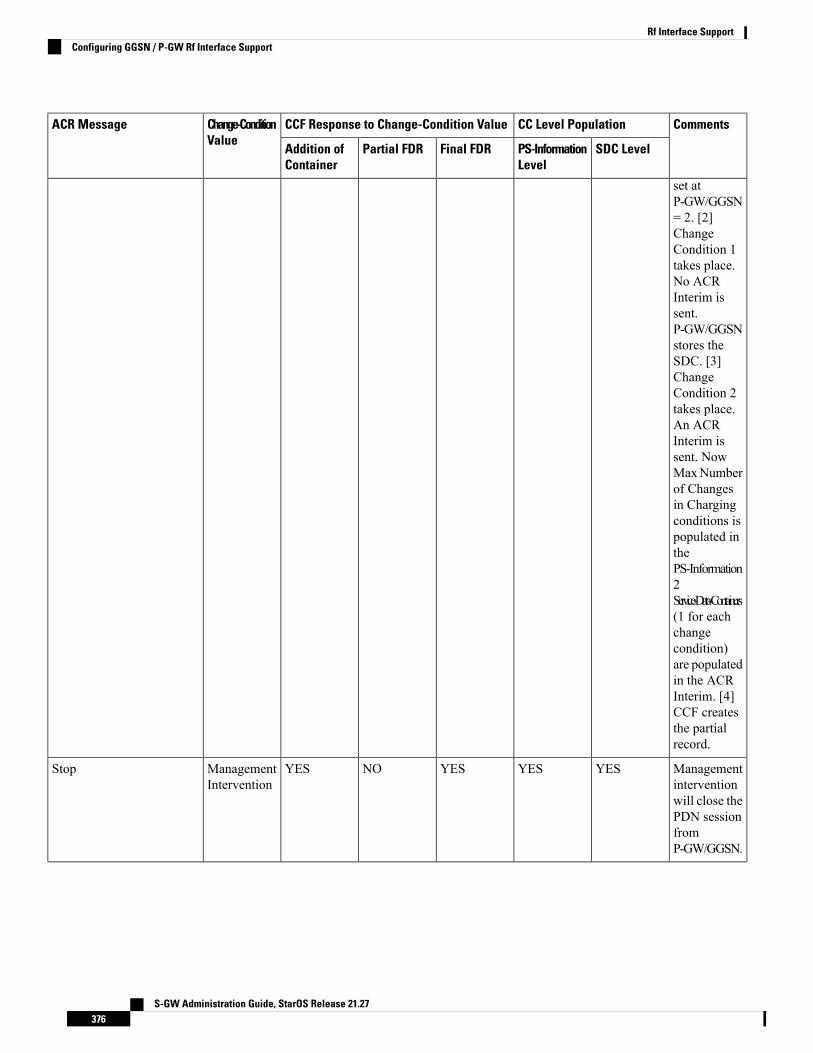
CommentsCC Level PopulationCCF Response to Change-Condition ValueChange-ConditionValue
ACR Message
SDC LevelPS-InformationLevel
Final FDRPartial FDRAddition ofContainer
set atP-GW/GGSN= 2. [2]ChangeCondition 1takes place.No ACRInterim issent.P-GW/GGSNstores theSDC. [3]ChangeCondition 2takes place.An ACRInterim issent. NowMaxNumberof Changesin Chargingconditions ispopulated inthePS-Information2Service-Data-Containers(1 for eachchangecondition)are populatedin the ACRInterim. [4]CCF createsthe partialrecord.
Managementinterventionwill close thePDN sessionfromP-GW/GGSN.
YESYESYESNOYESManagementIntervention
Stop
S-GW Administration Guide, StarOS Release 21.27376
Rf Interface SupportConfiguring GGSN / P-GW Rf Interface Support

CommentsCC Level PopulationCCF Response to Change-Condition ValueChange-ConditionValue
ACR Message
SDC LevelPS-InformationLevel
Final FDRPartial FDRAddition ofContainer
This isincluded hereto indicatethat anACR[Interim]due to AIItimer willcontain oneor morepopulatedSDC/s fora/all flow/s,butChange-ConditionAVP willNOT bepopulated.
N/AN/ANONOYES-Interim
Configuring P-CSCF/S-CSCF Rf Interface SupportTo configure P-CSCF/S-CSCF Rf interface support, use the following configuration:
configurecontext vpn
aaa group default
diameter authentication dictionary aaa-custom8diameter accounting dictionary aaa-custom2diameter accounting endpoint <endpoint_name>
diameter accounting server <server_name> priority <priority>
exitdiameter endpoint <endpoint_name>
origin realm <realm_name>
use-proxyorigin host <host_name> address <ip_address>
peer <peer_name> address <ip_address>
exitend
Notes:
• For information on commands used in the basic configuration for Rf support, refer to the Command LineInterface Reference.
Gathering StatisticsThis section explains how to gather Rf and related statistics and configuration information.
S-GW Administration Guide, StarOS Release 21.27377
Rf Interface SupportConfiguring P-CSCF/S-CSCF Rf Interface Support
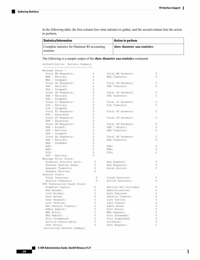
In the following table, the first column lists what statistics to gather, and the second column lists the actionto perform.
Action to performStatistics/Information
show diameter aaa-statisticsComplete statistics for Diameter Rf accountingsessions
The following is a sample output of the show diameter aaa-statistics command:Authentication Servers Summary-------------------------------Message Stats :Total MA Requests: 0 Total MA Answers: 0MAR - Retries: 0 MAA Timeouts: 0MAA - Dropped: 0Total SA Requests: 0 Total SA Answers: 0SAR - Retries: 0 SAA Timeouts: 0SAA - Dropped: 0Total UA Requests: 0 Total UA Answers: 0UAR - Retries: 0 UAA Timeouts: 0UAA - Dropped: 0Total LI Requests: 0 Total LI Answers: 0LIR - Retries: 0 LIA Timeouts: 0LIA - Dropped: 0Total RT Requests: 0 Total RT Answers: 0RTR - Rejected: 0Total PP Requests: 0 Total PP Answers: 0PPR - Rejected: 0Total DE Requests: 0 Total DE Answers: 0DEA - Accept: 0 DEA - Reject: 0DER - Retries: 0 DEA Timeouts: 0DEA - Dropped: 0Total AA Requests: 0 Total AA Answers: 0AAR - Retries: 0 AAA Timeouts: 0AAA - Dropped: 0ASR: 0 ASA: 0RAR: 0 RAA: 0STR: 0 STA: 0STR - Retries: 0
Message Error Stats:Diameter Protocol Errs: 0 Bad Answers: 0Unknown Session Reqs: 0 Bad Requests: 0Request Timeouts: 0 Parse Errors: 0Request Retries: 0
Session Stats:Total Sessions: 0 Freed Sessions: 0Session Timeouts: 0 Active Sessions: 0
STR Termination Cause Stats:Diameter Logout: 0 Service Not Provided: 0Bad Answer: 0 Administrative: 0Link Broken: 0 Auth Expired: 0User Moved: 0 Session Timeout: 0User Request: 0 Lost Carrier 0Lost Service: 0 Idle Timeout 0NAS Session Timeout: 0 Admin Reset 0Admin Reboot: 0 Port Error: 0NAS Error: 0 NAS Request: 0NAS Reboot: 0 Port Unneeded: 0Port Preempted: 0 Port Suspended: 0Service Unavailable: 0 Callback: 0User Error: 0 Host Request: 0Accounting Servers Summary
S-GW Administration Guide, StarOS Release 21.27378
Rf Interface SupportGathering Statistics

---------------------------Message Stats :Total AC Requests: 0 Total AC Answers: 0ACR-Start: 0 ACA-Start: 0ACR-Start Retries : 0 ACA-Start Timeouts: 0ACR-Interim: 0 ACA-Interim: 0ACR-Interim Retries : 0 ACA-Interim Timeouts: 0ACR-Event: 0 ACA-Event: 0ACR-Stop : 0 ACA-Stop: 0ACR-Stop Retries : 0 ACA-Stop Timeouts: 0ACA-Dropped : 0
AC Message Error Stats:Diameter Protocol Errs: 0 Bad Answers: 0Unknown Session Reqs: 0 Bad Requests: 0Request Timeouts: 0 Parse Errors: 0Request Retries: 0
S-GW Administration Guide, StarOS Release 21.27379
Rf Interface SupportGathering Statistics

S-GW Administration Guide, StarOS Release 21.27380
Rf Interface SupportGathering Statistics
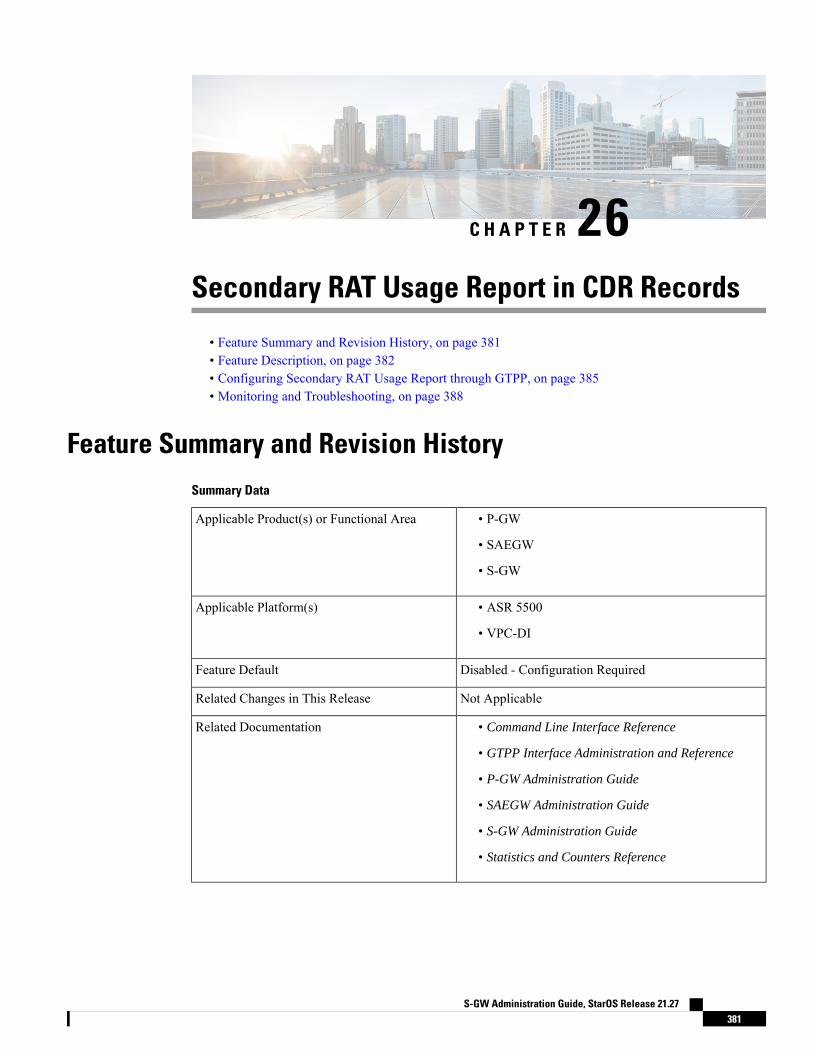
C H A P T E R 26Secondary RAT Usage Report in CDR Records
• Feature Summary and Revision History, on page 381• Feature Description, on page 382• Configuring Secondary RAT Usage Report through GTPP, on page 385• Monitoring and Troubleshooting, on page 388
Feature Summary and Revision HistorySummary Data
• P-GW
• SAEGW
• S-GW
Applicable Product(s) or Functional Area
• ASR 5500
• VPC-DI
Applicable Platform(s)
Disabled - Configuration RequiredFeature Default
Not ApplicableRelated Changes in This Release
• Command Line Interface Reference
• GTPP Interface Administration and Reference
• P-GW Administration Guide
• SAEGW Administration Guide
• S-GW Administration Guide
• Statistics and Counters Reference
Related Documentation
S-GW Administration Guide, StarOS Release 21.27381
Revision History
ReleaseRevision Details
• 21.26
• 21.23.14
P-GW and S-GW supports secondary RAT usage reports and CDRsprocessing through GTPP Group Configuration CLIs.
21.20.31P-GW and S-GW supports secondary RAT usage reports and CDRsprocessing through GTPP Group Configuration CLIs.
21.22.n7First Introduced.
Feature DescriptionReporting issues pertaining to 5G RANSecondaryRATUsageReport occur due to lack of:
• Control in identifying whether the RANSecondaryRATUsageReport must be processed in CDRs ornot. This allows the S-GW, P-GW, and SAEGW to either include these reports in the SGW-CDR orPGW- CDR or to simply ignore them.
• Number of available reports inside a CDR, if the control is active.
• Control in identifying whether Zero-volume reports must make it inside the CDR or not.
This results in billing loss of data. To overcome these reporting issues, you can trigger CLI controls usingGTPP group configuration to:
• Allow the S-GW, P-GW, and SAEGW to either include the RANSecondary RAT Usage reports in theSGW-CDR or PGW-CDR or to simply ignore them.
• Identify the number of secondary RAT usage reports available inside the SGW-CDR or the PGW- CDR.
This limit must be in accordancewith the system capability and ensureto consider the File-Format of the CDRs. If the configured limitexceeds, the system closes the SGW-CDR or PGW-CDR with theappropriate change-condition. For example,max-change-conditionCDR is reused for further reports.
Note
• Add or ignore Zero-volume reports inside the CDR.
• The CLI gtpp limit-secondary-rat-usage or hardcoded limit will be removed and the CLI gtpplimit-secondary-rat-usage is reused to control the number of records within the range 1-100.
• Provides logging when the CDR size reaches the maximum size. Through PGW-CDR counter, you canmonitor the number of occurrences when the CDR exceeds its size limit.
Behavior MatrixThe following table explains the new behavior of P-GW and S-GW for this feature.
S-GW Administration Guide, StarOS Release 21.27382
Secondary RAT Usage Report in CDR RecordsFeature Description
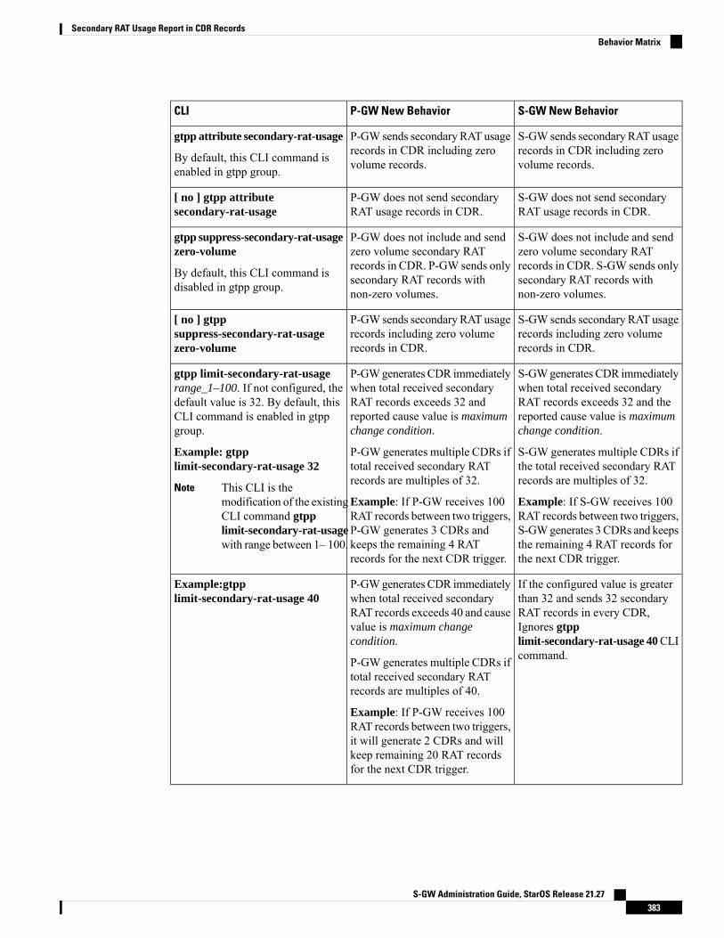
S-GW New BehaviorP-GW New BehaviorCLI
S-GW sends secondary RAT usagerecords in CDR including zerovolume records.
P-GW sends secondary RAT usagerecords in CDR including zerovolume records.
gtpp attribute secondary-rat-usage
By default, this CLI command isenabled in gtpp group.
S-GW does not send secondaryRAT usage records in CDR.
P-GW does not send secondaryRAT usage records in CDR.
[ no ] gtpp attributesecondary-rat-usage
S-GW does not include and sendzero volume secondary RATrecords in CDR. S-GW sends onlysecondary RAT records withnon-zero volumes.
P-GW does not include and sendzero volume secondary RATrecords in CDR. P-GW sends onlysecondary RAT records withnon-zero volumes.
gtpp suppress-secondary-rat-usagezero-volume
By default, this CLI command isdisabled in gtpp group.
S-GW sends secondary RAT usagerecords including zero volumerecords in CDR.
P-GW sends secondary RAT usagerecords including zero volumerecords in CDR.
[ no ] gtppsuppress-secondary-rat-usagezero-volume
S-GWgenerates CDR immediatelywhen total received secondaryRAT records exceeds 32 and thereported cause value is maximumchange condition.
S-GW generates multiple CDRs ifthe total received secondary RATrecords are multiples of 32.
Example: If S-GW receives 100RAT records between two triggers,S-GWgenerates 3 CDRs and keepsthe remaining 4 RAT records forthe next CDR trigger.
P-GWgenerates CDR immediatelywhen total received secondaryRAT records exceeds 32 andreported cause value is maximumchange condition.
P-GW generates multiple CDRs iftotal received secondary RATrecords are multiples of 32.
Example: If P-GW receives 100RAT records between two triggers,P-GW generates 3 CDRs andkeeps the remaining 4 RATrecords for the next CDR trigger.
gtpp limit-secondary-rat-usagerange_1–100. If not configured, thedefault value is 32. By default, thisCLI command is enabled in gtppgroup.
Example: gtpplimit-secondary-rat-usage 32
This CLI is themodification of the existingCLI command gtpplimit-secondary-rat-usagewith range between 1– 100.
Note
If the configured value is greaterthan 32 and sends 32 secondaryRAT records in every CDR,Ignores gtpplimit-secondary-rat-usage 40CLIcommand.
P-GWgenerates CDR immediatelywhen total received secondaryRAT records exceeds 40 and causevalue is maximum changecondition.
P-GW generates multiple CDRs iftotal received secondary RATrecords are multiples of 40.
Example: If P-GW receives 100RAT records between two triggers,it will generate 2 CDRs and willkeep remaining 20 RAT recordsfor the next CDR trigger.
Example:gtpplimit-secondary-rat-usage 40
S-GW Administration Guide, StarOS Release 21.27383
Secondary RAT Usage Report in CDR RecordsBehavior Matrix

S-GW New BehaviorP-GW New BehaviorCLI
S-GWgenerates CDR immediatelywhen the total received secondaryRAT records exceeds 20 and causevalue is maximum changecondition.
S-GW generates multiple CDRs iftotal received secondary RATrecords are in multiples of 20.
Example: If S-GW receives 100RAT records between two triggers,it will generate 5 CDRs.
P-GWgenerates CDR immediatelywhen total received secondaryRAT records exceed 20 and causevalue is maximum changecondition.
P-GW generates multiple CDRs iftotal received secondary RATrecords are multiples of 20.
Example: If P-GW receives 100RAT records between two triggers,P-GW generates 2 CDRs and willstore the remaining 20 RATrecords for the next CDR trigger.
Example:gtpplimit-secondary-rat-usage 20
Ignores the [ no ] gtpplimit-secondary-rat-usage CLIand sends 32 secondary RATrecords in every CDR.
Behavior is similar to the gtpplimit-secondary-rat-usage 32CLIimplementation.
Counter and debug logs are notrequired as it will never exceed theCDR size of 64k.
Generates CDR immediatelywhenthe total received secondary RATrecords exceed 255 and causevalue is maximum changecondition.
Generates multiple CDRs if thetotal received secondary RATrecords are multiples of 255.
Example: If 1000 RAT recordsbetween two triggers are received,then 3 CDRs are generated. Theremaining 235 RAT records arestored for the next CDR trigger.
[ no ] gtpplimit-secondary-rat-usage
Record ClosureService-specific unit limit is sentin the serviceConditionChangefile.
Relationship to Other Features• Sessmgr Restart While Processing Secondary RAT Usage CDR Records in the P-GW Administration
Guide.
• Secondary RAT Usage IE during GnGp handover, S-GW, and P-GW support of Secondary RAT DataUsage Report in Gz CDRs, see the 5G Non-Standalone chapter in the P-GW Administration Guide.
• P-GW support of Secondary RAT Data Usage Report in Rf CDRs, see the 5G Non-Standalone chapterin the P-GW Administration Guide.
LimitationsThis feature has the following limitations:
S-GW Administration Guide, StarOS Release 21.27384
Secondary RAT Usage Report in CDR RecordsRelationship to Other Features
• S-GW allows a maximum number of 16 secondary RAT records per bearer during session recovery andcheckpointing.
• P-GW allows a maximum number of 142 secondary RAT records across all bearers during sessionrecovery and checkpointing.
• Anything beyond these numbers gets lost during session recovery.
Configuring Secondary RAT Usage Report through GTPPUse the following GTPP configurations to close Secondary RAT Usage CDR records before exceeding abuffer size.
Enabling or Disabling the Secondary RAT Usage ReportUse the following configuration to enable or disable secondary RAT Usage report.
configurecontext context_name
gtpp group group_name
gtpp attribute secondary-rat-usagedefault gtpp attribute secondary-rat-usageno gtpp attribute secondary-rat-usageend
NOTES:
• gtpp attribute secondary-rat-usage: Sends an optional attribute Secondary RAT usage records.
• default gtpp attribute secondary-rat-usage: Sends an optional attribute Secondary RAT usage recordsby default.
• no gtpp attribute secondary-rat-usage: Does not send the optional attribute Secondary RAT usagerecords.
Controlling the Maximum Number of EntriesWhen the Secondary RAT usage record reaches the maximum configured value within a CDR, the CDRclosure cause occurs and uses maxChangeCond. The gtpp limit-secondary-RAT-usage CLI commandcontrols the maximum number of Secondary RAT usage record entries in the P-GW and S-GW CDRs. If thelimit is configured with a value more than 32, the partial CDRs get generated with a maximum of 32 for S-GWCDR.
The existing behaviour of S-GW has a limit of 32 Secondary RAT Usage records.Note
The following table explains the behavior of Secondary RAT records and CDR, and the maximum limit.
S-GW Administration Guide, StarOS Release 21.27385
Secondary RAT Usage Report in CDR RecordsConfiguring Secondary RAT Usage Report through GTPP
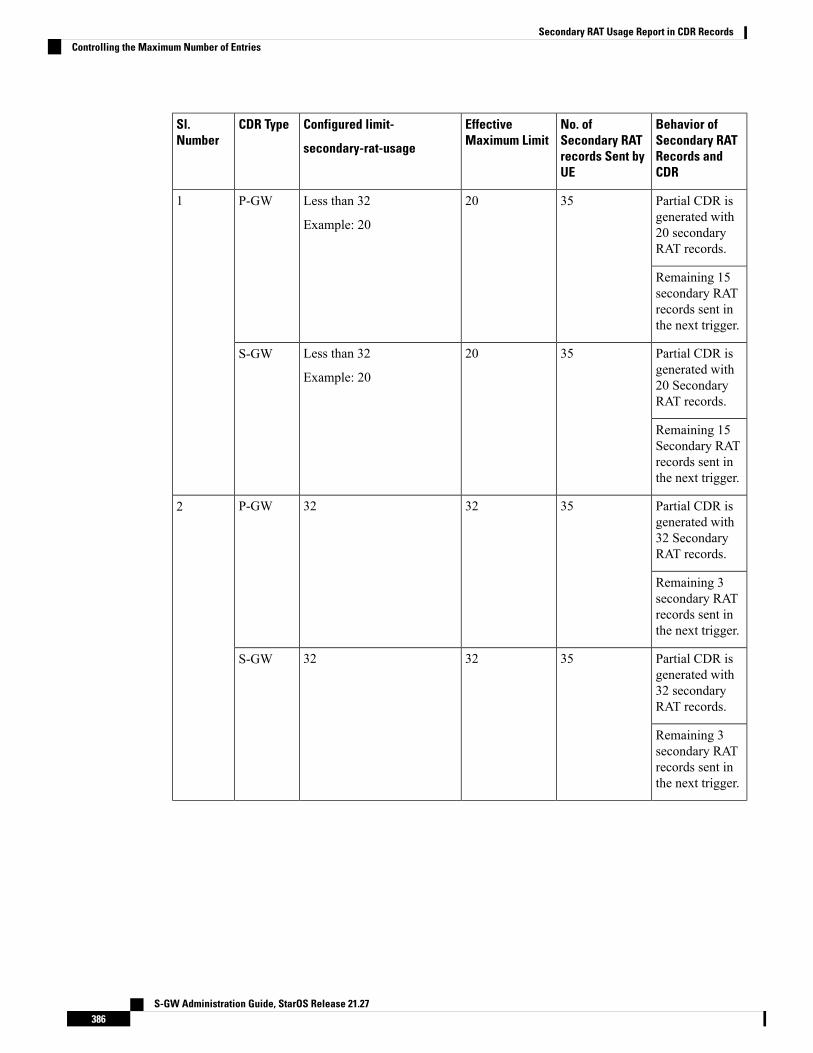
Behavior ofSecondary RATRecords andCDR
No. ofSecondary RATrecords Sent byUE
EffectiveMaximum Limit
Configured limit-
secondary-rat-usage
CDR TypeSl.Number
Partial CDR isgenerated with20 secondaryRAT records.
3520Less than 32
Example: 20
P-GW1
Remaining 15secondary RATrecords sent inthe next trigger.
Partial CDR isgenerated with20 SecondaryRAT records.
3520Less than 32
Example: 20
S-GW
Remaining 15Secondary RATrecords sent inthe next trigger.
Partial CDR isgenerated with32 SecondaryRAT records.
353232P-GW2
Remaining 3secondary RATrecords sent inthe next trigger.
Partial CDR isgenerated with32 secondaryRAT records.
353232S-GW
Remaining 3secondary RATrecords sent inthe next trigger.
S-GW Administration Guide, StarOS Release 21.27386
Secondary RAT Usage Report in CDR RecordsControlling the Maximum Number of Entries
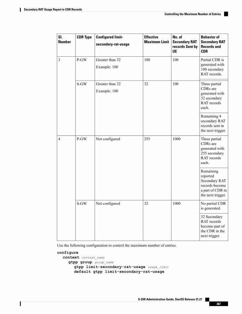
Behavior ofSecondary RATRecords andCDR
No. ofSecondary RATrecords Sent byUE
EffectiveMaximum Limit
Configured limit-
secondary-rat-usage
CDR TypeSl.Number
Partial CDR isgenerated with100 secondaryRAT records.
100100Greater than 32
Example: 100
P-GW3
Three partialCDRs aregenerated with32 secondaryRAT recordseach.
10032Greater than 32
Example: 100
S-GW
Remaining 4secondary RATrecords sent inthe next trigger.
Three partialCDRs aregenerated with255 secondaryRAT recordseach.
1000255Not configuredP-GW4
RemainingreportedSecondary RATrecords becomea part of CDR inthe next trigger.
No partial CDRis generated.
100032Not configuredS-GW
32 SecondaryRAT recordsbecome part ofthe CDR in thenext trigger.
Use the following configuration to control the maximum number of entries.
configurecontext context_name
gtpp group group_name
gtpp limit-secondary-rat-usage usage_limit
default gtpp limit-secondary-rat-usage
S-GW Administration Guide, StarOS Release 21.27387
Secondary RAT Usage Report in CDR RecordsControlling the Maximum Number of Entries

no gtpp limit-secondary-rat-usageend
NOTES:
• gtpp limit-secondary-rat-usage usage_limit: Enter a maximum number of secondary RAT reports.usage_limit must be an integer in the range of 1-100. The recommended value for S-GW CDR is 32.
For example, if the limit is set to 10, then the CDR is generated once the configured value is reached.
• default gtpp limit-secondary-rat-usage: Specifies a default value of 32.
• no gtpp limit-secondary-rat-usage: Disables the CDR generation with limited number of secondaryRAT usage information.
Suppressing Zero-Volume Secondary RAT Usage ReportUse the following configuration to suppress zero-volume Secondary RAT Usage report.
configurecontext context_name
gtpp group group_name
gtpp suppress-secondary-rat-usage zero-volumedefault gtpp suppress-secondary-rat-usage zero-volumeno gtpp suppress-secondary-rat-usage zero-volumeend
NOTES:
• gtpp suppress-secondary-rat-usage zero-volume: Suppresses either Secondary RAT records or zerovolume Secondary RAT records.
• default gtpp suppress-secondary-rat-usage zero-volume: Does not suppress the zero volume secondaryRAT usage records.
• no gtpp suppress-secondary-rat-usage zero-volume: Does not suppress the zero volume SecondaryRAT usage records.
Monitoring and TroubleshootingThis section provides information on how to monitor and troubleshoot using show commands available insupport of this feature.
Show Commands and OutputsThis section provides information regarding show commands and their outputs for this feature.
show configThe output of this CLI command displays the following parameters.
S-GW Administration Guide, StarOS Release 21.27388
Secondary RAT Usage Report in CDR RecordsSuppressing Zero-Volume Secondary RAT Usage Report
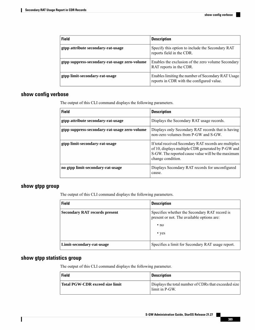
DescriptionField
Specify this option to include the Secondary RATreports field in the CDR.
gtpp attribute secondary-rat-usage
Enables the exclusion of the zero volume SecondaryRAT reports in the CDR.
gtpp suppress-secondary-rat-usage zero-volume
Enables limiting the number of Secondary RATUsagereports in CDR with the configured value.
gtpp limit-secondary-rat-usage
show config verboseThe output of this CLI command displays the following parameters.
DescriptionField
Displays the Secondary RAT usage records.gtpp attribute secondary-rat-usage
Displays only Secondary RAT records that is havingnon-zero volumes from P-GW and S-GW.
gtpp suppress-secondary-rat-usage zero-volume
If total received Secondary RAT records are multiplesof 10, displays multiple CDR generated by P-GW andS-GW. The reported cause value will be the maximumchange condition.
gtpp limit-secondary-rat-usage
Displays Secondary RAT records for unconfiguredcause.
no gtpp limit-secondary-rat-usage
show gtpp groupThe output of this CLI command displays the following parameters.
DescriptionField
Specifies whether the Secondary RAT record ispresent or not. The available options are:
• no
• yes
Secondary RAT records present
Specifies a limit for Secondary RAT usage report.Limit-secondary-rat-usage
show gtpp statistics groupThe output of this CLI command displays the following parameter.
DescriptionField
Displays the total number of CDRs that exceeded sizelimit in P-GW.
Total PGW-CDR exceed size limit
S-GW Administration Guide, StarOS Release 21.27389
Secondary RAT Usage Report in CDR Recordsshow config verbose

S-GW Administration Guide, StarOS Release 21.27390
Secondary RAT Usage Report in CDR Recordsshow gtpp statistics group

C H A P T E R 27S-GW Event Reporting
This chapter describes the record content and trigger mechanisms for S-GW event reporting. When enabledthe S-GW writes a record of session events and sends the resulting event files to an external file server forprocessing. Each event is sent to the server within 60 seconds of its occurrence.
The S-GW Event Reporting feature is applicable to S-GW and SAEGW (Pure-S calls).Note
This chapter includes the following topics:
• S-GW Event Reporting, on page 391
S-GW Event ReportingThis chapter describes the record content and trigger mechanisms for S-GW event reporting. When enabledthe S-GW writes a record of session events and sends the resulting event files to an external file server forprocessing. Each event is sent to the server within 60 seconds of its occurrence.
The S-GW Event Reporting feature is applicable to S-GW and SAEGW (Pure-S calls).Note
This chapter includes the following topics:
Event Record TriggersWhen properly configured, the S-GW creates and sends a record in CSV format as the session events listedbelow occur.
• ID 1: Session Creation• ID 2: Session Deletion• ID 3: Bearer Creation• ID 4: Bearer Deletion• ID 5: Bearer Modification
• suppress intra-system handover• configurable enable active to idle transition event reporting
S-GW Administration Guide, StarOS Release 21.27391
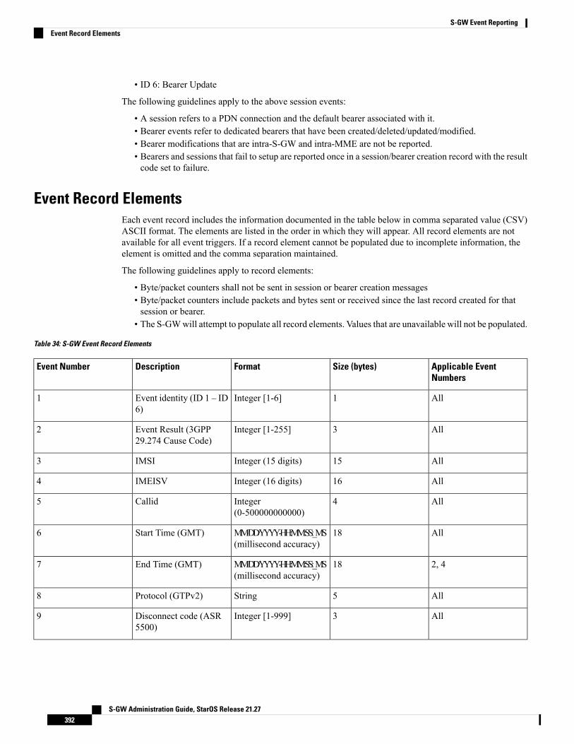
• ID 6: Bearer Update
The following guidelines apply to the above session events:
• A session refers to a PDN connection and the default bearer associated with it.• Bearer events refer to dedicated bearers that have been created/deleted/updated/modified.• Bearer modifications that are intra-S-GW and intra-MME are not be reported.• Bearers and sessions that fail to setup are reported once in a session/bearer creation record with the resultcode set to failure.
Event Record ElementsEach event record includes the information documented in the table below in comma separated value (CSV)ASCII format. The elements are listed in the order in which they will appear. All record elements are notavailable for all event triggers. If a record element cannot be populated due to incomplete information, theelement is omitted and the comma separation maintained.
The following guidelines apply to record elements:
• Byte/packet counters shall not be sent in session or bearer creation messages• Byte/packet counters include packets and bytes sent or received since the last record created for thatsession or bearer.
• The S-GWwill attempt to populate all record elements. Values that are unavailable will not be populated.
Table 34: S-GW Event Record Elements
Applicable EventNumbers
Size (bytes)FormatDescriptionEvent Number
All1Integer [1-6]Event identity (ID 1 – ID6)
1
All3Integer [1-255]Event Result (3GPP29.274 Cause Code)
2
All15Integer (15 digits)IMSI3
All16Integer (16 digits)IMEISV4
All4Integer(0-500000000000)
Callid5
All18MM/DD/YYYY-HH:MM:SS:_MS(millisecond accuracy)
Start Time (GMT)6
2, 418MM/DD/YYYY-HH:MM:SS:_MS(millisecond accuracy)
End Time (GMT)7
All5StringProtocol (GTPv2)8
All3Integer [1-999]Disconnect code (ASR5500)
9
S-GW Administration Guide, StarOS Release 21.27392
S-GW Event ReportingEvent Record Elements
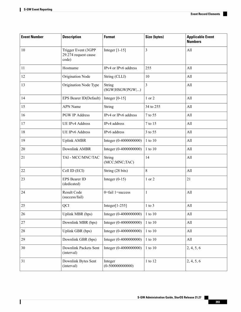
Applicable EventNumbers
Size (bytes)FormatDescriptionEvent Number
All3Integer [1-15]Trigger Event (3GPP29.274 request causecode)
10
All255IPv4 or IPv6 addressHostname11
All10String (CLLI)Origination Node12
All3String(SGW|HSGW|PGW|...)
Origination Node Type13
All1 or 2Integer [0-15]EPS Bearer ID(Default)14
All34 to 255StringAPN Name15
All7 to 55IPv4 or IPv6 addressPGW IP Address16
All7 to 15IPv4 addressUE IPv4 Address17
All3 to 55IPv6 addressUE IPv6 Address18
All1 to 10Integer (0-4000000000)Uplink AMBR19
All1 to 10Integer (0-4000000000)Downlink AMBR20
All14String(MCC;MNC;TAC)
TAI - MCC/MNC/TAC21
All8String (28 bits)Cell ID (ECI)22
211 or 2Integer (0-15)EPS Bearer ID(dedicated)
23
All10=fail 1=successResult Code(success/fail)
24
All1 to 3Integer[1-255]QCI25
All1 to 10Integer (0-4000000000)Uplink MBR (bps)26
All1 to 10Integer (0-4000000000)Downlink MBR (bps)27
All1 to 10Integer (0-4000000000)Uplink GBR (bps)28
All1 to 10Integer (0-4000000000)Downlink GBR (bps)29
2, 4, 5, 61 to 10Integer (0-4000000000)Downlink Packets Sent(interval)
30
2, 4, 5, 61 to 12Integer(0-500000000000)
Downlink Bytes Sent(interval)
31
S-GW Administration Guide, StarOS Release 21.27393
S-GW Event ReportingEvent Record Elements

Applicable EventNumbers
Size (bytes)FormatDescriptionEvent Number
2, 4, 5, 61 to 12Integer(0-500000000000)
Downlink PacketsDropped (interval)
32
2, 4, 5, 61 to 12Integer(0-500000000000)
Uplink Packets Sent(interval)
33
2, 4, 5, 61 to 12Integer(0-500000000000)
Uplink Bytes Sent(interval)
34
2, 4, 5, 61 to 10Integer (0-4000000000)Uplink Packets Dropped(interval)
35
All7 to 55IPv4 or IPv6 addressMME S11 IP Address36
All7 to 55IPv4 or IPv6 addressS1u IP Address ofeNodeB
37
Active-to-Idle TransitionsThis table below describes how active-to-idle transitions generate event records.
Table 35: Subscriber-initiated Attach (initial) Call Flow Description
DescriptionStep
UE becomes Active (via UE or NW initiated servicerequest)
1
Session becomes idle.2
S-GW acknowledges idle session.3
Bearer modification event record is created, with thefollowing fields:
• Start Time: Use the start time of the idle-to-activetransition
• End Time: Use the timestamp of the idle time
• Bytes up/Bytes down: Amount of data sentbetween transitions
• Packets up/Packets down: Number of packetssent between transitions
4
S-GW Administration Guide, StarOS Release 21.27394
S-GW Event ReportingActive-to-Idle Transitions
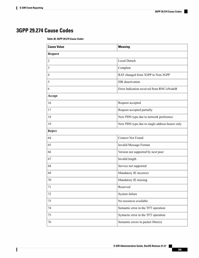
3GPP 29.274 Cause CodesTable 36: 3GPP 29.274 Cause Codes
MeaningCause Value
Request
Local Detach2
Complete3
RAT changed from 3GPP to Non-3GPP4
ISR deactivation5
Error Indication received from RNC/eNodeB6
Accept
Request accepted16
Request accepted partially17
New PDN type due to network preference18
New PDN type due to single address bearer only19
Reject
Context Not Found64
Invalid Message Format65
Version not supported by next peer66
Invalid length67
Service not supported68
Mandatory IE incorrect69
Mandatory IE missing70
Reserved71
System failure72
No resources available73
Semantic error in the TFT operation74
Syntactic error in the TFT operation75
Semantic errors in packet filter(s)76
S-GW Administration Guide, StarOS Release 21.27395
S-GW Event Reporting3GPP 29.274 Cause Codes
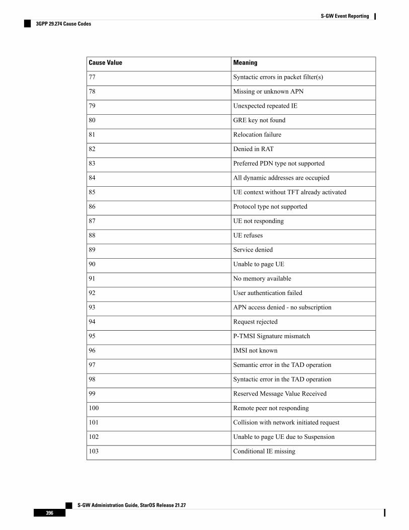
MeaningCause Value
Syntactic errors in packet filter(s)77
Missing or unknown APN78
Unexpected repeated IE79
GRE key not found80
Relocation failure81
Denied in RAT82
Preferred PDN type not supported83
All dynamic addresses are occupied84
UE context without TFT already activated85
Protocol type not supported86
UE not responding87
UE refuses88
Service denied89
Unable to page UE90
No memory available91
User authentication failed92
APN access denied - no subscription93
Request rejected94
P-TMSI Signature mismatch95
IMSI not known96
Semantic error in the TAD operation97
Syntactic error in the TAD operation98
Reserved Message Value Received99
Remote peer not responding100
Collision with network initiated request101
Unable to page UE due to Suspension102
Conditional IE missing103
S-GW Administration Guide, StarOS Release 21.27396
S-GW Event Reporting3GPP 29.274 Cause Codes
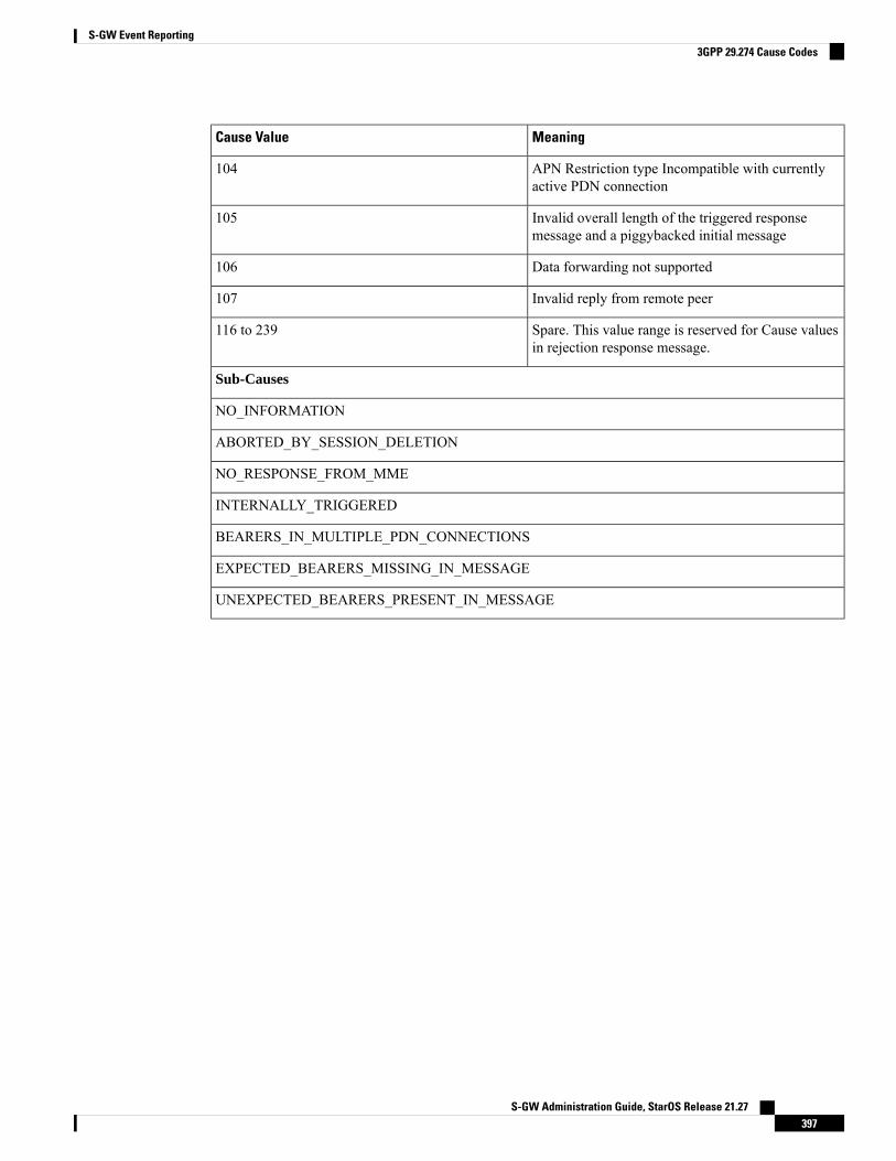
MeaningCause Value
APN Restriction type Incompatible with currentlyactive PDN connection
104
Invalid overall length of the triggered responsemessage and a piggybacked initial message
105
Data forwarding not supported106
Invalid reply from remote peer107
Spare. This value range is reserved for Cause valuesin rejection response message.
116 to 239
Sub-Causes
NO_INFORMATION
ABORTED_BY_SESSION_DELETION
NO_RESPONSE_FROM_MME
INTERNALLY_TRIGGERED
BEARERS_IN_MULTIPLE_PDN_CONNECTIONS
EXPECTED_BEARERS_MISSING_IN_MESSAGE
UNEXPECTED_BEARERS_PRESENT_IN_MESSAGE
S-GW Administration Guide, StarOS Release 21.27397
S-GW Event Reporting3GPP 29.274 Cause Codes

S-GW Administration Guide, StarOS Release 21.27398
S-GW Event Reporting3GPP 29.274 Cause Codes

C H A P T E R 28S-GW Paging Enhancements
• Feature Description, on page 399• How It Works, on page 400• Limitations, on page 401• Configuring High Priority DDN Interaction Feature, on page 402• Monitoring and Troubleshooting High Priority DDN Interaction Feature, on page 403
Feature DescriptionS-GW Paging includes the following scenarios:
Scenario 1: S-GW sends a DDN message to the MME/S4-SGSN nodes. MME/S4-SGSN responds to theS-GW with a DDN Ack message. While waiting for the DDN Ack message from the MME/S4-SGSN, if theS-GW receives a high priority downlink data, it does not resend a DDN to the MME/S4-SGSN.
Scenario 2: If a DDN is sent to an MME/S4-SGSN and TAU/RAU MBR is received from anotherMME/S4-SGSN, S-GW does not send DDN.
Scenario 3: DDN is sent to an MME/S4-SGSN and DDN Ack with Cause #110 is received. DDN Ack withcause 110 is treated as DDN failure and standard DDN failure action procedure is initiated.
To handle these scenarios, the following two enhancements have been added to the DDN functionality:
• High Priority DDN at S-GW
• MBR-DDN Collision Handling
These enhancements support the following:
• Higher priority DDN on S-GW and SAEGW, which helps MME/S4-SGSN to prioritize paging.
• Enhanced paging KPI and VoLTE services.
• DDN message and mobility procedure so that DDN is not lost.
• MBR guard timer, which is started whenDDNAckwith temporary HO is received. A newCLI commandddn temp-ho-rejection mbr-guard-timer has been introduced to enable the guard timer to wait forMBR once the DDN Ack with cause #110 (Temporary Handover In Progress) is received.
• TAU/RAU with control node change triggered DDNs.
S-GW Administration Guide, StarOS Release 21.27399
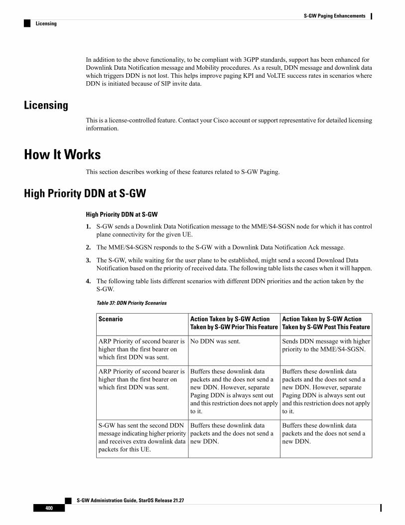
In addition to the above functionality, to be compliant with 3GPP standards, support has been enhanced forDownlink Data Notification message and Mobility procedures. As a result, DDN message and downlink datawhich triggers DDN is not lost. This helps improve paging KPI and VoLTE success rates in scenarios whereDDN is initiated because of SIP invite data.
LicensingThis is a license-controlled feature. Contact your Cisco account or support representative for detailed licensinginformation.
How It WorksThis section describes working of these features related to S-GW Paging.
High Priority DDN at S-GW
High Priority DDN at S-GW
1. S-GW sends a Downlink Data Notification message to the MME/S4-SGSN node for which it has controlplane connectivity for the given UE.
2. The MME/S4-SGSN responds to the S-GW with a Downlink Data Notification Ack message.
3. The S-GW, while waiting for the user plane to be established, might send a second Download DataNotification based on the priority of received data. The following table lists the cases when it will happen.
4. The following table lists different scenarios with different DDN priorities and the action taken by theS-GW.
Table 37: DDN Priority Scenarios
Action Taken by S-GW ActionTaken by S-GW Post This Feature
Action Taken by S-GW ActionTaken by S-GW Prior This Feature
Scenario
Sends DDN message with higherpriority to the MME/S4-SGSN.
No DDN was sent.ARP Priority of second bearer ishigher than the first bearer onwhich first DDN was sent.
Buffers these downlink datapackets and the does not send anew DDN. However, separatePaging DDN is always sent outand this restriction does not applyto it.
Buffers these downlink datapackets and the does not send anew DDN. However, separatePaging DDN is always sent outand this restriction does not applyto it.
ARP Priority of second bearer ishigher than the first bearer onwhich first DDN was sent.
Buffers these downlink datapackets and the does not send anew DDN.
Buffers these downlink datapackets and the does not send anew DDN.
S-GW has sent the second DDNmessage indicating higher priorityand receives extra downlink datapackets for this UE.
S-GW Administration Guide, StarOS Release 21.27400
S-GW Paging EnhancementsLicensing

Separate paging is always sent.Important
MBR-DDN Collision HandlingThe following table lists different MBR-DDN collision scenarios and action taken by S-GW to handle thesescenarios:
Table 38: MBR-DDN Collision Handling Scenarios
Action Taken by S-GW ActionTaken by S-GW Post This Feature
Action Taken by S-GW ActionTaken by S-GW Prior This Feature
Scenario
DDN is triggered to this newcontrol node as part of mobilityhandover process.
No DDN was sent.DDN is sent to anMME/S4-SGSNand TAU/RAU MBR is receivedfrom another MME/S4-SGSNwithout any data TEIDs.
S-GW starts a guard timer and waitfor TAU/RAU MBR from the newMME/S4-SGSN. The timer isstopped if anyMBRorDDN failureindication is received. But, if noneof them is received, and the timerexpires all buffered downlink datapackets are flushed.
If this is followed by mobilityhandover without any data TEIDs,DDN is resent to this new controlnode as well.
DDNAckwith cause 110 is treatedas DDN failure and standard DDNfailure action procedure is initiated.
DDN is sent to anMME/S4-SGSNand DDN Ack with Cause #110 isreceived.
Bearers marked for deletion are notincluded in any of the DDNmessages.
There is a possibility that DDNcould be sent with EBIscorresponding to bearers markedfor deletion.
MBR received with bearer contextto be removed.
LimitationsHigh Priority DDN at S-GW
This section lists the limitations for High Priority DDN at S-GW feature.
1. High Priority DDN is always enabled whenever the license is available.2. High priority DDN is sent only once. Any further higher priority data does not trigger another DDN.3. DDN delay timer and DDN throttling is not applicable to High Priority DDN.4. Separate Paging DDN is always sent out and above restriction does not apply to it.5. No-user-connect behavior restarts the moment high priority DDN is sent out.
S-GW Administration Guide, StarOS Release 21.27401
S-GW Paging EnhancementsMBR-DDN Collision Handling

MBR-DDN Collision Handling
This section lists the limitations for MBR-DDN Collision Handling feature.
1. EBI of a bearer marked for removal is not sent in any of the DDN messages.2. TAU/RAU triggered DDN is sent only once and is never reattempted even if aborted due to the collision
of MBR with DDN at the S-GW Ingress.3. DDN delay and throttling are not applicable to the TAU/RAU triggered DDN.4. No-user-connect behavior restarts the moment high priority DDN is sent out.5. High Priority DDN is not sent if high priority downlink data is received:
• After DDN Ack with Cause #110 is received• Before any MBR is received
6. Separate paging IE is not supported for TAU/RAU triggered DDN.
7. If DDN Ack with cause #110 is received and then later a downlink packet matches the configured 3-tupleof "Separate Paging", then also "Separate Paging DDN" is not sent as the UE is undergoing handoff.
8. The MBR guard timer is not restarted when the DDN Ack with cause #110 is received while the MBRguard timer is running.
Configuring High Priority DDN Interaction FeatureOperators can use this CLI command to enable guard timer to wait for MBR once the DDN Ack with cause#110 (Temporary Handover In Progress) is received.
Configuring mbr-guard-timerThis CLI sets the guard timer to wait for a MBR when DDN Ack with Cause #110 temp-ho-rejection) isreceived.
If the guard timer expires and if no MBR of any type or DDN Failure Indication is received, all the buffereddownlink data is flushed out and paging flags are reset.
If the guard timer is running and any MBR is received, the timer is stopped and no further action is taken.
If the guard timer is running and DDN Failure Indication is received, the timer is stopped and standard DDNfailure action is taken.
By default, this CLI command is always enabled.
configurecontext context_name
sgw-service service_name
ddn temp-ho-rejection mbr-guard-timer time_in_seconds
{ no | default } ddn temp-ho-rejection mbr-guard-timerend
Notes:
• no: Disables the guard timer.• default: Enables the guard timer and sets it to the default value, 60 seconds.
S-GW Administration Guide, StarOS Release 21.27402
S-GW Paging EnhancementsConfiguring High Priority DDN Interaction Feature
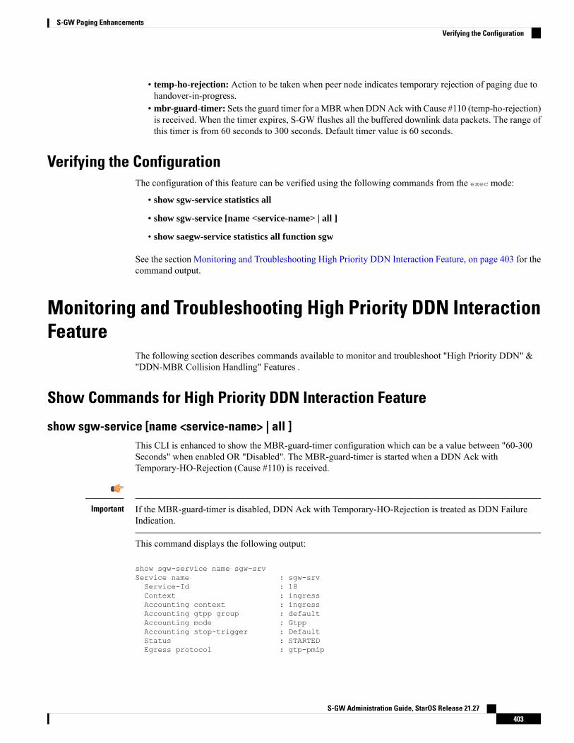
• temp-ho-rejection: Action to be taken when peer node indicates temporary rejection of paging due tohandover-in-progress.
• mbr-guard-timer: Sets the guard timer for aMBRwhen DDNAckwith Cause #110 (temp-ho-rejection)is received. When the timer expires, S-GW flushes all the buffered downlink data packets. The range ofthis timer is from 60 seconds to 300 seconds. Default timer value is 60 seconds.
Verifying the ConfigurationThe configuration of this feature can be verified using the following commands from the exec mode:
• show sgw-service statistics all
• show sgw-service [name <service-name> | all ]
• show saegw-service statistics all function sgw
See the section Monitoring and Troubleshooting High Priority DDN Interaction Feature, on page 403 for thecommand output.
Monitoring and Troubleshooting High Priority DDN InteractionFeature
The following section describes commands available to monitor and troubleshoot "High Priority DDN" &"DDN-MBR Collision Handling" Features .
Show Commands for High Priority DDN Interaction Feature
show sgw-service [name <service-name> | all ]This CLI is enhanced to show the MBR-guard-timer configuration which can be a value between "60-300Seconds" when enabled OR "Disabled". The MBR-guard-timer is started when a DDN Ack withTemporary-HO-Rejection (Cause #110) is received.
If the MBR-guard-timer is disabled, DDN Ack with Temporary-HO-Rejection is treated as DDN FailureIndication.
Important
This command displays the following output:
show sgw-service name sgw-srvService name : sgw-srvService-Id : 18Context : ingressAccounting context : ingressAccounting gtpp group : defaultAccounting mode : GtppAccounting stop-trigger : DefaultStatus : STARTEDEgress protocol : gtp-pmip
S-GW Administration Guide, StarOS Release 21.27403
S-GW Paging EnhancementsVerifying the Configuration
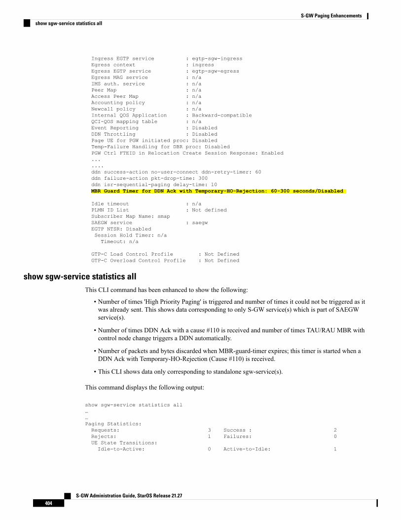
Ingress EGTP service : egtp-sgw-ingressEgress context : ingressEgress EGTP service : egtp-sgw-egressEgress MAG service : n/aIMS auth. service : n/aPeer Map : n/aAccess Peer Map : n/aAccounting policy : n/aNewcall policy : n/aInternal QOS Application : Backward-compatibleQCI-QOS mapping table : n/aEvent Reporting : DisabledDDN Throttling : DisabledPage UE for PGW initiated proc: DisabledTemp-Failure Handling for DBR proc: DisabledPGW Ctrl FTEID in Relocation Create Session Response: Enabled.......ddn success-action no-user-connect ddn-retry-timer: 60ddn failure-action pkt-drop-time: 300ddn isr-sequential-paging delay-time: 10MBR Guard Timer for DDN Ack with Temporary-HO-Rejection: 60-300 seconds/Disabled
Idle timeout : n/aPLMN ID List : Not definedSubscriber Map Name: smapSAEGW service : saegwEGTP NTSR: DisabledSession Hold Timer: n/aTimeout: n/a
GTP-C Load Control Profile : Not DefinedGTP-C Overload Control Profile : Not Defined
show sgw-service statistics allThis CLI command has been enhanced to show the following:
• Number of times 'High Priority Paging' is triggered and number of times it could not be triggered as itwas already sent. This shows data corresponding to only S-GW service(s) which is part of SAEGWservice(s).
• Number of times DDN Ack with a cause #110 is received and number of times TAU/RAU MBR withcontrol node change triggers a DDN automatically.
• Number of packets and bytes discarded when MBR-guard-timer expires; this timer is started when aDDN Ack with Temporary-HO-Rejection (Cause #110) is received.
• This CLI shows data only corresponding to standalone sgw-service(s).
This command displays the following output:
show sgw-service statistics all……Paging Statistics:Requests: 3 Success : 2Rejects: 1 Failures: 0UE State Transitions:Idle-to-Active: 0 Active-to-Idle: 1
S-GW Administration Guide, StarOS Release 21.27404
S-GW Paging Enhancementsshow sgw-service statistics all
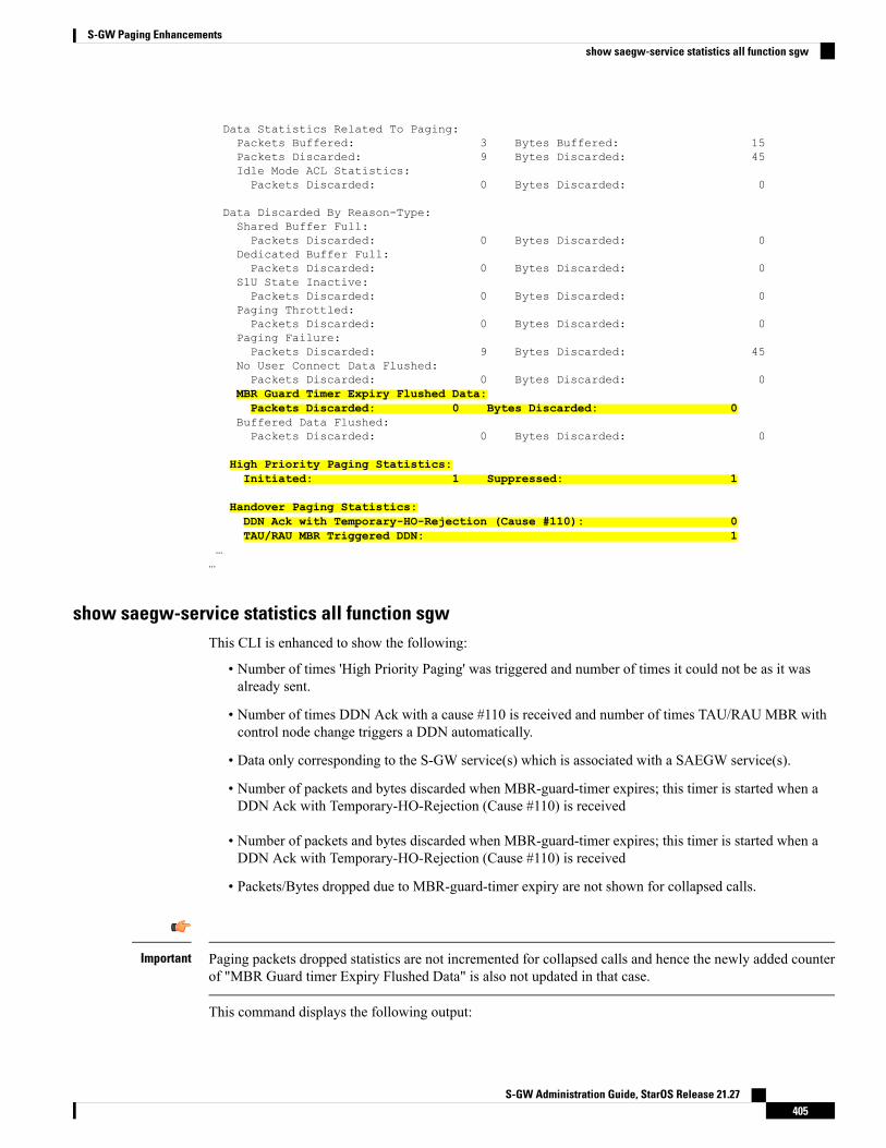
Data Statistics Related To Paging:Packets Buffered: 3 Bytes Buffered: 15Packets Discarded: 9 Bytes Discarded: 45Idle Mode ACL Statistics:Packets Discarded: 0 Bytes Discarded: 0
Data Discarded By Reason-Type:Shared Buffer Full:Packets Discarded: 0 Bytes Discarded: 0
Dedicated Buffer Full:Packets Discarded: 0 Bytes Discarded: 0
S1U State Inactive:Packets Discarded: 0 Bytes Discarded: 0
Paging Throttled:Packets Discarded: 0 Bytes Discarded: 0
Paging Failure:Packets Discarded: 9 Bytes Discarded: 45
No User Connect Data Flushed:Packets Discarded: 0 Bytes Discarded: 0
MBR Guard Timer Expiry Flushed Data:Packets Discarded: 0 Bytes Discarded: 0
Buffered Data Flushed:Packets Discarded: 0 Bytes Discarded: 0
High Priority Paging Statistics:Initiated: 1 Suppressed: 1
Handover Paging Statistics:DDN Ack with Temporary-HO-Rejection (Cause #110): 0TAU/RAU MBR Triggered DDN: 1
……
show saegw-service statistics all function sgwThis CLI is enhanced to show the following:
• Number of times 'High Priority Paging' was triggered and number of times it could not be as it wasalready sent.
• Number of times DDN Ack with a cause #110 is received and number of times TAU/RAU MBR withcontrol node change triggers a DDN automatically.
• Data only corresponding to the S-GW service(s) which is associated with a SAEGW service(s).
• Number of packets and bytes discarded when MBR-guard-timer expires; this timer is started when aDDN Ack with Temporary-HO-Rejection (Cause #110) is received
• Number of packets and bytes discarded when MBR-guard-timer expires; this timer is started when aDDN Ack with Temporary-HO-Rejection (Cause #110) is received
• Packets/Bytes dropped due to MBR-guard-timer expiry are not shown for collapsed calls.
Paging packets dropped statistics are not incremented for collapsed calls and hence the newly added counterof "MBR Guard timer Expiry Flushed Data" is also not updated in that case.
Important
This command displays the following output:
S-GW Administration Guide, StarOS Release 21.27405
S-GW Paging Enhancementsshow saegw-service statistics all function sgw

show saegw-service statistics all function sgwPaging Statistics:Requests: 3 Success : 2Rejects: 1 Failures: 0UE State Transitions:Idle-to-Active: 0 Active-to-Idle: 1
Data Statistics Related To Paging:Packets Buffered: 3 Bytes Buffered: 15Packets Discarded: 9 Bytes Discarded: 45Idle Mode ACL Statistics:Packets Discarded: 0 Bytes Discarded: 0
Data Discarded By Reason-Type:Shared Buffer Full:Packets Discarded: 0 Bytes Discarded: 0
Dedicated Buffer Full:Packets Discarded: 0 Bytes Discarded: 0
S1U State Inactive:Packets Discarded: 0 Bytes Discarded: 0
Paging Throttled:Packets Discarded: 0 Bytes Discarded: 0
Paging Failure:Packets Discarded: 9 Bytes Discarded: 45
No User Connect Data Flushed:Packets Discarded: 0 Bytes Discarded: 0
MBR Guard Timer Expiry Flushed Data:Packets Discarded: 0 Bytes Discarded: 0
Buffered Data Flushed:Packets Discarded: 0 Bytes Discarded: 0
High Priority Paging Statistics:Initiated: 1 Suppressed: 1
Handover Paging Statistics:DDN Ack with Temporary-HO-Rejection (Cause #110): 0TAU/RAU MBR Triggered DDN: 1
S-GW Administration Guide, StarOS Release 21.27406
S-GW Paging Enhancementsshow saegw-service statistics all function sgw
C H A P T E R 29Support for One Million S1-U Peer-to-PeerConnections
This chapter describes StarOS support for the One Million S1-U Peer-to-Peer Connections feature.
• Feature Description, on page 407• How it Works, on page 407• Configuring the Feature, on page 408• Show Command Output, on page 409
Feature DescriptionDue to production forecasts, support has been added to the StarOS for one million S1-U connections on asingle S-GW.
The S1-U interface is the user plane interface carrying user data between an eNodeB and an S-GW receivedfrom the terminal. The StarOS now has the capability to scale the number of S1-U peers to one million perVPN context.
A CLI command enables operators to set the number of S1-U peers for which statistics should be collected.The limit is restricted to less than one million peers (128k) due to StarOS memory limitations.
How it WorksThe gtpumgr uses the following guidelines while allocating peers:
• When a session installation comes from the SessionManager, a peer is created. If statistics are maintainedat the Session Manager, the gtpumgr also creates the peer record with the statistics.
• Peer records are maintained per service.
• The number of peers is maintained at the gtpumgr instance level. The limit is one million S1-U peersper gtpumgr instance.
• If the limit of one million peers is exceeded, then peer creation fails. It causes a call installation failurein the gtpumgr, which leads to an audit failure if an audit is triggered.
S-GW Administration Guide, StarOS Release 21.27407
The feature changes impact all the interfaces/services using the gtpu-service includingGGSN/S4-SGSN/S-GW/P-GW/SAEGW/ePDG/SaMOG/HNB-GW/HeNB-GW for:
• The Gn and Gp interfaces of the General Packet Radio Service (GPRS)
• The Iu, Gn, and Gp interfaces of the UMTS system
• The S1-U, S2a, S2b, S4, S5, S8, and S12 interfaces of the Evolved Packet System (EPS)
Recovery/ICSR Considerations• After a session manager/gtpumgr recovery or after an ICSR switchover, the same set of peers configuredfor statistics collection is recovered.
• Peers with 0 sessions and without statistics are not recovered.
• Peers with 0 sessions and with statistics are recovered.
• Peers with Extension Header Support disabled are recovered.
• While upgrading from a previous release, ensure the newer release chassis gtpu peer statistics thresholdis equal to or greater than the previous release. This way the GTPU peer statistics are preserved duringthe upgrade. For example, if you are upgrading from StarOS release 19.0 to 20.2, and the StarOS 19.0system has 17,000 GTPU sessions, then configure the threshold on the StarOS 20.2 system to 17,000 aswell.
Configuration and Restrictions• Due to the large number of GTP-U entities connecting to the StarOS, Cisco recommends disabling theGTP-U Path Management feature.
• The configured threshold is not the hard upper limit for statistics allocation because of the distributednature of system. It is possible that total GTP-U peers with statistics exceeds the configured thresholdvalue to some extent.
• It is assumed that all 1 million peers are not connected to the node in a point-to-point manner. They areconnected through routers.
• There will not be any ARP table size change for the StarOS to support this feature.
Configuring the FeatureThis section describes how to configure support for the One Million S1-U Peer Connections feature.
gtpu peer statistics thresholdThis new command has been added to Context Configuration Mode to specify the number of S1-U peers forwhich the StarOS will maintain statistics.
Use the following example to configure the feature:
S-GW Administration Guide, StarOS Release 21.27408
Support for One Million S1-U Peer-to-Peer ConnectionsRecovery/ICSR Considerations
configurecontext context_name
gtpu peer statistics threshold value
end
Notes :
• value represents the number of S1-U peers for which statistics will be maintained. Valid entries are from16000 to 128000. The default setting is 16000.
• The threshold cannot be configured to a lower value than the current value.
Show Command OutputThis section describes the show command output changes made to support the OneMillion S1-U Peers feature.
clear gtpu statistics peer-addressThe all keyword has been added to this command to enable operators to clear statistics for all S1-U peers forwhich statistics are being maintained.
clear gtpu statistics peer-address all
show gtpu statisticsThe output of this command has been enhanced to show the total number of GTPU peers, and the total numberof GTPU peers configured for statistics collection.
• Total GTPU Peers:
• Total GTPU Peers with stats:
show session subsystem facility sessmgrThe output of this command has been enhanced to provide the total number of S1-U (GTP-U) peers that areconfigured for statistics collection.
• Total Gtpu Peers with stats
S-GW Administration Guide, StarOS Release 21.27409
Support for One Million S1-U Peer-to-Peer ConnectionsShow Command Output

S-GW Administration Guide, StarOS Release 21.27410
Support for One Million S1-U Peer-to-Peer Connectionsshow session subsystem facility sessmgr

A P P E N D I X AS-GW Engineering Rules
This appendix provides Serving Gateway-specific engineering rules or guidelines that must be consideredprior to configuring the ASR 5500 for your network deployment. General and network-specific rules arelocated in the appendix of the System Administration Guide for the specific network type.
The following rules are covered:
• Interface and Port Rules, on page 411• S-GW Service Rules, on page 412• S-GW Subscriber Rules, on page 413
Interface and Port RulesThe assumptions and rules discussed in this section pertain to Ethernet line cards and the type of interfacesthey facilitate.
AssumptionsOverall assumptions for the S5/S8 and S11 interfaces used in the LTE EPC between Serving Gateway andPDN-GW are listed below.
• GTPv2-C is the signaling protocol used on the S5/S8 and S11 interfaces. Message and IE definitionscomply with 3GPP 29.274.
• S5 and S11 interfaces use IPv6 transport as defined in 29.274, section 10.
• MSISDN is assumed to be sent by MME in initial attach.
• MEI will always be retrieved by MME from UE and sent on S11 during initial attach and UE RequestedPDN connectivity procedure.
• MME will always send UE time zone information.
• The default bearer does not require any TFT.
• The PCO IE in Create Session Request shall contain two DNS server IP addresses. [S5/S8]
• UE's location change reporting support is required. [S5/S8]
• The S-GW does not verify the content of the IEs which are forwarded on the S5/S8 interface from theS11 interface. The P-GW verifies the content of all the IEs received on the S5/S8 interface.
S-GW Administration Guide, StarOS Release 21.27411
S1-U/S11 Interface RulesThe following engineering rules apply to the S1-U0/S11 interface:
• An S1-U/S11 interface is created once the IP address of a logical interface is bound to an S-GW service.The S-GW supports a maximum of one million S1-U peers.
• The logical interface(s) that will be used to facilitate the S1-U0/S11 interface(s) must be configuredwithin an "ingress" context.
• S-GW services must be configured within an "ingress" context.
• At least one S-GW service must be bound to each interface, however, multiple S-GW services can bebound to a single interface if secondary addresses are assigned to the interface.
• Depending on the services offered to the subscriber, the number of sessions facilitated by the S1-U0/S11interface can be limited.
S5/S8 Interface RulesThis section describes the engineering rules for the S5 interface for communications between the MobilityAccess Gateway (MAG) service residing on the S-GW and the LocalMobility Anchor (LMA) service residingon the P-GW.
MAG to LMA RulesThe following engineering rules apply to the S5/S8 interface from the MAG service to the LMA serviceresiding on the P-GW:
• An S5/S8 interface is created once the IP address of a logical interface is bound to an MAG service.
• The logical interface(s) that will be used to facilitate the S5/S8 interface(s) must be configured withinthe egress context.
• MAG services must be configured within the egress context.
• MAG services must be associated with an S-GW service.
• Depending on the services offered to the subscriber, the number of sessions facilitated by the S5/S8interface can be limited.
S-GW Service RulesThe following engineering rules apply to services configured within the system:
• A maximum of 256 services (regardless of type) can be configured per system.
Large numbers of services greatly increase the complexity of management and may impact overall systemperformance. Only create a large number of services only be configured if your application absolutely requiresit. Please contact your local service representative for more information.
Caution
S-GW Administration Guide, StarOS Release 21.27412
S-GW Engineering RulesS1-U/S11 Interface Rules
• The system maintains statistics for a maximum of 4,096 peer LMAs per MAG service.
• The total number of entries per table and per chassis is limited to 256.
• Even though service names can be identical to those configured in different contexts on the same system,this is not a good practice. Having services with the same name can lead to confusion, difficultytroubleshooting problems, and make it difficult to understand outputs of show commands.
S-GW Subscriber RulesThe following engineering rule applies to subscribers configured within the system:
• A maximum of 2,048 local subscribers can be configured per context.
• Default subscriber templates may be configured on a per S-GW or MAG service.
S-GW Administration Guide, StarOS Release 21.27413
S-GW Engineering RulesS-GW Subscriber Rules

S-GW Administration Guide, StarOS Release 21.27414
S-GW Engineering RulesS-GW Subscriber Rules