RZ Family Brochure - Renesas
36
2022.02 RZ FAMILY MICROPROCESSORS 64-Bit & 32-Bit High-performance MPUs
-
Upload
khangminh22 -
Category
Documents
-
view
0 -
download
0
Transcript of RZ Family Brochure - Renesas

2022.02
RZ FAMILY MICROPROCESSORS64-Bit & 32-Bit High-performance MPUs

Hum
an Machine Interface
NetworkControl
THE NEXT-GENERATION PROCESSOR TO MEET THE NEEDS OF THE SMART SOCIETY HAS ARRIVED.
RZ/V SERIES ___________________________________________ 04
RZ/G SERIES ___________________________________________ 08
RZ/A SERIES ___________________________________________ 16
RZ/T SERIES ___________________________________________ 22
RZ/N SERIES ___________________________________________ 30
PACKAGE LINEUP _______________________________________ 35
CONTENTS

02-03
The utilization of intelligent technology is advancing in all aspects of our lives, including electric household appliances, industrial equipment, building
management, power grids, and transportation. The cloud-connected “smart society” is coming ever closer to realization. Microcontrollers are now expected
to provide powerful capabilities not available previously, such as high-performance and energy-efficient control combined with interoperation with IT
networks, support for human-machine interfaces, and more. To meet the demands of this new age, Renesas has drawn on its unmatched expertise in
microcontrollers to create the RZ family of embedded processors. The lineup of these “next-generation processors that are as easy to use as conventional
microcontrollers” to meet different customer requirements.
The Zenith of the Renesas microAs embedded processors to help build the next generation of advanced products, the RZ family offers features not available elsewhere and brings new value
to customer applications.
RZ/V Series
RZ/G Series
RZ/A Series
RZ/T Series
RZ/N Series
32/64-bit Cortex®-A CPU, up to 1.5Hz3D Graphicsfor HMI Application
32-bit Cortex®-A CPU, up to 528MHz10MB Embedded RAMfor HMI Application
32-bit Cortex®-A/M CPU, up to 500MHzMulti-protocol Industrial Networkfor PLC, Remote IO, Gateway
64-bit Cortex®-A CPU, up to 1GHzLow-power Embedded AIfor Vision-AI Application
32-bit Cortex®-R CPU, up to 600MHzReal-time ControlMulti-protocol Encoder I/Ffor AC Servo, Actuator, Inverter
Arm® and Cortex® are registered trademarks of Arm Limited (or its subsidiaries) in the EU and/or elsewhere.

RZ/V Series
RZ/V Series Roadmap
RZ/V Series Application
2019 2020 2021 2022 2023 2024 2025 2026 CY
RZ/V2MCortex®-A53 x2 (1GHz)
DRP-AI, ISPRZ/V2L
Cortex®-A55 x2 (1.2GHz)Cotex®-M33 X1 (200MHz)
DRP-AI, Simple ISP
RZ/V-next (TBD)
RZ/V Series Features
AI Accelerator "DRP-AI" achieves high-speed AI inference and low power consumption
4K (2160p30) video codec and high-performance image signal processor (ISP) (RZ/V2M)
Provides image signal processor (Simple ISP) function with DRP library (RZ/V2L)
Equipped with a 3D Graphics Engine for fast image rendering (RZ/V2L)
Adopts Civil Infrastructure Platform (CIP) Linux kernel that can be supported for more than 10 years
IP Camera Surveillance camera Retail Logistics Image inspection
* DRP: Dynamically Reconfigurable Processor
Foundedin CY2016

04-05
Use Case
AI Development Flow
Open frameworks can be used for learning
Converts from industry standard ONNX Format to executable with DRP-AI Translator
Trai
ning
On
PCw
ith D
eep
Lear
ning
Fram
ewor
ks
DRP-AITranslator
Dataset for Training
Evaluation
Deploy
Target BoardCamera
“Cat”
Inferenceon D
evice
Training
Dataset for Testing
Convert toONNX format
Trained Model
Object codefor DRP-AI
RZ/V2M
Main System
HDMI
Ethernet
Serial interfaceCSI, IIC, or UART
Result of AI
Add-on the AI inferenceon your system
Output AIresult
Output AIresult
MIPI orUSB3.1
MIPI orUSB3.1
HDMI
Result of AIor videos
Result of AIor videos
Ethernet
Standalone system
Capturingimage
Capturingimage
RZ/V2M

RZ/V2M Group
CPU 2× Cortex-A53 (up to 1.0GHz)Vision and AI AI Accelerator; DRP-AI at 1.0 TOPS/W class Image Signal Processor (ISP) of multi-stream available Camera Interface; 2× MIPI CSI-2 Face and Human Detection EngineVideo and Graphics H.265/H.264 Multi Codec JPEG Codec Engine 2D Graphics EngineDisplay Interface MIPI-DSI (4-lane) HDMI 1.4aAudio Interface Serial Sound Interface × 1chCommunication Interface SD Host × 2ch PCI-Express 2.0 (1-lane) × 1ch Gigabit Ethernet × 1ch USB3.1 Gen1 Host/Function × 1ch I2C Bus × 4ch SCI × 6ch UART × 2chMemory Interface NAND Flash Interface ONFI1.0 × 1ch eMMC 4.5.1 × 1ch 32-bit LPDDR4-3200 × 1chSecurity Hardware Security Engine
RZ/V2L Group
CPU 2× Cortex-A55 or 1× Cortex-A55 (up to 1.2GHz) 1× Cortex-M33 (up to 200MHz)Vision and AI AI Accelerator; DRP-AI
* Image Signal Processor (Simple ISP) Function is provided as DRP Library Camera Interface; 1× MIPI CSI-2 / 1× Digital ParallelVideo and Graphics H.264 Codec 3D Graphics EngineDisplay Interface MIPI-DSI (4-lane) Digital ParallelAudio Interface Serial Sound Interface × 4chCommunication Interface Gigabit Ethernet × 2ch USB2.0 Host × 1ch USB2.0 Host/Function × 1ch I2C Bus × 4ch SCI × 2ch UART × 5chMemory Interface SPI Multi I/O (8bit DDR) × 1ch SDHI (UHS-I) / eMMC × 1ch 16-bit DDR3L-1333/DDR4-1600 × 1chSecurity Hardware Security Engine (Option)
System CPU
Timers
ARM debugger (CoreSight)
L2$: 512KB
Arm® Cortex®-A53: 1GHz
L1 I$: 32KBDMAC (16ch)
Power control
Timer (32ch)
PWM (16ch)
WDT (2ch)
Image Sensor I/FMIPI CSI-2 v1.2(4Lanes, 2ch)
External Memory I/FLPDDR4 (32-bit)
eMMC (1ch)
AnalogADC (20ch,12bit)
Display I/FHDMI v1.4a TX (1ch)
Audio I/FI2S (1ch)
Peripheral I/FSDI (2ch)
PCIe Gen2 (2Lane)
Gbit Ethernet MAC (1ch)
USB3.1 (1ch)(Host/Peripheral)
I2C (4ch)
CSI (6ch)
UART (2ch)
GPIO
Motor Controller
Environment Sensor I/F
Memories
L1 D$: 32KBNEON FPU
Arm® Cortex®-A53: 1GHz
RAMB 1MBRAMA 200KB
Security
Sensing and Analyzing
L1 I$: 32KB L1 D$: 32KBNEON FPU
AI-accelerator (DRP-AI)
General ProcessingAccelerator
Video and GraphicsCamera ISP
H.264/265 Multi Codec
2D Graphics engine
JPEG Codec
Multi-target detection(Face, Person’s body)
Temperature sensor (2ch)
Trusted Secure IP
System CPU
Timers
ARM debugger (CoreSight)
L3$: 256KB w/ECC
Arm® Cortex®-A55: 1.2GHz
L1 I$: 32KBDMAC (16ch)
Power control
32-bit Timer (1ch)
16-bit Timer (8ch)
PWM (8ch)
WDT (3ch)
External Memory I/FDDR3L/DDR4-1600 (16-bit)
SDHI (UHS-I) / eMMC (1ch)
Image Sensor I/FMIPI CSI-2 (4Lanes, 1ch)
Parallel (HD-30fps, 1ch)
Display I/FMIPI DSI-2 (4Lanes, 1ch)
Parallel (WXGA-60fps, 1ch)
Audio I/FSSI (I2S, 4ch)
SRC (1ch)
Analog12-bit ADC (8ch)
Peripheral I/FSDHI (UHS-I, 1ch)
USB2.0 (Host/Peripheral, 1ch)
Gbit Ethernet MAC (2ch)
USB2.0 (Host, 1ch)
I2C (4ch)
SCI 8/9-bit (2ch)
SCIF(UART) (5ch)
RSPI (3ch)
CAN-FD (2ch)
SPI Multi I/O (8-bit DDR, 1ch)
GPIO
Memories
L1 D$: 32KBNEON FPU
Arm® Cortex®-A55: 1.2GHz Arm®Cortex®-M33
200MHz
RAM 128KB w/ECC
Sensing and Analyzing
L1 I$: 32KB L1 D$: 32KBNEON FPU
AI-accelerator (DRP-AI)
Video and GraphicsImage Scaling Unit (5M pixel)
H.264 Enc/Dec (1920 × 1080pixel, 30fps)
3D GPU (Mali™-G31)
Security (Option)Secure Boot Device Unique ID
Crypto Engine JTAG Disable
TRNG OTP 4K-bit
Thermal Sensor (1ch)
¢ RZ/V2M block diagram
¢ RZ/V2L block diagram

06-07
Development Environment for AI
DRP-AI Translator Converts ONNX* format into object code for DRP-AI.
* ONNX: Open Neural Network Exchange
Trained model
DRP-AITranslator
DRP-AIObject Code
RZ/V2MEvaluation
Board
Super Long Term Software Support
Renesas RZ/G2 and RZ/V2 microprocessors are the only embedded MPUs that meet the long-term support demands for industrial and infrastructure equipment manufacturers through the 10+ year support offered by the Super Long Term Support (SLTS) kernel maintained by the Civil Infrastructure Platform (CIP). The CIP SLTS Linux kernel supports countermeasures against vulnerability to security attacks with a long-term maintenance period of 10 years or more. This reduces Linux maintenance costs and simplifies adoption of reliable industrial-grade Linux.
Verified Linux Package(VLP) Reduces Cost and Simplifies Design
The “Verified Linux Package (VLP)” for the RZ/G and RZ/V series is a combination of the Civil Infrastructure Platform (CIP) Core Package and the basic software (Linux BSP, multimedia, graphics, security, etc.) for IoT devices. This packaged software is verified by Renesas and is available. With VLPs, you can start developing applications quickly while minimizing Linux maintenance resources.
Image SignalProcessing
Video Codec
Verified Linux Package
RZ/G*1, RZ/V Reference Board
CIP Core package
AI inference Security
Rene
sas
Use
r lan
dCI
PKe
rnel
spa
ce Linux Kernel
CIP kernelRZ/G Device DriversRZ/V Device Drivers
On-boardDevice Drivers
Open Source Software
Linux Library Gstreamer
*1: RZ/G Reference Board is used for Kernel development as a software development platform for CIP projects.
Multimedia H.264 Codec (up to 1080p) H.265 Codec (up to 2160p) 2D graphics
AI Inference DRP-AI
CIP SLTS Kernel Civil Infrastructure Platform project 10+ years super long term support
Reliability/Security/Real-time

RZ/G Series
RZ/G Series Roadmap
RZ/G2 Group Specification 1
2016 2017 2018 2019 2020 2021 2022 2023 2024 CY
RZ/G2LCortex®-A55×1 or ×2 (1.2GHz)
Cortex®-M33×1 (200MHz)Mali-G31, H.264
16bit×1ch DDR4/DDR3L
RZ/G2LCCortex®-A55×1 or ×2 (1.2GHz)
Cortex®-M33×1 (200MHz)Mali-G31
16bit×1ch DDR4/DDR3L
RZ/G2ULCortex®-A55×1 (1.0GHz)
Cortex®-M33×1 (200MHz)16bit×1ch DDR4/DDR3L
RZ/G2HCortex®-A57×4 (1.5GHz)Cortex®-A53×4 (1.2GHz)Cortex®-R7×1 (800MHz)
GX6650, H.264, H26532bit×2ch LPDDR4-3200
RZ/G-nextRZ/G2MCortex®-A57×2 (1.5GHz)Cortex®-A53×4 (1.2GHz)Cortex®-R7×1 (800MHz)
GX6250, H.264, H26532bit×2ch LPDDR4-3200
RZ/G1CCortex®-A7x2 (1.0GHz)
SGX531, H.26432bit×1ch DDR3-1000
RZ/G1ECortex®-A7x2 (1.0GHz)
SGX540, H.26432bit×1ch DDR3-1333
RZ/G1HCortex®-A15x4 (1.4GHz)Cortex®-A7x4 (780MHz)
G6400, H.26432bit×2ch DDR3-1600
RZ/G1MCortex®-A15x2 (1.5GHz)
SGX544MP2, H.26432bit×2ch DDR3L-1600
RZ/G1NCortex®-A15x2 (1.5GHz)
SGX544MP2, H.26432bit×1ch DDR3L-1600
RZ/G2NCortex®-A57×2 (1.5GHz)Cortex®-R7×1 (800MHz)GE7800, H.264, H.265
32bit×1ch LPDDR4-3200
RZ/G2ECortex®-A53×2 (1.2GHz)Cortex®-R7×1 (800MHz)
GE8300, H.264,H.26532bit×1ch DDR3L-1856
RZ/G2 Platform Highlights
High Performance 64-bit Arm Cortex-A cores, plus powerful 3D graphics engine and video engine capable of supporting up to 4K UHD, to offer the highest performance
Wide Coverage Entry-level RZ/G2L Group 3 products equipped with Cortex-A55 with improved processing performance have been newly added to the RZ/G2 lineup
High Reliability Built-in Error Correction Code (ECC) for internal and external memory, which is essential for high-reliability mission critical systems
Super Long Term Support (SLTS) Applying Civil Infrastructure Platform (CIP) Linux, the Linux kernel will be provided with over 10 years of support
Verified Linux Package Renesas verifies and provides a Linux package that combines CIP and Linux basic software. Minimize your Linux maintenance resources
Items RZ/G2H RZ/G2M RZ/G2N RZ/G2ECPU (Arm® Cortex®-A)
4× Cortex®[email protected] 4× Cortex®[email protected] L1,L2 Parity/ECC
2× Cortex®[email protected] 4× Cortex®[email protected] L1,L2 Parity/ECC
2× Cortex®[email protected] L1,L2 Parity/ECC
2× Cortex®[email protected] L1,L2 Parity/ECC
CPU (Arm® Cortex®-R)
1× Cortex®-R7@800MHz L1,TCM w/ECC
1× Cortex®-R7@800MHz L1,TCM w/ECC
1× Cortex®-R7@800MHz L1,TCM w/ECC
1× Cortex®-R7@800MHz L1,TCM w/ECC
DRAM I/F 32-bit ×2ch LPDDR4(3200) w/ECC 32-bit ×2ch LPDDR4(3200) w/ECC 32-bit ×1ch LPDDR4(3200) w/ECC 32-bit ×1ch DDR3L(1856) w/ECCVideo in 2×MIPI-CSI2, 2×Digital (RGB/YCbCr)
up to 8 input image can be captured2×MIPI-CSI2, 2×Digital (RGB/YCbCr) up to 8 input image can be captured
2×MIPI-CSI2, 2×Digital (RGB/YCbCr) up to 8 input image can be captured
1×MIPI-CSI2, 1×Digital(RGB/YCbCr) up to 2 input image can be captured
Video Codec Support up to 4k resolutions Decoding: H.265, Encoding and Decoding: H.264
Support up to 4k resolutions Decoding: H.265, Encoding and Decoding: H.264
Support up to 4k resolutions Decoding: H.265, Encoding and Decoding: H.264
Support up to FHD resolutions Decoding: H.265, Encoding and Decoding: H.264
3D GFX PowerVR GX6650@600MHz PowerVR GX6250@600MHz PowerVR GE7800@600MHz PowerVR GE8300@600MHzDisplay out 1×HDMI, 1×LVDS, 1×Digital RGB 1×HDMI, 1×LVDS, 1×Digital RGB 1×HDMI, 1×LVDS, 1×Digital RGB 2×LVDS or 1×LVDS, 1×Digital RGBUSB USB2.0×2ch (1H, 1H/F/OTG)
USB3.0/2.0×1ch (DRD)USB2.0×2ch (1H, 1H/F/OTG) USB3.0/2.0×1ch (DRD)
USB2.0×2ch (1H, 1H/F/OTG) USB3.0/2.0×1ch (DRD)
USB2.0×1ch (H/F) USB3.0/2.0×1ch (DRD)
Gbit Ether 1ch 1ch 1ch 1chCAN 2ch (support CAN-FD) 2ch (support CAN-FD) 2ch (support CAN-FD) 2ch (support CAN-FD)PCIe 2ch (Rev2.0 1Lane)
one of the 2ch is shared with SATA2ch (Rev2.0 1Lane) 2ch (Rev2.0 1Lane)
one of the 2ch is shared with SATA1ch (Rev2.0 1Lane)
SATA 1ch (Pin Shared) No 1ch (Pin Shared) NoPackage 1022pin FCBGA, 29mm×29mm
0.8mm ball pitch1022pin FCBGA, 29mm×29mm 0.8mm ball pitch
1022pin FCBGA, 29mm×29mm 0.8mm ball pitch
552pin FCBGA, 21mm×21mm 0.8mm ball pitch
Pin Compatible

08-09
RZ/G2 Group Specification 2
Items RZ/G2L RZ/G2LC RZ/G2UL (Type2) Pin compatible with RZ/G2LC
RZ/G2UL (Type1) Full function
CPU (Arm® Cortex®-A)
1× or 2× Cortex®[email protected] L1,L3 Parity/ECC
1× or 2× Cortex®[email protected] L1,L3 Parity/ECC
1× Cortex®[email protected] L1,L3 Parity/ECC
1× Cortex®[email protected] L1,L3 Parity/ECC
CPU (Arm® Cortex®-M)
1× Cortex®-M33@200MHz 1× Cortex®-M33@200MHz 1× Cortex®-M33@200MHz 1× Cortex®-M33@200MHz
DRAM I/F 16-bit ×1ch DDR4-1600/DDR3L-1333 w/ECC 16-bit ×1ch DDR4-1600/DDR3L-1333 w/ECC 16-bit ×1ch DDR4-1600/DDR3L-1333 w/ECC 16-bit ×1ch DDR4-1600/DDR3L-1333 w/ECC
Video in 1×MIPI CSI-2 or 1×Digital Parallel input 1×MIPI CSI-2 1×MIPI CSI-2 1×MIPI CSI-2
Video Codec Support up to Full HD @30fps resolutions Encoding and Decoding: H.264
– – –
3D GFX Arm Mali-G31 GPU @500MHz Arm Mali-G31 GPU @500MHz – –
Display out 1×MIPI DSI or 1×Digital Parallel output 1×MIPI DSI – 1×Digital Parallel output
USB USB2.0×2ch (1Host, 1Host/Function/OTG) USB2.0×2ch (1Host, 1Host/Function/OTG) USB2.0×2ch (1Host, 1Host/Function/OTG) USB2.0×2ch (1Host, 1Host/Function/OTG)
Gbit Ether 2ch 1ch 1ch 2ch
CAN 2ch (support CAN-FD) 2ch (support CAN-FD) 2ch (support CAN-FD) 2ch (support CAN-FD)
12-bit ADC 8ch – – 2ch
Package 551pin LFBGA, 21mm×21mm 0.8mm ball pitch 456pin LFBGA, 15mm×15mm 0.5mm ball pitch
361pin LFBGA, 13mm×13mm 0.5mm ball pitch
361pin LFBGA, 13mm×13mm 0.5mm ball pitch
361pin LFBGA, 13mm×13mm 0.5mm ball pitch
Super Long Term Software Support
Renesas RZ/G2 and RZ/V2 microprocessors are the only embedded MPUs that meet the long-term support demands for industrial and infrastructure equipment manufacturers through the 10+ year support offered by the Super Long Term Support (SLTS) kernel maintained by the Civil Infrastructure Platform (CIP). The CIP SLTS Linux kernel supports countermeasures against vulnerability to security attacks with a long-term maintenance period of 10 years or more. This reduces Linux maintenance costs and simplifies adoption of reliable industrial-grade Linux.
Verified Linux Package(VLP) Reduces Cost and Simplifies Design
The “Verified Linux Package (VLP)” for the RZ/G and RZ/V series is a combination of the Civil Infrastructure Platform (CIP) Core Package and the basic software (Linux BSP, multimedia, graphics, security, etc.) for IoT devices. This packaged software is verified by Renesas and is available from the Renesas RZ Linux platform site. With VLPs, you can start developing applications quickly while minimizing Linux maintenance resources.
GUI Framework(Qt/HTML5)
Video Codec
Verified Linux Package
RZ/G*1, RZ/V Reference Board
CIP Core package
OpenGL Security
Rene
sas
Use
r lan
dCI
PKe
rnel
spa
ce Linux Kernel
CIP kernelRZ/G Device DriversRZ/V Device Drivers
On-boardDevice Drivers
Open Source Software
Linux Library Gstreamer Window system
*1: RZ/G Reference Board is used for Kernel development as a software development platform for CIP projects.
GUI Framework Qt application framework HTML5 application framework
Multimedia H.264 Codec H.265 Decoder 3D graphics
Secure Middle Ware Encrypted kernel boot Security communication Secure storage
CIP SLTS Kernel Civil Infrastructure Platform project 10+ years super long term support
Reliability/Security/Real-time
Pin Compatible

Flexible Development Kits
RZ/G2 development kits support the industry standard 96Boards specification and SMARC specification to enable evaluation and speed development with wide variety of mezzanine boards and existing carrier boards. Renesas provides circuit schematics, component BOMs, and board layout data to make it easy to spin your own custom hardware.
Main Memory: 4 GB DDR4 QSPI NOR FLASH 64 MByte I2C EEPROM 512 Byte External Storage: micro SD × 1 Connectivity: USB 2.0 × 2ch,
USB 3.0 × 1ch, GbE × 1 HDMI out / LVDS out or MIPI DSI out Wi-Fi + BT
Module board (Dimension: 82mm x 50mm)– Processor: RZ/G2L / RZ/G2LC / RZ/G2UL– Main Memory: 2GB DDR4 (1GB ×2)– QSPI NOR FLASH: 64MB– eMMC Memory: 64GB– External Storage: micro SD ×1– A/D Converter Interface ×6– JTAG connector
Carrier board (Dimension: 160mm × 100mm)– Gigabit Ethernet ×2– USB2.0 × 2ch (OTG ×1ch, Host ×1ch)– MIPI CSI-2 Camera connector (can connect to Google Coral Camera) – Micro HDMI (output) connector– CAN-FD ×2– External Storage: micro SD ×1– Audio Line in ×1– Audio Line out ×1– PMOD ×2– USB-Type C for Power Input
Main Memory: 2 GB DDR3L QSPI NOR FLASH 64 MByte I2C EEPROM 512 Byte External Storage: micro SD × 1 Connectivity: USB 2.0 × 2ch,
USB 3.0 × 1ch, GbE × 1 HDMI out / LVDS out or MIPI DSI out Wi-Fi + BT
¢ RZ/G2H,G2M,G2N Development Kit (96Boards format compatible)
¢ RZ/G2L SMARC v2.1 Module board + Carrier Board
¢ RZ/G2E Development Kit (96Boards format compatible)

10-11
HMI Solutions
RZ/G2H (R8A774Ex)
CPU core Arm® Cortex®-A57, quad-core
Max. operating frequency: 1.5GHz Arm® Cortex®-A53, quad-core
Max. operating frequency: 1.2GHz Arm® Cortex®-R7, single-core
Max. operating frequency: 800MHzCache memory (Cortex®-A57) L1 instruction cache: 48KB L1 data cache: 32KB L2 cache: 2MBCache memory (Cortex®-A53) L1 instruction cache: 32KB L1 data cache: 32KB L2 cache: 512KBCache memory (Cortex®-R7) L1 instruction cache: 32KB L1 data cache: 32KB I-TCM: 32KB D-TCM: 32KBExternal memory Ability to connect LPDDR4-SDRAM
via DDR dedicated bus Data bus width: 32 bits × 2 channelsExternal expansion Ability to connect flash ROM or SRAM
directly Data bus width: 8/16 bits PCI Express 2.0 : 1 Lane × 2 channels
(one of PHY is shared with Serial ATA)3D graphics PowerVR™ GX6650Video functions Video display interface × 3 channels (1
channel: HDMI(option), 1 channel: LVDS, 1 channel: RGB888)
Video input interface × 4 channels (2 channels: MIPI-CSI2, 2 channels: Digital(RGB/YCbCr))
Video codec module: VCP4 × 1 channel
IP converter module Video image processing functions
(color conversion, image enlarge-ment/reduction, filtering)
Audio functions Sampling rate converter × 10
channels Serial sound interface × 10 channelsStorage interfaces USB 3.0 DRD × 1 channel USB 2.0 × 2 channels (Host only 1
channel/Host-Function 1channel) SD host interface × 4 channels Multimedia card interface × 2
channels Serial ATA interface × 1 channelOther peripheral functions 32-bit timer × 15 channels PWM timer × 7 channels I2C bus interface × 7 channels Serial communication interface (SCIF)
× 6 channels Quad serial peripheral interface (QSPI)
× 2 channels (boot support) Clock-synchronous serial interface
(MSIOF) × 4 channels (SPI/IIS support)
Ethernet controller with AVB support (support for IEEE 802.1BA, IEEE 802.1AS, IEEE 802.1Qav, and IEEE 1722)
Controller area network (CAN) interface × 2 channels
Interrupt controller (INTC) Clock generator (CPG): on-chip PLL On-chip debug function
WXGA and below(1280 × 768)
Full HD(1920 × 1080)
4K(3840 × 2160)
RTOS
RZ/ASeries
MaxDisplay
resolution
OperatingSystem
RZ/G Series
Generation2 (64-bit CPU)
Generation1 (32-bit CPU)
NewGeneration2 (64-bit CPU)
32-bit Linux 64-bit Linux
• WXGAto 4K, functions: 3D Graphics, Video Codec• OS: Linux (RichOS)
RZ/G1CRZ/G1ERZ/G1N
RZ/G1HRZ/G1M
RZ/G2E
RZ/G2NRZ/G2MRZ/G2H
RZ/G2UL
RZ/G2LCRZ/G2L
¢ RZ/G2H (R8A774Ex) block diagram
System CPU
Timers
System controller
L2 cache: 2MB with ECC L2 cache: 512KB with ECC
4 × Cortex®-A57 1.5GHz
L1 I$ 48KBSystem RAM: 384KB
Thermal Sensor
26 × 32-bit Timer
Audio IPsAudio router w/10 ASRC,mixer, 10 I2S (6ch TDM),
90ch Audio DMA
Secure IP
15 × 32-bit Interval
WDT
7 × PWM out
JTAG Debug(Coresight)
Connectivity2 × PCIe2.0 (1Lane)
SATA (Rev.3.2) (shared)
USB3.0/2.0 (DRD)
4 × USB2.0 (2H, 2H/F/OTG)
Ethernet AVB (1Gbps)
2 × CAN2.0B
Crypto engine(AES, DES, Hash, RSA, TRNG)
3D GraphicsPowerVR GX6650
2D/3D tile based 600MHz
FC-BGA: 29 × 29mm2 1022-pins, 0.8mm pitch
Video CodecUp to 4K resolution
(2 channels)
Video IP
L1 D$ 32KBNEON/VFPv4
L1 I$ 32KBL1 D$ 32KB
NEON/VFPv4
4 × Cortex®-A53 1.2GHz
L1 I$ 32KBL1 D$ 32KBVFPv3-D16
1 × Cortex®-R7 800MHz
3 × Display out1 × Digital out, 1 × LVDS
1 × HDMI
4 × Video Signal Processor
2 × Fine Display Processor
8 × Video in2 × MIPI-CSI2(1 × 4L, 1 × 2L)
2 × Digital
6 × UART, 5 × H-UART4 × SPI
7 × I2C; 1 × DVFS ctrl
Memory I/F
16-bit ExtBus/SRAM
32-bit × 2ch LPDDR4-3200(ECC)
access cache
1 × QSPI (4/8-bit selectable)or 1 × Hyperflash
4 × SDIO (SDR104)
2 × eMMC (5.0, HS400)
I-TCM 32KB, D-TCM 32KBwith ECC

RZ/G2M (R8A774Ax)
RZ/G2N (R8A774Bx)
CPU core Arm® Cortex®-A57, quad-core
Max. operating frequency: 1.5GHz Arm® Cortex®-A53, quad-core
Max. operating frequency: 1.2GHz Arm® Cortex®-R7, single-core
Max. operating frequency: 800MHzCache memory (Cortex®-A57) L1 instruction cache: 48KB L1 data cache: 32KB L2 cache: 2MBCache memory (Cortex®-A53) L1 instruction cache: 32KB L1 data cache: 32KB L2 cache: 512KBCache memory (Cortex®-R7) L1 instruction cache: 32KB L1 data cache: 32KB I-TCM: 32KB D-TCM: 32KBExternal memory Ability to connect LPDDR4-SDRAM via
DDR dedicated bus Data bus width: 32 bits × 2 channelsExternal expansion Ability to connect flash ROM or SRAM
directly Data bus width: 8/16 bits PCI Express 2.0 : 1 Lane × 2 channels
(one of PHY is shared with Serial ATA)3D graphics PowerVR™ GX6250Video functions Video display interface × 3 channels (1
channel: HDMI(option), 1 channel: LVDS, 1 channel: RGB888)
Video input interface × 4 channels (2 channels: MIPI-CSI2, 2 channels: Digital(RGB/YCbCr))
CPU core Arm® Cortex®-A57, quad-core
Max. operating frequency: 1.5GHz Arm® Cortex®-R7, single-core
Max. operating frequency: 800MHzCache memory (Cortex®-A57) L1 instruction cache: 48KB L1 data cache: 32KB L2 cache: 2MBCache memory (Cortex®-R7) L1 instruction cache: 32KB L1 data cache: 32KB I-TCM: 32KB D-TCM: 32KBExternal memory Ability to connect LPDDR4-SDRAM via
DDR dedicated bus Data bus width: 32 bits × 1 channelExternal expansion Ability to connect flash ROM or SRAM
directly Data bus width: 8/16 bits PCI Express 2.0 : 1 Lane × 2 channels
(one of PHY is shared with Serial ATA)3D graphics PowerVR™ GE7800Video functions Video display interface × 3 channels (1
channel: HDMI(option), 1 channel: LVDS, 1 channel: RGB888)
Video input interface × 4 channels (2 channels: MIPI-CSI2, 2 channels: Digital(RGB/YCbCr))
Video codec module: VCP4 × 1 channel IP converter module Video image processing functions (color
conversion, image enlargement/reduction, filtering)
Audio functions Sampling rate converter × 10 channels Serial sound interface × 10 channelsStorage interfaces USB 3.0 DRD × 1 channel USB 2.0 × 2 channels (Host only 1
channel/Host-Function 1channel) SD host interface × 4 channels Multimedia card interface × 2 channelsOther peripheral functions 32-bit timer × 15 channels PWM timer × 7 channels I2C bus interface × 7 channels Serial communication interface (SCIF) ×
6 channels Quad serial peripheral interface (QSPI)
× 2 channels (boot support) Clock-synchronous serial interface
(MSIOF) × 4 channels (SPI/IIS support) Ethernet controller with AVB support
(support for IEEE 802.1BA, IEEE 802.1AS, IEEE 802.1Qav, and IEEE 1722, GMII/MII interface, PHY device connection support)
Ethernet controller with AVB support (support for IEEE 802.1BA, IEEE 802.1AS, IEEE 802.1Qav, and IEEE 1722)
Controller area network (CAN) interface × 2 channels
Interrupt controller (INTC) Clock generator (CPG): on-chip PLL On-chip debug function
Video codec module: VCP4 × 1 channel IP converter module Video image processing functions (color
conversion, image enlargement/reduction, filtering)
Audio functions Sampling rate converter × 10 channels Serial sound interface × 10 channelsStorage interfaces USB 3.0 DRD × 1 channel USB 2.0 × 2 channels (Host only 1
channel/Host-Function 1channel) SD host interface × 4 channels Multimedia card interface × 2 channels Serial ATA interface × 1 channelOther peripheral functions 32-bit timer × 15 channels PWM timer × 7 channels I2C bus interface × 7 channels Serial communication interface (SCIF) ×
6 channels Quad serial peripheral interface (QSPI)
× 2 channels (boot support) Clock-synchronous serial interface
(MSIOF) × 4 channels (SPI/IIS support) Ethernet controller with AVB support
(support for IEEE 802.1BA, IEEE 802.1AS, IEEE 802.1Qav, and IEEE 1722)
Controller area network (CAN) interface × 2 channels
Interrupt controller (INTC) Clock generator (CPG): on-chip PLL On-chip debug function
¢ RZ/G2M (R8A774Ax) block diagram
¢ RZ/G2N (R8A774Bx) block diagram
System
Timers
System controller
System RAM: 384KB
Thermal Sensor
26 × 32-bit Timer
Audio IPsAudio router w/10 ASRC,mixer, 10 I2S (6ch TDM),
90ch Audio DMA
Secure IP
15 × 32-bit Interval
WDT
7 × PWM out
JTAG Debug(Coresight)
Connectivity2 × PCIe2.0 (1Lane)
USB3.0/2.0 (DRD)
2 × USB2.0 (1H, 1H/F/OTG)
Ethernet AVB (1Gbps)
2 × CAN2.0B
Crypto engine(AES, DES, Hash, RSA, TRNG)
3D GraphicsPowerVR GX6250
2D/3D tile based 600MHz
FC-BGA: 29 × 29mm2 1022-pins, 0.8mm pitch
Video CodecUp to 4K resolution
(2 channels)
Video IP3 × Display Out
1 × Digital out, 1 × LVDS1 × HDMI
4 × Video Signal Processor
2 × Fine Display Processor
8 × Video in2 × MIPI-CSI2(1 × 4L, 1 × 2L)
2 × Digital
6 × UART, 5 × H-UART4 × SPI
7 × I2C; 1 × DVFS ctrl
Memory I/F
16-bit ExtBus/SRAM
32-bit × 2ch LPDDR4-3200(ECC)
access cache
Raw NAND(8/16-bit, ONFI 1.x,
ECC 1-8-bits)
1 × QSPI (4/8-bit selectable)or 1 × Hyperflash
4 × SDIO (SDR104)
2 × eMMC (5.0, HS400)
CPU
L2 cache: 2MB with ECC L2 cache: 512KB with ECC
2 × Cortex®-A57 1.5GHz
L1 I$ 48KBL1 D$ 32KB
NEON/VFPv4
L1 I$ 32KBL1 D$ 32KB
NEON/VFPv4
4 × Cortex®-A53 1.2GHz
L1 I$ 32KBL1 D$ 32KBVFPv3-D16
1 × Cortex®-R7 800MHz
I-TCM 32KB, D-TCM 32KBwith ECC
System CPU
Timers
System controller
L2 cache: 1MB with ECC I-TCM 32KB, D-TCM 32KB with ECC
2 × Cortex®-A57 1.5GHz
L1 I$ 48KBSystem RAM: 384KB
Thermal Sensor
26 × 32-bit Timer
Audio IPsAudio router w/10 ASRC,mixer, 10 I2S (6ch TDM),
90ch Audio DMA
Secure IP
15 × 32-bit Interval
WDT
7 × PWM out
JTAG Debug(Coresight)
Connectivity2 × PCIe2.0 (1Lane)
SATA (Rev.3.2) (shared)
USB3.0/2.0 (DRD)
2 × USB2.0 (1H, 1H/F/OTG)
Ethernet AVB (1Gbps)
2 × CAN2.0B
Crypto engine(AES, DES, Hash, RSA, TRNG)
3D GraphicsPowerVR GE7800
2D/3D tile based 600MHz
FC-BGA: 29 × 29mm2 1022-pins, 0.8mm pitch
Video CodecUp to 4K resolution
(2 channels)
Video IP
L1 D$ 32KBNEON/VFPv4
3 × Display out1 × Digital out, 1 × LVDS
1 × HDMI
2 × Video Signal Processor
1 × Fine Display Processor
8 × Video in2 × MIPI-CSI2(1 × 4L, 1 × 2L)
2 × Digital
6 × UART, 5 × H-UART4 × SPI
7 × I2C; 1 × DVFS ctrl
Memory I/F
16-bit ExtBus/SRAM
32-bit × 1ch LPDDR4-3200(ECC)
access cache
Raw NAND(8/16-bit, ONFI 1.x,
ECC 1-8-bits)
1 × QSPI (4/8-bit selectable)or 1 × Hyperflash
4 × SDIO (SDR104)
2 × eMMC (5.0, HS400)
1 × Cortex®-R7 800MHz
L1 I$ 32KBL1 D$ 32KBVFPv3-D16
12-13
RZ/G2E (R8A774C0)
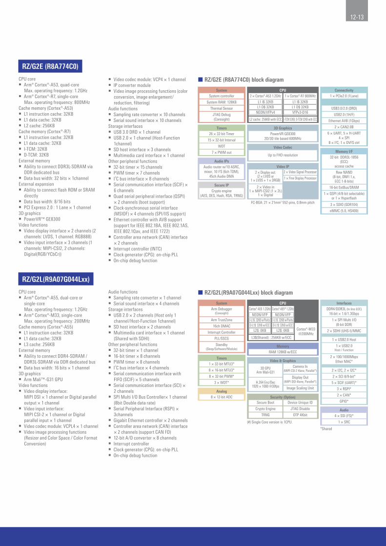
RZ/G2L(R9A07G044Lxx)
CPU core Arm® Cortex®-A53, quad-core
Max. operating frequency: 1.2GHz Arm® Cortex®-R7, single-core
Max. operating frequency: 800MHzCache memory (Cortex®-A53) L1 instruction cache: 32KB L1 data cache: 32KB L2 cache: 256KBCache memory (Cortex®-R7) L1 instruction cache: 32KB L1 data cache: 32KB I-TCM: 32KB D-TCM: 32KBExternal memory Ability to connect DDR3L-SDRAM via
DDR dedicated bus Data bus width: 32 bits × 1channelExternal expansion Ability to connect flash ROM or SRAM
directly Data bus width: 8/16 bits PCI Express 2.0 : 1 Lane × 1 channel3D graphics PowerVR™ GE8300Video functions Video display interface × 2 channels (2
channels: LVDS, 1 channel: RGB888) Video input interface × 3 channels (1
channels: MIPI-CSI2, 2 channels: Digital(RGB/YCbCr))
CPU core Arm® Cortex®-A55, dual-core or
single-core Max. operating frequency: 1.2GHz
Arm® Cortex®-M33, single-core Max. operating frequency: 200MHz
Cache memory (Cortex®-A55) L1 instruction cache: 32KB L1 data cache: 32KB L3 cache: 256KBExternal memory Ability to connect DDR4-SDRAM /
DDR3L-SDRAM via DDR dedicated bus Data bus width: 16 bits × 1 channel3D graphics Arm Mali™-G31 GPUVideo functions Video display interface:
MIPI DSI × 1 channel or Digital parallel output × 1 channel
Video input interface: MIPI CSI-2 × 1 channel or Digital parallel input × 1 channel
Video codec module: VCPL4 × 1 channel Video image processing functions
(Resizer and Color Space / Color Format Conversion)
Video codec module: VCP4 × 1 channel IP converter module Video image processing functions (color
conversion, image enlargement/reduction, filtering)
Audio functions Sampling rate converter × 10 channels Serial sound interface × 10 channelsStorage interfaces USB 3.0 DRD × 1 channel USB 2.0 × 1 channel (Host-Function
1channel) SD host interface × 3 channels Multimedia card interface × 1 channelOther peripheral functions 32-bit timer × 15 channels PWM timer × 7 channels I2C bus interface × 8 channels Serial communication interface (SCIF) ×
6 channels Quad serial peripheral interface (QSPI)
× 2 channels (boot support) Clock-synchronous serial interface
(MSIOF) × 4 channels (SPI/IIS support) Ethernet controller with AVB support
(support for IEEE 802.1BA, IEEE 802.1AS, IEEE 802.1Qav, and IEEE 1722)
Controller area network (CAN) interface × 2 channels
Interrupt controller (INTC) Clock generator (CPG): on-chip PLL On-chip debug function
Audio functions Sampling rate converter × 1 channel Serial sound interface × 4 channelsStorage interfaces USB 2.0 × 2 channels (Host only 1
channel/Host-Function 1channel) SD host interface × 2 channels Multimedia card interface × 1 channel
(Shared with SDHI)Other peripheral functions 32-bit timer × 1 channel 16-bit timer × 8 channels PWM timer × 8 channels I2C bus interface × 4 channels Serial communication interface with
FIFO (SCIF) × 5 channels Serial communication interface (SCI) ×
2 channels SPI Multi I/O Bus Controller× 1 channel
(8bit Double data rate) Serial Peripheral Interface (RSPI) ×
3channels Gigabit Ethernet controller × 2 channels Controller area network (CAN) interface
× 2 channels (support CAN FD) 12-bit A/D converter × 8 channels Interrupt controller Clock generator (CPG): on-chip PLL On-chip debug function
¢ RZ/G2E (R8A774C0) block diagram
¢ RZ/G2L(R9A07G044Lxx) block diagram
System
Timers
System controller
System RAM: 128KB
Thermal Sensor
26 × 32-bit Timer
Audio IPsAudio router w/10 ASRC,mixer, 10 I2S (6ch TDM),
45ch Audio DMA
Secure IP
15 × 32-bit Interval
WDT
7 × PWM out
JTAG Debug(Coresight)
Connectivity1 × PCIe2.0 (1Lane)
USB3.0/2.0 (DRD)
USB2.0 (1H/F)
Ethernet AVB (1Gbps)
2 × CAN2.0B
Crypto engine(AES, DES, Hash, RSA, TRNG)
3D GraphicsPowerVR GE8300
2D/3D tile based 600MHz
FC-BGA: 21 × 21mm2 552-pins, 0.8mm pitch
Video Codec
Up to FHD resolution
Video IP2 × Display out:
(2 × LVDS or1 × LVDS + 1 × DRGB)
2 × Video Signal Processor
1 × Fine Display Processor
2 × Video in1 × MIPI-CSI2 (1 × 2L)
1 × Digital
6 × UART, 5 × H-UART4 × SPI
8 × I2C; 1 × DVFS ctrl
Memory I/F
16-bit ExtBus/SRAM
32-bit DDR3L-1856(ECC)
access cache
Raw NAND(8-bit, ONFI 1.x,
ECC 1-8-bits)
1 × QSPI (4/8-bit selectable)or 1 × Hyperflash
3 × SDIO (SDR104)
eMMC (5.0, HS400)
CPU
L2 cache: 256KB with ECC I-TCM 32KB, D-TCM 32KB with ECC
2 × Cortex®-A53 1.2GHz
L1 I$ 32KBL1 D$ 32KB
NEON/VFPv4
1 × Cortex®-R7 800MHz
L1 I$ 32KBL1 D$ 32KBVFPv3-D16
System CPU
Timers
L3$(Shared) : 256KB w/ECC
Cortex®-A55 1.2GHz
NEON/VFPArm TrustZone
16ch DMAC
Interrupt Controller
PLL/SSCG
1 × 32-bit MTU3*
8 × 16-bit MTU3*
8 × 32-bit PWM*
3 × WDT*
Analog8 × 12-bit ADC
MemoryRAM 128KB w/ECC
Standby(Sleep/Software/Module)
Arm Debugger(Coresight)
*Shared
I-L1$: 32KB w/Parity
L2$: 0KB
NEON/VFPI-L1$: 32KB w/Parity
L2$: 0KB
Cortex®-A55(#) 1.2GHz
D-L1$: 32KB w/ECC D-L1$: 32KB w/ECC
Video & Graphics
Image Scaling Unit
Cortex®-M33@200MHz
Camera In(MIPI CSI-2 4lane, Parallel*)
Display Out(MIPI DSI 4lane, Parallel*)H.264 Enc/Dec
1920 × 1080 @30fps
3D GPUArm Mali-G31
Security (Option)
OTP 4KbitTRNG
Crypto Engine JTAG Disable
Secure Boot Device Unique ID
(#) Single Core version is 1CPU.
Audio4 × SSI (I2S)*
1 × SRC
Interfaces
2 × SDHI (UHS-I)/MMC
1 × USB2.0 Host
GPIO*
2 × CAN*
3 × RSPI*
5 × SCIF (UART)*
2 × SCI 8/9-bit*
2 × I2C, 2 × I2C*
1 × SPI Multi I/O(8-bit DDR)
DDR4/DDR3L (In line ECC)16-bit × 1.6/1.3Gbps
2 × 100/1000MbpsEther MAC*
1 × USB2.0Host / Function

RZ/G2LC(R9A07G044Cxx)
RZ/G2UL(R9A07G043Uxx)
CPU core Arm® Cortex®-A55, dual-core or
single-core Max. operating frequency: 1.2GHz
Arm® Cortex®-M33, single-core Max. operating frequency: 200MHz
Cache memory (Cortex®-A55) L1 instruction cache: 32KB L1 data cache: 32KB L3 cache: 256KBExternal memory Ability to connect DDR4-SDRAM /
DDR3L-SDRAM via DDR dedicated bus Data bus width: 16 bits × 1 channel3D graphics Arm Mali™-G31 GPUVideo functions Video display interface:
MIPI DSI × 1 channel Video input interface:
MIPI CSI-2 × 1 channel Video image processing functions
(Resizer and Color Space / Color Format Conversion)
CPU core Arm® Cortex®-A55, single-core
Max. operating frequency: 1.0GHz Arm® Cortex®-M33, single-core
Max. operating frequency: 200MHzCache memory (Cortex®-A55) L1 instruction cache: 32KB L1 data cache: 32KB L3 cache: 256KBExternal memory Ability to connect DDR4-SDRAM /
DDR3L-SDRAM via DDR dedicated bus Data bus width: 16 bits × 1 channelVideo functions Video display interface:
Digital parallel output × 1 channel Video input interface:
MIPI CSI-2 × 1 channel Video image processing functions
(Resizer and Color Space / Color Format Conversion)
Audio functions Sampling rate converter × 1 channel Serial sound interface × 2 channelsStorage interfaces USB 2.0 × 2 channels (Host only 1
channel/Host-Function 1channel) SD host interface × 2 channels Multimedia card interface × 1 channel
(Shared with SDHI)Other peripheral functions 32-bit timer × 1 channel 16-bit timer × 5 channels PWM timer × 4 channels I2C bus interface × 4 channels Serial communication interface with
FIFO (SCIF) × 3 channels Serial communication interface (SCI) ×
2 channels SPI Multi I/O Bus Controller× 1 channel
(4bit Double data rate) Serial Peripheral Interface (RSPI) ×
3channels Gigabit Ethernet controller × 1 channel Controller area network (CAN) interface
× 2 channels (support CAN FD) Interrupt controller Clock generator (CPG): on-chip PLL On-chip debug function
Audio functions Sampling rate converter × 1 channel Serial sound interface × 4 channelsStorage interfaces USB 2.0 × 2 channels (Host only 1
channel/Host-Function 1channel) SD host interface × 2 channels Multimedia card interface × 1 channel
(Shared with SDHI)Other peripheral functions 16-bit timer × 8 channels I2C bus interface × 4 channels Serial communication interface with
FIFO (SCIF) × 5 channels Serial communication interface (SCI) ×
2 channels SPI Multi I/O Bus Controller× 1 channel
(4bit Double data rate) Serial Peripheral Interface (RSPI) ×
3channels Gigabit Ethernet controller × 2 channels Controller area network (CAN) interface
× 2 channels (support CAN FD) 12-bit A/D converter × 2 channels Interrupt controller Clock generator (CPG): on-chip PLL On-chip debug function
¢ RZ/G2LC(R9A07G044Cxx) block diagram
¢ RZ/G2UL(R9A07G043Uxx) block diagram
System CPU
Timers
L3$(Shared) : 256KB w/ECC
Cortex®-A55 1.2GHz
NEON/VFPArm TrustZone
16ch DMAC
Interrupt Controller
PLL/SSCG
1 × 32-bit MTU3*
5 × 16-bit MTU3*
4 × 32-bit PWM*
3 × WDT*
MemoryRAM 128KB w/ECC
Standby(Sleep/Software/Module)
Arm Debugger(Coresight)
*Shared
I-L1$: 32KB w/Parity
L2$: 0KB
NEON/VFPI-L1$: 32KB w/Parity
L2$: 0KB
Cortex®-A55(#) 1.2GHz
D-L1$: 32KB w/ECC D-L1$: 32KB w/ECC
Video & Graphics
Cortex®-M33@200MHz
Camera In(MIPI CSI-2 4lane)
Display Out(MIPI DSI 4lane)
3D GPUArm Mali-G31
Security (Option)
OTP 4KbitTRNG
Crypto Engine JTAG Disable
Secure Boot Device Unique ID
(#) Single Core version is 1CPU.
Audio2 × SSI (I2S)*
1 × SRC
Interfaces
2 × SDHI (UHS-I)/MMC
1 × USB2.0 Host
GPIO*
2 × CAN*
3 × RSPI*
3 × SCIF (UART)*
2 × SCI 8/9-bit*
2 × I2C, 2 × I2C*
1 × SPI Multi I/O(4-bit DDR)
DDR4/DDR3L (In line ECC)16-bit × 1.6/1.3Gbps
1 × 100/1000MbpsEther MAC*
1 × USB2.0Host / Function
Image Scaling Unit
System CPU
Timers
L3$: 256KB w/ECC
Cortex®-A55 1.0GHz
NEON/VFPArm TrustZone
16ch DMAC
Interrupt Controller
PLL/SSCG
8 × 16-bit MTU3*(#)
2 × WDT*
Analog2 × 12-bit ADC(#)
MemoryRAM 128KB w/ECC
Standby(Sleep/Software/Module)
Arm Debugger(Coresight)
*Shared
(#) There are 2 types in RZ/G2UL. [Type-1] Full function version - This block diagram is Type-1.
[Type-2] RZ/G2LC pin compatible version- No support: Display out, Parallel-IF- 1×Ether MAC, 3×SCIF, 3×SSI
I-L1$: 32KB w/Parity
L2$: 0KBD-L1$: 32KB w/ECC
Video & Graphics
Cortex®-M33@200MHz
Security (Option)
OTP 1KbitTRNG
Crypto Engine JTAG Disable
Secure Boot Device Unique ID
Audio4 × SSI (I2S)*(#)
Interfaces
SDHI (UHS-I)/MMC
1 × USB2.0 Host
GPIO*
1 × SRC
2 × CAN*
3 × RSPI*
5 × SCIF (UART)*(#)
2 × SCI 8/9-bit*
2 × I2C, 2 × I2C*
1 × SPI Multi I/O(4-bit DDR)
DDR4/DDR3L (In line ECC)16-bit × 1.6/1.3Gbps
2 × 100/1000MbpsEther MAC*(#)
1 × USB2.0Host / Function
Image Scaling Unit
Camera In (MIPI CSI-2 4lane)
Display Out (Parallel-IF*)(#)

14-15
KIOSK/POS Terminal Measuring Equipment Inspection Device Medical Display Nurse Call System CNC Equipment Doorbell System
Building Automation Control Panel Digital Signage Surveillance Camera Handy Terminal Home Security Business Purpose EquipmentIndustrial Display
Multifunction Printer
RZ/G Linux Platform Solutions from Partner Companies
Visit the webpage below for the latest information on RZ/G Linux Platform development tools, including solutions from partner companies.https://www.renesas.com/products/microcontrollers-microprocessors/rz/softtools.html#rzg
RZ/G Series Application
The HMI can be made more expressive by making full use of the 3D graphics and video capabilities.

RZ/A Series
RZ/A Series Roadmap
2014 2015 2016 2017 2018 2019 2020 20222021 CY
RZ/A1HCortex®-A9 (400MHz)
10MB, WXGA, 2D RZ/A1MCortex®-A9 (400MHz)
5MB, WXGA, 2DRZ/A1LCortex®-A9 (400MHz)
3MB XGA
RZ/A1LUCortex®-A9 (400MHz)
3MB, XGA, JPEG
RZ/A2MCortex®-A9 (528MHz)
4MB, XGA, 2D
RZ/A-next
RZ/A1LCCortex®-A9 (400MHz)
2MB, XGA
RZ/A Series Application
Intercoms White goods White goods Vending machines Digital signage Diagnostic panels
Barcode scanners Office equipment Image sensor Data communication modules(telematics, emergency communications)
Robot Biometrics
Industrial panels
Handwriting recognition input devices
RZ/A Series Features
Large-capacity on-chip RAM: 10MB
Graphics display and camera input capabilities on a single chip
Rich peripheral functions and software
¢ Large-capacity on-chip RAM: 10MB
DRAM-less solution
Conventional MPU concept5V/12V
5V/12V
Regulator3.3V
Regulator1.5V / 0.75V
Regulator1.2V
Regulator3.3V
NOR
Flash
6 PCB layers for 1.2V, 3.3V, 1.5V/0.75V (DDR3)
4 PCB layers for 1.2V, 3.3V
DDR3 SPI FlashConventional MPU
Regulator1.2V
RZ/A
Higher costs
Higher costs
Advantages
•No need to design a
high-speed interface
•Reduced mounting area
•Reduced PCB cost
•No DRAM procurement issues
•Reduced EMI noise
RZ/A concept

16-17
Graphics Camera
DRP (Dynamically Reconfigurable Processor)Network
Wired LAN/wireless LAN
Real-time correction of distorted images
Input image
RZ/A
CPU
HMI functions
Large-capacity on-chip RAM
• Software• Graphics• Face recognition, human sensing• Image compression, decompression• Voice synthesis, etc.
Output imageOn-chip 2D graphics accelerator for fast image rendering
Narrowing down by RZ/A1 of only valuable information for transmission over the network
Reduction of network communication volume/ability to increase number of cameras flexibly
“Smooth” and “beautiful” graphics display by utilizing large-capacity on-chip RAM to the full
Ability to connect analog CMOS cameras
Ability to process imported images and extract a variety of information
Example systemsolution
Ability to accelerate image processing for applications such as barcode readers and biometric authentication
¢ Graphics display and camera input capabilities on a single chip
¢ Rich peripheral functions and software
Page0(2MB)[1MB]
{512KB}
Page1(2MB)[1MB]
{512KB}
Page2(2MB)[1MB]
{512KB}
Page3(2MB)[1MB]
{512KB}
Page4(2MB)[1MB]{1MB}
Video Display Controller ch1(A1H and A1M only)
Video Display Controller ch0
Buffer
Use of graphics bus byVDC to fetch multiplelayers of display data
Storage of input imagesvia graphics bus
Internal CPU bus
InternalGraphics bus
Page0(2MB)[1MB]
《512KB》{512KB}〈512MB〉
Page1(2MB)[1MB]
《512KB》{512KB}〈512MB〉
Page2(2MB)[1MB]《1MB》{512KB}〈512MB〉
Page3(2MB)[1MB]《1MB》{512KB}〈512MB〉
Page4(2MB)[1MB]《1MB》
{1MB}〈—〉
Large-capacity on-chip RAM
CPU
1234
Integration of multiple layers of data and output to LCD
{A1H (10MB)A1M [5MB]
A2M 《4MB》A1L, A1LU {3MB}
A1LC 〈2MB〉
The bus configuration with independent buses for images and hardware-based superimposition processing make it easy to create graphical applications.
With ample peripheral functions and software, a single chip can cover a wide range of fields, including display, camera input, communication, and audio functions.

DRP Library
The RZ/A2M's DRP* can process applications such as image processing several to dozens of times faster than software processing that relies on the CPU,
resulting in a faster system.
A wide variety of DRP libraries are available, and users do not need to code the DRP itself by calling it from user programs using the DRP driver.
The functions processed by the DRP can be dynamically changed from the user program, allowing multiple different processes to be used in combination.
Image Signal Processing (Simple ISP group)• Simple ISP with Color Calibration and 3DNR• Simple ISP with Object Detection by Color (HSV)• Simple ISP with Distortion Correction, etc.
Image Transformation and Filter• Bayer to Grayscale / RGB• Gamma Correction• Median Blur, etc.
Feature Detection• Canny Edge Detection• Harris’ Corner Detection• Find Contours, etc.
(0,0)
R
(0,3)
G
(0,2)
R
(0,1)
G
(1,0)
G
(1,3)
B
(1,2)
G
(1,1)
B
(2,0)
R
(2,3)
G
(2,2)
R
(2,1)
G
(3,0)
G
(3,3)
B
(3,2)
G
(3,1)
B
RZ/A2M Group
CPU (Arm® Cortex®-A9) Operating frequency: 528MHz Single-precision/double-precision FPU Arm® NEON™On-chip memory 4MBMain graphics and camera input functions Video display controller (VDC6): 1 channel
LCD output: Max. WXGA Screen superimposition: 3 layers Video input: Max. XGA
CMOS camera input (CEU): 1 channel MIPI-CSI2 interface: 1 channel Distortion compensation unit (IMR): 1 channel 2D graphics engine: 1 channel Sprite engine: 1 channel JPEG coding engine: 1 channelMain memory interface functions NOR flash, SDRAM, NAND flash Serial flash: 1-bit/4-bit/8-bit: 1 channel, 8-bit: 1 channel
(ability to run stored programs directly) SD/MMC host interface: 2 channelsMain communication functions USB 2.0 High Speed: 2 channels (Host/Function switchable) 10M/100M EtherMAC: 2 channels SCIF: 5 channels I2C: 4 channels SSI: 4 channels RSPI: 3 channels CAN-FD: 2 channelsOptional functions DRP (Dynamically Reconfigurable Processor)Package 176-LFBGA (13mm×13mm, 0.8mm pitch) 256-LFBGA (11mm×11mm, 0.5mm pitch) 272-FBGA (17mm×17mm, 0.8mm pitch) 324-FBGA (19mm×19mm, 0.8mm pitch)
¢ RZ/A2M block diagram
SystemDMAC 16ch
Interrupt ControllerPLL/SSCG
On-chip Debug(JTAG/SWD)
Standby(Sleep/Software/Deep/Module)
TimersOSTM
32-bit × 3chMTU3
32-bit × 1chMTU3
16-bit × 8chPWM
32-bit × 8ch
WDT RTC
DRP (option)(Dynamically Reconfigurable Processor)
CPU
Cortex®-A9 528 MHz
NEON FPU
MemorySRAM: 4MB
I CACHE: 32KB D Cache: 32KBL2 Cache: 128KB
Graphics
VDC6 (LCDC)Timing Controller
Digital Input
LVDSIMR-LS2
Sprite EngineCMOS Camera I/F 2D Graphics EngineMIPI Camera I/F JPEG Codec Engine
Security (Option)
Secure Boot
Crypto Engine
TRNG
Device Unique ID
JTAG Disable
InterfacesI2C4chSCI2ch
SCIF (UART)5ch
RSPI3ch
CAN-FD2ch
Ethernet MAC(100M: IEEE1588 v2)
2ch
IrDASSI (I2S)
4chSPDIF
1ch
BSC (E×t. Bus I/F)
HyperFlash™ / HyperRAM™
OctaFlash™ / OctaRAM™SPI Multi I/O (DDR)
(1,4 or 8bit width)NAND Flash I/F
(ONFI1.0, ECC)USB2.0
HS 2ch Host/Peripheral/OTGSDHI (UHS-I)/MMC
2ch
GPIO
AnalogADC
12-bit × 8ch

18-19
RZ/A1H Group and RZ/A1M Group (Pin Compatible)
CPU (Arm® Cortex®-A9) Operating frequency: 400MHz Single-precision/double-precision FPU Arm® NEON™On-chip memory RZ/A1H: 10MB RZ/A1M: 5MBMain graphics and camera input functions Video display controller (VDC5): 2 channels
LCD output: Max. WXGA Screen superimposition: 4 layers Video input: Max. XGA (CVBS analog input supported)
CMOS camera input (CEU): 1 channel PAL/NTSC decoder (DVDEC): 2 channels Distortion compensation unit (IMR): 1 channel Open VG accelerator: 1 channel JPEG coding engine: 1 channelMain memory interface functions NOR flash, SDRAM, NAND flash QSPI serial flash: 2 channels (ability to run stored programs directly) SD host interface: 2 channels MMC host interface: 1 channelMain communication functions USB 2.0 High Speed: 2 channels (Host/Function switchable) 10M/100M EtherMAC: 1channel SCIF: 8 channels I2C: 4 channels SSI: 6 channels RSPI: 5 channels Ethernet AVB: 1 channel CAN: 5 channelsPackage 256-LFBGA (11mm × 11mm,0.5mm pitch) 256-LFQFP (28mm × 28mm,0.4mm pitch) 324-FBGA (19mm × 19mm,0.8mm pitch)
RZ/A1LU Group
CPU (Arm® Cortex®-A9) Operating frequency: 400MHz Single-precision/double-precision FPU Arm® NEON™On-chip memory 3MBMain graphics and camera input functions LCD controller (VDC5): 1 channel
LCD output: Max. WXGA Screen superimposition: 3 layers Video input: Max. XGA
CMOS camera input (CEU): 1 channel JPEG coding engine: 1 channelMain memory interface functions NOR flash, SDRAM QSPI serial flash: 1 channel (ability to run stored programs directly) SD host interface: 2 channels MMC host interface: 1 channelMain communication functions USB 2.0 High Speed: 2 channels (Host/Function switchable) 10M/100M EtherMAC: 1channel SCIF: 5 channels I2C: 4 channels SSI: 4 channels RSPI: 3 channels Ethernet AVB: 1 channel CAN: 2 channelsPackage 176-LFBGA (8mm × 8mm,0.5mm pitch) 176-LFQFP (24mm × 24mm,0.5mm pitch) 208-LFQFP (28mm × 28mm,0.5mm pitch)
¢ RZ/A1H,and RZ/A1M block diagram
¢ RZ/A1LU block diagram
Interfaces
10/100 Ether MAC
USB2.0HS 2ch Host/FuncNAND Flash
I/FExternal Bus 32-bit ROM,
SRAM, SDRAM, PCMCIA
SPI Multi2ch
SCIF8ch
RSPI 5ch
I2C4ch
IEBus 1ch
SSI (I2S)6ch
SPDIF 1ch
SDHI2ch
MMC 1ch
CAN5ch
MOST501ch
Smart Card I/F2ch
IrDA 1ch
LIN Master2ch
Ethernet AVB
MemorySRAM
A1H: 10MB/A1M: 5MBSRAM L2 Cache
128 KBCache
32 KB + 32 KB
System
DMAC 16ch
Interrupt Controller
Clock Generation with SSCG
JTAG Debug
Customer Unique ID*
Audio
SCUX 4ch ASRC
CDROM DEC
Sound Generator
AnalogADC
12-bit × 8ch
* =Option
Timers
MTU2 16-bit × 5ch
WDT8-bit × 1chOS Timer 32-bit × 2ch
PWM Timer16ch
Real-Time CLK
GraphicsVideo Display Controller
2chOpenVG 1.1
Enhanced eng.PAL/NTSC
dec. 2chCMOS Camera I/F
1chFish Eye Correction
2chJPEG Engine
1ch
CPU
Cortex®-A9 400MHz
NEON FPU
CPU
Cortex®-A9 400MHz
NEON FPU
MemorySRAM
3MBSRAML2 Cache
128 KBCache
32 KB + 32 KB
System
DMAC 16ch
Interrupt Controller
Clock Generation with SSCG
JTAG Debug
Customer Unique ID*
Audio
SCUX 4ch ASRC
AnalogADC
12-bit × 8ch
* =Option
TimersMTU2
16-bit × 5chWDT
8-bit × 1chOS Timer 32-bit × 2ch
Real-Time CLK
GraphicsVideo Display Controller
1chCMOS Camera I/F
1chJPEG Engine
1ch
Interfaces
10/100 Ether MAC
CAN2ch
USB2.0HS 2ch Host/Func
External Bus 32-bitROM, SRAM,
SDRAM, PCMCIASPI Multi
1chSCIF5ch
RSPI3ch
I2C4ch
SSI (I2S)4ch
SPDIF1ch
SDHI2ch
MMC1ch
Smart Card I/F2ch
IrDA 1ch
Ethernet AVB

RZ/A1L, RZ/A1LC Group
CPU (Arm® Cortex®-A9) Operating frequency: 400MHz Single-precision/double-precision FPU Arm® NEON™On-chip memory RZ/A1L: 3MB RZ/A1LC: 2MBMain graphics and camera input functions LCD controller (VDC5): 1 channel
LCD output: Max. WXGA Screen superimposition: 3 layers Video input: Max. XGA
CMOS camera input (CEU): 1 channelMain memory interface functions NOR flash, SDRAM, NAND flash QSPI serial flash: 1 channel (ability to run stored programs directly) SD host interface: 2 channels MMC host interface: 1 channelMain communication functions USB 2.0 High Speed: 2 channels (Host/Function switchable) 10M/100M EtherMAC: 1 channel SCIF: 5 channels I2C: 4 channels SSI: 4 channels RSPI: 3 channels CAN: 2 channelsPackage 176-LFBGA (8mm × 8mm,0.5mm pitch) 176-LFQFP (24mm × 24mm,0.5mm pitch) 208-LFQFP (28mm × 28mm,0.5mm pitch) 233-FBGA (15mm × 15mm, 0.8mm pitch)
¢ RZ/A1L, RZ/A1LC block diagram
CPU
Cortex®-A9 400MHz
NEON FPU
MemorySRAM
A1L: 3 MB/A1LC: 2 MBSRAM L2 Cache
128 KBCache
32 KB + 32 KB
System
DMAC 16ch
Interrupt Controller
Clock Generation with SSCG
JTAG Debug
Audio
SCUX 4ch ASRC
CDROM DEC*
AnalogADC
12-bit × 8ch
* RZ/A1L Group specification only.
TimersMTU2
16-bit × 5chWDT
8-bit × 1chOS Timer 32-bit × 2ch
Real-Time CLK
GraphicsVideo Display Controller
1chCMOS Camera I/F
1ch
Interfaces
10/100 Ether MAC
USB2.0HS 2ch Host/Func
External Bus 32-bitROM, SRAM,
SDRAM, PCMCIASPI Multi
1chSCIF5ch
RSPI3ch
I2C4ch
IEBus*1ch
SSI (I2S)4ch
SPDIF1ch
SDHI2ch
MMC1ch
CAN2ch
MOST50*1ch
Smart Card I/F2ch
IrDA 1ch
LIN Master*1ch

20-21
RZ/A Series: Development Environments (Integrated Development Environments)
RZ/A Series: Development Tools (Debuggers, ICEs)
Developmentenvironments
• DS-5 • IAR Embedded Workbench® for Arm®
• eBinder • e2 studio*3
Compilers • Arm CC*1 • IAR C/C++ compiler*2 • Arm CC*1 • GNU tool*4
ICEs • DSTREAM™• ULINKpro™• ULINKproD™• ULINK2™
• I-jet™/I-jet Trace™ for Arm Cortex®-A/R/M• JTAGjet-Trace
• PARTNER-Jet2 from Kyoto Microcomputer Co., Ltd.
• adviceLUNAII from DTS INSIGHT Corporation
• J-Link LITE from Segger• J-Link series from Segger*5
*1. Arm CC is included in DS-5 Starter Kit for RZ/A and RZ/T, which is available free of charge, and in the popularly priced DS-5 RZ/A Edition. There is also a free evaluation version that provides full functionality but is limited to 30 days of use. Contact a DS-5 sales
agent for details.
*2. A free evaluation license is available provided the 30-day time-limited evaluation or the permanent 32KB size-limited evaluation (www.iar.com/EWARM)
*3. Eclipse-based development environment from Renesas (https://www.renesas.com/e2studio)
*4. GNU TOOLS & SUPPORT Website (https://gcc-renesas.com)
*5. Renesas does not handle ICEs from Segger. Contact a sales agent for details.
Debuggers • PARTNER-Jet2 • microVIEW-PLUS • CSIDE version 7
ICEs • adviceLUNA II • PALMiCE4
Supportedcompilers
• exeGCC from Kyoto Microcomputer• GNU tool*1
• Arm CC*2
• IAR C/C++ compiler,*3 etc.
• Arm CC*2
• GNU tool,*1 etc.• Arm CC*2
• IAR C/C++ compiler*3
• GNU tool,*1 etc.
*1. GNU TOOLS & SUPPORT Website (https://gcc-renesas.com)
*2. Arm CC is included in DS-5. In addition to the popularly priced DS-5 RZ/A and RZ/T editions, a fully functional evaluation version of DS-5 that expires after 30 days is available free of charge. Contact your DS-5 dealer for details.
*3. Two versions of the software are available for download free of charge. One limits the code size to 32KB and can be used with no time limitation. The other has no limit on code size and expires after 30 days. (www.iar.com/EWARM)
JTAG model Large capacity trace model
RZ/A Series: Solutions from Partner Companies
Visit the webpage below for the latest information on RZ/A Series development tools, including solutions from partner companies.https://www.renesas.com/products/microcontrollers-microprocessors/rz/softtools.html#rza

RZ/T Series
RZ/T Series Roadmap
~2019 2020 20222021 CY
Under Development
RZ/T1Cortex®-R4 (600/450/300MHz)544K TCM + 1MB, EtherCAT
RZ/T1Cortex®-R4 (600/450MHz)
544K TCM + 1MB, R-IN Engine
RZ/T1Cortex®-R4 (450MHz)
544K TCM
RZ/T-next Higher Performance
Safety
RZ/T Series Features
High-performance, high-speed real-time control
R-IN engine
Integrated peripheral functions
High-speed RAM directly connected to the CPU for high-speed processing and dependable real-time responsiveness without caching
ECC for enhanced reliability
Vectored Interrupt Controller (VIC) to assure interrupt responsiveness suitable for embedded control
¢ High-performance, high-speed real-time control
Cortex®-R4 Processor with FPU
Bus master interface Bus slave interface
IRQ
64
64
IRQADDR
Interrupt
Single-precision/double-precision
FPU
CPU Core300MHz/450MHz/600MHz
Tightly Coupled Memory (ATCM)512KB (w/ ECC)
Tightly Coupled Memory (BTCM)32KB (w/ ECC)
VIC
Data cache(w/ ECC)
Instruction cache(w/ ECC)
Bus interface
Address for InterruptService Routine

22-23
R-IN engine industrial Ethernet communication accelerator performs standard Ethernet processing in hardware.
Network processing is up to four times as fast.
The encoder interface was external with conventional FPGA or ASIC approaches but is now integrated on-chip.
This one-chip AC servo solution helps reduce the component count and save space.
¢ R-IN engine
¢ Integrated peripheral functions
32-bitgeneral-purpose
MCU
R-INengine
RTOS accelerator
Easy to change the protocol because processing is done in software
Ethernet accelerator that performs standard
Ethernet processing in hardware
High-speed, energy-efficient communicationFlexible support for multiple protocols
Protocolprocessing
Protocolprocessing
Memorycoping
Headersorting Checksum RTOS
processing
FactoryAutomationNetwork
FactoryAutomationNetwork
Unnecessary
Unnecessary
Conventional MCU RZ/T1
Incorporationof peripheralfunctions
CacheGPIO or SIO
FPGA(encoder interface)
Multiprotocolencoderinterface
Motor Motor
IGBT IGBT
AbsoluteEncoder
AbsoluteEncoder
CPU CPU
PWM Timers PWM Timers(MTU3a, GPT)
R-INengine
ASSP (EtherCAT, etc.)
FPGA(encoder interface)
ASSP (EtherCAT, etc.)
TCM

Industrial motors Industrial controllers Robots Actuators AC servo drivers
RZ/T Series Application
High-speed operation at 300MHz/450MHz/600MHz provides higher performance and improved functionality for industrial equipment such as industrial motors or AC servo drivers. Products incorporating the R-IN engine accelerator for industrial Ethernet communication can also handle a variety of industrial Ethernet processing tasks without sacrificing real-time performance.
RZ/T1 Group
¢ RZ/T1 Group block diagram
Timers
6 × 16-bit CMT
2 × 32-bit CMT2
4 × 16-bit GPT
1 × WDT
1 × iWDT
12 × 16-bit TPU
2 × 4gr× 4-bit PPG
8 × 16-bit + 1 × 32-bitMTU3a
Interfaces5 × SCIF
2 × I2C
2 × CAN
USB 2.0 HS (Host/Func)
GPIO
∆∑/F
EtherCAT Slave Controller (option)
1 × EthernetMAC (100Mbps)With switch + IEEE1588
Memory Interfaces4 × SPI
SRAM I/F (32-bit bus)
SDRAM I/F (32-bit bus)
Burst ROM I/F (32-bit bus)
QSPI (Flash I/F)withDirect Access from CPU
System2 × 16ch DMAC
JTAG Debug
Clock Generation Circuit
SecuritySecure boot (option)
Analog(8 + 16) × 12-bit ADC
Interface
FBGA320 (17mm × 17mm, 0.8mm pitch)QFP176pin (20mm × 20mm, 0.4mm pitch)
CPUCortex®-R4 Processor with FPU
300MHz/450MHz/600MHz1.2V (Core), 3.3V (I/O)
FPU MPU Debug VIC
MemoryATCM: 512KB with ECCBTCM: 32KB with ECC
Extended RAM: 1MB w/ECC (option)I Cache: 8KB w/ECC D Cache: 8KB w/ECC
R-IN Engine (option)CPU Cortex®-M3
125MHz 1.2V (Core), 3.3V (I/O)
HW-RTOS AcceleratorMPU NVICDebug
MemoryInstruction RAM: 512KB with ECC
Data RAM: 512KB with ECC
JTAG w/ disable function
Encoder interfaces (option)
High performance CPU Arm® Cortex®-R4 Processor Operating frequency: 300MHz/450MHz/600MHz High-performance, high-speed real-time control Single-precision/double-precision floating-point unitR-IN engine (option) Arm® Cortex®-M3 Operating frequency: 125MHz HW-RTOS accelerator R-IN engine instruction memory: 512KB (w/ ECC) + data memory: 512KB (w/ ECC)On-chip memory Tightly Coupled Memory: 512KB (w/ ECC) + 32KB (w/ ECC) Extended RAM instruction memory 512KB (w/ ECC) + data memory: 512KB (w/ ECC)
(option)Features Industrial Ethernet communication accelerator with multi-protocol support (R-IN engine)
(option) EtherCAT slave controller (option) PWM timer: MTU3a, GPT Encoder interface (Nikon A-format™/BiSS-C/EnDat2.2/HIPERFACE DSL®/Tamagawa)
(option)Note: 2ch encoder support depends on the combination of the selected protocol. High Speed USB Secure boot (option) Safety functions
– ECC memory– CRC (32-bit)– Independent WDT: Operating on dedicated on-chip oscillator
Δ∑ interface 100Mbps EtherMAC (with Ethernet switch) Ethernet accelerator Power supply voltage: 1.2V, 3.3VPackage FBGA 320pin (17mm × 17mm, 0.8mm pitch) QFP 176pin (20mm × 20mm, 0.4mm pitch)

24-25
RZ/T1 Product Lineup
CPU Tightly coupled memory Extended RAM
600 MHz + R-IN Engine
(150MHz)
512KB +32KB
– (1MB for R-IN) R7S910017 R7S910018
450 MHz + R-IN Engine
(150MHz)
512KB +32KB
– (1MB for R-IN) R7S910015 R7S910016
600 MHz 512KB +32KB 1MB R7S910007 R7S910013 R7S910027 R7S910028
450 MHz 512KB +32KB
1MB R7S910006 R7S910025 R7S910026
– R7S910001 R7S910002 R7S910011
300 MHz 512KB +32KB – R7S910035 R7S910036
Package 176 QFP 320 BGA 320 BGA 320 BGA 320 BGA 320 BGA 320 BGAEncoder I/F – Yes – Yes – Yes
Industrial Ethernet – (Standard Ethernet) EtherCAT Multi-protocol support

Utilizing the Arm® Ecosystem
¢ Utilizing Renesas’ Experience and the Arm® Ecosystem
Customers can benefit from solutions combining Renesas’ accumulated experience in the microcontroller industry and the global ecosystem of Arm® partners. Products such as development environments, OS, and middleware are available from partner companies supporting the RZ/T series.
RZ/T Series: Development Environments (Integrated Development Environments)
RZ/T Series: Development Tools (Debuggers, ICEs)
Developmentenvironments
• IAR EmbeddedWorkbench® for Arm®
• DS-5 • e2 studio*1
Compilers • IAR C/C++ compiler*2 • Arm CC*3 • GNU tool*4
Other tools • AP4 code generation tool from Renesas is compatible.
• AP4 code generation tool from Renesas is compatible.
• Code generation function available as a plug-in.
ICEs • I-jet™/I-jet Trace™ for Arm Cortex®-A/R/M• JTAGjet-Trace
• DSTREAM™• ULINKpro™• ULINKproD™• ULINK2™
• J-Link LITE from Segger• J-Link series
from Segger*5
*1. Eclipse-based development environment from Renesas (http://renesas.com/e2studio)
*2. Two versions of the software are available for download free of charge. One limits the code size to 32KB and can be used with no time limitation. The other has no limit on code size and expires after 30 days. (www.iar.com/EWARM)
*3. Arm CC is included in DS-5. In addition to the popularly priced DS-5 RZ/A and RZ/T editions, a fully functional evaluation version of DS-5 that expires after 30 days is available free of charge. Contact your DS-5 dealer for details.
*4. GNU TOOLS & SUPPORT Website (https://gcc-renesas.com)
*5. Renesas does not handle ICEs from Segger. Contact a sales agent for details.
Debuggers • PARTNER-Jet2 • microVIEW-PLUS • CSIDE version 7
ICEs • adviceLUNA II • PALMiCE4
Supportedcompilers
• exeGCC from Kyoto Microcomputer• GNU tool*1
• Arm CC*2
• IAR C/C++ compiler,*3 etc.
• Arm CC*2
• GNU tool,*1 etc.• Arm CC*2
• IAR C/C++ compiler*3
• GNU tool,*1 etc.
*1. GNU TOOLS & SUPPORT Website (https://gcc-renesas.com)
*2. Arm CC is included in DS-5. In addition to the popularly priced DS-5 RZ/A and RZ/T editions, a fully functional evaluation version of DS-5 that expires after 30 days is available free of charge. Contact your DS-5 dealer for details.
*3. Two versions of the software are available for download free of charge. One limits the code size to 32KB and can be used with no time limitation. The other has no limit on code size and expires after 30 days. (www.iar.com/EWARM)
JTAG model Large capacity trace model

26-27
e2 studio: Integrated Development Environment Based on Eclipse
e2 studio is an integrated development environment based on the Eclipse open source integrated development environment and CDT plug-ins supporting development in C/C++. The version of e2 studio that is compatible with the RZ/T series provides support for a code generation plug-in.
¢ C/C++ perspective: code generation plug-in
A code generation plug-in is available that enables the user to generate device driver programs for peripheral functions of Renesas microcontrollers (timers, UART, A/D converter, etc.) by entering settings in a graphical user interface. It is possible to specify the processing of multiplexed pins in a pin table and view a pin assignment diagram to confirm the settings.
AP4: Code Generation Support Tool
AP4 is a standalone tool that automatically generates peripheral function control programs (device driver programs) based on settings entered by the user. The build tool (compiler) is selectable. This makes it possible to generate peripheral function control program code to match a specific build tool and enables interoperation with integrated development environments. (https://www.renesas.com/ap4)The version of AP4 that is compatible with the RZ/T series can generate compatible source code for IAR Embedded Workbench® for Arm® from IAR Systems, Development Studio (DS-5™) from Arm®, and e2 studio (GNU Tools).
Automaticgeneration of
peripheralsettings
UARTCSI Timer User application
A/DD/A Port
DMA Clock Device driver
Middleware
RTOS
Microcontroller
Software
Integrated DevelopmentEnvironmente² studio
AP4 • Automatically generates microcontroller peripheral
function control programs (device driver programs).
• Outputs integrated development environment
workspace files and program files.
Code
Generator
CompilerDebugger
Note: Compatible source code can be generated for IAR
Embedded Workbench® for Arm® from IAR Systems,
Development Studio (DS-5™) from Arm®, and e2 studio (GNU
Tools).
RZ/T Series: Solutions from Partner Companies
Visit the webpage below for the latest information on RZ/T Series development tools, including solutions from partner companies.https://www.renesas.com/products/microcontrollers-microprocessors/rz/softtools.html#rzt

RZ/T1-Starter-Kit-Plus
The Renesas Starter Kit+ for RZ/T1 is the perfect starter kit for developers who are new to the RZ/T1.
The kit includes an LCD display module, J-LINK Lite debugging emulator, and e2 studio integrated development environment so you can start evaluating the
RZ/T1 immediately after opening the box.
Ordering number: RTK7910018S01000BE
RZ/T1 Motion Control Solution Kit
RZ/T1 Motion Control Solution Kit is a complete hardware and software solution for the Renesas RZ/T1 MPU. It delivers best-in-class processing power and
real-time architecture to run tighter control loops, network connectivity to support deterministic communication, and high-speed encoder interface –
effectively serving as a connected servo solution on a single chip.
The kit includes an RZ/T1 CPU card, and a dual channel 3-phase inverter to support dual channel servo motor control with current and position feedback.
Ordering number: YDRIVE-IT-RZT1
RZ/T1 (R7S910018) QSPI FlashROM 64Mbyte SDRAM 64Mbyte × 2 NOR Flash 64Mbyte × 2 Rich interface Serial, USB, CAN Digilent Pmod I/F (PMOD connector) Δ∑ I/F (DSMI connector) Ethernet (10/100Base, EtherCAT) I/F etc. Audio codec Includes Segger's simple debug probe "J-LINK Lite" Includes LCD for debugging
Package includes all parts needed for motor control evaluation Supports safe design and can be used for reference Includes multifunction utility tool Servo control software is available
https://www.renesas.com/YDRIVE-IT-RZT1
https://www.renesas.com/RZT1-Starter-Kit-Plus

28-29
MEMO

RZ/N Series
RZ/N Series Roadmap
2015 2016 2017 2018 2019 2020 2021 2022 CY
Under Development
RZ/N-next for TSN
RZ/N1DCortex®-A7 DualDDR, 5port Ether
RZ/N1SCortex®-A7
6M, 5port Ether
RZ/N1LCortex®-M3
6M, 3port Ether
RZ/N Series Features
1. Provides optimized microcontrollers for a variety of industrial network applications
2. Integrated R-IN engine (accelerator) supporting main industrial Ethernet protocols
3. Redundant network configuration reduces network downtime to zero
1. Provides optimized microcontrollers for a variety of industrial network applications
�The three CPU types lineup and integrated 5-port gigabit Ethernet switch make it possible to provide the optimal microcontrollers for a wide range of industrial
network applications.
— Lineup of three CPU types for excellent hardware scalability: Dual-core Cortex®-A7 (500MHz × 2), single-core Cortex®-A7 (500MHz), and R-IN engine only
(125MHz).
— 5-port gigabit Ethernet switch and two independent MAC units support applications such as PLC devices and Ethernet switches. Integration of peripheral
components helps reduce BOM cost.
Controller
DDR2/3App CPU
(high-performance)
CommunicationCPU
Ethernet switch
SRAMAppCPU
(medium-performance)
CommunicationCPU
Ethernet switch
Ethernet switch
Remote IO
DDR2/3
SRAM CommunicationCPU
Ethernet switch
AppCPU
R-IN engine
RZ/N1D
Ethernet switch
Ethernet switch
Ethernet switch
R-IN engine
RZ/N1S
R-IN engine
RZ/N1L
Large- capacity
RAM
Large- capacity
RAM
AppCPU
Conventional configuration Configuration using RZ/N1

30-31
2. Integrated R-IN engine (accelerator) supporting main industrial Ethernet protocols
�The R-IN engine accelerator supports a wide range of protocols and enables high-speed processing.
It reduces the load on the main CPU (Arm® Cortex®-A7) and contributes to highly efficient application control.
CANTransceiver
RS-485 Transceiver
Corte
x®-A
7Co
rtex®
-M3
HW-R
TOS
OS
CUSTOMER Application
Core to Core (C2C)
External H/WRZ/N1 H/W
Partner SWRenesas SW
Ethernet/IP™
PROFINET®
POWERLINK®
CoE, EoEFoE, SoE
Sercos®III CAN open
EtherCATSlave
Controller
Sercos®IIISlave
Controller
CANController
UARTController
IO-LinkModbus
RTUASCII
Modbus/TCP
TCP/IP, UDP/IP stack
Ethernet, Switch Driver
Abstraction Layer
Ethernet Switch, 802.3 MAC
Ethernet PHY (10/100/1000Mbps)
3. Redundant network configuration reduces network downtime to zero
�Advanced redundant network configuration support helps eliminate network downtime.
— Redundant network connections: Parallel Redundancy Protocol (PRP)
— Looped network connections: HSR (High-availability Seamless Redundancy), DLR (Device Level Ring), RSTP (Rapid Spawning Trees)
PLC industrial controllers Industrial switches Sensor hubs Gateways Communication modules Remote I/O
RZ/N Series Application

RZ/N1D Group
¢ RZ/N1D Group block diagram
¢ Application example: Programmable logic controller block diagram
Timers6 × 16-bit GPT2 × 32-bit GPT
× 2
1 × WDT per CPU
16 × PWM out
System2×16ch DMAC
DisplayLCD Controller
JTAG
Clock Generation Circuit
Interfaces8 × UART
2 × I²C
2 × CAN
6 × SPI
Memory InterfaceQuad SPI
NAND Flash I/F
DDR2/DDR3 IF
2 × SDIO/eMMC
Security (option)Secure Boot, JTAG Lock,
Unique ID
USB2.0 HS(Host/Func)
Memory
CPUArm® Cortex®-A7 Dual Core Processor
500MHz
FPU MMU Debug GIC
Package400-pin LFBGA 17mm × 17mm / 0.8mm pitch324-pin LFBGA 15mm × 15mm / 0.8mm pitch
L2 Cache 256 KB
SRAM 2MB (with ECC)
L1 CacheI-Cache 16KBD-Cache 16KB
L1 CacheI-Cache 16KBD-Cache 16KB
R-IN Engine
EtherCAT Slave Controller
Sercos® III Slave Controller
HW-RTOS Accelerator
MPU Debug NVIC
Ethernet Accelerator
EtherSwitch (4port + 1port)(QoS, Aging, EEE, Snooping, DLR, TDMA, Storm
protection cut through, Jumbo frames)
CPU Arm® Cortex®-M3125MHz
CPU core Arm® Cortex®-A7 dual-core processor Operating frequency: 500MHzCache memory L1 I-cache: 16KB × 2, D-cache: 16KB × 2 L2: 256KBInternal memory 2MB (ECC)External memory DDR2/DDR3 controller Quad I/O SPI SDIO eMMC NAND flash controllerR-IN engine Arm® Cortex®-M3 Operating frequency: 125MHz HW-RTOS accelerator Ethernet acceleratorMain Ethernet communication functions EtherCAT slave controller Sercos® III slave controller HSR switch (400-pin) 5-port Ethernet switchOther communication functions UART × 8 channels I2C × 2 channels USB Host/Function × 1 channel, Host 1 channel SPI × 6 channels (master × 4 channels, slave × 2 channels) CANOther functions LCD controller ADC: 12-bit × 8 channels × 2 units (400-pin) ADC: 12-bit × 8 channels × 1 unit (324-pin) PWM timer, GPTPackage 400-pin: LFBGA, 17 × 17mm, 0.8mm pin pitch 324-pin: LFBGA, 15 × 15mm, 0.8mm pin pitchOperating temperature Tj = −40°C to +110°C
GPIOs(LEDs,extension,...)
RenesasRZ/N1D
400BGA
NANDFlash
DDR2/3
40MHzOsc
LCD
EthPHY
EthPHY
EthPHY
USB 2.0
SDIO
Eth Magn
Eth Magn
Eth Magn

32-33
RZ/N1S Group
¢ RZ/N1S Group block diagram
¢ Application example: Sensor Hub block diagram
Timers6 × 16-bit GPT2 × 32-bit GPT
× 2
1 × WDT per CPU
16 × PWM out
System2×16ch DMAC
DisplayLCD Controller
JTAG
Clock Generation Circuit
Interfaces8 × UART
2 × I²C
2 × CAN
6 × SPI
Memory InterfaceQuad SPI
NAND Flash I/F
2 × SDIO/eMMC
Security (option)Secure Boot, JTAG Lock,
Unique ID
USB2.0 HS(Host/Func)
Memory
CPUArm® Cortex®-A7 Single Core Processor
500MHz
FPU MMU Debug GIC
Package324-pin LFBGA 15mm × 15mm / 0.8mm pitch196-pin LFBGA 12mm × 12mm / 0.8mm pitch
L2 Cache 128 KB
SRAM 6MB (with ECC)
L1 CacheI-Cache 16KBD-Cache 16KB
R-IN Engine
EtherCAT Slave Controller
Sercos® III Slave Controller
HW-RTOS Accelerator
MPU Debug NVIC
Ethernet Accelerator
EtherSwitch (4port + 1port)(QoS, Aging, EEE, Snooping, DLR, TDMA, Storm
protection cut through, Jumbo frames)
CPU Arm® Cortex®-M3125MHz
CPU core Arm® Cortex®-A7 single-core processor Operating frequency: 500MHzCache memory L1 I-cache: 16KB, D-cache: 16KB L2: 128KBInternal memory 6MB (ECC)External memory Quad I/O SPI SDIO eMMC NAND flash controllerR-IN engine Arm® Cortex®-M3 Operating frequency: 125MHz HW-RTOS accelerator Ethernet acceleratorMain Ethernet communication functions EtherCAT slave controller Sercos® III slave controller 5-port Ethernet switchOther communication functions UART × 8 channels I2C × 2 channels USB Host/Function × 1 channel, Host 1 channel SPI × 6 channels (master × 4 channels, slave × 2 channels) CANOther functions LCD controller ADC: 12-bit × 8 channels × 1 unit PWM timer, GPTPackage 324-pin: LFBGA, 15 × 15mm, 0.8mm pin pitch 196-pin: LFBGA, 12 × 12mm, 0.8mm pin pitchOperating temperature Tj = −40°C to +110°C
GPIOs(LEDs,extension,...)
Sensor Hub
RenesasRZ/N1S
196BGA
40MHzOsc
Serialflash
Eth PHYEth Magn
USB2.0 H/F
Eth Magn Eth PHY
IO-LinkPHYs
IO-LinkPHYs

RZ/N1L Group
¢ RZ/N1L Group block diagram
Timers6 × 16-bit GPT2 × 32-bit GPT
× 2
1 × WDT per CPU
16 × PWM out
System2×16ch DMAC
JTAG
Clock Generation Circuit
Interfaces8 × UART
2 × I²C
2 × CAN
6 × SPI
Memory InterfaceQuad SPI
NAND Flash I/F
1 × SDIO/eMMC
USB2.0 HS(Host/Func)
Memory
Package196-pin LFBGA 12mm × 12mm / 0.8mm pitch
SRAM 6MB (with ECC)
R-IN Engine
EtherCAT Slave Controller
Sercos® III Slave Controller
HW-RTOS Accelerator
MPU Debug NVIC
Ethernet Accelerator
EtherSwitch (2port + 1port)(QoS, Aging, EEE, Snooping, DLR, TDMA, Storm
protection cut through, Jumbo frames)
CPU Arm® Cortex®-M3125MHz
R-IN engine Arm® Cortex®-M3 Operating frequency: 125MHz HW-RTOS accelerator Ethernet acceleratorInternal memory 6MB (ECC)External memory Quad I/O SPI SDIO eMMC NAND flash controllerMain Ethernet communication functions EtherCAT slave controller Sercos® III slave controller GbE Ethernet switchOther communication functions UART × 8 channels I2C × 2 channels USB Host/Function × 1 channel, Host 1 channel SPI × 6 channels (master × 4 channels, slave × 2 channels) CAN × 2 channelsOther functions LCD controller ADC: 12-bit × 8 channels × 1 unit PWM timer, GPTPackage 196-pin: LFBGA, 12 × 12mm, 0.8mm pin pitchOperating temperature Tj = −40°C to +110°C
RZ/N Series: Solutions from Renesas Partners
Visit the webpage below for the latest information on RZ/N Series development tools, including solutions from partner companies.https://www.renesas.com/products/microcontrollers-microprocessors/rz/softtools.html#rzn
CONNECT IT! ETHERNET RZ/N
CONNECT IT! ETHERNET RZ/N is the perfect solution kit for developers new to developing with the RZ/N1.
The kit comes with not only an evaluation board, but also a JTAG emulator and various sample software.
It is possible to evaluate master communication / slave communication of industrial networks.
https://www.renesas.com/RZN-YConnect-It
JTAG emulator– IAR I-jet Lite (20-pin flat ribbon/USB cable)
2 USB cables Startup manuals Pin setting tool RZ/N Solution Kit DVD
– User's manual– OS (Linux, ThreadX®(Evaluation version), HW-RTOS)– Software PLC Codesys– Protocol stacks

34-35
RZ Family Package Lineup
Pin-type:Size:
Pitch:Thickness:
Group:
176-HLQFP20 x 20 mm0.40 mm1.70 mmRZ/T1
176-LFBGA8 x 8 mm0.50 mm1.40 mmRZ/A1L, A1LC, A1LU
176-LFQFP24 x 24 mm0.50 mm1.70 mmRZ/A1L, A1LU
Pin-type:Size:
Pitch:Thickness:
Group:
196-LFBGA12 x 12 mm0.80 mm1.70 mmRZ/N1L, N1S
208-LFQFP28 x 28 mm0.50 mm1.70 mmRZ/A1L, A1LU
256-LFBGA11 x 11 mm0.50 mm1.40 mmRZ/A2M, A1H, A1M
233-FBGA15 x 15 mm0.80 mm1.9 mmRZ/A1LU
176-LFBGA13 x 13 mm0.80 mm1.40 mmRZ/A2M
256-LFQFP28 x 28 mm0.40 mm1.70 mmRZ/A1H, A1M
324-LFBGA15 x 15 mm0.80 mm1.70 mmRZ/N1D, N1S
324-FBGA19 x 19 mm0.80 mm2.10 mmRZ/A2M, A1H, A1M
Pin-type:Size:
Pitch:Thickness:
Group:
320-FBGA17 x 17 mm0.80 mm2.30 mmRZ/T1
272-FBGA17 x 17 mm0.8 mm1.90 mmRZ/A2M
Pin-type:Size:
Pitch:Thickness:
Group:
400-LFBGA17 x 17 mm0.80 mm1.70 mmRZ/N1D
Pin-type:Size:
Pitch:Thickness:
Group:
501-FBGA21 x 21 mm0.80 mm2.40 mmRZ/G1E, G1C
831-FBGA27 x 27 mm0.80 mm2.40 mmRZ/G1H, G1M, G1N
552-FBGA21 x 21 mm0.80 mm2.45 mmRZ/G2E
551-LFBGA21 x 21 mm0.80 mm1.40 mmRZ/G2L, V2L
Pin-type:Size:
Pitch:Thickness:
Group:
1022-FBGA29 x 29 mm0.80 mm2.5 mmRZ/G2M, G2N
3.15 mmRZ/G2H
361-LFBGA13 x 13 mm0.50 mm1.40 mmRZ/G2LC, G2UL
456-LFBGA15 x 15 mm0.50 mm1.40 mmRZ/G2L, V2L
841-FCBGA15 x 15 mm0.50 mm1.90 mm ± 0.2 mmRZ/V2M
www.renesas.com
Notice1. Descriptions of circuits, software and other related information in this document are provided only to illustrate the operation of semiconductor products and application examples. You are fully responsible for the incorporation or any other use of the circuits, software, and information in the
design of your product or system. Renesas Electronics disclaims any and all liability for any losses and damages incurred by you or third parties arising from the use of these circuits, software, or information.2. Renesas Electronics hereby expressly disclaims any warranties against and liability for infringement or any other claims involving patents, copyrights, or other intellectual property rights of third parties, by or arising from the use of Renesas Electronics products or technical information described
in this document, including but not limited to, the product data, drawings, charts, programs, algorithms, and application examples.3. No license, express, implied or otherwise, is granted hereby under any patents, copyrights or other intellectual property rights of Renesas Electronics or others.4. You shall be responsible for determining what licenses are required from any third parties, and obtaining such licenses for the lawful import, export, manufacture, sales, utilization, distribution or other disposal of any products incorporating Renesas Electronics products, if required.5. You shall not alter, modify, copy, or reverse engineer any Renesas Electronics product, whether in whole or in part. Renesas Electronics disclaims any and all liability for any losses or damages incurred by you or third parties arising from such alteration, modification, copying or reverse
engineering.6. Renesas Electronics products are classified according to the following two quality grades: “Standard” and “High Quality”. The intended applications for each Renesas Electronics product depends on the product’s quality grade, as indicated below. "Standard": Computers; office equipment; communications equipment; test and measurement equipment; audio and visual equipment; home electronic appliances; machine tools; personal electronic equipment; industrial robots; etc. "High Quality": Transportation equipment (automobiles, trains, ships, etc.); traffic control (traffic lights); large-scale communication equipment; key financial terminal systems; safety control equipment; etc. Unless expressly designated as a high reliability product or a product for harsh environments in a Renesas Electronics data sheet or other Renesas Electronics document, Renesas Electronics products are not intended or authorized for use in products or systems that may pose a direct threat to
human life or bodily injury (artificial life support devices or systems; surgical implantations; etc.), or may cause serious property damage (space system; undersea repeaters; nuclear power control systems; aircraft control systems; key plant systems; military equipment; etc.). Renesas Electronics disclaims any and all liability for any damages or losses incurred by you or any third parties arising from the use of any Renesas Electronics product that is inconsistent with any Renesas Electronics data sheet, user’s manual or other Renesas Electronics document.
7. No semiconductor product is absolutely secure. Notwithstanding any security measures or features that may be implemented in Renesas Electronics hardware or software products, Renesas Electronics shall have absolutely no liability arising out of any vulnerability or security breach, including but not limited to any unauthorized access to or use of a Renesas Electronics product or a system that uses a Renesas Electronics product. RENESAS ELECTRONICS DOES NOT WARRANT OR GUARANTEE THAT RENESAS ELECTRONICS PRODUCTS, OR ANY SYSTEMS CREATED USING RENESAS ELECTRONICS PRODUCTS WILL BE INVULNERABLE OR FREE FROM CORRUPTION, ATTACK, VIRUSES, INTERFERENCE, HACKING, DATA LOSS OR THEFT, OR OTHER SECURITY INTRUSION (“Vulnerability Issues”). RENESAS ELECTRONICS DISCLAIMS ANY AND ALL RESPONSIBILITY OR LIABILITY ARISING FROM OR RELATED TO ANY VULNERABILITY ISSUES. FURTHERMORE, TO THE EXTENT PERMITTED BY APPLICABLE LAW, RENESAS ELECTRONICS DISCLAIMS ANY AND ALL WARRANTIES, EXPRESS OR IMPLIED, WITH RESPECT TO THIS DOCUMENT AND ANY RELATED OR ACCOMPANYING SOFTWARE OR HARDWARE, INCLUDING BUT NOT LIMITED TO THE IMPLIED WARRANTIES OF MERCHANTABILITY, OR FITNESS FOR A PARTICULAR PURPOSE.
8. When using Renesas Electronics products, refer to the latest product information (data sheets, user’s manuals, application notes, “General Notes for Handling and Using Semiconductor Devices” in the reliability handbook, etc.), and ensure that usage conditions are within the ranges specified by Renesas Electronics with respect to maximum ratings, operating power supply voltage range, heat dissipation characteristics, installation, etc. Renesas Electronics disclaims any and all liability for any malfunctions, failure or accident arising out of the use of Renesas Electronics products outside of such specified ranges.
9. Although Renesas Electronics endeavors to improve the quality and reliability of Renesas Electronics products, semiconductor products have specific characteristics, such as the occurrence of failure at a certain rate and malfunctions under certain use conditions. Unless designated as a high reliability product or a product for harsh environments in a Renesas Electronics data sheet or other Renesas Electronics document, Renesas Electronics products are not subject to radiation resistance design. You are responsible for implementing safety measures to guard against the possibility of bodily injury, injury or damage caused by fire, and/or danger to the public in the event of a failure or malfunction of Renesas Electronics products, such as safety design for hardware and software, including but not limited to redundancy, fire control and malfunction prevention, appropriate treatment for aging degradation or any other appropriate measures. Because the evaluation of microcomputer software alone is very difficult and impractical, you are responsible for evaluating the safety of the final products or systems manufactured by you.
10. Please contact a Renesas Electronics sales office for details as to environmental matters such as the environmental compatibility of each Renesas Electronics product. You are responsible for carefully and sufficiently investigating applicable laws and regulations that regulate the inclusion or use of controlled substances, including without limitation, the EU RoHS Directive, and using Renesas Electronics products in compliance with all these applicable laws and regulations. Renesas Electronics disclaims any and all liability for damages or losses occurring as a result of your noncompliance with applicable laws and regulations.
11. Renesas Electronics products and technologies shall not be used for or incorporated into any products or systems whose manufacture, use, or sale is prohibited under any applicable domestic or foreign laws or regulations. You shall comply with any applicable export control laws and regulations promulgated and administered by the governments of any countries asserting jurisdiction over the parties or transactions.
12. It is the responsibility of the buyer or distributor of Renesas Electronics products, or any other party who distributes, disposes of, or otherwise sells or transfers the product to a third party, to notify such third party in advance of the contents and conditions set forth in this document.13. This document shall not be reprinted, reproduced or duplicated in any form, in whole or in part, without prior written consent of Renesas Electronics.14. Please contact a Renesas Electronics sales office if you have any questions regarding the information contained in this document or Renesas Electronics products.(Note 1) “Renesas Electronics” as used in this document means Renesas Electronics Corporation and also includes its directly or indirectly controlled subsidiaries.(Note 2) “Renesas Electronics product(s)” means any product developed or manufactured by or for Renesas Electronics.
SALES OFFICESRefer to "http://www.renesas.com/" for the latest and detailed information.
Renesas Electronics CorporationTOYOSU FORESIA, 3-2-24 Toyosu, Koto-ku, Tokyo 135-0061, Japan
Renesas Electronics America Inc. Milpitas Campus1001 Murphy Ranch Road, Milpitas, CA 95035, U.S.A.Tel: +1-408-432-8888, Fax: +1-408-434-5351
Renesas Electronics America Inc. San Jose Campus6024 Silver Creek Valley Road, San Jose, CA 95138, USATel: +1-408-284-8200, Fax: +1-408-284-2775
Renesas Electronics Canada Limited603 March Road, Ottawa, ON K2K 2M5, CanadaTel: +1-613-595-6300, Fax: +1-613-595-6329
Renesas Electronics Europe GmbHArcadiastrasse 10, 40472 Düsseldorf, GermanyTel: +49-211-6503-0, Fax: +49-211-6503-1327
Renesas Electronics (China) Co., Ltd.Room 101-T01, Floor 1, Building 7, Yard No. 7, 8th Street, Shangdi, Haidian District, Beijing 100085, ChinaTel: +86-10-8235-1155, Fax: +86-10-8235-7679
Renesas Electronics (Shanghai) Co., Ltd.Unit 301, Tower A, Central Towers, 555 Langao Road, Putuo District, Shanghai 200333, ChinaTel: +86-21-2226-0888, Fax: +86-21-2226-0999
Renesas Electronics Hong Kong LimitedUnit 3501-03, 35/F, One Kowloon, 1 Wang Yuen Street, Kowloon Bay, Hong KongTel: +852-2265-6688, Fax: +852 2886-9022
Renesas Electronics Taiwan Co., Ltd.13F, No. 363, Fu Shing North Road, Taipei 10543, TaiwanTel: +886-2-8175-9600, Fax: +886 2-8175-9670
Renesas Electronics Singapore Pte. Ltd.80 Bendemeer Road, #06-02 Singapore 339949Tel: +65-6213-0200, Fax: +65-6213-0300
Renesas Electronics Malaysia Sdn.Bhd.Unit No 3A-1 Level 3A Tower 8 UOA Business Park, No 1 Jalan Pengaturcara U1/51A, Seksyen U1, 40150 Shah Alam, Selangor, MalaysiaTel: +60-3-5022-1288, Fax: +60-3-5022-1290
Renesas Electronics India Pvt. Ltd.Bagmane Tech Park, Municipal No. 66/1-4, Lakeview Block, Block B, Ground Floor, Krishnappa Garden, C V Raman Nagar, Bengaluru, Karnataka 560 093, IndiaTel: +91-80-67208700
Renesas Electronics Korea Co., Ltd.7F, Hae-seong 2nd building, 508, Teheran-ro, Gangnam-gu, Seoul, Korea 06178Tel: +82-2-558-3737, Fax: +82-2-558-5338
(Rev.5.0-1 October 2020)
© 2022 Renesas Electronics Corporation.All rights reserved.
Document No. R01CP0031EJ0700