Rules for the classification of ships, Part 26 - Welding, edition ...
107
RULES FOR THE CLASSIFICATION OF SHIPS Part 26 – WELDING July 2021 CROATIAN REGISTER OF SHIPPING Hrvatska (Croatia) • 21000 Split • Marasovića 67 • P.O.B. 187 Tel.: (...) 385 (0)21 40 81 11 Fax.: (...) 385 (0)21 35 81 59 E-mail: [email protected] web site: www.crs.hr
-
Upload
khangminh22 -
Category
Documents
-
view
1 -
download
0
Transcript of Rules for the classification of ships, Part 26 - Welding, edition ...

RULES
FOR THE CLASSIFICATION OF
SHIPS
Part 26 – WELDING
July 2021
CROATIAN REGISTER OF SHIPPING
Hrvatska (Croatia) • 21000 Split • Marasovića 67 • P.O.B. 187
Tel.: (...) 385 (0)21 40 81 11
Fax.: (...) 385 (0)21 35 81 59
E-mail: [email protected]
web site: www.crs.hr

By the decision of the General Committee of Croatian Register of Shipping,
RULES FOR THE CLASSIFICATION OF SHIPS
Part 26 – WELDING
have been adopted on 28th June 2021 and shall enter into force on 1st July 2021

RULES FOR THE CLASSIFICATION OF SHIPS
PART 26
2021
REVIEW OF AMENDMENTS IN RELATION TO PREVIOUS
EDITION OF THE RULES
RULES FOR THE CLASSIFICATION OF SHIPS
Part 26 – WELDING
All major changes throughout the text in respect to the Rules for classification of ships, Part 26 – Welding, edition July
2019, as last amended by Amendments No. 1, edition July 2020 are shaded.
Items not being indicated as corrected has not been changed.
The grammatical and print errors, have also been corrected throughout the text of the subject Rules but are not indica-
ted as a correction.

RULES FOR THE CLASSIFICATION OF SHIPS
PART 26
2021
This Part of the Rules includes the requirements of the following international Organisations:
International Association of Classification Societies (IACS)
Unified Requirements (UR):
W17 (rev. 5, 2018), W23 (rev. 2, Apr 2018, Corr. 1, June 2019), W26 (rev. 1, 2005), W28 (Rev. 2, 2012),
W32 (2016), W33 (rev. 1, May 2020), W34 (Dec 2019), W35 (June 2019)
Unified Recommendations (Rec.):
No. 17 (rev.1, Mar 2020), No. 20 (rev.1, 2007), No. 70 (rev.1, 2006)
International Standard Organization (ISO): -
European Norm (EN): -
European Norm with status of Croatian Norm:
HRN EN ISO 9606 series, HRN EN ISO 15614-1: 2017; HRN EN ISO 15614-2: 2007, HRN EN ISO 14731: 2008, HRN EN ISO
3834-1: 2007, HRN EN ISO 3834-2: 2007, HRN EN ISO 3834-3: 2007, HRN EN ISO 3834-4: 2007, HRN EN ISO 3834-5:
2007/corr.1:2008, HRI CEN ISO/TR 3834-6:2008, HRN EN ISO 5817: 2014, HRN EN ISO 6520-1: 2008, HRN EN ISO 10042:
2008/+corr. 1: 2008; HRN EN ISO 17652-2:2004 HRN EN ISO 17636-1: 2014, HRN EN ISO 19232-1: 2013, HRN EN ISO 7963:
2010, HRN EN ISO 17640: 2012, HRN EN ISO 7963: 2010, HRN EN ISO 16811: 2014, HRN EN ISO 17638: 2016; HRN EN
ISO 23278: 2015, HRN EN ISO 17635: 2017; HRN EN ISO 23277: 2015

RULES FOR THE CLASSIFICATION OF SHIPS
PART 26
2021
Contents:
Page
1 GENERAL REQUIREMENTS, PROOF OF QUALIFICATIONS, APPROVALS ......................................... 1
1.1 GENERAL REQUIREMENTS .................................................................................................................................................... 1
1.2 REQUIREMENTS FOR APPROVAL OF WELDING SHOPS AND SHIPYARDS FOR PERFORMING OF WELDING
WORKS ........................................................................................................................................................................................ 2
1.3 QUALIFICATION TESTING AND CERTIFCATION OF WELDERS ..................................................................................... 4
1.4 WELDING PROCEDURE TESTS .............................................................................................................................................12
1.5 WELDING CONSUMABLES ....................................................................................................................................................32
1.6 OVERWELDABLE SHOP PRIMERS ........................................................................................................................................62
2 FABRICATION AND INSPECTION OF WELDED JOINTS ......................................................................... 63
2.1 FABRICATION OF WELDED JOINTS .....................................................................................................................................63
2.2 HEAT TREATMENT ..................................................................................................................................................................64
2.3 NON-DESTRUCTIVE TESTING OF WELDS ..........................................................................................................................67
2.4 REQUIREMENTS FOR NDT SUPPLIERS ...............................................................................................................................70
2.5 NON-DESTRUCTIVE TESTING OF SHIP HULL STEEL WELDS ........................................................................................72
2.6 ADVANCED NON-DESTRUCTIVE TESTING OF MATERIALS AND WELDS ..................................................................80
3 WELDING IN THE VARIOUS FIELDS OF APPLICATION ......................................................................... 92
3.1 WELDING OF HULL STRUCTURES .......................................................................................................................................92
3.2 WELDING OF STEAM BOILERS AND PRESSURE VESSELS .............................................................................................96
3.3 WELDING OF PIPELINES ........................................................................................................................................................97
3.4 WELDING OF MACHINERY COMPONENTS ........................................................................................................................97
ANNEX I ............................................................................................................................................................................ 99
ANNEX II ........................................................................................................................................................................ 100

RULES FOR THE CLASSIFICATION OF SHIPS 1
PART 26
2021
1 GENERAL REQUIREMENTS,
PROOF OF QUALIFICATIONS,
APPROVALS
1.1 GENERAL REQUIREMENTS
1.1.1 General
1.1.1.1 The present Part of the Rules (hereinafter re-
ferred to as: the Rules) applies to all welding operations per-
formed in the course of new constructions, conversion or re-
pair:
1. ship hull, superstructure, deck houses;
2. equipment and gear;
3. machinery and machinery installation;
4. steam boilers and pressure vessels;
5. piping;
when they are subject to classification and/or
technical supervision of the CROATIAN REGISTER OF
SHIPPING (hereinafter referred to as: the Register).
Note:
The terms "welding", "welding work", welding process" etc.
used in these Rules also cover all other thermal and/or mech-
anized joining processes such as brazing which, because they
are deemed as "special processes" under the terms of the
quality assurance standards, require pre-qualification which
has to be carried out by qualified personnel and constantly
monitored. These Rules shall be applied in an analogous
manner to these processes. The nature and scope of the quality
assurance measures required will be specified by the Register
on a case-by-case basis.
1.1.1.2 The present Part of the Rules applies to all weld-
ing works on machinery, installations and equipment for
which the Register has issued the Rules, guidelines or other
technical directions where reference is made to this Rules.
1.1.1.3 The present Part of the Rules shall be applied
analogously where other Rules, guidelines or directions issued
by the Register contain no special instructions with regard to
welding works.
1.1.1.4 The present Part of the Rules may be applied
analogously to other welding works, other than those referred
to in 1.1.1, if they are subject to the supervision of the
Register. Where necessary, these cases shall be considered by
the Register in each particular case.
1.1.1.5 Exceptions to the present Part of the Rules shall
be agreed with the Register in each particular case.
1.1.1.6 The Register reserves the right to make amend-
ments of the present Part of the Rules, should this prove nec-
essary on the basis of more recent knowledge or operating ex-
perience.
Other Rules, Standards and Specifications
1.1.2.1 The Standards and Instructions mentioned in the
following Sections of this Part of the Rules form an integral
part of it. The same applies to the working documents (e.g.
drawings, welding specifications, etc.) approved by the Regis-
ter.
1.1.2.2 The application of other Rules, standards, guide-
lines or other technical instructions shall be agreed with the
Register in each particular case.
1.1.2.3 If there are differences in requirements between
this Part of the Rules and the other relevant standards or
specifications, the requirements of this Part of the Rules shall
be applied, unless otherwise agreed.
1.1.3 Technical documentation
1.1.3.1 Technical documentation for welding which
shall be submitted to the Register for approval, prior to com-
mencement of fabrication, shall contain all necessary details
for the preparation, execution and where applicable, the in-
spection of the welds.
This information shall, as a rule, cover the fol-
lowing:
a) base materials, shapes and dimensions of
products;
b) welding process and welding consumables;
c) shapes and dimensions of welds;
d) preheating and heat input during welding;
e) heat treatment after welding;
f) subsequent treatment of the welds;
g) methods and scope of inspection;
h) requirements applicable to the welded joints
i) (e.g. quality, evaluation category and simi-
lar).
1.1.3.2 When during the manufacture of ships struc-
tures, materials, welding processes, welding consumables,
shapes and dimensions of welds, comply with the normal
shipbuilding practice the details referred to in 1.1.3.1. need not
be particularly specified.
1.1.3.3 For particular structures (e.g. liquefied gas
tanks), materials (e.g. high strength structural steels and clad
plates), or welding processes, the following additional infor-
mation and documentation shall be provided:
j) weld preparation, assembly and auxiliary
(tack) welds;
a) welding positions, welding sequence
(sketches);
b) weld build-up (build-up of joint) number of
passes;
c) heat input during welding (heat input per
unit of weld length).
1.1.4 Materials, Weldability
1.1.4.1 All materials shall be chosen in accordance with
the intended application and conditions of service and shall
comply with the Rules for the classification of ships, Part 25 -
Metallic Materials. Their properties shall be documented to
the specified extent by test certificates (e.g. in compliance
with HRN EN 10204).
1.1.4.2 If according to 1.1.4.1., materials to be welded
and their properties are not specified in the Rules for the clas-
sification of ships, Part 25 - Metallic Materials, the welding
shop shall prove their weldability (e.g. with respect to existing

2 RULES FOR THE CLASSIFICATION OF SHIPS
PART 26
2021
standards) or shall submit the material specifications for ap-
proval. Where there is any doubt to the weldability of materi-
al, the welding shop shall specially demonstrate it in the weld-
ing procedure tests.
1.1.4.3 The welding shop shall ensure that only materi-
als referred to in 1.1.4.1. and 1.1.4.2 are used and shall pro-
vide proof thereof at the Surveyors request.
1.1.5 Welding Consumables
1.1.5.1 Welding consumables shall enable a welded
joint to be appropriate to the base material and service condi-
tions. They shall be tested in compliance with the Section 1.5
and shall be approved for the respective application. This pro-
vision applies in analogous manner to brazing materials.
1.1.5.2 Approval shall be given, as a rule, by the Regis-
ter. When, in special cases, e.g. repairs, no welding consuma-
bles are approved by the Register, welding consumables ap-
proved by the other recognized testing bodies may be used in
agreement with the Register.
1.1.5.3 The welding shop supervisor shall ensure that
only tested welding consumables approved by the Register are
used and at the Surveyors request the proof thereof shall be
provided.
1.1.6 Quality Assurance, Responsibility
1.1.6.1 The welding shop is responsible for ensuring
that the manufacturing conditions and quality comply to those
at the time of approval as well as to the requirements of the
Rules and, where applicable, that the conditions stated in ap-
provals and supplementary Rules shall be complied with. The
shop shall also ensure through regular inspections and tests
that the required quality is achieved. The responsibilities of
the welding supervisors are also covered in EN ISO 14731.
The tests carried out by a Surveyor to the Register shall not re-
lieve the welding shop from this responsibility.
The range and extent of the quality inspections
required is determined by the structure in question.
1.1.6.2 When the delivery is carried out by subcontrac-
tors, the welding shop shall be responsible for ensuring that
the conditions of the present part of the Rules are complied
with by the subcontractors.
1.1.6.3 If alterations of the approved documentation or
deviations from approved manufacture procedure become
necessary, the welding shop shall apply for the Surveyors con-
sent thereto. The Surveyor shall notify any alterations during
fabrication.
1.1.6.4 The materials shall be marked in such a way that
they can be identified and matched up with the test certificate
during and after manufacture.
1.1.6.5 If the marking is likely to be erased during man-
ufacture, the welding shop shall promptly transfer the mark to
another part of the product.
1.1.6.6 In the manufacture of steam boilers and pressure
vessels, each weld joint shall be marked with the welders
symbol. This requirement may be dispensed with if the weld-
ing shop supervisory staff keep a record of the welders names
who execute the individual weld joint.
1.1.7 Inspection, liability
1.1.7.1 The welding shop is liable to present all compo-
nents of the required intermediate and final inspections to the
Surveyor. All welded joint shall be easily accessible for in-
spection. Welded joints shall not be tested with coatings or
protected so as to make it difficult or impossible to inspect the
weld in concern.
1.1.7.2 All the manufacturers records and documents
regarding the quality assurance shall be submitted to the Reg-
ister for inspection.
These shall cover in particular:
− drawings and other working documents;
− material test certificates;
− welders and welding procedure test certifi-
cates;
− test reports and relevant documents (radio-
graphs, ultrasonographs) of non-destructive
tests;
− certificates on hot-forming and heat treat-
ment (where applicable);
− production test results, intermediate results
(if necessary).
1.1.7.3 The Register shall give no guarantees that weld-
ed structures or components tested by its surveyor fully com-
ply with the requirements and that their manufacture has been
performed correctly and in accordance with the tested proce-
dure. Products which prove defective in service or in operation
may be rejected even if an earlier inspection was satisfactory,
if the defect or deficiency cannot be rectified.
1.2 REQUIREMENTS FOR APPROVAL
OF WELDING SHOPS AND SHIPYARDS
FOR PERFORMING OF WELDING
WORKS
1.2.1 Approval
1.2.1.1 Shipyards and welding shops including their
branches and subcontractors (hereinafter organizations) which
perform welding works on structures referred to in 1.1.1., shall
be approved for these works by the Register.
The preconditions for this approval are that the
organization satisfy the requirements stated in 1.2.2, that they
are inspected by the Register in accordance with 1.2.3 and,
where necessary, that the welding procedure tests are carried
out in accordance with 1.2.4.
Any approval in accordance with 1.2.1.1 covers
the most essential welding quality requirements in accordance
with the standards HRN EN ISO 3834. For certification under
the terms of these standards, the requirements set out in 1.2.2
and 1.2.3 must be also met. These additional requirements
shall be regarded as having been met when the organization
has in place a certified quality assurance system in accordance
with standard HRN EN ISO 9001.
In special cases, a welding shop may be ap-
proved for performing welding works within the restricted ar-
ea of activity, under the special procedure, previously ap-
proved by the Register.

RULES FOR THE CLASSIFICATION OF SHIPS 3
PART 26
2021
1.2.1.2 The application for approval shall be submitted
in writing to the Register. The application shall contain the
following data relating to the approval:
− nature and structure of components;
− categories and dimensions of the materials
used;
− welding procedures and positions;
− heat treatments (where necessary);
− pressure vessel class (for boilers and pres-
sure vessels).
1.2.1.3 If a certificate of compliance with the welding
quality requirements stipulated in HRN EN ISO 3834-2, -3 or
-4 is required over and above approval in accordance with
these Rules, this must be expressly noted in the application for
approval.
1.2.1.4 Application for approval (the form is specified
in Appendix I of the present Rules) submitted to the Register
shall contain the following documentation:
− a description of organization (the form is
specified in Appendix II of the present
Rules);
− copies of the qualification documents of the
welding supervisors;
− copies of the welders certificate or the list of
the qualified welders (testing standard, test-
ing body, date of testing, test category, date
of the last re-test) signed by a Surveyor.
− copies of the welding procedure certificates.
1.2.1.5 For certification in accordance with 1.2.1.3, in-
formation and documents relating to the elements specified in
Appendix I to HRN EN ISO 3834-1 for the respective grade of
requirement (HRN EN ISO 3834-2 = comprehensive, -3 =
standard, or -4 = elementary quality requirements) must be al-
so enclosed with the application for approval (e.g. in the form
of relevant procedure instructions):
- contract review
- design review
- treatment of subcontractors
- equipment maintenance
- quality inspections
- non conformances
- calibration
- identification
- traceability
If the organization operates a certified quality
system comforming to the standard HRN EN ISO 9001, the
Quality Manual (and if specified in Appendix I to HRN EN
ISO 3834-1) documentation relating to the quality assurance
measures performed (quality reports) must be submitted to the
Register for inspection in place (of the above information and
documents).
1.2.1.6 An approval granted according to these Rules or
certification in accordance with HRN EN ISO 3834 shall be
valid for three (3) years. If the welding works are constantly
performed under the supervision of the Register, the validity
may be extended, at request of the organization, for next three
years, without subsequent examination.
When welding works are being performed with-
out the Register's supervision for more than one year, the va-
lidity of the Approval Certificate may be extended for a period
of three years, after the repeated supervision of the organiza-
tion.
1.2.1.7 If the conditions under which the approval was
granted, changed (e.g. the use of unqualified welding proce-
dures, materials and/or welding consumables, or if the organi-
zation supervisory staff has changed), the organization shall
duly notify the Register.
If the organization does not stick to the condi-
tions under which the approval was granted to it, the approval
shall cease to be valid. Also in case that serious defects are de-
tected, the Register may carry out interim inspection and if
necessary, may withdraw the approval.
1.2.2 Requirements
1.2.2.1 Organization shall have at its disposal suitable
workshops, equipment and machinery to the extent necessary
for proper performance of welding works. This includes, for
example, suitable storage facilities and baking equipment for
the welding consumables, preheating and heat treatment
equipment and means for weather protection of welding work
in the open air. Equipment and facilities which do not belong
to the organization may be taken into account when evaluating
the capabilities of the organization provided that the condi-
tions necessary for the proper manufacture are complied with
and that such equipment is available without restrictions
1.2.2.2 Organization shall have at least one fully quali-
fied welding supervisor who is responsible for ensuring of per-
forming quality welding works.
Welding supervisor shall have experience ap-
propriate to the scope of the manufacture works and shall pro-
vide necessary documentary proof to the Register.
With respect to the nature and work extent, the
following persons shall be appointed as welding supervisors:
− welding engineers 1; for fabrication of im-
portant components of the hull structure and
of offshore installations, also of handling
equipment, steam boilers, pressure vessels,
pressure lines and engine and transmission
components,
− welding technicians 2 for fabrication of sim-
pler or less heavily stressed components.
For information relating to the qualification of
the welding supervising staff, their tasks and responsibilities,
see EN ISO 14731.
The welding supervisor shall be permanently
employed with the organization. Supervisions on the welding
works by outside staff is not acceptable.
1.2.2.3 Organization shall be staffed with qualified
welders and for automatic welding with adequately trained
operators. The required number of qualified welders shall be
1 welding engineers (IWE, IWT, IWS) in the recommenda-
tions of the International Institute of Welding (IIW) / Eu-
ropean Welding Federation (EWF) or engineers with on
equivalent level of knowledge.
2 welding technicians (IWT, IWS) as defined in the recom-
mendations of the International Institute of Welding (IIW)
/ European Welding Federation (EWF) or, if necessary,
other persons with suitable knowledge.

4 RULES FOR THE CLASSIFICATION OF SHIPS
PART 26
2021
determined by the size of organization and the scope of
welding works performed under supervision of the Register.
However, a minimum of two qualified welders are required,
for each welding process. Welders for manual and semi-
automatic welding shall be tested in accordance with the
Section 1.3.
The welding of a test piece in a successfully
completed welding procedure may be taken as a proof of
manual skill for testing of welder qualification.
Operators of fully mechanised or automatic
welding equipment shall be trained in the use of the equipment
and be capable of setting and operating the equipment in such
a way that the required weld quality is achieved. The qualifi-
cation of the operators must be demonstrated in accordance
with HRN EN ISO 14732, on welded test pieces, e.g. in weld-
ing procedure or fabrication test.
1.2.3 Inspection
1.2.3.1 Before starting the manufacture, a Surveyor
shall inspect organization in compliance with the requirements
of 1.2.2.
1.2.3.2 The inspection of organization shall include all
documentation necessary for evaluation of quality assurance
which shall be submitted to a Surveyor. These especially in-
clude the welding supervisors qualification documents, weld-
ers certificates, reports on previous welding procedure tests as
well as the results of the previous tests of welded joints.
For certification according to HRN EN ISO
3834, compliance with the additional quality requirements
stated in the standards shall be demonstrated to the Surveyor.
1.2.3.3 Inspection procedure, reporting and decision of
issuance Approval Certificate is to be in accordance with the
Rules for the classification of ships, Part 1 – General Re-
quirements, Chapter 4 – Approval of manufacturers and ser-
vice suppliers.
1.2.4 Welding Procedure Tests
1.2.4.1 If welding procedure tests are required they shall
be carried out before the approval of organization or extension
of the approval validity. Requirements for the performance of
these tests and requirements applicable to test results are given
in Section 1.4. Welding procedure tests shall be performed in
such a way that the conditions of manufacture are covered
with regard to materials, welding procedures, welding con-
sumables, wall thickness, shapes of welds and heat treatment.
The properties of base material for test piece shall be docu-
mented by test certificate.
1.2.4.2 In general, a welding procedure test is valid only
within the tolerances specified in the Approval Certificate and
shall not be transferable from the organization where it has
been performed to another organization. The Register may
permit the exemption in case of a branch organization which is
under the constant supervision of the main organization where
the manufacture conditions are the same as well as the weld-
ing processes used. Welding procedure tests performed in the
workshop are not valid at the same time for welding in the
field. In such cases the welding procedure test shall be repeat-
ed in a whole or partly under field conditions as determined by
the Register. The Register may desist from the repeated tests if
the properties of the field welds are documented by the pro-
duction tests.
1.2.4.3 Welding procedure tests performed under the
supervision of other testing bodies may be accepted by the
Register in a whole or partly at the organization request if they
are acceptable on the basis of test results. In such cases, the
complete test reports as well as the Approval Certificate issued
by other testing body shall be submitted to the Register for
evaluation.
1.2.5 Certificate on Approval; Certificate
according to HRN EN ISO 3834
The Register shall issue Certificate on Approval
for the organization to carry out welding works, provided the
relevant requirements are satisfied in the tests. The Certificates
on Approval shall be valid within the limits specified in the
Certificates. Where proof has been furnished that the addition-
al requirements listed in 1.2.1.5 according to HRN EN ISO
3834 have been met, the Register issued a certificate based on
this in accordance with this standard.
If the previously issued Certificate on Approval
has been replaced or amended, the data specified in the more
recent Certificate shall be taken as valid. This applies specially
to the range of application, e.g. for a specific welding process-
es.
1.3 QUALIFICATION TESTING AND
CERTIFCATION OF WELDERS
1.3.1 General
1.3.1.1 Welders intended to be engaged in welding of
hull structural steels shall be qualified in accordance with
1.3.2.
Welders intended to be engaged in welding on
structures other than referred to in 1.1.1 shall be certified to a
standard recognised by the Register, e.g. HRN EN ISO 9606
series, ASME Section IX, ANSI/AWS D1.1.
1.3.1.1 Recognition of other standards is subject to ac-
ceptance by the Register.
1.3.1.2 Qualification tests shall be carried out under su-
pervision of the Register and in compliance with the require-
ments of this Section.
1.3.2 Qualification scheme for welders of hull
structural steels
1.3.2.1 Scope
1.3.2.1.1 This section gives requirements for a qualification
scheme for welders intended to be engaged in the fusion
welding of steels as specified in the Rules for the classification
of ships, Part 25 - Metallic Materials, Sections 3.2, 3.11, 3.12
and 3.4.2 for hull structures.
1.3.2.1.2 This qualification scheme does not cover weld-
ers engaged in oxy-acetylene welding.

RULES FOR THE CLASSIFICATION OF SHIPS 5
PART 26
2021
1.3.2.1.3 This qualification scheme does not cover weld-
ing of pipes.
1.3.2.2 General
1.3.2.2.1 Those welders intended to be engaged in weld-
ing of hull structures in shipyards and manufacturers shall be
tested and qualified in accordance with this scheme and issued
with a qualification certificate endorsed by the Register.
1.3.2.2.2 The welding operator responsible for setting up
and/or adjustment of fully mechanized and automatic equip-
ment, such as submerged arc welding, gravity welding, elec-
tro-gas welding and MAG welding with auto-carriage, etc.,
must be qualified whether he operates the equipment or not.
However, a welding operator, who solely oper-
ates the equipment without responsibility for setting up and/or
adjustment, does not need qualification provided that he has
experience of the specific welding work concerned and the
production welds made by the operators are of the required
quality.
The qualification test and approval range of the
welding operator are left to the discretion of the Register with
reference to HRN EN ISO 14732.
1.3.2.2.3 These requirements are applicable to welding of
hull structures both during new construction and the repair of
ships.
1.3.2.2.4 The training of welders, control of their qualifi-
cation and maintenance of their skills are the responsibility of
shipyards and manufacturers. The Surveyor is to verify and be
satisfied that the welders are appropriately qualified.
1.3.2.2.5 Welders or welding operators qualified in ac-
cordance with national or international welder qualification
standards may also be engaged in welding of hull structures at
the discretion of the Register provided that the qualification
testing, range of approval and revalidation requirements are
considered equivalent to these requirements.
1.3.2.3 Range of qualification of welders
1.3.2.3.1 A welder is to be qualified in relation to the fol-
lowing variables of welding:
a) base metal
b) welding consumables type
c) welding process
d) type of welded joint
e) plate thickness
f) welding position
1.3.2.3.2 Base metals for qualification of welders or weld-
ing operators are combined into one group with a specified
minimum yield strength ReH ≤ 460 N/mm2.
The welding of any one metal in this group co-
vers qualification of the welder or welding operator for the
welding of all other metals within this group.
1.3.2.3.3 For manual metal arc welding, qualification tests
are required using basic, acid or rutile covered electrodes. The
type of covered electrodes (basic, acid or rutile) included in
the range of approval is left at the discretion of the Register.
Welding with filler material qualifies for weld-
ing without filler material, but not vice versa.
1.3.2.3.4 The welding processes for welder’s qualification
are to be classified in Table 1.3.2.3.1 as,
M - Manual welding
S - Semi-automatic welding / Partly mecha-
nized welding
T - TIG welding
Each testing normally qualifies only for one
welding process. A change of welding process requires a new
qualification test.
1.3.2.3.5 The types of welded joint for welder’s qualifica-
tion are to be classified as shown in Table 1.3.2.3.2 in accord-
ance with the qualification test.
Welders engaged in full/partial penetration T
welds shall be qualified for butt welds for the welding process
and the position corresponding to the joints to be welded.
Table 1.3.2.3.1
Welding processes for welder’s qualification
Symbol Welding process in actual welding works HRN EN ISO 4063
M Manual welding Manual metal arc welding (metal arc welding
with covered electrode) 111
S Partly mechanized welding
Metal inert gas (MIG) welding 131
Metal active gas (MAG) welding
Flux cored arc (FCA) welding 135, 138(1), 136(2)
T TIG welding Tungsten inert gas (TIG) welding 141
Note:
The Register may require separate qualification for solid wires, metal-cored wires and flux cored wires as follows:
(1) A change from MAG welding with solid wires (135) to that with metal cored wires (138), or vice versa is permitted.
(2) A change from a solid or metal cored wire (135/138) to a flux cored wire (136) or vice versa requires a new welder
qualification test.

6 RULES FOR THE CLASSIFICATION OF SHIPS
PART 26
2021
Table 1.3.2.3.2
Types of welded joint for welder’s qualification
Type of welded joint used in the test assembly for the qualification test Type of welded joint qualified
Butt weld
Single sided weld
With backing A A, C, F
Without backing B A, B, C, D, F
Double sided weld
With gouging C A, C, F
Without gouging D A, C, D, F
Fillet weld - - F F
1.3.2.3.6 For fillet welding, welders who passed the
qualification tests for multi-layer technique welding can be
deemed as qualified for single layer technique, but not vice
versa.
1.3.2.3.7 The qualified plate thickness range arising from
the welder qualification test plate thickness is shown in Table
1.3.2.3.3. The types of welded joint for welder’s qualifica-
tion.
Table 1.3.2.3.3
Plate thicknesses for welder’s qualification
Thickness of test assembly
T (mm)
Qualified plate
thickness range
t (mm)
T < 3 T ≤ t ≤ 2T
3 ≤ T < 12 3 ≤ t ≤ 2T
12 ≤ T 3 ≤ t
1.3.2.3.8 The welding positions qualified as a result of
the actual welding position used in a satisfactory welder’s
qualification test, are shown in Table 1.3.2.3.4 and Table
1.3.2.3.5. Diagrams showing the definitions of weld position
used in Table 1.3.2.3.4 and Table 1.3.2.3.5 are shown in Fig-
ure 1.3.2.3.1.
The Register may require a qualification test
with fillet welding for welders who are employed to perform
fillet welding only. Welders engaged in welding of T joints
with partial or full penetration are to be qualified for butt
welding.
1.3.2.3.9 A welder qualified for butt or fillet welding can
be engaged in tack welding for the welding process and posi-
tion corresponding to those permitted in his certificate.
Alternatively, welders engaged in tack welding
only can be qualified on the test assemblies shown in Figure
1.3.2.4.4 or Figure 1.3.2.4.5.
Table 1.3.2.3.4
Qualified welding positions when testing with butt welding
Qualification
test position
with butt
weld
Qualified welding positions in
actual welding works
Butt welds Fillet welds
PA PA PA, PB
PC PA, PC PA, PB, PC
PE PA, PC, PE PA, PB, PC, PD, PE
PF PA, PF PA, PB, PF
PG PG PG
Table 1.3.2.3.5
Qualified welding positions when testing with fillet welding
Qualification
test position with
fillet weld
Qualified welding positions in
actual welding works
Fillet welds
PA PA
PB PA, PB
PC PA, PB, PC
PD PA, PB, PC; PD, PE
PE PA, PB, PC, PD, PE
PF PA, PB, PF
PG PG

RULES FOR THE CLASSIFICATION OF SHIPS 7
PART 26
2021
a) PA: flat position b) PB: horizontal vertical position
c) PC: horizontal position d) PD: horizontal overhead position
e) PE: overhead position
f) PF: Vertical up position g) PG: vertical down position
Note:
- p is the welding position
Figure 1.3.2.3.1
Welding positions

8 RULES FOR THE CLASSIFICATION OF SHIPS
PART 26
2021
1.3.2.4 Qualification test
1.3.2.4.1 General
1.3.2.4.1.1 Welding of the test assemblies and testing of
test specimens shall be witnessed by the Surveyor.
1.3.2.4.2 Test assemblies
1.3.2.4.2.1 Test assemblies for butt welds and for fillet
welds are to be prepared as shown in Figure 1.3.2.4.1, Figure
1.3.2.4.2 and Figure 1.3.2.4.3 in each qualification test.
1.3.2.4.2.2 Test assemblies for butt tack welds and for fil-
let tack welds are to be prepared as shown in Figure 1.3.2.4.4
and Figure 1.3.2.4.5.
1.3.2.4.2.3 Testing materials and welding consumables
shall conform to one of the following requirements or to be
of equivalent grade approved by the Register.
a) Testing materials
- Hull structural steels specified in the
Rules for the classification of ships,
Part 25 - Metallic materials, Section
3.2 - Normal and higher strength
structural steels,
- Hull structural forged steels specified
in the Rules for the classification of
ships, Part 25 - Metallic materials,
Section 3.11 - Hull and machinery
steel forgings,
- Hull structural cast steels specified in
Rules for the classification of ships,
Part 25 - Metallic materials, Section
3.12 - Hull and machinery steel cast-
ings,
- Hull structural steels with specified
minimum yield point 460 N/mm2
specified in Rules for the classifica-
tion of ships, Part 25 - Metallic mate-
rials, Section 3.4.2 - Application of
YP47 steel plates,
b) Welding consumables
- Consumables for hull structural steels
specified in Section 1.5.1.
- Consumables for YP47 steels speci-
fied in the Rules for the classification
of ships, Part 25 - Metallic materials,
3.4.2.6.4.
1.3.2.4.2.4 The welder qualification test assembly is to be
welded according to a welding procedure specification (WPS
or pWPS) simulating the conditions in production, as far as
practicable.
1.3.2.4.2.5 Root run and capping run need each to have a
minimum of one stop and restart. The welders are allowed to
remove minor imperfections only in the stop by grinding be-
fore restart welding.
Figure 1.3.2.4.1
Dimensions and types of test assembly for butt welds (T < 12 mm)

RULES FOR THE CLASSIFICATION OF SHIPS 9
PART 26
2021
Figure 1.3.2.4.2
Dimensions and types of test assembly for butt welds (T ≥ 12 mm)
Figure 1.3.2.4.3
Dimensions and types of test assembly for fillet welds

10 RULES FOR THE CLASSIFICATION OF SHIPS
PART 26
2021
Figure 1.3.2.4.4
Dimensions and types of test assembly for tack butt welds
Figure 1.3.2.4.5
Dimensions and types of test assembly for tack fillet welds

RULES FOR THE CLASSIFICATION OF SHIPS 11
PART 26
2021
1.3.2.4.3 Examination and test
1.3.2.4.3.1 The test assemblies specified in 1.3.2.4.2 shall
be examined and tested as follows:
a) For butt welds
- Visual examination
- Bend test
Note:
Radiographic test or fracture test may be carried out in lieu
of bend test except the gas shielded welding processes with
solid wire or metal cored wire.
b) For fillet welds
- Visual examination
- Fracture test
Note:
Two macro sections may be taken in lieu of the fracture test.
c) For tack welds
- Visual examination
- Fracture test
Additional tests may be required, at the discre-
tion of the Register.
1.3.2.4.3.2 Visual examination
The welds shall be visually examined prior to
the cutting of the test specimen for the bend test and fracture
test. The result of the examination is to show the absence of
cracks or other serious imperfections.
Imperfections detected are to be assessed in ac-
cordance with quality level B in ISO 5817, except for the fol-
lowing imperfection types for which level C applies:
− Excess weld metal
− Excess penetration
− Excessive convexity
− Excessive throat thickness
1.3.2.4.3.3 Bend test
Transverse bend test specimens are to be in ac-
cordance with the Rules, Part 25-Metallic materials, Section
2 Test specimens and mechanical testing procedures for ma-
terial.
The mandrel diameter to thickness ratio (i.e.
D/T) is to be that specified for welding consumable (Section
1.5.1 and the Rules for the classification of ships, Part 25 -
Metallic materials, 3.4.2.6.4.
Two face bend test and two root bend test spec-
imens are to be tested for initial qualification test, and one
face and one root bend test specimens for extension of ap-
proval. For thickness 12mm and over, four side specimens
(two side specimens for extension of approval) with 10 mm
in thickness may be tested as an alternative.
At least one bend test specimen shall include
one stop and restart in the bending part, for root run or for
cap run.
The test specimens are to be bent through 180
degrees. After the test, the test specimens shall not reveal any
open defects in any direction greater than 3mm. Defects ap-
pearing at the corners of a test specimen during testing should
be investigated case by case.
1.3.2.4.3.4 Radiographic test
When radiographic testing is used for butt
welds, imperfections detected shall be assessed in accordance
with ISO 5817, level B.
1.3.2.4.3.5 Fracture test (Butt welds)
When fracture test is used for butt welds, full
test specimen in length is to be tested in accordance with ISO
9017. Imperfections detected shall be assessed in accordance
with ISO 5817, level B.
1.3.2.4.3.6 Fracture test (Fillet welds)
The fracture test is to be performed by folding
the upright plate onto the through plate.
Evaluation shall concentrate on cracks, porosity
and pores, inclusions, lack of fusion and incomplete penetra-
tion. Imperfections that are detected shall be assessed in ac-
cordance with ISO 5817, level B.
1.3.2.4.3.7 Macro examination
When macro examination is used for fillet
welds, two test specimens are to be prepared from different
cutting positions; at least one macro examination specimen
shall be cut at the position of one stop and restart in either
root run or cap run. These specimens are to be etched on one
side to clearly reveal the weld metal, fusion line, root pene-
tration and the heat affected zone.
Macro sections shall include at least 10mm of
unaffected base metal.
The examination is to reveal a regular weld
profile, through fusion between adjacent layers of weld and
base metal, sufficient root penetration and the absence of de-
fects such as cracks, lack of fusion, etc.
1.3.2.4.4 Retest
1.3.2.4.4.1 When a welder fails a qualification test, the fol-
lowing shall apply.
a) In cases where the welder fails to meet
the requirements in part of the tests, a re-
test may be welded immediately, consist-
ing of another test assembly of each type
of welded joint and position that the
welder failed. In this case, the test is to be
done for duplicate test specimens of each
failed test.All retest specimens shall meet
all of the specified requirements.
b) In cases where the welder fails to meet
the requirements in all parts of the re-
quired tests or in the retest prescribed in
4.4.1 a), the welder shall undertake fur-
ther training and practice.
c) When there is specific reason to question
the welder’s ability or the period of effec-
tiveness has lapsed, the welder shall be
re-qualified in accordance with the tests
specified in 4.2 and 4.3.

12 RULES FOR THE CLASSIFICATION OF SHIPS
PART 26
2021
1.3.2.4.4.2 Where any test specimen does not comply with
dimensional specifications due to poor machining, a replace-
ment test assembly shall be welded and tested.
1.3.2.5 Certification
1.3.2.5.1 Qualification certificates are normally issued
when the welder has passed the qualification test by the Reg-
ister. Each Shipyard and Manufacturer shall be responsible
for the control of the validity of the certificate and the range
of the approval.
1.3.2.5.2 The following items shall be specified in the
certificate:
a) Range of qualification for base metal,
welding processes, filler metal type, types
of welded joint, plate thicknesses and
welding positions.
b) Expiry date of the validity of the qualifi-
cation.
c) Name, date of birth, identification and the
photograph of the welder.
d) Name of shipbuilder / manufacturer.
1.3.2.5.3 When a certificate is issued, the relative docu-
ments such as test reports and/or revalidation records shall be
archived as annexes to the copy of certificate according to the
rules of the Register.
1.3.2.5.4 The status of approvals of each individual qual-
ification is to be demonstrated to the Register when request-
ed.
1.3.2.6. Period of Validity
1.3.2.6.1 Initial approval
1.3.2.6.1.1 Normally the validity of the welder’s approval
begins from the issue date of qualification certificate when all
the required tests are satisfactorily completed.
The certificate is to be signed at six-month in-
tervals by the shipyards/manufacturers personnel who is re-
sponsible for production weld quality provided that all the
following conditions are fulfilled:
a) The welder shall be engaged with reason-
able continuity on welding work within
the current range of approval. An inter-
ruption for a period no longer than six
months is permitted.
b) The welder’s work shall in general be in
accordance with the technical conditions
under which the approval test is carried
out.
c) There shall be no specific reason to ques-
tion the welder’s skill and knowledge.
1.3.2.6.1.2 If any of these conditions are not fulfilled, the
Register is to be informed and the certificate is to be can-
celled.
The validity of the certificate may be main-
tained in agreement with the Register as specified in
1.3.2.6.2. The maintenance scheme of qualification is in ac-
cordance with 1.3.2.6.2.1 a) or b).
1.3.2.6.2 Maintenance of the approval
1.3.2.6.2.1 Revalidation shall be carried out by the Regis-
ter. The skill of the welder shall be periodically verified by
one of the following:
a) The welder shall be tested every 3 years.
b) Every 2 years, two welds made during the
last 6 months of the 2 years validity peri-
od shall be tested by radiographic or ul-
trasonic testing or destructive testing and
shall be recorded. The weld tested shall
reproduce the initial test conditions ex-
cept for the thickness. These tests revali-
date the welder's qualifications for an ad-
ditional 2 years.
1.3.2.6.2.2 The Register has to verify compliance with the
above conditions and sign the maintenance of the welder’s
qualification certificate.
1.4 WELDING PROCEDURE TESTS
1.4.1 Scope
1.4.1.1 This Section gives requirements for qualifica-
tion tests of welding procedures intended for the use of weld-
able steels and aluminium alloys as specified in Rules for the
classification of ships, Part 25 – Metallic materials, Sections
3.2, 3.4, 3.11, 3.12, 5.1 and 5.2. The welding procedure tests
of other metallic materials shall be considered by the Register
in each particular case.
Welding procedures applied for manufacture
and build in of structures referred to in 1.1.1 shall be tested
and approved by the Register in compliance with the re-
quirements of this Section.
This Section specifies the scope and methods of
the welding procedure testing for the arc welding processes
of steels and aluminium alloys referred to in 1.3.1.2. Other
processes shall be specially approved.
1.4.1.2 Welding procedure qualification tests made in
accordance with EN, ISO, JIS, AWS or ASME may be con-
sidered for acceptance provided that, as a minimum, they are
equivalent to and meet the technical intent of these Rules to
the satisfaction of the Surveyor.
1.4.2 General
1.4.2.1 Welding procedure qualification tests are in-
tended to verify that a manufacturer is adequately qualified to
perform welding operations using a particular procedure.
1.4.2.2 In general welding procedure tests are to reflect
fabrication conditions in respect to welding equipment, inside
or outside fabrication, weld preparation, preheating and any
postweld heat treatment. It is to be the manufacturer’s re-
sponsibility to establish and document whether a procedure is
suitable for the particular application.
1.4.2.3 For the welding procedure approval the weld-
ing procedure qualification test is to be carried out with satis-
factory results. Welding procedure specifications are to refer
to the test results achieved during welding procedure qualifi-
cation testing.

RULES FOR THE CLASSIFICATION OF SHIPS 13
PART 26
2021
1.4.2.4 Welding procedures qualified at a manufacturer
are valid for welding in workshops under the same technical
and quality management.
1.4.3 Preliminary welding procedure
specification and welding procedure
specification
1.4.3.1 A welding procedure specification (WPS) is to
be prepared by the shipyard or manufacturer which intends
toperform the welding procedure qualification test. This doc-
ument is also referred to as a preliminary welding procedure
specification (pWPS). The pWPS can be modified and
amended during procedure tests as deemed necessary howeer
it is to define all relevant variables as mentioned in the WPS
(refer to HRN EN ISO 15614 or other recognized standards).
1.4.3.2 The shipyard or manufacturer is to submit to
the Register a pWPS for review prior to the tests. In case that
the test pieces welded according to the pWPS show unac-
ceptable results the pWPS is to be adjusted by the shipyard or
manufacturer. The new pWPS is to be prepared and the test
pieces welded in accordance with the new pWPS.
1.4.3.3 The WPS is to be used as a basis for the pro-
duction welds, and upon satisfactory completion of the tests
based on the pWPS, the Register may approve it as a WPS.
In case that a WPS is approved by the Register the approval
range is to be in compliance with Section 1.4.4.6 (steels) and
1.4.5.5 (aluminium alloys).
1.4.3.4 A welding procedure specification shall, as a
minimum, containing the following data as relevant for the
welding operation:
- parent material (grade, standard, conditi-
ons of heat treatment) and thickness ran-
ge,
- dimensions of base material (thickness,
diameter),
- type of welding process and equipment as
appropriate,
- joint/grove design, preparation and
backing material, if any,
- welding position/s and direction of wel-
ding,
- welding consumables (grade, trade name,
electrode or wire diameter, shiel-
ding/backing gas, flux),
- welding sequence, number and order of
passes (layers),
- welding parameters (current, voltage, tra-
vel speeds, etc.),
- preheat and interpass temperature,
- post-weld heat treatment if applicable,
- other information relevant to the welding
procedure as applicable.
1.4.4 Qualification of welding procedures for
steels
1.4.4.1 General
1.4.4.1.1 Preparation and welding of test pieces are to be
carried out in accordance with the pWPS and under the gen-
eral condition of production welding which it represents.
1.4.4.1.2 Welding of the test assemblies and testing of
test specimens are to be witnessed by the Surveyor.
1.4.4.1.3 If tack welds and/or start and stop points are a
condition of the weld process they are to be fused into the
joint and are to be included in the test assemblies.
1.4.4.2 Butt weld
1.4.4.2.1 Assembly of test pieces in plate
The test assembly is to be of a size sufficient to
ensure a reasonable heat distribution and according to Fig.
1.4.4.2-1 with the minimum dimensions:
a) manual or semi-automatic welding:
width = 2a, a = 3 x t, min 150 mm
length b = 6 x t, min 350 mm
b) automatic welding:
width = 2a, a = 4 x t, min 200 mm
length b = 1000 mm
For hull structural steel plates impact tested in
the longitudinal direction (CVN-L) in the Rules for the clas-
sification of ships, Part 25 – Metallic materials, Section 3.2,
the butt weld of the test piece is perpendicular to the rolling
direction of the two plates.
For high strength quenched and tempered steel
plates impact tested in the transverse direction (CVN-T) in
Rules for the classification of ships, Part 25 – Metallic mate-
rials, Section 3.4, the butt weld of the test piece is parallel to
the rolling direction of the two plates.
Figure 1.4.4.2-1
Test assembly for a butt weld in plate
14 RULES FOR THE CLASSIFICATION OF SHIPS
PART 26
2021
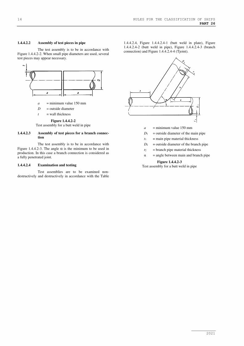
1.4.4.2.2 Assembly of test pieces in pipe
The test assembly is to be in accordance with
Figure 1.4.4.2-2. When small pipe diameters are used, several
test pieces may appear necessary.
a = minimum value 150 mm
D = outside diameter
t = wall thickness
Figure 1.4.4.2-2
Test assembly for a butt weld in pipe
1.4.4.2.3 Assembly of test pieces for a branch connec-
tion
The test assembly is to be in accordance with
Figure 1.4.4.2-3. The angle α is the minimum to be used in
production. In this case a branch connection is considered as
a fully penetrated joint.
1.4.4.2.4 Examination and testing
Test assemblies are to be examined non-
destructively and destructively in accordance with the Table
1.4.4.2.4, Figure 1.4.4.2.4-1 (butt weld in plate), Figure
1.4.4.2.4-2 (butt weld in pipe), Figure 1.4.4.2.4-3 (branch
connection) and Figure 1.4.4.2.4-4 (Tjoint).
a = minimum value 150 mm
D1 = outside diameter of the main pipe
t1 = main pipe material thickness
D2 = outside diameter of the branch pipe
t2 = branch pipe material thickness
α = angle between main and branch pipe
Figure 1.4.4.2-3
Test assembly for a butt weld in pipe

RULES FOR THE CLASSIFICATION OF SHIPS 15
PART 26
2021
Table 1.4.4.2.4
Examinations and tests for butt welds
Test piece Type of test Extent of testing Note
Butt weld on plate with full
penetration
Figure 1.4.4.2.4-1
Visual
Surface crack detection
Radiographic or Ultrasonic testing
Transverse tensile test
Longitudinal tensile test
Transverse bend test
Impact test
Macro examination
Hardness test
100%
100%
100%
2 specimens
required
4 specimens
required
1 specimen
required
-
1
2
as per 1.4.4.2.4.2
as per 1.4.4.2.4.3
as per 1.4.4.2.4.4
as per 1.4.4.2.4.5
as per 1.4.4.2.4.6
as per 1.4.4.2.4.7
Butt weld on pipe with full
penetration
Figure 1.4.4.2.4-2
Visual
Surface crack detection
Radiographic or Ultrasonic testing
Transverse tensile test
Transverse bend test
Impact test
Macro examination
Hardness test
100%
100%
100%
2 specimens
4 specimens
required
1 specimen
required
-
1
2
as per 1.4.4.2.4.2
as per 1.4.4.2.4.4
as per 1.4.4.2.4.5
as per 1.4.4.2.4.6
as per 1.4.4.2.4.7
Branch connection with full
penetration
Figure 1.4.4.2.4-3
T-joint with full penetration
Figure 1.4.4.2.4-4
Visual
Surface crack detection
Ultrasonic or radiographic
Macro examination
Hardness test
100%
100%
100%
2 specimens
required
-
1
2,3
as per 1.4.4.2.4.6
as per 1.4.4.2.4.7
Notes:
1) Penetrant testing or magnetic particle testing. For non-magnetic materials, penetrant testing.
2) Ultrasonic testing shall not be used for t ≤ 10 mm.
3) For outside diameter ≤ 50 mm, no ultrasonic test is required.
For outside diameter > 50 mm, if it is not technically possible to execute the ultrasonic examination, radiographic examination
shall be provided that the joint configuration will allow meaningful results.

16 RULES FOR THE CLASSIFICATION OF SHIPS
PART 26
2021
Figure 1.4.4.2.4-1
Location of test specimens for a butt weld in plate
Figure 1.4.4.2.4-2
Location of test specimens for a butt weld in pipe
1) Macro and hardness test specimen to be
taken in position A)
2) Macro test specimen in position B
α – Branch angle
Figure 1.4.4.2.4-3

RULES FOR THE CLASSIFICATION OF SHIPS 17
PART 26
2021
Location of test specimens for a branch connection
1) Discard 25 mm
2) Macro test specimen
3) Macro and hardness test specimen
4) Welding direction
Figure 1.4.4.2.4-4
Location of test specimens for a T-joint
1.4.4.2.4.1 Non-destructive testing
Test assemblies are to be examined by visual
and by non-destructive testing prior to the cutting of test
specimen. In case that any post-weld heat treatment is re-
quired or specified, non-destructive testing is to be performed
after heat treatment. For steels according to Rules, Part 25 –
Metallic materials, Section 3.4 with specified minimum yield
strength of 420 N/mm2 and above the non-destructive testing
is to be delayed for a minimum of 48 hrs, unless heat treat-
ment has been carried out. NDT procedures are to be agreed
with the Register.
Imperfections detected by visual or non-
destructive testing are to be assessed in accordance with
HRN EN ISO 5817, class B, except for excess weld metal
and excess of penetration for which the level C applies.
1.4.4.2.4.2 Transverse tensile test
The testing is to be carried out in accordance
with the Rules for the classification of ships, Part 25 – Metal-
lic materials, Section 2.4. The tensile strength recorded for
each specimen is not to be less than the minimum required
for the base metal.
When butt welds are made between plates of
different grades, the tensile strength to be obtained on the
welded assembly is to be in accordance with the requirements
relating to the steel grade having lower strength.
1.4.4.2.4.3 Longitudinal tensile test
Longitudinal tensile test of deposited weld met-
al taken lengthways from the weld is required for cases where
the welding consumable is not approved by the Register.
The testing is to be carried out in accordance
with Rules for the classification of ships, Part 25 – Metallic
materials, Section 2.4. The tensile properties recorded for
each specimen are not to be less than the minimum required
for the approval of the appropriate grade of consumable.
Where more than one welding process or type
of consumable has been used to make the test weld, test spec-
imens are to be taken from the area of the weld where each
was used with the exception of those processes or consuma-
bles used to make the first weld run or root deposit.
1.4.4.2.4.4 Bend test
Transverse bend tests for butt joints are to be in
accordance with the Rules for the classification of ships, Part
25 – Metallic materials, Section 2.6.
The mandrel diameter to thickness ratio (i.e.
D/t) is to be that specified for the welding consumable (Sec-
tion 1.5).
The bending angle is to be 180°. After testing,
the test specimens are not to reveal any open defects in any
direction greater than 3 mm. Defects appearing at the corners
of a test specimen during testing are to be investigated case
by case.
Two root and two face bend specimens are to
be tested. For thickness 12 mm and over, four side bend spec-
imens may alternatively be tested.
For butt joints in heterogeneous steel plates,
face and root longitudinal bend test specimens may be used
instead of the transverse bend test specimens.
1.4.4.2.4.5 Impact test
a) Normal and higher strength hull structural
steels according to the Rules for the classification of ships,
Part 25 – Metallic materials, Section 3.2.
The positions of specimens are to be in accord-
ance with these requirements. Dimensions and testing are to
be in accordance with the requirements of the Rules for the
classification of ships, Part 25 – Metallic materials, Section
2.7.
Test specimen with Charpy-V-notch are to be
used and sampled from 1 to 2 mm below the surface of the
base metal, transverse to the weld and on the side containing
the last weld run.
V-notch specimens are located in the butt-
welded joint as indicated in Figure 1.4.4.2.4.5-1 and Figure
1.4.4.2.4.5-2 and the V-notch is to be cut perpendicular to the
surface of the weld.
Test temperature and absorbed energy are to be
in accordance with Table 1.4.4.2.4.5.
When butt welds are made between different
steel grades/types, the test specimens are to be taken from the
side of the joint with lower toughness of steel. Temperature
and absorbed energy results are to be in accordance with the
requirements for the lower toughness steel.
Where more than one welding process or con-
sumable has been used to make the test weld, impact test
specimens are to be taken from the respective areas where
each was employed. This is not to apply to the process or
consumables used solely to make the first weld run or root
deposit.
The testing of sub - size specimen is to be in
accordance with Rules for the classification of ships, Part 25
– Metallic materials, Section 2.7.2.

18 RULES FOR THE CLASSIFICATION OF SHIPS
PART 26
2021
Table 1.4.4.2.4.5
Impact test requirements for butt joints (t≤50 mm)
Grade of steel Testing temperature
(C°)
Value of minimum average absorbed energy (J) 1),2)
For manually or semi-automatically welded joints For automatically
welded joints Downhand, Horizontal,
Overhead
Vertical upward,
Vertical downward
A3) 20
47
34 34
B3), D 0
E -20
A32, A36 20
D32, D36 0
E32, E36 -20
F32, F36 -40
A40 20
39 39 D40 0
E40 -20
F40 -40
Notes:
1) For thickness above 50 mm impact test requirements are to be agreed by the Register.
2) These requirements are to apply to test piece of which butt weld is perpendicular to the rolling direction of the plates.
3) For Grade A and B steels average absorbed energy on fusion line and in heat affected zone is to be minimum 27 J.
b) High strength quenched and tempered steels
according to the Rules for the classification of ships, Part 25
– Metallic materials, Section 3.4.
Impact test is to be performed as described in
the above a).
V-notch specimens are located in the butt weld-
ed joint as indicated in Figure 1.4.4.2.4.5-1 and Figure
1.4.4.2.4.5-2 and the V-notch is to be cut perpendicular to the
surface of the weld.
Test temperature and absorbed energy are to be
in accordance with the requirements of base metal as speci-
fied in the Rules for the classification of ships, Part 25 – Me-
tallic materials, Section 3.4.
c) Weldable C and C-Mn hull steel castings and
forgings according to the Rules for the classification of ships,
Part 25 – Metallic materials, Sections 3.11 and 3.12.
For base metal with specified impact values test
temperature and absorbed energy are to be in accordance
with the requirements of the base metal to be welded.

RULES FOR THE CLASSIFICATION OF SHIPS 19
PART 26
2021
a) t ≤ 50 mm1)
Note:
1) For one side single run welding over 20 mm notch location “a” is to be added on root side.
b) t > 50 mm
Notch locations:
a – center of weld “WM”
b – on fusion line “FL”
c – in HAZ, 2 mm from fusion line
Figure 1.4.4.2.4.5-1
Location of V-notch for butt weld of normal heat input (heat input ≤ 50 kJ/cm)
a) t ≤ 50 mm1)
Note:
1) For one side welding with thickness over 20 mm notch location “a”, “b” and “c” is to be added on root side.
b) t > 50 mm
Notch locations:
a – center of weld “WM”
b – on fusion line “FL”
c – in HAZ, 2 mm from fusion line
d – in HAZ, 5 mm from fusion line
e – in HAZ, 10 mm from fusion line in a case of heat input > 200 kJ/cm
Figure 1.4.4.2.4.5-2
Location of V-notch for butt weld of high heat input (heat input > 50 kJ/cm)

20 RULES FOR THE CLASSIFICATION OF SHIPS
PART 26
2021
1.4.4.2.4.6 Macro examination
The test specimens are to be prepared and
etched on one side to clearly reveal the weld metal, the fusion
line and the heat affected zone.
Macro examination is to include about 10 mm
unaffected base metal.
The examination is to reveal a regular weld
profile, through fusion between adjacent layers of weld and
base metal and the absence of defects such as cracks, lack of
fusion etc.
1.4.4.2.4.7 Hardness test
Hardness test is required for steels with speci-
fied minimum yield strength of ReH ≥ 355 N/mm2. The Vick-
ers method HV 10 is normally to be used. The indentations
are to be made in the weld metal, the heat affected zone and
the base metal measuring and recording the hardness values.
At least two rows of indentations are to be carried out in ac-
cordance with Fig. 1.4.4.2.4.7-1 and 1.4.4.2.4.7-2, and for T-
joint in accordance with Fig. 1.4.4.3.3.3-1 and 1.4.4.3.3.3-3.
For each row of indentations there is to be a
minimum of 3 individual indentations in the weld metal, the
heat affected zones (both sides) and the base metal (both
sides).
The results from the hardness test are not to ex-
ceed the following:
- Steel with a specified minimum yield
strength ReH ≤ 420 N/mm2 : 350 HV10
- Steel with a specified minimum yield
strength 420 N/mm2 < ReH ≤ 690 N/mm2 :
420 HV10
Figure 1.4.4.2.4.7-1
Examples of hardness test with rows of indentations (R) in butt welds
Table 1.4.4.2.4.7
Recommended distances l between indentations for hardness test in the heat affected zone
Vickers hardness
Symbol
Distance between indentations
l
(mm)
HV 10 1
The distance of any indentation from the previ-
ous indentation is not to be less than the value allowed for the
previous indentation by HRN EN ISO 6507-1.

RULES FOR THE CLASSIFICATION OF SHIPS 21
PART 26
2021
Figure 1.4.4.2.4.7-2
Example showing the position of the indentations for hardness test in the weld metal, the heat affected zone and the base metal of a
butt weld (dimensions in mm)
1.4.4.3 Fillet weld
1.4.4.3.1 Assembly of test pieces
The test assembly is to be of a size sufficient to
ensure a reasonable heat distribution and according to Fig.
1.4.4.3-1 with the minimum dimensions:
a) manual or semi-automatic welding:
width a = 3 x t, min 150 mm
length b = 6 x t, min 350 mm
b) automatic welding:
width a = 3 x t, min 150 mm
length b = 1000 mm
1.4.4.3.2 Welding of test pieces
The test assembly is welded on one side only.
For single run manual and semi-automatic welding, a
stop/restart is to be included in the test length and its position
is to be clearly marked for subsequent examination.
1.4.4.3.3 Examination and testing
Test assemblies are to be examined non-
destructively and destructively in accordance with the Table
1.4.4.3.3.
Figure 1.4.4.3-1
Test assembly for fillet weld and T-joint

22 RULES FOR THE CLASSIFICATION OF SHIPS
PART 26
2021
Table 1.4.4.3.3
Examinations and tests for fillet welds
Test piece Type of test Extent of testing Note
Fillet weld
Figure 1.4.4.3-1
Visual
Surface crack detection
Macro examination
Hardness test
Fracture test
100%
100%
2 specimens
required
required
-
1
as per 1.4.4.3.3.2
as per 1.4.4.3.3.3
as per 1.4.4.3.3.4
Notes:
1) Penetrant testing or magnetic particle testing. For non-magnetic materials, penetrant testing.
1.4.4.3.3.1 Non-destructive testing
Test assemblies are to be examined by visual
and by non-destructive testing prior to the cutting of test
specimen. In case that any post-weld heat treatment is re-
quired or specified, non-destructive testing is to be performed
after heat treatment. For steels according to Rules, Part 25 –
Metallic materials, Section 3.4 with specified minimum yield
strength of 420 N/mm2 and above the non-destructive testing
is to be delayed for a minimum of 48 hrs, unless heat treat-
ment has been carried out. NDT procedures are to be agreed
with the Register.
Imperfections detected by visual or non-
destructive testing are to be assessed in accordance with
HRN EN ISO 5817, class B, except for excess convexity and
excess throat thickness for which the level C applies.
1.4.4.3.3.2 Macro examination
The test specimens are to be prepared and
etched on one side to clearly reveal the weld metal, fusion
line, root penetration and the heat affected zone.
Macro examination is to include about 10 mm
unaffected base metal.
The examination is to reveal a regular weld
profile, through fusion between adjacent layers of weld and
base metal, sufficient root penetration and the absence of de-
fects such as cracks, lack of fusion etc.
1.4.4.3.3.3 Hardness test
Hardness test is required for steels with speci-
fied minimum yield strength of ReH ≥ 355 N/mm2. The Vick-
ers method HV 10 is normally to be used. The indentations
are to be made in the weld metal, the heat affected zone and
the base metal measuring and recording the hardness values.
At least two rows of indentations are to be carried out in ac-
cordance with Fig. 1.4.4.3.3.3-1, 1.4.4.3.3.3-2 and
1.4.4.3.3.3-3.
For each row of indentations there is to be a
minimum of 3 individual indentations in the weld metal, the
heat affected zones (both sides) and the base metal (both
sides).
The results from the hardness test are not to ex-
ceed the following:
- Steel with a specified minimum yield
strength ReH ≤ 420 N/mm2 : 350 HV10
- Steel with a specified minimum yield
strength 420 N/mm2 < ReH ≤ 690 N/mm2 :
420 HV10
1.4.4.3.3.4 Fracture test
The fracture test is to be performed by folding
the upright plate onto the through plate. Evaluation is to con-
centrate on cracks, porosity and pores, inclusions, lack of fu-
sion and incomplete penetration. Imperfection that are detect-
ed is to be assessed in accordance with HRN EN ISO 5817,
class B.
a) Fillet weld b) T-joint weld
Figure 1.4.4.3.3.3-1
Examples of hardness test with rows of indentations (R) in fillet welds and in T-joint welds

RULES FOR THE CLASSIFICATION OF SHIPS 23
PART 26
2021
Figure 1.4.4.3.3.3-2
Example showing the position of the indentations for hardness test in the weld metal,
the heat affected zone and the base metal of a fillet weld (dimensions in mm)
Figure 1.4.4.3.3.3-3
Example showing the position of the indentations for hardness test in the weld metal,
the heat affected zone and the base metal of a T-joint weld (dimensions in mm)
1.4.4.4 Re-testing
1.4.4.4.1 If the test piece fails to comply with any of the
requirements for visual or non-destructive testing one further
test piece is to be welded and subjected to the same examina-
tion. If this additional test piece does not comply with the rel-
evant requirements, the pWPS is to be regarded as not capa-
ble of complying with the requirements without modification.
1.4.4.4.2 If any test specimens fail to comply with the
relevant requirements for destructive testing due to weld im-
perfections only, two further test specimens are to be ob-
tained for each one that failed. These specimens can be taken
from the same test piece if there is sufficient material availa-
ble or from a new test piece, and are to be subjected to the
same test. If either of these additional test specimens does not
comply with the relevant requirements, the pWPS is to be re-

24 RULES FOR THE CLASSIFICATION OF SHIPS
PART 26
2021
garded as not capable of complying with the requirements
without modification.
1.4.4.4.3 If a tensile test specimen fails to meet the re-
quirements, the re-testing is to be in accordance with the
Rules for the classification of ships, Part 25 – Metallic mate-
rials, Section 2.9.2.
1.4.4.4.4 If there is a single hardness value above the
maximum values allowed, additional hardness tests are to be
carried out (on the reverse of the specimen or after sufficient
grinding of the tested surface). None of the additional hard-
ness values is to exceed the maximum hardness values re-
quired.
1.4.4.4.5 The re-testing of Charpy impact specimens are
to be carried out in accordance with Rules for the classifica-
tion of ships, Part 25 – Metallic materials, Section 2.9.3.
1.4.4.4.6 Where there is insufficient welded assembly
remaining to provide additional test specimens, a further as-
sembly is to be welded using the same procedure to provide
the additional specimens.
1.4.4.5 Test record
1.4.4.5.1 Welding conditions for test assemblies and test
results are to be recorded in welding procedure test record.
Forms of welding procedure test records can be taken from
the Register rules or from relevant standards.
1.4.4.5.2 A statement of the results of assessing each test
piece, including repeat tests, is to be made for each welding
procedure test. The relevant items listed for the WPS of these
requirements are to be included.
1.4.4.5. A statement that the test piece was made ac-
cording to the particular welding procedure is to be signed by
the Surveyor witnessing the test and is to include the Register
identification.
1.4.4.6 Range of approval
1.4.4.6.1 General
1.4.4.6.1.1 All the conditions of validity stated below are
to be met independently of each other.
1.4.4.6.1.2 Changes outside of the ranges specified are to
require a new welding procedure test.
1.4.4.6.1.3 Shop primers may have an influence on the
quality of fillet welds and is to be considered. Welding pro-
cedure qualification with shop primer will qualify those
without but not vice versa.
1.4.4.6.2 Base metal
1.4.4.6.2.1 Normal and higher strength hull structural
steels according to the Rules for the classification of ships,
Part 25 – Metallic materials, Section 3.2
a) For each strength level, welding proce-
dures are considered applicable to the
same and lower toughness grades as that
tested.
b) For each toughness grade, welding proce-
dures are considered applicable to the
same and two lower strength levels as
that tested.
c) For applying the above a) and b) to high
heat input processes above 50 kJ/cm, e.g.
the two-run technique with either sub
submerged arc or gas shielded metal arc
welding, electro slag and electro gas
welding, welding procedure is applicable
to that toughness grade tested and one
strength level below
Where steels used for construction are supplied
from different delivery conditions from those tested the Reg-
ister may require additional tests.
1.4.4.6.2.2 High strength quenched and tempered steels
according to the Rules for the classification of ships, Part 25
– Metallic materials, Section 3.4.
a) For each strength level, welding proce-
dures are considered applicable to the
same and lower toughness grades as that
tested.
b) For each toughness grade, welding proce-
dures are considered applicable to the
same and one lower strength level as that
tested.
c) The approval of quenched and tempered
steels does not quality thermo-
mechanically rolled steels (TMCP steels)
and vice versa.
1.4.4.6.2.3 Weldable C and C-Mn hull steel forgings ac-
cording to the Rules for the classification of ships, Part 25 –
Metallic materials, Section 3.11.
a) Welding procedures are considered appli-
cable to the same and lower strength level
as that tested.
b) The approval of quenched and tempered
hull steel forgings does not quality other
delivery conditions and vice versa.
1.4.4.6.2.4 Weldable C and C-Mn hull steel castings ac-
cording to the Rules for the classification of ships, Part 25 –
Metallic materials, Section 3.12.
a) Welding procedures are considered appli-
cable to the same and lower strength level
as that tested.
b) The approval of quenched and tempered
hull steel castings does not quality other
delivery conditions and vice versa.
1.4.4.6.3 Material thickness and pipe diameter
1.4.4.6.3.1 The qualification of a WPS carried out on a test
assembly of thickness t is valid for the thickness range given
in Table 1.4.4.6.3.1.
1.4.4.6.3.2 In addition to the requirements of Table
1.4.4.6.3.1, the range of approval of throat thickness “a” for
fillet welds is to be as follows:
- Single run: “0.75 x a” to “1.5 x a”
- Multi-run: as for butt welds with multi-
run (i.e. a=t)

RULES FOR THE CLASSIFICATION OF SHIPS 25
PART 26
2021
Table 1.4.4.6.3.1
Approval range of thickness for butt weld and T-joint welds and fillet welds
Thickness of test piece
t1)
(mm)
Range of approval
Fillet weld
Figure 1.4.4.3-1
Butt and T-joint welds with single run
or single run from both sides
Butt and T-joint welds with multi-run and fillet
welds
3 < t ≤ 12 0,7t to 1,1t 3 to 2t
12 < t ≤ 100 0,7t to 1,1t3) 0,5 t to 2t
(max.150)
Notes:
1) For For multi process procedures, the recorded thickness contribution of each process is to be used as basis for the
range of approval for the individual welding process.
2) For fillet welds, the range of approval is to be applied to both base metals.
3) For high heat input processes over 50 kJ/cm, the upper limit of range of approval is to be 1.0 x t.
1.4.4.6.3.3 For the vertical-down welding, the test piece
thickness “t” is always taken as the upper limit of the range
of application.
1.4.4.6.3.4 For unequal plate thickness of butt welds the
lesser thickness is ruling dimension.
1.4.4.6.3.5 Notwithstanding the above, the approval of
maximum thickness of base metal for any technique is to be
restricted to the thickness of test assembly if three of the
hardness values in the heat affected zone are found to be
within 25 HV of the maximum permi ted, as stated
1.4.4.2.4.7 and 1.4.4.3.3.3.
1.4.4.6.3.6 The qualification of a welding procedure test on
diameter D shall include qualification for diameters in the
following ranges given in Table 1.4.4.6.3.6.
Table 1.4.4.6.3.6
Approval range for pipe and branch connection outside
diameters
Diameter of the test piece
D (mm) Range of approval1)
D ≤ 25 0,5D to 2D
D > 25 ≥ 0,5D (25 mm min.)
Notes:
1) Approval given for plates also covers pipes when the out-
side diameter is > 500 mm or when the diameter is >150
mm welded in the PA or PC rotated position, within the
limitations of the Table 1.4.4.6.10.
1.4.4.6.3.7 A welding procedure test carried out on a
branch connection with angle α shall approve all branch an-
gles α1 in the range of α ≤ α1 ≤ 90°.
1.4.4.6.4 Welding position
Approval for a test made in any position is res-
tricted to that position (see Figures 1.4.4.6.4-1, 1.4.4.6.4-2,
1.4.4.6.4-3 and 1.4.4.6.4-4). To qualify a range of positions,
test assemblies are to be welded for highest heat input positi-
on and lowest heat input position and all applicable tests are
to be made on those assemblies.
For example, butt welds in plate the highest
heat input position is normally PF and the lowest PC. For
fixed pipe welds the hardness tests shall be taken from the
overhead welding position.
1.4.4.6.5 Welding process
1.4.4.6.5.1 The approval is only valid for the welding pro-
cess(es) used in the welding procedure test. It is not permitted
to change from a multi-run to a single run.
1.4.4.6.5.2 For multi-process procedures the welding pro-
cedure approval may be carried out with separate welding
procedure tests for each welding process. It is also possible to
make the welding procedure test as a multi-process procedure
test. The approval of such a test is only valid for the process
sequence carried out during the multi-process procedure test.
1.4.4.6.6 Welding consumable
Except high heat input processes over 50kJ/cm,
welding consumables cover other approved welding consum-
ables having the same grade mark including all suffixes spec-
ified in Section 1.5 with the welding consumable tested.
1.4.4.6.7 Heat input
1.4.4.6.7.1 The upper limit of heat input approved is 25%
greater than that used in welding the test piece or 55 kJ/cm
whichever is smaller, except that the upper limit is 10%
greater than that for high heat input processes over 50 kJ/cm.
1.4.4.6.7.2 The lower limit of heat input approved is 25%
lower than that used in welding the test piece.
1.4.4.6.8 Preheating and interpass temperature
1.4.4.6.8.1 The minimum preheating temperature is not to
be less than that used in the qualification test.
1.4.4.6.8.2 The maximum interpass temperature is not to
be higher than that used in the qualification test.

26 RULES FOR THE CLASSIFICATION OF SHIPS
PART 26
2021
1.4.4.6.9 Post-weld heat treatment
The heat treatment used in the qualification test
is to be maintained during manufacture. Holding time may be
adjusted as a function of thickness.
1.4.4.6.10 Type of joint
1.4.4.6.10.1 Range of approval depending on type of welded
joints for test assembly is to be specified in Table 1.4.4.6.10.
1.4.4.6.10.2 A qualification test performed on a butt weld
will also qualify for fillet welding within the thickness ranges
specified for fillet welds specified in 1.4.5.3 above.
Table 1.4.4.6.10
Range of qualification for type of welded joint
Type of welded joint for test assembly Range of
approval
Butt
welding
One
side
With backing A A, C
Without backing B A, B, C, D
Both
side
With gouging C C
Without gouging D C, D
Notes:
- T joints butt welded only qualify T joints butt welded and
fillet welds.
- Fillet welding qualifies fillet welding only.
1.4.4.6.11 Other variables
The range of approval relating to other varia-
bles may be taken as specified in HRN EN ISO 15614-1.
1.4.5. Qualification of welding procedures for
aluminium alloys
1.4.5.1 General
1.4.5.1.1 Basic requiremens are given in 1.4.1, 1.4.2 and
1.4.3.
1.4.5.1.2 These requirements specifically excludes the
welding procedure intended for LNG containment.
1.4.5.1.3. The welding processes below indicated, toget-
her with their relevant numbering according to ISO 4063, are
in general used for welding aluminium alloys:
- 131 - metal-arc inert gas welding (MIG
welding)
- 141 - tungsten inert gas arc welding (TIG
welding)
- 15 - plasma arc welding
1.4.5.1.3 The welding consumables shall be approved in
accordance with the requirements specified in Section 1.5.4.
Where non approved welding consumables are
used at the discretion of the Register, the requirements for the
qualification of the welding procedures shall be established
on a case by case basis. In general additional tests on deposit-
ed weld metal are required in accordance with Section 1.5.4.
1.4.5.2 Butt weld
1.4.5.2.1 Assembly of test pieces and welding
The test assembly is to be of a size sufficient to
ensure a reasonable heat distribution during welding and ac-
cording to 1.4.4.2.1.
The edge preparation and fit up is to be in ac-
cordance with the pWPS. If tack welds are to be fused into
the production joint they shall be included in the test pieces.
The cleaning of the parts to be welded shall be carried out in
accordance with the welding procedure.
The welding is to be carried out in accordance
with the pWPS and under the general conditions of produc-
tion welding which it represents.
1.4.5.2.2 Examination and testing
Test assemblies are to be examined non-
destructively and destructively in accordance with the Table
1.4.5.2.2. Test specimens are to be taken in accordance with
Figure 1.4.5.2.
Table 1.4.5.2.2
Examinations and tests for butt welds
Test piece Type of test Extent of testing Note
Butt weld on plate with
full penetration
Figure 1.4.5.2.
Visual
Dye penetrant test
Radiographic or Ultrasonic examination1)
Transverse tensile test
Transverse bend test2)
Macroscopic examination
Microscopic examination3)
100%
100%
100%
2 specimens
2 root and 2 face specimens
1 specimen
1 specimen
-
as per 1.4.5.2.3
as per 1.4.5.2.3
as per 1.4.5.2.4
as per 1.4.5.2.5
as per 1.4.5.2.6
as per 1.4.5.2.6
Notes:
1) Ultrasonic testing shall not be used for t ≤ 10 mm.
2) 2 root and 2 face bend test specimens can be substituted by 4 side bend test specimens for t ≥ 12 mm.
3) Only for 6xxx-alloys (material group 23) and all casting alloys.

RULES FOR THE CLASSIFICATION OF SHIPS 27
PART 26
2021
Figure 1.4.5.2
Location of test specimens for a butt weld in plate
1.4.5.2.3 Non-destructive examination
Non destructive examinations are to be carried
out after any required post weld heat treatment, natural or ar-
tificial ageing, and prior to the cutting of the test specimens.
Welds are to be free from cracks. Imperfections
detected by visual or non-destructive testing are to be as-
sessed in accordance with HRN EN ISO 10042, level B, ex-
cept for excess weld metal or convexity, excess throat thick-
ness and excess of penetration for which the level C applies.
1.4.5.2.4 Transverse tensile test
The specimens for transverse tensile test is to
be carried out in accordance with the Rules for the classifica-
tion of ships, Part 25 – Metallic materials, Section 2.4. The
tensile strength shall meet requirements stated in Table
1.4.5.2.4.
Table 1.4.5.2.4
Minimum tensile strength by grade for aluminium alloys for
series
Grade (alloy designation) Minimum tensile strength
(N/mm2)
5754 190
5086 240
5083 275
5383 290
5059 330
5456 290
6005A 170
6061 170
6082 170
1.4.5.2.5 Bend test
The specimens for bend tests are to be ma-
chined to the dimensions given in the Rules for the classifica-
tion of ships, Part 25 – Metallic materials, Section 2.4. For
dissimilar or heterogeneous butt joints longitudinal bend tests
may be required instead of transverse bend tests.
The bend test specimens are to be bent on a
mandrel with maximum diameter as given in the formula be-
low. The bending angle shall be 180°.
d = ss
tA
t−
⋅100
where:
d - the maximum former diameter
ts - the thickness of the bend test specimen (this includes side
bends)
A - the minimum tensile elongation required by the alloy
grade, temper condition and thickness (for combination be-
tween different alloys, the lowest individual value should be
used).
After testing the test specimens should not re-
veal any open defect in any direction greater than 3 mm. De-
fects appearing at the corner of the specimens may be disre-
garded, unless there is evidence that they result from lack of
fusion.
Wrap around method bend tests are recom-
mended for the above mandrel diameter for each alloy.
1.4.5.2.6 Macroscopic / Microscopic examination
The test specimen shall be prepared and exam-
ined in accordance with ISO 17639 and etched on one side to
clearly reveal the fusion line, the HAZ and the build up of the
runs and the unaffected base metal.
The macroscopic examination shall reveal a
regular weld profile, thorough fusion between adjacent layers
of weld and base metal and the absence of defects such as

28 RULES FOR THE CLASSIFICATION OF SHIPS
PART 26
2021
cracks and lack of fusion The macroscopic examination shall
include unaffected parent material.
The acceptance levels specified in 1.4.5.2.3 ap-
ply.
Care should be taken when etching certain al-
loys to avoid producing crack like indications.
1.4.5.3 Fillet weld
1.4.5.3.1 Assembly of test pieces and welding
The test assembly is to be of a size sufficient to
ensure a reasonable heat distribution during welding and ac-
cording to 1.4.4.3.1.
The two plates should be positioned and tack
welded edgewise so as to constitute a T assembly without
clearance.
Welding on one or both sides and fit up should
be as detailed in the pWPS.
In general for manual and semiautomatic weld-
ing a stop/restart position should be included in the test
length and should be clearly marked for subsequent examina-
tion.
he cleaning of the parts to be welded should be
carried out in accordance with the welding procedure.
1.4.5.3.2 Examination and testing
Test assemblies are to be examined non-
destructively and destructively in accordance with the Table
1.4.5.2.2. Test specimens is to be taken in accordance with
Figure 1.4.5.3.
Table 1.4.5.3.2
Examinations and tests for fillet welds
Test piece Type of test Extent of testing Note
Fillet weld on plate
Figure 1.4.5.3
Visual
Dye penetrant test
Macroscopic examination1)
Microscopic examination2)
Fracture test
100%
100%
2 specimens
1 specimen
1 specimen
-
as per 1.4.5.3.3
as per 1.4.5.3.4
as per 1.4.5.3.4
as per 1.4.5.3.4
Notes:
1) One of the macro sections shall be taken at the position of the stop/restart (see 1.4.5.3.1).
2) Only for 6xxx-alloys (material group 23) and all casting alloys.
1) Discard 25 mm
2) Micro and macro test specimen
3) Macro test specimen
4) Welding direction
Figure 1.4.5.3
Location of test specimens for a T-joint
1.4.5.3.3 Visual examination and surface crack detec-
tion
The requirements specified in 1.4.5.2.3 are to
be complied with.
1.4.5.3.4 Macroscopic / microscopic examination and
fracture test
The fracture test as well as the macro examina-
tion shall, in general, satisfy the acceptance level specified in
1.4.5.2.3.
Dimension of leg size, throat and penetration
should in general be reported.
1.4.5.4 Re-testing
If the test assembly fails to comply with any of
the requirements for visual examination or NDE, one further
test assembly is to be welded and subjected to the same ex-
amination.
If any test specimen fails to comply with the
relevant requirements, two additional test specimens are to be
obtained for each one that failed. These specimens can be
taken from the same assembly, if there is sufficient material,
or from a new test assembly. For the acceptance both tests
shall give satisfactory results.
Where failed in the above re-testing, the pWPS
is to be modified before further consideration by the Survey-
or is given to a new test assembly for re-qualification.
1.4.5.5 Range of approval
1.4.5.5.1 General
The approval of the WPS obtained by a ship-
yard or a manufacturer is valid for welding in all its work-
shops under the same technical and quality control.

RULES FOR THE CLASSIFICATION OF SHIPS 29
PART 26
2021
All the conditions of validity stated below
should be met independently of each other.
Changes outside of the ranges specified may
require a new welding procedure test.
1.4.5.5.2 Parent metal
The aluminium alloys are grouped into three
groups:
- Group A: aluminium-magnesium alloys
with Mg content ≤ 3.5% (alloy 5754)
- Group B: aluminium-magnesium alloys
with 4% ≤ Mg ≤ 5.6% (alloys 5059,
5083, 5086, 5383 and 5456)
- Group C: aluminium-magnesium-silicon
alloys (alloys 6005A, 6061 and 6082)
For each Group, the qualification made on one
alloy qualifies the procedure also for the other alloys of the
same Group with equal or lower specified tensile strength af-
ter welding.
The qualification made on Group B alloy quali-
fies the procedure also for Group A alloys.
1.4.5.5.3 Thickness
The qualification of a WPS carried out on a test
assembly of thickness t is valid for the thickness range given
in Table 1.4.5.5.3-1.
In case of butt-joints between dissimilar thick-
ness, t is the thickness of the thinner material.
In case of fillet joints between dissimilar thick-
ness, t is the thickness of the thicker material.
In addition to the requirements of Table
1.4.5.5.3-1, the range of qualification of the throat thickness a
is given in Table 1.4.5.5.3-2.
Where a fillet weld is qualified by means of a
butt weld test, the throat thickness range qualified should be
based on the thickness of the deposited weld metal.
Where the majority of production work is fillet
welding, an additional fillet weld test may be required.
Table 1.4.5.5.3-1
Range of qualification for parent material thickness
Thickness of the test piece,
t (mm) Range of qualifications
t ≤ 3 0,5 to 2t
3 < t ≤ 20 3 to 2t
t > 20 ≥ 0,8t
Table 1.4.5.5.3-2
Range of qualifications for the throat thickness of fillet
welds
Throat thickness of the test
piece, a (mm) Range of qualifications
a < 10 0,75a to 1,5a
a ≥ 10 ≥ 7,5
1.4.5.5.4 Welding position
Provided that comparable welding parameters
are used for the included welding positions a test in any one
position qualifies for welding in all positions except for verti-
cal downwards (PG) position where in any case separate
welding procedure test is required.
1.4.5.5.5 Type of joint
The range of approval for the types of joint in
relation to the type of joint used in the procedure qualifica-
tion test is as follows:
- butt-joint welded from one side with
backing qualifies also for welding from
both sides with gouging;
- butt-joint welded from one side without
backing qualifies also for welding from
one side with backing, from both sides
with gouging and from both sides without
gouging;
- butt-joint welded from both sides with
gouging only qualifies that condition,
- butt-joint welded from both sides without
gouging qualifies also for welding from
both sides with gouging and from one
side with backing.
1.4.5.5.6 Welding process
The approval is valid only for the welding pro-
cess used in the welding procedure test. It is not permitted to
change a multi run deposit into a single run (or single run on
each side) or viceversa for a given process. In the case of a
multi-process procedure, the approval is only valid for apply-
ing the processes in the order used during the procedure qual-
ification tests.
Note:
For multi-process procedures each welding process may be
approved separately or in combination with other processes.
Similarly one or more processes may be deleted from an ap-
proved WPS provided the joint thickness is within the ap-
proved thickness range of the relevant welding process to be
applied.
1.4.5.5.7 Welding consumables
The welding consumable used in the qualifica-
tion tests qualifies:
.1 Approved welding consumables of the
same strength as the consumable used in
the procedure qualification tests.
.2 Approved welding consumables of higher
strength than the consumable used in the
procedure qualification tests.
The qualification given to shielding gas and
backing gas is restricted to the gas/gas mixture used in the
welding procedure test, see HRN EN ISO 14175 or other
recognised standards for gas designations.
1.4.5.5.8 Type of current
Changes in the type of current (AC, DC,
pulsed) and polarity require a new welding procedure qualifi-
cation.

30 RULES FOR THE CLASSIFICATION OF SHIPS
PART 26
2021
1.4.5.5.9 Preheat and interpass temperature
The lower limit of approval is the preheat tem-
perature applied at the start of the welding procedure test.
The upper limit of approval is the interpass
temperature reached in the welding procedure test.
1.4.5.5.10 Post-weld heat treatment or ageing
Addition or deletion of post weld heat treatment
or ageing is not permitted except that artificial ageing for
6000 series alloys gives approval for prolonged natural age-
ing.
1.4.5.5.11 Other variables
The range of approval relating to other varia-
bles may be taken as specified in HRN EN ISO 15614-2.
Figure 1.4.4.6.4-1
Welding positions according to ISO Standard – Butt welds
Figure 1.4.4.6.4-2
Welding positions according to ISO Standard – Fillet welds

RULES FOR THE CLASSIFICATION OF SHIPS 31
PART 26
2021
Figure 1.4.4.6.4-3
Welding positions according to AWS-Code – Butt welds
Figure 1.4.4.6.4-4
Welding positions according to AWS-Code – Fillet welds

32 RULES FOR THE CLASSIFICATION OF SHIPS
PART 26
2021
1.5 WELDING CONSUMABLES
1.5.1 General
1.5.1.1 All welding consumables used for welding of
structures referred to in 1.1.1 shall be tested and approved by
the Register.
1.5.1.2 The Register shall grant the approval for the
welding consumables on the basis of the manufacturers ap-
plication, technical documentation (1.5.1.3) as well as on the
basis of the results obtained from the testing carried out under
the supervision of the Register and with the approved pro-
gram according to the present Section.
1.5.1.3 Application for approval shall be submitted to
the Register by the manufacturer of the welding consumable
accompanied with the documentation including the follow-
ing:
− name of the manufacturer of the welding
consumables,
− trade name, mark, and type,
− grade of the welding material, including
additional symbols (if necessary) in com-
pliance with this Rules,
− recommended area of application , includ-
ing for example, base material, welding po-
sitions and similar,
− chemical composition and mechanical
properties of weld metal,
− sizes (diameters, lengths),
− instructions manual (current, polarity),
backing, heat treatment etc.,
− classification (EN, ISO, etc.),
− marking, packaging,
− proposed testing laboratory and date of test.
1.5.1.4 On the ground of satisfactory testing results the
Register shall issue the Certificate on the type approval and
testing of welding consumables and shall enlist it in its List
of type approved products and manufacturers. With such an
approval the manufacturer is liable to ensure that, during
manufacture the composition and properties of the products
comply with those of the tested welding consumables.
1.5.1.5 The manufacturer is liable to enter the infor-
mation on the approval certificate into its catalogue of the list
of approval and testing of welding consumables.
1.5.1.6 Unless otherwise agreed, the approved welding
consumables shall be in accordance with 1.5.2 - 1.5.4, tested
annually in the presence of a Surveyor to the Register to
prove that the material properties comply with those of the
tested welding consumables.
1.5.1.7 In case of any change of the properties, chemi-
cal composition of the approved material or the technology of
its production, the tests shall be repeated.
1.5.1.8 Welding consumables which are not covered by
these Rules (e. g. for welding of high - alloy steels, etc.) shall
be tested for the approval in accordance with the special pro-
gram approved by the Register.
1.5.1.9 When the results of any testing fail to meet the
requirements that testing shall be repeated on duplicate re-
test specimens.
For that purpose test specimen may be taken
from the same batch as the former test pieces. In case that re-
testing does not give satisfactory results, the causes shall be
traced and the whole testing repeated.
1.5.1.10 As an alternative to the annual procedures for
approval of welding consumables described in 1.5.2 and
1.5.3, a procedure for the acceptance of manufacturer's quali-
ty assurance systems for welding consumables in accordance
with the provisions of IACS Recommendation No. 17 may be
applied. Welding consumable grades Y89 and Y96 are ex-
cluded.
When, at the manufacturer's request, the Regis-
ter decides to implement this scheme, all the clauses of IACS
Recommendation No. 17 are to be fully complied with by the
manufacturer, without exclusions.
By acceptance of the manufacturer’s quality as-
surance system the Register delegates to the manufacturer the
responsibility for checking that the necessary inspections and
tests are carried out and obliges the manufacturer to comply
with the applicable requirements of the Rules. The Register
will check the effectiveness of the quality assurance system
through verification of the Quality Management System
(QMS).
1.5.2 Approval of consumables for welding
normal and higher strength structural
steels
1.5.2.1 General
1.5.2.1.1 Scope
1.5.2.1.1.1 These requirements give the conditions of ap-
proval and inspection of welding consumables used for hull
structural steel according to the Rules for the classification of
ships, Part 25 - Metallic Materials, Section 3.2 as follows:
− normal strength steels Grades A, B, D and
E,
− higher strength steels Grades A32, D32,
E32, A36, D36 and E36,
− higher strength steels with minimum yield
strength 390 N/mm2: Grades A40, D40 and
E40,
− higher strength steels for low temperature
application: Grades F32, F36 and F40.
Welding consumables for high strength steels
for welded structures are to comply with the requirements of
Section 1.5.3.
These requirements are not applicable for weld-
ing procedure qualification tests at the shipyard.
1.5.2.1.1.2 Categories of products
The concerned welding consumables are divid-
ed into several categories as follows:
− covered electrodes for manual welding and
gravity welding,
− wire/flux combinations for two run or mul-
ti-run submerged arc welding,

RULES FOR THE CLASSIFICATION OF SHIPS 33
PART 26
2021
− solid wire/gas combinations for arc weld-
ing,
− flux cored wires with or without gas for arc
welding,
− consumables for use in electroslag and elec-
trogas vertical welding
1.5.2.1.2 Grading
1.5.2.1.2.1 Basic groups and grades
Filler metals are divided into three groups:
− normal strength filler metals for welding
normal strength hull structural steels,
− higher strength filler metals for welding
normal and higher strength hull structural
steels with minimum yield strength up to
355 N/mm2,
− higher strength filler metals for welding
normal and higher strength hull structural
steels with minimum yield strength up to
390 N/mm2.
Each of the three groups is based on corre-
sponding tensile strength requirements.
Each filler metal group is further divided into
several grades:
− Grades 1, 2 and 3 for ordinary-strength fill-
er metals,
− Grades 1Y, 2Y, 3Y and 4Y for higher
strength filler metals for steels up to 355
N/mm2 yield strength,
− Grades 2Y 40, 3Y 40, 4Y 40 and 5Y 40 for
higher strength filler metals for steels up to
390 N/mm2 yield strength.
The Grade assignment is given in respect of
Charpy V-notch impact test requirements.
For each strength basic group, welding con-
sumables, which have satisfied the requirements for a higher
toughness grade are considered as complying with the re-
quirements for a lower toughness grade.
1.5.2.1.2.2 Correlation of welding consumables to hull
structural steel grades.
The correlation between the hull steel grades
and the welding consumables grades that must be used for the
hull steel welding, is stated in the following Table
1.5.2.1.2.2.

34 RULES FOR THE CLASSIFICATION OF SHIPS
PART 26
2021
Table 1.5.2.1.2.2
Corelation of welding consumables to hull structural steels
Grades of welding
consumables (see notes)
Hull structural steel grades
A B D E A32/36 D32/36 E32/36 F32/36 A40 D40 E40 F40
1, 1S, 1T, 1M, 1TM, IV X
1YS, 1YT, 1YM, 1YTM,
1YV X 2)
2, 2S, 2T, 2M, 2TM, 2V X X X
2Y, 2YS, 2YT, 2YM, 2YTM,
2YV X X X X X
2Y40, 2Y40S, 2Y40T,
2Y40M, 2Y40TM, 2Y40V 1) 1) 1) X X X X
3, 3S, 3T, 3M, 3TM, 3V X X X X
3Y, 3YS, 3YT, 3YM, 3YTM,
3YV X X X X X X X
3Y40, 3Y40S, 3Y40T,
3Y40M, 3Y40TM, 3Y40V 1) 1) 1) 1) X X X X X X
4Y, 4YS, 4YT, 4YM, 4YTM,
4YV X X X X X X X X
4Y40, 4Y40S, 4Y40T,
4Y40M, 4Y40TM, 4Y40V 1) 1) 1) 1) X X X X X X X X
5Y40, 5Y40S, 5Y40T,
5Y40M, 5Y40TM, 5Y40V 1) 1) 1) 1) X X X X X X X X
1) see note d)
2) see note e)
Notes:
(a) When joining normal to higher strength structural steel, consumables of the lowest acceptable grade for either material being
joined may be used.
(b) When joining steels of the same strength level but of different toughness grade, consumables of the lowest acceptable grade for
either material being joined may be used.
(c) It is recommended that controlled low hydrogen type consumables are to be used when joining higher strength structural steel
to the same or lower strength level, except thatother consumables may be used at the discretion of the Register when the carbon
equivalent is below or equal to 0.41%.When other than controlled low hydrogen type electrodes are used appropriate procedure
tests for hydrogen cracking may be conducted at the discretion of the Register.
(d) The welding consumables approved for steel Grades A40, D40, E40 and/or F40 may also be used for welding of the corre-
sponding grades of normal strength steels subject to the special agreement with the Register.
(e) When joining higher strength steels using Grade 1Y welding consumables, the material thicknesses should not exceed 25 mm.
1.5.2.1.2.3 Hydrogen marks
Welding consumables of Grades 2 and 3 and
Grades 2Y, 3Y and 4Y and of Grades 2Y 40, 3Y 40, 4Y 40
and 5Y 40 for which the hydrogen content has been con-
trolled in accordance with paragraph 1.5.2.4.5.3 are identified
by the mark H15, H10 or H5.
1.5.2.1.3 Manufacture
1.5.2.1.3.1 The manufacturer's plant, methods of produc-
tion and quality control of welding consumables are to be
such as to ensure reasonable uniformity in manufacture.
1.5.2.2 Approval procedure
1.5.2.2.1 Plant inspection
1.5.2.2.1.1 The Surveyor is to be satisfied that the manu-
facturer's plant, methods of production and quality control of
welding consumables are to be such as to ensure a reasonable
uniformity in manufacture, as mentioned in 1.5.2.1.3.1 above.
1.5.2.2.2 Test assemblies
1.5.2.2.2.1 Preparation
The test assemblies are to be prepared under the
supervision of the Surveyor, and all tests are to be carried out
in his presence.

RULES FOR THE CLASSIFICATION OF SHIPS 35
PART 26
2021
When a welded joint is performed, the edges of
the plates are to be bevelled either by mechanical machining
or by oxygen cutting; in the later case, a de-scaling of the
bevelled edges is necessary.
1.5.2.2.2.2 Welding conditions
The welding conditions used such as amperage,
voltage, travel speed, etc are to be within the range recom-
mended by the manufacturer for normal good welding prac-
tice. Where a filler material is stated to be suitable for both
alternating current (AC) and direct current (DC), AC is to be
used for the preparation of the test assemblies.
1.5.2.2.3 Firms with several factories - sister firms
When a filler product is manufactured in sever-
al factories of the same company, the complete series of ap-
proval tests should be carried out in one of the works only. In
the other factories, a reduced test programme at least equiva-
lent to annual tests is permitted if the manufacturer can certi-
fy that the materials used and the fabrication process are
identical with those used in the main works.
This requirement is applicable to all manufac-
turers of filler products under license (sister firms). However,
should there be any doubt, complete test-series may be re-
quired.
Note:
Wire flux combination for submerged arc welding. If a
unique powder flux is combined with different wires coming
from several factories belonging to the same firm, it may be
admitted to perform only one test-series if the different wires
are conformable to the same technical specification, after
approval of the Register.
1.5.2.2.4 Annual inspection and tests
The production techniques and associated
quality control procedures at all establishments approved for
the manufacture of welding consumables are to be subjected
to an annual reappraisal. On these occasions, samples of the
approved consumable are to be selected by the Surveyor and
subjected to the tests detailed in subsequent sections of these
requirements. These are to be completed and reported within
the one year period beginning at the initial approval date, and
repeated annually so as to provide at least an average of one
annual test per year. Equivalent alternative arrangements may
be accepted subject to special agreement with the Register.
1.5.2.2.5 Alterations to approved consumables
Any alteration proposed by the manufacturer to
the approved consumable which may result in a change in the
chemical composition and the mechanical properties of the
deposited metal, must be immediately notified to the Regis-
ter. Additional tests may be necessary.
1.5.2.2.6 Upgrading and uprating
Upgrading and uprating of welding consuma-
bles will be considered only at manufacturer's request, pref-
erably at the time of annual testing. Generally, for this pur-
pose, tests from butt weld assemblies will be required in ad-
dition to the normal annual approval tests.
1.5.2.2.7 Additional tests
The Register may request, in a particular case,
additional tests or requirements as may be considered neces-
sary.
1.5.2.3 Mechanical testing procedure
1.5.2.3.1 Test specimens
1.5.2.3.1.1 Specimens dimensions
Deposited metal and butt weld tensile, butt
weld bend and Charpy V-notch impact test specimens are to
be machined to the dimensions given in the Rules for the
classification of ships, Part 25 - Metallic materials, Section 2
– Test specimens and mechanical testing procedures for ma-
terial.
1.5.2.3.1.2 Specimens location and preparation
1) Deposited metal tensile
The longitudinal axis must coincide with
the centre of the weld and:
a) the mid thickness of the weld in the
deposited metal test assemblies.
b) the mid thickness of the 2nd run in
the two-run welded test assemblies.
The specimens may be heated to a tem-
perature not exceeding 250°C for a period
not exceeding 16 hours for hydrogen re-
moval prior to testing.
2) Butt weld tensile
The upper and lower surfaces of the weld
are to be filed, ground or machined flush
with the surface of the plate.
3) Butt weld bend
The upper and lower surfaces of the weld
are to be filed, ground or machined flush
with the surface of the plate and the sharp
corners of the specimens rounded to a ra-
dius not exceeding 2 mm.
4) Charpy V-notch impact
The test specimens shall be cut with their
longitudinal axes transverse to the
weldlength and:
a) at mid thickness of the weld in the
deposit metal and butt weld test as-
semblies with multi-run technique;
b) on the 2nd run side, 2 mm maximum
below the surface in the two-run
welded test assemblies;
c) 2 mm maximum below one surface in
the electroslag or electrogas welded
test assemblies.
The notch shall be cut in the face of the
test piece perpendicular to the surface of
the plate and shall be positioned in the
centre of the weld and, for electroslag and
electrogas welded test assemblies, also at
2 mm from the fusion line in the deposit-
ed metal.

36 RULES FOR THE CLASSIFICATION OF SHIPS
PART 26
2021
1.5.2.3.2 Testing procedures
1.5.2.3.2.1 Tensile
Tensile tests are to be carried out on an ap-
proved tensile testing machine. On deposited metal test spec-
imens, the values of yield stress, tensile strength and elonga-
tion are to be recorded. On butt weld specimens, the values of
tensile strength are to be recorded together with the position
of fracture.
1.5.2.3.2.2 Bend
The test specimens are to be capable of with-
standing, without fracture or crack, being bent through an an-
gle of 120° over a former having a diameter three times the
thickness of the specimen. However, superficial cracks of
less than 3 mm long on the outer surface should not be taken
into consideration.
For each set of bend tests one specimen is to be
tested with the face of the weld in tension and the other with
the root of the weld in tension except in the electroslag or
electrogas welded test assemblies, where side bend tests are
carried out in lieu of face and root bend tests.
1.5.2.3.2.3 Charpy V-notch impact
Impact tests are to be carried out on a Charpy
impact machine of an approved type. A set of three test spec-
imens is to be prepared and tested. The average absorbed en-
ergy value is to comply with the requirements of subsequent
sections. One individual value may be less than the required
average value provided that it is not less than 70% of this
value.
The test temperature for Grades 2, 2Y, 2Y 40,
3, 3Y, 3Y 40, 4Y, 4Y 40 and 5Y 40 test pieces is to be con-
trolled to within ±2°C of the prescribed temperature.
1.5.2.3.3 Re-test procedures
1.5.2.3.3.1 Tensile and bend
Where the result of a tensile or bend test does
not comply with the requirements, duplicate test specimens
of the same type are to be prepared and satisfactorily tested.
Where insufficient original welded assembly is available, a
new assembly is to be prepared using welding consumables
from the same batch. If the new assembly is made with the
same procedure (particularly the number of runs) as the orig-
inal assembly, only the duplicate re-test specimens needs to
be prepared and tested. Otherwise, all test specimens should
be prepared as for re-testing.
1.5.2.3.3.2 Charpy V-notch impact
Re-test requirements for Charpy impact tests
are to be in accordance with the Rules for the classification of
ships, Part 25 - Metallic materials, Section 2 – Test speci-
mens and mechanical testing procedures for material. Further
re-tests may be made at the Surveyor's discretion, but these
must be made on a new welded assembly and must include
all tests required for the original assembly, even those which
were previously satisfactory.
1.5.2.4 Covered electrodes for manual arc welding
1.5.2.4.1 General
1.5.2.4.1.1 Grades
Depending on the results of the Charpy V-notch
impact tests, electrodes are divided into the following grades:
− for normal strength steel: Grades 1, 2 and 3
− for higher strength steel with minimum
yield strength up to 355 N/mm2: Grades 2Y
and 3Y and 4Y (Grade 1Y not applicable
for manual welding).
− for higher strength steels with minimum
yield strength up to 390 N/mm2: Grades 2Y
40, 3Y40, 4Y 40 and 5Y 40.
1.5.2.4.1.2 Hydrogen marks
If the electrodes are in compliance with the re-
quirements of the hydrogen test given in 1.5.2.4.5 hereafter, a
suffix H15, H10 or H5 will be added to the Grade mark.
1.5.2.4.2 Deposited metal tests
1.5.2.4.2.1 Preparation of deposited metal test assem-
blies
Two deposited metal test assemblies are to be
prepared in the downhand position as shown in Fig. 1.5.2.4.2,
one with 4 mm diameter electrodes and the other with the
largest size manufactured. If an electrode is available in one
diameter only, one test assembly is sufficient. Any grade of
ship structural steel may be used for the preparation of these
test assemblies.
The weld metal is to be deposited in single or
multi-run layers according to normal practice, and the direc-
tion of deposition of each layer is to alternate from each end
of the plate, each run of weld metal being not less than 2 mm
and not more than 4 mm thick. Between each run, the assem-
bly is to be left in still air until it has cooled to less than
250°C but not below 100°C, the temperature being taken in
the centre of the weld, on the surface of the seam. After weld-
ing, the test assemblies are not to be subjected to any heat
treatment.
1.5.2.4.2.2 Chemical analysis
At the discretion of the Register, the chemical
analysis of the deposited weld metal in each test assembly is
to be supplied by the manufacturer and is to include the con-
tent of all significant alloying element.
1.5.2.4.2.3 Execution of tests
One tensile and three impact test specimens are
to be taken from each test assembly as shown in Figure
1.5.2.4.2. Care is to be taken that the axis of the tensile test
specimen coincides with the centre of the weld and the mid-
thickness of the plates. Tests are to be performed according
to Section 1.5.2.3 of these requirements.
1.5.2.4.2.4 Results of tests and requirements
The results of all tests are to comply with the
requirements of Table 1.5.2.4-1 as appropriate.

RULES FOR THE CLASSIFICATION OF SHIPS 37
PART 26
2021
Figure 1.5.2.4.2
Deposited metal test assembly
Table 1.5.2.4-1
Requirements for deposited metal test (covered manual electrodes)
Grade Minimum yield
stress Tensile strength
Minimum
elongation on 50 mm
gauge length
(Lo = 5 d)
Charpy V-notch impact test
Test Temperature Minimum Average
Energy
(N/mm2) (N/mm2) (%) (oC) (J)
1
2
3
305
400-560
22
20
0
-20
47
47
47
2Y
3Y
4Y
375
490-660
22
0
-20
-40
47
47
47
2Y 40
3Y 40
4Y 40
5Y 40
400 510-690 22
0
-20
-40
-60
47
47
47
47

38 RULES FOR THE CLASSIFICATION OF SHIPS
PART 26
2021
1.5.2.4.3 Butt weld tests
1.5.2.4.3.1 Preparation of butt weld test assemblies
Butt weld assemblies as shown in Fig. 1.5.2.4.3
are to be prepared for each welding position (downhand, hor-
izontal-vertical, vertical-upward, vertical-downward and
overhead) for which the electrode is recommended by the
manufacturer, except that electrodes satisfying the require-
ments for downhand and vertical-upward positions will be
considered as also complying with the requirements for the
horizontal-vertical position subject to the agreement
of the Register.
Where the electrode is to be approved only in
the downhand position, an additional test assembly is to be
prepared in that position.
For the preparation of the test assemblies one of
the steel grades as listed below for the individual electrode
grades shall be used:
− Grade 1 electrodes: A
− Grade 2 electrodes: A, B, D
− Grade 3 electrodes: A, B, D, E
− Grade 2Y electrodes: A32, A36, D32, D36.
− Grade 3Y electrodes: A32, A 36, D32, D36,
E32, E36
− Grade 4Y electrodes:A32, A36, D32, D36,
E32, E 36,F32, F36
− Grade 2Y 40 electrodes: A40, D40
− Grade 3Y 40 electrodes: A40, D40, E40
− Grade 4Y 40 electrodes: A40, D40, E40,
F40
− Grade 5Y 40 electrodes: A40, D40, E40,
F40
Where higher strength steel with minimum
yield strength 315 N/mm2 is used for grade 2Y, 3Y and 4Y
electrodes, the actual tensile strength of the steel is to be not
less than 490 N/mm2.
The chemical composition including the con-
tent of grain refining elements is to be reported.
1.5.2.4.3.2 Sequence of welding
Downhand (a). The first run with 4 mm diame-
ter electrode. Remaining runs (except the last two layers)
with 5 mm diameter electrodes or above according to the
normal welding practice with the electrodes. The runs of the
last two layers with the largest diameter of electrode manu-
factured.
Downhand (b) Where a second downhand test
is required). First run with 4 mm diameter electrode. Next run
with an electrode of intermediate diameter of 5 mm or 6 mm,
and the remaining runs with the largest diameter of electrode
manufactured.
Horizontal - vertical. First run with 4 mm or 5
mm diameter electrode. Subsequent runs with 5 mm diameter
electrodes.
Vertical-upward and overhead. First run with
3.25 mm diameter electrode. Remaining runs with 4 mm di-
ameter electrodes or possibly with 5 mm if this is recom-
mended by the manufacturer for the positions concerned.
Vertical-downward. If the electrode tested is
intended for vertical welding in the downward direction, this
technique is to be adopted for the preparation of the test as-
sembly using electrode diameters as recommended by the
manufacturer.
For all assemblies the back sealing runs are to
be made with 4 mm diameter electrodes in the welding posi-
tion appropriate to each test sample, after cutting out the root
run to clean metal.
For electrodes suitable for downhand welding
only, the test assemblies may be turned over to carry out the
back sealing run.
Normal welding practice is to be used, and be-
tween each run the assembly is to be left in still air until it has
cooled to less than 250°C but not below 100°C, the tempera-
ture being taken in the centre of the weld, on the surface of
the seam. After welding, the test assemblies are not to be sub-
jected to any heat treatment.
1.5.2.4.3.3 Radiographic examination
It is recommended that the welded assemblies
be subjected to a radiographic examination to ascertain if
there are any defects in the weld prior to the preparation of
test specimens.
1.5.2.4.3.4 Execution of tests
The test specimens as shown in Figure 1.5.2.4.3
are to be prepared from each test assembly.
Tests are to be performed according to Section
1.5.2.3 requirements.
1.5.2.4.3.5 Result of tests and requirements
The results of all tensile and impact tests are to
comply with the requirements of Table 1.5.2.4-2 as appropri-
ate. The position of fracture in the transverse tensile test is to
be reported. The bend test specimens can be considered as
complying with the requirements if, after bending, no crack
or defect having any dimensions exceeding 3 mm can be seen
on the outer surface of the test specimen.

RULES FOR THE CLASSIFICATION OF SHIPS 39
PART 26
2021
Figure 1.5.2.4.3
Butt weld test assembly
Table 1.5.2.4-2
Requirements for butt weld test (covered manual electrodes)
Quality grade of
consumables
Tensile strength
(transverse test)
(N/mm2)
Charpy V-notch impact test
Test temperature
(Co)
Minimum average energy (J)
Downhand,
horizontal-vertical, overhead Vertical (upward and
downward)
1
2
3
400
20
0
-20
47
47
47
34
34
34
2Y
3Y
4Y
490
0
-20
-40
47
47
47
34
34
34
2Y 40
3Y 40
4Y 40
5Y 40
510
0
-20
-40
-60
47
47
47
47
39
39
39
39
1.5.2.4.4 Hot cracking test
1.5.2.4.4.1 Hot cracking test may be required at the discre-
tion of the Register.
1.5.2.4.5 Hydrogen test
1.5.2.4.5.1 Hydrogen marks
At the request of the manufacturer, electrodes
may be submitted to a hydrogen test. A suffix H15, H10 or H
5 will be added to the grade number to indicate compliance
with the requirements of this test.
1.5.2.4.5.2 Execution of hydrogen test
The mercury method or thermal conductivity
detector method according to standard ISO 3690 is to be
used. Four weld assemblies are to be prepared. The tempera-
ture of the specimens and minimum holding time are to be
complied with following, according to the measuring method
respectively.

40 RULES FOR THE CLASSIFICATION OF SHIPS
PART 26
2021
Measuring Method Test temperature
(Co)
Minimum Holding Time
(h)
Thermal
Conductivity
Detector
Method(1)
Gas
Chromatography
45 72
150 6
Note:
1) The use of hot carrier gas extraction method may be considered subject to verification of
the testing procedure to confirm that collection and measurement of the hydrogen oc-
curs continuously until all of the diffusible hydrogen is quantified..
The use of the glycerine method may be admit-
ted at the Regster's discretion. This method is described here-
after.
Four test specimens are to be prepared, measur-
ing 12 mm by 25 mm in cross section by about 125 mm in
length. The parent metal may be any grade of ship structural
steel and, before welding, the specimens are to be weighed to
the nearest 0.1 gram. On the 25 mm surface of each test spec-
imen, a single bead of welding is to be deposited, about 100
mm in length by a 4 mm electrode, fusing 150 mm of the
electrode. The welding is to be carried out with an arc as
short as possible and with a current of about 150 amp.
The electrodes, prior to welding, can be submit
ted to th normal drying process recommended by the manu-
facturer. Within 30 seconds of the completion of the welding
of each specimen the slag is to be removed and the specimen
quenched in water at approximately 20°C.
After 30 seconds in the water, the specimen is
to be cleaned and dried, and then placed in an apparatus suit-
able for the collection of hydrogen by displacement of glyc-
erine. The glycerine is to be kept at a temperature of 45°C
during the test. All four specimens are to be welded and
placed in individual hydrogen collecting apparatus within a
period of time which will limit any variation in hydrogen
content due to variation in exposure to moisture absorption
following any drying treatment. This should not exceed 30
minutes.
The specimens are to be kept immersed in the
glycerine for a period of 48 hours and, after removal, are to
be cleaned in water and spirit dried and weighed to the near-
est 0.1 gram to determine the amount of weld deposit. The
amount of gas involved is to be measured to the nearest 0.05
cm3 and corrected for temperature and pressure to 0°C and
760 mm Hg.
1.5.2.4.5.3 Results to be obtained
The individual and average diffusible hydrogen
contents of the four specimens are to be reported, and the av-
erage value in cm3 per 100 grams is not to exceed the follow-
ing:
Mark Diffusible Hydrogen
Contents Measuring Method
H15 151 Mercury Method
Thermal Conductivity Detector Method
Glycerine Method H10 102
H5 5 Mercury Method
Thermal Conductivity Detector Method
Notes:
1) 10 cm3 per 100 grams where the glycerine method is used.
2) 5 cm3 per 100 grams where the glycerine method is used.
Note: The glycerine method is not to be used for the welding consumables with H 5 mark.
1.5.2.4.6 Covered electrodes for manual fillet welding
1.5.2.4.6.1 General
Where an electrode is submitted only to ap-
proval for fillet welding and to which the butt weld test pro-
vided in 1.5.2.4.3 is not considered applicable, the first ap-
proval tests are to consist of the fillet weld tests given in
1.5.2.4.6.2, and deposited metal tests similar to those indicat-
ed in 1.5.2.4.2.
Where an electrode is submitted to approval for
both butt and fillet welding, the first approval tests may, at
the discretion of the Register, include one fillet weld test as
detailed hereunder and welded in the horizontal-vertical posi-
tion.
1.5.2.4.6.2 Fillet weld test assemblies
When the electrode is proposed only for fillet
welding, fillet weld assemblies as shown in Figure 1.5.2.4.6-
1, are to be prepared for each welding position (horizontal-
vertical, vertical upwards, vertical downwards or overhead)
for which the electrode is recommended by the manufacturer.
The length of the test assemblies L is to be sufficient to allow
at least the deposition of the entire length of the electrode be-
ing tested.

RULES FOR THE CLASSIFICATION OF SHIPS 41
PART 26
2021
The grade of steel used for the test assemblies
is to be as detailed in 1.5.2.4.3.1.
The first side is to be welded using the maxi-
mum size of electrode manufactured and the second side is to
be welded using the minimum size of electrode manufactured
and recommended for fillet welding.
The fillet size will in general be determined by
the electrode size and the welding current employed during
testing.
1.5.2.4.6.3 Tests on fillet weld assemblies
1) Macrographs
Each test assembly is to be sectioned to
form three macro-sections each about
25mm thick. They are to be examined for
root penetration, satisfactory profile,
freedom from cracking and reasonable
freedom from porosities and slag inclu-
sions.
2) Hardness
At the discretion of the Register, the
hardness of the weld, of the heat affected
zone (HAZ) and of parent metal may be
determined, and reported for information
(see Figure 1.5.2.4.6-2).
3) Fracture
One of the remaining sections of the fillet
weld is to have the weld on the first side
gouged or machined to facilitate breaking
the fillet weld, on the second side by clos-
ing the two plates together, submitting the
root of the weld to tension. On the other
remaining section, the weld on the second
side is to be gouged or machined and the
section fractured using the same proce-
dure. The fractured surfaces are to be ex-
amined and there should be no evidence
of incomplete penetration, or internal
cracking and they should be reasonably
free from porosity.
Figure 1.5.2.4.6-1
Fillet weld test assembly
Figure 1.5.2.4.6-2
Hardness readings
1.5.2.4.7 Covered electrodes for gravity or contact
welding
Where an electrode is submitted solely to ap-
proval for use in contact welding using automatic gravity or
similar welding devices, deposited metal tests, fillet weld
tests (see 1.5.2.4.6) and, where appropriate, but weld tests
similar to those for normal manual electrodes are to be car-
ried out using the process for which the electrode is recom-
mended by the manufacturer.
Where a covered electrode is submitted to ap-
proval for use in contact welding using automatic gravity or
similar welding devices in addition to normal manual weld-
ing, fillet weld and, where appropriate, butt weld tests, using
the gravity of other contact device as recommended by the
manufacturer, are to be carried out in addition to the normal
approval tests.
In the case of a fillet welding electrode using
automatic gravity or similar contact welding devices, the fil-
let welding should be carried out using the welding process
recommended by the manufacturer, with the longest size of
the electrode manufactured. The manufacturer's recommend-
ed current range is to be reported for each electrode size.
Where approval is requested for the welding of
both normal strength and higher strength steel, the assemblies
are to be prepared using higher strength steel.

42 RULES FOR THE CLASSIFICATION OF SHIPS
PART 26
2021
1.5.2.4.8 Annual tests and upgrading
1.5.2.4.8.1 Annual tests and periodical inspection of
manufacturer's plant
All establishments where approved electrodes
are manufactured shall be subject to annual inspection.
The annual tests are to consist of at least the
following:
1) Covered electrode for normal manual arc
welding
Two deposited metal test assemblies are
to be prepared in accordance with
1.5.2.4.2. The mechanical properties (one
tensile test, 3 Charpy-V impact tests on
each assembly) are to be in accordance
with Table 1.5.2.4-1. This also applies to
electrodes which are approved only for
fillet welding.
At the discretion of the Register a butt
weld test to be welded in down-hand or in
vertical position, can be required in lieu
of the deposited metal test 4 mm elec-
trodes. Three Charpy V-notch impact test
specimens are to be taken from the butt
weld assembly.
For Mark H 10 and Mark H 5 covered
electrodes, a hydrogen test following
1.5.2.4.5 can also be required for each
annual test at the discretion of the Regis-
ter.
2) Covered electrodes for gravity or contact
welding
Where an electrode is approved solely for
gravity or contact welding, the annual test
is to consist of one deposited metal test
assembly using the gravity or other con-
tact device as recommended by the manu-
facturer. If this electrode is approved also
for normal manual arc welding the annual
test is to be performed according to
1.5.2.4.8.1-1).
1.5.2.4.8.2 Upgrading and uprating of electrodes
1) Upgrading and uprating will be consid-
ered only at the manufacturer's request,
preferably at the time of annual testing.
Generally, for this purpose, tests on butt-
weld assemblies will be required in addi-
tion to the normal reapproval tests.
2) Upgrading refers to notch toughness and
consequently, only Charpy V impact tests
are required from the respective butt-weld
assemblies as required by 1.5.2.4.3
(downhand, horizontal vertical, vertical
up or/and down, overhead, as applicable),
and have to be performed at the upgraded
temperature.
These butt-weld tests are to be made in
addition to the normal requirements for
annual deposited metal tests (which have,
of course, to take into consideration the
upgraded temperature for Charpy V spec-
imens).
3) Uprating refers to the extension of ap-
proval in order to cover the welding of
higher strength steels; of course, welding
of normal strength steels continue to be
covered by the extended approval, as
stated in 1.5.2.1.2.1.
For this purpose all butt-weld tests are to be
made again, as required in 1.5.2.4.3 and using higher strength
steel, as parent metal.
1.5.2.5 Wire flux combinations for submerged arc
welding
1.5.2.5.1 General
1.5.2.5.1.1 Categories
Wire flux combinations for single electrode submerged
arc automatic welding are divided into the following two cat-
egories:
− For use with the multi-run technique
− For use with the two run technique
Where particular wire-flux combinations are in-
tended for welding with both techniques, tests are to be car-
ried out for each technique.
1.5.2.5.1.2 Grades
Depending on the results of impact tests, wire-
flux combinations are divided into the following grades:
− For normal strength steel: Grades 1, 2 or 3.
− For higher strength steels with minimum
yield strength up to 355 N/mm2: Grades
1Y, 2Y, 3Y or 4Y.
− For higher strength steels with minimum
yield strength up to 390 N/mm2: Grades 2Y
40, 3Y 40, 4Y 40 or 5Y 40.
The suffixes T, M or TM will be added after the
grade mark to indicate approval for the tworun technique,
multi-run technique or both techniques, respectively.
1.5.2.5.1.3 Multiple electrode submerged arc welding
Wire-flux combinations for multiple electrode
submerged arc welding will be subject to separate approval
tests. They are to be carried out generally in accordance with
the requirements of this section.
1.5.2.5.1.4 Mechanical tests on assemblies
Mechanical tests on assemblies with submerged
arc welding for wire/flux approval are given in Table 1.5.2.5-
1.
1.5.2.5.2 Approval tests for multi-run technique
1.5.2.5.2.1 Grades of steel
Where approval for use with the multi-run
technique is requested, deposited metal and butt weld tests
are to be carried out.
For deposited metal test assembly any grade of
ship structural steel may be used.

RULES FOR THE CLASSIFICATION OF SHIPS 43
PART 26
2021
For butt weld test assembly one of the grades of
steel as listed below for the individual grades of wire-flux
combinations shall be used:
− Grade 1 wire-flux combinations: A
− Grade 2 wire-flux combinations: A, B, D
− Grade 3 wire-flux combinations: A, B, D, E
− Grade 1 Y wire-flux combinations: A32,
A36
− Grade 2Y wire-flux combinations: A32,
A36, D32, D36
− Grade 3Y wire-flux combinations: A32,
A36, D32, D36, E32, E36
− Grade 4Y wire-flux combinations: A32,
A36, D32, D36, E32, E36, F32, F36
− Grade 2Y 40 wire-flux combinations: A40,
D40
− Grade 3Y 40 wire-flux combinations: A40,
D40 E40
− Grade 4Y 40 wire-flux combinations: A40,
D 40, E 40, F 40
− Grade 5Y 40 wire-flux combinations: A40,
D 40, E 40, F 40
1.5.2.5.2.2 Deposited metal test assembly
1) Preparation
One deposited metal test assembly is to
be prepared as shown in Figure 1.5.2.5-1.
Welding is to be carried out in the down-
hand position, and the direction of depo-
sition of each run is to alternate from each
end of the plate. After completion of each
run, the flux and welding slag is to be re-
moved. Between each run the assembly is
to be left in still air until it has cooled to
less than 250 °C, but not below 100 °C,
the temperature being taken in the centre
of the weld, on the surface of the seam.
The thickness of the layer is to be not less
than the diameter of the wire nor less than
4 mm.
The weld conditions, including amperage,
voltage and rate of travel speed are to be
in accordance with the recommendations
of the manufacturer and are to conform
with normal good welding practice for
multi-run welding.
2) Chemical analysis
At the discretion of the Register, the
chemical analysis of the deposited weld
metal in this test assembly is to be sup-
plied by the manufacturer and is to in-
clude the content of all significant alloy-
ing elements.
3) Execution of tests
In accordance with Table 1.5.2.5-1, the
test specimens as shown in Figure
1.5.2.5-1 are to be prepared from each
test assembly. Tests are to be performed
according to Section 1.5.2.3 require-
ments.
4) Results and requirements
The results of all tests are to comply with
the requirements of Table 1.5.2.5-2, as
appropriate.

44 RULES FOR THE CLASSIFICATION OF SHIPS
PART 26
2021
All dimensions in mm unless otherwise indicated
All dimensions in mm unless otherwise indicated
Figure 1.5.2.5-1
Deposited metal test assembly
Table 1.5.2.5-1
General table giving the mechanical tests on assemblies with submerged arc welding for wire/flux approval
M
(multi-run technique)
T
(two-run technique)
TM
(two-run and multi-run technique)
Deposited
metal
assembly
Butt weld
assembly
Butt weld
assembly
(minimum
thickness
Butt weld
assembly
(maximum
thickness)
Deposited metal
assembly
Butt weld assembly
Multi-run
technique
Two-run technique
Minimum
thickness
Maximum
thickness
3CV
2LT
2TT
4TB
3CV
2TT
2TB
3CV
2TT
2TB
3CV
1LT
3CV
1LT
2TT
4TB
3CV
2TT
2TB
3CV
2TT
2TB
3CV
1LT
Symbol definitions:
TT Transverse Tensile Test on the butt weld assembly
TB Transverse Bend Test on the butt weld assembly
CV Charpy V-Impact Test in axis of the weld
LT Longitudinal Tensile Test in the weld

RULES FOR THE CLASSIFICATION OF SHIPS 45
PART 26
2021
Table 1.5.2.5-2
Requirements for deposited metal tests (wire-flux combination)
Grades of welding
consumables
Yield stress
(N/mm2)
minimum
Tensile strength
(N/mm2)
Elongation on 50 mm
gauge length
(Lo = 5d)
% minimum
Charpy V-notch impact test
Test temperature
(oC)
Average energy (J),
minimum
1
2
3
305 400-560 22
20
0
-20
34
34
34
1Y
2Y
3Y
4Y
375 490-660 22
20
0
-20
-40
34
34
34
34
2Y 40
3Y 40
4Y 40
5Y 40
400 510-690 22
0
-20
-40
-60
39
39
39
39
1.5.2.5.2.3 Butt weld test assembly
1) Preparation
One butt weld test assembly is to be pre-
pared as shown in Figure 1.5.2.5-2 in the
downhand position by welding together
two plates (20 to 25 mm thick), each not
less than 150 mm in width and sufficient
length to allow the cutting out of test
specimens of the prescribed number and
size.
The plate edges are to be prepared to
form a single vee joint, the included angle
between the fusion faces being 60° and
the root face being 4 mm.
The welding is to be carried out by the
multi-run technique and the welding con-
ditions are to be the same as those adopt-
ed for the deposited metal test assembly.
The back sealing run is to be applied in
the downhand position after cutting out
the root run to clean metal.
After welding the test assembly is not to
be subject to any heat treatment.
2) Radiographic examination
It is recommended that the welded as-
sembly be subject to a radiographic ex-
amination to ascertain if there are any de-
fects in the weld prior to the preparation
of test specimens.
3) Execution of tests
The test specimen to be prepared from the
welded assembly are given in Table
1.5.2.5-1 and shown in Fig. 1.5.2.5-2. The
tests are to be performed according to the
requirements of Section 1.5.2.3.
4) Results of tests and requirements
The results of all tensile and impact tests
are to comply with the requirements of
Table 1.5.2.5-3 as appropriate. The posi-
tion of the fracture in the transverse ten-
sile test is to be reported.
The bend test specimens can be consid-
ered as complying with the requirements
if, after bending, no crack or defect, hav-
ing any dimension exceeding 3 mm can
be seen on the outer surface of the test
specimen.

46 RULES FOR THE CLASSIFICATION OF SHIPS
PART 26
2021
All dimensions in mm unless otherwise indicated
Figure 1.5.2.5-2
Multi-run butt weld test assembly (submerged arc welding)
Table 1.5.2.5-3
Requirements for butt weld tests (wire-flux combination)
Grade of welding
consumables
Tensile strength
(transverse test)
(N/mm2)
Charpy V-notch impact tests
Test temperature
(oC)
Average energy (J)
minimum
1
2
3
400
20
0
-20
34
34
34
1Y
2Y
3Y
4Y
490
20
0
-20
-40
34
34
34
34
2Y 40
3Y 40
4Y 40
5Y 40
510
0
-20
-40
-60
39
39
39
39

RULES FOR THE CLASSIFICATION OF SHIPS 47
PART 26
2021
1.5.2.5.3 Approval tests for two-run technique
1.5.2.5.3.1 Number of test assemblies
Where approval for use with the two-run
technique is requested, two but weld test assemblies are to be
prepared using the following thicknesses:
− For grades 1 and 1Y: 12 to 15 mm and 20
to 25 mm
− For grades 2, 2Y, 3, 3Y and 4Y: 20 to 25
mm and 30 to 35 mm
− For grades 2Y 40, 3Y 40, 4Y 40 and 5Y 40:
20 to 25 mm and 30
to 35 mm
A limitation of the approval to the medium
range (up to the maximum welded plate thickness) may be
agreed to by the Register. Test assemblies shall then be weld-
ed using plates of 12 to 15mm and 20 to 25mm irrespective
of the grade for which the approval is requested.
When a wire-flux combination is offered to ap-
proval for use with the two-run technique only, it is reminded
that no deposited metal test assemblies have to be done. In
this case approval tests are limited to the butt welds on two-
run assemblies described in 1.5.2.5.3.2 hereafter.
Where approval is requested for welding of
both normal strength and higher strength steel two assemblies
are to be prepared using higher strength steel. Two assem-
blies prepared using normal strength steel may also be re-
quired at the discretion of the Register.
1.5.2.5.3.2 Butt weld tests assemblies
1) Preparation of assemblies
The maximum diameter of wire, grades
of steel plate and edge preparation to be
used are to be in accordance with Fig.
1.5.2.5-3. Small deviations in the edge
preparation may be allowed if requested
by the manufacturer. The root gap should
not exceed 1 mm.
Each butt weld is to be welded in two
runs, one from each side, using amperag-
es, voltages and travel speeds in accord-
ance with the recommendations of manu-
facturer and normal good welding prac-
tice.
After completion of the first run, the flux
and welding slag are to be removed and
the assembly is to be left in still air until it
has cooled to 100°C, the temperature be-
ing taken in the centre of the weld, on the
surface of the seam.
After welding, the test assemblies are not
to be subjected to any heat treatment.
2) Radiographic examination
It is recommended that the welded as-
semblies are subjected to radiographic
examination to ascertain if there are any
defects in the weld prior to the prepara-
tion of test specimens.
3) Execution of tests
The test specimens indicated in Table
1.5.2.5-1 and shown in Figure 1.5.2.5-4
are to be prepared from each test assem-
bly. Tests are to be performed according
to Section 1.5.2.3 requirements. The
Charpy V-notch impact test specimens
are to be machined from each welded as-
sembly from the positions and with the
orientations shown in Fig. 1.5.2.5-5.
4) Results of tests and requirements
The results of all tensile and impact tests
are to comply with the requirements of
table 5b and 5c as appropriate. The posi-
tion of fracture in the transverse tensile
test is to be reported. The bend test spec-
imens can be considered as complying
with the requirements if, after bending, no
crack or defect having any dimensions
exceeding 3 mm can be seen on the outer
surface of the test specimen.
5) Chemical analysis
The chemical analysis of the weld metal
is to be supplied by the manufacturer, and
is to include the content of all significant
alloying elements.

48 RULES FOR THE CLASSIFICATION OF SHIPS
PART 26
2021
Table 1.5.2.5-3
Butt weld test assemblies (two-run technique)
Plate
thickness
(mm)
Recommended
preparation (mm)
Maximum
diameter of
wire (mm)
Grade wire-flux
combination
Grade of normal
strength
steel
Grade of higher strength
steel
about
12-15
5 1
1Y
A
-
-
A32, A36
about
20-25
6
1
1Y
2
2Y
2Y 40
3
3Y
3Y 40
4Y
4Y 40
5Y 40
A
-
A, B or D
.
.
A, B, D or E
-
-
-
-
-
-
A32, A36
-
A32, A36, D32, D36
A40, D40
-
A32, A36, D32, D36, E32, E36
A40, D40, E40
A32, A36, D32, D36, E32, E36, F32, F36
A40, D40, E40, F40
A40, D40, E40, F40
about
30-35
7
2
2Y
2Y 40
3
3Y
3Y 40
4Y
4Y 40
5Y 40
A, B or D
-
-
A, B, D or E
.
.
-
-
-
-
A32, A36, D32, D36
A40, D40
-
A32, A36, D32, D36, E32, E36
A40, D40, E40, A32, A36, D32, D36,
E32, E36, F32, F36
A40, D40, E40, F40
A40, D40, E40, F40

RULES FOR THE CLASSIFICATION OF SHIPS 49
PART 26
2021
Figure 1.5.2.5-4
All dimensions in mm unless otherwise indicated
All dimensions in mm unless otherwise indicated
Figure 1.5.2.5-5
1.5.2.5.4 Annual tests – upgrading
1.5.2.5.4.1 Annual tests
All establishments where approved wire/flux
combinations are manufactured shall be subject to annual in-
spection.
Annual tests are to consist of at least the fol-
lowing:
a) multi-run technique: on deposited metal
assembly and tests: 1 tensile and 3 impact
tests.
b) two-run technique: one butt weld assem-
bly with 20 mm minimum thickness plate
and tests: 1 transverse tensile, 2 trans-
verse bends and 3 impact tests. One lon-
gitudinal tensile test specimen is also to
be prepared where the wire-flux combina-
tion is approved solely for the two-run
technique.
The assemblies are to be prepared and tested in
accordance with the requirements for initial approval.
Where a wire-flux combination is approved for
welding both normal strength and higher strength steel, the
latter steel is to be used for the preparation of the butt weld
assembly required by 1.5.2.5.4.1 b).

50 RULES FOR THE CLASSIFICATION OF SHIPS
PART 26
2021
1.5.2.5.4.2 Upgrading and rating
1.5.2.5.4.2.1 Upgrading of wire-flux combinations in con-
nection with the impact properties will be considered as de-
tailed in 1.5.2.4.8.2-2), and for wire-flux combinations ap-
proved for two runs welding, a butt-weld in the maximum
thickness approved is to be made and sampled for Charpy-V
testing in accordance with 1.5.2.5.3.2-3).
1.5.2.5.4.2.2 Uprating of wire-flux combinations in connec-
tion with the tensile properties will be considered as detailed
in 1.5.2.4.8.2-3).
1.5.2.6 Wires and wire-gas combinations for metal
arc welding
1.5.2.6.1 General
1.5.2.6.1.1 Categories
Wire-gas combinations and flux-cored or flux-
coated wires (for use with or without a shielding gas) are di-
vided into the following categories for the purposes of ap-
proval testing:
a) For use in semi-automatic multi-run
welding.
b) For use in single electrode automatic mul-
ti-run welding.
c) For use in single electrode automatic two-
run welding.
Note:
The term semi-automatic is used to describe processes in
which the weld is made manually by a welder holding a gun
through which the electrode wire is continuously fed.
1.5.2.6.1.2 Grades and suffixes
1) Depending on the results of impact tests,
wires and wire-gas combinations are di-
vided into the following grades:
- For normal strength steel Grades 1, 2
and 3;
- For higher strength steels with mini-
mum yield strength up to 355
N/mm2: Grades 1Y, 2Y, 3Y and 4Y.
- For higher strength steels with mini-
mum yield strength up to 390
N/mm2: Grades 2Y 40, 3Y 40, 4Y 40
and 5Y 40.
2) A suffix "S" will be added after the grade
mark to indicate approval for semi-
automatic multi-run welding.
3) For wires intended for automatic welding,
the suffixes "T", "M" or "TM" will be
added after the grade mark to indicate ap-
proval for two-run, multi-run, or both
welding techniques, respectively.
4) For wires intended for both semi-
automatic and automatic welding, the suf-
fixes will be added in combination.
1.5.2.6.1.3 Composition of shielding gas
1) Where applicable, the composition of the
shielding gas is to be reported. Unless
otherwise agreed by the Register, addi-
tional approval tests are required when a
shielding gas is used other than that used
for the original approval tests.
2) The approval of a wire in combination
with any particular gas can be applied or
transferred to any combination of the
same wire and any gas in the same num-
bered group as defined in Table 1.5.2.6-1,
subject to the agreement of the Register.
Table 1.5.2.6-1
Compositional limits of designated groups of gas types and mixtures
Group Gas composition (Vol. %)
CO2 O2 H2 Ar
M1 1
2
3
4
> 0 to 5
> 0 to 5
-
> 0 to 5
-
-
> 0 to 3
> 0 to 3
> 0 to 5
-
-
-
Rest1)2)
Rest 1)2)
Rest 1)2)
Rest 1)2)
M2 1
2
3
> 5 to 25
-
> 5 to 25
-
> 3 to 10
> 0 to 8
-
-
-
Rest 1)2)
Rest 1)2)
Rest 1)2)
M3 1
2
3
> 25 to 50
-
> 5 to 50
> 10 to 15
> 8 to 15
-
-
-
Rest 1)2)
Rest 1)2)
Rest 1)2)
C 1
2
100
Rest
-
> 0 to 30
-
-
-
-
Notes: 1) Argon may be substituted by Helium up to 95% of the Argon content. 2) Approval covers gas mixtures with equal or higher Helium contents only.

RULES FOR THE CLASSIFICATION OF SHIPS 51
PART 26
2021
1.5.2.6.1.4 Low hydrogen approval
1) Flux-cored or flux-coated wires which
have satisfied the requirements for
Grades 2, 2Y, 2Y 40, 3, 3Y, 3Y 40, 4Y,
4Y 40 and 5Y 40 may, at manufacturer's
option, be submitted to the hydrogen test
as detailed in 1.5.2.4.5, using the manu-
facturer's recommended welding condi-
tions and adjusting the deposition rate to
give a weight of weld deposit per sample
similar to that deposited when using
manual electrodes.
2) A suffix H15, H10 or H5 will be added to
the grade mark, in the same conditions as
for manual arc welding electrodes (see
1.5.2.4.5.3 above) to indicate compliance
with the requirements of the test.
1.5.2.6.2 Approval for semi-automatic multi-run
welding
1.5.2.6.2.1 General
Approval tests for semi-automatic multi-run
welding are to be carried out generally in accordance with
Section 1.5.2.4, except as required by 1.5.2.6.2, using the
semi-automatic multi-run technique for the preparation of all
test assemblies.
1.5.2.6.2.2 Preparation of deposited metal assemblies
1) Two deposited metal test assemblies are
to be prepared in the downhand position
as shown in Fig. 1.5.2.4.2, one using the
smallest diameter, and the other using the
largest diameter of wire intended for the
welding of ship structures. Where only
one diameter is manufactured, only one
deposited metal assembly is to be pre-
pared.
2) The weld metal is to be deposited accord-
ing to the practice recommended by the-
manufacturer, and the thickness of each
layer of weld metal is to be between 2
and 6 mm.
1.5.2.6.2.3 Chemical analysis
The chemical analysis of the deposited weld metal in
each test assembly is to be supplied by the manufacturer, and
is to include the content of all significant alloying elements.
1.5.2.6.2.4 Mechanical tests
On each assembly, tests are to be made in ac-
cordance with 1.5.2.4.2.3, and the results are to comply with
the requirements of 1.5.2.4.2.4, appropriate to the required
grade.
1.5.2.6.2.5 Preparation of butt weld assemblies
1) Butt weld assemblies as shown in Fig.
1.5.2.4.3 are to be prepared for each
welding position (downhand, horizontal-
vertical, vertical upwards, vertical down-
wards and overhead) for which the wire
or wire-gas combination is recommended
by the manufacturer.
2) The downhand assembly is to be welded
using, for the first run, wire of the small-
est diameter to be approved and, for the
remaining runs, wire of the largest diame-
ter to be approved.
3) Where approval is requested only in the
downhand position, an additional butt
weld assembly is to be prepared in that
position using wires of different diameter
from those required by 1.5.2.6.2.5-2).
Where only one diameter is manufac-
tured, only one downhand butt weld as-
sembly is to be prepared.
4) The butt weld assemblies in positions
other than downhand, are to be welded
using, for the first run, wire of the small-
est diameter to be approved, and, for the
remaining runs, the largest diameter of
wire recommended by the manufacturer
for the position concerned.
1.5.2.6.2.6 Radiographic examination
It is recommended that the welded assemblies
are subjected to radiographic examination to ascertain if there
are any defects in the welds prior to the preparation of test
specimens.
1.5.2.6.2.7 Tests
On each assembly, tests are to be made in ac-
cordance with 1.5.2.4.3.4, and the results are to comply with
the requirements of 1.5.2.4.3.5.
1.5.2.6.2.8 Fillet weld tests
Fillet weld test assemblies are required to be
made in accordance with 1.5.2.4.6.1 and 1.5.2.4.6.2, and test-
ed in accordance with 1.5.2.4.6.3.
1.5.2.6.3 Approval for automatic multi-run welding
1.5.2.6.3.1 General
Approval tests for automatic multi-run welding
are to be carried out generally in accordance with section
1.5.2.5 multi-run approval, except as required by 1.5.2.5.2,
using the automatic multi-run technique for the preparation of
all test assemblies.
1.5.2.6.3.2 Preparation of deposited metal assembly
One deposited metal assembly is to be prepared
as shown in Fig. 1.5.2.5-1. Welding is to be as detailed in
1.5.2.5.2.2.1, except that the thickness of each layer is to be
not less than 3 mm.
1.5.2.6.3.3 Chemical analysis
The chemical analysis of the deposited weld
metal in this test assembly is to be supplied by the manufac-
turer, and is to include the content of all significant alloying
elements.

52 RULES FOR THE CLASSIFICATION OF SHIPS
PART 26
2021
1.5.2.6.3.4 Mechanical tests
Tests on this assembly are to be made in ac-
cordance with 1.5.2.5.2.2-3), and the results are to comply
with the requirements of 1.5.2.5.2.2-4).
1.5.2.6.3.5 Preparation of butt weld weld assemblies
One butt weld assembly is to be prepared in
each welding position which is to be approved.
Generally, this will be the downhand position
only, in which case only one assembly is required. Prepara-
tion of the assembly is to be in accordance with 1.5.2.5.2.3-
1).
1.5.2.6.3.6 Radiographic examination
It is recommended that each assembly be sub-
jected to a radiographic examination to ascertain any defect
in the weld prior to testing.
1.5.2.6.3.7 Mechanical tests
Tests are to be made on each assembly in ac-
cordance with 1.5.2.5.2.3-3) and the results are to comply
with the requirements of Table 1.5.2.5-3. Where more than
one assembly is prepared and tested, the number of transverse
tensile and bend test specimens from each assembly may be
halved.
1.5.2.6.3.8 Discretionary approval
At the discretion of the Register, wires or wire-
gas combinations approved for semi-automatic multi-run
welding may also be approved, without additional tests, for
automatic multi-run welding approval.
This is generally the case when automatic mul-
ti-run welding is performed in the same conditions of weld-
ing current and energy as semi-automatic welding with the
concerned wire-gas combination.
The only difference between the two welding
processes in this case is that the welding gun is held by an au-
tomatic device instead of the welder's hand.
1.5.2.6.4 Approval for automatic two-run welding
1.5.2.6.4.1 General
Approval tests for automatic two-run welding
are to be carried out generally in accordance with the re-
quirements of Section 1.5.2.5.3, except as required by
1.5.2.6.4, using the automatic two-run welding technique for
the preparation of all test assemblies.
1.5.2.6.4.2 Preparation of butt weld assemblies
1) Two butt weld test assemblies are to be
prepared, generally as detailed in
1.5.2.5.3.1 and 1.5.2.5.3.2, using plates
12-15 mm and 20-25 mm in thickness. If
approval is requested for welding plate
thicker than 25 mm, one assembly is to be
prepared using plates approximately 20
mm in thickness and the other using
plates of the maximum thickness for
which approval is requested.
2) The plate preparation of the test assem-
blies is to be as shown in Fig. 1.5.2.6.
Small deviations in the edge preparation
may be allowed, if requested by the man-
ufacturer. For assemblies using plates
over 25 mm in thickness, the edge prepa-
ration is to be reported for information.
Deviations or variations will be expected
to form part of the manufacturer's stand-
ard recommended procedure for this
technique and thickness range.
3) The diameters of wires used are to be in
accordance with the recommendations of
the manufacturer and are to be reported.
All dimensions in mm unless otherwise indicated
Figure 1.5.2.6 Recommended edge preparation for two-run butt weld test assemblies

RULES FOR THE CLASSIFICATION OF SHIPS 53
PART 26
2021
1.5.2.6.4.3 Radiographic examination
It is recommended that the welded assemblies
be subjected to radiographic examination to ascertain any de-
fect in the weld prior to testing, and to confirm full penetra-
tion continuously along the major part of the welded length
of each assembly.
1.5.2.6.4.4. Mechanical tests
Tests are to be made on each assembly in ac-
cordance with 1.5.2.5.3.2-3 to 1.5.2.5.3.2-5 and the results
are to comply with the requirements of 1.5.2.5.2.2-4) and Ta-
ble 1.5.2.5-3.
1.5.2.6.4.5 Chemical analysis
The chemical analysis of the deposited weld
metal on the second side welded, is to be reported for each
assembly.
1.5.2.6.5 Annual tests and up-grading
1.5.2.6.5.1 Annual tests
Annual tests are to consist of at least:
a) Wires approved for semi-automatic or
both semi-automatic and automatic multi-
run welding : one deposited metal test as-
sembly prepared in accordance with
1.5.2.6.2.2 using a wire of diameter with-
in the range approved for the semi-
automatic multi-run welding of ship
structures.
b) Wires approved for automatic multi-run
welding: one deposited metal test assem-
bly prepared in accordance with
1.5.2.6.3.2 using a wire of diameter with-
in the range approved for automatic mul-
ti-run welding of ship structures.
c) Wires approved for automatic two-run
welding: one butt weld test assembly pre-
pared in accordance with 1.5.2.6.4.2 us-
ing plates of 20-25 mm in thickness. The
wire diameter used is to be reported.
The test specimens are to be prepared and test-
ed in accordance with the requirements of this Section, ex-
cept that only the following tests are required:
a) For deposited metal assemblies (semi-
automatic and automatic multi-run): one
tensile and three impact tests.
b) For butt weld assemblies (automatic two-
run): one transverse tensile, two bend and
three impact tests. One longitudinal ten-
sile test is also required where the wire is
approved solely for automatic two-run
welding.
Note:
At the discretion of the Register, hydrogen test can be carried
out following 1.5.2.4.5.
1.5.2.6.5.2 Up-grading and up-rating
1) Up-grading of flux cored wires and wire-
gas combinations in connection with the
impact properties will be considered as
detailed in 1.5.2.4.8.2-2.)
2) Up-rating of flux cored wires and wire-
gas combinations with the tensile proper-
ties will be considered as detailed in
1.5.2.4.8.2-3).
1.5.2.7 Consumables for use in eletroslag and elec-
trogas vertical welding
1.5.2.7.1 General
1.5.2.7.1.1 The requirements for the two-run technique as
detailed in Section 1.5.2.5 are applicable for the approval of
special consumables used in electro-slag and electro-gas ver-
tical welding with or without consumable nozzles except as
otherwise required by the following requirements especially
as regards the number and kind of the test-pieces used for the
mechanical tests and taken from the butt welded assemblies.
1.5.2.7.1.2 For Grades 1Y, 2Y, 3Y, 4Y, 2Y 40, 3Y 40, 4Y
40 and 5Y 40 approval of the consumables may be restricted
for use only with specific types of higher strength steel. This
is in respect of the content of grain refining elements, and if
general approval is required, a niobium treated steel is to be
used for the approval tests.
1.5.2.7.1.3 For these special welding consumables, the pre-
scription 1.5.2.1.2.1 may not be entirely applicable for tech-
nical reasons.
Where approval is requested for welding of
both normal strength and higher strength steel two assemblies
are to be prepared using higher strength steel. Two assem-
blies prepared using normal strength steel may also be re-
quired at the discretion of the Register.
1.5.2.7.2 Butt weld tests
1.5.2.7.2.1 Preparation of test assemblies
Two butt weld test assemblies are to be pre-
pared, one of them with plates 20/25 mm thick, the other with
plates 35/40 mm thick or more. The grade of the steel to be
used for each one of these assemblies must be selected ac-
cording to the requirements given in the Figure 1.5.2.5-3 for
two-run submerged arc welding.
The chemical composition of the plate, includ-
ing the content of grain refining elements is to be reported.
The welding conditions and the edge prepara-
tion are to be those recommended by the welding consumable
manufacturer and are to be reported.
1.5.2.7.2.2 Radiographic examination
It is recommended that the welded assemblies
be subjected to a radiographic examination to ascertain if
there are any defects in the weld prior to the preparation of
test specimens.
1.5.2.7.2.3 Test series
Each assembly shall be cut to give test speci-
mens according to Figure 1.5.2.7.
The length of the assembly should be sufficient
to allow the selection of all the test specimens:

54 RULES FOR THE CLASSIFICATION OF SHIPS
PART 26
2021
− 2 longitudinal tensile test specimens with
their axis at the centre of the weld.
− 2 transverse tensile test specimens.
− 2 side bend test specimens.
− 2 sets of 3 Charpy-V notch impact test
specimens in accordance with Figure
1.5.2.7:
- 1 set with the notch in the axes of the
weld,
- 1 set with the notch at 2 mm from the fu-
sion line in the deposited metal.
− 2 macro-sections to the weld (towards the
middle of the weld and towards one end).
1.5.2.7.2.4 Results to be obtained
The results of the tensile, bend and impact tests
are to comply with the requirements of paragraph 1.5.2.5.3
(two-run welding) for the class of filler product in question.
1.5.2.7.3 Annual tests and up-grading
1.5.2.7.3.1 All factories which manufacture approved con-
sumables for use in electroslag and electrogas welding must
be subject to an annual inspection and tests in accordance
with 1.5.2.2.4.
1.5.2.7.3.2 One test assembly must be prepared from plates
20/25 mm thick, and tested as indicated in 1.5.2.7.2.
The following specimens are to be selected:
− 1 longitudinal tensile specimen from the ax-
is of the weld,
− 1 transverse tensile specimen,
− 2 side bend specimens,
− 3 Charpy-V specimens notched at the cen-
tre of the weld (position 1 Fig. 1.5.2.7),
− 3 Charpy-V specimens cut out transverse to
the weld with their notches at 2 mm from
the fusion line, in the weld,
− macro section.
1.5.2.7.3.3 The results to be obtained should meet the re-
quirements given in 1.5.2.5.3 (two-run welding) for the class
of the consumables in question.
1.5.2.7.3.4 Upgrading and uprating
Upgrading and uprating will be considered only
at the manufacturers’ request, at the time of annual testing.
Generally, for this purpose, full tests from butt weld assem-
blies as indicated in 1.5.2.7.2 will be required, irrespective of
the other tests requested if the concerned consumable is also
approved (and possibly upgraded or uprated) according to
Section 1.5.2.5 or Section 1.5.2.6.

RULES FOR THE CLASSIFICATION OF SHIPS 55
PART 26
2021
Figure 1.5.2.7
Electroslag and electrogas butt weld test assembly
1.5.3 Approval of Welding Consumables for
High Strength Steels for Welded
Structures
1.5.3.1 General
1.5.3.1.1 Scope
1.5.3.1.1.1 These requirements supplements the 1.5.2 and
give the conditions of approval and inspection of welding
consumables used for high strength steels for welded struc-
tures according to the Rules for the classification of ships,
Part 25 – Metallic materials, Section 3.4 with yield strength
levels from 420 N/mm2 up to 960 N/mm2 and impact grades
A, D, E and F, except that impact grade F is not applicable
for 890 N/mm2 and 960 N/mm2 yield strength levels.
Where no special requirements are given, those
of 1.5.2 apply in analogous manner.
1.5.3.1.1.2 The welding consumables preferably to be used
for the steels concerned are divided into several categories as
follows :
− covered electrodes for manual welding,
− wire-flux combinations for multi-run*)
submerged arc welding,
− solid wire-gas combinations for arc welding
(including rods for gas tungsten arc weld-
ing),
− flux cored wire with or without gas for arc
welding.

56 RULES FOR THE CLASSIFICATION OF SHIPS
PART 26
2021
*) Wire-flux combinations for single or two-run technique
are subject to special consideration of the Register.
1.5.3.1.2 Grading, Designation
1.5.3.1.2.1 Based on the yield strength of the weld metal,
the welding consumables concerned are divided into eight
(yield) strength groups :
− Y42 - for welding steels with minimum
yield strength 420 N/mm2
− Y46 - for welding steels with minimum
yield strength 460 N/mm2
− Y50 - for welding steels with minimum
yield strength 500 N/mm2
− Y55 - for welding steels with minimum
yield strength 550 N/mm2
− Y62 - for welding steels with minimum
yield strength 620 N/mm2
− Y69 - for welding steels with minimum
yield strength 690 N/mm2
− Y89 - for welding steels with minimum
yield strength 890 N/mm2
− Y96 - for welding steels with minimum
yield strength 960 N/mm2
1.5.3.1.2.2 Each of the eight (yield) strength groups is fur-
ther divided into three main grades in respect of Charpy V-
notch impact test requirements (test temperatures):
− Grade 3, test temperature -20oC
− Grade 4, test temperature -40oC
− Grade 5, test temperature -60oC
1.5.3.1.2.3 Analogously to the designation scheme used in
1.5.2 the welding consumables for high strength steels are
subject to classification designation and approval as follows:
− According to 1.5.3.1.2.2 with the quality
grade 3, 4 or 5.
− With the added symbol Y and an appended
code number designating the minimum yi-
eld strength of the weld metal correspon-
ding to 1.5.3.1.2.1: Y42, Y46, Y50, Y55,
Y62, Y69, Y89 and Y96.
− With the added symbol H10 or H5 for con-
trolled hydrogen content of the weld metal.
− With the added symbol S (semi-automatic)
for semi-mechanised welding.
− With the added symbol M designating mul-
ti-run technique* (and is applicable only to
welding consumables for fully mechanised
welding).
* Wire –flux combinations for single or two-run technique
are subject to special consideration of the Register.
1.5.3.1.2.4 Each higher quality grade includes the one (or
those) below Grade A ... and D ... steels according to the
Rules for the classification of ships, Part 25 – Metallic mate-
rials, Section 3.4 are to be welded using welding consuma-
bles of at least quality grade 3, grade E ... steels using at least
quality grade 4 and grade F ... steels using at least quality
grade 5., see the following table:
Consumable Grade Steel Grades covered
3 Y... D.. and A..
4 Y... E.., D.. and A..
5 Y... F.., E.., D.. and A..
Welding consumables approved with grades
..Y42, ..Y46 and ..Y50 are also considered suitable for weld-
ing steels in the two strength levels below that for which they
have been approved. Welding consumables approved with
grades ..Y55, ..Y62 and ..Y69 are also considered suitable for
welding steels in the one strength level below that for which
they have been approved.
Welding consumables with grade Y89 are con-
sidered suitable for welding steels in the same strength level
only. Welding consumables with grade Y96 are also consid-
ered suitable for welding steels in the one strength level be-
low that for which they have been approved.
Where the design requirements permit under-
matching weld joint, then welding consumables within the
scope of this section can be considered subject to Register
discretion and Manufacturer’s recommendations.
The Register may, in individual cases, restrict
the range of application in (up to) such a way, that approval
for any one strength level does not justify approval for any
other strength level.
1.5.3.1.3 Manufacture, testing and approval proce-
dure
1.5.3.1.3.1 Manufacturer’s plant, production methods and
quality control measures shall be such as to ensure reasonable
uniformity in manufacture, see also 1.5.2.
1.5.3.1.3.2 Testing and approval procedure shall be in ac-
cordance with sections 1.5.2.2 and 1.5.2.3 and as required in
1.5.2 for the individual categories (types) of welding con-
sumables mentioned in 1.5.3.1.1.2 above.
1.5.3.2 Testing of the Weld Metal
1.5.3.2.1 For testing the deposited weld metal, test pieces
analogous to those called for in sections 1.5.2.4.2, 1.5.2.5.2,
1.5.2.6.2 or 1.5.2.6.3 respectively shall be prepared, depend-
ing on the type of the welding consumables (and according to
the welding process). The base metal used shall be a fine-
grained structural steel compatible with the properties of the
weld metal, or the side walls of the weld shall be buttered
with a weld metal of the same composition.
1.5.3.2.2 The chemical composition of the deposited
weld metal shall be determined and certified in a manner
analogous to that prescribed in 1.5.2.4.2.2. The results of the
analysis shall not exceed the limit values specified in the
standards or by the manufacturer, the narrower tolerances be-
ing applicable in each case.
1.5.3.2.3 Depending on the type of welding consumables
(and according to welding process), the test specimens pre-
scribed in 1.5.2.3.1, 1.5.2.4.2, 1.5.2.6.2 or 1.5.2.6.3 respec-
tively shall be taken from the weld metal test pieces in a simi-
lar manner.
1.5.3.2.4 The mechanical properties shall meet the re-
quirements stated in Table 1.5.3-1 and Table 1.5.3-2. The
provisions of 1.5.2 apply in analogous manner to the perfor-

RULES FOR THE CLASSIFICATION OF SHIPS 57
PART 26
2021
mance of tests, including in particular to the maintenance of
the test temperature in the notched bar impact test and the
carrying out of results.
Table 1.5.3-1
Required toughness properties of the weld metal
Quality grade Test temperature
[oC]
Minimum notch impact energy
[J]1)
3 -20 Y42 : ≥ 47
Y46 : ≥ 47
Y50 : ≥ 50
Y55 : ≥ 55
Y62 : ≥ 62
Y69 : ≥ 69
Y89 : ≥ 692)
Y96 : ≥ 692)
4 -40
5 -60
Note: 1) Charpy V-notch impact test specimen,, mean value of three specimens; for re-
quirements regarding minimum individual values and re-tests, see 1.5.2.3.3.2. 2) Quality grade 5 is not applicable for Y89 and Y96 grade consumables.
Table 1.5.3-2
Required strength properties of the weld metal
Symbols added to quality
grade
Minimum yield strength or
0,2% proof stress
[N/mm2]
Tensile strength
[N/mm2]
Minimum elongation
[%]
Y42 420 520 - 680 20
Y46 460 540 - 720 20
Y50 500 590 - 770 18
Y55 550 640 - 820 18
Y62 620 700 - 890 18
Y69 690 770 - 940 17
Y89 890 940 - 1100 14
Y96 960 980 - 1150 13
1.5.3.3 Testing on welded joints
1.5.3.3.1 Depending on the type of the welding consum-
ables (and according to the welding process), the testing on
the welded joints shall be performed on butt-weld test pieces
in analogous manner to sections 1.5.2.4.3, 1.5.2.5.2,
1.5.2.6.2, 1.5.2.6.3, or 1.5.2.6.4 respectively.
1.5.3.3.2 Depending on the type of the welding consum-
ables (and according to the welding process), the butt-weld
test pieces called for in 1.5.3.3.1 shall be welded in a manner
analogous to that prescribed in 1.5.2. The base metal used
shall be a high-strength fine-grained structural steel with min-
imum yield strength and tensile strength matching the con-
sumable grade being approved and compatible with the added
symbol for which application is made.
1.5.3.3.3 Depending on the type of the welding consum-
ables (and according to the welding process), the test speci-
mens described in 1.5.2. shall be taken from the butt-weld
test pieces.
1.5.3.3.4 The mechanical properties must meet the re-
quirements stated in Table 1.5.3-3. The provisions of 1.5.2
apply in analogous manner to the performance of the tests,
including in particular the maintenance of the test tempera-
tures in the notched bar impact test and the requirements re-
garding the retest specimens.
1.5.3.3.5 Where the bending angle required in Table
1.5.3-3 is not achieved, the specimen may be considered as
fulfilling the requirements, if the bending elongation on a
gauge length Lo fulfills the minimum elongation require-
ments stated in Table 1.5.3-2. The gauge length Lo = Ls + t
(Ls = width of weld, t = specimen thickness), see Figure 1.5.3
below.

58 RULES FOR THE CLASSIFICATION OF SHIPS
PART 26
2021
Table 1.5.3-3
Required properties of welded joints
Quality grade Added symbol
Minimum tensile
strength
[N/mm2]
Minimum notch
impact energy,
test temperature
Minimum bending
angle1)
Bend ratio
D/t2)
3 to 5 in
accordance with Ta-
ble 1.5.3-1
Y42 520
Depending on the
quality grade and
yield strength in ac-
cordance with Table
1.5.3-1
120o
4
Y46 540 4
Y50 590 4
Y55 640 5
Y62 700 5
Y69 770 5
Y89 940 6
Y96 980 7
1) Bending angle attained before the first incipient crack, minor pore exposures up to a maximum length of 3 mm , allowed. 2) D = mandrel diameter, t = specimen thickness.
Figure 1.5.3
1.5.3.4 Hydrogen Test
1.5.3.4.1 The welding consumables, other than solid
wire-gas combinations, shall be subjected to a hydrogen test
in accordance with the mercury method prescribed in ISO
3690, or any other method, such as the gas chromatographic
method which correlates with that method, in respect of cool-
ing rate and delay times during preparation of the weld sam-
ples, and the hydrogen volume determinations.
1.5.3.4.2 The diffusible hydrogen content of the weld
metal determined in accordance with provisions of 1.5.2.4.5,
shall not exceed the limits given in Table 1.5.3-4.
Table 1.5.3-4
Yield strength
group
Hydrogen
symbol
Maximum hydrogen content
(cm3/100 g deposited
weld metal)
Y42
Y46
Y50
H10 10
Y55
Y62
Y69
H5 5
Y89
Y96 H5 5
1.5.7.5 Annual Repeat Test
The annual repeat tests specified in 1.5.2 shall
etail the preparation and testing of weld metal test pieces as
prescribed under 1.5.3.2. For grades Y69 to Y96 annual hy-
drogen test is required. In special cases, the Register may re-
quire more extensive repeat tests.
1.5.4 Requirements for welding consumables
for aluminium alloys
1.5.4.1 General
1.5.4.1.1 Scope
1.5.4.1.1.1 The following provisions give conditions for
approval and inspection of welding consumables to be used
for hull construction and marine structure aluminium alloys
according to the Rules for the classification of ships, Part 25
- Metallic materials, Section 5 – Aluminium alloys. Where
no special requirements are given herein, e.g. for the approval
procedure or for the welding of test assemblies and testing,
those of 1.5.2 apply in analogous manner.
1.5.4.1.1.2 The welding consumables preferably to be used
for the welding of aluminium alloys concerned are divided
into two categories as follows:

RULES FOR THE CLASSIFICATION OF SHIPS 59
PART 26
2021
W = wire electrode – and wire-gas combina-
tion for metal-arc inert gas welding MIG
(131, acc. to ISO 4063), TIG (141) or
plasma arc welding (15)
R = rod-gas combination for tungsten inert
gas arc welding TIG (141) or plasma arc
welding (15)
1.5.4.1.2 Grading, Designation
1.5.4.1.2.1 The consumables concerned are graded as men-
tioned in Table 1.5.4-1, in accordance with the alloy type and
strength level of the base materials used for the approval
tests.
1.5.4.1.2.2 Approval of a wire or a rod will be granted in
conjunction with a specific shielding gas acc. to Table 1.5.4-2
or defined in terms of composition and purity of “special” gas
to be designated with group sign “S”. The composition of the
shielding gas is to be reported. The approval of a wire or rod
with any particular gas can be applied or transferred to any
combination of the same wire or rod and any gas in the same
numbered group as defined in Table 1.5.4-2, subject to the
agreement of the Register.
Table 1.5.4-1
Consumable grades and base materials for the approval test
Consumable
quality grade
(Symbol)
Base material for the tests
Alloy designation
Numerical Chemical symbol
RA/WA 5754 AlMg 3
RB/WB 5086 AlMg 4
RC/WC
5083 AlMg4,5Mn0,7
5383 AlMg4,5Mn0,9
5456 AlMg5
5059 Al Mg5,5MnZnZr
RD/WD
6005A AlSiMg(A)
6061 AlMg1SiCu
6082 AlSi1MgMn
Table 1.5.4-2
Compositional limits of shielding gases and mixtures to be used
Group Gas composition (Vol. %)1)
Argon Helium
I - 1
I - 2
I - 3
I - 4
I - 5
100
-
Rest
Rest
Rest
-
100
> 0 to 33
> 33 to 66
> 66 to 95
S Special gas, composition to be specified, see 1.5.4.1.2.2
Note: 1) Gases of other chemical composition (mixed gases) may be considered as "special gases"
and covered by a separate test.
1.5.4.1.3 Manufacture, testing and approval proce-
dure
1.5.4.1.3.1 Manufacturer's plant, production methods and
quality control measures shall be such as to ensure reasonable
uniformity in manufacture, see also 1.5.2.
1.5.4.1.3.2 Testing and approval procedure shall be in ac-
cordance with 1.5.2.2 and 1.5.2.3 and as required in 1.5.2 for
the individual categories (types) of welding consumables,
shielding gases and their mixtures mentioned in 1.5.4.1.1.2
above.
1.5.4.2 Testing, required properties
1.5.4.2.1 Testing of the deposited weld metal
1.5.4.2.1.1 For the testing of the chemical composition of
the deposited weld metal, a test piece according to Figure
1.5.4-1 shall be prepared. The size depends on the type of the
welding consumable (and on the welding process) and shall
give a sufficient amount of pure weld metal for chemical
analysis. The base metal used shall be compatible with the
weld metal in respect of chemical composition.
1.5.2.2.1.2 The chemical composition of the deposited
weld metal shall be determined and certified in a manner

60 RULES FOR THE CLASSIFICATION OF SHIPS
PART 26
2021
analogous to that prescribed in 1.5.2.6.2.3. The results of the
analysis shall not exceed the limit values specified by the
manufacturer.
Figure 1.5.4-1
Deposited weld metal test assembly
1.5.4.2.2 Testing of butt weld assemblies
1.5.4.2.2.1 The testing of the welded joints shall be per-
formed on butt-weld test assemblies according to Figure
1.5.4-2 and Figure 1.5.4-3, made from materials as given in
Table 1.5.4-1, in an analogous manner to 1.5.2.4.3,
1.5.2.6.2.5, 1.5.2.6.3.5 or 1.5.2.6.4.2 respectively.
1.5.4.2.2.2 Butt weld test assemblies according to Figure
1.5.4-2 with a thickness of 10 to 12 mm are to be prepared
for each welding position (downhand, horizontal-vertical,
vertical-upward and overhead) for which the consumable is
recommended by the manufacturer; except that consumables
satisfying the requirements for downhand and vertical-
upward positions will be considered as also complying with
the requirements for the horizontal-vertical position subject
to the agreement of the Register.
1.5.4.2.2.3 Additionally one test assembly according to
Figure 1.5.4-3 with a thickness of 20 to 25 mm is to be weld-
ed in the downhand position only.
1.5.4.2.2.4 On completion of welding, assemblies must be
allowed to cool naturally to ambient temperature. Welded test
assemblies and test specimens must not be subjected to any
heat treatment.
Grade D assemblies should be allowed to natu-
rally ageing for a minimum period of 72 hours from the com-
pletion of welding before testing is carried out.
1.5.4.2.2.5 The test specimens shown in Figure 1.5.4-2 and
Figure 1.5.4-3 and described in 1.5.2 shall be taken from the
butt weld test assemblies.
1.5.4.2.2.6 The mechanical properties must meet the re-
quirements stated in Table 1.5.4-3. The provisions of 1.5.2
apply in analogous manner to the performance of the tests,
including the requirements regarding the annual repeat tests
and retesting. The position of the fractures is to be stated in
the report. The macrographic specimen shall be examined for
imperfections such as lack of fusion, cavities, inclu-
sions,pores or cracks.
T = Flat tensile test specimen
BC = Face bend test specimen
BR = Root bend test specimen
M = Macrographic section

RULES FOR THE CLASSIFICATION OF SHIPS 61
PART 26
2021
Notes:
1) Edge preparation is to be single V or double V with 70° angle.
2) Back sealing runs are allowed in single V weld assemblies.
3) In case of double V assembly both sides shall be welded in the same welding position
Figure 1.5.4-2
Butt weld test assembly for positional welding
Figure 1.5.4-2
Additional butt weld test assembly in downhand position
T = Flat tensile test specimen
BC = Face bend test specimen
BR = Root bend test specimen
M = Macrographic section
Notes:
1) Edge preparation is to be single V with 70° angle.
2) Back sealing runs are allowed
Table 1.5.4-3
Requirements for the transverse tensile and bend tests
Grade Base material
used for the test
Tensile
strength Rm
[N/mm2]
min.
Former
diameter
Bending angle 1)
[°]
min.
RA/WA 5754 190 3 t
180o
RB/WB 5086 240 6 t
RC/WC
5083 275 6 t
5383 or 5456 290 6 t
5059 330 6 t
RD/WD 6061, 6005A or 6082 170 6 t
Note: 1) During testing, the test specimen shall not reveal any one single flaw greater than 3 mm in any direction. Flaws ap-
prearing at the corners of a test specimen shall be ignored in the evaluation, unless there is evidence that they result
from lack of fusion.

62 RULES FOR THE CLASSIFICATION OF SHIPS
PART 26
2021
1.5.4.4 Annual repeat tests
1.5.4.4.1 The annual repeat tests shall entail the prepara-
tion and testing of the deposited weld metal test assembly as
prescribed under 1.5.4.2.1.1 (Figure 1.5.4-1) and of the
downhand butt weld test assembly according to 1.5.4.2.2.2
(Figure 1.5.4-2).
1.6 OVERWELDABLE SHOP
PRIMERS
1.6.1 General
1.6.1.1 Overweldable shop primers applied to plates,
sections etc. shall not significantly impair the quality of
welded joints.
Overweldable shop primers for which the Reg-
ister has issued Certificate on approval on the basis of a po-
rosity test may be used. Even if the Certificate on approval
has been issued, overweldable shop primers intended for
welding may be approved for automatic double fillet welding
only after a special welding procedure test in the users work.
1.6.2 Testing and approval of shop primers
1.6.2.1 Application for approval of the shop primer
shall be submitted by the manufacturer to the Register to-
gether with the following information:
− Manufacturer (and licensor, where applica-
ble),
− Brand name (and licensors brand name,
where applicable) together with the original
brand name in the case of commercial des-
ignations used for marketing.
− Code number/symbol identifying the for-
mulation,
− Characteristic pigment base
− Characteristic binding agent base
− Instructions for use (preparation of surface,
methods of application, dry coat thickness
etc.,
− Documentation relating to previous tests,
approvals etc.,
− Place and date of proposed tests.
1.6.2.2 The porosity test shall be performed by neutral,
properly equipped testing authorities recognized by the Reg-
ister for that purpose. Testing should be performed in accord-
ance HRN EN ISO 17652-2.
1.6.2.3 The identity of the sample submitted for testing
shall be established and recorded in the test report.
1.6.2.4 The Certificate on approval issued by the Reg-
ister, imposes on the manufacturer the responsibility for en-
suring that the composition and characteristics of the shop
primer remain constant. Any modifications shall be reported
automatically to the Register and shall necessitate new tests
in compliance with 1.6.2.2.
1.6.2.5 Approval is valid for 3 years. On application by
the manufacturer it may be extended by a further 3 years at
time. In the application, the manufacturer shall confirm in
writing that no changes have been made to the product since
the initial approval was granted.

RULES FOR THE CLASSIFICATION OF SHIPS 63
PART 26
2021
2 FABRICATION AND
INSPECTION OF WELDED
JOINTS
2.1 FABRICATION OF WELDED
JOINTS
2.1.1 General
2.1.1.1 This Section contains the general guidances ap-
plicable to the performance of welding work extending from
the weld preparation to the completion of the welded joint.
2.1.1.2 All workshops wishing to perform welding
works shall comply with the requirements of this Rules speci-
fied in 1.2, 1.3, 1.4 and, where necessary 2.3. Each workshop
shall maintain up-to-date records on the compliance with the
relevant requirements and shall submit them to the Surveyor
to the Register, at his request.
2.1.1.3 Welding may be performed on materials whose
identity and weldability, under the given production condi-
tions, can be uniformly established (by reference to markings,
certificates etc.).
2.1.1.4 Welding consumables tested in compliance
with 1.5 of these Rules, approved by the Register and of a
quality grade appropriate to the base material, may be used
for welding. Welding consumables for the special welding
procedures, approved on the basis of the welding procedure
test, may be used only for the range of application specified
in the relevant approval certificate.
2.1.1.5 Overweldable shop primers applied to plates,
sections, etc. which are not removed prior to welding shall be
tested and approved by the Register in compliance with 1.6
of these Rules.
2.1.1.6 Welded joints shall be performed in accordance
with approved drawings, welding practice or company stand-
ards approved by the Register. Exceptions to these Rules are
subject to the Registers agreement in each particular case.
2.1.2 Weld preparation
2.1.2.1 Weld preparation may be carried out by thermal
cutting or machining. Groove edges shall be free from impu-
rities and defects which may impair the quality of the welded
joint.
2.1.2.2 When preparing and assembling components,
care shall be taken to ensure compliance with the weld shapes
and root openings specified in the approved documentation.
For single- and double-bevel butt welds, provision shall be
made for adequate root openings to enable sufficient root
penetration.
The root opening shall not exceed twice the
specified gap. The size of the gap may be reduced locally by
the build-up welding of the side walls in agreement with the
Surveyor to the Register.
2.1.2.3 Components which are butt welded shall be
aligned as accurately as possible. Therefore sections welded
to plating shall be left unwelded at the ends for this purpose.
2.1.2.4 Tack welds shall be performed as much as pos-
sible, by trained personnel. The places where their quality
does not meet the requirements applicable to the welded
joint, shall be carefully removed before permanent welding.
Clamping plates, temporary ties and aligning pins shall be
made from the same or similar material as base material and
shall not be used more than necessary. Any damage caused
during their removal shall be competently repaired.
2.1.3 Weather protection, preheating
2.1.3.1 The areas which shall be welded shall be ade-
quately protected against climatic influences such as wind,
damp and cold and shall be preheated where necessary. The
need for preheating and the preheating temperature shall be
determined by various factors such as chemical composition,
plate thickness, heat dissipation and ambient temperature.
Details regarding this requirement are given in 2.2. Preheat-
ing shall be applied uniformly throughout the thickness of the
plate over width of four times the plate thickness, but not less
than 100 mm.
2.1.4 Welding positions and welding sequence
2.1.4.1 Welding shall be performed, as a rule, in the
optimum welding position.
The welding sequence shall ensure minimum
relieving stresses and deformations in welded structures. In
particular cases, the Register may require the welding sched-
ule to be submitted.
2.1.5 Performance of welding work
2.1.5.1 The welding shop shall ensure that the specified
welding parameters are adhered to and that the welding work
is expertly performed. Components which have not been ful-
ly welded and which shall be handled or turned shall have
welded joints of adequate strength. Cracked tack welds shall
not be welded over, but they shall be machined out prior to
welding. Welds shall have sufficient penetration and shall
display a clean, regular surface with smooth transition to the
base material. Excessive weld metal, undercuts or notches
which may affect the weld quality shall be avoided.
2.1.6 Straightening and tolerances
2.1.6.1 Straightening operations (thermal or mechani-
cal) shall not impair the quality of the materials and welded
joints. Register may require verification of the suitability of
the straightening method (e.g. by means of a welding proce-
dure test). Tolerances for welded structures are stated in the
manufacturing documentation and shall be in accordance
with one of the recognized standards (e.g. HRN EN ISO
13920).
64 RULES FOR THE CLASSIFICATION OF SHIPS
PART 26
2021
2.1.7 Post-weld treatment
2.1.7.1 When the post-weld treatment is intended to be
carried out to improve the surface finishing in case of dynam-
ic loading, such treatment shall not impair the characteristics
of the welded joints.
For post-weld heat treatment, see 2.2 and for
the surface treatment for non-destructive testing see 2.3.
2.2 HEAT TREATMENT
2.2.1 General
2.2.1.1 This Section apply to the preheating prior to
and during the welding as well as to heat treatment of welded
joints.
2.2.2 Equipment and appliances for heat
treatment
2.2.2.1 When heat treatment is carried out in furnaces,
the furnaces shall be equipped with calibrated devices for
temperature control, monitoring and temperature recorders.
The furnace dimensions and heating system shall enable the
component to be evenly heated to the required temperature.
The furnace shall be properly serviced and examined at regu-
lar intervals.
2.2.2.2 If no furnaces of sufficient size are available,
heat treatment may be carried out in specially designed
equipment. Such equipment shall comply with the require-
ments of 2.2.2.1. regarding control, monitoring and tempera-
ture recording.
2.2.2.3 If no heat treatment units of sufficient size are
available, heat treatment may be carried out in sections in
agreement with the Register. Requirements regarding control,
monitoring and temperature recording, specified in 2.2.2.1,
shall be complied with also in this case and for this equip-
ment.
2.2.2.4 Preheating may be carried out in furnaces or by
means of heating appliances such as gas burners or resistance
mats. Their use imposes the method of pre-heating tempera-
ture monitoring as well as interpass temperature throughout
the welding operation. Temperature may be monitored by
means of suitable appliances such as contact thermometers,
temperature sensitive crayons or similar.
2.2.3 Weather protection, preheating
2.2.3.1 The area in which welding work is performed
shall be sheltered from wind, damp and cold. Where gas-
shielded arc welding is carried out, special attention shall be
paid to adequate draught protection.
At ambient temperature below +5oC, additional
measures shall be taken, such as shielding of components,
preliminary heating and preheating, especially when welding
with a rather low heat input (laying down of thin fillet welds
or welding of thick-walled components).
Wherever possible, no welding shall be per-
formed at ambient temperatures below -10oC.
2.2.3.2 The need for preheating and the preheating
temperature depend on a number of factors. The most consid-
erable are:
− chemical composition of the base material,
− the workpiece thickness and the type of
weld joint,
− the welding process and welding parame-
ters,
− temperature dependence on mechanical
properties of the weld metal and the heat-
affected zone,
− diffusible hydrogen content of the weld
metal.
The operating temperature to be maintained
(minimum preheating temperature and maximum interpass
temperature) for (hull) structural steels may be determined in
accordance with HRN EN 1011-2. Guide values for the pre-
heating temperature are contained in Figures 2.2.3-a and
2.2.3-b shown below for two different energy inputs per unit
length of weld1) and hydrogen contents H2) of the weld metal
together with the various carbon equivalents CET3).
1) Energy input per unit length of weld:
E =
U [volts] ⋅ I [amps] ⋅ welding time [min] ⋅ 6
mm
kJ
length of weld [mm] ⋅ 100
2) Hydrogen content:
H 5 = max. 5 ml diffusible hydrogen per 100 g of weld
metal
H 15 = max 15 ml difusible hydrogen per 100 g of weld
metal
3) Carbon equivalent:
402010
NiCuCrMoMnCCET +
++
++=
When the temperature of a component being
welded is lower than the preheating temperature (calculated
on the basis of above data) preheating is necessary.
Various methods of preheating may be applied:
− continuous heating prior to and during the
welding,
− alternate heating and welding,
− heating only prior to start of welding. When
the heat input during welding is sufficient
to maintain the minimum preheating and in-
terpass temperatures.
The heating method may be chosen at ones dis-
cretion, provided that it does not affect material by local
overheating or cause nuisance by making the welding area
dirty.
Irrespective of the data referred to in Figures
2.2.3-a and 2.2.3-b, at the area where auxiliary erection welds
are carried out (e.g. handling lugs) shall be preheated as well
as all unalloyed steels with thickness of 20 mm and over and
all alloyed steels.
For austenite steels, drying of the areas to be
welded by heating shall be sufficient.
Preheating shall be applied uniformly through-
out the thickness of material over the width of 4 x the materi-

RULES FOR THE CLASSIFICATION OF SHIPS 65
PART 26
2021
al thickness, but not less than 100 mm on both sides of the
weld. Local overheating shall not be permitted.
The preheating temperatures specified in Fig-
ures 2.2.3-a and 2.2.3-b may be applied to tack welds.
CET = 0,25 / H5
CET = 0,30 / H5
CET = 0,35 / H5
CET = 0,40 / H5
CET = 0,25 / H15
CET = 0,30 / H15
CET = 0,35 / H15
CET = 0,40 / H15
Wall thickness (mm)
Figure 2.2.3-a
Minimum preheating temperatures (operating temperatures) applicable to welding processes with a relatively low heat input
(energy input per unit length1) E ≈ 0,5 kJ/mm) as a function of the carbon equivalent CET on the base material and hydrogen content
of the weld metal
CET = 0,25 / H5
CET = 0,30 / H5
CET = 0,35 / H5
CET = 0,40 / H5
CET = 0,25 / H15
CET = 0,30 / H15
CET = 0,35 / H15
CET = 0,40 / H15
Wall thickness (mm)
Figure 2.2.3-b
Minimum preheating temperatures (operating temperatures) applicable to welding processes with a relatively high input
(energy input per unit length1) E ≈ 3,5 kJ/mm) as a function of the carbon equivalent Ceq on the base material and the hydrogen con-
tent of the weld metal
Min
imu
m t
emp
erat
ure
pre
hea
ting (
oC
) M
inim
um
tem
per
atu
re p
reh
eati
ng (
oC
)

66 RULES FOR THE CLASSIFICATION OF SHIPS
PART 26
2021
Table 2.2.3 gives guide values of the carbon
equivalent CET for some of the grades of hull structural
steels (based on the information of steel manufacturer).
Table 2.2.3
Hull steel grades Ceq [% in weight]
Average value1) Maximum value1)
A
E
D36
E36TM
D40
E40TM
0,27
0,26
0,33
0,27
0,27
0,24
0,28
0,27
0,34
0,28
0,28
0,25
1) For product thickness up to 50 mm.
2.2.4 Post weld heat treatment
2.2.4.1 Post weld heat treatment shall be carried out on
welded joints in accordance with 3.1 to 3.4.
Guide values for stress relief heat treatment are
given in Table 2.2.4.1.
The stress relief heat treatment shall be carried
out by means of slow, even heating of the components to the
prescribed temperature ranges, holding in these ranges for
two minutes per mm of wall thickness (but not less than 30
minutes), slow cooling down to 400o and after that complete
cooling in still air. For thick-walled components, the holding
time need not be longer than 150 minutes.
Table 2.2.4.1
Heat treatment temperatures for stress-relief heat treatment,
of welded joints using similar filler metals
Category in accordance
with
HR CEN ISO/TR 15608
Steel grades
Examples of appropriate steels in
accordance with the Register's
Rules or the Standards1)
Heat treatment
temperature
[oC]
1.1
Normal-strength hull structural steels and
comparable structural steels, grade of steel
forgings and castings Grades A - E 550-600
1.2
Higher-strength hull structural steels and
comparable structural steels, grades of steel
forgings and castings
Grades A36- E36 530-580
1.2 High-temperature, low Mo alloy steels 16 Mo 3 550-620
2
Normalised or thermo-mechanically pro-
cessed fine-grained steels with yield strengths
> 360 N/mm2
Grades A39- E39
S 460 tm 550-600
3
Quenched and tempered fine-grained
structural steels with yield strengths
> 360 N/mm2 S 690 QL 530-580
5
5.1
5.2
Steels with a max. Cr content of 10%, max.
Mo content of 1,2%
13 Cr Mo 4-5
10 Cr Mo 9-10, 11 Cr Mo 9-10
630-680
670-720
7
7.1
7.2
7.3
7.3
7.3
Nickel steels with a max. Ni content of 10%
13 Mn Ni 6-3 (0,5% Ni)
12 Ni 14 (3,5% Ni)
12 Ni 19 (5% Ni)
X 8 Ni 9 (9% Ni)
X 7 Ni 9 (9% Ni)
530-560
530-560
550-560 2) 2)
Note:
1) Steel grades not listed here are to be classed with comparable grades.
2) Heat treatment should be avoided.

RULES FOR THE CLASSIFICATION OF SHIPS 67
PART 26
2021
2.3 NON-DESTRUCTIVE TESTING OF
WELDS
2.3.1 General
This Section apply to the performance of non-
destructive tests of welded joints according to the methods
and scopes prescribed in the individual sections of Section 3
for various fields of application. The present part shall also
apply to the non-destructive tests of welded joints specified
in other Parts of the Rules for which no specific details are
given therein. The standards specified in the following para-
graphs of this Section are integral part of this Rules and shall
be complied with when performing the non-destructive weld
tests. When the standards differ from the Rules, the latter
shall take precedence.
Requirements for NDT Suppliers, e.g. firms
providing NDT services on ships and offshore struc-
ture/components subject to classification are given in 2.4.
The requirements are obligatory for the inde-
pendent NDT companies or NDT department/section that
forms a part of a company providing NDT services on new-
buildings, but provisions may be applied to firms providing
NDT sevices on other structures.
Additionally to the requirements of 2.3.2 to
2.3.14, non-destructive testing of of ship hull steel welds dur-
ing new building and ship repair shall be performed in ac-
cordance with the requirements specified in 2.5.
Requirements on the methods and quality levels
for advanced non-destructive testing of materials and welds
during new building of ships are given in 2.6.
2.3.2 Test methods, appliances and test
equipment
The choice of the test method to be applied in
each particular case shall be determined, among other things,
by the weld shape, the material and the defects to be expected
(type and position). The following basic requirements shall
be mostly complied with:
a) For wall and weld thickness up to 30 mm,
radiographic inspection shall be prefera-
ble method; for larger thickness, ultrason-
ic inspection shall be used as the basic
test method.
b) For wall or weld thickness of 8 mm and
above, either radiographic or ultrasonic
examinations shall be applied in agree-
ment with the Register.
c) For radiographic examination, X-ray
sources shall be used wherever possible.
Gamma-ray sources may be used only in
agreement with the Register on the basis
of examination and approval of the test
method.
d) For magnetic materials, testing for sur-
face cracks shall be carried out by the
magnetic particle method; the use of pen-
etrants for magnetic materials shall be in
agreement with the Register.
The test method shall be such as to enable de-
tecting of possible external or internal defects. Where neces-
sary, two or more test methods may be used in combination.
The particular test method to be used shall be stated in the in-
spection schedule. The test appliances as well as media used
shall comply with the requirements of the relevant standards
and shall be properly used and serviced.
2.3.3 Inspection personnel, supervisors
The non-destructive weld testing may be
performed only by persons trained in the use of the relevant
test method and appliances as well as having the practical
experience. The Register is to be supplied with the
appropriate documentary proof of such training and
experience of the personnel for the particular non-destructive
weld test methods.
2.3.4 Inspection schedule, inspection reports
Inspection schedule for the non-destructive
weld test shall cover the following information:
− components of welded joints to be tested;
− scope and method of testing;
− areas to be inspected (location of sections,
product);
− criteria to be complied with;
− test method and/or standard, if the different
standards from those specified in these
Rules, shall be applied.
The inspection schedule shall be submitted to
the Register for approval.
The reports on testing shall be prepared on the
basis of all testing results and shall be submitted to the sur-
veyor to the Register with other relevant documentation.
2.3.5 Timing of testing
Non-destructive tests of welds shall, as a gen-
eral rule, be carried out after all welding operations are com-
pleted on the components concerned. Prior to these tests,
welded joints shall be visually inspected and all surface de-
fects which may cause misinterpretation of test results or
conclusion shall be removed. Components subjected to the
post-weld heat treatment shall be, as a general rule, inspected
after heat treatment. In case of higher strength, specially
high-strength structural steels and similar where the delayed
cracking are likely to occur (due to the presence of hydrogen
in the weld metal) the tests shall not be carried out earlier
than 48 hours after completion of the welding work. The
Register may require longer waiting time (e.g. 72 hours up to
a maximum of 7 days) or repeated tests (on a random sam-
pling basis) after appropriate waiting time.
Requirements for of ship hull steel welds dur-
ing new building are given in 2.5.2.4.
2.3.6 Preparation and performance of tests
The areas to be tested shall be sufficiently clean
and smooth for the respective test method. Irregularities in
the welded joint remains of auxiliary welds, welding spatter,
slag remains etc. and any protective coatings shall be re-
moved before the tests, if they are liable to prevent them from

68 RULES FOR THE CLASSIFICATION OF SHIPS
PART 26
2021
being performed properly. In special cases (e.g. ultrasonic
testing for transverse defects), machining of the weld and the
associated edge surface may be required. Non-destructive
tests are specified in 2.3.11. to 2.3.14.
2.3.7 Evaluation of test results
In the case of radiographic testing and individ-
ual methods of surface testing, the symbols specified in HRN
EN ISO 6520-1 shall be used to identify test defects.
For evaluation of particular sections of steel
welded structures, the evaluation categories in compliance
with HRN EN ISO 5817, shall be used, and for evaluation of
particular sections of aluminium alloys welded structures the
evaluation categories in compliance with HRN EN ISO
10042 shall be used.
The test results shall be evaluated by the quality
control department, while the ultimate evaluation shall be
made by a surveyor to the Register.
In the case of radiographic examination, the
results shall be rated in accordance with Table 2.3.7-b and for
ultrasonic examination the results shall be rated in two
categories: "acceptable" and "not acceptable" (repaired or
rejected).
Acceptability of welded joints (radiographically
tested) may be evaluated by applying the evaluation category
with three or five grades.
Evaluation of quality, according to the evalua-
tion category with five grades, shall be performed under the
Table 2.3.7-b or under the standard recognized by the Regis-
ter.
Evaluation of quality, according to the evalua-
tion category with three grades, shall be performed in accord-
ance with HRN EN ISO 5817 or HRN EN ISO 10042 respec-
tively of base material.
The quality of welded joints shall comply with
the requirements set forth in Table 2.3.7.-a.
Table 2.3.7-a
Quality of Welded Joints
Structure Category
Minimum permissible grade
According to
Table 2.3.7-b
According to HRN
EN ISO 5817 or
HRN EN ISO
10042
Hull As specified in 2.5
Heat
exchangers
and pressure
vessels
I
II
III
2
3
3
B
C
C
Pipings I
II
III
2
3
3
B
C
C
Machinery
and gears
On agreement with the Register
*) Depending on the loads applied to welded joints, the
Register may increase or decrease the required grade,
stated in the Table.
Table 2.3.7-b
Evaluation ratings
Findings Rating Remark
Weld free from detectable defects 1 = excellent -
Minor defects such as isolated pores and
small slag inclusions which do not reduce
the strength of the welded joints
2 = serviceable -
Acceptable defects such as small rows or
clusters of pores, small slag lines, short
root defects and minor lack of fusion
3 = leave as is Repair not recommended for components
subject to normal stresses. Short root
defects and minor lack of fusion may be
left only at non-critical points.
Defects to be avoided, e.g. coarse slag in-
clusions, pore accumulations, root defects,
lack of fusion, small isolated cracks
4 = to be repaired Repair required
Extensive major defects and cracks 5 = to be replaced Replacement of the sections of weld or of
the entire welded joints required

RULES FOR THE CLASSIFICATION OF SHIPS 69
PART 26
2021
2.3.8 Extension of the scope of inspection
If the percentage of defects exceeds that of the
prescribed, the Register may extend the scope of inspection.
2.3.9 Repairs, re-inspection
Welded joints shall be repaired in agreement
with the Register. Repaired welds shall be re-inspected and
shall be specially indicated in the inspection report and on the
radiographs ( R= repair).
2.3.10 Visual examination
Visual examination shall cover ( using the opti-
cal appliances, where necessary ) as follows:
− completeness; (if welded all required)
− dimensional accuracy;
− compliance with the specified weld shape;
− presence of inadmissible external defects.
The dimensional accuracy shall be checked by
means of suitable measuring instruments, on a random sam-
pling basis.
When checking the shape and external defects,
special attention shall be paid to:
− weld reinforcement or depression;
− weld edge angle;
− misalignment of edges,
− undercuts;
− visible porosity and slag inclusions;
− fused weld spatter;
− arc strikes on the base material;
− concave root surface and incomplete root
fusion;
− cracks;
− unequal side lengths (with fillet welds).
Tolerances are referred to in 2.3.7.
Repair of visible cracks is mandatory.
2.3.11 Radiographic examination
X-ray sources shall be used for the radiographic
inspection. In particular cases, in agreement with the
Register, gamma-ray sources may be used. Radiographic
parameters prescribed in the HRN EN ISO 17636-1 for the
test category A shall be preferably used in shipbuilding and
for test category B, in steam boiler, pressure vessel and
pipeline manufacture. In applying several films to inspect the
welds (e.g. for circumferential radiographs) they shall
overlap at the ends. When pipes are inspected having an
outside diameter ≤ 90 mm, elliptical radiograph may be
made.
Each radiograph shall include one image
quality indicator in accordance with HRN EN ISO 19232-1
(wire indicator). Each radiograph shall also include the
appropriate symbols (marks) to uniformly indicate its relation
to the structure as well as to the test report. The inspection
report shall cover the following information together with
explanatory sketches (where necessary):
− work number, component, inspection
schedule number, inspection position;
− material, welding process;
− workpiece or weld thickness;
− date and time of test;
− radiation source;
− tube voltage during inspection;
− radiographic parameters (to HRN EN ISO
17636-1), position of wire indicator;
− type of film;
− test category, image quality index;
− symbol denoting defect, to Table 2.3.7-a.
The initial evaluation shall be usually carried
out by the quality control department and the ultimate evalua-
tion on the basis of the radiographs and relevant reports shall
be carried out by the Surveyor to the Register.
2.3.12 Ultrasonic examination
The test appliances, probes and other accesso-
ries shall be in accordance with relevant standards (e.g. HRN
EN ISO 7963 or HRN EN ISO 17640). Calibration of the in-
struments prior to inspection shall be performed on the cali-
bration blocks to HRN EN ISO 7963.
Depending on the required echo sensitivity
(height) setting of sensitivity shall be done to HRN EN ISO
16811.
The weld test surface shall be smooth and free
from impurities, rust and spatter on both sides. Paint and pro-
tection coatings which are not likely to affect the test results
need not be removed prior to testing. The testing process
shall depend on the weld geometry and the possible orienta-
tion of defects.
Continuous echo indication which point at the
systematic weld defects (e.g. root defects due to incomplete
penetration or rows of pores), requires the repair even if the
repair limit values are not attained. Echo indications which
point at the presence of cracks necessitate repairs anyway. If
the evaluation of echo indications gives rise to doubt regard-
ing the need for repairs, the evaluation may be complemented
with radiographic inspection as to obtain accurate assess-
ment.
Inspection report (prescribed in HRN EN ISO
17640) shall be prepared for all testing and shall contain es-
sential information. Where echo indications below repair lim-
it values are also stated in the report, each defect thus identi-
fied shall be marked (e.g. leave as it is or to be repaired: a -
acceptable, or b - not acceptable).
2.3.13 Magnetic particle testing
The test appliances and media shall comply
with the requirements of the relevant standards (e.g. HRN EN
ISO 17638; HRN EN ISO 23278). The magnetising equip-
ment shall be provided with measuring devices which indi-
cate the magnetising current strength. Magnetic particles
(black or fluorescent) in a suitable suspension under influ-
ence of magnetic current, shall accumulate at the limits of de-
fects. The choice of the magnetisation method depend on the
geometry of the component and shall be agreed with the Reg-
ister. The testing surface shall be free from loose scale, rust,
weld spatter and other impurities. Notches, indentations,
scratches and edges which may cause false indications shall
be removed prior to inspection. Thin, dry layers (e.g. coat
thickness up to 20 µ mm) shall not be removed if they do not

70 RULES FOR THE CLASSIFICATION OF SHIPS
PART 26
2021
impede the inspection. Every spot of accumulation of mag-
netic particles which is not due to false indication shall be
stated in testing-report and shall be repaired. In the case of
small cracks, this may be done by grinding. Larger cracks
shall be machined out and repair-welded.
Inspection report shall cover the following de-
tails:
− details on the component, or a weld tested;
− data on magnetisation ;
− magnetizing equipment data;
− test media;
− test results;
− place and time of testing, testing body and
person performing the test.
2.3.14 Penetrant testing
The test appliances and media shall comply
with the requirements of the relevant standards (e.g. HRN EN
ISO 17635; HRN EN ISO 23277). Coloured or fluorescent
penetrants may be used as penetrant media. Penetrant remov-
ers and developers shall be compatible with the penetrant
used. The testing surface shall be completely free from scale,
rust, greases, oils and paints before the penetrant is applied as
to enable penetration into any surface defect. Also care shall
be taken to ensure that defects are not mechanically sealed by
preliminary cleaning. The testing surface shall be dry and the
temperature of the workpiece shall be between 5o and 50oC.
The penetration time shall be chosen in accordance with the
manufacturers instructions but shall not be less than 15
minutes for workpiece temperatures of 15oC and over, or less
than 30 minutes where the temperature is below 15oC. After
this procedure the surplus penetrant shall be completely
wiped off. The developer shall be applied evenly and thinly
as possible on the dried surface. The developing time shall be
the same as that of penetration.
Visual inspection shall be carried out upon the
expiry of application time of the developer. The test results
shall be assessed analogously as those in 2.3.13.
Test report shall cover the following:
− details on the component or a weld joint;
− test media (type, brand name);
− description of the test procedure;
− test results;
− place and time of testing, testing body and
person performing the test.
2.4 REQUIREMENTS FOR NDT
SUPPLIERS
2.4.1 General
2.4.1.1 Scope
Firms providing NDT (Non-Destructive Tes-
ting) services on ship and offshore structures/components su-
bject to classification, need to fulfil the requirements set be-
low. In this section, such firms will be referred to as the
Supplier.
2.4.1.2 Objective
The objective of this requirements is to ensure
that the Supplier is using appropriate procedures, has qualifi-
ed and certified personnel and has implemented written pro-
cedures for training, experience, education, examination, cer-
tification, performance, application, control, verification and
reporting of NDT. In addition, the Supplier shall furnish ap-
propriate equipment and facilities commensurate with provi-
ding a professional service.
2.4.1.3 Terms and definitions
The following terms and definitions apply for
this document:
NDT Non-destructive testing. Comprising,
but not limited to the methods and
techniques MT, PT, RT, RT-D, VT,
UT, PAUT, TOFD, ET and/or
ACFM.
Supplier Independent NDT company or NDT
department/section that forms a part
of a company providing NDT servi-
ces on ship and/or offshore compo-
nents/structures.
MT Magnetic Particle Testing
PT Penetrant Testing
RT Radiographic Testing
RT-D Digital Radiography (Several
techniques within the method RT, e.g.
Computed Radiography or Direct Ra-
diography)
UT Ultrasonic Testing
PAUT Phased Array Ultrasonic Testing
(Technique within the method UT)
TOFD Time of Flight Diffraction
(Technique within the method UT)
ET Electromagnetic Testing (i.e. Eddy
Current Testing and/or Alternating
Current Field Measurements
[ACFM])
VT Visual Testing
Industrial
sector
Section of industry or technology
where specialised NDT practices are
used, requiring specific product-
related knowledge, skill, equipment
and/or training.
2.4.1.4 References
The following referenced documents are to be
used for the application of this document as appropriate. For
undated references, the latest edition of the referenced docu-
ment (including any amendments) applies:
− ISO 9712:2012; Non-destructive testing -
Qualification and certification of NDT per-
sonnel
− ISO/IEC 17020:2012; Conformity assess-
ment – Requirements for the operation of

RULES FOR THE CLASSIFICATION OF SHIPS 71
PART 26
2021
various types of bodies performing inspec-
tion
− ISO/IEC 17024:2012; Conformity assess-
ment – General requirements for bodies op-
erating certification of persons
− ISO 9001:2015; Quality Management
Systems – Requirements
Other national adoptions of the standards listed
above are accepted as compliant and hence are accepted for
use together with this document.
2.4.2 Requirements for Supplier
The Supplier shall document, as required in
2.4.2.2 to 2.4.2.9, that it has the competence and control
needed to perform the specified services.
2.4.2.1 Requirements for documents
The following documents shall be available for
the Register upon request:
− an outline of Supplier's organisation and
management structure, including any sub-
sidiaries,
− information on the structure of the Suppli-
er’s Quality Management System,
− quality manual and documented procedures
covering the requirements given in item
2.4.2.2,
− for companies with in-house certification of
persons scheme; a written practice devel-
oped in accordance with a recognised
standard or recommended practice (i.e.
ASNT’s SNT-TC-1A, 2016, ANSI/ASNT
CP-189, 2016 or similar),
− operational work procedures for each NDT
method including selection of the NDT
technique,
− training- and follow-up programmes for
NDT operators including practical training
on various ship and offshore products,
− procedure for supervisor’s authorisation of
NDT operators,
− experience of the Supplier in the specific
service area,
− a list of documented training and experi-
ence for NDT operators within the relevant
service area, including qualifications and
third party certification per ISO 9712:2012
based certification schemes,
− description of equipment(s) used for the
services performed by the Supplier;
− a guide for NDT operators to use equip-
ment mentioned above;
− record formats for recording results of the
services referred to in item 2.4.2.9;
− information on other activities which may
present a Conflict of interest;
− record of customer claims and corrective
actions;
− any legal proceedings against the company
in the past/currently in the courts of law.
2.4.2.2 Quality management system
The Supplier shall have a documented quality
management system, covering at least:
− work procedures for all tasks and opera-
tions, including the various NDT methods
and NDT techniques for which the Supplier
is involved,
− preparation, issuance, maintenance and
control of documents,
− maintenance and calibration of the equip-
ment,
− training programs for the NDT operators
and the supervisors,
− maintenance of records for NDT operators’
and the supervisors’ training, qualification
and certification,
− certification of NDT operators including re-
validation and recertification,
− procedure for test of operators’ visual acui-
ty,
− supervision and verification of operation to
ensure compliance with the NDT proce-
dures,
− quality management of subsidiaries,
− job preparation,
− order reference system where each en-
gagement is traceable to when, who and
where the test was carried out,
− recording and reporting of information, in-
cluding retention time of records,
− code of conduct for the Supplier's activities;
especially the NDT activities,
− periodic review of work process proce-
dures,
− corrective and preventive action,
− feedback and continuous improvement,
− internal audits,
− the provision of accessibility to required
codes, standards and procedures to assist
NDT operators.
A documented quality system complying with
the most current version of ISO/IEC 17020:2012 and includ-
ing the above would be considered acceptable. The Supplier
should satisfy the requirements of Type A or Type B inspec-
tion body, as described in ISO/IEC 17020:2012.
2.4.2.3 Qualification and certification of NDT per-
sonnel
The Supplier is responsible for the qualification
and preferably 3rd party certification of its supervisors and
operators to a recognised certification scheme based on ISO
9712:2012.
Personnel qualification to an employer based
qualification scheme as e.g. SNT-TC-1A, 2016 or AN-
SI/ASNT CP-189, 2016 may be accepted if the Supplier's
written practice is reviewed and found acceptable by the Reg-
ister. The Supplier’s written practice shall as a minimum, ex-
cept for the impartiality requirements of a certification body
and/or authorised body, comply with ISO 9712:2012.

72 RULES FOR THE CLASSIFICATION OF SHIPS
PART 26
2021
The supervisors' and operators' certificates and
competence shall comprise all industrial sectors and
techniques being applied by the Supplier.
Level 3 personnel shall be certified by an ac-
credited certification body.
2.4.2.4 Supervisor
The Supplier shall have a supervisor or supervi-
sors, responsible for the appropriate execution of NDT opera-
tions and for the profesional standard of the operators and
their equipment, including the professional administration of
the working procedures. The supplier shall employ, on a full-
time basis, at least one supervisor independently certified to
Level 3 in the method(s) concerned as per the requirements
of item 2.3. It is not permissible to appoint Level 3 personnel;
they must be certified by an accredited certification body. It
is recognised that a Supplier may not directly employ a Level
3 in all the stated methods practiced. In such cases, it is per-
missible to employ an external, independently certified, Lev-
el 3 in those methods not held by the full-time Level 3(s) of
the Supplier.
The supervisor shall be directly involved in re-
view and acceptance of NDT Procedures, NDT reports, cali-
bration of NDT equipment and tools. The supervisor shall on
behalf of the Supplier re-evaluate the qualification of the op-
erators annually.
2.4.2.5 Operators
The operator carrying out the NDT and inter-
preting indications, shall as a minimum, be qualified and cer-
tified to Level 2 in the NDT method(s) concerned and as des-
cribed in item 2.4.2.3.
However, operators only undertaking the gathe-
ring of data using any NDT method and not performing data
interpretation or data analysis may be qualified and certified
as appropriate, at level 1.
The operator shall have adequate knowledge of
materials, weld, structures or components, NDT equipment
and limitations that are sufficient to apply the relevant NDT
method for each application appropriately.
2.4.2.6 Equipment
The Supplier shall maintain records of the NDT
equipment used and detail information related to mainte-
nance, calibration and verification activities. If the Supplier
hires equipment, such equipment shall have updated calibra-
tion records, and the operators shall be familiar with the spe-
cific equipment type prior to using it. Under any circumstan-
ce, the Supplier shall possess sufficient equipment to carry
out the services being a part of the NDT scope required by
the Register.
Where the equipment is of unique nature, the
NDT operators shall be trained by competent personnel in the
operation and use of the equipment before carrying out NDT
using this equipment.
2.4.2.7 Work instructions and procedures
The Supplier shall produce written procedures
for the NDT being applied. These procedures are to be writ-
ten, verified or approved by the Supplier’s Level 3. Proce-
dures shall define all relevant information relating to the in-
spection including defect evaluation against acceptance crite-
ria in accordance with the Rules. All NDT procedures and in-
structions shall be properly documented in such a way that
the performed testing can be easily retraced and/or repeated
at a later stage. All NDT procedures are to be acceptable to
the Register.
2.4.2.8 Sub-contractors
The Supplier shall give information of agree-
ments and arrangements if any part(s) of the services provid-
ed are subcontracted. The Supplier, in the following-up of
subcontracts shall give emphasis to the quality management
system of the subcontractor.
Subcontractors shall meet the same requirements placed on
Suppliers for any NDT performed.
2.4.2.9 Reporting
All NDT shall be properly documented in such
a way that the performed testing and examination can be easi-
ly retraced and/or repeated at a later stage. The reports shall
identify the defects present in the tested area, and a conclu-
sive statement as to whether the material, weld, component or
structure satisfies the acceptance criteria or not.
The report shall include a reference to the ap-
plicable standard, NDT procedure and acceptance criteria ap-
plied in the applicable NDT method/technique. In general,
the acceptance criteria shall comply with the Rules.
2.5 NON-DESTRUCTIVE TESTING OF
SHIP HULL STEEL WELDS
2.5.1 General
2.5.1.1 This document gives minimum requirements on
the methods and quality levels that are to be adopted for the
non-destructive testing (NDT) of ship hull structure steel
welds during new building (“hull structure” as defined in
QW103 – Hull survey of newconstruction and being available
upon request).
2.5.1.2 The quality levels given in this document refer
to production quality and not to fitness for- purpose of the
welds examined.
2.5.1.3 The NDT is normally to be performed by the
Shipbuilder or its subcontractors in accordance with these re-
quirements. The Register may require witnessing of the test-
ing.
2.5.1.4 It is the Shipbuilder’s responsibility to assure
that testing specifications and procedures are adhered to dur-
ing the construction and the reports are made available to the
Register on the findings made by the NDT.
2.5.1.5 The extent of testing and the number of check-
points are to be agreed between the Shipbuilder and the Reg-
ister. For criticality of structure reference is to be made to
Rules for the classification of ships, Part 2 – Hull, 1.4, tables
of structural member categories IACS CSR for Bulk Carriers
and Oil Tankers.
2.5.1.6 These requirements cover conventional NDT
methods. Advanced non-destructive testing (ANDT) methods

RULES FOR THE CLASSIFICATION OF SHIPS 73
PART 26
2021
such as phased array ultrasonic testing (PAUT), time of flight
diffraction (TOFD), digital radiography (RT-D), radioscopic
testing (RT-S), and computed radiography (RT-CR) are cov-
ered by section 2.6.
2.5.1.7 Terms and definitions
The following terms and definitions apply for
this document.
NDT Non-Destructive Testing - the development and
application of technical methods to examine
materials or components in ways that do not
impair their future usefulness and serviceabil-
ity, in order to measure geometrical characteris-
tics and to detect, locate, measure and evaluate
flaws. NDT is also known as non-destructive
examination (NDE), non-destructive inspection
(NDI) and non-destructive evaluation (NDE).
RT Radiographic Testing
UT Ultrasonic Testing
MT Magnetic Particle Testing
PT Dye or Liquid Penetrant Testing
PWHT Post Weld Heat Treatment
VT Visual Testing
2.5.2 Application
2.5.2.1 Base Metals
2.5.2.1.1 This document applies to fusion welds made in
normal and higher strength hull structural steels in accord-
ance with the Rules for the classification of ships, Part 25 -
Metallic Materials, Sections 3.2 and 3.4.2, 3.11, 3.12 and
3.4.2, high strength steels for welded structures in accordance
with the Rules for the classification of ships, Part 25 - Metal-
lic Materials, Section 3.4.1 and connections welds with hull
steel forgings in accordance with the Rules for the classifica-
tion of ships, Part 25 - Metallic Materials, Sections 3.11 and
hull steel castings in accordance with the Rules for the classi-
fication of ships, Part 25 - Metallic Materials, Section 3.12.
Base metal other than the above may be applied by the Regis-
ter.
2.5.2.2 Welding processes
2.5.2.2.1 This document applies to fusion welds made
using manual metal arc welding (shielded metal arc welding,
111), gas-shielded metal arc welding (gas metal arc welding,
including flux cored arc welding, 13x), gas-shielded arc
welding with non-consumable tungsten electrode (gas tung-
sten arc welding, 14x), submerged arc welding (12x), electro-
slag welding (72x) and electro-gas welding processes (73).
Terms and numbers according to ISO 4063:2009 ("x") indi-
cates that relevant subgroups are included). This document
may also be applied to welding processes other than the
above at the discretion of the Register.
2.5.2.3 Weld joints
2.5.2.3.1 This document applies to butt welds with full
penetration, tee, corner and cruciform joints with or without
full penetration, and fillet welds.
2.5.2.4 Timing of NDT
2.5.2.4.1 NDT shall be conducted after welds have
cooled to ambient temperature and after post weld heat
treatment where applicable.
2.5.2.4.2 For high strength steels for welded structure
with specified minimum yield stress in the range of 420
N/mm² to 690 N/mm², NDT shall not be carried out before 48
hours after completion of welding. For steel with specified
minimum yield greater than 690 N/mm² NDT shall not be
carried out before 72 hours after completion of welding. Re-
gardless of yield strength consideration is to be given to re-
quiring a delayed inspection where evidence of delayed
cracking has been observed in production welds.
At the discretion of the surveyor, a longer in-
terval and/or additional random inspection at a later period
may be required, (for example in case of high thickness
welds).
At the discretion of the surveyor, the 72 hour
interval may be reduced to 48 hours for radiographic testing
(RT) or ultrasonic testing (UT) inspection, provided there is
no indication of delayed cracking, and a complete visual and
random magnetic particle (MT) or penetrant testing (PT) in-
spection to the satisfaction of the surveyor is conducted 72
hours after welds have been completed and cooled to ambient
temperature.
Where post weld heat treatment (PWHT) is car-
ried out the requirement for testing after a delay period may
be relaxed, at the discretion of the surveyor.
2.5.2.5 Applicable methods for testing of weld joints
2.5.2.5.1 The methods mentioned in this document for
detection of surface imperfections are visual testing (VT), PT
and MT. The methods mentioned for detection of internal
imperfections are UT and RT.
2.5.2.5.2 Applicable methods for testing of the different
types of weld joints are given in Table 2.5.1.

74 RULES FOR THE CLASSIFICATION OF SHIPS
PART 26
2021
Table 2.5.1
Applicable methods for testing of weld joints
Weld Joint Parent material thickness Applicable test methods
Butt welds with full penetration thickness < 8mm1 VT, PT, MT, RT
thickness ≥ 8mm VT, PT, MT, UT, RT
Tee joints, corner joints and cruci-
form joints with full penetration
thickness < 8mm1 VT, PT, MT, RT3
thickness ≥ 8mm VT, PT, MT, UT, RT3
Tee joints, corner joints and cruci-
form joints without full penetration
and fillet welds
All VT, PT, MT, UT2, RT3
Notes:
1) In cases of thickness below 8mm the Register may consider application of an appropriate advanced
UT method.
2) UT may be used to check the extent of penetration in tee, corner and cruciform joints. This re-
quirement is to be agreed with the Register.
3) RT may be applied however there will be limitations.
2.5.3 Qualification of personnel involved in
NDT
2.5.3.1 The Shipbuilder or its subcontractors is respon-
sible for the qualification and preferably 3rd party certifica-
tion of its supervisors and operators to a recognised certifica-
tion scheme based on ISO 9712:2012.
Personnel qualification to an employer based
qualification scheme as e.g. SNT-TC-1A, 2016 or AN-
SI/ASNT CP-189, 2016 may be accepted if the Shipbuilder
or its subcontractors written practice is reviewed and found
acceptable by the Register. The Shipbuilder or its subcontra-
ctors written practice shall as a minimum, except for the im-
partiality requirements of a certification body and/or authori-
sed body, comply with ISO 9712:2012
The supervisors' and operators' certificates and
competence shall comprise all industrial sectors and
techniques being applied by the Shipbuilder or its subcontra-
ctors.
Level 3 personnel shall be certified by an ac-
credited certification body.
2.5.3.2 The Shipbuilder or its subcontractors shall have
a supervisor or supervisors, responsible for the appropriate
execution of NDT operations and for the professional stand-
ard of the operators and their equipment, including the pro-
fessional administration of the working procedures. The
Shipbuilder or its subcontractors shall employ, on a full-time
basis, at least one supervisor independently certified to Level
3 in the method(s) concerned as per the requirements of item
2.5.3.1. It is not permissible to appoint Level 3 personnel;
they must be certified by an accredited certification body. It
is recognised that a Shipbuilder or its subcontractors may not
directly employ a Level 3 in all the stated methods practiced.
In such cases, it is permissible to employ an external, inde-
pendently certified, Level 3 in those methods not held by the
full-time Level 3(s) of the Shipbuilder or its subcontractors.
The supervisor shall be directly involved in re-
view and acceptance of NDT Procedures, NDT reports, cali-
bration of NDT equipment and tools. The supervisor shall on
behalf of the Shipbuilder or its subcontractors re-evaluate the
qualification of the operators annually.
2.5.3.3 The operator carrying out the NDT and inter-
preting indications, shall as a minimum, be qualified and cer-
tified to Level 2 in the NDT method(s) concerned and as de-
scribed in item 2.5.3.1.
However, operators only undertaking the gathe-
ring of data using any NDT method and not performing data
interpretation or data analysis may be qualified and certified
as appropriate, at level 1.
The operator shall have adequate knowledge of
materials, welding, structures or components, NDT equip-
ment and limitations that are sufficient to apply the relevant
NDT method for each application appropriately.
2.5.4 Surface condition
2.5.4.1 Areas to be examined shall be free from scale,
slag, loose rust, weld spatter, oil, grease, dirt or paint that
might affect the sensitivity of the testing method.
Preparation and cleaning of welds for subse-
quent NDT are to be in accordance with the accepted NDT
procedures, and are to be to the satisfaction of the surveyor.
Surface conditions that prevent proper interpretation may be
cause for rejection of the weld area of interest.
2.5.5 General plan of testing: NDT method
selection
2.5.5.1 The extent of testing and the associated quality
levels are to be planned by the Shipbuilder according to the
ship design, ship type and welding processes used. For new
construction survey reference is to be made to the NDT re-
quirements of QW103 – Hull survey of newconstruction and
being available upon request, and the applicable parts of the
QW103 enclosures and appendices.
2.5.5.2 For each construction, the Shipbuilder shall
submit a plan for approval by the Register, specifying the ar-
eas to be examined and the extent of testing and the quality

RULES FOR THE CLASSIFICATION OF SHIPS 75
PART 26
2021
levels, with reference to the NDT procedures to be used. Par-
ticular attention is to be paid to inspecting welds in highly
stressed areas and welds in primary and special structure in-
dicated in the Rules for the classification of ships, Part 2 –
Hull, 1.4. The NDT procedure(s) shall meet the requirement
stated in section 2.5.6 and the specific requirements of the
Register. The plan shall only be released to the personnel in
charge of the NDT and its supervision.
In selecting checkpoints, emphasis shall be giv-
en to the following inspection locations:
− Welds in high stressed areas
− Fatigue sensitive areas
− Other important structural elements
− Welds which are inaccessible or very diffi-
cult to inspect in service
− Field erected welds
− Suspected problem areas
Block construction welds performed in the
yards, or at subcontracted yards/facilities, are to be consid-
ered in selecting checkpoints.
For other marine and offshore structures the
extent is to be agreed by the Register.
If an unacceptable level of indications are
found the NDT extent is to be increased.
2.5.5.3 The identification system shall identify the ex-
act locations of the lengths of weld examined.
2.5.5.4 All welds over their full length are to be subject
to VT by personnel designated by the Shipbuilder, who may
be exempted from the qualification requirements defined in
section 2.5.3.
2.5.5.5 As far as practicable, PT or MT shall be used
when investigating the outer surface of welds, checking the
intermediate weld passes and back-gouged joints prior to
subsequent passes deposition. MT shall be performed in fer-
romagnetic materials welds unless otherwise agreed with the
Register. Surface inspection of important tee or corner joints,
using an approved MT or PT method, shall be conducted to
the satisfaction of the surveyor.
2.5.5.6 Welded connections of large cast or forged
components (e.g. stern frame, stern boss, rudder parts, shaft
brackets) are to be tested over their full length using MT (MT
is the preferred method) or PT, (PT is to be applied for non-
ferrous metals) and at agreed locations using RT or UT.
2.5.5.7 As given in Table 2.5.1, UT or RT or a combi-
nation of UT and RT may be used for testing of butt welds
with full penetration of 8mm or greater. Methods to be used
shall be agreed with the Register. The method used shall be
suited for the detection of particular types and orientations of
discontinuities. RT and UT are used for detection of internal
discontinuities, and in essence they supplement and comple-
ment each other. RT is generally most effective in detecting
volumetric discontinuities (e.g. porosity and slag) whilst UT
is more effective for detecting planar discontinuities (e.g.
laminations, lack of fusion and cracks).
Although one method may not be directly relat-
able to the other, either one would indicate conditions of in-
adequate control of the welding process.
2.5.5.8 In general start/stop points in welds made using
automatic (mechanized) welding processes are to be exam-
ined using RT or UT, except for internal members where the
extent of testing is to be agreed with the attending surveyor.
2.5.5.9 Where the surveyor becomes aware that an
NDT location has been repaired without a record of the origi-
nal defect, the shipyard is to carry out additional examina-
tions on adjacent areas to the repaired area to the satisfaction
of the attending surveyor. Reference is to be made to the
Rules for the classification of ships, Part 2 – Hull, 1.4.
2.5.5.10 Welds in thick steels (>50mm) used in contai-
ner carrier, deck and hatch coaming areas are to be inspected
in accordance with the additional requirements in the Rules
for the classification of ships, Part 2 – Hull, 1.4.6.
2.5.6 Testing
2.5.6.1 General
2.5.6.1.1 The testing method, equipment and conditions
shall comply with recognized National or International stand-
ards, or other documents to the satisfaction of the Register.
2.5.6.1.2 Sufficient details shall be given in a written
procedure for each NDT technique submitted to the Register
for acceptance.
2.5.6.1.3 The testing volume shall be the zone which in-
clude the weld and parent material for at least 10mm each
side of the weld, or the width of the heat affected zone
(HAZ), whichever is greater. In all cases inspection shall
cover the whole testing volume.
2.5.6.1.4 Provision is to be made for the surveyor to veri-
fy the inspection, reports and records (e.g. radiographs) on
request.
2.5.6.2 Visual testing (VT)
2.5.6.2.1 The personnel in charge of VT is to confirm
that the surface condition is acceptable prior to carrying out
the inspection. VT shall be carried out in accordance with
standards agreed between the Shipbuilder and the Register.
2.5.6.3 Liquid penetrant testing (PT)
2.5.6.3.1 PT shall be carried out in accordance to ISO
3452-1:2013 or a recognized accepted standard and the spe-
cific requirement of the Register.
2.5.6.3.2 The extent of PT shall be in accordance to the
plans agreed with the attending surveyor and to the satisfac-
tion of the surveyor.
2.5.6.3.3 The surface to be examined shall be clean and
free from scale, oil, grease, dirt or paint so there are not con-
taminants and entrapped material that may impede penetra-
tion of the inspection media
2.5.6.3.4 The temperature of parts examined shall be typ-
ically between 5°C and 50°C, outside this temperature range
special low/high temperature penetrant and reference com-
parator blocks shall be used.

76 RULES FOR THE CLASSIFICATION OF SHIPS
PART 26
2021
2.5.6.4 Magnetic particle testing (MT)
2.5.6.4.1 MT shall be carried out in accordance to ISO
17638:2016 or a recognized accepted standard and the specif-
ic requirement of the Register.
2.5.6.4.2 The extent of MT shall be in accordance to the
plans agreed with the attending surveyor and to the satisfac-
tion of the surveyor.
2.5.6.4.3 The surface to be examined shall be free from
scale, weld spatter, oil, grease, dirt or paint and shall be clean
and dry. In general, the inside and outside of the welds to be
inspected need to be sufficiently free from irregularities that
may mask or interfere with interpretation.
2.5.6.5 Radiographic testing (RT)
2.5.6.5.1 RT shall be carried out in accordance to ISO
17636-1:2013 or an accepted recognized standard and any
specific requirement of Register.
2.5.6.5.2 The minimum inspected weld length for each
checkpoint is to be specified in the approved NDT plan (see
2.5.5.2) and shall follow the requirements of the Register.
For hull welds the minimum length inspected
by RT is typically 300mm.
The extent of RT shall be in accordance to the
approved plans and to the satisfaction of the surveyor.
Consideration may be given for reduction of in-
spection frequency for automated welds where quality assur-
ance techniques indicate consistent satisfactory quality. The
number of checkpoints is to be increased if the proportion of
non-conforming indications is abnormally high.
2.5.6.5.3 The inside and outside surfaces of the welds to
be radiographed are to be sufficiently free from irregularities
that may mask or interfere with interpretation. Surface condi-
tions that prevent proper interpretation of radiographs may be
cause for rejection of the weld area of interest.
2.5.6.6 Ultrasonic testing (UT)
2.5.6.6.1 UT shall be carried out according to procedure
based on ISO 17640:2018 (testing procedure), ISO
23279:2017 (characterization) and ISO 11666:2018 (ac-
ceptance levels) or accepted standards and the specific re-
quirements of the Register.
2.5.6.6.2 The minimum inspected weld length for each
checkpoint is to be specified in the approved NDT plan (see
5.2) and shall follow the requirements of the Register.
The extent of UT shall be in accordance to the
approved plans and to the satisfaction of the surveyor.
A checkpoint shall consist of the entire weld
length or a length agreed with the Register.
2.5.7 Acceptance Levels (criteria)
2.5.7.1 General
2.5.7.1.1 This section details the acceptance levels (crite-
ria) followed for the assessment of the NDT results. Tech-
niques include but are not limited to: VT, MT, PT, RT and
UT.
2.5.7.1.2 As far as necessary, testing techniques shall be
combined to facilitate the assessment of indications against
the acceptance criteria.
2.5.7.1.3 The assessment of indications not covered by
this document shall be made in accordance with a standard
agreed with the Register.
Alternative acceptance criteria can be agreed
with the Register, provided equivalency is established.
The general accepted methods for testing of
welds are provided in Table 2.5.2 and Table 2.5.3 for surface
and embedded discontinuities respectively. Refer to ISO
17635:2016.
Table 2.5.2
Method for detection of surface discontinuities (All type of welds including fillet welds)
Materials Testing Methods
Ferritic Steel
VT
VT, MT
VT, PT
Table 2.5.3
NDT for detection of embedded discontinuities (for butt and T joints with full penetration)
Materials and type
of joint
Nominal thickness (t) of the parent material to be welded (mm)
t < 8 8 ≤ t ≤ 40 t > 40
Ferritic butt-joints RT or UT1) RT or UT UT or RT2)
Ferritic T-joints UT1) or RT2) UT or RT2) UT or RT2)
Notes:
1) Below 8mm the Register may consider application of an appropriate advanced UT method.
2) RT may be applied however there will be limitations.

RULES FOR THE CLASSIFICATION OF SHIPS 77
PART 26
2021
2.5.7.2 Quality Levels
Testing requirements follows the designation of
a particular quality level of imperfections in fusion-welded
joints in accordance with ISO 5817:2014. Three quality le-
vels (B, C and D) are specified.
In general Quality level C is to be applied for
hull structure.
Quality level B corresponds to the highest requ-
irement on the finished weld, and may be applied on critical
welds.
This standard applies to steel materials with
thickness above 0.5 mm. ISO 5817:2014 Table 1 provides the
requirements on the limits of imperfections for each quality
level. ISO 5817:2014 Annex A also provides examples for
the determination of percentage of imperfections (number of
pores in surface percent).
All levels (B,C and D) refer to production qua-
lity and not to the fitness for purpose (ability of product, pro-
cess or service to serve a defined purpose under specific con-
ditions). The correlation between the quality levels defined in
ISO 5817:2014, testing levels/ techniques and acceptance le-
vels (for each NDT technique) will serve to define the purpo-
se under specific conditions. The acceptance level required
for examination shall be agreed with the Register. This will
determine the quality level required in accordance with the
non-destructive technique selected. Refer to tables 2.5.4 to
2.5.9.
2.5.7.3 Testing Levels
2.5.7.3.1 The testing coverage and thus the probability of
detection increases from testing level A to testing level C.
The testing level shall be agreed with the Register. Testing
level D is intended for special applications, this can only be
used when defined by specification. ISO 17640:2018 Annex
A tables A.1 to A.7 provide guidance on the selection of test-
ing levels for all type of joints in relation to the thickness of
parent material and inspection requirements.
2.5.7.3.2 The testing technique used for the assessment
of indications shall also be specified.
2.5.7.4 Acceptance Levels.
2.5.7.4.1 The acceptance levels are specified for each
testing technique used for performing the inspection. The cri-
teria applied is to comply with each standard identified in ta-
bles 2.5.4 to 2.5.9 (or any recognized acceptable standard
agreed with the Register).
2.5.7.4.2 Probability of detection (POD) indicates the
probability that a testing technique will detect a given flaw.
2.5.7.5 Visual testing (VT)
2.5.7.5.1 The acceptance levels and required quality lev-
els for VT are provided in IACS Rec 47 and Table 2.5.4 be-
low.
Table 2.5.4
Visual Testing
Quality Levels
(ISO 5817:2014 applies)a)
Testing Techniques/ levels
(ISO 17637:2016 applies)a) Acceptance levelsb)
B Level not specified B
C C
D D
Notes:
a) Or any recognized standard agreed with the Register and demonstrated to be acceptable
b) The acceptance levels for VT are the same to the quality levels requirements of ISO 5817:2014
2.5.7.6 Penetrant testing (PT)
2.5.7.6.1 The acceptance levels and required quality lev-
els for PT are provided in Table 2.5.5 below:
Table 2.5.5
Penetrant Testing
Quality Levels
(ISO 5817:2014 applies)a)
Testing Techniques/ levels
(ISO 3452-1:2013 applies)a)
Acceptance levels (ISO
23277:2015 applies)a)
B
Level not specified
2X
C 2X
D 3X
Notes:
a) Or any recognized standard agreed with the Register and demonstrated to be acceptable

78 RULES FOR THE CLASSIFICATION OF SHIPS
PART 26
2021
2.5.7.7 Magnetic Particle testing (MT)
2.5.7.7.1 The acceptance levels and required quality lev-
els for MT is provided in Table 6 below
Table 2.5.6
Magnetic Particle Testing
Quality Levels
(ISO 5817:2014 applies)a)
Testing Techniques/ levels
(ISO 17638:2016 applies)a)
Acceptance levels (ISO
23278:2015 applies)a)
B
Level not specified
2X
C 2X
D 3X
Notes:
a) Or any recognized standard agreed with the Register and demonstrated to be acceptable
2.5.7.8 Radiographic testing (RT)
2.5.7.8.1 The acceptance levels and required quality lev-
els for RT are provided in Table 2.5.7 below.
Reference radiographs for the assessment of
weld imperfections shall be provided inaccordance to ISO
5817:2014 or acceptable reognized standard agreed with the
Register.
Table 2.5.7
Radiographic Testing
Quality Levels
(ISO 5817:2014 applies)a)
Testing Techniques/ levels
(ISO 17636-1:2013 applies)a)
Acceptance levels (ISO 10675-
1:2016 applies)a)
B B (class) 1
C Bb) (class) 2
D At least A (class) 3
Notes:
a) Or any recognized standard agreed with the Register and demonstrated to be acceptable
b) For circumferential weld testing, the minimum number of exposures may correspond to the require-
ments of ISO 17636-1:2013, class A
2.5.7.9 Ultrasonic testing (UT)
2.5.7.9.1 The acceptance levels and required quality lev-
els for UT are provided in Tables 2.5.8 and 2.5.9 below:
Table 2.5.8
Ultrasonic Testing
Quality Levels
(ISO 5817:2014 applies)a)
Testing Techniques/ levels
(ISO 17640:2018 applies)a), b)
Acceptance levels (ISO 10675-
1:2016 applies)a)
B At least B 2
C At least A 3
D At least A 3c)
Notes:
a) Or any recognized standard agreed with the Register and demonstrated to be acceptable
b) When characterization of indications is required, ISO 23279:2017 is to be applied
c) UT is not recommended but can be defined in a specification with same requirement as Quality Level C

RULES FOR THE CLASSIFICATION OF SHIPS 79
PART 26
2021
Table 2.5.9
Recommended Testing and Quality Levels (ISO 17640)
Testing Levela),b),c) (ISO 17640:2018 applies) Quality Level (ISO 5817:2014 applies)
A C, D
B B
C By agreement
D Special application
Notes:
a) POD increases from testing level A to C as testing coverage increases
b) Testing Level D for special application shall be agreed with the Register
c) Specific requirements for testing levels A to C, are provided for various types of joints in ISO
17460:2018 Annex A
2.5.7.9.2 UT Acceptance Levels apply to the examina-
tion of full penetration ferritic steel welds, with thickness
from 8 mm to 100mm. The nominal frequency of probes used
shall be between 2MHz and 5MHz. Examination procedures
for other type of welds, material, thicknesses above 100 mm
and examination conditions shall be submitted to the consid-
eration of the Register.
2.5.7.9.3 The acceptance levels for UT of welds are to be
defined in accordance to ISO 11666:2018 requirements or
any recognized acceptable standard agreed with the Register.
The standard specifies acceptance level 2 and 3 for full pene-
tration welded joints in ferritic steels, corresponding to quali-
ty levels B and C (Refer to table 2.5.8).
2.5.7.9.4 Sensitivity settings and levels. The sensitivity
levels are set by the following techniques:
− Technique 1: based on 3mm diameter side-
drilled holes
− Technique 2: based on distance gain size
(DGS) curves for flat bottom holes (disk-
shaped reflectors)
− Technique 3: using a distance-amplitude-
corrected (DAC) curve of a rectangular
notch of 1mm depth and 1mm width
− Technique 4: using the tandem technique
with reference to a 6mm diameter flat-
bottom hole (disk shaped reflector)
The evaluation levels (reference, evaluative, re-
cording and acceptance) are specified in ISO 11666:2018
Annex A.
2.5.8 Reporting
2.5.8.1 Reports of NDT required shall be prepared by
the Shipbuilder and shall be made available to the Register.
2.5.8.2 Reports of NDT shall include the following ge-
neric items:
− Date of testing
− Hull number, location and length of weld
inspected
− Names, qualification level and signature of
personnel that have performed the testing
− Identification of the component examined
− Identification of the welds examined
− Steel grade, type of joint, thickness of par-
ent material, welding process
− Acceptance criteria
− Testing standards used
− Testing equipment and arrangement used
− Any test limitations, viewing conditions
and temperature
− Results of testing with reference to ac-
ceptance criteria, location and size of re-
portable indications
− Statement of acceptance / non-acceptance,
evaluation date, name and signature of
evaluator
− Number of repairs if specific area repaired
more than twice
2.5.8.3 In addition to generic items, reports of PT shall
include the following specific items:
− Type of penetrant, cleaner and developer
used
− Penetration time and development time
2.5.8.4 In addition to generic items, reports of MT shall
include the following specific items:
− Type of magnetization
− Magnetic field strength
− Detection media
− Viewing conditions
− Demagnetization, if required
2.5.8.5 In addition to generic items, reports of RT shall
include the following specific items:
− Type and size of radiation source (width of
radiation source), X-ray voltage
− Type of film/designation and number of
film in each film holder/cassette
− Number of radiographs (exposures)
− Type of intensifying screens
− Exposure technique, time of exposure and
source-to-film distance as per below:
− Distance from radiation source to weld
− Distance from source side of the weld to
radiographic film
− Angle of radiation beam through the weld
(from normal)
− Sensitivity, type and position of IQI (source
side or film side)

80 RULES FOR THE CLASSIFICATION OF SHIPS
PART 26
2021
− Density
− Geometric un-sharpness
− Specific acceptance class criteria for RT
Examinations used for acceptance or rejection
of welds shall be recorded in an acceptable medium. A writ-
ten record providing following information: identification
and description of welds, procedures and equipment used, lo-
cation within recorded medium and results shall be included.
The control of documentation unprocessed original images
and digitally processes images is to be to the satisfaction of
the surveyor.
2.5.8.6 In addition to generic items, reports of UT shall
include the following specific items:
− Type and identification of ultrasonic
equipment used (instrument maker, model,
series number), probes (instrumentmaker,
serial number), transducer type (angle, seri-
al number and frequency) and type of cou-
plant (brand).
− Sensitivity levels calibrated and applied for
each probe
− Transfer loss correction applied Type of
reference blocks
− Signal response used for defect detection
− Reflections interpreted as failing to meet
acceptance criteria
The method for review and evaluation of UT
reports is required for adequate quality control and is to be to
the satisfaction of the surveyor.
2.5.8.7 The shipyard is to keep the inspection records
specified in 2.5.8.2 to 2.5.8.6 of this document for at least for
5 years.
2.5.9 Unacceptable indications and repairs
2.5.9.1 Unacceptable indications shall be eliminated
and repaired where necessary. The repair welds are to be ex-
amined on their full length using appropriate NDT method at
the discretion of the Surveyor.
2.5.9.2 When unacceptable indications are found, addi-
tional areas of the same weld length shall be examined unless
it is agreed with the surveyor and fabricator that the indica-
tion is isolated without any doubt. In case of automatic weld-
ed joints, additional NDT shall be extended to all areas of the
same weld length.
All radiographs exhibiting non-conforming in-
dications are to be brought to the attention of the surveyor.
Such welds are to be repaired and inspected as required by
the surveyor. When non-conforming indications are observed
at the end of a radiograph, additional RT is generally required
to determine their extent. As an alternative, the extent of non-
conforming welds may be ascertained by excavation, when
approved by the surveyor.
2.5.9.3 The extent of testing can be extended at the
surveyor’s discretion when repeated nonacceptable disconti-
nuities are found.
2.5.9.4 The inspection records specified in section 8
are to include the records of repaired welds.
2.5.9.5 The Shipbuilder shall take appropriate actions
to monitor and improve the quality of welds to the required
level. The repair rate is to be recorded by the shipyard and
any necessary corrective actions are to be identified in the
builder’s QA system.
2.6 ADVANCED NON-DESTRUCTIVE
TESTING OF MATERIALS AND
WELDS
2.6.1 General
2.6.1.1 This document gives minimum requirements on
the methods and quality levels that are to be adopted for the
advanced non-destructive testing (ANDT) of materials and
welds during new building of ships. The advanced methods
intended for use under this requirements are listed in 2.6.2.
2.6.1.2 The ANDT is to be performed by the ship-
builder, manufacturer or its subcontractors in accordance
with these requirements. The Register’s surveyor may require
witnessing testing.
2.6.1.3 It is the shipbuilder’s or manufacturer’s respon-
sibility to ensure that testing specifications and procedures
are adhered to during the construction, and the report is to be
made available to the Register on the findings made by the
ANDT.
2.6.1.4 The extent and method of testing, and the num-
ber of checkpoints are normally agreed between the shipyard
and the Register.
2.6.1.5 Terms and definitions
The following terms and definitions apply for
this document.
ANDT Advanced non-destructive testing
RT-D Digital Radiography
RT-S Radioscopic testing with digital im-
age acquisition (dynamic≥12bit)
RT-CR Testing with computed radiography
using storage phosphor imaging
plates
PAUT Phased Array Ultrasonic Testing
TOFD Time of Flight Diffraction
AUT Automated Ultrasonic Examinations.
A technique of ultrasonic examina-
tion performed with equipment and
search units that are mechanically
mounted and guided, remotely oper-
ated, and motor-controlled (driven)
without adjustments by the techni-
cian. The equipment used to perform
the examinations is capable of record-
ing the ultrasonic response data, in-
cluding the scanning positions, by
means of integral encoding devices
such that imaging of the acquired data
can be performed.
SAUT Semi-Automated Ultrasonic Exami-
nations. A technique of ultrasonic ex-

RULES FOR THE CLASSIFICATION OF SHIPS 81
PART 26
2021
amination performed with equipment
and search units that are mechanically
mounted and guided, manually assist-
ed (driven), and which may be manu-
ally adjusted by the technician. The
equipment used to perform the exam-
inations is capable of recording the
ultrasonic response data, including
the scanning positions, by means of
integral encoding devices such that
imaging of the acquired data can be
performed
2.6.2 Applicability
2.6.2.1 Materials
2.6.2.1.1 This document applies to the following materi-
als and manufactured products:
− Material and welding for gas tankers (in-
formative reference only, as the Register
does not provide classification for liquified
gas carriers)
− Normal and higher strength hull structural
steels in accordance with the Rules, Part 25
- Metallic Materials, Section 3.2
− High strength steels for welded structures in
accordance with the Rules, Part 25 - Metal-
lic Materials, Section 3.4.1
− Hull steel forgings in accordance with the
Rules, Part 25 - Metallic Materials, Section
3.11
− Hull and machinery steel castings in ac-
cordance with the Rules, Part 25 - Metallic
Materials, Section 3.12
− Extremely Thick Steel Plates in Container
Ships in accordance with the Rules, Part 2 -
Hull, Section 1.4.6
− Cast Copper Alloy propellers in accordance
with the Rules, Part 25 - Metallic Materi-
als, Section 4.3
− Aluminium alloys for hull construction in
accordance with the Rules, Part 25 - Metal-
lic Materials, Section 5
− Cast Steel Propellers in accordance with the
Rules, Part 25 - Metallic Materials, Section
3.14
− YP47 Steels and Brittle Crack Arrest Steels
in accordance with the Rules, Part 25 - Me-
tallic Materials, Section 3.4.2
− Hull and machinery steel forgings in ac-
cordance with IACS Recommendation No.
68
− Marine steel castings in accordance with
IACS Recommendation No. 69
2.6.2.2 Welding processes
2.6.2.2.1 This document applies to welding processes
specified in Table 2.6.1. ANDT of welding process unspeci-
fied in Table 2.6.1 is to be to the satisfaction of the Register.
Table 2.6.1
Applicable welding process
Welding process ISO 4063:2009
Manual welding Shield Metal Arc Welding(SMAW) 111
Resistance welding Flash welding(FW) 24
Semi-automatic welding
(1) Metal Inert Gas welding(MIG)
(2) Metal Active Gas welding(MAG)
(3) Flux Cored Arc Welding(FCAW)
131
135, 138
136
TIG welding Gas Tungsten Arc Welding(GTAW) 141
Automatic welding
(1) Submerged Arc Welding(SAW)
(2) Electro-gas Welding(EGW)
(3) Electro-slag Welding(ESW)
12
73
72
2.6.2.3 Weld joints
2.6.2.3.1 This document applies to butt welds with full
penetration. Variations of joint design, for example, tee, cor-
ner and cruciform joints (with or without full penetration) can
be tested using PAUT. The constraints of joint design with
respect to testing are to be recognized, documented, and
agreed with the Register before application.
2.6.2.4 Timing of ANDT
2.6.2.4.1 ANDT are to be conducted after welds have
cooled to ambient temperature and after post weld heat
treatment where applicable.
2.6.2.4.2 Timing of ANDT on ship hull welds on steels
with specified minimum yield stress in the range of 420
N/mm2 to 690 N/mm2 shall be in accordance with 2.5.2.4.2.
2.6.2.5 Testing methods
2.6.2.5.1 The methods mentioned in this document for
detection of imperfections are PAUT (only automated / semi-
automated PAUT), TOFD, RT-D.
2.6.2.5.2 Applicable methods for testing of the different
types of materials and weld joints are given in Table 2.6.2.

82 RULES FOR THE CLASSIFICATION OF SHIPS
PART 26
2021
Table 2.6.2
Applicable methods for testing of materials and weld joints
Materials and weld joints Parent material thickness Applicable methods
Ferritic butt welds with full
penetration
thickness<6mm RT-D
6 mm ≤ thickness ≤ 40 mm PAUT, TOFD, RT-D
thickness>40mm PAUT, TOFD, RT-D*
Ferritic tee joints and corner joints
with full penetration thickness≥6mm PAUT, RT-D*
Ferritic cruciform joints with full
penetration thickness≥6mm PAUT*
Austenitic stainless steel butt welds
with full penetration1)
thickness<6mm RT-D
6 mm ≤ thickness ≤ 40 mm RT-D, PAUT*
thickness>40mm PAUT*, RT-D*
Austenitic stainless steel tee joints,
corner joints with full penetration1) thickness≥6mm PAUT*, RT-D*
Aluminum tee joints and corner
joints with full penetration thickness≥6mm PAUT*, RT-D*
Aluminum cruciform joints with
full penetration thickness≥6mm PAUT*
Aluminum butt welds with full
penetration
thickness<6mm RT-D
6 mm ≤ thickness ≤ 40 mm RT-D, TOFD, PAUT
thickness>40mm TOFD, PAUT, RT-D*
Cast Copper Alloy All PAUT, RT-D*
Steel forgings All PAUT, RT-D*
Steel castings All PAUT, RT-D*
Base materials/Rolled steels,
Wrought Aluminum Alloys
thickness<6mm RT-D
6 mm ≤ thickness ≤ 40 mm PAUT, TOFD, RT-D
thickness>40mm PAUT, TOFD, RT-D*
*Only applicable with limitations, need special qualification subject to acceptance by the Register.
Note:
1) The ultrasonic testing of anisotropic material using advanced methods will require specific procedures and
techniques. Additionally, the use of complementary techniques and equipment may also be required, e.g. using
angle compression waves, and/or creep wave probes for detecting defects close to the surface.
2.6.3 Qualification of personnel involved in
ANDT
2.6.3.1 The Shipbuilder, manufacturer or its subcon-
tractors is responsible for the qualification and preferably 3rd
party certification of its supervisors and operators to a recog-
nised certification scheme based on ISO 9712:2012.
Personnel qualification to an employer based
qualification scheme as e.g. SNT-TC-1A, 2016 or
ANSI/ASNT CP-189, 2016 may be accepted if the Ship-
builder, manufacturer or its subcontractors written practice is
reviewed and found acceptable by the Register. The Ship-
builder, manufacturer or its subcontractors written practice
shall as a minimum, except for the impartiality requirements
of a certification body and/or authorised body, comply with
ISO 9712:2012.
The supervisors' and operators' certificates and
competence shall comprise all industrial sectors and tech-
niques being applied by the Shipbuilder or its subcontractors.
Level 3 personnel shall be certified by an accredited certifica-
tion body.
2.6.3.2 The Shipbuilder, manufacturer or its subcon-
tractors shall have a supervisor or supervisors, responsible for
the appropriate execution of NDT operations and for the pro-
fessional standard of the operators and their equipment, in-
cluding the professional administration of the working proce-
dures. The Shipbuilder, manufacturer or its subcontractors
shall employ, on a full-time basis, at least one supervisor in-
dependently certified to Level 3 in the method(s) concerned
as per the requirements of item 2.6.3.1. It is not permissible
to appoint Level 3 personnel; they must be certified by an ac-
credited certification body. It is recognised that a Shipbuilder,
manufacturer or its subcontractors may not directly employ a
Level 3 in all the stated methods practiced. In such cases, it is
permissible to employ an external, independently certified,
Level 3 in those methods not held by the full-time Level 3(s)
of the Shipbuilder, manufacturer or its subcontractors.
The supervisor shall be directly involved in re-
view and acceptance of NDT Procedures, NDT reports, cali-
bration of NDT equipment and tools. The supervisor shall on
behalf of the Shipbuilder, manufacturer or its subcontractors
re-evaluate the qualification of the operators annually.
2.6.3.3 The operator carrying out the NDT and inter-
preting indications, shall as a minimum, be qualified and cer-

RULES FOR THE CLASSIFICATION OF SHIPS 83
PART 26
2021
tified to Level 2 in the NDT method(s) concerned and as de-
scribed in item 2.6.3.1.
However, operators only undertaking the gath-
ering of data using any NDT method and not performing data
interpretation or data analysis may be qualified and certified
as appropriate, at level 1.
The operator shall have adequate knowledge of
materials, weld, structures or components, NDT equipment
and limitations that are sufficient to apply the relevant NDT
method for each application appropriately.
2.6.4 Technique and procedure qualification
2.6.4.1 General
The shipbuilder or manufacturer has to submit
to the Register the following documentation for review:
− The technical documentation of the ANDT.
− The operating methodology and procedure
of the ANDT according to section 7.
− Result of software simulation, when appli-
cable.
2.6.4.2 Software simulation
Software simulation may be required by the
Register, when applicable for PAUT or TOFD techniques.
The simulation may include initial test set-up, scan plan, vol-
ume coverage, result image of artificial flaw etc.. In some
circumstances, artificial defect modeling/simulation may be
needed or required by the project.
2.6.4.3 Procedure qualification test
The procedure qualification for ANDT system
shall include the following steps:
− Review of available performance data for
the inspection system (detection abilities
and defect sizing accuracy).
− Identification and evaluation of significant
parameters and their variability.
− Planning and execution of a repeatability
and reliability test programme 1) which in-
cluding onsite demonstration.
− Documentation of results from the repeata-
bility and reliability test programs.
Note:
1) The data from the repeatability and reliability test pro-
gram is to be analyzed with respect to comparative qualifica-
tion block test report and onsite demonstration. The qualifi-
cation block shall be in accordance with ASME V Article 14
MANDATORY APPENDIX II UT PERFORMANCE
DEMONSTRATION CRITERIA or agreed by the Register,
and at least the intermediate level qualification blocks shall
be used. The high level qualification blocks shall be used
when sizing error distributions and an accurate POD need to
be evaluated. The demonstration process onsite shall be wit-
nessed by the Register’s surveyor.
2.6.4.4 Procedure approval
The testing procedure is to be evaluated based
upon the qualification results, if satisfactory the procedure
can be considered approved.
2.6.4.5 Onsite review
For the test welds, supplementary NDT shall be
performed on an agreed proportion of welds to be cross chec-
ked with other methods. Alternatively, other documented re-
ference techniques may be applied to compare with ANDT
results.
Data analyses shall be performed in accordance
with the above activities. Probability of Detection (PoD) and
sizing accuracy shall be established when applicable.
When the result of inspection review does not
conform to the approved procedure, the inspection shall be
suspended immediately. Additional procedure review qualifi-
cation and demonstration shall be undertaken to account for
any nonconformity.
When a significant nonconformity is found, the
Register has the right to reject the results of such activities.
2.6.5 Surface condition
2.6.5.1 Area to be examined shall be free from scale,
loose rust, weld spatter, oil, grease, dirt or paint that might af-
fect the sensitivity of the testing method.
2.6.5.2 Where there is a requirement to carry out
PAUT or TOFD through paint, the suitability and sensitivity
of the test shall be confirmed through an appropriate transfer
correction method defined in the procedure. In all cases, if
transfer losses exceed 12 dB, the reason shall be considered
and further preparation of the scanning surfaces shall be car-
ried out, if applicable. If testing is done through paint, then
the procedure shall be qualified on a painted surface.
2.6.5.3 The requirement for acceptable test surface fin-
ish is to ensure accurate and reliable detection of defects. For
the testing of welds, where the test surface is irregular or has
other features likely to interfere with the interpretation of
NDT results, the weld is to be ground or machined.
2.6.6 General plan of testing: NDT method selec-
tion
2.6.6.1 The extent of testing shall be planned by the
shipbuilder or manufacturer according to the ship design,
ship or equipment type and welding processes used. Particu-
lar attention shall be paid to highly stressed areas. The extent
of testing shall be in accordance with requirements applicable
with material of weld examined.
2.6.7 Testing requirements
2.6.7.1 General
2.6.7.1.1 The shipyard or manufacturer is to ensure that
personnel carrying out NDT or interpreting the results of
NDT are qualified to the appropriate level as detailed in sec-
tion 2.6.3.
2.6.7.1.2 Procedures
1) All NDT are to be carried out to a proce-
dure that is representative of the item un-
der inspection.
2) Procedures are to identify the component
to be examined, the NDT method, equip-
ment to be used and the full extent of the

84 RULES FOR THE CLASSIFICATION OF SHIPS
PART 26
2021
examinations including any test re-
strictions.
3) Procedures are to include the requirement
for components to be positively identified
and for a datum system or marking sys-
tem to be applied to ensure repeatability
of inspections.
4) Procedures are to include the method and
requirements for equipment calibrations
and functional checks, together with spe-
cific technique sheets / scan plans, for the
component under test.
5) Procedures are to be approved by person-
nel qualified to Level III in the appropri-
ate technique in accordance with a recog-
nised standard.
6) Procedures are to be reviewed by the
Register’s Surveyor.
2.6.7.1.3 The methods considered within the application
of this requirements are defined in section 2.6.2.5.1
2.6.7.1.4 PAUT techniques shall conform as a minimum
to section 2.6.7.2. Depending on the complexity of the item
under test and the access to surfaces, there may be a require-
ment for additional scans and/or complementary NDT tech-
niques to ensure that full coverage of the item is achieved.
2.6.7.1.4.1 PAUT of welds shall include a linear scan of
the fusion face, together with other scans as defined in the
specific test technique. Refer to linear scan requirements in
section 2.6.7.2.2.4.
2.6.7.1.5 TOFD techniques shall conform as a minimum
to section 2.6.7.3. Depending on the complexity of the item
under test and the access to surfaces, there may be a require-
ment for additional scans and/or complementary NDT tech-
niques to ensure that full coverage of the item is achieved.
2.6.7.1.6 RT-D techniques shall conform as a minimum
to section 2.6.7.4. For the purpose of this requirements, RT-D
comprises of two main RT methods; RT-S and RT-CR. Other
methods may be included (e.g. radioscopy systems), howev-
er, then must conform to this requirements as applicable, and
any specific requirements shall demonstrate equivalence to
these requirements.
2.6.7.1.6.1 In all RT-D methods, in addition to specific re-
quirements, detector output quality control methods shall be
described within the procedure.
2.6.7.1.6.2 The procedure shall define the level of magnifi-
cation, post-processing tools, image/data security and stor-
age, for final evaluation and reporting.
2.6.7.2 Phased array ultrasonic testing
PAUT shall be carried out according to proce-
dures based on ISO 13588:2019, ISO 18563- 1:2015, ISO
18563-2:2017, ISO 18563-3:2015 and ISO 19285:2017 or
recognized standards and the specific requirements of the
Register.
2.6.7.2.1 Information required prior to testing
A procedure shall be written and include the
following information as in minimum shown in table 2.6.3.
When an essential variable in Table 2.6.3 is to change from
the specified value, or range of values, the written procedure
shall require requalification. When a nonessential variable is
to change from the specified value, or range of values,
requalification of the written procedure is not required. All
changes of essential or nonessential variables from the value,
or range of values, specified by the written procedure shall
require revision of, or an addendum to, the written procedure.

RULES FOR THE CLASSIFICATION OF SHIPS 85
PART 26
2021
Table 2.6.3
Requirements of a PAUT Procedure
Requirement Essential
Variable
Nonessential
Variable
Material types or weld configurations to be examined, including thickness
dimensions and material product form (castings, forgings, pipe, plate, etc.)
X …
The surfaces from which the examination shall be performed X …
Technique(s) (straight beam, angle beam, contact, and/or immersion) X …
Angle(s) and mode(s) of wave propagation in the material X …
Search unit type, frequency, element size and number, pitch and gap di-
mensions, and shape
X …
Focal range (identify plane, depth, or sound path) X …
Virtual aperture size (i.e., number of elements, effective height1), and ele-
ment width)
X …
Focal laws for E-scan and S-scan (i.e., range of element numbers used, an-
gular range used, element or angle increment change)
X …
Special search units, wedges, shoes, or saddles, when used X …
Ultrasonic instrument(s) X …
Calibration [calibration block(s) and technique(s)] X …
Directions and extent of scanning X …
Scanning (manual vs. automatic) X …
Method for sizing indications and discriminating geometric from flaw in-
dications
X …
Computer enhanced data acquisition, when used X …
Scan overlap (decrease only) X …
Personnel performance requirements, when required X …
Testing levels, acceptance levels and/or recording levels X …
Personnel qualification requirements … X
Surface condition (examination surface, calibration block) … X
Couplant (brand name or type) … X
Post-examination cleaning technique … X
Automatic alarm and/or recording equipment, when applicable … X
Records, including minimum calibration data to be recorded (e.g., instru-
ment settings)
… X
Environmental and safety issues … X
Note:
1) Effective height is the distance from the outside edge of the first to last element used in the focal law.
2.6.7.2.2 Testing
2.6.7.2.2.1 Testing levels
The testing levels specified in the testing pro-
cedure shall be in accordance with recognized standards ac-
cepted by the Register. Four testing levels are specified in
ISO 13588:2019, each corresponding to a different probabil-
ity of detection of imperfections.
2.6.7.2.2.2 Weld Examinations
The weld examinations shall in accordance
with ISO 13588:2019 and the additional special requirements
of this Section.
2.6.7.2.2.3 Material Examinations
Material examinations shall conform to section
2.6.2.1 as a minimum.
2.6.7.2.2.4 Volume to be inspected
The purpose of the testing shall be defined by
the testing procedure. Based on this, the volume to be inspec-
ted shall be determined.
A scan plan shall be provided. The scan plan
shall show the beam coverage, the weld thickness and the
weld geometry.
If the evaluation of the indications is based on
amplitude only, it is a requirement that an ‘E’ scan (or linear
scan) shall be utilized to scan the fusion faces of welds, so
that the sound beam is perpendicular to the fusion face ± 5º.

86 RULES FOR THE CLASSIFICATION OF SHIPS
PART 26
2021
This requirement may be omitted if an ‘S’ (or sectorial) scan
can be demonstrated to verify that discontinuities at the fu-
sion face can be detected and sized, using the stated proce-
dure (note, this demonstration shall utilize reference blocks
containing suitable reflectors in location of fusion zone).
2.6.7.2.2.5 Reference blocks
Depending on the testing level, a reference
block shall be used to determine the adequacy of the testing
(e.g. coverage, sensitivity setting). The design and manufac-
ture of reference blocks shall be in accordance with ISO
13588:2019 or recognized equivalent standards and the spe-
cific requirements of the Register.
2.6.7.2.2.6 Indication assessment
Indications detected when applying testing pro-
cedure shall be evaluated either by length and height or by
length and maximum amplitude. Indication assessment shall
be in accordance with ISO 19285:2017 or recognized stand-
ards and the specific requirements of the Register. The sizing
techniques include reference levels, Time Corrected Gain
(TCG), Distance Gain Size (DGS) and 6 dB drop. 6 dB drop
method shall only be used for measuring the indications larg-
er than the beam width.
2.6.7.3 Time of flight diffraction
TOFD shall be carried out according to proce-
dure based on ISO 10863:2011, and ISO 15626:2018 or rec-
ognized standards and the specific requirements of the Regis-
ter.
2.6.7.3.1 Information required prior to testing
A procedure shall be written and include the
following information as shown in table 2.6.4. When an es-
sential variable in Table 2.6.4 is to change from the specified
value, or range of values, the written procedure shall require
requalification. When a nonessential variable is to change
from the specified value, or range of values, requalification
of the written procedure is not required. All changes of essen-
tial or nonessential variables from the value, or range of val-
ues, specified by the written procedure shall require revision
of, or an addendum to, the written procedure.
Table 2.6.4
Requirements of a TOFD Procedure
Requirement Essential
Variable
Nonessential
Variable
Weld configurations to be examined, including thickness di-
mensions and material product form (castings, forgings, pipe,
plate, etc.)
X …
The surfaces from which the examination shall be performed X …
Angle(s) of wave propagation in the material X …
Search unit type(s), frequency(ies), and element
size(s)/shape(s) X …
Special search units, wedges, shoes, or saddles, when used X …
Ultrasonic instrument(s) and software(s) X …
Calibration [calibration block(s) and technique(s)] X …
Directions and extent of scanning X …
Scanning (manual vs. automatic) X …
Data sampling spacing (increase only) X …
Method for sizing indications and discriminating geometric
from flaw indications X …
Computer enhanced data acquisition, when used X …
Scan overlap (decrease only) X …
Personnel performance requirements, when required X …
Testing levels, acceptance levels and/or recording levels X …
Personnel qualification requirements … X
Surface condition (examination surface, calibration block) … X
Couplant (brand name or type) … X
Post-examination cleaning technique … X
Automatic alarm and/or recording equipment, when applicable … X
Records, including minimum calibration data to be recorded
(e.g., instrument settings) … X
Environmental and safety issues … X

RULES FOR THE CLASSIFICATION OF SHIPS 87
PART 26
2021
2.6.7.3.2 Testing
2.6.7.3.2.1 Testing levels
The testing levels specified in the testing pro-
cedure shall be in accordance with recognized standards ac-
cepted by the Register. Four testing levels are specified in
ISO 10863:2011, each corresponding to a different probabil-
ity of detection of imperfections.
2.6.7.3.2.2 Volume to be inspected
The purpose of the testing shall be defined by
the testing procedure. Based on this, the volume to be inspec-
ted shall be determined.
A scan plan shall be provided. The scan plan
shall show the locations of the probes, beam coverage, the
weld thickness and the weld geometry.
2.6.7.3.2.3 Due to the nature of the TOFD method, there is
a possibility that the scan plan may reveal weld volume zones
that will not receive full TOFD coverage (commonly known
as dead zones, either in the lateral wave, back wall, or both).
If the scan plan reveals that these dead zones are not ade-
quately inspected, then further TOFD scans and/or comple-
mentary NDT methods shall be applied to ensure full inspec-
tion coverage.
2.6.7.4 Digital radiography
Digital radiography shall be performed per pro-
cedure(s) based on ISO 17636-2:2013 and standards referen-
ced therein, or recognized standards and additional specific
requirements of the Register.
Any variation to applying the standard (e.g. IQI
placement) shall be agreed with the Register.
A procedure shall be written and include the
following information as shown in table 2.6.5.
Table 2.6.5
Requirements of a Digital Radiography Procedure
Requirement
Material types or weld configurations to be examined, including thickness dimensions and
material product form (castings, forgings, pipe, plate, etc.)
Digitizing System Description:
Manufacturer and model no. of digitizing system
Physical size of the usable area of the image monitor
Film size capacity of the scanning device
Spot size(s) of the film scanning system
Image display pixel size as defined by the vertical/horizontal resolution limit of the monitor
Illuminance of the video display
Data storage medium
Digitizing Technique:
Digitizer spot size (in microns) to be used
Loss-less data compression technique, if used
Method of image capture verification
Image processing operations
Time period for system verification
Spatial resolution used:
Contrast sensitivity (density range obtained)
Dynamic range used
Spatial linearity of the system
Material type and thickness range
Source type or maximum X-ray voltage used
Detector type
Detector calibration
Minimum source-to-object distance
Distance between the test object and the detector
Source size
Test object scan plan (if applicable)
Image Quality Measurement Tools
Image Quality Indicator (IQI)
Wire Image Quality Indicator
Duplex Image Quality Indicator

88 RULES FOR THE CLASSIFICATION OF SHIPS
PART 26
2021
Image Identification Indicator
Testing levels, acceptance levels and/or recording levels
Personnel qualification requirements
Surface condition
Records, including minimum calibration data to be recorded
Environmental and Safety issues
2.6.7.4.1 Testing levels
Regarding choice of testing level per ISO
17636-2:2013 this is referred to in section 2.6.8.4.
2.6.8 Acceptance Levels
2.6.8.1 General
2.6.8.1.1 This section details the acceptance levels fol-
lowed for the assessment of the NDT results. Methods in-
clude but are not limited to: Phased array ultrasonic testing
(PAUT), Time of flight diffraction (TOFD), Digital radiog-
raphy (RT-D).
2.6.8.1.2 It may be necessary to combine testing methods
to facilitate the assessment of indications against the ac-
ceptance criteria.
2.6.8.1.3 Acceptance criteria for each material and weld
joint shall be in accordance with each section of the rules and
documents described in section 2.6.2.1.1.
2.6.8.2 Phased array ultrasonic testing
2.6.8.2.1 Weld Examinations
The relationship between acceptance levels,
testing levels and quality levels is given in Table 2.6.6.
Quality levels and acceptance levels for PAUT
of welds shall be in accordance with ISO 19285:2017 or rec-
ognized standard agreed with the Register.
2.6.8.2.2 Material Examinations
Quality levels and acceptance levels for PAUT
of material testing shall be in accordance to recognized stan-
dard agreed with the Register.
The acceptance levels for material examina-
tions shall conform as a minimum to the appropriate rules
and work instructions of the Register.
Table 2.6.6
Acceptance levels for PAUT
Quality Levels according to
ISO 5817:2014
Testing level according to
ISO 13588:2019
Acceptance levels according to
ISO 19285-1:2017
C, D A 3
B B 2
By agreement C 1
Special application D By agreement
2.6.8.3 Time of flight diffraction
The relationship between acceptance levels,
testing levels and quality levels is given in Table 7.
Quality levels and acceptance levels for TOFD
of welds shall be in accordance to ISO 15626:2018 or recog-
nized standard agreed with the Register.
Table 2.6.7
Acceptance levels for TOFD
Quality Levels according to
ISO 5817:2014
Testing level according to
ISO 10863:2011
Acceptance levels according to
ISO 15626:2018
B (Stringent) C 1
C (intermediate) At least B 2
D (Moderate) At least A 3
Special application D By agreement

RULES FOR THE CLASSIFICATION OF SHIPS 89
PART 26
2021
2.6.8.4 Digital radiography
The relationship between acceptance levels,
testing levels and quality levels is given inTable 2.6.8.
Quality levels and acceptance levels for Digital
Radiography of welds shall be in accordance with ISO 10675
or standard agreed with the Register.
Table 2.6.8
Acceptance levels for Digital radiography
Quality Levels according to
ISO 5817:2014 or ISO
10042:2018
Testing techniques/level
(class) according to ISO
17636-2:2013
Acceptance level according to
ISO 10675-1:2016 & ISO
10675-2:2017
B (Stringent) B (class) 1
C (intermediate) B* (class) 2
D (Moderate) A (class) 3
*For circumferential weld testing, the minimum number of exposures may correspond to the
requirements of ISO 17636-2:2013, class A
2.6.9 Reporting
2.6.9.1 The test report shall include at least the follow-
ing information:
a) a reference to standards of compliance;
b) information relating to the object under
test:
.1 identification of the object under test,
.2 dimensions including wall thickness,
.3 material type and product form,
.4 geometrical configuration,
.5 location of welded joint(s) examined,
.6 reference to welding process and heat
treatment,
.7 surface condition and temperature,
.8 stage of manufacture;
c) information relating to equipment:
Table 2.6.9
Information relating to equipment
Method Information
All manufacturer and type of instrument, including with identification numbers if required.
PAUT 1) manufacturer, type, frequency of phased array probes including number and size of
elements, material and angle(s) of wedges with identification numbers if required,
2) details of reference block(s) with identification numbers if required,type of couplant
used.
TOFD 1) manufacturer, type, frequency, element size and beam angle(s) of probes with iden-
tification numbers if required,
2) details of reference block(s) with identification numbers if required,
3) type of couplant used.
RT-D 1) system of marking used,
2) radiation source, type and size of focal spot and identification of equipment used,
3) detector, screens and filters and detector basic spatial resolution.
d) information relating to test technology:

90 RULES FOR THE CLASSIFICATION OF SHIPS
PART 26
2021
Table 2.6.10
Information relating to test technology
Method Information
All 1) testing level and reference to a written test procedure,
2) purpose and extent of test,
3) details of datum and coordinate systems,
4) method and values used for range and sensitivity settings,
5) details of signal processing and scan increment setting,
6) access limitations and deviations from standards, if any.
PAUT 1) increment (E-scans) or angular increment (S-scans),
2) element pitch and gap dimensions,
3) focus (calibration should be the same as scanning),
4) virtual aperture size, i.e. number of elements and element width,
5) element numbers used for focal laws,
6) documentation on permitted wedge angular range from manufacturer,
7) documented calibration, TCG and angle gain compensation,
8) scan plan.
TOFD 1) details of TOFD setups,
2) details of offset scans, if required.
RT-D 1) detector position plan,
2) tube voltage used and current or source type and activity,
3) time of exposure and source-to-detector distance,
4) type and position of image quality indicators,
5) achieved and required SNRN for RT-S or achieved and required grey values and/or
SNRN for RT-CR,
6) for RT-S: type and parameters such as gain, frame time, frame number, pixel size,
calibration procedure,
7) for RT-CR: scanner type and parameters such as pixel size, scan speed, gain, laser
intensity, laser spot size,
8) image-processing parameters used, e.g. of the digital filters.
a) information relating to test results:
Table 2.6.11
Information relating to test results
Method Information
All 1) acceptance criteria applied,
2) tabulated data recording the classification, location and size of relevant indications
and results of evaluation,
3) results of examination including data on software used,
4) date of test,
5) reference to the raw data file(s),
6) date(s) of scan or exposure and test report,
7) names, signatures and certification of personnel.
PAUT 1) phased array images of at least those locations where relevant indications have been
detected on hard copy, all images or data available in soft format,
2) reference points and details of the coordinate system.
TOFD TOFD images of at least those locations where relevant TOFD indications have been de-
tected.

RULES FOR THE CLASSIFICATION OF SHIPS 91
PART 26
2021
2.6.9.2 Results of NDT are to be recorded and evaluat-
ed by the shipbuilder or manufacturer on a continual basis.
These records are to be available to the Surveyor.
2.6.9.3 The shipbuilder or manufacturer is to be re-
sponsible for the review, interpretation, evaluation and ac-
ceptance of the results of NDT. Reports stating compliance or
otherwise with the criteria established in the inspection pro-
cedure are to be issued
2.6.9.4 In addition to the above general reporting re-
quirements, all specified NDT methods will have particular
requirements and details that shall be listed in the report. Re-
fer to the applicable method standards for specific require-
ments.
2.6.9.5 The shipbuilder or manufacturer is to keep the
inspection records for the appropriate period deemed by Reg-
ister.
2.6.10 Unacceptable indications and repairs
All indications (discontinuities) exceeding the
applicable acceptance criteria shall be classed as defects, and
shall be eliminated and repaired as per applicable appropriate
rules and work instructions of the Register.

92 RULES FOR THE CLASSIFICATION OF SHIPS
PART 26
2021
3 WELDING IN THE VARIOUS
FIELDS OF APPLICATION
3.1 WELDING OF HULL
STRUCTURES
3.1.1 General
The requirements of this Section apply to all
welding works carried out on the ships hull, superstructure
and deckhouses including the components forming part of the
ships structure (e.g. hatch covers, masts, deck cranes, etc.) re-
ferred to in the Section 1.1.1 of these Rules.
3.1.2 Approval of shipyards and welding
shops
All shipyards and welding shops intended to
perform works on structures covered by these Rules under
supervision of the Register, shall comply with the require-
ments referred to in the Section 1.2 of these Rules and shall
be approved by the Register. Application for approval shall
be submitted to the Register before starting the welding and
shall contain information and documentation prescribed in
the Section 1.2 of these Rules.
3.1.3 Quality control
Shipyards and welding shops shall ensure regu-
lar quality control during the manufacture. The welding
works shall be in compliance with these Rules, approved
workshop documentation and good welding practice.
3.1.4 Materials, weldability
Welded structures shall be fabricated only us-
ing base materials of proven weldability. Materials shall
comply with the Rules for the classification of ships, Part 25
- Metallic Materials.
3.1.5 Welding consumables
All the welding consumables used for welding
the structures referred to in 3.1.1 shall be approved by the
Register in compliance with 1.5 of these Rules. Choice and
grades of welding consumables for hull structural steels shall
be in compliance with the Table 1.5.2.1.2.2 - Correlation of
welding consumables to hull structural steels.
The welding consumables may only be used in
the approved welding positions and in accordance with the
requirements and recommendations of the manufacturer.
3.1.6 Welding processes and welding
procedure tests
Welding processes shall, regularly, be tested by
the Register in compliance with 1.4.
The requirements to which the welded joints of
the hull structural steels shall be complied with are detailed in
1.4.
3.1.7 Welding of clad steels
Edge preparation of the welded joint shall be in
accordance with the standards or drawings approved by the
Register. Edges shall be machined or ground. The edges of
parts to be assembled shall fit each other closely and shall not
be out of alignment on the clad surface. Corrosion resistance
and the thickness of the clad side shall be equal to that of the
clad material. The chemical composition of weld metal, ex-
cept of that in the root size, shall correspond to that of clad
material.
As a rule, the plate surface opposite to the clad
surface shall be welded first and than on the clad side. The
non clad side shall be welded so that no melting of the clad-
ding layer is likely to occur. Prior to welding on the clad side,
the root of the unalloyed weld shall be cleaned to sound met-
al by machining or grinding and given a concave shape. For a
back sealing run the same welding consumables shall be used
as for welding the cladding layer. The cladding layer shall be
welded so as to reduce the interpenetration of alloyed and un-
alloyed materials to a minimum. For welding the cladding
layer, welding electrodes and wires of the smallest possible
diameter shall be used.
The welding shall be carried out at the lowest
possible rate of energy input. The weld on the clad face shall
be made at least two layers. Transverse weawing of the elec-
trode in welding the cladding layer shall not be permitted.
Where the top layer width is such that it should be deposited
in several runs, the last run shall be made along the middle of
the weld. When the two-side welding of clad steel pipes is
not possible, the entire joint shall be welded by welding con-
sumables appropriate for the cladding material.
Thin steel plates shall be welded by welding
consumables appropriate for the cladding material.
3.1.8 Welding of castings and forgings
Steel castings and forgings regardless of the
ambient temperature, shall be pre-heated or subjected to other
technological measures prior to welding, to ensure the re-
quired quality of welding. The defects in the new steel forg-
ings and castings may be rectified by welding only in case
the weldability of the steel concerned has been previously
checked with due regard to the special conditions of the cast
or forged element.
The repair shall be carried out prior to the final
heat treatment. Welding after the final heat treatment shall be
permitted only exceptionally. The repair of castings and forg-
ings by welding shall not be permitted if the same defects ap-
pear repeatedly. The welding of defects in castings shall be
carried out after sprues and heads have been removed and the
castings thoroughly cleaned of sand, scale and inclusions.
The surfaces to be repaired shall be ground to sound metal so
as to ensure the full penetration throughout the welded area.
The surfaces to be welded shall be horizontal and shall be
without sharp corners.
The normal strength hull structural steels do not
require preheating. However, with large cross sections (e.g.
steel castings or forgings where unfavourable conditions re-

RULES FOR THE CLASSIFICATION OF SHIPS 93
PART 26
2021
garding design or welding technology apply, uniform prelim-
inary heating of the areas surrounding the welded joints is
advisable. Higher strength hull structural steels shall general-
ly be preheated if the temperature of the workpiece is less
than 5oC.
If it is higher than this, preheating shall be car-
ried out upwards of a specific threshold wall thickness with
respect to other factors referred to in Table 3.1.9.
For an average carbon equivalent and an aver-
age heat input (energy applied per unit length of weld) the
wall thickness t and preheating temperature T shown in Fig.
3.1.9 may be used as a guide
.
Table 3.1.9
Influence of various factors on the preheating temperature
Lower preheating temperature Factors influencing preheating Raised preheating temperature
Low-alloyed steels Chemical composition (hardening properties) of the base
material, e.g. expressed by the carbon equivalent. higher-alloyed steels
small Thickness of workpiece (heat dissipation, rigidity,
state of residual stresses) large
Butt welded joints (uniting two
plates) thick (multiplepass) seam
Type of joint, shape and dimensions of weld, heat input,
heat dissipation
T-joints(uniting three plates), thin
(single-pass) seams
high Ambient temperature, temperature of workpiece (heat
dissipation) low
high Heat input during welding (energy applied per unit
length of weld) low
low Hydrogen content of weld metal (type and re-baking of
welding consumables and auxiliary materials) high
3.1.9 Preheating
Necessity and degree of preheating shall be in
accordance with Table 3.1.9.7
Figure 3.1.9
Wall thickness and preheating temperatures for higher-
strength hull structural steels (guide values)
Preheating shall be applied uniformly through-
out the thickness of the plate and to a distance four times the
plate thickness, but not more than 100 mm on both sides of
the weld. Localized preheating shall not be permitted. The
preheating temperature shall be kept constant throughout the
duration of the welding work.
3.1.10 Welding of aluminium and its alloys
The welding operations on aluminium and on
its alloys referred to in 1.1.1. shall be performed by certified
welders approved by the Register.
Welding consumables and the welding proce-
dure applied shall be approved by the Register and the weld-
ers shall be qualified and certified. The welding operations
shall be so performed as to ensure a good quality joint, its
maximum strength, chemical composition similar to that of
the base metal and the sufficient corrosion resistance. Edge
preparation prior to welding shall be carried out in compli-
ance with the standards or technical documentation approved
by the Register. The joints shall be arranged so as to make it
possible to weld them in the most convenient position. Where
scalloped constructions are concerned, the welding shall be
performed round the ends of all lugs.
The reinforcement of edges shall be removed
only if stated in the drawings. Just before welding, the joint
edges of aluminium and aluminium are to degreased and
cleaned from dirt with stainless steel wire brush. In case of
multirun welding, each run of deposit shall be brushed before
the next run is applied.
In case of the double-sided welding prior to
welding of the reverse side, the root of the weld shall be
cleaned to the sound metal. In way of riveted structures made
of aluminium alloys, all major welding operations shall be
completed before riveting.
Welded joints shall have no machining or paint-
ing whatsoever when submitted for acceptance. Application

94 RULES FOR THE CLASSIFICATION OF SHIPS
PART 26
2021
of non-destructive methods other than radiography shall be
specially considered by the Register.
The requirements to which the welded joints of
aluminium alloys shall be complied with are shown in Table
3.1.10
Table 3.1.10
Requirements applicable to aluminium alloys
Base material Welded joints1)
Numerical Chemical symbol Tensile strength
[N/mm2] Bending angle2)
5754 Al Mg 3 190
180o
5086 Al Mg 4 240
5083 Al Mg 4,5 Mn 0,7 275
5383 Al Mg 4,5 Mn 0,7 mod 290
6005A Al Si Mg (A) 165
6061 Al Mg Si 1 Cu 155
6082 Al Si 1 Mg Mn 170
1) Using a weld consumable of a quality grade in accordance with 1.5.8.1
2) Bending mandrel diameter to be selected in accordance with 1.5.8.3
3.1.11 Inspection of welding and welded joints
3.1.11.1 Inspection of welding operations and welded
joints during manufacture and repairs of structures and com-
ponents shall be performed through the inspection authorities
of the working organizations. The inspection results shall be
registered by the working organization and filed until the
commissioning of the item and shall be submitted to the Sur-
veyor to the Register on his request, for supervision. When
necessary, the working organization shall perform the follow-
ing tests of welded joints:
1. tightness test;
2. strength test;
3. non-destructive testing.
The method of these testing shall comply with
the requirements of the relevant Parts of the Rules, or with
standards approved by the Register.
Requirements of 2.5 are to be followed for
nondestructve testing of ship hull steel welds during new
building.
In addition to the requirements of 2.5.5, guide-
lines for determining number of NDT checkpoints are given
in 3.1.11.2 to 3.1.11.3.
3.1.11.2 The number of radiographs at radiographic ex-
amination or controlled weld lengths at the ultrasonic exami-
nation of welded joints in hull structures referred to in
3.1.11.3 shall be determined by the formula:
,,
Ln
50100 ⋅
⋅=
η
where:
n = number of the controlled weld
lengths,
L = total length of welded joints, m;
0,5 = controlled weld length, m;
η = ratio of the controlled weld lengths
and total weld lengths in percentage
(in accordance with Fig. 3.1.11.3).
Where the controlled weld length is less than
0,5 m, the real value of controlled weld length shall be substi-
tuted in the formula. The working organization shall deter-
mine the percentage of weld defects, once every six months
at least, on the basis of the examination results and shall re-
port these data to the Register. The percentage of defects K
shall be determined by the formula:
LK
100⋅=l
,
where:
l = total length of welds found defective
during the examination, m.
L = total weld length controlled, m
If the percentage of defects is more than 5 per-
cent, Register reserves the right to require, for every percent
of rejected welds exceeding 5 percent, an increase in the
number of the controlled weld lengths by 10 percent. The
number of controlled weld lengths may be reduced if the
Register finds the general standard of welding operations sat-
isfactory. The sections of welded joints where the major de-
fects are found shall be cut and re-welded. Rectified sections
shall be re-tested and the testing results reported to the Regis-
ter.
3.1.11.3 Number of welded joints to be subjected to a
non-destructive examination shall comply with the approved
scheme and their positions on the relevant object shall be de-
termined by the manufacturers quality control in agreement
with the Register after welding operations are complied with.
In addition to the number of controlled weld lengths in ac-
cordance with the Figure 3.1.11.3 and Table 3.1.11.3, the fol-
lowing welded joints shall be controlled:

RULES FOR THE CLASSIFICATION OF SHIPS 95
PART 26
2021
Table 3.1.11.3
Location of welded
joints to be examined
Percentage of the total
number of controlled
weld lengths
Note
Strength deck
(deck plating) 20 See note
Bottom plating,
including bilge strake 20 See note
Side plating 10 See note
Hatch coamings and
second deck girders 20
Hatch coamings and
strength deck girders 10
Watertight bulkhead
plating 10
Stern frame 5 See
3.1.11.3.5
Double bottom plating
and other parts of hull
structure subjected to
high loads
5
Note:
2/3 of the total number of controlled weld lengths shall
be of butt transverse welds and 1/3 of butt longitudinal
welds.
.1 those lying amidship (according to the
Rules for the classification of ships, Part
2 - Hull) but not closer than 0,4 L on the
longitudinal and transversal seams of the
strength and second deck plating at
hatchway corners at points adjoining the
coaming, but not less than one controlled
weld length per seam;
.2 butts on thickened stringer plates of the
upper deck at the ends of superstructures,
but not less than one controlled weld
length per butt,
.3 butts of the sheerstrake lying amidship,
but not less than one controlled weld
length per butt,
.4 mounted butt weld joints of hull members
lying amidships at least;
− one controlled weld length for every
5 butts of longitudinal framing mem-
bers,
− one controlled weld length for 10
butts of transverse framing members.
5. joints of stern, sternframe and ice belt of
ship with 1 AS, 1 A, 1 B, 1C and 1D ice
category and icebreakers, the number of
weld length shall be agreed with the Reg-
ister.
6. T-joints between deck stringer plate and
sheerstrake, examination is required for
20 percent of the length of welds,
.7 when welding into a rigid contour is car-
ried out, the welded joints shall be con-
trolled along whole length.
Besides, the welded joints of all structures ex-
posed to heavy loads such as cargo masts and posts, cantile-
ver beams etc. shall be also subject to control. When the
quality grade of weld is not achieved, two additional lengths
of the same weld shall be controlled at another two places.
Should these lengths reveal any defects, further control shall
be undertaken along the same weld in both directions until
satisfactory results are obtained.
Where conversion or repair is concerned, the
number of controlled weld lengths shall be determined by the
Register depending on the extent of the welding operations as
well as on the class of structure.
3.1.11.4 The evaluation category of welded joints of
ships hull is specified in 2.3.7 of the Rules.
Diagram of the part of welded joints to be controlled
The total length of welded joints, L, m
Figure 3.1.11.3

96 RULES FOR THE CLASSIFICATION OF SHIPS
PART 26
2021
3.2 WELDING OF STEAM BOILERS
AND PRESSURE VESSELS
3.2.1 General
The requirements of this Section apply to the
welding of steam boilers and pressure vessels manufactured
from base metal and welding consumables which comply
with the requirements of the present part of the Rules as well
as with those in the Rules for the classification of ships, Part
25 - Metallic Materials.
3.2.2 Execution of welded joints
Welded joints of boilers shall be so marked as
to make it possible to identify the operator (welder) who has
performed the welding. Longitudinal and transversal welds of
boiler shells shall be performed by full penetration welding,
except where the welding coefficient of the welded joint in
accordance with the Rules for the classification of ships, Part
10 - Boilers, Heat Exchangers and Pressure Vessels, para-
graph 2.1.5.1, is adopted to be ≤ 0,8. Longitudinal and trans-
versal joints of boiler shells as well as those of pressure ves-
sels shall be butt welded. If butt welding cannot be applied,
the type of weld and the welding procedure shall be specially
considered by the Register in each particular case. Any weld-
ing of fastenings, catches and similar components for erect-
ing purposes on the boiler shell, shall be considered by the
Register in each particular case. When the openings in boilers
are closed up by means of plugs fixed by welding the re-
quirements of standards approved by the Register shall be
complied with.
Worn-out shell plates of boilers and pressure
vessels can be repaired by building-up only on agreement
with the Register.
The built-up area shall not exceed 500 cm2 and
its depth shall not be over 30 per cent of the plate thickness.
If these conditions cannot be fulfilled, the defect area shall be
repaired by inserting a new plate.
3.2.3 Heat treatment
Heat treatment of boilers and pressure vessels
shall be carried out in compliance with the standards or in-
formation of the base material manufacturer. Welded joints
which are oversized or which are of special design and can-
not be subjected to stress relief heat treatment as a whole ,
shall be heat treated partly in agreement with the Register.
Such heat treatment shall be performed by uniform heating
along the welded joint (see 2.2.3.2). Oxyacetylene heat
treatment shall not be permitted to be applied locally.
3.2.4 Inspection of welded joints
The mechanical properties and macrostructure
of the welded joints when manufacturing boilers, heat ex-
changers and pressure vessels classified in accordance with
the Rules for the classification of ships, Part 10 - Boilers,
Heat Exchangers and Pressure Vessels, paragraph 1.3.1.2.,
shall be examined within the following extent:
1. Boilers and pressure vessels of class I
In case of the individual and serial pro-
duction, each longitudinal joint for each
plate thickness shall be tested. Transver-
sal joint shall be tested only in case the
welding procedure is substantially differ-
ent from that applied to the longitudinal
joint or when a pressure vessel is manu-
factured with a transverse joint only.
In case of serial production of pressure
vessels which are welded solely applying
a transverse joint, one test assembly shall
be prepared for each 30 m of joint length.
Welded joint on a separately prepared test
assembly shall be as equivalent as possi-
ble to the transverse joint on the vessel.
2. Boilers and pressure vessels of class II
In case of the individual production, each
longitudinal joint for each plate thickness
shall be tested.
In case of serial production, one test as-
sembly shall be prepared for each 40 m of
the longitudinal and transverse joint
length.
3. Pressure vessels of class III
In case of individual production, one test
assembly shall be prepared and in serial
production for each 40 m of the longitu-
dinal and transversal joint length, one test
assembly shall be prepared.
Test assemblies shall be attached to the longi-
tudinal joint of a boiler or pressure vessel so that the test plate
joint to be welded is a continuation of the joint of the relevant
part. The test assembly shall be manufactured from the same
plate as that of the boiler shell or the relevant pressure vessel,
and the welding procedure shall be the same as employed in
the welding of the boiler or pressure vessel joint. Dimensions
of test assembly shall be sufficient to enable the preparing of
test pieces as well as the re-tests. Prior to heat treatment, test
assembly shall be straightened. For that purpose, it may be
heated to the temperature which is lower than that for heat
treatment. Test assemblies shall be heat treated simultaneous-
ly in the same furnace integral with the items to which they
belong. They are separated from the boiler shell after being
marked by the Register. A test assembly thus prepared shall
provide:
Class I
− one transverse tensile test specimen;
− two transverse bend test specimens (one
with the face of the weld in tension, the
other with the root of the weld in tension);
− three impact test specimens.
The longitudinal axis of the test specimen shall
be perpendicular to the weld and shall run through the middle
of the plate parallel with its surface. The notch in the test
specimen shall be perpendicular to the plate surface nearly to
the middle of the weld.
Class II
− one transverse tensile test specimen,
− one transverse bend test specimen (the root
of the weld in tension)

RULES FOR THE CLASSIFICATION OF SHIPS 97
PART 26
2021
Class III
− one transverse tensile test specimen.
But welded joints of boilers, heat exchangers
and pressure vessels shall be examined by one of the non-
destructive methods to the extent referred to in the Table
3.2.4, depending on the class of construction (see the Rules
for the classification of ships, Part 10 - Boilers, Heat Ex-
changers and Pressure Vessels, 1.3.1.2).
Table 3.2.4
Class
Length of tested welds, in per cent,
compared to total weld length
Longitudinal
welds
Transverse
welds
I 100 50
II 25
III On agreement with the Register
The evaluation category of welded joints of
boilers and pressure vessels is specified in 2.3.7 of the Rules.
3.3 WELDING OF PIPELINES
3.3.1 General
The type of welded joints in pipes shall be in
compliance with the standards.
3.3.2 Execution of welded joints
The butt welded joints of pipes shall be carried
out with full root penetration. Welding with the removable
backing rings shall be permitted. The use of remaining back-
ing rings in butt welds of pipelines shall be permitted only
where these rings do not adversely affect the performance.
Butt joints of flanges with pipes shall not be carried out with
the remaining backing rings.
Welded joints of pipes shall be heat treated in
the following cases:
1. in pipes of low-alloy steel;
2. in case of welding of main steam pipe-
lines at temperature above 350oC
The welded joints of piping depending on the
class indicated in Table 1.2.2, Part 8, Piping, shall be radi-
ographed to the extent as stated below:
− Class I piping with the outer diameter of
pipe ≥ 75 mm-100% butt joints;
− Class I piping with the outer diameter of
pipe < 75 mm-10% of butt joints;
− Class II piping with the outer diameter of
pipe ≥ 100 mm -10% of butt joints;
− Class II piping with the outer diameter of
pipe < 100 mm -random check of butt
joints.
When 10% of the butt joints are radiographed,
not less than one joint from the total number made by a par-
ticular welder shall be controlled.
If required by the Register, the scope of testing
may be extended depending on the type of material or weld-
ing procedure.
The Class III piping shall be examined visually
but the Register may require a random check of welds by ra-
diography.
Where, for technical reasons, the Class I and II
piping cannot be radiographed, the Register may permit other
methods of examination.
In some cases, the ultrasonic examination may
be applied instead of radiography.
For controlling fillet welds of Class I and II
piping, magnetic particle method may be applied on agree-
ment with the Register, depending on the type of material,
thickness, outer diameter and on the composition of the
working medium.
In the case of automatic and semi-automatic
welding of pipes, or in the case of serial production of pipes,
the scope of radiographic examination may be reduced on
agreement with the Register.
The acceptance criteria of welded piping are
specified in 2.3.7 of these Rules.
The repair of pipeline damaged areas by weld-
ing in each case shall be subject to special consideration of
the Register.
3.4 WELDING OF MACHINERY
COMPONENTS
3.4.1 General
The requirements of this Section apply to the
welding of the ship machinery structures manufactured from
base materials and welding consumables which comply with
the requirements of the present Part of the Rules as well as
with the Part 25 - Metallic Materials. The structures may al-
so be manufactured from the equivalent material if agreed
with the Register.
3.4.2 Execution of welded joints
The welded joints in structures exposed to dy-
namic loads shall be welded with full penetration. The transi-
tion from the base metal to the weld shall be smooth. Where
the structure is intended to operate at high temperature or in a
chemically aggressive medium, these conditions shall be tak-
en into account when selecting the welding consumables.
The application of welding to shafting and
crank shafts shall be specially considered by the Register in
each particular case. Conditions to be fulfilled shall be as fol-
lows:
− 100 per cent of testing shall be carried out
by one of non-destructive methods;
− the fatigue strength of welded joint adopted
in calculation shall be guaranteed.
Scope of test welding as well as the test pro-
gram prior to welding procedure shall be agreed with the
Register. The application of welding, building-up, metal pul-
verisation and other similar methods, when manufacturing or
repairing ship machinery items, may be permitted in case the
testing results are satisfactory in accordance with the method
approved by the Register and provided that such a method
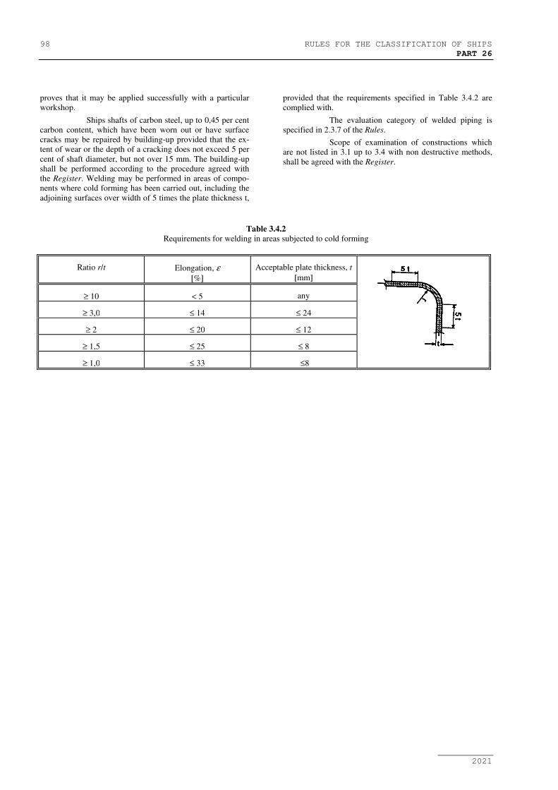
98 RULES FOR THE CLASSIFICATION OF SHIPS
PART 26
2021
proves that it may be applied successfully with a particular
workshop.
Ships shafts of carbon steel, up to 0,45 per cent
carbon content, which have been worn out or have surface
cracks may be repaired by building-up provided that the ex-
tent of wear or the depth of a cracking does not exceed 5 per
cent of shaft diameter, but not over 15 mm. The building-up
shall be performed according to the procedure agreed with
the Register. Welding may be performed in areas of compo-
nents where cold forming has been carried out, including the
adjoining surfaces over width of 5 times the plate thickness t,
provided that the requirements specified in Table 3.4.2 are
complied with.
The evaluation category of welded piping is
specified in 2.3.7 of the Rules.
Scope of examination of constructions which
are not listed in 3.1 up to 3.4 with non destructive methods,
shall be agreed with the Register.
Table 3.4.2
Requirements for welding in areas subjected to cold forming
Ratio r/t Elongation, ε
[%]
Acceptable plate thickness, t
[mm]
≥ 10 < 5 any
≥ 3,0 ≤ 14 ≤ 24
≥ 2 ≤ 20 ≤ 12
≥ 1,5 ≤ 25 ≤ 8
≥ 1,0 ≤ 33 ≤8

RULES FOR THE CLASSIFICATION OF SHIPS 99
PART 26 – ANNEX I
2021
ANNEX I
CROATIAN REGISTER OF SHIPPING
APPLICATION FOR APPROVAL
OF SHIPYARD / WELDING SHOP TO
PERFORM WELDING WORKS IN SHIPBUILDING AND THE MACHINERY
COMPONENTS THEREOF
In accordance with the Rules for the classification of ships of the Croatian Register of Shipping, Part 26 - Welding
we Company:
Address:
hereby make application to the CRS for approval together with following documents:
Nature of the approval sought Approval for
shipyard/welding shop Extension
1. Application from shipyard/welding shop
2. Description of shipyard/welding shop in accordance with Appendix II 1)
3. "Range of application" appendix(es) to description of shipyard/welding
shop 1)
4. Proof of qualifications for welding supervisor(s) 1)
5. List of qualified welders 1)
6. Descriptions of welding procedures (WPS) 1)
7. List of qualified welding procedures 1)
8. List of inspection (supervising) personnel 1)
9. Other proofs, approvals (e.g. proof of compliance with the quality re-
quirements: 1)
- in accordance with HRN EN ISO 3834-2, or 1)
- in accordance with HRN EN ISO 3834-3 or 1)
- in accordance with HRN EN ISO 3834-4 1)
Note:
1) Only if changes have been made since first approval.
Place, Date Applicant

100 RULES FOR THE CLASSIFICATION OF SHIPS
PART 26 - ANNEX II
2021
ANNEX II
CROATIAN REGISTER OF SHIPPING
DESCRIPTION OF SHIPYARD/WORKSHOP FOR APPROVAL
TO PERFORM WELDING WORKS IN
SHIPBUILDING AND THE MACHINERY COMPONENTS THEREOF
SHIPYARD/
WORKSHOP
Address:
Telephone: Fax: e-mail:
Responsible person:
Range of welding work:
1. WELDING PERSONNEL
1.1 Supervisor(s)
(welding engineer, welding technician, foreman)
1.2 qualified welders
a) Certificates and records, renewal, withdrawal
b) Welders file
c) Intervals and shop control of welders
d) Welders activities to Certificate
e) Welders marks
f) Promotion of welders, new welders
g) Supervision of the welders performance
h) Existing number of welders
2. WELDING CONSUMABLES
2.1 Warehouse
a) Records (input-output)
b) Drying
c) Dispatch

RULES FOR THE CLASSIFICATION OF SHIPS 101
PART 26 - ANNEX II
2021
2.2 Type of welding consumables
3. BASE MATERIALS, (PLATES, PROFILES, PIPES)
3.1 Warehouse
a) Records
b) Marking
3.2 Grade of material
4. WELDING EQUIPMENT
4.1 Electric sources
a) Types (prospectus)
b) Records (file of sources)
c) Maintenance (with respect to the Protection at Work Requirements and technological performance properties)
d) Number of existing electrical sources
4.2 Welding equipment
a) Control units for MIG/MAG, TIG, plasma, SMAW
4.3 Welding jigs
a) Positioners
b) Turnovers
c) Other
5. PERFORMED WELDING PROCEDURES AND WELDERS QUALIFICATION TESTS
5.1 Performed welding procedure qualification tests
5.2 Performed welders qualification tests
6. SUPERVISION AND CONTROL
6.1 Organisational scheme and control position

102 RULES FOR THE CLASSIFICATION OF SHIPS
PART 26 - ANNEX II
2021
6.2 Non-destructive examination of welds (internal)
6.3 Qualifications of supervising personnel
6.4 Non-destructive examination of welds (external)
7. DOCUMENTATION
7.1 Workshop documentation and its review from the technological point of view
7.2 Technological instructions (instruction sheets) for integral welding
7.3 Scope and method of welded joints examination
8. MISCELLANEOUS
8.1 Heat treatment (equipment)
8.2 Protection at work with respect to welding
9. REFERENCES
Welding supervisor:
Place, date, Name