Quantitative assessment of regional left ventricular motion using endocardial landmarks
Route Directions Generationusing Visible Landmarks
Davide RussoDepartment of Information
Engineering, ComputerScience and Mathematics,
University of L’Aquila,Via Vetoio, Coppito, 67100
L’Aquila, [email protected]
Sisi ZlatanovaGIS Technology, Department
OTB, Architecture and theBuilt Environment,
Delft University of TechnologyJulianalaan 134, 2628 BL
Delft, The [email protected]
Eliseo ClementiniDepartment of Industrial and
Information Eng., andEconomics,
University of L’Aquila,Via G. Gronchi 18, 67100
L’Aquila, [email protected]
ABSTRACTThe aim of this research is to investigate how to communi-cate route directions for wayfinding assistance in indoor en-vironments including visible landmarks along the route. Wepropose an algorithm to automatically generate low level di-rections, as an XML file, that can be later translated in otherlanguages, e.g., IndoorGML. The most suitable data modelis a graph with openings (doors, windows, passages), fea-tures and concave corners as nodes, and edges based on geo-metrical visibility between them. For a given route, the pro-posed algorithm extracts all the surrounding visible nodesand groups them to simplify subsequent textual instructions.This process is then implemented in a software prototype,“IndoorNav”, based on an Android device. It uses QRcodescanning for locating user position, calculates the best routeto follow, generates low-level route directions, and translatesthem into textual instructions in the requested language; fi-nally, it shows them to users.
KeywordsIndoor Navigation, Wayfinding, Landmarks, Location BasedSystems, Android, Route directions.
1. INTRODUCTIONIn order to reach places that satisfy our needs and wants,
we need to know where to go and how to get there. Ac-cording to Montello [23]: “Navigation” can be defined as the”coordinated and goal-directed movement of one’s self (one’sbody) through the environment”. As Montello proposed, itmay be conceptualized as consisting of two components: 1)wayfinding, which involves localization of ourselves and thedestination, and the choice of the right route to take; 2) lo-comotion, which refers to the movement of the body in thedirection we intend, avoiding obstacles and barriers. In this
Permission to make digital or hard copies of all or part of this work forpersonal or classroom use is granted without fee provided that copies arenot made or distributed for profit or commercial advantage and that copiesbear this notice and the full citation on the first page. To copy otherwise, torepublish, to post on servers or to redistribute to lists, requires prior specificpermission and/or a fee. Request permissions from [email protected].
ISA’14, November 04-07 2014, Dallas/Fort Worth, TX, USACopyright 2014 ACM 978-1-4503-3137-1/14/11 ...$15.00http://dx.doi.org/10.1145/2676528.2676530.
paper, we deal with the wayfinding component of naviga-tion and we are not considering locomotion issues. We willconcentrate on providing directions to follow in wayfindingtasks. Indoor navigation is not a new concept, but in con-trast to outdoor (or car) navigation, it has more and newchallenges to deal with; Stoffel identified these key differ-ences [31]:
• Shape diversity : the network structure of roads is reg-ular and clearly defined, road segments are linear andat every junction of 3 or more segments there is a de-cision point; also, large metropolises show a grid pat-tern, especially modern districts. In contrast, a sys-tematic treatment of indoor environments is difficult,architects have more freedom in designing a building,rooms can vary in size and shape depending on theirfunction. Particularly large rooms can be unique fortheir shape and multitude of connections.
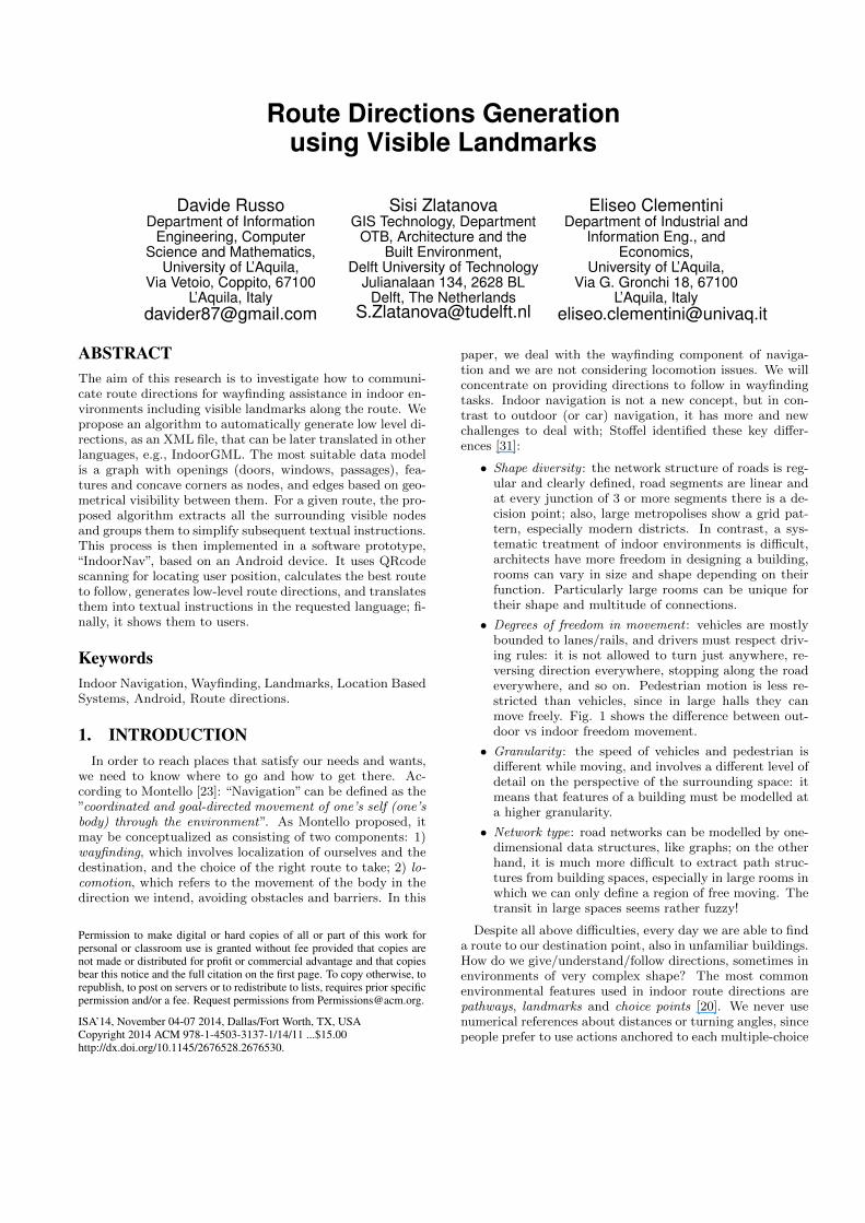
• Degrees of freedom in movement : vehicles are mostlybounded to lanes/rails, and drivers must respect driv-ing rules: it is not allowed to turn just anywhere, re-versing direction everywhere, stopping along the roadeverywhere, and so on. Pedestrian motion is less re-stricted than vehicles, since in large halls they canmove freely. Fig. 1 shows the difference between out-door vs indoor freedom movement.
• Granularity : the speed of vehicles and pedestrian isdifferent while moving, and involves a different level ofdetail on the perspective of the surrounding space: itmeans that features of a building must be modelled ata higher granularity.
• Network type: road networks can be modelled by one-dimensional data structures, like graphs; on the otherhand, it is much more difficult to extract path struc-tures from building spaces, especially in large rooms inwhich we can only define a region of free moving. Thetransit in large spaces seems rather fuzzy!
Despite all above difficulties, every day we are able to finda route to our destination point, also in unfamiliar buildings.How do we give/understand/follow directions, sometimes inenvironments of very complex shape? The most commonenvironmental features used in indoor route directions arepathways, landmarks and choice points [20]. We never usenumerical references about distances or turning angles, sincepeople prefer to use actions anchored to each multiple-choice
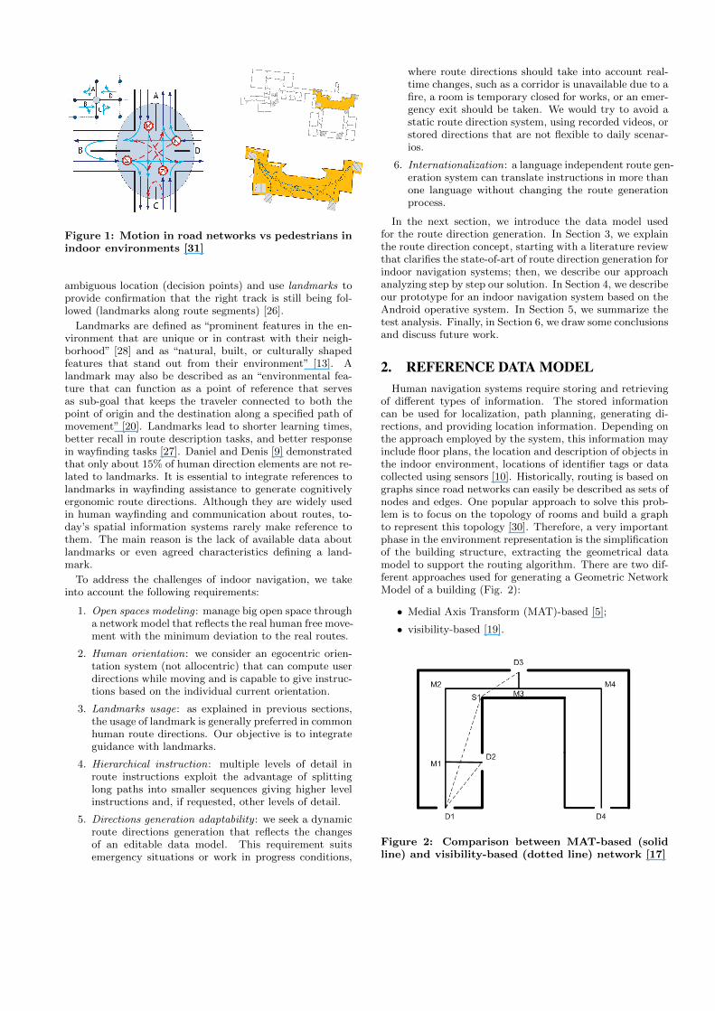
Figure 1: Motion in road networks vs pedestrians inindoor environments [31]
ambiguous location (decision points) and use landmarks toprovide confirmation that the right track is still being fol-lowed (landmarks along route segments) [26].
Landmarks are defined as “prominent features in the en-vironment that are unique or in contrast with their neigh-borhood” [28] and as “natural, built, or culturally shapedfeatures that stand out from their environment” [13]. Alandmark may also be described as an “environmental fea-ture that can function as a point of reference that servesas sub-goal that keeps the traveler connected to both thepoint of origin and the destination along a specified path ofmovement” [20]. Landmarks lead to shorter learning times,better recall in route description tasks, and better responsein wayfinding tasks [27]. Daniel and Denis [9] demonstratedthat only about 15% of human direction elements are not re-lated to landmarks. It is essential to integrate references tolandmarks in wayfinding assistance to generate cognitivelyergonomic route directions. Although they are widely usedin human wayfinding and communication about routes, to-day’s spatial information systems rarely make reference tothem. The main reason is the lack of available data aboutlandmarks or even agreed characteristics defining a land-mark.
To address the challenges of indoor navigation, we takeinto account the following requirements:
1. Open spaces modeling : manage big open space througha network model that reflects the real human free move-ment with the minimum deviation to the real routes.
2. Human orientation: we consider an egocentric orien-tation system (not allocentric) that can compute userdirections while moving and is capable to give instruc-tions based on the individual current orientation.
3. Landmarks usage: as explained in previous sections,the usage of landmark is generally preferred in commonhuman route directions. Our objective is to integrateguidance with landmarks.
4. Hierarchical instruction: multiple levels of detail inroute instructions exploit the advantage of splittinglong paths into smaller sequences giving higher levelinstructions and, if requested, other levels of detail.
5. Directions generation adaptability : we seek a dynamicroute directions generation that reflects the changesof an editable data model. This requirement suitsemergency situations or work in progress conditions,
where route directions should take into account real-time changes, such as a corridor is unavailable due to afire, a room is temporary closed for works, or an emer-gency exit should be taken. We would try to avoid astatic route direction system, using recorded videos, orstored directions that are not flexible to daily scenar-ios.
6. Internationalization: a language independent route gen-eration system can translate instructions in more thanone language without changing the route generationprocess.
In the next section, we introduce the data model usedfor the route direction generation. In Section 3, we explainthe route direction concept, starting with a literature reviewthat clarifies the state-of-art of route direction generation forindoor navigation systems; then, we describe our approachanalyzing step by step our solution. In Section 4, we describeour prototype for an indoor navigation system based on theAndroid operative system. In Section 5, we summarize thetest analysis. Finally, in Section 6, we draw some conclusionsand discuss future work.
2. REFERENCE DATA MODELHuman navigation systems require storing and retrieving
of different types of information. The stored informationcan be used for localization, path planning, generating di-rections, and providing location information. Depending onthe approach employed by the system, this information mayinclude floor plans, the location and description of objects inthe indoor environment, locations of identifier tags or datacollected using sensors [10]. Historically, routing is based ongraphs since road networks can easily be described as sets ofnodes and edges. One popular approach to solve this prob-lem is to focus on the topology of rooms and build a graphto represent this topology [30]. Therefore, a very importantphase in the environment representation is the simplificationof the building structure, extracting the geometrical datamodel to support the routing algorithm. There are two dif-ferent approaches used for generating a Geometric NetworkModel of a building (Fig. 2):
• Medial Axis Transform (MAT)-based [5];
• visibility-based [19].
Figure 2: Comparison between MAT-based (solidline) and visibility-based (dotted line) network [17]
We choose the visibility-based approach, with a geometrical-topological network model in which nodes are openings (win-dows, doors, and passages), concave corners and furnitureobjects; and transitions are the connections between nodeswhich have geometrical visibility.
3. ROUTE DIRECTIONS GENERATIONThe act of supporting someone by giving directions is de-
fined as guidance; the given instructions are defined as routedirections [25]. Route directions are primary means to guidesomeone in finding one’s way: they are task oriented spec-ifications of the actions to follow in order to reach the des-tination. The process of communicating route directions isfertile ground for scientific inquiry, being maps (especiallyfloor plans) still the most popular presentation form. Onereason is certainly their pervasive use in physical guides [4].
An important issue for maps is their orientation in rela-tion with user’s one and the surrounding space [3]. Textualinstructions, instead of maps, are the most simple presen-tation form for navigation [24] and they are easy to createand can be used in every smartphone. In his studies incognitive psychology, Allen analyzed route directions’ pro-duction and comprehension and described all the challengesabout the communication of spatial information with textualform [1] [2]. In AllenaAZs work, the production and compre-hension of route directions is based on a structural organiza-tion of the route communication process, which specificallyhas four phases:
1. Initiation: ask for destination point and optionallyconstraints to be observed.
2. Route description: the respondent supplies a set ofcommunicative statements that provides informationto reach the destination. It entails two types of state-ment: directive and descriptive. Route descriptionsinvolve specific components, most importantly, envi-ronmental features, delimiters, verbs of movement, andstate-of-being verbs.
3. Securing : includes questioner’s reaction to the routedescription, clarification queries and confirmation state-ments.
4. Closure: it is a social convention, typically verbal in-dications that the episode is reaching a conclusion.
3.1 Related workOnce a route (as path over the network graph) has been
calculated, the first thing to think about is directional infor-mation that allows locating entities in space and defines theuser’s orientation. Directional relations are used in severalaspects in route directions: they state the location of entitiesencountered along the route (like landmarks) as concerns theway finder or other entities; they announce a change of head-ing at decision points, e.g., represent turning actions; andthey may relate these actions to an entity’s location to betteranchor them in space. People represent spatial knowledge,such as distances and directions, qualitatively. Since dis-tances and directions are represented as qualitative categor-ical knowledge, people apply these categories also in routedirections. In research on qualitative spatial reasoning, sev-eral qualitative direction models have been proposed. Thesemodels divide the two-dimensional space into (labeled) re-gions. These sectors map all possible angular bearings to a
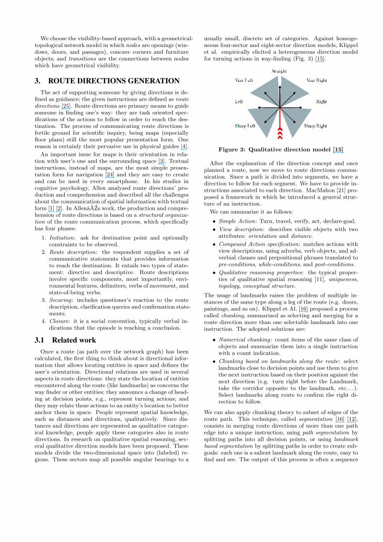
usually small, discrete set of categories. Against homoge-neous four-sector and eight-sector direction models, Klippelet al. empirically elicited a heterogeneous direction modelfor turning actions in way-finding (Fig. 3) [15].
Figure 3: Qualitative direction model [15]
After the explanation of the direction concept and onceplanned a route, now we move to route directions commu-nication. Since a path is divided into segments, we have adirection to follow for each segment. We have to provide in-structions associated to each direction. MacMahon [21] pro-posed a framework in which he introduced a general struc-ture of an instruction.
We can summarize it as follows:
• Simple Action: Turn, travel, verify, act, declare-goal;
• View description: describes visible objects with twoattributes: orientation and distance.
• Compound Action specification: matches actions withview descriptions, using adverbs, verb objects, and ad-verbial clauses and prepositional phrases translated topre-conditions, while-conditions, and post-conditions.
• Qualitative reasoning properties: the typical proper-ties of qualitative spatial reasoning [11], uniqueness,topology, conceptual structure.
The usage of landmarks raises the problem of multiple in-stances of the same type along a leg of the route (e.g. doors,paintings, and so on). Klippel et Al. [16] proposed a processcalled chunking, summarized as selecting and merging for aroute direction more than one selectable landmark into oneinstruction. The adopted solutions are:
• Numerical chunking : count items of the same class ofobjects and summarize them into a single instructionwith a count indication.
• Chunking based on landmarks along the route: selectlandmarks close to decision points and use them to givethe next instruction based on their position against thenext direction (e.g. turn right before the Landmark,take the corridor opposite to the landmark, etc. . . ).Select landmarks along route to confirm the right di-rection to follow.
We can also apply chunking theory to subset of edges of theroute path. This technique, called segmentation [16] [12],consists in merging route directions of more than one pathedge into a unique instruction, using path segmentation bysplitting paths into all decision points, or using landmarkbased segmentation by splitting paths in order to create sub-goals: each one is a salient landmark along the route, easy tofind and see. The output of this process is often a sequence

Figure 4: Overview of GUARD, the generation process for context-specific route directions [25]
of directions with a hierarchical structure, stored using amarkup language to simplify the parsing of the instruction:typically, XML is the language used to describe route di-rections, which are still coded and not explicitly translatedinto natural comprehensive language, usually called low-levelroute directions.
Following the previous remarks on how to generate low-level route direction, Richter [25] developed GUARD (Gen-erating Unambiguous, Adapted Route Directions), a com-putational process used for generating context-specific routedirections and their interplay. It consists of four major stepsdepicted in Fig. 4. At first, for each decision point all ap-plicable low-level turn instructions are generated. The indi-vidual turn instructions are then combined applying simplechunking rules; these chunks are adapted to general chunk-ing principles in a post-processing step. Finally, in an op-timization process, those chunks are chosen from the previ-ously generated set.
The process was developed for outdoor navigation, us-ing road network (medial axis based) datasets; since it isnot easily adaptable for indoor navigation, it needs a reviewfor pedestrian free movement and locomotion constraints.Other standard XML models for low level route instructionshave been proposed by Mani et al. “SpatialML AnnotationScheme” [22] 1: they proposed a custom data model with anXSD schema similar to the GUARD output.
The following step, after route directions generation, dealswith generating natural language instructions: translatingthe low-level route instructions into high level natural lan-guage is a research field covered by the CORAL2 project [7][8]. Also Cuayahuitl et al. [6] improved algorithms for natu-ral language generation starting from an XML file. Geldof’sresearch with RPML (Route Planning Markup Language)[12] covers this field of research as well.
3.2 Proposed AlgorithmWe can now explain the core problem of this research:
the interaction part of an indoor Location Based GuidanceSystems (iLBGS) and how we generate low level route di-rections that can be easily translated in various presentationforms (textual, arrows, images, etc. . . ). We choose to followthe GUARD system approach [25], originally thought foroutdoor navigation, adapted for indoor environments usinga visibility based data model. Steps followed are the same asRichter’s ones: extract abstract instruction for each decisionnode, apply chunking rules on it, optimize them using seg-mentation. We assume that a path between two nodes of thedataset has been computed, having at least one transition.The output is not a natural language series of instruction,
1http://sourceforge.net/projects/spatialml/2http://web.science.mq.edu.au/ coral/
but an abstract data representation, written in XML format,that encapsulates all the information needed for a completetranslation into natural language.
Before starting, we introduce an example of dataset thatwill be used as reference for the route direction generation.Fig. 5 shows a floor of an imaginary test building, with nodes(orange dots with node number) and transitions (blue seg-ments) and a path calculated between nodes 1 and 9 (nodes6 & 7 are virtual doors, node 8 is a concave corner)
We apply the egocentric qualitative direction model in-troduced by Klippel et al. [15] (Fig. 3). As explained inprevious section, we have stored in each node of the graph adirection that represents the starting user orientation whilepassing through the node. We put the direction model over-lapping the node, centered on it, and let the node directionmatch with the “straight” direction. Then, we can easily de-termine a quantitative direction for all visible nodes match-ing all connecting edges with the respective belonging sector.For instance, when the user passes through node 1, (s)he hastwo visible nodes, node 2 that has the qualitative direction“Veer Left” and node 3 that has the qualitative direction“Veer right”. Therefore, when we want to refer to node 2 (inthis case, it is the next node of the path), we can use thequalitative direction model and suggest “Veer left and walkuntil. . . ”.
Figure 5: Example of a Building floor, with visibilitygraph: nodes are the circles with node number andthe transitions are the dotted segments. A pathbetween nodes 1 and 9 is highlighted with arrows
3.2.1 Route Directions Extraction
Starting from the extraction step and using our visibilitydata model, for each edge of the planned path we create
an object of the SingleEdgeDirection class. Then, we needto collect all the outgoing segments that belong to the sameNavigableSpace of the path for each starting node of this listof path edges. Then, we generate an instruction to reachthe next node by giving starting direction, path distanceand next node name (for instance, it could be subsequentlytranslated as “Turn right and walk for 10 meters reachingDoor 1.240”), and then we add a direction for all the rest ofvisible nodes. We repeat this process for all the nodes in thepath obtaining for each segment of the path a “next-nodeinstruction” and a collection of visible nodes. For instance,in Fig. 5, when the user is located at node 2 and needsto reach node 4, the transition that belongs to the samespace of (2,4) is only (2,5). The other outgoing transitionsof node 2, which are (2,1) and (2,3), belong to a differentNavigableSpace and are not considered. So, in this example,for node 2, we collect the edges (2,4) and (2,5) and definefor each of them the qualitative direction, then we store thenext node data about edge (2,4) separately from the others(in this case only another visible node, so only edge (2,5))using an object of the class NextNodeInstruction, and eachof the others as new object of VisibleNodeInstruction class.
3.2.2 Route Directions Chunking
With the Chunking step, we analyze all visible nodes di-rections of each node along the path, trying to highlightnodes closest to the next goal node (for instance, it couldbe subsequently translated as “Door 1.240 is on the Right ofthe Escalator”) and aggregate nodes of the same Class typefor numerical counting instructions (for instance, it could besubsequently translated as “Door 1.240 is after three doorson the right”). For each SingleEdgeDirection, we collect vis-ible nodes, within a fixed radius from the next goal, in bothleft and right sides. We introduce ClosestChunkingInstruc-tions that store also the belonging side of the closest node.After that, we want to group (for each SingleEdgeDirection)the visible nodes of the same class and then divide them intoleftSide and rightSide referring to the next-node direction.We store each group of at least one element into anotherobject of the class called NumericalChunkingInstruction, inwhich we also store the counting number of elements belong-ing to it.
3.2.3 Route Directions Optimization
Finally, the Optimization step is based on the segmenta-tion concept. At this time, we have a direction divided intopath segments, but we want to merge some of them intohigher level instructions using criteria to achieve a hierar-chical structure. We propose two optimization criteria:
• room optimization, in which all transitions in the sameroom (as navigable space) are merged to create a roomInstruction that contains all the directions in it. Thisis the case of a room with a non-convex shape, withoutvisibility between the starting and ending nodes: thereare corners to be overcome to reach the next door.With this solution, the user receives detailed directionsstep by step, and in most cases (s)he is able to reachthe next space without any other instruction. In detail,we encapsulate each SingleEdgeDirection in a new ob-ject of RoomDirection class, and group them into thesame RoomDirection object when the belonging Navi-gableSpace of consecutive edges remains the same. We
want to remark what happens between nodes 7 and 9where edges (7,8) and (8,9) belong to the same navi-gable space.
• floor optimization, in which all VerticalUnits and Hor-izontalUnits directions belonging to the same collec-torSpace (HorizontalSpace or VerticalSpace) are col-lapsed into one floor instruction as first (higher level)instruction to be performed. Usually, users with Ver-ticalSpace movement between floors need only this in-struction to reach the next HorizontalSpace (for in-stance a VerticalSpace instruction could be subsequentlytranslated as “reach the third floor”, and users do notneed more instruction to reach the next step).
3.2.4 Route Directions Process Output
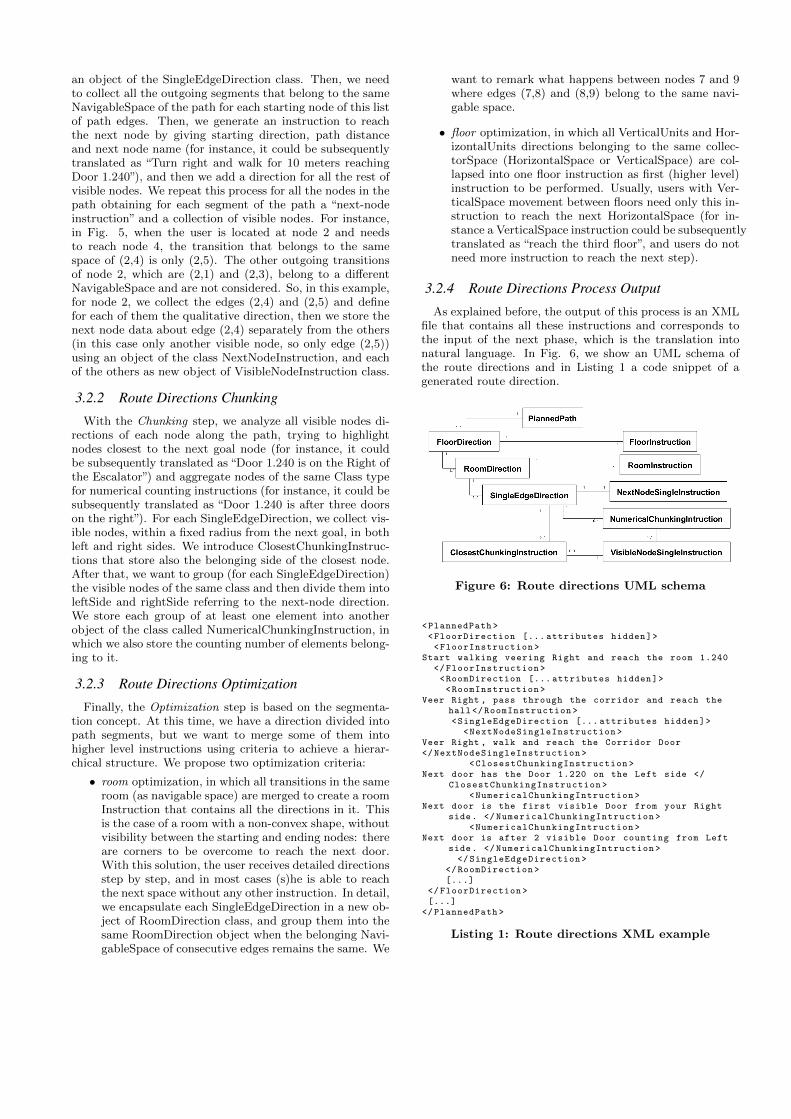
As explained before, the output of this process is an XMLfile that contains all these instructions and corresponds tothe input of the next phase, which is the translation intonatural language. In Fig. 6, we show an UML schema ofthe route directions and in Listing 1 a code snippet of agenerated route direction.
Figure 6: Route directions UML schema
<PlannedPath ><FloorDirection [... attributes hidden]><FloorInstruction >
Start walking veering Right and reach the room 1.240</FloorInstruction ><RoomDirection [... attributes hidden]><RoomInstruction >
Veer Right , pass through the corridor and reach thehall</RoomInstruction ><SingleEdgeDirection [... attributes hidden]>
<NextNodeSingleInstruction >Veer Right , walk and reach the Corridor Door</NextNodeSingleInstruction >
<ClosestChunkingInstruction >Next door has the Door 1.220 on the Left side </
ClosestChunkingInstruction ><NumericalChunkingIntruction >
Next door is the first visible Door from your Rightside. </NumericalChunkingIntruction >
<NumericalChunkingIntruction >Next door is after 2 visible Door counting from Left
side. </NumericalChunkingIntruction ></SingleEdgeDirection >
</RoomDirection >[...]
</FloorDirection >[...]
</PlannedPath >
Listing 1: Route directions XML example

(a) (b) (c)
Figure 7: IndoorNav screenshoots of the textual instruction presentation: (a) the higher level instruction,(b) the room segmentation, (c) a single edge instruction with landmarks indications highlighted: ”door 1.250”as current next node and doors 0.130 and 0.140 as additional visible landmarks along the route)
4. DELEVOPED PROTOTYPE:INDOORNAV
Systems that automatically and autonomously help hu-mans on wayfinding are called Location-Based GuidanceSystems (LBGS). They are one of the most important ap-plications of Location Based Systems (LBS) and, with thegradual maturation of ubiquitous computing and the rapidadvances in mobile devices and wireless communication, theyhave gained increasing interest also as an important appli-cation of ubiquitous computing [14]. Following our startingrequirements of a guidance system using textual instructionswith the addiction of arrows and images (when needed), wehave developed an Android based application called“Indoor-Nav”.
In order to provide route direction service to users a webservice has been developed. Based on the Apache CatalinaTomCat Java server, a servlet called“RouteDirectionsServlet”answers to GET/POST web requests providing the XMLfile containing route directions with natural language trans-lation.
To solve the positioning issue, we used QRCodes, assignedto each node of the graph (it translates the nodeID into a2D image), and placed near the doors/windows/furnitureobjects. They are direct sensing tags with low infrastruc-tural costs and high accuracy of user positioning. We havedeveloped code scanning using the ZBar3 Android libraryfor QRCodes Image Scanning, which easily fits our needsand does not require too much time for integration in anAndroid application. The scanning library, when activated,automatically detects the QRCode orientation and its em-bedded reference code and sends the code back to the callerapplication.
Before explaining the interface and its basic functions, weintroduce the interaction between the user, IndoorNav, andthe web service. Fig. 8 illustrates the interaction flow. Atfirst, the user scans a QRCode (1), used for understandinghis starting position, then (s)he enters the ending desired
3http://zbar.sourceforge.net/
point using interface interaction (and optionally disables el-evators usage) (2). Then (3), clicking on the “find route”button on the interface, the IndoorNav application sends arequest to the web service and (4) receives an XML responsethat is (5) parsed and graphically (6) rendered in the nextview, so that the user can read and follow textual instruc-tions. Whenever the user wants, (s)he can go back and scanagain a QRCode near to him(her) in order to update his(her)position and update route directions.
The presentation form of route instructions, following theirhierarchical structure, is shown in Fig. 7. At first level, theinterface shows higher level instructions with an arrow indi-cating the starting direction and the distance to be covered.Clicking on one of them, the interface shows the second levellist, always with arrows and distance. When we need a thirdlevel of detail, the interface provides a button on the rightthat shows a different interface with an arrow on the top,then the distance, the textual instruction, and optionally animage of the next target node. Scrolling down this view, theinterface gives the possibility to receive other hints, such aschunking instructions and closest landmarks to the goal. Allthe instructions are numbered so that in the second level,users have always the reference higher level: for instance,instruction number 3) and lower level instruction 3.1).
5. TEST ANALYSISWith a handmade dataset of a testing building4, we have
performed a two-part study based on four different routes,trying to answer the question: are the route directions gen-erated by IndoorNav understandable, allowing someone tofind his (her) way? The tests were conducted involving fivepeople and providing them an Android smartphone5 runningIndoorNav for route guidance. We have placed all QRCodesin front of the respective doors. To start each test, the userwas led to the starting point and invited to follow route in-
4OTB research institute for the Built environment, Facultyof Architecture, Delft University, The Netherlands5HTC Desire C
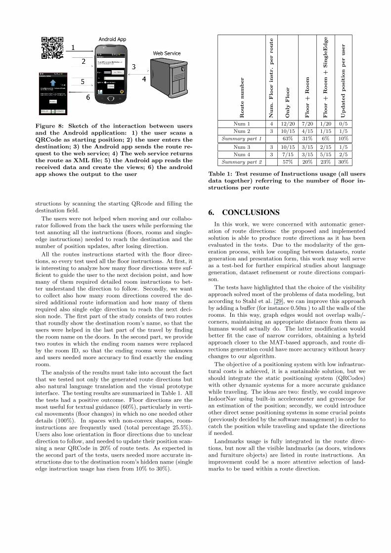
Figure 8: Sketch of the interaction between usersand the Android application: 1) the user scans aQRCode as starting position; 2) the user enters thedestination; 3) the Android app sends the route re-quest to the web service; 4) The web service returnsthe route as XML file; 5) the Android app reads thereceived data and create the views; 6) the androidapp shows the output to the user
structions by scanning the starting QRcode and filling thedestination field.
The users were not helped when moving and our collabo-rator followed from the back the users while performing thetest annoting all the instructions (floors, rooms and single-edge instructions) needed to reach the destination and thenumber of position updates, after losing direction.
All the routes instructions started with the floor direc-tions, so every test used all the floor instructions. At first, itis interesting to analyze how many floor directions were suf-ficient to guide the user to the next decision point, and howmany of them required detailed room instructions to bet-ter understand the direction to follow. Secondly, we wantto collect also how many room directions covered the de-sired additional route information and how many of themrequired also single edge direction to reach the next deci-sion node. The first part of the study consists of two routesthat roundly show the destination room’s name, so that theusers were helped in the last part of the travel by findingthe room name on the doors. In the second part, we providetwo routes in which the ending room names were replacedby the room ID, so that the ending rooms were unknownand users needed more accuracy to find exactly the endingroom.
The analysis of the results must take into account the factthat we tested not only the generated route directions butalso natural language translation and the visual prototypeinterface. The testing results are summarized in Table 1. Allthe tests had a positive outcome. Floor directions are themost useful for textual guidance (60%), particularly in verti-cal movements (floor changes) in which no one needed otherdetails (100%). In spaces with non-convex shapes, room-instructions are frequently used (total percentage 25.5%).Users also lose orientation in floor directions due to uncleardirection to follow, and needed to update their position scan-ning a near QRCode in 20% of route tests. As expected inthe second part of the tests, users needed more accurate in-structions due to the destination room’s hidden name (singleedge instruction usage has risen from 10% to 30%).
Route
number
Num
.Floorin
str.perroute
Only
Floor
Floor+
Room
Floor+
Room
+Sin
gleEdge
Update
dposition
peruse
r
Num 1 4 12/20 7/20 1/20 0/5
Num 2 3 10/15 4/15 1/15 1/5
Summary part 1 63% 31% 6% 10%
Num 3 3 10/15 3/15 2/15 1/5
Num 4 3 7/15 3/15 5/15 2/5
Summary part 2 57% 20% 23% 30%
Table 1: Test resume of Instructions usage (all usersdata together) referring to the number of floor in-structions per route
6. CONCLUSIONSIn this work, we were concerned with automatic gener-
ation of route directions: the proposed and implementedsolution is able to produce route directions as it has beenevaluated in the tests. Due to the modularity of the gen-eration process, with low coupling between datasets, routegeneration and presentation form, this work may well serveas a test-bed for further empirical studies about languagegeneration, dataset refinement or route directions compari-son.
The tests have highlighted that the choice of the visibilityapproach solved most of the problems of data modeling, butaccording to Stahl et al. [29], we can improve this approachby adding a buffer (for instance 0.50m ) to all the walls of therooms. In this way, graph edges would not overlap walls/-corners, maintaining an appropriate distance from them ashumans would actually do. The latter modification wouldbetter fit the case of narrow corridors, obtaining a hybridapproach closer to the MAT-based approach, and route di-rections generation could have more accuracy without heavychanges to our algorithm.
The objective of a positioning system with low infrastruc-tural costs is achieved, it is a sustainable solution, but weshould integrate the static positioning system (QRCodes)with other dynamic systems for a more accurate guidancewhile traveling. The ideas are two: firstly, we could improveIndoorNav using built-in accelerometer and gyroscope foran estimation of the position; secondly, we could introduceother direct sense positioning systems in some crucial points(previously decided by the software management) in order tocatch the position while traveling and update the directionsif needed.
Landmarks usage is fully integrated in the route direc-tions, but now all the visible landmarks (as doors, windowsand furniture objects) are listed in route instructions. Animprovement could be a more attentive selection of land-marks to be used within a route direction.

The dynamic generation of route directions allows the sys-tem to adapt route directions to any changes of the datamodel in real-time: room layout changes, inaccessible doorsor openings (e.g., an emergency case with fire in a corridor,with dynamic changes of the rooms accessibility), featuresaddiction or position changing.
As future work, there are still several open issues: nodesnot visible from a decision point are not taken into account inroute directions generation, but during travel they could ap-pear and disorient the user. Also path segmentation could beimproved, including landmark based segmentation, so thatusers, while traveling in large/long rooms, could receive in-structions with landmarks (visible along the path leg) as anintermediate goal to reach before arriving to the next door.The users accessibility (e.g. wheelchair) should been takeninto account by the route planner, avoiding usage of graphedges (e.g. stairs) according to users requirements.
7. REFERENCES[1] Gary L. Allen. From knowledge to words to wayfinding:
Issues in the production and comprehension of routedirections. In Proceedings of the International Conferenceon Spatial Information Theory: A Theoretical Basis forGIS, COSIT ’97, pages 363–372, London, UK, UK, 1997.Springer-Verlag.
[2] Gary L Allen. Principles and practices for communicatingroute knowledge. Applied Cognitive Psychology,14(4):333–359, 2000.
[3] Anthony J. Aretz and Christopher D. Wickens. The mentalrotation of map displays. Human Performance,5(4):303–328, 1992.
[4] Jurg Baus, Keith Cheverst, and Christian Kray. A survey ofmap-based mobile guides. In Map-based Mobile Services,pages 193–209. Springer, 2005.
[5] Harry Blum et al. A transformation for extracting newdescriptors of shape. Models for the perception of speech andvisual form, 19(5):362–380, 1967.
[6] Heriberto Cuayahuitl, Nina Dethlefs, Kai-Florian Richter,Thora Tenbrink, and John Bateman. A dialogue system forindoor wayfinding using text-based natural language.International Journal of Computational Linguistics andApplications, 1(1-2):285–304, 2010.
[7] Robert Dale, Sabine Geldof, and Jean-Philippe Prost.Generating more natural route descriptions. In Proceedingsof the 2002 Australasian natural language processingworkshop, pages 41–48, 2002.
[8] Robert Dale, Sabine Geldof, and Jean-Philippe Prost. Coral:Using natural language generation for navigationalassistance. In Proceedings of the 26th Australasian computerscience conference-Volume 16, pages 35–44. AustralianComputer Society, Inc., 2003.
[9] Marie-Paule Daniel and Michel Denis. Spatial descriptionsas navigational aids: A cognitive analysis of route directions.Kognitionswissenschaft, 7(1):45–52, 1998.
[10] Navid Fallah, Ilias Apostolopoulos, Kostas Bekris, andEelke Folmer. Indoor human navigation systems: A survey.Interacting with Computers, 25(1):21–33, 2013.
[11] Christian Freksa. Qualitative spatial reasoning. Cognitiveand linguistic aspects of geographic space, (63):361–372,1991.
[12] Sabine Geldof and Robert Dale. Improving route directionson mobile devices. In ISCA Tutorial and ResearchWorkshop (ITRW) on Multi-Modal Dialogue in MobileEnvironments, 2002.
[13] Reginald G Golledge. Human wayfinding and cognitivemaps. Wayfinding behavior: Cognitive mapping and otherspatial processes, pages 5–45, 1999.
[14] Haosheng Huang and Georg Gartner. A survey of mobile
indoor navigation systems. In Cartography in Central andEastern Europe, pages 305–319. Springer, 2010.
[15] Alexander Klippel, Carsten Dewey, Markus Knauff,Kai-Florian Richter, Dan R Montello, Christian Freksa, andEsther-Anna Loeliger. Direction concepts in wayfindingassistance systems. In Workshop on Artificial Intelligence inMobile Systems, pages 1–8, 2004.
[16] Alexander Klippel, Stefan Hansen, Kai-Florian Richter, andStephan Winter. Urban granularities - a data structure forcognitively ergonomic route directions. GeoInformatica,13(2):223–247, 2009.
[17] L.Liu and S.Zlatanova. A ”door-to-door” path-findingapproach for indoor navigation. In Proceedings ofGeoInformation For Disaster Management Conference2011, pages 3–8, 2011.
[18] Kristin L. Lovelace, Mary Hegarty, and Daniel R. Montello.Elements of good route directions in familiar and unfamiliarenvironments. In Christian Freksa and David M. Mark,editors, COSIT, volume 1661 of Lecture Notes in ComputerScience, pages 65–82. Springer, 1999.
[19] Tomas Lozano-Perez and Michael A. Wesley. An algorithmfor planning collision-free paths among polyhedral obstacles.Commun. ACM, 22(10):560–570, October 1979.
[20] Kevin Lynch. The image of the city, volume 11. the MITPress, 1960.
[21] Matt MacMahon, Brian Stankiewicz, and BenjaminKuipers Walk the Talk: Connecting Language, Knowledge,and Action in Route Instructions In Proc. of the 21stNational Conference on Artificial Intelligence, pages1475-1482, 2006.
[22] Inderjeet Mani, Janet Hitzeman, and Cheryl Clark.Annotating natural language geographic references. In proc.LREC 2008-W13 Workshop on Methodologies andResources for Processing Spatial Language, pages 11-15,2008.
[23] Daniel R. Montello. Navigation. In Cambridge University,editor, The Cambridge Handbook of Visuospatial thinking,pages 257–294. Cambridge University Press, 2005.
[24] Verena Radoczky. How to design a pedestrian navigationsystem for indoor and outdoor environments. In GeorgGartner, William E. Cartwright, and Michael P. Peterson,editors, Location Based Services and TeleCartography,Lecture Notes in Geoinformation and Cartography, pages301–316. Springer, 2007.
[25] Kai-Florian Richter. Context-specific route directions:generation of cognitively motivated wayfinding instructions.PhD thesis, University of Bremen, 2008.http://d-nb.info/987640062.
[26] Kai-Florian Richter. Prospects and challenges of landmarksin navigation services. In Cognitive and Linguistic Aspectsof Geographic Space, pages 83–97. Springer, 2013.
[27] Tracy Ross, Andrew J. May, and Simon Thompson. Theuse of landmarks in pedestrian navigation instructions andthe effects of context. In Stephen A. Brewster and Mark D.Dunlop, editors, Mobile HCI, volume 3160 of Lecture Notesin Computer Science, pages 300–304. Springer, 2004.
[28] Alexander W Siegel and Sheldon H White. Thedevelopment of spatial representations of large-scaleenvironments. Advances in child development and behavior,10:9–55, 1975.
[29] Christoph Stahl. New perspectives on built environmentmodels for pedestrian navigation. Spatial Cognition 2008Poster Proceedings, pages 016–08, 2008.
[30] Horst Steuer. High precision 3D indoor routing on reducedvisibility graphs. In Progress in Location-Based Services,pages 265–275. Springer, 2013.
[31] Edgar-Philipp Stoffel. Hierarchical graphs as organisationalprinciple and spatial model applied to pedestrian indoornavigation. PhD thesis, Ludwig Maximilians UniversityMunich, 2009. http://d-nb.info/100055080X.
Copyright © 2022 FDOKUMEN