Rotor position estimation of AC machines using the zero-sequence carrier-signal voltage
10
IEEE TRANSACTIONS ON INDUSTRY APPLICATIONS, VOL. 41, NO. 6, NOVEMBER/DECEMBER 2005 1637 Rotor Position Estimation of AC Machines Using the Zero-Sequence Carrier-Signal Voltage Fernando Briz, Member, IEEE, Michael W. Degner, Senior Member, IEEE, Pablo García, Student Member, IEEE, and Juan Manuel Guerrero, Member, IEEE Abstract—This paper analyzes the sensorless control of ac machines based on the zero-sequence voltage generated by the in- jection of a carrier-signal voltage. The analysis focuses on rotor po- sition estimation (tracking of rotor-position-dependent saliencies), but the methods discussed apply equally to flux position estima- tion (tracking of flux-dependent saliencies). Analyses of relevant aspects like selection of the carrier-signal frequency, measurement of the zero-sequence carrier-signal voltage, and decoupling of saturation-induced saliencies are included. Index Terms—Rotor position estimation, saliency-based sensor- less control, zero-sequence voltage. I. I NTRODUCTION N UMEROUS sensorless methods, based on machine mod- els and measured electrical variables (currents and volt- ages), for estimating the rotor velocity of ac machines have been proposed [1], [2]. While such methods provide adequate performance in the medium- and high-speed range, they suffer from increased parameter sensitivity in the low-speed range. In addition, for dc excitation, they are incapable of providing estimates due to the unobservable nature of rotor quantities for that type of excitation. To overcome these limitations, saliency (asymmetry) tracking-based methods have recently been developed [3]–[8]. Since the spatial saliencies tracked by these methods are intrinsic to the magnetic/mechanical design of the machine, their location (phase angle) does not change significantly with respect to their source (flux, rotor/stator structure) as a function of operating point. Estimating the position of these saliencies, and hence the rotor position or flux angle, is made possible at low and zero speeds by the addition of a high-frequency Paper IPCSD-05-055, presented at the 2004 Industry Applications Society Annual Meeting, Seattle, WA, October 3–7, and approved for publication in the IEEE TRANSACTIONS ON INDUSTRY APPLICATIONS by the Industrial Drives Committee of the IEEE Industry Applications Society. Manuscript submitted for review February 14, 2005 and released for publication August 8, 2005. This work was supported in part by the Research, Technological Development, and Innovation Programs of the Principado of Asturias-ERDF under Grant PB02-055 and by the Spanish Ministry of Science and Technology-ERDF under Grant DPI2001-3815. F. Briz, P. García, and J. M. Guerrero are with the Department of Electrical, Computer, and Systems Engineering, University of Oviedo, Gijón 33204, Spain (e-mail: [email protected]; [email protected]; guerrero@isa. uniovi.es). M. W. Degner is with the Electric Machine Drive Systems Department, Sus- tainable Mobility Technologies, Ford Motor Company, Dearborn, MI 48121- 2053 USA (e-mail: [email protected]). Digital Object Identifier 10.1109/TIA.2005.857469 excitation superimposed on the fundamental excitation. The major differences between these saliency-based methods are the type of high-frequency excitation and the signal processing used for estimating the rotor position. This paper analyzes the use of zero-sequence carrier-signal voltage for rotor position estimation in induction machines when a balanced and symmetric high-frequency carrier-signal voltage (positive sequence) is applied to the stator windings. zero-sequence carrier-signal voltage techniques were initially proposed for flux angle estimation [9] and only recently have been proposed for rotor position estimation [10]. A difficulty in using the zero-sequence carrier-signal voltage is its mea- surement, which may make it less appealing than methods utilizing current sensors already present in the drive [3]–[6]. However, there are two major advantages to the use of zero- sequence carrier-signal voltage. First, as observed in [10], the magnitude of the zero-sequence carrier-signal voltage does not depend on the frequency of the carrier-signal. This enables the use of higher carrier-signal frequencies, reducing the resulting carrier-signal current, the associated torque ripple, and acoustic noise. Second, harmonics in the carrier-signal voltage due to the nonideal behavior of the inverter [4], [11] are easier to decouple from the zero-sequence carrier-signal voltage, increasing the robustness and accuracy of position estimation. This paper includes analysis of the physical principles and mathematical modeling of the proposed method. It also dis- cusses implementation issues, including the selection of carrier- signal frequency, the effects caused by the nonideal behavior of the inverter, measurement methods for the zero-sequence carrier-signal voltage, and decoupling of saturation-induced saliencies. II. SALIENCY-TRACKING-BASED SENSORLESS TECHNIQUES USING THE ZERO-SEQUENCE CARRIER-SIGNAL VOLTAGE Carrier-signal based sensorless methods inject a high- frequency excitation signal (current or voltage) that interacts with the machine saliencies to produce components in mea- surable electrical variables. These components are then used to estimate the position of the saliency. When a machine is excited with a high-frequency signal, its response can be modeled using the stator transient inductance provided that the excitation frequency is substantially faster than the stator transient time constant [3], [7], [10]. When the machine is salient, assuming the saliency varies sinusoidally, the stator transient inductance 0093-9994/$20.00 © 2005 IEEE
-
Upload
independent -
Category
Documents
-
view
0 -
download
0
Transcript of Rotor position estimation of AC machines using the zero-sequence carrier-signal voltage
IEEE TRANSACTIONS ON INDUSTRY APPLICATIONS, VOL. 41, NO. 6, NOVEMBER/DECEMBER 2005 1637
Rotor Position Estimation of AC Machines Usingthe Zero-Sequence Carrier-Signal Voltage
Fernando Briz, Member, IEEE, Michael W. Degner, Senior Member, IEEE, Pablo García, Student Member, IEEE,and Juan Manuel Guerrero, Member, IEEE
Abstract—This paper analyzes the sensorless control of acmachines based on the zero-sequence voltage generated by the in-jection of a carrier-signal voltage. The analysis focuses on rotor po-sition estimation (tracking of rotor-position-dependent saliencies),but the methods discussed apply equally to flux position estima-tion (tracking of flux-dependent saliencies). Analyses of relevantaspects like selection of the carrier-signal frequency, measurementof the zero-sequence carrier-signal voltage, and decoupling ofsaturation-induced saliencies are included.
Index Terms—Rotor position estimation, saliency-based sensor-less control, zero-sequence voltage.
I. INTRODUCTION
NUMEROUS sensorless methods, based on machine mod-els and measured electrical variables (currents and volt-
ages), for estimating the rotor velocity of ac machines havebeen proposed [1], [2]. While such methods provide adequateperformance in the medium- and high-speed range, they sufferfrom increased parameter sensitivity in the low-speed range.In addition, for dc excitation, they are incapable of providingestimates due to the unobservable nature of rotor quantities forthat type of excitation.
To overcome these limitations, saliency (asymmetry)tracking-based methods have recently been developed [3]–[8].Since the spatial saliencies tracked by these methods areintrinsic to the magnetic/mechanical design of the machine,their location (phase angle) does not change significantly withrespect to their source (flux, rotor/stator structure) as a functionof operating point. Estimating the position of these saliencies,and hence the rotor position or flux angle, is made possibleat low and zero speeds by the addition of a high-frequency
Paper IPCSD-05-055, presented at the 2004 Industry Applications SocietyAnnual Meeting, Seattle, WA, October 3–7, and approved for publication in theIEEE TRANSACTIONS ON INDUSTRY APPLICATIONS by the Industrial DrivesCommittee of the IEEE Industry Applications Society. Manuscript submittedfor review February 14, 2005 and released for publication August 8, 2005.This work was supported in part by the Research, Technological Development,and Innovation Programs of the Principado of Asturias-ERDF under GrantPB02-055 and by the Spanish Ministry of Science and Technology-ERDF underGrant DPI2001-3815.
F. Briz, P. García, and J. M. Guerrero are with the Department of Electrical,Computer, and Systems Engineering, University of Oviedo, Gijón 33204,Spain (e-mail: [email protected]; [email protected]; [email protected]).
M. W. Degner is with the Electric Machine Drive Systems Department, Sus-tainable Mobility Technologies, Ford Motor Company, Dearborn, MI 48121-2053 USA (e-mail: [email protected]).
Digital Object Identifier 10.1109/TIA.2005.857469
excitation superimposed on the fundamental excitation. Themajor differences between these saliency-based methods arethe type of high-frequency excitation and the signal processingused for estimating the rotor position.
This paper analyzes the use of zero-sequence carrier-signalvoltage for rotor position estimation in induction machineswhen a balanced and symmetric high-frequency carrier-signalvoltage (positive sequence) is applied to the stator windings.zero-sequence carrier-signal voltage techniques were initiallyproposed for flux angle estimation [9] and only recently havebeen proposed for rotor position estimation [10]. A difficultyin using the zero-sequence carrier-signal voltage is its mea-surement, which may make it less appealing than methodsutilizing current sensors already present in the drive [3]–[6].However, there are two major advantages to the use of zero-sequence carrier-signal voltage. First, as observed in [10], themagnitude of the zero-sequence carrier-signal voltage does notdepend on the frequency of the carrier-signal. This enables theuse of higher carrier-signal frequencies, reducing the resultingcarrier-signal current, the associated torque ripple, and acousticnoise. Second, harmonics in the carrier-signal voltage due to thenonideal behavior of the inverter [4], [11] are easier to decouplefrom the zero-sequence carrier-signal voltage, increasing therobustness and accuracy of position estimation.
This paper includes analysis of the physical principles andmathematical modeling of the proposed method. It also dis-cusses implementation issues, including the selection of carrier-signal frequency, the effects caused by the nonideal behaviorof the inverter, measurement methods for the zero-sequencecarrier-signal voltage, and decoupling of saturation-inducedsaliencies.
II. SALIENCY-TRACKING-BASED SENSORLESS
TECHNIQUES USING THE ZERO-SEQUENCE
CARRIER-SIGNAL VOLTAGE
Carrier-signal based sensorless methods inject a high-frequency excitation signal (current or voltage) that interactswith the machine saliencies to produce components in mea-surable electrical variables. These components are then used toestimate the position of the saliency. When a machine is excitedwith a high-frequency signal, its response can be modeledusing the stator transient inductance provided that the excitationfrequency is substantially faster than the stator transient timeconstant [3], [7], [10]. When the machine is salient, assumingthe saliency varies sinusoidally, the stator transient inductance
0093-9994/$20.00 © 2005 IEEE
1638 IEEE TRANSACTIONS ON INDUSTRY APPLICATIONS, VOL. 41, NO. 6, NOVEMBER/DECEMBER 2005
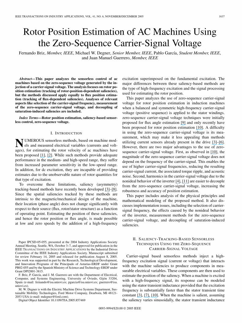
Fig. 1. Injection of the carrier-signal voltage.
can be modeled as consisting of a constant term and a varyingsaliency-position-dependent term (1)–(3) [10]
van = (ΣLσs+2∆Lσs cos(h θe))diadt
(1)
vbn =(
ΣLσs+2∆Lσs cos(
h
(θe−
2π
3
)))dibdt
(2)
vcn =(
ΣLσs+2∆Lσs cos(
h
(θe−
4π
3
)))dicdt
(3)
where ΣLσs and ∆Lσs are the average and differential statortransient inductances, h is the harmonic order of the saliencyrelative to electrical angular units, and θe is the angular positionof the saliency in electrical radians.
While (1)–(3) are valid for any form of high-frequency ex-citation, this paper focuses on the particular case of a balancedand symmetric high-frequency voltage excitation (Fig. 1)
vsqds_c = Vcejθc ωc =
dθc
dt. (4)
The resulting zero-sequence voltage
vs0s =
13(van + vbn + vcn) (5)
can be used to extract the saliency position information.Using (1)–(3) and provided that no zero-sequence currents
exist (6), the zero-sequence voltage can be calculated as afunction of the phase voltages va, vb, and vc, and phase induc-tances (7), i.e.,
diadt
+dibdt
+dicdt
= 0 (6)
vs0s = −vaLbLc + vbLaLc + vcLaLb
LbLc + LaLc + LaLb. (7)
Note that the inductances La, Lb, and Lc in (7) stand for theinductance terms in (1)–(3), respectively.
Using (4) to calculate the resulting phase voltages
va =Vc cos(ωct) (8)
vb =Vc cos(
ωct −2π
3
)(9)
vc =Vc cos(
ωct −4π
3
)(10)
substituting these as well as the inductance terms La, Lb,and Lc from (1)–(3) into (7) allows an analytical solution forthe zero-sequence carrier-signal voltage to be obtained as thatshown in (11) at the bottom of the page.
While (11) is the general solution of the zero-sequencecarrier-signal voltage, it does not provide much insight aboutits nature. Much simpler and more insightful solutions of (11)are obtained by considering specific values for h:
1) for h = 1, 4, 7, . . .
vs0sc =V0ch cos(ωct−hθe)−V0c2h cos(ωct+2hθe) (12)
2) for h = 2, 5, 8, . . .
vs0sc =V0ch cos(ωct+hθe)−V0c2h cos(ωct−2hθe) (13)
3) for h = 3, 6, 9, . . .
vs0sc = 0 (14)
where V0ch = (VcΣLσs∆Lσs)/(ΣL2σs − ∆L2
σs) is themagnitude of the hθe component of the zero-sequencecarrier-signal voltage and V0c2h=(Vc∆L2
σs)/(ΣL2σs −
∆L2σs) is the magnitude of the −2hθe component of the
zero-sequence carrier-signal voltage.Some interesting conclusions can be obtained from the
analysis of (12)–(14).1) For values of h that are not integer multiples of three,
the zero-sequence voltage is seen to consist of two phase-modulated components at hθe and −2hθe, respectively.
2) The magnitude of the second component V0c2h is neg-ligible when compared to the magnitude of the firstcomponent V0ch when ∆Lσs ΣLσs, which is typicallythe case.
3) The magnitudes of the two components are indepen-dent of the carrier-signal frequency assuming that themagnitudes of the average and differential stator tran-sient inductances are not a function of the carrier-signalfrequency.
4) For h = 3, 6, . . . (triplen harmonics), no zero-sequencecarrier-signal voltage is produced.
vs0sc
=Vc
((cos
(23hπ
)−1
)cos(θc)
(2∆Lσs sin2(hθe)+ΣLσs cos(hθe)
)−(ΣLσs+2∆Lσs cos(hθe))
√3 sin(θc) sin(hθe) sin
(23hπ
))(
3ΣL2σs+4ΣLσs∆Lσs cos(hθe)
(2 cos
(23hπ
)+1
)+4∆L2
σs
(cos(hθe)2
(2 cos
(23hπ
)+1
)− sin
(23hπ
)2))
(11)
BRIZ et al.: ROTOR POSITION ESTIMATION OF AC MACHINES USING ZERO-SEQUENCE CARRIER-SIGNAL VOLTAGE 1639
A. Carrier-Signal Current
Injection of the carrier-signal voltage produces a carrier-signal current. Its analytical form
isqds_c = −jIcpejωct − jIcnej(±hθe−ωct) (15)
where Icp = (Vc/ωc)(ΣLσs/(ΣL2σs − ∆L2
σs)) and Icn =(Vc/ωc)(∆Lσs/(ΣL2
σs − ∆L2σs)), can be determined from the
same set of equations used to obtain the zero-sequence carrier-signal voltage [10].
The use of the negative sequence carrier-signal current forsaliency position estimation has been widely studied [3]–[5]and is not covered in this paper. Since the sensorless methodanalyzed in this paper only uses the zero-sequence voltage, thepresence of the carrier-signal current is an unwanted effect as itproduces noise, vibration, and additional losses. One interestingfact that can be observed from (15) is that the magnitude ofthe carrier-signal current is inversely proportional to the carrier-signal frequency. This implies that increasing the carrier-signalfrequency, for a constant carrier-signal voltage, reduces thecarrier-signal current and its adverse effects.
B. Rotor Position Estimation Using the Zero-SequenceCarrier-Signal Voltage
Using high-frequency excitation for rotor position estimationrequires a rotor position-dependent saliency that couples withthe stator windings to produce a measurable signal. Althoughrotor position-dependent saliencies are sometimes present instandard machine designs due to the combined effect of rotorand stator slotting [4], [5], [7], [10], they can also be specificallycreated in several ways [3], [6]. In all cases, rotor designs withopen or semi-open slots are needed.
Independent of how a saliency is created, in order for it tocouple with the stator windings and produce a zero-sequencecarrier-signal voltage, the expression
hsp = n · p, n = 1, 2, 4, 5, 7, 8, 10, . . . (16)
needs to be satisfied, assuming the machine has an integernumber of slots per pole per phase, where p is the number ofpoles and hsp is the saliency harmonic order relative to 360mechanical degrees.
Saliencies caused by the combination of rotor and statorslotting produce a permeance waveform that has a fundamentalspatial harmonic given by
hsp = |R − S| (17)
where S and R are equal to the number of stator and rotor slots,respectively. The fundamental of this permeance waveformrotates at the mechanical speed shown in [5], [10]
ωp =R
(R − S)ωrm. (18)
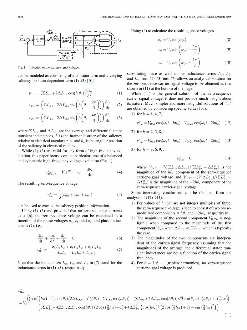
Fig. 2 shows the frequency spectrum of the zero-sequencecarrier-signal voltage (5) in a test machine, for both no fun-damental excitation and rated flux, rated load. The parameters
Fig. 2. Frequency spectrum of the zero-sequence carrier-signal voltageωc = 500 Hz, Vc = 20 V (peak). (a) No fundamental current, ωr = 1 Hz.(b) Rated flux-rated load, ωe = 4 Hz, ωr = 1 Hz.
TABLE IINDUCTION MOTOR PARAMETERS
of this machine are shown in Table I. There are two importantobservations that can be seen in Fig. 2. First, rotor–statorslotting produces a rotor-position-dependent modulation of thezero-sequence carrier-signal voltage of the form
vs0sc = V0ch cos(ωct + hθr) (19)
with h being the number of rotor slots per pole pair (14 forthis case).
Second, when fundamental current exists, saturation-inducedsaliencies are also created [harmonics in Fig. 2(b) that arefunctions of the fundamental excitation frequency ωe]. Whilethose saliencies may be useful for flux angle estimation, theyare a disturbance to rotor position estimation and need to bedecoupled or otherwise compensated for in order to minimizethe estimation error.
In addition to the rotor–stator slotting saliency andsaturation-induced saliencies, some level of asymmetry in thestator windings due to the manufacturing process usually exists.This produces a stationary saliency, which can give rise toa measurable component of the zero-sequence carrier-signalvoltage. However, such a component would be expected tobe similar from machine-to-machine with the same design,being relatively easy to decouple. Additional asymmetries, e.g.,eccentricities in the rotor, have not been observed to causeany measurable effect in healthy machines. Other potentialsources of saliencies would be those caused by faults in themachine, including turn-to-turn faults in the stator windings,and damaged rotor bars. The actual impact of such saliencieson the zero-sequence carrier-signal voltage, and therefore onthe estimated position, would strongly depend on the levelof fault.
III. SELECTION OF THE CARRIER-SIGNAL FREQUENCY
Selection of the carrier-signal frequency involves severaltradeoffs. Increasing the carrier-signal frequency has two majoradvantages: 1) the carrier-signal current magnitude is reduced
1640 IEEE TRANSACTIONS ON INDUSTRY APPLICATIONS, VOL. 41, NO. 6, NOVEMBER/DECEMBER 2005
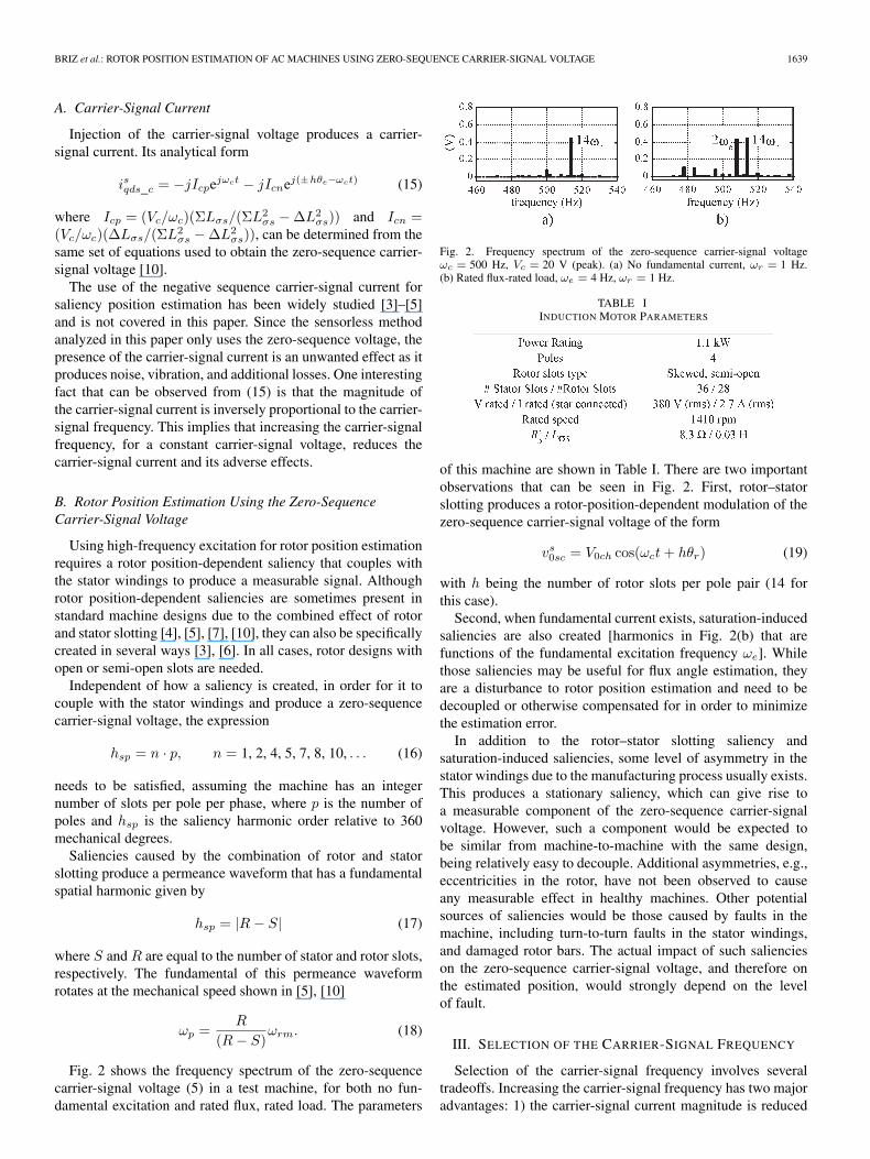
Fig. 3. Experimentally measured magnitude of the 2ωe and 14ωr componentsof the zero-sequence carrier-signal voltage as a function of the carrier-signalfrequency for the motor in Table I. The motor was operated at rated flux, ratedload. A carrier-signal voltage of 20 V (peak) was used.
and 2) the spectral separation with respect to the fundamentalexcitation is increased, which reduces the interaction betweenthe fundamental excitation and the carrier-signal excitation[12]. However, increasing the carrier-signal frequency has somedetrimental effects, most of them related to the nonideal behav-ior of the inverter. These effects are analyzed in the followingsection.
The theoretical model developed in Section II was basedon the high-frequency behavior of the machine. One of themore interesting conclusions reached from this model wasthat the zero-sequence carrier-signal voltage is independentof the carrier-signal frequency. This conclusion is only validif the average and differential stator transient inductances arenot functions of the carrier-signal frequency. Fig. 3 showsthe magnitudes of the rotor–stator slotting and the saturation-induced components of the zero-sequence carrier-signal voltagefor several carrier-signal frequencies. From Fig. 3, it can beseen that the rotor-position-dependent component’s magnitudeis almost constant, independent of the carrier-signal frequency,while the saturation-induced component’s magnitude decreasesas ωc increases. This suggests that increased carrier-signalfrequencies would result in a slight reduction in the sensitivityto the presence of saturation-induced components for detectingrotor-position-dependent components.
Unless otherwise stated, all the experimental results pre-sented in this paper used a carrier-signal frequency of ωc =2500 Hz and a carrier-signal voltage magnitude of Vc = 20 V(peak). This resulted in a carrier-signal current (15) witha magnitude of 48 mA (peak), which corresponds to 1.2%of the rated current. The inverter switching frequency wasωs = 15 kHz, with a dead time of 2 µs. No compensation ofthe dead time was implemented.
IV. IMPLEMENTATION ISSUES AFFECTING THE
CARRIER-SIGNAL VOLTAGE EXCITATION AND
MEASUREMENT OF THE ZERO-SEQUENCE
CARRIER-SIGNAL VOLTAGE
The injection of the carrier-signal voltage and the measure-ment of the resulting zero-sequence carrier-signal voltage aresimple in principle (Fig. 1). There are, however, a number ofimplementation issues that can strongly influence the results.These issues are analyzed in this section.
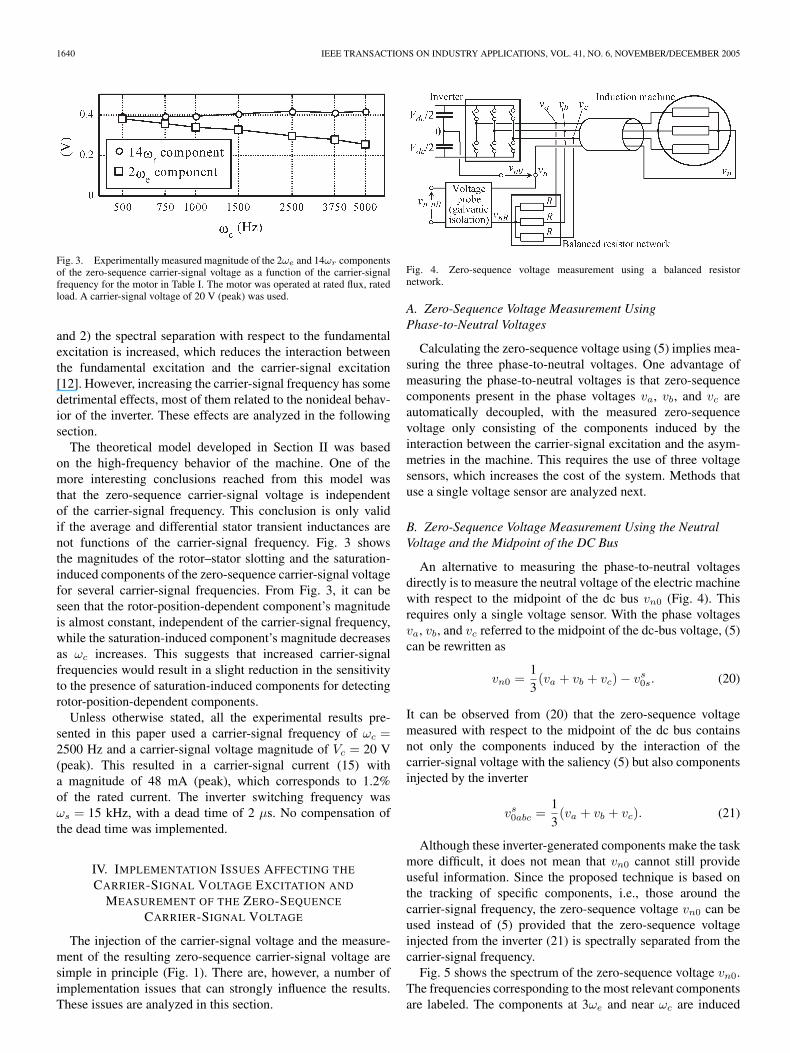
Fig. 4. Zero-sequence voltage measurement using a balanced resistornetwork.
A. Zero-Sequence Voltage Measurement UsingPhase-to-Neutral Voltages
Calculating the zero-sequence voltage using (5) implies mea-suring the three phase-to-neutral voltages. One advantage ofmeasuring the phase-to-neutral voltages is that zero-sequencecomponents present in the phase voltages va, vb, and vc areautomatically decoupled, with the measured zero-sequencevoltage only consisting of the components induced by theinteraction between the carrier-signal excitation and the asym-metries in the machine. This requires the use of three voltagesensors, which increases the cost of the system. Methods thatuse a single voltage sensor are analyzed next.
B. Zero-Sequence Voltage Measurement Using the NeutralVoltage and the Midpoint of the DC Bus
An alternative to measuring the phase-to-neutral voltagesdirectly is to measure the neutral voltage of the electric machinewith respect to the midpoint of the dc bus vn0 (Fig. 4). Thisrequires only a single voltage sensor. With the phase voltagesva, vb, and vc referred to the midpoint of the dc-bus voltage, (5)can be rewritten as
vn0 =13(va + vb + vc) − vs
0s. (20)
It can be observed from (20) that the zero-sequence voltagemeasured with respect to the midpoint of the dc bus containsnot only the components induced by the interaction of thecarrier-signal voltage with the saliency (5) but also componentsinjected by the inverter
vs0abc =
13(va + vb + vc). (21)
Although these inverter-generated components make the taskmore difficult, it does not mean that vn0 cannot still provideuseful information. Since the proposed technique is based onthe tracking of specific components, i.e., those around thecarrier-signal frequency, the zero-sequence voltage vn0 can beused instead of (5) provided that the zero-sequence voltageinjected from the inverter (21) is spectrally separated from thecarrier-signal frequency.
Fig. 5 shows the spectrum of the zero-sequence voltage vn0.The frequencies corresponding to the most relevant componentsare labeled. The components at 3ωe and near ωc are induced
BRIZ et al.: ROTOR POSITION ESTIMATION OF AC MACHINES USING ZERO-SEQUENCE CARRIER-SIGNAL VOLTAGE 1641
Fig. 5. Experimentally measured spectrum of the zero-sequence voltage vn0.The motor was operated at rated flux, rated load.
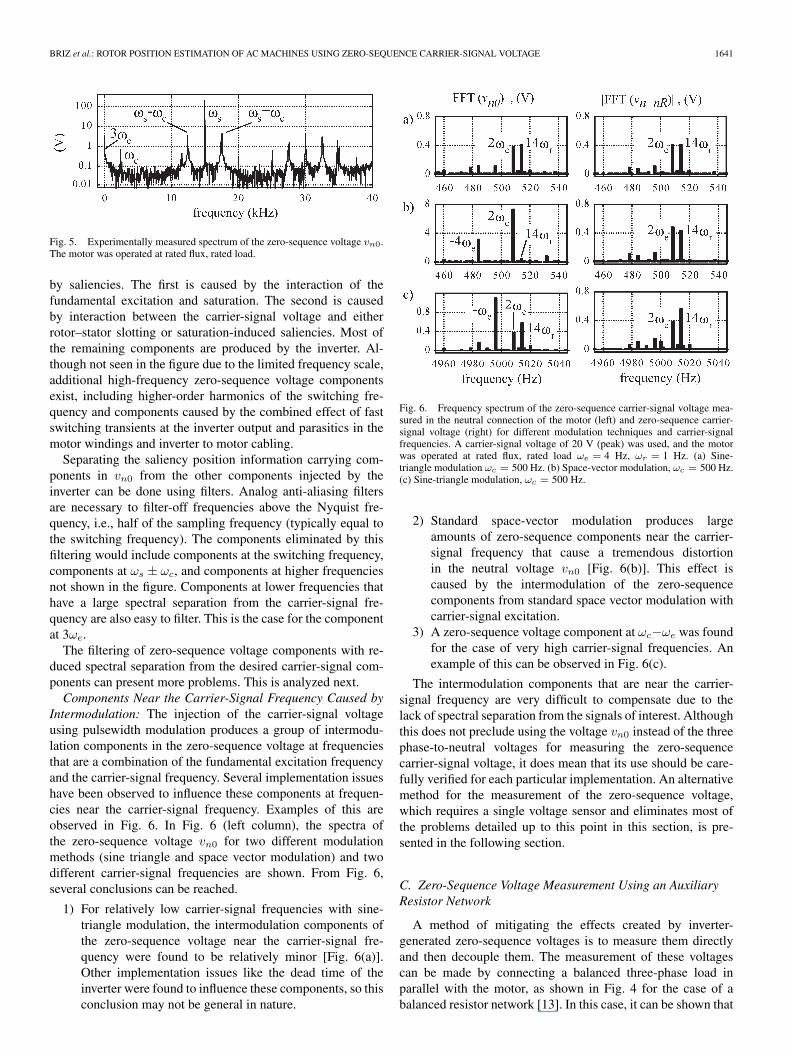
by saliencies. The first is caused by the interaction of thefundamental excitation and saturation. The second is causedby interaction between the carrier-signal voltage and eitherrotor–stator slotting or saturation-induced saliencies. Most ofthe remaining components are produced by the inverter. Al-though not seen in the figure due to the limited frequency scale,additional high-frequency zero-sequence voltage componentsexist, including higher-order harmonics of the switching fre-quency and components caused by the combined effect of fastswitching transients at the inverter output and parasitics in themotor windings and inverter to motor cabling.
Separating the saliency position information carrying com-ponents in vn0 from the other components injected by theinverter can be done using filters. Analog anti-aliasing filtersare necessary to filter-off frequencies above the Nyquist fre-quency, i.e., half of the sampling frequency (typically equal tothe switching frequency). The components eliminated by thisfiltering would include components at the switching frequency,components at ωs ± ωc, and components at higher frequenciesnot shown in the figure. Components at lower frequencies thathave a large spectral separation from the carrier-signal fre-quency are also easy to filter. This is the case for the componentat 3ωe.
The filtering of zero-sequence voltage components with re-duced spectral separation from the desired carrier-signal com-ponents can present more problems. This is analyzed next.Components Near the Carrier-Signal Frequency Caused by
Intermodulation: The injection of the carrier-signal voltageusing pulsewidth modulation produces a group of intermodu-lation components in the zero-sequence voltage at frequenciesthat are a combination of the fundamental excitation frequencyand the carrier-signal frequency. Several implementation issueshave been observed to influence these components at frequen-cies near the carrier-signal frequency. Examples of this areobserved in Fig. 6. In Fig. 6 (left column), the spectra ofthe zero-sequence voltage vn0 for two different modulationmethods (sine triangle and space vector modulation) and twodifferent carrier-signal frequencies are shown. From Fig. 6,several conclusions can be reached.
1) For relatively low carrier-signal frequencies with sine-triangle modulation, the intermodulation components ofthe zero-sequence voltage near the carrier-signal fre-quency were found to be relatively minor [Fig. 6(a)].Other implementation issues like the dead time of theinverter were found to influence these components, so thisconclusion may not be general in nature.
Fig. 6. Frequency spectrum of the zero-sequence carrier-signal voltage mea-sured in the neutral connection of the motor (left) and zero-sequence carrier-signal voltage (right) for different modulation techniques and carrier-signalfrequencies. A carrier-signal voltage of 20 V (peak) was used, and the motorwas operated at rated flux, rated load ωe = 4 Hz, ωr = 1 Hz. (a) Sine-triangle modulation ωc = 500 Hz. (b) Space-vector modulation, ωc = 500 Hz.(c) Sine-triangle modulation, ωc = 500 Hz.
2) Standard space-vector modulation produces largeamounts of zero-sequence components near the carrier-signal frequency that cause a tremendous distortionin the neutral voltage vn0 [Fig. 6(b)]. This effect iscaused by the intermodulation of the zero-sequencecomponents from standard space vector modulation withcarrier-signal excitation.
3) A zero-sequence voltage component at ωc−ωe was foundfor the case of very high carrier-signal frequencies. Anexample of this can be observed in Fig. 6(c).
The intermodulation components that are near the carrier-signal frequency are very difficult to compensate due to thelack of spectral separation from the signals of interest. Althoughthis does not preclude using the voltage vn0 instead of the threephase-to-neutral voltages for measuring the zero-sequencecarrier-signal voltage, it does mean that its use should be care-fully verified for each particular implementation. An alternativemethod for the measurement of the zero-sequence voltage,which requires a single voltage sensor and eliminates most ofthe problems detailed up to this point in this section, is pre-sented in the following section.
C. Zero-Sequence Voltage Measurement Using an AuxiliaryResistor Network
A method of mitigating the effects created by inverter-generated zero-sequence voltages is to measure them directlyand then decouple them. The measurement of these voltagescan be made by connecting a balanced three-phase load inparallel with the motor, as shown in Fig. 4 for the case of abalanced resistor network [13]. In this case, it can be shown that
1642 IEEE TRANSACTIONS ON INDUSTRY APPLICATIONS, VOL. 41, NO. 6, NOVEMBER/DECEMBER 2005
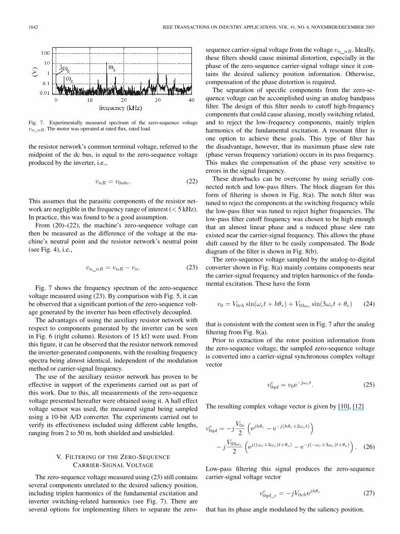
Fig. 7. Experimentally measured spectrum of the zero-sequence voltagevn_nR. The motor was operated at rated flux, rated load.
the resistor network’s common terminal voltage, referred to themidpoint of the dc bus, is equal to the zero-sequence voltageproduced by the inverter, i.e.,
vnR = v0abc. (22)
This assumes that the parasitic components of the resistor net-work are negligible in the frequency range of interest (< 5 kHz).In practice, this was found to be a good assumption.
From (20)–(22), the machine’s zero-sequence voltage canthen be measured as the difference of the voltage at the ma-chine’s neutral point and the resistor network’s neutral point(see Fig. 4), i.e.,
vn_nR = vnR − vn. (23)
Fig. 7 shows the frequency spectrum of the zero-sequencevoltage measured using (23). By comparison with Fig. 5, it canbe observed that a significant portion of the zero-sequence volt-age generated by the inverter has been effectively decoupled.
The advantages of using the auxiliary resistor network withrespect to components generated by the inverter can be seenin Fig. 6 (right column). Resistors of 15 kΩ were used. Fromthis figure, it can be observed that the resistor network removedthe inverter-generated components, with the resulting frequencyspectra being almost identical, independent of the modulationmethod or carrier-signal frequency.
The use of the auxiliary resistor network has proven to beeffective in support of the experiments carried out as part ofthis work. Due to this, all measurements of the zero-sequencevoltage presented hereafter were obtained using it. A hall effectvoltage sensor was used, the measured signal being sampledusing a 10-bit A/D converter. The experiments carried out toverify its effectiveness included using different cable lengths,ranging from 2 to 50 m, both shielded and unshielded.
V. FILTERING OF THE ZERO-SEQUENCE
CARRIER-SIGNAL VOLTAGE
The zero-sequence voltage measured using (23) still containsseveral components unrelated to the desired saliency position,including triplen harmonics of the fundamental excitation andinverter switching-related harmonics (see Fig. 7). There areseveral options for implementing filters to separate the zero-
sequence carrier-signal voltage from the voltage vn_nR. Ideally,these filters should cause minimal distortion, especially in thephase of the zero-sequence carrier-signal voltage since it con-tains the desired saliency position information. Otherwise,compensation of the phase distortion is required.
The separation of specific components from the zero-se-quence voltage can be accomplished using an analog bandpassfilter. The design of this filter needs to cutoff high-frequencycomponents that could cause aliasing, mostly switching related,and to reject the low-frequency components, mainly triplenharmonics of the fundamental excitation. A resonant filter isone option to achieve these goals. This type of filter hasthe disadvantage, however, that its maximum phase slew rate(phase versus frequency variation) occurs in its pass frequency.This makes the compensation of the phase very sensitive toerrors in the signal frequency.
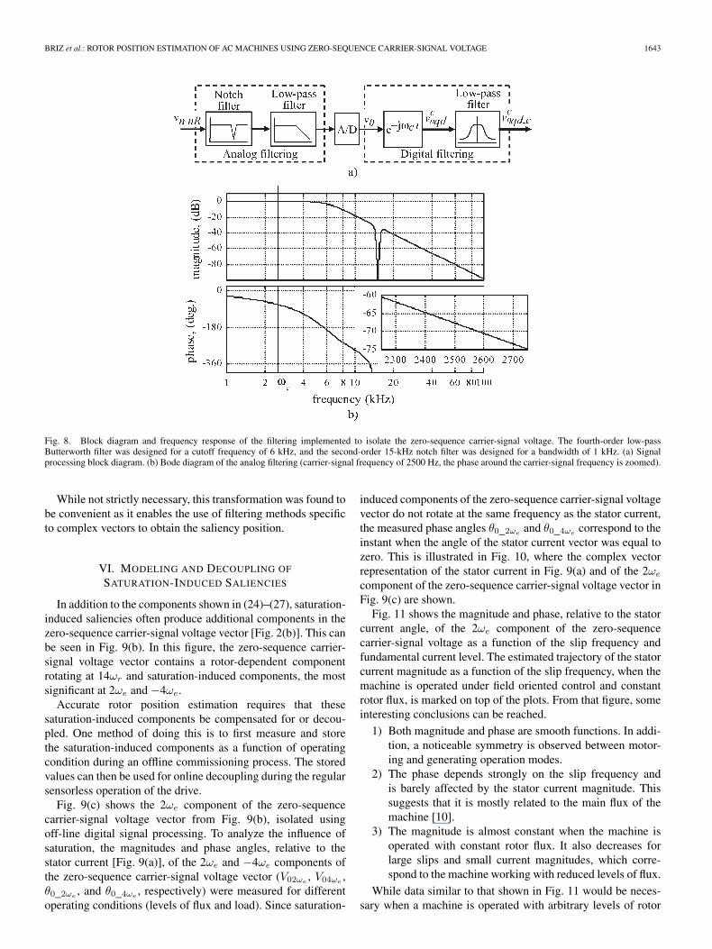
These drawbacks can be overcome by using serially con-nected notch and low-pass filters. The block diagram for thisform of filtering is shown in Fig. 8(a). The notch filter wastuned to reject the components at the switching frequency whilethe low-pass filter was tuned to reject higher frequencies. Thelow-pass filter cutoff frequency was chosen to be high enoughthat an almost linear phase and a reduced phase slew rateexisted near the carrier-signal frequency. This allows the phaseshift caused by the filter to be easily compensated. The Bodediagram of the filter is shown in Fig. 8(b).
The zero-sequence voltage sampled by the analog-to-digitalconverter shown in Fig. 8(a) mainly contains components nearthe carrier-signal frequency and triplen harmonics of the funda-mental excitation. These have the form
v0 = V0ch sin(ωct + hθr) + V03ωesin(3ωet + θe) (24)
that is consistent with the content seen in Fig. 7 after the analogfiltering from Fig. 8(a).
Prior to extraction of the rotor position information fromthe zero-sequence voltage, the sampled zero-sequence voltageis converted into a carrier-signal synchronous complex voltagevector
vc0qd = v0e−jωct. (25)
The resulting complex voltage vector is given by [10], [12]
vc0qd = −j
V0c
2
(ejhθr − e−j(hθr+2ωct)
)
− jV03ωe
2
(ej((ωc+3ωe)t+θe) − e−j(−ωc+3ωe)t+θe)
). (26)
Low-pass filtering this signal produces the zero-sequencecarrier-signal voltage vector
vc0qd_c = −jV0chejhθr (27)
that has its phase angle modulated by the saliency position.
BRIZ et al.: ROTOR POSITION ESTIMATION OF AC MACHINES USING ZERO-SEQUENCE CARRIER-SIGNAL VOLTAGE 1643
Fig. 8. Block diagram and frequency response of the filtering implemented to isolate the zero-sequence carrier-signal voltage. The fourth-order low-passButterworth filter was designed for a cutoff frequency of 6 kHz, and the second-order 15-kHz notch filter was designed for a bandwidth of 1 kHz. (a) Signalprocessing block diagram. (b) Bode diagram of the analog filtering (carrier-signal frequency of 2500 Hz, the phase around the carrier-signal frequency is zoomed).
While not strictly necessary, this transformation was found tobe convenient as it enables the use of filtering methods specificto complex vectors to obtain the saliency position.
VI. MODELING AND DECOUPLING OF
SATURATION-INDUCED SALIENCIES
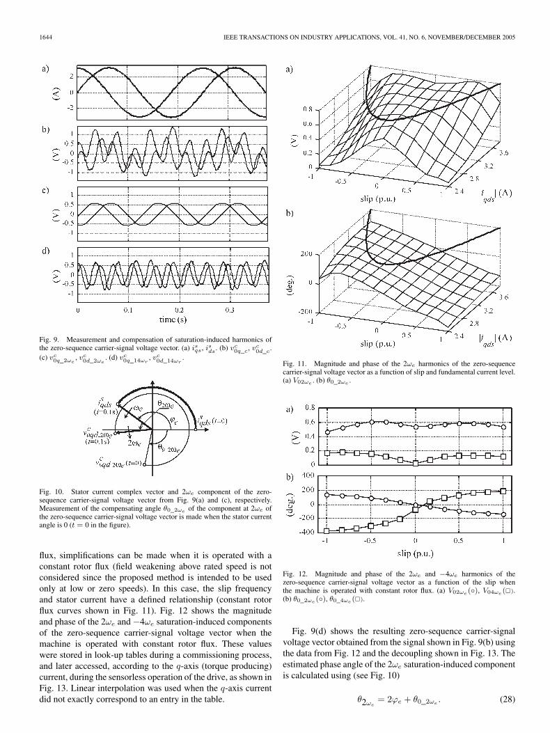
In addition to the components shown in (24)–(27), saturation-induced saliencies often produce additional components in thezero-sequence carrier-signal voltage vector [Fig. 2(b)]. This canbe seen in Fig. 9(b). In this figure, the zero-sequence carrier-signal voltage vector contains a rotor-dependent componentrotating at 14ωr and saturation-induced components, the mostsignificant at 2ωe and −4ωe.
Accurate rotor position estimation requires that thesesaturation-induced components be compensated for or decou-pled. One method of doing this is to first measure and storethe saturation-induced components as a function of operatingcondition during an offline commissioning process. The storedvalues can then be used for online decoupling during the regularsensorless operation of the drive.
Fig. 9(c) shows the 2ωe component of the zero-sequencecarrier-signal voltage vector from Fig. 9(b), isolated usingoff-line digital signal processing. To analyze the influence ofsaturation, the magnitudes and phase angles, relative to thestator current [Fig. 9(a)], of the 2ωe and −4ωe components ofthe zero-sequence carrier-signal voltage vector (V02ωe
, V04ωe,
θ0_2ωe, and θ0_4ωe
, respectively) were measured for differentoperating conditions (levels of flux and load). Since saturation-
induced components of the zero-sequence carrier-signal voltagevector do not rotate at the same frequency as the stator current,the measured phase angles θ0_2ωe
and θ0_4ωecorrespond to the
instant when the angle of the stator current vector was equal tozero. This is illustrated in Fig. 10, where the complex vectorrepresentation of the stator current in Fig. 9(a) and of the 2ωe
component of the zero-sequence carrier-signal voltage vector inFig. 9(c) are shown.
Fig. 11 shows the magnitude and phase, relative to the statorcurrent angle, of the 2ωe component of the zero-sequencecarrier-signal voltage as a function of the slip frequency andfundamental current level. The estimated trajectory of the statorcurrent magnitude as a function of the slip frequency, when themachine is operated under field oriented control and constantrotor flux, is marked on top of the plots. From that figure, someinteresting conclusions can be reached.
1) Both magnitude and phase are smooth functions. In addi-tion, a noticeable symmetry is observed between motor-ing and generating operation modes.
2) The phase depends strongly on the slip frequency andis barely affected by the stator current magnitude. Thissuggests that it is mostly related to the main flux of themachine [10].
3) The magnitude is almost constant when the machine isoperated with constant rotor flux. It also decreases forlarge slips and small current magnitudes, which corre-spond to the machine working with reduced levels of flux.
While data similar to that shown in Fig. 11 would be neces-sary when a machine is operated with arbitrary levels of rotor
1644 IEEE TRANSACTIONS ON INDUSTRY APPLICATIONS, VOL. 41, NO. 6, NOVEMBER/DECEMBER 2005
Fig. 9. Measurement and compensation of saturation-induced harmonics ofthe zero-sequence carrier-signal voltage vector. (a) isqs, isds. (b) vc
0q_c, vc0d_c.
(c) vc0q_2ωe
, vc0d_2ωe
. (d) vc0q_14ωr
, vc0d_14ωr
.
Fig. 10. Stator current complex vector and 2ωe component of the zero-sequence carrier-signal voltage vector from Fig. 9(a) and (c), respectively.Measurement of the compensating angle θ0_2ωe of the component at 2ωe ofthe zero-sequence carrier-signal voltage vector is made when the stator currentangle is 0 (t = 0 in the figure).
flux, simplifications can be made when it is operated with aconstant rotor flux (field weakening above rated speed is notconsidered since the proposed method is intended to be usedonly at low or zero speeds). In this case, the slip frequencyand stator current have a defined relationship (constant rotorflux curves shown in Fig. 11). Fig. 12 shows the magnitudeand phase of the 2ωe and −4ωe saturation-induced componentsof the zero-sequence carrier-signal voltage vector when themachine is operated with constant rotor flux. These valueswere stored in look-up tables during a commissioning process,and later accessed, according to the q-axis (torque producing)current, during the sensorless operation of the drive, as shown inFig. 13. Linear interpolation was used when the q-axis currentdid not exactly correspond to an entry in the table.
Fig. 11. Magnitude and phase of the 2ωe harmonics of the zero-sequencecarrier-signal voltage vector as a function of slip and fundamental current level.(a) V02ωe . (b) θ0_2ωe .
Fig. 12. Magnitude and phase of the 2ωe and −4ωe harmonics of thezero-sequence carrier-signal voltage vector as a function of the slip whenthe machine is operated with constant rotor flux. (a) V02ωe (), V04ωe ().(b) θ0_2ωe (), θ0_4ωe ().
Fig. 9(d) shows the resulting zero-sequence carrier-signalvoltage vector obtained from the signal shown in Fig. 9(b) usingthe data from Fig. 12 and the decoupling shown in Fig. 13. Theestimated phase angle of the 2ωe saturation-induced componentis calculated using (see Fig. 10)
θ2ωe= 2ϕe + θ0_2ωe
. (28)
BRIZ et al.: ROTOR POSITION ESTIMATION OF AC MACHINES USING ZERO-SEQUENCE CARRIER-SIGNAL VOLTAGE 1645
Fig. 13. Decoupling of saturation-induced components of the zero-sequencecarrier-signal voltage vector and rotor position and velocity estimation using atracking observer.
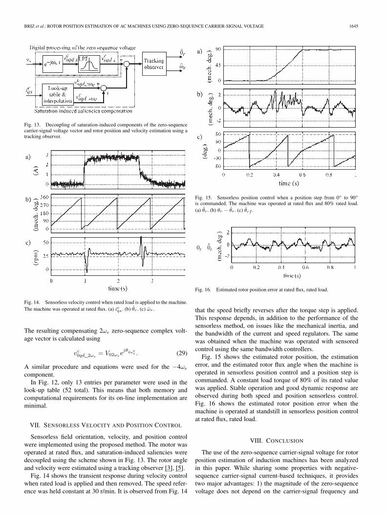
Fig. 14. Sensorless velocity control when rated load is applied to the machine.The machine was operated at rated flux. (a) ieqs. (b) θr . (c) ωr .
The resulting compensating 2ωe zero-sequence complex volt-age vector is calculated using
vc0qd_2ωe
= V02ωeejθ2ωt
e . (29)
A similar procedure and equations were used for the −4ωe
component.In Fig. 12, only 13 entries per parameter were used in the
look-up table (52 total). This means that both memory andcomputational requirements for its on-line implementation areminimal.
VII. SENSORLESS VELOCITY AND POSITION CONTROL
Sensorless field orientation, velocity, and position controlwere implemented using the proposed method. The motor wasoperated at rated flux, and saturation-induced saliencies weredecoupled using the scheme shown in Fig. 13. The rotor angleand velocity were estimated using a tracking observer [3], [5].
Fig. 14 shows the transient response during velocity controlwhen rated load is applied and then removed. The speed refer-ence was held constant at 30 r/min. It is observed from Fig. 14
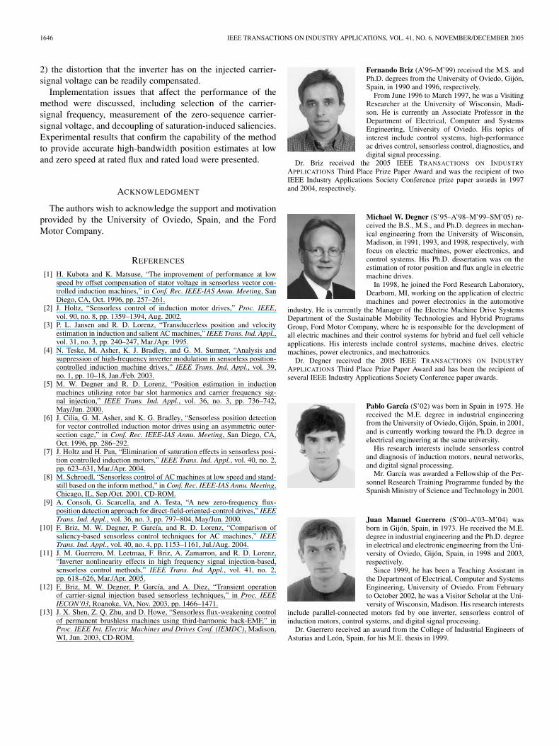
Fig. 15. Sensorless position control when a position step from 0 to 90
is commanded. The machine was operated at rated flux and 80% rated load.(a) θr . (b) θr − θr . (c) θrf .
Fig. 16. Estimated rotor position error at rated flux, rated load.
that the speed briefly reverses after the torque step is applied.This response depends, in addition to the performance of thesensorless method, on issues like the mechanical inertia, andthe bandwidth of the current and speed regulators. The samewas obtained when the machine was operated with sensoredcontrol using the same bandwidth controllers.
Fig. 15 shows the estimated rotor position, the estimationerror, and the estimated rotor flux angle when the machine isoperated in sensorless position control and a position step iscommanded. A constant load torque of 80% of its rated valuewas applied. Stable operation and good dynamic response areobserved during both speed and position sensorless control.Fig. 16 shows the estimated rotor position error when themachine is operated at standstill in sensorless position controlat rated flux, rated load.
VIII. CONCLUSION
The use of the zero-sequence carrier-signal voltage for rotorposition estimation of induction machines has been analyzedin this paper. While sharing some properties with negative-sequence carrier-signal current-based techniques, it providestwo major advantages: 1) the magnitude of the zero-sequencevoltage does not depend on the carrier-signal frequency and
1646 IEEE TRANSACTIONS ON INDUSTRY APPLICATIONS, VOL. 41, NO. 6, NOVEMBER/DECEMBER 2005
2) the distortion that the inverter has on the injected carrier-signal voltage can be readily compensated.
Implementation issues that affect the performance of themethod were discussed, including selection of the carrier-signal frequency, measurement of the zero-sequence carrier-signal voltage, and decoupling of saturation-induced saliencies.Experimental results that confirm the capability of the methodto provide accurate high-bandwidth position estimates at lowand zero speed at rated flux and rated load were presented.
ACKNOWLEDGMENT
The authors wish to acknowledge the support and motivationprovided by the University of Oviedo, Spain, and the FordMotor Company.
REFERENCES
[1] H. Kubota and K. Matsuse, “The improvement of performance at lowspeed by offset compensation of stator voltage in sensorless vector con-trolled induction machines,” in Conf. Rec. IEEE-IAS Annu. Meeting, SanDiego, CA, Oct. 1996, pp. 257–261.
[2] J. Holtz, “Sensorless control of induction motor drives,” Proc. IEEE,vol. 90, no. 8, pp. 1359–1394, Aug. 2002.
[3] P. L. Jansen and R. D. Lorenz, “Transducerless position and velocityestimation in induction and salient AC machines,” IEEE Trans. Ind. Appl.,vol. 31, no. 3, pp. 240–247, Mar./Apr. 1995.
[4] N. Teske, M. Asher, K. J. Bradley, and G. M. Sumner, “Analysis andsuppression of high-frequency inverter modulation in sensorless position-controlled induction machine drives,” IEEE Trans. Ind. Appl., vol. 39,no. 1, pp. 10–18, Jan./Feb. 2003.
[5] M. W. Degner and R. D. Lorenz, “Position estimation in inductionmachines utilizing rotor bar slot harmonics and carrier frequency sig-nal injection,” IEEE Trans. Ind. Appl., vol. 36, no. 3, pp. 736–742,May/Jun. 2000.
[6] J. Cilia, G. M. Asher, and K. G. Bradley, “Sensorless position detectionfor vector controlled induction motor drives using an asymmetric outer-section cage,” in Conf. Rec. IEEE-IAS Annu. Meeting, San Diego, CA,Oct. 1996, pp. 286–292.
[7] J. Holtz and H. Pan, “Elimination of saturation effects in sensorless posi-tion controlled induction motors,” IEEE Trans. Ind. Appl., vol. 40, no. 2,pp. 623–631, Mar./Apr. 2004.
[8] M. Schroedl, “Sensorless control of AC machines at low speed and stand-still based on the inform method,” in Conf. Rec. IEEE-IAS Annu. Meeting,Chicago, IL, Sep./Oct. 2001, CD-ROM.
[9] A. Consoli, G. Scarcella, and A. Testa, “A new zero-frequency flux-position detection approach for direct-field-oriented-control drives,” IEEETrans. Ind. Appl., vol. 36, no. 3, pp. 797–804, May/Jun. 2000.
[10] F. Briz, M. W. Degner, P. García, and R. D. Lorenz, “Comparison ofsaliency-based sensorless control techniques for AC machines,” IEEETrans. Ind. Appl., vol. 40, no. 4, pp. 1153–1161, Jul./Aug. 2004.
[11] J. M. Guerrero, M. Leetmaa, F. Briz, A. Zamarron, and R. D. Lorenz,“Inverter nonlinearity effects in high frequency signal injection-based,sensorless control methods,” IEEE Trans. Ind. Appl., vol. 41, no. 2,pp. 618–626, Mar./Apr. 2005.
[12] F. Briz, M. W. Degner, P. García, and A. Diez, “Transient operationof carrier-signal injection based sensorless techniques,” in Proc. IEEEIECON’03, Roanoke, VA, Nov. 2003, pp. 1466–1471.
[13] J. X. Shen, Z. Q. Zhu, and D. Howe, “Sensorless flux-weakening controlof permanent brushless machines using third-harmonic back-EMF,” inProc. IEEE Int. Electric Machines and Drives Conf. (IEMDC), Madison,WI, Jun. 2003, CD-ROM.
Fernando Briz (A’96–M’99) received the M.S. andPh.D. degrees from the University of Oviedo, Gijón,Spain, in 1990 and 1996, respectively.
From June 1996 to March 1997, he was a VisitingResearcher at the University of Wisconsin, Madi-son. He is currently an Associate Professor in theDepartment of Electrical, Computer and SystemsEngineering, University of Oviedo. His topics ofinterest include control systems, high-performanceac drives control, sensorless control, diagnostics, anddigital signal processing.
Dr. Briz received the 2005 IEEE TRANSACTIONS ON INDUSTRY
APPLICATIONS Third Place Prize Paper Award and was the recipient of twoIEEE Industry Applications Society Conference prize paper awards in 1997and 2004, respectively.
Michael W. Degner (S’95–A’98–M’99–SM’05) re-ceived the B.S., M.S., and Ph.D. degrees in mechan-ical engineering from the University of Wisconsin,Madison, in 1991, 1993, and 1998, respectively, withfocus on electric machines, power electronics, andcontrol systems. His Ph.D. dissertation was on theestimation of rotor position and flux angle in electricmachine drives.
In 1998, he joined the Ford Research Laboratory,Dearborn, MI, working on the application of electricmachines and power electronics in the automotive
industry. He is currently the Manager of the Electric Machine Drive SystemsDepartment of the Sustainable Mobility Technologies and Hybrid ProgramsGroup, Ford Motor Company, where he is responsible for the development ofall electric machines and their control systems for hybrid and fuel cell vehicleapplications. His interests include control systems, machine drives, electricmachines, power electronics, and mechatronics.
Dr. Degner received the 2005 IEEE TRANSACTIONS ON INDUSTRY
APPLICATIONS Third Place Prize Paper Award and has been the recipient ofseveral IEEE Industry Applications Society Conference paper awards.
Pablo García (S’02) was born in Spain in 1975. Hereceived the M.E. degree in industrial engineeringfrom the University of Oviedo, Gijón, Spain, in 2001,and is currently working toward the Ph.D. degree inelectrical engineering at the same university.
His research interests include sensorless controland diagnosis of induction motors, neural networks,and digital signal processing.
Mr. García was awarded a Fellowship of the Per-sonnel Research Training Programme funded by theSpanish Ministry of Science and Technology in 2001.
Juan Manuel Guerrero (S’00–A’03–M’04) wasborn in Gijón, Spain, in 1973. He received the M.E.degree in industrial engineering and the Ph.D. degreein electrical and electronic engineering from the Uni-versity of Oviedo, Gijón, Spain, in 1998 and 2003,respectively.
Since 1999, he has been a Teaching Assistant inthe Department of Electrical, Computer and SystemsEngineering, University of Oviedo. From Februaryto October 2002, he was a Visitor Scholar at the Uni-versity of Wisconsin, Madison. His research interests
include parallel-connected motors fed by one inverter, sensorless control ofinduction motors, control systems, and digital signal processing.
Dr. Guerrero received an award from the College of Industrial Engineers ofAsturias and León, Spain, for his M.E. thesis in 1999.