Rosenbauer South Dakota
218
Rosenbauer South Dakota 10040-0006 06/10/19 1 One (1) == 101' Technical Information - 0.000 == One (1) AERIAL COST IS DEALER NET 00-00-0004 One (1) 101' THREE SECTION REAR MOUNT PLATFORM MODEL 00-01-1100 10 One (1) 101' Three Section, Rear Mount, Platform 00-01-1110 101' THREE SECTION REAR MOUNT PLATFORM Platform Design and Construction The 101 foot three section, steel aerial platform has a maximum height of 100' 7" at the top of the platform handrail at 75 degrees elevation. The horizontal reach from the outside edge of the platform to the center of the turntable is 94' 2.8". Operation on grades The aerial shall be capable of being operated with full rated capabilities in any plane up to 5 degrees out of level with the turntable leveled as much as possible by placement of the outriggers. Operation beyond this limit shall be at the operator's discretion. Extension and Retraction System The extension cylinders have counter balance valves mounted directly to them. The extension cylinders extend and retract the platform with a 4:1 cable cylinder arrangement from totally retracted to 101' 6" at 75 degrees totally extended. State-of-the-Art Technology The aerial device materials, parts, technology or procedures used in construction of the apparatus are subject to change at the manufacturer's discretion to provide "equal or better" products and must be in compliance to applicable NFPA # 1901 standards and industry standard practice. One (1) 101' Three Section, Rear Mount, Base Section 00-01-1120 BASE SECTION The platform base section length shall be 36' 2", with inside dimensions of 39.25"; distance between the top of the handrail and the centerline of the rungs shall be 28". The base rails shall be 100,000 PSI material and the handrails shall be 100,000 PSI material. One (1) 101' Three Section, Rear Mount, Mid Section 00-01-1130 MID SECTION The platform mid-section length shall be 36' 8", with inside dimension of 32.5"; distance between the top of the handrail and the centerline of the rungs shall be 23.125". The base rails shall be 100,000 PSI material and the handrails shall be 100,000 PSI material. One (1) 101' Three Section, Rear Mount, Fly Section 00-01-1140
-
Upload
khangminh22 -
Category
Documents
-
view
2 -
download
0
Transcript of Rosenbauer South Dakota

Rosenbauer South Dakota
10040-0006 06/10/191
One (1) == 101' Technical Information - 0.000 ==
One (1) AERIAL COST IS DEALER NET00-00-0004
One (1) 101' THREE SECTION REAR MOUNT PLATFORM MODEL00-01-1100 10
One (1) 101' Three Section, Rear Mount, Platform00-01-1110
101' THREE SECTION REAR MOUNT PLATFORMPlatform Design and ConstructionThe 101 foot three section, steel aerial platform has a maximum height of 100' 7" at the top of theplatform handrail at 75 degrees elevation. The horizontal reach from the outside edge of theplatform to the center of the turntable is 94' 2.8".
Operation on gradesThe aerial shall be capable of being operated with full rated capabilities in any plane up to 5degrees out of level with the turntable leveled as much as possible by placement of theoutriggers. Operation beyond this limit shall be at the operator's discretion.
Extension and Retraction SystemThe extension cylinders have counter balance valves mounted directly to them. The extensioncylinders extend and retract the platform with a 4:1 cable cylinder arrangement from totallyretracted to 101' 6" at 75 degrees totally extended.
State-of-the-Art TechnologyThe aerial device materials, parts, technology or procedures used in construction of the apparatusare subject to change at the manufacturer's discretion to provide "equal or better" products andmust be in compliance to applicable NFPA # 1901 standards and industry standard practice.
One (1) 101' Three Section, Rear Mount, Base Section00-01-1120
BASE SECTIONThe platform base section length shall be 36' 2", with inside dimensions of 39.25"; distancebetween the top of the handrail and the centerline of the rungs shall be 28". The base rails shallbe 100,000 PSI material and the handrails shall be 100,000 PSI material.
One (1) 101' Three Section, Rear Mount, Mid Section00-01-1130
MID SECTIONThe platform mid-section length shall be 36' 8", with inside dimension of 32.5"; distancebetween the top of the handrail and the centerline of the rungs shall be 23.125". The base railsshall be 100,000 PSI material and the handrails shall be 100,000 PSI material.
One (1) 101' Three Section, Rear Mount, Fly Section00-01-1140

Rosenbauer South Dakota
10040-0006 06/10/192
FLY SECTIONThe platform fly section length shall be 38' with inside dimension of 27.375"; the distancebetween the top of the handrail and the centerline of the rungs shall be 19.25". The base railsshall be 100,000 PSI material and the handrails shall be 70,000 PSI steel material.
One (1) 101' Three Section, Rear Mount, Platform Basket00-01-1150
PLATFORM BASKETThe platform basket shall be constructed of a steel frame with aluminum doors, front sides andbottom with a floor area of nineteen square feet (38" x 72") with continuous 42" high guardrailing. The floor shall be built of aluminum bar grating for a skid resistant surface and toprovide for drainage.
The gates on the left and right front corners shall swing inward and a gate for entry from theladder to the platform shall swing upward.
Heat ShieldA heat reflective shield is provided on the front, sides, and bottom of the platform. The heatshield shall on the bottom shall be coated in a black line-x.
Water Curtain Spray SystemA water curtain system provides a cooling spray under the entire floor of the platform with aminimum of 75 gallons per minute. A single quarter turn valve with an actuator accessible fromthe platform shall control the spray system.
Safety Belt AttachmentThe platform shall have provisions for personnel working on the platform to attach fall protectionharnesses. Four (4) attachment points for connection of a safety harness shall be provided in theplatform. Two attachment points shall be bolted to the rear and two shall be welded diagonally tothe rear and side wall at the rear of the platform.
Rope EyeletsTwo (2) rope rescue eyelets, with a combined lifting capacity of 1000 pounds, shall be welded tothe bottom of the platform. The eyelets shall be able to carry 500 lbs. per eyelet with no other inor attached to the platform.
Repelling ArmsOne (1) set of repelling arms shall be mounted to the front of the platform one (1) on each side ofthe platform above the monitor(s) and shall be held in place with two (2) pins. The repellingarms shall be capable of being stored by removing the adjusting arms in the slotted coupling andfolding them in against the front of the platform. Each repelling arm shall have a capacity of250lbs. The repelling arms shall be able to support a rescue basket. The rescue basket shall beable to clip onto the repelling arms to help with rescue operations.
Rosenbauer South Dakota
10040-0006 06/10/193
Parapet ArmsOne (1) set of parapet arms shall be supplied with the aerial. The parapet arms shall fit into thecoupler at the top and bottom of the platform. The brackets can hold up to a 20' roof ladder. Theladder shall be secured through its beams and one (1) rung, by a bar capable of being latched inplace and able to withstand 500lbs load while maintaining a two to one (2:1) safety factor.
One (1) AERIAL ENGINEERING DRAWINGS00-03-0001
One (1) Technical Drawings, Platform00-03-1110
TECHNICAL DRAWINGSTechnical and engineering drawings shall be provided for the aerial platform as follows: left sideview, top view and rear view.
One (1) Technical Drawings, 12V Electrical Wiring Schematic00-03-3000
ELECTRICAL DRAWINGSTechnical and engineering drawings shall be provided for the 12 volt electrical system for themodel of apparatus specified.
One (1) Technical Drawings, Hydraulic Plumbing Schematic00-03-3200
HYDRAULIC DRAWINGSTechnical and engineering drawings shall be provided for the aerial device hydraulic system.
One (1) Platform Operation Instructions, By Aerial Mfg, At FD 3 Days00-07-1300
AERIAL OPERATION INSTRUCTIONSAs required by applicable sections of NFPA #1901, operating instructions and demonstration ofthe aerial apparatus shall be provided at the purchaser's location. The aerial manufacturer shallprovide these instructions and demonstration of the aerial apparatus.
Personnel providing the instructions shall be professionally trained by the aerial manufacturerprior to the delivery process. All costs of these instructions shall be borne by the bidder. Thebidder shall notify the purchaser a minimum of 14 days prior to the instruction period. Thebidder shall provide classroom instructions, operational instruction. The instructor shall providethe all necessary material to assure proper operation of the aerial device.
This instruction period shall be for a minimum and maximum of three (3) days at the purchaser'slocation.
One (1) Platform Manuals, Operation and Service Manuals, Electronic00-08-1100
AERIAL OPERATION MANUALS
Rosenbauer South Dakota
10040-0006 06/10/194
At time of delivery, an aerial manual shall be supplied which shall include aerial operationoverview, service documentation, wiring schematics and technical high-level bill of materialdrawings. The documentation shall address at a minimum the inspection, service, and operationsof the fire apparatus and all major components thereof. This documentation and manuals shall beprovided in the English language.
One (1) Aerial Warranty, 1 Year, Material & Workmanship00-09-1210
MATERIAL AND WORKMANSHIP WARRANTY ONE (1) YEARTERMS AND CONDITIONSRosenbauer hereby warrants each new Rosenbauer Aerial to be free from defects in material andworkmanship for a warranty period of one (1) year starting on the date the vehicle is delivered tooriginal purchaser. Under this warranty, Rosenbauer agrees to furnish any item or items toreplace those that have been found to be defective in material or workmanship where there is noindication of abuse, neglect or other than normal service. Such an item or items, at the option ofRosenbauer must be made available for our inspection at our request and returned to our factoryor another location designated by Rosenbauer. Transportation of such an item or items will bearranged and covered by buyer within thirty (30) days after the date of failure and within one (1)year from the date of delivery of the apparatus to the original purchaser, whichever occurs first.The inspection must indicate that the failure was attributed to defective material or workmanship.Authorization for repair or item replacement must be sought from Rosenbauer customer servicedepartment prior to repair or item replacement occurring.
This warranty is applicable only if the aerial device is serviced annually by an authorizedRosenbauer service facility. The cost of the annual service is the responsibility of the purchaser.
THIS WARRANTY SHALL NOT APPLY TO OR COVER THE FOLLOWING:· Normal maintenance services or adjustments, including but not limited to, lubricants, cable
adjustment, hoses, and other incidentals.· Any item that has been repaired, replaced or altered by a facility not approved in advance by
Rosenbauer, or in a manner which, at Rosenbauer’s discretion, may adversely affect the safeoperation or durability of the vehicle or item.
· Special, incidental or consequential damages including, but not limited to, loss of time,inconvenience, loss of use, lost profits or transportation fees or charges to or from any facility.
· Any malfunction resulting from misuse, negligence, alteration, accident or lack of operationalknowledge, lack of normal or required maintenance or adjustments, exposure to corrosive agents,fire, severe environmental conditions or acts of God.
EXCLUSIONS OF DAMAGES BOTH INCIDENTAL AND CONSEQUENTIAL.At no time shall Rosenbauer be held liable for any incidental, consequential, indirect, specialand/or punitive damages whatsoever, whether coming from breach of contract, warranty, tort orequity. Such items shall include the chassis or other items sold by Rosenbauer, or their operationor their failure to operate, or defects herein, or any undertakings, acts or omissions related to,

Rosenbauer South Dakota
10040-0006 06/10/195
regardless whether Rosenbauer’s knowledge of the possibility of any such damage.
Without limitation of the generality of the preceding statements, Rosenbauer categoricallydisclaims any and all liability for property and personal injury, damages, penalties for lostrevenue and/or profit, loss of aerial or products and associated pieces of equipment, the expenseof substituting chassis and/or products, or the out of service expenses, resulting from damagesand/or delays, that creates down time expenses and/or create economic losses, or any third partyclaims for damages.
This warranty is in lieu of all other warranties, expressed or implied, and all other obligations orliabilities on our part. We neither assume nor authorize any person to assume for us any liabilityor make any alteration to this warranty in connection with the sale of our apparatus unlessexpressly given in writing by Rosenbauer.
NOTE: Surety bond, if required, will cover standard one year warranty period only and will notcover any extended warranties allowed by seller or other component manufacturers.
One (1) No Extended Hydarulic Warranty - Pick To Select ===00-09-5010
One (1) AERIAL TESTING00-10-0000
One (1) 3rd Party Aerial Testing, NFPA 190100-10-1100
THIRD PARTY TESTINGThe aerial ladder shall be inspected and tested by a third party. A non-destructive test shall beperformed on each unit at a rate of 100% inspection by the Underwriters Laboratories inspector,exceeding the requirements applicable section of NFPA #1901 for new apparatus. Allnon-destructive procedures shall be fully documented and meet or exceed the requirements ofapplicable sections of NFPA #1901.
One (1) Performance Testing, Waterway Flow Test, 3rd Party00-10-2100
PERFORMANCE WATER FLOW TESTINGThe waterway flow test shall be conducted by an accredited third party testing organization withcertified results provided on delivery of the apparatus. If the aerial device is equipped with apermanent water system and has a rated vertical height of 110 ft (34 m) or less, standard modelflow test data shall be provided to the purchaser.
If the water system has been modified from the standard model configuration, a new flow testshall be conducted to determine that the friction loss in the water system between the base of theswivel and the monitor outlet does not exceed 100 psi (700 kPa) with 1000 gpm (3748 L/min)flowing and with the water system at full extension.

Rosenbauer South Dakota
10040-0006 06/10/196
A flow test shall be conducted on each vehicle to determine that the water system is capable offlowing 1000 gpm (3748 L/min) (or rating as specified in these specifications) at 100 psi (700kPa) nozzle pressure with the aerial device at full elevation and extension.
Where the apparatus is equipped with a fire pump designed to supply the water system, the testshall be conducted using the onboard fire pump.
The intake pressure to the fire pump shall not exceed 20 psi (140 kPa).One (1) Outriggers, Galvanized, Beam Inner, Jack Tube Pad
01-00-1410 21
GALVANIZED OUTRIGGERSThe aerial outriggers assemblies, beam, outer jack tube, inner jack tube, jack cover plate, andjack pad shall be galvanized.
The outriggers shall be galvanized inside and out. The process shall eliminate the rusting,scratching or paint chips on the outriggers. The galvanizing process shall permeate the metaland shall not be an "over-coating only" on outside surfaces. The galvanized components shalllessen the potential for corrosion and eliminates the requirement for finish paint. The processshall negate any later requirement for touch-up paint or total repaint of the outrigger/stabilizerassemblies.
The galvanizing shall provide the steel outriggers with both barrier and cathodic protection fromcorrosion. The galvanizing process shall immerse the complete outrigger components in moltenzinc. The galvanizing diffusion process shall allow the zinc to bond to the steel, at the molecularlevel. The galvanized zinc coating shall provide a barrier that shields the steel from theenvironment.
One (1) Outrigger, Galvanized Warranty, 25 Year00-09-8625
CORROSION RESISTANT WARRANTYA galvanized steel corrosion protection warranty shall be provided for the aerial outriggers andstabilizers for a period of twenty-five (25) years. The conditions of the corrosion protectionwarranty shall be as follows.
1. This warranty shall cover parts and labor to correct the affected area or parts only and shall notbe deemed to include entire outrigger or stabilizer assemblies. This warranty does not includethe turntable, aerial ladder sections, or torque box.
2. Should any warranty claim occur, the affected area shall be inspected, reviewed and approved bythe aerial manufacturer prior to any work being completed.
Rosenbauer South Dakota
10040-0006 06/10/197
3. Any authorized warranty work shall be only performed by the aerial manufacturer or itsdesignated repair personnel or facility. Any repairs completed by un-authorized repair shops orpersonnel shall cause this warranty to be invalid.
4. Transportation costs associated with this corrosion protection warranty shall be the responsibilityof the purchaser.
5. Warranty shall not cover damage due to lack of specified normal maintenance and service asoutlined and required in the service and operating manuals provided with the apparatus..
6. Warranty shall not cover damage from accidents, abuse, physical and mechanical damage, and allother conditions not considered as "normal" operating conditions.
7. The obligations of the aerial manufacturer pursuant to the foregoing warranty with respect to theoutriggers and stabilizers shall be limited to the cost of bringing the affected area into compliancewith the specifications or of removing any defects in materials or workmanship.
One (1) Torque Box Galvanized01-00-1700 21
GALVANIZED TORQUE BOXThe torque box shall be hot dip galvanized inside and out. The galvanizing shall include the topand bottom and sides of the torque box, outrigger electrical compartment, and outrigger valvecontrol compartment.
The torque box shall be totally hot dip galvanized. The galvanizing process shall not be anover-coating only to outside surfaces but shall permeate the metal. The galvanizing process shallprevent or greatly lessen rust and corrosion on the torque box and in areas between the torquebox and chassis frame rails, as well as areas which cannot be reached when washing the unit andwhich cannot be visually inspected, and shall eliminate the need to finish paint the torque box.
The galvanizing process shall provide the steel torque box assembly with both barrier andcathodic protection from corrosion. The galvanizing process shall immerse the complete torquebox component in molten zinc. The galvanizing diffusion process shall allow the zinc to bond tothe steel, at the molecular level. The galvanized zinc coating shall provide a barrier that shieldsthe steel from the environment.
One (1) Torque Box, Galvanized Warranty, 25 Year00-09-8425
CORROSION RESISTANT WARRANTYA galvanized steel corrosion protection warranty shall be provided for the aerial torque box for aperiod of twenty-five (25) years. The conditions of the corrosion protection warranty shall be asfollows.
Rosenbauer South Dakota
10040-0006 06/10/198
1. This warranty shall cover parts and labor to correct the affected area or parts only and shall notbe deemed to include the entire torque box assembly. This warranty does not include theturntable, aerial ladder sections, or outrigger/stabilizers.
2. Should any warranty claim occur, it shall be inspected, reviewed and approved by the aerialmanufacturer prior to any work being completed.
3. Any authorized warranty work shall be only performed by the aerial manufacturer or itsdesignated repair personnel or facility. Any repairs completed by un-authorized repair shops orpersonnel shall cause this warranty to be invalid.
4. Transportation costs associated with this corrosion protection warranty shall be the responsibilityof the purchaser.
5. Warranty shall not cover damage due to lack of specified normal maintenance and service asoutlined and required in the service and operating manuals provided with the apparatus..
6. Warranty shall not cover damage from accidents, abuse, physical and mechanical damage, and allother conditions not considered as "normal" operating conditions.
7. The obligations of the aerial manufacturer pursuant to the foregoing warranty with respect to thetorque box shall be limited to the cost of bringing the affected area into compliance with thespecifications or of removing any defects in materials or workmanship.
S One (1) Galvanized All Sections and Paint the Base Section Only, Black01-00-2145 28
AERIAL SECTIONS GALVANIZED & BASE SECTION PAINTED ONLYPrior to assembly, each aerial ladder section shall be hot dip galvanized. The galvanizing processwill permeate each ladder section to prevent rust and corrosion and not be merely an over-coatingThe galvanized aerial ladder sections shall be provided in the natural finish eliminating therequirement for finish paint and the subsequent requirements for touch up paint and/or totalrepaint after a period of time due to nicks, chips and corrosion resulting from hitting the laddermany times in use. The galvanized ladder shall reduce the maintenance requirement for greaseonce or twice a year, based on duty cycle.
The aerial ladder sections are galvanized inside and out, including base rails, hand rails,diagonals, rungs and K-Braces. This process eliminates the rusting, scratching or paint chips onthe aerial sections. Galvanizing has been recognized as an effective way to protect steel fromcorrosion.
Galvanizing shall provide a barrier and cathodic protection from corrosion. During thegalvanizing process, the complete aerial ladder sections shall be immersed in molten zinc.

Rosenbauer South Dakota
10040-0006 06/10/199
Through diffusion, the zinc shall bond to the steel at the molecular level. The resulting zinccoating shall provide a barrier that shields the steel from the environment.
After the ladder sections are galvanized the base section only shall be properly cleaned andprepared for paint. The section shall be painted black.
One (1) Aerial Structural Design Warranty, 25 Years00-09-2230
STRUCTURAL DESIGN WARRANTY TWENTY-FIVE (25) YEARTERMS AND CONDITIONSRosenbauer hereby shall warranty each new Rosenbauer aerial device to be free from structuralfailure caused by defective design and workmanship for a warranty period of twenty-five (25)years or 100,000 miles starting on the date the vehicle is delivered to original purchaser. Underthis warranty, Rosenbauer agrees to furnish any item or items to replace those that have beenfound to be defective in material or workmanship where there is no indication of abuse, neglector other than normal service. Such an item or items, at the option of Rosenbauer must be madeavailable for our inspection at our request and returned to our factory or another locationdesignated by Rosenbauer. Transportation of such an item or items will be arranged and coveredby buyer within thirty (30) days after the date of failure and within two (2) years from the date ofdelivery of the apparatus to the original purchaser, whichever occurs first. The inspection mustindicate that the failure was attributed to defective material or workmanship. Authorization forrepair or item replacement must be sought from Rosenbauer customer service department prior torepair or item replacement occurring.
This warranty is applicable only if the aerial device is serviced annually by an authorizedRosenbauer service facility. The cost of the annual service is the responsibility of the purchaser.
THIS WARRANTY SHALL NOT APPLY TO OR COVER THE FOLLOWING:· Normal maintenance services or adjustments, including but not limited to, filters, lubricants,
cable adjustment, hoses, and other incidentals.· Any item that has been repaired, replaced or altered by a facility not approved in advance by
Rosenbauer, or in a manner which, at Rosenbauer’s discretion, may adversely affect the safeoperation or durability of the vehicle or item.
· Special, incidental or consequential damages including, but not limited to, loss of time,inconvenience, loss of use, lost profits or transportation fees or charges to or from any facility.
· Any malfunction resulting from misuse, negligence, alteration, accident or lack of operationalknowledge, lack of normal or required maintenance or adjustments, exposure to corrosive agents,fire, severe environmental conditions or acts of God.
EXCLUSIONS OF DAMAGES BOTH INCIDENTAL AND CONSEQUENTIAL.At no time shall Rosenbauer be held liable for any incidental, consequential, indirect, specialand/or punitive damages whatsoever, whether coming from breach of contract, warranty, tort or

Rosenbauer South Dakota
10040-0006 06/10/1910
equity. Such items shall include the chassis or other items sold by Rosenbauer, or their operationor their failure to operate, or defects herein, or any undertakings, acts or omissions related to,regardless whether Rosenbauer’s knowledge of the possibility of any such damage.
Without limitation of the generality of the preceding statements, Rosenbauer categoricallydisclaims any and all liability for property and personal injury, damages, penalties for lostrevenue and/or profit, loss of chassis or products and associated pieces of equipment, theexpense of substituting chassis and/or products, or the out of service expenses, resulting fromdamages and/or delays, that creates down time expenses and/or create economic losses, or anythird party claims for damages.
This warranty is in lieu of all other warranties, expressed or implied, and all other obligations orliabilities on our part. We neither assume nor authorize any person to assume for us any liabilityor make any alteration to this warranty in connection with the sale of our apparatus unlessexpressly given in writing by Rosenbauer.
NOTE: Surety bond, if required, will cover standard one year warranty period only and will notcover any extended warranties allowed by seller or other component manufacturers.
One (1) Aerial Ladder Section, Paint Warranty, 1 Year00-09-7075
PAINT WARRANTY ONE (1) YEARTERMS AND CONDITIONSRosenbauer hereby warrants the paint on the Rosenbauer aerial of each new fire & rescue vehicleto be free from blistering, peeling, corrosion or any other adhesion defect caused by defectivemanufacturing methods or paint material selection for a warranty period of one (1) year startingon the date the vehicle is delivered to original purchaser. Under this warranty, Rosenbaueragrees to furnish any item or items to replace those that have been found to be defective inmaterial or workmanship where there is no indication of abuse, neglect or other than normalservice. Such an item or items, at the option of Rosenbauer must be made available for ourinspection at our request and returned to our factory or another location designated byRosenbauer. Transportation of such an item or items will be arranged and covered by buyerwithin thirty (30) days after the date of failure and within one (1) year from the date of deliveryof the apparatus to the original purchaser. The inspection must indicate that the failure wasattributed to an adhesion defect caused by defective manufacturing methods or paint materialselection. Authorization for repair or item replacement must be sought from Rosenbauercustomer service department prior to repair or item replacement occurring.
This warranty is applicable only if the aerial device is serviced annually by an authorizedRosenbauer service facility. The cost of the annual service is the responsibility of the purchaser.
THIS WARRANTY SHALL NOT APPLY TO OR COVER THE FOLLOWING:

Rosenbauer South Dakota
10040-0006 06/10/1911
· Any item that has been repaired, repainted or altered by a facility not approved in advance byRosenbauer.
· Special, incidental or consequential damages including, but not limited to, loss of time,inconvenience, loss of use, lost profits or transportation fees or charges to or from any facility.
· Any defect resulting from misuse, negligence, alteration, accident or lack of normal or requiredmaintenance or adjustments, exposure to corrosive agents, fire, severe environmental conditionsor acts of God.
· Painted items which are manufactured by a party other than Rosenbauer and which areseparately warranted by that party.
EXCLUSIONS OF DAMAGES BOTH INCIDENTAL AND CONSEQUENTIAL.At no time shall Rosenbauer be held liable for any incidental, consequential, indirect, specialand/or punitive damages whatsoever, whether coming from breach of contract, warranty, tort orequity. Such items shall include the chassis or other items sold by Rosenbauer, or their operationor their failure to operate, or defects herein, or any undertakings, acts or omissions related to,regardless whether Rosenbauer’s knowledge of the possibility of any such damage.
Without limitation of the generality of the preceding statements, Rosenbauer categoricallydisclaims any and all liability for property and personal injury, damages, penalties for lostrevenue and/or profit, loss of chassis or products and associated pieces of equipment, the expenseof substituting chassis and/or products, or the out of service expenses, resulting from damagesand/or delays, that creates down time expenses and/or create economic losses, or any third partyclaims for damages.
This warranty is in lieu of all other warranties, expressed or implied, and all other obligations orliabilities on our part. We neither assume nor authorize any person to assume for us any liabilityor make any alteration to this warranty in connection with the sale of our apparatus unlessexpressly given in writing by Rosenbauer.
NOTE: Surety bond, if required, will cover standard one year warranty period only and will notcover any extended warranties allowed by seller or other component manufacturers.
One (1) Aerial Ladder Sections, Galvanized Warranty, 25 Years00-09-8200
CORROSION RESISTANT WARRANTYA galvanized steel corrosion protection warranty shall be provided for the aerial ladder sectionsfor a period of twenty-five (25) years. The conditions of the corrosion protection warranty shallbe as follows.
1. Aerial manufacturer will not be held responsible for any damage due to high temperatures fromfire conditions, chemicals, or any material that could attack the galvanized surface.
2. The galvanized coating warranty shall cover re-coating of affected areas only.

Rosenbauer South Dakota
10040-0006 06/10/1912
3. Should any warranty claim occur, it shall be inspected, reviewed and approved by the aerialmanufacturer prior to any work being completed.
4. Any authorized warranty work shall be only performed by the aerial manufacturer or itsdesignated repair personnel or facility. Any repairs completed by un-authorized repair shops orpersonnel shall cause this warranty to be invalid.
5. Transportation costs associated with this corrosion protection warranty shall be the responsibilityof the purchaser.
6. This warranty shall cover parts and labor to the affected area or parts only and shall not bedeemed to include entire ladder sections or the entire aerial device. This warranty does notinclude aerial rung coverings.
7. Warranty shall not cover damage due to lack of specified normal maintenance and service asoutlined and required in the service and operating manuals provided with the apparatus..
8. Warranty shall not cover damage from accidents, abuse, physical and mechanical damage, and allother conditions not considered as "normal" operating conditions.
9. The obligations of the aerial manufacturer pursuant to the foregoing warranty with respect to anysuch aerial ladder sections shall be limited to the cost of bringing the affected area intocompliance with the specifications or of removing any defects in materials or workmanship.
One (1) Pltfrm Bskt Frame Galvanized and Skins Only Painted01-00-1330 10
PLATFORM BASEKET GALVANIZED & PAINTEDThe outside support structure of the aerial platform basket shall be galvanized. This shall notinclude walking surfaces, aluminum tread plate areas, stainless steel hand rails, waterway, orother basket accessories.
The aerial platform basket framework shall be entirely coated. The process shall eliminate therusting, scratching or paint chips on the basket. The galvanizing process shall permeate themetal and shall not be an "over-coating only" on outside surfaces. The galvanized componentsshall lessen the potential for corrosion and eliminates the requirement for finish paint. Theprocess shall negate any later requirement for touch-up paint or total repaint of the platformbasket framework.
The galvanizing shall provide the steel platform basket with both barrier and cathodic protectionfrom corrosion. The galvanizing process shall immerse the complete platform basket componentsin molten zinc. The galvanizing diffusion process shall allow the zinc to bond to the steel, at the

Rosenbauer South Dakota
10040-0006 06/10/1913
molecular level. The galvanized zinc coating shall provide a barrier that shields the steel from theenvironment.
The aluminum covering of the platform basket will be painted the same color as the aerialsections if the galvanized aerial sections are painted. If the ladder sections are just galvanizedthen the platform shall be painted Ascot Gray to match to galvanizing.
One (1) Aerial Ladder Bed, HD, S/S Scuff Plate10-05-1200
LADDER BEDA heavy duty hydraulic tank built into the ladder bed shall provide support of the aerial in thetravel position.
On the base section of the aerial device, a stainless steel scuff plate shall be installed where theaerial comes in contact with the travel support.
One (1) NO GALVANIZED/PAINTED OUTRIGGERS01-00-2200
One (1) == 101' Base Components - 0.000 ==
One (1) Rung Cover, High-Traction Material10-03-1000 21
RUNG COVERS
For ease of climbing the ladder rungs shall be equally spaced on a maximum 14" centers andminimum 11.75" centers and shall have a skid-resistant surface or covering.
For added safety, skid-resistant rung covering shall be provided. The rung covering shall nottwist and shall cover at least 60 percent of the climbing area of each rung.
Round rungs shall be provided and shall have a minimum outside diameter of 1-1/4", includingthe skid-resistant surface or covering.
For maximum strength, the minimum design load for each rung shall be 500lb distributed over a3-1/2" wide area at the center of the length of the rung with the rung oriented in its weakestposition.
Each aerial rung shall be covered with one (1) continuous piece of a protective, High-Tractionsafety walk non- skid material.
One (1) Aerial Wear Pads, Between Telescoping Sections10-05-1100
WEAR PADSThe aerial wear pads shall be "PET" type and shall incorporate semi-crystalline hardness, rigidity,mechanical strength with exceptional sliding properties and very low sliding wear. The pads

Rosenbauer South Dakota
10040-0006 06/10/1914
shall be used between the telescoping sections for maximum weight distribution, strength, andsmooth operation. Side wear pads shall be nylatron GSM, stainless steel adjustment screws shallbe provided on the side wear pads to permit proper side clearance.
One (1) Sign Panel Brackets, Aerial10-06-1200
SIGN PANEL BRACKETSThe aerial manufacturer shall supply aerial sign brackets welded to the base section of the aerial.These brackets shall be located on both sides of the base section.
One (1) Sign Panels, Aerial, 16"x120" Matching Aerial Sections10-06-1400
AERIAL SIGN PANELSSign panels shall be provided on each side of the base section that are 16" high x 120" long. Thepanels shall be painted to match the aerial ladder sections.
One (1) Provsisions for Backlit Sign Panels10-06-1752
PROVISIONS FOR BACKLIT SIGN PANELSProvisions shall be installed on the aerial for the capability to add backlighting to the sign panels.The lights shall be able to be activated while driving down the road from a switch in the cab.
One (1) Rosenbauer "R" Cradle Sign Brackets10-06-1800
CRADLE COVER BRACKETSBrackets shall be installed on the cradle of the aerial for the installation of the cover. Design andinstalltion shall be done by the final OEM.
One (1) Provisions for Cylinders Covers to be Backlit10-06-1852
PROVISIONS FOR BACKLIT SIGN PANELSProvisions shall be installed on the aerial for the capability to add backlighting to the cylindercovers. The lights shall be able to be activated while driving down the road froma switch in thecab.
One (1) Base Markings, Indicate Extension Position, Red10-06-2020 21
EXTENSION MARKINGSTo improve safety and to provide the operator with vital information, extension markings shallbe provided. For best visibility the base section of the ladder shall include markings on theoutside of the left handrail and the inside of the right handrail to indicate extension position ofthe ladder in operation. The markings will be RED reflective numbers and mark every 10 feetwith a hash mark between the numbers.
One (1) Platform Brthg Air System, DOT, (1)4500, (2)Outlets10-08-3100 21
BREATHING AIRA breathing air system shall be provided from the base section of the platform to the tip of theplatform basket.. The system shall be installed to comply with all applicable sections of NFPA#1901 standards. The cylinders shall be shipped fully pressurized with breathing air. The

Rosenbauer South Dakota
10040-0006 06/10/1915
breathing air system service and operation shall be covered in the manuals provided with theapparatus on delivery.
The installation shall include the following equipment:1. One (1) 4500 PSI 444 Cubic Foot DOT air cylinder2. One (1) pressure gauge on the cylinder3. One (1) air pressure regulator with downstream pressure gauge4. One (1) Grade D air filter5. Two (2) air outlets in platform basket.
Piping SystemAll components of the piping system shall be designed for a pressure rating of three times theworking pressure that they are expected to carry. The piping system shall be arranged with ahigh-pressure regulator at the air supply that shall limit the air pressure in the piping up the aerialdevice to the pressure required to supply 125 psi at the outlet point.
All piping, valves, and components shall be fabricated of corrosion-resistant materials and shallbe sized for the number of outlets provided at the secondary aerial ladder operator's position. Apressure relief valve set to relieve the pressure at 1½ times the working pressure of the pipingsystem in the event of regulator failure shall be provided on the downstream side of thehigh-pressure regulator.
All valves, pressure regulators, and gauges shall be protected from accidental damage. Thepiping or hose system between the air cylinder(s) and the secondary aerial operator's positionshall be installed so as to prevent damage due to abrasion, bending, pinching, or exposure toexcessive heat.
A low air warning system shall be provided that will monitor the air volume and provide anaudible and visual warning at the lower control station when the air volume is at or below 20percent.
The quality of the breathing air shall meet the requirements of NFPA #1989, Standard onBreathing Air Quality for Fire and Emergency Services Respiratory Protection.
All components of the system that the breathing air will be in contact with shall be cleaned of oil,grease, contaminants, and foreign material.
One (1) Brthg Air System, Refill Valve, Quick Disconnect10-08-5200
BREATHING AIR QUICK DISCONNECTA breathing air quarter-turn refill valve shall be mounted between the breathing air regulator andthe air cylinder and shall be used for refilling the base section air cylinder(s).
One (1) Brthng Air System,Smart Aerial Air Monitor System,T/Tbl-Bskt10-08-7560
Rosenbauer South Dakota
10040-0006 06/10/1916
BREATHING AIR MONITORING SYSTEMThe Smart Aerial breathing air system indicator shall be displayed on the smart screen at theturntable control stand and platform control stand. The indicator will change from green toamber to red to red flashing to alert the operator that the air is getting low.
One (1) Breathing Air Bottle(s) Color, Same as Ladder Sections10-09-1010
BREATHING AIR BOTTLE COLORThe breathing air bottle shall be painted the same color as the ladder sections.
One (1) Breathing Air Bottle(s) Marking Color, Same as Extension Markings10-09-2010
BREATHING AIR BOTTLE MARKING COLORThe identification markings on the breathing air bottle shall be reflective material and to matchthe color of the extension markings on the ladder.
One (1) == 101' Fly Components - 0.000 ==
One (1) === NO Roof Ladder, Bolt On, Mnt Bracket, Inside Fly Section -Pick to Select ===45-02-1000
One (1) Pike Pole, Weld Plates, Tip of Fly45-03-1030
PIKE POLE WELD PLATESWelded-in mounting plates shall be installed for a pike pole mounting on the left side of the flysection.
One (1) === NO Axe Bolt On Mounting Brackets - Pick to Select ===45-03-1110
One (1) === NO Halligan/Rubbish Tool - Pick to Select ===45-03-2000
One (1) Platform, Lighting , LED49-05-0100
PLATFORM FLOOR LIGHTINGWhite LED lighting will be provided to illuminate the platform. The platform floor lighting shallbe activated by the aerial master switch.
One (1) Platform Basket, Components, Self Leveling49-05-1000
PLATFORM SELF LEVELINGThe platform leveling system shall be provided and designed so that the platform can besupported and maintained level relative to the turntable, regardless of elevation.
The platform leveling system shall consist of electric controls powering hydraulic cylinders, withmanual override. Leveling of the platform shall be maintained with two (2) hydraulic cylinderslocated at the platform. The system shall not require a slave cylinder and shall provide a simpler,more reliable system.

Rosenbauer South Dakota
10040-0006 06/10/1917
The system shall provide the capability to manually tilt the basket and hold this position forbetter access to the work area.
One (1) Platform Extending Arms49-05-2100
PLATFORM EXTENDING ARMSExtending arms shall be provided to permit connection of a roof ladder or rescue basket to theplatform basket. They are secured to the platform using a retainer pin. These arms rotate andwill lock into place in the travel position and rescue position. Each arm is rated at 250lbs.Together the arms are rated at 500lbs.
One (1) Mansaver Bar, FRC, Installed Platform Opening49-05-3000
PLATFORM MAN-SAVER BAROne (1) Fire Research 24" ManSaver aerial safety bar with 10" loop shall be installed. The safetybar shall open either upward or inward, and be spring loaded to automatically return to thehorizontal closed position. The safety bar assembly shall be made of aluminum and stainlesssteel.
The length of bar shall be: 24". Location of safety bar shall be installed at the platform basketopening from the aerial fly section to the platform basket.
One (1) Platform Basket , Hoses, (2) Storage Boxes, Bulit In49-05-4050
PLATFORM STORAGE BOXESThe rear walls of the platform shall each have a storage box built in to give personnel in theplatform access to equipment and hose from the inside of the platform. Each storage box shallhave a mesh cover to prevent the objects being stored from falling out. Both sides of the storagebox shall be covered in a black bed liner type of material. The black color shall prevent the glareto personnel in the cab while driving.
One (1) Bumpers, Platform Step, Rubber49-05-5000
PLATFORM RUBBER BUMPERSA heavy extruded rubber bumper shall be fastened to the outside of the platform for extraprotection. To protect the bottom of the platform there shall be four (4) rubber bumpers attached.
One (1) Platform Tilt Up Switch49-06-1010
PLATFORM TILT UP SWITCHThere shall be a switch in the cab to to allow the platform to be nested up/back to increase drivervisibility.
One (1) == 101' Aerial Rotation System - 0.000 ==
One (1) AERIAL ROTATION SYSTEM50-00-0000
One (1) Platform Rotation System, 48", Platform

Rosenbauer South Dakota
10040-0006 06/10/1918
50-00-1400
PLATFORM ROTATION SYSTEMTwo (2) hydraulic motors to operate two (2) planetary gearboxes, capable of field adjustment, torotate the aerial platform activating the rotation system.
A 48” diameter external tooth bearing shall be provided for 360 degree continuous rotation ineither direction. As turntable bearing bolts are required to be checked and re-torqued at regularintervals, to make this task relatively simple, the ability to re-torque all bolts from the top of theturntable is mandatory.
The bearing is bolted to the bearing base plate using thirty (30) 1.00" SAE Grade 8 bolts. Thebearing is bolted to the turntable using thirty (30) 1.00" SAE Grade 8 bolts.
Two hydraulic release/spring brakes provide a positive lock for the rotation.
Two (2) pressure reducing valves control the force of the rotation to protect the side load of theaerial platform.
One (1) Panel Language: English50-00-2010
CONTROL PANEL LANGUAGEAll panels including main operations stations, outrigger stations, warning labels and load chartsshall be written in English.
One (1) Smart Aerial Control, Platform, Turntable, Command Pedestal50-01-1525 21
COMMAND PEDESTALThe Command Pedestal and platform control system is monitored by programmable logiccontrol. The programmable logic control operating system shall use absolut encoders forelevation and roation to be able to monitor the following functions continuously to offermaximum safety. The monitored aerial control functions are as follows:
The turntable shall have a stand up Command Pedestal. The following items shall appear on thepanel at the main control station:· One (1) aerial Smart Screen
· One (1) system pressure gauge, 0-5,000 psi minimum· One (1) emergency stop button· One (1) joystick controller· Monitor switches
The following items shall appear on the panel at the platform control station:· One (1) aerial Smart Screen
· One (1) emergency stop button· One (1) joystick controller· Monitor switches
Rosenbauer South Dakota
10040-0006 06/10/1919
The system shall be capable of performing simultaneous aerial functions.
Smart ScreenOne (1) aerial smart screen shall be installed at the main control station and one (1) at theplatform control station. The screen shall consist of multiple pages. All screen shall have thesame information.The first page on the screen shall be the main aerial information. It shall give the followinginformation:
· Aerial rotation: as the aerial is rotated 180 degrees left and right of the ladder bed, positive andnegative numbers shall indicate how far right or left the aerial is rotated.
· Aerial height: as the aerial extends and elevates the distance from of the top of the platformhandrail to the ground shall be indicated on the screen.
· Aerial reach: as the aerial extends the reach shall be indicated on the screen from the front of theplatform to the center of the turntable.
· Aerial extension remaining: as the aerial extends the amount of feet remaining to extend shall beindicated.
· Rungs aligned indicator: as the aerial extends the rungs aligned indicator shall illuminate on thesmart screen, indicating safety for climbing. The indicator shall not illuminate when the rungs arenot aligned.
· Operational envelop indicators: prior to the aerial coming upon an unsafe operating position,while operating over the short jacked side of the truck or to close to the cab and body, thecollision protection shall ramp to a stop. The right disable, down disable and/or left disableindicators shall appear on the screen indicating to the operator the function that is inoperablebased on the position of the aerial.
The aerial shall be programed so it shall not make contact with the cab or body or any equipmentas identified during the build process. Programmable cab and body collision protection shallalert the operator with indicators on the screen stating Right Rotation Disabled, Down Disabledand Left Rotation Disabled. Each individual indicator shall illuminate when the correspondingaerial function(s) (right rotation, left rotation or lowering) are disabled. All three indicators shallilluminate when the E-STOP is pushed or the outrigger interlock is active.
· Emergency stop engaged indicator: when the emergency stop button is engaged an indicator shallappear on the screen. An emergency stop button on the control panel shall be used for immidateemergency stopping of all aerial functions at all operating locations.

Rosenbauer South Dakota
10040-0006 06/10/1920
· Aerial load gauge: a load indicator shall appear on the screen to visually allow the operator toknow they are within the safe operating parameters. The indicator shall change colors, green(safe), amber (caution) and red (overloaded) to alert the operator of the load on the aerial. Thered load indicator shall flash and begin to sound a warning alarm at 100 pounds over the ratedload.
· Outrigger warning indicator: when any outrigger is not fully extended and the jack is notsupporting some of the truck weight a pie chart shall flash to indicate the outrigger has not beenset for aerial operations. The outrigger diagram shall show the percent the outriggers have beenextended. The outrigger diagram shall not change color until the jack has been set. Once theoutrigger has been set the outrigger diagram shall change colors to match the pie charts diplay ofcolor and safe operational envelop.
The aerial shall be able to be rotate 360 degees over the short jacked side of the truck. Aprogrammable logic control system allows the aerial to rotate over the short jacked outriggerswhile maintaining safe operating parameters. An indicator shall appear on all the smart screensto warn the operator that one or more outriggers have been short set. An operational pie chartshall also be on the smart screen to indicate the safe operating parameters depending on the shortset outrigger. In the event the vehicle has been set up with one or more of the outriggers shortset, any attempted operation outside the predetermined parameters shall automatically ramp theoperation to a feather-soft stop. A corresponding disable light shall appear on the screen to alertthe operator of the disabled function. The operator shall be able to return the aerial back to thesafe operating parameters without the use of overrides.
· Auto bedding indicator and switch: an indicator shall appear when the aerial is in the 20/20/20zone (within 20 degrees left or right of the ladder bed, below 20 degrees elevation and 20 percentretraction remaining) indicating the ladder can now be automatically stowed. By pushing amomentary button on the side of the screen the aerial shall rotate, retract and lower into the bedwhile avoiding cab and body collision.
· Tip lights switch: a button on the side of the screen shall turn all of the tip lights and the runglights on and off.
· Tracking lights switch: a button on the side of the screen shall turn all of the tracking lights andthe panel lights on and off.
· Flow and Pressure gauge: an indicator on the screen shall give a continuous reading of themonitors flow and presser. By pressing the momentary switch the icon shall switch to totalgallons flowed. Total gallons shall be saved until the truck master switch has been turned off.
· Hydraulic tank level: an icon will indicate the amount of oil left in the tank.

Rosenbauer South Dakota
10040-0006 06/10/1921
· Hydraulic tank temperature: an icon will indicate the temperature of the oil in the hydrulic tank.
The second page shall display the following information:· Side to side leveling: a picture and number (positive or negative) indicating how level the truck is
left to right.· Front to back leveling: a picture and number (positive or negative) indicating how level the truck
is front to back.· Aerial hour meter: continual reading of the operational hours on the aerial.· Outrigger extension: an outrigger with percentage shall appear indicating how far the outrigger is
extended: red (25%-49% extension), orange (50%-74% extension), yellow (75%-95%extension), or green (96%-100% extension). The percentage shall co-inside with the operationalpie chart on the next page to show the operator the parameters in which the aerial shall be able tooperate.
· Dirty fliter: a picture will illuminate when the aerial filters are dirty and need to be replaced.
The third page shall display the following engine diagnostics information:· Engine RPM: shows live readings of the engines RPM's· Engine coolant temperature: shows live readings of the engines coolant temperature· Engine oil pressure: shows live readings of the engines oil pressure.· Battery charging condition: shows live readings of the engine's battery condition· Transmission fluid temperature: shows live readings of the transmission fluid temperature.· Fuel level: shows live readings in percentage of the amount of fuel remaining.
The fourth page shall display the following information:· Aerial operations pie chart: an operational pie chart shall show in the corresponding color (red,
orange, yellow or green) how far each outrigger out is extended and aerial's operationalparameters based on each outrigger set up.
The fifth page shall display the following information:· Load and reach chart: an aerial load and reach chart shall be displayed to inform the operator of
the operational capabilities of the aerial wet and dry.
Aerial SpeedThe aerials speed functions are proportionally regulated by the elevation and extension of theaerial. The aerial shall have proportional slow down on full extension and full retraction. Theelevation system shall proportionally reduce the speed at sixty (60) degrees and ramp to off atfull elevation. Lowering shall proportionally reduce the speed at three (3) degrees and ramp tooff at minus twelve (-12) degrees. When the aerial is fully retracted the aerial speed shall be 20percent faster than when fully extended.
The controls are also proportionally regulated during rotation, extension and elevationoperations. The aerial shall smoothly ramp up to full operation speed to prevent jerking of the

Rosenbauer South Dakota
10040-0006 06/10/1922
aerial. Should the operator release the controller during any of the three operations, the aerialshall ramp to a smooth soft stop.
Joystick ControllerA single joystick controller shall control aerial left/right, extend/retract and raise/lower functions.The joystick shall operate with the natural movement of the operator’s hand for rotation andelevation. There shall be a thumb lever on the joystick to operate extension and retraction. Thejoystick shall have built in ramp up and ramp down capabilities.
The safety interlock trigger on the back side of the joystick must be engaged to opearate all aerialfunctions. With the trigger activated the RPM's shall increase to 1,250 RPM and maintain therefor two (2) seconds after returning to the neutral position.
LightingLED Lights shall illuminate the main control station and turntable work area for added operatorvisibility and safety.
One (1) Aerial Gauges & Visual Diplay, Feet/Gallons50-01-1900
GAUGES & VISUAL DISPLAY UNITSAll gauges and visual display on the aerial apparatuses at the operating positions shall readout inthe following measurements:· Distances shall be displayed in feet and inches· Loads shall be displayed in pounds· Flows shall be displayed in gallons/psi· Engine information shall be displayed in F/PSI
One (1) Command Pedestal Lid50-02-1010
CONTROL STAND LIDThere shall be a lid installed on the command pedestal to give extra protection to the screen andjoystick.
One (1) Tuntable, Two Sided50-06-1200 21
TURNTABLEThe turntable shall be two sided (left and rear) with the corners cut to allow for personnel to enterand exit the turntable. The turntable walking area shall be covered with NFPA #1901 compliantskid resistant black Line-X material, with a 2-1/2" lip. Two (2) 42" high, slip resistant coveredhandrails capable of withstanding a 225 pound force applied from any direction shall be installedon the turntable.
One (1) Handrails on Turntable, Stainless Steel, Line-X Balck01-00-2020
HANDRAIL STAINLESS STEELThe handrails shall be stainless steel and coated in black line-x.
One (1) Handrail Orientation; Bent Outward01-00-2054

Rosenbauer South Dakota
10040-0006 06/10/1923
HANDRAIL ORIENTATIONThe turntable handrails shall be bent outwards to allow for maximum room on the turn table. Thehandrail shall have an opening that allows for equipment to pass through from the ground to theaerial.
One (1) Safety Bar, FRC, (2), Swing Up At Turntable Openings50-08-1230
TURNTABLE MAN SAVER BARSTwo (2) Fire Research ManSaver bars shall be installed on the left and right side of the turntable.The safety bars shall lift either upward or inward to open, and be spring loaded to automaticallyreturn to the horizontal closed position. The safety bar assembly shall be made of aluminum andstainless steel.
One (1) Mansaver Bar Color; Red50-08-1420
MANSAVER BAR COLORThe mansaver bar vinyl cover shall be red.
One (1) Turntable Control Stand, Line-X Black50-11-1220
TURNTABLE FINISHThe aerial control console will be constructed from smooth aluminum and Line-X black. Theback of the control panel will have one (1) full hinged door. The front of the control panel willhave one (1) 8" x 8" hinged door. These doors are provided for maintenance and emergencyoperation of the aerial.
One (1) Outrigger Control Screen, Smart Aerial65-04-1115
OUTRIGGER CONTROL PANELThe outrigger control panel shall have a switch to energize the hydraulic system for outriggerfunctions.
Control PanelThe control panel shall include a Smart Screen that will display the same information as the otherSmart Screens on the aerial, no buttons shall be active that will allow for aerial operation (i.e.auto bedding). There shall be three (3) swiches not located on the screen at the rear of the truck.
6. Manual override system to override the outrigger/aerial interlock system7. One (1) switch for the emergency power unit.8. Outrigger on/off switch
One (1) Hydraulic System, Filter, High Pressure90-01-2200
HYDRAULIC HIGH PRESSURE FILTERThe hydraulic system shall be equipped with a 'high pressure' hydraulic oil filter between thepump and the control valve designed to meet the flow requirements of the system. There shall bea filter replacement light on the outrigger control panel for the convenience of the mechanic. Thereturn filter and pressure filter shall be connected together to the same light on the outriggercontrol panel to indicate replacement of filters.

Rosenbauer South Dakota
10040-0006 06/10/1924
One (1) Hydraulic System, Return Filter, Low Pressure90-01-3210
HYDRAULIC RETURN FILTERA 10 micron low pressure return line filter element shall be connected to the hydraulic reservoir.The 10 micron return line replaceable filter. There shall be a filter replacement light on theoutrigger control panel for the convenience of the mechanic. The return filter and pressure filtershall be connected together to the same light on the outrigger control panel to indicatereplacement of filters.
One (1) Warning Label, Ladder Control Stands50-07-1100
WARNING LABELSDanger, caution, and warning labels shall be installed at all aerial control stations, individualcontrols, and at various locations on the aerial device. These labels shall be in compliance toindustry warning symbols, ASME, SAE, and applicable NFPA #1901 standard. These labelsshall be with symbols commonly used in the fire industry.
One (1) Air Horn Button, Turntable Panel50-17-1200
AIR HORNA momentary switch shall be provided for controlling the vehicle's air horn at the turntablecontrol console. The switch will be mounted on the turntable control console.
One (1) == 101' Torque Box Components - 0.000 ==
One (1) Torque Box60-00-1120
TORQUE BOXThe torque box connecting the turntable to the outriggers shall provide the rigidity needed for theaerial to be operated at -12 degrees to a +75 degrees elevation and full extension. The dimensionsof the torque box will be unique to the truck and based upon customer requested specificationsand engineering stability requirements. The back of the torque box shall be open for the option ofladder storage.
One (1) Tow Eyes60-03-1030
TOW EYESTwo (2) tow eyes shall be installed on the rear of the torque box.
One (1) == 101' Outriggers & Stabilizers - 0.000 ==
One (1) Outriggers, Smart Aerial Components65-01-1200
OUTRIGGER COMPONENTSThe aerial device outriggers and stabilizers shall be designed to function with the Smart Aerialoperational components. The system shall have a pad that pivots left-to-right and front-to-rear.

Rosenbauer South Dakota
10040-0006 06/10/1925
Extension Beams
The extension beams shall entirely enclose the extension cylinders to prevent damage to the rodsand hoses. Each outrigger shall be controlled with an independent controller which can extendand lower the outrigger at the same time or raise and retract the outrigger at the same time.
A double box design shall enclose the jack cylinders completely to protect the rods from damagethat could result from exterior circumstances.
Jack CylindersThe jack cylinders shall have pilot operated check valves for both the raised and loweredpositions. Each jack tube shall be drilled for mechanical pin locks for a safety backup.
The outrigger jack cylinders shall be mounted so they can be removed from the top of theoutrigger jack tube. Jack cylinders that are removed from the bottom of the outrigger jack tubewill not be accepted.
Outrigger Deployment Alarm and Warning SystemThe outrigger deployment alarm, of not less than 87 DBA, shall sound at all times while theoutrigger master switch is in the on position and stops sounding only when the outrigger switchis turned off. The audible alarm shall warn personnel that outrigger movement is possible at anytime the switch is on.
Safety FeaturesThe outrigger system provides the following safety features:
9. A cradle interlock system shall be provided, to prevent the lifting of the aerial from the nestedposition until the operator has positions all the stabilizers in a load supporting configuration.
2. There shall be a system on the truck that continually monitors the weight and balance on thetruck and how that effects the associated operating parameter. This system allows operators to setup the truck up in a short-jacked position. The operator shall be allowed to operate the full 180degrees off of the short-jacked side of the truck within the safe operating parameters without theneed of a second operator. Operators shall be able to identify on the screen what quadrant eachoutrigger is set in as well as the associated safe operating parameters they are in.
3. The outrigger not extended indicator on the screen shall have a warning indicator flashing if oneor more outriggers has not been set.
4. The monitoring system on the truck shall be able to identify if two or more adjacent outriggerscome off the ground and shut down the current aerial operation. The monitoring system shallthen only allow the operator to adjust the truck back into the safe operating parameters.
Rosenbauer South Dakota
10040-0006 06/10/1926
LightingA Whelen V-Series, model 5V3R, shall be mounted to the inside of the vertical outrigger jackbeam. The warning light shall consist of 12 red Super-LED's installed on a V-light PC boardwith a TIR V-light reflector. The flashing lights shall alert personnel on either side of theoutrigger of it's location. The V-light PC board shall have four white Super-LED's installedbelow that work independently as the ground illumination light. The lights shall activate withthe master switch.
Outrigger and Stabilizer Specifications
The specified outriggers and torque box system shall provide a 1-1/2 to 1 stability safety factorwhen the aerial is in any operating position.
The stability requirements shall be met by the apparatus on which the aerial device is mountedwhen that apparatus is in a service-ready condition but with all normally removable items such aswater, hose, ground ladders, and loose equipment removed.
The aerial device shall be capable of sustaining a static load 1-1/3 times its rated capacity inevery position in which the aerial device can be placed when the apparatus is on a slope of 5degrees downward in the direction most likely to cause overturning.
All outriggers and stabilizers that protrude beyond the body of the apparatus shall be striped orpainted with reflective material so as to indicate a hazard or obstruction. Each outrigger orstabilizer shall also be provided with one or more red warning light(s) located either on thestabilizer or in the body panel visible on the side of the apparatus where the stabilizer is located.
Cradle Interlock SystemA cradle interlock system shall be provided, to prevent the lifting of the aerial from the nestedposition until the operator has positions all the stabiliers in a load supporting configuration. Aswitch shall be installed at the cradle, to prevent operations of the stabilizers once the aerial hasbeen elevated from the nexted position.
One (1) Outriggers, 2 Front Out-Down, 2 Rear Out-Down65-02-1240
OUTRIGGERSTwo (2) front and two (2) rear out and down H-style outriggers shall be provided on theapparatus. The rear outriggers shall be located directly behind the rear axle and the frontoutriggers shall be connected to the front of the torque box.
The outrigger assemblies shall consist of the following components:

Rosenbauer South Dakota
10040-0006 06/10/1927
1. A 2-1/2" inside diameter cylinder with a 1.375" outside diameter rod shall extend and retractthe outrigger 60".
2. A 5" inside diameter cylinder with a 3" outside diameter rod shall raise and lower each jacktube a distance of 28".
Outrigger Spread
The total width from the center of pivot pin to center of pivot pin when the outriggers are fullyextended shall be: 17' 6".
One (1) Short Jacking, Smart Aerial65-03-1300
SHORT JACKINGThe aerial device shall be able to be operated a full 360 degrees while any outrigger is short set.As the outriggers are set further out the operating parameters are adjusted to allow for more aerialoperations. The outriggers shall be monitored and operations shall be displayed when theoutriggers are in the following quadrants 25% - 49%, 50% - 74%, 75% - 95% and 96% - 100%.An operational graph shall be displayed outlaying the operational capabilities of the aerial withineach quadrant. The outrigger along with the load on the aerial will continually be monitored sothat the aerial is always within safe operating parameters. Devices that do not allow the aerial tooperate 360 degrees while the truck is short jacked shall not be accepted, no exception.
One (1) Outrigger Plates, Auxiliary, 1/2" Alum65-07-1100 10
OUTRIGGER PLATESAn auxiliary outrigger plate shall be provided for each outrigger. The units shall be 2' x 2' insize, one for each outrigger made from 1/2" aluminum with a handle for easy movement.
One (1) Outrigger Stowed Indicator, Light in Cab65-09-1200
OUTRIGGER STOWED INDICATOR LIGHTAn outrigger stowed indicator light will be provided in the cab. The light shall indiate if one ormore outriggers is not fully retracted and fully raised. The light will be connected to the door ajarlight in the cab.
One (1) == 101' Aerial Waterway & Capabilities - 0.000 ==
One (1) Performance Capabilities, Pltfrm, 1500GPM, -12/+7570-00-1210
PERFORMANCE CAPABILITIESThe following are aerial ladder and water capabilities for the operation of this unit in the unsupportedconfiguration with the truck level, the outriggers fully extended and lowered to relieve the chassis weight fromthe axles. The capabilities are based upon 360-degree continuous rotation and up to full extension.
The following capabilities are based upon continuous 360-degree rotation and up to full extension. The aerialladder and water system shall be designed to permit the following flows:

Rosenbauer South Dakota
10040-0006 06/10/1928
1,500 GPM: 90-degrees to the side of the ladder centerline1,500 GPM: 45-degrees up and down from a line parallel to the centerline
Elevation Capabilities DRY Capabilities WETTip
LoadEvenly
DistributedTip
LoadEvenly
Distributed-12 degrees to 30 degrees 1,000 lbs 1,250 lbs 500 lbs 750 lbs30 degrees to 45 degrees 1,000 lbs 1,500 lbs 500 lbs 750 lbs45 degrees to 60 degrees 1,000 lbs 2,000 lbs 500 lbs 1,500 lbs60 degrees to 75 degrees 1,000 lbs 2,500 lbs 500 lbs 2,000 lbs
The above ratings shall be based on average weight of personnel on the ladder at 250 pounds each.
The ladder must meet the 2:1 safety factor requirement for material based on the weight of the ladder plus a1,000 pound live load at the platform, flowing 1,500 GPM of water at 90 degrees to the side of the platform atzero degrees elevation.
One (1) Waterway 360 Degree 4" Swivel, 3-Port70-00-1420
SWIVELThere shall be a 4" waterway swivel with 360 degrees continuous rotation. It shall be installedthrough the turntable and torque box to connect the aerial waterway plumbing from the waterpump to the aerial. The hydraulic oil for the aerial shall be directed through a three-porthydraulic swivel with 360 degrees continuous rotation.
The swivel will be a modular three component swivel. It shall have a separate electrical swivel,hydraulic swivel and waterway swivel that when connected shall form one component. The threeindividual swivels shall not affection the operations of any other part of the swivel. Indivdualreplacement of each individual portion of the swivel shall be capable.
One (1) Waterway, Alum, Pltfrm, 5"OD Base, 4.5"Mid, 4"Fly70-01-1300 21
WATERWAYA aerial waterway shall be provided from the base of the aerial device to the tip of the fly section.The aerial telescoping aluminum waterway shall be fabricated of aluminum and shall have three(3) tubes as follows:
1. 5" outside diameter at the base section2. 4.5" outside diameter at the lower mid-section,3. 4" outside diameter at the upper mid-section
Butterfly ValveOne (1) handwheel controlled 4" butterfly valve shall be installed before the monitor at the endof the waterway.
One (1) Waterway Color; Match Ladder Sections

Rosenbauer South Dakota
10040-0006 06/10/1929
70-01-1720
WATERWAY COLORThe waterway base tube color shall be painted to match the ladder sections. The inner telescopictubes shall be left black.
One (1) Waterway, 4" Butterfly Valve, Air Operated70-02-1110
AIR OPERATED BUTTERFLY VALVEOne (1) 4" quarter-turn butterfly valve for the waterway system shall be installed. The valveshall be air operated and shall be mounted directly below the water swivel. The air operatedbutterfly valve sahll be controlled from the smart screen(s). There shall also be a small screeninstalled at the pump panel location to control of the valve.
One (1) Wireless Radio Remote, Platform Monitor(s) & Outriggers70-13-1202
WIRELESS RADIO REMOTEThere shall be a radio receiver for the aerial, monitor and outriggers controls supplied at theaerial control panel and powered by the chassis 12-volt electrical system The radio receiver shallhave proportional outputs to drive the 12-volt electric proportional aerial and outrigger controlhydraulic valves, as well as the on/off output for monitor control.
The radio remote control transmitter/receiver shall be powered by two AA batteries and shalloperate approximately 300 feet from the truck, no tether shall be required. The transmitter /receiver shall have a belt strap for comfortable operations. The remote shall control following:
AerialControls
MonitorControls
OutriggerControls
Raise &Lower
Stream &Shape
Extend &Retract
Extend &Retract
Up & Down Raise &Lower
Left &Right
Rotation
Left & RightRotation
The following items shall be included on the remote:
Enable Switch: shall allow the remote to talk to the transmitter located at the main controlstation. Hitting the momentary enable switch shall allow the operator to begin operations of anyfunction on the remote. If the operator does not choose a function after engaging the enableswitch the remote will cease communication with the transmitter after 5 seconds. This switchserves as a dead man switch to the controls on the remote.
Full / Half Speed Switch: there shall be a turtle and rabbit indicator on the remote to allow theoperator to run the aerial operations at full (rabbit) or half (turtle) speed.
Rosenbauer South Dakota
10040-0006 06/10/1930
Air Horn Switch: shall allow the operator to engage the air horn on the truck (if there is one).
Emergency Stop Button: if enabled, shall lock out all operations of all controls from everyoperator station. This serves as a safety back up incase the operator gets the aerial into an unsafesituation. The operator will have to disengage this switch before being able to operate the aerialfrom any control station.
Auto Bed Switch: is a momentary switch that when engaged will rotate, retract and lower theaerial into the bedded position while avoiding cab and body collision. Once the aerial is in the20/20/20 zone (within 20 degrees left or right of the ladder bed, below 20 degrees elevation and20 percent retraction remaining) the ladder can now be automatically stowed.
LCD Display: shall give the operator continuous readings of the aerial information. Thisinformation shall include:
· Aerial rotation: as the aerial is rotated 180 degrees left and right of the ladder bed, positive andnegative numbers shall indicate how far right or left the aerial is rotated.
· Aerial height: as the aerial extends and elevates the distance from of the top of the handrail to theground shall be indicated on the screen.
· Aerial reach: as the aerial extends the reach shall be indicated on the screen from the tip of theaerial to the center of the turntable.
· Aerial elevation: as the aerial is elevated the elevation angle is indicated.
· Aerial extension remaining: as the aerial extends the amount of feet remaining to extend shall beindicated.
· Operational Envelop Disabled: shall be indicated on the screen if the left, right or down functionis disabled.
· Overload Condition: shall display on the screen to alert the operator.
· Outrigger Not Set: is displayed if the outriggers still need to be set.
· Outrigger Not Extended: when any outrigger is not fully extended and the jack is not supportingsome of the truck weight the operator shall be notified of the exact outrigger that needs to beadjusted.
· Breathing Air (optional): shall be reported if the breathing air is low or off.One (1) Outrigger Control Valves, Electric, Proportional, (4) Out-Down

Rosenbauer South Dakota
10040-0006 06/10/1931
65-04-1425
PROPORTIONAL ELECTRIC OUTRIGGER CONTROLSThe aerial shall be equipped with four (4) out and down outriggers with proportionally controlthe electric outrigger valves activated by momentary rocker switches. The proportionallycontrolled outriggers shall allow the outrigger to deploy at full speed up until the very end ofpositioning at which time the valve shall back off and allow the outrigger to come to a smoothsoft stop. The main controls shall be located at the rear and to the outside of the truck, addtionalcontrols shall be provided on a wireless radio remote. Both locations shall give the operator fullview and control of each outrigger.
One (1) Outriggers, Automatic Self-Leveling, (4)Extending Outriggers65-06-1300
AUTOMATIC SELF-LEVELINGThe apparatus shall be equipped with an automatic self-leveling system for four (4) outriggers.The system shall operate as follows:
5. A button shall be incorporated into the smart screen. The button will need to be activated.6. The operator will then need to manually extend the outriggers and manually lower the jacks until
they touch the ground.7. Once the outriggers are extended and the last outrigger jack touches the ground, the automatic
jack leveling system will level the truck.
Once all aerial operations are complete, the safety pins are pulled and the operator is ready tostow the outriggers. The operator shall activate the all jacks up button built into the smart screen.All the jacks will raise up until they are in their stowed position. The operator shall thenmanually retract the outriggers to the stowed position.
One (1) Monitor, Akron, 3486, Elec, StreamMaster II with AVM70-17-1026 20
AERIAL VALVE MONITOROne (1) Akron Brass StreamMasterII with the Aerial Valve Monitor (AVM) shall be insalledfront center of the platform basket. The all-electric monitor is rated to 2000 gpm (7600 lpm) andconstructed of lightweight Pyrolite. It shall have a 3-1/2” (89 mm) NH outlet and cast-in turningvanes in each elbow. The monitor shall have fully enclosed motors and gears with manualhandwheel overrides for both horizontal and vertical rotation and may be operatedsimultaneously. The monitor is not to exceed 15” (381 mm) high and 11-5/8” (295 mm) wide.The vertical travel shall be -135 degrees to 45 degrees.
The aerial valve manifold (AVM) shall be manually operated through a gearbox to open andclose the main waterway valve. The base of the AVM shall have a 4” (100 mm), 150 lb flangedinlet. The AVM shall not increase the height of the standard monitor by more than 4.5”. It shallhave at least one 90 degree ball valve with 2 ½” NH threads on the outlet. There shall be lessthan ½ PSI friction loss through the main valve when flowing 2000GPM and it shall be rated fora maximum operation pressure of 250 PSI.
One (1) Nozzle, Akron, 5178, 1500 GPM

Rosenbauer South Dakota
10040-0006 06/10/1932
70-17-1130
NOZZLEAn Akron Brass model 5178 electrically controlled combination solid stream and fog nozzleshall be provided at the end of the monitor. The nozzle shall be constructed of Pyrolite, with a 2"orifice solid bore, and a fog flow of 1500 GPM at 80 PSI. The nozzle shall have a 12 voltelectric motor, a 3.5" NH inlet, and built-in stream shaper, and shall not exceed 14-13/16" inlength or 24 lbs, in weight.
One (1) Waterway, Relief Valve, 2.5", Above Turntable70-03-1210
2.5" RELIEF VALVEA 2.5” relief valve shall be installed above the turntable.
One (1) Monitor(s) Color; Match Ladder Sections70-15-1010
MONITOR COLORMonitor(s) (including valve setup if applicable) shall be painted to match the ladder sections.
One (1) == 101' Electrical System - 0.000 ==
One (1) Intercom, 2-Station, Turntable & Platform, Atkinson: AD26C & AD26D80-01-2130
INTERCOMThe two station intercom communication system shall have the master station at the platformaerial turntable and secondary intercom and speaker at the platform basket area.
The master station shall have a volume control and a push-to-talk button. The remote stationshall operate "hands free" and constantly transmit to the master station and speaker, unless themaster station push-to-talk button is pressed.
The intercom shall be designed for exterior aerial application. Each station shall have a weatherresistant and protective housing and water resistant speakers.
Atkinson Intercom
The Atkinson Dynamics Intercom AD26C master intercom and the AD26D slave intercom aredesigned for use in rugged, physical conditions and challenging acoustic environments. Thedurable construction is ideal for use on fire apparatus, emergency vehicles or any other mobilecommand equipment. The Atkinson Intercom provides high volume, clear audio communication.
The system is designed to provide clear communication for all personnel with minimumconnections.
The remote unit, installed at the ladder tip, continuously transmits to the base stations. Basestation units include a Push-to-Talk (PTT) button to transmit to other intercom positions.
One (1) Light Housing Color; Black

Rosenbauer South Dakota
10040-0006 06/10/1933
80-09-1020
LIGHT HOUSING COLORAll light housing shall be black in color.
One (1) Tracking Light, Base Section, (1) Hi-Viz: FT-MC-33-FT-W80-10-1240
TRACKING LIGHTSA FireTech Hi-Viz, model number FT-MB-33-FT-W light bar shall be installed on the bottomof the cradle cross bar to serve as the tracking lights and illuminate the ladder sections. Thelights shall be activated from the tracking light switch on the main control station.
One (1) Tip Lights, Platform, (2), Whelen: Micro Pioneer MPPWCS82-48-1040
TIP LIGHTSTwo (2) Whelen Micro Pioneer™ Model # MPPWCS shall be installed at the front of theplatform. The 45 watt +12 DC, 3.25 Amp, Micro Pioneer lighthead configuration shallincorporate 12 white Super-LED® with a TIR reflector and a polycarbonate cover with a chromefinish. The MPPWCS lights shall be activated from the tip light switch on the main controlstation and have an On/Off switch covered by a rubber boot and a black fiberglass enforcedpolycarbonate handle. The MPPWCS shall have a standard 8° spot light lens. The MPPWCSlight shall have 4,100 usable lumens.
One (1) Platform DOT Travel Lights: Rear-Mounts82-48-1210
DOT LIGHTSFive (5) amber LED DOT travel lights shall be installed three (3) on the front of the platformbasket and one (1) on each side. The lights shall turn on with all other chassis DOT lights.
One (1) Platform Basket Warning Lights: Whelen TION T-Series82-49-1140
WARNING LIGHTS
The platform basket warning lights shall be the Whelen TION T-Series. The warning light shall
include an internal flasher with 25 Scan-Lock™ flash patterns including steady burn with seven
Modes of Operation with optional white override.
One (1) Pltfrm Bskt Wrng Lts: Whelen (2)Frnt, (1)Each Side82-49-1210 30
PLATFORM WARNING LIGHTS QUANITYFour (4) Whelen LED lights shall be mounted on the platform basket, two on the front and oneon each side of the basket.
One (1) Platform Basket Warning Lights: Activate Turntable & Cab82-49-1310
PLATFORM WARNING LIGHTS ACTIVATIONThe platform baskets front warning lights shall be controlled from a switch in the cab when theaerial master is not activated. With the aerial master engaged ALL warning lights on theplatform shall be controlled from a switch on the turntable control stand.
One (1) Platform Basket Warning Lights, Color: Red TIONR

Rosenbauer South Dakota
10040-0006 06/10/1934
82-49-1710
PLATFORM WARNING LIGHTS COLORThe Whelen ION T-Series super-LED platform basket warning lights are to be red in color, part#TIONR
One (1) === NO 120V Scene Lights Under the Platform - Pick to Select ===82-49-3000
One (1) === NO Telescopic Lights - Pick to Select ===82-49-4100
One (1) Receptacle, Pltfrm Bskt, 120V, 15A, (1)Circuit, (1)Outlet85-49-1100
PLATFORM RECEPTACLEOne (1) 120-volt AC circuit shall be run through the collector ring swivel, with one (1) with a 20amp breaker, 15 amp receptacle mounted in the platform basket. Only one box is needed. Thereceptacle(s) shall be a twist-lock three prong type with a weather proof cover.
One (1) === NO Platform Marker Lights - Pick to Select ===86-45-2600
One (1) Ladder Rung Lights, LED, Red87-10-2100 21
RUNG LIGHTINGThe ladder rungs of each aerial section shall be equipped with 12-volt LED luma-bar lighting.The luma-bar shall run the full length of the climbing portion of each section. These lights shallbe activated from the turntable tracking light switch. The ladder rung lights shall be "red" incolor.
One (1) Extra Slip Rings & Wire Up the Ladder89-01-1010
EXTRA WIRINGThere shall be three (3) additional spares in the electrical portion of the swivel for the likelyevent that the truck will sell with additional electrical options. There shall also be three (3)additional 110 wires run up the aerial to accommodate changes made with the selling of theaerial.
One (1) === No Opticom Wiring & Installation - Pick to Select ===89-01-2000
One (1) === No Camera - Pick to Select ===90-20-1001
One (1) == 101' Hydraulic System - 0.000 ==
One (1) AERIAL HYDRAULIC SYSTEM90-00-0000
One (1) Hydraulic System, 40 Gallon Tank90-00-1200

Rosenbauer South Dakota
10040-0006 06/10/1935
HYDRAULIC SYSTEMThe hydraulic system shall have a load sensing, variable gallonage, hydraulic piston pump with a12-volt pressure reducing system. To reduce the normal time for aerial set up, the hydraulic pumpshall be of the load sensing design. The hydraulic system shall have sufficient oil flow to providethe capability of performing multiple functions simultaneously without reducing operating speedsof the selected functions.
The hydraulic oil for the aerial shall be directed through a hydraulic swivel with 360 degreescontinuous rotation. Enclosed in the hydraulic swivel shall be a minimum of twenty (20)electrical collector rings and a maximum of thirty-six (36) electrical collector rings with360-degrees continuous rotation.
The hydraulic pump shall be large enough to provide oil to meet all of the requirements neededfor aerial and outrigger operation standards.
A pressure reducing valve set at 500 PSI above the system pressure shall be connected to thehydraulic pump. This pressure reducing valve shall be a safety device for hydraulic pumpfailure. The hydraulic oil shall be directed through high pressure hydraulic hose and tubing.
The hydraulic system shall be designed to direct oil to the outriggers only while the ladder is inthe bedded position. The oil can be directed to the aerial operation only when all of theoutriggers are supporting sufficient load. This operation is made available through the use ofelectrical diverter valves with a manual override system for safety backup.
Hydraulic System Installation
The non-sealing moving parts of all hydraulic components, whose failure results in motion of theaerial device, shall have a minimum bursting strength of four times the maximum operatingpressure to which the component is subjected.
Dynamic sealing parts of all hydraulic components, whose failure results in motion of the aerialdevice, shall not begin to extrude or otherwise fail at pressures at or below two times themaximum operating pressure to which the component is subjected.
Static sealing parts of all hydraulic components, whose failure results in motion of the aerialdevice, shall have a minimum bursting strength of four (4) times the maximum operatingpressure to which the component is subjected.
All hydraulic hose, tubing, and fittings shall have a minimum bursting strength of at least threetimes the maximum operating pressure to which the components are subjected. All hydraulichoses shall have a stamped embedded on one end of the metal fitting to include the date,
Rosenbauer South Dakota
10040-0006 06/10/1936
technicians creating the hose identification number, PSI of hose and the company the hose wasmade by. This shall assist a mechanic in determining the age of the hydraulic hose.
All other hydraulic components shall have a minimum bursting strength of at least two times themaximum operating pressure to which the components are subjected.
The hydraulic system shall be provided with an oil pressure gauge at the control station position.
Hydraulic Reservoir
The hydraulic system shall be supplied by a 40 gallon oil tank with a 10 micron filter on thereturn line and a 100 mesh filter on the pump inlet side.
A means for checking and filling the hydraulic reservoir shall be readily accessible.
The fill location shall be conspicuously marked with a label that reads “Hydraulic Oil Only.”
Instructions for checking and filling the hydraulic reservoir shall be provided.
The hydraulic system components shall be capable of maintaining, under all operatingconditions, oil cleanliness and temperature that comply with the component manufacturer'srecommendations.
One (1) Hydraulic System, Gated Drain Line90-01-1400
HYDRAULIC GATED DRAIN LINEOne (1) quarter turn shut-off valve shall be connected in the drain line of the hydraulic oil tank..
One (1) Hydraulic System, Gtd Suction Line, Btwn Hyd Tnk/Pmp90-01-1450
HYDRAULIC GATED DRAIN LINEOne (1) quarter turn shut-off valve shall be supplied between the suction line of the hydraulic oiltank and the inlet of the hydraulic pump.
One (1) Hydraulic Oil, ISO 3290-00-1510
HYDRAULIC OIL ISO 32The hydraulic oil in this truck shall be ISO 32. Industrial hydraulic oils are made from selectedbase oils combined with new low-zinc universal anti-wear hydraulic oil additive. it providespremium anti-wear, rust, and oxidation inhibited oil. this additive system is balanced with highquality base oils to ensure that the final product provides the best combination of anti-wear,admissibility, filterability, rust protection, oxidation resistance and foam resistance properties.
One (1) Hyd Elevation System, 7" Cylinder, -12/+75 Deg

Rosenbauer South Dakota
10040-0006 06/10/1937
90-04-1600
ELEVATION SYSTEMThe hydraulic elevation system shall have two (2) 7" inside diameter cylinders that have 4.50"diameter rods and a 42" stroke. The elevation system shall elevate the aerial from -12 degrees to+75 degrees. Each cylinder shall have lock valves connected directly to the barrel of thecylinder. The cylinders shall be equipped with spherical bushings to minimize cylinder rod wear.
A pressure-reducing valve shall limit the force of the aerial when lowering and the systempressure limits the force when elevating the aerial.
All hydraulic cylinders utilized in the aerial elevation and extension system shall becommercially available and shall be of standard sizes and lengths rather than special sizes or ofproprietary manufacture. This requirement is important since it assures quicker parts availability,shorter down time, and less costly replacement parts for cylinders.
One (1) Power-Take-Off, Hot Shift, Trans Mtd, w/Indicator Light90-06-1100
PTOAn electrical start-stop "hot shift" PTO shall be mounted to the transmission. The PTO shall beconnected to the hydraulic pump and shall supply power for all aerial and outrigger operations.Electrical safety wiring shall require that the vehicle be in neutral and the parking brake setbefore the PTO will operate. A "PTO Engaged" indicator light is installed in the cab of theapparatus.
One (1) Hydraulic System, (1) Emergency 12V, Stow/Outriggers90-07-1100
EMERGENCY BACK UP PUMPAn emergency hydraulic system shall be provided for capability for limited ladder functions andto stow the ladder and outriggers in case of prime motor failure.
The emergency system shall be powered from the 12-volt electrical system from the apparatusbattery system and shall not be load managed.
One (1) AERIAL COST IS DEALER NET99-04-1100

QUOTATION
Stock HDG 101' Cobra Aerial #1
Exp. Date: 06/02/2019Quote No: 10040-0006COBRA RM S: 101-RBA-02 101-3 RMP SmartCOBRA RM S: 101-RMP-01 101' Technical InformationCOBRA RM S: 101-RMP-02 101' Base ComponentsCOBRA RM S: 101-RMP-03 101' Fly ComponentsCOBRA RM S: 101-RMP-04 101' Aerial Rotation SystemCOBRA RM S: 101-RMP-05 101' Torque Box ComponentsCOBRA RM S: 101-RMP-06 101' Outriggers & StabilizersCOBRA RM S: 101-RMP-07 101' Aerial Waterway & CapabilitiesCOBRA RM S: 101-RMP-08 101' Electrical SystemCOBRA RM S: 101-RMP-09 101' Hydraulic System
06/10/2019 Page 1PART NO S DESCRIPTION QTY ID
== 101' Technical Information - 0.000 == 1 RKA00-00-0003 Pricing as of Rosenbauer QW Release 02/08/2019 1 RKA00-00-0004 AERIAL COST IS DEALER NET 1 RKA
ROSENBAUER AERIAL MODELS 1 RKA
101' THREE SECTION REAR MOUNT PLATFORM MODEL 1 RKA
00-01-1110 |-- 101' Three Section, Rear Mount, Platform 1 RKA00-01-1120 |-- 101' Three Section, Rear Mount, Base Section 1 RKA00-01-1130 |-- 101' Three Section, Rear Mount, Mid Section 1 RKA00-01-1140 |-- 101' Three Section, Rear Mount, Fly Section 1 RKA00-01-1150 |-- 101' Three Section, Rear Mount, Platform Basket 1 RKA
AERIAL ENGINEERING DRAWINGS 1 RKA
00-03-1110 Technical Drawings, Platform 1 RKA00-03-3000 |-- Technical Drawings, 12V Electrical Wiring Schematic 1 RKA00-03-3200 |-- Technical Drawings, Hydraulic Plumbing Schematic 1 RKA
OPERATIONAL INSTRUCTIONS 1 RKA
00-07-1300 > Platform Operation Instructions, By Aerial Mfg, At FD 3 Days 1 RKA
AERIAL SERVICE and OPERATION MANUALS 1 RKA
00-08-1100 Platform Manuals, Operation and Service Manuals, Electronic 1 RKA
AERIAL WARRANTIES 1 RKA
00-09-1210 Aerial Warranty, 1 Year, Material & Workmanship 1 RKA00-09-3000 |-- No Extended Waterway Warranty - Pick to Select === 1 RKA00-09-5010 |-- No Extended Hydarulic Warranty - Pick To Select === 1 RKA

06/10/2019 Page 2PART NO S DESCRIPTION QTY ID
AERIAL TESTING 1 RKA
00-10-1100 3rd Party Aerial Testing, NFPA 1901 1 RKA00-10-2100 Performance Testing, Waterway Flow Test, 3rd Party 1 RKA
AERIAL PAINTING & CORROSION PROTECTION 1 RKA
01-00-1410 Outriggers, Galvanized, Beam Inner, Jack Tube Pad 1 RKA00-09-8625 |-- Outrigger, Galvanized Warranty, 25 Year 1 RKA01-00-1700 Torque Box Galvanized 1 RKA00-09-8425 |-- Torque Box, Galvanized Warranty, 25 Year 1 RKA01-00-2145 S Galvanized All Sections and Paint the Base Section Only, Black 1 RKA
AERIAL SECTIONS GALVANIZED & BASE SECTION PAINTEDONLYPrior to assembly, each aerial ladder section shall be hot dip galvanized. Thegalvanizing process will permeate each ladder section to prevent rust andcorrosion and not be merely an over-coating The galvanized aerial laddersections shall be provided in the natural finish eliminating the requirement forfinish paint and the subsequent requirements for touch up paint and/or totalrepaint after a period of time due to nicks, chips and corrosion resulting fromhitting the ladder many times in use. The galvanized ladder shall reduce themaintenance requirement for grease once or twice a year, based on duty cycle.
The aerial ladder sections are galvanized inside and out, including base rails,hand rails, diagonals, rungs and K-Braces. This process eliminates therusting, scratching or paint chips on the aerial sections. Galvanizing has beenrecognized as an effective way to protect steel from corrosion.
Galvanizing shall provide a barrier and cathodic protection from corrosion.During the galvanizing process, the complete aerial ladder sections shall beimmersed in molten zinc. Through diffusion, the zinc shall bond to the steel atthe molecular level. The resulting zinc coating shall provide a barrier thatshields the steel from the environment.
After the ladder sections are galvanized the base section only shall be properlycleaned and prepared for paint. The section shall be painted black.
00-09-2230 |-- Aerial Structural Design Warranty, 25 Years 1 RKA00-09-7075 |-- Aerial Ladder Section, Paint Warranty, 1 Year 1 RKA00-09-8200 |-- Aerial Ladder Sections, Galvanized Warranty, 25 Years 1 RKA01-00-1330 |-- Pltfrm Bskt Frame Galvanized and Skins Only Painted 1 RKA10-05-1200 |-- Aerial Ladder Bed, HD, S/S Scuff Plate 1 RKA
NO GALVANIZED/PAINTED OUTRIGGERS 1 RKA== 101' Base Components - 0.000 == 1 RKA
10-03-1000 Rung Cover, High-Traction Material 1 RKA10-05-1100 Aerial Wear Pads, Between Telescoping Sections 1 RKA10-06-1200 Sign Panel Brackets, Aerial 1 RKA10-06-1400 > Sign Panels, Aerial, 16"x120" Matching Aerial Sections 1 RKA10-06-1752 > |-- Provsisions for Backlit Sign Panels 1 RKA10-06-1800 > Rosenbauer "R" Cradle Sign Brackets 1 RKA10-06-1852 |-- Provisions for Cylinders Covers to be Backlit 1 RKA10-06-2020 Base Markings, Indicate Extension Position, Red 1 RKA10-08-3100 Platform Brthg Air System, DOT, (1)4500, (2)Outlets 1 RKA10-08-5200 |-- Brthg Air System, Refill Valve, Quick Disconnect 1 RKA10-08-7560 |-- Brthng Air System,Smart Aerial Air Monitor System,T/Tbl-Bskt 1 RKA10-09-1010 |-- Breathing Air Bottle(s) Color, Same as Ladder Sections 1 RKA

06/10/2019 Page 3PART NO S DESCRIPTION QTY ID
10-09-2010 |-- Breathing Air Bottle(s) Marking Color, Same as Extension Markings 1 RKA== 101' Fly Components - 0.000 == 1 RKA
45-02-1000 === NO Roof Ladder, Bolt On, Mnt Bracket, Inside Fly Section -Pick to Select === 1 RKA45-03-1030 Pike Pole, Weld Plates, Tip of Fly 1 RKA45-03-1110 === NO Axe Bolt On Mounting Brackets - Pick to Select === 1 RKA45-03-2000 === NO Halligan/Rubbish Tool - Pick to Select === 1 RKA
PLATFORM BASKET COMPONENTS 1 RKA
49-05-0100 Platform, Lighting , LED 1 RKA49-05-1000 Platform Basket, Components, Self Leveling 1 RKA49-05-1100 === NO 8" Extension, Platform Basket - Pick to Select === 1 RKA49-05-2100 Platform Extending Arms 1 RKA49-05-3000 Mansaver Bar, FRC, Installed Platform Opening 1 RKA49-05-4050 Platform Basket , Hoses, (2) Storage Boxes, Bulit In 1 RKA49-05-5000 Bumpers, Platform Step, Rubber 1 RKA49-06-1010 > Platform Tilt Up Switch 1 RKA
== 101' Aerial Rotation System - 0.000 == 1 RKA
AERIAL ROTATION SYSTEM 1 RKA
50-00-1400 Platform Rotation System, 48", Platform 1 RKA50-00-2010 Panel Language: English 1 RKA50-01-1525 Smart Aerial Control, Platform, Turntable, Command Pedestal 1 RKA50-01-1900 |-- Aerial Gauges & Visual Diplay, Feet/Gallons 1 RKA50-02-1010 |-- Command Pedestal Lid 1 RKA50-06-1200 |-- Tuntable, Two Sided 1 RKA01-00-2020 |-- Handrails on Turntable, Stainless Steel, Line-X Balck 1 RKA01-00-2054 |-- Handrail Orientation; Bent Outward 1 RKA50-08-1230 |-- Safety Bar, FRC, (2), Swing Up At Turntable Openings 1 RKA50-08-1420 |-- Mansaver Bar Color; Red 1 RKA50-11-1220 |-- Turntable Control Stand, Line-X Black 1 RKA50-11-1400 |-- === NO Turntable Control Lid/Door Ajar - Pick to Select === 1 RKA65-04-1115 |-- Outrigger Control Screen, Smart Aerial 1 RKA90-01-2200 |-- Hydraulic System, Filter, High Pressure 1 RKA90-01-3210 |-- Hydraulic System, Return Filter, Low Pressure 1 RKA50-07-1100 Warning Label, Ladder Control Stands 1 RKA50-17-1200 Air Horn Button, Turntable Panel 1 RKA50-20-1100 === NO Aerial Lubrication Automatic System - Pick to Select === 1 RKA
== 101' Torque Box Components - 0.000 == 1 RKA
TORQUE BOX COMPONENTS 1 RKA
60-00-1120 Torque Box 1 RKA== 101' Outriggers & Stabilizers - 0.000 == 1 RKA
OUTRIGGERS and STABILIZERS 1 RKA
65-01-1200 Outriggers, Smart Aerial Components 1 RKA65-02-1240 > Outriggers, 2 Front Out-Down, 2 Rear Out-Down 1 RKA65-02-2170 |-- === NO Moving Outriggers to Directly Behind Cab - Pick to Select === 1 RKA65-03-1300 Short Jacking, Smart Aerial 1 RKA65-07-1100 > Outrigger Plates, Auxiliary, 1/2" Alum 1 RKA65-09-1200 Outrigger Stowed Indicator, Light in Cab 1 RKA
== 101' Aerial Waterway & Capabilities - 0.000 == 1 RKA
AERIAL PERFORMANCE CAPABILITIES 1 RKA
70-00-1210 Performance Capabilities, Pltfrm, 1500GPM, -12/+75 1 RKA70-00-1420 |-- Waterway 360 Degree 4" Swivel, 3-Port 1 RKA

06/10/2019 Page 4PART NO S DESCRIPTION QTY ID
70-01-1300 |-- Waterway, Alum, Pltfrm, 5"OD Base, 4.5"Mid, 4"Fly 1 RKA70-01-1720 |-- Waterway Color; Match Ladder Sections 1 RKA70-02-1110 |-- Waterway, 4" Butterfly Valve, Air Operated 1 RKA70-13-1202 |-- Wireless Radio Remote, Platform Monitor(s) & Outriggers 1 RKA65-04-1425 |-- Outrigger Control Valves, Electric, Proportional, (4) Out-Down 1 RKA65-06-1300 |-- Outriggers, Automatic Self-Leveling, (4)Extending Outriggers 1 RKA70-17-1026 |-- Monitor, Akron, 3486, Elec, StreamMaster II with AVM 1 RKA70-17-1130 |-- Nozzle, Akron, 5178, 1500 GPM 1 RKA70-03-1210 Waterway, Relief Valve, 2.5", Above Turntable 1 RKA70-04-1100 > Waterway, Relief Valve & Drain Valve 1 RKA70-15-1010 Monitor(s) Color; Match Ladder Sections 1 RKA
== 101' Electrical System - 0.000 == 1 RKA
AERIAL ELECTRICAL SYSTEMS 1 RKA
80-01-2130 Intercom, 2-Station, Turntable & Platform, Atkinson: AD26C & AD26D 1 RKA80-09-1020 Light Housing Color; Black 1 RKA80-10-1240 Tracking Light, Base Section, (1) Hi-Viz: FT-MC-33-FT-W 1 RKA80-11-0000 |-- === NO 120V Tracking Lights - Pick to Select === 1 RKA82-48-1040 Tip Lights, Platform, (2), Whelen: Micro Pioneer MPPWCS 1 RKA82-48-1100 |-- === NO 120V Tip Lights - Pick to Select === 1 RKA82-48-1210 Platform DOT Travel Lights: Rear-Mounts 1 RKA82-49-1140 Platform Basket Warning Lights: Whelen TION T-Series 1 RKA82-49-1210 |-- Pltfrm Bskt Wrng Lts: Whelen (2)Frnt, (1)Each Side 1 RKA82-49-1310 > |-- Platform Basket Warning Lights: Activate Turntable & Cab 1 RKA82-49-1710 |-- Platform Basket Warning Lights, Color: Red TIONR 1 RKA82-49-3000 === NO 120V Scene Lights Under the Platform - Pick to Select === 1 RKA82-49-4100 === NO Telescopic Lights - Pick to Select === 1 RKA85-49-1100 Receptacle, Pltfrm Bskt, 120V, 15A, (1)Circuit, (1)Outlet 1 RKA86-45-2600 === NO Platform Marker Lights - Pick to Select === 1 RKA87-10-2100 Ladder Rung Lights, LED, Red 1 RKA89-01-1010 > Extra Slip Rings & Wire Up the Ladder 1 RKA89-01-2000 === No Opticom Wiring & Installation - Pick to Select === 1 RKA90-20-1001 === No Camera - Pick to Select === 1 RKA
== 101' Hydraulic System - 0.000 == 1 RKA
AERIAL HYDRAULIC SYSTEM 1 RKA
90-00-1200 Hydraulic System, 40 Gallon Tank 1 RKA90-01-1400 |-- Hydraulic System, Gated Drain Line 1 RKA90-01-1450 |-- Hydraulic System, Gtd Suction Line, Btwn Hyd Tnk/Pmp 1 RKA90-00-1510 Hydraulic Oil, ISO 32 1 RKA90-04-1600 Hyd Elevation System, 7" Cylinder, -12/+75 Deg 1 RKA90-06-1100 Power-Take-Off, Hot Shift, Trans Mtd, w/Indicator Light 1 RKA90-07-1100 Hydraulic System, (1) Emergency 12V, Stow/Outriggers 1 RKA99-04-1100 AERIAL COST IS DEALER NET 1 RKA

Rosenbauer South Dakota
10002-0005 10/11/19
1
One (1)
== Rosenbauer Commander - 218.019 02/18/19 ==
One (1)
03-00-0101
NFPA 2016 STANDARDS
This unit shall comply with the NFPA standards effective January 1, 2016.
Certification of slip resistance of all stepping, standing and walking surfaces shall be supplied
with delivery of the apparatus.
A plate that is highly visible to the driver while seated shall be provided which states the overall
height, length, and gross vehicle weight rating.
The manufacturer shall have programs in place for training, proficiency testing and performance
for any staff involved with certifications.
An official of the company shall designate, in writing, which is qualified to witness and certify
test results.
One (1)
08-09-0100
PAINT WARRANTY FIVE YEAR
The PPG paint performance guarantee will cover the areas of the vehicle finished with the
specified product for a period of FIVE (5) years beginning the day the vehicle is delivered to the
purchaser.
The full apparatus chassis, manufactured and painted by Rosenbauer Motors, LLC, shall be
covered for the following paint failures as outlined on the guarantee certificate:
• Peeling or delaminating of the topcoat and/or other layers of paint.
• Cracking or checking.
• Loss of gloss caused by cracking, checking, or hazing.
• Any paint failure caused by defective PPG Fleet Finishes, which are covered by this guarantee.
All guarantee exclusions, limitations, and methods of claims are covered in the full certificate
provided to the original purchaser.
Note: Surety bond, if required, will cover standard one-year warranty period only and will not
cover any extended warranties allowed by seller or other component manufacturers.
One (1)
Rosenbauer South Dakota
10002-0005 10/11/19
2
08-09-0104
CAB STRUCTURE WARRANTY
The cab structure shall be warranted for a period of ten (10) years with the complete detail of the
warranty outlined in a document provided upon request.
One (1)
08-09-0105
TRANSMISSION WARRANTY
The Allison EVS transmission shall be warranted for a period of five (5) years with the complete
detail of the warranty outlined in a document provided upon request.
One (1)
08-09-0106
ENGINE WARRANTY
The Cummins engine shall be warranted for a period of five (5) years or 100,000 miles,
whichever comes first, with the complete detail of the warranty outlined in a document provided
upon request.
One (1)
08-09-0107
FRAME WARRANTY
The frame and cross members shall carry a lifetime warranty with the complete detail of the
warranty outlined in a document provided upon request.
One (1)
08-09-0109
FRONT AXLE WARRANTY
The front axle shall be warranted by Hendrickson for five (5) years or 500,000 miles,
whichever comes first, under the general service application.
One (1)
08-09-010A
REAR AXLE WARRANTY
The rear axle(s) shall be warranted by Meritor for five (5) years with unlimited miles under the
general service application.
One (1)
08-09-0110
CAB AND CHASSIS WARRANTY

Rosenbauer South Dakota
10002-0005 10/11/19
3
The cab and chassis shall carry a twelve (12) month warranty providing limited parts and labor
from the date the complete apparatus is delivered to the end user. The complete detail of the
warranty shall be outlined in a document provided upon request.
One (1)
08-09-0301
STATIC LOAD SEAT TEST INFORMATION
This model of seat shall have successfully completed the static load tests set forth by FMVSS
207/210. This testing shall include a simultaneous forward load of 3000 pounds each on the lap
and shoulder belts and twenty (20) times the weight through the center of gravity. This model of
seat installed in the cab model, as specified, shall have successfully completed the dynamic sled
testing using FMVSS 208 as a guide with the following accommodations. In order to reflect the
larger size outfitted firefighters, the test dummy used shall be a 95th percentile hybrid III male
weighing 225 pounds rather than the 50th percentile male dummy weighing 165 pounds as
referenced in FMVSS 208.
The materials used in construction of the seat shall also have successfully completed testing with
regard to the flammability of materials used in the occupant compartments of motor vehicles as
outlined in FMVSS 302, of which dictates the allowable burning rate of materials in the occupant
compartments of motor vehicles.
One (1)
08-09-0302
CAB TEST INFORMATION
The cab as built shall have successfully completed the pre-load side impact, static roof load
application and frontal impact without encroachment to the occupant survival space when tested
in accordance with Section 4 of SAE J2420 COE Frontal Strength Evaluation Dynamic Loading
Heavy Trucks, Section 5 of SAE J2422 Cab Roof Strength Evaluation Quasi –Static Loading
Heavy Trucks and ECE R29 Uniform Provisions Concerning the Approval of Vehicles with
regard to the Protection of the Occupants of the Cab of a Commercial Vehicles Annex 3
Paragraph 5.
The above tests shall have been witnessed by and attested to by an independent third party. The
test results shall have been recorded using cameras, high speed imagers, accelerometers and
strain gauges.
Documentation of the testing shall be provided upon request.
One (1)
08-09-0303
CAB INTEGRITY CERTIFICATION

Rosenbauer South Dakota
10002-0005 10/11/19
4
The manufacturer shall provide a cab crash test certification with this proposal including SAE
J2422 Cab Roof Strength Evaluation - Quasi-Static Loading for Heavy Trucks and SAE J2420
COE Frontal Strength Evaluation - Dynamic Load for Heavy Trucks.
One (1)
08-09-0304
CAB TEST INFORMATION
Roof Crush
The cab shall be subjected to a roof crush test of 120,000-pounds exceeding the requirements of
ECE 29 criteria. The 120,000-pound requirement is important to ensure to most structurally
sound and safe cab in the event of a crash or roll over.
Side Impact
The cab shall be subjected to dynamic moving barrier slammed into the side of the cab at 7.5
mph, striking with an impact of 15,157-foot pounds of energy. This test will closely represent
the forces a cab would incur in a rollover incident.
Frontal Impact
The cab shall withstand a frontal force produced from a moving barrier slammed into the front of
the cab traveling at 10.5 mph, striking with an impact of 42,587-foot pounds of energy.
The same cab shall withstand all tests without any measurable intrusion into the survival space of
the occupant area.
One (1)
08-09-0501
OPERATION AND PARTS LIST MANUALS
Each cab and chassis shall include two (2) electronic copies of the operation manuals and parts
listings. The manuals shall include information specific to the components included on the
apparatus.
One (1)
08-09-0503
ENGINE AND TRANSMISSION MANUALS
One (1) paper copy of the specific engine and transmission manuals shall accompany each cab
and chassis.
One (1)
08-09-0530

Rosenbauer South Dakota
10002-0005 10/11/19
5
AS BUILT WIRING DIAGRAMS
Each cab and chassis shall include one (1) digital copy of the wiring schematics and component
wiring. The wiring schematics shall be developed on a software program such as VeSys Design
or equal that provides continuity in files and diagram. The software shall allow you to trace
through the design schematics to identify cross referenced items such as in-line connectors and
wires. The software shall be interactive which allows you to view one electrical assembly
drawing, click on a wire routing and the program will take you to the related circuit assembly or
termination point. The software shall also provide a searchable function allowing you to view
multiple diagrams using readily available pdf viewers. The digital copy of the wiring schematics
shall be compatible with hand held devices such as I-Pads.
One (1)
08-09-0540
USB STORAGE
For ease of service the chassis shall come with an on-board USB flash drive. The flash drive
shall have a minimum of 8 GB of storage capacity; and shall be located behind the access panel
on the driver side kick panel, next to the data port for the engine.
The following items shall be stored on the Flash Drive. No Exception.
• As built wiring diagrams
• Plumbing diagram
• Chassis, body and aerial manuals
The USB shall be accessible through a USB-A to USB-B cable.
One (1)
08-80-0200
ROAD SAFETY KIT
One (1) 2-1/2# ABC DOT Approved fire extinguisher shall be provided. The fire extinguisher
shall be shipped loose with the chassis.
One (1) set of DOT approved hazard triangles shall be supplied with the chassis. They shall be
stored in a plastic case and shipped loose with the chassis.
One (1) first aid kit
One (1)
03-00-0160
==== No Angle of Approach Requirement ====
One (1)
Rosenbauer South Dakota
10002-0005 10/11/19
6
03-00-0162
==== No Angle of Departure Requirement ====
One (1)
03-00-0500
CAB
One (1)
03-00-0700
CAB CUSTOM STYLE
The cab shall be a custom, cab over engine style, with the driver and officer positions ahead of
the engine and front axle. The cab shall be specifically designed and manufactured for the fire
service industry.
The cab shall be designed by manufacturer’s Engineering to meet the unique, Heavy-duty construction
specifications. The raw cab will be fabricated to meet the exacting demand of the fire industry and shall
be manufactured by a company with no less than 50 years of experience in building custom cabs. All
aspects of the cab will be quality checked by manufacturer’s personnel. All cab and chassis
customization and assembly will take place on the manufacturers premises.
The cab shall be of a totally enclosed full tilt design, with the interior area completely open to
improve visibility and verbal communication between the occupants. The cab shall be capable of
tilting 45-degrees, allowing the chassis engine to be removed, if required, without tilting the cab
beyond 45-degrees. No Exceptions.
The cab shall include a four (4)-point rubber isolated cab pivot and mounting system. The rear
histic mounts shall be isolated from the chassis frame to reduce the transfer of road vibrations
and frame torque into the cab, while providing superior handling characteristics. No solid
mounted rear lock downs shall be acceptable. No Exceptions.
The front cab pivot assemblies shall be 1/2" A36 steel plate with a .31" thick 2-1/2" diameter
tube cross member mechanically attached to the cab and frame. There shall be two (2)
greaseable rubber isolated engineered bushings to reduce the transfer of road vibrations into the
cab.
The cab shall be locked down by a two (2)-point automatic spring-loaded hook mechanism that
actuates after the cab has been lowered.
The cab super-structure shall be designed with high strength 6061-T6 Aluminum extrusions and
3/16" 5052-H32 Aluminum plate. This shall include the “A”, “B”, “C” and “D” extruded pillars,
triple wall front end reinforced by 3/16" thick x 2"x3" extrusion tubes, 3/16" side walls and rear
wall. This shall offer superior occupant protection in the event of vehicle impact.

Rosenbauer South Dakota
10002-0005 10/11/19
7
The extrusions shall provide adequate space for routing of wiring and hoses which will provide
service accessibility. Routing of harnessing which requires pulling of wires through tubes will
not be allowed. No Exceptions.
The "A" pillar shall be of a closed section, one-piece extrusion extending from the cab header to
the bottom of the cab. This design shall ensure strength and superior resistance to buckling in the
event of a frontal impact.
The cabs front corners shall be constructed of 5052-H32 stamped Aluminum to provide a
consistent material composition. The stamping process alleviates the high tendency of fractures
through the fusing of dissimilar metal composition as appears with a casting process.
Cast cab components, including cab corners, "A" pillars and front fascia components shall not be
acceptable due to the high tendency of fractures. No Exceptions.
Additional cab strength shall be obtained through closed section, dual extrusions in the
construction of the "D" pillars.
The front façade shall be constructed with dual wall .19” thick 5052-H32 Aluminum plates
which make up the front bulkhead, reinforced by .19” thick 6061-T6 Aluminum extrusion
(box-sections), though-out the inner and outer perimeter of the front end / façade. The
reinforcing third wall / barrier is .13” thick 5052-H32 work hardened Aluminum façade panels.
All panels shall be welded, no adhesive.
The cab side wall of the cab shall be 3/16” thick 5052-H32 Aluminum plate. The cab side plate
shall wrap the corner of the cab b pillar and slam post. The cab rear wall plates shall be
reinforced with a minimum of two (2) 3/16 x 3” Aluminum sections; the cab side reinforcements
shall be a minimum of 28” apart and span from the cab B pillar and cab C pillar.
The rear wall of the cab shall be 3/16” thick 5052-H32 Aluminum plate. The rear cab plate shall
wrap the corner of the cab and attach to the cab D pillar and slam post. The cab rear wall plates
shall be reinforced with four horizontal and dual vertical support sections; the dual vertical
support structure shall consist of 1/8” thick x 2” 6061-T6 Aluminum tubes and the horizontal hat
sections shall consist of 1/8” thick x 4” 5052-H32 Aluminum. The dual vertical support sections
shall be 40” a-part, and the cab shall contain a minimum of four (4) 4” hat section horizontal
supports.

Rosenbauer South Dakota
10002-0005 10/11/19
8
Additionally, the rear edge of the floor shall include a 3/16” 6061-T6 Aluminum tube extrusion
(under the floor) and a 7” 5052-H32 Aluminum cab floor support section (above the floor)
The outside cab width shall measure 99” across. The interior cab shall have a width of 93".
The cab length shall measure 77-1/3” from the center of the front axle to the front cab skin and
60” from center of the front axle to the back of the cab, for a total cab length of 137.3”.
The cab shall also feature ample driver and officer foot room, a total of 3.7 square feet for the
driver and 4.45 square feet of floor space at the officer’s feet. (No exceptions)
The crew floor shall feature a complete flat floor design, including provisions for a one o'clock
PTO inclusion, while still offering an uninterrupted 25 total square feet of space.
The leading edge of the cab floor from the steps shall meet NFPA 15.7.4 slip resistance
requirements on both the front and rear cab doors. No Exceptions.
The cab shall meet or exceed cab impact test (SAE J-2420, cab rollover test (SAE J2422), and
cab seating requirements (FMVSS 210, and FMVSS 208).
The cab shall include 4 doors. They shall have a front two (2) cab doors shall have a minimum
clear opening of 42.5" wide by 81” high measured from the top of the lower cab step to the top of
the door opening.; and the rear two (2) crew doors shall be a minimum clear door opening of
38-1/2" wide by 81” high measured from the top of the lower cab step to the top of the door
opening. The length of the door will vary depending on door type.
ROOF STYLE - FLAT
The roof of the cab shall incorporate a flat roof style. The cab roof design shall incorporate an
angled front roof, transitioning into a rolled extrusion for a swept back design.
The roof of the cab shall feature dual .25" thick interlocked structural member extrusions running
the entire width of the cab defending against buckling in the event of a rollover.
The interior cab height based on the flat roof style shall measure a minimum of 55-1/2”.
The crew roof super structure shall include a reinforcement hat-section structure 1/8” thick
5052-H32 Aluminum bracing. The for-aft support braces will be 24” on center apart, the side to
side support braces will stretch from cab side to cab side and centered between the dual 3/16”
extruded and plate reinforced roll-cage section.

Rosenbauer South Dakota
10002-0005 10/11/19
9
The forward cab roof section shall include a combination of 1/8” 6061-T6 extruded tube
reinforcements and a hat-section structure 1/8” thick 5052-H32 Aluminum bracing. The bracing
shall wrap the entire perimeter of the cab forward roof, and the condenser support structure.
The condenser support structure shall include 1/8” triple sections, supporting the outer perimeter
and center of the condenser mounting pad.
Additionally, the entire roof super structure is reinforced by a .25” thick roof edge corner
extrusion around the entire cab perimeter.
A drip rail shall be provided along the top radius of each cab side. The drip rails shall help
prevent water from the cab roof running down the cab side.
One (1)
03-06-1015
CAB DOORS
The cab shall include a total of four (4) doors, two (2) forward and two (2) rear crew doors.
The forward cab doors shall be a minimum of 45" wide, and have a cab structure opening of
42.5" wide; and the rear crew doors shall be a minimum of 41" wide, and a cab structure opening
of 38.5" wide to provide enhanced entry and egress of the cab.
Each cab door shall feature:
• Superior strength and rigidity from 3/16" closed section extruded door frames
• Damping inside each door for a solid feel and minimized reverberation when closed
• A rolled rubber bulb seal style gasket shall be utilized around the door ensuring a weather tight
fit
• Integrated, mechanical door stop
• A full length, hidden piano style 10 gauge stainless steel door hinge with a 1/4" pin, which shall
be mounted inside the panel of the door prohibiting dirt and debris from becoming trapped in the
hinge
• An integrated one-piece inner door assembly that includes a glass track, mounting provisions for
window regulator, door handle and door panel shall be utilized. The inner door assembly shall
be easily removed with nut inserts. Self-tapping screws shall not be acceptable.
Rosenbauer South Dakota
10002-0005 10/11/19
10
One (1)
03-06-0015
CAB STEPS
The cab steps shall meet NFPA 13-7.3 in size and slip resistance requirements.
The cab shall incorporate a two-step design at each door, with a first step height of approximately
22” from the ground. The leading edge of the first step shall be 5" further outboard than the
second step to provide a staircase design for safer egress.
The front cab first step shall measure a minimum of 33" wide x 10" deep. The front cab
intermediate step shall measure a minimum 31" wide x 8" deep.
The crew cab first step shall measure a minimum of 26" wide x 10" deep. The crew cab
intermediate step shall measure a minimum 28" wide x 9" deep.
The top crew step shall incorporate an angle approximately midway from the rear wall to the
crew door hinge extending out the flooring under the rear facing outer seat positions, offering
foot placement for safety while seated in this position.
CAB STEP TRIM
The cab steps shall include a 12 gauge 304 Grip Strut stainless steel construction on the first step,
the step closest to the ground. The stainless steel finish shall be a number 7 mirror. The step shall
include a frame which is integral with the construction of the cab for rigidity and strength. The
Grip Strut shall allow water and other debris to flow through rather than becoming packed under
the step. The middle step shall be integral with the cab in construction and shall be trimmed in
3003-H22 embossed aluminum tread plate which is 0.084" thick.
One (1)
03-06-1025
FULL LENGTH DOORS
All doors shall be full length from the roof of the cab extending down to cover and protect the
entrance step areas.
One (1)
03-06-1500
No Lower Door Kick Panel (No Overlay)
One (1)
03-06-1100
DOOR HANDLES
Rosenbauer South Dakota
10002-0005 10/11/19
11
The exterior door handles shall be constructed of die-cast steel and chrome plated for a pleasing
appearance. They shall feature a vertically oriented heavy duty pull style handles which are
extended out and suitable for easy grasping with a gloved hand.
The interior door handle shall be a paddle style which shall be chrome in color. The paddle shall
be hinged towards the rear of the cab.
Each door latch shall feature a military grade aligning dove tail guide striker assembly for
precision door closure which prevents sagging throughout the life of the vehicle. No exceptions.
One (1)
03-06-1120
CAB DOOR LOCKS
All cab doors shall include manual door locks with keys. The door lock shall include a toggle
and shall be an integral part of the interior door handle which is red in color. The exterior door
lock is integral with the door latch. The cab doors may be unlocked from the exterior with a key
or through a thumb turn from inside the cab.
One (1)
03-06-1135
INTERIOR CAB DOORS
All cab doors shall consist of a one-piece formed and stamped aluminum interior panel. The
panel shall include a formed collar around the interior door latch. The door panels shall be
attached to the door with nutserts. ABS material shall not be acceptable. No Exceptions.
One (1)
03-06-1202
INTERIOR CAB DOOR FINISH
All cab doors shall be finished with a polyurethane coating for durability. The finish shall be
black in color.
One (1)
04-05-0110
INTERIOR FRONT DOOR PULL
The interior driver and officer cab doors shall each include one (1) customized cast Aluminum
single piece door grab pull designed specifically for the fire service.
The single piece door pull shall have a curved designed in an “L” formation to provide multiple
points for grasping with a gloved hand. The horizontal dimension shall be a minimum of 28"
and the vertical dimension shall be a minimum of 20". The door pulls shall have an ergonomic
curve making them easier to grasp when entering and exiting the cab. No Exceptions.

Rosenbauer South Dakota
10002-0005 10/11/19
12
The door pull shall feature secure mounting in three separate locations of the pull utilizing
Stainless-steel fasteners with nut inserts in each location. Self-tapping screws or other mounting
techniques shall not be allowed for interior door pulls or grab handles.
Each handle shall be constructed of A356 Aluminum casting and shall feature a yellow powder
coated finish.
One (1)
04-05-0151
INTERIOR GRAB HANDLE REAR DOOR
A yellow powder coated cast Aluminum grab handle shall be provided on the inside of each rear
crew door. The handle shall extend horizontally the width of the window just above the
windowsill. The handle shall assist with entry and egress from the crew area of the vehicle.
The interior driver and officer rear cab crew doors shall include one (1) customized cast
Aluminum single piece door grab pulls designed specifically for the fire service.
The door pull shall have an ergonomic curve making them easier to grasp when entering and
exiting the cab. No Exceptions.
The door pull shall feature secure mounting with Stainless-steel fasteners with nut inserts in each
location. Self-tapping screws or other mounting techniques shall not be allowed for interior door
pulls or grab handles.
Each handle shall be constructed of A356 Aluminum casting and shall feature a yellow powder
coated finish.
One (1)
03-08-0101
WINDSHIELD
A one (1)-piece, safety glass full width windshield with more than 3,228 square inches of area
will be provided. No Exceptions.
The windshield shall feature:
• A completely uninterrupted view from both the driver and officer positions
• The windshield will consist of three (3) layers; the outer layer, the middle safety laminate, and
the inner layer. The .114" thick outer light layer will provide superior chip resistance. The middle
safety laminate layer will prevent the windshield glass pieces from detaching in the event of
breakage.

Rosenbauer South Dakota
10002-0005 10/11/19
13
• Economical replacement readily available from auto glass supplier
• Easily removable for replacement using standard automotive techniques
• A frit band will be provided along with an outer trim seal on the outside perimeter of the
windshield for a finished automotive appearance.
One (1)
03-08-0102
WINDSHIELD WIPER SYSTEM
A single windshield wiper system shall be incorporated in conformance with FMVSS and SAE
requirements. Two (2) 22" windshield wiper arms shall be mounted below the windshield. Each
arm shall include a 26" long wiper to provide optimum windshield clearing.
The windshield wiper fluid reservoir can be filled without raising the cab.
One (1)
08-02-0135
WINDSHIELD WIPER ACTIVATION
The windshield wipers shall be activated through a switch on the driver's panel, with intermittent
control.
One (1)
03-08-0115
WINDOW -DRIVER'S DOOR
The driver's door shall include a window which measures a minimum of 25.5" wide x 21" high
with a minimum clear viewing area of 694 square inches. The glass shall include a standard
automotive tint and through the use of a manual crank style handle shall roll completely into the
door housing.
The window shall be trimmed in a black anodized aluminum ring and rubber seal to keep water
from entering the cab when closed.
One (1)
03-08-0117
WINDOW- OFFICER'S DOOR
The officer's door shall include a window which measures a minimum of 25.5" wide x 21" high
with a minimum clear viewing area of 694 square inches. The glass shall include a standard
automotive tint and through the use of a manual crank style handle shall roll completely into the
door housing.

Rosenbauer South Dakota
10002-0005 10/11/19
14
The window shall be trimmed in a black anodized aluminum ring and rubber seal to keep water
from entering the cab when closed.
One (1)
03-08-0200
REAR DRIVER SIDE CREW WINDOW
The rear driver's side crew door shall include a window measuring 26.75" wide x 21.75" high
with a minimum clear viewable area of 581 square inches. The glass shall include a standard
automotive tint and through the use of a manual crank style handle shall roll completely into the
door housing.
One (1)
03-08-0240
REAR OFFICER SIDE CREW WINDOW
The rear officer's side crew door shall include a window measuring 26.75" wide x 21.75" high
with a minimum clear viewable area of 581 square inches. The glass shall include standard
automotive tint and through the use of a crank style handle shall roll completely into the door
housing.
One (1)
03-08-0300
DRIVER CANOPY SIDE WINDOW
The cab shall include a fixed driver's side window glass which shall be located between the cab
front and rear doors. The glass shall be 17.5" wide x 23.5" high and shall include a standard
automotive tint and shall be trimmed in a black anodized rubber ring for a tight seal when closed.
One (1)
03-08-0350
OFFICER CANOPY SIDE WINDOW
The cab shall include a fixed officer's side window glass which shall be located between the cab
front and rear doors. The glass shall be 17.5" wide x 23.5" high and shall include a standard
automotive tint and shall be trimmed in a black anodized rubber ring for a tight seal when closed.
One (1)
03-08-2500
==== No Rhino Plate Transparent Window Armor ====
One (1)
04-00-0000
CAB INTERIOR AND TRIM
One (1)
03-09-8010
CAB INSULATION
Rosenbauer South Dakota
10002-0005 10/11/19
15
The cab shall be insulated from road and vehicle resonance, exterior sound and thermal intrusion.
The cab insulation system shall be comprised of three separate components each designed to
assure optimal thermal and acoustic properties are achieved. Two layers of insulation material
shall be utilized.
A minimum of .8” of SCbond Polyurethane Foam insulation shall be applied as an additional
insulation between the cab skin and all interior ceiling surfaces. The insulation shall have a
density of 10 lb/ft3 +/-.5 providing better thermal properties and acoustic reduction properties.
A layer of 1/8” barrier bubble film laminated between two layers of reflective metalized film
shall be provided in the roof to minimize the effects of radiant heat. The barrier shall be mold
and mildew resistant and have a Class A/Class 1 fire rating. The barrier shall have a minimum of
a R-5.6 rating. No Exception
The interior cab insulation system shall meet NFPA 1901 14.1.6 standards and ensure that no
seated position within the cab exceeds 90dB. This decibel rating shall be measured with the
apparatus traveling 45 mph with climate control settings off.
All insulation used in the construction of the cab shall be marine grade featuring longevity and
resistance to degradation.
The interior of the cab including the rear wall, side walls and ceiling panels shall be insulated.
Use of open cell material as the primary insulation will not be acceptable. No exceptions.
One (1)
03-09-8015
ENGINE TUNNEL INSULATION
The engine tunnel shall include an insulated barrier from noise on the underside of each tunnel
surface. This barrier shall be engineered for surrounding engines.
The insulation barrier shall provide an acceptable decibel level within the cab meeting or
exceeding the recommendations of NFPA 1901.
The thickness of the engine tunnel insulation shall be 1" thick. The insulating material shall be
open cell polyether based foam with a textured surface, specifically designed for acoustic
absorption.
Use of aluminized faced material on the engine tunnel shall not be acceptable. No exceptions.

Rosenbauer South Dakota
10002-0005 10/11/19
16
The engine tunnel insulation shall be precisely cut and sealed to fit each segment on the
underside of the tunnel surface. The insulation shall then be affixed by a pressure sensitive
adhesive.
The insulation shall meet or exceed FMVSS 302 flammability testing.
One (1)
03-09-8020
DAMPING INSULATION
The entire cab, including the ceiling and walls shall include additional insulation reducing
structure borne noise from vibration, impact and resonance within the cab.
One (1)
04-01-1001
INTERIOR TRIM MATERIAL
The interior trim shall feature a 31 oz. marine grade vinyl which features a tensile strength of
ASTM D751 of excellent, tear strength meeting the Federal standard 191-5134 of excellent and
shall be oil resistant passing the CID-A-A-2950A requirement for no permeation.
Due to the excellent qualities of the marine grade vinyl material, no other type of interior trim
shall be acceptable. No Exceptions.
The soft trim vinyl shall feature mildew resistance passing ASTM G21-90 and shall be rated to
-25 degrees Fahrenheit.
The vinyl shall be flame retardant meeting California Fire Code 117, UFAC Class 1, and BIFMA
Class 1 and shall have a high resistance to abrasion.
The interior of the cab including the ceiling panels shall feature this soft trim and shall be black
in color.
One (1)
04-01-1051
REAR WALL INTERIOR MATERIAL
The rear wall of the cab shall be covered in black 31 oz. marine grade vinyl for a more pleasing
appearance.
One (1)
04-02-1001
THROTTLE AND BRAKE PEDALS
Rosenbauer South Dakota
10002-0005 10/11/19
17
The apparatus shall have floor mounted throttle and brake pedals.
One (1)
04-02-1105
FLOOR MAT
The interior flooring of the cab shall be covered with an advanced black multi-layer acoustic
dampening mat. The floor matting shall be an open/closed cell, flexible polyurethane polyamide
material with frictional dampening and dissipation properties. The mat shall be a fire and skid
resistant non-wicking material.
One (1)
04-02-1702
SUN VISORS
The driver and officer seats shall feature a sun visor mounted in the header over each seating
position. The sun visors shall be gray tinted plastic.
One (1)
04-02-1798
Cab Coating Interior Color
One (1)
05-01-1050
INTERIOR CAB FINISH
The interior cab shall be finished in a high performance polyurethane coating including the
interior A, B, C and D pillars, all occupant seat frames and any surrounding surfaces extending to
the ball seal around each door. This type of coating shall feature:
• Durability, scratch, chemical and abrasion resistance
• Consistent, even coverage and a uniform texture
• Resistance from fading from exposure to UV light
• Black in color
One (1)
04-03-0002
ENGINE TUNNEL
The distance from the back of the tunnel to the interior wall shall be 46" measured at floor level
and 52" at top of engine tunnel. No Exception.
One (1)
04-03-1050

Rosenbauer South Dakota
10002-0005 10/11/19
18
ENGINE TUNNEL
The engine tunnel shall be constructed of Aluminum offering superior durability in addition to
thermal and acoustic resistance.
The tunnel shall feature a polyurethane coating which shall match the dash and header in texture
and color for a consistent appearance and robust finish.
The engine tunnel shall feature:
• A low-profile design measuring approximately 46.5" wide and 21.5" in height from the crew
floor shall offer optimum visibility of the windshield and cab interior from any seated position.
No Exception.
• The engine tunnel at the driver's position shall be a tapered design, featuring 24" clear width at
floor level, first taper shall start 16.5" from floor level and taper inward for a clear width of 26"
and the final taper shall start at 21" from floor level and taper inward for a clear width of 33".
• The engine tunnel at the officer's position shall be a tapered design, featuring 23" clear width at
floor level, first taper shall start 16.5" from floor level and taper inward for a clear width of 22.5"
and the final taper shall start at 21" from floor level and taper inward for a clear width of 31.5".
• The design shall offer a minimum of 30" for the driver and 28.5" for the officer as measured
from the inside door pan to the top edge of the tunnel. The dimension measured at the "H" (hip)
point, with the seat in the lowest position, shall be a minimum of 28.5" for the driver and 27" for
the officer. No Exception.
CAB DASH
The cab dash shall offer Heavy-duty, durable construction from formed Aluminum. The cab
dash shall be finished with an advanced polyurethane coating for a rugged finish.
The polyurethane finish shall provide a tough, flexible, impact-absorbing, chemical &
abrasion-resistant, even-textured and skid-resistant surface. The polyurethane finish shall offer
durability and scratch resistance even against today's advanced firefighting turnout materials with
consistent, even coverage and a uniform texture. The polyurethane coating finish shall resist
fading from UV light.
This construction shall allow for a clean, seamless dash area that shall reduce unnecessary
joining of cab dash components. This design allows for the following features:

Rosenbauer South Dakota
10002-0005 10/11/19
19
• Optimal heating and cooling of cab occupants, HVAC louvers shall be integrated into the gauge
panel with a total of six (6) louvers; three louvers pointing at the driver and three louvers
pointing at the officer.
• For improved safety cab switches and controls shall be ergonomically located within easy reach
of the driver when in the seated position with seatbelts fastened. This design will reduce driver
distraction and increase safety by putting frequently accessed driver controls within easy reach to
allow the driver more time to focus on the road.
• The officer side cab dash shall house the three HVAC louvers on the officer side. This panel will
also provide ergonomically located switches and controls for the officer. All controls shall be
within easy reach while in the seated position with seatbelts fastened.
• Access panels on the top of the dash for both the driver and officer sides easing maintenance
access to controls, components and gauge assemblies
• The driver side dash shall include gauges for primary air pressure, secondary air pressure, a
Pacific Insight instrumentation gauge panel and the DEF gauge as standard
• The driver side dash shall also include two (2) lower panels to the left and right of the steering
column for FMVSS switches such as the Off/Ignition and start switches and the park brake
assembly
• The dash shall include a provision for switches to the right of the Driver
• The officer dash shall include a flat area for optional mounting cradles or brackets for a laptop
computer, mobile data terminal, map compartment or clip board
• The officer dash shall include a provision for switches to the left of the Officer
One (1)
04-03-1020
CAB DASH & ENGINE TUNNEL
The cab dash and the engine tunnel of the cab shall be coated with polyurethane coating for a
durable finish. The color shall be black.
One (1)
04-04-1360
CUP HOLDER
Rosenbauer South Dakota
10002-0005 10/11/19
20
Two (2) cup holders shall be provided. There shall be one mounted on both the driver and officer
side and shall be in the forward outer portion on the upper portion of the dash.
One (1)
08-01-0144
INSTRUMENTATION PANEL
The instrumentation panel inlay shall be powder coat black.
One (1)
03-08-3999
CAB HEADER - HEAT AND AC
One (1)
03-08-4000
Cab Header / Heating and AC
One (1)
05-02-0012
CAB HEADER
The cab header shall offer heavy duty, durable construction using resin transfer molding (RTM)
technology formed composite material. The composite material shall be .28" thick for improved
resistance and military type strength.
RTM is a low pressure, closed molding process which offers a dimensionally accurate and high
quality surface finish composite molding, using liquid thermoset polymers reinforced with
various forms of fiber reinforcements. The matrix selection of polymer and reinforcement
dictates molding mechanical and surface finish performance.
ABS polymer construction shall not be acceptable. No Exceptions.
The cab header shall offer a finish of a polyurethane coating for a rugged design and finish. No
Exceptions.
The polyurethane finish shall provide a tough, flexible, impact-absorbing, chemical &
abrasion-resistant, even-textured and skid-resistant surface. The polyurethane finish shall offer
durability and scratch resistance even against today's advanced firefighting turnout materials with
consistent, even coverage and a uniform texture. The polyurethane coating finish shall resist
fading from UV light.
The cab header shall also be purpose built for integration of Fire/EMS components and ease of
maintenance with panels above both the driver and officer positions measuring 8" wide x
15"long for mounting radios, aerial controls and switches.
HVAC HEATING AND COOLING SYSTEMS

Rosenbauer South Dakota
10002-0005 10/11/19
21
The interior cab climate control shall be comprised of a triple system that shall include a
defroster, a cab and crew heater and air conditioner for a complete HVAC system. The air
conditioning system shall be comprised of compressor, condenser, and a minimum of three (3)
evaporators to provide consistent temperature control throughout the entire cab.
The system shall be rated as an Emergency Vehicle grade for the use in Fire and Rescue style
vehicles and shall provide environmental air treatment in accordance with published SAE
standards.
The HVAC system shall be tested and certified by the component manufacturer and a third party
independent certified testing laboratory, including all three systems. Documentation of test
results shall be provided with the bid. No Exceptions.
The HVAC system shall be a total and complete system, and shall provide sufficient defrosting,
heating and cooling to the entire cab. The HVAC system shall meet or exceed all specified items
without the use of auxiliary heating and cooling systems.
DEFROSTING SYSTEM
The defrosting system shall feature:
• Maximum defrost and heating performance, a 30,000 BTU heater-defroster unit with 718 CFM
of air flow will be provided inside the cab.
• Easy access, a removable cover and strategic location under the center portion of the instrument
panel.
• Six (6) vents which shall be located in the top forward portion of the dash for superior defrosting
properties across the entire windshield.
• A system capable of clearing 90 percent or more of the windshield in fifteen (15) minutes or less
after a three (3) hour cold soak at 0 degrees Fahrenheit (-17.78 degrees Celsius).
• A system that exceeds Flash Fogging standards that are set forth in the SAE Heavy-duty Cab
with Sleeper specifications. Documentation from a third-party testing facility shall be available
upon request. No Exception.
Rosenbauer South Dakota
10002-0005 10/11/19
22
• An integral aluminum frame air filter, high performance dual scroll blowers, and ducts designed
to provide maximum defrosting capabilities for the one (1) piece windshield.
HEATING SYSTEM
The heating system shall feature:
• Delivery of a minimum of 82,000 BTU/hour of heat to the entire cab.
• Heat and air circulation shall be provided to the driver and officer foot area of the cab as standard
through ducting in the foot well area of both positions. No Exception.
• Substantial air movement and heating provided to the driver and officer's position, with six (6)
adjustable louvers, located in the dash, three (3) adjustable louvers directed at the driver and
three (3) adjustable louvers directed at the officer
• Dual overhead units, with five (5) adjustable louvers shall be mounted above the rear facing seat
positions on the driver and officer side of the cab
• A minimum of 880 CFM of air flow measured at the front seated positions and 1580 CFM of air
flow per side in the rear seated positions for a combined total of 4040 CFM of air flow in the cab.
No Exceptions.
• The heater shall be plumbed with a shut off valve at the engine, so that the coolant bypasses the
heaters.
AIR CONDITIONING
The air conditioning system shall feature:
• A minimum of 96,000 BTU/hour of cooling capacity to the entire cab.
• One (1) evaporator shall be located under the center dash and Two (2) crew overhead evaporators
located near the B-pillar on each side of the cab allowing for greater frontal visibility for the
forward facing crew seating and allowing for more interior mounting of accessories.
• A gravity condensation drain system shall be utilized. These drains shall remove all
condensation from the evaporator units and direct it to the exterior of the chassis cab for optimal
performance. Systems utilizing pumps to remove condensation, or gravity systems with poles or
other obstructions located within the cab to route drains through shall not be acceptable. No
Exceptions.
Rosenbauer South Dakota
10002-0005 10/11/19
23
• Substantial air movement for optimum cooling shall be provided to the driver and officer
positions, with six (6) adjustable louvers, located in the dash, three (3) adjustable louvers shall
be directed at the driver and three (3) adjustable louvers shall be directed at the officer
• The air condition system shall be capable of cooling the cab from 110 degrees Fahrenheit (43.33
degrees Celsius) to 70 degrees Fahrenheit (21.11 degrees Celsius) at 60% humidity in less than
30 minutes with an engine RPM of 1400; and cool the cab from 100 degrees Fahrenheit to 73
degrees Fahrenheit at 80% humidity, after a three (3) hour heat soak. A certification document
from the testing facility shall be available upon request. No Exception.
Proposals offering ceiling mounted evaporator units in the center of the cab above or on the
engine tunnel shall not be accepted as this is a safety consideration due to the lack of visibility
and communication within the cab.
One (1)
05-01-6010
CAB PAINT AIR CONDITIONING CONDENSER COVER
The air conditioning condenser cover shall be made out of aluminum and shall be painted to
match the roof color. Plastic condenser covers will not be acceptable. No Exception.
SAME COLOR AS ROOF
One (1)
05-02-0047
HEATER HOSE
The heater hose inside the cab for the HVAC system shall be premium silicone hose.
One (1)
05-02-0201
CONDENSER
The cab air conditioning system shall include one (1) low profile HE-condenser which shall be
centered on the driver's side of the cab.
One (1)
08-02-0120
HEATING AND COOLING CONTROLS
The HVAC system shall be controlled from the Driver dash through three (3) turn style knobs for
the temperature control, the fan control and for the mode. Fan controls shall also be available to
the rear crew area.

Rosenbauer South Dakota
10002-0005 10/11/19
24
One (1)
08-02-0100
REAR CREW AREA CONTROLS –CENTERED OVERHEAD
The controls for the crew area heat shall be mounted overhead, centered between the rear facing
seating position.
One (1)
03-09-0105
SEAT AND SEAT BELT COLOR
This seat in the cab shall be black in color with a red seat belt.
One (1)
03-09-01X3
DRIVER SEAT
The driver’s seat shall be a 911 Seats XL, wide series seat.
Standard features of this 10way Non SCBA 3pt ABTS (all belts to seats) include 108 degree
recline, adjustable headrest, wide contoured back with 2 way adjustable lumbar. Electronic
adjustments include fore/aft, up/down, front/rear tilt.
The seat shall feature an XL 21-inch-wide comfort cushion including Seats Incorporated
exclusive EVC (elastomeric vibration control); easing tailbone pressure, enhancing comfort and
reducing vibration by up to 50%. This system has Seats Inc’s D2 (dual density) foam combining
a soft topper foam pad further enhancing comfort, and a high-density bottom foam base to
promote longevity.
The seat(s) shall have a 7-year manufactures warranty no exception.
Cushion reinforced with French seaming and is NFPA compliant with an occupancy sensor.
One (1)
03-09-000A
SEAT BELT SINGLE RETRACTOR
The seat shall feature 3pt ABTS (all belts to seats). The seat belt shall feature Ready Reach to ensure that
the seat belt is easy to see and grab while in full turnout gear.
One (1)
03-09-0121
SEAT BACK
The seat back shall incorporate a standard style headrest.
One (1)

Rosenbauer South Dakota
10002-0005 10/11/19
25
03-09-02X3
SEAT MOUNTING DRIVER
The driver’s electric seat shall be installed in an ergonomic position in relation to the cab dash.
The power seat or seats installed in the cab shall be wired directly to battery power.
One (1)
03-09-0902
SEAT MATERIAL
The seats shall include Turnout Tuff material; this urethane-coated denier nylon is water
repellent to 75 PSI of water Pressure. Suitable for Heavy Duty applications, this cloth has a
bursting strength of 300+ pounds per foot and surface abrasion of 1000+ cycles-Heavy Grit
Wheel. Modeled after Turnout Gear, this material contains a rip-stop weave stopping unraveling
if punctured standing up to hard working environments. Turnout Tuff is manufactured to meet
flammability requirements including FMVSS 302, UFAC class 1, and California Fire Code
Technical Bulletin No. 117 Section E.
One (1)
03-09-0920
SEAT BACK LOGO
The seat back shall include the “Rosenbauer” logo. The logo shall be centered on the standard
headrest of the seat back.
One (1)
03-09-3010
DRIVER SEAT BOX STORAGE COMPARTMENT
There shall be a storage area under the driver’s seat. The compartment shall be 21.25 inches
wide, 22.50-inches long, and 6.25 inches high. The access opening shall be 15.00 inches wide
and 4.50 inches high.
One (1)
03-09-3236
ALUMINUM ACCESS DOOR
There shall be an aluminum door cover provided for the driver and officer seat compartment. The
door shall be coated to match the interior of the cab, and it shall be equipped with a piano style
hinge and a manual latch.
One (1)
03-09-024A
OFFICER SEAT

Rosenbauer South Dakota
10002-0005 10/11/19
26
The officer seat shall be 911 Seats Incorporated 911 Seats XL, wide series seat.
The seat shall feature 3pt ABTS (all belts to seats).
The seat shall feature a 21-inch-wide XL comfort cushion including Seats Incorporated exclusive
EVC (elastomeric vibration control); easing tailbone pressure, enhancing comfort and reducing
vibration by up to 50%. This system has Seats Inc’s D2 (dual density) foam combining a soft
topper foam pad further enhancing comfort, and a high-density bottom foam base to promote
longevity. Seat to include wide comfort back with contoured foam.
The seat(s) shall have a 7-year manufactures warranty no exception.
Cushion reinforced with French seaming and is NFPA compliant with an occupancy sensor.
One (1)
03-09-000A
SEAT BELT SINGLE RETRACTOR
The seat shall feature 3pt ABTS (all belts to seats). The seat belt shall feature Ready Reach to ensure that
the seat belt is easy to see and grab while in full turnout gear.
One (1)
03-09-0119
SEAT BACK
The seat back shall include a Ziamatic brand EZ-LOC® mechanical self-contained breathing
apparatus (SCBA) bracket. The Positive Locking Mechanical walk away bracket shall meet
NFPA 1901-03 9G dynamic requirements for cylinder restraint systems for use in crew
compartments of fire truck cabs. The bracket shall be third Party tested to ten (10) times the
force of gravity.
The bracket shall secure a self-contained breathing apparatus with all sizes of cylinders without
the need of tools for adjustment. The bracket shall securely lock the SCBA in place without
damaging the cylinder wall. The bracket shall also include an integrated center cushion release
handle which activates the lever on the bracket saving the occupant from reaching behind the
SCBA in order to release the bracket.
The basic bracket and clamp arms shall be made of strong, yet light-weight, aluminum alloys.
Hex arms and operating levers shall be plated steel to withstand years of constant use. The
bracket shall allow donning of the SCBA in a fast and easy manner.
One (1)
03-09-0310
==== No Parade Panels ====
One (1)

Rosenbauer South Dakota
10002-0005 10/11/19
27
03-09-0902
SEAT MATERIAL
The seats shall include Turnout Tuff material; this urethane-coated denier nylon is water
repellent to 75 PSI of water Pressure. Suitable for Heavy Duty applications, this cloth has a
bursting strength of 300+ pounds per foot and surface abrasion of 1000+ cycles-Heavy Grit
Wheel. Modeled after Turnout Gear, this material contains a rip-stop weave stopping unraveling
if punctured standing up to hard working environments. Turnout Tuff is manufactured to meet
flammability requirements including FMVSS 302, UFAC class 1, and California Fire Code
Technical Bulletin No. 117 Section E.
One (1)
03-09-0920
SEAT BACK LOGO
The seat back shall include the “Rosenbauer” logo. The logo shall be centered on the standard
headrest of the seat back.
One (1)
03-09-3020
OFFICER’S SEAT BOX STORAGE COMPARTMENT
There shall be a storage area under the officer’s seat. The compartment shall be 19.75 inches
wide, 17.50 inches long, and 6.25 inches high. The access opening shall be 9.00 inches wide and
4.50 inches high.
Two (2)
03-09-035B
REAR FACING OUTER SEAT
Two (2) rear facing outer crew area seat(s) shall be 911 Seats Incorporated XL, wide series flip
bottom seat(s).
The seat(s) shall also feature a 21-inch-wide XL comfort cushion including Seats Incorporated
exclusive EVC (elastomeric vibration control); easing tailbone pressure, enhancing comfort and
reducing vibration by up to 50%. This system has Seats Inc’s D2 (dual density) foam combining
a soft topper foam pad further enhancing comfort, and a high-density bottom foam base to
promote longevity. Seat to include wide comfort back with contoured foam.
The seat(s) shall have a 7-year manufactures warranty no exception.
Cushion reinforced with French seaming and is NFPA compliant with an occupancy sensor.

Rosenbauer South Dakota
10002-0005 10/11/19
28
Belt Orientation- LH & RH to Door
Two (2)
03-09-000A
SEAT BELT SINGLE RETRACTOR
The seat shall feature 3pt ABTS (all belts to seats). The seat belt shall feature Ready Reach to ensure that
the seat belt is easy to see and grab while in full turnout gear.
Two (2)
03-09-0119
SEAT BACK
The seat back shall include a Ziamatic brand EZ-LOC® mechanical self-contained breathing
apparatus (SCBA) bracket. The Positive Locking Mechanical walk away bracket shall meet
NFPA 1901-03 9G dynamic requirements for cylinder restraint systems for use in crew
compartments of fire truck cabs. The bracket shall be third Party tested to ten (10) times the
force of gravity.
The bracket shall secure a self-contained breathing apparatus with all sizes of cylinders without
the need of tools for adjustment. The bracket shall securely lock the SCBA in place without
damaging the cylinder wall. The bracket shall also include an integrated center cushion release
handle which activates the lever on the bracket saving the occupant from reaching behind the
SCBA in order to release the bracket.
The basic bracket and clamp arms shall be made of strong, yet light-weight, aluminum alloys.
Hex arms and operating levers shall be plated steel to withstand years of constant use. The
bracket shall allow donning of the SCBA in a fast and easy manner.
Two (2)
03-09-0310
==== No Parade Panels ====
Two (2)
03-09-038A
REAR FACING OUTER SEAT MOUNTING
Each rear facing outer seat shall be mounted facing the rear of the cab.
Two (2)
03-09-0902
SEAT MATERIAL
The seats shall include Turnout Tuff material; this urethane-coated denier nylon is water
repellent to 75 PSI of water Pressure. Suitable for Heavy Duty applications, this cloth has a
bursting strength of 300+ pounds per foot and surface abrasion of 1000+ cycles-Heavy Grit
Wheel. Modeled after Turnout Gear, this material contains a rip-stop weave stopping unraveling
Rosenbauer South Dakota
10002-0005 10/11/19
29
if punctured standing up to hard working environments. Turnout Tuff is manufactured to meet
flammability requirements including FMVSS 302, UFAC class 1, and California Fire Code
Technical Bulletin No. 117 Section E.
Two (2)
03-09-0920
SEAT BACK LOGO
The seat back shall include the “Rosenbauer” logo. The logo shall be centered on the standard
headrest of the seat back.
Two (2)
03-09-055B
FORWARD FACING CENTER SEAT
Two (2) forward facing center crew area seat(s) shall be 911 Seats Incorporated XL, wide series
flip bottom seat(s).
The seat(s) shall also feature a 21-inch-wide XL comfort cushion including Seats Incorporated
exclusive EVC (elastomeric vibration control); easing tailbone pressure, enhancing comfort and
reducing vibration by up to 50%. This system has Seats Inc’s D2 (dual density) foam combining
a soft topper foam pad further enhancing comfort, and a high-density bottom foam base to
promote longevity. Seat to include wide comfort back with contoured foam.
The seat(s) shall have a 7-year manufactures warranty no exception.
Cushion reinforced with French seaming and is NFPA compliant with an occupancy sensor
Belt Orientation- LH & RH to Door
Two (2)
03-09-000A
SEAT BELT SINGLE RETRACTOR
The seat shall feature 3pt ABTS (all belts to seats). The seat belt shall feature Ready Reach to ensure that
the seat belt is easy to see and grab while in full turnout gear.
Two (2)
03-09-0119
SEAT BACK
The seat back shall include a Ziamatic brand EZ-LOC® mechanical self-contained breathing
apparatus (SCBA) bracket. The Positive Locking Mechanical walk away bracket shall meet
NFPA 1901-03 9G dynamic requirements for cylinder restraint systems for use in crew

Rosenbauer South Dakota
10002-0005 10/11/19
30
compartments of fire truck cabs. The bracket shall be third Party tested to ten (10) times the
force of gravity.
The bracket shall secure a self-contained breathing apparatus with all sizes of cylinders without
the need of tools for adjustment. The bracket shall securely lock the SCBA in place without
damaging the cylinder wall. The bracket shall also include an integrated center cushion release
handle which activates the lever on the bracket saving the occupant from reaching behind the
SCBA in order to release the bracket.
The basic bracket and clamp arms shall be made of strong, yet light-weight, aluminum alloys.
Hex arms and operating levers shall be plated steel to withstand years of constant use. The
bracket shall allow donning of the SCBA in a fast and easy manner.
Two (2)
03-09-0310
==== No Parade Panels ====
Two (2)
03-09-057A
SEAT MOUNTING FORWARD FACING CENTER
The forward facing center seats shall be installed facing the front of the cab.
Two (2)
03-09-0902
SEAT MATERIAL
The seats shall include Turnout Tuff material; this urethane-coated denier nylon is water
repellent to 75 PSI of water Pressure. Suitable for Heavy Duty applications, this cloth has a
bursting strength of 300+ pounds per foot and surface abrasion of 1000+ cycles-Heavy Grit
Wheel. Modeled after Turnout Gear, this material contains a rip-stop weave stopping unraveling
if punctured standing up to hard working environments. Turnout Tuff is manufactured to meet
flammability requirements including FMVSS 302, UFAC class 1, and California Fire Code
Technical Bulletin No. 117 Section E.
Two (2)
03-09-0920
SEAT BACK LOGO
The seat back shall include the “Rosenbauer” logo. The logo shall be centered on the standard
headrest of the seat back.
One (1)
03-09-3100
SEAT FRAME FORWARD FACING ENCLOSED

Rosenbauer South Dakota
10002-0005 10/11/19
31
The forward-facing center seats shall include an enclosed seat box which is located and
installed on the rear wall.
The seat box shall be constructed of no less than 5052-H32 .19" thick aluminum plate.
One (1)
03-09-3200
SEAT FRAME FORWARD FACING ACCESS
The seat frame shall include a cutout in the center of the wall facing the tunnel for access. The cutout shall be a
minimum of 7.5”h x 28”w.
One (1)
03-09-4001
SEAT COMPARTMENT FINISH
The seat frame shall be finished to match the interior finish of the cab.
One (1)
04-05-1900
Exterior Grab Handles 18" Aluminum
One (1)
04-05-1910
Exterior Grab Handles Bare Aluminum
One (1)
04-05-2000
EXTERIOR GRAB HANDLES
One (1) 18” anti-slip exterior assist handle shall be mounted behind each of the cab doors. The
grab handle shall be mounted on stanchions and constructed of aluminum and be 1.25” diameter
with a knurled finish enabling non-slip assistance with a gloved hand and mounted on
stanchions. The handles shall be mounted to the cab with nutserts. No Exception.
One (1)
04-08-0010
CAB FASCIA
The cab fascia shall offer a traditional, yet aggressive appearance, in its design and shall be
constructed of work-hardened 5052-H32 aluminum. This design shall feature:
• A super structure which is fully welded to the cab, for a seamless and robust integration
• Thermoformed headlamp bezels, constructed of impact resistant, polycarbonate composite which
is vacuum metalized to eliminate pealing and bubbling of a chrome type film or plating

Rosenbauer South Dakota
10002-0005 10/11/19
32
• Traditional style headlight bezels with 4 x 6 high intensity headlights which shall add a classic
look to the fascia while improving visibility
One (1)
04-08-0140
FRONT GRILLE
A prominent front grille shall punctuate the aggressive design of the cab with its outboard wing
style warning light bezels and heavy framework. The front grille shall feature:
• Fabricated construction for superior strength and durability
• Stainless Steel mirror finish for a distinctive appearance
• Up to six (6) warning light locations along the mid bar for a variety of warning light
combinations
One (1)
04-08-0022
LIGHT BEZEL
The front grille shall include wing light bezels. The bezels shall be constructed of a stainless
material and shall be capable of holding two (2) 4” x 6” warning lights.
One (1)
04-08-0090
GRILLE LOGO
The front grille shall include a Rosenbauer logo.
One (1)
04-08-0125
FRONT GRILLE INLAY
The front grille shall include a honeycomb inlay of steel, painted black, which shall provide air
flow to through the grille and provide a sporty, muscular appearance to the front of the apparatus.
The horizontal bars shall be overlaid with polished stainless steel strips.
One (1)
06-03-2022
FLUID FILLS & CHECK
For ease of maintenance and access, the following fluid checks shall be located behind the
tiltable and/or removable mesh panel:
• Engine Oil dipstick

Rosenbauer South Dakota
10002-0005 10/11/19
33
• Engine Coolant Sight Glass
• Power Steering Fluid dipstick
• Windshield Washer Fluid
The following fluid fill shall be located behind the tiltable and/or removable mesh panel:
• Power Steering
• Windshield Washer
Proposals including access to fluid checks through the tunnel or by raising the cab shall not be
considered.
One (1)
08-00-0503
HEADLIGHTS
A quadruple headlight assembly shall be provided in the fascia to enhance the look.
One (1)
08-00-0540
HEADLIGHT LOCATION
The headlights shall be located on the front fascia in the upper buckets, on each side of the cab
grille.
104 OS, 105 OS, and 104 DS, 105 DS
One (1)
08-00-0602
FRONT TURN SIGNALS
Two (2) Whelen Series 600 LED square front turn signal assemblies shall be supplied. Each turn
signal shall be mounted in an attractive façade style bezel which is an integral part of the fascia.
One (1)
08-00-0630
TURN SIGNAL LOCATION
The turn signals shall be located on the front fascia directly below the headlights, one each side
of the cab grille.
Rosenbauer South Dakota
10002-0005 10/11/19
34
106 OS & DS
One (1)
08-00-0606
SIDE MARKER LIGHTS
Two (2) Weldon amber LED round, side marker light assemblies shall be mounted on the side of
the cab ahead of the driver door, adjacent to the front head lamp bezel.
One (1)
08-00-0608
FRONT MARKER LAMPS
The cab front shall include five (5) LED amber marker lamps above the windshield in
accordance with the Department of Transportation requirements.
One (1)
08-01-0303
HEADLIGHT AND MARKER LIGHT ACTIVATION
The head light and marker lights shall be activated through a switch on the driver's panel.
One (1)
04-08-0151
CAB FENDERS
The cab wheel wells shall include full width, 14-gauge 304 polished, stainless-steel cab fenders
to resist corrosion and enable easier cleaning maintenance. The inner liner, measuring 18" wide
shall be constructed of plastic with an outer fenderette measuring 2.5" wide. The inner liner shall
be installed with 410 stainless-steel hardware that has been coated with black zinc oxide.
One (1)
04-09-0190
==== No Stainless-Steel Rear Wall Cap - pick to select ====
One (1)
04-09-0300
COMMANDER LOGO
A COMMANDER logo shall be installed on each side of the chassis cab.
One (1)
04-10-0351
FRONT MUD FLAPS
The cab and chassis shall be provided with rubber front mud flaps.
One (1)
05-00-0221

Rosenbauer South Dakota
10002-0005 10/11/19
35
CAB TILT SYSTEM
The cab shall be a full tilt style. A hydraulic cab lift system shall be provided consisting of an
electric powered hydraulic pump, dual lift cylinders, and necessary hoses and valves.
The dual lift cylinders shall lift the cab 45 degrees from a horizontal plane facilitating easy
engine maintenance. The chassis engine shall be able to be removed if required without tilting
the cab beyond 45-degrees.
The center line of the chassis cab tilt shall be a minimum of 76" from the center line of the front
axle, providing a large corridor between the cab and front tire for maximum work space and
accessibility to fan, fan belt, fan drive, air compressor, power steering pump, alternator and air
filter.
The tilt angle shall allow access to the engine and area under the cab without contacting any
components mounted to the gravel shield.
The cab shall include a four (4)-point rubber isolated cab pivot and mounting system. The rear
histic mounts shall be isolated from the chassis frame to reduce the transfer of road vibrations
and frame torque into the cab, while providing superior handling characteristics.
The front cab pivot assemblies shall be a 1/2" A36 steel plate with a .31" thick 2-1/2" diameter
tube cross member mechanically attached to the cab and frame. There shall be two (2)
greaseable rubber isolated engineered bushings to reduce the transfer of road vibrations into the
cab.
The cab shall be locked down by a two (2)-point automatic spring-loaded hook mechanism that
actuates after the cab has been lowered.
The cylinders shall include blocking valves (velocity fuses) which prevent motion when no
control buttons are pushed. In the event of a hydraulic system failure, the valves shall retain the
fluid in the cylinders.
A redundant mechanical stay arm shall automatically be engaged once the cab has been fully
raised. Before lowering the cab, this device must be disengaged using the stay arm control
located on the driver’s side rear of the cab, providing the operator protection from high engine
exhaust temperatures. The stay arm shall be safety yellow for high visibility so that it is easy to
see whether the arm is in place or not. No Exception
All mounting points shall be bolted directly to the frame rail.

Rosenbauer South Dakota
10002-0005 10/11/19
36
The cab lift safety system shall be interlocked with the parking brake. The cab tilt mechanism
shall be active only when the parking brake is set and the battery master switch is in the on
position. If the parking brake is release, the cab tilt mechanism shall be disabled.
There shall be a manual pump incorporated in the event of a system failure to the cab tilt system.
A warning light shall illuminate in the cab instrument panel to indicate whenever the cab is not
fully latched in the locked down position, and the parking break is release.
One (1)
05-00-0021
CAB TILT LIMIT SWITCH
An adjustable cab tilt limit switch shall be included with the cab tilt system. The switch shall
effectively limit cab's travel to avoid impact with bumper mounted items, or station ceiling
clearance, when being tilted.
There shall be a safety bar to hold the cab at the new adjusted height for additional safety.
One (1)
05-00-0045
CAB TILT LOCK DOWN INDICATOR
The cab dash shall include a message located within the dual air pressure gauge which shall alert
the driver when the cab is unlocked and ajar. The alert message shall cease to be displayed when
the cab is in the fully lowered position and the hold down hooks are secured and locked to the
cab mounts.
In addition to the alert message an audible alarm shall sound when the cab is unlocked and ajar
and the parking brake is released.
One (1)
05-00-5000
REARVIEW MIRRORS
One (1)
05-00-5005
Bus Style Mirrors
One (1)
05-00-7130
REARVIEW MIRRORS
Ramco model CRM-1350-PCHR bus style mirrors shall be provided. The mirror heads shall be
injection molded chrome plated ABS plastic and shall measure 9.75" wide x 13.5" high. The
Rosenbauer South Dakota
10002-0005 10/11/19
37
mirrors shall be mounted one (1) on each the driver and officer doors of the cab with polished
die-cast Aluminum arms.
The mirrors shall feature an upper heated remote-controlled flat glass and a lower heated
remote-controlled convex glass. The mirror control switches shall be located within easy reach of
the driver. The mirrors shall be manufactured using the finest quality non-glare glass and shall
feature a rigid mounting reducing vibration. The mirrors shall be corrosion free under all
weather conditions.
One (1)
08-01-0821
REARVIEW MIRROR REMOTE ACTIVATION
The driver's panel shall include activation for the rearview mirrors remote function. The driver
panel shall also include a switch activating the mirrors to be heated.
One (1)
05-01-5010
CAB SINGLE TONE PAINT
The cab surface shall be thoroughly washed with grease cutting solvent (PPG DX330) prior to
any sanding. The cab surface shall then be sanded and minor imperfections filled and sanded.
The prepared surface shall then be washed again with (PPG DX330) to remove any contaminants
from all surfaces to be painted.
The first coating to be applied shall be a pre-treat epoxy primer (.5 to 1.0 dry film build) for
maximum adhesion to the body material. The next two to four coats shall be a polyurethane
primer resurfacing agent (PPG F4936). The film build shall be 4-6 mils when dry. The primer
coat, after appropriate dry time, shall be sanded with 320-600 grit sandpaper to ensure a
maximum gloss finish. The last step shall be an application of at least three coats of PPG FDG
polyurethane two-component color (single stage). The film build shall be 2-3 mils when dry.
The single stage polyurethane shall provide a UV barrier to prevent fading and chalking.
The cab shall then be painted with the specific color designated by the customer with a minimum
thickness of 2.00 mils of finished paint, followed by a clear top coat not to exceed 2.00 mils.
One (1)
05-01-5021
CAB PAINT LOWER
The lower or primary cab color shall be PPG ______________________ color and
____________ number.
PPG; Paint Color; Paint Number:

Rosenbauer South Dakota
10002-0005 10/11/19
38
Paint Process:PPG - 71663
One (1)
05-01-6051
CAB UNDERCOAT
The cab shall have an undercoat applied prior to the cab being set on the running gear. The under
coat shall be a waterborne, one-component, air dry undercoat formulated to prevent chipping,
cracking and marring of painted or unpainted surfaces after exposure to high impact sand, gravel
or other abrasive materials. It shall also have high corrosion resistance.
One (1)
07-05-010D
FRONT AXLE
The front axle beam shall be rated to carry 24,000 lbs. and consist of a fabricated box cross
section construction with 100ksi plate and a continuous beam architecture to minimize stress
points for added durability. The box shaped cross section resists horizontal, vertical, and twisting
forces more effectively than traditional I-beam axles while helping to reduce dynamic camber
and toe changes therefore a traditional I-beam axle shall not be considered. The axle shall
incorporate a removable kingpin feature for ease of kingpin serviceability. The knuckles shall
allow for compatibility with disc brakes mounted at the 12 o’clock position and with drum
brakes, and allow for wheel cut up to 45 degrees. They shall also utilize premium kingpin
bushings and seals to provide enhanced protection from the elements to improve bushing life.
The axle shall be warrantied for five (5) years or five hundred thousand (500,000) miles
whichever comes first. No Exception.
One (1)
07-05-0120
FRONT WHEEL BEARING LUBRICATION
The front axle wheel bearings shall be lubricated with oil. The oil level can be visually checked
via clear inspection windows in the front axle hubs.
One (1)
07-05-0286
FRONT SUSPENSION
The suspension shall consist of multi-leaf parabolic springs with double wrapped front eye that
are packaged within an integrated clamp group that allows for ease of OEM assembly on to the
axle beam and reduced part count. The clamp group bolts are tightened on the top of the clamp
group opposed to the traditional U-bolt on the bottom making it easier to access with a torque

Rosenbauer South Dakota
10002-0005 10/11/19
39
wrench for servicing. The spring shall also include a lower shock attachment with an upturned
eye. The springs will contain threaded pin bushings to allow simplification of spring alignment as
well as long service life and improved ride quality. The suspension and spring geometry will be
optimized to provide improved bump steer and Ackermann. Two ZF Sachs twin-tube shocks
shall be provided with the front suspension assembly. The shocks shall be specially developed
for parabolic leaf springs with a digressive characteristic curve using a patented piston system.
The shocks shall feature multi-stage piston and base valves. The combination of valves shall
achieve the desired damping characteristics that are ideal for the application. The suspension
shall be rated for a minimum of 24,000 lbs. No Exception.
One (1)
07-05-0341
POWER STEERING GEAR WITH ASSIST
The power steering gear shall be a TRW model TAS 85 and shall include the following:
• A balanced, hydraulic, positive displacement, sliding vane power steering pump which is gear
driven from the engine
• One-piece, 2" diameter drag link for maintaining consistent wheel alignment resulting in less
maintenance.
• The steering gear shall be mounted on a plane that is at a 9-degree angle in relationship to the
center plane of the chassis. This mounting technique is designed to reduce the operating angle of
input steering shafts. A more direct, responsive, and smoother handling vehicle will result from
these unique design characteristics.
A certified torque and geometry study by TRW shall be available upon request.
One (1)
07-06-0420
CHASSIS ALIGNMENT
The chassis frame rails shall be measured to insure the length is correct and cross checked to
make sure they run parallel and are square to each other. The front and rear axles shall be laser
aligned. The front tires and wheels shall be aligned and toe-in set on the front tires by the
apparatus manufacturer.
Alignment documentation shall be available upon request.
One (1)
07-07-0001
425 Front Tires
One (1)
07-07-0201

Rosenbauer South Dakota
10002-0005 10/11/19
40
FRONT TIRES
The front tires shall be Michelin 425 65R 22.5 "L” tubeless radial XFE regional tread.
The front tires shall feature:
• A stamped load capacity of 22,800 pounds per axle with a speed capacity of 65 miles per hour
when properly inflated to 120 pounds per square inch, and a 24,396 pound per axle intermittent
service rating.
Two (2)
07-06-0436
TIRE BALANCING
There shall be counter acting balancing beads used in all of the tires.
One (1)
07-07-074B
FRONT WHEEL
The front wheels shall be Alcoa hub piloted, 22.5" x 12.25" polished aluminum wheels. The
hub piloted mounting system shall provide easy installation and shall include two-piece flange
nuts. The wheels shall feature one-piece forged strength and shall include Alcoa’s
Dura-Bright® finish with XBR technology as an integral part of the wheel surface. Alcoa
Dura-Bright® wheels keep their shine without polishing. Brake dust, grime and road debris are
easily removed by simply cleaning the wheels with soap and water.
One (1)
07-06-0522
FRONT AXLE CRAMP ANGLE
The chassis shall have a front axle cramp angle of 45 degrees to the left and right.
One (1)
07-07-0940
==== No Run Flat Tire Safety Ring ====
One (1)
07-07-0920
==== No Front Full Wheel Cover ====
One (1)
07-07-0940
==== No Run Flat Tire Safety Ring ====
One (1)
07-08-0203

Rosenbauer South Dakota
10002-0005 10/11/19
41
FRONT BRAKES
The front brakes shall be Meritor EX225 Disc Plus disc brakes with 17" vented rotors. The disc
brakes shall be provided with visual wear indicators.
The front brakes shall include brake chambers supplied by Meritor and shall be approved per
application.
One (1)
07-05-0315
STEERING COLUMN AND WHEEL
The cab shall include a Douglas Autotech steering column. The steering column shall feature an
18”, four (4) spoke steering wheel located at the driver’s position; a five (5) position tilt and
2.25” telescopic adjustment. The steering wheel shall be provided with a black vinyl cover with
foam padding and a horn button, self-canceling turn signal switch, four-way hazard switch and
headlamp dimmer switch. The steering column shall also incorporate a steering angle sensor.
The chassis shall include dual electric 12-volt horn with a minimum 110 decibels.
One (1)
07-06-0112
REAR AXLE
A Meritor RT-58-185 tandem driving axle shall be incorporated as the rear axle for the chassis.
The axle shall feature:
• Rated capacity of 63,000 pounds
• Heavy duty Hypoid gearing for longer life, increased strength and quieter operation
• Industry-standard wheel ends for compatibility with both disc and drum brakes, and unitized oil
seal technology to keep lubricant in and help prevent contaminant damage
• Rigid differential case for high axle strength and reduced maintenance
• Rugged Dependability
• Rectangular shaped, hot formed housing with a standard wall thickness at spring seat of .56” for
extra strength and rigidity
• 2-year warranty

Rosenbauer South Dakota
10002-0005 10/11/19
42
REAR AXLE DIFFERENTIAL LUBRICATION
The rear axle differential shall be lubricated with oil.
REAR WHEEL BEARING LUBRICATION
The rear axle wheel bearings shall be lubricated with oil.
One (1)
07-06-0282
REAR SUSPENSION
The tandem rear axle shall feature a Hendrickson ULTMAAX™ severe duty rubber ride
suspension. The suspension shall be designed to balance outstanding durability, load stability,
and mobility. The system shall offer increased stability as the load increases.
The suspension shall feature
• Progressive rate springs.
• Inccreased stiffness as the load increases
• Long service life and easy replacement for reduced downtime
• High-roll stability characteristics
The rear suspension capacity shall be rated at 63,000 pounds.
One (1)
07-08-0110
BRAKE SYSTEM
A rapid build-up air brake system shall be provided. The air brakes shall include a three (3) air
tank, four (4) reservoir system with a minimum of 5852 cubic inch of air capacity. A floor
mounted treadle valve shall be mounted inside the cab for graduated control of applying and
releasing the brakes. The system shall include an anti-compounding feature. All air reservoirs
provided on the chassis shall be labeled for identification.
The rear axle spring brakes shall automatically apply in any situation when the air pressure falls
below 25 PSI and shall include a mechanical means for releasing the spring brakes when
necessary. An audible alarm shall designate when the system air pressure is below 60 PSI.
A six (6) sensor, six (6) modulator Anti-lock Braking System (ABS) shall be installed on the
front and tandem rear axles in order to prevent the brakes from locking or skidding while braking
during hard stops or on icy or wet surfaces. This in turn shall allow the driver to maintain
steering control under heavy braking and in most instances, shorten the braking distance. The
electronic monitoring system shall incorporate diagonal circuitry which shall monitor wheel
speed during braking through a sensor and tone ring on each wheel. A dash mounted ABS lamp

Rosenbauer South Dakota
10002-0005 10/11/19
43
shall be provided to notify the driver of a system malfunction. The ABS system shall
automatically disengage the auxiliary braking system device when required. The speedometer
screen shall be capable of reporting all active defaults using PID/SID and FMI standards.
Additional safety shall be accommodated through Automatic Traction Control (ATC) which
shall be installed on the tandem rear axle. The ATC system shall apply the ABS when the drive
wheels loose traction. The system shall scale the electronic engine throttle back to prevent wheel
spin while accelerating on ice or wet surfaces.
The Electronic Stability Control (ESC) unit is a functional extension of the electronic braking
system. It is able to detect any skidding of the vehicle about its vertical axis as well as any
rollover tendency. The control unit comprises an angular-speed sensor that measures the
vehicle’s motion about the vertical axis, caused, for instance, by cornering or by skidding on a
slippery road surface. An acceleration sensor measures the vehicle’s lateral acceleration. The
Controller Area Network (CAN) bus provides information on the steering angle. On the basis of
lateral acceleration and steering angle, an integrated microcontroller calculates a theoretical
angular speed for the stable vehicle condition.
The Meritor Wabco ABS and ESC system shall come with a three (3) year/300,000 mile parts
and labor warranty.
w/ air manifold
Two (2)
07-08-0252
REAR BRAKES
The rear brakes shall be Meritor 16.50 inch X 8.63 inch S-cam drum type.
The rear brakes shall include brake chambers supplied by Meritor and shall be approved per
application.
REAR BRAKE SLACK ADJUSTERS
The rear brakes shall include Meritor automatic slack adjusters installed on the axle which
features a simple, durable design offering reduced weight. The automatic slack adjusters shall
feature a manual adjusting nut which cannot inadvertently be backed off and threaded grease
fittings for easy serviceability.
Two (2)
07-06-0300
REAR SHOCK ABSORBERS

Rosenbauer South Dakota
10002-0005 10/11/19
44
Shock absorbers shall be supplied by the suspension manufacturer and installed on the rear axle
suspension.
One (1)
07-06-0351
REAR AXLE DIFFERENTIAL CONTROL
The tandem axles shall include an inter-axle differential lock which shall allow both axles to be
engaged as drive axles.
One (1)
08-01-0910
INTERAXLE DIFFERENTIAL LOCK CONTROL ACTIVATION
The inter-axle differential lock control shall be activated through a switch on the driver's panel.
One (1)
07-07-0451
REAR TIRES
The rear tires shall be Michelin 315/80R 22.5 20PR “L” tubeless radial XDN2 Grip all weather
tread.
The rear tires shall feature:
• A stamped load capacity of 33,080 pounds per axle with a speed capacity of 75 miles per hour
when properly inflated to 130 pounds per square inch
One (1)
07-07-0851
REAR WHEEL
The rear wheels shall be Alcoa hub piloted, heavy duty, 22.50 inch X 9.00 inch polished
aluminum wheels with Alcoa Dura-Bright® wheel treatment with XBR® technology as an
integral part of the wheel. The hub piloted mounting system shall provide easy installation and
shall include two-piece flange nuts.
One (1)
07-07-0620
VALVE STEM EXTENSION - TANDEM AXLE
To allow for easy checking and inflation of the rear inner tires shall be equipped with a
multi-layer valve stem extension, the layers shall be as follows: starting from the inner to out
layer, stainless steel metal core, air tube, stainless steel jacket, protective color.
One (1)

Rosenbauer South Dakota
10002-0005 10/11/19
45
07-07-0925
==== No Full Wheel Cover, Rear Wheel ====
One (1)
07-07-0993
VEHICLE TOP SPEED
The top speed of the vehicle shall be programmed at approximately 60 MPH +/-2 MPH at
governed engine RPM.
One (1)
07-08-0189
AIR TANK BRACKETS & STRAPS
The air tank(s) shall be mounted to the frame rail with brackets that are hot dipped galvanized
thereby creating a barrier and cathodic protection from corrosion, and eliminating the
requirement for finish paint and the subsequent requirements for touch up paint and/or total
repaint after a period of time due to nicks, chips and corrosion. Powder coated or painted air tank
brackets shall not be accepted. No exception.
All of the air tank straps shall be plastic coated stainless-steel cable. No Exception.
One (1)
07-08-0301
PARK BRAKE
Upon application of the push-pull valve in the cab, the rear brakes will engage via mechanical
spring force. This is accomplished by dual chamber rear brakes, satisfying the FMVSS parking
brake requirements.
Park brake system shall include an anti-compounding feature.
One (1)
08-02-0130
PARK BRAKE CONTROL
A Meritor-Wabco manual hand control push-pull style valve shall operate the parking brake
system. The control shall be yellow in color.
The parking brake actuation valve shall be mounted on the driver's side dash to the right of the
steering column within easy reach of the driver.
One (1)
07-08-0410
AIR DRYER
The brake system shall include a Wabco System Saver 1200 Plus air dryer with an integral

Rosenbauer South Dakota
10002-0005 10/11/19
46
100-watt heater with a Metri-Pack sealed connector. The system shall have an integrated purge
volume and integrated governor.
The system shall have the following features:
• Premium desiccant provides greater water adsorption
• Replaceable spin on cartridge for simple maintenance
• Compact light weight design
• Pressure relief safety valve
• Turbo cut-off valve for boosted compressor applications
• Service components are external for easy replacement
• Common service components proven for reliability and quality
• Integrated with the air governor.
.
One (1)
07-08-0551
MOISTURE EJECTORS
Manual pet-cock type drain valves shall be installed on all reservoirs of the air supply system.
One (1)
07-08-0570
AIR SUPPLY LINES
A dual air system plumbed with color coded reinforced nylon tubing air lines shall be installed
on the chassis. The primary (rear) brake line shall be green, the secondary (front) brake line
orange, the parking brake line yellow and the auxiliary (outlet) will be black; in accordance with
SAE standards. No Exception.
Brass push-lock type fittings shall be used on the nylon tubing. All drop hoses shall include fiber
reinforced neoprene covered hoses.
One (1)
07-08-0725
AIR HORN RESERVOIR
One (1) air tank, with a 1200 cubic inch reservoir, shall be installed on the chassis to act as a
supply tank for operating air horns. The reservoir shall be isolated with a 90 PSI pressure
Rosenbauer South Dakota
10002-0005 10/11/19
47
protection valve on the reservoir supply side to prevent depletion of the air to the air brake
system.
One (1)
07-09-001C
FRAME
To avoid frame cracking and failure over time, the top flange of the frame adjacent to the engine
installation shall have a tapered design. Notches for engine components shall not be accepted
due to fatigue and the potential for cracking.
The chassis frame shall consist of three (3) “C” style parallel rails, constructed of high strength
low alloy and shall feature the following:
•• A Stenx MODEL 110XF 10.19” high by 3.63” deep cold rolled steel frame or equivalent.
• Inner channel measuring 9.31" high x 3.25" deep x .25" thick
• Third channel measuring 8.69" high x 3.00" deep x .25" thick
• The 10.19” frame height shall be maintained throughout the entire length of the frame to allow
for maximum storage capacity for the entire apparatus.
• If frame rails that are larger than those specified are to be utilized, the maximum height of each
frame rail shall not exceed 10.25” at any point on the frame rail. This will ensure the lowest
possible vehicle center of gravity allowing maximum stability as well as providing the lowest
body height possible.
• Frame rail shall have a consistent frame web throughout the entire length.
• The entire frame rail design shall be manufactured in the United States of America and readily
available on the aftermarket.
• Grade 8 Structural fasteners, Huck bolts shall not be acceptable. No Exception.
• The hardware used for the chassis shall be are to be corrosion resistant. The process shall be
dip-spin-bake coated with two coats of zinc/aluminum metal flake coating in an inorganic binder.
Coating one is to be zinc flake and coating two is to be aluminum flake. The zinc flakes
sacrificially corrode to protect the base metal. The aluminum flakes prolong the life of the zinc.
Salt fog test life, based on ASTM B117 on unassembled fasteners, is 1000 hours to red rust. The
same test on assembled fasteners is 750 hours to red rust. The two step coating is RoHS
compliant as it eliminates the hexavalent chromium used in the passivation of electroplated zinc
coatings to create yellow zinc (zinc dichromate). The elimination of the zinc plating also greatly
reduces the likelihood that hydrogen embrittlement will occur. Hydrogen embrittlement is a side
effect of electroplating that reduces toughness and can lead to fracture. No Exception
Rosenbauer South Dakota
10002-0005 10/11/19
48
• Manufacturer's lifetime warranty
The frame ratings shall be as follows:
• 110,000 PSI minimum yield strength high strength low alloy steel
• Minimum Resisting Bending Moment (RBM) of 3,572,000-inch pounds per rail
To avoid frame cracking and failure over time, the top flange of the frame adjacent to the engine
installation shall have a tapered design. Notches for engine components shall not be accepted
due to fatigue and the potential for cracking. No Exceptions.
UNDER-FRAME REINFORCEMENT
An under slung frame reinforcement shall be installed below the frame rails in the transmission
area to increase the vertical rigidity of the frame.
The under-frame reinforcement provides:
• Enhanced handling
• Improved ride quality
• Increase resistance to frame and cross member fatigue
• Enhanced vehicle stability providing improved safety to occupants
CROSS MEMBERS
There shall be a minimum of seven (7) steel plate cross members installed on the apparatus.
• 50,000 psi minimum yield strength steel plate cross members
• Manufacturer's lifetime warranty to match frame warranty. No Exceptions
• Installed with one-piece cross member gusset to maximize vertical strength and minimize cross
member flex
• Crossmembers can be inverted when required to allow for PTO drive line installation without the
need for notching or modifying the cross members in anyway. No Exceptions.

Rosenbauer South Dakota
10002-0005 10/11/19
49
FRONT FRAME EXTENSION
A single piece 80,000 PSI steel extension shall be installed on the front of the frame rails.
• Reduces frame flex which translates into improved vehicle handling and ride quality
• Designs using multiple piece, bolted together extensions will not be acceptable since they are
prone to more flexing, possible frame failure and cab cracking
• Allows radiator to be removed through the bottom of the frame extension without tilting the
chassis cab
• Minimizes damage to the chassis cab in the event of frontal impact accident
• Maintains structural integrity of the chassis frame rails while attaching bumper extensions of
varying lengths
• Splayed or notched frame rails and/or extensions shall not be accepted
• Provides foundational strength and stability of the cab tilt system which provides superior access
to engine and cooling components
One (1)
07-09-0138
FRAME FINISH
Prior to assembly, each frame rail section and cross members shall be hot dip galvanized. The
galvanizing process will permeate each frame section to prevent rust and corrosion and not be
merely an over-coating. The galvanized frame sections shall be provided in the natural finish
eliminating the requirement for finish paint and the subsequent requirements for touch up paint
and/or total repaint after a period of time due to nicks, chips and corrosion.
Galvanizing shall provide a barrier and cathodic protection from corrosion. During the
galvanizing process, the complete frame sections and cross members shall be immersed in
molten zinc; except for the cross member that contains the engine mounts. Through diffusion, the
zinc shall bond to the steel at the molecular level. The resulting zinc coating shall provide a
barrier that shields the steel from the environment.
FRONT FRAME EXTENSION FINISH

Rosenbauer South Dakota
10002-0005 10/11/19
50
The front frame extension shall be hot dipped galvanized to resist weather, dirt and other
corrosive material.
Proposals offering powder coated or painted frames shall not be accepted. No Exceptions.
One (1)
08-09-0200
FRAME GALVANIZING WARRANTY
Rosenbauer Motors, LLC hereby warrants the galvanized frame rails shall be warranted for a
period of twenty 20 years and includes the following coverage:
• The galvanized surfaces of the frame rails and cross members shall be free from corrosion caused
by dissimilar metals, adhesion, blistering or peeling.
• The galvanized surfaces of the frame rails and cross members shall be free from any corrosion
perforation.
Under this warranty Rosenbauer Motors, LLC agrees to repair or refinish any galvanized surface
that has been found to have a defect caused by defective manufacturing methods or galvanized
material where there is no indication of abuse, neglect, unusual or other than normal service
providing that such item or items are, at the option of Rosenbauer Motors, LLC, made available
for our inspection at our request, returned to our factory or other location designated by us with
transportation prepaid within thirty days after the date of failure or within twenty years from the
date of delivery of the apparatus to the original purchaser, whichever occurs first, and inspection
indicates the failure was attributed to a defect caused by defective manufacturing methods or
galvanized material selection. Written authorization for repair or item replacement must be
sought from Rosenbauer Motors, LLC customer service prior to the repair or item replacement
occurring.
Coverage Period
0 – 10 years = 100%
11 – 15 years = 50%
16 – 20 years = 25%
This warranty shall not apply to or cover:
• Normal maintenance services including clean and repair of surface corrosion caused by normal
road salt/chemicals or debris contacting the frame rails and cross members.

Rosenbauer South Dakota
10002-0005 10/11/19
51
• Damage to the galvanized frame rails caused by exposure to severe environmental or chemical
conditions or acidic environment.
• Any item that has been repaired, replaced or altered by a facility not approved in advance by
Rosenbauer Motors, LLC, or in a manner which, at Rosenbauer Motors, LLC discretion, may
adversely affect the safe operation or durability of the vehicle or item.
• Special, incidental or consequential damages including, but not limited to, loss of time,
inconvenience, loss of use, lost profits or transportation fees or charges to or from any facility.
• Any malfunction resulting from misuse, negligence, alteration, accident or lack of operational
knowledge, lack of normal or required maintenance or adjustments, fire or acts of God.
This warranty is in lieu of all other warranties expressed or implied, and all other obligations or
liabilities on our part. This warranty does not supersede the structural warranty We neither
assume nor authorize any person to assume for us any liability or make any alteration to this
warranty in connection with the sale of our apparatus unless expressly given in writing by
Rosenbauer Motors, LLC, 5190 260th St. Wyoming, MN 55092.
NOTE: Surety bond, if required, will cover standard one-year warranty period only and will not
cover any extended warranties allowed by seller or other component manufacturers.
One (1)
06-00-0050
Engine Placement
One (1)
06-00-1590
ENGINE
A Cummins X 15 liter diesel fueled, turbo charged engine shall feature the following:
• One of the highest power to weight ratios in its class
• Heavy-duty replaceable wet liners, roller followers, by-pass oil filtration with replaceable spin on
cartridge and targeted piston cooling for longer service in tough work environments
• Improved cooled EGR system
• 912 cubic inches of displacement
• High pressure common rail fuel system producing a precise quantity of fuel at ultra high
pressures
• Fully integrated, robust electronic engine controls

Rosenbauer South Dakota
10002-0005 10/11/19
52
• Electric fuel lift pump. No Exceptions.
The engine shall be coupled with a Holset VGT™ (Variable Geometry Turbocharger).
The engine shall be filled with Citgo brand Citgard 500 (or equivalent) SAE 15W40 CJ4 low ash
engine oil for proper engine lubrication.
The engine shall be EPA certified to meet the 2017 emissions standards without compromising
performance, reliability or durability using cooled exhaust gas recirculation and selective
catalytic reduction technology.
The engine shall include an original equipment manufacturer installed oil drain plug.
The engine shall include programming which will govern the top speed of the vehicle.
ENGINE PLACEMENT
The engine shall be a maximum of 36" from the center line of the front axle to the front face of
the engine block. The engine valve cover shall be a maximum of 23" from the top of the frame.
The engine placement shall provide optimal weight distribution to the front axle to enhance
vehicle handling. More weight out in front of the front axle can cause a “fulcrum effect” and
cause unsafe “bump steer” conditions.
The engine shall be mounted in a position that provides for the lowest possible height of the
interior engine tunnel. An engine tunnel height from the floor of the chassis cab shall be no more
than 21” high inside the cab.
AIR COMPRESSOR
The air compressor provided for the engine shall be a Wabco® SS318 single cylinder
pass-through drive type compressor which shall be capable of producing 18.7 CFM at 1200
engine RPMs. The air compressor shall feature a higher delivery efficiency translating to more
air delivery per horsepower absorbed. The compressor shall include an aluminum cylinder
head which shall improve cooling, reduce weight and decrease carbon formation. Superior
piston and bore finishing technology shall reduce oil consumption and significantly increasing
the system component life.
AIR GOVERNOR

Rosenbauer South Dakota
10002-0005 10/11/19
53
An air governor shall be provided to control the cut-in and cut-out pressures of the engine
mounted air compressor. The governor shall be calibrated to meet FMVSS requirements. The air
governor shall be integrated in the air dryer assembly.
One (1)
06-00-0052
Cummins X12 & X15 Surcharge
One (1)
06-00-1592
HORSEPOWER
The engine shall have 505 horsepower at 1600 RPM, with a governed speed of 2100 RPM.
The engine shall have 1850-foot pounds of torque at 1150 RPM.
One (1)
06-02-1130
ENGINE FAN DRIVE
The engine cooling system fan shall incorporate a thermostatically controlled, one (1) piece
eleven (11) blade Horton clutched type fan drive, and shroud.
When the clutched fan is disengaged it shall facilitate improved vehicle performance, cab heating
in cold climates, and fuel economy. The fan clutch design shall be fail safe so that if the clutch
drive fails, the fan shall engage to prevent engine overheating due to the fan clutch failure.
One (1)
06-04-3000
The clutch fan shall automatically engage in pump mode (when applicable).
One (1)
06-02-1526
AUXILIARY ENGINE BRAKE
A Cummins engine compression brake, for the six (6) cylinder engine, shall be provided. The
engine compression brake shall:
• Activate upon 0% accelerator when in operation mode and activate the vehicle’s brake lights.
TRANSMISSION PRE-SELECT
When the auxiliary brake is engaged, the transmission shall automatically shift to second gear to
decrease the rate of speed. The transmission shall assist the secondary braking system, thereby
slowing the vehicle.
One (1)

Rosenbauer South Dakota
10002-0005 10/11/19
54
08-01-0204
AUXILIARY ENGINE BRAKE CONTROL
An auxiliary engine brake control device shall be included. The electronic control device shall
monitor various conditions and shall activate the engine brake only if all of the following
conditions are simultaneously detected:
• A valid gear ratio is detected.
• The driver has requested or enabled engine compression brake operation.
• The throttle is at a minimum engine speed position.
• The electronic controller is not presently attempting to execute an electronically controlled final
drive gear shift.
The auxiliary brake shall be controlled through an on/off switch and individual low/medium/high
selector switches on the Driver's panel.
One (1)
06-03-1010
ENGINE PROGRAMMING HIGH IDLE SPEED
The Engine high idle will be set at 1250 RPM. The high idle will be operational only when the
parking brake is set and the truck transmission is in neutral.
One (1)
06-03-1025
ENGINE HIGH IDLE CONTROL
The vehicle shall be equipped with an automatic high-idle speed control. It shall be pre-set so
when activated, it will operate the engine at the appropriate RPM to increase alternator output
and optimize output of the HVAC system.
This device shall operate only when the master switch is activated and the transmission is in
neutral with the parking brake set. The device shall disengage when the operator depresses the
brake pedal, or the transmission is placed in gear, and shall be available to manually, through a
switch, or automatically re-engage when the brake is set, or when the transmission is placed in
neutral.
One (1)
06-05-3030

Rosenbauer South Dakota
10002-0005 10/11/19
55
ENGINE AIR INTAKE
The engine air intake system shall include an ember separator air intake filter which shall be
located behind the fascia.
The filter shall protect the downstream air filter from embers using a combination of unique flat
and crimped metal screens constructed into a corrosion resistant steel frame.
This multilayered screen shall be designed to trap embers or allow them to burn out before
passing through the pack, while creating only minimal air flow restriction through the system.
Periodic cleaning or replacement of the screen shall be all that is required after installation.
The intake shall also feature a cyclone style water separator to remove unwanted moisture from
incoming air.
The engine shall include an air intake filter which shall be bolted to the frame and located under
the front of the cab. This dry type filter shall ensure dust and debris is safely contained inside the
disposable housing, eliminating the chance of contaminating the air intake system during air filter
service via a leak-tight seal.
The filter must have a capacity of no less than 1350 cubic feet of air per minute. The filter paper
media must be of a flame retardant treated material. An electric air filter restriction indicator
shall also be included with the system.
One (1)
06-06-3738
ENGINE EXHAUST SYSTEM
The exhaust system shall include a one-piece diesel particulate filter (DPF), a diesel oxidation
catalyst, and a selective catalytic reduction catalyst (SCR) to meet current EPA standards.
The selective catalytic reduction catalyst shall utilize a diesel exhaust fluid solution consisting of
urea and purified water to convert nitrogen oxide into nitrogen, water, and trace amounts of
carbon dioxide. The solution shall be injected into the system between the DPF and SCR
chambers.
The system shall utilize 0.065-inch-thick stainless steel exhaust tubing between the engine turbo
and the DPF.
The after-treatment canister through the end of the tailpipe shall all be connected with zero leak
gasketed clamps. The discharge shall terminate horizontally on the right side of the vehicle ahead
of the rear tires with an exhaust gas diffuser.
Rosenbauer South Dakota
10002-0005 10/11/19
56
The diffuser shall lower exhaust gas temperatures during the regeneration cycle.
One (1)
06-06-4006
DIESEL EXHAUST FLUID TANK
There shall be a molded cross linked polyethylene tank for the Diesel Exhaust Fluid (DEF). The
tank shall have a capacity of not less than five (5) usable gallons (18.92 Liters) and shall be
mounted on the left hand side of the chassis frame in front of the batteries below the frame.
The DEF tank shall be designed with capacity for expansion in case of fluid freezing. Engine
coolant, which shall be thermostatically controlled, shall be run through lines in the tank to help
prevent the DEF from freezing and to provide a means of thawing the fluid if it should become
frozen.
One (1)
06-06-4100
DIESEL EXHAUST FLUID TANK
There shall be an access door provided in the top rear step of left side crew area for access to the
DEF tank.
One (1)
06-08-0100
ENGINE EXHAUST ACCESSORIES
An exhaust temperature mitigation device shall be shipped loose for installation by the body
manufacturer on the vehicle. The temperature mitigation device shall lower the temperature of
the exhaust by combining ambient air with the exhaust gasses at the exhaust outlet.
One (1)
06-08-0200
ENGINE EXHAUST WRAP
The exhaust tubing between the engine turbo and the diesel particulate filter (DPF) shall be
wrapped with a thermal cover in order to retain the necessary heat for DPF regeneration. The
exhaust wrap shall also help protect surrounding components from radiant heat which can be
transferred from the exhaust.
One (1)
08-02-0140
DIESEL PARTICULATE FILTER CONTROLS
Provide DPF system status annunciation indicator lights, lights shall be installed on driver dash
to alert driver when regeneration is needed and when DPF is in an active re-generation cycle.

Rosenbauer South Dakota
10002-0005 10/11/19
57
Warning systems shall provide DEF low level warning.
Driver's dash shall be provided with two (2) controls for the Diesel particulate filter; one (1)
manual regeneration switch to activate a regeneration cycle manually when passive burn is
unobtainable due to driving conditions; and one (1) Regen "Inhibit Switch".
The switches shall be located in a covered location.
One (1)
06-04-2006
ENGINE COOLING SYSTEM
The radiator and the complete cooling system shall meet or exceed NFPA and engine
manufacturer cooling system requirements.
The system shall include and feature the following:
• A vertically stacked charge air cooler providing the maximum cooling capacity for the engine.
Proposals offering horizontally stacked charge air cooler shall not be acceptable. No Exceptions
• The charge air cooler and radiator shall measure not less than 1382 square inches
• A surge tank with a low coolant probe and capable of removing entrained air from the cooling
system, with built in sight glass
• Radiator re-circulation shields to prevent heated air from re-entering the cooling system and
affecting performance
• Mounts allowing the entire radiator to drop through the frame for service when needed - No
Exceptions
• Engine placement shall provide a minimum of 8” between the engine fan and radiator to
maximize the airflow and cooling of the engine.
• A Spin on Element water filter with corrosion inhibitor shall be provided for the cooling system.
No Exception.
• The coolant filter shall be provided with two (2) shut off valves, one (1) one inlet and one (1)
outlet. No Exception.
• Cooling system shall be tested and certified by the engine manufacturer

Rosenbauer South Dakota
10002-0005 10/11/19
58
COOLANT HOSES
The cooling systems hose shall be formed silicone hose and formed aluminized steel tubing and
include constant tension spring clamps.
ENGINE COOLANT
The cooling package shall include Extended Life Coolant (ELC). The use of ELC provides
longer intervals between coolant changes over standard coolants providing improved
performance. The coolant shall contain a 50/50 mix of ethylene glycol and de-ionized water to
keep the coolant from freezing to a temperature of -34 degrees F.
Supplemental coolant additives (SCA) are not required as this is part of the extended life coolant
makeup.
One (1)
06-04-4010
ADDITIONAL COOLANT SHUT OFF VALVE
An additional coolant shut off valve with connection shall be installed in the chassis coolant lines
with a connector. This shall allow for the installation of an additional heater such as a pump
compartment heater without draining the coolant system.
One (1)
06-05-1005
ENGINE PUMP HEAT EXCHANGER
A single bundle type coolant to water heat exchanger shall be installed between the engine and
the radiator. This pump heat exchanger shall circulate water from the fire pump to the heat
exchanger thereby reducing the temperature of the coolant for the engine. The heat exchanger
shall be designed to prohibit water from the pump from coming in contact with the engine
coolant.
One (1)
07-01-0102
TRANSMISSION
The drive train shall include an Allison model EVS 4000 torque converting, automatic
transmission which shall include electronic controls. The transmission shall feature two (2)
10-bolt PTO pads located on the converter housing; one (1) in the 8:00 o'clock position and one
(1) in the 1:00 o'clock position.
The transmission shall include two (2) internal oil filters and Allison approved transmission fluid
which shall be utilized in the lubrication of the EVS transmission. An electronic oil level sensor
shall be included with the readout located in the shift selector.

Rosenbauer South Dakota
10002-0005 10/11/19
59
The Gen transmission shall include prognostic diagnostic capabilities. These capabilities shall
include the monitoring of the fluid life, filter change indication, and transmission clutch
maintenance.
The transmission gear ratios shall be:
1st 3.51:1
2nd 1.91:1
3rd 1.43:1
4th 1.00:1
5th 0.74:1
6th 0.64:1 (if applicable)
Rev 4.80:1
TRANSMISSION COOLING SYSTEM
The transmission shall include a water to oil cooler system located in the cooling loop between
the radiator and the engine. The transmission cooling system shall meet all transmission
manufacturer requirements. The transmission cooling system shall feature continuous flow of
engine bypass water to maintain uninterrupted transmission cooling.
TRANSMISSION DRAIN PLUG
The transmission shall include an original equipment manufacturer installed magnetic oil drain
plug.
AUTOMATIC NEUTRAL
The transmission shall be provided with an automatic neutral. When the parking brake is applied
the transmission automatically returns to neutral.
One (1)
07-01-0500
TRANSMISSION FLUID
The transmission shall include two (2) internal oil filters and Allison approved transmission fluid
which shall be utilized in the lubrication of the EVS transmission. An electronic oil level sensor
shall be included with the readout located in the shift selector.
One (1)
07-02-0008
TRANSMISSION SHIFT SELECTOR

Rosenbauer South Dakota
10002-0005 10/11/19
60
An Allison GEN V pressure sensitive range selector touch pad shall be provided and located on
the tunnel to the right of the driver.
The shift selector shall provide an indicator on the digital display and shall alert the
driver/operator when a specific maintenance function is required.
One (1)
07-02-0013
PTO LOCATION
The transmission driven power take off (PTO) shall be mounted in the 1:00 o’clock position.
One (1)
07-02-0052
TRANSMISSION MODE PROGRAMMING
The transmission, upon start-up, will select the fifth speed operation without the need to press
the mode button.
One (1)
07-02-0066
TRANSMISSION PROGRAMMING
The EVS Vocation Package Number 198 for the fire service for this apparatus as a Pumper. This package shall
incorporate an automatic neutral with selector override. This feature commands the transmission to neutral when
the park brake is applied, regardless of drive range requested on the shift selector which requires re-selecting the
drive range to shift out of neutral for the override.
This package shall be coupled with the use of a split shaft PTO and incorporate pumping circuits. The
transmission will detect the pump engaged signal and automatically select or deselect fourth gear lock-up.
These circuits shall be used allowing the vehicle to operate in the fourth range lockup while operating the pump
mode due to the 1 to 1 ratio through the transmission, therefore the output speed of the engine is the input speed
to the pump. The pump output can be easily calculated by using this input speed and the drive ratio of the pump
itself to rate the gallons of water the pump can provide.
A nine (9) pin diagnostic connector will be provided.
The trans module shall contain the following circuits:
Function ID Description Wire Assignment
C1 PTO Drive Interface Output 1 142
J Fire Truck Pump Mode (4th Lockup) 122/123
C Range Indicator 145 (4th)
G1 PTO Drive Interface Output 1 130

Rosenbauer South Dakota
10002-0005 10/11/19
61
Signal Return 103
One (1)
07-02-0253
DRIVELINE
All drivelines shall be heavy duty metal tube and equipped with Spicer 1810 series universal
joints.
The shafts shall be dynamically balanced prior to installation to alleviate future vibration. In
areas of the driveline where a slip shaft is required, the splined slip joint shall be coated with
Glide Coat®.
One (1)
07-04-0108
FUEL FILTER/WATER SEPARATOR
The fuel system shall have a Fleetguard FS1065 fuel filter/water separator as a primary filter. The
fuel filter shall have a drain valve.
A water in fuel sensor shall be provided and wired to an instrument panel lamp and audible alarm
to indicate when water is present in the fuel/water separator.
A secondary fuel filter shall be included as approved by the engine manufacturer.
One (1)
07-04-0310
FUEL SYSTEM
The fuel tank shall have a capacity of fifty (50) gallons/one hundred eighty-nine (189) liters and
shall measure 35.00 inches in width X 15.00 inches in height X 24.00 inches in length. The tank
shall offer:
• A vent port which will facilitate venting to the top of the fill neck for rapid filling without any
“blow-back”
• Two (2) 2” NPT fill ports for left and right hand fill with a .5” NPT drain plug centered side to
side 9" from the front of the tank
• A roll over ball check vent for temperature related fuel expansion and draw
• A design including dual draw tubes and sender flanges

Rosenbauer South Dakota
10002-0005 10/11/19
62
• A baffled design and shall be constructed of steel
• A black Powder Coated exterior to ensure corrosion resistance
The fuel tank shall be mounted below the frame, behind the rear axle. There shall be two (2)
three-piece strap hanger assemblies with “U” straps bolted midway on the fuel tank, allowing the
tank to be easily lowered and removed for service purposes.
The strap hanger material shall be stainless steel. No Exceptions.
For isolation of vibration and movement, rubber isolating pads shall be provided between the
tank and the hanger strap assemblies. The tank straps shall be attached to rubber coated cross
members which help isolate the tank from frame flex.
Strap mounting studs through the rail, hidden behind the body shall not be acceptable.
All fuel lines shall be connected with steel fittings with all fittings pointed towards the right
side (curbside) of the chassis.
The chassis fuel lines shall feature an additional 4’ of length provided so the tank can be easily
lowered and removed for service purposes which shall be coiled and secured at the top of the
tank.
One (1)
07-04-0216
FUEL LINES
The fuel system supply and return lines installed from the fuel tank to the engine shall be black
aramid braided lines with a fiber outer braid. The fuel lines shall be connected with reusable steel
fittings. Fuel line is compatible with bio-fuel blends.
One (1)
07-04-0225
FUEL SHUTOFF VALVE
Two (2) fuel shutoff valves shall be installed at the fuel filter to allow the fuel filter to be
changed without loss of fuel to the fuel pump.
One (1)
07-04-0230
FUEL COOLER
The cross flow air to fuel cooler shall be all aluminum and shall be provided to lower fuel
temperature allowing the vehicle to operate at higher ambient temperatures. The fuel cooler shall
be located behind the battery box, under the frame.

Rosenbauer South Dakota
10002-0005 10/11/19
63
The fuel cooler shall incorporate a fan for improved heat transfer.
The fuel cooler shall be mounted to the frame using hot dipped galvanized brackets. Powder
coated or painted brackets shall not be acceptable. No exception.
One (1)
08-00-0403
ALTERNATOR
The charging system shall include a 275-amp Delco Remy 40SI 12-volt alternator. The
alternator shall feature:
• Premium brushless design providing added durability and life
• Provide the highest efficiency resulting in less horsepower requirements
• Remote sense technology in extending the life of the battery
• 70% efficiency
• 3 Year warranty
One (1)
08-00-0101
ELECTRICAL SYSTEM
There shall be a 12-volt direct current single starting electrical system providing power to all
components for the cab and chassis. The system shall feature:
• 300-degree Fahrenheit high temperature, flame retardant loom
• All SAE wiring color coded and labeled as to its function
• Wiring which is cross link with 311-degree Fahrenheit insulation
• A suppressed system in accordance with SAE J551
The primary power distribution will be located forward of the officer's seating position and be
easily accessible while standing on the ground for simplified maintenance and troubleshooting.
Additional electrical distribution centers will be provided throughout the vehicle to house the
vehicle's electrical power, circuit protection, and control components. The electrical distribution
centers will be located strategically throughout the vehicle to minimize wire length. For ease of

Rosenbauer South Dakota
10002-0005 10/11/19
64
maintenance, all electrical distribution centers will be easily accessible. All distribution centers
containing fuses, circuit breakers and/or relays will be easily accessible.
Circuit protection devices, which conform to SAE standards, will be utilized to protect electrical
circuits. All circuit protection devices will be rated per NFPA requirements to prevent wire and
component damage when subjected to extreme current overload.
General protection circuit breakers will be a combination of automatic and manual reset breakers.
This will provide a durability and capacity maximization of the electrical system. When
required, automotive type fuses will be utilized to protect electronic equipment. Control relays
and solenoid will have a direct current rating of 125 percent of the maximum current for which
the circuit is protected per NFPA.
EMI/RFI PROTECTION
To prevent erroneous signals from crosstalk contamination and interference, the electrical system
will meet, at a minimum, SAE J551/2, thus reducing undesired electromagnetic and radio
frequency emissions. An advanced electrical system will be used to ensure radiated and
conducted electromagnetic interference (EMI) or radio frequency interference (RFI) emissions
are suppressed at their source.
The apparatus will have the ability to operate in the electromagnetic environment typically found
in fire ground operations to ensure clean operations. The electrical system will meet, without
exceptions, electromagnetic susceptibility conforming to SAE J1113/25 Region 1, Class C EMR
for 10KHz-1GHz to 100 Volts/Meter. The vehicle OEM, upon request, will provide EMC testing
reports from testing conducted on an entire apparatus and will certify that the vehicle meets SAE
J551/2 and SAE J1113/25 Region 1, Class C EMR for 10KHz-1GHz to 100 Volts/Meter
requirements. Component and partial (incomplete) vehicle testing is not adequate as overall
vehicle design can impact test results and thus is not acceptable by itself.
EMI/RFI susceptibility will be controlled by applying appropriate circuit designs and shielding.
The electrical system will be designed for full compatibility with low-level control signals and
high-powered two-way radio communication systems. Harness and cable routing will be given
careful attention to minimize the potential for conducting and radiated EMI/RFI susceptibility.
ELECTRICAL HARNESSING INSTALLATION
To ensure rugged dependability, all wiring harnesses installed by the apparatus manufacturer will
conform to the following specifications:
SAE J1128 - Low tension primary cable
Rosenbauer South Dakota
10002-0005 10/11/19
65
SAE J1292 - Automobile, truck, truck-tractor, trailer and motor coach wiring
SAE J163 - Low tension wiring and cable terminals and splice clips
SAE J2202 - Heavy duty wiring systems for on-highway trucks
NFPA 1901 - Standard for automotive fire apparatus
FMVSS 302 - Flammability of interior materials for passenger cars, multipurpose passenger
vehicles, trucks and buses
SAE J1939 - Serial communications protocol
SAE J2030 - Heavy-duty electrical connector performance standard
SAE J2223 - Connections for on board vehicle electrical wiring harnesses NEC - National
Electrical Code
SAE J561 - Electrical terminals - Eyelet and spade type
SAE J928 - Electrical terminals - Pin and receptacle type A
For increased reliability and harness integrity, harnesses will be routed throughout the cab and
chassis in a manner which allows the harnessing to be laid into its mounting location. Routing of
harnessing which requires pulling of wires through tubes will not be allowed.
Wiring will be run in loom or conduit where exposed, and have grommets or other edge
protection where wires pass through metal. Wiring will be color, function and number coded.
Wire colors will be integral to each wire insulator and run the entire length of each wire.
Harnessing containing multiple wires and uses a single wire color for all wires will not be
allowed. Function and number codes will be continuously imprinted on all wiring harness
conductors at 3.00" intervals. All wiring installed between the cab and into doors will be
protected by an expandable rubber boot to protect the wiring. Exterior exposed wire connectors
will be positive locking, and environmentally sealed to withstand elements such as temperature
extremes, moisture and automotive fluids.
Electrical wiring and equipment will be installed utilizing the following guidelines:
• All wire ends not placed into connectors will be sealed with a heat shrink end cap. Wires without
a terminating connector or sealed end cap will not be allowed.
• All holes made in the roof will be caulked with silicon. Large fender washers, liberally caulked,
will be used when fastening equipment to the underside of the cab roof.
• Any electrical component that is installed in an exposed area will be mounted in a manner that
will not allow moisture to accumulate in it. Exposed area will be defined as any location outside
of the cab or body.

Rosenbauer South Dakota
10002-0005 10/11/19
66
• For low cost of ownership, electrical components designed to be removed for maintenance will
be quickly accessible. For ease of use, a coil of wire will be provided behind the appliance to
allow them to be pulled away from the mounting area for inspection and service work.
•• Corrosion preventative compound will be applied to non-waterproof electrical connectors located
outside of the cab or body. All non-waterproof connections will require this compound in the
plug to prevent corrosion and for easy separation of the plug.
• Any lights containing non-waterproof sockets in a weather-exposed area will have corrosion
preventative compound added to the socket terminal area.
• All electrical terminals in exposed areas will have protective Coating applied completely over the
metal portion of the terminal.
• Rubber coated metal clamps will be used to support wire harnessing and battery cables routed
along the chassis frame rails.
• Heat shields will be used to protect harnessing in areas where high temperatures exist.
Harnessing passing near the engine exhaust will be protected by a heat shield.
• Cab and crew cab harnessing will not be routed through enclosed metal tubing. Dedicated wire
routing channels will be used to protect harnessing therefore improving the overall integrity of
the vehicle electrical system. The design of the cab will allow for easy routing of additional
wiring and easy access to existing wiring.
• All braided wire harnesses will have a permanent label attached for easy identification of the
harness part number and fabrication date.
• All standard wiring entering or exiting the cab will be routed through sealed bulkhead connectors
to protect against water intrusion into the cab.
BATTERY CABLE INSTALLATION
All 12-volt battery cables and battery cable harnessing installed by the apparatus manufacturer
will conform to the following requirements:
SAE J1127 - Battery Cable
SAE J561 - Electrical terminals, eyelets and spade type
SAE J562 - Nonmetallic loom
SAE J836A - Automotive metallurgical joining
SAE J1292 - Automotive truck, truck-tractor, trailer and motor coach wiring
NFPA 1901 - Standard for automotive fire apparatus
Battery cables and battery cable harnessing will be installed utilizing the following guidelines:

Rosenbauer South Dakota
10002-0005 10/11/19
67
• All battery cables and battery harnesses will have a permanent label attached for easy
identification of the harness part number.
• Splices will not be allowed on battery cables or battery cable harnesses.
• For ease of identification and simplified use, battery cables will be color coded. All positive
battery cables will be red in color or wrapped in red loom the entire length of the cable. All
negative battery cables will be black in color.
• For increased reliability and reduced maintenance, all electrical buss bars located on the exterior
of the apparatus will be coated to prevent corrosion.
ELECTRICAL COMPONENT INSTALLATION
All lighting used on the apparatus will be, at a minimum, a two (2) wire light grounded through a
wired connection to the battery system. Lights using an apparatus metal structure for grounding
will not be allowed.
An operational test will be conducted to ensure that any equipment that is permanently attached
to the electrical system is properly connected and in working order. The results of the tests will
be recorded and provided to the purchaser at time of delivery.
One (1)
04-04-1310
12V POWER POINTS
There shall be two (2) 12v power points provided. They shall be mounted in the driver’s side of
the dash. They shall be within easy reach of the driver; and shall be wired directly to the battery
One (1)
04-04-1330
12V POWER POINTS
There shall be two (2) 12v power points provided. They shall be mounted in the officer’s side of
the dash. They shall be within easy reach of the officer; and shall be wired directly to the battery.
One (1)
08-01-0075
DRIVER SWITCH PANEL
The driver panel to the right of the Driver’s position shall include the following:
• In the upper most row on the left side it shall have two power points. Next to the power points
will be the HVAC Controls, which shall include three (3) controls, the fan speed, comfort and
defrost control, and temperature control. In the far-right position shall be the seat belt indicator.

Rosenbauer South Dakota
10002-0005 10/11/19
68
• In the middle section there shall be eight (8) backlit switches, the switch on the far-right side
shall be a high idle switch.
• In the bottom row there shall be six (6) switches. The two (2) switches in the far-right location
shall be the dimmer switch in the second to last switch location and the wiper controls in the last
switch location.
One (1)
08-01-0240
MASTER WARNING SWITCH
A master switch shall be included in the main rocker switch panel. The switch shall be a rocker
type, red in color and labeled “Master” for identification. The switch shall feature control over all
devices wired through it. Any warning device switch left in the “ON” position shall
automatically power up when the master switch is activated.
One (1)
08-02-0521
====No PWR Cable for Additional Pwr Studs====
One (1)
08-04-1100
AM/FM RADIO WITH WEATHERBAND
A radio receiver shall be located in the headliner. The receiver shall handle vibrations,
temperature fluctuations, and humidity with ease. The front panel's protective covering shall
keep out any dust and debris.
The receiver's AM and FM tuner shall feature presets for radio stations, and the Weather Band
tuner shall include automatic NOAA weather for alerts to any severe weather. A portable player
jack shall be available on the front panel.
The backlit LCD display shall feature easy to read digital readout in all lighting conditions.
One (1)
08-04-1140
OVERHEAD RADIO MOUNT
The overhead radio shall be mounted on the driver's side.
One (1)
08-04-2000
SPEAKERS
Two (2) overhead speakers shall be provided in the cab for the radio.
One (1)
08-02-0612

Rosenbauer South Dakota
10002-0005 10/11/19
69
VEHICLE DATA RECORDER
Apparatus shall be equipped with a Class1 “Vehicle Data Recorder (VDR) that is connected to
the power train CAN (Controller Area Network) bus consisting of transmission (TCM), engine
control (ECM) and anti-lock brake (ABS) modules mounted on the apparatus. The VDR will
function per NFPA 1901-2009 sections 4.11 (Vehicle Data Recorder) utilizing the power train s
J1939 data.
The VDR data shall be downloadable by USB cable to a computer using either Microsoft ™ or
Apple ™ Operating Systems using Class 1/ O.E.M. supplied reporting software. The latest
version of the software shall be available by contacting Class 1.
The apparatus shall be equipped with a Class1 Seat Belt Warning System” (SBW) that is
connected to the power train CAN (Controller Area Network) bus consisting of transmission
(TCM), engine control (ECM) and anti-lock brake (ABS) modules mounted on the apparatus.
The SBW will function per NFPA 1901-2009 14.1.3.10 (Seat Belt Warning) using the Class1
“Seat Belt Input Module” for seat occupied and belt status information.
The SBW system shall have the ability to use either normally open (NO) or normally closed (NC)
switches (user selectable by “dip switches” at ground potential) for operation.
One (1)
08-01-0010
CAB INSTRUMENTATION
The instrumentation panel within the cab shall feature a Pacific Insight gauge panel which shall
include three (3) 5"diameter information centers, telltale indicator lamps, control switches,
alarms, and a LCD diagnostic panel.
The gauges shall be easy to read including red backlighting.
The instrument panel shall contain the following gauges and indictors:
The middle information center shall include:
• A programmable speedometer to read either 0 to 140 MPH or 0 to 140 KM/H
• An amber telltale lamp indicating the Check Engine
• An amber telltale lamp indicating MIL Engine Emissions System Malfunction
• A red telltale lamp indicating Stop Engine
• A tachometer gauge with 0-3,000 RPM
The right hand side information center shall include:
• A gauge to display the engine oil pressure with high and low-level indicators and stop engine
alarm

Rosenbauer South Dakota
10002-0005 10/11/19
70
• A fuel level gauge with a low fuel indicator and alarm
• An LED bar displaying 4 stages of the level for the Diesel Exhaust Fluid (DEF) with a refill
indicator
• A voltage gauge with low voltage indicator
• A water temperature gauge with high water temp indicator and alarm
The left hand side information center shall include:
• A primary air PSI gauge including low air and high air warning displays
• A secondary air PSI gauge with low and high air warning indication
An LCD diagnostic display, located in the left hand side information center shall include digital
readouts for the following:
• Odometer
• Transmission oil temp
• Engine oil temp
• Speedometer
• Engine hours
• Engine and transmission code
• Exhaust temp
• Engine coolant temp
• Engine oil PSI
• Turbo boost PSI
• Primary air pressure
• Secondary air pressure
• Engine load %
• Engine torque
• Battery volts
• Fuel level %
• Vehicle speed

Rosenbauer South Dakota
10002-0005 10/11/19
71
• RPM
• DEF level
• Instant fuel economy
• Average fuel economy
• Engine hours
• Capable to record three trips, each shall be include:
· Trip distance
· Fuel economy
· Fuel used
· Idle fuel used
• The LCD screen shall also provide diagnostic capability
To promote safety, the following telltale indicator lamps will be integral to the gauge assembly
and are located below the middle information center. The indicator lamps will be "dead-front"
design that is only visible when active. The colored indicator lights will have descriptive text or
symbols. The following indicator lamps shall be located on the Telltale panel:
BLUE Indicator Lights
• High Beam Headlight
GREEN Indicator Lights
• Right Turn Indicator
• Left Turn Indicator
• Battery On (Always On)
YELLOW Indicator Lights
• Particle Filter Regeneration (DPF)
• Regeneration Inhibit (Switch Engaged)

Rosenbauer South Dakota
10002-0005 10/11/19
72
• Air Intake Restriction
• High Exhaust System Temperature (HEST)
• Wait to Start (when applicable)
• ATC (Automatic Traction Control) (when applicable)
• Water in Fuel
RED Indicator Lights
• Low Engine Coolant Level
• Air Bag Warning (when applicable)
• Check Transmission
• High Transmission Temperature
• ABS
• Parking Brake
ALARMS
Audible steady tone warning alarm: A steady audible tone alarm will be provided whenever a
warning message is present.
Alarm silence: Any active audible alarm will be able to be silenced with a button on the right
side of the LCD screen.
INDICATOR LAMP AND ALARM PROVE-OUT
Telltale indicators and alarms will perform prove-out at initial power-up to ensure proper
performance.
DIAGNOSTIC PANEL
A diagnostic panel shall allow diagnostic tools such as computers to connect to various vehicle
systems for improved trouble shooting providing a lower cost of ownership. The panel shall be
accessible while standing on the ground and located inside the driver's door to the left of the

Rosenbauer South Dakota
10002-0005 10/11/19
73
steering column. Diagnostic switches shall allow engine and ABS systems to provide blink codes
should a problem exist.
The diagnostic panel shall include:
• Engine diagnostic port
• V-Mux USB diagnostic port (when applicable)
• Engine diagnostic switch (blink codes flashed on check engine telltale indicator)
• Diesel particulate filter regeneration switch (when applicable)
• Diesel particulate filter regeneration inhibit switch (when applicable)
The enclosed diagnostic panel, accessible through the HVAC access panel shall include:
• Transmission diagnostic port
• ABS diagnostic port
• SRS diagnostic port (when applicable)
One (1)
08-01-0125
BACKLIGHTING COLOR
The instrumentation gauges and the switch panel legends shall be backlit using red LED
backlighting.
One (1)
08-00-0340
6 Battery System
One (1)
08-00-0322
BATTERIES
The single start electrical system shall include six (6) group 31 1000 CCA batteries.
The batteries shall feature:
• A 200 minute reserve capacity
• 4/0 dual path starter cables per SAE J541
• Heat shrink and sealant encapsulated ends on the cables
• Maintenance free
One (1)
08-00-0224

Rosenbauer South Dakota
10002-0005 10/11/19
74
BATTERY COMPARTMENTS
A well ventilated, hot dipped galvanized battery storage compartment shall house the batteries on
the officer and driver side of the chassis and shall be located so as to offer easy access to the
batteries when the cab is tilted.
The each battery compartment shall feature:
• Hot dipped galvinized 3/16" steel construction.
• A complete floor of heavy duty, industrial grade, recycled Turtle Tile brand interlocking matting
• A double hinged hot dipped galvanized steel cover with two (2) rubber latches shall be utilized
providing easy access to the batteries. No tools shall be required to gain access to the batteries.
• When in the open position, the double hinged door shall be flush with the bottom of the battery
compartment, allowing for a sweep out style floor and removal of the batteries when necessary,
without the inference of a lower lip. No Exceptions.
One (1)
08-00-0248
BATTERY CABLES
The starting system shall include cables which shall be protected by a 275 degree F, minimum
high temperature flame retardant loom.
The cables shall be in a loom to help keep out dirt, dust and debris.
One (1)
08-00-0251
BATTERY JUMPER STUD
The starting system shall include battery jumper studs.
These studs shall be located in the forward most portion of the driver's side lower step.
The studs shall allow the vehicle to be jump started, charged, or the cab to be raised in an
emergency in the event of battery failure.
One (1)
08-01-0034
IGNITION
A master battery system with a keyless start ignition system shall be provided. Each system shall
be controlled by a marine grade two position switch, of which shall be mounted on the left side
Rosenbauer South Dakota
10002-0005 10/11/19
75
of the steering wheel adjacent to the driver's knee.
A push button type starter button shall be provided on the driver dash to the left of the steering
wheel.
The starter button shall only operate when both the master battery and ignition switches are in the
“ON” position.
One (1)
08-01-0040
POWER & GROUND STUD
An electrical distribution panel shall include two (2) power studs. The studs shall be a minimum
of 1/4" and each of the power studs shall be circuit protected with a fuse of the specified
amperage. One (1) power stud shall be capable of carrying up to a 40-amp battery direct load.
One (1) power stud shall be capable of carrying up to a 15-amp ignition switched load. The two
(2) power studs shall share one (1) 1/4" ground stud.
One (1)
08-00-0721
GROUND LIGHTS
Each door shall include a Whelen 3SC0CDCR LED NFPA compliant ground light mounted to
the underside of the cab step below each door.
Each light shall include a polycarbonate lens, a housing which is vibration welded and a bulb
which shall be shock mounted for extended life.
One (1)
08-01-0751
GROUND LIGHT ACTIVATION
The ground lights shall activate when the park brake is engaged.
One (1)
08-00-0732
CAB STEP LIGHTING
One (1) LED light shall be mounted to the riser of the middle cab step, a total of eight (8) step
lights for the cab, in accordance with NFPA.
Each light shall include a polycarbonate lens and shall be contained in a housing which is
vibration welded with a bulb which shall be shock mounted. Each step light shall not be any
larger than 3" in diameter.
One (1)
08-01-0753

Rosenbauer South Dakota
10002-0005 10/11/19
76
STEP LIGHT ACTIVATION
The step lighting shall be activated by opening any of the cab doors on the respective side.
One (1)
08-00-0770
DOOR JAMB WARNING LIGHTS
One (1)
08-00-0783
ENGINE COMPARTMENT LIGHTING
Two (2) LED lights shall be mounted to the engine compartment in such a fashion as to provide
as much light as possible to the engine compartment area. The engine compartment lighting
shall activate with the tilting of the cab.
One (1)
08-00-0791
INTERIOR OVERHEAD CAB LED LIGHTING
Each cab door shall include a dual red and white LED lamp. There shall be one (1) light
centered over each of the Driver and Officer’s seat and one centered over each crew door.
The clear lamp shall illuminate with the opening of each respective door with both the red and
clear portions of the lamp activated by individual lighted switches on each lamp.
One (1)
08-00-4090
DO NOT MOVE APPARATUS LIGHT
The front headliner of the cab shall include a flashing red Whelen round LED light with a red
lens clearly labeled "Do Not Move Apparatus".
The flashing red light shall be 3.00-inches in diameter and shall be located centered left to right
for greatest visibility.
The light shall be interlocked for activation when either a cab door is not firmly closed, or an
apparatus compartment door is not closed, and the parking brake is released.
One (1)
08-01-2010
BACK-UP ALARM
An ECCO model 575 backup alarm shall be installed at the rear of the chassis with an output
level of 107 dB. The alarm shall automatically activate when the transmission is placed in
reverse.

Rosenbauer South Dakota
10002-0005 10/11/19
77
One (1)
08-05-1102
AERIAL INTERFACE
One (1)
08-05-2002
Aerial Pre Wire - P2P
Includes
* (3) 2 gauge Batteries cables, 2 red & 1 black - ran down driver’s side from forward cross
member to extend 5 ft beyond frame - cap both ends
* ¼” fuel line loop from fuel tank aux pick up to aux return down the driver side to the first
cross member behind the cab with an additional 10 ft of hose. Mark hose with a sticker to
indicate which side of loop is for pick up and return
* Arrow Stick Harness from Dash to extend 10 ft beyond end of frame rails
* White wires 1-11 and 1 Red wire
* (2) Pieces of ¼” airline to run down the driver side from behind the cab to extend 10 ft
beyond the frame rails.
* J1939 Wire from rear of cab to extend 10 ft beyond frame rails

PRODUCTION SPEC Rosenbauer South Dakota
Stock 101 for order 19
Exp. Date: 06/21/2019
Quote No: 10002-0005
CAB: RBM4000 Rosenbauer Commander
10/11/2019 Page 1
PART NO S DESCRIPTION QTY ID
== Rosenbauer Commander - 218.019 02/18/19 == 1 RAC2
03-00-0017 |-- NO PRICE PROTECTION - FEB 2019 Release 1 RAC2
No Price protection - orders using the July 2018 QW data must be received by
December 31, 2018.
03-00-0018 |-- === Pricing as of Rosenbauer QW Release 2-1-18 Price good untill
9-1-19 ====
1 RAC2
03-00-0030 |-- Aluminum Surcharge 1 RAC2
03-00-0031 |-- Frame Surcharge 1 RAC2
03-00-0101 |-- Certification - NFPA 1 RAC2
08-09-0100 |-- Cab Paint Warranty Five Years 1 RAC2
08-09-0104 |-- Cab Structural Warranty Ten Years 1 RAC2
08-09-0105 |-- Transmission Warranty Allison Five Years 1 RAC2
08-09-0106 |-- Engine Warranty Cummins Five Years 1 RAC2
08-09-0107 |-- Frame Warranty Lifetime 1 RAC2
08-09-0109 |-- Front Axle Warranty Hendrickson 1 RAC2
08-09-010A |-- Rear Axle Warranty Meritor - 5 Year 1 RAC2
08-09-0110 |-- Warranty - Cab and Chassis One Year 1 RAC2
08-09-0301 |-- Cab Test Information Static Load Seat Test 1 RAC2
08-09-0302 |-- Cab Test Information Crash Test ECE-29 1 RAC2
08-09-0303 |-- Cab Test Information SAE J2420; J2422 1 RAC2
08-09-0304 |-- Cab Test Information Roof Crush, Side & Frontal Impact 1 RAC2
08-09-0501 |-- Operation & Parts List Manuals (2) Sets, CD 1 RAC2
08-09-0503 |-- Engine & Transmission Operation Manuals (1) Set 1 RAC2
08-09-0530 |-- As Built Wiring w/Plumbing Diagram (1) Set 1 RAC2
08-09-0540 |-- On Board USB Manual Storage 1 RAC2
08-80-0200 |-- DOT KIT 1 RAC2
VEHICLE TYPE 1 RAC2
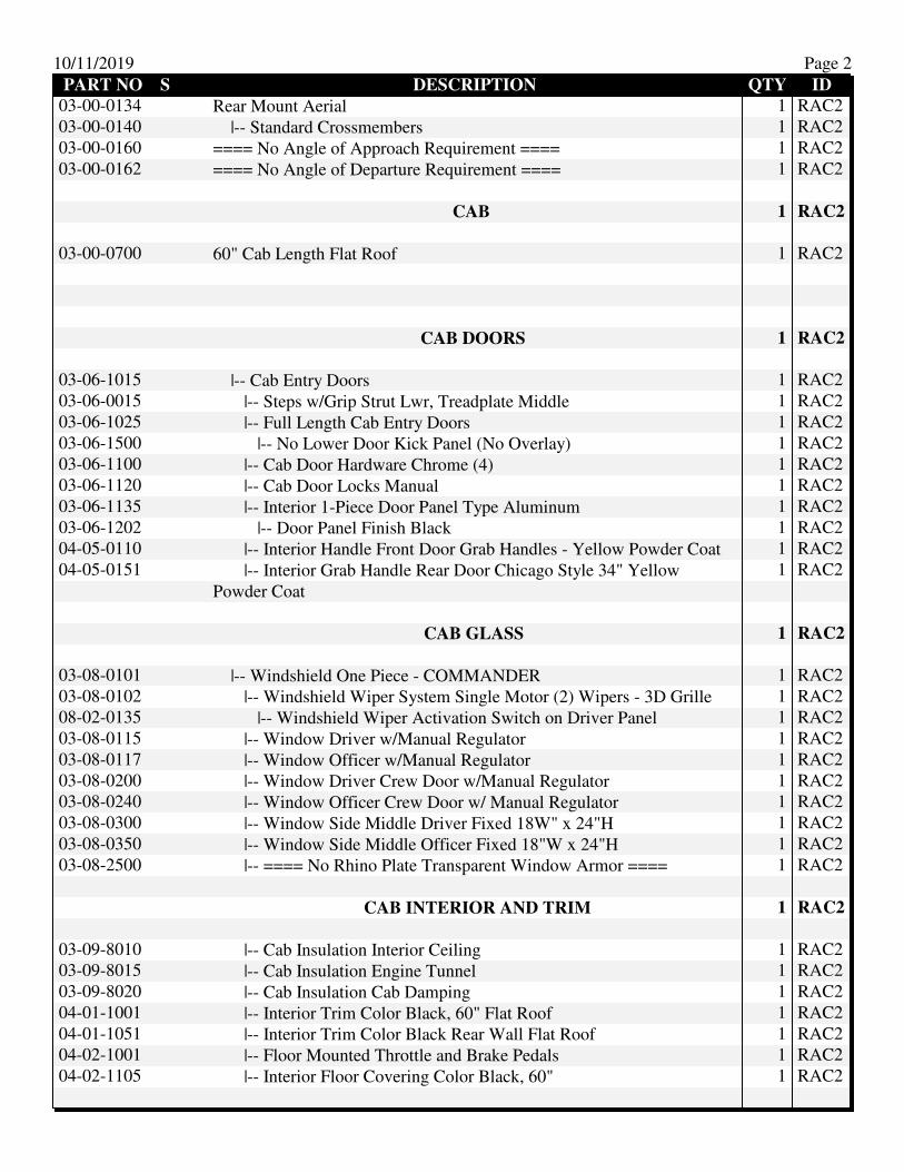
10/11/2019 Page 2
PART NO S DESCRIPTION QTY ID
03-00-0134 Rear Mount Aerial 1 RAC2
03-00-0140 |-- Standard Crossmembers 1 RAC2
03-00-0160 ==== No Angle of Approach Requirement ==== 1 RAC2
03-00-0162 ==== No Angle of Departure Requirement ==== 1 RAC2
CAB 1 RAC2
03-00-0700 60" Cab Length Flat Roof 1 RAC2
CAB DOORS 1 RAC2
03-06-1015 |-- Cab Entry Doors 1 RAC2
03-06-0015 |-- Steps w/Grip Strut Lwr, Treadplate Middle 1 RAC2
03-06-1025 |-- Full Length Cab Entry Doors 1 RAC2
03-06-1500 |-- No Lower Door Kick Panel (No Overlay) 1 RAC2
03-06-1100 |-- Cab Door Hardware Chrome (4) 1 RAC2
03-06-1120 |-- Cab Door Locks Manual 1 RAC2
03-06-1135 |-- Interior 1-Piece Door Panel Type Aluminum 1 RAC2
03-06-1202 |-- Door Panel Finish Black 1 RAC2
04-05-0110 |-- Interior Handle Front Door Grab Handles - Yellow Powder Coat 1 RAC2
04-05-0151 |-- Interior Grab Handle Rear Door Chicago Style 34" Yellow
Powder Coat
1 RAC2
CAB GLASS 1 RAC2
03-08-0101 |-- Windshield One Piece - COMMANDER 1 RAC2
03-08-0102 |-- Windshield Wiper System Single Motor (2) Wipers - 3D Grille 1 RAC2
08-02-0135 |-- Windshield Wiper Activation Switch on Driver Panel 1 RAC2
03-08-0115 |-- Window Driver w/Manual Regulator 1 RAC2
03-08-0117 |-- Window Officer w/Manual Regulator 1 RAC2
03-08-0200 |-- Window Driver Crew Door w/Manual Regulator 1 RAC2
03-08-0240 |-- Window Officer Crew Door w/ Manual Regulator 1 RAC2
03-08-0300 |-- Window Side Middle Driver Fixed 18W" x 24"H 1 RAC2
03-08-0350 |-- Window Side Middle Officer Fixed 18"W x 24"H 1 RAC2
03-08-2500 |-- ==== No Rhino Plate Transparent Window Armor ==== 1 RAC2
CAB INTERIOR AND TRIM 1 RAC2
03-09-8010 |-- Cab Insulation Interior Ceiling 1 RAC2
03-09-8015 |-- Cab Insulation Engine Tunnel 1 RAC2
03-09-8020 |-- Cab Insulation Cab Damping 1 RAC2
04-01-1001 |-- Interior Trim Color Black, 60" Flat Roof 1 RAC2
04-01-1051 |-- Interior Trim Color Black Rear Wall Flat Roof 1 RAC2
04-02-1001 |-- Floor Mounted Throttle and Brake Pedals 1 RAC2
04-02-1105 |-- Interior Floor Covering Color Black, 60" 1 RAC2

10/11/2019 Page 3
PART NO S DESCRIPTION QTY ID
04-02-1702 |-- Interior Trim Sun Visor Tinted 1 RAC2
04-02-1798 |-- Cab Coating Interior Color 1 RAC2
05-01-1050 |-- Cab Coating Interior Black 1 RAC2
CAB DASH AND ENGINE TUNNEL - 60" LONG 1 RAC2
04-03-1050 |-- Cab Dash & Engine Tunnel Alum Dash - Overhead HVAC 1 RAC2
04-03-1020 |-- Cab Dash & Engine Tunnel Coating Black 1 RAC2
04-04-1360 |-- Cup Holders 1 RAC2
08-01-0144 |-- Instrumentation Panel Inlay - Powder Coat Black 1 RAC2
CAB HEADER - HEAT AND AC 1 RAC2
03-08-4000 Cab Header / Heating and AC 1 RAC2
05-02-0012 |-- Heating w/ Air Conditioning, Overhead, 12V DC 1 RAC2
05-01-6010 |-- Cab Paint A/C Condenser on Roof 1 RAC2
SAME COLOR AS ROOF
05-02-0047 |-- Heater Hose - Silicone 1 RAC2
05-02-0201 |-- A/C Condenser Location Roof Mount Mid Driver Side 1 RAC2
08-02-0120 |-- Heat & A/C Activation Manual Drvr Panel Mounted & Rear
Crew Controls
1 RAC2
08-02-0100 |-- Rear Crew Controls Manual - Located Overhead Center 1 RAC2
SEATS 1 RAC2
03-09-0105 |-- Seat Color Black/Red Seat Belt 1 RAC2
03-09-01X3 |-- Seat Driver 911 Seats Inc XL 10-Way Electric ABTS 1 RAC2
03-09-000A |-- Single Retractor Seat Belt - Seats Inc 1 RAC2
03-09-0121 |-- Seat Back Non-SCBA 1 RAC2
03-09-02X3 |-- Seat Mounting Driver Electric XL - Seats Inc 1 RAC2
03-09-0902 |-- Seat Material Turnout Tuff 1 RAC2
03-09-0920 |-- Seat Logo Rosenbauer 1 RAC2
03-09-3010 |-- Driver Seat Box Storage Compartment 1 RAC2
03-09-3236 |-- Seat Box Driver & Officer Storage Access Doors (2)
Driver/Officer
1 RAC2
03-09-024A |-- Seat Officer 911 XL Seats Inc Fixed ABTS 1 RAC2
03-09-000A |-- Single Retractor Seat Belt - Seats Inc 1 RAC2
03-09-0119 |-- Seat Back SCBA Center Cushion Release W/ Zico EZ LOC 1 RAC2
03-09-02X5 |-- Seat Mounting Officer Fixed XL Seats Inc 1 RAC2
03-09-0310 |-- ==== No Parade Panels ==== 1 RAC2
03-09-0902 |-- Seat Material Turnout Tuff 1 RAC2
03-09-0920 |-- Seat Logo Rosenbauer 1 RAC2
03-09-3020 |-- Officer Seat Box Storage Compartment 1 RAC2
03-09-033A |-- Two (2) Outboard Rear Facing Seats - XL 1 RAC2
03-09-035B |-- Seat Crew Rear Facing Outer 911 Seats Inc XL Flip-Up ABTS 2 RAC2
Belt Orientation- LH & RH to Door

10/11/2019 Page 4
PART NO S DESCRIPTION QTY ID
03-09-000A |-- Single Retractor Seat Belt - Seats Inc 2 RAC2
03-09-0119 |-- Seat Back SCBA Center Cushion Release W/ Zico EZ LOC 2 RAC2
03-09-0310 |-- ==== No Parade Panels ==== 2 RAC2
03-09-038A |-- Seat Mounting Rear Facing Outer - XL Seats Inc. 2 RAC2
03-09-0902 |-- Seat Material Turnout Tuff 2 RAC2
03-09-0920 |-- Seat Logo Rosenbauer 2 RAC2
03-09-041A |-- Two (2) Center Forward Facing Seats - XL 1 RAC2
03-09-055B |-- Seat Crew Forward Facing Center 911 Seats Inc XL Flip-up 2 RAC2
Belt Orientation- LH & RH to Door
03-09-000A |-- Single Retractor Seat Belt - Seats Inc 2 RAC2
03-09-0119 |-- Seat Back SCBA Center Cushion Release W/ Zico EZ LOC 2 RAC2
03-09-0310 |-- ==== No Parade Panels ==== 2 RAC2
03-09-057A |-- Seat Mounting Forward Facing Center - XL 2 RAC2
03-09-0902 |-- Seat Material Turnout Tuff 2 RAC2
03-09-0920 |-- Seat Logo Rosenbauer 2 RAC2
03-09-3100 |-- Seat Box (2 person) Forward Facing (FFC Seats) 1 RAC2
03-09-3200 |-- Seat Box (60/54) Forward Facing Storage Access Cutout (1)
Center Forward
1 RAC2
03-09-4001 |-- Seat Box Finish - Match Cab Interior Coating 1 RAC2
CAB EXTERIOR 1 RAC2
04-05-1900 Exterior Grab Handles 18" Aluminum 1 RAC2
04-05-1910 |-- Exterior Grab Handles Bare Aluminum 1 RAC2
04-05-2000 |-- Exterior Grab Handles Aluminum with Stanchions 18" 1 RAC2
CAB FRONT FASCIA 1 RAC2
04-08-0010 ===== Traditional Front with Rectangular Headlamp Bezels ===== 1 RAC2
04-08-0140 |-- Front Grille, 3D Stainless Steel 1 RAC2
04-08-0022 |-- Wing Light Bezel - Stainless 1 RAC2
04-08-0090 |-- Logo, Rosenbauer, Grille Mount 1 RAC2
04-08-0125 |-- Front Grille Inlay, Black Honeycomb w/ stainless steel bars 1 RAC2
06-03-2022 |-- Fluid Checks at Grille X15 1 RAC2
08-00-0503 |-- Headlights, Quad, with Rectangular Bezel 1 RAC2
08-00-0540 |-- Headlight Location - Upper Bucket 1 RAC2
104 OS, 105 OS, and 104 DS, 105 DS
08-00-0602 |-- Front Turn Signals Whelen 600 LED (2) 1 RAC2
08-00-0630 |-- Turn Signal Located Below Headlights 1 RAC2
106 OS & DS
08-00-0606 |-- Side Marker Light LED (2) 1 RAC2

10/11/2019 Page 5
PART NO S DESCRIPTION QTY ID
08-00-0608 |-- Front Marker Lamps Face Mounted LED (Center 3 Lightings, 2
Corner)
1 RAC2
08-01-0303 |-- Headlight & Marker Light Activated Rocker Switch Driver Panel 1 RAC2
04-08-0151 Cab Fender Stainless Steel 1 RAC2
04-09-0190 ==== No Stainless-Steel Rear Wall Cap - pick to select ==== 1 RAC2
04-09-0300 Logo, Commander, Cab Sides 1 RAC2
04-10-0351 Mud Flaps Front 1 RAC2
CAB TILT 1 RAC2
05-00-0221 Cab Tilt System - Heavy Duty w/ Manual Back Up 1 RAC2
05-00-0021 |-- Cab Tilt Limit Switch 1 RAC2
05-00-0045 |-- Cab Tilt Lock Down Indicator 1 RAC2
05-00-0100 |-- Cab Tilt Control Receptacle Temp 1 RAC2
REARVIEW MIRRORS 1 RAC2
05-00-5005 Bus Style Mirrors 1 RAC2
05-00-7130 |-- Ramco-Bus-Drv Dr Mt (CRM-1350PCHR)-Off Dr Mt
(CRM-1350PCHR)-H&R,H&R(LWR)CVX
1 RAC2
08-01-0821 |-- Rearview Mirror Remote & Heat Switch Driver Panel 1 RAC2
EXTERIOR CAB PAINT 1 RAC2
05-01-5010 Cab Paint Exterior Single Color 1 RAC2
05-01-5021 |-- Cab Paint Lower / Primary 1 RAC2
PPG; Paint Color; Paint Number:
Paint Process:PPG - 71663
05-01-6051 |-- Cab Undercoating 1 RAC2
FRONT AXLE 1 RAC2
07-05-010D Front Axle Hendrickson SteerTek 24000# 1 RAC2
07-05-0120 |-- Front Wheel Bearing Lube Oil 1 RAC2
07-05-0286 |-- Front Suspension Hendrickson Parabolic Spring 24K Low Profile 1 RAC2
07-05-0341 |-- Power Steering Gear TRW TAS 85 w/Assist- 20K and up - L9 &
X15 Steertek Axle
1 RAC2
07-06-0420 |-- Chassis Alignment 1 RAC2
07-07-0001 |-- 425 Front Tires 1 RAC2
07-07-0201 |-- (2) Front Tires 425/65R 22.5 Michelin XFE "L" 1 RAC2
07-06-0436 |-- Counter Acting Balancing Beads 2 RAC2
07-07-074B |-- (2) Front Wheels Alcoa Dura-Bright 22.5 x 12.25 Aluminum 1 RAC2
07-06-0522 |-- Front Cramp Angle 45 Degrees 1 RAC2
07-07-0940 |-- ==== No Run Flat Tire Safety Ring ==== 1 RAC2
07-07-0920 |-- ==== No Front Full Wheel Cover ==== 1 RAC2
07-07-0940 |-- ==== No Run Flat Tire Safety Ring ==== 1 RAC2
07-08-0203 |-- Front Brakes Meritor EX225 Disc 17" 1 RAC2

10/11/2019 Page 6
PART NO S DESCRIPTION QTY ID
07-05-0315 4 Spoke Steering Wheel with ESC Tilt/Telescopic 18" 1 RAC2
REAR AXLE 1 RAC2
07-06-0112 Rear Axle, Tandem, 63000# Meritor RT-58-185 1 RAC2
07-06-0282 |-- Rear Suspension Hendrickson ULTIMAAX UMX 63000# 1 RAC2
07-08-0110 |-- Electronic Stability Control Tandem Axle - Two Valve System 1 RAC2
w/ air manifold
07-08-0252 |-- Rear Brakes S-Cam Drum 16.5" x 8.6" 2 RAC2
07-06-0300 |-- Rear Shock Absorbers 2 RAC2
07-06-0351 |-- Rear Axle Differential Control w/Interaxle Diff Lock - Tandem Std 1 RAC2
08-01-0910 |-- Interaxle Diff Lock Control Activated Rocker Switch Driver
Panel (Tandem)
1 RAC2
07-07-0451 |-- (8) Rear Tires 315/80R 22.5 Michelin XDN2 Grip "L" 1 RAC2
07-07-0851 |-- (8) Rear Wheels Alcoa Dura-Bright 22.5 x 9.00 Aluminum 1 RAC2
07-07-0620 |-- Valve Stem Extension - Tandem Axle 1 RAC2
07-07-0925 |-- ==== No Full Wheel Cover, Rear Wheel ==== 1 RAC2
07-07-0993 |-- Vehicle Top Speed 60 1 RAC2
07-08-0189 |-- Air Tank Brackets - Hot Dipped Galvanized 1 RAC2
07-08-0301 |-- Park Brake Rear Wheels Only 1 RAC2
08-02-0130 |-- Park Brake Control Driver Dash 1 RAC2
07-08-0410 |-- Wabco System Saver 1200 1 RAC2
07-08-0551 |-- Moisture Ejectors Manual 1 RAC2
07-08-0570 |-- Air Supply Lines Nylon 1 RAC2
07-08-0725 |-- Air Horn Reservoir (1) 1200 Cu In 1 RAC2
07-09-001C Frame Triple Channel 35.00" Frame Width 1 RAC2
07-09-0050 |-- Wheelbase Range 240" - 259" 1 RAC2
07-09-0090 |-- Rear Overhang 120.0" 1 RAC2
07-09-0138 |-- Frame/Front Extension Hot Dip Galvanized 1 RAC2
08-09-0200 |-- Galvanized Frame Warranty BR 1 RAC2
07-09-0111 |-- Misc Frame Options 101' Aerial Hole Pattern 1 RAC2
ENGINE 1 RAC2
06-00-0050 |-- Engine Placement 1 RAC2
06-00-1590 |-- Engine, Cummins X15, Base Spec 2017 1 RAC2
06-00-0052 |-- Cummins X12 & X15 Surcharge 1 RAC2
06-00-1592 |-- 505 HP Cummins X15 1 RAC2
06-02-1130 |-- Fan Clutch - X15 1 RAC2
06-04-3000 |-- Fan Clutch Programming - Standard 1 RAC2
06-02-1526 |-- Auxiliary Engine Brake Compression Brake (JAKE) 1 RAC2
08-01-0204 |-- Auxiliary Engine Brake Control On/Off & Low/Med/High
Switch Driver Panel
1 RAC2
06-02-2005 |-- AC Compressor X15, ISM & Export ISL 1 RAC2
06-03-1010 |-- Engine High Idle Speed 1250 RPM 1 RAC2

10/11/2019 Page 7
PART NO S DESCRIPTION QTY ID
06-03-1025 |-- Engine High Idle Control Manual & Automatic w/o Load Mng 1 RAC2
06-05-3030 |-- Engine Air Intake Filtration and Restriction X15 1 RAC2
06-06-3738 |-- Engine Exhaust System One Piece Officer Side Inboard
DPF/SCR - X15 -2017
1 RAC2
06-06-4006 |-- DEF Tank - 2017 1 RAC2
06-06-4100 |-- DEF Tank Access Fill Door 1 RAC2
06-08-0100 |-- Engine Exh Acc Temp Mitigation 1 RAC2
06-08-0200 |-- Engine Exhaust Wrap 1 RAC2
08-02-0140 |-- DPF Control Regeneration Switch & Inhibit Switch Covered 1 RAC2
06-04-2006 |-- Engine Cooling System- X 15.0L 1 RAC2
06-04-4010 |-- Coolant Valve Shut Off Valve w/Connection - For Additional
Heater
1 RAC2
06-05-1005 |-- Engine Pump Heat Exchanger X15 1 RAC2
TRANSMISSION 1 RAC2
07-01-0102 |-- Transmission Allison 4000 EVS 1 RAC2
07-01-0500 |-- Transmission Fluid - Standard 1 RAC2
07-02-0008 |-- Transmission GEN V-E Push Button Key Pad 1 RAC2
07-02-0013 |-- Transmission 1 o'clock PTO 1 RAC2
07-02-0052 |-- Transmission Mode Programming 5th Startup/5th Mode 1 RAC2
07-02-0066 |-- Transmission Feature Programming I/O Package 198/Pumper 1 RAC2
07-02-0253 |-- Driveline Spicer 1810 HD 1 RAC2
07-04-0108 |-- Fuel Filter/Water Separator Cummins FS1065 1 RAC2
07-04-0310 |-- Fuel Tank 50 Gal/189 Liter, Dual Fill 1 RAC2
07-04-0216 |-- Fuel Lines Aramid Braid 1 RAC2
07-04-0225 |-- Fuel Shutoff Valve (2) at Filter 1 RAC2
07-04-0230 |-- Fuel Cooler Behind Battery Box 1 RAC2
08-00-0403 |-- Alternator Delco Remy 275 Amp 1 RAC2
ELECTRICAL SYSTEM 1 RAC2
08-00-0101 Electrical System 12V DC 1 RAC2
04-04-1310 |-- (2) Power Points - Driver's Side 1 RAC2
04-04-1330 |-- (2) Power Points - Officer's Side 1 RAC2
08-01-0075 |-- Driver Panel / Controls & Switches - 12V DC 1 RAC2
08-01-0240 |-- Master Warning Switch on Driver Panel 1 RAC2
08-02-0521 |-- ====No PWR Cable for Additional Pwr Studs==== 1 RAC2
08-04-1100 |-- Radio WB/AM/FM - Overhead Mount 1 RAC2
08-04-1140 |-- Overhead Radio Mount - driver's side 1 RAC2
08-04-2000 |-- Two (2) Speakers 1 RAC2
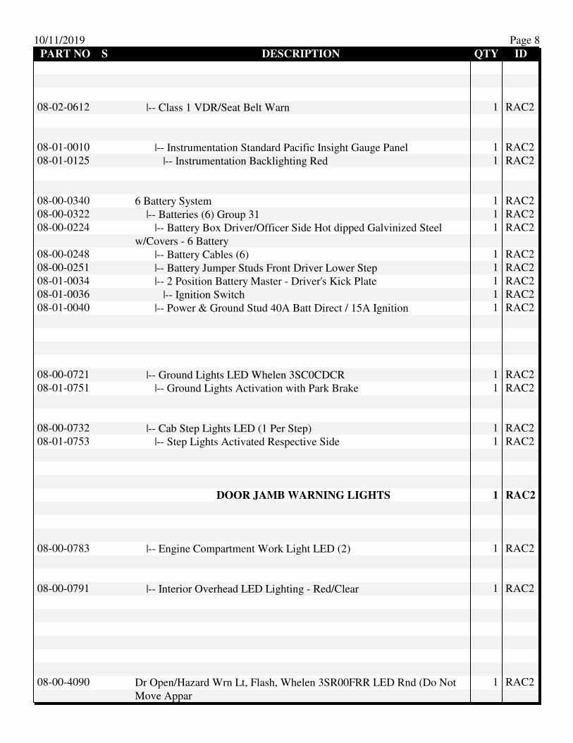
10/11/2019 Page 8
PART NO S DESCRIPTION QTY ID
08-02-0612 |-- Class 1 VDR/Seat Belt Warn 1 RAC2
08-01-0010 |-- Instrumentation Standard Pacific Insight Gauge Panel 1 RAC2
08-01-0125 |-- Instrumentation Backlighting Red 1 RAC2
08-00-0340 6 Battery System 1 RAC2
08-00-0322 |-- Batteries (6) Group 31 1 RAC2
08-00-0224 |-- Battery Box Driver/Officer Side Hot dipped Galvinized Steel
w/Covers - 6 Battery
1 RAC2
08-00-0248 |-- Battery Cables (6) 1 RAC2
08-00-0251 |-- Battery Jumper Studs Front Driver Lower Step 1 RAC2
08-01-0034 |-- 2 Position Battery Master - Driver's Kick Plate 1 RAC2
08-01-0036 |-- Ignition Switch 1 RAC2
08-01-0040 |-- Power & Ground Stud 40A Batt Direct / 15A Ignition 1 RAC2
08-00-0721 |-- Ground Lights LED Whelen 3SC0CDCR 1 RAC2
08-01-0751 |-- Ground Lights Activation with Park Brake 1 RAC2
08-00-0732 |-- Cab Step Lights LED (1 Per Step) 1 RAC2
08-01-0753 |-- Step Lights Activated Respective Side 1 RAC2
DOOR JAMB WARNING LIGHTS 1 RAC2
08-00-0783 |-- Engine Compartment Work Light LED (2) 1 RAC2
08-00-0791 |-- Interior Overhead LED Lighting - Red/Clear 1 RAC2
08-00-4090 Dr Open/Hazard Wrn Lt, Flash, Whelen 3SR00FRR LED Rnd (Do Not
Move Appar
1 RAC2
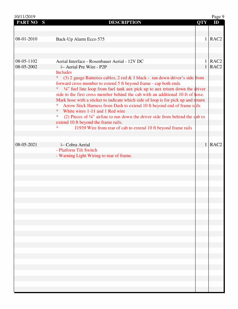
10/11/2019 Page 9
PART NO S DESCRIPTION QTY ID
08-01-2010 Back-Up Alarm Ecco 575 1 RAC2
08-05-1102 Aerial Interface - Rosenbauer Aerial - 12V DC 1 RAC2
08-05-2002 |-- Aerial Pre Wire - P2P 1 RAC2
Includes
* (3) 2 gauge Batteries cables, 2 red & 1 black - ran down driver’s side from
forward cross member to extend 5 ft beyond frame - cap both ends
* ¼” fuel line loop from fuel tank aux pick up to aux return down the driver
side to the first cross member behind the cab with an additional 10 ft of hose.
Mark hose with a sticker to indicate which side of loop is for pick up and return
* Arrow Stick Harness from Dash to extend 10 ft beyond end of frame rails
* White wires 1-11 and 1 Red wire
* (2) Pieces of ¼” airline to run down the driver side from behind the cab to
extend 10 ft beyond the frame rails.
* J1939 Wire from rear of cab to extend 10 ft beyond frame rails
08-05-2021 |-- Cobra Aerial 1 RAC2
- Platform Tilt Switch
- Warning Light Wiring to rear of frame.
Rosenbauer South Dakota
10385-0004 10/11/19
1
One (1)
== Aerial Bid Prep Forms - 22.019 02/18/19 ==
One (1)
00-00-000L
ROSENBAUER APPARATUS SOLUTIONS - RAS - February 2019
One (1)
00-00-1300
#7604 Stock HDG 101' Cobra
BID SPECIFICATIONS
FOR
ROSENBAUER CUSTOM PUMPER One (1)
00-00-1499
OVERALL HEIGHT
An overall height restriction has not been specified for this apparatus.

Rosenbauer South Dakota
10385-0004 10/11/19
2
One (1)
00-00-1509
OVERALL LENGTH
An overall length restriction has not been specified for this apparatus.
One (1)
00-00-1519
OVERALL WIDTH
An overall width restriction has not been specified for this apparatus.
One (1)
00-00-1529
WHEELBASE
A wheelbase restriction has not been specified for this apparatus.
One (1)
00-00-1539
ANGLE OF APPROACH
The angle of approach for the apparatus shall not be less than eight (8) degrees as specified by
the current edition of NFPA 1901.
One (1)
00-00-1549
ANGLE OF DEPARTURE
The angle of departure for the apparatus shall not be less than eight (8) degrees as specified by
the current edition of NFPA 1901.
One (1)
00-00-1600
NFPA Equipment Allowances
One (1)
00-00-1620
NFPA AERIAL/QUINT EQUIPMENT ALLOWANCE
In compliance with NFPA #1901 standards, the apparatus shall be engineered to provide an allow
of 2500 pounds of fire department provided loose equipment.
One (1)
00-12-1100
FINANCIAL STABILITY SPECIFICATIONS
With high-profile instances of fire apparatus manufacturers encountering financial difficulties, it
is imperative that fire departments be diligent in evaluating the financial position of the

Rosenbauer South Dakota
10385-0004 10/11/19
3
companies they solicit to build on their emergency response vehicles. A contract entered into
with a company on shaky ground is a dangerous prospect, since conducting business with a
manufacturer in such condition could open the department to monumental problems.
Take, for instance, the growing theme of manufacturers requiring as opposed to offering
pre-payment and progressive payment options with a corresponding discount off the price of a
vehicle. Such offers are made with an ulterior motive in mind, as it can be generally inferred that
manufacturers requiring pre-payments and progressive payments do so because they need your
cash today to fund production of other vehicles already in the backlog.
Should problems arise, as has been the case in situations too numerous to mention, your
department risks losing any down payments already made or even the entire cost of a piece of
equipment should certain pre-pay discount situations go awry.
While pre-payment discounts may be enticing, it is important to know just how stable the
manufacturer seeking your funds is before you make that commitment. If you enter into one of
these agreements and the manufacturer hits a rough patch, it is you that will be hurting, because
your funds may not be recoverable. However, if you enter into a contract with a financially sound
manufacturer, you will reap all of the benefits of a well-built truck at a lower cost. You may
equally, by taking advantage of the time-value of money, be able to afford more truck than
initially thought, because funds saved by leveraging pre-payment options could allow you get
some added features that you might not necessarily have been able to afford.
With this in mind, it must be noted that Rosenbauer is a company with rock-solid financial
stability. This is a statement not made lightly, as we can prove it to you. We can provide
language that you can insert into your bid specifications that stipulates that in order for bids to be
accepted by a fire department, the company bidding must meet several fiscal criteria.
The first criteria call for the successful bidder to meet a debt-to-equity ratio not exceeding a 2.0
rating. Rosenbauer presently stands at a 1.51 rating, which is well-below the accepted rating.
This low number results from Rosenbauer owning more assets with a marginal debt service.
This means we are not using lenders to fund our operations, nor our growth.
The second requirement is that the debt coverage ratio of the successful body builder exceeds a
100 rating. The higher the number, the better able a company is to meet its payment obligations
with banks and creditors. Rosenbauer’s number is at 279.6, which is nearly three times the
required amount. The higher the debt coverage ratio, the easily and more fluidly a company is
positioned to pay its monthly obligations and operating costs.
The third criteria require that the equity ratio of the successful bidder must exceed .30 rating. A
higher equity ratio indicates that the body builder has increased flexibility to meet its financial
obligations which translates into greater financial stability. Rosenbauer currently has an equity

Rosenbauer South Dakota
10385-0004 10/11/19
4
ratio of .387 which is well above the accepted rating and an excellent indicator of financial
strength.
When exploring and evaluating various manufacturers to consider for building your apparatus,
there is little doubt you will find one that stands on as firmly a financial ground as Rosenbauer.
While others are experiencing stressful issues that raise doubts as to the company’s long-term
viability, Rosenbauer continues to demonstrate a strengthening of its financial position in the
apparatus manufacturing industry. Because Rosenbauer meets and exceeds all the above-stated
financial bid requirements, we are best positioned to ensure customers of a strong relationship
with the company, which cannot be claimed by most of our competitors in this volatile market.
The Rosenbauer America Dun and Bradstreet number is 02-447-3584. To acquire a Dun and
Bradstreet report, telephone them at 1-800-234-3867 (in Canada 800-463-6362) or visit their web
site address at www.dnb.com. Dun and Bradstreet is nationally-recognized, independent financial
analysis company.
One (1)
01-06-0550
ROLL STABILITY CONTROL
Roll stability control shall be supplied on the chassis.
One (1)
01-07-0060
ENGINEERING BLUEPRINTS
ROSENBAUER has submitted "proposal" blueprints which are “representative” of the vehicle
being proposed and these have been generated on computer-aided-design (CAD) equipment.
The blueprints are provided as follows:
Sheet No. 1: Left side exterior view
Right side exterior view
Rear exterior view
ROSENBAUER shall be provide construction drawings for approval prior to actual construction
of the vehicle.
The design of the equipment is in accordance with the best engineering practices. The equipment
design and accessory installation shall permit accessibility for use, maintenance and service. All
components and assemblies shall be free of hazardous protrusions, sharp edges, cracks or other
elements, which might cause injury to personnel or equipment.

Rosenbauer South Dakota
10385-0004 10/11/19
5
All oil, hydraulic, and air tubing lines and electrical wiring shall be located in protective
positions properly attached to the frame or body structure and shall have protective loom or
grommets at each point where they pass through structural members, except where a
through-frame connector is necessary.
Parts and components will be located or positioned for rapid and simple inspection and
recognition of excessive wear or potential failure. Whenever functional layout of operating
components determines that physical or visual interference between items cannot be avoided, the
item predicted to require the most maintenance shall be located for best accessibility.
One (1)
01-07-1100
CHANGE ORDERS
To ensure the proper engineering and construction of the purchaser's custom fire apparatus in a
timely manner, the contractor shall consider the order final and complete after any changes made
during the pre-construction conference are mutually approved. Change orders requested after the
pre-construction conference are discouraged. It shall be understood and agreed that any changes,
if approved, after the order has been released to Engineering, shall constitute a valid cause for
production delay and without penalty to the contractor.
One (1)
== Aerial Warranties - 22.019 02/18/19 ==
One (1)
01-16-0150
BODY WARRANTY
We warrant each new motorized fire apparatus manufactured by ROSENBAUER AMERICA,
LLC for a period of ONE YEAR from the date of delivery, except for chassis and other
components noted herein.
Under this warranty we agree to furnish any parts to replace those that have failed due to
defective material or workmanship where there is no indication of abuse, neglect, unusual or
other than normal service providing that such parts are, at the option of ROSENBAUER
AMERICA, LLC, made available for our inspection at our request, returned to our factory or
other location designated by us with transportation prepaid within thirty days after the date of
failure or within one year from the date of delivery of the apparatus to the original purchaser,
whichever occurs first, and inspection indicates the failure was attributed to defective material or
workmanship.
The warranty on the chassis and chassis supplied components, storage batteries, generators,
electrical lamps and other devices subject to deterioration is limited to the warranty of the
Rosenbauer South Dakota
10385-0004 10/11/19
6
manufacturer thereof and adjustments for the same are to be made directly with the manufacturer
by the customer.
This warranty will not apply to any fire apparatus that has been repaired or altered outside our
factory in any way, which in our opinion might affect its stability or reliability.
This warranty shall not apply to those items that are usually considered normal maintenance and
upkeep services: including, but not limited to, normal lubrication or proper adjustment of minor
auxiliary pumps or reels.
This warranty is in lieu of all other warranties, expressed or implied, and all other obligations or
liabilities on our part. We neither assume nor authorize any person to assume for us any liability
in connection with the sales of our apparatus unless made in writing by ROSENBAUER
AMERICA, LLC.
One (1)
01-19-0250
ALUMINUM BODY WARRANTY - FIVE YEAR
Rosenbauer America, LLC warrants to the original purchaser only, that the all aluminum body,
fabricated by Rosenbauer America, LLC, under normal use and with reasonable maintenance, be
structurally sound and will remain free from corrosion perforation for a period of FIVE (5) years.
This warranty does not apply to the following items that are covered by a separate warranty: paint
finish, hardware, moldings, and other accessories attached to this body. In addition, this warranty
does not apply to any part or accessory manufactured by others and attached to this body.
ROSENBAUER AMERICA, LLC MAKES NO OTHER WARRANTY, EXPRESS OR
IMPLIED, WITH RESPECT TO THE ALUMINUM BODY AND ALL IMPLIED
WARRANTIES OF MERCHANTABILITY AND FITNESS FOR A PARTICULAR PURPOSE
AND HEREBY DISCLAIMED.
Rosenbauer America, LLC will replace without charge, repair or make a fair allowance for any
defect in material or workmanship demonstrated to its satisfaction to have existed at the time of
delivery or not due to misuse, negligence, or accident. If Rosenbauer America, LLC elects to
repair this body, the extent of such repair shall be determined solely by Rosenbauer America,
LLC, and shall be performed solely at the Rosenbauer America, LLC factory, or at an approved
facility. The expense of any transportation to or from such repair facility shall be borne by the
purchaser and is not an item covered under this warranty.
Rosenbauer America, LLC will not be liable for damages and under no circumstances will its
liability exceed the price for a defective body. The remedies set forth herein are exclusive and in
substitution for all other remedies to which the purchaser would otherwise be entitled.

Rosenbauer South Dakota
10385-0004 10/11/19
7
Rosenbauer America, LLC will be given a reasonable opportunity to investigate all claims. The
purchaser must commence any action arising out of, based upon or relating to agreement or the
breach hereof, within twelve months from the date the cause of the action occurred.
Note: Surety bond, if required, will cover standard one year warranty period only and will not
cover any extended warranties allowed by seller or other component manufacturers.
One (1)
01-19-2800
GALVANIZED SUBFRAME WARRANTY
Subject to the provisions, limitations and conditions set forth in this warranty, Rosenbauer
America, LLC (hereby referred to as "seller"), hereby warrants to each original purchaser only
that each new hot dip galvanized body subframe (exclusive of paint finish and hardware) is
structurally sound and free of all structural defects of both material and workmanship and further
warrants that it will maintain such structural integrity for the duration of ownership by the
original purchaser. This warranty terminates upon transfer of possession or ownership by
original purchaser.
This warranty is conditioned upon normal use and reasonable maintenance of such subframe;
prompt written notice of all defects to seller or one of the seller's then authorized dealers in the
area; no repair or additions there to except by seller or authorized by it; said defect not resulting
from misuse, negligence, accident, remount, overloading beyond applicable weight rating by
customer or third parties. If any such conditions are not complied with, this warranty shall
become void and unenforceable.
Should repairs become necessary under the terms or the warranty, the extent of that repair shall
be determined solely by the seller and shall be performed solely at Rosenbauer America, LLC or
a repair facility designated by the seller. The expense of any transportation to or from such repair
facility shall be that of the purchaser and is not an item covered by this warranty.
Seller reserves the unrestricted right at any time from time to time to make changes in the design
of and/or improvements on its products without thereby imposing any obligation on itself to
make corresponding changes or improvements in or on its products theretofore manufactured.
EXCLUSIONS AND LIMITATIONS: THIS MANUFACTURER'S WARRANTY IS
PROVIDED IN PLACE OF ANY AND ALL OTHER REPRESENTATIONS OR IMPLIED
WARRANTIES. NO PERSON IS AUTHORIZED TO MAKE ANY REPRESENTATIONS OR
WARRANTY ON BEHALF OF ROSENBAUER AMERICA, LLC OR ANY OF ITS
DISTRIBUTORS OTHER THAN SET FORTH IN THIS MANUFACTURER'S WARRANTY.
YOUR RIGHT TO SERVICE AND REPLACEMENT OF PARTS ON THE TERMS
EXPRESSLY SET FORTH HERIN ARE YOUR EXCLUSIVE REMEDIES AND NEITHER

Rosenbauer South Dakota
10385-0004 10/11/19
8
THE MANUFACTURER NOR ANY OF ITS DISTRIBUTORS SHALL BE LIABLE FOR
DAMAGES, WHETHER ORDINARY, INCIDENTAL OR CONSEQUENTIAL.
Note: Surety bond, if required, will cover standard one year warranty period only and will not
cover any extended warranties allowed by seller or other component manufacturers.
One (1)
01-20-0250
PAINT WARRANTY FIVE YEAR
The PPG paint performance guarantee will cover the areas of the vehicle finished with the
specified product for a period of FIVE (5) years beginning the day the vehicle is delivered to the
purchaser.
The full apparatus body, manufactured and painted by Rosenbauer America, LLC, shall be
covered for the following paint failures as outlined on the guarantee certificate:
• Peeling or delaminating of the topcoat and/or other layers of paint.
• Cracking or checking.
• Loss of gloss caused by cracking, checking, or hazing.
• Any paint failure caused by defective PPG Fleet Finishes, which are covered by this guarantee.
All guarantee exclusions, limitations, and methods of claims are covered in the full certificate
provided to the original purchaser.
Note: Surety bond, if required, will cover standard one year warranty period only and will not
cover any extended warranties allowed by seller or other component manufacturers.
One (1)
01-17-0750
PUMP WARRANTY
Waterous warrants, to the original buyer only, that products and parts manufactured by Waterous
will be free from defects in material and workmanship under normal use and service for a period
of five (5) years from the date the product is first placed in service, or five and one half 5-1/2
years from the date of shipment by Waterous, whichever period will be the first to expire;
provided the buyer notifies Waterous in writing, of the defect in said product within the warranty
period, and said product is found by Waterous to be conforming with the aforesaid warranty.
When required in writing by Waterous, defective products must be promptly returned by the
buyer to the Waterous Company at Waterous' plant at South St. Paul, Minnesota, or at such other
place as may be specified by Waterous with transportation and other charges prepaid. A returned
materials authorization (RMA) is required for all products and parts and may be requested by

Rosenbauer South Dakota
10385-0004 10/11/19
9
phone, fax or mail. The previously mentioned warranty excludes any responsibility or liability of
Waterous for:
A. Damages or defects due to accident, abuse, misuse, abnormal operating conditions,
negligence, accidental causes or improper maintenance, or attributable to written specifications
or instructions furnished by buyer;
B. Defects in products manufactured by others and furnished by Waterous hereunder, it being
understood and agreed by the parties that the only warranty provided for such products shall be
the warranty provided by the manufacturer thereof which, if assignable, Waterous will assign to
the buyer, if requested by Buyer;
C. Any product or part, altered, modified, serviced or repaired other than by Waterous, without
its prior written consent.
D. The cost of dismantling, removing, transporting, storing, or insuring the defective product or
part and the cost of reinstallation.
E. Normal wear items (packing, strainers, filters, light bulbs, anodes, intake screens, etc.)
This warranty is subject to Waterous' conditions of sale (Waterous Company form number
F-2190 as currently in effect all of which are herein incorporated and by this reference made a
part hereof.
All other warranties are excluded, whether expressed or implied by operation of law or
otherwise, including all implied warranties of merchantability or fitness for purpose. Waterous
shall not be liable for consequential or incidental damages directly or indirectly arising or
resulting from breach of any of the terms of this limited warranty or from the sale, handling, or
use of any other product or part. Waterous' liability hereunder, either for breach of warranty or
for negligence, is expressly limited at Waterous' option:
A. To the replacement at the agreed point of delivery of any product or part, which upon
inspection by Waterous or its duly authorized representative, is found not to conform to the
limited warranty set forth above, or
B. To the repair of such product or part, or
C. To the refund or crediting to buyer of the net sales price of the defective product or part.
Buyer's remedies contained herein are exclusive of any other remedy otherwise available to the
buyer.
One (1)
01-17-1050

Rosenbauer South Dakota
10385-0004 10/11/19
10
STAINLESS STEEL PLUMBING WARRANTY
The manufacturer shall provide a ten (10) year warranty on the stainless steel plumbing
components and installation. The manufacturer shall supply details of their warranty information
with their bid submission.
One (1)
01-18-0450
WATER TANK WARRANTY
UNITED PLASTIC FABRICATION INC. Warrants each UPF POLY-TANK IIE
Booster/Foam tank to be free from manufacturing defects in material and workmanship for the
service life of the vehicle (vehicle must be actively used in fire suppression). The UPF
POLY-TANK IIE must be installed in accordance with the United Plastic Fabricating installation
manual. Every UPF POLY-TANK IIE is thoroughly inspected and tested for leaks before
leaving our facility. Should any problems develop with your UPF POLY-TANK IIE
booster/foam tank and will not meet performance criteria during the service life of the vehicle,
notify UPF in writing or call our TOLL FREE SERVICE HOT LINE 1-800-USA-POLY.
Provide UPF with the serial number and a description of the problem. If the tank problem would
render the truck out of service, UPF will dispatch a service technician WITHIN 48 HOURS (2
DAYS) to repair the tank. (This time period is for North America only). If the vehicle can
remain in service, UPF will dispatch a service technician within a mutually agreed upon time
period.
We will repair, or at our option, replace the tank with a new UPF POLY-Tank IIE. UPF will
cover customary and reasonable costs to remove and install the UPF POLY-TANK IIE. This
warranty will not cover tanks that have been improperly installed, misused or abused, and the
serial number must not have, been altered, defaced or removed. UPF will not cover any
unauthorized third party repairs or alterations. Any of these actions may void the warranty.
THERE ARE NO WARRANTIES, EXPRESSED OR IMPLIED, WHICH EXTEND
BEYOND THE DESCRIPTION OF THE FACE HEREOF. THERE IS NO EXPRESS OR
IMPLIED WARRANTY OF MERCHANTABILITY OR A WARRANTY OF FITNESS
FOR A PARTICULAR PURPOSE. ADDITIONALLY, THIS WARRANTY IS IN LIEU
OF ALL OTHER OBLIGATIONS OR LIABILITIES ON THE PART OF UNITED
PLASTIC FABRICATION, INC.
This warranty contains the entire warranty. It is the sole warranty and price agreements or
representation, whether oral or written, are either merged herein or expressly cancelled.
UNITED PLASTIC FABRICATION, INC. Neither assumes, nor authorizes any person
supposing to act on its behalf, to change, nor assume for it, any warranty or liability concerning
its product.

Rosenbauer South Dakota
10385-0004 10/11/19
11
IN NO EVENT WILL UNITED PLASTIC FABRICATION, INC BE LIABLE FOR AN
AMOUNT IN EXCESS OF THE PRESENT RETAIL, PURCHASE PRICE PLUS
INSTALLATION AND REMOVAL COST OF THE BOOSTER TANK, FOR ANY LOSS
OR DAMAGE, WHETHER DIRECT OR INDIRECT, INCIDENTAL,
CONSEQUENTIAL, OR OTHERWISE ARISING OUT OF FAILURE OF ITS
PRODUCT.
This warranty gives you specific legal rights, and you may have other rights, which vary from
state to state. Some states do not allow exclusion or limitation of incidental of incidental or
consequential damage, so the above limitation or exclusion may not apply to you. Some states
do not allow limitation on how long an implied warranty lasts, so the above limitation may not
apply to you.
One (1)
01-33-3100
COMPLETE PRINTED MANUAL
ROSENBAUER shall provide with the vehicle upon delivery, one (1) complete delivery manual.
This manual shall be in a notebook type binder, with reference tabs for each section of the
vehicle. In addition to the printed material, the manual shall be provided in electronic format.
Within each section shall be:
• Individual component manufacturer instruction and parts manuals
• Warranty forms for the body
• Warranty forms for all major components
• Warranty instructions and format to be used in compliance with warranty obligations
• Wiring diagrams
• Installation instruction and drawings for major parts
• Visual graphics and electronic photos for the installation of major parts
• Necessary normal routine service forms, publications and components of the body portion of the
apparatus
• Technical publications for training and instruction on major body components
• Warning and safety related notices for personnel protection
• Cab and chassis manuals on parts, service and maintenance shall be provided
One (1)
01-33-3400
"ON-LINE" SERVICE MANUAL SUPPORT
As part of the standard delivery manual, ROSENBAUER shall give a password-protected link to
the end user, allowing access to the manufacturers' database on service parts. The internet-based
system shall allow the end user to access the major component supplier's service parts listing
such as Hale, Waterous, Akron, etc. This shall be accomplished with simplistic point and click

Rosenbauer South Dakota
10385-0004 10/11/19
12
features on the manufacturer line item within the "stripper" or "line item sheet". This will
include, automatic updates, printable schematics and manufacturer's web links and is available in
the commercially available format of Adobe Acrobat Reader to access these documents.
Rosenbauer America, LLC shall submit with the bid proposal, a sample set of on line Adobe
formatted material that has been printed from the manufacturer’s website.
Parts Listings within Manuals
The manuals will include cross-reference part numbers from the ROSENBAUER part number to
the vendor parts. Example: ROSENBAUER Hydraulic Ladder Rack, Part #LR-MN-0002
cross-referenced to Ziamatic Corporation Part 098-MN2345. This will allow for reference
between individual parts and complete installation assemblies as completed by the body builder.
The manuals will list all components of the vehicle that includes a vendor part utilized in a
complete installation via the manufacturer’s "line item sheet" or "stripper" utilized to
manufacture the completed vehicle. These are "As Built" and proposals with "typical" or
"generic" manuals will be rejected.
Illustrative Schematics within Manuals
ROSENBAUER shall include installation diagrams and drawings of all major sub assemblies.
This will include components such as hydraulic ladder rack assemblies, pump panels, tanks, fire
pumps, etc. The drawings shall be linked via an Internet based service program, in an electronic
format from the manufacturers "stripper" (line item listing) of the manufacturing document.
ROSENBAUER shall submit, upon request, a sample schematic.
Digital Images within Manuals
In addition to two and three-dimensional installation drawings, ROSENBAUER shall make
accessible, via an internet based link, the actual photos of the installed components listed within
the "stripper" or line sheet. This will include, but not limited to wiring terminals, main body
distribution strips, fire pump shifting, auxiliary components, etc. ROSENBAUER shall submit
a sample of these upon request.
Installation Instructions within Manuals
ROSENBAUER "work instructions" or "installation instructions" shall be included with the
service manuals. These documents shall be accessible via a web-based link to the individual
vehicle manufactured. The work instructions shall give systematic instructions of the component
installation process. ROSENBAUER shall submit, upon request, a sample set of instructions.
Automatic Updates of Manuals and Parts Listings

Rosenbauer South Dakota
10385-0004 10/11/19
13
The online manuals will include automatic updates that are accessible via the web link. When
clicking on the part within the manufacturer’s stripper or line sheet, it will allow the end user to
access the component manufacturer website for updated information. This will allow for latest
parts and service components from the individual part manufacturer or vendor.
Electrical Schematics
To maintain the vehicles electrical systems, the manufacturer shall provide to the purchaser the
instructional manuals, complete electrical information and schematics on the vehicle. The
electrical information shall be provided as follows:
Wiring Systems 12 and 120 Volt:
• Graphic symbols for electrical diagrams.
• Wire labeling, imprinting codes and index.
• Computer generated electrical schematics indicating the circuit number, wire size, switches,
circuit breaker and terminals on the vehicle.
ROSENBAUER shall submit, upon request, a sample set of diagrams.
One (1)
== Use Drop Down For Chassis Options - 218.019 02/18/19 ==
One (1)
== Aerial - DC Electrical System COMMANDERS ONLY - 22.019 02/18/19 ==
One (1)
56-01-1600
ELECTRIC SIREN AND CONTROL
One (1) Whelen model #295SLSA1 electronic siren shall be mounted in the cab. This unit shall
feature an electronic air horn, wail, yelp, hi-lo and shall have a hard wired PA microphone.
One (1)
56-02-1600
SPEAKER
One (1) Federal Signal DynaMax 100-watt speaker, Model #ES100, shall be installed. The
speaker shall feature a Neodymium driver and a high strength composite housing that is chemical
resistant and maintains rigidity at high temperatures.
One (1)
56-02-1650
SPEAKER

Rosenbauer South Dakota
10385-0004 10/11/19
14
One (1) stainless steel grille shall be installed on the speaker.
One (1)
56-03-1800
SPEAKER LOCATION
The siren speaker shall be installed on the apparatus bumper extension, as determined by the
body manufacturer.
One (1)
57-02-4600
LIGHTBAR
Two (2) Whelen Ultra Freedom IV 21.5" light bars shall be included with the apparatus cab. The
light bars shall be a model F4NMINI and shall be mounted on the roof of the cab, towards the
front, above the windshield.
Each light bar shall feature:
• Two (2) red Linear Super LED corner modules
• One (1) white 400 series Linear LED light front center
• One (1) red 400 series linear LED endcap light
• Clear hard coated lenses to provide extended life/luster protection against UV & chemical
stresses
• Designed in accordance with NFPA Zone A requirements
One (1)
57-10-0600
LIGHTBAR ACTIVATION
The front upper light bar shall be activated through the master warning switch.
One (1)
58-71-1820
UPPER REAR WARNING LIGHTS
One (1) pair of Whelen Super LED, rotating beacons, P/N L31H*F, shall be installed, one each
side on the upper rear of the apparatus body. The unit shall have dimensions of 4" high x 7-9/16"
deep.
One (1)
57-20-8100
The driver side warning light shall be a Whelen LED rotator, model L31HRF with a red lens.
One (1)
57-20-8101
Rosenbauer South Dakota
10385-0004 10/11/19
15
The officer side warning light shall be a Whelen LED rotator, model L31HRF with a red lens.
One (1)
58-74-5100
REAR WARNING LIGHT MOUNTING
The upper rear lights shall be mounted on cast aluminum stanchions attached to the apparatus
body, one on each side.
One (1)
58-03-6300
UPPER WING FRONT WARNING LIGHTS
One (1) pair of Whelen model M6 LED warning lights shall be installed, one each side one the
front of the chassis cab upper wing area. The dimensions of the lights shall be 4-5/16" x 6-3/4".
One (1)
57-20-1200The driver side warning light shall be a Whelen Model M6R red Super-LEDTM with color lens.
One (1)
57-20-1201The officer side warning light shall be a Whelen Model M6R red Super-LEDTM with color lens.
Two (2)
58-01-2140
Each light shall be mounted with a Whelen Model M6FC chrome flange.
One (1)
58-03-7300
INBOARD WARNING LIGHTS
One (1) pair of Whelen model M6 LED warning lights shall be installed, one each side one the
front of the chassis cab, in the inboard warning light position. The dimensions of the lights shall
be 4-5/16" x 6-3/4".
One (1)
57-20-1200The driver side warning light shall be a Whelen Model M6R red Super-LEDTM with color lens.
One (1)
57-20-1201The officer side warning light shall be a Whelen Model M6R red Super-LEDTM with color lens.
Two (2)
58-01-2140
Each light shall be mounted with a Whelen Model M6FC chrome flange.

Rosenbauer South Dakota
10385-0004 10/11/19
16
One (1)
58-09-2000
INTERSECTION WARNING LIGHTS
One (1) pair of Whelen model M6 LED warning lights shall be installed one each side of the
chassis cab. The dimensions of the lights shall be 4-5/16" x 6-3/4".
One (1)
57-20-1200The driver side warning light shall be a Whelen Model M6R red Super-LEDTM with color lens.
One (1)
57-20-1201The officer side warning light shall be a Whelen Model M6R red Super-LEDTM with color lens.
Two (2)
58-01-2140
Each light shall be mounted with a Whelen Model M6FC chrome flange.
One (1)
58-26-2000
LOWER MID-BODY WARNING LIGHTS
One (1) pair of Whelen model M6 LED warning lights shall be installed , one each side of the
apparatus, mid-body. The dimensions of the lights shall be 4-5/16" x 6-3/4".
One (1)
57-20-1200The driver side warning light shall be a Whelen Model M6R red Super-LEDTM with color lens.
One (1)
57-20-1201The officer side warning light shall be a Whelen Model M6R red Super-LEDTM with color lens.
Two (2)
58-01-2140
Each light shall be mounted with a Whelen Model M6FC chrome flange.
One (1)
58-36-2000
LOWER REAR SIDE WARNING LIGHTS
One (1) pair of Whelen model M6 LED warning lights shall be installed, one each side of the
apparatus body, towards the rear of the body. The dimensions of the lights shall be 4-5/16" x
6-3/4".
One (1)
57-20-1200

Rosenbauer South Dakota
10385-0004 10/11/19
17
The driver side warning light shall be a Whelen Model M6R red Super-LEDTM with color lens.
One (1)
57-20-1201The officer side warning light shall be a Whelen Model M6R red Super-LEDTM with color lens.
Two (2)
58-01-2140
Each light shall be mounted with a Whelen Model M6FC chrome flange.
One (1)
58-81-2000
LOWER REAR WARNING LIGHTS
One (1) pair of Whelen model M6 LED warning lights shall be installed, one each side on the
lower rear of the apparatus body. The dimensions of the lights shall be 4-5/16" x 6-3/4".
One (1)
57-20-1200The driver side warning light shall be a Whelen Model M6R red Super-LEDTM with color lens.
One (1)
57-20-1201The officer side warning light shall be a Whelen Model M6R red Super-LEDTM with color lens.
One (1)
50-03-1000
LOW VOLTAGE ELECTRICAL SYSTEM SPECIFICATIONS
The electrical system shall include all panels, electrical components, switches and relays, wiring
harnesses and other electrical components. The electrical equipment installed by the apparatus
manufacturer shall conform to current automotive electrical system standards, the latest Federal
DOT standards, and the requirements of the applicable NFPA standards.
All wiring shall be stranded copper or copper alloy conductors of a gauge rated to carry 125
percent of the maximum current for the protected circuit. Voltage drops in all wiring from the
power source to the using device shall not exceed 10 percent. The wiring and wiring harness and
insulation shall be in conformance to applicable SAE and NFPA standards. The wiring harness
shall conform to SAE J-1128 with GXL temperature properties. All exposed wiring shall be
protected in a loom with a minimum 289 degree Fahrenheit rating. All wiring looms shall be
properly supported and attached to body members. The electrical conductors shall be constructed
in accordance with applicable SAE standards, except when good engineering practice requires
special construction.
The wiring connections and terminations shall use a method that provides a positive mechanical

Rosenbauer South Dakota
10385-0004 10/11/19
18
and electrical connection and shall be installed in accordance with the device manufacturer's
instructions. Electrical connections shall be with mechanical type fasteners and large rubber
grommets where wiring passes through metal panels.
The wiring between the cab and body shall be joined using Deutsche type connectors or an
enclosed in a terminal junction panel area. This system will permit body removal with minimal
impact on the apparatus electrical system. All connections shall be crimp-type with insulated
shanks to resist moisture and foreign debris such as grease and road grime. Weather-resistant
connectors shall be provided throughout to ensure the integrity of the electrical system.
Any electrical junction or terminal boxes shall be weather resistant and located away from water
spray conditions. In addition, the main body junction panel shall house the automatic reset
breakers and relays where required.
There shall be no exposed electrical cabling, harnesses, or terminal connections located in
compartments, unless they are enclosed in a junction box or covered with a removable electrical
panel. The wiring shall be secured in place and protected against heat, liquid contaminants and
damage. Wiring shall be uniquely identified every three-inches (3") by color coding or permanent
marking with a circuit function code and identified on a reference chart or electrical wiring
schematic per requirements of applicable NFPA #1901 standards.
The electrical circuits shall be provided with low voltage overcurrent protective devices. Such
devices shall be accessible and located in required terminal connection locations or weather
resistant enclosures. The overcurrent protection shall be suitable for electrical equipment and
shall be automatic reset type and meet SAE standards. All electrical equipment, switches, relays,
terminals, and connectors shall have a direct current rating of 125 percent of maximum current
for which the circuit is protected. The system shall have electro-magnetic interference
suppression provided as required in applicable SAE standards.
The electrical system shall include the following:
• Electrical terminals in weather exposed areas shall have a non-conductive grease or spray
applied. A corrosion preventative compound shall be applicable to all terminal plugs located
outside of the cab or body.
• The electrical wiring shall be harnessed or be placed in a protective loom.
• Holes made in the roof shall be caulked with silicone. Large fender washers shall be used when
fastening equipment to the underside of the cab roof.
• Any electrical component that is installed in an exposed area shall be mounted in a manner that
will not allow moisture to accumulate in it.
• A coil of wire must be provided behind an electrical appliance to allow them to be pulled away
Rosenbauer South Dakota
10385-0004 10/11/19
19
from mounting area for inspection and service work.
• All lights that have their sockets in a weather exposed area shall have corrosion preventative
compound added to the socket terminal area.
The warning lights shall be switched in the chassis cab with labeled switches in an accessible
location. Individual rocker switches shall be provided only for warning lights provided over the
minimum level of warning lights in either the stationary or moving modes. All electrical
equipment switches shall be mounted on a switch panel mounted in the cab convenient to the
operator. The warning light switches shall be of the rocker type. For easy nighttime operation, an
integral indicator light shall be provided to indicate when the circuit is energized. All switches
shall be appropriately identified as to their function.
A single warning light switch shall activate all required warning lights. This switch will allow the
vehicle to respond to an emergency and "call for the right of way". When the parking brake is
applied, a "blocking right of way" system shall automatically activate per requirements of the
applicable NFPA standards. All "clear" warning lights shall be automatically turned off upon
application of the parking brake.
NFPA REQUIRED TESTING OF ELECTRICAL SYSTEM
The apparatus shall be electrically tested upon completion of the vehicle and prior to delivery.
The electrical testing, certifications, and test results shall be submitted with delivery
documentation per requirements of the applicable NFPA standards. The following minimum
testing shall be completed by the apparatus manufacturer:
1. Reserve capacity test:
The engine shall be started and kept running until the engine and engine compartment
temperatures are stabilized at normal operating temperatures and the battery system is fully
charged. The engine shall be shut off and the minimum continuous electrical load shall be
activated for ten (10) minutes. All electrical loads shall be turned off prior to attempting to restart
the engine. The battery system shall then be capable of restarting the engine. Failure to restart the
engine shall be considered a failed test.
2. Alternator performance test at idle:
The minimum continuous electrical load shall be activated with the engine running at idle speed.
The engine temperature shall be stabilized at normal operating temperature. The battery system
shall be tested to detect the presence of battery discharge current. The detection of battery
discharge current shall be considered a test failure.
Rosenbauer South Dakota
10385-0004 10/11/19
20
3. Alternator performance test at full load:
The total continuous electrical load shall be activated with the engine running up to the engine
manufacturer's governed speed. The test duration shall be a minimum of two (2) hours.
Activation of the load management system is permitted during this test. However, if an alarm
sounds due to excessive battery discharge, as detected by the system requirements in the NFPA
standards, or a system voltage of less than 11.7 volts dc for more than 120 seconds is present, the
test has failed.
4. Low voltage alarm test:
Following the completion of the above tests, the engine shall be shut off. The total continuous
electrical load shall be activated and shall continue to be applied until the excessive battery
discharge alarm activates. The battery voltage shall be measured at the battery terminals. With
the load still applied, a reading of less than 11.7 volts dc for a 12 volt system shall be considered
a test failure. The battery system shall then be able to restart the engine. Failure to restart the
engine shall be considered a test failure.
NFPA REQUIRED DOCUMENTATION
The following documentation shall be provided on delivery of the apparatus:
a. Documentation of the electrical system performance tests required above.
b. A written load analysis, including:
1. The nameplate rating of the alternator.
2. The alternator rating under the conditions.
3. Each specified component load.
4. Individual intermittent loads.
One (1)
50-05-1510
WEATHER RESISTANT ELECTRICAL JUNCTION BOX
The electrical junction or terminal boxes shall be weather resistant and located away from water
spray conditions. In addition, the main body junction panel shall house the automatic reset

Rosenbauer South Dakota
10385-0004 10/11/19
21
breakers and relays where required. The main body junction panel shall be located in the pump
compartment.
One (1)
50-12-1200
DASH MOUNTED EMERGENCY ELECTRICAL SWITCH PANEL
An electrical switch panel shall be designed and mounted in the cab dash area. All switches shall
be provided with backlighted snap-in legend inserts.
SWITCHES
All emergency light switches shall be lighted, rocker style. Switches shall be internally lit when
the switch circuit is in the on position. A plug-in identification label is to be provided and
installed adjacent to each rocker switch with backlighting provided behind the label.
An internally lighted "master" switch shall be provided and wired through a heavy-duty relay to
activate power to the emergency lights.
One (1)
50-20-1600
AUTO-EJECT
A Kussmaul "Super Auto-Eject" 20-amp automatic disconnect device shall be provided and
installed on the 110 volt shoreline connection. The device shall be complete with weatherproof
cover and matching plug with digital display, part number 091-55-194, incorporated into the
cover. The Auto-Eject shall be activated by the chassis starter switch to disconnect the plug.
The Super Auto-Eject shall be completely sealed to prevent contamination of the mechanism by
inclement weather and road conditions. The Super Auto-Eject shall have an internal switch to
open and close the AC circuit after the mating connector is inserted and before the connector is
removed.
IN JUMP WINDOW AS PER DRAWING
One (1)
50-20-1126
SHORE POWER PLUG
The shore power plug shall be located over the left front wheel of the custom chassis.
One (1)
50-41-3000
AIR HORNS

Rosenbauer South Dakota
10385-0004 10/11/19
22
Two (2) 24.5" Stuttertone chrome plated air horns shall be recess mounted into the front bumper
with one positioned on each side. An air protection valve shall be provided in the air horn piping
that will not allow the chassis air brake system to drop below 90 PSI.
One (1)
50-43-2000
ELECTRIC TRAFFIC HORN AND AIR HORN SELECTOR SWITCH
One (1) selector switch shall be provided on the cab's dash that will allow the chassis steering
wheel horn button to activate either the electric traffic horn or air horn system.
One (1)
51-05-6400
PUMP ENCLOSURE LIGHTS
One (1) LED work light shall be provided in the pump enclosure.
One (1)
51-05-9000
The control switch shall be mounted on the light head.
One (1)
52-08-1009
HAND LIGHTS
All NFPA required portable hand lights supplied by the Customer must be installed before the
apparatus is placed into service.
One (1)
53-01-1200
MARKER LIGHTS
LED marker lights shall be installed on the vehicle in conformance to the Department of
Transportation requirements.
One (1)
53-02-1200
LICENSE PLATE BRACKET
One (1) stainless steel license plate bracket shall be provided at the rear of the apparatus. The
bracket shall have a LED light.
One (1)
53-03-2750
TAIL LIGHTS
One (1) pair of Whelen M6 LED tail/brake lights shall be provided. The rectangular 4"x6" lights
shall be red.
One (1)

Rosenbauer South Dakota
10385-0004 10/11/19
23
53-04-2750
TURN SIGNALS
One (1) pair of Whelen M6 LED turn signals with populated sequential chevron arrow shall be
provided.
One (1)
53-06-3550
BACKUP LIGHTS
One (1) pair of Whelen Series M6 LED backup lights shall be installed on the rear of the
apparatus body. The dimensions shall be 4" x 6" and the lens color shall be clear.
One (1)
53-07-1210
FOUR LIGHT HOUSING
One (1) pair of chrome plated tail light housings shall be supplied. Each housing shall be
designed to hold four (4) Whelen M6 rear lights located at the lower rear corners of the body.
One (1)
53-05-1800
MID BODY LED TURN SIGNALS
One (1) pair of mid body LED turn signals shall be provided. The location of the turn lights shall
be at mid-body near the rear wheel axle.
One (1)
54-03-1200
PUMP PANEL GROUND LIGHTS
Two (2) LED ground lights shall be installed under the pump panel running boards. One (1)
light shall be located on the driver's side and one (1) light located on the officer's side of the
apparatus.
One (1)
54-03-1600
REAR STEP GROUND LIGHTS
Two (2) LED ground lights shall be installed under rear step of the apparatus.
One (1)
54-04-1999
The ground lights shall automatically activate when the parking brake is applied.
Two (2)
54-10-1450
REAR TAILBOARD LIGHTS

Rosenbauer South Dakota
10385-0004 10/11/19
24
Two (2) LED step lights with clear lens shall be installed to illuminate the step surfaces at the
rear of the apparatus body.
One (1)
54-11-2100
The step/walkway light switch shall be installed and wired to the parking brake.
One (1)
54-12-1918
DECK LIGHTS - REAR
The deck lights shall be installed at the rear of the hose bed.
One (1)
54-12-1320
One (1) 12 volt Code 3 Model CW2450 spotlight and one (1) 12 volt Code 3 Model CW2451
floodlight, each with nine (9) LED's, shall be installed. The lights shall have an "on-off" switch,
handle and swivel base.
One (1)
54-12-3010
A deck light switch shall be installed and wired to the parking brake.
One (1)
58-91-1720
TRAFFIC ARROW LIGHT
One (1) Whelen Model #TAM85 Traffic Advisor shall be installed. The light shall be equipped
with eight (8) 500 Series TIR6™ Super-LED lights in a low profile flat style lamps measuring
46-7/8" (119cm) in length. The unit shall be mounted at the rear of the apparatus body. The
Traffic Advisor control head shall be mounted inside the cab and be accessible by the driver and
officer.
One (1)
58-95-1300
The traffic arrow light shall be surface mounted at the rear of the apparatus body.
One (1)
== Aerial - Chassis Modifications - 22.019 02/18/19 ==
One (1)
10-02-1100
FLUID DATA PLAQUE
One (1) fluid data plaque containing required information shall be provided based on the
applicable components for this apparatus, compliant with NFPA Standards:
• Engine oil
• Engine coolant

Rosenbauer South Dakota
10385-0004 10/11/19
25
• Chassis transmission fluid
• Drive axle lubricant
• Power steering fluid
• Pump transmission lubrication fluid
• Other NFPA applicable fluid levels or data as required
Location shall be in the driver's compartment or on driver's door.
One (1)
10-02-1200
DATA & WARNING LABELS
HEIGHT LENGTH & WEIGHT
A highly visible label indicating the overall height, length, and weight of the vehicle shall be
installed in the cab dash area.
One (1)
10-02-1300
NO RIDE LABEL
One (1) "NO RIDERS" label shall be applied on the vehicle at the rear step area or other
applicable areas. The label shall warn personnel that riding in or on these areas, while the vehicle
is in motion is prohibited.
One (1)
10-02-2100
CAB SEATING POSITION LIMITS
One (1) label shall be installed in the cab to indicate seating positions for firefighters. A weight
allowance of 250 pounds for each shall be factored into the gross vehicle weight rating of the
chassis.
One (1)
10-02-2500
HELMET WARNING TAG
One (1) label shall be installed in the cab, visible from each seating position. The label shall read
"CAUTION: DO NOT WEAR HELMET WHILE SEATED." Helmets must be properly stowed
while the vehicle is in motion according to the current edition of NFPA 1901.
One (1)
10-03-6100
REAR TOWING PROVISIONS
There shall be two (2) tow eyes furnished at the rear of the body and attached directly to each
chassis frame rail. The tow eyes shall be accessible above the rear tailboard. The tow eyes shall

Rosenbauer South Dakota
10385-0004 10/11/19
26
be constructed of 5/8" plate steel with a 4" I.D. hole, large enough for passing through a tow
chain end hook.
One (1)
80-43-2400
The tow plates shall be painted black.
One (1)
10-05-4118
BUMPER
The chassis shall feature a standard, two (2) rib 12" high by 102" wide wrap around style bumper
constructed from highly polished, 10 gauge, 316 stainless steel.
The bumper shall be mounted to an eighteen inch (18") long chassis frame extension.
A contoured apron / gravel shield fabricated from NFPA compliant, slip-resistant polished
aluminum shall enclose the top and end "wing" areas between the bumper and the cab.
One (1)
10-04-2720
FRONT BUMPER COMPARTMENT
One (1) recessed fire hose compartment constructed from smooth aluminum shall be installed in
the center of the front bumper extension. Water drain holes shall be drilled in the bottom.
One (1)
10-04-3150
BUMPER COMPARTMENT DOOR
One (1) aluminum tread plate door for the front bumper compartment shall be supplied. The flat
door shall have a stainless steel hinge at the rear and a latch to secure the compartment.
One (1)
10-06-1120
HUB AND LUG NUT COVERS
The apparatus shall have chrome or stainless steel hub and lug nut covers on the front and
tandem rear axles.
One (1)
10-06-1652
TIRE PRESSURE INDICATOR
There shall be a tire pressure indicator, p/n RWTG1235, at each tire’s valve stem on the vehicle
that shallindicate if there is insufficient pressure in the specific tire.
One (1)
Rosenbauer South Dakota
10385-0004 10/11/19
27
10-08-2100
REAR MUD FLAPS
One (1) pair of black mud flaps shall be installed behind the rear wheels.
One (1)
== Midship Aerial Pump & Plumbing - 22.019 02/18/19 ==
One (1)
20-23-3200
WATEROUS CSUC20 SINGLE STAGE PUMP
A Waterous model CSUC20, single stage centrifugal pump shall be designed to mount on the
chassis frame rails and shall be split-drive shaft driven. The pump casing shall be of high-tensile,
close-grained gray iron. Pump body shall be horizontally split in two (2) sections, for easy
removal of impeller assembly including wear rings and bearings from beneath the pump without
disturbing the mounting or piping.
IMPELLER
A matched bronze impeller specifically designed for the fire service will be provided. It will be
accurately balanced both mechanically and hydraulically, for vibration-free operation. The
impeller shaft shall be stainless steel, heat-treated and precisely ground to size. It shall be
supported on both ends by oil or grease lubricated ball bearings.
Replaceable wear rings, bronze, reverse-flow, labyrinth-type shall be provided. Three (3) deep
groove ball bearings shall be located outside the pump to give rugged support and proper
alignment to the impeller shaft. The bearings shall be oil or grease lubricated. All bearings shall
be completely separated from the water being pumped.
PUMP TRANSMISSION
The housing shall be constructed of high tensile aluminum and be of three (3) piece, horizontally
split design. The transmission driveline shafts shall be made from alloy steel forging, hardened
and ground to size. The drive and driven sprockets shall be made of steel and shall be carbonized
and hardened. The drive chain shall be Morse HV involute form chain. The lubrication system
shall be an impeller shaft driven oil pump to deliver oil to an integral spray header, to completely
pressure lubricate the drive chain.
PUMP MOUNTING
The pump shall be bolted to steel angles in pump module, using grade 8 bolts.

Rosenbauer South Dakota
10385-0004 10/11/19
28
DRIVELINE
Hollow-tube drivelines and universals shall be properly matched to the engine and transmission
output torque ratings.
One (1)
20-23-3130
2000 GPM FIRE PUMP SPECIFICATIONS
The centrifugal type fire pump shall be a Waterous model CSUC20 midship mounted with a
rated capacity of 2000 GPM. The pump shall meet NFPA 1901 requirements.
The pump shall be certified to meet the following deliveries:
2000 GPM @ 150 PSI
2000 GPM @ 165 PSI
1400 GPM @ 200 PSI
1000 GPM @ 250 PSI
One (1)
22-03-1600
LEFT SIDE -- 6" UNGATED INTAKE
One (1) 6" ungated suction intake shall be installed on the left side pump panel to supply the fire
pump from an external water supply. The threads shall be 6" NST. The intake shall be
provided with a removable screen.
One (1)
22-41-5700
One (1) 6" chrome plated cap shall be provided. The threads shall be NST and the cap shall be
equipped long handles.
One (1)
22-03-2600
RIGHT SIDE -- 6" UNGATED INTAKE
One (1) 6" ungated suction intake shall be installed on the right side pump panel to supply the
fire pump from an external water supply. The intake shall be provided with a removable screen.
One (1)
22-41-5700
One (1) 6" chrome plated cap shall be provided. The threads shall be NST and the cap shall be
equipped long handles.
One (1)
20-26-2200
FIRE PUMP MECHANICAL SHAFT SEAL
The Waterous fire pump shall be equipped with self-adjusting, maintenance free, 'mechanical

Rosenbauer South Dakota
10385-0004 10/11/19
29
shaft seal' which is designed to be functional in the unlikely event of a seal failure.
One (1)
20-26-2400
IMPELLER HUBS
The Waterous fire pump impeller hubs shall be "Flame Plated", impregnated with tungsten
carbide to assure maximum pump life and efficiency despite the presence of abrasive particles,
such as fine sand, in the water being pumped.
One (1)
20-26-3200
ELECTRIC/PNEUMATIC PUMP SHIFT
The fire pump shift shall be air-operated incorporating an air cylinder with an electrically
actuated pneumatic switch to shift from ROAD to PUMP and back. The fire pump shift control
switch and valve shall be mounted in the cab.
The fire pump shift system shall be equipped with a means to prevent unintentional movement of
the control device from its set position. The system shall include a nameplate indicating the
chassis transmission shift selector position to be used for pumping and located so that it can be
easily read from the driver's position.
The system shall include the applicable NFPA standard interlocks, pump shift and OK TO
PUMP indicator lights in the cab and pump panel. The fire pump shift system shall be equipped
with an interlock system to ensure that the pump drive system components are properly engaged
in the pumping mode of operation so the pumping system can be safely operated from the pump
operator's position.
If applicable, the secondary braking device shall be automatically disengaged for pumping
operations.
One (1)
20-29-1200
PRIMER – AUTOMATIC
An automatic fire pump priming system shall be provided and installed. The system shall be
oil-less type and environmentally safe. Once engaged, the system shall be fully automatic and
not require any action from the pump operator/engineer when pump draft is lost. This feature
provides an additional safety margin by maintaining pump flow from the available water source
automatically during drafting operations. When air is introduced during a drafting operation
from conditions such as whirlpools or turbulence from porta-tank refill operations, the priming
system shall automatically engage to remove the air and stabilize water flow and pump pressure.
For additional safety, the entire system shall operate at less than 70dBA of ambient noise.
Rosenbauer South Dakota
10385-0004 10/11/19
30
The priming system shall engage automatically whenever the pump discharge falls below five (5)
psi and shall remain engaged until a pump prime has been achieved. The priming system shall
automatically disengage when a positive pump discharge pressure has been established. The
electrical current draw from the chassis batteries shall not exceed four (4) amps at any given time
of operation and allow for unlimited run time without causing an overheat condition for of any of
the system components.
A single engagement switch shall be provided on the pump control panel that will allow the
operator to engage the automatic pump priming system. There shall be a light provided on the
pump control panel to indicate when the system is engaged. The pump shall be capable of taking
suction and discharging water with a lift of 10 feet in not more than 30 seconds with the pump
dry, through 20 feet of suction hose of appropriate size. The priming system shall comply with
applicable sections of NFPA standards.
One (1)
20-29-1250
PRIMER CONTROL
A rocker switch control shall be provided on the pump operator's panel, for the main pump
primer control.
One (1)
27-10-3400
PRESSURE GOVERNOR AND ENGINE-PUMP MONITORING
One (1) Fire Research InControl series TGA300 pressure governor and monitoring display kit
shall be installed. The kit shall include a control module, intake pressure sensor, discharge
pressure sensor, and cables. The control module case shall be waterproof and have dimensions
not to exceed 5 1/2" high by 10 1/2" wide by 2" deep. Inputs for monitored information shall be
from a J1939 databus or independent sensors. Outputs for engine control shall be on the J1939
databus or engine specific wiring.
The following continuous displays shall be provided:
• Pump discharge; shown with four daylight bright LED digits more than 1/2" high
• Pump Intake; shown with four daylight bright LED digits more than 1/2" high
• Pressure / RPM setting; shown on a dot matrix message display
• Pressure and RPM operating mode LEDs
• Throttle ready LED
• Engine RPM; shown with four daylight bright LED digits more than 1/2" high
• Check engine and stop engine warning LEDs
• Oil pressure; shown on a dual color (green/red) LED bar graph display
• Engine coolant temperature; shown on a dual color (green/red) LED bar graph display
Rosenbauer South Dakota
10385-0004 10/11/19
31
• Transmission Temperature: shown on a dual color (green/red) LED bar graph display
• Battery voltage; shown on a dual color (green/red) LED bar graph display.
The dot-matrix message display shall show diagnostic and warning messages as they occur. It
shall show monitored apparatus information, stored data, and program options when selected by
the operator. All LED intensity shall be automatically adjusted for day and night time operation.
The program shall store the accumulated operating hours for the pump and engine to be
displayed with the push of a button. It shall monitor inputs and support audible and visual
warning alarms for the following conditions:
• High Battery Voltage
• Low Battery Voltage (Engine Off)
• Low Battery Voltage (Engine Running)
• High Transmission Temperature
• Low Engine Oil Pressure
• High Engine Coolant Temperature
• Out of Water (visual alarm only)
• No Engine Response (visual alarm only).
The program features shall be accessed via push buttons located on the front of the control panel.
There shall be an USB port located at the rear of the control module to upload future firmware
enhancements.
Inputs to the control panel from the pump discharge and intake pressure sensors shall be
electrical. The discharge pressure display shall show pressures from 0 to 600 psi. The intake
pressure display shall show pressures from -30 in. Hg to 600 psi.
The governor shall operate in two control modes, pressure and RPM. No discharge pressure or
engine RPM variation shall occur when switching between modes. A throttle ready LED shall
light when the interlock signal is recognized. The governor shall start in pressure mode and set
the engine RPM to idle. In pressure mode the governor shall automatically regulate the discharge
pressure at the level set by the operator. In RPM mode the governor shall maintain the engine
RPM at the level set by the operator except in the event of a discharge pressure increase. The
governor shall limit a discharge pressure increase in RPM mode to a maximum of 30 psi. Other
safety features shall include recognition of no water conditions with an automatic programmed
response and a push button to return the engine to idle.
The pressure governor, monitoring and master pressure display shall be programmed to interface
with a specific engine.
One (1)
21-00-2000
PUMP ANODES
Rosenbauer South Dakota
10385-0004 10/11/19
32
There shall be sacrificial, zinc anodes in the pump steamer ports which shall protect the pump
and piping from electrolysis. These anodes shall also act as screens.
One (1)
21-00-3300
PUMP PLUMBING SYSTEM
The fire pump plumbing system shall be of rigid stainless steel pipe or flexible piping with
stainless steel fittings. Mechanical grooved couplings shall be installed to permit flexing of the
plumbing system and allow for quick removal of piping or valves for service. Flexible hose
couplings shall be threaded stainless steel or mechanical grooved coupling connections.
The fire pump and plumbing shall be hydrostatically tested in compliance to applicable sections
of NFPA standards. The test results shall be included in the delivery documentation.
One (1)
21-01-0200
FIRE PUMP MASTER DRAIN
The fire pump plumbing system and fire pump shall be piped to a single push-pull type master
pump drain assembly.
ADDITIONAL LOW POINT DRAINS
The plumbing system shall be equipped with additional low point manually operated drain valves
to allow total draining of the fire pump plumbing system. These valves shall be accessible from
the side of the vehicle and labeled.
One (1)
21-01-7100
FIRE PUMP & PLUMBING SYSTEM PAINTING
The fire pump and plumbing system shall be painted by the fire apparatus manufacturer. The fire
pump and the plumbing shall be painted metallic silver.
One (1)
21-01-8100
HOSE THREADS
The hose threads shall be National Standard Thread (NST) on all base threads on the apparatus
intakes and discharges.
One (1)
22-51-5210
WATER TANK TO PUMP LINE

Rosenbauer South Dakota
10385-0004 10/11/19
33
One (1) 3" water tank to the rear mounted fire pump line shall be provided with a full flow
quarter turn ball valve, 4" piping, and with flex hose and stainless steel hose clamps. The tank to
pump line shall be equipped with a check valve to prevent pressurization of the water tank.
The line shall be flow tested during the fire pump testing and shall meet applicable requirements
of NFPA standards.
One (1)
22-50-0100
The tank to pump valve shall be controlled at the pump operator's panel.
One (1)
24-62-1300
The valve shall be an Akron 8000 Series three-inch (3") valve with a stainless ball.
One (1)
22-55-4012
One (1) Akron valve equipped with a manually operated pull rod, with quarter-turn locking
feature shall be provided on the intake. The handle shall be equipped with a color-coded name
plate.
One (1)
23-02-1300
FIRE PUMP TO WATER TANK FILL LINE
One (1) 2" fire pump to water tank refill and pump bypass cooler line shall be provided. The
valve shall be a full flow quarter turn ball valve with 2" piping and flex hose to tank. The valve
control handle shall have a nameplate located near the valve control.
One (1)
24-62-1200
The valve shall be an Akron 8000 Series two-inch (2") valve with a stainless ball.
One (1)
22-55-4012
One (1) Akron valve equipped with a manually operated pull rod, with quarter-turn locking
feature shall be provided on the intake. The handle shall be equipped with a color-coded name
plate.
One (1)
20-30-3100
FIRE PUMP SPLIT SHAFT DRIVESHAFTS AND INSTALLATION
The mid-ship split shaft fire pump shall be installed and shall include installation of the fire
pump, modification and/or fabrication of new drivelines and all pump-mounting brackets. The
drive shaft(s) shall be spin balanced prior to final installation.
One (1)
20-31-3600
INTAKE RELIEF/DUMP VALVE

Rosenbauer South Dakota
10385-0004 10/11/19
34
One (1) TFT A18 series, 2-1/2" intake relief/dump valve preset at 125 psi shall be permanently
installed on the suction side of the fire pump. The valve shall have an adjustment range of 75 psi
to 250 psi, and shall be designed to automatically self-restore to a non-relieving position when
excessive pressure is no longer present.
Discharge side of the intake relief valve shall be plumbed away from the pump operator.
One (1)
20-31-4100
FIRE PUMP COOLING
The fire pump shall be equipped with 3/8" cooling line from the pump to the water tank. This
re-circulation line shall be controlled by a pump panel control valve with nameplate label noting
it as the "fire pump bypass cooler". There shall be a check valve installed in the pump cooler line
to prevent tank water from back flowing into the pump when it is not in use.
One (1)
20-31-5200
CHASSIS ENGINE HEAT EXCHANGER COOLING SYSTEM
The apparatus shall be equipped with a heat exchanger for supplementary chassis engine cooling
during fire pump operations. A manually opened valve, mounted at the operator's panel, shall
direct water from the fire pump to the heat exchanger that is mounted in the engine radiator
cooling hose. The system shall provide cooling water from the fire pump to circulate around the
engine radiator coolant without mixing or coming in direct contact with the engine coolant. The
complete installation shall be done by the fire apparatus manufacturer.
A nameplate label shall be installed on the pump panel noting "engine cooling system" with
"on-off" opening directions noted.
One (1)
20-31-1250
UNDERWRITERS LABORATORIES CERTIFICATION
The pump shall undergo an Underwriters Laboratories Incorporated test per applicable sections
of NFPA standards, prior to delivery of the completed apparatus.
The UL acceptance certificate shall be furnished with the apparatus on delivery.
One (1)
20-31-1500
FIRE PUMP TEST LABEL
A fire pump performance and rating label shall be installed on the fire apparatus pump panel.
The label shall denote levels of pump performance and testing completed at factory. These shall

Rosenbauer South Dakota
10385-0004 10/11/19
35
include GPM at net pump pressure, RPM at such level, and other pertinent data as required by
applicable NFPA standards. In addition, the pressure control device, tank to pump flow tests,
and other required testing shall be completed.
In addition, the entire pump, suction and discharge passages shall be hydrostatically tested to a
pressure as required by applicable NFPA standards. The pump shall be fully tested at the pump
manufacturer's factory to the performance specifications as outlined by applicable NFPA
standards. Pump shall be free from objectionable pulsation and vibration.
If applicable, the fire pump shall be tested and rated as follows:
100% of rated capacity at 150 pounds net pressure.
70% of rated capacity at 200 pounds net pressure.
50% of rated capacity at 250 pounds net pressure.
100% or rated capacity at 165 pounds net pressure.
One (1)
22-12-1100
LEFT SIDE -- 2-1/2" GATED INTAKE
One (1) 2-1/2" gated suction intake shall be installed on left side pump panel to supply the fire
pump from an external water supply. The control valve shall be a quarter turn ball valve and
shall have 2-1/2" NST female thread of chrome plated brass.
The intake shall be equipped with a ¾" drain and bleeder valve. A nameplate label and
removable screen shall be installed.
One (1)
21-01-2502
An Innovative Controls ¾” cast bronze quarter-turn drain/bleeder valve shall be installed. The
valve shall be complete with a chrome plated bronze ball, reinforced teflon seals, and blow-out
proof stem rated to 600 PSI. A chrome plated zinc handle shall be provided on each drain valve
complete with a recessed ID label provision. The handle shall lift to open and push down to
close.
One (1)
22-41-1100
One (1) 2-1/2" chrome plated plug shall be provided. The threads shall be NST and the plug
shall be equipped rocker lugs and chain or cable securement.
One (1)
24-62-1250
The valve shall be an Akron 8000 Series two and one half-inch (2-1/2") valve with a stainless
ball.
One (1)
22-55-4050
Rosenbauer South Dakota
10385-0004 10/11/19
36
The valve shall be equipped with one (1) manually operated, swing-type manual control located
adjacent the intake. The valve shall be equipped with a color-coded name plate.
One (1)
23-05-3200
2" DISCHARGE FRONT CENTER BUMPER
One (1) 2" discharge shall be installed at front center bumper area with brass swivel outlet with
1-1/2" NST male threads. The valve control shall be on pump panel and a nameplate label
provided at valve control area.
The plumbing shall be flexible hose with abrasion resistant support mountings. Auxiliary low
point drains shall be provided on the discharge line.
One (1)
21-01-2200
A Class 1 automatic type 3/4" bleeder valve shall be installed.
One (1)
23-05-9200
The hose connection for the front discharge shall be swivel type located above the front bumper
deck level.
One (1)
24-61-1200
The specified valve shall be an Akron 8000 Series two-inch (2") valve with a stainless ball.
One (1)
24-53-0020
For valve actuation, the specified discharge shall be equipped with a side mount valve control.
The ergonomically designed 1/4 turn push-pull T-handle shall be chrome plated zinc with
recessed labels for color coding and signage. The gear-control rod, double laminated locking
clips, and rod housing shall be stainless steel and provide true positive lock that will eliminate
valve drift. Bronze and Teflon impregnated stainless steel bushings in both ends of rod housing
shall eliminate rod deflection, never need lubrication and ensure consistent long-term operation.
The control assembly shall include a decorative chrome-plated zinc panel mounted bezel with
recessed color-coded label.
One (1)
27-02-1500
One (1) 2-1/2" IC discharge pressure gauges (0-400 PSI) shall be provided. The face of the gauge
shall be a WHITE dial with black letters. The gauges will be located on the pump instrument
panel.
One (1)
23-06-2200
TWO (2) 1-1/2" CROSSLAY DISCHARGES

Rosenbauer South Dakota
10385-0004 10/11/19
37
Two (2) pre-connect 1-3/4" hose crosslays shall be installed over pump enclosure, with quarter
turn 2" diameter ball valves. The outlets shall be a 2" NPT female swivel x 1-1/2" male NST
hose threads.
The crosslay hosebeds shall have smooth aluminum sides. The hosebed decking shall be
constructed with slots integrated into the hosebed floor.
Each hosebed shall provide for a minimum capacity of 200 feet of 1-3/4" diameter double jacket
hose with nozzle, for hose provided by the fire department. A divider shall be installed to
separate the crosslay beds.
Two (2)
21-01-2502
An Innovative Controls ¾” cast bronze quarter-turn drain/bleeder valve shall be installed. The
valve shall be complete with a chrome plated bronze ball, reinforced teflon seals, and blow-out
proof stem rated to 600 PSI. A chrome plated zinc handle shall be provided on each drain valve
complete with a recessed ID label provision. The handle shall lift to open and push down to
close.
Two (2)
24-61-1200
The specified valve shall be an Akron 8000 Series two-inch (2") valve with a stainless ball.
Two (2)
24-53-0020
For valve actuation, the specified discharge shall be equipped with a side mount valve control.
The ergonomically designed 1/4 turn push-pull T-handle shall be chrome plated zinc with
recessed labels for color coding and signage. The gear-control rod, double laminated locking
clips, and rod housing shall be stainless steel and provide true positive lock that will eliminate
valve drift. Bronze and Teflon impregnated stainless steel bushings in both ends of rod housing
shall eliminate rod deflection, never need lubrication and ensure consistent long-term operation.
The control assembly shall include a decorative chrome-plated zinc panel mounted bezel with
recessed color-coded label.
Two (2)
27-02-1500
Two (2) 2-1/2" IC discharge pressure gauges (0-400 PSI) shall be provided. The face of the
gauge shall be a WHITE dial with black letters. The gauges will be located on the pump
instrument panel.
One (1)
23-08-3300
CROSSLAY HINGED COVER WITH END FLAPS

Rosenbauer South Dakota
10385-0004 10/11/19
38
The crosslay hosebed shall be equipped with a single aluminum diamond plate hinged cover with
vinyl end flaps with hook & loop fasteners. The cover shall have rubber bumpers, latching
devices, and lift up handle on each end of the cover.
The hosebed cover shall be labeled, "Not a Standing or Walking Surface", per NFPA.
One (1)
29-20-5600
The vinyl cover shall be red in color.
One (1)
23-08-4130
CROSSLAY HOSE BED TRIM
The crosslay hosebed shall be equipped anodized aluminum angle overlays, one on each end of
the hosebed.
One (1)
23-08-5019
CROSSLAY HOSEBEDS
Crosslay hosebed(s) shall be mounted over the upper pump panel or gauge panel in the upper
portion of the pump enclosure. The crosslay hosebed shall be approximately 12" from the top of
the pump enclosure.
Two (2)
23-09-4100
LEFT SIDE PUMP PANEL -- 2-1/2" DISCHARGE
Two (2) 2-1/2" discharge shall be installed on the left side pump panel area and shall be
controlled by a quarter turn ball valve. The discharge shall have 2-1/2" NST male hose threads.
A color coded nameplate label shall be provided adjacent the control handle.
Two (2)
21-01-2502
An Innovative Controls ¾” cast bronze quarter-turn drain/bleeder valve shall be installed. The
valve shall be complete with a chrome plated bronze ball, reinforced teflon seals, and blow-out
proof stem rated to 600 PSI. A chrome plated zinc handle shall be provided on each drain valve
complete with a recessed ID label provision. The handle shall lift to open and push down to
close.
Two (2)
24-02-1200
Two (2) chrome plated elbow with rocker lugs shall be provided with 2-1/2" NST swivel female
x 2-1/2" NST male hose threads.
Two (2)
24-03-1400
Two (2) 2-1/2" NST rocker lug chrome plated vented cap and cable or chain securement shall be
Rosenbauer South Dakota
10385-0004 10/11/19
39
provided.
Two (2)
24-61-1250
The specified valve shall be an Akron 8000 Series two and one half-inch (2-1/2") valve with a
stainless ball.
Two (2)
24-53-0020
For valve actuation, the specified discharge shall be equipped with a side mount valve control.
The ergonomically designed 1/4 turn push-pull T-handle shall be chrome plated zinc with
recessed labels for color coding and signage. The gear-control rod, double laminated locking
clips, and rod housing shall be stainless steel and provide true positive lock that will eliminate
valve drift. Bronze and Teflon impregnated stainless steel bushings in both ends of rod housing
shall eliminate rod deflection, never need lubrication and ensure consistent long-term operation.
The control assembly shall include a decorative chrome-plated zinc panel mounted bezel with
recessed color-coded label.
Two (2)
27-02-1500
Two (2) 2-1/2" IC discharge pressure gauges (0-400 PSI) shall be provided. The face of the
gauge shall be a WHITE dial with black letters. The gauges will be located on the pump
instrument panel.
One (1)
23-10-4100
RIGHT SIDE PUMP PANEL -- 2-1/2" DISCHARGE
One (1) 2-1/2" discharge shall be installed on the right side pump panel area and shall be
controlled by a quarter turn ball valve. The discharge shall have 2-1/2" NST male hose threads.
A color coded nameplate label shall be provided adjacent the control handle.
One (1)
21-01-2502
An Innovative Controls ¾” cast bronze quarter-turn drain/bleeder valve shall be installed. The
valve shall be complete with a chrome plated bronze ball, reinforced teflon seals, and blow-out
proof stem rated to 600 PSI. A chrome plated zinc handle shall be provided on each drain valve
complete with a recessed ID label provision. The handle shall lift to open and push down to
close.
One (1)
24-02-1200
One (1) chrome plated elbow with rocker lugs shall be provided with 2-1/2" NST swivel female
x 2-1/2" NST male hose threads.
One (1)
24-03-1400
One (1) 2-1/2" NST rocker lug chrome plated vented cap and cable or chain securement shall be

Rosenbauer South Dakota
10385-0004 10/11/19
40
provided.
One (1)
24-61-1250
The specified valve shall be an Akron 8000 Series two and one half-inch (2-1/2") valve with a
stainless ball.
One (1)
24-53-0020
For valve actuation, the specified discharge shall be equipped with a side mount valve control.
The ergonomically designed 1/4 turn push-pull T-handle shall be chrome plated zinc with
recessed labels for color coding and signage. The gear-control rod, double laminated locking
clips, and rod housing shall be stainless steel and provide true positive lock that will eliminate
valve drift. Bronze and Teflon impregnated stainless steel bushings in both ends of rod housing
shall eliminate rod deflection, never need lubrication and ensure consistent long-term operation.
The control assembly shall include a decorative chrome-plated zinc panel mounted bezel with
recessed color-coded label.
One (1)
27-02-1500
One (1) 2-1/2" IC discharge pressure gauges (0-400 PSI) shall be provided. The face of the gauge
shall be a WHITE dial with black letters. The gauges will be located on the pump instrument
panel.
One (1)
23-10-5200
RIGHT SIDE PUMP PANEL -- 3" x 4" DISCHARGE
One (1) 3" discharge shall be installed on the right side pump panel area and shall be controlled
by a full flow 3" slow-close quarter turn ball valve. The discharge shall have 4" NST male hose
threads. A color coded nameplate label shall be provided adjacent the control handle.
One (1)
21-01-2502
An Innovative Controls ¾” cast bronze quarter-turn drain/bleeder valve shall be installed. The
valve shall be complete with a chrome plated bronze ball, reinforced teflon seals, and blow-out
proof stem rated to 600 PSI. A chrome plated zinc handle shall be provided on each drain valve
complete with a recessed ID label provision. The handle shall lift to open and push down to
close.
One (1)
24-02-2600
One (1) lightweight aluminum elbow with 30 degree slant shall be provided. Threads shall be 5"
Storz with lugs and manual locks x 4" female swivel NST with rocker lugs.
One (1)
24-03-2200
One (1) 5" lightweight aluminum Storz cap with cable or chain securement shall be provided.

Rosenbauer South Dakota
10385-0004 10/11/19
41
One (1)
24-61-1300
The specified valve shall be an Akron 8000 Series three-inch (3") valve with a stainless ball.
One (1)
24-53-0300
One (1) Akron valve equipped with a manually operated pull rod, with quarter-turn locking
feature and a manual slow-close device shall be provided on the specified discharge. The handle
shall be equipped with color-coded name plate.
One (1)
27-02-1500
One (1) 2-1/2" IC discharge pressure gauges (0-400 PSI) shall be provided. The face of the gauge
shall be a WHITE dial with black letters. The gauges will be located on the pump instrument
panel.
One (1)
24-10-1100
REAR AERIAL INLET AND DISCHARGE
One (1) 3" fire pump discharge shall be piped to the rear of the apparatus with 4" pipe and
controlled with a slow close valve on the pump panel. The 4" rear inlet connection shall provide
a dual supply to the aerial device. The rear inlet shall have 4" NST male threads and a 4" NST
rocker lug cap with cable or chain securement shall be provided.
There shall be a 1-1/2" drain installed in the rear aerial supply line with control on the rear of the
apparatus body.
A color coded nameplate labels shall be provided at rear and on the pump panel control handle.
One (1)
21-01-2500
An Innovative Controls ¾” cast bronze quarter-turn drain/bleeder valve shall be installed. The
valve shall be complete with a chrome plated bronze ball, reinforced teflon seals, and blow-out
proof stem rated to 600 PSI. A chrome plated zinc handle shall be provided on each drain valve
complete with a recessed ID label provision. The handle shall lift, to open and push down, to
close.
One (1)
24-03-1700
One (1) 4" NST rocker lug chrome plated vented cap and cable or chain securement shall be
provided.
One (1)
24-61-1300
The specified valve shall be an Akron 8000 Series three-inch (3") valve with a stainless ball.
One (1)
24-53-0300

Rosenbauer South Dakota
10385-0004 10/11/19
42
One (1) Akron valve equipped with a manually operated pull rod, with quarter-turn locking
feature and a manual slow-close device shall be provided on the specified discharge. The handle
shall be equipped with color-coded name plate.
One (1)
27-02-1500
One (1) 2-1/2" IC discharge pressure gauges (0-400 PSI) shall be provided. The face of the gauge
shall be a WHITE dial with black letters. The gauges will be located on the pump instrument
panel.
One (1)
24-10-5000
RELIEF VALVE
A pre-set relief valve capable of protecting the waterway system by relieving pressure through
the dumping of water to the environment. The relief valve shall be plumbed to dump the excess
water below the chassis frame rails.
One (1)
24-10-5100
DRAIN VALVE
A 1-1/2 inch minimum drain valve shall be installed at the low point of the waterway inlet
system. The handle to operate the drain valve shall be extended to the rear of the body.
One (1)
== Aerial - Side Mount Pump Compt - 22.019 02/18/19 ==
One (1)
26-02-1600
SIDE MOUNT PUMP ENCLOSURE
The side mount pump enclosure shall be removable and supported from the chassis frame rails.
This enclosure will allow independent flexing of the pump enclosure from the body and allow for
quick removal. The support structure shall be constructed of extruded aluminum tubing and
angle.
All pump suction and discharge controls are to be mounted on the driver side pump operator's
panel so as to permit operation of the pump from a central location. The fire pump, valves and
controls shall be accessible for service and maintenance as required by applicable sections of
NFPA standards.
The "master" gauges shall be suitably enclosed and mounted on a full pump compartment width
"hinged" gauge panel constructed of the same material as the pump operators control panel,
allowing access to the backside of all gauges and gauge lines. The individual gauges shall be
mounted inline with the control handle or adjacent to the control handle. Panel is to include a

Rosenbauer South Dakota
10385-0004 10/11/19
43
stainless steel piano hinge, flush mounted chrome plated trigger latch, and stainless steel cable
end stops. Electrical wiring and all gauge lines shall be properly tie wrapped to prevent kinking
or cutting of the lines when the panel is opened.
The following controls and equipment as specified in the specifications, shall be provided on the
pump panel or within the pump enclosure:
• Primer.
• Pump and plumbing area service lights.
• Pressure control device and throttle control.
• Fire pump and engine instruments.
• Pump intakes and discharge controls.
• Master intake and discharge gauges.
• Tank fill control.
• Tank suction control.
• Water tank level gauge.
• Pump panel lights.
One (1)
26-30-1100
LEFT SIDE RUNNING BOARD -- SIDE MOUNT PANEL
The left side mount pump panel shall be equipped with side running board. The running board
will extend along the width of the pump enclosure from the forward end of the body module to
behind the chassis cab.
The running board shall be constructed of aluminum tread plate, bolted in place with stainless
steel fasteners. The step surfaces shall be in compliance with applicable sections of NFPA
requirements.
One (1)
26-30-3000
PUMP SLIDE OUT STEP -- LEFT SIDE
A slide out step assembly shall be installed on the left side pump panel using roller bearing slide
tracks. The step shall be fabricated of slip resistant NFPA compliant grating, and shall extend out
approximately 24" and lock in both the in and out positions.
One (1)
26-30-1150
RIGHT SIDE RUNNING BOARD -- SIDE MOUNT PANEL
The right side mount pump panel shall be equipped with side running board. The running board
will extend along the width of the pump enclosure from the forward end of the body module to
behind the chassis cab.

Rosenbauer South Dakota
10385-0004 10/11/19
44
The running board shall be constructed of aluminum tread plate, bolted in place with stainless
steel fasteners. The step surfaces shall be in compliance with applicable sections of NFPA
requirements.
One (1)
26-31-3100
PUMP ENCLOSURE ACCESS DOOR -- LEFT SIDE UPPER
A pump panel access door shall be provided on the upper left side of the side mount pump
enclosure. The access door shall be approximately 18" high and as wide as possible. The door
shall be constructed of aluminum tread plate with push button type latches.
One (1)
26-31-3200
PUMP ENCLOSURE ACCESS DOOR -- RIGHT SIDE UPPER
A pump panel access door shall be provided on the upper right side of the side mount pump
enclosure. The access door shall be approximately 18" high and as wide as possible. The door
shall be constructed of aluminum tread plate with push button type latches.
One (1)
26-35-5100
PUMP PANEL -- SIDE MOUNT
The pump operator's panel, along with the lower left hand and right hand pump panels shall be
constructed of Line-X aluminum material and be fastened to the pump enclosure with 1/4"
stainless steel bolts.
The instrument area shall have a stainless steel continuous hinge that shall swing for easy access
to gauges.
One (1)
26-35-1100
LEFT SIDE PUMP PANEL -- BOLTED
The pump panel installed on the left hand side of the pump enclosure shall be fastened to the
pump enclosure with 1/4" stainless steel bolts.
One (1)
26-35-1400
HINGED PUMP PANEL -- RIGHT SIDE
The pump panel installed on the on the right hand side of the pump enclosure shall be hinged
with push-button latches.
One (1)
26-55-1100

Rosenbauer South Dakota
10385-0004 10/11/19
45
LABELS
Safety, information, data, and instruction labels for apparatus shall be provided and installed at
the operator's instrument panel.
The labels shall include rated capacities, pressure ratings, and engine speeds as determined by the
certification tests. The no-load governed speed of the engine, as stated by the engine
manufacturer, shall also be included.
The labels shall be provided with all information and be attached to the apparatus prior to
delivery.
One (1)
26-55-2400
COLOR CODED PUMP PANEL LABELING AND NAMEPLATES
Discharge and intake valve controls shall be color coded in compliance to guidelines of
applicable sections of NFPA standards.
Innovative Controls permanent type nameplates and instruction panels shall be installed on the
pump panel for safe operation of the pumping equipment and controls.
One (1)
26-56-1125
MIDSHIP PUMP PANEL LIGHTS -- LEFT SIDE
Three (3) Techiq E10-W0001-1 or equal LED lights with clear lenses shall be installed under an
instrument panel light hood on the left side pump panel. The lights shall be controlled by a
switch located on the operator's instrument panel.
One (1)
26-56-1225
MIDSHIP PUMP PANEL LIGHTS -- RIGHT SIDE
Two (2) Tecniq E10-W0001-1 or equal LED lights with clear lenses shall be installed under an
instrument panel light hood on the right side pump panel. The lights shall be controlled by a
switch located on the operator's instrument panel.
One (1)
26-56-2000
PUMP ENGAGED LIGHT
One (1) pump panel light shall be illuminated at the time the fire pump is engaged into operation.
The remaining lights shall be controlled by a switch located on the operator's instrument panel.
One (1)
27-01-1500
Rosenbauer South Dakota
10385-0004 10/11/19
46
MASTER DISCHARGE AND INTAKE GAUGES
Two (2) 4" diameter IC discharge pressure and intake gauges (30"-0-600 PSI) shall be provided.
The face of the gauge shall be a WHITE dial with black letters. The gauges will be located on the
pump instrument panel.
The master gauges shall have clear scratch resistant molded crystals with captive O-ring seals
shall be used to ensure distortion free viewing and to seal the gauge. The gauges shall be filled
with a synthetic mixture to dampen shock and vibration, lubricate the internal mechanisms,
prevent lens condensation and ensure proper operation from –40°F to +160°F. Each gauge shall
exceed ANSI B40.1 Grade A requirements with an accuracy of +/- 1.5% full scale and include a
size appropriate phosphorous bronze bourdon tube with a reinforced lap joint and large tube base
to increase the tube life and gauge accuracy. A polished chrome-plated brass bezel shall be
provided to prevent corrosion and protect the lens and gauge case.
One (1)
27-01-4100
TEST TAPS
Test taps for pump intake and pump pressure shall be provided on the pump instrument panel
and be properly labeled.
One (1)
27-35-1100
WATER TANK GAUGE
One (1) Fire Research TankVision Pro model WLA300-A00 tank indicator kit shall be installed
on the pump panel. The kit shall include an electronic indicator module, a pressure sensor, and a
10' sensor cable. The indicator shall show the volume of water in the tank on nine (9) easy to see
super bright RGB LEDs. A wide view lens over the LEDs shall provide for a viewing angle of
180 degrees. The indicator case shall be waterproof, manufactured of Polycarbonate/Nylon
material, and have a distinctive blue label.
The program features shall be accessed from the front of the indicator module. The program shall
support self-diagnostics capabilities, self-calibration, six (6) programmable colored light patterns
to display tank volume, adjustable brightness control levels and a datalink to connect remote
indicators. Low water warnings shall include flashing LEDs at 1/4 tank, down chasing LEDs
when the tank is almost empty, and an output for an audio alarm.
The indicator shall receive an input signal from an electronic pressure sensor. The sensor shall be
mounted from the outside of the water tank near the bottom. No probe shall place on the interior
of the tank. Wiring shall be weather resistant and have automotive type plug-in connectors.
One (1)

Rosenbauer South Dakota
10385-0004 10/11/19
47
== HLFD/LRFD TA RM Aerial 100+ (side bed) - 22.019 02/18/19 ==
One (1)
25-25-0062
WATER TANK
The apparatus shall be equipped with a rectangular tank.
One (1)
25-38-1300
WATER TANK - 500 GALLON
The apparatus shall be equipped with a five-hundred (500) gallon polypropylene water tank. The
tank shall be equipped with a three-inch (3") overflow pipe. The tank body and end bulkheads
shall be constructed of .5" thick, polypropylene, nitrogen-welded and tested inside and out. Tank
construction shall conform to applicable NFPA standards. The tank shall carry a lifetime
warranty.
The transverse and longitudinal .375" thick swash partitions shall be interlocked and welded to
each other as well as to the walls of the tank. The partitions shall be designed and equipped with
vent holes to permit air and liquid movement between compartments.
The .5" thick cover shall be recessed .375" from the top of the side walls. Hold down dowels
shall extend through and be welded to both the covers and the transverse partitions, providing
rigidity during fast fill operations. Drilled and tapped holes for lifting eyes shall be provided in
the top area of the booster tank.
The water fill tower shall be provided at front of the tank. The 0.5" thick polypropylene fill and
overflow tower shall be equipped with a hinged lid and a removable polypropylene screen. The
overflow tube shall be installed in fill tower and piped with schedule 40 PVC pipe through the
tank.
The water tank sump shall be located in the forward area of the tank. There will be a schedule 40
polypropylene tank suction pipe from the front of the tank to the tank sump. The tank drain and
clean out shall be a 3.0" IPT schedule 80 female flange with plug, located in the bottom of the
tank sump.
The pump to tank refill connection shall be a sized to mate with tank fill discharge line. A
deflector shield inside the tank will also be provided.
The water tank manufacturer shall certify the capacity of the water tank prior to delivery of the
apparatus. This capacity shall be recorded on the manufacturer's record of construction and the
certification shall be provided to the purchaser when the apparatus is delivered.
One (1)
Rosenbauer South Dakota
10385-0004 10/11/19
48
25-44-1200
WATER TANK FILL TOWER
A fill tower measuring approximately 10” x 10” square shall be provided on the water tank up to
and including 500 gallons total capacity.
One (1)
25-42-1100
The apparatus shall be equipped with a polypropylene water tank. The tank body and end
bulkheads shall be constructed of .75" thick, polypropylene, nitrogen-welded and tested inside
and out. Tank construction shall conform to applicable NFPA standards. The tank shall carry a
lifetime warranty.
The transverse and longitudinal .375" thick swash partitions shall be interlocked and welded to
each other as well as to the walls of the tank. The partitions shall be designed and equipped with
vent holes to permit air and liquid movement between compartments.
The .5" thick cover shall be recessed .375" from the top of the side walls. Hold down dowels
shall extend through and be welded to both the covers and the transverse partitions, providing
rigidity during fast fill operations. Drilled and tapped holes for lifting eyes shall be provided in
the top area of the booster tank.
A combination vent/water fill tower shall be provided at front of the tank. The 0.5" thick
polypropylene fill and overflow tower shall be equipped with a hinged lid and a removable
polypropylene screen. The overflow tube shall be installed in fill tower and piped with a
minimum schedule 40 PVC pipe through the tank.
The water tank sump shall be located in the forward area of the tank. There will be a schedule 40
polypropylene tank suction pipe from the front of the tank to the tank sump. The tank drain and
clean out shall be located in the bottom of the tank sump. The sump shall have a minimum 3"
threaded outlet on the bottom to be used for a combination clean out and drain.
The pump to tank refill connection shall be a sized to mate with tank fill discharge line. A
deflector shield inside the tank will also be provided.
The tank shall rest on the body cross members in conjunction with such additional cross
members, spaced at a distance that would not allow for more than 530 square inches of
unsupported area under the tank floor. In cases where overall height of the tank exceeds 40
inches, cross member spacing must be decreased to allow for not more than 400 square inches of
unsupported area.
The tank must be isolated from the cross members through the use of hard rubber strips with a
minimum thickness and width dimension of 1/4” x 1” and a hardness of approximately 60
Rosenbauer South Dakota
10385-0004 10/11/19
49
durometer. The rubber must be installed so it will not become dislodged during normal operation
of the vehicle. Additionally, the tank must be supported around the entire bottom outside
perimeter and captured both in the front and rear as well as side to side to prevent tank from
shifting during vehicle operation.
A picture frame type cradle mount with a minimum of 2" x 2" x 1/4” mild steel, stainless steel, or
aluminum angle shall be provided or the use of corner angles having a minimum dimension of 4"
x 4" x 1/4” by 6” high are permitted for the purpose of capturing the tank.
Although the tank is designed on a free floating suspension principle, it is required that the tank
have adequate vertical hold down restraints to minimize movement during vehicle operation. If
proper retention has not been incorporated into the apparatus hose floor structure, an optional
mounting restraint system shall be located on top of the tank, half way between the front and the
rear on each side of the tank. These stops can be constructed of steel, stainless steel or aluminum
angle having minimum dimensions of 3" x 3" x 1/4” and shall be approximately 6” to 12” long.
These brackets must incorporate rubber isolating pads with a minimum thickness of 1/4” inch
and a hardness of 60 durometer affixed on the underside of the angle. The angle should then be
bolted to the body side walls of the vehicle while extending down to rest on the top outside edge
of the upper side wall of the tank.
Hose beds floors must be so designed that the floor slat supports extend full width from side wall
to side wall and are not permitted to drop off the edge of the tank or in any way come in contact
with the individual covers where a puncture could occur. Tank top must be capable of supporting
loads up to 200 lbs per sq. foot when evenly distributed. Other equipment such as generators,
portable pumps, etc. must not be mounted directly to the tank top unless provisions have been
designed into the tank for that purpose. The tank shall be completely removable without
disturbing or dismantling the apparatus structure.
One (1)
25-42-1190
The water tank shall be certified for the capacity of the water tank prior to delivery of the
apparatus. This capacity shall be recorded on the manufacturer's record of construction and the
certification shall be provided to the purchaser when the apparatus is delivered.
One (1)
30-00-0000
BODY CONSTRUCTION
One (1)
40-00-0670
TANDEM AXLE REAR MOUNT AERIAL BODY
A tandem axle rear mount aerial body shall be provided and constructed as follows:
One (1)

Rosenbauer South Dakota
10385-0004 10/11/19
50
00-01-5100
CHASSIS REQUIREMENTS FOR AERIAL APPARATUS
The following items shall be included with the chassis to operate the aerial device:
• Truck chassis with a selectable high idle system. High idle to be set at 1,200 rpm
• A red warning light installed in the driving compartment and visible to the driver to indicate if
any outrigger is not in the stowed position.
• There shall be a (hot shift) PTO system mounted to the chassis transmission. The PTO assembly
shall supply power to the hydraulic pump for all aerial operations. Electrical safety wiring shall
be installed that requires the transmission be in neutral, or the fire pump engaged and the parking
brake set before the PTO will operate.
• A PTO engaged indicator light shall be installed in the cab of the apparatus.
One (1)
00-01-5200
BODY BUILDER REQUIREMENTS FOR AERIAL APPARATUS
The following items shall be installed by the body builder for the aerial device:
• Auxiliary outrigger plates, 2 ft. X 2 ft. for each outrigger. Outrigger plates to be installed on
heavy aluminum brackets and installed adjacent to each outrigger.
• A preset relief valve capable of protecting the waterway system by relieving pressure through the
dumping of water to the environment. Relief valve shall be plumbed to dump excess water
below chassis frame.
• A 1-1/2 inch minimum drain valve shall be installed at the low point of the waterway inlet
system. Handle to operate drain valve shall be extended to rear of body.
• Reflective striping shall be installed on all stabilizers that protrude beyond the body of the
apparatus.
• Warning signs for the aerial and outriggers shall be installed to meet the aerial manufacturer
recommendations.
• A leveling bubble shall be installed on the rear of the truck, for side to side leveling.
• A leveling bubble shall be installed at the pump operator's panel, for front to rear leveling.
• There shall be a ladder alignment indicator provided on the turntable to indicate when the ladder
is aligned with the travel support and may be lowered into it.
A Load Chart with indicator arrow shall be mounted, visible to aerial operator.
One (1)
00-01-5192
OUTRIGGER PAD STORAGE

Rosenbauer South Dakota
10385-0004 10/11/19
51
Four (4) aluminum outrigger pad storage brackets capable of holding one (1) outrigger pad each
shall be installed. There shall be one storage bracket located adjacent to each outrigger in an
easily accessible location.
One (1)
00-01-5204
SAFETY HARNESS
The aerial apparatus shall be equipped with four (4) Pac Mule AZ241 belts. Safety belts in the
following sizes shall be provided by the apparatus body builder:
Available sizes are: M, L, XL, & XXL.
If sizes are not specified, the following will be provided:
(1) - L
(2) - XL
(1) - XXL
One (1)
00-01-5212
One (1) Large (L) Size Belt (34" - 40").
Two (2)
00-01-5214
Two (2) Extra-Large (XL) Size Belt (42" - 50").
One (1)
00-01-5216
One (1) Extra-Extra-Large (XXL) Size Belt (52" and larger).
One (1)
30-01-1860
1/8" ALUMINUM BODY
The body shall be fabricated of aluminum extrusions, smooth aluminum sheet and aluminum
treadplate.
The aluminum extrusion alloy shall be 6061 with a temper rating of T6, and have a tensile
strength of 45,000 PSI and yield strength of 40,000 pounds. The aluminum extrusions shall 3" x
3" aluminum tubing, 1-3/4" x 3" aluminum tubing and 3" x 3" aluminum angle and specially
designed extrusions, up to .250" wall thickness where applicable.
The smooth aluminum sheet material alloy shall be 5052 with a temper rating of H32, and have a
tensile strength of 33,000 PSI and yield strength of 28,000 pounds.

Rosenbauer South Dakota
10385-0004 10/11/19
52
The aluminum treadplate alloy shall be 3003 with a temper rating of H22, and have a tensile
strength of 30,000 PSI and yield strength of 28,000 pounds.
The extrusions shall be designed as structural-framing members with the smooth aluminum and
treadplate fabricated to form compartments, hosebeds, and floors. All aluminum material shall
be welded together using the latest mig spray pulse arc welding system.
Compartment floors shall be of the sweep out design with the floor higher than the compartment
door lip and to be water and dust proof. All compartments shall be made to the maximum
practical dimensions to provide maximum storage capacity. To ensure maximum storage space,
the apparatus shall be constructed without any void spaces between the body and the
compartment walls. Double wall construction does not meet this requirement.
All exterior compartments shall have polished aluminum drip moldings installed above the doors
where necessary to prevent water from entering the compartments.
Wheel well panels shall be formed aluminum that is welded in place. There shall be no visible
bolt heads, retention nuts or fasteners on the exterior surface of the panel. To fully protect the
wheel well area from road debris and to aid in cleaning, a full depth radius wheel well liner shall
be provided. The frame side of the wheel well area on each side of the opening shall be attached
to the frame side of the front and rear compartments. All seams on the frame side of the body
shall be welded and caulked to prevent moisture from entering the compartments.
The rear wheel wells shall be radius cut for a streamlined appearance. A fenderette shall be
furnished at each rear wheel well opening, held in place with stainless steel fasteners.
FASTENERS
All aluminum and stainless steel components shall be attached using stainless steel fasteners.
Compartment door hinges, handrails and running boards shall be attached using minimum 1/4"
diameter machine bolt fasteners.
3/16" diameter fasteners shall only be used in nonstructural areas such as; door handles, trim
moldings, gauge mounting, etc.
One (1)
30-01-2250
ELECTROLYSIS CORROSION CONTROL
The apparatus shall be assembled using ECK or electrolysis corrosion control, on all high
corrosion potential areas, such as door latches, door hinges, trim plates, fenderettes, etc. This
coating is a high zinc compound that shall act as a sacrificial barrier to prevent electrolysis and
Rosenbauer South Dakota
10385-0004 10/11/19
53
corrosion between dissimilar metals. This shall be in addition to any other barrier material that
may be used.
All 1/4" diameter and smaller screws and bolts shall be stainless steel.
Due to the expected life of the vehicle, proposals will only be acceptable from manufacturers that
include these corrosion features.
One (1)
30-01-3110
OUTRIGGER COVERS
Brushed stainless steel covers shall be attached to the extending outrigger assemblies.
One (1)
30-01-3152
OUTRIGGER PLATES
Auxiliary outrigger plates, 2-ft x 2-ft for each outrigger shall be provided. The outrigger plates
shall be installed on heavy brackets and installed adjacent to each outrigger.
One (1)
30-02-2200
COMPARTMENT FLOORS
The compartment floors shall be constructed of smooth aluminum material, to match the
compartment interior walls.
One (1)
44-06-3100
TANDEM AXLE WHEEL AREA
For ease of accessibility and maintenance, wheel well panels shall be double break formed
painted smooth plate that is welded in place.
To fully protect the wheel well area from road debris and to aid in cleaning, a full depth
(minimum of 25") radius wheel well liner shall be provided. Wheel well liner shall be smooth
aluminum to prevent corrosion.
One (1)
44-06-4100
FENDERETTES
The rear wheel wells shall be radius cut for a streamlined appearance. A polished aluminum
fenderette shall be furnished at each rear wheel well opening, held in place with concealed
stainless steel fasteners.
One (1)

Rosenbauer South Dakota
10385-0004 10/11/19
54
41-39-1300
HOSEBED STORAGE AREA
The apparatus hosebody is to be properly reinforced without the use of angles or structural
shapes, and free from all projections which might injure the fire hose.
The main hosebody of the aerial unit shall run along the right side of the apparatus body, above
the lower body compartments. The width of the hosebed shall be from the side wall of the aerial
torque box to the side sheet of the apparatus body.
One (1)
41-39-2100
ALUMINUM HOSEBED GRATING
The hose bed compartment deck shall be constructed entirely from maintenance-free, extruded
aluminum slats. The slats shall have an anodized, radiused ribbed top surface. The slats shall be
of widths approximately 3/4'' high x 7.5'' wide and shall be welded into a one-piece grid system
to prevent the accumulation of water and allow ventilation to assist in drying hose.
One (1)
40-00-5200
TANDEM AXLE SUBFRAME AERIAL BODY
The apparatus body subframe shall be constructed entirely of heavy steel structural channel
material.
The front subframe shall be attached to the chassis frame rails using heavy "U" bolt fasteners to
allow removal of the subframe and body assembly from the chassis. There shall be a barrier
provided between the subframe and body to prevent electrolysis.
The rear subframe and lower body platform support members shall be fabricated of 3.4 lb. Per
foot heavy channel and bolted to the frame rails.
This steel subframe shall carry the weight of the apparatus body, tank, water and equipment.
This method of apparatus construction gives an excellent strength/weight ratio.
One (1)
40-01-3200
BODY WIDTH
The overall width of the aerial body shall not exceed 102".
One (1)
40-01-6300
COMPARTMENT DEPTH

Rosenbauer South Dakota
10385-0004 10/11/19
55
The lower portion of the side compartments on the aerial body shall be 26" deep.
One (1)
40-01-7300
COMPARTMENT DEPTH
The side compartments on the aerial body shall be 26" deep the full height of the compartments.
One (1)
40-01-9610
COMPARTMENT DEPTH
The side compartments on the aerial body shall have the maximum available height and depth
dimensions. These dimensions shall remain consistent for the full height and depth of the
compartment.
Eleven (11)
30-02-1140
ROLL UP DOOR CONSTRUCTION
Compartment doors shall be equipped with AMDOR™ brand roll-up doors complete with the
following features:
1” aluminum double wall slats with continuous ball & socket hinge joint designed to prevent
water ingression and weather tight recessed dual durometer seals,
Double wall reinforced bottom panel with stainless steel lift bar latching system, bottom panel
flange with cut-outs for ease of access with gloved hands, reusable slat shoes with positive
snap-lock securement, smooth interior door curtain to prevent equipment hang-ups,
One-piece aluminum door track / side frame, top gutter with non-marring seal, non-marring
recessed side seals with UV stabilizers to prevent warpage ,
Dual leg bottom seal, with all wear component material to be Type 6 Nylon.
One (1)
40-10-0900
LEFT SIDE BODY COMPARTMENTS
The left side body compartmentation shall be as follows:
One (1)
40-10-1020
LEFT FRONT COMPARTMENT
There shall be one (1) compartment located above the front outrigger. The compartment shall be

Rosenbauer South Dakota
10385-0004 10/11/19
56
equipped with a single natural finish roll up door.
The compartment shall be equipped with the following:
One (1)
44-40-1100
One (1) louver with filter shall be installed in the compartment.
One (1)
45-01-1050
ADJUSTABLE SHELVING TRACKS
The compartments shall be equipped with two (2) aluminum adjustable tracks, vertically
mounted, that are bolted in place for adjustable shelving and equipment mounting.
One (1)
55-01-5114
COMPARTMENT LIGHTS
Two (2) LUMA BAR vertically mounted roll-up compartment LED door lights shall be installed
one each side of the door opening. The compartment lights shall be integrated into the roll-up
door tracks with the light actuation with the door opening.
The lights shall have a polycarbonate lens to eliminate breakage from impact and eliminate heat
build up.
One (1)
55-06-1400
The compartment light will be controlled by a magnetic "On-Off" switch located on each
compartment door.
One (1)
40-10-2020
LEFT FRONT COMPARTMENT
There shall be one (1) full height compartment located ahead of the rear wheels. The
compartment shall be equipped with a full height single natural finish roll up door.
The compartment shall be equipped with the following:
One (1)
44-40-1100
One (1) louver with filter shall be installed in the compartment.
One (1)
45-01-1050
ADJUSTABLE SHELVING TRACKS

Rosenbauer South Dakota
10385-0004 10/11/19
57
The compartments shall be equipped with two (2) aluminum adjustable tracks, vertically
mounted, that are bolted in place for adjustable shelving and equipment mounting.
One (1)
55-01-5114
COMPARTMENT LIGHTS
Two (2) LUMA BAR vertically mounted roll-up compartment LED door lights shall be installed
one each side of the door opening. The compartment lights shall be integrated into the roll-up
door tracks with the light actuation with the door opening.
The lights shall have a polycarbonate lens to eliminate breakage from impact and eliminate heat
build up.
One (1)
55-06-1400
The compartment light will be controlled by a magnetic "On-Off" switch located on each
compartment door.
One (1)
40-10-4010
LEFT HIGH SIDE COMPARTMENTS
There shall be two (2) compartments above the rear wheels. Each compartment shall be
equipped with a single natural finish roll up door.
The compartments shall be equipped with the following:
Two (2)
44-40-1100
Two (2) louver with filter shall be installed in the compartment.
Two (2)
45-01-1050
ADJUSTABLE SHELVING TRACKS
The compartments shall be equipped with two (2) aluminum adjustable tracks, vertically
mounted, that are bolted in place for adjustable shelving and equipment mounting.
Two (2)
55-01-5114
COMPARTMENT LIGHTS
Two (2) LUMA BAR vertically mounted roll-up compartment LED door lights shall be installed
one each side of the door opening. The compartment lights shall be integrated into the roll-up
door tracks with the light actuation with the door opening.
Rosenbauer South Dakota
10385-0004 10/11/19
58
The lights shall have a polycarbonate lens to eliminate breakage from impact and eliminate heat
build up.
Two (2)
55-06-1400
The compartment light will be controlled by a magnetic "On-Off" switch located on each
compartment door.
One (1)
40-10-5010
LEFT REAR COMPARTMENT
There shall be one (1) full height compartment located behind the rear wheels. The compartment
shall be equipped with a single full height natural finish roll up door.
The compartment shall be equipped with the following:
One (1)
44-40-1100
One (1) louver with filter shall be installed in the compartment.
One (1)
45-01-1050
ADJUSTABLE SHELVING TRACKS
The compartments shall be equipped with two (2) aluminum adjustable tracks, vertically
mounted, that are bolted in place for adjustable shelving and equipment mounting.
One (1)
55-01-5114
COMPARTMENT LIGHTS
Two (2) LUMA BAR vertically mounted roll-up compartment LED door lights shall be installed
one each side of the door opening. The compartment lights shall be integrated into the roll-up
door tracks with the light actuation with the door opening.
The lights shall have a polycarbonate lens to eliminate breakage from impact and eliminate heat
build up.
One (1)
55-06-1400
The compartment light will be controlled by a magnetic "On-Off" switch located on each
compartment door.
One (1)
40-10-6020
LEFT REAR COMPARTMENT
There shall be one (1) compartment located above the rear outrigger. The compartment shall be

Rosenbauer South Dakota
10385-0004 10/11/19
59
equipped with a single natural finish roll up door.
The compartment shall be equipped with the following:
One (1)
44-40-1100
One (1) louver with filter shall be installed in the compartment.
One (1)
45-01-1050
ADJUSTABLE SHELVING TRACKS
The compartments shall be equipped with two (2) aluminum adjustable tracks, vertically
mounted, that are bolted in place for adjustable shelving and equipment mounting.
One (1)
55-01-5114
COMPARTMENT LIGHTS
Two (2) LUMA BAR vertically mounted roll-up compartment LED door lights shall be installed
one each side of the door opening. The compartment lights shall be integrated into the roll-up
door tracks with the light actuation with the door opening.
The lights shall have a polycarbonate lens to eliminate breakage from impact and eliminate heat
build up.
One (1)
55-06-1400
The compartment light will be controlled by a magnetic "On-Off" switch located on each
compartment door.
One (1)
40-10-7120
ACCESS LADDER
There shall be a swing out and down access ladder supplied and installed on the left side
apparatus, for accessing the aerial turntable. It shall be of an all aluminum design and shall
incorporate treads six (6") inches deep and no more than eighteen (18") inches apart. The ground
to the first step dimension, on level ground, shall be no more than eighteen (18") inches.
The access ladder shall have integrated hand holds in the steps, to aid in the ascent/descent of the
ladder.
When in the deployed position the ladder shall have an angle of approximately 75-degrees to
facilitate ascending and descending the ladder. The ladder shall be retained in the stowed and
deployed position by two (2) gas cylinders and shall not require the use of latches to hold it in
position.

Rosenbauer South Dakota
10385-0004 10/11/19
60
One (1)
40-12-0900
RIGHT SIDE BODY COMPARTMENTS
The right side body compartmentation shall be as follows:
One (1)
40-12-1020
RIGHT FRONT COMPARTMENT
There shall be one (1) compartment located above the front outrigger. The compartment shall be
equipped with a single natural finish roll up door.
The compartment shall be equipped with the following:
One (1)
44-40-1100
One (1) louver with filter shall be installed in the compartment.
One (1)
45-01-1050
ADJUSTABLE SHELVING TRACKS
The compartments shall be equipped with two (2) aluminum adjustable tracks, vertically
mounted, that are bolted in place for adjustable shelving and equipment mounting.
One (1)
55-01-5114
COMPARTMENT LIGHTS
Two (2) LUMA BAR vertically mounted roll-up compartment LED door lights shall be installed
one each side of the door opening. The compartment lights shall be integrated into the roll-up
door tracks with the light actuation with the door opening.
The lights shall have a polycarbonate lens to eliminate breakage from impact and eliminate heat
build up.
One (1)
55-06-1400
The compartment light will be controlled by a magnetic "On-Off" switch located on each
compartment door.
One (1)
40-12-2020
RIGHT FRONT COMPARTMENT
There shall be one (1) full height compartment located ahead of the rear wheels. The
compartment shall be equipped with a full height single natural finish roll up door.

Rosenbauer South Dakota
10385-0004 10/11/19
61
The compartment shall be equipped with the following:
One (1)
44-40-1100
One (1) louver with filter shall be installed in the compartment.
One (1)
45-01-1050
ADJUSTABLE SHELVING TRACKS
The compartments shall be equipped with two (2) aluminum adjustable tracks, vertically
mounted, that are bolted in place for adjustable shelving and equipment mounting.
One (1)
55-01-5114
COMPARTMENT LIGHTS
Two (2) LUMA BAR vertically mounted roll-up compartment LED door lights shall be installed
one each side of the door opening. The compartment lights shall be integrated into the roll-up
door tracks with the light actuation with the door opening.
The lights shall have a polycarbonate lens to eliminate breakage from impact and eliminate heat
build up.
One (1)
55-06-1400
The compartment light will be controlled by a magnetic "On-Off" switch located on each
compartment door.
One (1)
40-12-4000
RIGHT OVERWHEEL COMPARTMENT
There shall be no compartment above the rear wheels.
One (1)
40-12-5070
RIGHT REAR COMPARTMENT
There shall be one (1) low compartment located behind the rear wheels. The compartment shall
be equipped with a single full height natural finish roll up door.
The compartment shall be equipped with the following:
One (1)
44-40-1100
One (1) louver with filter shall be installed in the compartment.
One (1)

Rosenbauer South Dakota
10385-0004 10/11/19
62
45-01-1050
ADJUSTABLE SHELVING TRACKS
The compartments shall be equipped with two (2) aluminum adjustable tracks, vertically
mounted, that are bolted in place for adjustable shelving and equipment mounting.
One (1)
55-01-5114
COMPARTMENT LIGHTS
Two (2) LUMA BAR vertically mounted roll-up compartment LED door lights shall be installed
one each side of the door opening. The compartment lights shall be integrated into the roll-up
door tracks with the light actuation with the door opening.
The lights shall have a polycarbonate lens to eliminate breakage from impact and eliminate heat
build up.
One (1)
55-06-1400
The compartment light will be controlled by a magnetic "On-Off" switch located on each
compartment door.
One (1)
40-12-6000
RIGHT OUTRIGGER COMPARTMENT
There shall be no compartment above the front outriggers.
One (1)
40-12-8070
RIGHT REAR COMPARTMENT
There shall be one (1) low compartment located behind the rear outrigger. The compartment
shall be equipped with a single full height natural finish roll up door.
The compartment shall be equipped with the following:
One (1)
44-40-1100
One (1) louver with filter shall be installed in the compartment.
One (1)
45-01-1050
ADJUSTABLE SHELVING TRACKS
The compartments shall be equipped with two (2) aluminum adjustable tracks, vertically
mounted, that are bolted in place for adjustable shelving and equipment mounting.
One (1)
Rosenbauer South Dakota
10385-0004 10/11/19
63
55-01-5114
COMPARTMENT LIGHTS
Two (2) LUMA BAR vertically mounted roll-up compartment LED door lights shall be installed
one each side of the door opening. The compartment lights shall be integrated into the roll-up
door tracks with the light actuation with the door opening.
The lights shall have a polycarbonate lens to eliminate breakage from impact and eliminate heat
build up.
One (1)
55-06-1400
The compartment light will be controlled by a magnetic "On-Off" switch located on each
compartment door.
One (1)
40-95-3000
REAR COMPARTMENT
There shall be one (1) compartment located at the rear of the apparatus. The compartment,
located within the aerial torque box, shall have provisions to accommodate ladders and pike
poles.
The compartment shall be equipped with a natural finish roll up door.
One (1)
55-01-5010
COMPARTMENT LIGHT
Two (2) LUMA BAR vertically mounted roll-up compartment LED door lights shall be installed
one each side of the door opening. The compartment lights shall be integrated into the roll-up
door tracks with the light actuation with the door opening.
The lights shall have a polycarbonate lens to eliminate breakage from impact and eliminate heat
build up.
One (1)
55-06-1400
The compartment light will be controlled by a magnetic "On-Off" switch located on each
compartment door.
One (1)
90-02-3600
SLIDE OUT REAR LADDER AERIAL TORQUE BOX
Ground ladders and pike poles shall be accessed from the rear of the apparatus. All ladders shall
mounted individual brackets and slide on composite material so as not to damage the main beams

Rosenbauer South Dakota
10385-0004 10/11/19
64
of the ladders. Pike poles and the folding ladder shall be stored in individual storage area.
Ladders shall have stops provided on the front of all slides so ladders will not slide forward
during emergency braking conditions.
One (1)
90-03-0225
LADDER SOURCE
New ground ladders shall be provided by the body builder.
Six (6)
90-16-5200
PIKE POLE MOUNTING BRACKET
Six (6) tube shall be provided for pike pole mounting. The tube shall have a 2" interior diameter
and shall be mounted inside of the apparatus body.
One (1)
41-41-1100
AERIAL REAR BUMPER
A 4" rear bumper shall be provided at the rear of the apparatus body, and be easily removable for
replacement or repair. The rear bumper shall be constructed of .188" aluminum diamond plate or
equal non-slip surface in compliance with NFPA #1901 standards.
One (1)
== Aerial - Common Body Parts - 22.019 02/18/19 ==
One (1)
44-01-1200
FRONT BODY PROTECTION PANELS
Brushed stainless steel overlays and panels shall be installed on the front corners of the body.
The material shall be bolted in place and sealed to prevent any moisture entry between the
overlay and the body structure.
One (1)
44-01-1450
FRONT BODY PROTECTION PANELS
Aluminum tread plate overlays and panels shall be installed on the front of the body
compartment from the lower edge to the top of the compartment doors.
One (1)
44-01-6000
CATWALKS
Aluminum tread plate catwalks shall be installed on the top of the compartments.

Rosenbauer South Dakota
10385-0004 10/11/19
65
One (1)
44-01-4000
REAR BODY PROTECTION PANELS
The rear body panels of the body shall be a smooth material, to allow for the proper application
and installation of a "Chevron" stripe on the rear.
One (1)
41-44-4140
FOLDING STEPS LEFT SIDE FRONT
Three (3) folding steps of die cast high-strength zinc/aluminum alloy, plated with a superior
automotive grade chrome finish shall be provided. The greater than 42 sq. in. serrated non-skid
step traction area also offers an oversized non-slip grasp hand-hold. A heavy duty stainless steel
spring design firmly holds the step in the open or closed positions. A rubber stop prevents any
transit noise and rattles in the closed position. Step lighting shall be from a Truck Lite light
mounted below the step.
The step has been third part tested to assure conformation of NFPA 1901 and FHA, 49CFR
specifications for stepping surfaces and handhold.
The step shall be installed on the left side front compartment face.
One (1)
41-44-4240
FOLDING STEPS RIGHT SIDE FRONT
Three (3) folding steps of die cast high-strength zinc/aluminum alloy, plated with a superior
automotive grade chrome finish shall be provided. The greater than 42 sq. in. serrated non-skid
step traction area also offers an oversized non-slip grasp hand-hold. A heavy duty stainless steel
spring design firmly holds the step in the open or closed positions. A rubber stop prevents any
transit noise and rattles in the closed position. Step lighting shall be from a Truck Lite light
mounted below the step.
The step has been third part tested to assure conformation of NFPA 1901 and FHA, 49CFR
specifications for stepping surfaces and handhold.
The step shall be installed on the right side front compartment face.
One (1)
44-02-1100
EXTRUDED ALUMINUM RUB RAILS
Full body length polished aluminum rub rails shall be bolted in place on the lower right and left
body sides. The side rub rails shall be a heavy extruded aluminum "C" channel.
Rosenbauer South Dakota
10385-0004 10/11/19
66
One (1)
44-02-2000
NYLON SPACERS FOR RUB RAILS
There shall be nylon spacers provided between the rub rail and the body. This shall allow wash
out and replacement in the event of damage.
One (1)
44-07-4300
FUEL TANK ACCESS PANEL
There shall be a removable panel in the bottom of the torque tube, used to gain access to the fuel
tank and fuel gauge-sending unit.
One (1)
44-07-5310
FUEL FILL DOOR
A brushed aluminum fuel fill enclosure door shall be installed in the left side aerial outrigger
panel. A label indicating DIESEL FUEL ONLY shall be applied.
One (1)
44-11-5100
WHEEL WELL PROVISION LOCATION
The wheel well provisions shall be located on the left side of the apparatus, ahead of the rear
wheels.
One (1)
44-10-1100
One (1) breathing air cylinder storage compartment shall be provided and located in the rear
wheel well of the apparatus body.
The cylinder storage compartment shall be constructed entirely of aluminum. The door
assemblies shall be bolted in-place and removable for repair or replacement.
Compartment shall be provided with SCBA cylinder scuff protection. A brushed aluminum door
with push button trigger latch shall be provided.
One (1)
44-10-6000
One (1) one-inch (1") wide loop of black webbing shall be installed in each SCBA compartment
to prevent the bottle from sliding out of the compartment in case of door failure. The loop shall
be mounted, centered in the compartment and shall hang within one-inch (1") of the
compartment floor to allow the bottle to pass by the strap when the bottle is placed in the
compartment. The strap shall loop over the valve.
Two (2)
Rosenbauer South Dakota
10385-0004 10/11/19
67
44-11-5200
WHEEL WELL PROVISIONS LOCATION
The wheel well provisions shall be located on the left side of the apparatus, between the rear
tandem wheels.
Two (2)
44-10-1100
Two (2) breathing air cylinder storage compartment shall be provided and located in the rear
wheel well of the apparatus body.
The cylinder storage compartment shall be constructed entirely of aluminum. The door
assemblies shall be bolted in-place and removable for repair or replacement.
Compartment shall be provided with SCBA cylinder scuff protection. A brushed aluminum door
with push button trigger latch shall be provided.
Two (2)
44-10-6000
Two (2) one-inch (1") wide loop of black webbing shall be installed in each SCBA compartment
to prevent the bottle from sliding out of the compartment in case of door failure. The loop shall
be mounted, centered in the compartment and shall hang within one-inch (1") of the
compartment floor to allow the bottle to pass by the strap when the bottle is placed in the
compartment. The strap shall loop over the valve.
One (1)
44-11-5305
WHEEL WELL PROVISION LOCATION
The wheel well provisions shall be located on the left side of the apparatus, behind of the rear
wheels.
One (1)
44-10-1100
One (1) breathing air cylinder storage compartment shall be provided and located in the rear
wheel well of the apparatus body.
The cylinder storage compartment shall be constructed entirely of aluminum. The door
assemblies shall be bolted in-place and removable for repair or replacement.
Compartment shall be provided with SCBA cylinder scuff protection. A brushed aluminum door
with push button trigger latch shall be provided.
One (1)
44-10-6000
One (1) one-inch (1") wide loop of black webbing shall be installed in each SCBA compartment
to prevent the bottle from sliding out of the compartment in case of door failure. The loop shall

Rosenbauer South Dakota
10385-0004 10/11/19
68
be mounted, centered in the compartment and shall hang within one-inch (1") of the
compartment floor to allow the bottle to pass by the strap when the bottle is placed in the
compartment. The strap shall loop over the valve.
One (1)
44-11-5500
WHEEL WELL PROVISION LOCATION
The wheel well provisions shall be located on the right side of the apparatus, ahead of the rear
wheels.
One (1)
44-10-1100
One (1) breathing air cylinder storage compartment shall be provided and located in the rear
wheel well of the apparatus body.
The cylinder storage compartment shall be constructed entirely of aluminum. The door
assemblies shall be bolted in-place and removable for repair or replacement.
Compartment shall be provided with SCBA cylinder scuff protection. A brushed aluminum door
with push button trigger latch shall be provided.
One (1)
44-10-6000
One (1) one-inch (1") wide loop of black webbing shall be installed in each SCBA compartment
to prevent the bottle from sliding out of the compartment in case of door failure. The loop shall
be mounted, centered in the compartment and shall hang within one-inch (1") of the
compartment floor to allow the bottle to pass by the strap when the bottle is placed in the
compartment. The strap shall loop over the valve.
Two (2)
44-11-5600
WHEEL WELL PROVISIONS LOCATION
The wheel well provisions shall be located on the right side of the apparatus, between the rear
tandem wheels.
Two (2)
44-10-1100
Two (2) breathing air cylinder storage compartment shall be provided and located in the rear
wheel well of the apparatus body.
The cylinder storage compartment shall be constructed entirely of aluminum. The door
assemblies shall be bolted in-place and removable for repair or replacement.
Compartment shall be provided with SCBA cylinder scuff protection. A brushed aluminum door
with push button trigger latch shall be provided.

Rosenbauer South Dakota
10385-0004 10/11/19
69
Two (2)
44-10-6000
Two (2) one-inch (1") wide loop of black webbing shall be installed in each SCBA compartment
to prevent the bottle from sliding out of the compartment in case of door failure. The loop shall
be mounted, centered in the compartment and shall hang within one-inch (1") of the
compartment floor to allow the bottle to pass by the strap when the bottle is placed in the
compartment. The strap shall loop over the valve.
One (1)
44-11-5700
WHEEL WELL PROVISION LOCATION
The wheel well provisions shall be located on the right side of the apparatus, behind of the rear
wheels.
One (1)
44-10-1100
One (1) breathing air cylinder storage compartment shall be provided and located in the rear
wheel well of the apparatus body.
The cylinder storage compartment shall be constructed entirely of aluminum. The door
assemblies shall be bolted in-place and removable for repair or replacement.
Compartment shall be provided with SCBA cylinder scuff protection. A brushed aluminum door
with push button trigger latch shall be provided.
One (1)
44-10-6000
One (1) one-inch (1") wide loop of black webbing shall be installed in each SCBA compartment
to prevent the bottle from sliding out of the compartment in case of door failure. The loop shall
be mounted, centered in the compartment and shall hang within one-inch (1") of the
compartment floor to allow the bottle to pass by the strap when the bottle is placed in the
compartment. The strap shall loop over the valve.
One (1)
== Aerial - AC Electrical System - 22.019 02/18/19 ==
One (1)
60-90-1000
GREEN STAR IDLE REDUCTION TECHNOLOGY (IRT)
A Green Star idle reduction technology system shall be supplied with the apparatus that will
significantly reduce the amount of diesel exhaust soot, NOx and CO2 emissions into the
atmosphere. Diesel engines contain pollutants that negatively impact human health and the

Rosenbauer South Dakota
10385-0004 10/11/19
70
environment. Diesel engine exhaust contains particulate (black soot), hydrocarbons, carbon
monoxide and nitrogen oxides.
The Green Star IRT system shall be supplied with the apparatus that will significantly reduce fuel
consumption and the amount of diesel exhaust particulates (black soot), hydrocarbons, carbon
monoxide and nitrogen oxides released into the atmosphere. IRT has been verified by the U.S.
EPA to reduce emissions from diesel powered vehicles.
A Green Star IRT will reduce idle time, fuel consumption and release of toxic pollutants through
use of an auxiliary power unit (APU) in conjunction with automatic chassis engine controls. An
APU is U.S. EPA listed as a method to reduce emissions. The automatic chassis engine controls
will shut down the chassis diesel engine during times not requiring the chassis diesel engine.
When the chassis diesel engine is not required a timer will start. When the timer has nearly
expired the APU will be engaged and the chassis diesel engine will be shut down.
The chassis is protected against low chassis battery voltage. If during the idle reduction the
chassis battery voltage drops below a safe level, the automatic engine controls will restart the
chassis engine.
One (1)
60-90-1189
GREEN STAR "INHIBIT" SWITCH
There shall be a momentary rocker switch with green indicator on the cab switch panel labeled
"INHIBIT". When activated, the switch shall "INHIBIT" or prevent the automatic operation of
the Green Star IRT system.
One (1)
60-90-2000
AUXILIARY POWER UNIT (APU)
A Kubota D1105-BG EPA and CARB tier 4 rated diesel generator engine with a power rating of
7.9 KW will be provided. The Kubota engine will drive a Mecc Alte NPE32-B/4 industrial duty
4 pole, 60Hz, 120/240VAC, brushless, digitally regulated generator. The Mecc Alte generator
will have a continuous rating of 10.5KW. The engine and generator will run 1800RPM. This
lower RPM leads to substantially longer life and less maintenance compared to other APU
systems. Total standard 12VDC power output is 270AMPS. An APU on/off switch will be
provided in the chassis cab to start and stop the APU on demand.
One (1)
60-90-2820
REMOTE MOUNT OIL FILTER

Rosenbauer South Dakota
10385-0004 10/11/19
71
A remote oil filter kit is to be installed up to 3 feet from the diesel APU to improve access to the
diesel APU oil filter.
One (1)
60-90-3020
GREEN STAR AUXILIARY 12 VOLT AIR CONDITIONING
The system shall have a minimum of a 12.6 cubic inch a/c compressor, belt driven by the Green
Star diesel APU engine, providing refrigerant the chassis a/c system. The belt driven compressor
refrigerant lines shall be connected into the chassis a/c system to provide cool and dry air into the
chassis cab using the chassis cab's a/c evaporator and condenser. All a/c systems in the chassis
cab shall perform comparably to when the chassis engine is running. controls for the auxiliary
a/c use the existing a/c controls that are part of the chassis cab climate control system.
The auxiliary a/c using the diesel APU is available anytime the chassis engine is not running, the
APU is running, chassis ignition is on and air conditioning has been selected through the chassis
a/c controls. Auxiliary a/c shall not require the chassis to be in idle reduction.
One (1)
60-90-4400
POWER PACK
A 40-amp, three stage battery charger and high output rocking piston air compressor shall be
provided. The charger and compressor are to be contained in a single metal enclosure. The
charger maintains the chassis batteries to a peak voltage of 14.4 VDC, which is compatible with
all chassis battery types, including high performance deep cycle batteries. The air compressor
maintains chassis air pressure between 85 to 110 PSI.
The PowerPack has systems to protect the compressor from hard starting under load and has low
compressed air output temperatures. This ensures longer compressor life and low starting
currents. The compressor has a higher output than many other chassis air makeup compressors.
The compressor is specifically designed to have lower sound levels.
A display is provided with the PowerPack. The display is to be installed in a location at or near
the shore power inlet. The display also have a moving graphic indicating to the user that the
PowerPack is plugged in and shore power AC line power is at the PowerPack.
If a generator APU is installed on the apparatus, an automatic transfer system, between the off
truck power and on truck generator shall be installed to provide AC line voltage to the
PowerPack when the generator is running.
One (1)
60-91-3100
Rosenbauer South Dakota
10385-0004 10/11/19
72
DIESEL APU DISPLAY
A color display shall be installed at the pump operator's panel to indicate diesel APU hours, IR
shutdown timer, chassis battery condition, APU coolant temperature, APU oil pressure and
preheat time. The display shall have buttons to manually start and stop the APU to provide
120/240 VAC power on demand.
locate in the window over right front drivers side
One (1)
60-20-1300
GENERATOR MOUNTING LOCATION
The generator shall be installed on top of the body.
One (1)
60-20-4100
CIRCUIT BREAKER BOX
One (1) circuit breaker box for single phase voltage equipment shall be provided capable of
holding twelve (12) breakers.
One (1)
60-20-5100
CIRCUIT BREAKER BOX LOCATION
The circuit breaker box shall be installed in an outside body compartment.
LOCATE IN THE L2 COMPARTMENT FORWARD WALL
One (1)
60-20-7400
The instrument panel for the generator shall be installed next to the breaker panel.
Two (2)
60-25-1300
120V ELECTRIC RECEPTACLE -- STRAIGHT BLADE
Two (2) 120-volt 15 amp straight blade, 3-prong duplex receptacle with spring loaded
weatherproof cover shall be provided.
One (1)
60-30-2600
The electric receptacle shall be located near the left side wheel well.
One (1)
60-30-2700

Rosenbauer South Dakota
10385-0004 10/11/19
73
The electric receptacle shall be located near the right side wheel well.
One (1)
61-01-3100
ELECTRIC CABLE REEL
One (1) Hannay ECR-1600 series electric cable reel with an electric rewind shall be installed on
the vehicle. The reel shall be designed for use with 120 volt, three (3) wire cable. The duty rating
of the cable reel shall be for continuous usage. The reel shall be installed so that it is easily
accessible for cord access and maintenance. A 12-volt motor controlled by a push button switch
located in a convenient position and properly labeled shall perform the electric rewind function.
The installation of the cable reel shall meet applicable sections of the NFPA standards.
Reel Capacity
The reel shall be sized to hold 110 percent of the capacity needed for the specified cable length.
The wire size shall be in accordance with the National Electric Code.
Labeling
An information label shall be installed in a location visible adjacent to any permanently
connected reel with the following data:
• Voltage
• Phase
• Current type
• Current rating
• Total cable length
Electrical Supply Wiring To Reel
The wiring shall end in a sealed conduit box at the reel with mechanical connectors to allow
removal of the reel. Appropriately, sized wire and circuit breakers shall be utilized.
One (1)
61-02-1700
The electric cable reel shall be installed in the upper left side body compartment ahead of the rear
wheels.
One (1)
61-03-3400
A two hundred foot (200') length of 10/3 black electric cable shall be installed with specified
plugs. The cable shall be type SEO-WA with a 20 amp, 120 volt rating.
One (1)
61-04-7200
Rosenbauer South Dakota
10385-0004 10/11/19
74
The electric cable shall be configured with a 120-volt 20 amp NEMA L5-20R three prong, twist
lock female receptacle.
One (1)
61-04-9100
One (1) ball stop shall be attached to the electric cable to prevent total re-wind and to allow the
cable to remain at a reachable position. The ball shall positively attach to the cable and be bright
orange in color for high visibility.
One (1)
61-04-8200
One (1) four-sided encompassing stainless steel roller unit for the electric cable shall be installed
on specified reels. The roller unit shall be mounted in the specified location to permit the cable to
feed directly off the reel.
One (1)
== Aerial-Equipment Systems - 22.019 02/18/19 ==
One (1)
== Aerial - Tandem Axle - Pnt/Ltr/Str - 22.019 02/18/19 ==
One (1)
80-05-2100
BODY PAINT PROCESS
All bright metal fittings, if unavailable in stainless steel shall be heavily chrome plated. Iron
fittings shall be copper plated prior to chrome plating. If applicable, any and all accessory items
shall be removed from the body prior to cleaning and painting. Any accessory items that are to
be painted, shall be painted separately and installed after the body is painted and cured.
All seams shall be caulked, both inside and along the exterior edges, with a urethane automotive
sealant to prevent moisture from entering between any body panels.
The body and all parts shall be thoroughly washed with a grease cutting solvent (PPG CFX436)
prior to any sanding. After the body has been sanded and the weld marks and minor
imperfections are filled and sanded, the body shall be washed again with (PPG CFX436) to
remove any contaminants on the surface.
The next two to four coats (depending on need) shall be a PPG DelFleet F4936 High Solids
Epoxy Gray Primer. The film build shall be 4-6 mils when dry. The primer surfacer coat, after
appropriate dry time, shall be sanded with 320-600 grit sandpaper to ensure maximum gloss of
the paint. The last step is the application of at least three coats of PPG DelFleet polyurethane
FBC-color, the film build being 2-3 mils dry. Followed by three coats PPG DelFleet F3906 high
build clear, the film build being 2-3 mils dry. This shall provide a UV barrier to prevent fading
and chalking.

Rosenbauer South Dakota
10385-0004 10/11/19
75
All products and technicians are certified by PPG every two (2) years.
One (1)
80-06-1100
APPARATUS COLOR
The apparatus shall be __PPG-71663__ in color.
One (1)
80-34-1400
INTERIOR COMPARTMENT FINISH
The interior compartment walls shall be coated with Line-X. The compartments shall be cleaned
with a wax and grease remover and then caulked with a urethane caulk. The lining material shall
dry to form an impervious one piece covering to protect the compartment interiors from damage.
The Line-X shall be applied on twelve (12) compartments.
One (1)
80-34-9000
INTERIOR COMPARTMENT FINISH
The lining material shall be grey in color.
One (1)
80-42-1500
TOUCH-UP PAINT
One (1) two (2) ounce bottle of touch-up paint shall be furnished with the completed truck at
final delivery.
One (1)
80-50-1700
SIMULATED GOLD LEAF LETTERING
The lettering shall be applied in simulated gold leaf material, shaded in black and encapsulated in
clear Mylar.
A quantity of fifty (50), four (4) inch letters are to be placed on the cab and on the body as
directed by fire department.
Lettering Info needed once Truck is sold
One (1)
80-50-4205

Rosenbauer South Dakota
10385-0004 10/11/19
76
LETTERING
Two (2) painted panels shall be supplied for attachment to the sides of the aerial device. The
panels shall be painted to match the color of the aerial device. Lettering (up to fifty (50) letters)
shall be provided on the aerial sign panels. The maximum size of the panels shall be up to 12" x
144". The lettering provided shall be painted or vinyl with the color specified by the customer at
pre-construction conference.
Lettering Info needed once Truck is sold
One (1)
80-50-5105
AERIAL LIFT CYLINDER PROTECTIVE COVERS
There shall be aluminum protective covers provided, one over each of the two (2) aerial lift
cylinder assemblies. The covers shall be constructed from .125 thick, smooth aluminum material
and be designed to prevent damage to the lift cylinders due to impact from environmental factors.
The protective covers shall be bolted in place using stainless steel fasteners and easily removable
for service to the aerial lift cylinders. Lubrication points shall be accessible without the need to
remove the protective covers. In addition to the added component protection, the lift cylinder
covers shall provide added fire fighter safety from lift cylinder pinch point areas and a superior
aesthetic appearance to the aerial device.
Each aerial cylinder panel shall have an illuminated, backlit apparatus manufacturer’s logo. The
logo shall illuminate with the marker lights and headlights. The logo shall be illuminated with an
even distribution of light. Additional design considerations shall include: weather resistance,
serviceability and durability.
One (1)
80-71-1400
REFLECTIVE STRIPING
A 1" x 6" x 1" wide 3M brand Scotchlite reflective multi-stripe shall be affixed to the perimeter
of the vehicle. There shall be a 1" gap between each of the stripes. Striping shall conform to
applicable NFPA requirements. At least 50% of the perimeter length of each side and width of
the rear, and at least 25% of the perimeter width of the front of the vehicle shall have reflective
striping.
One (1)
80-75-1600
COLOR OF STRIPING MATERIAL
The color of the 3M brand striping material shall be white.
One (1)

Rosenbauer South Dakota
10385-0004 10/11/19
77
80-72-1108
CHEVRON STRIPING
The entire rear portion of the body shall have Oralite V98 reflective red and yellow striping
installed. The chevron style striping shall be applied at a 45-degree upward angle pointing
towards the center upper portion of the rear panel.
One (1)
80-72-1400
REFLECTIVE TAPE ON OUTRIGGERS
The outriggers that extend beyond the side of the body shall have white reflective tape applied to
both the front and rear facing sides.
One (1)
80-79-1000
YELLOW SAFETY TAPE - STANDING & WALKING SURFACES
The apparatus shall be NFPA standard 15.7.1.6 designating any horizontal standing or walking
surface higher than 48-in (1220 mm) from the ground and not guarded by railing or structure at
least 12-in (300 mm) high shall have at least a 1-in (25 mm) wide safety yellow line delineation
that contrasts with the background to mark the outside perimeter of the designated standing or
walking surface area, excluding steps and ladders.
One (1)
80-80-1200
AERIAL INSTRUCTION LABELS
Safety and instructional labels shall be applied at all necessary areas on the aerial device to
identify points critical to the safe operation and maintenance of the aerial.
One (1)
80-81-0100
LEVELING GAUGE
A leveling gauge shall be installed on the rear to show when the apparatus is level from side to
side. A second gauge shall be provided on the rear to show when the apparatus is level from
front to back. The approximate size of the leveling gauges shall be 3" x 1-1/2".
One (1)
== Aerial - Loose Equipment - 22.019 02/18/19 ==
Two (2)
90-03-3400
ROOF LADDER
Two (2) Duo Safety Model 875-A, 16 foot aluminum roof ladder with folding steel roof hooks on

Rosenbauer South Dakota
10385-0004 10/11/19
78
one end and steel spikes on the other end shall be provided on the apparatus. The ladder shall
meet or exceed all latest NFPA Standards.
One (1)
90-06-4600
EXTENSION LADDER
One (1) Duo-Safety Model 900-A, 24 foot two (2) section aluminum extension ladder shall be
provided on the apparatus. The ladder shall meet or exceed all the latest NFPA standards.
One (1)
90-07-4300
EXTENSION LADDER
One (1) Duo-Safety Model 1225-A, 35 foot three (3) section aluminum extension ladder shall be
provided on the apparatus. The ladder shall meet or exceed all the latest NFPA standards.
One (1)
90-08-2600
FOLDING LADDER
One (1) Duo Safety Model 585-A, 10 foot folding aluminum ladder shall be provided on the
apparatus. The ladder shall meet or exceed all the latest NFPA Standards.
One (1)
90-09-2300
COMBINATION LADDER
One (1) Duo Safety Model 300-A, 10/15 foot combination aluminum ladder shall be provided on
the apparatus. The ladder shall meet or exceed all the latest NFPA Standards.
Two (2)
90-16-2200
PIKE POLE
Two (2) 4' pike pole with “D” handle shall be provided. The pike pole shall be of fiberglass
construction.
One (1)
90-16-2300
PIKE POLE
One (1) 6' pike pole with round handle shall be provided. The pike pole shall be of fiberglass
construction.
One (1)
90-16-2600
PIKE POLE

Rosenbauer South Dakota
10385-0004 10/11/19
79
One (1) 8' pike pole with round handle shall be provided. The pike pole shall be of fiberglass
construction.
One (1)
90-16-2800
PIKE POLE
One (1) 10' pike pole with round handle shall be provided. The pike pole shall be of fiberglass
construction.
One (1)
90-16-3000
PIKE POLE
One (1) 12' pike pole with round handle shall be provided. The pike pole shall be of fiberglass
construction.
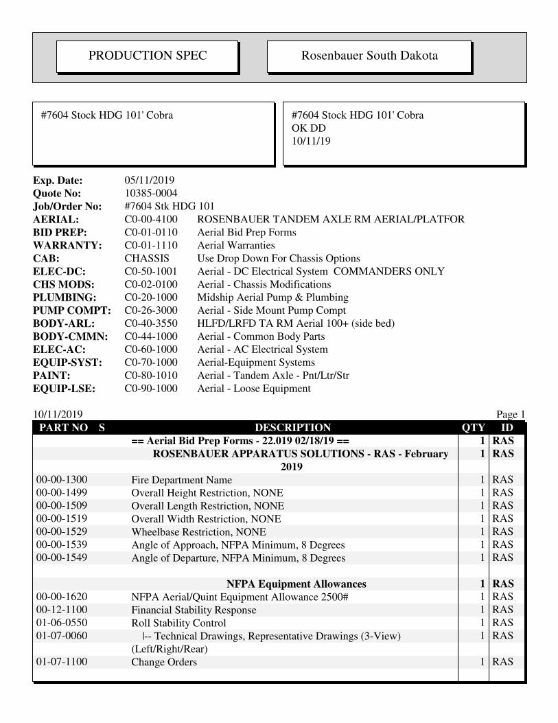
PRODUCTION SPEC Rosenbauer South Dakota
#7604 Stock HDG 101' Cobra #7604 Stock HDG 101' Cobra
OK DD
10/11/19
Exp. Date: 05/11/2019
Quote No: 10385-0004
Job/Order No: #7604 Stk HDG 101
AERIAL: C0-00-4100 ROSENBAUER TANDEM AXLE RM AERIAL/PLATFOR
BID PREP: C0-01-0110 Aerial Bid Prep Forms
WARRANTY: C0-01-1110 Aerial Warranties
CAB: CHASSIS Use Drop Down For Chassis Options
ELEC-DC: C0-50-1001 Aerial - DC Electrical System COMMANDERS ONLY
CHS MODS: C0-02-0100 Aerial - Chassis Modifications
PLUMBING: C0-20-1000 Midship Aerial Pump & Plumbing
PUMP COMPT: C0-26-3000 Aerial - Side Mount Pump Compt
BODY-ARL: C0-40-3550 HLFD/LRFD TA RM Aerial 100+ (side bed)
BODY-CMMN: C0-44-1000 Aerial - Common Body Parts
ELEC-AC: C0-60-1000 Aerial - AC Electrical System
EQUIP-SYST: C0-70-1000 Aerial-Equipment Systems
PAINT: C0-80-1010 Aerial - Tandem Axle - Pnt/Ltr/Str
EQUIP-LSE: C0-90-1000 Aerial - Loose Equipment
10/11/2019 Page 1
PART NO S DESCRIPTION QTY ID
== Aerial Bid Prep Forms - 22.019 02/18/19 == 1 RAS
ROSENBAUER APPARATUS SOLUTIONS - RAS - February
2019
1 RAS
00-00-1300 Fire Department Name 1 RAS
00-00-1499 Overall Height Restriction, NONE 1 RAS
00-00-1509 Overall Length Restriction, NONE 1 RAS
00-00-1519 Overall Width Restriction, NONE 1 RAS
00-00-1529 Wheelbase Restriction, NONE 1 RAS
00-00-1539 Angle of Approach, NFPA Minimum, 8 Degrees 1 RAS
00-00-1549 Angle of Departure, NFPA Minimum, 8 Degrees 1 RAS
NFPA Equipment Allowances 1 RAS
00-00-1620 NFPA Aerial/Quint Equipment Allowance 2500# 1 RAS
00-12-1100 Financial Stability Response 1 RAS
01-06-0550 Roll Stability Control 1 RAS
01-07-0060 |-- Technical Drawings, Representative Drawings (3-View)
(Left/Right/Rear)
1 RAS
01-07-1100 Change Orders 1 RAS
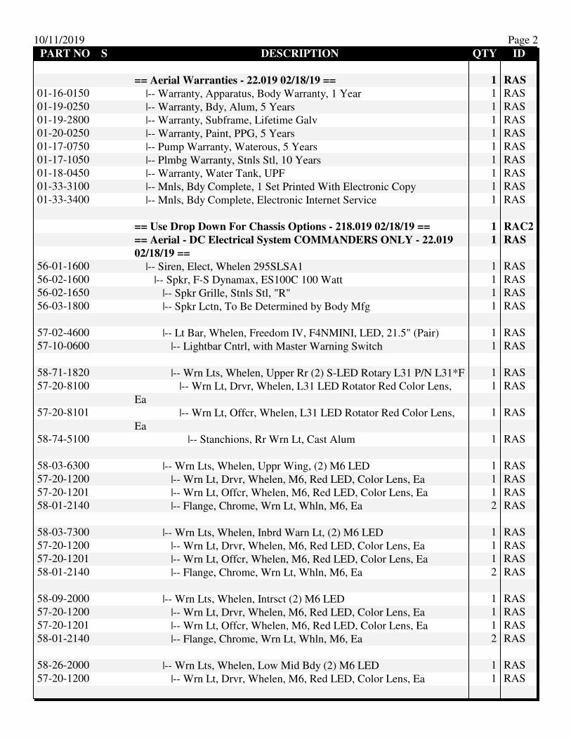
10/11/2019 Page 2
PART NO S DESCRIPTION QTY ID
== Aerial Warranties - 22.019 02/18/19 == 1 RAS
01-16-0150 |-- Warranty, Apparatus, Body Warranty, 1 Year 1 RAS
01-19-0250 |-- Warranty, Bdy, Alum, 5 Years 1 RAS
01-19-2800 |-- Warranty, Subframe, Lifetime Galv 1 RAS
01-20-0250 |-- Warranty, Paint, PPG, 5 Years 1 RAS
01-17-0750 |-- Pump Warranty, Waterous, 5 Years 1 RAS
01-17-1050 |-- Plmbg Warranty, Stnls Stl, 10 Years 1 RAS
01-18-0450 |-- Warranty, Water Tank, UPF 1 RAS
01-33-3100 |-- Mnls, Bdy Complete, 1 Set Printed With Electronic Copy 1 RAS
01-33-3400 |-- Mnls, Bdy Complete, Electronic Internet Service 1 RAS
== Use Drop Down For Chassis Options - 218.019 02/18/19 == 1 RAC2
== Aerial - DC Electrical System COMMANDERS ONLY - 22.019
02/18/19 ==
1 RAS
56-01-1600 |-- Siren, Elect, Whelen 295SLSA1 1 RAS
56-02-1600 |-- Spkr, F-S Dynamax, ES100C 100 Watt 1 RAS
56-02-1650 |-- Spkr Grille, Stnls Stl, "R" 1 RAS
56-03-1800 |-- Spkr Lctn, To Be Determined by Body Mfg 1 RAS
57-02-4600 |-- Lt Bar, Whelen, Freedom IV, F4NMINI, LED, 21.5" (Pair) 1 RAS
57-10-0600 |-- Lightbar Cntrl, with Master Warning Switch 1 RAS
58-71-1820 |-- Wrn Lts, Whelen, Upper Rr (2) S-LED Rotary L31 P/N L31*F 1 RAS
57-20-8100 |-- Wrn Lt, Drvr, Whelen, L31 LED Rotator Red Color Lens,
Ea
1 RAS
57-20-8101 |-- Wrn Lt, Offcr, Whelen, L31 LED Rotator Red Color Lens,
Ea
1 RAS
58-74-5100 |-- Stanchions, Rr Wrn Lt, Cast Alum 1 RAS
58-03-6300 |-- Wrn Lts, Whelen, Uppr Wing, (2) M6 LED 1 RAS
57-20-1200 |-- Wrn Lt, Drvr, Whelen, M6, Red LED, Color Lens, Ea 1 RAS
57-20-1201 |-- Wrn Lt, Offcr, Whelen, M6, Red LED, Color Lens, Ea 1 RAS
58-01-2140 |-- Flange, Chrome, Wrn Lt, Whln, M6, Ea 2 RAS
58-03-7300 |-- Wrn Lts, Whelen, Inbrd Warn Lt, (2) M6 LED 1 RAS
57-20-1200 |-- Wrn Lt, Drvr, Whelen, M6, Red LED, Color Lens, Ea 1 RAS
57-20-1201 |-- Wrn Lt, Offcr, Whelen, M6, Red LED, Color Lens, Ea 1 RAS
58-01-2140 |-- Flange, Chrome, Wrn Lt, Whln, M6, Ea 2 RAS
58-09-2000 |-- Wrn Lts, Whelen, Intrsct (2) M6 LED 1 RAS
57-20-1200 |-- Wrn Lt, Drvr, Whelen, M6, Red LED, Color Lens, Ea 1 RAS
57-20-1201 |-- Wrn Lt, Offcr, Whelen, M6, Red LED, Color Lens, Ea 1 RAS
58-01-2140 |-- Flange, Chrome, Wrn Lt, Whln, M6, Ea 2 RAS
58-26-2000 |-- Wrn Lts, Whelen, Low Mid Bdy (2) M6 LED 1 RAS
57-20-1200 |-- Wrn Lt, Drvr, Whelen, M6, Red LED, Color Lens, Ea 1 RAS
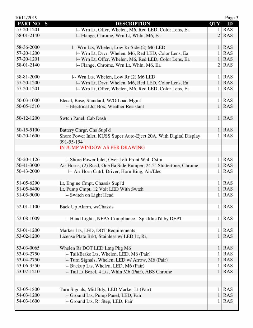
10/11/2019 Page 3
PART NO S DESCRIPTION QTY ID
57-20-1201 |-- Wrn Lt, Offcr, Whelen, M6, Red LED, Color Lens, Ea 1 RAS
58-01-2140 |-- Flange, Chrome, Wrn Lt, Whln, M6, Ea 2 RAS
58-36-2000 |-- Wrn Lts, Whelen, Low Rr Side (2) M6 LED 1 RAS
57-20-1200 |-- Wrn Lt, Drvr, Whelen, M6, Red LED, Color Lens, Ea 1 RAS
57-20-1201 |-- Wrn Lt, Offcr, Whelen, M6, Red LED, Color Lens, Ea 1 RAS
58-01-2140 |-- Flange, Chrome, Wrn Lt, Whln, M6, Ea 2 RAS
58-81-2000 |-- Wrn Lts, Whelen, Low Rr (2) M6 LED 1 RAS
57-20-1200 |-- Wrn Lt, Drvr, Whelen, M6, Red LED, Color Lens, Ea 1 RAS
57-20-1201 |-- Wrn Lt, Offcr, Whelen, M6, Red LED, Color Lens, Ea 1 RAS
50-03-1000 Elecal, Base, Standard, W/O Load Mgmt 1 RAS
50-05-1510 |-- Electrical Jct Box, Weather Resistant 1 RAS
50-12-1200 Swtch Panel, Cab Dash 1 RAS
50-15-5100 Battery Chrgr, Chs Supl'd 1 RAS
50-20-1600 Shore Power Inlet, KUSS Super Auto-Eject 20A, With Digital Display
091-55-194
1 RAS
IN JUMP WINDOW AS PER DRAWING
50-20-1126 |-- Shore Power Inlet, Over Left Front Whl, Cstm 1 RAS
50-41-3000 Air Horns, (2) Rcsd, One Ea Side Bumper, 24.5" Stuttertone, Chrome 1 RAS
50-43-2000 |-- Air Horn Cntrl, Driver, Horn Ring, Air/Elec 1 RAS
51-05-6290 Lt, Engine Cmpt, Chassis Supl'd 1 RAS
51-05-6400 Lt, Pump Cmpt, 12 Volt LED With Swtch 1 RAS
51-05-9000 |-- Switch on Light Head 1 RAS
52-01-1100 Back Up Alarm, w/Chassis 1 RAS
52-08-1009 |-- Hand Lights, NFPA Compliance - Spl'd/Instl'd by DEPT 1 RAS
53-01-1200 Marker Lts, LED, DOT Requirements 1 RAS
53-02-1200 License Plate Brkt, Stainless w/ LED Lt, Rr, 1 RAS
53-03-0065 Whelen Rr DOT LED Ltng Pkg M6 1 RAS
53-03-2750 |-- Tail/Brake Lts, Whelen, LED, M6 (Pair) 1 RAS
53-04-2750 |-- Turn Signals, Whelen, LED w/ Arrow, M6 (Pair) 1 RAS
53-06-3550 |-- Backup Lts, Whelen, LED, M6 (Pair) 1 RAS
53-07-1210 |-- Tail Lt Bezel, 4 Lts, Whln M6 (Pair), ABS Chrome 1 RAS
53-05-1800 Turn Signals, Mid Bdy, LED Marker Lt (Pair) 1 RAS
54-03-1200 |-- Ground Lts, Pump Panel, LED, Pair 1 RAS
54-03-1600 |-- Ground Lts, Rr Step, LED, Pair 1 RAS
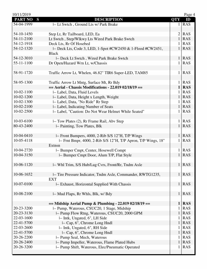
10/11/2019 Page 4
PART NO S DESCRIPTION QTY ID
54-04-1999 |-- Lt Swtch , Ground Lts w/ Park Brake 1 RAS
54-10-1450 Step Lt, Rr Tailboard, LED, Ea 2 RAS
54-11-2100 Lt Swtch , Step/Wlkwy Lts Wired Park Brake Swtch 1 RAS
54-12-1918 Deck Lts, Rr Of Hosebed 1 RAS
54-12-1320 |-- Deck Lts, Code 3, LED, 1-Spot #CW2450 & 1-Flood #CW2451,
Black
1 RAS
54-12-3010 |-- Deck Lt Swtch , Wired Park Brake Swtch 1 RAS
55-11-1100 Dr Open/Hazard Wrn Lt, w/Chassis 1 RAS
58-91-1720 Traffic Arrow Lt, Whelen, 46.82" TIR6 Super-LED, TAM85 1 RAS
58-95-1300 Traffic Arrow Lt Mntg, Surface Mt, Rr Bdy 1 RAS
== Aerial - Chassis Modifications - 22.019 02/18/19 == 1 RAS
10-02-1100 |-- Label, Data, Fluid Levels 1 RAS
10-02-1200 |-- Label, Data, Height x Length, Weight 1 RAS
10-02-1300 |-- Label, Data, "No Ride" Rr Step 1 RAS
10-02-2100 |-- Label, Indicating Number of Seats 1 RAS
10-02-2500 |-- Label, "Caution: Do Not Wear Helmet While Seated" 1 RAS
10-03-6100 |-- Tow Plates (2), Rr Frame Rail, Abv Step 1 RAS
80-43-2400 |-- Painting, Tow Plates, Blk 1 RAS
10-04-0410 |-- Front Bumpers, 4000, 2-Rib S/S 12"H, T/P Wings 1 RAS
10-05-4118 |-- Frnt Bmpr, 4000, 2-Rib S/S 12"H, T/P Apron, T/P Wings, 18"
Extnsn
1 RAS
10-04-2720 |-- Bumper Cmpt, Center, Hosewell Compt 1 RAS
10-04-3150 |-- Bumper Cmpt Door, Alum T/P, Flat Style 1 RAS
10-06-1120 |-- Whl Trim, S/S Hub/Lug Cvrs, Front/Rr, Tndm Axle 1 RAS
10-06-1652 |-- Tire Pressure Indicator, Tndm Axle, Commander, RWTG1235,
EXT
1 RAS
10-07-0100 |-- Exhaust, Horizontal Supplied With Chassis 1 RAS
10-08-2100 |-- Mud Flaps, Rr Whls, Blk, w/ Bdy 1 RAS
== Midship Aerial Pump & Plumbing - 22.019 02/18/19 == 1 RAS
20-23-3200 |-- Pump, Waterous, CSUC20, 1 Stage, Midship 1 RAS
20-23-3130 |-- Pump Flow Rtng, Waterous, CSUC20, 2000 GPM 1 RAS
22-03-1600 |-- Intk, Ungated, 6", LH Side 1 RAS
22-41-5700 |-- Cap, 6", Chrome Long Hndl 1 RAS
22-03-2600 |-- Intk, Ungated, 6", RH Side 1 RAS
22-41-5700 |-- Cap, 6", Chrome Long Hndl 1 RAS
20-26-2200 |-- Pump Seal, Mech, Waterous 1 RAS
20-26-2400 |-- Pump Impeller, Waterous, Flame Plated Hubs 1 RAS
20-26-3200 |-- Pump Shift, Waterous, Elec/Pneumatic Operated 1 RAS

10/11/2019 Page 5
PART NO S DESCRIPTION QTY ID
20-29-1200 |-- Primer, Trident Air Primer, Automatic 1 RAS
20-29-1250 |-- Primer Control - Main Pump Rocker Switch 1 RAS
27-10-3400 |-- Pressure Gvrnr, FRC, In-Cntrl, w/Bdy, TGA300 1 RAS
STAINLESS STEEL PUMP PLUMBING 1 RAS
21-00-2000 |-- Screens/Anodes, Pump 1 RAS
21-00-3300 |-- Piping, Stnls Stl - 1250 GPM & Up 1 RAS
21-01-0200 |-- Pump Drain, Master, Manifold, Push Pull Type 1 RAS
21-01-7100 |-- Painting, Pump & Piping, Silver 1 RAS
21-01-8100 |-- Threads, National Hose (NST) 1 RAS
22-51-5210 |-- Tank-To-Pump, Water Tank, 3" Vlv/4" Piping, Midship,
Pmpr/Tnkr
1 RAS
22-50-0100 |-- Single Tank to Pump Control - Pump Operator's Panel 1 RAS
24-62-1300 |-- Vlv Mfger, AKR, 8000, (3") 1 RAS
22-55-4012 |-- Intk Vlv Cntrl, Pull Rod, 1/4 Turn, AKR - IC 1 RAS
23-02-1300 |-- Tank Fill/Cooling Line, Water Tank, 2" 1 RAS
24-62-1200 |-- Vlv Mfger, AKR, 8000, (2") 1 RAS
22-55-4012 |-- Intk Vlv Cntrl, Pull Rod, 1/4 Turn, AKR - IC 1 RAS
20-30-3100 |-- Pump Instln, Midship Split-Shaft, By Bdy Bldr 1 RAS
20-31-3600 Dump-Relief Vlv, Suction Side, TFT A18 1 RAS
20-31-4100 Pump Cooler, Bypass-To-Tank, 3/8" 1 RAS
20-31-5200 Heat Exchanger, Engine, Complete 1 RAS
20-31-1010 |-- Fire Pump Testing - Aerials 1 RAS
20-31-1250 |-- Pump Test, Aerial, UL 1 RAS
20-31-1500 |-- Pump Test, Label 1 RAS
22-12-1100 Intk, Aux, Gtd, 2-1/2", NST, Left Side 1 RAS
21-01-2502 |-- Drain/Bleeder, IC Lift-Up, Mnl 1/4 Turn - Spec Only 1 RAS
22-41-1100 |-- Plug, 2-1/2", Chrome Rocker Lug, w/Chain 1 RAS
24-62-1250 |-- Vlv Mfger, AKR, 8000, (2-1/2") 1 RAS
22-55-4050 |-- Intk Vlv Cntrl, AKR, Mnl Swing Type-Adjacent 1 RAS
23-05-3200 |-- Dschg, 2" x 1-1/2" Front Center Bumper, Swivel, NST Brass
Swivel
1 RAS
21-01-2200 |-- Drain/Bleeder, Class 1, Automatic 1 RAS
23-05-9200 |-- Hose Connection, Abv Frnt Bmpr, Swivel 1 RAS
24-61-1200 |-- Vlv Mfger, AKR, 8000, (2") 1 RAS
24-53-0020 |-- Dschg Vlv Cntrl, Pull Rod, 1/4 Turn, SM, AKR - IC w/Gauge 1 RAS
27-02-1500 |-- Gauge, Dschg, IC, 2-1/2" 400#, WF 1 RAS
23-06-2200 |-- Crosslay Dschgs, (2) 1-1/2", Over Pump Panel, NST 200 ft
x1-3/4-in ea w/divider
1 RAS

10/11/2019 Page 6
PART NO S DESCRIPTION QTY ID
21-01-2502 |-- Drain/Bleeder, IC Lift-Up, Mnl 1/4 Turn - Spec Only 2 RAS
24-61-1200 |-- Vlv Mfger, AKR, 8000, (2") 2 RAS
24-53-0020 |-- Dschg Vlv Cntrl, Pull Rod, 1/4 Turn, SM, AKR - IC w/Gauge 2 RAS
27-02-1500 |-- Gauge, Dschg, IC, 2-1/2" 400#, WF 2 RAS
23-08-3300 |-- Crosslay Cvr, Alum T/P, Sngl, W/Vinyl End Flaps (Non NFPA
Walking Surface)
1 RAS
29-20-5600 |-- Vinyl Cover, Color, RED 1 RAS
23-08-4130 |-- Crosslay Trim, Alum Angles, Both Sides 1 RAS
23-08-5019 |-- Crosslay Dschgs, Over Pump Panel, Normal Height 1 RAS
23-09-4100 Dschg, 2-1/2", Left Side, Pump Panel, NST 2 RAS
21-01-2502 |-- Drain/Bleeder, IC Lift-Up, Mnl 1/4 Turn - Spec Only 2 RAS
24-02-1200 |-- Elbow, 2-1/2"F x 2-1/2" NST M, Chrome 2 RAS
24-03-1400 |-- Cap, 2-1/2", NST Chrome, Rocker Lug, w/Chain 2 RAS
24-61-1250 |-- Vlv Mfger, AKR, 8000, (2-1/2") 2 RAS
24-53-0020 |-- Dschg Vlv Cntrl, Pull Rod, 1/4 Turn, SM, AKR - IC w/Gauge 2 RAS
27-02-1500 |-- Gauge, Dschg, IC, 2-1/2" 400#, WF 2 RAS
23-10-4100 Dschg, 2-1/2", Right Side, Pump Panel, NST 1 RAS
21-01-2502 |-- Drain/Bleeder, IC Lift-Up, Mnl 1/4 Turn - Spec Only 1 RAS
24-02-1200 |-- Elbow, 2-1/2"F x 2-1/2" NST M, Chrome 1 RAS
24-03-1400 |-- Cap, 2-1/2", NST Chrome, Rocker Lug, w/Chain 1 RAS
24-61-1250 |-- Vlv Mfger, AKR, 8000, (2-1/2") 1 RAS
24-53-0020 |-- Dschg Vlv Cntrl, Pull Rod, 1/4 Turn, SM, AKR - IC w/Gauge 1 RAS
27-02-1500 |-- Gauge, Dschg, IC, 2-1/2" 400#, WF 1 RAS
23-10-5200 Dschg, 3" x 4"NST, Right Side, Pump Panel, NST 1 RAS
21-01-2502 |-- Drain/Bleeder, IC Lift-Up, Mnl 1/4 Turn - Spec Only 1 RAS
24-02-2600 |-- Elbow, LW Alum, 5" Storz x 4"F 1 RAS
24-03-2200 |-- Cap, LW Alum, 5" Storz, w/Cable 1 RAS
24-61-1300 |-- Vlv Mfger, AKR, 8000, (3") 1 RAS
24-53-0300 |-- Dschg Vlv Cntrl, Pull Rod, 1/4 Turn, SM, AKR Slow Close - IC
w/Gauge
1 RAS
27-02-1500 |-- Gauge, Dschg, IC, 2-1/2" 400#, WF 1 RAS
24-10-1100 Aerial Dschg/Inlet, 3", Rear, 4" NSTM w/4" Cap, 1-1/2" Drain 1 RAS
21-01-2500 |-- Drain/Bleeder, IC Lift-Up, Mnl 1/4 Turn 1 RAS
24-03-1700 |-- Cap, 4", Chrome, Rocker Lug, w/Chain 1 RAS
24-61-1300 |-- Vlv Mfger, AKR, 8000, (3") 1 RAS
24-53-0300 |-- Dschg Vlv Cntrl, Pull Rod, 1/4 Turn, SM, AKR Slow Close - IC
w/Gauge
1 RAS
27-02-1500 |-- Gauge, Dschg, IC, 2-1/2" 400#, WF 1 RAS
24-10-5000 Relief Valve, Aerial Waterway 1 RAS
24-10-5100 Drain Valve, Aerial Waterway 1 RAS
== Aerial - Side Mount Pump Compt - 22.019 02/18/19 == 1 RAS
26-02-1600 Pump Enc, Side Mt, Extrd Alum, Aerial 1 RAS

10/11/2019 Page 7
PART NO S DESCRIPTION QTY ID
26-30-1100 Rng Brd, LH Pump Panel, Alum T/P, SM 1 RAS
26-30-3000 |-- Step, Slide Out, Alum T/P, LH Pump Panel 1 RAS
26-30-1150 Rng Brd, RH Pump Panel, Alum T/P, SM 1 RAS
26-31-3100 Pump Side Access Door, Upper LH, Alum T/P 1 RAS
26-31-3200 Pump Side Access Door, Upper RH, Alum T/P 1 RAS
26-35-5100 Pump Panel, Line X, LH/RH, SM 1 RAS
26-35-1100 |-- Pump Panel, Bltd, LH 1 RAS
26-35-1400 |-- Pump Panel, Hngd, RH 1 RAS
26-55-1100 Labels, Test Data and Safety Placards 1 RAS
26-55-2400 Labels, Innovative Controls Color Coded 1 RAS
26-56-1125 Pump Panel LED Lts, (3) Tecniq E10-W0001-1, Midship LH w/ Sw on
Pmp Oprtr's Pnl
1 RAS
26-56-1225 Pump Panel LED Lts (2), Midship RH, Tecniq E10-W0001-1 1 RAS
26-56-2000 Pump Panel Lt (1), Actuated w/Pump Engagement 1 RAS
27-01-1500 |-- Mstr Gauges, IC, 4" PSI, Pr 1 RAS
27-01-4100 Gauge, Test Taps 1 RAS
PUMP PANEL INSTRUMENTATION 1 RAS
27-35-1100 Water Tank Gauge, FRC, TankVision Pro 300, Pump Panel
WLA300-A00
1 RAS
== HLFD/LRFD TA RM Aerial 100+ (side bed) - 22.019 02/18/19 == 1 RAS
25-25-0062 |-- Water Tank, Rectangular Tank 1 RAS
25-38-1300 |-- Water Tank, 500 Gal, Aerial, Poly 1 RAS
25-44-1200 |-- Water Tank, Fill Tower, 10" x 10", <500 Gals 1 RAS
25-42-1100 |-- Water Tank, Base Specs, Poly 1 RAS
25-42-1190 |-- Water Tank, Manufacturer, No Preference, Poly 1 RAS
30-00-0399 Raw Material Surcharge - Tandem Axle 1 RAS
40-00-0670 AERIAL - RMA100+ TA - 1/8" FRMD ALUM 1 RAS
00-01-5100 |-- Chs Requirements, Ladder 1 RAS
00-01-5200 |-- Bdy Requirements, Ladder, Four (4) Outriggers 1 RAS
00-01-5192 |-- Outrigger Pad Storage, Single, Four (4) Total 1 RAS
00-01-5204 |-- Harness, Safety, Pac Mule, Four (4), Provd'd By Bdy Bldr 1 RAS
Available sizes are: M, L, XL, & XXL.
If sizes are not specified, the following will be provided:
(1) - L
(2) - XL
(1) - XXL

10/11/2019 Page 8
PART NO S DESCRIPTION QTY ID
00-01-5212 |-- Size, Safety Harness, Large, 34"-40" Waist 1 RAS
00-01-5214 |-- Size, Safety Harness, X-Large, 42"-50" Waist 2 RAS
00-01-5216 |-- Size, Safety Harness, XX-Large, 52"&Up Waist 1 RAS
30-01-1860 |-- Bdy Const - Rosenbauer Aerial - 1/8" Alum 1 RAS
30-01-2250 |-- Electrolysis Corrosion Cntrl 1 RAS
30-01-3110 |-- Cover, Outrigger, Brshd SS 1 RAS
30-01-3152 |-- Outrigger Plates 1 RAS
30-02-2200 |-- Smooth Alum Compt Floors 1 RAS
44-06-3100 |-- Whl Well Panel, Alum Pntd, Tndm Axle - Alum 1 RAS
44-06-4100 |-- Fenderette, Polished Aluminum 1 RAS
40-00-2650 TA RM HLFD/LRHD, 102" OAW, 26" Full Dpth/26" LwrDpth 1 RAS
AERIAL / PLATFORM HOSEBEDS - SIDE HOSEBED 1 RAS
41-39-1300 |-- Hosebed, Aerial, Right Hand Side Load 1 RAS
41-39-2100 |-- Hosebed, Grating, Extrd Alum, Aerial 1 RAS
40-00-5200 |-- Bdy, Aerial Subframe Tndm Axle 1 RAS
40-01-3200 |-- Bdy, Aerial, Overall Width 102" 1 RAS
40-01-6300 |-- Cmpt Dpth, Aerial Bdy, 26"D LwrBdy, 102"W Bdy 1 RAS
40-01-7300 |-- Cmpt Dpth, Aerial Bdy, 26"D Full Height x Full Dpth 1 RAS
40-01-9610 |-- HLHD/LRHD Tndm Axle RM Roll Up Drs 1 RAS
30-02-1140 |-- Roll-Up Drs - Amdor 11 RAS
LEFT SIDE COMPARTMENTATION 1 RAS
40-10-1020 |-- Abv Front Outrigger - Sgle Comp't - Roll Up Dr - Natural Finish 1 RAS
44-40-1100 |-- Vents, Compts, Louvers, Includes Filters (Ea) 1 RAS
45-01-1050 |-- Shelving Tracks, (2) Unistrut, Alum 1 RAS
55-01-5114 |-- Cmpt LED Lt, Luma Bar, (2) Ea Cmpt 1 RAS
55-06-1400 |-- Cmpt Lt, Dr Swtch, Magnetic, Ea 1 RAS
40-10-2020 |-- Ahd Rr Whls - Full Ht Comp't - Roll Up Dr - Natural Finish 1 RAS
44-40-1100 |-- Vents, Compts, Louvers, Includes Filters (Ea) 1 RAS
45-01-1050 |-- Shelving Tracks, (2) Unistrut, Alum 1 RAS
55-01-5114 |-- Cmpt LED Lt, Luma Bar, (2) Ea Cmpt 1 RAS
55-06-1400 |-- Cmpt Lt, Dr Swtch, Magnetic, Ea 1 RAS
40-10-4010 |-- Two (2) Compts - Upr Hgh Sde - Roll Up Drs - Natural Finish 1 RAS
44-40-1100 |-- Vents, Compts, Louvers, Includes Filters (Ea) 2 RAS
45-01-1050 |-- Shelving Tracks, (2) Unistrut, Alum 2 RAS
55-01-5114 |-- Cmpt LED Lt, Luma Bar, (2) Ea Cmpt 2 RAS
55-06-1400 |-- Cmpt Lt, Dr Swtch, Magnetic, Ea 2 RAS
40-10-5010 |-- Bhnd Rr Whls - Full Ht Comp't - Roll Up Dr - Natural Finish 1 RAS
44-40-1100 |-- Vents, Compts, Louvers, Includes Filters (Ea) 1 RAS
45-01-1050 |-- Shelving Tracks, (2) Unistrut, Alum 1 RAS
55-01-5114 |-- Cmpt LED Lt, Luma Bar, (2) Ea Cmpt 1 RAS
55-06-1400 |-- Cmpt Lt, Dr Swtch, Magnetic, Ea 1 RAS
40-10-6020 |-- Abv Rr Outrigger - Sgle Comp't - Roll Up Dr - Natural Finish 1 RAS

10/11/2019 Page 9
PART NO S DESCRIPTION QTY ID
44-40-1100 |-- Vents, Compts, Louvers, Includes Filters (Ea) 1 RAS
45-01-1050 |-- Shelving Tracks, (2) Unistrut, Alum 1 RAS
55-01-5114 |-- Cmpt LED Lt, Luma Bar, (2) Ea Cmpt 1 RAS
55-06-1400 |-- Cmpt Lt, Dr Swtch, Magnetic, Ea 1 RAS
40-10-7120 |-- Access Ladder, Swing Out & Down, Left Side - EZ Climb 1 RAS
RIGHT SIDE COMPARTMENTATION 1 RAS
40-12-1020 |-- Abv Front Outrigger - Sgle Comp't - Roll Up Dr - Natural Finish 1 RAS
44-40-1100 |-- Vents, Compts, Louvers, Includes Filters (Ea) 1 RAS
45-01-1050 |-- Shelving Tracks, (2) Unistrut, Alum 1 RAS
55-01-5114 |-- Cmpt LED Lt, Luma Bar, (2) Ea Cmpt 1 RAS
55-06-1400 |-- Cmpt Lt, Dr Swtch, Magnetic, Ea 1 RAS
40-12-2020 |-- Ahd Rr Whls - Full Ht Comp't - Roll Up Dr - Natural Finish 1 RAS
44-40-1100 |-- Vents, Compts, Louvers, Includes Filters (Ea) 1 RAS
45-01-1050 |-- Shelving Tracks, (2) Unistrut, Alum 1 RAS
55-01-5114 |-- Cmpt LED Lt, Luma Bar, (2) Ea Cmpt 1 RAS
55-06-1400 |-- Cmpt Lt, Dr Swtch, Magnetic, Ea 1 RAS
40-12-4000 |-- No Upr Hgh Sde Compts 1 RAS
40-12-5070 |-- Bhnd Rr Whls - Low Comp't - Roll Up Dr - Natural Finish 1 RAS
44-40-1100 |-- Vents, Compts, Louvers, Includes Filters (Ea) 1 RAS
45-01-1050 |-- Shelving Tracks, (2) Unistrut, Alum 1 RAS
55-01-5114 |-- Cmpt LED Lt, Luma Bar, (2) Ea Cmpt 1 RAS
55-06-1400 |-- Cmpt Lt, Dr Swtch, Magnetic, Ea 1 RAS
40-12-6000 |-- No Compt Abv Outrigger 1 RAS
40-12-8070 |-- Bhnd Rr Outrigger - Low Comp't - Roll Up Dr - Natural Finish 1 RAS
44-40-1100 |-- Vents, Compts, Louvers, Includes Filters (Ea) 1 RAS
45-01-1050 |-- Shelving Tracks, (2) Unistrut, Alum 1 RAS
55-01-5114 |-- Cmpt LED Lt, Luma Bar, (2) Ea Cmpt 1 RAS
55-06-1400 |-- Cmpt Lt, Dr Swtch, Magnetic, Ea 1 RAS
40-95-3000 Rr Aerial Bdy Configuration - Roll Up Dr - Natural Finish 1 RAS
55-01-5010 |-- Cmpt LED Lt, Luma Bar, (2) Ea Cmpt (approx 20") 1 RAS
55-06-1400 |-- Cmpt Lt, Dr Swtch, Magnetic, Ea 1 RAS
90-02-3600 |-- Ladder Strge, Rr Slide, Aerial Torque Box 1 RAS
90-03-0225 |-- Ladders, Ground, Provd'd By Bdy Bldr, SD 1 RAS
90-16-5200 |-- Pike Pole Mtg Tube, Intrnl, Ea 6 RAS
REAR STEP BUMPERS - AERIALS/PLATFORMS 1 RAS
41-41-1100 |-- Rr Bumper, Aerial, 4" 1 RAS
HANDRAILS - AERIALS/PLATFORMS 1 RAS

10/11/2019 Page 10
PART NO S DESCRIPTION QTY ID
== Aerial - Common Body Parts - 22.019 02/18/19 == 1 RAS
44-01-1200 |-- Bdy Trim, Frnt Bdy, Corner Stone Guards, Brshd S/S 1 RAS
44-01-1450 |-- Bdy Trim, Frnt Cmpt, Ht of Side Cmpts, Alum T/P 1 RAS
44-01-6000 |-- Catwalks Top of Side Cmpts, Alum Treadplate 1 RAS
REAR BODY DESIGN - AERIAL 1 RAS
44-01-4000 |-- Bdy Trim, Entire Rr Bdy, Smooth for Chevron Stripe 1 RAS
AUXILIARY REAR BODY STEPS AND LADDERS 1 RAS
AUXILIARY FRONT BODY STEPS 1 RAS
41-44-4140 |-- Steps, Fldg, Frnt, Left Hand (3), Integral LED Lts 1 RAS
41-44-4240 |-- Steps, Fldg, Frnt, Right Hand (3), Integral LED Lts 1 RAS
HANDRAILS - AERIALS/PLATFORMS 1 RAS
44-02-1100 |-- Rub Rails, Lwr Bdy, Extrd Alum 1 RAS
44-02-2000 |-- Rub Rails, Spacers, Nylon 1 RAS
44-07-4300 Fuel Tank, Removable Access Panel - Aerial Torque Box 1 RAS
44-07-5310 Fuel Fill Door, LH Aerial Outrigger Panel 1 RAS
44-11-5100 Whl Well Prvsns, Ahd of Whls Left Side 1 RAS
44-10-1100 |-- Whl Well Cmpt, Sngl SCBA Tube, Alum Dr, Push Button Latch 1 RAS
44-10-6000 |-- Whl Well Compt, SCBA Compt Straps 1 RAS
44-11-5200 Whl Well Prvsns, Btwn Tndms Left Side 2 RAS
44-10-1100 |-- Whl Well Cmpt, Sngl SCBA Tube, Alum Dr, Push Button Latch 2 RAS
44-10-6000 |-- Whl Well Compt, SCBA Compt Straps 2 RAS
44-11-5305 Whl Well Prvsns, Bhnd Whls Left Side 1 RAS
44-10-1100 |-- Whl Well Cmpt, Sngl SCBA Tube, Alum Dr, Push Button Latch 1 RAS
44-10-6000 |-- Whl Well Compt, SCBA Compt Straps 1 RAS
44-11-5500 Whl Well Prvsns, Ahd of Whls Right Side 1 RAS
44-10-1100 |-- Whl Well Cmpt, Sngl SCBA Tube, Alum Dr, Push Button Latch 1 RAS
44-10-6000 |-- Whl Well Compt, SCBA Compt Straps 1 RAS
44-11-5600 Whl Well Prvsns, Btwn Tndms Right Side 2 RAS
44-10-1100 |-- Whl Well Cmpt, Sngl SCBA Tube, Alum Dr, Push Button Latch 2 RAS
44-10-6000 |-- Whl Well Compt, SCBA Compt Straps 2 RAS
44-11-5700 Whl Well Prvsns, Bhnd Whls Right Side 1 RAS
44-10-1100 |-- Whl Well Cmpt, Sngl SCBA Tube, Alum Dr, Push Button Latch 1 RAS
44-10-6000 |-- Whl Well Compt, SCBA Compt Straps 1 RAS
== Aerial - AC Electrical System - 22.019 02/18/19 == 1 RAS
60-90-1000 Green Star Idle Reduction Technology (IRT) 1 RAS
60-90-1189 |-- === No Green Star Inhibit Switch === 1 RAS

10/11/2019 Page 11
PART NO S DESCRIPTION QTY ID
60-90-2000 |-- Auxiliary Diesel Power Unit (APU) 7.9 KW Kubota D1105-BG 1 RAS
60-90-2820 |-- Remote Mount Oil Filter 1 RAS
60-90-3020 |-- Custom Chassis Greenstar Air Conditioning 1 RAS
60-90-4400 |-- Power Pack 1 RAS
60-91-3100 |-- Green Star Display 1 RAS
locate in the window over right front drivers side
60-20-1300 |-- Gnrtr Mtg, Top of Bdy 1 RAS
60-20-4100 |-- Circuit Breaker Box, 6 to 8KW, 1 PH 1 RAS
60-20-5100 |-- Gnrtr Breaker Lctn, Side Compt 1 RAS
LOCATE IN THE L2 COMPARTMENT FORWARD WALL
60-20-7400 |-- Gnrtr Instrmnt Panel Lctn, Breaker Panel 1 RAS
60-25-1300 |-- Rcptcl, 120V, 15 Amp, Strght Bld, Duplex 2 RAS
60-30-2600 |-- Rcptcl Lctn, Left Side, Whl Well, Ea 1 RAS
60-30-2700 |-- Rcptcl Lctn, Right Side, Whl Well, Ea 1 RAS
61-01-1550 Cable Reels, Provd'd by Bdy Bldr 1 RAS
61-01-3100 |-- Cable Reel, Hannay ECR1600, Elec Rwnd, 120V 50A 3 Wire 1 RAS
61-02-1700 |-- Cable Reel Lctn, Left Side, Ahd Rr Whls Cmpt, Upper 1 RAS
61-03-3400 |-- Cable, Elec, 120V, 200' 10/3 Blk 1 RAS
61-04-7200 |-- Cable Rcptcl, 120V L5-20R, 3-Prong, Twst Lck 1 RAS
61-04-9100 |-- Ball Stop, Cable, Orange 1 RAS
61-04-8200 |-- Roller Assy, Cable Reel, 4-Way, SS Rollers 1 RAS
== Aerial-Equipment Systems - 22.019 02/18/19 == 1 RAS
== Aerial - Tandem Axle - Pnt/Ltr/Str - 22.019 02/18/19 == 1 RAS
80-05-2100 Bdy Paint, Tndm Axle Aerial 1 RAS
80-06-1100 |-- Apparatus Color 1 RAS
The apparatus shall be __PPG-71663__ in color.
80-34-1400 Compt Finish, Line-X, Upt to 12 Cmpts 1 RAS
80-34-9000 |-- Compt Finish, Liner Matl, Grey 1 RAS
80-40-1100 Whls, Alum, By the Chassis Manufacturer 1 RAS
80-42-1500 Bdy Paint, Touch Up, 2 oz. Bttl, One Color 1 RAS
80-50-1700 Lettering, 4" Mylar Gold Leaf, 50 Letters 1 RAS
Lettering Info needed once Truck is sold
80-50-4205 Lettering, Aerial Sign Panel, 12"x144", Backlit 1 RAS
Lettering Info needed once Truck is sold
80-50-5105 Aerial Cylinder Panels, Pntd, Backlit OEM Logo 1 RAS
80-71-1400 Stripe, Triple Reflective, 1" x 6" x 1" 1 RAS
80-75-1600 |-- Reflective Stripe Material, White 1 RAS
80-72-1108 Stripe, Reflective, Oralite V98, Chevron Pattern Entire Rr Red/Yellow 1 RAS
80-72-1400 Stripe, Reflective, Aerial Outriggers, Both Sides of Ea White 1 RAS
80-79-1000 NFPA Standing / Walking Surfaces Yellow Safety Tape (NFPA 15.7.1.6) 1 RAS

10/11/2019 Page 12
PART NO S DESCRIPTION QTY ID
80-80-1200 Labels, Aerial Ladder Identification and Safety 1 RAS
80-81-0100 Leveling Gauge, (1) Side-to-Side, (1)Front-to-Back 1 RAS
== Aerial - Loose Equipment - 22.019 02/18/19 == 1 RAS
90-03-0020 AERIAL Compliment (115-ft MIN) Duo Safety (NFPA compliant) 1 RAS
90-03-3400 |-- Ladder, Roof, Duo-Safety, 16' Alum 875-A 2 RAS
90-06-4600 |-- Ladder, Ext, Duo-Safety, 24' Alum, 2 Sect 900-A 1 RAS
90-07-4300 |-- Ladder, Ext, Duo-Safety, 35' Alum, 3 Sect 1225-A 1 RAS
90-08-2600 |-- Ladder, Attic, Duo-Safety, 10' Alum, Fold 585-A 1 RAS
90-09-2300 |-- Ladder, Combo, Duo-Safety, 10/15' Alum #300-A 1 RAS
90-16-2200 |-- Pike Pole, 4' Fbgls, "D" Hndl 2 RAS
90-16-2300 |-- Pike Pole, 6' Fbgls, Round Hndl 1 RAS
90-16-2600 |-- Pike Pole, 8' Fbgls, Round Hndl 1 RAS
90-16-2800 |-- Pike Pole, 10' Fbgls, Round Hndl 1 RAS
90-16-3000 |-- Pike Pole, 12' Fbgls, Round Hndl 1 RAS