
Instructivo técnico de análisis/ensayo para Salmonella ... - SAG

EUROPEAN TRANSACTIONS ON ELECTRICAL POWEREuro. Trans. Electr. Power 2011; 21:522–540Published online 20 May 2010 in Wiley Online Library (wileyonlinelibrary.com). DOI: 10.1002/etep.459
Robust control of hybrid fuel cell/energy storage distributedpower generation system in weak grid under balanced
and unbalanced voltage sag
*C
TecyE-
Co
A. Hajizadeh1*,y, M. A. Golkar1 and L. Norum2
1Electrical and Computer Engineering Department, K.N.Toosi University of Technology, Tehran, Iran2Electrical Power Engineering Department, Norwegian University of Science and Technology, Trondheim,
Norway
SUMMARY
The operation and control of fuel cell (FC) distributed generation (DG) systems combined with energy storageare studied in this paper. For this purpose, modeling of hybrid FC/energy storage DG system is developed.Dynamic models for proton exchange membrane fuel cell (PEMFC), supercapacitor, DC–DC converters, andgrid connected inverter are described. Then a PI controller for the FC converter (boost) and a sliding modecontroller for supercapacitor converter (buck-boost converter) are designed to regulate their duty cycles basedon the requested current. Moreover, a robust current control strategy for voltage source converter based onpositive and negative symmetrical components is presented for treating the unbalance and balance voltage sagconditions. In order to control the power between dc power sources and stabilize the dc-link power duringnormal and fault conditions, a self-tuning fuzzy control strategy has been designed. This controller determinesthe supercapacitor power that should be generated according to the amount of available energy in dc-link. Thehybrid system is studied under unbalance and balance voltage sag condition. Simulation results are given toshow the response of whole system under voltage sag and illustrate the performance including active powercontrol and voltage sag ride-through capability of the proposed control strategy. Copyright # 2010 John Wiley& Sons, Ltd.
key words: control; distributed generation; energy storage; PEM fuel cell; fuzzy; sliding mode; robust;voltage sag
1. INTRODUCTION
The progress in deregulation of the electricity market and utility restructuring makes that the tight
constraints are imposed on the construction of new transmission lines. In this case, the interest in
distributed generation (DG) systems installed near load is increasing [1]. Fuel cell (FC) is one of the
attractive DG technologies. Environmental friendliness, practically noise free operation, and high
efficiency make FCs a very sound competitor on the future power systems. The FCs also produce water
and heat by combining hydrogen with oxygen, and have 50% efficiency for only electricity but could
reach 85% in the case of combined heat and power (CHP). Also, the FCs can be used for various
applications such as stationary sites (buildings, hospitals, domestic utility, etc.), transportation (FC
vehicle), portable power (laptop, cell phone), and distributed power [2]. Many of the FC power systems
are connected to the grid via power electronic converters to improve the system integrity, reliability,
and efficiency [3,4]. So it is important to design control strategy to keep the safe operation of these
systems during normal and faulty conditions. The grid-connected power electronic converters
are highly sensitive to voltage disturbances. This makes it is necessary to reduce the effects of voltage
orrespondence to: A. Hajizadeh, Electrical and Computer Engineering Department, K.N.Toosi University of
hnology, Seyedkhandan, Dr. Shariati Ave, P.O. Box 16315-1355, Tehran, Iran.
mail: [email protected]
pyright # 2010 John Wiley & Sons, Ltd.
ROBUST CONTROL OF HYBRID FUEL CELL 523
disturbances on their operations [5]. A voltage sag is a drop in voltage with duration between one half-
cycle and 1 minute [6], which is, in most cases, caused by a short-circuit fault. The operation of DG
units under voltage sag has not received much attention in the past research. Moreover, many grid
operators demand the immediate shutdown of DG in case of grid disturbances as a prerequisite for grid
connection.
As the power generated by DG units increases, the disconnection of DG units stresses the utility
grid and could cause power unbalance; which may turn into instability. So, the interaction between
DG units and the grid during the voltage sag is very important and it must be considered when
designing the proper control strategy. In this paper a control strategy is proposed for FC power
systems combined with energy storage under voltage sag conditions. Up to now, a considerable
study has not been presented for operation of FC DG systems under voltage sags. Much research
has concentrated only on control of grid connected voltage source converter (VSC) [7–10].
Authors in Ref. [11] have presented a control strategy for hybrid FC/battery energy DG system
with voltage sag ride-through capability. But it has been supposed that the voltage sag ride-through
can be achieved only by increasing the current rating of the VSC and the role of energy storage has
not been considered. During the voltage sag, a decrease in voltage magnitude at the grid-connected
converter is occurs. In this case, in order to avoid overloading of the converter, current controllers
limit the power of DG units that can be supplied to the grid during voltage sag. For FC DG systems,
the power limitation can be a problem due to the slow dynamics of FC. So it needs to combine FC
with energy storage to respond the rapid changes of power demand. The comparison between
energy storages shows that the use of supercapacitor is suitable as short term energy storage [12].
Short-term storage is the storage that maintains energy reserves sufficient to provide rated power
from a few seconds up to a minute. The two basic applications are; for use in uninterruptible
power supply (UPS) and for power system stabilization. Due to the lower power density than
supercapacitors, the batteries cannot charge or discharge fast enough during the voltage sag.
Additionally, the batteries have a slow charging time, limited by a charging current; in contrast,
the supercapacitor can be charged in a short time, depending on the availability of a high charging
power from the main source.
In most of today’s DG applications, batteries are placed as an assistant power source [13] to deliver
the power for long time. So it is important to study the operation and the behavior of FC DG system
combined with supercapacitor energy storage under voltage sag conditions.
In this paper a control strategy has been proposed for hybrid FC/energy storage power generation
system in weak grid during voltage sag conditions. The term weak grid usually refers to systems where
the voltage level is not constant. First, dynamic modeling of each component of the hybrid system is
described. Then control structure of the hybrid power generation system is investigated. Simulation
results prove the effectiveness of the proposed control strategy.
2. DESCRIPTION OF HYBRID FUEL CELL/ENERGY STORAGE DISTRIBUTED
GENERATION SYSTEM
The structure of hybrid FC/energy storage DG system that investigated in this paper is shown in
Figure 1. As shown, it consists of FC, energy storage, DC–DC power converters, grid connected
converter, and transformer and output filter. The whole hybrid DG system is considered to study its
interaction between utility grid during voltage sag.
In this section, mathematical equations and modeling of each component for the proposed hybrid
system is presented.
2.1 Modeling and control of fuel cell subsystem
FCs are static energy conversion devices that convert the chemical energy of fuel directly into electrical
energy. The model of FC power plant used in this study is based on the dynamic proton exchange
membrane fuel cell (PEMFC) stack model developed in Ref. [14]. The performance of FC is affected
by several operating variables, as discussed in the following. This model is based on simulating the
Copyright # 2010 John Wiley & Sons, Ltd. Euro. Trans. Electr. Power 2011; 21:522–540
DOI: 10.1002/etep

Figure 1. Proposed structure of hybrid fuel cell/energy storage distributed generation system.
524 A. HAJIZADEH, M. A. GOLKAR AND L. NORUM
relationship between output voltage and partial pressure of hydrogen, oxygen, and water. The Nernst’s
equation and Ohm’s law determine the average voltage magnitude of the FC stack. The following
equations model the voltage of the FC stack:
Vfc ¼ N0ðE0Þ þRT
2Flog
PH2P0:5
O2
PH2O
! !� RintI (1)
PH2, PH2O, and PO2
are determined by the following differential equations:
PH2
:¼ � 1
tH2
PH2þ 1
KH2
ðqinH2
� 2KrIfc� �
PH2O
:¼ � 1
tH2OPH2O þ 2
KH2OKrIfc
� �PO2
:¼ � 1
tO2
PO2þ 1
KO2
ðqinO2
� KrIfc� � (2)
The Kr constant is defined by the relation between the rate of reactant hydrogen and the FC current:
qrH2
¼ N0Ifc
2F¼ 2KrIfc (3)
Moreover, a simple model of reformer that generates hydrogen through methane has been
considered. The model is second-order transfer function. The mathematical form of the model can be
written as follows [15]:
qH2
qmethane
¼ CV
t1t2s2 þ ðt1 þ t2Þsþ 1(4)
The FC cannot immediately respond to power demand during start-up or sudden load changes due to
its slow dynamics. Usually to connect a FC to an external power system, it is necessary to boost the FC
voltage or to increase the number of cells. The role of the DC–DC boost converter is to increase the FC
voltage, to control the FC power, and to regulate the voltage. Figure 2 shows the DC–DC converter
Figure 2. Boost DC/DC converter model.
Copyright # 2010 John Wiley & Sons, Ltd. Euro. Trans. Electr. Power 2011; 21:522–540
DOI: 10.1002/etep

ROBUST CONTROL OF HYBRID FUEL CELL 525
model. This boost converter is described by the following two nonlinear state space averaged
equations [13]:
diL
dt¼ �RL
L� 1 � d
L
� �VC þ 1
LU
dVC
dt¼ 1 � d
CiL � iO
C
(5)
In order to design control strategy for FC power plant, two parameters should be considered and
regulated. These parameters are hydrogen flow according to output power and FC current. According
to Equations (2) and (3), to control hydrogen flow from the FC, a feedback from the stack current is
considered. Equation (3) shows that the reacting fuel quantity,qrH2
, is directly proportional to the output
current, Ifc, the factor Kr being a cell constant. Hence, the desired utilization is translated to
corresponding output current demand:
qinH2
¼ 2Kr
Uf;opt
Idemand (6)
A proportional integral (PI) controller is used to control the flow rate methane in the reformer.
Oxygen flow is determined using the hydrogen–oxygen flow ratio rH–O. The control strategy for
reformer is illustrated in Figure 3.
In the proposed control structure, choosing the control system parameters affects the system
performance. So it is important to design PI controller properly. Another important parameter that must
be controlled properly is FC current. For this purpose, a boost DC–DC converter is selected for FC
converter. The current mode control of DC–DC converter has been used to regulate the FC current. A
typical range of Uf is 80–90% [4], which ensures that the operational limits mentioned above are
observed. The corresponding limitation for the demand current is then calculated as following equation:
0:8qinH2
2Kr
¼ Ifc min � Ifc ref � Ifc max ¼0:9qin
H2
2Kr
(7)
To obtain transfer function of FC current loop and apply classical control analysis and design
methods (such as Nyquist criterion, Bode plots) in converter controls, the following transfer function
can be investigated based on the state space signal models of boos DC–DC converter model [3,16]:
TiFC�dðsÞ ¼ iFCðsÞ
dðsÞ ¼ 1
s2 þ RL
Lsþ 1�D2
LC
sVCO
L
� �þ ILOð1 � DÞ
LC
� �(8)
The control structure for FC current with has been shown in Figure 4. In this structure, the transfer
function of PWM block can be modeled as:
TPWM ¼ 1
KPWM
(9)
2.2 Modeling and control of supercapacitor subsystem
Supercapacitors store electrical energy by accumulating charge on two parallel electrodes separated by
a dielectric material. The capacity represents the relationship between the electric charge stored in the
Figure 3. Reformer controller layout.
Copyright # 2010 John Wiley & Sons, Ltd. Euro. Trans. Electr. Power 2011; 21:522–540
DOI: 10.1002/etep

Figure 4. The block diagram of fuel cell converter control strategy.
526 A. HAJIZADEH, M. A. GOLKAR AND L. NORUM
capacitor and voltage between the two electrodes of the capacitor. The classical equivalent circuit of
the supercapacitor is shown in Figure 5 [17]. The SOC is the only state variable of the energy storage
system:
dSOC
dt¼ IES
Qm
(10)
Since the EPR models leakage effects and influences long-term energy storage performance of the
supercapacitor, only the ESR will be taken into account.
The supercapacitor energy storage connects to the DC-link by using bidirectional converter. This
converter topology is slightly more complex than the boost converter since includes one additional
switch. But it has the advantage of allowing bidirectional power flow, which means energy can flow
from the energy source to the load and back from the load to the energy source. This feature is very
convenient for energy storage devices like batteries and supercapacitors, because it allows to
recharge the device after each time their energy is used. The schematic of buck boost converter
is shown in Figure 6. The average model of such a converter could is defined by the following
equations [18]:
diL
dt¼ ð1 � dÞ 1
LvO þ d
Vin
L
dvO
dt¼ ð1 � dÞ 1
CO
iL � iO
CO
(11)
The control input for the above model is the function d, called duty cycle function.
Figure 5. Equivalent model for the supercapacitor bank.
Figure 6. Buck-boost converter model.
Copyright # 2010 John Wiley & Sons, Ltd. Euro. Trans. Electr. Power 2011; 21:522–540
DOI: 10.1002/etep

ROBUST CONTROL OF HYBRID FUEL CELL 527
Two important objectives must be satisfied by proper control of buck-boost converter: regulation of
supercapacitor voltage and providing the requested power from supercapacitor. For this purpose the
following equation is considered:
L disc
dt¼ dvsc � ð1 � dÞvdc � Rscisc
Cdcdvdc
dt¼ ð1 � dÞisc � iO
isc ¼ �Cscdvsc
dt
(12)
So, according to the above nonlinear equations and need for fast response during the transient power,
a nonlinear sliding mode control (SMC) [18] is designed for control of buck-boost converter. To design
the SMC, first the sliding surface should be defined. For this purpose the following surface as a function
is considered:
S ¼ ðisc � isc�refÞ þ ðiO � iO�refÞ (13)
According to this criterion for sliding surface, the requested current (power) that should be produced or
absorbed by supercapacitor during voltage sag is determined. Moreover, the voltage of supercapacitor is
regulated. In Figure 7 the details of the proposed control structure for buck-boost converter is shown.
2.3 Modeling and control of grid connected voltage source converter
A three-phase equivalent circuit of VSC is shown in Figure 8. To reduce harmonics, LCL filter is connected
between the converter and the grid [19]. The dynamic model of the three-phase VSC is represented in:
di1k
dt¼ �R1
L1
i1k þ1
L1
ðvik � vckÞ
di2k
dt¼ �R2
L2
i2k þ1
L1
ðvck � vskÞ
CfdVck
dt¼ i1k � i2k
(14)
where k¼ {a, b, c}.
Figure 7. Proposed control structure for buck-boost converter.
Figure 8. Three-phase dc/ac voltage source converter.
Copyright # 2010 John Wiley & Sons, Ltd. Euro. Trans. Electr. Power 2011; 21:522–540
DOI: 10.1002/etep
528 A. HAJIZADEH, M. A. GOLKAR AND L. NORUM
Control of grid connected VSC is an important problem during voltage disturbances. It needs fast
current controllers to track the current references according to change in active and reactive power
during the fault. The current controller used in this paper consists of two vector current controllers
based on SMC that regulate the positive and negative sequence currents separately and are
implemented in two different rotating coordinate systems. The need for regulating the positive and
negative sequence currents is related for treating the unbalance voltage sag.
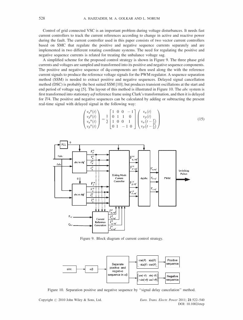
A simplified scheme for the proposed control strategy is shown in Figure 9. The three phase grid
currents and voltages are sampled and transformed into its positive and negative sequence components.
The positive and negative sequence of dq-components are then used along the with the reference
current signals to produce the reference voltage signals for the PWM regulator. A sequence separation
method (SSM) is needed to extract positive and negative sequences. Delayed signal cancellation
method (DSC) is probably the best suited SSM [10]; but produces transient oscillations at the start and
end period of voltage sag [5]. The layout of this method is illustrated in Figure 10. The abc system is
first transformed into stationary ab reference frame using Clark’s transformation, and then it is delayed
for T/4. The positive and negative sequences can be calculated by adding or subtracting the present
real-time signal with delayed signal in the following way:
vapðtÞ
vbpðtÞ
vanðtÞ
vbnðtÞ
0BB@
1CCA ¼ 1
2
1 0 0 � 1
0 1 1 0
1 0 0 1
0 1 � 1 0
2664
3775
vaðtÞvbðtÞ
va t � T4
� �vb t � T
4
� �0BB@
1CCA (15)
Figure 9. Block diagram of current control strategy.
Figure 10. Separation positive and negative sequence by ‘‘signal delay cancelation’’ method.
Copyright # 2010 John Wiley & Sons, Ltd. Euro. Trans. Electr. Power 2011; 21:522–540
DOI: 10.1002/etep
ROBUST CONTROL OF HYBRID FUEL CELL 529
According to the proposed control strategy, the purpose of the current controller is to synthesize a
voltage correction vector so that the current error vector can be kept to a minimum value.
In this paper, the current controller has been implemented by using SMC technique due to its
robustness and overshoot-free fast tracking capability [20].
The SMC is a nonlinear control approach which complies with the nonlinear characteristic of a
power electronic converter. Such control technique is robust even against the plant parametric variation
and can compensate the modeling approximations. Also, it is characterized by a good dynamic
response. In addition, the SMC is simple to implement.
According to the dynamic model of inverter given in (14), the state space equations of the system can
be written as (16):
X:ðtÞ ¼ AXðtÞ þ BU þ EVg
YðtÞ ¼ CXðtÞ (16)
where the state variable is X, the control input U, and grid voltage Vg and given in (17–19):
X ¼ ip2d i
p2q in2d in2q
h iT
; (17)
U ¼ Upd Up
q Und Un
q
h iT
; (18)
Vg ¼ Vpgd Vp
gq Vngd Vn
gq
h iT
(19)
For the control plant given in (16), the SMC law can be derived as follows. To let the current output Y
track the reference input iref, a sliding mode manifold can be chosen in the form of (20):
Sdqp
Sdqn
� �¼ i
p2dq
in2dq
� ��
ip;ref2dq
in;ref2dq
" #; (20)
where ip;ref2dq and i
n;ref2dq are the specified current vector commands for the positive and negative sequence
of dq-components.
The sliding mode can be reached if the control input U(t) is designed to be the solution of (21):
d
dtSðtÞ ¼ 0 (21)
The control law satisfies (21) is called equivalent control and is given by (22):
UeqðtÞ ¼ ðCBÞ�1½iref � CAXðtÞ � CEVgðtÞ� (22)
In order to generate proper current references, consider the complex apparent power from the grid:
Sg ¼ ðvpsdq ejvt þ vn
sdq e�jvtÞðip2dq ejvt þ in2dq e�jvtÞ� ¼ðPþ P2c cosð2vtÞ þ P2s sinð2vtÞÞþjðQþ Q2c cosð2vtÞ þ Q2s sinð2vtÞÞ
(23)
By expanding (23), the following expression in matrix form can be written:
P ¼ ðvpsdi
p2d þ vp
sqip2q þ vn
sdin2d þ vn
sqin2qÞ
Q ¼ ðvpsqi
p2d � v
psdi
p2q þ vn
sqin2d � vn
sdin2qÞ
Pc2 ¼ ðvpsdi
n2d þ vp
sqin2q þ vn
sdip2d þ vn
sqip2qÞ
Ps2 ¼ ðvpsdi
n2q � vp
sqin2d � vn
sdip2q þ vn
sqip2dÞ
Qc2 ¼ ðvpsqi
n2d � v
psdi
n2q � vn
sdip2q þ vn
sqip2dÞ
Qs2 ¼ ðvpsdi
n2d þ vp
sqin2q � vn
sdip2d � vn
sqip2qÞ
; (24)
where P and Q are the constant active and reactive power, respectively, while the subscripts Ps2 and Pc2
represent the second harmonic sine and cosine component of the active power. These are the oscillating
Copyright # 2010 John Wiley & Sons, Ltd. Euro. Trans. Electr. Power 2011; 21:522–540
DOI: 10.1002/etep
530 A. HAJIZADEH, M. A. GOLKAR AND L. NORUM
active powers due to the unbalance in the grid voltages. During generating the reference currents, the
oscillating reactive powers (Q2c, Q2s) cannot be included in the calculation. Therefore to simplify the
calculation and work with an invertible matrix (4� 4), oscillating reactive power is not controlled and
will flow through the system [5].
Hence, the reference currents can be calculated as follows:
ip�2d
ip�2q
in�2d
in�2q
2664
3775 ¼
vpsd vp
sq vnsd vn
sq
vpsq � v
psd vn
sq � vnsd
vnsq � vn
sd � vpsq vn
sd
vnsd vn
sq vpsd vp
sq
2664
3775�1
P�
Q�
�DPs2
�DPc2
2664
3775; (25)
DP ¼ 2 � ðR1 þ R2Þ � ððip2dÞ2 þ ðip2qÞ
2 þ ðin2dÞ2 þ ðin2qÞ
2Þ; (26)
DPc2 ¼ 2 � ðR1 þ R2Þ � ðip2din2d þ i
p2qi
n2qÞ þ 2 � v� L� ðip2di
n2q � i
p2qi
n2dÞ; (27)
DPs2 ¼ 2 � ðR1 þ R2Þ � ðip2din2q � i
p2qi
n2dÞ þ 2 � v� ðL1 þ L2Þ � ð�i
p2di
n2d � i
p2qi
n2qÞ (28)
This algorithm calculates current references by setting active and reactive power references (P�, Q�),
and by forcing the oscillating active power demanded by the filter to be delivered from the grid
(P�2c ¼ �DP2c; P�
2s ¼ �DP2s). Then, no oscillating active power flows between the dc link and the filter.
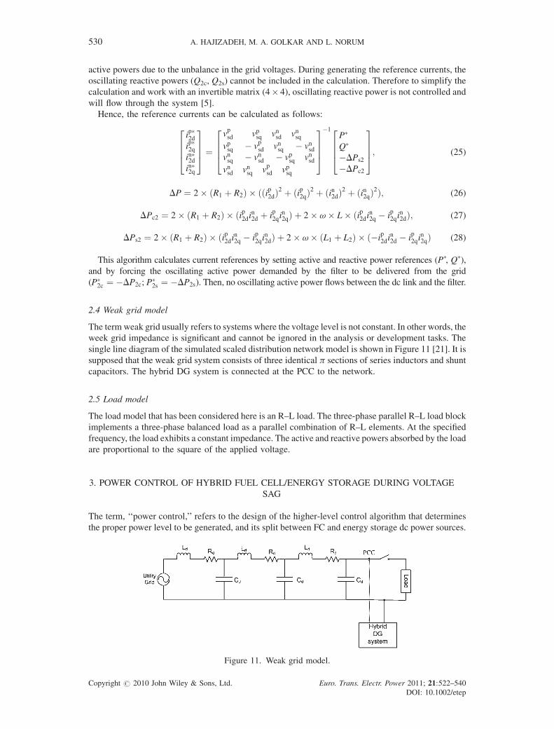
2.4 Weak grid model
The term weak grid usually refers to systems where the voltage level is not constant. In other words, the
week grid impedance is significant and cannot be ignored in the analysis or development tasks. The
single line diagram of the simulated scaled distribution network model is shown in Figure 11 [21]. It is
supposed that the weak grid system consists of three identical p sections of series inductors and shunt
capacitors. The hybrid DG system is connected at the PCC to the network.
2.5 Load model
The load model that has been considered here is an R–L load. The three-phase parallel R–L load block
implements a three-phase balanced load as a parallel combination of R–L elements. At the specified
frequency, the load exhibits a constant impedance. The active and reactive powers absorbed by the load
are proportional to the square of the applied voltage.
3. POWER CONTROL OF HYBRID FUEL CELL/ENERGY STORAGE DURING VOLTAGE
SAG
The term, ‘‘power control,’’ refers to the design of the higher-level control algorithm that determines
the proper power level to be generated, and its split between FC and energy storage dc power sources.
Figure 11. Weak grid model.
Copyright # 2010 John Wiley & Sons, Ltd. Euro. Trans. Electr. Power 2011; 21:522–540
DOI: 10.1002/etep

ROBUST CONTROL OF HYBRID FUEL CELL 531
This makes that the dc link power be stabilized and regulated the dc link voltage consequently. During the
voltage sag condition, a decrease in voltage amplitude occurs at the converter terminal. It makes an
increasing of the output currents of inverter. In this case, the power control strategy should limit the power at
the dc side of VSC to avoid overloading of the converter. This will thus limit the power that the DG unit can
supply to the grid during voltage sag, resulting the dc-link voltage will increase. To avoid a too high dc-link
voltage, the power balance between inverter power and DG power must be satisfied. One existing method to
solve these issues is to install energy storages which absorb power from dc link. In Figure 12 the flow of
power during different operating conditions in dc link is shown. If the losses in both the FC converter and
supercapacitor converter are neglected, the following differential equation for dc link is given:
Cdcvdc
dvdc
dt¼ PFC þ PSC � Pgrid ¼ vFCiFC þ vSCiSC � Pgrid; (29)
where PFC is the FC power, PSC is the supercapacitor power, and Pgrid is the grid power.
According to Equation (29), in order to regulate the dc link voltage it is necessary to keep the power
balance in dc link. In this equation, the change in grid power is considered as disturbance during the
voltage sag. Moreover it is important to consider the dynamic limitations of FC power to meet the
balance of power in dc link. In this case, the FC power could not change rapidly and the FC controller
with DC–DC converter should regulate the operating point of FC. But the amount of power that should
be absorbed by supercapacitor to balance the power in dc link is very important and it depends on the dc
link energy. The dc link energy measurement is carried out by means of the following calculation:
EdcðkÞ ¼1
2
� �CdcV
2dcðkÞ (30)
In this paper, a power flow control structure has been developed for hybrid power sources during
voltage sag. It is based on self-tuning fuzzy logic control (FLC) strategy that determines the
supercapacitor power according to the following inputs:
eðkÞ ¼ Edc�refðkÞ � EdcðkÞDeðkÞ ¼ eðkÞ � eðk � 1Þ ; (31)
where Edc-ref is the reference dc link energy which calculated by reference dc link voltage.
Hence, it is essential to design robust and stable control strategy to guarantee the stability of the dc
link of hybrid system. For this purpose, a robust self-tuning fuzzy PI control structure has been
developed [22]. The block diagram of the fuzzy PI controller is shown in Figure 13.
By using the scaling factors (SFs) Ge, GDe, the quantities e and De are converted to normalized eN
and DeN. These normalized quantities eN and DeN are crisp in nature and therefore need to be first
converted to their corresponding fuzzy variables. After fuzzification, the fuzzified inputs are given to
the fuzzy inference mechanism which, depending on the given fuzzy rule base, gives the normalized
incremental change in control output (DuN). The output DuN is converted into actual incremental
change in control output (Du) by using the SF Gu. For the implementation the fuzzy inference engine,
Figure 12. Power flow in hybrid fuel cell/energy storage power system.
Copyright # 2010 John Wiley & Sons, Ltd. Euro. Trans. Electr. Power 2011; 21:522–540
DOI: 10.1002/etep

Figure 13. The block diagram of the self-tuning fuzzy PI controller.
532 A. HAJIZADEH, M. A. GOLKAR AND L. NORUM
the ‘‘min’’ operator for connecting multiple antecedents in a rule, the ‘‘min’’ implication operator, and
the ‘‘max’’ aggregation operator have been used [23]. Actually, the output DuN from the inference
mechanism is fuzzy in nature, hence, to determine the crisp output, the defuzzification stage is applied.
The centroid defuzzification Scheme [22] has been used here for obtaining the output Du. Finally, the
actual value of the controller output (u) is computed by:
uðkÞ ¼ uðk � 1Þ þ DuðkÞ (32)
The relationships between the SFs and the input and output variables of the self-tuning FLC are as
follows:
eN ¼ Gee
DeN ¼ GDeDe
Du ¼ ðaGuÞDuN
(33)
In this scheme, the FLC is tuned on-line (while the controller is in operation) by dynamically
adjusting its output scale factor by a gain updating factor (a). The value of a is determined from a rule
base defined on e and De and derived from the knowledge of control engineering. Generally, selection
of suitable values for Ge, GDe and Gu are made based on the knowledge about the process to be
controlled and sometimes through trial and error to achieve the best possible control performance. This
is so because, unlike conventional non-fuzzy controllers, there is no well-defined method for selecting
appropriate values of SFs for FLC.
Each fuzzy control rule in the controller rule base is of the form:
‘‘If e is E and De is DE, then Du is DU’’where E, DE, and DU are the fuzzy sets corresponding to error,
change in error, and the incremental change in the control output, respectively. In this work, for both the
inputs (e and De) and the output (Du), seven fuzzy subsets have been used. These are: positive big (PB),
positive medium (PM), positive small (PS), zero (ZE), negative small (NS), negative medium (NM), and
negative big (NB). For each of these fuzzy sets, triangular membership function (MF) has been used [22].
From this figure it is observed that the triangles are symmetric with equal base having 50% overlap
with neighboring MFs. As each of the two inputs has seven fuzzy sets, there are altogether 49 control
rules in the FLC. The rule base for computing the output Du is shown in Table I which is a widely used
rule base designed with a two dimensional phase plane. The control rules in Table I are built based on
the characteristics of the step response. Moreover, the gain updating factor (a) is calculated using fuzzy
rules of the form:
If e is E and De is DE then a is a.
Copyright # 2010 John Wiley & Sons, Ltd. Euro. Trans. Electr. Power 2011; 21:522–540
DOI: 10.1002/etep

Table I. Rule base for computing the output Du.
De/e NB NM NS ZE PS PM PB
NB NB NB NB NM NS NS ZENM NB NM NM NM NS ZE PSNS NB NM NS NS ZE PS PMZE NB NM NS ZE PS PM PBPS NM NS ZE PS PS PM PBPM NS ZE PS PM PM PM PBPB ZE PS PS PM PB PB PB
ROBUST CONTROL OF HYBRID FUEL CELL 533
From Figure 9 it is observed that the value of a is computed from the normalized values of e and De by a
fuzzy rule base. The MFs used for e and De are exactly same as those used in FLC. Moreover, the same
fuzzy operators also been used in this case. The MFs for the factor a are defined in the domain [0,1]. As
each of the two inputs (e and De) to the fuzzy rule base (corresponding to a) has seven fuzzified variables,
the rule base has 49 rules for computing the value of a. Table II shows the rule base for computing a. This
rule base has been designed to improve the control performance under large disturbances such as three-
phase short circuit on the transmission lines, a sudden loss of generating unit or a large loss of load, etc. For
example, immediately after a large disturbance, e may be small but De will be sufficiently large (they will
be of same sign) and, for this case, a is supposed to be large to increase the gain. Therefore, under these
circumstances, the appropriate rules are ‘‘IFe is PS and De is PM THEN is B’’ or ‘‘IFe is NS and De is NM
THEN a is B.’’ On the other hand, for steady state conditions (i.e., e�0 and De�0), controller gain should
be very small (e.g., IFe is ZE andDe is ZE THEN a is ZE) to avoid chattering problem around the set point.
Further justification for using the rule base in Table II can be found in Ref. [24].
4. SIMULATION RESULTS
In order to show the effectiveness of proposed control strategy, the simulation model of the proposed
hybrid DG system has been built in Matlab/Simulink environment. The parameters of the hybrid FC/
energy storage DG system in this study are given in Table III. In this case study, the output power of the
FC power system during normal conditioning is considered to 50 kW. Moreover the supercapacitor
bank has is capable of sustaining the extra load of 20 kW during the voltage disturbances as short term
energy storage. So it is supposed that initial voltage for supercapacitor is 72 V. The average current to
be supplied by the supercapacitor bank corresponds to the average of the maximum and minimum
current demands from the supercapacitor bank, that is:
imax ¼ P
Vmin
¼ 20 000
48¼ 416:6A
imin ¼ P
Vmax
¼ 20 000
96¼ 208:3A
iavg ¼ ð416:6 þ 208:3Þ2
¼ 312:5A
(34)
Table II. Rule base for computing the output a.
De/e NB NM NS ZE PS PM PB
NB VB VB B SB S S ZENM VB VB B B MB S VSNS VB VB B VB VS S VSZE S SB MB ZE MB SB SS VS S VS VB B MB VBPM VS S MB B B VB VBPB ZE S SB B VB VB VB
V, very; S, small; M, medium; B, big; N, negative; P, positive; ZE, zero.
Copyright # 2010 John Wiley & Sons, Ltd. Euro. Trans. Electr. Power 2011; 21:522–540
DOI: 10.1002/etep

Table III. Parameters of the hybrid DG system.
Fuel cell system parametersFaraday’s constant (F) 96 484 600 C/kmolHydrogen time constant (tH2
) 26.1 sHydrogen valve molar constant (KH2
) 8.43� 10�4
kr constant¼N0/4F 9.9497� 10�7
No load voltage (E0) 0.6 VNumber of cells (N0) 384Oxygen time constant (tO2
) 2.91 sOxygen valve molar constant (KO2
) 2.52� 10�3
FC internal resistance (r) 0.126VFC absolute temperature (T) 343 KUniversal gas constant (R) 8314.47 J/(kmol K)Utilization factor (Uf) 0.8Water time constant (tH2O) 78.3 sWater valve molar constant (KH2O) 2.81� 10�4
Boost DC–DC converter parametersRated voltage (V) 200/650 VRated power 50 kWNominal duty cycle 0.6
Supercapacitor bank parametersMaximum allowable terminal voltage 96 VMinimum allowable terminal voltage 48 VOperating terminal voltage 72 VSupercapacitor capacitance (Csc) 165 F
Voltage source converter parametersNominal AC voltage 400 VNominal phase current 125 ANominal DC voltage 650 VDC-link capacitance 550mFR1 1.6 mVL1 0.52 mHR2 0.6 mVL2 0.2 mHCf 137.83mFfs 50 Hz
Weak grid parametersRd 0.05VLd 2.05 mHCd 46mF
534 A. HAJIZADEH, M. A. GOLKAR AND L. NORUM
For the proposed application, Maxwell Technologies Boost-cap1 BMOD0165 type supercapacitor
is used. The specification of the supercapacitor is given in Table I (http://www.maxwell.com/pdf/uc/
datasheets/20090428_48V_series_1009365.6.pdf). In order to meet the power demand, four
supercapacitor modules are used, where two strings of two modules connected in series. The total
capacitance (Ctotal) and resistance (Rtotal) may be obtained as:
Ctotal ¼ Cmodulenp
ns¼ 165 � 2
2¼ 165 F
Rtotal ¼ Rmodulenp
ns¼ 6:1 � 10�3 � 2
2¼ 6:1 mV
; (35)
where np and ns are the number of parallel and series connected capacitor, respectively.
The system was tested under several different operating conditions to investigate its power
management and load-following capabilities as well as its stability during unbalanced and balanced
voltage sags. The unbalance voltage sag that implemented for simulation is voltage sag type C with
60% magnitude.
4.1 Operation under normal conditions
A certain amount of power may be scheduled to be delivered to a load center from the utility grid with
the rest to be supplied by the hybrid FC system. Therefore, a proper controller must be designed to
Copyright # 2010 John Wiley & Sons, Ltd. Euro. Trans. Electr. Power 2011; 21:522–540
DOI: 10.1002/etep

Figure 14. Active and reactive powers delivered to the grid from hybrid DG system and the correspondingreference powers.
ROBUST CONTROL OF HYBRID FUEL CELL 535
ensure that only scheduled power is delivered from the grid and that the FC system follows the
remainder of load demand. Figure 14 shows active and reactive powers delivered to the grid from
hybrid DG system and the corresponding scheduled reference powers. Both show that the control
strategy quickly tracks the references with little overshoot. Similarly Figure 15 depicts the FC and
supercapacitor powers during normal operation. As shown, when the reference of active power
changes, the supercapacitor power also changes to deliever part of power during transient to stabilize
DC-link power. Moreover, according to slow dynamics of FC, its generated power changes slowly.
4.2 Operation under unbalance voltage sag
The proposed control strategy has been examined in case of unbalanced voltage sags. A volatg sag,
resulting from two-phase fault (type C), is applied at the grid side. The voltage sag starts at 0.7 seconds
for duration of 0.1 seconds with voltage drop of 60%. The grid voltage during voltage sag type C has
been shown in Figure 16a. As illustrated in Figure 16b, the grid currents increase to above 1.5 p.u. In
this case, the grid currents are limited by current controllers to avoid overloading of the converter.
Also after voltage sag, the current controllers adapt fast according to the new current references to
shape the grid currents. In Figure 16c, the average and instantaneous active power during normal and
Figure 15. Fuel cell and supercapacitor powers.
Copyright # 2010 John Wiley & Sons, Ltd. Euro. Trans. Electr. Power 2011; 21:522–540
DOI: 10.1002/etep

Figure 16. Simulation results during voltage sag type C.
536 A. HAJIZADEH, M. A. GOLKAR AND L. NORUM
voltage sag conditions have been presented. As shown during voltage sag the injected active power to
the grid is decreased and there are small oscillations on instantaneous active power. These oscillations
are related to the proposed current control strategy that considered in this paper. It makes that the
oscillating active power that demands by the filter to be delivered from the grid and no oscillating active
power flows between the dc link and the filter. Moreover, there are large oscillations on reactive power
that is shown in Figure 16d. But the average of reactive power is 0. Because the reference of reactive
power that considered for this simulation is 0, it is supposed that there is no voltage regulation in
proposed control strategy. The DC-link voltage is shown in Figure 16e. During the voltage sag, there is
an increasing on dc link voltage but it is not much more than 10% of nominal value. In these conditions,
to stabilize the dc-link power, the fuzzy controller manages the power flow between FC and
supercapacitor. Hence the reference power of the energy storage bank changes for decreasing the input
power on DC-link during voltage disturbance and the proposed control strategy makes the operating
mode of the energy storage bank goes to the charging mode. In Figure 16e and g, the FC output and
energy storage power are presented. Because of the slow variations of the FC, the output power of the
FC power plant remains constant during the voltage sag and for stabilizing the amount of power on DC-
link; the energy storage absorbs the extra power. According to Figure 16h, it is clear that the output
voltage of FC system has not changed during the occurring the voltage disturbances in distribution
systems and it is very important on the life time of FC system. On the other hand, during the voltage
sag, the energy storage energy storage makes to improve the performance of the hybrid system and the
generated power oscillations during the voltage sag compensate by the supercapacitor energy storage.
In this condition, the proposed power flow control strategy finds the suitable operating point for
the energy storage and FC power sources.
4.3 Operation under balanced voltage sag
For the evaluation of proposed control strategy, the hybrid system also has been studied under balanced
voltage sag with 40%. The duration of voltage sag is considered 0.1 seconds and the response of whole
Copyright # 2010 John Wiley & Sons, Ltd. Euro. Trans. Electr. Power 2011; 21:522–540
DOI: 10.1002/etep
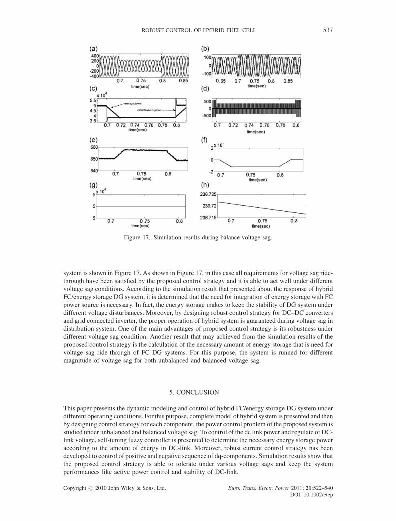
Figure 17. Simulation results during balance voltage sag.
ROBUST CONTROL OF HYBRID FUEL CELL 537
system is shown in Figure 17. As shown in Figure 17, in this case all requirements for voltage sag ride-
through have been satisfied by the proposed control strategy and it is able to act well under different
voltage sag conditions. According to the simulation result that presented about the response of hybrid
FC/energy storage DG system, it is determined that the need for integration of energy storage with FC
power source is necessary. In fact, the energy storage makes to keep the stability of DG system under
different voltage disturbances. Moreover, by designing robust control strategy for DC–DC converters
and grid connected inverter, the proper operation of hybrid system is guaranteed during voltage sag in
distribution system. One of the main advantages of proposed control strategy is its robustness under
different voltage sag condition. Another result that may achieved from the simulation results of the
proposed control strategy is the calculation of the necessary amount of energy storage that is need for
voltage sag ride-through of FC DG systems. For this purpose, the system is runned for different
magnitude of voltage sag for both unbalanced and balanced voltage sag.
5. CONCLUSION
This paper presents the dynamic modeling and control of hybrid FC/energy storage DG system under
different operating conditions. For this purpose, complete model of hybrid system is presented and then
by designing control strategy for each component, the power control problem of the proposed system is
studied under unbalanced and balanced voltage sag. To control of the dc link power and regulate of DC-
link voltage, self-tuning fuzzy controller is presented to determine the necessary energy storage power
according to the amount of energy in DC-link. Moreover, robust current control strategy has been
developed to control of positive and negative sequence of dq-components. Simulation results show that
the proposed control strategy is able to tolerate under various voltage sags and keep the system
performances like active power control and stability of DC-link.
Copyright # 2010 John Wiley & Sons, Ltd. Euro. Trans. Electr. Power 2011; 21:522–540
DOI: 10.1002/etep

538 A. HAJIZADEH, M. A. GOLKAR AND L. NORUM
6. LIST OF SYMBOLS
Fuel cell parameters
CV c
Copyright #
onversion factor
E0 v
oltage associated with the reaction free energyF F
araday’s constantIfc c
urrent of the fuel cell stackN0 n
umber of cells connected in seriesqmethane m
ethane flow rateqinH2
m
olar flow of hydrogenqinO2
m
olar flow of oxygenR u
niversal gas constantRint in
ternal resistance of fuel cell stackrH–O h
ydrogen–oxygen flow ratioT f
uel cell temperatureUf u
tilization factort1, t2 r
eformer time constantsDC–DC converter parameters
d d
uty cycle of the switching deviceD n
ominal duty cycle (chosen at 0.7)iL in
ductor currentiO o
utput currentILO n
ominal current of inductorKPWM a
mplitude of the PWM saw tooth carrier signalU in
put voltageVC o
utput capacitor voltageVCO n
ominal voltage of output capacitorSupercapacitor parameters
C t
otal capacitance of supercapacitorEPR e
quivalent parallel resistance representing the self-discharging lossesESR e
quivalent series resistance representing the charging and discharging resistanceIES o
utput current of supercapacitorisc s
upercapacitor currentQm m
aximum energy of supercapacitorSOC s
tate of charge of supercapacitorvsc s
upercapacitor voltageDC-link parameters
Edc D
C-link energyPFC f
uel cell powerPgrid g
rid powerPSC s
upercapacitor powervdc D
C-link voltageVoltage source converter parameters
idq d
q components of currentindq np
egative sequence of dq currents
idq p
ositive sequence of dq currentsi1 i
nductor current (1)2010 John Wiley & Sons, Ltd. Euro. Trans. Electr. Power 2011; 21:522–540
DOI: 10.1002/etep

ROBUST CONTROL OF HYBRID FUEL CELL 539
i2 i
Copyrig
nductor current (2)
Pg o
utput active power of inverterPc2g s
econd harmonic cosine component of the active powerPs2g s
econd harmonic sine component of the active powerQg o
utput reactive power of invertervc c
apacitor voltagevi i
nverter output voltagevs g
rid voltagevdq d
q components of voltagevab a
b components of voltagevpdq p
ositive sequence of dq voltagesvndq n
egative sequence of dq voltagesvnab n
egative sequence of ab voltagesvpab p
ositive sequence of ab voltagesREFERENCES
1. Bayod-Rujula AA. Future development of the electricity systems with distributed generation. Energy 2009; 34:377–
383 10.1016/j.energy.2008.12.008.
2. Ellis MW, VonSpakovsky MR, Nelson DJ. Fuel Cell Systems: Efficient, Flexible Energy Conversion for the 21st
century. in Proceedings of the IEEE, 2001; 89: 1808–1818.
3. Wang C, Nehrir NH, Gao H. Control of PEM fuel cell distributed generation systems. IEEE Transaction on Energy
Conversion 2006; 21:586–595. 10.1109/TEC.2005.860404.
4. Golkar MA, Hajizadeh A. Control strategy of hybrid fuel cell/battery distributed generation system for grid-
connected operation. Journal of Zhejiang University Science A 2009; 10:488–496. 10.1631/jzus.A0820151.
5. Saccomando G, Svensson J. Transient Operation of Grid Connected Voltage Source Converter under Unbalanced
Voltage Conditions. in Proceedings of the IEEE Industry Application Society Annual Meeting, 2001; 4: 2419–2424.
6. Bollen MH. Understanding Power Quality Problems: Voltage Sags and Interruptions, IEEE Press: New York, 1999.
7. Rendersa B, Ryckaert WR, De Gusseme K, Stockman K, Vandevelde L. Improving the voltage dip immunity of
converter-connected distributed generation units. Renewable Energy 2008; 33:1011–1018. 10.1016/
j.renene.2007.05.023.
8. Rodrıguez P, Timbus AV, Teodorescu R, Liserre M, Blaabjerg F. Independent PQ control for distributed power
generation systems under grid faults. in Proceedings of the 32nd Annual Conference IEEE IECON, 2006;
5185–5190.
9. Magueed FA, Sannino A, Svensson J. Transient performance of voltage source converter under unbalanced voltage
dips. in Proceedings of the IEEE PESC, Aachen, Germany, 2004; 1163–1168.
10. Sannino A, Bollen MH, Svensson J. Voltage tolerance testing of three-phase voltage source converters. IEEE
Transaction on Power Delivery 2005; 20:1633–1639. 10.1109/TPWRD.2004.833881.
11. Hajizadeh A, Golkar MA. Control of Hybrid Fuel Cell/Battery Distributed Power Generation System with
Voltage Sag Ride-Through Capability. 2nd IEEE International Conference on Power and Energy (PECon 08),
2008; 463–467. 10.1109/PECON.2008.4762510.
12. Sahay K, Dwivedi B. Energy storage technology for performance enhancement of power systems. Electrical Power
Quality & Utilization Magazine 2009; 4:1–12.
13. Hajizadeh A, Golkar MA. Intelligent power management strategy of hybrid distributed generation system.
International Journal of Electrical Power and Energy Systems 2007; 29:783–795. 10.1016/j.ijepes.2007.06.025.
14. El-Sharkh MY, Rahman A, Alam MY, Byrne PC, Sakla AA, Thomas T. A dynamic model for a stand-alone
PEM fuel cell power plant for residential applications. Journal of Power Sources 2004; 138:199–204. 10.1016/
j.jpowsour.2004.06.037.
15. Uzunoglu M, Alam MS. Dynamic modeling, design, and simulation of a combined PEM fuel cell and ultracapacitor
system for stand-alone residential applications. IEEE Transactions on Energy Conversion 2006; 21:767–775.
10.1109/TEC.2006.875468.
16. Mohan N, Undeland TM, Robbins WP. Power Electronics: Converters, Applications, and Design, Wiley: New York,
2003.
17. Kisacikoglu MC, Uzunoglu M, Alam MS. Load sharing using fuzzy logic control in a fuel cell/ultracapacitor hybrid
vehicle. International Journal of Hydrogen Energy 2009; 34:1497–1507. 10.1016/j.ijhydene.2008.11.035.
18. Yuri B, Shtessel YB, Zinober ASL, Shkolnikov A. Sliding mode control of boost and buck-boost power converters
using method of stable system centre. Automatica 2003; 39:1061–1067. 10.1016/S0005-1098(03)00068-2.
19. Teodorescu R, Blaabjerg F, Borup U, Liserre M. A new control structure for grid-connected LCL PV inverters with
zero steady-state error and selective harmonic compensation. 2004; 1: 580–586. 10.1109/APEC.2004.1295865.
20. Slotine JJ, Li W. Applied Nonlinear Control, Prentice-Hall: Englewood Cliffs, NJ, 1991.
ht # 2010 John Wiley & Sons, Ltd. Euro. Trans. Electr. Power 2011; 21:522–540
DOI: 10.1002/etep

540 A. HAJIZADEH, M. A. GOLKAR AND L. NORUM
21. Magueed F, Awad H. Voltage Compensation in Weak Grids Using Distributed Generation with Voltage Source
Converter as a Front End. International Conference on Power Electronics and Drives Systems, 2005; 234–239.
10.1109/PEDS.2005.1619691.
22. Mudi RK, Pal NR. A robust self-tuning scheme for PI- and PD-type fuzzy controllers. IEEE Transaction on Fuzzy
Systems 1999; 7:2–16. 10.1109/91.746295.
23. Jamshidi M. Fuzzy Logic and Control, Software and Hardware Applications, Ch 1–4, University of New Mexico,
PTR Prentice-Hall, Inc.: USA, 1993.
24. Pal K, Mudi RK, Pal NR. A new scheme for fuzzy rule-based system identification and its application to self-
tuning fuzzy controllers. IEEE Transaction on Systems, Man and Cybernetic B: Cybernetics 2002; 32:470–482.
1083-4419(02)04375-3.
Copyright # 2010 John Wiley & Sons, Ltd. Euro. Trans. Electr. Power 2011; 21:522–540
DOI: 10.1002/etep
Copyright © 2022 FDOKUMEN