Robotic system for MRI-guided prostate biopsy: feasibility of teleoperated needle insertion and ex...
12
1 23 International Journal of Computer Assisted Radiology and Surgery A journal for interdisciplinary research, development and applications of image guided diagnosis and therapy ISSN 1861-6410 Volume 7 Number 2 Int J CARS (2012) 7:181-190 DOI 10.1007/s11548-011-0598-9 Robotic system for MRI-guided prostate biopsy: feasibility of teleoperated needle insertion and ex vivo phantom study Reza Seifabadi, Sang-Eun Song, Axel Krieger, Nathan Bongjoon Cho, Junichi Tokuda, Gabor Fichtinger & Iulian Iordachita
Transcript of Robotic system for MRI-guided prostate biopsy: feasibility of teleoperated needle insertion and ex...

1 23
International Journal of ComputerAssisted Radiology and SurgeryA journal for interdisciplinary research,development and applications of imageguided diagnosis and therapy ISSN 1861-6410Volume 7Number 2 Int J CARS (2012) 7:181-190DOI 10.1007/s11548-011-0598-9
Robotic system for MRI-guided prostatebiopsy: feasibility of teleoperated needleinsertion and ex vivo phantom study
Reza Seifabadi, Sang-Eun Song, AxelKrieger, Nathan Bongjoon Cho, JunichiTokuda, Gabor Fichtinger & IulianIordachita

1 23
Your article is protected by copyright and all
rights are held exclusively by CARS. This e-
offprint is for personal use only and shall not
be self-archived in electronic repositories.
If you wish to self-archive your work, please
use the accepted author’s version for posting
to your own website or your institution’s
repository. You may further deposit the
accepted author’s version on a funder’s
repository at a funder’s request, provided it is
not made publicly available until 12 months
after publication.

Int J CARS (2012) 7:181–190DOI 10.1007/s11548-011-0598-9
ORIGINAL ARTICLE
Robotic system for MRI-guided prostate biopsy: feasibilityof teleoperated needle insertion and ex vivo phantom study
Reza Seifabadi · Sang-Eun Song · Axel Krieger ·Nathan Bongjoon Cho · Junichi Tokuda ·Gabor Fichtinger · Iulian Iordachita
Received: 12 January 2011 / Accepted: 26 April 2011 / Published online: 23 June 2011© CARS 2011
AbstractPurpose Magnetic Resonance Imaging (MRI) combinedwith robotic assistance has the potential to improve on clini-cal outcomes of biopsy and local treatment of prostate cancer.Methods We report the workspace optimization and phan-tom evaluation of a five Degree of Freedom (DOF) paral-lel pneumatically actuated modular robot for MRI-guidedprostate biopsy. To shorten procedure time and consequentlyincrease patient comfort and system accuracy, a prototype ofa MRI-compatible master–slave needle driver module usingpiezo motors was also added to the base robot.Results Variable size workspace was achieved using appro-priate link length, compared with the previous design. The5-DOF targeting accuracy demonstrated an average error of2.5 mm (STD = 1.37 mm) in a realistic phantom inside a 3Tmagnet with a bevel-tip 18G needle. The average positiontracking error of the master–slave needle driver was alwaysbelow 0.1 mm.Conclusion Phantom experiments showed sufficient accu-racy for manual prostate biopsy. Also, the implementationof teleoperated needle insertion was feasible and accurate.These two together suggest the feasibility of accurate fullyactuated needle placement into prostate while keeping theclinician supervision over the task.
R. Seifabadi (B) · A. Krieger · N. B. Cho ·G. Fichtinger · I. IordachitaLaboratory for Computational Sensing and Robotics (LCSR),The Johns Hopkins University, Baltimore, MD, USAe-mail: [email protected]
R. Seifabadi · G. FichtingerLaboratory for Percutaneous surgery (Perk Lab),Queen’s University, Kingston, ON, Canada
S.-E. Song · J. TokudaDepartment of Radiology, Brigham and Women’s Hospital and HarvardMedical School, Boston, MA, USA
Keywords Transperineal prostate biopsy ·MRI compatible · Pneumatic robot · Teleoperation ·Accuracy evaluation · Phantom study
Introduction
Prostate cancer is the most common cancer in men in theUnited States. In 2010, over 200,000 men were expected tobe diagnosed with prostate cancer with over 32,000 deathsof this disease [1]. Early stage cancer detection is criticallyimportant to ensure patient survival. Despite its poor speci-ficity, PSA level is used to determine which patient is a can-didate for core needle biopsy. Each year approximately 1.5million prostate biopsy procedures are performed only in theUnited States [2]. For this reason, a surgical biopsy needleis inserted into a predefined target position inside prostateunder image guidance.
Transrectal ultrasound (TRUS) guidance is the “GoldStandard” navigation method for the biopsy due to its real-time nature, relative low cost, and ease of use. However, thisimaging modality is not capable of visualizing cancer [3]but rather the contour of prostate, resulting in a significantnumber of false negatives in conventional TRUS-guided sys-tematic biopsy, where 6–12 cores equally distributed withinthe prostate are sampled.
MRI is a superior imaging modality, primarily due to itshigh sensitivity for detecting prostate tumors, excellent softtissue contrast, high spatial resolution, and multi-planar vol-umetric imaging capabilities [4]. Despite its unique capa-bilities, MRI has two main limitations when it comes to arobotic approach: strong magnetic field (1.5T or greater) thatrequires MRI compatibility of surgical devices, sensors, andactuators as well as physical limitation of in-bore access andworkspace.
123
Author's personal copy
182 Int J CARS (2012) 7:181–190
Several MRI-compatible robots have been reported forprostate intervention. The robotic systems can be catego-rized into transrectal, transperineal, and transgluteal depend-ing upon the anatomical access method used [8].
(1) Transrectal approach: In [5–7] two generations ofMRI-guided systems were developed for transrectalprostate biopsies, therapeutic injections, and markerplacements. APT I had 2-DOF (roll and pitch) and wasactuated manually through two flexible shafts com-ing out of the bore. APT II has been used in manyclinical procedures at a few health care institutions.In [8], a motorized APT is introduced where the rolland pitch movements are actuated using piezo motors.In [9] Beyersdorff and in [10], Engelhard developedMRI-guided transrectal needle biopsies in patient stud-ies with a system (Invivo Germany GmbH, Schwerin,Germany) employing manual alignment of a needlesleeve. Elhawary reported a prototype robotic systemusing linear piezo-ceramic motors for transrectal pros-tate biopsy [11]. This system employed remotely drivenneedle driver module with haptic force feedback at themaster side.
(2) Transperineal approach: MRI-guided transperinealprostate intervention was primarily studied in patientexperiment inside an open MRI scanner [12] and thenconventional closed MRI scanner [13]. In [14] and[15], Chinzei and Di Maio designed systems to assisttransperineal intra-prostatic needle placement. In [16],Tadakuma developed an MRI-compatible robot fortransperineal needle placement in the prostate usingdielectric elastomer actuators (DEAs). In [17], Sto-ianovici developed a fully automated pneumaticallyactuated device for transperineal brachytherapy seedplacement in phantom experiment. In [18], Fischerdeveloped a pneumatic 2-DOF robot for transperi-neal prostate needle placement in phantom study. In[19], Goldenberg developed a robotic system employ-ing ultrasonic actuators for MRI-guided transperinealprostate intervention. In [20], van den Bosch reporteda hydraulically and pneumatically actuated tappingdevice to alleviate undesirable prostate displacementand deformation. Su reported a 3-DOF Cartesian robotfor MRI-guided transperineal needle alignment witha 3-DOF needle steering module for teleoperated andautonomous seed implantation [21,22].
(3) Transglutteal approach: In [23], Zangos proposed andclinically validated the feasibility of manual trans-gluteal approach with an open 0.2T MRI scanner. In[24], Zangos used the Innomotion robot for transglut-eal approach in a cadaver study at 1.5T.
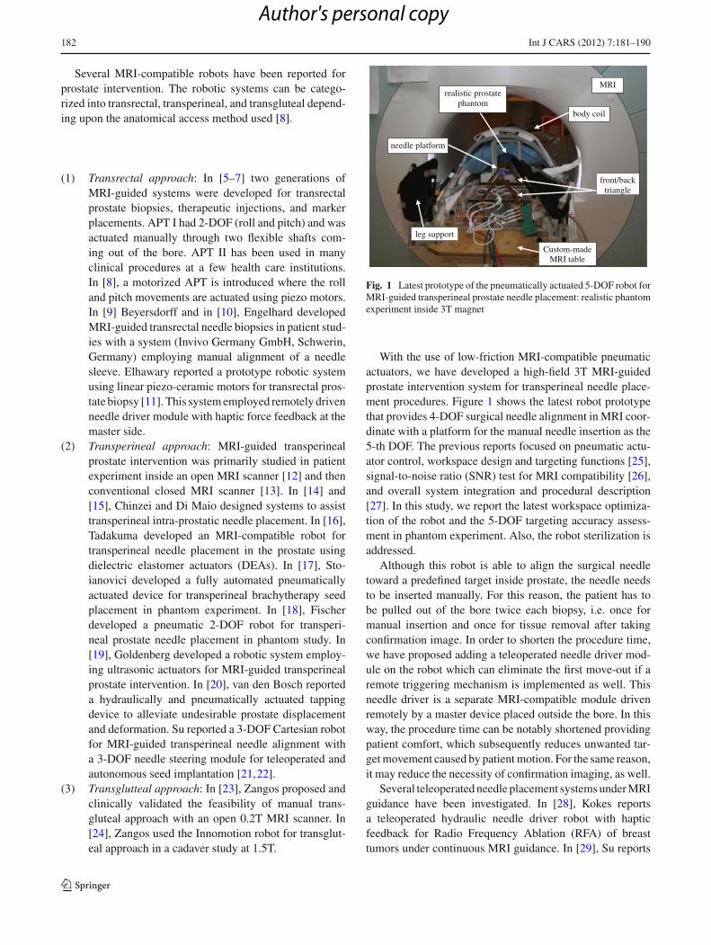
leg support
needle platform
MRI realistic prostate
phantom
front/back triangle
body coil
Custom-made MRI table
Fig. 1 Latest prototype of the pneumatically actuated 5-DOF robot forMRI-guided transperineal prostate needle placement: realistic phantomexperiment inside 3T magnet
With the use of low-friction MRI-compatible pneumaticactuators, we have developed a high-field 3T MRI-guidedprostate intervention system for transperineal needle place-ment procedures. Figure 1 shows the latest robot prototypethat provides 4-DOF surgical needle alignment in MRI coor-dinate with a platform for the manual needle insertion as the5-th DOF. The previous reports focused on pneumatic actu-ator control, workspace design and targeting functions [25],signal-to-noise ratio (SNR) test for MRI compatibility [26],and overall system integration and procedural description[27]. In this study, we report the latest workspace optimiza-tion of the robot and the 5-DOF targeting accuracy assess-ment in phantom experiment. Also, the robot sterilization isaddressed.
Although this robot is able to align the surgical needletoward a predefined target inside prostate, the needle needsto be inserted manually. For this reason, the patient has tobe pulled out of the bore twice each biopsy, i.e. once formanual insertion and once for tissue removal after takingconfirmation image. In order to shorten the procedure time,we have proposed adding a teleoperated needle driver mod-ule on the robot which can eliminate the first move-out if aremote triggering mechanism is implemented as well. Thisneedle driver is a separate MRI-compatible module drivenremotely by a master device placed outside the bore. In thisway, the procedure time can be notably shortened providingpatient comfort, which subsequently reduces unwanted tar-get movement caused by patient motion. For the same reason,it may reduce the necessity of confirmation imaging, as well.
Several teleoperated needle placement systems under MRIguidance have been investigated. In [28], Kokes reportsa teleoperated hydraulic needle driver robot with hapticfeedback for Radio Frequency Ablation (RFA) of breasttumors under continuous MRI guidance. In [29], Su reports
123
Author's personal copy

Int J CARS (2012) 7:181–190 183
a 3-DOF teleoperated needle driver installed on top of a3-DOF Cartesian linear stage for brachytherapy. In [30], Tsereports a 5-DOF robot for needle alignment with a singleDOF teleoperated module for transrectal prostate biopsy.
Unlike previously discussed systems, our master device isdesigned to be placed inside scanner room as surgeons needto be close to the patient during the interventional procedure.This means that conventional (non-MRI compatible) hapticdevices cannot be deployed due to the high magnetic field.This paper reports the initial study of a human-controlledneedle drive added to an existing robot.
The paper is organized as follows: system architectureand procedure are discussed in “System design”. In “Needledriver module design”, teleoperated needle driver module isintroduced and discussed. Workspace optimization is brieflydiscussed, as well. In “Experiments and results”, the overallsystem needle placement accuracy is evaluated in phantomexperiment inside a 3T magnet. Also, the performance of theproposed teleoperated needle insertion driver is evaluated.The paper is continued by discussion in “Discussion” andends by conclusions and future works in “Conclusions andfuture works”.
System design
System components
Figure 2 illustrates a diagram of system components andinformation flow. In MRI suite (left side), the patient andthe robot are placed inside scanner and the robot control-ler is placed at 3 m distance from the scanner’s bore. Themedical air supply available in a standard hospital is used torun the pneumatic robot. The controller sends the pressuresignals (commands) to the robot pneumatic actuators andreceives position feedback from the robot optical encoders.There is no electrical communication between them in orderto keep the Electro Magnetic Interference (EMI) minimized.The power supply for the controller is placed in the controlroom to further reduce the EMI. In the control room (rightside), the scanner console that is a workstation for runningthe MRI machine is placed. 3D Slicer (http://www.slicer.org/) is running on a Linux-based workstation called plan-ning workstation. Intra-operative MRI images are importedfrom the scanner console to 3D Slicer. Target positions areselected by the clinician in this software and sent as com-mands to the robot controller. A local network is establishedamong the planning workstation, the scanner console, andthe robot controller. Data communication between the net-work and robot controller is via fiber-optic Ethernet to avoidEMI.
Dotted-line squares show new added components to theexisting system as discussed earlier. These components
Scanner
Robot+
Needle driver
RobotController
Scannerconsole
Planningworkstation
Local network
Power supply
Optic data transfer Medical air supply / flowWire data transfer DC power via EM filtered panel
Master Master-slave Controller
MRI suite Control suite
Visual Feedback Haptic Feedback
Surgeon MRI Screen
Fig. 2 Diagram of system components and information flow. Dotted-line squares show new added components to the previous setup
include the following: the master console, the slave (needledriver module), and the master–slave control units. Currently,the needle driver controller is not integrated with the robotcontroller. The surgeon stands next to the scanner and movesthe master console while observing the real-time image.The slave follows the master’s movement and then performsinsertion.
To avoid interference with the pubic arch and urethra, a5-DOF parallel kinematic structure was proposed [25]. Thepyramid structure of the robot helps to maximize the useof ‘under-legs’ space and minimize ‘between-legs’ space. Ifnecessary, the workspace can be shifted vertically by insert-ing a spacer. Timing belts and pulleys transmit each pneu-matic cylinder movement to the prismatic manipulation offront and rear triangle structures. These pulleys and tim-ing belts function as external damping mechanism as wellto stabilize cylinder’s dynamic behavior and solve many ofthe difficulties associated with servo control of pneumatics.MRI-compatible optical encoders are used for position sens-ing. The moving parts are made of Ultem, which is suffi-ciently rigid and MRI compatible. The needle is located onthe linkage connecting the front and back mechanisms.
The controller operates inside the scanner room, approx-imately 3 m away from the 3T scanner, without func-tional difficulties or significant image quality degradation[18]. The controller is inside an EMI-shielded enclosurecontains the embedded Linux PC providing low-level servocontrol, the piezoelectric valves, pressure sensors, and thefiber-optic Ethernet converter. A customized graphical userinterface (GUI) specifically designed for the prostate inter-vention is used with the robot [34].
123
Author's personal copy

184 Int J CARS (2012) 7:181–190
In case of robot failure, the robot is removed and the pro-cedure is continued manually by a grid of template similarto standard ultrasound-guided procedure [35,36].
Robot kinematics
The robot comprises two identical planar mechanisms (frontand rear triangles) as shown in Fig. 3. Each planar parallelstructure can move its end effector within the correspond-ing plane with the use of two pneumatic actuators 1 and 2(3 and 4). As these two mechanisms are coupled togetherwith an adjustable link and two spherical joints at both ends,they generate yaw and pitch orientations as well as x andy in-plane movement if moved asynchronous, resulting in4-DOF. The 5th DOF, i.e. the insertion, is performed man-ually. Each 2-DOF mechanism provides a workspace sur-rounding a sphere of 50 mm diameter (Fig. 3b).
The way the robot reaches a target (i.e. the inverse kine-matics) is as follows: first, a target and a straight trajectory(considering pubic arc/urethra avoidance) are specified byclinician in the navigation software. These target and trajec-tory are given in MRI coordinate system and thus needed tobe transformed into robot coordinate system. For this reason,Z-frame is used [37]. Then, the line defined by the target andthe trajectory intersects the front and rear planes (Fig. 3a) giv-ing (x1, y1) and (x2, y2). Then, each 2-DOF planar mecha-nism must move as follows such that the effectors reach thosecoordinates (Fig. 3b):
J1 = x1+√
(L2 − (y1 − a)2) , J2 = x1−√
(L2−(y1 − a)2)
where J1 and J2 are x coordinates of each actuator. Similarrelationship exists for J3 and J4 (back triangle mechanisms)with replacing x2 and y2 for x1 and y1.
Workspace optimization
The robot was designed with variable link length so thatrobot’s workspace can easily be modified or intra-operativelychanged depending upon the prostate size and height rela-
tive to the table. Considering the robot kinematics (Fig. 3a),the rear triangle requires larger manipulation range becausethe front triangle is fundamentally responsible for needleentry area and the rear triangle is responsible for angula-tions. Also, since insertion angle is usually upwards i.e.posterior-to-anterior, shorter rear triangle link length wouldbenefit. Originally, 120 mm link length was designed for alltriangle links. However, 120/100 mm for front triangle linkand 120/100/80 mm for rear triangle are currently available.Figure 4 shows an axial view of 120 mm front—120 mm rearworkspace (a) and 120 mm front—80 mm rear workspace(b). As seen, the 2D workspace has enlarged as the result ofshortening the back links.
Sterilization
Prostate biopsies that are performed through the rectum donot require sterilization. In contrast, we propose a system fortransperineal access that requires some degree of steriliza-tion. Compared with the conventional prostate biopsy systemin which a disposable grid template is used, the brass tube infront triangle which guides the needle through (Fig. 8) is notdisposable and rather permanently attached to the links bythe front spherical joint. Hence, for the current version, weproposed to dismantle the top parts (Fig. 8, dotted-line area)as an ensemble and send to the plasma sterilization beforeeach procedure. The non-sterile parts are covered by a plas-tic drape with a small hole for the needle to travel through(Fig. 5). The use of drape did not show interference with therobot’s movement.
Needle driver module design
The clinical workflow of this robotic system is as follows:
(1) Patient is placed inside the bore;(2) Z-frame is placed on a predefined position on the
custom-made MRI board;
Fig. 3 The manipulatorconsists of a pair of identical2-DOF planar mechanism (a).Planar mechanism workspaceand in-plane inverse kinematicsrelationship are shown (b)
123
Author's personal copy

Int J CARS (2012) 7:181–190 185
Fig. 4 2D view of robot workspace when front/rear triangles link length are changed: a 120/120: a sphere of 50 mm diameter represents a relativelylarge prostate, b 120/80: The 2D workspace is enlarged as the result of shortening the back links
Sterilized drape Biopsy needle
Robot
Patient’s leg
Fig. 5 Robot is covered by a sterilized drape with a small hole on itfor needle travel. Plasma sterilization is applied to top parts
(3) Z-frame is scanned and 3D Slicer find the transforma-tion matrix from MRI coordinate to robot coordinate;
(4) Z-frame is removed;(5) Robot is placed between patient’s legs on a predefined
position on custom-made MRI board;(6) Intra-operative MRI image of the anatomy is acquired
and imported in navigation software;(7) One target and needle trajectory is specified in plan-
ning workstation;(8) Planning software (3D Slicer) sends the transforma-
tion matrix and target information to the robot con-troller;
(9) The controller solves the Inverse Kinematic Problem(IKP) and commands the robot actuators to orient theneedle toward the target;
(10) The patient is pulled out of the bore;(11) The surgeon inserts the needle manually;(12) Patient is placed back into MRI;(13) Confirmation image is taken;(14) The needle tip is compared with the planned target in
axial plane and targeting error is found;
(15) If the error is acceptable (<3 mm), patient is pulled outfor tissue removal and go to next target starting from(7);
(16) Otherwise, patient is pulled out for needle removal andgo to the same target starting from (7).
The important issue with the manual insertion is that the sec-ond move-out followed by move-in (underlined above) notonly extends the procedure duration by itself but also raisesthe risk of targeting failure as the result of patient movement,thus causing repetition of items 7–15. Hence, this study aimsto eliminate manual needle insertion so as to reduce the pro-cedure time and boost patient comfort. Automated needleinsertion is not the solution due to safety issue. The solutionproposed here is a teleoperated needle insertion. As depictedin Fig. 6, the surgeon stands in MRI room, next to the patientand operates an MRI-compatible master device, which fairlymimics a realistic needle insertion. Also, the surgeon will beable to benefit from real-time MRI image through a screeninside the MRI room. In this way, surgeon will have a morerealistic sense of doing the task.
The requirements for this teleoperatoin system can besummarized as follows:
(1) The needle driver should precisely follow the masterposition not only in free space movement, but also dur-ing the insertion (i.e. q1 = q2).
(2) The system should be MRI compatible with negligibleSNR degradation.
(3) The needle driver should be sufficiently compact suchthat it can be mounted on top of the base robot.
(4) The slave must be sufficiently strong to penetrate thetissue (at least 8.9N [30]).
Needle driver (slave robot)
The needle driver is designed to be installed on top of thelinkage between the front and the rear triangles. The needle
123
Author's personal copy

186 Int J CARS (2012) 7:181–190
Z
YX
R
S
A
Fig. 6 Schematic view of the overall master–slave system. The surgeon interacts with a master device to insert a needle at remote site. The surgeonis provided haptic and visual feedback
Table 1 Comparison of different piezo motors
Motor MRI compatible Max thrust (N)
Nanomotion � Up to 32
PI × Not available
PiezoLEG � 10
driver is located close to the scanner’s iso-center, and MRIcompatibility becomes the first concern for actuator selec-tion. Based upon the previous experience, pneumatic actua-tors are hard to control especially when they are configuredas a master–slave system. This is due mainly to the air com-pressibility and their inherent non-linearity of the pneumaticactuator. An alternative to pneumatic actuator is piezo motor,which provides high precision and ease of control. Moreover,piezo motor generates enough force in a small footprint. Wecompared three different types of piezo motors: Nanomo-tion Ltd. (Yoqneam, Israel), PI PILine (Physik Instrumente,Karlsruhe, Germany) and Piezomotor Piezoleg (PiezomotorAB, Upsala, Sweden). Table 1 shows the comparison.
As a result, Nanomotion motor was selected as it providesnot only enough thrust for penetrating prostate (almost 8.9N[30]) but also MRI compatibility.
In order to achieve the given clinical task, the moduleshould:
• Provide sufficient thrust;• Be sufficiently compact so that it can be installed on the
top of the robot;• Be MRI compatible (minimum image degradation);• Be as frictionless as possible since mechanical friction
obstructs the needle–tissue interaction.
To measure position, optical encoders are employed asfollows: modular EM1 electro optical encoders (US Dig-ital, Vancouver, Washington), along with a 500 lines perinch (LPI) code strip. Figure 7 shows a close-up view of
HR4 Nanomotion motors
Horizontal stops
Optical Encoder
Motor plate
Fig. 7 The needle driver: Two HR4 Nanomotion motors (28Ntogether) are placed against each other. Optical encoder is employedfor position feedback
stage using two Nanomotion HR-4 motors with four motorelements each (28N together). This stage was previouslyused as the linear stage for the motorized APT robot [8]. Alow-cost, custom-made linear stage was built, because off-the-shelf linear bearings are usually not MRI compatible andcostly. A pairs of HR-4 Nanomotion motors were axiallypre-loaded against each other on a ceramic drive strips andprovided linear motion of a drive shaft that slides axially for-ward and backward on an aluminum plate. Vertical and hor-izontal stops are used to limit vertical movement and defineend stops for travel. All materials are non-metalic (Ultem,plastic, or ceramic) except the motor plate that was made ofaluminum for increased rigidity. Figure 8 shows this moduleinstalled on top of the robot.
Master device
In our preliminary prototype (Fig. 9), the master device isnot yet actuated. It consists of a MRI-compatible slide andrail (Igus Inc., East Providence, RI) which mimics the nee-dle insertion. To measure position, optical encoding was
123
Author's personal copy

Int J CARS (2012) 7:181–190 187
Needle Driver Module
Pneumatic robot
Needle guide
Fig. 8 The needle driver is installed on top of the pneumatic robot.Dotted-line area shows sterilizable parts
Optical Encoder
Acrylic plateEncoder strip Slider and rail
18 G needle
Fig. 9 The master device: A needle is translated by a slider on a railaffixed to the Acrylic sheet. Position measurement is done by opticalencoder
AB5 amplifier
Galil motion controller
Fig. 10 Galil motion controller and AB5 Nanomotion amplifier
employed with 500 lines per inch (LPI) code strip. In thenext step, a linear module similar to the needle driver willreplace the current master device, in order to generate hapticforce feedback on surgeon’s fingers.
Needle driver controller unit
The needle driver controller unit consists of NanomotionAB5 motor amplifiers, a DMC-21×3 Ethernet motion con-troller (Galil Motion Control, Rocklin, California) (Fig. 10),and a PC workstation on which GalilTools (the software tocommand the controller and to monitor sensor signals) runs.A 24 V DC power supply is used to run the controller andamplifier. If shielded properly, the SNR degradation as theresult of using AB5 amplifiers would be negligible as long
as the motor is not moving (even if in the motor-on mode)[8]. However, in our application, the motor is running whilethe scanner is operating. This will impact the SNR notice-ably. For this reason, we are planning to replace AB5 witha custom-made amplifier, which will eliminate the high-fre-quency switching of the current amplifier.
Experiments and results
Ex vivo accuracy evaluation with manual insertion
In the earlier studies, we evaluated the system in the follow-ing three series of preliminary experiments: (1) manipulatorpositioning accuracy and repeatability test [25], (2) signal-to-noise ratio (SNR) test for MRI compatibility [26], and (3)patient compatibility and comfort tests for system integrationand procedural feasibility [27]. Here, we performed an exvivo experiment (Fig. 1) using a commercial prostate inter-vention training phantom (Model 053 Ultrasound ProstateTraining Phantom, Computerized Imaging Reference Sys-tems, Inc., Norfolk, VA). The objective of this experimentwas to evaluate the overall accuracy of needle placement inprostate biopsy procedures. The prostate phantom was placedand fixed in a height typical in a real clinical procedure. Inthe beginning, the Z-frame was secured on the predefinedposition on the custom-made MRI table. The image of theZ-frame was acquired using 3D Fast Low Angle Shot(FLASH) (TR/TE: 12/1.97 ms; acquisition matrix: 256 ×256; flip angle 45◦; field of view: 160 × 160 mm; slicethickness: 2 mm; receiver bandwidth: 400 Hz/pixel; num-ber of averages: 3). After imaging the Z-frame, the imageswere uploaded in 3D Slicer and the transformation matrixfrom RAS (Right/Left, Anterior/Posterior, Superior/Infe-rior) to robot coordinate (XYZ) was calculated by the soft-ware. The prostate phantom was then imaged and importedto the navigation software. The image of the phantomwas acquired using 2D Turbo Spin Echo (TSE) sequence(TR/TE = 5,250/100 ms; acquisition matrix = 320 × 224;flip angle = 150◦; field of view = 140 × 140 mm; slicethickness = 3 mm; receiver bandwidth = 203 Hz/pixel). Then,the Z-frame was removed, and the robot was placed in acertain pose on MRI board. In 3D Slicer, a total of 15 tar-gets were randomly picked within the prostate capsule in thephantom, as indicated in Table 2. These targets were chosenin different area of the prostate capsule to ensure the reportedaverage error is independent of the target location. Thesoftware sent those targets and corresponding needle trajec-tories (in quaternion format) to the robot controller alongwith the RAS-to-XYZ transformation matrix (calculated byZ-frame registration) via Ethernet cable. After a 18−gauge×20 cm needle with bevel-shaped tip (MRI Bio Gun, E-Z-EM,Westbury, NY) was inserted for each target, a confirmation
123
Author's personal copy

188 Int J CARS (2012) 7:181–190
Table 2 Results of needle placement accuracy evaluation in realistic phantom in 3T magnet ( mm)
Target # 1 2 3 4 5 6 7 8 9 10 11 12 13 14 15 Avg STD
R 9.0 20.4 9.6 15.3 2.1 2.4 9.6 15.60 11.1 15.0 11.0 13.0 0 2.4 9.6 − −A 16.3 15.8 28.3 21.5 15.8 24.0 10.9 11.50 12.0 17.0 22.0 18.0 0 24.0 10.9 − −S 12.5 12.5 12.5 22.0 22.0 22.0 32.0 32.00 12.5 12.5 12.5 20.0 0 25.0 25.0 − −Err_R −1.3 2.1 0.3 3.7 2.6 0.5 −0.4 0.2 3.2 1.7 0.8 −1.2 0 3.5 −1.2 0.97 1.73
Err_A 3.2 2.7 −1.8 −0.4 2 3.4 1.4 0.8 0.1 −0.6 −0.5 3.7 0 3.1 1.1 1.22 1.74
Err_Total 3.5 3.4 1.8 3.7 3.2 3.4 1.4 0.8 3.2 1.8 0.9 3.8 0 4.6 1.6 2.50 1.37
1 2 3 4 5 6 7 8 9 10 11 12 13 14 150
0.5
1
1.5
2
2.5
3
3.5
4
4.5
5
Target #
Acc
urac
y (m
m)
Needle Placement Error
Average Error
Fig. 11 Overall needle placement error in ex vivo phantom experi-ment: the needle was bevel-tip 18G×20 cm
image was acquired around the target with a Half FourierAcquisition Single Shot Turbo Spin Echo (HASTE) sequence(TR/TE = 1000/102 ms; matrix = 320 × 179; flip angle =150◦; field of view = 280×224 mm; slice thickness = 2 mm;receiver bandwidth = 780 Hz/pixel) along axial and sagittalplane in order to measure the 2D needle placement error.The 2D needle placement error was defined as the distancebetween the predefined target and the center of the needleartifact on the same axial plane, as obtained. The error inS direction (normal to the axial image plane) was ignoredas the needle artifact was visible in a slide before and afterthe predefined target. Moreover, the biopsy sample is typ-ically 15–20 mm implying that few millimeters of error inneedle direction is practically insignificant. The error com-ponents in R and A direction (entitled Err_R and Err_A,respectively) as well as the overall in-plane error (entitledErr_Total) for each target are provided in Table 2. Figure 11shows the histogram of the overall in-plane error for eachtarget as well as the average error. Target 13 was an out-lier, and it was eliminated. The results are discussed in“Discussion”.
0 2 4 6 8 10 12 14 16 18 200
10
20
30
40
time (sec)
Pos
ition
(m
m) Master Position
Slave Position
0 2 4 6 8 10 12 14 16 18 20-1
0
1
2
3
4
5
time (sec)
Pos
ition
Err
or (
mm
)Tracking Error
Ave Error
Fig. 12 Position tracking of the master–slave needle insertion module
Position tracking evaluation of the master–slaveneedle driver
The performance of the master–slave insertion module isexplored separately as shown in Fig. 12. The main exper-imental objective of the needle driver system was to testwhether the needle driver follows the command sent by themaster device. A simple code was written in G-language(the language of GalilTools). The controller at the slave sidewas a Proportional-Integral (PI) controller with the KP = 100and KI = 20. The master was moved back and forth over a40 mm range of motion for 20 s, and it was expected thatthe slave follows the master without any delay. As seen, theneedle driver was following the master accurately withoutnoticeable delay. The average error was 0.03 mm. Thisexperiment was repeated 3 times, and the error was below0.1 mm in all cases.
Discussion
The required accuracy is determined by the clinically sig-nificant size of prostate cancer foci. Although there is no
123
Author's personal copy

Int J CARS (2012) 7:181–190 189
standard yet, it is generally agreed that 3 mm accuracy is suf-ficient [38]. As seen in Fig. 11 and Table 2, the average ofthe overall system needle placement error (i.e. including themanipulator error and the registration error) for the manualinsertion approach is 2.5 mm (STD = 1.37) which seems ade-quate. However, due to prostate motion in real clinical proce-dure, the clinical targeting error is expected to be somewhatlarger [39].
As the master–slave needle insertion system is only replac-ing the manual insertion (i.e. the 5th DOF), it should notaffect the 4-DOF robot targeting accuracy (i.e. the needlealignment). Also, Fig. 12 shows that the slave followedthe master with high accuracy and with no noticeable timedelay. Hence, the results of the two experiments together sug-gest that the proposed 5-DOF robotic system has acceptableaccuracy.
Conclusions and future works
A transperineal pneumatic robot was developed for MRI-guided prostatic biopsy. The robot addressed problems asso-ciated with previously developed MRI-guided prostate robotsystems, including workspace limitation, needle placementaccuracy, sterilization, and MRI compatibility. Pre-patientmockup trial was carried out in order to investigate the overallsystem needle placement accuracy. As the latest develop-ment, a prototype of a needle driver module was introduced.This needle driver module was added on top of the robot andcan run remotely by a master device placed close to scanner.In conclusion, the overall concept, design, and implementa-tion showed feasibility in initial phantom experiments. Workcontinues toward a clinically certifiable implementation.Also, we are considering possible solutions for an MRI-com-patible force measurement technology in order to feedbackthe insertion force to the clinician’s hand. Studies have beencarried out on MRI-compatible force sensors ([32] and thereferences therein) that are not commercially available andhave various limitations. The only commercially availabletechnology is FBG force sensors [33]. After implementingFBG force sensors, a tool will be given to the clinician sothat they can distinguish between different stages of needleadvancement.
Acknowledgments This work was funded by the US NationalInstitute of Health grants 5R01CA111288-04, 5R01EB002963-05,5P01CA067165, and 5U41RR019703. Gabor Fichtinger was supportedas Cancer Care Ontario Research Chair. We are grateful to Dr.Clare Tempany and Dr. Nobuhiko Hata (Department of Radiology,Brigham and Women’s Hospital and Harvard Medical School, BostonMA, USA) for their support on the pre-clinical experiments.
Conflict of interest None.
References
1. American Cancer Society (2010) Cancer facts and figures 2010.American Cancer Society, Atlanta
2. Jemal A, Siegel R, Ward E, Hao Y, Xu J, Thun MJ (2009) Can-cer Statistics, 2009. CA: A Cancer Journal for Clinicians, pagecaac.20006
3. Terris MK, Wallen EM, Stamey TA (1997) Comparison of mid-lobe versus lateral systematic sextant biopsies in detection of pros-tate cancer. Urol Int 59:239–242
4. Yu KK, Hricak H (2000) Imaging prostate cancer. Radiol ClinNorth Am 38(1):59–85
5. Chowning SL, Susil RC, Krieger A, Fichtinger G, Whitcomb LL,Atalar E (2006) A preliminary analysis and model of prostate injec-tion distributions. Prostate 66(4):344–357
6. Krieger A, Metzger G, Fichtinger G, Atalar E, Whitcomb LL(2006) A hybrid method for 6-DOF tracking of MRI-compatiblerobotic interventional devices. In: Proceedings of the IEEE interna-tional conference on robotics and automation, vol 2006. Orlando,FL, USA, pp 3844–3849
7. Krieger A, Susil R, Tanacs A, Fichtinger G, Whitcomb L, Atalar E(2002) A mri compatible device for MRI-guided transrectal pros-tate biopsy. International Society of Magnetic Resonance Imagingin Medicine, Tenth Scientific Meeting, Honolulu, p 338
8. Krieger A, Iulian I, Sang-Eun S, Bongjoon CN, Peter G, GaborF, Louis W (2010) Development and preliminary evaluation of anactuated MRI-compatible robotic device for MRI-guided prostateintervention. ICRA, AK, US
9. Beyersdorff D, Winkel A, Hamm B, Lenk S, Loening SA,Taupitz M (2005) MR imaging-guided prostate biopsy with aclosed MR unit at 1.5T: Initial results. Radiology 234(2):576–581
10. Engelhard K, Hollenbach HP, Kiefer B, Winkel A, Goeb K,Engehausen D (2006) Prostate biopsy in the supine position in astandard 1.5- T scanner under real time MR-imaging control usinga MR-compatible endorectal biopsy device. Eur Radiol 16(6):1237–1243
11. Elhawary H, Zivanovic A, Rea M, Davies B, Besant C, McRobbieD, de Souza N, Young I, Lamprth M (2006) The feasibility of MRimage guided prostate biopsy using piezoceramic motors inside ornear to the magnet isocentre. Int Conf Med Image Comput ComputAssist Interv 9(Pt 1):519–526
12. D’Amico AV, Tempany CM, Cormack R, Hata N, Jinzaki M,Tuncali K, Weinstein M, Richie JP (2000) Transperineal mag-netic resonance image guided prostate biopsy. J Urol 164(2):385–387
13. Susil R, Camphausen K, Choyke P, McVeigh E, GS GG, Ning H,Miller R, Atalar E, Coleman C, Menard C (2004) System for pros-tate brachytherapy and biopsy in a standard 1.5T MRI scanner.Magn Reson Med 52(3):683–687
14. Chinzei K, Hata N, Jolesz FA, Kikinis R (2000) MRI-compatiblesurgical assist robot: system integration and preliminary feasibilitystudy. In: Medical image computing and computer-assisted inter-vention (MICCAI), vol 1935, pp 921–930
15. DiMaio SP, Pieper S, Chinzei K, Hata N, Haker SJ, Kacher DF,Fichtinger G, Tempany CM, Kikinis R (2007) Robot-assisted nee-dle placement in open MRI: system architecture, integration andvalidation. Comput Aided Surg 12(1):15–24
16. Tadakuma K, DeVita LSY, Dubowsky S (2008) The experimen-tal study of a precision parallel manipulator with binary actuation:with application to MRI cancer treatment. In: Proceedings of theIEEE ICRA, Pasadena, USA
17. Stoianovici D, Song D, Petrisor D, Ursu D, Mazilu D, MuntenerM, Mutener M, Schar M, Patriciu A (2007) MRI stealth robot forprostate interventions. Minim Invasive Ther Allied Technol 16(4):241–248
123
Author's personal copy

190 Int J CARS (2012) 7:181–190
18. Fischer GS, Iordachita I, Csoma C, Tokuda J, DiMaio SP, Tempa-ny CM, Hata N, Fichtinger G (2008) MRI-compatible pneumaticrobot for transperineal prostate needle placement. IEEE/ASMETrans Mechatron 13(3):295–305
19. Goldenberg AA, Trachtenberg J, Kucharczyk W, Yi Y, Haider M,Ma L, Weersink R, Raoufi C (2008) Robotic system for closed boreMRI-guided prostatic interventions. IEEE/ASME Trans Mecha-tron 13(3):374–379
20. van den Bosch MR, Moman MR, van Vulpen M, BattermannJJ, Duiveman E, van Schelven LJ, de Leeuw H, Lagendijk JJW,Moerland MA (2010) Mri-guided robotic system for transperinealprostate interventions: proof of principle. Phys Med Biol55(5):N133–N140
21. Su H, Harrington K, Cole G, Fischer G (2010) Modular needlesteering driver for MRI-guided transperineal prostate intervention,IEEE ICRA, Workshop on snakes, worms and catheters, Anchor-age, AK
22. Su H, Zervas M, Cole G, Furlong C, Fischer G (2011) Real-timeMRI-guided needle placement robot with integrated fiber opticforce sensing. In: Proceedings of the IEEE international confer-ence on robotics and automation (ICRA), China
23. Zangos S, Eichler K, Engelmann K, Ahmed M, Dettmer S,Herzog C, Pegios W, Wetter A, Lehnert T, Mack MG, VoglTJ (2005) MRguided transgluteal biopsies with an open low-fieldsystem in patients with clinically suspected prostate cancer: tech-nique and preliminary results. Eur Radiol 15(1):174–182
24. Zangos S, Herzog C, Eichler K, Hammerstingl R, Lukoschek A,Guthmann S, Gutmann B, Schoepf UJ, Costello P, VoglTJ (2007) MR-compatible assistance system for punction in a high-field system: device and feasibility transgluteal biopsies of the pros-tate gland. Euro Radiol 17(4):1118–1124
25. Song S, Cho N, Ficsher G, Hata N, Tempany C, Fichtinger G,Iordachita I (2010) Development of a pneumatic robot for MRI-guided transperineal prostate biopsy and brachytherapy: newapproaches. In: Proceedings of the IEEE international conferenceon robotics and automation, Anchorage, USA
26. Song S, Cho N, Tokuda J, Hata N, Tempany C, Fichtinger G,Iordachita I (2010) MRI compatibility study of a pneumaticallyactuated robotic system for transperineal prostate needle place-ment. Computer-assisted radiology and surgery (CARS), Geneva,Switzerland
27. Song S, Cho N, Tokuda J, Hata N, Tempany C, Fichtinger G,Iordachita I (2010) Preliminary evaluation of a MRI-compatiblemodular robotic system for MRI-guided prostate interventions.BioRob, Tokyo, Japan
28. Kokes R, Lister K, Gullapalli R, Zhang B, MacMillan A, Richard H,Desai JP (2009) Towards a teleoperated needle driver robot withhaptic feedback for RFA of breast tumors under continuous MRI.Med Image Anal 13:445–455
29. Su H, Shang W, Cole G, Harrington K, Fischer G (2010) Hapticsystem design for MRI-guided needle based prostate brachyther-apy. Haptic symposium
30. Tse ZH, Elhawary H, Rea M, Young I, Davis BL, Lamperth M(2009) A haptic unit designed for magnetic resonance guidedbiopsy. IMechE 223:159–172
31. Mewes P, Tokuda J, DiMaio SP, Fischer GS, Csoma C, Gobi DG,Tempany C, Fichtinger G, Hata N (2008) An integrated MRI androbot control software system for an MR-compatible robot in pros-tate intervention. In: Proceedings of the IEEE international confer-ence on robotics and automation (ICRA)
32. Su H, Fischer G (2009) A 3-axis optical force/torque sensor forprostate needle placement in magnetic resonance imaging environ-ments. In: Proceedings of the 2nd annual IEEE international con-ference on technologies for practical robot applications, Boston,MA, USA, pp 5–9
33. Park Y-L, Elayaperumal S, Daniel BL, Kaye E, Pauly KB, BlackRJ, Cutkosky MR (2008) MRI-compatible haptics: feasibility ofusing optical fiber Bragg grating strain-sensors to detect deflectionof needles in an MRI environment, International Society for Mag-netic Resonance in Medicine (ISMRM) 2008, Toronto, Canada
34. Tokuda J, Fischer GS, Papademetris X, Yaniv Z, Ibanez L, Cheng P,Liu H, Blevins J, Arata J, Golby AJ, Kapur T, Pieper S, Burdette EC,Fichtinger G, Tempany CM, Hata N (2009) OpenIGTLink: anopen network protocol for image-guided therapy environment. IntJ Med Robotics Comput Assist Surg 5(4):423–434
35. Tuncali K, Tokuda J, Iordachita I, Song SE, Fedorov A, Oguro S,Lasso A, Fennessy FM, Tang Y, Tempany CM, Hata N (2011) 3TMRI-guided transperineal trgeted prostate biopsy: clinical feasibil-ity, safety, and early results, ISMRM
36. Tokuda J, Tuncali K, Iordachita I, Song SE, Fedorov A, Oguro S,Lasso A, Fennessy FM, Tang Y, Tempany CM, Hata N (2011)Preliminary accuracy evaluation of 3T MRI-guided transperinealprostate biopsy with grid template, ISMRM
37. Masamune K, Fichtinger G, Patriciu A, Sakuma I, Dohi T, Stoiano-vici D (2001) System for robotically assisted percutaneous proce-dures with computed tomography guidance. J Comp Aided Surg6:370–383
38. Van der Kwasta TH, Woltersc T, Evansa A, Roobolc M (2008) Sin-gle prostatic cancer foci on prostate biopsy. Eur Urol Suppl7(8):549–556
39. Xu H, Lasso A, Vikal S, Guion P, Krieger A, Kaushal A, WhitcombLL, Fichtinger G (2010) MRI-guided robotic prostate biopsy: aclinical accuracy validation. Medical image computing and com-puter-assisted intervention (MICCAI), pp 383–391
123
Author's personal copy