Robot Programming
487
A Handbook Written by TurtleBot3 Developers Robot Programming YoonSeok Pyo I HanCheol Cho I RyuWoon Jung I TaeHoon Lim From the basic concept to practical programming and robot application
-
Upload
khangminh22 -
Category
Documents
-
view
1 -
download
0
Transcript of Robot Programming

A Handbook Written by TurtleBot3 Developers
Robot ProgrammingYoonSeok Pyo I HanCheol Cho I RyuWoon Jung I TaeHoon Lim
From the basic concept to practical programming and robot applicationR
obot Programm
ingYoonS
eok Pyo
HanC
heol Cho
RyuW
oon Jung TaeH
oon Lim
From the basic concept to practical robot application programming
• ROS Kinetic Kame : Basic concept, instructions and tools • How to use sensor and actuator packages on ROS• Embedded board for ROS : OpenCR1.0• SLAM & navigation with TurtleBot3• How to program a delivery robot using ROS Java• OpenManipulator simulator using MoveIt! and Gazebo
This Handbook is written for
college students and graduate students who want to learn robot programming based on ROS (Robot Operating system) and also for professional researchers and engineers who work on robot development or software programming.
We have tried to offer detailed information we learned while working on TurtleBot3 and OpenManipulator. We hope this book will be the complete handbook for beginners in ROS and more people will contribute to the ever-growing community of open robotics.
ROBOTIS CO., LTD.
http://www.robotis.com
http://www.turtlebot.com
http://turtlebot3.robotis.com
ROS Robot ProgrammingYoonSeok Pyo
The lead author, YoonSeok Pyo, is a researcher at ROBOTIS and is the manager in charge of the Open Source Team. He is researching and developing an intelligent system for open source based service robot platform. His work revolves around the question “what are robots to us?” and strives to bring robots closer to our daily lives. After graduating from Kwang Woon University in Korea with a degree in Electrical Engineering, he worked at the Korea Institute of Science and Technology (KIST). He was a research fellow of the Japan Society for the Promotion of Science (JSPS) from 2014 to 2016 in Japan. He received his Ph.D. and M.E. degrees in Information Science and Electrical Engineering from Kyushu University, Japan. He enjoys talking to people who have a dream in the field of robotics. He is always looking for new adventures and hopes to meet readers of this book through lectures, seminars, tutorials, and exhibitions related to robots and ROS.
HanCheol Cho
HanCheol is in charge of the firmware and robot controller development at ROBOTIS. He was previously an ATM firmware developer at LG CNS and is interested in programming and robots. His interest in robots started when he first saw the micro mouse robot contest in middle school and has since enjoyed studying and sharing information on robotics technology. In particular, he is interested in the firmware that controls the robot hardware as well as FPGA, and is working with projects in this field. He believes that technology is most improved when shared, and dreams of still soldering and programming in the twilight years of his life.
RyuWoon Jung
Leon (RyuWoon) Jung is a researcher at ROBOTIS developing autonomous driving systems and actuator applications. He believes that the value of robots lies in filling in the gaps in the areas where humans fail to complement each other and strives to reflect this in the research and development of robots. Leon received his bachelor's and master's degrees from the Department of Electrical Engineering and Bioscience at Waseda University. He has written for the ROBOCON MAGAZINE and is in charge of AutoRace, a large-scale autonomous driving robot competition. He is currently involved in the research and development of autonomous driving robots in the Open Source Robotics Technology Sharing Community (www.oroca.org).
TaeHoon Lim
Darby (TaeHoon) Lim is a ROBOTIS researcher in the Open Source Team who is responsible for the development of the TurtleBot3 and OpenManipulator, as well as acting as the keeper of good-looks in the office. Darby believes that creativity comes from diverse experiences and a broad range of knowledge, and therefore enjoys traveling, reading and speaking with people with diverse backgrounds. Darby aims to develop robots that can convey a different experience and leave an impression to many people, using collaboration with people in fields such as movies, exhibitions, and media to achieve this. He is hosting the “LookSo in Film” open project in OROCA since 2016 as a bummer scriptwriter and software engineer.
ROS Official Robot Platform Series
ISBN 978-11-962307-1-5

ROS Robot ProgrammingAuthors YoonSeokPyo,HanCheolCho,RyuWoonJung,TaeHoonLim
First Edition Dec22,2017
Published by ROBOTISCo.,Ltd.Address #1505,145,GasanDigital1-ro,GeumCheon-gu,Seoul,RepublicofKoreaE-mail [email protected] www.robotis.comISBN 979-11-962307-1-5
ALLRIGHTSRESERVEDCopyright©2017ROBOTISCo.,Ltd.
Reproduction and modification of this book in any form or by means is strictly prohibitedwithoutthepriorconsentorthewrittenpermissionfromthepublisher.
ROS Robot Programming
YoonSeokPyo,HanCheolCho,RyuWoonJung,TaeHoonLim

iv
Robotics Engineering has great expectations laid upon it as an up-and-coming industry and the next-generation growth power, even though it currently has no clear business models except for industrial robots. The problem is that it has been this way for over ten years, and there is still no clear change since then. Why is this? Although there may be many explanations, it stands that there are still many limitations on applying robotics engineering to a business model. Commercialization still remains a great task for this field. In order to solve this, there must be cooperation on a global scale. This can be achieved through software platforms supported by active communities. In the case of ROS, Robot Operating System, there are academic researchers, industry personnel, and hobbyists all participating in the development process. Furthermore, the people involved range from robotics majors to network experts, computer scientists, and computer vision specialists, bringing together a wide range of expertise not only in the robotics industry but through cross-disciplinary fields. I expect robotics engineering to develop towards a different path than the one it has been taking, solving problems that were out of reach until now through cooperation and exchange of resources. The time has come that robotics engineering is not a mere industry of tomorrow, but an industry of today.
This book is a ROS robot programming guide based on the experiences we had accumulated from ROS projects. We tried to make this a comprehensive guide that covers all aspects necessary for a beginner in ROS. Topics such as embedded system, mobile robots, and robot arms programmed with ROS are included. For those who are new to ROS, there are footnotes throughout the book providing more information on the web. Through this book, I hope that more people will be aware of and participate in bringing forward the ever-accelerating collective knowledge of Robotics Engineering.
Lastly, I would like to thank everybody who helped in publishing this book. I am also grateful to Morgan, Brian, Tully and all ROS development team, maintainers and contributors. A sincere gratitude to the ROS experts Jihoon Lee, Byeongkyu Ahn, Keunman Jung, Changhyun Sung, Seongyong Koo, who always shine new knowledge on me. I look forward to continue doing more great things with you all. A special thanks to Changhoon Han, Inho Lee, Will Son, Jason and Kayla Kim who was pivotal in helping the book be easy to understand to non-experts. Thanks to the entire ROBOTIS team. This book is here thanks to the great team, who started this endeavor with the question of “What is a robot?” I would like to thank members of Open Source Team(OST), which strives to help more people ponder upon and develop robots. I also thanks to Jinwook Kim, he is a pillar in the open source ecosystem and community. Much thanks to the ROS Avengers Hancheol Cho, Ryuwoon Jung,
Preface

v
and Taehoon Lim, who are all co-authors of this book. A special thanks to my academic advisor from Kyushu University, Professor Ryo Kurazume and Professor Tsutomu Hasegawa. You have allowed me to walk the path of a researcher, and I continue to learn much from you. Thank you for the never-ending teachings. I would also like to thank Hyungil Park and the entire administrative team of OROCA who gave me endless support in making this book. Thank you to all the members from OROCA and to the staff of the OROCA Open Projects, who is so passionate of the open robotics platform development. I look forward to more discussions and projects on many topics regarding robotics. Thanks to the administrators of the Facebook group, the Korea Open Society for Robotics, and to all my fellow colleagues who deeply care for and ponder on the robotics. Thanks to the robot game team, RO:BIT, with whom I have shared my youth. Thanks to the robot research club, ROLAB. I would also like to thank the CEO, Bill(Byoungsoo) Kim, and CTO, Inyong Ha, of ROBOTIS whose support my all activity so that I can write this book.
Last but not least, I would like to thank my loving family. To my parents: I love, admire, and always thank you. I would like to extend my love and gratitude to my parents-in-law, who always support me by my side. To my loving wife Keunmi Park, who always takes care of me: I love you, always thank you, and wish to live in much happiness with you! To my son, Jian, and daughter, Jiwoo, who I cherish most in this world: I will always try to be a father that makes this world brighter and happier!
July 2017,Yoon Seok Pyo
Preface
vi
Robots consist of many functional components and require specialized skills in various fields. Therefore, there are still many technical limitations that must be overcome and additional research necessary for robots to be used at a level of everyday life. In order to do this, not only experts but also companies in related industries and general users must collaborate in the effort. Beyond the implementation and utilization of robots, we need a platform for collaboration and technical progress, and I think that is ROS. ROS has various elements for spreading and lowering entry barriers to technology. I hope that the ROS platform will aid in the accumulation of knowledge and technology, and new robots will be able to join our lives based on this.
Embedded systems control sensors and actuators play an important role in processing data and configuring robots in real time. Microcontrollers are generally used for real-time processing, and this book describes methods and basic examples of using ROS for these embedded systems. I hope that it will be helpful for users who use ROS to set up an embedded system.
I would like to thank Hyung Joon Pyo, Hyung il Park, and Byung Hoon Park for our joined efforts in creating OpenCR. I will cherish memories of you helping me to overcome my shortcomings. I am also grateful to Open Source Team (OST) members who always make me cheerful and happy. I would like to thank In wook Kim for giving me generous advice and encouragement during difficult times since the beginning of my career. I would also like to thank Byoung Soo Kim, the CEO of ROBOTIS for giving me the opportunity for a new challenge in my life. When I was young, I read his writings in the Hitel online society, which allowed me to learn a lot and eventually led me to make robots, and ultimately I was able to join his company to make robots.
I promise to be a good father to my loving son, Yu Chan, who I have not been able to play with a lot for the excuse of being busy. I would like to express my love and gratitude to my wife Kyoung Soon, who always gives me strength when I am in need and returns my immature behaviors with love and care.
July 2017,Han Cheol Cho
Preface
vii
Now, make robots as we imagined! There was a time when I used to make robots using the robot kits enclosed in books. Even when I would succeed in making simple movements, I was so pleased and content thinking “This is a robot!” However, in recent years, many concepts of robots have been redefined through the enhancement of computer performance, decreasing cost of equipment, and the rapid and convenient prototyping of materials. Hobbyists began to dive into making robots, growing the mass of information. Even cars, planes, and submarines can now be called robot platforms as makers began to automate their own products. As people in various fields started to incorporate technology that encompasses a wide range of knowledge, robots have finally begun taking the form of what it has long been dreamed of. At the first glance, we may say that the robotics society is at a great age, but on the other side of this progress, there could be those that have dropped out from the fast-paced progress and trend of the performance and speed of today’s robots. This could thereby make robots only accessible to those who have knowledge or the people inside the industry.
ROS can be the solution to this problem. It is easy to learn and use the skills required in the field without being an expert. You can save the time and money it would have taken to aquire the skills that used to be necessary. A system is developing that allows people to ask the producers about an issue and receive direct feedback, enhancing the development environment. Companies such as BMW are currently implementing ROS. It is becoming possible to use ROS in business or for collaboration. The introduction of ROS can be considered as having a competitive advantage in the corresponding field.
I hope that I will be able to meet the readers of this book again in the world of ROS. I would like to express my sincere thanks and appreciation to the members of Open Source Team (OST), especially Dr. Yoon Seok Pyo, who gave me the opportunity to participate in writing this book. I would also like to thank Han Cheol Cho and Tae Hoon Lim, who went through this process with me amidst various ongoing projects. In addition, I would like to thank Hyunjong Song and Hyun Suk Kim, who gave me generous advice and help in the robot society, Jinwook Kim, who helped me so that I could continue learning about robots, Ki Je Sung, who joined me in hosting the autonomous driving tournament, and the members of the Oroca AuTURBO project, who I have spent valuable times with. And I would like to express to appreciation to my parents for their generous support and care. I want them to know that I only wish to be able to repay their love somehow. I give my deepest gratitude to my brother whose company has enriched my life and to Ha Kim, who will always be by me. First and foremost, I give all the glory to my Creator, God.
July 2017,Ryu Woon Jung
Preface

viii
Today we can find many videos in articles about how our society, economy, and culture will change in the future based on state-of-the-art robot technology and artificial intelligence. Although there is optimism that our lives will improve thanks to the rapidly developing society, a pessimistic outlook that the labor market will take a toll is making people more insecure. As such, research and development on robots and artificial intelligence that is currently taking place around us will have a profound impact on us in the near future. Therefore, we have to be more interested in robot technology than we are now and try to understand and be prepared for the future.
Open source is contributing to the development and popularization of technology using collective intelligence in response to the rapidly developing technologies of today. Robotics technology is now able to evolve through the collaboration of many people based on open source, and complex algorithms can be easily integrated into personal robots. We can prevent technology from being monopolized by only a specific group to influence society, and we will be able to overcome the mystery and fear of robots.
My goal is to touch people’s hearts through the application and change of technology and to get the public more interested in these technologies. As a first step, we are trying to allow people to learn various robot technologies from the open source community and to get people to open up their project code to foster collaboration among many people. Next, I plan to meet with people who are in other fields and share each other’s thoughts and knowledge. Through this, I hope to contribute to the popularization of technology in new ways and provide various experiences that enable people to easily adapt to the changing society.
I was in charge of the manipulator part of this book and tried to organize the ROS, Gazebo, and MoveIt! Wiki contents to be easier to understand. I also tried filling in gaps by including topics that were not explained in the Wiki which took me some time to understand. I hope to be a person who can share useful knowledge with others.
I would first like to thank Dr. Yoon Seok Pyo, who has given me many lessons as my senior in school and as a supervisor at work. You gave me the courage and opportunity throughout the entire process of writing this book. I would also like to thank Dr. Chang Hyun Seong for reviewing my writing in spite of your busy schedule, and for kindly answering all my questions. Special thanks to my Open Source Team colleagues whom I spend time with from morning to evening, and to the whole ROBOTIS company members who have always greet
Preface

ix
me with smiles. I personally want to thank Professor Jong ho Lee, who was my professor at my graduate school. Under his guidance, I was able to develop not only engineering knowledge and research but also integrity, patience and responsibility. Thank you once again.
Lastly, I would like to express my love and gratitude to my loving father who is always by my side with a warm heart, my mother who has such curiosity and creativity and is always open to learn from everything, and my only brother with whom I always feel most comfortable. I would like to thank Go Eun Kim, who has stood by my side for the past seven years with understanding and enduring love. You make my heart beat each day.
July 2017,Tae Hoon Lim
Preface

x
YoonSeok Pyo
The lead author, YoonSeok Pyo, is a researcher at ROBOTIS and is the manager in charge of the Open Source Team. He is researching and developing an intelligent system for open source based service robot platform. His work revolves around the question “what are robots to us?” and strives to bring robots closer to our daily lives. After graduating from Kwang Woon University in Korea with a degree in Electrical Engineering, he worked at the Korea Institute of Science and Technology (KIST). He was a research fellow of the Japan Society for the Promotion of Science (JSPS) from 2014 to 2016 in Japan. He received his Ph.D. and M.E. degrees in Information Science and Electrical Engineering from Kyushu University, Japan. He enjoys talking to people who have a dream in the field of robotics. He is always looking for new adventures and hopes to meet readers of this book through lectures, seminars, tutorials, and exhibitions related to robots and ROS.
HanCheol Cho
HanCheol is in charge of the firmware and robot controller development at ROBOTIS. He was previously an ATM firmware developer at LG CNS and is interested in programming and robots. His interest in robots started when he first saw the micro mouse robot contest in middle school and has since enjoyed studying and sharing information on robotics technology. In particular, he is interested in the firmware that controls the robot hardware as well as FPGA, and is working with projects in this field. He believes that technology is most improved when shared, and dreams of still soldering and programming in the twilight years of his life.
About the Authors

xi
RyuWoon Jung
Leon (RyuWoon) Jung is a researcher at ROBOTIS developing autonomous driving systems and actuator applications. He believes that the value of robots lies in filling in the gaps in the areas where humans fail to complement each other and strives to reflect this in the research and development of robots. Leon received his bachelor's and master's degrees from the Department of Electrical Engineering and Bioscience at Waseda University. He has written for the ROBOCON MAGAZINE and is in charge of AutoRace, a large-scale autonomous driving robot competition. He is currently involved in the research and development of autonomous driving robots in the Open Source Robotics Technology Sharing Community (www.oroca.org).
TaeHoon Lim
Darby (TaeHoon) Lim is a ROBOTIS researcher in the Open Source Team who is responsible for the development of the TurtleBot3 and OpenManipulator, as well as acting as the keeper of good-looks in the office. Darby believes that creativity comes from diverse experiences and a broad range of knowledge, and therefore enjoys traveling, reading and speaking with people with diverse backgrounds. Darby aims to develop robots that can convey a different experience and leave an impression to many people, using collaboration with people in fields such as movies, exhibitions, and media to achieve this. He is hosting the “LookSo in Film” open project in OROCA since 2016 as a bummer scriptwriter and software engineer.
About the Authors

xii
Open Source Software and Hardware
All of the open source software and hardware used in this book are publicly available on the GitHub and Onshape and are being continuously updated with user feedbacks and improvements. The following list of the GitHub and Onshape links are related to the open source software and hardware used in this book.
Open Source Software List
≆≆ https://github.com/ROBOTIS-GIT/robotis_tools → Chapter 3
≆≆ https://github.com/ROBOTIS-GIT/ros_tutorials → Chapter 4, Chapter 7, Chapter 13
≆≆ https://github.com/ROBOTIS-GIT/DynamixelSDK → Chapter 8, Chapter 10
≆≆ https://github.com/ROBOTIS-GIT/dynamixel-workbench → Chapter 8, Chapter 13
≆≆ https://github.com/ROBOTIS-GIT/dynamixel-workbench-msgs → Chapter 8, Chapter 13
≆≆ https://github.com/ROBOTIS-GIT/hls_lfcd_lds_driver → Chapter 8, Chapter 10, Chapter 11
≆≆ https://github.com/ROBOTIS-GIT/OpenCR → Chapter 9, Chapter 12
≆≆ https://github.com/ROBOTIS-GIT/turtlebot3 → Chapter 10, Chapter 11
≆≆ https://github.com/ROBOTIS-GIT/turtlebot3_msgs → Chapter 10, Chapter 11
≆≆ https://github.com/ROBOTIS-GIT/turtlebot3_simulations → Chapter 10, Chapter 11
≆≆ https://github.com/ROBOTIS-GIT/turtlebot3_applications → Chapter 10, Chapter 11
≆≆ https://github.com/ROBOTIS-GIT/turtlebot3_deliver → Chapter 12
≆≆ https://github.com/ROBOTIS-GIT/open_manipulator → Chapter 13
Open Source Contents

xiii
Open Source Hardware List
≆≆ OpenCR (Chapter 9)
• Board: https://github.com/ROBOTIS-GIT/OpenCR-Hardware
≆≆ TurtleBot3 (Chapter 10, Chapter 11, Chapter 12, Chapter 13)
• Burger: http://www.robotis.com/service/download.php?no=676
• Waffle: http://www.robotis.com/service/download.php?no=677
• Waffle Pi: http://www.robotis.com/service/download.php?no=678
• Friends OpenManipulator Chain: http://www.robotis.com/service/download.php?no=679
• Friends Segway: http://www.robotis.com/service/download.php?no=680
• Friends Conveyor: http://www.robotis.com/service/download.php?no=681
• Friends Monster: http://www.robotis.com/service/download.php?no=682
• Friends Tank: http://www.robotis.com/service/download.php?no=683
• Friends Omni: http://www.robotis.com/service/download.php?no=684
• Friends Mecanum: http://www.robotis.com/service/download.php?no=685
• Friends Bike: http://www.robotis.com/service/download.php?no=686
• Friends Road Train: http://www.robotis.com/service/download.php?no=687
• Friends Real TurtleBot: http://www.robotis.com/service/download.php?no=688
• Friends Carrier: http://www.robotis.com/service/download.php?no=689
≆≆ OpenManipulator (Chapter 10, Chapter 13)
• Chain: http://www.robotis.com/service/download.php?no=690
• SCARA: http://www.robotis.com/service/download.php?no=691
• Link: http://www.robotis.com/service/download.php?no=692
Open Source Contents

xiv
Open Source Software Download
All source codes covered in this book are downloaded from the GitHub repository. There are two ways to download the source codes: ➊ Direct download using the Git command, and ➋ Download as a compressed file via a web browser. Please refer to the following instructions for each download method.
➊ Direct Download
To use the “git” command to download directly in Linux, you will need to install git. Open a terminal window and install git as follows:
$ sudo apt-get install git
You can download the source code of the repository with the following command. (e.g.: ros_tutorials Package)
$ git clone https://github.com/ROBOTIS-GIT/ros_tutorials.git
➋ Download with a Web Browser
If you enter the address (https://github.com/ROBOTIS-GIT/ros_tutorials) on a web browser, you will be connected to the GitHub repository. You can download the compressed file by clicking on 'Clone or download', then click on the 'Download ZIP' button in the upper right corner.
Open Source Contents

xv
Open Source Contents
The latest information about TurtleBot3, which is the official robot platform of ROS, used as course material in this book can be found in the following public resources. You can build up your ROS robot programming skills by exercising with these continuously updated open source software and various examples of TurtleBot3.
≆≆ TurtleBot Homepage http://www.turtlebot.com
≆≆ TurtleBot3 Wiki Page http://turtlebot3.robotis.com
≆≆ TurtleBot3 Video https://www.youtube.com/c/ROBOTISOpenSourceTeam
In addition, the contents related to the OpenCR controller for building ROS embedded systems covered in this book and OpenManipulator for learning manipulation are also available. Information about Dynamixel, which is used as an actuator for TurtleBot3 and OpenManipulator, and its required software of Dynamixel SDK and Dynamixel Workbench can also be found from below links.
≆≆ OpenCR [http://emanual.robotis.com/] > [PARTS] > [Controller] > [OpenCR]
≆≆ OpenManipulator [http://emanual.robotis.com/] > [PLATFORM] > [OpenManipulator]
≆≆ Dynamixel SDK http://wiki.ros.org/dynamixel_sdk
[http://emanual.robotis.com/] > [SOFTWARE] > [DYNAMIXEL] > [Dynamixel SDK]
≆≆ Dynamixel Workbench http://wiki.ros.org/dynamixel_workbench
[http://emanual.robotis.com/] > [SOFTWARE] > [DYNAMIXEL] > [Dynamixel Workbench]
Lastly, there are materials that can be used as ROS study reference. It contains chapter-by-chapter summaries as well as case examples that are very useful if used together with this book, for college courses, group studies and seminars.
≆≆ Lecture Material https://github.com/ROBOTIS-GIT/ros_seminar
≆≆ Reference Material https://github.com/ROBOTIS-GIT/ros_book
≆≆ Source Code for Tutorials https://github.com/ROBOTIS-GIT/ros_tutorials
Open Source Contents

Related Communities and Questions
If you have any questions about ROS, feel free to post them on ROS Answers (http://answers.ros.org) following our support guidelines: ‘http://wiki.ros.org/Support’. You will be able to get assistance from the authors as well as anybody with experiences in the forum. If you have direct questions about this book, feel free to post them on Issue Tracker: ‘https://github.com/ROBOTIS-GIT/ros_book/issues’.
ROS Discourse is for news and general interest discussions. ROS Answers provides a forum which can be filtered by tags to make sure the relevant people can find and/or answer the question, and not overload everyone with hundreds of posts. Robot Source Community is a robotics technology sharing community for robot developers.
≆≆ Robot Source Community http://www.robotsource.org/
≆≆ ROS Discourse https://discourse.ros.org/
≆≆ ROS Answers http://answers.ros.org/
≆≆ ROS Wiki http://wiki.ros.org/
Disclosure≆≆ The open source code used in this book is governed by the respective designated license, and the
copyright owner or contributor is not responsible nor liable, in its sole discretion, for any direct or
indirect damages, incidental or consequential damages, special or general damages, illegal or negligent
infringements arising out of the use of the software.
≆≆ The open source code used in this book may differ from the actual code depending on the version
used by the reader.
≆≆ Company names and product names appearing in this book are generally registered trademarks of the
respective companies, and related signs such as TM, ©, ® are omitted in the text.
≆≆ If you have any questions regarding the contents of this book, please contact the publisher or use the
community mentioned above.
Open Source Contents
xvii
1.1. Platform Components 2
1.2. Robot Software Platform 3
1.3. Need for Robot Software Platform 5
1.4. The Future That Robot Software Platform Will Bring 7
2.1. Introduction to ROS 10
2.2. Meta-Operating System 10
2.3. Objectives of ROS 12
2.4. Components of ROS 13
2.5. ROS Ecosystem 14
2.6. History of ROS 15
2.7. ROS Versions 16
2.7.1.VersionRules 18
2.7.2.VersionReleasePeriod 19
2.7.3.SelectingaVersion 20
3.1. Installing ROS 24
3.1.1.GeneralInstallation 24
3.1.2.QuickInstallation 29
3.2. ROS Development Environment 29
3.2.1. ROSSettings 29
3.2.2. IntegratedDevelopmentEnvironment(IDE) 33
3.3. ROS Operation Test 36
Robot Software Platform
Robot Operating System ROS
Configuring the ROS Development Environment
Chapter 1
Chapter 2
Chapter 3
Contents

xviii
4.1. ROS Terminology 41
4.2. Message Communication 49
4.2.1. Topic 50
4.2.2. Service 51
4.2.3. Action 52
4.2.4. Parameter 54
4.2.5. MessageCommunicationFlow 54
4.3. Message 60
4.3.1. msgFile 62
4.3.2. srvFile 62
4.3.3. actionFile 63
4.4. Name 64
4.5. Coordinate Transformation (TF) 66
4.6. Client Library 68
4.7. Communication between Heterogenous Devices 68
4.8. File System 69
4.8.1. FileConfiguration 69
4.8.2. InstallationFolder 70
4.8.3. WorkspaceFolder 71
4.9. Build System 74
4.9.1. CreatingaPackage 74
4.9.2. ModifyingthePackageConfigurationFile(package.xml) 75
4.9.3. ModifyingtheBuildConfigurationFile(CMakeLists.txt) 78
4.9.4. WritingSourceCode 87
4.9.5. BuildingthePackage 88
4.9.6. RunningtheNode 89
Important Concepts of ROSChapter 4
Contents

xix
5.1. ROS Command List 91
5.2. ROS Shell Commands 93
5.2.1. roscd:ROSChangeDirectory 94
5.2.2. rosls:ROSFileList 95
5.2.3. rosed:ROSEditCommand 95
5.3. ROS Execution Commands 95
5.3.1. roscore:Runroscore 96
5.3.2. rosrun:RunROSNode 97
5.3.3. roslaunch:LaunchMultipleNodes 98
5.3.4. rosclean:ExamineandDeleteROSLogs 99
5.4. ROS Information Commands 99
5.4.1. RunNode 100
5.4.2. rosnode:ROSNode 101
5.4.3. rostopic:ROSTopic 103
5.4.4. rosservice:ROSService 107
5.4.5. rosparam:ROSParameter 110
5.4.6. rosmsg:ROSMessageInformation 113
5.4.7. rossrv:ROSServiceInformation 115
5.4.8. rosbag:ROSLogInformation 117
5.5. ROS Catkin Commands 121
5.6. ROS Package Commands 124
6.1. 3D Visualization Tool (RViz) 129
6.1.1. InstallingandRunningRViz 132
6.1.2. RVizScreenComponents 133
6.1.3. RVizDisplays 135
ROS Commands
ROS Tools
Chapter 5
Chapter 6
Contents

xx
6.2. ROS GUI Development Tool (rqt) 137
6.2.1. InstallingandRunningrqt 137
6.2.2. rqtPlugins 138
6.2.3. rqt_image_view 141
6.2.4. rqt_graph 143
6.2.5. rqt_plot 144
6.2.6. rqt_bag 146
7.1. Things to Know Before Programming ROS 149
7.1.1. StandardUnit 149
7.1.2. CoordinateRepresentation 150
7.1.3. ProgrammingRules 150
7.2. Creating and Running Publisher and Subscriber Nodes 151
7.2.1. CreatingaPackage 152
7.2.2. ModifyingthePackageConfigurationFile(package.xml) 152
7.2.3. ModifyingtheBuildConfigurationFile(CMakeLists.txt) 153
7.2.4. WritingtheMessageFile 154
7.2.5. WritingthePublisherNode 155
7.2.6. WritingtheSubscriberNode 157
7.2.7. BuildingaNode 158
7.2.8. RunningthePublisher 159
7.2.9. RunningtheSubscriber 160
7.2.10.CheckingtheCommunicationStatusoftheRunningNodes 161
7.3. Creating and Running Service Servers and Client Nodes 162
7.3.1. CreatingaPackage 162
7.3.2. ModifyingthePackageConfigurationFile(package.xml) 163
Basic ROS ProgrammingChapter 7
Contents

xxi
7.3.3. ModifyingtheBuildConfigurationFile(CMakeLists.txt) 164
7.3.4. WritingtheServiceFile 165
7.3.5. WritingtheServiceServerNode 166
7.3.6. WritingtheServiceClientNode 167
7.3.7. BuildingNodes 169
7.3.8. RunningtheServiceServer 169
7.3.9. RunningtheServiceClient 170
7.3.10.UsingtherosservicecallCommand 170
7.3.11.UsingtheGUITool,ServiceCaller 171
7.4. Writing and Running the Action Server and Client Node 172
7.4.1. CreatingaPackage 173
7.4.2. ModifyingthePackageConfigurationFile(package.xml) 173
7.4.3. ModifyingtheBuildConfigurationFile(CMakeLists.txt) 174
7.4.4. WritingtheActionFile 175
7.4.5. WritingtheActionServerNode 176
7.4.6. WritingtheActionClientNode 179
7.4.7. BuildingaNode 180
7.4.8. RunningtheActionServer 180
7.4.9. RunningtheActionClient 182
7.5. Using Parameters 184
7.5.1. WritingtheNodeusingParameters 184
7.5.2. SettingParameters 186
7.5.3. ReadingParameters 187
7.5.4. BuildingandRunningNodes 187
7.5.5. DisplayingParameterLists 187
7.5.6. ExampleofUsingParameters 187
7.6. Using roslaunch 189
7.6.1. Usingtheroslaunch 189
7.6.2. LaunchTag 192
Contents

xxii
8.1. Robot Packages 195
8.2. Sensor Packages 197
8.2.1. TypeofSensors 198
8.2.2. ClassificationofSensorPackages 199
8.3. Camera 199
8.3.1. PackagesRelatedtoUSBCamera 200
8.3.2. USBCameraTest 201
8.3.3. VisualizationofImageInformation 203
8.3.4. RemoteTransferImages 205
8.3.5. CameraCalibration 207
8.4. Depth Camera 212
8.4.1. TypesofDepthCamera 212
8.4.2. DepthCameraTest 215
8.4.3. VisualizationofPointCloudData 215
8.4.4. PointCloudRelatedLibrary 216
8.5. Laser Distance Sensor 217
8.5.1. PrincipleofLDSSensor'sDistanceMeasurement 218
8.5.2. LDSTest 219
8.5.3. VisualizationofLDSDistanceValues 221
8.5.4. UtilizingLDS 222
8.6. Motor Packages 223
8.6.1. Dynamixel 223
8.7. How to Use Public Packages 224
8.7.1. SearchingPackages 225
8.7.2. InstallingtheDependencyPackage 228
8.7.3. InstallingthePackage 229
8.7.4. ExecutePackage 230
Robot. Sensor. Motor.Chapter 8
Contents

xxiii
9.1. OpenCR 235
9.1.1. Characteristics 236
9.1.2. BoardSpecification 238
9.1.3. EstablishDevelopmentEnvironment 241
9.1.4. OpenCRExamples 250
9.2. rosserial 255
9.2.1. rosserialserver 256
9.2.2. rosserialclient 256
9.2.3. rosserialProtocol 257
9.2.4. Constraintsofrosserial 259
9.2.5. Installingrosserial 260
9.2.6. Examplesofrosserial 262
9.3. TurtleBot3 Firmware 273
9.3.1. TurtleBot3BurgerFirmware 273
9.3.2. TurtleBot3WaffleandWafflePiFirmware 274
9.3.3. TurtleBot3SetupFirmware 275
10.1. Robot Supported by ROS 279
10.2. TurtleBot3 Series 279
10.3. TurtleBot3 Hardware 280
10.4. TurtleBot3 Software 283
10.5. TurtleBot3 Development Environment 284
10.6. TurtleBot3 Remote Control 287
10.6.1.ControllingTurtleBot3 287
10.6.2.VisualizationofTurtleBot3 289
Embedded System
Mobile Robots
Chapter 9
Chapter 10
Contents

xxiv
10.7. TurtleBot3 Topic 290
10.7.1.SubscribedTopic 292
10.7.2.ControllingaRobotusingSubscribeTopic 292
10.7.3.PublishedTopic 293
10.7.4.VerifyRobotStatususingPublishedTopics 294
10.8. TurtleBot3 Simulation using RViz 297
10.8.1.Simulation 297
10.8.2.LaunchVirtualRobot 298
10.8.3.OdometryandTF 299
10.9. TurtleBot3 Simulation using Gazebo 303
10.9.1.GazeboSimulator 303
10.9.2.LaunchVirtualRobot 305
10.9.3.VirtualSLAMandNavigation 308
11.1. Navigation and Components 313
11.1.1.NavigationofMobileRobot 313
11.1.2.Map 314
11.1.3.PoseofRobot 314
11.1.4.Sensing 317
11.1.5.PathCalculationandDriving 317
11.2. SLAM Practice 317
11.2.1.RobotHardwareConstraintsforSLAM 317
11.2.2.MeasuredTargetEnvironmentofSLAM 319
11.2.3.ROSPackageforSLAM 320
11.2.4.ExecuteSLAM 320
11.2.5.SLAMwithSavedBagFile 323
SLAM and NavigationChapter 11
Contents

xxv
11.3. SLAM Application 324
11.3.1.Map 324
11.3.2.InformationRequiredinSLAM 326
11.3.3.SLAMProcess 327
11.3.4.CoordinateTransformation(TF) 328
11.3.5.turtlebot3_slamPackage 329
11.4. SLAM Theory 332
11.4.1.SLAM 332
11.4.2.VariousLocalizationMethodologies 333
11.5. Navigation Practice 336
11.5.1.ROSPackageforNavigation 337
11.5.2.ExecuteNavigation 337
11.6. Navigation Application 339
11.6.1.Navigation 340
11.6.2.InformationRequiredforNavigation 341
11.6.3.NodeandTopicStateofturtlebot3_navigation 342
11.6.4.Settingsforturtlebot3_navigation 343
11.6.5.DetailedParameterSettingforturtlebot3_navigation 348
11.7. Navigation Theory 355
11.7.1.Costmap 355
11.7.2.AMCL 357
11.7.3.DynamicWindowApproach(DWA) 359
Contents

xxvi
12.1. Delivery Service Robot 362
12.2. Configuration of a Delivery Service Robot 362
12.2.1.SystemConfiguration 362
12.2.2.SystemDesign 363
12.2.3.ServiceCoreNode 367
12.2.4.ServiceMasterNode 377
12.2.5.ServiceSlaveNode 385
12.3. Android Tablet PC Programming with ROS Java 390
13.1. Manipulator Introduction 399
13.1.1.ManipulatorStructureandControl 399
13.1.2.ManipulatorandROS 402
13.2. OpenManipulator Modeling and Simulation 403
13.2.1.OpenManipulator 403
13.2.2.ManipulatorModeling 404
13.2.3.GazeboSetting 421
13.3. MoveIt! 429
13.3.1.move_group 429
13.3.2.MoveIt!SetupAssistant 430
13.3.3.GazeboSimulation 445
13.4. Applying to the Actual Platform 449
13.4.1.PreparingandControllingOpenManipulator 449
13.4.2.OpenManipulatorwithTurtleBot3WaffleandWafflePi 454
index 456
Service Robot
Manipulator
Chapter 12
Chapter 13
Contents

Chapter 1 _ Robot Software Platform 1
Robot Software Platform
Chapter 1

ROS Robot Programming2
1.1. Platform Components
Figure 1-1 PC and Smartphone
“What do these two product groups have in common?”
PC (Personal Computer) and PP (Personal Phone) can be classified as IT products. As their names suggest, these are personal products that almost everyone possesses. As shown in Figure 1-2, if we break down the commonalities of these products, we can see that they consist of a hardware module that allows integration with various hardware and operating system that manages this hardware. The hardware abstraction-based software development environment provided by the operating system has applications that provide various services and numerous users who use these product groups.
Within the IT industry Hardware, Operating System, Application, and User are said to be the four main ecosystem components of a platform as shown in Figure 1-2. When all these components exist and when there are an unseen division and collaboration of work between these components, it is said that a platform can successfully become popular and personalized.
The previously mentioned PC and PP did not have all four of these components from the beginning. At the beginning, they only had an on-board software to operate a specific hardware device using the hardware dedicated firmware developed by one company and could only use services provided by the manufacturer. If this concept is hard to understand, let’s use feature phones as an example. Feature phones were produced by innumerable manufacturers before the advent of the iPhone from Apple. One can say that the common factor that allowed the success of these PC or PP is the appearance of operating systems (Windows, Linux, Android, iOS, etc.). The appearance of operating systems unified hardware and software which led to the modularity of hardware. Mass production reduced cost, specialized development brought high performance, and ultimately made it possible for computers and mobile phones to be personalized.

Chapter 1 _ Robot Software Platform 3
Figure 1-2 Four main components of the ecosystems and the repetition of history that can be seen for PC, PP, and PR
Furthermore, engineers are capable of developing application programs in the development environment provided by the operating system even without a thorough understanding of hardware, and a new job group called App Developers that did not exist even 10 years ago was introduced in the smartphone field. The modularity of hardware has been progressing around operating systems in this way, and application programs based on hardware abstraction provided by the operating system have been separated. Therefore, services that users wished to get were created and had become the popularized product, or platform. As for PR (Personal Robot) that is gaining attention along with PC and PP, how far along has the representative service robot platform progressed? As history is said to repeat itself, will PR come into our lives as the flow of PC and PP have done before? We will look into this in the next section.
1.2. Robot Software PlatformRecently within the robotics field, platforms have been gaining attention. A platform is divided into software platform and hardware platform. A robot software platform includes tools that are used to develop robot application programs such as hardware abstraction, low-level device control, sensing, recognition, SLAM(Simultaneous Localization And Mapping), navigation, manipulation and package management, libraries, debugging and development tools. Robot hardware platforms not only research platforms such as mobile robots, drones and humanoids, but also commercial products such as SoftBank’s Pepper, MIT Media Lab’s Jibo are spurring the launch.
ROS Robot Programming4
What is noteworthy is that this hardware abstraction is occurring in conjunction with the aforementioned software platforms, making it possible to develop application programs using a software platform even without having expertise in hardware. This is the same with how we can develop mobile apps without knowing the hardware composition or specifications of the latest smartphone. Also, as opposed to the previous work process of how robot developers were doing everything from hardware design to software design, more non-robot field software engineers can now participate in the development of robot application programs. In other words, software platforms have allowed many people to contribute to robot development, and robot hardware is being designed according to the interface provided by software platforms.
Among these software platforms, major platforms are Robot Operating System (ROS)1, Japanese Open Robotics Technology Middleware (OpenRTM)2, European real-time control centered OROCOS3, Korean OPRoS4, etc. Although their names are different, the fundamental reason of advent of robot software platforms is because there are too many different kinds of robot software, and their complications are causing many problems. Therefore robot researchers from around the world are collaborating to find a solution. The most popular robot software platform is ROS, a Robot Operating System that will be covered in this book.
For instance, when implementing a function that helps a robot to recognize its surrounding situation, the diversity of hardware and the fact that it is directly applied in real-life can be a burden. Some tasks may be considered easy for humans, but researchers in a college laboratory or company are too difficult to deal with robots to perform a lot of functions such as sensing, recognition, mapping, and motion planning. However, it would be a different story if professionals from around the world shared their specialized software to be used by others. For example, the robotics company Robotbase5, which drew attention in the social funding KickStarter and CES2015, recently developed the Robotbase Personal Robot and successfully launched it through a social funding. In the case of Robotbase, they focused on their core technology which is face recognition and object recognition, and for their mobile robot they used the mobile robot base from Yujin Robot6 which supports ROS, for the actuator they used ROBOTIS Dynamixel7, and for the obstacle recognition, navigation, motor drive, etc. they used the public package of ROS. Another example can be found in the ROS Industrial Consortium (ROS-I)8. Many of the companies leading the industrial robot field participate in this consortium and are solving some of the newly emerging and difficult problems from the industrial robot field one by one, such as in automation, sensing, and collaborative robot. Using a common platform, especially a software platform, is proved to be promoting collaboration to solve problems that were previously difficult to tackle and increasing efficiency.
1 http://www.ros.org/
2 http://openrtm.org
3 http://www.orocos.org/
4 http://ropros.org/
5 https://www.kickstarter.com/projects/403524037/personal-robot
6 http://www.yujinrobot.com/
7 http://www.robotis.com
8 http://rosindustrial.org/

Chapter 1 _ Robot Software Platform 5
1.3. Need for Robot Software Platform
“Why should we use a Robot Software Platform?”
Why should we learn ROS, which is the new concept of robot software platform? This is a frequently asked question at offline ROS seminars. The short answer is because it can reduce development time. Often people say they do not want to spare their time learning a new concept and would rather stick to their current methods to avoid changing the already built system or existing programs. However, ROS does not require one to develop the existing system and programs all over again, but can rather easily turn a non-ROS system to a ROS-system by simply inserting a few standardized codes. In addition, ROS provides various tools and software that are commonly used, and it allows users to focus on the features that they are interested in or would like to contribute in, which ultimately reduces the development and maintenance time. Let us look at the five main characteristics of ROS.
First is the reusability of the program. A user can focus on the feature that the user would like to develop, and download the corresponding package for the remaining functions. At the same time, they can share the program that they developed so that others can reuse it. As an example, it is said that for NASA to control their robot Robonaut29 used in the International Space Station, they not only used programs developed in-house but also used ROS, which provides various drivers for multi-platforms, and OROCOS, which supports real-time control, message communication restoration and reliability, in order to accomplish their mission in outer space. The Robotbase above is another example of thoroughly implemented reusable programs.
Second is that ROS is a communication-based program. Often, in order to provide a service, programs such as hardware drivers for sensors and actuators and features such as sensing, recognition and operating are developed in a single frame. However, in order to achieve the reusability of robot software, each program and feature is divided into smaller pieces based on its function. This is called componentization or modularization according to the platform. Data should be exchanged among nodes(a process that performs computation in ROS) that are divided into units of minimal functions, and platforms have all necessary information for exchanging of data among nodes. The network programming, which is greatly useful in remote control, becomes possible when communication among node is based on network so that nodes are not restricted by hardware. The concept of network connected minimal functions is also applied to Internet of Things (IOT), so ROS can replace the IoT platforms. It is remarkably useful for finding errors because programs that are divided into minimal functions can be debugged separately.
Third is the support of development tools. ROS provides debugging tools, 2D visualization tool (rqt, rqt is a software framework of ROS that implements the various GUI tools in the form
9 https://robonaut.jsc.nasa.gov/R2/

ROS Robot Programming6
of plugins) and 3D visualization tool (RViz) that can be used without developing necessary tools for robot development. For example, there are many occasions where a robot model needs to be visualized while developing a robot. Simply matching the predefined message format allows users to not only check the robot’s model directly, but also perform a simulation using the provided 3D simulator(Gazebo). The tool can also receive 3D distance information from recently spotlighted Intel RealSense or Microsoft Kinect and easily convert them into the form of point cloud, and display them on the visualization tool. Apart from this, it can also record data acquired during experiments and replay them whenever it is necessary to recreate the exact experiment environment. As shown above, one of the most important characteristics of ROS is that it provides software tools necessary for robot development, which maximizes the convenience of development.
Fourth is the active community. The robot academic world and industry that have been relatively closed until now are changing in the direction of emphasizing collaboration as a result of these previously mentioned functions. Regardless of the difference in individual objectives, collaboration through these software platforms is actually occurring. At the center of this change, there is a community for open source software platform. In case of ROS, there are over 5,000 packages that have been voluntarily developed and shared as of 2017, and the Wiki pages that explain their packages are exceeding 18,000 pages by the contribution of individual users. Moreover, another critical part of the community which is the Q&A has exceeded 36,000 posts, creating a collaboratively growing community. The community goes beyond discussing the instructions, and into finding necessary components of robotics software and creating regulations thereof. Furthermore, this is progressing to a state where users come together and think of what robot software should entail for the advancement of robotics and collaborate in order to fill the missing pieces in the puzzle.
Fifth is the formation of the ecosystem. The previously mentioned smartphone platform revolution is said to have occurred because there was an ecosystem that was created by software platforms such as Android or iOS. This type of progression is likewise underway for the robotic field. In the beginning, every kind of hardware technology was overflowing, but there was no operating system to integrate them. Various software platforms have developed and the most esteemed platform among them, ROS, is now shaping its ecosystem. It is creating an ecosystem that everyone ― hardware developers from the robotic field such as robot and sensor companies, ROS development operational team, application software developers, and users ― can be happy with it. Although the beginning may yet be marginal, when looking at the increasing number of users and robot-related companies and the surge of related tools and libraries, we can anticipate a lively ecosystem in the near future.

Chapter 1 _ Robot Software Platform 7
1.4. The Future That Robot Software Platform Will BringThe robot field is moving on the same track as the previously shown example of the smartphone field. Although there are still much to be developed compare to the smartphone operating system, the robot software platform is in a vibrant stage where anyone can become the industry leader. The following platforms listed below are the most active robot software platforms.
■ MSRDS10 Microsoft Robotics Developer Studio, Microsoft - U.S.
■ ERSP11 Evolution Robotics Software Platform, Evolution Robotics - Europe
■ ROS Robot Operating System, Open Robotics12 - U.S.
■ OpenRTM National Institute of Adv. Industrial Science and Technology (AIST) - Japan
■ OROCOS Europe
■ OPRoS ETRI, KIST, KITECH, Kangwon National University - South Korea
■ NAOqi OS13 SoftBank and Aldebaran - Japan and France
Aside from these, there are also Player, YARP, MARIE, URBI, CARMEN, Orca and MOOS.
Figure 1-3 Various Robot Software Platforms
As you see above, various robot software platforms are appearing, but it is hard to conclude which one is better. The reason is that each of them provides unique and convenient functions such as component extension, communication feature, visualization, simulator, real-time and much more. However, much like the current operating systems of personal computers, the robot software platforms that are selected by users will become more popular while others are diminishing. Since we are not developing the actual software platform, we will focus on our development skills for application programs that can be running on general purpose robot software platforms.
10 https://www.microsoft.com/robotics/
11 https://en.wikipedia.org/wiki/Evolution_Robotics
12 https://www.openrobotics.org/
13 http://doc.aldebaran.com/2-1/index_dev_guide.html

ROS Robot Programming8
Many times I am asked, “Which is the best robot software platform?” and my answer to that is “Let’s stop making the new playground right now! Let’s dream of being a great player in this playground moving forward.”
We can compare this to the case of Android. Just as we had not developed nor do we have the power to control the Android ecosystem but it has come to dominate the hardware and software markets and is greatly contributing to the growth of the economy. We can likely become a great player in the robot software platform market.
Then which of the currently existing robot software platforms would be good for us to become familiar with? My best answer would be ROS, which is developed and maintained by Open Robotics. Not only because of its highly active community, but also taking into account the various libraries, expandability and convenience of development, there is no other platform like ROS. For your information, Open Source Robotics Foundation (OSRF) has changed its name to Open Robotics in May 2017.
It should also be noted that the global ROS community is more active than any other robot software platform’s community. It is easier to find information when you encounter a problem while using it because ROS is not solely developed by Open Robotics but by academic researchers, field developers, and even hobbyists, and all of these people actively utilize the community when they encounter questions, therefore, making it readily available for other users to find valuable information. In addition to this, there are not only robot specialists but also a great number of network specialists and people in the computer science and computer vision field who are developing ROS even more promising robot software platform.
By using a robot software platform, even if a robot is composed of various hardware as long as the basic functions are ready, you can create an application program without thoroughly understanding the hardware. This is much the same as how we can develop mobile apps without knowing the hardware composition or details of the latest smartphone.
Unlike past work processes, when robot developers had to do everything from hardware design to software design, more software engineers can now participate in the development process of actual robot applications. In other words, software platform allowed many engineers to efficiently contribute to robot development, and hardware technicians, for example, can focus on designing hardware that supports the interface required by the software platform. This change provides the opportunity for robot industries to advance rapidly.

Chapter 2 _ Robot Operating System ROS 9
Robot Operating System ROS
Chapter 2

ROS Robot Programming10
2.1. Introduction to ROS
ROS is an open-source, meta-operating system for your robot. It provides the services you
would expect from an operating system, including hardware abstraction, low-level device control, implementation of commonly-used functionality, message-passing between processes, and package management. It also provides tools and libraries for obtaining, building, writing, and running code across multiple computers.
http://www.ros.org/
The ROS Wiki defines ROS as above. In other words, ROS includes hardware abstraction layer similar to operating systems. However, unlike conventional operating systems, it can be used for numerous combinations of hardware implementation. Furthermore, it is a robot software platform that provides various development environments specialized for developing robot application programs.
2.2. Meta-Operating SystemOperating Systems (OS) for general purpose computers include Windows (XP, 7, 8, 10), Linux (Linux Mint, Ubuntu, Fedora, Gentoo) and Mac (OS X Mavericks, Yosemite, El Capitan). For smartphones, there are Android, iOS, Symbian, RiMO, Tizen, etc.
Is ROS a new operating system for robots?
ROS is the abbreviation for Robot Operating System, so it would be safe to say that it is an operating system. In particular, those who are new to ROS might think that it is a similar operating system as aforementioned operating systems. When I first encountered ROS, I also thought that it was a new operating system for robots.
However, a more accurate description would be that ROS is a Meta-Operating System1. Although the Meta-Operating System is not a defined term in the dictionary, it describes a system that performs processes such as scheduling, loading, monitoring and error handling by utilizing virtualization layer between applications and distributed computing resources.
1 http://wiki.ros.org/ROS/Introduction

Chapter 2 _ Robot Operating System ROS 11
Therefore, ROS is not a conventional operating system such as Windows, Linux and Android, but a meta-operating system that runs on the existing operating system. In order to operate ROS, an operating system such as Ubuntu, which is one of Linux’s distributions, must be installed first. After completing ROS installation on top Linux, features provided by the conventional operating system such as process management system, file system, user interface and program utility (compiler, thread model) can be used. In addition to the basic features provided by Linux, ROS provides essential functions required for robot application programs as libraries such as data transmission/reception among heterogeneous hardware, scheduling, and error handling. This type of software is also called middleware or software framework.
As a meta-operating system, ROS is developing, managing, and providing application packages for various purposes, and it has formed an ecosystem that distributes packages developed by users. As described in Figure 2-1, ROS is a supporting system for controlling a robot and sensor with a hardware abstraction and developing robot application based on existing conventional operating systems.
Figure 2-1 ROS as a Meta-Operating System
As shown in Figure 2-2, ROS data communication is supported not only by one operating system, but also by multiple operating systems, hardware, and programs, making it highly suitable for robot development where various hardware are combined. This will be discussed in detail in the following section.

ROS Robot Programming12
Figure 2-2 ROS Multi-Communication
2.3. Objectives of ROSOne of the most frequently asked questions I received over the years in ROS-related seminars is to compare ROS with other robot software platforms (OpenRTM, OPRoS, Player, YARP, Orocos, CARMEN, Orca, MOOS, Microsoft Robotics Studio). A simple comparison with these platforms may be possible, but the comparison is not meaningful because they each have different purposes. As a user of ROS, I felt that the goal of ROS is to “build the development environment that allows robotic software development to collaborate on a global level!” That is to say, ROS is focused on maximizing code reuse in the robotics research and development, rather than orienting towards the so-called robot software platform, middleware, and framework. To support this, ROS has the following characteristics.
■ Distributed process: It is programmed in the form of the minimum units of executable processes (nodes), and each process runs independently and exchanges data systematically.
■ Package management: Multiple processes having the same purpose are managed as a package so that it is easy to use and develop, as well as convenient to share, modify, and redistribute.
■ Public repository: Each package is made public to the developer’s preferred public repository (e.g., GitHub) and specifies their license.
■ API: When developing a program that uses ROS, ROS is designed to simply call an API and insert it easily into the code being used. In the source code introduced in each chapter, you will see that ROS programming is not much different from C++ and Python.
Chapter 2 _ Robot Operating System ROS 13
■ Supporting various programming languages: The ROS program provides a client library2 to support various programming languages. The library can be imported in programming languages that are popular in the robotics field such as Python, C++, and Lisp as well as languages such as JAVA, C#, Lua, and Ruby. In other words, you can develop a ROS program using a preferred programming language.
These characteristics of ROS have allowed users to establish an environment where it is possible to collaborate on robotics software development on a global level. Reusing a code in robotics research and development is becoming more common, which is the ultimate goal of ROS.
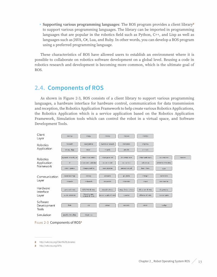
2.4. Components of ROSAs shown in Figure 2-3, ROS consists of a client library to support various programming
languages, a hardware interface for hardware control, communication for data transmission and reception, the Robotics Application Framework to help create various Robotics Applications, the Robotics Application which is a service application based on the Robotics Application Framework, Simulation tools which can control the robot in a virtual space, and Software Development Tools.
Figure 2-3 Components of ROS3
2 http://wiki.ros.org/Client%20Libraries
3 http://wiki.ros.org/APIs

ROS Robot Programming14
2.5. ROS EcosystemThe term ‘Ecosystem’ is often mentioned in the smartphone market after the advent of various operating systems such as Android, iOS, Symbian, RiMO, and Bada. The ecosystem refers to the structure that connects hardware manufacturers, operating system developing companies, app developers, and end users.
For example, the smartphone manufacturers will produce devices that support hardware interfaces of the operating system, and operating system companies create a generic library to operate devices from various manufacturers. Therefore, software developers can use numerous devices without understanding hardware to develop applications. The ecosystem includes the distribution of application to end users.
The ecosystem was not a new concept in the market. There were also a variety of hardware manufacturers in the personal computer market, and this hardware was bound together mainly by Microsoft’s Windows operating system and the open source Linux. The formation of technology ecosystem seems to be as natural as the natural ecosystem.
Robotics is also forming its ecosystem. Various hardware technologies were overflowing in the beginning, but there was no operating system to integrate them. Several software platforms appeared and ROS drew enough attention to build an ecosystem. Although its effect may yet be marginal, when looking at the increasing number of users, robot-related companies, and related tools and libraries, we can anticipate a fully functional ecosystem in the near future.
Figure 2-4 ROS Ecosystem

Chapter 2 _ Robot Operating System ROS 15
The Figure 2-4 shows the status of ROS during ROSCon in 20174, based on the official statistics of ROS5 and the ROS Wiki data of 20176. Some may think that this is still on marginal level, but there is no other robot software platform that is widely used in the robotics field like ROS. I am eager to see how it will grow more in the future.
2.6. History of ROSLet us take a deeper look into ROS. In May 2007, ROS was started by borrowing the early open-source robotic software frameworks including switchyard7, which is developed by Dr. Morgan Quigley8 by the Stanford Artificial Intelligence Laboratory in support of the Stanford AI Robot STAIR (STanford AI Robot) project9.
Dr. Morgan Quigley and Dr. Brian Gerkey
Dr. Morgan Quigley is one of the founders and software development manager of Open Robotics (formerly the Open Source Robotics Foundation, OSRF), which is responsible for the development and management of ROS. Switchyard is a program created for the development of artificial intelligence robots used in the AI lab’s projects at the time, and is the predecessor of ROS. In addition, Dr. Brian Gerkey (http://brian.gerkey.org/), the developer of the Player/Stage Project (Player network server and 2D Stage simulator, later affects the development of 3D simulator Gazebo), which was developed since 2000 and has had a major impact on ROS’s networking program, is the CEO and co-founder of Open Robotics. Thus ROS was influenced by Player/Stage from 2000 and Switchyard from 2007 before Willow Garage changed the name to ROS in 2007.
In November 2007, U.S. robot company Willow Garage succeeded the development of ROS. Willow Garage is a well-known company in the field for personal robots and service robots. It is also famous for developing and supporting the Point Cloud Library (PCL), which is widely used for 3D devices such as Kinect and the image processing open source library OpenCV.
Willow Garage started to develop ROS in November of 2007, and on January 22, 2010, ROS 1.0 came out into the world. The official version known to us was released on March 2, 2010 as ROS Box Turtle. Afterwards, C Turtle, Diamondback and many versions were released in alphabetical order like Ubuntu and Android.
4 http://roscon.ros.org/2017/
5 http://wiki.ros.org/Metrics
6 http://wiki.ros.org/
7 http://www.willowgarage.com/pages/software/ros-platform
8 https://www.osrfoundation.org/team/morgan-quigley/
9 http://stair.stanford.edu/

ROS Robot Programming16
ROS is based on the BSD 3-Clause License10 and Apache License 2.011, which allows anyone to modify, reuse, and redistribute. ROS also provided a large number of the latest software and participated actively in education and academics, becoming known first through the robotics academic society. There is now ROSDay and ROSCon12 conferences for developers and users, and also various community gatherings under the name of ROS Meetup13. In addition, the development of robotic platforms that can apply ROS are also accelerating. Some examples are the PR214 which stands for Personal Robot and the TurtleBot15, and many applications have been introduced through these platforms, making ROS as the dominating robot software platform.
Figure 2-5 OSRF Logo (http://osrfoundation.org/)
Figure 2-6 Open Robotics Logo (https://www.openrobotics.org/)
2.7. ROS VersionsIn 2007, Willow Garage succeeded the research of the robot software framework that began with the Switchyard at Stanford University’s AI Lab and continued the development under the name of Robot Operating System (ROS). With the sixth official release version ‘ROS Groovy Galapagos’, Willow Garage attempted to penetrate into the commercial service robot market in 2013 but ended up splitting into several start-ups, and ultimately handed over to the Open Source Robotics Foundation (OSRF). Since then, four more versions were released and starting from May 2017, OSRF changed its name to Open Robotics and has been developing, operating, and managing ROS. Most recently, 11th version of ROS, the ROS Lunar Loggerhead, was released on May 23, 2017. ROS labels the first letter of each release name in alphabetical order and uses a turtle as their symbol (see Figure 2-7).
10 https://opensource.org/licenses/BSD-3-Clause
11 https://www.apache.org/licenses/LICENSE-2.0
12 http://roscon.ros.org
13 http://wiki.ros.org/Events
14 http://www.willowgarage.com/pages/pr2/overview
15 http://www.turtlebot.com/

Chapter 2 _ Robot Operating System ROS 17
ROS Releases and Conferences
■ Dec 08, 2017 - Release of ROS 2.0
■ Sep 21, 2017 - ROSCon2017 (Canada)
■ May 23, 2017 - Release of Lunar Loggerhead
■ May 16, 2017 - Changed name from OSRF to Open Robotics
■ Oct 8, 2016 - ROSCon2016 (South Korea)
■ May 23, 2016 - Release of Kinetic Kame
■ Oct 3, 2015 - ROSCon2015 (Germany)
■ May 23, 2015 - Release of Jade Turtle
■ Sep 12, 2014 - ROSCon2014 Conference (U.S.)
■ Jul 22, 2014 - Release of Indigo Igloo
■ Jun 6, 2014 - ROS Kong 2014 Conference (Hong Kong)
■ Sep 4, 2013 - Release of Hydro Medusa
■ May 11, 2013 - ROSCon2013 Conference (Germany)
■ Feb 11, 2013 - Open Source Robotics Foundation takes on development/management
■ Dec 31, 2012 - Release of Groovy Galapagos
■ May 19, 2012 - ROSCon2012 Conference (U.S.)
■ Apr 23, 2012 - Release of Fuerte
■ Aug 30, 2011 - Release of Electric Emys
■ Mar 2, 2011 - Release of Diamondback
■ Aug 2, 2010 - Release of C Turtle
■ Mar 2, 2010 - Release of Box Turtle
■ Jan 22, 2010 - Release of ROS 1.0
■ Nov 1, 2007 - Willow Garage starts development under the name ‘ROS’
■ May 1, 2007 - Switchyard Project, Morgan Quigley, Stanford AI LAB, Stanford University
■ 2000 - Player/Stage Project, Brian Gerkey, University of Southern California (USC)

ROS Robot Programming18
Figure 2-7 ROS Versions(http://wiki.ros.org/)
2.7.1. Version RulesSo far ROS has released ROS 1.0, Box Turtle, C Turtle, Diamondback, Electric Emys, Fuerte Turtle, Groovy Galapagos, Hydro Medusa, Indigo Igloo, Jade Turtle, Kinetic Kame, and Lunar Loggerhead versions.
Apart from their version 1.0, ROS has been naming their versions to start in alphabetical order, same as Ubuntu and Android. For instance, the Kinetic Kame version is the 11th version thus starting with the alphabet K, and the 10th official release version.
In addition, there is one more rule. Each version has an illustration in the form of a poster and a turtle icon, as shown in Figure 2-8. These turtle icons are also used in the official simulation tutorial called ‘turtlesim’. The turtle symbol for ROS was stemmed from the educational programming language Logo16 from MIT’s AI Lab17 in the 1960s. More than 50 years ago in 1969, a turtle robot was developed using Logo, which was able to actually move on the floor and draw pictures according to the instructions given by the computer. Based on this robot, a program ‘turtlesim’ was developed and the actual robot was later also called TurtleBot18.
Figure 2-8 Turtle icons for each version of ROS
16 https://en.wikipedia.org/wiki/Logo_(programming_language)
17 http://el.media.mit.edu/logo-foundation/what_is_logo/index.html
18 http://spectrum.ieee.org/automaton/robotics/diy/interview-turtlebot-inventors-tell-us-everything-about-the-robot

Chapter 2 _ Robot Operating System ROS 19
2.7.2. Version Release PeriodThe ROS version has been updating twice a year (April and October), the same as the release period of the ROS supporting operating system Ubuntu. However, in 2013 users started suggesting a new version cycle due to the frequent updates, and the feedback was taken into account. Thus starting with the Hydro Medusa version in 2013, a new version has been released once a year in May, a month after the Ubuntu xx.04 version is released. For your reference, May 23rd is World Turtle Day19, and ROS is releasing its new version on this symbolic day.
The supporting period of ROS is different for each version, but generally two years of support is available after its release. Every two years, ROS and Linux releases Long Term Support20 version and ROS is supported for the next five years. For instance, the Kinetic Kame version, which supports Ubuntu 16.04 LTS, will be supported until April 2021. Versions other than the LTS versions are generally intended for minor upgrades and maintenance as they support the latest Linux kernel. Therefore many ROS users
use the LTS versions which are released every two years. The latest ROS version released21 since 2014 are shown in Figure 2-9.
Figure 2-9 Recent ROS versions and end of support date
19 https://www.worldturtleday.org/
20 https://wiki.ubuntu.com/LTS
21 http://wiki.ros.org/Distributions

ROS Robot Programming20
2.7.3. Selecting a VersionSince ROS is a meta-operating system, you will need to choose an OS to use. ROS supports Debian, Ubuntu, Linux Mint, OS X, Fedora, Gentoo, openSUSE, Arch Linux, and Windows, but the most popular operating systems are Debian, Ubuntu and Linux Mint. For this reason, I would like to recommend Debian, Ubuntu LTS or Linux Mint, which are the most commonly used ROS version.
Ubuntu ported package information for the kinetic version of ROS can be found at the corresponding information page22. In this page, you can see whether the kinetic version has been completed or is in the process of migrating packages (source) for each Linux version.
The release name of Linux may not be familiar with you. As you can see from the following list of Ubuntu versions, 14.04 Trusty is the Ubuntu ‘T’ version and is being released in alphabetical order. You should be able to find a stable version from the list. The latest version of ROS shows that many packages are still in progress, but if it is not critical to your application, you can either use the latest version or currently available version. If the package you were using is not converted for the latest ROS version, you might have to wait a bit.
■ Ubuntu 18.04 Bionic Beave (LTS)
■ Ubuntu 17.10 Artful Aardvark
■ Ubuntu 17.04 Zesty Zapus
■ Ubuntu 16.10 Yakkety Yak
■ Ubuntu 16.04 Xenial Xerus (LTS)
■ Ubuntu 15.10 Wily Werewolf
■ Ubuntu 15.04 Vivid Vervet
■ Ubuntu 14.10 Utopic Unicorn
■ Ubuntu 14.04 Trusty Tahr (LTS)
■ Ubuntu 13.10 Saucy Salamander
■ Ubuntu 13.04 Raring Ringtail
■ Ubuntu 12.10 Quantal Quetzal
■ Ubuntu 12.04 Precise Pangolin (LTS)
22 http://repositories.ros.org/status_page/ros_kinetic_default.html

Chapter 2 _ Robot Operating System ROS 21
I recommend the following combination until 2019 when the new Linux and ROS LTS versions will become stable.
■ Operating System: Ubuntu 16.04 Xenial Xerus23 (LTS) or Linux Mint 18.x or Debian Jessie
■ ROS: ROS Kinetic Kame24
23 http://releases.ubuntu.com/16.04/
24 http://wiki.ros.org/kinetic

ROS Robot Programming22
Configuring the ROS Development Environment
Chapter 3

Chapter 3 _ Configuring the ROS Development Environment 23
Although ROS supports a variety of operating systems, since Ubuntu is the most widely used among ROS users, this book deals only with Ubuntu and Linux Mint, which is compatible with Ubuntu.
The ROS application development environment used in this book is as follows.
■ Hardware: Desktop or laptop using Intel or AMD processor
■ Operating System: Ubuntu 16.04.x Xenial Xerus or Linux Mint 18.x
■ ROS: Kinetic Kame
If you have a different version of Ubuntu installed on your computer, please check the official site, and if your operating system is OS X1 or Windows2 you can check the corresponding Wiki3 page for the installation methods. If you are using a single board computer (SBC) that uses an ARM CPU instead of Intel or AMD CPU, we do not separately provide instruction for the installation of ROS, but if you are using Ubuntu or Linux Mint then you can follow the below instructions.
Figure 3-1 Desktop screen of Linux Mint
1 http://wiki.ros.org/kinetic/Installation/OSX/Homebrew/Source
2 http://wiki.ros.org/hydro/Installation/Windows
3 http://wiki.ros.org/kinetic/Installation
ROS Robot Programming24
3.1. Installing ROS
3.1.1. General InstallationLet us install ROS Kinetic. You will be able to install ROS Kinetic without much difficulty by following the instructions below. You can also use the quick installation script provided in section 3.1.2 for even simpler installation.
NTP(Network Time Protocol) Configuration Although it is not included in the official ROS installation package, we can configure the NTP4 in order to reduce the ROS Time difference in the communication between multiple PCs. The installation method is to first install ‘chrony’ and then designate the NTP server using the ‘ntpdate’ command. This will show the time difference between the server and the client computer, and will set the time to match the designated server. This is a method to minimize the time difference between different PCs by designating the same NTP server.
$ sudo apt-get install -y chrony ntpdate
$ sudo ntpdate -q ntp.ubuntu.com
Adding Source ListWe will add the ROS repository address to ros-latest.list. Open a new terminal window and enter the following command.
$ sudo sh -c 'echo "deb http://packages.ros.org/ros/ubuntu $(lsb_release -sc) main" > /etc/apt/
sources.list.d/ros-latest.list'
If you are using Linux Mint version 18.x, use the following command. The code mentioned above, $(lsb_release -sc) gets the code name of the Linux distribution version. Linux Mint 18.x uses the code name of Xenial, so it is possible to add the same source list as Ubuntu.
$ sudo sh -c 'echo "deb http://packages.ros.org/ros/ubuntu xenial main" > /etc/apt/
sources.list.d/ros-latest.list'
4 https://en.wikipedia.org/wiki/Network_Time_Protocol

Chapter 3 _ Configuring the ROS Development Environment 25
Setting up the KeyWe will add a public key in order to download the package from the ROS repository with the following command. Note that the following key may change depending on the situation of the server’s operation, so please refer to the official Wiki page5.
$ sudo apt-key adv --keyserver hkp://ha.pool.sks-keyservers.net:80 --recv-key
421C365BD9FF1F717815A3895523BAEEB01FA116
Updating the Package IndexNow that we have put the ROS repository address in the source list we must perform indexing of the package list again. Although not mandatory, we do recommend upgrading all of the currently installed Ubuntu packages before installing ROS.
$ sudo apt-get update && sudo apt-get upgrade -y
Installing ROS Kinetic KameWe will install the ROS packages for desktop using the following command. This will include ROS, rqt, RViz, robot-related libraries, simulation, navigation, etc.
$ sudo apt-get install ros-kinetic-desktop-full
The command above will install the basic rqt package, but we can additionally install all of the packages related to rqt. Installing all the packages related to rqt by using the following command will facilitate many aspects as well as allow the use of various rqt plugins.
$ sudo apt-get install ros-kinetic-rqt*
5 http://wiki.ros.org/kinetic/Installation/Ubuntu

ROS Robot Programming26
ROS Package Binary
To install the ROS packages, you can use the following apt-cache command to search for all the packages that begin with ‘ros-kinetic’. By running this command, you can see approximately 1,600 packages.
$ apt-cache search ros-kinetic
If you wish to install a package individually, you can use the following command.
$ sudo apt-get install ros-kinetic-[NAME_OF_PACKAGE]
Another way would be to use the GUI tool Synaptic Package Manager.
APT (Advanced Packaging Tool) 6
The apt (Advanced Packaging Tool) from apt-get, apt-key, and apt-cache is a package management command that is widely used in Debian series Linux such as Ubuntu and Linux Mint.
http://en.wikipedia.org/wiki/Advanced_Packaging_Tool
Deleting a previous version of ROS and alternating use of different versions of ROS
‘sudo apt-get purge ros-indigo-*’ This command allows configuration and file deletion. When using together with a previous version, from the command that loads the ROS configuration file added to ‘~/.bashrc’.
$ source /opt/ros/kinetic/setup.bash
This part can be changed to kinetic or indigo.
Initializing rosdepBe sure to initialize rosdep before using ROS. The rosdep is a feature that enhances user convenience by easily installing dependent packages when using or compiling core components of ROS.
$ sudo rosdep init
$ rosdep update
6 https://en.wikipedia.org/wiki/Advanced_Packaging_Tool

Chapter 3 _ Configuring the ROS Development Environment 27
Installing rosinstallThis program installs various packages of ROS. Be sure to install this useful tool that is frequently used.
$ sudo apt-get install python-rosinstall
Load the Environment FileThis command imports the environment setting file. Environment variables such as ROS_ROOT, ROS_PACKAGE_PATH, etc. are defined.
$ source /opt/ros/kinetic/setup.bash
Creating and Initializing a Workspace FolderROS uses a ROS dedicated build system called catkin. To use this, you need to create and initialize a catkin workspace folder as follows. This configuration only needs to be performed once, unless you create a new workspace folder.
$ mkdir -p ~/catkin_ws/src
$ cd ~/catkin_ws/src
$ catkin_init_workspace
Now that we have created the catkin workspace folder, let’s build it. Currently, the catkin workspace only contains the ‘src’ folder and the ‘CMakeLists.txt’ file inside, but as a test use the ‘catkin_make’ command to build.
$ cd ~/catkin_ws/
$ catkin_make
Once you have finished building without errors, run the ‘ls’ command. In addition to the ‘src’ folder created by the user, ‘build’ and ‘devel’ folders have been created. The build related files for the catkin build system are saved in the ‘build’ folder, and the execution related files are saved in the ‘devel’ folder.
$ ls
build
devel
src

ROS Robot Programming28
Lastly, we will import the setting file associated with the catkin build system.
$ source ~/catkin_ws/devel/setup.bash
TestingThe installation for ROS has been completed. The following command will verify whether the installation was successful or not. Close all terminal windows and open a new terminal window. Now enter the following command to run roscore.
$ roscore
If it runs like the following without errors, the installation is completed. Terminate the process with [Ctrl+c].
... logging to /home/pyo/.ros/log/9e24585a-60c8-11e7-b113-08d40c80c500/roslaunch-pyo-5207.log
Checking log directory for disk usage. This may take awhile.
Press Ctrl-C to interrupt
Done checking log file disk usage. Usage is <1GB.
started roslaunch server http://localhost:38345/
ros_comm version 1.12.7
SUMMARY
========
PARAMETERS
* /rosdistro: kinetic
* /rosversion: 1.12.7
NODES
auto-starting new master
process[master]: started with pid [5218]
ROS_MASTER_URI=http://localhost:11311/
setting /run_id to 9e24585a-60c8-11e7-b113-08d40c80c500
process[rosout-1]: started with pid [5231]
started core service [/rosout]

Chapter 3 _ Configuring the ROS Development Environment 29
3.1.2. Quick InstallationIf you are using is 16.04.x or Linux Mint 18.x, the following script will allow you to simplify the aforementioned ROS installation procedure.
$ wget https://raw.githubusercontent.com/ROBOTIS-GIT/robotis_tools/master/install_ros_kinetic.sh
$ chmod 755 ./install_ros_kinetic.sh
$ bash ./install_ros_kinetic.sh
The install_ros_kinetic.sh shell script downloaded with the ‘wget’ command from above quick installation contains general installation procedure covered in section 3.1.1 and ROS environment setting that will be covered in the next section 3.2.1.
3.2. ROS Development Environment
3.2.1. ROS SettingsThe following command needs to be executed every time we open a new terminal window in
order to apply the settings to current terminal window.
$ source /opt/ros/kinetic/setup.bash
$ source ~/catkin_ws/devel/setup.bash
To avoid this repetitive task, we can set it to import a setting file when we open a new terminal window every time Additionally, we can configure the ROS network and create quick commands for frequently used commands.
First, we will use the text editor ‘gedit’ program to open the ‘.bashrc’ file. This book uses gedit as a default text editor, but you can also use atom, sublime text, vim, emacs, nano, visual studio code, etc.
$ gedit ~/.bashrc
When you import the ‘.bashrc’ file, there are many settings that have already been configured. Without modifying any of these settings, scroll down to the very bottom of the ‘bashrc’ file and append the following lines (replace xxx.xxx.xxx.xxx with your IP address. Please refer to the section on ‘ifconfig’ in footnote 7 for configuring the IP address). Once you have set everything, save your changes and close gedit.

ROS Robot Programming30
~/.bashrc
# Set ROS Kinetic
source /opt/ros/kinetic/setup.bash
source ~/catkin_ws/devel/setup.bash
# Set ROS Network
export ROS_HOSTNAME=xxx.xxx.xxx.xxx
export ROS_MASTER_URI=http://${ROS_HOSTNAME}:11311
# Set ROS alias command
alias cw='cd ~/catkin_ws'
alias cs='cd ~/catkin_ws/src'
alias cm='cd ~/catkin_ws && catkin_make'
Now we will enter the following command to apply the new settings of the ‘.bashrc’ file. You can also close and open the terminal window to apply the configurations of the ‘.bashrc’ file. From now on, whenever you open a terminal window, ‘.bashrc’ settings will be applied to the terminal window.
$ source ~/.bashrc
Now let’s take a closer look at what we have previously set up.
Importing the ROS Settings File‘#’ is the symbol that indicates the start of a comment, and the content that follows is the comment. ‘source /opt/ros/kinetic/setup.bash’ in the second line and ‘source ~/catkin_ws/devel/setup.bash’ in third line are ROS setting files that must be configured.
# Set ROS Kinetic
source /opt/ros/kinetic/setup.bash
source ~/catkin_ws/devel/setup.bash
Configuring the ROS NetworkThis is the configuration for ROS_MASTER_URI and ROS_HOSTNAME. ROS uses a network to communicate messages between nodes, so the network configuration is very important. First, we will use our own IP address to both fields. Later on if there are master PC and the robot uses a host PC, network has to be configured on both PCs in order to allow multiple computers to communicate each other. For now we will enter our own network IP to both fields as we are

Chapter 3 _ Configuring the ROS Development Environment 31
using only one PC. The following example shows the case of how to configure if your IP address is ‘192.168.1.100’. You can check your IP information in the terminal window with ‘ifconfig’ command.
# Set ROS Network
export ROS_HOSTNAME=192.168.1.100
export ROS_MASTER_URI=http://${ROS_HOSTNAME}:11311
If you are running all packages on one PC, there is no need to assign a specific IP, but instead assign ‘localhost’ for both fields.
# Set ROS Network
export ROS_HOSTNAME=localhost
export ROS_MASTER_URI=http://localhost:11311
ifconfig7
In order to check the IP address on Linux, use the ifconfig command. By running the ifconfig command in the terminal window as shown in the following example, IP address will be shown next to the ‘inet addr’ in ‘enp3s0’ for wired LAN and in ‘wlp2s0’ for wireless LAN. The following example shows both wireless and wired LAN. The IP for wired LAN connection is 192.168.1.100 whereas the wireless LAN is 192.168.11.19.
$ ifconfig
enp3s0 Link encap:Ethernet HWaddr d8:cb:8a:f1:74:2b
inet addr:192.168.1.100 Bcast:192.168.1.255 Mask:255.255.255.0
inet6 addr: fe80::60fc:7e2b:b877:f82b/64 Scope:Link
UP BROADCAST RUNNING MULTICAST MTU:1500 Metric:1
RX packets:52 errors:0 dropped:0 overruns:0 frame:0
TX packets:81 errors:0 dropped:0 overruns:0 carrier:0
collisions:0 txqueuelen:1000
RX bytes:10172 (10.1 KB) TX bytes:8917 (8.9 KB)
Interrupt:19
lo Link encap:Local Loopback
inet addr:127.0.0.1 Mask:255.0.0.0
inet6 addr: ::1/128 Scope:Host
7 https://en.wikipedia.org/wiki/Ifconfig

ROS Robot Programming32
UP LOOPBACK RUNNING MTU:65536 Metric:1
RX packets:3520 errors:0 dropped:0 overruns:0 frame:0
TX packets:3520 errors:0 dropped:0 overruns:0 carrier:0
collisions:0 txqueuelen:1
RX bytes:560728 (560.7 KB) TX bytes:560728 (560.7 KB)
wlp2s0 Link encap:Ethernet HWaddr 08:d4:0c:80:c5:00
inet addr:192.168.11.19 Bcast:192.168.11.255 Mask:255.255.255.0
inet6 addr: fe80::a60b:e157:4157:d9dc/64 Scope:Link
UP BROADCAST RUNNING MULTICAST MTU:1500 Metric:1
RX packets:675821 errors:0 dropped:0 overruns:0 frame:0
TX packets:219992 errors:0 dropped:0 overruns:0 carrier:0
collisions:0 txqueuelen:1000
RX bytes:919561165 (919.5 MB) TX bytes:46928931 (46.9 MB)
Quick CommandLet’s set the quick commands that are frequently used in ROS development. The following cw, cs, and cm are custom commands that I have defined as alias commands.
■ cw: Move to the predefined catkin workspace directory ‘~/catkin_ws’
■ cs: Move to the directory ‘~/catkin_ws/src’ in the catkin workspace directory that contains source files
■ cm: Move to the catkin workspace directory ‘~/catkin_ws’, and build ROS packages with ‘catkin_make’ command
# Set ROS alias command
alias cw='cd ~/catkin_ws'
alias cs='cd ~/catkin_ws/src'
alias cm='cd ~/catkin_ws && catkin_make'

Chapter 3 _ Configuring the ROS Development Environment 33
How to check the ROS settings
The ‘export | grep ROS’ command displays the ROS setting.
$ export | grep ROS
declare -x ROSLISP_PACKAGE_DIRECTORIES=”/home/pyo/catkin_ws/devel/share/common-lisp”
declare -x ROS_DISTRO=”kinetic”
declare -x ROS_ETC_DIR=”/opt/ros/kinetic/etc/ros”
declare -x ROS_HOSTNAME=”localhost”
declare -x ROS_MASTER_URI=”http://localhost:11311”
declare -x ROS_PACKAGE_PATH=”/home/pyo/catkin_ws/src:/opt/ros/kinetic/share”
declare -x ROS_ROOT=”/opt/ros/kinetic/share/ros” ROS
3.2.2. Integrated Development Environment (IDE)The Integrated Development Environment (IDE) provides the development environment so that the user can perform tasks related to program development, such as coding, debugging, compiling, distribution in a single program. Most developers have at least a couple of their favorite IDEs.
ROS supports many IDEs8. The most commonly used IDEs are Eclipse, CodeBlocks, Emacs, Vim, NetBeans, QtCreator9. In my case I used to work with Eclipse, but it has become quite heavy in the recent versions and it was inconvenient for me to use with ROS’s catkin build system. Therefore having looked into other IDEs, it seems that the most suitable tool for simple tasks would be Visual Studio Code, and for GUI interface development it would be QtCreator. Especially, rqt and RViz for ROS development, debugging, visualization are developed with Qt, and the fact that users can develop plug-ins for ROS tools using Qt plug-ins makes QtCreator very useful.
Furthermore, even if you do not use Qt it is well adequate to be used as a general purpose editor, and it can import a project directly through ‘CMakeLists.txt’, making it very convenient when using ‘catkin_make’.
The following section contains information on configuring the ROS development environment with QtCreator. However, I would like to make it clear that even if you use other IDEs, there will be no problem in understanding the contents of this book.
8 http://wiki.ros.org/IDEs
9 https://www.qt.io/ide/

ROS Robot Programming34
Installing QtCreator
$ sudo apt-get install qtcreator
Launching QtCreatorThe QtCreator can be launched with the icon as well. However, if we are to apply the settings such as the ROS path that we configured in ‘~/.bashrc’ to QtCreator, then we must open a new terminal window and enter the following command to launch QtCreator. In this matter, all of the settings configured in ‘~/.bashrc’ will be applied when launching QtCreator.
$ qtcreator
QtCreator has been opened by the command above as shown in Figure 3-2.
Figure 3-2 QtCreator IDE

Chapter 3 _ Configuring the ROS Development Environment 35
Importing a ROS Package as a ProjectAs previously mentioned, QtCreator uses ‘CMakeLists.txt’, and ROS package is also based on ‘CMakeLists.txt’, so by clicking on the ‘OpenProject’ button and selecting ‘CMakeLists.txt’ of a specific ROS package, you can easily import the package as a project as shown in Figure 3-3.
The shortcut for build is [Ctrl+b] and ‘catkin_make’ will be executed when compiling source code. Built files will be saved in the ‘build’ folder in the same directory of the package. For example, when you compile the package ‘tms_rp_action’, built files are placed in ‘build-tms_rp_action-Desktop-Default folder’. The files that would originally be stored in ‘~/catkin_ws/build’ and ‘~/catkin_ws/devel’ are compiled separately and placed in a new location, so in order to run it you will later need to run ‘catkin_make’ again in the terminal window. It is not necessary to repeat this process every time, so during development, we can develop and debug in QtCreator, and once the development is finished then we can use ‘catkin_make’. For your information, there is a Qt Creator Plugin for ROS (https://github.com/ros-industrial/ros_qtc_plugin/wiki) which optimizes QtCreator for the ROS development environment.
Figure 3-3 Opening a Project with QtCreator
In addition to QtCreator, we also recommend Visual Studio Code and Eclipse. Visual Studio Code is very lightweight editor like ‘Atom’, ‘Sublime Text’, ‘Clion’, so it is very fast and ROS Extension makes it easy to use ROS. Eclipse is a general-purpose IDE used by a very large number of people and is used by many ROS users as well. For more information, see the following wiki.

ROS Robot Programming36
■ http://wiki.ros.org/IDEs
Figure 3-4 Workspace of the QtCreator Project
3.3. ROS Operation TestNow that we have installed ROS, let’s test if it works correctly. The following example is the turtlesim package (bundle of nodes) provided by ROS to display the turtle on the screen and control the turtle with the keyboard node (program).
Starting from this section, many ROS-specific terms such as node, package, and roscore will appear, which will be explained in detail in Chapter 4. ROS Terminology. In this section, we will verify that ROS has been installed without any problems.
Running roscoreOpen a new terminal window (Ctrl + Alt + t) and run the following command. This will run roscore, which will have control over the whole ROS system.
$ roscore

Chapter 3 _ Configuring the ROS Development Environment 37
Figure 3-5 Screen showing roscore running
Running turtlesim_node in the turtlesim packageOpen a new terminal window and enter the following command. Then you will see appended messages, and turtlesim_node in the turtlesim package will be executed. In the middle of blue window, you will see a turtle (the shape of the turtle can change randomly when it is executed so that it may look different from Figure 3-6).
$ rosrun turtlesim turtlesim_node
[INFO] [1499182058.960816044]: Starting turtlesim with node name /turtlesim
[INFO] [1499182058.966717811]: Spawning turtle [turtle1] at x=[5.544445], y=[5.544445],
theta=[0.000000]
Figure 3-6 Screen showing the turtle being moved

ROS Robot Programming38
Running turtle_teleop_key in the turtlesim packageOpen a new terminal window and enter the following command. Then you will see appended messages and instructions, and turtle_teleop_key of the turtlesim package will be executed. If any of arrow keys on the keyboard (←, → , ↑, ↓) is pressed in this terminal window, the turtle will move according to the arrow key as shown in the right picture of Figure 3-6. You must enter the key in the corresponding terminal window. Although this is only a simple simulation, we will be able to control an actual robot with the same method.
$ rosrun turtlesim turtle_teleop_key
Reading from keyboard
---------------------------
Use arrow keys to move the turtle.
Using the [Tab] key in the terminal window
In Linux we often enter commands in the terminal window. There are many users who are unfamiliar with the command line interface, but as one becomes proficient with it, it becomes a very fast and convenient method. However, even experienced users do not memorize all the commands and frequently use the [Tab] key instead. In the Linux terminal window, the [Tab] key supports auto-completion. This feature eliminates the need to memorize all the commands, and lets you enter commands quickly and accurately without a typo. As an example, take a look at the rosrun command used earlier. As shown below, after typing turtlesim we can use the [Tab] key to find the various nodes that we can use in the turtlesim package.
$ rosrun turtlesim [Tab]
Additionally, if we type turtle_teleop and press the [Tab] key, then it will auto-complete the rest of command that we can use. This applies not only for ROS but for all Linux commands, so we suggest you to make use of this feature.
$ rosrun turtlesim turtle_teleop[Tab]$ rosrun turtlesim turtle_teleop_key
Running rqt_graph in the rqt_graph packageEntering the rqt_graph command in a new terminal window will run the rqt_graph node in the rqt_graph package. The result is shown as a diagram of the information of currently running nodes (programs) as shown in Figure 3-7.
$ rqt_graph

Chapter 3 _ Configuring the ROS Development Environment 39
The rqt_graph node shows information about the currently running nodes in a GUI form. A circle represents a node and a square represents a topic. If we look at Figure 3-7, an arrow is drawn from the ‘/teleop_turtle’ node that connects to ‘/turtlesim’. This demonstrates that the two nodes are running, and there is message communication taking place between these two nodes.
The square box ‘/turtle1/cmd_vel’, which is a sub-topic of the turtle1 topic, located in between two arrows is the topic name for two nodes, and visualizes that the speed command entered with the keyboard in the teleop_turtle node is being sent to the turtlesim node as a message in the topic.
That is to say, using the above two nodes, keyboard commands were transferred to the robot simulation. More detailed information will be explained in the following sections, and if you have followed along well so far, you have completed the ROS operation test.
Figure 3-7 The rqt_graph node
Closing the node The roscore and each node can be terminated by pressing [Ctrl+c] in the corresponding terminal windows. For your information, [Ctrl+c] is used to close a program on Linux/Unix forcibly.

ROS Robot Programming40
Important Concepts of ROS
Chapter 4

Chapter 4 _ Important Concepts of ROS 41
In order to develop a robot related to ROS1, it is necessary to understand the essential components and concepts of ROS. This chapter will introduce the terminology used in ROS and the important concepts of ROS such as message communication, message file, name, coordinate transformation (TF), client library, communication between heterogeneous devices, file system, and build system.
4.1. ROS TerminologyThis section explains the most frequently used ROS terms. Use this section as a ROS glossary. Many terms may be new to the reader and even if there are unfamiliar terms, look over the definition and move on. You will become more familiar with the concepts as you engage with examples and exercises in each of the following chapters.
ROSROS provides standard operating system services such as hardware abstraction, device drivers, implementation of commonly used features including sensing, recognizing, mapping, motion planning, message passing between processes, package management, visualizers and libraries for development as well as debugging tools.
MasterThe master2 acts as a name server for node-to-node connections and message communication. The command roscore is used to run the master, and if you run the master, you can register the name of each node and get information when needed. The connection between nodes and message communication such as topics and services are impossible without the master.
The master communicates with slaves using XMLRPC (XML-Remote Procedure Call)3, which is an HTTP-based protocol that does not maintain connectivity. In other words, the slave nodes can access only when they need to register their own information or request information of other nodes. The connection status of each other is not checked regularly. Due to this feature, ROS can be used in very large and complex environments. XMLRPC is very lightweight and supports a variety of programming languages, making it well suited for ROS, which supports variety of hardware and programming languages.
When you execute ROS, the master will be configured with the URI address and port configured in the ROS_MASTER_URI. By default, the URI address uses the IP address of local PC, and port number 11311, unless otherwise modified.
1 http://wiki.ros.org/ROS/Concepts
2 http://wiki.ros.org/Master
3 https://en.wikipedia.org/wiki/XML-RPC

ROS Robot Programming42
NodeA node4 refers to the smallest unit of processor running in ROS. Think of it as one executable program. ROS recommends creating one single node for each purpose, and it is recommended to develop for easy reusability. For example, in case of mobile robots, the program to operate the robot is broken down into specialized functions. Specialized node is used for each function such as sensor drive, sensor data conversion, obstacle recognition, motor drive, encoder input, and navigation.
Upon startup, a node registers information such as name, message type, URI address and port number of the node. The registered node can act as a publisher, subscriber, service server or service client based on the registered information, and nodes can exchange messages using topics and services.
The node uses XMLRPC for communicating with the master and uses XMLRPC or TCPROS5 of the TCP/IP protocols when communicating between nodes. Connection request and response between nodes use XMLRPC, and message communication uses TCPROS because it is a direct communication between nodes independent from the master. As for the URI address and port number, a variable called ROS_HOSTNAME, which is stored on the computer where the node is running, is used as the URI address, and the port is set to an arbitrary unique value.
PackageA package6 is the basic unit of ROS. The ROS application is developed on a package basis, and the package contains either a configuration file to launch other packages or nodes. The package also contains all the files necessary for running the package, including ROS dependency libraries for running various processes, datasets, and configuration file. The number of official packages is about 2,500 for ROS Indigo as of July 2017 (http://repositories.ros.org/status_page/ ros_indigo_default.html) and about 1,600 packages for ROS Kinetic (http://repositories.ros.org/status_page/ros_kinetic_default.html). In addition, although there could be some redundancies, there are about 4,600 packages developed and released by users (http://rosindex.github.io/stats/).
MetapackageA metapackage7 is a set of packages that have a common purpose. For example, the Navigation metapackage consists of 10 packages including AMCL, DWA, EKF, and map_server.
4 http://wiki.ros.org/Nodes
5 http://wiki.ros.org/ROS/TCPROS
6 http://wiki.ros.org/Packages
7 http://wiki.ros.org/Metapackages

Chapter 4 _ Important Concepts of ROS 43
MessageA node8 sends or receives data between nodes via a message. Messages are variables such as integer, floating point, and boolean. Nested message structure that contains another messages or an array of messages can be used in the message.
TCPROS and UDPROS communication protocol is used for message delivery. Topic is used in unidirectional message delivery while service is used in bidirectional message delivery that request and response are involved.
TopicThe topic9 is literally like a topic in a conversation. The publisher node first registers its topic with the master and then starts publishing messages on a topic. Subscriber nodes that want to receive the topic request information of the publisher node corresponding to the name of the topic registered in the master. Based on this information, the subscriber node directly connects to the publisher node to exchange messages as a topic.
Publish and Publisher The term ‘publish’ stands for the action of transmitting relative messages corresponding to the topic. The publisher node registers its own information and topic with the master, and sends a message to connected subscriber nodes that are interested in the same topic. The publisher is declared in the node and can be declared multiple times in one node.
Subscribe and SubscriberThe term ‘subscribe’ stands for the action of receiving relative messages corresponding to the topic. The subscriber node registers its own information and topic with the master, and receives publisher information that publishes relative topic from the master. Based on received publisher information, the subscriber node directly requests connection to the publisher node and receives messages from the connected publisher node. A subscriber is declared in the node and can be declared multiple times in one node.
The topic communication is an asynchronous communication which is based on publisher and subscriber, and it is useful to transfer certain data. Since the topic continuously transmits and receives stream of messages once connected, it is often used for sensors that must periodically transmit data. On the other hands, there is a need for synchronous communication with which request and response are used. Therefore, ROS provides a message synchronization method called ‘service’. A service consists of the service server that responds to requests and the service client that requests to respond. Unlike the topic, the service is a one-time message
8 http://wiki.ros.org/Messages
9 http://wiki.ros.org/Topics

ROS Robot Programming44
communica tion. When the request and response of the service is completed, the connection between two nodes is disconnected.
ServiceThe service10 is synchronous bidirectional communication between the service client that requests a service regarding a particular task and the service server that is responsible for responding to requests.
Service ServerThe ‘service server’ is a server in the service message communication that receives a request as an input and transmits a response as an output. Both request and response are in the form of messages. Upon the service request, the server performs the designated service and delivers the result to the service client as a response. The service server is implemented in the node that receives and executes a given request.
Service ClientThe ‘service client’ is a client in the service message communication that requests service to the server and receives a response as an input. Both request and response are in the form of message. The client sends a request to the service server and receives the response. The service client is implemented in the node which requests specified command and receives results.
ActionThe action11 is another message communication method used for an asynchronous bidirectional communication. Action is used where it takes longer time to respond after receiving a request and intermediate responses are required until the result is returned. The structure of action file is also similar to that of service. However, feedback data section for intermediate response is added along with goal and result data section which are represented as request and response in service respectively. There are action client that sets the goal of the action and action server that performs the action specified by the goal and returns feedback and result to the action client.
Action ServerThe ‘action server’ is in charge of receiving goal from the client and responding with feedback and result. Once the server receives goal from the client, it performs predefined process.
10 http://wiki.ros.org/Services
11 http://wiki.ros.org/actionlib
Chapter 4 _ Important Concepts of ROS 45
Action ClientThe ‘action client’ is in charge of transmitting the goal to the server and receives result or feedback data as inputs from the action server. The client delivers the goal to the action server, then receives corresponding result or feedback, and transmits follow up instructions or cancel instruction.
ParameterThe parameter12 in ROS refers to parameters used in the node. Think of it as *.ini configuration files in Windows program. Default values are set in the parameter and can be read or written if necessary. In particular, it is very useful when configured values can be modified in real-time. For example, you can specify settings such as USB port number, camera calibration parameters, maximum and minimum values of the motor speed.
Parameter ServerWhen parameters are called in the package, they are registered with the parameter server13 which is loaded in the master.
CatkinThe catkin14 refers to the build system of ROS. The build system basically uses CMake (Cross Platform Make), and the build environment is described in the ‘CMakeLists.txt’ file in the package folder. CMake was modified in ROS to create a ROS-specific build system. Catkin started the alpha test from ROS Fuerte and the core packages began to switch to Catkin in the ROS Groovy version. Catkin has been applied to most packages in the ROS Hydro version. The Catkin build system makes it easy to use ROS-related builds, package management, and dependencies among packages. If you are going to use ROS at this point, you should use Catkin instead of ROS build (rosbuild).
ROS BuildThe ROS build (rosbuild)15 is the build system that was used before the Catkin build system. Although there are some users who still use it, this is reserved for compatibility of ROS, therefore, it is officially not recommended to use. If an old package that only supports the rosbuild must be used, we recommend using it after converting rosbuild to catkin.
12 http://wiki.ros.org/Parameter%20Server#Parameters
13 http://wiki.ros.org/Parameter%20Server
14 http://wiki.ros.org/catkin
15 http://wiki.ros.org/rosbuild

ROS Robot Programming46
roscoreroscore16 is the command that runs the ROS master. If multiple computers are within the same network, it can be run from another computer in the network. However, except for special case that supports multiple roscore, only one roscore should be running in the network. When ROS master is running, the URI address and port number assigned for ROS_MASTER_URI environment variables are used. If the user has not set the environment variable, the current local IP address is used as the URI address and port number 11311 is used which is a default port number for the master.
rosrunrosrun17 is the basic execution command of ROS. It is used to run a single node in the package. The node uses the ROS_HOSTNAME environment variable stored in the computer on which the node is running as the URI address, and the port is set to an arbitrary unique value.
roslaunchWhile rosrun is a command to execute a single node, roslaunch18 in contrast executes multiple nodes. It is a ROS command specialized in node execution with additional functions such as changing package parameters or node names, configuring namespace of nodes, setting ROS_ROOT and ROS_PACKAGE_PATH, and changing environment variables19 when executing nodes.
roslaunch uses the ‘*.launch’ file to define which nodes to be executed. The file is based on XML (Extensible Markup Language) and offers a variety of options in the form of XML tags.
bagThe data from the ROS messages can be recorded. The file format used is called bag20, and ‘*.bag’ is used as the file extension. In ROS, bag can be used to record messages and play them back when necessary to reproduce the environment when messages are recorded. For example, when performing a robot experiment using a sensor, sensor values are stored in the message form using the bag. This recorded message can be repeatedly loaded without performing the same test by playing the saved bag file. Record and play functions of rosbag are especially useful when developing an algorithm with frequent program modifications.
16 http://wiki.ros.org/roscore
17 http://wiki.ros.org/rosbash#rosrun
18 http://wiki.ros.org/roslaunch
19 http://wiki.ros.org/ROS/EnvironmentVariables
20 http://wiki.ros.org/Bags

Chapter 4 _ Important Concepts of ROS 47
ROS WikiROS Wiki is a basic description of ROS based on Wiki (http://wiki.ros.org/) that explains each package and the features provided by ROS. This Wiki page describes the basic usage of ROS, a brief description of each package, parameters used, author, license, homepage, repository, and tutorial. The ROS Wiki currently has more than 18,800 pages of content.
RepositoryAn open package specifies repository in the Wiki page. The repository is a URL address on the web where the package is saved. The repository manages issues, development, downloads, and other features using version control systems such as svn, hg, and git. Many of currently available ROS packages are using GitHub21 as repositories for source code. In order to view the contents of the source code for each package, check the corresponding repository.
GraphThe relationship between nodes, topics, publishers, and subscribers introduced above can be visualized as a graph. The graphical representation of message communication does not include the service as it only happens one time. The graph can be displayed by running the ‘rqt_graph’ node in the ‘rqt_graph’ package. There are two execution commands, ‘rqt_graph’ and ‘rosrun rqt_graph rqt_graph’.
NameNodes, parameters, topics, and services all have names22. These names are registered on the master and searched by the name to transfer messages when using the parameters, topics, and services of each node. Names are flexible because they can be changed when being executed, and different names can be assigned when executing identical nodes, parameters, topics, and services multiple times. Use of names makes ROS suitable for large-scale projects and complex systems.
Client LibraryROS provides development environments for various languages by using client library23 in order to reduce the dependency on the language used. The main client libraries are C++, Python, Lisp, and other languages such as Java, Lua, .NET, EusLisp, and R are also supported. For this purpose, client libraries such as roscpp, rospy, roslisp, rosjava, roslua, roscs, roseus, PhaROS, and rosR have been developed.
21 http://www.github.com/
22 http://wiki.ros.org/Names
23 http://wiki.ros.org/Client%20Libraries

ROS Robot Programming48
URIA URI (Uniform Resource Identifier) is a unique address that represents a resource on the Internet. The URI is one of basic components that enables interaction with Internet and is used as an identifier in the Internet protocol.
MD5MD5 (Message-Digest algorithm 5)24 is a 128-bit cryptographic hash function. It is used primarily to verify data integrity, such as checking whether programs or files are in its unmodified original form. The integrity of the message transmission/reception in ROS is verified with MD5.
RPCRPC (Remote Procedure Call)25 stands for the function that calls a sub procedure on a remote computer from another computer in the network. RPC uses protocols such as TCP/IP and IPX, and allows execution of functions or procedures without having the developer to write a program for remote control.
XMLXML (Extensible Markup Language) is a broad and versatile markup language that W3C recommends for creating other special purpose markup languages. XML utilizes tags in order to describe the structure of data. In ROS, it is used in various components such as *.launch, *.urdf, and package.xml.
XMLRPCXMLRPC (XML-Remote Procedure Call) is a type of RPC protocol that uses XML as the encoding format and uses the request and response method of the HTTP protocol which does not maintain nor check the connection. XMLRPC is a very simple protocol, used only to define small data types or commands. As a result, XMLRPC is very lightweight and supports a variety of programming languages, making it well suited for ROS, which supports a variety of hardware and languages.
TCP/IPTCP stands for Transmission Control Protocol. It is often called TCP/IP. The Internet protocol layer guarantees data transmission using TCP, which is based on the IP (Internet Protocol) layer in the Internet Protocol Layers. It guarantees the sequential transmission and reception of data.
24 https://en.wikipedia.org/wiki/Md5sum
25 http://wiki.ros.org/ROS/Technical%20Overview

Chapter 4 _ Important Concepts of ROS 49
TCPROS is a message format based on TCP/IP and UDPROS is a message format based on UDP. TCPROS is more frequently used in ROS.
CMakeLists.txtCatkin, which is the build system of ROS, uses CMake by default. The build environment is specified in the ‘CMakeLists.txt’26 file in each package folder.
package.xmlAn XML file27 contains package information that describes the package name, author, license, and dependent packages.
4.2. Message Communication So far, we have only given an introduction to ROS but not explained in detail how ROS works. In this section, we will take a look at the core functions and concepts of ROS. For the detailed description of each term used in ROS concept description, refer to the glossary of terms discussed earlier. This section will only deal with ROS concepts. The actual programming method is covered in Chapter 7, ROS Basic Programming.
As described in Chapter 2, ROS is developed in unit of nodes, which is the minimum unit of executable program that has broken down for the maximum reusability. The node exchanges data with other nodes through messages forming a large program as a whole. The key concept here is the message communication methods among nodes. There are three different methods of exchanging messages: a topic which provides a unidirectional message transmission/reception, a service which provides a bidirectional message request/response and an action which provides a bidirectional message goal/result/feedback. In addition, the parameters used in the node can be modified from the outside of node. This can also be considered as a type of message communication in the larger context. Message communication is illustrated in Figure 4-1 and the differences are summarized in Table 4-1. It is important to use each topic, service, action, and parameter according to its correct purpose when programming on ROS.
26 http://wiki.ros.org/catkin/CMakeLists.txt
27 http://wiki.ros.org/catkin/package.xml

ROS Robot Programming50
Figure 4-1 Message Communication between Nodes
Type Features Description
Topic Asynchronous Unidirectional Usedwhenexchangingdatacontinuously
Service Synchronous Bi-directional Usedwhenrequestprocessingrequestsandrespondscurrentstates
Action Asynchronous Bi-directional Usedwhenitisdifficulttousetheserviceduetolongresponsetimesaftertherequestorwhenanintermediatefeedbackvalueisneeded
Table 4-1 Comparison of the Topic, Server, and Action
4.2.1. TopicCommunication on topic uses the same type of message for both publisher and subscriber as shown in Figure 4-2. The subscriber node receives the information of publisher node corresponding to the identical topic name registered in the master. Based on this information, the subscriber node directly connects to the publisher node to receive messages. For example, if the current position of the robot is generated in the form of odometry28 information by calculating the encoder values of both wheels of the mobile robot, the asynchronous odometry information can be continuously transmitted in unidirectional flow using a topic message(x, y,
28 http://wiki.ros.org/navigation/Tutorials/RobotSetup/Odom

Chapter 4 _ Important Concepts of ROS 51
i). As topics are unidirectional and remain connected to continuously send or receive messages, it is suitable for sensor data that requires publishing messages periodically. In addition, multiple subscribers can receive message from a publisher and vice versa. Multiple publishers and subscribers connections are available as well.
Figure 4-2 Topic Message Communication
4.2.2. ServiceCommunication on service is a bidirectional synchronous communication between the service client requesting a service and the service server responding to the request as shown in Figure 4-3. The aforementioned ‘publish’ and ‘subscribe’ of the topic is an asynchronous method which is advantageous on periodical data transmission. On the other hands, there is a need for synchronous communication which uses request and response. Accordingly, ROS provides a synchronized message communication method called ‘service’.
A service consists of a service server that responds only when there is a request and a service client that can send requests as well as receiving responses. Unlike the topic, the service is one-time message communication. Therefore, when the request and response of the service are completed, the connection between two nodes will be disconnected. A service is often used to command a robot to perform a specific action or nodes to perform certain events with a specific condition. Service does not maintain the connection, so it is useful to reduce the load of the network by replacing topic. For example, if the client requests the server for the current time as shown in Figure 4-3, the server will check the time and respond to the client, and the connection is terminated.
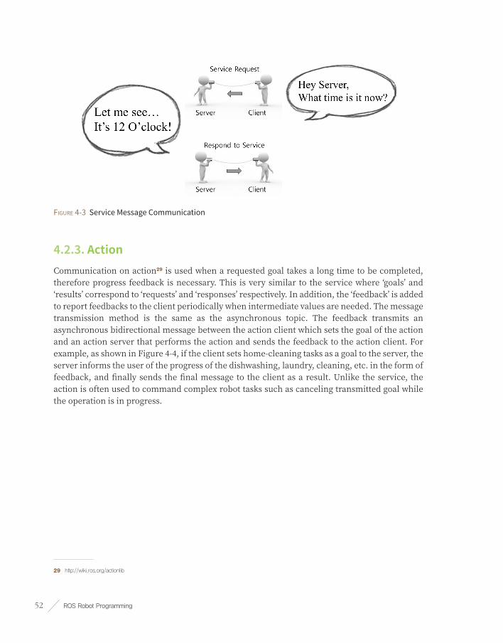
ROS Robot Programming52
Figure 4-3 Service Message Communication
4.2.3. ActionCommunication on action29 is used when a requested goal takes a long time to be completed, therefore progress feedback is necessary. This is very similar to the service where ‘goals’ and ‘results’ correspond to ‘requests’ and ‘responses’ respectively. In addition, the ‘feedback’ is added to report feedbacks to the client periodically when intermediate values are needed. The message transmission method is the same as the asynchronous topic. The feedback transmits an asynchronous bidirectional message between the action client which sets the goal of the action and an action server that performs the action and sends the feedback to the action client. For example, as shown in Figure 4-4, if the client sets home-cleaning tasks as a goal to the server, the server informs the user of the progress of the dishwashing, laundry, cleaning, etc. in the form of feedback, and finally sends the final message to the client as a result. Unlike the service, the action is often used to command complex robot tasks such as canceling transmitted goal while the operation is in progress.
29 http://wiki.ros.org/actionlib

Chapter 4 _ Important Concepts of ROS 53
Figure 4-4 Action Message Communication
The publisher, the subscriber, the service server, the service client, the action server, and the action client can be implemented in separate nodes. In order to exchange messages among these nodes, the connection has to be established first with the help of a master. A master acts like a name server as it keeps names of nodes, topics, services and action as well as the URI address, port number and parameters. In other words, nodes register their own information with the master upon launch, and acquire relative information of other nodes from the master. Then, each node directly connects to each other to perform message communication. This is shown in Figure 4-5.
Figure 4-5 Message Communication
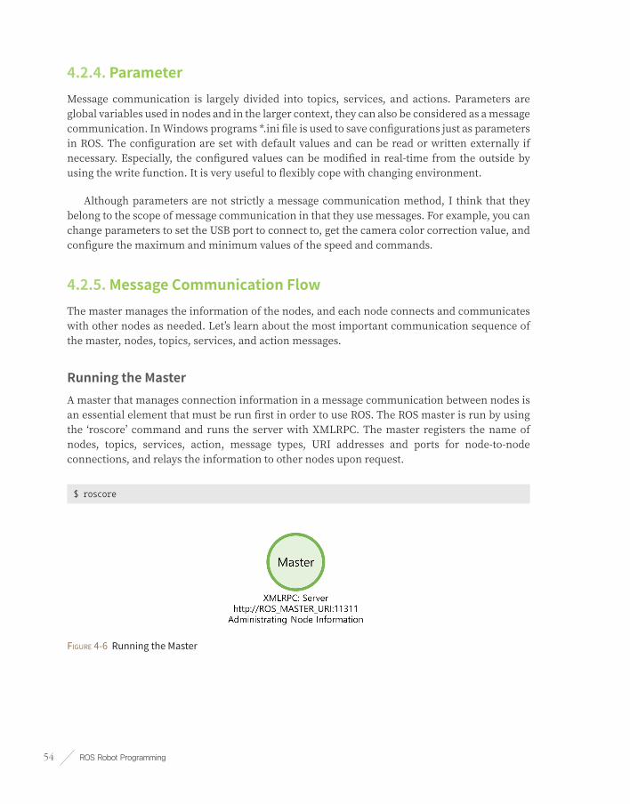
ROS Robot Programming54
4.2.4. ParameterMessage communication is largely divided into topics, services, and actions. Parameters are global variables used in nodes and in the larger context, they can also be considered as a message communication. In Windows programs *.ini file is used to save configurations just as parameters in ROS. The configuration are set with default values and can be read or written externally if necessary. Especially, the configured values can be modified in real-time from the outside by using the write function. It is very useful to flexibly cope with changing environment.
Although parameters are not strictly a message communication method, I think that they belong to the scope of message communication in that they use messages. For example, you can change parameters to set the USB port to connect to, get the camera color correction value, and configure the maximum and minimum values of the speed and commands.
4.2.5. Message Communication FlowThe master manages the information of the nodes, and each node connects and communicates with other nodes as needed. Let’s learn about the most important communication sequence of the master, nodes, topics, services, and action messages.
Running the Master A master that manages connection information in a message communication between nodes is an essential element that must be run first in order to use ROS. The ROS master is run by using the ‘roscore’ command and runs the server with XMLRPC. The master registers the name of nodes, topics, services, action, message types, URI addresses and ports for node-to-node connections, and relays the information to other nodes upon request.
$ roscore
Figure 4-6 Running the Master

Chapter 4 _ Important Concepts of ROS 55
Running the Subscriber NodeSubscriber nodes are launched with either a ‘rosrun’ or ‘roslaunch’ commands. The subscriber node registers its node name, topic name, message type, URI address, and port with the master as it runs. The master and node communicate using XMLRPC.
$ rosrun PACKAGE_NAME NODE_NAME
$ roslaunch PACKAGE_NAME LAUNCH_NAME
Figure 4-7 Running the Subscriber Node
Running the Publisher NodePublisher nodes, like subscriber nodes, are executed by ‘rosrun’ or ‘roslaunch’ commands. The publisher node registers its node name, topic name, message type, URI address and port with the master. The master and node communicate using XMLRPC.
Figure 4-8 Running the Publisher Node

ROS Robot Programming56
Providing Publisher InformationThe master distributes information such as the publisher’s name, topic name, message type, URI address and port number of the publisher to subscribers that want to connect to the publisher node. The master and node communicate using XMLRPC.
Figure 4-9 Provide Publisher Node Information to Subscriber Node
Connection Request from the Subscriber Node The subscriber node requests a direct connection to the publisher node based on the publisher information received from the master. During the request procedure, the subscriber node transmits information to the publisher node such as the subscriber node’s name, the topic name, and the message type. The publisher node and the subscriber node communicate using XMLRPC.
Figure 4-10 Connection Request from the Subscriber Node

Chapter 4 _ Important Concepts of ROS 57
Connection Response from the Publisher NodeThe publisher node sends the URI address and port number of its TCP server in response to the connection request from the subscriber node. The publisher node and the subscriber node communicate using XMLRPC.
Figure 4-11 Connection Response from the Publisher Node
TCPROS Connection The subscriber node creates a client for the publisher node using TCPROS, and connects to the publisher node. At this point, the communication between nodes uses TCP/IP based protocol called TCPROS.
Figure 4-12 TCP Connection

ROS Robot Programming58
Message Transmission The publisher node transmits a predefined message to the subscriber node. The communication between nodes uses TCPROS.
Figure 4-13 Topic Message Transmission
Service Request and ResponseThe procedures discussed above correspond to the communication on ‘topic’. Topic communication publishes and subscribes messages continuously, unless the publisher or subscriber is terminated. There are two types of services.
■ Service Client: Request service and receive response
■ Service Server: Receive a service, execute the specified task, and return a response
The connection between the service server and the client is the same as the TCPROS connection for the publisher and subscriber described above. Unlike the topic, the service terminates connection after successful request and response. If additional request is necessary, the connection procedure must be carried out again.
Figure 4-14 Service Request and Response
Action Goal, Result, Feedback Action may look similar to the request and the response of the service with an additional feedback message in order to provide intermediate result between the request (goal) and the response(result), but in practice it is rather more like a topic. In fact, if you use the ‘rostopic’ command to list up topics, there are five topics such as goal, status, cancel, result, and feedback that are used in the action. The connection between the action server and the client is similar to

Chapter 4 _ Important Concepts of ROS 59
the TCPROS connection of the publisher and subscriber, but the usage is slightly different. For example, when an action client sends a cancel command or the server sends a result value, the connection will be terminated.
Figure 4-15 Action Message Communication
We previously tested ROS with ‘turtlesim’. In this test, the master and two nodes were used, and the ‘/turtle1/cmd_vel’ topic was used between the two nodes to pass the translational and rotational messages to the virtual TurtleBot. Putting this in perspective with the ROS concept described above, it can be represented as in Figure 4-16.
Figure 4-16 Example of Message Communication

ROS Robot Programming60
4.3. MessageA message30 is a bundle of data used to exchange data between nodes. The topics, services, and actions are using messages to communicate. A message can include basic data types such as integer, floating point, Boolean as well as message arrays such as ‘float32[] ranges’, ‘Point32[10] points’. Moreover, a message can contain other messages such as ‘geometry_msgs/PoseStamped’. Also, the header ‘std_msgs/Header’ which is commonly used in ROS can be included in the message. These messages can be described as field types and field names as shown below.
fieldtype1 fieldname1
fieldtype2 fieldname2
fieldtype3 fieldname3
The ROS data type shown in Table 4-2 can be used in the field type. The following example is the simplest form of message, and you can use an array for the field type as shown in Table 4-3. Embedded messages in the message are also commonly used.
int32 x
int32 y
ROS Data Type Serialization C++ Data Type Python Data Type
bool unsigned8-bitint uint8_t bool
int8 signed8-bitint int8_t int
uint8 unsigned8-bitint uint8_t int
int16 signed16-bitint int16_t int
uint16 unsigned16-bitint uint16_t int
int32 signed32-bitint int32_t int
uint32 unsigned32-bitint uint32_t int
int64 signed64-bitint int64_t long
uint64 unsigned64-bitint uint64_t long
float32 32-bitIEEEfloat float float
float64 64-bitIEEEfloat double float
string asciistring std::string str
time secs/nsecsunsigned32-bitints ros::Time rospy.Time
30 http://wiki.ros.org/msg

Chapter 4 _ Important Concepts of ROS 61
ROS Data Type Serialization C++ Data Type Python Data Type
duration secs/nsecssigned32-bitints ros::Duration rospy.Duration
Table 4-2 Basic data types for messages in ROS, serialization methods, corresponding C ++ and Python data types
ROS Data Type Serialization C++ Data Type Python Data Type
fixed-length noextraserialization boost::array,std::vector tuple
variable-length uint32lengthprefix std::vector tuple
uint8[] uint32lengthprefix std::vector bytes
bool[] uint32lengthprefix std::vector<uint8_t> listofbool
Table 4-3 How to use ROS message data types as an array, corresponding C ++ and Python data types
The header (std_msgs/Header), which is commonly used in ROS, can also be used as a message. The Header.msg file in std_msgs31 contains the sequence ID, time stamp, and frame ID, and use them to probe the message or measure the time.
std_msgs/Header.msg
# Sequence ID: Messages are sequentially incremented by 1.
uint32 seq
# Timestamp: Has two child attributes, the stamp.sec for second and the stamp.nsec for
nanosecond.
time stamp
# Stores the Frame ID
string frame_id
The following shows how actually to use a message in the ROS program. For example, in the case of the ‘teleop_turtle_key’ node of the turtlesim package, which we tested in Chapter 3, the translational speed (meter/sec) and rotational speed (radian/sec) is sent as a message to the turtlesim node according to the directional keys (←, →, ↑, ↓) entered from the keyboard. The TurtleBot moves on the screen using the received speed values. The message used at this time is the ‘twist’32 message in ‘geometry_msgs’.
31 http://wiki.ros.org/std_msgs
32 http://docs.ros.org/api/geometry_msgs/html/msg/Twist.html

ROS Robot Programming62
Vector3 linear
Vector3 angular
In the message structure above, ‘linear’ and ‘angular’ values are declared as a Vector3 type. This is the similar form to the nested message as the Vector3 is a message type in the ‘geometry_msgs’33. The Vector334 contains the following data.
float64 x
float64 y
float64 z
In other words, six topics published from the ‘teleop_turtle_key’ node are linear.x, linear.y, linear.z, angular.x, angular.y, and angular.z. All of these are float64 type which is one of the basic data types described in ROS. With these data, arrow keys of the keyboard can be converted to the translational speed (meter/sec) and the rotational speed (radian/sec) message, so that the TurtleBot could be controlled.
The topic, service, and action described in the previous section use messages. Although they are similar in the form and the concept, they are divided into three types according to their usage. This will be discussed in more detail in the following section.
4.3.1. msg FileThe ‘msg’ file is the message file used by topics, with has the file extension of ‘*.msg’. The ‘Twist’35 message in the ‘geometry_msgs’ described above is an example of message. Such msg file consists of field types and field names.
geometry_msgs/Twist.msg
Vector3 linear
Vector3 angular
4.3.2. srv FileThe ‘srv’ file is the message file used by services, with the file extension of ‘*.srv’. For example, the SetCameraInfo36 message in the ‘sensor_msgs’ described above is a typical srv file. The major
33 http://docs.ros.org/api/geometry_msgs/html/index-msg.html
34 http://docs.ros.org/api/geometry_msgs/html/msg/Vector3.html
35 http://docs.ros.org/api/geometry_msgs/html/msg/Twist.html
36 http://docs.ros.org/api/sensor_msgs/html/srv/SetCameraInfo.html

Chapter 4 _ Important Concepts of ROS 63
difference from the msg file is that the series of three hyphens (---) serve as a delimiter; the upper message being the service request message and the lower message being the service response message.
sensor_msgs/SetCameraInfo.srv
sensor_msgs/CameraInfo camera_info
---
bool success
string status_message
4.3.3. action FileThe action message file37 is the message file used by actions38, with the file extension of ‘*.action’. Unlike msg and srv, it is relatively uncommon message file, so there is no typical example of the message file, but can be used as shown in following example. The major difference from the msg and srv files is that the series of three hyphens (---) are used in two places as delimiters, the first being the goal message, the second being the result message, and the third being the feedback message. The biggest difference of the action file is the feedback message feature. The goal message and the result message of the action file can be compared to the request and the response message of the srv file mentioned above, but the additional feedback message of the action file is used to send feedback while the designated process is being performed. As describe in the following example, when the starting position of ‘start_pose’ and the goal position of ‘goal_pose’ of the robot are transmitted as request values, the robot moves to the received goal position and returns the ‘result_pose’. While the robot is moving to the goal position, the ‘percent_complete’ message periodically transmits feedback values showing the progress in the form of the percentage of the goal point reached.
geometry_msgs/PoseStamped start_pose
geometry_msgs/PoseStamped goal_pose
---
geometry_msgs/PoseStamped result_pose
---
float32 percent_complete
37 http://wiki.ros.org/actionlib_msgs
38 http://wiki.ros.org/actionlib
---(three consecutive hyphens)

ROS Robot Programming64
4.4. NameROS has an abstract data type called ‘graph’ as its basic concept39. This graph shows the connection relationship between each node and the relationship of messages (data) sent and received with arrows. To do this, messages and parameters used in nodes, topics, and services in ROS all have unique names40. Let’s take a closer look at the names of topics. The name of the topic is divided into the relative method, the global method and the private method as shown in Table 4-4.
The topic is usually declared as shown in the following code. This will be covered in more detail in Chapter 7. Here, let’s modify the topic’s name in order to understand how to use names.
int main(int argc, char **argv) // Node Main Function
{
ros::init(argc, argv, "node1"); // Node Name Initialization
ros::NodeHandle nh; // Node Handle Declaration
// Publisher Declaration, Topic Name = bar
ros::Publisher node1_pub = nh.advertise<std_msg::Int32>("bar", 10);
In the above example, the name of the node is ‘/node1’. If the publisher is declared as a ‘bar’ without any symbols, the topic will have the relative name ‘/bar’. Even if the slash(/) character is used to declare in global, the topic name will still be ‘/bar’.
ros::Publisher node1_pub = nh.advertise<std_msg::Int32>("/bar", 10);
However, if you declare the name as private using the tilde(~) character, the topic name becomes ‘/node1/bar’.
ros::Publisher node1_pub = nh.advertise<std_msg::Int32>("~bar", 10);
The declaration of the name can vary as shown in Table 4-4. The ‘/wg’ means a change of the namespace. This is discussed in more detail in the next section.
39 http://wiki.ros.org/ROS/Concepts
40 http://wiki.ros.org/Names

Chapter 4 _ Important Concepts of ROS 65
Node Relative (Default) Global Private
/node1 bar→ /bar /bar→ /bar ~bar→ /node1/bar
/wg/node2 bar→ /wg/bar /bar→ /bar ~bar→ /wg/node2/bar
/wg/node3 foo/bar→ /wg/foo/bar /foo/bar→ /foo/bar ~foo/bar→ /wg/node3/foo/bar
Table 4-4 Naming Rule
How can two cameras be run? Simply executing the related node twice will terminate the previously executed node, due to the fact that there must be a unique name in ROS. However, achieving two cameras does not require you to run a separate program or change the source code. Simply change the name of the node when running it by using either namespaces or remapping.
To help you understand, suppose you have a virtual ‘camera_package’. Suppose that the camera node is executed when the ‘camera_node’ of ‘camera_package’ is executed, the way to run this is as follows.
$rosrun camera_package camera_node
If ‘camera_node’ transmits the image data of the camera via the image topic, this image topic can be received with ‘rqt_image_view’ as follows
$rosrun rqt_image_view rqt_image_view
Now let’s modify the topic values of these nodes by remapping. The following command will change the topic name as ‘/front/image’. In the below command, the ‘image’ is the topic name of ‘camera_node’ and the below example shows how to change the topic name by setting options in execution commands.
$ rosrun camera_package camera_node image:=front/image
$ rosrun rqt_image_view rqt_image_view image:=front/image
For example, if there are three cameras, such as front, left, and right, when the multiple nodes are executed under the same name, there will be conflicted names and therefore the previously executed node gets terminated. Therefore, nodes with the same name can be executed in the following way. Below, the name option is followed by consecutive underscores(__). Options such as ‘__ns’, ‘__name’, ‘__log’, ‘__ip’, ‘__hostname’, and ‘__master’ are special options used when running the node. Also, single underscore(_) is placed in front of the topic name if it is used as a private.

ROS Robot Programming66
$ rosrun camera_package camera_node __name:=front _device:=/dev/video0
$ rosrun camera_package camera_node __name:=left _device:=/dev/video1
$ rosrun camera_package camera_node __name:=right _device:=/dev/video2
$ rosrun rqt_image_view rqt_image_view
The following example will bind the nodes and topics into a single namespace. This ensures that all nodes and topics are grouped into a single namespace and all names are changed accordingly.
$ rosrun camera_package camera_node __ns:=back
$ rosrun rqt_imgae_view rqt_imgae_view __ns:=back
We have seen various uses of names. Names support the ability to seamlessly connect the ROS system as a whole. In this section, we learned how to change the name value using the node command ‘rosrun’. Similarly, by using ‘roslaunch’, it is possible to execute these options at once. This will be discussed in more detail in Chapter 7 with examples.
4.5. Coordinate Transformation (TF)When describing the robot’s arm pose as shown in Figure 4-17, it can be described as the relative coordinate transform41 of each joint. For example, the hand of a humanoid robot is connected to the wrist, the wrist is connected to the elbow, and the elbow is connected to the shoulder. In addition, the elbow can be displayed in relation to the leg joint poses while the robot is walking and moving. Finally, the coordinate of elbow correlates with the center of robot feet. Conversely, when the robot is walking, coordinates of the robot’s hands move according to the relative coordinate transformation of the respective correlated joints. In addition, if the robot tries to catch an object, the origin of the robot will be relatively positioned on a specific map, and the object will also be positioned on the map. The robot can calculate the position of the object relative to its position on the map to catch the object. In robotics programming, the robot’s joints (or wheels with rotating axes) and the position of each robot through coordinate transformation are very important, and in ROS, this is represented by TF (transform)42.
41 http://wiki.ros.org/geometry/CoordinateFrameConventions
42 http://wiki.ros.org/tf

Chapter 4 _ Important Concepts of ROS 67
Figure 4-17 Coordinate of the Robot Parts (THORMANG3, http://robots.ros.org/thormang/)
In ROS, the coordinate transformation TF is one of the most useful concepts when describing the robot parts as well as obstacles and objects. The pose can be described as a combination of positions and orientations. Here, the position is expressed by three vectors x, y, and z, and the orientation by four vectors x, y, z, and w, called a quaternion. The quaternion is not intuitive because they do not describe the rotation of three axes (x, y, z), such as the roll, pitch, and yaw angles that are often used. However, the quaternion form is free from the gimbal lock or speed issues that present in the Euler method of roll, pitch and yaw vectors. Therefore, the quaternion type is preferred in robotics, and ROS also uses quaternion for this reason. Of course, functions to convert Euler values to quaternions are provided for convenience.
TF uses the message structure43 shown below. The Header is used to record the converted time, and a message named ‘child_frame_id’ is used to specify the child coordinates. The relative position and orientation are described in the following data form: transform.translation.x / transform.translation.y / transform.translation.z / transform.rotation.x / transform.rotation.y / transform.rotation.z / transform.rotation.w
43 http://docs.ros.org/api/geometry_msgs/html/msg/TransformStamped.html
ROS Robot Programming68
geometry_msgs/TransformStamped.msg
Header header
string child_frame_id
Transform transform
A brief description of TF was given. More detailed TF examples will be explained in the modeling part of mobile robots (Chapter 10, 11) and manipulators (Chapter 13).
4.6. Client LibraryProgramming languages are very diverse. C++ is often used for performance and hardware-centric control, and Python or Ruby is used for productivity. LISP is widely used in the artificial intelligence field, MATLAB for scientific software such as and numerical analysis, Java for Android, as well as many more such as C#, Go, Haskell, Node.js, Lua, R, EusLisp, Julia, etc. It cannot be said which of these languages is more important than others. The developer will select the most suitable language depends on the nature of the work. Therefore, ROS, which supports robots with various purposes, allows developer to select the most appropriate language according to the purpose. Nodes can be written in various languages, and the information is exchanged through message communication between nodes. The software module that makes it possible to write nodes in various languages is the client library. Some of the most commonly used libraries are ‘roscpp’ for the C++ language, ‘rospy’ for the Python language, ‘roslisp’ for LISP, and ‘rosjava’ for Java. In addition, there are ‘roscs, roseus, rosgo, roshask, rosnodejs, RobotOS.jl, roslua, PhaROS, rosR, rosruby’ and ‘Unreal-Ros-Plugin’. Each client library is still under development for language diversity of ROS.
This book will focus on ‘roscpp’ for the C++ language. Even if different languages are used, the concepts are the same with different programming syntax. Therefore, developers can use the language most suitable for the purpose by referring to the wiki of each client library.
4.7. Communication between Heterogenous Devices As described in the meta-operating system part of Chapter 2, ROS supports communication between different devices through the use of message communication, message, name, transform function, and client library (see Figure 4-18). ROS can be run regardless of the type of operating system it is installed upon, and regardless of the programming language used. As long as ROS is installed and each node is properly designed, communication between nodes is very easy. For example, the status of a robot can be monitored on MacOS, even if Ubuntu, a distribution of Linux, is installed on the robot. At the same time, the user can command the robot from an Android-based app. An example of this is covered in the USB camera description in Chapter 8, by taking an example of video stream transmission between two different PCs. And
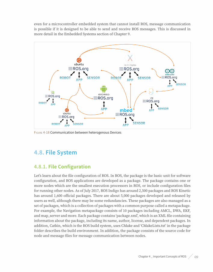
Chapter 4 _ Important Concepts of ROS 69
even for a microcontroller embedded system that cannot install ROS, message communication is possible if it is designed to be able to send and receive ROS messages. This is discussed in more detail in the Embedded Systems section of Chapter 9.
Figure 4-18 Communication between heterogenous Devices
4.8. File System
4.8.1. File ConfigurationLet’s learn about the file configuration of ROS. In ROS, the package is the basic unit for software configuration, and ROS applications are developed as a package. The package contains one or more nodes which are the smallest execution processors in ROS, or include configuration files for running other nodes. As of July 2017, ROS Indigo has around 2,500 packages and ROS Kinetic has around 1,600 official packages. There are about 5,000 packages developed and released by users as well, although there may be some redundancies. These packages are also managed as a set of packages, which is a collection of packages with a common purpose called a metapackage. For example, the Navigation metapackage consists of 10 packages including AMCL, DWA, EKF, and map_server and more. Each package contains ‘package.xml’, which is an XML file containing information about the package, including its name, author, license, and dependent packages. In addition, Catkin, which is the ROS build system, uses CMake and ‘CMakeLists.txt’ in the package folder describes the build environment. In addition, the package consists of the source code for node and message files for message communication between nodes.

ROS Robot Programming70
ROS’s file system is divided into installation folders and workspace folders. If the desktop version of ROS is installed, the installation folder is created in the /opt folder, and core utilities including roscore, rqt, RViz, robot related library, simulation and navigation are installed within the folder. The user rarely has a need to modify the files in this area. However, in order to modify the package that is officially distributed as a binary file, check the repository that contains the original source and copy the source to the workspace by using ‘git clone [REPOSITORY_ADDRESS]’ in ‘~/catkin_ws/src’ rather than using the package installation command of ‘sudo apt-get install ros-kinetic-xxx’,.
The user’s workspace can be create wherever the user wants, but let’s create it in the Linux user folder of ‘~/catkin_ws/ (‘~/’ is the ‘/home/user/’ folder in the Linux). Next, let’s learn about the ROS installation folder and workspace.
Binary Installation and Source Code Installation
There are two methods to install ROS packages. The first is to install the packages provided in the binary form which can be executed immediately without a build process. The second is for the user to download the source code of the package and build it before installation. These methods are used in different purposes. If you would like to modify the package or check the contents of the source code, you can use the latter installation method. The following is an example of a TurtleBot3 package and describes the differences between the two installation methods.
1. Binary Installation
$ sudo apt-get install ros-kinetic-turtlebot3
2. Source Code Installation
$ cd ~/catkin_ws/src
$ git clone https://github.com/ROBOTIS-GIT/turtlebot3.git
$ git clone https://github.com/ROBOTIS-GIT/turtlebot3_msgs.git
$ cd ~/catkin_ws/
$ catkin_make
4.8.2. Installation FolderROS is installed in the ‘/opt/ros/[VERSION_NAME]’ folder. For example, if you have installed the ROS Kinetic Kame version, the ROS installation path is:
■ ROS Installation Folder Path ‘/opt/ros/kinetic’

Chapter 4 _ Important Concepts of ROS 71
File ConfigurationWhen ROS is installed, ‘/opt/ros/kinetic’ folder consists of bin, etc, include, lib, the share folder and some configuration files as shown in Figure 4-19.
Figure 4-19 ROS File Configuration
File and folder descriptionsThe ROS folder contains the packages and ROS programs selected upon the installation of ROS. The details are as follows.
■ /bin Executable Binary Files
■ /etc ROS and Catkin related Configuration Files
■ /include Header Files
■ /lib Library Files
■ /share ROS Packages
■ env.* Environment Configuration Files
■ setup.* Environment Configuration Files
4.8.3. Workspace FolderYou can create a workspace wherever you want, but in this book, let’s use ‘~/catkin_ws/’ which is under the Linux user folder for convenience. The full path for the selected workspace folder will

ROS Robot Programming72
be ‘/home/username/catkin_ws’. For example, if the username is ‘oroca’ and the name of the catkin folder is ‘catkin_ws’, the path is:
■ Workspace Path: /home/oroca/catkin_ws/
File ConfigurationAs shown in Figure 4-20, there is a folder called ‘catkin_ws’ under the ‘/home/username/’ folder, and it consists of build, devel, and src folders. Note that the build and devel folders are created after catkin_make.
Figure 4-20 File Configuration of catkin workspace
Detailed File Configuration The workspace is a space that stores and builds user-created packages and packages published by other developers. Users perform most operations related to ROS in this folder. The details are as follows.
■ /build Build Related Files
■ /devel msg, srv Header Files and User Package Library, Execution Files
■ /src User Packages
User PackageThe ‘~/catkin_ws/src’ folder is the space for the user source code. In this folder, you can save and build your own ROS packages or packages developed by other developers. The ROS build system will be described in detail in the next section. Figure 4-21 below shows the state after completing the ‘ros_tutorials_topic’ package. It describes folders and files that are commonly used, although the configuration can vary depending on the purpose of the package.

Chapter 4 _ Important Concepts of ROS 73
Figure 4-21 File Configuration of the User Package
■ /include Header Files
■ /launch Launch Files Used with roslaunch
■ /node Script for rospy
■ /msg Message Files
■ /src Source Code Files
■ /srv Service Files
■ CMakeLists.txt Build Configuration File
■ package.xml Package Configuration File

ROS Robot Programming74
4.9. Build SystemThe ROS build system uses CMake (Cross Platform Make) by default and the build environment is described in the ‘CMakeLists.txt’ file in the package folder. ROS provides ROS-specific catkin build system with modified CMake.
The reason for using CMake on ROS is to allow the ROS package to be built on multiple platforms. Unlike Make, which relies only on Unix-based systems, CMake supports Windows, as well as Unix-based systems of Linux, BSD, and OS X. It also supports Microsoft Visual Studio and can be easily applied to Qt development. Furthermore, the Catkin build system makes it easy to use ROS-related builds, package management, and dependencies between packages.
4.9.1. Creating a Package The command to create a ROS package is as follows.
$ catkin_create_pkg [PACKAGE_NAME] [DEPENDENT_PACKAGE_1] [DEPENDENT_PACKAGE_N]
‘catkin_create_pkg’ command creates a package folder that contains the ‘CMakeLists.txt’ and ‘package.xml’ files necessary for the Cake build system. Let’s create a simple package to help you understand. First, open a new terminal window (Ctrl + Alt + t) and run the following command to move to the workspace folder.
$ cd ~/catkin_ws/src
The package name to be created is ‘my_first_ros_pkg’. Package names in ROS should all be lowercase and must not contain spaces. The naming guideline also uses an underscore(_) between each word instead of a dash(-) or a space. See the relevant pages for coding style guide44 45 and naming conventions in ROS. Now, let’s create a package named ‘my_first_ros_pkg’ with the following command:
$ catkin_create_pkg my_first_ros_pkg std_msgs roscpp
‘std_msgs’ and ‘roscpp’ were added as optional dependent packages in the previous command. This means that the ‘std_msgs’, which is a standard message package of ROS, and the ‘roscpp’, which is a client library necessary to use C/C++ in ROS, must be installed prior to the
44 http://wiki.ros.org/CppStyleGuide
45 http://wiki.ros.org/PyStyleGuide

Chapter 4 _ Important Concepts of ROS 75
creation of the package. These dependent package settings can be specified when creating the package, but can also be created directly in ‘package.xml’.
Once the package is created, ‘my_first_ros_pkg’ package folder will be created in the ‘~/catkin_ws/src’ folder, along with the default internal folder that the ROS package should have, and the ‘CMakeLists.txt’ and ‘package.xml’ files. The contents can be checked with the ‘ls’ command as below, and the inside of the package can be checked using the GUI-based tool Nautilus which acts like Window Explorer.
$ cd my_first_ros_pkg
$ ls
include → Include Folder
src → Source Code Folder
CMakeLists.txt → Build Configuration File
package.xml → Package Configuration File
Figure 4-22 Automatically Created Files and Folders when Creating a New Package
4.9.2. Modifying the Package Configuration File (package.xml)‘Package.xml’, which is one of the essential ROS configuration files, is an XML file containing information about the package, including the package name, author, license, and dependent packages. The original file without any modifications is shown below.
package.xml
<?xml version="1.0"?>
<package>
<name>my_first_ros_pkg</name>
<version>0.0.0</version>
<description>The my_first_ros_pkg package</description>
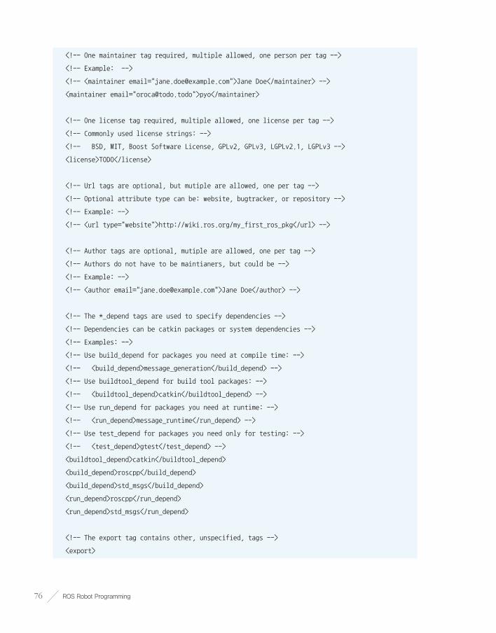
ROS Robot Programming76
<!-- One maintainer tag required, multiple allowed, one person per tag -->
<!-- Example: -->
<!-- <maintainer email="[email protected]">Jane Doe</maintainer> -->
<maintainer email="[email protected]">pyo</maintainer>
<!-- One license tag required, multiple allowed, one license per tag -->
<!-- Commonly used license strings: -->
<!-- BSD, MIT, Boost Software License, GPLv2, GPLv3, LGPLv2.1, LGPLv3 -->
<license>TODO</license>
<!-- Url tags are optional, but mutiple are allowed, one per tag -->
<!-- Optional attribute type can be: website, bugtracker, or repository -->
<!-- Example: -->
<!-- <url type="website">http://wiki.ros.org/my_first_ros_pkg</url> -->
<!-- Author tags are optional, mutiple are allowed, one per tag -->
<!-- Authors do not have to be maintianers, but could be -->
<!-- Example: -->
<!-- <author email="[email protected]">Jane Doe</author> -->
<!-- The *_depend tags are used to specify dependencies -->
<!-- Dependencies can be catkin packages or system dependencies -->
<!-- Examples: -->
<!-- Use build_depend for packages you need at compile time: -->
<!-- <build_depend>message_generation</build_depend> -->
<!-- Use buildtool_depend for build tool packages: -->
<!-- <buildtool_depend>catkin</buildtool_depend> -->
<!-- Use run_depend for packages you need at runtime: -->
<!-- <run_depend>message_runtime</run_depend> -->
<!-- Use test_depend for packages you need only for testing: -->
<!-- <test_depend>gtest</test_depend> -->
<buildtool_depend>catkin</buildtool_depend>
<build_depend>roscpp</build_depend>
<build_depend>std_msgs</build_depend>
<run_depend>roscpp</run_depend>
<run_depend>std_msgs</run_depend>
<!-- The export tag contains other, unspecified, tags -->
<export>

Chapter 4 _ Important Concepts of ROS 77
<!-- Other tools can request additional information be placed here -->
</export>
</package>
Below are descriptions of each statement.
■ <?xml> This tag indicates that the contents in the document abide by the XML Version 1.0.
■ <package> This tag is paired with </package> tag to indicate the configuration part of the ROS package configuration part.
■ <name> This tag indicates the package name. The package name entered when creating the package is used. The name of the package can be changed by the developer.
■ <version> This tag indicates the package version. The developer can assign the version of the package.
■ <description> A short description of the package. Usually 2-3 sentences.
■ <maintainer> The name and e-mail address of the package administrator.
■ <license> This tag indicates the license, such as BSD, MIT, Apache, GPLv3, LGPLv3.
■ <url> This tag indicates address of the webpage describing the package, or bug management, repository, etc. Depending on the type, you can assign it as a website, bugtracker, or repository.
■ <author> The name and email address of the developer who participated in the package development. If multiple developers were involved, append multiple <author> tags to the following lines.
■ <buildtool_depend> Describes the dependencies of the build system. As we are using the Catkin build system, write ‘catkin’.
■ <build_depend> Dependent package name when building the package.
■ <run_depend> Dependent package name when running the package.
■ <test_depend> Dependent package name when testing the package.
■ <export> It is used when using a tag name that is not specified in ROS. The most widely used case is for metapackages. In this case, use <export> <metapackage/></export> to notify that the package is a metapackage.
■ <metapackage> The official tag used within the export tag that declares the current package as a metapackage.

ROS Robot Programming78
I modified the package configuration file (package.xml) as follows. Let’s modify it in your own environment as well. If you are unfamiliar with it, you can use the below file as is:
package.xml
<?xml version="1.0"?>
<package>
<name>my_first_ros_pkg</name>
<version>0.0.1</version>
<description>The my_first_ros_pkg package</description>
<license>Apache License 2.0</license>
<author email="[email protected]">Yoonseok Pyo</author>
<maintainer email="[email protected]">Yoonseok Pyo</maintainer>
<url type="bugtracker">https://github.com/ROBOTIS-GIT/ros_tutorials/issues</url>
<url type="repository">https://github.com/ROBOTIS-GIT/ros_tutorials.git</url>
<url type="website">http://www.robotis.com</url>
<buildtool_depend>catkin</buildtool_depend>
<build_depend>std_msgs</build_depend>
<build_depend>roscpp</build_depend>
<run_depend>std_msgs</run_depend>
<run_depend>roscpp</run_depend>
<export></export>
</package>
4.9.3. Modifying the Build Configuration File (CMakeLists.txt)Catkin, the build system for ROS, uses CMake and describes the build environment in the ‘CMakeLists.txt’ in the package folder. It configures the executable file creation, dependency package priority build, link creation, and so on. The original file without any modifications is shown below.
CMakeLists.txt
cmake_minimum_required(VERSION 2.8.3)
project(my_first_ros_pkg)
## Find catkin macros and libraries
## if COMPONENTS list like find_package(catkin REQUIRED COMPONENTS xyz)
## is used, also find other catkin packages
find_package(catkin REQUIRED COMPONENTS
roscpp

Chapter 4 _ Important Concepts of ROS 79
std_msgs
)
## System dependencies are found with CMake's conventions
# find_package(Boost REQUIRED COMPONENTS system)
## Uncomment this if the package has a setup.py. This macro ensures
## modules and global scripts declared therein get installed
## See http://ros.org/doc/api/catkin/html/user_guide/setup_dot_py.html
# catkin_python_setup()
################################################
## Declare ROS messages, services and actions ##
################################################
## To declare and build messages, services or actions from within this
## package, follow these steps:
## * Let MSG_DEP_SET be the set of packages whose message types you use in
## your messages/services/actions (e.g. std_msgs, actionlib_msgs, ...).
## * In the file package.xml:
## * add a build_depend tag for "message_generation"
## * add a build_depend and a run_depend tag for each package in MSG_DEP_SET
## * If MSG_DEP_SET isn't empty the following dependency has been pulled in
## but can be declared for certainty nonetheless:
## * add a run_depend tag for "message_runtime"
## * In this file (CMakeLists.txt):
## * add "message_generation" and every package in MSG_DEP_SET to
## find_package(catkin REQUIRED COMPONENTS ...)
## * add "message_runtime" and every package in MSG_DEP_SET to
## catkin_package(CATKIN_DEPENDS ...)
## * uncomment the add_*_files sections below as needed
## and list every .msg/.srv/.action file to be processed
## * uncomment the generate_messages entry below
## * add every package in MSG_DEP_SET to generate_messages(DEPENDENCIES ...)
## Generate messages in the 'msg' folder
# add_message_files(
# FILES

ROS Robot Programming80
# Message1.msg
# Message2.msg
# )
## Generate services in the 'srv' folder
# add_service_files(
# FILES
# Service1.srv
# Service2.srv
# )
## Generate actions in the 'action' folder
# add_action_files(
# FILES
# Action1.action
# Action2.action
# )
## Generate added messages and services with any dependencies listed here
# generate_messages(
# DEPENDENCIES
# std_msgs
# )
################################################
## Declare ROS dynamic reconfigure parameters ##
################################################
## To declare and build dynamic reconfigure parameters within this
## package, follow these steps:
## * In the file package.xml:
## * add a build_depend and a run_depend tag for "dynamic_reconfigure"
## * In this file (CMakeLists.txt):
## * add "dynamic_reconfigure" to
## find_package(catkin REQUIRED COMPONENTS ...)
## * uncomment the "generate_dynamic_reconfigure_options" section below
## and list every .cfg file to be processed
## Generate dynamic reconfigure parameters in the 'cfg' folder

Chapter 4 _ Important Concepts of ROS 81
# generate_dynamic_reconfigure_options(
# cfg/DynReconf1.cfg
# cfg/DynReconf2.cfg
# )
###################################
## catkin specific configuration ##
###################################
## The catkin_package macro generates cmake config files for your package
## Declare things to be passed to dependent projects
## INCLUDE_DIRS: uncomment this if you package contains header files
## LIBRARIES: libraries you create in this project that dependent projects also need
## CATKIN_DEPENDS: catkin_packages dependent projects also need
## DEPENDS: system dependencies of this project that dependent projects also need
catkin_package(
# INCLUDE_DIRS include
# LIBRARIES my_first_ros_pkg
# CATKIN_DEPENDS roscpp std_msgs
# DEPENDS system_lib
)
###########
## Build ##
###########
## Specify additional locations of header files
## Your package locations should be listed before other locations
# include_directories(include)
include_directories(
${catkin_INCLUDE_DIRS}
)
## Declare a C++ library
# add_library(my_first_ros_pkg
# src/${PROJECT_NAME}/my_first_ros_pkg.cpp
# )
## Add cmake target dependencies of the library
## as an example, code may need to be generated before libraries

ROS Robot Programming82
## either from message generation or dynamic reconfigure
# add_dependencies(my_first_ros_pkg ${${PROJECT_NAME}_EXPORTED_TARGETS}
${catkin_EXPORTED_TARGETS})
## Declare a C++ executable
# add_executable(my_first_ros_pkg_node src/my_first_ros_pkg_node.cpp)
## Add cmake target dependencies of the executable
## same as for the library above
# add_dependencies(my_first_ros_pkg_node ${${PROJECT_NAME}_EXPORTED_TARGETS}
${catkin_EXPORTED_TARGETS})
## Specify libraries to link a library or executable target against
# target_link_libraries(my_first_ros_pkg_node
# ${catkin_LIBRARIES}
# )
#############
## Install ##
#############
# all install targets should use catkin DESTINATION variables
# See http://ros.org/doc/api/catkin/html/adv_user_guide/variables.html
## Mark executable scripts (Python etc.) for installation
## in contrast to setup.py, you can choose the destination
# install(PROGRAMS
# scripts/my_python_script
# DESTINATION ${CATKIN_PACKAGE_BIN_DESTINATION}
# )
## Mark executables and/or libraries for installation
# install(TARGETS my_first_ros_pkg my_first_ros_pkg_node
# ARCHIVE DESTINATION ${CATKIN_PACKAGE_LIB_DESTINATION}
# LIBRARY DESTINATION ${CATKIN_PACKAGE_LIB_DESTINATION}
# RUNTIME DESTINATION ${CATKIN_PACKAGE_BIN_DESTINATION}
# )
## Mark cpp header files for installation
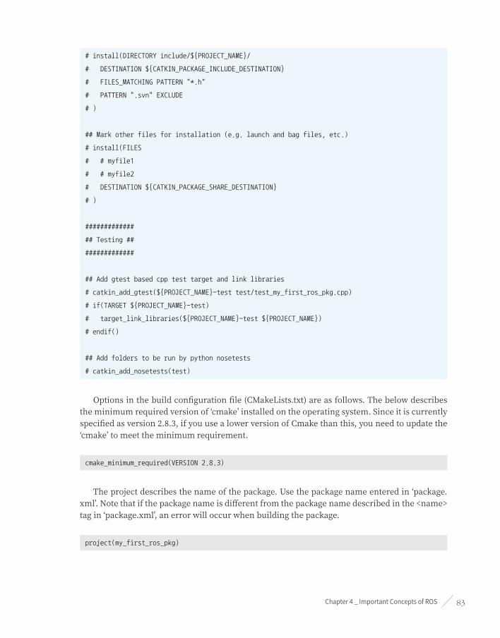
Chapter 4 _ Important Concepts of ROS 83
# install(DIRECTORY include/${PROJECT_NAME}/
# DESTINATION ${CATKIN_PACKAGE_INCLUDE_DESTINATION}
# FILES_MATCHING PATTERN "*.h"
# PATTERN ".svn" EXCLUDE
# )
## Mark other files for installation (e.g. launch and bag files, etc.)
# install(FILES
# # myfile1
# # myfile2
# DESTINATION ${CATKIN_PACKAGE_SHARE_DESTINATION}
# )
#############
## Testing ##
#############
## Add gtest based cpp test target and link libraries
# catkin_add_gtest(${PROJECT_NAME}-test test/test_my_first_ros_pkg.cpp)
# if(TARGET ${PROJECT_NAME}-test)
# target_link_libraries(${PROJECT_NAME}-test ${PROJECT_NAME})
# endif()
## Add folders to be run by python nosetests
# catkin_add_nosetests(test)
Options in the build configuration file (CMakeLists.txt) are as follows. The below describes the minimum required version of ‘cmake’ installed on the operating system. Since it is currently specified as version 2.8.3, if you use a lower version of Cmake than this, you need to update the ‘cmake’ to meet the minimum requirement.
cmake_minimum_required(VERSION 2.8.3)
The project describes the name of the package. Use the package name entered in ‘package.xml’. Note that if the package name is different from the package name described in the <name> tag in ‘package.xml’, an error will occur when building the package.
project(my_first_ros_pkg)

ROS Robot Programming84
The ‘find_package’ entry is the component package required to perform a build on Catkin. In this example, ‘roscpp’ and ‘std_msgs’ are set as dependent packages. If the package entered here is not found in the system, an error will occur when building the package. In other words, this is an option to require the installation of dependent packages for the custom package.
find_package(catkin REQUIRED COMPONENTS
roscpp
std_msgs
)
The following is a method used when using packages other than ROS. For example, when using Boost, the ‘system’ package must be installed beforehand. This feature is an option that allows you to install dependent packages.
find_package(Boost REQUIRED COMPONENTS system)
The ‘catkin_python_setup()’ is an option when using Python with ‘rospy’. It invokes the Python installation process ‘setup.py’.
catkin_python_setup()
‘add_message_files’ is an option to add a message file. The ‘FILES’ option will automatically generate a header file (*.h) by referring to the ‘.msg’ files in the ‘msg’ folder of the current package. In this example, message files Message1.msg and Message2.msg are used.
add_message_files(
FILES
Message1.msg
Message2.msg
)
‘add_service_files’ is an option to add a service file to use. The ‘FILES’ option will refer to ‘.srv’ files in the ‘srv’ folder in the package. In this example, you have the option to use the service files Service1.srv and Service2.srv.
add_service_files(
FILES
Service1.srv
Service2.srv
)
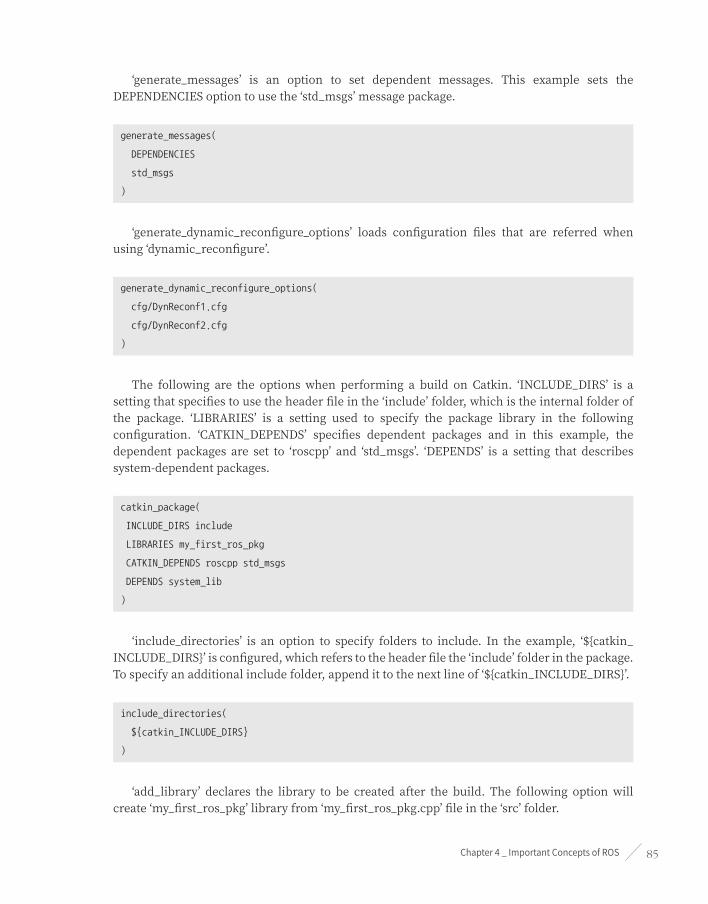
Chapter 4 _ Important Concepts of ROS 85
‘generate_messages’ is an option to set dependent messages. This example sets the DEPENDENCIES option to use the ‘std_msgs’ message package.
generate_messages(
DEPENDENCIES
std_msgs
)
‘generate_dynamic_reconfigure_options’ loads configuration files that are referred when using ‘dynamic_reconfigure’.
generate_dynamic_reconfigure_options(
cfg/DynReconf1.cfg
cfg/DynReconf2.cfg
)
The following are the options when performing a build on Catkin. ‘INCLUDE_DIRS’ is a setting that specifies to use the header file in the ‘include’ folder, which is the internal folder of the package. ‘LIBRARIES’ is a setting used to specify the package library in the following configuration. ‘CATKIN_DEPENDS’ specifies dependent packages and in this example, the dependent packages are set to ‘roscpp’ and ‘std_msgs’. ‘DEPENDS’ is a setting that describes system-dependent packages.
catkin_package(
INCLUDE_DIRS include
LIBRARIES my_first_ros_pkg
CATKIN_DEPENDS roscpp std_msgs
DEPENDS system_lib
)
‘include_directories’ is an option to specify folders to include. In the example, ‘${catkin_INCLUDE_DIRS}’ is configured, which refers to the header file the ‘include’ folder in the package. To specify an additional include folder, append it to the next line of ‘${catkin_INCLUDE_DIRS}’.
include_directories(
${catkin_INCLUDE_DIRS}
)
‘add_library’ declares the library to be created after the build. The following option will create ‘my_first_ros_pkg’ library from ‘my_first_ros_pkg.cpp’ file in the ‘src’ folder.

ROS Robot Programming86
add_library(my_first_ros_pkg
src/${PROJECT_NAME}/my_first_ros_pkg.cpp
)
‘add_dependencies’ is a command to perform certain tasks prior to the build process such as creating dependent messages or dynamic reconfigurations. The following options describe the creation of dependent messages and dynamic reconfiguration, which are the dependencies of the ‘my_first_ros_pkg’ library.
add_dependencies(my_first_ros_pkg ${${PROJECT_NAME}_EXPORTED_TARGETS} ${catkin_EXPORTED_TARGETS})
‘add_executable’ specifies the executable to be created after the build. The option specifies the system to refer to the ‘src/my_first_ros_pkg_node.cpp’ file to generate the ‘my_first_ros_pkg_node’ executable file. If there are multiple ‘*.cpp’ files to be referenced, append them after ‘my_first_ros_pkg_node.cpp’. If there are two or more executable files to be created, add an additional ‘add_executable’ entry.
add_executable(my_first_ros_pkg_node src/my_first_ros_pkg_node.cpp)
‘add_dependencies’ option is like the ‘add_dependencies’ previously described, which is required to perform certain tasks such as creating dependent messages or dynamic reconfigurations prior to building libraries or executable files. The following describes the dependency of the executable file named ‘my_first_ros_pkg_node’, not the library mentioned above. It is most often used when creating message files prior to building executable files.
add_dependencies(my_first_ros_pkg_node ${${PROJECT_NAME}_EXPORTED_TARGETS} ${catkin_EXPORTED_TARGETS})
‘target_link_libraries’ is an option that links libraries and executables that need to be linked before creating an executable file.
target_link_libraries(my_first_ros_pkg_node
${catkin_LIBRARIES}
)
In addition, the Install option used when creating the official distribution ROS package and the testing option used for the package test is provided.

Chapter 4 _ Important Concepts of ROS 87
The following is the modified build configuration file (CMakeLists.txt). Modify the file for your package. For more information on how to use the configuration file, please refer to the packages of TurtleBot3 and ROBOTIS OP3 published at ‘https://github.com/ROBOTIS-GIT’.
CMakeLists.txt
cmake_minimum_required(VERSION 2.8.3)
project(my_first_ros_pkg)
find_package(catkin REQUIRED COMPONENTS roscpp std_msgs)
catkin_package(CATKIN_DEPENDS roscpp std_msgs)
include_directories(${catkin_INCLUDE_DIRS})
add_executable(hello_world_node src/hello_world_node.cpp)
target_link_libraries(hello_world_node ${catkin_LIBRARIES})
4.9.4. Writing Source Code The following setting is configured in the executable file creation section (add_executable) of the ‘CMakeLists.txt’ file mentioned above.
add_executable(hello_world_node src/hello_world_node.cpp)
This is the setting to create the executable ‘hello_world_node’ by referring to the ‘hello_world_node’ source code in the ‘src’ folder of the package. As ‘hello_world_node.cpp’ source code has to be manually created and written by developer, let’s write a simple example.
First, move to the source code folder (src) in your package folder by using ‘cd’ command and create the ‘hello_world_node.cpp’ file as shown below. This example uses the gedit editor, but you can use your preferred editor, such as vi, gedit, qtcreator, vim, or emacs.
$ cd ~/catkin_ws/src/my_first_ros_pkg/src/
$ gedit hello_world_node.cpp
Then, write the following source code in the created file.
hello_world_node.cpp
#include <ros/ros.h>
#include <std_msgs/String.h>
#include <sstream>
int main(int argc, char **argv)

ROS Robot Programming88
{
ros::init(argc, argv, "hello_world_node");
ros::NodeHandle nh;
ros::Publisher chatter_pub = nh.advertise<std_msgs::String>("say_hello_world", 1000);
ros::Rate loop_rate(10);
int count = 0;
while (ros::ok())
{
std_msgs::String msg;
std::stringstream ss;
ss << "hello world!" << count;
msg.data = ss.str();
ROS_INFO("%s", msg.data.c_str());
chatter_pub.publish(msg);
ros::spinOnce();
loop_rate.sleep();
++count;
}
return 0;
}
4.9.5. Building the PackageOnce above code is saved in the file, all the necessary work for building a package is completed. Before building the package, update the profile of the ROS package with the below command. It is a command to apply the previously created package to the ROS package list. Although this is not mandatory, it is convenient to update after creating a new package as it will allows to find the package using auto-completion feature with the Tab key.
$ rospack profile
The following is a Catkin build. Go to the Catkin workspace and build the package.
$ cd ~/catkin_ws && catkin_make

Chapter 4 _ Important Concepts of ROS 89
Alias Command
As mentioned in Section 3.2 Setting Up the ROS Development Environment, if you set alias cm=’cd ~/catkin_ws && catkin_make’ in the ‘.bashrc’ file, you can replace the above command with ‘cm’ command in the terminal window. As it is very useful, make sure to set it by referring to the ROS Development Environment setup section.
4.9.6. Running the NodeIf the build was completed without any errors, a ‘hello_world_node’ file should have been created in ‘~/catkin_ws/devel/lib/my_first_ros_pkg’.
The next step is to run the node. Open a terminal window (Ctrl + Alt + t) and run roscore before running the node. Note that roscore must be running in order to execute ROS nodes, and roscore only needs to be run once unless it stops.
$ roscore
Finally, open a new terminal window (Ctrl + Alt + t) and run the node with the command below. This is a command to run a node called ‘hello_world_node’ in a package named ‘my_first_ros_pkg’.
$ rosrun my_first_ros_pkg hello_world_node
[INFO] [1499662568.416826810]: hello world!0
[INFO] [1499662568.516845339]: hello world!1
[INFO] [1499662568.616839553]: hello world!2
[INFO] [1499662568.716806374]: hello world!3
[INFO] [1499662568.816807707]: hello world!4
[INFO] [1499662568.916833281]: hello world!5
[INFO] [1499662569.016831357]: hello world!6
[INFO] [1499662569.116832712]: hello world!7
[INFO] [1499662569.216827362]: hello world!8
[INFO] [1499662569.316806268]: hello world!9
[INFO] [1499662569.416805945]: hello world!10
When the node is running, messages such as ‘hello world!0,1,2,3 ...’ can been viewed in the terminal window in strings. This is not an actual message transfer in ROS, but it can be seen as a result of the build system example discussed in this section. Since this section is intended to describe the build system of ROS, the source code for messages and nodes will be discussed in more detail in the following chapters.

ROS Robot Programming90
ROS Commands
Chapter 5

Chapter 5 _ ROS Commands 91
5.1. ROS Command List
ROS Wiki
The ROS commands are explained in detail on the Wiki page ‘http://wiki.ros.org/ROS/Command LineTools’. In addition, the GitHub repository ‘https://github.com/ros/cheatsheet/releases’ summarizes important commands described in this chapter. It will be a helpful reference to utilize along with the descriptions in this chapter.
When using ROS, we enter commands in a Shell environment to perform tasks such as using file systems, editing, building, debugging source codes, package management, etc. In order to use ROS properly, we will need to familiarize ourselves with not only the basic Linux commands but also with the ROS specific commands.
In order to become proficient with the various commands used for ROS, we will give a brief description of the functions of each command, and introduce them one by one with examples. When introducing a command, each one is ranked with three stars based on their frequency of use and importance. You may need some time to get used to the commands, but the more you use them, you will soon find yourself using each kind of ROS functions quickly and easily using these commands.
ROS Shell Commands
Command Importance Command Explanation Description
roscd ★★★ ros+cd(changes directory) Move to the directory of the designated ROS package
rosls ★☆☆ ros+ls(lists files) Check file list of ROS package
rosed ★☆☆ ros+ed(editor) Edit file of ROS package
roscp ★☆☆ ros+cp(copies files) Copy file of ROS package
rospd ☆☆☆ ros+pushd Add directory to the ROS directory index
rosd ☆☆☆ ros+directory Check the ROS directory index
ROS Execution Commands
Command Importance Command Explanation Description
roscore ★★★ ros+core master(ROS name service) + rosout(record log) + parameter server(manage parameter)

ROS Robot Programming92
Command Importance Command Explanation Description
rosrun ★★★ ros+run Run node
roslaunch ★★★ ros+launch Launch multiple nodes and configure options
rosclean ★★☆ ros+clean Examine or delete ROS log file
ROS Information Commands
Command Importance Command Explanation Description
rostopic ★★★ ros+topic Check ROS topic information
rosservice ★★★ ros+service Check ROS service information
rosnode ★★★ ros+node Check ROS node information
rosparam ★★★ ros+param(parameter) Check and edit ROS parameter information
rosbag ★★★ ros+bag Record and play ROS message
rosmsg ★★☆ ros+msg Check ROS message information
rossrv ★★☆ ros+srv Check ROS service information
rosversion ★☆☆ ros+version Check ROS package and release version information
roswtf ☆☆☆ ros+wtf Examine ROS system
ROS Catkin Commands
Command Importance Description
catkin_create_pkg ★★★ Automatic creation of package
catkin_make ★★★ Build based on catkin build system
catkin_eclipse ★★☆ Modify package created by catkin build system so that it can be used in Eclipse
catkin_prepare_release ★★☆ Cleanup log and tag version during release
catkin_generate_changelog ★★☆ Create or update ‘CHANGELOG.rst’ file during release
catkin_init_workspace ★★☆ Initialize workspace of the catkin build system
catkin_find ★☆☆ Search catkin

Chapter 5 _ ROS Commands 93
ROS Package Commands
Command Importance Command Explanation Description
ropack ★★★ ros+pack(package) View information regarding a specific ROS package
rosinstall ★★☆ ros+install Install additional ROS packages
rosdep ★★☆ ros+dep(dependencies) Install dependency package of the ROS corresponding package
roslocate ☆☆☆ ros+locate Show information of ROS package
roscreate-pkg ☆☆☆ ros+create-pkg(package) Automatic creation of ROS package (used in previous rosbuild system)
rosmake ☆☆☆ ros+make Build ROS package (used in previous rosbuild system)
5.2. ROS Shell CommandsROS shell commands are also called rosbash1. These commands allow us to use the bash shell commands commonly used in Linux for the ROS development environment as well. Generally ‘ros’ prefixes are used in conjunction with suffixes such as ‘cd, pd, d, ls, ed, cp, run’. The relevant commands are as follows.
Command Importance Command Explanation Description
roscd ★★★ ros+cd(changes directory) Move to the directory of the designated ROS package
rosls ★☆☆ ros+ls(lists files) Check file list of ROS package
rosed ★☆☆ ros+ed(editor) Edit file of ROS package
roscp ★☆☆ ros+cp(copies files) Copy file of ROS package
rospd ☆☆☆ ros+pushd Add directory to the ROS directory index
rosd ☆☆☆ ros+directory Check the ROS directory index
From these, we will look into the commands ‘roscd’, ‘rosls’, and ‘rosed’ which are used frequently.
1 http://wiki.ros.org/rosbash

ROS Robot Programming94
Environment for using ROS shell commands
In order to use ROS shell commands, ‘rosbash’ must be installed using the following command, and can only be used in a terminal window that has configured ‘source /opt/ros/<ros distribution>/setup.bash’. This does not have to be installed separately, and if you have finished building the ROS development environment from Chapter 3 then you will be able to use it.
$ sudo apt-get install ros-<ros distribution>-rosbash
5.2.1. roscd: ROS Change Directory
roscd [PACKAGE_NAME]
This is a command to move to the directory where the package is saved. The basic instruction is to type the ‘roscd’ command followed by the package name as a parameter. In the following example, the turtlesim package is in the folder where ROS is installed so we get the following result, but if you put the name of a package that you created (for example, my_first_ros_pkg created in Chapter 4) as a parameter, then it moves to the folder of the package that you have designated. This is a command that is frequently used in the command-based ROS.
$ roscd turtlesim
/opt/ros/kinetic/share/turtlesim $
$ roscd my_first_ros_pkg
~/catkin_ws/src/my_first_ros_pkg $
The ros-kinetic-turtlesim package must be installed first in order to get the identical result as shown above. If it is not installed yet, you can install it with the following command.
$ sudo apt-get install ros-kinetic-turtlesim
If the package is already installed, you will see the message that says the package is already installed as shown below.
$ sudo apt-get install ros-kinetic-turtlesim
[sudo] password for USER:
Reading package lists... Done
Building dependency tree
Reading state information... Done
ros-kinetic-turtlesim is already the newest version (0.7.1-0xenial-20170613-170649-0800).
0 upgraded, 0 newly installed, 0 to remove and 29 not upgraded.

Chapter 5 _ ROS Commands 95
5.2.2. rosls: ROS File List
rosls [PACKAGE_NAME]
This is a command to check the file list of the specific ROS package. We can use the ‘roscd’ command to move to the corresponding package folder and then use the ‘ls’ command to perform the same function, but this command is used occasionally when we need to check without moving to the package directory.
$ rosls turtlesim
cmake images msg srv package.xml
5.2.3. rosed: ROS Edit Command
rosed [PACKAGE_NAME] [FILE_NAME]
This is a command used to edit a specific file in the package. If you run this command, it opens the corresponding file with the editor that the user has set up. This is often used when you want to quickly make a simple modification. The user can assign which editor will be used by editing the command export EDITOR = ‘emacs -nw’ in your ‘~/.bashrc’ file. As previously mentioned, this command is used for simple tasks that need to modify directly in the command window, and it is not recommended for complex tasks. It is not a command that is used often.
$ rosed turtlesim package.xml
5.3. ROS Execution CommandsThe ROS execution commands control the execution of ROS nodes. Above all, the most essential is roscore which is used as the name server for nodes. And for the execution commands there are ‘rosrun’ and ‘roslaunch’. We use ‘rosrun’ to run one node and ‘roslaunch’ to run multiple nodes or to additionally configure various options. And ‘rosclean’ is a command that deletes the logs recorded when node was running.
Command Importance Command Explanation Description
roscore ★★★ ros+core master(ROS name service) + rosout(record log) + parameter server(manage parameter)
rosrun ★★★ ros+run Run node

ROS Robot Programming96
Command Importance Command Explanation Description
roslaunch ★★★ ros+launch Launch multiple nodes and configure options
rosclean ★★☆ ros+clean Examine or delete ROS log file
5.3.1. roscore: Run roscore
roscore [OPTION]
Roscore is the master that manages the connection information for communication among nodes, and is an essential element that must be the first to be launched to use ROS. The ROS master is launched by the ‘roscore’ command, and runs as an XMLRPC server. The master registers node information such as names, topics and service names, message types, URI addresses and ports, and when there is a request this information is passed to other nodes. Upon the launch of ‘roscore’, ‘rosout’ is executed as well, which is used to record ROS standard output logs such as DEBUG, INFO, WARN, ERROR, FATAL, etc. Also the parameter server which manages the parameters is executed.
When roscore is running, the URI configured in the ROS_MASTER_URI is set as the master URI to run the master. ROS_MASTER_URI can be configured by the user in ‘~/.bashrc’ file as mentioned in the ROS Configuration section in Chapter 3.
$ roscore
... logging to /home/pyo/.ros/log/c2d0b528-6536-11e7-935b-08d40c80c500/roslaunch-pyo-20002.log
Checking log directory for disk usage. This may take awhile.
Press Ctrl-C to interrupt
Done checking log file disk usage. Usage is <1GB.
started roslaunch server http://localhost:43517/
ros_comm version 1.12.7
SUMMARY
========
PARAMETERS
* /rosdistro: kinetic
* /rosversion: 1.12.7
NODES
auto-starting new master

Chapter 5 _ ROS Commands 97
process[master]: started with pid [20013]
ROS_MASTER_URI=http://localhost:11311/
setting /run_id to c2d0b528-6536-11e7-935b-08d40c80c500
process[rosout-1]: started with pid [20027]
started core service [/rosout]
In the terminal screen, we can see that the logs are saved in the directory ‘/home/xxx/.ros/log/’. The displayed message also notifies that we can close roscore with [Ctrl+c], the information of roslaunch server and ROS_MASTER_URI, and that the parameter server of ‘/rosdistro’ and ‘/rosversion’ and the /rosout node have all been running.
Log Save Path
In the above example, it shows that the path where the logs are saved is ‘/home/xxx/.ros/log/’, but in reality it is saved in the location where the ROS_HOME environment variable is configured. If the ROS_HOME environment variable has not been configured, then the default value is ‘~/.ros/log/’.
5.3.2. rosrun: Run ROS Node
rosrun [PACKAGE_NAME] [NODE_NAME]
Rosrun is a command that runs only one node in the specified package. The following example is a command that runs the ‘turtlesim_node’ node in the turtlesim package. For your information, the turtle icon that appears on the screen is selected randomly.
$ rosrun turtlesim turtlesim_node
[ INFO] [1512634911.275228307]: Starting turtlesim with node name /turtlesim
[ INFO] [1512634911.281614642]: Spawning turtle [turtle1] at x=[5.544445], y=[5.544445],
theta=[0.000000]

ROS Robot Programming98
Figure 5-1 Screen after the turtlesim_node node is executed
5.3.3. roslaunch: Launch Multiple Nodes
roslaunch [PACKAGE_NAME] [launch_FILE_NAME]
Roslaunch is a command that executes more than one node in the specified package or sets execution options. As shown in the following example, simply launching the ‘openni_launch’ package will run more than 20 nodes and more than 10 parameter servers, such as ‘camera_nodelet_manager’, ‘depth_metric’, ‘depth_metric_rect’, ‘depth_points’, etc. As we can see, using the launch file is quite useful for running multiple nodes at the same time, and is a frequently used execution method in ROS. More information about creating the ‘*.launch’ file that is used in this example will be provided in Section 7.6 Using roslaunch.
$ roslaunch openni_launch openni.launch
~ omitted ~
Note that in order to run this example and get the same result, the relevant package ‘ros-kinetic-openni-launch’ must be installed. If it is not installed yet, you can install it with the following command.
$ sudo apt-get install ros-kinetic-openni-launch

Chapter 5 _ ROS Commands 99
5.3.4. rosclean: Examine and Delete ROS Logs
rosclean [OPTION]
This is a command to check or delete the ROS log file. As ‘roscore’ is launched, the history of all nodes is recorded in the log file and the data accumulates over time, so it needs to be periodically deleted using the ‘rosclean’ command.
The following is an example for examining the log usage.
$ rosclean check
320K ROS node logs → This means the total usage for the ROS node is 320KB
When running ‘roscore’, if the following WARNING message appears, it means that the log file exceeds 1GB. If the system is running out of space for the log, clean up the space with ‘rosclean’ command.
WARNING: disk usage in log directory [/xxx/.ros/log] is over 1GB.
The following is an example of deleting logs in the ROS log repository (it is ‘/home/rt/.ros/log’ in this example). If you wish to delete, press the ‘y’ key to proceed.
$ rosclean purge
Purging ROS node logs.
PLEASE BE CAREFUL TO VERIFY THE COMMAND BELOW!
Okay to perform:
rm -rf /home/pyo/.ros/log
(y/n)?
5.4. ROS Information CommandsROS information commands are used to check information regarding topics, services, nodes, parameters, etc. In particular, ‘rostopic’, ‘rosservice’, ‘rosnode’, and ‘rosparam’ are used frequently, and ‘rosbag’ can record and play data, which is one of the major features of ROS, so be sure to fully understand it.

ROS Robot Programming100
Command Importance Command Explanation Description
rostopic ★★★ ros+topic Check ROS topic information
rosservice ★★★ ros+service Check ROS service information
rosnode ★★★ ros+node Check ROS node information
rosparam ★★★ ros+param(parameter) Check and edit ROS parameter information
rosbag ★★★ ros+bag Record and play ROS message
rosmsg ★★☆ ros+msg Check ROS message information
rossrv ★★☆ ros+srv Check ROS service information
rosversion ★☆☆ ros+version Check ROS package and release version information
roswtf ☆☆☆ ros+wtf Examine ROS system
5.4.1. Run NodeWe will use the following commands to practice the turtlesim provided by ROS in order to learn about nodes, topics and services. Prior to testing with the ROS information commands, we will need to make the following preparations.
Run roscore Close all the terminals to ensure any conflicts with other processes. Then open a new terminal and run the following command.
$ roscore
In order to run the ‘turtlesim_node’ in the ‘turtlesim’ package, open a new terminal and run the following command. This will run ‘turtlesim_node’ in the ‘turtlesim’ package. A blue screen with a random turtle image will appear.
$ rosrun turtlesim turtlesim_node
Run the turtle_teleop_key node in the turtlesim packageOpen a new terminal and run the following command. This will run the ‘turtle_teleop_key’ node in the ‘turtlesim’ package. Once it is run, we can use arrow keys on this terminal window to control the turtle. Pressing arrow keys will move the turtle on the screen. Although this is a simple simulation, it is still sending a message with the translational speed (m/s) and rotational speed (rad/s) necessary for moving the turtle, and we will be able to control an actual robot later

Chapter 5 _ ROS Commands 101
with the same message remotely. For more detailed information and instructions regarding messages, refer to Section 4.2 Message Communication and Chapter 7 Basic ROS Programming.
$ rosrun turtlesim turtle_teleop_key
5.4.2. rosnode: ROS NodeUnderstanding nodes is necessary, so please refer to the Section 4.1 ROS Terminology.
Command Description
rosnode list Check the list of active nodes
rosnode ping [NODE_NAME] Test connection with a specific node
rosnode info [NODE_NAME] Check information of a specific node
rosnode machine [PC_NAME OR IP] Check the list of nodes running on the corresponding PC
rosnode kill [NODE_NAME] Stop running a specific node
rosnode cleanup Delete the registered information of the ghost nodes for which the connection information cannot be checked
rosnode list: Check the list of running nodesThis is a command to list up all nodes connected to ‘roscore’. If you have only run ‘roscore’ and the previous example(‘turtlesim_node’, ‘turtle_teleop_key’), then you will see that ‘rosout’, which is executed along with ‘roscore’ for recording logs, and ‘teleop_turtle’ and ‘turtlesim’ nodes that were executed in the previous example will be on the list.
$ rosnode list
/rosout
/teleop_turtle
/turtlesim
Running a node and the actual node name
In the previous example, when ‘turtlesim_node’ and ‘turtle_teleop_key’ are being executed and yet ‘teleop_turtle’ and ‘turtlesim’ are appearing in the ‘rosnode list’ is because the name of the running node is different from the actual node name. For example, the ‘turtle_teleop_key’ node is configured as “ros :: init (argc, argv, “teleop_turtle”);” in the source file. We recommend creating the same name of the running node and the actual node name.

ROS Robot Programming102
rosnode ping [NODE_NAME]: Test connection with a specific nodeThe following is a test to check whether the turtlesim node is actually connected to the computer that is currently used. If it is connected, it will receive an XMLRPC response from the corresponding node as follows.
$ rosnode ping /turtlesim
rosnode: node is [/turtlesim]
pinging /turtlesim with a timeout of 3.0s
xmlrpc reply from http://192.168.1.100:45470/ time=0.377178ms
If there is a problem running the corresponding node or the communication has been interrupted, the following error message will appear.
ERROR: connection refused to [http://192.168.1.100:55996/]
rosnode info [NODE_NAME]: Check information of a specific nodeBy using the ‘rosnode info’ command, we can check the information of a specific node. Generally, you can check Publications, Subscriptions, Services as well as the information about the running node URI and topic input/output. A lot of information that is displayed has been omitted here, so it is recommended to run this practice.
$ rosnode info /turtlesim
------------------------------------------------
Node [/turtlesim] Publications:
* /turtle1/color_sensor [turtlesim/Color]
~ omitted ~
rosnode machine [PC_NAME OR IP]: Check the list of nodes running on the corresponding PC
By using this command, we can see the list of nodes that are running on a specific device (PC or mobile device).
$ rosnode machine 192.168.1.100
/rosout
/teleop_turtle
/turtlesim

Chapter 5 _ ROS Commands 103
rosnode kill [NODE_NAME]: Stop running a specific nodeThis is a command to close a running node. We can close a node directly using [Ctrl+c] on the terminal window where the node was running, but we can also close it by specifying the node to kill as follows.
$ rosnode kill /turtlesim
killing /turtlesim
killed
If we close a node with this command, a warning message will appear on the terminal window where the corresponding node is running as shown below and the node will be closed.
[WARN] [1512635717.915684117]: Shutdown request received.
[WARN] [1512635717.915711940]: Reason given for shutdown: [user request]
rosnode cleanup: Delete the registered information of the ghost nodes with unverified connection information
This command deletes unverified connection information of ghost nodes. When a node shuts down abnormally due to an unexpected error, this command deletes the corresponding node from the list that the connection information has been cut. Although this command is not frequently used, it is a useful command because you do not need to terminate and run ‘roscore’ again to delete up the ghost node.
$ rosnode cleanup
5.4.3. rostopic: ROS TopicUnderstanding topics is necessary, so please refer to the Section 4.1 ROS Terminology.
Command Description
rostopic list Show the list of active topics
rostopic echo [TOPIC_NAME] Show the content of a message in real-time for a specific topic
rostopic find [TYPE_NAME] Show the topics that use specific message type
rostopic type [TOPIC_NAME] Show the message type of a specific topic
rostopic bw [TOPIC_NAME] Show the message data bandwidth of a specific topic
rostopic hz [TOPIC_NAME] Show the message data publishing period of a specific topic

ROS Robot Programming104
Command Description
rostopic info [TOPIC_NAME] Show the information of a specific topic
rostopic pub [TOPIC_NAME] [MESSAGE_TYPE] [PARAMETER]
Publish a message with the specific topic name
Close all the nodes before running the example regarding ROS topic. Then run ‘roscore’, ‘turtlesim_node’ and ‘turtle_teleop_key’ in three different terminal windows by running the following commands.
$ roscore
$ rosrun turtlesim turtlesim_node
$ rosrun turtlesim turtle_teleop_key
rostopic list: Show the list of active topicsThe ‘rostopic’ list command lists up the topics that are currently being sent and received.
$ rostopic list
/rosout
/rosout_agg
/turtle1/cmd_vel
/turtle1/color_sensor
/turtle1/pose
If you add the ‘-v’ option to the ‘rostopic list’ command, it separates the published topics and the subscribed topics, and shows the message type for each topic as well.
$ rostopic list -v
Published topics:
* /turtle1/color_sensor [turtlesim/Color] 1 publisher
* /turtle1/cmd_vel [geometry_msgs/Twist] 1 publisher
* /rosout [rosgraph_msgs/Log] 2 publishers
* /rosout_agg [rosgraph_msgs/Log] 1 publisher
* /turtle1/pose [turtlesim/Pose] 1 publisher
Subscribed topics:
* /turtle1/cmd_vel [geometry_msgs/Twist] 1 subscriber
* /rosout [rosgraph_msgs/Log] 1 subscriber

Chapter 5 _ ROS Commands 105
rostopic echo [TOPIC_NAME]: Show the content of a message in real-time for a specific topicThe following example shows the data for ‘x’, ‘y’, ‘theta, linear_velocity’, and ‘angular_velocity’ that constitutes the ‘/turtle1/pose’ topic in real-time.
$ rostopic echo /turtle1/pose
x: 5.35244464874
y: 5.544444561
theta: 0.0
linear_velocity: 0.0
angular_velocity: 0.0
~ omitted ~
rostopic find [TYPE_NAME]: Show the topics that use a specific message type
$ rostopic find turtlesim/Pose
/turtle1/pose
rostopic type [TOPIC_NAME]: Show the message type of a specific topic
$ rostopic type /turtle1/pose
turtlesim/Pose
rostopic bw [TOPIC_NAME]: Show the message data bandwidth of a specific topicIn the following example, we can see that the data bandwidth used in the ‘/turtle1/pose’ topic is 1.27KB per second on average.
$ rostopic bw /turtle1/pose
subscribed to [/turtle1/pose]
average: 1.27KB/s
mean: 0.02KB min: 0.02KB max: 0.02KB window: 62 ...
~ omitted ~
rostopic hz [TOPIC_NAME]: Show the message data publishing period of a specified topicIn the following example, we can check the publishing period of the ‘/turtle1/pose’ data. As a result, we can see that the message is being published at a period of about 62.5Hz (0.016sec = 16msec).

ROS Robot Programming106
$ rostopic hz /turtle1/pose
subscribed to [/turtle1/pose]
average rate: 62.502
min: 0.016s max: 0.016s std dev: 0.00005s window: 62
rostopic info [TOPIC_NAME]: Show the information of a specific topicIn the following example, we can see that the ‘/turtle1/pose’ topic uses the ‘turtlesim/Pose’ message type and published from the ‘/turtlesim’ node, and there are no topics that are being subscribed.
$ rostopic info /turtle1/pose
Type: turtlesim/Pose
Publishers:
* /turtlesim (http://192.168.1.100:42443/)
Subscribers: None
rostopic pub [TOPIC_NAME] [MESSAGE_TYPE] [PARAMETER]: Publish a message with the specified topic nameThe following is an example of publishing a message with the topic name ‘/turtle1/cmd_vel’ with a message type of ‘geometry_msgs/Twist’.
$ rostopic pub -1 /turtle1/cmd_vel geometry_msgs/Twist -- '[2.0, 0.0, 0.0]' '[0.0, 0.0, 1.8]'
publishing and latching message for 3.0 seconds
The following is a description for each of the options.
■ -1 Publish the message only once (it runs only once, but it runs for 3 seconds as shown above).
■ /turtle1/cmd_vel the specific topic name
■ geometry_msgs/Twist the name of the message type published
■ -- ‘[2.0, 0.0, 0.0]’ ‘[0.0, 0.0, 1.8]’ moving in the x-axis coordinate with a speed of 2.0m per second, and with a rotation of 1.8rad per second about the z-axis

Chapter 5 _ ROS Commands 107
Figure 5-2 Screen showing the published message applied
5.4.4. rosservice: ROS ServiceUnderstanding services in necessary, so please refer to the Section 4.1 ROS Terminology.
Command Description
rosservice list Display information of active services
rosservice info [SERVICE_NAME] Display information of a specific service
rosservice type [SERVICE_NAME] Display service type
rosservice find [SERVICE_TYPE] Search services with a specific service type
rosservice uri [SERVICE_NAME] Display the ROSRPC URI service
rosservice args [SERVICE_NAME] Display the service parameters
rosservice call [SERVICE_NAME] [PARAMETER] Request service with the input parameter
Close all nodes before running the example regarding ROS service. Then run ‘roscore’, ‘turtlesim_node’ and ‘turtle_teleop_key’ in different terminal windows by running the following commands.
$ roscore
$ rosrun turtlesim turtlesim_node
$ rosrun turtlesim turtle_teleop_key

ROS Robot Programming108
rosservice list: Display information of active servicesThis command displays information about the active services. All services that are in use in the same network will be displayed.
$ rosservice list
/clear
/kill
/reset
/rosout
/get_loggers
/rosout
/set_logger_level
/spawn
/teleop_turtle/get_loggers
/teleop_turtle/set_logger_level
/turtle1/set_pen
/turtle1/teleport_absolute
/turtle1/teleport_relative
/turtlesim/get_loggers
/turtlesim/set_logger_level
rosservice info [SERVICE_NAME]: Display information of a specific serviceThe following is an example of checking the node name, URI, type, and parameter of the ‘/turtle1/set_pen’ service using the info option of ‘rosservice’.
$ rosservice info /turtle1/set_pen
Node: /turtlesim
URI: rosrpc://192.168.1.100:34715
Type: turtlesim/SetPen
Args: r g b width off
rosservice type [SERVICE_NAME]: Display service typeIn the following example, we can see that the ‘/turtle1/set_pen’ service is the type of ‘turtlesim/SetPen’.
$ rosservice type /turtle1/set_pen
turtlesim/SetPen

Chapter 5 _ ROS Commands 109
rosservice find [SERVICE_TYPE]: Search services with a specific service typeThe following example is a command to search for services with the type ‘turtlesim/SetPen’. We can see that the result is ‘/turtle1/set_pen’.
$ rosservice find turtlesim/SetPen
/turtle1/set_pen
rosservice uri [SERVICE_NAME]: Display the ROSRPC URI serviceBy using the uri option of ‘rosservice’, we can check the ROSRPC URI of the ‘/turtle1/set_pen’ service as shown below.
$ rosservice uri /turtle1/set_pen
rosrpc://192.168.1.100:50624
rosservice args [SERVICE_NAME]: Display the service parametersLet us check each parameter of the ‘/turtle1/set_pen’ service as shown in the following example. Through this command, we can check that the parameters being used in the ‘/turtle1/set_pen’ service are ‘r’, ‘g’, ‘b’, ‘width’, and ‘off’.
$ rosservice args /turtle1/set_pen
r g b width off
rosservice call [SERViCE_NAME] [PARAMETER]: Request service with the input parameterThe following example is a command that requests the ‘/turtle1/set_pen’ service. The values ‘255 0 0 5 0’ correspond to the parameters (r, g, b, width, off) used for the ‘/turtle1/set_pen’ service. The value of ‘r’ which represents red has the maximum value of 255 while ‘g’ and ‘b’ are both ‘0’, so the color of the pen will be red. The ‘width’ is set to a thickness of 5, and ‘off’ is set to 0 (false), so the line will be displayed. ‘rosservice call’ is an extremely useful command that is used for testing when using a service, and is frequently used.
$ rosservice call /turtle1/set_pen 255 0 0 5 0
Using the command above, we requested for a service that changes the properties of the pen used in turtlesim, and by ordering a command to move in ‘turtle_teleop_key’, we can see that the color of pen that was white is now displayed in red as below.

ROS Robot Programming110
Figure 5-3 Example of rosservice call
5.4.5. rosparam: ROS ParameterUnderstanding parameters is necessary, so please refer to the Section 4.1 ROS Terminology.
Command Description
rosparam list View parameter list
rosparam get [PARAMETER_NAME] Get parameter value
rosparam set [PARAMETER_NAME] Set parameter value
rosparam dump [FILE_NAME] Save parameter to a specific file
rosparam load [FILE_NAME] Load parameter that is saved in a specific file
rosparam delete [PARAMETER_NAME] Delete parameter
Let us close all the nodes before running the example regarding ROS parameter. Then run ‘roscore’, ‘turtlesim_node’ and ‘turtle_teleop_key’ in different terminal windows by running the following commands.
$ roscore
$ rosrun turtlesim turtlesim_node
$ rosrun turtlesim turtle_teleop_key

Chapter 5 _ ROS Commands 111
rosparam list: View parameter list A list of parameters being used in the same network will be shown.
$ rosparam list
/background_b
/background_g
/background_r
/rosdistro
/roslaunch/uris/host_192_168_1_100__39536
/rosversion
/run_id
rosparam get [PARAMETER_NAME]: Get parameter valueIf you want to check the value of a specific parameter, you can type in the parameter name as an option after the ‘rosparam get’ command.
$ rosparam get /background_b
255
If you want to check the values of all the other parameters apart from a specific parameter, you can use ‘/’ as an option which will show the values of all the parameters as below.
$ rosparam get /
background_b: 255
background_g: 86
background_r: 69
rosdistro: 'kinetic'
roslaunch:
uris: {host_192_168_1_100__43517: 'http:// 192.168.1.100:43517/'}
rosversion: '1.12.7'
run_id: c2d0b528-6536-11e7-935b-08d40c80c500
rosparam dump [FILE_NAME]: Save parameter to a specific fileThe following example is a command that saves the current parameter value to the ‘parameters.yaml’ file. This is very useful because it can save a parameter value that was used to apply in the next run (‘~/’ represents the user’s home directory).

ROS Robot Programming112
$ rosparam dump ~/parameters.yaml
rosparam set [PARAMETER_NAME]: Set parameter valueThe following example sets the ‘background_b’ parameter of the turtlesim node, which is a parameter regarding the background color, to ‘0’.
$ rosparam set background_b 0
$ rosservice call clear
RGB is changed from ‘255, 86, 69’ to ‘0, 86, 69’, so the color becomes a dark green as shown in the picture to the right in Image 5-4. However, the ‘turtlesim’ node does not read and apply the parameters right away, so we need to first modify the parameters with the command ‘rosparam set background_b 0’ and then refresh the screen with the command ‘rosservice call clear’. The application of a parameter changes according to the node.
Figure 5-4 Example of ‘rosparam set’
rosparam load [FILE_NAME]: Load parameter that is saved in a specified fileContrary to ‘rosparam dump’, this loads the ‘parameters.yaml’ file and uses it as the current parameter value. As shown in the following example, if we run the ‘rosservice call clear’ command, it will be replaced with the parameter value of the loaded file, and the background color that was changed to green in Image 5-4 will change back to blue as it was when the dump command was run. Rosparam load is a useful command that is used quite often, so let us become familiar with it.
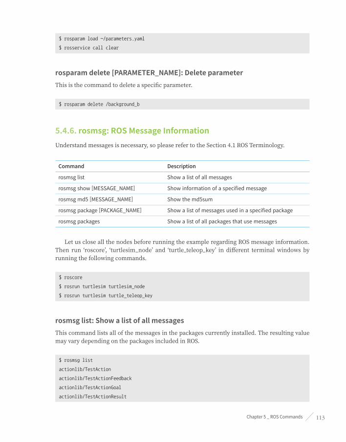
Chapter 5 _ ROS Commands 113
$ rosparam load ~/parameters.yaml
$ rosservice call clear
rosparam delete [PARAMETER_NAME]: Delete parameterThis is the command to delete a specific parameter.
$ rosparam delete /background_b
5.4.6. rosmsg: ROS Message InformationUnderstand messages is necessary, so please refer to the Section 4.1 ROS Terminology.
Command Description
rosmsg list Show a list of all messages
rosmsg show [MESSAGE_NAME] Show information of a specified message
rosmsg md5 [MESSAGE_NAME] Show the md5sum
rosmsg package [PACKAGE_NAME] Show a list of messages used in a specified package
rosmsg packages Show a list of all packages that use messages
Let us close all the nodes before running the example regarding ROS message information. Then run ‘roscore’, ‘turtlesim_node’ and ‘turtle_teleop_key’ in different terminal windows by running the following commands.
$ roscore
$ rosrun turtlesim turtlesim_node
$ rosrun turtlesim turtle_teleop_key
rosmsg list: Show a list of all messagesThis command lists all of the messages in the packages currently installed. The resulting value may vary depending on the packages included in ROS.
$ rosmsg list
actionlib/TestAction
actionlib/TestActionFeedback
actionlib/TestActionGoal
actionlib/TestActionResult

ROS Robot Programming114
actionlib/TestFeedback
actionlib/TestGoal
sensor_msgs/Joy
sensor_msgs/JoyFeedback
sensor_msgs/JoyFeedbackArray
sensor_msgs/LaserEcho
zeroconf_msgs/DiscoveredService
~ omitted ~
rosmsg show [MESSAGE_NAME]: Show information of a specific messageThis shows information of a specific message. The following is an example of displaying the ‘turtlesim/Pose’ message information. We can see the message contains five pieces of information of the float32 type variables ‘x’, ‘y’, ‘theta’, ‘linear_velocity’, and ‘angular_velocity’.
$ rosmsg show turtlesim/Pose
float32 x
float32 y
float32 theta
float32 linear_velocity
float32 angular_velocity
rosmsg md5 [MESSAGE_NAME]: Show the md5sumThe following is an example to check the md5 information of the ‘turtlesim/Pose’ message. When an MD5 problem occurs during message communication, you will need to check the md5sum with this command. Generally it is not commonly used. For more information on md5sum, refer to Section 4.1 ROS Terminology.
$ rosmsg md5 turtlesim/Pose
863b248d5016ca62ea2e895ae5265cf9
rosmsg package [PACKAGE_NAME]: Show a list of messages used in a specific packageBy using this command, we can see the messages used in a specific package.
$ rosmsg package turtlesim
turtlesim/Color
turtlesim/Pose

Chapter 5 _ ROS Commands 115
rosmsg packages: Show the list of all packages that use messages
$ rosmsg packages
actionlib
actionlib_msgs
actionlib_tutorials
base_local_planner
bond
control_msgs
costmap_2d
~omitted~
5.4.7. rossrv: ROS Service InformationUnderstanding services is essential, so please refer to the Section 4.1 ROS Terminology.
Command Description
rossrv list Show a list of all services
rossrv show [SERVICE_NAME] Show information of a specific service
rossrv md5 [SERVICE_NAME] Show the md5sum
rossrv package [PACKAGE_NAME] Show a list of services used in a specific package
rossrv packages Show a list of all packages that use services
Let us close all the nodes before running the example regarding ROS service information. Then run ‘roscore’, ‘turtlesim_node’ and ‘turtle_teleop_key’ in different terminal windows by running the following commands.
$ roscore
$ rosrun turtlesim turtlesim_node
$ rosrun turtlesim turtle_teleop_key
rossrv list: Show a list of all servicesThis is a command to list all of the services in the packages currently installed on ROS. Depending on the packages currently included in ROS, the resulting value may vary.

ROS Robot Programming116
$ rossrv list
control_msgs/QueryCalibrationState
control_msgs/QueryTrajectoryState
diagnostic_msgs/SelfTest
dynamic_reconfigure/Reconfigure
gazebo_msgs/ApplyBodyWrench
gazebo_msgs/ApplyJointEffort
gazebo_msgs/BodyRequest
gazebo_msgs/DeleteModel
~ omitted ~
rossrv show [SERVICE_NAME]: Show information of a specific serviceThe following is an example of displaying the ‘turtlesim/SetPen’ service information. We can see that it is a service containing five pieces of information of uint8 type variables ‘r’, ‘g’, ‘b’, ‘width’, and ‘off’. For your information, ‘---’ is used as a line separating the request and response in the service file, so for the case of ‘turtlesim/SetPen’ we can see that there is only a request and no content that corresponds to a response. For more information on service files, refer to Section 4.3 and practical examples are available in Section 7.3.
$ rossrv show turtlesim/SetPen
uint8 r
uint8 g
uint8 b
uint8 width
uint8 off
---
rossrv md5 [SERVICE_NAME]: Show the md5sumThe following is an example to check the md5 information of the ‘turtlesim/SetPen’ service. When an MD5 problem occurs during the service request/response, you will need to check the md5sum, and this is the command you can use. Generally it is not commonly used.
$ rossrv md5 turtlesim/SetPen
9f452acce566bf0c0954594f69a8e41b

Chapter 5 _ ROS Commands 117
rossrv package [PACKAGE_NAME]: Show a list of services used in a specific packageThis command lists up the services used in a specific package.
$ rossrv package turtlesim
turtlesim/Kill
turtlesim/SetPen
turtlesim/Spawn
turtlesim/TeleportAbsolute
turtlesim/TeleportRelative
rossrv packages: Show a list of all packages that use services
$ rossrv packages
control_msgs
diagnostic_msgs
dynamic_reconfigure
gazebo_msgs
map_msgs
nav_msgs
navfn nodelet
oroca_ros_tutorials
roscpp
sensor_msgs
std_srvs
tf
tf2_msgs
turtlesim
~omitted~
5.4.8. rosbag: ROS Log InformationIt was explained in Section 4.1 ROS Terminology that in ROS we can save various messages in bag format and play them back when necessary in order to reproduce the same environment when data is recorded. Rosbag is a program that creates, plays, and compresses bags, and has the following various functions.

ROS Robot Programming118
Command Description
rosbag record [OPTION] [TOPIC_NAME] Record the message of a specific topic on the bsg file
rosbag info [FILE_NAME] Check information of a bag file
rosbag play [FILE_NAME] Play a specific bag file
rosbag compress [FILE_NAME] Compress a specific bag file
rosbag decompress [FILE_NAME] Decompresses a specific bag file
rosbag filter [INPUT_FILE] [OUTPUT_FILE] [OPTION]
Create a new bag file with the specific content removed
rosbag reindex bag [FILE_NAME] Reindex
rosbag check bag [FILE_NAME] Check if the specific bag file can be played in the current system
rosbag fix [INPUT_FILE] [OUTPUT_FILE] [OPTION]
Fix the bag file version that was saved as an incompatible version
Let us close all the nodes before running the example regarding ROS log information. Then run ‘roscore’, ‘turtlesim_node’ and ‘turtle_teleop_key’ in different terminal windows by running the following commands.
$ roscore
$ rosrun turtlesim turtlesim_node
$ rosrun turtlesim turtle_teleop_key
rosbag record [OPTION][TOPIC_NAME]: Record the message of a specific topicFirst, we will use the rostopic list command to check the list of topics currently being used in the ROS network.
$ rostopic list
/rosout
/rosout_agg
/turtle1/cmd_vel
/turtle1/color_sensor
/turtle1/pose

Chapter 5 _ ROS Commands 119
As shown in the following example, from the topics that are in use, we will type in the topic we want to record as an option when start recording the bag file. After we start recording, on the terminal window that the ‘turtle_teleop_key’ node is running, if we control the turtle by using the arrow keys on the keyboard, the ‘/turtle1/cmd_vel’ topic assigned as the option will be recorded. Then if we press [Ctrl+c] to stop recording, a bag file ‘2017-07-10-14-16-28.bag’ will be created as shown below.
$ rosbag record /turtle1/cmd_vel
[INFO] [1499663788.499650818]: Subscribing to /turtle1/cmd_vel
[INFO] [1499663788.502937962]: Recording to 2017-07-10-14-16-28.bag.
If you wish to record all the topics at the same time, then add the ‘-a’ option.
$ rosbag record -a
[WARN] [1499664121.243116836]: --max-splits is ignored without --split
[INFO] [1499664121.248582681]: Recording to 2017-07-10-14-22-01.bag.
[INFO] [1499664121.248879947]: Subscribing to /turtle1/color_sensor
[INFO] [1499664121.252689657]: Subscribing to /rosout
[INFO] [1499664121.257219911]: Subscribing to /rosout_agg
[INFO] [1499664121.260671283]: Subscribing to /turtle1/pose
rosbag info [bag FILE_NAME]: Check information of a bag fileBy using this command we can check the information of a bag file. The following example is a recorded ‘/turtle1/cmd_vel’ topic, and 373 messages were recorded. The message type used is ‘geometry_msgs/Twist’, and we can also check information such as path, bag version, time, etc.
$ rosbag info 2017-07-10-14-16-28.bag
path: 2017-07-10-14-16-28.bag
version: 2.0
duration: 17.4s
start: Jul 10 2017 14:16:30.36 (1499663790.36)
end: Jul 10 2017 14:16:47.78 (1499663807.78)
size: 44.5 KB
messages: 373
compression: none [1/1 chunks]
types: geometry_msgs/Twist [9f195f881246fdfa2798d1d3eebca84a]
topics: /turtle1/cmd_vel 373 msgs : geometry_msgs/Twist

ROS Robot Programming120
rosbag play [bag FILE_NAME]: Play a specific bag fileThe following example is a command to play the recorded ‘2017-07-10-14-16-28.bag’ file. The message ‘/turtle1/cmd_vel’ from the time of the recording is transmitted exactly, and we can see the turtle move in the screen. However, the same result as shown in Figure 5-5 can only be obtained when ‘turtlesim_node’ is restarted and initialize the robot trajectory and robot position.
$ rosbag play 2017-07-10-14-16-28.bag
[INFO] [1499664453.406867251]: Opening 2017-07-10-14-16-28.bag
Waiting 0.2 seconds after advertising topics... done.
Hit space to toggle paused, or 's' to step.
[RUNNING] Bag Time: 1499663790.357031 Duration: 0.000000 / 17.419737
[RUNNING] Bag Time: 1499663790.357031 Duration: 0.000000 / 17.419737
[RUNNING] Bag Time: 1499663790.357163 Duration: 0.000132 / 17.419737
~ omitted ~
As in the following figure, we can see that the original data and the data during playback are the same.
Figure 5-5 Example of rosbag play
rosbag compress [bag FILE_NAME]: Compress a specific bag fileA bag file recorded for a short period of time creates relatively small size file, which is not a problem, but if a bag file records data for a long period of time then it takes up a lot of storage space. The following compression command is used in this case, and by compressing it will take up very little storage space.

Chapter 5 _ ROS Commands 121
$ rosbag compress 2017-07-10-14-16-28.bag
2017-07-10-14-16-28.bag 0% 0.0 KB 00:00
2017-07-10-14-16-28.bag 100% 35.0 KB 00:00
The bag file from the example above is reduced to a quarter as shown below. And the original file before compression is separately saved with ‘orig’ tag added to its name.
2017-07-10-14-16-28.bag 12.7kB
2017-07-10-14-16-28.orig.bag 45.5kB
rosbag decompress [bag FILE_NAME]: Decompresses a specific bag fileTo decompress the compressed bag file, use the following command. This will restore the bag file to the original state before compression.
$ rosbag decompress 2017-07-10-14-16-28.bag
2017-07-10-14-16-28.bag 0% 0.0 KB 00:00
2017-07-10-14-16-28.bag 100% 35.0 KB 00:00
5.5. ROS Catkin CommandsROS Catkin commands are used when building a package using the catkin build system.
Command Importance Description
catkin_create_pkg ★★★ Automatic creation of package
catkin_make ★★★ Build based on catkin build system
catkin_eclipse ★★☆ Modify package created by catkin build system so that it can be used in Eclipse
catkin_prepare_release ★★☆ Cleanup log and tag version during release
catkin_generate_changelog ★★☆ Create or update ‘CHANGELOG.rst’ file during release
catkin_init_workspace ★★☆ Initialize workspace of the catkin build system
catkin_find ★☆☆ Search catkin

ROS Robot Programming122
catkin_create_pkg: Automatic creation of package
catkin_create_pkg [PACKAGE_NAME] [DEPENDENCY_PACKAGE1] [DEPENDENCY_PACKAGE 2] ...
The ‘catkin_create_pkg’ is a command that creates an empty package containing ‘CMakeLists.txt’ and ‘package.xml’ files. For detailed instructions, please refer to Section 4.9 where the build system of ROS is explained. The following is an example of using ‘catkin_create_pkg’ command to create ‘my_package’ package which depends on ‘roscpp’ and ‘std_msgs’.
$ catkin_create_pkg my_package roscpp std_msgs
catkin_make: Build based on catkin build system
catkin_make [OPTION]
The ‘catkin_make’ is a command to build a package created by a user or a downloaded package. The following is an example of building all packages in the ‘~/catkin_ws/src’ folder.
$ cd ~/catkin_ws
$ catkin_make
To build just some of the packages and not all of the packages, run with the ‘--pkg [PACKAGE_NAME]’ option as shown below.
$ catkin_make --pkg user_ros_tutorials
catkin_eclipse: Modify package created by catkin build system so that it can be used in EclipseThe ‘catkin_eclipse’ is a command to configure an environment of a package for managing and programming with Eclipse, one of the Integrated Development Environments (IDEs). Running this command will create project files for Eclipse such as ‘~/catkin_ws/build/.cproject’, ‘~/catkin_ws/build/.project’, etc. From the Eclipse menu, by selecting [Makefile Project with Existing Code] and choosing ‘~/catkin_ws/build/’ we can manage all packages in ‘~/catkin_ws/src’ from Eclipse.
$ cd ~/catkin_ws
$ catkin_eclipse

Chapter 5 _ ROS Commands 123
catkin_generate_changelog: Create file CHANGELOG.rstThe ‘catkin_generate_changelog’ is a command that creates the ‘CHANGELOG.rst’ file that logs the changes when updating the version of a package.
catkin_prepare_release: Manage change records and version tags when preparing for release
The ‘catkin_prepare_release’ is a command used to update the ‘CHANGELOG.rst’ created by the ‘catkin_generate_changelog’ command. The ‘catkin_generate_changelog’ and ‘catkin_prepare_release’ commands are used when registering a created package with the official ROS repository, or when updating the version of a registered package.
catkin_init_workspace: Initialize working folder of the catkin build systemThe ‘catkin_init_workspace’ is a command to initialize the user working folder (~/catkin_ws/src). As mentioned in Section 3.1, except for special occasions, this command is executed only once during the ROS installation.
$ cd ~/catkin_ws/src
$ catkin_init_workspace
catkin_find: Search Catkin, find and show the workspaceThe ‘catkin_find’ is a command that shows the working folders for each project.
catkin_find [PACKAGE_NAME]
By using the ‘catkin_find’ command, we can find out all the working folders we are using. Additionally, if we run ‘catkin_find PACKAGE_NAME’, it will show the working folders relevant to the package specified in the option as shown below.
$ catkin_find
/home/pyo/catkin_ws/devel/include
/home/pyo/catkin_ws/devel/lib
/home/pyo/catkin_ws/devel/share
/opt/ros/kinetic/bin
/opt/ros/kinetic/etc
/opt/ros/kinetic/include
/opt/ros/kinetic/lib
/opt/ros/kinetic/share

ROS Robot Programming124
$ catkin_find turtlesim
/opt/ros/kinetic/include/turtlesim
/opt/ros/kinetic/lib/turtlesim
/opt/ros/kinetic/share/turtlesim
5.6. ROS Package CommandsROS package commands are used to manage ROS packages, such as showing information of packages and installing related packages.
Command Importance Command Explanation Description
ropack ★★★ ros+pack(package) View information regarding a specific ROS package
rosinstall ★★☆ ros+install Install additional ROS packages
rosdep ★★☆ ros+dep(dependencies) Install dependency package of the ROS corresponding package
roslocate ☆☆☆ ros+locate Show information of ROS package
roscreate-pkg ☆☆☆ ros+create-pkg(package) Automatic creation of ROS package (used in previous rosbuild system)
rosmake ☆☆☆ ros+make Build ROS package (used in previous rosbuild system)
rospack: View information regarding a specific ROS package
rospack [OPTION] [PACKAGE_NAME]
The ‘rospack’ is a command to show information such as the save location, dependency, entire package list regarding the specific ROS package, and we can use options such as ‘find’, ‘list’, ‘depends-on’, ‘depends’, ‘profile’, etc. As shown in the example below, if we specify a package name after the ‘rospack find’ command, the saved location of the package will be shown.
$ rospack find turtlesim
/opt/ros/kinetic/share/turtlesim
The ‘rospack list’ command shows all the packages in the PC. By combining the ‘rospack list’ command with the Linux search command ‘grep’ we can easily find a package. For instance, running ‘rospack list | grep turtle’ will only display the packages related to turtle as shown in the example below.

Chapter 5 _ ROS Commands 125
$ rospack list
actionlib /opt/ros/kinetic/share/actionlib
actionlib_msgs /opt/ros/kinetic/share/actionlib_msgs
actionlib_tutorials /opt/ros/kinetic/share/actionlib_tutorials
amcl /opt/ros/kinetic/share/amcl
angles /opt/ros/kinetic/share/angles
base_local_planner /opt/ros/kinetic/share/base_local_planner
bfl /opt/ros/kinetic/share/bfl
$ rospack list | grep turtle
turtle_actionlib /opt/ros/kinetic/share/turtle_actionlib
turtle_tf /opt/ros/kinetic/share/turtle_tf
turtle_tf2 /opt/ros/kinetic/share/turtle_tf2
turtlesim /opt/ros/kinetic/share/turtlesim
If we specify a package name after the ‘rospack depends-on’ command, it will only show the packages that are using the specific package as shown in the following example.
$ rospack depends-on turtlesim
turtle_tf2
turtle_tf
turtle_actionlib
If we specify the package name after the ‘rospack depends’ command, it will show the dependency packages needed to run the specific package as shown in the following example.
$ rospack depends turtlesim
cpp_common
rostime
roscpp_traits
roscpp_serialization
genmsg
genpy
message_runtime
std_msgs
geometry_msgs
catkin
gencpp
genlisp
message_generation

ROS Robot Programming126
rosbuild
rosconsole
rosgraph_msgs
xmlrpcpp
roscpp
rospack
roslib
std_srvs
The ‘rospack profile’ command re-indexes the package by checking the package information and working folders such as ‘/opt/ros/kinetic/share’ or ‘~/catkin_ws/src’ where packages are saved. You can use this command when a newly added package is not listed by the ‘roscd’ command.
$ rospack profile
Full tree crawl took 0.021790 seconds.
Directories marked with (*) contain no manifest. You may
want to delete these directories.
To get just of list of directories without manifests,
re-run the profile with --zombie-only
-------------------------------------------------------------
0.020444 /opt/ros/kinetic/share
0.000676 /home/pyo/catkin_ws/src
0.000606 /home/pyo/catkin_ws/src/ros_tutorials
0.000240 * /opt/ros/kinetic/share/OpenCV-3.2.0-dev
0.000054 * /opt/ros/kinetic/share/OpenCV-3.2.0-dev/haarcascades
0.000035 * /opt/ros/kinetic/share/doc
0.000020 * /opt/ros/kinetic/share/OpenCV-3.2.0-dev/lbpcascades
0.000008 * /opt/ros/kinetic/share/doc/liborocos-kdl
rosinstall: Install additional ROS packagesTh ‘rosinstall’ is a command that automatically installs or updates ROS packages managed by Source Code Managements (SCMs) such as SVN, Mercurial, Git, Bazaar. As seen in Section 3.1, once we run the program, necessary packages will be automatically installed or updated whenever there are package updates.
rosdep: Install dependency package of the ROS corresponding package
rosdep [OPTION]

Chapter 5 _ ROS Commands 127
The ‘rosdep’ is a command that installs the dependency file of the specific package. There are options such as ‘check’, ‘install’, ‘init’ and ‘update’. As shown in the following example, running ‘rosdep check PACKAGE_NAME’ will check the dependency of the specific package. Running ‘rosdep install PACKAGE_NAME’ will install the dependency package of the specific package. Furthermore, there are also ‘rosdep init’ or ‘rosdep update’, but please refer to Section 3.1 for the detailed instructions.
$ rosdep check turtlesim
All system dependencies have been satisified
$ rosdep install turtlesim
All required rosdeps installed successfully
roslocate: Show information of ROS package
roslocate [OPTION] [PACKAGE_NAME]
The ‘roslocate’ is a command that shows information such as the ROS version used for the package, SCM type, repository location, and so on. Available options are ‘info’, ‘vcs’, ‘type’, ‘uri’, ‘repo’, etc. Here we will look at ‘info’, which shows all of this information at once.
$ roslocate info turtlesim
Using ROS_DISTRO: kinetic
- git:
local-name: turtlesim
uri: https://github.com/ros/ros_tutorials.git
version: kinetic-devel
roscreate-pkg: Automatic creation of ROS package (used in previous rosbuild system)The ‘roscreate-pkg’ is a command that automatically creates a package similar to the ‘catkin_create_pkg’ command. It is a command that was used in the previous rosbuild system, before the catkin build system. It has been left for version compatibility, and is not used in the recent versions.
rosmake: Build ROS package (used in previous rosbuild system)The ‘rosmake’ is a command that builds a package similar to the ‘catkin_make’ command. It is a command that was used in the previous rosbuild system, before the catkin build system. It has been left for version compatibility, and is not used in the recent versions.

ROS Robot Programming128
ROS Tools
Chapter 6

Chapter 6 _ ROS Tools 129
Apart from the commands introduced in Chapter 5, there are various tools that can help us when using the ROS. We should note these GUI tools as complementary to the command line tools. There are quite a number of ROS tools, including the tools that ROS users have personally released as well. Among these tools, the ones we will discuss in this chapter do not directly process a function in the ROS, but they are greatly useful supplementary tools for programming with ROS.
The tools that we will cover in this chapter are as follows.
■ RViz 3D visualization tool
■ rqt Qt-based ROS GUI development tool
■ rqt_image_view Image display tool (a type of rqt)
■ rqt_graph A tool that visualizes the correlation between nodes and messages as a graph (a type of rqt)
■ rqt_plot 2D data plot tool (a type of rqt)
■ rqt_bag GUI-based bag data analysis tool (a type of rqt)
6.1. 3D Visualization Tool (RViz) RViz1 is the 3D visualization tool of ROS. The main purpose is to show ROS messages in 3D, allowing us to visually verify data. For example, it can visualize the distance from the sensor of a Laser Distance Sensor (LDS) to an obstacle, the Point Cloud Data (PCD) of the 3D distance sensor such as RealSense, Kinect, or Xtion, the image value obtained from a camera, and many more without having to separately develop the software.
Figure 6-1 Loading screen of RViz, the 3D visualization tool of ROS
1 http://wiki.ros.org/rviz
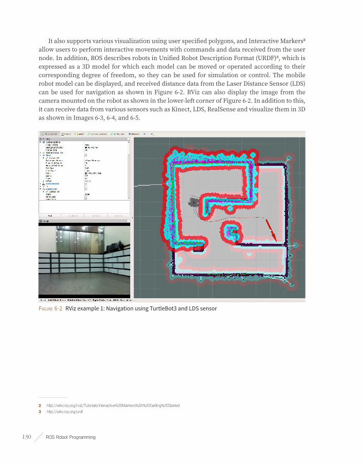
ROS Robot Programming130
It also supports various visualization using user specified polygons, and Interactive Markers2 allow users to perform interactive movements with commands and data received from the user node. In addition, ROS describes robots in Unified Robot Description Format (URDF)3, which is expressed as a 3D model for which each model can be moved or operated according to their corresponding degree of freedom, so they can be used for simulation or control. The mobile robot model can be displayed, and received distance data from the Laser Distance Sensor (LDS) can be used for navigation as shown in Figure 6-2. RViz can also display the image from the camera mounted on the robot as shown in the lower-left corner of Figure 6-2. In addition to this, it can receive data from various sensors such as Kinect, LDS, RealSense and visualize them in 3D as shown in Images 6-3, 6-4, and 6-5.
Figure 6-2 RViz example 1: Navigation using TurtleBot3 and LDS sensor
2 http://wiki.ros.org/rviz/Tutorials/Interactive%20Markers%3A%20Getting%20Started
3 http://wiki.ros.org/urdf

Chapter 6 _ ROS Tools 131
Figure 6-3 RViz example 2: Obtain the skeleton of a person using Kinect and Command with a Motion
Figure 6-4 RViz example 3: Measuring distance using LDS

ROS Robot Programming132
Figure 6-5 RViz example 4: distance, infrared, color image value obtained from Intel RealSense
6.1.1. Installing and Running RVizIf you have installed ROS with ‘ros-[ROS_DISTRO]-desktop-full’ command, RViz should be installed by default. If you did not install the ‘desktop-full’ version ROS or for some reason, RViz is not installed, use the following command to install RViz.
$ sudo apt-get install ros-kinetic-rviz
The execution command of RViz is as follows. However, just as for any other ROS tool, roscore must be running. For your reference, you can also run it with the node running command ‘rosrun rviz rviz’.
$ rviz

Chapter 6 _ ROS Tools 133
6.1.2. RViz Screen Components
Figure 6-6 Composition of the RViz screen
➊ 3D View: This black area is located in the middle of the screen. It is the main screen which allows us to see various data in 3D. Options such as background color of the 3D view, fixed frame, and grid can be configured in the Global Options and Grid settings on the left column of the screen.
➋ Displays: The Displays panel on the left column is for selecting the data that we want to display from the various topics. If we click [Add] button on the lower left corner of the panel, the display4 selection screen will appear as shown in Figure 6-7. Currently, there are about 30 different types of displays we can choose from, which we will explore more in the following section.
➌ Menu: The Menu bar is located on the top of the screen. We can select commands to save or load the current display settings, and also can select various panels.
➍ Tools: Tools are located below the menu bar, where we can select buttons for various functions such as interact, camera movement, selection, camera focus change, distance measurement, 2D position estimation, 2D navigation target-point, publish point.
➎ Views: The Views panel configures the viewpoint of the 3D view.
4 http://wiki.ros.org/rviz/DisplayTypes
➊ ➎➍➌
➋
➏

ROS Robot Programming134
■ Orbit: The specified point is called the focus and the orbit rotates around this point. This is the default value and the most commonly used view.
■ FPS(first-person): This displays in a first-person viewpoint.
■ ThirdPersonFollower: This displays in a third-person viewpoint that follows a specific target.
■ TopDownOrtho: This uses the Z-axis as the basis, and displays an orthographic projection of objects on the XY plane.
■ XYOrbit: This is similar to the default setting which is the Orbit, but the focus is fixed on the XY plane, where the value of Z-axis coordinate is fixed to zero.
➏ Time: Time shows the current time (wall time), ROS Time, and the elapsed time for each of them. This is mainly used in simulations, and if there is a need to restart it, simply click the [Reset] button at the very bottom.
Figure 6-7 RViz display select screen

Chapter 6 _ ROS Tools 135
6.1.3. RViz DisplaysThe most frequently used menu when using RViz will probably be the Displays5 menu. This Displays menu is used to select the message to display on the 3D View panel, and descriptions on each item are explained in Table 6-1.
Icon Name Description
Axes Displays the xyz axes.
CameraCreates a new rendering window from the camera perspective and overlays an image on top of it.
DepthCloud
Displays a point cloud based on the Depth Map. It displays distance values acquired from sensors such as Kinect and Xtion with DepthMap and ColorImage topics as points with overlayed color obtained from the camera.
Effort Displays the force applied to each rotary joint of the robot.
FluidPressure Displays the pressure of fluids, such as air or water.
Grid Displays 2D or 3D grids.
Grid CellsDisplays each cells of the grid. It is mainly used to display obstacles in the costmap of the navigation
GroupThis is a container for grouping displays. This allows us to manage the displays being used as one group.
Illuminance Displays the illuminance.
ImageDisplays the image in a new rendering window. Unlike the Camera display, it does not overlay the camera
InteractiveMarkersDisplays Interactive Markers. We can change the position (x, y, z) and rotation (roll, pitch, yaw) with the mouse.
LaserScan Displays the laser scan value.
MapDisplays the occupancy map, used in navigation, on top of the ground plane.
MarkerDisplays markers such as arrows, circles, triangles, rectangles, and cylinders provided by RViz.
MarkerArray Displays multiple markers.
5 http://wiki.ros.org/rviz/DisplayTypes

ROS Robot Programming136
Icon Name Description
Odometry
Displays the odometry information in relation to the passage of time in the form of arrows. For example, as the robot moves, arrow markers are displayed showing the traveled path in a connected form according to the time intervals.
Path Displays the path of the robot used in navigation.
Point Cloud Displays point cloud data. This is used to display sensor data from depth cameras such as RealSense, Kinect, Xtion, etc. Since PointCloud2 is compatible with the latest Point Cloud Library (PCL), we can generally use PointCloud2.
Point Cloud2
PointStamped Displays a rounded point.
PolygonDisplays a polygon outline. It is mainly used to simply display the outline of a robot on the 2D plane.
Pose
Displays the pose (location + orientation) on 3D. The pose is represented in the shape of an arrow where the origin of the arrow is the position(x, y, z,) and the direction of the arrow is the orientation (roll, pitch, yaw). For instance, pose can be represented with the position and orientation of the 3D robot model, while it can be represented with the goal point.
Pose Array Displays multiple poses.
RangeThis is used to visualize the measured range of a distance sensor such as an ultrasonic sensor or an infrared sensor in the form of a cone.
RelativeHumidity Displays the relative humidity.
RobotModel Displays the robot model.
TF
Displays the coordinate transformation TF used in ROS. It is displayed with the xyz axes much like the previously mentioned axes, but each axis expresses the hierarchy with an arrow according to the relative coordinates.
Temperature Displays the temperature.
WrenchStampedDisplays the wrench, which is the torsion movement, in the form of ‘arrow’ (force) and ‘arrow+circle’ (torque).
Table 6-1 Rviz Displays Panel

Chapter 6 _ ROS Tools 137
6.2. ROS GUI Development Tool (rqt) Besides the 3D visualization tool RViz, ROS provides various GUI tools for robot development. For example, there is a graphical tool that shows the hierarchy of each node as a diagram thereby showing the status of the current node and topic, and a plot tool that schematizes a message as a 2D graph. Starting from the ROS Fuerte version, more than 30 GUI development tools have been integrated as the tool called rqt6 which can be used as a comprehensive GUI tool. Furthermore, RViz has also been integrated as a plugin of rqt, making rqt an essential GUI tool for ROS.
Not only that, but as the name suggests, rqt was developed based on Qt, which is a cross-platform framework widely used for GUI programming, making it very convenient for users to freely develop and add plugins. In this section we will learn about the ‘rqt’ plugins ‘rqt_image_view’, ‘rqt_graph’, ‘rqt_plot’ and ‘rqt_bag’.
6.2.1. Installing and Running rqtif you have installed ROS with ‘ros-[ROS_DISTRO]-desktop-full’ command rqt will be installed by default. If you did not install the ‘desktop-full’ version ROS or for some reason, ‘rqt’ is not installed, then the following command will install ‘rqt’.
$ sudo apt-get install ros-kinetic-rqt*
The command to run rqt is as follows. You can simply type in ‘rqt’ on the terminal. For your reference, we can also run it with the node execution command ‘rosrun rqt_gui rqt_gui’.
$ rqt
If we run ‘rqt’ then the GUI screen of rqt will appear as shown in Figure 6-8. If it is the first time being launched, it will display only the menu without any content below. This is because the plugin, which is the program that is directly run by ‘rqt’, has not been specified.
6 http://wiki.ros.org/rqt
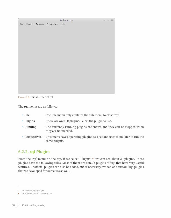
ROS Robot Programming138
Figure 6-8 Initial screen of rqt
The rqt menus are as follows.
■ File The File menu only contains the sub-menu to close ‘rqt’.
■ Plugins There are over 30 plugins. Select the plugin to use.
■ Running The currently running plugins are shown and they can be stopped when they are not needed.
■ Perspectives This menu saves operating plugins as a set and uses them later to run the same plugins.
6.2.2. rqt PluginsFrom the ‘rqt’ menu on the top, if we select [Plugins7 8] we can see about 30 plugins. These plugins have the following roles. Most of them are default plugins of ‘rqt’ that have very useful features. Unofficial plugins can also be added, and if necessary, we can add custom ‘rqt’ plugins that we developed for ourselves as well.
7 http://wiki.ros.org/rqt/Plugins
8 http://wiki.ros.org/rqt_common_plugins

Chapter 6 _ ROS Tools 139
Action
■ Action Type Browser: This is a plugin to check the data structure of an action type.
Configuration
■ Dynamic Reconfigure: This is a plugin to modify the parameter value of a node.
■ Launch This is a GUI plugin of roslaunch, which is useful when we cannot remember the name or composition of roslaunch.
Introspection
■ Node Graph: This is a plugin for the graphical view that allows us to check the relationship diagram of the currently running nodes or message flows.
■ Package Graph: This is a plugin for the graphical view that displays the dependencies of the packages.
■ Process Monitor: We can check the PID (Processor ID), CPU usage, memory usage, and number of threads of the currently running nodes.
Logging
■ Bag: This is a plugin regarding the ROS data logging.
■ Console: This is a plugin to check the warning and error messages occurring in the nodes in one screen.
■ Logger Level: This is a tool to select a logger, which is responsible for publishing the logs, and set the logger level9 to publish a specific log such as ‘Debug’, ‘Info’, ‘Warn’, ‘Error’, and ‘Fatal’. It is very convenient if ‘Debug’ is selected while debugging process.
Miscellaneous Tools
■ Python Console: This is a plugin for the Python console screen.
■ Shell: This is a plugin that launches a shell.
■ Web: This is a plugin that launches a web browser.
9 http://wiki.ros.org/roscpp/Overview/Logging

ROS Robot Programming140
Robot Tools
■ Controller Manager: This is a plugin to check the status, type, hardware interface information of the robot controller.
■ Diagnostic Viewer: This is a plugin to check the robot status and error.
■ Moveit! Monitor: This is a plugin to check the MoveIt! data that is used for motion planning.
■ Robot Steering: This is a GUI tool for robot manual control, and this GUI tool is useful for controlling a robot in remote.
■ Runtime Monitor: This is a plugin to check the warnings or errors of the nodes in real-time.
Services
■ Service Caller: This is a GUI plugin that connects to a running service server and requests a service. This is useful for testing service.
■ Service Type Browser: This is a plugin to check the data structure of a service type.
Topics
■ Easy Message Publisher: This is a plugin that can publish a topic in a GUI environment.
■ Topic Publisher: This is a GUI plugin that can publish a topic. This is useful for topic testing.
■ Topic Type Browser: This is a plugin that can check the data structure of a topic. This is useful for checking the topic type.
■ Topic Monitor: This is a plugin that lists the currently used topics, and checks the information of the selected topic from the list.
Visualization
■ Image View: This is a plugin that can check the image data from a camera. This is useful for simple camera data testing.
■ Navigation Viewer: This is a plugin to check the position or goal point of the robot in the navigation.
■ Plot: This is a GUI plugin for plotting 2D data. This is useful for schematizing 2D data.
■ Pose View: This is a plugin for displaying the pose (position+orientation) of a robot model or TF.
■ RViz: This is the RViz plugin which is a tool for 3D visualization.
■ TF Tree: This is a plugin of a graphical view type that shows the relationship of each coordinates acquired from the TF in the tree structure.

Chapter 6 _ ROS Tools 141
Figure 6-9 rqt Plugin
Since it is difficult to introduce all of the plugins, in this chapter we will learn about the ones that are most frequently used, which are ‘rqt_image_view’, ‘rqt_bag’, ‘rqt_graph’ and ‘rqt_plot’.
6.2.3. rqt_image_viewThis is a plugin10 to display the image data of a camera. Although it is not an image processing process, it is still quite useful for simply checking an image. A USB camera generally supports UVC, so we can use the ‘uvc_camera’ package of ROS. First, install the ‘uvc_camera’ package using the following command.
$ sudo apt-get install ros-kinetic-uvc-camera
Connect the USB camera to the USB port of the PC, and launch the ‘uvc_camera_node’ in the ‘uvc_camera’ package using the following command.
$ rosrun uvc_camera uvc_camera_node
10 http://wiki.ros.org/rqt_image_view

ROS Robot Programming142
Once installation is completed, run ‘rqt’ with the ‘rqt’ command, and go to the menu and select [Plugins] → [Image View]. In the message selection field located on the upper left side, select ‘/image_raw’ to see the image as shown in the Figure 6-10. More information about the camera sensor will be provided in Section 8.3.
$ rqt
Apart from selecting the plugin from the rqt menu, we can also use dedicated execution command as below.
$ rqt_image_view
Figure 6-10 Checking the image data of the USB camera as an image view

Chapter 6 _ ROS Tools 143
6.2.4. rqt_graphThe ‘rqt_graph’11 is a tool that shows the correlation among active nodes and messages being transmitted on the ROS network as a diagram. This is very useful for understanding the current structure of the ROS network. The instruction is very simple. As an example, for the purpose of checking the nodes, let’s run ‘turtlesim_node’ and ‘turtle_teleop_key’ in the ‘turtlesim’ package described in Section 3.3, and the ‘uvc_camera_node’ in the ‘uvc_camera’ package described in Section 6.2.3. Each node should be executed in a separate terminal.
$ rosrun turtlesim turtlesim_node
$ rosrun turtlesim turtle_teleop_key
$ rosrun uvc_camera uvc_camera_node
$ rosrun image_view image_view image:=image_raw
After executing all nodes, launch ‘rqt’ with the ‘rqt’ command, and go to the menu to select [Plugins] → [Node Graph]. For your information, we can also run it with ‘rqt_graph’ without having to manually select the plugin from the menu.
The correlation among nodes and topics when ‘rqt_graph’ is running is shown as Figure 6-11.
$ rqt
Figure 6-11 Example of rqt_graph
11 http://wiki.ros.org/rqt_graph

ROS Robot Programming144
In Figure 6-11, circles represent nodes (/teleop_turtle, /turtlesim) and squares (/turtle1/cmd_vel, /image_raw) represent topic messages. The arrow indicates the transmission of the message. In the previous example when we executed ‘turtle_teleop_key’ and ‘turtlesim_node’, the ‘teleop_turtle’ node and the ‘turtlesim’ node were running respectively. We can verify that these two nodes are transmitting data with the arrow key values of the keyboard in the form of translational speed and rotational speed message (topic name: /turtle1/cmd_vel).
We can also verify that the ‘uvc_camera’ node in the ‘uvc_camera’ package is publishing the ‘/image_raw’ topic message and the ‘image_view_xxx’ node is subscribing it. Unlike this simple example, the actual ROS programming consists of tens of nodes that transmit various topic messages. In this situation, ‘rqt_graph’ becomes very useful for checking the correlation of nodes on the ROS network.
6.2.5. rqt_plot This time let’s run ‘rqt_plot’ with the following command instead of selecting the plugin from the rqt menu. For your reference, we can run it with the node execution command ‘rosrun rqt_plot rqt_plot’.
$ rqt_plot
Once ‘rqt_plot’ is up and running, click the gear shaped icon on the top right corner of the program. We can select the option as shown in Figure 6-12, where the default setting is ‘MatPlot’. Apart from MatPlot we can also use PyQtGraph and QwtPlot, so refer to the corresponding installation method and use the graph library of your choice.
For example, in order to use PyQtGraph as the default plot instead of MatPlot, download and install the latest ‘python-pyqtgraph_0.9.xx-x_all.deb’ file from the download address below. If installation is completed, the PyQtGraph item will be enabled and you will be able to use PyQtGraph.
■ http://www.pyqtgraph.org/downloads/

Chapter 6 _ ROS Tools 145
Figure 6-12 Install option of rqt_plot
The ‘rqt_plot’12 is a tool for plotting 2D data. Plot tool receives ROS messages and displays them on the 2D coordinates. As an example, let us plot the x and y coordinates of the ‘turtlesim’ node pose message. First we need to launch ‘turtlesim_node’ of the turtlesim package.
$ rosrun turtlesim turtlesim_node
Enter ‘/turtle1/pose/’ in the Topic field on the top of ‘rqt_plot’ tool, and it will draw the ‘/turtle1/pose/’ topic on the 2D (x-axis: time, y-axis: data value) plane. Alternatively, we can run it with the following command by specifying the topic to be schematized.
$ rqt_plot /turtle1/pose/
Then launch ‘turtle_teleop_key’ in the ‘turtlesim’ package so that we can move around the turtle on the screen.
$ rosrun turtlesim turtle_teleop_key
12 http://wiki.ros.org/rqt_plot

ROS Robot Programming146
As shown in Figure 6-13, we can check that the x, y position, direction in theta, translational speed, and rotational speed of the turtle are plotted. As we can see, this is a useful tool for displaying the coordinates of 2D data. In this example, we have used turtlesim, but it is also useful for displaying 2D data of nodes developed by users as well. It is particularly suitable for displaying the sensor value over a period of time, such as speed and acceleration.
Figure 6-13 Example of rqt_plot
6.2.6. rqt_bag The ‘rqt_bag’ is a GUI tool for visualizing a message. The ‘rosbag’ that we covered in ‘Section 5.4.8 rosbag: ROS Log Information’ was text-based tool, but ‘rqt_bag’ has a visualization function added which allows us to see the image of the camera right away, making it very useful for managing image data messages. Before we begin practice, we must run all of the ‘turtlesim’ and ‘uvc_camera’ related nodes covered in the ‘rqt_image_view’ and ‘rqt_graph’ tool. Then we create a bag file with the ‘/image_raw’ message of the camera and the ‘/turtle1/cmd_vel’ message of ‘turtlesim’ using the following command.
In Section 5.4 we have used the ‘rosbag’ program to record, play, and compress various topic messages of ROS as a bag file. The ‘rqt_bag’ is a GUI version of the previously introduced ‘rosbag’, and just like rosbag it can also record, play, and compress topic messages. In addition, since it is a GUI program, all commands are provided as buttons so they are easy to use, and we can also watch the camera images according to the change in time like the video editor.
As in the following example, in order to take advantage of the feature of ‘rqt_bag’, let us save the USB camera image as a bag file and then play it with ‘rqt_bag’.
$ rosrun uvc_camera uvc_camera_node
$ rosbag record /image_raw
$ rqt

Chapter 6 _ ROS Tools 147
Launch ‘rqt’ with the ‘rqt’ command, and go to the menu and select [Plugins] → [Logging] → [Bag]. Then select the folder-shaped Load Bag icon on the top left side and load the ‘*.bag’ file that we just recorded. Then we will be able to check the camera image according to the change in time as shown in Figure 6-14. We can also zoom in, play, and check the number of data over time, and with the right-click, ‘Publish option will appear which allows us to publish the message again.
Figure 6-14 Example of rqt_bag
We have now completed the installations and instructions of the rqt tools. As we could not explain all of the plugins in this section, we encourage you to try using these tools for yourself referring to the few of the examples we have seen until now. Although these tools may not directly involved with robots or sensors as ROS nodes do, when we are performing these tasks they can be used as helpful supplementary tools for saving, preserving, modifying, and analyzing data.

ROS Robot Programming148
Basic ROS Programming
Chapter 7

Chapter 7 _ Basic ROS Programming 149
Now that you have been introduced to ROS, let’s learn about ROS programming. The hottest keywords in the previous chapters were messages, topics, services, actions, and parameters. It is because these terms are the core of ROS. The node, which is the minimum execution unit, exchanges input and output messages between nodes through message communication on topics, services, actions, and parameters. In this chapter, we will learn about ROS programming with practical examples.
7.1. Things to Know Before Programming ROS
7.1.1. Standard UnitThe messages used in ROS follows SI units, the most widely used standard in the world. This is also stated in REP-01031. For example, length in Meters, mass in Kilograms, time in Seconds, current in Amperes, angle in Radians, frequency in Hertz, force in Newtons, power in Watts, voltage in Volts, and temperature in Celsius are used. All other units are made up of a combination of aforementioned units. For example, the translational speed is expressed in meter/sec, and the rotational speed is expressed in radian/sec. While it is recommended to use the messages provided by ROS, it does not matter if you create a completely new type of message that you have redefined as needed. However, it is imperative to comply with the use of SI unit, as this will allow other users to use the custom message without unit conversion.
Quantity Unit Quantity Unit
Length Meter Frequency Hertz
Mass Kilogram Force Newton
Time Second Power Watt
Current Ampere Voltage Volt
Angle Radian Temperature Celsius
REP (ROS Enhancement Proposals)
REP is a proposal that is used when suggesting rules, new functions, and management methods within the ROS community. It is used to democratically create ROS rules or negotiate contents necessary for development, operation and management of ROS. Once a proposal is received, many ROS users can review and refer to it as a standard document that is created through mutual collaboration. An REP document can be found at http://www.ros.org/reps/rep-0000.html.
1 http://www.ros.org/reps/rep-0103.html

ROS Robot Programming150
7.1.2. Coordinate RepresentationThe x, y and z axes2 in ROS uses right hand rule as shown in Figure 7-1. The front is the positive direction of the x-axis, and the axis is represented by red (R). The left side is the positive direction of the y-axis, and the axis is represented by green (G). Finally, the upward direction is the positive direction of z-axis, and the axis is represented by blue (B). To easily memorize this, you can point the thumb, index, and middle fingers out in the shape of the three axes. The index finger is the x-axis, the middle finger is the y-axis, and the thumb is the z-axis. The order mentioned above becomes the x, y, z and the order of colors, RGB.
You can use the right-hand-rule3 for the rotation direction of the robot. The direction that your right hand curls is the positive rotation direction. For example, if the robot rotates from 12 to 9 o’clock direction, using the radian for the rotation angle, the robot rotates by +1.5708 radians on the z-axis.
These coordinate representations are used frequently in ROS programming and must be programmed in the form of x: forward, y: left, z: up.
Figure 7-1 x, y, z axes and the right-hand-rule
7.1.3. Programming RulesROS recommends developers to comply with the programming style guide to maximize the source code reusability of each program. This reduces the amount of additional work that developers frequently need to do when working with source code, enhances code understanding among other collaborators, and facilitates code reviews between developers. This is not a requirement, but many ROS users agree and adhere to this rule. Therefore, I would like to strongly encourage users to abide by this programming rule.
2 http://www.ros.org/reps/rep-0103.html#coordinate-frame-conventions
3 http://en.wikipedia.org/wiki/Right-hand_rule

Chapter 7 _ Basic ROS Programming 151
The rules are explained in detail in the Wiki (C++4, Python5) for each language. In this book, the basic naming rule6 is explained below, so please get familiar with this rule prior to programming on ROS.
Type Naming Rule Example
Package under_scored Ex) first_ros_package
Topic, Service under_scored Ex) raw_image
File under_scored Ex) turtlebot3_fake.cpp
However, messages, services and action file names placed in the /msg and /srv folders follow CamelCased rules when using ROS messages and services. This is because the *.msg, *.srv, and *.action files are converted to header files and then used as structures or types (e.g. TransformStamped.msg, SetSpeed.srv)
Namespace under_scored Ex) ros_awesome_package
Variable under_scored Ex) string table_name;
Type CamelCased Ex) typedef int32_t PropertiesNumber;
Class CamelCased Ex) class UrlTable
Structure CamelCased Ex) struct UrlTableProperties
Enumeration Type CamelCased Ex) enum ChoiceNumber
Function camelCased Ex) addTableEntry();
Method camelCased Ex) void setNumEntries(int32_t num_entries)
Constant ALL_CAPITALS Ex) const uint8_t DAYS_IN_A_WEEK = 7;
Macro ALL_CAPITALS Ex) #define PI_ROUNDED 3.0
7.2. Creating and Running Publisher and Subscriber NodesThe publishers and subscribers used in ROS message communication can be compared with a transmitter and receiver. In ROS, the transmitter is called publisher, and the receiver is called subscriber. This section aims to create a simple message file, and create and run Publisher and Subscriber nodes.
4 http://wiki.ros.org/CppStyleGuide
5 http://wiki.ros.org/PyStyleGuide
6 http://wiki.ros.org/ROS/Patterns/Conventions#Naming_ROS_Resources

ROS Robot Programming152
7.2.1. Creating a PackageThe following command creates a ‘ros_tutorials_topic’ package. This package is dependent on the ‘message_generation’, ‘std_msgs’, and ‘roscpp’ packages, as they are appended as dependency options followed by the custom package name. The ‘message_generation’ package will be required to create a new message. ‘std_msgs’ is the ROS standard message package and ‘roscpp’ is the client library to use C/C++ in ROS. These dependent packages can be included while creating the package, but they can also be added after creating the ‘package.xml’ in the package folder.
$ cd ~/catkin_ws/src
$ catkin_create_pkg ros_tutorials_topic message_generation std_msgs roscpp
When the package is created, the ‘ros_tutorials_topic’ package folder is created in the ‘~/catkin_ws/src’ folder. In this package folder, the ‘CMakeLists.txt’ and ‘package.xml’ files are created along with default folders. You can inspect it with the ‘ls’ command as below, or check the inside of the package using the GUI-based Nautilus, which is similar to Windows File Explorer.
$ cd ros_tutorials_topic
$ ls
include → Header File Folder
src → Source Code Folder
CMakeLists.txt → Build Configuration File
package.xml → Package Configuration File
7.2.2. Modifying the Package Configuration File (package.xml)The ‘package.xml’ file, one of the required ROS configuration files, is an XML file containing the package information such as the package name, author, license, and dependent packages. Let’s open the file using an editor (such as gedit, vim, emacs, etc.) with the following command and modify it for the current node.
$ gedit package.xml
The following code shows how to modify the ‘package.xml’ file to match the package you created. Personal information will be included in the content, so you can modify it as you wish. For a detailed description of each option, see Section 4.9.

Chapter 7 _ Basic ROS Programming 153
ros_tutorials_topic/package.xml
<?xml version="1.0"?>
<package>
<name>ros_tutorials_topic</name>
<version>0.1.0</version>
<description>ROS tutorial package to learn the topic</description>
<license>Apache License 2.0</license>
<author email="[email protected]">Yoonseok Pyo</author>
<maintainer email="[email protected]">Yoonseok Pyo</maintainer>
<url type="bugtracker">https://github.com/ROBOTIS-GIT/ros_tutorials/issues</url>
<url type="repository">https://github.com/ROBOTIS-GIT/ros_tutorials.git</url>
<url type="website">http://www.robotis.com</url>
<buildtool_depend>catkin</buildtool_depend>
<build_depend>roscpp</build_depend>
<build_depend>std_msgs</build_depend>
<build_depend>message_generation</build_depend>
<run_depend>roscpp</run_depend>
<run_depend>std_msgs</run_depend>
<run_depend>message_runtime</run_depend>
<export></export>
</package>
7.2.3. Modifying the Build Configuration File (CMakeLists.txt)Catkin, which is the build system of ROS, uses CMake. Therefore, the build environment is described in the ‘CMakeLists.txt’ file in the package folder. This file configures executable file creation, dependency package priority build, link creation, and so on.
$ gedit CMakeLists.txt
The following is the modified code of CMakeLists.txt for the package we created. See Section 4.9 for a detailed description of each option.
ros_tutorials_topic/CMakeLists.txt
cmake_minimum_required(VERSION 2.8.3)
project(ros_tutorials_topic)
## A component package required when building the Catkin.

ROS Robot Programming154
## Has dependency on message_generation, std_msgs, roscpp.
## An error occurs during the build if these packages do not exist.
find_package(catkin REQUIRED COMPONENTS message_generation std_msgs roscpp)
## Declaration Message: MsgTutorial.msg
add_message_files(FILES MsgTutorial.msg)
## an option to configure the dependent message.
## An error occurs duing the build if "std_msgs" is not installed.
generate_messages(DEPENDENCIES std_msgs)
## A Catkin package option that describes the library, the Catkin build dependencies,
## and the system dependent packages.
catkin_package(
LIBRARIES ros_tutorials_topic
CATKIN_DEPENDS std_msgs roscpp
)
## Include directory configuration.
include_directories(${catkin_INCLUDE_DIRS})
## Build option for the "topic_publisher" node.
## Configuration of Executable files, target link libraries, and additional dependencies.
add_executable(topic_publisher src/topic_publisher.cpp)
add_dependencies(topic_publisher ${${PROJECT_NAME}_EXPORTED_TARGETS} ${catkin_EXPORTED_TARGETS})
target_link_libraries(topic_publisher ${catkin_LIBRARIES})
## Build option for the "topic_subscriber" node.
add_executable(topic_subscriber src/topic_subscriber.cpp)
add_dependencies(topic_subscriber ${${PROJECT_NAME}_EXPORTED_TARGETS}
${catkin_EXPORTED_TARGETS})
target_link_libraries(topic_subscriber ${catkin_LIBRARIES})
7.2.4. Writing the Message FileThe following option is added to the CMakeLists.txt file.
add_message_files(FILES MsgTutorial.msg)
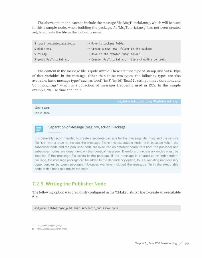
Chapter 7 _ Basic ROS Programming 155
The above option indicates to include the message file ‘MsgTutorial.msg’, which will be used in this example node, when building the package. As ‘MsgTutorial.msg’ has not been created yet, let’s create the file in the following order:
$ roscd ros_tutorials_topic → Move to package folder
$ mkdir msg → Create a new 'msg' folder in the package
$ cd msg → Move to the created 'msg' folder
$ gedit MsgTutorial.msg → Create 'MsgTutorial.msg' file and modify contents
The content in the message file is quite simple. There are time type of ‘stamp’ and ‘int32’ type of data variables in the message. Other than these two types, the following types are also available: basic message types7 such as ‘bool’, ‘int8’, ‘int16’, ‘float32’, ‘string’, ‘time’, ‘duration’, and ‘common_msgs’8 which is a collection of messages frequently used in ROS. In this simple example, we use time and int32.
ros_tutorials_topic/msg/MsgTutorial.msg
time stamp
int32 data
Separation of Message (msg, srv, action) Package
It is generally recommended to create a separate package for the message file ‘msg’ and the service file ‘srv’ rather than to include the message file in the executable node. It is because when the subscriber node and the publisher node are executed on different computers both the publisher and subscriber nodes are dependent on the identical message. Therefore unnecessary nodes must be installed if the message file exists in the package. If the message is created as an independent package, the message package can be added to the dependency option, thus eliminating unnecessary dependencies between packages. However, we have included the message file in the executable node in this book to simplify the code.
7.2.5. Writing the Publisher NodeThe following option was previously configured in the ‘CMakeLists.txt’ file to create an executable file:
add_executable(topic_publisher src/topic_publisher.cpp)
7 http://wiki.ros.org/std_msgs
8 http://wiki.ros.org/common_msgs

ROS Robot Programming156
That is, the ‘topic_publisher.cpp’ file is built in the src’ folder to create the ‘topic_publisher’ executable file. Let’s create a code that performs publisher node functions in the following order:
$ roscd ros_tutorials_topic/src → Move to the 'src' folder, which is the source folder of
the package
$ gedit topic_publisher.cpp → Create or modify new source file
ros_tutorials_topic/src/topic_publisher.cpp
// ROS Default Header File
#include "ros/ros.h"
// MsgTutorial Message File Header
// The header file is automatically created when building the package.
#include "ros_tutorials_topic/MsgTutorial.h"
int main(int argc, char **argv) // Node Main Function
{
ros::init(argc, argv, "topic_publisher"); // Initializes Node Name
ros::NodeHandle nh; // Node handle declaration for communication with ROS system
// Declare publisher, create publisher 'ros_tutorial_pub' using the 'MsgTutorial'
// message file from the 'ros_tutorials_topic' package. The topic name is
// 'ros_tutorial_msg' and the size of the publisher queue is set to 100.
ros::Publisher ros_tutorial_pub =
nh.advertise<ros_tutorials_topic::MsgTutorial>("ros_tutorial_msg", 100);
// Set the loop period. '10' refers to 10 Hz and the main loop repeats at 0.1 second intervals
ros::Rate loop_rate(10);
ros_tutorials_topic::MsgTutorial msg; // Declares message 'msg' in 'MsgTutorial' message
// file format
int count = 0; // Variable to be used in message
while (ros::ok())
{
msg.stamp = ros::Time::now(); // Save current time in the stamp of 'msg'
msg.data = count; // Save the the 'count' value in the data of 'msg'
ROS_INFO("send msg = %d", msg.stamp.sec); // Print the 'stamp.sec' message

Chapter 7 _ Basic ROS Programming 157
ROS_INFO("send msg = %d", msg.stamp.nsec); // Print the 'stamp.nsec' message
ROS_INFO("send msg = %d", msg.data); // Print the 'data' message
ros_tutorial_pub.publish(msg); // Publishes 'msg' message
loop_rate.sleep(); // Goes to sleep according to the loop rate defined above.
++count; // Increase count variable by one
}
return 0;
}
7.2.6. Writing the Subscriber NodeThe following is an option in the ‘CMakeLists.txt’ file to generate the executable file.
add_executable(topic_subscriber src/topic_subscriber.cpp)
This mean that the ‘topic_publisher.cpp’ file is built to create the ‘topic_subscriber’ executable file. Let’s write a code that performs subscriber node functions in the following order:
$ roscd ros_tutorials_topic/src → Move to the 'src' folder, which is the source folder of
the package
$ gedit topic_subscriber.cpp → Create or modify new source file
ros_tutorials_topic/src/topic_subscriber.cpp
// ROS Default Header File
#include "ros/ros.h"
// MsgTutorial Message File Header
// The header file is automatically created when building the package.
#include "ros_tutorials_topic/MsgTutorial.h"
// Message callback function. This is a function is called when a topic
// message named 'ros_tutorial_msg' is received. As an input message,
// the 'MsgTutorial' message of the 'ros_tutorials_topic' package is received.
void msgCallback(const ros_tutorials_topic::MsgTutorial::ConstPtr& msg)
{
ROS_INFO("recieve msg = %d", msg->stamp.sec); // Shows the 'stamp.sec' message

ROS Robot Programming158
ROS_INFO("recieve msg = %d", msg->stamp.nsec); // Shows the 'stamp.nsec' message
ROS_INFO("recieve msg = %d", msg->data); // Shows the 'data' message
}
int main(int argc, char **argv) // Node Main Function
{
ros::init(argc, argv, "topic_subscriber"); // Initializes Node Name
ros::NodeHandle nh; // Node handle declaration for communication with ROS system
// Declares subscriber. Create subscriber 'ros_tutorial_sub' using the 'MsgTutorial'
// message file from the 'ros_tutorials_topic' package. The topic name is
// 'ros_tutorial_msg' and the size of the publisher queue is set to 100.
ros::Subscriber ros_tutorial_sub = nh.subscribe("ros_tutorial_msg", 100, msgCallback);
// A function for calling a callback function, waiting for a message to be
// received, and executing a callback function when it is received
ros::spin();
return 0;
}
$ cd ~/catkin_ws → Move to Catkin Workspace
$ catkin_make → Run catkin build
7.2.7. Building a NodeNow let’s build the message file, publisher node, and subscriber node in the ‘ros_tutorials_topic’ package with the following command. The source of the ‘ros_tutorials_topic’ package is in ‘~/catkin_ws/src/ros_tutorials_topic/src’, and the message file of the ‘ros_tutorials_topic’ package is in ‘~/catkin_ws/src/ros_tutorials_topic/msg’.
The output files of built package will be located in the ‘/build’ and ‘/devel’ folders in ‘~/catkin_ws’. The configuration used in Catkin build is stored in ‘/build’ folder, and executable files are stored in ‘/devel/lib/ros_tutorials_topic’ and the message header file that is automatically generated from the message file is stored in ‘/devel/include/ros_tutorials_topic’. Check the files in each folder above to verify the created output.

Chapter 7 _ Basic ROS Programming 159
7.2.8. Running the PublisherNow let’s run the publisher. The following is a command to run the ‘ros_tutorial_msg_publisher’ node of the ‘ros_tutorials_topic’ package using the ‘rosrun’ command. Be sure to run ‘roscore’ from another terminal before running the publisher node. From now on, we will assume ‘roscore’ is executed before the node execution.
$ roscore
$ rosrun ros_tutorials_topic topic_publisher
When you run the publisher, you can see the output screen shown in Figure 7-2. However, the string displayed on the screen is the data in the publisher using the ROS_INFO() function, which is similar to the printf() function used in common programming languages. In order to actually publish the message on topic, we must use a command that acts as a subscriber node, such as a subscriber node or rostopic.
Figure 7-2 Execution screen of the ‘topic_publisher’ node
Let’s use the ‘rostopic’ command to receive the topic published by ‘topic_publisher’. First, list up the topics currently running on the ROS. Use ‘rostopic list’ command to verify that the ‘ros_tutorial_msg’ topic is running.
$ rostopic list
/ros_tutorial_msg
/rosout
/rosout_agg

ROS Robot Programming160
Next, let’s verify the message being published from the publisher node. In other words, read the message on the ‘ros_tutorial_msg’ topic. You can see the published message as shown in Figure 7-3.
$ rostopic echo /ros_tutorial_msg
Figure 7-3 Received ‘ros_tutorial_msg’ topic
7.2.9. Running the SubscriberThe following is the command to run the ‘topic_subscriber’ node of ‘ros_tutorials_topic’ package using the ‘rosrun’ command to run the subscriber.
$ rosrun ros_tutorials_topic topic_subscriber
When the subscriber is executed, the output screen is shown as in Figure 7-4. The published message on the ‘ros_tutorial_msg’ topic is received, and the value is displayed on the screen.

Chapter 7 _ Basic ROS Programming 161
Figure 7-4 Screen showing the execution of the ‘topic_subscriber’ node
7.2.10. Checking the Communication Status of the Running NodesNext, let’s check the communication status of executed nodes using ‘rqt’ from Section 6.2. You can use either ‘rqt_graph’ or ‘rqt’ command as shown below. When executing ‘rqt’, select [Plugins] → [Introspection] → [Node Graph] from the menu and currently running nodes and messages can be seen as shown in Figure 7-5.
$ rqt_graph or $ rqt
Figure 7-5. Connection Diagram drawn with ‘rqt_graph’

ROS Robot Programming162
In the figure above, we can observe that the publisher node (topic_publisher) is transmitting a topic (ros_tutorial_msg), and the topic is received by the subscriber node (topic_subscriber).
In this section, we have created a publisher and subscriber nodes that are used in the topic communication, and executed them to learn how to communicate between nodes. The example source can be found at the following github address:
■ https://github.com/ROBOTIS-GIT/ros_tutorials/tree/master/ros_tutorials_topic
If you want to run it right away, you can clone the source code with the following command in the ‘~/catkin_ws/src’ folder and build the source. Then run the ‘topic_publisher’ and ‘topic_subscriber’ nodes.
$ cd ~/catkin_ws/src
$ git clone https://github.com/ROBOTIS-GIT/ros_tutorials.git
$ cd ~/catkin_ws
$ catkin_make
$ rosrun ros_tutorials_topic topic_publisher
$ rosrun ros_tutorials_topic topic_subscriber
7.3. Creating and Running Service Servers and Client NodesA service can be divided into two types: a Service Server that responds only when there is a request and a Service Client that can send both requests and respond to requests. Unlike the topic, the service is a one-time message communication. Therefore, when the request and the response of the service are completed, the two connected nodes will be disconnected.
These services are often used when requesting a robot to perform a specific action. Alternatively, it is used for nodes that require specific events to occur under certain conditions. As service is a single occurrence of communication method, it is a very useful method that can replace the topic with a small network bandwidth.
In this section, we will create a simple service file and run a service server node and a service client node.
7.3.1. Creating a PackageThe following command creates the ‘ros_tutorials_service’ package. This package has dependency on the ‘message_generation’, ‘std_msgs’, and ‘roscpp’ packages, so dependency

Chapter 7 _ Basic ROS Programming 163
option was appended. The ‘message_generation’ package is used to create a new message. The ‘std_msgs’ package is the ROS standard message package, and the ‘roscpp’ package allows the client library to use C++ in ROS. These can be included while creating the package, but it may also be added after creating the ‘package.xml’ file
$ cd ~/catkin_ws/src
$ catkin_create_pkg ros_tutorials_service message_generation std_msgs roscpp
When the package is created, the ‘ros_tutorials_service’ package folder is created in the ‘~/catkin_ws/src’ folder. In this package folder, the ‘CMakeLists.txt’ and ‘package.xml’ files are created along with default folders. You can inspect it with the ‘ls’ command as shown below,
$ cd ros_tutorials_service
$ ls
include → Header File Folder
src → Source Code Folder
CMakeLists.txt → Build Configuration File
package.xml → Package Configuration File
7.3.2. Modifying the Package Configuration File (package.xml)The ‘package.xml’ file is one of the necessary ROS configuration files. It is an XML file containing package information such as the package name, author, license, and dependent packages. Let’s open the file using an editor (such as gedit, vim, emacs, etc.) with the following command and modify it for the intended node.
$ gedit package.xml
The following code shows how to modify the ‘package.xml’ file to serve the package you are creating. Personal information is included in the content, so you can modify it as needed. For a detailed description of each option, see Section 4.9.
ros_tutorials_service/package.xml
<?xml version="1.0"?>
<package>
<name>ros_tutorials_service</name>
<version>0.1.0</version>
<description>ROS tutorial package to learn the service</description>
<license>Apache License 2.0</license>

ROS Robot Programming164
<author email="[email protected]">Yoonseok Pyo</author>
<maintainer email="[email protected]">Yoonseok Pyo</maintainer>
<url type="bugtracker">https://github.com/ROBOTIS-GIT/ros_tutorials/issues</url>
<url type="repository">https://github.com/ROBOTIS-GIT/ros_tutorials.git</url>
<url type="website">http://www.robotis.com</url>
<buildtool_depend>catkin</buildtool_depend>
<build_depend>roscpp</build_depend>
<build_depend>std_msgs</build_depend>
<build_depend>message_generation</build_depend>
<run_depend>roscpp</run_depend>
<run_depend>std_msgs</run_depend>
<run_depend>message_runtime</run_depend>
<export></export>
</package>
7.3.3. Modifying the Build Configuration File (CMakeLists.txt)The ROS build system catkin uses CMake. Therefore, the build environment is described in the ‘CMakeLists.txt’ file in the package folder. This file configures executable file creation, dependency package build priority, link creation, and so on. The difference from the ‘ros_tutorials_topic’ described above is that the ‘ros_tutorials_service’ package adds a new service server node, service client node, and service file (*.srv) whereas the ‘ros_tutorials_topic’ added the publisher node, subscriber node, and msg file.
$ gedit CMakeLists.txt
ros_tutorials_service/CMakeLists.txt
cmake_minimum_required(VERSION 2.8.3)
project(ros_tutorials_service)
## A component package required when building the Catkin.
## Has dependency on message_generation, std_msgs, roscpp.
## Error occurs during the build if these packages are missing.
find_package(catkin REQUIRED COMPONENTS message_generation std_msgs roscpp)
## Serivce Declaration: SrvTutorial.srv
add_service_files(FILES SrvTutorial.srv)
## Configure the dependent message.

Chapter 7 _ Basic ROS Programming 165
## An error occurs duing the build if "std_msgs" is not installed.
generate_messages(DEPENDENCIES std_msgs)
## A Catkin package option that describes the library, the Catkin build
## dependencies, and the system dependent packages.
catkin_package(
LIBRARIES ros_tutorials_service
CATKIN_DEPENDS std_msgs roscpp
)
## Configure the directory to Include
include_directories(${catkin_INCLUDE_DIRS})
## Build option for the "service_server" node.
## Configuration of Executable files, target link libraries, and additional
## dependencies.
add_executable(service_server src/service_server.cpp)
add_dependencies(service_server ${${PROJECT_NAME}_EXPORTED_TARGETS} ${catkin_EXPORTED_TARGETS})
target_link_libraries(service_server ${catkin_LIBRARIES})
## Build option for the "service_client" node.
add_executable(service_client src/service_client.cpp)
add_dependencies(service_client ${${PROJECT_NAME}_EXPORTED_TARGETS} ${catkin_EXPORTED_TARGETS})
target_link_libraries(service_client ${catkin_LIBRARIES})
7.3.4. Writing the Service FileThe following option is added to the ‘CMakeLists.txt’ file.
add_service_files(FILES SrvTutorial.srv)
This option will include the ‘SrvTutorial.srv’ when building the package, which will be used in this node. Let’s create the ‘SrvTutorial.srv’ file in the following order:
$ roscd ros_tutorials_service → Move to package folder
$ mkdir srv → Create a new 'srv' service folder in the package
$ cd srv → Move to the created 'srv' folder
$ gedit SrvTutorial.srv → Create 'SrvTutorial.srv' file and modify contents

ROS Robot Programming166
Let’s create an ‘int64’ type of ‘a’ and ‘b’ service requests and ‘result’ service response as follows. The ‘---’ is a delimiter that separates the request and the response. The structure is similar to the message of the topic described above, except the delimiter ‘---’ that separates the request and response messages.
ros_tutorials_service/srv/SrvTutorial.srv
int64 a
int64 b
---
int64 result
7.3.5. Writing the Service Server NodeThe following option is added to the ‘CMakeLists.txt’ file.
add_executable(service_server src/service_server.cpp)
This meaning, the ‘service_server.cpp’ file is built to create the ‘service_server’ executable file. Let’s create the code that performs the service server node function in the following order:
$ roscd ros_tutorials_service/src → Move to the 'src' folder, which is the source folder of
the package
$ gedit service_server.cpp → Create or modify the source file
ros_tutorials_service/src/service_server.cpp
// ROS Default Header File
#include "ros/ros.h"
// SrvTutorial Service File Header (Automatically created after build)
#include "ros_tutorials_service/SrvTutorial.h"
// The below process is performed when there is a service request
// The service request is declared as 'req', and the service response is declared as 'res'
bool calculation(ros_tutorials_service::SrvTutorial::Request &req,
ros_tutorials_service::SrvTutorial::Response &res)
{
// The service name is 'ros_tutorial_srv' and it will call 'calculation' function
// upon the service request.
res.result = req.a + req.b;
--- (three consecutive hyphens)

Chapter 7 _ Basic ROS Programming 167
// Displays 'a' and 'b' values used in the service request and
// the 'result' value corresponding to the service response
ROS_INFO("request: x=%ld, y=%ld", (long int)req.a, (long int)req.b);
ROS_INFO("sending back response: %ld", (long int)res.result);
return true;
}
int main(int argc, char **argv) // Node Main Function
{
ros::init(argc, argv, "service_server"); // Initializes Node Name
ros::NodeHandle nh; // Node handle declaration
// Declare service server 'ros_tutorials_service_server'
// using the 'SrvTutorial' service file in the 'ros_tutorials_service' package.
// The service name is 'ros_tutorial_srv' and it will call 'calculation' function
// upon the service request.
ros::ServiceServer ros_tutorials_service_server = nh.advertiseService("ros_tutorial_srv",
calculation);
ROS_INFO("ready srv server!");
ros::spin(); // Wait for the service request
return 0;
}
7.3.6. Writing the Service Client NodeThe following option is added to the ‘CMakeLists.txt’ file to generate the executable file.
add_executable(service_client src/service_client.cpp)
When the ‘service_client.cpp’ file is built, the ‘service_client’ executable file will be generated. Let’s create a code that performs the service client node function in the following order:

ROS Robot Programming168
$ roscd ros_tutorials_service/src → Move to the "src" folder, which is the source
folder of the package
$ gedit service_client.cpp → Create or modify the source file
ros_tutorials_service/src/service_client.cpp
#include "ros/ros.h" // ROS Default Header File
// SrvTutorial Service File Header (Automatically created after build)
#include "ros_tutorials_service/SrvTutorial.h"
#include <cstdlib> // Library for using the "atoll" function
int main(int argc, char **argv) // Node Main Function
{
ros::init(argc, argv, "service_client"); // Initializes Node Name
if (argc != 3) // input value error handling
{
ROS_INFO("cmd : rosrun ros_tutorials_service service_client arg0 arg1");
ROS_INFO("arg0: double number, arg1: double number");
return 1;
}
ros::NodeHandle nh; // Node handle declaration for communication with ROS system
// Declares service client 'ros_tutorials_service_client'
// using the 'SrvTutorial' service file in the 'ros_tutorials_service' package.
// The service name is 'ros_tutorial_srv'
ros::ServiceClient ros_tutorials_service_client =
nh.serviceClient<ros_tutorials_service::SrvTutorial>("ros_tutorial_srv");
// Declares the 'srv' service that uses the 'SrvTutorial' service file
ros_tutorials_service::SrvTutorial srv;
// Parameters entered when the node is executed as a service request value are stored at 'a' and 'b'
srv.request.a = atoll(argv[1]);
srv.request.b = atoll(argv[2]);
// Request the service. If the request is accepted, display the response value
if (ros_tutorials_service_client.call(srv))

Chapter 7 _ Basic ROS Programming 169
{
ROS_INFO("send srv, srv.Request.a and b: %ld, %ld", (long int)srv.request.a, (long
int)srv.request.b);
ROS_INFO("receive srv, srv.Response.result: %ld", (long int)srv.response.result);
}
else
{
ROS_ERROR("Failed to call service ros_tutorial_srv");
return 1;
}
return 0;
}
7.3.7. Building NodesBuild the service file, service server node and service client node in the ‘ros_tutorials_service’ package with the following command. The source of the ‘ros_tutorials_service’ package is in ‘~/catkin_ws/src/ros_tutorials_service/src’, and the service file is in ‘~/catkin_ws/src/ros_tutorials_service/srv’.
$ cd ~/catkin_ws && catkin_make → Go to the catkin folder and run the catkin build
The output of the build is saved in the ‘~/catkin_ws/build’ and ‘~/catkin_ws/devel’ folders. The executable files are stored in ‘~/catkin_ws/devel/lib/ros_tutorials_service’ and the catkin build configuration is stored in ‘~/catkin_ws/build’. The service header file that is automatically generated from the message file is stored in ‘~/catkin_ws/devel/include/ros_tutorials_service’. Check the files in each path above to verify the created output.
7.3.8. Running the Service ServerThe service server written in the previous section is programmed to wait until there is a service request. Therefore, when the following command is executed, the service server will be launched and waits for a service request. Be sure to run ‘roscore’ before running the node.
$ roscore
$ rosrun ros_tutorials_service service_server
[INFO] [1495726541.268629564]: ready srv server!

ROS Robot Programming170
7.3.9. Running the Service ClientAfter running the service server, run the service client with the following command.
$ rosrun ros_tutorials_service service_client 2 3
[INFO] [1495726543.277216401]: send srv, srv.Request.a and b: 2, 3
[INFO] [1495726543.277258018]: receive srv, srv.Response.result: 5
The parameter 2 and 3 entered with execution command are programmed to be transmitted as the service request values. As a result, a and b requested service as a value of 2 and 3 respectively, and the sum of these two values is transmitted as a response value. In this case, execution parameter is used as a service request, but actually, it can be replaced with a command, or a value to be calculated and a variable for a trigger can be used as a service request.
Figure 7-6 Topic Publisher (left) and Topic Subscriber (right)
Note that the service can’t be seen in the ‘rqt_graph’ because it is a one-time communication while Topic publishers and subscribers are maintaining the connection as shown in Figure 7-6.
7.3.10. Using the rosservice call CommandThe service request can be executed by launching a service client node such as ‘service_client’ from above example, but there is also a method using the ‘rosservice call’ command or the ‘Service Caller’ of ‘rqt’. Let’s look at how to use the ‘rosservice call’.
Write the corresponding service name, such as ‘/ros_tutorial_srv’, after the rosservice call command as shown in the command below. This is followed by the required parameters for the service request.

Chapter 7 _ Basic ROS Programming 171
$ rosservice call /ros_tutorial_srv 10 2
result: 12
In the previous example, we set the ‘int64’ type variable ‘a’ and ‘b’ as the request as shown in the service file below, so we entered ‘10’ and ‘2’ as parameters. The ‘int64’ type of ‘12’ is returned as a ‘result’ of the service response.
int64 a
int64 b
---
int64 result
7.3.11. Using the GUI Tool, Service CallerFinally, there is a method of using rqt’s ‘ServiceCaller’, which is a GUI tool. First, let’s run ‘rqt’, the ROS GUI tool.
$ rqt
Next, select [Plugins] → [Services] → [Service Caller] from the menu of the ‘rqt’ program and the below screen will appear.
Figure 7-7 Service request through rqt’s ‘Service Caller’ plug-in

ROS Robot Programming172
If you select the service name in the Service field at the top, you will see the information required for the service request in the Request field. To request a service, enter the information in the Expression of each request information. ‘10’ was entered for ‘a’, and ‘5’ was entered for ‘b’. Upon clicking on the <Call> icon in the form of a green phone at the upper right corner, the service request will be executed, and the response at the bottom of the screen will show the ‘result’ of the service response.
The rosservice call described above has the advantage of running directly on the terminal, but for those who are unfamiliar with Linux or ROS commands, we recommend to use rqt’s ‘Service Caller’.
In this section, we have created the service server and the service client, and executed them to learn how to communicate between nodes with service. Source codes for the example can be found in the following GitHub address:
■ https://github.com/ROBOTIS-GIT/ros_tutorials/tree/master/ros_tutorials_service
If you want to run the example right away, you can clone the source code with the following command in the ‘~/catkin_ws/src’ folder and build it. Then run the ‘service_server’ and ‘service_client’ nodes.
$ cd ~/catkin_ws/src
$ git clone https://github.com/ROBOTIS-GIT/ros_tutorials.git
$ cd ~/catkin_ws
$ catkin_make
$ rosrun ros_tutorials_service service_server
$ rosrun ros_tutorials_service service_client 2 3
7.4. Writing and Running the Action Server and Client NodeIn this section, we will create and run action server and action client nodes, and we will look at Action9, which is the third message communication method we discussed in Section 4.2. Unlike topics and services, actions are very useful for asynchronous, bidirectional, and more complex programming where an extended response time is expected, after processing request and intermediate feedbacks are needed. Here we will use the ‘actionlib’ example10 introduced in the ROS Wiki.
9 http://wiki.ros.org/actionlib
10 http://wiki.ros.org/actionlib_tutorials/Tutorials

Chapter 7 _ Basic ROS Programming 173
7.4.1. Creating a PackageThe following command creates a ‘ros_tutorials_action’ package. This package has dependency on the ‘message_generation’, ‘std_msgs’, ‘actionlib_msgs’, ‘actionlib’, ‘roscpp’ packages, so the according dependency option was included.
$ cd ~/catkin_ws/src
$ catkin_create_pkg ros_tutorials_action message_generation std_msgs actionlib_msgs actionlib roscpp
7.4.2. Modifying the Package Configuration File (package.xml)Much of the process for this, including modifying the package configuration file (package.xml), is very similar to that of the topic and service described above. Except for specific details that need to be mentioned for this example, only the source code will be provided and we will skip the details.
$ roscd ros_tutorials_action
$ gedit package.xml
ros_tutorials_action/package.xml
<?xml version="1.0"?>
<package>
<name>ros_tutorials_action</name>
<version>0.1.0</version>
<description>ROS tutorial package to learn the action</description>
<license>BSD</license>
<author>Melonee Wise</author>
<maintainer email="[email protected]">pyo</maintainer>
<buildtool_depend>catkin</buildtool_depend>
<build_depend>roscpp</build_depend>
<build_depend>actionlib</build_depend>
<build_depend>message_generation</build_depend>
<build_depend>std_msgs</build_depend>
<build_depend>actionlib_msgs</build_depend>
<run_depend>roscpp</run_depend>
<run_depend>actionlib</run_depend>
<run_depend>std_msgs</run_depend>
<run_depend>actionlib_msgs</run_depend>
<run_depend>message_runtime</run_depend>

ROS Robot Programming174
<export></export>
</package>
7.4.3. Modifying the Build Configuration File (CMakeLists.txt)The difference between this configuration file and previous configuration files for ‘ros_tutorials_topic’ and ‘ros_tutorials_service’ nodes is the file extension for the message file. The previous examples used an ‘msg’ and ‘srv’ file respectively, and this ‘ros_tutorials_action’ package adds an action file (*.action). Also, new action server and client nodes were added as example nodes. In addition, since we are using a library called ‘Boost’ apart from ROS, an additional dependency option has been added.
$ gedit CMakeLists.txt
ros_tutorials_action/CMakeLists.txt
cmake_minimum_required(VERSION 2.8.3)
project(ros_tutorials_action)
find_package(catkin REQUIRED COMPONENTS
message_generation
std_msgs
actionlib_msgs
actionlib
roscpp
)
find_package(Boost REQUIRED COMPONENTS system)
add_action_files(FILES Fibonacci.action)
generate_messages(DEPENDENCIES actionlib_msgs std_msgs)
catkin_package(
LIBRARIES ros_tutorials_action
CATKIN_DEPENDS std_msgs actionlib_msgs actionlib roscpp
DEPENDS Boost
)
include_directories(${catkin_INCLUDE_DIRS} ${Boost_INCLUDE_DIRS})

Chapter 7 _ Basic ROS Programming 175
add_executable(action_server src/action_server.cpp)
add_dependencies(action_server ${${PROJECT_NAME}_EXPORTED_TARGETS} ${catkin_EXPORTED_TARGETS})
target_link_libraries(action_server ${catkin_LIBRARIES})
add_executable(action_client src/action_client.cpp)
add_dependencies(action_client ${${PROJECT_NAME}_EXPORTED_TARGETS} ${catkin_EXPORTED_TARGETS})
target_link_libraries(action_client ${catkin_LIBRARIES})
7.4.4. Writing the Action FileThe following option is added to the CMakeLists.txt file.
add_action_files(FILES Fibonacci.action)
The above option indicates to include the service ‘Fibonacci.action’, which will be used in this node, when building the package. As ‘Fibonacci.action’ file has not been created yet, let’s create it in the following order:
$ roscd ros_tutorials_action → Move to package folder
$ mkdir action → Create a new action folder called 'action in the package
$ cd action → Move to the created 'action' folder
$ gedit Fibonacci.action → Create 'Fibonacci.action' file and modify contents
In the action file three consecutive hyphens (---) are used in two places as delimiters. The first section is the ‘goal’ message, the second is the ‘result’ message, and the third is the ‘feedback’ message. The main difference is that the relationship between the ‘goal’ message and the ‘result’ message is the same as in the above-mentioned ‘srv’ file. However, the ‘feedback’ message is used for intermediate feedback transmission while the specified process is being performed.
Fibonacci.action
# goal definition
int32 order
---
# result definition
int32[] sequence
---
# feedback definition
int32[] sequence

ROS Robot Programming176
Five Basic Messages in Action
In addition to the Goal, Result, and Feedback message that can be found in an action file, the action file uses two additional messages: Cancel and Status. The Cancel message uses ‘actionlib_msgs/GoalID’ as a message that cancels the action execution from the action client or from a separate node while the action is being processed. The Status message can check the status of the current action according to State transitions11 such as PENDING, ACTIVE, PREEMPTED, and SUCCEEDED12.
7.4.5. Writing the Action Server NodeThe following option is configured on the ‘CMakeLists.txt’ file to generate an executable file:
add_executable(action_server src/action_server.cpp)
That is, the ‘action_server.cpp’ file is built to create the ‘action_server’ executable file. Let’s write the code that performs as the action server node in the following order:
$ roscd ros_tutorials_action/src → Move to the 'src' folder, which is the source folder of
the package
$ gedit action_server.cpp → Create or modify new source file
ros_tutorials_action/src/action_server.cpp
#include <ros/ros.h> // ROS Default Header File
#include <actionlib/server/simple_action_server.h> // action Library Header File
#include <ros_tutorials_action/FibonacciAction.h> // FibonacciAction Action File Header
class FibonacciAction
{
protected:
// Node handle declaration
ros::NodeHandle nh_;
// Action server declaration
actionlib::SimpleActionServer<ros_tutorials_action::FibonacciAction> as_;
11 http://wiki.ros.org/actionlib/DetailedDescription
12 http://docs.ros.org/kinetic/api/actionlib_msgs/html/msg/GoalStatus.html

Chapter 7 _ Basic ROS Programming 177
// Use as action name
std::string action_name_;
// Declare the action feedback and the result to Publish
ros_tutorials_action::FibonacciFeedback feedback_;
ros_tutorials_action::FibonacciResult result_;
public:
// Initialize action server (Node handle, action name, action callback function)
FibonacciAction(std::string name) : as_(nh_, name, boost::bind(&FibonacciAction::executeCB,
this, _1), false), action_name_(name)
{
as_.start();
}
~FibonacciAction(void)
{
}
// A function that receives an action goal message and performs a specified
// action (in this example, a Fibonacci calculation).
void executeCB(const ros_tutorials_action::FibonacciGoalConstPtr &goal)
{
ros::Rate r(1); // Loop Rate: 1Hz
bool success = true; // Used as a variable to store the success or failure of an action
// Setting Fibonacci sequence initialization,
// add first (0) and second message (1) of feedback.
feedback_.sequence.clear();
feedback_.sequence.push_back(0);
feedback_.sequence.push_back(1);
// Notify the user of action name, goal, initial two values of Fibonacci sequence
ROS_INFO("%s: Executing, creating fibonacci sequence of order %i with seeds %i, %i",
action_name_.c_str(), goal->order, feedback_.sequence[0], feedback_.sequence[1]);
// Action content

ROS Robot Programming178
for(int i=1; i<=goal->order; i++)
{
// Confirm action cancellation from action client
if (as_.isPreemptRequested() || !ros::ok())
{
// Notify action cancellation
ROS_INFO("%s: Preempted", action_name_.c_str());
as_.setPreempted(); // Action cancellation
success = false; // Consider action as failure and save to variable
break;
}
// Store the sum of current Fibonacci number and the previous number in the feedback
// while there is no action cancellation or the action target value is reached.
feedback_.sequence.push_back(feedback_.sequence[i] + feedback_.sequence[i-1]);
as_.publishFeedback(feedback_); // Publish feedback
r.sleep(); // sleep according to the defined loop rate.
}
// If the action target value is reached,
// transmit current Fibonacci sequence as the result value.
if(success)
{
result_.sequence = feedback_.sequence;
ROS_INFO("%s: Succeeded", action_name_.c_str());
as_.setSucceeded(result_);
}
}
};
int main(int argc, char** argv) // Node Main Function
{
ros::init(argc, argv, "action_server"); // Initializes Node Name
// Fibonacci Declaration(Action Name: ros_tutorial_action)
FibonacciAction fibonacci("ros_tutorial_action");
ros::spin(); // Wait to receive action goal
return 0;
}

Chapter 7 _ Basic ROS Programming 179
7.4.6. Writing the Action Client NodeThe following is an option in the ‘CMakeLists.txt’ file to generate for the Client Node.
add_executable(action_client src/action_client.cpp)
This meaning, the ‘action_client.cpp’ file is built to generate the ‘action_client’ executable file. Let’s write the code that performs the action client node function in the following order:
$ roscd ros_tutorials_action/src → Move to the "src" folder, which is the source
folder of the package
$ gedit action_client.cpp → Create or modify new source file
ros_tutorials_action/src/action_client.cpp
#include <ros/ros.h> // ROS Default Header File
#include <actionlib/client/simple_action_client.h> // action Library Header File
#include <actionlib/client/terminal_state.h> // Action Goal Status Header File
#include <ros_tutorials_action/FibonacciAction.h> // FibonacciAction Action File Header
int main (int argc, char **argv) // Node Main Function
{
ros::init(argc, argv, "action_client"); // Node Name Initialization
// Action Client Declaration (Action Name: ros_tutorial_action)
actionlib::SimpleActionClient<ros_tutorials_action::FibonacciAction> ac("ros_tutorial_action",
true);
ROS_INFO("Waiting for action server to start.");
ac.waitForServer(); //Wait until action server starts
ROS_INFO("Action server started, sending goal.");
ros_tutorials_action::FibonacciGoal goal; // Declare Action Goal
goal.order = 20; // Set Action Goal (Process the Fibonacci sequence 20 times)
ac.sendGoal(goal); // Transmit Action Goal
// Set action time limit (set to 30 seconds)
bool finished_before_timeout = ac.waitForResult(ros::Duration(30.0));

ROS Robot Programming180
// Process when action results are received within the time limit for achieving the action goal
if (finished_before_timeout)
{
// Receive action target status value and display on screen
actionlib::SimpleClientGoalState state = ac.getState();
ROS_INFO("Action finished: %s",state.toString().c_str());
}
else
ROS_INFO("Action did not finish before the time out."); // If time out occurs
//exit
return 0;
}
7.4.7. Building a NodeBuild the action file, action server node, and action client node in the ‘ros_tutorials_action’ package with the following command. The source of the ‘ros_tutorials_action’ package is in ‘~/catkin_ws/src/ros_tutorials_action/src’, and the action file is in ‘~/catkin_ws/src/ros_tutorials_action/src/action’.
$ cd ~/catkin_ws && catkin_make → Go to the catkin folder and run the catkin build
7.4.8. Running the Action ServerThe action server written in the previous section is programmed to wait without any processing until there is an action ‘goal’. Therefore, when the following command is executed, the action server waits for a ‘goal’ to be set. Be sure to run ‘roscore’ before running the node.
$ roscore
$ rosrun ros_tutorials_action action_server
Action is similar to Service, as described in Section 4.3, in that there is an action ‘goal’ and a ‘result’ corresponding to the ‘request’ and ‘response’. However, actions have ‘feedback’ messages corresponding to intermediate feedback in the process. This is might look similar to Service, but it is very similar to Topic in its actual message communication method. The use of the current action message can be verified through the ‘rqt_graph’ and ‘rostopic list’ commands as shown below.

Chapter 7 _ Basic ROS Programming 181
$ rostopic list
/ros_tutorial_action/cancel
/ros_tutorial_action/feedback
/ros_tutorial_action/goal
/ros_tutorial_action/result
/ros_tutorial_action/status
/rosout
/rosout_agg
For more information on each message, append the ‘-v’ option to the rostopic list. This will separate the topics to be published and subscribed, as follows:
$ rostopic list -v
Published topics:
* /ros_tutorial_action/feedback [ros_tutorials_action/FibonacciActionFeedback] 1 publisher
* /ros_tutorial_action/status [actionlib_msgs/GoalStatusArray] 1 publisher
* /rosout [rosgraph_msgs/Log] 1 publisher
* /ros_tutorial_action/result [ros_tutorials_action/FibonacciActionResult] 1 publisher
* /rosout_agg [rosgraph_msgs/Log] 1 publisher
Subscribed topics:
* /ros_tutorial_action/goal [ros_tutorials_action/FibonacciActionGoal] 1 subscriber
* /rosout [rosgraph_msgs/Log] 1 subscriber
* /ros_tutorial_action/cancel [actionlib_msgs/GoalID] 1 subscriber
To visually verify the information, use the ‘rqt_graph’ command shown below. Figure 7-8 shows the relationship between the action server and client as well as the action message, which are transmitted and received bidirectionally. Here, the action message is represented by the name ‘ros_tutorial_action/action_topics’. When Actions is deselected in the group menu, all five messages used in the action can be seen as shown in Figure 7-9. Here we can see that the action basically consists of 5 topics and nodes that publish and subscribe to this topic.
$ rqt_graph

ROS Robot Programming182
Figure 7-8 The relationship between the action message, which is transmitted and received bi-direction-ally, the action server, and the client
Figure 7-9 5 messages used in Action
7.4.9. Running the Action ClientThe action client is run with the following command. As the action client is started, the action ‘goal’ message is set to 20.
$ rosrun ros_tutorials_action action_client

Chapter 7 _ Basic ROS Programming 183
By setting the goal value, the action server will start the Fibonacci sequence as follows. The rostopic command ‘rostopic echo /ros_tutorial_action/feedback’ can be used to get more feedback values or results.
$ rosrun ros_tutorials_action action_server
[INFO] [1495764516.294367721]: ros_tutorial_action: Executing, creating fibonacci sequence of
order 20 with seeds 0, 1
[INFO] [1495764536.294488991]: ros_tutorial_action: Succeeded
$ rosrun ros_tutorials_action action_client
[INFO] [1495764515.999158825]: Waiting for action server to start.
[INFO] [1495764516.293575887]: Action server started, sending goal.
[INFO] [1495764536.295139830]: Action finished: SUCCEEDED
$ rostopic echo /ros_tutorial_action/feedback
header:
seq: 42
stamp:
secs: 1495764700
nsecs: 413836908
frame_id: ''
status:
goal_id:
stamp:
secs: 1495764698
nsecs: 413136891
id: /action_client-1-1495764698.413136891
status: 1
text: This goal has been accepted by the simple action server
feedback:
sequence: [0, 1, 1, 2, 3]
---
In this section, we have created action server and action client nodes, and executed them to learn how to communicate between nodes. Related sources can be found in the following GitHub address:
■ https://github.com/ROBOTIS-GIT/ros_tutorials/tree/master/ros_tutorials_action
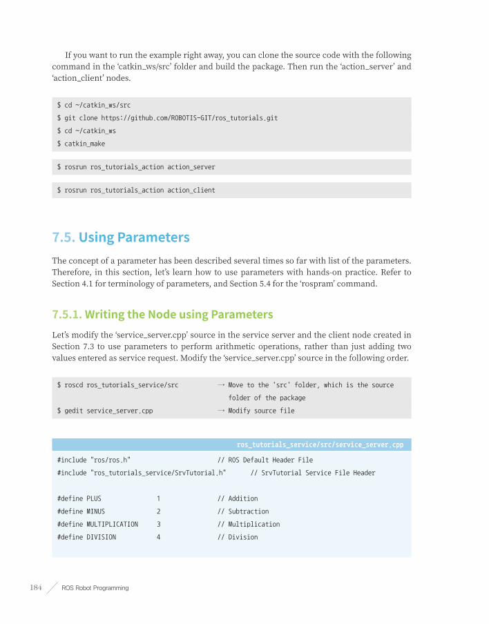
ROS Robot Programming184
If you want to run the example right away, you can clone the source code with the following command in the ‘catkin_ws/src’ folder and build the package. Then run the ‘action_server’ and ‘action_client’ nodes.
$ cd ~/catkin_ws/src
$ git clone https://github.com/ROBOTIS-GIT/ros_tutorials.git
$ cd ~/catkin_ws
$ catkin_make
$ rosrun ros_tutorials_action action_server
$ rosrun ros_tutorials_action action_client
7.5. Using Parameters The concept of a parameter has been described several times so far with list of the parameters. Therefore, in this section, let’s learn how to use parameters with hands-on practice. Refer to Section 4.1 for terminology of parameters, and Section 5.4 for the ‘rospram’ command.
7.5.1. Writing the Node using ParametersLet’s modify the ‘service_server.cpp’ source in the service server and the client node created in Section 7.3 to use parameters to perform arithmetic operations, rather than just adding two values entered as service request. Modify the ‘service_server.cpp’ source in the following order.
$ roscd ros_tutorials_service/src → Move to the 'src' folder, which is the source
folder of the package
$ gedit service_server.cpp → Modify source file
ros_tutorials_service/src/service_server.cpp
#include "ros/ros.h" // ROS Default Header File
#include "ros_tutorials_service/SrvTutorial.h" // SrvTutorial Service File Header
#define PLUS 1 // Addition
#define MINUS 2 // Subtraction
#define MULTIPLICATION 3 // Multiplication
#define DIVISION 4 // Division

Chapter 7 _ Basic ROS Programming 185
int g_operator = PLUS;
// The process below is performed if there is a service request
// The service request is declared as 'req', and the service response is declared as 'res'
bool calculation(ros_tutorials_service::SrvTutorial::Request &req,
ros_tutorials_service::SrvTutorial::Response &res)
{
// The operator will be selected according to the parameter value and calculate 'a' and 'b',
// which were received upon the service request.
// The result is stored as the Response value.
switch(g_operator)
{
case PLUS:
res.result = req.a + req.b; break;
case MINUS:
res.result = req.a - req.b; break;
case MULTIPLICATION:
res.result = req.a * req.b; break;
case DIVISION:
if(req.b == 0)
{
res.result = 0; break;
}
else
{
res.result = req.a / req.b; break;
}
default:
res.result = req.a + req.b; break;
}
// Displays the values of 'a' and 'b' used in the service request, and the 'result' value
// corresponding to the service response.
ROS_INFO("request: x=%ld, y=%ld", (long int)req.a, (long int)req.b);
ROS_INFO("sending back response: [%ld]", (long int)res.result);
return true;
}
int main(int argc, char **argv) // Node Main Function

ROS Robot Programming186
{
ros::init(argc, argv, "service_server"); // Initializes Node Name
ros::NodeHandle nh; // Node handle declaration
nh.setParam("calculation_method", PLUS); // Reset Parameter Settings
// Declare service server 'service_server' using the 'SrvTutorial' service file
// in the 'ros_tutorials_service' package. The service name is 'ros_tutorial_srv' and
// it is set to execute a 'calculation' function when a service is requested.
ros::ServiceServer ros_tutorial_service_server = nh.advertiseService("ros_tutorial_srv",
calculation);
ROS_INFO("ready srv server!");
ros::Rate r(10); // 10hz
while (1)
{
// Select the operator according to the value received from the parameter.
nh.getParam("calculation_method", g_operator);
ros::spinOnce(); // Callback function process routine
r.sleep(); // Sleep for routine iteration
}
return 0;
}
As most of the contents are similar to the previous examples, let’s just take a look at the additional parts needed to use parameters. In particular, the ‘setParam’ and ‘getParam’ methods in bold font are the most important parts when using parameters. As they are very simple methods, it can be easily understood by just reading its usage.
7.5.2. Setting ParametersThe following code sets the parameter of ‘calculation_method’ to ‘PLUS’. Since the word ‘PLUS’ is defined as ‘1’ in the code in section 7.5.1, the ‘calculation_method’ parameter becomes ‘1’ and the service response will add the received values from the service request.
nh.setParam("calculation_method", PLUS);
Note that parameters can be set to integers, floats, boolean, string, dictionaries, list, and so on. For example, ‘1’ is an integer, ‘1.0’ is a float, ‘internetofthings’ is a string, ‘true’ is a boolean, ‘[1,2,3]’ is a list of integers, and ‘a: b, c: d’ is a dictionary.

Chapter 7 _ Basic ROS Programming 187
7.5.3. Reading ParametersThe following gets the parameter value from ‘calculation_method’ and sets it as the value of ‘g_operator’. As a result, ‘g_operator’ from the code in section 7.5.1 checks the parameter value in every ‘0.1’ seconds to determine which operation to use on the values received through the service request.
nh.getParam("calculation_method", g_operator);
7.5.4. Building and Running NodesRebuild the service server node in the ‘ros_tutorials_service’ package with the following command.
$ cd ~/catkin_ws && catkin_make
When the build is done, run the ‘service_server’ node of the ‘ros_tutorials_service’ package with the following command.
$ roscore
$ rosrun ros_tutorials_service service_server
[INFO] [1495767130.149512649]: ready srv server!
7.5.5. Displaying Parameter ListsThe ‘rosparam list’ command displays a list of parameters currently used in the ROS network. From the displayed list, ‘/calculation_method’ is the parameter we used.
$ rosparam list
/calculation_method
/rosdistro
/rosversion
/run_id
7.5.6. Example of Using ParametersSet the parameters according to the following command, and verify that the service processing has changed while requesting the same service each time.

ROS Robot Programming188
$ rosservice call /ros_tutorial_srv 10 5 → Input variables a and b for arithmetic operation
result: 15 → Resulting value from the default operation
$ rosparam set /calculation_method 2 → Subtraction
$ rosservice call /ros_tutorial_srv 10 5
result: 5
$ rosparam set /calculation_method 3 → Multiplication
$ rosservice call /ros_tutorial_srv 10 5
result: 50
$ rosparam set /calculation_method 4 → Division
$ rosservice call /ros_tutorial_srv 10 5
result: 2
The ‘calculation_method’ parameter can be changed with the ‘rosparam set’ command. With the changed parameters, you can see the different result values with the same input of ‘rosservice call /ros_tutorial_srv 10 5’. As shown in above example, parameters in ROS can control the flow, setting, and processing of nodes from outside the node. It’s a very useful feature so familiarize yourself with this feature even if you do not need it right away.
In this section, we have modified a service server and learned how to use parameters. The corresponding source code has been renamed as ‘ros_tutorials_parameter’ package to distinguish it from the service source code that was previously created, and can be found in the following GitHub address.
■ https://github.com/ROBOTIS-GIT/ros_tutorials/tree/master/ros_tutorials_parameter
If you want to run the example right away, you can clone the source code with the following command in the ‘catkin_ws/src’ folder and build the package. Then run the ‘service_server’ and ‘service_client’ nodes.
$ cd ~/catkin_ws/src
$ git clone https://github.com/ROBOTIS-GIT/ros_tutorials.git
$ cd ~/catkin_ws
$ catkin_make
$ rosrun ros_tutorials_parameter service_server_with_parameter
$ rosrun ros_tutorials_parameter service_client_with_parameter 2 3

Chapter 7 _ Basic ROS Programming 189
7.6. Using roslaunch The ‘rosrun’ is a command that executes just one node, and ‘roslaunch’ can run more than one node. Other features of the ‘roslaunch’ command include the ability to modify parameters of the package, rename the node name, the ROS_ROOT and ROS_PACKAGE_PAPATION_PATH settings, and change environment variables.
The ‘roslaunch’ uses the ‘*.launch’ file to select executable nodes, which is XML-based and provides tag-specific options. The execution command is ‘roslaunch [package name] [roslaunch file]’.
7.6.1. Using the roslaunchTo learn how to use roslaunch, rename the ‘topic_publisher’ and ‘topic_subscriber’ nodes previously created. There is no point of only changing the names, so let’s run two sets of publisher and subscriber nodes to communicate with each other.
First, write a ‘*.launch’ file. The file used for roslaunch has a ‘*.launch’ extension file name, and you have to create a ‘launch’ folder in the package folder and place the launch file in that folder. Create a folder with the following command and create a new file called ‘union.launch’.
$ roscd ros_tutorials_topic
$ mkdir launch
$ cd launch
$ gedit union.launch
Write the contents of the ‘union.launch’ file as follows.
union.launch
<launch>
<node pkg="ros_tutorials_topic" type="topic_publisher" name="topic_publisher1"/>
<node pkg="ros_tutorials_topic" type="topic_subscriber" name="topic_subscriber1"/>
<node pkg="ros_tutorials_topic" type="topic_publisher" name="topic_publisher2"/>
<node pkg="ros_tutorials_topic" type="topic_subscriber" name="topic_subscriber2"/>
</launch>
The tags required to run the node with the ‘roslaunch’ command are described within the <launch> tag. The <node> tag describes the node to be executed by ‘roslaunch’. Options include ‘pkg’, ‘type’, and ‘name’.

ROS Robot Programming190
■ pkg Package name
■ type Name of the actual node to be executed (Node Name)
■ name The name (executable name) to used when the node corresponding to the ‘type’ above is executed. The name is generally set to be the same as the type, but it can be set to use a different name when executed.
Once the ‘roslaunch’ file is created, run ‘union.launch’ as follows. Note that when the ‘roslaunch’ command runs several nodes, the output (info, error, etc.) of the executed nodes is not displayed on the terminal screen, making it difficult to debug. If you add the ‘--screen’ option, the output of all nodes running on that terminal will be displayed on the terminal screen.
$ roslaunch ros_tutorials_topic union.launch --screen
What would the screen look like if we run it? First, let’s take a look at the nodes currently running with the following command.
$ rosnode list
/rosout
/topic_publisher1
/topic_publisher2
/topic_subscriber1
/topic_subscriber2
As a result, the ‘topic_publisher’ node is renamed and executed as ‘topic_publisher1’ and ‘topic_publisher2’. The ‘topic_subscriber’ node is also renamed and executed as ‘topic_subscriber1’ and ‘topic_subscriber2’.
The problem is that unlike the initial intention to “run two publisher nodes and two subscriber nodes and make them communicate with their corresponding pairs”, we can see through ‘rqt_graph’ (Figure 7-10) that each subscriber is receiving a topic from both publishers. This is because we simply changed the name of the node to be executed without changing the name of the message to be used. Let’s fix this problem with namespace tag in ‘roslaunch’.

Chapter 7 _ Basic ROS Programming 191
Figure 7-10 Diagram showing multiple node execution using roslaunch
Let’s modify the ‘union.launch’ file that we created earlier.
$ roscd ros_tutorials_topic/launch
$ gedit union.launch
ros_tutorials_topic/launch/union.launch
<launch>
<group ns="ns1">
<node pkg="ros_tutorials_topic" type="topic_publisher" name="topic_publisher"/>
<node pkg="ros_tutorials_topic" type="topic_subscriber" name="topic_subscriber"/>
</group>
<group ns="ns2">
<node pkg="ros_tutorials_topic" type="topic_publisher" name="topic_publisher"/>
<node pkg="ros_tutorials_topic" type="topic_subscriber" name="topic_subscriber"/>
</group>
</launch>
The tag <group> binds specific nodes. The option ‘ns’ refers to the name of the group as a namespace, and the name and message of the node belonging to the group are both included in the name specified by ‘ns’.

ROS Robot Programming192
Once again, visualize the status of the connection and message transmission between nodes using ‘rqt_graph’. This time, we can see that each node is communicating its intended pair as shown in Figure 7-11.
Figure 7-11 Message communication when using namespace
7.6.2. Launch TagThe Launch tag can be applied in a variety of ways depending on the XML13 that is written in the launch file. The tags used in Launch are as follows.
■ <launch> The beginning and end of the roslaunch syntax.
■ <node> Tag for node execution. The package, node name, and execution name can be changed.
■ <machine> The name, address, ros-root, and ros-package-path of the system running the node can be set.
■ <include> Additional launch file can be included from current/other packages to be launched together.
■ <remap> ROS variables such as node name and topic name used in the node can be replaced with other name.
■ <env> Set environment variables such as path and IP (rarely used).
13 http://wiki.ros.org/roslaunch/XML≆

Chapter 7 _ Basic ROS Programming 193
■ <param> Set the parameter name, type, value, etc.
■ <rosparam> Check and modify parameter information such as load, dump, and delete like the ‘rosparam’ command.
■ <group> Group executable nodes.
■ <test> Used to test nodes. Similar to <node>, but with options available for testing purposes.
■ <arg> Define a variable in the launch file so that the parameter is changed when executed as shown below.
Internal parameters can be changed from the outside when executing a launch file with <param> and <arg> tags, which is a variable in the launch file. Familiarize yourself with this parameter as it is a very useful and widely used method.
<launch>
<arg name="update_period" default="10" />
<param name="timing" value="$(arg update_period)"/>
</launch>
$ roslaunch my_package my_package.launch update_period:=30

ROS Robot Programming194
Robot. Sensor. Motor.
Chapter 8

Chapter 8 _ Robot. Sensor. Motor. 195
8.1. Robot PackagesA robot is largely classified into hardware and software. Mechanism, motors, gears, circuits, sensors are categorized as hardware. Micro-controller firmware that drives or controls the robot’s hardware, and application software that builds map, navigates, creates motion and perceives environment based on sensor data are classified as software.
ROS can be classified as application software and depending on the specialized applications it is classified as robot package1, sensor package2 and motor3 package. These packages are provided by robot companies such as Willow Garage, ROBOTIS, Yujin Robot and Fetch Robotics as well as Open Robotics (OSRF, formerly Open Source Robotics Foundation) and university labs in robot engineering. Individual developers also develop and distribute packages related to ROS robots, sensors and motors.
The masterpiece of robot package is without a doubt PR2 and TurtleBot in Figure 8-1. Among them, PR2 is a mobile-based humanoid robot developed for research by Willow Garage responsible for the ROS development. Until this day, the core package of other robots is derived from PR2 which is a representative robot package of ROS.
Although PR2 is a general purpose and its performance is superior, the price was not competitive enough to vitalize ROS in the market, so TurtleBot was developed to increase the boundary of ROS. First TurtleBot was based on the Create which is iRobot’s cleaning robot platform. For TurtleBot2, KOBUKI was adopted as a mobile platform which was the improved version of iCLEBO of Yujin Robot in Korea. Now TurtleBot3, a Dynamixel based mobile robot, developed in colloboration with ROBOTIS, Open Robotics which will be extensively covered in this book. Details on TurtleBot and usage of the robot packages are covered in section 10.
Figure 8-1 PR2 (Left), TurtleBot2 (2nd from the left), TurtleBot3 (3 models on the right)
1 http://robots.ros.org/,≆http://wiki.ros.org/Robots
2 http://wiki.ros.org/Sensors
3 http://wiki.ros.org/Motor%20Controller%20Drivers

ROS Robot Programming196
In addition to these representative robots, there are over 180 different types of robot packages as shown in Figure 8-2. These numbers are limited to robots with its package sources being released and the numbers will increase if other robots from companies, research labs, universities, and indiviuals are included.
Figure 8-2 Robots powered by ROS (http://robots.ros.org/)
The following are the different types of robots that are used in almost every field and disclosed robot packages can be found at http://robots.ros.org/.
■ Manipulator
■ Mobile robot
■ Autonomous car
■ Humanoid
■ UAV: Unmanned Aerial Vehicle
■ UUV: Unmanned Underwater Vehicle
The installation procedure for the robot package should be very simple if it is a ROS official package. First, check if the robot package that you are about to use is listed at ROS Wiki (http://robots.ros.org/) or use the command below to search for the entire ROS package list.
$ apt-cache search ros-kinetic

Chapter 8 _ Robot. Sensor. Motor. 197
Using synaptic, a Linux GUI package manager program, to search the word ‘ros-kinetic’ is another possible method. The installation procedure for the robot package should be very simple if it is a ROS official package. Here are some command examples of installing the PR2 package.
$ sudo apt-get install ros-kinetic-pr2-desktop
The following is the installation command for TurtleBot3 package.
$ sudo apt-get install ros-kinetic-turtlebot3 ros-kinetic-turtlebot3-msgs ros-kinetic-
turtlebot3-simulations
It is recommended to use the latest source code instead of the binary installation since TurtleBot3 is constantly getting upated. Details about this method are covered in the chapter 10 ‘Mobile Robot’.
Even if the robot package you are about to use is not an official package, information for installation can be found in Wiki of the robot package. For example, Pioneer, widely known for its mobile robot, the package can be downloaded to the source folder of catkin workspace from the repository as shown below.
$ cd ~/catkin_ws/src → Move to the source folder of catkin workspace
$ hg clone http://code.google.com/p/amor-ros-pkg/ → Download from repository
As such, the robot package can be downloaded from either the open source repository according to the installation method shown in the Wiki or released official ROS package.
Please follow the description of the corresponding robot package for the usage of each node included in the package. The robot package basically includes a robot operating drive node, a node for acquiring and utilizing the mounted sensor data, and a remote control node. If the robot is an articulated robot, it includes an inverse kinematics node whereas a navigation node is included for a mobile robot.
8.2. Sensor PackagesSensors play crucial roles in a robot. There are many researches to extract meaningful information from various environments and to recognize environment using this information and transmit it to robot. Such environmental information is very diverse such as location, space, weather, voice, inertia, vibration, gas, current amount, RFID, object, external force recognition. This information is used as important data for the robot to perform an operation.
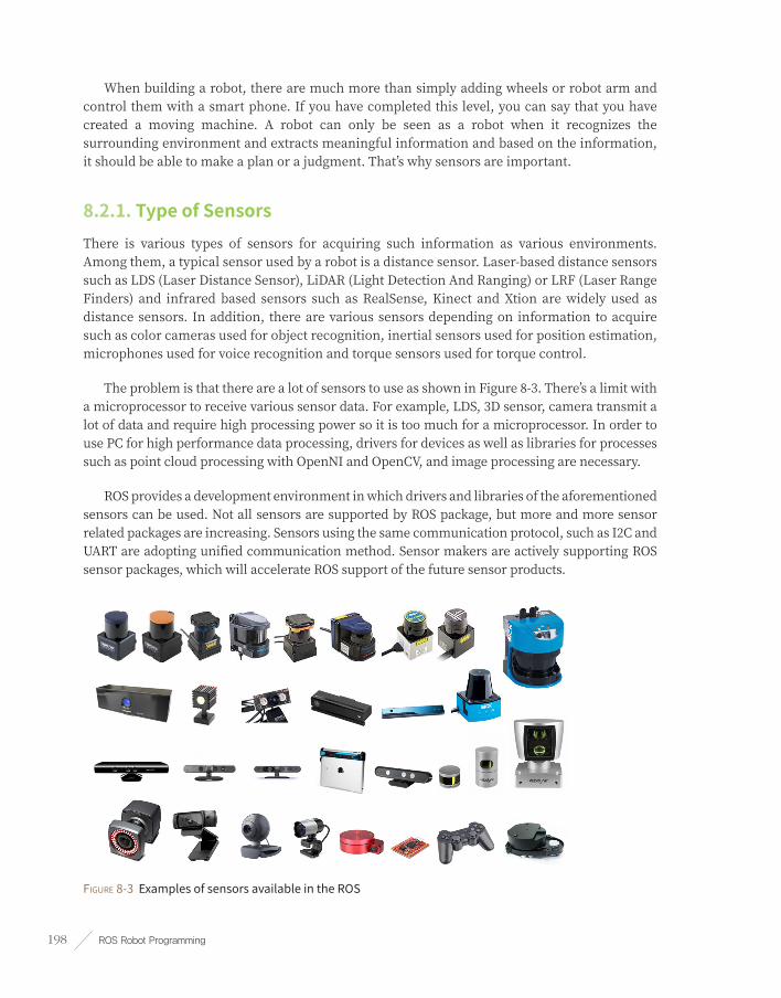
ROS Robot Programming198
When building a robot, there are much more than simply adding wheels or robot arm and control them with a smart phone. If you have completed this level, you can say that you have created a moving machine. A robot can only be seen as a robot when it recognizes the surrounding environment and extracts meaningful information and based on the information, it should be able to make a plan or a judgment. That’s why sensors are important.
8.2.1. Type of SensorsThere is various types of sensors for acquiring such information as various environments. Among them, a typical sensor used by a robot is a distance sensor. Laser-based distance sensors such as LDS (Laser Distance Sensor), LiDAR (Light Detection And Ranging) or LRF (Laser Range Finders) and infrared based sensors such as RealSense, Kinect and Xtion are widely used as distance sensors. In addition, there are various sensors depending on information to acquire such as color cameras used for object recognition, inertial sensors used for position estimation, microphones used for voice recognition and torque sensors used for torque control.
The problem is that there are a lot of sensors to use as shown in Figure 8-3. There’s a limit with a microprocessor to receive various sensor data. For example, LDS, 3D sensor, camera transmit a lot of data and require high processing power so it is too much for a microprocessor. In order to use PC for high performance data processing, drivers for devices as well as libraries for processes such as point cloud processing with OpenNI and OpenCV, and image processing are necessary.
ROS provides a development environment in which drivers and libraries of the aforementioned sensors can be used. Not all sensors are supported by ROS package, but more and more sensor related packages are increasing. Sensors using the same communication protocol, such as I2C and UART are adopting unified communication method. Sensor makers are actively supporting ROS sensor packages, which will accelerate ROS support of the future sensor products.
Figure 8-3 Examples of sensors available in the ROS

Chapter 8 _ Robot. Sensor. Motor. 199
8.2.2. Classification of Sensor PackagesThere are several sensor packages available on the ROS sensor Wiki page. Sensors are classified into 1D range finders, 2D range finders, 3D Sensors, Pose Estimation (GPS + IMU), Cameras, Sensor Interfaces, Audio / Speech Recognition, Environmental, Force / Torque / Touch Sensors, Motion Capture, Power Supply, RFID and the sensors are introduced in their categories.
For more information on sensor packages, see the ROS sensor Wiki page mentioned above. In particular, the following packages are considered important packages in this book.
■ 1D Range Finders: Infrared distance sensors that can be used to make low-cost robots.
■ 2D Range Finders: LDS is commonly used in navigation.
■ 3D Sensors: Sensors such as Intel’s RealSense, Microsoft’s Kinect and ASUS’s Xction are necessary for 3D measurements.
■ Audio/Speech Recognition: Currently, there are very few areas related to speech recognition, but it seems to be added continuously.
■ Cameras: Camera drivers and various application packages that are widely used for object recognition, face recognition, character recognition are listed.
■ Sensor Interfaces: Very few sensors support USB and Web protocols. Still, many sensor data can be easily obtained from the microprocessor. These sensors can be connected to ROS via UART of microprocessor or mini PCs. These sensor interfaces are introduced.
There are various sensor packages available, so find the sensors best suitable for your project and apply them. The most commonly used cameras, depth cameras and laser distance sensors (LDS) will be discussed in detail in the following sections.
8.3. CameraThe camera corresponds to the eye in the robot. The images obtained from the camera are very useful for recognizing the environment around the robot. For example, object recognition using a camera image, facial recognition, a distance value obtained from the difference between two different images using two cameras (stereo camera), mono camera visual SLAM, color recognition using information obtained from an image and object tracking are very useful.
There are many kinds of cameras to be used for image processing but, we will cover the USB camera. The USB camera means that it supports USB connection. Another name is USB Video

ROS Robot Programming200
device Class (UVC)4. The official name is ‘UVC camera’, but generally it is called as ‘USB camera’ which will be commonly used in this section.
As of July 2017, the latest version of UVC is 1.55. The UVC 1.5 version supports the latest USB 3.0 and is available on almost all operating systems including Linux, Windows, and OS X. It is easy to use, widespread and cheaper than other cameras. In this section, we will practice how to run a USB camera and check the data.
Camera Interface
USB is not the only available interface for a camera. Some cameras have network capabilities that can be connected via LAN or WiFi to stream videos to the web. Such cameras are called webcams.
Also, some cameras use FireWire (IEEE 1394 protocol) for high-speed transmission, and they are mainly used for research purposes where high-speed image transmission is required. The FireWire standard is not readily available on common boards, but it is developed by Apple and is mostly used in Apple products.
8.3.1. Packages Related to USB CameraROS provides various packages related to USB camera. More information can be found in the ‘Sensor/Camera’ category of the ROS Wiki (http://wiki.ros.org/Sensors/Cameras). Let’s take a look at packages related to USB cameras.
■ libuvc-camera: This is an interface package for operating cameras with the UVC standard. (Developer: Ken Tossell)
■ uvc-camera: This is a very convenient package with relatively detailed camera settings. Moreover, if you are considering a stereo camera configuration, this package would be ideal for the purpose.
■ usb-cam: This is a very simple camera driver for Bosch. (By Benjamin Pitzer)
■ freenect-camera, openni-camera, openni2-camera: All three packages are labeled as ‘camera’, but these packages are for depth cameras like Kinect or Xtion. These sensors include a color camera, therefore, they are also called RGB-D cameras. These packages are required to use their color images.
■ camera1394: This is a driver for cameras using IEEE 1394 standard FireWire.
■ prosilica-camera: This is used in AVT’s prosilica camera, which is widely used for research purposes.
4 https://en.wikipedia.org/wiki/USB_video_device_class
5 http://www.usb.org/developers/docs/devclass_docs/

Chapter 8 _ Robot. Sensor. Motor. 201
■ pointgrey-camera-driver: This is a driver for the Point Gray camera of Point Gray Research which is widely used for research.
■ camera-calibration: James Bowman, and Patrick Mihelich developed this camera calibration package that applies OpenCV’s calibration feature. Many camera-related packages require this package.
8.3.2. USB Camera TestIn this section, let’s practice with the uvc-camera6 developed by Ken Tossell. It is one of the most used packages in the USB camera packages. The usage of other related packages is similar, so if you want to use another package, check the Wiki page for that package.
■ USB Camera: Connect the USB camera to the USB port of your computer.
■ Camera Connection Information: Open a new terminal window and check that the connection is correctly made with ‘lsusb’ command as shown below. If you have a generic UVC camera, you can check if the camera is connected like the underlined message below.
$ lsusb
Bus 004 Device 001: ID 1d6b:0003 Linux Foundation 3.0 root hub
Bus 003 Device 001: ID 1d6b:0002 Linux Foundation 2.0 root hub
Bus 002 Device 002: ID 2109:0812 VIA Labs, Inc. VL812 Hub
Bus 002 Device 001: ID 1d6b:0003 Linux Foundation 3.0 root hub
Bus 001 Device 005: ID 046d:c52b Logitech, Inc. Unifying Receiver
Bus 001 Device 006: ID 05e3:0608 Genesys Logic, Inc. Hub
Bus 001 Device 013: ID 046d:08ce Logitech, Inc. QuickCam Pro 5000
Bus 001 Device 012: ID 0c45:7603 Microdia
Bus 001 Device 002: ID 2109:2812 VIA Labs, Inc. VL812 Hub
Bus 001 Device 007: ID 8087:0a2a Intel Corp.
Bus 001 Device 001: ID 1d6b:0002 Linux Foundation 2.0 root hub
uvc_camera Package Installation
$ sudo apt-get install ros-kinetic-uvc-camera
6 http://wiki.ros.org/uvc_camera

ROS Robot Programming202
Image Related Package Installation
$ sudo apt-get install ros-kinetic-image-*
$ sudo apt-get install ros-kinetic-rqt-image-view
Running the uvc_camera nodeIf you run the ‘uvc_camera’ node, you will get this warning message about the camera calibration, ‘[WARN] [1423194481.257752159]: Camera calibration file /home/xxx/.ros/camera_info/camera.yaml not found.’ because the calibration file is missing. Let’s ignore this for now as we will cover calibration in detail in the next section.
$ roscore
$ rosrun uvc_camera uvc_camera_node
Verify Topic MessageThe following topic message shows that the camera information (/camera_info) and image information (/image_raw) are being published.
$ rostopic list
/camera_info
/image_raw
/image_raw/compressed
/image_raw/compressed/parameter_descriptions
/image_raw/compressed/parameter_updates
/image_raw/compressedDepth
/image_raw/compressedDepth/parameter_descriptions
/image_raw/compressedDepth/parameter_updates
/image_raw/theora
/image_raw/theora/parameter_descriptions
/image_raw/theora/parameter_updates
/rosout
/rosout_agg

Chapter 8 _ Robot. Sensor. Motor. 203
8.3.3. Visualization of Image InformationIn the previous section, we confirmed that image information is being published while ‘uvc_camera_node’ node is running. In this section, we use ‘image_view’ and RViz to visualize image information. If you do not see the image here, there is a problem with the camera driver or connection, so go to the previous section to see if there is a problem.
Visualization with image_view NodeFirst, let’s run the ‘image_view’ node to see the image information. The option ‘image:=/image_raw’ is appended, and ‘/image_raw’ is an option to view the topic as an image in the topic list. When executed, a camera image is displayed in a small window, as shown in Figure 8-4.
$ rosrun image_view image_view image:=/image_raw
Figure 8-4 Image view using image_view node
Visualization with rqt_image_view NodeLet’s take a look at the ‘rqt_image_view’ in Section 6.2. ‘image_view’ is added to ‘rqt_image_view’ as an rqt plugin with GUI interface. Running the ‘rqt_image_view’ node displays the image shown in Figure 8-5. Unlike ‘image_view’, you can select a topic in the image viewer GUI that is already running.
$ rqt_image_view image:=/image_raw

ROS Robot Programming204
Figure 8-5 Viewing images using the rqt_image_view node
Visualization with RVizLet’s run RViz visualization tool. For a detailed description of RViz, see Section 6.1.
$ rviz
Change the Displays option when RViz is executed. Click [Add] at the bottom left of RViz and select [Image] in the [By display type] tab as shown in Figure 8-6 to bring up the image display.
Figure 8-6 Adding image display to RViz

Chapter 8 _ Robot. Sensor. Motor. 205
Change the value of [Image Topic] in the [Image] option to ‘/image_raw’, then the image is displayed as shown in Figure 8-7. If the image looks small, adjust the size of the image panel with your mouse.
Figure 8-7 Viewing images using RViz
8.3.4. Remote Transfer ImagesIn the previous section, we connected the USB camera to the computer and collected images directly.
However, since the robot is moving, the operator cannot follow the robot to see the image from the camera attached to the robot. In this section, I will explain how to check the image information of the camera mounted on the robot from another computer in the remote place. Be sure to read and follow the instructions carefully.
Computer with Camera AttachedThe ROS master can be any computer, but in this example, the computer to which the camera is connected is the ROS master. The first thing you need to do is to configure network variables such as ROS_MASTER_URI and ROS_HOSTNAME. First, let’s open the bashrc file using a document editing tool such as gedit, sublime text, vim, emacs, nano.

ROS Robot Programming206
$ gedit ~/.bashrc
There will be many settings when you open the bashrc file. Leave the previous settings as they are, and go down to the bottom of the bashrc file and modify the ROS_MASTER_URI and ROS_HOSTNAME variables as below. Note that the IP address (192.168.1.100) in the following example must be the IP address of the computer to which the camera is connected. If necessary, modify the IP address. To check your IP address, you can use the ‘ifconfig’ command, which is described in Section 3.2.
export ROS_MASTER_URI = http://192.168.1.100:11311
export ROS_HOSTNAME = 192.168.1.100
Then run roscore and run ‘uvc_camera_node’ node in another terminal window.
$ roscore
$ rosrun uvc_camera uvc_camera_node
Remote ComputerLikewise the master PC, remote computer needs to be configured. Open the bashrc file and modify the variables ROS_MASTER_URI and ROS_HOSTNAME. Set ROS_MASTER_URI to the IP address of the computer to which the camera is connected (master PC), and change the IP address of the ROS_HOSTNAME as remote computer (192.168.1.120 is the IP of the remote computer in this example). Check your IP address of the remote PC with ifconfig and configure the setting correctly.
Then, run the ‘image_view’.
export ROS_MASTER_URI = http://192.168.1.100:11311
export ROS_HOSTNAME = 192.168.1.120
$ rosrun image_view image_view image:=/image_raw
In this section, we covered how to view the image acquired from the camera mounted on the robot from the remote computer. It can be used as a remote sensing robot, a video conferencing robot, or a webcam, that is, a surveillance system, which is a digital camera capable of transmitting images to the network in real time, because the robot can be remotely controlled and recognize environment.

Chapter 8 _ Robot. Sensor. Motor. 207
8.3.5. Camera CalibrationWhen uvc_camera node is running, a warning message about the camera calibration ‘[WARN] [1423194481.257752159]: Camera calibration file /home/xxx/.ros/camera_info/camera.yaml not found.’ may appear which can be ignored if further image process is not required.
However, camera calibration is necessary if you are measuring distance from images acquired with a stereo camera or processing images for object recognition.
In order to obtain accurate distance information from the image obtained from the camera, information such as the lens characteristics, the gap between the lens and the image sensor, and the twisted angle of the image sensor are required for each camera. This is because the camera image is a projection of the three-dimensional space into a two-dimensional face, and this projection process is affected by the characteristics of each camera.
For example, each lens and the image sensor are different from each other, the gap between the lens and the image sensor is different due to the hardware structure of the camera, the lens and the image sensor are not perfectly aligned during camera production process which causes misalignment of the image center and the principal point, and the image sensor could be slightly twisted or angled.
Camera calibration is a process to correct these differences by calculating the camera’s unique parameters. As camera calibration is very important, it is difficult to cover the details in this book, so please refer to other materials that explains OpenCV image process.
ROS offers a calibration package using OpenCV’s camera calibration. Calibrate your camera as described in the following sections.
Camera CalibrationInstall the camera calibration package and run the ‘uvc_camera_node’ node as follows:
$ sudo apt-get install ros-kinetic-camera-calibration
$ rosrun uvc_camera uvc_camera_node
Next, let’s check the current camera information.
Since there is no information about camera calibration yet, default values will be displayed.
$ rostopic echo /camera_info
header:
seq: 7609
stamp:
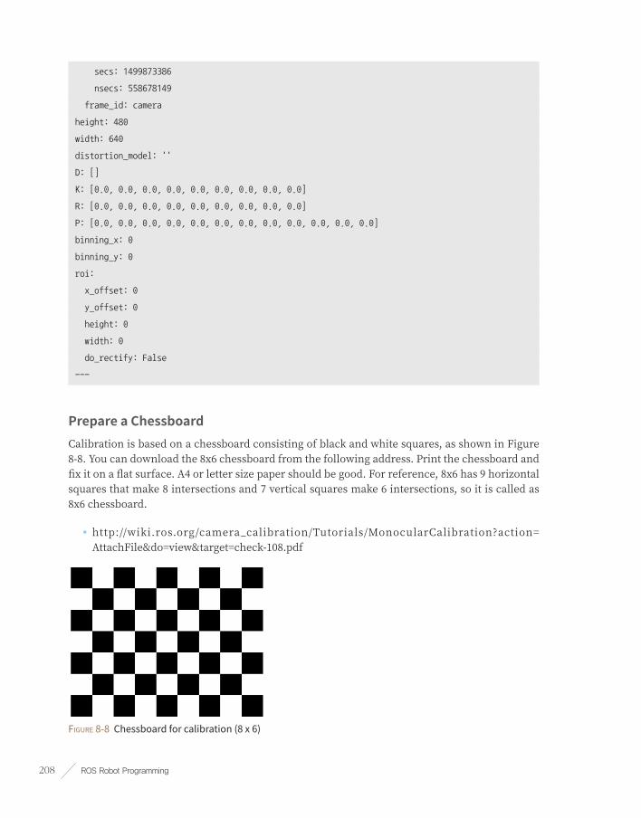
ROS Robot Programming208
secs: 1499873386
nsecs: 558678149
frame_id: camera
height: 480
width: 640
distortion_model: ''
D: []
K: [0.0, 0.0, 0.0, 0.0, 0.0, 0.0, 0.0, 0.0, 0.0]
R: [0.0, 0.0, 0.0, 0.0, 0.0, 0.0, 0.0, 0.0, 0.0]
P: [0.0, 0.0, 0.0, 0.0, 0.0, 0.0, 0.0, 0.0, 0.0, 0.0, 0.0, 0.0]
binning_x: 0
binning_y: 0
roi:
x_offset: 0
y_offset: 0
height: 0
width: 0
do_rectify: False
---
Prepare a ChessboardCalibration is based on a chessboard consisting of black and white squares, as shown in Figure 8-8. You can download the 8x6 chessboard from the following address. Print the chessboard and fix it on a flat surface. A4 or letter size paper should be good. For reference, 8x6 has 9 horizontal squares that make 8 intersections and 7 vertical squares make 6 intersections, so it is called as 8x6 chessboard.
■ http://wiki.ros.org/camera_calibration/Tutorials/MonocularCalibration?action= AttachFile&do=view&target=check-108.pdf
Figure 8-8 Chessboard for calibration (8 x 6)

Chapter 8 _ Robot. Sensor. Motor. 209
CalibrationLet’s perform the camera calibration. Before we start, ‘--size 8x6’ is the parameter of width and height of the chessboard, whereas ‘--square 0.024’ is the actual length of side of single square. This width and height of the square may vary from printer to printer, so measure the actual size of the chessboard and enter the proper values. In this case, the width and height of the square is 24mm, so the example below will be displayed accordingly.
$ rosrun camera_calibration cameracalibrator.py --size 8x6 --square 0.024 image:=/image_raw
camera:=/camera
Once the calibration node is running, the GUI will appear as shown in Figure 8-9. If you point the camera to the chess board, the calibration will start immediately. On the right side of the GUI screen you will see colored horizontal bars labeled as X, Y, Size and Skew. These are calibration conditions for correct calibration and you have to adjust the chessboard to various directions with respect to the camera. As conditions are getting better, the bars of X, Y, Size and Skew will get longer and turn green.
Figure 8-9 Calibration GUI initial state
The ‘CALIBRATE’ button is activated as shown in Figure 8-10 when necessary images for calibration are collected. Calibration process takes approximately 1 to 5 minutes to calculate the actual calibration. When the calculation is completed, click the SAVE button to save the calibration information of the camera. The saved address is displayed in the terminal window where the calibration was performed and is stored in the /tmp folder like ‘/tmp/calibrationdata.tar.gz’.

ROS Robot Programming210
Figure 8-10 Calibration process using the calibration GUI
Create Camera Parameter FileLet’s create a camera parameter file (camera.yaml) for ROS that contains camera calibration parameters. Unzip the ‘calibrationdata.tar.gz’ file to see the ‘ost.txt’ file that contains calibration parameters and image files (*.png) used for calibration process.
$ cd /tmp
$ tar -xvzf calibrationdata.tar.gz
Rename the ‘ost.txt’ to ‘ost.ini’, and create a camera parameter file (camera.yaml) using the convert node of the ‘camera_calibration_parsers’ package. After creating the parameter file, save it in ‘~/.ros/camera_info/’ folder as the following example, and camera related packages used in ROS will refer to this information.
$ mv ost.txt ost.ini
$ rosrun camera_calibration_parsers convert ost.ini camera.yaml
$ mkdir ~/.ros/camera_info
$ mv camera.yaml ~/.ros/camera_info/
The ‘camera.yaml’ file contains parameters shown as the following example and user can customize ‘camera_name’ value. Generally, camera-related packages often uses ‘camera’ as a default value, so I changed the ‘camera_name’ value from ‘narrow_stereo’ to ‘camera’.

Chapter 8 _ Robot. Sensor. Motor. 211
~/.ros/camera_info/camera.yaml
image_width: 640
image_height: 480
camera_name: camera
camera_matrix:
rows: 3
cols: 3
data: [778.887262, 0, 302.058565, 0, 779.885146, 221.545303, 0, 0, 1]
distortion_model: plumb_bob
distortion_coefficients:
rows: 1
cols: 5
data: [0.195718, -0.419555, -0.002234, -0.016098, 0]
rectification_matrix:
rows: 3
cols: 3
data: [1, 0, 0, 0, 1, 0, 0, 0, 1]
projection_matrix:
rows: 3
cols: 4
data: [794.464417, 0, 294.819501, 0, 0, 805.005371, 220.404173, 0, 0, 0, 1, 0]
The ‘camera.yaml’ contains information such as camera matrix (camera_matrix), distortion coefficient (distortion_coefficients), ‘rectification_matrix’ for stereo camera correction and the projection matrix. Description for each parameter can be found at ‘http://wiki.ros.org/image_pipeline/CameraInfo’. Finally, run the ‘uvc_camera_node’ node again. Make sure that you do not receive warnings about the calibration file at this time.
$ rosrun uvc_camera uvc_camera_node
[INFO] [1499873830.472050095]: using default calibration URL
[INFO] [1499873830.472116471]: camera calibration URL:
file:///home/xxx/.ros/camera_info/camera.yaml
In addition, if you look at the ‘/camera_info’ topic, you can see that the D, K, R, and P parameters are populated, as shown in the following example.
$ rostopic echo /camera_info
header:
seq: 2213

ROS Robot Programming212
stamp:
secs: 1499874042
nsecs: 898227060
frame_id: camera
height: 480
width: 640
distortion_model: plumb_bob
D: [0.195718, -0.419555, -0.002234, -0.016098, 0.0]
K: [778.887262, 0.0, 302.058565, 0.0, 779.885146, 221.545303, 0.0, 0.0, 1.0]
R: [1.0, 0.0, 0.0, 0.0, 1.0, 0.0, 0.0, 0.0, 1.0]
P: [794.464417, 0.0, 294.819501, 0.0, 0.0, 805.005371, 220.404173, 0.0, 0.0, 0.0, 1.0, 0.0]
binning_x: 0
binning_y: 0
roi:
x_offset: 0
y_offset: 0
height: 0
width: 0
do_rectify: False
---
8.4. Depth CameraDepth camera can be called as Depth sensor in the same category as LDS (laser distance sensor) and if it can acquire color image, it can also be called as RGB-D camera. It can also be called as Kinect Camera in the meaning that Microsoft succeeded in popularization of depth camera with Kinect.
In this section we will call it Depth Camera so that the terms are not confused.
8.4.1. Types of Depth CameraDepth cameras can be divided into various types according to the method of acquiring information, such as ToF7 (Time of Flight), Structured Light8, and Stereo9 method.
7 https://en.wikipedia.org/wiki/Time-of-flight_camera
8 https://en.wikipedia.org/wiki/Structured-light_3D_scanner
9 https://en.wikipedia.org/wiki/Range_imaging

Chapter 8 _ Robot. Sensor. Motor. 213
ToF (Time of Flight)The ToF method radiates infrared rays and measures the distance by the time it returns. In general, the IR transmission unit and the receiving unit are a pair (configuration may differ in some cases), and the distance measured by each pixel is read. The reason why the ToF method is more expensive than the structured light using the coherent radiation pattern method is that the hardware price is increased in this structural aspect (recently, various methods such as the distance calculation using the phase difference are introduced with competitive price).
ToF sensors include Panasonic’s D-IMager, MESA Imaging’s SwissRanger, Fotonic’s FOTONIC-B70, PMDtechnologies’s CamCube and CamBoard, SoftKinectic’s DepthSense DS series, and Microsoft’s recently released Kinect 2.
Figure 8-11 From left, D-IMager, SwissRanger, CamBoard, Kinect2
Structured LightRepresentative products of structured light based products include Microsoft’s Kinect and ASUS’s Xtion, which use a coherent radiation pattern (patent cited with US20100225746 patent, also called coherent radiation). These sensors use PrimeSense’s PrimeSense System on a Chip (SoC).
Figure 8-12 From left Kinect, Xtion, Carmine, Structure Sensor
The Depth Camera using PrimeSense’s PrimeSense SoC is a sensor consisting of one infrared projector and one infrared camera, which uses a coherent radiation pattern that was not present in the existing ToF method. This technology started getting attention after solving its high cost and external interference issues, and then Carmine, Capri with the PrimeSense SoC were released. In addition, Microsoft’s Kinect with the same SoC chip became popular as a controller of Xbox. After that, Asus’s Xtion was released, which was designed with a general computer usage in mind. These are all sensors equipped with the PrimeSense SoC.

ROS Robot Programming214
However, there was a problem when Apple took over PrimeSense in December 2013.
PrimeSense’s Carmine and Capri products were no longer available for purchase, Microsoft’s Kinect was discontinued, and ASUS’s Xtion was discontinued later as well. Occipital’s Structure Sensor, which is the last product with the PrimeSense SoC, sells its products as an accessory to Apple until today, but we do not know what will happen in the future. These popular low-cost products now became a history.
StereoA stereo camera (see Figure 8-13), which is one of the Depth Camera types, has been researched from a much longer time ago than the previous two types, and its distance is calculated using binocular parallax like the left and right eyes of a person. As the name suggests, the stereo camera is equipped with two image sensors at specific distance and calculates the grid value using the difference between the two image images captured by these two image sensors. Representative products include Point Gray’s Bumblebee camera and WithRobot’s OjOcamStereo.
There are various types of stereo camera, and distinctive method is to configure an infrared projector that emits infrared rays with a coherent pattern and two infrared image sensors that receive infrared rays to obtain distance by triangulation method. The former with dual image sensor is called passive stereo camera and the latter with the infrared projector is called active stereo camera. One of the representative active stereo cameras is Intel’s RealSense, which is about $100 for the R200 model. It is the cheapest among the Depth cameras so far, small in size and similar in performance to the Xtion described above. The D400 series is a new generation of RealSense, which has been widely used in the robotics field because of its small size, wide viewing angle, outdoor use, improved sensing distance.
Figure 8-13 From left Bumblebee, OjOcamStereo, RealSense

Chapter 8 _ Robot. Sensor. Motor. 215
8.4.2. Depth Camera TestThis section uses Intel’s RealSense R200 to install and run drivers for Depth Cameras.
Installing RealSense Related PackagesDownload and install RealSense-specific drivers and executable packages.
$ sudo apt-get install ros-kinetic-librealsense ros-kinetic-realsense-camera
Run the r200_nodelet_default launch file.Run the ‘r200_nodelet_default.launch’ file located in the ‘realsense_camera’ package.
$ roscore
$ roslaunch realsense_camera r200_nodelet_default.launch
If you followed the above instructions but run into package installation issues or operation issues, you may need to use a specific configuration for different Linux kernels. Refer to the following Wiki address for more information.
■ http://wiki.ros.org/librealsense
8.4.3. Visualization of Point Cloud DataA set of collected 3D distance data from the Depth Camera is called Point Cloud Data because it resembles cloud in shape. In order to visualize Point Cloud Data in GUI environment, launch RViz and change the display options shown as the following.
➊ Go to [Global Options] and Change [Fixed Frame] to ‘camera_depth_frame’.
➋ Click the [Add] button at the bottom left of RViz, then select [PointCloud2] to add it. Set topic to ‘camera/depth/points’ and select the size and color.
➌ Once all the settings are completed, you can see the PCD data as shown in Figure 8-14. Since the color reference is set to the X axis, the farther the point locates from the X axis,
the color gets closer to purple.

ROS Robot Programming216
Figure 8-14 Point cloud data visualized on the RViz’s PointCloud2 display
If you are using other Depth cameras, check the following Wiki address to learn how to operate the camera and how to use the package.
■ http://wiki.ros.org/Sensors#A3D_Sensors_.28range_finders_.26_RGB-D_cameras.29
8.4.4. Point Cloud Related LibraryDepth sensors are divided into LDS and Depth cameras according to the method of acquiring information. All distance sensors in this category are the same in the sense that they represent the distance to the object with a point and deal with Point Cloud, which is an aggregate of points. As a collection of APIs for using this Point Cloud, PCL (Point Cloud Library) 10 is used that performs filtering, segmentation, surface reconstruction, extracting fitting and features from the model.
10 http://pointclouds.org/

Chapter 8 _ Robot. Sensor. Motor. 217
OpenNIOpenNI (Open Natural Interaction)11 is a driver and various API libraries developed by PrimeSense Inc. with Willow Garage and ASUS to use PrimeSense’s products. NI (Natural Interaction) means communication between humans and machines which came from the meaning of interaction based on human senses rather than keyboards and mice. Most sensors with a PrimeSense SoC are using this driver.
Similar libraries include Microsoft’s Kinect Windows SDK and Libfreenect, which was once known for freeing up the Kinect by hacking device for the first time. In addition to the basic driver for managing Point Cloud Data, OpenNI also includes middleware such as NITE, which handles the human body skeleton. After Apple took over PrimeSense, OpenNI was put on the brink of disposal, but Occipital is now offering OpenNI12 in its Github repository13.
8.5. Laser Distance SensorLaser Distance Sensors (LDS) are referred to various names such as Light Detection And Ranging (LiDAR), Laser Range Finder (LRF) and Laser Scanner. LDS is a sensor used to measure the distance to an object using a laser as its source. The LDS sensor has the advantage of high performance, high speed, real time data acquisition, so it has a wide range of applications in relation to distance measurement. This is a sensor widely used in the field of robots for recognition of objects and people, and distance sensor based SLAM (distance-based sensor), and also widely used in unmanned vehicles due to its real time data acquisition.
Typical products are Hokuyo’s URG series which is widely used indoors as shown in Fig. 8-15 while SICK is widely used for outdoor use. Velodyne’s HDL series equipped with several laser sensors. The biggest disadvantage of these sensors is price. Prices vary from product to product, but they usually cost in the thousands of dollars and Velodyne’s HDL series are worth much more. Chinese products (such as RPLIDAR), which compensate for these shortcomings, hit the market at a low price of about $400/USD. Recently, LDS (HLS-LFCD2)14 product is expected to hit the market as low as $170/USD.
11 http://en.wikipedia.org/wiki/OpenNI
12 https://structure.io/openni
13 https://github.com/occipital/openni2
14 http://wiki.ros.org/hls_lfcd_lds_driver

ROS Robot Programming218
Figure 8-15 From left SICK LMS 210, Hokuyo UTM-30LX, Velodyne HDL-64e, HLS-LFCD LDS
8.5.1. Principle of LDS Sensor’s Distance MeasurementThe LDS sensor calculates the difference of the wavelength when the laser source is reflected by the object. The problem is that manufacturers only use one laser source due to price and control issues. For reference, Velodyne’s HDL series use as few as 16 and as many as 64 lasers which dramatically increase the price of the product. Therefore, most LDS sensors use only one laser. A typical LDS consists of a single laser source, a reflective mirror, and a motor. When you drive the LDS, you can hear the sound of the rotating motor, because it rotates the inner mirror and scans the laser in a horizontal plane. Typically measures from 180 to 360 degrees, depending on the product.
The left image of Figure 8-16 shows the LDS with a laser inside and a mirror that is tilted at an angle. The motor rotates the mirror and sensor measures the return time of the laser (calculates the difference in wavelength). This way, the sensor scans objects in a horizontal plane around the LDS as shown in the center image. However, the accuracy is dropped as the distance becomes longer as shown in the right image.
Figure 8-16 Distance measurement using LDS

Chapter 8 _ Robot. Sensor. Motor. 219
Although users do not need to know how LDS works, it is important to inform users of the possible issues / warnings of using LDS.
First, since the laser is used as a light source, a strong laser beam can damage the eye. Products are classified based on the laser source, so it is important to note this when purchasing a product. In general, the laser is classified from Class 1 to Class 4, and the higher the number, the more dangerous it is. Class 1 is a safe product with no problem with direct eye contact. Class 2 increases the risk of prolonged exposure. The LDS described above correspond to class 1.
Secondly, because it measures the return of the laser source, therefore, is useless if nothing is reflected. In other words, transparent glass, plastic bottles, glass cups are tend to reflect or scatter the laser source in many directions. And for mirrors, lights are reflected back to the mirror making it inaccurate measurement.
Lastly, because the horizontal plane is scanned, only objects on the horizontal plane are detected by the sensor. In other words, you need to know that it is 2D data (in some cases, the LDS is rotated to measure 3D space by collecting multiple 2D dimension data).
8.5.2. LDS TestTypical LDS packages for ROS include ‘sicks300’, ‘sicktoolbox’, ‘sicktoolbox_wrapper’ package that support SICK LDS and ‘hokuyo_node’, ‘urg_node’ package that support Hokuyo’s LDS and velodyne package that supports velodyne’s LDS. There are also rplidar which supports RPLIDAR and ‘hls_lfcd_lds_driver’ which supports LDS of TurtleBot 3.
Installing the hls_lfcd_lds_driver packageIn this section, we are going to test using LDS (HLS-LFCD2) from HLDS (Hitachi-LG Data Storage), so you must install ‘hls_lfcd_lds_driver’ package15.
$ sudo apt-get install ros-kinetic-hls-lfcd-lds-driver
Connect LDS and Change PermissionHLS-LFCD2 uses serial communication and USB converter is required in order to connect the sensor to PC. When the sensor is connected to the PC, it is recognized as ‘ttyUSB*’ in Linux Ubuntu system. (Note that the sensor is recognized as ‘ttyUSB0’ in this example).
15 http://wiki.ros.org/hls_lfcd_lds_driver

ROS Robot Programming220
$ ls -l /dev/ttyUSB*
crw-rw---- 1 root dialout 188, 0 Jul 13 23:25 /dev/ttyUSB0
In the previous command, read and write permission for ttyUSB0 are not granted. Let’s set and check the permission using below commands.
$ sudo chmod a+rw /dev/ttyUSB0
$ ls -l /dev/ttyUSB*
crw-rw-rw- 1 root dialout 188, 0 Jul 13 23:25 /dev/ttyUSB0
You can see from the result that the permission has been granted with the chmod command.
Run hlds_laser launch fileIn order to run ‘hlds_laser’ launch file, enter below command while roscore is running.
$ roslaunch hls_lfcd_lds_driver hlds_laser.launch
Verify Scan DataWhen the ‘hlds_laser’ node is running, the LDS value is transmitted in the ‘/scan’ topic. This data can be read with the rostopic echo command as follows.
$ rostopic echo /scan
header:
seq: 49
stamp:
secs: 1499956463
nsecs: 667570534
frame_id: laser
angle_min: 0.0
angle_max: 6.28318548203
angle_increment: 0.0174532923847
time_increment: 2.98899994959e-05
scan_time: 0.0
range_min: 0.119999997318
range_max: 3.5
ranges: [0.0, 0.47200000286102295, 0.4779999852180481, 0.48399999737739563, 0.4909999966621399,
0.4970000088214874, 0.0, 0.5099999904632568,

Chapter 8 _ Robot. Sensor. Motor. 221
In the laser scan data, ‘frame_id’ is set to ‘laser’ and the measurement angle is set to ‘6.28318548203 radian’ which is equal to 360°. The measurement angle increment is set to 1° (0.0174532923847 rad = 1deg) and the minimum and maximum measuring disatnaces are 0.11 meter and 3.5 meter respectively. You can also see that the distance measured data for each angle is being published as an array ‘ranges’.
8.5.3. Visualization of LDS Distance ValuesNow run RViz to check the LDS distance information in the GUI environment. Once RViz is running, change the display options in the following order:
$ rviz
➊ Set the ‘Type’ in Views on the top right of the RViz to ‘TopDownOrtho’ so that the display is changed to top view that draws distance information on XY plane.
➋ From the left column, go to [Global Options] and set the [Fixed Frame] to ‘laser’.
➌ Click the [Add] button in the bottom left corner of RViz, then select [Axes] in the display. Change the detail settings for Length and Radius as shown in Figure 8-17.
➍ Click the [Add] button on the bottom left of RViz and select [LaserScan] from the display. Change the detail settings for Topic, Color Transformer and Color as shown in Figure 8-17.
Figure 8-17 Display LaserScan on RViz

ROS Robot Programming222
After all the settings are completed, you can see that the object is scanned around the z axis of the coordinates where x axis and y axis are shown in red and green colors respectively, as shown in Figure 8-17. The gray grid is set to 1m so that the measured distance value can be compared to the actual environment.
The RViz configuration can be saved as a file. Let’s check the Laser sensor data in RViz with the following command.
$ roslaunch hls_lfcd_lds_driver view_hlds_laser.launch
8.5.4. Utilizing LDSThere are infinite usages of LDS, and SLAM (Simultaneous Localization And Mapping)16 is one of the most well known examples of using LDS. SLAM creates a map by recognizing obstacles around the robot and estimates current position of the robot within a map as shown in Figure 8-18. SLAM is covered in detail in Chapter 11.
Figure 8-18 Using LDS: obstacle detection of mobile robot
As another example of using LDS, the robot is able to detect various objects in the surroundings and react based on the current environment as shown in Fig. 8-19. Practical applications of LDS will be covered in more detail in Chapters 10 and 11 by using the LDS on the robot.
16 https://en.wikipedia.org/wiki/Simultaneous_localization_and_mapping

Chapter 8 _ Robot. Sensor. Motor. 223
Figure 8-19 Using LDS: detecting people and moving objects
8.6. Motor PackagesThe Motors page17, which was recently added to the ROS Wiki, is a collection of packages of motors and servo controllers supported by the ROS. Currently, there are packages that support ‘PhidgetMotorControl HC’, ‘Roboteq AX2550 Motor Controller’ and ‘ROBOTIS Dynamixel’.
8.6.1. DynamixelThe Dynamixel is an integrated module that is composed of a reduction gear, a controller, a motor and a communication circuit. Dynamixel series offers feedbacks for position, speed, temperature, load, voltage and current data by using a daisy-chain method that enables simple wire connection between devices. In addition to a basic position control, speed control and torque control (for specific models) are also available, which are commonly used in robotics.
17 http://wiki.ros.org/Motor%20Controller%20Drivers

ROS Robot Programming224
Dynamixel are widely used in robotics because of their various useful functions. There are multiple methods to use Dynamixels for robots, but two basic methods will be covered. The first method in the chapter 13 is using communication converter U2D2 to deliver control packets from PC to Dynamixels and the second method in the chapter 9 is using embedded boards such as OpenCR to directly control Dynamixels. In order to support Dynamixels in these various development environments, the Dynamixel SDK18 can be used which supports various programming languages such as C, C ++, C #, Python, Java, MATLAB, and LabVIEW for three major OS(Linux, Windows, MacOS). The Dynamixel SDK also supports Arduino and distributed as a ROS package, Dynamixel can be easily used in ROS. Typical packages supporting Dynamixels are ‘dynamixel_motor’, ‘arbotix’, and ‘dynamixel_workbench’19. The first two packages are provided by community users, and the latter package is officially provided by ROBOTIS. The ‘dynamixel_workbench’ uses the official Dynamixel SDK and supports various features such as Dynamixel setting on GUI, position / velocity / torque control and multi port example in ROS. TurtleBot3, which will be discussed in detail in this book, also uses Dynamixel as its actuator. Let’s take a closer look at these motors in Chapter 9, Embedded Systems, and Chapter 10, Mobile Robots.
Figure 8-20 Dynamixel series
8.7. How to Use Public PackagesHow many packages have been released to ROS? As of July 2017, ROS Kinetic provides about 1,600 packages (http://repositories.ros.org/status_page/ros_kinetic_default.html), and packages developed and released by users are approximately 5,000 (http://rosindex.github.io/stats/). In this section, you will learn how to search among public packages and install and use the packages you need.
18 http://wiki.ros.org/dynamixel_sdk
19 http://wiki.ros.org/dynamixel_workbench

Chapter 8 _ Robot. Sensor. Motor. 225
First, enter the below address in the web browser, and click ‘kinetic’ among ROS versions near the search box. The packages available for kinetic, which is the latest ROS version, will be listed as shown in Figure 8-21.
■ http://www.ros.org/browse/list.php
Figure 8-21 Lists of ROS Packages
This is the packages released as ROS Kinetic version. The number of packages seems to be about 1,600. Indigo, the previous LTS version, had released more than 2,900 packages. Most packages are continuously supported over multiple ROS versions, but some packages are not continuously supported. Even if a specific package is not supported in your ROS version, ROS has some compatibility with other versions, so a few modifications will allow you to use the package. The next section will explain how to use packages.
8.7.1. Searching PackagesTo find a specific package among published ROS packages, enter the keyword in the search box on the web page ‘http://wiki.ros.org/’ and it will show the search result with the relevant search term in the site. For example, if you enter ‘find object’ and click the Submit button, you can see informations or questions about various packages that match the keyword you entered.
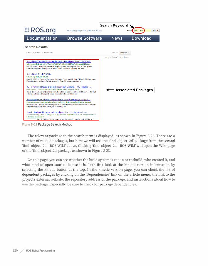
ROS Robot Programming226
Figure 8-22 Package Search Method
The relevant package to the search term is displayed, as shown in Figure 8-22. There are a number of related packages, but here we will use the ‘find_object_2d’ package from the second ‘find_object_2d - ROS Wiki’ above. Clicking ‘find_object_2d - ROS Wiki’ will open the Wiki page of the ‘find_object_2d’ package as shown in Figure 8-23.
On this page, you can see whether the build system is catkin or rosbuild, who created it, and what kind of open source license it is. Let’s first look at the kinetic version information by selecting the kinetic button at the top. In the kinetic version page, you can check the list of dependent packages by clicking on the ‘Dependencies’ link on the article menu, the link to the project’s external website, the repository address of the package, and instructions about how to use the package. Especially, be sure to check for package dependencies.

Chapter 8 _ Robot. Sensor. Motor. 227
Figure 8-23 Package information

ROS Robot Programming228
8.7.2. Installing the Dependency PackageIf you check the package dependencies in the Wiki page20 of the ‘find_object_2d’ package, you can see that this package depends on a total of 12 different packages.
■ catkin
■ cv_bridge
■ genmsg
■ image_transport
■ message_filters
■ pcl_ros
■ roscpp
■ rospy
■ sensor_msgs
■ std_msgs
■ std_srvs
■ tf
Use the ‘rospack list’ or ‘rospack find’ command to verify that the necessary packages are installed.
Verify with ‘rospack list’ command
$ rospack list
actionlib /opt/ros/kinetic/share/actionlib
actionlib_msgs /opt/ros/kinetic/share/actionlib_msgs
actionlib_tutorials /opt/ros/kinetic/share/actionlib_tutorials
Verify with ‘rospack find’ command (if the package is installed)
$ rospack find cv_bridge
/opt/ros/kinetic/share/cv_bridge
20 http://wiki.ros.org/find_object_2d

Chapter 8 _ Robot. Sensor. Motor. 229
Verify with ‘rospack find’ command (if the package is not installed)
$ rospack find cv_bridge
[rospack] Error: package 'cv_bridge' not found
If the dependent package is not installed, check the installation method on each Wiki page and install all dependency packages.
$ sudo apt-get install ros-kinetic-cv-bridge
Also, the ‘find_object_2d’ package in ‘2. Quick start’ on the Wiki page (http://wiki.ros.org/find_object_2d) is described to require the ‘uvc_camera’ package (http://wiki.ros.org/uvc_camera), so install the ‘uvc_camera’ package.
$ sudo apt-get install ros-kinetic-uvc-camera
8.7.3. Installing the PackageIf you have installed all the dependency packages, then install ‘find_object_2d’. Typical installation methods are binary installation and downloading and building source code. In the package information in Figure 8-23, click on the link to the repository and navigate to the Github address, which will guide you to the installation instructions.
Binary Installation
$ sudo apt-get install ros-kinetic-find-object-2d
Source Installation
$ cd ~/catkin_ws/src
$ git clone https://github.com/introlab/find-object.git
$ cd ~/catkin_ws/
$ catkin_make
The following packages are not directly related to ROS, but the OpenCV and Qt libraries are used in the ‘find_object_2d’ package, so you need to install them.

ROS Robot Programming230
$ sudo apt-get install libopencv-dev // Install OpenCV
$ sudo apt-get install libqt4-dev // Install Qt
8.7.4. Execute PackageRun the package as described in the ‘find_object_2d’ package information. Start ‘roscore’ first and start the camera node using the following command in another terminal window.
$ roscore
$ rosrun uvc_camera uvc_camera_node
Then open another terminal window and run the ‘find_object_2d’ node like the following command.
$ rosrun find_object_2d find_object_2d image:=image_raw
Save the image from the USB camera as a common image file format such as PNG or JPEG, and drag and drop the file to the executed GUI program. Here, we used two images for detection as shown in Figure 8-24.
Figure 8-24 Two sample images
Let’s try object detection now. Prepare an image that includes both registered and unregistered objects, and place the image in front of the camera as shown in Figure 8-25. As a result, you can see that two objects are surrounded by rectangles and are properly detected.

Chapter 8 _ Robot. Sensor. Motor. 231
Figure 8-25 Two detected objects
You can also use the ‘rostopic echo’ command in the terminal window to verfiy the ‘/object’ topic or run the ‘print_objects_detected’ node to see the information of detected object. When you create a new package using this package, you can create another application package if you subscribe the coordinates of detected objects as a topic.
$ rostopic echo /object
$ rosrun find_object_2d print_objects_detected
The packages released on ROS are increasing rapidly as the ROS begins to be widely used.
As it is explained in this section, if you know how to find and use packages when you need them, those who have been worked hard to develop the package will allow you to go beyond one step further and to spend more time on what you really need to concentrate on. This is the basic idea of ROS. Accumulated knowledge leads us to higher level of robotics development.
This chapter explained how to use packages in the ROS. Please refer to the ROS Wiki for details on how to use each package.

ROS Robot Programming232
Embedded System
Chapter 9

Chapter 9 _ Embedded System 233
An embedded system can be defined as a special-purpose computer embedded in a system that requires device control.
Embedded System1
An embedded system is an electronic system that exists within a device as a computer system that performs specific functions for control of a machine or other system that requires control. In other words, an embedded system can be defined as a specific purpose computer system that is a part of the whole device and serves as a brain for systems that need to be controlled.
Many embedded devices are used to implement the functions of robots as shown in Figure 9-1.
In particular, a microcontroller capable of real-time control is required to use an actuator or sensor of a robot, and the high-performance processor-based computer is required for image processing using a camera or navigation, manipulation.
Figure 9-1 Embedded system configuration of robot
Figure 9-22 shows various systems from 8-bit microcontroller to high-performance PC and you need to configure an embedded system with the right performance to match your needs. ROS requires an operating system such as Linux which it is operated by a PC or ARM Cortex-A series high-performance CPUs.
1 https://en.wikipedia.org/wiki/Embedded_system
2 https://roscon.ros.org/2015/presentations/ros2_on_small_embedded_systems.pdf

ROS Robot Programming234
Figure 9-2 Types of embedded boards
Operating systems such as Linux do not guarantee real-time operation, and microcontrollers suitable for real-time control are required to control actuators and sensors.
In case of TurtleBot3 Burger and Waffle Pi, a ARM Cortex-M7 series microcontroller is used for its actuator and sensor control, and the Raspberry Pi 3 board, which uses for Linux and ROS, is connected via USB and configured as shown in Figure 9-3.
.
Figure 9-3 TurtleBot3 embedded system configuration

Chapter 9 _ Embedded System 235
9.1. OpenCROpenCR (Open-source Control Module for ROS)3 is an embedded board that supports ROS and is used as the main controller of TurtleBot3. Hardware information4 such as schematic, firmware, gerber data and source code5 for TurtleBot3 are disclosed and users can also release and redistribute original/modified codes.
The STM32F7466 from ST is used as the main MCU with the built in ARM Cortex-M7 core, and the floating point calculation is supported by hardware, making it suitable for implementing functions requiring high performance.
Figure 9-4 OpenCR interface configuration
3 http://emanual.robotis.com/docs/en/platform/turtlebot3/appendix_opencr1_0/
4 https://github.com/ROBOTIS-GIT/OpenCR-Hardware
5 https://github.com/ROBOTIS-GIT/OpenCR
6 http://www.st.com/en/microcontrollers/stm32f746ng.html

ROS Robot Programming236
Figure 9-5 OpenCR block diagram
9.1.1. Characteristics
High PerformanceST’s STM32F746 chip used in OpenCR is a high-performance microcontroller running at up to 216MHz with the Cortex-M7 core at the top of ARM microcontrollers. It can also be used for processing large amounts of data by utilizing algorithms and various peripheral devices that require high-speed operation.
Arduino SupportFor those who are unfamiliar with the embedded development environment, the development environment of OpenCR is easy to use by using the Arduino IDE7. The OpenCR provides Arduino UNO8 compatible interface, so various libraries, source code and shield modules made for Arduino development environment can be used. Since the OpenCR board is added and managed by the board manager in Arduino IDE, it is easy to update the firmware.
7 https://www.arduino.cc/en/Main/Software
8 https://store.arduino.cc/usa/arduino-uno-rev3

Chapter 9 _ Embedded System 237
Various InterfacesOpenCR supports both TTL and RS485 communication, which are default interfaces for Dynamixel from ROBOTIS. In addition, the board supports UART, SPI, I2C, CAN communication interface as well as additional GPIO pins. It is also possible to develop and debug firmware using JTAG9 equipment such as STLink or JLink for professional developers since the JTAG port is supported.
IMU SensorOpenCR includes MPU925010 chip, which is integrated triple-axis gyroscope, triple-axis accelerometer, and triple-axis magnetometer sensor in one chip, therefore, various applications using IMU sensor can be used without adding a sensor. High speed read and write is available because the sensor data is transferred with I2C or SPI communication.
Power OutputWhen the OpenCR is receiving 7V ~ 24V input power source, 12V (1A), 5V (4A) and 3.3V (800mA) outputs are supported. It can be used as a power source of SBC and sensor such as Raspberry Pi, USB camera because it supports up to 5V / 4A.
Figure 9-6 Power output Diagram
Power Hot SwapWhen the SMPS (Switched-Mode Power Supply, often referred to as a device that converts AC power to DC power) source is connected to OpenCR, the board power source automatically switches from the battery to the SMPS. Similarly, if the battery is connected while using the SMPS and the SMPS is disconnected, the board operates on battery power. This makes it possible to switch to battery power or SMPS without having to shut down the power while running the OpenCR.
9 https://en.wikipedia.org/wiki/JTAG
10 https://www.invensense.com/products/motion-tracking/9-axis/mpu-9250/

ROS Robot Programming238
Figure 9-7 Hot-swap configuration
Open SourceMaterials required for building OpenCR board are open. The bootloader, firmware and the PCB gerber that are necessary for hardware manufacture is available on GitHub. Therefore, the user can modify it as needed and produce it.
■ https://github.com/ROBOTIS-GIT/OpenCR
■ https://github.com/ROBOTIS-GIT/OpenCR-Hardware
9.1.2. Board Specification
Hardware SpecificationHardware specifications of OpenCR are shown in Table 9-1.
Items Specifications
Microcontroller STM32F746ZGT6/32-bitARMCortex®-M7withFPU(216MHz,462DMIPS)
Sensors Gyroscope3-Axis,Accelerometer3-Axis,Magnetometer3-Axis(MPU9250)
Programmer ARMCortex10pinJTAG/SWDconnector
USBDeviceFirmwareUpgrade(DFU)
USB(VirtualCOMPort)
ExtensionPorts 32pins(L14,R18)*Arduinoconnectivity
Sensormodulex4pins
Extensionconnectorx18pins
CommunicationPorts USB
TTL(JST3pin/Dynamixel)
RS485(JST4pin/Dynamixel)
UARTx2
CAN
SPI
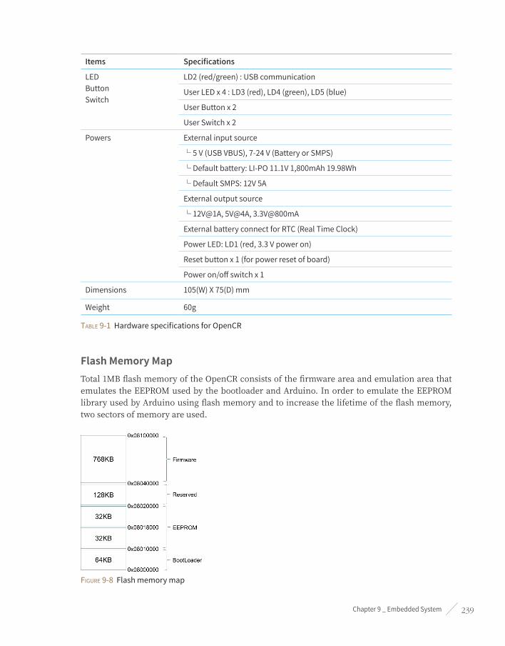
Chapter 9 _ Embedded System 239
Items Specifications
LEDButtonSwitch
LD2(red/green):USBcommunication
UserLEDx4:LD3(red),LD4(green),LD5(blue)
UserButtonx2
UserSwitchx2
Powers Externalinputsource
└5V(USBVBUS),7-24V(BatteryorSMPS)
└Defaultbattery:LI-PO11.1V1,800mAh19.98Wh
└DefaultSMPS:12V5A
Externaloutputsource
└12V@1A,5V@4A,3.3V@800mA
ExternalbatteryconnectforRTC(RealTimeClock)
PowerLED:LD1(red,3.3Vpoweron)
Resetbuttonx1(forpowerresetofboard)
Poweron/offswitchx1
Dimensions 105(W)X75(D)mm
Weight 60g
Table 9-1 Hardware specifications for OpenCR
Flash Memory MapTotal 1MB flash memory of the OpenCR consists of the firmware area and emulation area that emulates the EEPROM used by the bootloader and Arduino. In order to emulate the EEPROM library used by Arduino using flash memory and to increase the lifetime of the flash memory, two sectors of memory are used.
Figure 9-8 Flash memory map

ROS Robot Programming240
IMU SensorMPU9250 sensor from InvenSense is located at the center of the OpenCR board for accurate measurement. The MPU9250 has built-in gyroscope, accelerometer, and magnetometer sensors on one chip. Orientations of the sensor are shown in the following Figures 9-9 and 9-10.
Figure 9-9 Direction of gyroscope and accelerometer
Figure 9-10 Direction of magnetometer

Chapter 9 _ Embedded System 241
9.1.3. Establish Development EnvironmentThe default development environment of OpenCR is Arduino IDE. OpenCR is compatible with Arduino and additional hardware that extend features can be supported with a separate library. Install the OpenCR from the board manager of Arduino IDE and proceed to setup. Download the Arduino IDE distributed from Arduino.cc and manage the board through the board manager. Let’s setup a development environment in the following sections.
USB Port PermissionIn order to download the firmware from the Arduino IDE to OpenCR, the USB access permission needs to be set with the following commands. The following instruction is for the Linux development environment. Open a new terminal window with a short cut (Ctrl + Alt + t) and enter the following commands.
$ wget https://raw.githubusercontent.com/ROBOTIS-GIT/OpenCR/master/99-opencr-cdc.rules
$ sudo cp ./99-opencr-cdc.rules /etc/udev/rules.d/
$ sudo udevadm control --reload-rules
$ sudo udevadm trigger
The ‘99-opencr-cdc.rules’ file contains options to change the access permission of the USB port and to prevent the OpenCR from being recognized as a modem.
In Linux, when the serial device is connected, the system transmits a command to identify whether the device is a modem or not, and this command could cause an issue when OpenCR is connected to the Linux system.
ATTRS{idVendor}=="0483" ATTRS{idProduct}=="5740", ENV{ID_MM_DEVICE_IGNORE}="1", MODE:="0666"
Compiler PreferencesThe GCC in OpenCR uses 32-bit executable files so if you have a 64-bit OS installed, you need to add a 32-bit compatibility on the system.
$ sudo apt-get install libncurses5-dev:i386
Installing Aduno IDEDownload the latest version of the Arduino IDE from the Arduino download site. OpenCR has been tested in version 1.6.12 or above, and has confirmed that it runs on the latest version 1.8.2. If you have a higher version of the Arduino IDE, you can still use the latest version because Arduino maintains compatibility with lower versions.

ROS Robot Programming242
■ https://www.arduino.cc/en/Main/Software
Download the latest version and extract it to the ‘~/tools’ folder and proceed with the installation. If you do not have the tools folder, create a new one with the command ‘cd ~/ && mkdir tools’.
$ cd ~/tools/arduino-1.8.2
$ ./install.sh
Add the Arduino IDE path to your shell script file so you can run it from any location. The shell script file can be edited using gedit or other text editing programs like vim, emacs, nano, sublime text and visual studio code.
$ gedit ~/.bashrc
Add the location of uncompressed file path to your PATH and add the following command to apply it.
export PATH=$PATH:$HOME/tools/arduino-1.8.2
$ source ~/.bashrc
Run Adunino IDEWhen the installation is complete, run the program from the terminal window with the following command.
$ arduino

Chapter 9 _ Embedded System 243
Figure 9-11 Arduino IDE screen
OpenCR SettingsOnce the Arduino IDE installation is completed, you need to add the board so that you can build and download the firmware to OpenCR. From the menu of the Arduino IDE, select File → Preferences, enter the following address to the board configuration file in the Additional Boards Manager URLs field in Figure 9-12 and click ‘OK’.
■ https://raw.githubusercontent.com/ROBOTIS-GIT/OpenCR/master/arduino/opencr_release/package_opencr_index.json

ROS Robot Programming244
Figure 9-12 Enter the board configuration file URL
After entering the board configuration file URL, select Tools → Board → Boards Manager from the Arduino IDE menu as shown in Figure 9-13.
Figure 9-13 Run the Boards Manager

Chapter 9 _ Embedded System 245
You can see the OpenCR at the end of the board list. If you select ‘OpenCR by ROBOTIS’ and install it, relevant files will be automatically installed. You can uninstall the current version or switch to other versions in the boards manager.
Figure 9-14 Board list
Figure 9-15 Select Board

ROS Robot Programming246
When OpenCR board is connected to the PC, it is recognized as a serial device. If you select the serial port name from Tools → Port as shown in Figure 9-16, you are now ready to use the OpenCR board.
Figure 9-16 Select Communication port
Verify Firmware downloadSelect File → New to create a new file as shown in Figure 9-17. Select the board and communication port and click the right arrow icon to build the source code and download to OpenCR.

Chapter 9 _ Embedded System 247
Figure 9-17 Firmware build and download
Once the source code has been compiled, the Arduino IDE calls the OpenCR downloader and starts downloading the firmware. At the bottom of the message window, the following message will be displayed and the downloaded firmware will be executed.
Figure 9-18 Download message

ROS Robot Programming248
Firmware Recovery ModeIf any problem occurs during the operation and the firmware and can not be downloaded due to the problem, the firmware can be downloaded by forcibly executing the bootloader. To execute the bootloader, press and hold the PUSH SW2 button on the board and reset the board with the RESET button, and the bootloader will load. When the bootloader is running, the firmware can be normally downloaded.
Figure 9-19 Firmware recovery mode
Update Bootloader When OpenCR bootloader needs to be updated, the DFU function of the bootloader that is built in STM32F746 can be used. DFU mode allows users to update bootloader without having additional equipments such as JTAG. For reference, the bootloader is pre-loaded at the time of board production, so there are not much instances when users have to update it. While the OpenCR is connected to PC with USB, press and hold the BOOT0 pin and press RESET to activate the bootloader built into the STM32F746 and enter the DFU mode.
Figure 9-20 DFU mode button

Chapter 9 _ Embedded System 249
You can verify if you successfully entered DFU mode using the ‘lsusb’ command. While in DFU mode, you should be able to see ‘STMicroelectronics STM Device in DFU Mode’ in the list of USB devices as shown in Figure 9-21.
$ lsusb
Figure 9-21 Verify the DFU Mode
In order to activate the DFU mode, select Tools → Programmer → DFU_UTIL from the Arduino IDE menu as shown in Figure 9-22.
Figure 9-22 Select ‘Programmer’

ROS Robot Programming250
After changing the Programmer, you need to select Tools → Burn Bootloader as shown in Figure 9-23 to update the bootloader. When the update is completed, you must reset the board.
Figure 9-23 Bootloader update
9.1.4. OpenCR ExamplesIf you add OpenCR package to the Arduino IDE from the Arduino board manager, you can use the OpenCR example in the File → Examples menu. There are a number of examples available to help users control and learn how to use the hardware connected to the OpenCR. Let’s take a look at some examples of the additional features provided by OpenCR.

Chapter 9 _ Embedded System 251
Figure 9-24 OpenCR examples
LED OpenCR has 4 additional LEDs shown in the following Figure 9-25 that users can use. Let’s display the information using these LEDs.
Figure 9-25 Location of LEDs
The four LEDs are defined as BDPIN_LED_USER_1, BDPIN_LED_USER_2, BDPIN_LED_USER_3, BDPIN_LED_USER_4, and the following example will flash the LED sequentially.
blink_led
int led_pin = 13;
int led_pin_user[4] = { BDPIN_LED_USER_1, BDPIN_LED_USER_2, BDPIN_LED_USER_3, BDPIN_LED_USER_4 };
void setup() {
pinMode(led_pin, OUTPUT);
pinMode(led_pin_user[0], OUTPUT);
pinMode(led_pin_user[1], OUTPUT);
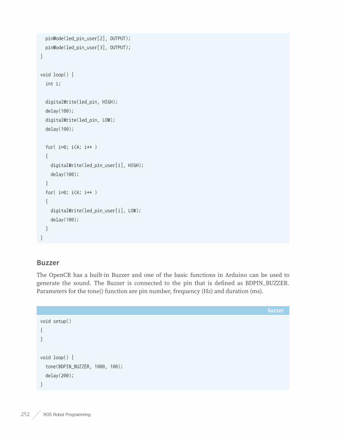
ROS Robot Programming252
pinMode(led_pin_user[2], OUTPUT);
pinMode(led_pin_user[3], OUTPUT);
}
void loop() {
int i;
digitalWrite(led_pin, HIGH);
delay(100);
digitalWrite(led_pin, LOW);
delay(100);
for( i=0; i<4; i++ )
{
digitalWrite(led_pin_user[i], HIGH);
delay(100);
}
for( i=0; i<4; i++ )
{
digitalWrite(led_pin_user[i], LOW);
delay(100);
}
}
BuzzerThe OpenCR has a built-in Buzzer and one of the basic functions in Arduino can be used to generate the sound. The Buzzer is connected to the pin that is defined as BDPIN_BUZZER. Parameters for the tone() function are pin number, frequency (Hz) and duration (ms).
buzzer
void setup()
{
}
void loop() {
tone(BDPIN_BUZZER, 1000, 100);
delay(200);
}

Chapter 9 _ Embedded System 253
Voltage MeasurementThe OpenCR can measure the voltage input from the battery or SMPS. It can be measured using the getPowerInVoltage() function, which returns the input voltage as a unit of Voltage.
read_voltage
void setup() {
Serial.begin(115200);
}
void loop() {
float voltage;
voltage = getPowerInVoltage();
Serial.print("Voltage : ");
Serial.println(voltage);
}
IMU SensorThe accelerometer and gyroscope sensor values are converted to the Roll, Pitch and Yaw value of the board by sensor fusion. When the IMU class is created as an object and the update() function is called, the acceleration and gyro values are periodically read from the sensor. The default calculation cycle is 200Hz, but can be changed.
read_roll_pitch_yaw
#include <IMU.h>
cIMU IMU;
void setup()
{
Serial.begin(115200);
IMU.begin();
}
void loop()
{

ROS Robot Programming254
static uint32_t pre_time;
IMU.update();
if( (millis()-pre_time) >= 50 )
{
pre_time = millis();
Serial.print(IMU.rpy[0]);
Serial.print(" ");
Serial.print(IMU.rpy[1]);
Serial.print(" ");
Serial.println(IMU.rpy[2]);
}
}
Dynamixel SDKIn order to control the Dynamixel actuators from ROBOTIS, the OpenCR uses the modified DynamixelSDK C++ for Arduino. The usage of DynamixelSDK is the same, and the existing source code might be partially modified.
DynamixelSDK can be downloaded at the following address, and the modified version is already downloaded to your OpenCR by default.
■ https://github.com/ROBOTIS-GIT/DynamixelSDK
Some of the DynamixelSDK examples are included in the OpenCR library and support both protocols 1.0 and 2.0.
Figure 9-26 Examples of DynamixelSDK Protocol 1.0

Chapter 9 _ Embedded System 255
Figure 9-27 Examples of DynamixelSDK Protocol 2.0
9.2. rosserialThe rosserial11 is a package that converts ROS messages, topics, and services to be used in a serial communication. Generally, microcontrollers use serial communication like UART rather than TCP/IP which is used as default communication in ROS. Therefore, to convert message communication between a microcontroller and a computer using ROS, rosserial should interpret messages for each device.
Figure 9-28 rosserial server (for PC) and client (for embedded system)
In the figure 9-28, the PC running ROS is a rosserial server12 and the microcontroller connected to the PC becomes the rosserial client13. Both server and client send and receive data using the rosserial protocol, any hardware that is capable of sending and receiving data can be used. This makes it possible to use ROS messages with UART that is often used in microcontrollers.
11 http://wiki.ros.org/rosserial
12 http://wiki.ros.org/rosserial_server
13 http://wiki.ros.org/rosserial_client

ROS Robot Programming256
For example, if the analog sensor connected to the microcontroller is read and converted its analog value into a digital value and then transmitted to the serial port, the ‘rosserial_server’ node of the computer receives this sensor data and converts it to a Topic used in ROS. Conversely, if motor control value from other node is received as a Topic in the ‘rosserial_server’ node, the ‘rosserial_server’ node converts the value and sends it to the microcontroller in serial format to control the connected motor.
In the case of general computer including SBC, rosserial can not guarantee real-time control. However, using microcontroller as an auxiliary hardware controller enables real-time control.
9.2.1. rosserial serverThe rosserial server for PC is a node which relays communication with rosserial protocol14 between embedded devices and a PC running ROS. Depending on the programming language implemented, up to three nodes are supported as of now.
rosserial_pythonThis package is implemented with Python language and is commonly used to use rosserial.
rosserial_serverAlthough the performance has been improved with the use of C++ language, there are some functional limitations compared to rosserial_python.
rosserial_javaThe rosserial_java library is used when a Java-based module is required, or when it is used with the Android SDK.
9.2.2. rosserial clientThe rosserial_client library is ported to the microcontroller embedded platform in order to use it as a client for rosserial. The library supports Arduino platform. Therefore, any board that supports Arduino can use the library, and the open source code makes it easy to port to other platforms.
14 http://wiki.ros.org/rosserial/Overview/Protocol

Chapter 9 _ Embedded System 257
rosserial_arduinoThis library is for the Arduino board that supports Arduino UNO and Leonardo board, but it can also be used on other boards through source modification. The OpenCR board used in TurtleBot3 has a modified rosserial_arduino library.
rosserial_embeddedlinuxThis is a library that can be used on embedded Linux.
rosserial_windowsThis library supports Windows operating system and communicates with Windows applications.
rosserial_mbedThis library supports mbed platform, which is an embedded development environment, and enables the use of mbed boards.
rosserial_tivacThis is a library for use on the Launchpad board manufactured by TI.
9.2.3. rosserial ProtocolThe rosserial server and client send and receive data in packets based on serial communication. The rosserial protocol is defined in byte level and contains information for packet synchronization and data validation.
Packet configurationThe rosserial packet includes the header field to send and receive the ROS standard message and the checksum field to verify the validity of the data.
Figure 9-29 Structure of the rosserial Packet

ROS Robot Programming258
Sync Flag
This flag byte is always 0xFF and indicates the start of the packet.
Sync Flag / Protocol version
This field indicates the protocol version of ROS where Groovy is 0xFF and Hydro, Indigo, Jade, Kinetic are 0xFE.
Message Length
This 2 bytes field indicates the data length of the message transmitted through the packet. The Low byte comes first, followed by the High byte.
Checksum over message length
The checksum verifies the validity of the message length and is calculated as follows.
255 - ((Message Length Low Byte + Message Length High Byte) % 256)
Topic ID
The ID field consists of 2 bytes and is used as an identifier to distinguish the message type. Topic IDs from 0 to 100 are reserved for system functions. The main topic IDs used by the system are shown below and they can be displayed from ‘rosserial_msgs/TopicInfo’.
uint16 ID_PUBLISHER=0
uint16 ID_SUBSCRIBER=1
uint16 ID_SERVICE_SERVER=2
uint16 ID_SERVICE_CLIENT=4
uint16 ID_PARAMETER_REQUEST=6
uint16 ID_LOG=7
uint16 ID_TIME=10
uint16 ID_TX_STOP=11
Serialized Message Data
This data field contains the serialized messages.
Checksum over topic ID and Message Data
This checksum is for validating Topic ID and message data, and is calculated as follows.

Chapter 9 _ Embedded System 259
255 - ((Topic ID Low Byte + Topic ID High Byte + Data byte values) % 256)
Query PacketWhen the rosserial server starts, it requests information such as topic name and type to the client. When requesting information, the query packet is used. The Topic ID of query packet is 0 and the data size is 0. The data in the query packet is shown below.
0xff 0xfe 0x00 0x00 0xff 0x00 0x00 0xff
When the client receives the query packet, it sends a message to the server with the following data, and the server sends and receives messages based on this information.
uint16 topic_id
string topic_name
string message_type
string md5sum
int32 buffer_size
9.2.4. Constraints of rosserialAlthough it is possible to send and receive ROS standard messages with the embedded system using rosserial, there are some hardware limitations of the embedded system that may cause an issue. Therefore, when creating a node using rosserial, these constraints must be considered.
Memory ConstraintsThe microcontrollers used in the embedded system have a considerably smaller memory compare to standard PCs. Therefore, the memory capacity has to be considered in advance before defining the number of publishers, subscribers, and transmit and receive buffers. Messages exceeding the size of the transmission or reception buffers can not be handled so beware of the message size. In the case of OpenCR, it provides 1MB of Flash memory and 320KB SRAM so that you can upload a lot of programming. In addition, you can use rosserial more freely by setting the buffer size for serialization and deserialization to 1024 bytes for setting up to use 25 publishers and 25 subscribers.
Float64When using rosserial_arduino as a rosserial client, the microcontroller in the Arduino board does not support 64bit floating point calculation, so when building a library, the 64bit data type is automatically converted to 32bit type. If the embedded board supports 64bit floating point

ROS Robot Programming260
calculation, you can modify the data type conversion code in ‘make_libraries.py’. Since OpenCR uses Cortex-M7 processor with FPU, it supports the 64bit floating point calculation.
StringsBecause of the memory restriction of the microcontroller, the string data is not stored in the String message, but only the pointer to the defined string is stored in the message. The following example shows how to use a String message.
std_msgs::String str_msg;
unsigned char hello[13] = "hello world!";
str_msg.data = hello;
ArraysSimilar to Strings, array uses pointer to handle the actual data in the array, and the end of an array data is not known. Therefore, length of the array should be included when transmitting and receiving messages.
BaudrateUART communication with 115200bps could become slower to handle messages when the number of message increases. OpenCR uses virtual USB serial communication in order to provide high-speed communication.
9.2.5. Installing rosserialTo use rosserial, install the required packages for ROS and use the platform client library of the device to be used. Follow these steps to install the required packages and find out how to use it with the Arduino platform.
Installing PackageInstall the rosserial and Arduino support packages with the following command. In addition, there are ‘ros-kinetic-rosserial-windows’, ‘ros-kinetic-rosserial-xbee’ and ‘ros-kinetic-rosserial-embeddedlinux’, but install additional packages if necessary.
$ sudo apt-get install ros-kinetic-rosserial ros-kinetic-rosserial-server ros-kinetic-rosserial-
arduino

Chapter 9 _ Embedded System 261
Create LibraryTo use downloaded packages in Arduino environment, you need to create a rosserial library for Arduino. Move to the libraries folder of the Arduino IDE as below, and delete the previously created library files. Execute the ‘make_libraries.py’ file in the ‘rosserial_arduino’ package to create ‘ros_lib’. Since OpenCR already includes the ‘ros_lib’ library for TurtleBot3, the following procedure is not required for TurtleBot3.
$ cd ~/Arduino/libraries/
$ rm -rf ros_lib
$ rosrun rosserial_arduino make_libraries.py .
Change Communication PortIn case of using Arduino ROS library, a specific communication port is defined as a default. General Arduino boards use the Serial object in the HardwareSerial class, therefore, in order to change the communication port, the source code of the generated library must be modified. NodeHandle is defined with ArduinoHardware class in the ‘ros.h’ file in the library folder and ArduinoHardware class should be modified to change the communication port.
ros.h
#include "ros/node_handle.h"
#include "ArduinoHardware.h"
namespace ros
{
/* Publishers, Subscribers, Buffer Sizes */
typedef NodeHandle_<ArduinoHardware, 25, 25, 1024, 1024> NodeHandle;
}
In the case of OpenCR, SERIAL_CLASS is defined as USBSerial in ‘ArduinoHardware.h’ file so that it can communicate via USB port. If different communication port is required, serial port class and object can be modified.
ArduinoHardware.h
#define SERIAL_CLASS USBSerial
__contents omitted__
class ArduinoHardware
{
iostream = &Serial;

ROS Robot Programming262
__contents omitted__
}
9.2.6. Examples of rosserialOpenCR provides rosserial examples for OpenCR along with the rosserial library. As shown in Figure 9-30, input and output examples such as LED, button and IMU sensor can be found and more examples will be added.
Figure 9-30 rosserial examples for OpenCR
You must run roscore first before trying the following examples.
LEDFour LEDs are defined in the ‘led_out’ subscriber using ‘std_msg/Byte’, which is ROS standard data type. When the callback function in the subscriber is called, the corresponding LED to the bit 0 ~ 3 of the received message will respond by turning on or off the light when the bit is 1 or 0 respectively.
a_LED.ino
#include <ros.h>
#include <std_msgs/String.h>
#include <std_msgs/Byte.h>
int led_pin_user[4] = { BDPIN_LED_USER_1, BDPIN_LED_USER_2, BDPIN_LED_USER_3, BDPIN_LED_USER_4 };
ros::NodeHandle nh;
void messageCb( const std_msgs::Byte& led_msg) {
int i;
for (i=0; i<4; i++)

Chapter 9 _ Embedded System 263
{
if (led_msg.data & (1<<i))
{
digitalWrite(led_pin_user[i], LOW);
}
else
{
digitalWrite(led_pin_user[i], HIGH);
}
}
}
ros::Subscriber<std_msgs::Byte> sub("led_out", messageCb );
void setup() {
pinMode(led_pin_user[0], OUTPUT);
pinMode(led_pin_user[1], OUTPUT);
pinMode(led_pin_user[2], OUTPUT);
pinMode(led_pin_user[3], OUTPUT);
nh.initNode();
nh.subscribe(sub);
}
void loop() {
nh.spinOnce();
}
Download the firmware with Arduino IDE and run the rosserial server using rosserial_python as follows. If OpenCR is connected to another USB port other than ‘ttyACM0’, modify the execution command ‘_port: = /dev/ttyACM0’ to correct serial port. Once the rosserial server is running, rosserial server and OpenCR client will send and receive packets through USB serial port.
$ rosrun rosserial_python serial_node.py __name:=opencr _port:=/dev/ttyACM0 _baud:=115200
[INFO] [1495609829.326019]: ROS Serial Python Node
[INFO] [1495609829.336151]: Connecting to /dev/ttyACM0 at 115200 baud
[INFO] [1495609831.454144]: Note: subscribe buffer size is 1024 bytes
[INFO] [1495609831.454994]: Setup subscriber on led_out [std_msgs/Byte]

ROS Robot Programming264
Open a new terminal and enter ‘rostopic list’ command to verify the ‘led_out’ topic.
$ rostopic list
/diagnostics
/led_out
/rosout
/rosout_agg
The following ‘rostopic pub’ commands will write a value in the message and publish it to the ‘led_out’ topic.
$ rostopic pub -1 led_out std_msgs/Byte 1 → USER1 LED On
$ rostopic pub -1 led_out std_msgs/Byte 2 → USER2 LED On
$ rostopic pub -1 led_out std_msgs/Byte 4 → USER3 LED On
$ rostopic pub -1 led_out std_msgs/Byte 8 → USER4 LED On
$ rostopic pub -1 led_out std_msgs/Byte 0 → LED Off
ButtonThis example also uses ‘std_msgs/Byte’ data type like the LED example, but ‘button’ is declared as a topic name for ‘pub_button’ node to publish the button status to the server. The following example code publishes pressed or released status of SW1 and SW2 button of the OpenCR board as a Byte value. The button status is published at regular interval of 50ms.
b_Button.ino
#include <ros.h>
#include <std_msgs/Byte.h>
ros::NodeHandle nh;
std_msgs::Byte button_msg;
ros::Publisher pub_button("button", &button_msg);
void setup()
{
nh.initNode();
nh.advertise(pub_button);
pinMode(BDPIN_PUSH_SW_1, INPUT);

Chapter 9 _ Embedded System 265
pinMode(BDPIN_PUSH_SW_2, INPUT);
}
void loop()
{
uint8_t reading = 0;
static uint32_t pre_time;
if (digitalRead(BDPIN_PUSH_SW_1) == HIGH)
{
reading |= 0x01;
}
if (digitalRead(BDPIN_PUSH_SW_2) == HIGH)
{
reading |= 0x02;
}
if (millis()-pre_time >= 50)
{
button_msg.data = reading;
pub_button.publish(&button_msg);
pre_time = millis();
}
nh.spinOnce();
}
Download the Button example and run rosserial_python from PC as follows, and the message for setting up the button publisher will be displayed.
$ rosrun rosserial_python serial_node.py __name:=opencr _port:=/dev/ttyACM0 _baud:=115200
[INFO] [1495609931.875745]: ROS Serial Python Node
[INFO] [1495609931.885488]: Connecting to /dev/ttyACM0 at 115200 baud
[INFO] [1495609934.000344]: Note: publish buffer size is 1024 bytes
[INFO] [1495609934.001180]: Setup publisher on button [std_msgs/Byte]
Make sure you have a button topic with ‘rostopic list’ command.

ROS Robot Programming266
$ rostopic list
/button
/diagnostics
/rosout
/rosout_agg
Open a new terminal window and enter the following command to display the published button status in every 50ms.
$ rostopic echo button
data: 1
---
data: 1
---
data: 1
---
data: 1
---
data: 1
Measure Input VoltageAs shown in Figure 9-31, the input voltage can be measured by reading ADC value of 3.3V level adjusted input voltage after the voltage divider circuit. The adjusted input voltage (Vout) can be calculated with the voltage divider formular; Vout = (10/57) * Input Voltage. Therefore, the actual input voltage can be calculated by dividing Vout with 0.1754 (≈10/57). In OpenCR, the getPowerInVoltage() function performs the conversion, so you can use this function to calculate the actual input voltage from read ADC value.
Figure 9-31 Voltage measurement circuit
In order to represent the exact voltage, ‘std_msgs/Float32’ data type is used in the voltage measuring example. Declare the publisher node ‘pub_voltage’ with ‘voltage’ topic, and measured input voltage will be published every 50ms.

Chapter 9 _ Embedded System 267
c_Voltage.ino
#include <ros.h>
#include <std_msgs/Float32.h>
ros::NodeHandle nh;
std_msgs::Float32 voltage_msg;
ros::Publisher pub_voltage("voltage", &voltage_msg);
void setup()
{
nh.initNode();
nh.advertise(pub_voltage);
}
void loop()
{
static uint32_t pre_time;
if (millis()-pre_time >= 50)
{
voltage_msg.data = getPowerInVoltage();
pub_voltage.publish(&voltage_msg);
pre_time = millis();
}
nh.spinOnce();
}
Run the rosserial server with the following command.
$ rosrun rosserial_python serial_node.py __name:=opencr _port:=/dev/ttyACM0 _baud:=115200
[INFO] [1495609160.098041]: ROS Serial Python Node
[INFO] [1495609160.108219]: Connecting to /dev/ttyACM0 at 115200 baud
[INFO] [1495609162.224307]: Note: publish buffer size is 1024 bytes
[INFO] [1495609162.225184]: Setup publisher on voltage [std_msgs/Float32]

ROS Robot Programming268
To verify the input voltage of OpenCR, open a new terminal window and read the value in ‘voltage’ topic with ‘rostopic echo’ command.
$ rostopic echo voltage
data: 12.1300001144
---
data: 12.1099996567
---
data: 12.1300001144
---
data: 12.1099996567
IMUIn order to pass the IMU sensor value with the ROS standard message type, ‘sensor_msgs/Imu’ message is used. The following example converts the calculated attitude with the IMU sensor library to ‘sensor_msgs/Imu’ message type and publishes the message via a topic. Generate the tf with ‘base_link’ to set it as reference tf for IMU sensor, and connect ‘base_link’ to IMU sensor so that the change of attitude can be monitored from the ‘base_link’ value.
d_IMU.ino
#include <ros.h>
#include <sensor_msgs/Imu.h>
#include <tf/tf.h>
#include <tf/transform_broadcaster.h>
#include <IMU.h>
ros::NodeHandle nh;
sensor_msgs::Imu imu_msg;
ros::Publisher imu_pub("imu", &imu_msg);
geometry_msgs::TransformStamped tfs_msg;
tf::TransformBroadcaster tfbroadcaster;
cIMU imu;

Chapter 9 _ Embedded System 269
void setup()
{
nh.initNode();
nh.advertise(imu_pub);
tfbroadcaster.init(nh);
imu.begin();
}
void loop()
{
static uint32_t pre_time;
imu.update();
if (millis()-pre_time >= 50)
{
pre_time = millis();
imu_msg.header.stamp = nh.now();
imu_msg.header.frame_id = "imu_link";
imu_msg.angular_velocity.x = imu.gyroData[0];
imu_msg.angular_velocity.y = imu.gyroData[1];
imu_msg.angular_velocity.z = imu.gyroData[2];
imu_msg.angular_velocity_covariance[0] = 0.02;
imu_msg.angular_velocity_covariance[1] = 0;
imu_msg.angular_velocity_covariance[2] = 0;
imu_msg.angular_velocity_covariance[3] = 0;
imu_msg.angular_velocity_covariance[4] = 0.02;
imu_msg.angular_velocity_covariance[5] = 0;
imu_msg.angular_velocity_covariance[6] = 0;
imu_msg.angular_velocity_covariance[7] = 0;
imu_msg.angular_velocity_covariance[8] = 0.02;
imu_msg.linear_acceleration.x = imu.accData[0];
imu_msg.linear_acceleration.y = imu.accData[1];
imu_msg.linear_acceleration.z = imu.accData[2];

ROS Robot Programming270
imu_msg.linear_acceleration_covariance[0] = 0.04;
imu_msg.linear_acceleration_covariance[1] = 0;
imu_msg.linear_acceleration_covariance[2] = 0;
imu_msg.linear_acceleration_covariance[3] = 0;
imu_msg.linear_acceleration_covariance[4] = 0.04;
imu_msg.linear_acceleration_covariance[5] = 0;
imu_msg.linear_acceleration_covariance[6] = 0;
imu_msg.linear_acceleration_covariance[7] = 0;
imu_msg.linear_acceleration_covariance[8] = 0.04;
imu_msg.orientation.w = imu.quat[0];
imu_msg.orientation.x = imu.quat[1];
imu_msg.orientation.y = imu.quat[2];
imu_msg.orientation.z = imu.quat[3];
imu_msg.orientation_covariance[0] = 0.0025;
imu_msg.orientation_covariance[1] = 0;
imu_msg.orientation_covariance[2] = 0;
imu_msg.orientation_covariance[3] = 0;
imu_msg.orientation_covariance[4] = 0.0025;
imu_msg.orientation_covariance[5] = 0;
imu_msg.orientation_covariance[6] = 0;
imu_msg.orientation_covariance[7] = 0;
imu_msg.orientation_covariance[8] = 0.0025;
imu_pub.publish(&imu_msg);
tfs_msg.header.stamp = nh.now();
tfs_msg.header.frame_id = "base_link";
tfs_msg.child_frame_id = "imu_link";
tfs_msg.transform.rotation.w = imu.quat[0];
tfs_msg.transform.rotation.x = imu.quat[1];
tfs_msg.transform.rotation.y = imu.quat[2];
tfs_msg.transform.rotation.z = imu.quat[3];
tfs_msg.transform.translation.x = 0.0;
tfs_msg.transform.translation.y = 0.0;
tfs_msg.transform.translation.z = 0.0;

Chapter 9 _ Embedded System 271
tfbroadcaster.sendTransform(tfs_msg);
}
nh.spinOnce();
}
Download the example and run the rosserial server with the following command to create the ‘imu’ and ‘tf’ publishers.
$ rosrun rosserial_python serial_node.py __name:=opencr _port:=/dev/ttyACM0 _baud:=115200
[INFO] [1495611663.941723]: ROS Serial Python Node
[INFO] [1495611663.946220]: Connecting to /dev/ttyACM0 at 115200 baud
[INFO] [1495611666.075668]: Note: publish buffer size is 1024 bytes
[INFO] [1495611666.076638]: Setup publisher on imu [sensor_msgs/Imu]
[INFO] [1495611666.146240]: Setup publisher on /tf [tf/tfMessage]
Open a new terminal window and verify the ‘imu’ topic message data as follows.
$ rostopic echo /imu
header:
seq: 686
stamp:
secs: 1495611700
nsecs: 369472074
frame_id: imu_link
orientation:
x: 0.0232326872647
y: -0.0115436725318
z: -4.04381135013e-05
w: 0.999659180641
orientation_covariance: [0.0024999999441206455, 0.0, 0.0, 0.0, 0.0024999999441206455, 0.0, 0.0,
0.0, 0.0024999999441206455]
angular_velocity:
x: 0.0
y: 0.0
z: 0.0
angular_velocity_covariance: [0.019999999552965164, 0.0, 0.0, 0.0, 0.019999999552965164, 0.0,
0.0, 0.0, 0.019999999552965164]
linear_acceleration:

ROS Robot Programming272
x: 370.0
y: 754.0
z: 16228.0
linear_acceleration_covariance: [0.03999999910593033, 0.0, 0.0, 0.0, 0.03999999910593033, 0.0,
0.0, 0.0, 0.03999999910593033]
---
In order to visualize the IMU data, use RViz which can graphically represent the IMU data in 3D space. Enter the command as follows to run the RViz.
$ rviz
Go to Global Options → Fixed Frame and select ‘base_link’ in the RViz Displays option panel as shown in Figure 9-32. Then click Add at the bottom of the Displays option panel to add ‘Axes’ to the option item and select ‘imu_link’ for the Reference Frame to see the change of axis on the screen according to the attitude of OpenCR.
Figure 9-32 Visualized IMU data in Rviz
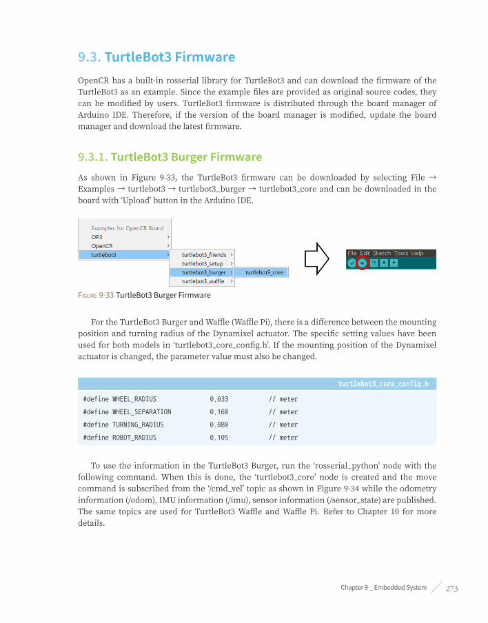
Chapter 9 _ Embedded System 273
9.3. TurtleBot3 FirmwareOpenCR has a built-in rosserial library for TurtleBot3 and can download the firmware of the TurtleBot3 as an example. Since the example files are provided as original source codes, they can be modified by users. TurtleBot3 firmware is distributed through the board manager of Arduino IDE. Therefore, if the version of the board manager is modified, update the board manager and download the latest firmware.
9.3.1. TurtleBot3 Burger FirmwareAs shown in Figure 9-33, the TurtleBot3 firmware can be downloaded by selecting File → Examples → turtlebot3 → turtlebot3_burger → turtlebot3_core and can be downloaded in the board with ‘Upload’ button in the Arduino IDE.
Figure 9-33 TurtleBot3 Burger Firmware
For the TurtleBot3 Burger and Waffle (Waffle Pi), there is a difference between the mounting position and turning radius of the Dynamixel actuator. The specific setting values have been used for both models in ‘turtlebot3_core_config.h’. If the mounting position of the Dynamixel actuator is changed, the parameter value must also be changed.
turtlebot3_core_config.h
#define WHEEL_RADIUS 0.033 // meter
#define WHEEL_SEPARATION 0.160 // meter
#define TURNING_RADIUS 0.080 // meter
#define ROBOT_RADIUS 0.105 // meter
To use the information in the TurtleBot3 Burger, run the ‘rosserial_python’ node with the following command. When this is done, the ‘turtlebot3_core’ node is created and the move command is subscribed from the ‘/cmd_vel’ topic as shown in Figure 9-34 while the odometry information (/odom), IMU information (/imu), sensor information (/sensor_state) are published. The same topics are used for TurtleBot3 Waffle and Waffle Pi. Refer to Chapter 10 for more details.

ROS Robot Programming274
$ rosrun rosserial_python serial_node.py __name:=turtlebot3_core _port:=/dev/ttyACM0
[INFO] [1500275719.375458]: ROS Serial Python Node
[INFO] [1500275719.380338]: Connecting to /dev/ttyACM0 at 57600 baud
[INFO] [1500275721.496849]: Note: publish buffer size is 1024 bytes
[INFO] [1500275721.497162]: Setup publisher on sensor_state [Turtlebot3_msgs/SensorState]
[INFO] [1500275721.499622]: Setup publisher on imu [sensor_msgs/Imu]
[INFO] [1500275721.502328]: Setup publisher on cmd_vel_rc100 [geometry_msgs/Twist]
[INFO] [1500275721.507266]: Setup publisher on odom [nav_msgs/Odometry]
[INFO] [1500275721.511984]: Setup publisher on joint_states [sensor_msgs/JointState]
[INFO] [1500275721.568189]: Setup publisher on /tf [tf/tfMessage]
[INFO] [1500275721.571585]: Note: subscribe buffer size is 1024 bytes
[INFO] [1500275721.571865]: Setup subscriber on cmd_vel [geometry_msgs/Twist]
[INFO] [1500275721.573235]: Start Calibration of Gyro
[INFO] [1500275724.046148]: Calibrattion End
Figure 3-34 publish and subscribe topic of turtlebot3_core node
9.3.2. TurtleBot3 Waffle and Waffle Pi FirmwareTurtleBot3 Waffle and Waffle Pi firmware can be downloaded by selecting File → Examples → turtlebot3 → turtlebot3_waffle → turtlebot3_core and click Upload button from Arduino IDE as shown in Figure 9-35.

Chapter 9 _ Embedded System 275
Figure 9-35 TurtleBot3 Waffle and Waffle Pi Firmware
turtlebot3_core_config.h
#define WHEEL_RADIUS 0.033 // meter
#define WHEEL_SEPARATION 0.287 // meter
#define TURNING_RADIUS 0.1435 // meter
#define ROBOT_RADIUS 0.220 // meter
9.3.3. TurtleBot3 Setup FirmwareThe Dynamixel actuators used in the TurtleBot3 have a factory set IDs and configurations. If you replace the actuator or modify the setting for a different purpose, you must reconfigure the setting value to use with the TurtleBot3 again. The example of changing the actuator’s setting is included, so let’s change the setting value.
Download Setup FirmwareAs shown in Figure 9-36, from the example menu, go to turtlebot3 → turtlebot3_setup → turtlebot3_setup_motor, download the firmware to OpenCR board, and proceed with setting process. After completing the setup, download the proper TurtleBot3 firmware to OpenCR.
Figure 9-36 Example of TurtleBot3 actuator setup
Click the Upload button on the Arduino IDE to download and once download is completed, click the serial monitor icon on the upper right corner of the application as shown in Figure 9-37. Connect the Dynamixel to the OpenCR. Note that this firmware only works with one Dynamixel, so you have to connect only one Dynamixel at a time.

ROS Robot Programming276
Figure 9-37 Download and run serial monitor
Change Dynamixel SettingWhen the serial monitor is executed, a menu for the Dynamixel setup is displayed as shown in Figure 9-38. TurtleBot3 consists of two Dynamixel actuators on the left and right respectively, so select the Dynamixel based on the assembly position. To set up the left motor, enter ‘1’.
Figure 9-38 TurtleBot3 actuator setup menu
To prevent input mistakes, a confirmation menu is displayed once again. To proceed with the changes, enter ‘Y’.
Figure 9-39 Setting confirmation menu
If you enter ‘Y’, the setup tool starts to search the connected Dynamixel using different baudrates, and ID. If a Dynamixel is found, it will be reset for the TurtleBot3 configuration. When the setup is completed, ‘OK’ message is printed.

Chapter 9 _ Embedded System 277
Figure 9-40 Setup complete message
Dynamixel TestComplete the setup procedure and verify if the change has been properly made. If you select one of the test menu for the motor, the connected Dynamixel with correct configuration will iterate the rotation in the clockwise and counterclockwise. To end the test, press the Enter key again. To test the left Dynamixel, enter ‘3’ as shown in Figure 9-41 and enter ‘4’ for the right Dynamixel.
Figure 9-41 Dynamixel test menu
We have discussed how to integrate ROS in an embedded system. The embedded system is closely related to robots that require real-time control. Having learned to integrate ROS will help with your future robot developments. Chapters 10, 11, 12, and 13 will cover practical examples of mobile robots using the embedded system described in this chapter.
ROS Robot Programming278
Mobile Robots
Chapter 10

Chapter 10 _ Mobile Robots 279
10.1. Robot Supported by ROSRobots supported by ROS can be found on the Wiki page (http://robots.ros.org/). About 180 robots are developed based on ROS. Some of these include custom robots that are publicly released by developers, and it is a noticeable list considering a single system supports such diverse robots. The most well-known robots among these are the PR2 developed by Willow Garage and TurtleBot. Both robots are ROS standard platforms that Willow Garage or Open Robotics (formerly OSRF) took part in development. In this chapter, we will focus on TurtleBot which was developed as an entry level platform.
10.2. TurtleBot3 SeriesTurtleBot is a ROS standard platform robot. Turtle is derived from the Turtle robot, which was driven by the educational computer programming language ‘Logo’1 in 1967. In addition, the turtlesim node, which first appears in the basic tutorial of ROS, is a program that mimics the command system of the Logo turtle2 program. It is also used to create the Turtle icon as a symbol of ROS as shown in Figure 10-1. The nine dots used in the ROS logo derived from the back shell of the turtle. TurtleBot, which originated from the Turtle of Logo, is designed to easily teach people who are new to ROS through TurtleBot as well as to teach computer programming language using Logo. Since then TurtleBot has become the standard platform of ROS, which is the most popular platform among developers and students.
Figure 10-1 Symbols of each ROS version
There are 3 versions of the TurtleBot series3 (see Figure 10-2). TurtleBot1 was developed by Tully (Platform Manager at Open Robotics) and Melonee (CEO of Fetch Robotics) from Willow Garage on top of the iRobot’s Roomba-based research robot, Create, for ROS deployment. It was developed in 20104 and has been on sale since 2011. In 2012, TurtleBot2 was developed by Yujin Robot based on the research robot, iClebo Kobuki. In 2017, TurtleBot3 was developed with features to supplement the lacking functions of its predecessors, and the demands of users. The TurtleBot3 adopts ROBOTIS smart actuator ‘Dynamixel’ for driving.
1 http://el.media.mit.edu/logo-foundation/index.html
2 http://el.media.mit.edu/logo-foundation/what_is_logo/logo_primer.html
3 http://www.turtlebot.com/about
4 http://spectrum.ieee.org/automaton/robotics/diy/interview-turtlebot-inventors-tell-us-everything-about-the-robot

ROS Robot Programming280
Figure 10-2 From left TurtleBot1, TurtleBot2, TurtleBot3 (last three models)
TurtleBot3 is a small, affordable, programmable, ROS-based mobile robot for use in education, research, hobby, and product prototyping. The goal of TurtleBot3 is to dramatically reduce the size of the platform and lower the price without having to sacrifice its functionality and quality, while at the same time offering expandability. The TurtleBot3 can be customized into various ways depending on how you reconstruct the mechanical parts and use optional parts such as the computer and sensor. In addition, TurtleBot3 is evolved with cost-effective and small-sized SBC that is suitable for robust embedded system, 360 degree distance sensor and 3D printing technology.
10.3. TurtleBot3 HardwareThere are three official TurtleBot35 models, TurtleBot3 Burger, Waffle and Waffle Pi as shown in Figure 10-3, and this book will mainly discuss based on TurtleBot3 Burger unless otherwise mentioned. In addition, TurtleBot3 supports various structures and hardware such as Monster, Tank, Carrier and these variations are named as TurtleBot3 + [Suffix]. The basic components of TurtleBot3 are actuators, an SBC for operating ROS, a sensor for SLAM and navigation, restructurable mechanism, an OpenCR embedded board used as a sub-controller, sprocket wheels that can be used with tire and caterpillar, and a 3 cell lithium-poly battery. TurtleBot3 Waffle is different from Burger in terms of platform shape which can conveniently mount components, use of higher torque actuators, high-performance SBC with Intel processor, RealSense Depth Camera for 3D recognition from Intel. TurtleBot3 Waffle Pi is the same shape as the Waffle model, but this model is used the Raspberry Pi as the Burger model, and the Raspberry Pi Camera to make it more affordable.
5 http://turtlebot3.robotis.com

Chapter 10 _ Mobile Robots 281
Figure 10-3 Hardware configuration of TurtleBot3
The 3D CAD design files of TurtleBot3 are available through cloud-based 3D CAD tool ‘Onshape’, and allows all design team members to access the shared design files using smartphones, tablets as well as PC, regardless of operating system. Not only you can check each component of TurtleBot3 using a web browser, but also you can download parts to your repository and make your own parts by modifying the design. After downloading the STL file, parts can be printed using a 3D printer. The files for each model can be found in the Open Source item provided as an appendix at the TurtleBot3 official Wiki6.
6 http://turtlebot3.robotis.com

ROS Robot Programming282
Figure 10-4 Open source hardware of TurtleBot3
Official TurtleBot3 Wiki
The aforementioned hardware details of TurtleBot3 and basic contents described in this chapter can also be found in the official TurtleBot3 wiki in following link. To learn ROS using TurtleBot3, refer to the link below.
http://turtlebot3.robotis.com
Open Source Hardware for TurtleBot3
The hardware design files and software of the TurtleBot3 are open to the public. If you need the hardware files for each TurtleBot3 model and for OpenCR used as the sub-controller of the TurtleBot3, refer to the list and links below. Unless otherwise stated, all hardware are open source and comply with the Hardware Statement of Principles and Definition v1.0 license.
OpenCR: https://github.com/ROBOTIS-GIT/OpenCR-Hardware

Chapter 10 _ Mobile Robots 283
TurtleBot3 Burger: http://www.robotis.com/service/download.php?no=676
TurtleBot3 Waffle: http://www.robotis.com/service/download.php?no=677
TurtleBot3 Waffle Pi: http://www.robotis.com/service/download.php?no=678
TurtleBot3 Friends OpenManipulator Chain: http://www.robotis.com/service/download.php?no=679
TurtleBot3 Friends Segway: http://www.robotis.com/service/download.php?no=680
TurtleBot3 Friends Conveyor: http://www.robotis.com/service/download.php?no=681
TurtleBot3 Friends Monster: http://www.robotis.com/service/download.php?no=682
TurtleBot3 Friends Tank: http://www.robotis.com/service/download.php?no=683
TurtleBot3 Friends Omni: http://www.robotis.com/service/download.php?no=684
TurtleBot3 Friends Mecanum: http://www.robotis.com/service/download.php?no=685
TurtleBot3 Friends Bike: http://www.robotis.com/service/download.php?no=686
TurtleBot3 Friends Road Train: http://www.robotis.com/service/download.php?no=687
TurtleBot3 Friends Real TurtleBot: http://www.robotis.com/service/download.php?no=688
TurtleBot3 Friends Carrier: http://www.robotis.com/service/download.php?no=689
10.4. TurtleBot3 SoftwareThe TurtleBot3 software consists of firmware (FW) of OpenCR board used as a sub-controller and 4 ROS packages. The firmware of TurtleBot3 is also called as ‘turtlebot3_core’ in the sense that it is the core of TurtleBot3 which was already described in Chapter 9 Embedded System. It uses OpenCR as a sub-controller to estimate the location of the robot by calculating the encoder value of Dynamixel, which is the driving motor of TurtleBot3 or to control the velocity according to the command published by the upper-level software. In addition, acceleration and angular velocity are obtained from 3-axis acceleration and 3-axis gyro sensor mounted on OpenCR to estimate the direction of the robot, and the battery state is also measured and transmitted via topics.
TurtleBot3’s ROS package includes 4 packages which are ‘turtlebot3’, ‘turtlebot3_msgs’, ‘turtlebot3_simulations’, and ‘turtlebot3_applications’. The ‘turtleBot3’ package contains TurtleBot3’s robot model, SLAM and navigation package, remote control package, and bringup package. The ‘turtlebot3_msgs’ package contains message files used in turtlebot3, ‘turtlebot3_simulations’ contains packages related to simulation, and ‘turtlebot3_applications’ package contains applications.

ROS Robot Programming284
Open source software for TurtleBot3
The software of TurtleBot3 is disclosed to public as an open source. The OpenCR bootloader used as a sub-controller of TurtleBot3, the firmware for developing with Arduino IDE, and the firmware for controlling TurtleBot3, as well as the ROS packages (turtlebot3, turtlebot3_msgs, turtlebot3_simulations, turtlebot3_applications) are also available as an open source. Licenses for open source software vary for each source but basically comply with Apache license 2.0, and some software uses 3-Clause BSD License and GPLv3.
https://github.com/ROBOTIS-GIT/OpenCR
https://github.com/ROBOTIS-GIT/turtlebot3
https://github.com/ROBOTIS-GIT/turtlebot3_msgs
https://github.com/ROBOTIS-GIT/turtlebot3_simulations
https://github.com/ROBOTIS-GIT/turtlebot3_applications
10.5. TurtleBot3 Development EnvironmentThe development environment of TurtleBot3 can be divided into Remote PC that performs remote control, SLAM, Navigation package, and TurtleBot PC that controls the robot components and collects sensor information as shown in Figure 10-5. Both PCs are very similar in terms of its development environment, but the packages they use are configured differently depending on the performance and purpose of the PC. The basic development environment for both PC requires Linux (here Ubuntu 16.04 and compatible Linux mint and Ubuntu MATE) as the base operating system, and ROS (Kinetic Kame). Refer to Chapter 3 for configuring ROS Development Environment in detail. Also, refer to the following website for setting up PC, TurtleBot and OpenCR.
■ http://turtlebot3.robotis.com
If you have Linux and ROS installed, you can install the software associated with TurtleBot3. All of these installation methods are described in the above-mentioned TurtleBot3 wiki, but here we summarize them briefly and explain just the installation method. Let’s install dependent packages and TurtleBot3 packages on the operating PC (this PC will be referred as the Remote PC) that controls the TurtleBot3. However, we have excluded the ‘turtlebot3_applications’ package which contains various examples not mentioned in this book.

Chapter 10 _ Mobile Robots 285
Installation command for Dependent Packages (Remote PC)
$ sudo apt-get install ros-kinetic-joy ros-kinetic-teleop-twist-joy ros-kinetic-teleop-twist-
keyboard ros-kinetic-laser-proc ros-kinetic-rgbd-launch ros-kinetic-depthimage-to-laserscan ros-
kinetic-rosserial-arduino ros-kinetic-rosserial-python ros-kinetic-rosserial-server ros-kinetic-
rosserial-client ros-kinetic-rosserial-msgs ros-kinetic-amcl ros-kinetic-map-server ros-kinetic-
move-base ros-kinetic-urdf ros-kinetic-xacro ros-kinetic-compressed-image-transport ros-kinetic-
rqt-image-view ros-kinetic-gmapping ros-kinetic-navigation
TurtleBot3 Package Installtion (Remote PC)
$ cd ~/catkin_ws/src/
$ git clone https://github.com/ROBOTIS-GIT/turtlebot3.git
$ git clone https://github.com/ROBOTIS-GIT/turtlebot3_msgs.git
$ git clone https://github.com/ROBOTIS-GIT/turtlebot3_simulations.git
$ cd ~/catkin_ws && catkin_make
Next, install TurtleBot3 packages and dependent packages such as sensor package in the SBC of TurtleBot3.
Installation command for Dependent Package (TurtleBot3)
$ sudo apt-get install ros-kinetic-joy ros-kinetic-teleop-twist-joy ros-kinetic-teleop-twist-
keyboard ros-kinetic-laser-proc ros-kinetic-rgbd-launch ros-kinetic-depthimage-to-laserscan ros-
kinetic-rosserial-arduino ros-kinetic-rosserial-python ros-kinetic-rosserial-server ros-kinetic-
rosserial-client ros-kinetic-rosserial-msgs ros-kinetic-amcl ros-kinetic-map-server ros-kinetic-
move-base ros-kinetic-urdf ros-kinetic-xacro ros-kinetic-compressed-image-transport ros-kinetic-
rqt-image-view ros-kinetic-gmapping ros-kinetic-navigation
TurtleBot3 Package Installtion (TurtleBot3)
$ cd ~/catkin_ws/src
$ git clone https://github.com/ROBOTIS-GIT/turtlebot3.git
$ git clone https://github.com/ROBOTIS-GIT/turtlebot3_msgs.git
$ git clone https://github.com/ROBOTIS-GIT/hls_lfcd_lds_driver.git
$ cd ~/catkin_ws && catkin_make

ROS Robot Programming286
Figure 10-5 Setting Remote Control for TurtleBot3
Once all software are installed, it is important to configure the network environment as shown in Figure 10-5. For details on how to change the settings of ROS_HOSTNAME and ROS_MASTER_URI, refer to Section 3.2 and Section 8.3. TurtleBot3 uses desktop PC or laptop as a Remote PC, which acts as a master to run the roscore and takes process demanding controls such as SLAM and Navigation. The SBC in TurtleBot3 is responsible for operating robot components and sensor data collection. The following is an example of remote control setting when ROS Master is running on the remote PC.
Verify the IP address of the Remote PCIn the terminal window, use ‘ifconfig’ command to check the IP address of the remote PC (for example, 192.168.7.100).
ROS_HOSTNAME and ROS_MASTER_URI settings on the Remote PCModify the ROS_HOSTNAME and ROS_MASTER_URI settings in the ‘~/.bashrc’ file as follows:
export ROS_HOSTNAME=192.168.7.100
export ROS_MASTER_URI=http://${ROS_HOSTNAME}:11311
Verify the IP address of TurtleBot3Check the IP address of TurtleBot3 using ‘ifconfig’ command in the terminal window. Let’s say the IP address of TurtleBot3 is 192.168.7.200. As a precaution, the TurtleBot must be in the same network area as the Remote PC.

Chapter 10 _ Mobile Robots 287
ROS_HOSTNAME and ROS_MASTER_URI settings of the TurtleBot3 SBCModify the ROS_HOSTNAME and ROS_MASTER_URI settings in the ‘~/.bashrc’ file as follows
export ROS_HOSTNAME=192.168.7.200
export ROS_MASTER_URI=http://192.168.7.100:11311
Now we have completed the development environment for TurtleBot3. In the next section, let’s control TurtleBot3 with various ROS packages starting with remote control.
10.6. TurtleBot3 Remote ControlLet’s take a look at remote control of TurtleBot3. Nearly all devices that can be connected to a PC, such as keyboard, bluetooth controller RC100, PS3 joystick, XBOX 360 joystick, Wii Remote, Nunchuk, Android app, LEAP Motion can be used to control TurtleBot3. For more information, refer to the teleoperation section at ‘http://turtlebot3.robotis.com/’. In this section, we will use the most commonly used keyboard and the PS3 joystick, which is often used for robot control.
10.6.1. Controlling TurtleBot3
Run roscore (Remote PC)On the remote PC, use the following command to run roscore. The roscore should be executed only once.
$ roscore
Execute the file turtlebot3_robot.launch [TurtleBot]In TurtleBot, run the launch file ‘turtlebot3_robot.launch’ as follows. This launch file executes the ‘turtlebot3_core’ which is in charge of communication with OpenCR, the controller of the TurtleBot3, and ‘hls_lfcd_lds_driver’ node which drives LDS which is a 360 degree distance sensor.
$ roslaunch turtlebot3_bringup turtlebot3_robot.launch --screen

ROS Robot Programming288
--screen option
Roslaunch can execute multiple nodes at the same time. However, messages from each node are not displayed by default. If necessary, you can use the ‘--screen’ option to see all of the hidden messages during operation. If you are using roslaunch, it is recommended to append this option.
Execute the file turtlebot3_teleop_key.launch [Remote PC]Execute the ‘turtlebot3_teleop_key.launch’ file from the Remote PC.
$ roslaunch turtlebot3_teleop turtlebot3_teleop_key.launch --screen
When you run this launch file, the ‘turtlebot3_teleop_keyboard’ node is executed and the following message appears in the terminal window. This node receives ‘w’, ‘a’, ‘d’, ‘x’ key inputs and transmits the translational and rotational speed to the robot in m/sec and rad/sec respectively. The ‘spacebar’ and ‘s’ key will reset the translational and rotational speed to ‘0’ to stop the movement of TurtleBot3.
Control Your TurtleBot3!
---------------------------
Moving around:
w
a s d
x
w/x : increase/decrease linear velocity
a/d : increase/decrease angular velocity
space key, s : force stop
CTRL-C to quit
If you want to use the PS3 joystick instead of the keyboard to teleoperate the TurtleBot3, install the dependent package for joystick on the remote PC as follows. Then run the ‘teleop.launch’ file in the ‘teleop_twist_joy’ package to control the robot with the PS3 joystick. The PS3 joystick must be connected to the remote PC via Bluetooth.
$ sudo apt-get install ros-kinetic-joy ros-kinetic-joystick-drivers ros-kinetic-teleop-twist-joy
$ roslaunch teleop_twist_joy teleop.launch --screen

Chapter 10 _ Mobile Robots 289
10.6.2. Visualization of TurtleBot3Let’s visualize the status of the robot on RViz. Before executing RViz, the 3D model has to be set as Burger. Use the below command to designate the 3D model of TurtleBot3 Burger. If you are running TurtleBot3 Waffle or Waffle Pi, you should set the TURTLEBOT3_MODEL parameter as ‘waffle’ or ‘waffle_pi’ instead of ‘burger’. Then execute the ‘turtlebot3_model.launch’ file and RViz will be loaded.
$ export TURTLEBOT3_MODEL=burger
$ roslaunch turtlebot3_bringup turtlebot3_remote.launch
$ rosrun rviz rviz -d `rospack find turtlebot3_description`/rviz/model.rviz
When RViz is executed, the 3D model of TurtleBot3 Burger will be displayed at the origin of RGB coordinates along with the tf of each joint of the robot as shown in Figure 10-6. Also, the distance data from 360 degree LDS sensor can be displayed around the robot as red dots.
Figure 10-6 Visualization of TurtleBot3
In order to operate TurtleBot3, some works has to be done from local TurtleBot3 SBC, which will be a nuisance for the user to work back and forth on two computers. To solve this problem, remotely accessing the TurtleBot3 SBC from the remote PC using SSH is recommended. This allows you to execute commands on the TurtleBot3 SBC from the remote PC. Here’s an example of how to remotely connect to the TurtleBot3 SBC from the remote PC. For more information, see the notes on SSH.
$ ssh [email protected]
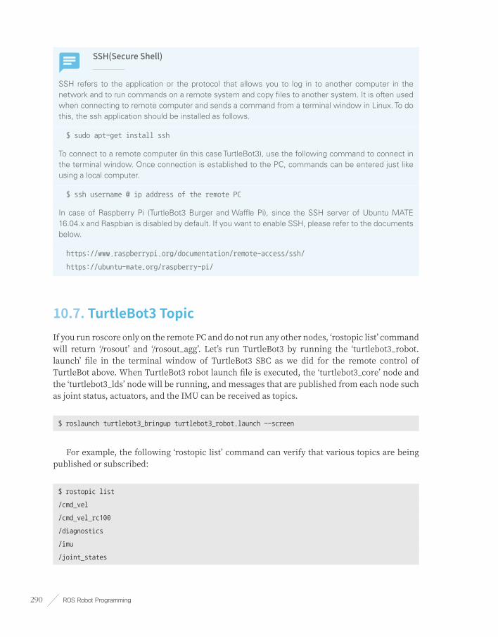
ROS Robot Programming290
SSH(Secure Shell)
SSH refers to the application or the protocol that allows you to log in to another computer in the network and to run commands on a remote system and copy files to another system. It is often used when connecting to remote computer and sends a command from a terminal window in Linux. To do this, the ssh application should be installed as follows.
$ sudo apt-get install ssh
To connect to a remote computer (in this case TurtleBot3), use the following command to connect in the terminal window. Once connection is established to the PC, commands can be entered just like using a local computer.
$ ssh username @ ip address of the remote PC
In case of Raspberry Pi (TurtleBot3 Burger and Waffle Pi), since the SSH server of Ubuntu MATE 16.04.x and Raspbian is disabled by default. If you want to enable SSH, please refer to the documents below.
https://www.raspberrypi.org/documentation/remote-access/ssh/
https://ubuntu-mate.org/raspberry-pi/
10.7. TurtleBot3 TopicIf you run roscore only on the remote PC and do not run any other nodes, ‘rostopic list’ command will return ‘/rosout’ and ‘/rosout_agg’. Let’s run TurtleBot3 by running the ‘turtlebot3_robot.launch’ file in the terminal window of TurtleBot3 SBC as we did for the remote control of TurtleBot above. When TurtleBot3 robot launch file is executed, the ‘turtlebot3_core’ node and the ‘turtlebot3_lds’ node will be running, and messages that are published from each node such as joint status, actuators, and the IMU can be received as topics.
$ roslaunch turtlebot3_bringup turtlebot3_robot.launch --screen
For example, the following ‘rostopic list’ command can verify that various topics are being published or subscribed:
$ rostopic list
/cmd_vel
/cmd_vel_rc100
/diagnostics
/imu
/joint_states

Chapter 10 _ Mobile Robots 291
/odom
/rosout
/rosout_agg
/rpms
/scan
/sensor_state
/tf
In addition, launch the ‘turtlebot3_teleop_key.launch’ on the remote PC as you did for TurtleBot3 remote control:
$ roslaunch turtlebot3_teleop turtlebot3_teleop_key.launch --screen
To get more details on node and topic, run ‘rqt_graph’ as shown in the following example. You can then check out the topics published from and subscribed by the TurtleBot3 as shown in Figure 10-7.
$ rqt_graph
Figure 10-7 TurtleBot3 node and topic

ROS Robot Programming292
10.7.1. Subscribed TopicThe topics mentioned above can be divided into subscribing topics received by TurtleBot3 and publishing topics transmitted from TurtleBot3. Among them, the subscribing topics are shown in the below table. You do not need to know all the subscribing topics, but it would be a good practice to learn how to use them. Above all things, let’s take a look at ‘cmd_vel’. This is a useful topic for controlling the robot, and the user can control the forward, backward, left and right rotation of the robot with this topic.
Topic Name Format Function
motor_power std_msgs/Bool DynamixelTorqueOn/Off
reset std_msgs/Empty ResetOdometryandIMUData
sound turtlebot3_msgs/Sound OutputBeepSound
cmd_vel geometry_msgs/Twist Controlthetranslationalandrotationalspeedoftherobot.unitinm/s,rad/s(actualrobotcontrol)
* Topics used in TurtleBot3 may change depending on the purpose.Table 10-1 Subscribed Topics of the TurtleBot3
10.7.2. Controlling a Robot using Subscribe TopicFor the previously mentioned subscribe topics, the robot receives and processes topics that the user has published. It is difficult to test every topic in this book, so let’s just use a few subscribe topics. The following example stops the motor with ‘rostopic pub’ command in the terminal window.
$ rostopic pub /motor_power std_msgs/Bool "data: 0"
Next, let’s control the velocity of the TurtlebBot3. The x and y used here are the translational speeds, and the unit is the ROS standard m/s. And z is the rotational speed in rad/s. When the value of x is 0.02 as shown in the following example, the TurtleBot3 advances at 0.02 m/s in the positive x-axis direction.
$ rostopic pub /cmd_vel geometry_msgs/Twist "linear:
x: 0.02
y: 0.0
z: 0.0
angular:
x: 0.0

Chapter 10 _ Mobile Robots 293
y: 0.0
z: 0.0"
When the z value is given as 1.0 as shown in the following example, the TurtleBot3 will rotate counterclockwise at 1.0 rad/s.
$ rostopic pub /cmd_vel geometry_msgs/Twist "linear:
x: 0.0
y: 0.0
z: 0.0
angular:
x: 0.0
y: 0.0
z: 1.0"
10.7.3. Published TopicTopics that the TurtleBot3 publishes are diagnostics, debugging, sensors related topics such as ‘joint_states’, ‘sensor_state’, ‘odom’, ‘version_info’ and ‘tf’.
You do not need to know all the published topics, but it would be a good practice to learn how to use them. Especially, ‘odom’ for odometry information, ‘tf ’ for transformation information, ‘joint_states’ for joint information, and sensor information related topics are essential when using TurtleBot3 hereafter.
Topic Name Format Function
sensor_state turtlebot3_msgs/SensorState TopicthatcontainsthevaluesofthesensorsmountedontheTurtleBot3
battery_state sensor_msgs/BatteryState Containsbatteryvoltageandstatus
scan sensor_msgs/LaserScan TopicthatconfirmsthescanvaluesoftheLiDARmountedontheTurtleBot3
imu sensor_msgs/Imu Topicthatincludestheattitudeoftherobotbasedontheaccelerationandgyrosensor.
odom nav_msgs/Odometry ContainstheTurtleBot3’sodometryinformationbasedontheencoderandIMU
tf tf2_msgs/TFMessage Containsthecoordinatetransformationsuchasbase_footprintandodom

ROS Robot Programming294
Topic Name Format Function
joint_states sensor_msgs/JointState Checkstheposition(m),velocity(m/s)andeffort(N·m)whenthewheelsareconsideredasjoints.
diagnostics diagnostic_msgs/DiagnosticArray Containsselfdiagnosticinformation
version_info turtlebot3_msgs/VersionInfo ContainstheTurtleBot3hardware,firmware,andsoftwareinformation
cmd_vel_rc100 geometry_msgs/Twist ThistopicispublishedwhentheBluetooth-basedcontroller,RC100,isconnectedtocontrolthevelocity(m/s)andangularspeed(rad/s)ofmobilerobot.
* Topics used in TurtleBot3 may change depending on the purpose.
10.7.4. Verify Robot Status using Published TopicsPublished topics mentioned above transmit the sensor value of the robot, the motor status, and the position of the robot on topics. In this section, you will subscribe some topics and verify the current state of the robot.
The ‘sensor_state’ topic mainly deals with analog sensors connected to the OpenCR embedded board. You can get information such as bumper, cliff, button, left_encoder, right_encoder as the following example.
$ rostopic echo /sensor_state
stamp:
secs: 1500378811
nsecs: 475322065
bumper: 0
cliff: 0
button: 0
left_encoder: 35070
right_encoder: 108553
battery: 12.0799999237
---
The ‘odom’ topic can be used to obtain odometry information, which records driving information. In TurtleBot3, the essential odometry information can be obtained based on gyro and encoder. The odometry is necessary for navigation.

Chapter 10 _ Mobile Robots 295
$ rostopic echo /odom
header:
seq: 30
stamp:
secs: 1500379033
nsecs: 274328964
frame_id: odom
child_frame_id: ''
pose:
pose:
position:
x: 3.55720114708
y: 0.655082702637
z: 0.0
orientation:
x: 0.0
y: 0.0
z: 0.113450162113
w: 0.993543684483
covariance: [0.0, 0.0, 0.0, 0.0, 0.0, 0.0, 0.0, 0.0, 0.0, 0.0, 0.0, 0.0, 0.0, 0.0, 0.0, 0.0,
0.0, 0.0, 0.0, 0.0, 0.0, 0.0, 0.0, 0.0, 0.0, 0.0, 0.0, 0.0, 0.0, 0.0, 0.0, 0.0, 0.0, 0.0, 0.0,
0.0]
twist:
twist:
linear:
x: 0.0
y: 0.0
z: 0.0
angular:
x: 0.0
y: 0.0
z: -0.00472585950047
covariance: [0.0, 0.0, 0.0, 0.0, 0.0, 0.0, 0.0, 0.0, 0.0, 0.0, 0.0, 0.0, 0.0, 0.0, 0.0, 0.0,
0.0, 0.0, 0.0, 0.0, 0.0, 0.0, 0.0, 0.0, 0.0, 0.0, 0.0, 0.0, 0.0, 0.0, 0.0, 0.0, 0.0, 0.0, 0.0,
0.0]
---

ROS Robot Programming296
The ‘tf’ topic is the translation and rotation information of each joint of the robot transformed in the relative coordinate to the ‘base_footprint’, such as coordinate transformation between ‘base_footprint’, which is the center position of the robot on the XY plane, and odom, which is the odometry information.
$ rostopic echo /tf
transforms:
-
header:
seq: 0
stamp:
secs: 1500379130
nsecs: 727869913
frame_id: odom
child_frame_id: base_footprint
transform:
translation:
x: 3.55720019341
y: 0.655082404613
z: 0.0
rotation:
x: 0.0
y: 0.0
z: 0.112961538136
w: 0.993599355221
---
You can also use the ‘tf_tree’ plugin in ‘rqt’ as shown in Figure 10-8 to visualize the tf information in GUI environment. In Figure 10-8, since the robot model information is missing and therefore each coordinate is not connected, but when performing coordinate translation with robot model information, the connection information of each joint can be used as shown in Figure 10-14.
$ rosrun rqt_tf_tree rqt_tf_tree

Chapter 10 _ Mobile Robots 297
Figure 10-8 Visualization of the Coordinate Transformation through tf_tree
We have completed the topic section. ROS uses topic, service and action to communicate among nodes, which are the processors. Especially, topic is the most widely used message communication method.
10.8. TurtleBot3 Simulation using RViz
10.8.1. SimulationTurtleBot3 supports development environment that can be programmed and developed with a virtual robot in the simulation. There are two development environments to do this, one is using 3D visualization tool ‘RViz’ and the other is using the 3D robot simulator ‘Gazebo’.
In this section, we will first look into how to use RViz. RViz is a very useful to control TutleBot3 and test SLAM and Navigation using the ‘turtlebot3_simulations’ metapackage. To use virtual simulation with this metapackage, the ‘turtlebot3_fake’ package should be installed first. This is mentioned in Section ‘10. 5 TurtleBot3 Development Environment’. If you have already installed the package, move on to the next section.

ROS Robot Programming298
10.8.2. Launch Virtual RobotTo launch the virtual robot, execute the ‘turtlebot3_fake.launch’ file in the turtlebot3_fake package as shown below.
$ export TURTLEBOT3_MODEL=burger
$ roslaunch turtlebot3_fake turtlebot3_fake.launch
The above command loads the 3D modeling file in the turtlebot3_description package and executes the ‘turtlebot3_fake_node’ which publishes fake topics as actual robot publishes, and the ‘robot_state_publisher’ node which publishes the transformation of each wheel to ‘tf ’ topic. However, the sensor information cannot be used in RViz, a 3D simulator based on physics engine ‘Gazebo’ should be used. As Gazebo will be explained in the next section, we will take a look at Odometry and TF that can be verified during a simple movement.
In order to visualize TurtleBot3 on RViz, run RViz and go to [Global Options] → [fixed frame] and select ‘/odom’. Then click the ‘Add’ button in the bottom left corner of the window to add ‘RobotModel’ and display the 3D model file loaded from ‘turtlebot3_fake.launch’ in the center of the screen as shown in Figure 10-9.
Figure 10-9 Load Virtual Robot
Next, let’s run a virtual robot. Run the ‘turtlebot3_teleop_key.launch’ file from the ‘turtlebot3_teleop’ package, which lets you operate the robot remotely with the keyboard.
$ roslaunch turtlebot3_teleop turtlebot3_teleop_key.launch
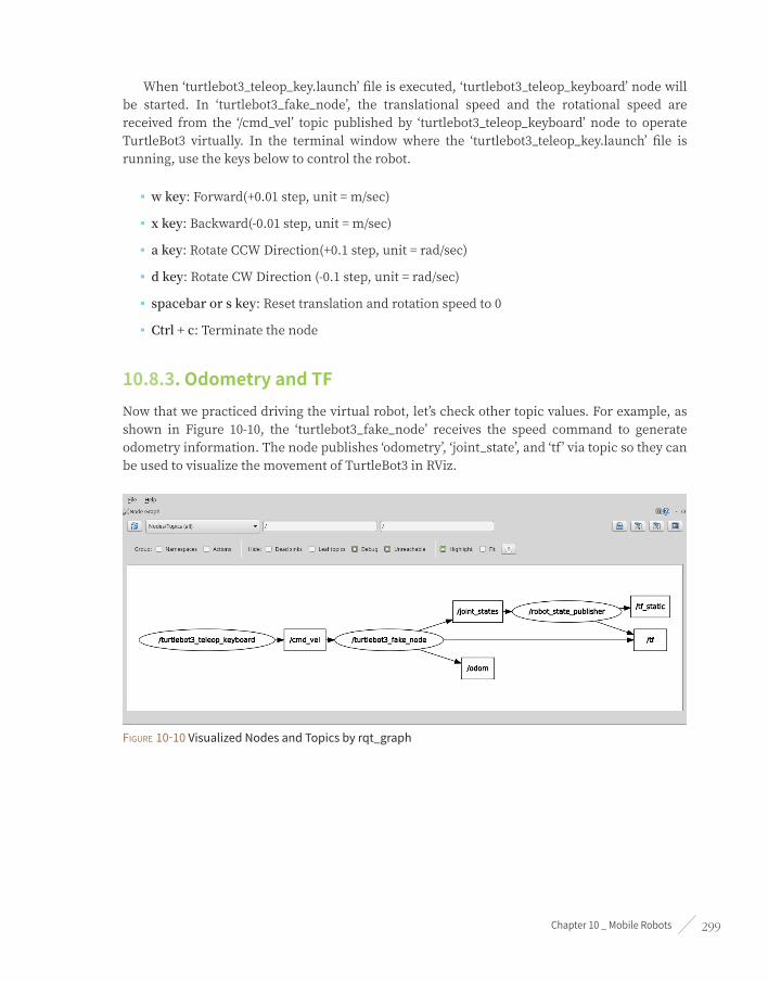
Chapter 10 _ Mobile Robots 299
When ‘turtlebot3_teleop_key.launch’ file is executed, ‘turtlebot3_teleop_keyboard’ node will be started. In ‘turtlebot3_fake_node’, the translational speed and the rotational speed are received from the ‘/cmd_vel’ topic published by ‘turtlebot3_teleop_keyboard’ node to operate TurtleBot3 virtually. In the terminal window where the ‘turtlebot3_teleop_key.launch’ file is running, use the keys below to control the robot.
■ w key: Forward(+0.01 step, unit = m/sec)
■ x key: Backward(-0.01 step, unit = m/sec)
■ a key: Rotate CCW Direction(+0.1 step, unit = rad/sec)
■ d key: Rotate CW Direction (-0.1 step, unit = rad/sec)
■ spacebar or s key: Reset translation and rotation speed to 0
■ Ctrl + c: Terminate the node
10.8.3. Odometry and TFNow that we practiced driving the virtual robot, let’s check other topic values. For example, as shown in Figure 10-10, the ‘turtlebot3_fake_node’ receives the speed command to generate odometry information. The node publishes ‘odometry’, ‘joint_state’, and ‘tf’ via topic so they can be used to visualize the movement of TurtleBot3 in RViz.
Figure 10-10 Visualized Nodes and Topics by rqt_graph

ROS Robot Programming300
Let’s first make sure that odometry information is generated and published properly. Although ‘rostopic echo /odom’ command in the terminal window can verify the information, let’s visualize the odometry information with RViz. Click the ‘Add’ button at the bottom left of RViz, then select the ‘By Topic’ tab as shown in Figure 10-11 and add ‘Odometry’ by selecting it. A red arrow appears on the screen indicating the odometry in the forward direction of the TurtleBot. Uncheck ‘Covariance’ under the Odometry option and adjust the size of the Shaft and Head size since the initial arrow is too big for the robot.
Figure 10-11 Adding the odometry display to verify the odom topic
Now, let’s move around the virtual TurtleBot3 using the ‘turtlebot3_teleop_keyboard’ node. As shown in Figure 10-12, red arrows are displayed on the robot’s trajectory. This odometry is a very basic information indicating where the robot is currently located at. In the above practice, we checked that odometry information is displayed correctly.

Chapter 10 _ Mobile Robots 301
Figure 10-12 Movement and odometry information of the virtual TurtleBot3 Burger
The tf topic containing the relative coordinates of TurtleBot3 components can be verified with the rostopic command as before, but let’s visualize it with RViz like odom and visualize the hierarchy with ‘rqt_tf_tree’.
Click the Add button at the bottom left of RViz and select ‘TF’. This will display ‘odom’, ‘base_footprint’, ‘imu_link’, ‘wheel_left_link’, ‘wheel_right_link’, etc., as shown in Figure 10-13. Let’s move the virtual TurtleBot3 again using the ‘turtlebot3_teleop_keyboard’ node. As TurtleBot3 moves, you can see the ‘wheel_left_link’ and ‘wheel_right_link’ rotate.

ROS Robot Programming302
Figure 10-13 Visualized tf topics in Rviz
Now, run ‘rqt_tf_tree’ with the following command. We can see that the TurtleBot3 components are relatively transformed as shown in Figure 10-14. The position of sensors that can be mounted on the robot can be expressed likewise. This will be covered in detail in the next chapter.
$ rosrun rqt_tf_tree rqt_tf_tree

Chapter 10 _ Mobile Robots 303
Figure 10-14 Visualized tf topics in rqt_tf_tree
10.9. TurtleBot3 Simulation using Gazebo
10.9.1. Gazebo SimulatorGazebo is a 3D simulator that provides robots, sensors, environment models for 3D simulation required for robot development, and offers realistic simulation with its physics engine. Gazebo is one of the most popular simulators for open source in recent years, and has been selected as the official simulator of the DARPA Robotics Challenge7 in the US. It is a very popular simulator in the field of robotics because of its high performance even though it is open source. Moreover, Gazebo is developed and distributed by Open Robotics which is in charge of ROS and its community, so it is very compatible with ROS.
The following are the characteristics8 of Gazebo.
7 http://www.darpa.mil/program/darpa-robotics-challenge
8 http://gazebosim.org/

ROS Robot Programming304
■ Dynamics Simulation: In the early days of development, only ODE(Open Dynamics Engine) was supported. However, since version 3.0, various physical engines such as Bullet, Simbody, and DART are used to meet the needs of various users.
■ 3D Graphics: Gazebo uses OGRE(Open-source Graphics Rendering Engines), which is often used in games, not only the robot model but also the light, shadow and texture can be realistically drawn on the screen.
■ Sensors and Noise Simulation: Laser range finder (LRF), 2D/3D camera, depth camera, contact sensor, force-torque sensor and much more are supported and noise can be applied to the sensor data similar to the actual environment.
■ Plug-ins: APIs are provided to enable users to create robots, sensors, environment control as a plug-in.
■ Robot Model: PR2, Pioneer2 DX, iRobot Create, and TurtleBot are already supported in the form of SDF, a Gazebo model file, and users can add their own robots with an SDF file.
■ TCP/IP Data Transmission: The simulation can be run on a remote server and Google’s Protobufs, a socket-based message passing is used.
■ Cloud Simulation: Gazebo provides cloud simulation CloudSim environment for use in cloud environments such as Amazon, Softlayer, and OpenStack.
■ Command Line Tool: Both GUI and CUI tools are supported to verify and control the simulation status.
The latest version of Gazebo is 8.0, and just five years ago, it was 1.9. The current version is the adopted as a default application of the ROS Kinetic Kame used in this book. If ROS is installed as instructed in ‘3.1 ROS installation’, Gazebo can be used without additional installation.
Now let’s run Gazebo. If there are no problems, you can see that Gazebo is running as shown in Figure 10-15. For now, Gazebo can be seen as an independent simulator as it is not related to ROS.
$ gazebo

Chapter 10 _ Mobile Robots 305
Figure 10-15 Gazebo initial screen
10.9.2. Launch Virtual RobotLet’s install dependent packages to run TurtleBot3 on the Gazebo simulator. The ‘gazebo_ros_pkgs’ metapackage that connects Gazebo and ROS is already installed, and 3D simulation package for TurtleBot3 ‘turtlebot3_gazebo’ is also required, but it has already been installed in ‘10.5 TurtleBot3 Development Environment’.
Below is a command to set the 3D model file to Burger or Waffle, Waffle Pi. The example command is based on the Waffle which can get the camera information. Set the TURTLEBOT3_MODEL variable to ‘waffle’ with the following command. If the command is written in the ‘~/.bashrc’ file, you do not need to set the model every time when opening a new terminal window.
$ export TURTLEBOT3_MODEL=waffle
Now run the launch file as shown in the following example. The ‘gazebo’, ‘gazebo_gui’, ‘mobile_base_nodelet_manager’, ‘robot_state_publisher’, and ‘spawn_mobile_base’ nodes are executed together and TurtleBot3 Waffle appears in the Gazebo screen, as shown in Figure 10-16. Gazebo is a 3D simulator that uses a lot of CPU, GPU and RAM resources due to the use of physics engine and graphic effects. Depending on the hardware specifications of PC, it may take a considerable amount of time to load the application.
$ roslaunch turtlebot3_gazebo turtlebot3_empty_world.launch
As shown in the following figure, you can see that only the robot is displayed in an empty plane.

ROS Robot Programming306
Figure 10-16 3D view of TurtleBot3 on Gazebo
In the above example, only the robot is loaded in the Gazebo. In order to perform the actual simulation, the user can specify the environment or load the environment model provided by Gazebo. An environment model can be added to Gazebo by clicking on ‘Insert’ at the top of the screen and selecting a file. There are various robot models and objects as well as environment models, so let’s add them when necessary.
In this instruction, we will use provided environment. Close the currently active Gazebo screen by clicking the ‘X’ button in the upper left corner of the screen or enter [Ctrl + c] in the terminal window where you launched Gazebo.
Run the ‘turtlebot3_world.launch’ file as follows. The ‘turtlebot3_world.launch’ file will be loaded with the ‘turtlebot3.world’ environment model we already created. The turtlebot3.world environment model has been created from the symbol of TurtleBot series as shown in Figure 10-17. If you wish to create your own environment model, check the ‘/models/turtlebot3.world’ file in the ‘turtlebot3_gazebo’ package to see how it is configured.
$ roslaunch turtlebot3_gazebo turtlebot3_world.launch
Figure 10-17 TurtleBot3 and Environment Model

Chapter 10 _ Mobile Robots 307
Now run the remote control launch file in the following example to control the virtual TurtleBot3 in the Gazebo environment using the keyboard.
$ roslaunch turtlebot3_teleop turtlebot3_teleop_key.launch
Gazebo looks pretty similar to the RViz simulation of the previous section until now. Gazebo, however, is not only designed to look like a virtual robot, but it can also virtually check the collision, calculate the position, and use the IMU sensor and camera. Below is an example of using this launch file. When the file is executed, the virtual TurtleBot3 moves randomly in the loaded environment and avoid obstacles before running into the wall as shown in Figure 10-18. This is a great example of learning Gazebo.
$ export TURTLEBOT3_MODEL=waffle
$ roslaunch turtlebot3_gazebo turtlebot3_simulation.launch
Figure 10-18 TurtleBot3 automatically moving and avoiding obstacles on Gazebo
In addition to this, let’s run RViz with the following command. As shown in Figure 10-19, RViz can visualize the position of robot operating in Gazebo, distance sensor data and camera image. This simulation output is almost identical to operating an actual robot in the environment model designed just like the one in Gazebo.
$ export TURTLEBOT3_MODEL=waffle
$ roslaunch turtlebot3_gazebo turtlebot3_gazebo_rviz.launch
ROS Robot Programming308
Figure 10-19 Visualized virtual LiDAR data and camera image in RViz
10.9.3. Virtual SLAM and NavigationThis section explains the use of command for virtual SLAM and Navigation. In the next chapter, we will cover SLAM for creating a map using the actual TurtleBot3 and navigation for moving to a specific destination on the given map. After familiarizing yourself with SLAM and navigation through Gazebo, try the actual operation in the next chapter.
Virtual SLAM Execution ProcedureWhen you run the dependent packages and move the robot in virtual space and create a map as shown below, you can create a map as shown in Figure 10-20 and the finalized map will look like the Figure 10-21.
Launch Gazebo
$ export TURTLEBOT3_MODEL=waffle
$ roslaunch turtlebot3_gazebo turtlebot3_world.launch
Launch SLAM
$ export TURTLEBOT3_MODEL=waffle
$ roslaunch turtlebot3_slam turtlebot3_slam.launch
Execute RViz
$ export TURTLEBOT3_MODEL=waffle
$ rosrun rviz rviz -d `rospack find turtlebot3_slam`/rviz/turtlebot3_slam.rviz

Chapter 10 _ Mobile Robots 309
Remotely Control TurtleBot3
$ roslaunch turtlebot3_teleop turtlebot3_teleop_key.launch
Save the Map
$ rosrun map_server map_saver -f ~/map
Figure 10-20 Running SLAM on Gazebo (Left: Gazebo, Right: RViz)
Figure 10-21 Generated Map of Gazebo Environment

ROS Robot Programming310
Virtual Navigation Execution ProcedureTerminate all applications that were executed during the virtual SLAM practice and execute related packages in the following instruction, the robot will appear on the previously generated map. After setting the initial position of the robot on the map, set the destination to run the navigation as shown in Figure 10-22. The initial position only needs to be set once.
Execute Gazebo
$ export TURTLEBOT3_MODEL=waffle
$ roslaunch turtlebot3_gazebo turtlebot3_world.launch
Execute Navigation
$ export TURTLEBOT3_MODEL=waffle
$ roslaunch turtlebot3_navigation turtlebot3_navigation.launch map_file:=$HOME/map.yaml
Execute RViz and Set Destination
$ export TURTLEBOT3_MODEL=waffle
$ rosrun rviz rviz -d `rospack find turtlebot3_navigation`/rviz/turtlebot3_nav.rviz
Figure 10-22 Running Naviation on Gazebo (Left: Gazebo, Right: RViz)

Chapter 10 _ Mobile Robots 311
Two simulation methods of the TurtleBot3 package were introduced. One is to use RViz, a 3D visualization tool of ROS, and the other is to use Gazebo, a 3D robot simulator. Simulation is a great tool for users because it allows to perform programming tasks very close to the actual environment with a robot.
TurtleBot Simulation
TurtleBot supports three types of simulation which are stage, stdr, and Gazebo. Refer to the Wiki below to perform various simulations with a virtual robot.
http://wiki.ros.org/TurtleBot_stdr
http://wiki.ros.org/TurtleBot_gazebo
http://wiki.ros.org/TurtleBot_stage

ROS Robot Programming312
SLAM and Navigation
Chapter 11

Chapter 11 _ SLAM and Navigation 313
11.1. Navigation and ComponentsIt might be easier to understand navigation as the GPS navigation in a daily life. If you set a destination on the navigation device, the navigation allows you to check the distance and travel time from current location to the destination, and you can set specific preferences and informations such as places to stop by and preferred roads on the way.
The navigation system has a relatively short history. In 1981, a Japnese car maker Honda first proposed an analog system based on a three-axis gyroscope and a film map called ‘Electro Gryrocator1’. Afterwards Etak Navigator2, an electronic navigation system operated with electronic compass and sensors attached to wheels, was introduced by the U.S. automotive supply company Etak. However, mounting the sensor and electronic compass to the car was a heavy burden for the automobile prices and had reliability problems of the navigation system. Since the 1970s, the United States has been developing satellite positioning systems for military purposes, and in the 2000s, 24 GPS3 (Global Positioning System) satellites became available for general purpose, and triangulation based navigation systems using these satellites began to spread.
11.1.1. Navigation of Mobile RobotLet’s return to robots now. The foundation and highlight of a mobile robot is without a doubt, navigation. Navigation in robotics are unseparable and essential. Navigation is the movement of the robot to a defined destination, which is not as easy as it sounds. But it is important to know where the robot itself is and to have a map of the given environment. It is also important to find the optimized route among the various routing options, and to avoid obstacles such as walls and furniture. There’s not an easy mission.
Figure 11-1 Navigation
1 https://en.wikipedia.org/wiki/Electro_Gyrocator
2 https://en.wikipedia.org/wiki/Etak
3 https://en.wikipedia.org/wiki/Global_Positioning_System

ROS Robot Programming314
What do we need to implement navigation in robots? It may vary depending on the navigation algorithm, and the followings may be required as basic features.
➊ Map
➋ Pose of Robot
➌ Sensing
➍ Path Calculation and Driving
11.1.2. MapThe first essential feature for navigation is the map. The navigation system is equipped with a very accurate map from the time of purchase, and the modified map can be downloaded periodically so that it can be guided to the destination based on the map. But will a map of the room be available where the service robot will be placed? Like a navigation system, a robot needs a map, so we need to create a map and give it to the robot, or the robot should be able to create a map by itself.
SLAM4 (Simultaneous Localization And Mapping) is developed to let the robot create a map with or without a help of a human being. This is a method of creating a map while the robot explores the unknown space and detects its surroundings and estimates its current location as well as creating a map.
11.1.3. Pose of RobotSecondly, the robot must be able to measure and estimate its pose (position + orientation). In case of an automobile, the GPS is used to estimate its pose. However, the GPS can not be used indoors, and even if it can be used, a GPS with large errors cannot be used for robots. Nowadays, high-precision system such as DGPS5 is used, but this is also useless indoors as well as being too expensive for general purpose. In order to overcome this problem, various methods such as marker recognition and indoor location estimation have been introduced. However, in terms of cost and accuracy, it is still insufficient for general use. Currently, the most widely used indoor pose estimation method for service robots is dead reckoning6 7, which is a relative pose estimation, but it has been used for a long time and is composed of low cost sensors and can obtain a certain level of accurate pose estimation result. The amount of movement of the robot is measured with the rotation of the wheel. However, there is an error between the calculated distance with wheel rotation and the actual travel distance. Therefore, the inertial information
4 https://en.wikipedia.org/wiki/Simultaneous_localization_and_mapping
5 https://en.wikipedia.org/wiki/Differential_GPS
6 https://en.wikipedia.org/wiki/Dead_reckoning
7 http://www.cs.cmu.edu/afs/cs.cmu.edu/academic/class/16311/www/s07/labs/NXTLabs/Lab%203.html
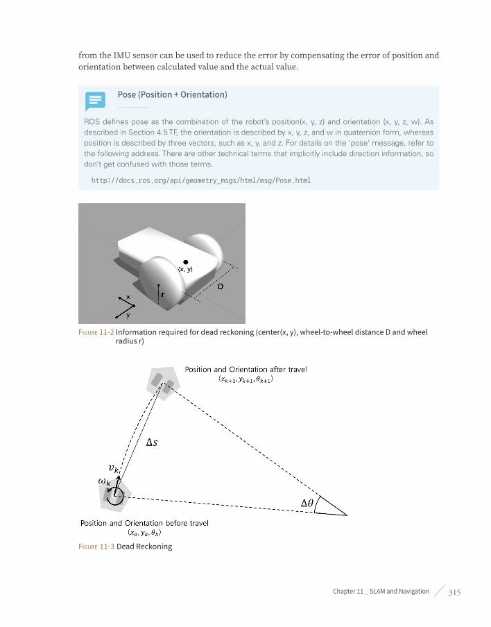
Chapter 11 _ SLAM and Navigation 315
from the IMU sensor can be used to reduce the error by compensating the error of position and orientation between calculated value and the actual value.
Pose (Position + Orientation)
ROS defines pose as the combination of the robot’s position(x, y, z) and orientation (x, y, z, w). As described in Section 4.5 TF, the orientation is described by x, y, z, and w in quaternion form, whereas position is described by three vectors, such as x, y, and z. For details on the ‘pose’ message, refer to the following address. There are other technical terms that implicitly include direction information, so don’t get confused with those terms.
http://docs.ros.org/api/geometry_msgs/html/msg/Pose.html
Figure 11-2 Information required for dead reckoning (center(x, y), wheel-to-wheel distance D and wheel radius r)
Figure 11-3 Dead Reckoning

ROS Robot Programming316
Here’s a brief explaination about the dead reckoning. When there is a mobile robot as shown in Figure 11-2, let D be the distance between the wheels and r be the radius of the wheel. Assuming the robot traveled a very short distance during time T
e, the rotational speed(v
l, v
r) of the left and
right wheels are calculated as shown in Eqs. (11-1) and (11-2) with the amount of left and right motor rotation (current encoder value E
lc, E
rc and the previous encoder value E
lp, E
rp).
vl =
vr =
.
.
( Elc - Elp )
( Erc - Erp )
r
r
Te
Te
180
180
(radian / sec)
(radian / sec)
(Equation 11-1)
(Equation 11-2)
The Equations 11-3 and 11-4 calculates the velocity of the left and right wheel (Vl, V
r). From
the left and right wheel velocity, linear velocity (vk) and the angular velocity (~
k) of the robot can
be obtained as shown in Equations 11-5 and 11-6.
Vl = vl. r (meter/sec) (Equation 11-3)
Vr = vr. r (meter/sec) (Equation 11-4)
vk =
~k =
(Vr + Vl )
(Vr - Vl )
2
D
(meter/sec)
(radian/sec)
(Equation 11-5)
(Equation 11-6)
Finally, using these values, we can obtain the position (x( k+1)
, y( k+1 )
) and the orientation (i( k+1 )
) of the robot from Equation 11-7 to 11-10.
Ds = vkTe Di = ~kTe (Equation 11-7)
(Equation 11-8)
(Equation 11-9)
x( k+1 ) = xk + Ds cos ik +Di
2U Z
y( k+1 ) = yk + Ds sin ik +Di
2U Z
i( k+1 ) = ik + Di (Equation 11-10)

Chapter 11 _ SLAM and Navigation 317
11.1.4. SensingThirdly, figuring out whether there are obstacles such as walls and objects requires sensors. Various types of sensors such as distance sensors and vision sensors are used. The distance sensor uses laser-based distance sensors (LDS, LRF, LiDAR), ultrasonic sensors and infrared distance sensors. The vision sensor includes stereo cameras, monocameras, omnidirectional cameras, and recently, RealSense, Kinect, Xtion, which are widely used as Depth camera, are used to identify obstacles.
11.1.5. Path Calculation and DrivingThe last essential feature for navigation is to calculate and travel the optimal route to the destination. This is called path search and planning, and there are many algorithms that perform this such as A* algorithm8, potential field9, particle filter10, and RRT (Rapidly-exploring Random Tree) 11.
In this section, we have briefly summarized SLAM and the components of navigation, but it is still difficult and vast to understand. The robot pose measurement and estimation was explained in the previous section. The obstacle measurement such as wall and objects, is described in the Chapter 8 Robots, Sensors and Motors. Now, let’s look at the SLAM to create a map, and navigation with the generated map.
11.2. SLAM PracticeBefore describing the theory of SLAM, let’s see how to use SLAM with TurtleBot3. The bag file which can be used to create a map is located in the GitHub repository, so it is recommended to try this example. The theory of SLAM will be reviewed in Section 11.4 after completing the SLAM practice.
11.2.1. Robot Hardware Constraints for SLAMThe gmapping12, cartographer13, and rtabmap14 packages are widely used for SLAM, and in this section, we will be using the gmapping package. It is good to understand some hardware constraints when using gmapping, though they are not related to mobile robots.
8 https://en.wikipedia.org/wiki/A*_search_algorithm
9 http://www.cs.cmu.edu/~./motionplanning/lecture/Chap4-Potential-Field_howie.pdf
10 https://en.wikipedia.org/wiki/Particle_filter
11 https://en.wikipedia.org/wiki/Rapidly-exploring_random_tree
12 http://wiki.ros.org/gmapping
13 http://wiki.ros.org/cartographer
14 http://wiki.ros.org/rtabmap

ROS Robot Programming318
MovementThe platform must be able to move with the X, Y axis linear velocity command and theta angular velocity command. For examples, the robot composed of two motors such as a differential drive mobile robot or an omni-wheel robot which has more than three drive shafts.
OdometryThe odometry information should be obtainable. The traveled distance should be measured by calculating via dead reckoning or compensating pose with inertial data or estimating translation speed and angular speed with IMU sensor so the robot can calculate and estimate its current pose.
Distance Measuring SensorFor SLAM and navigation, the robot should have sensors such as LDS (Laser Distance Sensor), LRF (Laser Range Finder) or LiDAR that can measure distance to the obstacle on the XY plane. Depth cameras such as RealSense, Kinect, and Xtion can also convert 3D information into 2D information of the XY plane. In other words, it is necessary to mount a sensor capable of measuring the distance on the XY plane. Ultrasonic sensors, PSD sensors, and visual SLAMs can also be considered, but they will not be covered in this book.
Shape of RobotRobots with a regular polygon or circular shapes are covered in this section. Transformed robots that are long on one axis, robots too big to pass between doors, bipedal humanoid robots, multi-joint mobile robots, and flying robots are not considered for SLAM. In this chapter, we will use TurtleBot3, the official ROS platform we discussed in Chapter 10. The TurtleBot3 in Figure 11-4 satisfies all four SLAM constraints mentioned above.

Chapter 11 _ SLAM and Navigation 319
Figure 11-4 Shape and Dimension of TurtleBot3 Burger, Waffle and Waffle Pi
11.2.2. Measured Target Environment of SLAMAlthough SLAM enabled environments is not specified, there are certain constraints due to the characteristics of the Gmapping algorithm : ➊ square shaped room with no obstacles, ➋ a long corridor without any distinctive objects, ➌ glasses that doesn’t reflect laser or infrared light, ➍ mirrors that scatters light, ➎ wide and open environments where obstacle information cannot be acquired, such as a lake or sea.
In the example in the book, the environment is set as a labyrinth with a grid structure that can be measured the length as shown in Figure 11-5.

ROS Robot Programming320
Figure 11-5 Measurement target environment
11.2.3. ROS Package for SLAMThe SLAM-related ROS packages used in this section are the TurtleBot3 metapackage and gmapping package in the the ‘slam_gmapping’ metapackage, and the ‘map_server’ package in the navigation metapackage. These packages were already installed in the ‘10.5 TurtleBot3 Development Environment’. Since this section is a follow-up exercise, only the execution procedure will be described. The description for each package will be covered in detail in the next section. In order to avoid confusion, [Remote PC] and [TurtleBot] tags will be used to indicate where the command should be applied.
11.2.4. Execute SLAMThe SLAM execution sequence is as follows. This example is describing commands for TurtleBot3 Waffle as a reference. If you are using the Burger or Waffle Pi, simply change the ‘TURTLEBOT3_MODEL’ in the command from ‘waffle’ to ‘burger’ or ‘waffle_pi’.
roscoreRun ‘roscore’ on the [Remote PC]
$ roscore
Launch RobotIn [TurtleBot], run the ‘turtlebot3_robot.launch’ file for executing the ‘turtlebot3_core’ and ‘turtlebot3_lds’ nodes.
$ roslaunch turtlebot3_bringup turtlebot3_robot.launch

Chapter 11 _ SLAM and Navigation 321
Run SLAM PackageExecute the launch file ‘turtlebot3_slam.launch’ in the [Remote PC]. The ‘turtlebot3_slam’ package consists of just one launch file. The launch file executes a ‘robot_state_publisher’ node that publishes the three-dimensional position and orientation information of both wheels and each joint in TF, and a ‘slam_gmapping’ node for map building. In addition, the ‘robot_model’ is set to load the URDF (Unified Robot Description Format) which describes the appearance of the robot.
$ export TURTLEBOT3_MODEL=waffle
$ roslaunch turtlebot3_slam turtlebot3_slam.launch
Run RVizLet’s run the visualization tool RViz so that you can visually check the results during SLAM. When you run RViz with the following options, the display plugins are added from the beginning.
$ export TURTLEBOT3_MODEL=waffle
$ rosrun rviz rviz -d `rospack find turtlebot3_slam`/rviz/turtlebot3_slam.rviz
Save Topic MessageA user can directly operate the robot and perform the SLAM operation. The ‘/scan’ and ‘/tf’ topics published during the operation can be saved as a ‘scan_data.bag’ file as shown in the below command. You can read this file to create a map later, or you can reproduce the ‘/scan’ and ‘/tf’ topics at the time of the experiment when you are working on the map without having to repeat the experiment. Think of it as storing the topic data from the experiment (the ‘/scan’ and ‘/tf’ topics). The ‘-O’ option of the following command is an option to specify the name of the output file, and saves the bag file as ‘scan_data.bag’. Saving topic messages is not mandatory in SLAM, so you can skip it if you do not need to save messages.
$ rosbag record -O scan_data /scan /tf
Robot ControlThe following command allows the user to control the robot to perform SLAM operation manually. It is important to avoid vigorous movements such as changing the speed too quickly or rotating too fast. When building a map using the robot, the robot should scan every corner of the environment to be measured. It requires some experiences to build a clean map, so let’s practice SLAM multiple times to build up know how.

ROS Robot Programming322
$ roslaunch turtlebot3_teleop turtlebot3_teleop_key.launch
Create MapNow that you have all the work done, let’s run the ‘map_saver_node’ to create a map. The map is drawn based on the robot’s odometry, tf information, and scan information of the sensor when the robot moves. These data can be seen in the RViz from the previous example. The created map is saved in the directory in which ‘map_saver’ is runnig. Unless you specify the file name, it is stored as ‘map.pgm’ and ‘map.yaml’ file which contains map information.
The ‘-f ’ option refers to the folder and file name where the map file is saved. If ‘~/map’ is used as an option, ‘map.pgm’ and ‘map.yaml’ will be saved in the map folder of user’s home folder(~/).
$ rosrun map_server map_saver -f ~/map
Use the process above to create your map. The nodes and topics required for mapping can be obtained by using ‘rqt_graph’ as shown in Figure 11-6. The mapping process is shown in Figure 11-7, and the completed map is shown in Figure 11-8. We can confirm that the above-mentioned experimental environment is properly drawn in the map.
Figure 11-6 Nodes and topics required for SLAM

Chapter 11 _ SLAM and Navigation 323
Figure 11-7 SLAM running for mapping
Figure 11-8 Completed Map
11.2.5. SLAM with Saved Bag FileLet’s exercise the SLAM without TurtleBot3 and LDS sensor. In order to do this, recorded bag file is required and it can be downloaded with the following command.
$ wget https://raw.githubusercontent.com/ROBOTIS-GIT/turtlebot3/master/turtlebot3_slam/bag/
TB3_WAFFLE_SLAM.bag
Rest of the procedure is similar to the above SLAM instructions. However, the ‘rosbag’ command option needs to be modified from ‘save’ to ‘play’. Then it will behave in the same manner as the actual experiment.
$ roscore
$ export TURTLEBOT3_MODEL=waffle

ROS Robot Programming324
$ roslaunch turtlebot3_bringup turtlebot3_remote.launch
$ export TURTLEBOT3_MODEL=waffle
$ rosrun rviz rviz -d `rospack find turtlebot3_slam`/rviz/turtlebot3_slam.rviz
$ roscd turtlebot3_slam/bag
$ rosbag play ./TB3_WAFFLE_SLAM.bag
$ rosrun map_server map_saver -f ~/map
The following section describes the source codes of the packages and how to set up the packages you have run in the previous example.
11.3. SLAM ApplicationIn this section, we are going to look into the ROS packages used in SLAM and learn how to create and configure it. The TurtleBot3 metapackage, the gmapping package in the ‘slam_gmapping’ metapackage, and the ‘map_server’ package in the navigation metapackage will be covered. This section provides technical details for SLAM so that it can be applied to the robot. The theory of SLAM is covered in section 11.4.
This section is based on TurtleBot3 robot platform and LDS sensor, but SLAM can be implemented on a customized robot without limitation to a specific robot platform or sensor. If you want to create your own robot platform or build your customized TurtleBot3 robot platform, this section will be helpful.
11.3.1. MapFirst of all, there’s a lot more to be covered about maps since map is the output we are looking for in this section. If we give a paper map to a robot, do you think the robot can understand it? Probably not. The robot would need it digitalized to understand and compute the information. The definition of the map for robot navigation has been discussed for a long time and is still being discussed. Particularly, recent maps include not only two-dimensional information but also three-dimensional information, and sometimes it even includes segmentations of an object which is unrelated to the navigation information.
In this section, we will use the two-dimensional Occupancy Grid Map (OGM), which is commonly used in the ROS community. The map obtained from the previous section as shown in Figure 11-9, white is the free area in which the robot can move, black is the occupied area in which the robot can not move, and gray is the unknown area.

Chapter 11 _ SLAM and Navigation 325
Figure 11-9 Occupancy Grid Map
The area in the map is represented by grayscale values that range from ‘0’ to ‘255’. This value is obtained through the posterior probability of the Bayes’ theorem, which calculates the occupancy probability that represents the occupancy state. The occupancy probability ‘occ’ is expressed as ‘occ = (255 - color_avg) / 255.0’. If the image is 24 bit, ‘color_avg = (grayscale value of one cell / 0xFFFFFF x 255)’. The closer this ‘occ’ is to 1, the higher the probability that it is occupied, and the closer to ‘0’, it is the less likely to be occupied.
When the occupancy probability is published as ROS message (nav_msgs/OccupancyGrid), it is redefined to an integer [0 ~ 100]. An area close to ‘0’ is the free area defined as an unoccupied area whereas ‘100’ is defined as an occupied area, and ‘-1’ is especially defined for unknown area.
In ROS, actual map is stored in ‘*.pgm’ file format(portable graymap format) and the ‘*.yaml’ file contains map information. For example, if we check out the map information(map.yaml) we saved in Section 11.2, the image parameter defines the map file name and resolution defines the map resolution in meters/pixel.
image: map.pgm
resolution: 0.050000
origin: [-10.000000, -10.000000, 0.000000]
negate: 0
occupied_thresh: 0.65
free_thresh: 0.196
That is to say, each pixel can be converted to 5cm. Origin is the origin of the map, and each value represents x, y and yaw respectively. The lower left corner of the map represents x = -10m, y = -10m. Negate inverts black and white color. The color of each pixel is determined by the occupancy probability. If the occupancy probability exceeds occupied threshold (occupied_thresh), the pixel is expressed as an occupied area in black color. Otherwise, the pixel will be expressed as a free area in white color.
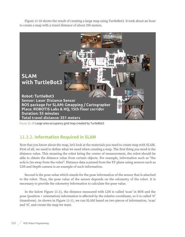
ROS Robot Programming326
Figure 11-10 shows the result of creating a large map using TurtleBot3. It took about an hour to create a map with a travel distance of about 350 meters.
Figure 11-10 Large area occupancy grid map created by TurtleBot3
11.3.2. Information Required in SLAMNow that you know about the map, let’s look at the materials you need to create map with SLAM. First of all, we need to define what we need when creating a map. The first thing you need is the distance value. This meaning the robot being the center of measurement, the robot should be able to obtain the distance value from certain objects. For example, information such as “the sofa is 2m away from the robot”. Distance data scanned from the XY plane using sensors such as LDS and Depth camera is an example of such information.
Second is the pose value which stands for the pose information of the sensor that is attached to the robot. Thus, the pose value of the sensor depends on the odometry of the robot. It is necessary to provide the odometry information to calculate the pose value.
In the below Figure 11-11, the distance measured with LDS is called ‘scan’ in ROS and the pose (position + orientation) information is affected by the relative coordinate, so it is called ‘tf’ (transform). As shown in Figure 11-11, we run SLAM based on two pieces of information, ‘scan’ and ‘tf’, and create the map we want.

Chapter 11 _ SLAM and Navigation 327
Figure 11-11 Scan and tf data required in SLAM and the relation to the map.
11.3.3. SLAM ProcessTo create the map with SLAM, the ‘turtlebot3_slam’ package was created in addition to the ‘turtlebot3_core’ node. This package does not have a source file, but packages needed for SLAM is launched when executing the launch file. The flow of SLAM procedure is illustrated in Figure 11-12 and each process is described below.
Figure 11-12 Flowchart of turtlebot3_slam
➌ ➋ ➊
➍
➎

ROS Robot Programming328
sensor_node(Example: turtlebot3_lds)The ‘turtlebot3_lds’ node runs the LDS sensor and sends the ‘scan’ information, which is necessary for SLAM, to the ‘slam_gmapping’ node.
turtlebot3_teleop(Example: turtlebot3_teleop_keyboard)The ‘turtlebot3_teleop_keyboard’ node is a node that can receive the keyboard input and control the robot. This node sends the translation and rotation speed command to the ‘turtlebot3_core’ node.
turtlebot3_coreThe ‘turtlebot3_core’ node receives the translation and rotation speed command and moves the robot. While the node publishes ‘odom’, which is the measured and estimated pose of robot, it also publishes the converted relative coordinate of ‘odom’ in ‘tf ’ form, in the order of odom → base_footprint → base_link → base_scan.
turtlebot3_slam_gmappingThe ‘turtlebot3_slam_gmapping’ node creates a map based on the scan information from the distance measuring sensor and the tf information, which is the pose value of the sensor.
map_saverThe ‘map_saver’ node in the ‘map_server’ package creates a ‘map.pgm’ file and a ‘map.yaml’ file that is an information file for the map.
11.3.4. Coordinate Transformation (TF)The two pieces of information used in SLAM are the distance value and the pose where the distance value is measured. The distance value can be acquired from the sensor node, and the pose value of the sensor can be obtained by calculating the position of the sensor. The sensor is mounted at a fixed location of the robot, and the robot moves according to the remote control command. That is, the robot and the sensor are physically fixed, and the pose (position + orientation) of the sensor is changed according to the pose of the robot. It is easier to think of this as relative coordinate transformation which is called ‘tf’ in ROS. The following command will visualize the relative coordinates in a tree structure.
$ rosrun rqt_tf_tree rqt_tf_tree
If you execute the above command, you can check the relative coordinate transformation (tf) of the robot and sensor with the ‘tf tree viewer’ as shown in Figure 11-13. In other words, if we

Chapter 11 _ SLAM and Navigation 329
focus on the LDS pose in the pose of the robot, the pose information is relatively connected in the order of odom → base_footprint → base_link → base_scan. The commanded translational speed and rotational speed from the ‘turtlebot3_teleop_keyboard’ node controls the robot while the pose of the robot is measured according to the dead reckoning. During this procedure, the ‘odom’ is published as ‘tf ’. The base_footprint → base_link → base_scan is physically fixed, which describes each coordinate transformation as described in ‘/urdf/turtlebot3_waffle.urdf.xacro’ file of the ‘turtlebot3_description’ package and periodically publishes ‘tf ’ through the ‘robot_state_publisher’ node.
Figure 11-13 Relative Coordinate Transformation Status of Map and Robot Parts
11.3.5. turtlebot3_slam PackageThe contents of the ‘turtlebot3_slam.launch’ file in the ‘turtlebot3_slam’ package looks as below. The launch file is divided into two main sections, where the first part contains the ‘turtlebot3_remote.launch’ file and the second part executes the ‘turtlebot3_slam_gmapping’ node.
turtlebot3_slam/launch/turtlebot3_slam.launch
<launch>
<!-- Turtlebot3 -->
<include file="$(find turtlebot3_bringup)/launch/turtlebot3_remote.launch" />
<!-- Gmapping -->
<node pkg="gmapping" type="slam_gmapping" name="turtlebot3_slam_gmapping" output="screen">

ROS Robot Programming330
<param name="base_frame" value="base_footprint"/>
<param name="odom_frame" value="odom"/>
<param name="map_update_interval" value="2.0"/>
<param name="maxUrange" value="4.0"/>
<param name="minimumScore" value="100"/>
<param name="linearUpdate" value="0.2"/>
<param name="angularUpdate" value="0.2"/>
<param name="temporalUpdate" value="0.5"/>
<param name="delta" value="0.05"/>
<param name="lskip" value="0"/>
<param name="particles" value="120"/>
<param name="sigma" value="0.05"/>
<param name="kernelSize" value="1"/>
<param name="lstep" value="0.05"/>
<param name="astep" value="0.05"/>
<param name="iterations" value="5"/>
<param name="lsigma" value="0.075"/>
<param name="ogain" value="3.0"/>
<param name="srr" value="0.01"/>
<param name="srt" value="0.02"/>
<param name="str" value="0.01"/>
<param name="stt" value="0.02"/>
<param name="resampleThreshold" value="0.5"/>
<param name="xmin" value="-10.0"/>
<param name="ymin" value="-10.0"/>
<param name="xmax" value="10.0"/>
<param name="ymax" value="10.0"/>
<param name="llsamplerange" value="0.01"/>
<param name="llsamplestep" value="0.01"/>
<param name="lasamplerange" value="0.005"/>
<param name="lasamplestep" value="0.005"/>
</node>
</launch>
First, let’s look at the ‘turtlebot3_remote.launch’ file. This file contains the user-specified robot model to be loaded and executes the ‘robot_state_publisher’ node, which publishes the robot state information of both wheels and each joint in TF.

Chapter 11 _ SLAM and Navigation 331
turtlebot3_bringup/launch/turtlebot3_remote.launch
<launch>
<arg name="model" default="$(env TURTLEBOT3_MODEL)" doc="model type [burger, waffle, waffle_pi]"/>
<include file="$(find turtlebot3_bringup)/launch/includes/description.launch.xml">
<arg name="model" value="$(arg model)" />
</include>
<node pkg="robot_state_publisher" type="robot_state_publisher" name="robot_state_publisher"
output="screen">
<param name="publish_frequency" type="double" value="50.0" />
</node>
</launch>
The ‘turtlebot3_slam_gmapping’ node allows you to rename the ‘slam_gmapping’ node in the gmapping package when launching the node. To make this node run properly, you need to modify the various options for your robot and sensor. The following settings are for TurtleBot3 Waffle. If you want to use a different robot other than TurtleBot3, please refer to the following explanation and modify the setting according to your robot and sensor.
slam_gmapping Node Setting
<param name="base_frame" value="base_footprint"/> The frame attached to the mobile base
<param name="odom_frame" value="odom"/> The frame attached to the odometry system
<param name="map_update_interval" value="2.0"/> Map update interval (sec)
<param name="maxUrange" value="4.0"/> Max Range of laser sensor to use (meter)
<param name="minimumScore" value="100"/> Min Score considering the results of scan matching
<param name="linearUpdate" value="0.2"/> Min travel distance required for processing
<param name="angularUpdate" value="0.2"/> Min rotation angle required for processing
<param name="temporalUpdate" value="0.5"/> If the last scan time exceeds this update time, the
scan is performed. Negative values will be ignored and not used.
<param name="delta" value="0.05"/> Map Resolution: Distance / Pixel
<param name="lskip" value="0"/> Number of beams to skip in each scan
<param name="particles" value="120"/> Number of particles in particle filter
<param name="sigma" value="0.05"/> Standard deviation of laser-assisted search
<param name="kernelSize" value="1"/> Window size of laser-assisted search
<param name="lstep" value="0.05"/> Initial search step (translation)
<param name="astep" value="0.05"/> Initial search step (rotation)
<param name="iterations" value="5"/> Number of scan-matching iterations
<param name="lsigma" value="0.075"/> The sigma of a beam used for likelihood computation

ROS Robot Programming332
<param name="ogain" value="3.0"/> Gain to be used while evaluating the likelihood
<param name="srr" value="0.01"/> Odometry error (translation→ translation)
<param name="srt" value="0.02"/> Odometry error (translation→ rotaion)
<param name="str" value="0.01"/> Odometry error (rotation → translation)
<param name="stt" value="0.02"/> Odometry error (rotation → rotation)
<param name="resampleThreshold" value="0.5"/>Resampling threshold value
<param name="xmin" value="-10.0"/> Initial map size (min x)
<param name="ymin" value="-10.0"/> Initial map size (min y)
<param name="xmax" value="10.0"/> Initial map size (max x)
<param name="ymax" value="10.0"/> Initial map size (max y)
<param name="llsamplerange" value="0.01"/> Translational sampling range for the likelihood
<param name="llsamplestep" value="0.01"/> Translational sampling step for the likelihood
<param name="lasamplerange" value="0.005"/> Angular sampling range for the likelihood
<param name="lasamplestep" value="0.005"/> Angular sampling step for the likelihood
All of the contents necessary for mapping has been explained. The following section deals with the theory of SLAM.
11.4. SLAM Theory
11.4.1. SLAMSLAM (Simultaneous Localization And Mapping) means to explore and map the unknown environment while estimating the pose of the robot itself by using the mounted sensors on the robot. This is the key technology for navigation such as autonomous driving.
Encoders and inertial measurement units (IMU) are typically used for pose estimation. The encoder calculates the approximate pose of the robot with dead reckoning which measures the amount of rotation of the driving wheel. This process comes with quite an amount of estimation error and the inertial information measured by the inertial sensor compensates for the error of the calculated pose. Depending on the purpose, the pose can be estimated without the encoder, but only using the inertial sensor.
This estimated pose can be corrected once again with the surrounding environmental information obtained through the distance sensor or the camera used when creating the map. This pose estimation methodology includes Kalman filter, Markov localization, Monte Carlo localization using particle filter, and so on.

Chapter 11 _ SLAM and Navigation 333
Distance sensors such as ultrasonic sensors, light detectors, radio detectors, laser range finders, and infrared scanners are often used for mapping. In addition to the distance sensor, cameras are also used to measure the distance such as a stereo camera. Also, there is a visual SLAM using a general camera.
Also, a method of recognizing the environment by attaching markers has been proposed. For example, this method has markers on the ceiling for the camera to distinguish them. Recently, depth cameras (RealSense, Kinect, Xtion, etc.) have been widely used to extract the distance information which is as accurate as distance sensors.
11.4.2. Various Localization MethodologiesThe pose estimation is a very important research field in robotics, and is being actively studied until this day. If the pose of the robot can be properly estimated, tasks such as SLAM, which is a map building based on the pose, can be done easily. However, there are many problems such as uncertainty of the sensor observation information, and the real-time property must be secured in order to operate in actual environment. Various location estimation methods have been studied to solve this problem. In this section, Kalman filter and Particle filter methodology are discussed as general examples of pose estimation.
Kalman filterThe Kalman filter which was used in NASA’s Apollo project was developed by Dr. Rudolf E. Kalman, who has since then become famous for the algorithm. His filter was a recursive filter that tracks the state of an object in a linear system with noise. The filter is based on the Bayes probability which assumes the model and uses this model to predict the current state from the previous state. Then, an error between the predicted value of the previous step and the actual measured present value obtained by measuring instrument is used to perform an update step of estimating more accurate state value. The filter repeats above process and increases the accuracy. This process is simplified as shown in Figure 11-14.
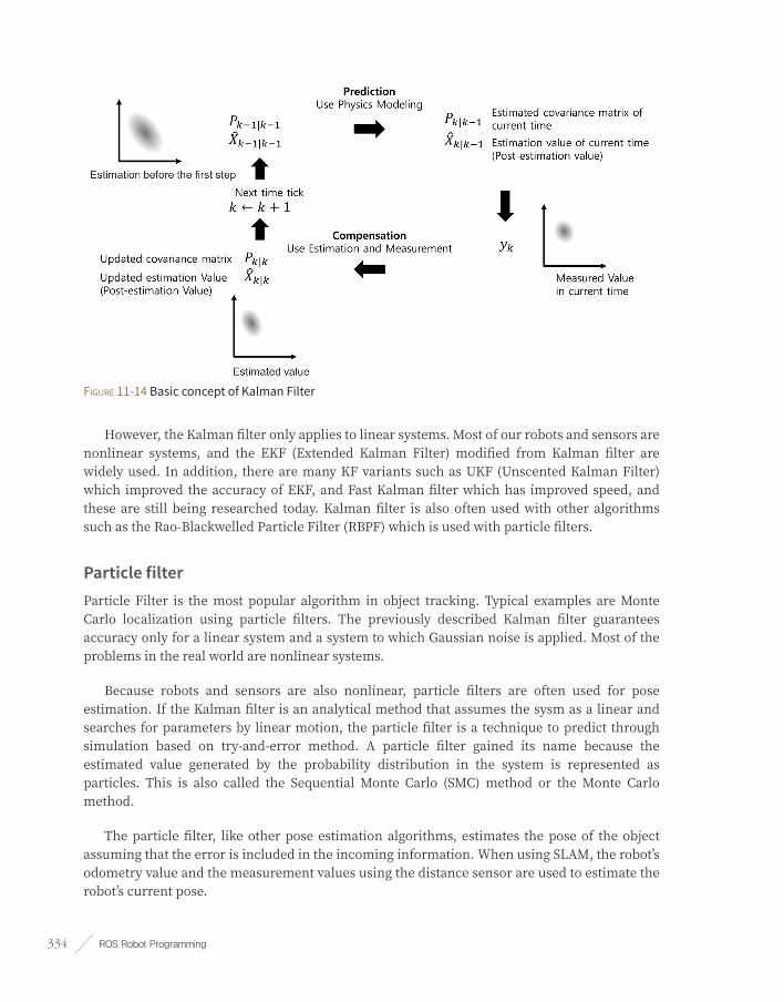
ROS Robot Programming334
Figure 11-14 Basic concept of Kalman Filter
However, the Kalman filter only applies to linear systems. Most of our robots and sensors are nonlinear systems, and the EKF (Extended Kalman Filter) modified from Kalman filter are widely used. In addition, there are many KF variants such as UKF (Unscented Kalman Filter) which improved the accuracy of EKF, and Fast Kalman filter which has improved speed, and these are still being researched today. Kalman filter is also often used with other algorithms such as the Rao-Blackwelled Particle Filter (RBPF) which is used with particle filters.
Particle filterParticle Filter is the most popular algorithm in object tracking. Typical examples are Monte Carlo localization using particle filters. The previously described Kalman filter guarantees accuracy only for a linear system and a system to which Gaussian noise is applied. Most of the problems in the real world are nonlinear systems.
Because robots and sensors are also nonlinear, particle filters are often used for pose estimation. If the Kalman filter is an analytical method that assumes the sysm as a linear and searches for parameters by linear motion, the particle filter is a technique to predict through simulation based on try-and-error method. A particle filter gained its name because the estimated value generated by the probability distribution in the system is represented as particles. This is also called the Sequential Monte Carlo (SMC) method or the Monte Carlo method.
The particle filter, like other pose estimation algorithms, estimates the pose of the object assuming that the error is included in the incoming information. When using SLAM, the robot’s odometry value and the measurement values using the distance sensor are used to estimate the robot’s current pose.

Chapter 11 _ SLAM and Navigation 335
In the particle filter method, the uncertain pose is described by a bunch of particles called samples. We move the particles to a new estimated position and orientation based on the robot’s motion model and probabilities, and measure the weight of each particle according to the actual measurement value, and gradually reduce the noise to estimate a precise pose. In the case of a mobile robot, each particle is represented as a particle = pose (x, y, i), weight, and each particle is an arbitrary small particle representing the estimated position and orientation of the robot expressed by x, y, and i of the robot and the weight of each particle.
This particle filter goes through the following 5 procedures. Except for the initialization in step 1, steps 2~5 are repeatedly performed to estimate the robot’s pose. In other words, it is a method to estimate the pose of the robot by updating the distribution of the particles that shows the probability of the robot on the X, Y coordinate plane based on the measured sensor value.
➊ Initialization
Since the robot’s initial pose (position, orientation) is unknown, the particles are randomly arranged within the range where the pose can be obtained with N particles. Each of the initial particle weighs 1/N, and the sum of the weight of particles is 1. N is empirically determined, usually in the hundreds. If the initial position is known, particles are placed near the robot.
➋ Prediction
Based on the system model describing the motion of the robot, it moves each particle as the amount of observed movement with odometry information and noise.
➌ Update
Based on the measured sensor information, the probability of each particle is calculated and the weight value of each particle is updated based on the calculated probability.
➍ Pose estimation
The position, orientation, and weight of all particles are used to calculate the average weight, median value, and the maximum weight value for estimating pose of the robot.
➎ Resampling
The step of generating new particles is to remove the less weighed particles and to create new particles that inherit the pose information of the weighted particles. Here, the number of particles N must be maintained.
In addition, if the number of samples is sufficient, the particle filter may be more accurate than the pose estimation from EKF or UKF that improved the Kalman filter. However, if the numbers are not sufficient, it may not be accurate. SLAM based on Rao-Blackwelled Particle

ROS Robot Programming336
Filter (RBPF), which utilizes both particle filter and Kalman filter at the same time, is also widely used as an approach to solve this problem.
Particle Filter
To learn more about particle filters, refer to the book ‘Probabilistic Robotics’ used as a textbook in robotics, by Sebastian Thrun (Professor at Stanford, Google Fellow, Udacity founder). I strongly recommend this book to anyone who wants to study robotics.
http://www.probabilistic-robotics.org/
https://www.udacity.com/course/cs373
This concludes the explanation of SLAM. The explanation of gmapping has been replaced by the particle filter description. Please refer to the thesis papers mentioned in the following reference for details. The next section deals with navigation.
OpenSLAM and Gmapping
As explained, the SLAM is an extensively researched field in robotics. Such informations can be found in the latest academic journals and presentations, and many of these studies are open-source compiled by the OpenSLAM group and can be found at OpenSLAM.org. This site is a must visit site.
The gmapping we used in section 11.4 is also introduced here, and the ROS community uses it extensively in SLAM. There are two papers introduced in regards to gmapping. One was published at ICRA 2005 and another was published at “Robotics, IEEE Transactions on” journal in 2007 .
These papers describe how to reduce the number of particles to reduce the computation volume and realize real-time operation. The main approach is to use the Rao-Blackwellized particle filter described above. Refer to the article for more details and a rough description can be seen in the discussion of particle filters in section 11.4.2.
[1] Grisetti, Giorgio, Cyrill Stachniss, and Wolfram Burgard, Improving grid-based slam with rao-blackwellized particle filters by adaptive proposals and selective resampling, Proceedings of the 2005 IEEE International Conference on Robotics and Automation, pp. 2432-2437, 2005.
[2] Grisetti, Giorgio, Cyrill Stachniss, and Wolfram Burgard, Improved techniques for grid mapping with rao-blackwellized particle filters, IEEE Transactions on Robotics, Vol.23, No.1, pp.34-46, 2007
11.5. Navigation PracticeBefore explaining the navigation, I will explain how to perform the navigation using TurtleBot3. The theory of navigation will be discussed in Section 11.7 after navigation application is discussed.

Chapter 11 _ SLAM and Navigation 337
Robot hardware for navigation is already mentioned in Section 11.2. TurtleBot3 was used as a mobile robot, and a LDS was used as a sensor. The measurement environment was the same as that of SLAM. In this section, we will look at the navigation that moves the robot to a specified destination using the map created by the previous SLAM example.
11.5.1. ROS Package for NavigationThe navigation-related ROS packages used in this section are the turtlebot3 metapackage from the previous SLAM practice, the ‘move_base’ in the navigation metapackage, amcl, and ‘map_server’ packages. Installation of these packages were completed during the previous SLAM section. Since this section is a hands-on practice, I will describe only the execution method. The description of each package is provided in the next section.
11.5.2. Execute NavigationThe order of execution for navigation is as follows. In this example, we will use the TurtleBot3 Waffle as a reference. If you are using a Burger or Waffle Pi, simply change the parameter of ‘TURTLEBOT3_MODEL’ in the command from ‘waffle’ to ‘burger’ or ‘waffle_pi’.
roscoreRun roscore on the [Remote PC].
$ roscore
Launch RobotFrom [TurtleBot], run the ‘turtlebot3_robot.launch’ file for excuting the ‘turtlebot3_core’ and ‘turtlebot3_lds’ nodes.
$ roslaunch turtlebot3_bringup turtlebot3_robot.launch
Execute Navigation PackageRun the ‘turtlebot3_navigation.launch’ file in the [Remote PC]. The ‘turtlebot3_navigation’ package consists of several launch files. When the package is executed, the following nodes will be launched along with the 3D model information of TurtleBot3.
■ The ‘robot_state_publisher’ node for publishing the three-dimensional position and orientation information of both wheels and joints in TF
■ The ‘map_server’ node that loads the map

ROS Robot Programming338
■ The AMCL (Adaptive Monte Carlo Localization) Node
■ The ‘move_base’ node.
$ export TURTLEBOT3_MODEL=waffle
$ roslaunch turtlebot3_navigation turtlebot3_navigation.launch map_file:=$HOME/map.yaml
Execute RVizLet’s run RViz, a visualization tool of ROS that enables visual confirmation of the goal pose designation and results in navigation. When you run RViz with the following options, it is very convenient to add display plugins from the scratch.
$ rosrun rviz rviz -d `rospack find turtlebot3_navigation`/rviz/turtlebot3_nav.rviz
When you run the above command, you can see the screen shown in Figure 11-15. On the right map you will see many green arrows, which are the particles of the particle filter described in SLAM theory. This will be explained later, but navigation also uses particle filters. The robot is in the middle of the green arrows.
Figure 11-15 Particles visible in RViz (green arrows around the robot)
Estimate Initial PoseFirst, the initial pose estimation of the robot should be performed. When you press [2D Pose Estimate] in the menu of RViz, a very large green arrow appears. Move it to the pose where the actual robot is located in the given map, and while holding down the left mouse button, drag the green arrow to the direction where the robot’s front is facing. This is like a command for

Chapter 11 _ SLAM and Navigation 339
estimating the pose of the robot in the early stage. Then move the robot back and forth with tools like the ‘turtlebot3_teleop_keyboard’ node to collect the surrounding environment information and find out where the robot is currently located on the map. When this process is completed, the robot estimates its actual position and orientation by using the position and orientation specified by the green arrow as the initial pose.
Setting the Destination and Moving the RobotWhen everything is ready, let’s try the move command from the navigation GUI. If you press [2D Nav Goal] in the menu of RViz, a very large green arrow appears. This green arrow is a marker that can specify the destination of the robot. The root of the arrow is the ‘x’ and ‘y’ position of the robot, and the orientation pointed by the arrow is the ‘theta’ direction of the robot. Click this arrow at the position where the robot will move, and drag it to set the orientation. The robot will create a path to avoid obstacles to its destination based on the map (see Figure 11-16).
Figure 11-16 Destination settings (big arrow) and how the robot is moving
The following sections describe the source details and how to set up the packages you have run previously. It will be divided into practice, application, and theory just as a SLAM example.
11.6. Navigation ApplicationSection 11.5 was a hands on practice for navigation, and this section explores the ROS package used in navigation and how to create and configure it. We will look at the TurtleBot3 metapackage and LDS driver ‘turtlebot3_lds’ node, TurtleBot3’s three-dimensional model information (turtlebot3_description), the ‘map_server’ node that loads the previously created map, the Adaptive Monte Carlo Localization node and the ‘move_base’ node. The objective of this section is to apply the navigation on your robot.
In this section, we will explain based on the TurtleBot3 robot platform and the LDS sensor used with it. By understanding this instruction, you can perform navigation with your own robot, which is not limited to a specific robot platform or specific sensors. If you want to create your own robot platform or build customized robot based on TurtleBot3 robot platform, this tutorial will be helpful.

ROS Robot Programming340
11.6.1. NavigationNavigation is to move the robot from one location to the specified destination in a given environment. For this purpose, a map that contains geometry information of furniture, objects, and walls of the given environment is required. As described in the previous SLAM section, the map was created with the distance information obtained by the sensor and the pose information of the robot itself.
The navigation enables a robot to move from the current pose to the designated goal pose on the map by using the map, robot’s encoder, inertial sensor, and distance sensor. The procedure for performing this task is as follows.
SensingOn the map, the robot updates its odometry information with the encoder and the inertial sensor (IMU sensor), and measures the distance from the pose of the sensor to the obstacle (wall, object, furniture, etc.).
Localization / Pose estimationBased on the wheel rotation amount from the encoder, the inertia information from the IMU sensor, and the distance information from the sensor to the obstacle, the localization/pose estimation of the current robot is performed on the previously created map. There are many pose estimating methods, but in this section we will be using the particle filter localization method and Adaptive Monte Carlo Localization (AMCL), which is a variant of Monte Carlo Localization (MCL).
Motion planningThe motion planning, which is also called as path planning, creates a trajectory from the current pose to the target pose specified on the map. The created path plan includes the global path planning in the whole map and the local path planning for smaller areas around the robot. We plan to use the ‘move_base’ and ‘nav_core’ route planning packages in ROS based on the Dynamic Window Approach (DWA), which is an obstacle avoidance algorithm.
Move / Obstacle avoidanceIf a command is given to the robot based on the movement trajectory created by the motion planning, the robot moves to the destination according to the planned path. Since the sensing, the pose estimation, and the motion planning are still being executed while moving, obstacles or moving objects that suddenly appear will be avoided using the Dynamic Window Approach (DWA) algorithm.

Chapter 11 _ SLAM and Navigation 341
11.6.2. Information Required for NavigationFigure 11-17 illustrates the relationship between the essential nodes and topics to run the ROS navigation package. We will focus on the information required for navigation. The topic name and the topic message type are shown separately when describing the topic in Figure 11-17. For example, in the case of odometry, ‘/odom’ is the topic name and ‘nav_msgs/Odometry’ is the form of the topic message.
Figure 11-17 Relationship between essential nodes and topics on the navigation packages configuration
Odometry (‘/odom’, nav_msgs/Odometry)The robot’s odometry information is used in local path planning by receiving information such as the current speed of the robot to generates a local path or to avoid obstacles.
Coordinate Transformation (‘/tf’, tf/tfMessage)Since the pose of the robot sensor changes depending on the hardware configuration of the robot, ROS uses relative coordinate transformation (TF). This simply describes the relative x, y, z coordinate of the sensor from the odometry of the robot. For example, the coordinate of the sensor can be obtained via odom → base_footprint → base_link → base_scan transformation and published on the topic. The ‘move_base’ node receives the topic and performs the path planning with the pose of the robot and the sensor.
Distance Sensor (‘/scan’, sensor_msgs/LaserScan or sensor_msgs/PointCloud)This refers to the distance value measured from the sensor. LDS and RealSense, Kinect, Xtion are commonly used. This distance sensor is used to estimate the robot’s current pose or to plan the motion of the robot using AMCL (adaptive Monte Carlo localization).

ROS Robot Programming342
Map (‘/map’, nav_msgs/GetMap)Navigation uses an occupancy grid map. In this tutorial, we will use the ‘map.pgm’ and ‘map.yaml’ created from the previous section with the ‘map_server’ package.
Target Coordinates (‘/move_base_simple/goal’, geometry_msgs/PoseStamped)Target coordinates are specified by the user. An additional target coordinate command package can be created using device such as a tablet, but in this section, we will use RViz to set the target coordinates. The target coordinates consist of two-dimensional coordinates (x, y) and direction θ.
Velocity Command (‘/cmd_vel’, geometry_msgs/Twist)The robot can be transferred to the destination coordinate by publishing the velocity command that follows the planned path.
11.6.3. Node and Topic State of turtlebot3_navigationAs described in section 11.5, if ‘turtlebot3_robot.launch’ and ‘turtlebot3_navigation.launch’ files are launched on [turtlebot], the robot is ready for navigation.
$ roslaunch turtlebot3_bringup turtlebot3_robot.launch
$ export TURTLEBOT3_MODEL=waffle
$ roslaunch turtlebot3_navigation turtlebot3_navigation.launch map_file:=$HOME/map.yaml
When you execute the ‘rqt_graph’, which visualizes the node and topic information running on the ROS, the information can be visually shown as Figure 11-18. As you can see in the diagram, the information required for the navigation described above is published and subscribed as the topic names ‘/odom’, ‘/tf’, ‘/scan’, ‘/map’ and ‘/cmd_vel’. The ‘move_base_simple/goal’ is published when the destination coordinate is specified from the RViz.

Chapter 11 _ SLAM and Navigation 343
Figure 11-18 Node and Topic state of turtlebot3_navigation
11.6.4. Settings for turtlebot3_navigationThe ‘turtlebot3_navigation’ package contains a launch file that launches navigation related nodes and packages, and configuration files such as xml file, yaml file that configures various parameters, map file, and rviz configuration file. Below are details of these files.
/launch/turtlebot3_navigation.launch
The ‘turtlebot3_navigation.launch’ file launches all navigation related packages.
/launch/amcl.launch.xml
The ‘amcl.launch.xml’ file contains various parameter settings of Adaptive Monte Carlo Localization (AMCL) and is used with ‘turtlebot3_navigation.launch’ file.

ROS Robot Programming344
/param/move_base_params.yaml
This configuration file configures the parameter of ‘move_base’ that supervises motion planning.
/param/costmap_common_params_burger.yaml
/param/costmap_common_params_waffle.yaml
/param/global_costmap_params.yaml
/param/local_costmap_params.yaml
Navigation uses the occupancy grid map described in section 11.3.1. Based on this occupancy grid map, each pixel is calculated as an obstacle, a non-movable area, and a movable area using the robot’s pose and surrounding information obtained from the sensor. In this calculation, the concept of costmap is applied. The above files are configuring parameters of the costmap. The ‘costmap_common_params.yaml’ has common parameters where ‘global_costmap_params.yaml’ file is required for the global area motion planning while ‘local_costmap_params.yaml’ file is required for the local area motion planning. The ‘costmap_common_params.yaml’ comes with a suffix of burger or waffle according to the model of the robot and the file contains different information for each model. However, the TurtleBot3 Waffle Pi model is the same as the TurtleBot3 Waffle model except the camera. So the TurtleBot3 Waffle Pi model uses the ‘waffle’ suffix to use the TurtleBot3 Waffle model settings.
/param/dwa_local_planner_params.yaml
‘dwa_local_planner’ is a package that ultimately trasmits the speed command to the robot and sets the parameters for it.
base_local_planner_params.yaml
This file contains configuration value for ‘base_local_planner’, however, it is not used because turtlebot3 uses ‘dwa_local_planner’ instead. This is because the parameter setting in the ‘move_base’ node has been modified in advance as follows:
<param name="base_local_planner" value="dwa_local_planner/DWAPlannerROS" />
/maps/map.pgm
/maps/map.yaml
Save and use the previously created occupancy grid map in the ‘/maps’ folder.

Chapter 11 _ SLAM and Navigation 345
/rviz/turtlebot3_nav.rviz
This file contains the setting information of RViz. This file is used to load Grid, RobotModel, TF, LaserScan, Map, Global Map, Local Map and AMCL Particles from the RViz display plug-in.
The following ‘turtlebot3_navigation.launch’ file contains details of the robot model, ‘robot_state_publisher’, map server, AMCL, and ‘move_base’ execution and configuration.
/launch/turtlebot3_navigation.launch
<launch>
<arg name="model" default="$(env TURTLEBOT3_MODEL)" doc="model type [burger, waffle,
waffle_pi]"/>
<!-- Turtlebot3 -->
<include file="$(find turtlebot3_bringup)/launch/turtlebot3_remote.launch" />
<!-- Map server -->
<arg name="map_file" default="$(find turtlebot3_navigation)/maps/map.yaml"/>
<node name="map_server" pkg="map_server" type="map_server" args="$(arg map_file)">
</node>
<!-- AMCL -->
<include file="$(find turtlebot3_navigation)/launch/amcl.launch.xml"/>
<!-- move_base -->
<arg name="cmd_vel_topic" default="/cmd_vel" />
<arg name="odom_topic" default="odom" />
<node pkg="move_base" type="move_base" respawn="false" name="move_base" output="screen">
<param name="base_local_planner" value="dwa_local_planner/DWAPlannerROS" />
<rosparam file="$(find turtlebot3_navigation)/param/costmap_common_params_$(arg model).yaml"
command="load" ns="global_costmap" />
<rosparam file="$(find turtlebot3_navigation)/param/costmap_common_params_$(arg model).yaml"
command="load" ns="local_costmap" />
<rosparam file="$(find turtlebot3_navigation)/param/local_costmap_params.yaml" command="load" />
<rosparam file="$(find turtlebot3_navigation)/param/global_costmap_params.yaml"
command="load" />
<rosparam file="$(find turtlebot3_navigation)/param/move_base_params.yaml" command="load" />
<rosparam file="$(find turtlebot3_navigation)/param/dwa_local_planner_params.yaml"
command="load" />
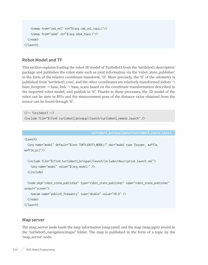
ROS Robot Programming346
<remap from="cmd_vel" to="$(arg cmd_vel_topic)"/>
<remap from="odom" to="$(arg odom_topic)"/>
</node>
</launch>
Robot Model and TFThis section explains loading the robot 3D model of TurtleBot3 from the ‘turtlebot3_description’ package and publishes the robot state such as joint information via the ‘robot_state_publisher’ in the form of the relative coordinate transform, ‘tf’. More precisely, the ‘tf’ of the odometry is published from ‘turtlebot3_core’, and the other coordinates are relatively transformed (odom → base_footprint → base_link → base_scan) based on the coordinate transformation described in the imported robot model, and publish to ‘tf ’. Thanks to these processes, the 3D model of the robot can be seen in RViz and the measurement pose of the distance value obtained from the sensor can be found through ‘tf’.
<!-- Turtlebot3 -->
<include file="$(find turtlebot3_bringup)/launch/turtlebot3_remote.launch" />
turtlebot3_bringup/launch/turtlebot3_remote.launch
<launch>
<arg name="model" default="$(env TURTLEBOT3_MODEL)" doc="model type [burger, waffle,
waffle_pi]"/>
<include file="$(find turtlebot3_bringup)/launch/includes/description.launch.xml">
<arg name="model" value="$(arg model)" />
</include>
<node pkg="robot_state_publisher" type="robot_state_publisher" name="robot_state_publisher"
output="screen">
<param name="publish_frequency" type="double" value="50.0" />
</node>
</launch>
Map serverThe map_server node loads the map information (map.yaml) and the map (map.pgm) stored in the ‘turtlebot3_navigation/maps/’ folder. The map is published in the form of a topic by the ‘map_server’ node.

Chapter 11 _ SLAM and Navigation 347
<!-- Map server -->
<arg name="map_file" default="$(find turtlebot3_navigation)/maps/map.yaml"/>
<node name="map_server" pkg="map_server" type="map_server" args="$(arg map_file)">
</node>
AMCL(Adaptive Monte Carlo Localization)Run the amcl node for AMCL and set the relevant parameters. This is covered in detail in section 11.6.5.
<include file="$(find turtlebot3_navigation)/launch/amcl.launch.xml"/>
move_baseSet costmap-related parameters necessary for motion planning, and set parameters for ‘dwa_local_planner’ that passes the moving speed command to the robot, and set parameters for ‘move_base’ that supervises the motion planning. Detailed explanations are available in section 11.6.6.
<arg name="cmd_vel_topic" default="/cmd_vel" />
<arg name="odom_topic" default="odom" />
<node pkg="move_base" type="move_base" respawn="false" name="move_base" output="screen">
<param name="base_local_planner" value="dwa_local_planner/DWAPlannerROS" />
<rosparam file="$(find turtlebot3_navigation)/param/costmap_common_params_$(arg model).yaml"
command="load" ns="global_costmap" />
<rosparam file="$(find turtlebot3_navigation)/param/costmap_common_params_$(arg model).yaml"
command="load" ns="local_costmap" />
<rosparam file="$(find turtlebot3_navigation)/param/local_costmap_params.yaml" command="load" />
<rosparam file="$(find turtlebot3_navigation)/param/global_costmap_params.yaml" command="load" />
<rosparam file="$(find turtlebot3_navigation)/param/move_base_params.yaml" command="load" />
<rosparam file="$(find turtlebot3_navigation)/param/dwa_local_planner_params.yaml"
command="load" />
<remap from="cmd_vel" to="$(arg cmd_vel_topic)"/>
<remap from="odom" to="$(arg odom_topic)"/>
</node>

ROS Robot Programming348
11.6.5. Detailed Parameter Setting for turtlebot3_navigationLet’s set up the detailed parameters for the ‘turtlebot3_navigation’ we discussed earlier.
AMCL (Adaptive Monte Carlo Localization)The ‘amcl.launch.xml’ file contains parameter settings of AMCL and is used with ‘turtlebot3_navigation.launch’ described above. The description of AMCL will be discussed in the navigation theory.
turtlebot3_navigation/launch/amcl.launch.xml
<launch>
<!-- if true, AMCL receives map topic instead of service call. -->
<arg name="use_map_topic" default="false"/>
<!-- topic name for the sensor values from the distance sensor. -->
<arg name="scan_topic" default="scan"/>
<!-- used as the initial x-coordinate value of the Gaussian distribution in initial pose
estimation.-->
<arg name="initial_pose_x" default="0.0"/>
<!-- used as the initial y-coordinate value of the Gaussian distribution in the initial pose
estimation.-->
<arg name="initial_pose_y" default="0.0"/>
<!-- used as the initial yaw coordinate value of the Gaussian distribution in the initial pose
estimation. -->
<arg name="initial_pose_a" default="0.0"/>
<!-- execute the amcl node by referring to the parameter settings below. -->
<node pkg="amcl" type="amcl" name="amcl">
<!-- filter related parameter -->
<!-- min number of particles allowed -->
<param name="min_particles" value="500"/>
<!-- max number of particles allowed (the higher the better; set based on PC performance) -->
<param name="max_particles" value="3000"/>
<!-- max error between the actual distribution and the estimated distribution -->
<param name="kld_err" value="0.02"/>
<!-- translational motion required for filter update (meter) -->
<param name="update_min_d" value="0.2"/>
<!-- rotational motion required for filter update (radian) -->

Chapter 11 _ SLAM and Navigation 349
<param name="update_min_a" value="0.2"/>
<!-- resampling interval -->
<param name="resample_interval" value="1"/>
<!-- conversion allowed time (by sec) -->
<param name="transform_tolerance" value="0.5"/>
<!-- index drop rate(slow average weight filter), deactivated if 0.0 -->
<param name="recovery_alpha_slow" value="0.0"/>
<!-- index drop rate(fast average weight filter), deactivated if 0.0 -->
<param name="recovery_alpha_fast" value="0.0"/>
<!-- refer to above initial_pose_x -->
<param name="initial_pose_x" value="$(arg initial_pose_x)"/>
<!-- refer to above initial_pose_y -->
<param name="initial_pose_y" value="$(arg initial_pose_y)"/>
<!-- refer to above initial_pose_a -->
<param name="initial_pose_a" value="$(arg initial_pose_a)"/>
<!-- max period to visually displaying scan and path info -->
<!-- example: 10Hz = 0.1sec, deactivated if -1.0 -->
<param name="gui_publish_rate" value="50.0"/>
<!-- same as the explanation for use_map_topic -->
<param name="use_map_topic" value="$(arg use_map_topic)"/>
<!--distance sensor parameter -->
<!-- change the sensor topic name -->
<remap from="scan" to="$(arg scan_topic)"/>
<!-- max distance of laser sensing distance (meter) -->
<param name="laser_max_range" value="3.5"/>
<!-- max number of laser beams used during filter update -->
<param name="laser_max_beams" value="180"/>
<!-- z_hit mixed weight of sensor model (mixture weight) -->
<param name="laser_z_hit" value="0.5"/>
<!-- z_short mixed weight of sensor model (mixture weight) -->
<param name="laser_z_short" value="0.05"/>
<!-- z_max mixed weight of sensor model (mixture weight) -->
<param name="laser_z_max" value="0.05"/>
<!-- x_rand mixed weight of sensor model (mixture weight) -->
<param name="laser_z_rand" value="0.5"/>
<!-- standard deviation of Gaussian model using z_hit of sensor -->
<param name="laser_sigma_hit" value="0.2"/>
<!-- index drop rate parameter for z_short of sensor -->

ROS Robot Programming350
<param name="laser_lambda_short" value="0.1"/>
<!-- max distance and obstacle for likelihood_field method sensor -->
<param name="laser_likelihood_max_dist" value="2.0"/>
<!-- sensor type(select likelihood_field or beam) -->
<param name="laser_model_type" value="likelihood_field"/>
<!-- parameter related to odometry -->
<!-- robot driving methods. "diff" or "omni" can be selected -->
<param name="odom_model_type"value="diff"/>
<!-- estimated rotational motion noise of the odometry during rotational motion -->
<param name="odom_alpha1" value="0.1"/>
<!-- estimated rotational motion noise of the odometry during translation motion -->
<param name="odom_alpha2" value="0.1"/>
<!-- estimated translation motion noise of the odometry during translation motion -->
<param name="odom_alpha3" value="0.1"/>
<!-- estimated translation motion noise of the odometry during rotational motion -->
<param name="odom_alpha4" value="0.1"/>
<!-- odometry frame -->
<param name="odom_frame_id" value="odom"/>
<!-- robot base frame -->
<param name="base_frame_id" value="base_footprint"/>
</node>
</launch>
move_baseThis is a parameter setting file of ‘move_base’ that supervises the motion planning.
turtlebot3_navigation/param/move_base_params.yaml
# choosing whether to stop the costmap node when move_base is inactive
shutdown_costmaps: false
# cycle of control iteration (in Hz) that orders the speed command to the robot base
controller_frequency: 3.0
# maximum time (in seconds) that the controller will listen for control information before the
space-clearing operation is performed
controller_patience: 1.0
# repetition cycle of global plan (in Hz)
planner_frequency: 2.0
# maximum amount of time (in seconds) to wait for an available plan before the space-clearing

Chapter 11 _ SLAM and Navigation 351
operation is performed
planner_patience: 1.0
# time (in sec) allowed to allow the robot to move back and forth before executing the recovery
behavior.
oscillation_timeout: 10.0
# oscillation_timeout is initialized if you move the distance below the distance (in meter) that
the robot should move so that it does not move back and forth.
oscillation_distance: 0.2
# Obstacles farther away from fixed distance are deleted on the map during costmap initialization
of the restore operation
conservative_reset_dist: 0.1
costmapNavigation uses an occupancy grid map. Based on this occupancy grid map, each pixel is calculated as an obstacle, a non-movable area, and a movable area based on the robot’s pose and surrounding information obtained from the sensor. In this calculation, the concept of costmap is applied. The parameter of costmap configuration consists of ‘costmap_common_params.yaml’ file, ‘global_costmap_params.yaml’ file for the global area motion planning, and ‘local_costmap_params.yaml’ file for the local area motion planning. The ‘costmap_common_params_burger.yaml’ file is used for burger and ‘costmap_common_params_waffle.yaml’ file is used for waffle. However, the TurtleBot3 Waffle Pi model is the same as the TurtleBot3 Waffle model except the camera. So the TurtleBot3 Waffle Pi model uses the ‘waffle’ suffix to use the TurtleBot3 Waffle model settings.
The following is the parameter setting for the TurtleBot3 Burger.
turtlebot3_navigation/param/costmap_common_params_burger.yaml
# Indicate the object as an obstacle when the distance between the robot and obstacle is within
this range.
obstacle_range: 2.5
# sensor value that exceeds this range will be indicated as a freespace
raytrace_range: 3.5
# external dimension of the robot is provided as polygons in several points
footprint: [[-0.110, -0.090], [-0.110, 0.090], [0.041, 0.090], [0.041, -0.090]]
# radius of the robot. Use the above footprint setting instead of robot_radius.
# robot_radius: 0.105
# radius of the inflation area to prevent collision with obstacles
inflation_radius: 0.15
# scaling variable used in costmap calculation. Calculation formula is as follows.

ROS Robot Programming352
# scaling
# exp(-1.0 * cost_scaling_factor *(distance_from_obstacle - inscribed_radius)) *(254 - 1)
cost_scaling_factor: 0.5
# select costmap to use between voxel(voxel-grid) and costmap(costmap_2d)
map_type: costmap
# tolerance of relative coordinate conversion time between tf
transform_tolerance: 0.2
# specify which sensor to use
observation_sources: scan
# set data type and topic, marking status, minimum obstacle for the laser scan
scan: {data_type: LaserScan, topic: scan, marking: true, clearing: true}
Below is parameter settings for TurtleBot3 Waffle. Unlike the TurtleBot3 Burger, the Waffle’s ‘footprint’ and ‘inflation_radius’, which prevents collision to the obstacle, are different. All other values are the same, and for the parameter description, refer to the Burger’s description.
turtlebot3_navigation/param/costmap_common_params_waffle.yaml
obstacle_range: 2.5
raytrace_range: 3.5
footprint: [[-0.205, -0.145], [-0.205, 0.145], [0.077, 0.145], [0.077, -0.145]]
inflation_radius: 0.20
cost_scaling_factor: 0.5
map_type: costmap
transform_tolerance: 0.2
observation_sources: scan
scan: {data_type: LaserScan, topic: scan, marking: true, clearing: true}
turtlebot3_navigation/param/global_costmap_params.yaml
global_costmap:
global_frame: /map # set map frame
robot_base_frame: /base_footprint # set robot's base frame
update_frequency: 2.0 # update frequency
publish_frequency: 0.1 # publish frequency
static_map: true # setting whether or not to use given map
transform_tolerance: 1.0 # transform tolerance time
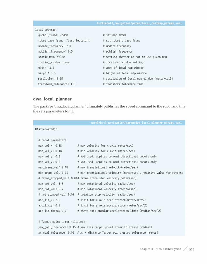
Chapter 11 _ SLAM and Navigation 353
turtlebot3_navigation/param/local_costmap_params.yaml
local_costmap:
global_frame: /odom # set map frame
robot_base_frame: /base_footprint # set robot's base frame
update_frequency: 2.0 # update frequency
publish_frequency: 0.5 # publish frequency
static_map: false # setting whether or not to use given map
rolling_window: true # local map window setting
width: 3.5 # area of local map window
height: 3.5 # height of local map window
resolution: 0.05 # resolution of local map window (meter/cell)
transform_tolerance: 1.0 # transform tolerance time
dwa_local_plannerThe package ‘dwa_local_planner’ ultimately publishes the speed command to the robot and this file sets parameters for it.
turtlebot3_navigation/param/dwa_local_planner_params.yaml
DWAPlannerROS:
# robot parameters
max_vel_x: 0.18 # max velocity for x axis(meter/sec)
min_vel_x:-0.18 # min velocity for x axis (meter/sec)
max_vel_y: 0.0 # Not used. applies to omni directional robots only
min_vel_y: 0.0 # Not used. applies to omni directional robots only
max_trans_vel: 0.18 # max translational velocity(meter/sec)
min_trans_vel: 0.05 # min translational velocity (meter/sec), negative value for reverse
# trans_stopped_vel: 0.01 # translation stop velocity(meter/sec)
max_rot_vel: 1.8 # max rotational velocity(radian/sec)
min_rot_vel: 0.7 # min rotational velocity (radian/sec)
# rot_stopped_vel: 0.01 # rotation stop velocity (radian/sec)
acc_lim_x: 2.0 # limit for x axis acceleration(meter/sec^2)
acc_lim_y: 0.0 # limit for y axis acceleration (meter/sec^2)
acc_lim_theta: 2.0 # theta axis angular acceleration limit (radian/sec^2)
# Target point error tolerance
yaw_goal_tolerance: 0.15 # yaw axis target point error tolerance (radian)
xy_goal_tolerance: 0.05 # x, y distance Target point error tolerance (meter)

ROS Robot Programming354
# Forward Simulation Parameter
sim_time: 3.5 # forward simulation trajectory time
vx_samples: 20 # number of sample in x axis velocity space
vy_samples: 0 # number of sample in y axis velocity space
vtheta_samples: 40 # number of sample in theta axis velocity space
# Trajectory scoring parameter (trajectory evaluation)
# Score calculation used for the trajectory evaluation cost function is as follows.
# cost =
# path_distance_bias * (distance to path from the endpoint of the trajectory in meters)
# + goal_distance_bias * (distance to local goal from the endpoint of the trajectory in meters)
# + occdist_scale * (maximum obstacle cost along the trajectory in obstacle cost (0-254))
path_distance_bias: 32.0 # weight value of the controller that follows the given path
goal_distance_bias: 24.0 # weight value for the goal pose and control velocity
occdist_scale: 0.04 # weight value for the obstacle avoidance
forward_point_distance: 0.325 # distance between the robot and additional scoring point (meter)
stop_time_buffer: 0.2 # time required for the robot to stop before collision (sec)
scaling_speed: 0.25 # scaling Speed (meter/sec)
max_scaling_factor: 0.2 # max scaling factor
# Oscillation motion prevention paramter
# distance the robot must move before the oscillation flag is reset
oscillation_reset_dist: 0.05
# Debugging
publish_traj_pc: true # debugging setting for the movement trajectory
publish_cost_grid_pc: true # debugging setting for costmap
global_frame_id: odom # ID setting for global frame
mapThe previously created occupancy grid map is saved at the ‘/maps’ folder. There are no other configuration parameters.
/maps/map.pgm
/maps/map.yaml

Chapter 11 _ SLAM and Navigation 355
turtlebot3_nav.rvizThis file contains setting information of RViz and calls the RViz’s display plug-ins such as Grid, Robot Model, TF, LaserScan, Map, Global Map, Local Map, and Amcl Particles. It is recommended to use the following file without any configuration. You can use options when running the command as below.
$ rosrun rviz rviz -d `rospack find turtlebot3_navigation`/rviz/turtlebot3_nav.rviz
Details to use the navigation package has been explained. In the next section, we will discuss the theory of costmap, Adaptive Monte Carlo Localization (AMCL), and Dynamic Window Approach (DWA).
11.7. Navigation Theory
11.7.1. CostmapThe pose of the robot is estimated based on the odometry obtained from the encoder and inertial sensor (IMU sensor). And the distance between the robot and the obstacle is obtained by the distance sensor mounted on the robot. The pose of robot and sensor, obstacle information, and the occupancy grid map obtained as a result from SLAM are used to load the static map and utilize the occupied area, free area, and unknown area for the navigation.
In navigation, costmap calculates obstacle area, possible collision area, and a robot movable area based on the aforementioned four factors. Depending on the type of navigation, costmap can be divided into two. One is the ‘global_costmap’, which sets up a path plan for navigating in the global area of the fixed map. The other is ‘local_costmap’ which is used for path planning and obstacle avoidance in the limited area around the robot. Although their purposes are different, both costmaps are represented in the same way.
The costmap is expressed as a value between ‘0’ and ‘255’. The meaning of the value is shown in Figure 11-19, and to briefly summarize, the value is used to identify whether the robot is movable or colliding with an obstacle. The calculation of each area depends on the costmap configuration parameters specified in Section 11.6.
■ 000: Free area where robot can move freely
■ 001~127: Areas of low collision probability
■ 128~252: Areas of high collision probability
■ 253~254: Collision area
■ 255: Occupied area where robot can not move

ROS Robot Programming356
Figure 11-19 Relationship between distance to obstacle and costmap value
For example, the actual costmap is expressed as shown in Figure 11-20. In detail, there is a robot model in the middle and the rectangular box around it corresponds to the outer surface of the robot. When this outline line contacts the wall, the robot will bump into the wall as well. Green represents the obstacle with the distance sensor value obtained from the laser sensor. As the gray scale costmap gets darker, it is more likely to be collision area. The same works for the case of color representation. The pink area is the actual obstacle, and the light blue area is the point where the center of the robot comes into this area, and the border is drawn with a thick red pixel. There is no important meaning for color since the user can modify it in RViz.

Chapter 11 _ SLAM and Navigation 357
Figure 11-20 Costmap representation (gray scale)
11.7.2. AMCLAs mentioned in section 11.4 SLAM Theory Particle Filter, the Monte Carlo localization (MCL) pose estimation algorithm is widely used in the field of pose estimation. AMCL (Adaptive Monte Carlo Localization) can be regarded as an improved version of Monte Carlo pose estimation, which improves real-time performance by reducing the execution time with less number of samples in the Monte Carlo pose estimation algorithm. So, let’s look at the basic Monte Carlo pose estimation (MCL).
The ultimate goal of Monte Carlo pose estimation (MCL) is to determine where the robot is located in a given environment. That is, we must get x, y, and θ of the robot on the map. For this purpose, MCL calculates the probability that the robot can be located. First, the position and orientation (x, y, θ) of the robot at time t are denoted by x
t, and the distance information obtained
from the distance sensor up to time t is denoted by z0...t
= {z0, z
1, ..., z
t}, and the movement
information obtained from the encoder up to time t is u0...t
= {u0, u
1, ..., u
t}. Then we can calculate
belief (posterior probability using Bayesian update formula) with the following equation.
bel( xt ) = p( xt|z0...t, u0..t ) (Equation 11-11)

ROS Robot Programming358
Since the robot may have hardware errors, establish the sensor model and the movement model. Then process the prediction and the update of the Bayes filter as follows.
In the prediction step, the position bel'( xt ) of the robot at the next time frame is calculated
using the movement model p( xt | x
t-1, u
t-1 ) of the robot and the probability bel( x
t-1 ) at the
previous position, and the movement information u received from the encoder.
bel'( xt ) = 8p( xt | xt-1, ut-1 )bel( xt-1 )dxt-1 (Equation 11-12)
The following is the update step. This time, sensor model p( zt | x
t ), the probability bel( x
t ) and
the normalization constant eta ( ht ) is used to obtained more accurate probability bel'( x
t ) based
on the sensor information.
bel( xt ) = htp( zt | xt )bel'( xt ) (Equation 11-13)
The following is the procedure for estimating the position by generating N particles with the particle filter using the calculated probability bel( x
t ) of the current position. Please refer to the
particle filter description in section 11.4 SLAM Theory. In the MCL, the term “sample” is used instead of particle, and goes through the SIR (Sampling Importance weighting Re-sampling) process. The first is the sampling process. Here, a new sample set ( | )p z x( ) ’( )
ti
t ti~ h= is extracted using the robot
movement model p( xt | x
t-1, u
t-1 ) at the probability bel( x
t-1 ) of the previous position. The sample
“i” ( | )p z x( ) ’( )ti
t ti~ h= among sample set ( | )p z x( ) ’( )
ti
t ti~ h= , the distance information z
t, and the normalization constant h is used
to obtain the weight ( | )p z x( ) ’( )ti
t ti~ h=.
( | )p z x( ) ’( )ti
t ti~ h= (Equation 11-14)
Finally, in the resampling process, we create N samples of new Xt sampling (particle) sets
using sample ( | )p z x( ) ’( )ti
t ti~ h= and weight ( | )p z x( ) ’( )
ti
t ti~ h=.
{ | ... } ~ { , }X x j N x1( ) ’( ) ( )t t
jt
iti~= ={ | ... } ~ { , }X x j N x1( ) ’( ) ( )
t tj
ti
ti~= = ( | )p z x( ) ’( )
ti
t ti~ h= (Equation 11-15)
By repeating the above SIR process while moving the particles, the estimated robot position increases in accuracy. For example, as shown in Figure 11-21, we can see the process of converging location from ‘t1’ to ‘t4’. All of this process was referred to ‘Probabilistic Robotics’ by Professor Sebastian Thrun, which is called as the textbook of probability related field in robotics. If time permits, I recommend you to take a look at this book.

Chapter 11 _ SLAM and Navigation 359
Figure 11-21 AMCL process for robot pose estimation
11.7.3. Dynamic Window Approach (DWA)Dynamic Window Approach (DWA) is a popular method for obstacle avoidance planning and avoiding obstacles. This is a method of selecting a speed that can quickly reach a target point while avoiding obstacles that can possibly collide with the robot in the velocity search space. In ROS, Trajectory planner was used for local path planning, but DWA is being replaced because of its superior performance.
First, the robot is not in the x and y-axis coordinates, but in the velocity search space with the translational velocity v and the rotational velocity ω as axes, as shown in Figure 11-22. In this space, the robot has a maximum allowable speed due to hardware limitations, and this is called Dynamic Window.
v: Translational velocity (meter/sec)
~: Rotational velocity (radian/sec)
Vs: Maximum velocity area
Va: Permissible velocity area
Vc: Current velocity
Vr: Speed area in Dynamic Window
amax: Maximum acceleration / deceleration rate
G(v, ~) = v(a·heading(v, ~) + b·dist(v, ~) + c·velocity(v, ~)): Objective function
heading(v, ~): 180 - (difference between the direction of the robot and the direction of the
target point)
dist(v, ~): Distance to the obstacle
velocity(v, ~): Selected velocity
a, b, c: Weighting constant
v(x): Smooth Function
In this dynamic window, the objective function G(v, ~) is used to calculate the translational velocity v and the rotational velocity ~ that maximizes the objective function which considers the direction, velocity and collision of the robot. If we plot it, we can find optimal velocity among various v and ~ options to destination as shown in Figure 11-23.
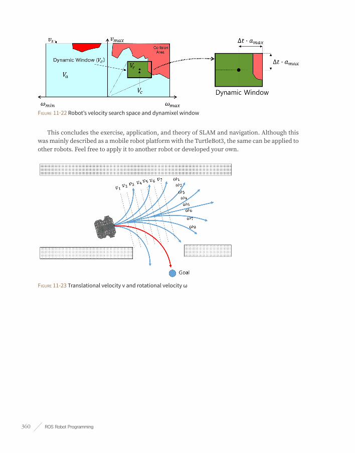
ROS Robot Programming360
Figure 11-22 Robot’s velocity search space and dynamixel window
This concludes the exercise, application, and theory of SLAM and navigation. Although this was mainly described as a mobile robot platform with the TurtleBot3, the same can be applied to other robots. Feel free to apply it to another robot or developed your own.
Figure 11-23 Translational velocity v and rotational velocity ω

Chapter 12 _ Service Robot 361
Service Robot
Chapter 12
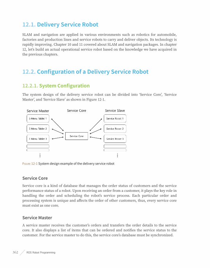
ROS Robot Programming362
12.1. Delivery Service RobotSLAM and navigation are applied in various environments such as robotics for automobile, factories and production lines and service robots to carry and deliver objects. Its technology is rapidly improving. Chapter 10 and 11 covered about SLAM and navigation packages. In chapter 12, let’s build an actual operational service robot based on the knowledge we have acquired in the previous chapters.
12.2. Configuration of a Delivery Service Robot
12.2.1. System ConfigurationThe system design of the delivery service robot can be divided into ‘Service Core’, ‘Service Master’, and ‘Service Slave’ as shown in Figure 12-1.
Figure 12-1 System design example of the delivery service robot
Service CoreService core is a kind of database that manages the order status of customers and the service performance status of a robot. Upon receiving an order from a customer, it plays the key role in handling the order and scheduling the robot’s service process. Each particular order and processing system is unique and affects the order of other customers, thus, every service core must exist as one core.
Service MasterA service master receives the customer’s orders and transfers the order details to the service core. It also displays a list of items that can be ordered and notifies the service status to the customer. For the service master to do this, the service core’s database must be synchronized.

Chapter 12 _ Service Robot 363
Service SlaveAs a robot platform and physical object that processes an order, the service slave updates the service status of the order to the service core in real time.
12.2.2. System DesignThe service master, service slave, and service core can be as little as a single computer or as many as distributed to one per computer. However, a single computer may not be able to process all the work when running all the process on one computer and on the otherhand, heavily distributing to each computer may lead to overload on the wireless communication. Thus, careful allocation is critical for proper processing. Also since ROS 1.x is a system created to control one robot, in order to use ROS on multiple computers the following command should be entered to reduce the time difference between each computer.
$ sudo ntpdate ntp.ubuntu.com
For example, as in Figure 12-2, I used the following devices to implement a delivery service robot system.
■ Service Core: NUC i5 (3 computers to execute roscore and service core)
■ Service Master: 3 SAMSUNG NOTE 10.4 Android OS
■ Service Slave: 3 Intel Joule 570x of TurtleBot3 Carrier (TurtleBot3 Waffle customized for a delivery robot)
Figure 12-2 Actual image of the delivery service robots and its operating systems.

ROS Robot Programming364
Once the overall concept is completed, you will have to decide what messages should be exchanged between the nodes in each area as in Figure 12-3.
Figure 12-3 Example of the messages in each area being transmitted by the delivery service robot
Although one pad can supervise mutiple robots, to simplify the system structure, one pad per robot was paired to carry out the service. The pad used to place an order must send the information of the pad ID and selected items to the service core. Based on the pad ID, the service core determines which service robot to designate the work and transmits the corresponding target site for the ordered item to perform the service.
Based on path planning algorithm, the service robot moves to the received target site. While carrying out this mission, the robot transmits the service status of the robot including the collision with the obstacle, the route failure, the arrival of the target, and whether or not the ordered item is acquired. The service core processes information such as status on duplicate orders related to the ordered items, orders received from the robot while the robot is in service to present to the customer through the pad. Every information sent and received during this process uses customized new msg files or srv files.

Chapter 12 _ Service Robot 365
Figure 12-4 Example of a delivery service robot’s node structure

ROS Robot Programming366
Before getting into details about each node of the service robot, let’s understand the general concept first. Figure 12-4 shows the correlation of all the nodes and topics of the delivery service robot to build in Chapter 12. The graph consists of 3 groups and the ‘service_core’. The service robot related nodes are paired up with ‘tb3p’, ‘tb3g’, ‘tb3r’ namespaces in each group. The ‘service_core’ must supervise three groups and therefore should not be dependent on any group. If you want to configure a system that allows one pad to control mutiple robots instead of pairing each robot to a single pad, you need to create separate groups for each pad and each service robot under a separate namespace.
The reason why group namespace1 is used when developing a service robot’s system is because when a majority of robot or computers want to use one type of ROS package at the same time, it is impossible to execute duplicated names of nodes and topics registered in ROS master.
Among the topics grouped into three namespaces, Figure 12-5 shows a node graph that focuses on the topics that ‘service_core’ directly sends and receives. The ‘service_core’ receives an order through a topic called ‘/pad_order’ and receives the robot’s path finding and destination success through the ‘/move_base/action_topics’ topic. It also delivers the service status via the ‘/service_status’ topic, passes the file location of the recorded voice file via ‘/play_sound_file’, and coordinates the robot’s target point via ‘/move_base_simple/goal’.
1 http://wiki.ros.org/roslaunch/XML/group
Figure 12-5 List of topics that service_core node sends and receives

Chapter 12 _ Service Robot 367
Figure 12-6 is a flow chart for preparing the delivery service. Navigation uses the map made with SLAM. When serving, think about which location to use as a service location. The position should be identified and recorded as the coordinate values on the map created, and the coordinate values will be used in ROS parameter acquisition and configuration in ‘service_core’ to be described later. For my example, I need coordinate values of the location for the customer to place an order and location for the robot to get an ordered item. Refer to chapter 10 and 11 or details on SLAM and navigation.
Figure 12-6 Flowchart for Preparing Delivery Services
The source code necessary to build a delivery service robot described here, are available in the address below. Let’s move on to the configuration and sources of the nodes.
■ https://github.com/ROBOTIS-GIT/turtlebot3_deliver
12.2.3. Service Core NodeFigure 12-7 shows the basic structure of the service core’s source. This node starts with the main() function and first sets the ROS parameter via fnInitParam(). Afterwards, orders received from customers through the pad and cbReceivePadOrder() and cbCheckArrivalStatus() functions that receive data about the robot’s target position arrival status are declared to execute as topic subscribe and through functions fnPubServiceStatus(), fnPubPose(), the service state and the target position of the robot coordinate values are published. This process is executed in an endless loop until the [Ctrl + c] key is pressed

ROS Robot Programming368
Figure 12-7 Basic structure of service core
When function serviceCore() is executed, function fnInitParam() is called and a publisher and subscriber are defined for various data transmission and reception. The ‘service_core’ must handle topics for the three robots, three pads. Therefore, three types of publisher and subscriber are defined. Each of their work is described as below.
Item Description
pubServiceStatusPad Publisherthatpublishesdeliveryservicestatustopad
pubPlaySound Publisherthatpublishesthelocationofrecordedvoicefiles
subPadOrder Subscribersthatsubscribetocustomerordersfromthepads
subArrivalStatus Subscriberthatsubscribestothearrivalofarobot
Table 12-1 ServiceCore() function in service_core.cpp
/turtlebot3_carrier/src/service_core.cpp (parts of excerpt)
ServiceCore()
{
fnInitParam();
pubServiceStatusPadTb3p = nh_.advertise<turtlebot3_carrier::ServiceStatus>("/tb3p/
service_status", 1);
pubServiceStatusPadTb3g = nh_.advertise<turtlebot3_carrier::ServiceStatus>("/tb3g/
service_status", 1);
pubServiceStatusPadTb3r = nh_.advertise<turtlebot3_carrier::ServiceStatus>("/tb3r/
service_status", 1);
pubPlaySoundTb3p = nh_.advertise<std_msgs::String>("/tb3p/play_sound_file", 1);
pubPlaySoundTb3g = nh_.advertise<std_msgs::String>("/tb3g/play_sound_file", 1);
pubPlaySoundTb3r = nh_.advertise<std_msgs::String>("/tb3r/play_sound_file", 1);
pubPoseStampedTb3p = nh_.advertise<geometry_msgs::PoseStamped>("/tb3p/move_base_simple/goal", 1);
pubPoseStampedTb3g = nh_.advertise<geometry_msgs::PoseStamped>("/tb3g/move_base_simple/goal", 1);

Chapter 12 _ Service Robot 369
pubPoseStampedTb3r = nh_.advertise<geometry_msgs::PoseStamped>("/tb3r/move_base_simple/goal", 1);
subPadOrderTb3p = nh_.subscribe("/tb3p/pad_order", 1, &ServiceCore::cbReceivePadOrder, this);
subPadOrderTb3g = nh_.subscribe("/tb3g/pad_order", 1, &ServiceCore::cbReceivePadOrder, this);
subPadOrderTb3r = nh_.subscribe("/tb3r/pad_order", 1, &ServiceCore::cbReceivePadOrder, this);
subArrivalStatusTb3p = nh_.subscribe("/tb3p/move_base/result", 1,
&ServiceCore::cbCheckArrivalStatusTB3P, this);
subArrivalStatusTb3g = nh_.subscribe("/tb3g/move_base/result", 1,
&ServiceCore::cbCheckArrivalStatusTB3G, this);
subArrivalStatusTb3r = nh_.subscribe("/tb3r/move_base/result", 1,
&ServiceCore::cbCheckArrivalStatusTB3R, this);
ros::Rate loop_rate(5);
while (ros::ok())
{
fnPubServiceStatus();
fnPubPose();
ros::spinOnce();
loop_rate.sleep();
}
}
The fnInitParam() function obtains the target pose (position + orientation) data of the robot on the map from the given parameter file. In this example, the robot should be able to move to three positions where customers can place an order and also be able to move to the three locations where ordered items can be acquired, therefore, it is necessary to store the information of the six coordinates of the locations on the map. The structure of the fnInitParam() function is as follows.
Item Description
poseStampedTable Coordinateswherecustomerplacesandreceivesorders
poseStampedCounter Coordinatesofwheretheitemisloadedontherobot
Table 12-2 fnInitParam() Function in service_core.cpp

ROS Robot Programming370
/turtlebot3_carrier/src/service_core.cpp (parts of excerpts)
void fnInitParam()
{
nh_.getParam("table_pose_tb3p/position", target_pose_position);
nh_.getParam("table_pose_tb3p/orientation", target_pose_orientation);
poseStampedTable[0].header.frame_id = "map";
poseStampedTable[0].header.stamp = ros::Time::now();
poseStampedTable[0].pose.position.x = target_pose_position[0];
poseStampedTable[0].pose.position.y = target_pose_position[1];
poseStampedTable[0].pose.position.z = target_pose_position[2];
poseStampedTable[0].pose.orientation.x = target_pose_orientation[0];
poseStampedTable[0].pose.orientation.y = target_pose_orientation[1];
poseStampedTable[0].pose.orientation.z = target_pose_orientation[2];
poseStampedTable[0].pose.orientation.w = target_pose_orientation[3];
nh_.getParam("table_pose_tb3g/position", target_pose_position);
nh_.getParam("table_pose_tb3g/orientation", target_pose_orientation);
poseStampedTable[1].header.frame_id = "map";
poseStampedTable[1].header.stamp = ros::Time::now();
poseStampedTable[1].pose.position.x = target_pose_position[0];
poseStampedTable[1].pose.position.y = target_pose_position[1];
poseStampedTable[1].pose.position.z = target_pose_position[2];
poseStampedTable[1].pose.orientation.x = target_pose_orientation[0];
poseStampedTable[1].pose.orientation.y = target_pose_orientation[1];
poseStampedTable[1].pose.orientation.z = target_pose_orientation[2];
poseStampedTable[1].pose.orientation.w = target_pose_orientation[3];
nh_.getParam("table_pose_tb3r/position", target_pose_position);
nh_.getParam("table_pose_tb3r/orientation", target_pose_orientation);
poseStampedTable[2].header.frame_id = "map";

Chapter 12 _ Service Robot 371
poseStampedTable[2].header.stamp = ros::Time::now();
poseStampedTable[2].pose.position.x = target_pose_position[0];
poseStampedTable[2].pose.position.y = target_pose_position[1];
poseStampedTable[2].pose.position.z = target_pose_position[2];
poseStampedTable[2].pose.orientation.x = target_pose_orientation[0];
poseStampedTable[2].pose.orientation.y = target_pose_orientation[1];
poseStampedTable[2].pose.orientation.z = target_pose_orientation[2];
poseStampedTable[2].pose.orientation.w = target_pose_orientation[3];
nh_.getParam("counter_pose_bread/position", target_pose_position);
nh_.getParam("counter_pose_bread/orientation", target_pose_orientation);
poseStampedCounter[0].header.frame_id = "map";
poseStampedCounter[0].header.stamp = ros::Time::now();
poseStampedCounter[0].pose.position.x = target_pose_position[0];
poseStampedCounter[0].pose.position.y = target_pose_position[1];
poseStampedCounter[0].pose.position.z = target_pose_position[2];
poseStampedCounter[0].pose.orientation.x = target_pose_orientation[0];
poseStampedCounter[0].pose.orientation.y = target_pose_orientation[1];
poseStampedCounter[0].pose.orientation.z = target_pose_orientation[2];
poseStampedCounter[0].pose.orientation.w = target_pose_orientation[3];
nh_.getParam("counter_pose_drink/position", target_pose_position);
nh_.getParam("counter_pose_drink/orientation", target_pose_orientation);
poseStampedCounter[1].header.frame_id = "map";
poseStampedCounter[1].header.stamp = ros::Time::now();
poseStampedCounter[1].pose.position.x = target_pose_position[0];
poseStampedCounter[1].pose.position.y = target_pose_position[1];
poseStampedCounter[1].pose.position.z = target_pose_position[2];
poseStampedCounter[1].pose.orientation.x = target_pose_orientation[0];

ROS Robot Programming372
poseStampedCounter[1].pose.orientation.y = target_pose_orientation[1];
poseStampedCounter[1].pose.orientation.z = target_pose_orientation[2];
poseStampedCounter[1].pose.orientation.w = target_pose_orientation[3];
nh_.getParam("counter_pose_snack/position", target_pose_position);
nh_.getParam("counter_pose_snack/orientation", target_pose_orientation);
poseStampedCounter[2].header.frame_id = "map";
poseStampedCounter[2].header.stamp = ros::Time::now();
poseStampedCounter[2].pose.position.x = target_pose_position[0];
poseStampedCounter[2].pose.position.y = target_pose_position[1];
poseStampedCounter[2].pose.position.z = target_pose_position[2];
poseStampedCounter[2].pose.orientation.x = target_pose_orientation[0];
poseStampedCounter[2].pose.orientation.y = target_pose_orientation[1];
poseStampedCounter[2].pose.orientation.z = target_pose_orientation[2];
poseStampedCounter[2].pose.orientation.w = target_pose_orientation[3];
}
The values of the parameters indicated in the ‘target_pose.yaml’ file are coordinate values on the map that the robot needs to perform its services. There are various ways to obtain the coordinate values, and the simplest method is to use the ‘rostopic echo’ command to get the pose value during navigation. However, these coordinates change with each mapping through SLAM so avoid rewritting the map while performing the actual navigation to reduce the positional changes of objects and obstacles so that you can continue with the same map.
/turtlebot3_carrier/param/target_pose.yaml
table_pose_tb3p:
position: [-0.338746577501, -0.85418510437, 0.0]
orientation: [0.0, 0.0, -0.0663151963596, 0.997798724559]
table_pose_tb3g:
position: [-0.168751597404, -0.19147400558, 0.0]
orientation: [0.0, 0.0, -0.0466624033917, 0.998910716786]
table_pose_tb3r:
position: [-0.251043587923, 0.421476781368, 0.0]

Chapter 12 _ Service Robot 373
orientation: [0.0, 0.0, -0.0600887022438, 0.998193041382]
counter_pose_bread:
position: [-3.60783815384, -0.750428497791, 0.0]
orientation: [0.0, 0.0, 0.999335763287, -0.0364421763375]
counter_pose_drink:
position: [-3.48697376251, -0.173366710544, 0.0]
orientation: [0.0, 0.0, 0.998398746904, -0.0565680314445]
counter_pose_snack:
position: [-3.62247490883, 0.39046728611, 0.0]
orientation: [0.0, 0.0, 0.998908838216, -0.0467026009308]
Next, based on which service procedure the current robot is in, the fnPubPose() function is used to set the next target position when the robot reaches the target position. When the robot completes the service, all parameters are reset.
Item Description
is_robot_reached_target Whethertherobothasreacheditsnavigationdestination
is_item_available Availabilityofitems
item_num_chosen_by_pad Itemnumberoftheorder
robot_service_sequence Processthattherobotisperforming
0-Waitingforcustomer’sorder1-Immediatelyafterreceivingcustomer’sorder2-Goingtogetitemordered3-Loadingordereditems4-Movingtocustomer’slocation5-Deliveringitemstocustomer
fnPublishVoiceFilePath() Functiontopublishthepathoftherecordedvoicefile
ROBOT_NUMBER Robot’snumber(Userdefined)
Table 12-3 fnPubPose() Functions in service_core.cpp

ROS Robot Programming374
/turtlebot3_carrier/src/service_core.cpp (parts of excerpt)
void fnPubPose()
{
if (is_robot_reached_target[ROBOT_NUMBER])
{
if (robot_service_sequence[ROBOT_NUMBER] == 1)
{
fnPublishVoiceFilePath(ROBOT_NUMBER, "~/voice/voice1-2.mp3");
robot_service_sequence[ROBOT_NUMBER] = 2;
}
else if (robot_service_sequence[ROBOT_NUMBER] == 2)
{
pubPoseStampedTb3p.publish(poseStampedCounter[item_num_chosen_by_pad[ROBOT_NUMBER]]);
is_robot_reached_target[ROBOT_NUMBER] = false;
robot_service_sequence[ROBOT_NUMBER] = 3;
}
else if (robot_service_sequence[ROBOT_NUMBER] == 3)
{
fnPublishVoiceFilePath(ROBOT_NUMBER, "~/voice/voice1-3.mp3");
robot_service_sequence[ROBOT_NUMBER] = 4;
}
else if (robot_service_sequence[ROBOT_NUMBER] == 4)
{
pubPoseStampedTb3p.publish(poseStampedTable[ROBOT_NUMBER]);
is_robot_reached_target[ROBOT_NUMBER] = false;
robot_service_sequence[ROBOT_NUMBER] = 5;
}
else if (robot_service_sequence[ROBOT_NUMBER] == 5)
{
fnPublishVoiceFilePath(ROBOT_NUMBER, "~/voice/voice1-4.mp3");
robot_service_sequence[ROBOT_NUMBER] = 0;

Chapter 12 _ Service Robot 375
is_item_available[item_num_chosen_by_pad[ROBOT_NUMBER]] = 1;
item_num_chosen_by_pad[ROBOT_NUMBER] = -1;
}
}
}
… omitted …
The cbReceivePadOrder() function receives the number of the pad used at the time of ordering and the item number of the ordered item to determine whether the service is available. If the service is available, the ‘robot_service_sequence’ is set to ‘1’ to start the service. The source code of this function is as follows.
Item Description
pad_number Numberofthepadorderedfrom(Numberofrobottoservice)
item_number Itemnumberoftheorder
Table 12-4 cbReceivePadOrder() Function in service_core.cpp
/turtlebot3_carrier/src/service_core.cpp (parts of excerpt)
void cbReceivePadOrder(const turtlebot3_carrier::PadOrder padOrder)
{
int pad_number = padOrder.pad_number;
int item_number = padOrder.item_number;
if (is_item_available[item_number] != 1)
{
ROS_INFO("Chosen item is currently unavailable");
return;
}
if (robot_service_sequence[pad_number] != 0)
{
ROS_INFO("Your TurtleBot is currently on servicing");
return;
}
if (item_num_chosen_by_pad[pad_number] != -1)
{

ROS Robot Programming376
ROS_INFO("Your TurtleBot is currently on servicing");
return;
}
item_num_chosen_by_pad[pad_number] = item_number;
robot_service_sequence[pad_number] = 1; // just left from the table
is_item_available[item_number] = 0;
}
The cbCheckArrivalStatus() function shown below checks the moving state of the subscribing robot. The ‘else’ block of the code handles if the robot comes across an obstacle during its navigation or is unable to find its path in the algorithm.
/turtlebot3_carrier/src/service_core.cpp (parts of excerpt)
void cbCheckArrivalStatusTB3P(const move_base_msgs::MoveBaseActionResult rcvMoveBaseActionResult)
{
if (rcvMoveBaseActionResult.status.status == 3)
{
is_robot_reached_target[ROBOT_NUMBER_TB3P] = true;
}
else
{
…omitted…
}
}
void cbCheckArrivalStatusTB3G(const move_base_msgs::MoveBaseActionResult rcvMoveBaseActionResult)
{
…omitted…
}
void cbCheckArrivalStatusTB3R(const move_base_msgs::MoveBaseActionResult rcvMoveBaseActionResult)
{
…omitted…
}

Chapter 12 _ Service Robot 377
The fnPublishVoicePath() function shown in the following source code publishes the location of the pre-recorded voice file as a String. In order to actually play the voice on ROS, you will need additional ROS Package.
/turtlebot3_carrier/src/service_core.cpp (parts of excerpt)
void fnPublishVoiceFilePath(int robot_num, const char* file_path)
{
std_msgs::String str;
str.data = file_path;
if (robot_num == ROBOT_NUMBER_TB3P)
{
pubPlaySoundTb3p.publish(str);
}
else if (robot_num == ROBOT_NUMBER_TB3G)
{
pubPlaySoundTb3g.publish(str);
}
else if (robot_num == ROBOT_NUMBER_TB3R)
{
pubPlaySoundTb3r.publish(str);
}
}
12.2.4. Service Master NodeIn this example, the service master node runs on a tablet PC with the Android OS. However, nodes can also be programmed to accepted orders through the terminal. Details on ROS Java2 programming using Android OS platform will be covered in the next chapter. The source of the service master node described below is created by applying ‘android_tutorial_pubsub’, a simple topic publishing and subscribing example source that is provided by ROS Java.
turtlebot3_carrier_pad/ServicePad.java
package org.ros.android.android_tutorial_pubsub;
import org.ros.concurrent.CancellableLoop;
2 http://wiki.ros.org/rosjava

ROS Robot Programming378
import org.ros.message.MessageListener;
import org.ros.namespace.GraphName;
import org.ros.node.AbstractNodeMain;
import org.ros.node.ConnectedNode;
import org.ros.node.topic.Publisher;
import org.ros.node.topic.Subscriber;
import javax.security.auth.SubjectDomainCombiner;
public class ServicePad extends AbstractNodeMain {
private String pub_pad_order_topic_name;
private String sub_service_status_topic_name;
private String pub_pad_status_topic_name;
private int robot_num = 0;
private int selected_item_num = -1;
private boolean jump = false;
private int[] item_num_chosen_by_pad = {-1, -1, -1};
private int[] is_item_available = {1, 1, 1};
private int[] robot_service_sequence = {0, 0, 0};
public boolean[] button_pressed = {false, false, false};
public ServicePad() {
this.pub_pad_order_topic_name = "/tb3g/pad_order";
this.sub_service_status_topic_name = "/tb3g/service_status";
this.pub_pad_status_topic_name = "/tb3g/pad_status";
}
public GraphName getDefaultNodeName() {
return GraphName.of("tb3g/pad");
}
public void onStart(ConnectedNode connectedNode) {
final Publisher pub_pad_order = connectedNode.newPublisher(this.pub_pad_order_topic_name,
"turtlebot3_carrier/PadOrder");
final Publisher pub_pad_status = connectedNode.newPublisher(this. pub_pad_status_topic_name,
"std_msgs/String");

Chapter 12 _ Service Robot 379
final Subscriber<turtlebot3_carrier.ServiceStatus> subscriber =
connectedNode.newSubscriber(this.sub_service_status_topic_name, " turtlebot3_carrier/
ServiceStatus");
subscriber.addMessageListener(new MessageListener<turtlebot3_carrier.SerivceStatus>() {
@Override
public void onNewMessage(turtlebot3_carrier.SerivceStatus serviceStatus)
{
item_num_chosen_by_pad = serviceStatus.item_num_chosen_by_pad;
is_item_available = serviceStatus.is_item_available;
robot_service_sequence = serviceStatus.robot_service_sequence
}
});
connectedNode.executeCancellableLoop(new CancellableLoop() {
protected void setup() {}
protected void loop() throws InterruptedException
{
str_msgs.String padStatus = (str_msgs.String)pub_pad_status.newMessage();
turtlebot3_carrier.PadOrder padOrder =
(turtlebot3_carrier.PadOrder)pub_pad_order.newMessage();
String str = "";
if (button_pressed[0] || button_pressed[1] || button_pressed[2])
{
jump = false;
if (button_pressed[0])
{
selected_item_num = 0;
str += "Burger was selected";
button_pressed[0] = false;
}
else if (button_pressed[1])
{
selected_item_num = 1;

ROS Robot Programming380
str += "Coffee was selected";
button_pressed[1] = false;
}
else if (button_pressed[2])
{
selected_item_num = 2;
str += "Waffle was selected";
button_pressed[2] = false;
}
else
{
selected_item_num = -1;
str += "Sorry, selected item is now unavailable. Please choose another item.";
}
if (is_item_available[selected_item_num] != 1)
{
str += ", but chosen item is currently unavailable.";
jump = true;
}
else if (robot_service_sequence[robot_num] != 0)
{
str += ", but your TurtleBot is currently on servicing";
jump = true;
}
else if (item_num_chosen_by_pad[robot_num] != -1)
{
str += ", but your TurtleBot is currently on servicing";
jump = true;
}
padStatus.setData(str);
pub_pad_status.publish(padStatus);
if(!jump)
{
padOrder.pad_number = robot_num;

Chapter 12 _ Service Robot 381
padOrder.item_number = selected_item_num;
pub_pad_order.publish(padOrder);
}
}
Thread.sleep(1000L);
}
});
}
}
In the code, MainActivity class receives and uses an instance of ServicePad class. Other than that, it is pretty much the same as general MainActivity class so we will omit detailed explanation and only look into the part corresponding to delivery service.
The number of the robot to be controlled by the tablet PC to which this example is uploaded is designated as robot_num as the following source code, and the number of the selected product on the tablet PC is initialized to ‘-1’.
private int robot_num = 0;
private int selected_item_num = -1;
In order to avoid duplicate orders, the tablet PC must be synchronized with the order status stored in the service core before receiving the customer’s order. The following source code is declared in the service core in the same format as the array that records the order status.
private int[] item_num_chosen_by_pad = {-1, -1, -1};
private int[] is_item_available = {1, 1, 1};
private int[] robot_service_sequence = {0, 0, 0};
When you create an instance of the ServicePad class in the MainActivity class, you will specify the topic name as follows. In this example, each pad and robot pair is specified as a group namespace, so it is necessary to write the name used in the namespace in front of each topic name.
public ServicePad() {
this.pub_pad_order_topic_name = "/tb3g/pad_order";
this.sub_service_status_topic_name = "/tb3g/service_status";
this.pub_pad_status_topic_name = "/tb3g/pad_status";
}

ROS Robot Programming382
Specifies the node name that appears on the ROS. The node name should also be written with the group namespace.
public GraphName getDefaultNodeName() {
return GraphName.of("tb3g/pad");
}
From the service core, the user receives service conditions such as the item number of ordered item, the availability of item selection, and the service status of the robot.
subscriber.addMessageListener(new MessageListener<turtlebot3_carrier.ServiceStatus>() {
@Override
public void onNewMessage(turtlebot3_carrier.ServiceStatus serviceStatus)
{
item_num_chosen_by_pad = serviceStatus.item_num_chosen_by_pad;
is_item_available = serviceStatus.is_item_available;
robot_service_sequence = serviceStatus.robot_service_sequence;
}
});
This portion processes the customer’s orders based on the overall service situation synchronized with the service core. Likewise, checks whether or not the order is duplicated, and if the service is available, publishes the order. Figures 12-8 and 12-9 show examples of successful and unsuccessful orders, respectively, when a customer selects an item drawn on the pad.
protected void loop() throws InterruptedException
{
std_msgs.String padStatus = (std_msgs.String) pub_pad_status.newMessage();
turtlebot3_carrier.PadOrder padOrder = (turtlebot3_carrier.PadOrder)
pub_pad_order.newMessage();
String str = "";
if (button_pressed[0] || button_pressed[1] || button_pressed[2])
{
jump = false;
if (button_pressed[0])
{

Chapter 12 _ Service Robot 383
selected_item_num = 0;
str += "Burger was selected";
button_pressed[0] = false;
}
else if (button_pressed[1])
{
selected_item_num = 1;
str += "Coffee was selected";
button_pressed[1] = false;
}
else if (button_pressed[2])
{
selected_item_num = 2;
str += "Waffle was selected";
button_pressed[2] = false;
}
else
{
selected_item_num = -1;
str += "Sorry, selected item is now unavailable. Please choose another item.";
}
if (is_item_available[selected_item_num] != 1)
{
str += ", but chosen item is currently unavailable.";
jump = true;
}
else if (robot_service_sequence[robot_num] != 0)
{
str += ", but your TurtleBot is currently on servicing";
jump = true;
}
else if (item_num_chosen_by_pad[robot_num] != -1)
{
str += ", but your TurtleBot is currently on servicing";
jump = true;
}

ROS Robot Programming384
padStatus.setData(str);
pub_pad_status.publish(padStatus);
if(!jump)
{
padOrder.pad_number = robot_num;
padOrder.item_number = selected_item_num;
pub_pad_order.publish(padOrder);
}
}
Thread.sleep(1000L);
}
Figure 12-8 Example 1 of menu displayed on a pad (When the order is successfully received)
Figure 12-9 Example 2 of menu displayed on a pad (When unavailable item is selected)
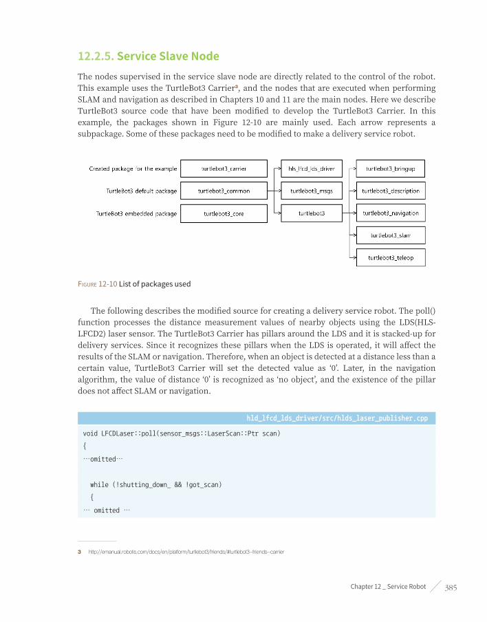
Chapter 12 _ Service Robot 385
12.2.5. Service Slave NodeThe nodes supervised in the service slave node are directly related to the control of the robot. This example uses the TurtleBot3 Carrier3, and the nodes that are executed when performing SLAM and navigation as described in Chapters 10 and 11 are the main nodes. Here we describe TurtleBot3 source code that have been modified to develop the TurtleBot3 Carrier. In this example, the packages shown in Figure 12-10 are mainly used. Each arrow represents a subpackage. Some of these packages need to be modified to make a delivery service robot.
Figure 12-10 List of packages used
The following describes the modified source for creating a delivery service robot. The poll() function processes the distance measurement values of nearby objects using the LDS(HLS-LFCD2) laser sensor. The TurtleBot3 Carrier has pillars around the LDS and it is stacked-up for delivery services. Since it recognizes these pillars when the LDS is operated, it will affect the results of the SLAM or navigation. Therefore, when an object is detected at a distance less than a certain value, TurtleBot3 Carrier will set the detected value as ‘0’. Later, in the navigation algorithm, the value of distance ‘0’ is recognized as ‘no object’, and the existence of the pillar does not affect SLAM or navigation.
hld_lfcd_lds_driver/src/hlds_laser_publisher.cpp
void LFCDLaser::poll(sensor_msgs::LaserScan::Ptr scan)
{
…omitted…
while (!shutting_down_ && !got_scan)
{
… omitted …
3 http://emanual.robotis.com/docs/en/platform/turtlebot3/friends/#turtlebot3-friends-carrier

ROS Robot Programming386
if(start_count == 0)
{
if(raw_bytes[start_count] == 0xFA)
{
start_count = 1;
}
}
else if(start_count == 1)
{
if(raw_bytes[start_count] == 0xA0)
{
… omitted …
//read data in sets of 6
for(uint16_t i = 0; i < raw_bytes.size(); i=i+42)
{
if(raw_bytes[i] == 0xFA && raw_bytes[i+1] == (0xA0 + i / 42))
{
… omitted …
for(uint16_t j = i+4; j < i+40; j=j+6)
{
index = (6*i)/42 + (j-6-i)/6;
// Four bytes per reading
uint8_t byte0 = raw_bytes[j];
uint8_t byte1 = raw_bytes[j+1];
uint8_t byte2 = raw_bytes[j+2];
uint8_t byte3 = raw_bytes[j+3];
// Remaining bits are the range in mm
uint16_t intensity = (byte1 << 8) + byte0;
uint16_t range = (byte3 << 8) + byte2;
scan->ranges[359-index] = range / 1000.0;
scan->intensities[359-index] = intensity;
}
}
}

Chapter 12 _ Service Robot 387
/// Add pillars ///
for(uint16_t deg = 0; deg < 360; deg++)
{
if(scan->ranges[deg] < 0.15)
{
scan->ranges[deg] = 0.0;
scan->intensities[deg] = 0.0;
}
}
/// end of addition ///
scan->time_increment = motor_speed/good_sets/1e8;
}
else
{
start_count = 0;
}
}
}
}
The ‘turtlebot3_core’ is a firmware installed on the control board OpenCR used by TurtleBot3, and ‘turtlebot3_motor_driver.cpp’ is a source that directly controls the actuator used in TurtleBot3. The actual service robot moves with objects loaded, so proper control is required for safe movement. Therefore, we added the profile control of Dynamixels which is not included in the original source of ‘turtlebot3_motor_driver.cpp’. Here, the value of ADDR_X_PROFILE_ACCELERATION is 108. For more information about the actuator, please refer to the Dynamixel manual (http://emanual.robotis.com/).
turtlebot3_core(for TurtleBot3 Waffle)/turtlebot3_motor_driver.cpp
bool Turtlebot3MotorDriver::init(void)
{
… omitted …
// Enable Dynamixel Torque
setTorque(left_wheel_id_, true);
setTorque(right_wheel_id_, true);
/// begin addition ///
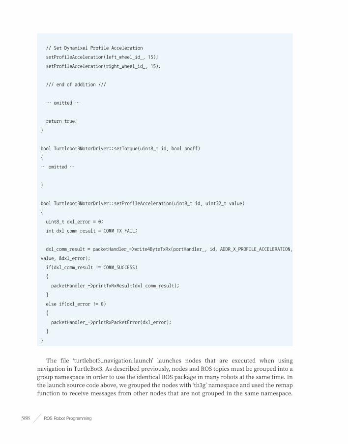
ROS Robot Programming388
// Set Dynamixel Profile Acceleration
setProfileAcceleration(left_wheel_id_, 15);
setProfileAcceleration(right_wheel_id_, 15);
/// end of addition ///
… omitted …
return true;
}
bool Turtlebot3MotorDriver::setTorque(uint8_t id, bool onoff)
{
… omitted …
}
bool Turtlebot3MotorDriver::setProfileAcceleration(uint8_t id, uint32_t value)
{
uint8_t dxl_error = 0;
int dxl_comm_result = COMM_TX_FAIL;
dxl_comm_result = packetHandler_->write4ByteTxRx(portHandler_, id, ADDR_X_PROFILE_ACCELERATION,
value, &dxl_error);
if(dxl_comm_result != COMM_SUCCESS)
{
packetHandler_->printTxRxResult(dxl_comm_result);
}
else if(dxl_error != 0)
{
packetHandler_->printRxPacketError(dxl_error);
}
}
The file ‘turtlebot3_navigation.launch’ launches nodes that are executed when using navigation in TurtleBot3. As described previously, nodes and ROS topics must be grouped into a group namespace in order to use the identical ROS package in many robots at the same time. In the launch source code above, we grouped the nodes with ‘tb3g’ namespace and used the remap function to receive messages from other nodes that are not grouped in the same namespace.

Chapter 12 _ Service Robot 389
This method is also used when the topic name can not be modified in the source code. Please note that this modification should be done not only in the launch file, but also in all areas where grouping such as the RViz file is required.
turtlebot3/turtlebot3_navigation/turtlebot3_navigation.launch
<launch>
<!—- addition starts -->
<group ns="tb3g">
<remap from="/tf" to="/tb3g/tf"/>
<remap from="/tf_static" to="/tb3g/tf_static"/>
<!-- addition ends -->
<arg name="model" default="waffle" doc="model type [burger, waffle]"/>
… omitted …
</node>
<!—- addition starts -->
</group>
<!-- addition ends -->
</launch>
If everything has gone smoothly up to this point, building the system shown in Figure 12-11 will be successful.

ROS Robot Programming390
Figure 12-11 Navigation view of each robot displayed on RViz
12.3. Android Tablet PC Programming with ROS JavaIn the previous section, we have described about placing orders using a pad, for example, the menu that operates on the pad in Figure 12-8. In this section, we will install Android Studio IDE4 on Linux and build a ROS Java development environment. Then, explain a simple ROS Java example.
The following describes how to install the necessary packages for installing Android Studio IDE and applying ROS Java environment. ROS Java refers to the ROS client library running in the Java language. Let’s first set the necessary environment for using Java. The necessary packages are the Java SE Development Kit (JDK), and you need to specify the location where you want to run it. This book describes how to download JDK 8, but you should modify it when the JDK version is updated.
$ sudo apt-get install openjdk-8-jdk
$ echo export PATH=${PATH}:/opt/android-sdk/tools:/opt/android-sdk/platform-tools:/opt/android-
studio/bin >> ~/.bashrc
$ echo export ANDROIS_HOME=/opt/android-sdk >> ~/.bashrc
$ source ~/.bashrc
4 https://developer.android.com/studio/index.html

Chapter 12 _ Service Robot 391
The following command downloads the necessary tools for building in ROS Java. After that, install and build a package that contains the ROS Java system and examples. The ‘android_core’ folder is the workspace folder as ‘catkin_ws’ on ROS.
$ sudo apt-get install ros-kinetic-rosjava-build-tools
$ mkdir -p ~/android_core
$ wstool init -j4 ~/android_core/src https://raw.github.com/rosjava/rosjava/kinetic/
android_core.rosinstall
$ source /opt/ros/kinetic/setup.bash
$ cd ~/android_core
$ catkin_make
Here’s how to install Android Studio IDE. To avoid confusion, I will use identical names and locations of the folders and files described in the ROS Android. These packages are add-on packages for installing mksdcard that allows you to use the SD card in your Android Studio IDE to implement the Virtual Device. If you do not install these packages, the mksdcard function fails to install.
$ sudo apt-get install lib32z1 lib32ncurses5 lib32stdc++6
This book installs the Android Studio IDE and SDK in ‘/opt’ folder, which is the installation folder recommended by ROS Android5. To install to the ‘/opt’ folder, you need to change the user permissions of ‘/opt’ to be writable.
$ sudo chown -R $USER:$USER /opt
The Android Studio IDE installation file can be found here. https://developer.android.com/studio/index.html#download
When the installation file is downloaded, extract it to ‘/opt/android-studio’. After decompression, the folder is configured as shown in Figure 12-12.
5 http://wiki.ros.org/android

ROS Robot Programming392
Figure 12-12 Decompressed Android Studio IDE
When the extraction is completed, enter the following command to start the IDE installation.
$ /opt/android-studio/bin/studio.sh
When the window shown in Figure 12-13 appears, click ‘Run without import’ to proceed to ‘custom install’.
Figure 12-13 First window that appears during installation
After that, you should see the window for installing Android SDK like Figure 12-14. Please note that you need to set the installation location to ‘/opt/android-sdk’. If you do not have the ‘android-sdk’ folder, create it in the location and proceed.
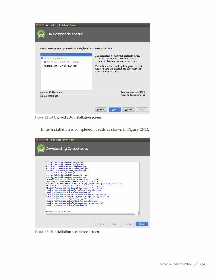
Chapter 12 _ Service Robot 393
Figure 12-14 Android SDK installation screen
If the installation is completed, it ends as shown in Figure 12-15.
Figure 12-15 Installation completed screen

ROS Robot Programming394
When the Android Studio IDE is successfully installed, a ‘Welcome to Android Studio’ window will appear as shown in Figure 12-16.
Figure 12-16 Welcome to Android Studio
Now, proceed to update the Android SDK through Configure → SDK Manager.
In Figure 12-17, the available SDKs to be updated are 10 (Gingerbread), 13 (Honeycomb), 15 (Ice cream) and 18 (Jellybean) and each number represents the API level of SDK.
Figure 12-17 Setting up the Android SDK

Chapter 12 _ Service Robot 395
After setting is completed, click on an existing Android Studio project in the window and import the previously installed ‘android_core’ as shown in Figure 12-18. When you click OK, the IDE window shown in Figure 12-19 appears and begins to build the imported source.
Figure 12-18 Import Project
Figure 12-19 Import Screen of Android Studio IDE
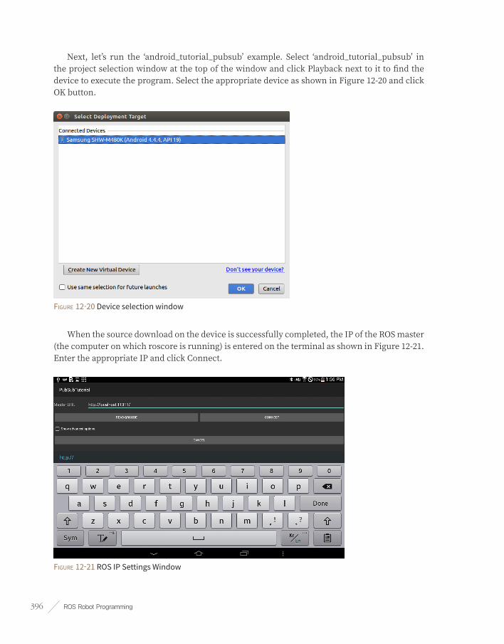
ROS Robot Programming396
Next, let’s run the ‘android_tutorial_pubsub’ example. Select ‘android_tutorial_pubsub’ in the project selection window at the top of the window and click Playback next to it to find the device to execute the program. Select the appropriate device as shown in Figure 12-20 and click OK button.
Figure 12-20 Device selection window
When the source download on the device is successfully completed, the IP of the ROS master (the computer on which roscore is running) is entered on the terminal as shown in Figure 12-21. Enter the appropriate IP and click Connect.
Figure 12-21 ROS IP Settings Window

Chapter 12 _ Service Robot 397
When ‘android_tutorial_pubsub’ is executed, the device publishes ‘Hello world!’ followed by increasing number as a type of ‘std_msgs::String’. Now, let’s subscribe to a string that the device publishes on your computer. If you look at the ‘/chatter’ topic using the ‘rostopic echo’ command as described previously, you can see that the topic is being published as follows.
$ rostopic echo /chatter
data: Hello world! 96
---
data: Hello world! 97
---
data: Hello world! 98
---
data: Hello world! 99
---
data: Hello world! 100
---
data: Hello world! 101
---
We looked at SLAM and service robot that have applied navigation in the previous chapter. As described in this chapter, it is not difficult to build a service robot. I close this chapter with hopes that this book helps you build a great robot.

ROS Robot Programming398
Manipulator
Chapter 13

Chapter 13 _ Manipulator 399
13.1. Manipulator IntroductionManipulators are robots designed for use in factories where simple repetitive tasks are performed. It is designed to replace dangerous work or to replace repetitive tasks, and many studies have recently been conducted aiming at collaborating with human.1 2
As the research on human robot interaction (HRI)3 became active, manipulators have started being used in various fields (Media Arts4, VR5, etc.) as well as factories and providing a new experience to the general public. By combining a digital actuator and 3D printing technology, the manipulators have become more accessible for the general public, and it is growing as a major player in the maker and education industry.6 7 8 On the other hands, many worry and fear that the combination of manipulators and artificial intelligence will take away their jobs.9 10 Manipulators have long been a tool for enriching society and are still helping people in many different areas.11 12 In the future, if the development of the manipulator can pervade our lives without getting out of its essence, it is expected that the manipulator will become a part of our life just like robot vacuum cleaners.
We will introduce a structural description of the manipulator and a library for the manipulator that ROS supports. OpenManipulator by ROBOTIS is one of the manipulators that support ROS, and has the advantage of being able to easily manufacture at a low cost by using Dynamixel actuators with 3D printed parts. With this manipulator, I will introduce and explain how to use the Gazebo 3D simulator that works with ROS and an integrated library for manipulators called MoveIt!. Finally, I’m going to talk about the compatibility between OpenManipulator, TurtleBot3 Waffle, Waffle Pi and how to configure and to control the actual platform.
13.1.1. Manipulator Structure and ControlThe basic structure of the manipulator consists of a base, a link, a joint, and an end-effector, as shown in Figure 13-1.
1 https://www.automationworld.com/inside-human-robot-collaboration-trend
2 https://www.kuka.com/en-us/technologies/human-robot-collaboration
3 https://en.wikipedia.org/wiki/Human%E2%80%93robot_interaction
4 https://youtu.be/lX6JcybgDFo
5 http://www.asiae.co.kr/news/view.htm?idxno=2016100416325879220
6 http://www.littlearmrobot.com/
7 https://niryo.com/products/
8 http://www.ufactory.cc/#/en/
9 http://time.com/4742543/robots-jobs-machines-work/
10 http://adage.com/article/digitalnext/5-jobs-robots/308094/
11 https://www.bostonglobe.com/magazine/2015/09/24/this-robot-going-take-your-job/paj3zwznSXMSvQiQ8pdBjK/story.html
12 https://www.automationworld.com/article/abb-unveils-future-human-robot-collaboration-yumi
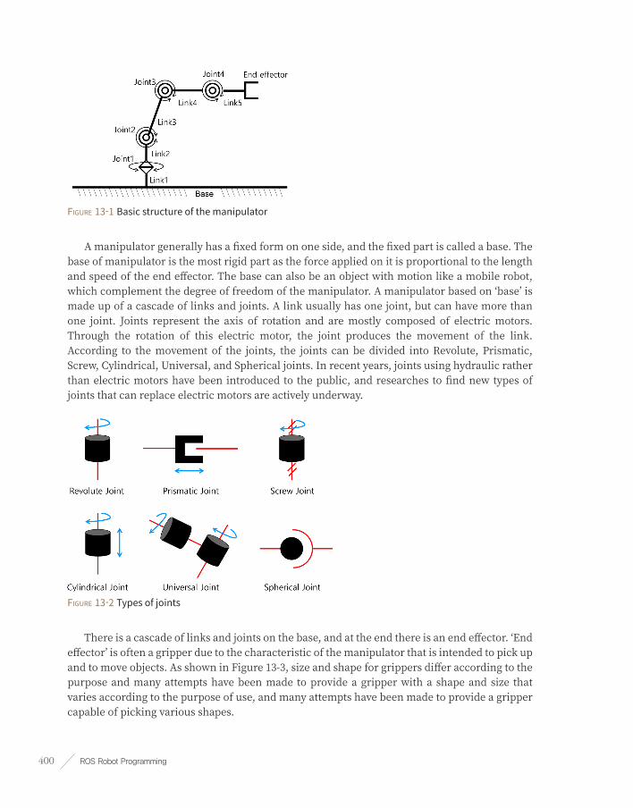
ROS Robot Programming400
Figure 13-1 Basic structure of the manipulator
A manipulator generally has a fixed form on one side, and the fixed part is called a base. The base of manipulator is the most rigid part as the force applied on it is proportional to the length and speed of the end effector. The base can also be an object with motion like a mobile robot, which complement the degree of freedom of the manipulator. A manipulator based on ‘base’ is made up of a cascade of links and joints. A link usually has one joint, but can have more than one joint. Joints represent the axis of rotation and are mostly composed of electric motors. Through the rotation of this electric motor, the joint produces the movement of the link. According to the movement of the joints, the joints can be divided into Revolute, Prismatic, Screw, Cylindrical, Universal, and Spherical joints. In recent years, joints using hydraulic rather than electric motors have been introduced to the public, and researches to find new types of joints that can replace electric motors are actively underway.
Figure 13-2 Types of joints
There is a cascade of links and joints on the base, and at the end there is an end effector. ‘End effector’ is often a gripper due to the characteristic of the manipulator that is intended to pick up and to move objects. As shown in Figure 13-3, size and shape for grippers differ according to the purpose and many attempts have been made to provide a gripper with a shape and size that varies according to the purpose of use, and many attempts have been made to provide a gripper capable of picking various shapes.

Chapter 13 _ Manipulator 401
Figure 13-3 Types of grippers (from left: ROBOTIQ, ROBOTIS, Cornell University)
The method of controlling the manipulator can be classified into Joint Space Control and Task Space Control.
The joint space control is a method of calculating the coordinate of the end of the manipulator by inputting the angle of rotation of each joint as shown in Figure 13-4. The coordinate of the end of the manipulator(X, Y, Z, i, z, and }) can be obtained through Forward Kinematics.
Figure 13-4 Forward Kinematics
As shown in Figure 13-5, the task space control has an input of the coordinate of the end of the manipulator and outputs of the rotation of each joint, as opposed to the joint space control. The pose of object in the task space includes its position and orientation. Since we live in a three-dimensional world, position of object can be expressed as X, Y, and Z and orientation of it can be expressed as i(roll), z(pitch), and } (yaw). Let’s use a cup on a table as an example. A cup on the desk (assuming that the origin of the cup is at the center of the cup) can be said that even if the position is fixed, its pose can changed by lying it down or by rotating the direction of the cup. In other words, when mathematically interpreted, it means that there are 6 unknowns, so if there are 6 equations, you can find the unique solution. However, not all manipulator has six degrees of freedom. It is more efficient to design the degree of freedom according to the purpose and environment in which the manipulator is used. The degree of rotation of each joint according to the end of the manipulator can be obtained by using inverse kinematics.
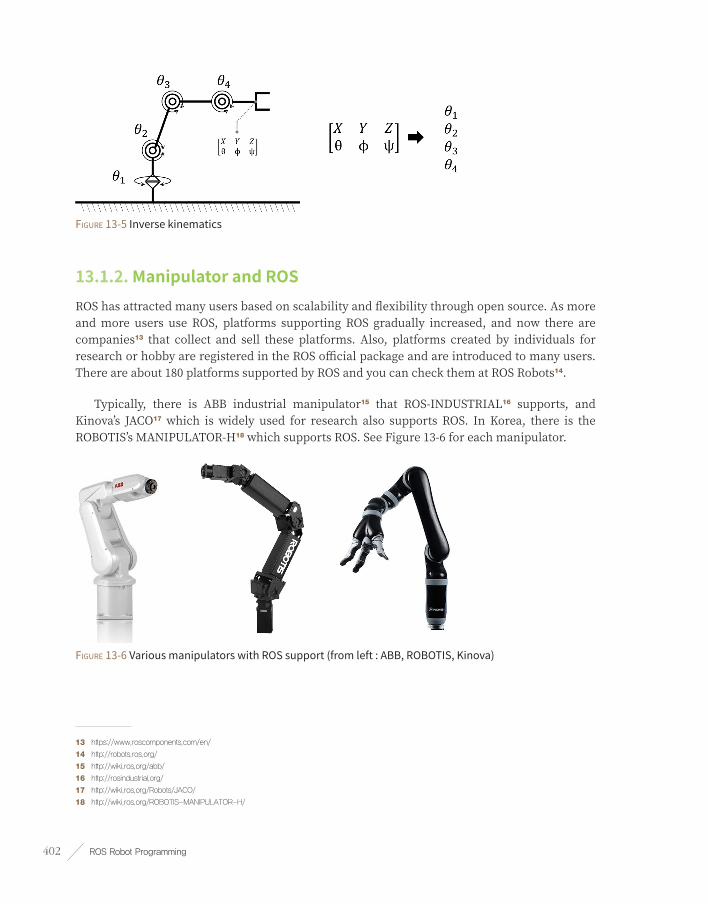
ROS Robot Programming402
Figure 13-5 Inverse kinematics
13.1.2. Manipulator and ROSROS has attracted many users based on scalability and flexibility through open source. As more and more users use ROS, platforms supporting ROS gradually increased, and now there are companies13 that collect and sell these platforms. Also, platforms created by individuals for research or hobby are registered in the ROS official package and are introduced to many users. There are about 180 platforms supported by ROS and you can check them at ROS Robots14.
Typically, there is ABB industrial manipulator15 that ROS-INDUSTRIAL16 supports, and Kinova’s JACO17 which is widely used for research also supports ROS. In Korea, there is the ROBOTIS’s MANIPULATOR-H18 which supports ROS. See Figure 13-6 for each manipulator.
Figure 13-6 Various manipulators with ROS support (from left : ABB, ROBOTIS, Kinova)
13 https://www.roscomponents.com/en/
14 http://robots.ros.org/
15 http://wiki.ros.org/abb/
16 http://rosindustrial.org/
17 http://wiki.ros.org/Robots/JACO/
18 http://wiki.ros.org/ROBOTIS-MANIPULATOR-H/

Chapter 13 _ Manipulator 403
13.2. OpenManipulator Modeling and SimulationROS provides useful tools for manipulators.
The first is to create a Unified Robot Description Format (URDF) 19 file as Extensible Markup Language (XML) as a visualization tool for robot modeling. You can create a simple manipulator or custom designed parts for your URDF file format and see it in the ROS visualization tool RViz.
The second is a 3D simulator Gazebo20 that can simulate the actual operating environment. The Gazebo simulation environment, like URDF, can be easily created using Simulation Description Format (SDF) 21 files using XML. Gazebo also supports ROS-Control22 and plugin23 functions to control various sensors and robots.
The third is MoveIt! 24 It is an integrated library and powerful tool for manipulators that provides open libraries such as the Kinematics and Dynamics Library (KDL) 25 and The Open Motion Planning Library (OMPL) 26, which helps you identify the various functions of the manipulator, such as collision calculation, motion planning and Pick and Place demos.
Let’s look at how to use the three tools mentioned above and implement them with sample codes.
13.2.1. OpenManipulatorOpenManipulator is an open source software and open source hardware based manipulator developed by ROBOTIS. OpenManipulator supports the Dynamixel X series27, and you can make robots by choosing the actuators of the specifications you require. Also, since it is composed of the basic frame and the 3D printed frame, it is possible to produce a new type of manipulator according to your environment or purpose. With these characteristics, we will provide manipulators with various shapes and functions such as SCARA, Planar, and Delta in addition to the four-joint manipulator. OpenManipulator supports ROS, OpenCR28, Arduino IDE29 and Processing30.
19 http://wiki.ros.org/urdf
20 http://gazebosim.org/
21 http://sdformat.org/
22 http://wiki.ros.org/ros_control
23 http://gazebosim.org/tutorials?tut=ros_gzplugins
24 http://moveit.ros.org/
25 http://www.orocos.org/kdl
26 http://ompl.kavrakilab.org/
27 http://en.robotis.com/index/product.php?cate_code=101210
28 http://emanual.robotis.com/docs/en/parts/controller/opencr10/
29 https://www.arduino.cc/en/main/software
30 https://processing.org/

ROS Robot Programming404
The OpenManipulator Chain used in this chapter has the most basic form of the manipulator, and the end effector has a linear gripper shape made of a 3D printed frame. The OpenManipulator Chain design files are all available on Onshape31, and the source code can be downloaded from ROBOTIS GitHub32. The source code supports both ROS, Arduino and Processing, the Gazebo package for OpenManipulator Chain and MoveIt! Package. In addition, the OpenManipulator Chain is mechanically compatible with the TurtleBot3 Waffle and Waffle Pi, and has the potential to expand functionally to compensate for the lack of freedom.
We will look at OpenManipulator Chain source code, URDF, Gazebo and MoveIt!. The following are the ROS packages required to use the above three tools. Let’s install these packages.
$ sudo apt-get install ros-kinetic-ros-controllers ros-kinetic-gazebo* ros-kinetic-moveit* ros-
kinetic-dynamixel-sdk ros-kinetic-dynamixel-workbench-toolbox ros-kinetic-robotis-math ros-
kinetic-industrial-core
13.2.2. Manipulator ModelingLet’s look at how to make a model each component to simulate a real manipulator in virtual space. Before looking at the URDF in the OpenManipulator Chain, let’s create a simple URDF for a manipulator consisting of three joints and four links.
First, create the ‘testbot_description’ package as follows, and then create the urdf folder. Then use an editor to create the testbot.urdf file and enter the following URDF example.
$ cd ~/catkin_ws/src
$ catkin_create_pkg testbot_description urdf
$ cd testbot_description
$ mkdir urdf
$ cd urdf
$ gedit testbot.urdf
31 https://goo.gl/NsqJMu
32 https://github.com/ROBOTIS-GIT/open_manipulator

Chapter 13 _ Manipulator 405
testbot_description/urdf/testbot.urdf
<?xml version="1.0" ?>
<robot name="testbot">
<material name="black">
<color rgba="0.0 0.0 0.0 1.0"/>
</material>
<material name="orange">
<color rgba="1.0 0.4 0.0 1.0"/>
</material>
<link name="base"/>
<joint name="fixed" type="fixed">
<parent link="base"/>
<child link="link1"/>
</joint>
<link name="link1">
<collision>
<origin xyz="0 0 0.25" rpy="0 0 0"/>
<geometry>
<box size="0.1 0.1 0.5"/>
</geometry>
</collision>
<visual>
<origin xyz="0 0 0.25" rpy="0 0 0"/>
<geometry>
<box size="0.1 0.1 0.5"/>
</geometry>
<material name="black"/>
</visual>
<inertial>
<origin xyz="0 0 0.25" rpy="0 0 0"/>
<mass value="1"/>
<inertia ixx="1.0" ixy="0.0" ixz="0.0" iyy="1.0" iyz="0.0" izz="1.0"/>
</inertial>
</link>
<joint name="joint1" type="revolute">

ROS Robot Programming406
<parent link="link1"/>
<child link="link2"/>
<origin xyz="0 0 0.5" rpy="0 0 0"/>
<axis xyz="0 0 1"/>
<limit effort="30" lower="-2.617" upper="2.617" velocity="1.571"/>
</joint>
<link name="link2">
<collision>
<origin xyz="0 0 0.25" rpy="0 0 0"/>
<geometry>
<box size="0.1 0.1 0.5"/>
</geometry>
</collision>
<visual>
<origin xyz="0 0 0.25" rpy="0 0 0"/>
<geometry>
<box size="0.1 0.1 0.5"/>
</geometry>
<material name="orange"/>
</visual>
<inertial>
<origin xyz="0 0 0.25" rpy="0 0 0"/>
<mass value="1"/>
<inertia ixx="1.0" ixy="0.0" ixz="0.0" iyy="1.0" iyz="0.0" izz="1.0"/>
</inertial>
</link>
<joint name="joint2" type="revolute">
<parent link="link2"/>
<child link="link3"/>
<origin xyz="0 0 0.5" rpy="0 0 0"/>
<axis xyz="0 1 0"/>
<limit effort="30" lower="-2.617" upper="2.617" velocity="1.571"/>
</joint>
<link name="link3">
<collision>
<origin xyz="0 0 0.5" rpy="0 0 0"/>

Chapter 13 _ Manipulator 407
<geometry>
<box size="0.1 0.1 1"/>
</geometry>
</collision>
<visual>
<origin xyz="0 0 0.5" rpy="0 0 0"/>
<geometry>
<box size="0.1 0.1 1"/>
</geometry>
<material name="black"/>
</visual>
<inertial>
<origin xyz="0 0 0.5" rpy="0 0 0"/>
<mass value="1"/>
<inertia ixx="1.0" ixy="0.0" ixz="0.0" iyy="1.0" iyz="0.0" izz="1.0"/>
</inertial>
</link>
<joint name="joint3" type="revolute">
<parent link="link3"/>
<child link="link4"/>
<origin xyz="0 0 1.0" rpy="0 0 0"/>
<axis xyz="0 1 0"/>
<limit effort="30" lower="-2.617" upper="2.617" velocity="1.571"/>
</joint>
<link name="link4">
<collision>
<origin xyz="0 0 0.25" rpy="0 0 0"/>
<geometry>
<box size="0.1 0.1 0.5"/>
</geometry>
</collision>
<visual>
<origin xyz="0 0 0.25" rpy="0 0 0"/>
<geometry>
<box size="0.1 0.1 0.5"/>
</geometry>
<material name="orange"/>

ROS Robot Programming408
</visual>
<inertial>
<origin xyz="0 0 0.25" rpy="0 0 0"/>
<mass value="1"/>
<inertia ixx="1.0" ixy="0.0" ixz="0.0" iyy="1.0" iyz="0.0" izz="1.0"/>
</inertial>
</link>
</robot>
URDF describes each component of the robot using XML tags. In the URDF format, first describe the name of the robot, the name and type of the base (URDF assumes that the base is a fixed link), and the description of the link connected to the base and then describe each joint and link. A link describes the name, size, weight, inertia of the link. The joints describes the name, type, and link connected to each joint. The dynamic parameters of the robot, visualization, and the collision model can be easily set. The URDF is initiated by the <robot> tag, and in general, it is common for the <link> tag and the <joint> tag to appear alternately to define links and joints that are components of the robot. The <transmission> tag is also often included for interfacing with the ROS-Control to establish the relationship between the joint and the actuator. Let’s take a closer look at the testbot.urdf we created.
The material tag describes information such as the color and texture of the link. In the following example, we have defined two materials, black and orange, to distinguish each link. The color uses a color tag, which can be set after the rgba option by entering a number between 0.0 and 1.0, corresponding to red, green, and blue. The last number stands for a transparency (alpha) value of 0.0 to 1.0, and a value of 1.0 means that the part is not transparent.
<material name="black">
<color rgba="0.0 0.0 0.0 1.0"/>
</material>
<material name="orange">
<color rgba="1.0 0.4 0.0 1.0"/>
</material>
The first component of the manipulator is the base which can be represented as a link in URDF. The base is connected to the first link and the joint, and this joint does not move and is located at the origin (0, 0, 0). Let’s look at the first link tag for a more detailed description of the <link> tag.

Chapter 13 _ Manipulator 409
<link name="base"/>
<joint name="fixed" type="fixed">
<parent link="base"/>
<child link="link1"/>
</joint>
<link name="link1">
<collision>
<origin xyz="0 0 0.25" rpy="0 0 0"/>
<geometry>
<box size="0.1 0.1 0.5"/>
</geometry>
</collision>
<visual>
<origin xyz="0 0 0.25" rpy="0 0 0"/>
<geometry>
<box size="0.1 0.1 0.5"/>
</geometry>
<material name="black"/>
</visual>
<inertial>
<origin xyz="0 0 0.25" rpy="0 0 0"/>
<mass value="1"/>
<inertia ixx="1.0" ixy="0.0" ixz="0.0" iyy="1.0" iyz="0.0" izz="1.0"/>
</inertial>
</link>
The URDF <link> tag consists of collision, visual, and inertial tags (see Figure 13-7) as in the link1 example above. The collision tag allows you to enter geometric information that indicates the range of interference of the link. Origin specifies the center coordinates of the interference range. And geometry writes the shape and size of the interference range centered on the origin coordinate. For example, the interference range of a hexahedron is a value of width, length and height. In addition to hexahedron type, there are cylindrical type and spherical type, and each shape has different parameters to input. Write the actual shape in the visual tag. Origin and geometry are identical to collision tags. You can also enter CAD files such as STL and DAE here. You can use the CAD model in the collision tag, but it can only be used with some physics engines such as ODE or Bullet. DART and Simbody do not support the CAD files. The inertial tag specifies the weight of the link(kg) and the moment of inertia(kg·m2). This inertia information can be obtained through design software or actual measurement and calculation, and is used for dynamics simulation.

ROS Robot Programming410
The described link 1, link 2, and link4 in the example testbot.urdf are shifted from the origin of upper joint (fixed, joint1, and joint3 respectively) by the offset of 0.25m, where the square column of 0.1m in width and 0.1m in length at 0.5m (0.25m in the plus direction and 0.25m in the minus direction) in length extending in the z-axis direction from the moved origin. Likewise for link 3, origin is shifted by 0.5m from the origin of the connected joint ( joint2), where the hexahedron with a length of 1m and a width of 0.1m and a length of 0.1m in the z-axis direction.
The understanding of relative coordinate transformation in URDF can be quite difficult when first encountered. It may be easier to understand each configuration value by seeing it, but it is helpful to understand how the relative coordinate transformation of each axis is expressed on RViz as shown in the Figure. 13-12. I recommended you to try it.
Properties of the link tag
<link33>: Link visualization, collision and inertia information setting
<collision>: Set information for link collision calculation
<visual>: Set visualization information for links
<inertial>: Set inertia information for the link
<mass>: Weight of Link (Kilogram) Setting
<inertia>: Inertia tensor34 setting
<origin>: Set transformation and rotation relative to the link’s relative coordinate system
<geometry>: Enter the shape of the model. box, cylinder, and sphere.
COLLADA (.dae), STL (.stl) format design files can also be imported. In the <collision> tag, you can reduce the calculation time by specifying it in a simple form
<material>: Link color and texture settings
33 http://wiki.ros.org/urdf/XML/link
34 https://en.wikipedia.org/wiki/Moment_of_inertia

Chapter 13 _ Manipulator 411
Figure 13-7 Modeling elements of links
Next, let’s look at the joint tag that connects links to links. The joint tag describes the characteristics of the joint as shown in Figure 13-8. Specifically, the name and type of joint, such as revolute, prismatic, continuous, fixed, floating, and planar form. The joint tag also describes the names of the two links that are connected, the location of the joints, and the limitations of the axis motion in terms of rotation and translational motion. Connected links are assigned with names of parent links and child links. The parent link is usually the link closest to the base link. The following example shows a joint setting for joint2.
<joint name="joint2" type="revolute">
<parent link="link2"/>
<child link="link3"/>
<origin xyz="0 0 0.5" rpy="0 0 0"/>
<axis xyz="0 1 0"/>
<limit effort="30" lower="-2.617" upper="2.617" velocity="1.571"/>
</joint>
Properties of the joing tag
<joint35>: Relationship with link and joint type setting
<parent>: parent link of the joint
<child>: child link of the joint
<origin>: Convert parent link coordinate system to child link coordinate system
<axis>: Set rotation axis
<limit>: Set the speed, force, and radius of the joint (applies only for revolute or prismatic joints)
35 http://wiki.ros.org/urdf/XML/joint

ROS Robot Programming412
Let’s take a closer look to understand. The type of joint2 was set to the revolute joint. The parent link is set to link2, and the child link is set to link3. In addition, the origin specifies the relative pose (position + orientation) of the coordinate system of joint2, with the coordinate system of joint1 as the origin as the origin. For example, the origin of the joint2 coordinate system is a distance of 0.5m from the joint1 in the z-axis direction of the joint1 coordinate system. The next step is axis settings. In the axis setting, write the direction of the rotation axis if it is the rotary type joint, and the motion direction if it is the translation type joint. In the case of joint2, it is set as a joint rotating in the y-axis direction. The limit sets the limitation for joint motion. Properties include the force (effort, unit in N), minimum, maximum angle (lower, upper, in radians), and velocity (in rad/s) given to the joint.
Figure 13-8 Modeling factors of joints
When you finish creating the model, let’s examine each link and joints to see if they are logically correct. In ROS, you can check the grammatical error of URDF created by ‘check_urdf’ command and the connection relation of each link as the following example. If the file is grammatically and logically correct, we can confirm that links 1, 2, 3, and 4 are connected as follows.
$ check_urdf testbot.urdf
robot name is: testbot
---------- Successfully Parsed XML ---------------
root Link: base has 1 child(ren)
child(1): link1
child(1): link2
child(1): link3
child(1): link4

Chapter 13 _ Manipulator 413
Next, let’s graph the model we created using the ‘urdf_to_graphiz’ program. If you run ‘urdf_to_graphiz’ as in the following example, a ‘*.gv’ file and a ‘*.pdf’ file are created. If you look at the PDF viewer, you can see the relationship between the link and the joint, as well as the relative coordinate transformation between each joint, as shown in Figure 13-9.
$ urdf_to_graphiz testbot.urdf
Created file testbot.gv
Created file testbot.pdf
Figure 13-9 Relationship between URDF and link
It is the fastest way to check the model’s link relationship with ‘check_urdf’ and ‘urdf_to_graphiz’. Finally, let’s check the robot model using RViz. To do this, go to the ‘testbot_description’ package folder and create a ‘testbot.launch’ file as shown in the following example.

ROS Robot Programming414
$ cd ~/catkin_ws/src/testbot_description
$ mkdir launch
$ cd launch
$ gedit testbot.launch
testbot_description/launch/testbot.launch
<launch>
<arg name="model" default="$(find testbot_description)/urdf/testbot.urdf" />
<arg name="gui" default="True" />
<param name="robot_description" textfile="$(arg model)" />
<param name="use_gui" value="$(arg gui)"/>
<node pkg="joint_state_publisher" type="joint_state_publisher" name="joint_state_publisher"/>
<node pkg="robot_state_publisher" type="state_publisher" name="robot_state_publisher"/>
</launch>
The launch file consists of parameters containing URDF, a ‘joint_state_publisher’36 node, and a ‘robot_state_publisher’ node. The ‘joint_state_publisher’37 node publishes the joint state of the robot made by URDF through the ‘sensor_msgs/JointState’ message and provides a GUI tool to give commands to the joints. The ‘robot_state_publisher’ node publishes the result of the forward kinematics computed with the robot information and the ‘sensor_msgs/JointState’ topic information set in the URDF as a tf38 message (see Figure 13-10).
Figure 13-10 Topics in the joint_state_publisher node and the robot_state_publisher node
36 http://wiki.ros.org/urdf/XML/joint
37 http://wiki.ros.org/robot_state_publisher
38 http://wiki.ros.org/tf

Chapter 13 _ Manipulator 415
Once everything is ready, run testbot.launch and RViz as follows:
$ roslaunch testbot_description testbot.launch
$ rviz
When the launch file is executed, the GUI of the ‘joint_state_publisher’ node is executed as shown in Figure 13-11. Here you can control the joint values of joints 1, 2 and 3. If you run RViz, select ‘base’ on Fixed Frame options and click the [Add] button at the lower left to add the ‘RobotModel’ to see the shape of each joint and link in RViz as shown in Figure 13-12. If you add ‘TF’ display and modify the ‘Alpha’ value of robot model to about 0.3, you can check the shape of each link and the relationship between joints as shown in the lower figure of Figure 13-12.
If you adjust the GUI bar of the ‘joint_state_publisher’ node, you can see that the virtual robot on RViz is controlled as shown in Figure 13-13. The relevant source code can be found in the GitHub repository:
■ https://github.com/ROBOTIS-GIT/ros_tutorials/tree/master/testbot_description
Figure 13-11 Joint State Publisher GUI
Figure 13-12 RViz view of each joint and link

ROS Robot Programming416
Figure 13-13 Results of manipulating each joint in the Joint State Publisher GUI tool
We have created the 3-axis manipulator according to the URDF format and confirmed it with RViz. Based on this, let’s look at URDF of OpenManipulator Chain which consists of 4-axis joint and linear gripper. First, download the source code from GitHub on OpenManipulator and TurtleBot3.
$ cd ~/catkin_ws/src
$ git clone https://github.com/ROBOTIS-GIT/open_manipulator.git
$ cd ~/catkin_ws && catkin_make
$ cd ~/catkin_ws/src/
$ git clone https://github.com/ROBOTIS-GIT/turtlebot3.git
$ git clone https://github.com/ROBOTIS-GIT/turtlebot3_msgs.git
$ git clone https://github.com/ROBOTIS-GIT/turtlebot3_simulations.git
$ cd ~/catkin_ws && catkin_make
Here is the configuration in OpenManipulator folder copied from Github.

Chapter 13 _ Manipulator 417
$ cd ~/catkin_ws/src/open_manipulator
$ ls
Arduino → Library for Arduino
open_manipulator → MetaPackage
open_manipulator_description → Modeling package
open_manipulator_dynamixel_ctrl → Dynamixel control package
open_manipulator_gazebo → Gazebo package
open_manipulator_moveit → MoveIt! package
open_manipulator_msgs → Message package
open_manipulator_position_ctrl → Position control package
open_manipulator_with_tb3 → OpenManipulator and TurtleBot3 package
The modeling package (open_manipulator_description) consists of a launch folder containing executable files, a meshes folder containing design files, a src folder containing the Publisher node, and a urdf folder. Open the urdf folder and the launch folder and look at the configuration.
$ roscd open_manipulator_description/urdf
$ ls
materials.xacro → Material info
open_manipulator_chain.xacro → Manipulator modeling
open_manipulator_chain.gazebo.xacro → Manipulator Gazebo modeling
$ roscd open_manipulator_description/launch
$ ls
open_manipulator.rviz → RViz configuration file
open_manipulator_chain_ctrl.launch → File to execute manipulator state info Publisher node
open_manipulator_chain_rviz.launch → File to execute manipulator modeling info visualization node
Once files are reviewed, open the materials.xacro file.
$ roscd open_manipulator_description/urdf
$ gedit materials.xacro
open_manipulator_description/urdf/materials.xacro
<?xml version="1.0"?>
<robot>

ROS Robot Programming418
<material name="black">
<color rgba="0.0 0.0 0.0 1.0"/>
</material>
<material name="white">
<color rgba="1.0 1.0 1.0 1.0"/>
</material>
<material name="red">
<color rgba="0.8 0.0 0.0 1.0"/>
</material>
<material name="blue">
<color rgba="0.0 0.0 0.8 1.0"/>
</material>
<material name="green">
<color rgba="0.0 0.8 0.0 1.0"/>
</material>
<material name="grey">
<color rgba="0.5 0.5 0.5 1.0"/>
</material>
<material name="orange">
<color rgba="${255/255} ${108/255} ${10/255} 1.0"/>
</material>
<material name="brown">
<color rgba="${222/255} ${207/255} ${195/255} 1.0"/>
</material>
</robot>
The XML Macro39 is a macro language that allows you to recall code that is abbreviated as xacro. I recommended you to create a macro for repeatedly used codes. The ‘material.xacro’ file specifies the colors required for the visualization of the future manipulator.
39 http://wiki.ros.org/xacro

Chapter 13 _ Manipulator 419
Next, let’s examine the URDF file required for modeling and visualizing the OpenManipulator Chain.
$ roscd open_manipulator_description/urdf
$ gedit open_manipulator_chain.xacro
open_manipulator_description/urdf/open_manipulator_chain.xacro
<!-- some parameters -->
<xacro:property name="pi" value="3.141592654" />
<!-- Import all Gazebo-customization elements, including Gazebo colors -->
<xacro:include filename="$(find open_manipulator_description)/urdf/open_manipulator_chain.gazebo
.xacro" />
<!-- Import RViz colors -->
<xacro:include filename="$(find open_manipulator_description)/urdf/materials.xacro" />
URDF has many repetitive phrases in order to represent the connecting structure of links and joints, and therefore has a disadvantage of taking a lot of modification time. However, using xacro can greatly reduce these tasks. For example, it is possible to manage the code efficiently by setting the variable of the circumference as above, or by separately managing the material information file and the Gazebo configuration file created in the above and including it in the actually used file.
We have previously covered about the <link> and <joint> tags when creating a URDF for a 3-axis manipulator. The OpenManipulator chain also uses the <transmission> tag to work with ROS-Control. Let’s take a look at the transmission tag.
open_manipulator_description/urdf/open_manipulator_chain.xacro
<!-- Transmission 1 -->
<transmission name="tran1">
<type>transmission_interface/SimpleTransmission</type>
<joint name="joint1">
<hardwareInterface>PositionJointInterface</hardwareInterface>
</joint>
<actuator name="motor1">
<hardwareInterface>PositionJointInterface</hardwareInterface>
<mechanicalReduction>1</mechanicalReduction>
</actuator>
</transmission>
ROS Robot Programming420
<transmission> is a mandatory tag for interworking with ROS-Control. It inputs the command interface between the joint and the actuator. The command interfaces are effort, velocity, and position and users can select desired control input.
<transmission> tag
<transmission>: Variable setting between joints and actuators
<type>: Type setting for the transmission method of torque
<joint>: Joint configuration info
<hardwareInterface>: Hardware interface settings
<actuator>: Actuator information setting
<mechanicalReduction>: Gear ratio setting between actuator and joint
The OpenManipulator Chain consists of four joints (motors) and five links, a linear gripper consists of two links and one joint (motor). Other than the linear gripper being prismatic, the rest of the descriptions are the same with the previous description so please check the URDF file.
Run the launch file to visualize the completed URDF file in RViz and move the joint using the ‘joint_state_publisher’ GUI as shown in Figure 13-14.
$ roslaunch open_manipulator_description open_manipulator_chain_rviz.launch
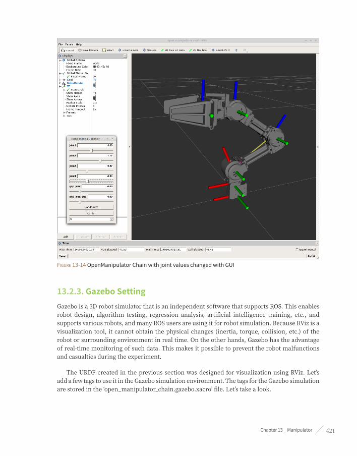
Chapter 13 _ Manipulator 421
Figure 13-14 OpenManipulator Chain with joint values changed with GUI
13.2.3. Gazebo SettingGazebo is a 3D robot simulator that is an independent software that supports ROS. This enables robot design, algorithm testing, regression analysis, artificial intelligence training, etc., and supports various robots, and many ROS users are using it for robot simulation. Because RViz is a visualization tool, it cannot obtain the physical changes (inertia, torque, collision, etc.) of the robot or surrounding environment in real time. On the other hands, Gazebo has the advantage of real-time monitoring of such data. This makes it possible to prevent the robot malfunctions and casualties during the experiment.
The URDF created in the previous section was designed for visualization using RViz. Let’s add a few tags to use it in the Gazebo simulation environment. The tags for the Gazebo simulation are stored in the ‘open_manipulator_chain.gazebo.xacro’ file. Let’s take a look.

ROS Robot Programming422
$ roscd open_manipulator_description/urdf
$ gedit open_manipulator_chain.gazebo.xacro
open_manipulator_description/urdf/open_manipulator_chain.gazebo.xacro
<!-- Link1 -->
<gazebo reference="link1">
<mu1>0.2</mu1>
<mu2>0.2</mu2>
<material>Gazebo/Grey</material>
</gazebo>
Color and inertia information are essential for setting up the link to be used in Gazebo. Since the inertia information is included in the URDF file created earlier, only the color needs to be configured. In addition, gravity, damping, and frictional forces can be set for the Open Dynamics Engine (ODE)40 41, a physics engine supported by Gazebo. In the above file, only the coefficient of friction is set as an example. There is also a parameter for the joint information, which is not mentioned.
<gazebo> tag
<gazebo>: Parameter setting for Gazebo simulation
<mu1>, <mu2>: Setting of friction coefficient
<material>: Setting of link color
open_manipulator_description/urdf/open_manipulator_chain.gazebo.xacro
<!-- ros_control plugin -->
<gazebo>
<plugin name="gazebo_ros_control" filename="libgazebo_ros_control.so">
<robotNamespace>/open_manipulator_chain</robotNamespace>
<robotSimType>gazebo_ros_control/DefaultRobotHWSim</robotSimType>
</plugin>
</gazebo>
40 http://gazebosim.org/tutorials?tut=ros_urdf&cat=connect_ros
41 http://www.ode.org/

Chapter 13 _ Manipulator 423
Gazebo plugin42 is a tool to support the status and control of robot’s sensor and motor created by URDF or SDF with ROS message and service communication. Plugin supports various sensors such as camera, laser, inertial navigation sensor, mobile platform control such as differential, skid steering drive, parallel movement, and ROS-Control. The OpenManipulator Chain uses the joint’s position control interface and enables the default plug-in library.
<gazebo> tag
<gazebo>: Parameter setting for Gazebo simulation
<plugin>: Tool for sensor and robot status control
<robotNamespace>: Set the robot name to use in Gazebo
<robotSimType>: Setting the plugin name for robot simulation interface.
The above code will be repeated, so check out the following source code.
open_manipulator_description/urdf/open_manipulator_chain.gazebo.xacro
<?xml version="1.0"?>
<robot>
<!-- World -->
<gazebo reference="world">
</gazebo>
<!-- Link1 -->
<gazebo reference="link1">
<mu1>0.2</mu1>
<mu2>0.2</mu2>
<material>Gazebo/Grey</material>
</gazebo>
<!-- Link2 -->
<gazebo reference="link2">
<mu1>0.2</mu1>
<mu2>0.2</mu2>
<material>Gazebo/Grey</material>
</gazebo>
42 http://gazebosim.org/tutorials?tut=ros_gzplugins&cat=connect_ros

ROS Robot Programming424
<!-- Link3 -->
<gazebo reference="link3">
<mu1>0.2</mu1>
<mu2>0.2</mu2>
<material>Gazebo/Grey</material>
</gazebo>
<!-- Link4 -->
<gazebo reference="link4">
<mu1>0.2</mu1>
<mu2>0.2</mu2>
<material>Gazebo/Grey</material>
</gazebo>
<!-- Link5 -->
<gazebo reference="link5">
<mu1>0.2</mu1>
<mu2>0.2</mu2>
<material>Gazebo/Grey</material>
</gazebo>
<!-- grip_link -->
<gazebo reference="grip_link">
<mu1>0.2</mu1>
<mu2>0.2</mu2>
<material>Gazebo/Grey</material>
</gazebo>
<!-- grip_link_sub -->
<gazebo reference="grip_link_sub">
<mu1>0.2</mu1>
<mu2>0.2</mu2>
<material>Gazebo/Grey</material>
</gazebo>
<!-- ros_control plugin -->
<gazebo>
<plugin name="gazebo_ros_control" filename="libgazebo_ros_control.so">

Chapter 13 _ Manipulator 425
<robotNamespace>/open_manipulator_chain</robotNamespace>
<robotSimType>gazebo_ros_control/DefaultRobotHWSim</robotSimType>
</plugin>
</gazebo>
</robot>
The file ‘open_manipulator_chain.gazebo.xacro’ is used for setting parameters for Gazebo simulation and is included in ‘open_manipulator_chain.xacro’ file. Now use the completed URDF to display the OpenManipulator chain in the Gazebo.
$ roscd open_manipulator_gazebo/launch
$ ls
open_manipulator_gazebo.launch → File to launch Gazebo
position_controller.launch → File to launch ROS-CONTROL
The launch folder, which is a subfolder of the ‘open_manipulator_gazebo’ folder, contains the launch file to run Gazebo and to execute ROS-Control. Open these Gazebo launch files and see which nodes are included.
$ roscd open_manipulator_gazebo/launch
$ gedit open_manipulator_gazebo.launch
open_manipulator_gazebo/launch/open_manipulator_gazebo.launch
<?xml version="1.0" ?>
<launch>
<!-- These are the arguments you can pass this launch file, for example paused:=true -->
<arg name="paused" default="false"/>
<arg name="use_sim_time" default="true"/>
<arg name="gui" default="true"/>
<arg name="headless" default="false"/>
<arg name="debug" default="false"/>
<!-- We resume the logic in empty_world.launch, changing only the name of the world to be
launched -->
<include file="$(find gazebo_ros)/launch/empty_world.launch">
<arg name="world_name" value="$(find open_manipulator_gazebo)/world/empty.world"/>
<arg name="debug" value="$(arg debug)" />

ROS Robot Programming426
<arg name="gui" value="$(arg gui)" />
<arg name="paused" value="$(arg paused)"/>
<arg name="use_sim_time" value="$(arg use_sim_time)"/>
<arg name="headless" value="$(arg headless)"/>
</include>
<!-- Load the URDF into the ROS Parameter Server -->
<param name="robot_description"
command="$(find xacro)/xacro.py '$(find open_manipulator_description)/urdf/open_manipulator_ch
ain.xacro'"/>
<!-- Run a python script to the send a service call to gazebo_ros to spawn a URDF robot -->
<node name="urdf_spawner" pkg="gazebo_ros" type="spawn_model" respawn="false" output="screen"
args="-urdf -model open_manipulator_chain -z 0.0 -param robot_description"/>
<!-- ros_control robotis manipulator launch file -->
<include file="$(find open_manipulator_gazebo)/launch/position_controller.launch"/>
</launch>
The above launch file includes the ‘empty_world.launch’ file, the ‘spawn_model’ node, and the ‘position_controller.launch’ file. The ‘empty_world.launch’ file contains nodes that executes Gazebo, so you can set up the simulation environment, GUI, and time. The Gazebo simulation environment supports files created in SDF format. The ‘spawn_model’ node is responsible for calling the robot based on the URDF, and ‘position_controller.launch’ is responsible for setting up and executing ROS-Control.
Now, if you run Gazebo by typing the following command into the terminal, you can see the OpenManipulator Chain in the Gazebo simulation space, as shown in Figure 13-15.
$ roslaunch open_manipulator_gazebo open_manipulator_gazebo.launch

Chapter 13 _ Manipulator 427
Figure 13-15 OpenManipulator Chain of Gazebo simulation space
Next, open a new terminal window and check the topic list.
$ rostopic list
/clock
/gazebo/link_states
/gazebo/model_states
/gazebo/parameter_descriptions
/gazebo/parameter_updates
/gazebo/set_link_state
/gazebo/set_model_state
/joint_states
/open_manipulator_chain/grip_joint_position/command
/open_manipulator_chain/grip_joint_sub_position/command
/open_manipulator_chain/joint1_position/command

ROS Robot Programming428
/open_manipulator_chain/joint2_position/command
/open_manipulator_chain/joint3_position/command
/open_manipulator_chain/joint4_position/command
/open_manipulator_chain/joint_states
/rosout
/rosout_agg
Looking at the list of topics, there are topics with the ‘/gazebo’ namespace and topics with the ‘/open_manipulator_chain’ namespace. We can use ROS-Control to check and control the state of the robot on Gazebo using topics with the ‘/open_manipulator_chain namespace’. Let’s move the robot using the following command.
$ rostopic pub /open_manipulator_chain/joint2_position/command std_msgs/Float64 "data: 1.0"
--once
Figure 13-16 OpenManipulator Chain controlled by communication with ROS-CONTROL

Chapter 13 _ Manipulator 429
Through simple message communication, you can see that the second joint of the OpenManipulator chain moves as shown in Figure 13-16.
13.3. MoveIt!MoveIt!43 is an integrated library for manipulators that provides a variety of functions including fast inverse kinematics analysis for motion planning, advanced algorithms for manipulation, robot hand control, dynamics, controllers, and motion planning. It is also easy to use without advanced knowledge of the manipulator because the GUI is offered to assist with various settings needed to use MoveIt!. This is a tool that many ROS users love because it allows visual feedback using RViz. Let’s briefly review the structure of MoveIt!, and then create a MoveIt! package to control the OpenManipulator chain.
13.3.1. move_group
Figure 13-17 Communication scheme with move_group node
43 http://moveit.ros.org/

ROS Robot Programming430
As shown in Figure 13-17, the ‘move_group’ node can exchange commands with the user using ROS actions and services. MoveIt! provides various user interfaces and built a service that allows more users to communicate with ‘move_group’ node by using ‘move_group’ interface in C++ language or by using ‘move_commander’ in Python language and ‘Motion Planning plugin to RViz’.
The ‘move_group’ node receives information about the robot from the URDF, Semantic Robot Description Format (SRDF) 44, and MoveIt! Configuration. URDF that you have created will be used whereas SRDF and MoveIt! Configuration will be created through the Setup Assistant45 provided by MoveIt!.
The ‘move_group’ node provides the state and control of the robot and its environment through ROS topics and actions. The joint state uses ‘sensor_msg/JointStates’ message, the transformation information uses the tf library, and the controller uses the ‘FollowTrajectoryAction’ interface to inform the user about the robot status. In addition, the user is provided with information on the environment where the robot is operating and the status of the robot through the ‘planning scene’.
The ‘move_group’ provides a plugin function for its extensibility, and provides an opportunity to apply various functions (control, path generation, dynamics, etc.) to the user’s robot through an open source library. The plugin built into MoveIt! is a great library that has already been proven to a lot of people, and a number of recently-developed open source libraries will soon be available as well. Open Motion Planning Library (OMPL) 46, Kinematic and Dynamic Library (KDL)47, and A Flexible Collision Library (FCL) 48 are in the category of those libraries.
13.3.2. MoveIt! Setup Assistant To create a MoveIt! package for manipulators, you will need URDF, SRDF, and MoveIt! Configuration files. The Setup Assistant provided by MoveIt! creates the SRDF based on URDF and MoveIt! Configuration files for the MoveIt! package. Let’s learn how to create a MoveIt! package using the MoveIt! Setup Assistant for the OpenManipulator Chain.
Type the following command into the terminal and run MoveIt! Setup Assistant.
$ roslaunch moveit_setup_assistant setup_assistant.launch
44 http://wiki.ros.org/srdf
45 http://docs.ros.org/kinetic/api/moveit_tutorials/html/doc/setup_assistant/setup_assistant_tutorial.html
46 http://ompl.kavrakilab.org/
47 http://www.orocos.org/kdl
48 http://gamma.cs.unc.edu/FCL/fcl_docs/webpage/generated/index.html

Chapter 13 _ Manipulator 431
Figure 13-18 Start page of the MoveIt! Setup Assistant
Figure 13-18 is the first page you will see when you run the ‘MoveIt! Setup Assistant’. In this screen, you can see the representative ROS character, the Turtle, on the right, and you can choose whether to create a new package or modify an existing package in the left page. Since we need to create a new package, let’s click on the [Create New MoveIt Configuration Package] button.
Figure 13-19 Start page of the MoveIt! Setup Assistant

ROS Robot Programming432
MoveIt! Setup Assistant builds an SRDF file with additional settings based on the robot model stored in the URDF file or COLLADA file. Click the [Browse] button shown in Figure 13-19, open the ‘open_manipulator_chain.xacro’ file you created earlier, and click the [Load Files] button.
Figure 13-20 Self-Collisions page of the MoveIt! Setup Assistant
If you have successfully loaded the file, go to the ‘Self-Collision’ page. This page allows you to define the sampling density needed to build the ‘Self-Collision Matrix’ and, if necessary, the user can determine the range of collisions between the links that make up the robot, as shown in Figure 13-20 below. The higher the sampling density, the more computation is required to prevent collision between links in various poses of the robot. Set the desired sampling density and click the [Generate Collision Matrix] button. The default value is set to ‘10,000’.

Chapter 13 _ Manipulator 433
Figure 13-21 Virtual Joints page of the MoveIt! Setup Assistant
The ‘Virtual Joints’ page provides a virtual joint between the base of the manipulator and the reference coordinate system. For example, if an ‘OpenManipulator Chain’ is mounted to the TurtleBot3 Waffle or Waffle Pi, the degree of freedom of it can be provided to the OpenManipulator Chain through a Virtual Joint. Since the base is fixed, you do not need to set up a virtual joint as shown in Figure 13-21.
Figure 13-22 Planning Groups page of the MoveIt! Setup Assistant

ROS Robot Programming434
MoveIt! provides motion planning for each of the manipulators divided into groups, which you can set the group in the ‘Planning Groups’ page. The OpenManipulator Chain consists of four joints and one gripper so set arm group and gripper group. Clicking the [Add Group] button at the lower right corner of Figure 13-22 will change the window as shown in Figure 13-23.
Figure 13-23 Create new group page on the Planning Groups page
In this step, you can specify the group name and select the desired kinematic analysis plug-in (Kinematic Slover). Set the group name as arm and select the desired kinematics interpretation plugin. Since the manipulator will be divided into joint groups, choose [Add Joint] button. If the window changes as shown in Figure 13-24, select joints 1~4 and click the [Save] button to create the group as shown in Figure 13-25.

Chapter 13 _ Manipulator 435
Figure 13-24 Create new group window on the Planning Groups page
Figure 13-25 Arm group created on the Planning Groups page

ROS Robot Programming436
If you have created the ‘arm’ group, let’s create a ‘gripper’ group just like this. The linear gripper controlled by one actuator is not supported by the kinematic analysis plug-in. Therefore, when creating a gripper group, set the kinematics analysis plug-in to ‘None’. And like the arm group, select the joints ‘grip_joint’ and ‘grip_joint_sub’ in page of ‘Add Joints’. Once the gripper group is completed, you can see the ‘arm’ group and the ‘gripper’ group as shown in Figure 13-26.
Figure 13-26 Arm group and gripper groups created on the Planning Groups page
Figure 13-27 Robot Poses page of the MoveIt! Setup Assistant

Chapter 13 _ Manipulator 437
The ‘Robot Poses’ page allows you to create and register specific postures of the robot. Click the [Add Pose] button at the bottom right of Figure 13-27 to register the posture of all motors with an angle of zero degrees. Clicking on the button will take you to the pose creation window as shown in Figure 13-28, where you set all the joint values to 0.0 and write the pose name.
Figure 13-28 Pose generation window on the Robot Poses page
Figure 13-29 End Effectors page in MoveIt! Setup Assistant

ROS Robot Programming438
The ‘End Effectors’ page can register the manipulator’s end-effector. Click the [Add End Effector] button at the bottom right as in Figure 13-29 to register the linear gripper that the OpenManipulator Chain has.
Figure 13-30 End Effectors settings window on the End Effectors page
Write the ‘End Effector Name’ as shown in Figure 13-30 and select ‘gripper’ in the group created on the ‘Planning Groups’ page. When you check URDF, the gripper has the fifth link as its parent link.

Chapter 13 _ Manipulator 439
Figure 13-31 Passive Joints page in MoveIt! Setup Assistant
The ‘Passive Joints’ page allows you to specify joints that are excluded from motion planning. In the OpenManipulator Chain, there is no passive joint, so let’s move on without making any changes, as shown in Figure 13-31.
Figure 13-32 Author Information page in MoveIt! Setup Assistant

ROS Robot Programming440
On the ‘Author Information’ page, enter the name and email of the creator of the package. Fill in the blanks as shown in Figure 13-32.
Figure 13-33 Configuration Files page in MoveIt! Setup Assistant
Once all the settings are completed, you can finish the ‘Configuration Files’ page. Click the [Browse] button at the top of Figure 13-33 to create the ‘open_manipulator_moveit_example’ folder in the ‘open_manipulator’ folder and click the [Generate Package] button in the lower right corner to create a config folder and a launch folder containing executable files for MoveIt! Configuration.
Check out the generated package and run the demo.
$ cd ~/catkin_ws/src/open_manipulator/open_manipulator_moveit_example
$ ls
Config → YAML and SRDF files for MoveIt! Configuration
launch → Launch file
.setup_assistant → Package information generated by the setup assistant
CMakeLists.txt → CMake build system input file
package.xml → Defining package properties
$ cd ~/catkin_ws && catkin_make
$ roslaunch open_manipulator_moveit_example demo.launch

Chapter 13 _ Manipulator 441
Figure 13-34 MoveIt! RViz demo
When you run the Demo, you can see the OpenManipulator Chain through the RViz window as shown in Figure 13-34. In the Context page of the MotionPlanning command window located in the lower left corner, you can select the motion planning library49 supported by OMPL. Select ‘RRTConnectkConfigDefault’ and go to the Planning page.
Originally, the coordinates of the end point of the manipulator are represented as X, Y, Z and rotation values represented as i(Roll), z(Pitch), and }(Yaw). However, since the OpenManipulator Chain has only four joints, the end points will have only the degrees of freedom of the X, Z and Pitch axes (the remaining one degree of freedom is the Yaw axis rotation of the first joint). Remember this and move the end point to the desired coordinates.
49 http://ompl.kavrakilab.org/planners.html

ROS Robot Programming442
Figure 13-35 Manipulator motion planning using MoveIt! RViz demo
If you have moved to the desired location, click the [Plan & Excute] button on the Planning page to check the movement.
Designation of the target pose (position + orientation) of the manipulator
In this example, you can specify the target pose of the manipulator by inputting the position and orientation on RViz. In addition to this, you can also use the method of specifying only the position by moving the green sphere marker (Interactive marker). To do this, write ‘position_only_ik: true’ at the bottom of the kinematics.yaml file in the config folder.
$ roscd open_manipulator_moveit/config/
$ gedit kinematics.yaml
arm:

Chapter 13 _ Manipulator 443
kinematics_solver: kdl_kinematics_plugin/KDLKinematicsPlugin
kinematics_solver_search_resolution: 0.005
kinematics_solver_timeout: 0.005
kinematics_solver_attempts: 3
position_only_ik: true
OpenManipulator provides a MoveIt! example package. Check the ‘open_manipulator_moveit’ package folder in the ‘open_manipulator’ folder.
$ roscd open_manipulator_moveit
$ ls
Config → YAML and SRDF files for the move_group setup
include → Trajectory filter header file
launch → Launch file
src → Trajectory filter source code file
.setup_assistant → Package information produced by the setup assistant
CMakeLists.txt → CMake build system input file
package.xml → Defining package properties
planning_request_adapters_plugin_description.xml → Plugin set-up file
You can see more files than those created using the setup assistant above. Rapidly-exploring Random Tree (RRT) 50, commonly known as a path generation algorithm, randomly samples the path to find a proper path to move from a current location to a target location, and returns the result. Each joint value returned represents the required pose data to move to the target position. However, in order to move from the n-th posture to the (n+1)-th posture, joint values obtained at a smaller sampling time are needed. Therefore, ‘industrial_trajectory_filters’51 supported by ROS-INDUSTRIAL are used for this purpose.
How to apply industrial_trajectory_filters
1. Download the ROS-INDUSTRIAL CORE package
$ git clone https://github.com/ros-industrial/industrial_core.git
2. Check ‘industrial_trajectory_filters’ in downloaded ros-industrial package
$ cd ~/catkin_ws/src/industrial_core/industrial_trajectory_filters/
50 https://en.wikipedia.org/wiki/Rapidly-exploring_random_tree
51 http://wiki.ros.org/industrial_trajectory_filters

ROS Robot Programming444
3. Copy ‘planning_request_adapters_plugin_description.xml’, ‘src’ and ‘include’ folders in the ‘industrial_trajectory_filters’ folder and paste it into the moveit package you created earlier
$ cp -r planning_request_adapters_plugin_description.xml src include ~/catkin_ws/src/
open_manipulator/open_manipulator_moveit_example/
4. Create ‘smoothing_filter_params.yaml’ in the config folder and specify the coefficient
$ cd ~/catkin_ws/src/open_manipulator/open_manipulator_moveit_example/config
$ gedit smoothing_filter_params.yaml
smoothing_filter_name: /move_group/smoothing_5_coef
smoothing_5_coef:
- 0.25
- 0.50
- 1.00
- 0.50
- 0.25
5. Open ‘ompl_planning_pipeline.launch.xml’ in the launch folder and add the following filter to planning_adapters:
$ cd ~/catkin_ws/src/open_manipulator/open_manipulator_moveit_example/launch
$ gedit ompl_planning_pipeline.launch.xml
industrial_trajectory_filters/UniformSampleFilter
industrial_trajectory_filters/AddSmoothingFilter
6. Add the following parameters to the same file.
<param name="sample_duration" value="0.04" />
<rosparam command="load" file="$(find open_manipulator_moveit)/config/smoothing_filter_
params.yaml"/>
7. The contents of the launch file when you insert contents 5 and 6 are shown in the following example.
<launch>
<!-- OMPL Plugin for MoveIt! -->
<arg name="planning_plugin" value="ompl_interface/OMPLPlanner" />
<!-- The request adapters (plugins) used when planning with OMPL.
ORDER MATTERS -->
<arg name="planning_adapters" value="
industrial_trajectory_filters/UniformSampleFilter
industrial_trajectory_filters/AddSmoothingFilter

Chapter 13 _ Manipulator 445
default_planner_request_adapters/AddTimeParameterization
default_planner_request_adapters/FixWorkspaceBounds
default_planner_request_adapters/FixStartStateBounds
default_planner_request_adapters/FixStartStateCollision
default_planner_request_adapters/FixStartStatePathConstraints" />
<arg name="start_state_max_bounds_error" value="0.1" />
<param name="planning_plugin" value="$(arg planning_plugin)" />
<param name="request_adapters" value="$(arg planning_adapters)" />
<param name="start_state_max_bounds_error" value="$(arg start_state_max_bounds_error)" />
<param name="sample_duration" value="0.04" />
<rosparam command="load" file="$(find open_manipulator_moveit)/config/ompl_planning.yaml"/>
<rosparam command="load" file="$(find open_manipulator_moveit)/config/smoothing_
filter_params.yaml"/>
</launch>
8. How to launch
$ roslaunch open_manipulator_moveit_example demo.launch
Use the following command to see how this differs from the previous demonstration.
$ roslaunch open_manipulator_moveit open_manipulator_demo.launch
13.3.3. Gazebo SimulationPreviously, the Gazebo simulator was able to test the robot’s behavior in real-world environments. In this section, we will check the movement of robot using message communication between ‘move_group’ and OpenManipulator Chain in Gazebo simulator. Let’s run Gazebo first.
$ roslaunch open_manipulator_gazebo open_manipulator_gazebo.launch
In the previous section, we tried to control the robot of Gazebo simulator using message communication. Let’s look at the ‘open_manipulator_position_ctrl’ package, which is the source code for this.

ROS Robot Programming446
$ roscd open_manipulator_position_ctrl/src
$ gedit position_controller.cpp
open_manipulator_position_ctrl/src/position_controller.cpp
bool PositionController::initStatePublisher(bool using_gazebo)
{
// ROS Publisher
if (using_gazebo)
{
ROS_WARN("SET Gazebo Simulation Mode");
for (std::map<std::string, uint8_t>::iterator state_iter = joint_id_.begin();
state_iter != joint_id_.end(); state_iter++)
{
std::string joint_name = state_iter->first;
gazebo_goal_joint_position_pub_[joint_id_[joint_name]-1] =
nh_.advertise<std_msgs::Float64>("/" + robot_name_ + "/" + joint_name + "_position/command", 10);
}
gazebo_gripper_position_pub_[LEFT_GRIP] = nh_.advertise<std_msgs::Float64>("/" + robot_name_
+ "/grip_joint_position/command", 10);
gazebo_gripper_position_pub_[RIGHT_GRIP] = nh_.advertise<std_msgs::Float64>("/" +
robot_name_ + "/grip_joint_sub_position/command", 10);
}
else
{
goal_joint_position_pub_ = nh_.advertise<sensor_msgs::JointState>("/robotis/
open_manipulator/goal_joint_states", 10);
}
}
bool PositionController::initStateSubscriber(bool using_gazebo)
{
// ROS Subscriber
if (using_gazebo)
{
gazebo_present_joint_position_sub_ = nh_.subscribe("/" + robot_name_ + "/joint_states", 10,
&PositionController::gazeboPresentJointPositionMsgCallback, this);
}

Chapter 13 _ Manipulator 447
else
{
present_joint_position_sub_ = nh_.subscribe("/robotis/open_manipulator/
present_joint_states", 10, &PositionController::presentJointPositionMsgCallback, this);
}
move_group_feedback_sub_ = nh_.subscribe("/move_group/feedback", 10,
&PositionController::moveGroupActionFeedbackMsgCallback, this);
display_planned_path_sub_ = nh_.subscribe("/move_group/display_planned_path", 10,
&PositionController::displayPlannedPathMsgCallback, this);
gripper_position_sub_ = nh_.subscribe("/robotis/open_manipulator/gripper", 10,
&PositionController::gripperPositionMsgCallback, this);
}
The position_controller node of the open_manipulator_position_ctrl package obtains the result of motion planning through message communication with the ‘move_group’ node, and is in charge of creating the final input value that can control the manipulator through the inverse kinematics calculation to follow the generated motion plan. In the above code, we check whether to use Gazebo, and if the manipulator is controlled in the Gazebo environment, we register the topic publisher corresponding to it and subscribe to the state of each joint value of the current manipulator.
The ‘position_controller’ node is included in the ‘open_manipulator_demo.launch’ file. Enter the parameter value for communication with Gazebo after the command to execute this demo.
$ roslaunch open_manipulator_moveit open_manipulator_demo.launch use_gazebo:=true
If you select the desired motion planning library in the RViz window and define the end point coordinates and click the Plan and Excute button as shown in Figure 13-35, you can see that the manipulator in the Gazebo simulator environment and the manipulator in the RViz window as shown in Figure 13-36 move together.
Figure 13-36 Manipulator motion planning using MoveIt! RViz demo

ROS Robot Programming448
Figure 13-37 Manipulator behavior in Gazebo environment using MoveIt!
The ‘position_controller’ node is responsible for controlling the linear gripper with message communication with ‘move_group’.
open_manipulator_position_ctrl/src/position_controller.cpp
void PositionController::gripperPositionMsgCallback(const std_msgs::String::ConstPtr &msg)
{
if (msg->data == "grip_on")
{
gripOn();
}
else if (msg->data == "grip_off")
{
gripOff();
}
else
{
ROS_ERROR("If you want to grip or release something, publish 'grip_on' or 'grip_off'");
}
}
To move the linear gripper, just publish the topic as follows. You can see how the gripper moves as shown in Figure 13-38. To operate the other way around, use the ‘grip_off’ in the command.
$ rostopic pub /robotis/open_manipulator/gripper std_msgs/String "data: 'grip_on'" --once

Chapter 13 _ Manipulator 449
Figure 13-38 Gripper operation in Gazebo environment using MoveIt!
13.4. Applying to the Actual PlatformSo far we have used MoveIt! to control the manipulator on the Gazebo simulator. In this section, let’s find out what we need to control the actual OpenManipulator Chain and control it.
13.4.1. Preparing and Controlling OpenManipulatorThe OpenManipulator Chain consists of a total of five Dynamixel X actuator series compatible frames and 3D printing parts. Users can purchase Dynamixel X actuators and compatible frames, and download design files for 3D printing from Onshape52.
52 https://goo.gl/NsqJMu

ROS Robot Programming450
Figure 13-39 OpenManipulator Chain design file uploaded to Onshape
To run Dynamixel on ROS, you need the ‘dynamixel_sdk’ package53. ‘dynamixel_sdk’ is a ROS package included in the DYNAMIXEL SDK provided by ROBOTIS which helps to control Dynamixel more easily by providing a control function for packet communication.
Figure 13-40 DYNAMIXEL SDK provided by ROBOTIS
53 http://wiki.ros.org/dynamixel_sdk

Chapter 13 _ Manipulator 451
The ‘dynamixel_workbench’54 metapackage is also provided by ROBOTIS makes it easier to change the parameters of the Dynamixel control table using the ‘single_manager’ package, and also provides a convenient GUI. It also provides an example of how to control Dynamixel in the ROS via the toolbox library and the controller package.
Figure 13-41 dynamixel-workbench, One of the ROS official packages provided by ROBOTIS,
Set all the baudrates of the Dynamixels to 1Mbps (1,000,000bps), and set the operation mode to position control mode. Assign IDs of 1 through 5 for each Dynamixel, and start assembling by referring to the OpenManipulator Wiki and published hardware (Onshape) information. Once the assembly is completed, use U2D2 to communicate with OpenManipulator Chain, convert the communication method TTL or RS-485 to USB and connect it to the main computer. For
54 http://wiki.ros.org/dynamixel_workbench

ROS Robot Programming452
power, use an SMPS with an output of 12V, 5A and supply power to the Dynamixels using the SMPS2DYNAMIXEL.
U2D2 and USB2DYNAMIXEL
U2D2 is the latest version of USB2DYNAMIXEL and has connectors compatible with Dynamixel X series. Also, unlike the existing USB2DYNAMIXEL, it supports micro USB connector and its size has been significantly reduced. U2D2 supports RS-485, TTL and additional UART
Figure 13-42 Configuration and connection method for running OpenManipulator
When the connection is completed, enter the following command in the terminal window. Here, ‘chmod’ sets the permission to use the device. The following example is an example when U2D2 is recognized as ttyUSB0.
$ sudo chmod a+rw /dev/ttyUSB0
$ roslaunch open_manipulator_dynamixel_ctrl dynamixel_controller.launch
When execution is completed, torque is applied to each Dynamixel. Let’s check the topic list.
$ rostopic list
/robotis/dynamixel/goal_states
/robotis/dynamixel/present_states
/rosout
/rosout_agg
As mentioned above, the current position of each Dynamixel can be monitored through the topic message communication, and the Dynamixel can be operated at a desired angle value.
Now let’s control the actual manipulator through MoveIt!
$ roslaunch open_manipulator_moveit open_manipulator_demo.launch
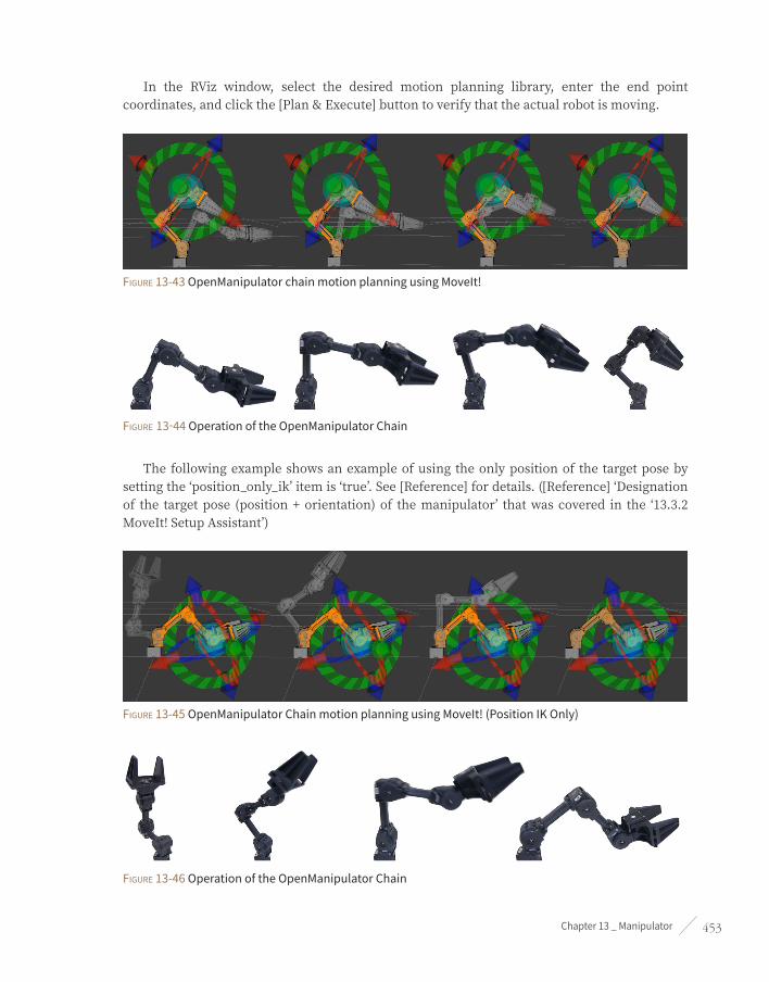
Chapter 13 _ Manipulator 453
In the RViz window, select the desired motion planning library, enter the end point coordinates, and click the [Plan & Execute] button to verify that the actual robot is moving.
Figure 13-43 OpenManipulator chain motion planning using MoveIt!
Figure 13-44 Operation of the OpenManipulator Chain
The following example shows an example of using the only position of the target pose by setting the ‘position_only_ik’ item is ‘true’. See [Reference] for details. ([Reference] ‘Designation of the target pose (position + orientation) of the manipulator’ that was covered in the ‘13.3.2 MoveIt! Setup Assistant’)
Figure 13-45 OpenManipulator Chain motion planning using MoveIt! (Position IK Only)
Figure 13-46 Operation of the OpenManipulator Chain

ROS Robot Programming454
13.4.2. OpenManipulator with TurtleBot3 Waffle and Waffle PiThe OpenManipulator Chain has the advantage of being compatible with TurtleBot3 Waffle and Waffle Pi. Through this compatibility can compensate for the lack of freedom and can have greater completeness as a service robot with the the SLAM and navigation capabilities that the TurtleBot3 has.
In this section, we will look at RViz by adding TurtleBot3 Waffle URDF to the ‘open_manipulator_chain.xacro’ file created above.
You can see the URDF folder where you saved the URDF file in the turtlebot3_description folder. When I created the URDF file for the OpenManipulator Chain, I mentioned that it would be easier to reuse it later if saved in the xacro file format. Let’s examine the ‘open_manipulator_with_tb3’ package.
$ roscd open_manipulator_with_tb3/urdf
$ gedit open_manipulator_chain_with_tb3.xacro
open_manipulator_with_tb3/urdf/open_manipulator_chain_with_tb3.xacro
<!-- Include TurtleBot3 Waffle URDF -->
<xacro:include filename="$(find turtlebot3_description)/urdf/turtlebot3_waffle_naked.urdf.xacro" />
<!-- Base fixed joint -->
<joint name="base_fixed" type="fixed">
<origin xyz="-0.005 0.0 0.091" rpy="0 0 0"/>
<parent link="base_link"/>
<child link="link1"/>
</joint>
If you open the URDF file of the ‘open_manipulator_with_tb3’ package, you can see the code to include the file ‘turtlebot3_waffle_naked.urdf.xacro’ at the top. With this code, the TurtleBot3 Waffle can be loaded, and the manipulator creates a fixed joint on the link where it should be positioned.
TurtleBot3 Waffle and Waffle Pi
The TurtleBot3 Waffle and Waffle Pi are basically equipped with a LIDAR sensor, but for user convenience, ROBOTIS also offers a URDF without a LIDAR sensor.

Chapter 13 _ Manipulator 455
Now let’s run RViz with the following command.
$ roslaunch open_manipulator_with_tb3 open_manipulator_chain_with_tb3_rviz.launch
Figure 13-47 OpenManipulator Chain mounted on TurtleBot3 Waffle
The OpenManipulator Chain uses a modular actuator called Dynamixel, which can be mounted on various robots. It is recommended to use the reuseability of xacro on a customized robot.
456
Symbols
~/ 70/(forward slash) 64--screen 288--- (three consecutive hyphens) 63, 166, 175~ (tilde) 64__ (two consecutive underscores) 65_ (underscore) 65
A
Action 44, 52, 58Action Client 45, 179Action File 63, 175Action Server 44, 176AMCL 340, 347, 348, 357Android 390APT 26Arduino 241ARM 234
B
Bag 46, 323bashrc 29Button 264Buzzer 252
C
Camera 199Camera Calibration 207Catkin 45, 74, 121catkin_create_pkg 152catkin_make 122catkin_python_setup 84Chessboard 208Client Library 13, 47, 68CMake 74CMakeLists.txt 49, 74, 78, 153, 164, 174collision 409communication 5community 6Coordinate Representation 150Costmap 351, 355
D
DAE 409dead reckoning 314degrees of freedom 401, 441Depth Camera 212DWA 340, 353, 359Dynamixel 223, 254, 275, 450dynamixel_sdk 450dynamixel_workbench 451
Index
457
E
Ecosystem 6, 14embedded system 233
F
feedback 58Forward Kinematics 401
G
Gazebo 303, 421, 445Gmapping 336goal 58GUI 129, 137, 415
H
History 15
I
IDE 33ifconfig 31IMU 237, 253, 268inertial 409Installation 24inverse kinematics 401
J
Java 390joint 400, 412Joint Space Control 401
K
Kalman filter 333Kinetic Kame 18, 25
L
LDS 218LED 251, 262link 400, 408Log 97, 117, 146LTS 19, 21
M
Manipulator 399Map 314, 322, 324, 354map_saver 328map_server 309, 320, 322, 324Map server 346Master 41, 54MD5 48Message 43, 60, 155Message Communication 49
Index

Message File 154Meta-Operating System 10Metapackage 42Model 346Modeling 404Motor 223move_base 347, 350move_group 429MoveIt! 429MoveIt! Setup Assistant 430msg File 62
N
Name 47, 64Namespace 65, 66, 151, 191, 366Naming 151Navigation 308, 313, 336, 339, 355Node 42NTP 24ntpdate 24
O
Occupancy Grid Map 325Odometry 299, 318, 341OGM 324OpenCR 235OpenManipulator 403, 454
Open Robotics 16OpenSLAM 336OSRF 16
P
Package 42, 224package.xml 49, 75, 152, 163, 173Parameter 45, 54, 184Parameter Server 45Particle Filter 334, 336pgm 322, 342Platform 2Pose 314, 315Publish 43Publisher 43, 55, 155
Q
Qt 33, 137quaternion 67, 315
R
remapping 65REP 149Repository 47result 58
458
Index

reusability 5Robot 195ROS 41rosbag 117, 146rosbuild 45roscd 94rosclean 99roscore 28, 36, 46, 54, 96roscpp 47, 68rosdep 26, 126rosed 95ROS_HOSTNAME 30, 205, 287rosinstall 27, 126roslaunch 46, 55, 98, 189roslocate 127rosls 95ROS_MASTER_URI 30, 205, 287rosmsg 113rosnode 101rospack 124rosparam 110rospy 47, 68rosrun 46, 55, 97rosserial 255, 259, 260, 262rosserial client 256rosserial Protocol 257rosserial_python 256rosserial server 256rosservice 107rossrv 115rostopic 103
RPC 48rqt 137rqt_bag 146rqt_graph 38, 47, 143rqt_image_view 141rqt_plot 144RViz 129, 204, 215, 221, 272, 297, 298RViz Displays 135
S
SDF 403Sensor 197Service 44, 51Service Caller 171Service Client 44, 58, 167Service Core 362, 367Service File 165Service Master 362, 377Service Server 44, 58, 166Service Slave 363, 385Simulation 297, 303, 311SLAM 308, 317, 324, 332SRDF 430srv File 62SSH 290STL 409Subscribe 43Subscriber 43, 56, 157switchyard 15
459
Index

T
Task Space Control 401TCPROS 49, 57teleoperation 287TF 66, 299, 328, 341, 346Tool 5, 129, 137Topic 43, 50TurtleBot 279TurtleBot3 273, 279, 280, 283, 284, 287, 290, 297, 303turtlesim 37
U
U2D2 452Unit 149URDF 403, 404, 430urdf_to_graphiz 413URI 48
V
visual 409Voltage 253, 266
W
Wiki 47, 91Workspace 27, 71
X
XML 48, 408XMLRPC 48
Y
YAML 111, 207, 322, 342, 344, 440
Index
460
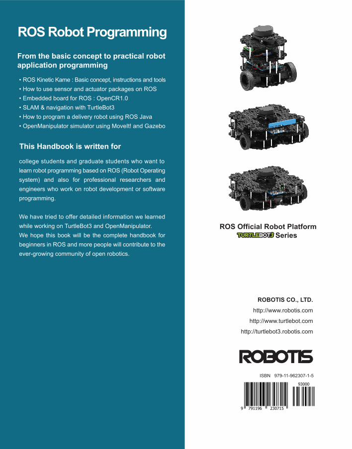
A Handbook Written by TurtleBot3 Developers
Robot ProgrammingYoonSeok Pyo I HanCheol Cho I RyuWoon Jung I TaeHoon Lim
From the basic concept to practical programming and robot application
Robot Program
ming
YoonSeok P
yo H
anCheol C
ho R
yuWoon Jung
TaeHoon Lim
From the basic concept to practical robot application programming
• ROS Kinetic Kame : Basic concept, instructions and tools • How to use sensor and actuator packages on ROS• Embedded board for ROS : OpenCR1.0• SLAM & navigation with TurtleBot3• How to program a delivery robot using ROS Java• OpenManipulator simulator using MoveIt! and Gazebo
This Handbook is written for
college students and graduate students who want to learn robot programming based on ROS (Robot Operating system) and also for professional researchers and engineers who work on robot development or software programming.
We have tried to offer detailed information we learned while working on TurtleBot3 and OpenManipulator. We hope this book will be the complete handbook for beginners in ROS and more people will contribute to the ever-growing community of open robotics.
ROBOTIS CO., LTD.
http://www.robotis.com
http://www.turtlebot.com
http://turtlebot3.robotis.com
ROS Robot ProgrammingYoonSeok Pyo
The lead author, YoonSeok Pyo, is a researcher at ROBOTIS and is the manager in charge of the Open Source Team. He is researching and developing an intelligent system for open source based service robot platform. His work revolves around the question “what are robots to us?” and strives to bring robots closer to our daily lives. After graduating from Kwang Woon University in Korea with a degree in Electrical Engineering, he worked at the Korea Institute of Science and Technology (KIST). He was a research fellow of the Japan Society for the Promotion of Science (JSPS) from 2014 to 2016 in Japan. He received his Ph.D. and M.E. degrees in Information Science and Electrical Engineering from Kyushu University, Japan. He enjoys talking to people who have a dream in the field of robotics. He is always looking for new adventures and hopes to meet readers of this book through lectures, seminars, tutorials, and exhibitions related to robots and ROS.
HanCheol Cho
HanCheol is in charge of the firmware and robot controller development at ROBOTIS. He was previously an ATM firmware developer at LG CNS and is interested in programming and robots. His interest in robots started when he first saw the micro mouse robot contest in middle school and has since enjoyed studying and sharing information on robotics technology. In particular, he is interested in the firmware that controls the robot hardware as well as FPGA, and is working with projects in this field. He believes that technology is most improved when shared, and dreams of still soldering and programming in the twilight years of his life.
RyuWoon Jung
Leon (RyuWoon) Jung is a researcher at ROBOTIS developing autonomous driving systems and actuator applications. He believes that the value of robots lies in filling in the gaps in the areas where humans fail to complement each other and strives to reflect this in the research and development of robots. Leon received his bachelor's and master's degrees from the Department of Electrical Engineering and Bioscience at Waseda University. He has written for the ROBOCON MAGAZINE and is in charge of AutoRace, a large-scale autonomous driving robot competition. He is currently involved in the research and development of autonomous driving robots in the Open Source Robotics Technology Sharing Community (www.oroca.org).
TaeHoon Lim
Darby (TaeHoon) Lim is a ROBOTIS researcher in the Open Source Team who is responsible for the development of the TurtleBot3 and OpenManipulator, as well as acting as the keeper of good-looks in the office. Darby believes that creativity comes from diverse experiences and a broad range of knowledge, and therefore enjoys traveling, reading and speaking with people with diverse backgrounds. Darby aims to develop robots that can convey a different experience and leave an impression to many people, using collaboration with people in fields such as movies, exhibitions, and media to achieve this. He is hosting the “LookSo in Film” open project in OROCA since 2016 as a bummer scriptwriter and software engineer.
ROS Official Robot Platform Series
ISBN 979-11-962307-1-5
9 791196 230715
93000