
Road Structures Design Manual - Abu Dhabi - Jawdah
222
-
Upload
khangminh22 -
Category
Documents
-
view
0 -
download
0
Transcript of Road Structures Design Manual - Abu Dhabi - Jawdah


ROAD STRUCTURES DESIGN MANUAL
DOCUMENT NO: TR-516
SECOND EDITION
AUGUST- 2021

Document No: TR-516
Second Edition, August-2021
Department of Municipalities and Transport
PO Box 20
Abu Dhabi, United Arab Emirates
© Copyright 2021, by the Department of Municipalities and Transport. All Rights Reserved. This
document, or parts thereof, may not be reproduced in any form without written permission of the
publisher

ROAD STRUCTURES DESIGN MANUAL
PAGE i
TOC SECOND EDITION – AUGUST 2021
TABLE OF CONTENTS
Table of Contents .......................................................................................................................... i
List of Figures .............................................................................................................................. xi
List of Tables............................................................................................................................... xii
Abbreviations and Acronyms ................................................................................................... xiii
1 INTRODUCTION ................................................................................................................. 1
1.1 Overview .......................................................................................................................... 1
1.2 Purpose and Scope .......................................................................................................... 1
1.2.1 General ...................................................................................................................... 1
1.2.2 AASHTO LRFD Bridge Design Specifications ............................................................ 2
1.3 Application of this Manual ................................................................................................. 3
1.3.1 Definition of Road Structures ..................................................................................... 3
1.3.2 Hierarchy of Priority ................................................................................................... 3
1.4 Design Objectives ............................................................................................................. 3
1.4.1 Serviceability ............................................................................................................. 3
1.4.2 Constructability .......................................................................................................... 4
1.4.3 Maintenance of Traffic ............................................................................................... 4
1.4.4 Sustainability ............................................................................................................. 4
1.4.5 Aesthetics .................................................................................................................. 4
1.5 Design Approval Procedures ............................................................................................ 4
1.5.1 Objectives .................................................................................................................. 4
1.5.2 Reference .................................................................................................................. 5
1.6 Structure Design Checklists .............................................................................................. 5
2 LOADS AND LOAD FACTORS .......................................................................................... 6
2.1 General ............................................................................................................................. 6
2.1.1 Limit States ................................................................................................................ 6
2.1.2 Load Factors and Combinations ................................................................................ 7
2.2 Permanent Loads ........................................................................................................... 11
2.2.1 General .................................................................................................................... 11
2.2.2 Down drag (DD) on Deep Foundations .................................................................... 11
2.2.3 Support Settlement (SE) .......................................................................................... 11
2.3 Transient Loads .............................................................................................................. 12
2.3.1 General .................................................................................................................... 12

ROAD STRUCTURES DESIGN MANUAL
PAGE ii
TOC SECOND EDITION – AUGUST 2021
2.3.2 Abu Dhabi Vehicular Load (ADVL) ........................................................................... 12
2.3.3 Wind Loads (WS and WL) ....................................................................................... 14
2.3.4 Earthquake Effects (EQ) .......................................................................................... 14
2.3.5 Uniform Temperature (TU) ....................................................................................... 17
2.3.6 Temperature Gradient (TG) ..................................................................................... 17
2.3.7 Live-Load Surcharge (LS) ........................................................................................ 18
2.3.8 Ground Water Levels ............................................................................................... 18
3 STRUCTURAL ANALYSIS ............................................................................................... 19
3.1 Acceptable Methods ....................................................................................................... 19
3.1.1 General .................................................................................................................... 19
3.1.2 Exceptions ............................................................................................................... 19
3.2 Static Analysis ................................................................................................................ 19
3.2.1 Refined Analysis ...................................................................................................... 19
3.2.2 Approximate Analysis .............................................................................................. 20
3.2.3 Lateral Wind-Load Distribution in Multi-Beam Bridges ............................................. 22
3.3 Dynamic Analysis ........................................................................................................... 23
3.3.1 Seismic Analysis ...................................................................................................... 23
3.3.2 Wind-Induced Vibration ........................................................................................... 23
3.4 Transverse Deck Loading, Analysis, and Design ............................................................ 23
4 CONCRETE STRUCTURES ............................................................................................. 24
4.1 Structural Concrete Design ............................................................................................. 24
4.1.1 Member Design Models ........................................................................................... 24
4.1.2 Flexural Resistance ................................................................................................. 24
4.1.3 Shear Resistance .................................................................................................... 26
4.1.4 Strut-and-Tie Model ................................................................................................. 26
4.1.5 Torsion .................................................................................................................... 27
4.1.6 Fatigue .................................................................................................................... 28
4.1.7 Lateral Confinement Reinforcement ........................................................................ 28
4.2 Environmental Classification ........................................................................................... 28
4.2.1 General .................................................................................................................... 28
4.2.2 Classification Criteria ............................................................................................... 29
4.2.3 Chloride Content ...................................................................................................... 31
4.3 Materials ......................................................................................................................... 32
4.3.1 Concrete Strength ................................................................................................... 32

ROAD STRUCTURES DESIGN MANUAL
PAGE iii
TOC SECOND EDITION – AUGUST 2021
4.3.2 Reinforcing Steel ..................................................................................................... 32
4.3.3 Prestressing Strand ................................................................................................. 32
4.3.4 Prestressing Bars .................................................................................................... 32
4.4 Reinforced Concrete Structures ...................................................................................... 33
4.4.1 Durability Measures ................................................................................................. 33
4.4.2 Reinforcing-Steel Details ......................................................................................... 33
4.5 Prestressed Concrete Superstructures ........................................................................... 37
4.5.1 Basic Criteria ........................................................................................................... 37
4.5.2 Post-Tensioned Bridges .......................................................................................... 37
4.5.3 Precast, Prestressed Concrete Girders.................................................................... 50
4.5.4 Pretensioned/Post-Tensioned Beams ...................................................................... 57
4.5.5 Camber Diagram ..................................................................................................... 57
4.5.6 Responsibilities ........................................................................................................ 57
5 STEEL STRUCTURES ..................................................................................................... 59
5.1 General ........................................................................................................................... 59
5.1.1 Economical Steel Superstructure Design ................................................................. 59
5.1.2 Rolled Beams vs Welded Plate Girders ................................................................... 60
5.1.3 Economical Plate Girder Proportioning .................................................................... 61
5.1.4 Falsework ................................................................................................................ 64
5.2 Materials ......................................................................................................................... 64
5.2.1 Structural Steel ........................................................................................................ 64
5.2.2 Bolts ........................................................................................................................ 67
5.2.3 Splice Plates ............................................................................................................ 67
5.3 Horizontally Curved Members ......................................................................................... 67
5.3.1 General .................................................................................................................... 67
5.3.2 Diaphragms, Bearings, and Field Splices ................................................................ 67
5.4 Fatigue Considerations ................................................................................................... 68
5.4.1 Load-Induced Fatigue .............................................................................................. 68
5.4.2 Other Fatigue Considerations .................................................................................. 69
5.5 General Dimension and Detail Requirements ................................................................. 69
5.5.1 Deck Haunches ....................................................................................................... 69
5.5.2 Sacrificial Metal Thickness ....................................................................................... 69
5.5.3 Minimum Thickness of Steel Plates ......................................................................... 69
5.5.4 Camber .................................................................................................................... 70

ROAD STRUCTURES DESIGN MANUAL
PAGE iv
TOC SECOND EDITION – AUGUST 2021
5.5.5 Diaphragms and Cross Frames ............................................................................... 70
5.5.6 Jacking .................................................................................................................... 74
5.5.7 Lateral Bracing ........................................................................................................ 74
5.5.8 Inspection Access (Tub Girders) .............................................................................. 75
5.6 I-Sections in Flexure ....................................................................................................... 75
5.6.1 General .................................................................................................................... 75
5.6.2 Shear Connectors .................................................................................................... 76
5.6.3 Stiffeners ................................................................................................................. 76
5.6.4 Deck-Overhang Cantilever Brackets ........................................................................ 78
5.7 Connections and Splices ................................................................................................ 78
5.7.1 Bolted Connections.................................................................................................. 78
5.7.2 Welded Connections ................................................................................................ 79
5.7.3 Splices ..................................................................................................................... 80
6 DECKS AND DECK SYSTEMS ........................................................................................ 82
6.1 Concrete Decks .............................................................................................................. 82
6.1.1 Protection of Reinforcing Steel ................................................................................ 82
6.1.2 Empirical Design ...................................................................................................... 82
6.1.3 Traditional Design Using the “Strip Method” ............................................................ 82
6.1.4 Precast Concrete Deck Panels ................................................................................ 83
6.2 Metal Decks .................................................................................................................... 83
6.2.1 Grid Decks ............................................................................................................... 83
6.2.2 Orthotropic Steel Decks ........................................................................................... 83
6.3 Design Details for Concrete Bridge Decks ...................................................................... 84
6.3.1 General .................................................................................................................... 84
6.3.2 Detailing Requirements for Concrete-Deck Haunches ............................................. 85
6.3.3 Reinforcing Steel Over Intermediate Piers or Bents ................................................. 88
6.3.4 Minimum Negative Flexure Slab Reinforcement ...................................................... 88
6.3.5 Crack Control in Continuous Decks ......................................................................... 88
6.3.6 Skewed Decks ......................................................................................................... 89
6.3.7 Temperature and Shrinkage Reinforcement ............................................................ 91
6.3.8 Thickened Slab End Requirements .......................................................................... 91
6.3.9 Phase Constructed Decks ....................................................................................... 91
6.3.10 Stay-in-Place Forms ................................................................................................ 91

ROAD STRUCTURES DESIGN MANUAL
PAGE v
TOC SECOND EDITION – AUGUST 2021
6.3.11 Concrete Deck Pouring Sequence for Decks Constructed Compositely in Conjunction
with Concrete and Steel Girders .............................................................................. 91
6.3.12 Longitudinal Construction Joints .............................................................................. 94
6.3.13 Longitudinal Concrete Deck Joints ........................................................................... 96
6.3.14 Transverse Edge Beam for Steel Girder Bridges ..................................................... 96
6.3.15 Concrete Deck Overhang/Bridge Rail ...................................................................... 96
6.4 Approach Slabs .............................................................................................................. 98
6.4.1 Usage ...................................................................................................................... 98
6.4.2 Design Criteria ......................................................................................................... 98
7 FOUNDATIONS ................................................................................................................ 99
7.1 General ........................................................................................................................... 99
7.1.1 Scope ...................................................................................................................... 99
7.1.2 Design Methodology ................................................................................................ 99
7.1.3 Bridge Foundation Design Process .......................................................................... 99
7.1.4 Bridge Design/Geotechnical Design Interaction ..................................................... 100
7.2 Spread Footings and Pile Caps .................................................................................... 103
7.2.1 Usage .................................................................................................................... 103
7.2.2 Dynamic Load Allowance (Impact Modifier, IM) ..................................................... 104
7.2.3 Thickness .............................................................................................................. 104
7.2.4 Depth ..................................................................................................................... 104
7.2.5 Bearing Resistance and Eccentricity ...................................................................... 104
7.2.6 Sliding Resistance ................................................................................................. 104
7.2.7 Differential Settlement ........................................................................................... 105
7.2.8 Reinforcement ....................................................................................................... 106
7.2.9 Miscellaneous ........................................................................................................ 106
7.3 Deep Foundations ........................................................................................................ 107
7.3.1 General .................................................................................................................. 107
7.3.2 Component Spacing .............................................................................................. 107
7.3.3 Drilled Shafts ......................................................................................................... 107
7.3.4 Driven Piles ........................................................................................................... 112
7.3.5 Pile/Shaft Testing .................................................................................................. 115
7.4 Modelling for Lateral Loading ........................................................................................ 117
7.4.1 Horizontal Movement ............................................................................................. 118
7.5 Mass Concrete ............................................................................................................. 118

ROAD STRUCTURES DESIGN MANUAL
PAGE vi
TOC SECOND EDITION – AUGUST 2021
8 ABUTMENTS, PIERS, AND WALLS .............................................................................. 119
8.1 Abutments/Wingwalls ................................................................................................... 119
8.1.1 General .................................................................................................................. 119
8.1.2 General Abutment/Wing wall Design and Detailing Criteria .................................... 120
8.1.3 Seat Abutments ..................................................................................................... 120
8.1.4 Integral Abutments................................................................................................. 121
8.1.5 Semi-Integral Abutments ....................................................................................... 121
8.1.6 MSE Wall Abutments ............................................................................................. 122
8.1.7 Wingwalls .............................................................................................................. 122
8.1.8 Abutment Construction Joints ................................................................................ 123
8.2 Piers ............................................................................................................................. 123
8.2.1 Pier Caps ............................................................................................................... 123
8.2.2 Column Cross Sections ......................................................................................... 124
8.2.3 Column Reinforcement .......................................................................................... 125
8.2.4 Column Construction Joints ................................................................................... 126
8.2.5 Multi-Column Piers ................................................................................................ 126
8.2.6 Single-Column Piers .............................................................................................. 126
8.2.7 Pier Walls .............................................................................................................. 127
8.2.8 Dynamic Load Allowance (DLA) ............................................................................ 127
8.2.9 Moment-Magnification ........................................................................................... 127
8.2.10 Pier, Column, and Footing Design ......................................................................... 127
8.3 Walls (Earth Retaining Systems) .................................................................................. 129
8.3.1 General .................................................................................................................. 129
8.3.2 Responsibilities ...................................................................................................... 130
8.3.3 Types of Earth Retaining Systems ......................................................................... 132
8.3.4 Mechanically-Stabilized Earth (MSE) Walls ........................................................... 134
8.4 Geosynthetic Reinforced Soil (GRS) Walls and Abutments .......................................... 143
9 EXPANSION JOINTS ..................................................................................................... 144
9.1 Design Requirements: Movement and Loads ............................................................... 144
9.1.1 General .................................................................................................................. 144
9.1.2 Estimation of General Design Thermal Movement, T ........................................... 145
9.1.3 Estimation of Design Movement ............................................................................ 145
9.1.4 Setting Temperature .............................................................................................. 146
9.2 Expansion Joint Selection and Design .......................................................................... 146

ROAD STRUCTURES DESIGN MANUAL
PAGE vii
TOC SECOND EDITION – AUGUST 2021
9.2.1 General .................................................................................................................. 146
9.2.2 Sheet and Strip Seals ............................................................................................ 146
9.2.3 Modular Expansion Joint ....................................................................................... 147
9.2.4 Steel Finger Joints ................................................................................................. 147
9.2.5 Reinforced Elastomeric .......................................................................................... 147
9.2.6 Silicone Joint Sealant ............................................................................................ 147
9.2.7 Compression and Cellular Seals ............................................................................ 148
9.2.8 Asphaltic Plug Joint (Poured Seals) ....................................................................... 148
9.2.9 Expansion Joints for Asphaltic Overlays ................................................................ 148
9.3 Expansion Joints for Post-Tensioned Bridges ............................................................... 148
9.4 Expansion Joint Design ................................................................................................ 149
10 BEARINGS ..................................................................................................................... 150
10.1 General ......................................................................................................................... 150
10.1.1 Movements and Loads .......................................................................................... 150
10.1.2 Effect of Camber and Construction Procedures ..................................................... 150
10.1.3 Design Thermal Movements .................................................................................. 150
10.1.4 Estimation of Total Design Movement.................................................................... 151
10.1.5 Serviceability, Maintenance, and Protection Requirements .................................... 151
10.1.6 Anchor Bolts .......................................................................................................... 151
10.1.7 Bearing Plate Details ............................................................................................. 152
10.1.8 Levelling Pad at Integral Abutments ...................................................................... 152
10.1.9 Lateral Restraint .................................................................................................... 153
10.2 Bearing Types and Selection ........................................................................................ 153
10.2.1 General .................................................................................................................. 153
10.2.2 Steel-Reinforced Elastomeric Bearings .................................................................. 154
10.2.3 Plain Elastomeric Bearing Pads ............................................................................. 154
10.2.4 High-Load, Multi-Rotational (HLMR) Bearings ....................................................... 155
10.2.5 Polytetrafluoroethylene (PTFE) Sliding Surfaces ................................................... 155
10.2.6 Seismic Isolation Bearings ..................................................................................... 155
10.3 Plain Elastomeric Bearing Pads and Steel-Reinforced Elastomeric Bearings ............... 155
10.3.1 General .................................................................................................................. 156
10.3.2 Holes in Elastomer................................................................................................. 156
10.3.3 Edge Distance ....................................................................................................... 156
10.3.4 Steel-Reinforced Elastomeric Bearings .................................................................. 156

ROAD STRUCTURES DESIGN MANUAL
PAGE viii
TOC SECOND EDITION – AUGUST 2021
10.3.5 Design of Plain Elastomeric Bearing Pads ............................................................. 156
10.3.6 Design of Steel-Reinforced Elastomeric Bearings .................................................. 156
11 PEDESTRIAN BRIDGES ................................................................................................ 158
11.1 General ......................................................................................................................... 158
11.2 Live Load ...................................................................................................................... 158
11.2.1 Pedestrian Load (PL) ............................................................................................. 158
11.2.2 Vehicle Load (LL) .................................................................................................. 158
11.3 Wind Load (WS) ........................................................................................................... 158
11.4 Vibrations ..................................................................................................................... 159
11.5 Design .......................................................................................................................... 159
11.5.1 Geometrics ............................................................................................................ 159
11.5.2 Structure Type ....................................................................................................... 159
11.5.3 Seismic .................................................................................................................. 159
11.5.4 Fatigue .................................................................................................................. 159
11.5.5 Detailed Design Requirements .............................................................................. 159
11.5.6 Deflections ............................................................................................................. 160
11.5.7 Steel Connections ................................................................................................. 160
11.5.8 Charpy V-Notch Testing ........................................................................................ 161
11.5.9 Painting/Galvanizing .............................................................................................. 161
11.5.10 Erection ................................................................................................................. 161
11.5.11 Railings/Enclosures ............................................................................................... 162
11.5.12 Drainage ................................................................................................................ 162
11.5.13 Corrosion Resistant Details ................................................................................... 162
11.5.14 Lighting/Attachments ............................................................................................. 162
11.5.15 Maintenance and Inspection Attachments ............................................................. 162
12 CULVERTS ..................................................................................................................... 163
12.1 Reinforced Concrete Boxes .......................................................................................... 163
12.1.1 General .................................................................................................................. 163
12.1.2 Analysis ................................................................................................................. 163
12.1.3 Span-to-Rise Ratios ............................................................................................... 163
12.1.4 Deformations ......................................................................................................... 164
12.1.5 Design Method ...................................................................................................... 164
12.1.6 Dead Loads and Earth Pressure ............................................................................ 164
12.1.7 Live Load ............................................................................................................... 164

ROAD STRUCTURES DESIGN MANUAL
PAGE ix
TOC SECOND EDITION – AUGUST 2021
12.1.8 Wall Thickness Requirements ............................................................................... 164
12.1.9 Reinforcement Details ........................................................................................... 165
12.1.10 Skewed Culverts .................................................................................................... 165
12.2 Concrete Arch Culverts ................................................................................................. 165
12.3 Concrete Pipe Culverts ................................................................................................. 166
12.3.1 General .................................................................................................................. 166
12.3.2 Materials ................................................................................................................ 166
12.3.3 Design ................................................................................................................... 166
13 SOUND BARRIERS ........................................................................................................ 167
13.1 Sound Barrier Design ................................................................................................... 167
13.1.1 General Features – Panel Height and Post Spacing .............................................. 167
13.1.2 Wind Loads ........................................................................................................... 167
13.1.3 Lateral Earth Pressure ........................................................................................... 167
14 SIGN AND LUMINAIRE SUPPORTS .............................................................................. 168
14.1 General ......................................................................................................................... 168
14.2 Deformations ................................................................................................................ 168
14.3 Basic Wind Speed ........................................................................................................ 168
14.4 Steel Design ................................................................................................................. 168
14.4.1 Base-Plate Thickness ............................................................................................ 168
14.4.2 Welded Connections .............................................................................................. 168
14.4.3 Bolted Connections................................................................................................ 169
14.4.4 Anchor Bolt Connections ....................................................................................... 169
14.4.5 Bolt Types ............................................................................................................. 169
14.5 Aluminium Design ......................................................................................................... 169
14.6 Prestressed-Concrete Poles ......................................................................................... 170
14.7 Foundation Design........................................................................................................ 170
14.7.1 Geotechnical Design of Drilled Shaft Foundations ................................................. 170
14.7.2 Structural Design of Drilled Shaft Foundations ....................................................... 170
14.8 Design Loads for Vertical Supports ............................................................................... 170
15 ROAD TUNNELS ............................................................................................................ 171
15.1 General ......................................................................................................................... 171
15.2 Definition of Road Tunnels ............................................................................................ 171
15.3 Geotechnical Site Investigations ................................................................................... 172
15.4 Fire Protection .............................................................................................................. 172
ROAD STRUCTURES DESIGN MANUAL
PAGE x
TOC SECOND EDITION – AUGUST 2021
15.5 Constructability ............................................................................................................. 172
15.6 Design Life ................................................................................................................... 172
15.7 Design Considerations .................................................................................................. 173
15.7.1 Design Elements ................................................................................................... 173
15.7.2 Live Load ............................................................................................................... 174
15.7.3 Seismic Considerations ......................................................................................... 174
15.8 Tunnel Types ................................................................................................................ 174
15.8.1 Cut-and-Cover Tunnels ......................................................................................... 174
15.8.2 Mined or Bored Tunnels ........................................................................................ 175
15.8.3 Immersed Tunnels ................................................................................................. 176
15.9 Tunnel Lining ................................................................................................................ 176
16 BRIDGE EVALUATION .................................................................................................. 177
16.1 Load Rating .................................................................................................................. 177
16.1.1 General .................................................................................................................. 177
16.1.2 Importance of Load Rating ..................................................................................... 177
16.1.3 Methodology .......................................................................................................... 177
16.1.4 Thresholds for Re-Rating Existing Bridges ............................................................ 177
16.1.5 Limit States for Load Rating ................................................................................... 177
16.1.6 Dimensions ............................................................................................................ 178
16.1.7 The LRFR Load-Rating Equation ........................................................................... 178
16.1.8 Analytical Methods for the Load Rating of Post-Tensioned Box Girder Bridges ..... 179
16.2 Design Load Rating ...................................................................................................... 179
16.3 Legal-Load Rating and Load Posting ............................................................................ 179
16.3.1 Legal-Load Rating ................................................................................................. 179
16.3.2 Load Posting.......................................................................................................... 180
16.4 Permitting and Permit-Load Rating ............................................................................... 180
16.4.1 Permitting .............................................................................................................. 180
16.4.2 Permit-Load Rating ................................................................................................ 180
16.5 Load Testing of Bridges ................................................................................................ 180
16.5.1 General .................................................................................................................. 180
16.5.2 Load Testing Calculations...................................................................................... 181
16.5.3 Load Testing Method Statement ............................................................................ 181
16.5.4 Load Testing Analysis Report ................................................................................ 183
CITED REFERENCES ................................................................................................................ 184

ROAD STRUCTURES DESIGN MANUAL
PAGE xi
TOC SECOND EDITION – AUGUST 2021
INDEX 187
APPENDIX A .............................................................................................................................. 193
LIST OF FIGURES
Figure 2.1: Characteristics of the Design Truck ............................................................................. 12
Figure 2.2: Permit Design Live Loads (for P-13 Vehicle) ............................................................... 13
Figure 2.3: Design Response Spectrum ....................................................................................... 15
Figure 2.4: Positive Vertical Temperature Gradient in Concrete and Steel Superstructures .......... 18
Figure 3.1: Common Deck Superstructures Covered .................................................................... 21
Figure 4.1: Flowchart for Environmental Classification of Structures ............................................. 30
Figure 4.2: Deviator Diaphragm Detail .......................................................................................... 45
Figure 4.3: Inside Corner Detail at Pier ......................................................................................... 45
Figure 4.4: Details at Expansion Joints ......................................................................................... 46
Figure 5.1: Grouping Flanges for Efficient Fabrication (from the AASHTO/NSBA Steel Bridge
Collaboration (15)) ........................................................................................................................ 62
Figure 5.2: Flange Width Transition (Plan View) ........................................................................... 62
Figure 5.3: Drip Plate Detail .......................................................................................................... 66
Figure 5.4: Typical Pier and Intermediate Diaphragm Connection (Rolled Beams) ....................... 72
Figure 5.5: Typical Abutment Diaphragm Connection (Skewed Diaphragm with Rolled Beams) .. 72
Figure 5.6: Typical Pier and Intermediate Cross Frames (Plate Girder Web > 1200 mm) ............ 73
Figure 5.7: Typical Abutment Cross Frames (Plate Girder Web > 1200 mm) ................................ 73
Figure 5.8: Schematic of Location for Deck Overhang Bracket ..................................................... 78
Figure 5.9: Typical Welded Splice Details ..................................................................................... 81
Figure 6.1: Haunch Dimension for Steel Plate Girders .................................................................. 86
Figure 6.2: Haunch Dimension for Steel Rolled Beams ................................................................. 86
Figure 6.3: Haunch Dimension for Concrete ................................................................................. 87
Figure 6.4: Haunch Reinforcement for Deep Haunches (> 100 mm) ............................................. 87
Figure 6.5: Skew Angle and Length/Bridge Width Ratios .............................................................. 90
Figure 6.6: Typical Pour Diagram (Continuous Steel and Precast Girders) ................................... 93
Figure 6.7: Support for Finishing Machine ..................................................................................... 95
Figure 6.8: Transverse Edge Beam .............................................................................................. 97
Figure 7.1: Concrete Backfill Under Stepped Footing.................................................................. 107
Figure 7.2: Drilled Shaft Detail (For Shafts Larger Than Columns) ............................................. 110
Figure 7.3: Drilled Shaft Detail (With Equal Diameter Shaft and Column) .................................. 111
Figure 7.4: Method of Modelling Deep Foundation Stiffness ....................................................... 118

ROAD STRUCTURES DESIGN MANUAL
PAGE xii
TOC SECOND EDITION – AUGUST 2021
Figure 8.1: Tops of Drop Caps .................................................................................................... 124
Figure 8.2: Design Criteria for Acute Corners of MSE Bin Walls ................................................. 135
Figure 8.3: MSE Wall Minimum Front Face Embedment ............................................................. 136
Figure 8.4: Broken Backfill with Traffic Surcharge ....................................................................... 138
Figure 8.5: Broken Backfill without Traffic Surcharge .................................................................. 139
Figure 8.6: Proprietary Retaining Walls ....................................................................................... 140
Figure 11.1: Tubular Truss Splice Detail ..................................................................................... 161
LIST OF TABLES
Table 2.1: Load Combinations and Load Factors ............................................................................ 7
Table 2.2: Load Factors for Permanent Loads, p ......................................................................... 10
Table 2.3: Spectral Response Accelerations for the Abu Dhabi Emirate ....................................... 14
Table 2.4: Acceleration Coefficients .............................................................................................. 16
Table 2.5: Site-Class Definitions ................................................................................................... 16
Table 2.6: BDS Procedure “A” Temperature Ranges .................................................................... 17
Table 4.1: Criteria for Substructure Environmental Classifications ................................................ 31
Table 4.2: Chloride Intrusion Rate/Environmental Classifications.................................................. 31
Table 4.3: Compressive Strength of Concrete .............................................................................. 32
Table 4.4: Concrete Cover ............................................................................................................ 34
Table 4.5: Tensile Stress Limits .................................................................................................... 37
Table 4.6: Minimum Centre-to-Centre Duct Spacing (Straight Ducts) ........................................... 39
Table 4.7: Minimum Tendons Required for Critical Post-Tensioned Sections .............................. 42
Table 4.8: Recommended Minimum Duct Radius (for Steel Ducts) ............................................... 43
Table 6.1: Orthotropic-Deck Panel Proportions ............................................................................ 84
Table 7.1: Resistance Factors for Drilled Shafts ......................................................................... 112
Table 7.2: Driven Pile Selection Guide ........................................................................................ 113
Table 7.3: Table of Additional Sacrificial Steel Thickness Required (mm) ................................... 116
Table 8.1: Required Tendons for Post-Tensioned Substructure Elements .................................. 128
Table 8.2: Minimum Centre-to-Centre Duct Spacing ................................................................... 128
Table 9.1: BDS Procedure “A” Temperature Changes ................................................................ 144
Table 9.2: Expansion Joint Selection ......................................................................................... 146
Table 10.1: Summary of Bearing Capabilities ............................................................................. 154

ROAD STRUCTURES DESIGN MANUAL
PAGE xiii
TOC SECOND EDITION – AUGUST 2021
ABBREVIATIONS AND ACRONYMS
AASHTO American Association of State Highway and Transportation Officials
ACI American Concrete Institute
AD Police Abu Dhabi Traffic Police
ADSC International Association of Foundation Drilling
ADVL Abu Dhabi Vehicular Load
AHT Astronomic High Tide
AISI American Iron and Steel Institute
ASCE American Society of Civil Engineers
ASTM American Society for Testing and Materials
AWS American Welding Society
BCS AASHTO LRFD Bridge Construction Specifications
BDS AASHTO LRFD Bridge Design Specifications
BR Braking Force
Caltrans California Department of Transportation
CANDE Culvert Analysis and Design
CE Centrifugal Force
CIS Cast-in-Situ
CR Creep
CT Truck Collision
CV Vessel Collision
DC Component Dead Load
DCDT Deflected Cantilever Displacement Transducers
DD Down Drag
DL Dead Load
DLA Dynamic Load Allowance
DMA Department of Municipalities and Transport
DMAT Department of Municipal Affairs and Transport
DPB AASHTO Guide Specifications for Design of Pedestrian Bridges
DTI Direct Tension Indicator
DW Wearing Surface Dead Load
EH Horizontal Earth Pressure
EL Locked-In Forces

ROAD STRUCTURES DESIGN MANUAL
PAGE xiv
TOC SECOND EDITION – AUGUST 2021
EQ Earthquake Effects
ES Earth Surcharge
EV Vertical Earth Pressure
FCM Fracture Critical Member
FHWA Federal Highway Administration
FR Friction
GGBFS Ground Granulated Blast Furnace Slag
GRS Geosynthetic Reinforced Soil
GSBD AASHTO Guide Specifications for LRFD Seismic Bridge Design
HDPE High-Density Polyethylene
HLMR High-Load, Multi-Rotational
HPS High-Performance Steel
IM Impact Modifier
ITS Intelligent Transportation Systems
LL Live Load
LS Live-Load Surcharge
LRFD Load-and-Resistance Factor Design
LRFR Load and Resistance Factor Rating
LVDT Linear Variable Displacement Transducers
MBE AASHTO Manual for Bridge Evaluation
MCFT Modified Compression Field Theory
MHW Mean High-Water Level
MLL Minimum Low-Water Level
MLW Mean Low-Water Level
MRT AASTHO Technical Manual for Design and Construction of Road Tunnels – Civil
Elements
MSE Mechanically Stabilized Earth
NATM New Austrian Tunnelling Method
NCHRP National Cooperative Highway Research Program
NFPA National Fire Protection Association
NHW Normal High-Water Level
NJDOT New Jersey Department of Transportation
NLW Normal Low- Water Level
NSBA National Steel Bridge Alliance

ROAD STRUCTURES DESIGN MANUAL
PAGE xv
TOC SECOND EDITION – AUGUST 2021
PCA Portland Cement Association
PCI Prestressed/Precast Concrete Institute
PGA Peak Ground Acceleration
PI Point of Intersection
PL Pedestrian Load
ppm Parts per Million
PS Secondary Forces from Post-Tensioning
PT Post-Tensioned
PTFE Polytetrafluoroethylene
PVC Polyvinyl Chloride
RF Rating Factor
RF Reduction Factor
RSDM Abu Dhabi Road Structures Design Manual
RSF Reinforced Soil Foundations
SE Differential Settlement
SEM Sequential Excavation Method
SH Shrinkage
SSS AASHTO Standard Specifications for Structural Supports for Highways Signs,
Luminaires, and Traffic Signals
T Period
TBM Tunnel Boring Machine
TG Temperature Gradient
TU Uniform Temperature
UPC Urban Planning Council
UV Ultra Violet
WA Water Load
WS Wind Load on Structure
WL Wind on Live-Load

ROAD STRUCTURES DESIGN MANUAL
Page 1
01-INTRODUCTION SECOND EDITION – AUGUST 2021
1 INTRODUCTION
1.1 Overview
In 2010, DMAT-DOT (former Abu Dhabi Department of Transport) commenced with the “Unifying
and Standardizing of Road Engineering Practices” Project. The objective of the project was to
enhance the management, planning, design, construction, maintenance, and operation of all roads
and related infrastructures in the Emirate and to ensure a safe and uniform operational and structural
capacity throughout the road network.
To achieve this objective, a set of standards, specifications, guidelines, and manuals were
developed in consultation with all relevant authorities in the Abu Dhabi Emirate including the
Department of Municipal Affairs (DMA) and Urban Planning Council (UPC). In the future, all
authorities or agencies involved in roads and road infrastructures in the Emirate shall exercise their
functions and responsibilities in accordance with these documents. The purpose, scope, and
applicability of each document are clearly indicated in each document.
It is recognized that there are already published documents with similar objectives and contents
prepared by other authorities. Such related publications are mentioned in each new document and
are being superseded by the publication of the new document, except where previously published
documents are recognized and referenced in the new document.
The Executive Council issued amendments to some of the Structural Design Criteria, detailed in
previous edition of this Manual. The key objective of the amendments was primarily to reduce the
initial cost of the highway structures that corresponds to reduction in the service life of highway
structures (bridges, underpasses, and tunnels). The service life of the structure and associated cost
is fundamentally controlled by many factors some of these key factors considered revisions are
reducing the clear concrete cover, concrete compressive strength, revising crack width parameters
etc.
1.2 Purpose and Scope
1.2.1 General
The basic purpose and scope for the Road Structures Design Manual (RSDM, the Manual) is as
follows:
1. Purpose. The Manual is an application-oriented document for design of road structures.
2. Scope. The Manual provides design specifications for road structures in the Abu Dhabi
Emirate as a supplement to the AASHTO Bridge Design Specifications. In some instances,
background information is provided on design specifications. The Manual is not a structural
design theory resource or a research document. Where beneficial, the Manual provides
design details for various structural elements.
3. Audience. The primary audience for the Manual is the owner’s employees, other relevant
authorities, consultants and contractors for the design and construction of road structures in
the Abu Dhabi Emirate.

ROAD STRUCTURES DESIGN MANUAL
Page 2
01-INTRODUCTION SECOND EDITION – AUGUST 2021
The Manual is based on the AASHTO LRFD Bridge Design Specifications, 6th Edition, 2012 (1)
(BDS) and:
• in general, does not duplicate information in the BDS, unless necessary for clarity;
• elaborates on specific articles of the BDS;
• presents interpretative information and commentary on some provisions, where required;
these texts are highlighted throughout the document;
• modifies sections from the BDS where required due to local conditions or because the bridge
owner has adopted a different practice;
• indicates owner’s preference where the BDS presents multiple options; and
• indicates bridge design applications presented in the BDS that are not typically used in the
Abu Dhabi Emirate.
In addition, the Manual discusses, for selected applications, the intent of the BDS to assist the bridge
designer in proper application.
The Manual will be revised periodically as newer editions of the BDS are published. If newer editions
of the BDS (and any Interims) become available before the Manual is revised, then the more recent
editions of the BDS shall govern.
1.2.2 AASHTO LRFD Bridge Design Specifications
1.2.2.1 General
The BDS establishes minimum requirements that apply to common road bridges and other structures
such as retaining walls and culverts. Long-span or unique structures may require design provisions
in addition to those presented in the BDS. AASHTO issues interim revisions annually and,
periodically, publishes a completely updated edition. The BDS serves as a standard for use by bridge
designers. Many agencies also have used the BDS as a basis for the development of their own
structural specifications.
All calculations and drawings should be provided in the metric (SI) system, as far as possible.
However, the Consultant may refer to AASHTO LRFD (2007) for the conversion of formulae where
applicable. US customary units may be used if conversion is not possible, or if loss of accuracy
would result.
1.2.2.2 LRFD Methodology
The BDS presents a Load-and-Resistance-Factor Design (LRFD) methodology for the structural
design of bridges. Basically, the LRFD methodology requires that bridge components be designed
to satisfy four sets of limit states: Strength, Service, Fatigue-and-Fracture, and Extreme-Event.
Through the use of reliability indices derived through statistical analyses, the Strength limit-state
provisions of the BDS reflect a uniform level of safety for all structural elements, components, and
systems.
ROAD STRUCTURES DESIGN MANUAL
Page 3
01-INTRODUCTION SECOND EDITION – AUGUST 2021
1.3 Application of this Manual
1.3.1 Definition of Road Structures
Road structures are part of the roadway infrastructure including bridges, viaducts, utility bridges,
culverts, underpasses, tunnels, and retaining walls. Road structures also include pedestrian bridges,
sound barriers, and structural supports for traffic signs and luminaires.
1.3.2 Hierarchy of Priority
Where conflicts are observed in publications and documents for structural design, the following
hierarchy of priority applies to determine the appropriate application:
• Structural Design Memoranda issued by the owner,
• This Manual,
• BDS, and
• All other generally recognised structure-related publications (e.g. research studies).
1.4 Design Objectives
Reference: BDS Article 2.5
In addition to the design objectives outlined in the BDS, the following emphasizes objectives of
special importance to the Abu Dhabi Emirate.
1.4.1 Serviceability
1.4.1.1 Durability
Reference: BDS Article 2.5.2.1
Provide special attention to durability issues during design and construction. In consideration of local
conditions, this Manual specifies material and protective measures to enhance the durability
provisions already included in the BDS.
1.4.1.2 Inspectability and Maintainability
Reference: BDS Articles 2.5.2.2 and 2.5.2.3
Provide access to different parts of structures for inspection, maintenance, rehabilitation, and
replacement where necessary (e.g. bearings, expansion joints, future post-tensioning tendons).
Provide all required jacking points.
1.4.1.3 Adjacent Structures
As practical, the bridge design shall not affect nor have any negative impact, on adjacent existing
buildings and structures (if any) or any planned construction in the area. Therefore, consideration
shall be given to existing structures during the design process.
1.4.1.4 Utilities and Intelligent Transportation Systems (ITS)
Reference: BDS Article 2.5.2.5

ROAD STRUCTURES DESIGN MANUAL
Page 4
01-INTRODUCTION SECOND EDITION – AUGUST 2021
Provide service provisions as required by the interested authorities. Design protection culverts for
oil, water, sewer, gas and electricity in consideration of the service authorities’ requirements.
Design bridges and tunnels to accommodate necessary ITS infrastructure, as identified in the project
ITS documents.
Provide pull boxes at appropriate spacing for ease of maintenance and for pulling cables.
1.4.2 Constructability
Reference: BDS Article 2.5.3
1.4.3 Maintenance of Traffic
Minimize the disturbance to traffic flow on the existing roads during construction. (Refer to the “Abu
Dhabi Work Zone Traffic Management Manual”).
1.4.4 Sustainability
A sustainable bridge project must satisfy transportation requirements and improve the economy,
environment, and social aspects. Although the concept of sustainable bridge design is still in
development, and clear standards have not been formalized, all bridges in the Abu Dhabi Emirate
shall be designed with sustainability as a major design objective.
1.4.5 Aesthetics
Reference: BDS Article 2.5.5
Every effort shall be made in the treatment of structures to respect the local aesthetic design and
culture. Design concepts would be easily implementable. Also, construction issues shall be
considered in the architectural treatment concepts. Architectural elements must be functional,
durable, and easily maintainable. Desirably, each structure will have individuality; however, a
completely different aesthetic treatment is not required for every structure. Desirably, maintain a
sense of continuity throughout the entire highway corridor.
Design the architectural treatment to be continuous throughout an interchange. Underpasses
spanning a given roadway would have a similar treatment to establish continuity. Decorative and
median lighting would be similar on overpasses along a given route, unless special lighting is
requested by the client over the structure. For more details on the aesthetics and landscape works,
refer to PR-401 Public Realm Design Manual (PRDM).
1.5 Design Approval Procedures
1.5.1 Objectives
The fundamental objectives of the design approval procedures are to ensure that the project’s
required construction, rehabilitation, or demolition are safe to implement. The procedures also
ensure that any new structures are:
• safely serviceable in use,
• constructible,
• durable,

ROAD STRUCTURES DESIGN MANUAL
Page 5
01-INTRODUCTION SECOND EDITION – AUGUST 2021
• economic to build and maintain,
• comply with the objectives of sustainability,
• have due regard for the environment, and
• satisfactorily perform their intended functions.
The design check shall also ensure that the road users, and others who may be affected, are
protected from any adverse effects resulting from any work to the structure, and that there is always
adequate provision for safety.
1.5.2 Reference
The design approval procedures for different types of structures shall be according to CG 300
(Revision-0) “Technical Approval of Highway Structures” (2).
When independent checking (Category 2 & 3) is required, the Checker must perform their own
calculations (to be submitted, any disagreement arising between Designer or Assessor and Checker
that they cannot resolve must be notified immediately to the client and the approving authority.
1.6 Structure Design Checklists
The bridge design documents (calculations, specifications, and drawings) shall be checked for
completeness, at all design stages, according to the Bridge Design Checklists presented in Appendix
A.

ROAD STRUCTURES DESIGN MANUAL
PAGE 6
02-LOADS AND LOAD FACTORS SECOND EDITION – AUGUST 2021
2 LOADS AND LOAD FACTORS
Sections 1 and 3 of the BDS discuss various aspects of loads and load factors. Unless noted
otherwise in Chapter 2, the BDS loads and load factors shall be followed.
2.1 General
2.1.1 Limit States
Reference: BDS Articles 1.3.2 and 3.4.1
All of the limit-state load combinations as specified in BDS Table 3.4.1-1 shall be followed, except
as modified herein.
The BDS groups the design criteria together within groups termed as “limit states” to which different
load combinations are assigned.
2.1.1.1 BDS “Total Factored Force Effect” Equation
All structure components and connections shall be designed to satisfy the basic BDS equation for
the total factored force effects for all limit states:
Equation 2.1
where: ɣi = load factor
Qi = load or force effect
ɸ = resistance factor
Rn = nominal resistance
ɳi = load modifier as defined in BDS Equations 1.3.2.1-2 and 1.3.2.1-3
The left-hand side of BDS Equation 1.3.2.1-1 (Equation 2.1 above) is the sum of the factored load
(force) effects acting on a component; the right-hand side is the factored nominal resistance of the
component. Consider the equation for all applicable limit state load combinations. Similarly, the
equation is applicable to superstructures, substructures, and foundations.
For the Strength limit states, the BDS is basically a hybrid design code. The force effect on the left-
hand side of the BDS equation is based upon elastic structural response, while resistance on the
right-hand side of the equation is determined predominantly by applying inelastic response
principles. The hybrid nature of strength design assumes that the inelastic component of structural
performance will always remain relatively small because of non-critical redistribution of force effects.
This non-criticality is assured by providing adequate redundancy and ductility of structures.
2.1.1.2 Load Modifier
Use ɳi values of 1.00 for all limit states, because bridges designed in accordance with this Manual
will demonstrate traditional levels of redundancy and ductility. Rather than penalize less redundant
niii RQ
ROAD STRUCTURES DESIGN MANUAL
PAGE 7
02-LOADS AND LOAD FACTORS SECOND EDITION – AUGUST 2021
or less ductile bridges, such bridges are not encouraged. The designer may on a case-by-case basis
designate a bridge to be of special operational importance and specify an appropriate value of ɳi.
The load modifier ɳi relates to ductility, redundancy, operational importance, and is a function of the
factors ɳD, ɳR, and ɳI. The location of ɳi on the load side of Equation 2.1 may appear counterintuitive
because it appears to be more related to resistance than to load. ɳi is on the load side for a logistical
reason. When ɳi modifies a maximum load factor, it is the product of the factors as indicated in BDS
Equation 1.3.2.1-2; when ɳi modifies a minimum load factor, it is the reciprocal of the product as
indicated in BDS Equation 1.3.2.1-3. These factors are somewhat arbitrary; their significance is in
their presence in the BDS and not necessarily in the accuracy of their magnitude. The BDS factors
reflect the desire to promote redundant and ductile bridges.
Do not confuse the load modifier accounting for importance of BDS Article 1.3.5, ηI, with the
importance categories for seismic design of BDS Articles 3.10.3 and 4.7.4.3. The importance load
modifier is used in the basic BDS Equation, but the importance categories are used to determine the
minimum seismic analysis requirements.
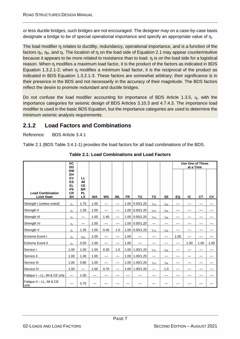
2.1.2 Load Factors and Combinations
Reference: BDS Article 3.4.1
Table 2.1 (BDS Table 3.4.1-1) provides the load factors for all load combinations of the BDS.
Table 2.1: Load Combinations and Load Factors
Load Combination Limit State
DC DD DW EH EV ES EL PS CR SH
LL IM CE BR PL LS WA WS WL FR TU TG SE
Use One of These at a Time
EQ IC CT CV
Strength I (unless noted) p 1.75 1.00 — — 1.00 0.50/1.20 TG SE — — — —
Strength II p 1.35 1.00 — — 1.00 0.50/1.20 TG SE — — — —
Strength III p — 1.00 1.40 — 1.00 0.50/1.20 TG SE — — — —
Strength IV p — 1.00 — — 1.00 0.50/1.20 — — — — — —
Strength V p 1.35 1.00 0.40 1.0 1.00 0.50/1.20 TG SE — — — —
Extreme Event I p EQ 1.00 — — 1.00 — — — 1.00 — — —
Extreme Event II p 0.50 1.00 — — 1.00 — — — — 1.00 1.00 1.00
Service I 1.00 1.00 1.00 0.30 1.0 1.00 1.00/1.20 TG SE — — — —
Service II 1.00 1.30 1.00 — — 1.00 1.00/1.20 — — — — — —
Service III 1.00 0.80 1.00 — — 1.00 1.00/1.20 TG SE — — — —
Service IV 1.00 — 1.00 0.70 — 1.00 1.00/1.20 — 1.0 — — — —
Fatigue I – LL, IM & CE only — 1.50 — — — — — — — — — — —
Fatigue II – LL, IM & CE only
— 0.75 — — — — — — — — — — —

ROAD STRUCTURES DESIGN MANUAL
PAGE 8
02-LOADS AND LOAD FACTORS SECOND EDITION – AUGUST 2021
2.1.2.1 Strength Load Combinations
The load factors for the Strength load combinations are calibrated based upon structural reliability
theory and represent the uncertainty of their associated loads. The significance of the Strength load
combinations can be simplified as follows:
1. Strength I Load Combination. This load combination represents random traffic and the
heaviest truck to cross the bridge in its design life. During this live-load event, a significant
wind is not considered probable.
2. Strength II Load Combination. In the BDS, this load combination represents an owner-
specified permit load model. This live-load event has less uncertainty than random traffic
and, thus, a lower live-load load factor. Use this load combination for design in conjunction
with the permit live load design vehicle (P-13 load) discussed in Section 2.3.2.2.
3. Strength III Load Combination. This load combination represents the most severe wind
during the bridge’s design life. During this severe wind event, no significant live load is
assumed to cross the bridge.
4. Strength IV Load Combination. This load combination represents an extra safeguard for
bridge superstructures where the unfactored dead load exceeds seven times the unfactored
live load. Thus, the only significant load factor is the 1.25 dead-load maximum load factor.
For additional safety, and based solely on engineering judgment, the BDS has arbitrarily
increased the load factor for DC to 1.5. Do not consider this load combination for any
component except a superstructure component, and never where the unfactored dead-load
force effect is less than seven times the unfactored live-load force effect. This load
combination typically governs only for longer spans, approximately greater than 60 m in
length. Thus, this load combination is only necessary in relatively rare cases.
5. Strength V Load Combination. This load combination represents the simultaneous
occurrence of a “normal” live-load event and a wind event with load factors of 1.35 and 0.4,
respectively.
For components not traditionally governed by wind force effects, the Strength III and Strength V load
combinations usually do not govern. Generally, the Strength I and Strength II load combinations will
govern for a typical multi-girder highway bridge.
2.1.2.2 Service Load Combinations
Unlike the strength load combinations, the service load combinations are material dependent. The
following applies:
1. Service I Load Combination. Apply this load combination to control cracking in reinforced
concrete components and compressive stresses in prestressed concrete components. Also,
use this load combination to calculate deflections and settlements of superstructure and
substructure components.
2. Service II Load Combination. Apply this load combination to control permanent deformations
of compact steel sections and the “slip” of slip-critical (i.e. friction-type) bolted steel
connections.

ROAD STRUCTURES DESIGN MANUAL
PAGE 9
02-LOADS AND LOAD FACTORS SECOND EDITION – AUGUST 2021
3. Service III Load Combination. Apply this load combination to control tensile stresses in
prestressed concrete superstructure components under vehicular traffic loads. The Service
III load combination does not apply to the design permit live load design vehicle.
4. Service IV Load Combination. Apply this load combination to control tensile stresses in
prestressed concrete substructure components under wind loads. For components not
traditionally governed by wind effects, this load combination usually does not govern.
2.1.2.3 Extreme-Event Load Combinations
The extreme-event limit states differ from the strength limit states, because the event for which the
bridge and its components are designed has a greater return period than the design life of the bridge
(or a much lower frequency of occurrence than the loads of the strength limit state). The following
applies:
1. Extreme-Event I Load Combination. This load combination is applied to earthquakes. Use a
load factor of 0.5 for γEQ for all live-load related forces in BDS Table 3.4.1-1. Earthquakes in
conjunction with scour (which is considered a change in foundation condition, not a load) can
result in a very costly design solution if severe scour is anticipated. In this case, typical
practice is to combine one-half of the total design scour (sum of contraction, local, and long-
term scour) with the seismic loading.
2. Extreme-Event II Load Combination. This load combination is applied to various types of
collisions (vessel or vehicular) applied individually.
2.1.2.4 Fatigue-and-Fracture Load Combination
The Fatigue-and-Fracture load combination, although strictly applicable to all types of
superstructures, only affects the steel elements, components, and connections of a limited number
of steel superstructures. Chapter 5 discusses fatigue and fracture for steel structures.
2.1.2.5 Application of Multiple-Valued Load Factors
Maximum and Minimum Permanent-Load Load Factors
In Table 2.1, the variable P represents load factors for all of the permanent loads, shown in the first
column of load factors. This variable reflects that the Strength and Extreme-Event limit state load
factors for the various permanent loads are not single constants, but they can have two extreme
values. Table 2.2 (BDS Table 3.4.1-2) provides these two extreme values for the various permanent
load factors, maximum and minimum. Permanent loads are always present on the bridge, but the
nature of uncertainty is that the actual loads may be more or less than the nominal specified design
values. Therefore, maximum and minimum load factors reflect this uncertainty.
Select the appropriate maximum or minimum permanent-load load factors to produce the more
critical load effect. For example, in continuous superstructures with relatively short end spans,
transient live load in the end span causes the bearing to be more compressed, while transient live
load in the second span causes the bearing to be less compressed and perhaps lift up. To check
the maximum compression force in the bearing, place the live load in the end span and use the
maximum DC load factor of 1.25 for all spans. To check possible uplift of the bearing, place the live
load in the second span and use the minimum DC load factor of 0.90 for all spans.
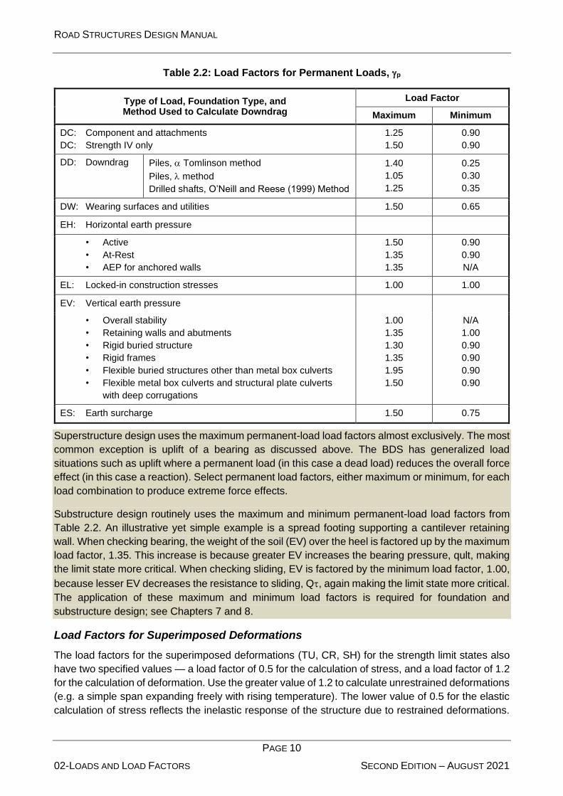
ROAD STRUCTURES DESIGN MANUAL
PAGE 10
02-LOADS AND LOAD FACTORS SECOND EDITION – AUGUST 2021
Table 2.2: Load Factors for Permanent Loads, p
Type of Load, Foundation Type, and Method Used to Calculate Downdrag
Load Factor
Maximum Minimum
DC: Component and attachments
DC: Strength IV only
1.25
1.50
0.90
0.90
DD: Downdrag Piles, Tomlinson method
Piles, method
Drilled shafts, O’Neill and Reese (1999) Method
1.40
1.05
1.25
0.25
0.30
0.35
DW: Wearing surfaces and utilities 1.50 0.65
EH: Horizontal earth pressure
• Active
• At-Rest
• AEP for anchored walls
1.50
1.35
1.35
0.90
0.90
N/A
EL: Locked-in construction stresses 1.00 1.00
EV: Vertical earth pressure
• Overall stability
• Retaining walls and abutments
• Rigid buried structure
• Rigid frames
• Flexible buried structures other than metal box culverts
• Flexible metal box culverts and structural plate culverts
with deep corrugations
1.00
1.35
1.30
1.35
1.95
1.50
N/A
1.00
0.90
0.90
0.90
0.90
ES: Earth surcharge 1.50 0.75
Superstructure design uses the maximum permanent-load load factors almost exclusively. The most
common exception is uplift of a bearing as discussed above. The BDS has generalized load
situations such as uplift where a permanent load (in this case a dead load) reduces the overall force
effect (in this case a reaction). Select permanent load factors, either maximum or minimum, for each
load combination to produce extreme force effects.
Substructure design routinely uses the maximum and minimum permanent-load load factors from
Table 2.2. An illustrative yet simple example is a spread footing supporting a cantilever retaining
wall. When checking bearing, the weight of the soil (EV) over the heel is factored up by the maximum
load factor, 1.35. This increase is because greater EV increases the bearing pressure, qult, making
the limit state more critical. When checking sliding, EV is factored by the minimum load factor, 1.00,
because lesser EV decreases the resistance to sliding, Q, again making the limit state more critical.
The application of these maximum and minimum load factors is required for foundation and
substructure design; see Chapters 7 and 8.
Load Factors for Superimposed Deformations
The load factors for the superimposed deformations (TU, CR, SH) for the strength limit states also
have two specified values — a load factor of 0.5 for the calculation of stress, and a load factor of 1.2
for the calculation of deformation. Use the greater value of 1.2 to calculate unrestrained deformations
(e.g. a simple span expanding freely with rising temperature). The lower value of 0.5 for the elastic
calculation of stress reflects the inelastic response of the structure due to restrained deformations.

ROAD STRUCTURES DESIGN MANUAL
PAGE 11
02-LOADS AND LOAD FACTORS SECOND EDITION – AUGUST 2021
For example, use one-half of the temperature rise to elastically calculate the stresses in a
constrained structure. Using 1.2 times the temperature rise in an elastic calculation overestimates
the stresses in the structure. The structure resists the temperature inelastically through redistribution
of the elastic stresses.
2.2 Permanent Loads
2.2.1 General
Reference: BDS Article 3.5
The BDS specifies seven components of permanent loads, which are either direct gravity loads or
caused by gravity loads. The primary forces from prestressing are considered as part of the
resistance of a component and has been omitted from the list of permanent loads in Section 3 of the
BDS. However, when designing anchorages for prestressing tendons, the prestressing force is the
only load effect, and it will appear on the load side of Equation 2.1. The permanent load EL includes
secondary forces from pre-tensioning or post-tensioning.
As discussed in Section 2.1.2.5, the permanent force effects in superstructure design are factored
by the maximum permanent-load load factors almost exclusively. The most common exception is
the check for uplift of a bearing. In substructure design, the permanent force effects are routinely
factored by the maximum or minimum permanent-load load factors from BDS Table 3.4.1-2.
The following lists additional minimum loads that are usually applicable to Abu Dhabi structures:
• Unit weight of reinforced and prestressed concrete: 25 kN/m3.
• 110 mm of asphalt wearing course shall be considered. Unit weight of wearing course: 23
kN/m3.
• The actual weight and position of all known utilities; otherwise, an additional dead load (curb
to curb) of 1.0 kN/m2 shall be considered.
2.2.2 Down drag (DD) on Deep Foundations
Reference: BDS Article 3.11
Deep foundations (i.e. drilled shafts and driven piles) through unconsolidated soil layers may be
subject to downdrag, DD. Downdrag is a load developed along the vertical sides of a deep-
foundation element tending to drag it downward typically due to consolidation of soft soils underneath
embankments reducing its resistance. Calculate this additional load as a skin-friction effect. If
possible, detail the deep foundation to mitigate the effects of downdrag; otherwise, design the
foundation considering downdrag. Chapter 7 discusses mitigation methods.
2.2.3 Support Settlement (SE)
Differential settlement between adjacent substructure units or transversely across a single
substructure unit induces stresses in continuous structures and deflections in simple supported
structures. Although some bridges can easily resist these stresses and deflections, consider the
potential effects of differential settlement in the longitudinal and transverse direction on a case-by-
case basis.
.

ROAD STRUCTURES DESIGN MANUAL
PAGE 12
02-LOADS AND LOAD FACTORS SECOND EDITION – AUGUST 2021
A minimum value of differential settlement of 20 mm with short-term concrete modulus OR 10 mm with long-term concrete modulus shall be considered in the design. In the event of bridge jacking for bearing’s replacement, the live load shall be closed partially (50%) or totally (100%) (if required).
The location of jacking points and area of jack for replacing the bearings shall also be specified on the design drawings.
2.3 Transient Loads
2.3.1 General
The BDS recognizes 19 transient loads. Static water pressure, stream pressure, buoyancy, and
wave action are integrated as water load, WA. Creep, settlement, shrinkage, and temperature (CR,
SE, SH, TU, and TG), are superimposed deformations. If restrained, these result in force effects,
and are elevated in importance to “loads.” For example, restrained strains due to an increase in
uniform-temperature induce compression forces.
2.3.2 Abu Dhabi Vehicular Load (ADVL)
Reference: BDS Articles 3.6.1, 3.6.3, 3.6.4, and 3.11.6.4
Design all bridges and their components for the ADVL notional live-load model. The ADVL replaces
the HL-93 notional live-load model of the BDS. It consists of the HL-93 notional live-load components
— the design truck, the design tandem and the design lane loads — each multiplied by 1.5. The
dimensions of the vehicles and the lanes remain the same as the HL-93. See Figure 2.1.
Figure 2.1: Characteristics of the Design Truck
Multiply all other transient loads associated with vehicular load as defined in the BDS (e.g. CE, BR,
LS, and the fatigue load) by 1.5.
For short and medium span bridges, vehicular live load is the most significant component of load.
Dead loads become more significant for long-span bridges. Long-span bridges are defined as those

ROAD STRUCTURES DESIGN MANUAL
PAGE 13
02-LOADS AND LOAD FACTORS SECOND EDITION – AUGUST 2021
governed by the Strength IV load combination where the dead load is seven times or more greater
than the live load.
2.3.2.1 Multiple Presence Factors
The multiple presence factor of 1.0 for two loaded lanes, as given in BDS Table 3.6.1.1.2-1, is the
result of the BDS calibration for the notional load, which has been normalized relative to the
occurrence of two side by side, fully correlated, or identical, vehicles. Use the multiple presence
factor of 1.2 for one loaded lane where a single design tandem or single design truck governs, such
as in overhangs, decks, etc. The multiple presence factors of 0.85 and 0.65 for three lanes and more
than three lanes loaded, respectively, may govern for wider bridges.
Do not apply the multiple-presence factors to fatigue loads.
2.3.2.2 Permit Loads for Design (P Load)
Use the Caltrans P-13 “Standard Permit Design Vehicle” for the design of structures to provide a
minimum permit-load capacity on all highway structures. This accounts for vehicles that exceed the
legal limits and that operate on highways and structures under special transportation permits. See
Error! Reference source not found.. Design all bridges for the Strength II, Service I, and Service II l
oad combinations with the P load in the exterior right lane and the ADVL in all other lanes.
Figure 2.2: Permit Design Live Loads (for P-13 Vehicle)

ROAD STRUCTURES DESIGN MANUAL
PAGE 14
02-LOADS AND LOAD FACTORS SECOND EDITION – AUGUST 2021
2.3.3 Wind Loads (WS and WL)
Reference: BDS Article 3.8
Use a wind velocity, VB, of 160 km/h at 10 m above low ground or above design water level. Use a
gust factor of 1.14 for signs, luminaire supports, and pedestrian bridges only. For some Pedestrian
Bridges, an increased Gust factor value may be required depending upon the structure flexibility and
exposure conditions. The increased factor shall be subjected to client approval
The wind velocity used in the BDS is often referred to as a “3-second gust,” which is the highest
sustained gust over a 3-second period having a probability of being exceeded per year of 1 in 50
(ASCE 7-10) (3).
2.3.4 Earthquake Effects (EQ)
Reference: AASHTO LRFD Specifications for Bridge Design (BDS)
Apply the provisions of the BDS (1) to bridges in the Abu Dhabi Emirate. Use the spectral response
accelerations given in Table 2.3 in conjunction with the provisions of the BDS.
Design bridges and road tunnels to withstand the spectral response accelerations given in Table 2.3 for return periods of 475,1000 and 2475 years. The return period of 2475 years shall be used for “Critical Bridges” and the return period of 1000 years for the “Essential Bridges” and the return period of 475 years for other bridges, or as specified by owner. After the event characterized by these spectral response accelerations, the structure may sustain significant damage, and a possible disruption of service; however, the structure will have a low probability of collapse
Table 2.3: Spectral Response Accelerations for the Abu Dhabi Emirate
Return Period in Years
Peak Horizontal Ground Acceleration
Coefficient, PGA
Short-Period (0.2 sec) Value of
Spectral Acceleration Coefficient, Ss
Longer-Period (1 sec) Value of
Spectral Acceleration Coefficient, S1
475 0.060 0.150 0.067
1000 0.075 0.185 0.083
2475 0.090 0.225 0.100
Although most of the Emirate, based on available information, falls in zone 1, the owner may
require higher level of performance and may select zone 2 for some areas.
The design response spectrum, illustrated in Figure 2.3 is variable and constructed using the
spectral response accelerations specified in Table 2.3 and other characteristics of the structure
as defined below.
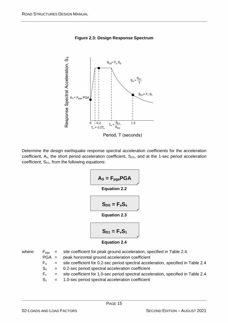
ROAD STRUCTURES DESIGN MANUAL
PAGE 15
02-LOADS AND LOAD FACTORS SECOND EDITION – AUGUST 2021
AS = FpgaPGA
SD1 = FvS1
SDS = FaSs
Figure 2.3: Design Response Spectrum
Determine the design earthquake response spectral acceleration coefficients for the acceleration
coefficient, As, the short period acceleration coefficient, SDS, and at the 1-sec period acceleration
coefficient, SD1, from the following equations:
Equation 2.2
Equation 2.3
Equation 2.4
where: Fpga = site coefficient for peak ground acceleration, specified in Table 2.4.
PGA = peak horizontal ground acceleration coefficient
Fa = site coefficient for 0.2-sec period spectral acceleration, specified in Table 2.4
Ss = 0.2-sec period spectral acceleration coefficient
Fv = site coefficient for 1.0-sec period spectral acceleration, specified in Table 2.4.
S1 = 1.0-sec period spectral acceleration coefficient

ROAD STRUCTURES DESIGN MANUAL
PAGE 16
02-LOADS AND LOAD FACTORS SECOND EDITION – AUGUST 2021
Table 2.4: Acceleration Coefficients
Site Class Fpga Fa Fv
A 0.8 0.8 0.8
B 1.0 1.0 1.0
C 1.2 1.2 1.7
D 1.6 1.6 2.4
E 2.5 2.5 3.5
F Consider the site-specific response geotechnical investigation and dynamic-site response analysis
Table 2.5 provides site-class definitions by soil type and profile.
Table 2.5: Site-Class Definitions
Site Class Soil Type and Profile
A Hard rock with measured shear wave velocity, sv > 1500 m/sec
B Rock with 750 m/sec < sv < 1500 m/sec
C Very dense soil and soil rock with 350 m/sec < sv < 750 m/sec, or with either N > 150
blows/m or us > 100 kPa
D Stiff soil with 175 m/sec < sv < 350 m/sec, or with either 50 m blows < N < 50 blows/m or
50 kPa < us < 100 kPa
E Soil profile with sv < 175 m/sec, or with either N < 50 blows/m or us < 50 kPa, or any profile
with more than 3 m of soft clay defined as soil with PI > 20, w > 40%, and us < 25 kPa
F
Soils requiring site-specific ground motion response evaluations, such as:
• Peats or highly organic clays (H > 3 m of peat or highly organic clay, where H = thickness of soil)
• Very high plasticity clays (H > 7.5 m with PI > 75)
• Very thick soft/medium stiff clays (H > 35 m)
Exceptions:
Where the soil properties are not known in sufficient detail to determine the site class, a site investigation shall be undertaken sufficient to determine the site class. Do not use Site Class E or F unless the owner determines that Site Class E or F could be present at the site or if Site Class E or F is established by geotechnical data.
where: sv = average shear wave velocity for the upper 30 m of the soil profile
N = average standard penetration test (SPT) blow count (blows/m) (ASTM D 1586) for the upper 30 m of the soil profile
us = average undrained shear strength in kPa (ASTM D 2166) for the upper 30 m of the soil
profile
PI = plasticity index (ASTM D 4318)
w = moisture content (ASTM D 2216)
H = thickness of soil layer

ROAD STRUCTURES DESIGN MANUAL
PAGE 17
02-LOADS AND LOAD FACTORS SECOND EDITION – AUGUST 2021
2.3.5 Uniform Temperature (TU)
Reference: BDS Article 3.12.2
Use Procedure A of BDS Article 3.12.2.1 to determine the appropriate design thermal range. Use
the minimum and maximum temperatures specified in Table 2.6 as TMinDesign and TMaxDesign,
respectively, in BDS Equation 3.12.2.3-1.
Assume a construction temperature of 30°C.
Table 2.6: BDS Procedure “A” Temperature Ranges
Concrete Bridges Steel Bridges
0°C - 60°C 0°C - 70°C
2.3.6 Temperature Gradient (TG)
Reference: BDS Article 3.12.3
Include the effects of TG in the design of all superstructures. The vertical TG is from

ROAD STRUCTURES DESIGN MANUAL
PAGE 18
02-LOADS AND LOAD FACTORS SECOND EDITION – AUGUST 2021
Figure 2.4.
Dimension A in

ROAD STRUCTURES DESIGN MANUAL
PAGE 19
02-LOADS AND LOAD FACTORS SECOND EDITION – AUGUST 2021
Figure 2.4 shall be:
• For concrete superstructures that are 400 mm or more in depth: 300 mm
• For concrete sections shallower than 400 mm: 100 mm less than the actual depth
• For steel superstructures: 300 mm and the distance t shall be the depth of the concrete deck
Temperature values T1 and T2 shall be 30°C and 8°C, respectively. Temperature value T3 shall be
0°C, unless a site-specific study is made to determine an appropriate value. Positive vertical
temperature gradient in concrete and steel structures is shown in

ROAD STRUCTURES DESIGN MANUAL
PAGE 20
02-LOADS AND LOAD FACTORS SECOND EDITION – AUGUST 2021
Figure 2.4. Other provisions shall be the same as BDS Article 3.12.3.

ROAD STRUCTURES DESIGN MANUAL
PAGE 21
02-LOADS AND LOAD FACTORS SECOND EDITION – AUGUST 2021
Figure 2.4: Positive Vertical Temperature Gradient in Concrete and Steel Superstructures
2.3.7 Live-Load Surcharge (LS)
Reference: BDS Article 3.11.6.4
Multiply equivalent heights of soil for vehicular loading on abutments and retaining walls specified in
BDS Tables 3.11.6.4-1 and 3.11.6.4-2, respectively, by 1.5 for use in the Abu Dhabi Emirate.
Retaining walls that retain soil supporting a roadway must resist the lateral pressure due to the live-
load surcharge. See Chapter 8 for retaining walls.
2.3.8 Ground Water Levels
Ensure that false water table measurements, resulting from a temporary depression of the water
table, because of construction activities, are not used in the design. Estimate the water table
conservatively considering the effects of tidal and seasonal fluctuations.
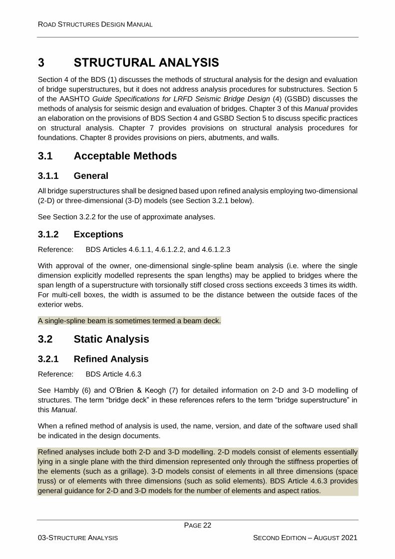
ROAD STRUCTURES DESIGN MANUAL
PAGE 22
03-STRUCTURE ANALYSIS SECOND EDITION – AUGUST 2021
3 STRUCTURAL ANALYSIS
Section 4 of the BDS (1) discusses the methods of structural analysis for the design and evaluation
of bridge superstructures, but it does not address analysis procedures for substructures. Section 5
of the AASHTO Guide Specifications for LRFD Seismic Bridge Design (4) (GSBD) discusses the
methods of analysis for seismic design and evaluation of bridges. Chapter 3 of this Manual provides
an elaboration on the provisions of BDS Section 4 and GSBD Section 5 to discuss specific practices
on structural analysis. Chapter 7 provides provisions on structural analysis procedures for
foundations. Chapter 8 provides provisions on piers, abutments, and walls.
3.1 Acceptable Methods
3.1.1 General
All bridge superstructures shall be designed based upon refined analysis employing two-dimensional
(2-D) or three-dimensional (3-D) models (see Section 3.2.1 below).
See Section 3.2.2 for the use of approximate analyses.
3.1.2 Exceptions
Reference: BDS Articles 4.6.1.1, 4.6.1.2.2, and 4.6.1.2.3
With approval of the owner, one-dimensional single-spline beam analysis (i.e. where the single
dimension explicitly modelled represents the span lengths) may be applied to bridges where the
span length of a superstructure with torsionally stiff closed cross sections exceeds 3 times its width.
For multi-cell boxes, the width is assumed to be the distance between the outside faces of the
exterior webs.
A single-spline beam is sometimes termed a beam deck.
3.2 Static Analysis
3.2.1 Refined Analysis
Reference: BDS Article 4.6.3
See Hambly (6) and O’Brien & Keogh (7) for detailed information on 2-D and 3-D modelling of
structures. The term “bridge deck” in these references refers to the term “bridge superstructure” in
this Manual.
When a refined method of analysis is used, the name, version, and date of the software used shall
be indicated in the design documents.
Refined analyses include both 2-D and 3-D modelling. 2-D models consist of elements essentially
lying in a single plane with the third dimension represented only through the stiffness properties of
the elements (such as a grillage). 3-D models consist of elements in all three dimensions (space
truss) or of elements with three dimensions (such as solid elements). BDS Article 4.6.3 provides
general guidance for 2-D and 3-D models for the number of elements and aspect ratios.

ROAD STRUCTURES DESIGN MANUAL
PAGE 23
03-STRUCTURE ANALYSIS SECOND EDITION – AUGUST 2021
3.2.2 Approximate Analysis
Reference: BDS Article 4.6.2
3.2.2.1 General
The bridge designer may use the approximate methods of BDS Article 4.6.2 for preliminary design
and single-spline beam analysis.
3.2.2.2 Live Load Distribution Factors In BDS Article 4.6.2.2.2, extend the Range of Applicability for the referenced bridge types of Figure
3.1 as follows:
1. BDS Table 4.6.2.2.2.b-1. For open prestressed concrete box beam bridges (Type “c” cross-
section), change the depth parameter range to 450 mm < d < 1800 mm, and the span length
parameter range to 6 m < L < 50 m. For prestressed flat slab bridges (Type “f” cross-section),
change the width parameter to 750 mm < b < 1550 mm. For prestressed concrete I-beam
bridges (Type “k” cross-section), change the longitudinal stiffness parameter range to 4.0
109 mm4 < Kg < 3.324 1012 mm4.
2. BDS Table 4.6.2.2.3.a-1. For open prestressed concrete box beam bridges (Type “c” cross-
section), change the depth parameter range to 450 mm < d < 1800 mm, and the span length
parameter range to 6 m < L < 50 m. For prestressed flat slab bridges (Type “f” cross-section),
change the moment of inertia range to 4.0 109 mm4 < I < 2.4 1011 mm4, and the width
parameter to 750 mm < b < 1550 mm.
3. BDS Table 4.6.2.2.3.b-1. For prestressed flat slab bridges (Type “f” cross-section), change
the width parameter to 750 mm < b < 1550 mm.
4. BDS Table 4.6.2.2.3.c-1. For open prestressed concrete box bridges (Type “c” cross-
section), change the depth parameter range to 450 mm < d < 1800 mm and the span length
parameter range to 6 m < L < 50 m. For prestressed flat slab bridges (Type “f” cross-section),
change the width parameter to 750 mm < b < 1550 mm.
The BDS distribution factor equations are based on work conducted in NCHRP Project 12-26. When
one or more of the parameters are outside the listed range of applicability, the equation could still
remain valid, particularly when the value or values are only slightly outside the range. The extended
values given herein are considered slightly outside of the BDS range of applicability. If one or more
of the parameters greatly exceeds the range of applicability, engineering judgment needs to be
exercised.
The BDS approximate method produces distribution factors that are conservative when compared
to refined analyses, although the beam stiffness and spacings vary significantly.
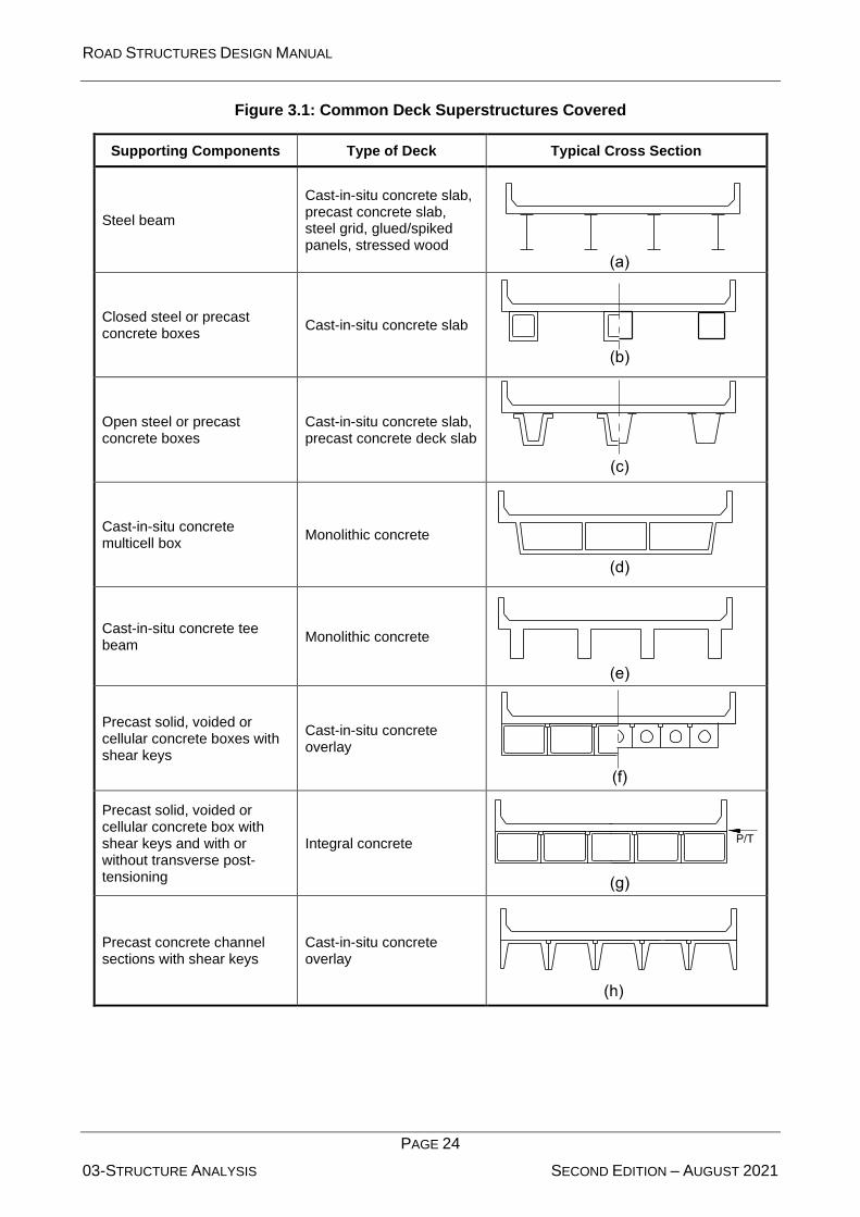
ROAD STRUCTURES DESIGN MANUAL
PAGE 24
03-STRUCTURE ANALYSIS SECOND EDITION – AUGUST 2021
Figure 3.1: Common Deck Superstructures Covered
Supporting Components Type of Deck Typical Cross Section
Steel beam
Cast-in-situ concrete slab, precast concrete slab, steel grid, glued/spiked panels, stressed wood
Closed steel or precast concrete boxes
Cast-in-situ concrete slab
Open steel or precast concrete boxes
Cast-in-situ concrete slab, precast concrete deck slab
Cast-in-situ concrete multicell box
Monolithic concrete
Cast-in-situ concrete tee beam
Monolithic concrete
Precast solid, voided or cellular concrete boxes with shear keys
Cast-in-situ concrete overlay
Precast solid, voided or cellular concrete box with shear keys and with or without transverse post-tensioning
Integral concrete
Precast concrete channel sections with shear keys
Cast-in-situ concrete overlay

ROAD STRUCTURES DESIGN MANUAL
PAGE 25
03-STRUCTURE ANALYSIS SECOND EDITION – AUGUST 2021
Figure 3.1: Common Deck Superstructures Covered
(Continued)
Supporting Components Type of Deck Typical Cross Section
Precast concrete double tee section with shear keys and with or without transverse post-tensioning
Integral concrete
Precast concrete tee section with shear keys and with or without transverse post-tensioning
Integral concrete
Precast concrete I or bulb-tee sections
Cast-in-situ concrete, precast concrete
Wood beams Cast-in-situ concrete or plank, glued/spiked panels or stressed wood
3.2.2.3 Distribution of Superimposed Load on Beam-Slab Bridges
Reference: BDS Article 4.6.2.2
Distribute barrier and railing permanent loads in accordance with BDS Article 4.6.2.2.
3.2.2.4 Consideration of Railing in Limit State Checks
Reference: BDS Article 4.5.1
Do not include traffic and pedestrian railings and raised sidewalks in the stiffness of the bridge when
determining deflections or for service or fatigue limit state checks.
3.2.3 Lateral Wind-Load Distribution in Multi-Beam Bridges
Reference: BDS Articles 3.8.1 and 4.6.2.7.1
Assume that typical concrete fascia girders satisfactorily resist transverse wind loads.
BDS Article 4.6.2.7.1 discusses load paths for transferring wind loads transversely applied to the
fascia girder to the bridge’s bearings. The Commentary provides guidelines on how girders resist
the wind loads. The provisions are directly applicable to steel girder bridges. In typical concrete girder
bridges, the distribution of wind load becomes insignificant due to their greater out-of-plane stiffness
in comparison with steel girders.
ROAD STRUCTURES DESIGN MANUAL
PAGE 26
03-STRUCTURE ANALYSIS SECOND EDITION – AUGUST 2021
3.3 Dynamic Analysis
3.3.1 Seismic Analysis
Reference: BDS Article 4.7.4, GSBD Articles 4.5 and 5.4
BDS Article 4.7.4 shall be followed with consideration of provisions in Chapter 2 of this Manual.
3.3.1.1 Structural Global Analysis
Use structural global analysis when it is necessary to capture the response of the entire bridge
system.
Bridge systems with irregular geometry (especially those with horizontal curvature, skews, multiple
transverse expansion joints, massive substructure components, and foundations supported by soft
soil) can exhibit dynamic response characteristics that are not obvious and may not be captured in
a separate subsystem analysis.
3.3.2 Wind-Induced Vibration
Reference: BDS Article 4.7.2.2
Special attention shall be given to wind-sensitive structures. These structures shall be analysed for
dynamic effects, such as buffeting by turbulent or gusting winds, and unstable wind-structure
interaction, such as galloping and flutter.
3.4 Transverse Deck Loading, Analysis, and Design
Reference: BDS Articles 3.6.1.2.2 and 3.6.1.2.3
Axle loads are usually those that produce the maximum effect from either the ADVL (i.e. 1.5 HL-93)
design truck or the design tandem axles (BDS Articles 3.6.1.2.2 and 3.6.1.2.3, respectively). Also
include the Multiple Presence Factors (BDS Article 3.6.1.1.2) in the transverse design. Do not
include the Tire Contact Area (BDS Article 3.6.1.2.5) in the transverse design of new bridges when
using influence surface analysis methods to calculate fixed-end moments. Consider lane loading
also in design of transverse deck.
Design the prestressed concrete deck for Strength I and Service I Load Combination excluding all
wind effects. Perform all analyses assuming no benefit from the stiffening effects of any traffic railing
barrier.
The Tire Contact Area (BDS Article 3.6.1.2.5) may be used when evaluating the transverse operating
rating of existing prestressed concrete box girder decks.
ROAD STRUCTURES DESIGN MANUAL
Page 27
04-CONCRETE STRUCTURE SECOND EDITION – AUGUST 2021
4 CONCRETE STRUCTURES
Section 5 of the BDS presents unified design requirements for reinforced and prestressed concrete
in all structural elements. This Chapter presents supplementary information specifically on the
properties of concrete and reinforcing steel and the design of structural concrete members.
The American Concrete Institute (ACI) uses unified provisions in ACI 318 (8).
4.1 Structural Concrete Design
4.1.1 Member Design Models
Reference: BDS Articles 5.6.3, 5.8.1, 5.8.3, and 5.13.2
Where planar sections remain planar after loading, the BDS allows two approaches to the design for
concrete members ⎯ the strut-and-tie model and the traditional sectional design model. For
members where planar sections do not remain planar after loading, use the strut-and-tie model. The
basic application of these models is as follows:
1. Sectional Design Model. Use the sectional design model for the design of typical bridge
girders, slabs, and other regions of components where the assumptions of traditional girder
theory are valid.
The sectional design model assumes that the response at a particular section depends only
on the calculated values of the sectional force effects such as moment, shear, axial load, and
torsion. The model does not consider the specific details of how the force effects are
introduced into the member. BDS Article 5.8.3 discusses the sectional design model.
Subarticles 1 and 2 describe the applicable geometry to use the technique to design for
shear.
2. Strut-and-Tie Model. Use the strut-and-tie model in regions near discontinuities (e.g. abrupt
changes in cross section, openings, coped (dapped) ends, deep girders, corbels). See BDS
Articles 5.6.3 and 5.13.2.
The strut-and-tie model discusses how the load is introduced into the member as a part of
the analysis.
The following Sections discuss each member design approach.
4.1.2 Flexural Resistance
Reference: BDS Article 5.8.3
4.1.2.1 Sectional Design Model
The flexural resistance of a section is typically obtained using the rectangular stress distribution of
BDS Article 5.7.2.2. In lieu of using this simplified approach, use a strain compatibility approach as
outlined in BDS Article 5.7.3.2.5.
The general equation for structural concrete flexural resistance in BDS Article 5.7.3.2.1 is based
upon the rectangular stress block, commonly called the Whitney stress block.
ROAD STRUCTURES DESIGN MANUAL
Page 28
04-CONCRETE STRUCTURE SECOND EDITION – AUGUST 2021
4.1.2.2 Limits for Flexural Steel Reinforcement
Maximum Reinforcement
Reference: BDS Articles 5.7.3.3.1 and 5.5.4.2.1
The current BDS provisions eliminate the former maximum limit of reinforcement. Instead, a
resistance factor varying linearly between the traditional values for flexure and compression
members (see BDS Equations 5.5.4.2.1-1 or 5.5.4.2.1-2) is applied to differentiate between tension-
and compression-controlled sections. Compression-controlled sections use a lower resistance factor
to achieve safety comparable to tension-controlled sections.
Minimum Reinforcement
Reference: BDS Articles 5.7.3.3.2 and 5.4.2.6
Provide flexural resistance equal to the lesser of:
• 1.2 times the cracking moment of the concrete section, defined by BDS Equation 5.7.3.3.2-1
and assuming that cracking occurs at the modulus of rupture, which is 1.0
for normal-weight concrete; or
• 1.33 times the factored moment required by the governing load combination.
4.1.2.3 Distribution of Reinforcement
Reference: BDS Article 5.7.3.4
In addition to the provisions of BDS Article 5.7.3.4, use the following:
1. Negative Moments. For the distribution of negative moment tensile reinforcement continuous
over a support, compute the deck’s effective tension width separately on each side of the
support based on BDS Article 5.7.3.4. Use the larger of the two effective widths for the
uniform distribution of the reinforcement into both spans.
2. Girders. Within the negative moment regions of continuous cast-in-situ structures, use a T25
for the top side face bar (skin reinforcement) on each face of the girder web.
3. Integral Pier Caps. For integral pier caps, place reinforcement approximately 75 mm below
the construction joint between the deck and the rest of the cap beneath it, or lower if
necessary to clear prestressing ducts. Design the reinforcement by taking Mu as 1.3 times
the negative moment of the dead load for that portion of the cap and superstructure located
beneath the construction joint and within 3 m of each side face of the cap; i.e. the cap width
plus 6 m. Service limit-state checks and shear design are not required for this condition. Only
include this reinforcement in computing the flexural resistance of the cap if a strain-
compatibility analysis is made to determine the stress in the bars.
4.1.2.4 Crack Control Reinforcement
Reference: BDS Article 5.7.3.4
Non-structural concrete, such as a levelling course, 100 mm or greater in thickness requires
reinforcement.
c
f

ROAD STRUCTURES DESIGN MANUAL
Page 29
04-CONCRETE STRUCTURE SECOND EDITION – AUGUST 2021
Distribute the reinforcing bars in all reinforced concrete members in tension to control cracking in
accordance with BDS Article 5.7.3.4. When designing for crack control, use γe = 0.65 in all cases.
Exceptions are buried structures and bridges in extremely aggressive environments, as discussed
in Section 4.2, in which case use γe = 0.50.
The thickness of clear cover used to compute dc shall not be taken to be greater than 50mm. Any
concrete cover thickness greater than the minimum required by Table 4.4 in Section 4.4.2.2 may be
neglected when calculating dc and h. See Section 7.5 for mass concrete requirements.
Provide additional consideration in the design to limit cracks due to intrinsic (including early thermal)
effects.
Several smaller reinforcing bars at moderate spacing are more effective in controlling crack widths
than fewer larger bars. The application of exposure conditions lower than those of the BDS provide
additional durability.
4.1.3 Shear Resistance
Reference: BDS Article 5.8.3
4.1.3.1 Sectional Design Models
For the sectional design model, use the general procedure of BDS Article 5.8.3.4.2 to determine the
shear resistance. When calculating the shear resistance, use the area of stirrup reinforcement
intersected by the distance 0.5dv cot on each side of the design section, as shown in BDS
Figure C5.8.3.2-3.
The simplified procedure for non-prestressed sections of BDS Article 5.8.3.4.1 and the simplified
procedure for prestressed and non-prestressed sections of BDS Article 5.8.3.4.3 are less accurate
methodologies. The general procedure mandated herein is the most accurate determination of shear
resistance.
4.1.3.2 Shear Friction
Reference: BDS Article 5.8.4
The steel required to comply with the provisions of BDS Article 5.8.4 is additive to the steel required
from other analyses, except as provided in BDS Article 5.10.11.
4.1.4 Strut-and-Tie Model
Reference: BDS Article 5.6.3
The strut-and-tie model is only applicable to the Strength and Extreme-Event limit states because
significant cracking must be present for the model to be valid.
Members, when loaded, indicate the presence of definite stress fields that can individually be
represented by tensile or compressive resultant forces as their vectorial sums. The “load paths”
taken by the resultants form a truss-like pattern that is optimum for the given loading. The resultants
are in reasonable equilibrium, especially after cracking. The designer’s objective is to conceive the
optimum pattern in developing the strut-and-tie model. The closer the designer’s assumption is to
the optimum pattern, the more efficient the use of materials. For poorly conceived strut-and-tie
ROAD STRUCTURES DESIGN MANUAL
Page 30
04-CONCRETE STRUCTURE SECOND EDITION – AUGUST 2021
models, the materials are used less efficiently, but the structure will be safe. The compressive
concrete paths are the struts, and the reinforcing steel groups are the ties. The model does not
involve shear or moment because the stresses are modelled as axial loads alone.
The application of the strut-and-tie model includes several simple steps:
1. Identify the truss model that carries the applied loads to the reactions and, subsequently,
establishes the truss geometry.
2. Proportion the struts according to the provisions of BDS Article 5.6.3.3, and the ties according
to BDS Article 5.6.3.4.
3. Proportion the nodal regions connecting the truss members based on BDS Article 5.6.3.5,
wherein concrete compression stresses are limited.
4. Provide crack control reinforcement according to BDS Article 5.6.3.6 to control the significant
cracking necessary to facilitate the strut-and-tie model.
The strut-and-tie model applies to bridge components such as pier caps, girder ends, post-tensioning
anchorage zones, etc. A thorough presentation of the model can be found in:
• NCHRP 20-7, Task 217 Verification and Implementation of Strut-and-Tie Model in BDS
Bridge Design Specifications, November 2007 (9);
• D. Mitchell, M. Collins, S. Bhidé and B. Rabbat, AASHTO “BDS Strut-and-Tie Model Design
Examples,” EB231, Portland Cement Association (PCA) (10);
• Chapter 8 of the PCI Precast Prestressed Concrete Bridge Design Manual (11); and
• J. Schlaich, et al, “Towards a Consistent Design of Structural Concrete,” PCI Journal, Vol.
32, No. 3, 1987 (12).
Cracking is associated with at least partial debonding and, thus, the bonding capacity of cracked
concrete cannot be considered completely reliable. The BDS generally requires that reinforcing steel
not be anchored in cracked zones of concrete. Improperly anchored reinforcing steel is commonly
overlooked.
4.1.5 Torsion
Reference: BDS Article 5.8
Where torsion effects are present, design the member in accordance with BDS Articles 5.8.2 and
5.8.3.6.
Torsion is not normally a major consideration in highway bridges. Examples that may require a
torsion design include:
• Cantilever brackets connected perpendicular to a concrete girder, especially if a diaphragm
is not located opposite the bracket;
• Concrete diaphragms used to make precast girders continuous for live load where girder
spacing varies in adjacent spans; and
• Abutment caps, if they are unsymmetrically loaded.

ROAD STRUCTURES DESIGN MANUAL
Page 31
04-CONCRETE STRUCTURE SECOND EDITION – AUGUST 2021
4.1.6 Fatigue
Reference: BDS Articles 3.4.1, 3.6.1.4, and 5.5.3
Do not consider fatigue for concrete decks or where the permanent stress fmin is compressive and
exceeds twice the maximum tensile live load stress. Also, do not consider fatigue for strands in fully
prestressed concrete members.
The fatigue limit state is not normally a critical issue for concrete structures.
4.1.7 Lateral Confinement Reinforcement
4.1.7.1 Columns
Reference: BDS Article 5.10.11.4
Lateral reinforcement for compression members consists of either spiral reinforcement, welded
hoops, or a combination of lateral ties and cross ties. Only use ties when it is not practical to provide
spiral or hoop reinforcement. Where longitudinal bars are required outside the spiral or hoop
reinforcement, provide lateral support with bars spaced and hooked as required for cross ties.
Extend the hooked bars into the core of the spiral or hoop one full development length.
4.1.7.2 Drilled Shafts
Extend the reinforcing steel cage for drilled shafts the full length of the pile.
Maximize the size of longitudinal and transverse reinforcement to increase the openings between all
reinforcement. This allows concrete to pass through the cage during placement. Maintain the
maximum spacing requirements of BDS Article 5.13.6.3d.
4.1.7.3 Headed Reinforcement
Consider headed reinforcement as an alternative to lateral reinforcing steel when conflicts make the
use of tie reinforcement impractical. Headed reinforcement consisting of friction welded or internally
forged heads conforms to ASTM A970M.
4.2 Environmental Classification
4.2.1 General
In the bridge drawing “General Notes,” include the environmental classification for both the
superstructure and substructure according to the following classifications:
1. Slightly aggressive
2. Moderately aggressive
3. Extremely aggressive
For the substructure, additional descriptive data is required for the environmental classification. After
the classification, provide the source and magnitude of the environmental classification parameters
for the classification in parentheses.

ROAD STRUCTURES DESIGN MANUAL
Page 32
04-CONCRETE STRUCTURE SECOND EDITION – AUGUST 2021
As an example, where the substructure is in an Extremely Aggressive environment due to low soil
pH of 4.5 and the superstructure is in a Slightly Aggressive environment, the format on the bridge
plans is:
ENVIRONMENTAL CLASSIFICATION:
Substructure: Extremely Aggressive (Soil pH = 4.5)
Superstructure: Slightly Aggressive
The substructure is not classified less severely than the superstructure.
4.2.2 Classification Criteria
Bridge substructure and superstructure environments are classified as Slightly Aggressive,
Moderately Aggressive, or Extremely Aggressive environments according to Figure 4.1. The
superstructure is defined as all components from the bearings upward. Every element below the
bearings is classified as substructure.
4.2.2.1 Marine Structures
Marine structures are structures located 1 km or less from a body of water containing chloride above
2000 ppm. All other structures are considered non-marine structures. Use chloride test results to
determine if a structure is classified as marine.
Classify superstructure and substructure as follows:
1. For structures 1 km or more from a body of water with chloride concentrations in excess of
6000 ppm, both superstructure and substructure are classified as extremely aggressive.
2. For structures over water with chloride concentrations of 2000 to 6000 ppm, the substructure
is classified as Extremely Aggressive. Superstructures located at 3.5 m or less above the
mean high water elevation are classified as extremely aggressive. Superstructures located
at an elevation greater than 3.5 m above the mean high water elevation are classified as
Moderately Aggressive.
3. For structures within 1 km of a body of water with a chloride concentration of 2000 to 6000
ppm, but not directly over the body of water, the superstructure is classified as Moderately
Aggressive. The non-marine criteria in
4. Table 4.1 applies to the substructure.
4.2.2.2 Non-Marine Structures
All structures that do not meet the criteria above are considered non-marine structures.
1. Substructure. Use
2. Table 4.1 to classify all non-marine substructures in contact with water and/or soil.
3. Superstructure. For any superstructure located within 1 km of any carbon burning industrial
facility, fertilizer plant, or any other similar industry, classify as Moderately Aggressive. For
all others, classify as Slightly Aggressive.

ROAD STRUCTURES DESIGN MANUAL
Page 33
04-CONCRETE STRUCTURE SECOND EDITION – AUGUST 2021
Figure 4.1: Flowchart for Environmental Classification of Structures
Start
Is thestructure over
Or within 1 km of a body of water with CL > 2000
ppm?
Non-Marine Structure
Marine Structure
Is the structure over or
within 1 km of a bodyof water with CL > 6000
ppm?
Is the superstructure within 1 km of
industrial facility?
Is the structure over
water?
Is the structure higher
than 3.5 m aboveMHW?
SuperstructureModerately
Aggressive and go to Table 4.1
for substructure classification
SuperstructureSlightly
Aggressive and go to Table 4.1
for substructure classification
SuperstructureExtremely
Aggressive and substructure
Extremely Aggressive
SuperstructureModerately
Aggressive and substructure
Extremely Aggressive
NoYes
Yes
No
No
No
Yes
No
Yes
Yes
Abbreviations:
CL = Chlorideppm = parts per million

ROAD STRUCTURES DESIGN MANUAL
Page 34
04-CONCRETE STRUCTURE SECOND EDITION – AUGUST 2021
Table 4.1: Criteria for Substructure Environmental Classifications
Classification Environmental
Condition Units
Steel Concrete
Water Soil Water Soil
Extremely Aggressive (if any of these conditions exist)
pH < 6.0 < 5.0
CI ppm > 2000 > 2000
SO4 ppm N/A > 1500 > 2000
Resistivity Ohm-cm < 1000 < 500
Slightly Aggressive (if all of these conditions exist)
pH > 7.0 > 6.0
CI ppm < 500 < 500
SO4 ppm N/A < 150 < 1000
Resistivity Ohm-cm > 5000 > 3000
Moderately Aggressive
This classification must be used at all sites not meeting requirements for either Slightly Aggressive or Extremely Aggressive environments.
pH = acidity (-log10H+; potential of hydrogen) CI = chloride content SO4 = sulphate content
4.2.3 Chloride Content
To optimize the materials selection process, the designer and/or materials engineer can obtain
representative cores to determine chloride intrusion rates for a superstructure within 1 km of a major
body of water containing more than 6000-ppm chlorides. The materials engineer takes core samples
from bridge superstructures in the immediate area of the proposed superstructure. The materials
laboratory tests core samples for chloride content and intrusion rates.
Generally, all superstructures within the line-of-sight and within 1 km of the Gulf are subject to
increased chloride intrusion rates of 0.027 kg/m3/year at a 50-mm concrete depth. The intrusion rate
decreases rapidly with distance from open waters and/or when obstacles such as rising terrain,
foliage, or buildings alter wind patterns.
After representative samples are taken and tested, use Table 4.2 to correlate the core results (the
chloride intrusion rate in kg/m3/year at a depth of 50 mm) with the classification.
Table 4.2: Chloride Intrusion Rate/Environmental Classifications
Chloride Intrusion Rate Classification
≥ 0.027 kg/m3/year Extremely Aggressive
< 0.027 kg/m3/year Moderately Aggressive
See Figure 4.1 for determining environmental classification.

ROAD STRUCTURES DESIGN MANUAL
Page 35
04-CONCRETE STRUCTURE SECOND EDITION – AUGUST 2021
4.3 Materials
4.3.1 Concrete Strength
Reference: BDS Article 5.4.2.1
Comply with all structural concrete requirements of the Abu Dhabi Standard Specifications: Volume
1: Road Works, Chapter 4, and Volume 2: Road Structures, Chapter 21 (Document Reference
Number TR-542-1 and TR-542-2).
Table 4.3 presents criteria for the minimum compressive strength of concrete in structural elements
in the Abu Dhabi Emirate.
Table 4.3: Compressive Strength of Concrete
Structural Element
Minimum 28-Day Compressive Strength
Cube Strength (Fcu)
Cylinder Strength
( cf )
Cast-in-situ post-tensioned concrete 45 MPa 36 MPa
Prestressed, precast concrete in bridge superstructure
50 MPa 40 MPa
Cast-in-situ reinforced concrete in bridge superstructure, barriers, and precast panels
45 MPa 36 MPa
Pier shafts, abutments, walls, drilled shafts, and their caps, approach slab
40 MPa 32 MPa
Non-reinforced concrete 25 MPa 20 MPa
4.3.2 Reinforcing Steel
Reference: BDS Article 5.4.3.1
Comply with all reinforcement requirements of the Abu Dhabi Standard Specifications: Volume 1:
Road Works, Chapter 5 (Document Reference Number TR-542-1). Black steel shall be used for all
structural elements.
4.3.3 Prestressing Strand
Reference: BDS Article 5.4.4.1
Comply with prestressing strand requirements of the Abu Dhabi Standard Specifications: Volume 2:
Road Structures, Chapter 22 (Document Reference Number TR-542-2).
4.3.4 Prestressing Bars
Reference: BDS Article 5.4.4.1
Comply with prestressing bar requirements of the Abu Dhabi Standard Specifications: Volume 2:
Road Structures, Chapter 22 (Document Reference Number TR-542-2).

ROAD STRUCTURES DESIGN MANUAL
Page 36
04-CONCRETE STRUCTURE SECOND EDITION – AUGUST 2021
4.4 Reinforced Concrete Structures
4.4.1 Durability Measures
Design the bridges and underpasses structures for a design life of 75 years.
Use the following measures as specified in the Abu Dhabi Standard Specifications: Volume 1: Road
Structures, Chapter 4 (Document Reference Number TR-542-1) to enhance the durability of
concrete structures:
• Addition of cementitious materials such as GGBFS, fly ash, and microsilica;
• Special proportioning of aggregates and selection of sources;
• Reduced water-to-cement ratio;
• Increased concrete cover;
• Use of corrosion inhibitor in some cases;
• Painting (protection coating) of concrete surfaces;
• Use of stainless steel reinforcement in difficult to access areas;
• Providing possible future connection to a cathodic protection system (where black steel is
used).
Protection of the bridge deck top surface against chloride ingress by a system of spray applied
waterproofing membrane (minimum 2mm thickness) shall be used for bridges located at
maximum 10km from coastal area.
Protection of the bridge deck top surface against chloride ingress by a system of spray applied
waterproofing membrane (minimum 1mm thickness) shall be used for bridges located at a
distance between 10-20km from coastal area and/or areas surrounded by sabkha salt.
For other locations, no need to use waterproofing membrane to protect the bridge deck top
surface.
An additional 20mm sand asphalt layer (or equivalent) shall be applied immediately above the
bridge deck spray applied waterproofing to those areas shown on the drawings and shall comply
with the specifications and the thickness should be deducted from wearing course thickness.
4.4.2 Reinforcing-Steel Details
4.4.2.1 Fabrication Lengths
Use a maximum length of 12 m for detailing reinforcing steel. Longer lengths up to 24 m are available
by special order (check with suppliers).
4.4.2.2 Concrete Cover
Reference: BDS Article 5.12.3
Table 4.4 presents the requirements for concrete cover over steel.

ROAD STRUCTURES DESIGN MANUAL
Page 37
04-CONCRETE STRUCTURE SECOND EDITION – AUGUST 2021
When deformed reinforcing bars are in contact with other embedded items (e.g., post-tensioning
ducts), consider the actual bar diameter, including deformations, in determining the design
dimensions of concrete members and cover.
4.4.2.3 Spacing of Reinforcing Bars
Reference: BDS Article 5.10.3
Use a maximum size of coarse aggregate of 20 mm to determine minimum spacing between
reinforcement bars based upon BDS Articles 5.10.3.1.1 and 5.10.3.1.2 for cast-in-situ and precast
members, respectively. In addition, use a clear distance between bars of 40 mm and 30 mm for cast-
in-situ and precast members, respectively.
Check the fit and clearance of reinforcing by calculations and large-scale drawings.
Table 4.4: Concrete Cover
Structural Elements or Conditions Concrete Cover (mm)
S or M E
Superstructure (cast-in-situ)
All external surface 50
All internal surfaces 40
Superstructure (precast)
Internal and external surfaces of segmental concrete boxes 40
Outside surface of superstructure box elements 40
Inside surface of superstructure box elements 40
External surfaces of prestressed beams 40
Substructure (cast-in-situ)
Piles & bottom surface of pile cap 100
External surfaces cast against earth and in contact with water 80
Exterior formed surfaces, columns, and top of footings not in contact with water/soil
60 80
Internal surfaces 70
Pierheads 60
Substructure (precast)
Substructure not in contact with water/soil 50 70
Prestressed piles 60 80
S = Slightly Aggressive
M = Moderately Aggressive
E = Extremely Aggressive
Skews tend to complicate problems with reinforcing fit.

ROAD STRUCTURES DESIGN MANUAL
Page 38
04-CONCRETE STRUCTURE SECOND EDITION – AUGUST 2021
Consider the tolerances normally allowed for cutting, bending, and locating reinforcing. Refer to ACI
315 (13) for allowed tolerances.
Some of the common areas of interference are:
• Anchor bolts in abutment caps;
• Between slab reinforcing and reinforcing in monolithic abutments or piers;
• Vertical column bars projecting through main reinforcing in pier caps;
• The areas near expansion devices;
• Embedded plates for prestressed concrete girders;
• Anchor plates for steel girders;
• At anchorages for a post-tensioned system; and
• Between prestressing (pretensioned or post-tensioned) steel and reinforcing steel stirrups,
ties, etc.
4.4.2.4 Development Length of Reinforcement
Develop reinforcement on both sides of a point of maximum stress at any section of a reinforced
concrete member. This requirement is based on development length, ld.
Development Length in Tension
Reference: BDS Article 5.11.2
The development length, ld (including all applicable modification factors), must not be less than 300
mm.
The development of bars in tension involves calculating the basic development length, ldb. The
length is modified by factors for bar spacing, cover, enclosing transverse reinforcement, top bar
effect, type of aggregate, and the ratio of required area to the area of reinforcement to be developed.
Development Length in Compression
Do not consider columns as compression members for development length computations. When
designing column bars with hooks to develop the tension, ensure that the straight length is also
adequate to develop the bar in compression because hooks are not effective in developing bars in
compression.
This practice ensures that columns in bending have adequate development in both tension and
compression.
Standard End Hook Development Length in Tension
Reference: BDS Article 5.11.2.4
The figure in the commentary of BDS Article C5.11.2.4.1 for hooked-bar details presents the
development of standard hooks. Use the same figure for both uncoated and coated bars, modified
as appropriate by the factors above.

ROAD STRUCTURES DESIGN MANUAL
Page 39
04-CONCRETE STRUCTURE SECOND EDITION – AUGUST 2021
Standard hooks use a 90 and 180 bend to develop bars in tension where space limitations restrict
the use of straight bars. End hooks on compression bars are not effective for development length
purposes.
4.4.2.5 Splices
Reference: BDS Article 5.11.5
Types/Usage
The following presents preferred practices on the types of splices and usage:
1. Lap Splices. Use conventional lap splices whenever practical. Use a minimum Class C splice
for T12 through T25 bars and a Class B splice for T32 bars. Where feasible, stagger lap
splices for main-member reinforcement such that a maximum of 50% are lapped in any one
location. Use a minimum stagger of 60 bar diameters between adjacent centrelines of splices
for individual and bundled bars.
If transverse reinforcing steel in a bridge deck is lapped near a longitudinal construction joint,
place the entire lap splice on the side of the construction joint that is poured last.
2. Mechanical Splices. (Reference: BDS Articles 5.11.5.2.2, 5.11.5.3.2, and 5.11.5.5.2). A
second method of splicing is by mechanical splices, which use proprietary splicing
mechanisms. Mechanical splices are appropriate away from plastic hinges and where
interference problems preclude the use of conventional lap splices, and in staged
construction. Even with mechanical splices, staggered splices are frequently necessary. The
designer must check clearances. In addition, consider fatigue. Mechanical splices must
develop 125% of the bar yield strength for reinforcing steel in non-yielding areas. Mechanical
splices must develop 160% of the bar yield strength for reinforcing steel in yielding areas not
subject to plastic hinging.
3. Welded Splices. Splicing of reinforcing bars by welding, although allowed by the BDS, is
prohibited.
4. Full Mechanical/Welded Splices. See BDS Article 5.11.5.3.2.
Plastic Hinge Regions
In columns and drilled shafts, do not use splices in the longitudinal reinforcing or splicing of spiral
reinforcing within the plastic hinge regions. Clearly identify the regions in the contract documents.
4.4.2.6 Bundled Bars
Reference: BDS Articles 5.11.2.3 and 5.11.5.2.1
Use two-bundled or three-bundled bars; do not use four-bundled bars.
For the development length of bars within a bundle, use an individual bar as specified in Section
4.4.2.4, increased by 20% for a three-bar bundle.
Determine lap splices of bundled bars based on development lengths as specified above. Do not
lap-splice entire bundles at the same location. Individual bars within a bundle may be lap spliced,

ROAD STRUCTURES DESIGN MANUAL
Page 40
04-CONCRETE STRUCTURE SECOND EDITION – AUGUST 2021
but do not overlap the splices. Check fit and clearance of reinforcing by calculations and large-scale
drawings.
4.5 Prestressed Concrete Superstructures
4.5.1 Basic Criteria
This discussion applies to both pretensioned and post-tensioned concrete members.
4.5.1.1 Concrete Stress Limits
Reference: BDS Article 5.9.4
The tensile stress limits in Table 4.5 shall apply under the Service III limit state for main members
that are prestressed. Limit the tensile stress limit at transfer to 0.35c
f MPa.
Table 4.5: Tensile Stress Limits
Environment Stress Limit (MPa)
Extremely Aggressive 0
Moderately Aggressive 0.175c
f
Slightly Aggressive 0.35 c
f
Non-Aggressive 0.5 c
f
4.5.1.2 Concrete Strength at Release
Reference: BDS Article 5.9.4.1
At release of the prestressing force, the minimum compressive concrete strength shall be 60% of
the specified 28-day strength.
4.5.2 Post-Tensioned Bridges
Reference: BDS Articles 5.4.5 and 5.4.6
Post-tensioned box-girder bridges are inherently complex to design and build. They require a
coordinated effort between designers and detailers to develop integrated plans that address all
design, detailing, and constructability issues. This Section presents only a portion of the
requirements necessary to accomplish this task.
4.5.2.1 Design
Shear Resistance
Strength Limit State
Reference: BDS Article 5.8.3
Determine the shear resistance of CIS, P/T bridges using the modified compression field theory
(MCFT) sectional model of BDS Article 5.8.3.4.2.

ROAD STRUCTURES DESIGN MANUAL
Page 41
04-CONCRETE STRUCTURE SECOND EDITION – AUGUST 2021
Service Limit State
Reference: BDS Article 5.8.5
The principal stress-limit requirements of BDS Article 5.8.5 apply to CIS, P/T bridges at the Service
limit state.
Flexural Resistance
Reference: BDS Article 5.7.3.2
Determine flexural resistance for CIS, P/T concrete bridges using the combined effects of bonded
prestressing and mild reinforcing steel based on BDS Article 5.7.3.2.
Principal Tensile Stresses
Reference: BDS Articles 5.8.5, 5.9.4.2.2 and 5.14.2.3.3
Use segmental construction without the use of vertical PT bars in the webs. First, reduce high
principal stresses by extending the section depth and/or thickening the web. When vertical PT bars
are required, limit the placement to the lesser of (1) the first two segments from the pier
segment/table or (2) ten percent of the span length.
Occasionally in cast-in-situ balanced cantilever construction, vertical PT bars supplying a nominal
vertical compression are used at select locations to control web cracking.
Anchor Set
Assume a typical post-tensioning anchor set of 6 mm (to be verified during construction).
Creep and Shrinkage
Calculate creep and shrinkage strains and effects using a relative humidity of 60%.
4.5.2.2 Detailing
Post-Tensioning Tendons
Strand Size
The preferred diameter of the prestressing strand for post-tensioning is 15.24 mm or 15.7 mm.
Tendon Components
Use ducts made of HDPE. However, if the tendon profile radius is less than 9 m, corrugated steel
ducts shall be used.
Tendons are proprietary systems that consist of an anchorage, duct, grout injection pipes, and
prestressing strand. Smaller tendons used in decks contain up to four strands. Consult specific post-
tensioning system brochures for the actual size of ducts. Two to five tendons are usually needed for
each girder web to satisfy design requirements. The centre of gravity specified at anchorages must
be consistent with tendon anchorage requirements (e.g. anticipated size(s) of bearing plates).
For cast-in-situ, post-tensioned box girder bridges, tendons are internal to the girder webs.
Segmental precast bridges can have tendons either external or internal to the girder web.

ROAD STRUCTURES DESIGN MANUAL
Page 42
04-CONCRETE STRUCTURE SECOND EDITION – AUGUST 2021
Tendon Profile
Show offset dimensions to post-tensioning duct profiles from fixed surfaces or clearly defined
reference lines. In regions of tight reverse curvature of short sections of tendons, show offsets at
sufficiently frequent intervals to clearly define the reverse curve.
Encase curved ducts that run parallel to each other, ducts in curved girders, ducts in chorded girders
where angle changes occur between segments, or ducts placed around a void or re-entrant corner
in concrete and reinforced as necessary to avoid radial failure (pull-out into the other duct or void).
For the tendon profile, use the following:
1. Secondary Effects.
• During design of continuous straight and curved structures, account for secondary
effects due to post-tensioning.
• Design curved structures for the lateral forces due to the plan curvature of the
tendons.
2. Tendon Geometry. When coordinating design calculations with detail drawings, consider that
the centre of gravity of the duct and the centre of gravity of the prestressing steel are not
necessarily coincidental. See Table 4.6.
3. Required Prestress. On the drawings, show prestress force values for tendon ends at
anchorages.
4. Internal/External Tendons. External tendons must remain external to the section without
entering the top or bottom slab.
5. Strand Couplers. Do not use strand couplers as described in BDS Article 5.4.5.
The geometry of a typical tendon profile is predominantly second-degree parabolic curved segments.
The tendons are essentially straight segments near the anchorages. The tendon group centre of
gravity and the bridge’s neutral axis coincide at the following locations ⎯ at the centrelines of
abutments, hinges, and points of dead-load contraflexure.
Table 4.6: Minimum Centre-to-Centre Duct Spacing (Straight Ducts)
Post Tensioned Bridge Type Minimum Centre-to-Centre Longitudinal Duct Spacing1
Precast segmental balanced cantilever 200 mm, two times outer duct diameter, whichever is greater.
Spliced I-girder bridges 100 mm, outer duct diameter plus 1.5 times maximum aggregate size or outer duct diameter plus 50 mm, whichever is greater.
Cast-in-situ voided slab bridges
Cast-in-situ multi-cell bridges
Cast-in-situ balanced cantilever
Duct diameter plus 75 mm or 1.7 times duct diameter, whichever is greater
1 Bundled tendons are not allowed. Note: For curved ducts, the BDS provisions shall be followed.

ROAD STRUCTURES DESIGN MANUAL
Page 43
04-CONCRETE STRUCTURE SECOND EDITION – AUGUST 2021
Post-Tensioning Systems
Specify tendon duct radius and dimensions to duct PI points on the design plans. For parabolically
curved ducts, show offset dimensions to post-tensioning duct trajectories from fixed surfaces or
clearly defined reference lines at intervals not exceeding 1.0 m. For curved ducts that run parallel to
each other or around a void or re-entrant corner, encase the ducts in concrete and reinforce as
necessary to avoid radial failure (pull-out into another duct or void). For approximately parallel ducts,
consider the arrangement, installation, stressing sequence, and grouting to avoid potential problems
with cross grouting of ducts.
Detail post-tensioned precast I-girders to utilize round ducts only.
Size ducts for all post-tensioning bars 13 mm larger than the diameter of the bar coupler.
Post-tensioned bridges can be constructed segmentally, consisting of many relatively short
components, or non-segmentally or span-by-span, consisting of long span-length components. In
segmental construction, no more than 50% of the number of tendons shall be coupled at a segmental
joint. In non-segmental construction, up to 100% of the tendons may be coupled at a joint on a case-
by-case basis.
Internal post-tensioning ducts must be positively sealed with a segmental duct coupler or O-ring at
all segment joints. Design and detail all internal tendon segmental duct couplers with a maximum
deflection of 9 degrees at the segment joint as shown in the following sketch.
Mount segmental duct couplers or O-ring hardware perpendicular to the bulkhead at the segment
joints. Use only approved PT systems that contain segmental duct couplers. See tendon alignment
schematic on the next page. Cast-in-situ closure joints are a minimum 450-mm wide.
Make segmental duct couplers normal to joints to allow stripping of the bulkhead forms.
Theoretically, the tendon must pass through the coupler without touching the duct or coupler. Over-
sizing couplers allows for standardized bulkheads and avoids curved tendons. The BDS limits the
number of coupled tendons to 50% of the total number.
To allow room for the installation of duct couplers, detail all external tendons with an additional cover
of 10 mm above that specified based upon environmental exposure.
Where external tendons pass through deviation saddles, design the tendons to be contained in
grouted steel pipes, cast into the deviation saddle concrete.
All anchorages must be accessible but protected after construction. Do not use strand anchorages
cast into concrete structures.
“Diablos” are preferred at deviation saddles as they are less susceptible to installation errors.

ROAD STRUCTURES DESIGN MANUAL
Page 44
04-CONCRETE STRUCTURE SECOND EDITION – AUGUST 2021
Instead of using steel pipes at the deviators, continuously curved voids (diablos) are cast into the
deviation diaphragm to allow larger deviations from the theoretical tendon profile.
For external tendons, use steel pipe ducts for curved portions of the tendon profile in the diaphragm.
Plastic duct is permissible for straight portions of tendon profile in the diaphragm.
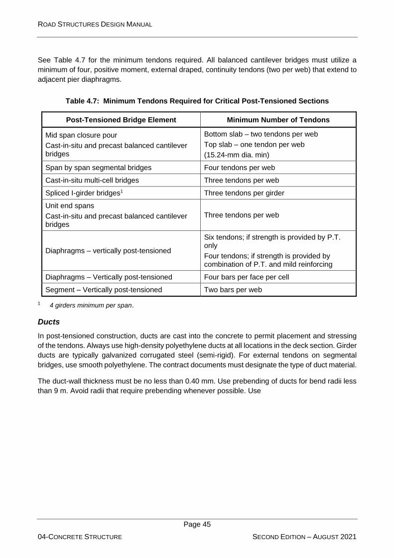
ROAD STRUCTURES DESIGN MANUAL
Page 45
04-CONCRETE STRUCTURE SECOND EDITION – AUGUST 2021
See Table 4.7 for the minimum tendons required. All balanced cantilever bridges must utilize a
minimum of four, positive moment, external draped, continuity tendons (two per web) that extend to
adjacent pier diaphragms.
Table 4.7: Minimum Tendons Required for Critical Post-Tensioned Sections
Post-Tensioned Bridge Element Minimum Number of Tendons
Mid span closure pour
Cast-in-situ and precast balanced cantilever bridges
Bottom slab – two tendons per web
Top slab – one tendon per web
(15.24-mm dia. min)
Span by span segmental bridges Four tendons per web
Cast-in-situ multi-cell bridges Three tendons per web
Spliced I-girder bridges1 Three tendons per girder
Unit end spans
Cast-in-situ and precast balanced cantilever bridges
Three tendons per web
Diaphragms – vertically post-tensioned
Six tendons; if strength is provided by P.T. only
Four tendons; if strength is provided by combination of P.T. and mild reinforcing
Diaphragms – Vertically post-tensioned Four bars per face per cell
Segment – Vertically post-tensioned Two bars per web
1 4 girders minimum per span.
Ducts
In post-tensioned construction, ducts are cast into the concrete to permit placement and stressing
of the tendons. Always use high-density polyethylene ducts at all locations in the deck section. Girder
ducts are typically galvanized corrugated steel (semi-rigid). For external tendons on segmental
bridges, use smooth polyethylene. The contract documents must designate the type of duct material.
The duct-wall thickness must be no less than 0.40 mm. Use prebending of ducts for bend radii less
than 9 m. Avoid radii that require prebending whenever possible. Use

ROAD STRUCTURES DESIGN MANUAL
Page 46
04-CONCRETE STRUCTURE SECOND EDITION – AUGUST 2021
Table 4.8 to tabulate the minimum bend radius of ducts for steel ducts. Do not use a bending radius
of less than 9 m for polyethylene or polypropylene ducts. For a radius less than 9 m, use galvanized
corrugated steel ducts.

ROAD STRUCTURES DESIGN MANUAL
Page 47
04-CONCRETE STRUCTURE SECOND EDITION – AUGUST 2021
Table 4.8: Recommended Minimum Duct Radius (for Steel Ducts)
Tendon Size Minimum Radius
12 15.24-mm dia 3.0 m
19 15.24-mm dia 4.0 m
27 15.24-mm dia 5.0 m
37 15.24-mm dia 6.0 m
A bridge can be constructed by post-tensioning precast components together longitudinally and/or
transversely by use of a cast-in-situ concrete joint. For this type, extend the end of the duct beyond
the concrete interface by at least 75 mm and not more than 150 mm to facilitate joining the ducts. If
necessary, the extension could be in a local blockout at the concrete interface. Joints between
sections of ducts must be positive metallic connections, which do not result in angle changes at the
joints. Use waterproof tape at all connections.
For multiple-strand tendons, the outside diameter of the duct must be no more than 40% of the least
gross concrete thickness at the location of the duct. During design, the bridge designer must lay out
an acceptable duct arrangement that matches the post-tensioning centre of gravity to determine the
need for a wider web. The internal free area of the duct must be at least 2.5 times the net area of
the prestressing steel. See BDS Article 5.4.6.2.
Grouting
Detail all post-tensioned bridges with the following corrosion protection strategies:
• Enhanced post-tensioned systems,
• Fully grouted tendons,
• Multi-level anchor protection,
• Bridges with no deck joints or watertight deck joints, and
• Multiple tendon paths.
Enhanced post-tensioning systems require three levels of protection for strand and four levels for
anchorages. (Deck overlays are not considered a level of protection for strands or anchorages):
1. Within the segment or concrete element:
a. Internal Tendons
• Concrete cover
• Plastic duct
• Complete filling of the duct with approved grout
b. External Tendons
• Hollow box structure itself
• Plastic duct
• Complete filling of the duct with approved grout

ROAD STRUCTURES DESIGN MANUAL
Page 48
04-CONCRETE STRUCTURE SECOND EDITION – AUGUST 2021
2. At the segment face or construction joint (internal and external tendons):
a. Epoxy seal (precast construction) or wet cast joint (cast-in-situ construction)
b. Continuity of the plastic duct
c. Complete filling of the duct with approved grout
The required four levels of protection for anchorages on interior surfaces (e.g. interior diaphragms)
are:
1. Grout
2. Permanent grout cap
3. Elastomeric seal coat
4. Concrete box structure
The required four levels of protection for anchorages on exterior surfaces (e.g. pier caps, expansion
joints, diaphragms) are:
1. Grout
2. Permanent grout cap
3. Encapsulating pour-back
4. Seal coat (elastomeric/methyl methacrylate on riding surface)
Internal post-tensioning bars used for erection with acceptable ducts, grout, and cover may remain
in the structure with no additional protection. Do not incorporate the force from these bars in the
service stress or strength calculations for the structure.
The strength of the grout should be comparable to that of the girder concrete; however, the strength
is not specified due to the high strengths that typically result from tendon grouts.
Use pre-approved bagged grout for tendon grouting. Use multiple injection and bleed ports at the
ends of the tendons and at all low and high points. The flushing of tendons due to blockage is
discouraged but allowed using vacuum grouting as a consideration for repairs.
Anchorage Details
Temporary or permanent post-tensioning anchorages may be required in the top or bottom slab of
box girders. If so, design and detail interior blisters, face anchors, or other approved means. Do not
use block-outs that extend to either the interior or exterior surfaces of the slabs.
Provide continuous longitudinal mild reinforcing through all segment joints for cast-in-situ segmental
construction.
Design and detail so that any future post-tensioning for strengthening utilizes external tendons (bars
or strands). Design future post tensioning so that any one span can be strengthened independently
of adjacent spans. For each future tendon, provide one duct/anchorage location for expansion joint
diaphragms and two duct/anchorage locations for internal pier segment diaphragms.
Detail anchor blisters so that tendons terminate no closer than 300 mm to a joint between segments.
Do not use transverse bottom slab ribs. Design full height diaphragms directing the deviation forces
directly into the web and slab. See Figure 4.2.

ROAD STRUCTURES DESIGN MANUAL
Page 49
04-CONCRETE STRUCTURE SECOND EDITION – AUGUST 2021
Do not use raised corner recesses in the top corner of pier segments at closure joints. Continue the
typical cross section to the face of the diaphragm. See Figure 4.3. Locate tendon anchorages to
permit jack placement.
Detail all interior blisters set back a minimum of 300 mm from the joint. Provide a “V”-groove around
the top slab blisters to isolate the anchorage from any free water. See the “V”-groove detail of
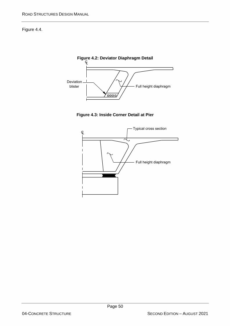
ROAD STRUCTURES DESIGN MANUAL
Page 50
04-CONCRETE STRUCTURE SECOND EDITION – AUGUST 2021
Figure 4.4.
Figure 4.2: Deviator Diaphragm Detail
Figure 4.3: Inside Corner Detail at Pier

ROAD STRUCTURES DESIGN MANUAL
Page 51
04-CONCRETE STRUCTURE SECOND EDITION – AUGUST 2021
Figure 4.4: Details at Expansion Joints
Deck Slabs
The following applies:
• Where draped post-tensioning is used in deck slabs, consider the final location of the centre
of gravity of the prestressing steel within the duct.
• Reduce critical eccentricities over the webs and at the centreline of the box by 5 mm from
theoretical to account for construction tolerances.
Intermediate Diaphragms
Intermediate diaphragms are not necessary for straight CIS concrete box girder bridges and curved
CIS concrete box girder bridges with an inside radius of 250 m. For curved box girder bridges having
an inside radius less than 250 m, intermediate diaphragms are required unless shown otherwise by
tests or structural analysis. For such curved box girders, the maximum diaphragm spacing shall be
12 m for a radius 20 m or less and 25 m for a radius between 135 m and 250 m.
Expansion Joint Details
At expansion joints, provide a recess and continuous expansion joint device seat to receive the
assembly, anchor bolts, and frames of the expansion joint; i.e. a finger or modular type joint. Lower
the upper tendon anchors and re-arrange the anchor layout as necessary to provide access for the
stressing jacks.
At all expansion joints, protect anchors from dripping water by means of skirts, baffles, V-grooves,
or drip flanges. Ensure that drip flanges are of adequate size and shape to maintain structural
integrity during form removal and erection.

ROAD STRUCTURES DESIGN MANUAL
Page 52
04-CONCRETE STRUCTURE SECOND EDITION – AUGUST 2021
4.5.2.3 Tendon Jacking
If the distance between anchorages exceeds 60 m, consider jacking at both ends. Determine one-
end or two-end stressing by design and specify in the contract documents.
Show the values of the wobble and curvature friction coefficients and the anchor set loss assumed
for the design in the contract documents.
There are several types of commercially available anchorages. The anchorages normally consist of
a steel block with holes in which the strands are individually anchored by wedges. Near the anchor
block (or coupler), the strands are fanned out to accommodate the anchorage hardware. The fanned
out portion of the tendon is housed in a transition shield. This is often called a trumpet, which could
be either steel or polyethylene, regardless of the duct material. Trumpets must have a smooth,
tangential transition to the ducts.
4.5.2.4 Erection Schedule and Construction System
Include a description of the construction method upon which the design is based.
Include in the design documents in outlined, schematic form, a typical erection schedule and
anticipated construction system.
State in the plans the assumed erection loads, and the times of application and removal of each
erection load.
Temporary load conditions often control the design and detailing of segmental and spliced girder
structures. Size the structure components for the temporary and final condition and loadings of the
bridge.
For large projects, more than one method of construction may be necessary based on project
specific site constraints.
4.5.2.5 Falsework
Cast-in-situ, post-tensioned bridges must be supported during construction. The bridge cannot
support even the dead load until post-tensioning is complete. The temporary supports used are
either earth fills, if traffic does not have to be maintained, or falsework. Earth fills must be compacted
sufficiently to keep settlement to a minimum. Falsework usually consists of a combination of timber
and steel structural components. Design the falsework to carry the entire dead load of the bridge
and construction loads. The falsework shall be checked and approved by a specialized engineer
with adequate related experience, as approved by the client.
4.5.2.6 Access and Maintenance
Reference: BDS Article 2.5.2.2
During preliminary engineering and when determining structure configuration, emphasize
accessibility and the safety of bridge inspectors and maintenance:
1. Height. For maintenance and inspection, the minimum interior, clear height of box girders
shall be 1.4 m.
2. Electrical. Show interior lighting and electrical outlets at the following locations:
ROAD STRUCTURES DESIGN MANUAL
Page 53
04-CONCRETE STRUCTURE SECOND EDITION – AUGUST 2021
• all ingress/egress access openings,
• both sides of diaphragms where girder is continuous,
• at the inside face of diaphragms where the girder is discontinuous; e.g. at end bents
and expansion joints, and
• spaced between the above locations at approximately equal intervals not to exceed
15 m.
3. Access. The following applies:
• Design box sections with ingress/egress access openings located at maximum 60 m
spacing. Space ingress/egress access openings such that the distance from any
location within the box to the nearest opening is 30 m or less. Provide a minimum of
two ingress/egress access openings per box girder line. Locate one ingress/egress
access opening near each end bent. Provide additional ingress/egress access doors
along the length of the box girder as required to meet the maximum spacing
requirement.
• Design doors in diaphragms with in-swinging, hinged, 6-mm mesh, steel screen
doors. Equip all doors at abutments and entrances with a lock and hasp.
• Provide an access opening through all interior diaphragms. If the bottom of the
diaphragm access opening is not flush with the bottom flange, provide concrete
ramps to facilitate equipment movement.
• The minimum diaphragm access opening is 800 mm wide 1050 mm, or 900 mm
diameter. Indicate on the plans that diaphragm access openings must remain clear
and must not be used for utilities, drain pipes, conduits, or other attachments. If these
items are required, provide additional areas or openings. In all other areas of the box,
provide a minimum continuous maintenance/inspection access envelope of 2-m high
1-m along the length of the box. Measure the 2-m height dimension of the envelope
from the bottom slab of the box. The height should clear all tendon ducts, anchorages,
blisters, deviation saddles, etc.
• Analyse access opening sizes and bottom flange locations for structural effects on
the girder. Generally, do not place ingress/egress access openings in zones of high
compression.
• Avoid ingress/egress access opening locations over traffic lanes that will require
extensive maintenance of traffic operations, and avoid other locations such as over
sloped embankments, over water or locations that could otherwise impact the safety
of inspectors or the travelling public. Where vagrant access is not a problem, place
an access opening near the abutment where no additional equipment will be required
for access.
4. Other Exterior Openings. Design each box girder with minimum 50-mm diameter ventilation
or drain holes located in the bottom flange on both sides of the box. Space the holes at
approximately 15-m or as needed to provide proper drainage. Place additional drains at all
low points against internal barriers. Locate drains to accommodate bridge grade.

ROAD STRUCTURES DESIGN MANUAL
Page 54
04-CONCRETE STRUCTURE SECOND EDITION – AUGUST 2021
Provide drains to prevent water (including condensation) from ponding near post-tensioning
components, face of diaphragms, blisters, ribs, and other obstructions. Show details in the
plans. Include the following:
• Specify a 50-mm diameter permanent plastic pipe (PVC with UV inhibitor) set flush
with the top of the bottom slab.
• A drip recess, 13 mm by 13 mm around bottom of pipe insert.
• Drains at all low points against internal barriers, blisters, etc.
• Drains on both sides of the box, regardless of cross slope (to avoid confusion).
• Vermin guards for all drains and holes.
• A note stating, “Install similar drains at all low spots made by barriers introduced to
accommodate means and methods of construction, including additional blocks or
blisters.”
Require a 6-mm screen on all exterior openings not covered by a door. This includes holes
in webs through which drain pipes pass, ventilation holes, drain holes, etc.
Design flexible barriers to seal openings between expansion joint segments of adjacent end
units to prevent birds from roosting on the box end ledges. Barriers are typically UV and
weather resistant and easily replaceable.
5. Other Box Sections. Provide accessibility to box sections (e.g. precast hollow pier segments)
similar to that for box girders, particularly concerning the safety of bridge inspectors and
maintenance personnel. During preliminary engineering and when determining structure
configuration, consider box girder accessibility and the safety of bridge inspectors and
maintenance personnel.
4.5.2.7 Integrated Drawings
Show congested areas of post-tensioned concrete structures on integrated drawings with an
assumed post-tensioning system. Such areas include anchorage zones, areas containing
embedded items for the assumed post-tensioning system, areas where post-tensioning ducts
deviate, both in the vertical and transverse directions, and other highly congested areas.
For all post-tensioned structures, accommodate possible conflicts between webs and external
tendons. Check for conflicts between future post-tensioning tendons and permanent tendons.
Select the assumed post-tensioning system, embedded items, etc., so that they accommodate
competitive systems using standard anchorages of 12, 19, 22, 25, 27, 31 or 37 15.24-mm dia.
strands. Detail integrated drawings utilizing the assumed system to a scale and quality required to
show double-line reinforcing and post-tensioning steel in two-dimension (2-D) and, when necessary,
in complete three-dimension (3-D) drawings and details.
Verify that the post tensioning in the structure can be accommodated by the anchorages listed in the
specifications and has been sized according to the approved post-tensioning systems.

ROAD STRUCTURES DESIGN MANUAL
Page 55
04-CONCRETE STRUCTURE SECOND EDITION – AUGUST 2021
Space post tensioning anchorages to accommodate spirals based on the anchorage size and not
on the number of strands in that anchorage.
Check required clearances for stressing jacks. Do not detail structures or provide construction
sequences that require curved stressing noses for jacks.
4.5.3 Precast, Prestressed Concrete Girders
4.5.3.1 Design
Reference: BDS Article 5.9
General
This Section addresses the general design theory and procedure for precast, prestressed (pre-
tensioned) concrete girders. For design examples, consult the PCI Bridge Design Manual, Chapter
9 (11).
Design bridges consisting of simple-span precast concrete girders and cast-in-situ concrete slabs to
be continuous for live load and superimposed dead loads by using a cast-in-situ closure diaphragm
at piers whenever possible. Other design options, including providing a compressible spacer at
debonded strand ends, are permissible.
The design of the girders for continuous structures is similar to the design for simple spans with the
following exception. In the area of negative moments, the member is treated as an ordinary
reinforced concrete section, and the bottom flanges of adjoining girders are connected at the interior
supports by reinforcement projecting from girder ends into a common diaphragm. The members are
typically fully continuous with a constant moment of inertia when determining both the positive and
negative moments due to loads applied after continuity is established.
The resistance factor (BDS Article 5.5.4) for flexure is 1.0, except for the design of the negative-
moment steel in the deck for structures made continuous for composite loads only. See the Abu
Dhabi Standard Drawings for Road Projects (Document Reference Number TR-541-2) for
continuous details. For this case, the resistance factor is the 0.90 value for reinforced concrete
members in flexure.
Use ASTM A416 (A416M), Grade 1860, low-relaxation, prestressing strands for the design of
prestressed beams. Do not use stress-relieved strands. Use straight-strand configurations (where
feasible) instead of draped strand configurations. The following requirements apply to simply
supported, fully pretensioned beams, whether of straight or depressed (draped) strand profile,
except where specifically noted otherwise.
Bridges with varying span lengths, skew angles, beam spacing, beam loads, or other design criteria
may result in very similar individual designs. Consider the individual beam designs as a first trial
subject to modifications by combining similar designs into groups of common materials and stranding
based upon the following priorities:
1. 28-day compressive concrete strength ( cf )
2. Strands (size, number, location)
3. Compressive concrete strength at release ( cif )
4. Do not use full length shielding (debonding) of prestressing strands
ROAD STRUCTURES DESIGN MANUAL
Page 56
04-CONCRETE STRUCTURE SECOND EDITION – AUGUST 2021
Grouping beam designs in accordance with the priority list maximizes casting bed usage and
minimizes variations in materials and stranding.
To achieve uniformity and consistency in designing beams, the following parameters apply:
1. Provide a strand pattern that is symmetrical about the centreline of the beam.
2. Distribute debonded strands evenly throughout the strand pattern. Whenever possible,
separate debonded strands in all directions by at least one fully bonded strand.
3. When analysing stresses of simple span beams, limit stresses based on BDS Table
5.9.4.1.2-1 with the following exception: For the outer 15 percent of the design span, tensile
stress at the top of beam may not exceed 1.05 cif at release. For transient loads during
construction, the tensile stress limit may be taken as 0.525 cf .
4. The minimum compressive concrete strength at release is the greater of 28 MPa or 0.6 cf .
Higher release strengths may be used on a case-by-case basis but must not exceed the
lesser of 0.8 cf or 42 MPa.
5. For precast, pretensioned, normal weight concrete members designed as simply supported
beams, use BDS Article 5.9.5.3, Approximate Estimate of Time-Dependent Losses. For all
other members, use BDS Article 5.9.5.4 with a 180-day differential between girder concrete
casting and placement of the deck concrete.
Controlling the Contractor’s construction sequence and materials for simple span precast,
prestressed beams is challenging. To benefit from the use of refined time-dependent analysis,
literally every prestressed beam design would have to be re-analysed using the proper construction
times, temperature, humidity, material properties, etc., of both the beam and the yet-to-be-cast
composite slab.
1. Base the stress and camber calculations for the design of simple span, pretensioned
components on the use of transformed section properties.
2. When wide-top beams such as I- and bulb-tees are used in conjunction with stay-in-place
metal forms, evaluate the edges of flanges of the beams to safely support the weight of the
forms, concrete, and construction load.
3. Provide the design thickness of the composite slab from the top of the stay-in-place metal
form to the finished slab surface. The superstructure concrete quantity does not include the
concrete required to fill the form flutes.
For non-standard single web prestressed beam designs, modify the requirements of BDS Article
5.10.10.1 to provide vertical reinforcement in the ends of pretensioned beams with the following
splitting resistance:
• 3% Pu from the end of the beam to h/8, but not less than 250 mm;
• 5% Pu from the end of the beam to h/4, but not less than 250 mm;
• 6% Pu from the end of the beam to 3h/8, but not less than 250 mm.
Do not apply losses to the calculated prestressing force (Pu). The minimum length of debonding from
the ends of the beams is one half of the depth of beam.

ROAD STRUCTURES DESIGN MANUAL
Page 57
04-CONCRETE STRUCTURE SECOND EDITION – AUGUST 2021
Provide embedded bearing plates in all prestressed I-girder beams deeper than 1500 mm. Provide
embedded bearing plates for all I beams. For all beam designs where the beam grade exceeds 2%,
include bevelled bearing plates.
Bearing plates add strength to the ends of the concrete beams to resist the temporary loadings
created in the bearing area by the release of prestressing forces and subsequent camber and elastic
shortening.
Analyse spans subject to significant lateral loads to determine the need for diaphragms.
When investigating the effect of significant lateral loads such as vessel collision or wave loads, check
the stresses at the interface of the beam top flange and the beam web, from each end of the beam
to a longitudinal distance approximately equivalent to the beam height.
Precast I-Girder Sections
Select the type of girder used in the superstructure based upon geometric restraints, economy, and
appearance. This Manual has not adopted standard precast concrete I-girder sections. AASHTO
and PCI have developed standard sections that are used in most locations throughout the world;
however, the sections and the associated design aids are not appropriate for the Abu Dhabi Emirate
because they do not have the required increased concrete cover.
To ensure that the structural system has an adequate level of redundancy, use a minimum of four
girder lines on new bridges.
Stage Loading
There are four loading conditions that must be considered in the design of a precast, prestressed
girder:
1. The first loading condition is when the strands are tensioned in the bed prior to placement of
the concrete. Seating losses, relaxation of the strand, and temperature changes affect the
stress in the strand prior to placement of the concrete. The fabricator must consider these
factors during girder fabrication and adjust the initial strand tension to ensure that the tension
prior to release meets the design requirements for the project. The prestressing shop
drawings must present a discussion on the fabricator’s proposed methods to compensate for
seating losses, relaxation, and temperature changes.
2. The second loading condition is when the strands are released and the force is transferred
to the concrete. After release, the girder will camber up and be supported at the girder ends
only. Therefore, the region near the end of the member is not subject to bending stresses
due to the dead load of the girder. This region may develop tensile stresses in the top of the
girder large enough to crack the concrete. The critical sections for computing the critical
temporary stresses in the top of the girder are near the end and at all debonding points. If
the designer considers the transfer length of the strands at the end of the girder and at the
debonding points, then assume that the stress in the strands is zero at the end of the girder
or debonding point. Also, assume that the stress varies linearly to the full transfer of force to
the concrete at the end of the strand transfer length.
Use the level of effective prestress immediately after release of the strands, which includes
the effects of elastic shortening and the initial strand relaxation loss, to compute the concrete
stresses at this stage.

ROAD STRUCTURES DESIGN MANUAL
Page 58
04-CONCRETE STRUCTURE SECOND EDITION – AUGUST 2021
There are several methods to relieve excessive tensile stresses near the ends of the girder:
• Debonding, where the strands remain straight but wrapped in plastic over a
predetermined distance to prevent the transfer of prestress to the concrete through
bonding;
• Adding additional strands in the top of the girder that are bonded at the ends but are
debonded in the centre portion of the girder. These strands are typically detensioned
after the girder is erected; or
• Deviating some of the strands to reduce the strand eccentricity at the end of the
girder.
3. The third loading condition occurs several weeks to several months after strand release when
the girder is erected, and the composite deck is cast. Camber growth and prestress losses
are design factors at this stage. If a cast-in-situ composite deck is placed, field adjustments
to the haunch thickness are usually needed to provide the proper vertical grade on the top of
deck and to keep the deck thickness uniform. Use reliable estimates of deflection and camber
to prevent excessive haunch thickness or to avoid significant encroachment of the top of
girder into the bottom of the concrete deck. Stresses at this stage are usually not critical.
See Section 8.7 of the PCI Bridge Design Manual (11) for determining the girder camber at
erection.
4. The fourth loading condition is after an extended period of time during which all prestress
losses have occurred and loads are at their maximum. This is often referred to as the
“maximum service load, minimum prestress” stage. The tensile stress in the bottom fibres of
the girder at mid-span generally controls the design.
Flexural Resistance
The design of prestressed concrete members in flexure normally begins with the determination of
the required prestressing level to satisfy service conditions. Consider all load stages that may be
critical during the life of the structure from the time prestressing is first applied. This is then followed
by a strength check of the entire member under the influence of factored loads. The strength check
seldom requires additional strands or other design changes.
For checking the stresses in the girder at the Service limit state, use the following basic assumptions:
1. Planar sections remain plane, and strains vary linearly over the entire member depth.
Therefore, adequately connect composite members consisting of precast concrete girders
and cast-in-situ decks so that this assumption is valid and all elements respond to
superimposed loads as one unit. Transform deck concrete to girder concrete when
computing section properties. Accomplish this by multiplying the effective deck width by the
ratio of the deck concrete modulus of elasticity to the girder concrete modulus of elasticity.
Use the gross concrete section properties (i.e. do not transform the area of prestressing
strands and reinforcing steel).
2. Assume that the girder is uncracked at the Service limit state.
3. Do not check stress limits for the deck concrete in the negative-moment region because the
deck concrete is not prestressed.

ROAD STRUCTURES DESIGN MANUAL
Page 59
04-CONCRETE STRUCTURE SECOND EDITION – AUGUST 2021
Vui = 12 Vu1/dv
Minimum Reinforcement Requirements
Reference: BDS Article 5.7.3.3.2
Apply the minimum reinforcement requirements of BDS Article 5.7.3.3.2 to all sections being
analysed, except at the ends of simply supported bridge girders.
The following defines the girder length from the simply supported end where the minimum
reinforcement does not need to be checked:
1. For prestressing concrete girders for a distance equal to the bonded development length.
For example, for a 1900 MPa strand with fpe = 1100 MPa, a 13-mm dia. strand yields 4 m
and a 15-mm dia. yields 4 m from the ends of the simply supported girder.
2. For reinforced concrete girders for a distance equal to 2.5 times the superstructure depth
from the centreline of bearing of the simply supported end.
For span lengths less than 8 m for simple span bridges, check the minimum reinforcement at mid-
span.
The use of a minimum reinforcement check was developed to ensure a ductile failure mode for lightly
reinforced deep beams. Bridge girders are slender and do not generally meet the definition of a deep
beam. Deep beams are members having a clear span less than 4 times the overall depth (as defined
by ACI 318). The use of the minimum reinforcing check has evolved in the specifications from
checking the critical section to checking every section. This evaluation at every section is justified in
buildings where heavy concentrated loads may be present near supports. In bridges, this condition
does not exist, and the critical section for bending is not near the support for simply supported bridge
beams. The ends of simply supported bridge girders are dominated by shear, not bending moment.
At these locations, it is unnecessary to check minimum reinforcing.
Interface Shear
Reference: BDS Article 5.8.4
Cast-in-situ concrete decks acting compositely with precast concrete girders must be able to resist
the interface shearing forces between the two elements. Use the following formula, substituting BDS
Equation 5.8.4.2-2 into BDS Equation 5.8.4.2-1, to determine the factored interface shear stress, Vui
:
Equation 4.1
The factored interface shear force must be less than or equal to the factored nominal interface shear
resistance; i.e.:
Equation 4.2
where: Vni = cAcv μ(Avf fy + Pc) (BDS Eq. 5.8.4.1-3)
Vui Vni

ROAD STRUCTURES DESIGN MANUAL
Page 60
04-CONCRETE STRUCTURE SECOND EDITION – AUGUST 2021
Neglect the permanent net force normal to the interface, Pc, if it is compressive.
4.5.3.2 Detailing
Prestressing Strands
Strand Size
Use 15.24 mm or 15.7 mm diameter seven-wire strand.
Strand Spacing
For the minimum spacing of strands, do not use less than 50 mm centre to centre.
Strand Profile
It is acceptable to use either a straight or draped strand profile for precast members. However, where
possible, use “draped” strand (i.e. deviated, harped, deflected) instead of “debonded,” because of
the greater shear capacity and reduced number of strands. However, the designer can use a
combination of debonded and draped strands when necessary to satisfy design requirements.
The advantages of straight trajectories include their simplicity of fabrication and greater safety.
Debonded or draped strands are used to control stresses and camber. Debonded strands are easier
to fabricate because a hold-down point is not required in the stressing bed.
Draped Strand
The following applies to draped strands in precast, pretensioned girders:
• At ends of girders, maintain a minimum of 100 mm between the top draped strands and any
straight strands that are located directly above the draped strands.
• At each hold-down point, limit the vertical force to a maximum of 215 kN for all draped strands
and 18 kN for each individual draped strand.
• The slope of the draped strands would not exceed 9.
• Where practical, locate hold-down points 1.5 m on each side of the centreline of the girder
(3 m apart).
Debonded Strands
Debond strands at the ends of precast, pretensioned concrete girders with the following restrictions:
1. Debond a maximum of 25% of the total number of prestressing strands to satisfy the
allowable stress limits. In any row, do not allow debonded strands to exceed 40% of the total
strands in that row.
2. Terminate not more than 40% of the debonded strands or four strands, whichever is greater,
at any section.
3. Debond strands in a pattern that is symmetrical about the vertical axis of the girder.
4. Round off the theoretical number of debonded strands to the closest even number (pairs) of
strands, except do not allow debonded strands in rows containing three strands or less.

ROAD STRUCTURES DESIGN MANUAL
Page 61
04-CONCRETE STRUCTURE SECOND EDITION – AUGUST 2021
5. Fully bond all exterior strands (including the entire bottom row).
6. At each end of a girder, the maximum length for debonding is 15% of the entire girder length.
In analysing stresses and/or determining the required length of debonding, limit stresses to the
values in BDS Article 5.9.4, except that tension is limited to 0.0948 cf for all exposure conditions.
Strand Patterns
Detail the strand pattern showing the total number of strands, layout and spacing, edge clearances,
which strands will be draped and/or debonded, and the layout of all mild reinforcing steel.
Frequently, precast, pretensioned girders of the same size and similar length in the same bridge or
within bridges on the same project may be designed with a slightly different number of strands. In
this case, consider using the same number and pattern of strands (including height of draping) for
these girders to facilitate fabrication.
Strand Splicing
Do not splice prestressing strand.
Diaphragms
Reference: BDS Article 5.13.2.2
For precast, prestressed girder spans, use cast-in-situ concrete diaphragms at all supports with the
girders embedded a minimum of 200 mm into the diaphragm.
For continuous precast, prestressed girder spans, ensure that the closure diaphragms at the piers
are cast with a horizontal construction joint between the diaphragm and the deck slab. For integral
abutments, also ensure that the end diaphragms are similarly cast.
Sole Plates
For an instantaneous slope at the bottom of the girder greater than or equal to 2%, use bevelled sole
plates to allow for level girder seats.
4.5.3.3 Girder Transportation
The bridge designer must investigate the feasibility of transporting heavy, long and/or deep girders.
In general, consider the following during the design phase:
• whether or not multiple routes exist between the bridge site and a major transportation facility,
and
• shorter and/or lighter girders may be required if access to the bridge site is limited by
roadway(s) with sharp horizontal curvature or weight restrictions.
Investigate routes for obstructions for girder depths exceeding 3 m, or if posted height restrictions
exist on the route.
Length of travel significantly increases the difficulty to transport girders. Consider alternative
transportation for heavy, long and/or deep girders. The transportation of girders weighing more than
72,500 kg may require analysis by a specialist, bridge strengthening, or other unique measures.

ROAD STRUCTURES DESIGN MANUAL
Page 62
04-CONCRETE STRUCTURE SECOND EDITION – AUGUST 2021
When the use of heavy, long and/or deep girders is being evaluated and transportation of the girders
over land is required, contact at least one prestressed girder manufacturer and request their input
regarding girder transportation. At least one combination of viable casting location and transportation
route is required.
4.5.4 Pretensioned/Post-Tensioned Beams
In the design of pretensioned beams made continuous by field-applied post-tensioning, design the
pretensioning such that, as a minimum, the following conditions are satisfied:
1. The pretensioning meets the minimum steel provisions of BDS Article 5.7.3.3.2.
2. The pretensioning is capable of resisting all loads applied prior to post-tensioning, including
a superimposed dead load equal to 50% of the uniform weight of the beam, without
exceeding the stress limitations for pretensioned concrete construction.
3. The pretensioning force is of such magnitude that the initial midspan camber at release,
including the effect of the dead load of the beam, is at least 13 mm.
4. Anchorage zones of post-tensioning ducts, and beam lengths in which ducts deviate both
horizontally and vertically, require integrated drawings in accordance with the minimum
reinforcement requirements in Section 4.5.3.1.
5. The limitation on the percentage of debonded strands of the pretensioned strand group at
the ends of beams may be increased to 37.5%. This limitation is assuming that post-
tensioning is applied to the beams prior to casting the deck concrete and that the total number
of debonded strands is equal to or less than 25% of the total area of pretensioned and post-
tensioned strands at the time of placement of the deck concrete (14).
Full depth diaphragms are required at all splice (closure pour) and anchorage locations. At closure
pour locations, cast intermediate diaphragms with the closure pours. Design diaphragms for out-of-
plane loads for chorded girders on a horizontal curve.
4.5.5 Camber Diagram
The designer must prepare a camber diagram that shows the amount of camber needed to
counteract the dead load and superimposed dead-load (if any) deflection. Determine the calculation
of the dead-load camber based on the gross section properties and BDS Article 5.7.3.6.
4.5.6 Responsibilities
4.5.6.1 Designer
The bridge designer is responsible for ensuring that the proposed design serves the purpose. The
designer chooses a cross section with a centre of gravity (force and location) and provides a
strand/tendon size and pattern to achieve the required allowable Service limit state stresses and
factored flexural resistance. The contract documents will specify the exact value with respect to
cf that the contractor must reach at release and at 28-days. The designer is also responsible for a
preliminary investigation of shipping and handling issues where larger or long precast girders are
used or where unusual site access conditions are encountered.

ROAD STRUCTURES DESIGN MANUAL
Page 63
04-CONCRETE STRUCTURE SECOND EDITION – AUGUST 2021
4.5.6.2 Contractor
In general, the contractor is responsible for implementing the prestressed concrete design according
to the bridge designer’s specifications. The contractor provides shop drawings showing all
calculations. In addition, for precast girders, the contractor is responsible for investigating stresses
in the components during proposed handling, transportation, and erection. The contractor may
propose changes to the cross-sectional shape of the girder. In these cases, the contractor must
redesign the girder to meet all requirements of the project. The contractor shall also prepare the “As
Built” drawings.
Contractor shall not commence the erection of installation of precast elements until the temporary
works design is approved by the Engineer. Contractor shall be responsible for design of temporary
works and supporting gantries and shall be in compliance with TA requirements specified in CG300.
All the temporary supporting members shall be rigid enough to sustain the anticipated loading and
shall be supported on firm & adequately compacted ground in accordance with the relevant
specifications. Contractor shall submit in advance a detailed Method Statement and Shop Drawings
with construction sequence for the approval of the Engineer.
ROAD STRUCTURES DESIGN MANUAL
PAGE 64
05-STEEL STRUCTURE SECOND EDITION – AUGUST 2021
5 STEEL STRUCTURES
This Chapter discusses structural steel provisions in Section 6 of the BDS that require amplification
or clarification for users of this Manual.
5.1 General
5.1.1 Economical Steel Superstructure Design
5.1.1.1 General
Factors that influence the initial cost of a steel bridge include detailing practices, the number of
girders (for a girder bridge), the grade of steel, type and number of substructure units (i.e. span
lengths), steel weight, fabrication, transportation, and erection. The cost for these factors changes
periodically based upon economic issues and the cost relationship among them.
Based upon market factors, the availability of steel may be an issue in meeting the construction
schedule. The bridge designer must verify the availability of the specified steel plates and rolled
beams. Producers and fabricators shall be contacted to ensure the availability of plates and rolled
beams. For more detailed information on availability, see Section 1.4 of the AASHTO/NSBA Steel
Bridge Collaboration’s Guidelines for Design for Constructability, G12.1-2003 (15).
5.1.1.2 Exterior Girders
The location of the exterior girder with respect to the overhang is controlled by these factors:
• Locate the exterior girder to limit the dead load and live load on the exterior girder such that
the exterior girder does not control the design (i.e. the interior and exterior girders are as
identical as possible).
• Consider the minimum and maximum overhang widths specified in Chapter 6.
• The space required for deck drains may affect the location of the exterior girder lines.
5.1.1.3 Fracture-Critical Members (FCMs)
Avoid bridges with fracture-critical members, which are members without a redundant load path
whose failure in tension would result in the collapse of the bridge.
5.1.1.4 Span Arrangements
Where pier locations are flexible, optimize the span arrangement. Consider the cost of the
superstructure, substructure, foundations, and approaches together as a total system.
To provide a balanced span arrangement for continuous steel bridges, select the end spans to be
approximately 80% of the length of interior spans. Avoid end spans less than 50% of the interior
span lengths to mitigate uplift.
End spans approximately 80% of the length of interior spans result in the largest possible negative
moments at the piers and smaller resulting positive moments and girder deflections. As a result, the
optimum proportions of the girders in all spans are nearly the same, resulting in an efficient design.

ROAD STRUCTURES DESIGN MANUAL
PAGE 65
05-STEEL STRUCTURE SECOND EDITION – AUGUST 2021
5.1.2 Rolled Beams vs Welded Plate Girders
5.1.2.1 General
Use rolled beams for spans up to approximately 25 m. Use welded plate girders for spans from
approximately 25 m to 120 m. When rolled beams are specified, ensure that the selected sections
are available consistent with the construction schedule.
For more information, see Section 1.1 of the AASHTO/NSBA Steel Bridge Collaboration’s Guidelines
for Design for Constructability, G12.1-2003 (15).
5.1.2.2 Welded Plate Girders
Design welded steel plate girders to optimize total cost including material costs also considering
fabrication, transportation, and erection costs. Top flanges of composite plate girders are typically
smaller than the bottom flanges. Vary the flange section along the length of the bridge generally
following the moment envelope to save cost by offsetting the increased fabrication costs of welded
flange transitions with larger savings in material costs. Typically, vary only flange thicknesses, not
widths, within a field section to reduce fabrication costs. The webs of plate girders are typically
deeper and thinner than the webs of rolled beams. To save in total costs, increase minimum web
thicknesses to minimize the use of stiffeners.
Due to buckling considerations, address the stability of the compression flange (i.e. the top flange in
positive-moment regions and the bottom flange in negative-moment regions) by providing lateral-
brace locations based upon BDS Equation 6.10.8.2.3 instead of the traditional 7.5 m maximum
diaphragm spacing.
On straight bridges (skewed or non-skewed), detail diaphragms as secondary members. On
horizontally curved bridges, design diaphragms as primary members.
The traditional 7.5 m maximum diaphragm spacing provides a good average preliminary value.
Horizontally curved girders transfer a significant amount of load between girders through the
diaphragms.
5.1.2.3 Rolled Beams
Rolled steel beams are available in depths up to 900 mm, with beams 600 mm and greater rolled
less frequently. Before beginning final design, verify with one or more potential fabricators and/or
producers that the section size is available. Most rolled beams used in the Abu Dhabi Emirate are
imported from Europe.
Rolled steel beams are characterized by doubly symmetrical, as-rolled cross sections with equal-
dimensioned top and bottom flanges and relatively thick webs. Thus, rolled steel beams are not
optimized cross sections for weight savings (as is a plate girder), but they are cost effective due to
lower fabrication and erection costs. The relatively thick webs preclude the need for web stiffeners.
Unless difficult geometrics or limited vertical clearances control, rolled steel beam superstructures
are more cost effective in relatively shorter spans.
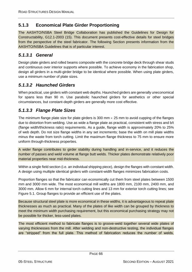
ROAD STRUCTURES DESIGN MANUAL
PAGE 66
05-STEEL STRUCTURE SECOND EDITION – AUGUST 2021
5.1.3 Economical Plate Girder Proportioning
The AASHTO/NSBA Steel Bridge Collaboration has published the Guidelines for Design for
Constructability, G12.1-2003 (15). This document presents cost-effective details for steel bridges
from the perspective of the steel fabricator. The following Section presents information from the
AASHTO/NSBA Guidelines that is of particular interest.
5.1.3.1 General
Design plate girders and rolled beams composite with the concrete bridge deck through shear studs
and continuous over interior supports where possible. To achieve economy in the fabrication shop,
design all girders in a multi-girder bridge to be identical where possible. When using plate girders,
use a minimum number of plate sizes.
5.1.3.2 Haunched Girders
When practical, use girders with constant web depths. Haunched girders are generally uneconomical
for spans less than 90 m. Use parabolic haunched girders for aesthetics or other special
circumstances, but constant-depth girders are generally more cost effective.
5.1.3.3 Flange Plate Sizes
The minimum flange plate size for plate girders is 300 mm 25 mm to avoid cupping of the flanges
due to distortion from welding. Use as wide a flange plate as practical, consistent with stress and b/t
(flange width/thickness ratio) requirements. As a guide, flange width is approximately 20% to 25%
of web depth. Do not size flange widths in any set increments; base the width on mill plate widths
minus the waste from torch cutting. Limit the maximum flange thickness to 75 mm to ensure more
uniform through-thickness properties.
A wider flange contributes to girder stability during handling and in-service, and it reduces the
number of passes and weld volume at flange butt welds. Thicker plates demonstrate relatively poor
material properties near mid-thickness.
Within a single field section (i.e. an individual shipping piece), design the flanges with constant width.
A design using multiple identical girders with constant-width flanges minimizes fabrication costs.
Proportion flanges so that the fabricator can economically cut them from steel plates between 1500
mm and 3000 mm wide. The most economical mill widths are 1800 mm, 2100 mm, 2400 mm, and
3000 mm. Allow 6 mm for internal torch cutting lines and 13 mm for exterior torch cutting lines; see
Figure 5.1. Group flanges to provide an efficient use of the plates.
Because structural steel plate is more economical in these widths, it is advantageous to repeat plate
thicknesses as much as practical. Many of the plates of like width can be grouped by thickness to
meet the minimum width purchasing requirement, but this economical purchasing strategy may not
be possible for thicker, less-used plates.
The most efficient method to fabricate flanges is to groove-weld together several wide plates of
varying thicknesses from the mill. After welding and non-destructive testing, the individual flanges
are “stripped” from the full plate. This method of fabrication reduces the number of welds,

ROAD STRUCTURES DESIGN MANUAL
PAGE 67
05-STEEL STRUCTURE SECOND EDITION – AUGUST 2021
Figure 5.1: Grouping Flanges for Efficient Fabrication (from the AASHTO/NSBA Steel Bridge Collaboration (15))
individual runoff tabs for both start and stop welds, the amount of material waste, and the number of
X-rays for non-destructive testing. The objective, therefore, is for flange widths to remain constant
within an individual shipping length by varying material thickness as required. Figure 5.1 illustrates
one example of an efficient fabrication for girders.
A constant flange width within a field section may not always be practical in girder spans over 90 m
where a flange width transition may be required in the negative bending regions. Though not
preferred, if a transition is necessary, shift the butt splice a minimum of 75 mm from the transition
into the narrower flange plate. See Figure 5.2.
This 75-mm shift makes it simpler to fit run-off tabs, weld and test the splice, and then grind off the
run-off tabs. For additional information on sizing flange plates, see Section 1.5 of the AASHTO/NSBA
Steel Bridge Collaboration’s Guidelines for Design for Constructability, G12.1-2003 (15).
Figure 5.2: Flange Width Transition (Plan View)

ROAD STRUCTURES DESIGN MANUAL
PAGE 68
05-STEEL STRUCTURE SECOND EDITION – AUGUST 2021
5.1.3.4 Field Splices
Use bolted field splices to reduce shipping lengths, but minimize the number. The preferred
maximum length of a field section is 35 m. However, the bridge designer may use lengths up to 45
m, but do not use field sections greater than 35 m without considering shipping, erection, and site
constraints. Welded field splices are prohibited.
As a general rule, the unsupported length in compression of the shipping piece divided by the
minimum width of the flange in compression in that piece is less than approximately 85. Good design
practice is to reduce the flange cross sectional area by no more than approximately 25% of the area
of the heavier flange plate at field splices to reduce the build-up of stress at the transition. For
continuous spans, the field sections over a pier are usually a constant length to simplify erection.
5.1.3.5 Shop Splices
Include no more than two shop flange splices in the top or bottom flange within a single field section.
Maintain constant flange widths within a field section for economy of fabrication as specified in
Section 5.1.3.3. In determining where changes in plate thickness occur within a field section,
compare the cost of groove-welded splices to the extra plate area.
Table 1.5.2.A of the AASHTO/NSBA Steel Bridge Collaboration’s Guidelines for Design for
Constructability, G12.1-2003 (15), provides guidelines for weight savings for Grade 345 steel
required to justify a flange shop splice. In many cases, it may be advantageous to continue the
thicker plate beyond the theoretical step-down point to avoid the cost of the groove-welded splice.
To facilitate testing of the weld, locate flange shop splices at least 600 mm away from web splices,
and locate flange and web shop splices at least 150 mm from transverse stiffeners.
Section 1.5 of the AASHTO/NSBA Steel Bridge Collaboration’s Guidelines for Design for
Constructability, G12.1-2003 (15), provides additional guidance on shop splices.
5.1.3.6 Web Plates
Where there are no depth restrictions, optimize the web depth. The minimum web thickness is 14
mm. Do not change the web thickness at any splice less than 3 mm. Maintain symmetry by aligning
the centrelines of the webs at splices.
Web design can have a significant impact on the overall cost of a plate girder. Considering material
costs alone, it is desirable to make girder webs as thin as design considerations permit. However,
this practice will not always produce the greatest economy because fabricating and installing
transverse stiffeners is one of the most labour-intensive of shop operations.
The following guidelines apply to the use of transverse stiffeners:
1. Unstiffened webs are generally more economical for web depths approximately 1200 mm or
less.
2. Between 1200-mm and 1800-mm depths, consider options for a partially stiffened and
unstiffened web, with unstiffened webs preferred.

ROAD STRUCTURES DESIGN MANUAL
PAGE 69
05-STEEL STRUCTURE SECOND EDITION – AUGUST 2021
A partially stiffened web is one whose thickness is 1.5 mm less than that allowed by
specification for an unstiffened web at a given depth and where stiffeners are required only
in areas of higher shear.
3. Above 1800 mm, consider options for partially stiffened or fully stiffened webs, with partially
stiffened webs preferred.
A fully stiffened web is one where stiffeners are present throughout the span.
5.1.3.7 Transverse Stiffeners
Proportion stiffeners that will be fabricated from flat bars in 6-mm increments in width and 3-mm
increments in thickness. Consult a fabricator for available flat sizes.
Flat bars (i.e. bar stock rolled to widths up to 200 mm at the mill) are typically more economical than
plates for stiffeners. The stiffeners can be fabricated by shearing flat bars of the specified width to
length.
5.1.3.8 Longitudinally Stiffened Webs
Do not use longitudinally stiffened webs.
In addition to being uneconomical, the ends of longitudinal stiffeners are fatigue sensitive if subject
to applied tensile stresses. Therefore, where used, terminate the ends in zones of little or no applied
tensile stresses.
5.1.4 Falsework
Design steel superstructures without intermediate falsework during the placing and curing of the
concrete deck slab.
5.2 Materials
Reference: BDS Article 6.4
5.2.1 Structural Steel
Reference: BDS Article 6.4.1
The following presents typical practices for the material type selection for structural steel members.
Typically, steel for bridge construction in the Abu Dhabi Emirate is imported from Europe.
5.2.1.1 Grade 250
Use Grade 250 steel only for the following structural members:
• transverse stiffeners,
• diaphragms, and
• bearing plates.
Grade 250 steel is becoming less used and, thus, less available. Generally, there is little or no cost
difference between Grade 345 and Grade 250 steel.
ROAD STRUCTURES DESIGN MANUAL
PAGE 70
05-STEEL STRUCTURE SECOND EDITION – AUGUST 2021
5.2.1.2 Grade 345
Use Grade 345 steel for the following structural members:
• rolled beams,
• plate girders,
• splice plates,
• diaphragms,
• stiffeners,
• steel piles, and
• bearing plates.
5.2.1.3 High-Performance Steel
Grade HPS485W
For some plate-girder bridges, a good choice of steel may be Grade HPS485W. In addition to
increased strength, the high-performance steels exhibit enhanced weathering, toughness, and
welding properties. A savings in weight offsets the premium on material costs. The most cost-
effective design solutions tend to be hybrid girders with Grade 345 webs with HPS485W tension and
compression flanges in the negative-moment regions and tension flanges only in the positive-
moment regions.
HPS485W may be painted for aesthetic reasons.
Grade HPS700W
Do not use Grade HPS700W except for special applications.
High-performance steel with a minimum specified yield strength of 700 MPa is available. It has yet
to be proven cost-effective for girder bridge applications.
5.2.1.4 Unpainted Weathering Steel
General
Unpainted weathering steel is the more cost-effective choice for structural steel superstructures. Do
not use weathering steel where the following conditions exist:
1. Environment. Do not use unpainted weathering steel in industrial areas where concentrated
chemical fumes may drift onto the structure or where the nature of the environment is
questionable. Do not use weathering steel in coastal regions where airborne salt may drift
onto the structure.
2. Water Crossings. Do not use unpainted weathering steel over bodies of water where the
clearance over the ordinary high water is 3.5 m or less.
The initial cost advantage of unpainted weathering steel when compared to painted steel can range
up to 15%. When future repainting costs are considered, the cost advantage is more substantial.
This reflects, for example, environmental considerations in the removal of paint, which significantly
increases the life-cycle cost of painted steel. FHWA Technical Advisory T5140.22 “Uncoated
Weathering Steel in Structures,” October 3, 1989 (16) discusses in-depth the application of

ROAD STRUCTURES DESIGN MANUAL
PAGE 71
05-STEEL STRUCTURE SECOND EDITION – AUGUST 2021
weathering steel and its potential problems. In addition, the proceedings of the “Weathering Steel
Forum,” July 1989 (17), are available from the FHWA Office of Implementation, HRT-10.
Despite its cost advantage, the use of unpainted weathering steel is not appropriate in all
environments and at all locations. For additional guidance on the appropriate application of
unpainted weathering steel, see the AISI publication Performance of Weathering Steel in Highway
Bridges: A Third Phase Report (18).
5.2.1.4.1 Design Details for Weathering Steel
Where weathering steel girders are used, use the same steel for the bearing plates as the girders.
Use Type 3 for the bolts, nuts, washers, and Direct Tension Indicators (DTIs), as specified in ASTM
A325M/ASTM A563M and ASTM F959M.
Paint weathering steel at the ends of girders, at expansion joints, and over piers for a distance of
3 m or for 1.5 times the web depth, whichever is greater. Use only the prime coat of the approved
bridge paint systems.
When using unpainted weathering steel, incorporate the following drainage treatments:
1. Minimize the number of bridge deck drains and extend the drainage outlets below the steel
bottom flange.
2. Eliminate details that serve as water and debris “traps.” Seal or paint overlapping surfaces
exposed to water. This sealing or painting applies to non-slip-critical bolted joints. Slip-critical
bolted joints or splices do not produce “rust-pack” when the bolts are spaced according to
the BDS and, therefore, do not require special protection.
3. Place a drip plate or other material transverse across the top of the bottom flange in front of
the substructure elements to prevent water from running off the flange onto the concrete.
Ensure that these attachments meet all fatigue requirements. Figure 5.3 shows a typical drip
plate detail.
Figure 5.3: Drip Plate Detail

ROAD STRUCTURES DESIGN MANUAL
PAGE 72
05-STEEL STRUCTURE SECOND EDITION – AUGUST 2021
5.2.1.1 Charpy V-Notch Fracture Toughness
Reference: BDS Article 6.6.2
The temperature zone appropriate for using BDS Table 6.6.2-1 for Abu Dhabi is Temperature
Zone 1.
5.2.2 Bolts
Reference: BDS Article 6.4.3
5.2.2.1 Type
For normal construction, high-strength bolts are:
1. Painted Steel: Use 22-mm A325M (Type 1).
2. Weathering Steel: Use 22-mm A325M (Type 3).
5.2.2.2 Hole Size
Do not use oversized or slotted holes; use these only in unusual circumstances with approval.
5.2.3 Splice Plates
In all cases, use the same material for the steel for all splice and filler plates as used in the web and
flanges of plate girders.
5.3 Horizontally Curved Members
Reference: BDS Articles 6.10 and 6.11
5.3.1 General
Use a curved girder on curved alignments, unless otherwise approved.
The BDS includes horizontally curved girders as a part of the provisions for proportioning I-shaped
and tub girders at both the Strength and Service limit states. In addition, the BDS specifies analysis
methodologies that detail various required levels of analysis.
5.3.2 Diaphragms, Bearings, and Field Splices
Use diaphragms for all curved steel simple-span and continuous-span bridges directed radially
except end diaphragms, which are parallel to the centreline of bearings.
Cross frames and diaphragms are primary members. However, due to the difficulty of obtaining a
Charpy specimen from a rolled shape such as an angle, Charpy V-notch impact-energy testing of
the cross frames is not required.
Design all diaphragms, including the connections to the girders, to carry the total load transferred at
each diaphragm location. Place cross frames and diaphragms as close as practical to the full depth
of the girders. Design cross frame and diaphragm connections for the 75% and average load
provisions of BDS Article 6.13.1, unless actual forces in the connections are determined from an
appropriate structural model.
ROAD STRUCTURES DESIGN MANUAL
PAGE 73
05-STEEL STRUCTURE SECOND EDITION – AUGUST 2021
Using the provisions of BDS Article 6.13.1 may result in very large connections that are difficult to
detail.
For typical bridges that are long in relationship to their width, ignore the transverse expansion. For
ordinary geometric configurations where the bridge length is long relative to the bridge width (say,
2½ times the width) and the rate of curvature is moderate (those satisfying the requirements of BDS
Article 4.6.1.2.4b), it is not necessary to consider the unique expansion characteristics of horizontally
curved structures. Wide, sharply curved or long-span structures may require the use of high-load
multi-rotational bearings. See Chapter 10. Consider providing restraint either radially and/or
tangentially to accommodate the transfer of seismic forces and the thermal movement of the
structure because the bridge tries to expand in all directions.
Design the splices in flanges of curved girders to carry flange bending or lateral bending stresses
and vertical bending stresses in the flanges.
5.4 Fatigue Considerations
Reference: BDS Article 6.6
BDS Article 6.6.1 categorizes fatigue as either “load induced” or “distortion induced.” Load induced
is a “direct” cause of loading. Distortion induced is an “indirect” cause in which the force effect,
normally transmitted by a secondary member, may change the shape of or distort the cross section
of a primary member.
5.4.1 Load-Induced Fatigue
Reference: BDS Article 6.6.1.2
5.4.1.1 General
For new steel bridges, design for infinite life. In addition, for all details, provide a fatigue resistance
greater than or equal to Detail Category C (i.e. Detail Categories A, B, B, C, and C).
5.4.1.2 Fatigue Stress Range
The following applies:
1. Range. If a refined analysis method is used, position the fatigue design truck to maximize
the stress in the detail under consideration. The fatigue design truck has a constant 9-m
spacing between the rear (1.5 140)-kN axles. The dynamic load allowance is 0.15. See
Chapter 2 for the definition of the fatigue design truck for the ADVL.
The fatigue stress range is the difference between the maximum and minimum stresses at a
structural detail subject to a net tensile stress. The stress range is caused by a single design truck
that can be placed anywhere on the deck within the boundaries of a design lane.
2. Analysis. Unless a refined analysis method is used, use the load distribution factor for a
single design lane in BDS Article 4.6.2.2 to determine fatigue stresses.
These tabularized distribution-factor equations incorporate a multiple presence factor of 1.2
that is removed by dividing either the distribution factor or the resulting fatigue stresses by
1.2. This division does not apply to distribution factors determined using the lever rule.

ROAD STRUCTURES DESIGN MANUAL
PAGE 74
05-STEEL STRUCTURE SECOND EDITION – AUGUST 2021
5.4.1.3 Fatigue Resistance
Fatigue resistance is independent of the steel strength. The application of higher-grade steels
causes the fatigue stress range to increase, but the fatigue resistance remains the same. This
independence implies that fatigue may become more of a controlling factor where higher strength
steels are used.
5.4.2 Other Fatigue Considerations
Reference: Various BDS Articles
Ensure compliance with fatigue requirements for all structural details (e.g. stiffeners, connection
plates, lateral bracing) shown in the contract documents. In addition to the considerations in Section
5.4.1, investigate the fatigue provisions in other Articles of Chapter 6 of the BDS. These include:
• Fatigue due to out-of-plane flexing in webs of plate girders — BDS Article 6.10.6.
• Fatigue at shear connectors — BDS Articles 6.10.10.1.2 and 6.10.10.2.
• Bolts subject to axial-tensile fatigue — BDS Article 6.13.2.10.3.
5.5 General Dimension and Detail Requirements
Reference: BDS Article 6.7
5.5.1 Deck Haunches
Detail the haunch at the centreline of bearing. It can vary in the span, if necessary, to accommodate
variations in camber, super-elevation ordinate, and vertical curve ordinate. The maximum positive
camber allowed in excess of that specified at mid-span is as follows: 20 mm for spans less than 30
m and 40 mm for spans more than 30 m. Use a 50-mm haunch for spans of less than 30 m and a
75-mm haunch for spans of more than 30 m. Neglect the haunch when determining the resistance
of the section.
A deck haunch is an additional thickness of concrete between the top of the girder and the bottom
of the deck to provide adjustability between the top of the cambered girder and the roadway profile.
5.5.2 Sacrificial Metal Thickness
Add a sacrificial metal thickness of 4 mm to 6 mm to the calculated thicknesses (round to practical
total thicknesses) to compensate for members subject to future corrosion.
5.5.3 Minimum Thickness of Steel Plates
Reference: BDS Article 6.7.3
For welded plate girder fabrication, minimum thickness requirements reduce deformations and
defects due to welding. Use the following for the minimum thickness of steel elements:
• Plate girder webs: 14 mm
• Stiffeners, connection plates: 12 mm; 14 mm preferred
• Plate girder flanges: 25 mm
ROAD STRUCTURES DESIGN MANUAL
PAGE 75
05-STEEL STRUCTURE SECOND EDITION – AUGUST 2021
• Bearing stiffener plates: 25 mm
• Gusset plates: 12 mm
• Angles/channels: 10 mm
For more detailed information, see Section 1.3 of the AASHTO/NSBA Steel Bridge Collaboration’s
Guidelines for Design for Constructability, G12.1-2003 (15).
5.5.4 Camber
Camber the entire girder length as required by the loading and profile grade. The loading includes
the shrinkage of the concrete deck. In addition, where dead load deflection and vertical curve offset
are greater than 6 mm, provide a compensating camber. Calculate camber to the nearest 3 mm,
with ordinates at 0.1 points throughout the length of the girder. Show the required camber values
from a chord line that extends from point of support to point of support. The camber is typically
parabolic.
Provide a camber diagram in all contract documents with structural steel girders.
5.5.5 Diaphragms and Cross Frames
Reference: BDS Articles 6.7.4 and 6.6.1.3.1
Determine the spacing of diaphragms and cross frames based upon the provisions of BDS Article
6.7.4.1. The design of the spacing is iterative. A good starting point is the traditional maximum
diaphragm and cross frame spacing of 7.5 m.
Most economical steel girder designs are spaced typically greater than 7.5 m in the positive-moment
regions. Diaphragms on rolled-beam bridges and cross frames on plate-girder bridges are vitally
important in steel girder superstructures. They stabilize the girders in the positive-moment regions
during construction and in the negative-moment regions after construction. Cross frames also serve
to distribute gravitational, centrifugal, and wind loads.
5.5.5.1 General
The following applies to diaphragms and cross frames:
1. Location. Place diaphragms or cross frames at each support and throughout the span at an
appropriate spacing. Plan the location of the field splices to avoid conflict between the
connection plates of the diaphragms or cross frames and any part of the splice material.
2. Skew. Regardless of the angle of skew, place all intermediate diaphragms and cross frames
perpendicular to the girders.
Locating cross frames near girder supports on bridges with high skews requires careful
consideration. When locating a cross frame between two girders, the relative stiffness of the
two girders must be similar. Otherwise, the cross frame acts as a primary member supporting
the more flexible girder. This may be unavoidable on bridges with exceptionally high skews
where a rational analysis of the structural system is required to determine actual forces.
3. End Diaphragms and Cross Frames. Locate end diaphragms and cross frames along the
centreline of bearing. Set the top of the diaphragm below the top of the girder to
accommodate the joint detail and the thickened slab at the end of the superstructure deck,

ROAD STRUCTURES DESIGN MANUAL
PAGE 76
05-STEEL STRUCTURE SECOND EDITION – AUGUST 2021
where applicable. Design the end diaphragms to support the edge of the slab including live
load plus impact.
4. Interior Support Diaphragms and Cross Frames. Generally, locate interior support
diaphragms and cross frames along the centreline of bearing. They provide lateral stability
for the bottom flange and bearings.
5. Curved-Girder Structures. Consider diaphragms or cross frames connecting horizontally
curved girders as primary members and orient radially.
6. Detailing. Detail diaphragms and cross frames to follow the cross slope of the deck; i.e. the
diaphragm or cross frame is parallel to the bottom of the deck. In the contract documents,
allow the contractor to use diaphragms or cross frames fabricated as a rectangle (as opposed
to a skewed parallelogram). In this case, the drops vary across the bridge.
Detailing diaphragms and cross frames to follow the cross slope allows the fabricator to use
a constant drop on each connection plate (i.e. the distance from the bottom of the flange to
the first bolt hole on the connection plate is constant).
The following identifies typical practices on the selection of diaphragms and cross frames:
1. Solid Diaphragms. These are preferred for rolled beams. For rolled-beam bridges with seat
abutments, design the end diaphragms as full depth to provide sufficient lateral restraint.
2. K-Frames. These are preferred for plate girder bridges.
3. X-Frames. In the case of relatively narrow girder spacings relative to the girder depth, an X-
frame may be more appropriate than a K-frame.
5.5.5.2 Diaphragm Details
On spans composed of rolled beams, detail diaphragms at interior span points as illustrated in Figure
5-4.
Figure 5.5 illustrates the typical diaphragm connection details at abutment supports for rolled beams.
Plate girders with web depths of 1200 mm or less have similar diaphragm details. For plate girder
webs more than 1200 mm deep, use cross frames as detailed in Figure 5.6 and Figure 5.7.
Detail pier and intermediate diaphragms for rolled-beam spans with a 75-mm minimum clearance
between the top of the diaphragm and the bottom of the top beam flange. For bridges having a
normal roadway crown, make the diaphragms level. For bridges having a super-elevated roadway,
place the diaphragms parallel to the slab.
Design and detail intermediate diaphragms as non-load bearing in the final position. Design
diaphragms at points of support as a jacking frame as specified in Section 5.5.6.

ROAD STRUCTURES DESIGN MANUAL
PAGE 77
05-STEEL STRUCTURE SECOND EDITION – AUGUST 2021
Figure 5.4: Typical Pier and Intermediate Diaphragm Connection (Rolled Beams)
Note: Select a channel depth approximately ½ of the girder depth.
Figure 5.5: Typical Abutment Diaphragm Connection (Skewed Diaphragm with Rolled Beams)
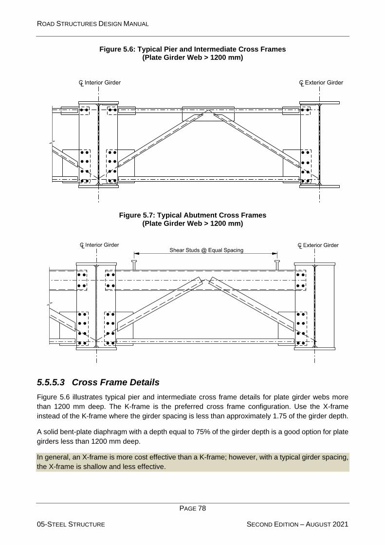
ROAD STRUCTURES DESIGN MANUAL
PAGE 78
05-STEEL STRUCTURE SECOND EDITION – AUGUST 2021
Figure 5.6: Typical Pier and Intermediate Cross Frames (Plate Girder Web > 1200 mm)
Figure 5.7: Typical Abutment Cross Frames (Plate Girder Web > 1200 mm)
5.5.5.3 Cross Frame Details
Figure 5.6 illustrates typical pier and intermediate cross frame details for plate girder webs more
than 1200 mm deep. The K-frame is the preferred cross frame configuration. Use the X-frame
instead of the K-frame where the girder spacing is less than approximately 1.75 of the girder depth.
A solid bent-plate diaphragm with a depth equal to 75% of the girder depth is a good option for plate
girders less than 1200 mm deep.
In general, an X-frame is more cost effective than a K-frame; however, with a typical girder spacing,
the X-frame is shallow and less effective.

ROAD STRUCTURES DESIGN MANUAL
PAGE 79
05-STEEL STRUCTURE SECOND EDITION – AUGUST 2021
Figure 5.7 illustrates the typical abutment cross frame connection details for plate girder webs more
than 1200 mm deep.
The rolled angles that comprise the cross frames are minimum sizes based upon the limiting
slenderness ratios of BDS Articles 6.8.4 and 6.9.3.
Weld the cross-frame transverse connection plates to the compression flange and the tension flange.
Design the welded connections to the flanges to transfer the cross-frame forces into the flanges.
Size the width of connection plates to use bar stock and to be not less than 125 mm. When the
connection plate also acts as a transverse stiffener, meet the requirements of BDS Article 6.10.8.1.
5.5.6 Jacking
Reference: BDS Article 3.4.3
Include a jacking plan in the contract drawings for all bearing-supported structures. Include live load
in the jacking plan for bridges with moderate to high traffic volumes or those with no readily available
detour. The bearing type determines the level of detail shown for the jacking plan.
Include only bearing stiffeners at all points of jacking for plain or reinforced elastomeric bearings.
Provide a conceptual jacking plan showing the jack location and clearances, required factored
reactions, and modifications to cross frames and diaphragms. Also, show conceptual requirements
for falsework and jacking frames if required.
Include a complete jacking plan for high-load multi-rotational, isolation, or other specialty bearings.
The jacking plan must include necessary bearing stiffeners, jack locations and clearances, factored
reactions, and additional modifications to cross frames and diaphragms. Also, include a detailed
design of the jacking frame if required, but do not include its fabrication as part of the contract
documents. Provide only conceptual falsework requirements.
In general, jacking frames will not be required at the supports unless there is insufficient clearance
between the bottom of girder and top of cap to place a jack. If less than 175 mm of clearance for the
jack, determine if the jack can be supported by temporary falsework. If temporary falsework is not
feasible, provide details for a jacking frame or widen the cap and place the bearings on pedestals to
provide sufficient space for a jack placed under the girder.
Other locations where jacking may be required are:
• At supports under expansion joints where joint leakage could deteriorate the bearing areas
of the girders; and
• At expansion bearings with large displacements where deformation-induced wear-and-tear
is possible.
If no jacking frame is provided, design the cross frame at the support to transfer lateral wind and
seismic forces to the bearings.
5.5.7 Lateral Bracing
Reference: BDS Article 6.7.5

ROAD STRUCTURES DESIGN MANUAL
PAGE 80
05-STEEL STRUCTURE SECOND EDITION – AUGUST 2021
The BDS requires the evaluation of lateral bracing for all stages of assumed construction
procedures. If the bracing is included in the structural model used to determine force effects, then
design it for all applicable limit states.
Provide temporary lateral bracing between adjacent boxes at ¼ points of spans. Remove after deck
placement.
In general, lateral bracing is not required in the vast majority of steel I-girder bridges (short through
medium spans); however, the bridge designer must check for this. Typical diaphragms and cross
frames transfer lateral loads adequately to eliminate the need for lateral bracing. For tub girders,
internal top lateral bracing is more typical. Tub girders can rack as much as 150 mm in one day due
to the thermal effects of the sun.
BDS Article 4.6.2.7 provides various alternatives relative to lateral wind distribution in multi-girder
bridges.
5.5.8 Inspection Access (Tub Girders)
Detail all steel tub girder bridges with access openings to allow inspection of the girder interior. Do
not locate access openings over travel lanes or railroad tracks and, preferably, not over shoulders
or maintenance roads. Locate the openings such that the general public cannot gain easy entrance.
Provide access openings in the bottom flange plate of all steel tub girders. Provide one access
opening at each end of the bridge when the total span length is 30 m or more.
Connect access plates to the bottom flange with high-strength bolts. If the general public has access
to the openings, provide bolts with special head configurations. The dimensions of the access
opening is a minimum 800 mm 800 mm square.
5.6 I-Sections in Flexure
Reference: BDS Article 6.10
5.6.1 General
Reference: BDS Article 6.10.1
5.6.1.1 Positive-Moment Region Maximum-Moment Section
For a compositely designed girder, consider the positive-moment region maximum-moment section
as compact in the final condition.
The cured concrete deck in the positive-moment region provides a large compression flange, and it
laterally braces the top flange. Very little, if any, of the web is in compression.
Top Flange
The Strength limit state during construction when the concrete is not fully cured governs the design
of the top flange in the positive-moment region as specified in BDS Article 6.10.3.4.
In the final condition after the deck has cured, the top flange adds little to the resistance of the cross
section. During curing of the concrete deck, however, the top flange is very important.

ROAD STRUCTURES DESIGN MANUAL
PAGE 81
05-STEEL STRUCTURE SECOND EDITION – AUGUST 2021
Bottom Flange (Tension Flange)
The Service II load combination permanent deformation provisions of BDS Article 6.10.4.2 govern.
The bottom flange, if properly proportioned, is not governed by the construction phase. The bottom
flange is governed by the final condition.
5.6.1.2 Negative-Moment Region Pier Section
Both top and bottom flanges in the negative moment region are governed by the Strength limit state
in the final condition. Furthermore, the bottom flange in compression is governed by the location of
the first intermediate diaphragm off the pier because it provides the discrete bracing for the flange.
The negative-moment region pier section is likely a non-compact section during all conditions. The
concrete deck over the pier is in tension in the negative-moment region and, thus, considered
cracked and ineffective at the nominal resistance (i.e. ultimate). Thus, a good portion of the steel
cross section is in compression. To qualify as compact, the web usually needs to be too thick to be
cost effective. Thus, the cost-effective section is typically a non-compact section.
5.6.1.3 Rigidity in Negative-Moment Regions
Reference: BDS Articles 6.10.1.5 and 6.10.1.7
BDS Article 6.10.1.5 permits the assumption of uncracked concrete in the negative-moment regions
for member stiffness. Use this stiffness to obtain continuity moments due to live load, future wearing
surface, and barrier weights placed on the composite section.
For the Service limit state control of permanent deflections under BDS Article 6.10.4.2 and the
Fatigue limit state under BDS Article 6.6.1.2, consider the concrete slab fully effective for both
positive and negative moments for members with shear connectors throughout the full lengths and
satisfying BDS Article 6.10.1.7.
5.6.2 Shear Connectors
Reference: BDS Article 6.10.10
The preferred size for shear studs for use on the flanges of girders and girders is a 22-mm diameter
by 125 mm; the minimum is a 20-mm diameter by 125 mm. The minimum number of studs in a group
is three in a single transverse row. Skew the studs parallel to the bottom slab reinforcing steel.
Increase the stud length in 25 mm increments when necessary to maintain a 50-mm minimum
penetration of the stud into the deck slab. Detail studs placed on relatively thin elements (e.g. girder
webs) as 19 mm diameter.
5.6.3 Stiffeners
Reference: BDS Article 6.10.11
5.6.3.1 Transverse Intermediate Stiffeners
Reference: BDS Article 6.10.11.1

ROAD STRUCTURES DESIGN MANUAL
PAGE 82
05-STEEL STRUCTURE SECOND EDITION – AUGUST 2021
Design straight girders without intermediate transverse stiffeners, if economical, or with intermediate
transverse stiffeners placed on one side of the web plate. If stiffeners are required, fascia girders
typically only have stiffeners on the inside face of the web for aesthetics.
Due to the labour intensity of welding stiffeners to the web, the unit cost of stiffener by weight is
approximately nine times that of the unit cost of the web by weight. It is seldom economical to use
the thinnest web plate permitted; therefore, investigate the use of a thicker web and fewer
intermediate transverse stiffeners or no intermediate stiffeners. If the bridge designer uses a design
that requires stiffeners, the preferred width of the stiffener is one that can be cut from commercially
produced bar stock.
Weld intermediate transverse stiffeners near side and far side to the compression flange. Do not
weld transverse stiffeners to tension flanges. The distance between the end of the web-to-stiffener
weld and the near toe of the web-to-flange fillet weld is between 4tw and 6tw.
Place transverse stiffeners, except when used as diaphragm or cross frame connections, on only
one side of the web.
Orient transverse intermediate stiffeners normal to the web. However, where the angle of crossing
is between 70 and 90, skew the stiffeners so that the diaphragms of cross frames may be
connected directly to the stiffeners.
Avoid longitudinal stiffeners. If used in conjunction with transverse stiffeners on spans with deeper
webs, place these preferably on the opposite side of the web from the transverse stiffener. Where
this is not practical (e.g. at intersections with cross frame connection plates), make the longitudinal
stiffener continuous. Do not interrupt the longitudinal stiffener for the transverse stiffener.
5.6.3.2 Bearing Stiffeners
Reference: BDS Article 6.10.11.2
Provide bearing stiffeners for all plate girders to prevent the possibility of web buckling at temporary
supports. They only require placement on one side and, for fascia girders, place on the inside.
Provide bearing stiffeners at the bearing points of rolled beams and plate girders. Design bearing
stiffeners at integral abutments for dead and construction loads only.
Design the bearing stiffeners as columns and extend the stiffeners to the outer edges of the bottom
flange plates. Use an effective column length of ¾ of the web depth.
The BDS does not specify an effective column length for the design of bearing stiffeners. The
reaction load applied at one end of the stiffener pair is resisted by forces distributed to the web
instead of by a force concentrated at the opposite end, as in columns. Therefore, it is not necessary
to consider the stiffeners as an end-hinged column even where the flanges are free to rotate.
Design the weld connecting the bearing stiffener to the web to transmit the full bearing force from
the stiffener to the web due to the factored loads.
Detail bearing stiffeners with the stiffener ends bearing on the loaded flange being milled to bear, or
weld with a full-penetration butt weld. The opposite end is tight fit only to the flange. Where bearing

ROAD STRUCTURES DESIGN MANUAL
PAGE 83
05-STEEL STRUCTURE SECOND EDITION – AUGUST 2021
stiffeners are also used as diaphragm or cross frame connection plates, fillet weld the stiffeners to
the girder flanges if they are milled to bear or tight fit.
5.6.4 Deck-Overhang Cantilever Brackets
Reference: BDS Article 6.10.3
During construction, the deck overhang brackets may induce twist in the exterior girder. Include in
the contract documents the requirement for the contractor to check the twist of the exterior girder
and bearing of the overhang bracket on the web. See Figure 5.8.
Figure 5.8: Schematic of Location for Deck Overhang Bracket
5.7 Connections and Splices
Reference: BDS Article 6.13
5.7.1 Bolted Connections
Reference: BDS Article 6.13.2
The following applies to bolted connections:
1. Type. For painted steel, use 22 mm A325M (Type 1) bolts. For unpainted weathering steel,
use A325M (Type 3) bolts.
2. Design. Design all bolted connections as slip-critical at the Service II limit state, except for
secondary bracing members.
3. Slip Resistance. BDS Table 6.13.2.8-3 provides values for the surface condition. Use Class
B surface condition for the design of slip-critical connections. Class B is applicable to
unpainted, blast-cleaned surfaces and to blast-cleaned surfaces with a Class B coating. Test
all specified coatings to ensure a slip resistance equal to or exceeding Class B. Paint the
faying surfaces of all slip-critical connections with the prime coat of the approved paint
systems.
ROAD STRUCTURES DESIGN MANUAL
PAGE 84
05-STEEL STRUCTURE SECOND EDITION – AUGUST 2021
5.7.2 Welded Connections
Reference: BDS Article 6.13.3
5.7.2.1 Welding Process
The governing specification for welding is the ANSI/AASHTO/AWS Bridge Welding Code D1.5 (19).
However, this specification does not provide control over all of the welding issues that may arise on
a project. As needed, consult additional reference specifications:
• AWS D1.1 (20) for welding of tubular members and strengthening or repair of existing
structures, and
• AWS D1.4 (21) if the welding of reinforcing steel must be covered by a specification.
5.7.2.2 Field Welding
Do not permit field welding except for all but a few special applications. The permissible applications
are welded splices for piles, connecting pile tips to piles, bearing plates to bottom flange plates, and
connector plates between new and existing portions of widened bridges at ends of simply supported
spans (though bolted connections are preferred for this application).
5.7.2.3 Design of Welds
The maximum weld size for a single-pass fillet weld applicable to all weld types is 8 mm. The AWS
D1.1 Structural Welding Code (20), Table 3.7, provides more specific maximum single-pass fillet-
weld sizes for various welding processes and positions of welding. Design the weld economically,
but its size is not typically less than 6 mm and, in no case, less than the requirements of BDS Article
6.13.3.4 for the thicker of the two parts joined. Show the weld terminations.
The following types of welds are prohibited:
• field-welded splices,
• intersecting welds,
• intermittent fillet welds (except for the connection of stop bars at expansion joints), and
• partial penetration groove welds (except for the connection of tubular members in hand rails).
Provide careful attention to the accessibility of welded joints. Provide sufficient clearance to place a
welding rod at the joint. Often, a large-scale sketch or an isometric drawing of the joint will reveal
difficulties in welding or where critical weld stresses must be investigated.
The design of fillet welds is integral to BDS Section 6 on steel design. The BDS addresses topics
such as resistance factors for welds, minimum weld size, and weld details to reduce fatigue
susceptibility.
The weld-strength calculations of the BDS assume that the strength of a welded connection is
dependent only on the weld metal strength and the area of the weld. Weld metal strength is a self-
defining term. The area of the weld that resists load is a product of the theoretical throat multiplied
by the length. The theoretical weld throat is the minimum distance from the root of the weld to its

ROAD STRUCTURES DESIGN MANUAL
PAGE 85
05-STEEL STRUCTURE SECOND EDITION – AUGUST 2021
theoretical face. Fillet welds resist load through shear on the throat, while groove welds resist load
through tension, compression, or shear depending upon the application.
Preferably, only show the type and sizes of the weld required and leave the details to the fabricator.
When considering design options, note that the most significant factor in the cost of a weld is the
volume of the weld material deposited. Over specifying a welded joint is unnecessary and
uneconomical. A single-pass weld is one made by laying a single weld bead in a single move of the
welder along the joint. A multiple-pass weld is one in which several beads are laid one upon the
other in multiple moves along the joint. Welds sized for a single pass are preferred because these
are more economical and least susceptible to resultant flaws.
5.7.3 Splices
Reference: BDS Article 6.13.6
5.7.3.1 Shop Splices
In addition to the provisions of BDS Article 6.13.6, the following applies to splices:
1. Location. Numerous groove welds and/or groove welds located in high stress regions are not
desirable. Locate flange shop splices away from high moment regions and web splices away
from high shear regions.
This is simple for flange splices in negative moment regions but more difficult with positive
moment regions. In positive moment areas, the magnitude of moment does not change
quickly along the girder compared to the negative moment. As such, locate shop splices on
longer span bridges in high positive moment regions.
The location of shop groove splices is normally dependent upon the length of plate available
to the fabricator. This length varies depending upon the rolling process. Fifteen meters is the
maximum length of plates that are normalized, quenched, and tempered (485 HPS). Other
plates (e.g. Grades 250 and 345) can be obtained in lengths greater than 25 m depending
on thickness. Consider the cost of adding a shop-welded splice instead of extending a thicker
plate when designing members.
2. Welded Shop Splice.
3. Figure 5-9 illustrates a welded flange splice. At flange splices, the thinner plate is not less
than one-half the thickness of the thicker plate.

ROAD STRUCTURES DESIGN MANUAL
PAGE 86
05-STEEL STRUCTURE SECOND EDITION – AUGUST 2021
Figure 5.9: Typical Welded Splice Details
See BDS Article 6.13.6.2 for more information on splicing different thicknesses of material
using butt welds.
5.7.3.2 Field Splices
In addition to the provisions of BDS Article 6.13.6, the following applies to field splices:
1. Type. Use bolted field splices only. In exceptional cases, welded splices may be used subject
to client’s approval.
2. Location. In general, locate field splices in main girders at low-stress areas and near the
points of dead-load contraflexure for continuous spans. Long spans may require that field
splices be located in high moment areas.
3. Bolts. Calculate design loads for bolts by an elastic method of analysis. Provide at least two
lines of bolts on each side of the web splice.
4. Design. Design bolted splices to satisfy both the slip-critical criteria under Service II loads
and the bearing-type connection criteria under the appropriate Strength limit states.
5. Swept Width (or Shipping Width) for Curved Girders. Locate field splices such that the
maximum swept width for a horizontally curved girder is 3 m within a single field section.
The swept width is the horizontal sweep in a curved girder plus its flange width.

ROAD STRUCTURES DESIGN MANUAL
PAGE 87
06-DECK AND DECK SYSTEM SECOND EDITION – AUGUST 2021
6 DECKS AND DECK SYSTEMS
Sections 3, 4, 5, 6, and 9 of the BDS present the AASHTO criteria for the structural design of bridge
decks. Section 3 specifies loads for decks and deck systems, Section 4 specifies their analyses, and
Section 9 specifies their resistance. Unless noted otherwise in this Chapter, BDS applies to the
design of decks.
This Chapter documents criteria on the design of concrete bridge decks constructed compositely in
conjunction with concrete and steel girders and top slabs of cast-in-situ, post-tensioned box girders.
The - Drainage Manual presents the requirements for bridge deck drainage.
6.1 Concrete Decks
6.1.1 Protection of Reinforcing Steel
Reference: BDS Articles 2.5.2.1 and 5.12
Protect the concrete bridge deck top surface against chloride ingress by a waterproofing as specified
in Section 4.4.1. Provide access for a possible future connection to a cathodic protection system. In
addition, for all concrete for deck slabs, approach slabs, and barrier rails, use a high-performance
concrete having a low water/cement ratio and low permeability.
Other methods are available to protect the reinforcing steel in concrete decks and to retard the rate
of corrosion. The bridge designer may occasionally use some of these methods to protect reinforcing
steel in concrete decks.
6.1.2 Empirical Design
Reference: BDS Article 9.7.2
Design all concrete decks that satisfy the requirements of BDS Article 9.7.2.2 in accordance with the
empirical-deck design provisions of BDS Article 9.7.2. Detail the reinforcement as specified in BDS
Article 9.7.2.5, except that the minimum amount of reinforcement is 860 mm2/m of steel for each
bottom layer and 573 mm2/m of steel for each top layer in lieu of the amounts of steel reinforcement
specified in the BDS.
The minimum amount of reinforcement specified in the BDS is increased to reflect the heavier
design live loads specified for the UAE.
6.1.3 Traditional Design Using the “Strip Method”
Reference: BDS Articles 9.7.3, 4.6.2.1.1, 4.6.2.1.3, and Appendix A4
Use BDS Table A4-1 to design the concrete deck reinforcement where the provisions of BDS Article
9.7.2.2 are not satisfied. Use a 215-kN axle instead of the 142-kN axle specified in the BDS.
Therefore, multiply the design moments shown in BDS Table A4-1 by 1.5.
BDS Table A4-1 tabulates the resultant live-load moments per unit width for slab steel design as a
function of the girder or web spacing, S. The Table distinguishes between negative moments and
positive moments and tabulates these for various design sections as a function of the distance from

ROAD STRUCTURES DESIGN MANUAL
PAGE 88
06-DECK AND DECK SYSTEM SECOND EDITION – AUGUST 2021
the girder or web centreline to the design section. BDS Article 4.6.2.1.6 specifies the design sections
for use.
6.1.4 Precast Concrete Deck Panels
The bridge designer may use precast bridge deck panels in lieu of a cast-in-situ concrete deck to
reduce bridge closure times for deck replacements or new bridge construction. Use grout to fill the
haunch between the top of the girder and the bottom of the deck panel, plus the horizontal shear
connector pockets and the panel-to-panel joints.
Design horizontal shear connectors for precast deck panels using the cohesion and friction factors
for a clean concrete surface, free of laitance, as specified in BDS Article 5.8.4.3 when extended
reinforcing bars are used as shear connectors. If a welded shear stud detail is used, design the
connections for strength using the cohesion and friction factors for concrete anchored to as-rolled
structural steel by headed studs, or use reinforcing bars where all steel in contact with concrete is
clean and free of paint. Also, check the studs for fatigue in accordance with Section 5 of the BDS.
Specify a smooth bottom surface on precast deck panels along the girder lines.
Based on research, no significant increase in strength is observed when the aggregate on the bottom
slab surface is exposed.
6.2 Metal Decks
6.2.1 Grid Decks
Reference: BDS Article 9.8.2
Use partially filled steel grid decks for redecking where the dead load of a concrete deck cannot be
tolerated due to deterioration of the girders and where an orthotropic deck is not cost effective.
Partially filled steel grid decks are also an alternative for moveable bridges where the deck weight is
an issue.
Do not use unfilled steel grid decks or fully-filled steel grid decks.
Unfilled grid decks exhibit poor fatigue resistance. The additional fill of a fully filled grid decks offers
no additional benefit.
6.2.2 Orthotropic Steel Decks
Reference: BDS Article 9.8.3
Investigate the fatigue limit state using the Level 3 design of BDS Article 9.8.3.4.
Three design levels are available in BDS Article 9.8.3.4. The preferred method is the more rigorous
Level 3 design of BDS Article 9.8.3.4.4 employing refined three-dimensional analysis.
Table 6.1 summarizes the limits for panel detailing proportions.
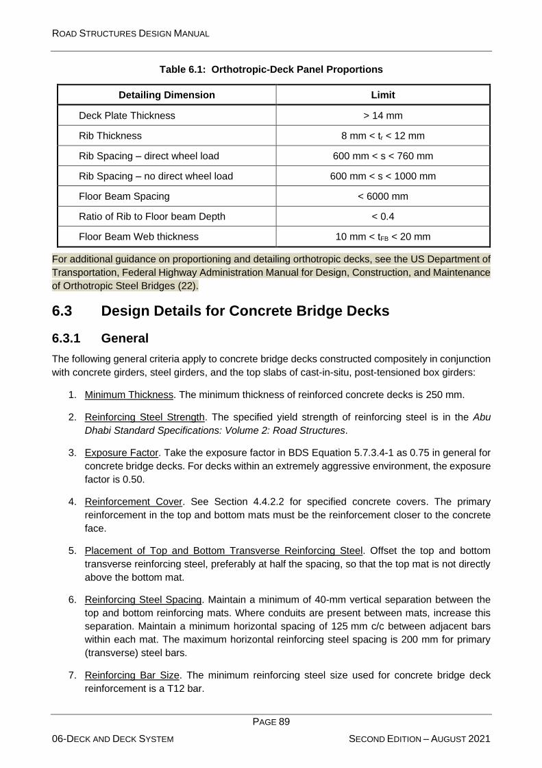
ROAD STRUCTURES DESIGN MANUAL
PAGE 89
06-DECK AND DECK SYSTEM SECOND EDITION – AUGUST 2021
Table 6.1: Orthotropic-Deck Panel Proportions
Detailing Dimension Limit
Deck Plate Thickness > 14 mm
Rib Thickness 8 mm < tr < 12 mm
Rib Spacing – direct wheel load 600 mm < s < 760 mm
Rib Spacing – no direct wheel load 600 mm < s < 1000 mm
Floor Beam Spacing < 6000 mm
Ratio of Rib to Floor beam Depth < 0.4
Floor Beam Web thickness 10 mm < tFB < 20 mm
For additional guidance on proportioning and detailing orthotropic decks, see the US Department of
Transportation, Federal Highway Administration Manual for Design, Construction, and Maintenance
of Orthotropic Steel Bridges (22).
6.3 Design Details for Concrete Bridge Decks
6.3.1 General
The following general criteria apply to concrete bridge decks constructed compositely in conjunction
with concrete girders, steel girders, and the top slabs of cast-in-situ, post-tensioned box girders:
1. Minimum Thickness. The minimum thickness of reinforced concrete decks is 250 mm.
2. Reinforcing Steel Strength. The specified yield strength of reinforcing steel is in the Abu
Dhabi Standard Specifications: Volume 2: Road Structures.
3. Exposure Factor. Take the exposure factor in BDS Equation 5.7.3.4-1 as 0.75 in general for
concrete bridge decks. For decks within an extremely aggressive environment, the exposure
factor is 0.50.
4. Reinforcement Cover. See Section 4.4.2.2 for specified concrete covers. The primary
reinforcement in the top and bottom mats must be the reinforcement closer to the concrete
face.
5. Placement of Top and Bottom Transverse Reinforcing Steel. Offset the top and bottom
transverse reinforcing steel, preferably at half the spacing, so that the top mat is not directly
above the bottom mat.
6. Reinforcing Steel Spacing. Maintain a minimum of 40-mm vertical separation between the
top and bottom reinforcing mats. Where conduits are present between mats, increase this
separation. Maintain a minimum horizontal spacing of 125 mm c/c between adjacent bars
within each mat. The maximum horizontal reinforcing steel spacing is 200 mm for primary
(transverse) steel bars.
7. Reinforcing Bar Size. The minimum reinforcing steel size used for concrete bridge deck
reinforcement is a T12 bar.

ROAD STRUCTURES DESIGN MANUAL
PAGE 90
06-DECK AND DECK SYSTEM SECOND EDITION – AUGUST 2021
8. Asphaltic Wearing Surface. Consider 110 mm of asphaltic wearing surface with a unit weight
of 23 kN/m3.
9. Length of Reinforcement Steel. For detailing, the maximum length of reinforcing steel in the
concrete deck is 12 m.
10. Placement of Transverse Reinforcing Steel on Skewed Bridges. The following applies:
a. Skews 25°: Place the transverse reinforcing steel parallel to the skew.
b. Skews > 25°: Place the transverse reinforcing steel perpendicular to the longitudinal
reinforcement.
See Section 6.3.4 for a definition of skew angle and for structural considerations related to
skewed reinforcing steel placement.
11. Splices/Connectors. Use lap splices for concrete deck reinforcement unless special
circumstances exist. Use mechanical connectors where clearance problems exist or on a
phased-construction project that precludes the use of lap splices. See Chapter 4 for more
discussion on splices.
Lap transverse slab reinforcement, if necessary, as follows: Negative moment steel in the
positive-moment region between the slab supports and positive moment steel in the
negative-moment region over the slab supports.
12. Shear Connectors for Concrete Girder Bridges. Extend stirrups from the girders into the
concrete slab to provide a composite section. Detail bars to hook around longitudinal
concrete deck reinforcement.
6.3.2 Detailing Requirements for Concrete-Deck Haunches
6.3.2.1 General
Provide haunches (i.e. concrete between the top of a steel flange or concrete girder and the bottom
of the concrete bridge deck) to account for construction variations and tolerances. The haunch varies
across the width of the flange due to cross slope, the length of the girder due to flange thickness,
camber variation, and profile. In all cases, however, use a minimum of a 15-mm haunch.
Include the girder haunch in the load calculations as dead load by applying the maximum haunch
dimension throughout the span. Ignore the haunch, however, in the calculation of the section’s
resistance.
Measure the control dimension “Y” at the centreline of bearing.
The control dimension varies along the span to compensate for variations in camber and super
elevation ordinate. In some cases where vertical curve corrections are small, the vertical curve
ordinate can be accommodated in the haunch without including it in the girder.
Detail the haunch flush with the vertical edge of the top flange.

ROAD STRUCTURES DESIGN MANUAL
PAGE 91
06-DECK AND DECK SYSTEM SECOND EDITION – AUGUST 2021
6.3.2.2 Haunch Dimensions for Steel Girders
Figure 6.1 illustrates the controlling factors used to determine the haunch dimension for steel plate
girders. Figure 6.2 illustrates a steel rolled beam. For plate girders, the control dimension “Y” is the
deck thickness “T” plus a dimension “X”. “X” is the greater of 50 mm plus the thickest top flange, or
75 mm.
Figure 6.1: Haunch Dimension for Steel Plate Girders
Figure 6.2: Haunch Dimension for Steel Rolled Beams
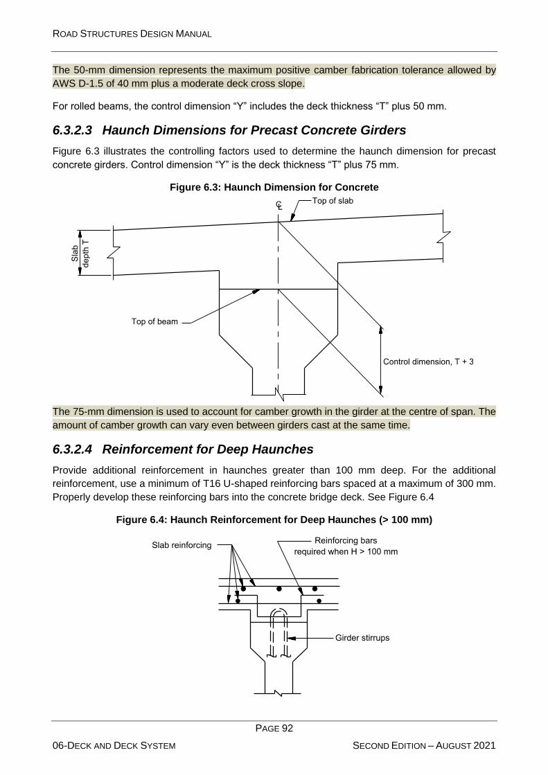
ROAD STRUCTURES DESIGN MANUAL
PAGE 92
06-DECK AND DECK SYSTEM SECOND EDITION – AUGUST 2021
The 50-mm dimension represents the maximum positive camber fabrication tolerance allowed by
AWS D-1.5 of 40 mm plus a moderate deck cross slope.
For rolled beams, the control dimension “Y” includes the deck thickness “T” plus 50 mm.
6.3.2.3 Haunch Dimensions for Precast Concrete Girders
Figure 6.3 illustrates the controlling factors used to determine the haunch dimension for precast
concrete girders. Control dimension “Y” is the deck thickness “T” plus 75 mm.
Figure 6.3: Haunch Dimension for Concrete
The 75-mm dimension is used to account for camber growth in the girder at the centre of span. The
amount of camber growth can vary even between girders cast at the same time.
6.3.2.4 Reinforcement for Deep Haunches
Provide additional reinforcement in haunches greater than 100 mm deep. For the additional
reinforcement, use a minimum of T16 U-shaped reinforcing bars spaced at a maximum of 300 mm.
Properly develop these reinforcing bars into the concrete bridge deck. See Figure 6.4
Figure 6.4: Haunch Reinforcement for Deep Haunches (> 100 mm)

ROAD STRUCTURES DESIGN MANUAL
PAGE 93
06-DECK AND DECK SYSTEM SECOND EDITION – AUGUST 2021
6.3.3 Reinforcing Steel Over Intermediate Piers or Bents
When cast-in-situ slabs are composite with simple span concrete beams, and are cast continuous
over intermediate piers or bents, provide supplemental longitudinal reinforcing in the tops of slabs.
Size, space, and place reinforcing bars in accordance with the following criteria:
1. T16 bars placed between the continuous, longitudinal reinforcing bars.
2. A minimum of 12 m in length or ⅔ of the average span length, whichever is less.
3. Placed symmetrically about the centreline of the pier or bent, with alternating bars staggered
1.5 m.
6.3.4 Minimum Negative Flexure Slab Reinforcement
Reference: BDS Article 6.10.1.7
Any location where the top of the slab is in tension under any combination of dead load and live load
is considered a negative flexural region.
6.3.5 Crack Control in Continuous Decks
Reference: BDS Article 5.10.8
To minimize shrinkage and deflection cracking in cast-in-situ decks, develop a designated deck
casting sequence for continuous flat slab and beam/girder superstructures and simple span
beam/girder superstructures with continuous decks. Indicate on the plans the sequence and
direction of each deck pour to minimize cracking in the freshly poured concrete and previously cast
sections of deck. Provide construction joints as required to limit the volume of concrete cast in a
given pour to between 153 m3 and 305 m3.
For simple span and continuous steel beam/girder superstructures, develop camber diagrams
considering the deck casting sequence and the effect on the changing cross section characteristics
of the superstructure. For continuous superstructures, the sequence results in construction joints
spaced approximately at locations of the points of dead load moment contraflexure. On continuous
superstructures, check longitudinal tension stresses in previously cast sections of the deck during
deck casting sequence per BDS Article 6.10.3.2.4. On the plans, state that a minimum of 72 hours
is required between pours in a given continuous unit. When developing casting sequences and
camber diagrams, use the appropriate concrete strength based on the day the structure is being
analysed.
Generally, for continuous steel girder superstructures, all of the positive moment sections of the deck
are cast first, followed by the negative moment sections.
For continuous concrete beam/girder superstructures, develop build-up diagrams considering the
deck casting sequence, time dependent effects, and the effect on the changing cross section
characteristics of the superstructure. The sequence results in construction joints spaced
approximately at locations of the points of dead load moment contraflexure. On the plans, state that
a minimum of 72 hours is required between pours in a given continuous unit
.
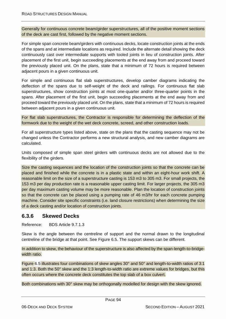
ROAD STRUCTURES DESIGN MANUAL
PAGE 94
06-DECK AND DECK SYSTEM SECOND EDITION – AUGUST 2021
Generally for continuous concrete beam/girder superstructures, all of the positive moment sections
of the deck are cast first, followed by the negative moment sections.
For simple span concrete beam/girders with continuous decks, locate construction joints at the ends
of the spans and at intermediate locations as required. Include the alternate detail showing the deck
continuously cast over intermediate supports with tooled joints in lieu of construction joints. After
placement of the first unit, begin succeeding placements at the end away from and proceed toward
the previously placed unit. On the plans, state that a minimum of 72 hours is required between
adjacent pours in a given continuous unit.
For simple and continuous flat slab superstructures, develop camber diagrams indicating the
deflection of the spans due to self-weight of the deck and railings. For continuous flat slab
superstructures, show construction joints at most one-quarter and/or three-quarter points in the
spans. After placement of the first unit, begin succeeding placements at the end away from and
proceed toward the previously placed unit. On the plans, state that a minimum of 72 hours is required
between adjacent pours in a given continuous unit.
For flat slab superstructures, the Contractor is responsible for determining the deflection of the
formwork due to the weight of the wet deck concrete, screed, and other construction loads.
For all superstructure types listed above, state on the plans that the casting sequence may not be
changed unless the Contractor performs a new structural analysis, and new camber diagrams are
calculated.
Units composed of simple span steel girders with continuous decks are not allowed due to the
flexibility of the girders.
Size the casting sequences and the location of the construction joints so that the concrete can be
placed and finished while the concrete is in a plastic state and within an eight-hour work shift. A
reasonable limit on the size of a superstructure casting is 153 m3 to 305 m3. For small projects, the
153 m3 per day production rate is a reasonable upper casting limit. For larger projects, the 305 m3
per day maximum casting volume may be more reasonable. Plan the location of construction joints
so that the concrete can be placed using a pumping rate of 46 m3/hr for each concrete pumping
machine. Consider site specific constraints (i.e. land closure restrictions) when determining the size
of a deck casting and/or location of construction joints.
6.3.6 Skewed Decks
Reference: BDS Article 9.7.1.3
Skew is the angle between the centreline of support and the normal drawn to the longitudinal
centreline of the bridge at that point. See Figure 6.5. The support skews can be different.
In addition to skew, the behaviour of the superstructure is also affected by the span-length-to-bridge-
width ratio.
Figure 6.5 illustrates four combinations of skew angles 30° and 50° and length-to-width ratios of 3:1
and 1:3. Both the 50° skew and the 1:3 length-to-width ratio are extreme values for bridges, but this
often occurs where the concrete deck constitutes the top slab of a box culvert.
Both combinations with 30° skew may be orthogonally modelled for design with the skew ignored.
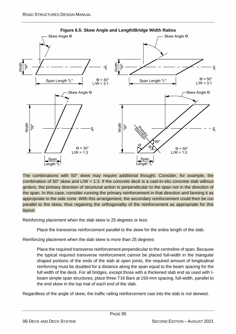
ROAD STRUCTURES DESIGN MANUAL
PAGE 95
06-DECK AND DECK SYSTEM SECOND EDITION – AUGUST 2021
Figure 6.5: Skew Angle and Length/Bridge Width Ratios
The combinations with 50° skew may require additional thought. Consider, for example, the
combination of 50° skew and L/W = 1:3. If the concrete deck is a cast-in-situ concrete slab without
girders, the primary direction of structural action is perpendicular to the span not in the direction of
the span. In this case, consider running the primary reinforcement in that direction and fanning it as
appropriate in the side zone. With this arrangement, the secondary reinforcement could then be run
parallel to the skew, thus regaining the orthogonality of the reinforcement as appropriate for this
layout.
Reinforcing placement when the slab skew is 25 degrees or less:
Place the transverse reinforcement parallel to the skew for the entire length of the slab.
Reinforcing placement when the slab skew is more than 25 degrees:
Place the required transverse reinforcement perpendicular to the centreline of span. Because
the typical required transverse reinforcement cannot be placed full-width in the triangular
shaped portions of the ends of the slab at open joints, the required amount of longitudinal
reinforcing must be doubled for a distance along the span equal to the beam spacing for the
full width of the deck. For all bridges, except those with a thickened slab end as used with I-
beam simple span structures, place three T16 Bars at 150-mm spacing, full-width, parallel to
the end skew in the top mat of each end of the slab.
Regardless of the angle of skew, the traffic railing reinforcement cast into the slab is not skewed.

ROAD STRUCTURES DESIGN MANUAL
PAGE 96
06-DECK AND DECK SYSTEM SECOND EDITION – AUGUST 2021
6.3.7 Temperature and Shrinkage Reinforcement
For all cast-in-situ decks, design temperature and shrinkage reinforcement per BDS Article 5.10.8,
except do not exceed 300 mm spacing. The minimum bar size is T12.
6.3.8 Thickened Slab End Requirements
For pretensioned simple span I-beam bridges, design the thickened slab end at locations of slab
discontinuity not supported by full depth diaphragms. Do not thicken the slab at intermediate
supports within an I-beam simple span unit where the deck slab is continuous.
6.3.9 Phase Constructed Decks
For decks constructed in phases and on bridge widenings, live load on the existing or previously
constructed portions of the superstructure can induce vibration and deflection into the newly
constructed portion of the superstructure. Evaluate the live load induced effects on deck casting and
curing and minimize these where possible.
Where possible, shift live load away from newly constructed portions of the deck during casting and
curing operations to minimize or eliminate deflection and vibration effects. This can be a significant
issue on long span or flexible superstructures, especially steel superstructures. Coordinate with the
traffic control plans.
6.3.10 Stay-in-Place Forms
Concrete stay-in-place forms can be used with precast concrete girders and steel I-girders. Do not
use stay-in-place forms in bays having longitudinal joints or in concrete deck overhangs.
Apply design loads for stay-in-place forms to all girder bridges.
Clearly state in the “General Notes” for each bridge project, whether or not stay-in-place forms are
permitted for the project and how the design was modified for their use; e.g. dead load allowance.
Composite stay-in-place forms are not permitted.
6.3.11 Concrete Deck Pouring Sequence for Decks Constructed Compositely in Conjunction with Concrete and Steel Girders
Reference: BDS Article 2.5.3
6.3.11.1 Typical Practice
The bridge designer determines the need for a concrete bridge deck pouring sequence based on
factors such as size of pour, configuration of the bridge, potential placement restrictions, direction of
placement, concrete deck tensile stresses, and any other special circumstances that might affect
the concrete bridge deck placement. In addition, provide a concrete deck-pouring schedule for
bridges that have any of the following features:
• continuous bridges,
• bridges with curved or non-parallel deck edges, or
• wide or long single span bridges.

ROAD STRUCTURES DESIGN MANUAL
PAGE 97
06-DECK AND DECK SYSTEM SECOND EDITION – AUGUST 2021
Where required, the bridge designer will present in the contract documents the sequence of placing
concrete in various sections (separated by transverse construction joints) of deck slabs on
continuous spans. Avoid or minimize the dead-load tensile stresses in the slab during concrete
setting to minimize cracking, and arrange the sequence to cause the least disturbance to the portions
placed previously.
For longer span steel girder bridges, the pouring sequence can lock-in stresses far different than
those associated with the instantaneous placement typically assumed in design. Therefore, for these
bridges, consider the pouring sequence in the design of the girders.
Concrete deck placement is uniform and continuous over the full width of the superstructure. The
first pours include the positive-moment regions in all spans. For all deck pours on a longitudinal
gradient of 3% or greater, the direction of pouring is uphill.
Figure 6.6 illustrates a sequence diagram for a sample pour for a continuous girder bridge. For
precast concrete girders, use a minimum of 1 m on each side of the centre of support or 5% of the
span length, whichever is greater.
For precast concrete girders, the cast-in-situ diaphragm over the abutment is cast integrally at the
same time as the concrete deck above it. The negative-moment regions for steel girders extend
between the points of beam dead load contraflexure.
For simple spans, pour the entire concrete deck at once. If this is not practical, pour the deck in a
series of longitudinal strips with closure pours as needed. For steel bridges, investigate potential
differential deflections.
Treat precast concrete girders made continuous for live load and superimposed dead load as a
special case. Pour the concrete deck segment and diaphragm over supports after the mid-span
regions of the deck have been poured as simple-span loads.
End wall concrete in integral abutments is usually cast concurrently with applicable portions of the
superstructure (e.g. bottom slab, web/diaphragm, concrete deck). The contract documents must
indicate the requirements for a special placement sequence.
6.3.11.2 Transverse Construction Joints
Place a transverse construction joint in the end span of concrete bridge decks on steel
superstructures where uplift is a possibility during the deck pour. Where used, place transverse
construction joints parallel to the transverse reinforcing steel. Do not place the joints over field
splices.
A bridge with a relatively short end span (60% or less) when compared to the adjacent interior span
is most likely to produce this form of uplift. Uplift during the deck pour can also occur at the end
supports of curved concrete decks and in superstructures with severe skews.
If analysis using the appropriate permanent load factors of BDS Article 3.4.1 demonstrates that uplift
occurs during concrete deck placement, require a construction joint in the end span and require
placing a portion of the deck first to act as a counterweight.

ROAD STRUCTURES DESIGN MANUAL
PAGE 98
06-DECK AND DECK SYSTEM SECOND EDITION – AUGUST 2021
Figure 6.6: Typical Pour Diagram (Continuous Steel and Precast Girders)
ROAD STRUCTURES DESIGN MANUAL
PAGE 99
06-DECK AND DECK SYSTEM SECOND EDITION – AUGUST 2021
6.3.12 Longitudinal Construction Joints
Longitudinal construction joints in concrete bridge decks can create planes of weakness that can
lead to maintenance problems. In general, do not use longitudinal construction joints, although they
cannot be avoided under certain circumstances (e.g. widenings, phased construction). The following
will apply to longitudinal construction joints:
1. Usage. Do not use longitudinal construction joints on concrete decks having a constant cross
section where the width is less than or equal to approximately 35 m. For deck widths greater
than 35 m (i.e. where the finishing machine span width must exceed 35 m), make provisions
to permit placing the deck in practical widths. Detail either a longitudinal joint or a longitudinal
closure pour, preferably not less than 1 m in width. Locate lap splices in the transverse
reinforcing steel within the longitudinal closure pour.
Such a joint should remain open as long as the construction schedule permits to allow
transverse shrinkage of the deck concrete. Consider the deflections of the bridge on either
side of the closure pour to ensure proper transverse fit.
2. Location. If a longitudinal construction joint is necessary, do not locate it underneath a wheel
line. Preferably, locate construction joints outside the girder flange and in a shoulder or
median area.
3. Closure Pours. For staged construction projects, use a closure pour to connect the slab
between stages. When used, the following apply:
• Do not use stay-in-place forms under the closure pour.
• Do not rigidly connect diaphragms/cross frames in the staging bay of structural steel
girders until after the adjacent stages of the concrete deck have been poured.
Construct concrete diaphragms in the staging bay of prestressed concrete girders
after adjacent portions of the bridge are complete. The diaphragms may be poured
as part of the closure.
• Do not tie or couple reinforcing steel between different stages until after the adjacent
stages of the concrete deck have been poured.
• Support the finishing machine on an overhang jack that is connected to the girder
loaded by the concrete deck pour. Do not place the finishing machine on a previously
poured deck. Indicate in the contract documents that this method of constructing the
closure pour is not allowed. See Figure 6.7.
A closure pour serves two useful purposes: It defers final connection of the stages until after
the deflection from concrete deck slab weight has occurred, and it provides the width needed
to make a smooth transition between differences in final grades that result from construction
tolerances. The closure width relates to the amount of relative dead-load deflection that is
expected to occur across the pour after the closure is placed. Use a minimum closure width
of 1 m.
Greater closure widths may be required when larger relative dead-load deflections are
anticipated. Estimate the required width by considering the closure pour to be a fixed-fixed
beam and by limiting the stresses in the concrete to the cracking stress.

ROAD STRUCTURES DESIGN MANUAL
PAGE 100
06-DECK AND DECK SYSTEM SECOND EDITION – AUGUST 2021
Figure 6.7: Support for Finishing Machine

ROAD STRUCTURES DESIGN MANUAL
PAGE 101
06-DECK AND DECK SYSTEM SECOND EDITION – AUGUST 2021
6.3.13 Longitudinal Concrete Deck Joints
Reference: BDS Article 14.5.1.1
There is not a specified maximum bridge width that can be used without a longitudinal open joint. As
an approximate guide, widths up to 35 m without a joint are usually acceptable. Open longitudinal
joints may be needed where the width of the bridge exceeds 35 m or on multiple-span bridges with
large skews.
Open longitudinal joints, used on slab-on-girder bridges, are not typically needed except on the
widest bridges. The requirement for open longitudinal joints in bridges is based on the bridge width,
skew, and span configuration.
The following applies:
1. Column Design. Use a longitudinal open joint where transverse temperature controls the
column design.
Desirably, the column design is controlled by seismic loads and not other load combinations.
2. Location. Do not place longitudinal open joints over a girder flange. If a longitudinal joint is
used, place the joint in both the superstructure and substructure.
6.3.14 Transverse Edge Beam for Steel Girder Bridges
Reference: BDS Article 9.7.1.4
Provide a transverse edge beam to support wheel loads near the transverse edge of the concrete
deck in conjunction with an end diaphragm for steel girder bridges. See Figure 6.8.
6.3.15 Concrete Deck Overhang/Bridge Rail
Reference: BDS Article 9.7.1.5
6.3.15.1 Overhang Width and Thickness
Concrete bridge deck overhang is the distance between the centreline of the exterior girder to the
outside edge of the deck. The overhang width must not be more than 40% of the girder spacing. The
thickness of the overhang at the outside edge of deck is the same as the interior deck thickness.
The thickness of the overhang at outside edge of girder is the deck thickness plus the haunch depth.
6.3.15.2 Structural/Performance Design
Reference: BDS Articles 13.6.1, 13.6.2, and 13.7.2
Design all combination bridge rail/concrete deck overhang designs to meet the structural design
requirements to sustain rail collision forces in BDS Article A13.2. Use a Class 2 exposure factor in
BDS Equation 5.7.3.4-1 for all bridge rails and deck overhang designs.

ROAD STRUCTURES DESIGN MANUAL
PAGE 102
06-DECK AND DECK SYSTEM SECOND EDITION – AUGUST 2021
Figure 6.8: Transverse Edge Beam

ROAD STRUCTURES DESIGN MANUAL
PAGE 103
06-DECK AND DECK SYSTEM SECOND EDITION – AUGUST 2021
When designing the deck overhang for Extreme Event II, include a vertical wheel load located 300
mm from the face of bridge rail in conjunction with transverse and longitudinal bridge rail loads; do
not apply the wheel load in combination with vertical rail loads. Design the deck overhang using the
rail resistance instead of the rail load. This ensures failure in the rail before the concrete deck
overhang.
Place sidewalks, when used, on the outside edge of bridge decks adjacent to rails. Assume the point
of fixity for the design of the rail at the deck level and not the top of sidewalk.
6.3.15.3 Bridge Barriers
See Chapter 7 “Bridge Rails” of the Abu Dhabi Roadside Design Guide (Document Reference No.
TR-518) for a discussion on bridge rails and transitions to bridge rails.
The following applies to bridge barrier joints:
1. Concrete Bridge Barrier Joints. Provide joints on concrete bridge rails at all locations of
expansion in the bridge; i.e. the joints on the bridge deck and barrier will match. In addition,
provide 50-mm open joints in the barrier, extending from the top of the barrier downward 600
mm, at the mid-span of each span and over supports. Consider additional open joints on
longer spans. Design open joints as discontinuities.
2. Barrier Rail Connection. Extend the expansion joint up into the barrier rail at least 150 mm.
6.4 Approach Slabs
6.4.1 Usage
Provide approach slabs on all bridges. See the Abu Dhabi Standard Drawings for Road Projects
(Document Reference No. TR-541-2).
6.4.2 Design Criteria
Design the roadway ends of approach slabs parallel to the bridge ends. The following design criteria
apply to approach slabs:
1. Analysis. If a special design is used, model the approach slab as a simple span with a span
of L/2.
2. Bridge Approach Joints. Provide a terminal joint or pavement relief joint at the end of the
roadway at the bridge approach slab, if the approaching roadway is concrete.
3. For the purpose of analysis of at-grade approach slab, it may be either partially suspended
or preferably fully supported on equivalent springs to achieve overall economy in design.
4. For approach slab that are buried less than 300mm, provide a flexible joint at the interface of
approach slab edge and fill. Flexible joint in the form of saw-cut filled with approved joint filler
or asphaltic plug joint to absorb any cracks on asphalt surface due to any differential
settlements.

ROAD STRUCTURES DESIGN MANUAL
PAGE 104
07-FOUNDATIONS SECOND EDITION – AUGUST 2021
7 FOUNDATIONS
7.1 General
7.1.1 Scope
A critical consideration for the satisfactory performance of any structure is the proper selection and
design of a foundation that will provide adequate support and addresses constructability
considerations. This Chapter presents criteria that are supplementary to Section 10 of the BDS for
the design of drilled shafts, spread footings, and driven piles. The Chapter is intended for use by the
bridge designer and as a reference for the geotechnical engineer. The Abu Dhabi Geotechnical
Investigation and Design: Part 2: Ground Investigation and Geotechnical Design (Document
Reference No. TR-509) discusses the geotechnical considerations for the design of bridge
foundations.
The structural engineer, with input from the geotechnical and hydraulic engineers, must determine
the structure loads and the pile/shaft section or spread footing configuration. The structural engineer
and the geotechnical engineer must consider constructability in the selection of the foundation
system. Consider issues such as existing underground and overhead utilities, pile-type availability,
availability of construction equipment, phase construction, conflicts with existing piles and structures,
effects on adjacent structures, etc., in evaluating foundation design.
Design all substructures to incorporate bearings or provide fixed connections to the superstructure.
Determine pile and drilled shaft loads and design footings and bent caps using plan pile and drilled
shaft locations. Detail footings and bent caps considering pile driving and drilled shaft placement
tolerances.
7.1.2 Design Methodology
Use the load and resistance factor design (LRFD) methodology for foundations.
The BDS distinguishes between the strength of the in-situ materials (soils and rock strata) supporting
the bridge and the strength of the structural components transmitting force effects to these materials.
Section 10 “Foundations” addresses in-situ materials, and Section 11 “Abutments, Piers, and Walls”
addresses structural components, which is necessitated by the substantial difference in the reliability
of in-situ materials and man-made structures. The foundation provisions of the BDS are essentially
strength design provisions with a primary objective to ensure equal, or close to equal, safety levels
in all similar components against structural failure.
Sections 5 and 6 of the BDS specify requirements for concrete and steel components. Apply the
appropriate provisions from these Sections in the structural design of drilled shafts, footings, and
driven piles.
7.1.3 Bridge Foundation Design Process
To select a foundation type, evaluate the load/structural considerations for the superstructure and
substructure, the geotechnical factors pertaining to the native soils, and site conditions. The following
summarizes the procedure for selecting and designing a bridge foundation type:

ROAD STRUCTURES DESIGN MANUAL
PAGE 105
07-FOUNDATIONS SECOND EDITION – AUGUST 2021
1. Preliminary Structure Layout. The bridge designer obtains preliminary soils information from
the geotechnical engineer to assist with the selection of support locations and span lengths.
Provide preliminary foundation loads to the geotechnical engineer.
2. Scour Potential. For bridges over waterways, the hydraulics engineer evaluates the proposed
bridge site and preliminary structure layout to identify the predicted hydraulic scour based on
material properties provided by the geotechnical engineer. This analysis is provided to both
the bridge designer and the geotechnical engineer.
As part of the subsurface site investigation, the geotechnical engineer provides a geologic or
historic elevation for scour. The hydraulics engineer calculates an anticipated hydraulic scour
depth. The bridge designer in conjunction with the geotechnical engineer and hydraulics
engineer determines a “design” scour for the design of the foundation.
3. Geotechnical Data. For all sites, the geotechnical engineer conducts a site-specific
subsurface investigation and prepares a Geotechnical Report. The geotechnical engineer
provides this Report to the bridge designer.
4. Foundation Type Selection. Based on information provided by the bridge designer (e.g.
structure layout, vertical and lateral loads, settlement criteria), the geotechnical engineer
provides the foundation-type to the bridge designer in the Geotechnical Report.
5. Detailed Structural Design. The bridge designer performs the detailed structural design of
the foundation based on Section 10 of the BDS as modified by Chapter 7 of this Manual in
conjunction with the structural requirements of Sections 5 and 6 of the BDS.
6. Soil Structure Interaction shall be considered according to AASHTO LRFD requirements.
7. The design of MSE walls shall satisfy AASHTO LRFD Section 11.
7.1.4 Bridge Design/Geotechnical Design Interaction
7.1.4.1 Overview
The geotechnical engineer is responsible for developing a subsurface exploration program and
preparing the preliminary geotechnical design and a Geotechnical Report. The bridge designer uses
the information to design bridge foundations and other structures. The successful integration of the
geotechnical design into the bridge design requires close coordination between the geotechnical
engineer and the bridge designer.
Prior to the design of the foundation, the bridge designer must have knowledge of the environmental,
climatic, and loading conditions expected during the life of the proposed unit. The primary function
of the foundation is to spread concentrated loads over a sufficient zone, to provide adequate bearing
resistance and limitation of movement and, when necessary, to transfer loads through unsuitable
foundation strata to suitable strata. Therefore, knowledge of the subsurface soil conditions, ground
water conditions, and scour is necessary.
7.1.4.2 Preliminary Geotechnical Design Data
The geotechnical engineer provides the preliminary geotechnical design data based on existing soil
information and any preliminary subsurface investigation. These general geotechnical data are used
to select the bridge foundation and initiate the preliminary structure design. Use the geotechnical

ROAD STRUCTURES DESIGN MANUAL
PAGE 106
07-FOUNDATIONS SECOND EDITION – AUGUST 2021
information in conjunction with the input of the hydraulics engineer (as applicable) to establish
support locations. Prior to beginning work on preliminary bridge design, the bridge designer reviews
the preliminary geotechnical design information to gain knowledge of the anticipated soil conditions
at the bridge site and the potential general foundation types. The preliminary geotechnical design
data provide a preliminary footing elevation and an expected allowable bearing pressure when
spread footings are used. For deep foundations, the selection will be driven piles or drilled shafts.
Driven piles will include pile capacity and type. Use the preliminary geotechnical information to
estimate sizes of foundation members.
7.1.4.3 Geotechnical Report
Subsurface Exploration
The geotechnical engineer performs a detailed subsurface exploration based on the bridge abutment
and pier locations and anticipated foundation type. The geotechnical engineer determines the
proposed boring locations. Typically, the structural modelling and analysis of the bridge proceed
based on the preliminary geotechnical design while the geotechnical subsurface exploration is
conducted. During this time, the bridge designer assumes a preliminary point-of-fixity or preliminary
footing elevation to model the substructure. The bridge designer determines, verifies, and provides
foundation loads or calculated bearing pressures to the geotechnical engineer. The bridge designer
provides the design loads (vertical and horizontal) at the bottom of substructure units. The bridge
designer also provides the elevation at which the loads or bearing pressures are applied. When the
geotechnical subsurface exploration has been completed, the geotechnical engineer will perform
laboratory testing and geotechnical design. The geotechnical engineer issues a Geotechnical Report
based on the field exploration, laboratory testing, geotechnical design, the preliminary bridge design,
and the loads provided by the bridge designer.
Foundation Design
The bridge designer uses the information provided in the Geotechnical Report to design foundations
for bridges and bridge-related structures. For deep foundations, the Geotechnical Report provides
tip elevations and p-y soil models of the subsurface that are used to perform foundation lateral soil-
structure interaction analyses. The bridge designer then performs the lateral soil-structure interaction
analysis with computer programs such as DFSAP, LPile Plus, or COM624. The bridge designer uses
the information to compute lateral displacements and to analyse the structural adequacy of the
columns and foundations. Use the lateral soil-structure interaction analysis to select the appropriate
method (point-of-fixity, stiffness matrix, linear stiffness springs, or p-y nonlinear springs) to model
the bridge foundation in the structural design software. For spread footings, the Geotechnical Report
provides the estimated footing elevation, allowable bearing pressure, and estimates on settlements
and lateral displacements. The bridge designer uses the information to finalize the design of the
footing and verify that members are not overstressed. Computer programs for lateral soil-structure
interaction analysis require reputable well-tested software.
Seismic Design
For bridges on deep foundations requiring seismic analysis, the bridge designer performs lateral
soil-structure interaction analyses using Extreme Event I loadings. If soil liquefaction is anticipated,
the geotechnical engineer provides the bridge designer with foundation downdrag loads due to
liquefaction for use in developing the Extreme Event I load combination. The geotechnical engineer
also provides any lateral soil forces that act on the foundation as a result of seismically induced

ROAD STRUCTURES DESIGN MANUAL
PAGE 107
07-FOUNDATIONS SECOND EDITION – AUGUST 2021
stability movements of earth retaining structures (e.g. embankments, retaining walls) or lateral soil
movements attributable to lateral spread. Include these additional lateral loads in the Extreme Event
I load combinations when evaluating lateral soil-structure interaction. The geotechnical engineer
generates the p-y soil model of the subsurface that accounts for cyclic loadings and any liquefied
soil conditions. The bridge designer then performs the lateral soil-structure interaction analysis with
computer programs such as DFSAP, LPILE Plus, or COM624. The bridge designer uses this
information to calibrate the seismic model of the structure.
The geotechnical engineer or the contracted geotechnical firm will issue a Geotechnical Report for
most projects. This report will include:
1. detailed soil conditions,
2. foundation type,
3. design parameters,
4. constructability considerations,
5. background information that may assist the structural engineer in determining appropriate
pile lengths,
6. input data for COM624, FBPier, and other design programs when lateral loads are a major
concern,
7. completed FHWA Report Checklist and Guidelines for Review of Geotechnical Reports and
Preliminary Plans and Specifications,
8. core boring drawings reflecting the foundation data acquired from field investigations, and
9. Required load tests.
The geotechnical engineer will obtain local, site-specific foundation construction history.
Geotechnical Reports shall conform to the Abu Dhabi Geotechnical Investigation and Design: Part
2: Ground Investigation and Geotechnical Design (Document Reference No. TR-509) and the FHWA
Report Checklist and Guidelines for Review of Geotechnical Reports and Preliminary Plans and
Specifications prepared by the Geotechnical and Materials Branch, FHWA, Washington, D.C.,
October 1985. Contact the Geotechnical Engineer to receive a copy of this document.
Verify the scope of services, as well as the proposed field and laboratory investigations before
beginning any operations.
7.1.4.4 Foundation Scour Design
This is a multi-discipline effort involving geotechnical, structures, and hydraulics engineers. The
process described below often requires several iterations. The foundation design must satisfactorily
address the various scour conditions, and furnish sufficient information for the Contractor to provide
adequate equipment and construction procedures. These three engineering disciplines have specific
responsibilities in considering scour as a step in the foundation design process.
1. The structures engineer determines the preliminary design configuration of a bridge structure
utilizing all available geotechnical and hydraulic data and performs lateral stability

ROAD STRUCTURES DESIGN MANUAL
PAGE 108
07-FOUNDATIONS SECOND EDITION – AUGUST 2021
evaluations for the applicable loadings (do not impose arbitrary deflection limits except on
movable bridges). A preliminary lateral stability analysis generally occurs during the
predesign phase of the project, and a final evaluation occurs subsequent to the selection of
the final configurations. The structures engineer must apply sound engineering judgment in
comparing results obtained from scour computations with available hydrological, hydraulic,
and geotechnical data to achieve a reasonable and prudent design.
2. The hydraulics engineer provides the worst case scour elevation through a 100-year flood
event (100-Year Scour), a 500-year flood event (500-Year Scour), and for “Long-Term
Scour.”
3. The geotechnical engineer provides the nominal axial (compression and tension)
capacity curves, mechanical properties of the soil, and foundation type based on
construction methods, pile availability, similar nearby projects, site access, etc.
It is not necessary to consider the scour effects on temporary structures.
7.2 Spread Footings and Pile Caps
Reference: BDS Article 10.7
This discussion applies to spread footings supported on soil and to pile caps.
Pile caps distribute loads among two or more drilled shafts or driven piles that support a single
column, group of columns, or walls.
7.2.1 Usage
Spread footings supported on soil are an appropriate foundation type if soils and estimated
settlements allow their use. They are typically only used in the Abu Dhabi Emirate to sometimes
support walls. Spread footings are prohibited:
• at stream crossings where they may be susceptible to scour, and
• on MSE fills.
Spread footings are thick, reinforced concrete members sized to meet the structural and
geotechnical loading requirements for the proposed structural system. A factor affecting the size of
the footing is the structural loading versus the ability of the soil to resist the applied loads.
The Geotechnical Report provides the maximum soil pressures, the minimum footing widths, and
the minimum footing embedment. BDS Table 10.5.5.2.2-1 shall be used for Resistance Factors ().
Determine the factored design load and proportion the footings to provide the most cost effective
design without exceeding the maximum soil pressures. Communicate with the geotechnical engineer
to ensure that the corresponding settlements do not exceed the tolerable limits.
Require dewatering with a note on the plans when in the Geotechnical Report. Dewatering is
required if the seasonal high ground water elevation is higher than 600 mm below the bottom of the
footing.
Verify sliding, overturning, and rotational stability of the footings.

ROAD STRUCTURES DESIGN MANUAL
PAGE 109
07-FOUNDATIONS SECOND EDITION – AUGUST 2021
7.2.2 Dynamic Load Allowance (Impact Modifier, IM)
If a significant portion of the footing is above ground, apply the dynamic load allowance, traditionally
termed Impact Modifier (IM), to the proportioning of footings.
7.2.3 Thickness
Reference: BDS Articles 5.13.3.6 and 5.13.3.7
Use a minimum footing thickness of 600 mm for bridge abutments and piers. Thinner footing
thicknesses may be used to support walls.
The footing or pile cap thickness may be governed by the development length of the column or wall
reinforcement, or by shear requirements. Avoid shear reinforcement in footings or pile caps. If shear
governs the thickness, it is usually more economical to use a thicker footing or pile cap without shear
reinforcement instead of a thinner footing or pile cap with shear reinforcement.
7.2.4 Depth
Reference: BDS Articles 5.8.3, 5.13.3.6, and 5.13.3.8
The following will apply:
1. In Waterways. On soil, locate the top of the spread footing below the design scour depth. On
rock, locate the bottom of the footing 300 mm below the surface of the scour-resistant rock.
2. Minimum Embedment and Bench Depth. Embed spread footings a sufficient depth to provide
the greatest of the following:
• adequate bearing and scour,
• 900 mm to the bottom of footing, or
• 600 mm of cover over the footing.
Locate pile caps above the lowest anticipated scour level if the piles are designed for this condition.
Construct footings to neither pose an obstacle to water traffic nor expose the footing to view during
low flow. Construct footings to pose minimum obstruction to water and debris flow if exposed during
high flows. In all cases, allowance to scour potential must be taken into consideration.
7.2.5 Bearing Resistance and Eccentricity
Reference: BDS Article 10.6.3
Present the required nominal bearing and the geotechnical resistance factor in the Contract
Documents.
7.2.6 Sliding Resistance
Reference: BDS Article 10.6.3.3
Use the coefficients of friction in the BDS for sliding resistance.
Keys in footings to develop passive pressure against sliding are not commonly used for bridges.
When it becomes necessary to use a key, the bridge designer will consult with the geotechnical
engineer.
ROAD STRUCTURES DESIGN MANUAL
PAGE 110
07-FOUNDATIONS SECOND EDITION – AUGUST 2021
7.2.7 Differential Settlement
Reference: Section 2.2.3
7.2.7.1 Typical Practice
Angular distortion is the differential settlement divided by the distance between the adjacent
foundations. The following presents general practices on the acceptable limits for angular distortion:
1. Limiting Angular Distortion. BDS Article C10.5.2.2 states that angular distortions between
adjacent foundations greater than 0.008 radians in simple spans and 0.004 radians in
continuous spans not be ordinarily permitted (Moulton et al., 1985 (23)); DiMillio, 1982 (24);
and Barker et al., 1991 (25).
2. Piers. Consider continuous footings or deep foundations where differential settlement is a
concern between columns within a pier.
Differential settlement (SE) is considered a superstructure load in the BDS. Differential settlement is
the difference between the settlements of two adjacent foundations. Generally, due to the methods
used to proportion foundations, settlements are within a tolerable range and, therefore, force effects
due to differential settlement are not investigated.
7.2.7.2 Effects of Foundation Settlement
If varying conditions exist, the Geotechnical Report will address settlement. Consider the following
effects:
1. Structural. Consider differential settlement in design if deemed significant, especially those
negative movements that may either cause or enlarge existing cracking in concrete deck
slabs.
The differential settlement of substructures causes the development of force effects in
continuous superstructures. The force effects are directly proportional to structural depth and
inversely proportional to span length, indicating a preference for shallow, long-span
structures. They are normally smaller than expected and tend to be reduced in the inelastic
phase.
2. Joint Movements. Consider any change in bridge geometry due to settlement that causes
movement in deck joints in detailing, especially for deep superstructures.
3. Profile Distortion. Excessive differential settlement may cause a distortion of the roadway
profile that may be undesirable for vehicles travelling at high speed.
4. Appearance. Viewing excessive differential settlement may create a feeling of lack of safety.
5. Mitigation. Where necessary, use ground modification techniques to improve the soil to
address differential settlement concerns. The techniques include but are not limited to:
• chemical grouting,
• over-excavation and replacement,
• surcharging,
• the construction of stone columns, and

ROAD STRUCTURES DESIGN MANUAL
PAGE 111
07-FOUNDATIONS SECOND EDITION – AUGUST 2021
• compaction grouting.
7.2.8 Reinforcement
Reference: BDS Articles 5.10.8 and 5.13.3
Chapter 4 discusses practices for the reinforcement of structural concrete. In addition, unless other
design considerations govern, use the following for reinforcement in footings:
1. Steel in Top of Footing. Use the minimum reinforcement in the top of pile caps and spread
footings as required by design.
For pile caps, the anchorage of piles or drilled shafts into footings requires tension
reinforcement in the top of the footing to resist the potential negative bending under seismic
action.
2. Embedment Length. Extend the vertical steel of the footing down to the bottom pile cap or
spread footing steel and hook onto the bottom end regardless of the footing thickness.
3. Spacing. The recommended minimum spacing of reinforcing steel in either direction is 125
mm centre to centre; the recommended maximum spacing is 300 mm centre to centre.
4. Blinding. Where blinding is used, extend the piles through the blinding and 100 mm into the
footing and locate the reinforcement above the top of piling.
5. Other Reinforcement Considerations. BDS Article 5.13.3 specifically addresses concrete
footings. For items not included, the other relevant provisions of Section 5 will govern. For
narrow footings, to which the load is transmitted by walls or wall-like abutments, the critical
moment section is at the face of the wall or abutment stem. The critical shear section is a
distance equal to the larger of “dv” (dv is the effective shear depth of the footing) or “0.5dv cot
“ ( is the angle of inclination of diagonal compressive stresses as defined in BDS Article
5.8.3.4) from the face of the wall or bent stem where the load introduces compression in the
top of the footing section. For other cases, either use BDS Article 5.13.3, or use a two-
dimensional analysis for greater economy of the footing.
7.2.9 Miscellaneous
7.2.9.1 Joints
Footings do not generally require construction joints. Where used, offset footing construction joints
600 mm from expansion joints or construction joints in walls and construct them with 75-mm deep
keyways.
7.2.9.2 Stepped Footings
Stepped footings may be used occasionally. Where used, the difference in elevation of adjacent
stepped footings is not be less than 600 mm. Extend the lower footing at least 600 mm under the
adjacent higher footing.
If high bearing pressures under a spread footing are present, use concrete backfill instead of
granular backfill for support under the upper step. See Figure 7.1. The two footings could be placed
monolithically, if the bearing pressure allows.

ROAD STRUCTURES DESIGN MANUAL
PAGE 112
07-FOUNDATIONS SECOND EDITION – AUGUST 2021
Figure 7.1: Concrete Backfill Under Stepped Footing
7.3 Deep Foundations
7.3.1 General
Attempt to use only one type and size of deep-foundation component (i.e. drilled shaft or driven pile)
throughout a structure.
7.3.2 Component Spacing
Reference: BDS Articles 10.7.3.9 and 10.8.3.6
To determine the minimum spacing of deep-foundation components in a group, obtain the maximum
resistance of the individual components; that is, select the spacing such that the efficiency factor, η,
equals 1.0.
Unless otherwise specified, determine the maximum spacing of deep-foundation components in a
group based upon the stiffness of the cap.
7.3.3 Drilled Shafts
Reference: BDS Article 10.8
7.3.3.1 Usage
Drilled shafts are the most common foundation for road structures. Typical shaft diameters range
from 900 mm to 1500 mm. In general, use drilled shafts to resist large lateral or uplift loads where
deformation tolerances are relatively small.
Drilled shafts derive load resistance either as end-bearing shafts transferring load by tip resistance
or as friction shafts transferring load by side resistance or a combination of both. Friction-only shafts
are the most desirable but may not be the most economical. Drilled shafts are typically good for
seismic applications.
7.3.3.2 Drilled Shaft Axial Compressive Resistance at the Strength
Limit State
Reference: BDS Articles 10.8.3.5.1, 10.8.3.5.2, and 10.8.3.5.4

ROAD STRUCTURES DESIGN MANUAL
PAGE 113
07-FOUNDATIONS SECOND EDITION – AUGUST 2021
The BDS provides procedures to estimate the axial resistance of drilled shafts in cohesive soils and
cohesionless soils in BDS Articles 10.8.3.5.1 and 10.8.3.5.2. In both cases, the resistance is the
sum of the shaft and tip resistances. BDS Article 10.8.3.5.4 discusses the determination of axial
resistance of drilled shafts in rock.
7.3.3.3 Structural Design
Use the following for the design of drilled shafts:
1. Column Design. Even soft soils provide sufficient support to prevent lateral buckling of the
shaft. Therefore, design drilled shafts surrounded by soil according to the criteria for short
columns in BDS Article 5.7.4.4 when soil liquefaction is not anticipated. If the drilled shaft is
extended above ground to form a pier, analyse and design the shaft as a column. Similarly,
consider the effects of scour around the shafts in the analysis.
2. Casing. Consider using a casing to maintain the excavation, especially when placing a shaft
within the water table. Do not consider this casing, if left in place after construction, in the
determination of the structural resistance of the shaft. However, consider the casing when
evaluating the seismic response of the foundation because the casing provides additional
resistance.
3. Lateral Loading. Section 7.3.3.8 discusses the analysis of drilled shafts for lateral loading
and resistance.
7.3.3.4 Design Details
Use the following when designing drilled shafts:
1. Location of Top of Shaft. Terminate drilled shafts 300 mm to 600 mm above the highest
anticipated groundwater table.
2. Edge Distance and Spacing. Locate shafts used in groups such that the distance from the
side of any shaft to the nearest edge of the cap is not less than 400 mm. Shaft spacing can
not exceed four shaft diameters.
3. Reinforcement. Chapter 5 discusses practices for the reinforcement of structural concrete.
Additional reinforcement criteria include:
• The shaft reinforcement is a minimum of 1% of the gross concrete area, and the
reinforcement extends over the entire length of the shaft and into the footing.
• For confinement reinforcement, use spirals (up to T16). For seismic applications,
consider butt-welded hoops.
• Detail drilled shafts and columns to accommodate concrete placement considering the
multiple layers of reinforcing steel including lap splices. Maximize lateral reinforcement
spacing. Use information from “The International Association of Foundation Drilling”
(26).
Figure 7.2 and Figure 7.3 (not recommended) illustrate typical drilled shaft and column
longitudinal and transverse reinforcement for the alternative of a single drill shaft supporting
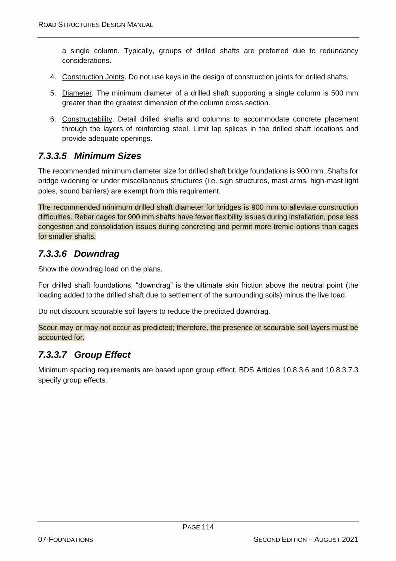
ROAD STRUCTURES DESIGN MANUAL
PAGE 114
07-FOUNDATIONS SECOND EDITION – AUGUST 2021
a single column. Typically, groups of drilled shafts are preferred due to redundancy
considerations.
4. Construction Joints. Do not use keys in the design of construction joints for drilled shafts.
5. Diameter. The minimum diameter of a drilled shaft supporting a single column is 500 mm
greater than the greatest dimension of the column cross section.
6. Constructability. Detail drilled shafts and columns to accommodate concrete placement
through the layers of reinforcing steel. Limit lap splices in the drilled shaft locations and
provide adequate openings.
7.3.3.5 Minimum Sizes
The recommended minimum diameter size for drilled shaft bridge foundations is 900 mm. Shafts for
bridge widening or under miscellaneous structures (i.e. sign structures, mast arms, high-mast light
poles, sound barriers) are exempt from this requirement.
The recommended minimum drilled shaft diameter for bridges is 900 mm to alleviate construction
difficulties. Rebar cages for 900 mm shafts have fewer flexibility issues during installation, pose less
congestion and consolidation issues during concreting and permit more tremie options than cages
for smaller shafts.
7.3.3.6 Downdrag
Show the downdrag load on the plans.
For drilled shaft foundations, “downdrag” is the ultimate skin friction above the neutral point (the
loading added to the drilled shaft due to settlement of the surrounding soils) minus the live load.
Do not discount scourable soil layers to reduce the predicted downdrag.
Scour may or may not occur as predicted; therefore, the presence of scourable soil layers must be
accounted for.
7.3.3.7 Group Effect
Minimum spacing requirements are based upon group effect. BDS Articles 10.8.3.6 and 10.8.3.7.3
specify group effects.
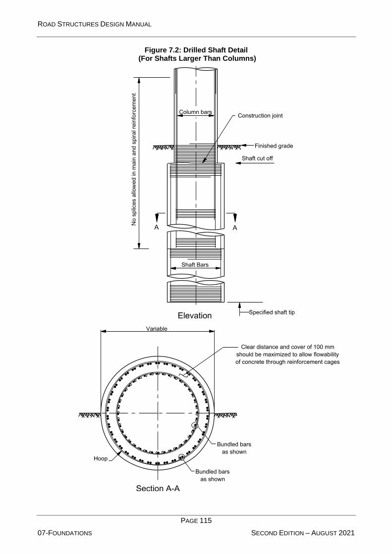
ROAD STRUCTURES DESIGN MANUAL
PAGE 115
07-FOUNDATIONS SECOND EDITION – AUGUST 2021
Figure 7.2: Drilled Shaft Detail (For Shafts Larger Than Columns)

ROAD STRUCTURES DESIGN MANUAL
PAGE 116
07-FOUNDATIONS SECOND EDITION – AUGUST 2021
Figure 7.3: Drilled Shaft Detail (With Equal Diameter Shaft and Column)

ROAD STRUCTURES DESIGN MANUAL
PAGE 117
07-FOUNDATIONS SECOND EDITION – AUGUST 2021
7.3.3.8 Laterally Loaded Shafts
Estimate the resistance of laterally loaded shafts according to approved methods. Several methods
exist for including the effects of shafts and surrounding soil in the structural model for lateral loadings
including seismic loads. Section 7.4 discusses the preferred method.
7.3.3.9 Resistance Factors
Use Table 7.1 to determine the resistance factors for drilled shafts.
Table 7.1: Resistance Factors for Drilled Shafts
Loading Design Method Construction QC
Method
Resistance
Factor,
Compression
For soil: FHWA alpha or beta method1 Specifications 0.6
For rock socket: McVay’s method2 neglecting end bearing
Specifications 0.6
For rock socket: McVay’s method3 including 1/3 end bearing
Specifications 0.55
For rock socket: McVay’s method2 Statnamic Load
Testing 0.7
For rock socket: McVay’s method2 Static Load Testing 0.75
Uplift
For clay: FHWA alpha method1 Specifications 0.35
For sand: FHWA beta method1 Specifications 0.45
For rock socket: McVay’s method2 Specifications 0.5
Lateral4 FBPier4 Specifications or lateral load test5
1.00
1 Refer to FHWA-IF-99-025, soils with N<15 correction suggested by O’Neill. 2 Refer to FDOT Soils and Foundation Handbook. 3 Extreme event. 4 Or comparable lateral analysis program. 5 When uncertain conditions are encountered.
Refer to BDS relevant section 10 and Manual TR-509 part-2, table 26 for further details on the
methods to determine the resistance factors.
7.3.4 Driven Piles
Reference: BDS Article 10.7
Driven piles are not typically used in the Abu Dhabi Emirate. Only consider driven piles if they prove
more economical than drilled shafts for deep foundations. Driven piles may become necessary
where other foundation solutions have an undesirable impact on marine ecology, result in soil-
contamination issues with regard to workers, etc.

ROAD STRUCTURES DESIGN MANUAL
PAGE 118
07-FOUNDATIONS SECOND EDITION – AUGUST 2021
Piles transfer loads to deeper suitable strata. Piles may function through skin friction and/or through
end bearing.
7.3.4.1 Pile Types/Selection
Pile Selection
The geotechnical engineer ultimately determines the selected type of pile. Table 7.2 provides
guidance in selecting pile types based on potential usage.
Table 7.2: Driven Pile Selection Guide
Pile Type Soil Conditions and Structural Requirements
Steel Pipe Pile
(closed or open end)
Loose to medium dense soils or clays where skin friction is the primary
resistance, and lateral stiffness in both directions is desirable, especially
in rivers where deep scour is anticipated and high lateral stiffness is
needed. Primarily used as a friction pile.
Steel H-Pile Rock or dense soil where end bearing is desirable and lateral flexibility in
one direction is not critical. Primarily used for end bearing.
Prestressed
Concrete Pile
Loose to medium dense soils or clays where skin friction is the primary
resistance.
7.3.4.2 Design Details
Reference: BDS Article 10.7.1
Pile Length
Reference: BDS Articles 10.7.1.10, 10.7.1.11, and 10.7.1.12
Determine pile length on a project-by-project basis. Use the same length for all piles for a specific
pier or abutment where practical. Show pile lengths in whole-meter increments.
Present the design and minimum pile tip elevations on the drawing of the structural element in the
contract documents.
Design pile tip elevations to reflect the elevation where the required ultimate pile capacity is
anticipated. Minimum pile tip elevations reflect the penetration required, considering scour and
liquefaction, to support both axial and lateral loads.
Predrill for piles placed at abutment embankments that are more than 1.5 m in depth. The size of
the pre-drilled hole is 50 mm larger than the diameter or largest dimension of the pile.
The Geotechnical Report provides project-specific requirements for the pile embedment, socketing,
and special construction requirements.
Reinforced Pile Tips
Where hard layers are anticipated, use reinforced pile tips to minimize damage for all steel piles.
Where rock is anticipated, equip the pile tips with teeth designed to penetrate into the rock.

ROAD STRUCTURES DESIGN MANUAL
PAGE 119
07-FOUNDATIONS SECOND EDITION – AUGUST 2021
The geotechnical engineer selects the type of pile tip. The bridge designer shows this in the contract
documents.
Battered Piles
Preferably, use vertical piles. Consider battered piles, typically 3V:1H, where there is inadequate
horizontal resistance. If battered piles are used, use a refined analysis; a two-dimensional analysis
is a minimum.
Edge Distance and Spacing
The distance from the side of any pile to the nearest edge of pile cap is not less than 250 mm. Pile
spacing cannot exceed 4.0 pile diameters.
Orientation
The orientation of steel H-piles (strong versus weak axis) is a design consideration, and it is
preferable that all piles be oriented the same. For diaphragm-with-pile integral abutments, use a
single row of piles driven vertically, with the strong axis parallel to the diaphragm centreline. See
Chapter 8 for a discussion on integral abutments.
7.3.4.3 Force Effects
Downdrag (DD) Loads
Mitigate downdrag forces by the following methods:
• provide friction-reducing material around the piles;
• construct embankments a sufficient amount of time in advance of the pile driving for the fill
to settle; or
• prebore and backfill the space around the installed pile with pea gravel (may be less effective
if the adjacent soil continues to settle).
When a pile penetrates a soft layer subject to settlement, evaluate the force effects of downdrag or
negative loading on the foundations. Downdrag acts as an additional permanent axial load on the
pile and may cause additional settlement. If the force is of sufficient magnitude, structural failure of
the pile or a bearing failure at the tip is possible. For piles that derive their resistance mostly from
end bearing, the structural resistance of the pile must be adequate to resist the factored loads
including downdrag.
Uplift Forces
Avoid tensile piles resisting uplift forces where practical due to the Abu Dhabi Emirate’s high water
table. Mass concrete is a potential alternative.
Uplift forces can be caused by lateral loads, buoyancy, or expansive soils. Check piles intended to
resist uplift forces for resistance to pullout and structural resistance to tensile loads. Check the
connection of the pile to the cap or footing.
Laterally Loaded Piles
Estimate the resistance of laterally loaded piles according to approved methods. Several methods
exist for including the effects of piles and surrounding soil into the structural model for lateral loadings
including seismic loads. Section 7.4 discusses the preferred method.

ROAD STRUCTURES DESIGN MANUAL
PAGE 120
07-FOUNDATIONS SECOND EDITION – AUGUST 2021
Group Effect
Minimum spacing requirements are based upon group effect. BDS Articles 10.7.3.9 and 10.7.3.11
specify group effects.
7.3.5 Pile/Shaft Testing
7.3.5.1 Pile Loads
Contract Documents
Present the applicable pile loads in the contract documents.
This information helps ensure that pile driving efforts during construction result in a foundation
adequate to support the design loads.
Static Load Tests
Reference: BDS Article 10.7.3.8.2
The geotechnical engineer determines the number and location of the static load tests. Present the
test locations and sizes in the contract documents. Pile tests shall be performed as specified in Abu
Dhabi Standard Specifications: Volume 2: Road Structures (Document Reference Number TR-542-
2).
Dynamic Pile Monitoring
Reference: BDS Article 10.7.3.8.3
Data obtained during pile-driving monitoring is used to verify pile resistance with CAPWAP.
During the installation of production piles, dynamic pile monitoring ensures that driving occurs in
accordance with the established criterion. It provides information on soil resistance at the time of
monitoring and on driving performance. Dynamic pile monitoring also reveals driving stresses, which
helps prevent pile damage. If damage is imminent, the monitoring provides an alert early enough to
save the pile from complete destruction.
7.3.5.2 Additional Steel Thickness
To account for future corrosion, add an additional sacrificial steel thickness to all permanent steel
substructure and wall components as shown in
Table 7.3.
The following criteria were used to determine the additional steel thickness required:
Environmental classification versus corrosion rate per side for partially buried piles and wall anchor
bars:
Non aggressive 0.01 mm/year
Slightly aggressive: 0.03 mm/year
Moderately aggressive: 0.05 mm/year
Extremely aggressive: 0.07 mm/year

ROAD STRUCTURES DESIGN MANUAL
PAGE 121
07-FOUNDATIONS SECOND EDITION – AUGUST 2021
Table 7.3: Table of Additional Sacrificial Steel Thickness Required (mm)
Steel Component
Substructure Environmental Classification
Slightly
Aggressive
Moderately
Aggressive
Extremely Aggressive
Case 11 Case 22
Pipe and H-Piles completely buried in
ground without corrosion protection
measures
2 4 Do not use 6
Pipe and H-Piles on land, partially buried in
ground with corrosion protection measures 2 5 Do not use 7
Pipe and H-Piles in water, partially buried in
ground without corrosion protection
measures
4 8 Do not use N/A
Pipe and H-Piles in water, partially buried in
ground with corrosion protection measures 2 5 Do not use N/A
Anchored Sheet Piles 0 0 0 0
Cantilevered Sheet Piles 1 2 3 3
Wall Anchor Bars with corrosion protection
measures 2 5 7 7
1 Case 1: Water > 2000 ppm chlorides or resistivity < 1000 ohm/cm or pH < 6.0; except for special case. 2 Case 2: Special case for land applications: where ground water < 2000 ppm chlorides and resistivity > 5000
ohm-cm and 4.9 < pH < 6.0
Environmental classification versus corrosion rate per side for completely buried piles:
Slightly aggressive: 0.01 mm/year
Moderately aggressive: 0.03 mm/year
Extremely aggressive: 0.04 mm/year
Design Life:
Pipe and H-piles without corrosion protection measures:
100 years (additional sacrificial thickness required)
Pipe and H-piles, sheet piles and wall anchor bars with corrosion protection measures:
100 years (coating system 30 years and sacrificial thickness 70 years). Corrosion
rates for anchored sheet pile walls beyond the coating system life are neglected due
to structural redundancy.
Application:
Partially buried pipe piles and H-piles: Two-sided attack at soil and/or water line.
ROAD STRUCTURES DESIGN MANUAL
PAGE 122
07-FOUNDATIONS SECOND EDITION – AUGUST 2021
Completely buried pipe piles and H-piles: Two-sided attack below ground line as shown in table
above; single sided attack if pipe piles are concrete filled.
Sheet Piles: Single-sided attack at soil and/or water line.
7.3.5.3 Test Piles
Reference: BDS Article 10.7.9
Test piles are constructed to determine soil capacity, pile-driving system, pile drivability, production
pile lengths, and driving criteria.
Depending on the bridge site and local conditions, a few test piles, as indicated in the contract
documents, are tested to 200% of service load or to failure. A number of working piles, as indicated
in tender documents, are tested to 150% of service load. All piles are tested with integrity testing.
Locate at least one test pile approximately at a recommended maximum of every 60 m of bridge
length with a minimum of two test piles per bridge structure. These requirements apply for each size
and pile type in the bridge except at end bents. For bascule piers and high-level crossings that
require large footings or cofferdam-type foundations, specify at least one test pile at each pier.
Consider maintenance of traffic requirements, required sequence of construction, geological
conditions, and pile spacing when determining the location of test piles. For phased construction,
locate test piles in the first phase of construction. The geotechnical engineer must verify the
suitability of the test pile locations.
The structural engineer must coordinate the test pile lengths and locations with the geotechnical
engineer and geotechnical consultant, before finalization of the plans.
Determination of pile capacity based on soil parameters from trial pile load testing shall not be
considered.
7.3.5.4 Load Tests
Reference: BDS Articles 10.7.3.8 and 10.8.3.5.6
See the Abu Dhabi Standard Specifications: Volume 2: Road Structures (Document Reference
Number TR-542-2), for load testing of drilled shafts and driven piles.
7.4 Modelling for Lateral Loading
When modelling deep foundations for lateral loading, ignore the first one meter of soil below
undisturbed grade. Use a structural model with site-specific p-y curves to represent the soil and
determine the lateral resistance of shafts or piles. Model the soil surrounding the shaft as a set of
equivalent non-linear soil “springs,” as represented in Figure 7.4. A discussion on modelling of the
soil strata as equivalent non-linear soil springs is given in Priestley, et al, “Seismic Design and
Retrofit of Bridges,” Wiley-Interscience, 1996.
The soil resistance “p” is a non-linear function of the corresponding horizontal shaft or pile deflection
“y.” The solution’s accuracy is a function of the spacing between nodes used to attach the soil
springs to the shaft or pile (the closer the spacing, the better the accuracy), and the shaft or pile
itself. Simple girder column elements are usually adequate for modelling behaviour.

ROAD STRUCTURES DESIGN MANUAL
PAGE 123
07-FOUNDATIONS SECOND EDITION – AUGUST 2021
The node placement for springs models the soil layers. Generally, the upper ⅓ of the shaft or pile in
stiff soils has the most significant contribution to the lateral soil reaction. Space springs in this region
at no more than 1 m apart. Springs for the lower ⅔ of the shaft or pile may transition to a much larger
spacing. Stiff foundations in weak soils will transfer loads much deeper in the soil, and the use of
more springs is necessary.
Figure 7.4: Method of Modelling Deep Foundation Stiffness
Use computer software (e.g. DFSAP, LPILE Plus, COM624) or similar to model soil-structure
interaction. Section 7.1.4 discusses the interaction between the bridge designer and the
geotechnical engineer.
7.4.1 Horizontal Movement
Horizontal displacement at top of pile shall be assessed in accordance with BDS clause 10.5.2.2. However, for service load combination, a value of 25mm at top of pile is acceptable. For abutments with single row of piles, a maximum value up to 38mm at ground level is acceptable.
7.5 Mass Concrete
Consider mass concrete requirements in selecting member sizes and avoid mass concrete if
practical; however, when its use is unavoidable, indicate which portions are mass concrete. See the
Abu Dhabi Standard Specifications: Volume 2: Road Structures (Document Reference Number TR-
542-1) for thermal control of mass concrete.

ROAD STRUCTURES DESIGN MANUAL
PAGE 124
08-ABUTMENTS, PIERS AND WALLS SECOND EDITION – AUGUST 2021
8 ABUTMENTS, PIERS, AND WALLS
Section 11 of the BDS discusses design and detailing requirements for abutments, piers, and walls.
This Chapter presents supplementary information on the design of these structural elements.
8.1 Abutments/Wingwalls
8.1.1 General
An abutment includes an end diaphragm, a stem wall, and wingwalls. A stem wall or diaphragm
functions as a wall providing lateral support for fill material on which the roadway rests immediately
adjacent to the bridge.
Abutments can be generally classified as rigid or flexible. This refers to the abutment’s fixity to the
foundation. Do not confuse this classification with the fixity of the beams or girders to the
substructure.
Rigid abutments incorporate expansion joints at the end of the bridge between the deck and the
backwall to accommodate thermal and other movements.
Flexible abutments (integral abutments) eliminate expansion joints at the end of the superstructure
by integrating the bridge deck and encased beam ends with the “backwall” to form an end wall.
Flexible abutments must accommodate the movements through elastic behaviour of the bridge and
the surrounding soil because the deck and beams are integral with the end bent.
An abutment may be one of the following three types:
1. Seat Abutment. Rigid abutment with a joint between the bridge deck and the backwall.
2. Integral Abutment. Flexible abutment without an expansion joint between the abutment and
the bridge deck (in cross section, the end wall and cap may appear as a monolithic rectangle
with no apparent division between them).
3. Semi-Integral Abutment. Flexible abutment with the bridge deck cast monolithically with the
end wall but with a bearing under the beam and a bond-breaker between the end wall and
cap to facilitate construction and subsequent maintenance.
Abutments may consist of a cast-in-situ, reinforced concrete cap founded on drilled shafts, piles, or
spread footings. The seat abutment supported on drilled shafts is the most common abutment
configuration in the Abu Dhabi Emirate. When practical, consider a jointless bridge in design.
Abutments on shafts or piles may use MSE walls to retain the approach fill.
Jointless bridges in service have demonstrated the ability to perform well within certain parameters.
Therefore, in the absence of in-depth analyses, design a jointless bridge under the following
parameters. Exceeding one or more of these parameters requires a more detailed analysis:
• 15 mm of total movement at each abutment,
• 30 degree skew or less, and
• abutment types that are supported on a single row of shafts or piles.

ROAD STRUCTURES DESIGN MANUAL
PAGE 125
08-ABUTMENTS, PIERS AND WALLS SECOND EDITION – AUGUST 2021
Where required, a detailed analysis must consider the zone of soil/structure interaction behind the
abutments, specifically the lateral soil pressure build-up and settlements that occur in this zone as a
result of thermal cycling. Conduct the design based upon the detailed analysis in published design
criteria from a recognized source applicable to the type of jointless bridge under consideration. One
suitable design guide is Section 15, Integral Abutment Bridges, of the NJDOT Design Manual for
Bridges and Structures (27).
8.1.2 General Abutment/Wing wall Design and Detailing Criteria
Use the following:
1. Expansion Joints. Consider vertical expansion joints for wall lengths exceeding 40 m. Water
proofing of expansion joints varies depending on whether the structure is submerged
(underpasses) or not (flyovers). See the Abu Dhabi Standard Specifications: Volume 2: Road
Structures (Document Reference Number TR-542-2).
2. Abutment Top Surfaces. Abutment seats at bearing locations are level. For seat abutments,
slope the remaining exposed top surfaces transversely to provide adequate drainage.
3. Approach Slab Support. Assume that the end of the approach slab at the bridge is supported
on the abutment and that the other end of the approach slab away from the bridge is
supported over half of its length by springs, which represent the soil under the approach slab.
4. Live-Load Surcharge (LS). Apply the live-load surcharge (LS) to the abutment assuming no
mitigating effect from the approach slab.
5. Dead Load. Include one-half of the dead load of the approach slab as an abutment dead
load.
6. Skewed Bridges. For skew angles greater than 30°, detail a 75-mm minimum chamfer at
acute corners.
7. Soil Reinforcements. Do not use soil reinforcements (such as steel strips and bar mats
commonly used in MSE wall construction) as attachments to abutment diaphragms or stem
walls to resist lateral loads applied to these components.
8. Reinforcement. Chapter 4 discusses practices for the reinforcement of structural concrete
(e.g. concrete cover, bar spacing). The design of abutments and wingwalls must meet all
applicable requirements in Chapter 4.
8.1.3 Seat Abutments
Use the following:
1. Seat Width. Typically, seismic design requirements govern the seat width.
2. Stem Width. The minimum stem width is 600 mm. Increase as required by design.
3. Minimum Size and Spacing of Bars. Determine the size and spacing of bars with a minimum
of T16 bars @ 200 mm unless noted otherwise.

ROAD STRUCTURES DESIGN MANUAL
PAGE 126
08-ABUTMENTS, PIERS AND WALLS SECOND EDITION – AUGUST 2021
8.1.4 Integral Abutments
Reference: BDS Article 11.6.2.1
Design integral abutment details to meet the following requirements:
1. Joints. The use of integral abutments allows joints to be placed away from the superstructure.
Thus, the potential leaking of joints does not result in deterioration of the bridge.
2. Foundation Components. Use a single row of drilled shafts or driven piles to support integral
abutments.
3. Shaft or Pile Embedment. To provide fixity, embed the shafts or piles a minimum of 100 mm
into the capping beam or pile cap.
4. Top and Bottom Deck Reinforcing. Extend the top and bottom slab reinforcing bars through
the abutment diaphragm.
5. Settlement of Fill. Investigate settlement of the fill in and around integral abutments.
See the Standard Drawings Manual for integral abutment details (TR 541)
Typically, integral abutments around the world have been supported on driven piles. Several
successful designs have used drilled shafts instead of piles. Shafts would have a lateral stiffness
comparable to typical driven piles.
8.1.5 Semi-Integral Abutments
For this type of abutment, cast the integral end diaphragm around the girder ends, attached to the
slab but separated from the cap. Attach wingwalls to the cap with only the diaphragm remaining free
to move. The usage of semi-integral abutments is limited for the Abu Dhabi Emirate.
Allow diaphragm movement and rotation through the detailing of the bearing or connection of the
girder and the cap as either:
• a pinned connection through a fixed (in terms of translation) bearing, or
• a floating abutment with an expansion bearing with the end of the bridge free to translate.
Usually in a single-span bridge, one end (typically, the downhill end) is fixed and the other end is
free to translate. In a multi-span bridge, both abutments are usually free with fixity provided at the
pier(s).
The following applies to the design of semi-integral abutments:
1. Pinned End. Assume a pinned (in terms of rotation) end for the structural design of the
superstructure.
2. Diaphragm Width. Typically, the end diaphragm width is the same as the pile cap beam but
will be a minimum of 750 mm.
3. Batter. Design walls to be a constant thickness; do not use battered walls except for high
cantilever abutments.
See the AD QCC Standard Drawings Manual for semi-integral abutment details (TR-541).

ROAD STRUCTURES DESIGN MANUAL
PAGE 127
08-ABUTMENTS, PIERS AND WALLS SECOND EDITION – AUGUST 2021
Semi-integral abutments allow for better detailing of abutments. At least two rows of piles are
required to support the abutment seat. It shares all of the benefits of an integral abutment and does
not have the problem of ensuring a flexible abutment support. The stiffer abutment seat may now be
used if necessary to fix the bridge superstructure. Supporting the deck on bearings also allows for
future jacking if required to overcome settlement, which is not possible for integral abutments.
8.1.6 MSE Wall Abutments
Two basic types of abutments with MSE walls exist:
1. “True” Abutment. An abutment supported by an MSE wall, in which the wall rests on a spread
footing atop the reinforced earth. Design the load from the spread footing as an earth
surcharge load (ES).
2. “False” Abutment. A shaft-supported abutment, in which the MSE wall wraps around an
otherwise open abutment. Isolate the shafts from the MSE backfill through sleeves to
eliminate down drag, and found the shafts in the soils below the MSE wall.
The typical MSE wall abutment in the Abu Dhabi Emirates is the “false” abutment type.
Piles placed within the mechanically stabilized earth backfill require special consideration. Place the
piles before the construction of the wall. To reduce the friction on the piles and to mitigate the down
drag forces, place a prefabricated jacketed pile sleeve on the plies, or place a slightly larger
corrugated pipe over the pile prior to backfilling. The piles must resist any horizontal each pressures
present.
As the wall is constructed, the subsoils beneath the wall and the MSE wall itself may compress. The
piles, however, are rigid. The compression of the soils induces a load into the piles due to friction.
Depending on site materials, the down drag forces can be substantial.
Modify the soil reinforcement when piles are located within the wall. The soil reinforcement cannot
be bent around the piles; they must remain linear to develop their strength. Also, do not attach the
soil reinforcement to the piles. Consider a skew of up to 15 from a line perpendicular to the wall
face, provided that the design accounts for this.
Bar mats can be cut and skewed, but they must conform to the following:
• Do not allow single longitudinal wires.
• Bar mats develop their strength from the cross wires. Use at least two longitudinal wires to
make the cross wire effective.
• Cut segments must meet minimum pull-out capacity factors of safety. Testing of cut
segments is required to show that their full strength is developed.
Ensure that all cutting of reinforcement occurs prior to the application of corrosion protection.
Section 8.3 discusses the use and design of MSE walls in more detail. The owner must approve the
use of MSE walls.
8.1.7 Wingwalls
Reference: BDS Article 11.6.1.4

ROAD STRUCTURES DESIGN MANUAL
PAGE 128
08-ABUTMENTS, PIERS AND WALLS SECOND EDITION – AUGUST 2021
Wingwalls must have sufficient length to retain the roadway embankment and to furnish protection
against erosion. With respect to abutments, the following applies to wingwalls:
1. Orientation. Orient wingwalls perpendicular to the direction of traffic on the bridge.
2. Thickness. The minimum thickness of any wingwall is 300 mm.
3. Wingwall/Abutment Connection. The junction of the abutment and wingwall is a critical design
element, requiring special considerations. Use a 600-mm triangular fillet at the junction of the
back of the abutment and wingwall. Use fillet reinforcement with a minimum of T20 reinforcing
bars at 300-mm spacing properly anchored into the wingwall and abutment.
4. Design Forces. The design forces for wingwalls are earth-pressure forces only. Also consider
seismic forces from the soil behind the wingwall in their design.
8.1.8 Abutment Construction Joints
To accommodate normal construction practices, detail the following horizontal construction joints in
the contract documents:
1. Seat Abutments. Detail a horizontal construction joint between the top of the abutment seat
and the bottom of the backwall. Some expansion joint types may require another construction
joint at the approach slab seat.
2. Integral Abutments. Detail a horizontal construction joint at the top of the end diaphragm at
the joint with the soffit.
3. Wingwalls. Detail a permissible horizontal construction joint at an elevation that is the same
as the top of the abutment seat.
Planned vertical construction joints are normally associated with staged construction. Make
provisions for splicing or mechanical reinforcing couplers on horizontal reinforcing steel. Place the
vertical reinforcing steel at least 75 mm from the construction joint.
8.2 Piers
Reference: BDS Article 11.7
8.2.1 Pier Caps
8.2.1.1 Usage
In general, use pier caps supported by a single column, multiple columns, or a solid pier wall.
Integral pier caps are preferred for aesthetics.
For outrigger caps, consider the torsional effects resulting from longitudinal seismic displacements.
Use a pin connection at the interface between the column top and bottom of the outrigger cap to
minimize torsion in the cap.
An outrigger cap is an integral cap that extends beyond the edge of the bridge superstructure. They
are used where columns cannot be placed within the width of the bridge superstructure.

ROAD STRUCTURES DESIGN MANUAL
PAGE 129
08-ABUTMENTS, PIERS AND WALLS SECOND EDITION – AUGUST 2021
8.2.1.2 Cap Width
Extend the width of pier caps beyond the sides of columns. The added width of the cap is a minimum
of 100 mm on each side of the column for a total of 200 mm by which the cap is larger than the
column. This width reduces the reinforcement interference between the column and cap. The cap
also has short cantilevered ends, when practical, to balance positive and negative moments in the
cap. Design the caps to meet the deflection requirements of BDS Article 2.5.2.6.2.
Seismic requirements for girder-seat widths may control cap width.
8.2.1.3 Superstructure Diaphragms
The dimension of diaphragm shall satisfy the requirements of BDS clause 5.12.3.5 & 5.12.4 and
relevant section of this manual.
The width of diaphragm should be evaluated taking into consideration of several factors that widely
vary from project to project e.g. the bridge span length, bearing arrangement, spacing and no. of
web or girders, congestion of reinforcement etc. and the design shall be supported with structural
calculations.
For preliminary assessment, the total width of box girder diaphragm at abutment shall not be less
than 1.5m or 5% of the span length, whichever is greater. For voided deck slab it shall be a minimum
5% of the span length. At pier location, the total width of diaphragm for box girder (at continuous
span) should be 2.0m for preliminary assessment. However, for voided deck slabs, total width of
diaphragm can be estimated as 10% of the span length.
.
8.2.1.4 Drop Caps
Step down the tops of drop caps as shown in Figure 8.1 to account for elevation differences between
girders:
Figure 8.1: Tops of Drop Caps
The drop cap steps are vertical, and the bearing surfaces are level. For planar (super-elevated) cross
sections, slope the bottom of the cap at the same rate as the cross slope of the top of the bridge
deck. For crowned sections, the bottom of the cap is level.
8.2.2 Column Cross Sections
Where a pier wall is used, the wall is solid for its entire height. The minimum thickness is 600 mm
and may be widened at the top to accommodate the bridge seat where required.
Caps are at least 200 mm wider than the column’s greatest dimension.
ROAD STRUCTURES DESIGN MANUAL
PAGE 130
08-ABUTMENTS, PIERS AND WALLS SECOND EDITION – AUGUST 2021
Where columns are supported on isolated drilled shafts, enlarge the shaft diameter relative to the
column to force plastic hinging in the column and protect the drilled shaft from inelastic action. The
drilled shaft diameter is typically 500 mm larger than the column diameter. Confirm that the diameters
selected for the column and shaft accommodate the overlapping reinforcing steel cages and cover
requirements in both the column and drilled shaft.
8.2.3 Column Reinforcement
8.2.3.1 General
Chapter 4 discusses practices for the reinforcement of structural concrete. This includes:
• concrete cover,
• bar spacing,
• lateral confinement reinforcement,
• development of reinforcement, and
• splices.
Design all concrete pier columns to meet all applicable requirements in Chapter 4.
8.2.3.2 Transverse Reinforcement
Reference: BDS Article 5.10.11
General
Use spirals or butt-welded spliced hoops as transverse reinforcing steel in octagonal or round
columns. Use ties in rectangular columns or for shapes where spirals or hoops cannot be used.
Reinforce columns with oblong cross sections and interlocking hoops with a centre-to-centre spacing
not to exceed ¾ times the diameter of the cage. Interlock the overlaps by a minimum of four bars.
Spiral Splices
Almost all spiral reinforcement requires a splice. BDS Article 5.10.11 provides requirements for
splices in spiral reinforcement. The contract documents must indicate plastic hinge regions where a
spiral splice is not allowed.
A lapped splice, where permitted, consists of an overlap distance of 60 bar diameters or 1½ column
diameters whichever is more. Terminate the ends of both spirals in a 135° hook, wrapped around a
longitudinal bar, and with a tail length of at least 150 mm. Provide a detail or description of the lapped
splice in the contract documents.
Where the spiral reinforcement extends into a footing or cap, the spiral reinforcement can be
discontinuous. This allows easier placement of the top mat of footing or bottom mat of cap
reinforcement. Provide a detail or note in the plans that shows an allowed discontinuity in the spiral
with a splice.
8.2.3.3 Longitudinal Reinforcement
Reference: BDS Article 5.10.11
For longitudinal column reinforcing bars, use T25 or larger, with T32 bars being the preferred
maximum. Detail the longitudinal reinforcing steel continuous with a maximum spacing of 200 mm

ROAD STRUCTURES DESIGN MANUAL
PAGE 131
08-ABUTMENTS, PIERS AND WALLS SECOND EDITION – AUGUST 2021
centre-to-centre. Fully develop the longitudinal column reinforcing bars where the bars enter into the
pier cap and the drilled shaft, spread footing, or pile cap.
The preferred detail for longitudinal reinforcement is continuous, unspliced reinforcement. In such
cases, include a note on the plans stating that splices are not allowed in the longitudinal
reinforcement.
If column heights require splices, use the provisions in BDS Article 5.10.11. Use mechanical couplers
or lap splices for splicing the longitudinal reinforcing steel. Do not locate splices within the plastic-
hinge regions of the column. Use a minimum stagger of 600 mm between adjacent splices and show
the locations in the plans. Stagger splices in bundled bars at a minimum of 600 mm.
Proposals by contractors to change the location or type of splice from those in the contract
documents are not allowed unless approved by the bridge designer. The resolution of conflicts or
errors requires special consideration.
8.2.3.4 Compression Member Connection to Caps
Terminate longitudinal bars at a point below the top cap reinforcement or prestressing ducts. If a
hook is required, extend the hook toward the compression member core. Maintain minimum
clearances for the placement of cap concrete through tremies.
8.2.4 Column Construction Joints
Use construction joints at the top and bottom of the column. Where columns exceed 8 m in height,
show construction joints such that concrete pours do not exceed 8 m in height. Where applicable,
locate all construction joints at least 300 mm above the water elevation expected during construction.
8.2.5 Multi-Column Piers
Support the columns by drilled shafts, individual caps/footings, or a combined cap/footing. The
following applies to the design and detailing of multi-column piers:
1. Column Spacing. In general, column spacing does not exceed approximately 8 m centre to
centre of columns.
2. Compressive Reinforcing Steel in Cap or Footing. If the initial design indicates the need for
compressive steel, redesign the pier to eliminate the need.
Compressive reinforcing steel tends to buckle when the cover is gone or when the concrete
around the steel is weakened by compression.
8.2.6 Single-Column Piers
The following applies to the design of single-column piers:
1. Cantilevers. The design of the cantilever is affected by the cantilever depth-versus-length
geometry. Where the distance between the centreline of the bearing and the column is less
than approximately twice the depth of the cantilever, consider using the strut-and-tie model
in BDS Article 5.6.3 for the design of the cantilever.
ROAD STRUCTURES DESIGN MANUAL
PAGE 132
08-ABUTMENTS, PIERS AND WALLS SECOND EDITION – AUGUST 2021
2. Cantilever Reinforcement. Extend all calculated cantilever reinforcement throughout the
entire length of the cap. Place cap stirrups in the cap within the limits of the shaft at a spacing
not exceeding 200 mm.
8.2.7 Pier Walls
Pier walls are solid full height. The dimensions of the wall in the transverse direction may be reduced
by providing cantilevers to form a hammerhead pier.
8.2.8 Dynamic Load Allowance (DLA)
Reference: BDS Article 3.6.2.1
Consider the Dynamic Load Allowance or Impact Modifier (IM) in the structural design of pier caps
and pier columns.
8.2.9 Moment-Magnification
Reference: BDS Article 5.7.4
For exceptionally tall or slender columns/shafts where the slenderness ratio (Kl/r) is greater than
100, use a refined analysis, as outlined in BDS Article 5.7.4.1. Where P-Delta design procedures
are used, consider the initial out-of-straightness of columns and the sustained dead load in the
design.
Ignore moment magnification in seismic design.
Piers, pier columns, and piles are referred to as compressive members, although their design is
normally controlled by flexure. In most cases, the use of the moment-magnification approach in BDS
Article 5.7.4.3 is necessary.
8.2.10 Pier, Column, and Footing Design
For tall piers or columns, detail construction joints to limit concrete lifts to 7.5 m. A maximum lift of 9
m may be allowed to avoid successive small lifts (less than approximately 5 m), which could result
in vertical bar splice conflicts or unnecessary splice length penalties.
Detail splices for vertical reinforcing at every horizontal construction joint, except that the splice
requirement may be disregarded for any lift of 3 m or less.
Avoid construction joints in tidal zones.
Coordinate the lift heights and construction joint locations with the concrete placement requirements
of the specifications.
On structures over water, vertical post-tensioning strand (except in cylinder piles) cannot extend
below an elevation that is 3.6 m above Mean High Water Level (MHW) or Normal High Water Level
(NHW), regardless of the Environmental Classification. Post-tensioning bars are excluded from this
restriction.
Precast pier sections with spliced sleeve connections for mild reinforcing are acceptable.

ROAD STRUCTURES DESIGN MANUAL
PAGE 133
08-ABUTMENTS, PIERS AND WALLS SECOND EDITION – AUGUST 2021
The minimum wall thickness for segmental piers is 250 mm if external post-tensioning is used and
300 mm if internal post-tensioning is used.
Locate post-tensioning applied to piers within a voided or hollow cross section and not external to
the pier. Where tendons extend from the underside of pier caps into hollow sections, provide a
13 mm 13 mm drip recess around the tendon duct. See Table 8.1 and Table 8.2.
Table 8.1: Required Tendons for Post-Tensioned Substructure Elements
Post-Tensioned Bridge Element Minimum Number of Tendons
Hammerhead pier cap
6
Straddle beam cap
Framed straddle pier column
C-pier column
C-pier cap
All other pier types and components not
listed
C-pier footing 8
Hollow cast pier column
Table 8.2: Minimum Centre-to-Centre Duct Spacing
Substructure Element Duct Spacing
Hammerhead pier cap Vertical Spacing. 100 mm, outer duct
diameter plus 1.5 times maximum aggregate
size or outer duct diameter plus 50 mm,
whichever is greater.
Horizontal Spacing. Outer duct diameter
plus 75 mm.
Straddle beam cap
C-pier cap
Pile/drilled shaft cap
Solid vertical column Outer duct diameter plus 75 mm.
Hollow cast pier column
Size footings such that the effective depth of concrete is sufficient to resist shear without the
requirement for shear reinforcement per BDS Article 5.13.3.6.
For bridges designed for vessel collision, design pier columns to be solid concrete from 5 m above
MHW or NHW to 600 mm below Mean Low Water Level (MLW) or Normal Low Water Level (NLW).
Voided sections that are filled after the column is constructed may be used.

ROAD STRUCTURES DESIGN MANUAL
PAGE 134
08-ABUTMENTS, PIERS AND WALLS SECOND EDITION – AUGUST 2021
The above requirement is sufficient for barge collision. Evaluate ship collision on a case-by-case
basis.
For all land projects, voided substructure piers and columns located within the clear zone (regardless
of the presence of guardrail or barriers) must be filled with concrete to 5 m above the finished grade.
For voided piers, the fill section may be accommodated with a secondary pour. Mass concrete fill
sections are cast against two layers of roofing paper.
For water crossings:
1. Locate the bottom of all pile caps a minimum of 300 mm below Minimum Low-Water Level
(MLL).
2. Locate the top of pile caps a minimum of 300 mm above Astronomic High Tide (AHT).
3. For submerged piers, provide fenders for protection.
A minimum height of 100 mm is required for all bearing pedestals (plinths) not poured monolithically.
The recommended maximum pedestal height is 375 mm. If taller pedestals are required, use
transversely sloping caps to minimize pedestal heights.
For precast struts set into, cast into or placed against cast-in-situ concrete within the splash zone,
maintain concrete cover over the entire interfacing surfaces of both the precast strut and the cast-
in-situ concrete. Connect precast struts to cast-in-situ concrete using only stainless steel or non-
metallic reinforcement.
Cast-in-situ concrete pulls away from a precast strut at the interface allowing water and/or chlorides
to enter and initiate corrosion.
Connect stay-in-place precast “bathtub” forms to cast-in-situ footings using stainless steel or non-
metallic reinforcement, or provide a mechanical connection across the interface between the form
and the footing (e.g. shear keys).
8.3 Walls (Earth Retaining Systems)
Reference: BDS Section 11
8.3.1 General
Use earth retaining systems to provide lateral support for a variety of applications:
• cuts in slopes for roadway alignments;
• roadway widening where right-of-way is limited;
• grade separations;
• proximate live-load surcharge from buildings, highways, etc., that must remain in place;
• stabilization of slopes where instabilities have occurred;
• protection of environmentally sensitive areas; and
• excavation support.
Earth retaining systems are classified according to the construction method and the mechanism
used to develop lateral support:
1. Construction Method. This may be either a “fill-wall” construction or “cut-wall” construction.
Fill-wall construction is where the wall is constructed from the base of the wall to the top (i.e.

ROAD STRUCTURES DESIGN MANUAL
PAGE 135
08-ABUTMENTS, PIERS AND WALLS SECOND EDITION – AUGUST 2021
“bottom-up” construction) such as an MSE wall. Cut-wall construction is where the wall is
constructed from the top of the wall to the base (i.e. “top-down” construction) such as a
soldier-pile wall.
2. Lateral Load Support. The basic mechanism of lateral load support may be either “externally
stabilized” or “internally stabilized.” Externally stabilized wall systems use an external
structural wall, against which stabilizing forces are mobilized. Internally stabilized wall
systems employ reinforcement that extends within and beyond the potential failure mass.
Rankin earth pressure may be used in lieu of Coulomb earth pressure. If Rankin earth pressure is
used, the resultant lateral earth load is considered located at the centroid of the earth pressure
diagram.
During the design process, review wall locations for conflicts with existing or proposed utilities and
drain pipes located beneath or adjacent to the proposed wall and/or reinforced soil zone. Analyse
for constructability, settlement effects, wall stability, maintenance repair access, potential for
relocation of the utility or drain pipe, etc. Coordinate wall and utility locations and designs with the
utilities engineer.
Do not place utilities or longitudinal drainage conveyances in the soil-reinforced zone behind
Mechanically Stabilized Earth (MSE) or tie-back walls.
It is undesirable and, in some cases, impossible to incorporate drain pipes and utilities within the
layered structural elements in the reinforced soil zone of an MSE wall, considering special design
and construction difficulties resulting from obstructions. Drain pipes and utilities placed below the
wall or in the reinforced soil zone cannot be maintained, because excavation in this zone can
undermine stability of the wall. In addition, leaking pipes can generate soil wash out and compromise
the structural integrity of the wall. Special design constraints may be imposed when a pressurized
utility carrier is placed within, through, under, or immediately adjacent to an MSE wall. This assures
that the design of structural elements considers support limitations that may be created by the
presence of utilities and potential damage or failure if a pressurized utility carrier leaks.
8.3.2 Responsibilities
The type selection for an earth retaining system is a collaborative effort between the bridge designer
and geotechnical engineer. The following identifies the basic responsibilities of each for the design
of earth retaining systems, except MSE walls.
8.3.2.1 Geotechnical Engineer
For permanent earth retaining systems, the geotechnical engineer:
• performs the geotechnical investigations;
• provides the wall type;
• provides the allowable soil bearing and lateral earth design coefficients for gravity, surcharge,
and seismic loading;
• performs the global and external stability checks;
ROAD STRUCTURES DESIGN MANUAL
PAGE 136
08-ABUTMENTS, PIERS AND WALLS SECOND EDITION – AUGUST 2021
• determines if there is a need for special drainage features due to the selected wall type and/or
site conditions; and
• determines the size and spacing of soil nails and tie-back anchors.
The geotechnical engineer also provides the following information to the bridge designer:
• earth pressure coefficients (ka, ko, kp) and an estimate of the amount of deformation to
develop the active and passive earth pressures and the factors of safety;
• unit weight of the backfill material;
• allowable interface friction between cast-in-situ concrete footing and soil;
• allowable bearing capacity;
• expected settlement;
• requirements for drainage control;
• testing requirements for anchored and soil nail walls; and
• special construction requirements for all walls.
8.3.2.2 Bridge Designer
The bridge designer performs the following for the design of earth retaining systems:
1. Design. For cast-in-situ concrete cantilever walls, non-gravity cantilever (sheet pile) walls,
and anchored walls, perform the internal stability design for the wall (e.g. wall dimensions
and reinforcing configurations). Perform the overturning, sliding, and bearing checks using
the geotechnical parameters provided by the geotechnical engineer. For soil nail and tie-
back anchor walls, design the reinforcing for the structural facing of the wall.
2. Detailing. Provide all construction details for the earth retaining system, including:
• Plan views to indicate the layout of the walls. Provide the station and offset to the wall
layout line (usually the front face) at all locations needed for locating the wall.
• Elevation views to show the length and design height of wall segments, and top and
bottom elevations of the wall. Provide top-of-wall elevations at intervals necessary to
build the walls. Provide elevations every 5 m when the top of wall is not on a straight
line. Footings are almost always level with the bottom and top of footing elevation
shown for each step.
• Typical sections to show all additional information on the wall. This includes the
dimensions of the footing and wall, approximate original ground line, finished ground
line at the bottom and top of wall, bench at bottom of wall, slopes at the bottom and
top of wall, drainage requirements, and reinforcing steel.
The Cited References provides additional references (28) (29) (30) (31) (32) (33) for the design of
earth retaining systems.
ROAD STRUCTURES DESIGN MANUAL
PAGE 137
08-ABUTMENTS, PIERS AND WALLS SECOND EDITION – AUGUST 2021
For determining the preliminary sizes, the stability of walls and footings shall be checked for a
minimum factor of safety of 1.5 against sliding and 2.0 against overturning for service limit state.
However, design approach recommended in LRFD bridge design specifications for stability checks
in strength limit state shall be adopted in the final design.”
8.3.3 Types of Earth Retaining Systems
8.3.3.1 Fill Walls
MSE Walls
MSE walls are constructed using reinforced layers of earth fill with extensible (polymeric or
geosynthetic) reinforcing. The facing for the walls can be concrete panels, geotextile fabrics, or
exposed welded wire. The heights of the walls can extend to over 30 m.
Advantages of MSE walls include:
• They tolerate larger settlements than a cast-in-situ concrete cantilever wall.
• They are relatively fast to build.
• They are relatively low in cost.
Cast-in-Situ Concrete Cantilever Walls
Cast-in-situ concrete cantilever walls are best-suited for sites with good bearing material and small
long-term settlement. In soft soils or when settlement may be a problem, the semi-gravity walls can
be pile supported. This adds to the cost, especially relative to a MSE wall. However, for short wall
lengths, the cast-in-situ concrete cantilever wall may be the most cost-effective selection.
Cast-in-situ concrete cantilever walls do not require special construction equipment, wall
components, or specialty contractors. They can be up to 10 m in height, although most are less than
6 m in height. The footing width for the walls is normally ½ to ⅔ the wall height.
Cast-in-situ concrete cantilever walls can be used in cut slope locations. In this case, the slope
behind the face of the wall requires excavation to provide clearance for the construction of the wall
footing. Do not use excavation slopes steeper than 1V:1.5H, which can result in significant
excavations in sloped areas.
8.3.3.2 Cut Walls
Soldier Pile Walls
For soldier pile walls, install H-piles every 2.5 m to 3 m and span the space between the H-piles with
lagging. Install the H-piles by grouting the H-pile into a drilled hole; however, they can also be
installed by driving.
The advantage of installing the H-pile by drilling is to avoid vibrations and the potential for driving
refusal.
The depth of the soldier pile is similar to the sheet pile wall; i.e. approximately two times the exposed
height. Use either timber or concrete panels for lagging.

ROAD STRUCTURES DESIGN MANUAL
PAGE 138
08-ABUTMENTS, PIERS AND WALLS SECOND EDITION – AUGUST 2021
For most soldier pile walls, a concrete facing is cast in front of the soldier piles and lagging after the
wall is at full height. Various architectural finishes can be used for the facing.
Anchored Walls
Ground-anchored wall systems (often called tie-back walls) typically consist of tensioned ground
anchors connected to a concrete wall facing. Ground anchors consist of a high-strength steel bar or
prestressing strand or FRP or GFRP shall be used. These are grouted into an inclined borehole and
then tensioned to provide a reaction force at the wall face. As a guidance, locate the anchors at 2.5-
m to 3-m horizontal and vertical spacing, depending on the required anchor capacity. Each anchor
is proof tested to confirm its capacity. The upper row of anchors can extend a distance equal to the
wall height plus up to 12 m behind the face of the wall.
Detailed design shall be carried out as per relevant international standards such as BS 8081:2015”.
For Proof Testing, relevant codes such as BS EN 1997-1:2004+A1:2013 shall be referred. Testing
at each anchor may not be required.
Specialized equipment is required to install and test the anchors, resulting in a higher cost relative
to conventional walls. An important consideration for this wall type can be the subsurface easement
requirements for the anchoring system.
Soil Nail Walls
A soil nail wall uses top-down construction. The typical construction methodology includes:
• a vertical cut of approximately 1.2 m;
• drill, insert, and grout soil nails;
• shotcrete exposed cut surface;
• repeat operation until total height of wall is complete; and
• for permanent applications, a reinforced concrete wall is cast over the entire surface.
A soil nail wall involves grouting large diameter rebar (e.g. T32 or larger) or strand into the soil at
1.2-m to 1.8-m spacing vertically and horizontally. For the length of the rebar or strand, use from 0.7
times the wall height to 1.0 times the wall height.
Specialty contractors are required when constructing this wall type. Soil nail walls can be difficult to
construct in certain soil and groundwater conditions. For example, where seeps occur within the wall
profile or in relatively clean sands and gravels, the soil may not stand at an exposed height for a
sufficient time to install nails and apply shotcrete.
Nongravity Cantilever (Sheet Pile) Walls
Sheet pile walls are normally driven or vibrated into the ground with a pile-driving hammer and are
most suitable at sites where driving conditions are amenable to pile driving. Therefore, part of the
design process requires performing a driveability analysis. Sites with shallow rock or consisting of
significant amounts of cobbles and boulders are not suitable for sheet pile driving.
Generally, the sheet pile must be driven to a depth of at least the exposed height to meet stability
requirements. Most sheet pile walls are 3 m to 4.5 m or less in height.

ROAD STRUCTURES DESIGN MANUAL
PAGE 139
08-ABUTMENTS, PIERS AND WALLS SECOND EDITION – AUGUST 2021
Although higher walls are possible, the structural design and installation requirements increase
significantly. Taller sheet pile walls require ground anchors that are typically attached to a horizontal
whaler beam installed across the face of the sheet piles.
8.3.4 Mechanically-Stabilized Earth (MSE) Walls
8.3.4.1 Design
FHWA Publication No. FHWA-NHI-00-043, “Mechanically Stabilized Earth Walls and Reinforced Soil
Slopes Design & Construction Guidelines,” contains background information on the initial
development of MSE wall design and is referenced in BDS Article 11.10.1 as the design guidelines
for geometrically complex MSE walls.
MSE walls are proprietary systems. The suppliers of the system design and supply all of the
elements that compose the wall, such as the precast concrete facing panels, tension straps, precast
barriers with their counterbalancing slabs, and copings. The supplier is responsible for the total
design of the MSE retaining wall system, including its internal and external stability, considering the
existing site/ground conditions and any required improvement to the existing soils.
For concrete cover requirements, see Table 4.4.
Only non-metallic soil reinforcement and fixings shall be utilized.
Construction of MSE walls shall be according to Abu Dhabi Standard Specifications: Volume 2: Road
Structures (Document Reference Number TR-542-2).
Minimum Service Life
1. Design permanent walls for a service life of 75 years.
2. Design temporary walls for the length of construction contract or a service life of three years,
whichever is greater.
Concrete Levelling Course
1. All permanent walls have a non-structural concrete levelling course as a minimum.
2. The entire bottom of the wall panel has bearing on the concrete levelling course.
Bin Walls
1. When two walls intersect forming an internal angle of less than 70 degrees, design the nose
section as a bin wall. Submit calculations for this special design with the plans for review and
approval.
2. Design structural connections between wall facings within the nose section to create an at-
rest bin effect without eliminating flexibility of the wall facings to allow tolerance for differential
settlements.
3. For wall facings without continuous vertical open joints, such as square or rectangular panels,
design the nose section to settle differentially from the remainder of the structure with a slip
joint. Facing panel overlap, interlock, or rigid connection across vertical joints is not permitted.
For aesthetic and differential settlement concerns, erect the panels in a pattern where the

ROAD STRUCTURES DESIGN MANUAL
PAGE 140
08-ABUTMENTS, PIERS AND WALLS SECOND EDITION – AUGUST 2021
horizontal panel joint line is discontinuous at every other panel. Use alternating standard
height and half height panel placement along the levelling pad.
4. Design soil reinforcements to restrain the nose section by connecting directly to each of the
facing elements in the nose section. Run soil reinforcement into the backfill of the main
reinforced soil volume to a plane at least 900 mm beyond the Coulomb (or Rankine) failure
surface. See Figure 8.2.
5. The design of facing connections, pullout, and strength of reinforcing elements and
obstructions must conform to the general requirements of the wall design.
Figure 8.2: Design Criteria for Acute Corners of MSE Bin Walls
Minimum Length of Soil Reinforcement
In lieu of the requirements for minimum soil reinforcement lengths in BDS Article C11.10.2.1, use
the following:
The minimum soil reinforcement length “L” is measured from the back of the facing element. The
length must be the maximum of the following:
• Walls in front of abutments on piling L 2.4 m and L 0.7H.
• Walls supporting abutments on spread footings L 7 m and L 0.6 (H+d) + 2 m, (d = fill
height about wall) and L 0.7H.

ROAD STRUCTURES DESIGN MANUAL
PAGE 141
08-ABUTMENTS, PIERS AND WALLS SECOND EDITION – AUGUST 2021
where: H = height of wall, in meters, and measured from the top of the levelling pad to the top of
the wall coping
L = length in meters, required for external stability design
For a MSE wall with reinforcement lengths equal to 70% of the wall height, estimate the anticipated
factored bearing pressure (quniform) to be about 200% of the overburden weight of soil and surcharge.
It may be necessary to increase the reinforcement length for external stability to assure that the
factored bearing pressure does not exceed the factored bearing resistance (qr) of the foundation
soil.
Minimum Front Face Wall Embedment
1. Consider scour and bearing capacity when determining front face embedment depth.
2. Consult with the hydraulic and geotechnical engineers to determine the elevation of the top
of levelling pad.
3. In addition to the requirements for minimum front face embedment in BDS Article 11.10.2.2,
the minimum front face embedment for permanent walls must comply with both a minimum
of 600 mm to the top of the levelling pad and Figure 8.3. Also, consider normal construction
practices.
Figure 8.3: MSE Wall Minimum Front Face Embedment
Facing
1. The typical panel size must be square and not exceed 2.75 sq m in area, nominal.
2. The typical non-square (i.e. diamond-shaped, not rectangular) panel size must not exceed
3.5 sq m in area.
3. Special panels (top out, etc.) must not exceed 4.5 sq m in area.
4. Full height facing panels must not exceed 2.4 m in height.
5. Consider the use of larger panels on a case-by-case basis. The reinforcing steel concrete
cover must comply with the design standard for the wall type as determined using Figure 8.3.
External Stability
The reinforced backfill soil parameters for analysis are (if detailed information is not available):
1. Sand backfill:

ROAD STRUCTURES DESIGN MANUAL
PAGE 142
08-ABUTMENTS, PIERS AND WALLS SECOND EDITION – AUGUST 2021
Moist unit weight: 1682 kg/m3
Friction angle: 30 degrees
2. Limerock backfill:
Moist unit weight: 1842 kg/m3
Friction angle: 34 degrees
3. Flowable fill backfill:
Moist unit weight: 721 to 2003 kg/m3
cf : Minimum 0.52 MPa
4. In addition to the horizontal back slope with traffic surcharge figure in BDS.
5.
6.
7.
8. Figure 8.4 illustrates a broken back slope condition with a traffic surcharge. If a traffic
surcharge is present and located within 0.5 H of the back of the reinforced soil volume, then
it must be included in the analysis.
9. Figure 8.5 illustrates a broken back slope condition without a traffic surcharge.
10. The geotechnical engineer is responsible for designing the reinforcement lengths for the
external conditions shown in Figure 8.6 and any other conditions that are appropriate for the
site.

ROAD STRUCTURES DESIGN MANUAL
PAGE 143
08-ABUTMENTS, PIERS AND WALLS SECOND EDITION – AUGUST 2021
Apparent Coefficient of Friction
When the angle of internal friction is determined for saturated conditions, do not modify the pullout
friction factor (F*) and the resistance factor for pullout (Ø) for the design of soil reinforcement below
the design flood elevation.
Soil Reinforcement Strength
1. For geosynthetic reinforcement, supplement BDS Table 11.10.6.4.3b-1 with the following
default value:
Application Total Reduction
Factor, RF
Critical temporary wall applications with non-aggressive soils
and polymers meeting the requirements listed in BDS Table
11-10.6.4.2b-1.
7.0
2. Do not design soil reinforcement to be skewed more than 15 degrees from a position normal
to the wall panel unless necessary and clearly detailed for acute corners.
3. Sometimes, the 15-degree criteria cannot be met due to vertical obstructions such as piling,
drainage structures, or bridge obstructions with angles. In these cases, clearly detail the soil
reinforcement skew details in the Shop Drawings.
4. Do not design soil reinforcement to be skewed more than 15 degrees from a horizontal
position in elevation view to clear horizontal obstructions.
5. Do not attach soil reinforcement to piling, and do not attach abutment piles to any retaining
wall system.
Reinforcement/Facing Connection
Design the soil reinforcement to facing panel connection to assure full contact of the connection
elements. The connection must be visible during construction for inspection.
Normally, mesh and bar mats are connected to the facing panel by a pin passing through loops at
the end of the reinforcement and loops inserted into the panels. If these loops are not aligned, then
some reinforcement will not be in contact with the pins, causing the remaining reinforcement to be
unevenly stressed and/or overstressed. If the quality of the connection cannot be assured through
pullout testing and quality control during installation, then reduce the strength of the soil
reinforcement and its connections accordingly.
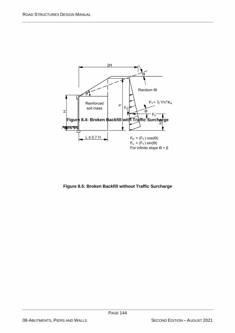
ROAD STRUCTURES DESIGN MANUAL
PAGE 144
08-ABUTMENTS, PIERS AND WALLS SECOND EDITION – AUGUST 2021
Figure 8.4: Broken Backfill with Traffic Surcharge
Figure 8.5: Broken Backfill without Traffic Surcharge
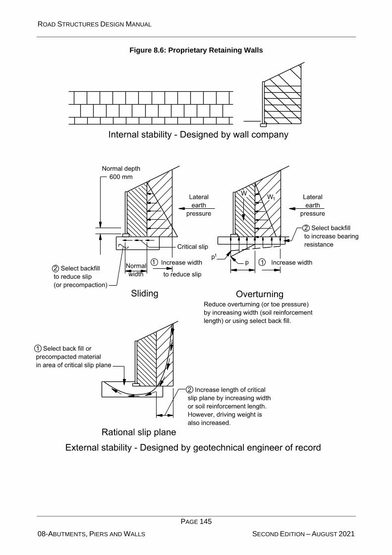
ROAD STRUCTURES DESIGN MANUAL
PAGE 145
08-ABUTMENTS, PIERS AND WALLS SECOND EDITION – AUGUST 2021
Figure 8.6: Proprietary Retaining Walls
ROAD STRUCTURES DESIGN MANUAL
PAGE 146
08-ABUTMENTS, PIERS AND WALLS SECOND EDITION – AUGUST 2021
Reinforcement/Facing Connection
Design the soil reinforcement to facing panel connection to assure full contact of the connection
elements. The connection must be visible during construction for inspection.
Normally, mesh and bar mats are connected to the facing panel by a pin passing through loops at
the end of the reinforcement and loops inserted into the panels. If these loops are not aligned, then
some reinforcement will not be in contact with the pins, causing the remaining reinforcement to be
unevenly stressed and/or overstressed. If the quality of the connection cannot be assured through
pullout testing and quality control during installation, then reduce the strength of the soil
reinforcement and its connections accordingly.
Flowable Fill Backfill
1. Flowable fill backfill will prevent the MSE wall from adapting to differential settlements and
sand or limerock backfilled MSE walls; however, the use of flowable fill may speed wall
construction. Flowable fill backfill is permitted only with written approval.
2. Prior to requesting approval, verify external stability, the accommodation of anticipated
settlements, and the cost-effectiveness of flowable fill backfill.
3. Provide 300 mm flowable fill cover in all directions between metallic soil reinforcement and
adjacent sand or limerock backfill. Provide 900 mm of sand or limerock backfill between the
top of the flowable fill and the bottom of the roadway base.
4. Indicate the minimum and maximum flowable fill unit weights that satisfy all external stability
requirements with a range of at least 160 kg/m3.
5. Provide for drainage of water between the flowable fill and the MSE wall panels.
End Bents on Piling or Drilled Shafts Behind MSE Walls
1. Locate MSE walls adjacent to end bents to avoid any conflicts with the end bent foundation
elements.
2. The minimum clear distance is 600 mm for the following:
Between the front face of the end bent cap or footing and the back face of wall panel.
For battered piles, at the base of the wall between the face of piling and the levelling pad.
Note: The 600-mm dimension is based on the use of 450 mm piles. For larger piles and
drilled shafts, increase the clear distance between the wall and pile or drilled shaft such that
no soil reinforcement is skewed more than 15 degrees.
3. Attach soil reinforcement to resist the overturning produced by the earth load, friction, and
temperature to end bents, unless the total settlement of the soil above the bottom of the end
bent cap exceeds 100 mm. In this case, do not attach the reinforcement to the end bent, and
design a special wall behind the backwall to accommodate the earth load.
End Bents on Spread Footings Behind MSE Walls
Size the spread footing so that the factored bearing pressure does not exceed 282 kN/m2.

ROAD STRUCTURES DESIGN MANUAL
PAGE 147
08-ABUTMENTS, PIERS AND WALLS SECOND EDITION – AUGUST 2021
1. The edge of the footing must be a minimum of 300 mm behind the back of the wall panel.
2. The minimum distance between the centreline of bearing on the end bent and the back of
the wall panel must be 1200 mm.
Back-to-Back MSE Walls
Design back-to-back MSE walls in accordance with Section 6.4 of FHWA-NHI-10-024 Design and
Construction of Mechanically Stabilized Earth Walls and Reinforced Slopes – Volume I.
GRS Walls and Abutments
FHWA Publication No. FHWA-HRT-11-026 “Geosynthetic Reinforced Soil Integrated Bridge System
Interim Implementation Guide” (GRS Guide) contains background information and design steps for
GRS walls and abutments. (Refer to this guide for figures referenced below.)
1. GRS abutments may be used to support single-span bridges that are not at risk of movement
due to sliding, uplift, etc.
2. Design the GRS abutment in accordance with the LRFD methodology contained in Appendix
C of the GRS Guide, except as otherwise described in this section.
3. Coordinate with the hydraulics engineer to determine the design scour depth at the abutment
with respect to the distance between abutments.
4. Utilize a reinforced soil foundation (RSF) in lieu of the concrete levelling course utilized for
MSE walls. (See Figure 30 and Section 7.4 of the GRS Guide.)
5. Detail the bottom layer of reinforcement for the GRS abutment to bear on top of the RSF at
the design scour elevation or 150 mm below the finished ground surface, whichever is
deeper.
6. Ensure that the minimum length of reinforcement, B (bottom layer of reinforcement) is not
less than 1800 mm.
7. Ensure that the thickness of the RSF is 450 mm or 0.25B, whichever is greater.
8. Extend the RSF a distance of at least 450 mm or 0.25B, whichever is greater, in front of the
wall facing.
9. Use a maximum vertical reinforcement spacing of 200 mm. (In the bearing reinforcement
zone, the reinforcement spacing is reduced by 50 percent.)
10. GRS walls are designed as GRS abutments, but without a “bearing reinforcement zone.”
8.3.4.2 External Stability and Internal Stability
The approved wall suppliers are responsible for the internal and external stability of the wall.
The external stability calculation includes a check for sliding, overturning, rotational failure, and
bearing pressure. Establish the wall geometry (including the width of reinforcement and height)
based on these items for each height of wall. Verify increases over that required for external stability
by the geotechnical engineer to ensure that the increase is justified.

ROAD STRUCTURES DESIGN MANUAL
PAGE 148
08-ABUTMENTS, PIERS AND WALLS SECOND EDITION – AUGUST 2021
8.3.4.3 Loads from Other Structures
Design MSE walls that support structures, such as soundwalls, for the lateral and vertical loads
imposed on the MSE wall. Document the magnitude of the force and where the force is applied on
the MSE wall in the contract documents or provide a drawing.
8.3.4.4 Barrier Rails
MSE walls that incorporate a roadside barrier or bridge rail at the top of wall require special attention.
The top of MSE walls are not strong enough to resist traffic impacts. Ensure that traffic impacts are
transferred from the barrier into a reinforced concrete slab that is part of or located just below the
roadway pavement. The concrete slab is sufficiently massive to keep vehicle impact forces from
being transferred into the MSE wall. Size the concrete slab to resist sliding and overturning forces
due to vehicle impacts, wind, or seismic loading as appropriate.
8.3.4.5 Copings
Cast-in-situ all copings at the top of MSE walls. Project the top of the walls 300 mm to 600 mm above
the top layer of soil reinforcement. The coping must be sufficiently large to hold together the
unbraced section. Extend reinforcing steel from the top wall panels into the coping.
8.4 Geosynthetic Reinforced Soil (GRS) Walls and
Abutments
GRS abutments are a shallow foundation and retaining wall option that may significantly reduce the
construction time and cost of single span bridges.
GRS walls and abutments, like MSE walls, are very adaptable to both cut and fill conditions and can
tolerate a greater degree of differential settlement than cast-in-situ walls. GRS walls, however, are
not appropriate for all sites.
GRS walls and abutments are constructed with coarse aggregate or GAB backfill and geosynthetic
soil reinforcement. However, site space limitations may preclude the use of GRS walls and
abutments because of the inability to place the soil reinforcement.
When excessive scour or settlements are anticipated, countermeasures, deep foundations, and/or
other wall types may be required.

ROAD STRUCTURES DESIGN MANUAL
Page 149
09-EXPANSION JOINTS SECOND EDITION – AUGUST 2021
9 EXPANSION JOINTS
BDS Article 14.4 discusses bridge joint movements and loads, and BDS Article 14.5 provides
requirements for joints and considerations for specific joint types. This Chapter presents criteria for
the design and selection of expansion joints in bridges.
9.1 Design Requirements: Movement and Loads
Reference: BDS Articles 14.4 and 14.5
9.1.1 General
Expansion joints in bridges accommodate the expansion and contraction of bridges due to
temperature variations, creep, and shrinkage. The following general criteria apply:
1. Minimize Number. Minimize the number of expansion joints because of the inherent
operational and maintenance problems. Abutment seats tend to deteriorate due to leaky
joints, collect debris, and provide locations for animal and human habitation. The use of
continuous structures minimizes the number of joints. When conditions permit, eliminate the
expansion joints on the bridge, and tie the approach slab into the superstructure. However,
always provide joints at the roadway end of approach slabs.
2. Tributary Expansion Length. The location of the point of zero movement is a function of the
longitudinal stiffness of the substructure elements and fixed bearings.
The tributary expansion length equals the distance from the expansion joint to the point of
assumed zero movement, which is the point along the bridge that is assumed to remain
stationary when expansion or contraction of the bridge occurs.
3. Consistency. When possible, use the same type of joint and construction details throughout
the bridge.
4. Maintenance. The selection, design, and detailing of expansion joints are of critical
importance to minimize maintenance problems.
Many of the maintenance problems on bridges are the result of failed joints.
5. Temperature Range. Use Procedure A of BDS Article 3.12.2.1 to determine the appropriate
design thermal range. Use the minimum and maximum temperatures specified in Table 9.1
as TMinDesign and TMaxDesign, respectively, in BDS Equation 3.12.2.3-1 (Equation 9.1).
Table 9.1: BDS Procedure “A” Temperature Changes
Concrete Bridges Steel Bridges
0°C to 60°C 0°C to 70°C
6. Recess Detail. Recess embedded steel elements, such as approach slab protection angles
and strip seal expansion joint restrainers, 6 mm from the finished grade.
This recess accommodates milling of the concrete adjacent to the joints.

ROAD STRUCTURES DESIGN MANUAL
Page 150
09-EXPANSION JOINTS SECOND EDITION – AUGUST 2021
7. Effects of Skew. Limit racking to 20% of the rated movement of the joint.
The thermal movements of skewed bridges are such that asymmetrical movements
(“racking”) can occur along the length of the expansion joints. The movement is not solely in
the longitudinal direction. The acute corners of a bridge with parallel skewed supports tend
to expand and contract more than the obtuse corners, causing the joint to rack.
8. Other Geometric Considerations.
Horizontally curved bridges and bridges with other special geometric elements (e.g. splayed
girders) do not necessarily expand and contract in the longitudinal direction of the girders.
The effect of thermal movements on the joints of complex bridges could be more pronounced
compared to bridges with simple geometrics.
9. Block-outs. Provide block-outs in decks at expansion joints to allow for joint placement.
The expansion joint assembly is installed and the block-out concrete placed after profile
grinding has been completed.
10. Cover Plates Over Expansion Joints. Use cover plates over expansion joints at sidewalks.
Where bicycles are anticipated in the roadway, consider using cover plates in the shoulder
area.
9.1.2 Estimation of General Design Thermal Movement, T
Reference: BDS Article 3.12.2.3
Estimate the design thermal movement, in millimetres, by the following equation:
Equation 9.1: (BDS Equation 3.12.2.3-1)
where: α = coefficient of thermal expansion, 1.08 x 10⁻⁵ for concrete bridges and 1.17 x
10-5 for steel girder bridges, mm/mm/C
L = tributary expansion length, mm
TMaxDesign = maximum design temperature from Table 9.1
TMinDesign = minimum design temperature from Table 9.1
9.1.3 Estimation of Design Movement
In addition to the thermal movement determined in Section 9.1.2, include the effects of creep (CR)
and shrinkage (SH) in the total movement for prestressed concrete bridges.
For steel girder structures, neglect creep and shrinkage effects in expansion-joint design because
they are minimal.
( )MinDesignMaxDesignT
TTLαΔ −=
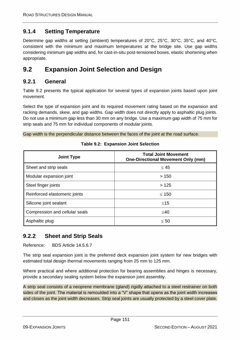
ROAD STRUCTURES DESIGN MANUAL
Page 151
09-EXPANSION JOINTS SECOND EDITION – AUGUST 2021
9.1.4 Setting Temperature
Determine gap widths at setting (ambient) temperatures of 20°C, 25°C, 30°C, 35°C, and 40°C,
consistent with the minimum and maximum temperatures at the bridge site. Use gap widths
considering minimum gap widths and, for cast-in-situ post-tensioned boxes, elastic shortening when
appropriate.
9.2 Expansion Joint Selection and Design
9.2.1 General
Table 9.2 presents the typical application for several types of expansion joints based upon joint
movement.
Select the type of expansion joint and its required movement rating based on the expansion and
racking demands, skew, and gap widths. Gap width does not directly apply to asphaltic plug joints.
Do not use a minimum gap less than 30 mm on any bridge. Use a maximum gap width of 75 mm for
strip seals and 75 mm for individual components of modular joints.
Gap width is the perpendicular distance between the faces of the joint at the road surface.
Table 9.2: Expansion Joint Selection
Joint Type Total Joint Movement
One-Directional Movement Only (mm)
Sheet and strip seals 45
Modular expansion joint > 150
Steel finger joints > 125
Reinforced elastomeric joints 150
Silicone joint sealant 15
Compression and cellular seals 40
Asphaltic plug 50
9.2.2 Sheet and Strip Seals
Reference: BDS Article 14.5.6.7
The strip seal expansion joint is the preferred deck expansion joint system for new bridges with
estimated total design thermal movements ranging from 25 mm to 125 mm.
Where practical and where additional protection for bearing assemblies and hinges is necessary,
provide a secondary sealing system below the expansion joint assembly.
A strip seal consists of a neoprene membrane (gland) rigidly attached to a steel restrainer on both
sides of the joint. The material is remoulded into a “V” shape that opens as the joint width increases
and closes as the joint width decreases. Strip seal joints are usually protected by a steel cover plate.

ROAD STRUCTURES DESIGN MANUAL
Page 152
09-EXPANSION JOINTS SECOND EDITION – AUGUST 2021
Strip seal joints are watertight when properly installed. Under typical conditions, the life of a strip
seal tends to be longer than that of other joint seals. However, these seals are difficult to replace,
and avoid splices in the membrane.
9.2.3 Modular Expansion Joint
Reference: BDS Article 14.5.6.9
Modular joints are expensive and may require significant maintenance; therefore, limit their use to
where thermal movements are greater than 125 mm. When selecting a modular joint system, use
only those that are designed to facilitate the repair and replacement of components and that have
been verified by long-term in-service performance. The contract documents must include a detailed
description of the requirements for a modular joint system.
The following applies to the design of modular-type expansion joints:
1. Joint Support. The block-outs and supports needed for modular joint systems are large and
require special attention when detailing. For modular joints supported from the top of the
girder, present a detail of the supporting device in the contract documents.
2. Splices. Where practical, provide full-length modular joints with no field splices across the
roadway width. If a field splice is required for staged construction on a slab-on-girder bridge,
space the support girders at a maximum of 600 mm from the splice location, outside of the
wheel path. The splice must be constructed according to the manufacturer’s requirements.
3. Neoprene Seal. Ensure that the neoprene seal, which is a strip seal gland in a modular joint,
is one piece across the roadway width, regardless of construction staging considerations.
9.2.4 Steel Finger Joints
Design steel fingers joints to support traffic loads with sufficient stiffness to preclude excessive
vibration. In addition to longitudinal movement, finger joints must also accommodate any rotations
or differential vertical deflection across the joint.
Steel finger joints have been successfully used to accommodate medium and large movement
ranges. They are generally fabricated from steel plates and are installed in cantilevered
configurations. Unfortunately, finger joints do not provide an effective seal against water infiltration.
Elastomeric and metal troughs have been installed beneath steel finger joints to catch and redirect
runoff water. However, in the absence of routine maintenance, the troughs clog and become
ineffective.
9.2.5 Reinforced Elastomeric
These joints are prefabricated units which span the deck joint gap and are either an elastomer or
elastomer reinforced with metal plates. Different sizes are available to suit various movement
ranges.
9.2.6 Silicone Joint Sealant
Reference: BDS Article 14.5.6.5
Use this system where anticipated movements are small and where the strip seal joint is impractical.

ROAD STRUCTURES DESIGN MANUAL
Page 153
09-EXPANSION JOINTS SECOND EDITION – AUGUST 2021
The movement capacity of this type of joint is dictated by the joint width at the time of installation,
which is a function of the installation width plus or minus some percent of original gap size. The
silicone joint sealant is relatively easy to maintain because local joint failures can be repaired. This
system can be bonded to concrete or steel surfaces.
9.2.7 Compression and Cellular Seals
Reference: BDS Article 14.5.6.6
Low-density, closed-cell foam products consist of pre-formed shapes compressed into the joint. The
sizes of the material and movement capacity follow the manufacturer’s requirements. Larger joints
may also require a cover plate for protection of the compression seal.
9.2.8 Asphaltic Plug Joint (Poured Seals)
Reference: BDS Article 14.5.6.5
Only use an asphaltic plug for retrofit applications for total movements of up to 50 mm.
This joint system consists of a metal flashing installed over the existing joint and covered with
concrete containing an asphaltic or other elastomeric binder. Its advantages include the elimination
of any mechanical anchorage system, ease of placement, low maintenance, and rideability. Its
disadvantages include the tendency to rut under heavy traffic and turning movements in hot weather.
9.2.9 Expansion Joints for Asphaltic Overlays
If a bridge deck will have an asphalt overlay, expansion joints that move less than 50 mm can be
retrofitted with plug joints. See Section 9.2.8.
These systems have the flexibility to accommodate joint movement and the strength to carry traffic.
Plug joints work well with asphalt overlays because they have similar flexibility.
For movement greater than 50 mm, place concrete headers within an asphalt overlay to facilitate
installation of the appropriate expansion joint from Table 9.2.
These concrete headers are often damaged by traffic impacting the edge, but are required for greater
movements.
9.3 Expansion Joints for Post-Tensioned Bridges
At expansion joints, provide a recess and continuous expansion joint device seat to receive the
assembly, anchor bolts, and frames of the expansion joint; i.e. a finger or modular type joint. In the
past, block-outs have been installed in the seats to provide access for stressing jacks to the upper
longitudinal tendon anchors and set as high as possible in the anchor block. Lower the upper tendon
anchors and re-arrange the anchor layout as necessary to provide access for the stressing jacks.
At all expansion joints, protect anchors from dripping water by means of skirts, baffles, v-grooves,
or drip flanges. Ensure that drip flanges are of adequate size and shape to maintain structural
integrity during form removal and erection.
See the Standard Drawings Manual for typical expansion joint details (TR-541)

ROAD STRUCTURES DESIGN MANUAL
Page 154
09-EXPANSION JOINTS SECOND EDITION – AUGUST 2021
9.4 Expansion Joint Design
Do not design superstructures utilizing expansion joints within the span (i.e. ¼ point hinges).
Identify the setting of expansion joint recesses and expansion joint devices, including any
precompression, on the drawings. Size and set expansion joints at time of construction for the
following conditions:
1. Allowance for opening movements based on the total anticipated movement resulting from
the combined effects of creep, shrinkage, and temperature rise and fall. For box girder
structures, compute creep and shrinkage from the time the expansion joints are installed
through day 4000.
2. To account for the larger amount of opening movement, set expansion devices
precompressed to the maximum extent possible. In calculations, allow for an assumed
setting temperature of 30 degrees C. Provide a table on the plans giving precompression
settings according to the prevailing conditions. Size expansion devices and set to remain
precompressed through the full range of design temperature from their initial installation until
a time of 4000 days.

ROAD STRUCTURES DESIGN MANUAL
PAGE 155
10-BEARINGS SECOND EDITION – AUGUST 2021
10 BEARINGS
BDS Article 14.4 discusses the force effects of bearings, and BDS Article 14.7 discusses types of
bearings. This Chapter presents criteria for the selection, design, and detailing of bearings for
bridges.
10.1 General
Select bridge bearings to accommodate the anticipated movements of the superstructure and
transmit the anticipated loads to the substructure.
The type of bearing selected depends upon the magnitude and type of movement and the magnitude
of the load.
10.1.1 Movements and Loads
Include both translations and rotations in the selection, design, and detailing of bearings.
The sources of movement include initial camber or curvature, construction loads, misalignment,
construction tolerances, settlement of supports, thermal effects, elastic shortening due to post-
tensioning, creep, shrinkage, and seismic and traffic loading.
10.1.2 Effect of Camber and Construction Procedures
Evaluate both the initial rotation and its short duration. At intermediate stages of construction, add
deflections and rotations due to the progressive weight of the bridge elements and to the construction
equipment to the effects of live load and temperature.
Consider the direction of loads, movements, and rotations. Do not simply add the absolute maximum
magnitudes of the design requirements. Anticipate the worst possible condition, but do not consider
combinations of absolute maximums that cannot realistically occur. In special cases, it may be
economical to install the bearing with an initial offset, or to adjust the position of the bearing after
construction has started, to minimize the adverse effect of the temporary initial conditions.
The initial camber of bridge girders induces bearing rotation. Initial camber may cause a larger initial
rotation on the bearing, but this rotation may decrease as the construction of the bridge progresses.
Rotation due to camber and the initial construction tolerances are sometimes the largest component
of the total bearing rotation.
10.1.3 Design Thermal Movements
Reference: BDS Article 3.12.2
Estimate the design thermal movement in accordance with Section 9.1.2.
Assume setting temperatures for the installation of the bearings of 20°C, 25°C, 30°C, 35°C, 40°C,
and 45°C, consistent with the minimum and maximum temperatures at the bridge site. At the time of
construction, the appropriate setting conditions may be chosen based upon the ambient
temperature.

ROAD STRUCTURES DESIGN MANUAL
PAGE 156
10-BEARINGS SECOND EDITION – AUGUST 2021
A given temperature change causes thermal movement in all directions. Because the thermal
movement is a function of the expansion length as shown in BDS Equation 3.12.2.3-1, a short, wide
bridge may experience greater transverse movement than longitudinal movement.
10.1.4 Estimation of Total Design Movement
In addition to the thermal movement determined in Section 10.1.3, consider the effects of creep (CR)
and shrinkage (SH) in the total movement for bridges in accordance with Section 9.1.3.
10.1.5 Serviceability, Maintenance, and Protection Requirements
Reference: BDS Article 2.5.2.3
Design and detail bearings under deck joints to minimize environmental damage and to allow easy
access for inspection. Design and detail bearing locations for potential bearing replacement.
Bearings under deck joints may be exposed to dirt, debris, and moisture that promote corrosion and
deterioration. The service demands on bridge bearings are very severe and result in a service life
that is typically shorter than that of other bridge elements.
The following provisions apply to all bridges with the exception of flat slab superstructures (cast-in-
situ or precast):
1. Design and detail the superstructure using bridge bearings that are reasonably accessible
for inspection and maintenance.
2. On all new designs, make provisions for the replacement of bearings without causing undue
damage to the structure and without having to remove anchorages or other devices
permanently attached to the structure.
3. Design and detail provisions for the removal of bearings, such as jacking locations, jacking
sequence, jack load, etc. Size the substructure width to accommodate the jacks and any
other required provisions.
4. When widening a bridge that does not already include provisions for replacing bearings,
consult the maintenance engineer who will decide if bearing replacement provisions must be
made on the plans.
Certain non-conventional structures, such as steel girders or segmental concrete box girders, require
separate details and notes describing jacking procedures. For steel I-girder bridges, design so that
jacks are placed directly under girder lines. For steel box girder bridges, design so that jacks are
placed directly under diaphragms. Always include a plan note stating that the jacking equipment is
not part of the bridge contract.
Few concrete I-beam bridges require elastomeric bearing pad replacement. Occasional replacement
of the pads does not justify requiring these provisions for every bridge.
10.1.6 Anchor Bolts
Reference: BDS Article 14.8.3
ROAD STRUCTURES DESIGN MANUAL
PAGE 157
10-BEARINGS SECOND EDITION – AUGUST 2021
Use anchor bolts to transfer horizontal forces through bearing assemblies when external devices
such as shear keys are not present. In addition, use anchor bolts as hold downs for bearings.
Use holes for anchor bolts in steel elements of bearing assemblies that are 6 mm larger in diameter
than the diameter of the anchor bolt. Locate the centrelines of anchor bolts a minimum of 50 mm
from the edge of the girder. A larger offset may be necessary to facilitate installation. Consider the
space necessary for nuts, washers, base plate welds, and construction tolerances and establish
anchor bolt locations accordingly. Maintain a 13-mm clearance from the edge of the elastomeric
bearing to the edge of the anchor bolt.
Provide sufficient reinforcement around the anchor bolts to develop the horizontal forces and anchor
them into the mass of the substructure unit. Identify potential concrete crack surfaces next to the
bearing anchorage and evaluate the shear friction capacity.
Conflicts between anchor bolt assemblies and substructure reinforcement are common, especially
for skewed bridges. Therefore, ensure that all reinforcing steel can fit around the bearing assemblies.
10.1.7 Bearing Plate Details
Use a bearing plate that is at least 25 mm wider than the elastomeric bearing on which the plate
rests. Use a minimum bearing plate thickness of 40 mm. When the instantaneous slope of the grade
plus the final in-place camber exceeds 1%, bevel the bearing plate to match the grade plus final
camber. For bevelled bearing plates, maintain a minimum of 40 mm thickness at the edge of the
bearing plate.
At expansion bearings, provide slotted bearing plates. Determine the minimum slot size according
to the amount of movement and end rotation calculated. The slot length, L, is:
L = (diameter of anchor bolt) + 1.2 (total movement) + 25 mm
The multiplier of 1.2 represents the load factor from BDS Table 3.4.1-1 for TU, CR, and SH.
The total movement should include an effect of girder end rotation at the level of the bearing plate.
Round the slot length to the next higher 6 mm. To account for possible different setting temperatures
at each stage, provide offset dimensions in the contract documents for stage-constructed projects.
For all other projects, consider the need to provide offset dimensions.
Top and bottom adapter plates shall be provided to allow for simple mechanical bearing
replacement. The fixing arrangement of the bearing to the top and bottom adapter plates shall be
such as to enable bearing replacement without the need for cutting into the bridge superstructure or
substructure. The bearing may be attached to the masonry plate by seating it in a machined recess
and bolting it down. To replace the bearing, the bridge will need to be lifted a height equal to the
depth of the recess.
10.1.8 Levelling Pad at Integral Abutments
Detail a plain elastomeric pad under the bearing plate of girders at integral abutments to provide a
level and uniform bearing surface. Structural grout is not an acceptable substitute.
ROAD STRUCTURES DESIGN MANUAL
PAGE 158
10-BEARINGS SECOND EDITION – AUGUST 2021
10.1.9 Lateral Restraint
Determine if lateral restraint of the superstructure of a bridge is required and make necessary
provisions to assure that the bridge will function as intended. The provisions include considerations
for the effects of geometry, creep, shrinkage, temperature, and/or seismic on the structure. When
lateral restraint of the superstructure is required, develop the appropriate method of restraint as
described hereinafter.
10.1.9.1 Elastomeric Bearings
When the required restraint exceeds the capacity of the bearing pad, provide the following
appropriate restraint:
1. For concrete girder superstructures, provide concrete blocks cast on the substructure and
positioned to avoid interference with bearing pad replacement.
2. For steel girder superstructures, provide extended sole plates and anchor bolts.
10.1.9.2 Mechanically Restrained Bearings
Design bearings that provide restraint through guide bars or pintles (e.g. pot bearings) to provide the
required lateral restraint. When unidirectional restraints are required, avoid multiple permanent
unidirectional restraints at a given pier location to eliminate binding. Where multiple unidirectional
restraints are necessary at a given pier, require bearings with external guide bars that are adjustable
and include a detailed installation procedure in the plans or specifications to ensure that the guide
bars are installed parallel to each other.
10.2 Bearing Types and Selection
10.2.1 General
Use steel-reinforced elastomeric bearings or plain elastomeric bearing pads for all girder bridges
where possible. Bridges with large bearing loads and/or multi-directional movement may require
other bearing devices such as high-load, multi-rotational (HLMR) bearings.
Distribute the loads among the bearings according to the superstructure analysis.
See Table 10.1 for a general summary of bearing capabilities. Use the values shown in the table for
preliminary guidance only. Complete the final design of the bearing according to the BDS. Provide
the geometry and other pertinent specifications for the bearing. If the load falls outside of the optimal
ranges, contact the bearing manufacturer.
Use bearing plates and anchor bolts for precast concrete and steel girder superstructures. Use
concrete shear keys with elastomeric bearings to transfer horizontal forces from a concrete box
girder superstructure to the substructure.
Bearing selection is influenced by many factors including loads, geometry, maintenance, available
clearance, displacement, rotation, deflection, availability, policy, designer preference, construction
tolerances, and cost. In general, vertical displacements are restrained, rotations are allowed to occur
as freely as possible, and horizontal displacements may be either accommodated or restrained.

ROAD STRUCTURES DESIGN MANUAL
PAGE 159
10-BEARINGS SECOND EDITION – AUGUST 2021
Table 10.1: Summary of Bearing Capabilities
Type
Load (kN) Absolute
Max. Load Limits
(kN)
Translation (mm)
Rotation
Limit
(Rad)
Cost
Typical Design Range1
Min Max Initial Maintenance
Steel-reinforced elastomeric bearing
450 to 6000 10,000 0 100 0.04 low high
High-load, multi-rotational (HLMR) bearings
Pot bearing
4000 to 30,000 50,000 02 02 0.04 - 0.05 high low
Disc bearing
4000 to 30,000 50,000 02 02 0.03 high low
Spherical bearing
4000 to 30,000 50,000 02 02 > 0.05 high low
Plain elastomeric pad 0 to 670 1000 0 20 0.0175 low high
1 Higher or lower values may be applicable if necessary.
2 High-load, multi-rotational (HLMR) bearings have no inherent translational capability. Expansion bearings
are achieved by using them in conjunction with flat PTFE sliding surfaces.
10.2.2 Steel-Reinforced Elastomeric Bearings
Reference: BDS Article 14.7.6
Use steel-reinforced elastomeric bearings for all typical girder bridges. Section 10.3 discusses the
design of these bearings in more detail.
Provide elastomeric expansion bearings with adequate seismic-resistant anchorages to resist the
horizontal forces in excess of those accommodated by shear in the pad. Provide a wider sole plate
and base plate to accommodate the anchor bolts.
Provide elastomeric fixed bearings with a horizontal restraint adequate for the full horizontal load.
Steel-reinforced elastomeric bearings are usually a low-cost option but require high maintenance.
10.2.3 Plain Elastomeric Bearing Pads
Reference: BDS Article 14.7.6
Use plain elastomeric bearing pads where bearing loads are light, up to 670 kN, and as levelling
pads at integral abutments for girder bridges.
Plain elastomeric bearing pads are usually a low-cost option and require minimal maintenance.
However, their use is restricted to lighter bearing loads for practical reasons. Plain elastomeric
bearing pads can support modest gravity loads, but they can only accommodate limited rotation or
translation. Hence, they are best suited for bridges with small expansion lengths or specialty
situations.

ROAD STRUCTURES DESIGN MANUAL
PAGE 160
10-BEARINGS SECOND EDITION – AUGUST 2021
10.2.4 High-Load, Multi-Rotational (HLMR) Bearings
Reference: BDS 14.7.4, 14.7.3 and 14.7.8
High-load, multi-rotational (HLMR) bearings include pot bearings, spherical bearings (termed
“Bearings with Curved Sliding Surfaces” in the BDS), and disc bearings. Only use these bearings
where bearing loads exceed the capabilities of steel-reinforced elastomeric bearings greater than
2900 kN. Select among HLMR bearings based upon the rotational capabilities presented in Table
10.1.
Only show schematic bearing details, combined with the specified loads, movements, and rotations,
in the contract documents. The manufacturer designs the bearing; this advantageously uses the
cost-effective fabrication procedures that are available in the shop.
HLMR bearings are generally avoided due to their cost.
Pot bearings are able to support large compressive loads, but their elastomer can leak and their
sealing rings can suffer wear or damage.
Modelling of a bridge supported on spherical bearings must recognize that the centre of rotation of
the bearing is not coincident with the neutral axis of the girder above.
Disc bearings are susceptible to uplift during rotation, which may limit their use to bearings with
polytetrafluoroethylene (PTFE) sliding surfaces.
10.2.5 Polytetrafluoroethylene (PTFE) Sliding Surfaces
Reference: BDS Article 14.7.2
Consider using PTFE sliding surfaces with expansion HLMR bearings and where the maximum
movements exceed the allowable for elastomeric bearings.
The following design information applies to PTFE sliding surfaces:
• Optimal design range for loads: 0 to 30,000 kN
• Translation: 25 mm to > 100 mm
10.2.6 Seismic Isolation Bearings
The AASHTO Guide Specifications for Seismic Isolation Design (34) and the FHWA Seismic
Retrofitting Manual for Highway Structures: Part 1 – Bridges (35) discuss the use of seismic isolation
bearings.
There are various types of seismic isolation bearings, most of which are proprietary.
10.3 Plain Elastomeric Bearing Pads and Steel-Reinforced Elastomeric Bearings
Reference: BDS Articles 14.7.5 and 14.7.6

ROAD STRUCTURES DESIGN MANUAL
PAGE 161
10-BEARINGS SECOND EDITION – AUGUST 2021
10.3.1 General
Plain elastomeric bearing pads and steel-reinforced elastomeric bearings have fundamentally
different behaviours and, therefore, are discussed separately.
Orient elastomeric pads and bearings so that the long side is parallel to the principal axis of rotation,
because this orientation better accommodates rotation.
10.3.2 Holes in Elastomer
Do not use holes in steel-reinforced elastomeric bearings or plain elastomeric bearing pads.
10.3.3 Edge Distance
For elastomeric pads and bearings resting directly on a concrete bridge seat, the minimum edge
distance is 75 mm.
The minimum low-temperature elastomer is Grade 3. Indicate the elastomer grade in the contract
documents.
10.3.4 Steel-Reinforced Elastomeric Bearings
Preferably, use steel-reinforced elastomeric bearings in combination with steel bearing plates for
slab-on-girder bridges. Use a 25-mm minimum clearance between the edge of the elastomeric
bearing and the edge of the bearing plate in the direction parallel to the beam or girder. Use a 13-
mm minimum clearance between the edge of the elastomeric bearing pad and the anchor bolt in the
direction perpendicular to the girder.
10.3.5 Design of Plain Elastomeric Bearing Pads
Design and detail plain elastomeric bearing pads according to Method A of BDS Article 14.7.6.
Use a maximum friction coefficient of 0.20 for the design of elastomeric pads that are in contact with
clean concrete or steel surfaces (1). If the shear force is greater than 0.20 of the simultaneously
occurring compressive force, then secure the bearing against horizontal movement. Use a friction
coefficient of 0.40 when checking the maximum seismic forces that can be transferred to the
substructure through the pad.
Plain elastomeric bearing pads rely on friction at the top and bottom surfaces to restrain bulging due
to the Poisson effect. Friction is unreliable, and local slip results in a larger elastomer strain than that
which occurs in steel-reinforced elastomeric pads and bearings. The increased elastomer strain
limits its load capacity, and the pad must be relatively thin if it will carry the maximum allowable
compressive load.
10.3.6 Design of Steel-Reinforced Elastomeric Bearings
Reference: BDS Articles 14.7.5 and 14.7.6
Typically, use the Method A procedure in BDS Article 14.7.6 for steel-reinforced elastomeric
bearings. The Method B procedure in BDS Article 14.7.5 may be used for high-capacity bearings.

ROAD STRUCTURES DESIGN MANUAL
PAGE 162
10-BEARINGS SECOND EDITION – AUGUST 2021
Use high-capacity elastomeric bearings only where very tight geometric constraints, extremely high
loads, or special conditions or circumstances require the use of higher grade material.
If a high-capacity elastomeric bearing is used, prepare a unique Special Provision for inclusion in
the contract documents.
Use a minimum elastomeric bearing length or width of 150 mm. Provide a minimum of 6 mm of cover
at the edges of the steel shims.
For bearing design, classify all bridge sites as being in Temperature Zone A, for which BDS Table
14.7.5.2-1 presents the design data.
Use a setting temperature of 20°C for the installation of the bearings unless the time of construction
is known. In this case, modify the setting temperature accordingly. Use 80% of the total movement
range for design. This value assumes that the bearing is installed within 30% of the average of the
maximum and minimum design temperatures.
BDS Article C14.7.5.3.4 recommends using 65% of the total movement range for design but, due to
the wide variation in temperatures across the Abu Dhabi Emirate and variations within a single day,
the design value is increased.
Account for creep (CR) and shrinkage (SH) according to the assumed construction schedule for
determining elastomeric thickness. If the construction schedule differs significantly, the contractor
must reconsider the required thickness.
Base the design thermal movement (ΔT) upon TMaxDesign and TMinDesign from Table 9.1.
For the minimum total elastomer thickness, use 2 (ΔT + ΔSH + ΔCR + ΔEL) with the appropriate
values of ΔT, ΔSH, ΔCR, and ΔEL for the bridge type and construction.
Ensure that the bearing details are consistent with the design assumptions used in the seismic
analysis of the bridge.
The Method B design procedure allows significantly higher average compressive stresses than
Method A. The higher allowable stress levels are justified by an additional acceptance test,
specifically a long-duration compression test. Design criteria for both methods are based upon
satisfying fatigue, stability, delamination, steel reinforcement yield/rupture, and elastomer stiffness
requirements.

ROAD STRUCTURES DESIGN MANUAL
PAGE 163
11-PEDESTRIAN BRIDGE SECOND EDITION – AUGUST 2021
11 PEDESTRIAN BRIDGES
A pedestrian bridge is defined as a bridge intended to carry primarily pedestrians and bicyclists and
light maintenance vehicles and not intended for use by typical highway traffic.
11.1 General
Use the AASHTO BDS and Guide Specifications for Design of Pedestrian Bridges (36) (DPB) for
the design and construction of typical pedestrian bridges with any modifications presented herein.
The DPB provides additional guidance on the design and construction of pedestrian bridges when
compared to the BDS, and for wind and fatigue provisions, when compared to the AASHTO Standard
Specifications for Structural Supports for Highway Signs, Luminaires, and Traffic Signals (37) (SSS).
In addition, the AASHTO Guide for the Planning, Design, and Operation of Pedestrian Facilities may
be useful in the planning, access facilities (i.e. stairs, lifts), and design of pedestrian bridges.
The preliminary design for a pedestrian bridge is intended to determine the most appropriate
structure type and configuration for a given site considering the design objectives of BDS Article 2.5
and Section 1.4 of this Manual.
11.2 Live Load
11.2.1 Pedestrian Load (PL)
Reference: DPB Article 3.1
Use a uniform pedestrian loading of 5.0 kN/m2 as specified in DPB Article 3.1.
The commentary of the DPB suggests that 7.18 kN/m2 represents the maximum credible pedestrian
load. This may be used for special cases where heavy pedestrian traffic can be expected.
11.2.2 Vehicle Load (LL)
Reference: DPB Article 3.2
Where maintenance vehicles can reach the superstructure, apply the vehicle configuration specified
in DPB Article 3.2 for the design of pedestrian bridges in the Abu Dhabi Emirate.
11.3 Wind Load (WS)
Reference: DPB Article 3.4 and SSS Articles 3.8 and 3.9
Use 160 km/h for the basic wind speed with a gust factor of 1.14 for the Abu Dhabi Emirate.
An increased Gust factor value may be required depending upon the structure flexibility and
exposure conditions. The increased factor shall be subjected to client approval.
The DPB specifies that wind loading is taken from the SSS instead of the BDS due to the potentially
flexible nature of pedestrian bridges and also due to the potential for traffic signs to be mounted on
them.

ROAD STRUCTURES DESIGN MANUAL
PAGE 164
11-PEDESTRIAN BRIDGE SECOND EDITION – AUGUST 2021
11.4 Vibrations
Reference: DPB Section 6
The bridge owner must not waive the vibration control provisions of DPB Section 6.
This provision mandates that the owner control vibrations whereas the DPB allows the owner to
waive this control.
11.5 Design
11.5.1 Geometrics
Design the geometrics of the bridge and the approach transitions to meet the requirements of the
DPB. For pedestrian bridges over waterways, the hydraulics engineer determines the necessary
hydraulic opening. Clearances over other facilities are determined on a project-by-project basis.
11.5.2 Structure Type
Select structure types as deemed appropriate for the given site. For an evaluation of structure type,
consider constructability, aesthetics, use of falsework, construction costs, etc.
11.5.3 Seismic
Apply the AASHTO seismic provisions to pedestrian bridges, as modified by this Manual. See
Chapter 2 and Section 3.3.1.
11.5.4 Fatigue
For fatigue load, use Section 11 of the SSS as specified in the DPB; for fatigue resistance, use
Section 6 of the BDS, Section 11 of the SSS, or Figure 2.13 of the AWS D1.1 – Structural Welding
Code – Steel (20), as appropriate, also as specified in the DPB.
11.5.5 Detailed Design Requirements
Design and detail pedestrian bridges as follows:
1. Fully design and detail foundation and substructure in the plans.
2. Fully design and detail all approach structures including non-truss approach spans, ramps,
steps/stairways, approach slabs, retaining walls, etc., in the plans.
3. Include general plan and elevation indicating minimum aesthetic requirements for the
prefabricated bridge in the plans.
4. In case of “Design and Build” contract, the Contractor designs and details a prefabricated
superstructure after award of the contract and submits the design calculations, technical
specifications, and fully detailed shop drawing to the Engineer for review and approval prior
to fabrication. Components in the shop drawings must include trusses, floor system, lateral
bracing, deck, railing/fencing, deck joints, bearing assemblies, etc. In conventional contracts,
these services (except shop drawings) will be provided by the Design Consultant and the
design will go through an appropriate checking in accordance with section 1.5 of this manual.

ROAD STRUCTURES DESIGN MANUAL
PAGE 165
11-PEDESTRIAN BRIDGE SECOND EDITION – AUGUST 2021
Desirably, limit the maximum overall width of prefabricated bridges to 3.6 m. This eliminates the
need for a spliced section.
Design all pedestrian bridges for a 75-year design life.
Clearance criteria for pedestrian bridges are as follows:
1. Provide a minimum of 3.0 m vertical clearance above the bridge deck, except for pedestrian
bridges that can be accessed by camels, where the vertical clearance above the deck is 4.5
m.
2. Consider future widening of the roadway below when determining horizontal clearances.
11.5.6 Deflections
Use the following to determine maximum allowable deflections for pedestrian bridges:
1. Pedestrian Load .................................................................. Span/500
2. Maintenance Vehicle Load .................................................. Span/500
3. Cantilever Arms Due to Service Pedestrian Live Load ....... Cantilever Length/300
4. Horizontal Deflection Due to Lateral Wind Load ................. Span/500
5. Design the pedestrian bridge to match the plan profile grade after all permanent dead load
has been applied.
11.5.7 Steel Connections
Field welding is allowed only by prior written approval and then only when bolting is impractical or
impossible.
11.5.7.1 Bolting Criteria
Design bolted connections per Chapter 5 with the exception of bearing type connections permitted
only for bracing members.
11.5.7.2 Tubular Steel Connections
Open-ended tubing is not acceptable.
Prior to bolting of field sections, tubular members are capped and fully sealed with the following
exception. Provide weep holes at the low point of all members to allow for drainage of water
accumulated inside the members during transport and erection. After erection is complete and prior
to painting, the weep holes are sealed with silicone plugs.
Require that all field splices be shop fit. Specify or show field sections bolted together using splice
plates. Direct Tension Indicators (DTI) are prohibited in bolted connections. When through bolting is
necessary, stiffen the tubular section to ensure the shape of the tubular section is retained after final
bolting. See Figure 11.1.
11.5.7.3 Vibrations
Pedestrian bridges are highly susceptible to vibrations. Limits on vibration are specified in the DPB.
Check vibration frequency under temporary construction conditions.

ROAD STRUCTURES DESIGN MANUAL
PAGE 166
11-PEDESTRIAN BRIDGE SECOND EDITION – AUGUST 2021
11.5.8 Charpy V-Notch Testing
Require ASTM A709M Charpy V-notch testing for all structural steel tension members.
Figure 11.1: Tubular Truss Splice Detail
Require impact testing requirements as follows:
1. Test non-fracture critical tension members in accordance with ASTM A709M (latest version).
2. Primary tension chords in a two truss bridge may be considered non-fracture critical due to
frame action.
3. Test fracture critical tension members according to ASTM A709M (latest version).
4. Test tubular tension members according to ASTM A500M.
5. Cross frames, transverse stiffeners, and bearing stiffeners not having bolted attachments
and expansion joints do not require testing.
11.5.9 Painting/Galvanizing
Coatings are not required for the interior of tubular components. Consider the suitability of the
fabricated component for galvanizing. Hot-dip galvanizing may be used where entire steel
components can be galvanized after fabrication and where project specific aesthetic requirements
allow. Welding components together after galvanizing is not acceptable.
11.5.10 Erection
Design and detail pedestrian bridge plans to minimize the disruption of traffic during bridge erection.
Include the following notes on the plans:
• erection over traffic is prohibited, and
ROAD STRUCTURES DESIGN MANUAL
PAGE 167
11-PEDESTRIAN BRIDGE SECOND EDITION – AUGUST 2021
• the Contractor is responsible for designing a falsework system capable of supporting portions
of the superstructure during erection.
11.5.11 Railings/Enclosures
Occasional use of the bridge by maintenance or emergency vehicles generally does not warrant the
use of a crash tested combination pedestrian/traffic railing.
Provide railing options as follows:
1. 1.3 m pedestrian/bicycle railing (minimum)
2. 1.5 m special height bicycle railing
3. Open top fence/railing combination
4. Full enclosure fence/railing combination
5. Open top cladding/railing combination (e.g. glass, steel panel, concrete panel)
6. Full enclosure cladding/railing combination
Utilize standard fence designs or connection details, where applicable.
In addition, structural review and approval, the railing shall also require approval by the Road Safety
Specialist from the relevant authorities.
11.5.12 Drainage
Design and detail drainage systems as required. Provide curbs, drains, pipes, or other means to
drain the superstructure pedestrian deck. Do not allow drainage of the superstructure onto the
roadway underneath.
11.5.13 Corrosion Resistant Details
Provide designs so that water and debris will quickly dissipate from all surfaces of the structure and
will not cause corrosion of members and connections.
11.5.14 Lighting/Attachments
For tubular structures, design any attachment, including electrical wiring, signs, signals, etc.,
strapped to the bridge. Do not allow the tapping of holes into the structural tubular members.
Design lighting attachments for wind loads as per the SSS.
11.5.15 Maintenance and Inspection Attachments
Inspections will be performed in accordance with current procedures and criteria and maintenance
guidelines. The inspection and maintenance criteria of private permitted bridges that cross Abu
Dhabi Emirate roadway facilities are the same as for public bridges.

ROAD STRUCTURES DESIGN MANUAL
Page 168
12-CULVERTS SECOND EDITION – AUGUST 2021
12 CULVERTS
Reference: BDS Section 12
Use only reinforced concrete boxes, concrete arch culverts, and concrete pipe culverts. Other culvert
options in the BDS offer less durability.
12.1 Reinforced Concrete Boxes
12.1.1 General
The structural design of reinforced concrete boxes is based on Section 12 of the BDS. The hydraulics
engineer is responsible for drainage appurtenances, and standard drawings apply in most cases.
Use a special design other than those represented by the standard drawings when:
• The box geometry or height of soil above the reinforced concrete box exceeds the limits
indicated on the standard drawings.
• Other structures impose loads on the reinforced concrete box.
• The sequence of backfilling the sides of the reinforced concrete box will not allow equal
loading.
• The design requires a special inlet, outlet, confluence, or other special hydraulic structure for
which a standard drawing does not exist.
12.1.2 Analysis
Analyse culverts using elastic methods and model the cross section as a plane frame (2D) using
gross section properties. Restrain the bottom slab by any of the following methods:
• Fully pinned support at one corner and pin-roller support at the opposite corner.
• Vertical springs (linear-elastic or non-linear soil springs) at a minimum of tenth points and a
horizontal restraint at one corner.
• Beam on elastic foundation and a horizontal restraint at one corner.
• Detail up-stand beams at the edges of the box with discontinuity joints so that they do not
contribute to the load distribution from the top slab (deck).
Obtain the modulus of subgrade reaction from the geotechnical engineer when performing the more
refined analyses in the second and third bullet items above.
12.1.3 Span-to-Rise Ratios
Do not use span-to-rise ratios exceeding 4:1.
As span-to-rise ratios approach 4:1, frame moment distribution is more sensitive to support
conditions, and positive moments at midspan can significantly exceed computed values even with a
relatively small horizontal displacement of frame leg supports.

ROAD STRUCTURES DESIGN MANUAL
Page 169
12-CULVERTS SECOND EDITION – AUGUST 2021
12.1.4 Deformations
Ensure that top slab deflection due to the live load plus impact does not exceed 1/800 of the design
span. For culverts located in urban areas used in part by pedestrians, ensure that this deflection
does not exceed 1/1000 of the design span.
Determine live-load deflections in accordance with BDS Article 2.5.2.6.2.
12.1.5 Design Method
Design new reinforced concrete culverts and extensions to existing culverts (precast or cast-in-situ,
four-sided, or three-sided) subjected to either earth fill and/or highway vehicle loading in accordance
with the BDS.
Investigate the need for culvert barrel weep holes to relieve uplift pressure. When culvert barrel weep
holes are necessary, show the requirement in the plans.
12.1.6 Dead Loads and Earth Pressure
Reference: BDS Articles 3.5, 3.11.5, and 3.11.7
The dead load on the top slab consists of the pavement, soil, and concrete slab. For simplicity in
design, the pavement may be assumed to be soil.
Use the following design criteria in determining dead load and earth pressures:
Soil = 1900 kg/m3 at = 30° to 2000 kg/m3 at = 32°
Reinforced concrete = 2500 kg/m3 horizontal earth pressure (at-rest) for:
Maximum horizontal load effects = 960 kg/m3, (assumes soil internal friction angle = 30°)
Minimum horizontal load effects = 480 kg/m3, (50% of maximum load effects)
Modify vertical earth pressures in accordance with BDS Article 12.11.2.2.1, Modification of Earth
Loads for Soil Structure Interaction (Embankment Installations), for both box and three-sided
culverts.
Verify final designs for materials used on site.
12.1.7 Live Load
Lane loading is required for the design of culverts with spans greater than 5 m in lieu of the exemption
in BDS Article 3.6.1.3.3.
12.1.8 Wall Thickness Requirements
Determine the exterior wall thickness for concrete culverts based on the design requirements, except
use the following minimum thickness requirements to allow for a better distribution of negative
moments and corner reinforcement:
Clear Span Minimum Exterior Wall Thickness
< 2.4 m 250 mm (precast); 300 mm (cast-in-situ)
2.4 m to < 4 m 300 mm
4 m to < 6 m 350 mm
6 m 400 mm

ROAD STRUCTURES DESIGN MANUAL
Page 170
12-CULVERTS SECOND EDITION – AUGUST 2021
The interior wall thickness in multi-cell culverts must not be less than 250 mm for precast culverts
and 300 mm for cast-in-situ culverts.
Increase the minimum wall thickness by 50 mm for concrete culverts in extremely aggressive
environments (100 mm concrete cover)
12.1.9 Reinforcement Details
Design the main reinforcement in the top and bottom slabs perpendicular to the sidewalls in cast-in-
situ culverts and non-skewed units of precast culverts. For reinforcement requirements of skewed
precast culverts, see Section 12.1.10.
The minimum inside bend diameter for negative moment reinforcement (outside corners of top and
bottom slabs) must satisfy the requirements of BDS Article 5.10.2.3 and must not be less than 4.0db
for welded wire reinforcement.
Top and bottom slab transverse reinforcement must be full-length bars, unless spliced to top and
bottom corner reinforcement.
12.1.10 Skewed Culverts
Design and detail skewed precast concrete culverts with non-skewed interior units designed for the
clear span perpendicular to the sidewalls and skewed end units designed for the skewed clear span.
For a cast-in-situ concrete box culvert with a skewed end, the top and bottom slab reinforcement is
“cut” to length to fit the skewed ends. The “cut” transverse bars have the support of only one culvert
sidewall and must be supported at the other end by edge beams (headwall or cutoff wall).
Precast concrete culverts with skewed ends usually cannot use edge beams as stiffening members
because of forming restrictions. The transverse reinforcement must be splayed to fit the geometry
of the skew. This splaying of the reinforcement increases the length of the transverse bars and, more
importantly, the design span of the end unit. For small skews, the splayed reinforcement is usually
more than adequate. However, large skews require more reinforcement and may require an
increased slab thickness or integral headwalls.
12.2 Concrete Arch Culverts
The following applies to concrete arch culverts:
• The design must meet the requirements of Section 12 of the BDS.
• Provide double reinforcement meeting BDS requirements for minimum reinforcing and
service limit state (crack control) criteria.
• Use the CANDE or similar computer program to verify the design.
• Provide design verification for a potential future condition that would require excavation of
backfill material along one edge of the arch.
• Design the arch culvert with a concrete invert.
• Ignore creep and shrinkage at mid-span of arch culverts with a CIS top and integral joint to
precast components.
• Design the “saddle” area of multiple-cell arch structures with a waterproofing system and a
suitable drainage system to control ponding and saturation of backfill soils. Provide

ROAD STRUCTURES DESIGN MANUAL
Page 171
12-CULVERTS SECOND EDITION – AUGUST 2021
weepholes in exterior walls at 10-m maximum spacing. All drains and weepholes are a
minimum 75-mm diameter.
• A technical representative of the arch culvert supplier must be on-site and must supply the
necessary technical assistance during the initial completion of major work activities. This
includes the placement of reinforcing, forming, concrete placement, form removal,
waterproofing, and backfilling.
First introduced in 1976 under the sponsorship of US Federal Highway Administration, CANDE
(Culvert ANalysis and DEsign) is a design and analysis tool for all types and sizes of buried
structures. CANDE is a public-domain finite element program that is used worldwide. CANDE
provides an elastic solution (Level 1), automated finite element mesh generation for common
configurations (Level 2), and a user-defined finite element mesh (Level 3).
12.3 Concrete Pipe Culverts
12.3.1 General
Round and elliptical pipes are widely used for roadway drainage. They are standardized structures,
and no structural drawings are necessary in the contract documents.
Elliptical pipes used in the Abu Dhabi Emirate are normally horizontally elliptical.
12.3.2 Materials
Materials for round and elliptical concrete pipe must meet the requirements of the Abu Dhabi
Standard Specifications: Volume 2: Road Structures (Document Reference Number TR-542-2) and
the AASHTO Standard Specifications for Transportation Materials and Methods of Sampling and
Testing (38), M170 (Round RCP) and M207 (Elliptical RCP).
12.3.3 Design
Design round and elliptical concrete pipe culverts according to Section 12 “Buried Structures and
Tunnel Liners” of the BDS.
Determine earth loads and live loads in accordance with Section 3 of the BDS as modified by Chapter
2 of this Manual.
The standard pipe class used in the Abu Dhabi Emirate is Class III. Use Classes IV and V pipe when
higher resistance is required. Base the selection of the required class of pipe on the diameter and
height of fill above the top of the pipe.
Concrete pipes are classified according to their construction and resistance as Class I, II, III, IV, or
class V.
ROAD STRUCTURES DESIGN MANUAL
Page 172
13-SOUND BARRIERS SECOND EDITION – AUGUST 2021
13 SOUND BARRIERS
Reference: BDS Section 15
The environmental engineer determines the warrants for, locations of, and minimum heights for
sound barrier walls. Use the following for the structural design of sound barriers:
• Section 15 of the BDS.
• Wind pressure from a wind velocity of 160 km/h and a gust factor of 1.14, as specified in
Chapter 2 of this Manual, Loads and Load Factors.
• Seismic load as specified in Chapter 2 of this Manual, Loads and Load Factors.
• For the masonry design, grout all cells and provide minimum reinforcing consisting of T16
bars at 400-mm vertical and 600-mm horizontal spacing.
13.1 Sound Barrier Design
13.1.1 General Features – Panel Height and Post Spacing
Reference: BDS Article 15.4
Post spacing is a minimum of 3 m and a maximum of 6 m.
All concrete wall panels are a minimum of 2 m high. Bottom panels are a minimum of 2.4 m high
when emergency access is required.
The minimum bottom panel height of 2 m is used to clear required fire hose access holes. The
minimum bottom panel height of 2.4 m for sound barriers requiring emergency access is used to
allow forming and installation of 2 m high doors.
13.1.2 Wind Loads
For sound barriers located on embankments and structures, determine the height zone by using the
elevation of adjoining ground as the approximate elevation of the original ground surface prior to
embankment construction.
13.1.3 Lateral Earth Pressure
Reference: BDS Article 3.11.5.10
For sound barriers supported on discrete vertical wall elements embedded in granular soil, rock, or
cohesive soil, use the simplified lateral earth pressure distributions shown in BDS Figures 3.11.5.10-
1, 3.11.5.10-2, and 3.11.5.10-3, respectively.
For sound barriers supported on continuous vertical elements embedded in granular soil or cohesive
soil, use the simplified earth pressure distributions shown in Figures 3.11.5.10-4 and 3.11.5.10-5,
respectively.

ROAD STRUCTURES DESIGN MANUAL
Page 173
14-SIGN AND LUMINAIRE SUPPORTS SECOND EDITION – AUGUST 2021
14 SIGN AND LUMINAIRE SUPPORTS
Reference: AASHTO Standard Specifications for Structural Supports for Highway Signs,
Luminaires, and Traffic Signals
14.1 General
This Section is a supplement to the AASHTO Standard Specifications for Structural Supports for
Highway Signs, Luminaires, and Traffic Signals (SSS) (37), much as the rest of the Manual is a
supplement to the BDS. Standard designs represented by standard drawings in the Abu Dhabi
Standard Drawings for Road Structures (Document Reference Number TR-541-2) apply in most
cases. Occasionally, the bridge designer becomes involved in the design of structural supports for
these roadside appurtenances.
14.2 Deformations
Reference: SSS Article 10.4
Deformations for specific structure types shall be limited as provided in SSS Articles 10.4.1 and
10.4.2. Where the deformations are not specified in SSS Articles, the provisions of BD 51/14 shall
govern.
The limit on deformations serves two purposes — to provide an aesthetically pleasing structure and
to provide adequate structural stiffness that will result in adequate serviceability.
14.3 Basic Wind Speed
Reference: SSS Article 3.8.2
Base the wind loads on the wind speeds of 160 km/h with a gust factor of 1.14.
14.4 Steel Design
14.4.1 Base-Plate Thickness
For base plate connections without stiffeners, the minimum base plate thickness is 50 mm.
Research has proven that full-penetration groove welds combined with thicker base plates increases
the pole-to-base-plate connection fatigue strength.
14.4.2 Welded Connections
14.4.2.1 Circumferential Welded Splices
On steel sign and signal structures, do not use circumferential welds on the uprights, arms, or chords
with the exceptions of the base plate weld, the flange plate connections on tubular truss members,
and the mitred arm-to-upright angle weld on monotube.
The intent is to avoid any unnecessary welds on sign, signal, or lighting structures.

ROAD STRUCTURES DESIGN MANUAL
Page 174
14-SIGN AND LUMINAIRE SUPPORTS SECOND EDITION – AUGUST 2021
14.4.2.2 Base Connection Welds
For base plate connections without stiffeners, only use full-penetration groove welds.
Research has proven that full-penetration groove welds combined with thicker base plates increases
the pole-to-base-plate connection fatigue strength.
14.4.3 Bolted Connections
Reference: SSS Article 5.16
Design all pole-to-arm connections on mast arm structures as “through bolted.” Do not use tapped
connections.
Through-bolted connections provide fully tensioned A325 bolts.
14.4.4 Anchor Bolt Connections
Reference: SSS Article 5.17
14.4.4.1 Minimum Number of Bolts
Use a minimum of six Grade 380, ASTM F1554 anchor bolts at the pole-to-foundation connection,
in case round base plates, for all sign, signal, and lighting structures that are designed for a minimum
service life of 50 years.
A minimum of six anchor bolts provides redundancy and better distribution of forces through the
base plate.
14.4.4.2 Use of Grout
Grout pads underneath the base plates in double-nut moment joints of miscellaneous highway
structures (i.e. mast arms, overhead sign structures, high mast lights, steel strain poles and
monotube structures) are not required.
Inspections have shown that a poorly functioning grout pad is worse than no grout pad at all. For
poles without a grout pad beneath the base plate, the double-nut moment joint requires adequate
tensioning of the anchor bolts. The nuts beneath the base plate, typically referred to as levelling
nuts, must be firmly tightened and locked to prevent loosening. This locking mechanism is
accomplished through the turn of the nut method or a properly placed grout pad.
14.4.5 Bolt Types
Reference: SSS Article 5.17.1
Do not use adhesive anchors or threaded post-tensioning bars.
Adhesive anchor and threaded post-tensioning bars have undesirable creep and ductility behaviour,
respectively.
14.5 Aluminium Design
Reference: SSS Article 6

ROAD STRUCTURES DESIGN MANUAL
Page 175
14-SIGN AND LUMINAIRE SUPPORTS SECOND EDITION – AUGUST 2021
Do not specify aluminium overhead sign structure supports with the exception of the vertical sign
panel hangers, which may be aluminium or steel.
Aluminium overhead sign structures are prone to unacceptable levels of vibration and fatigue
cracking.
14.6 Prestressed-Concrete Poles
Reference: BDS Article 7.10.2
The minimum clear concrete cover for all prestressed and non-prestressed poles shall be 40 mm
and 50 mm, respectively.
The minimum 40-mm and 50-mm covers are required on all concrete poles in all environments.
14.7 Foundation Design
Reference: SSS Article 13.6
Drilled shafts are the standard foundation type on high-mast light poles, span overhead signs, mast
arms, monotube, and steel strain poles. See Chapter 7 of this Manual for detailing requirements for
drilled shafts.
14.7.1 Geotechnical Design of Drilled Shaft Foundations
When calculating the embedment length of the drilled shaft, designer can refer to section 13 of
AASHTO-signs. Experience has established a safety factor of 2 produces conservative designs.
14.7.2 Structural Design of Drilled Shaft Foundations
Longitudinally reinforce drilled shaft foundations with a minimum of 1% steel. At a minimum, place
T16 stirrups at 100 mm spacing in the top 610 mm of shaft. In cantilever structures, design for shear
resulting from the torsion loading on the anchor bolt group.
Using 1% steel is conservative for flexural design in most cases. Additional stirrups in the top of the
shaft provide resistance against shear failure in the top of the shaft. Due to torsion, additional stirrups
may be required in cantilever structures.
14.8 Design Loads for Vertical Supports
When 3 or 4 span wire pole structures are connected, analyse the system with wind directions of 0,
45, and 90 degrees. If other angles are used, document the angles in the analysis report.
More refined analysis is typically not required due to the number of approximate assumptions made
in the analysis. Other angles may be analysed and substituted if program results are not consistent
at the specified angle.

ROAD STRUCTURES DESIGN MANUAL
PAGE 176
15-ROAD TUNNELS SECOND EDITION – AUGUST 2021
15 ROAD TUNNELS
Reference: AASHTO Technical Manual for Design and Construction of Road Tunnels - Civil
Elements
15.1 General
The AASHTO Technical Manual for Design and Construction of Road Tunnels - Civil Elements
(MRT) (39) provides recommendations for the planning, design, construction, and structural
rehabilitation and repair of the civil elements of road tunnels. The MRT is not an AASHTO
specification. AASHTO design and construction specifications for highway tunnels are under
development considering safety and operations, maintenance, and inspection for road tunnels.
This Chapter is a supplement to the MRT, much as the rest of the Abu Dhabi Road Structures Design
Manual is a supplement to the BDS. Except as modified herein, apply the MRT to the design of road
tunnels in the Abu Dhabi Emirates.
The MRT includes various types of tunnels, including cut-and-cover tunnels, mined or bored tunnels,
immersed tunnels, and jacked box tunnels.
Although there are no applicable mandatory International Standards, Highways Agency (Highways
Agency 1999) (40), Austroads (Austroads 2010a and 2010b) (41) and other publications provide
considerable reference and guidance material in addition to the MRT.
The type of construction (e.g. cut-and-cover, driven, or bored) may influence the cross-section
decision because the resulting cross-sections are different for each type. Bored tunnels are circular,
driven tunnels have a somewhat flatter roof, and cut-and-cover tunnel roofs are generally flat.
The Sequential Excavation Method (SEM), also commonly known as the New Austrian Tunnelling
Method (NATM), discussed in Chapter 9 of the MRT, is a type of mined tunnel construction. SEM
attempts to mobilize the self-supporting capability of the ground to an optimum, thus achieving
economy in ground support by understanding the behaviour of the ground as it reacts to the creation
of an underground opening.
Jacked box tunnelling, discussed in Chapter 12 of the MRT, is a unique tunnelling method for
constructing shallow, rectangular road tunnels beneath critical facilities such as operating railways,
major highways, and airport runways without the disruption of the services provided by these surface
facilities or having to relocate them temporarily to accommodate open excavations for cut-and-cover
construction.
15.2 Definition of Road Tunnels
Any fully enclosed length of roadway may be called a road tunnel, but there is general agreement
that a structure less than 80 m in length is not a tunnel. Various jurisdictions identify a minimum
length of between 80 m and 150 m as the length above which the structure is considered to be a
tunnel.

ROAD STRUCTURES DESIGN MANUAL
PAGE 177
15-ROAD TUNNELS SECOND EDITION – AUGUST 2021
A short tunnel may also be termed an underpass but, in general, treat any covered length of road
over 80 m as a tunnel in terms of fire considerations (NFPA 2008) (42).
The Highways Agency defines a road tunnel as a subsurface highway structure enclosed for a length
of 150 m or more (Highways Agency 1999) (43).
15.3 Geotechnical Site Investigations
The geotechnical site investigation is the most important process in planning, design, and
construction of a road tunnel. The geotechnical investigation and risk assessment shall be according
to the Manual for Geotechnical Investigation and Design: (Parts 1 and 2) (Document Reference
Number TR-509 part 1 and 2).
Tunnels are unique structures in that the surrounding ground material is the structural material that
carries most of the ground load. Therefore, geology has even more importance in tunnel construction
than above-ground bridge structures.
15.4 Fire Protection
For fire protection of road tunnels, use NFPA 502 - Standard for Road Tunnels, Bridges, and Other
Limited Access Highways (NFPA 2008) (42). Generally, due to local conditions, clients consider
variations to this standard. The designer shall identify potential deviations before designing tunnels.
This document, a standard produced by the National Fire Protection Association, uses tunnel length
to dictate minimum fire protection requirements:
• 90 m or less: No fire protection requirements.
• 90 m to 240 m: Minor fire protection requirements.
• 240 m or more: Major fire protection requirements.
15.5 Constructability
Select a type of tunnel construction that considers ground conditions, geometric
constraints/requirements, and other factors. In addition to being constructible, the type of
construction must be safe to construct.
In most cases, the designer must consider the need to obtain specialised equipment to make the
proposed type of tunnel construction achievable.
An essential consideration in the design of road tunnels is the constructability of the tunnel and the
safety of the people performing the construction.
15.6 Design Life
Design the main tunnel structure for a design life of 100 years or more. Select a design life for various
elements in the tunnel structure and the ancillary infrastructure based on the nature of the element
on the ease of maintaining or replacing the element. Replaceable items, such as computerised
operating systems, fans, and pumps, may be designed for a much shorter design life.

ROAD STRUCTURES DESIGN MANUAL
PAGE 178
15-ROAD TUNNELS SECOND EDITION – AUGUST 2021
Design the underpass structure for a design life of 75 years, which can be extended to 100 years
using cathodic protection according to specifications.
15.7 Design Considerations
15.7.1 Design Elements
Structural design considerations involve the integrity of the natural ground through which the tunnel
passes and the design of structural components to support the traffic and construction equipment.
The relevant structural design elements include:
• Geotechnical integrity of the surrounding ground;
• Strength of support linings;
• Design of running surface support where required (bridge or pavement design as required);
• Structural integrity of roof structures;
• Consideration of tunnel-induced ground movements and settlement;
• Adjacent infrastructure, excavations, and tunnels;
• Fire resistance of structural elements;
• Structural integrity of supports for equipment (e.g. ventilation, lighting, traffic signage,
communication facilities); and
• Design of ancillary structures (e.g. control centre, plant rooms, services buildings).
The structural design of tunnels requires the evaluation of the following:
• Evaluate the minimum hydraulic head adopted as part of the tunnel design, whether the
tunnel is fully tanked or not.
• Consider symmetric and asymmetric loads.
• Analysis of arching may be required, particularly where the cover is less than the width of the
tunnel.
• Incorporate concrete shrinkage, creep, and temperature effects.
• Consider the long-term concrete modulus (particularly in deflection assessments).
• Consider transverse shear keys under inclined tunnels if necessary to resist longitudinal
movement.
• When considering the leakage of water into the tunnel, ensure that no water leaks or drips
onto the tunnel road surface. Treat all tunnels in Abu Dhabi as submerged because of the
presence of a high water table. Therefore, provide a waterproofing membrane on all surfaces
in contact with the ground.
ROAD STRUCTURES DESIGN MANUAL
PAGE 179
15-ROAD TUNNELS SECOND EDITION – AUGUST 2021
Use the available literature for more complex tunnels.
15.7.2 Live Load
Design the structural components of road tunnels carrying traffic loads for the live-load models
specified in Sections 2.3.2 and 2.3.6.
Design tunnels (including the roof) for existing and known future loads (e.g. surface traffic loads,
buildings, earth pressures). Provide easements above, below, and around tunnels to ensure that
unintended loads are not imposed on the tunnel.
15.7.3 Seismic Considerations
Reference: MRT Chapter 13
Design road tunnels to withstand the spectral response accelerations given in Table 2-3 for a return period of 1000 years. After the event characterized by these spectral response accelerations, the tunnel may sustain significant damage and a possible disruption to service; however, the tunnel will have a low probability of collapse.
Although most of the Emirate, based on available information, falls in SDC A, the owner may select
SDC B for some areas.
These provisions are intended to achieve minimal damage to tunnels during moderate earthquake
ground motions and to prevent collapse during rare earthquakes that result in higher levels of ground
shaking.
See Section 2.3.4 for more information.
15.8 Tunnel Types
15.8.1 Cut-and-Cover Tunnels
Reference: MRT Chapter 5
This type of tunnel is constructed in a trench excavated from the surface and is appropriate for
shallow depths in suitable soils. Special cases include:
• Use of temporary sheet piles, contiguous pile or diaphragm walls. Do not use contiguous
piles or diaphragm walls as the permanent wall of the tunnel. It is not possible to waterproof
these walls. They are used only as temporary walls so that a structure waterproofed on the
outside can be constructed from within the temporary diaphragm-walled tunnel; and
• “Top down” construction.
Design considerations for cut-and-cover tunnels include the:
• Ease with which the soil can be excavated,
• Depth of water table below the natural surface,
• Availability of the surface material being removed for backfilling during the construction,
• Period and the consequences for the subsequent land use,
ROAD STRUCTURES DESIGN MANUAL
PAGE 180
15-ROAD TUNNELS SECOND EDITION – AUGUST 2021
• Need to dewater/pump the excavation,
• Stability and earth pressure on the sidewalls and loads and surcharges on the tunnel roof,
• Temporary construction loads,
• Preclude water leakage
• Uplift forces, and
• Access restrictions.
In sections of cut-and-cover tunnel in soft ground conditions, settlement adjacent to the structure
may occur. To account for control over the settlement, limit the deflection of the embedded wall
(contiguous pile wall or diaphragm wall) by propping, tie backs, or similar measures.
15.8.2 Mined or Bored Tunnels
References: MRT Chapters 6 through 9
Construct mined or bored tunnels, sometimes called driven tunnels, where there is sufficient ground
cover.
Typical mined tunnelling approaches use road headers, excavators, or drill-and-blast excavation
techniques.
For mined tunnels, a primary support is often required before the secondary lining is placed. The
lining may comprise cast-in-situ concrete, precast segments, or shotcrete (with or without rock bolts
depending on the material excavated). The cost of liners can vary widely depending on the soil types,
presence of swelling clays, soft rock, and/or water.
Typical bored tunnels use single shield, double shield, earth pressure balance, slurry shield, and
compressed air tunnel boring machines (TBMs).
In tunnels excavated using a tunnel boring machine (TBM), a liner (often precast segmental
concrete) is placed continuously behind the TBM as it advances creating a circular cross-section.
For bored tunnels, the timing of the placement of the liner behind the TBM depends on the integrity
of the material being excavated. The TBM may grip the sides of the tunnel (gripper) or thrust off the
liner (using hydraulic rams) as it advances. There are many different types of TBMs for various
situations.
Where soft ground conditions are common, earth pressure balance machines, slurry shield tunnel
boring machines, and mixed shield TBMs have been used.
In these shielded machines, the cutting head is enclosed within an air/watertight bulkhead that
stabilises the excavation face. Behind the sealed bulkhead, the rest of the tunnelling operations
remain under normal atmospheric pressure.
Tunnelling materials (e.g. earth, rock, clay, water, bentonite, lubricants) are directed through the
TBM cutting head and out the rear end. In addition to the TBM, there is a considerable amount of
material and transportation equipment that removes these products, recycles the bentonite, and
delivers power and hydraulics, water, chemicals, precast segments, or other materials for the lining.

ROAD STRUCTURES DESIGN MANUAL
PAGE 181
15-ROAD TUNNELS SECOND EDITION – AUGUST 2021
Air, water, lubricants, and chemicals can be lost through the tunnel face, side, and tail. This requires
continuous monitoring of face pressure, rate of advance, quantity of excavated material, and
chemical usage to maintain face integrity, skin, and tail seal.
15.8.3 Immersed Tunnels
Reference: MRT Chapter 11
Select the immersed tunnel construction for underwater crossings where conditions are suitable.
This may occur where it is not appropriate to use bored tunnels under the water (depth required,
material properties).
Precast reinforced concrete sections of the tunnel are manufactured in a dry dock, floated and towed
to their location above a dredged channel, sunk into position, and joined to previous sections.
Additional cells are often used to create extra buoyancy during placement, and these cells may then
be used for other functions such as placement of tunnel services and evacuation. Note that a tunnel
of this type with no cell would rarely be acceptable and, then, only for short tunnels.
15.9 Tunnel Lining
Reference: MRT Chapter 10 and BDS Article 12.13
Design steel tunnel liner plates in accordance with BDS Article 12.13. Construction will conform to
Section 25 of the AASHTO LRFD Bridge Construction Specifications (BCS) (44).
Use Chapter 10 of the MRT to design cast-in-situ concrete linings, precast segmental concrete
linings, and shotcrete linings.
ROAD STRUCTURES DESIGN MANUAL
PAGE 182
16-BRIDGE EVALUATION SECOND EDITION – AUGUST 2021
16 BRIDGE EVALUATION
16.1 Load Rating
16.1.1 General
The AASHTO Manual for Bridge Evaluation (MBE) (45) serves as a standard for bridge inspection
and rating. This Section is a supplement to the MBE with respect to bridge rating and, in particular,
Section 6A on ratings using the Load and Resistance Factor Rating (LRFR) methodology.
The LRFR methodology includes three levels of load rating:
• design load rating,
• legal load rating, and
• permit load rating.
16.1.2 Importance of Load Rating
The load rating of bridges is an important function in the Abu Dhabi Emirates. It allows the
comparative evaluation of existing structures. Bridges designed to former standards are compared
to contemporary standards, in conjunction with an appraisal of the bridge condition. Load rating is
also used to post bridges with insufficient load-carrying capacity and to evaluate permit overloads
on structures; see Sections 16.3 and 16.4, respectively.
16.1.3 Methodology
Load rate all bridges by the Load and Resistance Factor Rating (LRFR) methodology in Section 6A
of the MBE. The use of this single methodology provides uniformity in ratings.
The LRFR bridge-rating methodology is fully consistent with the BDS bridge-design methodology.
16.1.4 Thresholds for Re-Rating Existing Bridges
Re-rate a bridge to determine the new load-carrying capacities when a bridge inspection reveals a
quantifiable change in the bridge condition from deterioration or damage (e.g. increased metal
section loss). If the load-carrying capacity falls below certain limits, the bridge must be posted; see
Section 16.3.
16.1.5 Limit States for Load Rating
Use all limit states in MBE Table 6A.4.2.2-1 to load rate bridges in the Abu Dhabi Emirate.
The researchers who developed the original draft of the MBE included all appropriate limit states
necessary to operate highway bridges. Upon adoption, AASHTO made several of the limit states
(those shown as shaded cells in MBE Table 6A.4.2.2-1) optional for political reasons.

ROAD STRUCTURES DESIGN MANUAL
PAGE 183
16-BRIDGE EVALUATION SECOND EDITION – AUGUST 2021
( ))IMLL()(
)DW(()DC)(CRF
LL
DWDC
+
−−=
nnsc RC =
85.0sc
RfC =
16.1.6 Dimensions
Show dimensions from the as-built plans unless measured dimensions, as part of a visual inspection,
deviate significantly from the plan dimensions. With reported deterioration, the Evaluator may reduce
the structural dimensions of a deteriorated component based on engineering judgment derived from
a visual inspection of the bridge to discount deteriorated material.
Base the section properties of composite girders on the full depth of the composite deck slab unless
deterioration is noted.
16.1.7 The LRFR Load-Rating Equation
Reference: MBE Article 6A.4.2.1
Use the following general equation for rating factor, RF, to determine the load rating of each
component and connection of the bridge for each force effect (i.e. axial force, flexure, shear). The
equation is used for all three levels of the LRFR methodology:
Equation 16.1
For the strength limit states:
Equation 16.2
Where:
Equation 16.3
For the service limit states:
Equation 16.4
where: RF = rating factor
C = capacity
fR = allowable stress specified in the BDS
Rn = nominal member resistance
DC = dead-load effect due to structural components and attachments

ROAD STRUCTURES DESIGN MANUAL
PAGE 184
16-BRIDGE EVALUATION SECOND EDITION – AUGUST 2021
DW = dead-load effect due to wearing surface and utilities
LL = live-load effect
IM = dynamic load allowance
γDC = dead-load load factor for structural components and attachments
γDW = dead-load load factor for wearing surface and utilities
γLL = evaluation live-load load factor
φc = condition factor
φs = system factor
φn = BDS resistance factor
Use the application of the condition and system factors for load rating in the Abu Dhabi Emirate,
although they are optional in the MBE.
The researchers who developed the original draft of the MBE included the condition and system
factors as appropriate to operate highways bridges. Upon adoption, AASHTO made these factors
optional for political reasons.
16.1.8 Analytical Methods for the Load Rating of Post-Tensioned Box
Girder Bridges
Perform load rating in accordance with AASHTO MBE Article 6A.5.11.
16.2 Design Load Rating
Reference: MBE Articles 6A.1.7.1 and 6A.4.3
Design-load rating is the first level of rating in the LRFR methodology. Rate all bridges at this level.
Specify the design live load (ADVL) as in Chapter 2.
The design-load rating is used to assess the bridge’s adherence to the applicable design standard.
Two levels of reliability are included in the design-load rating level reflected by two different live-load
load factors for application in the general LRFR load-rating equation. Bridges with adequate design-
load capacity (i.e. RF 1) at the inventory level require no further evaluation.
The two levels of design-load rating are analogous to the traditional inventory and operating levels.
16.3 Legal-Load Rating and Load Posting
Reference: MBE Articles 6A.1.7.2, 6A.4.4 and 6A.8
16.3.1 Legal-Load Rating
Legal-load rating is the second level of load rating in the LRFR methodology. Rate bridges that do
not have sufficient design-load capacity (the first level of rating in the LRFR methodology) at the
legal-load level to determine the need to post or strengthen the bridge.
Legal-load rating provides a single safe load capacity for the ADVL model of Chapter 2. Use the
generalized live load factors for routine commercial traffic for the ADVL model.

ROAD STRUCTURES DESIGN MANUAL
PAGE 185
16-BRIDGE EVALUATION SECOND EDITION – AUGUST 2021
The legal-load ratings are used in decision-making for bridge posting or strengthening.
16.3.2 Load Posting
Close the bridge when it is not capable of carrying a minimum gross live-load weight of 5 tons.
Do not post the bridge when the rating factor, RF, calculated for the ADVL is greater than or equal
to 1.0. Otherwise, use the posting load as the rating factor, RF, times 45 tons.
16.4 Permitting and Permit-Load Rating
Reference: MBE Article 6A.1.7.3 and 6A.4.5
16.4.1 Permitting
Permits can be issued for single trips, multiple trips, or on an annual basis. Routine or annual permits
are usually valid for unlimited trips over a specified period of time for vehicles of a given axle
configuration within specified weight limits. Special or limit-crossing permits are usually valid for a
single trip or limited number of trips for a vehicle of a given axle configuration within specified weight
limits. Special permits may be allowed to mix with normal traffic or may be required to be escorted
in a manner that controls the speed, position, and proximity with regard to other traffic. The
Department of Transport has prepared permitting procedures for exceptional vehicles.
16.4.2 Permit-Load Rating
Permit-load rating is the third level of load rating in the LRFR methodology. Only consider bridges
that have sufficient load-carrying capacity for the Abu Dhabi legal load for permit-load rating.
Apply a live-load factor of 1.20 to the specific permit load for permit-load rating.
The calibrated load factors specified in MBE Article 6A.4.5.4.2a for use in the general LRFR load-
rating equation are specified for both types of permits mixing with or without traffic as a function of
ADTT. The load factors are intended to be used in conjunction with the AASHTO approximate
analysis method using distribution factors. Refined analysis is required in the Abu Dhabi Emirate for
load rating. Thus, the specified load factors in MBE Article 6A.4.5.4.2a are not applicable in the Abu
Dhabi Emirate.
16.5 Load Testing of Bridges
Reference: BDS Article 4.8.2 and MBE Section 8
16.5.1 General
The purpose of the load testing is to evaluate the structural performance and functional adequacy of
the bridge tested as an exact full-sized model with an appropriate margin of safety.
16.5.1.1 Classifications
Two basic types of load tests are available for bridge evaluation — diagnostic tests (see MBE Article
8.8.2) and proof tests (see MBE Article 8.8.3). Diagnostic tests determine certain response
characteristics of the bridge, or validate analytical procedures or mathematical models. Proof tests
ROAD STRUCTURES DESIGN MANUAL
PAGE 186
16-BRIDGE EVALUATION SECOND EDITION – AUGUST 2021
establish the maximum safe load-carrying capacity of a bridge, where the bridge behaviour is within
the linear-elastic range.
Load testing may be further classified as static load tests (see MBE Article 8.4.1) and dynamic load
tests (see MBE Articles 8.4.2). A static load test uses stationary loads to avoid bridge vibrations. The
intensity and position of the load may be changed during the test. A dynamic load test uses time-
varying loads or moving loads that excite vibrations in the bridge. Dynamic tests measure modes of
vibration, frequencies, dynamic load allowance, or obtain load history and stress ranges for fatigue
evaluation.
Diagnostic load tests may be either static or dynamic tests. Proof load tests are mostly static tests.
16.5.1.2 Definitions
“Design Live Load” means the ADVL including the corresponding dynamic load allowance (IM) and
multiple presence factors.
“Test Load” means the actual loads used at each stage of testing.
16.5.2 Load Testing Calculations
Predetermine the Test Load patterns and positions on the bridge deck to simulate load effects due
to the Design Live Load. The amount and configuration of the Test Load spectrum increments
applied during the test produces internal forces (bending moments, shear, and axial forces),
reactions, and deflections, at critical sections, equal to the corresponding Design Live Load values
used in the bridge design. Place the Test Load mutually in standard width design traffic lanes, spaced
across the entire bridge roadway width measured between curbs at pre-marked locations. The Test
Load shall be positioned within the lane so that the maximum effect is achieved. Precast concrete
blocks may be used as truck loads to achieve the required axle loads. Lorries loaded with aggregates
may also be used if the required axle loads can be achieved. Concentrated loads can be applied to
the deck by jacking against dead weight. Perform the load testing for all spans.
During the test, increase the Test Load incrementally to achieve the predetermined maximum live
longitudinal and transverse positive and negative (if any) moments in mid-spans; maximum live
longitudinal negative moments and maximum live transverse negative and positive moments at
internal supports; and maximum live-load reactions at supports.
Provide the theoretical bending moment, shear, and deflection diagrams and reactions for each Test
Load increment. Do not allow their values to exceed the corresponding values under Design Live
Loads.
Calculate and check longitudinal flexural stresses along the bridge at critical sections, so that they
do not exceed the maximum stress limits of the bridge at any time during the test.
16.5.3 Load Testing Method Statement
Perform the load testing after the bridge construction is completed and all superimposed dead loads
(pavement layers, parapets, footway, etc.) are applied.

ROAD STRUCTURES DESIGN MANUAL
PAGE 187
16-BRIDGE EVALUATION SECOND EDITION – AUGUST 2021
Apply the Test Load gradually in increments before reaching the final total amount, in a period not
less than five hours. Apply the maximum Test Load for a minimum period of twelve hours, and
perform the unloading gradually for mid spans but immediately for supports.
After each Test Load, measure the incremental deflections accurately and at a sufficient number of
points (at least two points every one fifth of each span) to produce sufficient data to plot the
theoretical and measured deflected shapes of the structure.
Take deflection measurements at piers and abutments for each Test Load increment, and for the
recovery case, to verify that the differential settlements or rotations of the supports do not exceed
the corresponding design values.
Measure elastic deflections, after the removal of each Test Load increment, to check recovery such
that any permanent deflection is minimal and within limits. The ratio of permanent irreversible
deflection to the total deflection will not exceed 0.2.
Provide and plot comparison tables and linear relationships between theoretical and measured
deflections for each Test Load increment to determine the slope of the compatibility line.
The general and structural safety of the bridge during testing is the responsibility of the consultant.
The consultant ensures that the elastic limit of the bridge is not exceeded and no damage is done to
the bridge or its components due to the test. Prestress steel, in case of prestressed concrete, must
not suffer any excessive losses due to faulty overload.
Submit the Load Testing Method Statement of bridge at least two months before the testing date,
including the following:
• the current status (or the status at testing time) of bridge to be tested;
• traffic management;
• load testing procedure;
• bridge deck discretization (measurement reference positions);
• dial gauges locations, sensitivities, etc., Deflected Cantilever Displacement Transducers
(DCDT) gauges, Linear Variable Displacement Transducers (LVDT) gauges and Demec
gauges;
• type of truck to be used in the test, its load capacity, load to be used in the test and wheel
load after each Test Load increment;
• loading test truck configurations in the longitudinal and transverse directions for each Test
Load increment;
• bridge deck moment influence lines for each test node;
• the bending moment, shear force, and theoretical deflection diagrams and support reactions
due to the Test Load;

ROAD STRUCTURES DESIGN MANUAL
PAGE 188
16-BRIDGE EVALUATION SECOND EDITION – AUGUST 2021
• a comparison between Design Live Load moments, shears, reactions, and deflections, and
their corresponding Test Load values at test nodes for each Test Load increment; and
• any additional information the consultant may find useful for the execution of the Load testing.
Conduct performance inspections on bearings to check that no additional restraint is present. Ensure
that the vertical deflections and compression of bearings and differential translations (i.e.
temperature-induced movements at expansion joints) are considerably below the design (or
manufacturer’s) limits. Determine the bridge deck temperature by means of thermocouples.
16.5.4 Load Testing Analysis Report
Submit a comprehensive Load Testing Analysis Report two weeks after the load testing is
completed. This report will include, but not be limited to the following:
• A summary of all items mentioned above in the Method Statement;
• The Interpretation of the test results;
• Loading diagrams for all Test Load increments and the unloading cases;
• A table containing measured vs. theoretical deflections for each Test Load increment;
• Longitudinal measured and theoretical deflection curves along the bridge centerline for each
Test Load increment;
• Graphs showing the measured and the theoretical deflections;
• Any local effects; and
• Final analysis, conclusions, and requirements for the bridge load testing.

ROAD STRUCTURES DESIGN MANUAL
PAGE 189
CITED REFERENCES SECOND EDITION – AUGUST 2021
CITED REFERENCES
1. AASHTO. LRFD Bridge Design Specifications. 6th Edition. Washington, D.C. : American
Association of State Highway and Transportation Officials, 2012.
2. British Highways Agency. CG-300 Technical Approval of Highway Structures (Revision-0)
(Formerly BD 2/12)
3. ASCE. Minimum Design Loads for Building and Other Structures. Reston, VA : American Society
of Civil Engineers, 2010. ASCE/SEI 7-10.
4. AASHTO. Guide Specifications for LRFD Seismic Bridge Design. Washington, D.C. : American
Association of State Highway and Transportation Officials, 2011.
5. Pascucci, V., M. W. Free and Z. A. Lubkowski. Seismic Hazard and Seismic Design
Requirements for the Arabian Peninsula Region. Beijing, China : Proceedings of the 14th
World Conference on Earthquake Engineering, October 12-17, 2008.
6. Hambly, E.C. Bridge Deck Behaviour. 2nd Edition. London & New York : Taylor & Francis, 1991.
7. O'Brien, E.J. and D. L. Keogh. Bridge Deck Analysis. [ed.] Taylor & Francis. London & New
York : s.n., 1999.
8. ACI. Building Code Requirements for Reinforced Concrete and Commentary. Detroit, MI :
American Concrete Institute, 2011. ACI 318-11.
9. NCHRP. Verification and Implementation of Strut-and-Tie Model in LRFD Bridge Design
Specifications. [ed.] B. T. and D.H. Sanders Martin. Washington, D.C. : NCHRP 20-7, Task
217, Final Report, National Academies, November 2007.
10. Portland Cement Association. AASHTO LRFD Bridge Design Specifications Strut-and-Tie
Model Design Examples. s.l. : Mitchell, D., M. Collins, S. Bhide and B. Rabbat, PCA EB231
(PCA), 2004.
11. PCI. Bridge Design Manual. 3rd Edition. Chicago, IL : Prestressed/Precast Concrete Institute,
2012.
12. —. Towards a Consistent Design of Structural Concrete. Chicago, IL : Prestressed/Precast
Concrete Institute. J. Schlaich, et al, 1987. PCI Journal, Vol. 32, No. 3.
13. ACI. Details and Detailing of Concrete Reinforcement. Detroit, MI : American Concrete Institute,
1999. ACI 315-99.
14. DOT, Florida. Structures Design Guidelines. s.l. : Florida Department of Transportation, 2012.
15. AASHTO/NSBA Steel Bridge Collaboration. Guidelines for Design for Constructability. G12.1-
2003.
16. FHWA. Uncoated Weathering Steel in Structures. Washington, D.C. : US Department of
Transportation, Federal Highway Administration, October 1989. Technical Advisory
T5140.22.

ROAD STRUCTURES DESIGN MANUAL
PAGE 190
CITED REFERENCES SECOND EDITION – AUGUST 2021
17. —. Forum on Weathering Steel for Highway Structures: Summary Report. Washington, D.C. :
US Department of Transportation, Federal Highway Administration, July 1989. FHWA Report
TS-89-016.
18. AISI. Performance of Weathering Steel in Highway Bridges: A Third Phase Report. Washington,
D.C. : American Iron and Steel Institute, 1995.
19. ANSI/AASHTO/AWS. Bridge Welding Code. Miami, Florida : American Welding Society, 2010.
AWS 1.5.
20. AWS. Structural Welding Code-Steel. Miami, FL : American Welding Society, 2010. AWS D1.1.
21. —. Structural Welding Code -- Reinforcing Steel. Miami, FL : American Welding Society, 2011.
AWS D1.4.
22. FHWA. Manual for Design, Construction, and Maintenance of Orthotropic Steel Bridges.
Washington, D.C. : US Department of Transportation, Federal Highway Administration,
2012.
23. FHWA. Moulton, L. K., H. V. S. GangaRao, G. T. Halvorsen. Tolerable Movement Criteria for
Highway Bridges. Washington, D.C. : US Department of Transportation, Federal Highway
Administration, 1985. FHWA RD-85-107.
24. FHWA. DiMillio, A.F. Performance of Highway Bridge Abutments on Spread Footings on
Compacted Fill. Washington, D.C. : US Department of Transportation, Federal Highway
Administration, 1982. FHWA RD-81-184.
25. NCHRP. Barker, R. M., J. M. Duncan, K. B. Rojiani, P.S.K. Ooi, C. K. Tan and S. G. Kim.
Manual for the Design of Bridge Foundations: Shallow Foundations, Driven Piles, Retaining
Walls and Abutments, Drilled Shafts, Estimating Tolerable Movements, Load Factor Design
Specifications, and Commentary. Washington, D.C. : NCHRP Report 343, National
Academies, 1991.
26. ADSC. Drilled Shafts: Construction Procedures and Design Methods. Irving, TX : ADSC: The
International Association of Foundation Drilling, 1999. TL4.
27. NJDOT. Design Manual for Bridges and Structures. Trenton, NJ : New Jersey Department of
Transportation, 2010.
28. US Navy. Foundations and Earth Structures. Alexandria, VA : Department of the Navy, Naval
Facilities Engineering Command, May 1982. NAVFAC DM 7.2.
29. FHWA. Geotechnical Engineering Circular No. 2 -- Earth Retaining Systems. Washington, D.C. :
US Department of Transportation, Federal Highway Administration, 1996. FHWA-SA-96-
038.
30. —. Geotechnical Engineering Circular No. 2 -- Earth Retaining Systems. Washington, D.C. : US
Department of Transportation, Federal Highway Administration, 1999. FHWA-IF-99-015.
31. —. Geotechnical Engineering Circular No. 7 -- Soil Nail Walls. Washington, D.C. : US
Department of Transportation, Federal Highway Administration, 2003. FHWA-IF-03-017.

ROAD STRUCTURES DESIGN MANUAL
PAGE 191
CITED REFERENCES SECOND EDITION – AUGUST 2021
32. —. Earth Retaining Structures: Reference Manual. Washington, D.C. : US Department of
Transportation, Federal Highway Administration, National Highway Institute, 2007. FHWA-
NHI-07-071.
33. —. Mechanically Stabilized Earth Walls and Reinforced Soil Slopes Design and Construction
Guidelines. Washington, D.C. : US Department of Transportation, Federal Highway
Administration, 2000. FHWA-SA-96-071.
34. AASHTO. Guide Specifications for Seismic Isolation Design. 3rd Edition. Washington, D.C. :
American Association of State Highway and Transportation Officials, 2010.
35. FHWA. Seismic Retrofitting Manual for Highway Structures: Part 1 - Bridges. Washington, D.C. :
US Department of Transportation, Federal Highway Administration, 2006. FHWA-HRT-06-
032.
36. AASHTO. LRFD Guide Specifications for Design of Pedestrian Bridges. 2nd Edition.
Washington, D.C. : American Association of State Highway and Transportation Officials,
2009.
37. —. Standard Specifications for Structural Supports for Highway Signs, Luminaires, and Traffic
Signals. 5th Edition. Washington, D.C. : American Association of State Highway and
Transportation Officials, 2009.
38. —. Standard Specifications for Transportation Materials and Methods of Sampling and Testing.
31st Edition. Washington, D.C. : American Association of State Highway and Transportation
Officials, 2011.
39. —. Technical Manual for Design and Construction of Road Tunnels - Civil Elements. 1st Edition.
Washington, D.C. : American Association of State Highway and Transportation Officials,
2010.
40. Highways Agency. Design Manual for Roads and Bridges. London, UK : Highways Agency,
1999. Vols. 2 - Highway Structures Design (Substructures and Special Structures) Materials,
Section 2 - Special Structures, Part 9 - BD 78/99 Design of Road Tunnels.
41. Austroads. Guide to Road Tunnels, Part 1: Introduction to Road Tunnels. Sydney, Australia :
Austroads, Publication No. AGRt01/10, 2010.
42. NFPA. Standard for Road Tunnels, Bridges and Other Limited Access Highways. s.l. : NFPA
502, National Fire Protection Association, 2008.
43. Austroads. Guide to Road Tunnels Part 2: Planning, Design and Commissioning. Sydney,
Australia : Austroads, Publication No. AGRT02/10, 2010.
44. AASHTO. LRFD Bridge Construction Specifications. 3rd Edition. Washington, D.C. : American
Association of State Highway and Transportation Officials, 2010.
45. —. Manual for Bridge Evaluation. 2nd Edition. Washington, D.C. : American Association of State
Highway and Transportation Officials, 2010.

ROAD STRUCTURES DESIGN MANUAL
PAGE 192
INDEX SECOND EDITION – AUGUST 2021
INDEX
A
AASHTO Guide Specifications for LRFD Seismic Bridge Design
........................................................................................ 19
AASHTO Manual for Bridge Evaluation ............................. 176
AASHTO Standard Specifications for Structural Supports for
Highway Signs, Luminaires, and Traffic Signals ............ 167
AASHTO Technical Manual for Design and Construction of
Road Tunnels - Civil Elements ....................................... 170
AASHTO/NSBA Steel Bridge Collaboration’s Guidelines for
Design for Constructability ............................................. 59
Abu Dhabi Vehicular Load ................................................... 12
Abutments ............................................... 32, 34, 56, 120, 142
Cantilever ..................................................................... 122
Integral ............................................. 77, 92, 121, 123, 153
MSE Walls ..................................................................... 122
Seat ....................................................................... 120, 123
Semi-Integral ................................................................ 121
Wingwalls ..................................................................... 119
Abutments/Wingwalls
Approach Slab Support ................................................. 120
Construction Joints ....................................................... 123
Dead Load ..................................................................... 120
Design and Detailing ..................................................... 120
Expansion Joints ........................................................... 120
Live-Load Surcharge ..................................................... 120
Reinforcement .............................................................. 120
Skewed Bridges ............................................................ 120
Aesthetics ........................................................ 4, 77, 123, 158
American Concrete Institute (ACI) – Analysis and Design of
Reinforced Concrete Bridge Structures .......................... 24
American Concrete Institute (ACI) 318 ................................ 54
Anchor Bolts ...................................34, 46, 147, 152, 153, 168
Anchored Walls ......................................................... 131, 132
ANSI/AASHTO/AWS Bridge Welding Code D1.5 .................. 79
Approach Slabs .............................................. 82, 98, 143, 158
Approximate Analysis .......................................................... 20
Arch Culverts ............................................................. 162, 164
Asphalt Wearing Course ...................................................... 11
Asphaltic Plug Joints .................................................. 145, 146
B
Barrier Rails ......................................................................... 82
Bearing Stiffeners .................................................. 74, 77, 160
Bearings ...................... 3, 22, 29, 67, 71, 74, 99, 122, 143, 149
Anchor Bolts ................................................................. 150
Bearing Plate Details ..................................................... 151
Camber ......................................................................... 151
Effect of Camber and Construction .............................. 149
Integral Abutments ...................................................... 151
Lateral Restraint ........................................................... 152
Movements .......................................................... 149, 150
Movements and Loads ................................................. 149
Serviceability, Maintenance, and Protection
Requirements .......................................................... 150
Thermal Movements ............................................ 149, 156
Types ............................................................. 149, 152, 153
Bents ................................................................................... 88
Bolted Connections ..................................................... 78, 159
Bolted Splices ...................................................................... 81
Bolts ........................................................... 66, 69, 75, 81, 168
Bridge Barriers .................................................................... 98
Bridge Design Checklists ....................................................... 5
Bridge Rails ......................................................................... 96
Buried Structures .............................................................. 165
C
Camber.......... 51, 52, 53, 55, 69, 70, 85, 87, 88, 149, 151, 197
Bearing Rotation .......................................................... 149
Structural Steel Girders .................................................. 70
Camber Diagram ................................................................. 57
Cantilever Walls
Concrete ............................................................... 131, 132
Chloride Content ................................................................. 31
Closed-Cell Compression Seal ........................................... 146
Closure Pour ....................................................... 42, 57, 92, 94
COM624 ............................................................................ 102
Compressive Strength of Concrete ..................................... 32
Concrete Cover ............ 26, 33, 43, 52, 84, 125, 129, 136, 169
Concrete Decks ................................................................... 82
Asphaltic Wearing Surface ............................................. 85
Camber Diagram ............................................................ 89
Closure Pours ................................................................. 94
Construction Joints ................................................... 88, 89
Crack Control .................................................................. 88
Empirical Design ............................................................. 82
Exposure Factor ............................................................. 84
Haunches........................................................................ 85
Length of Reinforcement Steel ...................................... 85
Live-Load Moments ........................................................ 82
Longitudinal Construction Joints .................................... 94
Longitudinal Joints ......................................................... 96
Minimum Negative Flexure Slab Reinforcement ........... 88
Minimum Thickness ....................................................... 84
Phase Constructed Decks ............................................... 91
Pouring Sequence .......................................................... 91
Precast Concrete Deck Panels ........................................ 83

ROAD STRUCTURES DESIGN MANUAL
PAGE 193
INDEX SECOND EDITION – AUGUST 2021
Protection of Reinforcing Steel ....................................... 82
Reinforcing Bar Size ........................................................ 85
Reinforcing Steel Spacing ............................................... 84
Reinforcing Steel Strength .............................................. 84
Shear Connectors ........................................................... 85
Skews ........................................................................ 85, 89
Splices ............................................................................. 85
Strip Method .................................................................. 82
Transverse Construction Joints ....................................... 92
Transverse Reinforcing Steel .......................................... 84
Concrete Girders
Deck Pours ...................................................................... 91
Concrete Pipe Culverts ...................................................... 165
Concrete Strength at Release .............................................. 37
Concrete Stress Limits ......................................................... 36
Construction Joints .........................92, 94, 106, 109, 126, 127
Creep ............................................................................. 12, 38
Cross Frames ............................ 67, 70, 71, 73, 74, 75, 77, 160
Culverts ................................................................. 3, 162, 165
Concrete Cover ............................................................. 164
Dead Loads ................................................................... 163
Design ................................................................... 162, 164
Live Load ....................................................................... 163
Reinforcement .............................................................. 164
Skewed ......................................................................... 164
Span-to-Rise Ratios ....................................................... 162
Wall Thickness .............................................................. 163
Cut-and-Cover Tunnels ...................................................... 173
D
Dead Load .8, 10, 11, 12, 25, 47, 49, 57, 59, 70, 83, 85, 91, 92,
94, 120, 127, 159, 163, 180
Deck Haunches .................................................................... 69
Deck Overhang .............................................................. 91, 96
Deck Reinforcement ............................................................ 85
Deck Thickness ........................................................ 52, 86, 87
Deck-Overhang .................................................................... 78
Deflection ....... 40, 53, 57, 70, 91, 94, 102, 117, 124, 172, 180
Concrete Decks ............................................................... 88
Department of Municipal Affairs ........................................... 1
Design Load Rating ............................................................ 178
DFSAP ................................................................................ 102
Diaphragms ................................................................... 75, 77
Concrete ............................................................. 27, 56, 57
Steel Structures .................................................. 64, 70, 71
Steel Superstructures ..................................................... 67
Direct Tension Indicators ..................................................... 66
Disc Bearings ..................................................................... 154
Distribution of Superimposed Load on Beam-Slab Bridges . 22
Downdrag .............................................. 10, 11, 101, 114, 122
Drilled Shafts ... 32, 36, 99, 101, 103, 106, 107, 109, 112, 117,
121, 124, 140, 169, 194
Abutments .................................................................... 119
Additional Steel Thickness ............................................ 115
Axial Compressive Resistance at the Strength Limit State
................................................................................ 108
Construction Joints ....................................................... 109
Diameter ...................................................................... 109
Downdrag ..................................................................... 109
Group Effect ................................................................. 109
Laterally Loaded Shafts ................................................ 112
Location of Top of Shaft ............................................... 108
Minimum Sizes ............................................................. 109
Reinforcement ............................................................. 108
Resistance Factors ........................................................ 112
Spacing ......................................................................... 108
Structural Design .......................................................... 108
Testing .......................................................................... 115
Usage ........................................................................... 107
Drip Plate ............................................................................ 66
Ductility ............................................................................. 6, 7
Durability .............................................................................. 3
Concrete Structures ....................................................... 33
Dynamic Analysis ................................................................ 23
E
Earth Retaining Systems ................................................... 129
Earthquakes ............................................................. 9, 14, 173
Elastomeric Bearings ............................................ 74, 152, 153
Environmental Classification ............................................... 28
Marine Structures .......................................................... 29
Non-Marine Structures .................................................. 29
Substructure ................................................................... 31
Superstructure ............................................................... 29
Expansion Joints ... 3, 23, 44, 45, 47, 66, 74, 79, 120, 143, 144,
160
Asphaltic Overlay ......................................................... 147
Cover Plates ................................................................. 144
Design .......................................................................... 147
Design Requirements: Movement and Loads .............. 143
Effects of Skew ............................................................. 144
Estimation of Design Movement .................................. 144
Estimation of General Design Thermal Movement ...... 144
Post-Tensioned Bridges ................................................ 147
Selection and Design .................................................... 145
Temperature Range ..................................................... 143
Tributary Expansion Length.......................................... 143
Extreme Event I
Foundations ................................................................. 101
Extreme Event II
Deck Overhang ............................................................... 98
Extreme-Event Load Combinations ....................................... 9
F
Fatigue
Fatigue Resistance.................................................... 69, 83
Fatigue Load ................................................................ 12, 158

ROAD STRUCTURES DESIGN MANUAL
PAGE 194
INDEX SECOND EDITION – AUGUST 2021
Fatigue Stress Range ........................................................... 68
FBPier ................................................................................ 102
Field Splices ............................................... 67, 70, 81, 92, 159
Expansion Joints ........................................................... 146
Flange Plates ................................................................. 62, 77
Flexural Resistance ...................................... 24, 25, 37, 53, 57
Flexural Steel Reinforcement .............................................. 25
Foundation Design ...................................................... 99, 101
Foundations ....................................23, 99, 101, 117, 142, 194
Bridge Design/Geotechnical Design Interaction ........... 100
Design ............................................................................. 99
Design Methodology ...................................................... 99
Downdrag ..................................................................... 101
Drilled Shafts ........................................................ 107, 169
Driven Piles ................................................................... 112
Geotechnical Report ............................................. 100, 101
Modelling for Lateral Loading ....................................... 117
Pile Caps ....................................................................... 103
Scour ............................................................................. 102
Scour Potential ............................................................. 100
Seismic Analysis ............................................................ 101
Spread Footings ............................................................ 103
G
Geosynthetic Reinforced Soil (GRS) Walls ......................... 142
Geotechnical Considerations ............................................... 99
Geotechnical Report .......................................... 100, 101, 102
Settlement .................................................................... 105
Girder Spacings .............................................................. 71, 96
Girders
Number of ...................................................................... 42
Grade HPS485W .................................................................. 65
Ground Water ..................................................................... 18
Guide Specifications for Design of Pedestrian Bridges ...... 157
Guide Specifications for Seismic Isolation Design .............. 154
H
Haunches
Reinforcement ................................................................ 87
High-Load, Multi-Rotational Bearings ....................... 153, 154
HL-93 ................................................................................... 23
HL-93 Notional Load ............................................................ 12
Horizontally Curved Bridges ........................................ 60, 144
Horizontally Curved Steel Members .................................... 67
I
Immersed Tunnels ............................................................. 175
Inspection Access (Tub Girders) .......................................... 75
Inspection and Maintenance ................................................. 3
Integral Abutments .. 56, 77, 92, 114, 119, 120, 121, 123, 153
Intelligent Transportation Systems ....................................... 3
I-Sections............................................................................. 75
J
Jacking .................................... 3, 12, 46, 71, 74, 122, 150, 180
Jointless Bridges ................................................................ 119
L
Lateral Bracing ....................................................... 69, 75, 158
Legal-Load Rating .............................................................. 178
Limit States ...................... 2, 6, 9, 10, 26, 67, 75, 81, 176, 177
Live Load .. 8, 9, 12, 14, 49, 59, 71, 74, 76, 82, 88, 91, 92, 109,
149, 163, 165, 173, 178, 195
Pedestrian Bridges ....................................................... 157
Live Load Distribution Factors ............................................. 20
Live-Load Surcharge ............................................. 18, 120, 129
Load Factors .................................................i, xii, 7, 9, 10, 166
Load Factors and Combinations ............................................ 7
Application of Multiple-Valued Load Factors ................... 9
Fatigue-and-Fracture Load Combinations ........................ 9
Service Load Combinations .............................................. 8
Load Modifier ........................................................................ 6
Load Posting ...................................................................... 178
Load Rating ........................................................ 176, 177, 178
Load Rating of Post-Tensioned Box Girder Bridges ........... 178
Load Testing ...................................................................... 179
Load Testing Calculations .................................................. 180
Load-Induced Fatigue.......................................................... 68
LPILE Plus .......................................................................... 102
LRFD Bridge Design Specifications .................................... 1, 2
LRFD Methodology ................................................................ 2
LRFR Load-Rating .............................................................. 177
M
Maintenance of Traffic .......................................................... 3
Mass Concrete .................................................................. 118
Metal Decks ........................................................................ 83
Grid Decks ...................................................................... 83
Orthotropic Steel Decks ................................................. 83
Mined or Bored Tunnels ................................................... 174
Modified Compression Field Theory ................................... 37
Modular Expansion Joint ................................................... 146
MSE Wall Abutments ........................................................ 122
MSE Walls .................. 119, 122, 123, 130, 132, 133, 140, 142
Barrier Rails .................................................................. 142
Copings ......................................................................... 142
Design .......................................................................... 133
End Bents on Piling or Drilled Shafts ............................ 140
End Bents on Spread Footings...................................... 140
External Stability .......................................................... 136
Facing ........................................................................... 136
Flowable Fill Backfill ..................................................... 140

ROAD STRUCTURES DESIGN MANUAL
PAGE 195
INDEX SECOND EDITION – AUGUST 2021
Minimum Front Face Wall Embedment........................ 135
Minimum Length of Soil Reinforcement ....................... 135
Reinforcement/Facing Connection ....................... 137, 140
Soil Reinforcement Strength ........................................ 137
Multiple Presence Factors ..................................... 13, 23, 180
N
Nongravity Cantilever (Sheet Pile) Walls ........................... 133
O
Operational Importance ........................................................ 7
P
Painting
Pedestrian Bridges ........................................................ 160
Steel Superstructures ............................................. 65, 159
Pedestrian Bridges ........................................... 2, 13, 157, 159
Charpy V-Notch Testing ................................................ 159
Deflections .................................................................... 159
Design ........................................................................... 158
Railings/Enclosures ....................................................... 161
Steel Connections ......................................................... 159
Permanent Loads................................................. 9, 10, 11, 22
Permit Loads ........................................................................ 13
Permit-Load Rating ............................................................ 179
Pier Caps
Cap Width ..................................................................... 124
Diaphragms for Piers Integral with the Superstructure 124
Drop Caps ..................................................................... 124
Usage ............................................................................ 123
Piers ................ 34, 50, 56, 59, 66, 88, 105, 117, 123, 127, 129
Column and Footing Design .......................................... 127
Column Cross Sections ................................................. 124
Columns 34, 35, 36, 77, 101, 103, 105, 106, 109, 110, 123,
124, 126, 127
Construction Joints ............................................... 126, 127
Development of Reinforcement ................................... 125
Drilled Shafts ................................................................ 126
Dynamic Load Allowance .............................................. 127
Lateral Confinement Reinforcement ............................ 125
Longitudinal Reinforcement ......................................... 125
Moment-Magnification ................................................ 127
Multi-Column ............................................................... 126
Pier Caps ........................................25, 27, 34, 44, 123, 127
Pier Walls ...................................................................... 127
Post-Tensioning ............................................................ 128
Reinforcement .............................. 124, 125, 126, 128, 129
Single-Column ............................................................... 126
Splices in Reinforcement .............................................. 125
Transverse Reinforcement ........................................... 125
Pile Caps .................................................................... 106, 129
Bearing Resistance and Eccentricity ............................. 104
Depth ........................................................................... 104
Dynamic Load Allowance ............................................. 104
Joints ............................................................................ 106
Reinforcement ............................................................. 106
Thickness ...................................................................... 104
Piles
Abutments ........................................................... 119, 121
Battered Piles ....................................................... 114, 140
Downdrag Loads........................................................... 114
Driven Piles ........................................... 101, 103, 117, 121
Force Effects ................................................................. 114
Group Effect ................................................................. 115
Laterally Loaded Piles ................................................... 114
Orientation ................................................................... 114
Pile Length .................................................................... 113
Prestressed Concrete Pile ............................................ 113
Reinforced Pile Tips ...................................................... 113
Spacing ......................................................................... 114
Steel H-Pile ................................................................... 113
Steel Pipe Pile ............................................................... 113
Steel Thickness ............................................................. 115
Testing .......................................................................... 115
Types/Selection ............................................................ 113
Uplift Forces ................................................................. 114
Plain Elastomeric Bearing Pads ................................. 153, 155
Polytetrafluoroethyl (PTFE) Sliding Surfaces ..................... 154
Post-Tensioned Box Girders ................................................ 82
Post-Tensioned Bridges....................................................... 37
Post-Tensioning Anchorage ................................................ 27
Post-Tensioning Systems
Access and Maintenance ................................................ 47
Anchorage Details .......................................................... 44
Construction ................................................................... 46
Deck Slabs ...................................................................... 46
Ducts ........................................................................ 39, 42
Expansion Joints ............................................................. 46
Falsework ....................................................................... 47
Grouting ......................................................................... 43
Integrated Drawings ....................................................... 49
Intermediate Diaphragms .............................................. 46
Post-Tensioning Tendons ................................................ 3, 49
Strand Size ...................................................................... 38
Tendon Profile ................................................................ 38
Pot Bearings .............................................................. 152, 154
Precast Concrete Girders
Haunches........................................................................ 87
Precast, Prestressed Concrete Girders ................................ 49
Debonded Strands.......................................................... 55
Design ............................................................................ 49
Detailing ......................................................................... 54
Diaphragms .................................................................... 56
Flexural Resistance ......................................................... 53
Girder Transportation .................................................... 56
Interface Shear ............................................................... 54

ROAD STRUCTURES DESIGN MANUAL
PAGE 196
INDEX SECOND EDITION – AUGUST 2021
Minimum Reinforcement Requirements ........................ 53
Precast I-Girder Sections ................................................ 51
Sole Plates ...................................................................... 56
Stage Loading ................................................................. 52
Strand Patterns ............................................................... 56
Strand Splicing ................................................................ 56
Prestressing Bars ................................................................. 32
Prestressing Strands ...................................................... 32, 54
Pretensioned/Post-Tensioned Beams ................................. 57
p-y Curves .......................................................................... 117
R
Range of Applicability .......................................................... 20
Redundancy ................................................. 6, 7, 52, 109, 116
Refined Analysis .................................... 19, 68, 114, 127, 169
Reinforced Concrete Boxes ............................................... 162
Reinforcement
Bundled Bars................................................................... 36
Columns .................................................................. 28, 109
Concrete Cover ......................................................... 33, 34
Crack Control Reinforcement ......................................... 25
Deck Reinforcement ................................................. 82, 85
Development Length of Reinforcement ......................... 35
Distribution ..................................................................... 25
Drilled Shafts .................................................................. 28
Fabrication Lengths ........................................................ 33
Flexural Steel .................................................................. 25
Headed Reinforcement .................................................. 28
Lateral Confinement Reinforcement .............................. 28
Spacing ........................................................................... 33
Spread Footings .................................................... 103, 125
Re-Rating Existing Bridges ................................................. 176
S
Seat Abutments ................................................... 71, 119, 120
Sectional Design Model ................................................. 24, 26
Segmental Concrete Box Girders ....................................... 150
Seismic
Acceleration Coefficients ................................................ 16
Soil Type and Profile ....................................................... 16
Seismic Analysis ....................................................... 7, 23, 101
Seismic Isolation Bearings ................................................. 154
Semi-Integral Abutments .......................................... 119, 121
Service Limit State ............................................................... 37
Service Load Combinations ................................................... 8
Settlement ... 8, 11, 12, 47, 100, 101, 103, 105, 109, 120, 121,
122, 131, 132, 134, 140, 142, 149, 174, 194
Shear Connectors ................................................................ 83
Shear Resistance ................................................................. 26
Post-Tensioned Bridges .................................................. 37
Shrinkage12, 38, 70, 88, 91, 94, 143, 144, 148, 149, 150, 152,
156, 164, 172
Sign and Luminaire Supports
Anchor Bolt Connections .............................................. 168
Bolt Types ..................................................................... 168
Bolted Connections ...................................................... 168
Design Loads ................................................................ 169
Foundation Design ....................................................... 169
Silicone Joint Sealant ........................................................ 146
Skews . 23, 34, 50, 60, 70, 71, 72, 76, 77, 90, 92, 96, 120, 122,
140, 144, 145, 197, 198
Soil Nail Walls ............................................................ 131, 133
Soldier Pile Walls ............................................................... 132
Sound Barriers........................................................ 2, 109, 166
Design .......................................................................... 166
Lateral Earth Pressure .................................................. 166
Wind Loads ................................................................... 166
Span Length 13, 19, 20, 38, 50, 54, 59, 75, 100, 105, 124, 194
Spectral Response Acceleration .......................................... 13
Spherical Bearings ............................................................. 154
Spiral Splices ..................................................................... 125
Splices .......................................... 35, 63, 66, 68, 94, 109, 198
Lap Splices ...................................................................... 35
Mechanical Splices ......................................................... 36
Reinforcing Bars ............................................................. 36
Shop Splices ................................................................... 80
Welded ........................................................................... 36
Spread Footings
Bearing Resistance and Eccentricity ............................. 104
Depth ........................................................................... 104
Differential Settlement ................................................ 105
Dynamic Load Allowance ............................................. 104
Joint Movement ........................................................... 105
Joints ............................................................................ 106
Reinforcement ............................................................. 106
Reinforcement Spacing ................................................ 106
Settlement ................................................................... 105
Sliding Resistance ......................................................... 104
Stepped Footings ......................................................... 107
Thickness ...................................................................... 104
Usage ........................................................................... 103
Standard Specifications for Structural Supports for Highway
Signs, Luminaires, and Traffic Signals .................. 157, 167
Static Analysis ..................................................................... 19
Stay-in-Place Forms ....................................................... 91, 94
Steel Finger Joints ............................................................. 147
Steel Girders....................................................... 22, 34, 70, 84
Continuous Decks ........................................................... 89
Deck Pours ..................................................................... 91
Diaphragms/Cross Frames ............................................. 94
Haunches........................................................................ 86
Negative Moment .......................................................... 92
Steel Plates, Minimum Thickness ........................................ 69
Steel Rolled Beams .............................................................. 86
Steel Structures
Diaphragm Spacing ........................................................ 60
Economical Plate Girder Proportioning .......................... 61
Economical Steel Superstructure Design ....................... 59

ROAD STRUCTURES DESIGN MANUAL
PAGE 197
INDEX SECOND EDITION – AUGUST 2021
Exterior Girders .............................................................. 59
Falsework ....................................................................... 64
Field Splices .................................................................... 63
Flange Plate Sizes ........................................................... 61
Fracture-Critical Members .............................................. 59
Haunched Girders ........................................................... 61
Longitudinally Stiffened Webs ........................................ 64
Rolled Beams .................................................................. 60
Rolled Beams vs Welded Plate Girders ........................... 60
Shop Splices .................................................................... 63
Span Arrangements ........................................................ 59
Transverse Stiffeners ...................................................... 64
Web Plates ...................................................................... 63
Welded Plate Girders...................................................... 60
Steel Superstructures
Camber ........................................................................... 70
Cross Frame Details ........................................................ 73
Fatigue Considerations ................................................... 68
Lateral Bracing ................................................................ 74
Shear Connectors ........................................................... 76
Splices ....................................................................... 78, 80
Stiffeners ........................................................................ 76
Steel Thickness .................................................................. 116
Steel-Reinforced Elastomeric Bearings .............. 153, 154, 155
Stiffeners ........................................................... 60, 63, 69, 77
Strand Splicing ..................................................................... 56
Strength Limit State ............................................................... 6
Strength Load Combinations ................................................. 8
Strip Seal Joint ................................................................... 145
Structural Concrete Design .................................................. 24
Structural Steel
Bolts ................................................................................ 67
Charpy V-Notch Fracture Toughness .............................. 67
Grade 250 ....................................................................... 64
Grade 345 ....................................................................... 65
High-Performance Steel.................................................. 65
Unpainted Weathering Steel .......................................... 65
Structural Supports for Signs and Luminaires ....................... 2
Strut-and-Tie Model .............................................. 24, 26, 126
Substructures ....................... 10, 11, 29, 34, 96, 101, 116, 158
Superimposed Deformations............................................... 10
Superstructure Types .......................................................... 21
Sustainability ......................................................................... 4
T
Temperature Gradient ........................................................ 17
Thermal Movement ............................. 68, 144, 145, 149, 150
Torsion ................................................................................ 27
Total Factored Force Effect ................................................... 6
Transient Loads ............................................................. 12, 50
Earthquake Effects .............................................. 13, 14, 15
Live-Load Surcharge ....................................................... 18
Transverse Construction Joints ........................................... 92
Transverse Deck Loading .................................................... 23
Transverse Edge Beam .................................................. 96, 97
Transverse Intermediate Stiffeners..................................... 76
Transverse Stiffeners ....................................... 63, 64, 77, 160
Tunnels
Design Considerations .................................................. 172
Design Life .................................................................... 171
Fire Protection ............................................................. 171
Geotechnical Site Investigations .................................. 171
Lining ............................................................................ 175
Live Load ...................................................................... 173
Seismic ......................................................................... 173
Types ............................................................................ 173
U
Uniform Temperature ......................................................... 17
Unit Weight of Concrete ..................................................... 11
Unpainted Weathering Steel .............................................. 65
Urban Planning Council ......................................................... 1
Utilities ........................................................... 3, 195, 196, 197
V
Vertical Clearance ....................................................... 60, 159
Vibration ............................................................................. 23
W
Walls ................................................................................. 129
Water Load ......................................................................... 12
Web Plates .......................................................................... 77
Welded Connections .............................................. 74, 79, 167
Welded Wire Reinforcement ............................................ 164
Wind Load
Pedestrian Bridges ....................................................... 157
Wind Loads ................................................................... 13, 22
Wingwalls .......................................................................... 123

ROAD STRUCTURES DESIGN MANUAL
PAGE 198
APPENDIX A SECOND EDITION – AUGUST 2021
APPENDIX A
STRUCTURE DESIGN CHECKLIST

PAGE 199
APPENDIX A SECOND EDITION – AUGUST 2021
❖PROJECT INFORMATION
• Project Name: • Designer:
• Structure Name: • Checker:
• Highway No.: • Drafter:
• Location: • Reviewer:
• NOTE: Each task, when applicable & completed, is Checked (Y, N, N/A), Dated and Initialled by the Designer, Checker and Reviewer.
Items Y N N/A Designer DATE Checker DATE Reviewer DATE
1. CONCEPT DESIGN
Data Collection
Project Scope
Vicinity Map or Data
Geotechnical Report
Hydraulic Report
Grade & Alignment
Location Narrative Concept Design Report (AIP) Title Block with location, Structure Number
General Background: Project Development & Justification
Design Objectives Purpose/Function of the Proposed Structure
Right-of-Way Restrictions
Permits and Restrictions
Utility Conflicts or Restrictions
ITS Strategy
Railroad Clearances & Restrictions
Geometry and Layout: Roadway Width, ADT, Grades & Alignment and Clearance
Sidewalks, Bridge Railings & Protective Screening
Hydraulics: Waterway Openings, High Water Elevation and Clearances
Embankment or Bent Protection Floodway Information, when appropriate
Foundations: Piling, Drilled Shafts, Spread Footings
Fills, Surcharges
Settlement
Lateral Earth, Seismic Loads
Liquefaction Potential
Aesthetic Requirements:

PAGE 200
APPENDIX A SECOND EDITION – AUGUST 2021
Items Y N N/A Designer DATE Checker DATE Reviewer DATE
Features on Railing, Piers, walls etc.
Design and Service Life
Selection of Structure Materials
Construction Sequence
Structure Features: Span Length & Span Arrangements
Type of Superstructure
Type of Bents & Location
Articulation of Structure Stage Construction & Detour Requirements
Design Concepts (decision/assumptions):
Building a New Structure vs. Widening Existing One
Use a Bridge vs. Culvert
Foundation Support Assumptions Assumed Pile or Drilled Shaft Bearing Capacity Loads
Assumed Lateral Soil Pressure Against End Bent
Seismic Load Assumptions Environmental Assessment Considerations:
Project Timing and Chronology
In-Water Work Period
Bird Nesting
Proposed Treatment of the Runoff Number & sizes of bents/footings added for new Structure. Discuss construction of new footings, bents & piles.
Type of isolation methods used during construction (i.e., coffer dam)
Extent and duration of in-water work (i.e. heavy machinery in wetted channel)
Amount or extent of fill or riprap
Other Considerations:
Existing Conditions
Constructability
Potential Risks and Hazards Coordination with Stakeholders Authorities
Obtaining NOCs from Service Authorities.
Concept Drawings
General and Structural Notes Alignment Data
Roadway Width
Intersection Stations & Angles
Span Lengths & Numbers
Angles between Bents & Centerline
Existing Structures
Right-of-Way Lines Demolitions
Utilities
ITS North Arrow Location map (w/North Arrow, Project Location Arrow and Nearest Town)

PAGE 201
APPENDIX A SECOND EDITION – AUGUST 2021
Items Y N N/A Designer DATE Checker DATE Reviewer DATE
Live Load Loading (sketch and note)
Elevation Datum
Existing Ground Line
High Water Elevation
Proposed Ground Line Hydraulic Data
Roadway Clearances
Footing Elevations & Pile Types
Datum Elevation
Concept Architectural Details Concept Cost Estimate Based on rough approximate calculations per square meter
Using projected quantities for tall abuts
2. PRELIMINARY DESIGN
General
Detours/Traffic Staging
Type of Bridge Railing
Movement (Expansion/ & Fixed) Joints
End Slope & Protection
Typical Bent Section
Guardrail Transitions
Plans
General and Structural Notes General Arrangement Drawings Plan & Elevation Drawings:
Foundation Footing Plan shown
Alignment & Bearing shown
Skew Angles shown
Bent Fixity (free, exp., hinge, etc.) shown
Slope Paving shown
Foundation Elevations
Pile Bearing or min. Tip Elevation shown
Drainage details
Stationing shown
Clearances shown
Railroad
Navigation
Highway
Location Map shown
Existing Structure shown
Utilities shown & located
ITS infrastructure shown and located
Grade Line Diagram shown
Elevation Datum shown
North Arrow shown
Hydraulic Data & High Water Mark shown
Superstructure Details:
Deck Elevation – Shown
Bearing Devices – Shown & Detailed
No. of Bearing Devices – Given

PAGE 202
APPENDIX A SECOND EDITION – AUGUST 2021
Items Y N N/A Designer DATE Checker DATE Reviewer DATE
Expansion Allowances – Shown
Joints – Shown & Detailed
Superstructure Details:
Located & Dimensioned
Cross Sections – Shown
Pre-stressing Details – Shown
Interim Bars – Shown
Bar Extensions – Adequate
End Anchorages of Longitudinal Bars – Sufficient
Post-tensioning Data – Included
Pier Details:
Column Steel – properly dim. w/splices
Neg. moment at X-Beam – Reinforced
Footing Elevations – Shown
Skew Angles – Shown
Hinges – Shown & Detailed
Seismic Restraints – Shown & Noted
Other necessary details for Preliminary Design:
3. DETAILED DESIGN
Detailed Drawings General and Structural Notes General Arrangement Drawings Plan & Elevation Drawings:
Footing Plan shown
Alignment & Bearing shown
Skew Angles shown
Bent Fixity (free, exp., hinge, etc.) shown
Slope Paving shown
Foundation Elevations
Pile Bearing or min. Tip Elevation shown
Drainage Details
Station and Layout Coordinates shown
Clearances shown
Railroad
Navigation
Highway
Minimum Construction Clearances shown
Rail Ends shown
Location Map shown
Detour shown
Existing Structure shown
Utilities shown & located
Grade Line Diagram shown
Elevation Datum shown
General Notes complete

PAGE 203
APPENDIX A SECOND EDITION – AUGUST 2021
Items Y N N/A Designer DATE Checker DATE Reviewer DATE
Accompanying Drawings shown correctly
North Arrow shown
Hydraulic Data & High Water Mark shown
Superstructure Details:
Deck Elevation – Shown
Bearing Devices – Shown & Detailed
No. of Bearing Devices – Given
Expansion Allowances – Shown
Camber Diagram – Shown
Joints – Shown & Detailed
Stage Construction – Detailed
Pour Schedule – Shown
Concrete Finish Sketch – Shown
Other Details:
Located & Dimensioned
Cross Sections – Shown
Reinforcement Details
Prestressing Details – Shown
Interim Bars – Shown @ Top of Stem
Bar Extensions – Adequate
End Anchorages of Longitudinal Bars – Sufficient
Post-tensioning Details/Data – Included
Pier Details:
Column Reinforcement Steel – properly dim. w/splices
Neg. moment at X-Beam – Reinforced
Foundation Elevations – Shown
Skew Angles – Shown
Utility Holes – Shown & Noted
Hinges – Shown & Detailed
Seismic Restraints – Shown & Noted
Guardrail Connections at End Bents
Concrete Finish – Shown
Miscellaneous Details:
Approach Slab, Railing, Joints, Waterproofing etc.
Specifications
Prepare & Assemble:
Specifications
Supplemental Specifications
Special Provisions
Bid Item Names Check
Bid Item Quantities Check
Specials Verify & Review
Cost Estimates
Calculate Quantities for All Materials

PAGE 204
APPENDIX A SECOND EDITION – AUGUST 2021
Items Y N N/A Designer DATE Checker DATE Reviewer DATE
Construction Time Estimate:
Graph Format
Critical Stages Shown
Design Calculations
Analysis & Design of structural Components
Documentation of work with:
Hand calculations, if required
Computer input and output
Detailed Design Calculations Including a brief summary for Design Straining Actions “bending moments, shear forces and bearing loads” for key Structural Elements
Design Verification Report and Design Completion Certificate
Durability Report, if required