RML-V Series - Property of Kent Industrial USA Do Not ...
112
Property of Kent Industrial USA Do Not Reproduce
-
Upload
khangminh22 -
Category
Documents
-
view
5 -
download
0
Transcript of RML-V Series - Property of Kent Industrial USA Do Not ...
Propert
y of K
ent In
dustr
ial U
SA
Do Not
Reprod
uce
Propert
y of K
ent In
dustr
ial U
SA
Do Not
Reprod
uce

-1-
Safety Instructions 2Lathe Safety 3Section 1 : Controls & Components 4
Identifi cation 4Control Panel 5Headstock Controls 5Carriage Controls 6Tailstock Controls 6Foot Brake 6
Section 2 : Setup 7Physical Environment 7Electrical Installation 7Lighting 7Weight Load 7Space Allocation 7Lifting & Moving 7Leveling 9Test Run 9Spindle Break-in 11
Section 3 : Operation 12CSS System 12Chuck 12Tailstock 14Centers 15Steady Rest 16Follow Rest 16Compound Slide 164-Way Tool Post 17Apron Stop 17Manual Feed 18Spindle Speed 18Power Feed 19Positioning Gearbox Levers 20Thread & Feed Rate Chart 20End Gear Setup 21Threading Controls 21Cutting Fluid System 24
Section 4 : Maintenance 25Schedule 25Cleaning 25Lubrication 25Cutting Fluid System 30Machine Storage 31
Section 5 : Service 32Backlash Adjustment 32Leadscrew End Play Adjustment 32Gib Adjustment 32Half Nut Adjustment 33Feedrod Clutch Adjustment 34V-Belts 34Brake & Switch 35Leadscrew Shear Pin Replacement 35
Section 6 : Parts 37Headstock 37Gearbox 44Apron 49Dail Indicator 53Compound Rest & Tool Post 57Saddles 61Bed & Shafts 65End Gear 68Main Motor 75Cabinet & Panel 78Cabinet & Panel 81Cabinet & Panel - Oil delivered 84Tailstock 875C Collet Closer Attachment 90Taper Attachment 93Bed Stop 96Bed Stop - Micrometer 99Steady Rest 102Follow Rest 105Tool Post Safety Guard 108
Table of Contents
RML-V Series
Propert
y of K
ent In
dustr
ial U
SA
Do Not
Reprod
uce

-2-
1. Owner’s Manual : All machinery and machining equipment presents serious injury hazards to untrained users. To reduce the risk of injury, anyone who uses this item must read and understand this entire manual before starting.
2. Safe Environment : Operating electrically powered equipment in a wet environment may result in electrocution; operating near highly fl ammable materials may result in a fi re or explosion. Only operate this item in a dry location that is free from fl ammable materials.
3. Trained / Supervised Operators Only : Untrained users can seriously injure themselves. Only allow trained and properly supervised personnel to operate this item. Make sure safe operation instructions are clearly understood. If electrically powered, use padlocks and master switches, and remove start switch keys to prevent unauthorized use or accidental starting.
4. Work Area : Clutter and dark shadows increase the risks of accidental injury. Only operate this item in a clean, non-glaring, and well-lighted work area.
5. Personal Protective Equipment : Operating or servicing this item may expose the user to fl ying debris, dust, smoke, dangerous chemicals, or loud noises. These hazards can result in eye injury, blindness, long-term respiratory damage, poisoning, cancer, reproductive harm or hearing loss. Reduce your risks from these hazards by wearing approved eye protection, respirator, gloves, or hearing protection.
6. Guards / Covers : Accidental contact with moving parts during operation may cause severe entanglement, impact, cutting, or crushing injuries. Reduce this risk by keeping any included guards/covers/doors installed, fully functional, and positioned for maximum protection.
7. Entanglement : Loose clothing, gloves, neckties, jewelry or long hair may get caught in moving parts, causing entanglement, amputation, crushing, or strangulation. Reduce this risk by removing / securing these items so they cannot contact moving parts.
8. Mental Alertness : Operating this item with reduced mental alertness increases the risk of accidental injury. Do not let a temporary infl uence or distraction lead to a permanent disability! Never operate when under the infl uence of drugs/alcohol, when tired, or otherwise distracted.
9. Electrical Connection : With electrically powered equipment, improper connections to the power source may result in electrocution or fi re. Always adhere to all electrical requirements and applicable codes when connecting to the power source. Have all work inspected by a qualifi ed electrician to minimize risk.
10. Disconnect Power : Adjusting or servicing electrically powered equipment while it is connected to the power source greatly increases the risk of injury from accidental startup. Always disconnect power before any service or adjustments, including changing blades or other tooling.
11. Secure Workpiece / Tooling : Loose workpieces, cutting tools, or rotating spindles can become dangerous projectiles if not secured or if they hit another object during operation. Reduce the risk of this hazard by verifying that all fastening devices are properly secured and items attached to spindles have enough clearance to safely rotate.
ATTENTIONIt is essential to read this operation manual and understand the program instructions and maintenance instructions before operating the machine.
This operation manual should be attached to the machine at all time where it is readily available to the operator for reference.
Safety Instructions
Propert
y of K
ent In
dustr
ial U
SA
Do Not
Reprod
uce

-3-
1. Clearing Chips : Metal chips can easily cut bare skin—even through a piece of cloth. Avoid clearing chips by hand or with a rag. Use a brush or vacuum to clear metal chips.
2. Chuck Key Safety : A chuck key left in the chuck can become a deadly projectile when the spindle is started. Always remove the chuck key after using it. Develop a habit of not taking your hand off of a chuck key unless it is away from the machine.
3. Tool Selection : Cutting with an incorrect or dull tool increases the risk of accidental injury because extra force is required for the operation, which increases risk of breaking or dislodging components, which can cause small shards of metal to become dangerous projectiles. Always select the right cutter for the job and make sure it is sharp. A correct, sharp tool decreases strain and provides a better fi nish.
4. Securing Workpiece : An improperly secured workpiece can fl y off of the lathe spindle with deadly force, which can result in a severe impact injury. Make sure the workpiece is properly secured in the chuck or faceplate before starting the lathe.
5. Large Chucks : Large chucks are very heavy and diffi cult to grasp, which can lead to crushed fi ngers or hands if mishandled. Get assistance when installing or removing large chucks to reduce this risk. Protect your hands and the precision-ground ways by using a chuck cradle or piece of plywood over the ways of the lathe when servicing chucks.
6. Safe Clearances : Workpieces that crash into other components on the lathe may throw dangerous projectiles in all directions, leading to impact injury and damaged equipment. Before starting the spindle, make sure the workpiece has adequate clearance by hand-rotating it through its entire range of motion. Also, check the tool and tool post clearance, chuck clearance, and saddle clearance.
7. Speed Rates : Operating the lathe at the wrong speed can cause nearby parts to break or the workpiece to come loose, which will result in dangerous projectiles that could cause severe impact injury. Large workpieces must be turned at slow speeds. Always use the appropriate feed and speed rates.
8. Stopping Spindle by Hand : Stopping the spindle by putting your hand on the workpiece or chuck creates an extreme risk of entanglement, impact, crushing, friction, or cutting hazards. Never attempt to slow or stop the lathe spindle with your hand. Allow the spindle to come to a stop on its own or use the brake (if equipped).
9. Crashes : Driving the cutting tool or other lathe components into the chuck may cause an explosion of metal fragments, which can result in severe impact injuries and major damage to the lathe. Reduce this risk by releasing automatic feeds after use, not leaving lathe unattended, and checking clearances before starting the lathe. Make sure no part of the tool, tool holder, compound slide, cross slide, or carriage will contact the chuck during operation.
10. Long Stock Safety : Long stock can whip violently if not properly supported, causing serious impact injury and damage to the lathe. Reduce this risk by supporting any stock that extends from the chuck/headstock more than three times its own diameter. Always turn long stock at slow speeds.
11. Coolant Safety : Contaminated cutting fl uid is a very poisonous biohazard that can cause personal injury from skin contact alone. Incorrectly positioned cutting fl uid nozzles can splash on the operator or the fl oor, resulting in an exposure or slipping hazard. To decrease your risk, change cutting fl uid regularly and position the cutting fl uid nozzle where it will not splash or end up on the fl oor.
Lathe Safety
Propert
y of K
ent In
dustr
ial U
SA
Do Not
Reprod
uce

-4-
11. Gearbox
12. Removable Chip Drawer
13. Apron
14. Brake Pedal
15. Thread Dial
16. Spindle Rotation ON / OFF Lever
17. Leadscrew
18. Feed shaft
19. Bed
20. Base
1. Headstock
2. Control Panel
3. D1-6 Camlock MT#6 Spindle
4. Steady Rest
5. 4-Position Tool Holder
6. Follow Rest
7. Work Lamp
8. Universal Cutting Fluid Tube and Nozzle
9. Cross Slide
10. Tailstock
Section 1 : Controls & ComponentsIdentifi cation
1
11 12 13 14 15 16 17
18
19
20
7 8 9 1062 3 4 5
Figure 1. The RML-1440 EVS Lathe.
Propert
y of K
ent In
dustr
ial U
SA
Do Not
Reprod
uce

-5-
9. Spindle Range Lever : Shifts the headstock into low or high range for spindle speeds between 20-400 RPM or 400-2500 RPM.
10. Gearbox Range Lever : This lever puts the gearbox in high or low range and has no effect on spindle RPM.
11. Feed Direction Lever : This lever changes the direction that the gearbox is turning at, and as a result the leadscrew and feed rod change direction.
12. Gearbox Levers : Moves the gearbox gears into particular ratios, which then turn the leadscrew and feed rod for threading and power feed operations.
1. CSS ON / OFF Switch : Turns the constant surface speed feature ON or OFF.
2. Tachometer Display : Indicates what RPM the spindle is currently rotating at.
3. Spindle Speed Dial : Changes the spindle speed to user-defi ned levels.
4. Power Light : Illuminates when lathe is receiving power.
5. Cutting Fluid Pump Switch : Turns cutting fl uid delivery ON / OFF.
6. Jog Button : Turns the spindle motor ON while being pressed and held.
7. Emergency Stop Button : Stops all machine functions. Twist clockwise to reset.
8. Main Power Switch (Optional) : Located at the rear of the lathe on the electrical box cover, this switch turns power ON / OFF to the lathe so lathe operations can begin.
Headstock ControlsControl Panel1 2 3 4 5 6 7
Figure 2. Control Panel.
8
Figure 3. Main Power Switch.
9
10
11
12
Figure 4. Headstock Controls.
Propert
y of K
ent In
dustr
ial U
SA
Do Not
Reprod
uce
-6-
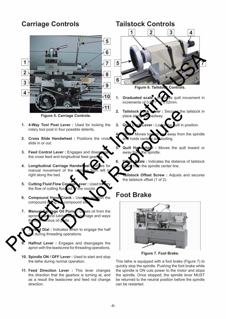
1. Graduated scale : Indicates quill movement in increments of 0.001" or 0.02mm.
2. Tailstock Lock Lever : Secures the tailstock in place along the bedway.
3. Quill Lock Lever : Locks the quill in position.
4. Quill : Moves toward and away from the spindle and holds centers and tooling.
5. Quill Handwheel : Moves the quill toward or away from the spindle.
6. Offset Scale : Indicates the distance of tailstock offset from the spindle center line.
7. Tailstock Offset Screw : Adjusts and secures the tailstock offset (1 of 2).
1. 4-Way Tool Post Lever : Used for locking the rotary tool post in four possible detents.
2. Cross Slide Handwheel : Positions the cross slide in or out.
3. Feed Control Lever : Engages and disengages the cross feed and longitudinal feed gearing.
4. Longitudinal Carriage Handwheel : Allows for manual movement of the carriage from left to right along the bed.
5. Cutting Fluid Flow Control Lever : Used to vary the fl ow of cutting fl uid out of the nozzle.
6. Compound Hand Crank : Used to position the compound along the compound slide.
7. Manual Carriage Oil Pump : Draws oil from the apron case and lubricates the carriage and ways through various oil ports.
8. Thread Dial : Indicates when to engage the half nut during threading operations.
9. Halfnut Lever : Engages and disengages the apron with the leadscrew for threading operations.
10. Spindle ON / OFF Lever : Used to start and stop the lathe during normal operation.
11. Feed Direction Lever : This lever changes the direction that the gearbox is turning at, and as a result the leadscrew and feed rod change direction.
Tailstock ControlsCarriage Controls
Figure 7. Foot Brake.
Figure 5. Carriage Controls.
1
3
4
5
6
7
8
9
10
11
2
Foot Brake
This lathe is equipped with a foot brake (Figure 7) to quickly stop the spindle. Pushing the foot brake while the spindle is ON cuts power to the motor and stops the spindle. Once stopped, the spindle lever MUST be returned to the neutral position before the spindle can be restarted.
Figure 6. Tailstock Controls.
1
5
6
7
2 3 4
Propert
y of K
ent In
dustr
ial U
SA
Do Not
Reprod
uce

-7-
Physical EnvironmentThe physical environment where your machine is operated is important for safe operation and longevity of parts. For best results, operate this machine in a dry environment that is free from excessive moisture, hazardous or fl ammable chemicals, airborne abrasives, or extreme conditions. Extreme conditions for this type of machinery are generally those where the ambient temperature is outside the range of 9° ~ 72ºC(48.2° ~ 161.6ºF); the relative humidity is outside the range of 20–95% (non-condensing); or the environment is subject to vibration, shocks, or bumps.
Electrical InstallationPlace this machine near an existing power source. Make sure all power cords are protected from traffi c, material handling, moisture, chemicals, or other hazards. Make sure to leave access to a means of disconnecting the power source or engaging a lockout / tagout device.
LightingLighting around the machine must be adequate enough that operations can be performed safely. Shadows, glare, or strobe effects that may distract or impede the operator must be eliminated.
Weight LoadMake sure that the surface upon which the machine is placed will bear the weight of the machine, additional equipment that may be installed on the machine, and the heaviest workpiece that will be used. Additionally, consider the weight of the operator and any dynamic loading that may occur when operating the machine.
Space AllocationConsider the largest size of workpiece that will be processed through this machine and provide enough space around the machine for adequate operator material handling or the installation of auxiliary equipment. With permanent installations, leave enough space around the machine to open or remove doors/covers as required by the maintenance and service described in this manual.
Lifting & MovingThis lathe is an extremely heavy machine. Serious personal injury or death may occur if safe lifting and moving methods are not followed. Get assistance from a professional rigger if you are unsure about your abilities or maximum load ratings of your lifting equipment.
To lift and move your lathe :1. Prepare the permanent location for the lathe.
2. Remove the shipping crate top and sides, then remove the small components from the shipping pallet.
3. To balance the lifting load, loosen the tailstock lock lever ( Figure 9 ), move the tailstock to the end of the bedway, then lock it in place.
Section 2 : Setup
Figure 8. Space required for full range of movement.
Model A B C TA1440 / 1640 2720 2080 1405 1095 / 1120
1460 / 1660 3228 2588 1913 1095 / 1120UNIT : mm
Tailstock Lock Lever
Figure 9. Tailstock lock lever.
Propert
y of K
ent In
dustr
ial U
SA
Do Not
Reprod
uce

-8-
b. Forklift work should be cooperatively done by two persons, that is an operator and watchman, not to damage projecting on the machine perimeter.
c. To put the fork, use the fork inserting the plinth mid-lift.
d. Keep the machine’s balance of gravity at the center of the forks.
5. Locking the carriage lock bolt and tailstock lock lever.
6. Lifting the machine with crane. (Figure 11)a. Make sure that minimum crane capacity is
more than 2 tons for security.
b. Only an authorized crane operator should use the lift machine.
c. Crane work should be cooperatively done by two persons, that is, an operator and a watchman, not to damage projecting on the machine perimeter.
d. To put in the jig with wire set inserting to bed way.
e. Make sure that two hexagon nuts is fi xed.
f. Keep the machine’s center of gravity at the center of the crane.
7. Moving the machine with a forklift. (Figure 12)a. Make sure that the minimum forklift capacity
is more than 2 tons for security.
Figure 11. Lifting the machine with crane.
Figure 12. Moving the machine with a forklift.
Figure 10. Carriage controls set for moving the carriage.
Carriage Handwheel Half Nut Lever
Feed Control Lever
Lock Bolt
CrossFeedNeutral
Long. Feed
4. To further balance the load, loosen the carriage lock bolt, disengage the half nut lever, put the feed control lever in neutral, then use the carriage handwheel to move the carriage next to the tailstock. (Figure 10)
Propert
y of K
ent In
dustr
ial U
SA
Do Not
Reprod
uce
-9-
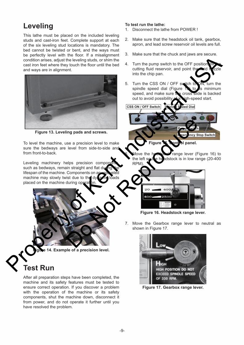
LevelingThis lathe must be placed on the included leveling studs and cast-iron feet. Complete support at each of the six leveling stud locations is mandatory. The bed cannot be twisted or bent, and the ways must be perfectly level with the fl oor. If a misalignment condition arises, adjust the leveling studs, or shim the cast iron feet where they touch the fl oor until the bed and ways are in alignment.
Figure 13. Leveling pads and screws.
6. Move the headstock range lever (Figure 16) to the left so the headstock is in low range (20-400 RPM).
To test run the lathe:1. Disconnect the lathe from POWER !
2. Make sure that the headstock oil tank, gearbox, apron, and lead screw reservoir oil levels are full.
3. Make sure that the chuck and jaws are secure.
4. Turn the pump switch to the OFF position, fi ll the cutting fl uid reservoir, and point the fl uid nozzle into the chip pan.
5. Turn the CSS ON / OFF switch to ON, turn the spindle speed dial (Figure 15) to its minimum speed, and make sure the cross slide is backed out to avoid possibility of a high-speed start.
Figure 15. Control panel.
CSS ON / OFF Switch Spindle Speed Dial
Pump Switch
Emergency Stop Switch
Figure 16. Headstock range lever.
Figure 17. Gearbox range lever.
To level the machine, use a precision level to make sure the bedways are level from side-to-side and from front-to-back. Leveling machinery helps precision components, such as bedways, remain straight and fl at during the lifespan of the machine. Components on an unleveled machine may slowly twist due to the dynamic loads placed on the machine during operation.
7. Move the Gearbox range lever to neutral as shown in Figure 17.
Test RunAfter all preparation steps have been completed, the machine and its safety features must be tested to ensure correct operation. If you discover a problem with the operation of the machine or its safety components, shut the machine down, disconnect it from power, and do not operate it further until you have resolved the problem.
Figure 14. Example of a precision level.
Propert
y of K
ent In
dustr
ial U
SA
Do Not
Reprod
uce
-10-
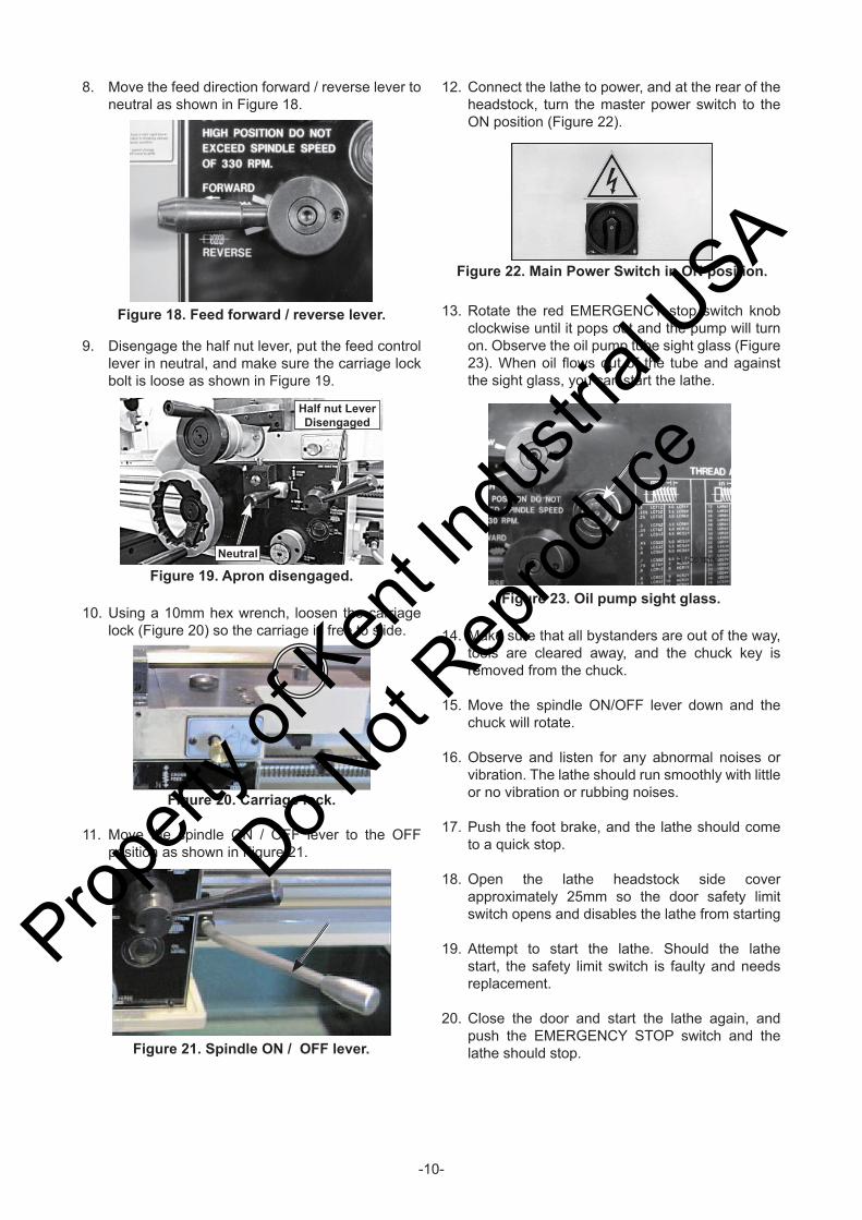
10. Using a 10mm hex wrench, loosen the carriage lock (Figure 20) so the carriage is free to slide.
Figure 20. Carriage lock.
Figure 21. Spindle ON / OFF lever.
Figure 22. Main Power Switch in ON position.
14. Make sure that all bystanders are out of the way, tools are cleared away, and the chuck key is removed from the chuck.
15. Move the spindle ON/OFF lever down and the chuck will rotate.
16. Observe and listen for any abnormal noises or vibration. The lathe should run smoothly with little or no vibration or rubbing noises.
17. Push the foot brake, and the lathe should come to a quick stop.
18. Open the lathe headstock side cover approximately 25mm so the door safety limit switch opens and disables the lathe from starting
19. Attempt to start the lathe. Should the lathe start, the safety limit switch is faulty and needs replacement.
20. Close the door and start the lathe again, and push the EMERGENCY STOP switch and the lathe should stop.
11. Move the spindle ON / OFF lever to the OFF position as shown in Figure 21.
12. Connect the lathe to power, and at the rear of the headstock, turn the master power switch to the ON position (Figure 22).
13. Rotate the red EMERGENCY stop switch knob clockwise until it pops out and the pump will turn on. Observe the oil pump tube sight glass (Figure 23). When oil fl ows out of the tube and against the sight glass, you can start the lathe.
Figure 23. Oil pump sight glass.
Figure 18. Feed forward / reverse lever.
8. Move the feed direction forward / reverse lever to neutral as shown in Figure 18.
9. Disengage the half nut lever, put the feed control lever in neutral, and make sure the carriage lock bolt is loose as shown in Figure 19.
Figure 19. Apron disengaged.Neutral
Half nut Lever Disengaged
Propert
y of K
ent In
dustr
ial U
SA
Do Not
Reprod
uce
-11-
21. Turn the cutting fl uid pump on, and fl uid should fl ow from the nozzle.
22. The test run is now fi nished. Shut the lathe down and begin the Spindle Break-In procedure.
Spindle Break-inIt is essential to closely follow the proper break-in procedures to ensure trouble-free performance. Complete this process once you have familiarized yourself with all instructions in this manual and completed the test run.
To break-in the spindle :1. Complete the Test Run procedure.
2. Turn the CSS ON / OFF dial to OFF and the spindle speed dial to the minimum speed.
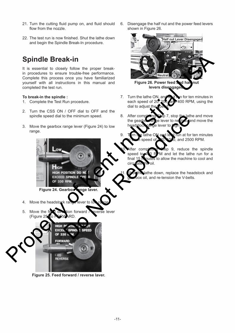
3. Move the gearbox range lever (Figure 24) to low range.
Figure 24. Gearbox range laver.
4. Move the headstock range lever to low range.
5. Move the feed direction forward / reverse lever (Figure 25) to FORWARD.
7. Turn the lathe ON, and let it run for ten minutes in each speed of 20, 200, and 400 RPM, using the dial to adjust the speed.
8. After completing Step 7, stop the lathe and move the gearbox range lever to neutral, and move the headstock range lever to high.
9. Turn the lathe ON and let it run at for ten minutes in each speed of 400, 1000, and 2500 RPM.
10. After completing Step 9, reduce the spindle speed to 400 RPM and let the lathe run for a fi nal 15 minutes to allow the machine to cool and circulate the oil.
11. Shut the lathe down, replace the headstock and gearbox oil, and re-tension the V-belts.
Figure 26. Power feed and half nut levers disengaged.
Half nut Lever Disengaged
Neutral
Figure 25. Feed forward / reverse laver.
6. Disengage the half nut and the power feed levers shown in Figure 26.
Propert
y of K
ent In
dustr
ial U
SA
Do Not
Reprod
uce
-12-
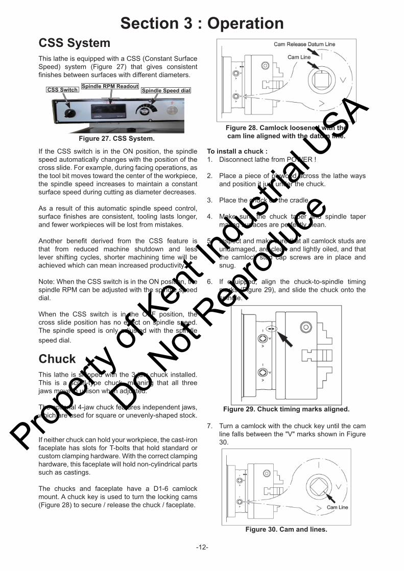
CSS SystemThis lathe is equipped with a CSS (Constant Surface Speed) system (Figure 27) that gives consistent fi nishes between surfaces with different diameters.
To install a chuck :1. Disconnect lathe from POWER !
2. Place a piece of plywood across the lathe ways and position it just under the chuck.
3. Place the chuck on the cradle.
4. Make sure the chuck taper and spindle taper mating surfaces are perfectly clean.
5. Inspect and make sure that all camlock studs are undamaged, are clean and lightly oiled, and that the camlock stud cap screws are in place and snug.
6. If equipped, align the chuck-to-spindle timing marks (Figure 29), and slide the chuck onto the spindle.
Section 3 : Operation
Figure 27. CSS System.
Spindle RPM ReadoutCSS Switch Spindle Speed dial
Figure 28. Camlock loosened with the cam line aligned with the datum line.
Figure 29. Chuck timing marks aligned.
Figure 30. Cam and lines.
If the CSS switch is in the ON position, the spindle speed automatically changes with the position of the cross slide. For example, during facing operations, as the tool bit moves toward the center of the workpiece, the spindle speed increases to maintain a constant surface speed during cutting as diameter decreases.
As a result of this automatic spindle speed control, surface fi nishes are consistent, tooling lasts longer, and fewer workpieces will be lost from mistakes.
Another benefi t derived from the CSS feature is that from reduced machine shutdown and less lever shifting cycles, shorter machining time will be achieved which can mean increased productivity.
Note: When the CSS switch is in the ON position, the spindle RPM can be adjusted with the spindle speed dial.
When the CSS switch is in the OFF position, the cross slide position has no effect on spindle speed. The spindle speed is only adjusted with the spindle speed dial.
ChuckThis lathe is shipped with the 3-jaw chuck installed. This is a scroll-type chuck, meaning that all three jaws move in unison when adjusted.
The optional 4-jaw chuck features independent jaws, which are used for square or unevenly-shaped stock.
If neither chuck can hold your workpiece, the cast-iron faceplate has slots for T-bolts that hold standard or custom clamping hardware. With the correct clamping hardware, this faceplate will hold non-cylindrical parts such as castings.
The chucks and faceplate have a D1-6 camlock mount. A chuck key is used to turn the locking cams (Figure 28) to secure / release the chuck / faceplate.
7. Turn a camlock with the chuck key until the cam line falls between the "V" marks shown in Figure 30.Prop
erty o
f Ken
t Indu
strial
USA
Do Not
Reprod
uce
-13-
8. Lock the other cams in a crisscross or star pattern so the chuck is drawn up evenly on all sides without any chance of misalignment.
9. Remove the chuck key.
To remove a chuck : 1. Disconnect lathe from POWER !
2. Place a piece of plywood across the lathe ways to protect the ways, or use a support cradle and position it just under the chuck.
3. Turn a cam with the chuck key until the cam line aligns with the cam release datum line.
4. Unlock the other cams in the same manner. Make sure to support the chuck as you align the last cam.
5. Remove the chuck key.
Installing and Adjusting Camlock StudWhen fi tting a chuck or faceplate with camlock studs, or when mounting a new chuck or faceplate, it may be necessary to install or adjust the camlock studs.
In order to properly install or adjust one or more camlock studs, you must remove a stud locking cap screw, then thread the camlock stud in or out until the line on the side of the stud is fl ush with the top of the chuck casting.
3-Jaw ChuckThe 3-jaw scroll-type chuck included with this lathe features hardened steel jaws that center the workpiece. When the operator opens or closes the jaws with the chuck key, the jaws move in unison.
There are two sets of jaws included with the 3-jaw chuck ─ inside and outside jaws. Use the correct jaws for the size and confi guration of the workpiece to hold it fi rmly and securely on the chuck.
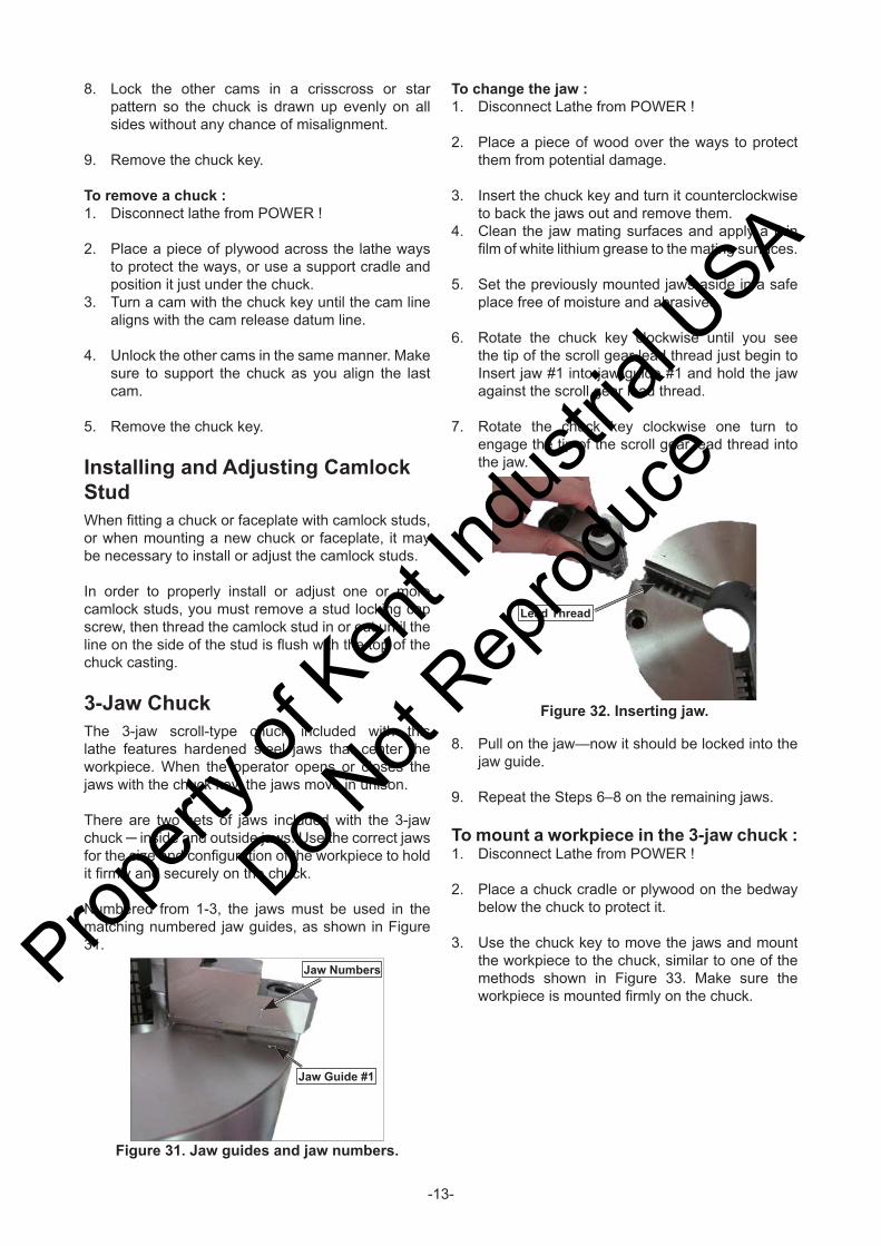
Numbered from 1-3, the jaws must be used in the matching numbered jaw guides, as shown in Figure 31.
To change the jaw : 1. Disconnect Lathe from POWER !
2. Place a piece of wood over the ways to protect them from potential damage.
3. Insert the chuck key and turn it counterclockwise to back the jaws out and remove them.
4. Clean the jaw mating surfaces and apply a thin fi lm of white lithium grease to the mating surfaces.
5. Set the previously mounted jaws aside in a safe place free of moisture and abrasives.
6. Rotate the chuck key clockwise until you see the tip of the scroll gear lead thread just begin to Insert jaw #1 into jaw guide #1 and hold the jaw against the scroll gear lead thread.
7. Rotate the chuck key clockwise one turn to engage the tip of the scroll gear lead thread into the jaw.
Lead Thread
Figure 32. Inserting jaw.
Jaw Guide #1
Jaw Numbers
Figure 31. Jaw guides and jaw numbers.
8. Pull on the jaw—now it should be locked into the jaw guide.
9. Repeat the Steps 6–8 on the remaining jaws.
To mount a workpiece in the 3-jaw chuck :1. Disconnect Lathe from POWER !
2. Place a chuck cradle or plywood on the bedway below the chuck to protect it.
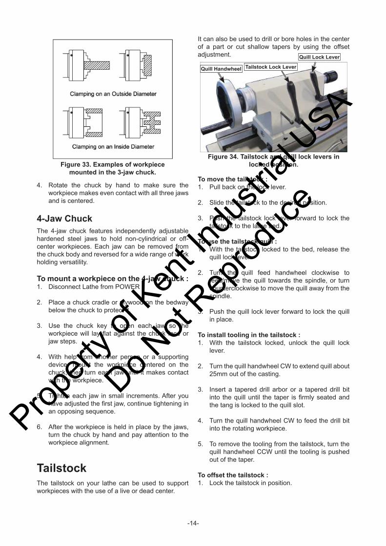
3. Use the chuck key to move the jaws and mount the workpiece to the chuck, similar to one of the methods shown in Figure 33. Make sure the workpiece is mounted fi rmly on the chuck.
Propert
y of K
ent In
dustr
ial U
SA
Do Not
Reprod
uce
-14-
Figure 33. Examples of workpiece mounted in the 3-jaw chuck.
4. Rotate the chuck by hand to make sure the workpiece makes even contact with all three jaws and is centered.
4-Jaw ChuckThe 4-jaw chuck features independently adjustable hardened steel jaws to hold non-cylindrical or off-center workpieces. Each jaw can be removed from the chuck body and reversed for a wide range of work holding versatility.
To mount a workpiece on the 4-jaw chuck :1. Disconnect Lathe from POWER !
2. Place a chuck cradle or plywood on the bedway below the chuck to protect it.
3. Use the chuck key to open each jaw so the workpiece will lay fl at against the chuck face or jaw steps.
4. With help from another person or a supporting device, mount the workpiece centered on the chuck, then turn each jaw until it makes contact with the workpiece.
5. Tighten each jaw in small increments. After you have adjusted the fi rst jaw, continue tightening in an opposing sequence.
6. After the workpiece is held in place by the jaws, turn the chuck by hand and pay attention to the workpiece alignment.
TailstockThe tailstock on your lathe can be used to support workpieces with the use of a live or dead center.
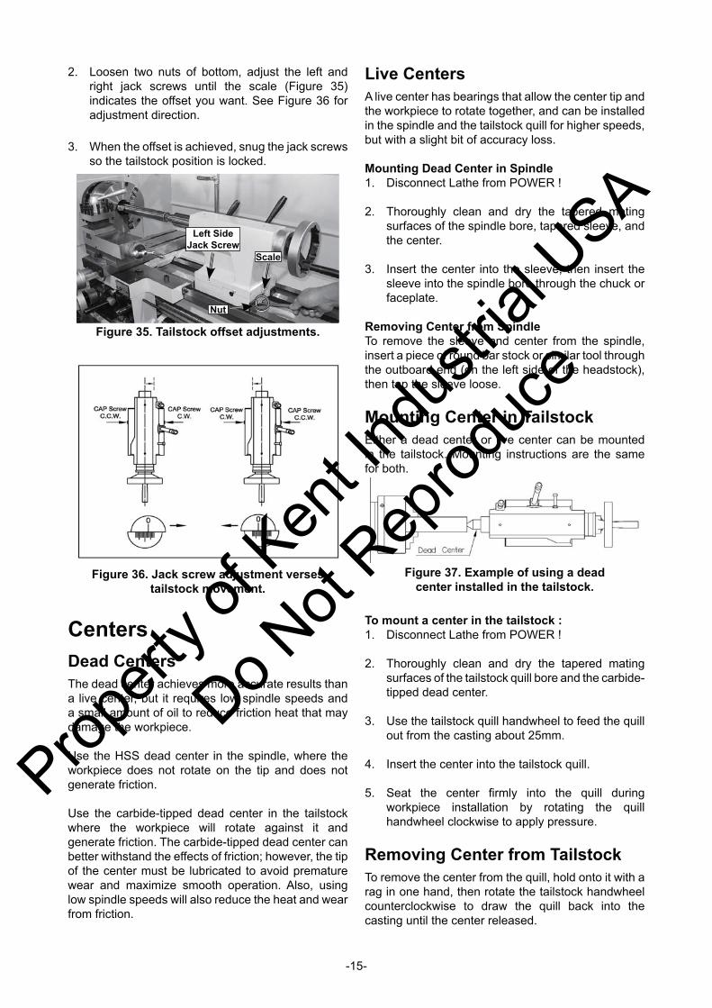
Figure 34. Tailstock and quill lock levers in locked position.
Quill Handwheel Tailstock Lock Lever
Quill Lock Lever
To move the tailstock :1. Pull back on the lock lever.
2. Slide the tailstock to the desired position.
3. Push the tailstock lock lever forward to lock the tailstock to the lathe bed.
To use the tailstock quill :1. With the tailstock locked to the bed, release the
quill lock lever.
2. Turn the quill feed handwheel clockwise to feed/move the quill towards the spindle, or turn counterclockwise to move the quill away from the spindle.
3. Push the quill lock lever forward to lock the quill in place.
To install tooling in the tailstock :1. With the tailstock locked, unlock the quill lock
lever.
2. Turn the quill handwheel CW to extend quill about 25mm out of the casting.
3. Insert a tapered drill arbor or a tapered drill bit into the quill until the taper is fi rmly seated and the tang is locked to the quill slot.
4. Turn the quill handwheel CW to feed the drill bit into the rotating workpiece.
5. To remove the tooling from the tailstock, turn the quill handwheel CCW until the tooling is pushed out of the taper.
To offset the tailstock :1. Lock the tailstock in position.
It can also be used to drill or bore holes in the center of a part or cut shallow tapers by using the offset adjustment.
Propert
y of K
ent In
dustr
ial U
SA
Do Not
Reprod
uce
-15-
CentersDead CentersThe dead center achieves more accurate results than a live center, but it requires low spindle speeds and a small amount of oil to reduce friction heat that may damage the workpiece.
Use the HSS dead center in the spindle, where the workpiece does not rotate on the tip and does not generate friction.
Use the carbide-tipped dead center in the tailstock where the workpiece will rotate against it and generate friction. The carbide-tipped dead center can better withstand the effects of friction; however, the tip of the center must be lubricated to avoid premature wear and maximize smooth operation. Also, using low spindle speeds will also reduce the heat and wear from friction.
Live CentersA live center has bearings that allow the center tip and the workpiece to rotate together, and can be installed in the spindle and the tailstock quill for higher speeds, but with a slight bit of accuracy loss.
Mounting Dead Center in Spindle1. Disconnect Lathe from POWER !
2. Thoroughly clean and dry the tapered mating surfaces of the spindle bore, tapered sleeve, and the center.
3. Insert the center into the sleeve, then insert the sleeve into the spindle bore through the chuck or faceplate.
Removing Center from SpindleTo remove the sleeve and center from the spindle, insert a piece of round bar stock or similar tool through the outboard end (on the left side of the headstock), then tap the sleeve loose.
Mounting Center in TailstockEither a dead center or live center can be mounted in the tailstock. Mounting instructions are the same for both.
Figure 36. Jack screw adjustment verses tailstock movement.
Figure 37. Example of using a dead center installed in the tailstock.
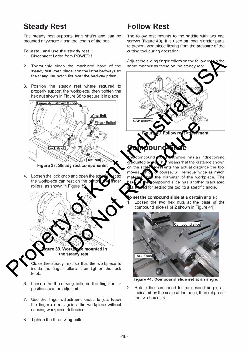
2. Loosen two nuts of bottom, adjust the left and right jack screws until the scale (Figure 35) indicates the offset you want. See Figure 36 for adjustment direction.
3. When the offset is achieved, snug the jack screws so the tailstock position is locked.
To mount a center in the tailstock :1. Disconnect Lathe from POWER !
2. Thoroughly clean and dry the tapered mating surfaces of the tailstock quill bore and the carbide-tipped dead center.
3. Use the tailstock quill handwheel to feed the quill out from the casting about 25mm.
4. Insert the center into the tailstock quill.
5. Seat the center fi rmly into the quill during workpiece installation by rotating the quill handwheel clockwise to apply pressure.
Removing Center from TailstockTo remove the center from the quill, hold onto it with a rag in one hand, then rotate the tailstock handwheel counterclockwise to draw the quill back into the casting until the center released.
Figure 35. Tailstock offset adjustments.
Scale
Nut
Left Side Jack Screw
Propert
y of K
ent In
dustr
ial U
SA
Do Not
Reprod
uce
-16-
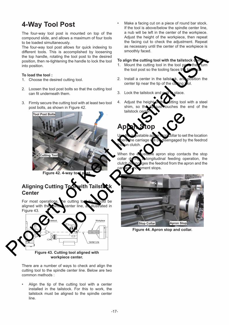
Steady RestThe steady rest supports long shafts and can be mounted anywhere along the length of the bed.
To install and use the steady rest :1. Disconnect Lathe from POWER !
2. Thoroughly clean the machined base of the steady rest, then place it on the lathe bedways so the triangular notch fi ts over the bedway prism.
3. Position the steady rest where required to properly support the workpiece, then tighten the hex nut shown in Figure 38 to secure it in place.
Figure 39. Workpiece mounted in the steady rest.
Figure 40. Follow rest attachment.
CAP Screws
4. Loosen the lock knob and open the steady rest so the workpiece can rest on the bottom two fi nger rollers, as shown in Figure 39.
Follow RestThe follow rest mounts to the saddle with two cap screws (Figure 40). It is used on long, slender parts to prevent workpiece fl exing from the pressure of the cutting tool during operation.
Adjust the sliding fi nger rollers on the follow rest in the same manner as those on the steady rest.
Compound SlideThe compound slide handwheel has an indirect-read graduated scale. This means that the distance shown on the scale represents the actual distance the tool moves, which of course, will remove twice as much material from the diameter of the workpiece. The base of the compound slide has another graduated scale used for setting the tool to a specifi c angle.
To set the compound slide at a certain angle :1. Loosen the two hex nuts at the base of the
compound slide (1 of 2 shown in Figure 41).
Figure 41. Compound slide set at an angle.
Lock Knob
Compound slide
5. Close the steady rest so that the workpiece is inside the fi nger rollers, then tighten the lock knob.
6. Loosen the three wing bolts so the fi nger roller positions can be adjusted.
7. Use the fi nger adjustment knobs to just touch the fi nger rollers against the workpiece without causing workpiece defl ection.
8. Tighten the three wing bolts.
2. Rotate the compound to the desired angle, as indicated by the scale at the base, then retighten the two hex nuts.
Figure 38. Steady rest components.
Finger Adjustment Knob
Wing Bolt
Finger Roller
Hex. Nut
Lock Knob
Propert
y of K
ent In
dustr
ial U
SA
Do Not
Reprod
uce
-17-
Figure 42. 4-way tool post.
Tool Post Bolts
Cutting Tool
Figure 43. Cutting tool aligned with workpiece center.
4-Way Tool PostThe four-way tool post is mounted on top of the compound slide, and allows a maximum of four tools to be loaded simultaneously.The four-way tool post allows for quick indexing to different tools. This is accomplished by loosening the top handle, rotating the tool post to the desired position, then re-tightening the handle to lock the tool into position.
To load the tool :1. Choose the desired cutting tool.
2. Loosen the tool post bolts so that the cutting tool can fi t underneath them.
3. Firmly secure the cutting tool with at least two tool post bolts, as shown in Figure 42.
Aligning Cutting Tool with Tailstock CenterFor most operations, the cutting tool tip should be aligned with the spindle center line, as illustrated in Figure 43.
There are a number of ways to check and align the cutting tool to the spindle center line. Below are two common methods : • Align the tip of the cutting tool with a center
installed in the tailstock. For this to work, the tailstock must be aligned to the spindle center line.
• Make a facing cut on a piece of round bar stock. If the tool is above/below the spindle center line, a nub will be left in the center of the workpiece. Adjust the height of the workpiece, then repeat the facing cut to check the adjustment. Repeat as necessary until the center of the workpiece is smoothly faced.
To align the cutting tool with the tailstock center :1. Mount the cutting tool in the tool post, then turn
the tool post so the tooling faces the tailstock.
2. Install a center in the tailstock, and position the center tip near the tip of the cutting tool.
3. Lock the tailstock and quill in place.
4. Adjust the height of the cutting tool with a steel shim, so the tip just touches the end of the tailstock center.
Apron StopUse the adjustable apron stop collar to set the location where the carriage will be disengaged by the feedrod friction clutch.
When the adjustable apron stop contacts the stop collar during a longitudinal feeding operation, the clutch disengages the feedrod from the apron and the carriage movement stops.
Figure 44. Apron stop and collar.Stop Collar Apron Stop
Propert
y of K
ent In
dustr
ial U
SA
Do Not
Reprod
uce
-18-
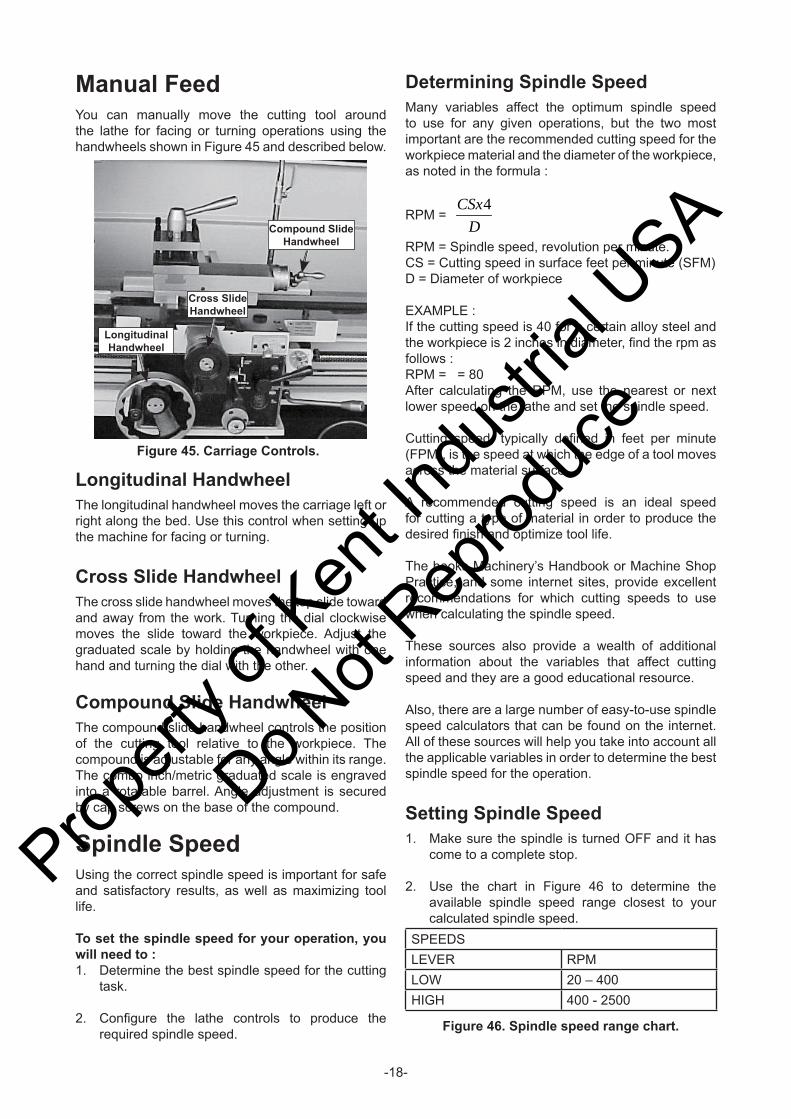
Longitudinal HandwheelThe longitudinal handwheel moves the carriage left or right along the bed. Use this control when setting up the machine for facing or turning.
Cross Slide HandwheelThe cross slide handwheel moves the top slide toward and away from the work. Turning the dial clockwise moves the slide toward the workpiece. Adjust the graduated scale by holding the handwheel with one hand and turning the dial with the other.
Compound Slide HandwheelThe compound slide handwheel controls the position of the cutting tool relative to the workpiece. The compound is adjustable for any angle within its range. The combo inch/metric graduated scale is engraved into a rotatable barrel. Angle adjustment is secured by cap screws on the base of the compound.
Spindle SpeedUsing the correct spindle speed is important for safe and satisfactory results, as well as maximizing tool life.
To set the spindle speed for your operation, you will need to :1. Determine the best spindle speed for the cutting
task.
2. Confi gure the lathe controls to produce the required spindle speed.
Figure 45. Carriage Controls.
Longitudinal Handwheel
Cross Slide Handwheel
Compound Slide Handwheel
Determining Spindle SpeedMany variables affect the optimum spindle speed to use for any given operations, but the two most important are the recommended cutting speed for the workpiece material and the diameter of the workpiece, as noted in the formula :
RPM = D
CSx4
RPM = Spindle speed, revolution per minute.CS = Cutting speed in surface feet per minute (SFM)D = Diameter of workpiece EXAMPLE :If the cutting speed is 40 for a certain alloy steel and the workpiece is 2 inches in diameter, fi nd the rpm as follows :RPM = = 80After calculating the RPM, use the nearest or next lower speed on the lathe and set the spindle speed.
Cutting speed, typically defi ned in feet per minute (FPM), is the speed at which the edge of a tool moves across the material surface.
A recommended cutting speed is an ideal speed for cutting a type of material in order to produce the desired fi nish and optimize tool life.
The books Machinery’s Handbook or Machine Shop Practice, and some internet sites, provide excellent recommendations for which cutting speeds to use when calculating the spindle speed.
These sources also provide a wealth of additional information about the variables that affect cutting speed and they are a good educational resource.
Also, there are a large number of easy-to-use spindle speed calculators that can be found on the internet. All of these sources will help you take into account all the applicable variables in order to determine the best spindle speed for the operation.
Setting Spindle Speed1. Make sure the spindle is turned OFF and it has
come to a complete stop.
2. Use the chart in Figure 46 to determine the available spindle speed range closest to your calculated spindle speed.
SPEEDSLEVER RPMLOW 20 – 400HIGH 400 - 2500
Figure 46. Spindle speed range chart.
Manual FeedYou can manually move the cutting tool around the lathe for facing or turning operations using the handwheels shown in Figure 45 and described below.
Propert
y of K
ent In
dustr
ial U
SA
Do Not
Reprod
uce

-19-
3. Adjust the spindle speed range lever to the range that covers your calculated spindle speed.
4. Turn the spindle ON and slowly turn the variable speed dial to carefully adjust the spindle speed to your calculated spindle speed.
Power FeedOn this machine, both the carriage and cross slide have power feed capability. The rate that these components move (feed rate) is controlled by how the levers are confi gured on the gearbox.
Feed rate and spindle speed must be considered together. The sources you use to determine the optimum spindle speed for an operation will also provide the optimal feed rate to use with that spindle speed.
Often, the experienced machinist will use the feeds and speeds given in their reference charts or web calculators as a starting point, then make minor adjustments to the feed rate (and sometimes spindle speed) to achieve the best results.
The carriage can alternately be driven by the leadscrew for threading operations. However, this section covers using the power feed option for the carriage and cross slide components for non-threading operations.
Power Feed ControlsThe feed direction lever controls direction of the carriage. The quick change feed direction knob reverses the feed direction of the carriage while the lathe is running.
Figure 49. Feed control lever positions.
Cross Feed
Neutral
Longitudinal Feed
To engage the power feed :1. Make sure the spindle is OFF and has come to a
complete stop.
2. Use the feed direction lever to select the direction that the feed rod will rotate.
3. Use the feed control lever on the front of the apron to engage power feed for either the carriage or the cross slide (see Figure 49). To engage the carriage, push the lever to the left and down. To engage the cross slide, push the lever to the right and up.
Feed Direction Lever
Figure 47. Feed Direction Lever.
Figure 48. Quick change feed direction knob.
To use the quick change feed direction knob :1. While the lathe is running, place the feed control
lever in neutral.
2. Push or pull the quick change feed direction knob to change the direction of the feed rod.
3. Re-engage the feed direction lever. The feed rod rotation will now be reversed, causing the engaged carriage or cross slide to move in the opposite direction.
Propert
y of K
ent In
dustr
ial U
SA
Do Not
Reprod
uce
-20-
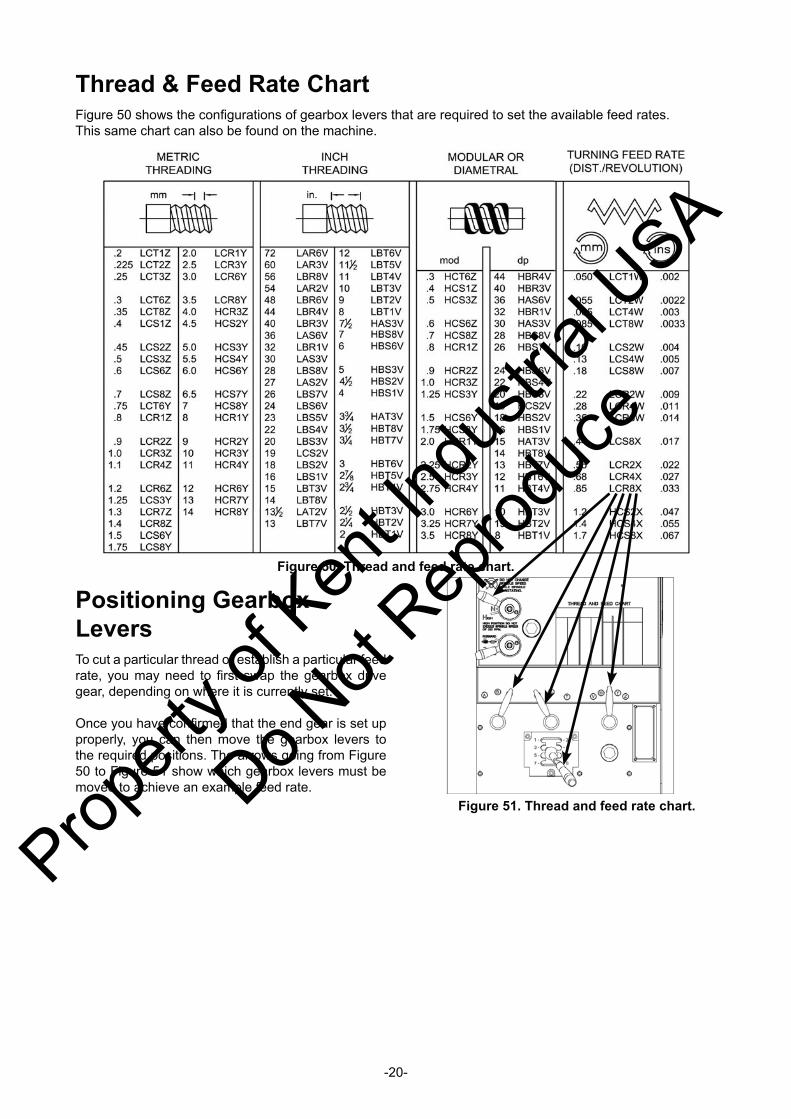
Thread & Feed Rate ChartFigure 50 shows the confi gurations of gearbox levers that are required to set the available feed rates.This same chart can also be found on the machine.
Figure 50. Thread and feed rate chart.
Figure 51. Thread and feed rate chart.
Positioning Gearbox LeversTo cut a particular thread or establish a particular feed rate, you may need to fi rst swap the gearbox drive gear, depending on where it is currently set.
Once you have confi rmed that the end gear is set up properly, you can then move the gearbox levers to the required positions. The arrows going from Figure 50 to Figure 51 show which gearbox levers must be moved to achieve an example feed rate.
Propert
y of K
ent In
dustr
ial U
SA
Do Not
Reprod
uce
-21-
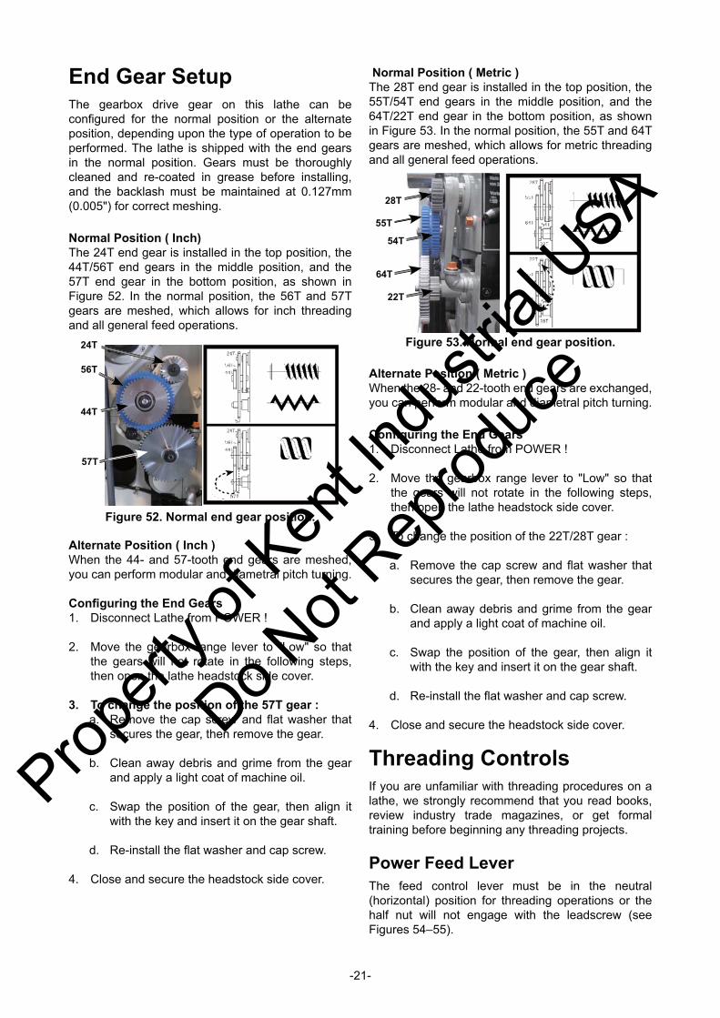
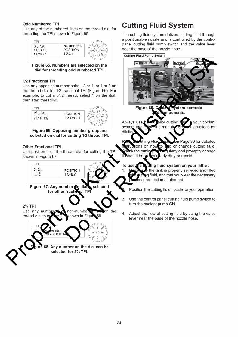
End Gear SetupThe gearbox drive gear on this lathe can be confi gured for the normal position or the alternate position, depending upon the type of operation to be performed. The lathe is shipped with the end gears in the normal position. Gears must be thoroughly cleaned and re-coated in grease before installing, and the backlash must be maintained at 0.127mm (0.005") for correct meshing.
Normal Position ( Inch)The 24T end gear is installed in the top position, the 44T/56T end gears in the middle position, and the 57T end gear in the bottom position, as shown in Figure 52. In the normal position, the 56T and 57T gears are meshed, which allows for inch threading and all general feed operations.
Normal Position ( Metric )The 28T end gear is installed in the top position, the 55T/54T end gears in the middle position, and the 64T/22T end gear in the bottom position, as shown in Figure 53. In the normal position, the 55T and 64T gears are meshed, which allows for metric threading and all general feed operations.
Alternate Position ( Inch )When the 44- and 57-tooth end gears are meshed, you can perform modular and diametral pitch turning.
Confi guring the End Gears1. Disconnect Lathe from POWER !
2. Move the gearbox range lever to "Low" so that the gears will not rotate in the following steps, then open the lathe headstock side cover.
3. To change the position of the 57T gear :a. Remove the cap screw and fl at washer that
secures the gear, then remove the gear.
b. Clean away debris and grime from the gear and apply a light coat of machine oil.
c. Swap the position of the gear, then align it with the key and insert it on the gear shaft.
d. Re-install the fl at washer and cap screw.
4. Close and secure the headstock side cover.
Figure 53. Normal end gear position.
28T
55T
54T
64T
22T
Alternate Position ( Metric )When the 28- and 22-tooth end gears are exchanged, you can perform modular and diametral pitch turning.
Confi guring the End Gears1. Disconnect Lathe from POWER !
2. Move the gearbox range lever to "Low" so that the gears will not rotate in the following steps, then open the lathe headstock side cover.
3. To change the position of the 22T/28T gear :
a. Remove the cap screw and fl at washer that secures the gear, then remove the gear.
b. Clean away debris and grime from the gear and apply a light coat of machine oil.
c. Swap the position of the gear, then align it with the key and insert it on the gear shaft.
d. Re-install the fl at washer and cap screw.
4. Close and secure the headstock side cover.
Threading ControlsIf you are unfamiliar with threading procedures on a lathe, we strongly recommend that you read books, review industry trade magazines, or get formal training before beginning any threading projects.
Power Feed LeverThe feed control lever must be in the neutral (horizontal) position for threading operations or the half nut will not engage with the leadscrew (see Figures 54–55).
24T
56T
57T
44T
Figure 52. Normal end gear position.
Propert
y of K
ent In
dustr
ial U
SA
Do Not
Reprod
uce
-22-
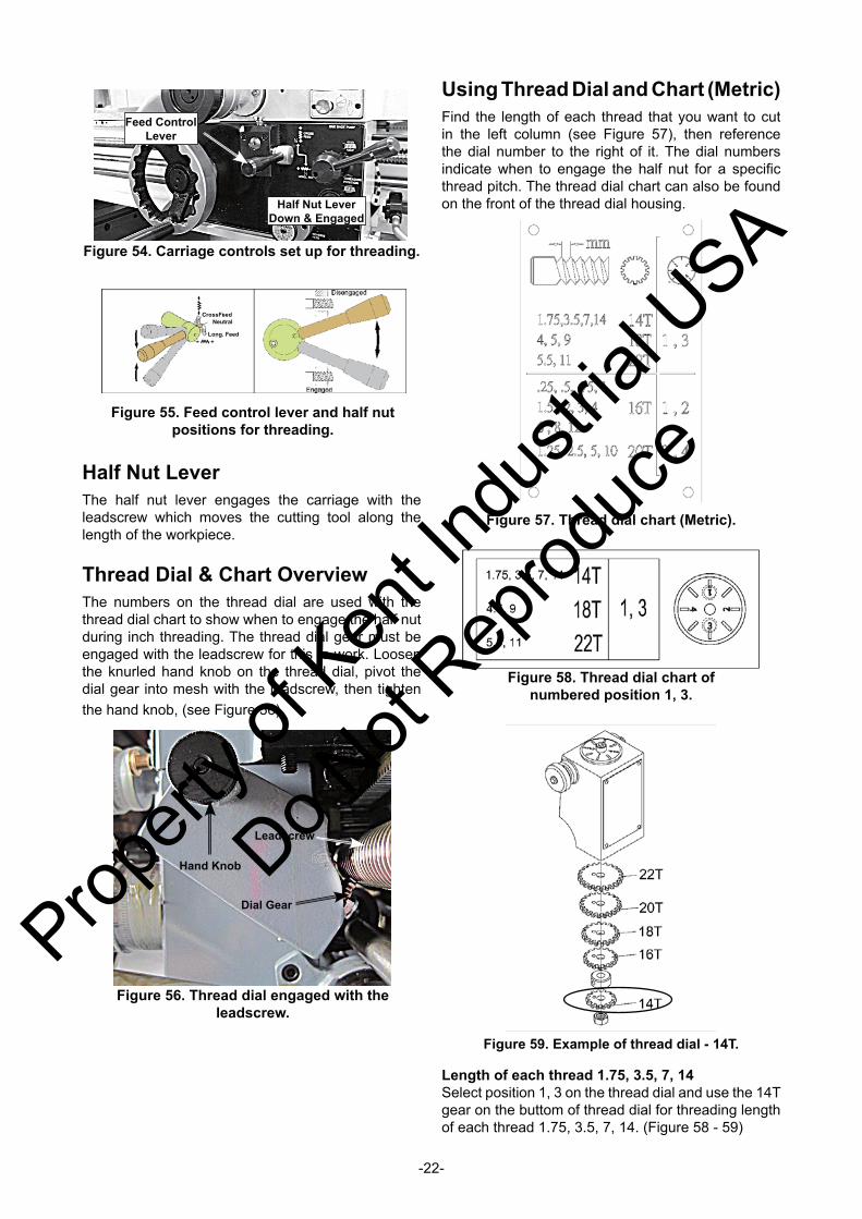
Half Nut LeverThe half nut lever engages the carriage with the leadscrew which moves the cutting tool along the length of the workpiece.
Thread Dial & Chart OverviewThe numbers on the thread dial are used with the thread dial chart to show when to engage the half nut during inch threading. The thread dial gear must be engaged with the leadscrew for this to work. Loosen the knurled hand knob on the thread dial, pivot the dial gear into mesh with the leadscrew, then tighten the hand knob, (see Figure 56).
Using Thread Dial and Chart (Metric)Find the length of each thread that you want to cut in the left column (see Figure 57), then reference the dial number to the right of it. The dial numbers indicate when to engage the half nut for a specifi c thread pitch. The thread dial chart can also be found on the front of the thread dial housing.
Feed Control Lever
Half Nut LeverDown & Engaged
Figure 54. Carriage controls set up for threading.
Hand Knob
Dial Gear
Leadscrew
Figure 56. Thread dial engaged with the leadscrew.
Length of each thread 1.75, 3.5, 7, 14Select position 1, 3 on the thread dial and use the 14T gear on the buttom of thread dial for threading length of each thread 1.75, 3.5, 7, 14. (Figure 58 - 59)
Figure 57. Thread dial chart (Metric).
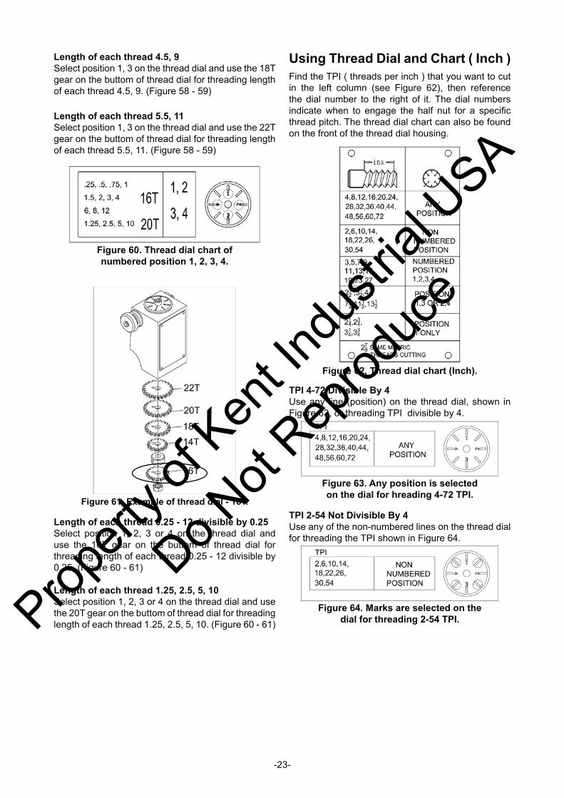
Figure 58. Thread dial chart of numbered position 1, 3.
Figure 59. Example of thread dial - 14T.
Figure 55. Feed control lever and half nut positions for threading.
CrossFeedNeutral
Long. Feed
Propert
y of K
ent In
dustr
ial U
SA
Do Not
Reprod
uce
-23-
Using Thread Dial and Chart ( Inch )Find the TPI ( threads per inch ) that you want to cut in the left column (see Figure 62), then reference the dial number to the right of it. The dial numbers indicate when to engage the half nut for a specifi c thread pitch. The thread dial chart can also be found on the front of the thread dial housing.
Length of each thread 0.25 - 12 divisible by 0.25Select position 1, 2, 3 or 4 on the thread dial and use the 16T gear on the buttom of thread dial for threading length of each thread 0.25 - 12 divisible by 0.25. (Figure 60 - 61)
Length of each thread 1.25, 2.5, 5, 10Select position 1, 2, 3 or 4 on the thread dial and use the 20T gear on the buttom of thread dial for threading length of each thread 1.25, 2.5, 5, 10. (Figure 60 - 61)
Length of each thread 4.5, 9Select position 1, 3 on the thread dial and use the 18T gear on the buttom of thread dial for threading length of each thread 4.5, 9. (Figure 58 - 59)
Length of each thread 5.5, 11Select position 1, 3 on the thread dial and use the 22T gear on the buttom of thread dial for threading length of each thread 5.5, 11. (Figure 58 - 59)
Figure 61. Example of thread dial - 16T.
Figure 62. Thread dial chart (Inch).
TPI 4-72 Divisible By 4Use any line (position) on the thread dial, shown in Figure 63, or threading TPI divisible by 4.
Figure 63. Any position is selected on the dial for hreading 4-72 TPI.
TPI 2-54 Not Divisible By 4Use any of the non-numbered lines on the thread dial for threading the TPI shown in Figure 64.
Figure 60. Thread dial chart of numbered position 1, 2, 3, 4.
Figure 64. Marks are selected on the dial for threading 2-54 TPI.Prop
erty o
f Ken
t Indu
strial
USA
Do Not
Reprod
uce
-24-
Cutting Fluid SystemThe cutting fl uid system delivers cutting fl uid through a positionable nozzle and is controlled by the control panel cutting fl uid pump switch and the valve lever near the base of the nozzle hose.
Nozzle Valve Lever
Cutting Fluid Pump Switch
Figure 69. Coolant system controls and components.
Odd Numbered TPIUse any of the numbered lines on the thread dial for threading the TPI shown in Figure 65.
1⁄2 Fractional TPIUse any opposing number pairs—2 or 4, or 1 or 3 on the thread dial for 1⁄2 fractional TPI (Figure 66). For example, to cut a 31⁄2 thread, select 1 on the dial, then start threading.
Other Fractional TPIUse position 1 on the thread dial for cutting the TPI shown in Figure 67.
Figure 65. Numbers are selected on the dial for threading odd numbered TPI.
Figure 66. Opposing number group are selected on dial for cutting 1⁄2 thread TPI.
Figure 67. Any number on dial is selected for other fractional TPI
2⅞ TPIUse any numbered or non-numbered line on the thread dial to cut the TPI shown in Figure 68
Figure 68. Any number on the dial can be selected for 2⅞ TPI.
Always use high quality cutting fl uid in your coolant system and follow the manufacturer's instructions for diluting.
Refer to Cutting Fluid System on Page 30 for detailed instructions on how to add or change cutting fl uid. Check the cutting fl uid regularly and promptly change it when it becomes overly dirty or rancid.
To use the cutting fl uid system on your lathe :1. Make sure the tank is properly serviced and fi lled
with cutting fl uid, and that you wear the necessary personal protection equipment.
2. Position the cutting fl uid nozzle for your operation.
3. Use the control panel cutting fl uid pump switch to turn the coolant pump ON.
4. Adjust the fl ow of cutting fl uid by using the valve lever near the base of the nozzle hose.
Propert
y of K
ent In
dustr
ial U
SA
Do Not
Reprod
uce
-25-
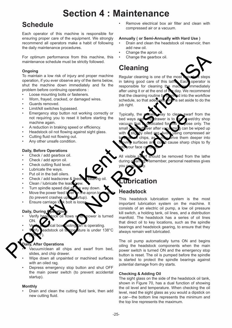
ScheduleEach operator of this machine is responsible for ensuring proper care of the equipment. We strongly recommend all operators make a habit of following the daily maintenance procedures.
For optimum performance from this machine, this maintenance schedule must be strictly followed.
OngoingTo maintain a low risk of injury and proper machine operation, if you ever observe any of the items below, shut the machine down immediately and fi x the problem before continuing operations :• Loose mounting bolts or fasteners.• Worn, frayed, cracked, or damaged wires.• Guards removed.• Limit/kill switches bypassed.• Emergency stop button not working correctly or
not requiring you to reset it before starting the machine again.
• A reduction in braking speed or effi ciency.• Headstock oil not fl owing against sight glass.• Cutting fl uid not fl owing out.• Any other unsafe condition.
Daily, Before Operations• Check / add gearbox oil.• Check / add apron oil.• Check cutting fl uid level.• Lubricate the ways.• Put oil in the ball oilers.• Check / add leadscrew & feedrod bearing oil.• Clean / lubricate the leadscrew.• Turn spindle speed dial all the way down.• Move the power feed lever on the apron to neutral
(to prevent crashes upon startup).• Ensure carriage lock bolt is loose. Daily, During Operations• Verify headstock oil fl ows when power is turned
ON.• Verify electrical box cooling fan is operating.• Verify headstock oil temperature is under 138°C
(280° F).
Daily, After Operations• Vacuum/clean all chips and swarf from bed,
slides, and chip drawer.• Wipe down all unpainted or machined surfaces
with an oiled rag.• Depress emergency stop button and shut OFF
the main power switch (to prevent accidental startup).
Monthly• Drain and clean the cutting fl uid tank, then add
new cutting fl uid.
• Remove electrical box air fi lter and clean with compressed air or a vacuum.
Annually ( or Semi-Annually with Hard Use )• Drain and clean the headstock oil reservoir, then
add new oil.• Change the apron oil.• Change the gearbox oil.
CleaningRegular cleaning is one of the most important steps in taking good care of this lathe. Each operator is responsible for cleaning the machine immediately after using it or at the end of the day. We recommend that the cleaning routine be planned into the workfl ow schedule, so that adequate time is set aside to do the job right.
Typically, the easiest way to clean swarf from the bed ways and chip drawer is to use a wet/dry shop vacuum that is dedicated for this purpose only. The small chips leftover after vacuuming can be wiped up with a slightly oiled rag. Avoid using compressed air to blow off chips, as it may drive them deeper into moving surfaces and could cause sharp chips to fl y into your face or hands.
All visible swarf should be removed from the lathe during cleaning. Remember, personal neatness gives you personality.
LubricationHeadstockThis headstock lubrication system is the most important lubrication system on the machine. It consists of an electric oil pump, a low oil pressure kill switch, a holding tank, oil lines, and a distribution manifold. The headstock has a series of oil lines that direct oil to key locations, such as the spindle bearings and headstock gearing, to ensure that they always remain well lubricated.
The oil pump automatically turns ON and begins oiling the headstock components when the main power switch is turned ON and the emergency stop button is reset. The oil is pumped before the spindle is started to protect the spindle bearings against potential damage from dry starts.
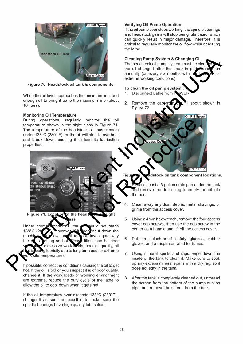
Checking & Adding OilThe sight glass on the side of the headstock oil tank, shown in Figure 70, has a dual function of showing the oil level and temperature. When checking the oil level, read the sight glass as you would a dipstick on a car—the bottom line represents the minimum and the top line represents the maximum.
Section 4 : Maintenance
Propert
y of K
ent In
dustr
ial U
SA
Do Not
Reprod
uce
-26-
When the oil level approaches the minimum line, add enough oil to bring it up to the maximum line (about 16 liters).
Monitoring Oil TemperatureDuring operations, regularly monitor the oil temperature shown in the sight glass in Figure 71. The temperature of the headstock oil must remain under 138°C (280° F). or the oil will start to overheat and break down, causing it to lose its lubrication properties.
Verifying Oil Pump OperationIf the oil pump ever stops working, the spindle bearings and headstock gears will stop being lubricated, which can quickly result in major damage. Therefore, it is critical to regularly monitor the oil fl ow while operating the lathe.
Cleaning Pump System & Changing OilThe headstock oil pump system must be cleaned and the oil changed after the break-in period and then annually (or every six months with hard service or extreme working conditions).
To clean the oil pump system :1. Disconnect Lathe from POWER !
2. Remove the cap from the fi ll spout shown in Figure 72.
Under normal conditions, the oil should not reach 138°C (280° F).; however, if it does, shut down the machine and allow the oil to cool. Investigate why the oil is getting so hot. Possibilities may be poor ventilation, excessive work loads, poor oil quality, oil that is losing lubricity due to long term use, or extreme work site temperatures.
If possible, correct the conditions causing the oil to get hot. If the oil is old or you suspect it is of poor quality, change it. If the work loads or working environment are extreme, reduce the duty cycle of the lathe to allow the oil to cool down when it gets hot.
If the oil temperature ever exceeds 138°C (280°F)., change it as soon as possible to make sure the spindle bearings have high quality lubrication.
3. Place at least a 3-gallon drain pan under the tank and remove the drain plug to empty the oil into the pan.
4. Clean away any dust, debris, metal shavings, or grime from the access cover.
5. Using a 4mm hex wrench, remove the four access cover cap screws, then use the cap screw in the center as a handle and lift off the access cover.
6. Put on splash-proof safety glasses, rubber gloves, and a respirator rated for fumes.
7. Using mineral spirits and rags, wipe down the inside of the tank to clean it. Make sure to soak up any excess mineral spirits with a dry rag, so it does not stay in the tank.
8. After the tank is completely cleaned out, unthread the screen from the bottom of the pump suction pipe, and remove the screen from the tank.
Figure 70. Headstock oil tank & components.
Oil Fill Spout
Sight Glass
Headstock Oil Tank
Figure 71. Location of the headstock oil sight glass.
Sight Glass
Figure 72. Headstock oil tank component locations.
Oil Fill Spout
Access Cover
Drain Plug
Propert
y of K
ent In
dustr
ial U
SA
Do Not
Reprod
uce
-27-
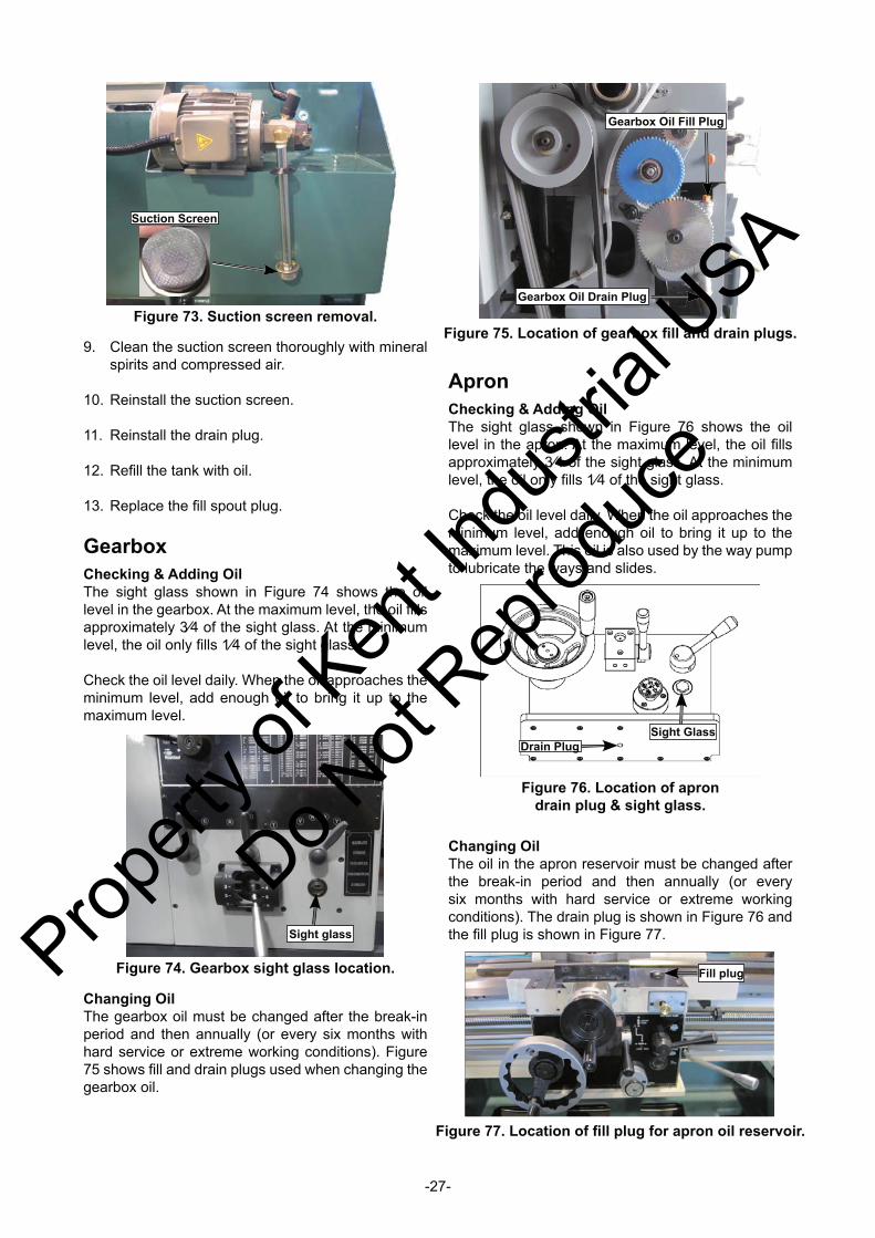
9. Clean the suction screen thoroughly with mineral spirits and compressed air.
10. Reinstall the suction screen.
11. Reinstall the drain plug.
12. Refi ll the tank with oil.
13. Replace the fi ll spout plug.
GearboxChecking & Adding OilThe sight glass shown in Figure 74 shows the oil level in the gearbox. At the maximum level, the oil fi lls approximately 3⁄4 of the sight glass. At the minimum level, the oil only fi lls 1⁄4 of the sight glass.
Check the oil level daily. When the oil approaches the minimum level, add enough oil to bring it up to the maximum level.
ApronChecking & Adding OilThe sight glass shown in Figure 76 shows the oil level in the apron. At the maximum level, the oil fi lls approximately 3⁄4 of the sight glass. At the minimum level, the oil only fi lls 1⁄4 of the sight glass.
Check the oil level daily. When the oil approaches the minimum level, add enough oil to bring it up to the maximum level. This oil is also used by the way pump to lubricate the ways and slides.
Figure 74. Gearbox sight glass location.
Sight glass
Figure 75. Location of gearbox fi ll and drain plugs.
Gearbox Oil Fill Plug
Gearbox Oil Drain Plug
Figure 77. Location of fi ll plug for apron oil reservoir.
Fill plug
Changing OilThe gearbox oil must be changed after the break-in period and then annually (or every six months with hard service or extreme working conditions). Figure 75 shows fi ll and drain plugs used when changing the gearbox oil.
Changing OilThe oil in the apron reservoir must be changed after the break-in period and then annually (or every six months with hard service or extreme working conditions). The drain plug is shown in Figure 76 and the fi ll plug is shown in Figure 77.
Suction Screen
Figure 73. Suction screen removal.
Figure 76. Location of apron drain plug & sight glass.
Sight GlassDrain Plug
Propert
y of K
ent In
dustr
ial U
SA
Do Not
Reprod
uce
-28-
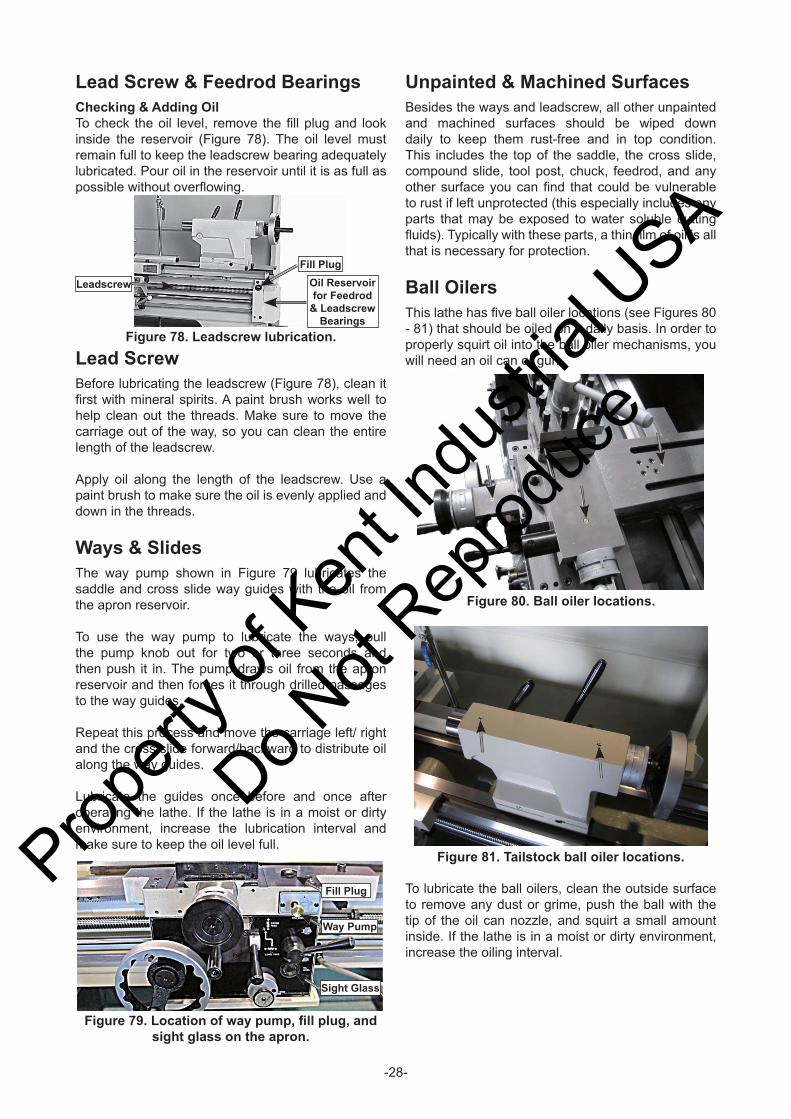
Lead Screw & Feedrod BearingsChecking & Adding OilTo check the oil level, remove the fi ll plug and look inside the reservoir (Figure 78). The oil level must remain full to keep the leadscrew bearing adequately lubricated. Pour oil in the reservoir until it is as full as possible without overfl owing.
Unpainted & Machined SurfacesBesides the ways and leadscrew, all other unpainted and machined surfaces should be wiped down daily to keep them rust-free and in top condition. This includes the top of the saddle, the cross slide, compound slide, tool post, chuck, feedrod, and any other surface you can fi nd that could be vulnerable to rust if left unprotected (this especially includes any parts that may be exposed to water soluble cutting fl uids). Typically with these parts, a thin fi lm of oil is all that is necessary for protection.
Ball OilersThis lathe has fi ve ball oiler locations (see Figures 80 - 81) that should be oiled on a daily basis. In order to properly squirt oil into the ball oiler mechanisms, you will need an oil can or gun.
Figure 80. Ball oiler locations.
Figure 81. Tailstock ball oiler locations.
To lubricate the ball oilers, clean the outside surface to remove any dust or grime, push the ball with the tip of the oil can nozzle, and squirt a small amount inside. If the lathe is in a moist or dirty environment, increase the oiling interval.
Figure 79. Location of way pump, fi ll plug, and sight glass on the apron.
Fill Plug
Sight Glass
Way Pump
Lead ScrewBefore lubricating the leadscrew (Figure 78), clean it fi rst with mineral spirits. A paint brush works well to help clean out the threads. Make sure to move the carriage out of the way, so you can clean the entire length of the leadscrew.
Apply oil along the length of the leadscrew. Use a paint brush to make sure the oil is evenly applied and down in the threads.
Ways & SlidesThe way pump shown in Figure 79 lubricates the saddle and cross slide way guides with the oil from the apron reservoir.
To use the way pump to lubricate the ways, pull the pump knob out for two or three seconds and then push it in. The pump draws oil from the apron reservoir and then forces it through drilled passages to the way guides.
Repeat this process and move the carriage left/ right and the cross slide forward/backward to distribute oil along the way guides.
Lubricate the guides once before and once after operating the lathe. If the lathe is in a moist or dirty environment, increase the lubrication interval and make sure to keep the oil level full.
Figure 78. Leadscrew lubrication.
Fill Plug
Leadscrew Oil Reservoir for Feedrod
& Leadscrew Bearings
Propert
y of K
ent In
dustr
ial U
SA
Do Not
Reprod
uce
-29-
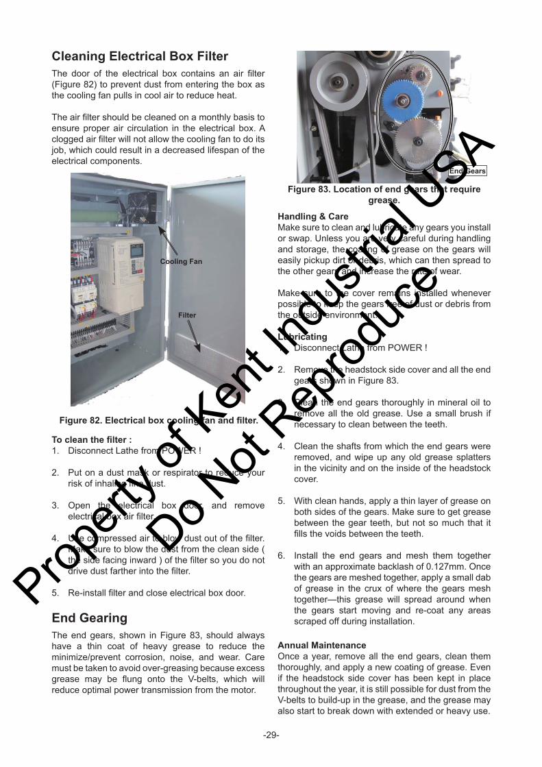
Cleaning Electrical Box FilterThe door of the electrical box contains an air fi lter (Figure 82) to prevent dust from entering the box as the cooling fan pulls in cool air to reduce heat.
The air fi lter should be cleaned on a monthly basis to ensure proper air circulation in the electrical box. A clogged air fi lter will not allow the cooling fan to do its job, which could result in a decreased lifespan of the electrical components.
Handling & CareMake sure to clean and lubricate any gears you install or swap. Unless you are very careful during handling and storage, the coating of grease on the gears will easily pickup dirt or debris, which can then spread to the other gears and increase the rate of wear.
Make sure to the cover remains installed whenever possible to keep the gears free of dust or debris from the outside environment.
Lubricating1. Disconnect Lathe from POWER !
2. Remove the headstock side cover and all the end gears shown in Figure 83.
3. Clean the end gears thoroughly in mineral oil to remove all the old grease. Use a small brush if necessary to clean between the teeth.
4. Clean the shafts from which the end gears were removed, and wipe up any old grease splatters in the vicinity and on the inside of the headstock cover.
5. With clean hands, apply a thin layer of grease on both sides of the gears. Make sure to get grease between the gear teeth, but not so much that it fi lls the voids between the teeth.
6. Install the end gears and mesh them together with an approximate backlash of 0.127mm. Once the gears are meshed together, apply a small dab of grease in the crux of where the gears mesh together—this grease will spread around when the gears start moving and re-coat any areas scraped off during installation.
Annual MaintenanceOnce a year, remove all the end gears, clean them thoroughly, and apply a new coating of grease. Even if the headstock side cover has been kept in place throughout the year, it is still possible for dust from the V-belts to build-up in the grease, and the grease may also start to break down with extended or heavy use.
Figure 82. Electrical box cooling fan and fi lter.
Cooling Fan
Filter
End Gears
Figure 83. Location of end gears that require grease.
To clean the fi lter :1. Disconnect Lathe from POWER !
2. Put on a dust mask or respirator to reduce your risk of inhaling fi ne dust.
3. Open the electrical box door, and remove electrical box air fi lter.
4. Use compressed air to blow dust out of the fi lter. Make sure to blow the dust from the clean side ( the side facing inward ) of the fi lter so you do not drive dust farther into the fi lter.
5. Re-install fi lter and close electrical box door.
End GearingThe end gears, shown in Figure 83, should always have a thin coat of heavy grease to reduce the minimize/prevent corrosion, noise, and wear. Care must be taken to avoid over-greasing because excess grease may be fl ung onto the V-belts, which will reduce optimal power transmission from the motor.
Propert
y of K
ent In
dustr
ial U
SA
Do Not
Reprod
uce
-30-
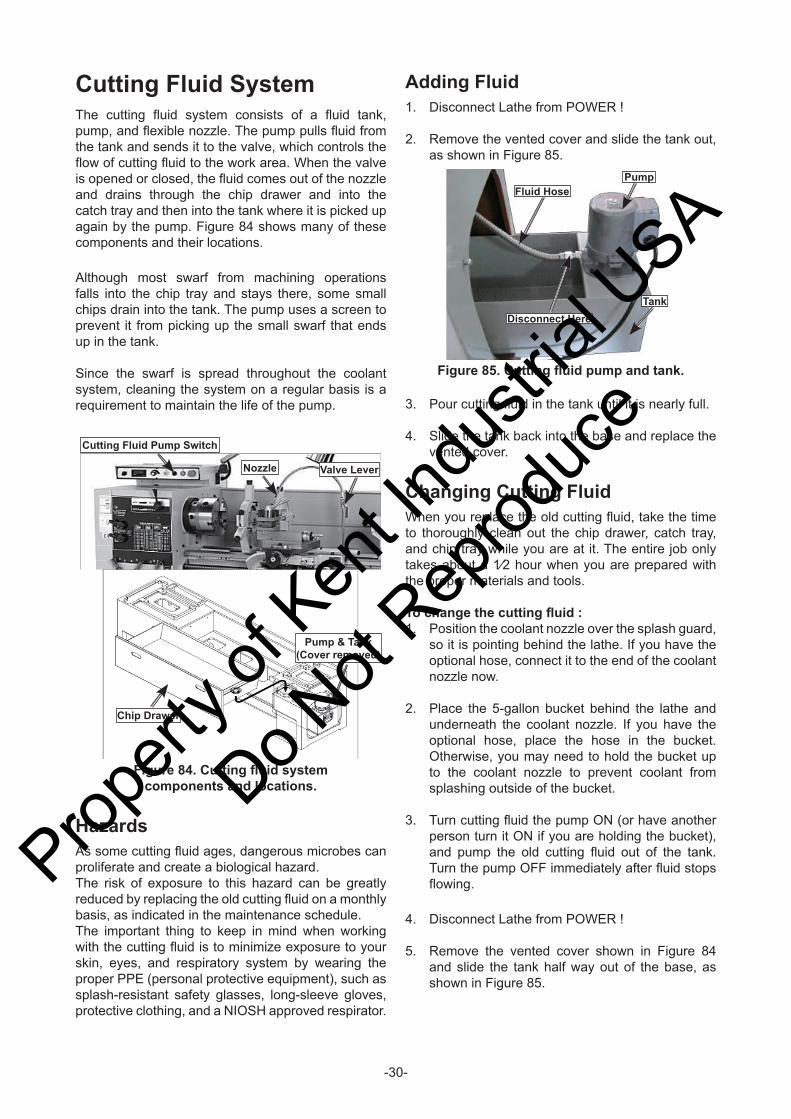
Cutting Fluid SystemThe cutting fl uid system consists of a fl uid tank, pump, and fl exible nozzle. The pump pulls fl uid from the tank and sends it to the valve, which controls the fl ow of cutting fl uid to the work area. When the valve is opened or closed, the fl uid comes out of the nozzle and drains through the chip drawer and into the catch tray and then into the tank where it is picked up again by the pump. Figure 84 shows many of these components and their locations.
Although most swarf from machining operations falls into the chip tray and stays there, some small chips drain into the tank. The pump uses a screen to prevent it from picking up the small swarf that ends up in the tank.
Since the swarf is spread throughout the coolant system, cleaning the system on a regular basis is a requirement to maintain the life of the pump.
Adding Fluid1. Disconnect Lathe from POWER !
2. Remove the vented cover and slide the tank out, as shown in Figure 85.
HazardsAs some cutting fl uid ages, dangerous microbes can proliferate and create a biological hazard.The risk of exposure to this hazard can be greatly reduced by replacing the old cutting fl uid on a monthly basis, as indicated in the maintenance schedule.The important thing to keep in mind when working with the cutting fl uid is to minimize exposure to your skin, eyes, and respiratory system by wearing the proper PPE (personal protective equipment), such as splash-resistant safety glasses, long-sleeve gloves, protective clothing, and a NIOSH approved respirator.
3. Pour cutting fl uid in the tank until it is nearly full.
4. Slide the tank back into the base and replace the vented cover.
Changing Cutting FluidWhen you replace the old cutting fl uid, take the time to thoroughly clean out the chip drawer, catch tray, and chip tray while you are at it. The entire job only takes about a 1⁄2 hour when you are prepared with the proper materials and tools.
To change the cutting fl uid :1. Position the coolant nozzle over the splash guard,
so it is pointing behind the lathe. If you have the optional hose, connect it to the end of the coolant nozzle now.
2. Place the 5-gallon bucket behind the lathe and underneath the coolant nozzle. If you have the optional hose, place the hose in the bucket. Otherwise, you may need to hold the bucket up to the coolant nozzle to prevent coolant from splashing outside of the bucket.
3. Turn cutting fl uid the pump ON (or have another person turn it ON if you are holding the bucket), and pump the old cutting fl uid out of the tank. Turn the pump OFF immediately after fl uid stops fl owing.
4. Disconnect Lathe from POWER !
5. Remove the vented cover shown in Figure 84 and slide the tank half way out of the base, as shown in Figure 85.
Nozzle
Chip Drawer
Pump & Tank(Cover removed)
Valve Lever
Cutting Fluid Pump Switch
Figure 84. Cutting fl uid system components and locations.
Figure 85. Cutting fl uid pump and tank.
Pump
Tank
Fluid Hose
Disconnect Here
Propert
y of K
ent In
dustr
ial U
SA
Do Not
Reprod
uce

-31-
6. Once or twice a month, depending on the ambient humidity levels in the storage environment, wipe down the machine as outlined in Step 3.
7. Every few months, start the machine and run all gear-driven components for a few minutes. This will keep the bearings, bushings, gears, and shafts well lubricated and protected from corrosion, especially during the winter months.
To prepare your machine for long-term storage (a year or more) :1. If the machine has oil-lubricated gearboxes, bring
the machine to operating temperature and drain and refi ll the all gearboxes with fresh oil.
2. Pump out the old cutting fl uid, and fl ush the lines and tank.
3. Disconnect Lathe from POWER !
4. Thoroughly clean all unpainted, bare metal surfaces, then apply a liberal coat of way oil, a heavy grease, or rust preventative. Take care to ensure these surfaces are completely covered but that the rust preventative or grease is kept off of painted surfaces.
5. Lubricate the machine as outlined in the lubrication section.
6. Loosen or remove machine belts so they do not become stretched during the storage period. Be sure to also affi x a maintenance note on the machine as a reminder that the belts have been loosened or removed.
7. Place a few moisture absorbing desiccant packs inside of the electrical box.
8. Cover and place the machine in a dry area that is out of direct sunlight and away from hazardous fumes, paint, solvents, or gas. Fumes and sunlight can bleach or discolor paint and make plastic guards cloudy.
If necessary, disconnect the fl uid hose from the pump, where shown in Figure 85.
6. Pour out the old cutting fl uid into your 5-gallon bucket and close the lid.
7. Flush the tank with hot soapy water, making sure the intake screen at the bottom of the pump intake pipe (inside the tank) is clean, and wipe up any remaining fl uid residue.
8. Slide the tank partially into the base and reconnect the fl uid hose.
9. Refi ll the tank with new cutting fl uid, then slide the tank completely into the base.
10. Connect Lathe to power.
11. Open the valve on the cutting fl uid nozzle.
12. Turn the cutting fl uid pump ON to verify that fl uid cycles properly, then turn it OFF.
Machine StorageIf the machine is not properly prepared for storage, it may develop rust or corrosion. If decommissioning this machine, use the steps in this section to ensure that it remains in good condition for later use.
To prepare your machine for short-term storage (up to a year) :1. Pump out the old cutting fl uid, and fl ush the lines
and tank.
2. Disconnect Lathe from POWER !
3. Thoroughly clean all unpainted, bare metal surfaces, then apply a liberal coat of way oil.
4. Lubricate the machine as outlined in the lubrication section.
5. Cover and place the machine in a dry area that is out of direct sunlight and away from hazardous fumes, paint, solvents, or gas. Fumes and sunlight can bleach or discolor paint and make plastic guards cloudy.Prop
erty o
f Ken
t Indu
strial
USA
Do Not
Reprod
uce
-32-
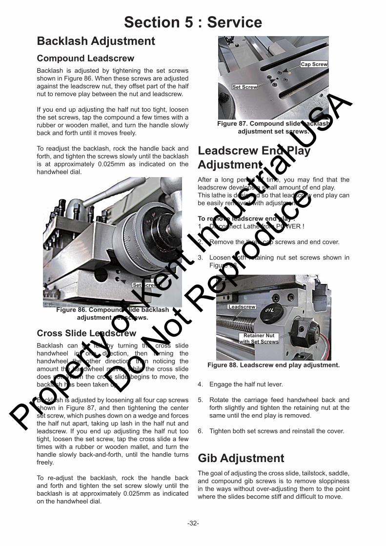
Backlash AdjustmentCompound LeadscrewBacklash is adjusted by tightening the set screws shown in Figure 86. When these screws are adjusted against the leadscrew nut, they offset part of the half nut to remove play between the nut and leadscrew.
If you end up adjusting the half nut too tight, loosen the set screws, tap the compound a few times with a rubber or wooden mallet, and turn the handle slowly back and forth until it moves freely.
To readjust the backlash, rock the handle back and forth, and tighten the screws slowly until the backlash is at approximately 0.025mm as indicated on the handwheel dial.
Leadscrew End Play AdjustmentAfter a long period of time, you may fi nd that the leadscrew develops a small amount of end play.This lathe is designed so that leadscrew end play can be easily removed with adjustment.
To remove leadscrew end play :1. Disconnect Lathe from POWER !
2. Remove the three cap screws and end cover.
3. Loosen both retaining nut set screws shown in Figure 88.
Section 5 : Service
Set Screws
Figure 86. Compound slide backlash adjustment set screws.
Figure 87. Compound slide backlash adjustment set screws.
Cap Screw
Set Screw
Figure 88. Leadscrew end play adjustment.
Retainer Nut with Set Screws
Leadscrew
Cross Slide LeadscrewBacklash can be felt by turning the cross slide handwheel in one direction, then turning the handwheel the other direction, then noticing the amount the handwheel moves while the cross slide does not. When the cross slide begins to move, the backlash has been taken up.
Backlash is adjusted by loosening all four cap screws shown in Figure 87, and then tightening the center set screw, which pushes down on a wedge and forces the half nut apart, taking up lash in the half nut and leadscrew. If you end up adjusting the half nut too tight, loosen the set screw, tap the cross slide a few times with a rubber or wooden mallet, and turn the handle slowly back-and-forth, until the handle turns freely.
To re-adjust the backlash, rock the handle back and forth and tighten the set screw slowly until the backlash is at approximately 0.025mm as indicated on the handwheel dial.
4. Engage the half nut lever.
5. Rotate the carriage feed handwheel back and forth slightly and tighten the retaining nut at the same until the end play is removed.
6. Tighten both set screws and reinstall the cover.
Gib AdjustmentThe goal of adjusting the cross slide, tailstock, saddle, and compound gib screws is to remove sloppiness in the ways without over-adjusting them to the point where the slides become stiff and diffi cult to move.
Propert
y of K
ent In
dustr
ial U
SA
Do Not
Reprod
uce
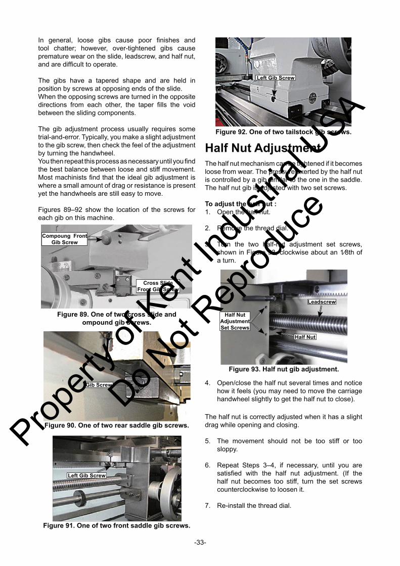
-33-
In general, loose gibs cause poor fi nishes and tool chatter; however, over-tightened gibs cause premature wear on the slide, leadscrew, and half nut, and are diffi cult to operate.
The gibs have a tapered shape and are held in position by screws at opposing ends of the slide.When the opposing screws are turned in the opposite directions from each other, the taper fi lls the void between the sliding components.
The gib adjustment process usually requires some trial-and-error. Typically, you make a slight adjustment to the gib screw, then check the feel of the adjustment by turning the handwheel.You then repeat this process as necessary until you fi nd the best balance between loose and stiff movement. Most machinists fi nd that the ideal gib adjustment is where a small amount of drag or resistance is present yet the handwheels are still easy to move.
Figures 89–92 show the location of the screws for each gib on this machine.
Half Nut AdjustmentThe half nut mechanism can be tightened if it becomes loose from wear. The pressure exerted by the half nut is controlled by a gib similar to the one in the saddle. The half nut gib is adjusted with two set screws.
To adjust the half nut :1. Open the half nut.
2. Remove the thread dial.
3. Turn the two half-nut adjustment set screws, shown in Figure 93, clockwise about an 1⁄8th of a turn.
Figure 91. One of two front saddle gib screws.
Left Gib Screw
Figure 92. One of two tailstock gib screws.
Left Gib Screw
4. Open/close the half nut several times and notice how it feels (you may need to move the carriage handwheel slightly to get the half nut to close).
The half nut is correctly adjusted when it has a slight drag while opening and closing.
5. The movement should not be too stiff or too sloppy.
6. Repeat Steps 3–4, if necessary, until you are satisfi ed with the half nut adjustment. (If the half nut becomes too stiff, turn the set screws counterclockwise to loosen it.
7. Re-install the thread dial.
Figure 93. Half nut gib adjustment.
Half Nut Adjustment Set Screws
Leadscrew
Half Nut
Figure 90. One of two rear saddle gib screws.
Gib Screw
Figure 89. One of two cross slide and ompound gib screws.
Compoung Front Gib Screw
Cross Slide Front Gib Screw
Propert
y of K
ent In
dustr
ial U
SA
Do Not
Reprod
uce
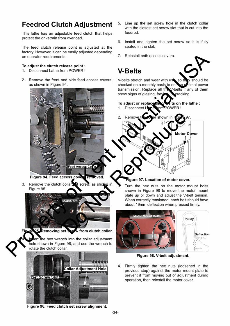
-34-
Feedrod Clutch AdjustmentThis lathe has an adjustable feed clutch that helps protect the drivetrain from overload.
The feed clutch release point is adjusted at the factory. However, it can be easily adjusted depending on operator requirements.
To adjust the clutch release point :1. Disconnect Lathe from POWER !
2. Remove the front and side feed access covers, as shown in Figure 94.
4. Insert the hex wrench into the collar adjustment hole shown in Figure 96, and use the wrench to rotate the clutch collar.
Figure 94. Feed access covers removed.
Feed Access Cover
Figure 97. Location of motor cover.
Motor Cover
3. Remove the clutch collar set screw, as shown in Figure 95.
Figure 95. Removing set screw from clutch collar.
Set Screw
Figure 96. Feed clutch set screw alignment.
Set Screw Slot
Collar Adjustment Hole
5. Line up the set screw hole in the clutch collar with the closest set screw slot that is cut into the feedrod.
6. Install and tighten the set screw so it is fully seated in the slot.
7. Reinstall both access covers.
V-BeltsV-belts stretch and wear with use, so they should be checked on a monthly basis to ensure optimal power transmission. Replace all the V-belts if any of them show signs of glazing, fraying, or cracking.
To adjust or replace the V-belts on the lathe :1. Disconnect Lathe from POWER !
2. Remove the cover shown in Figure 97.
3. Turn the hex nuts on the motor mount bolts shown in Figure 98 to move the motor mount plate up or down and adjust the V-belt tension. When correctly tensioned, each belt should have about 19mm defl ection when pressed fi rmly.
Figure 98. V-belt adjustment.
Motor Mount Bolts
Defl ection
Pulley
4. Firmly tighten the hex nuts (loosened in the previous step) against the motor mount plate to prevent it from moving out of adjustment during operation, then reinstall the motor cover.
Propert
y of K
ent In
dustr
ial U
SA
Do Not
Reprod
uce
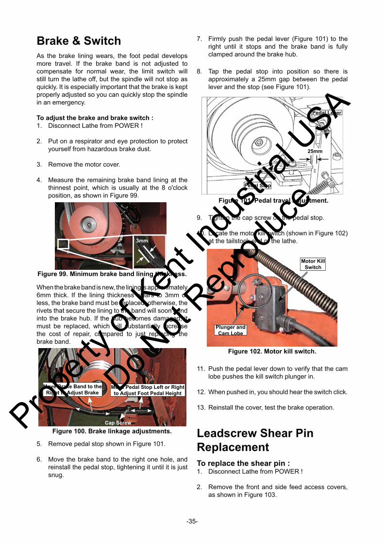
-35-
Brake & SwitchAs the brake lining wears, the foot pedal develops more travel. If the brake band is not adjusted to compensate for normal wear, the limit switch will still turn the lathe off, but the spindle will not stop as quickly. It is especially important that the brake is kept properly adjusted so you can quickly stop the spindle in an emergency.
To adjust the brake and brake switch :1. Disconnect Lathe from POWER !
2. Put on a respirator and eye protection to protect yourself from hazardous brake dust.
3. Remove the motor cover.
4. Measure the remaining brake band lining at the thinnest point, which is usually at the 8 o'clock position, as shown in Figure 99.
5. Remove pedal stop shown in Figure 101.
6. Move the brake band to the right one hole, and reinstall the pedal stop, tightening it until it is just snug.
3mm
Figure 99. Minimum brake band lining thickness.
When the brake band is new, the lining is approximately 6mm thick. If the lining thickness wears to 3mm or less, the brake band must be replaced; otherwise, the rivets that secure the lining to the band will soon grind into the brake hub. If the hub becomes damaged, it must be replaced, which will substantially increase the cost of repair, compared to just replacing the brake band.
9. Tighten the cap screw on the pedal stop.
10. Locate the motor kill switch (shown in Figure 102) at the tailstock end of the lathe.
Figure 100. Brake linkage adjustments.
Move Brake Band to the Right to Adjust Brake
Move Pedal Stop Left or Right to Adjust Foot Pedal Height
Cap Screw
Figure 101. Pedal travel adjustment.
25mm
Pedal Stop
Pedal Lever
Figure 102. Motor kill switch.
Plunger and Cam Lobe
Motor Kill Switch
7. Firmly push the pedal lever (Figure 101) to the right until it stops and the brake band is fully clamped around the brake hub.
8. Tap the pedal stop into position so there is approximately a 25mm gap between the pedal lever and the stop (see Figure 101).
11. Push the pedal lever down to verify that the cam lobe pushes the kill switch plunger in.
12. When pushed in, you should hear the switch click.
13. Reinstall the cover, test the brake operation.
Leadscrew Shear Pin ReplacementTo replace the shear pin :1. Disconnect Lathe from POWER !
2. Remove the front and side feed access covers, as shown in Figure 103.
Propert
y of K
ent In
dustr
ial U
SA
Do Not
Reprod
uce
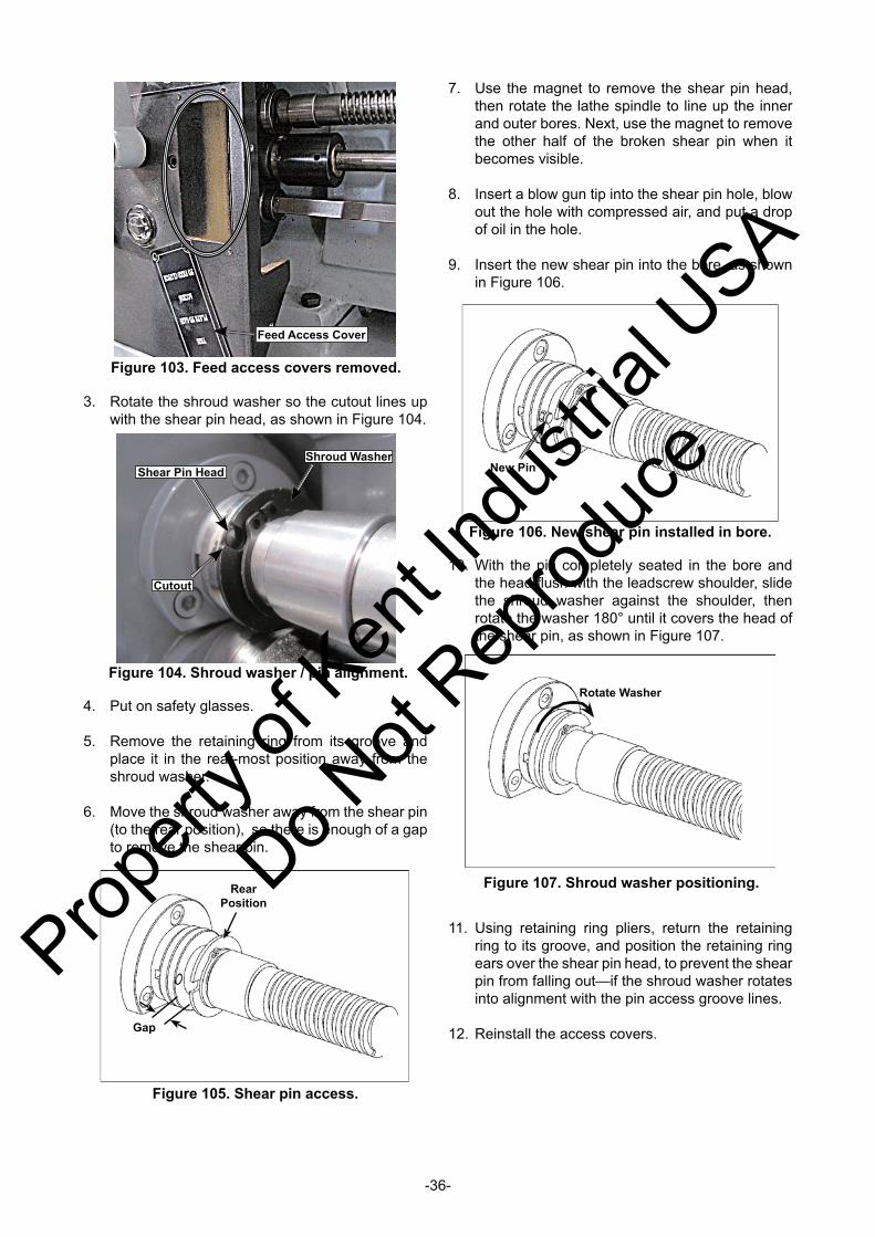
-36-
7. Use the magnet to remove the shear pin head, then rotate the lathe spindle to line up the inner and outer bores. Next, use the magnet to remove the other half of the broken shear pin when it becomes visible.
8. Insert a blow gun tip into the shear pin hole, blow out the hole with compressed air, and put a drop of oil in the hole.
9. Insert the new shear pin into the bore, as shown in Figure 106.
Figure 104. Shroud washer / pin alignment.
Shear Pin Head
Cutout
Shroud Washer
3. Rotate the shroud washer so the cutout lines up with the shear pin head, as shown in Figure 104.
4. Put on safety glasses.
5. Remove the retaining ring from its groove and place it in the rear-most position away from the shroud washer.
6. Move the shroud washer away from the shear pin (to the rear position), so there is enough of a gap to remove the shear pin.
Figure 106. New shear pin installed in bore.
New Pin
Figure 105. Shear pin access.
Gap
Rear Position
10. With the pin completely seated in the bore and the head fl ush with the leadscrew shoulder, slide the shroud washer against the shoulder, then rotate the washer 180° until it covers the head of the shear pin, as shown in Figure 107.
Figure 107. Shroud washer positioning.
Rotate Washer
11. Using retaining ring pliers, return the retaining ring to its groove, and position the retaining ring ears over the shear pin head, to prevent the shear pin from falling out—if the shroud washer rotates into alignment with the pin access groove lines.
12. Reinstall the access covers.
Figure 103. Feed access covers removed.
Feed Access Cover
Propert
y of K
ent In
dustr
ial U
SA
Do Not
Reprod
uce

-37-
Section 6 : PartsHeadstock
Propert
y of K
ent In
dustr
ial U
SA
Do Not
Reprod
uce
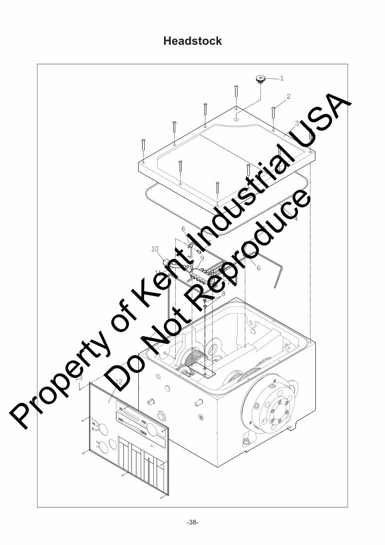
-38-
Headstock
Propert
y of K
ent In
dustr
ial U
SA
Do Not
Reprod
uce

-39-
Headstock
Propert
y of K
ent In
dustr
ial U
SA
Do Not
Reprod
uce

-40-
Headstock
Propert
y of K
ent In
dustr
ial U
SA
Do Not
Reprod
uce

-41-
Headstock
Propert
y of K
ent In
dustr
ial U
SA
Do Not
Reprod
uce

-42-
Headstock
KEY NO. PARTS NO. PARTS NAME Q'TY REMARK KEY NO. PARTS NO. PARTS NAME Q'TY REMARK
1 Oil Cover 1 3/4" 46 20022 Spring 2
2 Hex. socket head bolt 10 M6x40 47 Set screw 2 M8x8L
3 10057A Head stock cover 1 48 Oil sight 1 3/4"
4 O ring 1 Ø4x1700 49 Spring washer 6 M12
5 Hex. socket head bolt 2 M5x10 50 Hex. socket head bolt 6 M12x40
6 Piple clip 2 Ø4
7 Hex. socket head bolt 2 M5x20
8 Flat cross screw 2 M5x8 55 13-10023 Piug 1
9 Oil distributor 1 A-5S 56 O ring 1 G55
10 Quarter joint 1 Ø10 57 Clip 2 R62
11 Nylon tube 1 Ø10 58 Ball bearing 2 6206
12 61001-V Name plate 1 CNL-10019 Gear 1 24T
13 Rivet 8 Ø2 Key 2 10x8x25L
14 Set screw 2 M10x10L CNL-10020 Gear 1 67T
15 20026 Bush 2 Clip 1 S52
16 20028 Spring 2 Ø8x37L 63 10018-V Gear 1 38T
17 Steel ball 2 Ø8.5 64 10022-V Driving shaft 1
18 20098 Plug 2 Ø20 65 Key 1 7x7x25L
19 O ring 2 P14 66 Clip 3 S30
20 20014V14 Plug 2 Ø18 67 10022A Cover 1
21 O ring 6 P16 10001V14
22 20024A Lever 1 10001V16
23 Clip 1 S12 69 Clip 1 S25
24 20030 Fork 1 70 Ball bearing 1 6205
25 Spring pin 1 Ø6x36 71 10027-V Gear 1 30T
26 20014 Rod 1 72 10025-V Input haft 1
27 Spring pin 1 Ø6x40 73 Key 1 7x7x45L
28 20015A Lever 1 74 Ball bearing 1 6206LU
29 Key 1 5x5x22L 75 O ring 1 G85
30 Spring pin 3 Ø3x24 76 10024A Flanged bearing 1
31 20004 Handle 1 77 Oil seal 1 305008
32 20003 Hub 1 78 10031 Pully 1
33 20027 Washer 3 79 10032 Washer 1
34 Hex. socket head bolt 19 M6x16 80 Spring washer 1 M8
35 20044 Fork 1 81 Hex. socket head bolt 1 M8x25
36 20034 Fork 1 10003 Bolt 6
37 Clip 2 S15 10003-D6 Spindle 1
38 20032 Lever 2 10005 Cam spring 6
39 Clip 2 E8 10004 Cams 6
40 Key 2 5x5x30L 86 Key 2 10x6x85L
41 20005 Shaft 2 87 Key 1 7x7x30L
42 Key 2 5x5x17L 88 Hex. socket head bolt 3 M6x35
43 Steel ball 2 Ø1/4" 89 10007-A6 Front bearing cover 1
44 20021 Hub 2 90 10007-P 1
45 20048 Handle 2 91 Taper roller bearing 1 32019
82
Head stock 1
59
68
Propert
y of K
ent In
dustr
ial U
SA
Do Not
Reprod
uce

-43-
Headstock
KEY NO. PARTS NO. PARTS NAME Q'TY REMARK KEY NO. PARTS NO. PARTS NAME Q'TY REMARK
92 17-10008 Gear 1 79T
93 17-10009 Gear 1 36T
94 Taper roller bearing 1 30214A
95 Nut 1 YSRM70x2
96 Clip 4 S65
97 10010 Gear 1 42T
98 Ball bearing 1 6013
99 10012-P Packing O 1
100 10012 Outside cover 1
101 Clip 1 S70
105 10038 Washer 2
13-10049 Gear 1 21T
13-10050 Gear 1 42T
Key 1 6x6x15L
Clip 1 S35
110 O ring 3 P21
111 10034 Shaft 1
112 13-10039 Washer 3
Key 1 6x6x15L
Clip 1 S35
13-10048 Gear 1 42T
13-10047 Gear 1 21T
115 10036 Washer 3
116 10035 Shaft 1
117 Clip 2 S20
118 10046 Gear 1 21T
119 10033 Shaft 1
120 10051 Gear 1 21T
121 10037 Washer 2
122 Needle bearing 2 RNA-6904
123 10040 Shaft 1
124 O ring 1 P44
125 10041 Flange bearing 1
126 Hex. socket head bolt 3 M6x12
127 Oil seal 1 28x44x07
128 Square head plug 1 1/2"
106
113
Propert
y of K
ent In
dustr
ial U
SA
Do Not
Reprod
uce

-44-
Gearbox
Propert
y of K
ent In
dustr
ial U
SA
Do Not
Reprod
uce

-45-
Gearbox
Propert
y of K
ent In
dustr
ial U
SA
Do Not
Reprod
uce

-46-
Gearbox
Propert
y of K
ent In
dustr
ial U
SA
Do Not
Reprod
uce

-47-
Gearbox
KEY NO. PARTS NO. PARTS NAME Q'TY REMARK KEY NO. PARTS NO. PARTS NAME Q'TY REMARK
1 30003 Shaft 1 46 30039 Gear 1 22T
2 Oil seal 1 TC 203205 47 30040 Gear 1 33T
3 Bearing 2 TAF202820 48 30041 Gear 1 22T
4 30005 Flanged bearing 1 49 Clip 1 S17
5 30004 Washer 1 50 30042 Gear 1 20T/36T
6 Clip 6 S20 51 30016 Washer 1
7 Key 1 7x7x30 52 30017 Flanged bearing 1
8 30007 Gear 1 19T/20T 53 Oil seal 1 TC 203205
9 30008 Shaft 1 54 30014 Shaft 1
10 30018 Cover 1 55 30035 Flanged bearing 1
11 Bearing 5 16004 56 Oil seal 1 24x35x08
12 30006 Washer 1 57 30033 Shaft 1
13 30020 Gear 1 19T/30T 58 Key 1 5x5x35
14 30021 Washer 1 59 Bearing 1 6001
15 Clip 1 S25 60 Clip 1 S12
16 30019 Shaft 1 61 30043 Flanged bearing 1
17 30036 Shaft 1 62 30002-P Seal 1
18 Woodruff key 1 5x 19 63 30084 Partition nut 2
19 30018-P Oil seal 1 64 30077 Upper plate 2
20 30001 Gearbox body 1 65 30082 Fort support 1
21 Bearing 3 16004 66 30070 Spring 5 Ø6.35x20
22 30009 Gear 1 38T 67 Steel ball 7 1/4"
23 30010 Gear 1 23T/19T 68 30079 Partition 3
24 30011 Washer 3 69 30080 Fort support 1
25 Clip 6 R40 70 30078 Fort support 1
26 Bearing 3 6203 71 30081 Fort support 1
27 30012 Clutch 1 72 30087 Reverse-stop 1
28 30013 Washer 1 73 30085 Spacer 2
29 Clip 1 S16 74 30086 Shoulder plate 1
30 30015 Gear 1 35T 75 30100 Fixed plate A 1
31 30022 Gear 1 22T 76 30083 Fixed plate B 1
32 30023 Gear 1 19T 77 30053 Fork 2
33 30024 Gear 1 20T 78 30055 Fork 1
34 30025 Gear 1 24T 79 30054 Fork 1
35 30026 Gear 1 23T
36 30027 Gear 1 27T 81 Spring pin 8 Ø3x16
37 30028 Gear 1 24T 82 30061 Shaft 2
38 30029 Gear 1 28T 83 30065 Arm 1
39 30030 Gear 1 26T 84 30060 Cam 1
40 30031 Gear 1 38T 85 30059 Support seat 1
41 30032 Nut 1 86 Clip 2 E9
42 Clip 1 S22 87 30058 Washer 1
43 30034 Gear 1 36T/50T 88 Clip 2 S17
44 30037 Gear 1 22T 89 Woodruff key 4 4xØ13
45 30038 Gear 1 22T 90 30057 Shaft 1
Propert
y of K
ent In
dustr
ial U
SA
Do Not
Reprod
uce

-48-
Gearbox
KEY NO. PARTS NO. PARTS NAME Q'TY REMARK KEY NO. PARTS NO. PARTS NAME Q'TY REMARK
91 30047 Pad 1 201 Hex. socket head bolt 19 CAP 6x12
92 30062 Pin 2 202 Hex. socket head bolt 4 CAP 5x20
93 30063 Fork 1 203 Spring washer 4 M6
205 Hex. socket head bolt 2 CAP 6x35
96 30046 Pad 1 206 Spring pin 2 Ø4x24
97 30048 Lever 1 207 Set screw 2 SET 6x8
98 30099 Spring 2 Ø6x13 208 Hex. socket head bolt 4 CAP 6x20
209 Hex. socket head bolt 6 CAP 6x70
100 30052 Selector bar 1 210 Set screw 1 SET 5x6
101 Spring pin 2 Ø4x24 211 Hex. socket head bolt 3 CAP 5x25
102 30050 Shaft 2
103 O ring 2 P18 213 Hex. socket head bolt 3 CAP 5x12
104 30051 Bush 2 214 Dome cross screw 9 M4x6
105 30045 Fork 1 215 Hex. socket head bolt 3 CAP 8x65
106 Spring pin 4 Ø5x16 216 Taper pin 2 #7x3 1/4"
Square head plug 2 1/2"
Elbow 2 1/2"
Nipple 2 1/2"x1"
110 30002 Gearbox cover 1
111 30088 Selector lever 1
112 O ring 2 G40
113 30066 Selector lever support 1
114 30069 Spring 1
115 30068 Selector lever 1
116 O ring 1 G30
117 30067 Selector lever cover 1
118 30076 Specifying base 1
119 30071 Handle 3
120 30072 Washer 3
121 30073 Plug 3
122 Oil sight 1
123 30103-V Plate 1
124 30104 Plate 1
125 30064 Arm 1
107
Propert
y of K
ent In
dustr
ial U
SA
Do Not
Reprod
uce
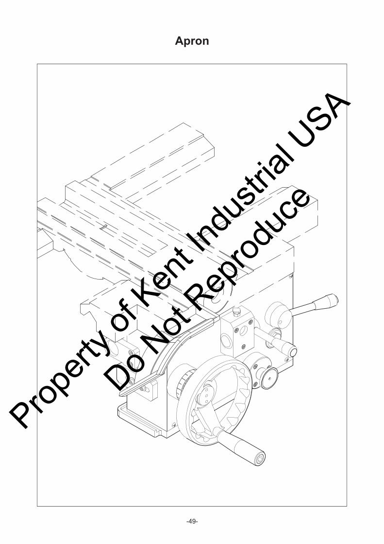
-49-
Apron
Propert
y of K
ent In
dustr
ial U
SA
Do Not
Reprod
uce
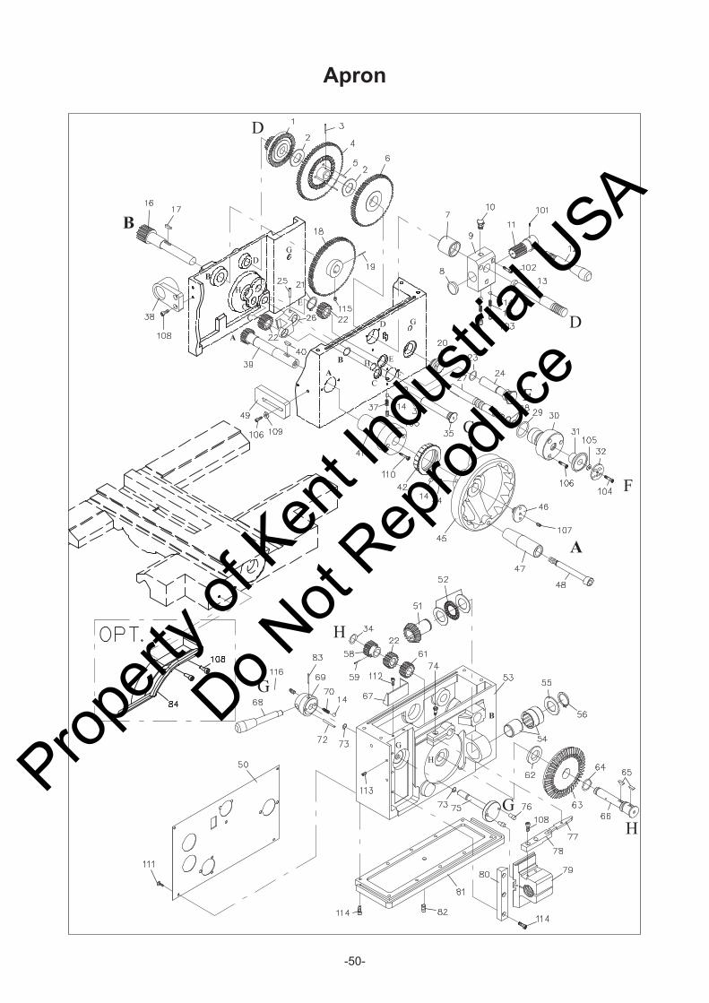
-50-
Apron
Propert
y of K
ent In
dustr
ial U
SA
Do Not
Reprod
uce

-51-
Apron
KEY NO. PARTS NO. PARTS NAME Q'TY REMARK KEY NO. PARTS NO. PARTS NAME Q'TY REMARK
1 40014 Gear 1 18T/60T 40005-M
2 Washer 2 AS3047 40005-I
3 Spring pin 1 Ø4x22 44 40006 Spring 3
4 40015 Gear 1 81T/60T 45 40007 Handle wheel 1
5 Pin 3 Ø4x17 46 40011 Plug 1
6 40017 Gear 1 72T/60T 47 40009 Handle 1
7 40060 Collar 1 48 40008 Screw 1
8 40071 Plug 1 49 40078 Safety plate 1
9 40023 Gear bracket 1 61039-L
10 Oil cap 1 61040-R
11 40019 Cam shaft 1 51 40034 Bevel gear 1 23T
12 40020 Handle 1 52 Thrust bearing 1 NTB/AS-2542
13 40018 Shaft 1 40001-L
14 Steel ball 7 1/4" 40001-R
15 13-30099 Spring 2 Ø6x13 54 Bearing 1 NK29/30
16 40013 Gear shaft 1 16T 55 40032 Washer 1
17 Key 1 5x5x18 56 Clip 1 S25
40012-M 82T
40012-I 81T 58 40066 Gear 1 18T
19 Spring pin 1 Ø5x36 59 Spring pin 1 Ø5x22
20 Oil sight 1
21 Clip 1 S16 61 40065 Gear 1 18T
22 40067 Gear 3 18T 62 40035 Washer 1
23 O ring 2 P18 63 40033 Bevel gear 1 64T
24 40068 Shaft 1 64 O ring 1 P18
25 Spring pin 1 Ø4x24 65 Woodruff key 2 4xØ13
40063-L 66 40031 Shaft 1
40073-R 67 49001-L Oil fence 1
27 40062 Shaft 1 68 40037 Handle 1
28 O ring 2 P16 69 40038 Hub 1
29 O ring 1 P26 70 14-20022 Spring 1 Ø6x27
30 40061 Shaft liner 1 72 Spring pin 1 Ø4x24
31 40076 Knob 1 73 O-ring 2 P9
40025-L 74 40045 Screw 1
40024-R 75 40039 Cam shaft 1
34 O ring 2 P12 76 40040 Pin 2
35 40064 Shaft 1 77 40044 Lever 1
78 40042 Stopper 1
37 Spring 1 Ø4x19 40041-M
38 40072 Bracket 1 40041-I
39 40003 Gear shaft 1 18T 80 40043 Gid 1
40 Woodruff key 1 19xØ5 81 40046 Base plate 1
40004-M 82 Plug 1 1/8"
40004-I 83 Spring pin 1 Ø4x36
84 13-40080 Handle wheel guard 1 OPT.
41 Shaft liner 1
42
26 Fork 1
32
79
18 Gear 1
Half nut 1
1Apron
1
53
Plate 1
Index ring
50 Plate 1
Propert
y of K
ent In
dustr
ial U
SA
Do Not
Reprod
uce

-52-
Apron
KEY NO. PARTS NO. PARTS NAME Q'TY REMARK KEY NO. PARTS NO. PARTS NAME Q'TY REMARK
101 Set screw 1 SET 5x6
102 Hex. socket head bolt 3 CAP 5x35
103 Set screw 4 SET 8x8
104 Dome hexagon screw 1 M5x12
105 Washer 1 M6
106 Hex. socket head bolt 5 CAP 6x25
107 Set screw 1 SET 6x25
108 Hex. socket head bolt 6 CAP 6x16
109 40077 Washer 2
110 Hex. socket head bolt 2 CAP 5x25
111 Dome cross screw 4 M4x6
112 Hex. socket head bolt 2 CAP 5x8
113 Set screw 2 SET 6x6
114 Hex. socket head bolt 13 CAP 5x16
115 Set screw 1 SET 6x8
116 Set screw 1 SET 8x16
Propert
y of K
ent In
dustr
ial U
SA
Do Not
Reprod
uce

-53-
Dail Indicator
Propert
y of K
ent In
dustr
ial U
SA
Do Not
Reprod
uce
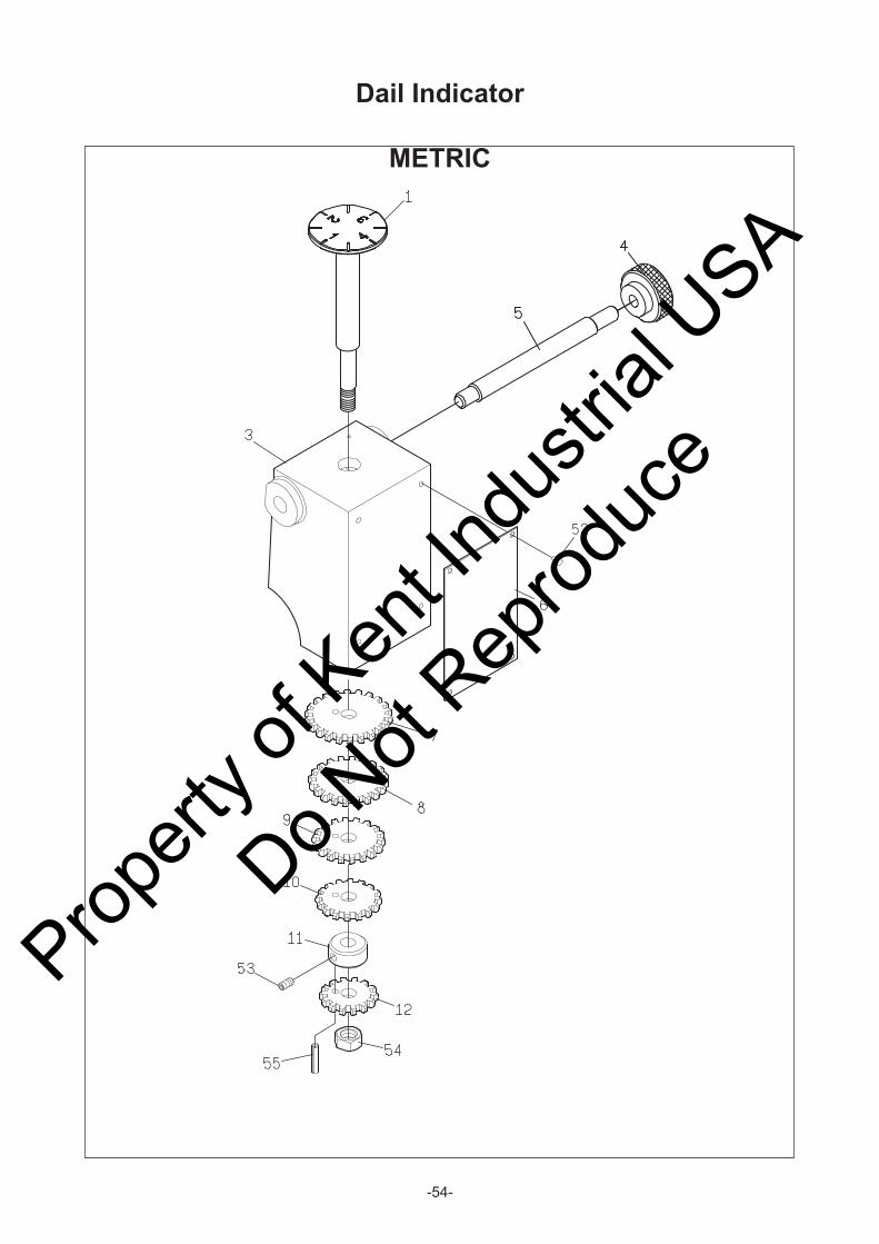
-54-
METRIC
Dail Indicator
Propert
y of K
ent In
dustr
ial U
SA
Do Not
Reprod
uce

-55-
Dail Indicator
IMPERIAL
Propert
y of K
ent In
dustr
ial U
SA
Do Not
Reprod
uce

-56-
Dail Indicator
KEY NO. PARTS NO. PARTS NAME Q'TY REMARK KEY NO. PARTS NO. PARTS NAME Q'TY REMARK
1 40048 Gear pivot 1 1 40048 Gear pivot 1
3 40092 Body 1 3 40092 Body 1
4 40053 Nut 1 4 40053 Nut 1
5 40094 Stud 1 5 40094 Stud 1
6 40074-M Threading plate 1 6 40074-I Threading plate 1
7 40058 Gear 1 22T 7 40050 Spacer 1
8 40057 Gear 1 20T 8 40059 Dial gear 1 16T
9 40056 Gear 1 18T
10 40055 Gear 1 16T
11 40051 Spacer 1
12 40054 Gear 1 14T
52 Rivet 4 Ø2 52 Rivet 4
53 Set screw 1 M6x6L 53 Set screw 1 M6x6L
54 Nylon Jam Nut 1 M8 54 Nylon Jam Nut 1 M8
55 Spring pin 1 Ø3x10L
METRIC(LEADSCREW PITCH 6) IMPERIAL(LEADSCREW 4 T.P.I.)
Propert
y of K
ent In
dustr
ial U
SA
Do Not
Reprod
uce
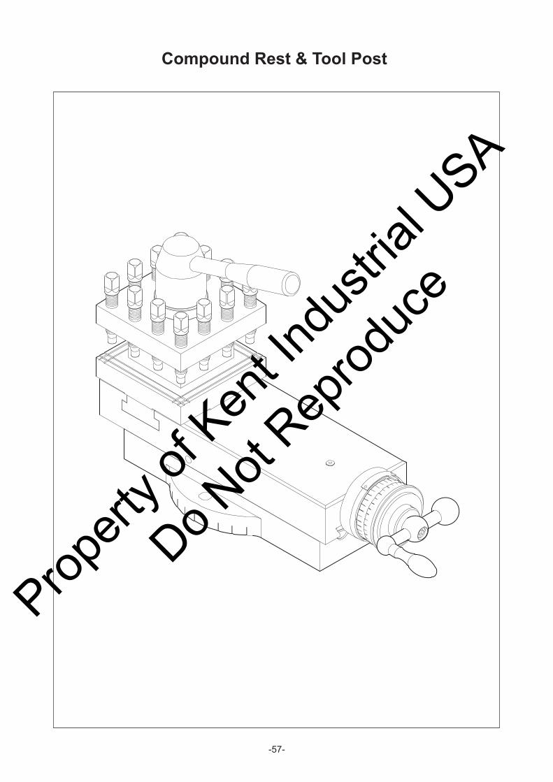
-57-
Compound Rest & Tool Post
Propert
y of K
ent In
dustr
ial U
SA
Do Not
Reprod
uce
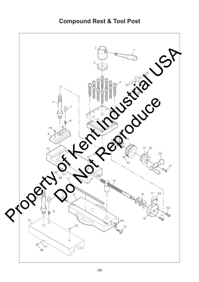
-58-
Compound Rest & Tool Post
Propert
y of K
ent In
dustr
ial U
SA
Do Not
Reprod
uce

-59-
Compound Rest & Tool Post
KEY NO. PARTS NO. PARTS NAME Q'TY REMARK KEY NO. PARTS NO. PARTS NAME Q'TY REMARK
1 50067 Handle 1 51 Hex. Socket head bolt 1 CAP 6x10
2 50066 Turret nut 1 52 Set screw 2 SET 5x8
3 50065 Collar 1 53 Hex. Socket head bolt 2 CAP 6x20
4 50068 Bolt 12 54 Rivet 2 Ø2
5 50060 Turret body 1 55 Set screw 2 SET 8x16
6 50062 Turret shaft 1 56 Oil ball 1 1/4"
7 50064 Pin 1 57 Steel ball 1 1
8 50043 Spring 1 58 Set screw 1 SET 8x12
9 50061 T Nut 1 59 Set screw 2 SET 6x16
50006 60 Set screw 1 SET 5x10
50006-SP
11 50056 Gib 1
12 50054 Screw 1
14-50004
16-50004
50038-M Nut 1
50042-M Screw 1
50038-I Nut 1
50042-I Screw 1
16 Trust bearing 2 51101
17 50063 Curve pilot 1
18 50041 Keep assy 1
50044-M Dial
50044-X Dual Dial
21 50111 Bush 1
22 50045 Handle wheel 1
24 50108 T wrench 1
19 1
Solid topslide 1
Swivel slide 113
10
14
Propert
y of K
ent In
dustr
ial U
SA
Do Not
Reprod
uce
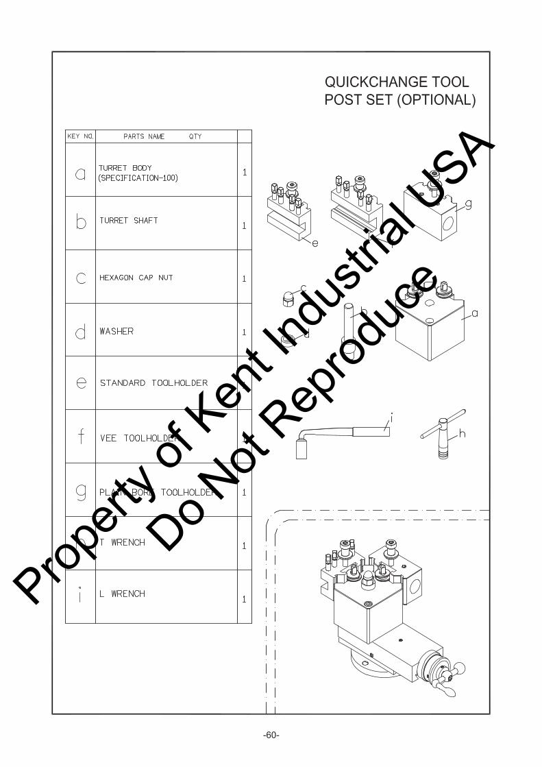
-60-
Propert
y of K
ent In
dustr
ial U
SA
Do Not
Reprod
uce

-61-
Saddles
Propert
y of K
ent In
dustr
ial U
SA
Do Not
Reprod
uce

-62-
Saddles
Propert
y of K
ent In
dustr
ial U
SA
Do Not
Reprod
uce

-63-
Saddles
Propert
y of K
ent In
dustr
ial U
SA
Do Not
Reprod
uce

-64-
Saddles
KEY NO. PARTS NO. PARTS NAME Q'TY REMARK KEY NO. PARTS NO. PARTS NAME Q'TY REMARK
1 50054 Adjust screw 6 37 50034 Bolt 1
2 50003 Cross slide 1 38 50053 Gib-Z 2
3 50036 Pivot 1 Ø18x28 39 50052 Front anti-floater 1
4 50037 T bolt 2 40 50055 Rear anti-floater 1
5 50023 Gib-X 1 41 50013 Washer 1 Ø6.5xØ15x3
6 50070 Wiper-X 1 42 50011 Gear 1 16T
7 50069 Plate -X 1 43 50012 Short shaft 1
8 Trust bearing 2 NTB/AS2 1226 44 Straight adapter 2 PT1/8xØ4
9 50026 Cap collar 2 45 AL. tube 1 Ø4x260
10 50017 Washer 1 46 Elbow adapter 2 PT1/8xØ4
50021 Wedge 1 7x7x30 47 AL. tube 1 Ø4x120
50019-M Nut 1 48 Oil filter 1 Ø6
50016-M Screw 1 49 AL. tube 1 Ø6x160
Key 1 3x3x100 50 Straight adapter 2 PT1/8xØ6
Spring pin 2 Ø5x40 51 Lubricator assy. 1
50021 Wedge 1 7x7x30 52 50058 Clamp plate 1
50019-I Nut 1 53 50077 Plate 1
50016-I Screw 1
Key 1 3x3x100
Spring pin 2 Ø5x40
101 Oil ball 2 1/4"
16 Spraying pipe 1 PT3/8 x 24" 102 Set screw 2 SET 6x30
17 Valve & junction assy. 1 PT3/8 103 Hex. socket head bolt 4 CAP 6x30
18 50018 Rear bracket 1 104 Nut 2 M10
19 50001 Saddle 1 105 Washer 2 M10
20 50050 Wiper F 2 106 Dome cross screw 13 M5x12
21 50051 Plate F 2 107 Hex. socket head bolt 2 CAP 6x25
22 Oil cover 1 NF 3/4" 108 Nut 1 M10
23 Taper Pin 2 #6x2 3/4"L 109 Hex. socket head bolt 15 CAP 6x20
24 50048 Wiper V 2 110 Hex. socket head bolt 4 CAP 8x60
25 50049 Plate V 2 111 Set screw 3 SEY 6x8
26 50014 Pinion 1 160DP 16T 112 Hex. socket head bolt 3 CAP 4x10
27 50015 Front bracket 1
28 Steel ball 4 1/4"
29 50032 Spring 4 Ø6x15 L 115 Hex. socket head bolt 1 CAP 5x16
30 Trust bearing 2 NTB/AS2 1730 116 Set screw 1 SET 8x35
31 50030 Washer 1 Ø18xØ52x4 117 Hex. socket head bolt 1 CAP 12x75
50027-M Dial ring 1
50027-I Dial ring 1
50031-M Dial 1 250dividing
5003 - Dual dial 1 200div/I , 254div/M
34 50029 Hand wheel 1
35 50033 Fix screw 1 M12xP1.75
36 50035 Handle 1
11
32
33
Propert
y of K
ent In
dustr
ial U
SA
Do Not
Reprod
uce

-65-
Bed & Shafts
Propert
y of K
ent In
dustr
ial U
SA
Do Not
Reprod
uce

-66-
Bed & Shafts
Propert
y of K
ent In
dustr
ial U
SA
Do Not
Reprod
uce

-67-
Bed & Shafts
KEY NO. PARTS NO. PARTS NAME Q'TY REMARK KEY NO. PARTS NO. PARTS NAME Q'TY REMARK
63001-40 13-63023-40 1
63001-60 14-63023-60 2
2 63038 Bolt 1 13-63024-GL
3 63027 Cover 1 14-63024-60G
4 63028 Fixed block 1
5 Steel ball 1 5/16"
6 18-40015 Spring 1 101 Hex. socket head bolt 3 CAP 6x55
7 63029 Switch flanged 1 102 Set screw 1 SET 6x16
8 63026 Bracket 1 103 Hex. socket head bolt 2 CAP 6x25
9 63043 Collar 1 104 Set screw 1 SET 10x10
63020 Lever assy 1 105 Hex. socket head bolt 1 CAP 8x70
63021 Pin 2 106 Taper pin 1 #7x3 1/4"L
63015 Third rod bracket 1 107 Taper pin 1 #7x2"L
63019 Sleeve 1 108 Hex. socket head bolt 1 CAP 8x35
63018 Spring 1 109 Nut 2 M12
63017 Spring cover 1 110 Key 2 5x5x15
Snap ring 1 S32 111 Hex. socket head bolt 1 CAP 6x20
112 Taper pin 1 #4x30L
63022 Handle 1 113 Spring pin 6 Ø6x25L
63030 Knob 1 114 Hex. socket head bolt 9 CAP 6x20
115 Set screw 1 SET 6x6
63014A-40 116 Washer 8 M12
63014A-60 117 Hexagon head bolt 8 M12x45
20 Thrust bearing 1 NTB/AS2 1831 118 Set screw 3 SET 6x8
63011A-40 119 60035 Collar 1
63011A-60 120 Limit switch 2 TM1704
22 63012 Stopper 1 121 Dome cross screw 2 M4x40
23 63016 Clutch collar 1
24 63013 Bush 1 a 63048-60 Shaft 1
25 Thrust bearing 1 51203 b Hex. socket head bolt 2 CAP 8x30
26 63042 Spring 4 c 63046-60 Chunk 1
27 63025 Nut 1 d Set screw 1 SET 8x20
28 Thrust bearing 2 51105 e 63050-60 Pin 3
29 Oil cover 1 f 63049-60 Chunk 1
63005A-40M g Set screw 2 SET 8x16
63005A-60M h 63047-60 Bracket 1
63005A-40I i Set screw 2 SET 8x8
63005A-60I
31 63006 Spring cover 1
32 63007 Spring 1 Ø27x55
33 Snap ring 1 S30
34 63010 Shear pin 1
35 63008 Shroud washer 1
36 63009 Collar 1
19 Third rod shaft 1
21 Feed rod 1
30 Leadscrew 1
37 Rack
38 Gap Rack 1
12
10
1 1Bed
Propert
y of K
ent In
dustr
ial U
SA
Do Not
Reprod
uce

-68-
End Gear
Propert
y of K
ent In
dustr
ial U
SA
Do Not
Reprod
uce

-69-
End Gear - 14"
METRIC
Propert
y of K
ent In
dustr
ial U
SA
Do Not
Reprod
uce

-70-
End Gear - 14"
IMPERIAL
Propert
y of K
ent In
dustr
ial U
SA
Do Not
Reprod
uce

-71-
End Gear - 16"
METRIC
Propert
y of K
ent In
dustr
ial U
SA
Do Not
Reprod
uce

-72-
End Gear - 16"
IMPERIAL
Propert
y of K
ent In
dustr
ial U
SA
Do Not
Reprod
uce

-73-
End Gear
KEY NO. PARTS NO. PARTS NAME Q'TY REMARK KEY NO. PARTS NO. PARTS NAME Q'TY REMARK
Hexagon head bolt CAP 6x20 Hexagon head bolt CAP 6x2060022 Washer 60022 Washer
13-60001-M Gear 28T 13-60007-I Gear 24T14-60017 Swing frane 14-60017 Swing frane
Key 7x7x15 Key 7x7x15Nut M14 Nut M14
60023 Washer 60023 WasherClip R47 Clip R47
13-60002-M Gear 54T/55T 13-60008-I Gear 44T/56TBall bearing 6005 Ball bearing 6005
60020 Washer 60020 Washer60013 Shaft collar 60013 Shaft collar60015 Gear shaft 60015 Gear shaft
Key Key60018 Stud 60018 Stud
Hexagon head bolt CAP 8x20 Hexagon head bolt CAP 8x2060021 Washer 60021 Washer
13-60004-M Gear 13-60010-I Gear13-6005-M Gear 60016 Collar
METRIC RML-14 IMPERIAL RML-14
Propert
y of K
ent In
dustr
ial U
SA
Do Not
Reprod
uce

-74-
End Gear
KEY NO. PARTS NO. PARTS NAME Q'TY REMARK KEY NO. PARTS NO. PARTS NAME Q'TY REMARK
Hexagon head bolt CAP 6x20 Hexagon head bolt CAP 6x2060022 Washer 60022 Washer
16-60001-M Gear 28T 16-60007-I Gear 24T16-60017 Swing frane 16-60017 Swing frane
Key 7x7x15 Key 7x7x15Nut M14 Nut M14
60023 Washer 60023 WasherClip R47 Clip R47
16-60002-M Gear 54T/55T 16-60008-I Gear 44T/56TBall bearing 6005 Ball bearing 6005
60020 Washer 60020 Washer60013 Shaft collar 60013 Shaft collar60015 Gear shaft 60015 Gear shaft
Key Key60018 Stud 60018 Stud
Hexagon head bolt CAP 8x20 Hexagon head bolt CAP 8x2060021 Washer 60021 Washer
16-60004-M Gear 16-60010-I Gear16-6005-M Gear 60016 Collar
METRIC RML-16 IMPERIAL RML-16
Propert
y of K
ent In
dustr
ial U
SA
Do Not
Reprod
uce

-75-
Main Motor
Propert
y of K
ent In
dustr
ial U
SA
Do Not
Reprod
uce

-76-
Main Motor
Propert
y of K
ent In
dustr
ial U
SA
Do Not
Reprod
uce

-77-
Main Motor
KEY NO. PARTS NO. PARTS NAME Q'TY REMARK KEY NO. PARTS NO. PARTS NAME Q'TY REMARK
1 60058 Pin 2 45 Limit switch 1 Tm1307
2 Nut 9 M10xP1.5 46 Nut 2 M4xP0.7
3 Washer 4 M10
14-61004
16-61004
5 60056 Nut 1
6 V belt 3 B69
7 60055 Bolt 1
8 61017 Cover 1
9 Dome cross screw 4 M6x10L
10 60053 Bolt 1
11 Nut 3 M8xP1.25
12 60046 Spring 1
13 Hex. socket head bolt 1 CAP 8x55
14 13-60033 Cam 1
15 Hex. socket head bolt 2 CAP 6x16
16 60061 Fixed plate 1
17 Hex. socket head bolt 7 CAP 10x25
18 60044 Washer 1
19 Washer 2 M8
20 Hex. socket head bolt 1 M8x45L
21 Clip 1 E8
22 60047 Lever 1
23 60028 Pin 1
24 60019 Brake belt 1
25 Taper pin 1 #4x1 3/4"L
26 61045RM5 Platform 1
27 60043 Shaft 1
28 17-60061 Support 1
29 Hex. socket head bolt 2 CAP 6x12
30 Dome cross screw 2 M4x30L
31 63028 Bracket 1
32 Limit switch 1 Tm-1704
33 10043A56 Motor pully 1
34 Hex. socket head bolt 4 M10x45L
35 Washer 8 M10
36 61045RM5 Plate 1
37 Nut 3 M16xP2.0
38 Washer 4 Ø16.5xØ40
39 60048 Rubber ring 2
40 60031 Screw 1
41 Motor 1 5hp
42 63043 Block 6
43 Hexagon head bolt 6 CAP 16x50
44 Dome cross screw 2 M4x40L
4 Cover 1
Propert
y of K
ent In
dustr
ial U
SA
Do Not
Reprod
uce

-78-
Cabinet & PanelTHE CHIP TRAY IN THE MIDDLE
Propert
y of K
ent In
dustr
ial U
SA
Do Not
Reprod
uce

-79-
Cabinet & PanelTHE CHIP TRAY IN THE MIDDLE
Propert
y of K
ent In
dustr
ial U
SA
Do Not
Reprod
uce

-80-
Cabinet & PanelTHE CHIP TRAY IN THE MIDDLE
KEY NO. PARTS NO. PARTS NAME Q'TY REMARK KEY NO. PARTS NO. PARTS NAME Q'TY REMARK
1 60032A Shsft 1 42 Work lamp 1 136
2 Hex. socket head bolt 4 CAP 8x25 43 Dome hexagon screw 4 M6x12
3 60029 Pedal bracket 2 44 Nut 4 M6
4 Hex. socket head bolt 12 CAP 6x16
5 13-60039 Collar 2
6 Hex. socket head bolt 2 CAP10x20
61043-40
61043-60
8 61016 Guard 1
9 Dome cross screw 7 M5x8
10 61228 Plate 1
11 Flat hexagon screw 2 M5x8
12 10058 Small bracket 1
13 Set screw 2 SET 8x12
14 Nut 2 M4xP0.7
15 Spring washer 2 M6
16 Hex. socket head bolt 3 CAP 6x12
17 15-61056 Bracket 1
18 Limit switch 1 Tz9212
19 Dome cross screw 2 M4x40
20
21 Washer 11 M8
22 Hex. Socket head bolt 11 CAP 8x20
61210-LA4
61210-LA6
24 Knob 1
25 Nut 1 M12
26 13-10102 Piovt 1
27 15-65053-B Chuck safety guard 1
28 Hex. socket head bolt 1 CAP 12x20
29 Set screw 1 M5x16
30 NL-61229 Bracket 1
Coolant conduit - 40 CT801x3/8"x74"
Coolant conduit - 60 CT801x3/8"x80"
32 Nipple 1 3/8"PTx3/8"PH
33 Coolant pump 1 MC6180
34 63061 Pump base 1
35 61019 Cover 1
36 Dome cross screw 4 M6x10
37 Plate 2
38 Dome Hex. Screw 8 M6x12
39 13-61037 Nameplate 1
40 13-61024 Nameplate 1
41 Washer 4 M6
Splash guard 1
31 1
7 Saddle 1
23
Propert
y of K
ent In
dustr
ial U
SA
Do Not
Reprod
uce

-81-
Cabinet & PanelFRONT MOVEABLE CHIP TRAY OPTIONAL
Propert
y of K
ent In
dustr
ial U
SA
Do Not
Reprod
uce

-82-
Cabinet & PanelFRONT MOVEABLE CHIP TRAY OPTIONAL
Propert
y of K
ent In
dustr
ial U
SA
Do Not
Reprod
uce

-83-
Cabinet & PanelFRONT MOVEABLE CHIP TRAY OPTIONAL
KEY NO. PARTS NO. PARTS NAME Q'TY REMARK KEY NO. PARTS NO. PARTS NAME Q'TY REMARK
1 60032A Shsft 1 42 13-61037 Nameplate 1
2 Hex. socket head bolt 4 CAP 8x25 43 13-61024 Nameplate 1
3 60029 Pedal bracket 2 44 Washer 4 M6
4 Hex. socket head bolt 12 CAP 6x16 45 Work lamp 1 136
5 13-60039 Collar 2 46 Dome hexagon screw 4 M6x12
6 Hex. socket head bolt 2 CAP 10x20 47 Nut 4 M6
61043-40
61043-60
8 61016 Guard 1
9 Dome cross screw 3 M5x8
10 61228 Plate 1
11 Flat hexagon screw 2 M5x8
12 10058 Small bracket 1
13 Set screw 2 SET 8x12
14 Nut 2 M4xP0.7
15 Spring washer 2 M6
16 Hex. socket head bolt 3 CAP 6x12
17 15-61056 Bracket 1
18 Limit 1 Tz9212
19 Dome cross screw 2 M4x40
20
21 Washer 11 M8
22 Hex. Socket head bolt 11 CAP 8x20
61210-LA4
61210-LA6
24 Knob 1
25 Nut 1 M12xP1.75
26 13-10102 Piovt 1
27 15-65053-B Chuck safety guard 1
28 Hex. socket head bolt 1 M12x20
29 Set screw 1 M5x16
30 NL-61229 Bracket 1
Coolant conduit - 40 CT801x3/8"x74"
Coolant conduit - 60 CT801x3/8"x80"
32 Nipple 1 3/8"PTx3/8"PH
33 Coolant pump 1 MC6180
34 61010-15 Coolant tank 1
35 61017 Cover 1
36 Dome cross screw 4 M6x10
37 61009PB6 Angle steel 2
38 61009B4 Chip tray 1
39 Hex. socket head bolt 2 M10x45
40 Plate 2
41 Dome Hex. Screw 8 M6x12
7 Saddle 1
31 1
23 Splash guard 1
Propert
y of K
ent In
dustr
ial U
SA
Do Not
Reprod
uce

-84-
Cabinet & Panel - Oil delivered
Propert
y of K
ent In
dustr
ial U
SA
Do Not
Reprod
uce

-85-
Cabinet & Panel - Oil delivered
Propert
y of K
ent In
dustr
ial U
SA
Do Not
Reprod
uce

-86-
KEY NO. PARTS NO. PARTS NAME Q'TY REMARK KEY NO. PARTS NO. PARTS NAME Q'TY REMARK
1 Quarter joint 2 3/8xM16
2 Thimble 2 PB10
3 Thimble nut 2 PA10
4 Hex. socket head bolt 3 CAP 5x10
5 Washer 2 M5
6 Pipe clip 2 Ø10
7 61059 Bracket E 1
8 Dome cross screw 2 M3x25L
9 Encoder 1 FQP2-1604N-3U2
10 Hexagon nut 2 M3
11 18-10077-V Minor tip 1
12 Spring pin 1 Ø3x15L
13 10021-V Balance ring 1
14 12001 Hexagon bushing 1
15 Hose clamp 2 1 1/2
16 Net hose 1 1 1/4x430L
17 Hex. socket head bolt 1 CAP 6x20
18 Hexagon nut 3 M6
19 Hex. socket head bolt 4 CAP 6x10
20 61018P01 Round cover 1
21 Pressure switch 1
22 T-joint 1 PT1/4"
23 Hexagon bushing 1 PT1/4"xPT1/4"
Lubrication pump 1 AM5
Direct drive motor 1 1/4HP
26 Quarter joint 1 PT1/4"xPT1/4"
27 Rubber ring 1
28 Nipple 1 PT3/8"X245L
29 Nylon tube 1 Ø10x100L
30 Plug nut 1 PT1"
31 Oil sight 1
32 Square heard plug 1 PT3/4"
33 61018V14 Oil tant 1
34 Washer 8 M6
35 Hex. socket head bolt 6 CAP 6x16
36 Hex. socket head bolt 5 CAP 8x20
37 Washer 6 M8
38 Hexagon nut 1 M8
39 61024-V Electrical box 1
24
Cabinet & Panel - Oil delivered
Propert
y of K
ent In
dustr
ial U
SA
Do Not
Reprod
uce

-87-
Tailstock
Propert
y of K
ent In
dustr
ial U
SA
Do Not
Reprod
uce

-88-
Tailstock
Propert
y of K
ent In
dustr
ial U
SA
Do Not
Reprod
uce

-89-
Tailstock
Page 1/1
KEY NO. PARTS NO. PARTS NAME Q'TY REMARK KEY NO. PARTS NO. PARTS NAME Q'TY REMARK
70004-M Lead screw 1 37 70018 Gib C 1
70005-M Nut 1 38 ML-70102 Spring 1 Ø25x45
70004-I Lead screw 1 39 70020 Clamp block 1
70005-I Nut 1 40 60018 Stud 1 M14x135
3 Key 1 5x5x20
4 Thrust bearing 2 MTB/AS2-2035
70007-M 101 Hex. socket head bolt 6 CAP 6x16
70007-I 102 Set screw 1 SET 6x25
6 Snap ring 1 S32 103 Hex. socket head bolt 1 CAP 6x12
7 70006 Washer 1 104 Hex. socket head bolt 1 CAP 8x70
70008-M 125 dividing 105 Hex. socket head bolt 2 CAP 8x60
70008-I 100 dividing 106 Hex. socket head bolt 1 CAP 6x8
9 70009 Handwheel 1
10 70010 Fixed screw 1 108 Dome cross screw 8 M5x12
11 70011 Bolt 1 M8x90 109 70095 Washer 2 M10
12 70012 Handle 1 110 Hexagon head bolt 2 M10x55
13 40016 Spring 3 Ø6.2x16 111 Washer 4 M14
14 Steel ball 3 1/4" 112 Hexagon nut 1 M14
70022 Clamp lever L 1 113 Hexagon nut 1 M8
70013 Cam shaft L 1 114 Rivet 4 Ø2
115 Spring washer 2 M10
70021 Clamp lever R 1
70017 Cam shaft R 1
19 Spring pin 2 Ø4x24
21 Oil seal 1 DH53
22 Oil ball 2 1/4"
14-70001
16-70001
24 70003 Quill 1
25 70014 Guide key 1
70032-U Marked plate U 1
70032-D Marked plate D 1
28 70015 Pin nut 2
29 70016 Pivot block 1
30 Set screw 1 M8x25
31 70002 Base 1
32 50054 Gib screw 2 M6xØ16
33 70024 Wiper V 2
34 70025 Plate V 2
35 70027 Plate F 2
36 70026 Wiper F 2
TAILSTOCK ASSMEBLY
1
5
8 Index ring 1
Flange 1
26
17
23 Tail stock 1
15
Propert
y of K
ent In
dustr
ial U
SA
Do Not
Reprod
uce

-90-
5C Collet Closer Attachment
Propert
y of K
ent In
dustr
ial U
SA
Do Not
Reprod
uce

-91-
5C Collet Closer Attachment
Propert
y of K
ent In
dustr
ial U
SA
Do Not
Reprod
uce

-92-
5C Collet Closer Attachment
KEY NO. PARTS NO. PARTS NAME Q'TY REMARK KEY NO. PARTS NO. PARTS NAME Q'TY REMARK
1 Hex. socket head bolt 3 M6x25
2 90048 Bracket 1
3 Nut 1 M16
4 90049 Bolt 1
5 90055 Bolt 1
6 90047 Connector Casting 1
7 Nut 2 W1/2"
8 90050 Screw 1 W1/2x155mm
90044 Handle Casting 1
00ST30M8 Set screw 2 SET 8x30
Nut 2 M8
Nut 1 1/2"-12UNC
90045 Handle Rod 1
90046 Handle 1
Clip 1 S34
Washer 1 Ø52.4xØ34.4x9
90042 Nut 1
90038 Bearing and Retainer 1
Ball bearing 1 6208
90037 Cam 1
Hex. socket head bolt 3 CAP 4x8
90043 Collar 1
90029 Tube 1
90031 Finger 3
90032 Pivot Pin 3 Ø6x40
90035 Knob 1
Steel ball 1 Ø5
90033 Spring 1
Pin 1 Ø5x18
30 Hex. socket head bolt 3 M5x12
31 90025 Index Ring 1
32 90023 Hub 1
33 90028 Tube 1
34 90027 Pin 1
35 90026 Bush 1
9
Propert
y of K
ent In
dustr
ial U
SA
Do Not
Reprod
uce

-93-
Taper Attachment
Propert
y of K
ent In
dustr
ial U
SA
Do Not
Reprod
uce

-94-
Taper Attachment
Propert
y of K
ent In
dustr
ial U
SA
Do Not
Reprod
uce

-95-
Taper Attachment
KEY NO. PARTS NO. PARTS NAME Q'TY REMARK KEY NO. PARTS NO. PARTS NAME Q'TY REMARK
1 50017 Collar 1 46 Set screw 4 SET 6x12
2 Hex. socket head bolt 2 CAP 6x20 47 18-80021 Bracket 1
3 50026 Cap collar 2 48 18-80020 Eccentric pin 1
4 Thrust bearing 2 NTB/AS2 1226 49 Hex. socket head bolt 2 CAP 10x50
5 80005 Yoke Plate 1 50 80027 Bracket 1
6 Nut 1 M10 51 18-80023 Hub 1
7 Flat hexagon screw 4 M6x8 52 Nut 1 M14
8 80002 Cover plate 1
9 80004 Yoke 1
10 18-70083 Copper pin 3
11 Set screw 3 SET 8x16
12 Hex. socket head bolt 4 CAP 8x45
13 Taper pin 2 #6x1 1/2"L
14 15-80001 Main bracket 1
15 18-80003 Plate 1
16 Done cross screw 2 M6x10
17 Set screw 3 SET 8x25
18 Hexagon nut 3 M8
19 Hex. socket head bolt 2 CAP 8x30
20 Rivet 4 Ø2
21 15-80025 Name plate 1
22 Hex. socket head bolt 2 CAP 8x20
23 18-80033 Stop 2
24 15-80010 Plate 1
25 18-80017 Nut 1
26 15-80012 Gib 1
27 Hex. socket head bolt 3 CAP 6x30
28 18-80011 Slide pivot pin 1
29 O ring 1 P21
30 18-80006 Side block 1
31 80008 Gib 1
32 80007 Screw 1
33 Hex. socket head bolt 2 CAP 8x25
34 15-80009 Swive slide 1
35 Hex. socket head bolt 2 CAP 6x25
36 15-80024 Name plate 1
37 Split pin 1 Ø2.5x16
38 18-80031 Bolt 1
39 18-80030 Pin 1
40 18-80019 Block 2
41 18-80016 Nut 1
42 18-80018 Block 1
43 18-80015 Screw 1
44 18-80014 Knob 1
45 18-80028 Bolt 1
Propert
y of K
ent In
dustr
ial U
SA
Do Not
Reprod
uce

-96-
Bed Stop
Propert
y of K
ent In
dustr
ial U
SA
Do Not
Reprod
uce

-97-
Bed Stop
Propert
y of K
ent In
dustr
ial U
SA
Do Not
Reprod
uce

-98-
Bed Stop
KEY NO. PARTS NO. PARTS NAME Q'TY REMARK KEY NO. PARTS NO. PARTS NAME Q'TY REMARK
1 Hex. socket head bolt 2 M10x60
2 70085-13 Body 1
3 18-70084 Pad 2
18-70059 Clamp plate 1
Set screw 2 M10x20
18-70083 Copper pin 2
Set SCREW 2 M8x16
Propert
y of K
ent In
dustr
ial U
SA
Do Not
Reprod
uce

-99-
Bed Stop - Micrometer
Propert
y of K
ent In
dustr
ial U
SA
Do Not
Reprod
uce

-100-
Bed Stop - Micrometer
Propert
y of K
ent In
dustr
ial U
SA
Do Not
Reprod
uce

-101-
Bed Stop - Micrometer
KEY NO. PARTS NO. PARTS NAME Q'TY REMARK KEY NO. PARTS NO. PARTS NAME Q'TY REMARK
1 Hex. socket head bolt 2 CAP 10x60
2 Rivet 2 Ø2
18-70060-M
18-70060-I
18-70057-M
18-70057-I
5 70048-13 Body 1
18-70056-M
18-70056-I
7 18-70059 Clamp plate 1
8 Set screw 2 SET 10x20
9 18-70083 Copper pin 2
10 Set screw 2 SET 8x16
11 Set screw 1 M8x12
12 Set screw 1 SET 8x12
4 Micro dial 1
6 Rod 1
3 Name plate 1
Propert
y of K
ent In
dustr
ial U
SA
Do Not
Reprod
uce

-102-
Steady Rest
Propert
y of K
ent In
dustr
ial U
SA
Do Not
Reprod
uce
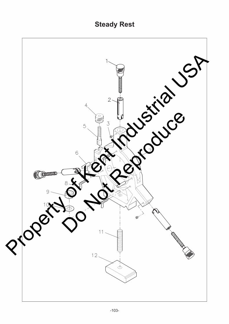
-103-
Steady Rest
Propert
y of K
ent In
dustr
ial U
SA
Do Not
Reprod
uce

-104-
Steady Rest
KEY NO. PARTS NO. PARTS NAME Q'TY REMARK KEY NO. PARTS NO. PARTS NAME Q'TY REMARK
70038 Adjusting knob 3
Spring pin 3 Ø4x40
70062 Collar 3
70035 Screw 3
70037 Finger 3
Pin 3 Ø8x23
Ball bearing 3 627
3 Set screw 3 SET 8x8
4 70064 Knob nut 1
5 70033 Clamp screw 1
6 70032 Hinge pin 2
70029 Top casting 1
14-70030 Base casting 1
70029 Top casting 1
16-70030 Base casting 1
8 70063 Single wing bolt 3
9 Nut 1 M12
10 Spring washer 1 M12
11 Hexagon head bolt 1 M12x75
12 70039 Clamp plate 1
1
2
7
Propert
y of K
ent In
dustr
ial U
SA
Do Not
Reprod
uce

-105-
Follow Rest
Propert
y of K
ent In
dustr
ial U
SA
Do Not
Reprod
uce

-106-
Follow Rest
Propert
y of K
ent In
dustr
ial U
SA
Do Not
Reprod
uce

-107-
Follow Rest
KEY NO. PARTS NO. PARTS NAME Q'TY REMARK KEY NO. PARTS NO. PARTS NAME Q'TY REMARK
70038 Adjusting screw 2
Spring pin 3 Ø4x40
70062 Collar 3
70045 Screw 2
70044 Finger 2
70047 Bracket 2
3 Set screw 2 SET 8x8
14-70041
16-70041
5 70063 Single wing bolt 2
1
2
Casting 14
Propert
y of K
ent In
dustr
ial U
SA
Do Not
Reprod
uce

-108-
Tool Post Safety Guard
Propert
y of K
ent In
dustr
ial U
SA
Do Not
Reprod
uce

-109-
Tool Post Safety Guard
Propert
y of K
ent In
dustr
ial U
SA
Do Not
Reprod
uce

-110-
Tool Post Safety Guard
ML-17/20-21
Page 1/1KEY NO. PARTS NO. PARTS NAME Q'TY REMARK KEY NO. PARTS NO. PARTS NAME Q'TY REMARK
Dome hexagon screw M6x10L
18-68001 Chip frame
18-68004 Plate - down 199x175xt4.5
18-68003 Plate - up 199x144xt4.5
Hex. socket head bolt M6x12L
Hex. socket head bolt M6x25L
18-68002
CHIP COVER
Propert
y of K
ent In
dustr
ial U
SA
Do Not
Reprod
uce