
RINGHALS KRAFTSTATION AGGREGAT 3 med
312
RINGHALS KRAFTSTATION AGGREGAT 3 Koncessionsansökan enligt atomenergilagen med preliminär säkerhetsrapport BAND 3 Kapitel 5, 6 och 7 Statens Vattenfallsverk Nr
-
Upload
khangminh22 -
Category
Documents
-
view
3 -
download
0
Transcript of RINGHALS KRAFTSTATION AGGREGAT 3 med

RINGHALS KRAFTSTATIONAGGREGAT 3
Koncessionsansökan
enligt atomenergilagen
medpreliminär säkerhetsrapport
BAND 3
Kapitel 5, 6 och 7
Statens Vattenfallsverk
Nr

STATENS VATTENFAUSVERK
VATTENFALL
Band 1
Band 2
n
Band 3
BAUD- OCH KAPITELINDELNINQ
Kapitel
1.
2.
3.
4.
5.
6.
7.
8.
9.
10.
11.
12.
Band 4
Band 5
13.
14.
INTRODUCTION AND SOMMART
PÖRLÄGGNINQSPLATS OCH QMOIVHUTGAR
REACTOR
REACTOR COOLANT SYSTEM
COOTATJHKENT SYSTEM
ENGINEERED SAFEGUARDS
TJJSTRUMEWTATION AND CONTROL
ELKRAFTSYSTEM
ATOILIARY AND EMERGENCY SYSTEMS
TURBINDEL OCH GENERATOR
WASTE DISPOSAL AND RADIATION PROTECTION SYSTEM
CONDUCT OF OPERATIONS
INITIAL TESTS AND OPERATIONS
SAFETY ANALYSIS

KAPITEL 5
Containment system
./ •
i,:,""

Section
5.5-5.1.15.1*2
5.25.2.15.2.25.2.2.15.2.2.2
5.35o.lt; t i ns* j t> «*• * J< #
5.5.1.25*2.25.5.2.15.3.2.25.3.2.35-3.2.45*3.2.55.5.2.65.3.2.75.3.3
5.5
5.6
TABLE OF COHTBHfS
Title
oaroAxnaara SYSTEM
Reaktorinne slutningFunktion ooh fSrutsättningar (later)Konstruktionsbeskrivning
Containment Isolation SystemDeøign BasisCont&iruaent Isolation Valves
Systea Design and ClassifioationValve Farameters TabulationValve
5,6.2
Reactor Containment Ventilation SystemDesign Basis
Performance ObjectivesList of Component Systems
Description of Component SystemsContainment Air Reoiroulatlon Cooling SystemControl Rod Drive Mechanism Cooling SystemNuclear Detector Well Cool ing/SysftbfBContainment Iodine Air Handling SystemCoafaiment Purge SystemContainment Pressure Belief SystemContainment Internal Filtering Unit
Components
System Design Evaluation
fests aud Inspection CapabilityPrinoipial Deiflga Criteria
Initial Comtainment Leakage Rate TestingPeriodic Containment Leakage Rate TestingPrevisions for Testing of PenetrationsProvisions for Testing of Isolation Valves
fryok- ooh tithetaprövning (later)Pre-operational TestingPost-Operational Tests
Paw
5.1.1-1
5.2.1-15.2.1-15.2.1-25.2.2-15*2.2-45.2.2-6
5.5.1-15.3.1-15.3*1-25.5.2-15.5*2-15.3.2-25.3.2-25.3.2-25.3.2-25.3.2-35.5.2-45.3*5-1
5.5*1-1
5.6.1-15*6.1-15*6.1-15.6.1-15.6.1-25*6.1-25.6.2-15.6.3-15.6.2-1
5-1

LIST CBf TABLE
Title
5.2.2-1 Contalnunt Piping Penetrations and Val ving
LI3T OF ?ICURS8
5.1.2
5.2.2-1
5.3.3-1
Seaktorinneslutning
Fuel Transfer Penetration
KVAC - Flow Diagram
5-11

VATTENFALLFfàn j Datum
BKV 3.6.1971Till
Enligt särBkild delgivningslieta
Enborl tammanlottning.n till
Titel
Kl.-nr
41230Art
BIStr'.inr
PJrfatlar»
A BergstrBm
K. Boye-HfrfllerVldl/Ulfordür»
Godkän?
T LindboAntat tntblad I Antal bllagiblod
6 i 1
Ringhals Kraftstation. Aggr. 3Westinghouee WS. 900 MfE.Reaktorinneslutning.Xonstrukt-ionsbeskrivning.
Sammanfattning
Pö'sliggande BI är en beskrivning av reaktorinneslutningen for rubr. avseendedimensionerande laeter, tillâtna pakänningar, oäkerhetafaktorer 8amt princip-utfomming och statiskt verkningeeätt.
IBil. Ritn. 1-782687
s s>. e.is9. soon oa,

Ringhals Kraftstation* Aggr. 3Westinghouse EWR 900 MWE.Reaktorinneslutning.
Innehållaförteckning
1• Reaktorinneslutningens uppgift
1.1. • • Allmänt
1.2. Dimensionerande laster
1.3. Tillåtna påkänningar. Normer och bestämmelser
1.4. Säkerhetsfaktorer
2. Beskrivning av reaktorinneslutningen
2.1. Allmän byggnadsbeskrivning
2.1.1. Golv
2.1.2. VSggar
2.1.3. Kupolen
2.1.4* Betongkinstruktioner inom inneslutningen
2.2. Beskrivning av de viktigaste konstruktionselementen
2.2.1. Betong
2.2.2. Förspänning, armering
2.2.3. Pog vid golv
2.2.4* Utförande kring hål genom betongväggen
2.2.5* Genomföringar för rör och kablar
2.2.6. Tätning av inneslutningens betongdelar
3. Tryck- och täthetsprovning
4. Reaktorinneslutningens statiska verkningssätt*
4.1* Tiden omedelbart efter gjutning
4.2. Vid förspänning
4*3* Betongen kryper, stålet relaxersr
4.4. Driftbelastning
4.5. Haveri

Reakto rlnneslutning
1.
1.1.
il
4
1.2.
Allmänt
Reaktorinneslutningsn har trå primära uppgiften
Å. Innealutnlngsn utgör att biologiskt strålskydd kring reaktor-tanken ooh ånggeneratorøraa.
B. Xnneslutningen är ett betongkärl» aoa vid maximalt antaget havariinnanför innealutnlngen kan uppta det dimensionerande övertrycketoch förhindra spridning av- radioaktiva produkter i omgivningen.
Dimensionerande laster
. Tryck- ooh -temperatur för loppet i betongkärlet omedelbart efterbrott pA en rörledning i den primära kretsen ger upphör till dedimensionerande belastningsfallen.
1»3» Tillåtna påkttnningar. Hormer och bestämmelser
För betongkonstruktionerna galler de statliga betongbeotämmelsernasamt för tpännbetongkonstruktioner dessutom spännbetosgnormer (supp-lement till Svensk Byggnorm SBIT-S 25:21). Book förutsattes betong-spänningarna vid momentan överhettning av betongens ytskikt vid etthaveri få överstiga de värden, som anges i bestämmelserna»
För den lnvändiga plåtbeklädnadsn skall byggsvets- ooh pannevetsnorner-na i tillämpliga delar gälla* I övrigt tillämpas kända erfarenheterfrån plåtlnklädnaden i hitintills uppförda reaktorinneslutningar inomlandet*
För övriga stålkonstruktioner skall gälla Svensk Byggnorm 67 (SBIf 67),Stålbyggnadsnorm 70 (St BK-Nt), Byggsvetsnonwr (St BI-I2), Ioner förskruv-, friktions- ooh nitförband (St BK-H3) ooh Statliga järnbestäia-raolnar (SOU I938t37) i tilläapllga delar, såvida ej genom teoretiskaundersökningar eller praktiska prov kan påvisas* att annat dimensio-neringsförfarande kan tillämpas.
1.4. Säkerhetsfaktorer
Inn#slutningen konstrueras för ett tryok p4 42,2 Hp/m (konstruktions»tryoket). Spännanwringen dlmsaslonsras, så att betongen fortfarandeär tryokt vid kemstruktionstryoket.
Det teoretiska beräknade Inre övertrycket uppgår till 40,1 Rp/a .Redan i valet av konstruktionstryoket finns således en säkerhetmot måttliga felbedömningar av haveritryoket.
Konstruktionen «tfoztes dessutom med hänsyn till vilka konsekvenserea större felbedömning av belastniugsförutsättningarna kan ha för dotstatiska verkningssättet.

2.1.
2.1.1.
2.1.2.
Om det tøorttlakt bsräknade inre övertryoket vid haveri ökas med50 %t vid oförttadrade värden på övriga aktuella lastar, skall iokesträokgränsen för konstruktionsstål ooh armering eller 0,2 gränsenfSr spännkablar överskridas. Detta Innebär att defönationerna hoekonstruktionen blir begränsade. Några mer omfattande sprickbild-ningar i stålskalet behöver således ej befaras* Tid enstaka punkterspeciellt vid svetsförband kring genoaförlngar o.dyl. kan dook spric-kor uppstå. Skulle övertryoket bli 50 $> högre än förutsatt får mansåledes räkna «ed ökat läokage. Oa det teoretiskt beräknade inreövertrycket vid haveri ökas mod 100 #, vid oförändrade värden påövriga aktuella laster overskrides sträckgränsen inom vissa delarav konstruktionen. Därenot skall ej brottgränsen för konstruktio-nen överskridas. Då belastningen Ökar mot detta tryok uppstårsuooessivt en omfattasde sprtokblldnlng 1 stål- ooh betongek&len,men trots detta är sannolikheten stor för. att konstruktionen »kallfungera som en enhet.
sbeskrivnljQg
Golv
Golvet g jutes direkt mot berget, där krafter från väggar och pelarenedföres. I övrigt gjutas golfplattan ovanpå wvdränerad makadam.
Golvet ligger oa 8 m under befintlig grundvattenyta, varför dennaavsänkes genon en tunnel under inneslutnlngen.
För att motverka sprickbildning i betongen p.g.a. krympning uppdelasgolvytan i flera gjutenheter eamt förses ned en sprlekfördelande ar-mering, son går genoa gjutfogaxna.
Golvet belägges ned plåtbeklädnad av stålplåt, som 1 sin tur försesmed skyddsbetong»
Väggarna utgöres ar en oa 55 a hög betongeylinder aed inre diametern35»4 a och väggtjeokleken 1,1 »• Cylindern uppbygges på så sätt, attförst utföres det tätande skalat i prinoip soa en cistern ned fastkupol» I takt «ed plåtaontaget inlägges kabelrör för den horisontel-la spännartMrlngen på konsoler» warn är svetsade på tätplåten*
Kar plåtaontaget är färdigt glMfermgjfutee den inre slakaraerade be-tongoylinderh. Vlgft jockleken äj* oa 25 «•• Väggen gjutes direkt aattätplåten, aåledes aed ensidig «lidfora. Härefter g jutes den yttrebetongcylindezn asi ensidig glidfora»
Rorlaontslla ooh vtrtikäla kablar inlägges efter gjutaingen»
Vid stt haveri blir den uppåtrlktade kraften från väggen större änegenvikten» varför spännkablar förankras 1 ovannämnda tunnel i ber-get ooh drages upp 1 väggen.

För att nedbringa väggens randaonent'vid de olika belastningsfallenutføres anslutningen till golvet med en glidfog och ett led. Sebeskrivning pkt* 2*2.3*
Bingförspänningen utføres eä att alla membranspänningar av det inreövertrycket (+2,2 Hp/m^) upptas av spännkablama. Vid normal driftd.v.s. utan övertryck, ger detta en tryekspänning i det I,'!^ tjookaskalet p& oa 90 kp/em*. Spänningen sjunker till ca 70 kp/cm efterbetongens krympning och ptålets relaxation. Vid genomföringar ochslussar ökas detta värde*
I vertikallod blir tryekepänningarna mindre.
2.1.3»
Kupolen utgöras av ett afäriskt segment, som uppbygges av en undretätande plåt, com liven tjänstgör som form vid gjutnlng av det 80 cmtjocka betongskalet* Spämikablanas A kupolen dimensioneras för sammaövertryck som väggarna.
2*1.4.
Betongkonstruktionerna inom izasesltttnlBgen uigöres dels av etrålakyddkring reaktor, bränslekanal och åaggeneratorer och dele ør bjälklag.Strålskyddsväggataa kring ånggeneratorema bäres mellan bottenplattapå + 93*0 och bjälklag + 100,0 ev pelare.
Vertikala laster från ånggsneratorer och huvudcirkulationspianpar föresgenom pendelstöd i stål och betongpelars placerade under dessa tillberg.
Horisontella haverilaster från ånggeneratorer ooh huvudoirkulatlons-pumpar föres genom bjälklag oeh strålskyddaväggar till berg.
OvsnfØr reaktortanken utlägges betongplank» som utgör skydd mot missi-ler från looket*
2o2. Beskrivning av de viktigaste kpnatrufctlonsftleaeaten
2.2.1. Betong
Betongen i inneslutnlngen skall uppfylla kvalitetskraven f Sr betongK45Of vattentät* X fråga om utförande ooh kontroll skall bestämmel-serna får utförandeklase I tillämpas.
FSrspänniugen utföres med något av de system, som godkänts av Kmagl.Väg* ooh Vatfcenbyggnadsstyreleen.
Hingkablarna förspännes aot förankringsklaokar på skalets utsida* Ur-sparingar vid upplagen igengjutes sedan kablarna spants ooh tnjekte-rate. I allaäahct omfattar varje enskild kabel ett halvt varv* varvidskarvarna färgk£utes eåf att varannan kabel skarvas vid 0 oeh 180 ochvarannan vid 90 och 270 . Härigenom blir försparmingskraften konstantlängs hela omkretsen.

De vertikal* kablarna som ej förankrat i tunnelnp för»»» med passivaförankringar i nedre änden ooh »panne» sålunda endast fr&n den övre?
De vertikala kablarna nedsänks* i ursparingar, eom utföres vid glid-formsgjutningen ar väggen.
Kablarna i kupolen utgöres av i horisontalplanet parallellt gåendekablar 1 tre lager med 120 förskjutning mellan varje lager*
All betong, såväl förspänd eom ej förspänd, armeras med elak armeringenligt bestämmelserna.
2.2.3.
Fogen vid golvet utföras sos led och glidfog för att reducera rand-störaingaraa i väggen. Fogens ledverkan åstadkommes genom två kon-oentrieka rader av plattor av gummi ooh mellanliggande stålplattor,som lägges i fogarna.
Glidningen sker mellan två stålplattor med ett mellanlägg av 2 teflon»folier eller likv.
2.2.4. Utfarande frring hål genom betongväggen
Ett e^ort antal häl skall upptagas i betongväggen för ång- ooh vatten-ledningar, elkablar, transport- ooh personalsluss m.au Tid dessa stäl-len förskjutes spännkablarna förbi hålen, så att den totala spännkraf-ten ej reduceras.
Kär genomföringama skall monteras uppskäres ett efter stålkonstruk-tionens storlek avpassat hål i tä"tplåten. Efter avslutat montagesvetsas tä-fjplåten fast i stålkonstruktionens tätningsfläns* varefteringjutning utföres med betong. Betongsektionen runt transport slussenökas i förhållande till cylindern i övrigt.
2.2.5* Oøacwföringar för röjr ooh kablar
Oenomföringarna utföres 1 princip 1 likhet med motsvarande för Ring-hals Kraftstation* Sålunda arrangeras en testkanal för anslutningenmellan tätplåt och stålkonstruktion. Denna kan användas för såvältäthetaprovning av svetsarna som för avsugning vid ev. läekage.
Detaljkonstruktionaarbetet för såväl rör- «om kabelgenomföringaT kommeratt utföras ooh redovisas för Delegationen för atomenergifrågor under1971-72.
2.2.6* Tätning av innesl»tnin|itns be£ong£»lajr
Som tätande medium användes stålplåt i olika former*
I botten utgöras tätplAten av 5 m plåt i rektangulära fält» vilkasvetsas till ett 1 betonggolvet lagjutet rutnät av stålprofiler.Svetsningen sker med kttlsvets. Håtfälten förses med nipplar, så attett övertryck för täthotskontroll kan anbringas bakom plåtfälten.
Gtam avsänkoing av grundvattenytan enligt pkt. 2.1.1. ovan skyddasplåten mot utvändigt vattentryok.

Väggarna tätas mtd 7 nm stålplåt* Håttn svetsas i sargar enligtclsteraaetoden. Väggplåten sanmanfogas av rektangulära plåtar istörsta praktisktlämpliga storlekar.
Svetef ogärna utföres som stumsvetsar från kägge sifior. De vertikalaplåtskarvarna förskjutes. Först monteras nedersta plåtsvepet förcylinderplåten. På detta svep monteras kupolens takstolar med till-hörande tätplåt* När takstolarna fixerats påbörjas påbyggnaden avcylindern underifrån* Tätplåton förses med påsvetsade konsoler, påvilka kabelrör för den horisontella spännarmeringen inlägges i taktmed plåtssontaget*
På utsidan forses plåten med U-prsfiler för täthetsprovning bakomsamtliga svetsar oah för ev. fraatida ventllering.
Eftersom plåten är ingjuten och således oåtkomlig för ev. erforder-ligt underhåll har det bedömts lämpligt* att betongen som extra re-serv har viss tätande försåga* Därför har dragspänningarna 1 betong-en genom förspänningen begränsats. Dessutom kem» om otäthet i någonsvets skulle föreligga, läckaget omhändertas genom ventilering avden aktuella delen av det av U-srofiler uppbyggda kan&lsyetemet.
Något korrosionsekydd erfordra» ej, då den överallt är ingjuten ibetong*
För att medge rörlighet 1 fogen utföras övergången mellan botten ochvägg som en dubbelt torold i 2 mm plåt* Konstruktionen utföres dubbeltför att ev. läekage kan omhändertas på samma sätt som för väggen» Benyttre totoidens inneryta korrosionsskydde.® genom lämplig ytbehandling*
Takplåten är 7 an tjock och korner även att tjänstgöra som form vidgjutning av ovanförliggande betong» Motsvarande U-profller som i väg-gen inlägges Över svetsarna. Svetsskarvarrta utföres som stumsvetsfrån bägge sidor. Takplåtens inneryta korroslonsskyddas genen lämpligytbehandling*
Takplåten kan vid ett ev* haveri koraaa att utsättas för missiler* d.v.e*accelererade komponentdelar såsom rördelar* bultar o.dyl. För missilerfrån reaktorlooket utgör dook de tidigare nämnda betongplanken ettskydd.
Beträffande svängande rör och hela komponenter kommer sådana att för-ankras så att några skador ej kan uppstå på plåten vid ev. haveri avdessa.
För kontroll av att konstruktionaf»rutsättnlngarna Kr uppfyllda be-träffande ixmeslutnlngens try okupptagande förmåga, täthet och statis-ka verkningssätt, skall tryck- ooh täthetsprovning ske vid l&apligtidpunkt under stationens uppbyggnad*
Tryck- och täth«rSsprovningen planeras ske oa 2 £ år tf ter njutningenav den yttre betongoylindern. Vid tryekprovningen provas hela inne-slutningsn för provtrycket 48*3 Hp/m^.
\

FØr tryofc- ooh tMtheteprowlng kommer aanare att uppgöras ettdetaljerat program, rilket 1 god tid korner att redovisa» förDelegationen för atomenergifrågor»
4. Healctorinneelutningena atatiaka rerkningasätt• 1111 IM III—HIM • • • [ • • • • l l é W » • • • ! ! • • [ • • • • • • • • • • I — • • • • • • • I
4*1• Tiden omedelbart after g.lutning
M oeaentet i betongen börjar binda etiger temperaturen. Vidden påföljande avaralningen krymper betongen ooh cylindernsraggar rör alg mot centrum. Då inneslutningena raggar vilar påled ooh Elialager, kan rörelsen försiggå utan att nämnvärdaspänningar uppstår i betongkonetruktionerna.
4.2. Vid förspanning2
Ar förepänningen uppkommer i ringlad att tryok på ca 90 kp/oa ooh1 rertlkalled ett tryck varierande mellan ca 50 och oa 40 kp/cm2
omedelbart efter uppspänningen. Botongkupolen får en motsvarandeiceridian- och rlngpåkänning på ca 90 kp/cm2, »etta medför att rag-garna rör sig mot centrum ooh förkortas 1 vertikalled.
Rörel sen kan försiggå utan att några näanvärda extra spänningar upp-står*
4»3« Batongen kryper» stålet relaxerar
Under tidaperioden efter förapänning (storlekaordningen 10 år)kryper betongen ooh minskar på detta sätt förapänningekraften.I samband med krypningen i betongen relaxerar ftJrøpannlngeatålen.Xren detta medför en minskning ar fSrapännlngakraften.
4.4. Driftabelastning
När stationen tas i drift ökas innetemperaturen» rilket Innebär attraggarna rör alg ut från centrum, en rörelee notaatt ovannämnda rörel-ser*
Härtill kommer an årlig rörelse från temperaturvariationer.
4*5* Haveri
Vid ett haveri innanför inne slutningen uppstår ett inre övertryck sommaximalt har beräknat a till 40,1 Hp/r2. Härar uppkommer-böjning arragg oeh tak*

+ 156,30
ftft/KHKRIMC
A — A ••

B-B: 1 200

5.2 CONTAINMENT I30LATI0N SYSTEM
b.r}.I DNfSIGN BASIS
Kach system whose piping penetrates tht containment leakage limiting boundary
ir, designed to maintain or establish isolation of the containment from the
outside environment under the following postulated conditions:
Any accident for which containment isolation is required(severely faulted conditions) and,
b. A coincident independent single -failure or malfunction (expected fault
. condition) occurring in any active system component within the isolated
bounds.
Piping penetrating the containment is designed for pressures at least equal
to the containment design pressure. Containment isolation valves are provided
as necessary in lines penetrating the containment to assure that no unrestric-
ted release of radioactivity can occur. Such releases might be due to rupture
of a"non-missile protected" line within the containment concurrent
with a loss-of-coolant accident, or due to rupture of a line outside
the containment which connects to a source of radioactive fluid within
the oontainment.
In general, isolation of a line outside the containment protects against rup-
ture of the line inside concurrent with a loss-of-coolant accident, or closes
off a line which communicates with the containment atmosphere in the event of
a loss-of-coolant accident. A piping rupture outside the containment at the
same time as a loss-of-coolant accident is not considered credible, and the
penetrating lines up to the isolation valve outside the containment are assumed
to be an extension of containment.
The isolation valve arrangement provides two barriers between the
Eeactor Ciolant System or containment atmosphere, and the environment.
5.2.1-1

System design ia such that failure of one valve to close will not prevent
isolation, and no manual operation is required for intnediate isolation.
Automatic Isolation Is initiated by a containment isolation signal, Section 7,
derived either from any automatic safety injection signal ("T" signal) or from
a high containment pressure signal ("P" signal).
Containment Isolation Valves
Criterion: Penetrations that require closure for the containment functionshall bo protected by redundant valving and associated appara-turs. (GDC 55)
Isolation valves are provided as neoessary for all fluid system lines pene-
trating the containment to assure at least two barriers for redundance
against leakage of radioactive fluids to the environment in the event of a
loss-of-coolant accident. These barriers, in the fonn of isolation valves
or closed systems, are defined on an individual line basis. In addition to
satisfying containment isolation criteria, the valving is designed to fa-
cilitate normal operation and maintenance of the systems and to ensure re-
liable operation of other engineered safeguards systems.
With respect to numbers and locations of isolation valves, the criteria
applied arc generally those outlined by thefakx classes described in
1'icction D.2.2
5.2.1-2

5.2.2 SYSTEM DESIGN AND CLASSIFICATION
The four claques lasted below are general categories into which line pcrui-
tr-ntlnc; containment may be classified. The following notes apply lo these
classifications.
1. The "not missile protected" designation refers to systems that are not
protected throughout their length inside containment agalnnt missiler,
generated as the result of a loss of coolant accident. These systems,
therefore, are not assumed invulnerable to rupture as a result of a
loss of coolant.
2. ' In order to qualify for containment isolation, valves inside the con-
tainment must be located outside the missile barrier for protection
against loss of function following an accident.
3. Manual isolation valves that are locked closed or otherwise closed and
under administrative control during power operation qualify as automatic
trip valves.
;i. A check valve qualifies as an automatic trip valve in certain incoming
lines.
5. The. double disk type of gate valve is used to Isolate certain lines.
6. Isolated lines between the containment and the second outside isolation
barrier (valve or closed system) are assumed to he an extension of eon-
"talnm&nk. : . . - ,
'(. ',"'..tøe,'first outside isolation valve Is located as oloae to the containment• • -• •:'• ,.."•.- -,-;T - - :. - : - | .„•
as possible unless a more remote location is dictated by equipment iso-... Ration.requirements.
5.2.2-1

Piping which penetrates the containment and is not required to
funotion following a loss-of-ooolant aeoident is provided with
two automatic isolation barriers) one barrier is located outside
the containment and one is inside the containment.
The definition of an automatic harrier, is either a olosed system
trip valve or check valve.
Using this definition four general classifications are derived:
1* Two closed systems - one inside, one outside, no isolation
valves required.
2. No closed systems - one valve ineide and one valve outside
required.
3, Closed system inside - no valve inside, valve required outside.
4* Closed system outside - no valve outside, valve required inside.
The same criteria apply,to lines which are used after an
accident except that manual isolation is acceptable.
Based on the four general classifications the following types of
valves would be used.
T*
cc
Ea
cl
opa
On
co:
tw<
sit
pos
Classifi cation
1
2
5
4-
Incoming Lines
Ho valves required
Trip valve outside andcheck valve inside ortwo trip valve», one in-side and one outside
frip valve or checkvalve outside, novalve inside
Trip or cheek valve in-side, no valve, outside
Outgoing Lines
Ho valves required
Two trip valves,one inside andone outside
Trip valve outside,ho valve inside
Trip valve inside,no valve outside
All check valves used for containaent Isolation are of the special
(soft seat) type capable of tight øhutoff at containment design
pressure against gas leakage.
.- JL'_ it,-
•fl
There are a number of speoial groups of penetrating lines and
containment access openings. These are disoussed below.
Bach ventilation purge duot penetration 1» provided with two tight-
closing butterfly valves* which- are closed during reactor power
operation and are aotuated to the olosed position automatically upon
a containment isolation «r a containment high radiation signal.
One valve is located Inside and one valve Is located outside the
containment at each penetration.
The ventilation outlet (relief) lir.es are similarly proteoted with
two tight closing butterfly valves in series, one inside and one out-
side ^he containment. These valves also are actuated to the closed
position upon a containment isolation or containment high radiation
signal.
(Cont'd)
es
d
5.2.2.-3
equipment tinow.n Match-in A l»olted, ganketed olosure whioh la sou Led
ing nnxclor operation. Thu personnel air look» oonnlnt of two doora In
set-lea with mechanical interlocks to assure that one door is closed at alltimes. . .
The fuel transfer tube penetration Inside the containment. Figure .5.2.2-1,
is designed to present a missile protected and pressurized double barrier
between the containment atmosphere and the atmosphere outside the contain-.
ment. The penetration closure is treated in a manner similar to the equip-
ment access hatch. The inside closure is a blind flange which contains two
gaskets.
The containment radiation monitor inlet and outlet lines communicate with
the containment atmosphere at operation (normally filled with air or vapor).
The inlet an well as the outlet line Is provided with two automatically
closing containment isolation valves.
5.2.2.1 Valve Parameters Tabulation
A summary of the fluid systems lines penetrating containment and the val-
ves and closed systems employed for containment isolation is presented in
Table 5.2.2-2. Each valve is described as to type, operator, position In-
dication and open or closed status during normal operation, shutdown and
accident conditions. Information is also presented on automatic trip by
containment isolation signal, and the fluid carried .by the line.
Containment isolation valves are provided with actuation and control
equipment appropriate to the valve type. Por example, air operated globe
and diaphragm (Saunders Patent) valves are generally equipped with air
diaphragm operators, with fail-safe operation assured by the control
devices in the instrument air supply to the valve. Motor operated gate
valves are capable of being supplied from reliable on site emergenoy
power as well as their normal power source.
The automatically tripped isolation valves are actuated to the closed
position by one of two separate containment isolation signals. The
5.2.2^

:
first of these signal» is derived in conjunction with automatic
safety injection aotuation, and trips the majority of the automatic
isolation valves. These are valves in the so-calltd "non-essential" x
prooess lines penetrating the containment. This is defined as "Phase A"
isolation, and the trip valve* are designated by the letter "T". The
aecond, or "Phase B", containment isolation signal is derived upon
actuation of the containment npray system» and trips the automatic
isolation valves in the so-called "essential" prooese lines pene-
trating the containment. ("P"-signal)
A manual containment isolation signal can be generated from the control
room. This signal performs the same functions as the automatically
derived "T" signal, i.e. "Phase A" isolation.
Non-automatic isolatloa valves, i.e., remote stop valves and manual
valves, are used in lines whioh must remain in service, at least
for a time, following an aocident. These are closed manually if and
when the lines are taken out of service.
Standard closing tines available with commeroial valve modes are
adequate for the sista of oontainment isolation valves used. Valves
equipped with air-diaphragm operators generally close in approximately
two seconds. The typical closing time available for large motor
operated gate valves is ten seconds.
The large butterfly valves used to isolats the oontainment ventilation
purge duets are equipped with air-eylinder operators, with spring
returns capable of dosing the välvts in two seconds• These välvts fail
to the closed position on loss of control signal or instrument air*
x "Non-essential" process lines art defined as those which do not in-crease the potential for damage to in-oontainment equipment whenisolated. "Essential" process lints are those .providing coolingwater and seal water flow through the reactor coolant pumps. Theseservices should not be interrupted unless absolutely necessary whilethe reactor coolant pumps are operating.
5.2.2-5

The following types of isolation valves are omployed outside the
containmentt
1. Diaphragm valves (Ssunders Patent)
2. Globe valves
5. Double disk gate valves
4. Regular gate valves
Diaphragm valves are used in lines 3 inches and «mailer, with low
pressure, low temperature service requirements (200 psig, 200 F or
less). Two remote operated valves in series are used in non-missile
protected lines going out of the oontainment. A noatbor of penetrating lines
are isolated by one manual or remote operated diaphragm valve. These lines
are missile protected inside the oontainment, and sone are connected to
external systems whioh have sufficient capacity for inflow to the oon-
tainment.
Two æanual or air operated globe valves in series are used to isolate
lines 2 inches and smaller with design pressure or temperature greater
than 200 psig or 200°F, respeotirtly.
Isolation valves with packed stems are provided with sttan leakoffs
if all of the following operating conditions are satisfiedt
1. Line size is 2 inches or larger. *,
2. Operating temperature can exceed 212°7«
5« The fluid is radioaotive*
5.2*2.2 Valve Qperability . '
All air and motor operated containment isolation valve» can be remotely
operated from the central control room» The open or closed conditions of
5.2.2-6

these valves is displayed visually in the control room at all times*
Only the valves located inside the oontainment which are missile
protected can be considered as available for containment isolation.
These valves are located outside the missile barrier*
All lines penetrating the oontainnent whioh normally carry radioactive
fluids or that can communicate with the oontainment atmosphere following
an accident are provided with radiation shielding f.n all areas where
personnel access is possible* Manual valves in the lines, including
containment isolation valves, are equipped with extension handles for
operation from outside the shielding*
Valves that are normally open during power operation and which must
be closed for oontainment isolation are actuated to the closed position
on receipt of a oontainment isolation signal.
i Redundant electrical control cirouits are provided for all remote
1 operated containment isolation välvts* If the normal power supply for
| the control circuits fails, they may be energized by an emergency
power supply* Duplicate cabling to the valve operators is not provided.
All air operated isolation valves fail closed on loss of oontrol signal
or control air* This is not detrimental tö power operation* If one
of the isolation valves should fail closed, operation of the oonneoted
systems either is not affected or can bs modified until repairs are
made*
It is not necessary to demonstrate that oontainment isolation barriers
are leak tight* The closed systems that back up the containment
isolation valves have adequate oapability for flow toward the oontain-
ment or adequate design to contain any radioactivity introduced into
the system as the result of an aocident.
Penetrating lines other than those associated with the engineered
safety features whioh oontinue to be used, at least for a time, after
containment isolation includet
5.2.2-7

1. Main steam headers.
2. Auxiliary feedwater headers*
J. Keactor coolant pump cooling water supply lines*
Reactor coolant pump cooling water return lines*
5. Reactor coolant pump seal water supply lines*
6. Containment air sample in if containment pressure «£. 5 P<*ig*
7. Containment air sample out if containment pressure<.5 psig.
5*2.2-8

ISOLATIOH VALVE CLASH IrlCAIIOKS
Inalae Contaiaaent Vessel
Penetration»
Accumulators Teat Lin*haesurixer Jtelltf Tank' Sampleto Gas Analyser
Kitrogen Supply - BC irsOn Tank
Sitrogen Supply - Accumulator
nitrogenSupply - Fr«teuri*trBelief lank
Fxwaurlser Jtaliaf lauk Xakeup
K Brain lank Vant Header
BMctor Coolant Drain lank Stain
Stea»
Faadwater
Staaa Generator Slowdown
laalrtual Haat Bamorel Loop-Outleaidual Heat Btaoval loop-In
letdown Llna
"Charging Una
Beactor Coolant Punp SaalWatar SupplyVater Batuza
Praaaurlxar Staas Saaplt Llnafrcaauritar Liquid Sajqil* UnaBot Lag Saspla Lintlual Trmnafar luba
Sarvica Air
Instzuoant Air
•aactor Coolant Srala lanicC M Saapla
Coatalnawnt Air Saapla'In
Systea type
SIS BSV
BCS I*
«16
315
acsBCS
wrens16
Position LuringSoraal Optratlon
Closed
Loss ofPowar
Closed
ChackCneek
CTCS
CVCS
HlssileProtectcäKiasil.Protect «dtisaileProtectedBST + BSTCheck -f BST
BST-I
Check
MissileProtectedKissUeProtected
i-issUeProtected
CloaadClosed
Open
CVCS Chack
CVCS
SS
SS
SS
ras
SA
IA
væ
asvBSVBSVBlindFläng*
-
RSV.T
Cloaed
Closed
Cloaed
Closea
_
lae Cor.t&inaent Vessel
-If
H3V-I
Cneck + «V
RSV-T
Hsv-r • asv-iBSV-I • BSV-T
Stop Check +Closed Sya.
Check + BSV
Positior. luringKormal Operation
iiocked Closea
Olosea
Open
Closed
OpenClosed
Open
OpenOpen
Open
BSV-t + asv-T Open
AS t*
A« is
Closed
-
-
-
Closea
Closes
Closed
-
_
Closed System
BSV * CloseäSy3te».
•SV-T
33V + IV •Closed System
£V + ClosedSyste»
Svs teit
asv-r •» asv-TBSV-I + H3V-I
asv-i • asv-iXV
Cseck * XV
Check * aSV-I
-
Open
Open
Open
Open
Open
Closea
Closea
Closeä
Closed
Closea
Open
Loss of• ro»er
Closed
Closed
Plow
«-0G-0
G-I
ClostaClosea
Cloaeä
Closed
As is
Closed
_
Open
Closed
Open
As is
As is
Closed
Closed
Closed
-
—
Op asCloaad
W-I
G-0
W-0
G-0
W-I
W-0
W-0
W-I
W-0W-I
I-I
<-0
G-0
1-0
W-0
1
G-I
e-i6-0
I ex;- erst *:*
> £vC • ÖS-.< 250 - Col
Cola
Coli
Coli
Coii
Cola
Cola
Cold
Eos
cot
Bot
Cold
Hot
Cold
Cold
Cola
Hot
Hot
sot
Cold
ColaCold
Cola
RSV-I » BSV-t Open* Closed Syste»
Closed G-I

H4V
IDS
Penetrations
Containment Air Sacple Out
f ire laterContainment Surge tactsSupply and ExhaustBeactor Cavity Susp
Salt water Supply toContainment Coolers
Salt water Return 2rocContainment Coolers
Vacuuo Belief
Beactor Coolant Funsp Cooling. Vater SupplyBaactor Coolant Pimp Coolingt'ater Betum
Excess Letdown Uaat Exchanger UCSCunjHHW^ Cooling Vater Supply
Sxceas Letdown Heat Exchanger
H&T
CCS
CCS
CCSComponent Cooling Vater ReturnSafety Injection Line SIS
Containaent Spray CS
Containment Sue? Bicirculation SISLines«ccusulator Kakeup Line SIS
Acout. Sample Line S.S.
Containment Fressure Belief H&V
F r e s s u r i i e r Pressure Generator DCS
Table 5 . £ . 2 - 1
ISOLATION VALVE CLASSIFICATION'S
(Cont'a)
Inside Zcz.ZhLz^iz.-. Vegael
System Type
HSY-f*'
Check
Check
RSV-P
Position gSoraal Operation
Closea
Ciosec
Open
Open
Cloaed Syitw
BSV + Check Open
Check +KiMileProtected
kiaaUeProtectecBSV
ESV-S*
HV
frotecseä
Protectei
Ciosec
Closec
Closed
Loss of
Closed
j8
As Is
Closea
Closea
Closed
u^alue Comifciraent Vessel
Type
asv-iCheci
HSV-T+ S3V-I
BSV- S
BSV-T • 33V-I
Position Luringäorsal Operation
Open
Closed
Open
Open
Open
Closed(2) SeriesVacuum BreakersRSV-P *BSV-P+ Open
.osed Systea
BSV-p^+ Closea OpenSystea
Ch»okSystenBSV-T + ClosedSystemBSV + CloseasystemBSV • HSV+ Closeä System
BSV + BSVClosed SystemCheck
ESV-T + BSV-I
HSV-IX'
•jy + Mv
Closeä
Closea
Ciosec
Closea
Open
Closed
Closed
Loss ofPower
Closea
Closea
Closea
Closed
Closes
Closed
As i s
As i s
Closed
As Is
Closes
flow
6-0
t-l
G-I/O
*-0
W-I
3-1
X-I
W-I
V-0
t-l
W-I
V-0
I-I
1-0
3-1/0G-I
<:OCi ? Hot200 f Cola
Cole
Cole
Cola
Cola
Cold
Cold
Cola
Cold
Cold
Cola
Cold
Cold
Cold
Hot
Cola
Cola
Cola
Cold.
\Se* following page for abbreviations)»
Talves also close on high radiation.

Table 5.2.2-1
ISOLATION YAL7E CLASSlfflCATIONS
(ContM)
ABBREVIATIONS
CCS - Component Cooling SystemSIS - Safety Inject ion SystemRCS - Reactor Coolant SystemWDS - Waste Disposal SystemMS - Main Steam SystemW - Eeedwater System
HERS - Besidual Heat Removal SystemCVCS - Chemical and Volume Control System
SS - Sampling SystemPHS - Fuel Handling SystemRMS - Ra.dia.tion Monitoring SystemH&V - Heating and Vent i la t ion
SA - Service Air SystemIA - Instrument Air System
PWS - Fire Water 3yetem
VALVES
RSV - Remotely-Operated Stop YalrsMV - Manual Valve
RSV+RSV - Remotely-Operated Stop Valves i n Ser ies- I - Tripped Closed on 3#ft%» I n j e c t i o n A«*aation-P - Tripped Closed on High Containment Pressure
Direction I - IN0 - OUT
Fluid 0 - GasW - Water

H.B. ROBINSON UNIT NO. 2FUEL TRANSFER PENETRATION
. ' PIGURK 5 . 2 . 2 - 1

5.3 HBACTOH CONTAINMENT VEKTIIATJOST SYSTEM
The primary purpose of ventilation is to reduce personnel oxponim-
to air borne radioaotive eontaminante and to prevent equipment
excoesive operating temperatures.
The reactor oontalnnsr.t ventilation systems do not introduce .any
outeide air to the containment during reactor operation. Except *~c~
infrequent releases which may be required due to le.'i>n/*e from th?
Instärument Äir System or Penetration Pressurise tio;" r/oten, the ryst
do«s not exhaust any containment air to thr; .-».teosphere during rci- o
operation.
The containment ventilation system is shown in Flow Diagram 5.3.7 -'<
5.3-1

I. 3.1 DESIGN BASIS
5.3.1.1 Performance Objectives
The ventila'.m^ systems are designed to accompli ah the following:
M ) Remove the normal heat loes from all equipmonl. mid piping in
tho reactor containment during plant operation nnd to mainlnjn a
I'anpQT'ituT'j of !20 21 or less inside the con Lai niræiil wi Mi <>1°T<'
oooLin/; water with two out of throe fHIIO nporal,' n, .
b) Provide sufficient air circulation and filler In/;; and .iodine remo-
val throughout all containment areas to permit two hours ucoecn
to the reactor containment at power operation and to areas where
direct dose rates are not limiting assuming defects exist in 1 per-
cent of the fuel rods.
e) Provide for positive circulation of air across the refueling water
surface to enhance personnel access and safely during shutdown.
']) Provide for purging of the containment vooool to the plant V<TII
Tor di.npur3ion to the environment. Tho rate of release doen not
permit off-sifce dose to exceed one tenth of thai permitted by 10
CRP 20. The purge system is designed to allow aafe and continuous^
access to the containment within two hours after planned or unplan-
ned reactor shutdown. Estimated leakage of coolant from reactor in-
to the containment atmosphere le 40 lbs per day.
e) To remove heat generated by the control rod drive mechanlsmo.
f) Provide cooling for the reactor vessel, primary concrete shield
and nuclear detectors.
5.3.1-1 ,

(j) Reduce the concentration of radioactive Iodine and other parti»
culale matter in the containment atmosphere to permissible
levels for purging nnd personnel acoess.
h) Provido for routine containment building pressure and vacuum
relief as roqwired during normal power operation.
';.?5.1.J? Li a <; of Component Systems
Ln urder to accomplish these objectives the following systems are
provided:
a) Containment Reeirculation Cooling System
b) Control Hod Drive Mechanism Cooling System
cj Nuclear ..Detector Well Cooling System
d) Containment Iodine A: r Handling System
«) Containment Purge System
i') Containment Pressure Relief System
g) Oontairaaeat Internal Flltétfinjf System '
-'• ' " * • * « ! " ' ' - ' ' - ' » , - ; . - - • ' : • • : >

1
1- 5.3.2 DESCRIPTION OF CØMPOIrøTT SYSTEMS
'>.••}.K.1 Cqntairucan^
The Rouotor Oontainment Air Recirculation Cooling Uywtem consists of
three air handling unit» loo*t#d on the containment bottom floor.
Bach air handling unit includee water cooling coils, a motor driven
centrifugal fan, and dampers.
Bach unit draws air frøa the containment atmosphere and discharges to
a common header f om. where it is distributed through ductwork to the
individual areas. v,3torJUag; reactor operation two of the three units are
operated. The distribution systemisarranged to ensure against short
circuiting the air flow- back ta the unit inlet.
5.3.2,2 Control^Sod, I|rihveijM9ch.anlsffl[ Cooling SystemV.-CV-' ' -V.
\ ' '• n ; ; . '
Air from the containment recirculation cooling system discharge duct
is drawn by axial flow fans to a cooling shroud surrounding the con-
trol rod drive mechanisms to absorb heat generated by the mechanisms
and is then discharged ,to the containment atmosphere. The system con-
alst», .pf .ductwork 4ja4(,£ptt«: 3.3#3 ,.,o*p»city fans. During'reactor opera-
tion three fans acf;,qp,eratedf 'S^tte^fly valves provided at the suction.
of each fan are, op«n«;d automatically when the corresponding fan is
In order to: remove,h
reactor vesselfrom the reactor vessel exterior surfaces,
and.primary, concrete shield, and to cool the
to the, reactor, a separate closed

air circulation system io provided. Air from the enclosed compart-
ment below the reactor vessel is passed upwards through the annular
space between the reactor vessel insulation «nd the primary shield
and through the nuclear detector veils to a system of ducts
connecting to the upper parts of the detector «alls and the annular
space» Th<? ducts are connected to two 100 % axial flow type fans
with absolute filters and cooling eoils. The cooled air from the
fftns in discharged to the enclosed compartment below the reactor.
This closed cooling system confines the argon ^1 produced by activa-
tion of the air passing through the annular space and detector wells.
5.3.2.4 Containment Iodine Air Handling System
1
This system consists of two axial flow fana with activated charcoal
filters and absolute filters and is provided to remove radioactive
iodine and other particulate activities released to the containment
atmosphere during normal power operation. The system is operated
prior to limited personnel access at reactor power and prior to plan-
nod shutdown to reduce the inventory of fission products to be
released by the purge air system to the environment. The fan and
filter units are located at the containment bottom floor. During power
opera lion, the containment particulate and radiogas monitor indications
will /fuide operation of either one or both of these untie for pre-aceess
cleanup or prior to purging. '
'Xi
I ,
5.3.2,5 Containment Pur^e System
a) Thu Containment Purge System is designed to deliver filtered air to
the containment and to discharge containment air to the enviroment.
Thy sjyotem capacity is based on. two volumetric changes in one hour
to assure» safe continuous access to the containment whitin two hours;
after a planned or unplanned reactor shutdown.
b) The purge supply:'éjF«t'e«;V^4jiøtjrt»; of •an.'^tdao^.-.aiar- intake and two
fan-filter units with absolute type filter and heating coils, and a
supply duct jp.ehetrating't]^
valves for isolation. Inside the eonialnmetft ?the intake duet isconnected to the common £•«£•* -of' the Contain»ent Air ÄteiscfttlatloBCooling System to dittribut» air to tht variout oomp*rt»«nt» andfloox level».
i -\ - „ 5,3.2-2 . . " . "

in-
wer;ionsiceess
Lr to
ment.
hour
hours
two
and a
iy
is
latlot
and
o) The pure? exhaust system collects air from tho various compart-
ments with a containment penetration which includes bubti.TfLy
V«K for isolation, exhaust ductwork, and two pur/;u oxhaunl
flow rnr.H with absolute filter» located in thu Auxiliary Building.
The fanw discharge to the plant vent. Dampers are provided in tho
duet before the filters. A separate air intake duct with dampers
is also provided. Operation of these danpera allows dilution of
the purge air exhaust to the environment.
d) The supply and exhaust penetrations through the containment are
each equipped with quick closing, tight seating, air operated
butterfly valves both inside and outside the containment. Theae
valves are designed to fail elostd on loss of control signal or
control air, and are closed during normal plant operation. Prior
to Activating the purge system after shutdown, the containment
parfciculafce and gas monitor will be used to indicate the airborne
activity levels inside the containment, as a guide for routine
release from the building.
5.3.2.6 Containment Pressure, Relief System
Normal power operation will be conduoted with the closed containment*
building at essentially atmospheric pressure. The Containment Pressure
Relief System is provided to control v«riationa in conlaiwnent pressure
with respect to atmospheric pressure, due to changes in atmospheric
pressure and to leakage from the Instrument Air and Penetration PresB-
urination Systems.
This system Includes separate 6-inch lines penetrating the containment,
each equipped with two quick dosing, tight seating, air operated but-
terfly valvos, one inside and one outside containment. These valves
are designed to fail closed on losa of control signal or control air, and
are closed during normal plant operation, except as required for pressure
control.
5.3.2-3

The pressure relief line dischargee to the plant vont fchrotygx a
. hiflh efficiency p.articulate air (HEPA) -filter, and a charcoal fil-
ter, for removal of particular© and halogen radioactivity from
t h e v e n t e d a i r . . • ; • • - . • ••.•••> ';/'•.: • • • '
Operation of the pressure relief lines is .manually-controlled by
the plant operator. A narrow range pressure-transmitter continuously
• ndi calwa containment pressure in--the control room. Separate high
;>T.T;;;U7V; nlurmr; are actuated by this transmitter to alert the ope-
rator to overpressure conditions. These alarms'are tentatively"set
Tor actuation nt plus and minus 0*3 psig. In the event of pressure
buildup, the operator will be guided by atmospheric conditions, and
by the containment particulate and radiogas jnonitor in relieving the
overpressure. •. •
Manual operation of both these'lines is overridden by automatic con-
tainment isolation and containment high radioactivity signals.
5.3,2.7 Containment Internal Filtering Unit
This system consists of two axial flow fans and one absolute filter.
During nom al operation only one fanø is employed to remove airborag
particulate matter from the containment atmosphere.
i :••'• ?;p'> "• .=.' ,':-i;Xs.".vr. 'il:*.£y ^yyi'-o.,.'
5.3.2-4'
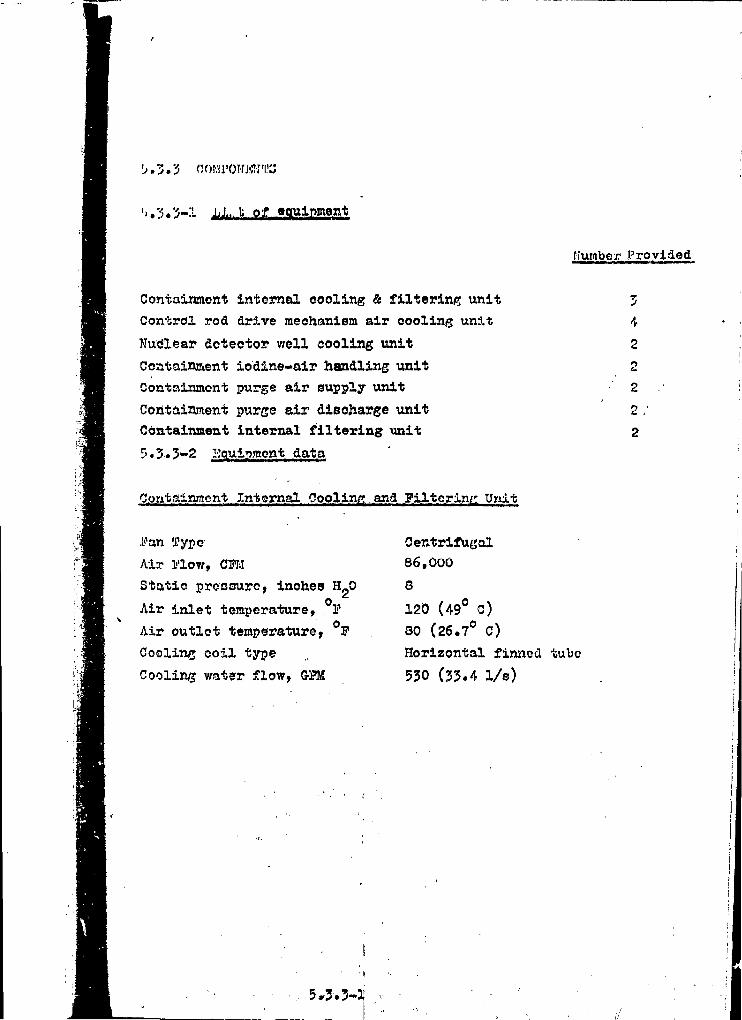
L». 3 .
•'..';•> Li., t of «auipment
h'umber Provided
Containment internal cooling & filtering unit
Control rod drive mechanism air cooling unit
Kutflear detector well cooling unit
Containment iodine-air handling unit
Containment purge air supply unit
Containment purge air discharge unit
Containment internal filtering -unit
5.3.3-2 llquipmont data
Z4
2
2
2
2
2
Containment Internal Cooling and Filtering Unit
i''an Type
Air l-'low, C M
Static pressure, inoheis H20
Air inlet temperature, . I1
Air outlet temperature, °P
Coolins coil type
Cooling water flow, &PM
Centrifugal
86,000
8
120 (49° C)30 (26.7° C)Horizontal finned tube530 (33.4 1/s)
5.3-. 3-3!

oJ. J?o<» !)rivo »Tochaniam Air C.oo.Iinfl Uni t s
A i r i''lovv Htito,
Static .Pressure, inches
Axial Plow
14,70010
Nuclear Detector -Well. .Cooling Unit
Pc>i Type
Aii Plow, CTI.i
Proseurej incheo H-0
Aiz- Inlet Temperature, °F
Air Outlet Temperature, F
Cooling Coil Type
Cooling Water 3?low, GPM
Filter Type
filter Media
Filter Efficiency
Axial Flow7,8CO
9
120 (49° C)
80 (26.7° C)
Horizontal» Pinned Tube
40 (2.5 1/s)
Absolute
Glass-Asbestos Paper
99.9 % for particles
0*3 microns and larger
Containment Iodino»Air Handling Unit
Vin Typo
/.XT j'''lO'.7, C'J!1-"
Static i'roosurc,-inches H_0
Axial Plow
5000
4
Iodine Eemoval
Activated Charcoal
99.99 %
Pilter Type
filter Media
Toöino Absorption Uffieieney
(second filter in series with above)
Filter Type ' Absolute
Pilter tledia GHass-Asbeetos Paper
Pilter Efficiency 99.9 % for particles
0.3 micron and larger
5.3.3-2

nt j'urge Air Supply Unit
Pan 7?ype
Air Flow, CFH
Statio Pressure, inches HgP
Air Inlet Temperature, Design, '
Air Outlet Temperature, Design,
Heating Coil Type
?liter Type
F.vlter Media
Centrifugal25,0008
O(-17.8° C)70 (21.1° C)Horizontal, Pinntd Tube
Absolute, Automatic Roll
Glass Fiber
Containment Purge Air Disoharge Unit
Fan Type
Air Flow, CFM
Statio Pressure, inches HgO
Pilter Type
Filter Media
Filter Efficiency
Containment Internal Filtering Unit
Fan Type
Air Flow, CFM
Filter Type
Axial Flow
25,000
9 *•
Absolute
Glass-Asbestos Paper
99,9 # for particles
0,3 aiorona and larger
Axial Flow
15,000
Absolute
5*3.3-3 Flow Diagram
The containment Ventilation is shown in Flow Diagram 5.3.3-1.
5.3.3-3


S.3.3. - /
I^*J £^<å\> i,. » , j t . . . . Hfc.-i

5*5 S y t e » Design Evaluation
Beskrivning av detaljerat beräkningsförfarande för irmeslutningenkoraner att redovisas senare.

5.6 TESTS ACT INSPECTIOK
PRINCIPAL DESIÖH CRITERIA
Centainaent LeekJMBL&alia, Ttetlmr
Criterioni Contftiawsnt shall be designed so that integrated leakage ratetesting oaa ba oonduotad at the peak pressure calculated toresult fron the design basis accident after completion andinstallation of all penetrations and the leakage rate shallbe measured orar a sufficient period of tiae to rerify itsoonforaanoe with required perforaanee. (GDC 54)
After completion of the oostalnaent atruoture aad installation of allpenetrations aad weld ©hannela cs integrated leak teat will be performedon the total containment
Following the initial integrated leak teat a atruotural strength teat on
the oontaiaadAt will be oonduoted»
ATter coapletion of the containaent atruoture and inatallation of penetra-tions and weld channels also on initial leakage rate teat will be oonduotedwhereby only the volum of the weld channels and double penetrationa areto b« included in the teat*
Periodic
Criterion1 The containaent shall be designad so that an integratedleakage rate eaa fee periodically deterained by teat duringplant lifetias. (ODC 55)
An integrated leakteat at suitable pressure lerel can be conductedduring aaansr shutdowns» This will be don* at dieorete oooaslens teriagplant lifatiae»
5.6.1-1
i.

A.leakage rat* teat «here only th* volume of weld ohanneli and
double penetration* are inoluded can be performed at any time
during the operational life of the plant»
Provieiona for Teetlng of Penetration»
Criterion* Provisions shall be «ad* to th* extent practical for
periodically testing penetrations which hare resilient
seals or expansion bellows to permit leak tightness to
be demonstrated at the peak pressure calculated to result
from occurrence of the design basis accident. (CSC 50)
Suoh penetrations are designed with double seals so as to permit full
pxessurization of the interior of the penetration and thus to demon-
strate sufficient leak tightness at the peak pressure*
Provisions for Testing of Isolation Talres
Criterion! Capability shall be prorided to th* extent praotioal for
testing functional operablllty of ralres and associated
apparatus essential to th* containment funotion for estab-
lishing that no failure has occurred and for determining
that ralre leakage do*s not exoeed acceptable limit*.
(GDC 57)
Capability is prorided to th* extent praotioal for testing th* functional
op rability of valres and associated apparatms Airing periods of reaotor
.' .tdown»
Xnitatlon of containment isolation employ* eoiaoidenee circuits which
allow oheoking of the operability tad «allsration of on* channel at a
time. Removal or bypas* of on* signal «hannel plaocs that oircuit in
the half-tripped mode.
The main steam and feedwater barrier* and isolation valves in systi
which conneot to the Reaotor Coolant System are hydrostatieally tested.
Valves in the Residual Heat Removal Syntem ar* not considered to be
isolation valves in the usual sense in as much as tho system would be
in operation under aooidont conditions*
5.6*1-2

5*6*2 Tryok- ooh täthetsprovning
En utførlig beskrivning av hur tr/ok- ooh täthetsprovningen förreaktorinaeslutaingen skall tillgå koaner att redovisas senare.
5*6*2-1

5.6.5 PreoparatlOBal faating*
5.6.4 Poat - Operational Teatiaf
A apaoifie prografl oonaavataff praoparatioual taatlng (inoludlngtaating dttring axeotion) and poat-oparation taating will b»workad out and rapoctad» Sta ohaptar 5.1.
t

KAPITEL 6
Engineered safeguards
"i'4 ,J ,s3*ifr %.

CHAPTER 6
TABLE OF CONTENTS
lection
1.1
rI 2. 2
Title Page
ENGINEERED SAFETY FEATURES 6.1-1
General Description 6.1-1
Equipment - Design and Fabrication Criteria 6.2-1
Pumps and Valves 6.2.1-1
Piping 6.2.2-1
Motors 6.2.3-1
Motors Located Outside the Containment 6.2.3-1
Motors Located Inside the Containment 6.2*3-1
,3.1
.3.1.1.1
,3.2.1
5.3.2.1.1
5.3.2.1.2
5.3,2.1.3
5.3.2.1.4.3.2,2
5.3.2.2.1
>»3.2.2.2
5.3.2.2.3
5.3.2.2.4
3.3.2.2.5
.3.2.2.6
5.3.2.2.7
-3.2.3
-3.2.4
Emergency Core Cooling System 6.3-1
Design Bases 6.3-1
Performance Objectives 6.3-1
Principal Design Criteria 6.3-4
Emergency Core Cooling System
Capability 6.3-4
System Design and Operation 6.3-6
System Description 6.3-6Injection Phase 6.3-7Changeover from Injection Phase to
Beoiroulation Phase 6.3-9
Reciroulation Phase 6.3-10
Steam Break Protection 6.3-12
Components 6*3-13
Accumulators 6.3-14
Boron Injeotion Tank 6.3-16
Pumpe m 6.3-17
Valvee 6.3-18
Piping 6.3-24
Pump and Valve Motors 6.3-27
Component Supports 6.3-30
Electrical Supply 6.3-31
Protection Against Dynealo Effecte 6.3-32
6-i

TABLE OF CONTENTS (Cont'd)
Section Title
6.3.3
6.3.3.1
6.3.3.2
6.3.3.3
6.3.3.4
6.3.3.56.3.3.6
6.3.3.76.3.3.8
6,3.3.9
6,3.3.9<
6.3.3.9.
6.3.4
6.3.4.16.3.4.2
6.3.5
6*3.5.1
«.3-5.26,3.5.2.
6.3.5.2.
6.3.5.^.6.3» 5« 2.
6.4
6<,4,1
1
2
1
2
54
•
Design EvaluationRangs of Core Froteotion
System Response
Single Failure Analysis
Reliance on Interconnected Systems
Shared Function Evaluation
Passive Systems
Emergency Flow to the Core
External Reoiroulation Loop Leakage
Pump NPSH Requirements
Low Head Safety Injeotion Pumps
High Head Safety Injection PumpsMinimus Operating Conditions
Limiting Conditions for Operation
Limiting Conditions for Maintenance
Inspections and Tests
Inspection
Tests
Preoperational Component Testing
Freoperational System Testing
Tests During Refueling Shutdowns
Tests During Normal Operation
Containment Spray Systta
Design Bases
Containment Heat Removal Systems
Inspeotion of Containment PressureHeduoing Systems
Testing of Containment PressureReducing Systems Components
Testing of Containment Spray Systems
Testing of Operational Sequence ofContainment Pressure Reducing Systems
Performance Objectives
Service Life '
6.3-33
6.3-3?
6.3-36
6.3-37
6.3-58
6.3-396.3-4O
6.3-42
6.3-43
6.3-44
6.3-44
6.3-456.3-46
6.3-46
6.3-47
6.3-48
6.3-48
6.3-49
6.3-49
6.3-50 •
6,3-51
6.3-52
6.4-1
6.4-1
6.4-1
6.4-2 i
6.4-2
6.4-3
6.4-3
6.4-3 ,:
6.4-5 ;
6-11

TABLE! OF CONTENTS (Cont'd)
6 . 4 . 5
| 6.4.4
Title
System Design and OperationSystem DescriptionReoiroulation PhaseChange-OverComponents
PumpsSpray Noszles
Spray Additive Tank
Heat Exchangers
Valvee
Piping
Motors for Pumps and Valves .
Electrical Supply
Environmental Protection
Material Compatability
Design Evaluation
System Response
Single Failure Analysis
Reliance in Interconnected Systems
Shared Function Evaluation
Tests and Inspections
Inspection Capability
Component Testing
System Testing
Operational Sequenoe Testing
6.4-6
6.4-6
6.4-7
6.4-7
6.4-O
6.4-8
6.4-8
6.4-9
6.4-10
6.4-10
6.4-10
6.4-10
6.4-10
6.4-10
6.4-116.4-12
6.4-12
6.4-12
6.4-13
6.4-136.4-14
6.4-14
6.4-14
6.4-15
6.4-15
6.5
; 6.5»1
Leakage Detection and Provisions for the Primary
and Auxiliary Coolant Loops 6» 5-1
Leakage Detection Systems 6.5-1
Design Bases 6*5-1Monitoring Reactor Coolant Leakage 6*5-1
Monitoring Radioactivity Releases 6.5-1
Principles of Design 6.5-2
Systems Design and Operation 6*5-2
Reactor Coolant System 6,5-3
6-111

TABI£ OF CONTENTS (Cont'd)
Section Title Page
Containment Air Partiou.late Monitor 6»5-J
Containment Hadioactive Gas Monitor 6»5-5
Condensate Measuring System 6.5-7
Component Cooling Liquid Monitor 6,5-0
Condenser Air Ejector Oas Monitor 6,3-0
Steam Generator Liquid Sample Monitor 6,3-9
Pump Activity 6,5-10
Liquid Inventory 6,5-10
Residual Heat Removal Loop 6.5-11
Component Cooling Loop 6,5-12
Salt Water System 6,5-12
Leakage Provisions 6,5-13
Design Basis 6.5-13
Design and Operation 6.5-13
Reactor Coolant System 6.5-13
Residual Heat Removal Loop 6.5-14
Component Cooling Loop 6.5-15
Salt Water System 6.5-15
6-iv

LIST OF TABLES
Table
6.J-2
6.3-3
6.3-4
6.J-5
6.3-6
6.3-76.3-8
6.4-2
6.4-3
6.4-4
6*4-5
Title
Accumulator Design Parameter»
Boron Injection Tank Seeign Parameter»
Pump Parametere
Maximum Potential External Reoiroulatlon Loop Leakage
Single Active Failure Analysis - Safety Injection System
Shared Functions Evaluation
Accumulator InleakageQuality Standards of Emergency Core Cooling Systems Components
Contaiment Spray Pump and Heat Exchanger Design Parameters
Spray Additive Tank Seeign Parameters
Single Failure Analysis - Contaiment Spray System
Shared Functions Evaluation
6-v

Figurw
6, >-^
6.4-1
6.4-2
LIST OF FIGURES
Tltj,*
Emergency Cor* Cooling Syete*
Emergency Cor* Cooling Syatea
Con» Protaotion vt* Break fiiaaattr
Flow Diagraat Contalna*nt Spray
Soditun Hydroxide Additive Connection Soheate

SAFETY
6,1 GENERAL DESCRIPTION
The engineered safety features, together with the containment system
(Seotion 3)» serve as protection to the public in the unlikely event
of a loss-of-coolant aooident which otherwise would result in public
exposure; to radiation* The engineered safety features are designed
to minimise suoh exposure by performing three functionot
1. To supply borated water to the reactor coolant system,
limit fuel rod oladding temperatures and metal-water
reaction, and ensure that the core will remain intact.
2. To limit the driving potential (differential) pressure
for leakage out of the containment,
5. To reduce leakage to the environment*
f he first function is satisfied by the timely and continuous supply of
water to the Reaotor Coolant System and the reaotor core. The
function is satisfied by the provision of (i) heat sinks for the
condensation of steam released inside the containment and the timely
«.«psessurisation of the containment to atmospheric pressure following
any loss-of-ooolant aooident, and (2) means for maintaining the con-
vainnssnt at approximately atmospheric oonditions for an extended period
at time. The third funotlon oan be satisfied by the addition of suit-
able chemicals to the Spray System,
The engineered safeguard systems to be provided for satisfying these
functions aret
1. A safety injection System» consisting of the high-head, low-head and
accumulators subsystems, which injects berated water into the reactor
coolant loops*
6.1-1

2, Two independent Containment Spray Sy ><ns which reduce the containment
temperature and returns the containment pressure to atmospheric. The
addition of suitable chemicals to the Spray System reduces the con-
centration of airborne fission products in the containment.
,1 ;1 !
I
The Safety Injection System provides for the charging of borated water to
the Reactor Coolant System frca the accumulators following a loss-of-coolant
accident. The three accumulators are self-oontalned and are designed to
supply water as soon as the Reaotor Coolant System drops below accumulator
pressure. Continued make-up is provided by the high head safety injection
pumps and the low head safety injection pumps. Both the high head and low
head safety injection pumps are electrio motor driven» capable of being
energized and operated rapidly, and powered by the emergency buses. The pumps
also ensure an adequate supply of borated water for an extended period of time
by recirculation of the water fron the oontainment sump to the reaotor core
through two entirely separate flow paths.
The two 100$ Spray Systems supply ohilled borated water to the oontainment
immediately following receipt of the containment spray initiation signal.
Each system includes two full-capaoity electric motor driven spray pumps which
are located outside the oontainment and are supplied with power fron the
emergency buses>The spray pumps are initially aligned to take suction from
the refueling water storage tank and the water is discharged through the
containment spray headers.
i .
i1 i
When the refueling water storage tank is emptied, the spray pumps, are
aV'v-ned to take suction from the oontainment sump» The water is passed,
through the containment spray heat exohangera to the spray headers* The
containment spray heat exohanger» are located outside the oontainment and
transfer containment heat to the component oooling system.
The Containment Spray System will "be designed to reduce $hA contain-
ment pressure following a loss of opolant accident to one half, of
.the oontainment design pressure, within £one hour after the acoident.
not to exceed one half of the design pressure any time after one hour,
and the containment pressure will ultimately be 'ireduoed to essentially
atmospheric within 42 hours.
6.1*2

The electrical equipment1 of all f:.gineered safety features operate on
norme.1 outside a-o power provided from two independent emergency buses.
Highly reliable on-site power is ensured by emergency generators, 3hould
all utside power sources fail (Section 8). In the unlikely event that
transferring is :ieeded of the needed electrically driven engineered tafe-
guar - equipment from one failed emergency generator to fin other, thio
can be done manually»
All engineered safeguards can he manually operated from the main control
room. The minimum engineered safeguards equipment started under emor^ncy
power conditions «ret
One high head safety injection pump (100/6 capacity per pump)
One low head safety injection pump
Two containment spray pumps
Routine periodic testing of the engineered safety features components are
performed as discussed under the individual systems.
6.1-5'-flI

6.2 EQUIHÖST - DESIGN AND FABRICATION CRITEPIA
The Containment Spray Syateme and their component» are coneictøred to boeaaential to the prevention and/or mitigation of consequences of accidentswhich oould affeot the public health and safety.
X
6.2-1

6.2.1 PUBPB and Valve»
The pumps and valve* are fabricated, ereoted and intpeoted as per therequirements of the suitable portions of applioable oodes*Materiale of construction are stainless steel or equivalent*
Valve packings are selected to minlaist or eliminate leakage,where necessary. For motor operated valves, the operators areselected to ensure reliable operation under aooldent condition».
Periodic testing and inspections of the Engineered Safety Features sub-sequent tø installation (Sections 6*3*5) supplement the designand fabrioation criteria.
6.2.1-1

6.2.2
Piping fabrication, installation, and testing ara in aooordanoe with theapplicable codas.
Ki>e routing ;.nd rapports ax* auoh that miaoile» generated from poatul»t«d<;vatiUh or th3 :'feoti3 of loua-of-ooolant oooid«nt« do not impair, or
ntW-ct, the operation of Containment Spray
6.2.2-1A.

('-.2. 'j Mo lory.
Motors Located Outside the Containment
kjto:- ; leotr ibal insulation systems are in aooordanoe with applicablestandards and -ire tested as required by these standards* Temperaturer ise design i s selected such that normal long l i f e will be achievedeven under accident loading conditions. Periodio electrical insulationt e s t s made during the lifetime of the equipment wil l deteot deterioration,i f a>).v, of the insulation system.
Motors Located Inside the Containment
Wind in,. , nnulaÅiurCSyuteais have beøn developed and are routinely used in
^at temperatures well in excotm of thoue oaloulated'.u ooo"!' uri'ior i.lie DUA Oonditions. • _.
Th' r o tort: are selected to ensure operation during LOCA oonditions. Motore lee t -loal iriiju.: ation systems are in aooordanoe with applicable- standards.The motor.-; are tested as required by these standards. Periodio eleotrioalinsulation t e s t s during the l i f e of the equipment deteot any deteriorationof the insulation to ensure that motors remain in a reliable operatingcondition.
?-«uri a. ja ars antifriction type, s i l i cone grease lubricated, on which high:'jrni-C: ra,tu.r« experience has been accumulated.
fj«j.j.rir •- loadirirj and high temperature t e s t s have been performed and the
'; •/.;••• -otrjrf b o string l i f e equals or exceeds that spec i f ied by the American
K-,-K . lino of B«arin,£ Manufacturers
6.2.3-1
JL

6.3 EMERGENCY CORE COOLING SYSTEM (ECCS)
6.^.1 DKSIGN BASES
6.^.1.1 ?grformanco Objective»
.i) For an aøaumed losw-of-coolant accident (LOCA) that is, for uny
pipo break up to and including1 the double-ended rupture of a re-
actor coolant pipe, or the LOCA associated with a rod ejection, or
the rupture of a steam generator tube, the ECCS is designed:
1} To automatically deliver borated oooling water
to the reactor core in large enough volume and
soon enough after the accident so thati
a. The cladding temperature is limited to
. the lower oft •
1. The melting temperature
of Zircaloy-4. ;
i
I2. The temperature at which
gross core geometry dis-
tortion,. Including clad :
fragmentation may be
expected*i*
b» The total core metal-water reaction
will be limited to less than one
percent.
2) To shut the reactor down and maintain it one percent
shutdown with all but one RCC aiimblie» inserted
after long-term core operation at rated power (2775MWt),
6.3-1
i •

oThe.se criteria will assure that the effeotive cooling of the coro is not im-
paired us n result of core geometry changes which would occur due to excessive
powwr generation or temperature changes»
b) For the 3team line break accident,the design bases ares
1) To maintain the core in place and essentially intact
so as not to impair effective cooling of the core,
with a stuck RCC assembly, with or without off-site
power, and minimum engineered safety features.
2) To maintain clad damage at an insignificant amount
for nny steam line break, with no stuck RCC as-
sembly, off-site power available, and all engineered
safety features»
c) For a single active failure, the design basis is to prevent any
return to criticality after shutdown (e.g», opening with failure
to close of a single steam line relief or safety valve).
Additional design bases aret
a) The SCCS objectives are met even though loss of normal station
power has occurred coincident with the accident.
;/) Any single active failure during injeotion does not prevent the
accomplishment of ECCS objectives» One active or passive failure
in the systems required for long-tern ECCS operation does not
prevent the accomplishment of ECCS objectives, nor cause the
total off-site dose to exoeed 10CFH10O limits, with credit for
detection and operator action»
c) Critical parts of the ECCS and of the RCS may be physically
inspected»
6.5-2

0 Active oomponont;j ol" Die ECC5 may be tested perioiiioul ly lu urmuru
U n t » 'i'iCli <î(jiii|>ori',Tit i:: o p o r a b i e .
•) An i n i.<.-.-i-.-j.(.• ?'J I'JCCS lout of act ive oomponento ma bo pur'l'uriucd iiu
.;lnii.'J(>wri wilhuul in Iroduoi no* i'low into the RCS.
t') I I iy au3um»:J lhal tho...highest worth RCC Assambly remairm utuok out
oï the ooi-H upon r aao tu r t r i p .
,•-) Components exposed to the aooident environment are designed lu
uperato in thai environment for the length of time required.
$.3-3

•>. 1.1.1 I'tMMOinal design c r i te r ia
Core Cooling System Capability
C:•' •»<-• :-.i.'n: Æn emergency Core Cooling System with HID capubility foracoompi j ahiii(£ adequate emer^enoy ooro cooliu.j »hall beprovided. This oore cooling aystem and the core uhalJ budesigned to prevent fuel and olad damage Uia t would interferewith one emergency oore ooolinty funotioti and to limit the oladmeta,!-water reaction to acceptable amounts i'or all aisse breaktiin tin* reactor ooolant piping up to the equivalent of a doublo-unded rupture of the largest pipe. The performance of suchdiner^onoy Cure Cooling System shall by ovaJualwii coriwervativelyin ouch area of uncertainty. (c»DC 44)
,iii;'juj.t-s umor^uncy core cooling is provided by trie liCCS whurts components
'• .'-f.it': i •• lnrb>: mode.-;. The three modeu are delirioaU-'J a j ;.a:u4ivu accumulator
'i ' ';!.••./ •, acLJVc ;ia.fw ty injection and residual heat removal recLrcu] ation.
"ri'j ,-r-ima.ry purjioae of the ECCS i s to automatically deliver cooling water
•_ t .-. reactor core in the event of a loss-of-oooiuut aooident (LOGA). Tnis
. isnitsj the fuel clad temperature and thereby enaurea that the core will
-e"i-iin intact and in plaoe, with i t s essential heat transfer jeometry pre-
.-irvya. '."his protection i s afforded fors
•i.\. All pipe break sizea up to and inoluding the hypothetical
:i 1 r^uinferfefitial rupture of a reactor ooolant loop.
.) A i.-.iii; of coolant associated with the rod ejection accident.
• ;) ! :;tuani ,;<!riorator tube rupture»
''.« bdiiio detii^n c r i t e r ia for loss-of-coolant accident evaluationa are»
! . T?i*3 oi adding temperature i s to be less than t
a.. The melting temperature of Ziroaloy-4.
L. The temperature at which gross oore geometry distortion,
inoluding clad fragmentation, may be expected.
2. ':'UJ tctal oore metal-water reaction will be 1 i nil too to Iwco than
1 percent.
<>. 3-4

Thus the core geometry i s retained to «uob. an extent that effeotive
cool in;; of the cox*« it) not impaired«
For uriy rufiiun; of u jtuum |/ipu and the aasooiated unoontrulJed hua Iruinuv-tl from tti<i ouro, Ut<- ISCCS addn »hutdown r«aotivi ty uu Ihul wi Hii .-.inm I-'J'I, -10 <>l'r~:;it« powui* und minimum on,'.;ine«rtid »Uii'uky tVi.-At.ufuM,
ifi'Ti; i.; n:j Of.>n.;i:'iu^n\,\:xi (lumu^b to the NuuCtor C u o l u u t SyuUim tnd Llio
i r»u iii p l u o u ami i n t a o t .
and! ae^re^a1,ion of instrumentation and oo'inponenits iu incor-porated to aywuro taut postulated malfunotions will nut impair thexbiJity uf th« tiyjjtem to meet the design objectives. The ay stem it»<:ffoctive in the event of loss of normal plant auxiliary power coincidentwith tne lust; of ooolant, and can aooonodate the failure of any
3oiti;/on rit, or in^urum«nt channel to respond aotively in the
i'.ic abi l i ty oi" tiw J3CC3 to meet i t s oapability oojeotive in pruBontedin ortctiuu ù.i.i, Thü analysis of the acoidenta ia preaonted in

6.$. 2 aYöTKM DKSIGN AND OPERATION
6.^.2.1 System Description
Adequate emergency core cooling following a LOCA is provided by the ECCS
shown in Figures 6.3-1 and 6.3-2. The system components operate in the
following possible modest
a) Injection of borated water by the passive accumulators.
b) Injection of borated water from the boron injection tnnk
and the refueling water storage tank with thn high head
safety injection pumpe and injection by the low head
safety injection pumps drawing borated water from the
refueling water storage tank.
c) Hecirculation of spilled coolant and injection water back
to the reactor and spray headers from the containment
sump using the low head safety injection pumps and con-
tainment spray pumps.
The initiation signal for oore cooling by the high head safety injection
pumps and the low head safety injection pumps is the safety injection signal
which is actuated by any of the following!
a) Low pressurizer pressure in coincidence with low pres-
surize r water level (one out of three pairs - a pair is
defined as a pressure signal and its assigned level signal).
b) High oontainment pressure (two out of three).
• •. . • , • )t
c) steam line differential pressures (two out of three
between steam line and main steam header).
d) High steam flow in any two of three steam lines (one out
of two per line) i» eoiucidence with; low -lo» wfce'am line pressure (two
out of three in steam generator header),, or low T in the reactorcoolant (two out of three).
•+ e) Manual actuation. ;'.'.'."- {

6.3-2.1.1 Injection Phase
The principal components of the Emergency Core Cooling System
which provide emergency core cooling immediately following a lous
of coolant are the accumulators (one for eaoh loop), the threw
high head safety injection pumps (whioh perform the charging
functions during normal operations) and the two low head safety
injection pump» (which perform residual heat removal functions
during plant shutdown). The high head safety injection pumps
are located in the auxiliary building. The low head safety injection
pumps are located in a pit adjacent to the reactor containment.
The accumulators, which are passive components, discharge into
the cold legs of the reaotor ooolant piping when pressure decreases
to approximately 600 psi gage, thus rapidly assuring core cooling
for large breaks. They are located inside the containment, but out-
side the shield walls; therefore, each is protected against possible
missiles.
The high head safety injection pumps deliver borated water to three
hot and three cold legs of the reaotor ooolant loops via separate
discharge headers. These pumpa provide for the make up of coolant
following a small break whioh does not immediately depressurize
the RCS to the accumulator discharge pressure* For large, b;reaks,
they start delivery after tte accumulators start their disoharge.
The suction of the high head safety injection pumps is aligned
from their normal suction at the volume control tank to the refuel-
ing water storage tank by the safety injection signal. The three
pumps are connected into two injection headers* One injection
header contains a boron injection tank (discharge side of piump)
for addition of negative reactivity to the reactor cold legs in
the minimum time delay. The tank contains boric acid at a nominal
6.3-7

value of 21,000 ppm boron (12 percent solution) and is isolated
from the safety injection pupp discharge line by redundant normally
closed parallel valves. The valves open upon receipt of a safety
injection signal» The isolation valvet of the injection lines lead-
ing to the hot legs are delayed in opening by a fixed preset tine
interval to ensure that the entire contents of the boron injection
tank have been injected into the cold legs before these valves open»
The refueling water flowing into the tank from the discharge of
the high head pumps forces the high boron concentration solution
out of the tank and into the RCS.
Kor large breaks, the KCS would be depressurized and voided of
coolant rapidly ( about ten seconds for the largest break) and a
high flow rate is required to quickly recover the exposed fuel rods
and limit possible core damage* To achieve this objective, the two
low head pumps, each delivering to a separate header, are available.
Delivery from one low head pump is required to supplement the
accumulator discharge* This provides for an active component
failure»
Valves under manual control which are nor»ally iti'thtfir 'ready pösltiört
and dö not receive a safety injection signal have their position
indicators on a, common portion of the control board» At any time
during operation when one of these, valves is not in the ready
ponition for injection, it is shown visually on the board» In addition,
un uudibjo alarm alerts the operator to the condition.
6.5-8

6.3.2.1.2 Changeover from Injection Phase to ««circulation Phase
The sequence, from the time of the safety injection signal, to the
changeover from the injection to the recirculation phase 1» as
foil lows:
a) First, sufficient water is delivered to provide the required
NPSH of the low head safety injeotion pumps to change to
recirculation.•
b) Second, the first low level alarm on the refueling water
storage tank sounds* The operator, at this point, takes
appropriate action to assure that sufficient NPSH exists
for the operating pumps to run until the refueling water
storage tank is nearly empty. This alarm also serves to
alert the operator to prepare for «witohover to the re-
circulation mode»
c) Finally the second low level alarm on the refueling water
storage tank sounds» At this time, the operator performs
the- switchover operation. The changeover fron injection to
reciroulation In effected by the operator in the control
room via a series of manual switching operations*
;v., , >,.',v-
. - • • , • -> • ' A

6.5*2.1.5 Reoireulation Phase
After the injeotion operation and when low level ie reached in the
refueling water storage tank, coolant spilled from the break and
water collected from the containment spray are cooled and returned
to the HCS and containment atmosphere by the recirculation. system»
Because the injection phase of the aooident is terminated before
tho refu(?] i rif; water storage tank is completely emptied) all pipes
are kept filled with water before recirculation is initiated. Water
lovel indication and alarms on the refueling water storage tank
give the operator ample warning to terminate the injeotion phase
while the operating pumps still have adequate Net Positive Suction
: oad. These indications and alarms also Infora him that sufficient
water has been injected into the containment to allow initiation
of recirculation with the low head safety injection pumps»
Two additional level indicators and alarms are provided in the
containment sump which also indicate whan injection oan be terminat-
ed and recirculation initiated* , .
The coolant spilled from the break and,spilled refueling water and
the water from the containment spray oolleot in the containment
.sump. Whtm the break is large, depressuriasation of the RCS oocurs
rapidly due to the large rate of mass and energy loss through the
break to the containment* For small breaks» the depreeeuriiation
by the -iCCS i 3 augmented by auxiliary feedwater addition to the
steam sjStem. Operator action to dump steam would augment depressur-
ination but credit is not taken in the analysis in Section 14*
When the necessary depressurization has been accomplished, the low
head safety injection pumps take suction front the containment sump*
pass the water through the residual heat exchangers for cooling
and return the coolant to the reactor* If depressurization of the
RCS proceeds slowly, recirculation of spilled coolant can be
accomplished by aligning the discharge of the low head safety in»
jection pumps with the suction of the high head safety injection
pumps.
<v •. 6.5-10 .: •;-,'. ••

/ * •
The redundant features of the reoiroulation loop include one pump
in each of two separate trains, each containing a residual heat
exchanger with crossover capability at the disoharge of each pump.
Each pump takes suction through separate linee from the containment
sump or through a common header from the refueling water storage
tank.
Those portions of the Safety Injection System located outside the
containment which are designed to circulate, under powWiccident
condi tions, radioactively contaminated water collected in th<*
containment, meet the following requirements»
ft) Shielding to maintain radiation levels within the guideline»set forth in 1OCFR1OO,
>>) Collection of discharges from pressure relieving devices
into closed systems.
c) Means to detect and control radioactivity leakage into the
environs, to the limits consistent with guidelines net forth
in 1OCFH1OO. ^
This criterion is met by minimizing leakage from the system*
KP<-i reflation loop leakage is discussed in Section 6.5» 3»
6.3-11

r3.2.1./J Steam Break Protection
A \m-fr." )<r>-;ik of n uttmm ».yutera pipe causes an uncontrolled reraovuJ
of hunt which rapidly coolu th« reactor coolant cauaing inoertion
oj" reactivity into tho uort<. Compeniation ie provided by injection
oj" a vs. pejo.nl conocniration of borio aoid solution from the boron
injection lunk. The opening of the Isolation valvas on those lines
injecting into the KCS hot legs will be delayed for a preset period
to ensure that the contents of the boron injection tank are dis-
charged into the RCS with a minimum delay.
»&-<

Components inside the containment are capable of wi.Ihu tumling or
am protected from differential pressure which may occur tJurin/;
the raj)id pressure rise to containment design pressure.
All motors, instruments, transmitter», and their associated cable»
located inside the containment are designed to function under tlw
post-accident temperature, pressure, and huaidil,y con«JJ litmiu
•1 core cooling componenta are austenitic »tainluus uteel,
and hence are compatible with the spray solution over the full
^H of exposurr-. in the post-accident regime.
6,5-13
i i'11J

}.'<'• >'. 1
Thu uvcumulutoru um pressure» vessels Tilled with born tod
unii f>ri-3our.izi'd with nitrogen gas. During normal operation uiwh
accumulator is isolated from the RCS by two check valves in scri.«:n.
Should the HCS pressure fall below the accumulator pressure, the
check valves open and berated water is forced into the KCS. Mechanical
operation of the swing-disc check valves is the only action required
to open the injection path from the accumulators to the oor<* vin
the cold
•]'ho l.fvel of borutod water in each accumulator tank is adjusted
'•«•nioi'.'l.y ;ir, required durirv; normal station operations* Refueling
w;ii.<r i.'; ;nl(i<:(i iir.ini', U\>: positive displacement pump»
Wat»;r l«-.'vel in reduced by draining to the reactor coolunt d m in
lunk. bjunplew of the solution in the tanks are taken at the sami>-
J int; st?itiön for periodic checks of boron concentration.
The acciimulators are passive engineered safety features because
the tfas forces injection} no external source of power or signal
transmission is needed to obtain fast-acting, high-flow capability
if thr> n"«»d should arLac, The three accumulators deliver
].y to i.in: Uir"o «old li!{:n of th« HCS.
Tin: di-iii n <:/ipno:i t,y of the accumulators is based on tho
this i flow t rom on<i of the accumulators spills on to the containment
P )o.r through th« ruptured loop. The flow from the two remaining
i<.cumulaLoro provides sufficient water to fill the volume outnid*»
or the core barrel below the nozzles, the bottom plenum, and ono-
un If the «ore.
The accumulators «ire carbon steel, clad with stainless steel.
Hedundant level and pressure provided with readouts on the control
board. Each indicator is equipped with high and low levw.1 alarms.
The margin between the minimum operating pressure and design pressure
6.3-14

providaa n band of acceptable operating condition» within which
ih'i uccumuLutor ays lam meets its design core cooling objectives. Tho
accumulator design parameter» are listed in Table 6.2-1, The band is
sufficiently wide to permit tht operator to minimize the frequency
of adjustments in the anount of contained gas or liquid to compensate for
leakage.
The accumulator nominal pressure was based on a parametric study to se-
lect an optimum combination of gas pressure and volume, water volume,
and total volume. Pressures significantly greater than the nominal
pressure tend to increase the amount of accumulator water carried
out of the break during blowdown, while lower pressurea result in loss
rapid delivery of the accumulator water to the reactor tending to delay
core recovery.
6,3-15

U.'j.2.V.2 Boron Injection Tank
The boron injection tank is constructed of oarbon. steel and clad
with stainless jteel for oorrosion resistance. The high head safety
injection pumps provide the motive force to inject the boric acid
solution into the HCS when the isolation valves open.
tank heaters and line heat tracing are provided to ensure
that the solution will be stored at a temperature in excess of the
solubility limit (1^0 " F at a concentration at 21,000 ppm boron).
The boron injection tank has two temperature detectors) one provides
huater control, control room alarm, and control room indication. The
other provides local indication, backup heater control, and control
room alarm.
The design parameters are presented in Table 6.3-2»
6.3-16

'b. Pumps
high head safety injection pumpe tupply berated water to
the RCS. The pumps are of the horisontal centrifugal type* driven
'by electric notors. Two low head safety injection pumps will also
isupply borated water to the RCS» Tabl* 6»3-3 gives the preliminary
•design parameters of the high head safety injection pumps and low
;head safety injection pumps.
,A1J prnn»Mn> containing parts of the pumps are chemically and physical*
Ly analysed and the results are checked to ensure conJ'ormanco with
the applicable ASTJå SIS or equivalent specification. In addition,
.•all pressure containing part of the pucps are liquid penetrant
inspected in accordance with the applicable codes*
'The pump design is reviewed with special attention to the reliability
.and maintenance aspects of the working components. Specific areas
include evaluation of the shaft seal and bearing design to determine
that adequate allowances have been ma.de for shaft deflection and
clearances between stationary parts*
The pumps are run at design flow and head, shutoff head and three
additional points to verify performance characteristics. The NPSH
vnlu.j i» established at design flow by means of adjusting suction
pressure.
' t i ••:

C. 3.2.2.-4 VaJvea
Ail »artü of valve.i UoOd in tbe Emergenoy Core Cooling Syutein
in con tac!. with bur;xlo<.l walur are a u s t e n i l i c atainlUB« uteoi or
•.Mjui v.-ij*:n t, corro.;ion ro:ti:il:uit m a t e r i a l . The motor opom tort«
<>n l.hi> in j ec t ion line; iauluUcit valveu are oap&ldo of rapid
v|>:r.ii.](>n. All valves r«qui red. for i n i t i a t i o n of uut'u ty
i njuc Liun or i-.uji-xiiun of the system have remote pos i t ion i n-
iJ ic i t iou in Uu: con t ro l room.
i - is apeoiriad for exceptional tightness and, where pou-
such as fur instrument valves, paokless diaphragm valvos
are used. All valves, except those whioh perform à control
function, are provided with "baokseats which are capable of l i -
mited leakage to less than one cubio oentimeter per hour per
inch of stem diameter, assuming no credit taken for valve paok-
Ln,;. Those valves which are normally open are "backseated.
\'orinalJy cloaüd ^loba valves are installed with recirculation
i'Jow under tho afa.it to prevent leakage of reoiroulated water
through the vaJv« utom packinjf. Relief valves are totally en-
clujucj. ControJ and motor operated valves, 2.5 in. and above,
which ur<- ••xpoaed to reoirculation flow, are provided with
double-packed stuffing boxes and stem leakoff oonnuotion«
which are piped to the Waste Disposal Syetem.
The check valves which isolate the safsty Injection System
from the RCS are installed immediately adjacent to the re-
actor coolant piping to reduoe the probability of a safety
injection ]ine rupture causing a LOCA.
A. relief valve, discharging to the pressuriser relief tank,
i« inntal ' lod i-> the low head safsty in j se t i on punp disoharge
h';.-idor to prevönt overpressure in the lines which have a
towvi" »j«ni.i;n prouaure than the RCS. Ths relief valve i s aet
ni tho duuit;n [treuuure of the low head safpty injection piping.
Tho ga3 relief valves on the aooumulators Jprotsot them from
pressuras in excess of the design valus.
i' " f
6.3-1» ii

a.) Notor operated Valves
The pressure-eontalning parts (body, bonnet and discs) ofthe valves employed in the Safety Injeotion System are de-signed per applicable ocde.
All ma to rial in oontaot with the primary fluid, except thepacking, ia austenitio stainleiie uteel or equivalent cor-rosion rouititing material.
The mit i fa asHOiribled unit ie hydrotested ixa outlined inthu appropriate speoifioations. The seating douign iu ofthe Darling parallel disc design, the Crane flexible wed-ge design, or the equivalent. These designs have thefeature of releasing the meohanioal holding force duringthe f irst inorement of travel. Thus, the motor operatorhas to work only against the friotional component of thehydraulio unbalanoe on the diso and the packing box fric-tion. Tho discs are guided throughout the full disc travelto prevent chattering and provide ease of gat« movement.The seating surfaoes arc hard faosd (Ste l l i te No. C oryuuivalent) to prevent galling and reduce wear.
Tho ateiti materiala am aolootod beoauou of their corrosionreaiatanoo, high tensile properties, and their roslatanoeto surface.scoring by the packing»The valve stuffing boxi s designed with a lantern ring l«ak-off connection witha niihimum of a full set of paoking below the lantern ringand a maximum of one-half of a set of packing above thelantern ring| a full set of a paoking i s defined as adepth of paoking equal to 1.5 t iaes the stem diameter.The experience with this stuffing box design and the se-lection of paoking and stem materials has been very fa-vorable in both conventional and nuclear power station».
The motor operator i s extremely rugged and i s rioted through-out tae power induitry for i t s re l iabi l i ty . The unit in-corporate» * "hammer blow" feature that allows the motorto impact the disc i away from the fore or bacKHuat uponopening or olosing» This "tMUMwr blow" f«atur« not onlyimpacts the di sos but allows the motor to attain Itsoperational spetd.; „-. ,',-'
• - • V o . i : • 6.3-19

the vulvo i» assembled, hydrostatioally tested; seat-leakage lea tad (fore and back), operationally tested,oleaned ami packaged per specifications. All manufac-turing procedures employed by the valv» supplier uuoham heir<i i'ciciitj, welding, repair welding and testing arw
to tfeutinghouse for approval.
For thoaw valvus which must funotion on the safety .injec-tion ;ji.(jri.\i.;, 10 asoonds operation i s required» For allother välvaJ in the system, the valve operator oompleteaj 1.3 cycle from one position to the other in 120 second».
Valves which must funotion against system pressure are do-signed such that they funotion with a pressure drop equalto full aystem pressure aoross the valve d i s c
:. b) Manual valves .
The stainless steel manual"* globe, gate and oheok valves are de-signed and built in aooordanoe Kith the requirements out-lined in the motor operated valv» désöripcion above.
The carbon a tod valves are built to conform with theapplicable) code. The material» of oonstruetion of thebody, bonnoL and disc oonform to the Specified require-muiits. The carbon a teel valves pass-only nonradioaotivefluids arid are aubjected to hydrostfttio tests with thepressure maintained for at least 30 minutes per inch of•--ill thiokness. Since the fluid controlled by oarbori steelvalves is not radioaotive, the double packing ånd sealweld provisions are not provided.
c) Accumulator Cheok Valves
The pressure-containing parts of this valve assembly aredesigned in accordance with appropriate speoifioatior*s.All parts in contact with the operating fluid are of ;
austenitic stainless steel or of equivalent corrosionr-jsiaiant materials prooured to applicable specification». •Tha cast pressure-containing part* are radiographed in
J ij -
5 • ' • • . ' < - ' \ • " • • : • •
6.5-20

with the aooeptanoe standard. TU« uau« iuunbuirun*; [jurts, machined »urfuoee, t'injahud hardand ;;aaku t, boar lag surfaoes are liquid pwnw I run l iii.i|iuutu'l
oodest •
Trio valves ia 'îesigned with a low prouauru flro<> oorii'ijuralitmwith all operating parts contained within Um body, whlohuliminates those problems associated with packing ÈJI.•«,expired to boric acid. The clapper arm shaft "bavstiiu,manufactured from Stel l i te No. 6 material. Tri« various
ts1 parts are selected for their corrosion realstant,and bearing properties.
The di:3C and 39at ring3 are manufactured from a forain;;.Ti.o mating surfaces are hard faced with Stoll i to Mo. 6 toimprove the valve seating l i f e .
'The valves are intended to be operated in the closed po-sit ion with a normal differential pressure across the discof approximately 1700 psi . The valves shall remain in thisposition except for testing and safety injection. Thevalve will not be required to normally operate in the opencondition, and henoe be subjected to itnpaot loads causedby suddsn flow reversal.
Whan the valve i s required to function, a differentialtreasure of leas than 25 psi gage will shear any par-t i c l e s that may attempt to prevent the valve from func-tioning. . . .
The experience derived from the oheolc valves employedin the Emergency Injection Syatem of the Carolina-Vir-ginia Tube Reaotor in a simil»r system indieatea thatthe 3ystera i s reliable and workable.
The CVTR BmertfBnoy Injection System, normally raaiM,aln«dat opntaintnent ambient condition» was separated from themain coolant piping by a single 6 in» oheolc vaiv«. Aleak detection was provided at a proper elavmtion toaooufflulate any lealcage ooming baolc through th« chedK

A ivvel alarm provided a signal on exoessive leakage. Thepreauure differential was 1500 psi and the system wasa t e n a n t . The valve was looated 2 to 3 ft fros tho mainoooJant i'iiMnj whioh resulted in some he a tup and oooldöwnoyelinj . The CVTH went c r i t i c a l la te in 1963 and operatedunt i l 196.'. During that time the level sensor in the de-tec lion rib ver alarmed due to oheok valve leakage.
•i) Rei i o T V;A;V.;:J
Th<; aoouinulntur roiief valves are sissed tö pass nitrogen,;a.:; a a rate in «xcwas of the accumulator gas f i l l linedel ivory ra te . The re l ief valves will also pass water in-excess of the expocted leak r a t e , but th is i s not neces—:jary because the time required to f i l l the gas space jjiveathe operator ampla opportunity to correct the s i tua t ion .Fur .-.'.a i«leakage rate 15 times the manufacturing testra te , there will be about 1000 days before water willreach the re l i e f valves. Prior to th i s , level and preaaure
m would have been actuated. .
i ) l , ' ; . t k a , j ' j L i m i t a t i o n a o f V a l v e s
i I'ioii for exceptional tightness and where
uuch ixa instrument valves, paokless diaphragm
a r o u s e d . • . . • • . , • - . •
N'r naUy open valves have backseats whioh l imi t leakage-3 isas than one cubic centimeter per hour per inoh of8ton; diametor assuming no credi t for ;packing in the valve.N'onnaily oloaed globe valves are, ins ta l led ¥ i t h ; r e o i r - _culatioa Jt'luw under, the seat to prevent stem leakage fromtau more radioactive fluid side of; the seat .
Mot, o r upozaled valves, which are exposed to reoiroulationflow, are provided with double-paoiced »tuffing boxes anda'iuti, Itakoff oonaeotions whioh are piped tö the.-Waeto
Syatem. c . ,,- ..,. i;, ;- . . , ; , ,', a • , ••;
1 ' i ' V .6 . 3 - 2 2 , , . . - ;. . ' . ' , . • • .

The specified leakage aoross the valve diso required tomeet the equipment specification and hydro Un t require-ments is aa 1'ollowsi
1)
2)
j )
4)
Conventional globe - three outio oentime turu[ier hoar per inoh of nominal pipo uivte.
Gate- valves - thr^e cubio oen time turu per hourI/or inoti of nominal pipo size; Ion cab i c oeri t i -me tora por hour per inoh for 300 and 1 t»<J pou-idstandard.
Motor-operated gate valves - three cubic cent i -meters per hour per inoh of nominal pipe sizeften oubio centimeters per hour per inch for300 and 150 pound standard.
Check; valves - three oubio pentimeters per hourper inoh of nominal pipe size; ten cubic centi-me tars per hour $%v inoh for 300 and 1 0 pound
lj) Accumulator oheolt valves - ten oubio centime torar hour per inoh of nominal pipe
Leakage from components of the reoirculation loop in-cluding valves, i s tabulated in Table 6.3-4.

Pi
AM Kmur;;oric.y '-'ore Cooling System piping in contact with bora-
led water i:: auutenitio stainless steel. Piping joints are wel-
•Jed except for the figged connections where required for ease
oi" maintenance.
The piping beyond the accumulator stop valves is designed for
RCS conditions (2485 psi gage, 65O°P). All other piping connec-
ted to the accumulator tanks is designed for 700 psi gage and
400°P.
The safety injection pump suction piping from the refueling
water storage tank is designed for low. pressure losses to meet
i'P"ill requirements of the pumps*
The safety injection high pressure branch lines are designed
lor hifth pressure losses to limit the flow rate out of the
branch line which may have ruptured at the connection to the
reactor coolant loop. The system design incorporates the abili-
ty to isojate the safety injection pumps on separate headers
such that full flow from at least one pump is ensured should a
branch line break, .. •
Purchased pipe and fittings have a specified nominal wall thick-..
ness that is no less than the sum of that required for pressure
co inment. mechanical strength and manufacturing tolerance.
Thermal pipim; flexibility analyses are performed. Speoial at- .
Len lion is directed to the piping configuration at the pumps
with Uif) objective of minimising pipe imposed loads at the suc-
tion and discharge nozSles. Piping is supported to accommodate
expansion due to temperature changes during the aooident.
Pipe and fittings material are procured in oonforaance with all
requirements of the applicable specifications. All materials
are verified for conformanoe to speeification and documented
, . 6.3-24T-' r- : • • • • ' .

by certification of compliance to material requirements. Spo
cifications impose additional quality control upon Ibe supp-
]lorn of' pipes and fittings as listed below t
.1) Check analyses are performed on both the purchaootl
pipe and f
b) Pipe branch lines between the reactor coolant pipes and
the isolation, stop valves conform to the applicable
specifi cation and meet the supplementary requirement
for ultrasonic testings.
c) Fittings conform to, the requirements of the applicable
specification. Fittings three inohes and above have re-
quirements for UT inspection.
Shop fabrication of piping subatsemblies is performed in accor-
dance with specifications which define and govern material
procurement, detailed design, shop fabrication, cleaning;, in-
spection, identification, packaging and shipment.
Welds ('or pipes sized 2.5 inches and larger are butt weldec5.
Reducing tees are used where the branoh size exceeds one half
of the header siae. Branch connections of sizes that are equal
to or less than one half of the header size are of a design
that conforms to the applicable rules for reinforcement. Bos-
ses for branch connections are attached to the header by means
of full penetration welds.
All welding is performed by qualified welders and welding pro-
cedures. The Shop Fabricator is required to submit all welding
procedures and evidence of qualifications for review and app-
roval prior to release for fabrication. All welding materials
used by the Shop^Fabricator must have prior approval.
All high pressure piping; ibutt welds containing radioactive
1 • ' •'• !,: 6 , 3 - 2 5 , ; ';•„ •
I'!

fJuid, at greater than 600 P temperature and 600 psi
pressure or equivalent, are radiographed. The remaining pi-
ping butt welds are randomly radiographed. Finished branch
welds are liquid p^nebrant examined on the outside and where
Bi'/-e permi la, on the inside root surfaces.
A post-bending solution anneal heat treatment 'is performed
on hot-formed stainless steel pipe bands. Completed bends
are then completely cleaned of oxidation from all affected
surfaces. The shop fabricator is required to submit the ben-
ding, heat treatment and cleanup procedures for review and
approval prior to release for fabrication.
General Gleaning of completed piping subassemblies (inside
and outside surfaces) As governed by basic ground rules set
forth in the specifications. For example, these specifications
prohibit the use of hydrochlorio acid and limit the chloride
content of service water and démineralized water.
Packaging of the piping subassemblies for shipment is done
so ao bo preclude damage during transit ånd storage. Openings
are closed and sealed with tightfiiting covers to prevent
entry of moisture arid foreign material. Flange facings and
weld end preparations are protected from damage by means of
wooden cover plates and såourely fastened in position. The
packi nfc' ar'rahgenieat proposed by the shop fabricator is sub-
ject to approval» ''-''"'
'6» $-26" 4-,

6.3.2.2.6 Pump and Valve Motors
a) Motors Outside the Containment
Motor electrioal insulation systems are supplied in ac-
cord ande with applicable standards and are tec toil an
required by suoh standards.
Temperature rise design selection is such that
normal long life is achieved even under accident loa-
ding conditions.
Criteria for motors of the Safety Injection System re-
quire that under any anticipated mode of operation, the
motor nameplate rating is not exceeded. The motors have
a 1.15 service factor. Design and teBt criteria ensure
that motor loading does not exceed the application cri-
teria.
b) Motors Inside the Containment
The motors for the valves inside containment are desig-
ned to withstand oontainment environment conditions fol-
lowing the LOCA so that the valvee can perform the re-
quired function during the reoovery period.
Periodic operation of the motors and tests of the in-
sulation resistance ensure that the motors remain in
a reliable operating condition*
Although the motors which are provided only to drive en-
gineered safety features equipment are normally run on-
ly for test, the design loading and temperature rise
limits are based on accident conditions. Normal design
margins are specified for these motors to make sure the
expected lifetime includes allowance for the occurrence
of accident conditions.
'' • 6.3-27
, ; > , • • '

I fj v
I j o) Valve Motor Operators! ,| !! , Tests to 'Jemonstrate the adequace of v/i'lve .motor
j i operators to be functional af ter expontir» to tempemtu-
i ' r e , precuure and radiation are be.intf conductor in two
j i groups.
i :I | The first group is the exposure of valve motor ope-
i rators to both temperature and pressures. Two suppliers
! j are conducting simulated containment pressure and tempe-
| < rature tests as follows with pressure-temperature simi-
j ' lar to that predicted for the incident:i
! ( » 1) Operator is located inside a pressure vessel
! ! which is exposed to approximately 330 P at
i i 90 psi gage.i
i
?.) Operator will be cycled approximately l.hree times1 under simulated valve operating loads.
3) Pressures and tenperatures will be reduced in
sfcep changes to 285 F at 60 psi gage, 219 F
at 20 psi gage and 152 F at atmosphere or less.
4 ) Operator will be cycled approximately three
times at eaoh of the levels of change. Pull re-
cordings of pertinent data will be taken through-
out the tests.
t>) Unit shall be examined after complation of
test and operating data compared to data
prior to exposure.
The second group test is the radiation test on the
knotor portion of thp valve operator*t ii , „ -
1) Two production line motors are being usedi
6,3-28

for this test» One is to be exposed to anintegral doee of 1,5.x to rad of gammaradiation for the approximate period of onemonth» The other motor will be used forthe final comparative analysis.
2) Both motors «rill be tested for ooil reoie-tanee, insulation meggering1 both before andafter motor; vibration and reversing opera-tions, ! !

; <'>.3.?«?.7 Component Supports,
j In the event of the hypothetical double-ended severance of
a reactor coolant pipe", the functional integrity of ihe sa-
fety injection system connections to the remaining reactor
; coolant loops will not be impaired. This integrity will be
'! established and maintained by the application of the follo-
wing deciffn criteria:
a) The reactor vesoel, steam generators and pumps will be
; supported and restrained to limit their movement under
pipe break conditions (including a double-ended reac-
tor coolant pipe rupture) to a maximum amount which
will assure the integrity of the steam and feedwater
i piping. The safety injection piping to the intact
loops will be designed to aooommodate the limited mo-1 vemen4; of the loop components without failure.
I b) *he safety injection piping serving each loop will be
anchored at the missile barrier in each loop area to
restrict incident damage to that portion of piping down-
stream of this point. The anchorage will be designed to
withstand without failure the thrust foroe on the sa-
fety injection branoh line severed from the reactor
coolant pipe discharging safety injection flow to the
containment, and to withstand a bending moment equiva-
lent to that which produces failure of the safety in-
jection piping under the action of free »nd disoharge
or motion of the broken reaotor coolant pip* to which
the safety injeotion piping is connected. This ancho-
rage will prevent possible failure upstream from the
support point where the branch line ties in to the /
safety injection piping header*
6.5-30f)

6,3.2.3 jJleqtr Cja-3. Supply
Details pf the normal and eaergenoy power souroes for the
Safety Inj«9tion System are presented in Chapter 8.
6.M1

i 6.3.2.4 Protection Against Dynamic Effects
The injection lines penetrate the containment adjacent 1,0
l.'io auxiliary building.
i«'or moot oi" the routing, these lines are outside the mio-
ailo barriers ami hence are protected from miaailea ori-
;:inat.in,-: within fche3e areas. Bach line penetrate» the mi.n-
sile barrier near the injection point to the reaptor cool-
ant pipe. In this manner maximum, separation and hence pro-
tection is provided in the coolant loop area.
Coolant loop supports are designed to restrict the motion
in one loop due to rupture in another to about 1/1O in.,
whereas the attached safety i'njeotion piping can sustain
a 3-in. 'lioplaoement without exceeding the working stress
ran/»e. The analysis assumes the injeotion flow to the rup-
loop i3 spilled on the containment floor.
6.3-5(2

f». DKSICN «VALUATION
Handte of Core Protection
The measure of effectiveness of the ECCS is the ability of the
pumps p.n<.' accumulators to keep the core flooded or to reflood the
core rapidly where the core has been uncovered for postulated large
area ruptures. The result of this performance is to sufficiently
limit any increase in clad temperature below a value where emergency
core cooling objectives are met. The range of cor©
protection as a funotion of break diameter provided by the various
components of the ECCS is presented in Figure 6.5-3»
gure 6.3-5 was developed from the results of the loss of coolant
accident studies presented in Section 14*5* Simulations of a sufficient
number of break sizes were performed to demonstrate that the ECCS
components meet the ømergency core cooling requirements. The injection
from the following combination of components was analyzed B.B discussed
below:
A.
B,
Har C.
One High Head Safety Injection Pump
Two High Head Safety Injection Pumps
One Low Head Safety Injection Pump and Two Accumulators
Bar I). Two High Head Safety Injection Pumps and Two Accumulators
Bar K. Two High Head Safety Injection Pumps, One Low Head Safety
Injection Pump and Two Accumulators
Bar F. One High Head Safety Injection Pimp, One Low Head Safety
Injection Pump and Two Accumulators
Note: For all of the cases, one low htad safety injection pump
is required for lbng-tarm recirculation.
6.5-53

rio crrriil L:J takun for tho nocumwlator which is attached to lh»>
r-u|)lur<*ii \t'tr iri Mi»-; «!:tno of ti «old leg break»
Ä.i lh minimum on-site «meryonoy power available the emergency cor
<:noljniv '".;ii i »rm-nt availabi o ia represented by Bar Y (one out of
hiyh hK»?ii] »afety injection pumps, one out of two low head safety
injection pun- .-, and two out of three accumulators for a cold log
br fik and three out of three accumulators for a hot leg break).
7,'it.M those systarna, the calculated maximum fuel cladding temperature
is limited to 2?60 F, which meets the emergency core cooling dnnjign <
objectives for all break sizes up to and including the double-ended
of the reactor coolant pipe (Section 14»3)«
Thf» four combinations, Bars A, B, C, and D, represent degraded oaiu-n
«ii.ii o_(j»«r'fition of lent! than the minimum design emergency cor*> cooling
<"juipn,"nt. Those caeea are shown only to present the capability of
ini ]•••:<dun) portion» of the systems and to demonstrate the overall
irsrj-rjw of the system. The. operation of one high head safety injection
• •u't.;i« Hur A , provides core protection for break sizes up to an
.)\-t"TJt break diameter of approximately 4 inches.
1"- •• ration of two high head safety injection pumps (Bar B) increases
> . if of «orv protection to a 14-in. equivalent break diameter
, i--f •• - . w r nuryc- line break).
Th« operation of one low head safety injection pump and two accumulators
(n.-jr C) has benn specifictilly analyzed for a range of equivalent
HV. nvt-ixu between the 14-in* preseurizer surge line break and the
ijouhlo-emlwd :i<!vnrerioH of .the reactor coolant pipe. This analysis
»how» that the required core protection is provided by these systems
for this range. The full range of core protection is also provided
for the case of two safety injection pumpB and two accumulators as
indicated in Bar D. . ,, . .
The casGS represented in Bars C and D are. presented to demonstrate
the redundancy between the low and high,head pumping systems to
provide protection for large area rupture* For large area ruptures
analyzed (14>3) the clad temperatures are turned around by the
6.5-34
I

fl
accumulator injection. The active pumping comporVntn tK-rv*! onJy to
complete the refill started by the accumulators»•\ither two high head
safety injection pump or one low head safety inj^cxåon pump provides
sufficient addition of water to continue the reduction of
irdtially caused by the accumulator*
\
6»5-35

6.^.^.2 System Response
-i
To provide protection for large area ruptures in the HCS the BCCS
must respond to rapidly refiood the core following the drprvmiun•/,».-
t i on and nor" vowim^ that is characteristic of large area rupturcm.
Til*- accumulators net to perform the rapid roflooding function with
m> iii'p<.>niifmjf v> L)»f« normal or emergency power sources» and also
with no di-p«.'»'(Ji;Tw:«-' oti thf rc.-.eipt of an actuation signal.
Operation of this system with two of the three available accumulator»
(io.livuring to tho reactor vessel (one accumulator spilling through
t.h<> break) will meet the criteria stated in Section 6.1.
T1 ". function of the safety injection pumps is to complete the refill
0 the vessel and ultimately return the core to a subcooled state.
A.E discussed earlier, the flow from either one high head safety injec-
tion pun-p or one low head safety injection pump is sufficient to com-
! plt:tf Vw rt'fil.1 with no loas of level in the core.j
;[' Initkil ruspanso of thf4 injection systems is automatic» with appropriate
i allowance<} for do]ays in actuation of circuitry and active components.
Th« active jjur tionw of tho injection systems are automatically actuated
by the wuCt.v injection signal (Chapter 7)» In addition» manual actuation
01 tiso f-.'-frr. ".r;j«otiojfi ay stem and individual components can be
.*><-oomp3ishwd from the control room» In analysis of system performance,
<'• lays in reaching the programmed trip points, and in actuation of
ooinpontjnts arr; conservatively established on the basis that only
on-site power is available.
Tbi; starting sequence of the charging pumps (used as high head safety
injection pumps) and residual heat removal pumps (used as low head injection
pumpa) and the related emergency power equipment is designed «o that
delivery of the full rated flow is reached within 25 secondB ofter the
proch -.r. parameters reach the set-points f or the injeotion signal*
Motor control centers are energized and injection valves are opened.
at the same time as the pumps are started» 7
6.J-36 '
JL

6.3» ?•3 Single Failure Analysis
A single active failure analysis is presented in Table <>•>•'> A] I
credible tmtivo uyntem .failures are considered. The /uialyuin oi" tho
UXJA f)r«;sj«jn!,od in Chapter 14 is consistent with th«.r uLngl" I'alluiv
an:il :iLtu The analysio shows tViat the failur»} of any niritflo nct,iv<>
<'.>«iitunont will not prevent fUllfillli^g.tho dooign funcUon.
Ln «-uicUlion» an alternative flew path is available» to maintain «or';
cooling if ivny part of the «circulation flow path becomuo unavailable.
The procodurtj followed to establish-the alternate f Low path a.l3o
isolates the spilling line.

T'>. .j>./ Holiance on Interconnected Systems
During the injection phase, the high head safety injection pumps do
not depend on any portion of other systems with the exception of the
suction line from the refueling water storage tank* During the re-
circulation phase or the accident for small breaks, if the pressure
is not reduced uo permit reoirculation by the low.head pumps alone,
suction to the high head safety injection pumps is provided by tho
low head safety injection pumps.' ' •- •
Th<; roniduul hc-at removal (low head) pumps are normally used during
factor- shutdown op««'n,fcions# Whenever the reactor is at power, the
r>uuips are alifjnod for emergency duty.
.Xbrr.s accumulation in the piping during construction is minimized
by controlled cleanliness procedures. However, the system is flushed
with clean water after construction is completed to remove any debris
th*»t <nay have entered the system inadvertently.
6.3-38
••» 3 *
Shared Function Evaluation
Table 6.5-6 is an evaluation of the sain components, which hav« beenpreviously disouesed, and a brief description of how each componentfunc-feions during normal opetation and during the accident.
6.5-39

T6.5.5.6 Passive Systems .
The accumulators are a passive safety feature in that they 'perform .
their ticmiiyn function in the total absence of an actuation Bignul ov .
pow<-.r sourc.-. The only moving parts in the accumulator injection train
arc in tho two check valves.
The working parts of the oheok valves are exposed to fluid of relative-
ly low boric acid concentration. Even if some införeseen deposition
accumulated, a reversed differential pressure of about 25 psi can
shear any particles in the bearing that may tend to prevent valve
functioning. This is demonstrated by calculation»
The isolation valve at each accumulator in only closed when the reactor
is intentionally depressurized or momentarily for testing when pressuriz-
ed, the isolation valve is normally open and an alarm in the control
room sounds if the valve is inadvertently closed» It is not expected
that th? isolation valve will have to be closed due to excessive
1 e/ika;;':> through the check valves.
Th'3 (Htv v. valvi-ic operate in the olosed position with a nominal differen-
tial pr-?B5iur« across the disc of approximately 1600 psi» They remain
in thin position except for testing or when called upon to function.
Since the valves operate normally in the olosed position and are there-
fore not subject to the abuse of flowing operation or impact loads
caused by sudden flow reversal and seating, they do not experience
any wear of tho moving parts, and therefore function as required.
Y/hen the RCS is being pressurised during the normal station heatup
oporation, the oheok valves are tested for leakage as soon as there
is about 100 psi differential across the valvs» This test confirms
tha,seating of the disc and whether or not there has been an increase
in the leakage sinoe the last test» When this test is completed, the
discharge line test valves are opened and the RCS pressure increase
is continued. There should be no increase in leakage fron this point
on since increasing reactor coolant pressure increases the seating
force and decreases the probability of leakage»
6.3-40 : ''""•'*- ! ' . t
'f He .icoumulators can, accept leakage fron the HCS without effect on
their availability* table 6*5*7 indicates what inleakage rates, over
a criven time period, require readjusting the level at the end of the
time period* In addition, these rates are compared to the maximum
allowed leak rates for aanufaoturing acceptance tests (twmnty cubic
cehtimeters per hour, i.e., two cubic centimeters per hour per inch).
IrfLeakage at a rate of five cubic centimeters per hour per inch* 2*5
times test, would require that the accumulator water volume be adjust-
ed approximately once every 50 months* This would indicate that level
adjustments can be scheduled for normal refueling shutdowns and that
this work can be done at the operator's convenience» At a leak rate
of 30 cubic centimeters per hour per inch (15 times the acceptance
leak rate), the water level will have to be readjusted approximately
one* every five to six months* This readjustment will take about two
hour» maximum.
The accumulators are located inside the reactor containment and pro-
tected from the Reactor Coolant System piping and components by a
missile barrier. Accidental release of the gas charge in the accumula-
tors would cause an increase in the containment pressure of approxi-
mately 0.1 psi* This release of gas has been included in the contain-
ment pressure analysis for the LOCA. Chapter 14.
During normal operation» the flow rate through the reactor coolant
piling ie approximately-five times the maximum flow rain from the
acfcuttiulai-or during injection* Therefore; fluid impingement forced on
reactor v*?Hsel components during operation of the accumulator i o not
r efe trie ting.
6*3-41

6,3.3*7 Emergency Flow to the Core
Special attention is ffiven to factor» that oould adversely affect
the avnumvialor and bafety injection flow to the core. Theae rnctorn
a) Steeun bi.ndi;.g in the core, including flow blockage due
to loop sealing '
b) Loss of accumulator vater during blowdowh
c) Short circuiting of the accumulator from the core to
another part of the RCS
d) Lons of accumulator water through the breaks*
42' &J
IA, .
6.5-42
6»J» %»fi External Reclroulation Loop Leakage
Table 6.5-4 summarizes the maximum potential leakage from the look
sources Of the »circulation loop which goes through the low head
safpt;* injection pumps, and possibly also through the high head safety
injection pumps. In the analysis, a maximum leakage is assumed from
each leak source, For. conservatism» three times the maximum expected
leak rate fron the pump seals vas assumed» even though the sealo are
acceptance tested to essentially zero leakage, and a leakage of ten
drops per minute was assumed from each flange although each flange
wpuld be adjusted to essentially zero leakage* The total maximum
pptential leakage resulting from all sources is approximately 1UO0
cjibic centimeters per hour to the auxiliary building atmosphere and
approximately cjV cubic centimeters per hour to the drain tank.
Quring recireulation, significant margin exists between the dwaign
snd operating conditions of the low head Safety Injection System
oomponents. In view of these margins, it is considered that the leak-
age rates tabulated in Table 6,3-4 are conservative.
I
detection exterior to containment is achieved through use of
level detection* The sump pumps start automatically in the event
£hat liquid accumulates in the sump and alarm in the control room in-
<t.i«ates that water has accumulated in the sump.
jFhe injection line piping is arranged so that a water seal is provided
jipstream of the valves looated outside the oontainment, and this pip-
jing can be isolated fro» the oontainoent. Thus, outleakage of air from
fthe containment to the refueling water storage tank and hence to the
^atmosphere will be prevented.
6.5-45

Pump MPSH Reguirementg
6.3.3.9.1 Low Head Safety Injection Pumps
The NPSH of these pumps is evaluated for both the injection and recir-
culation phase operation of the design basis accident. Recirculation
operation gives the limiting NPSH requirement, and the NPSH available
is determined from the containment water level, and the pressure drop
in the auction piping from the sump to the pumps.
6.3-44 -«if*
-•JL

(>»$»$»<)*'<£ High Head Safety Injection Pumps r
The MPSH for the high head safety injection pumps in evaluate;*for
both the injection and reoiroulation' phase operation of the design
basis accident. The end of injection phase operation gives the
limiting NPSH requirement and the HFSH available is determined from
the elevation head and vapor pressure of the water in the refueling
water storage tank» and the pressure drop in the suction piping from
the tank to the pumps*
J
i i
! I
3-45

6.J.4 MINIMUM OPERATING CONDITIONS
6.5./J.1 Limiting Conditions for Operation
Tho i-onctor will not be operated at power with the isolation valve»
in the »tali on accumulator lines olosed except for brief period o to
t«.««t the si«aUn{: «ffucUvenwoa of the injection lin» oheoJc valvo.
This would be done on one accumulator at a tine by depressuri'/.ing
the pj.pe between the check valve and the accumulator and measuring
water How into the test line* It is expected that this test will be
routinely perfoimed when the reactor is being returned to power after
an outage and the reactor pressure is raised above the accumulator
pressure. If leakage through a check valve should become excessive,
i-ho isolation valve would be closed and an orderly shutdown initiated
to repair the check valve* The performance of the cheek valves in
t Ids Application has been carefully studied and it is concluded that
it is highly unlikely that the accumulator lines would have to be
closed because of leakage*
6.3-46

»2 Limitjtrrø; ConditionB for Maintenance
The design philosophy with respect to active component*) in the oafoty
injection is to provide duplicate equipment BO that mtiintcmince in
bl'j during operation without impairment of the eafr-ty Tune.tion
the ayntttmo. Houtino servicing and maintenance or «quijmttmt of
j thio type would generally be scheduled for periods ot rrfutO in# and
maintenance outages»

6.J.5 INSPECTIONS AND TESTS ,
6.3.5.1 Inspection .
Quality standards of the Emergency Core Cooling 5yston component» fire
presented in Table 6.J-H. .
All components: of the Emergency Core Cooling System «re inspectedi .
periodienlly to demonstrate system readiness»
The pressure containing components are inspected for leaks from pump
ui',"]3, vnlvc? packing, flanged Joints and safety valves during syBtetn
testing.
In addition, to the extent practical) the critical parts of the
reactor vessel internals, pipes, valves and pumps are inspected vicual-
ly or by boroscopic examination for erosion, oorrosion and vibration
wear evidence, and for nondestructive test inspection where such
techniques are desirable and appropriate.
I
6.3-48

Teste
.5.5.2.1 Pruoperational Component Testing
Pneoperational performance tests of the components are performed in
the manufacturer1s shop. The pressure containing parts of the pump
are hydrostatio.il ly tested» Each pump iP given n nbop in.wfoirvm.nc.fi
test. The pumps are run at design flow and head, shutoff head and n%
additional points to verify performance characteristic», NPSl! is
egt/ibliahed at design flo"» by means of adulating nuction pivmttu1'» for
a rrjf>vei;e!ntn.tivi? pump. This test is witnessed by qualify ml
Tho r«mote operated valves in the Emergency Core Cooling System will
•Be motor-operated* Shop tests for each valve include a hydrostatic
pressure test, leakage tests, a check of opening and closing time,
and verification of torque switch and limit switch settings. The abili-
ty of the motor operator to move the valve with the design differential
pressure across the gate"is demonstrated "by opening the valve with
an appropriate hydrostatic pressure on one side of the valve.
l>he recirculation piping and accumulators are initially hydrostatioally
tiofited at 150 percent of design pressure. The service water and
component icooling water pumps are tested prior to initial operation.
'"•i.

Preoperational System Testing
jmrfortaanw tests of tips component* aro performed in
thr-f manufncturer1 o shop»
Al'ter hot functional tenting and prior to initial fuel loading, Mio
kHiGii ia oporat'.n«r<,iiy tested. These tests include individual pump
1'ulJ flow tests, accumulator operation and complete system operational
flow teats, with the reactcr head removed» The purpose of this tosit
is to demonstrate the proper functioning of the instrumentation and
actuation circuits and to evaluate the dynamics of placing the system
in operation. Water is supplied from the refueling water storage tank
for this series of tests. Actuation of the pressurizer low level and
pressure signals initiate the automatio start-up of the ECCS.
T-,H opcribility of the accumulators is checked by closing the stop
valvw, raising the pressure in the accumulator, and then opening the
.top vt'.lon fund obsfirving the accumulator level change to provide: nd i'j.ution of sys ten delivery. An additional check on system delivery
can i;< inusJ'j !>,y obson/j.ng the preasurizer level rise*

'•?• 'j Teat During Refueling Shutdown»
tt io conducted during shutdown to d<jmonutrut.<' profn>r »i
of thn KCCS. The..test of tho high head swif'oty injection
pump» employs the minimum flow recirculfition linwt wldch doJivwr to
the volume control tank. A test signal is applied to initiate automatic
eorv cocT-^r-: and verification is made that each pump attains the
* required discharge head on the reciroulation lime.
The te3t is considered satisfactory if control board indication and
vi.sual observations indicate all components have operated and sequenc-
ed properly. The automatic actuation circuitry, valves and pump breakers
are also checked during this test.
r- a •*
6.3-51

>.;'../\ T'.:-.I.M iri« Normal O p e r a t i o n
Kuch .•ictivc compori'-nt of the UCCS may be individually actuated on
the hormn.1 powi-.'i- MourcH at «ny tine during station operation to
demomitrato oper.'ibility.
The Chemical ?...,: foiume Control System charging pumps serve as the
high head safety injection pumps. As such, the operability of at least
one pump is demonstrated by continuous charging operation while the
station is at power. Demonstration tests can be performed at other
Mines on the other two pumps while charging with the third by employ-
ing th" minimum flow reciroulation line whioh connects back to the
vol um< • v or; \.~o 1 tank #
Tri»- t(. -,. of thi' ;•••.) uluul heat removal jAunp (used for low hoad nn!>ly
i njec •..!-?n) enWloyn, the* minimum flow recirculation test line which
l:- i>«.c:k to the auction of the pumps. Remote operated valves Rro
!, J and actuation circuits tested-during this flow test.
The acicurclator pressure and level are continuously monitored during
stati/r <. .«ration and flow from the tanks can be checked at any time
usirv? * r . l^nes.
Tne accjw-ua^ors, the boron injeotion tank, and the infection piping
up to the .final isolation valve are maintained full of boratcd water
whj/ij.. tim station is in operation. The accumulators are refilled with
born i.d wntur an roquir«« by usiing the positive displacement hydrotcst
f;pr>|»ntfi of the boron injection tank are periodically recirculated
to and C ® i the boric acid tanks by the boric acid transfer pumps»
The concentration in the accumulators, boron injection tank, and in-
jection piping are checked periodically by sampling*
,6.3-52

f
The operation of the remote atop valves in the accumulator <H uc
: in.- in tented by opening the remote test valves Ln the t cut. lino
between the remote stop valves and the check valven. Flow through the
test line is measuiedand the opening and closing of the discharge
line stop valvea is verified by the,flow instrumentation, 'fho teat
•line can also be used to check leakage both through the check valves
and to ascertain that these valves seat whenever the reactor system
pressure is raised.
i I!
6.3-55

TABLE 6 . 3 - 1
ACCUMULATOR DESIGN PARAMETERS
Nurnber
Stainless steel lined/carbonsteel
Design pressure, psi gage
Design temperaturet °F
Operating temperature, °P
Normal operating pressure, psi gage
Minimum operating pressure, psigage
Total volume, ft^
Minimum water volume at operatingconditions, ft^
Boron oonoentration (as feorioaoid) , ppm
Relief valve set-point , psi gage*'
700
300
60 - 150
650
600
1450
925
2000
700
x) The relief valves have soft seata and are designed and tested toensure zero leakage at the normal operating pressure.

TABLE 6 . 3 - 2
BORON INJECTION TANK DE3I0N PARAMETERS
Number
Total volume, gallons
Boron concentration noninal, pp»
Design pressure» psi gage
Design temperature, °F
Operating temperature, °F
Material
Heater power, lew/heater
Heaters, number
1
900
21,000 (12 peroent borioaoid solution)
2735
300
150-180
Carton steel/stainless steelclad
3
2

HICK HEAD
Pump Desif
Nutnber
Design pre
Design prc
Design ten
Design f i t
Maximum f1
Design hei
Shutoff h
Type
LOW HEAD
Pump Desij
Number of
Type
Design pr<
Design tei
Design fl<
Design h

TABLE 6.3-3
PUMP PARAMETERS
HIOH HEAD SAFETY INJECTION
Pump Design Parameters
NumTwr
Design pressure, disohirge,
(used inoharging
psi gage
Design pressure, auction, psi gags
Design temperature, F
Design flow rate, gpm
Maximum flow rate, gpm
Design head, ft
Shutoff head, ft
Type
LOW HEAD SAFETY IBJBCTIOH
Pump Design Parameters
Number of pumps
Type
Design pressure, psi gage
Design temperature, °P
Design flow, per pump, gpm
Design head, ft
(used in :residual
minimum
normal plant operation aspunps)
3
2800
250 \
300 1
150
600
5800
6200
Horisontal oentrifugal
normal plant operation asheat removal pumps)
i2
Vertical centrifugal
600
400 k j
3000 1
270 \

TABLE 6 .3-4
MAXIMUM POTEKTIAL, EXTERNAL ÆCIRCULATIOK LOOP LSAKACS
Items
Low Head Safety InjeotionPoapa
High Head Safety ftjeotionPumps
Flangesta. Piuipb. Valves Bonnet-to-Body
(larger than 2 inohes)
Valves - Stea Leakoffa
Mi8oellaneou8 Snail Valves
No. of Type of Leakage Control and UnitUnits Leakage Rate Used in the Analysis
2 Neohanioal seal with leakoff -per drop par ainuta
Leakage toAtmosphereoo per hr.
Leakage toDrain-Tankec per hr.
3
10
54
27
33
Saae as low head safety injeotionpumps
Gasket - adjusted to »ro leakagefollowing any test - ten drops perninut* per flange used in analysis
Baokaeated, double paoking withleakoff - one oo j*r hour perinch 8ten diaaeter
Flanged body packed stens - onedrop per minute used
Totals
0
300
560
0
99
959
9
0
G
27
0
48

TABLE 6 . 3 - 5
SINGLE ACTIVE FAILURE AKALYSIS SAFETY IBJBCTIOH SYSTEM
LOSS OF COOLANT
Component
A. Pimp t (injeotion phase)1) High Head Safety Injection
2) Low Head Safety Injeotion
Malfunction
to start
Pails to start
Comments
Three provided. Evaluation based on
operation of one.
Two provided. Evaluation based on
operation of one.
B, Automatically Operated Tal vest
(Open on Safety Injection Signal) -
(injeotion phase)
1) High head safety injeotion Fails to open
pump suotion valv* from
lov head safety injection
pump discharge.
One reoirculation line from each
lov head pump. Valve in other
line must be opened.

TABLE 6.3-5
Component
2) Isolation valve at suction
header from refueling
vater storage tank
3) Isolation valves on ta«
test line returning to
the refueling vater storage
tank.
Malfunction
Fails to close
Fails to close
Comments
Two valves in series in each of
two parallel lines tacked up by
check valve in coaaon.Jtine, one
required to close in éajoa line*
Tiro valves in series, one required
to close.

TABLE 6 , 3 - 6
SHARED FUNCTIONS EVALUATION
Component
Boron InjectionTank
Refueling WaterStorage Tank
Normal OperatingFunction
None
Storage tank forrefueling
Accumulators (3) None
Charging/High Head ChargingSafety InjectionPumps (3)
Low Head Safety NoneInjection Pumps(2)
x)
Normal OperatingArrangement
Lined up to dischargeof safety injectionpumps
Lined up to suctionof high head safetyinjection, low headsafety injection andspray pumps
Lined up to dischargeto cold legs of re-actor coolant piping
Take suction from VCTand discharge tonormal chargingconnections
Lined up to takesuction from ra-faeling water storagetank and discharge tohot legs of reactorcoolant piping
AccidentFunction
Source of highconcentrationborated vaterfor core.
Source of bora-ted water forcore and spraynozzles
Supply boratedwater to corepromptly
Supply boratedwater to core
Supply boratedwater to core
AccidentArrangement
Lined up to dischargeof safety injectionpumps on oold leginjection header
Lined up to suctionof high head safetyinjection, 1 o* headsafety injec on andspray pumps
Lined up to dischargeto cold legs of re-actor coolant piping
Lined up to takesuction from RWSTand discharge to hotand cold legs ofreactor coolant piping
Lined up to takesuction from refuel-ing water storagetank and discharge tohot legs of reactorcoolant piping
x ) Operate as Residual Heat Removal Pumps during system cold shutdown.

TABLE 6.3-6 (Cont»d)
Component Normal Operatingfunction
Normal OperatingArrangement
AccidentFunction
AccidentArrangement
Component CoolingPumps
Residual HeatExchangers (2)
Component CoolingHeat Sxchanjera
Residual HeatRemoval Puap (2)
Supply coolingwater to stationnuolear components
Remove residualhaat fro» ooreduring shutdown
Remove heat froncomponent cool-ing water
Circulate cooledvater for plantoooldovn andsupply vater tocore to reaoveresidual heatduring shutdowns
One pump in service
Lined up for reoir-oulation
One heat exchangerin service
Lined up to takemotion froa therefueling waterstorage tank
Supply coolingwater toresidual HX
Cool the recir-oulatedsump water
Cool water forresidual heatexohanger
Supply boratedwater to thaoore
One pump in service
Lined up for recir-culation
One heat exchangerin service
Lined up to takesuction from thefueling vater storagetank

TABLE 6.3-7
ACCTOULATOR IHLEAKAQB
Observed Leak Rat*oo ver hr
2470830
415276208
20.4
Tim* P*riod B*tw**nLe-rel Adjustments
1 month
3 month»
6 months9 months1 year
10 years
(Observed Leak[Max. Allowed
124.5
41.520.818.8
10.41.04
Rate) x )
Design)
A total of 63*4 oubio feet, added to the Initial amount, oan beaocepted in eaoh accumulator before an alarm is sounded.

TABLE 6.3-8
(gJALITT STANDARDS OF EMERQENCY CORE POOLING SYSTEMS COMPOKBKTS
PDMPS
A, Taata and Inapaotlona1. Parfornanoa ttast2* Dy» panatrant of prsasura ratalnlng parts31 Hydrostatic Tot
3. Spaoial Manufacturing Proosss Control1* W»ld, HOT and Intpootion prooodurta for2. 9arv«illano« of suppliora quality oontrol «yst»m and produot
AOCDMTJLATORS
A* T»ata and InaptotionaX. Hydroatatio Taat2, Radiography of longittidinal and girth valda3* Dy« p«n«tr§at/Bagnatio partiol» of mid
B« 8paolal Nonttfaoturlng Prooaaa Oontrol1, V«ldf falMPioation, VST and laapaotlon prooadura raviatr2» Survsillanoa of tuppliara quality oontrol and produot
VALVES
A* T«ata and Ihspaotiona(a) 200 pal and 200e7 er U l m (oatt oy bar atoök)
1* Bya Panatrant Taat2. HydroatatJo T«»t3. 8a#t Lfaiuga Taat

TABLE 6.3-8 (Cont'd)VALVES (Cont'd)
(o) Above 200 pel and 200°F
(i) Forged Valves
1. UT of billet prior to forging
2. Dye penetrant 100 peroent of accessible areas
after forging
3* Hydrostatic Test
4. Seat Leakage Test
(ii) Cast Valve*
1. Radiograph 100 peroent z '2. Vj« penetrant al l aooessifele areas x'3* Hydrostatio Test4. Seat Leakage Test
(o) Tunotional tests required fort
1» Motor Operated Valves
2. Auxiliary Relief Valve»
B. Special Manufacturing Prooess Control
1» Veld, NIT, performance testing, assembly and inspection
prooedure review
2. Surveillanos of suppliers quality oontrol and product
3* Speoial weld process prooedure qualification (e.g., hard
faoing)
x} For valves with radioactive service only.
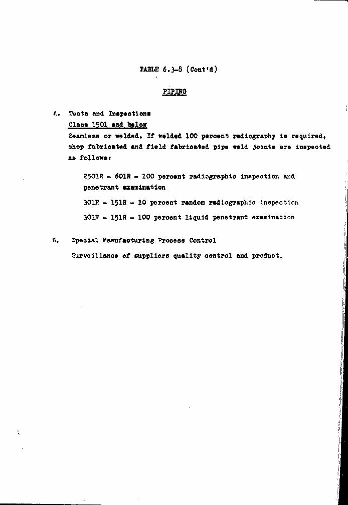
TABLE 6.3-8 (Cont'd)
A. Testa and Inspections
Claes 1501 and below
Seamless or welded. If welded 100 percent radiography is required,
shop fabricated and field fabricated pipe weld joints are inepeoted
as follows t
25O1R - 601R - 100 peroent radiographio inspeotion and.
penetrant examination
301R - 15IR «- 10 peroent random radiographio inspection
301R - 151R - 100 peroent liquid penetrant examination
K. Speoial Manufacturing Prooess Control
Survoillanoe of suppliers quality oontrol and product.
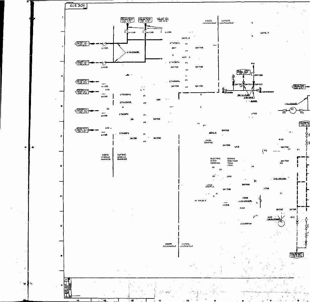
eft. aoij
• — - 4 / t
IKISIDCMIBSIlX
CUTS'DC
BARRIER
COWTAJNWIOJT
2TMS8FH
3U-TSS
r W4 •.\-n\eJ
|.T5S
VfTSS
LOCALSAMPLE.
ELECTRIC BORONSTRIP INJECTIONHEATERS TANK
ITEM:HI
CA
VI-TSO
I- RS
I
\ 11 1n.
110 375 SH-3
A3 ' \ 1 /
1
I

FIG. 6.3-1
NOTE, i
Fl
NO 3
Fl
FT
CONTAINMENT
-NdC*
LOCAL.
K> »7SSH.-3
r-rts-i 'f i
ELECTRIC BORON«TRIP IHJECTIONHEATERS TANK
ITEM:HI
•W i t s , <! j •
1. U0CA>KC0NICCTHMCl0aTOTANK,l«OL.S«\LVe.l>2. SAFnV,KMF.VM.VtCAiiO(«IIMliie INITIAL
HY««OKST AN» KSGT FM ?W PSIC FM NM-MAlKjMOKMTIOM.1
s. x* »ammm * CONTIIOLASSOCIAIID «liraV A I W P . CVCSMW.|i'OE17<r' .i K«£T, i
t. LOCATE 00IMCTMN A»OVt WAT» UVtC
g ^^SJB^LAQIS- ,
«MMtKWMMML un tv uft— awr.' imMwe r«ma ON» Ufflvt-
.-, nuww STATUS

i»-i.l-»OW *• i Si-tOig fctB[frT F.C.I

fZ-CiS !Z'-«» IZl-T»'
6.3-2
i.,t-*»-"»» T r1
b-,
N O T E S : 1 / . . • ~ .1, FLOW UNDER Sfc-VT: VAVLt O^ENS Kt 9 0 0 f>S(&.2. C0MT4.1NMSNT SUMP LEVEL. TRANSMITTER*4 tNDtC
&UPPLl£D » y A/t.

Ii8
(« 14
o o
U OS
7:
BAR a
BAR b
BAR c
BAR d
BAR e
BAR £
!./3 HIGH*
L/3 HIGH
h 111 LOW + 2/3 ACCUMULATORS
2/3 HIGH + 2/3 ACCUMULATORS *
1/3 HIGh + 1/2 LOW + 2/3 ACCUMULATORS
1/3 HIGH + Y 2 LOW + 2/3 ACCUMULATORS
I I ! I I I IC 2 4 6 10 12 14 18
(Surge Line)
(EQUIVALENT BREAK DIA. - IN)
* 1/2 LOW HEAD SAFETY INJECTION PUMPS ARE REQUIRED FOR RFXIRCULATION
HIGH = HIGH HEAD SAFETY INJECTION PUMPS (CHARGING PUMPS)
LOW - LOW HEAD SAFETY INJECTION PUMPS (RESIDUAL HEAT REMOVAL PUMP)
h
11
29(Double-Ended Reactor Coolant Pipe)
n90

6.4 COHTAmmf SWAT SYSTEM
6.4.1
Criterion; ¥%®T9 an aotive heat removal system is neededurder MOlA*nt conditions to prevent exceeding•semtsinaeist tomlgn pressure, this system shallparfera itc retired fsmotion, assuming failureof any ein«l« aetite ooaponent. (ODC 52)
Adequate oontainment heat removal capability for the Contain-
ment ie provided by the two separate, full oapaoity Contain-
ment Spray Systeme, «hos* ooaponents operate in the sequential
modes described in 6*4*2*
The prinary puryefl« of tke CofttaliUMnt Spray System is to
spray oool water ia*O tile oontainaent etaoaphere when appro-
priate in the -evvat of « loee-of-ooolant aooident and thereby
ensure that oontaliMwnt preseure after the aooident does not
sicked its deeiga mine Vhioh i« 60 peig. Tais protection is
afforded for all pipe break sixes up to and inoluding the
hypothetical instantaneous oiveunferential rupture of a reactor
coolant pipe. PresMM and teaperature transients for loss of
coolant aooident are presented in Seotion 14. Although the water
in the oore after a loes-of-eoolant aoeident is quiokiy suhcoo-
led *by the Safety Xajeotion Systea, the Containment Spray
System deslgo ie based on the oonserrâtire assumption that
'•:v3 oora reaidual heat is released to the containment as steam.
Any of the two Spray tysteas will provide sufficient heat remo-
val capability to aalataln the post-aooident containment pressure
below the design valve* assuming that the oore residual heat is
released to %h» oontainswnt as steam«
5?he Containment Spray^ System fill "be designed to reduoe the contain-
ment pressure following a loss of coolant accident to ono half of
the containment design pressure within ono hour after the accident,
not to exceed one half of the design pressure any time after one hour,
and the containment pressure will ultimately be reduced to essentially
atmospheric within 48 hours,6,4-4

Jt spéotion of Containment P w i m w Bsdupina?
Criterion! Design provision! «hall be mad* to the extentpraotioal to faoilitate the periodic physicalinspeotion of all important components of thecontainment pressure rsduoing systems» suoh aspumps, valves, spray nocsles and snaps» (0D0
Where praotioable, all active oomponents and- passivs compo-
nents of the Containment Spray Systems ars inspsoted periodi-
cally to assure system readiness. The pressure containing
systems are inspected for leaks from pump seals, valve paoking,
flenged joints and safety valves* During operational testing
of the oontainment spray pumps, the portions of the systems
subjeoted to pump pressure are inspected for leaks.
Testing of Containment Pressure — T?T<ilHOln< Systems Components
Criterion i The containment pressure reduoing systems shallbe designad, to the extent praotioal so thatactive components, suoh as pumps and valves, canbe tested periodically for operebility and requi-red functional performance (ODC 59).
All aotive components in the Containment Spray Systems are
adequately tested both in pre-operational performance tests
in the manufacturer's shop and in-plaoe testing after installa-
tion. Thereafter, perlodio tests ars also performed after any
component maintenance.
The component cooling water pumps and the servioe vater pumps
which supply the oooling vater to the residual heat exohangers
and spray heat exohangers are in operation on a relatively
continuous schedule during plant operation. Those pumps not
running during normal operation may be tested by ohanging the
operating pump (a).
±J_.'_
Testing of Co
Criterion: Aproaatas
Permanent tel
are located 1
at the oohtai
ohéokéd sépai
air test
obstructed, e
fiov through
generator or
Testing of OiReduoing Sysi
Criterion: Auid<V(
Capability ii
praotioal. tl
transfer tö i
design oöndii
ding the trar
tor power SOT
The Contains*
02 1
whenever tie
(Hi Hi) oonti
Signal is gii
two pumps and
and spray hea
this flow.

I.
Criterion: Å capability shall be provided to the extantpraotioal to teat pariodioally tha deliverycapability of the oontainment «pray systemat a position as oloaa to the spray nozzlesas is praotioal* (ODC 60)
Permanent test line* for all the oontainaent spray loopsare looated so that all components up to the isolation valvesat the containment »ay be tasted* These isolation valves arechecked separately.i
The- air test lines, for oheoking that spray nozzles are notobstructed, oonneot downstream of the isolation valves. Airflow through the noaslas is monitored by the use of a smokegenerator or tell-tales.
Testing of Operational Sequenoe of Containment PressureReducing Systems
Criterion: A capability shall be provided to test initiallyunder conditions as olose as praotioal to thedesign and the full operational sequence thatwould bring the oontainaant pressure-reduoingsystems into aotion, including the transfer toalternate power sources. (ODC 61)
Capability is provided, to test initially, to the extentpractical, the operational startup sequenoe beginning withtransfer to alternate power sources and ending with neardesign conditions for the Containment Spray System, inclu-ding the transfer to the alternat* emergency dieael-genera-tor power source*
Eerformanoe Ob^eotivea
The Containment Spray System is designed to sprayo: berated water into the oontainment building
whenever the ooinolienoe of two sat* of two out of three(Hi Hi) containment pressure signals ooours or a manualsignal is given. Either o:f the two spray systems containingtwo pump* and associated living two spray heat exohangerand spray headers are independently capable of deliveringihis flow.
!
i ,T

The design ban i a Is to provide suffioiont heat reaoval
capability to maintain the post-aooident oontainment
pressure below the design pressure and later on reduoe
tha pressure t*> ataospherio assuaing that the dors resi-
dual heat is released to the oontainaent as steaa*
A seoond purpose served by' the Contalnaent Spray System
is to remove elemental iodine fro» the oontainment atmos-
phere should it be relased in the event of a loss-of-oooiant
accident.
The spray system is designed to operate orer an extended
time period, following a priaary ooolant system failure
as* required to restore and aaintain oontainaent oonditions
at near atnospherio pressure» It has the capability of re-
ducing the containment post-aooident pressure and consequent
containment leakage taking into aooount any rsduotion due
to single failures of active ooaponents.
Those portions of the spray system looated outside of tho
oontainment which are designad to oiroulate, under post-
accident conditions, radloaotively oontaainated water oolleo-
tod in the oontainment meet the following requireaentei
a) Adequate shielding to aaintain radiation levels within
the guidelines of 10 OFS 100 (8eotion 11.2 and 11.3)»
b) Collection of discharges froa pressure relieving devioes
into closed systeas,
o) Means for isolation of any seetion under anticipated
malfunction or failure conditions.
d) Means to liait radioactivity1leakageto the environs,
consistent with guidelines set forth in 10 CPH 100.i '

The containment spray system is designed to operate over an
extended tim« period following a lots of ooolant aooident with
consideration given to single failure of active oomponents during
,-the injeotion phase and oonsiieration of either an aotive or
passive failure during the long tern reoiroulation phase.
Each of the spray trains provides complete backup for the other.i
;Service Life
.All portions of the system located within containment are designed
to withstand, without loss of functional performance, the post-
iaccident containment environment and operate without bonefit of
. smaintenance for the duration of time to restore and maintain
contaniment conditions at near atmospheric pressure.
6.4-5

II
6.4.3 SYSTEM DESIGN AND OPERATION
System Deaoription
Adequate containment cooling aul iodine reaoval arc provided
"by the Containment Spray Systen shown in 7igave 6.4-1 and 6.4-2 whose
components operate in sequential node*. These nodes arat
a) Spray a portion of the esntents of the refueling vater
storage tank into the entire containment atmosphere
using the oontainnent spray punps. During this mode, the
oontents of the spray additive tank (Sodium Hydroxide)
ere mixed into the spray strea» to provide adequate
iodine removal fron the oontainaent atmosphere by a
washing action.
b) Spray the water fron the containment snap using tbe spray
pumps. The water is passed through the containment spray
heat exchangers to the spray headers. The spray puapa ara
aligned to take suotion froa the oontainaent suap when
the refueling water storage tank has "been emptied.
Ths bases for the seleotion of the various conditions requiring
system actuation is presented in Seotion 14»
Two separate 100 i> oapaoity spray systeas ana provided. Eaoh
system provides containment oooling and iodine rerovei folio*
wing a loss of ooolant aooldent and oonsists of tno 100 %
pumps, two oontainnent spray heat exohangers» spray ring
headers and noasles, and the necessary piping and valves.
One spray additive tank is ooaaon to both systeas. The contain-
ment spray punps, heat exohangers and tbe apray additive tank
are looated in the auxiliary building*
The spray systea will be actuated by the ooinoidenoe of two
sets of two out of three (Hi Hi) oontainaent pressure signals.
This starting signal will start the puapa and opsn the discharge
valves to the spray header* If required, the operator can manually
actuate the entire spray system fron the control roo*.
6.4-6
Following act
containaent s
refueling wat
pump flow is
as the motive
solution fron
the fluid ia
where appropr
to the contai
The spray add
from the spra;
is empty whic]
Reoirouli
When the
spray pvu
sump. Th<
to the si
Two itidej
pumps are
Change-Q-g
The prooe
has been
Remote op
are under
in their :
signal) hi
of the cpi

Following aotuation of the high containment pressure signal the
containment spray pumps start and draw borated water from the
refueling water storage tank. A portion of the containment spray
pump flow is bypassed through the spray additive eduotor and is used
as the motive flow to draw 50 weight per cent sodium hydroxide
solution from the spray additive tank. After mixing in the eduotor,
the fluid is returned to the suction of the containment spray pump
where appropriately 95 per cent of the pump discharge flow is direoted
to the containment spray headers located inside the oontainment.
|
The spray additive solution is oontinually drawn into the eductor
from the spray additive tank until the refueling water storage tank
is empty whioh terminates tha injection phase.
Reciroulation Phase
When the refueling water storage tank has been emptied, the
spray pumps are aligned to take suction from the containment
sump. The water is passed through the spray heat exchangers
to the spray headers.
Two independent suction lines from the oontainment sump to the
pumps are provided, eaoh serving one system.
Change-Over
The procedure for the ohangs-over from injection to reciroulation
has been described in Section 6.3»
Remote operated valves of the Containment Spray System which
are under manual control (that is, valves which normally are
in their ready position and do not receive a containment spray
signal) have their positions indioated on a common portion
of the control board. At any time during operation when one of -
6.4-7

these valven is not in the ready position foar injeotion,
it is shown visually on the borad. In addition,:an audible
annunciation alerta the operator to the condition»
Components ;
Pumps
The four oontainment spray vamps are of the horisontal
centrifugal type drivan by electric motors.
These motors oan be powered Tron both normal and emergency
The design head of the pumps is sufficient to continue at rated
capacity with a minimum level in the refueling vater storage
tank against a head equivalent to the sum of the design pressure
of the containment, the head to the uppermost nossles, and the
line and the nozzle pressure losses»
The materials of oonstruotion are stainless steel or
equivalent corrosion resistant material* Design parameters are -
bed in Table 6*4-2,
Details of the component oooling punps and serrloe water pumps,
which serve the Safety Injeotion System and oontainment spray
system, are presented in Section $,
fcj>rafyjNoszles . . • „•
The spray nozzles are not subjeot to ologglng "by partioles less
than 1/4 inch in maximum dimension, and are oapable of produ-
oing a mean drop size of approxiuately 700 microns in diameter
with the spray pump operating at design oonditiona and the
oontainment at design pressure* Fluid is pumped to the nozzles and
screened through a 1/4 ihoh mesh. ,
6.4-8

•d
nizw
t *
During apray reoiroulation operation, the «rater is soreened
through a mesh before leaving the containment sump.
The nozzles and headers are so oriented ae to ensure adequate
coverage of the containment volume.
Spray Additiye_Tank
The capacity of the tank ia sufficient to contain enough sodium
hydroxide solution which, upon mixing with the refueling water
from the refueling water storage tank, the borio acid from the
boron injection tank, the borated water contained within the
accumulators and primary coolant, is able to maintain a pH of at
least 8.5. It also assures the continued iodine removal effectiveness
of the containment spray during the recirculation phase of operation
after the supply of borated water in the refueling water storage
tank has been exhausted. An inert atmosphere of nitrogen is
maintained over the solution to prevent degradation during the long
term storage. Å pressure of 1 to 2 psi is maintained in the tank
during storage. A level indicating alarm is provided in the control
room if, at any time, the solution tank contains less than the
required amount of sodium hydroxide solution. Periodic sampling
confirms that proper sodium hydrooxide concentration exists in the
tank.
••
•r
is and
The tank design parameters are given in Table 6.4-5.
' », u- •»:••, i , •
6.4-9
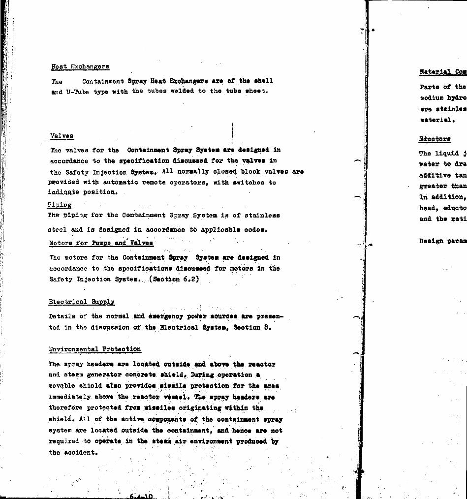
Heat Bxohan^era
The Containment Spray Heat Bxohangtrs art of theand U-Tube type with the tubes welded to the tube sheet
Valves j
The valves for the Containment Spray System are designed in
aocordanoe to the speoifioation disoussed foi* the valves in
the Safety Injeotion System* All normally closed block valves are
provided with automatic remote operators, with switches toindi.oa.te position.
Piping ' - . •• - . . . .The plpiiff for the Containment Spray System is of stainless
steel and is designed in aocordanoe to applicable codes.
Motors for Pumps and Valves
The motors for the Containment Spray System are designed in
aoocrdance to the speoifioations disoussed för motors in the
Safety Injection System. (Seotien 6.2)
Electrical Supply
Details of the normal and emergenoy power souroes are presen-
ted in the discussion of /the Eleotrioal System» Section 8*
Environmental Protection
The spray headers are looated outside and above the reaotor
and steam generator oonorete shield* During operation a
movable shield also provides missile protection for the area
immediately, above the reaetor vissel* Ttie spray headers are
therefore protected from missiles originating within the
shield. All of the aotive components of the oontainment spray
system are looated outside the oontainment* and heiioe are not
required to operate in the steam air environment produced by
the aooident» • ',
Material Comi
Parts of the
sodium hydro:
are stainles
material *
Bductors
The liquid ji
water to dra1
additive tan)
greater than
In addition*
head» eduoto
and the rati
Design paran
—10

Ill
len-
>r
rea
j>ray
not
Material Compatibility
Parte of the system in oontaot with borated water, thesodium hydroxide «pray additive, or moistures of the twoare stainless steel or an equivalent oorrosion resistantmaterial.
1 •!
inintires arebo
Eduotors
The liquid jet »duotors use the kinetio energy of the spraywater to draw the sodium hydroxide solution from the sprayadditive tank* The eductors are designed with a auction capacitygreater than the required flow rate of sodium hydroxide.In! addition, such faotors as spray pump discharge and suctionhead, eduotor suotion bead, friction losses, static pressure,and the ratio of motive to suotion liquid are considered.
'E' l -
inthe
Design parameters are presented in Table 6.4-4*
i :.
I

6.4-3 DKSIOM EVALUATION .
During the injection and reolroulstion phases the «pray
water is raised to the temperature of the oontainment in
falling through the steam-air mixture. The minimum fall
path of the droplets is approximately 100 ft* fro» the
lowest spray ring headers to the operating deok. The actual
fall path is longer due to the trajeotory of the droplets
sprayed out fron the ring header* Heat transfer oaloulations,
based upon 700 mioron droplets, show that thermal equilibrium
is reaohed in a distanoe of a few feet. Thus, the
spray water reaches essentially the saturation temperature.
In addition to heat removal, the spray system is effeotive
in scrubbing fission products from the oontainment atmosphere.
System Response
The starting sequence of the containment spray pumps and their
related emergenoy power equipment is designed so that delivery
of the minimum required flow is reaohed within 60 saoonds
whioh is the delay assumed for the starting of
containment cooling (Seotion 14.3). As described previously
the initiation of the addition of sodiu» hydroxide to the
spray flow is under the control of the operator.
Single Failure Analysis
A failure analysis has been made on all active components of
the system to show that the failure of any single aotive oompo-
nent trill not prevent fulfilling the design function. This
analysis is summarised in Table 6.4-5.
The analysis of the loss-of-ooolant aooidant presented in
Section 14 reflects the single failure analysis.
Relianoe on Interoonneoted Jys terns
The Containment Spray System operate* Independently of
other engineered eafety feature* following a lo**-of-
ooolant
Normal and er.ergenoy power supply requirements are dieoussed
in Seotion P.l
Shared Funotion Evaluation
Table 6.4-6 is an evaluation of the aain ooaponents whioh
have been disoussed previously and a brief desoription of
how each coiaponent functions during normal operation and
during the aooident.
6.4-13

Ill
6.4.4 TESTS AND INSPECTIONS
Inspeotion Capability
All components of the C< tiiainaent Spray System oan 1Minspeoted periodically -o demonstrate system readiness.
The pressure containing systems are inspeoted for leaks
from pumps seals, valves packing, flanged joints and
safety valves during system testing. During the opera-
tional testing of the containment spray pumps* the por-
tions of the system subjeoted to punp pressure are inapee-
ted for leaks.
Component Testing
All aotive components in the Containment Spray System are
tested both in pre-operational performance teets in the
manufacturer's saop and inplaoe testing after installation.
The containment spray pumps oan be tested singly by opening
the valves in the refueling vater storage tank reoiroulation
line. Each pump in turn oan be started by operator action and
checked for flow establishment. The f loir through the eductor
is indicated by the spray additive flow meter* The remotely
operated valves can be oycled open and closed periodically.
?he contents of the spray additive tank will be periodically
sampled to determine that the proper solution is present.
Initially the containment spray nossle availability is tested
by blowing smoke through the nossles and observing the flow
through the various nozzles in the containment.
During these tests the equipnent will be viuually inspeoted
for leaks. Leaking seals, packing, or flanges will be tightened
to eliminate the leak. Valve» and pumps will be operated and
inspeoted after any maintenance to ensure proper operation»
6.4-14

Operational Sequenoe Testing
The functional test of the Safety Injeotlon System desoribed
in Seotion 6.2-5 demonstrates proper transfer to the emergency
diesel generator power source in the event of loss of power.
A test signal simulating the containment spray signal will be
used to demonstrate operation of the spray system up to the
isolation valves on the pump disonarge.
6.4-15

TABUS 6 .4 -3
SPRAY ADDITIVE TAMK DESIGN PARAMETERS
Num"berTota l Volume (empty), g a l .
KaOH concentration, ir/o
Design temperature, F
Design pressure, p s i g
Material
1
4000
30
200
Atmospheric
Stainless Steel

TABLE 6.4-4
SPRAY ADDITIVE EDUCTOR PARAMETERS
Number
Design Pressure* psig
Design Temperature, °P
Material
4250
150
Stainless Steel

TABLE 6.4-5
STNGLE FAILURE ANALYSIS - CONTAINMENT SPRAY SYSTEM
Component
A, System
Malfunction
Fails
Comments and Consequence*
Tiro independent systenu furnished,evaluation based on one systemoperatina.
B. Spray Nozzles Clogged
C. Pumps
1) Containment Pails to start
Spray Pump
2) Residual Heat Fails to start
Removal Pump
3) Salt Water Fails to start
Pump
4) Component Fails to startCooling Pump
D. Automatically operated Valvest(Open on ooinoidenoe of two - 2/3high (Hi Hi) oontainment pressuresignals)
l) Containment Fails to openspray isola-tion valve
E. Valves OperatedFrom Control Room
Large number of nozzles for eaohsystem, renders clogging ofa significant number of nozzlesas inoredible.
Two provided for each system.
Two provided for each system.
Fans: provided. Operation of twopumps during reoirculationrequired.
Three provided. Operation of twopumps during reciroulationrequired.
Two provided in parallel for eaohsystem.

TABLE 6.4-5 (Continued)
Component Malfunotlon Comments and Consequences
l) Heoirculation
Containment sump Fails to open Two lines in paral el, eaohrecirculation with two valves in series,isolation One line required.

TAELS 6 . 4 - 6
SHARED FUNCTIONS 2VALUATI0N
Component Normal OperatingFunction
Normal OperatingArrangement
AccidentFunction
AccidentAri'angeffient
Spray AdditiveTank
None
Containment Spray Nonepumps (2)
Lined up for spraywater diversion
Lined up to sprayheaders
Source of sodiumhydroxide for sprayvater
Supply spray waterto containmentatmosphere
Lined up forspray waterdiversion
Lined up to sprayhealers

CONTAINMENT
•U- • B t .40b
HEAT 6 XC HA.Ntfi*«
ITEM SPZD **£«;* 5
I MCV '
u.
I ) ' »OIK 1
• } • - * 4OO5 ^ -iXSte£ONTAlltMCM*r nSPMAV PUMP T
H6AT &KCHANG6R A J . .L 2 ?»• j c .
1 " «014 •
•uKflS * l OB

'«•» I — ? — ^ — 1
SPRAY PUMP 7
— !- I
ZSTiNSHrysE
ALTCRNATnnSHARK NUC-I.E*
UNIT MO. 1ir/k/K v e\ - ^pi
-MONITOR
NO. i•\R PQtoEfl STA1
WESTINGHOUSE-MON» TOR
PROPOSAL
ALTERNATIVE.NO. 1
FORSMARK NUCLEAR POWER STATION
:,... UNIT NO., vCONTAINMENT SPRAY SYSTEM
FIGURE

H
K' I i,t L .Hl'i 1
' I O l -*-' I I
U N » !
i Ms i or
SPRAr M' i i .
" A " A "
Ou ' ' i '••' it > •' S " - n '
DA
A A"
SPR4Y h U ! ' •
NO2/L i '>
S f ' r - A t Nr A -
A A
ACONT/tlNMLN!
SUMP I
> '/// rVW
-txi-
4 r
j
NI -Due N
^ - S P C l
i l i) ' : i f :IH*
i
J
Cont ;ii nnwnt Spi:«y SystemSodium Hydroxide Additive Connection Scnerrio
Fig.

6.5 LEAKAGE DETECTION AKP PR0VI3I0H3 FOR THE PHIHA8Y
AND AUXILIARY COOLAKT IX)OPS
6.5.1 LEAKAGE DETECTION SYSTEMS
The leakage dataotion systems reveal the presence of signi-
fioant leakage from the primary and auxiliary coolant loops.
DSSION BASES
Monitoring Reaotor Coolant Leakage
Criterion: Means shall be provided to deteot significantuncontrolled leakage from the reaotor coolantpressure boundary. (ODC 16")
Positive indications in the control room of leakage of
coolant from the Reactor Coolant System to the containment
uro provided by equipment which permits continuous monitoring
of oontaihment air aotivity and humidity, and of runoff from
the condensate oolleoting pans under the cooling coils of the
containment air reoiroulation units. This equipment provides
indication of normal background which is indicative of a basic
level of leakage from primary systems and components. Any
increase in the obeserved parameters is an indication of ohange
within the containment, and the equipment provided is oapable
of monitoring this ohange. The basic design criterion is the
detection of deviations from normal oontalnment environmental
conditions including air partioulate activity, radiogas activity,
humidity, condensate runoff and in addition, in the oaøe of groeB
leakage, thra liquid inventory in the process systems and contain-
ment sump.
Monitoring Radioaotivity Releases
Criterion t Means shall be provided for monitoring the contain-ment atmosphere and the facility effluent dischargepaths for radioactivity released from normal opera-tions, fron anticipated transients, and from accidentconditions* An environmental monitoring program shallbe maintained to confirm that radioactivity releasesto the environs of the plant have not been exoessive.(GDC 17)
6.5-1

The containment atmosphere, the oomponent oooling loop
liquid, the liquid phase of the secondary side of the
oteam generator and the oondenaer vacuum pumps are moni-
tored for radioactivity concentration during normal opera-
tion, åntioipated transients and accident conditions.
Principle^ of Design ;
The prinoiplen for design of the leakage deteotion system»
can be oumtr.arir.ed an follows: iI
1. increased leakage oould occur as the results of failure
of pump seals, valve paoking glands, flange gaskets or
instrument connections. The maximum leakage rate oalcula- -
ted for these types of failures is 30 gpm which would be
the anticipated flow rate of water through the pump seal
if the entire seal were wiped out and the area between
the shaft and housing were completely open.
?. The leakage deteotion systems shall not produce spurious
annuneiation from normal expected leakage rates but shall
reliably annunciate increasing leakage.
3. Inoroaoinp leakage rate shall be annunciated in the controlroom. Operator action will be retjuired to Isolate the leakin the offending system.
SYSTEMS 3B5I0IT A5J> QPBRATIOV
Various methods are used to defeot leakage from either the
primary system or the auxiliary system. Although described to
sone extent under each system description, all methods are in-
cluded here for completeness.
n....-ti• ii-ill
6.5-2

Reactor Coolant System
During normal operation and anticipated reaotor transients
the following methods are employed to detect leakage from
the Reactor Coolant System".
Containment Air Partioulate Monitor
This channel take* oontinuoua air saaples from the contain-
ment atmosphere and measures the air partioulated gamma radio-
activity. The samples, drawn outside the containment, are in a
closed, sealed system ani are monitored by a sointiliation
counter - filter paper d*teotor assembly. The filter paper
collects all partioulate natter greater than 1 mioron in size
on its constantly moving surfaoe, which is viewed by a herme-
tioally sealed scintillation crystal (Hal) - photomultiplier
combination» After passing through the gas monitor, the samples
are returned to the containment.
The filter paper ha» a 25-day »ini«u« supply at normal speed.
The filter paper mechanism, an eleotromagnetio assembly whioh
controls the filter paper moveaent, is provided as an integral
part of the detector unit*
The detector assembly is in a completely oloeed housing* The
detector output is amplified by a preamplifier and transmitted
to the Radiation Monitoring Systea oabinet in the control room.
Lead shielding is provided to reduce the background radiation
level to wh»re it does not interfere with the detector's sensi-
tivity. „ .„•• - . •. •-,... :- . ..,; '•
The activity is indicated on seters and reoorded by a multipoint
recorder* High-aotiTity alar» indications are displayed on the
control board annunciator in addition to the Radiati on Mon i toring
cabinets. Local alar»s provide operational status of supporting,
«qaipnent such a» puppty npto^^^Øw »nd
l e r « . . • • • • • . ' •
6.5-3

I i
The oontainmont air partioulate monitor is the moat sens!»
tive instrument of thoce available for deteotion of reaotor
coolant leakage into the containment. This instrument is
capable of detecting partioulate aotivity in ooncentrations
as low as 10 110/00 of containment air. The measuring
ranpe is 10""° to 10"" no/eo.
i
The sensitivity of the air partioulate monitor to an increase
in reactor ooolant leak rate is dependent upon the magnitude
of the normal baseline leakage into the containment. The sensi-
tivity is greatest where base-line leakage is low as has been
demonstrated by the experiénoe of Indian Point Unit No. 1,
Yankee Rove and Dresden Unit 1. Where oontainment air parti-
culate activity is below the threshold of deteotibility, opera-
tion of the monitor with stationary filter paper would increase
leak sensitivity to a few oubio centimeters per minute. Assuming
a low background cf oontainment air partioulate radioaotivity,
a reactor ooolant oorrosion produot radioaotivity (Pe, Hn, Co, Cr)
of 0.2 y-c/oo (a value consistent vith little or no fuel oladding
leakage), and complete dispersion of the leaking radioactive solids
into the oontainment air, the air partioulate monitor is capable of
detecting leaks as small as approximately 0.013 gp» (50 cs/minute)
within twenty minutes after they oeour. If only ten per cent of
the partioulate aotivity is aotually dispersed in the air, leakage
rates of the order of 0.13 gpm (500 oc/minuta) are well within
the deteotable range» , .-••-•. •;
Por oases where bass-line reaotor ooolant falls within the dateo-
table limits of the air partioulate monitor, the instrument oan
be adjusted to ale.-;ia on leakage inoreaaat from two to five times
t h e b a s e - l i n e v a l u e . ' - " •;.>•";• ' .••.-. .- ."..'.- :--• ," "'''•.-.-=..•• -. -,-••. -'•;„-
Tho oontainment air partioulate Monitor together with the other
radiation monitors mentioned in this Section are further desori-v
b e d i n S e o t i o n 1 1 . 2 . •-•• • ' • •": ~r s > f - . t ' ' . - - . • •.- ;; •;, <?•"...• ><>.:•;.
Ccntsinsani
This ohannethe oontairthe oontairpartioulate
Bach sample
volumes, wi
samples are
The detectc
a gamma ser
gas volume
the baokgre
interfere «
and impedan
The deteoto
toring Syat
indioated b• I
High-aotiviboard annunSystem oabiments' oper
The
sensitive ,(
air particu:
that »ignif:
oladding d«j
Assuming a i
renee of<• ]
baokground i
this instruw
monitor.
6.5-4

Be
e
nsi-
en
era-
ease
urn ing
ty.
Co, Cr}
adding
B solids
pable of
ninute)
t of
leakage
hin
deteo-
oan
times
ther
Bt»ri-
ContsinsBant RsdJLpaotivs C M Mcr.itor
This ohannel measure» the gaseous gamma radioactivity in
the containment by taking the oontinuous air samples from
the oontainment atmosphere, after they pass through the air
partioulate monitors, and drawing the samples through a
o 1 ope--1 no a led system to a gas monitor assembly.
Each sample is constantly mixed in the fixed, shielded
volumes, where it is viewed by Oeiger-Mueller tubes. The
samples are then returned to the oø&tainment.
The detector is in a completely enolosed housing containing
a gamma sensitive Oeiger-Mueller tube mounted in a constant
gas volume container* Lead shielding is provided to reduce
the background radiation level to a point where it does not
interfere with the deteotor's sensitivity* A preamplifier
and impedenoe metohing oirouit is mounted at the detector.
The deteoter outputs are transmitted to the Radiation Moni-
toring System oabinets in the oontrol room» The aotirity is
indicated by meters and reoorded by a multipoint recorder.
High-aotivity alarm indications are displayed on the oontrol
board annunciator in addition to the Radiation Monitoring
System cabinets* Looal alarms annunciate the supporting equip-
ments* operational status.
The containment radipaotive gas laocitpr i« inherently less
sensitive (threshold at 10" no/oo) than the oontainment
air particulate monitor, and would funotion in the event
that signifioantrea«*«r coolant gaseous activity exist from fuel
cladding defeats, TW:meaBuriag range is 10 to 10~3 no/oo.
Ansuniing a reaotor aooJjant ao1»ivity of 0*3 n o/oo. the ooour-
renoe of a leak of two to four <|pm would deuble the sero leakafo
background in less -Shan an hour1» time» In these olroumstanoes
this instruatnt is a uMful baokup to the air partioulate
monitor. ' . • '•'"' '•' ;"." ' •
6.5-5
ill
i li-ft
i i : ' :

H
containment air partieulate and radioaotive gas monitors
have assemblies that are oommon to both channels. They are
described as follows:
i) The :H H assembly includes a puap unit and seleotor valves
that provide ° representative sample (or a "clean? sample)
to the cHi!,9Cter,
ii) The pump unit consists o'ft
1, A pump to obtain the air sample.
2, A flowmeter to indioate the flow rate»
3, A flow control valve to provide flow adjustment.
A. A flov alarm assembly to provide low and high flow
alarm signals.
iii) Selector valves are used to direct the desired saaple to
the detector for monitoring and to blow flow when the
ohannel is in maintenance or "purging" oondition.
iv) A pressure sensor is used to protect the system from high
pro3sure. This unit automatically closes an inlet and out-
let valve upon a high pressure oondition»
v) Fvrjring is accomplished with a valve oontrol arrangement
whereby the normal sample flow is blooked and the deteotor
urges with a "clean" sample» This facilitates detector
calibration by establishing the background level and aids
in verifying sample activity level.
vi) The flow oontrol panel in the öontrol ream Radiation
Monitoring System racks permits remote operation of the
flow oontrol: assembly. By operating a sample seleotor
switch on the control panel tike containment sample may bem o n i t o r e d ' . ' ' • ' ' .'•'-.•'•- ' " • .
6.5-6

vii) A sample flow rate indioator is oalibrated linearly
(from 0 to 14 oubio feet per minute).
Alarm lights art aotuated by the following?
1. Tlow »larm aøstably (lov or high flow)
2. The pressure sensor assembly (high pressure)
3. Tne filter paper sensor (paper drive malfunction)
4. The pump power oontrol switoh (pump motor on)
Condensate Measuring System
This leak detection method is based on the principle that
the condensate collected by the oooling ooils matches,
under equilibrium conditions, the leakage of vater and
steam from systeas within the containment. This prinoiple
applies because conditions within the oontainment promote
complete evaporation of leaking water from hot systems. The
air and internal structure temperatures are normally held
near 120cF, the relative humidity of the air is well below
the saturation point, and the oooling ooils "provide the only
significant surfaoes at or below the dew point temperature.
The oontainment oooling ooils are designed to remove the
sensible heat generated within the oontainment. The resul-
ting large coil «urfaoe area has the effeot that the exit
air from the coils has a dew point temperature which is very
nearly equal to the oooling water temperature.
Measurement of 4h> condensate drained from each of the venti-
latinf units ie made to determine condensation rate and thus
•.leak' rate»-;-.. .•',;/•.' • ..;
Should a leak ooour, the condensation rate will increase above
the previous steady stat* due to the increased vapor content of
the fan-cooler air intake'. Å new equilibrium rate will be approa-
ohed within approximately 30 minutts after the start of the leak.
6.5-7

•i! I
'4\ D« t «jo t i on of tho increasing condensation rate is possible,
;ij howover, within 1> to 10 minutes for condensation rates in
lj | tho order of l/?- gpm and larger. Readout of the condenantw
!J, flow measuring devioe, and high flow alarms will be providedh'j
jf in the control room*
jjji Component Coo i m p Liquid Monitor
-('
: "his ohanntl continuously monitors the component cooling
I loop of the Component Coolant System for aotivity indicative
of a leak of reactor coolant from either the Reactor Coolant
] System, the Residual Teat Removal System or Containment Spray
i 3ovs?tem. A scintillation counter is located in an in-line, well
: at the component cooling pump suction header* The detector
, ar-.senibly output is amplified by a preamplifier and transmitted
I to the Radiation Monitoring System oabineta in the control room.
| The activity is indicated on a meter and recorded by a multipoint
recorder. High-activity alarm indications are displayed on the
control board annunciator in addition to the Radiation Monitoring
System oabinetct.
The measuring rang* of this monitor is 10*"7 to 10" 110/00.
Condenser Air Ejector Gas Monitor
Thin channel monitors the discharge from the air ejector exhaust
header of the condensers for gaseous radiation which is indioa-
t: o of a primary to secondary system leak. The gas disoharge is
routed to the turbine roof vent.
The deteotor output is transmitted to the Radiation Monitoring
System cabinets in the control room. The aotivity is indicated
by a meter and recorded by a nultipoini recorder. High-aotivity
alarm indications are displayod on the oontrol board anhunoiator
in addition to the Radiation Monitoring cabinets.
6.5-8

A gamma sensitive Gsiger-Kualler tube is used to Hsonitor the
gaBeoue radiation level. The deteotor is inserted into an in-
line fixed volume oontainer whioh includes adequate shielding
to reduce the background radiation to where it does not inter-
fere with the deteotors maximum sensitivity. This monitor has
a maximum sensitivity of 10 nioroouries per cubic centimeter.
Steam Generator Liquid Sample Monitor
This ohannel monitors the liquid phase of the secondary eide of
the steam generator for radiation, whioh would indloate a pri-
msry-to-secondary system leak, providing baotcup information to
ihvft of the condenser air ejeotor gas monitor* Samples from
the bottom of each of the four steam generators are mixed to
a common header and the common sample is continuously moni-
tored by a scintillation oounter and holdup tank assembly.
Upon indloation of a high-radiation level, eaoh steam generator
is individually sampled in order to determine the souroe. This
sampling sequenoe is achieved by manually seleoting the desired
unit to be monitored and allotting sufficient time for sample
equilibrium to be established (approximately 1 minute).
A remote indicator panel, mounted at the detector location, in-
dicates the radiation level and high-radiation alarm.
The measuring rangs of this monitor is 10 J to 10 mioroouries
per oubio oentiaetsr.
A photoaultiplier tube - scintillation crystal (Nal) ooablna-
tion, mounted it» a hermetically staled unit, is used to monitor
liquid effluent abtivity. Lead shielding is provided to reduoe
the background level so it does not interfere with the doteotor's
jBw:imua sensitivity. The in-lins, fixsd-voluoe oontainer is an
integral part of the detector unit»

••V
f
31
i ;!•
• • * !
During cold shutdown personnel oan enter the oontainment
and make a vi tru al inspection for leaks. Th» loofttlon of
any leak in the Itøaotor Coolant System would Ise determined
by the presence of "boric aoid orystals ne*r th» leak* Tho
leaking fluid transfers the boric aoid crystals outside
the Heactor Coolant System and the process of evaporation
leaves +% m behind.
Tf an aocidant involving gross leakage from the Reactor
Coolant Systom occurred it oould "be deteoted by the follo-
wing method3.
Pump Activity
During normal operation only one oharging pump is operating.
].f a gross loss of reactor ooolsnt to another olosed system
occurred which was not deteoted "by the methods previously
described, the speed of the charging pump would indicate
tho leakage.
The leakage from the reactor ooolftnt will cause a decrease in
tho pressurizer liquid level that is within the sensitivity
range of the preesurizer level indicator. The charging pump
output will automatically inoreaee to try to maintain the
equivalence between the letdown flow and the oomoined oharging
line flow and flow across the reaotor ooolant pump seals. If
pump reaohea a high flow limit, an alarm is aotuated. A
break in the primary system would result in reaotor ooolant
flowing into the containment sump* Gross leakage to this
sump would be indicated "by the frequency of operation of the
containment sump pumps* ; . .-,;,-
L i q u i d I n v e n t o r y " " •'•"'-"•, - < \ ; ' ~ ; : .;v":,.'*:•• •-•-'•'•- -,-^j, r _• ••.-:',.-
Gross leaks might be detected by unscheduled ihoreases in
the amount of reaotor ooolant makeup water which is required
to maintain the normal level in the pres«uri*er. This is
inherently a low preoision meawureraent, since makeup water
is necessary as well for leaks from systems outside the
containment.
-<• §J+
A large tt
(letdown)
flowing ir
Uou.id le-\
operator *
:.ior.itore t
A high leu
•bank and h
monitors a
also indie
reactor co
high' tempa
let line f
Gross leak
oontainmei
an alarm.
Residual
The residi
heat from
Coolant Sj
Leakage fr
operation
radiation:
froai the R
The physio
will be wi
of the oon
Radiationmonitoring
operator wl

A large tube side to ah*11 side leak in the non»reg«norative(letdown) heat exohenger would result in reaotor ooolantflowing into the. oomponent oooling »«ter and a r i se in tho'tnuid level in the eompbnent oooling water surge tank. Theoperator would be alerted "by a high water »larm for tho surgetr- •- n-,g hi£h radiation and temperature alarm» actuated by
a* the component cooling water pump auction leader.
1
I
!) •
A high level alarm for the component oooling vater
tank and high radiation and temperature alarms actuated by
monitors at the component oooling pump suction hsader could
also indicate a thermal barrier cooling coil rupture in a
reactor coolant pump. However, in addition to thono i arms,
high' temperature and high flow on the oomponent oooli-i? out-
let line from the pump would aotivate alarms.
Gross leakaga might also be indioated by a rise in th" normal
containment sump level* High level in this sump will actuate
an alarm.
i i
'iilii
-.1.•I•ii
Residual Haat Removal Loop
The residual heat removal loop removes residual and sensible
beat from the oore and reduoes the temperature of the Reactor
Coolant System during the seoond phase of plant shutdown.
Leakage from the residual heat reeoval loop during normal
operation would be deteoted by the oosponent oooliug loop
radiation monitor («»«analysis of deteotion of leakage
from the Reeotor Coolant System in this section).
The physical layout of the two residual heat removal pumps
will be within separate shielded and isolated rooms outside
of the containment.
Radiation monitoring will be provided by the plant vent gas
monitoring system. Alarms in the oontrol room will alort the
operator when the activity exceeds a preset level. Small
H V!
f'V

leaks to the environment could "b« d«teot«d with these
systems within a short time after they ooourred.
Should a large tute eide to shell Bide leak develop in
a res:dual heat exchanger or the seal of a residual heat
removal ~* * break, the water level in the oomponent
oac". i# sur^ø tank would rise, and the—operator would bra
j.lorted hy a hi^h watej^a'larm. Hadiation and temperature
monitors at the component oooling water pump suction hoador
will also signal an alarm.
Leakage from the residual heat removal pumps is drained to
us para i« sumps equipped with a sump pump. The operation o-"
either sump pump will be indicated in the oontrol room nr
w means of detection of gross leakage (i.e., a seal failure)
from a residual heat removal pump.
Component Cooling Loop;
Visual inspection inside the containment is possible during
otM shutdown. Gross leakage from the component cooling loop
would bo indicated inside the oonAainment "by a rise in the
liquid level of the oontainment. This sump has a high level
el arm, f
Tf the leakage is from a part of the oomponsnt cooling loop
'itRide the oontainment, it would T>e dire o ted "hy floor drains
to the auxiliary building sump. The «uxiliery Imilding sump
pur:ps then transfer the leakage to the waste holdup tank.
Operation of the sump pumps is indicated in the control room
and would thus serve as a means of leak detection for this
part of the system.
Salt vater fiystem - • . • ,
The salt water lines to the oontainment are isolated at a loss-
of-coolant aociden'c., Under normal conditions the water pressure
exceeds the atmospheric; presaure in the containment. Hence, no
radioactive leak into the raw,!water lines inside, the oontainment
i s p o s s i b l e . -. '\. .•••• ..-, i- ,;-,'• ./• ..,.'-..

6.5.2 LSAKAOB PROVISIONS
Provisions are made for the isolation and oontainment of
any leakage.
PWSJOK BASTS
The provisions made for leakage are designed to prevent
uncontrolled leaking of reactor ooolant or auxiliary cooling
water. Thi3 is accomplished by (l) isolation of the leak by
valves,(2) designing relief valves to aooept the maximum flow
rate of water from the worst possible leak, (3) supplying
redundant equipment whioh allows a standby component to be
plaoed in operation while the leaking component is repaired
and (4) .'cut in g the leakage to various sumps and holdup
tankat
DE3ION AND OPERATION
Various provisions for leakage avert uncontrolled leakage
from the primary and auxiliary ooolant loopa.
System
When aign.rfioant leakage from the Reaotor Coolant Systen is
deteoted, action is taken to prevent the release of radioac-
tivity to the atmosphere outside the plant.
If either the oontainment air partioulated gamma activity
or the radioactive gas activity exceed,pre-set levels on
the oontainment air partioulate and radioaotive gas monitors,
respectively, the oontainment purge supply and exhaust duot
valves and pressure relief line valves are closed.
A high radiation alarm actuated by the steam generator
liquid sample monitor initiates closure of the isolation
valves in the blowdown lines «md sample lines.

Jf the component oooling loop radiation monitor signals ahigh radiation alarm, the valvs in the component ooolingsurRe tank vent line automatically oloses to prevent gaseousactivity release.
Jf a Isak from the Reactor Coolant System to the componentcooling looo •"••*>* a gross leak or if the leak could not beirjolabnr* from the oomponent oooling loop before the inflowcompletely f i l led the surgo tank, the rel ief valve on theuur^e tank would r i se . The diaohargo from this valve i s routedto the waste holdup tank in the auxiliary building.
A large leak in the Reaotor Coolant System pressure boundary,which ioos not flow into another olosed loop, would result inr'3 actor ooolant flowing into the containment sump.
Residual Heat Removal ftp
!^K' oon caintnant air partioulated gamma aotivity or high?Möoiotivs gas activity -«rill result in an alarm being activa-tor] i-.y either the containment air partioulate or radioactiveran mcini t-oz-s, respectively. The containment purge supply andex srtusit duct valves and pressure rel ief line valves are closed.'!;.: ?r !Kriig the x-aleaise of radioaotivity to the atmospherei.jth..af iftf» nuclear plant.
If leakage from the residual heat removal loop into the compo-nent oooling loop occurs, the oomponent oooling radiationmor'.tor will actuate an alarm and the valve in the oomponentcooling surge tank vent line i s automatically olosed to preventgaseous radioaotivity release. If the leaking oomponent ( i . e . ,a roiudual heat exchanger) oould not be isolated from the oompo-riont oooling loop before the inflow completely f i l l ed the surgetank, the rel ief valve on the surge tank would l i f t and theeffluent would be discharged to the auxiliary building wasteholdup tank.
6.5-14

Gros» leakage from the seotion of the residual boat removal
loop inside the oontainment, whioh does not flow into another
closed loop, would result in reactor ooolant flowing into the
containment 3ump.
Other leakage provisions for the residual heat removal loop
are discussed in Seotion 9*3»
Component Cooling Loop
Grpe» leakage from the ssotion of the component oooling loop
inside the oontainment whioh does not flow into another closed
loop will flow into the oontainment sump. Outside the contain-
ment major leakage vould he drained to the auxiliary building
sump. From here it is pumped to the waste holdup tank.
Other provisions made for leakage from the component cooling
loop are discussed in Seotion 9*3*
Salt Water System
Gross leakage from the salt water system will be direoted by
floor drains to the auxiliary building sump. Pumps will then
transfer this leakage to the wast» holdup tank.
6.1S-15

KAPITEL 7
Instrumentation and control
•L
4 * > 3 » '

Seotion
7
T.17.1*1
7.1*2
T.27.2.1
TABLE OF CONTENTS
mi*.INSTRUMENTATION AED CONTROL
General Design CriteriaInstrumentation and Control System Criteria
Instrumentation and Control SystemsRelated Criteria
Protective SystemsDesign Bases
Core Protection Systems
*£££7.1-1
7.1-17.1-17.1-17.1-2
7.2-la7.2-17.2-1
Engineered Safety Features Protection Systems7«2-2Protection Systems ReliabilityProtection Systems Redundancy and
IndependenceProtection Against Multiple Disability
for Protection SystemsDemonstration of Functional Operability
of Protection SystemsProtection Systems Failure Analysis DesignRedundancy of Reactivity ControlReactivity Control Systems MalfunctionPrinciples of DesignRedundancy and IndependenceManual ActuationChannel Bypass or Removal from OperationCapability for Test and CalibrationInformation Readout and Indicationof Bypass
Vital Protective Functions and GeneralRequirements .Completion of Protective ActionMultiple Trip Settings
7.2-3
7.2-3
7.2-4
7.7.7.
.2-6,2-6.2-7
7.2-77.2-77.2-77.2-87.2-87.2-8
7.2-9
7.2-97.2-107.2-10
Interlooks and Administrative Procedures 7.2-10
7.2.2
Protective ActionsIndicationAnnunoiators
Operating EnvironmentSystem Design
Reactor Protection System DescriptionSystem Safety Features
Separation of Redundant Protection
Loss of Fewer"Reactor Trip Signal Testing
Analog Channel TestingLogic Channel Testing
Primary Powr SourceProtectiVe Actions
Reactor Trip DescriptionManual TripHigh Nuclear Flux (Powir Range) TripHigh Nuclear Flux (Intermediate Range)Trip
Higii Jffuolear Flux (Source Range) Trip
7.2-107.2-li7.2-117.2-117.2-127.2-127.2-12
7.2-127.2-137.2-137.2-147.2-157.2-187.2-187.2-18
2-192-19
77.
7.2-197.2-19
«r-i-;

Section
7.»»
7.*».3
7.M
7.57.5.1
7*5*2
O
7.5.3
TABLE OF CONTENTS JCOKT'D)
•Title
Nuclear InstrumentationDesign BasesFission Process Monitors and Controls
System DesignProtection Fhilir.ophySource Hangc InstrumentationIntermediate. Ran^e InstrumentationPower Range InstrumentationEquipment £>esif?i Ervsis
Detailed DescriptionDetectorsSource Ran^eSource Range Auxiliary EquipmentIntermediate P.ea eIntermediate Range Auxiliary EquipmentPower RangePower Range Auxil >.ary EquipmentMiscellaneous Control and Indication Panel
System EvaluationPhilosophy and Set PointsReactor Trip ProtectionRod-Drop ProtectionControl and Alarm FunctionsLoss of PowerSafety Factors
Engineered Safety Features InstrumentationDesign Bases
Engineered Safety Features ProtectionSystems
System DesignEngineered Safety Feature ActuationInstrumentation DescriptionFeedwaterIndication
Engineered Safety Features InstrumentationEquipmentContainment PressureRefueling Water Storage Tank LevelSafety Injection Pumps Discharge PressureSafety Injection Pump EnergizationRadioactivityValve PositionLocal InstrumentationSump InstrumentationAlarms.
Instrumentation Used During LOCASystem Evaluation
Pressuriaer PressureSteam Generator Level ControlDuring Plant Ccoldovn
Motor and Valve ControlEnvironmental Capability
7 * 17.4-17.4-17.4-27.4-37.4-47 »4-57.4-67*4-77.4-77*4-77 »4-87.4-127.4-147 e 4-3.6
»217.4—237.4-237.4-237,4-247»k-257,4-26j.4-237.4-28
7-5-17.5-1
7.5-17,5,2-1
7,5.2-1'f.,5.2-17.5.2-1
7*5.2-17.5.2-27*5*2-27.5.2-27.5.2-27.5.2-37.5*2-37,5.2-37.5.2-37.5.2-47*5»2-47»5«3-l7.5.3-1
7.5*3-27.5.3-27c5.3-2

TABLE OF COHTENTS (COHT'D)
Section
7.4
7.4.3
7.4.4
7.57.5.1
7.5.2
7.5.3
Title Page
Nuclear Instrumentation 7.4-1Design Bases 7.4.1Fission Process Monitors and Controls 7.4-1
System Design 7.4-2Protection Philisophy 7.4-3Source Range Instrumentation 7.4-4Intermediate Range Instrumentation 7.4-5Power Range Instrumentation 7.4-6Equipment Design Basis 7.4-7
Detailed Description 7.4-7Detectors 7.4-7Source Range 7.4-8Source Range Auxiliary Equipment 7.4-12Intermediate Range 7.4-i4Intermediate Range Auxiliary Equipment 7.4-16Power Range 7.4-17Power Bange Auxiliary Equipment 7*4-21Miscellaneous Control and Indication Panel 7.4-23
System Evaluation 7.4-23Philosophy and Set Points 7.4-23Reactor Trip Protection 7,4-24Rod-Drop Protection T. -r-5Control and Alarm Functions 7.4-26Loss of Power 7.4-28Safety Factors 7.4-28
Engineered Safety Features Instrumentation 7.5-1Design Bases 7*5-1
Engineered Safety Features ProtectionSystems 7.5-1
System Design 7.5.2-1Engineered Safety Feature Actuation
Instrumentation Description 7.5*2-1Ftedwater 7.5.2-1Indication 7*5.2-1
Engineered Safety Features InstrumentationEquipment 7*5*2-1Containment Pressure 7*5*2-2Refueling Water Storage Tank Level 7*5.2-2Safety Injection Pumps Discharge Pressure 7.5*2-2Safety Injection Pump Energization 7.5*2-2Radioactivity 7.5.2-3Valve Position 7.5.2-3Local Instrumentation 7*5*2-3Sump Instrumentation 7.5*2-3Alarms. 7.5.2-4
Instrumentation Used During LOCA 7*5*2-4System Evaluation 7.5«3-1
Pressurizer Pressure 7.5.3-1Steam Generator Level ControlDuring Flaut Cooldown 7*5*3-2
Motor and Valve Control 7.5*3-2Environmental Capability 7*5*3-2
7-iii

Section
7.67.6.17.6.2
7.6.3
TABLE OF COHTSWTS (COWT'O)
Title
In-Core InstrumentationDesign BasisSystem DesignThermocouplesMovable Miniature Neutron Flux DetectornMechanical ConfigurationControl and Readout Description
System Evaluation
7.77.7.17.7.1.17.7.1.1.17.7.1.1.27.7.1.1.37.7.1.27.7.1.3•jr. 7.1. k7.7.27.7.3
Operating Control StationsControl AreaControl RoomDesign DescriptionDesign EvaluationInformation DisplayCommunicationsOccupancy RequirementsControl Area VentilationAuxiliary Control StationsSafety Features
7.8
7.9
Maximum Safety Settings and MinimumConditions for Operation
Surveillance Requirements
7.6.1-17.6.1-17.6.2-17.6,2-17.6.2-27.6.2-27.6.2-37.6.3-1
7.7-17.7-17.7-17.7-17.7-27.7-27.7-27.7-37.7-3
7.7-**
7.8-1
7.9-1
T-ir

LIST OF TABLES
Table Title
7 P1ANT INSTRUMENTATION AND CONTROL
7*2-1 Reactor Trip List7*2*2 Interlock Circuit*7.2-3 Rod Stops7.4-1 Source Range7.1.-2 Intermediate Range7.U-3 Power Range
7-r
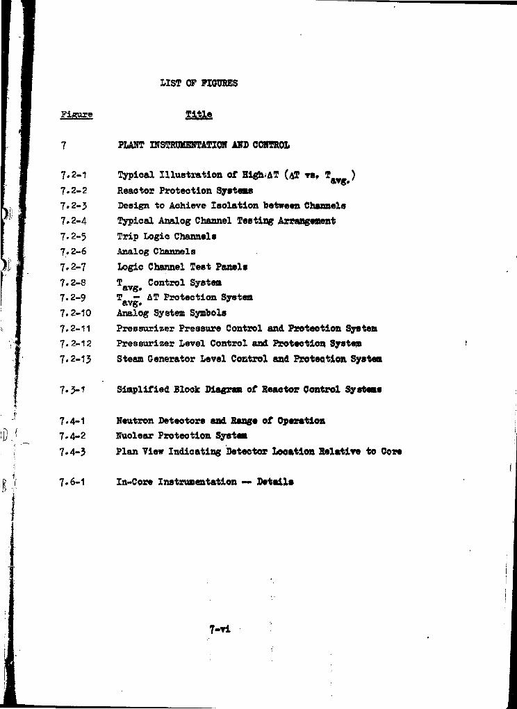
LIST OF FIGURES
Figure Title
PLANT INSTRUMENTATION AKS CONTROL
7.2-1
7.2-2
7.2-3
7.2-4
7*2-3
7.2-6
7.2-7
7.2-8
7.2-9
7.2-10
7.2-11
7.2-12
7.2-13
Typical Illustration of Hlgh.AT (A! VS. ! )avg#
Reactor Proteotion Systems
Design to Achieve Isolation between Channels
Typical Analog Channel Testing Arrangement
Trip Logic Channels
Analog Channels
Logic Channel Test PanelsT__ Control SystemT — AT Protection Systemavg»Analog System Symbols
Preesurizer Pressure Control and Protection System
Pressurizer Level Control and Protection System
Steam Generator Level Control and Protection System
7-5-1 Simplified Block Diagram of Reactor Control Systems
7.4-1 Neutron Detectors and Range of Operation
7.4-2 Nuclear Proteotion System
7.4-3 Plan View Indicating Detector Looatlon Relative to Cove
7.6-1 In-Core Instrumentation — Details
7-n

I. CON WC) li
of the oneration of the nuclcir uiul i.n '
;>ortions is accomplished by the instrumentation ruul control. c:y:-.teni!i
which provide the control room operat-jr'with required information
to operate the units in a safe and efficient manner* The systems
are designed to permit periodic on line tost to demonsIrato the
operability of the reactor protection system.
7.1 GENERAL DESIGN CRITERIA
Criteria applying in common to all instrumentation and control systems
ura Jviven in the following listing. Thereafter, criteria which arc
specific to any one of the instrumentation and control systems are
discussed in that section in which the system ic described.
7.1.1 Instrumentation and Control syotc-nis C ri t, v ria
Ins bruianntation and Control Systems
Criterion: Instrumentation and controls shall be provided as required
to monitor and maintain within prescribed ow-iviUir ranker
essential reactor facility operating variablou. ((JJ)O in).
Instrumentation and controls are provided to monitor and maintain
all operationally important reactor parameters within prescribed
operating ranges as required by the stated criterion. Procotit; variable
which are required on a continuous basis, for the startup» .wwc
operation and shutdown are indicated, recorded, and controlled from
the control room which is a controlled access area. The quantity and
types of instrumentation provided is adequate for safe and ord«r?.y
operation of all systems and> processes over the full operating rar.^e.
- 7.1-1 J

r i;
7.1.2 Related Criteria
:;rvcra-'. criteria are related to all instrumentation and control
- "si;earn "out are more specific to other features or systems. Those are
•'•«r-refore eiacucaed in other chapters» as listed»
V ?i berion
Suppression of Power Oscillations (GDC-7)
! • •: -ar Lo v C o re Dec iyn ( GDC-6 )
darda (ODC«-l)
IHundurdc (CrDC-5)
DiBcussion
Section 3.1
Section 3*1
Section 4.1
Section 4.1

7.2 PROTECTIVE SYSTERS
The protective ayattm ia oonaidarad to ba the reactor proteotlonsystem and the oontrol and instrumentation system aaaoolated withthe engineered safety features. The protection systems oonaists ofthe control and instrumentation asaooiated with the EngineeredSafety Features and the Reaotor Proteotion System.
7«2«1 Design Bases
Core Proteotion Systems '
Criterion: Core proteotion systems, together with associated equipment,shall be deaigned to prevent or to suppress conditionsthat could result in exceeding acceptable fuel damagelimits* (GDC 14).
If the reactor proteotion system receives signals which are indicativeof an approach to unsafe operating conditions, the system actuatesalarms, prevents control rod withdrawal, initiates load cutback, and/oropens the reactor trip breakers*
The basic reaotor operating philosophy is to define an allowable regionof power and ooolant temperature conditions. This allowable range isdefined by the primary tripping functions, the overpower A T trip,the over-temperature AT trip and the nuclear overpower trip.The operating region below these trip settings it designed so that nocombination of power, temperatures and presaure could result in M B Rless than 1*30 with all reactor ooolant pumps in operation. A completelist of tripping functions may be found in Table 7.2-1.
RCCA (rod cluster oontrol assemblies) withdrawal is prevented andturbine outback is initiated by a dropped RCCA signal to provideadditional oore proteotion. The dropped RCCA is indicated from individual
RCCA position indicators and by a rapid flux decrease on any of the powerrange nuclear channel»,
Rod stöps from nuclear overpower, overpower AT and over-temperature A Tdeviation are provided to prevent abnormal power conditions which couldresult from excessive control rod withdrawal initiated by a malfunctionof the reactor oontrol system or by operator violation of administrativeprocedures. '" .
7.2-1

Krotincercd Safety Features Protection Systems
Criterion: Protection ayetema «hell be provided for sensing aooldent
situations and initiating the operation of necessary
engineered safety features. (GDC 15).
Instrumentation and controls provided for the protective systems are
designed to trip the reactor, when neoeesary, to prevent or limit
fission product release from the core and to limit energy release)j
to signal containment isolation} and to oontrol the operation of j
engineered safety features equipment. :
The engineered safety features systems are actuated by the engineered
safety features actuation channels. Each coincidence network energizes
an engineered safety features actuation device that operates the
associated engineered safety features equipment, motor starters and
valve operators. The channels are designed to combine redundant
sensors, and independent channel circuitry, coincident trip logic and
different parameter measurements so that a safe and reliable system
is provided in which a single failure will not defeat the channel
function. The action initiating sensors, bistables and logic is shown
in the figures included in the detailed Engineered Safety Features
instrumentation description given in the System Design section.
The Engineered Safety Features instrumentation system actuates
(depending on the severity of the condition) the Safety Injection
System, the Containment Isolation System- and the containment Emergency
Cooling Systems.
The passive accumulators of the Safety Injection System do not require
signal or r^wer sources to perform their funotion. A description of
the actuation of the aotlve portion of the safety Injeotion System
may be found in Table 7.2-1.
Containment isolation is a» tabulated in Table 7.2-1.
7.2-2

Protection JSjs tems, Reliability
Criterion: Pröteotlon system shall be dcsi^nod for hi/tin functional
reliability and in-service testability noeceeary to avoid
undue risk to the health and safety of the public. (ODC 19).
Protection channels are designed with sufficient redundancy for in-
dividual channel calibration and test to be made during power operation
without degrading the reactor proteetionl Bypass removal of one tripi
channel is accomplished by placing that channel in a partial-trip mode.
For example, a two-out-of-three channel becomes a one-out-c-C-two
channel» Testing «ill not cause a trip unless a trip condition exists
in a concurrent channel*
1* Protection and operational reliability is achieved in part by providing
redundant instrumentation channels for each protective function.
These redundant channels are electrically independent and physically
separated. The channel design incorporates separate sensors, separate
power supplies, separate rack and panel mounted equipment and separate
relays for the actuation of the proteotiye function. Por protective
functions where two-out-of-three or two-out-of-four redundant-coincident
actuation is provided, a single channel failure will not impair the
protective function nor will it cause an unnecessary unit shutdown.
Protection Systems. Redundancy and Independence
Criterion: Redundancy and independence designed into protection
systems shall be sufficient to assure that no single failure
on removal from service of any component or channel of
such a system will result in loss of the protection function.
The redundancy provided shall include, ao a minimum, two
channels of protection for each protection function to be
• served. (GDC 20).
The reactor protection system is designed so that the most probable
modes of failure in each channel result In a signal calling TOT the
protective trip» The protection system design combines redundant sensors
and channel independence tilth coincident.Crip philosophy so that a safe
and reliable sySte» is provided in which a single failure will not
defeat the channel functioö, cause a spurious trip, or violate reactor
protection criteria.: • . •• • \ .- 7 . 2 - 5 v :' " .'. • - . :, , • •

p
Channel independence is carried throughout the system extending from the
sensor to the relay actuating the protective function. The protective and
control functions when combined are combined only at the sensor* The pro-
tective iand control functions are fully isolated in the remaining part of
the channel, control being derived from the primary protection signal path
through an isolation amplifier» A failure in the control circuit therefore
does not affect the protection channel.
A discussion of Engineered Safety Features (E3P) instrumentation mayi
be found under oection 7.5»
In the Reactor Protection System, two reactor trip breakers are provided
to interrupt power to the RCCA drive mechanisms. The breaker main •
contacts are connected in series (with the power supply) so that opening
either breaker interrupts power to all full length RCCA drive
mechanisms permitting the RCCAs to free fall into the core*
Further detail on redundancy is provided through the descriptions of
the respective systems covered by the various sub-sections in this
section. Required continuous power supply for the protection systems
is discussed in Section 8.
In summary, reactor protection is designed to meet all presently
defined reactor protection criteria, .
Protection Against Multiple jDlsabilitv for Protection•Svstems
Criterion: The effects of adverse conditions to which redundant
channels or protection systems might be exposed in common,
' either under normal conditions or those of an accident,
; shall not result in loss of the protection function or
shall be tolerable on some other basis. (GDC 23).
! The components of the protection system are designed and laid out so
that adverse environment accompanying an emergenoy situation in which
: the components are requirad to function does not Interfere with that
| f u n c t i o n . ;"• - '.-.-••-. :,, ...-. • •' i v •, ? •.,••; ;-'•••. :: • .'•
\ Separation of redundant analog protection ohazmels originates at the
• process senaors and continues thiwugh the field wirlne and containment
| penetrations to the analog protection racks. Physical separation is
: • ' • ' •• . 7 . 2 - 4 • . • ' , - - . '

used to the maxim* praotloal extent to aohisre separation of redundanttransmitter». Separation of field wiring is aehieved using separatewireways, oable trays, oonduit runs sad containment penetrations foreach redundant channel. Redundant analog equipment is separated by looatingcomponents in different protection raoks. Each channel is »nergized froma separate instrument bus*
Wiring between vital elements of the system outpide of equipment housingis routed and proteoted so as to maintain the true redundancy of theeye-betas with respect to physical hazards.
7*2-5

Demonstration of Functional, Operability of Proteotion Systems
Criteriont Means shall be inoluded for suitable testing of the active
components of proteotion systems while the reactor is in operation
to determine if failure or loss of redundancy has oocurred.
(GDC 25)
1
The signal conditioning equipment of eaoh proteotion channel in service at
power is capable of being calibrated and tested independently by simulated
analog input signals to verify its operation without tripping the reactor.
The testing scheme includes checking through the trip logio to the trip
breakers* Thus, the operability of eaoh trip channel can be determined \
conveniently and without ambiguity.
Protection System Failure Analysis Design
Criterion! The protection systems shall be designed to fail into a safe
state or into a state established as tolerable on' a defined
basis if conditions such as disconnection of the system, loss
of energy (e.g., electrical power, instrument air), or adverse
environments (e.g., extreme heat or oold, fire, steam,' or
water) are experienced.(GDC 26)
Each reactor trip channel is designed on the "de-energize to operate"
principle) an open channel or a loss of power causes that channel to go
into its trip mode.
Reactor trip is implemented by simultaneously interrupting power to the
magnetic latch mechanisms on eaoh drive allowing the full length rod clusters
to insert by free fall. The entire proteotion system is thus inherently
safe in the event of a lose of power* This equipment it seleotéd to with-
s-fet*na the ttost adverse environmental conditions to whioh it will be
subjected including post-accident conditions within the oontainment.
The engineered safety features initiating logic is designed on the sane
"de-energize to operate" principle as the reactor trip logic with the
exception of the containment spray actuation initiating logic which is
energize to operate in order to avoid spray operation on inadvertentSi j ' '
power failure. ,
- • 7 . 2 - 6 ! . , • : •

Redundancy of Reactivity Control
Criterion! Two independent control systems, preferably of different
principles, shall be provided. (GDC 27)
One of the two reactivity oontrol systems employs rod cluster control
assemblies to regulate the position of the neutron absorbere within the
reactor core. The other reactivity oontrol system employs the Chemioal
and Volume Control System to regulate the concentration of boric acid
solution neutron abeorber in the Reactor Coolant System.
Reactivity Control Systems Malfunction
Criterion! The reactor protection system shall be capable of protecting
against any single malfunction of the reactivity control system,
such as unplanned continuous withdrawal (not ejection or dropout)
of a control rod, by limiting reactivity transients to avoid
exceeding acceptable fuel damage limits. (GDC 31)
Reactor shutdown with RCCA is completely independent of the normal control
functions since the trip breakers interrupt the power to the full length
rod mechanisms regardless of existing control signals. Effects of contin-
uous withdrawal of a RCCA and of deboration are described in Section 7.3,
9.1, and 14.1.
Principles of Design
Redundancy and Independence
The protective systems are redundant and independent for all vital inputs
and functions. Each channel is functionally independent of every other
channel and reoeives power from two independent sources. Separation of
redundant protection channels is described in further detail in Section
7.2.2.
7.2-7

Manual Actuation
Means are provided for manual initiation of protective system aotlon*
Failure in the automatic system does not prevent the manual actuation of
protective functions. Manual eotuation is designed to require the operation
of a minimum of equipment»
Channel Bypass or Removal from Operation
The system is designed to permit any one channel to be maintained, tested
or calibrated during power operation without system trip* During such
operation the active parts of the system continue to meet the single failure
criterion, since the channel under test is either tripped or makes use
of superimposed test signals which do not negate the process signal*
EXCEPTION: "one-out-of-two" systems are permitted to violate the single
failure criterion during channel bypass provided that acceptable reliability
of operation can be otherwise demonstrated and bypass time interval is short.
Capability for Test and Calibration
The bistable portions of the protective system (e.g.. relays, biatables,
etc.) provide trip signals only after signals from analog portions of
the system reach preset values. Capability is provided for calibrating
and testing the performance of the bistable portlen of protective channels
and various combinations of the logio networks during reactor operation.
The analog portion of a protective channel (e.g.. sensor and amplifier)
provides an analog signal of the reactor or plant parameter. The following
methods for oheoking the analog portion of a protective channel during
reactor operation are provided!
a) Varying the monitored parameter.
b) Introducing and varying a substitute transmitter signal.
7.2-8

o. Cross checking between identioal qhannels or between channels whichbear a known relationship to eaeh other and whioh have readoutsavailable.
The design provide» for administrativ* control for the purpooe of manuallybypassing channels for test and calibration purposes.
The design provides for administrative control of access to al] trip settings,module calibration adjustments, test points, and signal injection points.
Information Readout and Indication of By-Pass
re The protective system providet the operator with complete informationpertinent to system status and safety»
Indication is provided on the Reactor Turbine Generator (RTG) board if aomesort of the system has been administratively bypassed or taken out of service.
Trios are indicated and identified down to the channel level.
Vital Protective »ouirements
The leactor Protection System monitors all parameters related to safeoperation of the reactor» The system is designed to trip the reaotor so asto protect the core against fuel rod cladding damage caused by departurefrom nucleate boiling (SMS), and to protect the Reactor Coolant Systemagainst damage caused by over-pressure. The Engineered Safety FeaturesInstrumentation System monitors parameters to detect failure of the ReaotorCoolant System, and initiates Engineered Safety Features operation. TheEngineered Safety Features Instrumentation System is described in 7*5»
i ;
i i
7.2-9

Coopletion of Proteotive Aotion
— • • -
When» operating requirement» necessitate automatio or manual bypass of
a protective function, the design is suoh that the bypass is removed auto»
matically whenever permissive conditions are not met. Devioes used to
achieve automatic removal of the bypass of a protective function are part
of the protective system ard are designed in accordance with the criteria
of this section*
The protective systems are so designed that» once initiatedt a protective
action goes to completion. Return to normal operation requires administrative
action by the operator.
Multiple Trip Settings
For monitoring nuclear flux» multiple trip settings are used. When it
is necessary to ohange to a more restrictive trip setting to provide adequate
protection for a particular mode of operation or set of operating conditions»
' the design provides positive means of assuring that the more restrictive
trip setting is used. The devices used to prevent improper use of less
restrictive trip settings are considered a part of the protective system
and are designed in accordance with the other provisions of these criteria.
! Interlocks and Administrative Procedures
j Interlocks and administrative procedures required to limit the consequences
I of fault conditions other than those speoified as limits for the protective
! function comply with the protective system oriteria.
Protective ^tctioqsi
The Reactor Protection System automatically trips the reactor when the
conditions listed in Table 7.2.1 exist*
7.2-10

Interlocking funotions of the Reaotor Protection System prevent controlrod withdrawal when a speoified parameter reaohes a value less than thevalue at whioh reactor trip is initiated»
For anticipated abnormal oonditionst protective systems in conjunctionwith inherent oharaoteristies and engineered safety features are designedto assure that limits for energy release to the oontaiment and forradiation exposure (as in 10 CfR 100) are not eaoeeded.
Indication
All transmitted signals (flow, pressure, temperature, etc.) which can lead
to a reaotor trip are either indicated or recorded for every channel.
All nuolear flux power rangs currents (top detector, bottom detector andalgebraic difference and average of bottom and top detector currents)are indicated and/or recorded.
Annunciators
Annunciators are also used to alert the operator of deviation from normaloperating conditions so that he may take corrective action to avoid a reaotortrip. Further, actuation of any rod stop or trip of any reaotor trip channelwill actuate an alarm*
L5 The protective ohannels ars designed to perform fheir function when subjectedto adverse environmental oonaitions and to prevent loss of function*
7*2-11

! ii
7.2.2 SYSTM DESIGN
Reaotor Protection System Description
Figure 7.2.1 illustrates typioal oore limits and shows the maximum trippoints which are used for the protection system. The solid lines indioatea typioal loous of BNHR • 1*30 at four pressures» and the dashed linesindioate maximum permissible trip points for the overtemperature high ATreaotor trip. Actual set points, to be determined, are lower to allow formeasurement and instrumentation errors. The overpower high AT reaotor triplimits the maximum oore power independent of the EMBS.
Adequate margins exist between the maximum nominal steady state operatingpoint (which includes allowance for temperature, oaloriffietrlo, and pressureerrors) and required trip points to preolude a spurious trip during designtransients. • • • - , .
A block diagram of the Reaotor Protection System showing various reactortrip functions and interlocks is shown in Figure 7.2-2,
System Safety Features
Separation of Redundant Protection
The Reactor Protection System is designed to aohieve separation betweenredundant protection channels. The channel design, it applied to theanalog and the logic portions of the protection system, and is illustratedby Figure 7«2-3. Although the illustration is for fear channel redundancy,the design is applicable to two and three ohannel redundancy.
Separation of redundant analog channels originates at thø process sensorsand continues along the field wiring and through oontainment penetrationsto the analog protection raoks. Isolation of field wiring i» achievedusing separate wireways, cable trays, conduit runs and oontainment penetrationsfor each redundant channel. Analog equipment is isolated by locatingredundant components in different protection raoks* Each ohannel is energizedfrom a separate a-o power feed. Logic equipment separation is achieved byproviding separate racks, each associated with individual trip breakers.Physical separation is provided between these raoks.
- ' , 7.2-12 \ " - -• ' i '

The reactor trip bistable* are mounted in the analog proteotion raoks
and are the final operational oompontnt in an analog proteotion ohannel.
Each bistable drivet tiro logio relay* ("C" & "0")* The oontaots from
the "C" relays are lnteroonneoted to fora the required actuation logio
for Trip Breaker No. 1. The transition froa ohannel identity to logio
identity if made at the logio relay ooil/relay oontaot interface. As
suoht there is both eleotrioal and physical separation between the analog
and the logio portions of the proteotion system. (The above logio network
is duplicated for Trip Breaker No. 2 using the oontaots from the "D" relays.
Therefore, the two redundant reactor trip logic channels will be physioally
separated and electrically isolated fro» one another. The Reactor Protection
System is comprised of identifiable ohannels which are physically, electrically
and funotionally separated and isolated fron one another. 11
i-!
Loss of Power ! •
A loaa of power in the Eeaotor Proteotion System causes the affected channel
to trip. All bistables operate in a normally energized state and go to
a de-energised state to initiate action. Availability of power to the
engineered safety features instrumentation is continuously indicated. The '
loss of instrument power to the sensors» instruments, logio or actuation '
devices in the engineering safety features instrumentation equipment associated •
with the affected ohannel, except for oontalnment spray which requires
instrument power for actuation* <
Realtor Trio Signal Tasting / s
Provisions are made for prooess variables to manually place the output of the
bistable in a tripped condition for Mat power" testing of all portions of
each trip circuit including the reaetor trip breakers. Administrative
procedure requires that the final element in a trip ohannel required during
power operation is placed in the trip mode before that ohannel is taken out
of service for repair or testing so that the single failure criterion is met
by the remaining channels. In the source and intermediate ranges where the
trip lögio is one-out-of-two for each range, bypasses are provided for this
testing procedure.
7.2-1?

I'M
!ji i Nuclear instrument power range channels are tested by superinposing a test
Ij j signal on the eensor signal so that the reactor trip protection is
; not bypassed. Based upon coincident logic (2/4) this will not trip the' i i .•\ | reactor^ however, a trip will occur if a reactor trip is required.
Provision in made for the insertion of test signals in each analog loop»
Verification of the test signal is made by portable instruments at test points
specifically provided for this purpose. This enables testing and calibration
of meters and bistables* Transmitters and sensors are oheoked against each
other and against preoision read-out equipment during normal power operation.
Analog Channel Testing
The basic elements of an analog protection channel are shown in Figure 7*2-4*
Each protection rack includes a test panel containing those switches, test
jacks and related equipment needed to test the channels contained in the
rack. A hinged cover encloses the test panel» Opening the oover or placing
the test-operate switch in the "TEST" position will initiate an alar». These
alarms are arranged on a rack basis to preclude entry to aore than one redundant
protection rack (or channel) at any time. The test panel cover is designed
such that it cannot be closed (and the alarm oleared) unless the test signal
plugs (described below) are removed» Closing the test panel cover will
mechanically return the test switohes to the "OPERATE1' position»
Administrative procedures will require that the bistable in the ohannel
under test be placed in the tripped mode prior to test» This places a proving
lamp across the bistable output so that the bistable trip point can be cheeked
during channel calibration. The bistable trip switohes must be manually
reset after completion of a test» Closing the test panel cover will not
restore these switohes to the untripped mode» However, the annunciator
on the RTG botrd cannot be reset until these switohes are returned to the
unbripped mode»
Administrative procedures prevent the nuclear instrumentation source range
and intermediate range protection channels fro* being disabled during
periodic testing. Power range overpower protection oannot be disabled
since this function is not affected by the testing of circuits. Administrative
7.2-14

controls also prevent the power range dropped-rod protection fron being
disabled by testing» In addition, the rod position system would provide
indication and assooiated oorreotive actions for a dropped rod oondltion.
Channel calibration will oonsist of inserting a test signal from an external
calibration signal source into the test signal injection jack. Where applicable,
the channel power supply will serve as a power source for the oalibration
source and permit verifying the output load oapaoity of the power supply.
Test points are located in the analog channel and provide an independent
means of measuring the oalibration signal level.
Channel Testing
The general design features of the logio system are described below. The
trip logic channels for a typical two-out-of-three and a two-out-of-four
trip function are shown in Figure 7*2-5. The analog portions of these channels
are «hown in Figure 7*2-6. Eaoh bistable drives two relays ("A*1 & "B" for
level and "C" & "S" for pressure). Contacts from the "A" and "C" relays
are arranged in a 2/3 and 2/4 trip matrix for Trip Breaker 1. The above con-
figuration is duplicated for Trip Breaker 2 using contacts from the "B"
and "D" relays* A series configuration is used for the trip breakers since
they are actuated (opened) by undervoltage coils. This approach is consistent
with a de-energize-to-trip preferred failure mode. The planned logic system
testing includes exercising the reaotor trip breakers to demonstrate system
integrity. By-pass breakers are provided for this purpose. During normal
operation, these by-pass breakers are open» Administrative control will
be used to minimize the amount of time these breakers are closed and to
prevent simultaneous closure of both by-pass breakers. Indication of a
closed condition of either by-pass breaker is provided locally and on the
test panel-.
As shown in Figure 7*2-5» the trip signal from the logio network is simultane-
ously applied to the main trip breaker assooiated with the speolfic logic chain
as well as the by-pass breaker assooiated with the alternate trip breaker.
Should a valid trip signal occur while AB-1 is by-passing Tfi-1, TB-2 will
be opened through its assooiated logic train* The trip signal applied to
TB-2 is simultaneously applied to AB-1 thereby opening the bypass around
7.2-15

r!
TB-l. TB-1 would either have been opened manually as part of the test orwould, be opeaed through its associated logic train which would be operationalor tripped during a test.
An auxiliary relay is located in parallel with the undervoltage coils ofJ' \ l ' . > ' '
the trip breakers. This relay is connected to an event recorder which isused to indicate transmission of a trip signal through the logic networkduring testing. Lights are also provided to indicate the status of the
relays.
The following procedure illustrates the method used for testing Trip BreakerNo. 1 and its associated logic network.
li .{

a* With the by-pas* breaker (AB-1) raoked-out, Manually olose and tripAB-1 to v«rify operation*
b. Rack-in and olose AB-1. Trip TB-1*
c. Sequentially de-enerfise the trip relay* (A1, A2, A}) for eaoh logiocombination (1-2, 1-5, 2-3). Verify that the logio network de-energizes the undervoltage ooil on TB-1 for eaoh logio combination*Since the event reoorder monitors the signal applied to the undervoltagecoil, operation of the undervoltage coil oan be determined from
the event reoorder*
d. Repeat "a" for every logio combination in eaoh matrix*
e. Reset TB-1.
f. Trip TB-1 to validate prior test remits a* evidenced by the event, recorder*
g. Reset TB-1* Trip and raok-out AB-1»
In order to minimi» tot possibility of operational errors (such as trippingthe reactor inadvertently or only partially oheoking all logic combinations)eaoh logic network includes a logio channel test panel* This panel includesthose switches, indioators and recorders needed to perform the logio systemtest. This arrangemeat is illustrated in Figure 7.2-7. The test switches usedto de-ehergice the trip bistable relays operate through inter-posing relaysas shown in Figure 7.2-4 and 7*2-6* This approach avoids violating theseparation philosophy used in the analog ohannel design* Thus, althoughtest switches for redundant ohannels are conveniently grouped on a singlepanel to facilitate testing, physical and eleotrical separation of redundantprotection ohfcnnels are maintained by the inolusion of the interposingrelay which is actuated by the logio tost switches.
7.2-17

j Primary Power Source
i
The primary power sources for the Reactor Proteotion System are the instrument
buses described in Section 8. The source of eleotrioal power for the
j j measuring elements and the aotuation of oirouits in the engineered safety
| | features instrumentation is also from these buses*
! ' 'I Protective Actions
• Reactor Trip Description
Rapid reactivity shutdown is provided by the insertion of full length
RCC assemblies by free fall. Duplicate eerles-conneoted circuit breakers
supply all power to the full length oontrol rod drive meohanisms. The
lull length RCCA must be energizsd to remain withdrawn from the oore.
Automatic reactor trip ocours upon the loss of power to the full length
control rods. The trip breakers are opened by the undervoltage ooils
on both breakers. The undervoltage ooils which are normally energized
become de-energized by any one of the several trip signals.
The design of the devices providing signals to the circuit breaker undervoltage
trip coils is suoh as to oause these ooils to trip the breaker on reactor
trip signal or power loss.
certain reactor trip channels are automatically bypassed at low power
*rhere they are not required for safety. Kuolear source range and intermediate
range trips are specifically prorided for proteotion at low power or sub-
critical operation» and at higher power operations they are bypassed by
manual action. .;; r
During power operation, a sufficient amount of rapid shutdown capability
in the form of oontrol rods is administratively maintained by means of
the control rod insertion limit monitors* Administratiw oontrol requires .
that all shutdown group rods be in the fully withdrawn position during
power operation.
A list of reactor trips» means of actuation and the coincident oirouit
requirements is given in Table 7*2-1. The interlock circuits» referred
to in Table 7.2-1, are listed in TaMe 7.2-2.

Manual Trip
The manual actuating devioes are independent of the automatic trip oirouitry,
and are not subject to failures which mak* the automatic circuitry inoperable.
Either of two manual trip devioes located in the control room oan initiate
a reactor trip*
High Kuolear Flux (Power fiance) Trip
This circuit trips the reactor when two of the four power range ohannels
read above the trip set-point. There are two independent trip settings,
a high and a low setting* The high trip setting provides protection during
normal power operation* The low setting whioh provides protection during
startup can be manually bypassed when two out of the four power range
channels read above approximately 1C# power (P10), Three out of the four
channels below 10$ automatically reinstates the trip function* The high
setting is always active.
High Nuclear Flux (intermediate Rwriw) Trin
This circuit trips the reactor when one out of the two intermediate range
ohannels reads above the trip set-point» This trip whioh provides proteotion
during reactor startup oan be manually bypassed if two out of four power
range channels are above approximately 1Q|G (P10)i Three out of four
channels below this value automatically reinstates the trip function.
The intermediate channels (including deteotors) are separate from the
power range channels.
High Nuclei"1» Flux (Sowos Ranged Trip
This circuit trips the reactor when on» of the two source range channels
reads above the t*ip set-point, 'fhis trip» whioh provides protection
during reactor startup oan be manually bypassed when one of two Intermediate
range ohannels reads above the P6 setpoint value and is automatically
reinstated when both intermediate range ohannels decrease below this
value (P6). This trip is also bypassed by two out of four high power
range signals (P10). The trip function oan also be reinstated below
P-1O by an administrative action requiring coincident manual actuation.
.. 7.2-19

ii i
The trip point ia set between the aouroe range cutoff power level and
the maximum source range power level.
Overtempegature AT Trip! '•
> !
The purpose of thia trip ia to protect the oore against 1MB* This trips
the reactor on coincidence of two out of the three signals, with one
set of temperature measurements per loop* The set point for this reactor
trip is continuously calculated for eaoh loop by solving the following
equations
^.etpoint - K1 " K 2 Tavg + V f (* *>
Where
Tav« " avera€?e reactor coolant temperature (*F)
P - pressurizer pressure, three independent Measurements (psia)
K1 • aet point bias (°P)
Kp,K., - constants based on the effeot of temperature and pressure
on the DHB liaita, {f•/?•), (»•/?•**)•
f (Aq) - a function of flux difference between upper and lower longion chamber sections*
Three of the four long ion chamber unit* separately feed eaoh overpower
AT trip channel» Thus, a single failure neither defeats the function
nor causes a spurious trip* Changes in f (åq.) oan only lead
to a decrease in trip setpoint*
A rod stop and turbine runbaok art) initiated when
where
• AT •rod stop eetpoint -
B_ • a set point bias7.2-20

1
The turbine runbaok isoontinued until AT is equal to or less than &!„. .' roa stop»
This function serves to maintain an essentially oonstant margin to trip,e.g., this gives the operator the opportunity to adjust the part lengthrods to reshape the flux before a reaotor trip occur».
Overpower AT Trip
The purpose of this trip is to proteot against exoeesive power level (fuelrod rating protection}» This trips the reaotor on coincidence of twoout of the three signals, with one set of temperature measurements perloop»
The set point for this reaotor trip is continuously calculated for eachchannel by solving equations of the font
&Tsetpoint " V E 5 ät * K6 ^TavgQ " Tavg ^ " f k « )
*
wheref(Aq) - a function of flux difference between upper and lower long
ion chamber sections (F*/$£ flux)
K. « a preset manually adjustable bias (F*)
HL * a oonstant (F /F"/MO)
a oonstant
T " *'
average reaotor coolant temperature
A similar rod stop and turbine runback function is provided for over power
protection.
7.2-21

1 :; Low Preasurizer Pressure Trip
; i The purpose of this trip is to proteot against excessive oore steam voids
j which could lead to DNB* This tripe the reactor on ooinoidenoe of two.out
j i of the three low preesurizer pressure signals. This trip is blocked wheni 1j ; three of the four power range ohannele and one of two turbine first etage! ! pressure channels read below approximately 1CpJ power (P7)#
; f ' Hif;h Pressurizer Pressure Trip' i i
The purpose of this trip is to limit the range of required protection
from the overtemperature A T trip and to protect against Reactor Coolant
System overpressure. The reactor is tripped on coincidence of two out-
of the three high pressurizer pressure signals*
High Pressurizer Water Level Trip
This trip is provided as a backup to the high pressurizer pressure trip.
The coincidence of two out of the three high pressurizer water level signals
trips the reaotor. This trip Is blocked when three of the four power range
channel a and one of two turbine first stage pressure ohannele read below
approximately 1Cj£ power (P7)«
Low Reactor Coolant Plow Trip
This trip protects the core from MJB following a low flow or loss of coolant
flow. The means of sensing low flow and a loss of ooolant flow aooident are
as followsi
a. Measured low flow in the reactor ooolant piping*
The low reactor flow trip is actuated by the ooinoidenoe of 2/j
signals for any reactor ooolant loop* The lets of f low in any two
loopB causes a reactor trip in the power range above approximately
1OjS (P7)* Above approximately 6Cj£ power (P8), the loss of flow in
any loop causes a reactor trip* The instrument used for flow
measurement is an elbow tap and is discussed in £motion 4*
7*2-22

b. Monitored electrical supply to the reactor coolant pumps*
The voltage and frequency of the buses which supply power to the
reactor coolant pumps is monitored. Under-volta^e will cause a j!
reactor trip. Under-frequency will cause a pump breaker trip which %
then will oause a reactor trip as follows: !
1) Above approximately 10?f power a loss of 2 of the 3 pumps will
cause a trip (P-7)»
2) Above approximately 60% power a loss of 1 of the 3 pumps will
cause a trip (P-8).
Safety Injection System (SIS) Actuation Trip
A reactor trip occurs when the safety injection system is actuated by.either
a manual (1/2) signal or automatic signals as listed in Table 7.2-1.
Turbin Generator Trip
A turbine trip causes a direct reactor trip at an operating level above
approximately 10# power* This occurs only when both turbines trip together
or when one turbine is out of order and the other one at load trips* When
both turbines are at load and one of then trips, there will not normally be
any reactor trip. The reactor trip is followed by a controlled short-term
release of steam to the condensor which removes sensible heat from the
reactor coolant system. Thereby steam release through steam generator safety
valves is avoided.
The turbine control system automatically trips the turbine generator under
any of the following conditions (main examples):
a. Turbine oyerspeed
b. Generator electrical fault*
c. Low condenser vacuum
d. High lube oil temperature _ . . . . .
e. Low lube oil pressure
f. Low control oil pressure
g. Reactor trip
h. Manual trip*
7.2-23

. ? • ! Steam/Fe edwator
This trip protects the reaotor from a sudden loci of its heat sink» Thetrip is actuated by a eteam/feedwater flow aisaatoh (1/2) in ooineidendewith low water level (1/2) in any stea» generator,
Low-Low Steam Generator Water Level Trip
The purpose of this trip is to proteot the steam generators in the oaseof a sustained steam/feedwater flow alsaatoh of insufficient magnitudeto cause a flow mismatch reactor trip* The trip is actuated on two outof the three (2/3) low-low water level signals in any steam generator*
Rod Stops
Hod stops are added to prevent a reactor trip or prevent an abnormalcondition from increasing in magnitude*
A list of rod stops is given in Table 7»2-5» S O M of these have beenpreviously noted under permissive cirouits, but are listed again forcompleteness*
Rod Drop Protection
Two independent systems are provided to sense a dropped rod. (1) a rodbottom position detection system and (2) a system whioh senses suddenreduction in out-of-eore neutron flux* Both proteotion systems initiateprotective action in the form of a turbine load outbaok and blocking ofautomatic rod withdrawal. This aotion compensates for possible adversecore power distributions and permits an orderly retrieval of the droppedRCC.
The primary proteotion for the dropped BCC aooident it the sod bottomsignal derived for each rod froa its individual position indication system*With the position indication system,, initiation of proteotion is not dependenton location, reactivity worth or power distribution obmmfos*
7.2-24

Backup protection is provided by use of the out-of-core power rarvj" nuni»nr
detectors and is particularly effective for larger nuclear flux reduction»!
occurring in the region of the core adjacent to the detector».
The rod drop detection oircuit from nuclear flux «oimists. basically of
a comparison of each of the four ion chamber n:i«nalB wil.h. the same si^rm]
taken through a first order lag; network» Since a dropped HCO a.st!»f»mbly
wilJ rapidly depress the local neutron flux, tho docx^aufe in flu* wii:
be detected by one or more of these circuits.
fl Such a sudden decrease in ion chamber current will be seen as a derivative
signal» A negative signal output greater than a preset value (approximate*'.y
10 per cent) from any one" of the four power rang»-» channels will actual'.1
the rod drop protection.
Figure 7*4-2 indicates schematically the Nuclear Instrumentation Syston,
including the dropped RCCA alarm.
Automatic turbine load outback is initiated by a signal from a dropped
rod control cluster assembly as indicated by either a rcpid decrease in
nuclear flux or by the rod bottom on-off controllers. Load cutback is
also initiated by an approch to an overpower or overtemperature condition.
This will prevent high powe,r operation which might 1f»ad to minimum DNB
ratio less than 1.30* .
The rod stop is redundant. Rod stop contacts are located in the rod control
logic cabinet and in the rod speed control analog rack. The turbine runback
acts by both of the following!
1. Reduction of the load reference setpoint of the turbine governor
speed changer by a preset amount. This is accomplished by reducing
the set point at a constant rat» for a preset time.
2. Reduction of the turbine load limit to a preset value. The load
limit (a damp on the voltage signal controlling the turbine control
valv* position) is reduo*d until turbine thermal load as sens"u
by «ithsr of two turbine» first »tag* prtinur» channel» in b«l<v* n
preset valu*. ' . , , . ,

fö i
Th'> »mount of' the runbnck in to hi* determined by physics test» of
rod worths *md hot channel factors during startup tests* The safety
requirement of t.he runback in to preclude return to a power level that
mitfht result in a core damage beoause of adverse hot channel factors.
It is expected that the startup tests will show that dropped rod hot channel
factors will not cause a DNBR less than 1*50 even at full power, and that
the .runback win be set for operational requirements. That is, the ÄU tome tic
io.Hd reduction would be large enough such that with reasonable operator
action, an orderLy manual shutdown can be accomplished rather than o. n-axctor
t.rip on low prpnsurizer pressure.
Control Group Uod Insertion .Limit Monitor
"'nt- control group rod insertion limits, Z,,, are calculated as a linear
'.motion of pow«r and reactor coolant average temperature. The equation
i. a :
JLL
wher« A, B are preset manually adjustable gains and C is a preset manually
adjustable bias. The (AT) B M > and (T - M -) are the average of the individual
tempérituré differences and the coolant average temperatures respectively
measured from the reactor coolant hot leg and the cold leg.
An insertion limit monitor with two alarm set points, is provided for the
control banka» A description of control ånd shutdown rod groups is; provided
i ri Section 7« 3» The "Low" alarm alerts the operator of an approach to
n reduced; shutdown reactivity situation requiring boron addition by following
•srocedures with the Chemical and Voluae Control System. If the actuation
of the "Low-Low" alarm occurs, the operator should take immediate action
to add boron to the system. il
I
>'•; II..
7.2-26

1.2. f, SYSTEM EVALUATION
Reaptor Protection System and DNB
The following is a description of how the reactor protection systempreventB DNB.
The plant variables affecting the DNB ratio aret
Thermal Power
Coolftirt flow
Coolant temperature
Coolant pressure
Core power distribution (hot channel factors)
Figure 7.2-1 illustrates the typical core limits for which DNBR for iK-
hottest fuel rod is 1•30 and shows the overpower and overtemperaturo A '
reactor trips locus as a function of T and pressure. This illuf.tr.tV-
is derived from the inlet temperature versus power relationships, i'L(rxr<
7»2-8 indicates T control system and is typical for one reactor cool:avgloop. Figure 7*2-9 illustrates T - AT protection system.
Variations in both flow and power are monitored by the overpower and o v
temperatur© ÄT trips since a decrease in flow wou)d have th<=> same eff>';J
on the measured loop AT signal as an increase in power. It is the natur'
of the DZJB limits that a reduction in flow of 1C$ would require a rodxxc-i
in power of only about 9J& to maintain the same DNBR, all other variable
remaining constant. Thus, the permissible AT increases somewhat at a
reduced flow* The trip setpoints are therefore set for a maximum flow.
A reduction in flow increases the margin between the trip point and the
actual core limit. Periodic measurements using the in-core instrument.-'
system are used to verify that the actual core power distribution is wi'
design limits.
Reactor trips-for a fixed high pressurizer pressure and for a fixed lor
pressurize? pressure are provided;to limit tho pressure range over whic-
core protection depends'=onthe overpower and fövertempératur'1 AT iriya.
7*2-27

i;! K^uctor trips on nuclear overpower and low reactor coolant flow are provided
il |'"!' for direct, immediate protection against rapid changed in these parameters.
i! i However, for all cases in which the calculated DNBR approaches 1.30» a
! reactor trip on overpower and/or overtemperature AT would also be actuated.
Th« Reactor Protection System actuates a reactor trip for a set of conditions
'''' ' f"f>r which the calculated DNBR for the worst fuel rod approaches 1.^0.• i . '
HfcuuH" oJ" tho statistical nature of the W-2 correlation and tho.statistical
! makoup of ». portion of the hot channel factors, there exists a finite
probability of a few rods being in DNB for a calculated ratio of 1.^0ror the wor.'it fuel rod (Section j5»2,2).
Vor the anticipated abnormal conditions, it is highly unlikely that tho
•/act combination of conditions (reactor coolant pressure, temperature
Did cofe power, instrumentation inaccuracies, etc.) that cause a DNBR of
1.30 will be approacned before a reactor trip. The simultaneous loss
of oower to al] of the reactor coolant pumps is the accident condition
mont likely to approach a DNBR of 1.30 for the calculated worst fuel rod.
In any event the DNBR at the worst fuel rod is near 1.30 for only a few
seconds. ' " ' '
'i'hr hottest fuel rodo are not adjacent to one another. They are located
nvnr the sport* RCCA thimbles. Fuel rods located in the immediate vicinity
of th<-> hottest fuel rod have a DNBR higher than that rod.
The AT trip functions are based on the differences between measured hot
leg and cold leg temperatures. These differences are proportional to fi
c o r e p o w e r . ' •' • • • . . • ' • • . ' , . ' . * • • • • • • . ••
j The &T trip functions ore provided with a nuclear fltix feedback to reflect
!'• n'mwasure of »jcial power diatributioni This will assist in preventing
n an advn'rse axial distribution which could lead to exceeding the allowable
l' core conditions. -
The reactor is equipped with part length control rods which are manually
controlled from the control:room and which projri.de flexibility in the
7.2-26

shaping of oore axial power distribution, thus improving the capability
of maintaining desired core aondition» while providing thn mvnns v drunp
out potential axial xenon oscillations.
In the event of a difference between the upper and lower ion chamber air.'in.
that exoeeda the desired range, automatic feedback oignals nr<? provided t.<;
reduce the overpower - overtomperature trip setpointa, block rod withdraw:r
and reduce the load to maintain appropriate operating margins ho Ui'%so
trip setpoints» The operator can then manually adjunt part lorvrth rods
using long ion chamber information displayed on the control board to m.-i> .
the difference between top and bottom detectors within the desired ran<ro
and thus enable the reactor to be returned to ito former power value.
Specific Control and Protection Interactions
Four power-range nuclear flux channels are provided for overpower r.roV":'.
Isolated outputs from all four channels ore averaged for automatik corV-
rod regulation of power* If any channel faila in ouch a way an v> oro'^v
a low output, that channel is incapable of proper overpower proV.-cticn.
In principle, the same failure may cause rod withdrawal and hone*, overpo/.
Two-out-of-four overpower trip logic will ensure an overpower trip if
needed even with an independent failure in another channel*
In addition, the control system will respond only to rapid changer, in
indicated nuclear flux» slow changes or drifts are compensated b.y thr>
temperature control signals* Also, a rapid decrease of any nuclear flux
signal will block automatic rod withdrawal as part of the rod drop wrote»?'
circuitry and initiate a load outback. Finally, an overpower signal from
any nuclear channel will block automatic rod withdrawal. The net point
for this rod stop is below the reactor trip set point.
Coolant Temperature
Three T ohannels are used for overtemperature-overpower protffction.
Output signals from three separate channels are also averaged for
control rod regulation of power and temperature. A spuriously low temp"? •
signal from one sensorwouldcause rod .withdrawal* Two out of thr«o<•
7.2-29

ål.
trip lo,"; i c it» uood to ensure that an overtemperature trip occur» if neodod
i;v«n with an independent failure in another ohannel»
In addition, channel deviation alarms in the control system will block
!;,j automatic rod motion (insertion or withdrawal) if any temperature channel
i} deviates significantly from the others» Automatic rod withdrawal blocks
!; I will also occur if any one of four nuclear channels indicates an overpower
condition or if any one of three temperature channels indicates an ovor-
L.-moprjiturf" condition. Two-out-of-tKree trip logic is used to ensure
th'tt /in ovortemporature trip will occur if needed even with an independent
f.-ii I utv in nnothor channel. Finally, as shown in Section 14.1, the combination
i ;>'• tripn on nuclear overpower, high pressurizer water level, and high
i.HTi:iuri'/if.'.r pressure also serve to limit an excursion for any rate of
\ f'.-i'-.tivity insertion.
\, Pressurizer Pressure
fr,i Three pressure channels arc used for high nnd low pressure protection
and as part of overpower-overtemperature protection (See Figure 7»2-11),
Isolated output signals from these channela also are used for pressure
•: control and compensation signals for rod control» These are discussed: separately below:
(1) Control or rod motion» one of the pressure channels in used for
rod control with a low pressure signal acting to withdraw roda,!i ?h<;'discussion'for coolant temperature is applicable, i.e., two-
: oufc-of-three logic for overpower-overtemperature protection as the
primary protection, with backup from multiple rod stops and "backup"
trip circuits. In addition, the pressure compensation signal is
limited in the control system1 such that failure of the pressure
signal cannot cause more than about 10*F change in T . This changei . avg
: can be accommodated at full power without a DKBR less than 1.30.
'•• Finally, the pressurizer safety valves are adequately sized to prevent
: s y s t e m o v e r p r e s s u r e . ' • • " '•';' iCy "*"•"•' • '•'• -''•••••. .,'"'''''
(2) Pressure Control* Spray* power-operated relief valves, and heaters
are controlled by isolated ««itptit signals from the pressure protection
: channels.
7»2»3C

I
F
n) Low Pressure
A spurious high pressure signal from owt channel nan ni\u::>-
low pressure by spurious seiufiiioft of sipira.y find/or a r^l '••!'
valve. Additional redundancy is provided in the protection
system to ensure underpressure protection, i.e., two-out-of-
three low pressure reactor trip lo/jic and onr-out-of-thr*»-
logic for safety injwotion» (Safety injection is actuated
on one-out-of-three coincident low pressure and low lov*->i.)
b) High Pressure
The pressurizer heaters are incapable of overpressurizin^ the
reactor coolant system» Maximum steam genera t i on rat*» with
heaters is about 15,000 lbs/hr., compared with n. total cipncn '.y
of 864,000 lbs/hrf for the three safety valven and a tot'il
capacity of 358,000 lbs/hr? for the two. pow^r-oporatefl r'.\lW
valves. Therefore, overpressure pj-otection is not r*»quirr-n
for a pressure control failure. Two-out-of-three high pr"r.Kur"
trip logic is therefor» used»
In addition, either of the two relief valves can easily maintain
pressure below the high pressure trip point. The two relief
valves are controlled by independent pressure channels, one
of which is independent of the pressure channel used for heater
control. Finally, the re.te of pressure rise achievable with
heaters is slow, and ample time and preooure alarms are available
for operator action.
Pressuriaer Level
Three pressuriwr level channelu are used for reactor trip, hi^h level
(2/j) and safety injection- with low level coincident with pr^nsuro (1/.)
low level coincident with pressure). Isolated output signals from th'.-'
channels are used for volume control, increasing or decreasing water ferel
A level control failure could fill or empty the pressurizer at n slow
rate (on the order of half an hoiö* or «ore)» (Sec Figure 7.2-1?)• Typical number» calculated for Ringhals Unit II, actual ntutber»
for Forsmark will be slightly different,
• . 7.2-31

I •:;j
(a) High Level
A rone tor tri p on [>rw8suriv.f*r high level is provided to prevwnt
rapid thcirmul expansion» of reactor coolant fluid from filling th<>
prt'ouuriw-rt Uie rapid change from high rates of steam relief bo
water relief can be damaging to the safety valves and tho rvlK-r
piping wnd pressure relief tank» However, a level contxol failure
cannot actuate the safety valves beoause the high pressure reactor
trip is set below the safety valve set pressure. With the slow
rate of charging available, overshoot in pressure before the trip is
effective is much less than the difference between reactor trip and
safety value set pressures. Therefore, a control failure does not
require protection system action»
in addition, ample time and alarms are available for operator action.
(l> Low L»?vel
b'or control failurea which tend to empty the pressurizer, one-out-
o!1-three logic for «afety injection actuation on low level coincident
with low pressure ensures that the protection system can withstand
an independent failure in another channel.
In addition, ample time and alarms exist for operator action
3team Generator Water Level) Feedwater Flow
i'eforo (lesurrnring control and protection interaction f or, these channels,
i t i» beneficial to review the protection system basis for this incrementation.
(Lj"t. Kifjure '(. 2-1
Tb<- bfudo funn lion of tlie reactor protection circuits associated with
low 3team generator water level and low feedwater flow is to preserve .
the steam generator heat sink for removal of long tern residual heat.
Should a complete loss of feedwater oocur with no protective action,, .the
steam generators would boil dry: and oause tin overtemperatur^-overpressure
excursion in the reactor coolant» Reactor trip» on temperature,
and p,rcs8uriz«r water level will trip the. unit before there ie any

-
to the core or reactor coolant system» However, reuI dual h»nt arter tri f
would ctfise thermal expansion, and disoharge of the rv.-i.otor coolant t,n i,,,,.
nonttiirm'-tnt through the pressurizer relief valve», Kwlumlunt omor^no.y
Vfnnlwilor pumps are provided to prevent this. K"»ictor trip» w.l fooforr
HM« utoam c tri» .«ra torn are dry to reduce th? required capacity and r-.tar-1, i.rv;
tinn.- rcjui rem««nta of these pumpa and to minimize Un? Uivrmal tranoi'int
on the reactor coolant system and steam generators. Independent trir»
circuits are provided for each steam generator for the following rcrv.son:••
1. Should severe mechanical damage occur to the fordwater line to or"
steam generator, it is diffioult to ensure tho functional integrity
of level and flow instrumentation for that unit. For instance,
a major pipe break between the feedwater flow element and the n>pjn
generator would oause high flow through the flow element. Thf rani.-1
depressurization of the steam generator would drastically aff r-i,
the relation between downcomer water level and ntoam (jen^rator e;:iV<r
inventory.
2. It is desirable to minimize thermal transient on a steam ^enor- tf>r
for. credible loss of feedwater accidents.
It should be noted that controller malfunctions caused by a protection
* ' - system failure affeot only.'one steam generator. Also, they do not
impair the capability of the main feedwater system under either
manual control or automatic control. Hence, the3e failures are far
from^being the worst oase with respect to decay heat removal with
the steam generators.
(1) Feedwater Flow • • •
A spurious high signal from the feedwater flow channel bein/j usi»d
for control would cause a reduction in feedwater flow and prevent
that channel from tripping* A reactor trip on low-low water level,
independent of indicated feedwater flow, will ensure a reactor trip
if needed.
In addition, the three-element feedwater controller incorporates
reset on level, such that with expected controller settings a rapid
" ; 7»2-35

t; • •
il
incr.'nri'- in tfn- flow rtignuJ would caUBQ only a MUill
in iov<>! hufor».' the controller re-opened the feedwater v n l w . A
r jJow inr.r«twm i n t h e 1 'oc . t lwnter s i g n a l w o u l d h a v e n o e f f e c t « i t n i l ,
a t e a m F l o w
A 3purious low steam flow signal would have the same effect aa a
high feedwater signal, discussed above.
Levelm
\ spurious high water level signal from the protection charme] used
for control will tend to close the feedwater valve» This level
channel \n independent of the level and flow channels used for reactor
zrip on ow flow coincident with low level.
a) A rapid increase in the level signal will completely otop feodwater
"low and lead to an actuation of a reactor trip on low fnedwater
x"low coincident with low level.
b) A slow drift in the level signal may not actuate a low feedwater
signal. Since the level decrease is slow, the operator has
time to respond to low level alarms. Since only one steam
generator is affected, automatic protection is not mandatory
and reactor trip on two-eut-of-three low-low level is acceptable•
:*>Uvun Lino Pressure
Thror; pressure channels per steam line are used for steam lins break
protection (two out of three? high differential pressure signals between
uny stoam lino and the main steam header or high sttaa f lov in two out
of three steam lines- with éi-tÉner low steam line pre »sure in two out
of three lines or two out of1, three lov «etnatirrifeféiy injection).
Normal Operating Environment-" ' I • ' -" . V F , .
The control room is maintained åi; the personnel comfor* level of (7O+-1O) F.øm
:: -.-'7.2*34

Protective; equipment inside the room is designed to opwutc within <lnr.ly,r)
Lolferunco ovwr this temperature range and will perform its protwolivc function
in an ambient of 110"F (i.e., there will be no loaa-oi'-»function in an
ambient temperature of 11O'F).
The operating environment for equipment within the containment will normally
be controlled to less than 120 °P. The Reactor Protective System Anotrumyn-
tation within the containment is designed for continuous operation. The
temperature of the out-of-core neutron detectors is maintained at or brOow
135 F by the normal containment air cooling system. The detectors are
designed for continuous operation at 155°F and will withstand operation at
175~F for short durations.
Typical test data (or reasonable engineering extrapolation ba,sed on test
data) will be used to verify that protection systems equipment will meet,
on a continuing basis, the functional requirements under the antivipatod
normal ambient conditions.
7*2-35

1.
2.
3.
4«
5.
6.
7.
8.
9B.
TABLE 7.2-1
LIST OP REACTOR TRIPS & CAUSES OF ACTUATION OF». ENGINEERED SAFETY FEATOKSS, CONTAINMENT
AND STEAM LIÆ ISOLATION A ADXILIARY FEEPWATER
REACTOR TRIP
Manual
High neutron flux
Orcrieaperatnre At
Ofarpowwr ' AT
Low presswriser pressure(fixed set point)
tø pressuriser pressure(fini set point)
pressmriser vat«r
Low reaotox coolant flow
Konitorvd «l«otrioal supplyxvactor coolant pusps«
Vodervoltag*
Und«rfrequenoy
t-
COINCIDENCE CIRCUITRY AMD INTERLOCKS
1/2, no interlocks
2/4, no interlocks
2/3, no-interlocks
2/3» no interlocks
-2/3« int«rloek«d with P-7
2/31 no interlocks
,« r •2/3» interlocked with P-7
2/3 per loop» interlocked withp-7» « * F-8
Loss of power on 2 out of 3 buses
Under frequonoy on 2 out of 3 buses
COlfflENTS
High and low settings}aanual blook and automaticreset of low setting byP-10, Table 7.2-2.
Low flow in 2 loopspermitted below P-7.Low flow in 1 loop. •-permitted below P-8.
Under frequency on 2 outof 3 buses will trip allreactor coolant pumps andconsequently cause reactortripi interlocked vithP-7 and P-8.


10.
I t .
14.
15.
leactor ooolattt puap breaker» •
Safety injection signal (Actuation)
Turbine-fwaerator trip
flow ai*aatoh 9M i m i é e v t with low steeagenerator leve l»
L«v~low st**a generator water l e v e l
r Interaediate range neutron f l u x
Source rang* neutron f lux
TABLE 7.2-1 (Continued)
COIMCIDBICE CIBCTITRT AND INTERLOCKS
Interlocks with P-7 and P-8
Low pressuriser pressure ( l / 3 ) coincidentwith low level ( i / 3 ) , or 2/3 highoontainaent pressure} 6rxz/3 highdifferential pressure between anystsaa l in* header and étswji l ine |or 2/3 high »teas flow in coincidencewith 2/3 low Tay or 2/3 lov steam l ine
pressure, or •åratal 1/2 (See 7.2Systea Oi«eription>>Pro^e^tive Actionfor Intexlooks).
2/3» low sttto stop oil pressureInterlocked rniUh. P-7 «att P-9, or1/2 stop valv* closure indication(interlocked with P-7, «nd P-9)
1/2, (stiea/feedwater flow ai«aatofc) inooiBoideiooe with i /* , (low steaagenerator water l*v*l)< per loop
2/5» P « loop,
1/2, aanual block peraitted by F-1O
i/2, aazeaal block permitted by P-6,interlocked with P-10
C0MMEHT3
Manaal block and autoaatiareset
Manual block and aa^oaatiareset

ISOLATION ACTUATION
16. Phase k - Safety Injection Signal
TABLE 7.2-1 (Continued)
COIMCIDBHOE.CIBCUITBY.AMD INTERLOCKS
See Item 1O| 2 momentary push buttons,pressing of either push button (1/2)will actuate.
Actuates all non-essentialservice containmentisolation trip valves
17* R U M S B - Containment pressar»
18. High containment activity
BKBBBBD SAFETY lEAWWES ACTOATIO»
19. Safety injection signal (*)
20. Containment spray signal (p)
Coincidence of two 2/5 containmentpressure (Hi-Hi pressure, sane signalwhich*actuates containment spray),or aanual 2/2 f ;
High activity signal, fro» airpsxtievlate detector or radiogasdetector, (i/2) .t .
See Item 10
2 oat of 5 high containment pressurein ooincidtnee «ith 2/3 High-Highcontainment pressure! or "manual 2cat of 2.
Actuates all essentialservice containmentisolation trip valves
This additional signalcloses contäinaent pmrg*««PJ?ly» »Jthaust daets andpressar* relief ducts only*

STEAM LDiBS ISOLATION ACTUATION
2 3 . _ Stea» Flow
24* Containment pressure
25* Mamal pas «teas loop
ABTTE.TÄ1 K'WHTflK
24» larsinet driven puap
MATS IATGR ISfiLAVTM
27* Close amin feedwater oontrolvalvva trip aain feedwaterptwps (fast closure)
TASLE 7*2-1 (Continued)
COIHCIMMCE CIRCUITRY AMD INTERLOCKS
High 8t«an linje flow in 2 out of 3loops coincident with either low T
in 2 out of 3* loops or low steam linepressure in 2 out of 3 loops.
2/3 high containment pressure Bignalin eeineiäenoe with 2/3 high-highcontainoent pressure*
1/1 per siieaa line
Coincidence of 2/5 low leva! in two steaagenerator»} or loss of roltage o& both6600 volt buses| or trip of aain feedwater puapa, or safety injection signal §or Manual 1/2
Actuated byt "1. Safety injection (see'itec 10)2. 2/3 h.i«h feedwater level in steaa
ganerAtor
CMHESTS

2
3
TASLE 7.2-2*
INTERLOCK CIRCUITS
Funotion
Prevent rod withdrawalon overpower
Auto-rod withdrawalstop at low powers
Auto-rod withdrawalstop on rod drop.
Required Input
.1/4 high nuolesx flux (power range)or 1/2 high nuclear flux(intermediate range) or 2/3 overJ.temperature ,AT or 2/3 overpower AT.
Low life load signal (turbinepressure)!
1
1/4 rapid decrease of nuolear flux(power ran*»)©» 1/1 ^ d bottom •irdioation
5
6
8
9
Stean dunp interlooks
Manual biook of sourcerange trip
Permissive power(block various trips).Required only atpower
Blook single primaryloop loss ox flow trip
Manual hlook of lowpower range trip (powerrange) intermediaterange trip
Rapid deorease of Ufe load elgnal(turbine pressure)
1/2 high intermediate range fluxallows manual block, 2/2 lowintermediate range defeats blook.
3/4 low-low nuolear flux (powerrange) and 2/2 lor/ MWe loadsignal, (turbine pressure).
3/4 low nuolear flux (power range)
2/4 high nuolear .flux allow» mantelblook. 3/4 low nuclear Aux (powerrange; defeats manual blook.
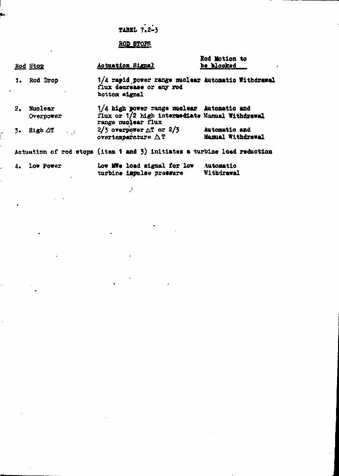
*»<
TABEL 7.2-3
ROP 8T0PB
Rod Motion toHod Stop Actuation. Signal bo »looked i
1. Rod Drop 1/4 rapid power range nuolear Autoaatio Withdrawalflux deorease or any rodbotton signal
2. Nuolear 1/4 high power range nuolear Autoaatio andOverpower flux or 1/2 high intermediate Manual Withdrawal
range nuo^ear flux3. High<£T , \ 2/3 overpower T or 2/3 Autoaatio and
overtenper&ture A ? Manual Withdrawal
Actuation of rod stops (item 1 and 3) initiates a turbine load reduction
4* Low Power Low MWe load signal for low Automaticturbine impulse pressure Withdrawal

•lYiir"A.L ILLUf ATiCN' Clr HIGH f/f' 1KIP (AT VS T y )
64
60
56
52
AT
44
40
36
540
L BOLD LINES -' I'ROTECIICN LIXIISi FAINT LINES - 1 . 3 DNSR LIMITS
= OPERATING POINI•rri OVERPOWER AT TRIP LINE :
|"-:l :::::::.I:::M
T TRIP LINESOVERTEMPERATURE
mm
; : : : : : : : : • ! • : : "
!•] 1V3""DNSR LINE'S 'FOR VARIOUSPRESSURES WITH DESIGN HOTCHANNEL FACTORS ANDMAXIMUM FLO'.-:
550 560 570 580 590 600 610 620 630 640
°F

POWER RANGE NUCLEAR FLUX TRIP (HIGH)
HIGH PRESSURIZER PRESSURE TRIPUNDER VOLTAGE 2 / 4
MANUAL TRIPSAFETY INJECTION TRIP
SOURCE RANGE NUCLEAR FLUX TRIP -»*
HIGH INTERMEDIATE RANGE NUCLEAR FLUX TRIP -*•
POWER RANGE NUCLEAR FLUX TRIP (LOW) - »
HIGH PRESSURIZER LEVEL TRIP -*•
TURBINE GENERATOR TRIP "
LOU REACTOR COOLANT FLOW TRIP "LOW PRESSURIZER PRESSURE TRIP -*•
REACTOR COOLANT PUMP BREAKER TRIP ~
INTERLOCKS
t fTURBINE *Vi.R*GE
10*0 NUCLEAR
FLUX
LOW-LOW STEAM GENERATOR HAT«-R LEVEL TRIPSTEAM/FEEDWATER FLOW MISMATCH
rs
2 S3
M
FLUX OlfFEKENCE RESET
FROM TOP AND BOTTOM
LONG ION CHAMBERS
'AVGREACTOR COOLANT PRESSURE
CONTACT OPENINGS
9C
KRL.«CTOR TRIP
BREAKER
REACTOR TRIP
BREAKER
1
1
I

ni s?
PROC CSS SENSORS ORTRANSMITTERSPENETRATIONASSEMBLY
CONTAINMENTWALL
ANALOGPROTECTION
RACKS
REACTOR TRIPBISTABLES
LOGICRELAY
CONTACTS(MATRIX)
LOGIC RACKS- LOGIC CH. «2LOGIC RACKS-LOG IC CH. *l
CONTROLROD
POWERSUPPLY
TRIP BREAKERU.'.J
TRIP BREAKER »2
CONTROLROOS
1DESIGN TO ACHIEVE ISOLATIONBETWEEN CHANNELS
FICUKIi 7.2-3

I1 ';
PROCESS SENSOR
ANNUN.CH. TEST SIGNAL *_
INJECTIONJACK».
POWERSUPPLY
LOGICTESTSWITCH
i\ TEST - OPERATE SWITCH
tLOGICIIEST
SWITCH
ORELAYS^ i
PROVINGLAMP
• : >
TYPICAL ANALOG CHANNEL TESTING AHRANOKMKNTFICUKI2 7.2-4
Ill

iiLi . i
DC Potnr
Sour»
CONTROL
ROD POWF.H
SUPPLY
C« Z
c* z
CJ -
c* 2
mmm
m
mm
M
- f - CJ
ct
Al
II
(AH-1)
TRIP
noun
TRIP MFAKCR
(TI-?)
oxc or niRrr pnus
THU» IiOGIC CIIANNKLSKIC. 7.2-5

S - SIGNAL INJECTION
TP - TEST POIOT
NOTE - REDUNDANT CHANNELSARE ISOLATED ANALOG CHA'INELS
FIGURE 7 . 2 - 6

FICURE 7.2-1
BREAKER %\ TEST PANEL BREAKER #2 TEST PANELff*
rO TB-1 TB-1
TRIP SET
TEST PUSHBUTTONS
O AB-2TRIP
AB-2SET
O
oEVENTRECORDER
LOGIC TEST SW - PRESSURE
CD 8LOGIC TEST SW - LEVEL
oo
TB-2TRIP
TEST
AB-1TRIP
TB-SET
PUSHBUTTONS
AB-1SET
EVENTRECORDER
O
0 €LOGIC TEST SW - PRESSURE
LOGIC TEST SW - LEVEL
LOGIC CHANNEL TEST PANELS

jM</i;nr, i .c-1.
COLD LEGTEMP
LOOP 2 LOOP 3
LOOPDEFEATSWITCH
7 TAVG
TURBINE IMPULSEPRESSURE
ÄT TO INSERTION MONITORS
FLUX CHAMBERS
LOOP 1 SHOWNTYPICAL OFTHREE
PRESSURIZERPRESSURE
DEVIATIONALARM (TYPICALOF THREE)
PROGRAMMER
INSERTION MONITORS
STEAM DUMP
PRESSURIZER LEVEL PROG
FEEDWATER CONTROL
RECORDER
DEVIATION ALARM
MANUALCONTROL OVER-RIDE
IN-OUT ROD SPEED
TAVG CONTROL SYSTEM
i ;
. i i
t , ; ,
i i '
. .1
ii;
FIGURE 7.2-8 I

BKTWEICN CHANNELS
FTCUKK 7.2-3
RTD ) HOT LEGy TEMP
NOTE: ONE LOOP SHOWN TYPICAL OFTHREE
RTD } C0LD LEGTEMP
&]
STEAM BREAK HI-LO ALARM
HI-LO ALARM
PRESSURIZERPRESSURE
OVER-POWER SET POINTOVER-TEMP SET POIOT
Over-PowerRod Stop
Over-TempRod Stop
Ov»r-T«mpRtactor Trip
TC )
| Ov«r-Pow«rRc/ictor Trip
T - AT PKOTECTION SYSTKMI'UJUKK 7 .2 -

TYPICAL ANALOG CHANNEL TESTING ARRANGKMKNTK1CUUU 7.?M
i- i
1 i •
] ANALOG SYSTEM SYMBOLS
i
i
fi
JJ
r|
i
- « j
fj
1]j
> 1
•ut • %
Al
Buf
f
Fl
^ FT
Hi LRT
Hi PRT
I/I
1S0L
LC
LI
L-Low
Lo L
Lo LRT
Lo PRT
LrefLT
NC
NE
KQ
PC
~ PI
refPS
Pl
R/r
s
SI
TTE
TJ
A * TP
- Alarm •
- Buffer ;
- Special Function (such as a pressure compensation ' ,unit or lead/log compensation) i
- Flow controller (off-on unless output signal is shown) jj
- Flow Indicator j
- Flow Transmitter ;j
- High Level Reactor Trip " ' ] I
- High Pressure Reactor Trip j !
- Isolation Current Repeater :\ .
- Isolation (other than I/I)
- Level controller (off-on unless output signal is shown)
- Level Indicator i ;' i i
- Low Level
Low Level
- Low Level Reactor Trip !
- Low Pressure Reactor Trip
- Programmed Reference Level '
- Level Transmitter
- Nuclear Flux Controller . f
- Nuclear Detector
- Nuclear Flux Indicator
- Nuclear Power Supply
- Pressure controller (off-on unless output signal Is shown)
- Pressure Indicator
- Programmed Reference Pressure
- Power Supply
- Pressure Transmitter
- Resistance to Current Connector
- Control channel transfer switch (used to maintain auto
channel during test of the protection channel) | ;
- Safety Injection ;
- Built-in Test Point j- Temperature Element ; 'j
- Test Signal Insertion Jack t
- Test Point . ' • ; . ; : , ;
U,L - Out of core upper or lower ion chamber flux signals1 ' . Fltur* 7.2-10 Ml

TKIi» I-OGIC CHANNKLSKIC. 7.2-5
råI I!
f"V
h
IrI•A
lit
a:
" { £.
<A
M
|
w •*»
pt»4
; t ; . i
i;;
r ; •»
i.'-Ii !

§>—•
N
rar
OO
4 ^
Or
c2a:«ctr.
AVAILABLE FORCONTROL FUHCTIONSWITCHING DURINGTESTS
Hi. L R.T.
S.I.
KTR ONHi, L

LOGIC CHANNEL TEST PANELS
in Bo o
' Ul
STRAM GENERATOR LKVI-X CO NT KOI. AN»PH0TKCT10N SYSTKM nti. 7.V.-l'i

TAVC CONTROL SYSTBt FIGURF. 7.2-8
7.2 RgftULATIMO SYSTEMS
7.3.1 DESION BASIS
The reaotor automatic control ay»t«m it designed to reduoe nuoloar planttransient» for the designed load perturbation*, *o that reactor trips
will not ooour for these load changes.
Overall reactivity control is aohieved by the combination of ohemloal
shim and Rod Cluster Control (RCC) assemblies. Long-term regulation
of core reactivity is accomplished by adjusting the oonoentration of
borio add in the reactor ooolant. Short-term reactivity control
for power changes or reaotor trip Is accomplished by moving RCC Assemblies.
The function of the. Reaotor Control System is to provide automatic
control of the RCC assemblies during power operation of the reaotor.
The system uses input signals including neutron flux; coolant temperature
and pressure; and turbine load. The Chesiioal and Volume Control System (Section
9) supplements the reaotor control system by the addition and removal
of varying amounts of borio add solution.
There is no provision for a direct continuous visual display of primary
ooolant boron concentration. When the reaotor is eritioal, the best
indication of reaotivlty status in .the oore is the position of the
control group in relation to power and average coolant temperature.
There is a direct relationship between control rod position and power
and it is this relationship which establishes .the lower insertion }
limit calculated by the rod insertion limit monitor. There are two
alarm setpoints to alert the operator to take corrective action in
the event a control group approaches or reaches its lower limit.
>
t'
i
i
i f
• i
i'
> Any-unecontrol
i & direo
of the
of the oduring o
of the
The Reao
load cha
155 of n
when out
The ope
i operatio
\ he may n
; or manuai can bei bank reac
1 to withdiij. criterion
|j than one
V:1 The syste
of 1056 an, of 15# to
Similar a
of 100* t
', The oontr
to within
or transl
7.3-1

'•' i
ir
v.
! i
Any unexpected change In the position of the control group under automatio •
control or a change In coolant temperature under manual control provides
& direct and Immediate Indication of a change In the reactivity status
of the reaotor. In addition» periodlo samples are taken for determination
of the ooolant boron concentration. The variation In concentration
during core life provides a further check on the reactivity status
of the reaotor Including oore depletion*
The Reaotor Control System is designed to enable the reaotor to follow
load changes automatically when "the output ii« approximately above
15$ of nominal power. Control rod positioning may be performed automatically
when output is above this value* and manually at any time*
The operator is able to select any single bank of rods for manual
operation. This is accomplished with a multlposltlon switch so that
he may not select mors than one bank. He nay also select automatic
or manual reaotor control, in either oase, however, the oontrdl banks
can tare moved only in their normal sequence with some overlap as one
bank reaches its full withdrawal position and the 'next bank begin* (
to withdraw. Relay interlocks, designed to meet the single failure
criterion, are provided to preclude simultaneous withdrawal of more
than one group of control and shutdown rods exoept In overlap regions.
The system enables the nuolear units to aooept a step load lnorease
of 1056 and a ramp increase of *# P « minute within the load range
of 1556 to 100*J without reaotor trip subject bo possible xenon limitations.
Similar step and ramp load redubtlons are possible within the range
of 1000 to 15* of nominal power. ' ' • • . '
The control system Is oapable of restoring oöolant average temperature
to within the programmed temperature deadband, following a soheduled
or transient change in load*
The pressurlzer
average coolant
of the Chemical
from ooolant d
power to zero
Following a rea
reaotor ooolant
valves by means
injeotlon of
temperature is
temperature is
removes residual
The oontrol sys
the full range o
operator adjus
procedures.
7*3.2 SYSTJM
The Power Regulatas follows:
a. Bod Contr
(1) Rod
(2) Rod
(*)" (b)
b. Steam Dumj
A simplified bloc*

T t - AT PROTECTIONVUMW.
r automatic
, provides
statustermination
tlon
tus
follow
PS
auteaatloally
uthat
itlo
banks
ure
are
Slot».
«Ltfttlons.
n«e
vature
uled
The pressurlzer water level is programmed to be a function of the
average ooolant temperature. This is to minimize the requirements
of the Chemical and Volume Control and Waste Disposal System resulting
from ooolant density ohanges during loading and unloading from full
power to zero power•
Following a reactor and turbine trip, sensible heat stored In the
reaotor ooolant is removed without aotuating the steam generator safety
valves by means of controlled steam bypass to the condenser and by
injection of feedwater to the steam generators. Reaotor ooolant system'
temperature is reduced to the no load condition. This no load ooolant
temperature is maintained by steam bypass to the condensers which
removes residual heat.
The oontrol system is designed to operate as a stable system over
the full range of autonatio control throughout oore life without requiring
operator adjustment of set points other than the normal calibration
procedures.
'•Vt!:ii'
7O.2 SYSTEM DESIGN
The Power Regulating System can be broken down into two subsystems
as follows:
a. Rod Control System
(1) Rod Drive Programmer
(2) Rod position Indication '
(a) individual'
(b) Oroup
%\
I
b. Steam Dump Control
A simplified blook diagram of the Reactor Control System is Shown in Figure
7.5-5
RCCA A
There a
part le
group e
(2) a
oluste

RCCA Arrangements
There are 49 total RCC assemblies of whioh 44 art full length and 5 are
part length rods. The full length rods are divided into (l) a shutdown
group comprising two shutdown banks of 8 and 4 rod dusters, respectively
(2) a control group comprising 4 control banke containing 8 rod
clusters each. .
Figure 3*2-1 shows the looation RCC assemblies within the
core. The four banks of the oontrol group are the only rods that can
be manipulated under automatic oontrol. The banks are divided into subgroups
to obtain smaller incremental reactivity changes. All RCC assemblies in
a subgroup are electrioally paralleled to move simultaneously. There is
individual position indication for eaoh RCCA. There are two types of
drive mechanism for the RCC assemblies, those for the full length assemblies
and those for the part length assemblies (Section J.2.3).
Control Group Rod Control
The automatic rod control system maintains the average coolant temperature
by adjusting the RCCA positions.
The reactor control system is capable of restoring programmed average
temperature following a change in load* The coolant average temperature
increases linearly from zero power to full power.
The control system will also initially compensate for reaotivity ohanges
caused by fuel depletion and/or xenon transients* Final compensation
for these two effects is made by adjusting the boron concentration. The
control system then readjusts the oontrol group rod in response to ohanges
in coolant average temperature resulting from ohanges in boron concentration.
The eoolant temp
resistance teape
loop. The averag
oontrol /Signal,
through a lead/1
determines the d
pressurlzer pres
employed as oont
compensation and
system response 1
The RCC assemble
into several subi
power operation,
speed rod drive 1
step at a time.
sequence is the 1
sequential rod oc
reaotivity at lot
average temperatt
Manual oontrol la
fixed speed.
Proper sequencing
aent in the Rod C
of the reaotor op
the shutdown rods
the operator sele
mounted seleetor i
Is spring return -
7*3-*

*U,L Out of core upper or lower ion e..a™« .- «figur* 7.2-10
nd 5 areshutdownrespectivelyä rod
Ithin thet oanInto subgroupsablits InThere la
pes ofth assemblies
temperature
«rageiperature
{ )obango
ation
on» The
to ohanges
lonoentration»
The ooolant temperaturea are measured by the hot leg and the oold leg
resistanoe temperature deteotors. There Is one average temperature per
loop. The average of three measured Average temperatures la the main
oontrol^signal. Thi s signal is sent to the oontrol group rod programmer
through a lead/lag compensation unit. The oontrol group rod programmer
determines the diraotlon add speed of oontrol group rod motion. A compensated
pressurlzer pressure signal, and a power-load mismatch signal are also
employed as oontrol signals to Improve the performanoe. The pressure
compensation and the power-load mismatch compensation serve to speed up
system response and to reduce transient peaks.
The RCC assemblies are divided into several main banks, and eaoh bank( )into several subgroups, to follow load ohanges over the full range of
power operation. Each subgroup in a bank Is driven by the same variable
speed rod drive control unit which moves the subgroups sequentially one
step at a time. The sequence of motion ia reversible i that is, a withdrawal
sequenoe Is the reverse of the insertion sequence. The variable speed
sequential rod oontrol affords the ability to insert a small amount of
reactivity at low speed to accomplish fine oontrol of reactor coolant
average temperature about a small temperature deadband.
Manual control is provided to move a control bank in or out at a preselected
fixed speed.
Proper sequencing of the HPCA is. assured first, by fixed programming equip-
•tent in the Rod Control System, and second, through administrative oontrol
of the reaotor operator. Startup is accomplished by first manually withdrawing
the shutdown rods to the full out position. This aotion requires that
the operator seleot the SHUTDOWN BANK position on a oontrol board
mounted selector swltoh and then position the DJ-HOLD-OUT lever (whloh
is spring return to the HOLD position) to the OUT position.
1t
; ;,
i '-\
' \ li'1
\
•' '•
• ; ?•
j •
i Ji
i 1 '
' j
!; i
•t !
;
' 1 '
j
[j
i
|
r|] (
'3
.T
; :
: ; '
i. ••!•!•
i 1 !
t .;
-'It'
; j
i . •
:
.; 1
'i i
i
RCCA are
selecting
and then po
MANUAL sel
in a prede
When thethe AUTOMA
and rod mot
Systems. A
above 150.
(or Inserted
programming
Programmingposition
out simul
sequence eon
The pro
sequence, l.i
in.
With the sim]
selection, ai
to the opera'
of the oontr<
Shutdown
The shutdownare capable <
with the adj\
shutdown mart
the moat rea«
all normal op
7.5-5I !
f''
• , * : •

ux signal*
Figur» 7.2-10
nP«r
t
t I .
lOBtpensatedBO
e
up
ible
>ne
Jxlrawald
f
elects
•qulp-
rxtrol
Lthdrawing
b
HCCA are then withdrawn under manual oontrol of the operator by first
selecting the MANUAL position on the oontrol board mounted «elector switch
and then positioning the IN-HOLD-OUT lever to the OUT position. In the
MANUAL seleetor switch position, the rods are withdrawn (or inserted)
in a predetermined programmed sequence by the automatic programming equipment!
When the reactor power reaches approximately 150, the operator may seledt
the AUTOMATIC position, where the W-H0LD-0UT lever is out of service,
and rod motion is controlled by the Reactor Control and Protection
Systems. An Interlock limits automatic oontrol to reactor power levels
above 15£« In the AUTOMATIC position» the rods are again withdrawn
(or Inserted) in c predetermined programmed sequence by the automatf.o
programming equipment.
Programming is set so that as the first bank out reaches a preset
position near the top of the core, the second bank out begins to move
out simultaneously with the first batft. This staggered withdrawal
sequence continues until the unit reaches the desired power level.
The programmed insertion sequence is the opposite of the withdrawal
sequence, i.e., the last oontrol bank out is the first oontrol bank
With the simplicity of the rod program, the minimal amount of operator
selection, and two separate direct position indications available
to the operator, there is very'little possibility'that rearrangement
of the oontrol rod sequencing ooulH be made.
Shutdown Groups Control
The shutdown groups of control rods together with the control groups
are capable of shutting the reactor down. Tney are used In conjunction
with the adjustment of chemical shim and the control groups to provide
shutdown margin of at least one per cent following reaotor trip with
the most reactive control rod in the fully with drawn position for
all normal operating conditions.
The shuWown |
are moved at i
fall into the
(tre withdrawn
with the contr
Part Lenrt
Part length rod
RCC assemblies,
absorber materli
feet), is to shi
xenon osolllatl<
The part length
moved together «
minute £ 10 per
is required to o
7.3-6
I

o
bgr firatleotor switohB. In theäserted)
equipment.
f «ay selectservice,
»tion«er levels»drawnitos*tf.o
isetto «orerawalivel.irawal
buk
»perator
bleigesient
group»
«Junctionprovidep withfor
The shutdown groups are Manually oontrolled during normal operation andare moved at a oonstant speed. Any reaotor trip signal causes them tofall into the oore. ihey are fully withdrawn during power operation andare withdrawn first during startup. Critioality is always approaohsdwith the control groups after withdrawal of the shutdown groups.
i! ••!
Part Length Rod Control t
Part length rods are provided in the reaotor in addition to the full lengthRCC assemblies. The function of the part length rods, which «iave neutronabsorber material in only the bottom one quarter of the length (threefeet), is to shape the axial power distribution and thus stabilize axialxenon oscillations* .:
The part length rods are operated only in manual control. The rods aremoved together as a bank at a rate of travel of fifteen (15) Inches perminute + 10 p w oent. The part length control rods do not trip »inoe poweris required to change their position.
Inte
The rod c
measureme
rod wit
controls
AT and
Rod
The oontr
programne
(each con
in a cyol
of each o
The seque
is the rei
proportioi
This provJ
signal fr<
A rod drii
signals fi
the coils
are plaoe<
line testj
trip breal
Full
Two sopawposition i
a) Analtby a
7.3-7

PRESSURE
and
to
andd
•ngthron
il
owe r
,1 _!,
j i
Interlock» i
' 'i
The rod oontrol group uaed for autoeatio oontrol Is lnterlooked with
measurement» of turbine firat atafje preaaure to prevent automatlo control
rod withdrawal below 150 of nominal power* Tht manual and automatic
controls are further interlocked with measurement» of nuolear flux,
AT and rod drop indication to prevent approaoh to an overpower condition*
Rod Drive Performance '
The control group Is driven by a aaqvenoing, variable apeed rod drive
programmer. In the control group of RCC assemblies, control subgroup»
(each containing a snail number of RCC aasemblioa) are moved sequentially
in a cycle such that all subgroups are maintained within one step
of each other. '
The sequence of motion Is reversible» that la, withdrawal sequence
is the reverse of the insertion sequence» The sequencing speed is
proportional to the oontrol signal from the Reaotor Control System.
This provides oontrol group speed oontrol proportional to the demand
signal from the oontrol system* i •
A rod drive mechanism oontrol center 1* provided to - receive sequenced
signals from the programmer and to actuate contactor» in aeries with
the coils cf the rod drive meohanisms. Two reaotor trip breakers
are plaoed in series with the supply for these ooils. To permit on-n
line testing, a bypass breaker la provided aoroaa each of the twot r i p b r e a k e r s * < > "'; , « • - , • ; ; • •• •
Pull Length RCCA Position Indication
Two separate systems are provided to sense and display oontrol rod
Vposition as, described belowi | ,
'! ' ' !'f ' ''•'a ) Analog System - An analog signal is produoed for eaoh RCCA assembly
by a linear position transmitter.
7.>8
An eleotr
of the co
When the
the magne
and there
oontrol r
high perm
coupling,
is derive
Lights ar
lights ar
b) Digital. i
In the rex
with eaoh
the digiti
subtract <
with one c
are mount*
The digital and
baokup for the
to compare the
apparent malfun
indication does
in the operatio;

PRESSUR1ZER LKVEL CONTROL AND PROTECTION «YSTKM
1 with
;lo oontrol
«stio
lux*
condition*
An eleotrloal eoll ataok Is plaoed above the stepping meehanlsms
of the oontrol rod magnetic jaoks external to the pressure housing.
When the associate* control rod ia at the bottom of the o or»,
the magnetic coupling betNeen a primary and seoondary Is small
and there is a small voltage induoed, In the seoondary. yvs the
oontrol rod Is raised by the magnetic Jaoks, the relatively
hitf» permeability of the lift rod oauses an Increase in magnetlo
coupling. Thus, an analog signal proportional to rod position
is derived.
drive
bgroups
quentially
»P
løe
is
*••
s«nd
ueneed
with
•s
on-
K>
Lights are provided for rod bottom positions for each rod. The
lights are operated by bistable devices In the analog system.
b) Digital. System * The digital system counts pulses generated
In the rod drive oontrol system. One counter is associated
with eaoh group (or subgroups) of RCC assemblies. Readout of
the digital system is in the form of eleotromeohanloal add-
subtraot counters reading the number of steps or rod withdrawal
with one display for eaoh group or subgroup. These readouts
are mounted on the oontrol panel.
The digital and analog systems are separate systems; eaoh serves as
baokup for the other. Operating procedures require the reactor operator
to oompare the digital and analog readings upon recognition of any
apparent malfunction. Therefore, a »ingle failure in rod position
Indication does not in Itself lead tile operator to take erroneous action
in the operation of the reactor. ' V
>od
assembly
7.>9 I
•i i

Individual RCCA Position Indioation •• •• •
This system derives the position signal dlreotly from measurements
of the drive rod position utilizing a linear variable differential
transformer (LVDT) as a deteotor. The drive shaft varies the amount
of ooupling between the primary and secondary windings of the ooils which
generates an analog signal proportional to rod position.
Part Length RCCA Position Indioation
The rod position indioation system is essentially identical to that
used for the full length rods. Rod bottom lights are not provided for
the part length rods.
Demand Position Indication ^ '
The bank demand position signal is derived from the programmer and is
displayed on an add-subtract pulse oounter meunted In the oontrol console.
Operational Information
The part length rods are used to oorreot for ohanges in axial power dlstri*
butlon in the core., Control information is derived through measurements
of the out-of-core .neutron flux distributions using the power range Instru-
mentation in the nuclear instrumentation system. ,
Turbine By-Fai
A turbine by-]
turbine trip,
turbine by-pat
the reactor cc
reactor/ power
and/or overpre
The turbine bj
ture exceeds t
decrease is gr
the live steam
two normally c
into the conde
open immediate
are modulated
temperature si
rods act" to re
therefore reno
programmed5 eg.u
The turbine by.
steaut flow at
Féedwatér* Ccartä
Each steam:gene
(:me Kigure Tii
of load: on the
feedweter contr
the; feedwat«r f
which i«: coapen
oi*erated. iir par
7-3-10

STBAM GENERATOR LV.WA. CONTHOI, ANDPROTECTION SYSTEM na. 7.Z-U
nent»
itial
••ount
ooils which
> that
rlded for
and ie
rol console4
power distri-
asureinents
rang* in»tru-
Turbine By-Pass
A turbine by-pass system is provided to accommodate a reactor trip with
turbine trip, or full loss of load without reactor and turbine trip. The
turbine by-pass system removes steam to reduce the transient imposed upon
the reactor coolant system. The control rod system can then reduce the
reactor- power to a new equilibrium value without causinp overtemperature
and/or overpressure conditions.
The turbine by-pass is actuated when the compensated average coolant tempera-
ture exceeds the programed value by a given value and the electrical load
decrease is greater than a given value. The by-pass steam is directed from
the live steam pipeline through two normally open motorized isolating valves,
two normally closed control valves into a steam dumping device and from there
into the condensor. Both the turbine by-pass control valves stroke to full
open immediately upon receiving the maximum by-pass signal. The control valves
are modulated after they are full open by the compensated coolant average
temperature; signal. The turbine by-pass reduces proportionally as the control
rods act to reduce the average coolant temperature. The artificial load is
therefore removed; as the coolant average temperature is restored to its
programmed equilibrium value.
The turbine by-pass steam capacity is approximately $0 per cent of full load
steairr flow at full load steam pressure.
Feedwater- Control:
Each steam generator is equipped with a three-element feedwater controller
(see Figure? T.2-13X which maintains a programmed water level as a function
of load on the secondary side of the steam generator. The three-element
feedweter controller regulates the feedwater valve by continuously 'comparing
the: feedwater flow signal, the water level signal and the steam flow signal
which is compensated by a steam pressure signal. The steam generators ar*
operated in parallel,, both on the feedwater and on the steam side.
:'(}•
I!1
I ;:•S J'i.(
" II
Continued
a sink fo
a reactor
valves wh
or when
override
Pressure
The react
using ei
region of
near the
proportio
These var
a small o
either wh
value or
The spray
when the ]
rate inon
a maximum,
pressure,
thermal si
chemistry
Two power
load redu<
Three spri
following
by-pass.
T.3-4!

•JKM, ANDinc. 7.2-J'J
i i
> with
>p« The
led upon
e the
rature
nt tempera-
eal load
sted from
Lng valves,
fron there
! tO full
mtrol valves
the control
. load is
> its
full load
troller
unction
extent
comparing
v signal
ora ara
11
1!
Ul
Continued delivery of feedwater to the steam generators is required as
a sink for the heat stored and generated in the reaotor ooolant following
a reaotor trip and turbine trip* An override signal closes the feedwater
valves when the average ooolant tamparature Is below a given tamparatura
or when the respective steam generator level rises to a given value. Manual
override of the feedwater control systems Is also provided*
. i •"" • • • • . -
Pressure Control
The reaotor coolant system pressure is maintained at oonatant value by
using either the heaters (in the watar region) or the apray (in the steam
region of the pressurizer). The electrical immersion heaters are located
near the bottom of the pressurizer. A portion of the heater groups ara
proportional heaters whloh are used to control small pressure variations •
These variations are due to heat losses* including heat lösses due to
a small continuous spray* The remaining (backup) heaters are turned on
either when the pressurizer pressure controller signal is below a given
value or when pressurizer level Is above a given level.
The spray nozzle is located at'the top of the pressurizer. Spray Is initiated
when the pressure controller signal as above a given aet point. The spray
rate increases proportionally with increasing preaaure until it reaches
a maximum, value. Steam condensed by the spray reduoes the pressurizer
pressure. A small continuous apray la normally maintained to reduce
thermal stressas and thermal shook and to help maintain uniform water
chemistry and temperature In the pressurizer.
Two power relief valvas limit system pressure to 2350 psia for large
load reduotlon transients.
Three spring-loaded safety valvea limit system pressure to 2750 psia
following a oomplete loss of load without direot reactor trip or turbina
by-pass.
7.3.3.
Unit Stabi111
The Rod Cont:
frequenoy of
about the coi
Continuous 01
feedback con
too large or
response, i.<
Because stab
automatic co:
below 15 per
The control
the full ran,
Step Load Chi
A typical po<
conditions, 1
step change
for automata
conservative
expected for
than full poi
devices.
The function
coolant tempi
value and to
within a giv<
prevented by
7.3-12

quired *s
t following
the feedwater
temperature
value. Manual
value by
(in the »tea»
art looated
groups ai>«
variations .
sa due to
i turned on
Low a given
Spray is initiated
it. The spray
it reaches
wssurizer
i reduae
>rm Mater
v large
50 psia
i or turbine
7.JJ.3. SYSTEM DESIGN EVALUATION1
Unit Stability
The Rod Control System is designed to limit the amplitude and the
frequency of continuous oscillation of coolant average temperature
about the control system set point within acceptable values.
Continuous oscillation can be induced by the introduction of a
feedback control loop with an effeotive loop gain which is either
too large or too small with respect to the process transient
response, i.e., instability induced by the control system ifself.
Because stability is more difficult to maintain, at low power under
automatic control, no provision is made to provide automatic control
below 15 percent of full power.
The control system is designed to operate as a stable system over
the full range of automatic control throughout core life.
Step Load Changes Without Steam Dump
A typical power control requirement is to restore equilibrium
conditions, without a trip, following a plus or minus 10 percent
step change in load demand, over the 15 to 100 percent power range
for automatic control. The design must necessarily be based on
conservative condition» and a greater transient capability is
expected for actual operating conditions. A load demand greater
than full power is prohibited by the turbine control load limit
devices.
The function of the control system is to minimize the reactor average
coolant temperature deviation during the transient within a given '
value and to restore average temperature to the programmed set point
within a given time. Excessive pressurizer pressure variations are
prevented by using spray and heaters in the pressurizer.
f
/
!
1 åi1 i1 '.
'. i
•
i
f
il
i; 1
i
; {
f
'I'-ll
i ;
, ,<•
1 '
, 1
i • '•'•
l\ '\
i ! •
\'
i •'. i-1
'i ' '
i, •!!
h 'i
] ':'
' . !
i ,
ti
f,
I-i 'i-
i 1
jj \
f".1'.;
;;
'i';
Ji *
j i
The margi
AT is of
influence
coolant t
Loadina a
Hamp load
power ran
system is
as functi
speed pro
reactivit
changes.
The averai
a continu»
expansion
Conversely
unloading,
resulting
system pr«
that the v
out during
The primär
average cc
over-tempe
The automa
generation
capability

and themf>eraturees .of a
B eitherentifaelf.
:wer under
tic control
tein over
ium
rcent
tr range
d on
is
eater
limit
tor average
a given '
set point
lone are
i
The margin between over-temperature AT set-point and the measured
AT is of primary concern for the step load changes. This margin is
influenced by nuclear flux» pressurizer pressure» average reactor
coolant temperature» and temperature rise across the core.
Loading and Unloading
Hamp loading and unloading is provided over the 15 to 100 percent
power range under automatic control. The function of the control
system is to maintain the average coolant temperature and pressure
as functions of turbine-generator load. The minimum control rod
speed provides a sufficient reactivity rate to compensate the
reactivity changes resulting from the moderator and fuel temperature
changes. i
The average coolant temperatur* increases during loading and causes
a continuous insurge to the pressurizer as a result of coolant
expansion. The sprays limit the resulting pressure Increase.
Conversely as the ooolant average temperature Is decreasing during
unloading» there is a continuous outsurge from the pressurizer
resulting from coolant contraction. The heaters limit the resulting
system pressure decrease. The pressurizer level is programmed such
that the water level is above the setpoint at which the heaters cut
out during the loading and unloading transients.
The primary concern for the loading is to limit the overshoot in
average coolant temperature so that a margin is provided for the
over-temperature AT set point.
The automatic load controls are designed to safely adjust the unit
generation to match load requirements,within the limits of the unit
capability and .licensed rating.
.> -U
Loss of Loa
The reactor
load,,;No re
automatic t
abnormal lo
imposed upo
reduced at
system. Red
percent of
RCC asaembl
The pressu
conditions»
minimum inc
operated re
pressure t
the above c
Turbine - <3
Whenever th
above 10£ p
both turbin
and the oth
and one of
The unit is
function of
significant
to the stea
The thermal
that of the
temperature
sink is req
prevent act
from full p
controlled
cold feedwa

he measuredis margin isage reactorore.
00 percente controlnd pressuretrol rodte the1 temperature
g and causes
coolantsase.ising duringsurizerhe resultingrammed such
heaters cut
rshoot ind for the
st the unitof the unit
• ' -A
|
Loss of Load With Turbine By-Pass
The reactor control «ystem is designed to accept loss of electricalload«..8lo reaetør trip, or turbine trip should be actuated. Theautomatic turbine by-pass system, is able to accommodate thisabnormal load rejection and to reduce the effects of the transientImposed upon the reactor, coolant system. The reactor power isreduced at; a rate consistent with the capability of the rod controlsystem. Reduction of the reactor power is automatic down to 15percent of full power. The by-pass flow reduction is as fast asRCC asoemblles rods are capable of inserting negative reactivity.
The pressurizer relief valves, might be actuated for the most adverseconditions» e.g.» the most negative Doppler coefficient, and the .minimum incremental rod worth. The relief capacity of the poweroperated relief V«ULT«« is sized large enough to limit the systempressure to prevent actuation of high pressure reactor trip forthe above conditions.
Turbine - Generator Trip With Reactor Trip
Whenever the turbine-generator unit trips at an operating levelabove 1Q# power» the reactor also trips. This occurs only whenboth turbines trip together or when one turbine is out of orderand the other one at load trips. When both turbines are at loadand one of them trips, there won't normally be any reactor trip.The unit is operated with a programmed average temperature as afunction of load, with the full load average temperaturesignificantly greater than the saturation temperature correspondingto the steam generator pressure at the safety valve set point.The thermal capacity of the realtor coolant system is greater thanthat of the secondary system, and because the full load averagetemperature is greater than the no load steam temperature, a heatsink is required to remove heat stored in the reactor coolant toprevent actuation of steam generator safety valves for this tripfrom full power. This-neat sink is provided by the combination ofcontrolled release of «tf«m to the condenser and by makeup ofcold feedwater to the stiara generators.
7.5-15
• "
f a I
i | •,;f Jr I'
• i r
n:;•i
•IN
The turbincoolant tetrip to tl"be rapid tWith the tto reducetemperaturthe total
Followingwill collasufficientThe feedwadecreaseswater leve
Additionalarid rnamtacoolant teis maintaiselected)This contrwhich arereactor tr
The pressabecause ofprogrammedtrip is abbecome uncSystem wilthe pressupressure t
The turbin<prevent theno load tershutdown me

electrical
. The
this
transient
r is
od control
to 15as t as
ctivity.
ost adverse
and the
power
system
•ip for
5 level
j when
C* order
it load
w trip.
re as a
^responding
point,
eater than
average
6, a heat
olant to
his trip
nation of
up of
r
The turbine by-paus system is controlled from the reactor average
coolant temperature signal whose set point values are reset upon
trip tb the no load value. Actuation of the turbine by-pass must
be rapid to prevent actuation of the steam generator safety valves.
With the by-pass valves open the average coolant temperature starts
to reduce quickly to the no load set point. A direct feedback of
temperature acts to proportionally olose the valves to minimize
the total amount of steam which Is by-passed.
Following the turbine trip, the steam voids in the steam generators
will collapse and the fully opened feedwater valves will provide
sufficient feedwater flow to restore water level in the downcomer.
The feedwater flow is cut off when' the average coolant temperature
decreases below a given temperature value or when the steam generator
water level reaches a given high level.
Additional feedwater makeup1 is then controlled manually to restore
and maintain steam generator level while assuring that the reactor
coolant temperature is at the desired value* Residual heat removal
is maintained by the steam generator pressure controller (manually
selected) which controls the amount of steam flow to the condensers.
This controller operates»the same bypass-valves to«the condensers
which are used during the initial transient following turbine and
reactor trip. •
Tne pressurizer pressure and level fall rapidly during the transient
because of coolant contraction. The pressurizer water level is
programmed so that the level'following the turbine and reactor \
trip is above the low level safety Injéötioh set'point. If heaters
become uncovered following the trip» the Chemical and volume Control
System will provide full charging fiow to restore water level in
the pressurizer. Heaters'are then turned on to1restore pressurizer
pressure to normal. . , ' "'
The turbine by-pass and feedwater control systems are designed to
prevent the average coolant temjpefrature falling below the programmed
no load temperature following tiW trip tö ensure adequate reactivity
shutdown margin.
c
MOTES:1. Tempera2. Pressur
Tco,
AVERAGINUNITTAVG
TO PRELEVEL
LEAD-LAGCOMPENSATK
UNIT
STEAM OUMP
PERMISSIVESTEAM DUMI
STEAM 0VALVE
STEAM CEIPRESS!CONTR
/ • •
cm/ror rmr

1 averageiet upon.ss musttty valve 8.;ure startsback ofnimize
generatorsprovideowncomer.mperatuream generator
o restoree reactort removal(manuallycondensers,ndensersbine and
e transientel Isactor •f heatersume Controlevel inessurizer
signed toprogrammed
> reactivi ty
• (
HOTES:1. Temperatures arc measured at stftam generator's inlet and outlet.2. Pressure is measured at the prcssurizer.
'COLD LEG 'COLO LEG 'COLO LEG
I THOT LEG
AVERAGETEMPERATURE
UNITLOOP I
'AVG ~ VTc
I THOT LE6
AVERAGETEMPERATURE
UNITLOOP 2
TAVG " V T C
I THOT LEG
AVERAGETEMPERATURE
UNITLOOP 3
TAVG = VT.C
ili
AVERAGINGUNITTAVG
PRESSURE SIGNALCOMPENSATION UNIT
TO PRESSURIZERLEVEL PROGRAMMER
LEAD-LAGCOMPENSATION
UNITu LEAO-LAG
COMPENSATIONUNIT
- prefNUCLEARFLUX SIGNAL
NUCLEAR FLUXCOMPENSATION UNIT
CONTROL GROUP CONTROLSPEED »HP DIRECTION
J
AVERAGETEMPERATURECONTROL UN IT
'ref
STEAM DUMP CONTROL'ref AVERAGE
TEMPERATUREPROGRAMMER
PERMISSIVE CIRCUITSTEAM DUMP CUTOUT
TURBINE LOADSIGNAL
STEAM DUMPVALVES
MANUAL RODCONTROL
STEAM GENERATORPRESSURECONTROL
PERMISSIVE CIRCUITS(ROD INTERLOCKS)
SEQUENTIAL RODCONTROL UNIT
AUTOMATIC CONTROL)
RODS IH(CONJROLGROUP)
RODS OUT(CONTROLGROUP)
PERMISSIVE CIRCUITS(ROD INTERLOCKS)
CONTROL RODACTUATORS
CONTROL RODDRIVE
MECHANISMSCONTROL HOPPOWER SUPPLY
REACTOR TRIPBREAKER I
REACTOR TRIPBREAKER 2
SIMPWFIKI) HLOCK DJAOlKAM OF REACTOR CONTROL

UK
Ii
Y . ' l . I
NUCUSAR INSTRUMENTATION
BASK.".
KJuuJou troceas Monitors and Controls
Criterion: Means shall be provided for monitoring or otherwisemeasuring and maintaining control over- the» fissionprocess throughout core life under ail condition^that can reasonably be anticipated to cause variationsin reactivity of the core. (GDC )
Nuclear Instrumentation is utilized primarily for reactor protection
by permitting monitoring of neutron flux and by generating
appropriate trip and alarm functions for various phases of reactor
operating and shutdown conditions. It also provides a secondary
control function and indicates reactor status during startup arxJ
power operation. The Nuclear Instrumentation System utili7.es
information from the three separate types of instrumentation channels
to provide three discrete protection levels. Kach range of
instrumentation (source, intermediate and power) provides the
necessary overpower reactor trip protection required during
operation in that range. The overlap of instrument ranees provides
reliable continuous protection from source to intermediate and low
power ranges. As the reactor power increases, the overpower
protection level is increased administratively after satisfactory
higher range instrumentation operation is obtained. Automatic
reset to more restrictive trip protection is provided when
power.
Various types of neutron detectors, with appropriate solid state
electronic circuitry, are used to monitor the leakage neutron flux
from a completely shutdown condition to 120 percent of full power.
The power range channels are capable of recording overpower
excursions up to 200.percent of full power.
The neutron flux covers a wide range between these extremes. There-
fore, monitoring with several ranges of instrumentation is
necessary. The lpwest range ("Source range") covers six decades of
leakage neutron flux.
7A-1
r .'.11,;'
f i i ! 'Mi'
1 ''; 1" I
:i
i
The lowest ot:neutron sou rawi Ui the ahut
<;ount per aoc
'..• i )',h\, <iin::vi(ii.
ovor-lHf) Letwt
r;ortion of ti
f,ion (."power*
LoLal iriritrun
with the hli't:
a l l ranges is
flux for a ty
source and in
Ti te system de
recording of
-start-up, and
refueling. He
are provided
permissive si
tion Sy
t'j::t n
y Jj ' » o Yo
The nuclear ii&i{fht indepenitwo the interiIn addition, 1'juunt rate ehf«•jhuniiel. The \
ch'umels are £

!;' i
herwinc.»is', i ont J or sävariations
r protection
of reactor
condary
rtup an«J
i7.es
tion channels
of
s the
provides
e and low
;er
sfactory
atJc
n rodi-uJn^
d state
tron flux
jll power,
er
es. There-
is
cades of ly
The lowest observed count rate depends on the strength of the
neutron sources in the core and the core multiplication associated
with the shutdown reactJ v.I ty. This is generally greater than one
•rount por aocond. The next range ("intermediate" ramie) oovur»
'..ifhU <)(j<::i.(\ou. : Mi tec tors and instrumentation are chosen to provide
ovurlHp between the higher portion of the source ran^e rind tha lower
nortion of the intermediate range. The highest range of Instrumenta-
tion (."power" range) covers slightly more than two decaduu of the?
lotal instrumentation range. This is a linear range that; overlaps
with the higher portion of the intermediate range. The overlap for
all ranges is shown in Figure 7*4-1 in terms of leakage neutron
flux for a typical PWR plant. Start-up-rate indication for the
source and intermediate range channels is provided at the control,
console.
Tiie system described above provides control room indication and
recording of reactor neutron flux during core-loading, shutdown,
Htart-up, and power operation as well as during subsequent
refueling. Reactor trip and rod-stop control and alarm signals
are provided by this system for safe plant operation. Control and
fxsrmissive signals are transmitted to the Reactor Control and
••r-otc:tlon System for automatic control. Equipment failures and
t'j::t ntatua information are annunciated in the control room.
f.>\.'<> SYSTEM DESIGN
The nuclear instrumentation system (Figure 7»4-2) consists of
eight independent channels: two of these being the source range,
two the intermediate range, and four the power range channels.
In addition, there are three auxiliary channels, the visual-audio
'jount rate channel, the comparator channel, and the startup rate
fi-innel. The various detectors associated wiih the eight primary
channels are shown In relative position with respect to the «ore
<• on CI duration on Figure 7»4-^.
7.4-S

.Prot.eo.tlon 1
Nuclear proicut>©f-core iprotective <its assocla'control rootrecording d<channels ar«required si)devices areas well as •side or theside of theof the-systiRedundant cleach channe".its detectoiassociated 1mounted in iseparation t
The overpbvHinstrumentastart-up öp^rora the hirange level
A one-of-tvprior to sccutoff. So\high voltaibelow the ;administra1
detector hand high vpower rang

.Protection Philosophy
Nuclear protection assurance is obtained from the three ranges of -out-of-core nuclear instrumentation. Separation of redundantprotective channels is maintained from the neutron sensor withits associated cables to the signal conditioning equipment in thecontrol room with i-ts associated output wiring, indicating orrecording devices and protective devices. Where redundant protectivechannels are combined to provide non-protective functions, therequired signals are derived through Isolation amplifiers. Thesedevices are designed so that open or short circuit conditionsas well as the application of 120 VAC or 140 VDC to the isolatedside of the circuit will have no effect on the input or protectionside of the circuit. As such, failures on the non-protective side .of the system will not affect the individual protection channels.Redundant channels are powered from independent power sources,each channel being provided With the necessary power supplies forits detectors, signal conditioning equipment, trip bistables andassociated trip relays. The nuclear instrumentation Channels aremounted in four separate racks to provide the necessary physicalseparation between redundant channels.
The overpower protection provided by the out-of-core nuclearinstrumentation consists of thr^e discrete levels. Continuation ofstart-up operation or power ine-MHwe requires a permissive signalfrom the higher range instrumentation channels before the lowerrange level trips can be manually blocked by the operator.
A one-of-two intermediate range-permissive signal (P6) is required ••••prior to source range level trip blocking and detector high voLtagecutoff. Source range level trips are automatically reactivated andhigh voltage restored "when both intermediate range ohannels are ;*below the permissive (£6) level. There are provisions foradministratively reactivating the source range level? trip anddetector high voltage if required. Souroe range level trip blockand high voltage cutoff are automatically maintained by the samepower range permissive (P10}i.

The intermediate range level trip and low-rang'e, power-range level
| trip can only be blocked after satisfactory operation and permissive
information are obtained from two-of-four power range channels.
Individual blocking switches are provided so'that the low-range»
power-range trip and intermediate range trip can be independently
blocked. These trips are automatically reactivated when any three
of the four power range channels are below the permissive (P10) ,.....
level, thus ensuring automatio activation of more restrictive trip,
protection. : -.-.,.,
Blocking of any reactor trip function is indicated by the control
board status lights. Channels which provide reactor protection
through one-of-two or one-of-four jLpglc matrices are equipped
with positive detent type trip-bypass switches to enable channel,
testing. The trip-bypass condition for individual channels is
indicated at the control board and at the nuclear instrumentetion
racks. The reactor protection afforded by the high-range, power-
range, power-range trip is never blocked or bypassed»
Source Range Instrumentation , ,.
Two independent source range channels are provided. Each receives
pulse-type signals from a proportional oounter. The preamplified
detector signal is received by the sourQe range Instrumentation
conditioning equipment located In the control room racks. The
detector signal., which is a random oount rate proportional to
I leakage neutron flux, is conditioned for conversion to an analog
signal proportional to the logarithm of the neutron flux oount
rate. ( . ". '" • ' i j * " ' ' . . ' . • • . • •
The Isolated analog signals from eaoh channel are sent to various ;
recording and indicating deVioee'jso. provide the operator with
necessary start-up Information. Bistable units also located in
the racks* are used to generate-,alarms and reactor trip signals.
J , ; ' I • ."

r
Trip signala fron tfat bistable» «TA transmitted to relay« In th« protectionrelay raota» where th« ncoeosary logio involved in generating reaotor tripsignals is performed« . , K,
An isolated oount rate signal derived from either ehanne^. is .connectedto a eoa\er-timer. This sane signal also feeds the audio oount rat». .,ohannel which provides an .audible eomnt rate signal t proportional tothe neutron flux. Speakers are provided both in the .containment andin the oontrol room* Start*«» rate indication is also provided foreach spare« rang© channel. These, signals are generated from the isolationamplifier output sinoe there is no protection function involved«
Intermediate Range Instrumentation
Two independent compensated ionisation chambers provide extended fluxeoverage from the upper end of the eouroe range to approximately 1OOjtpower. The equipment for eaeh ohannsl, including the high voltage andcompensating voltage power supplies, are located in sej.arato drawer a.To maintain-sepAration between these redundant ehannels, the drawersare mounted in separate raeks* The signal conditioning eqaipnent furnishesan analog output voltage proportional ,$o the logarithm of the neutron .flux spectrum. Each, ohannel «overs approximately ft deoades of leakage,flux. Isolation Amplifiers (for «lyuM-up-rat» oirouits, remote recording,remote indication, eto.) ana bistable amplifiers ( for permissives, rod-,etop and reaotor trip) use this analog voltage to indicate status andprovide the neeessary protection, functions« All relays associated withcontrol or protection «re looated in, the lofio or auxiliary relay racks*

Power Range Inatruaentatiøn
Pour dual aeotion, unooapenaated ionitation ohaabers are «**d for powerrange flux detection. Baoh ohaaber provide* two eurrent signal output*(one froa each eaotion) to signal conditioning equipment In th* controlroom rack*. Each ohaaber ha* aft independent high voltage power supply»The individual currant signal*- obtained froa- each aeetlon of the deteotorare proportional to upp*r oor* and lower oor« neutron flux r**pa*tiv*ly.
i Theee provide oore flux »tatu* inforsartioa at the iastruaant raoks andthrough isolation aaplifi*r* th* saa* inforaatian »t *he control oon*ol*.A separate output furnishes bias signal* «sad in th* overpower and ovarteaperature^ T reaotor trip funotions. Th* individual current signal* are ooabinedto provide an average signal proportional to av*rig».#or* fl*x.ia th*.associated oore quadrant* This average aignal 1* oonditionad to providean analog voltage aignal for u*e in peraiia'iire', «ontrol and protectionbi*table aaplfcfi*r«. L : "'•'
Isolation amplifiers, whi*h provide •r*aet* •ontrol1' eigaala and corepower status inforaation tö the^ opera***, al»ö u*ili«» th* averag* "pow*ranalog signal. Th* faax,.'fow*r ring* r«haalfrls or* op*tat*d froa *«parat*AC acurcee and ar* hou**d in »eparate racks *o that* siagl* failurewill not causa loa* of?prot*otiott fmnb%l*Mi. H*éaÄdaat r*lays for th* '
protewfcion funotione ar» located'in ttaf^logle portion-of the proteotioa •s y a t e a . " •; « ' , . "••.•. " • i . ! - ' . ' ; - ? ; : ; • . / : ' . ! ; • • • • •' ..• :, - , > ' • • • • • -"•-
"iji ,' '' ''-': V- -I.
Isolated analog output* froa >a*a few*» -range'- ahaaael; 'are' «eapared In ' -:< •a separat*'auxiliary ohaanel drawer* fkl*1 o*apariMWr'pr*vi<«* th* operatorwith annunoiation of deviation* in average power **tw**n th* four powerrange channels. Switches are provided to defeat this «oapariaon fora failed oh*nn*l so that subsequent deviations or f«Llur«* aaoug th*three raaalning channels are annuneiated*

Equipment Desijp jBasis
1 i
The out-of-cors nuclear instrumentation system consists of vcrioua plug-
in type modules which perform «the functions indicated on Figure 7*4- 2
for the souroe, »intermediate aad power ranges. Components ex* used*
where possible, la conjunction with a eonserra^ive design stressing
reliability, derating of component» and eisouits, and the use of field-
proven oiroults. On-line testing and calibration features are provided
for each ohannel. The test signals arc superimposed on the normal sensor
signal during plant operation. This permits«valid trip conditions to
over-ride the test signal siace the sensing elsmsnts are never removed
* fron the circuit.
7.4.3 DETAILED •SBSCRXfVIOB «
Detectors
The nuclear instrumentatioa system employs six detector radial looatlons
containing a total of eight detectors (two proportional counters, two
* compensated ionization chambers aad fotir, dual section unoompensat«d
ionization ohamber assemblies) Installed around the reactor in the primary
shield. Windows in the primary shield minimise leakage flux attenuation
4 «id distortion.
Borcn-10 lined proportional counters having a nominal thermal neutron
sensitivity of ten oounts per neutron por »sjuare oentimeter per seoond
(ops/nv), provide pulse signals to the sours» range ohannels. These
detectors are installed on opposite "flat* pcrtioms of the oore containing
the primary start-up sources, at an eletation approximating the quarter
core height. •
1 Compensated ioniiation ohaaber» nerve as aeutren sensors for ths intermediate
range ohannels and are looated in the same instrument well» and deteotor
assemblies as the' source range detsotors. These detectors have a nominal

thermal neutron sensitivity of 4 x 10 ^ amperes per neutron per square
centimeter per second. Gamut sensitivity isless then J x 10* amptros
per Roentgen per hoar when operated unsompensateä. and is rsduosd to
approximately 3 x 10" * amperes/R/hr in oompeneatsd operation*(Th»
detectors are positioned at an elevation corresponding to the oenttr
of the quarter oore height* , . ,
The detector assemblies containing ons.saoh of the abort aentiqntd dsteotors
use watertight; corrosion resistant, steel enclosures» High density
polyethylenet used as a noderator-insulato», within thf dttsator assemblies,.
will be confined at temperatures assosiattd with a loas-of-coolant aooldent»
The detectors are oonneoted to the Junction box at the top of the detector
well by special high temperature, radiation resistant oablts*
The remaining four detector assemblies contain the power range ionlzation
chambers. Each provides two current signals corresponding to the neutron
flux in the upper and lower sections of * «ore. quadrant* These detectors
have a total neutron sensitivs length sf,ten feat and a nominal thermal
neutron sensitivity for eaoh eeotio» of, 1«,7. x 1.0". .amperes per neutron
per square centlmetsr per seoond, Oaasa:sensitivity of each seotion
is approximately 10 amperes per Rssntgen per hour*
The detector assamblies for power rangs operation ars installed vertically
and located equidistant fron the realtor- r«M«l at.all poiat»i *nd» ,
to minimize neutron flux pattern dlatortieas, within on* foot of the
reactor vessel* Cabling from indlTjtøMl dotsoter wells to the oontainment
penetrations and to the instrument »Mkf la ^ « control room sxs routed
in individual oonduits, with physisal «iiaratioB feffeKfsi the psnstrations
and conduits asDooiated with redundant protective channels.
S o u r c e R a n g e • . ., i -~, , . v-, ,..,',' • • .. ••
The souros range output information i« .tabulated in ,Tasls 7*4-1,, Ths
detector for each souros range ohanusl is a Boron-10 lined proportional
counter* The signal received from the counter has a range of 1 to 10

•i| j pulses per seoond randomly generated aad is reoeivad through a fixed gain
pulse preamplifier located outside the oontainms'nto The preamplifier
I optimizes the signal-to-nolse ratio «ad, also furnishes high voltage ooupling
to the detector*
The preaap has internal provisions for geaoæ&ting, oelf-t*at frequencies
of 60 counts per seoond (OPS) and 10 CPSa These teat osoillator oirouits
are energized by a swito* located on taa associated souroe range drawer.
The souroe range «hansel power supplies Sws&LBh low voltage far preaap
operation as well as low vol*e®> for tä* drsxrer-iaounted modules. The
! j preamp is solid state in design with ålaarotø ©©Exponents aad includes
| an Impedanoe oatohing network between the proamp output and the 75-oh»
i j triaxial cable.
ki ' • N
! The preaap output is reoeived at the mi^liiios loeated on the souroe rang*
L j! j
1
drawer. This module provides asipllfieation and discrimliaatior., both of
which are adjustable* Bisorialaatioa is provided between neutron flux
pulses and combined noise and ggyäma«g0!&®r&t3d pulses« The dieerimlnator
supplies two outputs» one output (isolated) to a saaler-timer unit on
tho visual-audio channel drawer (see sourea rang® auxiliary equipment)}
and the other to a pulse shaper ( transistorized flip-flop circuit) which
supplies a constant amplitude pulse to the log integrator module within
the source range drawer*
Logarithmio integration of the pula* signal in performed in another modular
unit to obtain an analog DC oigaal. The log signal is then aepliflad
for local indication on the front pa»*l of the souroe range drawer, and
i is also delivered through a parallel ran i>» the souroe rang* level bistable*
and isolation amplifier, fh* analog outpat signal is proportional to
the count rat* being r*o*iv*d from the »«0801: and is dioplayed by the
front panel meter on a seal* eallbib. * logarithmically from 10 to 16
oounts per seoond. The solid stat* Isolatlon amplifier provides analog
outputs, all of whloh are adjustable through attenuator controls.
The output* are used as follow*! as remote indication (0-1 mn)f as
if"

remote recording (O-37*5 ** IC)« * 0-10 TOO output is »std by thtstart-up-ratt amplifier to prbduot a ttårt«ttp ratt indication atthe aain oontrol board. A spart output (0-5 TDC) If anuQftblt*
All bittablts vill employ a baalo plug-in «odul* with tht external wiringdetermining tht «odt of operation (latthing or non-latohlng and dlrtotlonof output ehangt with rising powtr)» ii'stabla's will- hava two adjMtatatei"Trip XrftTtl" and NSifftrtatialN. Tht first adjmstatwt féttraiaM 'thttrip point of tht blstablt, while tfct sttond dtttrmljws tit "dead ioatN
difftrenot bttwttn tht trip asd'irtltaat points• i&Vå* M s t a U t . The bistabltmodule oard will ineludt a relay drlVtr «ironit aWt' «p of an SCE andfull-wave bridge configuration* Tat bj|mtablt outpkt will oontrol thtSCR gate whioh, in turn, controls «tn*Mtion of tht fttll-wave bri'dge éupplyint;the power to drire up to four 115 TAC 1B7 rtla/s* All rtlays art looattdrenote frca tht IIS raoks*
. • ' •'.'»:. .
Of tht thrtt bistablts aoaltorlif tht øovrtt rangt lértl s4plifitrone is a spare, ont it uttd* to aonltor shutdowa flux lerel only, and thtthird monitors souroe rtage optration" daring sinitdown and startupoperation and proTidts a rtaotor trip on high flux ltrtl. Tht rtaotirityof the eore during shutdown is •onitortd' b y å Vistabit to tasurt pcottotlonof plant personnel working in tht oontainatnt* llstablt tripping willinitiate local visual and audiblt anwnoiation asd rtaot'e audibltannunoiation of any abnoraal inortast in tort attivity. Visual annunoiationooours at tht HIS raok and on tht aain oontrol Ward* Andiblt annunoiationis handled by tht annunciator located in t*e*«tnt*6l roe», and th«evacuation horn looattd in tht oontaiiistnt*
These amranoiators ensurt that pltat pwiÄlénntl will bt åltrttd to anypotentially unsaft tonditfton* fhit bistable aotio* will bt aattuallyblocked by deliberate optrat*r åttien tering siart «pV Hooking
JL

Is oontinuosly annunoiated at_the oontrol board during souroe
range operation and is automatically blocked by permissive P6.
The bistable trip point la approximately one-half deoade above
the flux level recorded during full shutdown.
The loursi range level bistable monitors the (tore aotivity du-
ring the full span of souroe range operation until suoh time
as the intermediate range qhannels assume control of that por-
tion of the reactor protection which is being supplied by nu-
clear instrumentation. At that time, when the Intermediate
range permissive P6 lu available, the souroe range reactor
trip bistable may be manually blooked and high voltage re-
moved from the BIO deteotor by the operator actuating two
momentary-oontaot switohes looated on the main control board.
A fourth bistable-rolay driver unit is used as a high volta-
ge failure monitor. Loss of this voltage actuates the bi-
stable, .the relay driver and then the associated relay. The .
relay provides oontrol board annunoiatlon through a one of
two matrix formed with a similar relay controlled by the
other souroe range. Failure of either souroe range high vol-
tage aotuates this common annunciator on the main oontrol
board. During normal operation the source range high vol-
tage will be out off (Mentioned above) when manual block of
the souroe range trips is initiated. In this instance, loss
of high voltage annunciation will be intentionally defeated
to prevent the alarming of a condition which is not abnormal.
A test-oallbrat* module la also included in eaoh souroe range
drawer for selfoheek of that particular channel. A multi-
position switch on the sovuroe range front panel controls
this awdule and als o the, operation of the built-in osoil-
latop olroujltf in the preamp. The module is capable of
injeotlng.test signals of either 60, igpj- iO5, and 10 counts
per seoond at the input to the post-aapllfier, or a variable
d.a. voltage corresponding to 1 to 106,oounts per second at
the input to the log amplifier., An interlook between the

' :•>•)
trip bypass switoh and tht test-oalibrate switoh will preventinadvertent actuation of the reaetor trip olrouits, {i.e., thechannel cannot be put in the test mode unless the trip is de-feated). Trip bypass will be annunciated on the souroe rangedrawer and on the main eontrol board. Operation of the test-calibrate nodule will be annunciated on the aontrøl board as"HIS Channel Test." This common anznmoiator for all NISchannel» will be alarmed when any ohrnnel is plaped in thetest position and will alert the operator that a test is be-ing performed at the NIS faoks.
Souroe Range Auxiliary Equipment -u
a. Visual-AUttio Count Rate
The visual-audio oount rate receives å signal from eachof the souroé rang* channels. This Isolated signal ori-ginates at the discriminator output in eaeh souroe range.A switoh on the audio count rate drawer seleets eithersouros range ohanael for monitoring. The selected sig»nal le fed to'a sealer-timer unit which permits oountaccumulation is the preset time or preset oount mode.A visyal dlspaly to five decimal places is presentedthrough oountlng strips looated on'the front of theaudio oount rate drawer;
A "Soale Paotor" switch permits division of the soaleroutput signal by 10, 100, or 1000. This signal, derivedfrom, the printer output of Ä e soaler, is conditionedand sent'to two'of t M audio «kplifitr» which power twospeakere i one s>eaker': located'In tJje oontrol reoa, and'the other" in the eÄtsittéént» These speakers give plantpersonnel an audible Indioption of the oount råib»* Sineethe audio amp signal'is taken from the eoded sealer'out-put, adjustment of the soale fadtor switch will alteronly the audible '"oount rate. This enables the operatorto maintain the audible count rate at a distinguisablelevel.
T.4-12

b. Remote Count Rate Meter
The denote meter indioation Is an analog signal propor-tional to the count rate being received, and Is obtainedfrom the 0*1 ma isolation amplifier output.
The meter Is mounted,on the main oontrol board and cali-brated logarithmically from 10° to 106 ops. This metorgives the same Indication at tht oontrol board as isdisplayed by the local meter on the correspondingsource range drawer.
c. Remote Recorder
This two-pen recorder, is oapable of continuously recor-ding any two NIS channels at a time. Each pen receivesits signal through a multi-position switoh which oanselect any one of the eight nuolear channels. In thecase of the source ranges, a 0-27*5.mvdo signal, pro-portional to the oount rate range of 10 to 10 ops, issupplied for recording during source range operation»
d. Start-up-Rate Ciroultry
The start-up rate drawer receives four Input signals(0-10 VDC) one from each of the source and intermediaterange channels. Pour rate amplifier modules conditionthese signals and output four rate signals to the re-spective control room S»U.K..meters (-.5 to 5 decade»/minute). A test module is provided which oan injecta test signal into any one of the rate circuits andoan be monitored on a test meter mounted on tht frontpanel of this drafrer, Two power supplies, are providedto assure rate indication frest at least one Source andIntermediate Range channel pair.
7.4-13

Intermediate Rang*
Intermediate Ranee output Information Is tabulated In Table7*4-2. Eaoh intermediate range channel reaelves a dlreotcurrent signal fron a compensated ion ohasJber and Suppliespositive high'voltage and compensating (negative) high vol-tage to its respeotlve deteotor*' The compensating highvoltage is used to oanoel the effects of gamma radiation onthe signal current being delivered to the intermediate rangechannel. Both high voltage supplies will be adjustablethrough controls located inside the channel drawer. The de-teotor signal is reoeived by the intermediate range loga- 'rithmio amplifier* The modular unit, comprised of severaloperational ampllfltrs and associated discrete solid state 'components, produces an analog voltage output signal whichis proportional to the logarithm of the input current. Thissignal is used for löoal Indication and it is monitored bythe isolation amplifier and the various bistable relay-driver modules within the' intermediate range drawer* A10 ampere signal is'continuously inserted and serves as
a reference during compensation. Local indication isprovided by a meter mounted on the front panel of the drawerwhich has a logarithmic seal* calibration of 10* to 10'^amperes. The isolation amplifier is the sanse solid state 'module that is used in the souroe range; it supplies the sameoutputs and for the same usage. Six bistable relay-driverunits are used in the intermediate range drawer to providethe following funotions»
One monitors' the positive'high voltageOne monitors the compensating high voltage ' (One provides the permissive P€One provides rod-stop (blooks automatic and manual rod
' « ' ' • •;; witHdraMftl)"
One provides reaetor trip . . ,One serves as a/spar» • •
7.4-1*

#
II *»• intermediate range permissive P-6 bistable drives two WBP
j relays (for redundanoy) and the relays, from eaoh ohannel are
combined in 1 of -2 matrices to provide the permissive function
and oontrol board annunciation of permissive availability. Per-
missive P-6 permits simultaneous manual blookin* of the souroe
range trips and removal of the souroe range deteotor high vol-
tage. Onoe souroe range Hooking has been performed, the ope-
rator may, through administrative aotion, defeat permissive
?-6 and reaotivate the souroe vasses high voltage and trip
funotions if required. This defeat is accomplished by the co-
incident operation of two oontrol board mounted, momentaxy-oon-
tact swltohes. This provision, however, is only operational
below permissive P-10 which is supplied by the power range
channels. Above P-10, the defeat olrouit is automatically
f bypassed and permissive P-6 is maintained whioh, in effect,
| maintains souroe range cutoff. The level bistable relay-
j driver unit whioh provides the intermediate range rod-stop
function also drives two WBP relays* Again, 1 of 2 matrloes
j formed by the relays from the two intermediate range Channels
i1 supply the rod-stop function -and oontrol board annunciation.
Blooking of the outputs of these matrices is administratively
performed when nuolear power is above permissive P-10 and can
only be accomplished by deliberate operator aotion on two| control board mounted switches.
The intermediate range reactor trip function is provided by a
similar olrouit arrangement, the only difference being tha trip
point of the bistable units. The sane oontrol board switohes
; which control blooking of the rod stop matrices alao provide
i blocking aotion for the r*aet©j> trip matrloes. These blocks
! are manually inserted «hen th« power range of instrumentation
indicates proper operation -through activation of. the P-10
permissive function.) On deswiasing power, however, the more
i restrictive intermediate-rang»» trip funotlons are automatically
reinserted in the profrfetive system. While these trips are
blooked, there will be continuous illumination on the main
oontrol board of "Intermediate Range Trip Blooked." The high
voltage failure monitors provide both local and remote annun-
ciation upon failure of the r^speotive high voltag* supplies.
A common "Intermediate Rang* U** of Deteotor Voltage" an-ir '*"*' separate "Intermediate Range ^ s s of Compensate Voltage" ire
provided as oontrol board annunciators for the intermediate
ranges. « r-»H"/S"

Administrativt testing of eaoh intermediate range bhannel la
provided by a built in test oallbrate mo-dule wbioh injects a
test signal at the input to the log amplifier. The signal is. .
controlled by a multi-position switch on the front of eaoh
intermediate range drawer. A fixed 10 ampere signal is
available along with a variable 10 through lo"*5 signal,
selectable in decade inorements.
As in source range testing» the test owitoh on the intermediate
range must be operated in ooinoidenoe with a trip bypass on the
drawer. An interlook between these switohes prevents injec-
tion of a test signal, until the trip bypass is in operation.
Removal of the trip bypass also removes the test signal.
Intermediate Range Auxiliary Equipment
a. Remote Meter .
The remote meter indication is in the form of an analog sig-
nal (0-1 ma) proportional to the ion chamber current. The
isolation amplifier in. «aoh channel supplies this output to
a separate meter, jtoter calibration is 10 to 10*' amperes.
b. Remote Recorder .
This is the same recorder desoribed above for the souroe
range. A 0-50 mV DC signal." from the isolation amplifier is
applied to the recorder and Is proportional to the ion
chamber ourrent range of 10" . to 10"* amperes. The signal
from I.R. Number 1 is available in position 3 of the re-
•-• eorder selector switches, and''I.R. Number 2 in position 4.
In switch positions 9 and 10, the signals from I.R. Number
1 and I.R. Number Z, Tfipectively, are applied to the in-
puts of two, adjustable span and zero (ASZ) units. Those
- **• units are then connected* te, the reoorder in pläoe of the
fixed span and zero "built-in" units. The ASZ units are
mounted on the control board and are used during physics ',;
testing*'
11

o. Start-Up-Rat* Circuitry
The start-up rat* drawer raoaiva* four input signals
(O-1OTOC) one from each of the souroe and intermediate
^ange ohannels. Four rate amplifier nodules oondition
these signals and output four rate signals to the res-
pective control room S.U.R. meters (-.5 to 5 deoades/'
minute). A test nodule is provided which can injsot a
I test signal into any one of the rate olrouits and oan
i be monitored on a test meter mounted on the front panel
| of this drawer. Two power supplies 'are provided to as»
i sure rate indication from at least one Souroe and Inter-
i mediate Range channel pair.
Power Rame
The power range output information is tabulated in Table 7*4-3.
The power range detector is a long unoompensated ion chamber
assembly which is comprised of two separate neutron sensitive
sections. Eaoh seotion supplies a current signal to the associ-
ated power range. There is one high voltage power supply per
channel and it supplies voltage to both sections of the associ-
ated deteotor. The two signals are reo*ived at the channel
input and handled through separate ammeter-shunt assemblies.
Four full-scale ranges oan be selected for eaoh ammeter through
switohes located on the front panel of the power range drawer,
100 pa, 300 pa, 1ma, and 5 ma B. C. The switch seleots shunt
resistors for the meter but never interrupts the ion ohauber*
signal to the power rang* ohannel. Th« circuit is so designed
that a failure of the meter or switoh will not Interrupt the
signal to the average power oirouitry.
The individual currents arc displayed on (the two front panel
ion chamber current m*t«rs and are thea s*nt to separate
isolation amplifiers. There are two isolation amplifiers moni-
toring eaoh of the two individual current signals. The unit
feeding the A T protection J!unotion is being used for it*
impedance matching characteristics rather than isolation»
All of the isolation amplifiers are oapable of providing the
same output ranges as the isolation amplifiers previously
described in relation to th4 source and intermediate ranges»
7.4-17

Two of the isolation amplifiers, one monitoring «aoh of th*
ourrents, supply signal* to the 4 T rsset» Th* other two isola-
tion amplifiers provide output for th* remote reoorder, reaote
meter and spare* The individual current signals' are the n sent
to a sunning amplifier Module whioh outputs a linear 0-1OV
D. C. signal proportional to their average. The output of
this unit will fee'd 'a linear Wpl'ifier with two controlss one
a "Zero" adjust looated on the module itself, while th* other
is a "Gain" adjust with a calibrated dial looated on th*
drawer's front panel, the output signal f roa this unit cor-
respond* to 0 to 120 percent of full power and is displayed
on a peroent full power aeter on the front panel of th* power
range drawer. This sane signal is delivered direotly to three
isolation amplifiers, a dropped rod sensing assembly, sad six
bistable relay-driver modules. These isolation amplifier*
are identical to those previously described and the outputs
are the sane in number and range but ax* used in different
functions. (Specific outputs froa the amplifiers are discussed
in the auxiliary equipment section which follows.)
The dropped-rod sensor assembly is an operational amplifier
unit whioh incorporate an adjustable lag network at one in-
put and a non-delayed signal on th* other. The unit oompares
the' actual power signal with the delayed power signal received
through the lag network and iuuplifi.es the difference* This
amplified differential signal is d*iiv*r*d to a bistabl* re-
lay-dri- or unit which trips when Ihe l*v*l 'of fttfi* signal '
exceed» a preset amount* Tri'ppiag of ihi* unit lndicat** a
power level change over the lag period which would b* indioa-
tive of a dropped rod. this bistabl* unit is a latching vype,
ensuring that the necessary action will'i* initiated and
carried to completion. Specifically, th* «nit control* dual
WBF relay* whioh, in 1 of 4 logi* matris** provide a rod-stop
and turbin* load out-Tifa*lc »ignal,'a control board annunciation
signal, and a spare input signal. Å reset switch on the assooi-
ated power range drawer must be operated manually to remove
the trip funotions and reset the bistable.
7.4-tS

J *'&© bistable unite which » M M * the power l«y«l signal em
derived by the linear amplifier art nen-latohing and perform
the following functions* 1} overpower rod-itop (blocks i
automatic sad manual rod withdrawal*- 2) permissive ftuw-
Horn (provision» for three «re iae^-porated in the de- .
sign but are not required oa all plant!)} 3) low-range
reaotor trip» and 4) high^rasge reactor trip.
The overpower rod-stop«and permissive bistable» aro units
which trip on high power level and control W3P relaye in the
remote relay racks» The roS^stop relay matrices (1 of 4)
->-*j provide a rod-stop funotltø to the ro* control systea and a
main control board aaffl»neia.-bion. Two-of-feur logic f developed
by relays controlled through the reopeotive power range
„" J bistables, provide the signals required for the peraieaivo
| functions. One set of ?«£aye provide peraieeive P-10, ae
was previously discussed with regard to its use in the aouroe
range and interne di »te range* Two other groups of relays are
available to provide ingrats <io t^o additional peradsaive funs*
tions when required» These bistable funotionSf when ueedfprovide pezuicaive P-8.
Pe.?,Bi»flive P»8 and P-10 are supplied solely by nuclear instru-
mentation*
For this reci6on« the nuclear irastrumentation design provides
for main oontrol board axummlation of P-8 and P-10 availability*
FermiBBive P-10 io used in all three ranges of nuclear instru-
mentation while ?"B is provided by nuclear instrumentation for
une in the reactor protection øystea*
The low range trip bistable actuates two WBF relays in the
logic eystes. The two relays provide redundancy within the
logic portion of the protection system. Bach relay is used in
a separate matrix with the relays from the other power range
channels to continue the redun<ianoy# The logio circuitry for-
med by the oontacts on theee relays provide for 1 of 4 and
2 of 4 logic outputs. The low range trip relays provide the
following functions t 1) spare input» 2) low range trip
annunciation (2 of 4 eoinoidenoe)} 5) reaotor-trip signal to
reactor protection system (2 of 4 coincidence)| and 4) annun-
ciation of "Single Channel Low Range f rip" (1 of 4)»

Proviaiona for manually blocking these fuaotiene beooaeavailable when 2 of 4 Power «anges exoeed the permissiveP-1O level» Qperator-aetion ,#a two. «^fatrol beard Mountedaomentary-oontaet ewi^ehesvthen initiate* the »looking ao»tion. A control board permieeiv» status., light» "Power BancoLow Bange Trip Blooked%, will be illuainated ©øntinuwwlywhen the trip Xunotion la blocked» On decreasing power,3 of 4 power rangee below the P-1O power level will auto-matioally reactivate the lew xange trip*
The high range reactor trip logic olremltry.ie developedJdeatioal to the low range raaotor trip eirouitry, but noprovision fpr blooking-is -included.
The high range trip reamine, active At «11 tinea to preventany continuation of an overpower
An additional biatable. «nit nenitQra, the hi^,^voltage powersupply in the power rangs. Qp9S>atlon..;otf thia wait la identloalto that for the ae»r«e ;«t4 intewwdiate raagea* She biatable ,providea relay aetuatioe in the remote ajelay raoka on failureof power range high voltage* While there la a aeparate relayfor eaoh power range» they;control, aeomnon "Power Bange Loa*of Detector Voltage" awmneiator on the nain eontrol .board»Separata looal indication of high voltage failure ia provided
on the power range drawefiv'' ti - ~ • • ' • . • . . , / • • •
The teat-oalibrate moåtité whioh ii provided on *ioh powerrange ia oapabl* of iöjetftlng terft •ignalv i/S aeveral point*in the ohannel. In all eaJeaf"'tile"ieat signala are euperinpo'aedon the noraml aignal. A ypaaa of the dropped rod rodatop circuitwill be required daring ohaanel teat» Slnoe thia olrouitpro-duoea a load ontbaok through a 1 of 4 loglo matrix for a. aud-den power ohaagef it m«»t be bypaaaed to prevent an inadver-tent dropped rod indication. An interlock between the bypasa..
awitoh and ohannel test awitoh ia provided aa waa done in thei • v ••,' • •• • • , •
aouroe and intermediate ranges.The bypaas awitoh from eachpower range will aotiva.ie a eommon anaunoiator,
f..4-2O

7.M
"NIS Trip Bypass", tatt individual bypass «tåte» lights w i n
identify tha particular channel. Tha remaining blstablea
•whieh witll i>e affeoted dttrlng-ehannei tatt do not require
bypassen ainoe they operate in 2 of 4 loglo. Tast nigaala
ean ba injeoted independently or simultaneously at tha in-
put of either ammeter«ahuat assembly to appear as tha indi-
vidual ion chamber currents. Operatio» of tha test-calibrate
awitoh on any powar rang* will cause tha "Chamnel ?aatN
annunoiator to ba alanad on tha *ain control board*
Basun Auxiliary BfmiWMint
a* Coaparator
b.
The oo«parator raeairtt «a itolatad signal fron aaoh
of tha fomr powar rangaa» Tarns signal» ara oondltionad
in separata operational aaplifiar oironita and than ooa-
pared with ons uMtntr to datarmlna if a prssat amount
of daviation of yowar lerala has ooourrad batwaan any
two power ranges'. Should saoh a deviation ooonr, the
oonparator output will operate * reaote relay to actu-
ate the oontrol beard annunoiator, "Power Range Channel
Deviation"* This alara will alert the-operator to either
a powar unbalance being monitored by the power ranges
or to a channel failure* Through other indicators,
the operator oaa then determine the deviating ohanrel(s)
and take corrective action. Should borreotion of the
situation not be isiaediateiy possible (e.g.» a ehasnel
failure» rather than reactor condition), provisions
are available to eliminate the failed channel from the
comparison funotion* The comparator ean then continue to
monitor the aotive channel».
Remote Recorder
Saeh power range supplies a 0-50 «TDC signal proportional
to O-12Q7& fp to the selector switshes for the two pens on
the Mitt nualea*. recorder. The signals from Power Ranges
Humber 1t »amber 2, lumber 3 sad lumber 4 sxe available
in positions 5, 6# 7 •»* 8 respectively on either channel
7*4^1

stlMtor eviteh* lay two of the rangee oan be monitoredcontinually during power range operation* All four eig-
are continually indioated oa oontroll board aetere*
Re m o t e M e t e r . , , , - „
, c ' • • •• •
The xemote aetere receive the 0-1. ma iaolated outputthat ia available from eaoh power range» Thla indicationoorreaponda to that ahown o» the power .range drawer*The aignal ie displayed on a aster aoale calibratedfrom 0 to 120 percent of full power*
d. Overpower Recorder
A pair of two-pen reoordera are, uaed to monitor theindividual average power, indications froa the fourpower rangea* Saoh recorder providea oontinuova aoni-toring of two power range okaaaele end haa a full-scaledefleotion tiae of 0*25 aeooada* The reoordera are ca-pable of diaplaying overpower exoureiona up to 200 per-oeat of full power* A .power range iaolated output of. 0-50 BIVDC will (eorreapond to. the range of zero percentto 200 paroent full power for theae reeordera.
e. . Ion Chaaber Current Beeordera
Four two-pen reoordera are provided to record the upperand lower ion ohaaber 'eurrente for eaoh power range de-tector. Two iaolated butputa (0-5 VDC), one froa eaohof the ion ohaaber iaolatlon aaplifiera*'are providedfor eaoh recorder* Coapariaon of the two traces willbe an indication of the flux'differenoe between theupper and lower eeotiW of a given detector*
f. \ Remote Heter (Dalta, Flux)
M>Four oontrol boafi'memnted aetera diaplay the flux; differenee between the upper afcd lower' io|i!ohamb«rs!; directly for eaek of the power' range 4eteotora.
7*4-??

MiscellMiooua Cc
lights (o»a par power range ohaanel) are providedon tkla panel to fee utai .during teat of the dropped rod-rodatop function. Illumination of one of the lights indioatesooapletion of the relay tripping function» eoaoerned withturbine load outbaok «ad rod: otop» for the channel undertest»
Switohea art alto provided on thit panel to permit * failedpower range ohaanol'a ©verpower-rod atop funotion to be by-passed, and ita average power signal to the ROS to be replaoedby a signal derived from an active channel. This will allownormal power operation to oontinue while the failed ohannel is
~*4 . repaired.
j 7.4.4 STSTEÉ EVAUJATIOMI • • • • . •• ' • ' • • : • • ;
J Philosophy arid" Set'feints' r
, „ . - . • • • ' ••. •
i Soring ahutdown and operation» three,diatrete Independentlevelt of nuclear protaotion,are provided fro» the threeranges of out-of-oore melear inatriuaate>tlon* The baaio
/ protection phAloaophy is, that the level^proteofion is prenentin all three rangea to provide a reliable, rapid and restrictiveprotection sys tea which is ;no^ dependent upon operation ofhigher range instrumentation», . ,:
, „ • • - ' ' ' • • • ' . • . * ' . •
Reliability la obtained by providi»g redundant.ohannela which
are physioally and eleetrically aeparmttd. 7aat trip reaponaeis an inherent advantage of using level trip protection lalieu of start-up rate protection (with a long tiae constant)during st«rt-up. More restriotif* op»ratien it aa inherentfeature aiaoe aa inorease in ,,pow«r oaaaot be perfotsjed

until satisfactory operation :.ie •,ob'|alae*_froa .higher .raageinstrumentation which permits adaiaistratlve bypass of thelower range instruaentatioB. Oa decreasing power 1 m l » pro-teotion ia automatically made «or» restrictive* Startupaooidcnta while in the soujpoe range are rapid.Vy teraiaatedwithout significant laorcaces in nuclear flux aad with essen*;
tially ao power geaeratloa or reactor coolant temperatur»inoreaae.
The iadioatloas aad adaialatratlTc actions «squired by thisproteotioa ayatea ave readily arailfttle to'the operator aadshould reault in a safe» uaooaplisated iaerease of power* '
e '.ii
Reaotor Trip Protectioa
During reaotor startHtp the operator will be made aware ofaatiafaotory operation of one or aore iateraediate range
• e
ohannela by ai nuaoiatioa (audible aad yiaual) at the controlboard. The aouree aad iateraediate range flux lerel informationis also readily arailable oa recorders and indioatera at thecontrol ooaaole* At this tia«t if both iateraediate rangeohannele are funetlaaiag properly, the^«perator would depressthe two aaaual blook switehes assoeiated vith-the source rangelogio oircuitry, thus eeaslag eutoff of searee raage detectorroltages and blocking the trip logic outputs, fhe manual blockshould not be iaitiatcdr howercrj aatil at least oae decadeof satisfactory iateraediate range -eperatioa is ebtaiasd*If one intermediate raage channel is not functioning, nornalpower increase oomld be perfcraed if deslredi The peraissireP6 anauaeiatlon is eoatiaueusly displayed by the control boardstatus lights. ' . • - . , , ' ..
• . . ; | - " ; - ' : • • ' • • ' • . • • ' ' •
Contiauatioa of the eta»t-ap proeedure ia the intenaediaterange would result la a ncraal power lacrease and the receiptof a peraissiTC aigaal froa the power raage ohaaaela whentwo-of-four ohaanels exceed 10 peroeat of full power* Theoperator would be alerted to this eoaditioa by a ooatrolboard peraissiTe atatua light* Indisators (oae per channel)and a reoorder also iadisaté plant status in teras of peroeatfull power. If the operator does not »lock the I*tt» trip nadcontinues the power increase, a rod stop will autoaatically

od (safety features equipment» motor starters and valve
operators. The channels are designed to combine redundant sen-
sors, and independent channel oirouitry, ooinoident trip logic
and different parameter measurements so that a safe and reliable
system is provided in which a single failure «ill not defeat
the channel function. The aotion initiating sensors, bistables
i and logic are shown in the figures inoluded in the detailed
" Engineered Safety Features Instrumentation Description given
in the System Design section. The Engineered Safety Features
instiunentation system aotuates (depending on the severity
of the condition) the Safety Injeotion System, oontainment
isolation, the Containment Spray System
Availability of control power to the engineered safety featu-
res trip channels is continuously indioated. The loss of in-
strument power to the sensors, instruments, or logic devices
in the engineered safety features instrumentation, places
that channel in the trip mode, except for containment spray
initiating channels which require instrument power for
actuation.
The pairzv<2 accumulators of the Safety Injection System do
not require signal or power sources to perform their funotiono
The actuation of tht» active portion of the Safety Injection
Syutem ia obtained from redundant low pressurizer pressure in
the coincidence with low pressuriter level.
The containment isolation signals provide the means of isola-
ting the various pipes passing through the containment walls
as required to prevent the release of radioactivity to the
outside environment in the event of a loss-of-coolant accident»
The actuation of the containment isolation may be found in
Table 7.2-1.
7.5-2

7.5 ENGINEERED SAFETY MATURES .IN3TKUMKMTATI0N
7.3*1 DESIGN KASES
The engineered safety features instrumentation measures .
temperatures» pressures* f Iowa, and levels in the reactor
coolant system, steam system, reactor oontainaent and
auxiliary systeBB, actuates the engineered safety features,
and monitors their operation. Prooess variables required on
a continuous basis 'for tHs startup, operation, and shutdown
of the unitare indicated, reoorded and controlled from the
control room* The quantity and types of process instrumentation
provided ensures safe and orderly operation of all systems
and processes orer the full operating range of the units.• i ' .
Certain controls and indicators which require a minimum of
operator attention, or are only in use intermittently, are
located on looal control .panels near the i equipment to be
controlled. Monitoring of the alarms of suoh control systems
is provided in the control room*
Engineered Safety Features Protection Systems
Criterion! Protection systems shall be provided for sensing
accident situations and initiating the operation
of necessary engineered safety features. (GDC 15)
Instrumentation and controls provided for the protective systems
are designed to trip the reactor, when necessary, to prevent or
limit fission product release from the oore and to limit energy
release) and to control the operation of Engineered Safety Fea-
tures equipment* ,
The engineered safety features systems are actuated by the
engineered safety features actuation ohannels. Each coincidence
network energizes an engineered safety features actuation device
that operates the associated
7.!H

LONGION
CHAMBER
SPAREWELL Q
LONGION
CHAMBER
PROPORTIONAL COUNTERCOMPENSATED IONIZATION CHAMBER
OLONGION
CHAMBER
SPAREWELL
PROPORTIONAL COUNTERCOMPENSATE!? IONIZATION CHAMBER
LONGION
CHAMBER
PLAN VIEW INDICATING DETECTOR LOCATION RELATIVE TO CORE
FIGURE 7.4-31

r
INTERMEDIATE RANGE (2 CHANNELS)COMPENSATED ION CHAMBER
COMPENSATION
VOLTAGEPOWER RANGE
TO REMOTE INDICATIONAHD RECORDING
TO REACTOR PROTECTI0
Q TO REMOTEpi INDICATION> AND3 RECORDING
8ao
5p.»
OJ
UHCOHPENSATEOION CHAMBERS
| * ( j u ) * POWER HETER
(LOG AMPLIFIER)
TO REMOTE INDICATIONAND RECORDING
TO REACTOR PROTECTION
R.T.
BLOCK RODWITHDRAWAL!
BLOCKEDBY P - 1 0
MANUALACTIOH
TOREACTORCONTROL
ROM[OTHER
HANNELS
(RATE)
DROPPEDROD
ALARM
[«C NC
ROD OROPBLOCK RODWITHDRAWAL,
OVERPOWERBLOCK RODWITHDRAWAL
PERMISSIVE
70J POWER
PERMISSIVESIGNAL
~\O% POWER
ALARM ONDEVIATION
(TVPICAL FOR ONE CHANNEL)
TO SOURCE RANGECUT OFF (SOURCERANGE TRIP BLOCKPERMISSIVE)
TO REMOVEUiroiCATION, RATEAND RECORDIHG
(TYPICAL FOR ONECHANNEL)
LOW HIGHRANGE RANGER.T. R .T .
BLOCKED BYP - 1 0 ANDMANUALACTION
SOURCE RANGE (2 CHANNELS)
B PROPORTIONAL10 CiUNTER
FROMOTHERCHANNEL
TO AUDIOAMPLIFIERSI SPEAKERS
LOG INTEGRATOR
71BLOCKED BYP - 6 ANDMANUALACTION
TO HIGHSHUTDOWNFLUX ALARM
TO REMOVEINDICATION, RATEAND RECORDING

^ •" ) -
3
THERMAL NEUTRON FLUX IN NEUTR0NS/CM2/SEC. s DETECTOR LOCATION
to
in
ro
wwo4
ja
ocd
ofs>
ro o<0
r i i i r iSOURCE
- O |O mo m•o c* oW —I O-~ o <= INTERMEDIATE
m— o
° 33 5POWER
X ae-O Crt ö
MH
O o oö ö —
H
2 I*1
(O
O
32
COmoWHOMWOW Oi-ä MW» O»
CA
ro
g

TABLE 7.4-3 (Continued)
Signal and Souroe
d. 115 VAC
e. 115 VAC
f. 115 VAC
g. 115 VAC
h." 115 VAC
Destination and/or Funotion •
R«ao« Protr Relay Rack(PeraiMiye P-1O)
äeao* Prot. Relay Rack(Spare Permissive)•
Reae* Prot. Relay Rack
(low Range Reactor Trip)
Beao. Prot. Belay Reek
(High Range Reactor Trip)Itito* Proo. Relay Raok(Annusciate "Power Range Lossof Detector Voltage")
9* Test-Calibrate (115 VAC) Mieo. Proo* Relay Raok(HIS Channel Test-HSB)
10. Trip Bypaas (115 VAC) Reao. Prot* Relay Raok(Blook of Rod-Drop Cirouit)
r- .

TABLE 7*4-? (Continued)
Signal and Source
5. Isolation Amplifier
(Average Power)
and/or Function
a.
b.
0.
d.
e.
0-10VJDC
0-5VDC
0-1 IBADC
0-50 mVDC
0-5VDC
6. Isolation Amplifier
(Average Power)
a.
"b.
e.d.
e.
0-10VDC
0-5VDC
0-1 jaATC
0-30 mADC
0-5VDC
7. Isolation Amplifier
(Average Power)
a.
b.
c.
d.
e.
0-1QVDC
0-5VDG
0*1 mADC
0-50 aVJDC
0-5V1W
8. Bistable Amplifiers
a.
b.
0*
115 VAC
115 VAC
115 VAC
Spur*
Spare
Revote Meter (Pereent
Remote Recorder
Spare
Power Misaateh
Spare
Spare
Spare
Spare
1
Comparator
Spare
Spare
Overpower Reoorder
Spare
Reac. Prot. Relay Rack
(Dropped Rod-Rod Stop)
liec. Proo* Relay Raok
(Overpower fiod Stop)
Reac. Prot. Relay Raok
(Spare Permissive)

TABLE 7.4-3 •
POWER F .'IS
Signal ond Source
1. Isolation Amplifier (ionChamber A)
a. O-1OVDC
b. O-5VDC
c . 0-1 mADC
d. 0-5VDC
e. 0-50 niVDC
Distination and/or Ainotion
r-Spare
Spare
Remote Meter (Delta Plux)
Remote Recorder
Spare
2. Isolation Amplifier
(lon Chamber A}
a. 0-101TDC
3. Isolation Amplifier (lonChamber B)
a. 0-10VDC
b. 0-5VDC
c. 0-1 mADC
d. 0-5VDC
e. 0-50 nVDC
Overpover-Overteaperature
Compensationi-
Spare
Spare
Remote Meter (Delti Flux)
Remote Reoorder
Spare '"
4* Isolation Amplifier (Ion Chamber B)
a. 0-10VDC AT Orerpower-OyerteaperatureCompensation
11
n .

TABU1 7.4-2
Signal and Source
1. Isolation Amplifier
a. O-1OVDC
bi '0-1aADC
o. 0-50BVDC
d. 0-5 VDC
e. 0-5 VDC
Destination and/or Ruction
Auxiliary Channel (S.U.R.)
Reaote Meter (Ampere)
Reaote Reeorder
Spare
Spare
. i
U
f
2. Bistable Amplifiers
a. 115 VAC
b.' 115 VAC
c. 115 VAC
d. 115 VAC
e. 115 VAC
f. 115 VAC
3. Trip Bypass (115 VAC)
• 1.1.
Relay Rack (Spare)i i
Reae. Fröt. Relay Sack
(Intermediate Bange Permissive
Miso. Proo. Belay Raek
(intermediate Range Rod-Stop)
Reae* Prot* Relay Raok
(Intermediate Range Reactor Trip)
Miso* Proo. Relay Raok
(Axummoi»t|er NI«5* Loss ofDetector Voltage11)
Miso* Proo* Relay Enok
(Annunoiste "I.R. Loss ofCoapensatitø Voltage11)
Reao. Prot. Relay Raok
(Block o/Hod-Stop andReaotor Trip)
4. TesttCalibrate (115 VAC) Misc. Paqoo. Relay Rack("MIS Channel TestN - MCB)

TABXJ2 7 . 4 - 1
SOURCE fUHOE
Signal and Souroe
1. Isolation Amplifiera. "o-IOVDO
b. O-5VDC
o. O-5VECd. 0-1 mADC
e. 0-37.5
Destination and/or Junction
Auxiliary Channel (S.U.R.)
Spare
SpareRemote Meter (CFS)
Remote Recorder
. i
2. Bistable Amplifier»
a. 115TAC
b. 115 VAC
o. 115VAC
d. 115VAC
Miso. Proc» Relay Raok (Spare)
Miso. Proo. Relay Raok
(Hi Flux LeTel @ Shutdown)
Reao* Prot* Relay Raok
(Souroe Range Reaotor Trip)
Miso* Proo* Relay Raok
•r(Annunciate "SourceLoss of Beteotor Voltage")
ti
3* Manual Block (115 VAC) > Misc. Proo. Relay Raok
(Blook Hi Flux Level (3
4. Trip Bypass (115VAC)
5. Test-Calibrate (HJVAC)
t rShutdown)
Reac. Prot. Relay Raok
(Block of 9«R» Reactor Trip)
Xiso. Proo* Relay Back
("I'lS Channel T e s t N m C B )
6. Discriminator (i-10 ops) Souroe ffange AuxiliaryChannel
(Visual-Audi'))
JL _
f
In the casejfof a failed chanrfel, this permits the
removal of the failed channel's average power signal
and the insertion of an active channel's signal in
the RCPS function.
Loss of Power
The nuclear instrumentation draws its primary power from the vital
instrument buses whose reliability is discussed in Seotion 8.
Redundant NIS channels are powered from separate buses. Loss of a
single vital instrument bus would result in the initiation of all
reactor trips associated with the channels deriving power from
tnat source. During power operation, the loss of ä single bus
would not result in a reactor trip since the power range reactor
trip function operates from a,2-of-4 logic. If the bus failure
occurred during source or intermediate range operation (i-of-2
logic) a reactor trip condition would result.
Safety Factors* • . - >. • .• • , .
i . '•The relation of the power range channels to the Reactor Protective
System has been described in Section 7»2. To maintain the desired
accuracy in trip action, the total error from drift in the power
range channels will be held to t'l.6 per cent at full power.
Routine tests and recallbration will ensure that this degree of
deviation is not exceeded. Bistable trip set points of the power
range channels will also be held to an accuracy of t 1.0 per cent
of full power.
1

c. Power Range %
The power ranges provide alarm and control functions similar
to those in the intermediate ranges. An overpower rod-stop
function from any of the four power range channels inhibits
rod withdrawal and is alarmed at the control board. The power
ranges also provide an alarm fund-ion when 2 of >l channels
exceed permissive P-10 level. As In the case of P-6 in the
intermediate range, this alerts the operating personnel that
administrative action (namely, blocking of intermediate and
low range trips) is'required before any further power increase
may take place.
The power ranges also have provision for an additional permissive
function P-8. A permissive status light.is provided for P-8,
"Nuclear Power Below P-8W. The extinguishing of the P-8 permissive
status light alerts the operator that the low flow trips and "pump
breaker open" trips are now active. These trips are blocked while
the status light is alarmed. Additional functions are provided
in the power range of operation. A dropped control rod will be
sensed by one or more of the power range channels, and this
condition will'initiate'a'blook rod withdrawal signal and a "
tuibine load cutback signal to t^e'reactor control and protection
system.
Another function is å power range'channel deviation alarm."This
alarm is furnished by the comparator channel through a comparison
of the average power level signals being supplied b"y the power
ranges. Actuation of this alarm alerts the operator to a power
unbalance between the channels so that corrective action can be
taken. Finally, three signals are supplied by each power range
to the reactor control and protection system; one signal from
each ion chamber Isolation amplifier, and one from the average
isolation amplifier. The isolated average power signal is
transmitted through the miscellaneous control and indication
panel switches.
7.4-27

Control and Alans. Rmstjlons •. 1 i • ' • ' . •
Various control and alas* fmnotioas-axe obtained fro* th*three ranets of out-of-ter* nuslea* instxuftMtation. duringshutdown, startup and power optratira» Vassa functions artustd to altxt tht operator of oonditloM wMoit require' ad*ssinlstrativ* aotion and afcert)personnel of uasaf* raastor •eonditions.They alto provide- signal* to tbt rod sostrol sy«*tea for antosatio blooki.ft& of rod withdrawal diring plantoperation to avoid unn*a*s*ary reactor tripe»
a. Souree Bange» ' • . . . • ' • • • • .
No oontrol funstionø aro, obtained fro» the soure» seng*channels* Alara itanotions are,provided, however, toalert the operator of any inadvertaat. elunges in shut-down reactivity. Visual annunciation of this conditionié at the oontrol board, with audible annunoiation per-formed in the oontainsant and eontrol roos* This alaracan either b* blooted prior to startup or oan serve asthe startup slant in-sonjunotion with adainistrativsprocedure*. .
b . I n t e r m e d i a t e B a m g * ! :'•••'•• • < •' * •. • • i- . - • • • . • . . • i
Both alarp and «optro^ Auctions ,,**» supplied by theinteraediate raag* «hannela. Blodjclnf of rod withdrawali s initiated, by either interaediate range or high fluxlevel. This condition is.alanifd at tht oontxol boardto alert the opsxator that rod-stop has been initiated.In addition» th* interaediate ranges provide an alam •.when *ith*r ohannel f*o*a«8 tdw^M peraissive level. ^
t This alerts ths, operator toth^faet that he mat take' adalnistrative Mtien tq.aanualljy blookth. aouro* range,'tripe'to prevent an iwidvertent t r i p l i n g norfludlnoreaae. .

occur from either of tli« intonatodiat» raa4#,f0hann«ls. Tht operator
should than depress the mojnewtary "Manual BlookM puuh buttons
associated with tht int»rm«dl*to-r*sj«» rod stop and rsaotor
trip logio. This wouli trantf »roprotto.tion-bo ths lowranf»
trips for tht four powsr, rango channel». Ths ptraissijrt P-10
status light would bt continuously displayed as vc» P-6» Ths
low-rang» manual hlook esrjUeh».* (two) »net bt dtprtsssd to
initiate blooking prios to oontinaatiea.of tht powtr inortast*
The permissive functions »Bsoolateö with adainlstrativs trip
blocking and automata® r»Mtira,ti©K a?» proridsd with ths
same ssparation snå .?«é»S2£3%y ne the trip function».
Whan deoreasiisg ponor opers-iiaa to lower lerale, more rsstrio-
tive trip'proteetioH is sæiteiwftie&ily afforded when ?'<ot A
power range channels a»6 b'elow P-10 permissive and when é of 2
intermediate rangeJohanael» arö below the peraioeive P6«o ii • J
RoS-Drop Pgotsotioa '
An additional proteotioia feaetion provided by tht powtr rangt
instrumentation is teatøSap to '*ht rød-drop prottotion of tht
rod bottom bi»table» oa t&e Hod Position Systta* Ths nuclear
inatrumontation rod-drop gsoteotioa is prorided by oomparison
of the average nuslear power signal with ths sams signal whioh
is conditioned by an adjustable lag: attwork* This atthod pro-
vides & response to dysataid signal ehangtt1 asseoiatad with a
dropped rod'conditionf ipfit/doAs'-nfeV'^spond to ths slower signal
changes assooiated %ith liöräal o^srfttion. Hod-stop aotuation
from at least one of tht four powtr rangs ehinnels will ooour
f of any dropptd rod dondlMoa»
Eaoh"rod-drop sensing circuit her *sÉoeiattd with it a bistablt
amplifitr driving two rsléiys in stpar*ts logio relay raoks. Tht
logio rti'ay katriets' Ax» «»onnttttd iri a tfnt-of-four," OR",
configuration to bl'oak röet Withdrawal' land initiatt a loadsi ,
outbaok»
7.4-25

Y. b. 2 System design
I "1
Engineered Safety Features Aotuation Instrumentation
Figures 7.2-11 and 12 «how "the action initiating sensors, bistables
and logic for the engineered safety features instrumentation*
The same channel isolation and separation criteria as described for
the reactor protection oircults are applied to the engineered safety
features actuation circuits* .
The Engineered Safety Features actuation instrumentation automaticallycommences the protective actions as noted on Table 7*2-1.
Peedwater
Any safety injection signal will Isolate the main feedwater lines
by closing all control valves (main and bypass valves), tripping
the main feedwater pumps and closing the pump discharge valves.
The auxiliary feedwater systems is actuated by the safety Injection
signal.
Indication
All transmitted signals (flow, pressure. temperature, etc.) which
oan ciause aotuation of the engineered safety features are either
indicated or recorded for every channel.
The d-o control supply associated with the engineered safety features
is designed to meet the single failure orlterion aueh that one failure
will not prevent actuation of sufficient engineered safety features,
to meet the core «ad oontainment cooling criterion.
Engineered Safety Features Instrumentation Equipment
The following instrumentation ensures monitoring of the effective
operation of the Engin3ered Safety Features»
7.5.2-1

Containment Pressure
iThroe channels, monitoring containment pressure* and derived from
three pressure taps reflect th* effectiveness of the oontainmeht
and cooling systems and other Sngineered Safety features* High
pressure indicates high temperatures and reduoed pressure indicates
reduced temperatures. Indicators and alarms are provided in the
control room to inform the operator of system status and to guide
actions taken during recovery operations» Containment pressure
indication will be used to distinguish between various incidents*
Redundant containment pressure signals are provided to Isolate the
containment. Each of the three pairs of differential pressure
transmitters external to the containment In the auxiliary building
have their own connection to the containment. Remote indicating
facilities» and alarm and control signals are provided from each
transmitter*
Remote indicating facilities are being provided which afford the
operator the opportunity to read containment pressure•
refueling Water Storage Tank level
Level Instrumentation on the refueling water storage tank consists
of two channels* One channel provides a local indioatlon and low
level alarm function» She saeond ohannel provides remote indication
(on the control board) and two low level alarms* One of these is a
normal operating low lsvel, and the other is a low-low level alarm*
Safety Injection System Pumps Discharge Pressure
< „ . i; ~ ' ' '. . " - '; • ' ' '\ A
These channels olearly show that the Safety Injection System pumps
are operating* The transmitters are outsid* the containment.
Safety Injection Pump Energisation , ' .
Safety injection pump motor power feed breakers indicate that they
have closed by energizing indicating lights on the control board*
7.5.2->2
t
1

1i
Radioactivity
Means are provided to measure the radloaotlvity in the containment
atmosphere after the inoident, elnoe this information will be required
for any subsequent entry into the containment following a LOCA. In
the event of a. major loss of coolant aooident, radiation monitors
will toe made available to monitor activity levels surrounding the
containment* She containment system partioulate and gaseous moni-
toring equipment oould provide information useful in poat-aocident
recovery operations, providing containment pressure is below 5 palg.
Yalve Position
All Engineered Safety features remote-operated valves have position
indication on the control board to show proper positioning of the
valves. Airoperated and solenoid-operated valves move in a preferred
direction with the loss of air or power* After a loss of power to
the motors, motor-operated valves remain in the same position as they
were prior to the loss of power.
Local instrumentation
The following local instrumentation is available.
a. Residual heat removal pump* disoharge pressure.
b. Residual heat exchanger exit temperatures.
c. Safety injection test line pressure and flow.
i
Sump Instrumentation
The containment sump instrumentation oonslsts of two, five-point
level switches with gaskettd junction boxes, designed to operate
in a post aooident environment. The transmitter housings are located
above any possible flooding level. The indicators and «larm system are
located in the control room*
7.5«,2-3

Alarms
Visual and audible alarms are provided to oall attention to
abnormal conditions* The alarms are of the Individual acknow-
ledgement type; that is» the operator must reoognize and ellenoe
the audible alarm for each point* ;
it
Instrumentation Used During loss of Coolant Acoident
Instruments to be provided and designed to function following the
major loss-of-coolant acoident are those which initiate or other-
wise govern the operation of engineered safety features* Preesurizer
pressure and level, and steam generator flow* pressure and level
sensors are located inside the oontainment because an equivalent
signal cannot be obtained from a sensor location more isolated
from the reactor*
It should be emphasized* however, that for the large loss-of-ooolant
incidents the initial suppression of the transient is independent
of any detection or actuation signal. That is, the water level will
be restored to the core by the passive accumulator system*
All pumps used for safety injection and initial oontainment spray
are located outside the containment* The operation of the equipment
can be verified by instrumentation that reads in the control room.
This instrumentation will not be affeoted by the acoident.
Depending upon the magnitude of the loss-of-ooolant incident, infor-
mation relative to the pressure of the Eeaotor Coolant System will
be required to determine which pumps will be used for reoirculation*
The information relative to the pressure of the Seactor Coolant
System will be required to decide if the charging pumps are required
for make-up water, such as for a relatively small loss-of-coolant
Incident. The discharge pressure of the charging pumps as read on
instrumentation outside the containment, will be sufficient. In
conjunction with the available accumulator instrumentation, a full
range of system pressure oan be determined*
7.5.2-4

The back-up for the instrumentation will be the refueling water
storage tank level instrumentation. Core reeireulution and con-
tainment spray reelrculation (if neoesøary) will bo manually
initiated when the refueling water storage tank is empty.
Considerations hare been given to all the instrumentation and
information that will be necessary for the recovery time following
a loss-of-coolant incident* Instrumentation external to the reactor
containment such as radloaotivity monitoring equipment will not be
affected by this postulated inoident and will be available to the
operator.

7.5*3 System Evaluation
Redundant instrumentation has been provided for all inputs to the
protective eystemo and vital control circuits*
Where wide process variable ranges and precise control are required,
both wide range and narrow range instrumentation is provided.
Instrumentation components are selected from standard commercially
available products with proven operating reliability.
All electrical and electronic instrumentation required for safe
and reliable operation is supplied from the vital instrumentation
buses»
Presaurizer Pressure
Any accident condition requiring emergency oore cooling would involve
low preasurizer pressure and level. The present design for emergency
core cooling is accomplished by the SIS aotuation from primary system
variables. Actuation is initiated by low pressurizer pressure
coincident with low preasurizer level* This coincidence arrangement
will prevent false actuation of the SIS in the event of a spurious
pressure or level signal.
A safety injection blook swi'toh is provided to permit the primary
system to be deprejsurised and its water level lowered for maintenance
and refueling operations without actuation of the Safety Injection
System.
This manual block switch will be Interlocked with pressurieer
pressure in such a way that the blocking action will automatically
be removed above a preset pressure as operating pressure is approached.
If two-out-of-three pressure signal* åre above this preset pressure,
blocking action cannot be initiated* The block condition will be
annunciated in the control room.
7.5.3-1
Steam Generator level Control During Plant Oooldown
The successful operation of the engineered safety features involves
only actuation control funotions. with one sxeeption. This exception
is the steam generator lerel oontrol function associated with plant
cooldown using the auxiliary feedwater pumps. Thio level control
syotem involves remote manual positioning of feedwater flow control
valves in order to maintain proper steam generator water level.
Steam generator water level indication and controls are located in
the control room and at a local oontrol station.
Motor and Valve Oontrol
For starting pump and fan motors, the control relays, when energized,
cause the closing coil on the circuit breaker or tie motor starter
to be energized» When motor startera are used the starter operating
coil will be supplied by power from the same source as the subject
motor. When circuit breakers are used for motor control the circuit
breaker closes and trip coils will be supplied by power from a
110 volt d-o battery bus.
Por valve motor oontrol, the oontrol relay causes the coil on the
main contaotor for the closing circuit to be energized. The closing
circuit in de-energized by the torque switch on the valve operator,
thereby insuring that the valves have closed to «. leak-tight
position.
Air actuated containment Isolation valves are spring loaded to
close upon loss of air pressure.
Environmental Capability
The Engineered Safety features Instrumentation equipment inside the
containment is de»igned to op»rat« under the aooident environment
of a ateamair mixture and radiation»
7.5.3-2

Electrical equipment for the engineered safety features is
located inside the containment, in the auxiliary building and
turbine eenerulor structure. The equipment located inoido the
containment which must function in the post-accident environment
io listed below. The expected length of time that the equipment
will be required to function following an aocldent is also given.
a. Safety Injection System and Containment Spray System actuation
sensors (first five minutes after accident).
b. Safety Injection System motor operated valves and flow
instrumentation (first five minuteB after aocldent).
c. Accumulator level instrumentation (first five minutes after
accident).
d. Containment supp level instrumentation (three hours)o
e. Air and motor operated containment isolation valves (operation
completed in first five minutes efter accident).
f. Power and instrumentation cables for the above listed equipment
The reactor protection control and instrumentation equipment and
electrical equipment for engineered safety features located in the
auxiliary building and turbine generator struoture will operate in
a normal ambient environment following a major loss-of-coolant
accident* Auxiliary building equipment in the containment Bump water
recirculation loop, as a function of time after a major loss-of-
coolant accident, is listed below:
a. Residual heat removal pumps and containment apray pumps.
b. Flow, temperature and pressure instrumentation for the .residual
heat removal system and containment spray system.
c. Power and instrument cables for pumps*
7.5.3-3

1
The deoign considerations and specifications to be used in the
soloction of motors which must function in the pout-accident
environment are discussed in Sections 6.2, 6.3 and 6.4. Similar
application criteria apply to the speoificationo of control and
inotrumentution equipment and other electrical equipment.
Areas of high radiation would exist inside the containment and in
those portions of the auxiliary building near residual heat removal
system equipment following a major loss-of-coolant accident. The
maximum dose rates within the containment would be approximately
4.2 x 10 rads per hour or 2.6 x 10' rads per week. The maximum
dose rates in high radiation areas of the auxiliary building
(residual heat removal compartments) would be less than one percent
as high. The ability of electrical equipment in the emergency core
cooling system to withstand radiation exposure would be limited by
radiation effects on electrical insulation materials and motor
bearing lubrication.
The electrical equipment for the emergency core cooling system located
in the containment will use only inorganic, silieone, and epoxy
plastio insulating materials. These materials havj a threshold for
radiation damage which might affect their function of 10 rad or
higher. They would therefore, provide considerable margin above
the maximum post-accident radiation dose that would result from the
exposure times specified earlier. The lower ambient temperatures
and radiation levels in the auxiliary building will permit the use
of normal elastomer or plastic insulation meterials. These materials6
have a threshold for radiation damage of 10 rad or higher.
Where required because of loeation in possible high radiation areas,
motor bearings will be lubricated with radiation-rated lubricants.
7.5.3-4

f;
7.6 IN-OOKB IHSTRU1ÆTATXOV
7.6.1 Design Basis
The in-eore inBtrviMtntatlor. it dtiigned to yitld lnfonMtloa on
the neutron flux distribution «ad fuel assembly outlet teapsra-
tures at ssleotad oore locations* Usinf the iafomatien obtained
from the in-core instrumentation system, it is possible to oonfirm
the reaotor oore design parameters and oaleulated hot ohannsl
factors* The system provides means for aequiring data and performs
no operational control*
y -7.6.1-1

7.6.2 System Design
i Tho in-eore instrumentation system consists of thermocouples,
poaitioned to measure fuel assembly coolant outlet temperature
at preselected locations, and flux thimbles» which run the length
of selected fuel assemblies to Measure the neutron flux distri-
bution within the reactor core.
The measured data obtained fro» the in-oore temperature and flux
distribution instrumentation system» in oonjunotion with previously
determined analytical information, can be used to determine the
fission power distribution in the core at any time throughout
core life. This method is more accurate than using calculations
alone. Once the fission power distribution has been established,
the maximum power output is primarily determined by thermal power
distribution and the thermal and hydraulio limitations determine
the maximum core capability.
The in-core instrumentation prorides information whloh may be used
to calculate the ooolant enthalpy distribution, the fuel burnup
distribution, and an estimate of the ooolant flow distribution.
Both radial and azimuthal symmetry of power may be evaluated by
combining the detector and thermocouple information from the one
quadrant with similar data obtained from the other three quadrants»
Thermocouples
Chromel-alumel thermocouples are threaded into guide tubes that
penetrate the reactor vessel head through seal assemblies, and
terminate at the exit flow end of the fuel assemblies» The thermo-
couples are provided with two primary seals, using high pressure
screwed fittings from oondult to head* (See Vlgure 7»6#1). The
0 thermocouples are enoloned in stainless steel sheaths within the
ubove tubes to allow replacement If necessary. Thermocouple out-
put r. are recorded in tho control roon. The support of the thermo-
couple guide tubes in the upper core support assembly is described
in Section 3.
7.6.2-1

2521
gee
thimble
dlmensi
The
coaxial
neutroi
range
detect»into ^reaotoi
to a tl
Site tfc
and •«and tland tl
intel
The
com
3.8S*
min
eel

Moyableir Miniature. Heutrofl flux Detectors
Mechanical Pot
Five fission chamber detectors (employing U-Og whioh Is 90 peroent
enriched in ^ 2 « ) can be remotely positioned in retractable guide
thimbles to provide flux mapping of the core* Maximum chamber
dimensions are 0,188-inoh in diameter and 2.10 inches in length.
The stainless steel deteotor shell is welded to the leading end
of t&e hélieal wrap drive oable and the stainless steel sheathed
coaxial oable* Saoh detector is designed to have & minimum thermal
neutron sensitivity of 1.5 x 10 amps/nv end a maximum gamma
sensitivity of 3 x 10" * anps/R/hr. Operating thermal neutron flux11 15range for these problems is 1 x 10 to 5 x 10 nv« Other miniature
detectors» such as gamma ionisation chambers and boron-lined neutron
detectors, can also be used in the system. Retractable thimbles
into which the miniature detectors are driven are pushed into the
reactor core through conduits which extend from tho bottom of the
reactor vessel down through the concrete shield area and then up
to a thimble seal cone»
Ths thisbles which *?• dry inside are closed at the leading enda,
and serve as the pressure barrier between the reactor water pressure
and the atmosphere. Mechanical seals between the retractable thimbles
and the conduits are provided at the eexL line.
During reactor operation, the retractable thimbles are stationary.
They are extracted downward from the core during refueling to avoid
interference within the core. A space above the seal line is
provided for the retraction operation.
The drive system for the insertion of the miniature detectors
consists basically of tlf» drive assemblies, five path group selector
aBsemblie.3 and five rotary seleetor assemblies. The drive systei
pushes nollow helicil-wrfp drive cables into the core with the
miniature -ietfector» a'otajshed, to the leading ends of the cables /ind
small diaaeter sheathed toaxial oable» threaded through the hoilow
centers back t© the trailing end» ot the drive eablesV »aoh drive

assembly generally consists of a gear mo-1.•'• which pushes a
holical-wrap drive cable and detector through a selcotive thimble
path by meane of a npecial drive box and inoludee a storage dovioe
that accommodates the total drive cable length* Further information
on mechanical design and oupport is described in Section 3.
Control and Readout Description
The control and readout system provides means for inserting the
miniature neutron detectors into the reactor core and withdrawing
the detectors at a selected speed while plotting a level of induced
radioactivity versus detector position* Each detector can be driven
in or out at speeds of 72 feet per minute or 12 feet per minute*
In normal operation* the detectors would move at a speed of 72 feet
per minute outside the reactor core and 12 feet per minute when
scanning the neutron flux* The average path length external to
the core is 120 fee*.
Five separate fuel assemblies will be scanned simultaneously* A
full core map is read in one hour* The control system consists of
two sectionsf one physically mounted with the drive units* and the
other contained in the control room* Limit switches in each drive
conduit provide means for pre-recording detector and cable posi-
tioning in preparation for a flux mapping operation* Each gear
box drives an encoder for positional data plotting* One group path
selector is provided for each drive unit to route the detector Into
one of the flux thimble groups* A rotary transfer assembly is a
transfer device that Is used to route a detector into any one of
up to ten selectable paths. Ten manually operated isolation
valves allow free passage of the detector and drive wire when,©pen,
and prevents leakage of ooolant in case of a thimble rupture» when
closed. A path common to each group of flux thimbles;is provided
to pornit cross calibration of the detectors.
The control room contains che necessary equipment for oontrol,
position indication, and flux recording* Panels are provided to
indicate the core position of the I: detectors f and for plotting the
flux level versus the deteoior position. Additional panels ars
for rmeh features as drl motor oontrols, core path
Bwltohen. plotting and gain oontrols. A "flux-mapping11
7.6.2-3

consists, briefly, of selecting (by panel switches) flux thimbles
in given fuel assemblies as various core quadrant locations. The
detectors are driven or inserted to the top of the core and stopped
automatically. An x-y plot (position vs* flux level) is Initiated
with the alow withdrawal of the detectors through the core from
top to a point below the bottom* In a similar manner other core
locations are selected and plotted.
Each detector provides axial flux distribution data along the center
of a fuel assembly* Various radial positlone of deteotors are then
compared to obtain a flux map for a region of the core.

7.6,3 System BValttatipn
The thimbles are distributed nearly uniformly orer the core with
about the Bame number of thimbles in each quadrant. The number
and location of thimbles have been ehoeen to permit measurement
of local to arerage peaking factor* to en, aeeuraoj of i 10 %
(95 % confidence). Measured nuelear peaking faetorø will be
increased by 10 % to allow for possible instrument error. The
DNB ratio calculated with the measured hot ehansel factor will
be con-pared to tho DUB ratio calculated from the design nuolear
hot channel factors. If the measured power peaking is larger
than expected» reduced power capability will be indicated.

O. g g o
THIMBLE HIGH PRESSURE SEAL
THERMOCOUPLE E M MQ5*T
THERHOCOtfLE
THESMOCOUPLE TO COKOUIT SEALM O OiSCCXNECT PlUG
THIH8LE SEAL PLUG(HTfOfiOSTATIC TEST)
TMIHSLE SEAL TASIE
THIK3LE LOW P.«SS.fl£ SEU.
(REfUEi.l»G Oner)
TKtSW!C«;?LE « H W l T TO VESSEL SEAL
THIMBLE CO«
THIM8LE OWOOIT TO VESSEL PEHETRATIOH T t 3 £ KLO JO I »T
IN-CORE INSTRUMENTATION'
FIGURE 7 . 6 - 1

7.7 OPERATING COmOL L
7.7.1 CONTROL AR3A
The plant is provided with a oontrol arc*. Within this ar*a we have thecontrol room, relay room, oomputer roen, oable galleries and nervioofacilities.
7-7.1-1 Control R00B
The control room is provided with panels for control, recording instruments,
switchyard control, radiation monitoring, in-core instrumentation and
nuclear instrumentation, operators computer console, etc*
The control panels contain those instruments and controls necessary for
operation of unit functions such as the reactor and its auxiliary system,
turbine generator, and the steam and power conversion systems.
The control room is continuously oeoupied by qualified operating personnel
under all operating and aocidsni conditions.
7.*». 1*1* Design Description
Sufficient shielding and ventilation is provided to assure that control
room personnel shall not be subjected to exoeasive doses under postulated
accident conditions.
The design features make it highly unlikely that a fire will originate in
the control room. Nevertheless, fire extinguishers will be provided. To
prevent a fire, or the sffeota of a fire, originating outside the control
room from spreading iaslde, all wall and floor openings will be sealed
to preclude the free passage of produots of combusti&n into the room.
7.7-1

7.7-1»1.2 Design Evaluation
Under design accident conditions the air conditioning system and the
.«shielding around the control room will permit continuous occupancy,Tf a design accident were coucurrent vith a lo»» yf off-site power(
continuous occupancy would «till be posuible because essential
of the air conditioning anä liRhtin» systems voulrt befropi on=site sources.
7.7.1.1.3 • . Information Display
The control station design and layout is such that all controls» in»
r, trumer-tation displays and alarms required for the safe start up» opera-
tion and shutdown of the plant are readily available to the operator in
the control room.
Alarms and annunciators in the control room provide wami:jg of abnormal
plant conditions which might lead to damage of components or release
of radioactive material to the environment, or to other possible unsafe
conditions. Displays and recorders are provided for indication of in»
.itantaneous and trend values of plant operating conditions and for
record purposes.
Consideration it; given to the fact that certain systems normally require
mor*- attention from the operator than do others, for example, the
reactor-turbine control systea is prominently located on the control
Indication provided in the oontrol room is discussed under the de-
scription of each individual system.
7.7.1.2 C oamuniqations
'Jonunurications is provided in the plaint by means of a private automatictelephone exchar^je.
A lou<i «speaker intercommunications and: paging system it available for
>>'..;<> by operating employees in key areas of the plant*

7.7.1.3 Oceupanoy Reguirgmont»
for
Safe occupancy of the control room area during abnormal eon«l.itionn in
provided for in the design of the auxiliary building, AdoquKte oliie]tting
i8 us*d to maintain acceptable radiation levels in th»o«; urvne under
accident conditions. Radlatioa deteotors and fire deteotor» uro provided
to monitor the air supply and to initiate appropriate alarm». Air
conditioning is included with provisions for the air to be r«oirculatoci
through filters. Emergency lighting is provided in the control room
area*
n»
opera*
«r in
IOZBB.1
in safe
in-
7.7.1.4 Control Area Ventilation
The control area air-conditioning system ie complete with filters and
heating and cooling coils* The system is enegissed from the emergency
buses.
The control area is protected from infiltration of fire, smoke, or air-
borne radioactivity from other areas of the auxiliary building by
minimum-leakage penetrations, absence of outside windows, and by the
positive air pressure maintained in the area during normal operation.
require
rol
ismatie
An fir par.ticulate monitor and an area gamma radiation monitor are pro-
vided in the pontroi room to provide warning of abnormal radiation
levels. In addition, area monitors and air particular monitors are
located in the auxiliary building. These and the plant vent monitor pro-
vide adequate warning of an unexpected release of radioactivity*
Reoirculation of air in the oontrol bay oan be maintained until the
source of radiation haaard is isolated and safe conditions are re-
stored*
In the event of an accident, safety injection actuation signals auto-
matically isolate the air-conditioning «ystrø. The radiation deteotors
mentioned above keep tht operator Informed of r»dl»tlon levels.
7.7-3

7.7.2 AUXILIARY CONTROL STATIONS
Local control panele are provided for systems and oomponents which
-lo not require full time operator attendance or are not used on a
continuous basis. Example of such a system is: the Waste Dispeeal
System. In these eases, hevever, appropriate alarms are activated
in the control roor. to alert the operator to an equipment malfunction
nr api>röach to unsafe conditions*
7.7.5 SAFETY FEATURES
opecial emphasis is given to maintaining oontrol during accident
conditions» The layout of the engineered safeguards sections of the
control board is designed to minimize the time required for the operat-
or to evaluate the system performance under accident conditions* Any
deviations from predetermined, conditions are alarmed so that corrective
action may be taken by the operator*
7.8 MAXI
TOR
Table 7..?-1features aotted intericafor these fli
•«•"S
7.7-4

It-
Lve
7.8 MAXIMUM SAFETY SYSTEM K ITIKCS AND MINIMUM C0MPITI0N3
FOR OPKKATION
Table 7««?-1 lists the reactor protection ancl engineered safety
features actuation pyateiM and Table 7.3-2 lists th<» aoeocia-
ted intarlcoka* Maxiraun permissible tettings for safe operation
for these functions will be established by the final design*
ft
7-8-ii
f'I'l"

.&
7.? STJRVEILLÅHCE :-;.;
The type of teet aetion (channel calibration or test funo'-.ion)
to be taken during operation of the plant and the ai,niimjun
frequency for testing.(eaoh refueling, shift, or month) for
the indicated channels will be *8ta»lished during the design
finalization.
Th* .instrum&ntuilon channclVt «bioh are «OTered inoludt for
exaaplef nuclear» remoter coolant temperature and flow,
pressuriser pressure aud level and auxiliary process channels
or components necessary to assure that facility operation is
maintained within the safe limits.