RIIMPO308E Conduct tracked dozer operations
160
Participant Name: Participant Signature: (Signature required confirming this is the work of the participant) Date: Participant ID: (OFFICE USE ONLY) RIIMPO308E Conduct tracked dozer operations Training Resource Manual This document is UNCONTROLLED in hard copy – Progressive Training (WA) Pty Ltd Prepared by: Jamin Feddersen/Sarah Pike Title: Conduct Tracked Dozer Operations Issue Dat P ea : ge 1 of F 1 eb 60 2016 Approved by: Management Code: RIIMPO308E Last Reviewed: May 2018 Reviewed by: Steve Meeny Document: Training Resource Manual Version: 1.2
-
Upload
khangminh22 -
Category
Documents
-
view
1 -
download
0
Transcript of RIIMPO308E Conduct tracked dozer operations

Participant Name:
Participant Signature:
(Signature required confirming this is the work of the participant)
Date:
Participant ID: (OFFICE USE ONLY)
RIIMPO308E Conduct tracked dozer operations
Training Resource Manual
This document is UNCONTROLLED in hard copy – Progressive Training (WA) Pty Ltd Prepared by: Jamin Feddersen/Sarah Pike Title: Conduct Tracked Dozer Operations Issue DatPea: ge 1 ofF1eb602016 Approved by: Management Code: RIIMPO308E Last Reviewed: May 2018 Reviewed by: Steve Meeny Document: Training Resource Manual Version: 1.2

Table of Contents
Topic 1 — Introduction and Overview..................................................................... 6
1.1 Introduction........................................................................................................................ 6
1.2 Training Package Summary .............................................................................................. 6
1.3 Safety and Informational Prompts ..................................................................................... 8
1.4 Assessments and Competence......................................................................................... 8
1.5 How to Use the Manuals ................................................................................................... 9
1.6 Workplace Health and Safety .......................................................................................... 10
1.7 Trainee Operator Responsibilities ................................................................................... 10
1.8 Summary ......................................................................................................................... 11
1.9 Glossary of Terms ........................................................................................................... 11
Topic 2 — Operational Safety ................................................................................ 13
2.1 Introduction...................................................................................................................... 13
2.2 Reporting Hazards and Incidents .................................................................................... 14
2.3 Consequence and Probability ......................................................................................... 15
2.4 Control Measures ............................................................................................................ 17
2.5 At-Risk Behaviour............................................................................................................ 17
2.6 Positive Communication.................................................................................................. 19
2.7 General Hazards when Accessing or Servicing the Equipment ..................................... 20
2.8 ‘Hot Seat’ Change Over .................................................................................................. 21
2.9 Pressure Systems ........................................................................................................... 23
2.10 General Hazards when Operating the Equipment........................................................... 25
2.11 Adverse Operating Conditions ........................................................................................ 29
2.12 Night/Low Light Operations ............................................................................................. 33
2.13 Visual Cues ..................................................................................................................... 36
2.14 General Tips for Night Operations................................................................................... 40
2.15 General Safety Equipment .............................................................................................. 41
2.16 Fire Extinguishers and Suppression Systems ................................................................. 44
Page 2 of 160
This document is UNCONTROLLED in hard copy – Progressive Training (WA) Pty Ltd Prepared by: Jamin Feddersen/Sarah Pike Title: Conduct Tracked Dozer Operations Issue Date: Feb 2016 Approved by: Management Code: RIIMPO308E Last Reviewed: May 2018 Reviewed by: Steve Meeny Document: Training Resource Manual Version: 1.2

This document is UNCONTROLLED in hard copy – Progressive Training (WA) Pty Ltd Prepared by: Jamin Feddersen/Sarah Pike Title: Conduct Tracked Dozer Operations Issue Date: Feb 2016 Approved by: Management Code: RIIMPO308E Last Reviewed: May 2018
Page 3 of Reviewed by: Steve Meeny Document: Training Resource Manual Version: 1.2
2.17 Housekeeping ................................................................................................................. 45
2.18 Summary ......................................................................................................................... 46
Topic 3 — Equipment Introduction ....................................................................... 47
3.1 Introduction — Know Your Machine................................................................................ 47
3.2 Technical Specifications.................................................................................................. 48
3.3 Dozer Dimensions ........................................................................................................... 49
3.4 Caterpillar D11R Overview.............................................................................................. 50
3.5 Major Components .......................................................................................................... 52
3.6 VIDS Message Centre..................................................................................................... 55
3.7 Blade ............................................................................................................................... 69
3.8 Ripper.............................................................................................................................. 70
3.9 Isolation Points ................................................................................................................ 72
3.10 Emergency Stop Switches .............................................................................................. 73
3.11 Fire Suppression System (FSS) ...................................................................................... 74
3.12 Roll Over Protection Structure (ROPS) ........................................................................... 77
3.13 Summary ......................................................................................................................... 78
Topic 4 — Instruments and Controls .................................................................... 79
4.1 Introduction...................................................................................................................... 79
4.2 Operator’s Seat ............................................................................................................... 79
4.3 Operator Instruments and Controls ................................................................................. 80
4.4 Foot Pedal Controls......................................................................................................... 89
4.5 Dashboard Panel............................................................................................................. 90
4.6 Window Wiper/Washer Controls ..................................................................................... 95
4.7 Emergency Shutdown Switches...................................................................................... 96
4.8 Summary ......................................................................................................................... 96
Topic 5 — Basic Operations .................................................................................. 97
5.1 Introduction...................................................................................................................... 97
5.2 Responsible Dozer Operation ......................................................................................... 98
5.3 Dozer Inspections............................................................................................................ 98
160

This document is UNCONTROLLED in hard copy – Progressive Training (WA) Pty Ltd Prepared by: Jamin Feddersen/Sarah Pike Title: Conduct Tracked Dozer Operations Issue Date: Feb 2016 Approved by: Management Code: RIIMPO308E Last Reviewed: May 2018
Page 4 of Reviewed by: Steve Meeny Document: Training Resource Manual Version: 1.2
5.4 Sequential Inspection .................................................................................................... 101
5.5 Starting the Dozer ......................................................................................................... 112
5.6 Brake System Test ........................................................................................................ 114
5.7 Steering System Test .................................................................................................... 115
5.8 Track Warm Up ............................................................................................................. 115
5.9 Moving Off ..................................................................................................................... 116
5.10 Changing Direction........................................................................................................ 117
5.11 Auto Shift....................................................................................................................... 118
5.12 Stopping ........................................................................................................................ 119
5.13 Shutting Down the Engine............................................................................................. 119
5.14 Park-Up Procedures...................................................................................................... 120
5.15 Documentary Procedure ............................................................................................... 121
5.16 Summary ....................................................................................................................... 121
Topic 6 — Advanced Operations......................................................................... 122
6.1 Introduction.................................................................................................................... 122
6.2 Operating in a Mining Area............................................................................................ 123
6.3 Operating Conditions..................................................................................................... 125
6.4 Minimising Equipment Damage and Wear .................................................................... 125
6.5 Operating Techniques ................................................................................................... 126
6.6 Tip Head Considerations ............................................................................................... 132
6.7 Planning ........................................................................................................................ 134
6.8 Advanced Operations.................................................................................................... 134
6.9 Conditions Monitoring.................................................................................................... 135
6.10 Operating Requirements ............................................................................................... 135
6.11 Dozer Push Operations ................................................................................................. 136
6.12 Advanced Dozing Operations........................................................................................ 138
6.13 Working on Slopes ........................................................................................................ 140
6.14 Ripping Techniques....................................................................................................... 144
6.15 Exclusion Zones ............................................................................................................ 152
160

This document is UNCONTROLLED in hard copy – Progressive Training (WA) Pty Ltd Prepared by: Jamin Feddersen/Sarah Pike Title: Conduct Tracked Dozer Operations Issue Date: Feb 2016 Approved by: Management Code: RIIMPO308E Last Reviewed: May 2018
Page 5 of Reviewed by: Steve Meeny Document: Training Resource Manual Version: 1.2
6.16 Emergency Responses and Actions ............................................................................. 154
6.17 Fire Procedure............................................................................................................... 156
Topic 7 — Performance Enhancement ............................................................... 159
7.1 Introduction.................................................................................................................... 159
7.2 Mentor ........................................................................................................................... 159
7.3 Operational Tasks ......................................................................................................... 159
7.4 Finalisation .................................................................................................................... 160
7.5 Summary ....................................................................................................................... 160
160

This document is UNCONTROLLED in hard copy – Progressive Training (WA) Pty Ltd Prepared by: Jamin Feddersen/Sarah Pike Title: Conduct Tracked Dozer Operations Issue Date: Feb 2016 Approved by: Management Code: RIIMPO308E Last Reviewed: May 2018
Page 6 of Reviewed by: Steve Meeny Document: Training Resource Manual Version: 1.2
Topic 1 — Introduction and Overview
1.1 Introduction
The purpose of this training program is to provide trainee operators with the necessary skills and
knowledge to operate the D11R in a safe and productive manner. The information in this manual
will be supplemented by practical instruction on the D11R Dozer.
Except for this topic (Topic One — Introduction and Overview), each topic will be formally
assessed using either a theory assessment instrument or a practical assessment instrument.
1.2 Training Package Summary
The content of this training package is based on the following topic structure:
Topic One — Introduction and Overview. This topic provides an overview of the way the
training program is managed, taught and assessed.
Topic Two — Operational Safety. This topic provides detail of hazards and safety issues that
may be encountered during track dozer operations.
Topic Three — Equipment Introduction. This topic provides an introduction of the Caterpillar
D11R Dozer and the main items of equipment.
160

This document is UNCONTROLLED in hard copy – Progressive Training (WA) Pty Ltd Prepared by: Jamin Feddersen/Sarah Pike Title: Conduct Tracked Dozer Operations Issue Date: Feb 2016 Approved by: Management Code: RIIMPO308E Last Reviewed: May 2018
Page 7 of Reviewed by: Steve Meeny Document: Training Resource Manual Version: 1.2
Topic Four — Instruments and Controls. This topic provides detail of the in-cab instruments
and controls.
Topic Five — Basic Operations. This topic provides the detail of basic operations including
pre-start inspections, start up procedures, post-start checks, basic manoeuvres within a non-
productive environment, park-up procedures, shut down procedures and post-operation checks
on the Caterpillar D11R Dozer.
Topic Six — Advanced Operations. This topic provides the detail of how to conduct day-to-day
dozing operations in a productive setting. This topic also sections on night operations and on
dealing with emergencies.
Topic Seven — Performance Enhancement. This topic provides detail of how the trainee will
undertake a period of OJT (on-the-job training) following successful completion of the practical
assessment.
1.2.1 Training Module Structure
Each training module consists of a number of components. These include:
Descriptor — The descriptor tells the trainer and assessor what is contained in the training package
and how to use it to train personnel.
Trainee’s Manual — The trainee’s manual contains all the information needed by personnel to
enable them to be able to operate the equipment. You should make use of the trainee’s manual to
help you learn about the Caterpillar D11R Dozer and as a reference booklet when you have
completed your training.
Visual Presentation — The visual presentation is a training aid that either the trainer or the
trainee’s can use to help with the training process. The visual presentation contains most of the
information from the trainee’s manual but it is in a shortened form and does not contain as much
detail.
Theory Assessment — Theory assessments are used when it is impossible to test your competence
in a practical setting. In the case of this training program, theory assessments are used to test your
knowledge of safety issues and some of the theoretical aspects of the dozing processes.
Competency Based Assessment — This is the main method to assess your skills and competence
in operating the equipment. Competency based assessment simply requires you to demonstrate all
the main tasks when you conduct dozing operations. You will also be asked some theory questions
as you demonstrate the various tasks. If you have studied the text and have listened carefully to
your trainer, you should have no difficulty in demonstrating that you are competent to do your job.
Your trainer or supervisor will be able to tell you how to locate the various sections of the training
package as you require them.
160

This document is UNCONTROLLED in hard copy – Progressive Training (WA) Pty Ltd Prepared by: Jamin Feddersen/Sarah Pike Title: Conduct Tracked Dozer Operations Issue Date: Feb 2016 Approved by: Management Code: RIIMPO308E Last Reviewed: May 2018
Page 8 of Reviewed by: Steve Meeny Document: Training Resource Manual Version: 1.2
1.3 Safety and Informational Prompts
The following safety prompts have been used throughout this training package to bring your
attention to potential hazards and safety issues.
DANGER!
Indicates a hazard or situation where failure to use the correct procedures WILL cause either severe personal injury or death.
WARNING!
Indicates a hazard or situation where failure to use the correct procedures COULD result in severe personal injury or death.
CAUTION!
Indicates a hazard or situation where failure to use the correct procedures COULD result in severe personal injury or equipment
damage.
IMPORTANT!
Indicates information within the text which is of particular importance to the procedure or operation being described.
NOTE!
Indicates information within the text which is of sufficient importance to warrant highlighting.
REMEMBER!
Indicates information which has been covered in an earlier section of the text but which warrants reinforcement.
1.4 Assessments and Competence
As you can see from the list of items in the components above, there are two types of assessment
with each training package. It is important that you complete these assessments to the best of your
ability at the completion of your training. In any of the assessments, you must achieve a pass-mark
160

This document is UNCONTROLLED in hard copy – Progressive Training (WA) Pty Ltd Prepared by: Jamin Feddersen/Sarah Pike Title: Conduct Tracked Dozer Operations Issue Date: Feb 2016 Approved by: Management Code: RIIMPO308E Last Reviewed: May 2018
Page 9 of Reviewed by: Steve Meeny Document: Training Resource Manual Version: 1.2
of 100%.
The reason the pass-mark has been set at 100% is because of the safety issues involved in working
in and around mining equipment. All personnel must prove that they are aware of all safety issues
and must carry out their work in accordance with the safety management policies and regulations.
For this reason, if you do not achieve 100% in any assessment, you will be asked to undertake
further study and re-take the assessment at a later time.
1.5 How to Use the Manuals
The Caterpillar D11R Track Dozer Training Program has been designed to serve a number of
purposes. These are:
self-paced learning guide
formal training modules
reference manuals.
‘Self-paced learning’ means that you use the manual as a learning guide to increase your knowledge
about the track dozer unassisted and at your own pace. If you use the manual in this way, you may
need to find a suitable person to assist you with any items that you do not understand or which
require clarification (eg. Supervisor, Dozer Trainer).
‘Formal training’ means that a qualified instructor uses the training package to train one or more
trainees in a formal classroom setting. In this case, the trainer will provide you with a copy of the
relevant manual and work through the contents with you and the other members of the training
class.
Finally, if you have access to the manuals during your day-to-day tasks, you can use them as a
means to answer questions you have about the dozing process. If you use the manual for this
purpose, it is then considered to be a ‘reference manual’.
1.5.1 Duration
The training and assessment are competency-based, the actual time taken in training may vary
depending on:
the teaching method/s used by the trainer
the knowledge and skills of the trainee at entry
the ability of the individual trainee.
1.5.2 Performance Enhancement
Once the trainee has successfully completed topics one to six, he/she will be complete a practical
assessment. If the trainee is successful and deemed competent, he/she will then undertake
160

This document is UNCONTROLLED in hard copy – Progressive Training (WA) Pty Ltd Prepared by: Jamin Feddersen/Sarah Pike Title: Conduct Tracked Dozer Operations Issue Date: Feb 2016 Approved by: Management Code: RIIMPO308E Last Reviewed: May 2018
10 of Reviewed by: Steve Meeny Document: Training Resource Manual Version: 1.2
a period of performance enhancement or on-the-job training (20 working days). The purpose of this
period is to allow the trainee to develop higher level skills on the equipment while under the ‘loose’
supervision of a ‘mentor’. The mentor will monitor the trainee’s operations from time-to-time and
will be available to answer any questions the trainee may have about the operation of the Caterpillar
D11R Dozer.
When the performance enhancement period has been completed, the assessor will deem the trainee
fully competent. There is no further formal assessment but the assessor at his/her discretion may
require the trainee to undertake some informal assessment tasks to ensure that skills have been
developed during the performance enhancement period.
1.6 Workplace Health and Safety
Trainees must be aware of relevant workplace health and safety issues in all situations and are
required to demonstrate safe working practices at all times. The work area must comply with
current workplace health and safety legislation and trainees must be aware of their Duty of Care at
all times. Your Duty of Care is the legal responsibility to conduct yourself and all of your tasks in a
manner which will ensure that all persons and equipment in your work area are safe. You must
remember and act in accordance with all the information you have been given at the induction.
1.7 Trainee Operator Responsibilities
It is the responsibility of all operators to:
arrive for work in a fit state, ready to perform their duties in a safe manner
maintain and use the correct PPE for the work area or task as provided
carry out and record pre-start inspections on any equipment you operate to ensure equipment
is safe to operate
start and operate the equipment in accordance with site operating requirements and the
manufacturer’s recommendations
comply with all safety requirements applicable to the operation
abide by all lawful instructions received from the Shift Supervisors
report all incidents, hazards and near misses to your Supervisor
report all machine faults to your Supervisor
clean and maintain the equipment area to an acceptable standard.
160

This document is UNCONTROLLED in hard copy – Progressive Training (WA) Pty Ltd Prepared by: Jamin Feddersen/Sarah Pike Title: Conduct Tracked Dozer Operations Issue Date: Feb 2016 Approved by: Management Code: RIIMPO308E Last Reviewed: May 2018
11 of Reviewed by: Steve Meeny Document: Training Resource Manual Version: 1.2
1.8 Summary
This topic has outlined the way the Caterpillar D11R Dozer program will be managed and how
assessments will be conducted. It has also provided an outline of the topics covered during training.
As a trainee, it is important that you use all the resources available to you and keep them for future
reference.
For your reference, a glossary of terms has been placed on the following pages.
The next topic in this training program will provide you with safety information that is specific to
operations of the Caterpillar D11R Dozer.
1.9 Glossary of Terms
Term Meaning
Fitness for Work
Fitness for work means that you are in a state (physical, mental and emotional), which enables you to perform your assigned tasks competently and in a manner that does not compromise the safety or health of yourself or others.
FOPS Falling Object Protective Structure. A structure fitted to a vehicle to protect the occupants of that vehicle from any rocks that may fall from the walls around the pit.
Footprint The area covered by the outside perimeter of a mobile equipment item. No person may enter the footprint of a mobile equipment item unless it is shut down and correctly isolated.
Incoming Operator An operator who is coming onto shift or who is replacing another operator for whatever reason.
Off-side
The side of the vehicle or equipment item opposite to the one on which the operator or driver is normally seated e.g. the off-side of a haul truck is the right-hand side; the off-side of an LV is the left-hand side.
On-side The side of the vehicle or equipment item on which the operator or driver is normally seated e.g. the on-side of a haul truck is the left- hand side; the on-side of an LV is the right-hand side.
Outgoing Operator An operator who is at the end of a shift or who is to be replaced for other reasons (operator break, etc).
Pit Supervisor (or nominee)
Person with overall responsibility for operations in the pit on any given shift.
Positive Communication
Communication in which a message is sent and a confirmation of receipt and understanding is returned by the intended recipient. The communication is not positive if no confirmation of receipt is returned from the intended recipient.
160

This document is UNCONTROLLED in hard copy – Progressive Training (WA) Pty Ltd Prepared by: Jamin Feddersen/Sarah Pike Title: Conduct Tracked Dozer Operations Issue Date: Feb 2016 Approved by: Management Code: RIIMPO308E Last Reviewed: May 2018
age 12 of Reviewed by: Steve Meeny Document: Training Resource Manual Version: 1.2
Term Meaning
Pre-Start Inspection
A full pre-start inspection must only be conducted when the Caterpillar D11R track dozer is shut down and fully isolated. Under these conditions, the person conducting the inspection is permitted to enter the track dozer footprint to conduct the inspection.
A full pre-start inspection must be conducted at least once in any given 24-hour period.
Queuing The situation where haul trucks create an orderly line while waiting to either be loaded at the track dozer. The queue progresses as the lead haul truck is moved into position to load.
ROM Run Of Mine material, normally the crusher pad or tipped directly into the crusher.
Walk-Around Inspection
A walk-around inspection is conducted by the incoming operator at the time of a hot-seat changeover. Because the track dozer is not shut down and fully isolated, the person conducting the inspection must remain a minimum of one-metre outside of the footprint.
160

This document is UNCONTROLLED in hard copy – Progressive Training (WA) Pty Ltd Prepared by: Jamin Feddersen/Sarah Pike Title: Conduct Tracked Dozer Operations Issue Date: Feb 2016 Approved by: Management Code: RIIMPO308E Last Reviewed: May 2018
13 of Reviewed by: Steve Meeny Document: Training Resource Manual Version: 1.2
Topic 2 — Operational Safety
2.1 Introduction
This topic provides information on safety issues that can occur when operating mobile equipment in
the mine. As well as some specific safety information, there is also a section on the identification
and management of hazards.
Safety on the mine site is critical. Potentially hazardous situations are encountered on a daily basis
and each member of the on-site staff must learn to identify and manage hazards as they arise. As a
part of safety management, all personnel must meet their responsibilities under their Duty of Care.
Your Duty of Care requires your total involvement to act responsibly and perform work in
accordance with legislation, site policies, safety standards and relevant codes of practice. It is your
responsibility to protect your own health and safety and the health and safety of other personnel by:
complying with health and safety rules and regulations
reporting all unsafe conditions, near misses, incidents, dangerous conditions or injuries
reporting damage or defective components for repair
being responsible for your actions and not endangering the health and safety of yourself or other
personnel
wearing correct Personal Protective Equipment (PPE) for the task
ensuring you are qualified, competent and confident to perform the task.
Your Duty of Care can be summed up in the following
sentence. ‘A Duty of Care means that a prudent person
will take appropriate steps to prevent an incident that
was or should have been reasonably foreseeable’.
If you and all personnel working on the site operate in
accordance with the above, you will have gone a long way to
ensuring that each person can complete each day’s work and
return home in the same condition as when they started.
160

This document is UNCONTROLLED in hard copy – Progressive Training (WA) Pty Ltd Prepared by: Jamin Feddersen/Sarah Pike Title: Conduct Tracked Dozer Operations Issue Date: Feb 2016 Approved by: Management Code: RIIMPO308E Last Reviewed: May 2018
14 of Reviewed by: Steve Meeny Document: Training Resource Manual Version: 1.2
2.2 Reporting Hazards and Incidents
As a part of your Duty of Care, you are responsible for identifying and reporting workplace hazards
and incidents. Any injury to a person, damage to property or damage to the environment is
considered to be an incident. The identification of hazards and risk are discussed in the section
below.
When you report a hazard or incident, you are:
announcing the problem
initiating investigation and corrective action
participating in creating a safer work place
adhering to site procedure and meeting your legal obligations
reduce the likelihood of injury or damage occurring.
Reporting a hazard or incident, regardless of how minor it may seem, is the first step to rectifying a
problem or managing a hazard.
2.2.1 General Risk Assessment and Hazard Management
Identifying and managing hazards are an important part of maintaining safety on site. The entire
operation benefits from the effective risk assessment and hazard management. This is because:
number of incidents and accidents is reduced
lost time injuries reduced
efficiency is improved
life of equipment is extended
working environment is made safer.
The following provides a very brief introduction to the identification and management of hazards in
the workplace.
2.2.2 Definition of Hazard
The term ‘hazard’ is used to describe an item, action or process that has the potential to cause
damage or injury. Three ways to define hazard are as follows:
1. The potential for harm (something which could cause damage or injury)
2. A source of potentially damaging or injury-causing energy (for example suspended load)
3. Energy source/s over which control has been lost (for example, a run-away vehicle)
160
This document is UNCONTROLLED in hard copy – Progressive Training (WA) Pty Ltd Prepared by: Jamin Feddersen/Sarah Pike Title: Conduct Tracked Dozer Operations Issue Date: Feb 2016 Approved by: Management Code: RIIMPO308E Last Reviewed: May 2018
15 of Reviewed by: Steve Meeny Document: Training Resource Manual Version: 1.2
2.2.3 Definition of Risk
The term ‘risk’ is used to define the chances of an incident occurring. Two ways to define the term
‘risk’ are as follows:
1. The potential for the occurrence of negative consequences as the result of an event (what could
happen if an incident occurs).
2. The combination of the likelihood of an unwanted event occurring and the consequences if it
does (how likely an incident could happen and what would happen if it does).
2.3 Consequence and Probability
As you can see from the above, once a hazard has been identified, the risk can be assessed by
looking carefully at the probability (or likelihood) of an incident occurring and the consequences
that will occur if the incident does happen. To know how to assess a risk, you must know what is
meant by the terms ‘probability’ and ‘consequence’.
2.3.1 Definition of Probability (or Likelihood)
Both of these terms mean essentially the same thing. They are both used to describe how likely or
how frequently an event could be expected to take place. To determine probability, you need to ask
yourself: ‘What are the chances that this event could happen?’
2.3.2 Consequence
The term consequence is used to describe the results that
could be expected if an event did occur. To determine
consequences, you need to ask yourself: ‘If this event
happened, what would be the worst expected outcomes?’
A combination of identifying hazards, determining
the risk of them occurring and the expected
consequences are the basis of risk assessment
and hazard management.
160

This document is UNCONTROLLED in hard copy – Progressive Training (WA) Pty Ltd Prepared by: Jamin Feddersen/Sarah Pike Title: Conduct Tracked Dozer Operations Issue Date: Feb 2016 Approved by: Management Code: RIIMPO308E Last Reviewed: May 2018
16 of Reviewed by: Steve Meeny Document: Training Resource Manual Version: 1.2
2.3.3 Risk Management
There are three basic steps to risk assessment and hazard management. These are:
identify the hazard/s
assess the risk/s
eliminate or control the risk/s.
Once you have identified the hazards, you need to assess the risks. The risk assessment matrix
below provides an easy method by which you can quickly assess the risk of a task or action before
you commence. You should always take time to think through the probabilities of events that might
happen and the consequences that would result if they did. You should make a habit of doing this
before you commence any task.
Risk Assessment Matrix
160

This document is UNCONTROLLED in hard copy – Progressive Training (WA) Pty Ltd Prepared by: Jamin Feddersen/Sarah Pike Title: Conduct Tracked Dozer Operations Issue Date: Feb 2016 Approved by: Management Code: RIIMPO308E Last Reviewed: May 2018
17 of Reviewed by: Steve Meeny Document: Training Resource Manual Version: 1.2
2.4 Control Measures
If the risk is too high (ie, it falls into the red or yellow zones on the matrix), you should consider
other ways to get the task done. This is generally referred to as ‘managing the risk’. There are a
number of methods you can use to manage the risks involved in any task or action. These are
known as ‘control measures’.
Control measures are put in place to reduce hazard exposure. The following list identifies hazard
reduction techniques starting with the most effective at the top of the list and the least effective at
the bottom of the list. This list is known as the ‘hierarchy of controls’.
Elimination — this means removal of a hazardous condition from the process or task.
Substitution — to use less hazardous processes materials or substances by replacing the
equipment with something safer.
Engineering — to modify equipment, guarding equipment or in some other way making the
equipment safer to use or work with.
Administrative — setting policy and procedures that help to keep personnel safe (eg, Safe
Operating Practices )
Personal protective equipment — use of PPE as a means to protect the individual from the
effects of hazards. Importantly, PPE should always be seen as the last line of protection.
While a single control measure can be useful, using a combination of control measures is often
more effective. Once control measures have been put in place, the risks should be reassessed to
ensure that the changes have been effective.
WARNING! If you cannot identify a safe way to do the task, seek advice from your supervisor or the health and safety officer. Never attempt to do any
task you do not believe to be safe.
2.5 At-Risk behavior
As well as the potential hazards in the tasks, processes or equipment, there is also the potential for
personnel to add to the hazards through ‘at-risk behavior’. At risk behavior is any action taken by
any person that could be expected to result in an unwanted incident.
At risk behaviors may include but are limited to:
reporting for work when not fit to do so
Ignorance of site rules or procedures
disregard for site rules and procedures
operating equipment for which you have not been properly trained
160

This document is UNCONTROLLED in hard copy – Progressive Training (WA) Pty Ltd Prepared by: Jamin Feddersen/Sarah Pike Title: Conduct Tracked Dozer Operations Issue Date: Feb 2016 Approved by: Management Code: RIIMPO308E Last Reviewed: May 2018
18 of Reviewed by: Steve Meeny Document: Training Resource Manual Version: 1.2
taking risks or short cuts
using equipment incorrectly or for purposes for which it was not designed
failing to alert the relevant person that equipment is malfunctioning
operating heavy equipment in an uncontrolled area or too close to other workers.
2.5.1 Fitness for Work
It is your responsibility to ensure that you are fit to work without feeling fatigued. If you do not
believe that you are fit for work, advise your supervisor.
Fatigue
Reporting for work fatigued or under the influence of drugs or alcohol is negligent and greatly
increases the risk of injury or death to yourself and your workmates.
WARNING!
Do not place yourself or your workmates at risk by reporting for work when you are not fit to do so.
Some of the methods used to prevent causing incidents through fatigue include:
getting enough rest, eating well and consuming an adequate amount of water
reducing physical and mental exertion to prevent fatigue
taking a break if you are fatigued
advising a supervisor if you are feeling fatigued
being aware of the symptoms that occur just prior to a micro sleep, e.g. restlessness, twitching,
irritability, excessive blinking.
Drugs and Alcohol
WARNING!
The consumption of alcohol or use of illicit and unauthorised drugs is forbidden in the workplace.
Drugs and alcohol compromise workplace safety. Consumption can lead to:
loss of co-ordination and/or concentration
drowsiness
confusion
dizziness
hallucinations.
A person at the workplace experiencing any of these conditions is likely to cause an incident which
could result in damage, injury or even death.
160

This document is UNCONTROLLED in hard copy – Progressive Training (WA) Pty Ltd Prepared by: Jamin Feddersen/Sarah Pike Title: Conduct Tracked Dozer Operations Issue Date: Feb 2016 Approved by: Management Code: RIIMPO308E Last Reviewed: May 2018
19 of Reviewed by: Steve Meeny Document: Training Resource Manual Version: 1.2
Prescription Medicines
Prescription medications can influence workplace performance by inducing drowsiness or other
Side-effects. If you are taking a prescription medicine, you must consult your supervisor and site
paramedic to ensure that you are fit to work.
Relevant medications may include:
sleeping pills
tranquilisers
anti-depressants
painkillers
sedatives
antihistamines
anti-hypertensive preparations
cold and flu medications.
WARNING! If you have any reason at all for believing that your fitness for work is
not 100%, see your supervisor and discuss the issue before you commence any work on site.
2.6 Positive Communication
The D11R operates in close proximity to other heavy mobile equipment items each and every day.
160

This document is UNCONTROLLED in hard copy – Progressive Training (WA) Pty Ltd Prepared by: Jamin Feddersen/Sarah Pike Title: Conduct Tracked Dozer Operations Issue Date: Feb 2016 Approved by: Management Code: RIIMPO308E Last Reviewed: May 2018
20 of Reviewed by: Steve Meeny Document: Training Resource Manual Version: 1.2
Accordingly, it is critical that all persons involved in the operations are aware of what others are
doing and where they are maneuvering their equipment items. To avoid confusion, positive
communication between the D11R and other equipment in the immediate working area must be
used at all times.
Positive communication can be by hand signal, light signal, or radio communication. The important
issues in positive communication are:
sender of the message must send a clear signal to the recipient that is immediately
understandable
recipient must respond with a signal that clearly indicates that he/she has received and
understood the original message
there must be a positive response from the recipient to say that the message has been received,
if not the sender must assume that the message has not been received and must send the
message again.
WARNING!
Never assume that any signal or message you have sent has been received until you receive a clear response to say that it has been
received from the intended recipient.
2.7 General Hazards when Accessing or
Servicing the Equipment The following sections outline some of the specific hazards you may encounter when dealing with
mobile equipment in general, in particular the D11R. You should consider and review these
hazards on a daily basis and whenever you commence a new task.
2.7.1 Mounting and Dismounting Mobile Equipment
An uncontrolled descent (a fall) from any height can cause significant personal injury. Falls of 300
mm or less have been known to cause paraplegia (permanent paralysis from the waist down).
Incorrect mounting and dismounting techniques are responsible for a large proportion of injuries
every year in the mining industry. To ensure your safety when using access stairs on the D11R you
must observe the following techniques:
Mount and dismount only where access stairs are provided.
face towards the access stairs (when ascending or descending).
maintain three-point ladder contact. That is, always have one hand and two feet or two hands
and one foot in contact with the access ladder at all times.
Never mount or dismount when the D11R is moving.
Never jump off access stairs.
160

This document is UNCONTROLLED in hard copy – Progressive Training (WA) Pty Ltd Prepared by: Jamin Feddersen/Sarah Pike Title: Conduct Tracked Dozer Operations Issue Date: Feb 2016 Approved by: Management Code: RIIMPO308E Last Reviewed: May 2018
21 of Reviewed by: Steve Meeny Document: Training Resource Manual Version: 1.2
2.8 ‘Hot Seat’ Change Over
A ‘hot-seat changeover’ is when an ‘out-going operator’ is replaced with an ‘in-coming operator’.
Long-term parking procedures are applied but the D11R engine is not shut down. A full pre-start
inspection must not be conducted unless the equipment is shut down and fully isolated.
The procedure for a hot-seat changeover is as follows:
1. The out-going operator and in-coming operator communicate and confirm the changeover
location as instructed by the pit supervisor.
2. The out-going operator drives the D11R to the designated changeover location.
3. On arrival at the location, the out-going operator parks the D11R in a fundamentally stable
position, which will allow the light vehicle driver to maintain the exclusion zone.
4. The out-going operator tests for fundamentally stable parking and applies long-term park-up
procedures. The engine is left running.
5. On arrival at the changeover location, the in-coming operator stops outside of the exclusion
zone and uses the two-way radio to request permission from the out-going operator to enter the
exclusion zone.
WARNING!
Approach the D11R from a direction which is within the vision of the operator from the cab (either directly or through rear-vision mirrors).
6. If it is safe to do so, the out-going operator advises the in-coming operator to enter the exclusion
zone.
7. The in-coming operator parks the light vehicle in the park zone (on-side of the D11R) within
vision of the D11R operator from the operator’s position. Do not enter the no-go zone.
160

This document is UNCONTROLLED in hard copy – Progressive Training (WA) Pty Ltd Prepared by: Jamin Feddersen/Sarah Pike Title: Conduct Tracked Dozer Operations Issue Date: Feb 2016 Approved by: Management Code: RIIMPO308E Last Reviewed: May 2018
22 of Reviewed by: Steve Meeny Document: Training Resource Manual Version: 1.2
8. The out-going operator leaves the D11R.
9. The out-going operator walks to the light vehicle and the out-going and in-coming operators
conduct a brief hand-over meeting. The handover must include any details relevant to dozing
operations including:
- Road conditions
- D11R condition
- Any additional traffic or auxiliary equipment in the operational area.
10. The in-coming operator conducts a walk-around inspection of the D11R.
11. The in-coming operator boards the D11R, moves into the operator position, fastens seat belt and
conducts instrumentation checks.
12. The out-going operator boards the light vehicle and moves outside the exclusion zone.
13. The out-going operator uses the two-way radio to advise the in-coming operator that the light
vehicle is now outside of the exclusion zone.
14. The in-coming operator confirms the message, informs the supervisor that the changeover has
been made and moves off in the normal manner to commence operations.
160

This document is UNCONTROLLED in hard copy – Progressive Training (WA) Pty Ltd Prepared by: Jamin Feddersen/Sarah Pike Title: Conduct Tracked Dozer Operations Issue Date: Feb 2016 Approved by: Management Code: RIIMPO308E Last Reviewed: May 2018
23 of Reviewed by: Steve Meeny Document: Training Resource Manual Version: 1.2
2.9 Pressure Systems
Any pressurized system has the potential to cause serious personal injury or even death. There
are number of pressurized systems on the Caterpillar D11R. These include:
engine coolant (hot pressurized fluid)
hydraulic systems (hot pressurized fluid)
auto-lube systems (pressurized grease)
air-conditioning system (pressurized gases)
Injuries inflicted from high-pressure materials escaping from a leak can result in the loss of a limb
or in extreme circumstances death.
It is important to remember that when inspecting pressurized systems you observe the following
safety points:
never open any pressurized system or fluid compartment until you are completely sure that the
system has been depressurized and correctly isolated.
do not attempt to undo fittings or lines on high-pressure systems without first ensuring the
system has been depressurized and correctly isolated.
under no circumstances use your hand or
finger to locate a leak from a pressurized
system — use a piece of cardboard or
similar material to locate the position of
the leak.
never place your finger over the outlet of
a grease nozzle or direct the grease nozzles
at other personnel.
WARNING! Never open a pressure system until you are certain it has been
correctly isolated and depressurized.
160

This document is UNCONTROLLED in hard copy – Progressive Training (WA) Pty Ltd Prepared by: Jamin Feddersen/Sarah Pike Title: Conduct Tracked Dozer Operations Issue Date: Feb 2016 Approved by: Management Code: RIIMPO308E Last Reviewed: May 2018
24 of Reviewed by: Steve Meeny Document: Training Resource Manual Version: 1.2
2.9.1 Fuels, Oils and Lubrication Fluids
During the course of your work with the Caterpillar D11R, you may come into contact with fuels,
coolant, lubricating oils, hydraulic fluids and specialized greases. All of these products can be
hazardous if the correct procedures are not used when handling them. To maintain your health and
safety and the health and safety of others, you must:
Always obtain, read, understand and follow the directions on
the relevant MSDS (Material Safety Data Sheet) before
handling any fluid or grease.
Use the correct PPE for any task you conduct.
No unprotected contact with fluids.
Avoid breathing mist and vapours from fluids.
Do not touch your, eyes, mouth or face with dirty hands.
Clean up fluid spills immediately using site-approved
methods.
Do not carry oily rags in your pockets.
Change out of oil-soaked clothing as soon as possible.
Report any significant contact with fluids or greases to your
supervisor.
2.9.2 Routine Servicing Precautions
During routine servicing or the replenishment of fuels, lubricants and fluids, additional hazards may
become apparent. To reduce the risk:
Ensure that access ladders are free of grease or oil spills that may create a slip hazard.
Clean up all fuel, oil or grease spills to prevent slip and environmental hazards.
Ensure that the pressure has been relieved before you service a pressurized system.
Remove replenishing caps and plugs with care remembering that the fluid may be hot and under
pressure.
Ensure that foreign objects do not fall into an open servicing point.
Ensure that all caps and plugs are correctly replaced at the completion of fuel or fluid
replenishment.
160

This document is UNCONTROLLED in hard copy – Progressive Training (WA) Pty Ltd Prepared by: Jamin Feddersen/Sarah Pike Title: Conduct Tracked Dozer Operations Issue Date: Feb 2016 Approved by: Management Code: RIIMPO308E Last Reviewed: May 2018
25 of Reviewed by: Steve Meeny Document: Training Resource Manual Version: 1.2
2.9.3 Permits and Procedures
As well as the information provided in this topic and in other training programs such as inductions
and the Pit Permit, you should remember that there are safety issues in each of the following
activities. You must ensure that you are appropriately qualified and that you are following
approved procedures for any of the following:
Hot work
work at heights
work in a confined space
excavations (outside of the normal mining area)
electrical work
slinging and lifting.
2.10 General Hazards when Operating the Equipment
Operators of all mining equipment must obey the general traffic rules at all times. Where the mine
rules make no specific provision, drivers and operators must obey the rules that are provided by the
normal Western Australian road traffic rules.
As well as the potential for incidents and resultant injuries, you should also be aware that mobile
equipment represents a significant portion of the investment in any given mining operation.
Accordingly, you should always operate the equipment in a manner that will reduce the likelihood
of incidents and in a manner which minimise damage and maximise the service life of the
equipment
Some of the general hazards that must be correctly managed are described below.
2.10.1 Authority to Operate Mobile Equipment
You must obey the following
No person is permitted operate any mobile equipment item unless he/she has:
- completed the approved training program given for that item of mobile equipment
- been authorized to do so in writing .
you are authorized to operate a mobile equipment item when under the direct supervision of an
approved trainer for approved training purposes.
160

This document is UNCONTROLLED in hard copy – Progressive Training (WA) Pty Ltd Prepared by: Jamin Feddersen/Sarah Pike Title: Conduct Tracked Dozer Operations Issue Date: Feb 2016 Approved by: Management Code: RIIMPO308E Last Reviewed: May 2018
26 of Reviewed by: Steve Meeny Document: Training Resource Manual Version: 1.2
2.10.2 Ready for Operations
All operators of mobile equipment must ensure that the equipment they are to operate is in suitable
condition for operations. The equipment must be properly inspected prior to operations and any
significant faults must be corrected before operations can begin.
As the operator, you can play your part in maintaining the equipment in a condition that is suitable
for operations by:
keeping the equipment clean
conducting the correct inspections
reporting defects and ensuring faults are rectified
operating the equipment within its limits
WARNING! Do not operate an equipment item if it is in an unsafe condition. An unsafe item of mobile equipment must be tagged out of service and
the condition reported to maintenance.
2.10.3 Seatbelts
It is the operator’s responsibility to ensure that all personnel travelling in any mobile equipment are
seated in properly installed seats and they are wearing correctly fitted seatbelts before the
equipment moves off.
2.10.4 Horn Signals
When mobile equipment has been parked or stationary for a significant amount of time the correct
horn signals must be sounded before starting the engine and before moving in any direction. These
signals are:
One Blast — before starting the engine
Two Blasts — before moving forward
Three Blasts — before reversing.
To enable personnel in the vicinity of the equipment to move to a safe location, you should signal
your intention to start or move the D11R 10 seconds before commencing the action.
160
This document is UNCONTROLLED in hard copy – Progressive Training (WA) Pty Ltd Prepared by: Jamin Feddersen/Sarah Pike Title: Conduct Tracked Dozer Operations Issue Date: Feb 2016 Approved by: Management Code: RIIMPO308E Last Reviewed: May 2018
27 of Reviewed by: Steve Meeny Document: Training Resource Manual Version: 1.2
CAUTION! Do not sound the horn if you start or move a D11R in the workshop
area. Without ear protection, the sound level will exceed 85dB. Use a spotter and proceed with extreme care.
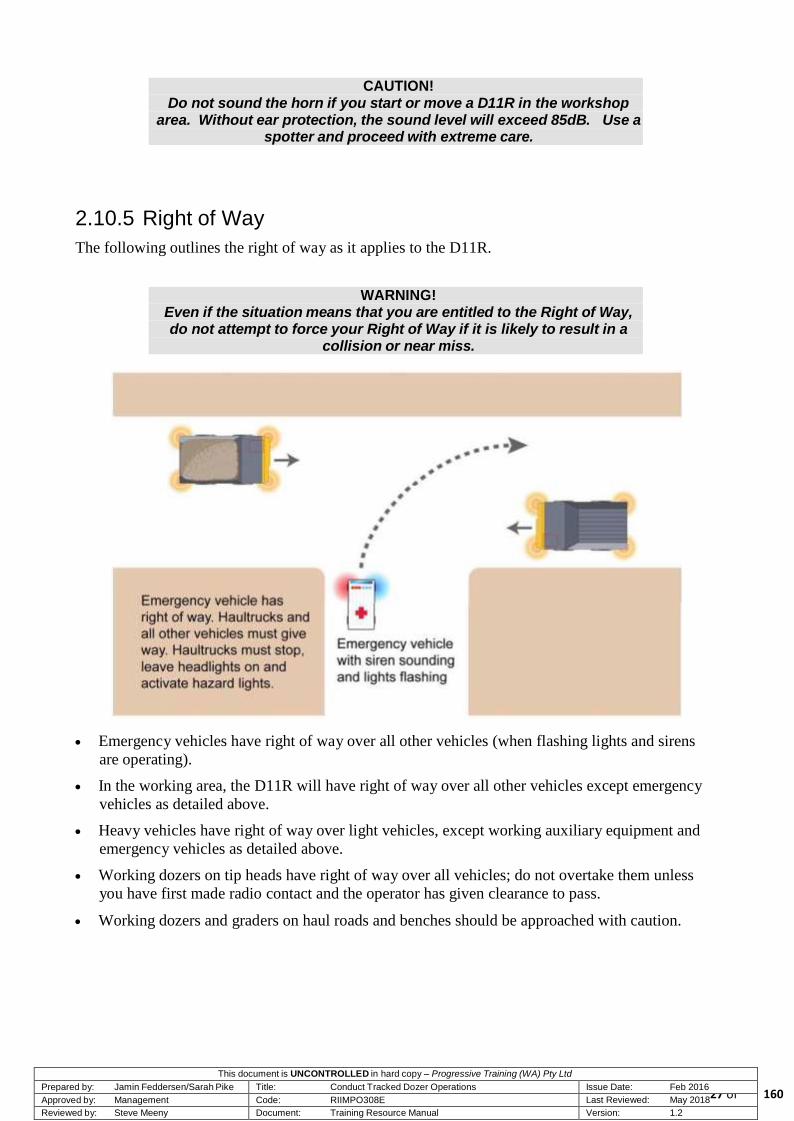
2.10.5 Right of Way
The following outlines the right of way as it applies to the D11R.
WARNING!
Even if the situation means that you are entitled to the Right of Way, do not attempt to force your Right of Way if it is likely to result in a
collision or near miss.
Emergency vehicles have right of way over all other vehicles (when flashing lights and sirens
are operating).
In the working area, the D11R will have right of way over all other vehicles except emergency
vehicles as detailed above.
Heavy vehicles have right of way over light vehicles, except working auxiliary equipment and
emergency vehicles as detailed above.
Working dozers on tip heads have right of way over all vehicles; do not overtake them unless
you have first made radio contact and the operator has given clearance to pass.
Working dozers and graders on haul roads and benches should be approached with caution.
160

This document is UNCONTROLLED in hard copy – Progressive Training (WA) Pty Ltd Prepared by: Jamin Feddersen/Sarah Pike Title: Conduct Tracked Dozer Operations Issue Date: Feb 2016 Approved by: Management Code: RIIMPO308E Last Reviewed: May 2018
28 of Reviewed by: Steve Meeny Document: Training Resource Manual Version: 1.2
NOTE! Where signage defines Right of Way it overrides these rules, except for the Right of Way of emergency vehicles with flashing lights and
sirens sounding.
2.10.6 Road Works
Operators must approach roads that are under repair or maintenance work with caution. Obey all
warning and instruction signs that indicate the presence of unsafe conditions.
It is important that operators obey speed signs and other advisory signs in road work areas.
Operators are to make positive communication with the unit in charge and proceed only when
permission is granted.
Road works that have already commenced will be mentioned at pre-shift communications. Details
of units working these areas will be provided for making positive communication. A radio
communication will be relayed to the mobile equipment operator if road works commence during
the shift.
Operators must stay alert when driving through road works zones because speed limits can change
very quickly.
Operators who are required to pass through a roadwork area must:
reduce speed
make positive communication with unit in charge of roadwork area
observe and obey all signage
proceed only when permission is given
remain vigilant when passing through road works area.
2.10.7 Spotting
At times, there will be a need to operate the Caterpillar D11R in restricted spaces. At these times, a
spotter may be required to assist the operator to safely negotiate the restricted space. The following
rules should be observed with respect to spotting operations:
WARNING! Spotting is potentially hazardous. Both the mobile equipment
operator and the spotter must exercise extreme care throughout the manoeuvre. If the operator loses sight of the spotter during the manoeuvre, he/she must immediately halt until contact with the
spotter is restored.
Spotting from the ground should only be carried out when absolutely necessary.
The spotter may instruct the mobile equipment operator by radio or with hand signals.
160

This document is UNCONTROLLED in hard copy – Progressive Training (WA) Pty Ltd Prepared by: Jamin Feddersen/Sarah Pike Title: Conduct Tracked Dozer Operations Issue Date: Feb 2016 Approved by: Management Code: RIIMPO308E Last Reviewed: May 2018
29 of Reviewed by: Steve Meeny Document: Training Resource Manual Version: 1.2
The operator must obey all instructions given by the spotter. The spotter is effectively in
control of the equipment.
The spotter must be in clear view of the operator at all times.
The operator must be in clear view of the spotter at all times
The spotter must remain at a safe distance from the truck at all times.
The operator must immediately stop the mobile equipment if the spotter is no longer visible.
When the spotting operation is complete, there must be ‘positive communication’ between the
operator and the spotter which informs the operator that the spotter is no longer in control.
2.10.8 Reduced/Obscured Vision
When operating the Caterpillar D11R your all-around vision is restricted due to the cabin’s height
above the ground and the structure of the machine. This means that the operator does not have
good vision around a large part of the machine from the operator’s position.
This in turn results in blind spots where other equipment and personnel are hidden from the
operator’s line of vision. All personnel operating either the D11R or other mobile equipment must
be constantly aware of the lack of visibility and operate in accordance with these limitations.
If you are uncertain as to what may be in your blind spot/s, stop the D11R and visually check the
area before proceeding.
2.11 Adverse Operating Conditions
During day-to-day D11R operation, you will experience adverse operating conditions that affect the
handling of your vehicle. These include:
wet conditions
dust
fog
unstable or uneven ground.
To maintain safe dozing operations, you must be aware of these hazards and the techniques used to
overcome and/or avoid them.
160

This document is UNCONTROLLED in hard copy – Progressive Training (WA) Pty Ltd Prepared by: Jamin Feddersen/Sarah Pike Title: Conduct Tracked Dozer Operations Issue Date: Feb 2016 Approved by: Management Code: RIIMPO308E Last Reviewed: May 2018
30 of Reviewed by: Steve Meeny Document: Training Resource Manual Version: 1.2
Operating in Dusty Conditions
2.11.1 Wet Conditions
Two main problems will be created through rain. Obviously the ground surface will become
slippery, traction will decrease and water may accumulate. Adequate water management strategies
will enable safe operating to continue but you should always be aware of problems such as:
boggy and soft ground
slippery ramp and haul road surfaces
loss of traction caused by undermining of haul roads and /or the pit floor
reduced visibility due to rain.
In addition, the accumulation of mud on cabin glass areas can drastically reduce visibility and
operating safety. Even normal levels of dust raised by the grading operation will combine with wet
glass areas and reduce visibility. Serviceability of windshield washing equipment is critical. To
maintain good visibility throughout the shift, you must ensure:
windshield wipers are in a serviceable condition with good wiper blades
the windshield washer is working correctly
the windshield washer water bottle is full at the start of each shift.
When operating in wet conditions you should adopt the following strategies to ensure that
operations continue in a safe and efficient manner:
Request the grading of haul roads and ramps to remove wet and sticky surfaces.
When operating near a high wall, always inspect the edge for undercutting, especially where
water has been flowing.
160

..
• Ensure that pit dewatering systems are
operating correctly.
• Reduce speed and increase vehicle
separation distances in wet and rainy
conditions.
This document is UNCONTROLLED in hard copy - Progressive Training (W A) Pfy Ltd
Prepared by: Jamin Feddersen/Sarah Pike I Title: Conduct Tracked Dozer Operations I lssue Date: Feb 20J...6
Approved by: Management I Code: RIIMP030BE I Last Reviewed: May 201S"'"'--
Reviewed by: Fir st Version I Document: Training Resource Manual I Version: 1.2
160

This document is UNCONTROLLED in hard copy – Progressive Training (WA) Pty Ltd Prepared by: Jamin Feddersen/Sarah Pike Title: Conduct Tracked Dozer Operations Issue Date: Feb 2016 Approved by: Management Code: RIIMPO308E Last Reviewed: May 2018
32 of Reviewed by: Steve Meeny Document: Training Resource Manual Version: 1.2
2.11.2 Dust
You will encounter dusty conditions during D11R operations. All movements and operations of
mobile equipment will tend to raise dust. Dust will also be generated when there is significant
wind.
Regardless of how dust is generated, dusty conditions mean reduced visibility and increased
potential for accident or injury.
Adopt the following techniques to help in the management of the hazards created by dust:
Notify water truck operators of dusty conditions in the operational areas and request surface
watering.
Maximise your visibility by keeping the operator’s cab glass clean and free of debris.
2.11.3 Fog
During night and early morning shifts, fog may cause visibility problems. Visibility can be further
reduced by the addition of dust.
Observe the following points when operating in fog:
Ensure that all windows are clean.
Ensure that all lights on the water truck are serviceable, clean and turned on.
Use the two-way radio for positive communications when interacting with other items of mobile
equipment.
2.11.4 Unstable or Uneven Ground
Unstable or uneven ground conditions occur in the pit, along the haul road or at the dump face.
Always be on the lookout for unstable surfaces. Uneven or unstable ground can easily cause an
operator to momentarily lose control of equipment. In extreme circumstances, an unstable or
uneven surface can cause a rollover.
Adopt the following strategies when operating on unstable or uneven ground:
Avoid soft areas that may collapse under the weight of the machine.
Do not attempt to operate the machine in conditions where the cross or transverse gradient is
approaching 8% (a ratio of less than 1 in 12.5). This figure will be lower if the ground is
uneven in addition to the cross slope.
160

This document is UNCONTROLLED in hard copy – Progressive Training (WA) Pty Ltd Prepared by: Jamin Feddersen/Sarah Pike Title: Conduct Tracked Dozer Operations Issue Date: Feb 2016 Approved by: Management Code: RIIMPO308E Last Reviewed: May 2018
33 of Reviewed by: Steve Meeny Document: Training Resource Manual Version: 1.2
2.12 Night/Low Light Operations
Reduced visibility is an additional hazard
during night or low light operations.
During night or low light operations, you
must exercise a greater level of caution than
you would during daylight operations.
In addition to a decrease of visibility and
the reduction of the effectiveness of
personal vision, further hazards are created
by reflected or scattered light and shadows
which can occur at night or during low light
conditions.
2.12.1 Shift Change-Over
Operating at Night
Operators must ensure that they have a clear understanding of the operational tasks and changed
conditions for their shift. In addition, they must maintain communication with supervision and pit
control throughout the night.
During shift changeovers, the issues detailed below must be considered by the outgoing shift and
communicated to the incoming shift. This is particularly important for the incoming night shift:
ramp/road closures and conditions
designated movement routes
general hazards and conditions in work area
location of dumps to be used
locations of equipment
location of any ‘sleeping shots’ and their boundaries
ancillary equipment operating in or around each work area.
160

This document is UNCONTROLLED in hard copy – Progressive Training (WA) Pty Ltd Prepared by: Jamin Feddersen/Sarah Pike Title: Conduct Tracked Dozer Operations Issue Date: Feb 2016 Approved by: Management Code: RIIMPO308E Last Reviewed: May 2018
34 of Reviewed by: Steve Meeny Document: Training Resource Manual Version: 1.2
2.12.2 Night Inspections
As in day shift, equipment inspections are a very important part of the operator’s job. Carry and use
a flashlight to assist in conducting pre-start inspections and/or walk-around checks. Ensure that
your own PPE is provided with the correct high-visibility striping or that you are wearing a high-
visibility vest.
REMEMBER!
Other personnel are working with the same reduced visibility that you are so make sure that you can be easily seen.
When conducting checks and inspections, you must pay particular attention to the following for
night operations:
Carry out careful checks on all vehicle operational, working and beacon lights.
Ensure that all lights are:
- clean
- aimed correctly
- functioning correctly
Have any unserviceable lights repaired before commencing operation.
Conduct a thorough walk around check of the vehicle
2.12.3 Movement at Night
Operators must take extra care when moving off and driving at night. Blind spots and areas of
shadow around other equipment items can be particularly hazardous. Consideration should be
given to the following:
Move carefully in the pit and dump areas and maintain adequate clearance from other vehicles.
Be courteous in your driving at all times.
Give ample warning to other vehicles and avoid making sudden changes of direction at night.
It is good operating practice to check around the vehicle before commencing operation after crib
breaks. Check and clean any lights that have become dirty or obscured.
the same speed limits apply at night as during daylight hours, you will need to adjust your
speed according to conditions.
When shutting the machine down at the end of the shift, all of the normal shutdown procedures
must be observed. Remember to switch off the lights to avoid discharging the batteries.
160

This document is UNCONTROLLED in hard copy – Progressive Training (WA) Pty Ltd Prepared by: Jamin Feddersen/Sarah Pike Title: Conduct Tracked Dozer Operations Issue Date: Feb 2016 Approved by: Management Code: RIIMPO308E Last Reviewed: May 2018
35 of Reviewed by: Steve Meeny Document: Training Resource Manual Version: 1.2
2.12.4 Poor Light Quality
There are additional hazards caused by light quality. These can include such times as:
dusk
dawn
low light
changing light
approaching storms, etc.
Similar difficulties may be experienced when equipment items approach each other or when
approaching areas lit by mobile lighting towers.
CAUTION!
Never look directly into the lights of oncoming mobile equipment, mobile lighting towers or the sun when it is low on the horizon.
You may be able to minimise the effects of unwanted light or poor light quality by using the
following techniques:
reposition the equipment items in order to reduce light coming into the cab or mirrors
reposition lighting plant if it is interfering with your vision
learn the location of hazardous shadowed areas
keep all windows and glass clean — ensure that any cracked glass replaced as soon as possible.
2.12.5 Headlights
Headlights are to be used at all times, day and night. Even if you think visibility is satisfactory for
you, others may not be able to see you.
Eyes take a few moments to recover from the dazzling lights of an oncoming vehicle. Never look
directly into a light source while operating or approaching another equipment item.
Adjust your mirrors to a position where light from the rear will not shine directly into your eyes. If
another operator fails to use his/her lights in a courteous manner, do not retaliate. If you are
followed by a person who has failed to dip the headlights, try a call on the radio or alternatively
move over and let that equipment pass.
160

This document is UNCONTROLLED in hard copy – Progressive Training (WA) Pty Ltd Prepared by: Jamin Feddersen/Sarah Pike Title: Conduct Tracked Dozer Operations Issue Date: Feb 2016 Approved by: Management Code: RIIMPO308E Last Reviewed: May 2018
36 of Reviewed by: Steve Meeny Document: Training Resource Manual Version: 1.2
2.12.6 Light and Dark Environments
Operators will face additional hazards when making the transition between light and dark operating
environments. Operators moving from well-lit pit areas onto dark, unlit haul roads and back into
brightly lit operational areas will suffer temporary reductions in vision.
In dark conditions the pupils of the eyes are wide open in order to allow as much light as possible
through the lens and through to the back of the eye. Following sudden exposure to bright light (eg,
on-coming vehicle, working lights, in-cab lights) and then a return to darkness, the iris of the eye
can take between 4 to 7 seconds to correct for the changes. An operator dazzled by light while
travelling in a vehicle or mobile equipment at 40 kmh will travel 45 to 78 metres virtually
completely blind. The hazards of misusing headlights in any circumstances are self-explanatory.
CAUTION!
Avoid working and driving with internal operators cabin lights on while driving.
REMEMBER!
As far as possible, limit the number of transitions you need to make from light to dark and from dark to light.
2.13 Visual Cues
During daylight driving or equipment operations, ninety percent of the driver’s or operators
decisions are based on visual cues. Visual cues come from:
depth perception
colour recognition
distance identification
contrast perception
peripheral vision.
In adverse conditions, low light or dark environments, the clarity of each of these visual cues is
significantly reduced. To counter this additional hazard, all operators should:
operate with greater caution in adverse conditions or poor light
reduce speed to suit the conditions and your own abilities and physical limitations
take more care over decisions and manoeuvres — think through
if you are not sure that a manoeuvre is safe, don’t do it.
160
This document is UNCONTROLLED in hard copy – Progressive Training (WA) Pty Ltd Prepared by: Jamin Feddersen/Sarah Pike Title: Conduct Tracked Dozer Operations Issue Date: Feb 2016 Approved by: Management Code: RIIMPO308E Last Reviewed: May 2018
37 of Reviewed by: Steve Meeny Document: Training Resource Manual Version: 1.2
2.13.1 Medical Conditions — Eyesight
If you have any eye conditions which make it difficult for you to
operate at night, you should inform your supervisor. You may need to
see an eye-care professional in order to obtain a diagnosis and
approach to dealing with the issue.
WARNING! Do not undertake night operations if you have any night-vision difficulties. Inform your supervisor
immediately.
2.13.2 Fatigue on Night Shift
Operator fatigue at any time is a hazard which can lead to equipment incidents. For personnel who
are working nights, disrupted sleep patterns can mean there is more of a likelihood of fatigue
becoming a problem.
IMPORTANT!
All operators have a duty of care to ensure that they have had adequate rest before coming onto shift.
Operators should be vigilant for any symptoms of fatigue. These will vary from person to person
but may include any, some or all of the following:
yawning
poor concentration
tired or sore eyes
restlessness
drowsiness
slow reactions
boredom
feeling irritable
making fewer and larger steering corrections
irrational speed control (unnecessary speed variations)
missing/ignoring signage
lane-wandering — having difficulty in staying in the lane or on the road
micro sleeps.
An operator suffering fatigue may experience any of the following:
reduced vigilance
160

This document is UNCONTROLLED in hard copy – Progressive Training (WA) Pty Ltd Prepared by: Jamin Feddersen/Sarah Pike Title: Conduct Tracked Dozer Operations Issue Date: Feb 2016 Approved by: Management Code: RIIMPO308E Last Reviewed: May 2018
38 of Reviewed by: Steve Meeny Document: Training Resource Manual Version: 1.2
impaired decision making
reduced reaction time
poor emotional state
poor motivation.
The hours between 3:00 am and 5:00 am and between 3:00 pm and 5:00 pm are the times when
fatigue is most likely to set in. However, this does not rule out fatigue at other times throughout the
day.
If you become aware of that you are feeling any of the symptoms above, you may be suffering
fatigue. In such a case, you must assess your condition and take immediate action in order to
maintain safety on site. This will generally mean that you need to contact your supervisor and
asked to be relieved due to fatigue.
WARNING!
In some cases, fatigue can impair a person’s judgment and performance as much as an alcohol reading at twice the legal limit.
2.13.3 Causes of Fatigue
There are three main causes of fatigue. These are:
inadequate or disrupted sleep
physical exertion
mental exertion.
Inadequate or Disrupted Sleep
If your sleep is shortened or disrupted to the point where you are not getting your regular sleep
requirement, you will accumulate a sleep debt. Sleep debt will cause you to feel fatigued and lead
to the symptoms described above. Disrupted sleep may be caused by a number of issues, including:
excessive intake of caffeine (especially before bedtime)
excessive intake of alcohol
excessive intake of nicotine
poor sleeping environment (too much light, noise, etc)
personal stress
poor eating habits (a large meal just before bedtime will disrupt sleep)
too little exercise.
160

This document is UNCONTROLLED in hard copy – Progressive Training (WA) Pty Ltd Prepared by: Jamin Feddersen/Sarah Pike Title: Conduct Tracked Dozer Operations Issue Date: Feb 2016 Approved by: Management Code: RIIMPO308E Last Reviewed: May 2018
39 of Reviewed by: Steve Meeny Document: Training Resource Manual Version: 1.2
2.13.4 Physical Exertion
Fatigue resulting from physical exertion will generally occur when a person has been engaged in
heavy manual work, perhaps in adverse conditions (extremes of cold or heat). Fatigue in these
cases is a natural result of the body’s energy resources being used up and the need for sleep to
recuperate — the person’s body is genuinely exhausted. If you are not in sleep debt and have a
reasonably healthy lifestyle, physical exertion is unlikely to be a factor in the fatigue of operators.
2.13.5 Mental Exertion
Extreme mental exertion is the result of continued levels of high concentration or high levels of
stress and a range of other mental inputs. It is important for everybody to learn to recognise what is
likely to cause them to become mentally fatigued and to learn how to combat its onset. In other
words, persons who suffer high levels of mental exertion leading to fatigue may need to learn how
to relax or ‘switch off’ at appropriate times.
2.13.6 Fatigue Prevention
The prevention of fatigue in the first place is a much safer, more efficient and effective way of
managing fatigue than trying to deal with it once it has occurred. Accordingly, it is each person’s
responsibility to ensure that they arrive for each shift in a refreshed state ready to carry out a full
shift of work.
The following points provide some of the key issues in preventing fatigue in the workplace:
Make sure your activities outside of working hours do not affect your ability to present for each
shift in a fit-for-work state.
Maintain a healthy lifestyle and ensure that you have a balanced and nutritious diet.
Ensure that you are regularly getting the right amount of sleep for your own needs — avoid
accumulating a sleep debt.
Ensure you correctly manage your intake of products that are likely to cause disrupted sleep
(caffeine, alcohol, nicotine, etc) so that your sleep time is effective.
Maintain your hydration levels throughout the day. Dehydration will cause tiredness and loss of
concentration.
If you frequently feel tired or sleepy, consider seeking medical advice.
Ensure that you know the effects of any prescription medication you are taking. If you know
that a prescription medication has the potential to make a person drowsy, report the situation to
your supervisor at the beginning of the shift.
WARNING!
Never operate any equipment item if you have any reason to believe that you may be significantly fatigued.
160

This document is UNCONTROLLED in hard copy – Progressive Training (WA) Pty Ltd Prepared by: Jamin Feddersen/Sarah Pike Title: Conduct Tracked Dozer Operations Issue Date: Feb 2016 Approved by: Management Code: RIIMPO308E Last Reviewed: May 2018
40 of Reviewed by: Steve Meeny Document: Training Resource Manual Version: 1.2
The only cure for fatigue is sleep. Using such methods as drinking, increasing air flow through a
vehicle, turning on the radio, face washing, etc, may work for a very short while but will not
overcome fatigue or sleep debt in the longer term.
It is mandatory to report the occurrence of any operator fatigue to your supervisor. This is a
measure aimed at eliminating the potential for fatigue-related incidents from the site rather than a
method for implementing disciplinary measures.
REMEMBER! Do not avoid making a report of your own fatigue. You may save your
life or the life of one of your work-mates.
2.14 General Tips for Night Operations
The following tips summarise most of the points of the information provided above:
In adverse conditions or when operating at night, you rely on driving and working lights.
Ensure that all lights function correctly and are kept clean.
Make sure that the operator’s cab glass is kept clean and in good condition.
Ensure that mirrors are correctly adjusted for night operations.
Maintain high levels of vigilance during night operations especially when reversing and turning
into off-side corners.
Where necessary, use a spotter to assist with positioning the machine. Always use the correct
spotting procedures.
Wide spread lighting should be used in open areas to minimise the effects of shadows and
maximise visibility. Position lighting plants to illuminate potentially hazardous areas.
Always assume that other operators are affected by similar visibility limitations.
Approach shadowed areas with caution.
Maintain greater separation distances from other equipment than you would during the day.
Lookout for headlights and tail lights of other vehicles.
Avoid sudden stops or changes of direction.
Try to remain in areas with which you are already familiarised.
160

This document is UNCONTROLLED in hard copy – Progressive Training (WA) Pty Ltd Prepared by: Jamin Feddersen/Sarah Pike Title: Conduct Tracked Dozer Operations Issue Date: Feb 2016 Approved by: Management Code: RIIMPO308E Last Reviewed: May 2018
41 of Reviewed by: Steve Meeny Document: Training Resource Manual Version: 1.2
2.15 General Safety Equipment
A range of safety equipment is used around the mine. You must ensure that you are aware of the
equipment and its purposes in the mine. If you encounter signage, demarcation tape, witches hats
or other control measures, do not proceed past them until you find out their purpose. If you cannot
determine their purpose, contact your supervisor or mine control.
2.15.1 Barricades
A variety of barricades and demarcation tapes are used on the site to separate work
(e.g. excavations) from operational areas, and to inform workers of potential danger.
The use of barricades and tapes is subject to conditions, including the following:
barricades must be checked by a supervisor on every shift
permission is required from the department head for continuing placement of tapes that have
been installed for in place longer than 48hrs
barricades left in position overnight must be illuminated
when star pickets are used, they must have yellow caps on the protruding ends
information tags must be attached to all barricades
supports must not be more than 10 metres apart
barricades and tapes must be immediately removed when no longer necessary.
2.15.2 Hazard and Danger Tapes
Hazard tape is used to isolate an area. It must
be:
accompanied by a Personal Danger/Out of
Service Tag detailing the nature of the
hazard
tagged in the name of the person who can
grant authorisation to proceed into the
tagged area.
Samples of Hazard Tape
160

This document is UNCONTROLLED in hard copy – Progressive Training (WA) Pty Ltd Prepared by: Jamin Feddersen/Sarah Pike Title: Conduct Tracked Dozer Operations Issue Date: Feb 2016 Approved by: Management Code: RIIMPO308E Last Reviewed: May 2018
42 of Reviewed by: Steve Meeny Document: Training Resource Manual Version: 1.2
2.15.3 Tagging
The purpose of tagging is to place an administrative barrier between potential sources of harm and a
person who may be exposed to this source of harm.
The tagging system is designed to protect people and equipment by identifying equipment or areas
that have the potential to cause harm.
Four types of tags commonly in use are:
Personal Danger Tags — are for the protection of the individual. They indicate that a person is
working in a location or on equipment in which they would be in danger if equipment were to be
started or moved. Never start or move an item of equipment if it is under the protection of a
Personal Danger Tag. Only the person who placed the Personal Danger Tag is permitted to
remove it.
Danger Tag Example
Out of Service Tags — any person may place an Out of Service Tag on any item of equipment
that is faulty or unsafe to use. Do not start or operate an item of equipment of equipment which
has an Out of Service Tag attached. Only a person qualified to repair the equipment can remove
an Out of Service Tag once it has been placed.
160

This document is UNCONTROLLED in hard copy – Progressive Training (WA) Pty Ltd Prepared by: Jamin Feddersen/Sarah Pike Title: Conduct Tracked Dozer Operations Issue Date: Feb 2016 Approved by: Management Code: RIIMPO308E Last Reviewed: May 2018
43 of Reviewed by: Steve Meeny Document: Training Resource Manual Version: 1.2
Out of Service Tag Example
Isolation Tags — identifies equipment that is isolated or partially isolated and which is
currently being worked on by maintenance personnel who may need to conduct ‘live testing’.
Only the person whose name is on the tag is permitted to start or move the equipment for the
purposes of live testing.
Isolation Tag Example
Information Tags — provide information that is important for the operator. Information
tags may provide information such as changed operating conditions or identifying non-critical
components that are temporarily out of service. Any person may place an Information Tag and
any person may remove it once the information provided is no longer current.
Information Tag Example
160

This document is UNCONTROLLED in hard copy – Progressive Training (WA) Pty Ltd Prepared by: Jamin Feddersen/Sarah Pike Title: Conduct Tracked Dozer Operations Issue Date: Feb 2016 Approved by: Management Code: RIIMPO308E Last Reviewed: May 2018
44 of Reviewed by: Steve Meeny Document: Training Resource Manual Version: 1.2
2.16 Fire Extinguishers and Suppression Systems
Most earthmoving machines will be fitted with fire extinguishers and fire suppression systems. It is
a prestart requirement that all extinguishers are fully charged and within the inspection period. The
fire suppression system must be tested as part of the daily prestart.
2.16.1 Fire Extinguishers
The use of fire extinguishers is governed by the following:
Fire extinguishers are to be used for their intended purpose only; there are no exceptions to this
rule. Disciplinary action will be taken against any person tampering with or misusing fire
fighting equipment.
Tag Out faulty extinguishers.
Do not operate any item of equipment if it is not fitted with a fully operational fire extinguisher.
Do not use a fire extinguisher to fight a fire unless you are sure that it is safe to do so.
Once a fire extinguisher has been discharged, it should be laid on the ground and its use
reported to your supervisor or the health and safety officer.
The common types of fire extinguisher are detailed below:
160

This document is UNCONTROLLED in hard copy – Progressive Training (WA) Pty Ltd Prepared by: Jamin Feddersen/Sarah Pike Title: Conduct Tracked Dozer Operations Issue Date: Feb 2016 Approved by: Management Code: RIIMPO308E Last Reviewed: May 2018
45 of Reviewed by: Steve Meeny Document: Training Resource Manual Version: 1.2
2.16.2 Fire Suppression Systems
The suppression system will be automatically activated in the event that there is a fire in the engine
bay. If a fire is detected prior to the automatic activation, the fire suppression system can be
manually activated either from within the cab or from ground level. Further details of the fire
suppression system are provided in the later topic on equipment introduction.
2.17 Housekeeping
Housekeeping is an important part of ensuring that safety is maintained in the operation of the
D11R. Remember to clean up as you go:
remove all spillage of oils, grease or other materials from walkways, catwalks and access
ladders
do not allow rubbish to accumulate in the operator’s cabin because it can easily interfere with
the safe operation of the equipment
do not allow dirt and mud to accumulate in the cab
ensure that the instruments and controls are kept free of dust build-up.
160

This document is UNCONTROLLED in hard copy – Progressive Training (WA) Pty Ltd Prepared by: Jamin Feddersen/Sarah Pike Title: Conduct Tracked Dozer Operations Issue Date: Feb 2016 Approved by: Management Code: RIIMPO308E Last Reviewed: May 2018
46 of Reviewed by: Steve Meeny Document: Training Resource Manual Version: 1.2
When cleaning the faces of instruments, take care not to scratch the surface of the instrument glass.
Repeatedly scratched glass will eventually become opaque and the instrument will become
unreadable.
REMEMBER! A good rule of thumb is to leave the equipment and the operator’s
cabin in the condition you would wish to find it.
2.18 Summary
This topic has provided information on safety in the mining environment. It is important that you
use the information above in conjunction with the knowledge of safety issues that you have gained
from your inductions and from obtaining your Pit Permit. Working safely requires a certain frame
of mind. You must always make sure you are working with the right frame of mind and that safety
is your main consideration.
160

This document is UNCONTROLLED in hard copy – Progressive Training (WA) Pty Ltd Prepared by: Jamin Feddersen/Sarah Pike Title: Conduct Tracked Dozer Operations Issue Date: Feb 2016 Approved by: Management Code: RIIMPO308E Last Reviewed: May 2018
47 of Reviewed by: Steve Meeny Document: Training Resource Manual Version: 1.2
Topic 3 — Equipment Introduction
3.1 Introduction — Know Your Machine
All candidates are required to read the D11R Operations and Maintenance Manual. Information in
this topic will assist you in identifying the dozers general arrangements, main mechanical
components and operating systems. You will also gain an understanding of the dozer’s performance
capabilities and limitations.
Caterpillar D11R Dozer
160

This document is UNCONTROLLED in hard copy – Progressive Training (WA) Pty Ltd Prepared by: Jamin Feddersen/Sarah Pike Title: Conduct Tracked Dozer Operations Issue Date: Feb 2016 Approved by: Management Code: RIIMPO308E Last Reviewed: May 2018
48 of Reviewed by: Steve Meeny Document: Training Resource Manual Version: 1.2
3.2 Technical Specifications
Item Specification
Engine
Gross Power 698kW — 935 hp
Net Power 634kW — 850 hp
Rated Power 1800rpm
Engine model Cat 3508B EUI diesel
Bore 170 mm
Stroke 190 mm
Displacement 34.5 L
Number of cylinders 8
Weight
Operating weight (all blades) 100, 573 kg (min) — 104,590 kg (max)
Sealed and Lubricated Track
Pitch 318 mm
Number shoes/side 41
Shoe type Extreme service
Width of shoe 710 mm
Length of track on ground 4444 mm
Ground contact area 6.3 m2
Ground height (from ground face of shoe) 102 mm
Ground clearance 623 mm
Gauge 2896 mm
Service Refill Capacity
Fuel tank 1609 L
Cooling system 238.8 L
Engine crankcase 106 L
Power train 344 L
Final drives (each) 30 L
Roller frames (each) 95 L
Pivot shaft compartment 51 L
Implement hydraulic system (tank only) 227.8 L
160

This document is UNCONTROLLED in hard copy – Progressive Training (WA) Pty Ltd Prepared by: Jamin Feddersen/Sarah Pike Title: Conduct Tracked Dozer Operations Issue Date: Feb 2016 Approved by: Management Code: RIIMPO308E Last Reviewed: May 2018
49 of Reviewed by: Steve Meeny Document: Training Resource Manual Version: 1.2
3.3 Dozer Dimensions
Cat D11R Dozer Dimensions
Item Specification
Overall length 10.820 m
Front canopy height 4.660 m
Height to ROPS 4.400 m
Height to exhaust 4.550 m
Overall width 6.360 m
Width to outside tracks 3.660 m
Blade capacity (all blades) 27.23 m — 34.43 m
Blade width (all blades) 5.6 m — 6.3 m
Blade height 2.3 m — 2.8m
Digging depth .76 m
Ground clearance 1.5 m
Maximum tilt 1.18 m — 1.34 m
Blade weight 14, 813 kg — 18,823 kg
Single-shank ripper 1.85 m
Single-shank ripper with push block 2.2 m
Multi-shank ripper 2.19 m
Width over trunnions 4.36 m
Drawbar height (centreline of clevis) from
ground face of shoe
.77 m
160

This document is UNCONTROLLED in hard copy – Progressive Training (WA) Pty Ltd Prepared by: Jamin Feddersen/Sarah Pike Title: Conduct Tracked Dozer Operations Issue Date: Feb 2016 Approved by: Management Code: RIIMPO308E Last Reviewed: May 2018
50 of Reviewed by: Steve Meeny Document: Training Resource Manual Version: 1.2
3.4 Caterpillar D11R Overview
The following section provides a brief description of the main components of the Caterpillar D11R
dozer.
Cat D11R Front Profile Blade
Cat D11R Right Side Profile
160

This document is UNCONTROLLED in hard copy – Progressive Training (WA) Pty Ltd Prepared by: Jamin Feddersen/Sarah Pike Title: Conduct Tracked Dozer Operations Issue Date: Feb 2016 Approved by: Management Code: RIIMPO308E Last Reviewed: May 2018
51 of Reviewed by: Steve Meeny Document: Training Resource Manual Version: 1.2
Cat D11R Left Side Profile
Cat D11R Rear Profile
160

This document is UNCONTROLLED in hard copy – Progressive Training (WA) Pty Ltd Prepared by: Jamin Feddersen/Sarah Pike Title: Conduct Tracked Dozer Operations Issue Date: Feb 2016 Approved by: Management Code: RIIMPO308E Last Reviewed: May 2018
52 of Reviewed by: Steve Meeny Document: Training Resource Manual Version: 1.2
Cat D11R Track Close-up
3.5 Major Components
The following section provides a brief description of the major components of the Caterpillar D11R
Dozer. The D11R is fitted with a number of electrical and mechanical systems. You are required to
understand the basic operation of each system.
The systems include the following:
power unit
transmission
braking system
hydraulic system
steering system.
160

This document is UNCONTROLLED in hard copy – Progressive Training (WA) Pty Ltd Prepared by: Jamin Feddersen/Sarah Pike Title: Conduct Tracked Dozer Operations Issue Date: Feb 2016 Approved by: Management Code: RIIMPO308E Last Reviewed: May 2018
53 of Reviewed by: Steve Meeny Document: Training Resource Manual Version: 1.2
3.5.1 Power Unit
The D11R is powered by a 3508B-series turbo charged, after cooled diesel engine.
The engine has a displacement of 34.5 litres and provides power to all operating systems.
Several systems make up the power unit and enable the engine to operate. The systems are as
follows:
lubrication system
cooling system
fuel system
air inlet and exhaust system.
Lubrication System
The lubrication system stores 106 litres of oil for the engine. Oil is pumped from the sump, through
the filter to the oil cooler and into the main oil galleries. From here oil is sent to the camshaft and
crankshaft bearings and to the piston cooling jets. The rocker arms, valves, lifters and push rods are
supplied by subsidiary lines. After lubrication is supplied to the engine accessories, oil is returned
to the sump for recirculation.
There is a bypass valve in the cover of the oil pump which controls the pressure of the pump oil.
The pumps capacity is larger than the system requires and excess oil is returned via the valve to the
sump for recirculation.
When starting in cold conditions, the bypass valve responds to high oil viscosity in the filter and
will open to give immediate lubrication to all components. When the oil reaches operating
temperature and normal viscosity, the pressure difference forces the bypass valve to close allowing
a normal flow of oil through the filter system.
Cooling System
The two-pass cooling system stores 238.8 litres of coolant, it circulates coolant from the sectioned
bottom tank up through the cooling elements. The coolant circulates through the engine then the
heat exchanger and returned to the bottom tank. The cooling elements are individual core modules.
The Engine Control Module (ECM) regulates fan speed in response to engine temperature through a
hydraulic variable displacement pump.
Fuel System
The fuel system stores 1609 litres of diesel. Fuel is pumped from the tank through primary and
secondary fuel filters to the pump housing fuel manifold. A bypass valve keeps the fuel pressure at
a constant level and a bleed valve redirects excess fuel through a return line back to the tank.
The fuel injection pump is fed by the manifold reservoir and pushes fuel, at high pressure, through
the injection nozzle in the cylinder head. The fuel injector nozzle alters the flow of fuel to a fine
mist for combustion in the cylinder.
160

This document is UNCONTROLLED in hard copy – Progressive Training (WA) Pty Ltd Prepared by: Jamin Feddersen/Sarah Pike Title: Conduct Tracked Dozer Operations Issue Date: Feb 2016 Approved by: Management Code: RIIMPO308E Last Reviewed: May 2018
54 of Reviewed by: Steve Meeny Document: Training Resource Manual Version: 1.2
The fuel injection pump responds to ECM input and increases or decreases the fuel pressure and
sends the exact amount of fuel to the fuel injection nozzle. There is one fuel injection pump for
each engine cylinder.
Air Inlet and Exhaust System
The air exhaust system supplies clean filtered air to the engine and discharges the burnt gases via
the exhaust system to atmosphere.
3.5.2 Transmission
Planetary Power Shift Transmission has three forward speeds, three reverse speeds and one neutral
position, it utilizes large diameter, high-capacity oil-cooled clutches. The transmission gears are
selected by the operator using the electronically operated Finger Tip control levers.
D11R Gear Speeds
The maximum travel speeds for gear selections are:
Gear
Speed in Km/h
Forward 1st 3.9
Forward 2nd 6.8
Reverse 1st 4.7
Reverse 2nd 8.2
3.5.3 Braking System
The D11R is fitted with a service brake, park brake and steering brake. All brakes are electronically
controlled from the operator cabin. The drums are constructed from ribbed cast metal and centred
on tapered roller bearings.
3.5.4 Hydraulic System
The hydraulic system on board the D11R provides power to operate the blade and ripper rams and
pin release on the ripper tyne.
3.5.5 Steering System
The dozer is fitted with an electronic clutch and brake (ECB) steering system. The system consists
of two small levers which send signals that control the steering valve. The steering valve requires
less then 3 pounds of pull to actuate.
160

This document is UNCONTROLLED in hard copy – Progressive Training (WA) Pty Ltd Prepared by: Jamin Feddersen/Sarah Pike Title: Conduct Tracked Dozer Operations Issue Date: Feb 2016 Approved by: Management Code: RIIMPO308E Last Reviewed: May 2018
55 of Reviewed by: Steve Meeny Document: Training Resource Manual Version: 1.2
3.6 VIDS Message Centre
The VIDS message centre displays operational parameters and warnings.
The VIDS consists of:
analog engine performance gauge cluster
action alarms
action lamps (there is also an action lamp to the rear far right of the operator’s seat)
VIDS display panel.
VIDS alerts the operator of an event or an immediate or impending problem in one or more of the
machine systems. The VIDS action lamp alerts the operator that an event in the system is present.
This lamp also indicates that diagnostic information is available for service personnel.
160

This document is UNCONTROLLED in hard copy – Progressive Training (WA) Pty Ltd Prepared by: Jamin Feddersen/Sarah Pike Title: Conduct Tracked Dozer Operations Issue Date: Feb 2016 Approved by: Management Code: RIIMPO308E Last Reviewed: May 2018
56 of Reviewed by: Steve Meeny Document: Training Resource Manual Version: 1.2
D11R Vital Intelligence Display System
D11R VIDS Keypad Directory
160

This document is UNCONTROLLED in hard copy – Progressive Training (WA) Pty Ltd Prepared by: Jamin Feddersen/Sarah Pike Title: Conduct Tracked Dozer Operations Issue Date: Feb 2016 Approved by: Management Code: RIIMPO308E Last Reviewed: May 2018
57 of Reviewed by: Steve Meeny Document: Training Resource Manual Version: 1.2
NOTE! An Active Event needs to be acknowledged with the OK Key before any other key can be used or recognised. The red LED lamp next to
the OK Key indicates a key has been activated.
160

This document is UNCONTROLLED in hard copy – Progressive Training (WA) Pty Ltd Prepared by: Jamin Feddersen/Sarah Pike Title: Conduct Tracked Dozer Operations Issue Date: Feb 2016 Approved by: Management Code: RIIMPO308E Last Reviewed: May 2018
58 of Reviewed by: Steve Meeny Document: Training Resource Manual Version: 1.2
VIDS consists of three display modules:
The Engine Performance Gauge Cluster consisting of four electronically driven analog gauges
which display:
engine coolant temperature
transmission oil temperature
fuel level
hydraulic oil temperature.
Speedometer/Tachometer Module includes:
analog tachometer
digital groundspeed readout
digital gear/direction readout.
3.6.1 Message Centre Module The message centre module provides a
variety of component and system
information through a universal analog
gauge and a digital message readout
display. A scroll function allows the
operator to view vital information on
multiple functions. Corresponding read outs
are displayed on the analog gauge with a
digital display of function name and status
on the message centre. This display will
also issue instructions to the operator.
Examples of system information are:
engine oil pressure, engine boost
pressure
power train oil temperature
engine temperature
main hydraulic pump pressure, blade
height
autoblade assist modes.
Message Centre
In standard operation, the first line of information in the message centre is status and the second line
of information is a selected gauge parameter. The alert indicator lamp is also located on the
message centre. It is activated by the main system module and flashes to indicate a serious or
critical abnormal condition.
160

This document is UNCONTROLLED in hard copy – Progressive Training (WA) Pty Ltd Prepared by: Jamin Feddersen/Sarah Pike Title: Conduct Tracked Dozer Operations Issue Date: Feb 2016 Approved by: Management Code: RIIMPO308E Last Reviewed: May 2018
59 of Reviewed by: Steve Meeny Document: Training Resource Manual Version: 1.2
An alert alarm is activated by the main module to sound when a critical abnormal condition exists.
The keypad allows access to diagnostic data recorded in the main monitoring system module and a
menu system which can tailor machine set-up preferences to an individual operator.
3.6.2 Keypad Module
The VIDS keypad module activates features at the touch of a key and provides accesses to the
settings menu.
The keypad allows the operator to access and acknowledge machine and system information
provided by VIDS, activate automatic dozer functions, access gauge values, customize factory
settings and change operator preferences on the message centre module. The easy-to-use keypad
works in conjunction with VIDS, allowing the operator to view details from alert messages for
assistance in diagnosis and fast troubleshooting.
The keypad consists of eight active keys that enable the operator to perform the following
functions:
Autoblade Assist Key activates auto-pitch function with an ON/OFF toggle switch and lights up
the indicator on the dashboard panel when enabled.
Float Key activates the float function with an ON/OFF toggle switch and lights up the indicator
on the dashboard panel when enabled.
Gauge Key accesses the message centre gauge analog parameter values.
Set Pitch Key changes preset blade and pitch angles for load, carry and dump segments of the
dozing cycle in conjunction with auto-pitch function.
Machine Set Key changes the preset dozer control response to either standard, fine or fast.
Menu Key changes the message centre preferences, views acknowledged and logged machine
events, accesses current machine statistics, shows dozer attachment options, views test display
and calibrates gauges.
Setup Key customizes settings for up to nine permanent operator ID accounts, saves shift
settings, recalls setup and clears changes.
Single Tilt Key changes the operating mode from dual tilt to single tilt for improved pryout
capability. The keypad also contains several utility keys used in conjunction with the function
keys:
OK Key allows the operator to accept a text prompt or menu choice.
Forward and Backward keys allow the operator to scroll through various levels of information
within a menu.
More Key allows the operator to view greater detail of an event, feature, or menu selection.
Cancel Key cancels the current menu selection and reverts back to the previous menu level.
160

This document is UNCONTROLLED in hard copy – Progressive Training (WA) Pty Ltd Prepared by: Jamin Feddersen/Sarah Pike Title: Conduct Tracked Dozer Operations Issue Date: Feb 2016 Approved by: Management Code: RIIMPO308E Last Reviewed: May 2018
60 of Reviewed by: Steve Meeny Document: Training Resource Manual Version: 1.2
3.6.3 Data and System Events
VIDS warns you about two types of events:
A ‘data event’ is a system operating outside its normal limits. An example of a data event is
HIGH HYD OIL TEMPERATURE.
VIDS can also diagnose problems within its own electrical system. These are called ‘system
events’. An example of a system event is ELECTRICAL SENSOR/SOLENOID.
If no events are indicated, the Message Centre displays Dozer Operating Status and System Hour
Meter on the first line and a selected Gauge Parameter label and value on the second line.
VIDS Warning Categories
When VIDS detects either a data or system event, it issues a warning. There are three categories of
warning.
Category Visual Alerts Explanation
Category 1 The red Alert Indicator flashes.
The message centre displays some explanatory text.
The machine needs attention.
Acknowledge by pressing the OK key on the keypad after reviewing the problem.
Category 2 Alert Indicator and the Action Lamp flash.
The message centre displays some explanatory text.
A change in machine operation is required to avoid possible damage to the indicated system.
Acknowledge by pressing the OK key on the keypad after reviewing the problem.
If the problem has not been corrected after a pre-set time delay, the message will reappear on the screen.
Category 3 Alert Indicator and the Action Light flash.
Action alarm sounds.
The message centre displays some explanatory text
You must immediately and safely shut down the machine to avoid injury to yourself or serious damage to the indicated system.
In most cases, you will not be able to silence the Action Alarm by pressing the OK key.
DANGER!
Do not operate the machine until the cause of the warning has been corrected.
Category 3 warnings also start the Event Recorder.
160

This document is UNCONTROLLED in hard copy – Progressive Training (WA) Pty Ltd Prepared by: Jamin Feddersen/Sarah Pike Title: Conduct Tracked Dozer Operations Issue Date: Feb 2016 Approved by: Management Code: RIIMPO308E Last Reviewed: May 2018
61 of Reviewed by: Steve Meeny Document: Training Resource Manual Version: 1.2
3.6.4 Dozer Operating Status Display
At any time, the VIDS Message Centre will display one of the following status messages:
Category Visual Alerts Explanation
Normal Operating Status
MANUAL
Manual operation of the dozer control.
FLOAT
Blade float is armed and activated.
STOWING RIP
Ripper is in the process of being stowed.
AutoBlade Assist (ABA) and AutoCarry Normal Operation Statuses
RESETTING
When the control is initially resetting the blade.
REDY TO CARY
Ready for the initial segment of the dozing cycle.
CARRY
Intermediate segment of the dozing cycle.
SPREAD
Final segment of the dozing cycle.
REDY TO RETN
After Spread, before going to Reverse.
BLD RESETTING
Resetting the Blade Height and Pitch while reversing.
RETURN
After blade resetting is complete, while still in a reverse gear.
Feature and Function Disabling Conditions
IMPLMT OFF
Implement Lockout Switch set to Implements Locked.
BLD LIFT ACT
Failed power up test — blade lift.
BLD TILT ACT
Failed power up test — blade tilt.
BLD PITCH ACT
Failed power up test — blade pitch.
RIP LIFT ACT
Failed power up test — ripper lift.
RIP I/O ACT
Failed power up test — ripper in/out.
ASTOW SW ACT
Failed power up test — Auto stow switch.
SERVICE MODE
Calibration procedure in progress.
160

This document is UNCONTROLLED in hard copy – Progressive Training (WA) Pty Ltd Prepared by: Jamin Feddersen/Sarah Pike Title: Conduct Tracked Dozer Operations Issue Date: Feb 2016 Approved by: Management Code: RIIMPO308E Last Reviewed: May 2018
62 of Reviewed by: Steve Meeny Document: Training Resource Manual Version: 1.2
Category Visual Alerts Explanation
LOW ENG SPD
Engine speed below 400 rpm for at least two seconds.
NOT RESET
Blade Pitch needs to be reset (see ABA section).
ASTOW OVERRIDE
Manual Ripper movement overrode Ripper AutoStow feature.
CC LOW SPD
The track speed is too low to start AutoCarry.
CC NOT IN 1F
Gear is not 1F when trying to active AutoCarry.
SVC BRK ACTIVE
Applying the Service Brake deactivated AutoCarry.
CARRY — CC OFF
In Carry when AutoCarry armed but not active.
CARRY — APF OFF
In Carry when AutoBlade Assist is armed but not active.
CC HYD OIL TEMP
High Hydraulic Oil Temp Condition when AutoCarry is active.
Feature and Function Disabling Conditions Requiring Service
ERR
Severe communication fault with the Implement ECM.
IMPLMNT SW ERR
All features and functions disabled due to Implement Lockout Switch fault.
LO VOLTAGE
All features and functions disabled due to Low ECM Voltage.
HI VOLTAGE
All features and functions disabled due to High ECM Voltage.
VIDS COMM ERR
VIDS ECM communication fault.
ENG COMM ERR
Engine ECM communication fault.
ECB COMM ERR
Powertrain ECM communication fault.
160

This document is UNCONTROLLED in hard copy – Progressive Training (WA) Pty Ltd Prepared by: Jamin Feddersen/Sarah Pike Title: Conduct Tracked Dozer Operations Issue Date: Feb 2016 Approved by: Management Code: RIIMPO308E Last Reviewed: May 2018
63 of Reviewed by: Steve Meeny Document: Training Resource Manual Version: 1.2
Category Visual Alerts Explanation
LIFT SNSRS ERR
Right and Left Lift Cylinder Sensor fault disabling
ABA’s AutoReturn and AutoSpread features.
TILT PRES ERR
Tilt Pump Pressure sensor fault.
MAIN PRES ERR
Main Pump Pressure sensor fault.
BLD CTRL ERR
Any Blade Control Handle (Tilt or Lift) fault disabling the ABA feature.
CTRL SW ERR
Any Blade Control Handle Switch fault disabling the ABA feature.
ABA SOL ERR
Any Solenoid fault disabling the ABA feature.
ASTOW SW ERR
AutoStow Switch fault disabling the Ripper AutoStow feature.
ASTOW SOL ERR
Any Solenoid fault disabling the Ripper AutoStow feature.
ASTOW TIMEOUT
Auto Ripper Raise or Shank In function took too long.
ASTOW CTRL ERR
Any Ripper Control Handle fault disabling the Ripper AutoStow feature.
BLD LIFT ERR
Any hardware fault disabling manual Blade Raise/Lower.
BLD TILT ERR
Any hardware fault disabling manual Blade Tilt.
BLD PITCH ERR
Any hardware fault disabling manual Blade Pitch.
RIP LIFT ERR
Any hardware fault disabling manual Ripper Raise/Lower.
RIP I/O ERR
Any hardware fault disabling manual Ripper Shank In/Out.
160

This document is UNCONTROLLED in hard copy – Progressive Training (WA) Pty Ltd Prepared by: Jamin Feddersen/Sarah Pike Title: Conduct Tracked Dozer Operations Issue Date: Feb 2016 Approved by: Management Code: RIIMPO308E Last Reviewed: May 2018
64 of Reviewed by: Steve Meeny Document: Training Resource Manual Version: 1.2
Category Visual Alerts Explanation
FLOAT HYD ERR
Any Deficiency in the pilot hydraulic supply causing float to kickout.
FLOAT SOL ERR
Solenoid fault disabling the blade float function.
CC DIS COMM ERR
Dynamic Inclination Sensor disabling the AutoCarry feature.
CC DIS COMM ERR
Dynamic Inclination Sensor disabling the AutoCarry feature.
CC SPD ERR
Ground Speed Sensor Fault disabling the AutoCarry feature.
3.6.5 D11R VIDS Gauge Categories and Parameter ID Numbers
The VIDS parameter ID numbers are listed in the following table.
ID #
Parameter
ID #
Parameter
100
Engine Speed
135
Engine Coolant Temp
102
Left Turbo Inlet Pressure
140
System Voltage
103
Right Turbo Inlet Pressure
170
Torque Rack Limit
104
Air Filter Restriction Pressure
171
Engine Oil Pressure Status
105
Boost Pressure
172
Crank Without Inject Status
106
Left Exhaust Temp
173
Throttle SW1 Status
108
Right Exhaust Temp
174
Throttle SW2 Status
109
Turbo Outlet Pressure
175
Throttle SW3 Status
110
Engine Aftercooler Coolant Temp
176
Throttle SW4 Status
116
Cold Mode Status
177
Right Air Filter Restriction Pressure
117
Engine Derate Status
178
Left Air Filter Restriction Pressure
160
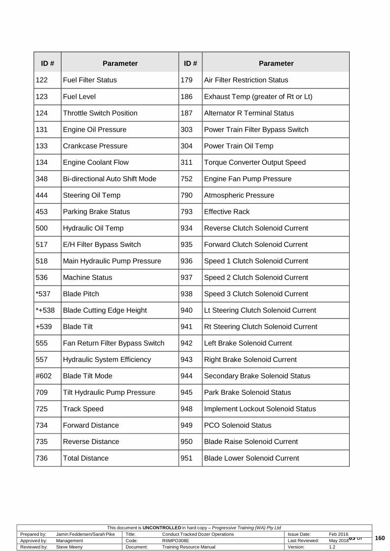
This document is UNCONTROLLED in hard copy – Progressive Training (WA) Pty Ltd Prepared by: Jamin Feddersen/Sarah Pike Title: Conduct Tracked Dozer Operations Issue Date: Feb 2016 Approved by: Management Code: RIIMPO308E Last Reviewed: May 2018
65 of Reviewed by: Steve Meeny Document: Training Resource Manual Version: 1.2
ID #
Parameter
ID #
Parameter
122
Fuel Filter Status
179
Air Filter Restriction Status
123
Fuel Level
186
Exhaust Temp (greater of Rt or Lt)
124
Throttle Switch Position
187
Alternator R Terminal Status
131
Engine Oil Pressure
303
Power Train Filter Bypass Switch
133
Crankcase Pressure
304
Power Train Oil Temp
134
Engine Coolant Flow
311
Torque Converter Output Speed
348
Bi-directional Auto Shift Mode
752
Engine Fan Pump Pressure
444
Steering Oil Temp
790
Atmospheric Pressure
453
Parking Brake Status
793
Effective Rack
500
Hydraulic Oil Temp
934
Reverse Clutch Solenoid Current
517
E/H Filter Bypass Switch
935
Forward Clutch Solenoid Current
518
Main Hydraulic Pump Pressure
936
Speed 1 Clutch Solenoid Current
536
Machine Status
937
Speed 2 Clutch Solenoid Current
*537
Blade Pitch
938
Speed 3 Clutch Solenoid Current
*+538
Blade Cutting Edge Height
940
Lt Steering Clutch Solenoid Current
+539
Blade Tilt
941
Rt Steering Clutch Solenoid Current
555
Fan Return Filter Bypass Switch
942
Left Brake Solenoid Current
557
Hydraulic System Efficiency
943
Right Brake Solenoid Current
#602
Blade Tilt Mode
944
Secondary Brake Solenoid Status
709
Tilt Hydraulic Pump Pressure
945
Park Brake Solenoid Status
725
Track Speed
948
Implement Lockout Solenoid Status
734
Forward Distance
949
PCO Solenoid Status
735
Reverse Distance
950
Blade Raise Solenoid Current
736
Total Distance
951
Blade Lower Solenoid Current
160

This document is UNCONTROLLED in hard copy – Progressive Training (WA) Pty Ltd Prepared by: Jamin Feddersen/Sarah Pike Title: Conduct Tracked Dozer Operations Issue Date: Feb 2016 Approved by: Management Code: RIIMPO308E Last Reviewed: May 2018
66 of Reviewed by: Steve Meeny Document: Training Resource Manual Version: 1.2
ID #
Parameter
ID #
Parameter
742
User Shutdown Status
952
Blade Tilt Left Solenoid Current
953
Blade Tilt Right Solenoid Current
972
Service Brake Pedal SW Position
954
Ripper Raise Solenoid Current
973
Decelerator Position
955
Ripper Lower Solenoid Current
974
Blade Pitch Back Switch Position
956
Ripper Shank In Solenoid Current
975
Bld Pitch Forward SW Position
957
Ripper Shank Out Solenoid Current
976
Bld Pitch Fwd Trigger SW Pos
958
Blade Control Lift Position
977
Trans Up Shift Switch Position
959
Blade Control Tilt Position
978
Trans Down Shift Switch Position
960
Ripper Control Lift Position
979
Bi-dir Auto Shift SW Position
961
Ripper Control In/Out Position
981
Ether Injection Switch Position
962
Machine Slope
Engine
963
Machine Side Slope
100
Engine Speed
964
Track Slip
104
Air Filter Restriction Pressure
965
Ground Speed
105
Boost Pressure
966
Operator Load Select
110
Engine Aftercooler Coolant Temp
967
Lt Steering Lever Position
123
Fuel Level
968
Rt Steering Lever Position
131
Engine Oil Pressure
969
FNR Lever Position
134
Engine Coolant Flow
970
Direction Switch Position
135
Engine Coolant Temp
971
Service Brake Pedal Position
Powertrain
557
Hydraulic System Efficiency
304
Power Train Oil Temp
602
Blade Tilt Mode
311
Torque Converter Output Speed
709
Tilt Hydraulic Pump Pressure
348
Bi-directional Auto Shift Mode
752
Engine Fan Pump Pressure
160

This document is UNCONTROLLED in hard copy – Progressive Training (WA) Pty Ltd Prepared by: Jamin Feddersen/Sarah Pike Title: Conduct Tracked Dozer Operations Issue Date: Feb 2016 Approved by: Management Code: RIIMPO308E Last Reviewed: May 2018
67 of Reviewed by: Steve Meeny Document: Training Resource Manual Version: 1.2
ID #
Parameter
ID #
Parameter
444
Steering Oil Temp
Service
453
Parking Brake Status
102
Left Turbo Inlet Pressure
725
Track Speed
103
Right Turbo Inlet Pressure
734
Forward Distance
106
Left Exhaust Temp
735
Reverse Distance
108
Right Exhaust Temp
736
Total Distance
109
Turbo Outlet Pressure
964
Track Slip
116
Cold Mode Status
965
Ground Speed
117
Engine Derate Status
Implement
122
Fuel Filter Status
500
Hydraulic Oil Temp
124
Throttle Switch Position
518
Main Hydraulic Pump Pressure
133
Crankcase Pressure
536
Machine Status
140
System Voltage
*537
Blade Pitch
170
Torque Rack Limit
*+538
Blade Cutting Edge Height
171
Engine Oil Pressure Status
+539
Blade Tilt
172
Crank Without Inject Status
173
Throttle SW1 Status
937
Speed 2 Clutch Solenoid Current
174
Throttle SW2 Status
938
Speed 3 Clutch Solenoid Current
175
Throttle SW3 Status
940
Lt Steering Clutch Solenoid Current
176
Throttle SW4 Status
941
Rt Steering Clutch Solenoid Current
177
Right Air Filter Restriction Pressure
942
Left Brake Solenoid Current
178
Left Air Filter Restriction Pressure
943
Right Brake Solenoid Current
179
Air Filter Restriction Status
944
Secondary Brake Solenoid Status
186
Exhaust Temp (greater of Rt or Lt)
945
Park Brake Solenoid Status
187
Alternator R Terminal Status
948
Implement Lockout Solenoid Status
160
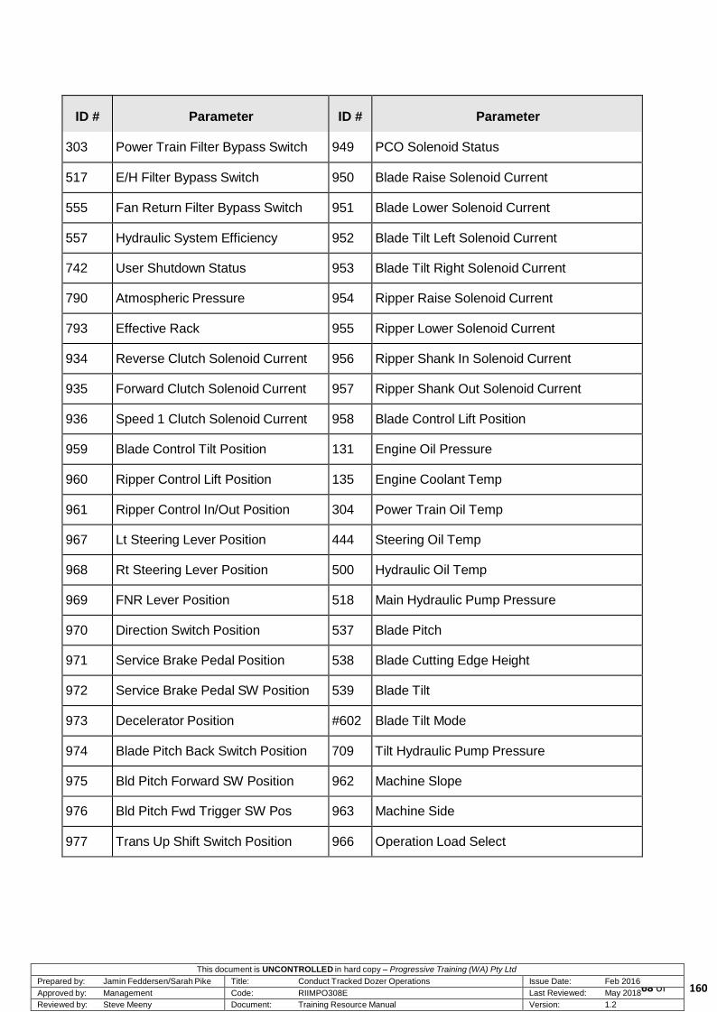
This document is UNCONTROLLED in hard copy – Progressive Training (WA) Pty Ltd Prepared by: Jamin Feddersen/Sarah Pike Title: Conduct Tracked Dozer Operations Issue Date: Feb 2016 Approved by: Management Code: RIIMPO308E Last Reviewed: May 2018
68 of Reviewed by: Steve Meeny Document: Training Resource Manual Version: 1.2
ID #
Parameter
ID #
Parameter
303
Power Train Filter Bypass Switch
949
PCO Solenoid Status
517
E/H Filter Bypass Switch
950
Blade Raise Solenoid Current
555
Fan Return Filter Bypass Switch
951
Blade Lower Solenoid Current
557
Hydraulic System Efficiency
952
Blade Tilt Left Solenoid Current
742
User Shutdown Status
953
Blade Tilt Right Solenoid Current
790
Atmospheric Pressure
954
Ripper Raise Solenoid Current
793
Effective Rack
955
Ripper Lower Solenoid Current
934
Reverse Clutch Solenoid Current
956
Ripper Shank In Solenoid Current
935
Forward Clutch Solenoid Current
957
Ripper Shank Out Solenoid Current
936
Speed 1 Clutch Solenoid Current
958
Blade Control Lift Position
959
Blade Control Tilt Position
131
Engine Oil Pressure
960
Ripper Control Lift Position
135
Engine Coolant Temp
961
Ripper Control In/Out Position
304
Power Train Oil Temp
967
Lt Steering Lever Position
444
Steering Oil Temp
968
Rt Steering Lever Position
500
Hydraulic Oil Temp
969
FNR Lever Position
518
Main Hydraulic Pump Pressure
970
Direction Switch Position
537
Blade Pitch
971
Service Brake Pedal Position
538
Blade Cutting Edge Height
972
Service Brake Pedal SW Position
539
Blade Tilt
973
Decelerator Position
#602
Blade Tilt Mode
974
Blade Pitch Back Switch Position
709
Tilt Hydraulic Pump Pressure
975
Bld Pitch Forward SW Position
962
Machine Slope
976
Bld Pitch Fwd Trigger SW Pos
963
Machine Side
977
Trans Up Shift Switch Position
966
Operation Load Select
160

This document is UNCONTROLLED in hard copy – Progressive Training (WA) Pty Ltd Prepared by: Jamin Feddersen/Sarah Pike Title: Conduct Tracked Dozer Operations Issue Date: Feb 2016 Approved by: Management Code: RIIMPO308E Last Reviewed: May 2018
69 of Reviewed by: Steve Meeny Document: Training Resource Manual Version: 1.2
ID #
Parameter
ID #
Parameter
978
Trans Down Shift Switch Position
979
Bi-dir Auto Shift SW Position
981
Ether Injection Switch Position
Operator
100
Engine Speed
* - Displays ‘ERR’ if selected as the Gauge Parameter and ABA is not active
Blade not Reset
+ - Always displays ‘ERR’ if selected as the Gauge Parameter for D11R Dozers
# - Always displays ‘ERR’ if selected as the Gauge Parameter for D11R Dozers
3.7 Blade
The D11R is fitted with a ‘U’ design
blade. Large winged areas protrude from
each side of the moldboard to prevent
spillage. These are controlled be a lever
in the operator’s cabin, and the
performance function varies the blades
angle and pitch. The dual-tilt feature
allows the operator to optimise the blades
pitch angle for each portion of the dozing
cycle.
Load displacement of the 11SU blade is
rated at 27.2m3 and the 11U blade at
34.4m3. Blade performance features
include:
dual-tilt load control
two-position tilt cylinder mounting
DH-2 steel cutting edges.
Dual-Tilt Load Control
D11R Blade Close-up
The D11R blade is fitted with dual tilt hydraulic cylinders, this function varies the blade angle up or
down on the left or right side of the blade and alters the pitch of the blade both forwards and
backwards. The dual-tilt feature allows the operator to optimise the blade pitch angle for each
portion of the dozing cycle.
160

This document is UNCONTROLLED in hard copy – Progressive Training (WA) Pty Ltd Prepared by: Jamin Feddersen/Sarah Pike Title: Conduct Tracked Dozer Operations Issue Date: Feb 2016 Approved by: Management Code: RIIMPO308E Last Reviewed: May 2018
70 of Reviewed by: Steve Meeny Document: Training Resource Manual Version: 1.2
Two-Position Tilt Cylinder Mounting
Two-position tilt cylinder mounting offers greater tilt performance flexibility. Specific applications
include;
penetration in forward position
carrying the load in the back position.
DH-2 Steel Cutting Edges
Alloy steel DH-2 blade cutting edges offer high wear resistance and extended service life. The DH-
3 alloy steel blade end bits resist softening from heat build up.
3.8 Ripper
The dozer has single and multi-shank rippers that are designed for deep impact and penetration.
The single-shank ripper provides machine balance and has several operator and performance
features.
The operator can adjust the shank depth from the seat using an optional single-shank pin puller.
Hydraulic pitch adjustment cylinders vary the shank angle to provide optimal penetration. The
angle of the tip can be altered to a position beyond vertical to improve the initial surface
penetration.
Rear counterweights provide dozer balance to maximise production.
Remote lube provides grease to ripper frame pin joints.
160

This document is UNCONTROLLED in hard copy – Progressive Training (WA) Pty Ltd Prepared by: Jamin Feddersen/Sarah Pike Title: Conduct Tracked Dozer Operations Issue Date: Feb 2016 Approved by: Management Code: RIIMPO308E Last Reviewed: May 2018
71 of Reviewed by: Steve Meeny Document: Training Resource Manual Version: 1.2
Single-shank Ripper
160

This document is UNCONTROLLED in hard copy – Progressive Training (WA) Pty Ltd Prepared by: Jamin Feddersen/Sarah Pike Title: Conduct Tracked Dozer Operations Issue Date: Feb 2016 Approved by: Management Code: RIIMPO308E Last Reviewed: May 2018
72 of Reviewed by: Steve Meeny Document: Training Resource Manual Version: 1.2
3.9 Isolation Points
The battery isolation switch isolates the dozer for pre-start inspections, shutdown procedures and
maintenance.
3.9.1 Battery Isolation Switch
The battery isolation switch is located in the isolation service box on the left side of the dozer just
beneath the operator’s cabin. Inside the service box is:
an auxiliary start receptacle
a pivot shaft oil receptacle
a battery isolation key switch
a power isolation key switch.
3.9.2 Isolation
Arrangement
After lifting the cover guard, the battery
disconnect switch is operated by turning
the key.
When this key is turned to the OFF
position (key vertical), the dozer
electrical system is disabled.
Battery Isolation Location
When the key is turned to the ON position, the battery remains connected to the electrical
system.
WARNING!
This battery disconnect switch is a positive lockout isolator and it must be correctly tagged out.
In order to activate the electrical
system turn the key clockwise.
The battery disconnect switch must be
turned to the ON position before you start
the engine.
Battery Isolation Switch
160

This document is UNCONTROLLED in hard copy – Progressive Training (WA) Pty Ltd Prepared by: Jamin Feddersen/Sarah Pike Title: Conduct Tracked Dozer Operations Issue Date: Feb 2016 Approved by: Management Code: RIIMPO308E Last Reviewed: May 2018
73 of Reviewed by: Steve Meeny Document: Training Resource Manual Version: 1.2
3.9.3 Starter Motor Isolation
The D11R is fitted with a starter motor isolation
switch. The starter motor isolation switch is
housed in a yellow box and when in the OFF
position will isolate the starter motor from the
electrical system. This allows power to all other
systems without the risk of an accidental engine
start and is generally used for maintenance
reasons.
CAUTION! Never turn the battery disconnect key OFF
while the engine is running. Electrical damage could result.
Starter Isolation Location
3.10 Emergency Stop Switches
The engine emergency stop switch is located in
the same position as the rear fire suppression
actuation control. When the switch is used, by
pushing it in, it must be reset by rotating the
knob after the emergency has passed.
There is usually an emergency shutdown in the
cabin as well. This may be located in any
convenient position. The one illustrated below
is on the right cabin window column. Emergency Stop Switch
Cabin Emergency Stop Switch
160

This document is UNCONTROLLED in hard copy – Progressive Training (WA) Pty Ltd Prepared by: Jamin Feddersen/Sarah Pike Title: Conduct Tracked Dozer Operations Issue Date: Feb 2016 Approved by: Management Code: RIIMPO308E Last Reviewed: May 2018
74 of Reviewed by: Steve Meeny Document: Training Resource Manual Version: 1.2
3.11 Fire Suppression System (FSS)
During mining production machines operate
at high temperatures and the potential for
fire is always present. The monitor gives
operators a system condition readout prior
to engine start, information includes status
of all fire suppression components.
It is a legislative requirement that mobile
operating equipment is equipped with an
onboard fire suppression system (FSS). The
FSS is an add-on after purchase component
and is the responsibility of the mining
company. It is the responsibility of each
operator to test and monitor the FSS.
The FSS is designed to extinguish a fire by
flooding the engine compartment with fire
retardant foam. The FSS is manually
activated by the operator.
Fire Shutdown Controller
IMPORTANT! The fire suppression system is designed to extinguish a fire in the
engine bay. It will not extinguish a fire in the cabin or other areas of the machine.
There are various FSS activation points
called actuator buttons on all equipment and
you must make yourself familiar with these.
The FSS is activated through actuator
cylinders filled with carbon dioxide (CO2).
There is one FSS cylinder on each side of
the engine. Look for the actuator buttons in
the following common positions:
in the operator’s cab
on the left side of the engine just above
the safety handgrip rail.
Fire Suppression System
160
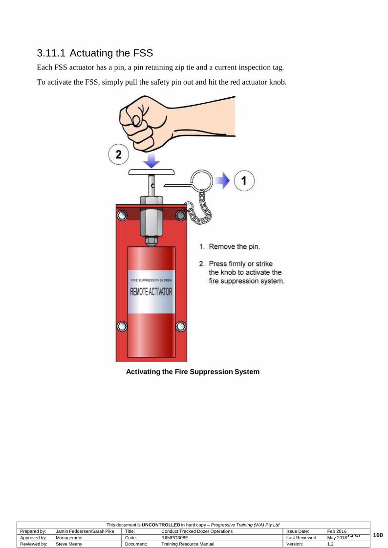
This document is UNCONTROLLED in hard copy – Progressive Training (WA) Pty Ltd Prepared by: Jamin Feddersen/Sarah Pike Title: Conduct Tracked Dozer Operations Issue Date: Feb 2016 Approved by: Management Code: RIIMPO308E Last Reviewed: May 2018
75 of Reviewed by: Steve Meeny Document: Training Resource Manual Version: 1.2
3.11.1 Actuating the FSS
Each FSS actuator has a pin, a pin retaining zip tie and a current inspection tag.
To activate the FSS, simply pull the safety pin out and hit the red actuator knob.
Activating the Fire Suppression System
160
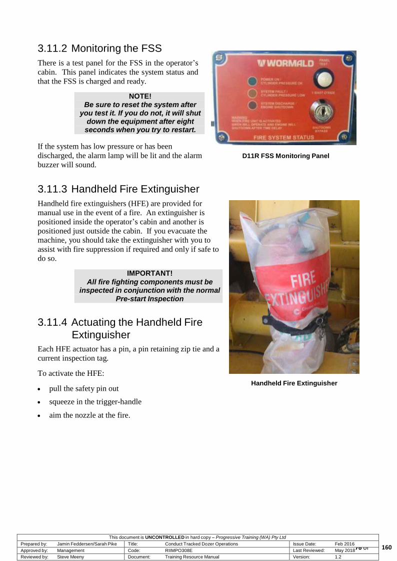
This document is UNCONTROLLED in hard copy – Progressive Training (WA) Pty Ltd Prepared by: Jamin Feddersen/Sarah Pike Title: Conduct Tracked Dozer Operations Issue Date: Feb 2016 Approved by: Management Code: RIIMPO308E Last Reviewed: May 2018
76 of Reviewed by: Steve Meeny Document: Training Resource Manual Version: 1.2
3.11.2 Monitoring the FSS
There is a test panel for the FSS in the operator’s
cabin. This panel indicates the system status and
that the FSS is charged and ready.
NOTE! Be sure to reset the system after
you test it. If you do not, it will shut down the equipment after eight
seconds when you try to restart.
If the system has low pressure or has been
discharged, the alarm lamp will be lit and the alarm
buzzer will sound.
D11R FSS Monitoring Panel
3.11.3 Handheld Fire Extinguisher
Handheld fire extinguishers (HFE) are provided for
manual use in the event of a fire. An extinguisher is
positioned inside the operator’s cabin and another is
positioned just outside the cabin. If you evacuate the
machine, you should take the extinguisher with you to
assist with fire suppression if required and only if safe to
do so.
IMPORTANT!
All fire fighting components must be inspected in conjunction with the normal
Pre-start Inspection
3.11.4 Actuating the Handheld Fire
Extinguisher
Each HFE actuator has a pin, a pin retaining zip tie and a
current inspection tag.
To activate the HFE:
pull the safety pin out
squeeze in the trigger-handle
aim the nozzle at the fire.
Handheld Fire Extinguisher
160

This document is UNCONTROLLED in hard copy – Progressive Training (WA) Pty Ltd Prepared by: Jamin Feddersen/Sarah Pike Title: Conduct Tracked Dozer Operations Issue Date: Feb 2016 Approved by: Management Code: RIIMPO308E Last Reviewed: May 2018
77 of Reviewed by: Steve Meeny Document: Training Resource Manual Version: 1.2
Additional pre-start inspection checks to be performed
include:
The contents pressure gauge
The service tag of every HFE
General condition
Mounting points
Pin tamper tag.
Handheld Fire Extinguisher
Pressure Gauge
IMPORTANT!
Do not attempt to fight a fire if your own safety is compromised.
REMEMBER! Operate equipment within recommended speed, engine
capability and limitations.
3.12 Roll Over Protection Structure (ROPS)
All Caterpillar machines have a built-in
Roll Over Protection Structure or ROPS.
This device is an attached guard located
above the operator’s cab and secured to the
main chassis.
The ROPS is designed to provide operator
crush protection in a rollover situation by
controlled bending of its structural
members, provided the operator is wearing
a seatbelt.
Modifications such as welding, cutting, or
drilling on a ROPS will negatively affect
the structure’s protective capabilities.
Roll Over Protection Structure (ROPS)
160

This document is UNCONTROLLED in hard copy – Progressive Training (WA) Pty Ltd Prepared by: Jamin Feddersen/Sarah Pike Title: Conduct Tracked Dozer Operations Issue Date: Feb 2016 Approved by: Management Code: RIIMPO308E Last Reviewed: May 2018
78 of Reviewed by: Steve Meeny Document: Training Resource Manual Version: 1.2
3.13 Summary
This topic has provided an introduction to the general arrangement and dimensions of the
Caterpillar D11R Dozer. You should now have a basic understanding of the dozer’s dimensions, its
inboard equipment, control panels and instruments, and its capabilities and limitations.
If you have any questions or require clarification of any part of this topic, you should ask your
instructor now, before undertaking the topic assignment.
160
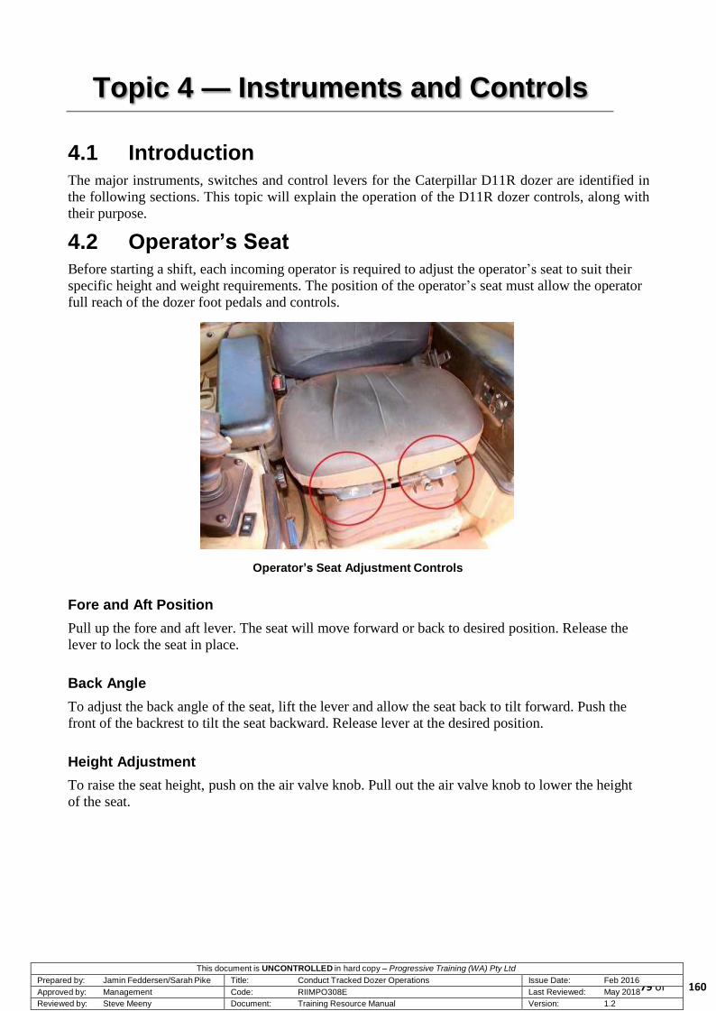
This document is UNCONTROLLED in hard copy – Progressive Training (WA) Pty Ltd Prepared by: Jamin Feddersen/Sarah Pike Title: Conduct Tracked Dozer Operations Issue Date: Feb 2016 Approved by: Management Code: RIIMPO308E Last Reviewed: May 2018
79 of Reviewed by: Steve Meeny Document: Training Resource Manual Version: 1.2
Topic 4 — Instruments and Controls
4.1 Introduction
The major instruments, switches and control levers for the Caterpillar D11R dozer are identified in
the following sections. This topic will explain the operation of the D11R dozer controls, along with
their purpose.
4.2 Operator’s Seat
Before starting a shift, each incoming operator is required to adjust the operator’s seat to suit their
specific height and weight requirements. The position of the operator’s seat must allow the operator
full reach of the dozer foot pedals and controls.
Operator’s Seat Adjustment Controls
Fore and Aft Position
Pull up the fore and aft lever. The seat will move forward or back to desired position. Release the
lever to lock the seat in place.
Back Angle
To adjust the back angle of the seat, lift the lever and allow the seat back to tilt forward. Push the
front of the backrest to tilt the seat backward. Release lever at the desired position.
Height Adjustment
To raise the seat height, push on the air valve knob. Pull out the air valve knob to lower the height
of the seat.
160

This document is UNCONTROLLED in hard copy – Progressive Training (WA) Pty Ltd Prepared by: Jamin Feddersen/Sarah Pike Title: Conduct Tracked Dozer Operations Issue Date: Feb 2016 Approved by: Management Code: RIIMPO308E Last Reviewed: May 2018
80 of Reviewed by: Steve Meeny Document: Training Resource Manual Version: 1.2
Weight Adjustment
The weight adjustment is automatically controlled by adjusting the height of the seat.
Lumbar Support
To increase support for the lower back, rotate the lumbar support knob clockwise. To decrease
support for the lower back, rotate lumbar support knob counterclockwise.
4.3 Operator Instruments and Controls
The D11R dozer has a number of cabin controls. The following sections will list these controls and
describe how to operate them. As an operator, you must be familiar with the location and operation
of the cabin controls to conduct safe dozing operations.
4.3.1 Steering Control
The Finger Tip Control (FTC) cluster is an electronic steering and transmission control combining
direction and gear selection onto one console.
Finger Tip Control Console
160

This document is UNCONTROLLED in hard copy – Progressive Training (WA) Pty Ltd Prepared by: Jamin Feddersen/Sarah Pike Title: Conduct Tracked Dozer Operations Issue Date: Feb 2016 Approved by: Management Code: RIIMPO308E Last Reviewed: May 2018
81 of Reviewed by: Steve Meeny Document: Training Resource Manual Version: 1.2
The two finger tip operated levers on the front
of the console are for left and right steering
direction:
Left and right steering clutch and brake
levers operate by pulling either lever
inwards. This action disengages the clutch
on the selected side and will steer the
machine to the desired direction.
The turning radius is controlled by the force
that is exerted on the lever. When you exert
more force on the lever, the turning radius
will be smaller. When you feel pressure on
the levers the steering is engaged. Pull
either left or right lever inward for a pivot
turn in that direction.
4.3.2 Transmission
Left and Right Steering Clutch and Brake Levers
The pivot thumb control located on the left hand rest is the
transmission direction selector. Rotating the thumb control
selects forward or reverse.
To move FORWARD. Press the top and rotate the
control to select forward.
To REVERSE. Press the bottom of the control and
rotate to select reverse.
Align the central location marks in order to select
NEUTRAL.
The transmission gear selector changes the gearing in
either direction. To select a higher gear, press the upper
switch, to downshift press the lower button.
Transmission Direction Selector
Transmission Gear Selector
160

This document is UNCONTROLLED in hard copy – Progressive Training (WA) Pty Ltd Prepared by: Jamin Feddersen/Sarah Pike Title: Conduct Tracked Dozer Operations Issue Date: Feb 2016 Approved by: Management Code: RIIMPO308E Last Reviewed: May 2018
82 of Reviewed by: Steve Meeny Document: Training Resource Manual Version: 1.2
4.3.3 Parking Brake Switch
The parking brake switch and lock panel is located at the inside of the left hand controls console.
When engaged the parking brake will lock the transmission in neutral.
The machine should not move when the parking brake switch is engaged.
When engaged, the parking brake indicator on the dashboard will light.
4.3.4 Parking Brake Lock
The parking brake lock uses the ignition key to activate.
To lock, insert the key in the slot. Move the key to the LOCK position. Remove the key to lock
the parking brake.
To unlock, insert the key into the slot and move the switch to the UNLOCK position.
CAUTION!
Do not use the parking brake for stopping the machine.
160

This document is UNCONTROLLED in hard copy – Progressive Training (WA) Pty Ltd Prepared by: Jamin Feddersen/Sarah Pike Title: Conduct Tracked Dozer Operations Issue Date: Feb 2016 Approved by: Management Code: RIIMPO308E Last Reviewed: May 2018
83 of Reviewed by: Steve Meeny Document: Training Resource Manual Version: 1.2
4.3.5 Throttle Control
The throttle control rocker switch is located
on the right console, to the left of the blade
control lever. The D11R engine is
programmed to start at LOW IDLE
automatically.
When the front end (rabbit) of the
rocker switch is depressed, the engine
speed increases to HIGH IDLE.
When the back end (turtle) of the rocker
switch is depressed, the engine speed
decreases to LOW IDLE.
To set the engine speed at less than
HIGH IDLE depress the decelerator
pedal until the engine is running at the
desired revs. Press and hold the front
end (rabbit icon) of the throttle control
Throttle Control Switch
switch. Hold for two seconds to lock the engine revs and then release the decelerator pedal. The
engine revs will not increase. This function is generally used for maintenance and engine
temperature control.
To return the engine speed to LOW or HIGH IDLE, press the appropriate selection on the
throttle control.
High Speed
Low Speed
160

This document is UNCONTROLLED in hard copy – Progressive Training (WA) Pty Ltd Prepared by: Jamin Feddersen/Sarah Pike Title: Conduct Tracked Dozer Operations Issue Date: Feb 2016 Approved by: Management Code: RIIMPO308E Last Reviewed: May 2018
84 of Reviewed by: Steve Meeny Document: Training Resource Manual Version: 1.2
4.3.6 Blade Control Lever
The blade control lever located on the right side of the operator’s seat controls all blade movement.
Blade Control
Operating functions of the blade control include:
Control Function
Icon
Explanation
Lower Blade
Push the handle forward in to LOWER the blade. When the handle is released, the handle will return to the neutral HOLD position.
Hold Blade
The handle will return to the neutral HOLD position when it is released from both RAISE and LOWER positions.
Raise Blade
Pull back on the handle to RAISE the blade. When the handle is released, the handle will return to the neutral HOLD position.
Tilt Blade Right
Push the handle to the right of to LOWER the right side of the blade and RAISE the left side of the blade. When the handle is released, the handle will return to the neutral HOLD position.
160

This document is UNCONTROLLED in hard copy – Progressive Training (WA) Pty Ltd Prepared by: Jamin Feddersen/Sarah Pike Title: Conduct Tracked Dozer Operations Issue Date: Feb 2016 Approved by: Management Code: RIIMPO308E Last Reviewed: May 2018
85 of Reviewed by: Steve Meeny Document: Training Resource Manual Version: 1.2
Control Function
Icon
Explanation
Hold Blade
The handle will return to the neutral HOLD position when it is released from both TILT RIGHT and TILT LEFT positions.
Tilt Blade Left
Push the handle to the left to LOWER the left side of the blade and RAISE the right side of the blade. When the handle is released, the handle will return to the neutral HOLD position.
Pitch Blade Forward
Hold the trigger in on the control grip. Move the lever to the right to pitch the blade FORWARD. Pitching the blade forward improves blade penetration. It also helps dump the load.
Pitch Blade Back
Depress the trigger on the control grip. Move the lever to the left to pitch the blade BACK. Pitching the blade to the rear improves the ability of the blade to carry the load.
4.3.7 Automatic and Manual Selection
The blade control handle has left and right yellow colored buttons to select alternate modes.
The L/H switch is the mode select button, which activates automatic control functions. Pushing
the mode select button will scroll through the CARRY, SPREAD, and RETURN blade options
and display which mode on the VIDS panel.
The R/H switch is the manual select button which engages manual control functions. Pushing
the manual select button cancels the automatic mode selection.
4.3.8 Dual-Tilt Load Control
The D11R blade is fitted with dual tilt hydraulic cylinders, controlled from the operator’s
compartment. This function varies the blade angle up or down on the left or right side of the blade
and alters the pitch of the blade both forwards and backwards. The dual-tilt feature allows the
operator to optimise the blade pitch angle for each portion of the dozing cycle.
160

This document is UNCONTROLLED in hard copy – Progressive Training (WA) Pty Ltd Prepared by: Jamin Feddersen/Sarah Pike Title: Conduct Tracked Dozer Operations Issue Date: Feb 2016 Approved by: Management Code: RIIMPO308E Last Reviewed: May 2018
86 of Reviewed by: Steve Meeny Document: Training Resource Manual Version: 1.2
4.3.9 Ripper Control
The ripper control lever is located on the right side of the operator’s seat directly behind the blade
control.
D11R Ripper Control
Operating functions of the ripper control include:
Control Function
Icon
Explanation
Lower Ripper
Push the bottom of the control lever to LOWER the ripper. When the lever is released, the lever will return to the neutral HOLD position.
Hold Ripper
The lever will return to the neutral HOLD position when it is released from both RAISE and LOWER positions.
Raise Ripper
Push the top of the control lever to RAISE the ripper. When the lever is released, the lever will return to the neutral HOLD position.
Shank In
Pull the front of the ripper shank in/out lever toward the operator to move the SHANK IN closer to the machine. When the lever is released, the lever will return to the neutral HOLD position.
160

This document is UNCONTROLLED in hard copy – Progressive Training (WA) Pty Ltd Prepared by: Jamin Feddersen/Sarah Pike Title: Conduct Tracked Dozer Operations Issue Date: Feb 2016 Approved by: Management Code: RIIMPO308E Last Reviewed: May 2018
87 of Reviewed by: Steve Meeny Document: Training Resource Manual Version: 1.2
Control Function
Icon
Explanation
Hold
The ripper shank in/out lever will return to the neutral HOLD position when it is released from both SHANK IN and SHANK OUT positions. Ripper movement stops.
Shank Out
Pull the rear of the ripper shank in/out lever toward the operator to move the SHANK OUT away from the machine. When the lever is released, the lever will return to the neutral HOLD position.
4.3.10 Auto Stow Function
The ripper auto stow function is activated by pressing the yellow button beneath the ripper control
hand rest and automatically raises and stows the ripper
Push the auto stow switch on the control to raise the ripper to maximum height
Cancel the auto stow function by pressing the switch again.
4.3.11 Hydraulic Implement Lockout Switch
The Hydraulic Implement Lockout switch
is located behind the ripper control panel.
When activated, the lockout switch makes
the hydraulic implement controls non-
functional.
Hydraulic Implememnt Lockout Switch
160

This document is UNCONTROLLED in hard copy – Progressive Training (WA) Pty Ltd Prepared by: Jamin Feddersen/Sarah Pike Title: Conduct Tracked Dozer Operations Issue Date: Feb 2016 Approved by: Management Code: RIIMPO308E Last Reviewed: May 2018
88 of Reviewed by: Steve Meeny Document: Training Resource Manual Version: 1.2
4.3.12 Heating and Air Conditioning System
The air conditioning and temperature
controls are located on the right side
console adjacent to the blade control. The
system controls internal cabin air
temperature and pressurises the cabin to
reduce the ingress of dust.
The controls include:
fan speed
heating or cooling
air conditioning options
defogging.
Air Conditioning Controls
4.3.13 Horn
Press the horn to activate when starting up,
moving off and reversing.
Horn
160

This document is UNCONTROLLED in hard copy – Progressive Training (WA) Pty Ltd Prepared by: Jamin Feddersen/Sarah Pike Title: Conduct Tracked Dozer Operations Issue Date: Feb 2016 Approved by: Management Code: RIIMPO308E Last Reviewed: May 2018
89 of Reviewed by: Steve Meeny Document: Training Resource Manual Version: 1.2
4.4 Foot Pedal Controls
The two foot pedals in the cabin of the D11R are the Service Brake and the Decelerator Pedal.
Foot Pedal Controls
4.4.1 Service Brake
The large pedal on the left is the service brake. Use the service brake to:
slow or stop the machine
prevent overspeeding
change directions.
Release the brake pedal in order to allow the machine to move forward and return to the desired
ground speed.
4.4.2 Decelerator pedal
The decelerator pedal is the small pedal on the right of the service break. Apply pressure to the
pedal to:
reduce engine revs temporarily
over ride the throttle setting
decelerate to lower revs for braking and changing direction
reduce the engine revs to assist cooling
releasing the pedal will return the machine to the pre set speed.
160

This document is UNCONTROLLED in hard copy – Progressive Training (WA) Pty Ltd Prepared by: Jamin Feddersen/Sarah Pike Title: Conduct Tracked Dozer Operations Issue Date: Feb 2016 Approved by: Management Code: RIIMPO308E Last Reviewed: May 2018
90 of Reviewed by: Steve Meeny Document: Training Resource Manual Version: 1.2
To vary speed from any setting, press the decelerator pedal to set the desired speed and hold the
rabbit icon down on the speed selector switch for two seconds. This will engage an override mode
and set the machine at the new speed. To disengage any over ride setting press the rabbit or turtle
icon and the pre set mode will engage.
4.5 Dashboard Panel
The section below details the controls found on the dashboard pane. As an operator you are required
to know the location and purpose of the dashboard controls. The controls located on the dashboard
panel are as follows:
Rocker switches
VIDS action lamp
Engine start switch
Analog engine performance gauges
VIDS multi-function display gauge and message centre
Transmission auto-function
Starting aid.
160

This document is UNCONTROLLED in hard copy – Progressive Training (WA) Pty Ltd Prepared by: Jamin Feddersen/Sarah Pike Title: Conduct Tracked Dozer Operations Issue Date: Feb 2016 Approved by: Management Code: RIIMPO308E Last Reviewed: May 2018
91 of Reviewed by: Steve Meeny Document: Training Resource Manual Version: 1.2
Dashboard Panel
160

This document is UNCONTROLLED in hard copy – Progressive Training (WA) Pty Ltd Prepared by: Jamin Feddersen/Sarah Pike Title: Conduct Tracked Dozer Operations Issue Date: Feb 2016 Approved by: Management Code: RIIMPO308E Last Reviewed: May 2018
92 of Reviewed by: Steve Meeny Document: Training Resource Manual Version: 1.2
4.5.1 Rocker Switches
The rocker switch panel situated on the top left of the dash consists of:
dashboard light (middle position to activate) and front flood lights (top position to activate)
side floodlights (top position to activate)
rear floodlights (middle position to activate) and ripper light (top position to activate)
hazard beacons
auxiliary circuit (top position to activate) operates auxiliary lighting or an additional electrical
circuit with connector, if fitted with the connector it will be located on the right fender below
the hydraulic tank. Any 24-volt accessories can be connected to the 2-pin connector.
starting aid (cold climate) is controlled by the ECM. A measured shot of ether is injected into
the engine air intake to assist start up.
Rocker Switches
160

This document is UNCONTROLLED in hard copy – Progressive Training (WA) Pty Ltd Prepared by: Jamin Feddersen/Sarah Pike Title: Conduct Tracked Dozer Operations Issue Date: Feb 2016 Approved by: Management Code: RIIMPO308E Last Reviewed: May 2018
93 of Reviewed by: Steve Meeny Document: Training Resource Manual Version: 1.2
4.5.2 VIDS Action Lamp
The VIDS action lamp illuminates under a number of
situations, they are:
during operator information input
non critical alarms during the starting sequence
critical alarms during operations
general alarms signifying status change.
4.5.3 Engine Start Switch
The engine start key must only be inserted and removed
with the ignition in the OFF position.
In the OFF position, there is no power to the electrical
circuits in the cabin. Power is dashboard, tail and dome
light are operational in the OFF position.
Action Lamp and Engine Start Switch
Turn the key clockwise to ON to activate all machinery circuits.
Turn the key clockwise to START to crank the engine.
Release the key after the engine starts. The key will return to the ON position.
4.5.4 Analog Engine Performance Gauges
The analog engine performance gauge cluster is a part of
VIDS, It displays:
engine coolant temperature
transmission oil temperature
fuel level
hydraulic oil temperature.
The red area of the temperature gauge indicates an
increase in temperature and requires immediate
corrective action. The red area of a quantity
measurement gauge indicates the remaining level in that
respective tank.
Gauges
160

This document is UNCONTROLLED in hard copy – Progressive Training (WA) Pty Ltd Prepared by: Jamin Feddersen/Sarah Pike Title: Conduct Tracked Dozer Operations Issue Date: Feb 2016 Approved by: Management Code: RIIMPO308E Last Reviewed: May 2018
94 of Reviewed by: Steve Meeny Document: Training Resource Manual Version: 1.2
4.5.5 VIDS Multi-function Display Gauge and Message Centre
The multi function gauge will display any of the analog readings from the engine and display the
relevant information in the VIDS window directly beneath the gauge. The readout mode is selected
from VIDS and is used to give updated information from the ECM.
4.5.6 VIDS Warning Category Indicators
The D11R monitoring and display system provides three warning category indicators (levels). Pop
up warnings appear on the VIDS display monitor as well as visual and audible prompts from the
front Action light, rear Action lamp and an Action alarm.
Category 1 Warning Indicator: An alert only warning appears on the VIDS display,
describing the event or diagnostic failure. The action lamp will illuminate to amber. The
warning can be acknowledged by pressing OK, if the failure or event does not reoccur this
action lamp will not continue to illuminate. If the event does reoccur the machine needs
attention.
Category 2 Warning Indicator: A warning appears on the VIDS display, describing the event
or diagnostic failure. The action lamp will illuminate to red alerting the operator that a change in
machine operation is immediately required to avoid possible damage to the indicated system.
The warning can be acknowledged by pressing OK, and will not re-appear for one hour if the
failure or event does not reoccur, the action lamp will stop flashing. If the problem has not been
corrected after the time delay, the message will reappear on screen.
Category 3 Warning Indicator: A warning appears on the VIDS display, describing the event
or diagnostic failure. The action light and lamp will flash red and the action alarm will pulse to
alert the operator, you must immediately shut down the machine and leave off. In most cases,
you will not be able to silence the Danger Alarm by pressing the OK switch. Do not continue to
operate the machine until the fault has been rectified. Category three alarms also start the Event
Recorder.
REMEMBER!
Operate equipment within recommended speed, engine capability and limitations.
4.5.7 Transmission Autoshift Function
The autoshift switch allows the operator to preset a FORWARD or REVERSE gear for directional
changes. It can be selected with the dashboard panel push button. When the machine is started, it is
in manual mode and the autoshift indicator light is not active.
To operate the Autoshift switch:
Repeatedly push the button for the autoshift function in order to select the modes of shifting.
The lights will display the desired mode.
For the best results, change the options with the transmission in NEUTRAL.
160
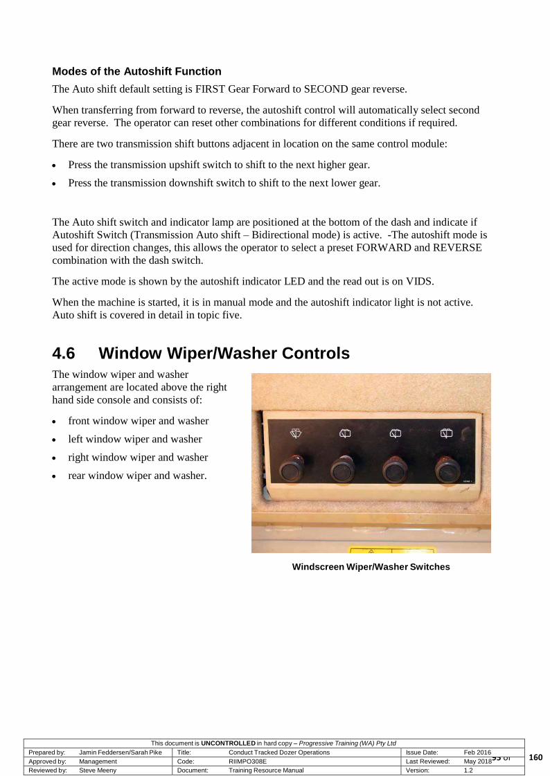
This document is UNCONTROLLED in hard copy – Progressive Training (WA) Pty Ltd Prepared by: Jamin Feddersen/Sarah Pike Title: Conduct Tracked Dozer Operations Issue Date: Feb 2016 Approved by: Management Code: RIIMPO308E Last Reviewed: May 2018
95 of Reviewed by: Steve Meeny Document: Training Resource Manual Version: 1.2
Modes of the Autoshift Function
The Auto shift default setting is FIRST Gear Forward to SECOND gear reverse.
When transferring from forward to reverse, the autoshift control will automatically select second
gear reverse. The operator can reset other combinations for different conditions if required.
There are two transmission shift buttons adjacent in location on the same control module:
Press the transmission upshift switch to shift to the next higher gear.
Press the transmission downshift switch to shift to the next lower gear.
The Auto shift switch and indicator lamp are positioned at the bottom of the dash and indicate if
Autoshift Switch (Transmission Auto shift – Bidirectional mode) is active. -The autoshift mode is
used for direction changes, this allows the operator to select a preset FORWARD and REVERSE
combination with the dash switch.
The active mode is shown by the autoshift indicator LED and the read out is on VIDS.
When the machine is started, it is in manual mode and the autoshift indicator light is not active.
Auto shift is covered in detail in topic five.
4.6 Window Wiper/Washer Controls
The window wiper and washer
arrangement are located above the right
hand side console and consists of:
front window wiper and washer
left window wiper and washer
right window wiper and washer
rear window wiper and washer.
Windscreen Wiper/Washer Switches
160

This document is UNCONTROLLED in hard copy – Progressive Training (WA) Pty Ltd Prepared by: Jamin Feddersen/Sarah Pike Title: Conduct Tracked Dozer Operations Issue Date: Feb 2016 Approved by: Management Code: RIIMPO308E Last Reviewed: May 2018
96 of Reviewed by: Steve Meeny Document: Training Resource Manual Version: 1.2
4.7 Emergency Shutdown Switches
The interior and exterior emergency engine shutdown switches are as yet to be retro fitted.
When the emergency engine shutdown switch is activated it will immediately shut down the dozer
engine, without requiring the start key to be turned OFF.
CAUTION!
The emergency shutdown switch should only be used in the case of an emergency.
4.8 Summary
This topic has provided an introduction to the general arrangement of controls and gauges in the
Caterpillar D11R Dozer. You should now have a basic understanding of its inboard equipment,
control panels and instruments.
If you have any questions or require clarification of any part of this topic, you should ask your
instructor now, before undertaking the topic assignment.
160

This document is UNCONTROLLED in hard copy – Progressive Training (WA) Pty Ltd Prepared by: Jamin Feddersen/Sarah Pike Title: Conduct Tracked Dozer Operations Issue Date: Feb 2016 Approved by: Management Code: RIIMPO308E Last Reviewed: May 2018
97 of Reviewed by: Steve Meeny Document: Training Resource Manual Version: 1.2
Topic 5 — Basic Operations
5.1 Introduction
The purpose of this topic is to introduce you to the pre-start and pre-operation inspection process
including post-start checks, basic operating techniques and shutdown procedures.
This topic is designed to provide hands-on experience. It is critical that the training instruction is
conducted in a non-production unpopulated setting, using an unladen dozer.
While learning to operate the dozer, it is important that trainee operators drive at reduced speed and
observe all necessary safety requirements. Safety should be your primary concern. As your
capabilities increase, you will gradually be able to operate the machine at its normal operational
speed.
160

This document is UNCONTROLLED in hard copy – Progressive Training (WA) Pty Ltd Prepared by: Jamin Feddersen/Sarah Pike Title: Conduct Tracked Dozer Operations Issue Date: Feb 2016 Approved by: Management Code: RIIMPO308E Last Reviewed: May 2018
98 of Reviewed by: Steve Meeny Document: Training Resource Manual Version: 1.2
5.2 Responsible Dozer Operation
To operate a dozer safely and efficiently, you must be aware of your responsibilities.
Your responsibilities include:
conducting walk around inspections and reporting defects
performing the required operator servicing
operating the dozer in a safe and efficient manner to maximise service life and productivity, and
avoid unnecessary equipment damage
maintaining high standards of housekeeping
observing all rules and regulations
being aware of dehydration and fatigue (if dehydrated or fatigued, you must not operate heavy
machinery.)
Maintaining a professional attitude and adhering to these responsibilities will assist in achieving
high standards of dozing operations on site.
5.3 Dozer Inspections
Regular inspections are critical to the long-term viability and operational use of a dozer. Safety and
structural integrity inspections must be conducted on critical items to ensure potential faults are
detected and rectified before they become major problems resulting in expensive downtime.
The purpose of any inspection is to ensure that the mobile equipment is safe to operate.
The four types of checks for the Caterpillar D11R dozer are:
Walk around checks
Pre-start checks
Post-start checks
Post-operation checks.
WARNING!
Never operate or use any item of equipment if its operational condition is suspect.
5.3.1 Warning Labels
Always follow the instructions listed on the warning labels attached to the dozer. For more
information, refer to Caterpillar D11R Dozer Operation and Maintenance manual.
160

This document is UNCONTROLLED in hard copy – Progressive Training (WA) Pty Ltd Prepared by: Jamin Feddersen/Sarah Pike Title: Conduct Tracked Dozer Operations Issue Date: Feb 2016 Approved by: Management Code: RIIMPO308E Last Reviewed: May 2018
99 of Reviewed by: Steve Meeny Document: Training Resource Manual Version: 1.2
5.3.2 Dozer Checks
When approaching a parked dozer always approach from the front. You must start the checks in one
spot and do all the checks in one continuous pass.
The safety checks that you conduct on the dozer are mandatory under legislation and require
specific items to be checked or inspected before you are allowed to start and operate the dozer. It is
critical that you conduct thorough dozer checks to ensure that safety and serviceability is
maintained at all times.
DANGER! Always allow time for fluids to cool before checking and replenishing reservoirs. Coolant and oils are extremely hot immediately after the
engine has stopped, and may cause serious burns.
5.3.3 The Immediate Area
Before you perform a pre-start inspection of the dozer, visually check the immediate area for trip
hazards and other obstructions. Ensure that the machine is isolated the immediate area is clear of
any unauthorised personnel and/or equipment.
5.3.4 Pre-Start Inspection
You must conduct a pre-start inspection of the dozer at the beginning of your shift, even if the dozer
has just been shut down by the previous operator. As part of your inspection requirements, you must
record all faults and defects and report them to the appropriate authority for corrective action. If a
fault cannot be rectified immediately and the safe operation of the dozer may be affected, you must
tag the dozer out of service and report the fault to your supervisor.
The pre-start inspection includes the following inspection procedures:
Ground level inspection
Upper level service area
Operator cabin inspection.
5.3.5 Recording Faults in Pre-Start Inspection Logbook
You must complete the Inspection Logbook at the start of each shift. Record any faults found
during the pre-start inspection in the Inspection Logbook and give a copy of the page to the
Supervisor at the end of each working shift.
160

This document is UNCONTROLLED in hard copy – Progressive Training (WA) Pty Ltd Prepared by: Jamin Feddersen/Sarah Pike Title: Conduct Tracked Dozer Operations Issue Date: Feb 2016 Approved by: Management Code: RIIMPO308E Last Reviewed: May 2018
100 of Reviewed by: Steve Meeny Document: Training Resource Manual Version: 1.2
5.3.6 Fault Category System
Most pre-start inspections have a fault category system in place. This allows you to determine the
severity of the fault and take the appropriate action based on that severity.
Category C or minor faults are regarded as low priority and should be reported to the shift
supervisor. The machine can still be operated and the workshop staff will repair these faults
within a specified time frame.
Category B faults is a type of fault where the machine cannot be operated unless the fault is
rectified.
Category A or major faults must be reported immediately through dispatch and the equipment
must not be operated until these faults have been rectified.
Small faults must not be ignored, as they have a tendency to develop into larger, more costly and
even perilous faults if disregarded. The pre-start inspection logbook and the fault category system
provide the operator with a means of registering and assessing faults to benefit the Maintenance
department.
5.3.7 Isolation
At the commencement of a new shift the operator must look for Personal Danger Tags or Out Of
Service Tags. Prestart procedure includes inspecting the machine for isolation tags and correctly
isolating the battery before the commencement of any inspection process.
IMPORTANT!
Always isolate all machines in strict accordance with site isolation regulations and procedures.
5.3.8 Walk-Around Check
You should conduct a walk-around check after the dozer has been shut down for a short period of
time, e.g. after you have stopped for a crib break. A thorough walk-around check should reveal any
obvious damage or leaks prior to the recommencement of operations. Any defects must be reported
and corrective action carried out before the dozer can return to normal operation.
When conducting any inspection on machinery it requires attention to detail that is ‘item specific’.
This means that you must check every item on the machine thoroughly.
WARNING! A pre-start inspection cannot be conducted if the dozer blade is
loaded. The blade must be empty before the inspection is commenced.
When conducting a pre-start inspection, you should complete all ground-level checks in one pass
before proceeding to the upper level service area and operator’s cabin. The following sections
detail the inspection requirements and provide a suggested inspection sequence.
160

This document is UNCONTROLLED in hard copy – Progressive Training (WA) Pty Ltd Prepared by: Jamin Feddersen/Sarah Pike Title: Conduct Tracked Dozer Operations Issue Date: Feb 2016 Approved by: Management Code: RIIMPO308E Last Reviewed: May 2018
101 of Reviewed by: Steve Meeny Document: Training Resource Manual Version: 1.2
5.4 Sequential Inspection
The inspection proceeds in an anticlockwise sequential order from the isolation point.
DANGER!
Never conduct a dozer inspection if the blade is not grounded.
REMEMBER ! to ‘Look Around, Look Down And Look Up’
for any hazards.
5.4.1 Conducting Ground Level Inspection
External Checks
Check the following:
Isolation and emergency shutdown unit for
damage and security
Front and rear idler wheels for wear and damage
Final drives for oil leaks and loose and missing
bolts
Track roller frames for oil leaks
Track rollers for wear and security
Tracks for wear and damage
Tracks for excessive dirt buildup
Tracks for correct tension
Track pins for wear and damage
Tag link for damage and security
Grouser plates for wear and security
Drive sprocket segments for wear, loose bolts and
damage
All hydraulic hoses, fittings and retaining clamps
for leaks, damage, wear and security
Final Drive and Sprockets
Grouser Plates and Bogie Assemblies
160

This document is UNCONTROLLED in hard copy – Progressive Training (WA) Pty Ltd Prepared by: Jamin Feddersen/Sarah Pike Title: Conduct Tracked Dozer Operations Issue Date: Feb 2016 Approved by: Management Code: RIIMPO308E Last Reviewed: May 2018
102 of Reviewed by: Steve Meeny Document: Training Resource Manual Version: 1.2
Check the following:
Blade arm trunnion and caps for wear and loose
or missing bolts
Blade arm for damage
Blade tilt cylinders for damage and leaks
Blade pitch cylinders for damage and leaks
Blade hoist cylinders for damage and leaks
Blade stabiliser arm for damage and security
Blade attachment points for damage, wear and
pin security.
Pitch Cylinders
Stabiliser Bar and Blade Lift Cylinder
Front
Check the following:
Radiator for damage, leaks and blocked
cooling fins
Blade cutting edge and end bits for wear, damage
and loose or missing bolts
Blade grille for damage and security.
Blade Cutting Edge/Corner tips/Grill
160

This document is UNCONTROLLED in hard copy – Progressive Training (WA) Pty Ltd Prepared by: Jamin Feddersen/Sarah Pike Title: Conduct Tracked Dozer Operations Issue Date: Feb 2016 Approved by: Management Code: RIIMPO308E Last Reviewed: May 2018
103 of Reviewed by: Steve Meeny Document: Training Resource Manual Version: 1.2
Rear Inspection
Check the following:
Ripper lift and tilt cylinders for leaks,
damage and security of mountings
Ripper mountings and pivot points for
damage, wear and security
Hydraulic hoses and fittings for damage,
security and leaks
Central lubrication control box and fittings for
leaks, security and damage
Ripper frame for cracks and damage
Ripper shank protection and tips for wear
and security
Ripper shank for wear
Ripper shank guard for security and damage
Ripper boot for security and wear
Ripper holding pins for security and damage.
Ripper Tilt/Hoist Cylinders
Ripper Shank and Tip
WARNING! Be very careful when climbing on or off equipment.
You can be seriously injured if you slip or fall when getting on or off mobile equipment. Remember
the three points of contact rule when climbing onto equipment.
160

This document is UNCONTROLLED in hard copy – Progressive Training (WA) Pty Ltd Prepared by: Jamin Feddersen/Sarah Pike Title: Conduct Tracked Dozer Operations Issue Date: Feb 2016 Approved by: Management Code: RIIMPO308E Last Reviewed: May 2018
104 of Reviewed by: Steve Meeny Document: Training Resource Manual Version: 1.2
5.4.2 Conducting Upper Level Inspections
The upper level inspections include essential system checks and you must inspect the following
items:
Fire suppression cylinders, pressure gauge and actuation buttons
Handheld fire extinguisher/s and pressure gauge
Engine oil level
Transmission oil level
Pivot shaft oil level (if fitted)
Coolant level
Air cleaner/exhaust systems
Hydraulic oil level
Fuel level
Air conditioner pre-cleaner
Cab doors, latches and glass
Seat adjustment.
NOTE! It is important that a visual check is conducted around the turbo and engine bay areas for leaking combustible fluids. Fluids can leak onto
hot engine parts resulting in ignition and fire.
160

This document is UNCONTROLLED in hard copy – Progressive Training (WA) Pty Ltd Prepared by: Jamin Feddersen/Sarah Pike Title: Conduct Tracked Dozer Operations Issue Date: Feb 2016 Approved by: Management Code: RIIMPO308E Last Reviewed: May 2018
105 of Reviewed by: Steve Meeny Document: Training Resource Manual Version: 1.2
5.4.3 Upper Left Side
Check the following:
Coolant level
Air pre-cleaner for cleanliness and security
Exhaust stack for security and flap operation
Engine cowling for damage and loose or missing
bolts
Access door at base of cab
Transmission oil level
Engine oil level
Engine compartment for fluid leaks, damage and
loose or missing itemsengine air filter for
cleanliness, damage and security Air Filter
Turbocharger and ducting for damage, cracking and
air leaks
Visible hoses, pipes and fittings for leaks and
security
Fuel tank for damage and leaks.
NOTE!
Check the transmission oil level with the engine running at low idle and with the oil at operating
temperature.
Hoses, Pipes and Fittings
160

This document is UNCONTROLLED in hard copy – Progressive Training (WA) Pty Ltd Prepared by: Jamin Feddersen/Sarah Pike Title: Conduct Tracked Dozer Operations Issue Date: Feb 2016 Approved by: Management Code: RIIMPO308E Last Reviewed: May 2018
106 of Reviewed by: Steve Meeny Document: Training Resource Manual Version: 1.2
5.4.4 Upper Right Side
Check the following:
Hydraulic oil level
Operator platform work light for damage and
cleanliness
Exhaust stack for security and flap operation
ROPS-mounted work lights for damage and
cleanliness
ROPS for damage and security
Hand held fire extinguisher for security
and pressure
Cabin door for damage and security
Glass areas for damage and cleanliness
Lights for damage and cleanliness
Wiper arm and blade for damage and operation
Fire suppression cylinders for security and pressure
Fire suppression cylinders pressure gauge for
contents and operation
Fire suppression actuator buttons for damage
Safety hand rails for damage and security.
Lube Tank
160

This document is UNCONTROLLED in hard copy – Progressive Training (WA) Pty Ltd Prepared by: Jamin Feddersen/Sarah Pike Title: Conduct Tracked Dozer Operations Issue Date: Feb 2016 Approved by: Management Code: RIIMPO308E Last Reviewed: May 2018
107 of Reviewed by: Steve Meeny Document: Training Resource Manual Version: 1.2
5.4.5 Fuel, Coolant and Oil Level Inspections
Fuel, coolant and oil level inspections include:
Fuel tank
Coolant level
Engine oil level
Transmission system oil level
Hydraulic system oil level
Pivot oil level
Equaliser oil.
Fuel, Coolant and Oil Level Inspection Points
Fuel Tank
The fuel tank is located on the left side of the dozer at the rear of the operator’s cabin. The cap is
on the left side of the tank.
160

This document is UNCONTROLLED in hard copy – Progressive Training (WA) Pty Ltd Prepared by: Jamin Feddersen/Sarah Pike Title: Conduct Tracked Dozer Operations Issue Date: Feb 2016 Approved by: Management Code: RIIMPO308E Last Reviewed: May 2018
108 of Reviewed by: Steve Meeny Document: Training Resource Manual Version: 1.2
Coolant Level
The coolant level sight glass is located in
the front left side engine bay.
Engine Oil Level
The oil level dipstick is located on the left
side of the dozer. Open the engine bay
access door and lift the dipstick to identify
the oil level. The dipstick has a separate
operational reading on each side.
These are:
Low idle reading is checked while
the engine is running
Engine stopped reading is checked
when the engine is stopped.
Coolant Level
Engine Oil Dipstick
160

This document is UNCONTROLLED in hard copy – Progressive Training (WA) Pty Ltd Prepared by: Jamin Feddersen/Sarah Pike Title: Conduct Tracked Dozer Operations Issue Date: Feb 2016 Approved by: Management Code: RIIMPO308E Last Reviewed: May 2018
109 of Reviewed by: Steve Meeny Document: Training Resource Manual Version: 1.2
Transmission System Oil Level
The transmission oil dipstick is behind the
engine access cover on the left side of the
machine.
Transmission oil needs to be checked
when the engine is running at low idle
and the oil is at operating temperature.
Hydraulic System Oil Level
The hydraulic oil tank is located on the
right side of the machine.
The oil level should reach the FULL
display mark in the sight gauge.
Transmission Oil Dipstick
Hydraulic Oil Tank and Sight Gauge
160

This document is UNCONTROLLED in hard copy – Progressive Training (WA) Pty Ltd Prepared by: Jamin Feddersen/Sarah Pike Title: Conduct Tracked Dozer Operations Issue Date: Feb 2016 Approved by: Management Code: RIIMPO308E Last Reviewed: May 2018
110 of Reviewed by: Steve Meeny Document: Training Resource Manual Version: 1.2
Pivot Shaft Oil Level
The pivot shaft oil is behind the engine
access cover on the left side of the machine.
Equaliser Bar End Pins Oil Level
The equaliser oil reservoir is located on the
left side of the machine in the compartment
next to the operator’s cabin.
DANGER! Do not open the radiator cap or splash oil at operational
temperatures.
Pivot Shaft Oil Reservoir
Equaliser Oil Reservoir
160

This document is UNCONTROLLED in hard copy – Progressive Training (WA) Pty Ltd Prepared by: Jamin Feddersen/Sarah Pike Title: Conduct Tracked Dozer Operations Issue Date: Feb 2016 Approved by: Management Code: RIIMPO308E Last Reviewed: May 2018
111 of Reviewed by: Steve Meeny Document: Training Resource Manual Version: 1.2
5.4.6 Conducting the Cabin Inspection
Check the following:
Cabin glass and lighting for cleanliness
Two-way radio for operation
Seat for anchor points, cushioning and suspension
Seatbelt for condition and operation
Debris and dirt around floor pedals
Mirrors for cleanliness and operation
Windows for damage
Emergency shutdown buttons for damage
Control panels for oil leaks
Controls and instruments for damage and operation
Cabin seals on door closure for integrity
Cabin pressure for integrity
Blinds for damage and operation
Air conditioner vents for cleanliness and
cooling/heating operation.
IMPORTANT!
While conducting the pre-start inspection, you must fill out the daily inspection checklist. Always report all worn, damaged and missing
components. Do not operate an unsafe machine.
WARNING!
After completing the pre-start inspection, it is the operator’s responsibility to make sure that other personnel have not arrived in the inspection area before starting up the machine. The machine
cannot be started while site personnel are within the vicinity.
160

This document is UNCONTROLLED in hard copy – Progressive Training (WA) Pty Ltd Prepared by: Jamin Feddersen/Sarah Pike Title: Conduct Tracked Dozer Operations Issue Date: Feb 2016 Approved by: Management Code: RIIMPO308E Last Reviewed: May 2018
112 of Reviewed by: Steve Meeny Document: Training Resource Manual Version: 1.2
5.5 Starting the Dozer
Before commencing the start-up sequence, you should be familiar with the function and operation
of the dozer’s major components, systems, instruments and controls as described in previous topics.
Do not attempt to operate the dozer unsupervised until you have been trained and assessed as
competent to conduct dozer operations.
IMPORTANT!
Remember to check instruments and gauges before starting the operations
Operational Precautions
When operating the dozer precautions must be taken to ensure safety, these include:
carry attachments approximately 40 cm above ground level
do not go close to the edge of a cliff, excavation, or overhang
If the machine begins to sideslip,
you should:
- discard the load
- turn the machine downhill
Be careful to avoid any condition
which could lead to tipping.
Tipping can occur when you work
on hills, banks and slopes.
Tipping can occur when you
cross ditches, ridges or other
unexpected obstructions
Drive the dozer straight up and
down the slopes, avoid operating the machine across the slope
Do not load the machine beyond the manufacturer’s recommended capacity
Know the maximum dimensions of your machine and be mindful of the weight ( > 100TON )
Ensure that ROPS is installed and functional.
5.5.1 Start-Up Procedure
After completing the pre-start inspection to site-safety satisfaction, observe the following to safely
and correctly start the vehicle. You should:
1. Remove all obstacles from the path of the machine and beware of wires and ditches.
2. Check that the area is clear of all personnel and equipment.
160
This document is UNCONTROLLED in hard copy – Progressive Training (WA) Pty Ltd Prepared by: Jamin Feddersen/Sarah Pike Title: Conduct Tracked Dozer Operations Issue Date: Feb 2016 Approved by: Management Code: RIIMPO308E Last Reviewed: May 2018
113 of Reviewed by: Steve Meeny Document: Training Resource Manual Version: 1.2
3. Check that no one is working on or underneath the machine.
4. Check for isolation tags.
5. De-isolate the machine — turn the battery isolation switch to the ON position.
6. Proceed to the operator’s cabin.
7. Adjust the seat to a comfortable operating position, seat adjustment should allow full-pedal
travel.
8. Put the seatbelt on and adjust it correctly.
9. Adjust the rear vision mirrors for best vision close to the machine.
10. Ensure that the park brake is ON, the transmission and direction select levers are in NEUTRAL
and the blade and ripper control levers are in the HOLD position.
11. Ensure that both radios and the air conditioner are OFF.
12. Reconfirm that the area is clear of all personnel and equipment.
13. Turn the ignition key to the ON position to activate all cab circuits.
14. Wait for VIDS to fully self-test and calibrate the system. If a fault is detected, the machine must
be checked by the Maintenance Department before the engine is started.
15. Make sure that all warning devices are working properly, including the Fire Suppression System
activity light, the machine horn and the reversing alarm.
16. Use the correct start-up horn signal — one blast and wait five seconds.
17. Turn the ignition key to the START position.
NOTE! Do not crank the engine for more than 30 seconds. If the engine does not start the first time, turn the key to the OFF position and override the idle timer before trying again. Allow the starter to cool for two
minutes before attempting another start.
18. After having turned the ignition key to the START position, release the key once the engine has
started.
19. Warm up the engine in low idle for at least five minutes and allow air pressure to build up.
20. Check for proper operation of all hydraulic controls, and protective devices while you operate
the machine slowly in an open area.
21. Lift attachments approximately 40 cm above ground level.
22. Do not go close to the edge of a cliff, excavation, or overhang.
160

This document is UNCONTROLLED in hard copy – Progressive Training (WA) Pty Ltd Prepared by: Jamin Feddersen/Sarah Pike Title: Conduct Tracked Dozer Operations Issue Date: Feb 2016 Approved by: Management Code: RIIMPO308E Last Reviewed: May 2018
114 of Reviewed by: Steve Meeny Document: Training Resource Manual Version: 1.2
5.5.2 Engine and Machine Warm Up
Whenever a machine has been parked for a long period of time, oil temperatures will drop
significantly. Always warm the machine systems before operating the machine in full production.
Failing to warm up the machine properly can result in engine and component damage.
To avoid damage, always run the engine until the coolant temperature is at least 82°C and then
warm up the other systems. Start with the hydraulics.
Complete an operational test for all hydraulic circuits alternating between the ripper and the
blade.
Run the engine at less than one-third throttle.
Slowly lift the blade to full extension and then lower it.
Repeat the same procedure for the ripper.
Warm up the transmission and the power train. If you cannot move the control for the transmission,
perform the following steps:
Engage the parking brake or apply the brake pedal.
Run the engine slightly above LOW IDLE.
Shift the transmission several times from FIRST FORWARD to FIRST REVERSE.
Release the brake.
Move the equipment forward for several meters and then reverse the same distance. Continue to
exercise the machine for several minutes.
To reduce the total warm-up time, the entire machine can be warmed up prior to completing the
hydraulic warm-up.
5.6 Brake System Test
When performed correctly the brake system test will determine if the service brake is functional.
Conduct the brake system test on dry, level ground.
The following procedure details how to conduct the brake system test.
1. Start the engine.
2. Raise all the attachments.
3. Depress the brake pedal.
4. Release the parking brake switch.
5. Select 2nd
forward gear while keeping the brake pedal depressed.
160

This document is UNCONTROLLED in hard copy – Progressive Training (WA) Pty Ltd Prepared by: Jamin Feddersen/Sarah Pike Title: Conduct Tracked Dozer Operations Issue Date: Feb 2016 Approved by: Management Code: RIIMPO308E Last Reviewed: May 2018
115 of Reviewed by: Steve Meeny Document: Training Resource Manual Version: 1.2
6. Select the FORWARD position.
7. Steadily increase the engine speed to full load speed. The dozer should not move through out
the duration of the engine speed increase. Movement of the dozer during this exercise indicates
a fault with the braking system.
8. If the machine begins to move while increasing the engine speed, immediately reduce the
engine speed and engage the parking brake.
9. Move the throttle switch to LOW IDLE. Turn on the parking brake switch and lower all
attachments to the ground.
10. Stop the engine.
11. In the event of a fault in the braking system immediately notify your supervisor. Do not operate
the dozer until the problem has been repaired.
12. Hydraulic System Test is performed to ensure the hydraulic system is operational.
13. To conduct the test, proceed with the following actions.
14. Lift the blade off the ground.
15. Tilt the blade from one side to the other.
16. Life the ripper assembly off the ground.
17. Move the ripper in and out.
18. If the hydraulic system is not functioning properly then immediately report it to your supervisor.
5.7 Steering System Test
The steering test should be completed as you are moving off. To test the steering system, use the
Finger Tip Control to turn the machine from left to right. If steering movements are abnormal,
report the fault to your supervisor. Do not operate the dozer until the fault has been repaired.
5.8 Track Warm Up
Track warm up is required when an extended period of no operation has occurred (three hours or
more). The warm up procedure consists of three minutes of FIRST gear operation with no load.
New or reconditioned tracks require three minutes of FIRST gear operation with no load, then a
further 20 minutes of FIRST gear operation with 50 percent load.
160

This document is UNCONTROLLED in hard copy – Progressive Training (WA) Pty Ltd Prepared by: Jamin Feddersen/Sarah Pike Title: Conduct Tracked Dozer Operations Issue Date: Feb 2016 Approved by: Management Code: RIIMPO308E Last Reviewed: May 2018
116 of Reviewed by: Steve Meeny Document: Training Resource Manual Version: 1.2
5.9 Moving Off
Once all post-start inspections have been successfully carried out and the machine has warmed up,
you are ready to drive the machine.
The procedure to move off in the dozer is as follows:
1. Conduct a final check of instruments and the immediate area.
2. Raise the blade and ripper.
3. Depress the service brake pedal and decelerator and release the parking brake.
4. Set the engine speed to high idle with the throttle switch.
5. Move the transmission control to the desired direction.
6. Select the gear.
7. Look around the area and in the rear-view mirror.
8. Sound the horn and wait five seconds.
- two blasts for FORWARD travel
- three blasts for REVERSE travel.
CAUTION! Allow five seconds between sounding the horn and moving off. This allows any personnel who may be endangered by the movement of
the dozer to move to a safe position.
9. Release the service brake and ease off the decelerator.
10. Check the steering.
11. Check brakes and steering lever control.
12. Transmission controls.
13. Select the appropriate route.
14. Ensure that the travel path is clear and move off at a safe speed.
CAUTION!
Apply the brakes gradually, unless circumstances require an immediate stop.
160

This document is UNCONTROLLED in hard copy – Progressive Training (WA) Pty Ltd Prepared by: Jamin Feddersen/Sarah Pike Title: Conduct Tracked Dozer Operations Issue Date: Feb 2016 Approved by: Management Code: RIIMPO308E Last Reviewed: May 2018
117 of Reviewed by: Steve Meeny Document: Training Resource Manual Version: 1.2
5.10 Changing Direction
To allow maximum service life of power train components, deceleration and/or braking are
recommended before any directional shifts are made. It is possible to make gear changes and
directional changes at full engine speed, however this practice is not suggested.
To change direction in the dozer, engage
the following procedure.
Decrease engine speed by pushing
the decelerator pedal downwards.
Select the desired direction by
rotating the directional control.
Select the required gear by pushing
the upshift or downshift.
Release the decelerator pedal to
increase engine speed.
5.10.1 Right Hand Turns
To make a gradual right turn, gently pull the right steering lever paddle toward the detent to turn.
To make a sharp right turn, pull the right steering lever hard against the stop. This will turn the
machine sharply to the right.
5.10.2 Left Hand Turns
To make a gradual left hand turn, pull the left steering clutch until you feel slight pressure. This will
release the left steering clutch and a gradual left turn will be made.
To make a sharp left hand turn, pull the steering / clutch brake against the stop. This will apply the
left brake.
5.10.3 Downhill Travel
Use the service brake when travelling downhill to prevent overspeeding. Use the service brakes
when changing directions on a steep slope. When driving down a grade use the same gear range that
is used for driving up the grade. Select the gear range that is necessary before starting the
downgrade. Do not change gears when you are going downhill. Use the service brake pedal to
control the dozer speed.
5.10.4 Cross Steering
When making gradual turns on a steep downgrade a technique called ‘cross-steering’ is applied.
This manoeuvre is achieved by using the weight of the machine to complete the turn.
160

This document is UNCONTROLLED in hard copy – Progressive Training (WA) Pty Ltd Prepared by: Jamin Feddersen/Sarah Pike Title: Conduct Tracked Dozer Operations Issue Date: Feb 2016 Approved by: Management Code: RIIMPO308E Last Reviewed: May 2018
118 of Reviewed by: Steve Meeny Document: Training Resource Manual Version: 1.2
5.10.5 Right Cross Steering
To turn to the right down a slope applying pressure to the left steering lever will declutch the left
side and allow that track to ‘free wheel’. The weight of the machine will turn the machine to the
right.
5.10.6 Left Cross Steering
To turn to the left down a slope applying pressure to the right steering lever will declutch the right
side and allow that track to ‘free wheel’. The weight of the machine will turn the machine to the
left.
5.10.7 Stopping
To stop the machine, depress the service brake and decelerator pedals and place the transmission in
neutral.
Do not stop the machine immediately after the machine has been operated under load. This can
cause overheating and accelerated wear of engine components.
After the machine is parked and the parking brake is engaged, allow the engine to run for five
minutes before shutdown. This allows areas of the engine to cool gradually.
CAUTION!
If you apply the brakes violently, the machine will stop violently. Apply the brakes gradually, unless circumstances require an
immediate stop.
5.11 Auto Shift
When the machine is started, it is in manual mode and the Auto shift function is not active. The
Auto shift function gives the operator a preset combination for changing from forward to reverse.
Engaged by pressing the Auto Shift button on the dashboard the Auto Shift light will illuminate
when active. The default Auto shift setting is first gear forward with second gear reverse. Alternate
settings are also available.
To engage Auto Shift mode:
stop the machine
select neutral and apply parking brake
press the Auto shift switch to engage.
160

This document is UNCONTROLLED in hard copy – Progressive Training (WA) Pty Ltd Prepared by: Jamin Feddersen/Sarah Pike Title: Conduct Tracked Dozer Operations Issue Date: Feb 2016 Approved by: Management Code: RIIMPO308E Last Reviewed: May 2018
119 of Reviewed by: Steve Meeny Document: Training Resource Manual Version: 1.2
5.12 Stopping
To stop movement depress the service brake and decelerator pedals and place the transmission in
NEUTRAL once you have come to a stop. If you are stopping for another vehicle to pass select
neutral and wait till the area is clear before continuing to move forward, do not use the parking
brake to stop the machine. Apply the parking brake to secure the machine and follow stable parking
procedure before exiting the cab.
5.12.1 Stable Parking Procedure
Always park the dozer on a level surface where possible.
If you must park on a grade dig the ripper into the ground before you come to a complete stop and
lower the blade to prevent the machine from rolling. After applying the parking brake switch you
should:
allow the engine to idle down while parking
make sure the transmission control is in the NEUTRAL position and the speed control to LOW
IDLE position
visually check all attachments are on the ground and activate the hydraulic control lock.
DANGER! Never reverse a machine into a parking position when equipment is
on your blind side.
5.13 Shutting Down the Engine
Shut down the dozer as follows:
Park the machine in a suitable location.
Switch off all lights.
Set the engine speed at low idle.
Use the idle timer to idle down the machine.
NOTE!
Prolonged idling can have adverse effects on an engine. Coking can occur on pistons and valves with manifolds and turbochargers also being affected. It is recommended that you do not idle the machine for more than 15 minutes. If the dozer is left idling for an extended
period, it should be set on fast idle to minimise coking effects.
160

This document is UNCONTROLLED in hard copy – Progressive Training (WA) Pty Ltd Prepared by: Jamin Feddersen/Sarah Pike Title: Conduct Tracked Dozer Operations Issue Date: Feb 2016 Approved by: Management Code: RIIMPO308E Last Reviewed: May 2018
120 of Reviewed by: Steve Meeny Document: Training Resource Manual Version: 1.2
Turn the key start switch to the OFF position and remove the key.
Set the parking brake.
Secure the doors and windows.
Carry out a post-operative check for wear and damage, and conduct any minor servicing.
Report any defects.
5.14 Park-Up Procedures
When parking the dozer plan to park on a level surface. In the circumstance of parking on a grade,
use blocks to prevent the machine from rolling.
The park-up procedure is as follows:
1. Use the service brake to stop the machine.
2. Lower all of the attachments to the ground.
3. Move the transmission control lever to NEUTRAL position.
4. Engage the parking brake switch.
5. Engage the implement lockout switch for the attachment controls.
6. Run the engine for five minutes at LOW IDLE.
7. Reduce the engine speed by pushing down the rear of the throttle control.
8. Turn the engine start switch key to the OFF position.
9. Turn the key for the battery disconnect switch to the OFF position.
10. Do not remove the key.
Turning the battery disconnect switch to the OFF position will provide the following benefits:
Prevent battery discharge that is caused by a battery short circuit.
Prevent battery discharge that is caused by the electrical components.
Prevent battery discharge that is caused by vandalism.
DANGER!
Never reverse a machine into a parking position when equipment is on your blind side.
160

This document is UNCONTROLLED in hard copy – Progressive Training (WA) Pty Ltd Prepared by: Jamin Feddersen/Sarah Pike Title: Conduct Tracked Dozer Operations Issue Date: Feb 2016 Approved by: Management Code: RIIMPO308E Last Reviewed: May 2018
121 of Reviewed by: Steve Meeny Document: Training Resource Manual Version: 1.2
5.15 Documentary Procedure
Every time you operate the dozer, the relevant documentation must be completed, including:
filling in a daily inspection checklist
filling in a daily material transportation sheet
You must complete all required records and documentation accurately and promptly.
WARNING!
Failure to immediately stop the machine if it moves during the test, can result in personal injury and / or equipment damage.
5.16 Summary
This topic has provided an introduction to the pre-start and pre-operation inspection procedures and
provided the information required to safely and competently perform basic driving operations in the
Caterpillar D11R dozer.
Your trainer has by now given you the opportunity to obtain practical experience driving the dozer
in a non-production and unpopulated environment. Remember to utilise the skills you have learnt
from this training module as you continue with your training. You should now have a good
understanding of an operator’s inspections and the steps you should take to rectify any potential
problems.
If you have any questions or require further clarification regarding any area of this topic, you should
ask your instructor now, before undertaking the topic assessment.
160

This document is UNCONTROLLED in hard copy – Progressive Training (WA) Pty Ltd Prepared by: Jamin Feddersen/Sarah Pike Title: Conduct Tracked Dozer Operations Issue Date: Feb 2016 Approved by: Management Code: RIIMPO308E Last Reviewed: May 2018
122 of Reviewed by: Steve Meeny Document: Training Resource Manual Version: 1.2
Topic 6 — Advanced Operations
6.1 Introduction
Safe and efficient dozer operations are dependent upon the competency of the operator. In regards
to basic and advanced operating procedures, trainee operators must form good performance habits.
Bad operating habits and incorrect procedures are dangerous and can damage the dozer. Not only
does this result in unnecessary downtime, but more importantly, it compromises the safety of both
the operator and other site personnel.
In this topic, you will learn advanced operating procedures. Your main source of instruction will be
your experienced trainer.
Each trainee operator is responsible for operating in a safe and productive manner, adhere to all
site-specific safety requirements and follow the trainer’s instructions.
FOCUS — always be alert and aware of what you are doing.
HAZARD — routinely inspect the work area for hazards.
VISION — maintain clear vision and be alert for fatigue.
LWLA — listen, watch and learn from your trainer and ask as many questions as necessary to
understand and perform each technique and procedure safely and competently.
IMPORTANT! Working conditions will vary throughout a shift and operators must
recognise and react to these changes to minimise hazards and maximise productivity.
160

This document is UNCONTROLLED in hard copy – Progressive Training (WA) Pty Ltd Prepared by: Jamin Feddersen/Sarah Pike Title: Conduct Tracked Dozer Operations Issue Date: Feb 2016 Approved by: Management Code: RIIMPO308E Last Reviewed: May 2018
123 of Reviewed by: Steve Meeny Document: Training Resource Manual Version: 1.2
6.2 Operating in a Mining Area
The mining environment is one where mobile equipment is constantly moving in conjunction with
other active machines. Driving to production conditions and following approved site procedures at
all times is extremely important. The following list is a summary of general machine operator
responsibilities.
There may be other site-specific responsibilities; your instructor will brief you on these.
CAUTION!
Before moving any earthmoving machine, always check the surrounding area, use the cautionary horn signal and wait five
seconds before proceeding. Always follow the pit permit and traffic management procedures and if
unsure ask for assistance and remember:
1. If spillage is encountered, immediately notify production and drive around it wherever possible.
2. Pay strict observance to machine-specific and site-specific speed limits.
3. Observe all traffic signs.
4. Always operate the dozer safely and productively.
5. Always operate the dozer with due care, do not operate the dozer in a manner that may cause
damage.
6. Keep to the left-hand side of the road wherever possible.
7. Do not ride up on the windrow.
8. Maintain a safe distance from other machines.
9. Observe all vehicles in the surrounding area and monitor the rear vision side mirrors.
10. Observe site procedures for giving way to other vehicles.
11. Move to the centre of the road when allowing other vehicles to pass.
12. Use good judgment and exercise caution at tipping areas, parking areas, intersections and
corners.
13. Slow down on corners and when making tight turns.
14. Never test the steering or steer the machine while it is stationary. Attempting to do so will
cause wear and possible damage to the steering linkages.
15. Engage the appropriate gear selection when ascending and descending hills.
16. Approach downgrades using the appropriate speed to avoid speeding, skidding and brakes
overheating.
160

This document is UNCONTROLLED in hard copy – Progressive Training (WA) Pty Ltd Prepared by: Jamin Feddersen/Sarah Pike Title: Conduct Tracked Dozer Operations Issue Date: Feb 2016 Approved by: Management Code: RIIMPO308E Last Reviewed: May 2018
124 of Reviewed by: Steve Meeny Document: Training Resource Manual Version: 1.2
NOTE!
Your trainer will advise you on the site-specific gear speeds for descending hills and ramps.
Use caution when reversing or turning on a gradient. This type of manoeuvre may be required
during dropcuts, cutbacks and ramp constructions or other unforeseen circumstances.
When operating in a mining area always operate the dozer according to the points listed below.
1. Use Three Point Contact when climbing on or off the machine.
2. Always use horn signals.
- ONE blast to start up
- TWO blasts to move forward
- THREE blasts for reverse
3. Wait ten seconds after using horn before moving or starting the engine.
4. Always conduct pre-start and pre-operation inspections.
5. Always report any defects.
6. Always operate the machine only from the seat.
7. Always fasten the seatbelt.
8. Never travel with the blade in a fully raised position.
9. Always park the machine safely in designated areas.
10. Ensure that high standards of housekeeping are
maintained.
160

This document is UNCONTROLLED in hard copy – Progressive Training (WA) Pty Ltd Prepared by: Jamin Feddersen/Sarah Pike Title: Conduct Tracked Dozer Operations Issue Date: Feb 2016 Approved by: Management Code: RIIMPO308E Last Reviewed: May 2018
125 of Reviewed by: Steve Meeny Document: Training Resource Manual Version: 1.2
6.2.1 Operator Awareness
Operator awareness means observing other mobile equipment as well as your own. Looking out for
the personal safety of fellow employees diminishes the potential for accidents.
Be aware of your surroundings, especially when conducting floor cleanups, keep a look out for:
Loading unit/excavator
Spotters
Personnel on foot and surveyors
Vehicle movements and traffic patterns.
6.3 Operating Conditions
To assist visibility on both the day and night shifts, ensure the following are kept clean:
headlights
clearance and indicator lights
stop/tail lights
reverse lights
work lights
windows
mirrors
dashboard lights.
NOTE!
You can adjust the dashboard light levels to suit you. You will be shown how to do this later in your training.
When driving, remember to approach loading and tipping areas with care.
6.4 Minimising Equipment Damage and Wear
The key words when operating a dozer are STEADY and CONSISTENT operation.
Thorough pre-start inspections are essential to ensure that any problems are identified as early as
possible and can be rectified before they reach breakdown stage. The following points describe
poor operating techniques that should be avoided.
1. Over speeding – leads to increased fuel consumption, heavier braking, increased vibration and
strain on the machine.
2. Violent turns or manoeuvring – leads to increased strain on the steering and suspension
components. Increases risk of load spillage.
160

This document is UNCONTROLLED in hard copy – Progressive Training (WA) Pty Ltd Prepared by: Jamin Feddersen/Sarah Pike Title: Conduct Tracked Dozer Operations Issue Date: Feb 2016 Approved by: Management Code: RIIMPO308E Last Reviewed: May 2018
126 of Reviewed by: Steve Meeny Document: Training Resource Manual Version: 1.2
3. Excessive acceleration when loaded – puts tremendous strain on the transmission and final drive
components.
4. Over-revving the engine.
5. Lifting to the hoist ram limits, damages the glands and seals.
6. Heavy braking.
7. Driving over rough ground – creates a high risk of track, suspension and body damage.
6.5 Operating Techniques
Operating a track dozer successfully requires good working knowledge of the machine. The right
attitude and a thorough understanding of operating techniques are equally important.
All operators should read the dozer Operations and Maintenance Manual, which contains all the
information required to operate the machine in a safe and productive manner while still working
within the guidelines of the manufacture’s recommendations.
A good dozer operator will display an attitude that encourages safe work practices, common
courtesy and especially, good communication with all other site personnel.
6.5.1 Operating the Blade
The following guidelines will help you to operate the blade safely and efficiently:
1. While the machine is in low gear, lower the blade to the ground to skim or clean up the ground
surface.
2. Pushing the blade control in ‘float mode’ will cause the blade to dig into consolidated ground.
3. Float mode will leave a smooth finish when reversing out, but soft spots may cause the blade to
dig in.
4. React to soft spots by slowing your skim rate and lifting your blade slightly when levelling the
surface.
160

This document is UNCONTROLLED in hard copy – Progressive Training (WA) Pty Ltd Prepared by: Jamin Feddersen/Sarah Pike Title: Conduct Tracked Dozer Operations Issue Date: Feb 2016 Approved by: Management Code: RIIMPO308E Last Reviewed: May 2018
127 of Reviewed by: Steve Meeny Document: Training Resource Manual Version: 1.2
6.5.2 Blade Steering
Blade steering is a method to steer the machine instead of using the steering system by allowing the
wings of the blade to bite into the surface. Generally applied when the blade is full of material this
does not overload the steering system and is a very efficient method, it is achieved by:
1. Using the tilt control on the blade to make graduated steering drifts while pushing material.
2. When the blade is tilted, one end of the blade penetrates the ground more than the other and will
dig in.
3. The dozer will turn towards the penetrating side without engaging the steering system.
NOTE!
As the dozer tracks travel over the ground, the machine will follow the ground contours. This will cause the blade cutting edge to move up and down, creating a corrugated surface. Respond to the machine
movement with accurate blade control to produce a fine finish.
6.5.3 Auto Blade Assist (ABA)
When armed and activated, the Auto Blade Assist feature provides automatic adjustment to the
blade pitch and height during the various dozing modes.
1. Press the rabbit on throttle switch, the engine must be running and set to high idle.
2. Press AUTO ABA to toggle the feature ON.
3. The LED will turn ON, if there are no disabling conditions, the display will read BLD PITCH
NOT RESET.
4. Raise the blade of the ground about 0.50 cm
5. Press the yellow button on blade control handle to reset ABA per message on screen. Blade will
go to zero pitch position then ahead to 10% default setting for load.
6. RESET W/MODE SEL
7. The red warning lamp will flash, but it is not necessary to press the OK key.
WARNING!
Blade will move with the next step.
160

This document is UNCONTROLLED in hard copy – Progressive Training (WA) Pty Ltd Prepared by: Jamin Feddersen/Sarah Pike Title: Conduct Tracked Dozer Operations Issue Date: Feb 2016 Approved by: Management Code: RIIMPO308E Last Reviewed: May 2018
128 of Reviewed by: Steve Meeny Document: Training Resource Manual Version: 1.2
To reset Blade Pitch, press MODE SELECT (left yellow button on the Blade Control Handle).
1. RESETTING will display and the blade will then move to the fully pitched back position, then
to the load position.
2. NOT RESET will display if this is NOT done correctly.
3. REDY TO CARY will display if this is done correctly.
4. REDY TO RETN
[OPTIONAL] If an Operator ID has been selected, Blade Pitch and Return Height may be changed
at this time.
Begin dozing by loading the blade.
To activate Carry Mode, press MODE SELECT.
1. CARRY will display and blade pitch will move to the preset for Carry.
2. To activate Spread Mode, press MODE SELECT.
3. SPREAD will display and the blade will lift and spread.
4. REDY TO RETN will display if MODE SELECT is pressed again.
5. To reset the blade automatically, shift to Reverse.
6. BLD RESETTING will display and blade will pitch back fully, before moving to the load pitch
position. On the Carry dozer, the blade will lift fully before moving to the load pitch and return
blade height.
7. RETURN will display if blade resetting is complete and the dozer is still in reverse.
8. To begin the dozing cycle, shift to forward.
9. REDY TO CARY will display. Repeat steps 5 through 9.
NOTE! MANUAL SEL (right yellow Blade Control button) pressed in Neutral or Forward will display REDY TO CARY. In Reverse will display REDY TO
RETN.
160

This document is UNCONTROLLED in hard copy – Progressive Training (WA) Pty Ltd Prepared by: Jamin Feddersen/Sarah Pike Title: Conduct Tracked Dozer Operations Issue Date: Feb 2016 Approved by: Management Code: RIIMPO308E Last Reviewed: May 2018
129 of Reviewed by: Steve Meeny Document: Training Resource Manual Version: 1.2
6.5.4 Set Pitch
The blade pitch angle can be set for load, carry and spread sections of the dozing cycle. Before
beginning the set pitch procedure, an operator ID must be selected and AutoBlade assist must be
armed and active with blade reset.
Press SET PITCH key.
1. SET BLADE PITCH MENU will display
2. SET LOAD PITCH default is 10% (D11R dozer) and 20% (D11R and D10R)
3. SET CARRY PITCH default is 0%
4. SET SPREAD PITCH default is 65% (D11R dozer) and 100% (D11R and D10R).
Select the Pitch setting to change with the associated number (1, 2, or 3).
1. BLD LOAD PITCH (nn%) will display on the first line with the current value in effect
2. OK NEW VALUE = nn% will display on the second line showing the value of the current blade
position
Move the blade to the desired pitch manually with the trigger/thumb control. As the blade moves
the value on the bottom line will change.
When the desired pitch is reached press the OK key.
1. BLD LOAD PITCH will display
2. SET TO nn% and the bottom line will show the new value.
Respond to the following option using the Arrow and OK keys.
3. SAVE TO SELECTD OPER
4. YES #NO
5. A ‘NO’ response will result in the new setting only affecting the current machine settings. The
selected Operator Settings will not be affected. The following message will display for four
seconds — CURENT SETTING CHNGD BUT NOT SAVED.
6. A ‘YES’ response will result in the new setting affecting both the current machine settings and
the selected Operator Settings. The following message will display for four seconds — LAST
CHANGE SAVED.
Note:
The normal display will return after completing any of the above functions.
Prior to completing any of the above functions, the CANCEL key can be used to return to the
normal display without any changes taking affect.
Changes to any of the above parameters can also be stored through the SAVE ALL SETTINGS
function (SETUP key).
160

This document is UNCONTROLLED in hard copy – Progressive Training (WA) Pty Ltd Prepared by: Jamin Feddersen/Sarah Pike Title: Conduct Tracked Dozer Operations Issue Date: Feb 2016 Approved by: Management Code: RIIMPO308E Last Reviewed: May 2018
130 of Reviewed by: Steve Meeny Document: Training Resource Manual Version: 1.2
6.5.5 Set Height
Blade return height can be set for the return portion of the dozing cycle when the machine is shifted
into reverse. Before beginning the Set Height procedure, operator ID must be selected and Auto
Blade assist must be armed and active with blade reset.
Press SET HT key.
1. BLD RETURN HT (nn%) will display on the first line with the current value in effect.
2. OK NEW VALUE = nn% will display on the second line showing the value of the current blade
position (Minimum is 30%).
Move the blade to the desired return height with the joystick. (As the blade moves the value on the
bottom line will change.)
When the desired height is reached press the OK key.
3. BLD RETURN HT will display
4. SET TO nn% and the bottom line will show the new value.
Respond to the following option using the arrow and ok keys.
5. SAVE TO SELECTD OPER
6. YES #NO
7. A ‘NO’ response will result in the new setting only affecting the current machine settings. The
selected operator settings will not be affected. The following message will display for four
seconds — CURENT SETTING CHNGD BUT NOT SAVED.
8. A ‘YES’ response will result in the new setting affecting both the current machine settings and
the selected operator settings. The following message will display for four seconds — LAST
CHANGE SAVED.
Note:
The normal display will return after completing any of the above functions.
Prior to completing any of the above functions, the CANCEL key can be used to return to the
normal display without any changes taking affect.
Changes to any of the above parameters can also be stored through the SAVE ALL SETTINGS
function (SETUP key).
160
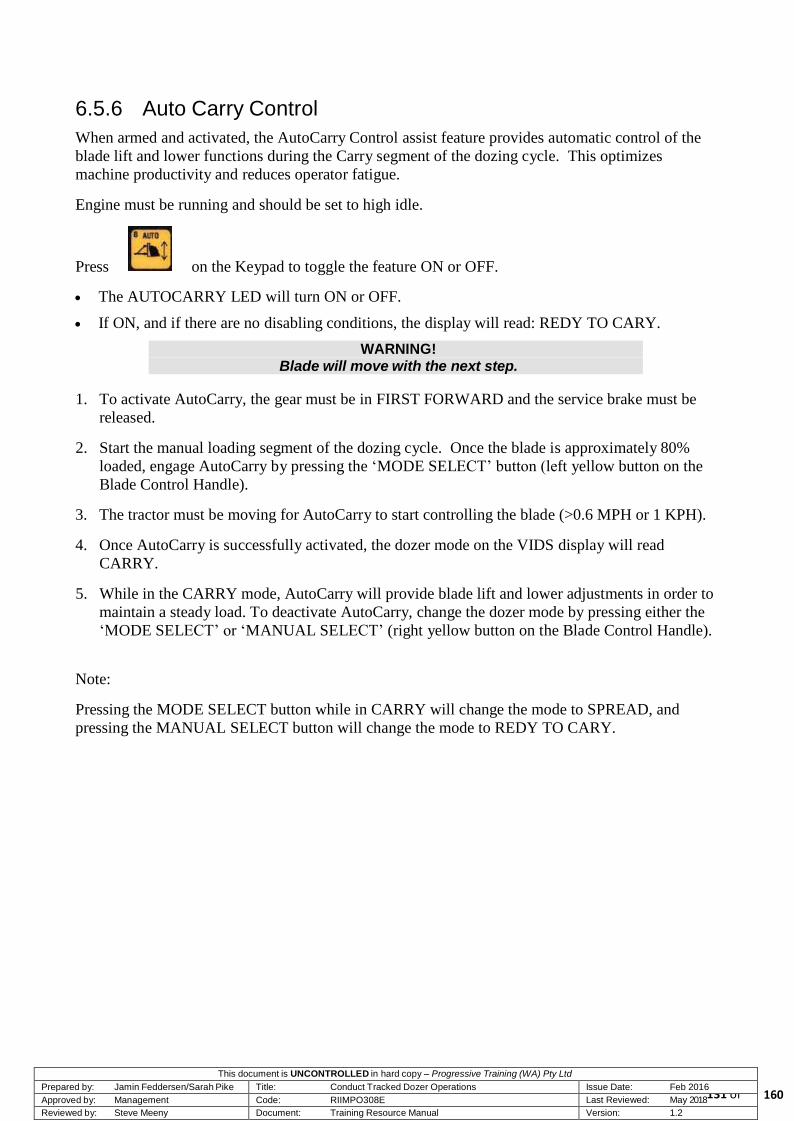
This document is UNCONTROLLED in hard copy – Progressive Training (WA) Pty Ltd Prepared by: Jamin Feddersen/Sarah Pike Title: Conduct Tracked Dozer Operations Issue Date: Feb 2016 Approved by: Management Code: RIIMPO308E Last Reviewed: May 2018
131 of Reviewed by: Steve Meeny Document: Training Resource Manual Version: 1.2
6.5.6 Auto Carry Control
When armed and activated, the AutoCarry Control assist feature provides automatic control of the
blade lift and lower functions during the Carry segment of the dozing cycle. This optimizes
machine productivity and reduces operator fatigue.
Engine must be running and should be set to high idle.
Press on the Keypad to toggle the feature ON or OFF.
The AUTOCARRY LED will turn ON or OFF.
If ON, and if there are no disabling conditions, the display will read: REDY TO CARY.
WARNING! Blade will move with the next step.
1. To activate AutoCarry, the gear must be in FIRST FORWARD and the service brake must be
released.
2. Start the manual loading segment of the dozing cycle. Once the blade is approximately 80%
loaded, engage AutoCarry by pressing the ‘MODE SELECT’ button (left yellow button on the
Blade Control Handle).
3. The tractor must be moving for AutoCarry to start controlling the blade (>0.6 MPH or 1 KPH).
4. Once AutoCarry is successfully activated, the dozer mode on the VIDS display will read
CARRY.
5. While in the CARRY mode, AutoCarry will provide blade lift and lower adjustments in order to
maintain a steady load. To deactivate AutoCarry, change the dozer mode by pressing either the
‘MODE SELECT’ or ‘MANUAL SELECT’ (right yellow button on the Blade Control Handle).
Note:
Pressing the MODE SELECT button while in CARRY will change the mode to SPREAD, and
pressing the MANUAL SELECT button will change the mode to REDY TO CARY.
160

This document is UNCONTROLLED in hard copy – Progressive Training (WA) Pty Ltd Prepared by: Jamin Feddersen/Sarah Pike Title: Conduct Tracked Dozer Operations Issue Date: Feb 2016 Approved by: Management Code: RIIMPO308E Last Reviewed: May 2018
132 of Reviewed by: Steve Meeny Document: Training Resource Manual Version: 1.2
6.6 Tip Head Considerations
Where the dozer is used to dump loads within the production environment the operator should
follow procedures for the mining area, they are:
NOTE!
Check the dump edge and the toe of the dump edge to ensure it is safe to commence pushing material over the dump.
1. Where possible, work the dump from right to left.
2. When spotting trucks onto the dump, you must remain visible to the truck operator at all times.
3. Position the dozer so that the truck operator has a clear view of the dozer from his/her driver’s
side window and mirrors.
4. When building a windrow on an undercut face or dump edge, you must physically inspect the
edge before commencing the task.
5. Ensure all loads are tipped short and pushed over the edge by the dozer if the tipping edge
appears unsafe or has slumped below a safe standard.
6. Ensure that all windrows on static dumps are built and maintained to site standards. The axle
height of the largest truck on site is usually regarded as the normal standard.
7. Maintain radio contact with trucks and other vehicles if you are working in dusty or confined
areas.
8. Visually check the dump level and keep the Supervisor informed if the dump starts to crack or
slump below the required level.
9. Maintain a slight slope up to the windrow at the tip head to allow for compaction and safety.
The amount of slope will vary depending on the type of material and height of the tip head.
10. Where possible use a laser level to monitor the dump level. Aim to keep the dump level within
300 mm of the relative level (RL).
11. Engage first gear when pushing bulky material on the dump and only select second gear for
light clean-up type work.
160

This document is UNCONTROLLED in hard copy – Progressive Training (WA) Pty Ltd Prepared by: Jamin Feddersen/Sarah Pike Title: Conduct Tracked Dozer Operations Issue Date: Feb 2016 Approved by: Management Code: RIIMPO308E Last Reviewed: May 2018
133 of Reviewed by: Steve Meeny Document: Training Resource Manual Version: 1.2
6.6.1 Spotting on Tip Heads
The following precautions are followed
when spotting on tip heads:
Position the machine ready for the
arrival of the haul truck reversing in.
The haul truck driver reverses in parallel
to the draft arm (side of the dozer),
keeping the dozer on the driver’s side at
all times.
The haul truck driver must remain no
less than two metres from the dozer.
At night time, turn off the cab or blade
lights to indicate the correct stopping
location. The haul truck driver dumps
the load.
After the truck tips, turn the lights back
on.
During the daytime, communicate by
hand signals to the truck driver.
Positioning the dozer
160

This document is UNCONTROLLED in hard copy – Progressive Training (WA) Pty Ltd Prepared by: Jamin Feddersen/Sarah Pike Title: Conduct Tracked Dozer Operations Issue Date: Feb 2016 Approved by: Management Code: RIIMPO308E Last Reviewed: May 2018
134 of Reviewed by: Steve Meeny Document: Training Resource Manual Version: 1.2
6.7 Planning
Before commencing your shift, you should find out:
Type of work required to undertaken
Production requirements for the shift
Equipment status
All information on current conditions and maintenance requirements.
Relevant site information is provided:
At a pre-shift meeting
On notice boards
Verbal instruction or written to the incoming operator
By your shift Supervisor
By the outgoing operator.
As a dozer operator, you should plan the coming shift as follows:
Consider how to accomplish your allocated tasks safely and efficiently
Identify hazards associated with the day’s operations
Discuss procedures that must be followed with other operators working in the area.
6.8 Advanced Operations
Advanced dozer operating techniques include:
Straight dozing
Slot dozing
Working on slopes
V-ditching
Pushing over edges
Clearing and grubbing
Windrow construction.
160
This document is UNCONTROLLED in hard copy – Progressive Training (WA) Pty Ltd Prepared by: Jamin Feddersen/Sarah Pike Title: Conduct Tracked Dozer Operations Issue Date: Feb 2016 Approved by: Management Code: RIIMPO308E Last Reviewed: May 2018
135 of Reviewed by: Steve Meeny Document: Training Resource Manual Version: 1.2
6.9 Conditions Monitoring
One of the most important aspects to operating machinery in any mine is that the operator must
monitor the loading area to maintain a streamlined process. Remember, that you are working in a
team and part of operational competency includes teamwork and the challenge of maintaining
efficiency in production. By monitoring the loading and pit conditions, the operator can quickly
assess operational requirements and adapt to changing conditions.
When working the dozer, it is imperative that the operator:
reacts promptly to all signals given from the pit floor
adhere to all production safety requirements
operate the machine safely within working environment limitations, production procedures and
road conditions
monitor the equipment performance utilising appropriate indicators to aid efficient operations
remove or manage contaminants upon identification
identifies and manages spillages on haul surfaces
meets scheduled requirements to ensure that production is not unduly delayed
maintain an efficient production cycle by following road rules and other site regulations.
6.10 Operating Requirements
General operating requirements that must be implemented when operating a dozer are:
Personnel who intend to operate a dozer must be competent and authorised to do so.
Pre-start inspection must always be conducted before commencing a shift.
When climbing onto or stepping off a dozer, always ensure Three Point Contact — one hand
and two feet or two hands and one foot — is maintained at all times. Always face the machine
and only use the equipment provided. This is important to remember, as dozer steps are not as
accessible as some other machines.
When working in the vicinity of blasted work faces, the dozer should not work parallel to the
face, as rocks may fall from above. Angle of work must be at 90 degrees when working at right
angles or not greater than or less than 45 degrees to the face when within 15 metres of the face.
If you must work parallel to a blasted face then seek the assistance and approval of the
Production Supervisor.
A dozer must travel down a ramp or traverse long distances (between jobs) in first or second
gear. This will assist in cooling the transmission and avoid undue pressure on the tracks, rollers
and idlers. This will also help control machine speed. Angles not greater than 45 degrees.
160

This document is UNCONTROLLED in hard copy – Progressive Training (WA) Pty Ltd Prepared by: Jamin Feddersen/Sarah Pike Title: Conduct Tracked Dozer Operations Issue Date: Feb 2016 Approved by: Management Code: RIIMPO308E Last Reviewed: May 2018
136 of Reviewed by: Steve Meeny Document: Training Resource Manual Version: 1.2
IMPORTANT!
Do not walk the machine down a ramp or to a distant destination in a gear higher than second.
All dozer rip and push operations must be done in FIRST gear as this allows maximum power to
be applied to the ground and the maximum amount of overburden to be pushed. To allow the
engine to remain at the optimum operating temperature the machine can be moved backward in
SECOND gear.
Contact the Shift Supervisor if this machine becomes bogged during operations. Do not attempt
to tow or push the machine from the bog prior to contacting the Supervisor.
Prior to commencing any dozing activity, the work area must be inspected by both the operator
and the supervisor. The surface and face of the bench must be inspected from the top of the
bench. Where accessible, the bottom of the bench must be inspected and coned off.
Cracks, slips, slumping and undermining must be noted during the inspection and
OCE/Supervisors notified if there is any doubt regarding the stability of the area.
6.11 Dozer Push Operations
It is important to ensure that dozer push operations are performed as efficiently as possible.
The key dozer push operations are:
maintaining slot confinement
keep slot depth at less than bonnet height
keep slots perpendicular to the High Wall or at 90° to the high wall
keep the high wall face as steep as possible
pushing material past the pivot point and maintaining material at the correct level
use a back-stacking method at the dump.
Should any of these key areas be too time consuming, the overall production operation will take too
long. For example, if a shovel set-up is such that the loading time is too long, the overall loading
capacity in the pit will be reduced, adversely affecting the haulage efficiency cycle. As a result,
haul trucks will have to wait or be redirected to another loading unit, where they may be required to
queue while waiting to be loaded.
6.11.1 Loading the Blade
The D11R is an extremely efficient mover of materials and is generally used over short distances
( less than 100 metres ). Beyond this distance they are less effective than other machines.
The hydraulic tilt on the blade of the D11R enables productivity to be significantly increased. In
the dig mode, the blade can be tilted forward. The weight of the D11R, combined with the use of
the decelerator to reduce track slippage, helps the operator cut into the material and fill the blade.
160

This document is UNCONTROLLED in hard copy – Progressive Training (WA) Pty Ltd Prepared by: Jamin Feddersen/Sarah Pike Title: Conduct Tracked Dozer Operations Issue Date: Feb 2016 Approved by: Management Code: RIIMPO308E Last Reviewed: May 2018
137 of Reviewed by: Steve Meeny Document: Training Resource Manual Version: 1.2
In the carry/slide segment, the blade can be tilted back. This reduces the cutting action and allows
the material to lay back into the blade itself and slide into the final position.
The traditional method of loading the blade is to push material horizontally. Material would have to
be re-handled if it was pushed to an edge. Re-handled material means wasted production time and
inefficient operation. The alternative is to use the D11R to its most productive advantage by dozing
on an angle to a pivot point.
6.11.2 Rolling Versus Sliding
There are two standard methods to load the blade during the dig segment:
Rolling refers to material that is rolled to the dump location. The technique is performed with a
U-blade.
Sliding refers to filling the blade and sliding the material in front. This technique is performed
with a Bull blade.
During the dig segment, with the blade tilted forward, the material is rolled up the face of the blade
and forward to the front of the load. Rolling only occurs when the blade is cutting. When the blade
is loaded it cannot handle more material. If the cutting action is allowed to continue, the cut load
will spill away from the blade. When the blade is full and continues to cut into the ground:
Horsepower is wasted because the machine is trying to cut as well as push a full blade load.
Cycles times are longer because machines that are cutting travel slower.
Blade wear is increased considerably because of the rolling action over the face of the blade and
the continued abrasion of the cutting edges.
Fuel consumption is higher due to the machine requiring more power to cut than it does to slide
material.
When it is tilted back after loading, the blade will stop cutting and spillage will be reduced.
This allows faster cycle times, greater efficiency, reduced wear and increased production levels.
WARNING! Do not wear safety glasses with side shields when loading a
haultruck. Safety glasses with side shields reduce visibility and have caused accidents in the mine environment.
160

This document is UNCONTROLLED in hard copy – Progressive Training (WA) Pty Ltd Prepared by: Jamin Feddersen/Sarah Pike Title: Conduct Tracked Dozer Operations Issue Date: Feb 2016 Approved by: Management Code: RIIMPO308E Last Reviewed: May 2018
138 of Reviewed by: Steve Meeny Document: Training Resource Manual Version: 1.2
6.12 Advanced Dozing Operations
Advanced operators in the pit area are required to be able to:
Clean up spillage
R e mo ve o ve r s i ze s p i l l a ge
Level floors
Clean up floors
Rip surface
Prepare drill pads
Clear scrub
Strip topsoil
Construct roads
Construct ramps or drop cuts
Push tip heads
Maintain stockpiles
Cut batters
Construct drains and sumps
Push up gravel or other material.
Use caution when cleaning spillage from haul roads and around excavator and shovel loading areas.
Let other operators know your intentions and ensure you receive confirmation prior to commencing
a clean-up task. Leave the area free of hazards and tidy.
Assess the task and ask for direction from your Supervisor before pushing material around on pit
floors or shots.
Get permission from your Supervisor prior to the commencement of any cleanup operation that
involves pushing material over any windrow on pit edge.
Use only SECOND gear for tramming and general light clean-up work.
CAUTION!
Under no circumstances is third gear to be used for general dozer work. Third gear is only to be used for relocating in an emergency.
Always ensure the blade and ripper is lowered when the machine is parked.
Do not allow un-authorised personnel to ride on or operate the dozer.
160

This document is UNCONTROLLED in hard copy – Progressive Training (WA) Pty Ltd Prepared by: Jamin Feddersen/Sarah Pike Title: Conduct Tracked Dozer Operations Issue Date: Feb 2016 Approved by: Management Code: RIIMPO308E Last Reviewed: May 2018
139 of Reviewed by: Steve Meeny Document: Training Resource Manual Version: 1.2
6.12.1 Straight Dozing
Observe the guidelines below when straight dozing.
1. Maintain a level cut for the best performance.
2. Fill the bulldozer blade.
3. Carry the load to the dump.
4. Avoid lugging or stalling the machine.
5. Avoid excessive spinning of the track.
If you need to turn the machine with a loaded blade, use the bulldozer tilt cylinders to steer the
machine instead of the steering lever. This is referred to as blade steer.
When you are performing leveling work, a full bulldozer blade manages better than a partially
loaded bulldozer blade.
6.12.2 Slot Dozing
Slot dozing is a particularly productive technique designed to transport large amounts of material in
a short space of time. Slot dozing doubles the amount of material that can be carried. When you
trap material in a slot, you can carry larger loads in front of the bulldozer blade. If the slot is kept at
bonnet height, it will keep the material in front of the blade and inside the slot. Deep slots do not
increase the amount of material that can be carried and are hazardous because they increase the risk
of material falling onto the machine. Slot depths must not exceed bonnet height of the machine
being used.
On the next and further passes continue to develop the length of the slot. The material cut should be
carried and slid along the slot to the dumping area. In this way, slot walls can hold considerably
more material than could be normally carried and slid.
Operators must judge how much material has to be cut to fill the blade and, at the same time, further
develop the length and depth of the slot.
Operators will develop this skill by observing other experienced operators, understanding the
principles involved and experimenting to achieve the best result.
When slot dozing
1. The depth of the slot should not be deeper than the top corner of the bulldozer blade.
2. Slots must be kept straight at bonnet height.
3. Start the slot at the dump end and work back.
4. This technique encourages downhill loading and stable load carrying on a level surface. Level
dozing through the entire slot is inefficient. This is due to the longer distance of the push.
160

This document is UNCONTROLLED in hard copy – Progressive Training (WA) Pty Ltd Prepared by: Jamin Feddersen/Sarah Pike Title: Conduct Tracked Dozer Operations Issue Date: Feb 2016 Approved by: Management Code: RIIMPO308E Last Reviewed: May 2018
140 of Reviewed by: Steve Meeny Document: Training Resource Manual Version: 1.2
When you are digging parallel slots
1. The windrow should be removed from the rear. This procedure allows the slot to be maintained
until the windrow is removed.
2. Maintain the windrow at a minimum width.
3. The centre berm should be wide enough to stand up without collapsing.
4. Maximum width should be approximately one-third of the bulldozer blade.
5. When the operator has completed the last slots across the working area, the slot walls can then
be taken out and the process repeated again.
6.12.3 Dealing with Slot Windrows
Prior to dealing with the windrows, the dump needs to be ready to be taken to the next lift.
Windrows are then pushed into the slots and, when a full blade is achieved, it is taken to the dump.
The tightness of material determines the amount of windrow that can be taken to the dump.
6.13 Working on Slopes
Dozer operators are often required to operate their machines on slopes. The D11R is capable of
operating up to a 45 degree angle but it is recommended not to exceed 30 degrees. The sections
below describe dozer operating techniques for working on slopes.
Operating Up or Down a Slope
When working on slopes or travelling, it is important not to over-speed the engine, especially when
you are unladen and moving down a slope. Remain alert for over speeding by:
Watch the tachometer and use the service brake.
Use the service brake to avoid engine over-speed and limit ground speed, especially at the top of
a slope where more control is needed to prevent excessive engine speed.
Prior to initiating a steering correction, reduce the ground speed of the machine to an acceptable
level by using the service brake.
Maximise the use of ‘cross-steering’ on slopes whenever possible.
Use lower gears when returning down slopes in order to keep the engine RPM elevated. This
technique will maintain maximum brake lubrication and use the engine as a speed retarder.
Decelerating lessens brake cooling flow and should not be used with steering that engages the
brakes.
160

This document is UNCONTROLLED in hard copy – Progressive Training (WA) Pty Ltd Prepared by: Jamin Feddersen/Sarah Pike Title: Conduct Tracked Dozer Operations Issue Date: Feb 2016 Approved by: Management Code: RIIMPO308E Last Reviewed: May 2018
141 of Reviewed by: Steve Meeny Document: Training Resource Manual Version: 1.2
Vertical Operation on a Slope
When possible, work on a slope vertically. This method is better than working horizontally. When
you are working on banks and slopes, use caution. If the machine starts to sideslip on a slope,
lighten the load and turn the machine downhill. When the machine is on a cross slope, work
vertically with tracks running up and down the slope.
Work downhill
Maintain a windrow of material on the low side of the machine in order to provide stability. Use
caution in order not to undercut the slope. Undercutting the slope will increase the slope.
Horizontal Operation on a Slope
If no other work method is available and it is necessary to work horizontally on a slope start at the
top of the slope and work down.
NOTE!
When you approach engine over-speed, the action lamps will flash. If the engine over-speeds, the action lamps will flash and the warning
alarm will sound.
6.13.1 V-Ditching
Technique
Tilt the dozer blade in order to start the desired slope.
Position the corner of the dozer blade in the centre of the ditch.
Cut to the desired depth.
6.13.2 Pushing Over Edges
Technique
Always check the work area below and barricade the area with cones to make sure there is no
access.
Check for undercuts before commencing work.
Push the material at a 90 degree angle in order to fill a trench.
Heave a full blade to the edge and return for another load.
Push the next full blade up to the previous load and push over the edge. Always leave the
remaining load for the next push.
160

This document is UNCONTROLLED in hard copy – Progressive Training (WA) Pty Ltd Prepared by: Jamin Feddersen/Sarah Pike Title: Conduct Tracked Dozer Operations Issue Date: Feb 2016 Approved by: Management Code: RIIMPO308E Last Reviewed: May 2018
142 of Reviewed by: Steve Meeny Document: Training Resource Manual Version: 1.2
NOTE!
When you are cutting material with the side of the blade, use caution so that the remaining material does not fall on the machine.
6.13.3 Clearing and Grubbing
Before clearing any vegetation, make sure the necessary environmental clearances are in place.
When pushing through scrub, always be aware of hazards.
Beware of all dead limbs.
Beware of all limbs that are hanging overhead.
To fell a large tree:
Cut the roots of the tree.
If additional leverage is needed, you can doze a small ramp near the base of the tree. The ramp
allows the machine to make higher contact on the tree.
Push the tree in the direction of the intended fall.
Advance cautiously. The ball of the root may hang up under the bulldozer blade. This could
drag the machine off the ramp.
6.13.4 Windrow Construction
Dozer constructed tip head windrows act as a barrier for haultrucks to reverse up to when dumping
a load.
Follow these procedures when constructing the windrow.
1. Assess conditions.
2. Amount of spilled material or material available for construction.
3. Quality of material available for construction. For lighter material, a wider base is needed to
affect stability. The weight of the material will affect the size of the blade loads.
160

This document is UNCONTROLLED in hard copy – Progressive Training (WA) Pty Ltd Prepared by: Jamin Feddersen/Sarah Pike Title: Conduct Tracked Dozer Operations Issue Date: Feb 2016 Approved by: Management Code: RIIMPO308E Last Reviewed: May 2018
143 of Reviewed by: Steve Meeny Document: Training Resource Manual Version: 1.2
4. Obstructions or hazards (large rocks or other debris).
5. Evenness or level of surface.
6. Hollows in the surface to be filled.
7. Position dozer at right angles to the location of the new windrow.
8. Straight doze material loads to the very edge of the bench or gully where the windrow is to be
constructed.
9. Windrows should be approximately 1.8 metres high with a base width determined by the density
of the material used in the construction.
10. The windrow should be solid enough to withstand the impact from the rear wheels of a
haultruck as it reverses to dump, and close enough to the tip head edge to allow the haultruck to
tip the load over the edge with no spillage inside the work area.
11. Raise the loaded blade to successively build up the windrow barrier.
12. Reverse out with the blade raised, then lower and manoeuvre to collect another load.
Maintaining the Windrow
Windrows require constant monitoring to gauge the need for maintenance, these factors play a role
in deterioration:
1. Type of material being dumped.
2. Frequency of truck arrivals.
3. Quality of the operating techniques of the truck driver, such as the amount of spillage or damage
to the windrow.
4. Straight dozing techniques are all that is required to maintain the windrow. The object is to
push the windrow further out as required to enable the trucks to continually dump clear of the
work area.
160

This document is UNCONTROLLED in hard copy – Progressive Training (WA) Pty Ltd Prepared by: Jamin Feddersen/Sarah Pike Title: Conduct Tracked Dozer Operations Issue Date: Feb 2016 Approved by: Management Code: RIIMPO308E Last Reviewed: May 2018
144 of Reviewed by: Steve Meeny Document: Training Resource Manual Version: 1.2
6.14 Ripping Techniques
The most important variable of all in maximising ripper production is effective operator technique.
Each ripping situation is different and the best ripping technique for any one job depends upon the
conditions.
The benefits of using proper ripper technique are:
I ncrease ripping production
Increased ripper tip life
Reduced track wear
Reduced dozer and ripper damage.
NOTE!
Rip downhill whenever possible.
6.14.1 Ripping and Gear Selection
FIRST gear is used for most ripping operations because 2 - 3 km/h generally gives the
most economical production.
Undercarriage and tip wear increase rapidly with only a small increase in speed.
6.14.2 Teeth
In most cases, start with one tooth. If the material is penetrated easily and breaks into pieces of
satisfactory size, try two teeth on the job. Three teeth should only be used in very easy to rip
material such as hardpan or shale.
One tooth is normally used for material which breaks out in large, thick slabs — the slabs either
fracture or pass around the shank.
When two or three teeth are used, the teeth act as a rake and can hold the large slabs under the
ripper beam.
IMPORTANT! Inspect ripper tips and shank protectors frequently for excessive
wear.
160

This document is UNCONTROLLED in hard copy – Progressive Training (WA) Pty Ltd Prepared by: Jamin Feddersen/Sarah Pike Title: Conduct Tracked Dozer Operations Issue Date: Feb 2016 Approved by: Management Code: RIIMPO308E Last Reviewed: May 2018
145 of Reviewed by: Steve Meeny Document: Training Resource Manual Version: 1.2
6.14.3 Ripping
Always use a centre shank when ripping with one shank. If material breaks up satisfactorily, more
shanks may be used.
Use FIRST gear for ripping operations. It is better to use additional shanks, where
practical, rather than to increase speed.
Use part throttle to control track slippage in rock.
Rip in one direction. Cross rip only when necessary to get a satisfactory fracture.
CAUTION! Do not turn or back dozer while shanks are in the ground. Twisting
strain on the shanks and tips may cause failure and rollover.
6.14.4 Ripping Depth
Sometimes it is practical to rip as deep as possible. However, where considerable stratification is
encountered, this may not be true. It is usually best to rip at partial depth and remove materials in
its natural layers rather than try to make a full depth pass. An initial half depth pass may break the
material loose, so the second pass can be made at full depth with much less effort and achieve better
total fragmentation. Another consideration is the ripping depth that can be maintained without
lifting the rear of the machine off the ground. If the tooth will not penetrate to the full depth, the
rear of the dozer will be lifted off the ground. When this occurs, traction is lost and ripping
production goes down.
Ripping depth and the number of teeth used should be considered together. While ripping with a
single tooth generally yields optimum production, many thinly laminated materials, particularly
shales, denser mudstones and siltstones, can be often better handled by more teeth at shallow
depths.
Rip no deeper than what can be ripped on the most difficult part of the cutting area.
Rip as deeply as possible in FIRST gear. Do not raise the ripper and rip in SECOND gear.
Keep several inches of material on top of the not ripped formation to cushion the machine
and provide traction.
To achieve a fine grade of final material, close spaced passes are recommended.
6.14.5 Packed Soil, Hard Pan, Clay, Shale or Cemented Gravel
Three shanks work well in these materials. Use as many shanks as possible to break material to the
desired size, without stalling or hanging up the machine.
6.14.6 Rock with Fractures, Faults and Planes of Weakness
Use two shanks where rock breaks out in small pieces, and the machine can handle the job easily.
When the machine begins to stall or the tracks start to spin, use only the centre shank.
160
This document is UNCONTROLLED in hard copy – Progressive Training (WA) Pty Ltd Prepared by: Jamin Feddersen/Sarah Pike Title: Conduct Tracked Dozer Operations Issue Date: Feb 2016 Approved by: Management Code: RIIMPO308E Last Reviewed: May 2018
146 of Reviewed by: Steve Meeny Document: Training Resource Manual Version: 1.2
6.14.7 Pass Spacing
Pass spacing helps determine the production rate, indicating the time required to cover the area.
Maximum spacing helps hold down the cost. However, the material end-use and moving methods
must be considered. The closer the spacing, the smaller the ripped chunks will be. Thus, crusher
acceptance, hauling and loading method limitations can dictate the spacing required.
6.14.8 Ripping Direction
Generally, ripping direction is dictated by the job layout. However, there are certain conditions
under which ripping direction will greatly affect production and results. Ripping with the
laminations may result in only deep channels. When this occurs, it may be necessary to rip the
material across the cut to obtain proper material breakup.
Usually ripping is done downhill whenever possible, helping the dozer to fully use its horsepower
and weight to increase production. However, uphill ripping sometimes is utilised to get more
downward pressure from the weight transfer of the dozer and get under the material to lift
efficiently.
If the material is laminated and the plane of the laminations is inclined to the ground surface, it is
best to rip from the shallow end (where the laminations reach the surface) toward the deep end.
This helps keep the tip in the ground. If ripping is done in the opposite direction, the tip tends to
slide up the laminations and be forced out of the ground.
6.14.9 Cross Ripping
Cross ripping makes the pit rougher, is more severe on scrapers and other excavating tools and
should be avoided if possible or used only where unidirectional ripping will not adequately loosen
the formation. Cross ripping increases dozer efficiency only in the very toughest material. It helps
break up material that comes out in large slabs and loosens material in which single pass ripping
produces only deep channels. When the material is extremely hard and difficult to penetrate, cross
ripping may separate fracture planes set up by the initial ripping pass. Although cross ripping
requires up to twice as many passes as parallel ripping, it may allow a ripper to be used where
blasting would otherwise be necessary.
6.14.10 Removing Ripped Material
Never doze or scrape all of the ripped material before ripping deeper. Always keep at least 150 mm
of ripped material above the unripped formation to cushion the dozer and provide traction. The
coefficient of traction between crushed rock and solid rock is considerably higher than between
solid rock and track shoes.
160

This document is UNCONTROLLED in hard copy – Progressive Training (WA) Pty Ltd Prepared by: Jamin Feddersen/Sarah Pike Title: Conduct Tracked Dozer Operations Issue Date: Feb 2016 Approved by: Management Code: RIIMPO308E Last Reviewed: May 2018
147 of Reviewed by: Steve Meeny Document: Training Resource Manual Version: 1.2
6.14.11 Adjustable Ripper
The angle of the shank can be varied, while ripping, to achieve maximum performance throughout
each ripping pass.
To insert the ripper into the material to be ripped:
Adjust the angle of the shank beyond the vertical position to give the correct tip angle for easy
entry into the material. The angle will differ depending upon material being ripped.
Lower the ripper into the material while moving forward.
The desired ripping depth is reached by moving the tip forward to obtain the correct angle for
best performance. This is usually between the vertical and forward shank positions.
Shallow ripping is recommended when a loader is removing the material. Deep ripping is
recommended when an excavator is removing material. Use the proper shank hole to provide the
required clearance between the ground and the beam. The shank may be positioned for shallow
ripping as well as deep ripping.
6.14.12 Positioning the Ripper Shank during the Pass
Being able to achieve initial penetration is critical and may be the determining factor for whether a
material is able to be ripped or not. In most cases, initial penetration for each pass begins with the
ripper shank angled well back beyond the vertical position.
160

This document is UNCONTROLLED in hard copy – Progressive Training (WA) Pty Ltd Prepared by: Jamin Feddersen/Sarah Pike Title: Conduct Tracked Dozer Operations Issue Date: Feb 2016 Approved by: Management Code: RIIMPO308E Last Reviewed: May 2018
148 of Reviewed by: Steve Meeny Document: Training Resource Manual Version: 1.2
Ripping — initial penetration at the start of the pass
Generally, the harder the rock, the greater the angle required to rip. In hard material, the rear of the
dozer may be forced up slightly as the ripper tip contacts the surface and penetration begins. This
effect is normal, but if the tip of the ripper fails to penetrate, and the rear of the dozer stays up, raise
the shank enough to set the tracks down flat again. Try different shank angles until the best angle
for penetration is found, while looking for faults, weak spots or fractures in the surface that may aid
penetration.
6.14.13 Positioning the Ripper Shank During the Pass
Using the correct shank angle during the pass is critical to ripper production.
Adjust the shank angle forward until the dozer feels ‘pulled into’ or pinned to the ground. The
ripper tip should be slightly below the heel of the shank, not allowing the heel of the shank to be
riding on the bottom of the trench.
160
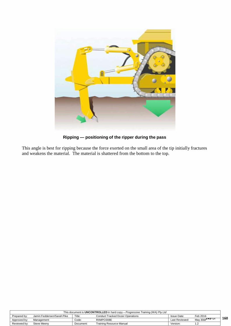
This document is UNCONTROLLED in hard copy – Progressive Training (WA) Pty Ltd Prepared by: Jamin Feddersen/Sarah Pike Title: Conduct Tracked Dozer Operations Issue Date: Feb 2016 Approved by: Management Code: RIIMPO308E Last Reviewed: May 2018
149 of Reviewed by: Steve Meeny Document: Training Resource Manual Version: 1.2
Ripping — positioning of the ripper during the pass
This angle is best for ripping because the force exerted on the small area of the tip initially fractures
and weakens the material. The material is shattered from the bottom to the top.
160

This document is UNCONTROLLED in hard copy – Progressive Training (WA) Pty Ltd Prepared by: Jamin Feddersen/Sarah Pike Title: Conduct Tracked Dozer Operations Issue Date: Feb 2016 Approved by: Management Code: RIIMPO308E Last Reviewed: May 2018
150 of Reviewed by: Steve Meeny Document: Training Resource Manual Version: 1.2
If the shank angle is too far back it causes the tip to drag across the rock and puts the face of the tip
and shank in contact with the material being ripped. This results in excessive wear and increased
resistance whereby traction is lost and ripping effectiveness is reduced.
Ripping — Incorrect shank angle during the pass
6.14.14 Using the Decelerator when Ripping
The decelerator is one of the most important dozer controls, and its proper use is a must for efficient
ripper operation. Located to the right of the brake, it should be used to match drawbar pull to
traction and ground conditions, and prevent track spin.
Too much power while ripping can result in excessive track spin, reduced undercarriage and ripper
tip life, and potential dozer damage. A constant, steady pull when ripping improves production and
reduces wear and tear on the machine.
Proper use of the decelerator enables the operator to apply just enough power to be on the verge of
track spin, taking advantage of all useable horsepower. This technique is especially important when
making initial cuts on a smooth or hard surface.
Use the decelerator to start out slowly, reduce the aggressiveness of the tracks, and make a series of
light cuts to break up the surface material and form a ‘work pad’ for the next series of deeper cuts.
160

This document is UNCONTROLLED in hard copy – Progressive Training (WA) Pty Ltd Prepared by: Jamin Feddersen/Sarah Pike Title: Conduct Tracked Dozer Operations Issue Date: Feb 2016 Approved by: Management Code: RIIMPO308E Last Reviewed: May 2018
151 of Reviewed by: Steve Meeny Document: Training Resource Manual Version: 1.2
Ripping — an example of poor shank length
6.14.15 Troubleshooting Ripping Equipment Problems
Use the following chart to aid in solving problems involving ripping equipment.
Problem
Causes
Action
Excessive Tip Breakage
Tip too long for conditions.
Shank protector missing.
Shank broken, bent, worn.
Wrong shank angle.
Too many shanks used.
Operator backing up or turning with tip in ground.
Change to shorter tip.
Check and replace if needed.
Check and replace if needed.
Adjust shank angle.
Decrease number of shanks.
Raise tip before turning or backing up.
Shank or Adaptor Breakage
Badly worn shank.
Operator side loading shank. Operator ripping while turning. Operator backing up with tip in ground.
Repair or replace shank.
Rip only in a straight line in forward direction.
Difficult Tip Installation
Material buildup on shank nose.
Shank nose bent or damaged.
Remove material.
Repair or replace shank.
160

This document is UNCONTROLLED in hard copy – Progressive Training (WA) Pty Ltd Prepared by: Jamin Feddersen/Sarah Pike Title: Conduct Tracked Dozer Operations Issue Date: Feb 2016 Approved by: Management Code: RIIMPO308E Last Reviewed: May 2018
152 of Reviewed by: Steve Meeny Document: Training Resource Manual Version: 1.2
Problem
Causes
Action
Lack of Penetration
Wrong tip in use.
Material too dense.
Improper operator technique.
Try different tip or penetration tip.
Use larger dozer, if possible. Make series of very shallow passes to provide improved traction. Tandem rip for small area. Pre-blast.
Change operators or instruct as to proper techniques (see following section on Ripping Techniques).
Damage to Track Shoes
Track shoes too wide. Track shoes not Extreme Service.
Use standard width Extreme Service Shoes.
6.15 Exclusion Zones
The exclusion zone is part of safe working operations with all heavy equipment changeovers and is
a clear area with no other equipment, personal or traffic in the area. A common occurrence with
dozer operations, operators will change over at the beginning and ends of the shift. Maintaining a
safe area to do the hot seat changeover requires an exclusion zone be established.
Long-term parking procedures are applied but the engine is not shut down. A walk-around
inspection is conducted outside of the footprint of the equipment. The outgoing operator and
incoming operator communicate and confirm the changeover location as instructed by the pit
supervisor. On arrival at the location, the outgoing operator parks the machine in a fundamentally
stable position which will allow the light vehicle driver to enter the exclusion zone and swap the
operators.
160

This document is UNCONTROLLED in hard copy – Progressive Training (WA) Pty Ltd Prepared by: Jamin Feddersen/Sarah Pike Title: Conduct Tracked Dozer Operations Issue Date: Feb 2016 Approved by: Management Code: RIIMPO308E Last Reviewed: May 2018
153 of Reviewed by: Steve Meeny Document: Training Resource Manual Version: 1.2
A 50-metre general exclusion zone
WARNING! The outgoing operator must ensure that the machine is parked in a
location that will allow the light vehicle carrying the incoming operator to maintain the 50-metre exclusion zone.
WARNING!
Approach the machine from a direction which is within the vision of the operator from the cab (either directly or through rear-vision
mirrors).
160

This document is UNCONTROLLED in hard copy – Progressive Training (WA) Pty Ltd Prepared by: Jamin Feddersen/Sarah Pike Title: Conduct Tracked Dozer Operations Issue Date: Feb 2016 Approved by: Management Code: RIIMPO308E Last Reviewed: May 2018
154 of Reviewed by: Steve Meeny Document: Training Resource Manual Version: 1.2
A 50-metre no-go zone
6.16 Emergency Responses and Actions
6.16.1 Introduction
When operating a dozer, you may encounter an emergency situation. However, it is impossible to
predict and plan for every emergency contingency. The following sections are provided as a guide
for the most likely scenarios. You should ensure that you understand emergency scenarios and the
appropriate response, but always remember that every situation is different. There may be
circumstances when following the instructions will increase the level of danger.
Therefore, you must use your self assessment in each situation, to ensure that you avoid:
Personal injury
Injury to other personnel
Environmental damage
Equipment damage
Loss of production.
If the dozer becomes immobilised due to ground conditions or mechanical faults, you should carry
out the correct shutdown procedure and immediately contact your supervisor and the maintenance
department. Your supervisor is responsible for confirmation of the appropriate actions to ensure the
dozer is repaired quickly.
160

This document is UNCONTROLLED in hard copy – Progressive Training (WA) Pty Ltd Prepared by: Jamin Feddersen/Sarah Pike Title: Conduct Tracked Dozer Operations Issue Date: Feb 2016 Approved by: Management Code: RIIMPO308E Last Reviewed: May 2018
155 of Reviewed by: Steve Meeny Document: Training Resource Manual Version: 1.2
6.16.2 Emergency Radio Procedure
In an emergency situation where you require assistance, transmit an emergency call over the two-
way radio. Upon the activation of an emergency, radio silence will commence immediately. To
initiate the emergency procedure you will carry out the following actions.
Transmit the words ‘Emergency, Emergency, Emergency’ and wait for a response. If you do not
receive a response within a few seconds retransmit the call. Once contact has been established,
provide emergency personnel with the following details:
Your NAME
LOCATION and nature of the emergency
TYPE of emergency situation (accident or injury)
Equipment or Personnel involved
Assistance that is required (ambulance, fire, mines rescue)
Hazards that may exist
Remain by the radio (if it is safe to do so) until you are relieved at the site. Leaving your radio may
place you and others in the area in greater danger.
6.16.3 Emergency Stop
In an emergency situation you will be required to stop the dozer as quickly as possible. In this
instance, observe the following:
stop the dozer
reduce the engine to idle
shut the machine down
transmit your position and emergency details
await instructions
maintain radio contact until relieved at the site
exit the vehicle as soon as possible.
6.16.4 Steering Failure
If an electrical or mechanical fault causes steering failure immediately stop the dozer by lowering
the blade. Shut the machine down as quickly as possible and notify the shift supervisor and the
workshop. When the machine has shut down the operator should disembark the machine and
attempt to identify the problem.
160

This document is UNCONTROLLED in hard copy – Progressive Training (WA) Pty Ltd Prepared by: Jamin Feddersen/Sarah Pike Title: Conduct Tracked Dozer Operations Issue Date: Feb 2016 Approved by: Management Code: RIIMPO308E Last Reviewed: May 2018
156 of Reviewed by: Steve Meeny Document: Training Resource Manual Version: 1.2
WARNING! Do not attempt to operate the dozer following any system failure.
6.16.5 Rollovers
Rollovers can occur when the dozer is doing gradient level work. The operators cab is fitted with a
Roll-over Protection System (ROPS) which is designed to protect the operator and withstand a
significant rollover impact. If the dozer rolls over you should:
Remain in the dozer operator’s cabin
Reduce body movement
Brace yourself in the operator’s seat as firmly as possible
When the rolling stops shut down the engine
When possible use the emergency radio procedures
When the movement has stopped and the area is safe, exit the cabin and move away from the
vehicle.
WARNING!
Do not attempt to jump out of the operator’s cabin during a rollover. Any attempt to exit the cabin while the machine is moving will most
likely result in severe injury or death.
6.17 Fire Procedure
An onboard fire has the potential to cause serious injury to you and other personnel and/or damage
to equipment. A fire can ignite from various sources including leaking fuel and hydraulic lines.
Remember that a fire in the engine compartment may occur without being visible to the operator.
Possible causes of fire on a dozer are:
Leaking diesel or oil near exhaust gasses
Electrical faults
Excessive heat generated by operational conditions
severely overheating the engine.
If the dozer catches fire, you should:
broadcast an emergency radio transmission
stop the machine as quickly and safely as possible
turn off the vehicle
if the suppression system has not engaged automatically, manually actuate the system
exit the dozer and proceed to ground level
actuate the isolation switch.
160

This document is UNCONTROLLED in hard copy – Progressive Training (WA) Pty Ltd Prepared by: Jamin Feddersen/Sarah Pike Title: Conduct Tracked Dozer Operations Issue Date: Feb 2016 Approved by: Management Code: RIIMPO308E Last Reviewed: May 2018
157 of Reviewed by: Steve Meeny Document: Training Resource Manual Version: 1.2
Avoid exiting on the damaged side of the machine if possible. If you have the time and it is safe to
do so, locate and remove the hand held extinguisher and attempt to assist in extinguishing the fire.
Do not place yourself at risk. Once the hand-held extinguisher is discharged and the fire is still
burning, move away from the machine to a safe location.
IMPORTANT! If you cannot fight a machine fire without endangering your safety, do not attempt to extinguish the fire. Retreat to a safe distance until the
emergency services arrive.
A mine official will direct a support vehicle to clear you from the area and you should exit onto the
support vehicle once it has completed its approach. Initiate an exclusion zone around the machine
if the fire is unable to be extinguished. Allow the burnt area to cool before approaching.
WARNING! In the event of a major engine fire operators are to immediately initiate
emergency shut down and stopping procedures activate the fire suppression system and exit the vehicle.
6.17.1 Electrical Contact
When operating around the mine site, be aware of overhead electrical cables. Should any part of the
dozer come into contact with an electrical installation and become stationary, you should:
broadcast an emergency radio transmission
shut down the machine
remain in the operator’s cabin
never attempt to handle electrical wires or components that may be touching the dozer
warn all personnel to remain clear (an exclusion zone will apply)
if the power has been isolated and you have received authority to leave the vehicle, exit the cab
remain well clear off the machine.
WARNING! Do not attempt to climb off the machine if in contact with overhead cables, you must wait until advised to do so and follow directions
from the ER personnel.
6.17.2 Environmental Protection
Contain, Clean and Report are the sequence of events that are required in the event of an
environmental situation. Mine site environmental policies cover the majority of environmental
incidents and situations that can arise during operations, including:
160

This document is UNCONTROLLED in hard copy – Progressive Training (WA) Pty Ltd Prepared by: Jamin Feddersen/Sarah Pike Title: Conduct Tracked Dozer Operations Issue Date: Feb 2016 Approved by: Management Code: RIIMPO308E Last Reviewed: May 2018
158 of Reviewed by: Steve Meeny Document: Training Resource Manual Version: 1.2
oil, fuel and lubricant spillage
dust generation
noise pollution
lighting pollution
vegetation and soils clearing
mining area rehabilitation.
You should always be aware of the environment in which you are operating and the environmental
policies that govern its use. Remember the golden rule when dealing with an environmental
emergency:
Contain
Clean
Report.
6.17.3 Summary
This topic has provided instructions on dozer emergencies and the techniques used to manage them.
You should now have a complete theoretical knowledge of the capabilities and functions of the
Caterpillar D11R Dozer, including:
Duty of car as a dozer operator
Knowledge of the occupational health and safety rules that govern the use of dozers in the mine
environment
How to conduct safe and efficient basic operations
How to conduct safe and efficient advanced operations
How to manage dozer emergencies.
If you have any questions or require clarification of any part of this topic, you should ask your
instructor now, before undertaking the topic assessment.
You should remember that, as an operator, you are responsible for safe dozer operations. You are
responsible for your own safety, the safety of others, and the safety of your equipment. If you are
able to accept that responsibility and act accordingly, you will be well on your way to becoming a
certified Dozer operator.
Once you have successfully completed the assessment for this topic, you will be given practical
training to test your new skills and knowledge in a production environment.
160

This document is UNCONTROLLED in hard copy – Progressive Training (WA) Pty Ltd Prepared by: Jamin Feddersen/Sarah Pike Title: Conduct Tracked Dozer Operations Issue Date: Feb 2016 Approved by: Management Code: RIIMPO308E Last Reviewed: May 2018
159 of Reviewed by: Steve Meeny Document: Training Resource Manual Version: 1.2
Topic 7 — Performance Enhancement
7.1 Introduction
The purpose of this topic is to provide you with the opportunity to develop enhanced operational
skills on the D11R Dozer while under the ‘loose supervision’ of a ‘mentor’.
At this stage you will have successfully completed your final practical competency-based
assessment as a part of the completion of topic 6. You will now be required to complete a period
ten working days of practical, hands-on experience before finally being deemed ‘fully competent’.
This period of on-the-job training will give you time to develop your operational skills to a high
level of proficiency. Although you are still nominally under training, there will be no formal
assessment at the end of the performance enhancement period. However, your trainer, supervisor or
mentor may require you to demonstrate some of advanced surface mining techniques if they believe
it is necessary to do so.
7.2 Mentor
While you complete the performance enhancement period you will be under the supervision of a
‘mentor’. Your mentor may be an experienced operator, your supervisor or your original trainer.
The mentor provides you with a person to contact at times when you need advice or directions on
how to carry out particular tasks. During your time under performance enhancement (or even as a
skilled operator) do not be afraid to ask questions if you are not entirely confident or sure about
certain tasks and operations.
Your mentor will also be responsible for monitoring you from time-to-time as you operate the
machine in a production setting. This is in order to identify and change any incorrect operating
techniques before they become bad habits.
7.3 Operational Tasks
During the period of skills development, you will be expected to conduct all normal surface mining
operations in a productive setting. As you conduct these tasks, you should try to maximise the
benefit of the skills development period by operating under a range of conditions. This includes
operations:
rainy or dusty conditions
night shift
wet or boggy ground
160

uneven ground
D11R Dozer working and simple haulage circuit
Each of these conditions will require you to employ different operating
strategies. You should seek assistance from your supervisor on any
operational problems that may arise from operating in these conditions.
Remember, most tasks become easier with repetition. Handling adverse
conditions is no different. The more operations that you carry out in
adverse conditions, the better your overall capabilities as an operator will
become.
7.4 Finalisation
Once you have completed the performance enhancement period under a
range of operating conditions, you will be considered to be fully
competent to operate the D11R Dozer. At the completion of the period,
your mentor, supervisor or trainer may require you to demonstrate some
of the techniques that you have learned and have been using. This is to
ensure that you have not adopted poor operational habits or techniques
since you were deemed competent at the completion of topic six.
7.5 Summary
This topic is the final topic of the D11R Dozer training package. You
should now concentrate on developing your skill as an operator of the
dozer. Most operators improve with the greater number of operational
hours that they achieve.
As you discover techniques or methods that make the dozing operation
more efficient, ensure that you raise these issues with your supervisor
and other personnel as appropriate.
It is important to remember that the reference material from this
training package is a valuable source of information about the
operation. You should keep this material with you during your work
on the D11R Dozer and refer to it on a regular basis, or as
appropriate.
Page 160 of 160
This document is UNCONTROLLED in hard copy – Progressive Training (WA) Pty Ltd Prepared by: Jamin Feddersen/Sarah Pike Title: Conduct Tracked Dozer Operations Issue Date: Feb 2016 Approved by: Management Code: RIIMPO308E Last Reviewed: May 2018 Reviewed by: Steve Meeny Document: Training Resource Manual Version: 1.2