Right-of-Way Lighting Policy - City of Ottawa
79
Right-of-Way Lighting Policy September 1, 2007 Draft Prepared by In collaboration with Document No. 21-10
-
Upload
khangminh22 -
Category
Documents
-
view
4 -
download
0
Transcript of Right-of-Way Lighting Policy - City of Ottawa
Right-of-Way Lighting Policy
September 1, 2007 Draft
Prepared by
In collaboration with
Document No. 21-10
RIGHT-OF-WAY LIGHTING POLICY
September 1, 2007
Contents ii
Table of Contents
CHAPTER 1 INTRODUCTION 1
1.1 GENERAL 1
1.2 INTENT 2
1.3 PURPOSE OF LIGHTING 2
CHAPTER 2 LIGHTING LEVELS AND DESIGN REQUIREMETNS 4
2.1 LIGHTING DESIGN CALCULATIONS 4
2.2 REQUIRED AVERAGE ROADWAY LIGHTING LEVELS 4
2.2.1 ILLUMINANCE CRITERIA 4
2.2.2 LUMINANCE CRITERIA 4
2.2.3 SMALL TARGET VISIBILITY (STV) CRITERIA 5
2.3 INTERSECTIONS 7
2.3.1 INTERSECTIONS OF PUBLIC RIGHTS-OF-WAY 7
2.3.2 INTERSECTIONS OF PUBLIC RIGHTS-OF-WAY WITH TRANSITWAYS 7
2.4 SIDEWALKS 8
2.5 LIGHTING POLE LOCATION AND OFFSET REQUIREMENT 10
2.5.1 POLE OFFSETS 10
2.5.1.1 Poles in Protected Areas 10
2.5.1.2 Poles in Unprotected Areas 10
2.6 LIGHTING DESIGNS IN PROXIMITY TO AIRPORTS 12
2.7 REDUCED ROADWAY LIGHTING LEVELS (ONE-HALF IESNA) 12
2.8 UNDERPASS, TUNNEL, BRIDGE & AT-GRADE RAILWAY CROSSING
LIGHTING APPLICATIONS 12
2.9 BICYCLE LANES 12
2.10 URBAN NATURAL FEATURES 13
2.11 TRANSITION ILLUMINATION 13
2.11.1 FULL CONTINUOUS LIGHTING UP TO A BOUNDARY ROAD 13
2.11.2 TRANSITION ILLUMINATION AT INTERSECTIONS 13
2.12 MARKER TYPE LIGHTING 14
2.13 HYDRO UTILITY WITHIN THE RIGHTS-OF-WAY 14
2.13.1 CONDITIONS OF SERVICE 14
2.13.2 JOINT USE HYDRO LIGHT POLE 14
2.14 CITY APPROVAL OF LIGHTING DESIGNS BY THIRD PARTIES 14
2.15 ROUNDABOUTS 14
2.16 OTHER JURISDICTIONS 15
2.17 THIRD PARTY ELECTRICAL ATTACHMENTS ON LIGHT POLES 15
RIGHT-OF-WAY LIGHTING POLICY
September 1, 2007
Contents iii
CHAPTER 3 “SPECIAL AREAS” 16
3.1 LIGHTING STRATEGY FOR “SPECIAL AREAS” 17
3.2 HIERARCHY FOR “SPECIAL AREA” LIGHTING 18
3.3 HERITAGE CONSERVATION DISTRICTS 18
3.3.1 PUBLIC CONSULTATION PROCESS 19
3.3.2 BOUNDARY ROADS OF HERITAGE CONSERVATION DISTRICTS 19
3.4 RURAL AREA VILLAGE MAINSTREETS 20
3.4.1 RURAL VILLAGE MAINSTREET CLASSIFICATION 20
3.4.2 PUBLIC CONSULTATION PROCESS 21
3.5 BUSINESS IMPROVEMENT AREAS 21
3.5.1 PUBLIC CONSULTATION PROCESS 22
3.5.2 BOUNDARY ROADS OF BUSINESS IMPROVEMENT AREAS 22
CHAPTER 4 CONTEXT-BASED POLICY APPLICATION 23
4.1 AREAS UNDER DEVELOPMENT – LIGHTING LEVELS AND STYLE 23
4.1.1 “ALL OTHER AREAS” UNDER DEVELOPMENT 23
4.1.2 INFILL OF EXISTING DEVELOPMENTS 23
4.1.3 “SPECIAL AREAS” UNDER DEVELOPMENT 23
4.2 RURAL ROADS 24
4.3 EXISTING UNLIT URBAN LOCAL ROADS 24
4.4 EXISTING URBAN LOCAL ROADS WITH MARKER LIGHTING 24
4.5 EXISTING URBAN LOCAL ROADS WITH PARTIAL LIGHTING 24
4.6 LIGHTING FOR THE FORMER CITY OF OTTAWA AREA 24
4.7 URBAN / RURAL AREA BOUNDARY RIGHTS-OF-WAY 25
4.8 URBAN LOCAL ROADS IN NEW RESIDENTIAL, EMPLOYMENT &
MIXED-USE CENTRE AREAS 25
4.9 LANEWAYS 25
4.10 THROUGH-BLOCK PEDESTRIAN WALKWAYS 25
4.11 LIGHTING OF PRIVATELY OWNED ROADS AND LANES 26
4.12 EXISTING CITY-OWNED LAWN LAMPS 26
4.13 MAJOR RE-LIGHTING PROJECT 26
CHAPTER 5 LIGHTING EQUIPMENT 27
5.1 BACKGROUND 27
5.2 LUMINAIRE CLASSIFICATION SYSTEM 28
5.3 POLE COLOURS 28
5.4 DECORATIVE LIGHTING EQUIPMENT 28
5.4.1 ‘SHORT-HEIGHT’ LIGHTING EQUIPMENT 29
RIGHT-OF-WAY LIGHTING POLICY
September 1, 2007
Contents iv
5.4.2 ‘MID-HEIGHT’ LIGHTING EQUIPMENT 29
5.4.3 ‘TALL-HEIGHT’ LIGHTING EQUIPMENT 29
5.5 LUMINAIRE GROUPING FOR “SPECIAL AREAS” 30
5.6 “ALL OTHER AREAS” 40
5.7 LUMINAIRE GROUPING FOR “ALL OTHER AREAS” 40
5.7.1 STANDARD POLES FOR ROADWAY LIGHTING 44
5.8 ROADWAY LIGHTING EQUIPMENT CONTEXT 44
CHAPTER 6 DESIGN CONSIDERATIONS 46
6.1 LIGHT POLLUTION 46
6.2 HORIZONTAL CURVES 46
6.3 STREET AND SIDEWALK LIGHTING SHADED BY TREES 46
CHAPTER 7 STREET LIGHTING WARRANTS 47
7.1 PRIORITIZATION OF LIGHTING 47
7.1.1 ROADWAY LIGHTING PRIORITIZATION DATABASE 47
7.2 ROADWAY LIGHTING WARRANTS 47
APPENDIX A Glossary 48
APPENDIX B Approved Lighting Equipment 51
APPENDIX C Mainstreet Roads 60
APPENDIX D Map Schedules 64
APPENDIX E Lighting Styles in Existing Heritage Conservation Districts 67
APPENDIX F Luminance Versus Illuminance 69
APPENDIX G Footnotes 73
RIGHT-OF-WAY LIGHTING POLICY
September 1, 2007
Contents v
List of Tables Table 2.1 Required Average Roadway Lighting Levels............................................. 6
Table 2.2 Required Average Lighting Levels for Intersections.................................. 8
Table 2.3 Required Average Lighting Levels for Sidewalks...................................... 9
Table 2.4 Pole Offsets for Poles Located in Unprotected Areas .............................. 11
Table 5.1 Roadway Lighting Equipment for “Special Areas” – Urban Area ........... 38
Table 5.2 Roadway Lighting Equipment for “Special Areas” – Rural Area ............ 39
Table 5.3 Roadway Lighting Equipment for “All Other Areas” .............................. 45
Table 7.1 Luminaires For “Special Areas” ............................................................... 51
Table 7.2 Poles & Luminaire Bracket Arms For “Special Areas”............................ 52
Table 7.3 Group A1 – Semi Cut Off Cobra Head Style Fixtures ............................. 53
Table 7.4 Group A2 – Full Cut Off Style Cobra Head Style Fixtures...................... 54
Table 7.5 Group B1 – Semi Cut Off Lantern Style Fixtures .................................... 55
Table 7.6 Group A2 – Full Cut Off Lantern Style Fixtures...................................... 55
Table 7.7 Group C – Round Style Fixxtures............................................................. 56
Table 7.8 Group D – ‘Shoe Box’ Style Fixtures....................................................... 57
Table 7.9 Underpass Luminaires .............................................................................. 58
Table 7.10 Luminaire Bracket Arms........................................................................... 58
Table 7.11 Aluminum Poles........................................................................................ 58
Table 7.12 Concrete Poles .......................................................................................... 59
Table 7.13 Business Improvement Area Existing Mainstreet Roads.......................... 60
Table 7.14 Suggested Rural Area Village Mainstreets ............................................... 61
RIGHT-OF-WAY LIGHTING POLICY
September 1, 2007
Contents vi
List of Figures
Figure 5.1 Group B Luminaires for “Special Areas” ................................................. 30
Figure 5.2 Group C Luminaires for “Special Areas” ................................................. 31
Figure 5.3 Group D Luminaires for “Special Areas”................................................. 31
Figure 5.4 Group E Luminaires for “Special Areas” ................................................. 32
Figure 5.5 Decorative Lighting Assemblies for ‘Short-Height’ Poles....................... 33
Figure 5.6 Decorative Lighting Assemblies for ‘Short-Height’ Poles....................... 34
Figure 5.7 Decorative Lighting Assemblies for ‘Mid-Height’ Poles......................... 35
Figure 5.8 Decorative Lighting Assemblies for ‘Mid-Height’ Poles......................... 36
Figure 5.9 Decorative Lighting Assemblies for ‘Tall-Height’ Poles ......................... 37
Figure 5.10 Standard Lighting Luminaires – Group A ................................................ 41
Figure 5.11 Standard Lighting Luminaires – Group B ................................................ 42
Figure 5.12 Standard Lighting Luminaires – Group C ................................................ 42
Figure 5.13 Standard Lighting Luminaires – Group D ................................................ 43
Figure 5.14 Standard Light Poles for “All Other Areas” ............................................. 44
RIGHT-OF-WAY LIGHTING POLICY
September 1, 2007
Introduction 1
CHAPTER 1 INTRODUCTION
1.1 GENERAL
With the amalgamation of the former municipalities, it was necessary for the City of Ottawa to develop a
Right-of-Way Lighting Policy in an effort to standardize the design and application of roadway and
sidewalk lighting within the city boundaries. The Right-of-Way Lighting Policy identifies lighting
related issues to be addressed in construction and reconstruction projects and future planning discussions
with the public, developers, stakeholders and City officials.
The Right-of-Way Lighting Policy was developed using recognized national and international practices
for roadway and sidewalk lighting, including the ANSI / IESNA RP-8-00 Roadway Lightingi and TAC
Guide for the Design of Roadway Lightingii as benchmarks. Building upon these benchmarks, the Policy
adopted specific standards and modified others in order to develop a more cost-effective and
environmentally conscious strategy for lighting rights-of-way. The Policy was also developed in context
of the City of Ottawa Official Planiii in terms of roadway and land use area classifications. The Policy
also incorporates selected components of the City of Ottawa Residential Street Lighting Policy, approved
on December 12, 2001. The 2001 policy is now superceded by this broader-based lighting policy.
This Policy adopts an approach for right-of-way lighting where all areas of the City are placed into one of
two categories; “Special Areas” and “All Other Areas”. “Special Areas” of the City includes land use
areas as identified in the City of Ottawa Official Plan Schedules
iii A and B (e.g. Mixed-Use Centres,
Traditional Mainstreets and Central Areas) and also as identified in this Policy (e.g. Community Design
Plan (CDP) Core Areas and Rural Area Village mainstreets). “All Other Areas” applies to parts of the
City outside of the designated “Special Areas”. The “Special Areas” will receive decorative style lighting
equipment and metal halide lighting (white light) to highlight the distinctiveness of the area. “All Other
Areas” will receive standard lighting equipment and high pressure sodium lighting.
The Right-of-Way Lighting Policy includes information on the purpose and impacts of street lighting,
minimum required lighting levels, acceptable styles of lighting poles and fixtures, priority and associated
aspects of street lighting such as designing with reducing light pollution in mind, and the use of banners
on street light poles.
This Policy will be reviewed as needed and updated appropriately to incorporate changes in lighting
technologies, lighting hardware and economics. Opportunity for public input to substantive changes in
the Policy will be provided through a report to Committee prepared in support of future policy updates
and Council approval.
RIGHT-OF-WAY LIGHTING POLICY
September 1, 2007
Introduction 2
1.2 INTENT
The Right-of-Way Lighting Policy is to be used by lighting designers, the public, developers and City
officials in recognizing lighting-related issues to be addressed in undertaking right-of-way lighting
projects. The fundamental goal of the Policy is to provide a uniform structure for the ongoing provision
of right-of-way lighting across the City carried out by the City, developers and other stakeholders. The
Policy strives to achieve the following over time:
i. Reduce overall lighting equipment inventory to achieve savings on maintenance and
lifecycle replacement,
ii. Provide a more uniform lighting approach throughout the City of Ottawa,
iii. Provide pole and fixture options that are high quality, cost efficient and maintainable,
iv. Reduce operational and maintenance budgets for right-of-way lighting,
v. Improve maintenance response time for right-of-way lighting,
vi. Improve urban design with uniform right-of-way lighting installation,
vii. Reduce light pollution by lowering lighting levels and requiring use of full cut-off
fixtures in specified urban areas and by reducing marker lighting levels in the rural area,
viii. Reduce energy consumption by using energy efficient fixtures, and
ix. Establish guidelines for assessing the need and prioritization of new right-of-way
lighting.
The Right-of-Way Lighting Policy applies to roadways and sidewalks within public rights-of-way under
the jurisdiction of the City. It does not apply to private properties, parks, open spaces, and pathways. It
also does not apply to federal and provincial roadways. Right-of-way lighting on these roadways will be
undertaken by the respective roadway authority on a project-by-project basis in cooperation with the City
of Ottawa as may be required. Transitway lighting is undertaken by the City in accordance with the
Transitway Design Manual (October 1993), as amended from time to time.
Although the Policy addresses several lighting design situations, there may be instances where a lighting
design issue is not covered. Where special circumstances in lighting design arise that are not addressed in
this policy the Director of Transportation and Parking Operations has authority to vary from the
requirements of this policy as may be required.
1.3 PURPOSE OF LIGHTING
The main purpose of right-of-way lighting is to achieve a level of visibility that assists the motorists and
pedestrians to perceive distinctly, and with certainty, roadway details such as raised curbs, horizontal
bends and obstacles in the roadway.
Right-of-way lighting is an operative tool that provides both economic and social benefits to the public
including:
i. Reducing night time accidents,
ii. Facilitating traffic flow,

RIGHT-OF-WAY LIGHTING POLICY
September 1, 2007
Introduction 3
iii. Promoting commercial activity downtown, in CDP Core Areas, Mixed Use Centres, and
Village mainstreets by the general public,
iv. Encouraging night time use of public & private facilities such as libraries, community
centres, entertainment facilities and commercial areas, and
v. Assisting in crime prevention and police enforcement.
The quality and safety of public rights-of-way is greatly influenced by the application of proper street
lighting and while very beneficial when used appropriately, right-of-way lighting may have negative
impacts when not implemented correctly such as:
i. Increased nighttime sky glow,
ii. Light trespass onto adjacent properties,
iii. Glare, and
iv. Increased energy consumption resulting in increased energy costs and greenhouse gas
emissions.
With careful planning and proper use of lighting poles and fixtures, the design of the right-of-way lighting
can provide a comfortable nighttime environment for both motorists and pedestrians using the City’s
rights-of-way.
RIGHT-OF-WAY LIGHTING POLICY
September 1, 2007
Introduction 4
CHAPTER 2 LIGHTING LEVELS AND DESIGN REQUIREMETNS
2.1 LIGHTING DESIGN CALCULATIONS
Lighting design calculations shall be carried out as described in Annex A Calculation and Measurement
Parameters and Annex B Design Guides and Example of the ANSI / IESNA RP-8-00 Roadway Lighting.
When performing lighting calculations, the travelled pavement width on which the calculation is being
undertaken, shall include from face of curb to face of curb (or from the painted line / edge of asphalt to
the painted line / edge of asphalt where no curb is present). Similarly for sidewalks, the lighting
calculations shall be carried out to include the sidewalk from the edge of concrete to edge of the concrete
of the sidewalk. The maintenance factor or light loss factor for all roadway and sidewalk lighting
calculations shall be 0.7 in the City of Ottawa.
In performing lighting computations, the designer should always attempt to minimize the amount of ‘over
lighting’, inherent in some lighting designs by manipulating one or more lighting parameters (including
luminaire mounting height, pole spacing or luminaire lamp wattage). The minimum lighting average
must be achieved while still satisfying the lighting uniformity and glare requirements outlined in Table
2.1 Required Average Roadway Lighting Levels.
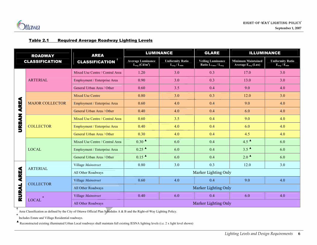
2.2 REQUIRED AVERAGE ROADWAY LIGHTING LEVELS
There are two distinct areas for rights-of-way lighting within the City of Ottawa; “Special Areas” and
“All Other Areas”. For both areas the required average roadway lighting levels are the same (for similar
road classifications) as shown in Table 2.1 Required Average Roadway Lighting Levels. In this policy the
City has adopted the lighting approach of the former City of Ottawa for average light levels on new Local
roads. Table 2.1 therefore shows that Local roads in new residential, Employment Areas and Mixed Use
Centres in the Urban Area are to be lit at one-half the IESNA recommended light levels (see also Chapter
4 Context Based Policy Applications for exceptions). The Table also shows the minimum average
Luminance levels, minimum average maintained Illuminance levels, the maximum uniformity ratios and
the maximum glare ratio by roadway and area classification.
2.2.1 Illuminance Criteria
The Illuminance method will complement the Luminance lighting criteria for designing roadway lighting
of all tangent sections of roadway. Illuminance will be used as a secondary lighting design tool for field
measurements and verification of the lighting design. It will only be used on its own to design roadway
lighting for curvilinear road sections, sidewalks / walkways and intersections.
2.2.2 Luminance Criteria
The Luminance method will now be utilized to design roadway lighting for all tangent sections of
roadway throughout the City of Ottawa. Right-of-way lighting designs will not be required to satisfy both
Luminance and Illuminance criteria. Luminance will only be complemented by the Illuminance for field
verification of lighting designs with the Luminance criteria taking precedence except as mentioned in
Section 2.2.1 Illuminance Criteria. Refer to Appendix F Luminance and Illuminance for a sample
calculation illustrating the impacts of attempting to utilize both criteria for roadway lighting designs.
RIGHT-OF-WAY LIGHTING POLICY
September 1, 2007
Introduction 5
2.2.3 Small Target Visibility (STV) Criteria
At the time of developing the Policy, the Roadway Lighting Committee of IESNA had yet to decide on
the reliability of the STV method for lighting design. Although all of the Committee members concur
that a contrast metric was desirable for lighting design, they did not agree that the STV method was that
metric. The STV criteria and any new lighting criteria should be investigated further at the time of any
future update to the Right-of-Way Lighting Policy.
RIGHT-OF-WAY LIGHTING POLICY
September 1, 2007
Lighting Levels and Design Requirements 6
Table 2.1 Required Average Roadway Lighting Levels
LUMINANCE GLARE ILLUMINANCE ROADWAY
CLASSIFICATION
AREA
CLASSIFICATION † Average Luminance
Lavg (Cd/m2)
Uniformity Ratio
Lavg / Lmin
Veiling Luminance
Ratio LVmax / Lavg
Minimum Maintained
Average Eavg (Lux)
Uniformity Ratio
Eavg / Emin
Mixed Use Centre / Central Area 1.20 3.0 0.3 17.0 3.0
Employment / Enterprise Area 0.90 3.0 0.3 13.0 3.0 ARTERIAL
General Urban Area / Other 0.60 3.5 0.4 9.0 4.0
Mixed Use Centre 0.80 3.0 0.3 12.0 3.0
Employment / Enterprise Area 0.60 4.0 0.4 9.0 4.0 MAJOR COLLECTOR
General Urban Area / Other 0.40 4.0 0.4 6.0 4.0
Mixed Use Centre / Central Area 0.60 3.5 0.4 9.0 4.0
Employment / Enterprise Area 0.40 4.0 0.4 6.0 4.0 COLLECTOR
General Urban Area / Other 0.30 4.0 0.4 4.5 4.0
Mixed Use Centre / Central Area 0.30 ▲ 6.0 0.4 4.5
▲ 6.0
Employment / Enterprise Area 0.25 ▲ 6.0 0.4 3.5
▲ 6.0
URBAN AREA
URBAN AREA
URBAN AREA
URBAN AREA
LOCAL
General Urban Area / Other 0.15 ▲ 6.0 0.4 2.0
▲ 6.0
Village Mainstreet 0.80 3.0 0.3 12.0 3.0 ARTERIAL
All Other Roadways Marker Lighting Only
Village Mainstreet 0.60 4.0 0.4 9.0 4.0 COLLECTOR
All Other Roadways Marker Lighting Only
Village Mainstreet 0.40 6.0 0.4 6.0 4.0
RURAL AREA
RURAL AREA
RURAL AREA
RURAL AREA
LOCAL *
All Other Roadways Marker Lighting Only
† Area Classification as defined by the City of Ottawa Official Plan Schedules A & B and the Right-of-Way Lighting Policy. * Includes Estate and Village Residential roadways.
▲ Reconstructed existing illuminated Urban Local roadways shall maintain full existing IESNA lighting levels (i.e. 2 x light level shown)
RIGHT-OF-WAY LIGHTING POLICY
September 1, 2007
Lighting Levels and Design Requirements 7
2.3 INTERSECTIONS
2.3.1 Intersections of Public Rights-of-Way
Urban area intersections will be fully lit if one of the intersecting roadways has full continuous lighting.
Urban area intersections will also be fully lit if they have traffic signals. This is to promote visibility and
safety at night for the intersection as it is a location where pedestrians, cyclists and motorists all meet and
negotiate for right of passage with each other at the controlled intersection. The intersection lighting shall
be the sum of the intersecting roadway lighting levels. Based on Table 2.1 Required Average Roadway
Lighting Levels, the Road and Area Classes intersect to form fifteen types of intersections. The required
lighting levels for each of these intersections are shown in Table 2.2 Required Average Lighting Levels
for Intersections that sets out the sum of the lighting values of the two intersecting roadways. To
determine the class of the roadway refer to Schedules “E” to “H” of the City of Ottawa Official Planiii. In
cases where the sum cannot be achieved (i.e. lower than the required levels in Table 2.2) due to the
geometric design or other physical limitations of the intersection, such as the location of Hydro utilities,
then the intersection levels, as a minimum, shall be 50% greater than the highest lighting level of the
intersecting roads. Table 2.2 will always take precedence for intersection lighting and not until all other
alternatives have been exhausted will the 50% exception to Table 2.2 apply. For intersections with only
one of the intersecting roads having full continuous lighting, the intersection light levels shall be 50%
greater than the levels of the fully lit approaching roadway. The non-illuminated intersecting roadway
shall have transition lighting as described in Section 2.11 Transition Illumination.
Where the design lighting levels of the intersecting roads exceed the criteria in Table 2.1 Required
Average Roadway Lighting Levels, the design levels shall then be used to determine the intersection
requirements. This is to maintain visibility and safety of everyone using the intersection by ‘highlighting’
the area with increased lighting levels compared to the levels on the approaching roadway of the
intersection.
2.3.2 Intersections of Public Rights-of-Way with Transitways
Lighting of intersections of Transitways with public road rights-of-way will be the sum of the Transitway
lighting level as required by the Transitway Design Manual (October 1993) and the public roadway
lighting level as set out in Table 2.1 Required Average Roadway Lighting Levels. In cases where the sum
cannot be achieved due to the geometric design or other physical limitations of the intersection, such as
the location of Hydro utilities, then the intersection levels, as a minimum, shall be 50% greater than the
highest lighting level of the intersecting public roadway and Transitway.
RIGHT-OF-WAY LIGHTING POLICY
September 1, 2007
Lighting Levels and Design Requirements 8
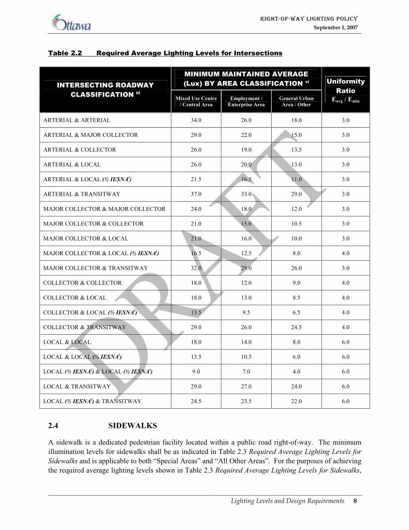
Table 2.2 Required Average Lighting Levels for Intersections
MINIMUM MAINTAINED AVERAGE
(Lux) BY AREA CLASSIFICATION vi INTERSECTING ROADWAY
CLASSIFICATION iii Mixed Use Centre
/ Central Area
Employment /
Enterprise Area
General Urban
Area / Other
Uniformity
Ratio
Eavg / Emin
ARTERIAL & ARTERIAL 34.0 26.0 18.0 3.0
ARTERIAL & MAJOR COLLECTOR 29.0 22.0 15.0 3.0
ARTERIAL & COLLECTOR 26.0 19.0 13.5 3.0
ARTERIAL & LOCAL 26.0 20.0 13.0 3.0
ARTERIAL & LOCAL (½ IESNAi) 21.5 16.5 11.0 3.0
ARTERIAL & TRANSITWAY 37.0 33.0 29.0 3.0
MAJOR COLLECTOR & MAJOR COLLECTOR 24.0 18.0 12.0 3.0
MAJOR COLLECTOR & COLLECTOR 21.0 15.0 10.5 3.0
MAJOR COLLECTOR & LOCAL 21.0 16.0 10.0 3.0
MAJOR COLLECTOR & LOCAL (½ IESNAi) 16.5 12.5 8.0 4.0
MAJOR COLLECTOR & TRANSITWAY 32.0 29.0 26.0 3.0
COLLECTOR & COLLECTOR 18.0 12.0 9.0 4.0
COLLECTOR & LOCAL 18.0 13.0 8.5 4.0
COLLECTOR & LOCAL (½ IESNAi) 13.5 9.5 6.5 4.0
COLLECTOR & TRANSITWAY 29.0 26.0 24.5 4.0
LOCAL & LOCAL 18.0 14.0 8.0 6.0
LOCAL & LOCAL (½ IESNAi) 13.5 10.5 6.0 6.0
LOCAL (½ IESNAi) & LOCAL (½ IESNAi) 9.0 7.0 4.0 6.0
LOCAL & TRANSITWAY 29.0 27.0 24.0 6.0
LOCAL (½ IESNAi) & TRANSITWAY 24.5 23.5 22.0 6.0
2.4 SIDEWALKS
A sidewalk is a dedicated pedestrian facility located within a public road right-of-way. The minimum
illumination levels for sidewalks shall be as indicated in Table 2.3 Required Average Lighting Levels for
Sidewalks and is applicable to both “Special Areas” and “All Other Areas”. For the purposes of achieving
the required average lighting levels shown in Table 2.3 Required Average Lighting Levels for Sidewalks,
RIGHT-OF-WAY LIGHTING POLICY
September 1, 2007
Lighting Levels and Design Requirements 9
sidewalks are assumed to be located adjacent to or within 2.5 m from the light pole. The roadway
lighting levels will take precedence over sidewalk lighting levels for sidewalks located more than 2.5 m
away from the light pole. Therefore roadways will not be over lit in order that the lighting of sidewalks in
distant locations or on the side of the road opposite a single sided lighting installation achieves the
average lighting levels in Table 2.3.
Sidewalks will be illuminated at the same time as the adjacent roadway is illuminated based on available
capital funding and in accordance with the priority ranking of the abutting roadway. Sidewalk lighting
will be provided through ‘back lighting’ of the roadway lighting system and only on streets where there is
a roadway lighting system. No separate dedicated sidewalk lighting systems will be installed in the City.
Sidewalks in “Special Areas” and in “All Other Areas” will be lit to the lighting levels and uniformity
ratios as shown in Table 2.3. In “Special Areas”, there is also the option of either utilizing pedestrian-
scale poles in conjunction with ‘tall-height’ light poles and/or pedestrian-scale luminaires mounted onto
the ‘tall-height’ light poles as determined through future public processes (refer to Section 3.1 Lighting
Strategy for “Special Areas”). Without a dedicated pedestrian lighting system, the Vertical Illuminance
component of the sidewalk lighting criteria identified in ANSI / IESNA RP-8-00 Roadway Lighting, will
not be practical to implement in some circumstances such as median lighting installations and therefore is
not utilized by this Policy.
Sidewalks that are lit with existing lighting from a pedestrian scale lighting system (“Special Areas”) or
from ‘back lighting’ resulting from an existing street lighting system (“All Other Areas”) shall remain as
is until such time when major reconstruction occurs. At that time the sidewalk lighting levels will
conform to Table 2.3 Required Average Lighting Levels for Sidewalks as may be required.
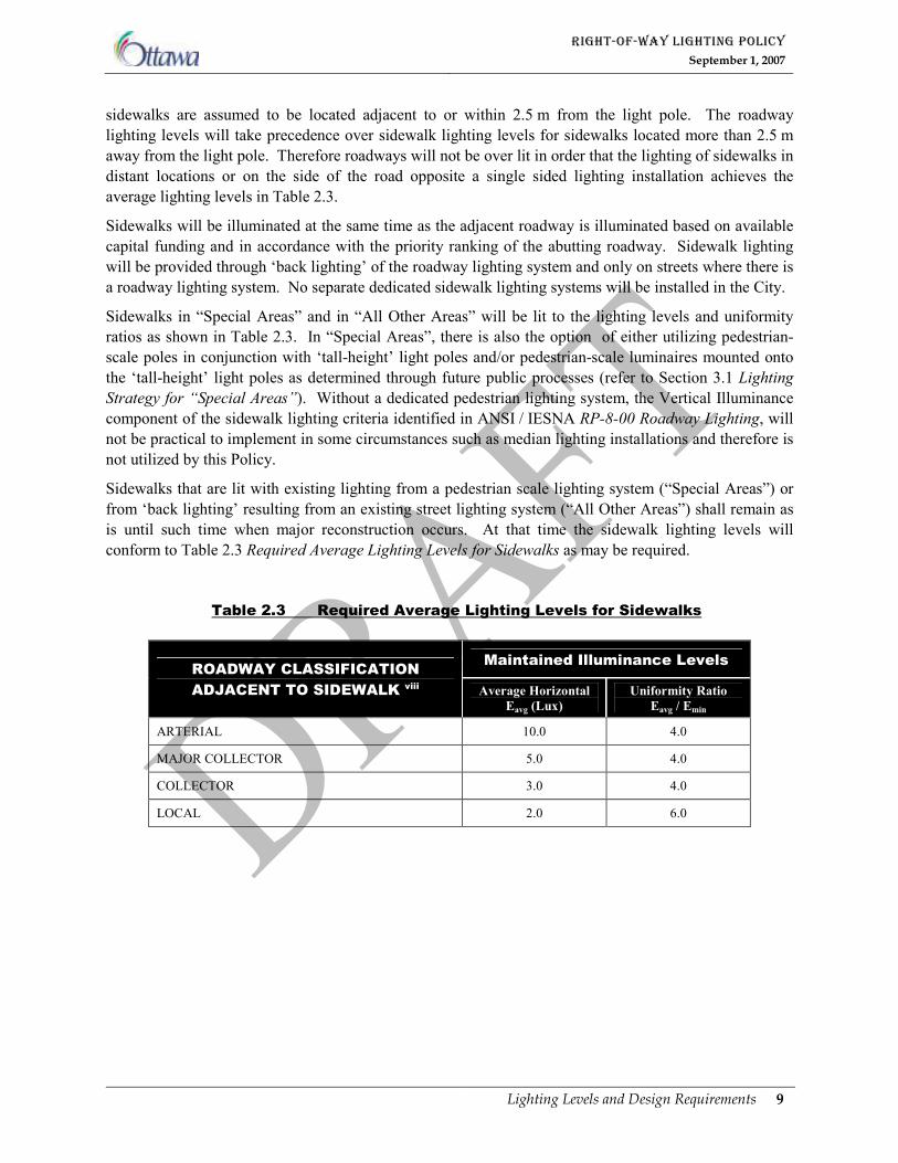
Table 2.3 Required Average Lighting Levels for Sidewalks
Maintained Illuminance Levels ROADWAY CLASSIFICATION
ADJACENT TO SIDEWALK viii Average Horizontal
Eavg (Lux)
Uniformity Ratio
Eavg / Emin
ARTERIAL 10.0 4.0
MAJOR COLLECTOR 5.0 4.0
COLLECTOR 3.0 4.0
LOCAL 2.0 6.0

RIGHT-OF-WAY LIGHTING POLICY
September 1, 2007
Lighting Levels and Design Requirements 10
2.5 LIGHTING POLE LOCATION AND OFFSET REQUIREMENT
Poles can be located in protected areas, unprotected areas or be mounted on structures. Poles in protected
areas include poles that are located behind a physical barricade such as a guide rail or concrete barrier
wall. Poles in unprotected areas include poles that are not located behind any physical barricade and are
typically located behind barrier type curb or the shoulder ‘rounding.’ These poles are susceptible to
impact by a vehicle accidentally leaving the roadway.
2.5.1 Pole Offsets
2.5.1.1 Poles in Protected Areas
Poles in protected areas shall be located on a project-by-project basis in accordance with the barrier
deflection characteristics and the proposed field conditions such as finished grades and right-of-way
width.
2.5.1.2 Poles in Unprotected Areas
The offset for poles in unprotected areas is defined as the distance from the front face of the barrier type
curb (or edge of traveled asphalt (solid white painted line) if no barrier type curb is present) to the nearest
face of the pole. Poles in unprotected areas shall have a minimum offset from the barrier type curb or
edge of traveled asphalt as indicated in Table 2.4 Pole Offsets for Poles Located in Unprotected Areas.
When using Table 2.4 the following shall be noted:
i. Deviations from the minimum pole offsets may only be approved at the discretion of the
Director, Traffic and Parking Operations.
ii. The use of frangible bases on decorative and standard lighting poles shall not be
permitted where the posted speed of the roadway is equal to or less then 60km/h.
iii. The pole offsets are for tangent road sections only.
iv. For curvilinear road sections, the pole offset shall be dealt with on a project-by-project
basis. Refer to the Roadside Safety Manual iv for guidelines and recommendations for
pole locations and offsets on curvilinear roadway sections
RIGHT-OF-WAY LIGHTING POLICY
September 1, 2007
Lighting Levels and Design Requirements 11
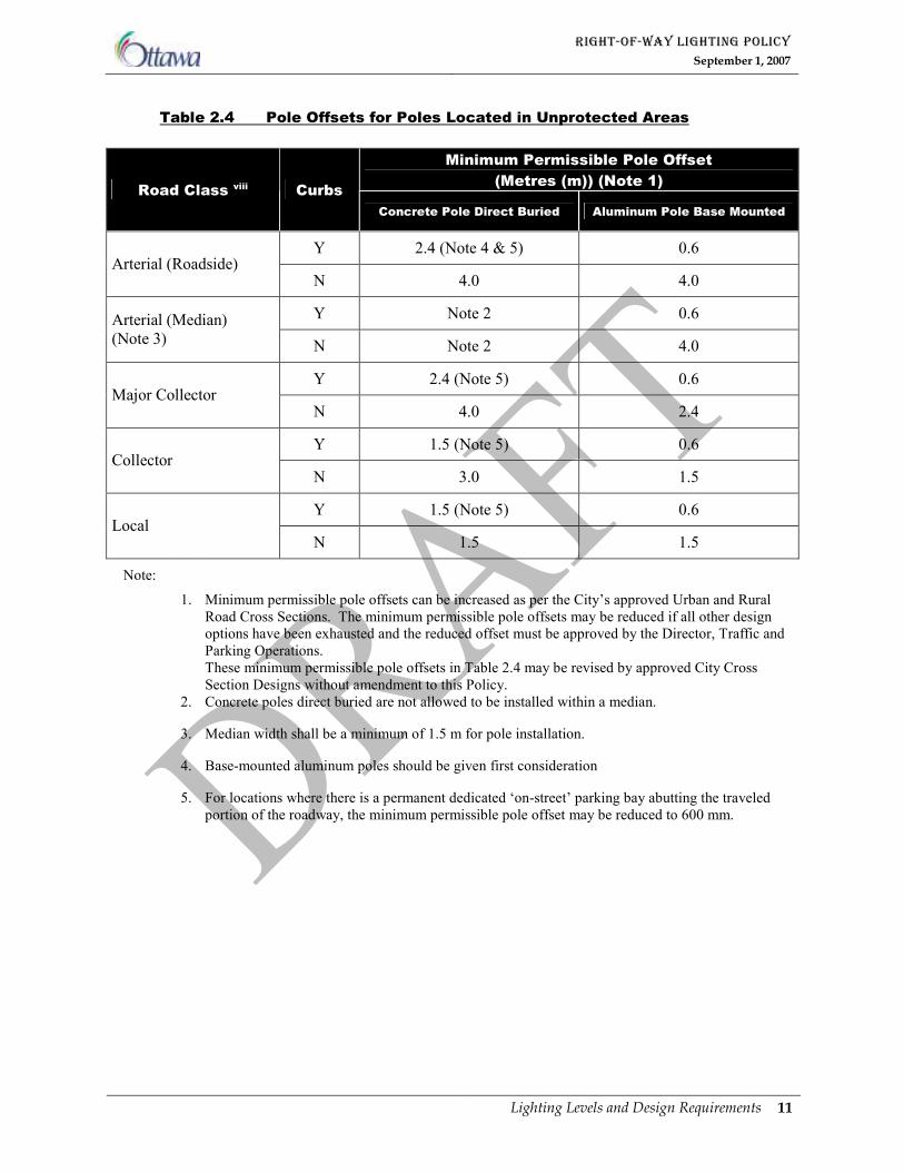
Table 2.4 Pole Offsets for Poles Located in Unprotected Areas
Minimum Permissible Pole Offset
(Metres (m)) (Note 1) Road Class viii Curbs
Concrete Pole Direct Buried Aluminum Pole Base Mounted
Y 2.4 (Note 4 & 5) 0.6
Arterial (Roadside) N 4.0 4.0
Y Note 2 0.6 Arterial (Median)
(Note 3) N Note 2 4.0
Y 2.4 (Note 5) 0.6
Major Collector N 4.0 2.4
Y 1.5 (Note 5) 0.6
Collector N 3.0 1.5
Y 1.5 (Note 5) 0.6
Local N 1.5 1.5
Note:
1. Minimum permissible pole offsets can be increased as per the City’s approved Urban and Rural
Road Cross Sections. The minimum permissible pole offsets may be reduced if all other design
options have been exhausted and the reduced offset must be approved by the Director, Traffic and
Parking Operations.
These minimum permissible pole offsets in Table 2.4 may be revised by approved City Cross
Section Designs without amendment to this Policy.
2. Concrete poles direct buried are not allowed to be installed within a median.
3. Median width shall be a minimum of 1.5 m for pole installation.
4. Base-mounted aluminum poles should be given first consideration
5. For locations where there is a permanent dedicated ‘on-street’ parking bay abutting the traveled
portion of the roadway, the minimum permissible pole offset may be reduced to 600 mm.
RIGHT-OF-WAY LIGHTING POLICY
September 1, 2007
Lighting Levels and Design Requirements 12
2.6 LIGHTING DESIGNS IN PROXIMITY TO AIRPORTS
Lighting designs in proximity to airports must adhere to Transport Canada’s aerodrome standards and
recommended practices. These requirements will typically restrict the height of the luminaires.
2.7 REDUCED ROADWAY LIGHTING LEVELS (ONE-HALF IESNA)
New local roadsviii constructed in Residential, Employment and Mixed-Use Centre areas are to be lit in
accordance with Table 2.1 Required Average Roadway Lighting Levels (at one-half of the IESNAi
recommended light levels). However, to ensure right-of-way illumination consistency in the completion
of neighbourhoods that are partially constructed or are approved for development (i.e. Composite Utility
Plan has been approved) when this policy comes into effect, future development phases shall have
right-of-way lighting designed and installed to match the existing street lighting levels up to the nearest
adjacent existing or planned arterialviii or collector
viii roadway. As described in Section 4.1.1 “All Other
Areas” Under Development, Section 4.1.2 Infill of Existing Developments and Section 4.1.3 “Special
Areas” Under Development, where a substantive portion of vacant development land within the adjacent
arterialviii or collector
viii roadway boundaries has not been approved for development (i.e. prior to Draft
Plan of Subdivision approval), the Director, Planning Branch has the authority to select an alternate road
or land use boundary (i.e. change from residential to commercial) up to which the existing street light
level of illumination will apply. The one-half IESNAi light levels will apply to new local roads
constructed beyond the existing or planned arterialviii road or collector
viii road, alternate road or land use
boundary.
2.8 UNDERPASS, TUNNEL, BRIDGE & AT-GRADE RAILWAY
CROSSING LIGHTING APPLICATIONS
Underpasses under the jurisdiction of the City will be illuminated using wall or overhead mounted
fixtures as listed in Appendix B Approved Lighting Equipment. The roadway lighting levels for the
underpass shall be similar to the adjoining roadway and conform to Table 2.1 Required Average Roadway
Lighting Levels. Underpasses must be illuminated if the approaches are fully illuminated. The light loss
factor for underpass lighting fixtures shall be 0.7, similar to the roadway fixtures. Lighting of bridges and
at-grade railway crossings will be at the same level as the adjoining roadway and be dealt with on a
project by project basis based on available capital funding and priority ranking of the associated roadway.
The illumination of tunnels shall be dealt with on a project-by-project basis based on available capital
funding.
2.9 BICYCLE LANES
Bicycle lanes are dedicated travel lanes for bicycles located on the roadway adjacent to the curb or edge
of pavement. The lanes are delineated with pavement markings and are considered part of the roadway.
As such, they will be illuminated based on the required roadway lighting levels stipulated in Table 2.1
Required Average Roadway Lighting Levels, and any illumination requirements will be governed by the
strategy for roadway lighting as set out in this Policy.
RIGHT-OF-WAY LIGHTING POLICY
September 1, 2007
Lighting Levels and Design Requirements 13
2.10 URBAN NATURAL FEATURES
Lighting design undertaken within 50 metres of a Category 1 or Category 2 Urban Natural Feature (UNF)
as identified in the City’s Urban Natural Features Strategy shall consider ways to mitigate potential
adverse impacts that right-of-way lighting may have on the natural habitat within the UNF. Lighting
design considerations in these circumstances include:
i. Placing luminaires in the right-of-way in a location that minimizes the amount of light
entering the UNF.
ii. Selecting a luminaire type with lighting optics that directs light along the length of the
right-of-way minimizing light spillage into the UNF.
iii. Designing to provide for reduced average light levels that meet or exceed the minimum
required average light level for the roadway class, but that result in minimizing the
amount of light entering the UNF.
2.11 TRANSITION ILLUMINATION
Where sections of roadways that are fully illuminated are located adjacent to sections that are not, the
street lighting shall be transitioned as recommended by the Guide for the Design of Roadway Lightingii
Transitioning of the roadway illumination will allow for easier adaptation of the driver’s eye from a lit to
a dark section of roadway. A consistent style of lighting equipment will be used in the transition area
selected from Appendix B Approved Lighting Equipment.
2.11.1 Full Continuous Lighting up to a Boundary Road
For unique situations where an urban road designation is being fully illuminated up to the boundary of an
urban / rural area, the full illumination shall be transitioned as recommended by the Guide for the Design
of Roadway Lighting ii. The transition illumination will be extended into the rural area up to and
including the point where the roadway tapers from an urban cross section (four lanes with curb) to a rural
cross section (two lanes without curb).
2.11.2 Transition Illumination at Intersections
For intersections where only one of the intersecting roads has full continuous lighting and the light levels
at the intersection are 50% greater than the light levels of the approaching illuminated roadway (as
required by Section 2.3 Intersections), the non-illuminated intersecting road shall have transition lighting
designed to extend the lighting beyond the intersection with a maximum of two pole cycles for each
approach.
RIGHT-OF-WAY LIGHTING POLICY
September 1, 2007
Lighting Levels and Design Requirements 14
2.12 MARKER TYPE LIGHTING
Marker type lighting shall consist of one of the following:
i. A single pole and luminaire located on the far right hand side of a ‘T’ intersection, or
ii. A single pole and luminaire located at ‘super mailbox’ locations, or
iii. Two poles and luminaires located diagonally opposite to each other at ‘four-way’
intersections.
The luminaire shall be a semi-cut off classification complete with a maximum lamp wattage of 100 watts
except at ‘super mailbox’ locations where the luminaire shall be a full cut-off classification. Marker type
lighting will only be installed for the intersection of two public rights-of-way where the rights-of-way are
travelled and maintained all year round. For an intersection of a public right-of-way and a private
roadway refer to Section 4.11 Lighting of Privately Owned Roads and Lanes for lighting
recommendations. Refer to Section 4.2 Rural Local Roads and Section 4.3 Existing Unlit Urban Local
Roads for context based marker type lighting installations. The installation of the marker type lighting
shall be subject to the availability of both existing electric power and capital funding.
2.13 HYDRO UTILITY WITHIN THE RIGHTS-OF-WAY
2.13.1 Conditions of Service
Roadway lighting systems shall meet the Conditions of Service set out by the local Electrical Supply
Authorities and the Electrical Safety Authority (ESA).
2.13.2 Joint Use Hydro Light Pole
Where Hydro utility poles are located within public rights-of-way, it is desirable to utilize these poles
where possible for the installation of luminaires in order to minimize the number of poles within
rights-of-way. These joint use Hydro / street light poles must be coordinated with the local Electrical
Supply Authority and shall satisfy the requirements of Ontario Regulation 22/04 Electrical Distribution
Safetyv for third party equipment mounted on Hydro utility poles.
2.14 CITY APPROVAL OF LIGHTING DESIGNS BY THIRD PARTIES
Lighting design for rights-of-way in the City of Ottawa shall be performed or supervised by a
Professional Electrical Engineer, registered in the Province of Ontario. The lighting design together with
the lighting calculation summary shall be submitted to the Program Manager, Street Light Asset
Management Unit of the City of Ottawa for review and final approval.
2.15 ROUNDABOUTS
Roundabouts shall be treated as an intersection and illuminated accordingly. Refer to Section 2.3
Intersections for more information.
RIGHT-OF-WAY LIGHTING POLICY
September 1, 2007
Lighting Levels and Design Requirements 15
2.16 OTHER JURISDICTIONS
Within the City of Ottawa, there are rights-of-way that are owned by, under the control of and/or that are
subject to design input by other public authorities such as the National Capital Commission (NCC), the
Ministry of Transportation Ontario (MTO) and Parks Canada. The NCC and MTO have their own
lighting policies which take precedence over the City’s Right-of-Way Lighting Policy. Parks Canada has
authority for providing design input on the lighting of bridges over the Rideau Canal.
The following is a partial listing of roadways/bridges that are under the control of or subject to lighting
design input by other authorities:
ROADWAYS
Aviation Parkway
Colonel By Drive
Confederation Boulevard
Island Park Drive
Ottawa River Parkway
Queen Elizabeth Drive
Rockcliffe Parkway
Experimental Farm Drive
Lady Grey Drive
Roads through the Greenbelt
HIGHWAYS
Highway 17
Highway 417
Highway 416
BRIDGES
Chaudière
Portage
Alexandria
MacDonald-Cartier
Billings
Cummings
Pretoria
Bank Street
MacKenzie King
Laurier Avenue
Union Street
Dunbar
As roadways/bridges are approved through future federal/municipal processes, these roadways/bridges
will be subject to the respective authority’s lighting policies without amendment to the above list or this
Policy.
2.17 THIRD PARTY ELECTRICAL ATTACHMENTS ON LIGHT POLES
Electrical attachments such as Christmas lights and wreaths are not permitted on light poles located
within any City right-of-way..

RIGHT-OF-WAY LIGHTING POLICY
September 1, 2007
“Special Areas” 16
CHAPTER 3 “SPECIAL AREAS”
“Special Areas” are to receive decorative style lighting equipment in accordance with this subsection.
The following locations are subject to the Special Area lighting strategy:
a. Central Area,
b. Mixed-Use Centres,
c. Town Centres,
d. Arterial Mainstreets
e. Traditional Mainstreets,
f. Heritage Conservation Districts,
g. Business Improvement Area mainstreets,
h. Rural Village mainstreets and
i. Community Design Plan (CDP) Core Areas
Areas (a) through (e) are designated and identified in the City of Ottawa Official Plan – Schedule B
Urban Policy Plan iii. Area (f) is identified in Annex 4 to the City of Ottawa Official Plan.
iii Areas (g)
and (h) are identified in the Right-of-Way Lighting Policy and discussed in Section 3.4 Rural Area
Village Mainstreets and Section 3.5 Business Improvement Areas. CDP Core Areas (i) are as shown in
Section D.2 CDP Core Areas of Appendix D Map Schedules and consist of existing or future high
density, mixed-use residential and commercial locations that have been identified through a Council
approved Community Design Plan (CDP) process but are not identified in the map schedules to the City
of Ottawa Official Plan. CDP Core Areas are subject to the Special Area lighting strategy as part of this
Right-of-Way Lighting Policy (e.g. Riverside South CDP Core Area). CDP Core Areas may be located
both in urban and in rural (village) locations. New CDP Core Areas, Village mainstreets and BIA
mainstreets identified through a future public process approved by Council are subject to Special Area
lighting without amendment to this Policy.
The decorative lighting equipment selection process for any “Special Area” may be initiated when one or
more of the following public consultation processes occurs:
i. Commencement of an Environmental Assessment and / or design for major roadway
reconstruction,
ii. Part of major lifecycle re-lighting project without roadway reconstruction,
iii. Part of preparation of a Community Design Plan for all or applicable parts of the Special
Area and,
iv. Other process as approved by the Director, Traffic and Parking Operations.
RIGHT-OF-WAY LIGHTING POLICY
September 1, 2007
“Special Areas” 17
Rights-of-way within any Special Area that are the subject of an Environmental Assessment (EA) or
detailed road design to provide for upgrading or new construction, including sections of connecting
streets, may be identified for installation of decorative lighting. When these rights-of-way have been
approved through a future public process approved by Council they are subject to Special Area lighting
without amendment to this Policy.
3.1 LIGHTING STRATEGY FOR “SPECIAL AREAS”
Decorative lighting shall be used on all rights-of-way in “Special Areas” except as otherwise provided for
in this Policy (i.e. in BIA’s and in Rural Area Villages only identified mainstreets are to be lit with
decorative lighting equipment - other streets in these areas are to be lit with standard lighting equipment).
There are three options for lighting “Special Areas” as follows:
i. ‘Mid-height’ pole complete with a decorative luminaire (Type E1, E2, E3, C, B1a or B2)
attached to the pole by either a bracket arm or post top mounted. The decorative
luminaire is complete with a Metal Halide (MH) lamp. This lighting option is applicable
to all roadway classifications except arterials.
ii. ‘Tall-height’ pole complete with a decorative luminaire (Type C1, C2, D1 or D2)
complete with a metal halide lamp and bracket arm. This lighting option is only
applicable to Arterial Roads vi.
iii. ‘Tall-height’ and ‘Short-height’ pole combination; the combination consists of a
‘tall-height’ pole with a single ‘short-height’ pole mid-span between the ‘tall-height’
poles. The ‘tall-height’ pole is complete with a decorative luminaire (Type C1, C2, D1 or
D2) with a MH lamp and a bracket arm. The ‘short-height’ pole is complete with a
decorative post top luminaire (Type B1a, B1b, B1c B1d or B2) with a MH lamp. There
is also the option to have an additional ‘short height’ style luminaire attached to the
‘tall-height’ pole on the opposite side of the ‘tall-height’ style luminaire for additional
lighting on the sidewalk side. This lighting option is applicable to all roadway
classifications.
All poles and luminaires for the “Special Area” lighting shall be selected from the “Special Area”
equipment list in Appendix B, Section B.1 “Special Areas”. All new and existing decorative lighting
poles used in “Special Areas” may accommodate banner and/or planter arms at the request by a
proponent subject to the following. The proponent shall submit in addition to the request for the addition
of banner and/or planter arms on lighting poles, an engineering report certified by a licensed Professional
Engineer in the province of Ontario. The engineering report must confirm that the integrity of the light
pole will not be compromised and that it can safely accommodate the additional load of the banner and/or
planter arms. The report shall also illustrate the proposed mounting height on the pole, minimum vertical
clearance from the ground and dimensions of the banner and/or planter.
All new lighting options selected, including the addition of banners and/or planters, are subject to
approval through a public consultation process described in Chapter 3 “Special Areas”. For existing
decorative lighting installations, the request to add banners and/or planters is subject to approval by the
Director, Planning Branch and Director, Traffic and Parking Operations.
RIGHT-OF-WAY LIGHTING POLICY
September 1, 2007
“Special Areas” 18
In addition to providing a certified engineering report, any banners placed on decorative poles are subject
to the City’s Signs By-law and must meet minimum vertical clearances as approved by the Director,
Traffic and Parking Operations. Any planters placed on decorative poles shall also meet minimum
vertical clearances as approved by the Director, Traffic and Parking Operations.
Within the boundary of any individual Special Area, all rights-of-way under the control of the City that
are subject to special lighting will use the same style of decorative luminaire and pole to provide both for
continuity in design and to simplify lighting maintenance.
3.2 HIERARCHY FOR “SPECIAL AREA” LIGHTING
Certain Special Area designations overlap with other Special Area categories. For example, a Traditional
Mainstreet may be located within a Business Improvement Area, and both may lie within a Heritage
Conservation District. To deal with situations such as this, a hierarchy approach has been developed to
assist in determining the style of right-of-way lighting to be applied. The following “Special Areas” are
listed in order of precedence for the application of the Policy in “Special Area” lighting:
i. Heritage Conservation Districts (HCD)
ii. Business Improvement Areas (BIA)
iii. Central Area
iv. Traditional Mainstreets, Arterial Mainstreets and Village mainstreets
In the example given above, because the HCD has higher illumination priority than the BIA and the
Traditional Mainstreet, the right-of-way lighting style of the HCD will take precedence and apply within
the overlap area only.
3.3 HERITAGE CONSERVATION DISTRICTS
Heritage Conservation Districts (HCD’s) are identified in the City of Ottawa Official Plan Annex 4
Heritage Conservation Districtsiii. HCD’s including designated heritage areas and bridges will be subject
to special (decorative style) lighting poles and fixtures.
The style of poles, luminaires and light source colour will be selected as part of a future public
consultation process conducted on a district-by-district basis with the public, affected residents and
stakeholders. For local roads in HCD’s, the light level can also be selected as part of the future public
consultation process provided that it is not less than a “marker” standard and not greater than the
recommended light levels for local roads shown in Table 2.1 Required Average Roadway Lighting Levels
(one-half IESNA recommended light level). Once a style of lighting equipment is selected through the
consultative process, the same style of equipment will be required in all future right-of-way lighting or re-
lighting projects within the respective HCD. This is consistent with the intent of the lighting policy to
reduce the range of lighting equipment across the City while providing opportunity for community input
and tailoring the lighting design to the needs of each HCD.
RIGHT-OF-WAY LIGHTING POLICY
September 1, 2007
“Special Areas” 19
3.3.1 Public Consultation Process
The lighting equipment selection process within any HCD may be initiated when one or more of the
following public consultation processes occurs:
i. Commencement of an Environmental Assessment and / or design for major roadway
reconstruction,
ii. Part of major lifecycle re-lighting project without roadway reconstruction,
iii. Part of preparation of a Community Design Plan for all or applicable parts of the HCD
and,
iv. Other process as approved by the Director, Traffic and Parking Operations.
Lighting poles and fixture styles for HCD’s may be selected from one of the following:
i. Specific decorative lighting equipment used in an established HCD as shown in
Appendix E Lighting Styles in Existing Heritage Conservation Districts or,
ii. The approved Special Area decorative style lighting equipment as listed in Appendix B
Approved Lighting Equipment or,
iii. One new or customized equipment type to suit the individual nature of the HCD.
New or customized lighting equipment must be approved by both Planning, Transit and Environment and
by Public Works and Services and must meet or exceed the lighting performance standards of this Policy.
3.3.2 Boundary Roads of Heritage Conservation Districts
Supplementary standard (non-decorative) lighting equipment will be used on arterial and collector
roadways that pass through or form the boundary of a HCD in order to satisfy Table 2.1 Required
Average Roadway Lighting Levels. The standard lighting equipment shall be selected from Appendix B
Approved Lighting Equipment. The lighting equipment of a local road that forms the boundary of a HCD
will be selected from one of the following:
i. The existing special lighting equipment style from within the adjoining HCD,
ii. The special lighting equipment style selected through an approved study process, or
iii. If neither (i) nor (ii) apply, the equipment style that is to be used on the boundary road
will be the same as that to be used on the same roadway beyond the HCD boundary.

RIGHT-OF-WAY LIGHTING POLICY
September 1, 2007
“Special Areas” 20
3.4 RURAL AREA VILLAGE MAINSTREETS
There are a total of twenty-six villages within the Rural Area identified in the City of Ottawa Official
Plan – Schedule G Rural Road Network iii including:
Galetta Kinburn Fitzroy Harbour
Constance Bay Dunrobin Carp
Ashton Munster Richmond
Fallowfield Manotick North Gower
Kars Osgoode Greely
Metcalfe Kenmore Vernon
Marionville Vars Carlsbad Springs
Navan Sarsfield Cumberland
Burritt’s Rapids Norte-Dame-des Champs
Designated Village mainstreets shall have decorative lighting equipment while all other rights-of-way
within the Village shall have standard street lighting equipment.
3.4.1 Rural Village Mainstreet Classification
The use of the term mainstreet within this Policy refers to the primary (i.e. commercial and/or residential)
street(s) of a Special Area including the designations, “Traditional Mainstreet” or “Arterial Mainstreet” of
the City of Ottawa Official Plan – Schedule B Urban Policy Planiii and other suggested mainstreets
subject to a future public consultation process as identified in Appendix C Mainstreet Roads.
Within the boundaries of a rural Village, only arterial and collector mainstreet roadways that provide
direct, through access in to and out of the Village as well as local mainstreet roadways that provide access
to commercial and or ‘mixed-use’ properties are candidate roads to receive special (decorative) lighting
equipment.
Appendix C.2 Rural Area Villages provides suggested mainstreets for each of the twenty-six rural area
Villages in the City. In some cases, only parts of the roads listed would be considered as a mainstreet for
decorative lighting purposes within the Village. The number and extent of mainstreet Roads in any
Village may be refined as part of a future public consultation process. Other collector and local roadways
internal to the Village are to receive “marker” lighting with standard lighting equipment selected from
Appendix B Approved Lighting Equipment.
RIGHT-OF-WAY LIGHTING POLICY
September 1, 2007
“Special Areas” 21
3.4.2 Public Consultation Process
The extent of Village mainstreet roads that are to be lit, the light source colour and the style of poles and
luminaires will be selected as part of a future public consultation process carried out on a village-by-
village basis with affected Village residents and stakeholders.
Once a style of lighting is selected through the consultative process, the same style of lighting equipment
is required to be used in future lighting or re-lighting projects on other applicable mainstreet roads in the
respective Village. This is consistent both with the intent of the lighting policy to reduce the range of
lighting equipment across the City and with the desire to achieve design consistency in terms of a lighting
theme for each Village.
The lighting equipment selection and mainstreet identification process for any Village mainstreet will be
initiated when one or more of the following public consultation processes occurs:
i. Commencement of an EA and / or design for major mainstreet reconstruction,
ii. Part of major lifecycle re-lighting project without mainstreet reconstruction,
iii. Part of preparation of a Community Design Plan for all or applicable parts of a Village
and,
iv. Other process as approved by the Director, Traffic and Parking Operations.
The decorative style lighting equipment for the rural area Village mainstreets shall be selected from the
approved Special Area decorative lighting equipment listed in Appendix B Approved Lighting Equipment.
3.5 BUSINESS IMPROVEMENT AREAS
Existing Business Improvement Areas (BIAs) are shown in Section D.1 Business Improvement Areas of
Appendix D Map Schedules. There are currently thirteen designated BIAs in the City as follows:
Bank Byward Preston
Rideau Somerset Somerset Village
Sparks Vanier Westboro
Barrhaven Orleans Carp
Manotick
The number and location of Business Improvement Areas are subject to change without amendment to the
Right-of-Way Lighting Policy. Only the mainstreets within a BIA District are candidates for special
street lighting equipment (refer to Appendix C.1 Business Improvement Area for existing mainstreet
Roads). All other roadways within the BIA District shall be lit with standard street lighting equipment.
The special and standard street lighting equipment shall be selected from Appendix B Approved Lighting
Equipment.
RIGHT-OF-WAY LIGHTING POLICY
September 1, 2007
“Special Areas” 22
3.5.1 Public Consultation Process
The style of poles and luminaires (decorative and/or standard) and the mainstreets to which they will
apply will be selected as part of a future public consultation process carried out on an area-by-area basis
and undertaken in consultation with the public, affected residents and stakeholders.
Once a style of lighting is selected through the consultative process the same style of lighting equipment
is required to be used in future lighting or re-lighting projects on other mainstreets within the respective
BIA identified either in the Right-of-Way Lighting Policy (Appendix C.1 Business Improvement Area) or
through another process as described below, as may be applicable. This is consistent both with the intent
of the lighting policy to reduce the range of lighting equipment across the City and with the desire to
achieve design consistency in terms of a lighting theme for each BIA.
The lighting equipment selection process for any BIA mainstreet will be initiated when one or more of
the following public consultation processes occurs:
i. Commencement of an EA and / or design for major mainstreet reconstruction,
ii. Part of major lifecycle re-lighting project along the mainstreet without roadway
reconstruction,
iii. Part of preparation of a Community Design Plan for all or applicable parts of a BIA and,
iv. Other process as approved by the Director, Traffic and Parking Operations.
For the public consultation process, the lighting pole and fixture style may be selected from one of the
following:
i. Existing BIA’s with decorative style lighting will continue to use, when decorative
lighting is extended or the BIA boundary is enlarged, the same style of equipment along
designated mainstreets within the respective BIA or,
ii. New BIA’s and existing BIA’s subject to major roadway reconstruction 1 along
identified mainstreets shall select the Special Area decorative lighting equipment from
Appendix B Approved Lighting Equipment.
3.5.2 Boundary Roads of Business Improvement Areas
Lighting of any mainstreet road that forms the boundary of a BIA will be undertaken using one of the
following:
i. The existing special lighting equipment style from within the adjoining BIA or,
ii. The decorative lighting equipment style from Appendix B Approved Lighting Equipment
as selected through an approved study process, or
iii. If neither (i) nor (ii) apply, the equipment style that is to be used on the boundary road
will be the same as that to be used on the same roadway beyond the BIA boundary.
RIGHT-OF-WAY LIGHTING POLICY
September 1, 2007
Context-Based Policy Application 23
CHAPTER 4 CONTEXT-BASED POLICY APPLICATION
4.1 AREAS UNDER DEVELOPMENT – LIGHTING LEVELS AND
STYLE
The following requirements will ensure consistency in right-of-way lighting for areas under development
at the time the Policy is approved.
4.1.1 “All Other Areas” under Development
To ensure right-of-way illumination consistency in the completion of neighbourhoods that are partially
constructed or are approved for development (i.e. Composite Utility Plan has been approved) when this
policy comes into effect, future development phases shall have right-of-way lighting designed and
installed to match the existing street lighting levels and equipment style up to the nearest adjacent existing
or planned arterial or collector roadway. However, where a substantive portion of vacant development
land within the adjacent arterial or collector roadway boundaries has not been approved for development
(i.e. prior to Draft Plan of Subdivision approval), the Director, Planning Branch has the authority to select
an alternate road or land use boundary (i.e. change from residential to commercial) up to which the
existing street light level of illumination and equipment style will apply.
For example, if a specific style of lighting equipment (e.g. a lantern style luminaire), was chosen for the
abutting development then that same style fixture is to be used in the new adjoining development up to
the nearest existing or planned arterial or collector road designation, or other approved boundary,
regardless of change in land ownership / developer.
4.1.2 Infill of Existing Developments
For infill developments, the existing roadway lighting levels of the abutting developed land shall apply.
Compatible style of roadway lighting poles and luminaires shall be utilized for the street lighting design.
The lighting equipment shall be selected from Appendix B Approved Lighting Equipment.
4.1.3 “Special Areas” Under Development
Where an area subject to Special Area lighting policies is partially constructed or is approved for
development at the time this Policy comes into effect (e.g. Kanata Town Centre), future development
phases shall have right-of-way lighting designed and installed to match the existing street lighting levels
and style of equipment for the remaining development land up to the nearest adjacent existing or planned
collector roadway, arterial roadway or land use boundary (i.e. change from residential to commercial).
However, where a substantive portion of vacant development land within the adjacent collector road,
arterial road or land use boundaries has not been approved for development (i.e. prior to Draft Plan of
Subdivision approval), the Director, Planning Branch has the authority to select an alternate road or land
use boundary up to which the existing street lighting ‘style of equipment’ will be installed.
RIGHT-OF-WAY LIGHTING POLICY
September 1, 2007
Context-Based Policy Application 24
4.2 RURAL ROADS
New and existing rural roadsvii shall receive marker type lighting installations as outlined in Section 2.12
Marker Type Lighting. Rural Village mainstreets are the exception to this rule and shall be lit in
accordance with Section 3.4 Rural Area Village Mainstreets.
4.3 EXISTING UNLIT URBAN LOCAL ROADS
Unlit urban local roadsvii shall receive an upgrade to marker type lighting installations as outlined in
Section 2.12 Marker Type Lighting. In addition to the availability of both electric power and capital
funding (Section 2.12 Marker Type Lighting), the installation of the marker lighting shall be based on the
priority ranking of this Policy. The priority ranking of some of the local roads in some instances is the
same and therefore any marker type lighting shall be completed based on the availability of both electric
power and capital funding.
4.4 EXISTING URBAN LOCAL ROADS WITH MARKER LIGHTING
Existing urban local roadsvii with marker lighting at the intersection shall remain as is. At the time of any
major roadway reconstruction the existing marker lighting will be reinstated but the lighting equipment
shall be selected to conform with Appendix B Approved Lighting Equipment.
4.5 EXISTING URBAN LOCAL ROADS WITH PARTIAL LIGHTING
Existing urban local roadsvii with partial mid-block illumination shall remain as is. At the time of any
major roadway reconstruction the partial mid-block illumination will be reinstated as per existing
conditions except that the lighting equipment will conform to Appendix B Approved Lighting Equipment.
Unlit intersections in the vicinity of the partial mid-block lighting shall be upgraded to marker type
lighting as outlined in Section 2.12 Marker Type Lighting.
4.6 LIGHTING FOR THE FORMER CITY OF OTTAWA AREA
The roadways within the former City of Ottawa have full continuous illumination. The existing lighting
levels are slightly higher compared to ANSI / IESNAi for arterial roadways and are lower for collector
and local roadways. At the time of major roadway reconstruction in the former Ottawa area, the existing
illumination levels for arterial roadsviii will be reduced and the collector road designation
viii lighting levels
will be increased to meet the requirements of this Policy as shown in Table 2.1 Required Average
Roadway Lighting Levels. Local roadsviii that are currently lit at one-half of the IES standard light level
for local roads will remain unchanged conforming to Table 2.1 Required Average Roadway Lighting
Levels.
RIGHT-OF-WAY LIGHTING POLICY
September 1, 2007
Context-Based Policy Application 25
4.7 URBAN / RURAL AREA BOUNDARY RIGHTS-OF-WAY
For rights-of-way that form the boundary between urban and rural areas, the urban classification shall
always take precedence over the rural policy for lighting that specific right-of-way. However, if the rural
area falls under a Special Area designation the Special Area lighting policy shall take precedence only
within the limits of the Special Area.
4.8 URBAN LOCAL ROADS IN NEW RESIDENTIAL, EMPLOYMENT &
MIXED-USE CENTRE AREAS
Urban local roads in new Residential, Employment, and Mixed Use Centre Areas constructed after
approval of this Policy will be illuminated to one-half the ANSI/IESNAi recommended lighting levels as
shown in Table 2.1 Required Average Roadway Lighting Levels. The lighting equipment shall conform to
that as listed in Appendix B Approved Lighting Equipment and the luminaires will be of Full Cut-Off
style with a maximum lamp wattage of 100 watts.
4.9 LANEWAYS
A laneway is typically a narrow roadway found in urban residential areas running between or behind
houses in neighbourhood blocks. This Policy applies to laneways owned and maintained by the City.
Laneways lit prior to the approval of this Policy shall remain as is with the same number of pole(s) and
luminaire(s). For existing laneways without lighting, only marker lighting consisting of a single pole and
luminaire shall be installed. The installation of the marker lighting will be considered if initiated by the
abutting property owners and as approved by the Director, Traffic and Parking Operations. The lighting
shall be subject to a lighting warrant review and availability of both capital funding and electric power.
The marker lighting shall only be located at the intersection of the laneway with the public road and not
within the laneway. New laneways shall be lit to a marker lighting standard at the intersection of the
laneway with the road and not within the laneway.
4.10 THROUGH-BLOCK PEDESTRIAN WALKWAYS
Through-block pedestrian walkways are short, mid-block connections between two public rights-of-way.
The installation of lighting for existing unlit and new through-block pedestrian walkways shall only be
installed on an as requested basis and only if the through-block pedestrian walkway connects two lit
public rights-of-way where both the rights-of-way and the through-block pedestrian walkway are open
and maintained by the City throughout the year. The lighting of the existing through-block pedestrian
walkways shall be subject to a lighting warrant review and the availability of both electric power and
capital funding. For new through-block pedestrian walkways, lighting requirements shall be provided
during the development of the through-block pedestrian walkway.
Typically through-block pedestrian walkways shall be lit to 2.0 Lux with a Uniformity of 4.0:1. If the
through-block pedestrian walkway lighting is approved, only full cut off, ‘shoe box’ style luminaires
(Group D) mounted at 4.6 metres above finished grade on approved lighting poles shall be used (refer to
Appendix B Approved Lighting Equipment for equipment description).
RIGHT-OF-WAY LIGHTING POLICY
September 1, 2007
Context-Based Policy Application 26
4.11 LIGHTING OF PRIVATELY OWNED ROADS AND LANES
Lighting of privately-owned roadways and lanes shall be installed and maintained at the expense of the
owner(s) of the private road or laneway. The lighting style and location is subject to the approval of the
Director, Planning and Infrastructure Approvals and cannot be located in the public right-of-way.
If the private road intersection with the public right-of-way warrants the installation of a traffic control
signal system, then it will be lit to City standards at the expense of the owner(s). The equipment shall
conform to Appendix B Approved Lighting Equipment.
4.12 EXISTING CITY-OWNED LAWN LAMPS
Portions of two neighbourhoods in the former municipality of Kanata have lawn lamps installed within
public rights-of-way that are owned, operated and maintained by the City of Ottawa. The existing lawn
lamps are located on residential streets in the Beaverbrook and Katimavik neighbourhoods as illustrated
in D.3 Existing Lawn Lamps in Appendix D Map Schedules. These lawn lamps are to be replaced with
standard lighting equipment selected from Appendix B Approved Lighting Equipment at the time the
existing fixtures reach the end of their life cycle as determined by the Director of Traffic and Parking
Operations. When the lawn lights are upgraded to the standard street lighting equipment, the lighting
levels will also be upgraded to meet the requirements of Table 2.1 Required Average Roadway Lighting
Levels, i.e. one half the ANSI/IESNA i recommended light levels.
4.13 MAJOR RE-LIGHTING PROJECT
A major re-lighting project occurs when the existing street lighting equipment (including poles,
luminaires and underground ducts and cables) has reached the end of its life expectancy and based on
available funds, it is scheduled for replacement with new lighting equipment selected from Appendix B
Approved Lighting Equipment. When the re-lighting project occurs without any major roadway
reconstruction, then the extent of the re-lighting project will be the replacement of the old equipment with
new and maintaining the existing lighting levels except as outlined in Section 4.6 Lighting For The
Former City of Ottawa Area. If the major re-lighting project occurs in conjunction with a major roadway
reconstruction involving a change in roadway geometry, then the re-lighting project must include a
lighting design to ensure the appropriate lighting levels are achieved on the new roadway geometry as
shown in Table 2.1 Required Average Roadway Lighting Levels. Major roadway reconstruction involves
one or more of the following; underground utilities work, sidewalk and/or curb reconstruction and/or
roadway geometry changes.
RIGHT-OF-WAY LIGHTING POLICY
September 1, 2007
Lighting Equipment 27
CHAPTER 5 LIGHTING EQUIPMENT
5.1 BACKGROUND
The City of Ottawa has developed performance criteria that the street lighting poles and luminaires
included in Appendix B Approved Lighting Equipment meet or exceed. These requirements are in place
to ensure lighting systems provide quality lighting that are efficient in terms of energy consumption,
operation and maintenance.
The City will continue to use High Intensity Discharge (HID) lamps for lighting all rights-of-way; High
Pressure Sodium (HPS) for “All Other Areas” and Metal Halide (MH) for “Special Areas”. HID lamps
are the most commonly used in luminaires for roadway lighting due to its high efficacy (light output over
the life of the lamp), long service life and energy efficiency.
Light Emitting Diode (LED) lamps were considered for street lighting as it is an emergent technology that
is advancing, but at this time more testing and technical information is required before it can be
considered for right-of-way lighting projects within the City. With a potential longer ‘lamp’ life than
HID lamps and significant energy savings, the LED technology should be revisited at the time of the next
Policy update.
Another emergent lighting technology considered in the preparation of this policy was the induction lamp
(or sometimes referred to as the electronic light bulb). Similar to HID lamps, the induction lamp has a
high efficacy and an even longer lamp life. Currently, no manufacturing standards have emerged in the
production of induction lamps resulting in varying lamp performance from manufacturer to manufacturer.
At present, the induction lamp is more expensive to purchase compared to the standards in this policy and
also requires special equipment to operate which would result in increased maintenance costs for the City.
These higher costs are not offset by the longer lamp life of the induction lamp. With no standardized
method for manufacturing and the initial higher cost, the induction lamp was not considered a viable
option to include in the Policy. This lighting technology should be revisited at the time of the next Policy
update.
Smart lighting systems were also looked at in an effort to conserve energy. The smart lighting system
would simply either turn off or dim the street lights at a predetermined time. The high cost of the
specialized hardware and software for this system is the primary limiting factor, and even with the
expected energy savings, will realize a payback period of approximately 7.5 to 14 years. Again this
technology should be revisited in future updates to the Policy.
Another technology that was investigated to provide energy savings was solar-powered street lighting
equipment. Unfortunately with LED lighting still in its infancy and not making the approved lighting
equipment list, the solar power option will not be a viable option if it is to be used with the standard street
lighting equipment. With LED lighting requiring little energy to operate it would be ideal for a solar
power application. Solar power applications should be revisited for future Policy updates as new lighting
technologies are approved for use such as LED lighting.
All lighting equipment in this Policy, including but not limited to poles, luminaires, bracket arms and
lamps, meets or exceeds the City of Ottawa Material Specifications. The City, in its own discretion, shall
revise the Approved Lighting Equipment list by substituting similar style fixtures in the approved
RIGHT-OF-WAY LIGHTING POLICY
September 1, 2007
Lighting Equipment 28
equipment list on an as-needed basis (e.g. manufacturer no longer makes the approved item) and for other
technical reasons.
5.2 LUMINAIRE CLASSIFICATION SYSTEM
The luminaire classification used in this Policy (i.e. Semi Cut Off and Full Cut Off) are based on the
terminology of the ANSI/IESNA RP-8-00 Roadway Lighting i document. At the time of writing this
Policy, the IESNA was developing a new classification system which categorized luminaires based on
their lumen output in various zones as follows:
i. High Angle Light Zone
i. Forward Light Zone
ii. Back Light Zone and,
iii. Up Light Zone
When the Policy is scheduled for updating in the future, the luminaire classification system adopted from
RP-8-00 Roadway Lightingi should be reviewed and revised to reflect the new terminology.
All decorative and standard luminaires listed in Appendix B Approved Lighting Equipment have a
minimum luminaire cut-off distribution of Semi-Cut Off .
5.3 POLE COLOURS
The approved colours for the lighting poles in Appendix B Approved Lighting Equipment are as follows:
i. Natural (typical aluminum or concrete pole finish)
ii. Black
iii. Grey
iv. Dark Bronze
v. Dark Green
Pole colour finishes shall be in conformance with the City of Ottawa Material Specifications which
supplements this Policy.
5.4 DECORATIVE LIGHTING EQUIPMENT
“Special Area” lighting equipment is listed in Section B.1 “Special Areas” in Appendix B Approved
Lighting Equipment and shown in Section 5.5 Luminaire Grouping for “Special Areas”. Selected
“Special Area” lighting equipment is also found in the lighting equipment for “All Other Areas” in
Section 5.7 Luminaire Grouping for “All Other Areas”. “Special Areas” are to be lit using uniform
lighting installations with the decorative style poles and fixtures. Section 5.5 “Luminaire Grouping for
Special Areas” sets out the different assemblies for decorative ‘tall-height’, ‘'mid-height’ and ‘short-
height’ poles with decorative luminaires and bracket arms. The different assemblies are also summarized
RIGHT-OF-WAY LIGHTING POLICY
September 1, 2007
Lighting Equipment 29
in Table 5.1 Roadway Lighting Equipment for “Special Areas”. Lighting of all rights-of-way in “Special
Areas” shall use equipment shown in Figures 5.5 to 5.9 and in accordance with Table 5.1. Other
combinations of the approved decorative poles and luminaires if requested through a public consultation
process shall be subject to approval from the Director, Traffic and Parking Operations.
5.4.1 ‘Short-Height’ Lighting Equipment
‘Short-height’ lighting equipment is typically comprised of a 4.3 metre high decorative pole or a 4.6
metre standard pole and a top mounted (post top) decorative luminaire. The ‘short-height’ pole is a
pedestrian-scale pole mainly providing sidewalk lighting with a slight contribution to the roadway
lighting. The maximum allowable wattage for luminaires on this type of pole is 70 watts. Because of the
short height of the pole, higher wattages may produce glare that can be distracting to both the motorists
and the pedestrians. Due to the low wattage, ‘Short-height’ poles are always used in conjunction with
‘Tall-height’ poles in order to achieve the required average levels shown in Table 2.1 Required Average
Roadway Lighting Levels for the roadway.
‘Short-height’ lighting equipment is illustrated in Figures 5.5 & 5.6 Decorative Lighting Assemblies For
‘Short-Height’ Poles. For ‘short-height’ lighting installations, the ‘short-height’ poles and Group B
luminaires can be interchanged to create different lighting assemblies compared to those shown in Figures
5.5 & 5.6 Decorative Lighting Assemblies For ‘Short-Height’ Poles.
5.4.2 ‘Mid-Height’ Lighting Equipment
‘Mid-height’ lighting equipment is typically comprised of a 6.0 metre high decorative pole or a 6.1 metre
standard pole and a decorative luminaire either top-mounted (post top) or side-mounted with a bracket
arm. Mid-height equipment is the standard for all “Special Areas” except for local streets in BIA’s and
Villages as previously mentioned.
‘Mid-height’ lighting equipment is shown in Figures 5.7 to 5.8. For ‘mid-height’ lighting installations,
the ‘mid-height’ poles and only Groups B and C luminaires can be interchanged to create different
lighting assemblies compared to those shown in Figures 5.7 & 5.8 Decorative Lighting Assemblies For
‘Mid-Height’ Poles. Group E luminaires are matched exclusively to a specific decorative pole and
bracket arm creating a unique lighting assembly as shown in Figure 5.8 Decorative Lighting Assemblies
For ‘Mid-Height’ Poles and cannot be interchanged.
5.4.3 ‘Tall-Height’ Lighting Equipment
‘Tall-height’ lighting equipment is comprised of a 9.8 metre or a 10.7 metre high pole with a decorative
luminaire, side mounted onto the pole with a bracket arm. This equipment is to be used on its own for
rights-of-way along Arterial Mainstreets vi and also in conjunction with ‘short-height’ poles in all other
“Special Areas” as determined through the public consultation process described in Section 3.1 Lighting
Strategy for “Special Areas”.
‘Tall-height’ lighting equipment is shown in Figure 5.9 Decorative Lighting Assemblies for ‘Tall-Height’
Poles. For ‘tall-height’ lighting installations, only the Group D1 luminaire can be interchanged with other
approved ‘tall-height’ poles to create different lighting assemblies compared to that shown in Figure 5.9.
The Group D2 luminaire is exclusive to a specific decorative pole and bracket arm creating a unique
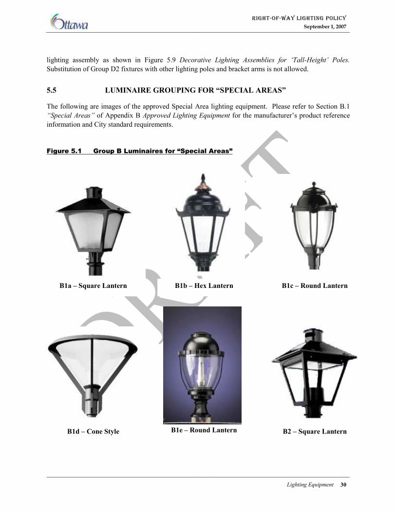
RIGHT-OF-WAY LIGHTING POLICY
September 1, 2007
Lighting Equipment 30
lighting assembly as shown in Figure 5.9 Decorative Lighting Assemblies for ‘Tall-Height’ Poles.
Substitution of Group D2 fixtures with other lighting poles and bracket arms is not allowed.
5.5 LUMINAIRE GROUPING FOR “SPECIAL AREAS”
The following are images of the approved Special Area lighting equipment. Please refer to Section B.1
“Special Areas” of Appendix B Approved Lighting Equipment for the manufacturer’s product reference
information and City standard requirements.
Figure 5.1 Group B Luminaires for “Special Areas”
B1a – Square Lantern B1b – Hex Lantern B1c – Round Lantern
B1d – Cone Style B2 – Square Lantern B1e – Round Lantern
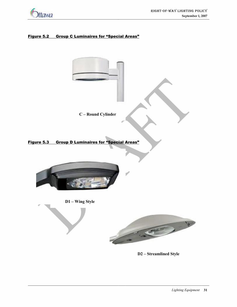
RIGHT-OF-WAY LIGHTING POLICY
September 1, 2007
Lighting Equipment 31
Figure 5.2 Group C Luminaires for “Special Areas”
Figure 5.3 Group D Luminaires for “Special Areas”
D2 – Streamlined Style
D1 – Wing Style
C – Round Cylinder
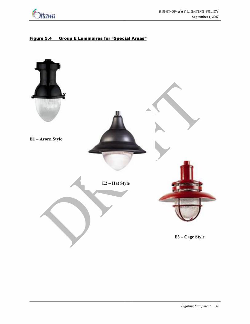
RIGHT-OF-WAY LIGHTING POLICY
September 1, 2007
Lighting Equipment 32
Figure 5.4 Group E Luminaires for “Special Areas”
E1 – Acorn Style
E2 – Hat Style
E3 – Cage Style
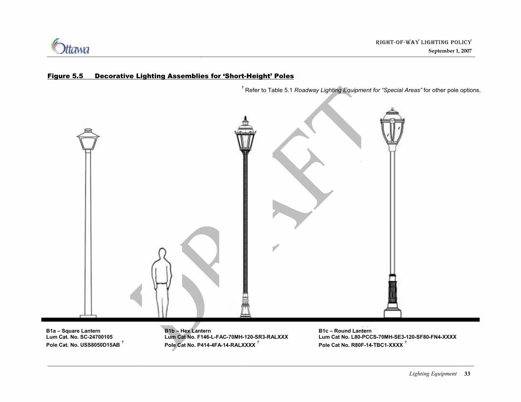
RIGHT-OF-WAY LIGHTING POLICY
September 1, 2007
Lighting Equipment 33
Figure 5.5 Decorative Lighting Assemblies for ‘Short-Height’ Poles
B1a – Square Lantern Lum Cat. No. SC-24700105
Pole Cat. No. USS8050D15AB †
B1b – Hex Lantern Lum Cat No. F146-L-FAC-70MH-120-SR3-RALXXX
Pole Cat No. P414-4FA-14-RALXXXX †
B1c – Round Lantern Lum Cat No. L80-PCCS-70MH-SE3-120-SF80-FN4-XXXX
Pole Cat No. R80F-14-TBC1-XXXX †
† Refer to Table 5.1 Roadway Lighting Equipment for “Special Areas” for other pole options.
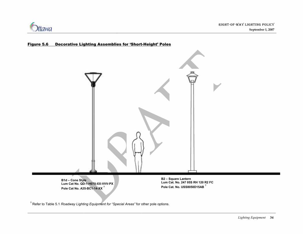
RIGHT-OF-WAY LIGHTING POLICY
September 1, 2007
Lighting Equipment 34
Figure 5.6 Decorative Lighting Assemblies for ‘Short-Height’ Poles
B1d – Cone Style Lum Cat No. QD-1-H070-XX-VVV-PX
Pole Cat No. A35-BC1-14-XX †
B2 – Square Lantern Lum Cat. No. 247 05S RH 120 R2 FC
Pole Cat. No. USS8050D15AB †
† Refer to Table 5.1 Roadway Lighting Equipment for “Special Areas” for other pole options.
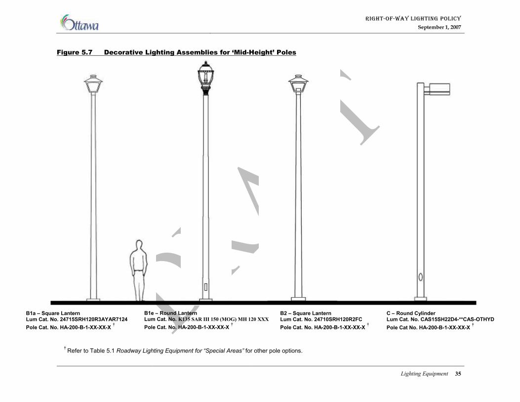
RIGHT-OF-WAY LIGHTING POLICY
September 1, 2007
Lighting Equipment 35
Figure 5.7 Decorative Lighting Assemblies for ‘Mid-Height’ Poles
C – Round Cylinder Lum Cat. No. CAS15SH22D4-**CAS-OTHYD
Pole Cat No. HA-200-B-1-XX-XX-X †
B1a – Square Lantern Lum Cat. No. 24715SRH120R3AYAR7124
Pole Cat. No. HA-200-B-1-XX-XX-X †
B2 – Square Lantern Lum Cat. No. 24710SRH120R2FC
Pole Cat. No. HA-200-B-1-XX-XX-X †
† Refer to Table 5.1 Roadway Lighting Equipment for “Special Areas” for other pole options.
B1e – Round Lantern Lum Cat. No. K135 SAR III 150 (MOG) MH 120 XXX
Pole Cat. No. HA-200-B-1-XX-XX-X †
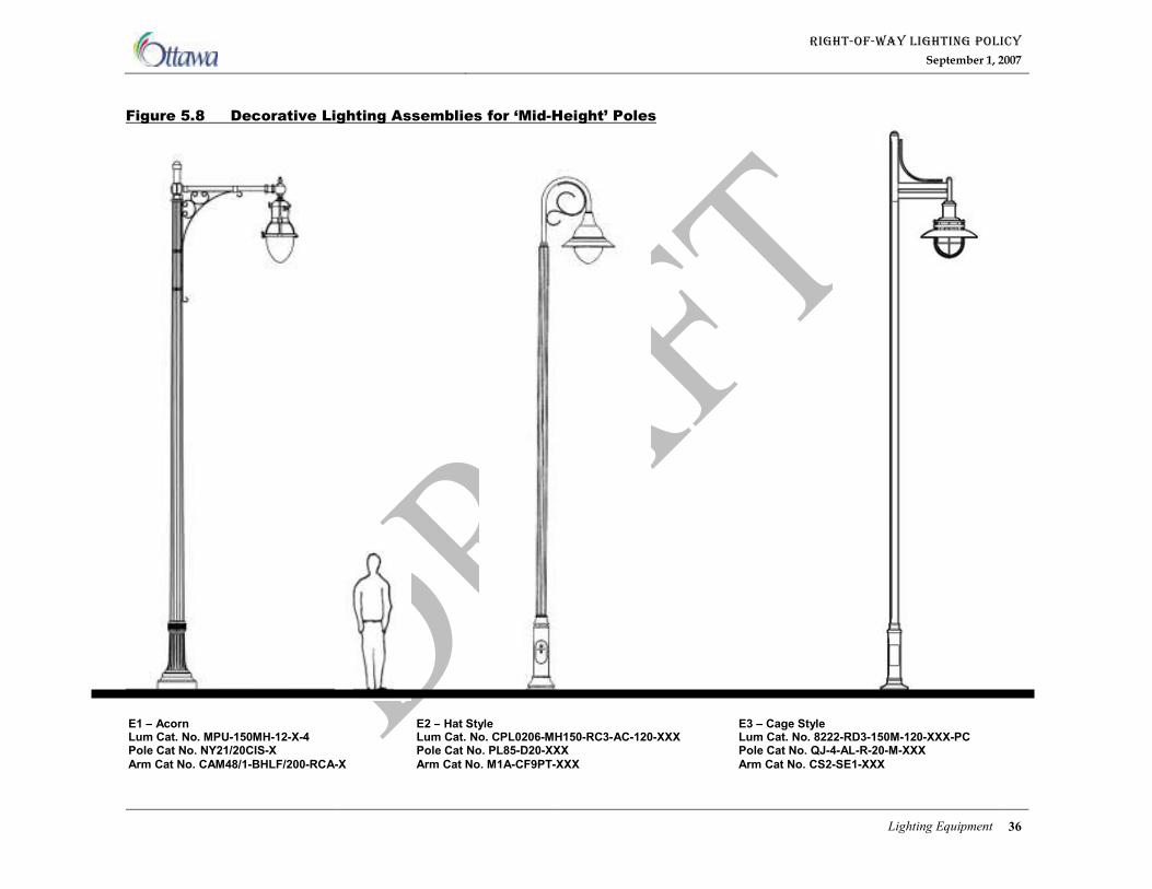
RIGHT-OF-WAY LIGHTING POLICY
September 1, 2007
Lighting Equipment 36
Figure 5.8 Decorative Lighting Assemblies for ‘Mid-Height’ Poles
E1 – Acorn Lum Cat. No. MPU-150MH-12-X-4 Pole Cat No. NY21/20CIS-X
Arm Cat No. CAM48/1-BHLF/200-RCA-X
E3 – Cage Style Lum Cat. No. 8222-RD3-150M-120-XXX-PC Pole Cat No. QJ-4-AL-R-20-M-XXX
Arm Cat No. CS2-SE1-XXX
E2 – Hat Style Lum Cat. No. CPL0206-MH150-RC3-AC-120-XXX Pole Cat No. PL85-D20-XXX
Arm Cat No. M1A-CF9PT-XXX
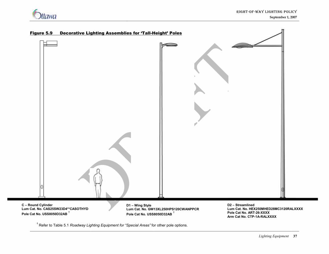
RIGHT-OF-WAY LIGHTING POLICY
September 1, 2007
Lighting Equipment 37
Figure 5.9 Decorative Lighting Assemblies for ‘Tall-Height’ Poles
D1 – Wing Style Lum Cat. No. GW13XL250HPS120CWANPPCR
Pole Cat No. USS8050D32AB †
D2 – Streamlined Lum Cat. No. HEX250MHED28MC3120RALXXXX Pole Cat No. ART-26-XXXX
Arm Cat No. CTP-1A-RALXXXX
C – Round Cylinder Lum Cat. No. CAS25SW23D4**CASOTHYD
Pole Cat No. USS8050D32AB †
† Refer to Table 5.1 Roadway Lighting Equipment for “Special Areas” for other pole options.

RIGHT-OF-WAY LIGHTING POLICY
September 1, 2007
Lighting Equipment 38
Table 5.1 Roadway Lighting Equipment for “Special Areas” – Urban Area
WATTAGE (Note 1)
POLES (Note 1) POLE LAYOUT
‘Tall’ ‘Mid’ ‘Short’
ROADWAY CLASS
LUMINAIRES
250
150
70
10.7m Concrete
9.8m Aluminum
9.8m (Note 2)
6.1m Concrete
5.5m Aluminum
6.0m (Note 2)
4.6m Concrete
4.6m Aluminum
4.3m (Note 2)
‘Tall-Height’
‘Mid-Height’
‘Tall-Height’ and/or
‘Short-Height’
� � � � � B1a
� � � � �
B1b � � � � �
B1c � � � � �
B1d � � � � �
B1e � � � �
� � � �
Group B
B2 � � � � �
� � � � Group C C
� � � �
D1 � � � � Group D
D2 � � �
E1 � � �
E2 � � �
ARTERIAL
&
MAJOR
COLLECTOR
&
COLLECTOR
Group E
E3 � � �
� � � � B1a
� � � �
B1b � � �
B1c � � �
B1d � � �
B1e � � � �
� � � �
Group B
B2 � � � �
Group C C � � �
D1 Group D
D2
E1 � � �
E2 � � �
URBAN AREA
URBAN AREA
URBAN AREA
URBAN AREA
LOCAL
Group E
E3 � � �
Notes: 1. Lamp Wattage and Pole Height may be increased for use at intersections if necessary to achieve the
minimum lighting levels.
2 These poles are custom equipment and are supplied by the luminaire manufacturer. They are unique
for each luminaire.
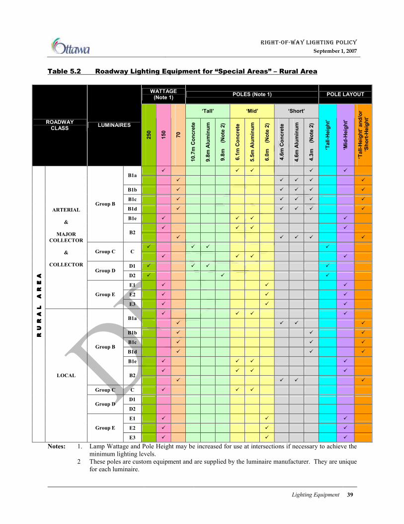
RIGHT-OF-WAY LIGHTING POLICY
September 1, 2007
Lighting Equipment 39
Table 5.2 Roadway Lighting Equipment for “Special Areas” – Rural Area
WATTAGE (Note 1)
POLES (Note 1) POLE LAYOUT
‘Tall’ ‘Mid’ ‘Short’
ROADWAY CLASS
LUMINAIRES
250
150
70
10.7m Concrete
9.8m Aluminum
9.8m (Note 2)
6.1m Concrete
5.5m Aluminum
6.0m (Note 2)
4.6m Concrete
4.6m Aluminum
4.3m (Note 2)
‘Tall-Height’
‘Mid-Height’
‘Tall-Height’ and/or
‘Short-Height’
� � � � � B1a
� � � � �
B1b � � � � �
B1c � � � � �
B1d � � � � �
B1e � � � �
� � � �
Group B
B2 � � � � �
� � � � Group C C
� � � �
D1 � � � � Group D
D2 � � �
E1 � � �
E2 � � �
ARTERIAL
&
MAJOR
COLLECTOR
&
COLLECTOR
Group E
E3 � � �
� � � � B1a
� � � �
B1b � � �
B1c � � �
B1d � � �
B1e � � � �
� � � �
Group B
B2 � � � �
Group C C � � �
D1 Group D
D2
E1 � � �
E2 � � �
RURAL AREA
RURAL AREA
RURAL AREA
RURAL AREA
LOCAL
Group E
E3 � � �
Notes: 1. Lamp Wattage and Pole Height may be increased for use at intersections if necessary to achieve the
minimum lighting levels.
2 These poles are custom equipment and are supplied by the luminaire manufacturer. They are unique
for each luminaire.
RIGHT-OF-WAY LIGHTING POLICY
September 1, 2007
Lighting Equipment 40
5.6 “ALL OTHER AREAS”
“All Other Areas” are locations other than “Special Areas” as designated by the City of Ottawa Official
Plan Schedules A & B. iii and by this Policy. The majority of the approved lighting equipment for “All
Other Areas” was adopted from the City of Ottawa Residential Street Lighting Policy 2001. The
approved lighting equipment for “All Other Areas” is listed in Appendix B Approved Lighting
Equipment. All street lighting fixtures in “All Other Areas” meet the ANSI / IESNA RP-8-00 Roadway
Lighting i definition of Semi-Cut Off or Full Cut Off.
Semi Cut-Off and Full Cut-Off luminaires were included in the approved lighting equipment list in
Appendix B, to achieve a balance between being environmentally friendly and practical in terms of cost
and performance. Pole spacing for Semi Cut Off fixtures is further apart compared to the Full Cut Off
fixtures resulting in cost savings and maintaining improved light distribution. However, Full Cut Off
fixtures produce zero ‘direct up-light’ and therefore are more environmentally friendly in terms of
minimizing light pollution.
Full Cut-Off luminaires are mandatory for urban local roads in new residential, employment, and mixed
use centre areas. In other lighting designs, full cut-off luminaires shall always be considered and shall be
utilized if they are determined to be practical in terms of pole spacing and/or other site conditions. Where
marker type lighting is required, Semi Cut-Off luminaires will be used due to the inherent ‘beacon effect’
of this fixture making the intersection more identifiable to motorists. The exception is that full cut-off
luminaires shall be used for marker lights for urban and rural super mailbox locations.
5.7 LUMINAIRE GROUPING FOR “ALL OTHER AREAS”
The luminaires for “All Other Areas” were grouped together for convenience based on their general
appearance and then further subdivided in subgroups (Semi Cut Off & Full Cut Off) by luminaire
distribution as described by RP-8-00 Roadway Lighting i. There are four luminaire groups including;
Group A Cobra-head Style Fixtures, Group B Lantern Style Fixtures, Group C Round Style Fixtures and
Group D ‘Shoe Box’ Style Fixtures.
Figure 5.8 to Figure 5.11 illustrates the different types of lighting fixtures approved for lighting
installations within the City of Ottawa.
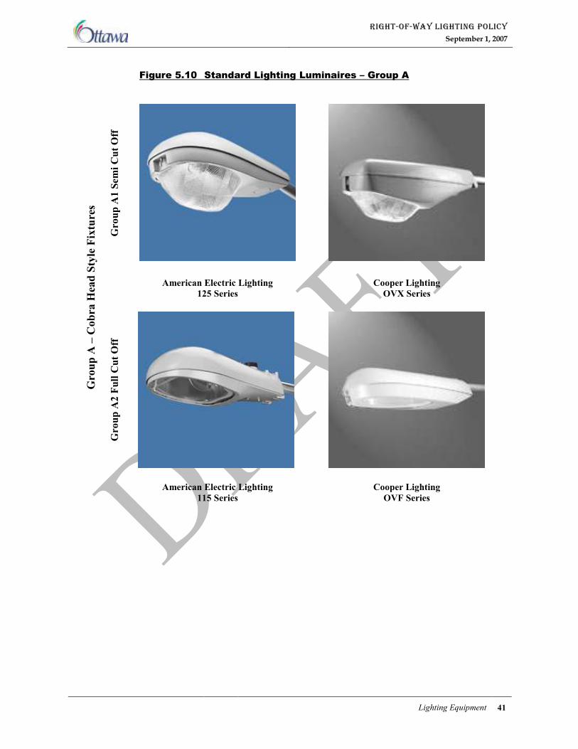
RIGHT-OF-WAY LIGHTING POLICY
September 1, 2007
Lighting Equipment 41
Figure 5.10 Standard Lighting Luminaires – Group A
Group A1 Semi Cut Off
American Electric Lighting
125 Series
Cooper Lighting
OVX Series
Group A2 Full Cut Off
Group A – Cobra Head Style Fixtures
American Electric Lighting
115 Series
Cooper Lighting
OVF Series
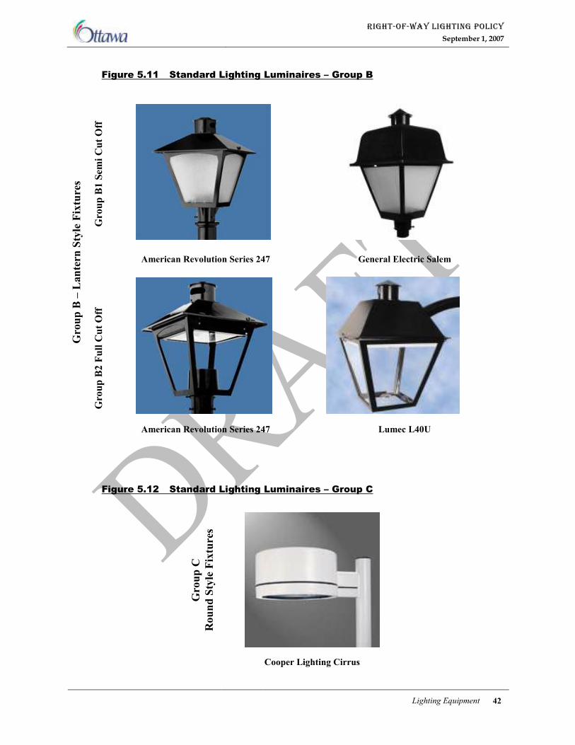
RIGHT-OF-WAY LIGHTING POLICY
September 1, 2007
Lighting Equipment 42
Figure 5.11 Standard Lighting Luminaires – Group B
Figure 5.12 Standard Lighting Luminaires – Group C
Group B1 Semi Cut Off
American Revolution Series 247 General Electric Salem
Group B – Lantern Style Fixtures
Group B2 Full Cut Off
American Revolution Series 247 Lumec L40U
Group C
Round Style Fixtures
Cooper Lighting Cirrus
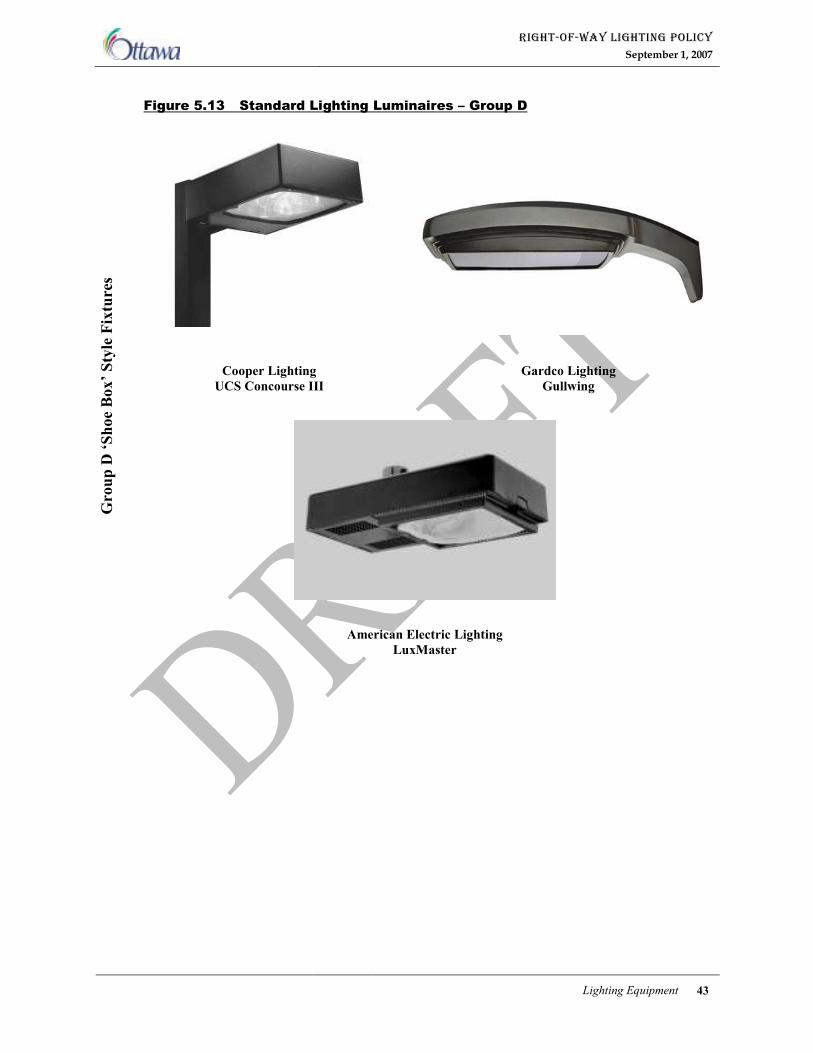
RIGHT-OF-WAY LIGHTING POLICY
September 1, 2007
Lighting Equipment 43
Figure 5.13 Standard Lighting Luminaires – Group D
Cooper Lighting
UCS Concourse III
Gardco Lighting
Gullwing
Group D ‘Shoe Box’ Style Fixtures
American Electric Lighting
LuxMaster
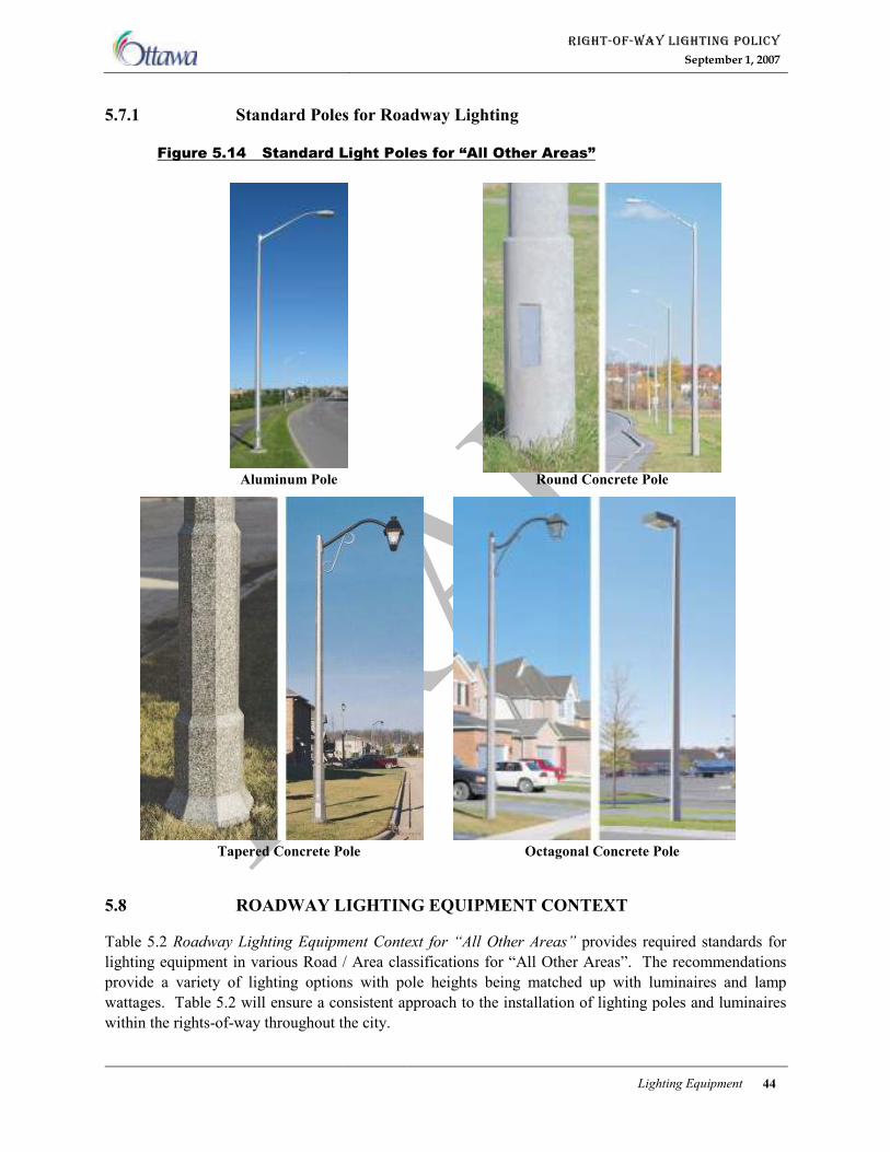
RIGHT-OF-WAY LIGHTING POLICY
September 1, 2007
Lighting Equipment 44
5.7.1 Standard Poles for Roadway Lighting
Figure 5.14 Standard Light Poles for “All Other Areas”
Aluminum Pole Round Concrete Pole
Tapered Concrete Pole Octagonal Concrete Pole
5.8 ROADWAY LIGHTING EQUIPMENT CONTEXT
Table 5.2 Roadway Lighting Equipment Context for “All Other Areas” provides required standards for
lighting equipment in various Road / Area classifications for “All Other Areas”. The recommendations
provide a variety of lighting options with pole heights being matched up with luminaires and lamp
wattages. Table 5.2 will ensure a consistent approach to the installation of lighting poles and luminaires
within the rights-of-way throughout the city.
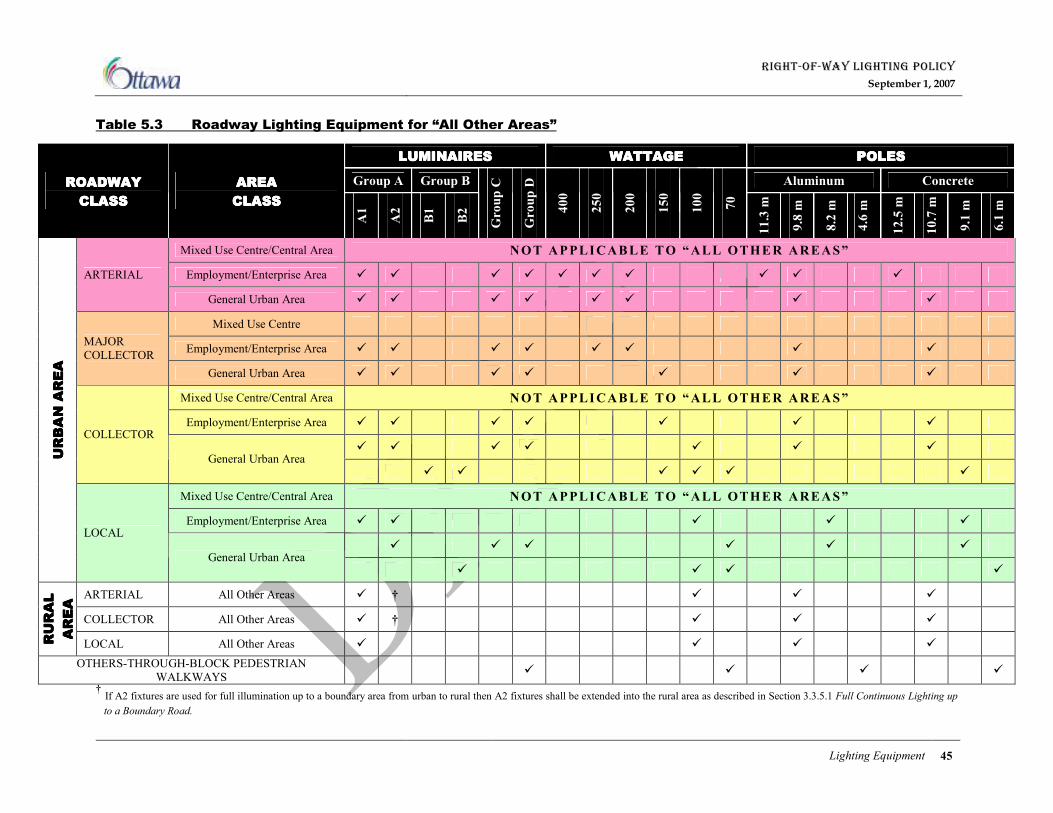
RIGHT-OF-WAY LIGHTING POLICY
September 1, 2007
Lighting Equipment 45
Table 5.3 Roadway Lighting Equipment for “All Other Areas”
† If A2 fixtures are used for full illumination up to a boundary area from urban to rural then A2 fixtures shall be extended into the rural area as described in Section 3.3.5.1 Full Continuous Lighting up
to a Boundary Road.
LUMINAIRESLUMINAIRESLUMINAIRESLUMINAIRES WATTAGEWATTAGEWATTAGEWATTAGE POLESPOLESPOLESPOLES
Group A Group B Aluminum Concrete ROADWAYROADWAYROADWAYROADWAY
CLASSCLASSCLASSCLASS
AREAAREAAREAAREA
CLASSCLASSCLASSCLASS
A1
A2
B1
B2
Group C
Group D
400
250
200
150
100
70
11.3 m
9.8 m
8.2 m
4.6 m
12.5 m
10.7 m
9.1 m
6.1 m
Mixed Use Centre/Central Area NOT APPLICABLE TO “ALL OTHER AREAS”
Employment/Enterprise Area � � � � � � � � � � ARTERIAL
General Urban Area � � � � � � � �
Mixed Use Centre
Employment/Enterprise Area � � � � � � � � MAJOR
COLLECTOR
General Urban Area � � � � � � �
Mixed Use Centre/Central Area NOT APPLICABLE TO “ALL OTHER AREAS”
Employment/Enterprise Area � � � � � � �
� � � � � � �
COLLECTOR
General Urban Area � � � � � �
Mixed Use Centre/Central Area NOT APPLICABLE TO “ALL OTHER AREAS”
Employment/Enterprise Area � � � � �
� � � � � �
URBAN AREA
URBAN AREA
URBAN AREA
URBAN AREA
LOCAL
General Urban Area � � � �
ARTERIAL All Other Areas � † � � �
COLLECTOR All Other Areas � † � � �
RURAL
RURAL
RURAL
RURAL
AREA
AREA
AREA
AREA
LOCAL All Other Areas � � � �
OTHERS-THROUGH-BLOCK PEDESTRIAN
WALKWAYS � � � �
RIGHT-OF-WAY LIGHTING POLICY
September 1, 2007
Design Considerations 46
CHAPTER 6 DESIGN CONSIDERATIONS
In the design and implementation of roadway lighting, there are many things to consider, such as light
pollution, transition of illumination, curvilinear road sections, etc. in order to provide a ‘proper’ lighting
system.
6.1 LIGHT POLLUTION
Light pollution is a term used to describe the negative effects of the use of lighting such as light trespass,
sky glow and glare. With the proper use of light fixtures and pole heights, light pollution can be
minimized. The implementation of a maximum semi cut-off fixture (5% up-light i) and the use of full
cut-off fixtures (0% up-light i) will reduce the amount of unwanted light into the environment. By also
lowering the luminaire wattages in areas where darkness is preferred, such as rural and residential areas,
from 150 watts to 100 watts, and also lowering the required average local roadway lighting levels in new
residential, employment area and mixed use centre developments, will also contribute to minimizing light
pollution.
6.2 HORIZONTAL CURVES
The illumination of horizontal curves shall be dealt with on a case-by-case basis and shall be subject to
the availability of electric power and capital funding. If approved, the lighting of any horizontal curve
shall be complete with semi cut-off class luminaires with maximum lamp wattage of 100 watts. The
lighting equipment shall conform to Appendix B Approved Lighting Equipment.
6.3 STREET AND SIDEWALK LIGHTING SHADED BY TREES
The City acknowledges that seasonally, street and sidewalk lighting shaded by the foliage of trees is
sometimes unavoidable. The resulting reduction in levels of roadway and sidewalk lighting is acceptable
provided that the original design and installation of street lighting equipment was properly coordinated
with the location of the trees. Therefore, street trees will not be trimmed to accommodate the street
lighting except as may be approved in special circumstances by the Director, Traffic and Parking
Operations.
RIGHT-OF-WAY LIGHTING POLICY
September 1, 2007
Street Lighting Warrants 47
CHAPTER 7 STREET LIGHTING WARRANTS
7.1 PRIORITIZATION OF LIGHTING
Capital funding for street lighting on unlit and underlit roadways, including its installation, operation and
maintenance, is limited, and must be allocated on a priority basis to projects that will yield the greatest
cost benefit ratio. Therefore, the City has applied a Weighting Scheme to various roadway factors such as
site conditions (including, for example, the presence of schools, parks, community centres), road class,
area class, bus routes and traffic volumes, to name a few. Each candidate roadway is scored based on the
sum of the weights for the various factors applicable to the respective roadway. The scores for each
roadway are then sorted numerically with the highest scoring roadway being given the highest priority to
receive a lighting upgrade. Although a roadway may be high in the priority list, it is also subject to a
lighting warrant analysis to meet specific lighting warrants before capital funding is allocated to construct
the new lighting.
7.1.1 Roadway Lighting Prioritization Database
The Roadway Lighting Prioritization Database (RLPD) is a separate document used to assist in the
implementation of this Policy. The RLPD was extracted and developed using the City of Ottawa GIS
Maintenance Database and Hydro Ottawa Existing Lighting Conditions Mapping. The RLPD will be
updated as required over time by the City to reflect new installations of street lighting, the addition of
new roadways, and revisions to road and area classifications as per the City of Ottawa Official Plan
Schedule Maps since the amalgamation of the City of Ottawa.
7.2 ROADWAY LIGHTING WARRANTS
Although a roadway may have high priority for street lighting it may not necessarily require the lighting.
The use of roadway lighting warrants will assist the City in establishing a consistent method of evaluating
the need for right-of-way lighting. The warrants provide conditions that must be satisfied to justify the
installation of lighting. Warrants give conditions that should be satisfied to justify the installation of
lighting, however, meeting warranting conditions does not obligate the City of Ottawa to provide lighting
or contribute to its cost.
Roadway Lighting Warrants shall be undertaken as described by the Guide to the Design of Roadway
Lighting ii.
RIGHT-OF-WAY LIGHTING POLICY
September 1, 2007
Appendix A Glossary 48
APPENDIX A GLOSSARY
A.1 ABBREVIATIONS
ANSI – American National Standards Institute,
CSA – Canadian Standard Association,
ESA – Electrical Safety Authority,
IEEE – Institute of Electrical and Electronics Engineers,
IESNA – Illuminating Engineering Society of North America,
TAC – Transportation Association of Canada,
MTO – Ministry of Transportation Ontario
A.2 DEFINITIONS
Average Illuminance: Average Illuminance, generally referred to as ‘Eavg.’ and measured in ‘Lux’, is
the arithmetical average of individual illuminance values calculated at predetermined points within an
area. For example, Average Illuminance on a section of roadway can be determined by overlaying an
imaginary grid on that section of the roadway, calculating illuminance values at each grid point and then
taking an average of all the values.
Average Luminance: Average Luminance or Average Pavement Luminance for a surface, generally
referred to as ‘LPavg.’ and measured in ‘Candelas per square metre (cd/m2), is the arithmetical average of
individual Luminance values calculated at predetermined points on the surface. Similar to calculating
Average Illuminance, Average Pavement Luminance for a section of roadway can be determined by
overlaying an imaginary grid on that section of the roadway, calculating Luminance values at each grid
point and then taking an average of all the values.
Candela (cd): The unit of luminous intensity formerly termed “candle”. One candela equals one lumen
per steradian.
Coefficient of Utilization (CU): A design factor that represents the percentage of bare lamp lumens that
are utilized to light the pavement surface. This factor is based on the luminaire position relative to the lit
area.
Footcandle (fc): The English unit of Illuminance; illuminance on a surface one square foot in area on
which there is uniformly distributed a light flux of one lumen. One footcandle equals 10.76 lux.
Glare: The sensation produced by the luminance within the visual field that is sufficiently greater than
the luminance to which the eyes are adapted to cause annoyance, discomfort or loss in visibility or visual
performance.
Illuminance (E): Illuminance is a measure of the “amount” of light a light source projects on to a
surface. More precisely, it is the density of luminous flux (Lumens) falling on a surface and decreases
with distance of the surface from the source (Inverse Square Law). The metric units for measurement of
illuminance are “Lux”, which is equal to 1 Lumen/m2 area.
RIGHT-OF-WAY LIGHTING POLICY
September 1, 2007
Appendix A Glossary 49
Initial Lamp Lumens (LL): Initial bare bulb lumen output of a light source.
Light: Radiant energy that is capable of being perceived by the eye and producing a visual sensation.
The visible portion of the electromagnetic spectrum extends from approximately 380 to 770 nanometers.
Lumen (lm): defined as:
A unit of measure of the quantity of light. One lumen is the amount of light which falls on an area of one
square foot, every point of which is one foot from the source of one candela. A light source of one
candela emits a total of 12.57 lumens; or
A measure of luminous flux emitted by a source. The output of a lamp is expressed by the manufacturers
in Lumens (e.g. 400 watt high pressure sodium lamp produces 50000 initial lumens).
Luminaire: A complete unit consisting of a lamp or lamps together with the parts designed to distribute
the light, to position and protect the lamps and to connect the lamps to the power supply.
Luminance: Luminance of a roadway surface, simply explained, is the intensity of reflected light per
unit area of the surface in the direction of the viewer. Luminance indicates the “brightness” of the
roadway surface ahead of the observer when viewed from a given location in a given direction.
Luminance at any location (point) on the roadway surface varies with the incident angles of light from
various light sources on to the surface, the reflectance properties of the pavement, and the viewing angle
of the stationary observer at the point.
Lux (lx): The SI unit of illuminance; defined as the amount of light on a surface of one square metre, all
points of which are one metre from a uniform source of one candela. One lux equals 0.0929 footcandle.
Maintained Average Illuminance/Luminance: Light output of a roadway lighting system deteriorates
over time due to many factors. Though many of these factors are complex in nature to quantify, two
major factors are depreciation of lamp lumen output due to its age (referred to as Lamp Lumen
Depreciation or ‘LLD’), and accumulation of dirt inside the luminaire as well as on the outside of the
glassware (referred to as Luminaire Dirt Depreciation or ‘LDD’). The product of these two factors is
referred to as Light Loss Factor or ‘LLF’.
Nuisance Light: Nuisance light can be defined as the presence of a bright source within the observer’s
field of view, which the observer finds objectionable and/or intrusive. This adverse effect includes the
increase in brightness of the night sky (Sky Glow) and glare experienced by people in the vicinity of
luminaires.
Q Factor: A measure to overall “lightness” of the surface
Sky Glow: The term used to describe the added sky brightness caused by the scattering of extraneous
light reflecting from the dust particles in the atmosphere.
Spill Light: Spill light can be defined as illumination of an area beyond the primary area that the light
source is intended to illuminate.
Steradian: A solid angle subtending an area on the surface of a sphere equal to the square of the sphere
radius.
Uniformity: Uniformity of lighting refers to “Quality” of lighting. The lighting must be uniformly
spread over an area for good visibility since the human eye requires a finite amount of time to adapt to
changes in light levels. The uniformity of lighting for an area, for both Illuminance and Luminance
RIGHT-OF-WAY LIGHTING POLICY
September 1, 2007
Appendix A Glossary 50
method, is determined by calculating the ratio of Average Illuminance/Luminance to Minimum
Illuminance/Luminance within the area.
Veiling Luminance: Also known as Disability Glare, it is the direct luminance superimposed on the
retina by external light sources, which causes a “veil” of light and reduces the contrast of an image. The
veiling luminance can be produced by a roadway luminaire, headlights of an oncoming vehicle,
advertising signs along the roadway, and stray commercial/residential lighting adjacent to the roadway.
Veiling luminance produced by only roadway luminaires is considered in the lighting calculations.
Visibility: The quality or state of being perceivable by the eye. In roadway lighting it is usually defined
in terms of the distance at which an object can just be perceived.
Warrant: The justification for the installation of roadway lighting based on several factors as defined in
the Transportation Association of Canada “Guide for the Design of Roadway Lighting”
A.3 REFERENCES
The following published documents have been used as the basis for establishing lighting design criteria:
Canadian Standard Association:
CSA C22.2 No. 211.2-M1984 (R2003) - Rigid PVC, Unplasticized Conduit
CSA C22.2 No. 227.1-97 (R2002) - Electrical Non-metallic Tubing (Bi-national standard, with UL 1653)
Illuminating Engineering Society of North America:
IESNA DG-5-94 - Recommended Lighting for Walkways and Class 1 Bikeways
IESNA LM-67- 94 - Calculation Procedures and Specifications of Criteria for Lighting Calculations
IESNA RP-8-00 - Roadway Lighting ANSI Approved
IESNA RP-22-96 - Recommended Practice for Tunnel Lighting
IESNA TM-3-95 - A Discussion of Appendix E – “Classification of Luminaire Light Distributions”
IESNA TM-10-00 - Addressing Obtrusive Light (Urban Sky Glow and Light Trespass) in Conjunction
with Roadway Lighting
IESNA TM-11-00 - Light Trespass; Research, Results and Recommendations
Transportation Association of Canada (TAC):
Guide for the Design of Roadway Lighting
Ministry of Transportation, Ontario (MTO):
Roadside Safety Manual
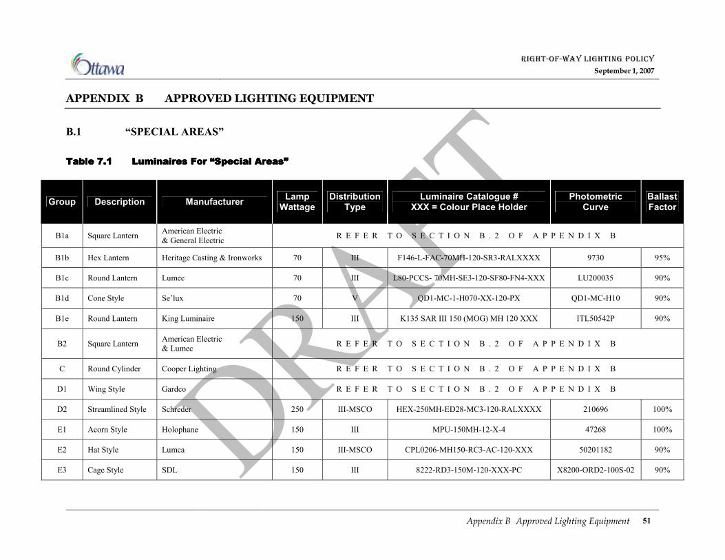
RIGHT-OF-WAY LIGHTING POLICY
September 1, 2007
Appendix B Approved Lighting Equipment 51
APPENDIX B APPROVED LIGHTING EQUIPMENT
B.1 “SPECIAL AREAS”
Table Table Table Table 7777....1111 LuminaireLuminaireLuminaireLuminaires For “Special Areas”s For “Special Areas”s For “Special Areas”s For “Special Areas”
Group Description Manufacturer Lamp
Wattage Distribution
Type Luminaire Catalogue #
XXX = Colour Place Holder Photometric
Curve Ballast Factor
B1a Square Lantern American Electric
& General Electric R E F E R T O S E C T I O N B . 2 O F A P P E N D I X B
B1b Hex Lantern Heritage Casting & Ironworks 70 III F146-L-FAC-70MH-120-SR3-RALXXXX 9730 95%
B1c Round Lantern Lumec 70 III L80-PCCS- 70MH-SE3-120-SF80-FN4-XXX LU200035 90%
B1d Cone Style Se’lux 70 V QD1-MC-1-H070-XX-120-PX QD1-MC-H10 90%
B1e Round Lantern King Luminaire 150 III K135 SAR III 150 (MOG) MH 120 XXX ITL50542P 90%
B2 Square Lantern American Electric
& Lumec R E F E R T O S E C T I O N B . 2 O F A P P E N D I X B
C Round Cylinder Cooper Lighting R E F E R T O S E C T I O N B . 2 O F A P P E N D I X B
D1 Wing Style Gardco R E F E R T O S E C T I O N B . 2 O F A P P E N D I X B
D2 Streamlined Style Schreder 250 III-MSCO HEX-250MH-ED28-MC3-120-RALXXXX 210696 100%
E1 Acorn Style Holophane 150 III MPU-150MH-12-X-4 47268 100%
E2 Hat Style Lumca 150 III-MSCO CPL0206-MH150-RC3-AC-120-XXX 50201182 90%
E3 Cage Style SDL 150 III 8222-RD3-150M-120-XXX-PC X8200-ORD2-100S-02 90%
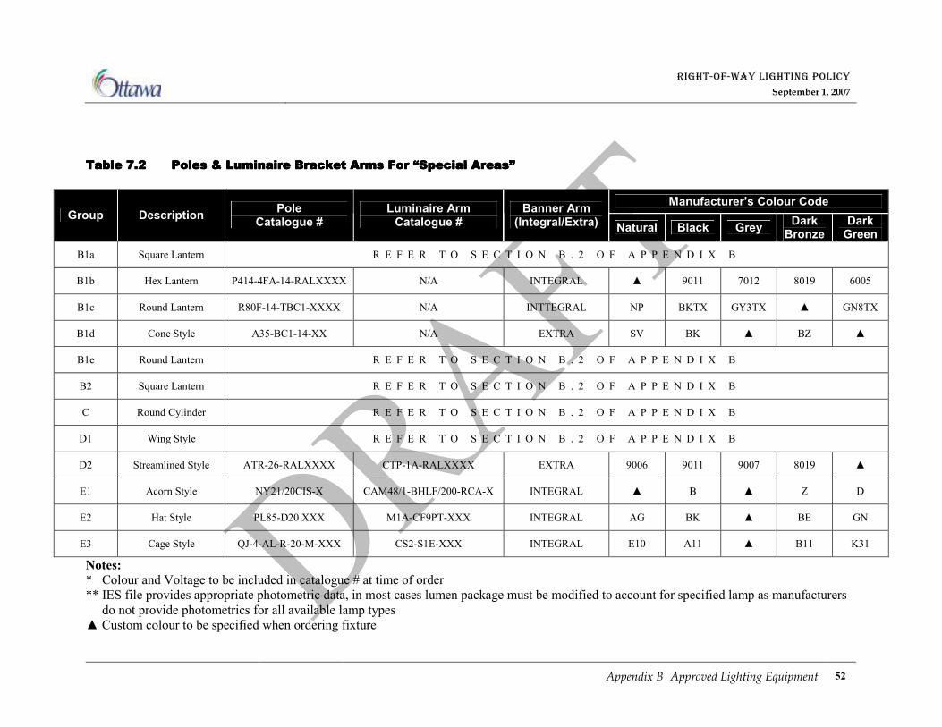
RIGHT-OF-WAY LIGHTING POLICY
September 1, 2007
Appendix B Approved Lighting Equipment 52
Table Table Table Table 7777....2222 Poles & LumiPoles & LumiPoles & LumiPoles & Luminaire Bracket Arms For “Special Areas”naire Bracket Arms For “Special Areas”naire Bracket Arms For “Special Areas”naire Bracket Arms For “Special Areas”
Manufacturer’s Colour Code Group Description
Pole Catalogue #
Luminaire Arm Catalogue #
Banner Arm (Integral/Extra)
Natural Black Grey Dark Bronze
Dark Green
B1a Square Lantern R E F E R T O S E C T I O N B . 2 O F A P P E N D I X B
B1b Hex Lantern P414-4FA-14-RALXXXX N/A INTEGRAL ▲ 9011 7012 8019 6005
B1c Round Lantern R80F-14-TBC1-XXXX N/A INTTEGRAL NP BKTX GY3TX ▲ GN8TX
B1d Cone Style A35-BC1-14-XX N/A EXTRA SV BK ▲ BZ ▲
B1e Round Lantern R E F E R T O S E C T I O N B . 2 O F A P P E N D I X B
B2 Square Lantern R E F E R T O S E C T I O N B . 2 O F A P P E N D I X B
C Round Cylinder R E F E R T O S E C T I O N B . 2 O F A P P E N D I X B
D1 Wing Style R E F E R T O S E C T I O N B . 2 O F A P P E N D I X B
D2 Streamlined Style ATR-26-RALXXXX CTP-1A-RALXXXX EXTRA 9006 9011 9007 8019 ▲
E1 Acorn Style NY21/20CIS-X CAM48/1-BHLF/200-RCA-X INTEGRAL ▲ B ▲ Z D
E2 Hat Style PL85-D20 XXX M1A-CF9PT-XXX INTEGRAL AG BK ▲ BE GN
E3 Cage Style QJ-4-AL-R-20-M-XXX CS2-S1E-XXX INTEGRAL E10 A11 ▲ B11 K31
Notes: * Colour and Voltage to be included in catalogue # at time of order
** IES file provides appropriate photometric data, in most cases lumen package must be modified to account for specified lamp as manufacturers
do not provide photometrics for all available lamp types
▲ Custom colour to be specified when ordering fixture
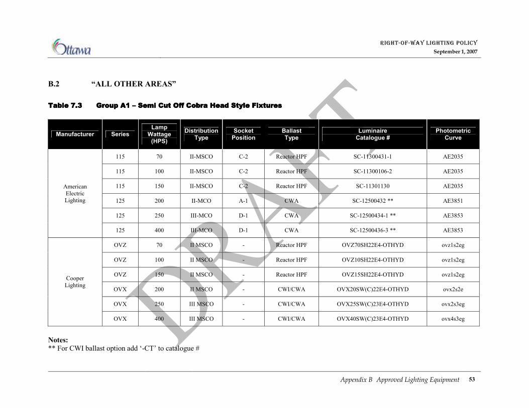
RIGHT-OF-WAY LIGHTING POLICY
September 1, 2007
Appendix B Approved Lighting Equipment 53
B.2 “ALL OTHER AREAS”
Table Table Table Table 7777....3333 Group A1 Group A1 Group A1 Group A1 –––– Semi Cut Off Cobra Head Style Fixtures Semi Cut Off Cobra Head Style Fixtures Semi Cut Off Cobra Head Style Fixtures Semi Cut Off Cobra Head Style Fixtures
Manufacturer Series Lamp
Wattage (HPS)
Distribution Type
Socket Position
Ballast Type
Luminaire Catalogue #
Photometric Curve
115 70 II-MSCO C-2 Reactor HPF SC-11300431-1 AE2035
115 100 II-MSCO C-2 Reactor HPF SC-11300106-2 AE2035
115 150 II-MSCO C-2 Reactor HPF SC-11301130 AE2035
125 200 II-MCO A-1 CWA SC-12500432 ** AE3851
125 250 III-MCO D-1 CWA SC-12500434-1 ** AE3853
American
Electric
Lighting
125 400 III-MCO D-1 CWA SC-12500436-3 ** AE3853
OVZ 70 II MSCO - Reactor HPF OVZ70SH22E4-OTHYD ovz1s2eg
OVZ 100 II MSCO - Reactor HPF OVZ10SH22E4-OTHYD ovz1s2eg
OVZ 150 II MSCO - Reactor HPF OVZ15SH22E4-OTHYD ovz1s2eg
OVX 200 II MSCO - CWI/CWA OVX20SW(C)22E4-OTHYD ovx2s2e
OVX 250 III MSCO - CWI/CWA OVX25SW(C)23E4-OTHYD ovx2s3eg
Cooper
Lighting
OVX 400 III MSCO - CWI/CWA OVX40SW(C)23E4-OTHYD ovx4s3eg
Notes: ** For CWI ballast option add ‘-CT’ to catalogue #
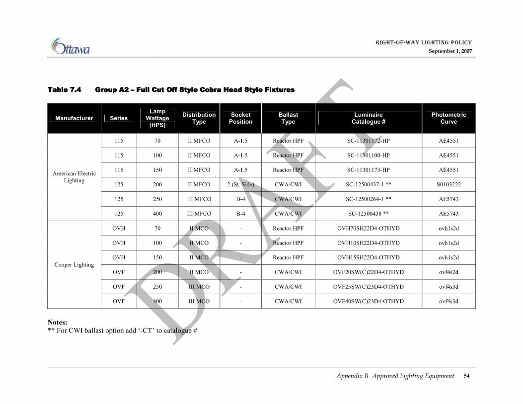
RIGHT-OF-WAY LIGHTING POLICY
September 1, 2007
Appendix B Approved Lighting Equipment 54
Table Table Table Table 7777....4444 Group A2 Group A2 Group A2 Group A2 –––– Fu Fu Fu Full Cut Off Style Cobra Head Style Fixturesll Cut Off Style Cobra Head Style Fixturesll Cut Off Style Cobra Head Style Fixturesll Cut Off Style Cobra Head Style Fixtures
Manufacturer Series Lamp
Wattage (HPS)
Distribution Type
Socket Position
Ballast Type
Luminaire Catalogue #
Photometric Curve
115 70 II MFCO A-1.5 Reactor HPF SC-11301172-HP AE4551
115 100 II MFCO A-1.5 Reactor HPF SC-11301100-HP AE4551
115 150 II MFCO A-1.5 Reactor HPF SC-11301173-HP AE4551
125 200 II MFCO 2 (St. Side) CWA/CWI SC-12500437-1 ** S0103222
125 250 III MFCO B-4 CWA/CWI SC-12500264-1 ** AE5743
American Electric
Lighting
125 400 III MFCO B-4 CWA/CWI SC-12500438 ** AE5743
OVH 70 II MCO - Reactor HPF OVH70SH22D4-OTHYD ovh1s2d
OVH 100 II MCO - Reactor HPF OVH10SH22D4-OTHYD ovh1s2d
OVH 150 II MCO - Reactor HPF OVH15SH22D4-OTHYD ovh1s2d
OVF 200 II MCO - CWA/CWI OVF20SW(C)22D4-OTHYD ovf4s2d
OVF 250 III MCO - CWA/CWI OVF25SW(C)23D4-OTHYD ovf4s3d
Cooper Lighting
OVF 400 III MCO - CWA/CWI OVF40SW(C)23D4-OTHYD ovf4s3d
Notes: ** For CWI ballast option add ‘-CT’ to catalogue #
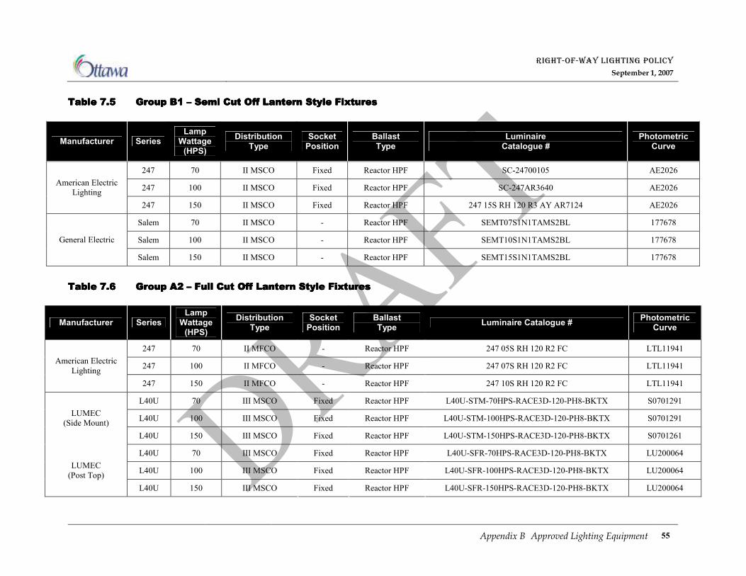
RIGHT-OF-WAY LIGHTING POLICY
September 1, 2007
Appendix B Approved Lighting Equipment 55
Table Table Table Table 7777....5555 Group B1 Group B1 Group B1 Group B1 –––– Semi Cut Off Lantern Style Fixtures Semi Cut Off Lantern Style Fixtures Semi Cut Off Lantern Style Fixtures Semi Cut Off Lantern Style Fixtures
Manufacturer Series Lamp
Wattage (HPS)
Distribution Type
Socket Position
Ballast Type
Luminaire Catalogue #
Photometric Curve
247 70 II MSCO Fixed Reactor HPF SC-24700105 AE2026
247 100 II MSCO Fixed Reactor HPF SC-247AR3640 AE2026 American Electric
Lighting
247 150 II MSCO Fixed Reactor HPF 247 15S RH 120 R3 AY AR7124 AE2026
Salem 70 II MSCO - Reactor HPF SEMT07S1N1TAMS2BL 177678
Salem 100 II MSCO - Reactor HPF SEMT10S1N1TAMS2BL 177678 General Electric
Salem 150 II MSCO - Reactor HPF SEMT15S1N1TAMS2BL 177678
Table Table Table Table 7777....6666 Group A2 Group A2 Group A2 Group A2 –––– Full Full Full Full CCCCut Off Lantern Style Fixturesut Off Lantern Style Fixturesut Off Lantern Style Fixturesut Off Lantern Style Fixtures
Manufacturer Series Lamp
Wattage (HPS)
Distribution Type
Socket Position
Ballast Type
Luminaire Catalogue # Photometric
Curve
247 70 II MFCO - Reactor HPF 247 05S RH 120 R2 FC LTL11941
247 100 II MFCO - Reactor HPF 247 07S RH 120 R2 FC LTL11941 American Electric
Lighting
247 150 II MFCO - Reactor HPF 247 10S RH 120 R2 FC LTL11941
L40U 70 III MSCO Fixed Reactor HPF L40U-STM-70HPS-RACE3D-120-PH8-BKTX S0701291
L40U 100 III MSCO Fixed Reactor HPF L40U-STM-100HPS-RACE3D-120-PH8-BKTX S0701291 LUMEC
(Side Mount)
L40U 150 III MSCO Fixed Reactor HPF L40U-STM-150HPS-RACE3D-120-PH8-BKTX S0701261
L40U 70 III MSCO Fixed Reactor HPF L40U-SFR-70HPS-RACE3D-120-PH8-BKTX LU200064
L40U 100 III MSCO Fixed Reactor HPF L40U-SFR-100HPS-RACE3D-120-PH8-BKTX LU200064 LUMEC
(Post Top)
L40U 150 III MSCO Fixed Reactor HPF L40U-SFR-150HPS-RACE3D-120-PH8-BKTX LU200064

RIGHT-OF-WAY LIGHTING POLICY
September 1, 2007
Appendix B Approved Lighting Equipment 56
Table Table Table Table 7777....7777 Group C Group C Group C Group C –––– Round Style Fixxtures Round Style Fixxtures Round Style Fixxtures Round Style Fixxtures
Manufacturer Series Lamp
Wattage (HPS)
Distribution Type
Ballast Type
Luminaire Catalogue #
Photometric Curve
Cirrus 70 II MCO Reactor HPF CAS70SH22D4-**CAS-OTHYD Z1232
Cirrus 100 II MCO Reactor HPF CAS10SH22D4-**CAS-OTHYD Z1232
Cirrus 150 II MCO Reactor HPF CAS15SH22D4-**CAS-OTHYD Z1232
Cirrus 250 III MCO CWA CAS25SW23D4-**CAS-OTHYD Z1253
Cooper
Lighting
Cirrus 400 III MCO CWA CAS40SW23D4-**CAS-OTHYD Z2263
Notes: ** Optional colours only – natural (bronze), white, black, grey and green
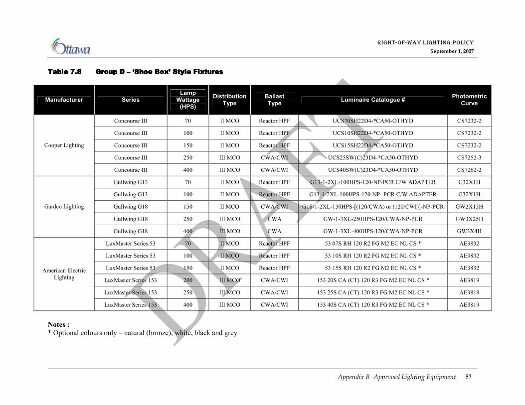
RIGHT-OF-WAY LIGHTING POLICY
September 1, 2007
Appendix B Approved Lighting Equipment 57
Table Table Table Table 7777....8888 Group D Group D Group D Group D –––– ‘‘‘‘Shoe BoxShoe BoxShoe BoxShoe Box’’’’ Style Fixtures Style Fixtures Style Fixtures Style Fixtures
Manufacturer Series Lamp
Wattage (HPS)
Distribution Type
Ballast Type
Luminaire Catalogue # Photometric Curve
Concourse III 70 II MCO Reactor HPF UCS70SH22D4-*CA50-OTHYD CS7232-2
Concourse III 100 II MCO Reactor HPF UCS10SH22D4-*CA50-OTHYD CS7232-2
Concourse III 150 II MCO Reactor HPF UCS15SH22D4-*CA50-OTHYD CS7232-2
Concourse III 250 III MCO CWA/CWI UCS25SW(C)23D4-*CA50-OTHYD CS7252-3
Cooper Lighting
Concourse III 400 III MCO CWA/CWI UCS40SW(C)23D4-*CA50-OTHYD CS7262-2
Gullwing G13 70 II MCO Reactor HPF G13-1-2XL-100HPS-120-NP-PCR C/W ADAPTER G32X1H
Gullwing G13 100 II MCO Reactor HPF G13-1-2XL-100HPS-120-NP- PCR C/W ADAPTER G32X1H
Gullwing G18 150 II MCO CWA/CWI G18-1-2XL-150HPS-[(120/CWA) or (120/CWI)]-NP-PCR GW2X15H
Gullwing G18 250 III MCO CWA GW-1-3XL-250HPS-120/CWA-NP-PCR GW3X25H
Gardco Lighting
Gullwing G18 400 III MCO CWA GW-1-3XL-400HPS-120/CWA-NP-PCR GW3X4H
LuxMaster Series 53 70 II MCO Reactor HPF 53 07S RH 120 R2 FG M2 EC NL CS * AE3832
LuxMaster Series 53 100 II MCO Reactor HPF 53 10S RH 120 R2 FG M2 EC NL CS * AE3832
LuxMaster Series 53 150 II MCO Reactor HPF 53 15S RH 120 R2 FG M2 EC NL CS * AE3832
LuxMaster Series 153 200 III MCO CWA/CWI 153 20S CA (CT) 120 R3 FG M2 EC NL CS * AE3819
LuxMaster Series 153 250 III MCO CWA/CWI 153 25S CA (CT) 120 R3 FG M2 EC NL CS * AE3819
American Electric
Lighting
LuxMaster Series 153 400 III MCO CWA/CWI 153 40S CA (CT) 120 R3 FG M2 EC NL CS * AE3819
Notes : * Optional colours only – natural (bronze), white, black and grey
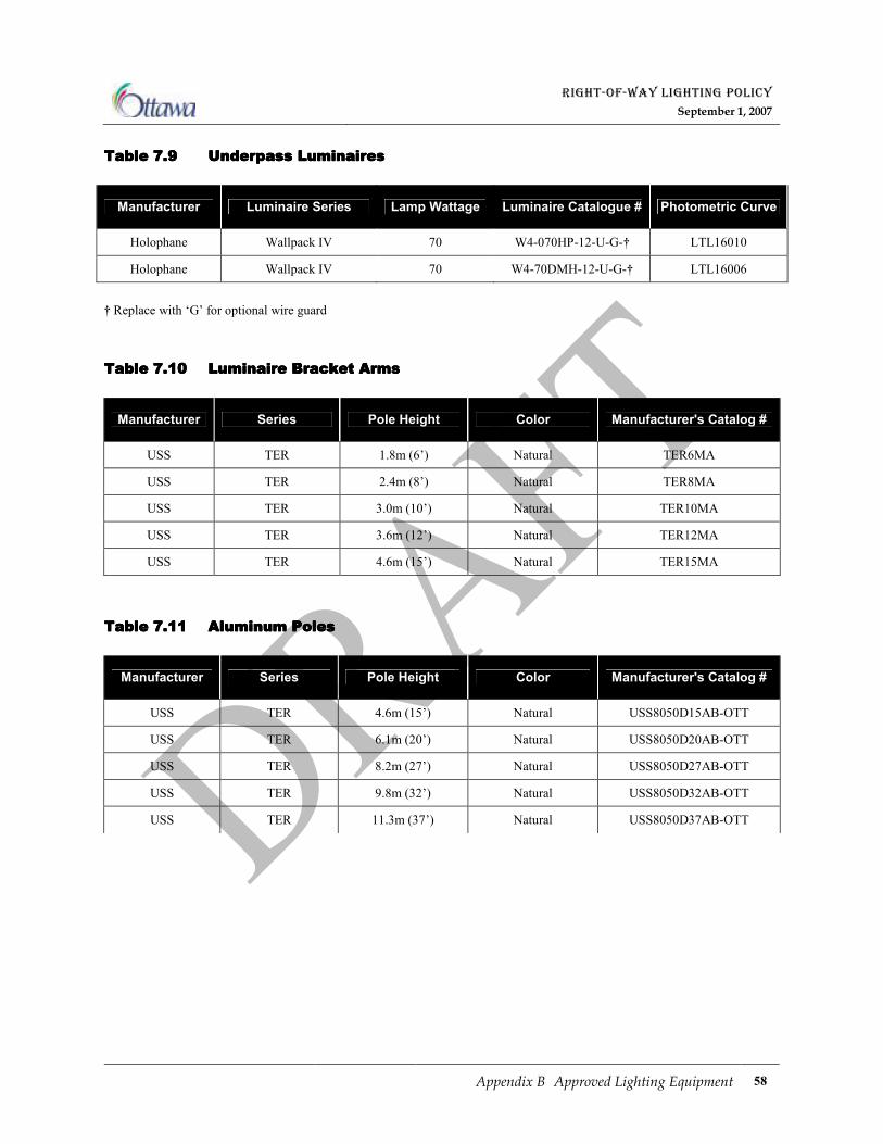
RIGHT-OF-WAY LIGHTING POLICY
September 1, 2007
Appendix B Approved Lighting Equipment 58
Table Table Table Table 7777....9999 Underpass LuminairesUnderpass LuminairesUnderpass LuminairesUnderpass Luminaires
Manufacturer Luminaire Series Lamp Wattage Luminaire Catalogue # Photometric Curve
Holophane Wallpack IV 70 W4-070HP-12-U-G-† LTL16010
Holophane Wallpack IV 70 W4-70DMH-12-U-G-† LTL16006
† Replace with ‘G’ for optional wire guard
Table Table Table Table 7777....10101010 Luminaire Bracket ArmsLuminaire Bracket ArmsLuminaire Bracket ArmsLuminaire Bracket Arms
Manufacturer Series Pole Height Color Manufacturer's Catalog #
USS TER 1.8m (6’) Natural TER6MA
USS TER 2.4m (8’) Natural TER8MA
USS TER 3.0m (10’) Natural TER10MA
USS TER 3.6m (12’) Natural TER12MA
USS TER 4.6m (15’) Natural TER15MA
Table Table Table Table 7777....11111111 AluminumAluminumAluminumAluminum Poles Poles Poles Poles
Manufacturer Series Pole Height Color Manufacturer's Catalog #
USS TER 4.6m (15’) Natural USS8050D15AB-OTT
USS TER 6.1m (20’) Natural USS8050D20AB-OTT
USS TER 8.2m (27’) Natural USS8050D27AB-OTT
USS TER 9.8m (32’) Natural USS8050D32AB-OTT
USS TER 11.3m (37’) Natural USS8050D37AB-OTT

RIGHT-OF-WAY LIGHTING POLICY
September 1, 2007
Appendix B Approved Lighting Equipment 59
Table Table Table Table 7777....12121212 Concrete PolesConcrete PolesConcrete PolesConcrete Poles
* 27' Cambridge for Solera Subdivision only.
Pole Colour
Manufacturer Pole Series
Pole Length
Pole Height above Grade
NATURAL BLACK BROWN MIDNIGHT LACE GREEN
USI Hampton 20 Foot 15 Foot HA-200-B-1-PG-
30-X-OTT OPTIONAL OPTIONAL OPTIONAL OPTIONAL
USI Hampton 20 Foot 15 Foot HA-200-B-1-PG-
10-X-OTT OPTIONAL OPTIONAL OPTIONAL OPTIONAL
USI Hampton 30 Foot 25 Foot HA-300-B-1-PG-
30-X-OTT OPTIONAL OPTIONAL OPTIONAL OPTIONAL
USI Hampton 30 Foot 25 Foot HA-300-B-1-PG-
10-X-OTT OPTIONAL OPTIONAL OPTIONAL OPTIONAL
USI Newport 35 Foot 30 Foot NE-350-B-1-PG-10-
X-OTT OPTIONAL OPTIONAL OPTIONAL OPTIONAL
USI Newport 41 Foot 35 Foot NE-410-D-1-PG-
10-X-OTT OPTIONAL OPTIONAL OPTIONAL OPTIONAL
USI Madison 20 Foot 15 Foot OPTIONAL MA-200-A-2-BE-
10-F-OTT
MA-200-A-2-DB-
10-F-OTT
MA-200-A-2-ML-
10-F-OTT
MA-200-A-2-AJ-
10-F-OTT
USI Madison 25 Foot 20 Foot OPTIONAL MA-250-B-2-BE-
60-F-OTT
MA-250-B-2-DB-
60-F-OTT
MA-250-B-2-ML-
60-F-OTT
MA-250-B-2-AJ-
60-F-OTT
USI Madison 30 Foot 25 Foot OPTIONAL MA-300-B-2-BE-
60-F-OTT
MA-300-B-2-DB-
60-F-OTT
MA-300-B-2-ML-
60-F-OTT
MA-300-B-2-AJ-
60-F-OTT
USI Madison 35 Foot 30 Foot OPTIONAL MA-350-B-2-BE-
60-F-OTT
MA-350-B-2-DB-
60-F-OTT
MA-350-B-2-ML-
60-F-OTT
MA-350-B-2-AJ-
60-F-OTT
USI Cambridge 25 Foot 20 Foot OPTIONAL CA-270-A-2-BE-
60-F-OTT
CA-270-A-2-DB-
60-F-OTT
CA-270-A-2-ML-
60-F-OTT
CA-270-A-2-AJ-60-
F-OTT
USI Cambridge *27 Foot 22 Foot OPTIONAL CA-270-A-2-BE-
60-F-OTT
CA-270-A-2-DB-
60-F-OTT
CA-270-A-2-ML-
60-F-OTT
CA-270-A-2-AJ-60-
F-OTT
USI Cambridge 30 Foot 25 Foot OPTIONAL CA-300-A-2-BE-
60-F-OTT
CA-300-A-2-DB-
60-F-OTT
CA-300-A-2-ML-
60-F-OTT
CA-300-A-2-AJ-60-
F-OTT
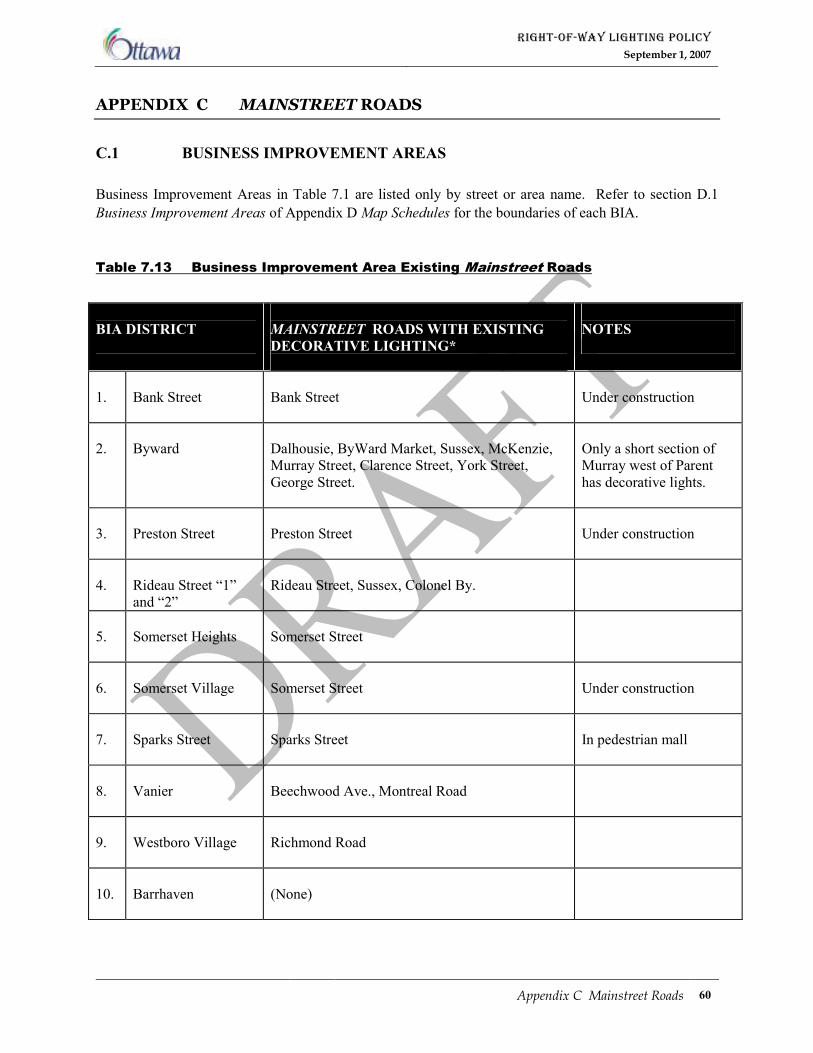
RIGHT-OF-WAY LIGHTING POLICY
September 1, 2007
Appendix C Mainstreet Roads 60
APPENDIX C MAINSTREET ROADS
C.1 BUSINESS IMPROVEMENT AREAS
Business Improvement Areas in Table 7.1 are listed only by street or area name. Refer to section D.1
Business Improvement Areas of Appendix D Map Schedules for the boundaries of each BIA.
Table 7.13 Business Improvement Area Existing Mainstreet Roads
BIA DISTRICT
MAINSTREET ROADS WITH EXISTING
DECORATIVE LIGHTING*
NOTES
1.
Bank Street
Bank Street
Under construction
2.
Byward
Dalhousie, ByWard Market, Sussex, McKenzie,
Murray Street, Clarence Street, York Street,
George Street.
Only a short section of
Murray west of Parent
has decorative lights.
3.
Preston Street
Preston Street
Under construction
4.
Rideau Street “1”
and “2”
Rideau Street, Sussex, Colonel By.
5.
Somerset Heights
Somerset Street
6.
Somerset Village
Somerset Street
Under construction
7.
Sparks Street
Sparks Street
In pedestrian mall
8.
Vanier
Beechwood Ave., Montreal Road
9.
Westboro Village
Richmond Road
10.
Barrhaven
(None)
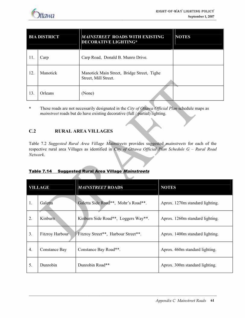
RIGHT-OF-WAY LIGHTING POLICY
September 1, 2007
Appendix C Mainstreet Roads 61
BIA DISTRICT
MAINSTREET ROADS WITH EXISTING
DECORATIVE LIGHTING*
NOTES
11.
Carp
Carp Road, Donald B. Munro Drive.
12.
Manotick
Manotick Main Street, Bridge Street, Tighe
Street, Mill Street.
13. Orleans (None)
*
These roads are not necessarily designated in the City of Ottawa Official Plan schedule maps as
mainstreet roads but do have existing decorative (full / partial) lighting.
C.2 RURAL AREA VILLAGES
Table 7.2 Suggested Rural Area Village Mainstreets provides suggested mainstreets for each of the
respective rural area Villages as identified in City of Ottawa Official Plan Schedule G – Rural Road
Network.
Table 7.14 Suggested Rural Area Village Mainstreets
VILLAGE
MAINSTREET ROADS
NOTES
1.
Galetta
Galetta Side Road**, Mohr’s Road**.
Aprox. 1270m standard lighting.
2.
Kinburn
Kinburn Side Road**, Loggers Way**.
Aprox. 1260m standard lighting.
3.
Fitzroy Harbour
Fitzroy Street**, Harbour Street**.
Aprox. 1400m standard lighting.
4.
Constance Bay
Constance Bay Road**.
Aprox. 460m standard lighting.
5.
Dunrobin
Dunrobin Road**
Aprox. 300m standard lighting.
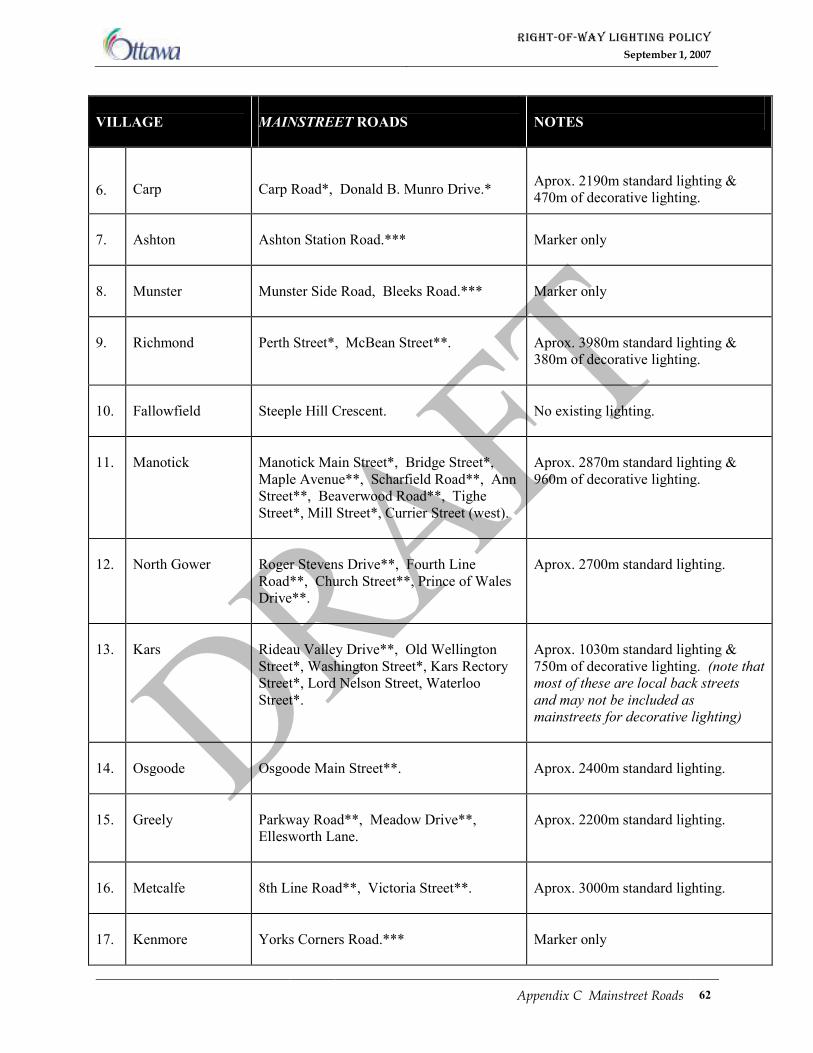
RIGHT-OF-WAY LIGHTING POLICY
September 1, 2007
Appendix C Mainstreet Roads 62
VILLAGE
MAINSTREET ROADS
NOTES
6.
Carp
Carp Road*, Donald B. Munro Drive.*
Aprox. 2190m standard lighting &
470m of decorative lighting.
7.
Ashton
Ashton Station Road.***
Marker only
8.
Munster
Munster Side Road, Bleeks Road.***
Marker only
9.
Richmond
Perth Street*, McBean Street**.
Aprox. 3980m standard lighting &
380m of decorative lighting.
10.
Fallowfield
Steeple Hill Crescent.
No existing lighting.
11.
Manotick
Manotick Main Street*, Bridge Street*,
Maple Avenue**, Scharfield Road**, Ann
Street**, Beaverwood Road**, Tighe
Street*, Mill Street*, Currier Street (west).
Aprox. 2870m standard lighting &
960m of decorative lighting.
12.
North Gower
Roger Stevens Drive**, Fourth Line
Road**, Church Street**, Prince of Wales
Drive**.
Aprox. 2700m standard lighting.
13.
Kars
Rideau Valley Drive**, Old Wellington
Street*, Washington Street*, Kars Rectory
Street*, Lord Nelson Street, Waterloo
Street*.
Aprox. 1030m standard lighting &
750m of decorative lighting. (note that
most of these are local back streets
and may not be included as
mainstreets for decorative lighting)
14.
Osgoode
Osgoode Main Street**.
Aprox. 2400m standard lighting.
15.
Greely
Parkway Road**, Meadow Drive**,
Ellesworth Lane.
Aprox. 2200m standard lighting.
16.
Metcalfe
8th Line Road**, Victoria Street**.
Aprox. 3000m standard lighting.
17.
Kenmore
Yorks Corners Road.***
Marker only
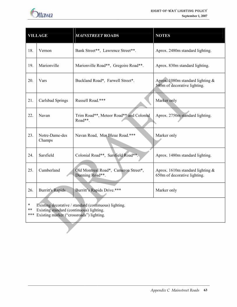
RIGHT-OF-WAY LIGHTING POLICY
September 1, 2007
Appendix C Mainstreet Roads 63
VILLAGE
MAINSTREET ROADS
NOTES
18.
Vernon
Bank Street**, Lawrence Street**.
Aprox. 2480m standard lighting.
19.
Marionville
Marionville Road**, Gregoire Road**.
Aprox. 830m standard lighting.
20.
Vars
Buckland Road*, Farwell Street*.
Aprox. 1080m standard lighting &
540m of decorative lighting.
21.
Carlsbad Springs
Russell Road.***
Marker only
22.
Navan
Trim Road**, Meteor Road** and Colonial
Road**.
Aprox. 2750m standard lighting.
23.
Notre-Dame-des
Champs
Navan Road, Mer Bleue Road.***
Marker only
24.
Sarsfield
Colonial Road**, Sarsfield Road**.
Aprox. 1480m standard lighting.
25.
Cumberland
Old Montreal Road*, Cameron Street*,
Dunning Road**.
Aprox. 1610m standard lighting &
650m of decorative lighting.
26.
Burritt's Rapids
Burritt’s Rapids Drive.***
Marker only
* Existing decorative / standard (continuous) lighting.
** Existing standard (continuous) lighting.
*** Existing marker (“crossroads”) lighting.
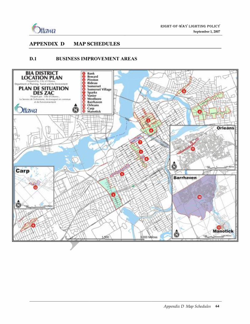
RIGHT-OF-WAY LIGHTING POLICY
September 1, 2007
Appendix D Map Schedules 64
APPENDIX D MAP SCHEDULES
D.1 BUSINESS IMPROVEMENT AREAS
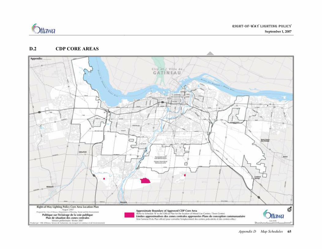
RIGHT-OF-WAY LIGHTING POLICY
September 1, 2007
Appendix D Map Schedules 65
D.2 CDP CORE AREAS
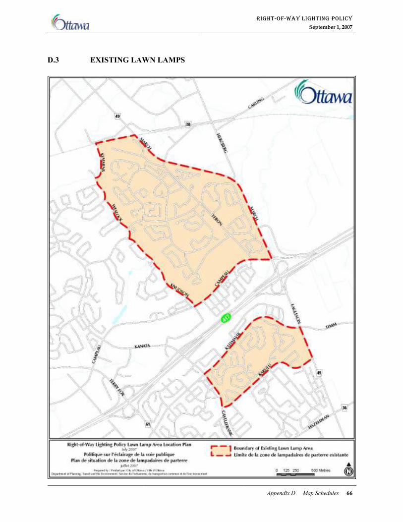
RIGHT-OF-WAY LIGHTING POLICY
September 1, 2007
Appendix D Map Schedules 66
D.3 EXISTING LAWN LAMPS
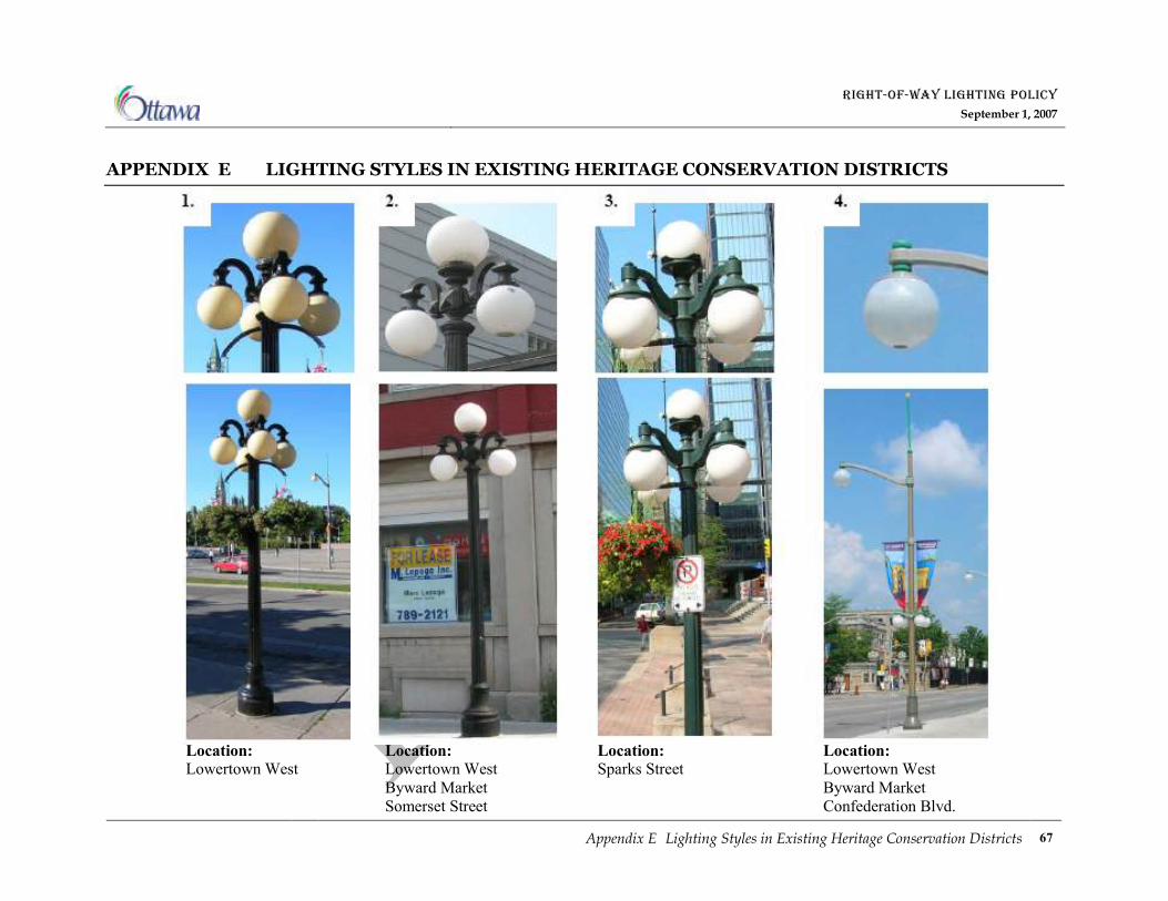
RIGHT-OF-WAY LIGHTING POLICY
September 1, 2007
Appendix E Lighting Styles in Existing Heritage Conservation Districts 67
APPENDIX E LIGHTING STYLES IN EXISTING HERITAGE CONSERVATION DISTRICTS
Location: Location: Location: Location: Lowertown West Lowertown West Sparks Street Lowertown West
Byward Market Byward Market
Somerset Street Confederation Blvd.
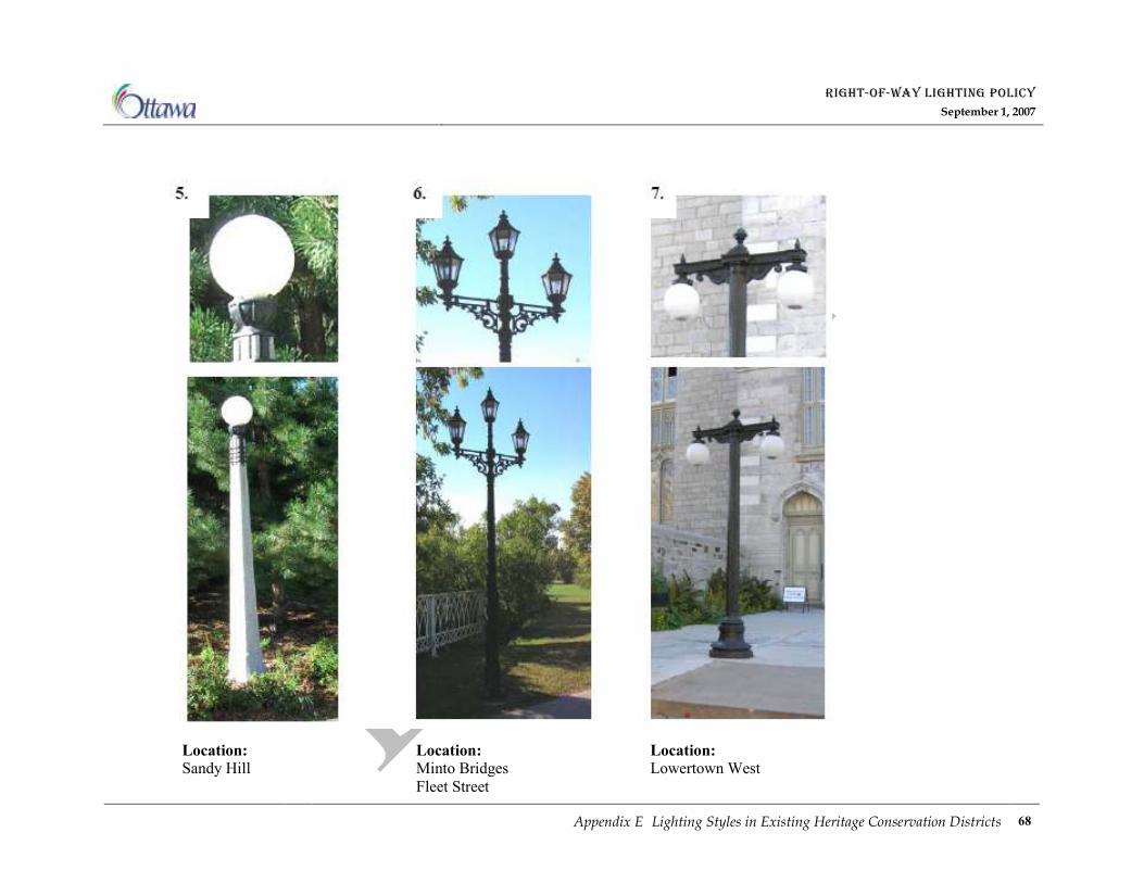
RIGHT-OF-WAY LIGHTING POLICY
September 1, 2007
Appendix E Lighting Styles in Existing Heritage Conservation Districts 68
Location: Location: Location: Sandy Hill Minto Bridges Lowertown West
Fleet Street
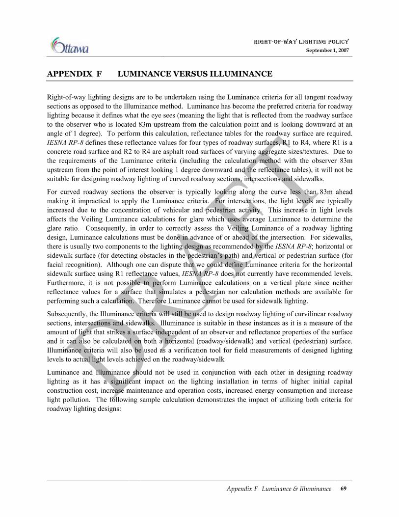
RIGHT-OF-WAY LIGHTING POLICY
September 1, 2007
Appendix F Luminance & Illuminance 69
APPENDIX F LUMINANCE VERSUS ILLUMINANCE
Right-of-way lighting designs are to be undertaken using the Luminance criteria for all tangent roadway
sections as opposed to the Illuminance method. Luminance has become the preferred criteria for roadway
lighting because it defines what the eye sees (meaning the light that is reflected from the roadway surface
to the observer who is located 83m upstream from the calculation point and is looking downward at an
angle of 1 degree). To perform this calculation, reflectance tables for the roadway surface are required.
IESNA RP-8 defines these reflectance values for four types of roadway surfaces, R1 to R4, where R1 is a
concrete road surface and R2 to R4 are asphalt road surfaces of varying aggregate sizes/textures. Due to
the requirements of the Luminance criteria (including the calculation method with the observer 83m
upstream from the point of interest looking 1 degree downward and the reflectance tables), it will not be
suitable for designing roadway lighting of curved roadway sections, intersections and sidewalks.
For curved roadway sections the observer is typically looking along the curve less than 83m ahead
making it impractical to apply the Luminance criteria. For intersections, the light levels are typically
increased due to the concentration of vehicular and pedestrian activity. This increase in light levels
affects the Veiling Luminance calculations for glare which uses average Luminance to determine the
glare ratio. Consequently, in order to correctly assess the Veiling Luminance of a roadway lighting
design, Luminance calculations must be done in advance of or ahead of the intersection. For sidewalks,
there is usually two components to the lighting design as recommended by the IESNA RP-8; horizontal or
sidewalk surface (for detecting obstacles in the pedestrian’s path) and vertical or pedestrian surface (for
facial recognition). Although one can dispute that we could define Luminance criteria for the horizontal
sidewalk surface using R1 reflectance values, IESNA RP-8 does not currently have recommended levels.
Furthermore, it is not possible to perform Luminance calculations on a vertical plane since neither
reflectance values for a surface that simulates a pedestrian nor calculation methods are available for
performing such a calculation. Therefore Luminance cannot be used for sidewalk lighting.
Subsequently, the Illuminance criteria will still be used to design roadway lighting of curvilinear roadway
sections, intersections and sidewalks. Illuminance is suitable in these instances as it is a measure of the
amount of light that strikes a surface independent of an observer and reflectance properties of the surface
and it can also be calculated on both a horizontal (roadway/sidewalk) and vertical (pedestrian) surface.
Illuminance criteria will also be used as a verification tool for field measurements of designed lighting
levels to actual light levels achieved on the roadway/sidewalk
Luminance and Illuminance should not be used in conjunction with each other in designing roadway
lighting as it has a significant impact on the lighting installation in terms of higher initial capital
construction cost, increase maintenance and operation costs, increased energy consumption and increase
light pollution. The following sample calculation demonstrates the impact of utilizing both criteria for
roadway lighting designs:

RIGHT-OF-WAY LIGHTING POLICY
September 1, 2007
Appendix F Luminance & Illuminance 70
Design Criteria for a Typical Arterial Roadway in an Employment Enterprise Area
A. Roadway Lighting Levels as indicated in Table 2.1 Required Average Roadway Lighting Levels:
1. Average Luminance = 0.9 Cd/m2
2. Average to Minimum Uniformity = 3:1
3. Veiling Luminance (Glare Ratio) = 0.3
4. Average Illuminance = 13 Lux
5. Average to Minimum Uniformity = 3:1
B. Lighting Equipment selected from Appendix B Approved Lighting Equipment including;
1. 400 Watt HPS by American Electric Lighting, Photometric Curve # AE3853
(Table 7.3 Group A1 – Semi Cut Off Cobra Head Style Fixtures),
2. 2.4m Luminaire Bracket (Table 7.10 Luminaire Bracket Arms), and
3. 11.3m Aluminum pole (Table 7.11 Aluminum Poles).
Figure 7.1 Roadway Lighting Design Using Luminance, illustrates a lighting design of a typical arterial
roadway section using the Luminance criteria. The design resulted in a lighting layout with about 16 light
poles per kilometer with pole spacing of 65m. The designed average Luminance achieved was 25%
higher than the required average. The increased lighting is inherent in any lighting design in attempting
to satisfy all the lighting criteria (in this case; Average, Uniformity & Glare). ‘Over Lighting’ should be
minimized as much as possible as discussed in Section 2.1 Lighting Design Calculations.
Luminance Criteria
Illuminance Criteria
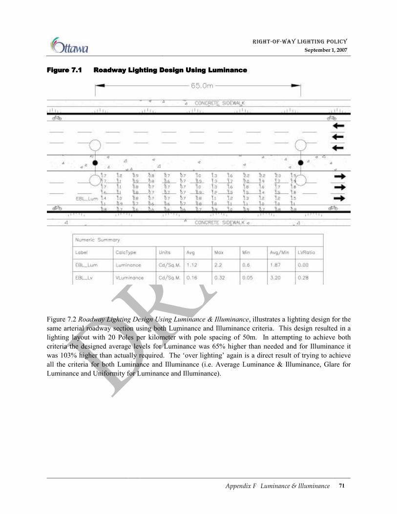
RIGHT-OF-WAY LIGHTING POLICY
September 1, 2007
Appendix F Luminance & Illuminance 71
Figure Figure Figure Figure 7777....1111 Roadway Lighting Design Using LuminanceRoadway Lighting Design Using LuminanceRoadway Lighting Design Using LuminanceRoadway Lighting Design Using Luminance
Figure 7.2 Roadway Lighting Design Using Luminance & Illuminance, illustrates a lighting design for the
same arterial roadway section using both Luminance and Illuminance criteria. This design resulted in a
lighting layout with 20 Poles per kilometer with pole spacing of 50m. In attempting to achieve both
criteria the designed average levels for Luminance was 65% higher than needed and for Illuminance it
was 103% higher than actually required. The ‘over lighting’ again is a direct result of trying to achieve
all the criteria for both Luminance and Illuminance (i.e. Average Luminance & Illuminance, Glare for
Luminance and Uniformity for Luminance and Illuminance).
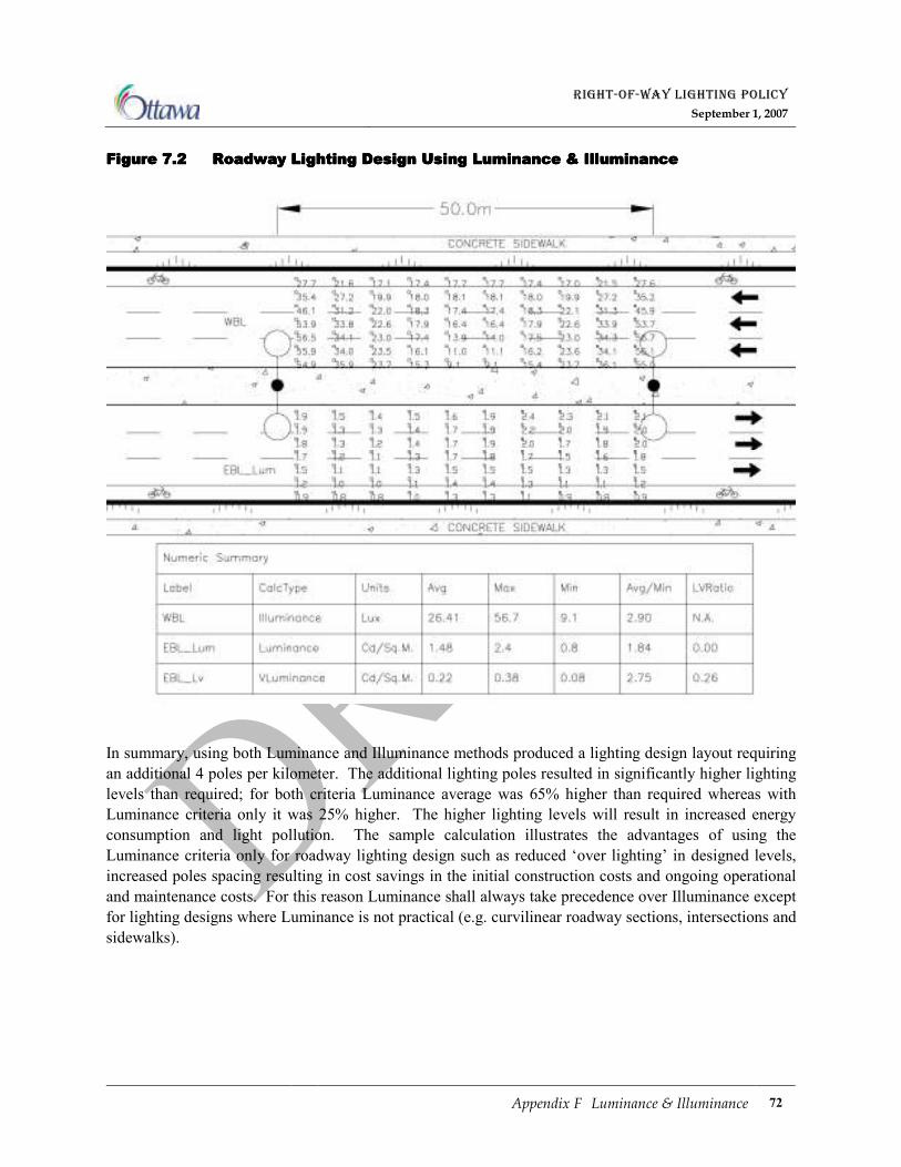
RIGHT-OF-WAY LIGHTING POLICY
September 1, 2007
Appendix F Luminance & Illuminance 72
Figure Figure Figure Figure 7777....2222 Roadway Lighting Design Using Luminance & IlluminanceRoadway Lighting Design Using Luminance & IlluminanceRoadway Lighting Design Using Luminance & IlluminanceRoadway Lighting Design Using Luminance & Illuminance
In summary, using both Luminance and Illuminance methods produced a lighting design layout requiring
an additional 4 poles per kilometer. The additional lighting poles resulted in significantly higher lighting
levels than required; for both criteria Luminance average was 65% higher than required whereas with
Luminance criteria only it was 25% higher. The higher lighting levels will result in increased energy
consumption and light pollution. The sample calculation illustrates the advantages of using the
Luminance criteria only for roadway lighting design such as reduced ‘over lighting’ in designed levels,
increased poles spacing resulting in cost savings in the initial construction costs and ongoing operational
and maintenance costs. For this reason Luminance shall always take precedence over Illuminance except
for lighting designs where Luminance is not practical (e.g. curvilinear roadway sections, intersections and
sidewalks).
RIGHT-OF-WAY LIGHTING POLICY
September 1, 2007
Appendix G Footnotes 73
APPENDIX G FOOTNOTES
i American National Standard Institute / Illuminating Engineering Society of North America (ANSI / IESNA)
ii Transportation Association Canada (TAC)
iii Available at http://www.ottawa.ca/city_hall/ottawa2020/official_plan/vol_1/schedules/index_en.html
iv Ministry of Transportation Ontario, Roadside Safety Manual
v Electricity Act 1998
vi Official Plan Schedule B available at
http://www.ottawa.ca/city_hall/ottawa2020/official_plan/vol_1/schedules/index_en.html vii
Official Plan Schedule G available at
http://www.ottawa.ca/city_hall/ottawa2020/official_plan/vol_1/schedules/index_en.html viii
Official Plan Schedule E available at
http://www.ottawa.ca/city_hall/ottawa2020/official_plan/vol_1/schedules/index_en.html