Rider-1943-PQR.pdf - World Radio History
185
- -SS 73e,- --- e - www.americanradiohistory.com
-
Upload
khangminh22 -
Category
Documents
-
view
2 -
download
0
Transcript of Rider-1943-PQR.pdf - World Radio History

- -SS 73e,- ---
e
-
www.americanradiohistory.com
PACKARD BELL PAGE 13-3
PACKARD BELL CO. MODEL D19
l0 40i F
O
W001 W001 Ó«._
WSZ W001
1 W 000
Owed
WOO =np
Oa
0000
W001
2 006
W0S
ó`T bou
001
WOOS
10
10
rv T
F
I a W01
E
00
1O --TPA" $T -
W001.`- WOS
ac-ó- 6iW011
I
e
C
3)1014
I1
ç 6.u11 WOB
-IH
WOOS
- WOOç
J wl vvr z
81 WQY
$
W
WOb
6au S WOO
I
I- I
I11I-iI I I
{ i i
t T
I
cto3
m 62lu
_ -1IF
.wv I WS
s
} t_
]A
011 WOOS Fr
I £ ª Wos
=o n ssrp
-o ó :
r a<'R'lîft
< O 17
00`
0.
o
Co (3)OO NOvf M
ONONd
O M]0pAY]d
(oloi
111010111
®John F. Rider
www.americanradiohistory.com

PAGE 13-4 PACKARD BELL MODEL 48H
PACKARD BELL CO.
w00/
100000\
I.OS[ 0051 Mo 900
'9ºMC
N _I p
wló, T (( ó j `.^
=f000' IL wNW
MO¡f
r
ó ==,00o
be* 000'
i;
YoSI 4.efivvve
10Y1n0J -10A W00ÿ
V IwC
MOOI I, l ..y 1BM[
jtjA
h
Q9
- . Sconti u ^yti
ó et 2t'ióá:Z r ^ti....?F» k -.^anrp.C. ar
1,101
r
. 00061
ëkoop'
--
- --F----- H-- 111
,,e
111
'60`
®John F. Rider www.americanradiohistory.com

PACKARD BELL PAGE 13-5
MODEL 66DR PACKARD BELL CO. MODEL 66DRC
6S47 4547 688G 65k7 6V64T a0 R S á
IL/
f
-- e I , - - tSS . , o
OJ yt T L°e JNtp, 7777
'LY2I0
nl
El =JO t é
t 1 - /t t" h ,;
Y - 1 1
r 2ME0 fME4 MM
j
¡ B WM _ = 2 =.OJ 1 1
.
OJ i o .O.f _ . - . WO
1[ G 6166T J 4ó _ PWR_
TRRNS L .001 - -00J 0uwio$F. - 6X54i
P/CN-uP : - - o' 4 óti
-Q 50oM
^Ó'-- .........1"----'-
W .-+-wvvw- =r
m Vr SD
oZ e ñó
# ® 0 fLORT 1 I I Y y: n L/
_ ~
60R
O ' t 1 RECORD RRDIO = .
T0 HEATERS v 2 IF 6SR7 '1[F ,,._, = Iii I1
2
3 PR. MICROPNOKC
3 2 ® ® t Q
7 aW .,. 4 PLRY'BRCK
RR 01 O - PILOTS
ÿ ¿SRI RLLBOTTONS
RELERSEC Ali MICROINONC
feM Ñ
I
aoa
PACKARD BELL CO. DR UDR
I
I
I
110420 V. So-[o.v
1 2 4
IF PEAK 460 KC
4SK7 45R7 48$G 6Sk7 01 4V64T i0a a= a1 , _- P L O -> a .Or /oI lioe SMf4. ti
JZ
I
=50 1 1 1
WAY t
t = , II r /JR
Irati ~^-.,..- er F IM
'
1 1 1
M
1 W IMO ' SMEG.+ I B 1
/N[p 1 ti Yf - -I- N1/rR _
gNVy r r i _ = =o5 -1-_ a 'OE - - 1 , Jt W
o o 16
_ OG
6V64T J. w1 ' 4ó - PwR ram L ._.-. ..-a -Thos oL. Eáú ` 6X147"
C2 )TP,CK_uP_íc, - SoOn ` F
6;54T 1 =r mo 10
® --[I ÿ eo
á iO KOC ---. 1.. I
=ó
O O t 1 RECORD RR010 - 70
«2 IF' Iirr ® 2 MICROPNORE ' ( NER7"ERf or 3 PR. Z 1
® 0 Q.W - . 4PLRY-BRCK
RRDiO- PILOTS
Q C
RLL 801 TONS
RLLERJCD _ P r
PRCKRRD BELL CO. 111 MODEL 6 6 D R C I
I/0 -120V. 5O-60..-.
1 2 4
©John F. Rider www.americanradiohistory.com

PAGE 13-6 PACKARD BELL MODELS 673,67BA,67BK,67BKA, 673PR,67BPRDL,67BR PACKARD BELL CO. MODELS 88, 86F, 33PA
PACKARD BELL MODELS 88 88P AND 88PA
65E7
6567 65117
1
88P a 88 PA
b5U7
Im 9
HIM 110-120V AC
JO - 6O+
L J IN MODEL 80 DOTTED LINES IN MAIN DIAGRAM ARE CONNECTED A5 SHOWN. PHONOGRAPH SWITCH IN ROH SHOWN IN RADIO POSITION.
6V66T
006
To H,61...3
YAVE Tá(JP TRIM 'TO
I 5146A1.6 T 456 KC
OP
TRANS
6K6GT
ROWE R
TRANS
6K6GT
2.° IF
456 KC
6x5GT
P'IF 456 KC
PACKARD BELL MODELS 676, 67BR, 678PR, 678PR DL, 67BA, 67BK , 67BKA.
65F7
G
6SQ7
'
o
ti
6U5 e
65A7 F
O5
00
meq
__11.03 65K7 6V66T 2501 101
.1
8
20M mg
N 250 ry
15meg
2r2
250M
.001
ti
r o o H
.00z
05
}
.,
= '.
<
I 6X561
S o O h
To HEATERS
110-120V AC 50-60--
65A7 6U5 OP
TRANS
POWER
TRANS.
'c John F. Rider www.americanradiohistory.com

PACKARD BELL PAGE 13-7
50011 2110..
MW.KNv 23 4
J
I_. -I I I- J . V --1,,T111
MIXER 50011
r r
VOL UMC EACH
PACKARD BELL CO.
2
2Q
75MF
¿I
ó- o
BOTTOM OF PL
1.511 G
Ó 2
LRY-BAC.
3
2NOnrvo380 BRN0 ANT
Auc
CUTE/NG HERD
/7/JTOMATIC CHAh'GER
L
P/LOT
1 P A.
2 RECORD MICROPHONE 3 MIXED PROGRAMS 4 R8010 OR PHONO 5 PL R V-8 ACK 6 RADIO OR AUTOMAT iL
PACKMOOCL ARD 120£1,
BELL CO. RECORDING CONTROL 800
SOM
705 I
10M
W.N.V. 1 IMEG O.5=
63K7
-3 L L
r 4 3 6 7 e 9 10
65K7
5ME0
.02
JMEL 883s 0N-
TROL
6307
5051
I º°,.5700 a ---<>
380 2n0
BONO
BRNO 0sC OSC.
50
000
GRID
'10D; L 120'L2
BC - OSC
_400 p KC - PROOER
0 2N0
BRNO OSC
SRO MHO O O - 05C.-
000
6AF6G
2/10 BRNO
urirr 0 0
540 290 BC
BRNO 8800 BRNO -RF-
7P 46 OKC
2R0 irr 0 o
PWR. TRANS OUTPUT
TRANS
RECORDING CHRNDER MOTOR MOTOR ONLY ONLY
00 0 RC. CORD
o Di
o PILOT a.o 6115 CAW
0 0 MICROPHONE
Qo 0 0 AUTOMATIC [L V
l RECORD PHONO 2 RUTOMRTIC 3 350 - //00 KC 1 600-1100 5 800-/300 6 800 -1400 7 /000-/750
C B BC MANUAL Ç 9 280 8840
10 3R0 +I
CHASSIS LAY-OUT
0. [LL®
m I I I I I 1 I I I I
1 2 3 4 5 6 7 8 9 10
MICROPHONE -0 0-1
01 63K7
006
n
Ieo
Bor To
SOCS[T
6JSGT
03
F
j" 11
IF 1 -TAI, 430 ?r
AUTOMATIC PHONO
CD
100
TEL EV. JACK
002
PRCKRRO BELL CO. 1100(0 /20E11
6V6GT
AUTOMATIC
F
I/O -120V,
©John F. Rider
000
S..,
F
F 20 -1
SY3G
www.americanradiohistory.com

PAGE 13-8 PACKARD BELL P.ODLL 130PR
^(2 L..J
o CO
- J
W
ó 2
PACKARD BELL. CO.
l A.>z1iJ
a
MOOT N
WO/
NO/
NC
qq) Nos
rÖ2íól 6w
x g
` t
1'1 ó
00*
(.
o o
r.
o
g
I --'H
ti
ally voQOI
N00/
ti
I
JUL º
N 2
l7
U
U .Y.
tD Lo
C
0
Eze
11
©John F. Rider www.americanradiohistory.com

PARMAK PAGE 13-1
co
\ JI --- 700-"-
300M
z.00M
(o
.0005
PARKER MeCRORY 31F G. CO. MODEL 5DB,1936 Royal MODEL 4J 1940 Royal MODEL 7C 1940 Imperial MODEL 7H 1940 Imperial
O ti 00 4,a2
").2.
I
[[`¡ ) ti
ti
h
vwVt.
.0005
11.
ó
JO
91
Zoo- c.
IN
.0007s
¿ 00M
v)
10
o
J o
Ñ 2 o u
©John F. Rider www.americanradiohistory.com

PAGE 13-2 PARMAK MODEL 525 1937 DeLuxe MODEL 733 1937 Masterpiece PARKER McCßOR.Y MFG. CO.
1001
C
'9'
ellTrilre et+Q
"IC6"
01 C/
T'Tod el 733
o0 o
" I ALI"
..__ 40Mti j I
MR ,1/VVy% 1 C7<-
Rd I MEG. -'\ MAN.- R6
66
1937 DELU13 bADDEi. 525
>lltegi 50A I O.®
o
WlRATOR
saretiRDIOLT
SIM ºuatuc tafflti TUIì[ tJOWT
"m"
GEM gLt;t:Tt1a
n
..19
ctIANGE aMrrcM
Y!OSaag ÇOMMRTMIKT
Model 525
o
o
o
00
00 ¡ o o
o o o
ALIGNMENT PROCEDURE
13.2g 4S123
1937 Mastorplece Model 733 WARNING: The following information is to be used only by an experienced serviceman with the proper equipment. In
most cases it is necessary only when set has been tampered with or damaged by accident. I.F. ALIGNMENT: Connect signal generator, through .00025 cond., to grid cap of /C6 tube. Set signal generator at 456
K.C. (this must be accurate), dial pointer at 1700 K.C. Short out oscillator section (center section) of variable cond. gang. Connect suitable output meter across voice coil of loud speaker. (If output meter is not available it will be necessary to adjust by ear, using the loudest note from signal generator.) Increase attenuator until output meter shows deflection or a note is heard from signal generator. Carefully adjust I.F. transformer trimmers for greatest deflection of meter or loudest note from generator. Reduce generator output as intensity of signal increases as I.F.s are tuned nearer their original 456 K.C. setting. Signal should be just audible by ear. Go back over the adjustments to be sure they are correct. Remove short from oscillator section of variable cond. and adjustment is complete.
B.C.-R.F. ALIGNMENT: (1) Connect signal generator, through .00025 cond., to antenna post Al. Short wave switch in broadcast position. (2) Set signal generator and dial pointer to /4007[-C. (3) Adjust ose. B.C. trimmer "A" (see diagram) for greatest deflection of meter or loudest note. (4) Set generator and dial pointer to 1400 K.C. Adjust antenna B.C. trimmer and trimmer "E" for greatest deflection of meter or loudest note. (5) Set generator and dial pointer to 600 K.C. Adjust trimmer "D" for greatest deflection or loudest note. (This adjustment is critical and must be accurate.) Rock cond. gang across 600 K.C. note while adjusting trimmer "D." Repeat adjustment at least twice to be sure it is correct.
POLICE AND AMATEUR BAND ADJUSTMENT: (1) Set switch in Police -Amateur position. Connect signal gen. to ant. post Al through 400 ohm resistor. (2) Set gen. and dial pointer to 6 meg. (6000 K.C.). Carefully adjust trimmer "B" for greatest deflection or loudest note. Check adjustment with gen. and dial pointer at 2 meg. (2000 K.C.).
FOREIGN BAND ADJUSTMENT: (1) Set switch in Foreign position. Connect gen. to ant. post Al through 400 ohm resistor. (2) Set generator and dial pointer to 18 meg. (18000 K.C.). This must be accurate. (3) Carefully adjust trimmer "C" and ant. S.W. trimmer for greatest deflection or loudest note. Check adjustment with gen. and dial pointer at 7 meg. (7000 K.C.). This completes all R.F. adjustments.
©John F. Rider www.americanradiohistory.com
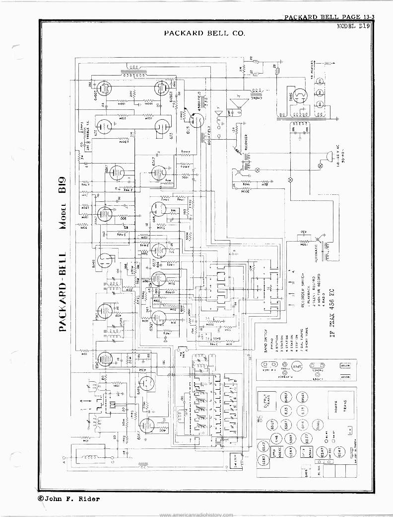
PARMAK PAGE 13-3
PARKER & McCRORY MFG. CO. LODî,L 650 1938 Masterpiece
1
C9
6D8G 6S7G
_C4
RI
te
6T7G c/em6L5G 24L i hvvv-
Ci3
I. F. PEAK 456 K. C.
Top-Ant. B.C. Trim. Center-Ant. Pol. Trim. Bottom-Ant. SW. Trim.
A-Osc. B.C. Trim. B-Osc. Pol. Trim. C-Osc. SW. Trim. D-Osc. B.C. Pad. E-Pres. B.C. Trim.
Cl. C2-8. C3 -5. C4, C5, C6 -.1-200V. C7, C8 -.5-150V. C9, C10 -.05-200V. C11 -.03-400V.
C12, C13, C16- .01-400V. C14, C15- .01-1000V. C17, C18- .003-400V. C19- .0005 Ceramicon C20- .004 Mica. C21- .0018 Mica.
C22- .0001 Mica. C23- .00025 Mica. C24- .0006 Paddler. C25- .05-200V. C26- .1-400v
l
á C3 l
6Z 7G
g lclr Z
E-7.7-(2¡
6ZYSG
ANT Coil.
608G
6L5G
®
Ai9 Se)
ce0e
Re
6456 -
T7G
Fa. TER CONO
6S 7G G ND ANT2 ANTE
6Z 7G
6ZYSG
VIBRATOi[ POWER sti_' Y
_J
TUBE LAYOUT BATTERY LEAnS
ALIGNMENT PROCEDURE
R1- 3 Megohms 1/4W. R2- 1 Megohms 1/4W. R3- 1/2 Megohms 1/4W. R4, R18- 150,000 1/4W. R5, R6- 100,000 1/4W. R15- 751/4W. R7- 50,0001/4W. R8- 20,000 1/4W. R9- 12,000 %W. RIO 2,0001/4W R16- 500,000 VC. R11- 1,000 1/4W. R12- 7501/4W. R13- 500 1/4W R14- 2001/4W. R17- 500.000 1-10W.
WARNING: The following information is to be used only by an experienced serviceman with the proper equipment. In most cases it is necessary only when set has been tampered with or damaged by accident.
I.F. ALIGNMENT: Connect signal generator, through .00025 cond., to grid cap of 6D8 tube. Set signal generator at 456 K.C. (this must be accurate), dial pointer at 1790 K.C. Short out oscillator section (center section) of variable cond. gang. Connect suitable output meter across voice coil of loud speaker. (If output meter is not available it will be necessary to adjust by ear, using the loudest note from signal generator.) Increase attenuator until output meter shows deflection or a note is heard from signal generator. Carefully adjust I.F. transformer trimmers for greatest deflection of meter or loudest note from generator. Reduce generator output as intensity of signal increases as I.F.s are tuned nearer their original 456 K.C. setting. Signal should be just audible by ear. Go back over the adjustments to be sure they are correct. Remove short from oscillator section of variable cond. and adjustment is complete.
B.C.-R.F. ALIGNMENT: (1) Connect signal generator, through .00025 cond., to antenna post Al. Short wave switch in broadcast position. (2) Set signal generator and dial pointer to 1700 K.C. (3) Adjust ose. B.C. trimmer "A" (see diagram) for greatest deflection of meter or loudest note. (4) Set generator and dial pointer to 1400 K.C. Adjust antenna B.C. trimmer and trimmer "E" for greatest deflection of meter or loudest note. (5) Set generator and dial pointer to 600 K.C. Adjust trimmer "D" for greatest deflection or loudest note. (This adjustment is critical and must be accurate.) Rock cond. gang across 600 K.C. note while adjusting trimmer "D." Repeat adjustment at least twice to be sure it is correct.
POLICE AND AMATEUR BAND ADJUSTMENT: (1) Set switch in Police -Amateur position. Connect signal gen. to ant. post AI through 400 ohm resistor. (2) Set gen. and dial pointer to 6 meg. (6000 K.C.). Carefully adjust trimmer 'B" for greatest deflection or loudest note. Check adjustment with gen. and dial pointer at 2 meg. (2000 K.C.).
FOREIGN BAND ADJUSTMENT: (1) Set switch in Foreign position. Connect gen. to ant. post Al through 400 ohm resistor. (2) Set generator and dial pointer to 18 meg. (18000 K.C.). This must be accurate. (3) Carefully adjust trimmer "C" and ant. S.W. trimmer for greatest deflection or loudest note. Check adjustment with gen. and dial pointer at 7 meg. (7000 K.C.). This completes all R.F. adjustments.
PM.
©John F. Rider
www.americanradiohistory.com

PAGE 13-4 PARMAK MODEL 733 1937 Masterpiece MODEL BA41 1936 Regal PARKER MeCRORY MFG. CO.
1937 MASTERPIECE MODEL 733
I.F. 456 KC FOR OTHER DATA SEE INDEX
VOLUME CONTROL
VMATOR CAN-.
P 32
SPEAKER BLUE
CHASSIS LAYOUT 1936 REGAL
MOD TI BA 41 SIX -VOLT STORAGE BATTERY SET
SHIELD
6pAOCAET AMTtANfA COIL
NICOLE NAND - ANT TRIMMER
IC6
JW ANTEANA COIL
IF - BC PA0O446 LAMOENEER
ANT. 6NI3 IF SW OSCILLATOR
HEU AND RED WIEN BLUE TRACER
36
FOR OTHER DATA SEE RIDER'S ìiOL.XII
^- 6 NeLT BATTERY
BLACK, BLAGE PI/TN GREEN TRACER AND-JNIFLD
©John F. Rider
www.americanradiohistory.com
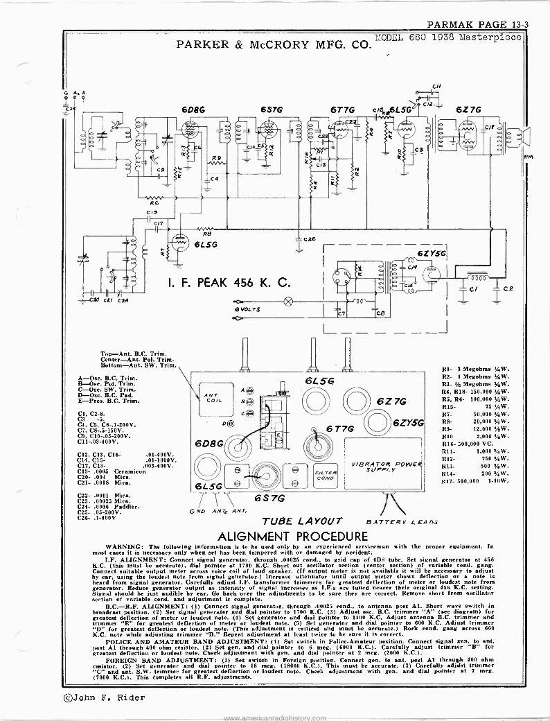
PHILCO PAGE 13-1
/ r /R .F
PHILCO RADIO & TELEVISION CORP. ISTDET-OSC.
a
i
c).
QQce' b~ O
MODEL AR -10
°NOTE: THIS SIDE OF Ii I BATTERY GROUNDED TO CASE.(FRAME OF CAR) -
15,O0On
a
r T
1,70011
-PARTS LIST-AR-ID No. Description Part No.No. Description
O o o O
O o o
E
ï+
L
Part Ne. Antenna Choke 65-0102 ©Condenser (.03 Mfd.) 61-0119 Condenser (.01 Mfd.) 81-0114 81teplacement Cone .
Antenna Transformer 65-0196 (For 73-0027-1) 91-0076 Tuning Condenser 63-0028 (For 73-0027-2) 91-0077 Aerial Compensator 63-0030 ®®®®®®Output Transformer 65-0258 Condenser (.05 Mfd.) 61-0101. $ Field Coll (Not Replaceable) Condenser (.05 Mfd.) .61-0111 Condenser (250 Mmfd.) .60-125157 Antenna Padder (on Tun. Cond.) ®Condenser (.5 Mfd.) ' 61-0106 Condenser (100 Mmfd.) .60-110157 "A" Choke 32-2477 Resistor (10,000 ohms) ..3-310154 Condenser (250 Mmfd.) .60-125157 Resistor (22,000 ohms) .,33-3221348Vibrator Choke 65-0204 Resistor (190 ohms) ..:.33-1193368 Condenser (.5 Mfd.) 61-0137 Condenser (.05 Mfd.) ....61-0111 e(3 Vibrator 83-0025 Pilot Lamp 69-00048 Resistor (220 ohms) ....33-122334 Filament Choke 65-0158 Resistor (220 ohms) ....33-122334 Resistor (100,000 ohms) 33-410154 Tower Transformer 65-0185
Condenser (.015 Mid.) 61-0138 Condenser (100 Mmfd.) .60-110157 Oscillator Padder (on Tun. Cond.)
. Oscillator Transformer 65-0194 Padder (Pri. 1st L F. Trans ) First I. F. Transformer 65-0191 Condenser (.05 Mfd.) 61-0111
®Padder (Sec. 1st I. F. Trans )
bù Resistor (190 ohms) ....33-119336 k Condenser (.05 Mfd.) 61-0111 84tesistor (15,000 ohms) .33-315334 »Volume Control (350,000 ohms)
II & On -OR Switch 67-0020 »RResistor (2,700 ohms) ..33-227434 »;Second I. F. Transformer 65-0192 @PIPadder (Sec. 1st I. F. Trans )
)t Resistor (2,200,000 ohms) 33-522154 ßi'Condenser (250 Mmfd.) .60-125157
Condenser (4,000 Mmfd.) 61-0128 Resistor '
(15,000,000 ohms) .'..33-615154 @Resistor (220,0110 ohms) 33-422151 MReststor (470,000 ohms) 3:i-447154 e Condenser (.01 Mfd.) 61-0120 ®Filter Condenser
(10-10-20 Mfd.) 61-0068 Cl Resistor (190 ohms) .. .33-119336 ®Resistor (2,200 ohms) ..33-222334
1ST I r ,TRANS /
©°
BCondenser (8 Mmfd.) ..60-008337 Tuning & Volume Knob ..-77-0765 Dial 55-1200 Dial
(139
(1614") 55-0588 (59á^) 55-0589
^) 55-0652 (7%") 55-0653
Pointer 57-1940 Tuning Shaft 57-1802 Window Crystal 55-0501 Speaker Unit 73-0027 Tube Side Cover 57-07918'059 Wiring Side Cover 77-0561FC5t) Back Strap 28-5998FA3 Mounting Bracket ....57-0812FC59 Cover Screws W1586FA3 Front Screws 97-0111FA3 Fuse Lead 77-0235 Fuse 45-2559 Vibrator Socket 27-6044, Loktal Socket 55-0575 Pilot Lamp Assembly 77-0342 Signal "A" Lead 77-0217 Generator Interference Condenser - 30-4007' Connection Distributor Resistor 33-1198 Bolt (Radio Mtg.) W I818FA3
Ant. ...
oa-or, swiTt.11 a- An recept. svOLuUt CONTel# 11
45 5 KC
745 TUBE 7C6 TUBE VIBRArOR OUTPUT 2ND. DET.-IST. AUDIO/
TUNING %CONTROL,
7Y4 TUB 787 TUBE 7A8 TUBE 7B7 TUB A ERS VOLUM RECTIFIER
Dummy Antenna
I F OET-OSC. R.F
Signal Generator Frequency
0.1 mf 455 kc AERIAL Is «
,RCcte TAC LC/ « « a fl (( if ((
« it se it se « « «
IAER/AL Note 3 30 mmf 1580 kc " 4-0,4p. " " 1400 kc 1400 kc 84 00 KC 1200-1400 kc 5 a
Note 1.-Adjust antenna compensator (5) two turns from tight position. Note 2.-Turn condenser rotor plates completely out of meshas far as they will go. Note 3.-Connect antenna lead, Part No. 95-0185, to antenna receptacle in the
radio. Connect a 30 mmf condenser in series between signal generator and antenna lead.
Note 4.-When antenna stage adjustment is made with radio installed in gar, the radio antenna lead must be connected to car antenna in usual manner. Connect signal generator output lead to a wire placed near car antenna but not connected to it.
Note 5.-After installing radio in ear, tune in a weak broadcast signal between 1200 and 1400 ke. Remove plug button on aide of radio and adjust antenna compensator (5) for maximum signal.
Receiver Wave -band
Switch
RECEPTACLE CONTROL
Receiver Dial
Setting
MODEL AR -/O TOP VIEW
/F 455XC
'ew s \\\
/400KC TOP ANT
102322TTON, H.r 05C. /5490 /CC
f U ÑbIG CONTROL
Note 2 11
Tr immer Number
Note 1
30 23 20 30 23 20 18
©John F. Rider www.americanradiohistory.com

PAGE 13.-2 PHILCO MODEL AR -40
PHILCO RADIO & TELEVISION CORP.
V' Oel. IAMeMNO)V' !E'CC-MO!' O mdmW mM^MNtOI.-Iti1flIOtOUlfidaM10.imVNE'r-IVIOMIfi!MK.t Mn,MO>..NNmö]MOo co If! N10 I0 .4'020040200.-40m,,,10 W00.0 0.-1y.-I.p10N10NMtiM^I.MMNOMMIOMIOmM<0000UM <011<010100m1 -10M
.- M. -I .-1 OM.+IM M^.-'ti.r.1 0 y'.IM CVNq.-Iri.y.'.1.-OMO.IM.yeM.-'tiMM.MU .-'mMM¡yti [y(yOCJUO.n10.n< IM.. O O1 O 00]ONM C101fJ001.. O CVOOKi 00 mr10010N100N000OONpOM10OtiE..O'O 7.!O pfpoo0[s.V'.-'Omy
.y II-J^M^m .ymMN Ññ ̂,...0.001 tO m 0if0OC~0.10i OMOm1OmtóNMf~Cmi '-',."4022.02.0,-10.2m.,-.10002, ''....C1'01.01.1.. -01.1W.............. My,y`MMIpÑ,Nd.
1 1 Mqqq M M M1 Ó M M' 1 m O 0 M ,g1 MM .Mp ..y..l y M M M MM . .M M M ^ÿ(1i . CO CO M . .M
ua
.teli !. 1010 10
; É ` ^ ' -ß '^ :. Z :^ '^ ' .^ : .F
' [z ó É. E ., .. ó^.. é ^, .- v°'im ° ° ^ ^ o^L^.-.^...-.á : .
55 .:có.:i4 6 SoEjp ^ x eral 8 EE9 m ^ mv â E.Ecoo ^z ó o(1,.'.
`d E.".a. ^E ó4Éoóe1 0 Ñ
0Ñ óÑó ôt otio ooo.s,',..1 ó.i óoVium-, 5o m c d Eoóí4o ó ó.4ó á á 7«,':2
á:; vV m o .,- 000 00 00010 00 op..p 00 1010 u7 O.Y10 p00 No00. p'C6:.Ñ 0.,,.óOOÿvLÿ óÑ`...ÿÑ NvCgÑ Qo0 . ̀v v vvO...v ti..:ÿ m T= mm .... 0 .Ó.)a
... ?. ....¡p U " óIO- É" titi^..Ú ..ma. CCJJ } .r`r....."... o< OOmV) CôoVo^q..0, Oo .. vUpa.mi G, .......2..-5A---0.2=°""5 U ÿ aE)
V007m.)s o`
.r.Iú a)a. 'I" UUm'ÚOi`e{a'.-'' ámS.+ á°'óa`i.d-?`m.ó m.ó9om.-i wpp.Cn mCy-e`emE.aiSacwezmgo^va,E.,Cmá meé4
a c -...o M E , 'o o o mg 'ó v .'oo ÿ.ó'ó ô c o.-., ú m m L'SS
.Yvmwdéóô ó..^y.aôidyál¿óóóaôiv O1a+aa v°).giá¿ómód-óóóiáóóya+ómg`^ ô00 Conp-.o Ag 0.0]0.U> UCs.a 0.UUFUFC.. 0.:UOC4Ri É>FODUFU>aUI>~aVUaUP''aUAAA>aFLT'. .gZVim-.A.7;U
®® oe®zo® C®®Z® it®4®ue0 ®lAhle W®®®eca®o®®o®®®®e4c® . d'MO INel' m .-I
10MK)lCV 10MM .-1 0 .11y .n O eN .-I M M C0 1000000^10 700 O O N.r." .CNN .-1... eM M 10 ..y O M 10
111 111 ri
_ 1.0120S.On,S
/ 1571
+
beer ewr q .0^^ÓM?
(jÓÓ1 .OMM m M M C
2'00 SI
l-- °0J -:..-^r.; óód`..dEtvE:r F
`_" .E^wEEe>:`' vtOOoril`
1 rn}1- o ¡iEpaº,4p.á~
- O osno--cg ö ._..W..Z --- 1 v .s.m 0a .ÿ t
H :ME ss L- s =d`d=
ó voll. N- 0
(] .____0. ÓÑdÓmmÓÓárÁp
(-)
1.-- Q M W ost
~ oQºóapo, _ r
f Y I
S17oi"m"
0000e e V0o0'oii
000000.1
oSZ
QQ9W DO Li
VOoo'oe
8-ie 04, m
uo07 J
©John F. Rider
M.7000£
m0©C030
www.americanradiohistory.com

PHILCO PAGE 13-3
MODEL AR -40 MODEL A11-45 MODEL AR -'50 MODEL R-55 MODEL ÁR-75
©John F. Rider www.americanradiohistory.com

PAGE 13-4 PHILCO MODEL 41-c31 MODEL 41-33
7 73 a
z¡
$i
PHILCO RADIO & TELEVISION CORP. C 00 CO b N H Á co
e.
= O 10 .. ti M tp .. V. O N N d'
.M1 N
ti M 000 00 M ve ve M M M 00 M Iy Ó M M M M M 10
Ó N
ä1,0 0 0 p a U
Cám..qt...p w á c
g gAAAáAÑ .7 §Óm tr00OJOti NM d. t0.01 000) g/ÿ' Z.-.-1.-.NNNNNNNNNN
.1 +. N co t- 1- a. b ua N ce a0 d. co n d: W.M .o .1
.o .I N l0 L.-, L9 t0 10 .1 .1 M .1. _ d' . <. h.-. ti N M
Os NOÑMMd. O.o. 2 6 m O.. d M M M M l i I.N!
O M N O 66 co
ce . M M epee M
1á 2á oo
d. N b .. ... +
.ii .Ü: 7d :,-,i'
é ...p EBd c 6
?o 6 É
E É v ¿' c .. 6
d Ová-pu t o2`éE W` Ó E E Ñ } ÿ R C M d g C0 p 0
Q VC C vo Ú Ú` "u: - U m U U ó
c.,
d r ó. U Sgó é e m
=á 2á^ v ú ` 2 g9ÓggAÑA>A _ .. N co V h 10 !- 00 co O .4 N M d. b
tll
<211) 11.
F-p
?eKölf \
-.-vvvvvv-e)"
2.
st
J
1 pp 11
11 'I ll
11
T
a
m
O) a. 00 CO T d d. .-. C. N. CO O M.1 N 0 0 Cf i Z .MO
co d. -1 cg t- t- 0M0 t0 000 U Ñ v N d. d I;J
CL q M N O 9.O 9 .. N O M M ;,..i.
M 00 M coco M H
M
á n
11-3
É ó
C
Ú
d. ..... 10 ti CO 0 O .4 N co y. .O 10 N N N N N N N in 1. e. nm L7 co
ti 03 n. d. 10 .- dt 7 .O .r r0-.
N O Ñ ti O . 0 C .f. N tie ve Cl r. Cl O.. Cl M M n. d. M- M O O O .. á M M M M
M d co
l -. M 0 CI 17
a O M M M 1.07
Ów ó E
Ñ Ó u at N F.r.. G C M .-1
p 2 ó ó U U- c _o1.,-., U o U U ó ó ,ÿ ti ,,, ú ú 'm ^.. 2 3 ÿ ÿ
S ... ... u a+ > > .Ñ ÿ ç .-.
F.á,éAÓ..FFAANA sZ..N00.1.n s t-OOOI O.. NM
V1
.
= öö^ á oo... . .
_ a d.N _ a e E E E é
EE x E ,. E óó c.- 0 0 fi t. o v O E E"` p E N
.nt O Ó Ó u 0 á` -' 0. C .i i C C C cyi E
C C N ti V V ' `e C 0 9 9.... O O M dt C
©John F. Rider www.americanradiohistory.com

PHILCO PAGE 13-5
00mN.tiaMfMODdlIfihdlmlyNOOlMy1N r2eMjM..n..i.n..ny0a.1M0010Í00.000t-M »MN.+-Ia M<O M ÁNan.1NOVMM.IVMManI.V'MW V1M ..... 6MM M MMMMM MM MM MO IM. eM OM M M W M M . MM M . M
MODEL 41-81
ON.1..11NTtiOD.FMaa Ez .nn.N12gtiKJ
40 1- 000a1N.nM ri l.+ . t0 N 6iMeeM*e. 00 CO ÓÓ M MM 00 M
©John F. Rider www.americanradiohistory.com

PAGE 13-6 PHILCO
del -e. Eº=.nM..0, h.+.ti...u..-ißflh 6
V.0,1.s4'fVcON.-ItOODti.ith M N .l .+N N t0
oO7NrMMrJ1010..M~M0,VN.V C+)O M0,0,Ó Ó COCO .fHaf0,CO 'CO
©John F. Rider www.americanradiohistory.com

PHIICO PAGE 13-7
B EY
eó..O ¿ Ó
QONOóMWNQO 75 D "`.`." U^UNUs'
Wóiey2u 24áámceáxcé> rozFia
t/1 ..I...i...l.....l..ÑCIcNq ÑNcgÑ
ö t "
32 M VOOOatitititi.-I.IeD W d.00 CC .Oy00.-LL'?0100).Id.ti KlV.d.-IN0].Od10 ñ MMMMW..y.yN.y.iN
VQ.CVNNCVCV,ÓtÓCCCCCG MMOMMMp,.MMw<OMMMM
ËÉg'»> EE""óóó 00 NNd .oi E ' : : `HÉE .... .a
Ó G 0 0 . L ...
ö _ uds
titiN000ÓWN .
WOrIN.. 00N.^O we V í0Ntl.CD10e091N0 ymjMlN[JM VROMMMMMMO'! Oj,,MOM MMMMMMMM !.<M09M ..
'. .. .
á0N . .Q :o__
ß-
b
Ñ.-.
++éB óÉ?e^eó s s m
^Oÿ d0}.-
2 Z
PHILCO RADIO & TELEVISION CORP.
e
l ª
---/O6baoa7
Tv'
T -A JE -4® ® O O MAMA
o
e 'Ó4.02 %
(5..,
® ` ¡¡l
!111" Y O; A W
1polQQo
t74E---11I
©
Ih
LQIII(/YV(VV('7VV v(I)v(L"/IIu O s - 7-' u
e g e
i i
Q O t-1 I á
b G"
Lude
11. I4
44Q4QJ oo6bol
m
F
3
O
4
ú0 Z O N 0 O Y = =e .O 7 Ó> 0.d..,00 ,g dd M m m M aó .+ m
Cl N Cl N Ci CD .. iM M M M M M V
h o
ti ti .... a el. ee OD LL'i .O .10. 0.-400.M.12.2 .-. l .-1 . .O .ti M
W O.I .4 O ti 0 0.- N W O O .Oy N O eM .0 K.l .. .a a! .O M E. N 0 d. a N.1 N.1 a V .. « .-. N.O V. M CD .0 .0 l^! .O N .-. co Ó O O Ó Ó M M M M M M M M M CO O M M O M M lD m<+! CO M r! M M a0 MC*
C .. .. ÿ O d d
ä
U ú ú
ú ó óß q C
G ö W ni É
p -.-.0 ~ 25 p 31'z' z' ó á á 6Ó tÿmÓf%Cig tigÉ
Ed..NMw.aOtiW rnó.,. Z 2 4l
vVyV T
0
> ' O
É E "
.+
800E ó,.;'; o E 6
E
"- .+ c ú
.Ny .M.i .e. .O. .O-. .. M Ñ Ñ
MODEL 41-90 MODEL 41-95 MODEL 41-100
N M "wiz
V . e $. _ C w to óh .. 7.a
.e .b !.4
e-2 p . . -0,1 x>S Q a34 m
Q m
..a. p 0.á Q0 42.11 .,i d
.g40.; . ` .. Q S :2.à
.^ y V a.. e}I .. i 0. 0 á ñ e
W z e i O'0
e/. É wC C 1+1,12 FI W E E o gl .r - p O N 8 n. O `n '7Ú
d a U :8s b .a e u d
g i".i a M 'di,' L: Q
Cyu O 1 d,, s ÿ-
Ma.O fakir,.1b.«'..v .1b.«'...1b.«'..
I.
N N Ni2gQ a- V. od 0 .2a 7
©John F. Rider www.americanradiohistory.com

PAGE 13-8 PHILCO MODEL 41-100 MODEL 41-105
e co lr 00 m O N Z j .q .1 9 .1 N N N Ñ
e- 34.- a. e. 0 0 .0i M ti.^ V.
et ei a á M N. 1 .i C C CJ N 7 0 M O co
M Co e0 co M M M
r Co Me. 10 Co
0N O e0.am0oom Co O W O N V. V N co O 0 CO ri M N CM
co M Ó ti N .-I eh e9 M d .M 03
. .'^
l^llL Yv v.waaaCVdv el. <Oen -N000 00000001Cu'iNu'J ... M.+.I .-1 H ti M.r VC:CIeeN MOerNOOONNeOO Cpl M.Iy.N .I tiNN O .-1 ÓMO VlMVM000.-ycr
ÓrMM M:JMMM M0+0MM v MM MMMMM Me.903MM . . . . . . .
. . . .
....ó0 . ..6i
_ . ... m á á m
©John F. Rider www.americanradiohistory.com

PHILCO PAGE 13-9
N m r
r m r`
J X X
PHILCO RADIO & TELEVISION CORP. 1i0132LS 42-1000,42-10094, 42-1009W
a
`72 e Q](YQ
1
CL... QQQQQ vOZ L ` uOOL
A+s/li vo. E
9
v000'OC9{ 'VVVVV..
v000'OL º v000'0LZ
-"VVVV\...
(.1.',D--
1hI00/
\J'- v000 fl/NM r' 03b
.79717
U
M1 OOO 'OC
k 1 P le VO HI 3.1.
} )n/0 9J/O'/ ,n babó\ ^
311MM /,."+Ooaf
0.7" .r '...rood ::ti uocº
-'m O
v
- o
á lbavr
Cv
H.
Pero
i I
i k
t9 Q1 >iQ99Q19QQQl,
M31/MC j M9/7 M/v
. ,oºººº`bor '
E
.1.
TT
{i' H
1
o o- O O
U
N
o
k
"29;0 Z5-90
r ---
U
<Ú UV UÚ
U
<N m ma A Nm/\
a
No \< rn«á <9 <Q
á
©John F. Rider www.americanradiohistory.com

PAGE 13-10 PHILCO
0 cOONiÑNtMDÓtyy(ppñaN000b OM bMNbONM NM. MN.N-bbNN OMNa-lDeebdbflNN MMMMMONmMMNNNMM
úát _
GZ 1'1M*d^9IÑNNMRÑáTYbINÑ-Ñ ññÑÑ;;3MÑtfÑbMMMMÑMÑ;MJbft;VM
NtimMNObISdb.l Ñ1YfyjÑIaNNTTMÓ
ÑNNMNO-aNN riOóéJñr:ppúa NNMINN3Ñ3
MMMNMMM_NM`1" MbMaabM Mp Od OMININbMINOInOñC-MNNnO qdNpp}{ tyé
ldfÓáQ{fNeÓp-ÓCNÓÑÓa-d! Md-MNpp
MMMMMMM3MSMMMMMM;MMM Oc.ÑYi
NN mm Ny - OMbM fN M --NNMMO en. -OMOr.NN-nNNap
MymNSS-NNatdD- ^-NMÓ-'NMdÓÑ QIN+ItaVMtODÓ3MÑMf dÑ3MM10OdMMMM
('',,John F. Rider www.americanradiohistory.com

ILCO PAGE 13-11
MODELS 42-1008,42-10092.1, PHILCO RADIO & TELEVISION CORP. 42-1009W
ALIGNING R. F. AND I. F. COMPENSATORS MODEL 42-1008. CODE 121; 42-1009w, AND 42-1009M. CODE 121
The following procedure is the same for both models.
EQUIPMENT REQUIRED I. SIGNAL GENERATOR: Covering the frequency range of the receiver, such os Philco Model 070.
2. ALIGNING INDICATOR: Either a vacuum tube voltmeter or oe audio output meter may be used -as an aligning indicator. Philco Models 027 and 028. Circuit testers contain both these meters.
3. TOOLS: Philco Fiber Screw Driver, Port No. 45.2610.
CONNECTING ALIGNING INSTRUMENTS VACUUM TUBE VOLTMETER: To use the vacuum tube voltmeter os an aligning section of the tuning condenser. Connect the ground or low side of the gener-
indicator, make the following connections: Attach the negative (- ) terminal ator to the chassis.
of the voltmeter to any point in the circuit where the A.V.C. voltage can be
obtained. Connect the positive (t) terminal of the vacuum tube voltmeter to When aligning the R. F. padders o loop is mode from o few turns of wire and
the chassis. connected to the signal generator output terminals; the signal generator is then
plo ed close to the loop of the radio. AUDIO OUTPUT METER: Terminal No. I is provided on the loop aerial panel for connecting one lead of the audio output meter to the voice coil of the When adjusting the radio outside the cabinet the loop oerial should be placed
speaker. The other lead of the meter is connected to the chassis. When using in approximately the some position around or near the chassis as when
these connections, the lowest A.C. scale of the meter must be used. (0 to 10 assembled.
volts). After connecting the aligning instruments, adjust the compensators as shown in
The audio output meter can also be connected between the plate of the output the tabulation below. Locations of the compensators are shown in the figure 3.
tube and the ground of the chassis. If the indicating meter pointer goes off scale when adjusting the compensator,
SIGNAL GENERATOR: When adjusting the "I. F." padders, the high side of reduce the strength of the signal from ''le generator. Keep volume control of
the signal generator ¡s connected through o .1 mfd. condenser to the antenna radio at maximum position.
SIGNAL GENERATOR RECEIVER
Operations in Order Output
Connections to Receiver
Dial Setting
Dial Setting
Control Settings
Adjust Compensators in Order
Special Instructions
I
Amt. Section of Tuning Cond.
with .1 .mfd. Cond. 455 K.C.
Tuning Cond. Closed
Vol. Max. Bonds Switch
S. W.
35, 358 43A 47A
2
Loop Signal Generator
1720 K.C. 1720 K.C. Bands Switch "Brdcst" 14 Note A
Loop Signal Generator 1500 K.C. 1500 K.C. Bonds Switch
"Brdat" 7A
4 Loop Signal Generator
530 K.C. 580 K.C. Bands Switch "Brdcst" to
Roll comp. (SA) to max. Recheck
Operation No. 2
Loop Signal Generator
1720 K.C. 1720 K.C. Rands Switch "Ricks*" 14
6 Loop Signal Generator IS M.C. IS M.C. Bands Switch
S. W. 14A, t Not. B
AERIAL CONNECTIONS: The built-in loop aerial system is designed to operate NOTE A.-Dial calibration: In o der to adjust the receiver correctly, the dial without an outside aerial or ground and to give exceptionally sensitive receiving must be aligned to track properly with the tuning condenser. To do performance of stations on the standard and short wave freauencies. When oiler- this, proceed as follows: Turn the tuning condenser to the maximum citing the radio, however, in steel reinforced buildings and other shielded loco- capacity position (plates fully meshed). With the condenser in this tions, the PHILGO Outdoor Aerial Part No. 45-2817 is recommended for maxi- position, set the tuning pointer on the extreme left index line at the
mum receiving performance. The outdoor aerial can be easily connected to the low frequency end of the broadcast scale. radio by inserting the plug attached fo the transformer unit into the socket provided at the rear of the chassis. This aerial can be obtained from your NOTE B.-Adjust podder (I4A) to the second signal peak from the tight pod - local PHILCO distributors. A ground connection is not required with either tien. Roll podder (B) slowly to maximum on the first peak from type of installation. tight position.
11
[ I n
A
787
35 A 1235 .)
8A 2%L 11 7C6 7
41 47A u
/41-4/RROOND OR t O/ IRSlMur/ON O! DRIVE CORO, w CORD A`' 0o,ortO or !OM rR(.D(REY
...OMU too or out, ...OM OS(D. NNWawsrz
9 9 9 9 REAR y/EM Or [NASSI!
A
FIG. 3. LOCATIONS OF COMPENSATORS-TOP OF CHASSIS FIG. 4. INSTALLATION OF DRIVE CORDS POINTER AT LOW
MODELS 42-1008, 42-1009 FREQUENCY END OF DIAL TUNING CONDENSER CLOSED.
INTERMEDIATE FREQUENCY: 455 K.C. power supply. To operate on a I 1 5 -volt, 50 -cycle ,current, the phono-
graph motor must be changed to
TUNING BAND FREQUENCIES: 540 to 1720 K.C.; 9 to 15.5 M.C. t'HILCO TUBES USED: Nine; one 7C5, oscillator; one XXL, converter;
POWER SUPPLY: I I5 volts, 50 or 60 cycle A.C., Consumption Watts. two 7B7, I. F. amplifiers: 7C6, 2nd detector, 1st audio; 7C6, Phono -
These models are shipped for operation on a I15 -volt, 60 -cycle, A.C. graph pre-omplifier; two, 41 audio output, and a 6X5G, Rectifier,
®John F. Rider www.americanradiohistory.com

PAGE 13-12 PHILCO MODELS 42-1008,42-1009M,
42-1009P7 MODELS 42-1010,42-1011M
PHILCO RADIO & TELEVISION CORP.
MODELS 42-1008,42-1009M,42-1009 ADJUSTING ELECTRIC PUSH-BUTTON TUNING
Select five of the most popular stations received in the locality. Insert the station call letters into the spaces on the buttons. The station with the lowest frequency is placed in the second button from the left and the highest frequency is placed in the sixth push button on the right. Each push button is adjusted by two adjusting screws located on the rear of the chassis. Each set of screws is numbered and labeled "Ant.", "Osc." and covers a frequency range as follows:
KC. 1185 TO
1720
KC. 850 TO
1600
KC. 710 TO
1 185
KC. 540 TO
980
KC. 540 TG 980
1!0 7.73-)L -7i6 g1f4 3f2 il 9909®99999 OSC. ANT. OSC. ANT. OSC. ANT. OSC. ANT. OSC. ANT.
Looking at the front of the cabinet, the second button on the left is adjusted by adjusting screws No. I and 2. The next push button by adjusting screws No. 3 and 4, and the remaining push buttons in order.
I. Press in "Off -On" push button, turn "Bands" knob to "Broadcast."
2. Set up a Model 070 Signal Generator near the receiver and con- nect o loop oeris.l (mode fium a few turns of wire 12 inches in
ADJUSTING ELECTRIC The Electric push button tuning mechanism consists of ten push buttons. Five push buttons control and select power supply, Broadcast, Police and Shortwave Bands and Phonograph Operation. The remaining five push buttons are used for automatically selecting five standard broad- cast stations.
Select five of the most popular stations received in the locality. Insert the station call letters into the spaces above the buttons. The station with the lowest frequency is placed in the second button from the left and the highest frequency is placed in the sixth push button from the left. Each push button is adjusted by two adjusting screws located on the rear of the chassis. Each set of screws is numbered and labeled "Ant.", "Osc." and covers a frequency range as shown in Fig. I.
Looking at the front of the cabinet, the second button from the left is adjusted by adjusting screws No. I. The next push button by ad- justing screws No. 2, and the remaining push buttons in order.
I. Press in "Broadcast" push button.
2. Set up a Model 070 Signal Generator near the receiver and con- nect a loop aerial (made from a few turns of wire 12 inches in diameter) to the high and ground output jocks of the signal generator. Turn the output controls to maximum and set the modulation control to "MOD. ON."
3. Manually tune in the station to be set up on the first station push button. After doing this set the indicator of the 070 Signal Gen- erator to the frequency of the station being received. As the indicator approaches the frequency of the station a whistle will be heard; leave the indicator at this point.
diameter) to the high and ground output jocks of the signal generator. Turn the output controls to maximum and set the modulation control to "MOD. ON."
3. Manually tune in the station to be set up on the first push button. After doing this set the indicator of the 070 Signal Generator to the frequency of the station being received. As the indicator approaches the frequency of the station a whistle will be heard; leave the indicator at this point.
4. Turn "Bands" knob to "Push button" position. Using the insulated screw driver, turn the No. 2 "Osc." screw until the broadcast station identified by the signal generator is heard; at this point, turn the indi- cator of the signal generator away from the frequency of the station. Readjust No. 2 "Osc." and No. I "Ant." screws until the station is
clearly and distinctly heard. The push button should then be adjusted properly to the station.
After setting up the first station the same procedure as outlined above is used for the remaining stations. When these models are set up to receive the sound of a television program tuned in by the special type Philco Television Sets or if it is to be used in conjunction with a Philco Record Player, the lowest frequency push button should be used. To
tune in these programs, the same procedure as given for broadcast stations above is used.
Further details for setting up these Radios for operation with Philco
Television Sets or Record Players ore supplied with the instruments.
PUSH BUTTON TUNING 4. Press "in" the second push button from the left of cabinet. Using the insulated screw driver, turn the No. I "Osc." screw until the broad- cast station identified by the signal generator is heard; at this point, turn the indicator of the signal generator away from the frequency of the station. Readjust No. I "Osc." and "Ant." screws until the station is clearly and distinctly heard. The push button should then be adjusted properly to the station.
After setting up the first station the some procedure as outlined above is used for the remaining stations. When these models are set up to receive the sound of a television program tuned in by the special type Philco Television Sets or if it is to be used in conjunction with a Philco Record Player, the lowest frequency push button should be used. To tune in these programs, the same procedure as given for broadcast stations above is used.
Further details for setting up these Radios for operation with Philco Television Sets or Record Players are supplied with the instruments.
MODELS 42-1010A42-10111.' /COMPE NSA TOR NCI /7 O PNONO REPRODUCE -1i ADJ K t
OSC EXTERNAL
$OtRET o eOj(OOOOO o ` O C / OO OO PE L E YrSION
900 85 ;50 600510 1600 15( 1300 f200 WOO
FIG. I.-PUSH BUTTON COMPENSATOR LOCATIONS
LIGHT -BEAM REPRODUCER ADJUSTMENTS To reproduce the sound from o record, the light beam Of the reproducer must be carefully positioned -on the light sensitive cell. If the light beam is not core - fully set, the sound reproduction will be distorted, weak or, if the light beam is completely on or off the cell, the phonograph will be silent.
If any of these conditions exist, the following adjustment procedure should be made:
NOTE-These adjustments should be made with the power line voltage at 117 volts A.C.
A. ADJUSTING WIDTH OF LIGHT BEAM To moke this adjustment push the lamp socket assembly into its holder until a clear image of the lamp filament appears on the light cell. The socket should then be slightly pushed in beyond this point until the rectangular spot of light is S/32" in width. The socket assembly is now rotated no that the spotlight is vertical.
B. POSITIONING THE LIGHT REAM To position the light beam on the light cell, turn the adjusting screw at the lower left side of the reproducer until the spot is half on the cell and half on the metal frame surrounding the cell.
C. ADJUSTING INTENSITY OF LAMP When shipped from the factory, the lamp of the reproducer is adjusted for best operating efficiency. The intensity of the light from the lamp is adjusted by Compensator No. 17 located on the radio chassis. Under ordinary circum- stances, an adjustment will not be necessary. When replacing the reproducer or lamp, however, it may be necessary to readjust the light intensity. In this case the compensator is adjusted as follows:
I. Turn volume control on full and play a record.
2. While the record is playing, turn compensator 17 in the direction neces- sary to obtain the best operating point without distortion. By turning the compensator the strength of the pick-up output is increased or decreased.
D. INSTALLING NEW LAMP When installing a new lamp in the socket, there are two positions in which the lamp can be inserted. Ordinarily, either of these positions can be used. In
some cases, however, due to the lamp filament being off center, the lamp must
be inserted in the position that gives the best centering of the spot of light on the vibrating mirror.
FOR BOTH CHASSIS
©John B. Rider www.americanradiohistory.com

PHILCO PAGE 13-13
MODELS 42-1010,
John
PHILCO RADIO & TELEVISION CORP.
ivwv. v000bLb 00 oOL e
-u-000L; .,Lezei
v00000
d v1 93W i
1Y10193wZ
UOOLI,
931401
¡U011n8 A401id 66NOgatIMS SML
COO rLi
VOpoOZZ
a
.1,64914.,
111 1, VS'/ 1_
40 H)11AK Sill
42-1011M
CO, on 2,,e 0 NN hn MV
o
www.americanradiohistory.com

PAGE .13-14 PHILCO. MODELS 42-1010,
m
5 ' t m . . . . .,,. -
¢ " = 1 ; ^1 e N d _ e -ñ
` ys 3F_ ` e$ " -JN 70--Z ` C Y O ÿ.,, V O' ^
3 m«w W
ÿeoeé « iá i áQ 43.941 e, f
E« zt <ó ÓQvéá ó >2iz >2="7.2zer F«F «....
==a=- ¢Çc
& Eú3 j Fóáéá . w =47 ñ^d,.Aáe c< cé i ÿe 'h
m`a^yaê
et -o2I F -,t='_E`¢o9_é:3Ó o ow3c7
9d1 a'o++ó « ;t.óáryáÑ 3++O
awo óu
¢ áe
"=m3233wm maY z¢¢4M 33333
42-1011?.
M
-. 3
PHILCO RADIO & TELEVISION CORP.
2 m
Ññfñ<`mgiEQar. hRO ;a.{f7{i bMÑNQ N3MiiJÑoniÑfñfñ2ñÑ
a é
< W
38ege¡ee ;^ás5itOdmoymCOCpp1N
ñNÑ3ÑÑÑNÑÑNÑÑfrr)Mf+fMÑ
dig Tmfmm
ññbñtpp{ppmmfeoÌñúfOfÑO-- mm
ÓMOmNrQQMÓehNbb AMMMMXiMMMM<mN mÑ G7 !h! r.Qffb. gf".M33
C13
CO
3ÑE:a^MzÑcÓ. .«Fi,
QNr
-v_ox. áJU+E.
_F7.JAUÁ«s`f.
-Jeyp. ihéf
éN^-Er+YJL_q^yxE
F,è.FárvAe
S Á lä
1SIX y ^E i -<M ¢ QL
MM 2 ;b e= ß 13, e12__4_e
1=eM4 ó- iEG -<úcNo
c8_29 oc °wY Yw Ée.NEá»éaft i
oó eú a
`t g,"42:2 a2 mei sQñw
§§$§óSr,äee Eóés9t vw<v<eé o ¿OEnv3éú-t2e..
qE éVÿ¢`EZ y
°O««aoii«1«7 ae óóóéaié3FFF - 3
c g a a a < c ¢¢¢¢U<yy3 =VmW me
i:nnnnnn
Ó LL
K m Ó h OM.
ee d12/.04 M M
aa d
P.'ós Méo sm ro ry M
< n < < m Wm N Wm W m n Wr+fMMMM ñ ^MfM--NMWrmeM+fMNyNOne+fÑññÓñññ OmNORnrObNOn me, QmQ2--N ríQf -QQ= -M Ó2NeNQ=-Q20NbQr+QfÑNQQQ
M 3MteoM3MM3reoMrrMoreoíeerñe4fM3MMMMMrefMlen
m
O yej
éQé
ïiigiii111I .og.^^.ó.
áë":'
2aó4éñ_
N.E.
Ó« = ñ:_- .2i
^
`a g17474"dE ɧ ^03 ^
EE
e ó1ösEEé8vlEñE m§,^cE `é E -o á
ócNóSó 8QN`>e 14g Eo -
=gçóQ
$°
=-Eo2éE$
OOÓÑJ
é323ooeooc :E1 .-532t"4).5,7-2`12
I ae ö° c3
óvvjÿcma-aúeée
cF ÚzzÚé2r-.22'3e çc¢¢W á¢3ry
ÓÓÓÓ .d
.94'1 eQ '4Z;5."4.,
=n < W W W,W 3 = ufb-J$ roN M..l a _r+xiz-á á°e b-m!1,,en -_
Pº43rMª ad
ó vé
er, á
té3m a>;áeu5...
c <`by;`« w<Ed72Aó eoFFyce
WJ aUU UU;j V U U¢UxmUFmYfFaFo o Fo FF.
z w
<mmmmm
E7 L2 -N N
ñÑñ M4. Mf bl.:4eiÓlCieh4Mfr0l:4Oi Ñ -:e4 NN NN
da ÿé JefNfel
ä a
>)> ósá
EEv«9 ¿EEE m
MMO Cp Op JNr'1 br7beST7
NÑfMffrO VfYNf fiÑÑhbbmO b'Dbbbnn
nnn Ñ NN MP, p N-- N N N- N MQYf + -MQ Q M v- M M- O N- 4ddféMMdddfMddeh abMMMMr+ibMMbNMb
d \ C4,0©
aao //E
aJ ,
ú
,
M
_xNm88N-mNmzM-roMMm(((pppOWVVV 0.»pn8ñ mvefmnÑmÑOÑÑ°ÑdNr-bNnfrnO N Ñ ñÑ O N mO- - m- m bn b N e M . b MN NMM NMN n N3{p NNN M N N rfN'f
9
11
fe O
®
J
, e®
O Ñ
I `- C gn p
_
- N li
O I (.6 LL two
nNv
C, e
to,
13 é
ÑU
.
aÿN I I
^_ c 9 uYYYY E E E r` m
;;^ Có a
,-43m
Óÿ ^V w w- C F ^Af
$.^gE EEmE¢ti Ea e U m
r H~ ~w
q= 403 03 0+
EZ Ñ«e« tot E , °O é é: NOó
m w Éé9ác o¿éÑ eé E`é 2 Bi
ó ,i. _.«-«_w..-
-
UmU!UAU -oe._"e f "++ $ñóává o oYo c`má
áai m^m ó-oyyóóaea $c iiyv=vÑavié^
v yLóJZL«ÿ«-;-«-«
3Ev 7$ó2óócUe«3331toUmU .->oa'2e'eUO^aaaa.ñe aoaóaÿÚ2aU.-C=e ..a«+9e=6eeA. m =-«ÚëÑtytm.7.«2U d.. t$t LN
V«~g^ éEE óócc _ _ F_F22F220 C mFFFr-3-> >==Fw"3"a"ává iÓ=ó
Fa E.E.E.á a a a Ë¡ d w
N ÑÑ ññññ NNNN d a
Ñ Ñ Ñ mCi NM
M fV
ref
N MM s a M NM M eÓyyYfÑñNytÌ' NMMNÇ,Ñ<ÑNf
aubfMMMfeDMtOfmM
W
dej x
M m iirfnNfemr.nfmñ::i
()John F. Rider www.americanradiohistory.com

PHILCO PAGE 13-15
PHILCO RADIO & TELEVISION CORP.
ALIGNING R. F. AND I. F. COMPENSATORS The following procedure is the same for both models:
EQUIPMENT REQUIRED
I. SIGNAL GENERATOR: Covering the frequency range of the re-
ceiver, such as Philco Model 070.
2. ALIGNING INDICATOR: Either a vacuum tube voltmeter or an
MODELS 42-1010, 42-1011E
audio output meter may be used os an aligning indicator. Philco
Models 027 and 028 circuit testers contain both these meters.
3. TOOLS: Philco Fiber Screw Driver, Part No. 45.2610.
CONNECTING ALIGNING INSTRUMENTS
Either o vacuum tube voltmeter or an audio output meter may be
used as a signal indicator when adjusting the receiver.
Vacuum Tube Voltmeter: To use the vacuum tube voltmeter as an
aligning indicator, make the following connections: Attach the nega-
tive (-) terminal of the voltmeter to any point in the circuit where
the A. V. C. voltage can be obtained. Connect the positive (+ terminal of the vacuum tube voltmeter to the chassis.
Audio Output Meter: Terminal No. I is provided on the loop aerial
panel for connecting one lead of the audio output meter to 'he voice
coil of the speaker. The other lead of the meter is connected to the
chassis. When using these connections, the lowest A. C. scale of the
meter must be used. (0 to 10 volts).
The audio output meter can also be connected between the plate of
the output tube and the ground of the chassis.
Signal Generator: The radio can be aligned in the cabinet or removed
from the cabinet. When adjusting the "I. F." padders, the high side
of the signal generator is connected through a .1 mfd. condenser so
the lug on the aerial section of the tuning condenser. The ground or
low side of the signal generator is connected to the ground of the
receiver.
When aligning the R. F. padders with the radio in the cabinet, a
loop is made from a few turns of wire and connected to the signal
generator output terminals: the loop is then placed two or three feet
from the loop in the cabinet. If the radio is aligned outside of the
cabinet without the loop connected an aerial input transformer, Part
No. 76-1134, will be required. Insert the transformer into the external
aerial socket on the rear of the chassis. Connect the high output terminal of the signal generator to the terminal on the transformer.
Connect the ground terminal to the chassis.
After connecting the aligning indicator, adjust the compensators in
the order shown in the tabulation below. Locations of the compen-
sators are shown below. If the output meter pointer goes off scale
when adjusting the compensators, reduce the strength of the signal
from the generator.
Opera- tions in Order
SIGNAL GENERATOR RECEIVER SPECIAL
INSTRUCTIONS Output Connections to Receiver
Dial Setting
Dial Setting Control Setting Adjust Compen-
sators in Order
Lug Aerial Section of Tuning Condenser
455 KC 580 KC Vol. Max. "Brdcst" Push-button IN
50A, 41A 40B, 40A
2 Use Loop on Generator
or Aerial Trans. 1500 KC 1500 KC Vol. Max. 'Brdcst" Push-button IN
5E, 5 Note A
3 Use Loop on Generator
or Aerial Trans. 580 KC 580 KC Vol. Max.. "Brdcst" Push-button IN
5D Roll Tuning Condenser Note B
Use Loop on Generator Repeat Operation No. 2
5 Use Loop on Generator 6 MC 6 MC Vol. Max. "Police" Push-button IN SC
6 Use Loop on Generator 15 MC 15 MC Vol. Max. "S W." Push-button IN 5B, SA Note C
NOTE A-DIAL CALIBRATION: In order to adjust the receiver cor ectly, the maximum output on the first signal peak from the tight position (screw alt
dial must be oligned to track properly with the tuning condenser. To adjust the dial, proceed os follows: With the tuning condenser closed (maximum capacity), set the dial pointer on the extreme left index line of the low fre- quency end of the broadcast stole. The arrangement of the drive cable in this position is shown in the schematic.
NOTE B-When adjusting the low frequency compensator of Range One (Broadcast) or the aerial padders of the high frequency tuning range: the receiver Tuning Condenser must be adjusted (rolled) os follows: First, tune the compensator for maximum output, then vary the tuning condenser of the rece -ver for maximum output. Now turn the compensator slightly to the right or left and again vary the receiver tuning condenser for maximum output. This procedure of first setting the compensator and then varying the -tuning condenser is continued until maximum output rending is obtained.
NOTE C-To accurately adjust the high frequency oscillator compensator fo the fundamental instead of the image signal turn the oscillator compensator (5B) to the maximum capacity position (clockwise). From this position slowly turn the compensator counter -clockwise until a second peak is obtained on the output meter. Adjust the compensator for maximum output at this second peak.
If the above procedure is correctly performed, the image signal will be found (much weaker) by turning the signal generator diol 910 KC above the frequency being used on any high frequency ronge.
The aerial padder (5A) must be adjusted to moximum by rolling the tuning condenser. If two signal peaks occur when turning the padder, udiust the
the way down) of the padder.
FIG. 4.-LOCATIONS OF COMPENSATORS TOP OF CHASSIS 42-1010, 42-1011
©John F. Rider www.americanradiohistory.com

PAGE 13-16 PHILCO
©John F. Rider www.americanradiohistory.com

PHILCO PAGE 13-17
J NOTE:- TOP VIEWS OF SWITCH WAFERS ARE SHOWN
CONNECTED FOR OPERATION ON DIAL TUNING. SHADED ROTORS ARE LOCATED ON UNDERSIDE OF WAFER
X NOTE: THIS SIDE OFAEATTERY
GROUNDED TO CASE. (FRAME OF CAR.)
VIBRATOR
55 54
PART N> 75-0853
7B6' TUBE 2'w DET. 1A7 TUBE
sP1 AUDIO/ 49 I.F
A LEAD
'7Y4TUBE i7C5TUBE' RECTIFIER OUTPUT
No. Description Part No.
8 Antenna Choke 65-0102 Condenser (.01 Mfd.) 61-0114.
p Aerial Compensator Part of aD p Antenna Transformer 65-0323 O Resistor (820 ohms) ....33-182336
Qe Condenser (.05 Mid.) 61-0101 Condenser (.05 Mfd.) 61-0101
De Tuning Condenser 63-0047 oe Antenna Padder (on Tun. Cond.)
Antenna Padder Assembly 77-0512 Wafer Switch 77-0506
Q Resistor (10,000 ohms) .33-310334 ® Wave Trap Padder Part of 43
R. F. Transformer 65-0321 s Resistor - (1,000,000 ohms) .....33-510154
ISTOET-OSG.
1.000, Doon +vLuvvlP-
11.000n
ommiedote
O1+ 1
7BBTUBE DET. 05C.
óJ(64 7ET UBE
R.E
CV
J
r
AERIAL RECEPTen
® Condenser (25 Mmfd.) .30-1067 ® Resistor (100,000 ohms) 33-43,0154
s Silver Mica Condenser (280 Mmfd.) 61-0043
í(s Oscillator Padder (on Tun. Cond.) ® Condenser (250 Mmfd.) .60-125157 ® Condenser (.03 Mfd.l ... 61-0101. ® Resistor (68,000 ohms) .33-368334 ®® Padder (Pd. 1st I. F. Trans.)
Silver Mica Condenser (485 Mmfd.) 61-0144
® Resistor (22,000 ohms) .33-322434 ®® Condenser (15 Mmfd.) ..60-015327
Resistor (1,000,000 ohms) ....33-510154 3 Condenser_ (.05 Mfd.) 01-0101
1 DDET. IST. AUDIO
RECTIFIER
TV4
MODEL AR -50
OUTPUT
FOR OTHER DATA SEE INDEX
First i. F. Transformer ..65-0319 Vlbrât 83-0025 Padder Sec. 1st. I. F. Trans. Condenser (.5 Mfd.) 61-0137
Resistor (220 ohms) ....33-122334 fiers Power Transformer 65-0318
65-0173 Condenser (3000 Mmfd.) 61-0115' Resistor (1000 ohms) ...33-210434
65-0172 Q Condenser (250 Mmfd.) .60-125157 A Test Socket 55-1114
65-0171 $3 Test Link 57-1121 A On -Off Switch 85-0112
65-0170 3 Pilot Lamp 34-2039. 43 Condenser (.25 Mfd.) 61-0195
65-0166 3 Condenser (.05 Mrd.) 61-0101'
® Resistor (4700 ohms) ..33-247334 Q Condenser (6000 Mmfd.) 61-0155 e Resistor (27,000 ohms) .33-327154 ® Padder (Prl. 2nd I. F. Trans.) ® Second I. F. Transformer 65-0320 Q Padder (Sec. 2nd I. F. Trans.) 43 Resistor
(15,000,000 ohms) ..33-615154 Q Condenser (.01 Mid.) 61-0114
(22 ,
4
(20,000 ohms) 33-2 314 Condenser
ss Tone Control Switch Wafer 77-0733 ® Resistor (470,000 ohms) 33-447154 ® Filter Condenser
(10-15-20 Mfd.) 61-0089 ® Resistor (220 ohms) ...33-122436 ® Condenser (.015 Mfd.) 61-0138 Q Output Transformer 65-0419 e Replacement Cone
(For 73-0059-4 Speaker) 91-0209 (For 73-0059-9 Speaker) 91-0213
Field Coil Not Replaceable ee4 Filament Choke 32-2729 7 Col denser (.5 Mrd.) 61-0106 ® Condenser (250 Mfd.) ..60-125157 3 Condenser (250 Mmfd.) .60-125157 eg Resistor (180 ohms) ....33-118336 ® vibrator Choke 65-0075
Resistor (470 ohms) ...33-147336 - 4 Oscillator Transformer (550-1065 KC)
Q Oscillator Transformer (600-1165 KC)A
Oscillator Transformer (660-1240 }CC)
® Oscillator Transformer (750 1410 KC)
Oscillator Transformer (355-1580 KC)
® Low Frequency Padder ....63-0048 Resistor (150 ohms) ....33-115334'
® Manual Oscillator Q Resistor (1500 ohms) ...33-215334 Transformer 65-0420 Q Condenser (.07 Mfd.) 61-0152
4J Resistor (330 ohms) ....33-133334 g Resistor (47,000 ohms) .33-347331 Q Condenser (.1 Mfd.) 61-0104g Condenser (6000 Mmfd.) ..61-0155 8 Volume Control Radio Housing 77-0752FC59
(350,000 ohms) 67-0043 Control Assembly .........85-0133 55-1194 55-0035
57-1425FÁ3 57-1385
Dial Drive Cord Drive Cord Spring Tuning Shaft Volume Shaft 57-1384. Push Button Shaft 57-1386 Cable Clamps 57-1429FA38 Pointer 57-1889FCP Station Indicator Drum ...77-0755 Tone Control Lead 95-0135' Hook Bolt
(Radio Mtg.) 57-1340FAT 1,ockwasher (Radio Mtg.) W 166SFE7 Nut (Radio Mtg.) W98FA3 Speaker Unit 73-0059 Interference Condenser 40-4007, Distributor Resistor 33-1196 Speaker Cover 57-1942FC59, Wiring Side Cover 57-13451059 Padder Cover 57-1348FC59 Loktal Socket 55-0575 Vibrator Socket 27-6153 Screw & Core Assembly 57-1383 Brass Coil Cup W2032 Speaker Cable 95-0192 Volume Control Cable 95-0182 Volume Control Nut W684FA3, Tone Switch Shaft ....57-1839FA3
©John F. Rider www.americanradiohistory.com

PAGE 13-18 PHILCO MODLL AR -55
PHILCO RADIO & TELEVISION CORP
-II
L._ NOTE- TOP VIEWS OF SWITCH WAFERS ARE SHOWN
CONNECTED FOR OPERATION ON DIAL TUNING. SHADED ROTORS ARE LOCATED ON UNDERSIDE Of WAFERS.
'Ro----c\-Pb/ o NOTE' THIS SIDE OF A SATTER,'
GROUNDED TO CASE. (FRANC OF CAR)
No. Description Part, No. i Antenna Choke 65-0102 o Condenser (.O1 Mfd.) 61-0114
QQ Aerial Compensator Part of ®' a Antenna Transformer 65-0323 s Resistor (820 ohms) ....33-182336
© Condenser (.05 Mfd.) 61-0101 Te) Condenser (.05 Mfd.) 61-0101 e Tuning Condenser 63-0047
Qs Antenna Padder (on Pun. Cond.) o Antenna Padder Assembly
(For Push Buttons) 77-0512 n Wafer Switch 77-0506 Q Resistor (10,000 ohms) .33-310334 Q Wave Trap Padder Part of Ii R. F. Transformer 65-0321 Q Resistor
(1,000,000 ohms) ..33-510154 fOi Condenser (25 Mmfd.) 30-1067 g Resistor (100.000 ohms) 33-410154 g Condenser (280 Mmfd.) 61-0043 el) High Frequency Padder
(on Tun. Cond.) áq Condenser (250 Mmfd.) ..60-125157 xi Condenser (.05 Mfd.) 61-0101 e Resistor (68,000 ohms) .33-368334 e Padder (Fri. 1st I. F. Trans.) fO Condenser (485 Mmfd.) 61-0144 A Resistor (22,000 ohms) .33-322434 e Condenser (15 Mmfd.) ..60-015327 Q Resistor
(1,000,000 ohms) ....33-510154 ® Condenser (.05 Mfd.) 61-0101 ® First I. F. Transformer 65-0319 Qe) Padder (Sec. 1st I. F. Trans ) e Resistor (180 ohms) ....33-118336
Oscillator Transformer (550-1065 KC) 65-0173
® Oscillator Transformer (600-1165 KC) 65-0172
® Oscillator Transformer (660-1240 KC) 65-0171
® Oscillator Transformer (750-1410 KC) 65-0170
Oscillator Transformer (855-1580 KC) 65-0169
Low Frequency Padder 63-0048 Manual Oscillator Trans. . 65-0420 Resistor (15,000 ohms) ..33-31554
® Condenser (.01 Mfd.) 61-0 14 ® Volume Control
(350,000 ohms) 67-0032 Q Resistor (4.700 ohms) .33-247334 ® Condenser (6,000 Almfd.) .61-0155 ® kesistor (27.000 ohms) .33-327154 O 1 -adder (Pri. 2nd 1. F. Trans.)
PHILCO MODEL AR -55 I.F.= 455 KC
ISTDEL-OSC
4s5rrf
1,000,O0oA
No. Description Part No. Second I. F. Transformer 85-0320 Padder (Sec. 2nd I. F. Trans ) Resistor
(15,000,000 ohms) -.38-615154 ® Condenser (6,000 Mmfd.) 61-0155
Resistor (220,000 ohms) 33-422334 Q Condenser (.01 Mfd.) 61-0120 Q Tone Control Switch Wafer 77-0733 ® Resistor (470,000 ohms) 33-447154 ® Filter Condenser
(10-15-20 Mfd.) 61-0089 ® Resistor (220 ohms) ....33-122436 ® Condenser (.01 Mfd.) 61-0124 ® Output Transformer 65-0408 ® Replacement Cone
(For 73-0047-2 Speaker) 91-0086 (For 73-0047-3 Speaker) 91-0126 (For 73-0058-2 Speaker) 91-0086 (For 73-0058-3 Speaker) 91-0126 e Field Coil Assembly .Not Replaceable
e Filament Choke 32-2729 sl Condenser (.5 MEd.) 61-0106 ® Condenser (250 Mmfd.) .60-125157
Condenser (250 Mmfd.) .60-125157 Resistor (150 ohms) ....33-115334
® Vibrator Choke 65-0075 Q Vihrator 83-0025 Q Condenser (.5 Mfd.) 61-0137 Si Resistor (220 ohms) ....33-12'9334 ® Power Transformer 65-0318 Q Condenser (3,000 Mmfd.) _61-0113 Q Resistor (1,000 ohms) ..33-210434 Q Condenser (250 Mmfd.) .60-125157 e Condenser (250 Mmfd.) .60-125157 - Condenser (250 Mmfd.) .60-125157 T "On -Off" Switch 85-0112 8 Pilot Lamp 34-2039 Q Condenser (.25 Mfd.) 81-0125 ® Condenser (.05 Mfd.) 61-0101 +. Resistor (180 ohms) ....33-118336
® Test Socket 55-1118 e1 Test Link 57-1121 rni Resistor (47,000 ohms) .33-347334 ® Condenser (6,000 Mmfd.) 61-0155
Receiver Housing 77-0694FC59 Control Assembly 85-0133 Dial 55-1194 Drive Cord 55-0935 Drive Cord Spring ....57-1425FA3 Tuning Shaft 57-1385 Volume Shaft 57-1384 Push Button Shaft 57-1386 Pointer 57-1889FCP Station Indicator Drum ...77-0755 Tone Control Lead 95-0135
I ST. AUDIO
550,000 TOTAL TAP AT 35. own.
wO,vvf
No. Description Hook Bolt
(Receiver Mtg.) .... 37-1340FÁ3 Lockwasher
(Receiver Mtg.) W1668F1 7 Nut (Receiver Mtg.) W98FA3 Cable Clamps 57-1429FA38 Interference Condenser ....30-4007 Distributor Resistor 33-1196 Tube Side Cover 318-2382 Wiring Side Cover ....57-1345FC59 Padder Cover 57-1348FC59 Speaker Socket 55-0443 Loktal Socket 55-1075 Vibrator Socket 27-6153 Screw & Core Assembly 57-1363 Coil Cups (Brass) W-2032 Volume Control Nut W684FA3 Tone Control Switch
Shaft
The following parts
Speaker:
!VIBRATOR(
57- are f
7 ?CS TUBE oul 7PUTI
1839FA3 or the Dash
BR TUBE 2NO OCT. 7A7 TUBE 7B6 TUBE
IIStAUDIOI II F. I DEI T-OSC.I
754 TUBE RECTIFIER
z7
e0
31
6D ED¡_. ® 77 ® 3
`) O\'J SPEAKER SOCKET
7A7 TUBE RF.
RECTIFIER
7Y4
OUTPUT
1000 4.
i 1 9
Part No. Speak r & Housing Complete 318-2393
Speaker Unit 73-0058 Stud (Speaker Mtg.) 57-0892 Washer (Speaker Mtg.) ..2703FA3 Lockwasher (Speaker Mtg.) . W338 Nut (Speaker Mtg.) W.55FA3 Wood Spacer (Speaker Mtg.) 55-11642
The following parts are for the Instru- ment Board Speaker:
Speaker 73-0047 U" Bracket 57-0720FA3
Rubber Gasket & Screen ...55-0958 Side Brackets 57-1461 Cardboard Baffle 55-0957 Cardboard Spacers 55-0449 Nuts (Speaker Mtg.) W124FA3 Screw (Speaker Mtg.) W1582FA4 Lockwasher (Speaker Mtg.) ... W291 Lockwasher (Speaker Mtg ) W286 Carriage Bolt 97-0061FA3 Carriage Bolt Nut W98FA3 Bolt (Bracket Mtg.) ..97-0120FA34
o
AERIAL RECEPTACLE
©John F. Rider www.americanradiohistory.com

PHILCO PAGE 13-19
MODEL AR -65
,00 Le,
e
h e
PHILCO RADIO & TELEVISION CORP.
1`r0 01
2.,+ós0
/ Ei)
i C Hi . 000 0e[ I'.aoor ,.!-1"10'
ho 41
m da Z h NO
0
vo
.----''0Ó.X771.3 +I
O a. 7 n
O
a ..
o7n o's1 p
o 0 Q9 o v 000L
e -.routs.
00 .S1
e
Q o
U N ON H wr 0
I^'SO
GOO v 00L
0-1 .[.D1 s1s
e v000'S
W
U
¢ {wSOO'
I..
109406060
000,0006
e e :
e
e
e
M Q
v000( 0 0 0
nnn nn V OOL
O 0 J ,U, r
o
SO'
v 000U
e©
i
10) i
íN+Oi F-i'
e -v-001 o so
© 0os. (34,use
o
4,100
nv:M_..M _TM6C..Y.m
M'M-1 CC7,_ C;^ VOD.O.O
N.O, sU7..:,7 U
E. .z p,=°
ö , W có Ny UC cc J ¡oE uu+?óón ç'I.O?i .`y ..._ CC ÿU
R.oçUÚa=coi
óo:i.,-r .r-rioo._-ir.:::wtiá 0.7.-i000.7.1000,;r-000
.r.-+1.7.y,V J M:O[O00 .00 - nn M=.,'. ..O . MM
- .o ^^ ..,É .. ..,^ ÉÇ9ç :
TA 9
..,....=, ÇO ó 7_ C
%O 4 O ^00_ = + 7 ] O,7 j=O-i.7..1-.1G O_
ti..._ C
,.. Ó . `... C z J. OU
'AA -5,. a, a. _ c.
-.. - « a
ó ó ó ó ` -7.,0 =,- e».0._ ó'EO » ó
r,..7d V: >U>-'-_U_J t©eevzvmá®®ec
00 0 0 .-. e,1 O .. .t 1. 7 !. .f M .!J C O . .. o .. 00 O ó o-^ O çn0 1^9 000 ..:O LJ GJ Ox c J o0 o
G
_ i3 2 F. ?^Ti7 7-t9 O .c3=»- t, , - ? ... ..
... '_ O`.'- -. = `0 pi0_O C
wC 7, 232 eo¢ ñ 'm
a 02? 02.VID2 ® tzE@
ce-m.- cOe:eo dtiti,ti. «M^.=n ro.xo.=,-T:-.- ,m c^.c O-c-,-ó , ^ --0,0=1->
ó -= 0000-a0000-a:,.- ó J v
r r. r. n E 72.
- 1.,rJ O`z
Ó ÓU Cz - -
ZZ© cüzee eeoze
E
..
©John F. Rider
www.americanradiohistory.com

PAGE 13-20 PHILCO MODEL AR -6 5
PHILCO RADIO & TELEVISION CORP.
INSTRUCTIONS FOR ADJUSTING SHORT WAVE PADDERS (FIGURE 3)
SIGNAL GENERATOR ADJUST OPERATION
FREQUENCY CONNECTION DUMMY CAPACITY SPECIAL INSTRUCTIONS PADDlR
1
2
3
1
2
3
PUSH IN
IO M.C.
9.5 M.C.
6 M.C.
PUSH IN
12.1 M.C.
11.9 M.C.
11.7 M.C.
OPERATIONS
THE RIGHT HAND KNOB ON THE BAND
To Aerial Receptacle on Radio
To Aerial Receptacle on Radio
To Aerial Receptacle on Radio
THE RIGHT HAND KNOB ON THE THE BAND
To Aerial Receptacle on Radio
To Aerial Receptacle on Radio
To Aerial Receptacle on Radio
2 AND 3 ARE IMPORTANT SIGNAL
THE CONTROL UNTIL THE INDICATOR WINDOW
Note I
Note 1
Note I
CONTROL UNTIL THE INDICATOR WINDOW
Note I
Note I
Note I
AND MUST BE REPEATED IS RECEIVED
"RED" DOT APPEARS IN
Note 2 Rotate Tuning Condenser to
9.5 M.C. Signal Rotate Tuning Condenser to
6 M.C. Signal "WHITE" DOT APPEARS IN
Note 2
Rotate Tuning Condenser to 11.9 M.C. Signal
Rotate Tuning Condenser to 11.7 M.C. Signal
UNTIL MAXIMUM
OSC. 10 M.C. Pad to Outer Peak
ANT. 9.5 M.C.
ANT. 6 M.C.
OSC. 12.1 M.C.
ANT. 11.9 M.C.
ANT. 11.7 M.C.
SIGNAL GENERATOR PADDER
PERATION FREQUENCY CONNECTION
DUMMY CAPACITY SPECIAL INSTRUCTIONS PADDER
I
2
3
4
5
6
7
8
PUSH IN
455 K.C.
1580 K.C.
1400 K.C.
580 K.C.
1580 K.C.
1400 K.C.
580 K.C.
THE RIGHT HAND KNOB ON INDICATOR WINDOW AND
To Aerial Receptacle on Radio
To Aerial Receptacle on Radio
To Aerial Receptacle on Radio
To Aerial Receptacle on Radio
To Aerial Receptacle on Radio
To Aerial Receptacle on Radio
To Aerial Receptacle on Radio
THE CONTROL UNTIL THE BLACK STATIONS CAN BE TUNED IN
.1 Mfd.
See Note I
See Note I
See Note I
See Note I
See Note I
See Note I
DOT APPEARS IN THE BAND BY MANUAL TUNING
Note 2
Note 2
Set Tuning Condenser at 1400 K.C.
Set Tuning Condenser at 580 K.C.
Note 2
Set Tuning Condenser at 1400 K.C.
Set Tuning Condenser at 580 K.C.
©ie
No® 4
Note 3 e . ce
Note 4
No® 3
Make NOTE
aerial receptacle series between
NOTE mesh as
NOTE frequency
VIBRATOR
all adjustments for maximum reading on the output I -Connect the aerial lead, Part No. 95-0185,
in the radio. Connect a 10 mmfd. Condenser the signal generator and the aerial lead.
2-Turn the condenser rotor plates completely far as they will go. 3- Rock the tuning condenser while adjusting padder. Tune the condenser to the signal
7B6TUBE 2' DIT l .IV AUDIO, 7A7 TUBE al
meter. the padder for maximum output. Rotate the tuning condenser beck to the and forth slightly for maximum output. Then readjust the padder
in for maximum output. Repeat this procedure until no further improvement is noticed.
NOTE 4-When the aerial stage adjustment is made with the out of Radio installed in the car, the Radio aerial lead must be connected to the car aerial in the usual manner. Connect the signal gen -
the low erator output lead to a wire placed near the car aerial but not and adjust connected to it.
®e4 ©I
CID
0%0 ED0®®
®4D 1J7TUBE®0®0 DETOSC. ¡erne ®® 00
1 r !\ IG ., 'e,,e r' MODEL AR- 65-A;1,4--
TOP V/EW ;2 -2.--. 5
RNi. 2 ,i ,1, Ira ce -1 RAY _ , ANt.irt 3
1n\.Iñ.? .ç'J rF-,ao.p_' ir
(', / I ` 2LFTRANS 455KC4.
d i,.TRANS jj
11 or or 43 ® 1 II II II III \é . o
r i.% o .a
/dir L(M
0 CD
Ei .ld ®CD CD
O O O O o
00 0 0 00000 ®ED o
64
IF PADDER
©o 580# C
69
65
OSCILLATOR
AN
J4TENNA00/rc
Iseo NC
7Y4TUBE 7CSTUBE SPEAK R 7L7TUBE O O AERIAL RECTIFIER OUTPUT SOCKET R.F RECEPTACLE
©John F. Rider www.americanradiohistory.com

PHILCO RADIO & TELEVISION CORP. PHILCO MODEL AR -75
RF. 1ST. Ott Ox.
loq000n
z
T NOTt - TOP VI[Wt Or lionnat OVAr M As t11ONN tollMlfT00 la0. Ort0.m.OM OM OttlTOM1Me, 014A0t0 0.C(OMt .1ät tOtATte OM OMOt0.Net OP 10A910.e.
1
u., 0---o-0 NOTf r T A' -I ulet. Or "'CDTTtw1_1_ iQalt.-tfTouS!.GRAmt .. O. :AR)
No. Description Part No. 101 Antenna Choke 65-0102 º Condenser (.01 Mfd.) 61-0014
Qs Antenna Transformer 65-0323 Aerial Compensator Part of eg Resistor (330 ohms) ....33-133336 Condenser (.05 Mfd.) 61-0111 Condenser (.05 Mfd.) 61-0101 Antenna Padder Assembly 77-0512 Tuning Condenser 63-0047
® R. F. Padder (on l'un. Cond.). Oscillator Padder (on Tun. Cond.)
® Silver Mica Condenser (280 Mmfd.) 61-0043
® Wafer Switch Assembly 77-0506 ® Resistor (100,000 ohms) 33-410154
Resistor (10,000 ohms) 33-310334 I. F. Wave 'trap Padder ..Part of Q R. F. Transformer 65-0321 Coil Part of @J 8. Padder l'art of )
® Condenser (25 Maud.) ....30-1067 ® Resistor
(1,000,000 ohms) ...33510154 ® Condenser (.05 Mfd.) 61-0101 ® Resistor (150 ohms) ..33-115336 ® Condenser (250 Mmfd.) 60-125157
Padder (Pri. 1st I. F. Trans.) First I. F. Transformer 65-0310 Padder (Sec. 1st I. F. Trans ) Resistor (150 ohms) ....33-115336 Condenser (.05 Mfd.) 61-0111
® Resistor (68,000 ohms) 33-368339 e Silver Mica Condenser (485 Mmfd.) 61-0144
® Oscillator Transformer (550-1065 K.C.) 65-0173
® Oscillator Transformer (600-1165 K.C.) 65-0172
Oscillator Transformer (660-1240 K.C.) 65-0171
® Oscillator Transformer (750-1410 K.C.) 65-0170
® Oscillator Transformer (855-1580 K.C.) 65-0169
® Manual Oscillator Transformer 65-0420
Low Frequency Padder 63-0048 0. Condenser (15 Mmfd.) ..61-015327 ® Resistor (22,000 ohms) .33-322434 ® Condenser (.05 Mfd.) 61-0101 e Resistor
(1,000,000 ohms) .33-510154 ® Padder (Pri. 2nd I. F. Trans.) ® Second I. F. Transformer 65-0320 ®® Padder (Sec. 2nd I. F. Trans.)
1® Resistor (27.000 ohms) ..33-327154 íc Volume Control
O O O O O O
2MDDET. IST. ADDIO
er=.o41 )11D
(-! i3g___,r
\\>(1 /\ No. Description Part No.
(350,000 ohms) 67-0043 Resistor (470 ohms) ....33-147336
D Condenser (.01 Mfd.) 61-0110 8 Resistor (10,000,000 ohms) ..33-610154
Q Condenser (.25 Mfd.) 61-0112 8 Condenser (100 Mmfd.) ..60-11011
Tone Control Switch 77-0733 Resistor (220,000 ohms) 33-422334 Condenser (6,000 Mmfd.) 61-006211
® Condenser (4,000 Mmfd.) 61-0129 s9 Resistor
(10.000,000 ohms) ..33-610154
1oResistor
(477,000 ohms) .33-347334 Resistor (47,000 ohms) .33-347334 Condenser (.05 Mfd.) 61-0122 Resistor (470,000 ohms) 33-447154 Resistor (330 ohms) ....33-133436
® Filter Condenser (5-10-20-20 Mfd.) 61-0150
4 Condenser (.05 Mfd.) 61-0101 Resistor (470;000 ohms) 33-447154
It Resistor (2,200 ohms) ..33-222334 Condenser (.07 Mfd.) 61-0152 - Condenser (.1 Mfd.) 61-0113
® Resistor (4,700 ohms) ..33-247334 Resistor (1,500 ohms) ..33-215334 Condenser (.01 Mfd.) 61-0124 Output Transformer 65-0402
® Cone & Voice Coil (For 73-0056-2 Speaker) (For 73-0056-3 Speaker) e Condenser (250 Mmfd.) .60
T Field Coil Not Re 8 Condenser (250 Mmfd.) .60
Test Plug Link Test Socket Resistor (1,000 ohms) ..33 Condenser (5,000 Mmfd.) Power Transformer Resistor (220 ohms) ....33
® Condenser (.5 Mfd.) ® Vibrator 8 Vibrator Choke
Pilot Lamp Q Condenser (.5 Mfd.) NIP On -Oft Switch
Fuse A" Choke
Condenser (250 Mmfd.) .60 Housing 77-0 Control Assembly Dial Cord Tuning Shaft Volume Shaft Push Button Shaft
ra6TYDr
nO4AT0J 2
AUDIO , za lA'YtE 7A4TYlE 0 00
PHILCO PAGE 13-21
FOR tçOTHERDATA
PHASE INVERTER outllrt SEE INDEX
RECtIFIEk IQ000-,)g'
e5
543} `tS TYKE OUTDYT
91-0164 OBMription 91-0165 Pointer
Ma Tuer r Dosse.
TONS LDNTRDY AOtt
® ,5 77 75 m Tis au © DurÓT 50tKÉ
F® m © 00 17 G
-125157 Station Indicator Drum placeable Assembly 77-0755 -125157 Tone Control Lead 57-1121 (Receiver End) 55-1118 Tone Control Lead -210434 (Control End) 61-0153 Hook Bolt 85-0403 (Radio Mtg.) 5 -122334 Lockwasher 61-0134 (Radio Mtg.) 83-0025 65-0075 34-2039 Distributor Resistor 33-1196 61-0134 Tube Side Cover 318-2326 85-0112 Wiring Side Cover ...57-1863FC54 45-2559 Padder Cover 318-2325 32-1561 Speaker Socket 55-1117 -125157 Loktal Socket 55-0575 694FC54 Vibrator Socket 27-6153 85-0129 Screw & Core Assembly 57-1363 55-1194 Bra108 s0.owing
parts are used 57-1385 strument board speaker mounting: 57-1384 Speaker Unit 73-90114
32
57-1384 Cardboard Baffle 55-0957 57-1386
Part No. 57-1889
95-0176
95-0175
7-1340FÁ3
W1668FE7 Nut (Radio Mtg.) W98FA3 Interference Condenser ..30-4007
'4t 41 L_SOCORT'
No. Description Part'Ni, Rubber Gasket and Screen 55-1320 "U" Bracket 57-2162FA3 Side Brackets 57-1461FA3 Bolt (Bracket Mtg.) 97-0120FA3 Cardboard Spacers 55-0449 Nut (Speaker Mtg.) W124FA3 Screw (Speaker Mtg.) .. W 1582FA4 Lockwasher (Speaker Mtg.) .. W291 Lockwasher (Speaker Mtg.) W286 Carriage Bolt 97-C061FA3 Carriage Bolt Nut W98FA3
The following parts are used for dash speaker mounting:
Speaker & Housing Complete
Speaker Unit Speaker Housing Stud (Speaker Mtg.) Washer (Speaker Mtg.) Washer (Speaker Mtg.) Nut (Speaker Mtg.) Back Cover
In Screen & Cloth Assembly 77-0749 Ornament 57-0607FA8 Speaker Cable 95-0171
77-0748 73-0058
57-0642FC54 8122 4488
W679 W55A
77-0220
©John F. Rider
www.americanradiohistory.com

PAGE 13-22 PHILCO MODEL Studebaker Tuner Part 77-0588 PHILCO RADIO & TELEVISION CORP.
MODEL Packard Tuner Part 77»0636
o <
Ú g ,15)J
w w
D
Ó cc Z o
L±' -J b
rV Z CD w
zÚ (D <
Y
o â a` Ó E 8 .2 . 4 ú V 8
LN e, Aw>.0g &" " e u $ .Y
a q0""
O v aiÑ ' ÿTO'^pisÓû
N e T : -N
3 .,2G
ÿ aS2..o
3 1 ó4ó .2 , 'gp8 K.,79, .s
dÑLd q [E ô74
> °ÿ"° agE e"á1 e 1 2 T8 -2 ..7.' 4 b.5 y C o1 Ñ S V.°^
C y á d $r c .eu .s ÿ., ÿ
i v J
z ú Í'" °"¡Ih '"il
'^--.--p 22,2
] - V ''I' 1 e c 'r r Ì - `0
®om Ñ o ° 0 0
J .
5 ".,7re p b0
\ ci
? .>~ c3á° 57,» ti Me v c - gaG c , v Ex C
8 E >ü E dCäa8cE W o$'7 w
8 E'v ó O L Ti Q ó a É C SL2 °V c Ó1
d y á c a c.
° ó c A to ?
1.5
°.3 e () k flit v ó
ó w á ó o
ó '1'Qt '-.ñ ?bóc W W E 0 ro c ó j ÿrb = .d'-, u 0 ... C
I'd v 0 00 0 Y b 0 z 0 y 2.8, Gbd ó vd
8
a - ñ . C E p; á rñ +3 + 'ÿ E ao+ É o
;'IR6111111hlllilplllllllllllnlllllo ,a000, ,
1 :L'
Lº . el II
(A-,hn F. Rider www.americanradiohistory.com

PHILCO PAGE 13-23
MODEL S-1616
PHILCO RADIO & TELEVISION CORP.
MODEL S-1616 INSTALLING CALL LETTERS IN AUTOMATIC
TUNING DIAL One of the "A" leads on the back of the control head must
be connected so that the current is supplied to operate the automatic control dial. Insert the fuse in the fuse housing in the separate "A" lead (supplied in the radio package), and connect to the "A" lead on the control. The eyelet end of this lead should be connected to the terminal of the Gas Gauge nearest the center of the car.
1-Select and remove from the Call Letter Sheets, the Call Letters of five popular stations in the area in which the radio is to be operated and that comes within the frequency range of the positions on the dial as shown in Illustration for Model S-1616.
2-If the section of the dial in which the tab marked "DIAL" is not at the indicator window, push the Automatic Station Selector until it is in position in the indicator window. The control must be held against the edge of the instrument panel in order to complete the electrical circuit. 3-Push the Automatic Station Selector once more and No. 1 section of the dial will rotate to the front. Insert in this position the call letter tab of the station having the highest kilocycle frequency.
EXAMPLE: The No. 1 position may have the call letters of a station operating on 1400 kilocycles; the No. 2 position, a station operating on 1050 kilocycles. etc.
4-Repeat this procedure until all five call letter tabs se- lected are inserted in the dial in the order of their frequency. Be sure and record the call letters with respect to their posi- tion on the dial for use in setting up the adjusting screws.
5-The control unit should now be completely installed. Remove the trim panel covering the control openings and place the control unit in position in the back of the instrument panel. Insert the bezel windows in the bezel plate, and apply the bezel plate to the front of the panel. The control and bezel are assembled to the instrument with gland nuts. Using the special gland nut wrench provided, tighten the nuts and then apply the two knobs.
SETTING UP THE RECEIVER FOR AUTOMATIC TUNING
Before setting up the Receiver for automatic tuning, it is necessary to synchronize the automatic dial to the Receiver as follows:
Try to tune in a station with the tuning control knob. If no station can be picked up, push the automatic station selec- tor button until the position is found where stations can be tuned in. This is the "DIAL" position. Remove the automatic control cable from the Receiver and again push the automatic station selector button until the word "DIAL" appears in the dial window. The automatic control cable should then be re- placed in its socket on the Receiver and secured with the two self threading screws supplied.
1-Turn the Receiver on and allow it to operate for TWENTY minutes. Remove the cover plate over the automatic tuning adjusting screws. This plate is on the control end of the Receiver and can easily be pried off.
2-Push the automatic station selector button until the word "DIAL" is at the indicator window. Tune in the station whose call letters are in the No. 5 position on the dial (the lowest frequency station) and note the program. Push the automatic selector button five times and this station's call letters will appear at the indicator window.
IMPORTANT-Start adjustments with low frequency screws. 3-With a small screwdriver, turn the No. 5 adjusting screw
(See Illustration for Model S-1616) in the left column to the right or left until the station is tuned in. Now adjust the corresponding screw in the right column until maximum vol- ume is obtained. Make these adjustments carefully, as it may be easy to pass by the loudest point on some stations.
4-Press the automatic station selector button until "DIAL" again is at the indicator window and tune in the station whose call letters are in the No. 4 position on the automatic dial (the next higher frequency). Press the automatic button four times and adjust the number 4 set of adjusting screws to this station.
Repeat this procedure until each of the five pairs of adjust- ing screws has been tuned to its respective station.
It is NECESSARY that the setting of the adjusting screws be repeated to be sure they are properly set so that maximum performance may be had.
WSCREWS TURN ADJUSTING
COUNTER CLOCK- WISE TO INCREASE AND CLOCKWISE TO DECREASE
FREQUENCY.
FREQUENCY RANGE
550 TO 950 KC
600 TO 1000 KC
800 TO 1250 KO
950 TO 1400 KC
1000 T01580 KG
ADJUSTING SCREWS
VIEW OF AUTOMATIC ADJUSTING SCREWS
Be sure and save the unused call letters giving them to the owner as they may be needed at some future time if the radio is to be operated in a different area where the local stations are not the same.
If the Stations set up on the Automatic Tuning Dial should at some time tune in at the wrong position, the dial can be easily synchronized to the radio as follows:
9501.14M SC
600m1000 KC
10001o1580 550 10 950 KC } KC
DIAL POSITION
PHANTOM VIEW OF THE AUTOMATIC -DIAL SHOWING POSITIONS ON DIAL AND FREQUENCY
RANGE OF EACH
1-Find "DIAL" position as explained in the second Para- graph under "Setting up the Receiver for Automatic Tuning."
2-Remove the automatic cable from the socket on the end of the Receiver.
3-Press the automatic station selector button until "DIAL" appears in the Automatic Window.
4-Replace automatic cable.
FOR OTHER DATA SEE INDEX
©John F. Rider
www.americanradiohistory.com

?AGE 13-24 PHILçO MODEL P-1617 MODEL C-1703
E
c
82.
c ái Ó 3 8 g Ç m c ó c
°, l E U a0 N
« º ç
d
ó « ' c 2.E
N 2*=°E 22 g/5..2. /
"_
, d
>az - 5--- ' x = Sÿ.3.E°
á 58sÇ E l
i ° c
E
0,7.°T,2.22
- a$ rsF'c 3`dz
m m
zo É _ _
e / g3,8.id
xáE3 ó ° o $ p
EEvKga áyAgF. .=;3 a --w é,a,a ;
PHILCO RADIO & TELEVISION CORP.
.v.121/Ai Ê 3
Er$/ y ó °' c
« 2 c á ú
ám .°.
F o «óaú 3 e c .. E>>
g «. ú
1:',5«,115z ., -+ °
Ñ
/w m13 -a c
y e .
E á E a >w Á 'zé c x c c
= d a m °i « _
ÿF :; ° ú .° p ' r
21 m2 g á g
ó =ó= ' g .12 E. á ;
á 7+E
É é
d tez
8M EZ Tz
x xr E
=m
E
É
d d ò z Z
<'q E
ó
°
w m
E
:
o:á
2E1.1" 3 º
Ì-É E ó': c'. -°.c° _ $ Er -` i°
Z É% 3E É c é E ó
<,`s C; : wW °- `
FÉ c= 9 <1 - É 5i Ée _Rª « 3< m
'.. '.50-5 & '..-"e"---,--, s É v
c' d m = E_r d 3 á
Z i <' ' r °°- i E m II_ m é d
c r É ç -E
z02, E*° Ca %` o P - g 0.0.50A ñ o d á W -
F. ra 1; e -.,$
É _ , P c ÿ 3
m ú ap- 'm'3pisN3o° T.
E
`Ed4u-'°E?óc E 53°-ó.5 o. ic-
F F m E- « É g
E i F; á ó_> g
ó m ` - m É< o o o<
'
a á __ °;_=_ ;z
`C ó g a. '. úi E > i.< É c d W m < ^'oá aY Éc z`OE ° a,
`â i' :a3xE2""mc2°
á E l ÿ v°i é ú.ú m'v_ i i E- ..._ p$ ó.°. o
A) N Ó Ó Ó z z z
o r
3 W
o
o O O O
o co
Pu Y o o
©John F. Rider
www.americanradiohistory.com

PHILCO PAGE 13-25
t`Nt`I.MI-T ON _dOOTTTNNNI-NCI-hK K)ON MtnY': .il Oti O MO:MOCMMMPIv:Mt` MM TMOTh.MM.n1nMt-MtO..tOQi.ih M tn I.O TTM M.rn COOM .i M N TMM01n1nMCMOCMM 00 OOOtDtO.f.00o0c00.-.Mtn01P,NO.f0 0 0 O OtDO 000 O. -.O te Ota O N N..'+T.t.+CVtSI..t?Od.OTNt-O O O O Oti.i O O O O O O O Oh O C.Nj.OQOCáitNCI tfJÓ .1 d-ÑÑNGOCPIÑÓ...y01[)ÓON1[l tn 11-! tf:NO L..+M tt` ÓM t,,,,tn MMMO] M MtC t+0 00M co MMMMMMOOMt+:MT OJtOMO'MMtO m tD tp tOMM tl0t0t0 tpt-.l t0 t p00 M . t- :MM M M M
. . . . . . M . . ..,. . . . t0
> a_- , á .-, z .-.... . . . .oÉ_ ' _ i â .ó :3
©John F. Rider www.americanradiohistory.com
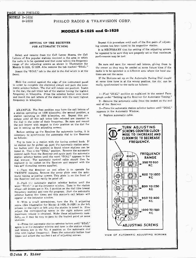
PAGE 13-26 PHILCO
MODELS S-1626 G-1628 PHILCO RADIO
MODELS S -
SETTING UP THE RECEIVER FOR AUTOMATIC TUNING
& TELEVISION CORP.
1626 and G-1628
Select and remove from the Call Letter Sheets, the Call Letters of five popular stations received in the area in which the radio is to be operated and that come within the frequency range of the adjusting screws as shown in Illustration for Models S-1626, G-1628. Also remove the tab marked "DIAL."
Insert the "DIAL" tab in the slot in the dial which is at the front.
Hold the control against the edge of the instrument panel in order to complete the electrical circuit and push the auto- matic selector button. The dial will rotate one position. Insert in the dial, the call letter tab of the station having the highest frequency in kilocycles. Press the selector button once more and insert the call letters of the station with the next highest frequency in kilocycles.
EXAMPLE-The first position may have the call letters of a station operating on 1400 kilocycles; the second position, a station operating on 1050 kilocycles, etc. Repeat this pro- cedure until all five call letter tabs selected are inserted in the dial in the order of their frequency. Be sure and record the call letters with respect to their position on the dial for use in setting up the adjusting screws.
Before setting up the Receiver for automatic tuning, it is
necessary to synchronize the automatic dial to the Receiver as follows:
Try to tune in a station with the tuning control knob. If no station can be picked up, push the automatic station selec- tor button until the position is found where stations can be tuned in. This is the "DIAL" position. Remove the automatic control cable from the Receiver and again push the automatic station selector button until the word "DIAL" appears in the dial window. The automatic control cable should then be replaced in its socket on the Receiver and secured with the two self threading screws supplied.
1-Turn the Receiver on and allow it to operate for TWENTY minutes. Remove the cover plate over the auto- matic tuning adjusting screws. This plate is on the front of the Receiver and can easily be pried off.
2-Push the automatic station selector button until the word "DIAL" is at the indicator window. Tune in the station whose call letters are in No. 5 position on the dial (the lowest frequency station) and note the program. Push the automatic selector button five times and this station's call letters will
appear at the indicator window.
3-With a small screwdriver, turn the No. 5 adjusting screw (See Illustration for Models S-1626, S-1628) in the left column to the right or left until the station is tuned in. Now
adjust the corresponding screw in the right column until maximum volume is obtained. Make these adjustments care- fully, as it may be easy to pass by the loudest point on some
stations. 4-Press the automatic station selector button until "DIAL"
again is at the indicator window and tune in the station whose
call letters are in the No. 4 position on the automatic dial
(the next higher frequency). Press the automatic button four times and adjust the number 4 set of adjusting screws.
Repeat this procedure until each of the five pairs of adjust- ing screws has been tuned to its respective station.
It is NECESSARY that the setting of the adjusting screws
be repeated to be sure they are properly set so that maximum performance may be had.
Be sure and save the unused call letters, giving them to the owner as they may be needed at some future time if the radio is to be operated in a different area where the local sta- tions are not the same.
If the Stations set up on the Automatic Tuning Dial should at some time tune in at the wrong position, the dial can be easily synchronized to the radio as follows:
1-Find "DIAL" position as explained in the second Para- graph under "Setting up the Receiver for Automatic Tuning."
2-Remove the automatic cable from the socket on the end end of the Receiver.
3-Press the automatic station selector button until "DIAL" appears in the Automatic Window.
4-Replace automatic cable.
erSCREWSTURN
ADJUSTING COUNTER CLOCK-
WISE TO INCREASE AND i CLOCKWISE TO DECREASE FREQUENCY.
FREQUENCY RANGE
550 T0 950 KC
600 T01000 KC
f 50 TO 1400 KC
1000 70 1580 KC
ADJUSTING SCREWS
VIEW OF AUTOMATIC ADJUSTING SCREWS
©John F. Rider www.americanradiohistory.com

PHILCO PAGE 13-27
MODEL S-1726 PHILCO RADIO & TELEVISION CORP.
--_oaa sa oasasa eéa aMaaPaaa = ss º +.7.52 1p 9 s---7-- s- s ,s -
_R1Q/ 14/1
e .Cf} ` O 1.1 JJddm.-.^OJ1 O^AJVJdrOJJJ.O ?PVJbñlddTdb.+IdJ1ÁJm-4'Z
. . 'w TM ... ^ ... .m É
. .. : 2. . :in :¡. n . .« T
^ .` T .
É ^ : : ' ^ E : ~ . . . ... . . . ÉF :
E E.^; w ó~ E ^» : E :
.27:o ̂ M : :^ .
c vv ' ó» v ói li',i . r É r E v:.°. Éviv É-cvv . Zv = E ,.: . . .. o E oE E.w^é'v°c...ÉSi"E _-sE..o+r wEEáá E- > ó E EE
EEóç$c``ºQ E=o-EÉc"Eº E°Eó'= $v°EE E°ÉxEE EEeuvl EE cvU óEÉ É E ÉcEéÉ áÿ- cV opó ot,T.` p ó N `,ri dó,z+- o "' co ÿ roEg ot Q ºº º ggº º ó_ $ gg g+ íño N °
R °
o"3--.-50a ?8 _.` úº SLL ú75 Q 8Q
°-R º°4 ^'..,«- -, }., ó }; °- Qº$ ° _SI Us r.c -.. s~Ñ aUU - m °v ,ñ`7VI' ciG¡ $8 . o~ 7G di -Me.
» >`' Ñ`. C".r C i `34;-1i° ß ` S `. SrS"v 1= E1.^'ó ß ß,t E ...... éc¡¡w~ ó:r cóói`Oiá ve``U ce Vec 2cercp ce° c
¡«vv=» Tvvói»Ev«v.v Evvti°vvve ° ^Uá mLóU«M: a e c =LL ._ c c- . c.'. c._ c= c c- o e e=c »} . c é é péi c é Ñ-9xv « E _, i écooEi LLiio+éois=ooioiopi"ioo¡oóió000Trp¡--iooó5óó`óOeóiióii3 4«UUuScerc-ceU-LLo_Uoc>-NUaUeeU°e> oosñ:tUUaeUacLLet)-UUUOÚr LLUU3o._OUKUU: U>dLLUcaUa[°cs
Z OOoo000._+6et+G+et+13MA.Ww.e;y.. emmoseeinezazeteeem eol®emb®®®®ee®®®meti©FJm®
e 44 ou h+ot
00001
Q
e e
D
voOL
O i'a0L
°00'o r 0 ó v000bLZ MMAI
O - WO OD m o<r Z NN
CD
ÿ
ó m
o:r
e e
v00e000'sl
Q9
e In
oÓ
gg ea
e 'o m
a O`__________ e _' 11
VoOo' voo0sZ
e
o
v000'££ o l,+ro' Ha
v004 la.o. I
e q 'i`19o'
so{ / .hl z£ e
Ate
U> Wr
tQ9Q 00
r0061fDOS1
uoQL
)c v o0r --N
0-- I
C- LA Y
I
la s' laaosz
Ñ
3,4a oSL,.
G 00000I e
I. o
v000boo'i
--H®
uoóib .J
aaa-- H> l+Ilo
vooe
(-bruz- 'a'
_ _ ...... O -Zew&I iG 0 0 .o
0 o o
r17
Ñ\
1
0 h
1_ ^ 2-'4-) lA
O O l co
4 1
-I 0 u (r)
\t
O
h Ir)
o
o
. m 14 r, G p Ó
£á Eá u]MMM,--i.-i.-INN °I yée oG fi5 mch a m
o mó no Fz á Oá Iii Ú y
Ó a ÿ C
U. M a i Z.
N .si .r. Q -0Cw
.01 p '9'1".gm'iáQÿÿ CD CO
= Z .. E á
n a oz.yg'"->""d yP
tt.
á.> w áoti.-+
o 0.1n o`- .>n.0
. ., ,,, ä5w ,
á3 ó ¢w7 Z '1"'-' y agaáx
" ÿvd °a ,
5' EH, §zóy C>. ó 5 yy-2
-,.,° -° b Á.SóG aE; .Cd.N 5 bmo4
m vü w
C O.a
á ñ E2 G
á C O cCCb
£ á« .. . . .. .. . Ele 'A ó O Úy C 2)--z> ci QC, M ó y Q
ó
'22 N v wb C
º C ` a
w C p il1N F + W
á_s I.mI,I,Y < N M VW
m y y y
Z zzz
.SC u 74.22
U
CC oór Ouú 7 t[j ^i°só rn v v
"
..i. O O 0
peD -en trD .r '.
©John F. Rider www.americanradiohistory.com

PAGE 13-28 PHILCO MODEL S-1726
PHILCO RADIO & TELEVISION CORP.
MODEL S-1726
The antenna and touch tuning station adjustments are accessible from the front of the receiver when the two screws holding the cover plate are removed. On cars equipped with the "Climatizer", it will be necessary to remove the 'screws holding the "Climatizer" control assembly to the lower edge of the instrument panel and drop it down out of the way while making the adjustments.
1-Turn on the radio set and allow it to heat for at least twenty minutes before starting any adjustments.
2-Press the touch control button until the word "DIAL" appears in the "DIAL" window. Tune in a weak station on the manual dial between 1350 and 1500 kilocycles. Now adjust the antenna high frequency compensating screw (See Illus- tration) until maximum volume is obtained.
3-Select five stations within the frequency range shown over each set of adjusting screws (See Illustration). Remove the call letters for these stations from the call letter tab sheet. Remove the top cover of the set; this exposes the plas- tic drum into which the tabs should be inserted. It is impor- tant to insert these tabs in a definite relationship with respect to frequency in order that tuning adjustments can be made properly. Arrange the tabs in the order of frequency from high to low, placing the highest frequency on the drum im- mediately next to the dial tab in a counter clockwise direction. Insert the remaining tabs in the order of freouency in this same counter clockwise direction. If the tabs have been in- serted correctly, it will be found that when the word "DIAL" shows in the window, the next push of the button will place the call letter for the highest frequency station in the window. Each successive push of the control button will place a next lower frequency station in the window until the series is re- peated.
TOUCH CONTROL
4-With "DIAL" showing in the dial window, manually tune in the station to be set up on push button number 1 and identify the program.
5-Press the touch control button once and adjust the left hand screw using the .small end of the special screw driver, until the station identified has been tuned in as accurately as possible. A final adjustment can be made by inserting the large end of the screw driver into the vernier adjusting screw. Careful adjustment of this screw will insure maximum per- formance in areas where reception is poor. NOTE: Stations of the higher frequencies are tuned in by turning the screws to the left or counter clockwise. Lower frequency stations are tuned by turning to the 'right or clockwise. Proceed in like manner with the adjustment of each of the remaining stations in the order of frequency until all five stations selected have been tuned in. Because there is some detuning of the coils (lue to the movements of the cores in adjacent coils, it is necessary to re -check the adjustments again going back from right to left and again re -checking from left to right. This is Impor- tant for accurate reception while driving at a distance from the broadcasting stations.
6-This final re -checking of adjustments should be made in an area of low signal strength in ydur service station or in some known "dead" spot where signals can just barely be heard.
7-Replace the cover plate over the adjusting screws and replace the "Climatiser" controls.
BE SURE AND SAVE THE UNUSED CALL LETTERS, GIVING THEM TO THE OWNER AS THEY MAY BE NEEDED AT SOME FUTURE TIME IF THE RADIO IS TO BE OPERATED IN A DIFFERENT AREA WHERE THE LOCAL STATIONS ARE NOT THE SAME.
STATION INDICATOR TONE DIAL CONTROL
55 / ''i/. (, IÍql
111111111 _111111111
VOLUME -ON-OFF
VERNIER ADJUSTING SCREW
ADJUSTING SCREW
ENLARGED VIEW OF ADJUSTING SCREW
MANUAL TUNING
ANTENNA HIGH FREQUENCY COMPENSATING SCREW
STATION ADJUSTMENTS) 850 750 710 0 625 540
TO TO TO TO TO 1580KC 1450KC 1380KC 1170KC 1000KC
i
()John F. Rider www.americanradiohistory.com

PHILCO PAGE 13-29
NOTE SA rCN WATERS ARE SNOFIN CONNECTED FOR OPIRATION ON COIL U.N. SONDRO ROTORS ARE LOCATED ON UNDERSIDE OF WAF ENS
OET-05C 7E3E1
0 NOTI:- THIS 5100 0F A
1 RF
G40 AD TO C CSC55
OF CAR)
T I F TRANS
4F -4554C
WAVE TRAD 4551TC
M00EL S: L-1760, L- I76E TOP VIEW
11F-OSC 1580 KC
rTUNINO CONO.
;t - 590 KC
LF-OSC
No. Description Part No. Tone Control Knob 57-0922FA8 Push -Button 55-0763 Indicator Dial Strip 55-0792 Drive Cord 55-0793 Dial Scale 55-0844 Bezel Plate 77-0430 Distributor Condenser 30-4404 Gas Gauge Condenser 30-4663 Generator Condenser 61-0040 Water and Oil Gauge Cond 61-0087 Mounting Bracket 57-1107
Bolt 97.0102 Bolt 57-I1540A3 Wing Nut 97-0103FA3 Speaker T3-0039 Pilot Lamp 34-2064 Antenna Lead 95-0110 Upper Insulator 55-0732 Lower Insulator 55-0733 Gland Nut 57-1072 Mounting Bracket 57-l093 Gland Nut Wrench 57-1074
MANUAL .T INC NN9B/
I,000,000n
SOLARI CONTROL ]54000 TOTAL 60,000 TAP
67 19 0 rrf
Dummy Antenna
Ant. Recept. 0.1 mf 4f
Signal Generator
Connection
2ND DET iST AUDIO
766
27,000 n
250rrf
24,0000
REGT -7Y4
I.F= 455 KC.
Signal Generator Frequency
455 kc
Receiver Wave -band
Switch'
Note 1
MODELS L-1760, L-1761
7C5 OUTPUT
10 r f. 2011
4 -
Receiver Dial Trimmer
Setting Number
Note 2 27 25
u x
if 44 41 u 19 44 f4 If IC if 17 41 4r 14 44 27
i" Rg /f 4f if 1f 4f 25 if If If 4f 4f 19 14 If if if K 17 1f 41 1f 14 44 93
Ant. 4 Note 4 1580 kc I4 K 60 4f 1360 kc If 1360 kc 56
ROrOMAT IC' 44 BUT TON 590 kc 4f 590 kc 57 *
1f 1580 kc 4f Note 2 60 4f If 1360 kc If 1360 kc 56 6
Note I.-Press "Rotomatic" Station -Selector button until "DIAL" appears in the window and stations can be tuned in by manual tuning.
Note 2.-Turn condenser rotor plates completely out of mesh as far as they will go. Note 3.-Adjust (9) for minimum output. Noto 4.-When TIRE -COMPARTMENT DOOR antenna is used; connect antenna
lead, part number 95-0120, to the antenna receptacle on the radio. Con- nect an 830 mmf condenser in series between antenna lead and signal - generator. Ground the shield pigtail on the antenna lead to the signal -generator. Be sure antenna switch (3) is turned clockwise.
When COWL antenna is used; connect the antenna lead, part number 95-0120, to the antenna receptacle in the radio. Connect a 45 mmf con- denser in series between antenna lead and signal -generator. Ground the shield pigtail on the antenna lead to the signal -generator. Be sure an- tenna switch (3) is turned counter -clockwise.
Note 5.-When the antenna -stage adjustment is made with the radio installed in the car, the radio antenna lead must be connected to the car antenna in the usual manner. Connect the signal -generator output lead to a wire placed near the car antenna, but not connected to it.
. While rocking.
John F. Rider www.americanradiohistory.com

PAGE 13-30 PHILCO MODELS L-1760,
L-1761 PHILCO RADIO & TELEVISION CORP.
MODELS L-1760 and L-1761 The Aerial and Rotomatic adjustments are easily accessible
through the openings in the instrument panel. (See Illustra- tion).
1-Turn the radio set on and allow it to heat for at least TWENTY minutes before starting any adjustments.
2-Press the Rotomatic button until the word "DIAL" appears in the Rotomatic indicator. Tune in a weak station on
the manual dial between 1400 and 1500 k;locycles. Now adjust the aerial screw until maximum volume is obtained. (When the special concealed cowl aerial is used, adjustment should be made with the aerial fully extended.)
VOLUME CONTROL ROTOMATIC ROTOMATIC
BUTTON & OFF -ON SWITCH INDICATOR
07 AERIAL
EIM
z\0^0^0 ) . \(®\ ®\®
I 2 3 4 5 FREQUENCY 550 550 750 900 900 KC.
RANGE 1050 LOSO 1300 1580 1580 KC.
MANUAL MANUAL
INDICATOR CONTROL
AUTOMATIC ADJUSTING SCREWS
3-Select five stations within the frequency range shown
under each set of adjustment screws shown in Illustration.
4-With "DIAL" showing on the Rotomatic indicator, man- ually tune in the station to he set up on position No. 1 and identify the program.
5-Press the Rotomatic button until No. 1 appears on the Rotomatic indicator. Now adjust the top screw at position No. 1 until the station selected is brought in with loudest volume. Then adjust the slo.ted hex screw at the bottom until maximum volume is obtained. NOTE: Stations of the higher frequencies are tuned in by turning the screws to the left or counter clockwise. Lower frequency stations are tuned by turning to the right or clockwise.
6-Proceed with setting up the remaining four stations in
the same manner as described under Paragraphs 4 and 5.
7-Because there is some detuning of the coils clue to the movements of the cores in adjacent coils, it is necessary to re-
check the adjustments again going back from Position No. 5
to No. 1 and again rechecking from No. 1 to No. 5. This is
important for accurate reception while driving at a distance from the broadcasting stations.
8-This final rechecking of adjustments should be made in
an area of low signal strength in your service station or in
some known "dead" spot where signals can just barely be
heard. 9-Should the Special Concealed Cowl Aerial be installed
after the original installation, it is absolutely essential that the aerial change -over switch be shifted counter -clockwise and also that all automatic adjustments be made again as described in Paragraphs Nos. 1 to 8. inclusive.
PARTS LIST No. Description Part No.
Antenna Choke 65-0168 Condenser (.01 mfd.) 61-0014 Antenna Transformer 65-0306 Cond (.05 mfd.) 30-4569 Resistor (100,000 ohms)... 33-410334 Sensitivity Control
$Resistor (10,000 ohms) e
O O O O O O
R. F. Transformer QQ I. F. Wave Trap Padder
33-310334 65-0305
0 Condenser (25 mmfd.) 33-1108 Resistor (1,000,000 ohms)..33-510234 Condenser (.25 mfd.) 61-0088 Resistor (100,000 ohms)....33-410334 Resistor (27,000 ohms) 33-327334 Condenser (250 mmfd.) 61-0034 Condenser (.1 mfd.) 30-4455 Padder (Pri. 1st I. F. Trans.) First I. F. Transformer 65-0303 Padder (Sec. 1st I. F. Trans.) Condenser (.05 mfd.) 30-4444 Resistor (680 ohms) 33-168334 Resistor (3300 ohms) 33-233354 Condenser (.05 mfd.) 30-4569 Resistor (1.000,000 ohms)...33-510154 Padder (Pri. 2nd I. F. Trans.) Second I. F. Transformer 65-0304 Padder (Sec. 2nd I. F. Trans ) Resistor (25,000 ohms 33-325234 Volume Control (350,000 ohms)
and On -Off Switch 67-0026 Condenser (.01 mfd.) 61-0014 Resistor (50,000 ohms) 33-347134 Condenser (.01 mfd.) 30-4479 Resistor (600 ohms) 33-160334 Condenser (.01 mfd.) 30-4479 Resistor (27,000 ohms) 33-327334 Condenser (.05 mfd.) 30-4444 Resistor (24,000 ohms) 33-324434 Resistor (1,000,000 ohms) 33-510154 Choke 65-0300 Condenser (250 mmfd.) 61-0033 Input Transformer 65-0293 Resistor (82,000 ohms) 33-382334
e Condenser (.02 mfd.) 30-4481 it Filter Cond. (10-20-20 mfd.). 61-0086 e Resistor (300 ohms) 33-130436 +@ Condenser (.02 mfd.) 30-4419 It) Resistor (15,000 ohms) 33-315354 e Tone Control Switch 85-0106 Q Condenser (3000 mmfd.) 30-4469 ll Output Transformer 65-0295 $i Replacement Cone
(For 73-0039-2 Speaker) 91-0113 (For 73-0039-4 Speaker) 91-0114
4) Field Coil Not Replaceable e Wafer Switch 77-0408 83 Antenna Padder Assembly.. 77-0391 ® Tuning Condenser 63-0036 ee First Padder (On Tuning Cond.)....
Low Frequency Padder 63-0037 4) Sil. Mica Cond. (300 mmfd.) 61-0003 e Manual Oscil. Transformer 65-0301 H Second Padder (On Tun. Cond.)....
iCondenser (15 mmfd.) 61.0038 Oscil. Trans. (900-1580 K.C.) 65-0255 Oscil. Trans. (900-1580 K.C.) 65-0255
e Oscil. Trans. (750-1300 K.C.) 65-0256 e Oscil. Trans. (550-1050 K.C.) 65-0257 e Oscil. Trans. (550-1050 K.C.) 65-0257 Q Sil. Mica Cond. (390 mmfd.) 61-0031 H Condenser (250 mmfd.) 61-0033 H Condenser (.5 mfd.) 61-0083
32.1644 O "A" Choke QQ Vibrator Choke Part of ) ® Vibrator 83-0017 Q Resistor (150 ohms) 33-115354 9 Resistor (200 ohms) 33-120354 Qi Condenser (.5 mfd.) 61-0083
Power Transformar 65-0294 Condenser (3000 mmfd.) 61.0059 Resistor (1000 ohms) 33-210554 Condenser (.25 mfd.) 61-0125
0 Resistor (10,000 ohms) 33.310334 ® Pilot Lamps 34-2064
Volume Control Knob 55-0748 Manual Control Knob 55-0750
©John F. Rider www.americanradiohistory.com

PHILCO PAGE 13-31
tieN 00 .! .M00 0..C-f'T d.V.<..000V lC.MO O.M.MlwIOCMti d10 d.-tivMt-.F.MI .I.FtitrCCAI ...--tOM....N .^.y t0 1['J ION CO..:I^IP! \oM.1l^H,..N.fJ .C"MCM .onMCCOIo CCDIf)IOM.f.lMMIo G1MC000OC.o.^.C.L^.'If..If. Tk9tK'Ct`.
.Y d. M. -M.. m.'...MMM.'. 0.+.-C^.C.+...+...C:C.+ OCN[t..^OCC .o.^i Ó 10 00 OONC00 ÓOMcicO00Cl CN1-CnM C0CNICCIo CO rrCÇoO1nCCOGÇI..c,cONc,CCOyCGtD..r.
Cl Cl N.CD Gl.. Cl NCI d'M V' N!' ,,,N E1N. o N M.-N.f'..r.+^Cl.rvC`tiCly; a.-e-. M OCO OOCGV..rN CIC^Cl..mC C VMC^l... V,NtOO CC ..NO .-I.. fY.CCCCM 7óóOMóó :_<<ODNNIC:If
OM ^'M M MC.:M P. M .MO .M Ce ce C7M t+i MM O OOM MMo COM2 M M M0'JM M M0O M MMM MM M MM 0D ".¡y.000OM MM00 t.m mm
.-.-.4g.. :7;1-,;. . . .^.... :^^ :^ : ^ ^ ̂ imz¡.. . v_ : :.. ,-.... . ...... . ;
`F G.:óÉ ^L -Mfr. ^^^^ó^Éc ^tÉ^E E óÉE -wm "Ér. ^^ ^^ ,-. `` ,_,
L A L ..m,-..c.-í.. O6 E « E o.. 2.: o ó ̂ oo ó É óa`-.t Eo t oo É ^ ogc áti d EôcvM tiT ó á. É É E
oo . E E` EE e%ov E o 0 40o t.ç F o:r.oo 000o"oio c u...: o rri. 5 4 5Si ;LIN á. ó OóÿFCOO p00.--.LoÇpO oNCC.,-op..Co obco,_,.00.o cCc.pr> Ir_In í.có000 tom.. .C-.n óoYfYQCPC mCo. a'''1.-'[.:.''
^1,.1. N' Ód'.`7o00Çm OOOI_ÇGV.Ñ OOt`,,tiMCOCOCOC.C.1=Ç0 N`..O-C ...1`Qvlvl.r '521"1CÉ0iHLd.d -1V1 ír y -COvÿ000QO`a.`ÿ5.5vÿ pÿÿ -Z..'-e.....--7.42,,,=2,,t_._2-Z--..N.T"4 G ..a. Ecr..ä O . .-.1Y
" ..i e. ...: `ú o ú eCd' `F gg v' .y ea. a. i m.. (.0
Gy L á....
óóóé`o_óclo`Cóó`aa-V « «ód oC°G`rlv,2d 2á c`C,,,j ao.PoC ÇÓ...q...«p CÓ«v CÓEíO+EEEaO-.wpN .a.-..0..+ C7E O EE E ÿ W ` ` d LN SL q O
pmp.:.:C:S~..M7.::^.::'i.`LLO!^.1.-%v..v. ' .Cv.T.CCLa:...vL.'.tdmCCao CCCmCC.'.__t¿,CG C 9mm C-`CmmC C CmCCC +CEi,:"FiCTnmCGC CCmC ... pO.,.,OOdppo oC7Rm OC czá7ááá 87 ÚACxF eáSrxeSiaá záScá. áSázSccc SÚÚfr`Ú0.CiCcUcc»aFccc:m. ccJrc c.>xge.
©© am®®®®®® ®z®®c® ®®®®c®c® ®®®ce®c®®®®®®®®®®acc©®
©John F. Rider
www.americanradiohistory.com

PAGE 13-32 PHILCO MODEL C-1808
PHILCO RADIO & TELEVISION CORP.
MODEL C-1808 - ADJUSTMENTS the prescribed frequency, turn the Radio volume control on full end set the signal generator attenuator so that a half scale read - All padding adjustments are carefully made at the factory ending is obtained on the meter. The signal in the speaker should be ordinarily no readjustments are necessary. However, when read -audible but not loud.
justments are required, the procedure given below must be fol- The shieldingon the output in detail. generator ouf ut lead
to the Radio housing. EQUIPMENT-Fully charged heavy duty storage battery or 6 volt power pack, 077 or 177 Philco Signal generator, 027 Philco Vacuum tube voltmeter and set tester or audio output meter, 45-2610 Pad- ding screw driver.
GENERAL-VACUUM TUBE VOLTMETER. The model 027 Vacuum tube voltmeter is an extremely sensitive and accurate test instrument and is recommended for use when aligning and adjust- ing auto radios. Connect the negative (-) terminal of thé MODEL Vacuum Tube Voltmeter to the high side (ungrounded side) of -the C-1806 volume control. Connect the positive (+) terminal to the radio housing. Connect the "AC" cord to e 110 volt AC socket. Press the VTVM button and the IO volt button. Turn the "Set Zero Ohms - VTVM" control clockwise until a click is heard. Allow the tubes to heat up for a few minutes. Short the 150 meg. VTVM termînels and adjust the "Set Zero 150 meg." control until thé meter reads zero on the 0-10 range scale (bottom scale). The needle will deflect from left to right.
AUDIO OUTPUT METER. If an audio output meter is used, connect the leads across the voice coil of the speaker. Use the 0-30 volt scale.
..A,,,.. x+cv+ - 580 KC
must be connected
IYgvF ragp OSs,e'C rufe eurnr lo,. +fY re.
TONI revere ra.,roa cane.
OPERATION SIGNAL GENERATOR
1
2
3
4
5
6
7
FREQUENCY CONNECTION DUMMY CAPACITY SPECIAL INSTRUCTIONS ADJUST
PADDER
455 K.C.
455 K.C.
1400 K.C.
580 K.C.
1400 K.C.
580 K.C.
PRESS THE "DIAL" BUTTON AND STATIONS CAN BE TUNED IN BY "DIAL" TUNING
To Aerial Receptacle on Radio
To Aerial Receptacle on Radio
To Aerial Receptacle on Radio
To Aerial Receptacle on Radio
To Aerial Receptacle on Radio
To Aerial Receptacle on Radio
1 Mfd.
.1 Mfd.
See Note I
See Note I
See Note I
See Note I
Note 2
Note 2
Set Tuning Control at 1400K.C.
Set Tuning Control at 580 K.C.
Set Tuning Control at 1400 K.G.
Set Tuning Control at 580 K.C.
Make all adjustments for maximum reading on the meter.
NOTE I-Connect the aerial lead, Part No. 95-0111, to the aerial receptacle in the radio. Connect a 25 Mmfd. Condenser in series between the signal generator and the aerial lead.
NOTE 2-Turn the tuning control clockwise as far as it will go.
NOTE 3 -Rock the tuning control while adjusting the low frequency screw. Tune the control to the signal and adjust the
INSTRUCTIONS FOR SETTING
I. Turn on the radio and allow it to operate tor twenty min- utes or longer if possible. All adjustments MUST be made with the aerial fully extended. Turn the volume control on full and set the tone control on voice. In metropolitan areas it is best to adjust the push buttons in a shielded building or under a viaduct.
2. Push in the DIAL button so that stations can be tuned in by manual tuning and tune in a weak station around 1400 K.C. on the dial. Then adjust the aerial padder (®) for maximum signal.
3. Select the five stations which you desire to use on push button tuning. Tune in a station between 535 and 1000 Kilocycles.
I
Note 3
Note 4
T Note 3
screw for maximum output. Kotate the tuning control' back and forth slightly for maximum output. Then readjust the screw for maximum output. Repeat this procedure until no further improve- ment is noticed.
NOTE 4-When the aerial stage adjustment is made with the Radio installed in the car, the Radio aerial lead must be connected to the car aerial in the usual manner. Connect the signal generator output lead to a wire placed near the car aerial but not connected to it.
UP ELECTRIC PUSH BUTTONS
Remove the No. I push button cover and push in the No. I but- ton. Using a coin or a small screw driver, adji st the button until the station selected is tuned in with the loudest volume. Turning the button counter -clockwise will increase the frequency, and clock- wise will decrease the frequency. Check the station by pushing in the DIAL button again to identify the program.
4. Proceed in the same manner for adjusting No. 2, No. 3, No. 4 and No. 5 buttons.
The stations may be set up before installing the radio in the car, but the final adjustments must be made after installation of the radio and connected to the aerial in the car.
©John F. Rider www.americanradiohistory.com

PHILCO PAGE 13-33
MODEL S-1824
PHILCO RADIO & TELEVISION CORPStudebaLer "Custom"
Im..VC ...} 'PT-.M-Q..I.COCIlK.TL^.edK N..Io)Ca..+.f1^.f mO rV:4 L71f,fnmlflL.]1fi`1[JvtN co....mo..u, óo...rpr.,lC3 moá,00¡¢ coOc.yMN co00{mmÓÓÓ00y0.. mmMO04i e CmmQNNQ1QQrtimti.¢
cC .
eC 5 . :o...-. L O 3 132 tititi rIT
....co.
©John F. Rider www.americanradiohistory.com

PAGE 13-34 PHILCO MODEL S-1824 Studebaker "Custom"
PHILCO RADIO & TELEVISION CORP.
MODEL S-1824 - ADJUSTMENTS All padding adjustments are carefully made at the factory and
ordinarily no readjustments are necessary. However, when read- justments are required, the procedure given below must be followed in detail.
EQUIPMENT- Fully charged heavy duty storage battery or 6 volt power pack, 077 or 177 Philco Signal generator, 027 Philco Vacuum tube voltmeter and set tester or audio output meter, 45-2610 Pad- ding screw driver.
GENERAL-VACUUM TUBE VOLTMETER. The model 027 Vacuum tube voltmeter is an extremely sensitive end accurate test instrument and is recommended for use when aligning and adjust- ing auto radios. Connect the negative (-) terminal of the Vacuum Tube Voltmeter to the high side (ungrounded side) of the volume control. Connect the positive (+) terminal to the radio housing. Connect the "AC" cord to a 110 volt AC socket. Press
the VTVM button and the 10 volt button. Turn the "Set Zero Ohms -- VTVM" control clockwise until a click is heard. Allow the tubes to heat up for a few minutes. Short the 150 meg. VTVM ter- minals and adjust the "Set Zero 150 meg." control until the meter reads zero on the 0-10 range scale (bottom scale). The needle will deflect from left to right.
AUDIO OUTPUT METER. If an audio output meter is used, connect the leads across the voice coil of the speaker. Use the 0-30 volt scale.
With the Radio and signal generator set up for operation at the prescribed frequency, turn the Radio volume control on full and set the signal generator attenuator so that a half scale read- ing is obtained on the meter. The signal in the speaker should be audible but not loud.
The shielding on the generator output lead must be connected to the Radio housing.
7Y4 TUBE II, ECT612Il,
44
TAU TUBE OUTPUT
esTueE 2LETRANs VlRATOR ZDET.
It' AUDIO
7A7TUBE 39 R.F.
G
3T
'7A7 TURF (íe n71.FTRANS.7
OPERATION
SIGNAL GENERATOR DUMMY CAPACITY SPECIAL INSTRUCTIONS
ADJUST PADDER
FREQUENCY CONNECTION
1 455 K.C. To Aerial Receptacle on Radio See Note I Note 2
2 1360 K.C. To Aerial Receptacle on Radio See Note I Set Tuning Control at 1360 K.C.
3 590 K.C. To Aerial Receptacle on Radio See Note I Set Tuning Control at 590 K.C. Note 3
4 1360 K.C. To Aerial Receptacle on Radio See Note 1 Set Tuning Control at 1360 K.C. ir;'
5 1200 to
1400 K.C. Note 5 Note 5 Note'S
Note 4
Make all adjustments for maximum reading on the meter.
NOTE I -Connect the aerial lead, Pert No. 95-0111, to the aerial receptacle in the radio. Connect a 35 Mmfd. Condenser in
series between the signal generator and the aerial lead.
NOTE 2-Turn the tuning control clockwise as far es it will go.
NOTE 3- Rock the tuning control while adjusting the low frequency screw. Tune the control to the signal and adjust the screw for maximum output. Rotate the tuning control back and forth slightly for maximum output. Then readjust the screw for
maximum output. Repeat this procedure until no further improve- ment is noticed.
NOTE 4-When the aerial stage adjustment is made with the Radio installed in the car, the Radio aerial lead must be connected to the car aerial in the usual manner. Connect the signal generator output lead to a wire placed near the car aerial but not connected to it.
NOTE 5-When installing the radio in the car, follow the in-
stallation instructions carefully. Tune in a weak broadcast signal between 1200 and 1400 Kilocycles on the control scale. Remove the plug button on the end of the radio and adjust the aerial com- pensator Q (see Figure 3) for maximum signal.
©John F. Rider www.americanradiohistory.com

PHILCO PAGE 13-35
P,.-CDEL S-1722 PHILCO RADIO & TELEVISION CORP.
S-1722 INSTALLING CALL LETTERS
Before installing the Receiver, the Call Letters of the sta- tions which are to be tuned in automatically must be inserted in the Automatic Dial. See Illustration,'Models S-1622, S-1722. Select and remove from the Call Letter Sheets, the Call Letters of five popular stations received in the area in which the radio is to be operated and that come within the fre- quency range of the adjusting screws as shown in Illustration Models S-1622, S-1722. Each of the adjusting screws cover the portion of the broadcast band as indicated in Illustration, Models S-1622, S-1722. It is important, therefore, that only such stations be selected as can be tuned in in the range as covered by each screw.
Push the Automatic Station Selector until the word "DIAL" is at the front. This is the starting point. Push the Automatic Station Selector once more and the first position of the dial will be at the front. Insert in this position the call letter tab of the station having the highest frequency in kilocycles. In- sert in back of each tab one of the clear celluloid tabs. Press the Automatic Station Selector button once more and insert the call letters of the station with the next highest frequency in kilocycles in the second position.
a)
CALL LETTER TAB
AUTOMATIC DIAL
Installing Call Letter Tabs
EXAMPLE-The first position may have the call letters of a station operating on 1400 kilocycles; the second position, a station operating on 1050 kilocycles, etc. Repeat this procedure until all five call letter tabs selected are inserted in the dial in the order of their frequency. Be sure and record the call letters with respect to their position on the dial for use in setting up the adjusting screws.
1-Turn the Receiver on and allow it to operate for TWENTY minutes. Remove the cover plate over the automat- ic tuning adjusting screws. This plate is on the front of the Receiver and is removed by removing two screws.
2-Push the Automatic Station Selector button until the word "DIAL' is at the indicator window. Tune in the station whose call letters are in the first position on the dial (the highest frequency station) and note the program. Push the Automatic Selector button once and this station's call letters will appear at the indicator window.
UPPER
LOWER
!ti. ̀ : ,i .'_ .'_ -ii`%;: :-ï.-' - -
¡ . - 11 ' l;i ri.i: :h:, r k ..
.. r
1oIi91580 KC
750-1300 KC 550-1000 KC
550-1000 KC
3-With a small screwdriver, turn the No. 1 adjusting screw (See Illustration, Models S-1622, S-1722) in the lower column, to the right or left until this station is tuned in. Now adjust the corresponding screw in the upper column until maximum volume is obtained. Make these adjustments carefully, as it may be easy to pass by the loudest point on some stations.
When adjusting for Automatic Tuning on strong local sta- tions the antenna rod should be all the way down and the adjustments made with the car in a shielded area, such as in a steel constructed building or under a viaduct. This is neces- sary in order to obtain a weak signal so the adjustments can be accurately made.
4-Press the Automatic Station Selector button until "DIAL" again is at the indicator window and tune in the station whose call letters are in the second position on the automatic dial (the next lowest frequency). Press the auto- matic button two times and adjust the number 2 set of ad- justing screws.
Repeat this procedure until each pair of the five pairs of adjusting screws has been tuned to its respective station.
IT IS NECESSARY THAT THE SETTING OF THE AD- JUSTING SCREWS BE REPEATED TO BE SURE THEY ARE PROPERLY SET SO THAT MAXIMUM PERFORM- ANCE MAY BE HAD.
Be -sure and save the unused call letters giving them to the owner as they may be needed at some future time if the radio is to be operated in a different area where the local stations are not the same.
©John F. Rider www.americanradiohistory.com

PAGE 13-36 PHILCO MODEL S-1625 Studebaker "Custom"
PHILCO RADIO & TELEVISION CORP.
ñ 7.
rem, THIS SIDE OF Ä BATTERY GROUNDED TO GASL (FRAME Or CAR)
PARTS LIST - S-1825 No. Description Part No. rer Antenna Choke . 65-0318 litä)Antenna Padder 63-0053 O Antenna Transformer 65-0349 0: Iron Core 57-1541 O Resistor (1,000 ohms) ..33-210334 O Condenser (.05 Mfd.) 61-0101 e Condenser (.05 Mfd.) 61-0111
T Resistor (10,000 ohms) .33-310334 el Condenser (250 Mmfd.) .60-125157
Resistor (68,000 ohms) .33-368154 Condenser (.05 Mfd.) 61-0101 e Pilot Lamp 34-2064 e Condenser(100 Mmfd.) ..60-110327
® R. F. Transformer 65-0359 ea Iron Core 57-1541
Fodder 63-0055 (3j Condenser (.05 Mfd.) 61-0111 ® Resistor (680 ohms) ...33-168336 it Condenser (110 Mmfd.) .60-110157 e Condenser (54.5 Mmfd.) .61-0149 Is Resistor (100.000 ohms) 33-410154 g Padder 63-0052 ® Resistor (150 ohms) ...33-115336 g Condenser (.05 Mfd.) 61-0111 á4 Condenser (215 Mmfd.) 61-0148 g Oscillator Transformer 65-0350 ea Iron Core 57-1542
g Condenser (250 Mmfd.) .80-125157 Resistor (22,000 ohms) .33-322334
g Series Tracking Transformer 65-0351 ea Series Tracking Core 57-1659 e' Resistor (68,000 ohms) .33-368334 e Condenser (.1 Mfd.) 61-0113
AResistor (4,700 ohms) .33-247434 Reslstor(1,000,000 ohms) 33-510154
g Padder (Prl. 1st I. F. Trans.) First I. F. Transformer 65-0352
g Padder (Sec. 1st I. F. Trans )
6A Padder (Pri. 2nd I. F. Trans )
9 Second I. F. Transformer 65-0353 (i1) Padder (Sec. 2nd I. F. Trans.) t3 Resistor (25,000 ohms) .33-325154 A Volume
On --Off Switch (350,000 ohms)
e Condenser (6,000 Mmfd.) 61-0103 Nb Condenser (.01 Mfd.) 61-0110
e Resistor (22,000 ohms) .33-322154 Resistor
(15.000.000 ohms) -.33-615154 8 Condenser (6.000 Mmfd.) 61-0155
e Tone Control Switch 85 0126 e Condenser (110 Mmfd.) ..60-110157
No. Description Part No. OD Resistor (220,000 ohms) 33-422334
Condenser (.01 Mfd.) 61-0100
e Resistor (470,000 ohms) 33-447154 Filter Condenser
(10-20-20 Mfd.) 61-0072 el Resistor (470 ohms) ....33-147436
;g
Condenser (.01 Mfd.) 61-0124
0 Output Transformer 65-0364 Field Coil Not Replaceable
ea Cone & Voice Coll 91-0166 e Jumper 57-1121
Test Socket 55-1078 63, Resistor (1,000 ohms) .33-210434
Condenser (5,000 Mmfd.) 61-0153 A Power Transformer 65-0347 e Resistor (100 ohms) ....33-110434 n Resistor . (100 ohms) ....33-110434 e 83-0027 e 61-0137 A 65-0151 e 32-1604 e 63 f 32-1644 r3 61-0137 B 45-2559
57-1623
Vibrator Condenser (.5 Mfd.) Vibrator Choke Filament Choke Condenser (250 Mmfd.) .60-125157 Condenser (250 Mmfd.) .60-125157 Condenser (250 Mmfd.) .60-125157 "A" Choke Condenser (.5 Mfd.) Fuse Manual Knob Sleeve Manual Knob Spacer 57-1689 Manual Knob Spring ..57-1628FA3 Manual Knob Skirt 55-1081 Manual Knob 55 1067 Tone & Volume Knob 77-0633 Sneaker Cable 95-0161 Screw (Cover Mtg.) ..W-2212mr,88 Tube Side Cover ... Wiring Side Cover ... Sneaker Unit Sneaker Gasket Bezel Front Sneed Nut pia)
Gland Nuts Rousing Vibrator Socket Tube Socket Push Button Knob Tuning Switch Coil Form Spring Coil Form Screw Core Draw Bar Spring
.57-1547FC54
.57-154RFr'54 73-0053 55-1045.
57-15R1F48 97-O13RFR7
55-1012 28-855RF.A8 Description
2ND. OCT. 1ST AUDIO .GHi1 OUT T
Y4TUBE RECTIFIER
766TU6E 2' 0 T.
SI" IUOIO , eO® 7A7T`6E T)
m®mm®mm TONE
CONTROL
PUSH GUTTON CONTROL
MANUAL TURING INTROI.
essit GUTTON ONTROL
ge I 2 1Íi'
Mm® ,mom0000 ® 7DSTU6E
OUTPUT
Part No. 77-O6ROP'C54 Latch Bar Spring 57-1650
27-6153 Push Bar Spring 57-1651 27-6151 Pointer Spring 57-1653 77-0612 Pointer & Cam Assembly 77-0647
97-111285 57-1840
Gland Nut Wrench ....28-5636FA3 97-0126 Generator Condenser 30-4007
....57-1649 Distributor Resistor 30-2250
53 7A7 TUBE 766Tu6E vOLUME R. DET.03C. CONTROL S.
'A' SWITCH
No. Description Distributor Condenser Fuel Gauge Resistor Ground Strap Wiring Nut
(Radio Mtg.) Hook Bolt
(Radio Mtg.)
Part No. ...60-125157
67-0041 77-0336
97-0048FA3
97-0135FA3
©John F. Rider www.americanradiohistory.com

PHILCO PAGE 13-37
=
( Y.1 Tf r. NOI;C:- THIS SIDE Ot A ; il e
TSQ r)ASE(FRAME OF OATTCRY 6ROUNDLD - T/ ' /
1 / a1 (ftwa SOlON01D
1
1 JJ ( Jf_
i LSweNae ewrtcN
_J - --,L--J
MODEL S-1826 PHILCO RADIO & TELEVISION CORP. Studebaker "Custom"
(
(
L
PARTS LIST - S-1826 Part No. No.
L Antenna Choke 65-0378 s)) Antenna Padder 63-0053
Antenna Transformer 65-0349 Iron Core 57-1541 Condenser (.05 Mfd.) 61-0111 Resistor (680 ohms) ....33-168334 Condenser (.05 Mfd.) 61-0111 Resistor (68,000 ohms) .33-368154 Resistor (10,000 ohms) .33-310334 Condenser (250 Mmfd.) :60-125157
® Resistor (68,000 ohms) .33-368154 ® Condenser (100 Mmfd.) .60-110157 ® R. P. Transformer . 65-0359
a Iron Core 57-1541 Padder 63-0052 Resistor (100,000 ohms) 33-410154 Condenser (110 Mmfd.) .60-110157
® Condenser (215 Mmfd.) 61-0148 ®Sensitivity Control 67-0036 Condenser (.05 Mfd.) 61-0111 Condenser (.05 Mfd.) 61-0111
® Condenser (.05 Mfd.) 61-0101 ® Padder 63-0055 ® Resistor (22,000 ohms) .33-322334 A Condenser (250 Mmfd.) .60-125157 ág Oscillator Transformer 65-0350 ea iron Core 57-1542 ® Resistor (150 ohms) ....33-115336 g Condenser (.05 Mfd.) 61-0111 g Condenser (54.5 Mmfd.) 61-0149 ® Oscillator Tracking Trans. 65-0351 ea Oscillator Tracking Core 57-1659 ® Padder (Pd. lot I. F. Trans )
® First T. F. Transformer 65-0352 Padder (See. 1st I. F. Trans )
A Resistor (27,000 ohms) .33-327434 ® Resistor (1,000,000 ohms) 33-510154 ® Padder (Pd. 2nd I. F. Trans.) g Second I. F. Transformer 65-0410
Padder (Sec. 2nd T. F. Trans )
® Resistor (25,000 ohms) .33-325154 ® Resistor (470 ohms) ..33-147336 ® Volume Control (350,000 ohms)
& On -OR Switch 67-0037 19 Muter Switch 85-0125
Condenser (.01 Mfd.) 61-0100 ® Resistor
(10,000,000 ohms) ..33-610154 g Condenser (.25 Mrd.) 61-0151 ® Condenser (.07 Mrd.) 61-0152 i3. Condenser (110 Mmid.) ..60-110157
i® Condenser (4,000 Mmfd.) .61-0129 Resistor
(10.000,000 ohms) ..33-610154 Fß Resistor (220,000 ohms) 33-422334 ® Condenser (.01 14Rä.) 61-0100
No. Description
o o O o o O o o
FOR ALIGN))LENT SEE INDEX
Description Part No.
(9 Resistor (220.000 ohms) 33-422334 Pone Control
(4,000,000 ohms) 67-0038 ® Condenser (.5 Mrd.) 61-0134 ® Resistor (4,700 ohms) ..33-247154 ® Resistor (1,500 ohrn8) ..33-215154 ® Condenser (.1 Mfd.) 61-0113 ® Filter Condenser
(5-10-20-20 Mfd.) 61-0150 Resistor (4,700 ohms) ..33-247434. Condenser (.05 Mrd.) 61-0122 Resistor (220,000 ohms) 33-422334
QResistor (470,000 ohms) 33-447154 Resistor (470,000 ohms) 33-447154
® Condenser (.05 Mrd.) 61-0101 ® Resistor (330 ohms) ....33-133436 ® Condenser (.01 Mrd.) 61-0124 ® Output 'transformer 65-0409 9 Field Coil Not Replaceable ea Cone & Voice Coll
(Icor 73-0052-2 Speaker) 91-0164 (For 73-0052-3 Speaker) 91-0165 3 Jumper 57-1121
E3 Test Socket 55-1078 Resistor (1,000 ohms) ..33-210434 Condenser (5.000 Mmfd.) 61-0153 Power Transformer 65-0358 Resistor (100 ohms) ...33-110434'
® Resistor (100 ohms) ...33-110434 ® Vibrator 83-0027
Condenser (250 Mmfd.) .60-125157 Condenser (.5 Mrd.) 61-0137 Vibrator Choke 65-0151 Condenser (250 Mmfd.) .60-125157 Condenser (250 Mmfd.) .60-125157 Condenser (.5 Mfd.) 61-0137 "A" Choke 32-1644 Fuse 4 2559, Solrnnid 65-0360 Solenoid Switch ....l'art of 85-0125 Pilot Lamp 34-2064. Description Tarring 8t Volume Knob 77-0633 Speaker Casket Honk Bolt (Radio Mtg.) 97-0135FA3 Speaker Cable Wing Nut (Radio Mtg.) 97-0048FA3 Speaker Unit Gland Nut Wrench ..28-5936FA3 Vibrator Socket Condenser (Generator) ..30-4007 Tube Socket
3 ®
A A
A A A A A
Ä LEAD 7Y4 TUBE
7B6TUBE MIME 7A7TUBC TOwf rNPDET.ISAUpO OCT OSC.. I f tOUT
O. REGTIr1E0.
cp CD (D ®m 1s
CD 0 0 ® 0 ®
ICS ICS TUBO 1AE1 OUTPUT OUTPUT DRIVER
Part No. 55-1045 95-0161 73-0052 27-6153 27-6151
Condenser (Distributor) .80-125157 Manual Knob Spacer 57-1669 Distributor Suppressor ....32-2250 Manual Knob 55-1067 Ground Strap 77-0336117anual Knob Sleeve 57-1623 Furl Gauge Resistor 67-0041 Manual Knob Spring ..57-1628FA3 Front Bezel 57-1549FA8 Manual Knob Skirt 55-1061 Speed Nut (Bezel Mtg.) 97-0136FET Claud Nut 28-6558FA8 Color Disc Assembly - R. P. 57-1538 Tuning Switch 77-Oú00T70646 Core DrawCoil BarSpring Spring .....57-1649 Dial 55 1012 Latch Rar Spring 57-1650 Push Button Knob 77-0612 Push Button Spring 57-1651
Muter Spring 57-1652
No.
PUSH
B TTON
CONTROL.
MANUAL CONTROL
Push SUTTON
A Di USTINS CONTROL
cl 1570RF.TUBO J © VOLUM CONTROL 6
OU -Ort SWITCH
PUSH SUTTON}
Description Part Ne. l'oinh-r Spring 57-1653 Pointer & Cam Assembly 77-0647 Screws (Bezel Mtg.) ..97-0111FA26 Screw (Corer Mtg.) ...W2212FA26 Housing & Bracket Assembly
(Ludington Green) . 77-0660FC54 Housing & Bracket Assembly
(English Grey) .... 77-0080FC55 Wiring Side Cover
(Ludington Green) . 57-15488'054 Wiring Side Cover
(English Grey) .... 57-1548FC55 Tube Side Cover
(Ludington Green) . 57-1547FC54 Tube Side Cover
(English Grey) .... 57-1547FC55
©John F. Rider www.americanradiohistory.com

PAGE 13-38 PHILCO MODEL S-1625 PHILCO RADIO & TELEVISION MODEL S-1826MCDEL P-1635
EQUIPMENT- Fully charged heavy duty storage battery or 6 volt power pack, 077 or 177 Philco Signal generator, 027 Philco Vacuum tube voltmeter and set tester or audio output meter, 45-2610 Pad- ding screw driver.
GENERAL-VACUUM TUBE VOLTMETER. The model 027 Vacuum tube voltmeter is an extremely sensitive and accurate test instrument and is recommended for use when aligning and adjust- ing auto radios. Connect the negative (-) terminal of the Vacuum Tube Voltmeter to the high side (ungrounded side) of the volume control. Connect the positive (+) terminal to the radio housing. Connect the "AC" cord to a 110 volt AC socket. Press the VTVM button and the 10 volt button. Turn the "Set Zero Ohms - VTVM" control clockwise until a click is heard. Allow the tubes to heat up for a few minutes. Short the 150 meg. VTVM terminals and adjust the "Set Zero 150 meg." control until the meter reads zero on the 0-10 range scale (bottom scale). The needle will deflect from left to right.
AUDIO OUTPUT METER. If an audio output meter is used, connect the leads across the voice coil of the speaker. Use the 0-30 volt scale.
With the Radio and signal generator set up for operation at the prescribed frequency, turn the Radio volume control on full and set the signal generator attenuator so that a half scale read- ing is obtained on the meter. The signal in the speaker should be audible but not loud.
The shielding on the generator output lead must be connected to the Radio housing.
CORP.
AERIAL COMP. /360 /CC o
MODEL 5-/825, .5-1826 TOP VIEW
/F Z70 KC
o.
i
o
o
OSC. 1600KC
RF /960 KC.
Ll OSC. 590 KC
OPERATION SIGNAL GENERATOR
DUMMY CAPACITY SPECIAL INSTRUCTIONS ADJUST PADDER FREQUENCY CONNECTION
1 PUSH IN THE TUNING CONTROL KNOB BY MANUAL
UNTIL STATIONS CAN BE TUNED IN TUNING
2 270 K.C. To Aerial Receptacle on Radio See Note I Note 2 ®®®® e'ï ee 3 1600 K.C. To Aerial Receptacle on Radio See Note I Set Tuning Control at 1600 K.C.
4 1360 K.C. To Aerial Receptacle on Radio See Note I Set Tuning Control at 1360 K.C. Note 4
5 590 K.C. To Aerial Receptacle on Radio See Note I Set Tuning Control at 590 K.C. ee Note 3
6 1600 K.C. To Aerial Receptacle on Radio See Note I Set Tuning Control at 1600 K.C.
7 1360 K.C. To Aerial Receptacle on Radio See Note I Set Tuning Control at 1360 K.C. Note 4
8 1200 to
1400 K.C. Note 5 Note 5 Note 5
Note 4
Make all adjustments for maximum reading on the meter.
NOTE I -Connect the aerial lead Part No. 95-01 I I, to the' aerial receptacle in the radio. Connect a 35 Mmfd. Condenser in series between the signal gnerator and the aerial lead.
NOTE 2-Turn the tuning control clockwise as far as it will go.
NOTE 3 - Rock the tuning control while adjusting the low frequency screw. Tune the control to the signal and adjust the screw for maximum output. Rotate the tuning control back and forth slightly for maximum output. Then readjust the screw for
INSTRUCTIONS FOR SETTING UP THE
Turn on the radio and allow it to operate for twenty minutes
or longer if possible. Press in any automatic button so that it remains engaged.
Then tune in the station desired by turning the small wheel in the
button. The station can be identified by the pointer, which in-
dicates the frequency of the station in Kilocycles. The automatic buttons may be readjusted to any station within the range of the
broadcast band. The automatic buttons may be readjusted to
maximum output. Repeat this procedure until no further improve- ment is noticed.
NOTE 4-When the aerial stage adjustment is made with the Radio installed in the car, the Radio aerial lead must be connected to the car aerial in the usual manner. Connect the signal generator output lead to a wire placed near the car aerial but not connected to it.
NOTE 5-When installing the radio in the car, follow the in- stallation instructions carefully. Tune in a weak broadcast signal between 1200 and 1400 Kilocycles on the control scale. Remove the plug button on the end of the radio and adjust the aerial com- pensator O2 (see Figure 3) for maximum signal.
AUTOMATIC TUNING BUTTONS stations in any sequence desired. However, for convenience in remembering stations, it is recommended that the buttons be set up in the same order that the stations appear across the dial.
CAUTION - All adjustments must be carefully made so that reception can be received best when remote from the broadcasting station. Careless tuning off to one side, even though the signal is
heard, will result in distorted reception.
©John F. Rider www.americanradiohistory.com

7A7
4 (
I j L 1
sol0MO
PHILCO RADIO & TELEVISION CORP.
Il .. ,
n =icu.-.-r oT , !!!T
Ill[ I KI_ o I 4= u
I- -4- 1,4._
PARTS LIST - P-1835
No. Description Part No. I Antenna Choke 65-0378 s Antenna Padder 63-0054
Q Antenna Transformer 85-0340 ®a Iron Core 57-1541 l) Condenser (.05 Mfd.) 61-0111 ® Resistor (680 ohms) .,,33-168334 ® Condenser (.05 Mfd.) 61-0111 Q Resistor (68,000 ohms) .33-368154 CS) Resistor (10,000 ohms) .33-310334 s® Condenser (250 Mmfd.) .60-125157 ® Resistor (68,000 ohms) .33-368154 3) Condenser (100 Mmfd.) .60-110321 ® R. F. Transformer 65-0359 @a Iron Core 57-1541 ® Padder 61-0055
O Resistor (100.000 ohms) '33-410154
3) Condenser (110 Mmfd.) .60-110157 Condenser (215 Blmfd.) 61-0148
@ Sensitivity Control 67-0036 ® Condenser (.05 Mrd.) 61-0111 ()j Condenser (.05 Mfd.) 61-0111 ® Condenser (.05 Mfd.) 61-0101 ® Padder 61-0052
Resistor (22,000 ohms) .33-322334 Condenser (250 Mmfd.) .60-125157 Oscillator Transformer 65-0367 Irón Core 57-1542 Resistor (150 ohms) ....33-115336 Condenser (.05 Mrd.) 61-0111 Condenser (54.5 Mmfd.) 61-0149 Oscillator Tracking
Transformer 65-0351 Oscillator Tracking Core 57-0996 Padder (Pri. 1st I. F. Trans )
First I. F. Transformer 65-0352 Padder (See. 1st I. F. Trans ) Resistor (27,000 ohms) .33-327434 Resistor(1,000,000 ohms) 33-510154 Padder (Pri. 2nd I. F. Trans.) Second I. F. Transformer 65-0353 Padder (See. 2nd I. F. Trans.) e
Resistor (25,000 ohms) .33-325154 Resistor (470 ohms) .33-147330 Volume Control (350,000 ohms)
& Tone Control & On -Off Switch 67-0035
Muter Switch 85-0125 Condenser (.01 Mfd.) 61-0100 Resistor
(10,000,000 ohms) ...33-610154 Condenser (.25 Mfd.) 61-0151 Condenser (.07 Mfd.) 61-0152 Condenser (110 Mmfd.) ..60-110157 Condenser (4.000 Mmfd.) 61-0129
No. Description Part No. 4.. Resistor
(10,000,000 ohms) ..33-610154 ® Resistor (220,000 ohms) 33-422334 ® Condenser (.01 Mfd.) 61-0100 ® Resistor (220,000 ohms) 33-422334 ® Tone Control
(4,000,000 ohms) ....Part of Condenser (.5 Mfd.) '65-0134 Resistor (4,700 ohms) ..33-247154 Resistor (1,500 ohms) ..33-215154 Condenser (.1 Mfd.) 61-0113 Filter Condenser (5-10-20-20 Mfd.) 61-0150
Resistor (4,700 ohms) ..33-247434 Condenser (.05 Mfd.) 61-0122
® Resistor (220,000 ohms) 33-422334 @ Resistor (470,000 ohms) 33-447154 Q Resistor (470,000 ohms) 33-447154 ® Condenser (.05 Mfd.) 61-0111 @ Resistor (330 ohms) ....33-133436 @ Condenser (.01 Mfd.) 61-0124 @ Output Transformer 65-0354
Field Coil Not Replaceable @a Cone & Voles Coil
(For 73-0050-2 Speaker) 91-0167 (For 73-0050-4 Speaker) 91-0168
Q Jumper 57-1121 @ Test Socket 55-1078 @ Resistor (1,000 ohms) .33-210434 ® Condenser (5,000 Mmfd.) 61-0153 QI Power Transformer 65-0347 ® Resistor (100 ohms) ....33-110434 ® Resistor (100 ohms) ....33-110434 6) Vibrator 83-0027 ® Condenser (250 Mmfd.) .60-125157
®Condenser (.5 Mrd.) 61-0137 Vibrator Choke 65-0151
® Condenser (250 MmM.) .60-125157 @ Condenser (250 Mmfd.) ..60-125157 6i Condenser (.5 Mfd.) 61-0137 @ "A" ^woke 32-1644 @ Fuse 45-2559
Solenoid 65 0360 ® Solenoid Switch ...Part of 85-0125
Pilot Lamp 34-2064 Front Bezel 57-1550F.48 Color Disc Assembly 77-0649 Coupling & Key Assembly 77-0651 Tuning Switch only 77-0601 R. F. Transformer Spring 57-1538 R. F. Transformer Mtg.
Screw 97-0126 Core Draw Ear Spring 57-1649,
soLONOIO sw,TtL
coLiEN»ION 7A7
Xlq, ¡l' I
IF PEAK 270 KC LAO,
VIBRATOR
7B6
PHILCO PAGE 13-39
7A4 05.1 7C5
.Ir)7 = sri ioó .
MODEL P-1635 Packard
766 TUBE 2"."0tT I Vossia , 747 TUBE I.F.
®II!"fq 22 _i . ®0 m^50.,1
o /L
7 J\ _ r'' o ^ .
;,,,. w) (I
eltgib
m ©m ®0 ©Is) O-
7YT 6 7C5 7M' 7A 4 /` DET RECTIFIER OUTPUT DSCTUBE RIVER 7,47 MU B.F.ßF.
CLIP
j0-\
`1737 PLUS
VOLUME TONE CONTROL,
CONTROL
Description Part No. Latch Bar Spring 57-1650 Push Button Spring 57-1651 Push Button Knob 77-0613 Muter Spring 57-1652 Pointer Spring 57-1653 Pointer & Cam Assembly - 77-0650 Dial 55-1034 Tuning & Volume Knob 77-0643 Tone Lever 57-1559FA8 Manual Return Spring 57-1620FA3 3Speaker Gasket 55-1037 Speaker Unit 73-0050 Speaker Cable 95-0161
PUSH
BUTTON
ADJUSTING
CON
PUSH
moss
TUNING CONTROL
Description Part Ne. Vibrator Socket 27-6153 Tube Socket 27-6151 Wick Bolt (Radio Mtg.) 57-1560FA3 Wing Nut (Radio Mtg.) ..W895FA3 Ignition Switch Condenser 30-4001 Generator Condenser 30-4475 Distributor Resistor 33-1196 Screw (Bezel Mtg.) .97-0111FA4 Speaker Cover & Bracket 77-0663' Tube Side Cover 57-155418C51 Speed Nut (Dial Mtg.) 97-0137FE7 Rousing & Bracket 77-0662FC51 Screw (Cover Mtg.) W-2212FA26
John F. Rider www.americanradiohistory.com

PAGE 13-40 PHILCO ù10DEL F-1841 Ford "Custom"
11
u..
PHILCO RADIO & TELEVISION CORP.
t'
so IHi1
000 0/
I 74
o 0 ò 0
t%O6 B . -v-000 oOi
wwv.n,. ,.000Yi`
d
-iF---ii1 j..'s
Vo_.: .!ase
e
N
0- f wSOO'
UOZY v04£
w - 000,7601-- CWI1 till
I.
v i mu. SS31
e
C.3
e
(YYJ 10 ?NM) 3SY7 O[ O30M0OY9
AlI311Y9.Y.. JO 3O/S fiNl :310M
rj'John F. Rider www.americanradiohistory.com

PHILCO PAGE 13-41
' MOM=+JOCtilltinMy _dd6W6MhdU WL-'s.[aG.a.Wts ^^ONO1d.^^' 0d 4'i1f)COtititillNO
O.H Wd.MZvrcH.aOwtitO)tOOZFti ...-lÿMlq MNMOfOMM1nH]MMONi NN qd...t`MO.MOOr.<O.+000':0000.y 00 ..00.f.n000NO0N.nOOtOOtn O0 C N, WOmOMOCw t.t.
áM CM <OCMM . CC
00 .nOM.nMNO M .-1.+M.+M.-1.+ O 0003t.t.00
=..i.-.00 .M..~-1.0-.Ó®ti®M 00g %OONO 0000 0 0 0 0 0 [ÓtOMO M<O0004táÓ tiI5 4U
00 . . 1
©John F. Rider
www.americanradiohistory.com

PAGE 13-42 PHILCO
07 CD M C 00 00 u, e}. v0 .-1 OD 00
ti-1 Cl d Q 00 N 00 00 00 d .ti O O C O O 0 0
1 t- O.Mi u, t` c- U, U, U, t- M l YJ t-- _- ot t ot[) lD
- E o ó m m m á 3.o O m m j
.o á ó Qo N j + o 0 -o -D mL<
um
o m =V m E E :E"
E ;-P óo
o E m ._ m m o0 oln E mCD D orn^cÉQ r_ -c
- O- w 0 + m" 0 >CD
m ' p + Ó =- m
H Q C V
_.=°C --.p . `p E m c w m 3 m_+= s 4 m -' o `^
J H J. m q m q
o J mv t ' m
>-i; O E c +°+ c Q°" 4 0 > m`O crÓ 0
Ñ o . tmi -.p -0 0 m
o m+ m ó p E m >
m m Q=. ,- al -^d á+s+ u OmOm- $ on. E 0-2 Lu
o O It; O ln ln O ln o 0 0 me V .r .4 N .-t r- lD
.r O
CD 1[J 00 0J l- .+ 00 M 050, t-
40 00 N D O O ti 0.+ .-1 O.1 d. OD titiÑ3C.á
' C
©John F. Rider www.americanradiohistory.com

PILOT RADIO CORP.
PILOT PAGE 13-1
MODEL F1d=qZ.Läte'
C
:g
«_ 0 óóó o
r
L
r
V 0000 < <
"'' ) < .. ; } n ; °,°. o c
II 2_,1 C` licaccu, ¡
I
1 J i
-_ 3
fi ° 012 -oc úá
- W1(1T] Q
O
" N --x.t-,-------i+-1+-
$"3 - .
rt 002 -SO 92-22
snee Ó V22 OC i
Ili M2-iL0OJ2 '9C1 -0C
k M2JO 0 or
V 0001 L22 -OC
J0_009 652 OC
ó ¡ 1
M ó JUJU,
I
+eo°Sc 2ióc O
- I1 TOóii.
QMM , ML U0000º
n92 -OC
Cº. -OC V00000, ~NM
MCV 00f9LW-
ºf2 -ºP
u
03
. H --- a
1'=
m
(:OOOOOi 139.0+02 7N01
1335 MY3tl 3
A u>.
2jg
:
3
©John F. Rider www.americanradiohistory.com

PAGE 13-2 PILOT MODEL FG-12,Ear1y ,4 PILOT RADIO CORP. MODELc:e FM-y1m"EacY°te
m' E Loó~t9á 1ó`é.? «i E..g.m á. ....Orp+,ÿ ïf Ci. 3 E.Ç a~i... aUÿ.,, ..,
>'>oc-C ÿz,U d.5-oQ.>.tdw dram í".C3 E
5n E d á .= > c d a. á o a'- _á, yc E C O.+ ... iy > C a4.
td 0 0 0 úi g; C... 8 E m U
C7
óa+ i -U C ' A. Cr.C.v a 3Gy Ú 3
g id mz ~ m=~ Ce gy §. .9' dcáE xcñÿ NC
2y e
N ú.çrr r U >_° 3l U Ó ú é U. O d
Uy .E C 12, ea e
.>4. C F. ' 'te-cor,r. o ¢?
aCi C x ' E .G ,ÿ C py yI Ó.0 i :+>.^..
`C,ú,C.O+aCa C L°'>.dL,7ó.m°riX m2 F i.. r ei
C.+ .0 C a6 C U 3, x C .+ a! 4r a d C , ` O Y.a 0 0 0 E,E,_ + ó W .p....-2...5. ',..E O C ñp0., a9 E a m Qa E yz+ p^I E w C og 1t_
C V aU. .. r ¿ Cl d Q C.S t0 Gf O C.+ O.+C.r w . EU aUr, e C Wtl
t°i o w C.+ O..a i.b i.^:7 C Q:':, 7..I. z i.2 H oó .> ÿwx
Q m> O^.U. 7--, m.,,,, V O$ C^Ó Ó C Ó C C U p og Ç 17 .-UI ú U . 7 t. O 3 C '''.2.
á 'z a0 '.52.z- Ó Ç .,, b i S o m ° . . a ., C
. á2 .:3 1;3' i'-' tG óa»"c Ca,^oEC-'dCdba0.+' c = mm
..pa, d^ 4 i'. a a+ a. C U .:, a7 C m O L 2 2.' C. U r 3 ú
g Ci c_oázve.>o.r°.éá-°.m=-odW °>
.E2.-Zi.-5 e-:-.5 prL.i r. i:3'á00 3b ..+ E¿ae ¡I gi ÿ 3 C7 rag E'.--, r' .. .:oi a;
P., m r s 1 E Ó
n .
Q 00 b T
ü .+ ñ o-ñ Jüü Z ffi ' d.Y.Qdx`ÚI`.:g:. Q °
9gN.
C3. lOtoaDaDioaDaDtoaoCOitae cooei á illllllllllli = r;
ú .4-> -8 v
881-0 C
r
C-) " en
r ^ T C
7, = y Ri 6 .,y 7 ¿. aQ'
v v c o.ai. E va a E ; m c:,lii
Exc°;i¢z_ ee z %w
óóóó°6z
OR
MI V OOOSt
0 1
21L -Oc
2 áe
!sb
O!
8 o o
s`
a0 gM O 00 t+°J Ñ N I
m
aqq " i é m m ó m
gPâr,
á á i o mo o mm to
0 O0 á 7.?
000
a O+ W
- --o-e C 000 0000
M
N
000 0 00 0 xx
i
00 0 0000000
ñppy
áGE C° ;'á"
'. Ó..
v .a. gi
Q
O N
¢
á1
ó< pp:
d O
IC; A á ì
o M S OI.
`$á
m
)John F. Rider www.americanradiohistory.com

PILOT PAGE 13-3
PILOT RADIO CORP. MODEL FM -12
m d °: m m 51.9-A4 E a m.. b y m ^ m y 0.r ;.e..y.9E .,º :b =yá .i>dQ 3g e.a `'aEeó= o.áC..EFu ócyi= 3 á^y y, eó_o.a =4 i>,y=o a.
y4^ Q+ ° Ó.- C
74:::
4^i GY7 E.y = .+ C' ó>. .. tq . O
e :c Q 4c ai a, s á á° C.. óóv 3 7.^ =' â8'O Y"`a?°«am, "dvc po yae4--0 o c > c 4 -oy_' me°i a_ á°Oa,L : m 3 óôi m óºU C mc m°Jae,m.: m'º- ó â° d ä y ; :9:J3+ . a '
m ., 5 ó 4 q y = c , . _ `° .: w e c P 4 = reC C ÿ , >aC ÿ..... 7 > ,C 'C.v w.E a N. 7 ó¿,.` O"U vL c0, q
,g 0.,..2 m 4. V ú . C ;C Z ym._e'-a-py "p...EvemVa,áC aL E a.
via
oy C ae at = id Z 0.-.2 00 a C >, C c. ai > V !t N ' i. .0 ,L' Cj C a> O .°- ` «+ .«.
0.0 p° 10, -d >Cmgm C.G3OZ JO-t07adyymV my...wy _.;. 7 .áv %:aVew^j,d e aeaC E ïi1i'! Ya.y°>C ÿ^°Ec C -gill = m o °° a.â e p. e °c>ae3 aäaaF a= y9éu z,-.... -Z.. ' é 3 e -o a, 3 .. . y
1122 0 C O,yV . > 3 C6 c yEE V y
3 E Y > , C aya m vp F C
ce ~ i.246214.: p. 6y+ O d cG .. a r ... Ú« Ó 1.-1' O V ..~,
Fó._
j,,,¡ 4,e, .+ pcC >a ae4e.E...aycrA.,C_',,,,.9.: V ..+_ I ap Á > C y ^1C a . C ... ty0 ,,d^ 67 íu0 rr ° ' a^ Y
pYp C+ V C Ó p p
COv. rr.77CQ Gw. > p °L E m.E 0. 7 CC 9...d >
a0 V.+ v e.°+ ,y> !it .ya L.4z:-.,;:5, E..:ów; OiE3.>dZw+ ym4rV¡...d-«>m^y-p_y..«mm.dv:4c a..w 3 v^ 4au i r.... m'.G.+ m. C0.OV>FE>=...,..t
ói ..W p'mYx 0...yp.+Vy7> d CNLr>.°+ 7 yn `^y' =H.c'è.', .,,.yaya .ece4..u cE°« dx-o.E= >,
a700 at) en 4ó çVçV .p..u. y O 7 p y c.n, ` V m- 7 .íVi++
V ta,. td.6-.4V _: ÿ 'C C y
J.. a0 Ó tTi m V O O . y . a, O r+ 7- C r C et Y C y C ä:.3.,..20.V'
^'J Ó .C+ noy aoe cyV3a. Gc= sca°.V=°" a, a. -E+ p ' cE>> ? çó,y __,,.°.á°'° =3`'°'3L>°B=°º . =óóó Cp
a:ar4 4ó.^'.a.aV o-oa3E.aE..6 .am.E.a...FoaEQE> m.... .,...u OX.°+ =b d,3 ÿ ..i Ç C .°+Ñ p. V ^.°+ aV. ú ami rn oÑa >, O OÑ«.x_+ Cj VL
3c ... 3 m. d o m=^,caeIIC y c,'.' r. E...Oa ú E 84-,-0-2-3 __3 E ti^. y U..C.'^_'Z d .+ ú E >,c Q C V v' w `. v U E á ... -O
¿ç -p . 3 i d.. Opro rn 6i a' mo. m= u m í. ,; O p v'a0 a. ^ a C .. m y_ e 2 xcp E V pa ,ees'.aó.n.,r ve= vE td.º , a, .,y7>.oi .+ot.dó^a.Era íy,E e,ti3âE.7 á C.p'«+.ZQmpm f m O cy x^ C . 6t ä V .y.ya >,.EZ .d3
L. r r
p t0 1ó Q
Zg'^. 3 m .Z "4 e V d y m E V ae N .., .a y
7 ..._ = E m r°7, C .9 a}.. - e° . m â oç o e d .e a) . at« ó E.Ç 4
C O E Ç i,CE q d a = r. ae O.c >,.- > at e C'>'E ma Lv EA . a`- x a Z. «As
_ 0 .13, oCmm °ypaeau ac ..1.:=.7.2a' .a:000,r r°dy 4>§2ä.,.,.g earaem O a,>Eca3oCu«-
y Ó ÿ ¿ . E>-."3.'
Ct ..~. ed m C' íy.
ir, Ó.
.,.-re, t E y .:: 2.;":1 ama Ó ^t 3 ..°. F V p .. a/ .`'a «, C O m ' ̂ _ r.
ae .9` >,Y':a >,Y V Sd Ó> Áama .E,E E_ oa .... Ú.G 4>, a>,m C> >, ta1 mú C'iV.y 3^ V 3 C .0 aa 93 >:--x Ey ..._ . o a, a,p F,c_ óo daOG er .E Gç o 0 " d ó« `pp o E.« aa ét á,G ee, 3 dacn á c > =. O vm =a $« o.O+ ae >; Nw L ó.a : dÑ^ LO8 O d m d'a.= y m d=e= â- C.0 E mE _^ o ra p Ex x . c.3- Q9 á.?:°. Y o- H v=i:i ee Ce^ J u >, O pO':a .a tie ., O = Z aF7 t ., >, Q W y _ m r C E 0 y y
á.- _« 3 r x 3 ,ar.a ;p.1C . ú .N «o E b C é v.z,écó vg W co . = d v =d `° .« y, .% d .a .. ae m.; Z .u.,.., h a. m O^ .. ra a7 => Yee = ' O ómt C e C Ó W vî
E u.a Gr. â,Ñ 3 E at d'v . m E.c o._ .4 2, >, ` .. g.Ë>ó>ymy> yfa>âmae°.,c6+ c.cr E°o-o..odL FGt: s~.ño óEp .,apúóñ,d-e . `ti x V m-o ^u. 3m«= Q a =.._.â > mc
>,b0 .. 3yd V ó: -=aC>emób 7.=Yy«Cb+_,vme mECm H mE m
u 9Ew.a muE.n.a i.
v ,dat 6y.a aaac gr.-. _E.a.>â m d=EE ti y'= ÑQ ó. ó d5 á
ge
d m., á'ó @g d'.,> ° e=:ñ-É. .°- 4É es,e ó[« .......C.4 F Ee r°'a Q é«` >; etE: .y ae .Vy.ÇaadtyyE,= -c=E óy s` Cc c°lv.=ai«-ó4áó:,z3 Z 3 .a 3 x 4..-....z .a .. .. .., .. p p V ,a E _ 3 a '..+ F.r aC i u i t0 . _
ó.-0p'ed.á áoó á d.º s ó á, 3 °-pE méoi00E:.°'-o.9atno 3 O =y Eb CJ 4. 4'Z m u '.+ F tf7 O- r. C C.E O C.a e C«
+' .0 -' om 3 O7 tu dÓ.3 =.° a,aeaemo `Co m ió d 875 3.a e; p >
b..: Gy. O^ Z Ó.7 me m r úG 5 1 C S+ g . E30 `` z r m-. 0 4 g~v V E ._,y._o...eö- v ó_ ée a 7.1-a-5.. ° 0-.5-0.2 ;r Qeái =y = 43 -G'vQ. Caa Em....y=..v>,4' áé E=F a{ 4« --4 ÿ o d
`o o .. [ w m ..°.` g 4,°. UT, > e° Ó' ä° ÿ.= p,e. = C 0. a^ H .,.. X H Qa .5...: '''-'5 O w °- Z aa y E .a
i07 â,óú3`d2m t z É° V da~i 7 4 m C m3°' 40 V t°3; ,,«ÿeEuy Er. 4m- C ..CC> r. t OCQyC7 EZCy 0.",._.aV ep._ 243 2,-2 e aad _a-wY O áae dOc = c. °a_ as+ 5_ º-éem._ aUº. W .. ^ 3 3 CO
y« r. y ÿ ., w r+ 6t tú .a Ó ._ F .0 d mma,y.E pE« « .°+Ca m,,a0.i:« Z ;C á:ZÓYC.ag.,.Vm Y'_«Ep .. d G W e d L." evpVe 3Vtq.aEUaaYai Cy.a,__>'e
C7 V Z Ó ó Ó p W^« Ó= G =..9. ° ñi > ó V C 1 C.d >, C V.+ V.V Y« O= Z e. O z q.âm ;" -- raE', é 3 z
IE
.a «>,«.c°'á'_>cw,mz[ ae cp.'. c a c^wóßa.3[M.°'av m-oie oE1ys« é crÑó-o.
3yaa..=. ä'^ Ó m c .° á.g °xisá ac- C 'm ̀ 3 é0tl y a c E E oyC0L m.0> 4 ae > _ v 4 .r =tar. Y C .d W o. rn . _ .o
V . C .a=Cr y C E as =e Ey.c mb ci mº O QE c Hów&[d> mÉ 6o. «L3 `_y^ÿa º -3: I: .. .óÚ v $.E Q m â m d 4^ º c o_.- c dsa .a : G:+ c mtiy ó,^ ° é y . = V r\
=w==,4dma8 i éygxc w u.. d3- á>Cé«:âáEá <-,... pi). É« F cº:tO É;,.; e.29. -.2".E. E`ar E
o ou y._..._ m â .. v:._9 v: ó .+ t.r, u m:+ 7._ .a y.E « ú :r.E 3= c`da,`, ç.o.Frs.Y Z
má;e e.1 .1 b d.`5
xá mw >=
4cu=. `c Em
_ co Q
73= ."=".. .e2.: g. A o, E.cp. c 7 E
.....1-8..1t T .E : _ i
' cm«a.edó v tr
=m >.O_3.e Cm. " 7 ó° °m r,_arg^, mr
« óp'tQ eEE:NEE°m x+CmCrâ 4aóo a .. .d c..o
E a., :>,.: .OY e C ú .0.OC«.y>,= 1. mmE4'
o yiey E
`a .aG
myy.Ç 0yE1 .d= Ci^ «.r°ÓJ .L.0
wj
` F-aAE. _C y Ú E22»ä:13 w:raE=Z.=p y 4 E.ZEm co..N
^ÿ 4QO
°0« + a,o ., = ur y >ad: E3E E e...2. 5 g C ry°=U d 3-mÿg
3 ^ -° $y Q=.
..L y m =V xG ..Lom.E._?trépyECE
á CgaPR.Occ d . a tiçCy-_ c ryâa 0. Lrc te .E °= yy. v Xy'a °: "z = C 4 h 1
Óéaa,W 7:::g
>g
Vo.. `i
LaÇ
a
ZiEC O.:474.:3;
Zy:5-
CG«i .
m5m
pm.¿Ey
LE[. Y
Z. C::°
s.n3+
rE pe^V"
. « C
:::
tyd
CF'e!"12-::::::
^,egl
p^
.Z..a F.ya+
+
pG
a.0 00
c,F3 â 3 .Nt.43 ä a.2 .9-2E- r;Y E_ u a x oa
4.e ym
d
oé= Qaly y
Eat
m o 3ZyL`; C : 7 0, a .çr{ C ryO a
'c 4 e aaemúC.C
.p y._ °. yaG E^yXy Em _yC
G -m _cm."_y`
eyç c m Qe°X.+ e o e X.> aGza_ F EH
"V e a« óY. yr=é-Edÿ rr.0««E wf%
=` m me ~p 4, r_ C E "
C d :+V
óyEE ' y p . . t--0
©John F. Rider www.americanradiohistory.com

PAGE 13-4 PILOT 1.:ODELFM-12
PILOT RADIO CORP
W > >>`w m iT1`. a¿ $ ÿ Z m Ce .4 m a~e °' a.=
w m Z EpQ ^ OO..CO 3$3;3E Q^ a, f. E Cc V E000'2 -..O V ET. a, O C 'A -t3..- Û m m m
ä.37.0A C 00 E m ÿi _ ^ . as a. C a/ y i. OC > . C7 V m m L - C C y c;E O . 100>vaE 0g ° oeO .. >a> E `,° = my ? ie'- - é 0.0 t x.E w.fl º áy;C ÿ._ !t ai'm a 5Z .°. Mi u
pC M .a m O ?A:- g
a0 ., .. gol Ó C Z a: 9....
O ° 0 a. meE oÿ,o,.,'"1,3,161;1^ m._yp, mE >> >mo m ye.a .. $ fi,_.9 o is ., d d E E > u° o°.+ ; u.S a ., c'- a l. .. -p%ac.a CUCm l4 m$ E:e m05C.0.N 7:'.E
.5.+ . 1'. ..a CV +
}}6'',, .4.4,-2;24 7_w Q pp C Ci 7 m a0 E E ^ Z Ç m O .. E a Q ~y C . . ,
"'°` V 7 F
> a 7 C .0a .-C. Z .0 . gj C L xOt o q e! w y 1 ai m .v S m4L C 8-t'212"1") Z y -.. + 00 7 m C Ó .K^: eeEt Oe° d Ó>a Ó Ot° 7-+cy e G>"''°:éc+'C C m O-eC mE.Ycm4,y, HU odii2 ó aa.?m'E ..ÿE E `Ed l'EE.5á8éoC!HH1 a,-o C _e2...e e «a,EESeám>g aewG c i 4w°Ud iKEoºe m3.m=á= º ÿ .,^. se`o éy°es>°w dcy'vaae°voáa °y°£` am
,. .. rr - 0 m Z' -e, O m ^ Y m 0 C a>id.: eoEc >COan E^ Q >°:.. .ymV cc E.n u mo« u r E. e m d a -' a o f'E.-._ m.^ «=0 OeC'- °. E ae e E ° EyO,aooeQ,EEe>a`,EEv " ó>d%EC e.9 E._ m a.- g'--9-
o eo i a,r,- >;oe .. 7 ..+ r C C.+ m.00 aZ ás a m .e a,,-+ a.+i ái 0 i.x'^+ v:.00F c. _ a. y^ d C r y - ro c E Ee °' e = °.E o°.g E c -ç d É é dt W L óy ii:.' -5, ó ..-11.-...--.7.. mm R' áaáa.E o EX '>< T r Û m .. .+ a O .- 0. O.a > o E. 9«° y 0 .a E a Z is m 0.
aE K c,.e.,-,,;..»......0 9 b p =.a C e,.. m `° m Ey p C o E E oe á.y3 o Ea,Sy :L m Ek a y-,;eaö `zmm3 E Z ÿ N^ . ºzó ÿ Ez_ E 3
a`. r öc erae c E >d > " 6 ó .9 '- E Eli m .. E5.>..--_, a E^x Y° E m : m.-._ E.. E° as c ...o 9 60 F c.° E
e ÿ:= E ° ° E O a E it i ':a E E Er. 8 E c.3 ak m éd m ,.aoee =° o °Dfi re - e..2,' >eY".-e 8e`p. °. 9daa c d°' caé`ad- ° c o° ° á' E« m: _..- .-: 4 ei a:3 =... E> E o.a m E a;ae o v o º..° ie .o E E
ó -2 -çó L m^
V 9 y 0 o a 6) 9 Z
= C ci p..0.. ° C m ÿ
m
to 0 1. r C
-'d.1)._2y á eeed oigg ..4g. E Cy -CZ` a°,'. C.º:. Ew ó.E. 3 Ee e g> a c .1.6:72
m d'°y /mEc al O 0
C ..:S V 0 m Ñ 7.-, °1
ETa. y e p ,q.á m oe «, e y.. m
e°o,y é Wi't 1211"i
4 d . e = .- .0 ° :' fi 9 ° .; a. m E,`im oºgc=>meEF^.`e, ma,fiE3"Oÿ Lo m E.S, v b d e a$ ° aE -C _o e..Sº
a°, a0uyg a, m á,5 C.. E'7 Eo+ e c,Ee E `' -y mó á - ae,° 6 mwE»E m- `-°6 5 ° iI:ìH y:17ee07 Ó.°'.oy.5 °...ÿ....oEO ` 90ó'=m.621.7324:i .?OEv..eom«c,áiEU ° ÿ..a=p$.0+6.0 f:
C aa OA`id.0a añ O ^ ..a . C 0L q ai ó^ yyy aa °-v m >a'-' A4Sy,r .°S^ ° E m c e 1 a.m_-.r 7'án .....,22,,,5.2,~O cd + c m0 ° eóz C . m-= F 0 E vZF O.9 O C- m a c e C _b e,
ór,9.5 .EE Eó é gEiE° aa°eÉrO.°'. %
ÿ i° ÿsi O dgE ÿd °4Edé vé9cy . E$ Ñ O d .. 2 E`'--a
E- 2 m> u`o7°bm EmeO-2 .? .. .oá, -ro m ?mt .m.óm
k
2:°a,°E .2_,-.2'.12.ä.34'"5; Y'aym.EO
E d O C E a0. s O rr. 5 a~, E
Yp
. .. 8Q
Z ; -Ti
m Ñ
O 20..0 Ó ex .r..312 E 0 C
1,- : a.°.9..-1' Q áE zy 9 r "..5 v E á e$.a E
°' ú $ ` cm, ` c w O ó g?^ 3 fix E ÿ éQ-g".9.1111 v1 m
ÚdEFy Eoe:oyL e .°.. pU Cº F NYE ä 1-04 25 y 3r °9 -2. -- x ----°?-29-911)
L. %.5.5 v c, -. .O, + g ., :-e C O p ÿ O.mr = L Ó
aÓ .r., O1 Ó O Ó Ó r v. O w Ç éd .L, g C c ar C.. E 0.a , C E.-2,,,,,,...., a ím.+ Z .0
r E Ev°° t d.> có°áóE°-v.5 d c° ÿ.9 w mmó c d p .°aa >° O .e.a 03.3 y d d
=EE E e ece,é-._ ...,.,..c E °t > ° a ° . o p,º a E $a.;
m ú ` E 'C E> G ° r., E°r e,eyy ... a° v mmym m .tEemC 4,2 (.2C11
E á m á-mp :
. áE ° E o m ó9 ó c ó m:ñr ,, óLcttoa
E 0_ e. y 0^, E y. >a pa E E' -',S% ~e i -2 -EE . 5 0.Z 7 0
.. Ç Ó EE, I4.),......-' R pqp yv. y U E'4 E C^ a 0~i O X C°+ 8T, E C ÿ 2Q 0 y..0a .. V -9ó r. -,X,,,s ya..>Cae O,=.CmLtd E_87 gy :d`- ....0..= 2.5"." ea.3.5
,Ecue ya, wOEe.e,0p,.0at,C...ÓOmX8pOm10..°nLr^ar..Ó0yo ó yd ° qa e0=ax^y °Q,ayo.>'>
. `mE ómcOimZ'-âE d.mEyerO' e,ay,-c°°°0o.ée ^.5:& g C V.-. Ó g....0. .C.aay O.C°a,.+L ÿ.., -.F fi y r..Z Cy ÿ m Ó C Ci
m ÿ ' c_0i ÿ > c - = á .a y Z Ñ = eo .' ÿ :C m ` 4 am, 4 .`°a
. 4 ,yn
E 'o.a c, m v No. -.1. ÿN^ .e; ,e,m .E ä E > ymy.co d c.E c Z .....7.1
-d_p
E a'' á, ag^'î,,,- ó'º.é E F > C SO C cy, ,y°n 0 C Ó°.5, d,w El0 a, ÿ E E O Ç 4 ..1----,-..p.,- S.al 0rd m.+ eg F°F _e -4 a á d c E' á
g, -e- °' ° y >
E c c md E c,cFQ$a,m o y o ú Ñ':a E E m^EE. e r ó cF E m E º ó4 E .5=4
m m Z -a Ga. C y 5 5 m Cä p.,+
e' á Q m m^ V d..a o
m w ww éw á
r. _a . efe
24> / ° °' C .xoa°aaó e °Oc o F ky0.°>Can 727
Q, d
Pe d .. i,.°°.9. 2'4 3 7 E.º.s9 :
¡III y~y..,Y > mrTE .m. ^' >%e,y
qyCCExmÓ 7E 0-eÿ a, .,a..a78V a u
o p y a o E s m É ! a7m ár9 o« Q F-°.Z--....a.y...o-'mr. ....= C ..,, W = d o *. g C Û.. @ a a m b me «
d m E>a-e
d.°'..5 E g ó E8d e%oE la e o ° Cs a¢t E.§,, c a° E c `rLE.3i.. une ,E$a0, i -°o ô a0áa°geeºoZ« eEá.E.S'zr :P.7, tEo;.1mEx
E ä E4; C q ey
ó dsc'. g,, C a°, E
a+ a a
K ó ó 00 á d$ °ei.' b é,ç' . 6 .9
E Ti GY d g.á 3 ai é E.873 á c ÿ é ., g
`4.-2w C w. ß, e, S ta .a > O':a 21 -- m g .a v: Ç E A y
E m... .+ ., y m .a..,.- .., > O ...9.0 m .. .a y 0 C C
.?..t> 0 .Ca
C y p m y .. 7 ..a E>
.. ',13.7- .- _C.: ÿ>a- Z óáAeoy. ÿ=VÿiçC EE9ÿó>.90 o.mpaE dA> -nE . m p . E x Pi .. c E m e -c e o â, °av y° S a°, ° O K. '- e m
Ecemi8mc=eeOomdñ..°.',Emx á° fi'ºy°ye'b'SO.Sy ° q ° a, $ .°3x a d $:3-.5y c oQ ° 4 e? c e m ey ë a ° o ° ° .. . 0 E w"' Ms m Irá L m -p E ',n
.-e9
a,.., .., m 0 O .a-g ºyy 0 m re .a m í0.... y.,á 7 °F' C 0 -p aC.C ,, Ct- ' Z lC.a m'C >." Ci' C a, y 0 *e'.2.-....;',% .,
G' ÿ ÿ e á O 7 eÓ L , Qr m eC Ci 0 .°+ ., a0. "Ò-,-d
p y y ° :00-=..ä.3.5.i8_22.-,:E,.oa,códa,aio>E .O..,Em`pC7m]SCcúéºm. Ee á çy>.Gce,.>°mc,._«x^o°o>, 3fi"='=m ey _mm pZE: ól^1 «,e -ó .- >, V a, m 0 y, -r
.0-+ ac,i x C.a 0 í% r L .., aá >,=.g V m a C V m .5 .°a í y E O° a w..9. ó, 0.Ûd0 >'C OC.1 m,,ym C 0m 0.0.,>,0,.73.05.0 C .=oaêocbs m->ddaºó a`sumy,05eaÿSL'°dó-°$9
>-dy b rri -m ar'.a° . Cmm .a fi0 ..,cO-e 7.V¿p' Ñcá'cváay.a,Ñm' it -e.:.;28 `f',,.- 9-q e e d qy, .. p a. C C -p m° VZ yw
á, m .° i E 0 d V 0 v.. aa .5y °, am E Ó..._ó, m',,,.t.N,.áe`r, a, gj ^Ç ri., a, .a ei ....7,-, .-e
an °n e 0.-+ 7 °..0. m t0 r. e .+ p.. m Ñ° y , 0 e m Z Ea .a ... °, E.0 E,» .0. Ú
y C a« -.p+ m.b. . E ^? c a, cx E a S v o« a,.23 ".eoi, ea ° E e e.. a....a 02 -7,.. o e -o d..:- m-'5Z a ó-. á' .. c>, m' °.5 9- C1-5..
m ó e; á a`.°,^«, °e« Ey ó d._._ ., a, c a yy o .c 5 e,-.,=- w ° m y.11.°1. ñ c, aa > y.,.
-p . 0 U C 0,Z m V.-+ 03
p -p .
--'033.12 15.52...' p. y i. a. _.
©-A E E ., m C. Úm.°'-çEí°'.5yda°,pap ?a>E.t,.,_raoipooô_é,.-'^ç'_.5°e°'.>.
'ia 'e 6, 0 012 > -233 O + 0 C ., ., ..ai O 0 7 V y .Ç y (r m Ó e a~0 > Fé°°áe._-gefi.wâ s.>- T_ea, -ew .r.^r+ FQa.9éc-º E Em . Qa.3y.-ee33.&oe>a.ayó.e,E bybE-.aa.9
ó a,nc-> w C ti J m 7 C Û
Ú y o's C 1` .ÿ.-.-C 0 ó 0 p, E ái a, EC e ÿ 0yZ ÿ Xÿ
x a¿,Eo`
5 °'- ...
E,
Ey-° ó.E q ek Fº.C,,d='â
>:a a O
C7 Z > N e - ó J N C C á E. B _ ,y i1 - .C. 4 V _m.a ! > mÿ 73l
:e. -oa°,E CmE4:1s
©John F. Rider www.americanradiohistory.com

PILOT PAGE 13-5
PILOT RADIO CORP.
A
005 600V 22 -II
t1' PEAK 455 KC 12SÁ7
300M4.J-Mlw RF CHOKE 12.25h. 75-1 20-25
BC.ASW OSC. COIL
72-15
LOOP ANT 74-8 100M 30 163
.002-600V. 22-6
Phono Pickup Ì
Turntable
ALL RESISTORS ARE 1/4 WATT UNLESS OTHERWISE SPECIFIED
G- GANG CONDENSER 26-9 P- TRIMMERS ON GANG T- TRIMMER CONDENSERS S- BAND SWITCH 100-10 SHOWN IN
SW POSITION RADIO- PHONO- TONE SWITCH SHOWN IN EXTREME COUNTERCLOCKWISE POSITION (Ho.1)
No I-RADIO VOICE No -2- - TREBLE
No.4-PHONO BVOICE
No 6- - BASSEE
BC OSC PADDER 27-8
IF --- .5- 200V 22-43
)000pM aa MIca
20-40 100 µpJ
aaa Meca 20-14
11 ppKII'
500M 30-1923500joyj Paper
22-55 1-600V. 22-37
AC. -0C
12SK7
RADIO -PHONO -TONE SWITCH 100 -II
M 30-78
200V.
2 Meg. 30-204
S pJ.M.ca 400 JMlca - 2.-5
273-24
500M 30-I92 1--JN/WN/W-
35L6GT
05-400V
250MM1 Mca 20-22
005-200V 22-9
HEATERS
DIAL INDICATOR LIGHTS BroWnBead 6W 150Ma.
SWITCH ON VOLUME CONTROL
05-y600V.
22-31
BOTTOM VIEW OF 8Á1Á4T TUBES 117 VOL Tg as al 13OVOLTS aras ($O VOLTS T1 -ea
1. aaaTTa oSautTs
2-30
MODEL TP -31
01-G(Ov 22-IB j 1
B PM Speaker
41 -II
g ó i föDoó
I
^-F^'
Filter Choke
PILOT RADIO CORP Long Island C ily, N Y . LISA
Schematic Di çç am Model TP-31
Drawn by (//Date II -1540 Checked 046II Dr9wg No Approvedby`.I 0-22
PHONOGRAPH OPERATION
IT IS IMPORTANT THAT THE SWITCH AT THE REAR OF THE CABINET IS IN THE POSITION CORRESPONDING TO THE TYPE OF LINE CURRENT BEING USED.
The motor is controlled by the automatic stop lever which is at the rear right side of the turntable. The lever protruding from under the turntable on the front side is the speed control. For true reproduction the speed should be adjusted to '78 revolutions per minute. Volume for both, "Phono" and "Radio" is regulated by the same control on the front of the receiver.
The toue control and phono radio switch must be in either of the three -clockwise positions for phonograph operation.
SERVICE NOTES The screws for adjusting both the R.F. and I.F. amplifiers of this re-
ceiver, together with the frequencies at which they should be adjusted, are all pictured on the above diagram. When aligning the I.F. amplifier, the generator must be -connected to the grid of the 12SK7 R.F. tube through a .1 mfd condenser. When aligning the receiver, first align the shortwave band connecting the generator to the antenna post with a 400
ohm resistor. Then align the broadcast band using a .0002 mfd. condenser.
When aligning the loop, the receiver should be in the cabinet with the back in place. The adjusting condenser can be reached through the slot in the lower left hand side of the back.
/2SK7
2SOA7 CO
O OD
O
/ó
AO
BO
O /2Sk7
CI 35zOS6T BALOLAST
iC)/P
QWNG CONDENSER
/2507
o
F/LTFR C/Á)RE
TOP VIEW OF CHASSIS
SPEAKER SOCKET
0/ LOOP SOCKET
0`.E L/NE CIAQD
e5)
,PEA,P V/E{Y OF CNFISS/S
tit t' /23 45 CgL/2112477eW HOLES
D/qL PLATE T.P/MMERS -4SSh'C 11-04,V7 SW 210 MC B-OSC SW 240Mc
' C-OSC BC /400 MC D-OSC PAQOER 6010KC E-LLaOPANT /400KC 0/AZ PLA7E /-S7NRT-536'KC
12 60 MC 3 600MC 4 /400 KC 5 2ro MC
TUN/NG RANGE BROADCAST RANGE 535-/720 KC OR 56/ 70 /74 METERS SNORT WAVE BANG 5 6 77::, 240 METERS 02 53 6 70 240 METERS Ore /2 5 METERS
©John F. Rider www.americanradiohistory.com

PAGE 13-6 PILOT
I2SA7 12557 300 pp/ Mme 12.2MILR.EChace IOOyY/.Mi4 20-25 75-1 20-14
MODEL TD -42 MODEL 1424 Phono PILOT RADIO CORP.
IF PEAK 455 KC
1215.7
o
83110-C
.005-600V
LOOP ANT. 74-8
.003 5- 200V. 22-55
I.W I/2
32-6 273 2
I 43:01 I I L- _yJ>rv
IF4551.
IT
RADIO -ITCH PHON100-12O-TONE SW
VHwed FrpnReer O Front of
V 3
e Waer T v .'r BJIIO-A 15 - 1V
BC.PADDER ,O 27-8
5-200V.
500M 30-192
MOO,4 O
20-27 3 O
ANT T.., t.DleA s Crysl.l P1ckoP ,...."1-600V
002.6003 1T 22-37 22-6
ALL RESISTORS ARE I/4WATT 1 Creel&
UNLESS OTHERWISE SPECIFIED I MlcroPAone
G -GANG CONDENSER 26-9 I PHON0' P -TRIMMERS ON GANG I
T- TRIMMER CONDENSERS S- BAND SWITCH IOO-II SHOWN
IN S.W. POSITION e -- RADIO -PHONO -TONE SWITCH SHOWN
IN EXTREME COUNTERCLOCKWISE POSITION No 1
No.1-RADIO VOICE Not - TREBLE
No4 PHONO VOICE Ney TREBLE Nob - BASS
OOPV / MIS.
Cry.l.l Culler
1
MICROPHpNE
OPERATION
01-200V
2,1 30-78
I RECORDER'
ZSok Mie 2o-jl
12507 35L6GT
400yRf Mic. 05-AO0V. .005-600V 20-27 .- 22-30 22-I -
(50 fl 30-16
- 2 Meg. 30-204," CORDER ITCH 100-13 05-60ov
22-31 2 SWITCH ON VOL Z
CONTROL
V 30-172 A Bock -Yellow 150 M
CONNECT A TO CONNECT 117 VOL TT Bleck -Yellow Bleck ----- - 130VOLTS Rea -Black Red -Yellow No Prlmery
No Prlrn.ry Bleck -Yellow to Red-Yllow
150 VOLTS Red -Green Rd 230 VOLTS Red -Green Black
40 MCD 250V ELEC.
24-41
¡
aoeoleaaa-OIaYT Gower Tr.nfformer
Black -Start 55-2
Model TD -42
T
65K 7
RAO/O . r.eUN° .
ro r[ -I
?led I. Transformer
1:i TO REcE/vLn' rvPT
1 J
65Q7
C J6 .O/ - LOOr LLo5s-r
/ MEGONM YOLL/L!E CONTROL TAP ''O AT /00,000 JHM5 D35í9
tf R .O/-2OOV.6141010000 2.205+.T
rO r /Ou,0u0 ` /Jod/
ale `JP P v6
4'tCtA`TAf:
PO
7, =Al PHONO INPUT .5-200 CIRCUIT FOR 2zoss-y5 AUTOMATIC S MIXER AUTOM TIC MÖDEL-1424 IM's PRINT s,h
PRIOR TO -
/3000 iL /J/ / 7
750,000 A .0O.ì- /000Y. 3072 5/035 -AN
/54000 n LTOf3
.00/f A7rL2 AI/ CA y. Al 0 TE _.'"G277/6 4/EWS OF PL UGS ANL) cers7wt RECEPTACLE ARE
`" tr, TOP P./EWS. n TUPNTABLE
roo Totr /RAMC
PHONO INPUT CIRCUIT. FOR MANUAL OPERATIO
S AI L C)THERs
PILOT RADIO CORPORATION T .,moo 1st. AND Cdry Y U S A
DO 001 ..
CH MA IC ¡¡J
-DI G CONNECTIONS p.
j2 40
25255 . (.fC : '
Model 1424 Phono Connection
For other Data see
Index.
)John F. Rider www.americanradiohistory.com

PILOT PAGE 13-7
PILOT RADIO CORP. MODEL TD -4 MODEL T%-422
IF PEAK 455 KC 125_,7 12,- 12 Src7 12587 3A. _el
700.4I Mca R F t NAME20-25, 25'1Y1 Mica 400 YJM<r T95 400vV 122uN 75-1 -X08 i0 1
OI-¡ç OV- 2773 273-24 I
iF=` z el
m Ñc qooYi la iF , i hi I#3
2 455 kc E
q _.455K f
ti ñ r
Sp ? 1 I ,
s
Ñ Q ± Front of wafer
Rre V1rw O
p O
' _ = 8 PM So
5 500 SO 92 >O
ea
s O` .-^MNWA-- I om r- - I
03.0-C '\ n II N 1-
.
T L I
9Ñ0 257 P( MICA
el
3_ 1t.- I~
To = I 83 0 LwA,/r
2M¡ 30 78 20-22
.---.=-- U a I
e o 0^.; soot/ 22.11 ~
u,
O -- (NOOSE
l _% Ó1.2-30V ,. "
J 0U9 zo0.1 ' 22.9 ---- --- .. ¿ C. + PADDER 22-16 3 r + H ,e 352501-
1-2009 L_ 2 a
JSC (01L 77- 5
O N V _ 5 0
n,ß.1 <
72 37-. - I
= 22 4a
0View Rea- View
'Ty OÑ P
- RA2x3-PHUN0 7CNE Sw1TCH I)c. 1
a Urvry =_ Ellie. CHoKe
n 200M
100M30 -I63 - ,---'717.(7r513'---- , >S LOOP ANT 74-8 30-177 84540-5
Ip> 1 .. 1000pm7 W n n n wY Mica X20-40
A < Y V H
r-40 MED f_ W N N Ñ
1- a 25OV ELEC
PN.n pN e Pick VD ^
100 YN( S O -îN w \,\.J "./\ 24-41
y Mica 20-14 = > Vn -1-i Me
./ NEATE RS
````'TTTT
; OMIT
yep¢ 0" 3° 92 ^ RED W
J
,50 El 30-16 V / \ VOLT OPERATION 3500jy1f. 2009 tw Idble Paper
BLACK RED GREEN y W RED W<
A N T .002-6009. 1 22 55 r Q 4 p º O_- Q.RI' AI i -J START
22-6 I -600v 22-37 SWITCH ON VO,
_ -- _.= - _ _ Ili ell ír1111 .
- 2 MCGS -
OMIT CONTROL ALL RESISTORS ARE A WATT UNLESS %
SPECIFIED
0 V. PORE, TRANSFORM T 22.312-31 5 -2 ER - 30-20á
OTHERWISE G GANG CONDENSER 26-9 B ULAGK START P- TRIMMERS ONiANG -1 T TRIMMER .UNDENSERS IL/ A BLACK YELLOW 5- BAND SWITCH 100-10 SHOWN IN Long
PILOT RADIO Cr N. Island C11y, N Y USA SW POSITION IMPORTANT:
,
RADIO- PNONO-TONE SWITCH SHOWN IN EXTREME COUNTERCLOCKWISE POSITION (No I( RECORD CHANGER
OPERATION CONNECT A To
CONNE(" CONNECT H T
° Sc Nemalic Diagram
Model t iaor MOTOR VOLTAGE MUST BE No I -RADIO VOICE ei_ TREBLE SAME AS LINE VOLTAGE. -2
117 VOLTS w[c`oÇ a`^t^ Drawn
-42
23 - Ne 7 BA55 No4-PH VOICEEB-- 130 a Me h.-. --- -.-. ° 110000 .e -...x. ---_ Checkedeby
or CW Dale 1 ^= No 5- - TREBLE
- I60 to coe[x RID ma AlHro Approved b1-
D90 -No 90-25 No 6 - BASS 230,' ono -UA.R K!S_`1E2' r(LLO^
. j -_-t. -
TUNING RANGE -
Broadcast Band 535 to 1720 kc.; 561 to 174 meters
Short Wave Band 5.6 to 24.0 mc.; 53.6 to 12.5 meters 1251(7
C e, IIA 0GAND alCOItDENXR
é
DIM PLATE ÇALIBRATION HOLES ISTART 535 KC. 2- 6 OM
` ' c 1 IC- 1
SA7 0
35 7- 600 NC 4---- -140OKC 5- --'--'- 210MC
5
CALIBRATION HOLES e IF e
I? 51(701F0 L60T
SERVICE NOTES DIAL PLATE MI POWER FILTKR
CHOKE 35
ZSGT TRANSFORMER
The screws for adjusting both the R.F. and I.F. amplifiers of this re- ( o
together the frequencies they be ºP Vmy ºE cw`Ssls `RP* ceiver, with at which should adjusted,.
are all pictured on the above diagram. When aligning the I.F. amplifier,
the generator must be connected to the grid of the 12SK7 R.F. tube
through a .1 mfd condenser. When aligning the receiver, first align the shortwave band connecting the generator to the antenna post with a 400
ohm resistor. Then align the broadcast band using a .0002 mfd.
condenser.
LOOP SOCKET
© o LO CORD SPEAKER
SOCKET
When aligning the loop, the receiver should be in the cabinet with the REAR V1w OE CHAS515
back in place. The adjusting condenser can be reached through the slot
in the lower left hand side of the back. TRIN4 R5 IF AD2JNSTED AT 455 KC A - ANTENNA SW 210 MC
MODELS TD -42, TX -4E B - OSEELA TOR SW 2040MC ó=ó5sit n;óñ PADOCR 60Ó NC
FOR GENERAL INSTRUMENTS 101 RECORD CHANGER,SEE E - LOOP ANTENNA 1400 AC
RIDER'S "AUTOMATIC RECORD CHANGERS AND RECORDERS".
©John F. Rider
www.americanradiohistory.com
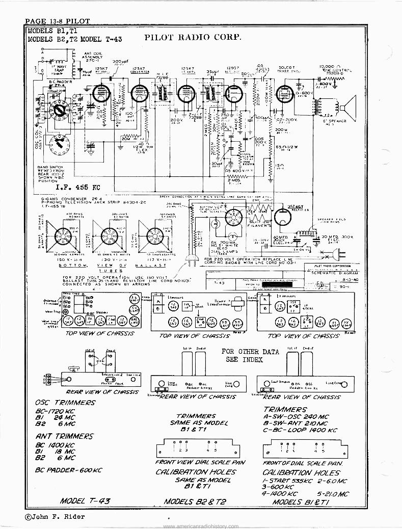
PAGE 13-8 PILOT MODELS B1, T1 MODELS B2, T2 MODEL T-43
B C.PADDER 2 -4
BAND SWITCH VIEWED FROM REAR 100-2 SHOWN IN BC POSITION
o
ANT COIL ASSEMBLY
270-I 300yyf 251(7
20~ /J
I.F. 455 KC
PILOT RADIO CORP.
125A7 CowvfRrER
CR 100 O PPA
2o 14
40 n 1/2W WW
FL ES. 32-6
G -GANG CONDENSER 26-4 P -PHONO TELEVISION JACK STRIP 84304-2C I. F.455 36
400 M5 eCwATls 50
JelMS 61 nA i
50o4.4s n3 wA r5 50 OHMS 45 wAT T5
150 V - 35 5
13 0 T T O M. VIEW OF BALLAST T U BES
FOR 220 VOLT OPERA ION USE 150 VOLT BALLAST TUBE 35-15 AND RESISTOR LINE CORD NO 103-I CON NECTED AS SHOWN BY ARROWS
Ist I.
73288-
1251(7 i E -.u_ 3S PPA
2,1,11. F. ^ 73288- o
200V. E 22 3
BREA CORNLC/10
00 owns 21wI,
'0474'T5
130 V -351n
TOP VIEW OF CHHSS/S
QEg1p VIEW OF Chf9SS/S
OSC 7/P/MME2.9 BC-/720 KC 8/ 24MC 82 6 MC
ANT TiP/MMEPS BC /4aokC 8/ /8 MC 82 6 MC
8C PADDER-600KC
MODEL T- ¢3
0 a5 lis 117 V-35-3
7.
ei sccKcr
12507 Os
I OV DCi :2-3'
2 MEG.
IN
6V. 200 MA. NO. 51 WHITE
BEAD DIAéa LAMPS
50L60 T vow[R
I 01-600V 22-e
50°'-t'":; (.02- 200 V.
200 M
005 200 V. }2.a
501_ n.:T 1250/ FILAMENTS
65,1.1/2 W
15'S 30-a
34 ,Cal" N[C1I[1[R
10,000 n TCNE CONTROL
79209-D
1F--^ .1-SOO1L 22.31
57 SPEAKER 40 3
SPEAKER FIELD 3.0 Gn.nS 1
40MFD. 30 MFD.
22 32 É0ÉCV2a-21r = z.Ei sw ON
'1
FOR 220 VOLT OPERATION REPLACE LINE II CORD NO 84048 WITH LINE CORD NO 103-1 ll
f
300V.
T-43
Re.t7- TOP VIEW OF CHASS/S
I3[ IF 214f
CJ NO.
Gano
PILOT RADIO CORPORATION
SCHEMATIC DIAGRAM
N_ 8-13-40
90-11
r , A
e
k[-Immers 1st
7CP VIEW OF CIYASS/S
FOR OTHER DATA SEE INDEX
O bäl O 01
Im ;[ PEA2P /ErY OF CHgSS/S
OBE 0 o Vadner 644 N[
I,ne 0 c.ta
T2P/MMERS SAME AS MODEL
51 87-1
171
iii i i171 1 2 3 4 5
F20/VT VIEW O//IL SCALE PyN CAL/B1C'AT/ON HOLES
SAME AS MODEL B1 &T/
MODELS 82 B T2
Ist.F 2ndfF s -- P re*~
OLoot. S«KatOBc osE
Padder 644 Lc
-Pene VIEW OF CHASS/S
T/P/MMERS A-SW-OSC 240 MC 8 -SW- ANT 2/OMC C -BC- ¿OOP /400 k'C
R 2 3 5 Io00 00
0
F2eONTOFD/4L SCALE PHN CAL/B8PAT/ON HOLES I- STg2T 535HC 2-60MC 3-600 Ic'C 4-/4OO11C 5 2/OMC
MODELS B/ if 77
©John F. Rider www.americanradiohistory.com

PILOT PAGE 13-9
PILOT RADIO CORP. .M0DEL T-48
DI
Ó
LOOP ANTENNA
G
E
O 5
b 1 b 7"
200M
LINK
.01-600V
IF PEAK 455 KC
r.w CONTROL
POWER TRANSFORMER 117 & 230 VOLTS 83412 F 150 VOLTS 8 412-L UNIVERSAL 83697 5 -BAND SWITCH 100-1 G -GANG, CONDENSER 26-2
65A7 I.F. 455 KC
D 5- 400V:1
20M
40rí2 NIwT
V _
8-40
17
65K 7
_Isrc
05-200"
500M.
-MIMAA/".
.05-200 V.
' IMEG.
M/WuVNvb
50M
6U5
25O00. 01-400V
66G
O N
130
005 000v
1 'Opt -25V ELEC.
.5-600,- .05-6009
IOO M 50M TONG CON T60.
.. 250 PN f caoRu wLJv
.NTROC T PPID
5Y3G 32mot IOf.Al 450 V
T T
ALL FILAMENTS IN PARALLE!
'S1 99Cd<B NT. TRiuNfRS O9a9-J T s I5 BC 6 B1 Ó5°SP TR1LPLSCpÓ9p9
a9R
SERVICE NOTES
a r i00%M0
600 V.
78889 NwiÇ^abs8°:
BOT TOM VIEW OF
SOCKETR
730T TOM VIEW SPKR. PLUG Er SPEAKER ;
FNTENNq TR/MMERS
OSC PqLXJEQS
Bio
820
The locatiin of all adjustments used in re -aligning this receiver, and the frequencies at which these adjustments should be made, are shown zoo,* _s.Q in the accompanying diagram. SOC,re-T
When aligning the I. F. amplifier, the generator must be connected to the grid of the 6SA7 tube through a .1 mfd condenser. When aligning the receiver on the Broadcast Band, connect the generator to the Antenna wire through a .0002 mfd condenser, and on the two short wave bands use a 400 ohm carbon resistor.
ANTENNA
This receiver contains the latest type of self-contained loop aerial and will give excellent results even in distant localities where the signal from the broadcasting státions are faint. However, it may be necessary to turn the cabinet toward the direction of the incoming signal (since most broadcasting stations use the directional antennas), for the best reception from that particular station. For short wave br distant broad- cast band reception, the use of an external antenna isrequired.
When using a. doublet antenna, connect one lead-in wire to terminal "A" at the rear of the chassis, and the other lead-in wire to terminal "D". Remove the connecting link- from terminals "D" and "G" and. connect terminal "G" to a ground such as a cold water pipe or radiator. If an ordinary single wire antenna is used, connect the lead-in wire to Terminal "A" on the rear of the chassis. Leave thé link between "D" and "G" terminals and connect a ground wire under terminal "G". A
doublet antenna kit complete with all accessories, can be purchased from your dealer. Ask to see the "Pilot Antenna Kit".
52 BC
0 0 Be B/
/sr /F
OSr' TR/MMEPS B-2 o
a POWEP T,A4NS.
aE.vQ 70P V/ElN OF CHf1SS/S
/SC/F 2nd/F
4s53- et" O
o
TEL EYiS/ON e PrrONO FCK ,9 0 D O
L //VE COQD f ,PEAP V/EINOF CNHSS/S
TUBE LINEUP 65,97- CONVE9PTE9? 6SK7- I F. 61/6 -2nd De t: -f7VC 6SE5 -1st /9.F 6F6Q-OUTPUT 5Y36 -/PECTIF/E,P 6U5- TUN/NG INDICATOR OSC PADDEPS BC -600 ,CiC B/-2.5MC B2-6tiIC /9N77 TIP/MMEPS BC -/500 /E'C B/- 22 MC 82-6 MC
©John F. Rider www.americanradiohistory.com

PAGE 13-10 PILOT MODEL T-71
LOOP ANTENNA 73381
.05-200V
IA7GT
.01-200V. 22-16 r-
22-28 = " 7 VW`4
1 2 Meg.
5131164 13007 plOsc. /.y 79` 31- 2ÖOA f-
--re t D D -t -.Qom Osc. Coll ""' 1 72-1
25 pf. 20-8
O
73328
--455 ke
Ól/1
PILOT Rr1I)IO CORP.
IN50T
7
22-38
73329
455 kc
IHSGT 0I -200V 22-16
100 MNf 20.141
1:0 r) 30 ^- Sa
1- OOV. 2 -34.
LTT
.002-4001 22-5
200n 13203
300 n 13003
100.000 Jti 13031
G - Gang condenser 26-1 P - Hi. P padders 70969-K All resistors are 1/4 watt unless othrwise specified.
LOOP
MERA
1400 kc.
TOP VIEW
cr
455ke.
REAR Val(
Model T-71
132'495
2?--31°°' IF PEAK 455 KC
ti REAR
SPEAKER LINE INE HERE CORD
2Meg Volume
3Ì n2ÓÓ,000^ 36-I
60 fd. 150 V Ele 24 26
I10 -125V. AC. or D.C.
Brown bead 6o-150ma. d.al lamp 72151
switch on volume control shown in
N -(c loe kwise) position
2050,, 20W. typped at 1350 .."1-
ß Top view of battery plugs
TUNING RANGE
5; PM. Dynamic Speaker 41-1
30» fd. 25 V.
Elec. 24-14
Slide Switch shown in 'AC, -DC (right) position. IOI-I
PILOT RA010 CORPORATION
Schematic )Diagram
=...-5-4-40 T 90-/
Broadcast Band: 561 to 187 meters; or 535 to 1605 kc.
SERVICE NOTES The location of the screws for adjusting the oscillator, loop and I.F. circuits is in- dicated above. When- aligning this receiver, the "A" and "B" batteries must be in place, and the
set correctly mounted in the cabinet. The signal generator should be connected to the grid of the 1A7GT through a .1 mfd
condenser when aligning the I.F. at 455 kc and when setting the oscillator trimmer at 1400 kc. The loop antenna trimmer and the 600 kc padder should be adjusted, using either e weak gtation or a radiated signal from a signal generator. This receiver may be aligned on either battery or house current.
REAR VIEW OF CABINET SHOWING BATTERIES IN PLACE
BATTERY INSTALLATION
Remove the screws from the back and carefully lift off the back.
When removing the batteries, first unscrew clamps, and then remove battery plugs. Be sure not to pull on the cables, but on the plugs themselves.
Place the new "A" and "B" batteries in position shown on diagram below and replace clamps in position shown below.
The black and white cable, coming from the chassis, has a 2 -prong plug which. is then plugged into the double "A" battery. The red and black cable has two 3 -prong plugs, both of which are plugged into the -'B" batteries. It is optional which plug goes into eithér "a" 'battery.
©John F. Rider
www.americanradiohistory.com

PLLOT PAGE 13-11
;COJOS Ny..aS JO .01108
1111,M
PILOT RADIO CORP. ° ~N Ñ =N
ó it. Ipol
7Wñ p
ap QÓf pOrv W
201 .N e
ZI',LL
H0001-SOO
CV
/9009500
II -ZZ A009-500 - LLI-OC NOOZ
pl
...-1MMMW-1 O2 -0C 64WO1
Z
iª
_ OOÑ1
. tº Illo
O
Om-
pN
191 -OC WOSZ ..w,r.
181-00
N.
N' ImII
OS C*I.00-E4OC
D0a.1 paO1óJ 63b11
2 9CN011MSf109111NOJ J14109
092Z
:. -IC P I OZ IOI
C1,1 -0C WOC
° ONONd ° illia
25 -OL .A009 -5C00.
Z-0Z ae C2Ls ;MOW
A009-5100' le ºI IÑ 9S1 -OC iN05
12
CC-LL AOOL-1'
ZS -OC U 005
UII
MMMti 99 -OC U 0001
b02 -OC
6aNZ
IB -OC
WOW
IÑ Hlrol O
ÑN
C
o>O ái
p I
My01.OL I
CCI -OC W OZ
HF IIIM
0 1'I
N
I--Illul
oml
1 s
7f OÑ
m
'Na
ÑéQ
LLIOCnOSI NV`-
- y 0 -s
rölä` 'TTFL-' ,rfF;^ 7k IIiII
m - 1 !-1F ---1m-- ºI m
5 21:7,Z f , 7- ; go III. <0xó .- z41 -0C
f o N g Ñ N 1IWA-.
o
a 0Óm mÑ o
Illul
o o
J1
o ¢ 09ZSZ 0i <O 09ZS2
Zo 0915L
091S L
U
L.0
äiä:
I 1 I[-22 \ 11009 -SO
C>59
CVS9
L 96 5119
LJS9
C069
u
ú
MODELS T -131,T-135
Ñ
0 0 0
bb
o o
OO 1:ó 1
a u
- 1 7W'22 tg(1)
7WO9 29m
JN OOSI 79m
L J
-TKI 1
Mg ALII I J. LJ a
V
8g
.1. p O)
C O Q
as 02 t- me ,0 O , CV cD Cl)
da O (zl
i r --I +3 ~Q d- / O o 6/9 0) N i< + (AD L. H H O
CD PG ri C t cV t Y' O +O M 1+ m w 1 O I U N 7 O 0 Gî N C/] .--1 ,., ri
ó
o il 11O0JöMSK
7W O'LL 2
. U W _ b
ó
W
O U 1-
WwI
Eó- ºe º;! 3
ñÑ RÑ
F +' G Z 1:3 cd O b g áo Ñ
-4- -O
> y al cd ..e4 e'
w V , -I,3 F. a) w ÿ F.
L. h+- F.
ho z, O w o av Sm
E O b4 ? ó ó
CI) d 0
U ,.=
84
y F. w w a O a ...
C W ~ i i+
d yF Ó
03w
U cu .= o F- ¡
.a 'v.'''. = ND C O C N- ÿ á O c3 al w j O IOa. w y ..r.
F as <.a Ñ C.)5 -I
TS .C.' 60 Gzl + w Ó C3 U . 1-1 L3
O ;~b -+Qo Wi84 a
g O
F w rO O O O
o a+ adC , co
-+ v ßl b4 +a o-, p Ó o V 73O;
C3
,.0d al VS
al b.O,T Ex
E4.1 .= b4 F, v c CD
<-. al al Fr e.1 . ÿ 3 .a
©John F. Rider www.americanradiohistory.com

PAGE 13-12 PILOT MODEL 7C-131 PILOT RADIO CORP.
ANI
LOOP ANTENNA A)5..lLV
RF ANPI 6_113
CONVCRTEN
CM!
oov On V25 WIN
o
O OOP PLUG SOCKET if 'B
.«(:. ANT COI/ ASS?
2
O - 5-2.á T R : 01.600V
son
ISNuIy
MORAr
s V 300n5W
BMoem
BNaI lute
30.L9W TOAI00 BALLAST BE 35b
eR.ION -CNnqrE e+.A.t .u0ef pNlg 9-25-I-ü:-p+ 3
,TERATqN 8-CnIqee NtMal IIAIe Jed eR.Le. 5-22-I -MG
1=
os- 455.c
ÇZ!> ii.T
3
00
ps -K.
os {{{{
zooe2 O
Y 001<;án
0 sn...L"""' esNNl+P
BC
osc COIL Ass. 80 82 2129 BI 272-10
- 1
t r WWI,
63RT
C
I-lfsl
L_ -ss
INN*. I/2Meq
+u
05200V
+DFI AUDIO
6SGT
NASO NVCRTER
o P!
tOONNIMN ñT ,e1
REAR VIEW O. 7
TONE CONTROL L PRONG SWITCO 00-:
1
OuTPul ?Akre
SLOG Q
Mounted W wt äe 9-9
cnsaN)
G NG Cw..OM.F. s ?6 T ewyy CN100-G POlI..I[T SNORT wNNCC a`11
2-SNOai wVE N OOP AIiT BC
- TRRIytER COILiD[NSFu 6LOA r T AR+ER s*RIP 827-7
TONE CONTROL SHORN [ TR[
CÓITpRCL.CNwbC POf.TqN1R
NE_, IN .aocc 2 - TREBLE
3 PRONO WSiCE r,gl nl -
LPr2,2T.RqA cBr/awTT VNLE51 v"°eef 91 BCe,I OTO[ 5C SPECKN' L
8 MTe OTWwC SPCAACR ,
BC RF KC
OIL
"`TRIMMER
TOP VIEW
LOOP SOCKE T
REAR VIEW OF CHASSIS
8
a OSC. TRIMMERS
/MONO -TELEVISION JACK
LINE VOLTAGE SWITCH
DEI
I17v. 2200.ß
DI L BAND INDICATOR LIGOTS 5EAD.50 MA6V-
A ce.Oc
SPEAKER SOCKET
LINE CORD
ANTENNA This receiver contains the latest type of self-contained loop aerial
and will give excellent results even in distant localities where the signal from the broadcasting stations are faint. However, it may be necessary to turn the cabinet toward the direction of the incoming signal (since most broadcasting stations use the directional antennas), for the best reception from that particular station. For short wave or distant broad- cast band reception, the use of an external antenna is required.
When using a doublet antenna, connect one lead-in wire to terminal "A" at the rear of the chassis, and the other lead-in wire to terminal "D". Remove the connecting link from terminals "D" and "G" and connect terminal "G" to a ground such as a cold water pipe or radiator. If an ordinary single wire antenna is used, connect the lead-in wire to Terminal "A" on the rear of the chassis. Leave the link between "D" and "G" terminals and connect a ground wire under terminal "G".
>MI
ry' 2526G1 PEI'unERq
LINE SW. gl3 SWITCO ON VOLUMC CONTROL
CORO tRT048 Ios -60Ó
l'80(
Otl -1r e ---- TaV4pMRDS
]OOV LEC
PILOT RDIO CORP LonqMlnYC.r, NV,U S A
'V=e Mqe+m
i
Dll
OFFRII FV_Dtei0-3-+0 C*µe+eV U.+1 N 90 -ITS
POWER SUPPLY Reo. will operate on 105- 126 v. or 200-240 v. as indicated on the locking plate,move switch to other position & replace plate. When operating on d.c., if rec. does not work 1 min. after turned on, reverse plug in light socket.
SERVICE NOTES Location of adjustments in realigning receiver, and frequencies at which they are made are shown in accompanying diagram. When aligning I.F. amp. the gen. is connected to the grid of 6SA7 tube thru a .1 mfd cond. When align- ing receiver on b.c. band, connect gen. to ant. wire thru a .0002 mfd cond. and on 2 s.w. banda use a
400 -ohm carbon resistor.
TUNING RANGE
B.C. Band 537 to 1740 kc; or 660 to 172.3 meters S.W. Band 2-1.98 to 7.09 mc; or 151.5 to -42.5 meters S.W.Band 1-7.2 to 24.5 mc; 41.6 to 12.2 meters
©John F. Rider
www.americanradiohistory.com

PILOT PAGE 13-13
MODEL T-132
0 8.
>` á. °mó
LY-0C OI II08MI-
8Óh wOOS
' C
e:wó 1- a1 -
r
oó00 -sa
L2 -OC V o51
Iñ 111>NÑ
PILOT RADIO CORP.
ös` 1B1 -OC
wOSE
C-22 5009 -5100'
V1MMM eOZ.00 sw2
ZS -02 5009-5000'
1 fI* 31fLI m L.00 iR _7
AR sry° nNw wosl
u
Ñ M,Ny jjN
0 0
1311005 0 b 5001
U0091 Çi'J º5
2Ye
8` óaa
la
OW
Y 00 Ory N ry
t
cv o 0 o .:t4 b o 0 b -ri b.z o C)
. 4->1-eó o -P-4->1 m h0 U
E 'CS
(DO (/) H O U 'd rl w bD+ Ir O î:al C) D }ti C) TJ ri U C) ad
W 0 14 o hD b TJ r ti O m Q)
1"1) W 0
j Cd 0+) ad PP 4-) U U
!A N t1 U t
U T1 o E Pm. W+'C>ce) C
tiz
1>yy
r Z IA 1
M
OL
Maw.
¡Ad
a
s e -e a c
©John F. Rider www.americanradiohistory.com

PAGE 13-14 PILOT MODEL T-133
LOOP THN2 221.-1
311 20 30-2.9
nr2ueL 001-.00v ÇONVEATCA
G -GANG CONOCNSCA 26-7 5 2ND SwCN 0-9 SNOAN MCA ACME
C 5417C4qOONTCACLOCNwISE
POSITION NO 1
61-5w Ncz- ez-w uEA
- M CONDE)N0 99 3
:'15;97 NC006 ro 1qN
7 255721/6
200V 122 ])
PILOT RADIO CORP.
200yy, M.. z0 -b
I-210 223]
7C7 7C6 7137 6060 62756
wICONTAOOLw2E
5-2003 500. 422-43 30-19
2eEttTE 111_6.1_19,61
4015-6003. MA 22-3
velwn. aro4 1.N
100 M 36-6
ear_eatr.
The location of all adjustments used in re -aligning this receiver, and the frequencies at which these adjustments should be made, are shown in the accompanying diagram.
When aligning the I. F. amplifier, the generator must be connected to the grid of the 7A8 tube through a .1 mfd condenser. When aligning the receiver on the Broadcast Band, connect the generator to .the Antenna wire through a .0002 mfd condenser, and on the two short "wave bands through a 400 ohm carbon resistor.
TUNING RANGE
Broadcast Band 537 to 1740 kc; or 560 to 172.3 meters Short Wave Band 2-1.98 to 7.09 mc; or 151.5 to 42.5 meters Short Wave Band 1-7.2 to 24.5 mc; 41.6 to 12.2 meters
T2P/MME,QS /F ADJUSTED TO 455 kC fNTENNA' A- SC /300 KC B - SW 60 MC C - SW 220 MC .2F: H- BC /SO0 ACC T- SW 60 MC k' -SW P20 MC OSC/L L FITOTe D- BC PADDE)e 600 MC E-SWPADDEP 25 MC F- SW 240 MC oscaiLs G- SW 80 4,1C L- SW 60 MC M-SC/500KC RF CO/LS
©John F. Rider
rosr cti/LS
ïóf0 ELEC 24-32
63750
soon, 31-6
';,19., CA .C4vM11SA M>L1611yM
B V1200M.. a6M9
IF PEAK 455 KC
Model T-133
Receiver for
5- 8 Volt D.C.
30- 40 Volt D.C.
100-130 Volt A.C. D.C.
200-260 Volt A.C. D.C.
/O AMP FUSE
y LEADS
4C -OC L/h1E CORO
voz TAGE ADAPTOe SW/TCH
~No 40 0c* roo-/ov I
o) S -e v OC
TELEV/S/0N ACE I
eEA)e /EW OF CHASS/S
200-.260 AC -OC
www.americanradiohistory.com

PILOT PAC.F 13-15
MODEL 173 PILOT RADIO CORP.
a
... o
> ll'
o Óm
1, 7 r iAÑ
I
o BB -OE IN 1, +i : , ``-'-i0.
N$ -,nVw p v 7, 0,--,nMnnnn,--:
III - - + 1 1 iBrOE wOSZ N/' I Q
I I I ? L1III'/O \ 1 I
`Ii III1a '1K I P
á Z ÿb 03 0 `áái L...-5 áo+.> .L °1 aui^z cd <le d ÿ,
ó ai. i. ua Naa º°` o
Ñ ; o . -,
A cc b 3 u o g m a,
o W-)-> yb F+ " m aiw+" ó o 5.F stc
o .rF g W OO t~c°..s. U , a) .rG a? áá
g aC`' F ói. .ji ad
as Y V ...9
O ++ t... OM V v w' úbO 12
d ,..4,+ N. C
A 3 =do .2d í sÌ Ó Ó
C y ...
ó NF C!AúQ
++
alp Ó e b0aa ,t.
al =w CyO cei
OU áÓO a) a)
a);va i+ y .O Fr aJ 4-1 ..= .+
al [4 C a7 y a) cu ^ a) 3 .S
=7 O ti 1
-i
v w
©John F. Rider www.americanradiohistory.com

PAGE 13-16 PILOT MODELS 193,194
Late PILOT RADIO CORP.
))10E9 IA )A2 059
3 Ñ
13M30S M3Mv3d5 AO 431Á ..0). 109
;74,,
e6 h \
¡ ' I
912 OE '2L1
M2/1 U OOSr
21 -OZ ,1 W sIIwOS
z
H
E91 -OE W00
9 e H
o 24 Co
BIII
ó
n002 -SO i A009.SOO-
EE -22 n002-1
OS I[SY9 3MOwJ 83013 malmmm
Ñ9ÓÓ E
ñ
LI -OE WOS
1s
:
nä
ÉF
J 001,1 ODI..J,.M.OÇ
CInMa1e a st.J
g °b ` g F -92 Ú
OC A > -WI -,c >
ÿg N J'.. F .. N b 03 .r.
ÿC O F
d O W
C^O O
ó -d .. a ., pp y o iq o
ti m ai U "g -4->
s, A "Ci .4-) z O bu ,F,
., 0 U ... v a) .-I F
"° c cez i -a cd o
.N, dD0 - C
'4 a)
E o F Á x Ó rn a cn
°d 03 u
O b0 4 p ^O
ce
.g T7 CD
-4
O
7,33 tu) Pá cv
O4-1 ai >. GO co ,,z G R h G a1 ad
V a Cg ., O .s Ú ÿ O a3 C a) o a Ú o H v. ca yv d
I" v do , . 3
d ar a1 .ÿ o .C 3 ...) y
1
43 43 4 at Si Lr O
I 1
g d ad
RI
1 Lr -ri 'b rl L. z m ® g Q ..%
ICM
CO
o 0W ' ó 1 m >ve sm°r ri -P 1 }7 ® ,n >~ L. oc ri oc
Ó o I
O A
CC.
I LO.rN1 ó ó ó L.
1 m m 4o mKr, i.c) I
S
M H .G' J4' U CC Ó .ri ß4
©John F. Rider www.americanradiohistory.com
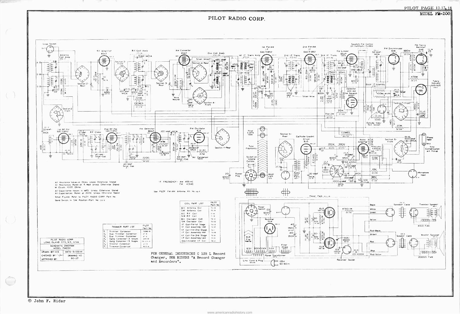
PILOT PAGE- 13-17.18
PILOT RADIO CORP. MODEL FM -200
Loop Socket
114m
A O
DO
G O
a
Antenna Coil Assy 270-n
Section 2 Front
Section 2- 1 Rear 77T.
RF Amplifier R.F. Coil Ass'y AM Converter 65K7 r ---- j71-- j 6SA7
00 2 zo in5A4F-MICA Iov
-, iS.W.I Section 3 - Front
01 Hizo -is; O5 B.C;
951 z2.zeT
600V IOO MMF, 600V 100 y
s2z-is MICA 22-6i MMF Ñ. - MICA 220M
2.2 MEG
3P2.e
2nd RF -FM 6AC7/1852
109 71.y
` = S.IvN-Cap
All Resistance Values in Ohms Unless Otherwise Stated All Resistances Rated at 5 Watt Unies. Otherwise Stated Al Equals 1000 Ohms
All Capacitance Values in MFD Unless Otherwise Stated
All Capacitances Rated at 200V Unies, Otherwise Stated
Small Figures Refer to PILOT RADIO CORP. Part No.
Band -Switch in SW. Position -Part No. zoo-º
PILOT RADIO CORP. LONG ISLAND CITY, N.Y., U.SA.
SCHEMATIC DIAGRAM MODEL FM200
DRAWN BY-M.G.
CHECKED BY -s'.
APPROVED BY-
DATE- 5/20/41
DRAWING NO.
90-27
FM Detector 6SA7
los
ú ñi{iv°J
40 MAR Silver -Cap
2.-I
TRIMMER PART LIST PILOT Part No.
T, Trimmer Condenser 72233-s 12 Dual . Trimmer Condenser 27-e 1*3 Dual Trimmer Condenser 27-2 T. Gang Condenser -3 Stages 226-10 Ts Gang Condenser- 3 Stages on 224-10
T. Trimmer Condenser 27-5 T, Trimmer Condenser bailo -o
Section 3- 1 Rear T.
V ire
Wound
IOO MMFNMICA
20-.41
Ose. Coil Asiy 272-20 Ist I.F. Trans. Aasy
273-
cl
teLsoI 'Ii-
;
º T2. -e I
zó-eo /
. 3600-1.MICA R.i I \Slver Mita/ I
"Pr I
Q I 0
I 1 ... o T,
L-_ _e_5 V/
a Section 4- Front
FM Oscillator 6J5
20-73
300Á1M MICA
40 Á14F- Silver -Cap
47M Air Condenser
11.16
IF FREQUENCY- AM 455 KC FM 43MC
Use PILOT FM -AM Antenna Kit No. no -7
Section I -Rear
COIL PART LIST PILOT Part No.
B.C. Antenna Coil 7046 S.W. Antenna Coil 70-.,
B.C. R.F. Coil n -u S.W R.F. Coil ,is B.C. Oscillator Colt 72-21
S.W. Oscillator Coil 72-22
I.F. Coil -FM -Ist Stage 71-12
I.F. Coil Assembly -AM 73-.d
I.F. Coil -FM -2nd Stage 73-6 I.F. Coil Assembly -AM 73 -lo
IF. Coil -FM -3rd Stage 75-s I.F Coil Assembly -AM 73-8
Discriminator I.F Coil 79-2,
20-' Power
600Vg Plue 2.-4s
FOR GENERAL INDUSTRIES C 125 L Record Changer, SEE RIDERS "A Record Changer and Recorders".
L
Ist FM -AM 2nd FM -AM I. F. IF,
6AC7/1852 6AC7/ 1852
09-7
22-M O1-
600v
05- 600V 22-3.
a-7 2nd I.F. Trans 213-2
125Q V / MMf _ Silver Mica
Pilot Lights74469 ^ Section 5-
Rear Cathdde Loaded Driver
1/^ ̀ 65 J
J5 109 37
Filaments /\ . Switch on i::,.........-..''-,....: 0
á
Volume tu 3 R
Control e'^` IS o o pa
_a o Zu ^\ 01 0
---Audio Jewel Q InDu
35-M AF Light 9 Trans. MICA ms, se-. zo-º
6L6 Fila -
mente
6.5V
Q19
Power Sockel .05.
600V 22-3.
Rect. ier 5U4
4717
oOVeppV º 4.0 º
Squelch FM Control on Harmonie Control r -
20-12 50 MMF -
MICA
O1.^i ¡ RQ .002 ARCA
.01- 600V 22-.e
Detector AVC-AM
M Squelch 6507
20M
W M -26e -
2.2 MEG
1OOM 390M
e 30-270
Power Pack 24.-.º
Filter 5.0V Cho
40l 350 2.-.r
40- _
350%7+
0, ÚÚ I Power Transformer
Line Cord S. Plug 84044 125V
50-60^7
FM Oiscnrrinator 6H6 680M 0º-.0
FM Tectif
ter 6116 2Je
10110 25
ry 30 22-20
r Y .02
eetio 1 -Front
Audio. e 0 Section 5- Amplifier Front
N Volume Control
OS 2)6-3
z2 -sa
68M "NA10. 30-2611
Black
4700-1W -MNth.
30-2º3
10003/
SI
22-26
White
Green I
1
' Yellow
iRed -Black
Brown
RM Blue
03-1000V Red -Yellow
470M V 70-275
(7, -il,;) Micropnone
Input s-
Tunng Indicator
6U5/ 6G5 ioºe
Plane 'Mut
s3-2
Tone Compensation
a/c Pickup
.06-i0 Speaker Cable
.611 Speaker Cable
Recorder Socket
Tweeter Speaker o -u
4100 Field
Woofer Speaker o -lo
z000n Field
John F. Rider
www.americanradiohistory.com

PILOT PAGE 13-19
PILOT RADIO CORP. MODEL FM -200
PAGE 13-20 PILOT MODEL FM2200
PILOT RADIO CORP.
oigkW
Ç1
m
Ó 0 vi 1
m G ám + m F W O W .0 C O P. r b
m H
O H 0
4>m O E O ri 0 C W E a h .44C
W P ÓaC meÑ wC ÓÓ6
G r T v y 0 0 o .0 00.0 C a Ó C H U U 0 rl W a H 0 G
g O y °0 0
4. O C O'
PH
T .0 .yWme C°
rlW+1H .0 0 0 0 0 41 CH U H U
HOH o ä° -1 W
Wl
C A 0C0W W WUC 0m vyO 0 ..i W 0 .l 0 o 01 4. 0 0+1 .i H O H O C W .1v +1 .1 .c.+ .0 pO o oc >, W.1 0.-1 r1 0 W E-4 "0 y 0a-. 0>sNJC U .0 0 0 2.' W el 0 0 O U
W
y U H el H a CI .l P49"j"..2 e,2 Wr0.C000Ñ
.t0 W W + +)1C.0HU 0wKW H .0 rI W0m,.1 yX0 0 W 0 y v ÚlU
r0 00mia.me
Ú F 1 m 4 gÓÑ1W'5W
Ó A 0y r1 41 Well -10C) p °Hva9CÑÁ H
P 01 y0 el
Ó 1. 0 0 01 OO W.gAC
AÓ.E1 WW HC°CÓ H el A L 0r1 as
O?+1 7 r1 .1! 0 0 N F O v 0 +l 41 .0
1.0 . 30g mi. UÓ F vODPe>E 04
f1W o 0
I ÑceCC[p+-1CWq+17mÑ AHHr"O ÑT Ó.l l +1 W O 7 >s 0 .l .1 W 0 C E
W 611 m> W ri v O 0 W .-1 0
C O .
U ri 0 rl0 01 ''yH OO Wi ,C.1 H 0 W V a aa
rl v U 0 H 0 .l C O C S5"9".12 a.1 +1 ,,rCCl
ei >.1 C t0 .rl 0 O
ç W
g Ó F W Ñ CO A °0001 7 i( W 6t
f7 v 01 W O H v v U U
r7l
R
i>.
0 rr[i11
W Q 0. 0
a11 0 >, O>pl H0 rHoi O Ñ F
pWEC
WÓ rl
IE-i V rrl
0.°0
(A-. Ó v 0 H Ñ C°J m .0
W ó Ñ +1 á f+ á 071 F .°) >
r1
0 ó
ri1 W 6° W 0 U O rl O W y U -, U
.2 yaWW UÓAc1. t 0 0 41 9..0i Ó C C m 0 W CC Ó Ó +1 .0 E O C A 0 C
.. b 0 W01 y se.
.CUI rl ó:> ei
0 Ó Ú C H C rW{ 0.0 CO
m a C0 100-11 m C V 0 q H H
OEi C U 0 Ñ.1C C +1 0 y W G A . O 0 H H X CO W .0 H 0 0 C W m U.0 0 .1 el 0 m 0 U 411.'r-ll C W +1 v . (z. 0 Ar1 U JC O W 0 a 0
.a 0 yi 0 .0 O .0 +1 +1 0 +1 0 0) elArtw
0 CO .0 CO 0 U m C. O W r o 0 0 a 0 m rrl1 .-1 m 0 ti .-1 -1 a 27 .-1 W A .i .0 H W.0 ....--1.--1 H 7 0 P. l-1 O k. C 1. 0 0 O .k 41
.arCm1l O í71 +10 G rl41) O 19 G0
m U-
F 0
ÿ a.i1 r1
5..
>K M
rWW-j Ñ t C1
m « +1 +1 C U O
1;4, a. 0 I. +H) y F. W am Ó O b1 H 0 C :d rCl {C1 O .0
pp r y 0 W rl >. .1 .0 O W O a F Ey 0 0> W Crl >s Cl1 .0 d.k 71 .1 +1 0 0 0 >s .+ 0 C O m U W 0
C CO C r+ el g W U H 0.i I d d el A O V H O v U W Oriri V 051 O+1 > +1r1 0 0 a H .a ..1 ^J 0 H C W F W 0 0 +1 1.i. .O 0 0 0 O v Ol W>+1 0 .l 0 P. a1 .s 0 rl 0.1
U O O 0 0 W O x .0 .O .l 0 0 W W y 0 r1 0 A b m 0 0 E W F. 6 0 y E OpOe W W xE UU co 1 aE ri C H m t..vad?.0 0 U 0 7+l +l
C H U F. H L 0 1> X +i rl VH b O
6 WEOv >.0 y 0A >s >>sçy 0 H 0 .0 el O o 0 7 o 1.l0.0 C y C 0 .0 1. el s .00 O A U 0 .0 H H A O AH W 0.i 0
ó °DÓrl +1.+10 (04040400. C. 0 0 ' CO +) 0 v Y A U Ca O Xi 1.7/.mr1.1v
P. U 00 a1 0 A C ri H 0. .l
4 1 O m
H W C X C 0 ri y 7 +1 0 v H O W A t1 V 0
W U C +l U W C H.O v 7 (0 0 0.1 21 O 0.1 0 0 .1 rl 0 7 7 p CE r1 O H a1 U g H.1 N.Ol W el 6 y 8. 0 H O.0 .l C 0 0.1 +1
as o Ñ Ñ 7 ó 0 W W to. q.°c ryrl1 Órpl H0 C W
H+1 0 A W OC WiA 0.W.1 W F 40v P.(0 H C
V\VII Ñ Ñ OD CO 03 CO tr. rÑi
C¡`C.nl¡e1tls0óÚV/]0.0á¡1pp,v.arpp.pp77`pp- g.d0.0.0.0.0.0.Ó2.0.0.0.0.0 V1.Ó 1 1 1 1 1 1 1 1 1 1 1 1 1 1 1 1 1 1
N N W .t .t >
1 I H0. Huiv g t
22 lee 1.1 Ch .k0.Ñ1q
H dW Ó Htdy W
r°-Irri p 1 Cs. H Ó H Ó 0O 0 7'
QC
0 04 0 ri 01 0
M OOyy
> H I-+ S 2.522.2.0
y 0
!>v (>tiv OPC Uri1`lav v>OP777.,e+140
1 I 1 1 1 I d 4 I 1 I I Çe 4? C
ewWC..eeWk.WW[s.dk.f ex
.f
A ei m m H W 0
21:15.041 0 640 C
G
Ó ó m rl Ds0 > gú?0
0 C
1Wk m r1 ó ID
l 0.1
abtt)
é° F.
ei 0
amM H Ñ. G .) Á 0
1Ñ7400i« A W C H .) 4.Á°0 g 81 W el .-1 O0 14
0.1 0 yMW ° O CO >s a1 >s
Á ',el 0 0 á H .0
0 0 W y 1°400.1 O O, HmC0ó m m O ri 0 v0 + bHcyd
0 O W .00OWpOY 0 23 W H 0 a .1 af
W..rr1l H H 01 .0 0 .rl 0.0 0 y 7> C1. A 7 40 ri > H C rl 40 0
ri 1
cO,
0 02:2 ri
O A .ö m W
> >s a W ro 0 rpl P.
.ml ó W ryi ÿ 40 Á AO
~ v A 0 .1 .0 .0 H 0 0 W v CD ` 211e° r1 + +.G .1 + CU + CO O.O A 0 H
P. N H 0 yipO W o é m ÑÓ.1lH0á 0 e el ..Ó
R Ó+ ri 01 0 el
t 41 0 rl el H v .0 0 .0 r-1 H m C o 8 o O.l O 1. rl 1
0 . (1. .l H yC y W Ó I 10°°
,0: 0 0 0 V+ U 0
14 4.1
M 0 v U C. U 0 0 C 0 0.i 0 .-WC1v U .1 0 O 0. C 0 W 7 0 H
? 0 4 t1.. WO1 @g
+l1 Ó g0 +°) 0 0 co > 1.
.O D > 7 W r1 U 0 R.
+1 .
.40)1.040 O H C F U 0 °. Ó
CO
yW t0 W A O b O C +.> C 0 0. > á yo
M° 00000ÓO .l0
Á el Ú
O Á P {. .0 1. C rm COriW1.UE
l a...4 mNC0H in
E... >I- P.mv 1°.
H (V
0 el y H U ri 0 C
° 1. k OC ó 4-.1
Ñ .1 O
Ig Ó Ó Á 0
.-1 H W 0 a P.
to in cu m
Wçç
1 1 h d Wó G .1 H O 0
rl R . y0 a
Ú Ñ P W y .1 W .l 11 W
{U...
H g W
O ÿ W B CCC H 7 N>>,,
0 4. p
1. 6E7. ,, C t Ha1W
p y,
O vv O . °H, +1E .1?.vWAyC r ./ Ñ C
in 4. 1 H a/ R. É 001 C° 0H)
0 v~ co C
m vy1
8§818 R0.''1
9 O óNriCC.0 d01 lel
m .a 0 m
F 2 F .HO r1 Ai C^ .t 0 5
0 y W 0
0
o
y 1H
rHrt[1ii
C
«t'''Ú áaa2á° I mA
çy 1
°
, á+1 w 4. '91
Á >,6.v
gF ó
°WqH ó 10.iDs 0 Ñ
A a +) pp o 0.U +13 pC m Má ..%ÑóA p
WA tl s
Wmóc°EeWá 0.
0p.r1 H 0 Ú O 0 0 e 0. U a1 °A00
1O 0 (1,202,10
H
UC 10Ú.i
0 . C t. W.1 tA+1O OHP.0
yÓ(0Ó1. OÑ°.-H
'C
0.0 0 0
WWC0l
.1
r«
rHOl
.1 mW ;
p ñ ó°R. el 0H
.1 l>
.H00io OR+H 0tÉ0C A p° el
7vÿv 1.W>WWdW.14. V1E0222
v
r. ó .; m W .. m
1 ¿O ..Ci t.pm., C m . > r0.
ra0 /0. X Q. HeV Ñ
el .4C
` 0el 0 U.0 0. el W v 01 0(: F e
... A Ì
+W1
j . 0 b ó g
0 d m W
el f- lb a O
O W O W.r W1AWC 1.
Wxv W
o WÑ a.iii
id CO UA W
W ° Ó0 g p °w co
r.".1-.00111;'
000 yC O HOC
CHÓ
.i1r>00CiHÑ
i O Ì
el el 01 el
k. >. malk
C 7
u
M.á qí1+v
Ó W
C1 9C
-y tñ
W W JÚ W17 0
41 0 L o
OW bW0HW
H a 0 v
O 0C7
WO
01 C 0 U Omy
V r -io HC > 0qÑ
i 0 W Uv 1°m ri
H +@1 O
.Ai ° 0 U V ri 1CD UR,.. t H r-1 e .1 00 U 1 0 X U .1: .1 A .l 11 W ri Ó . 8: X g X X
g C) 0 W U V rrrrr11111 +-1
0 O ppj E 0¡+yl H 9 7 U
O 0 nm Vs0 v7 00 v1f1W 0 W W W 20,-.' rl 0 7 0 9
Ñr/ P ....t -../ ra.0 rl.Orlri ...1, ..../ H> o{>.
o v o m 7 .q1 H
Z'''ii 0.1 9 rpi
fW. °+e1p d P v v Oa: tal .0 rsi..i Om' Ñ ó o Ca
á+y1 VOp
d O V 1. 'Ol F W Ñ W E W 9
v
C O
t iv!W
ÿ « 71 ÿy
,...0 AÑ a1 m >H0Ñ
Ó .lO .AW rlarWdó
XA{i1ñA 1á01 ÁH el P + H
Á0 r1 vr- PC el
40ÿ r1 1
+
W
C el
0 0 A°y% A W .1 H C
ÚA.10.XC>s7rv4p. 1N 00 0
m m O m .l Pe 0 .00.
0 W .1 ri 7 A R m{., 0 t
0 .rrll
0 i 6 A 0° 021.43-4914'41
H y0 .0 .0 i A 14
el 03 ei 2W
Z. yl D A m
R>O.,
i Ó W 00'1
.ó4. E 1 Á.CF.i 0 y 6
cAil H y G 0.1 pC W J 0 ox 7 40 Q O cod, J.l r) O y 0 0 40 el
H el
C 0.0H
0HUÓSC.DAO 00 .0 .0 yW
1>.g OÑ 0
0 U A
lA 0 AY
0m
P.
Wc7vác v
+1Ñ C 40 0 P+1 0 .l 7 0 41 C.l 7 04..l .l O It S mHGrl m
41 yÑ y y Ó0C0i0 XC ! d rIU
WCA.yt"a WgH ei
äEiÿ0.P1
O s¡ ÿÓpmQd 00ß.ñ +1
o coo ÿ1y i c 0 0 Ó 13 Al .0 .0 y °A 6 0 mv0 >....0 W W0U.1H U000. H.1 y 0
.0 0 U m .0 c e 0 .1 0 °my
W m WCyC° > RA .lC AÑF el 0HH.ia)
y1 0V E. a á ó -1 C
1 W W
Á. .0+ H.l +1
o Óm-1
10 CÑt O WQ.> on.,
0 1+. A 0 7
H 0 > 0
WAW.1F O
11 0 r+
0 1."C C Ñ 005.,.:_i3'2.. C.1 .>s 0 kell0H10yÑ 0.l Ñ 4.11 W 0ri W v C u W 0rl
Ó°vC°HÑÁA° ri ./ C
14 ei 0.0 +1VCy1m
o Wppp W
A.0W V 01
O 0v 1 ro°mv. 1ze00.1v ' 0R.lA .00 0° .0 W 1. 0 .l C .O+
'4'-'.3'4'-'.3W aW W
9
0.1 .1 H RF OHA 0
m i W F0. .O 0 .+.-'4.2 y Ñ k 0.i
Ó :05 a11 0 tH0 061
y r1i pG rE01 001 g>>0
.°l .ml .yi Ó Ó W 0 [- .l OCl C C ,0.., t. m Og1 t H +H) 1°E Ó v Cd H1 AC
O > W W 0
r C W0WCWC ra C :d
g W
m v 1. .-1 iO0 W 0v ..Wi,
¡4Óy 0 ór°I.RNa.rOOlpW W
CW F' 0.1 01 CW
^ 09 >. .y0 W C° 60 0.01 C
m 0
O
W
G W
HW t 0 >s. 0 r C Hrl y W .. W O4l0.g 0W yay 0..P. i Oi
C -v +c1
c U AHW 2. _4 m
+m 0 W
0 ri r- f .0 .4
) 1
G 0 El 0° 7 I.1 P.+)F y 0CÓW.0 WC
WO
CA0 ee
v OAr0.tiÑ 0vy l W
O W P Opp10 . C
0+1O 0 0 v W 0 H 0. 0 0 .i Al > .a O C 0 7 .0 .. .0 X .i
0. rl H ro .00d 0.1 1..->.
0 Ó.0l 7 Ú> a m O m U .1 A C` C 0 0 0.. 0 0 e..." 0rrl1 +1
A H O v A 1' 0 H R W O W
®John F. Rider ®John F. Rider
www.americanradiohistory.com

PILOT PAGE 13-21
PILOT RADIO CORP.
cn v
i
Q c O
MODEL FM -2
U
O
i 0 ® DH ssv Et,
o o
O
U Y U ó-
tc)0O Lc)
U U U cl-
0C ® InLá< Ñ
- 3 H
.a o c o
©John F. Rider www.americanradiohistory.com

PAGE 13-22 PILOT YODEL 300
WLV
g.
WOES
WLh
ccrOc I Hlul Q
Ill' >0
ro-Oc JWhM IIº
Ñ
n_
e WOLz
('öööxlr nnrr,º e
WI
3:
Ilul
0314 l so. -02 1 ºº-oc
LQr 1
r" L 1 L
J1
re 01 Ñ
ü üI +-'Ik-1I1I'
9k- .43A O nºOQº
ó
UOL6
ºOz -Oc
03WEE
PILOT RADIO CORP.
Lº
ÑO.
oc -Oz
ro
Wt.
03
3
In.
321c4 00 ALP
Ú
© rare"-,
u
o O
O
0000
II
Q
a
a4
e
p Q Ñ
4 ÿE á a3 yd Ñ~ <
,5 r. V o
Ó 61 .4 TvF.
a) G x+.,N a Á.0
ÿ} 3.
be N 0 m .Me p s. f=1
3'.. ^d £. . a) áo áo
;xi a Wc,. w.'
e,d. . O
F. C. i. b4 V ^.. x y a 03
ÿ ~ ó w w °°" LÌ 4 4d0 Ñ
a> GL C e 1 à~ " su
¡ai7 m e m t/2.. -.- tO 2.
0 V ceb r. ,,º o X a
a) I.
Ó 03 .. ee CI) 6e 1-1 .G
á g
aa
E g e o .. aO vo To c ac. á
o G . D F e 03 al - ,c2 .0 d x >~ v w
w ,g a C4 y.
ÿ .g ...º ..., 5 O
u
o o o
E B0
o
e Bá
V 0
0 es) J
e®
©John F. Rider www.americanradiohistory.com

PILOT PAGE 13-23
MODEL 340
}
PILOT RADIO CORP.
o
A0001-500
m
MOL
ñ_ myA
U - r Lei Or
nOZdV noa
A009-SOO
oÿ
3.
nOL
0 p> p ;8 8 or
m
óLLo9 = o
MCP
awe.. JwK "
ú rrlS21 1 03n22
u
OLP
rrwn,iepç !nn Sil 1 - "
o
m
E
e e MSZ -02 MS Of
rt-rr 18,11109e ..me
Of
MS
m
OSì
0469- 061
I OSI Ice W/il p
Ice
f
t0
> V .LI e b e ó i %D 61 d
mI F ; ' a,t m s! i"ó d}r-1 Rr 6 n Rd.
.a +1
óóeó p r" 1 { 30
m a o m + qr w.
M cÄ3
R O
is r r` .
N Ñ» I
xRe oR' ° ó O Q m ó ó
r1 w L. M 1" m°;
0. Ó ípo ¢. m 1
a. p d .4
q r`i-+ M' m 3: ` ó ó w m 1; 1/3j 4-1 rl 4
O 1 l +` 2 1º V
CO A m 133J 3 p qr s - oioñ m s.
L ¡""`, 13111m r fa ó R.
ila., mt Q' yf" :mdr
ti
-*. O ó F
.m A bt.
Q1 W C 3
C4
pp ó ú
ó ñ, ñ.,.A a
)MS9-061 .re -or IrFGI
3 în. ó
rwD Ju
nLY
o
002Z
Of
OL
G
o3
Rº
%¡Z R -{- .-t 1/31,tie"?
V'
4,
30
F m
©John F. Rider www.americanradiohistory.com

PAGE 13-24 PILOT MODEL 340 PILOT RADIO CORP.
FRONT VIC* OF CHASSIS
152 96 MC ..0
e e e e e I)B II 61 MC MC MC
. 600 Mc .+C1.c Ó
e e e e e 152 96 2 MC C
5MC 20 MC Q ® OO ISOO ItC
When aligning the I.F. amplifier, the generator must be connected to the
grid of the 6SA7 tube through a .1 mfd condenser. When aligning the receiver on
the Broadcast Band, connect the generator to the Antenna wire through a .0002 mfd
condenser, and on the seven short wave bands through a 400 ohm carbon resistor.
In general it is not recommended to re -align the bandspread ooils unless it
is definitely necessary. If re -aligning is found to be necessary, take off the
dial pan be removing the five screws, as indioated on the diagram.
First adjust the oscillator iron core to make the pointer correspond with the
calibration mark. Then adjust the antenna iron core for maximum output. The sig-
nal generator must be accurate within 5 kc on each band,and the use of a calibrating
crystal oscillator is recommended. Otherwise a broadcast signal of known frequency
may be used. In this receiver the oscillator frequency in higher than the signal frequency
on,the broadcast band and lower on the seven other bands.
This Pilot Superheterodyne Receiver has 10 tubes and a Cathode: Ray Tuning Beacon, and operates an either an Alternating or Direct Current power supply.
Broadcast Band
Short Wave Band
Short Wave Band 49 meter Band
31 meter Band
25 meter Band
19 meter Band
16 meter Band
A.C.-D.C. Receiver
TUNING RANGE - 535 to 1730 kc or 560 to 173
2 - 1.75 to 5.85 mc or 171 to 51
1 - 7.0 to 22.0 mc or 43 to 13.S
- 5.9 to 6.22 mc.
- 9.5 to 9.7 mo. - 11.38 to 11.92 mc.
- 15.05 to 15.38 mc.
- 17.62 to 17.98 mc.
meters meters meters
The location of all adjustments used in re -aligning this receiver, and the
frequencies at which these adjustments should be made,are shown in the accompany-
ing diagram.
©John F. Rider www.americanradiohistory.com

PILOT PAGE 13-25
0
.
r
I d - o+4N
;'01H/,.
"'aóól .000, 'CM) 2.ö61 Z,-ar"
q v
PILOT RADIO CORP.
e ú 1 U
RT eZT
MODELS T -1364,T-1464 Early
©John F. Rider
www.americanradiohistory.com

PAGE 13-26 PILOT
Models 1364,T-1464 Early
I:odel .1424 Series
For other data HOW' VI[w
See index.
ADJUST Ar Di- oscae o Mc
PILOT RADIO CORP.
TuN/NG ß/Acou { y/As.¢oglyEAssrg $c oso /£oo /(O 41 05C yOMG-
AN T. COILS
Q F.
COIL5
F/L rLF CNOK[
r
AO -ius= Ar HC -46OO KC
62 - 4.0 MC.
/Sf
/. F
5 ZMo
I. F.
SLfn
tgeAR Y/EW
ANT. P F TOP VIEW OF CHASSIS COILS-)
/31 140 M6
CO/LS Q F COILS
LEFT 510t OF C#45515
A/W-EA/NA CO/LS 7 --DETECTOR Co/LS--Th
OSCILLATOR CO/LS-- (SEE
'Sc ,s00Kc
82
B, o
/Y/GHT SIDE OF CHASS/S
cQo/c S
(sc / f
/ir / F 2N0/F. rRAAlSFOIM[P TRAMSFO/PMER
AOJ. A 7 455 KC
VMOMO
PEAle VIEW OF CHASSIS
f DIAL SCALE TVNI/vG BEACOMC,"\ 6Si{7 f//lcRcNu s
41110
ec Afc
2 3.00 Mc.
2nd IF / ACQNl
AT /-"9 SS Kcs.
(14
OSC r sl
/sT te:
W
k 65,47 4.4
o ó óse. Io7/ nee/ 237c
6.51S7 zhd`
25z6G
6S q tSt 6G
2SL
25L6G 6aL- LAST
TOP Y/ErV OF CHASS/S .
T-1424
PHolvo U TEL E IF/ s/ON
SPEAKER PLUG
ALIGN ON ANT e DE T.
BC dt /500 Arc.
132 di 9.00 Mc B/ dt 23.00Mc-
A'EA R l//EIN OF C/ -/A S S /S
©John F. Rider www.americanradiohistory.com

PILOT PAGE 13-27
©John F. Rider www.americanradiohistory.com

PAGE 13-28 PILOT MODEL X-1451 PILOT RADIO CORP
> ?78 V1 tn .0700.
' in IA
no GO
8Ñ, IDº
sr -1-
.1! O
- Ñ ,n N OU
Ú 2_ (9 ' In ' _
°_ -IH ,--2. --- IJ °2 n
``N n .
1 ODÓÜ -O.N
( 1s ozz J W >W 7 ocz 17 3>ó
9Eóiánv ©= ó(ri 61Ei r v 00' Z x_SSOaZ ' >
A r)OZ'SOO 4-1_ ,. Ñw -
W du e
31
t > N WU 2,..
U L`+ CL
1jl' II 01--ifi J' ( m ? o 411 ( ̀ ,ñv 2 wO? ` m~ i
I. Fv
N.ONW^ 0 rDOtfM1.JGl(J
áñbZEI 'O3VN b "", 'WO (1 N''u N a (7 r ,+ W 0 ñ- n-6EOE9 MOI $v gm1 'M'MvS19 W J I `
,
m N _ .:.:'i:: .Y Ì U0 II' 2 1
v c'i ' tD' u0i + V U
Nh1 II
NlN > ñ
J V-SSOZZ n00o1-so.
-)
l)Zct
LSOEI r001
O rócrÖ 5
u
~ W: 7,4
~Qm
eQfD
J O Cr Ó Cd
Cd F.. 5 > ° ,. zs Z óó
ñ _<
cp
F ááóñ á, c]+, ,-. 14: 5bD
0.) .a Cd d E 4->fr1
bá r -i e q Ñ Ó
° . Oaó I o
>-I
+2 fn ÿ >~ +,
ti v .. w rn
N 1I Ú a] ^ ,S"i Qi
N +1 V H ., +) Ca0 4j3a) a' cd H;.=4,sai
p
< ri;óa r°>r.
ó
ÿ yábM N+ " z: U a]
blY i+ IyOT .>Oi U]py x` a] O ii
ñ N v
LU)°0 á'0 ` O a] a)-,..,- 7._,;.., -0
`I-1 i.l ~ .r+ + ti -i= w 0 ci..)
( rn i O ,ÿ I :a) i (n ÿ+.ÿFor F.I.
+ n W m
cd
F¡ be e
Cd W y mY z . R. 3 + a) O 1.4 a)
tle
iyi
W a-+ E-+ ^s ` ° O O a)
W >w0 >~
a> ób*'z% t+j wYN O r. v o b0+
a < Z
i-i el O
Cd id çÿ i: cd ,j,Z a) a c] v]
a~ 2
z3~ a] mO ai óM ... cd _e_.) rn
ó á E cd
^CS O a) 0. 'O>~Ó Oal c
d3SN3GNOD ONO
o ce
OW UY
U zO _ a. J
A e
3
w
>
©John F. Rider www.americanradiohistory.com

PILOT PAGE 1312
PILOT RADIO CORP -- ANTENNA Col l S
DETEcTo,7 CoILS -1 oSc/LLqToR CO/ t5
(SEE NOT
Q.S_C PAODERS
6 o O C.
/?/ GNT 3/Of OF 1.1/14._1L-7
/VC,TE AL /ON AN ANT dk DE r 8 C at /SO Ó 8 2 . nt- 9.00 Mc, 8/ at 23. 00/+c
T-1524
BC Cil
Bz
/
Model 1424 Series
DEAL Se4Le y Model 173 T hN/NG eEACoy
osc re. 8c /soo ke,i -i 'l 82- 9.00
of COILS
6SK7
k Cö -- to wER
tR/DNS FOR- Mf k BM
'® h Z 6 s e C,
6SF
v 'oN6 t
adf !y ht IF,
I R 8, ?3Mc (zed If 6Y6
TOP OF CNASS/S
Zn d/ t- JPEAñ
LIc.N f Af `
0
. A v G'
Pr/oovo (Ö re -LE Y /$/ON
fi EAR WEN/ OP CNAss/s
FOR OTHER DATA, SEE -INDEX
/vNTENNA CO/LS OE TEC TOR CO/LS--% OJ'C/LLATOR CO/ 45-
ASEE NOTf.- 8C
B2 BL
e/ o
os c AonoERs 6Oo,Yt
pM6
Tv/1//N1-1911C0N
BC /S00 Kc
R/GNT S/DE OF '2 yOOM. ÇHA LSJAS
/V0 7-E
ALIGN ONANT. DET. B C ci.G /SOO Kc 32 at 9. 00 Mc. B / at 2.3. 00 Mc.
LOOP cSOC/f( r MODEL 173
arc r*
L
/.t IF
D/,gL SCALE Fi SK7 /°ILTeP l'soP
® B 2n / F
t
e TOP ti / E{1/ Of CI -M rSS/ S U
C
(SPEAKER PLIiO OJC
C''O I L cS
Ist/F. e
4
o
2nd I'f ^L /GNE
AT 4.1S Kes\ 1/7 V-220 V
LOCK ,517 -CH
PHONO (°-) TELE V/8 ION
REAR Ii/EW OF Ch'A
©John F. Rider www.americanradiohistory.com

PAGE 13-30 PILOT
Model 1524 Series
11j
>k 4 U r=
(31Y1,433)011d 31111v) tlM3Sl0 M3lA 1401.1.0111
80--, OL^ _
a.L--11i,
i rys
1LIEI- ..000'osz
k27-11-41'3N---T-4
Q Jf1J o n sznawoi EEIE.-,000
i. G100WAMAA3 ¡I
qp
4 PI T
ï
3
3
W
LLIE1 v0lO5Z dY SSOZ7,N009 - SZ'
vZOL( P
ss0zz nOOZ-Y
OZZE' OLP
ZSEGL DYI:N31-0,1111B.
rç S02Z >009.10'
o
PILOT RADIO CORP- 9.
131YW1 9f11d NdS 30 M31A 1.101108
av- -.--- ...19.1.01.., II 1i
A,o2273 J
a0
W -SSO ZZ n ooz-r
U
y
[SOli Hµ M
,000'00, k 01 d. oh
4 OlI. Nó
Ó N o N a
o two C ÿ 2;c0 rm.., A
cCQ ; Ó Ñ U
Á S-.
m A. v
7 mCdO c C
O CU 47
76 p .0 a w
r, C'O a+
, J LL O
. t. ó d+ o o O . O c0 .L PbW.ÿ cö .r 1
cC 0 ÍY Q Á Ó TCCID .+ ¿ C^. ' N CCI
v
u o p
cd -0 ° N C.;
Ñw3 6u C6
ai .0 Cnvv r
h h N
©John F. Rider www.americanradiohistory.com

RCA PAGE 13-1
MODEL MAGIC WAVE"
RCA MFG. CO., INC. ANTENNA
MAGIC WAVE ANTENNA WITH DISTRIBUTION TRANSFORMER
METHOD OF USING THE MAGIC WAVE ANTENNA TO FEED UP TO FOUR RECEIVERS THROUGH A STOCK NO. 98%4 DISTRIBUTION TRANSFORMER. IF MORE THAN FOUR RECEIVERS ARE TO BE USED, THE ANTENNA SHOULD BE MODIFIED AS SHOWN IN FIG. 2.
OUT OUT
C
DISTRiB- UTION
TRANSF. STOCK
NO. 9814
(.r.'`CG`G`C,O.IGOCC`G
p-
FIG. 1
TRANSMISSION LINE
LINE
LINE
211
OUT OUT
SCHEMATIC DIAGRAM OF DISTRIBUTION TRANSFORMER STOCK N0. 9814
"Cti1.1.1.111.11.1..
.1.^Ca.1.
STOCK NO 9813 RECEIVER COUPLING TRANSFORMERS TO FOUR RECEIVERS
-ANTENNA MAGIC WAVE ANTENNA SYSTEM STOCK N2. 9812
TRANSMISSION LINE
GND. TO RECEIVER
ANT.
ANT.
9511
GND.
LINE
311
SCHEMATIC DIAGRAM OF ANTENNA TRANSFORMER STOCK NO.9849
ELECTROSTATIC SHIELD
190 MMF.
LINE
211
LINE
ANT.
TO RECEIVER TERMINALS
LINE SCHEMATIC DIAGRAM OF RECEIVER COUPLING TRANSFORMER STOCK NO.9313
GM).
©John F. Rider www.americanradiohistory.com

PAGE 13-2 RCA MODEL "MAGIC WAVE"
ANTENNA RCA MFG. CO., INC.
FIG. 2 MODIFIED MAGIC WAVE ANTENNA AS USED WITH 2 TO S DISTRIBUTION TRANSFORM ERS
30' 15 .-I
PERFORMANCE CURVE OF MAGIC WAVE ANTENNA KIT
111111111111 311111111111111111111111111111 11111111II111111B3111111I1111I3111111111111 1111111111I1111111!1111111111III II
111111111Ii111111111,IA1111111111 !11111111111 111114111I11111111111111 11111111111111111r1111I11111111111111
; 111111111111I1111191111111111/11111111111 mo11111IIIIIIum11111111111ont111111111
111111111111111111111111I1n11IIIIlIi o 1111II111II1Z\1l!!1111111111111f111111111 oK 2 3 S
STOCK 9846
S I II01R 3 cym
TO RECEIVER COUPLING TRANSFORMERS STOCK NO.9813 - ONE FOR. EACH RECEIVER.
GND.
TO RECEIVER
ANT.
\,/ THIS MODIFIED ANTENNA 15 RECOMMENDED FOR INSTALLATIONS FEEDING A LARGE NUMBER OF RECEIVERS
ANTENNA COUPLING TRANSFORMER STOCK NO. 9849
DISTRIBUTION TRANSFORMERS STOCK NO. 9814
TRANSMISSION LINE
THE ABOVE DIAGRAM SHOWS THE INSTALLATION OF FIVE DISTRIBUTION TRANSFORMERS PROVIDING FOR THE OPERATION OF UP TO SIXTEEN RECEIVERS. TRANSMISSION LINES MAY BE RUN IN METAL CONDUIT IF DESIRED ALTHOUGH THIS IS NOT NECESSARY. TWO OR MORE LINES MAY BE RUN IN THE SAME CONDUIT BUT NOT WITH OTHER ELECTRICAL WIRING.
MASTER ANTENNA KIT STOCK Na 9845 - - 20 FEET
JUNCTION BOX --"" TRANSMISSION LINE
NOISE REDUCING ADJUSTMENT 540T01600KC RANGE
COUNTERPOISE
LINE
0
10,000 n.
COUNTERPOISE
20 FEET
COUNTERPOISE SUSPENSION WIRE
INSULATOR
_'D ,-220 MMF.
SCHEMATIC DIAGRAM OF RECEIVER TRANSFORMER STOCK 9846
EO {g ANT.
TO RECEIVER
GN D.
000.11
COUNTERPOISE SHOULD BE ONE HALF THE LENGTH OF THE TRANSMISSION LINE PLUS 10 FEET EXAMPLE: - IF THE TRANSMISSION LINE 15 40 FEET LONG, THE COUNTERPOI*E WILL BE 20+10 OR 30 FEET LONG.
©John F. Rider www.americanradiohistory.com

RCA PAGE 13-3
The kit consists of: 1 RCA Victor Magic Tone Cell with Flexible Tone Bridge
and Jewel -Lite Scanner assembled complete in cartridge form.
4 Mounting Screws.
RCA MFG. CO., INC.
Installation of the new Magic Tone Cell contained in this kit offers an opportunity for improving record reproduction from radio -phonographs or other record playing devices. Its design provides reduced "needle" chatter and surface noise, plus the additional feature of converting the pickup to a per- manent sapphire point type completely eliminating the chang- ing and use of needles, and crystal breakage at the time of needle change. It is particularly designed for installation in
1.5 D.B. PER olv. COMP
MODEL "Magic Tone Cell Pickup Kit
RCA Victrolas and Record Players manufactured during 1938 and later, with practically no exceptions and slight changes. See Table page 3.
Electrical Characteristics.- Output 1% volts at 400 cycles approximately. Impedance 200,000 ohms at 400 cycles approximately. Frequency characteristics. See Figure 1.
ENSATION
500,000 OHMS
30 50 100 300 500 1000 3000 5000 10,000 CYCLES PER SECOND
OUTPUT -FREQUENCY RESPONSE CURVE Figure 1-Typical Circuit and Curve
CIRCUIT DIAGRAM
2 Spacers. 1 Mounting Plate. 4 Washers. I Plug Button.
INSTALLATION The following illustrations show different types of pickup arms with the new Magic Tone Cell installed. SAPPHIRE LEAD WEIGHT
SAPPHIRE _--_FILLISTER HEAD (TO BE -- MOUNTING SCREWS
BINDER HEAD PLATE SCREW
SAPPHIRE
REMOVED)
17 FILLISTER HEAD MOUNTING SCREWS
--.-PICKUP ARM HEAD
SPACER ' HINGE SPRING PLATE PICKUP ARM SUPPORT
FILLISTER HEAD -MOUNTING SCREWS
PICKUP ARM HEAD
BINDER HEAD N SPACER PLATE SCREW PLATE
PICKUP ARM 1a SUPPORT
PICKUP ARM HEAD
FILLISTER HEAD MOUNTING SCREWS
SAPPHIRE
BINDER HEAD PLATE SCREW
PI M
SPACER PLATE
BINDER HEAD PLATE SCREW
SAPPHIRE
R-873
PICKUP ARM PICKUP ARM .HEAD SUPPORT
PLATE SPACER
13"
FILLISTER HEAD MOUNTING SCREWS
PICKUP ARM HEAD
PICKUP ARM SUPPORT BINDER HEAD // PLATE SPACER HINGE SPRING PLATE SCREW
PIN
PICKUP ARM SUPPORT
HINGE SPRING
H-8]1
Figure 2 -Pickup Arms-Underneath View with Supports
©John F. Rider www.americanradiohistory.com

PAGE 13-4 RCA MODEL "Magic Tone Cell Pickup Kit
To make the installation:
RCA MFG. CO.. INC.
1. See that the power control on the phonograph is
turned off.
2. Loosen the pickup arm at its base mounting so that it
can be lifted complete and turned over. The pickup
arm may be removed from its location in the cabinet
to the extent permitted by the connecting wires. The
support remains attached to the motorboard.
The arms A, D and E, Figure 2, may be disengaged
from their supporting pivots by compressing the two
hinge springs at the rear of the arms.
Remove the pickup arms B and C by pushing' out
the pin at the rear of the arm. Then pull the pickup
forward off the pickup arm support.
3. With pickup arm turned over in a convenient position, unsolder the two leads and loosen the two screws hold-
ing the present pickup cartridge in the pickup arm
head. Then remove the cartridge complete leaving the
loose leads clamped in the arm.
The arm A, Figure 2 may contain a lead weight
which will obstruct ready installation of the new pickup
cartridge. The weight may be removed by (a) scoring
the bracket at its bend with diagonal cutters and bend-
ing until it breaks or (b) drilling several small holes in
the bracket at the bend and bending until it breaks.
It is preferable and recommended to use a new arm,
Stock No. 9951, List Price $0.90.
4. Place the plate, supplied in the kit, in the pickup arm
head with the two irregularly shaped holes in the plate
matching with the screw holes in the arm. Attach the
plate loosely in position with the two short binder head
screws supplied in the kit, placing a washer above and
below the plate on each screw.
5. Solder the two leads to the strip terminals on the Magic
Tone Cell, being sure that the shield lead is attached
to the ground terminal-the one on the right when
viewed facing the front end, sapphire downwards- See Figures 2 and 3.
PICKUP AXIS
R-815
The soldering operation must be performed as quickly
as possible so as not to heat the crystal.
6. Place the Magic Tone Cell in position, sapphire out-
ward, with screw holes matched with the correct pair
of threaded holes in the plate. Before fastening the
Magic Tone Cell to the mounting plate, hold it in posi-
tion and adjust the plate so as to permit mounting with
playing point position, pickup axis and tracking the
same as for the cartridge removed.
Tighten up the plate screws and then assemble the
Magic Tone Cell in place using the two long fillister
head screws supplied, placing the spacers on the screws
between the cartridge and the mounting plate.
Note: Be careful not to bend the sapphire support
wire, and be sure that the lead connections do not
short to the arm, spacers or plate.
7. On pickup with a comparatively large hole on top for
needle insertion, insert the plug button, supplied in the
kit, securely in the hole.
8. Carefully reassemble the pickup arm and check its
movement, making any necessary adjustments for cor-
rect operation as indicated in later paragraphs.
In case adjustment for "set down" and "height" is
necessary it may be advisable to refer to service notes
for the particular record player.
It may be necessary to weaken the tension on the
feed -in spring on some mechanisms, in order to prevent
the pickup from kicking -in too hard at the beginning
of each record. Reduce tension by lengthening the
spring or in most cases cut and remove the spring.
On certain phonographs it may be desirable to adjust
the compensation in the audio circuit for best record
reproduction.
STRIP TERMINALS
SHIELD LEAD
HOLES FOR' GROUND MOUNTING SCREWS
R -8T2
Figure 4-Pickup Axis Figure 3-Magic Tone Cell (Sapphire Downwards)
(John F. Rider www.americanradiohistory.com

RCA PAGE 13-5
RCA MFG. CO., INC. MODEL "Magic Tone
Cell Pickup Kit
COMPENSATION Table of typical RCA Models with suggested changes for greatest volume and best fidelity
Model Electrical Adjustments
U,9 Change R14 to 220,000 ohms Change C17 to .005 mfd.
U25 Remove R9. Short out RIO. Connect C13 from high side of phono input to tap on volume control.
U-40 Change R18 to 120,000 ohms Change R16 to 22,000 ohms Change C9 to .005 mfd.
U-42 Change R18 to 68,000 ohms Change R16 to 18,000 ohms Change C9 to .007 mfd.
U-43 Change R18 to 220,000 ohms Change C9 to .005 mfd.
U-44 Change R24 to 15,000 ohms Change R25 to 150,000 ohms Change C49 to .005 mfd.
U-123 No changes required.
U-125 Remove R9. Short cut R10. Connect C12 from high side of phono input to tap on volume control.
U-130 Remove R46
R-98
V-100
V-170
V-200
Change Change
Change Change
Change Change
Change Change Change Change
R2 to 27,000 ohms CI to .025 mfd.
R14 to 180,000 ohms C17 to .005 mfd.
R21 to 220,000 ohms C48 to .005 mfd.
R4 to 82,000 ohms R5 to 180,000 ohms R6 to 270,000 ohms C25 to .005 mfd.
V-205 V-405
Mechanical Adjustments
On all models the sapphire height above the motorboard should be checked. The sapphire point must enter the record groove and bear prop- erly on the record. It must not strike or scrape on the motorboard as it may be damaged.
Swing out the pickup over the motor - board and adjust the sapphire height by carefully bending the pickup arm support bracket so that the sapphire point is 1/8 inch above the motor - board. The pickup should then- oper- ate properly throughout the playing cycle for both automatic and manual playing.
Any other necessary mechanical ad- justments should be made in accord- ance with the Service Notes for the particular model.
TESTS."-Page four.
Change R7 to 120,000 ohms Change R8 to 270,000 ohms Change R9 to 220,000 ohms Change R31 to 15,000 ohms Change C34 to .005 mfd.
The information on the above key models will serve as
a guide to cover the installation on other RCA Models of 1938 and later manufacture.
General Information on Compensation For Pickup Circuits 1. The pickup should be terminated or loaded in accordance with the information given in the preceding table. 2. Decreasing shunt resistance across pickup circuit decreases bass response and increasing shunt resistance across pickup cir- cuit increases bass response. 3. Examples of compensation adjustments.
Cl
Circuit I-Increasing R1 increases low frequency response. Increasing Cl increases high frequency response.
R3 Increasing value of R3 with respect to total value of R2 plus R3 increases the output.
CIRCUIT I Figure 5-Pickup Circuit
©John F. Rider www.americanradiohistory.com
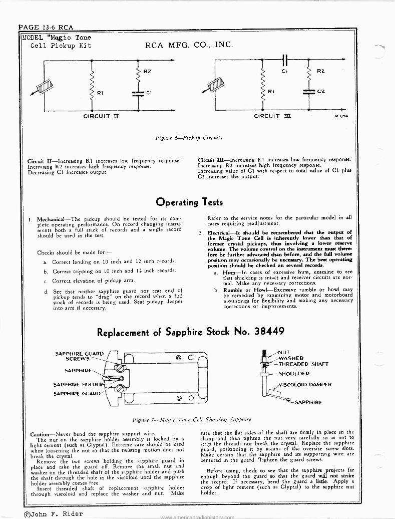
PAGE 13-6 RCA
MODEL "Magic Tone Cell Pickup Kit RCA MFG. CO., INC.
001' R1
CIRCUIT II
R2
TCI
Figure 6 --Pickup Circuits
Circuit II-Increasing R1 increases low frequency response. Increasing R2 increases high frequency response. Decreasing Cl increases output.
1.
R1 C2
T CIRCUIT III R-674
Circuit III-Increasing R1 increases low frequency response. Increasing R2 increases high frequency response. Increasing value of Cl with respect to total value of Cl plus C2 increases the output.
Operating Tests
Mechanical-The pickup should be tested for its corn- plete operating performance. On record changing instru- ments both a full stack of records and a single record should be used in the test.
Checks should be made for:- a. Correct landing on 10 inch and 12 inch records.
b. Correct tripping on 10 inch and 12 inch records.
c. Correct elevation of pickup arm.
d. See that neither sapphire guard nor rear end of pickup tends to "drag" on the record when a full stock of records is being used. Seat pickup deeper into arm if necessary.
Refer to the service notes for the particular model in all cases requiring readjustment.
2. Electrical-It should be remembered that the output of the Magic Tone Cell is inherently lower than that of former crystal pickups, thus involving a lower reserve volume. The volume control on the instrument must there- fore be further advanced than before, and the full volume position may occasionally be necessary. The best operating position should be checked on several records.
a. Hum-In cases of excessive hum, examine to see that shielding is intact and receiver circuits are nor, mal. Make any necessary corrections.
b. Rumble or Howl-Excessive rumble or howl may be remedied by examining motor and motorboard mountings for flexibility and making any necessary corrections or improvements.
Replacement of Sapphire Stock No. 38449
SAPPHIRE GUARD SCREWS
SAPPHIRE
SAPPHIRE HOLDER
SAPPHIRE GUARD
Figure 7-Magic Tone Cell Showring Sapphire
Caution-Never bend the sapphire support wire. The nut on the sapphire holder assembly is locked by a
light cement (such as Glyptal). Extreme care should be used when loosening the nut so that the twisting motion does not break the crystal.
Remove the two screws holding the sapphire guard in place and take the guard off. Remove the small nut and washer on the threaded shaft of the sapphire holder and push the shaft through the hole in the viscoloid until the sapphire holder assembly comes free.
Insert threaded shaft of replacement sapphire holder through viscoloid and replace the washer and nut. Make
NUT WASHER THREADED SHAFT
SHOULDER
I ale VISCOLOID DAMPER
SAPPHIRE
sure that the flat sides of the shaft are firmly in place in the clamp and then tighten the nut very carefully so as not to strip the threads nor break the crystal. Replace the sapphire guard, positioning it by means of the oversize screw slots. Make certain that the sapphire and its supporting wire are centered in the guard. Tighten the guard screws.
Before using, check to see that the sapphire projects far enough beyond the guard so that the guard will not strike the record. If necessary, bend the guard a little. Apply a
drop of light cement (such as Glyptal) to the sapphire nut holder.
g5John F. Rider www.americanradiohistory.com

RCA PAGE 13-7
(D)
TO ANTENNA
INSULATOR
ANTENNA TRANSFORMER
TRANSMISSION LINE
RECEIVER TRANSF. STOCK 12424
F E
ANT. GND.
RP -158, RP -160
F E
COIL
RCA MFG. CO., INC.
SPIDER -WEB ANTENNA STOCK Nº9689 APPROX. 37 FT.
TRANSMISSION LINE
P D
MODEL "Spider -Web" Antenna.
NOTES,CHANGES
DOTTED SECTION SHOWS POSITION OF ULTRA SHORT-WAVE
ANTENNA - MADE UP OF AUXILIARY KIT - STOCK NO. 9689
SCHEMATIC DIAGRAM OF RECEIVER TRANSFORMER STOCK 12424
ANT. ' 1 D
INSULATOR
C
COIL N
SCHEMATIC DIAGRAM OF ANTENNA TRANSFORMER
THE EFFECTIVE RANGE OF ANTENNA 15 FROM 140 TO 23,000 KC (4 BANDS) THE ULTRA HIGH FREQUENCY BAND
(23 TO 70 MC) MAY BE COVERED BY THE ADDITION OF AUXILIARY KIT STOCK NO. 9689
Tone Arm Stop Bracket:
On 2nd production RP -158 and RP -160, a stop bracket has been added to the top of the motorboard to restrain the tone arm. It is mounted by means of the same screw, lock - washer, and nut used to mount the pickup shorting switch. Where difficulty is experi- enced with excessive movement of the tone arm on 1st production mechanisms, this bracket may be added as shown. The bracket is Stock No. 39832. RP -158, -160
To Repeat One Record:
When checking RP -158 and -160 record changers for landing and tripping action, it is possible to play one record repeatedly by simply placing a weight on the rear record post. A small pipe nipple that fits over the top of the post is satisfactory.
SHORTING SW MOUNTING \ SCREWS
BRACKET II --158 -
AUTOMATIC STOP SW.
NtP d
Tone -arm stop bracket (No. 39832) position on RP -158, -160.
RUBBER BAND
APPROX .2%y
FOR 10" RECORDS PLACE RUBBER BAND
ACROSS FRAME AT POSITION OF BOTTOM SCREW
BOTTOM VIEW OF BELT GUIDE SCREW PLACE RUBBER BAND IN POSITION SHOWN.
FOR 12- RECORDS
RP -151 RECORD CHANGER
To Play One Record Continuously:
It is possible to play one record cqntinuously on the,RP-151 by stretching a 3h -in. or 4 -in. rubber band across the mechanism, as shown, to prevent the record dropping through the motorboard.
The continuous playing of a record in this manner is handy when the record changer is being serviced, especially after the separator knives have been checked and tested, and it is desired to allow the changer to run on the shop bench without attention.
Revised reject button and lever in RP -158, -162.
LINE
180 MMF.
ELECTROSTATIC SHIELD
V \ ANT. GND.
TO RECEIVER TERMINALS
RP -158, RP -162
Change in Reject Lever and Button:
2nd production of RP -158 and RP -162 auto- matic record changers have a reject lever ar- rangement as shown in accompanying sketch.
List Stock No. Description Price
39755 39756 39757
Button-Reject button .15 Lever-Reject lever and stud .25 Lever-Reject button right
angle lever .10
REJECT BUTTON STK NO. 39755
MOTOR BOARD
STK NO. 39757 STK NO. 39756
RP -160
Tone Arm Return Lever Spring:
The tone arm return lever spring Stock No. 39599. The correct 39038. V-215, V-221
REJECT LEVER
is listed as number is
Speaker RL -70N-6: On 2nd Production of V-215 and V-221,
the speaker is changed from RL -70M-2 to RL -.70N-6. The replacement parts are identical. A rubber band stretched across the motor - board as shown permits continuous play-
ing of one record on RP -151 record changer during service checking
of the mechanism.
©John F. Rider
www.americanradiohistory.com

PAGE 13-8 RCA CHANGES NOTES ,DATA
"KNOCKED -DOWN" VOICE
COIL AND CONE Installation Instructions:
To simplify cone replacement in certain speakers, the cone and voice coil are supplied as two separate units : (1) The voice coil and support, (2) The cone diaphragm.
General Procedure (a) Cement voice -coil support to the speaker
using centering gauge or speaker shims. (b) Solder voice -coil leads. (c) Put cone in place, cementing around rim
of speaker frame. (d) Cement junction of cone and voice coil.
Detailed Instructions (a) Remove old cone and voice coil. Protect
air gap with scotch tape. Clean off all paper and cement.
(b) Apply a ring of cement (Duco Household) on top plate.
(c) ,Insert centering gauge in new voice coil, handle first, from the winding end.
(d) Remove scotch tape from gap. Insert voice coil and gauge in gap with leads in cor- rect position for soldering. Press rim of voice coil support into the cement.
ABSORPTION WAVE TRAP For Loop Receivers:
Interference and cross modulation due to the presence of a strong local broadcast station is seldom experienced on loop -type receivers be- cause the signal pickup is much less on a loop
'than on an antenna. - However in rare cases where such interference is encountered, it can generally be eliminated by using an absorption -type wave trap, loosely coupled to the loop on the receiver, as shown in accompanying sketch, and tuned to the fre- quency of the interfering station.
A good absorption trap can be matte with a small loop like that used in Model BP -10 "Personal" radio. Fasten a two -section mica trimmer (salvaged from a discarded IF trans- former) on the small loop. Connect the trim- mer across the terminals of the small loop. Use one trimmer, or both in parallel, depending on whether the interfering station is at the high or low end of the broadcast band.
Tune the receiver to the frequency of the interfering station, place the trap near the re- ceiver loop, and adjust the trap trimmer(s) to resonance, indicated by a sharp dip in signal strength. Use smaller or larger capacity trim- mers if required to reach resonance.
Check to see if the particular interference effects have been eliminated. Adjust the posi- tion of the trap to secure closer coupling if necessary to further increase signal absorption. Avoid over coupling. Fasten the trap in the desired position on the receiver loop.
BP -10 LOOP USED AS ABSORPTION WAVE TRAP
On a loop receiver, interference front a strong local broadcast station can be reduced by using an absorption loop,
tuned to the interfering station, and loosely coupled to the
receiver loop.
RCA MFG. CO., INC. (e) Solder the voice coil leads to terminals,
allowing sufficient slack to permit free mo- tion of the cone. Dress leads in plane of motion, clear of cone and housing.
(f) Apply a ring of cement around the rim of speaker frame. Place cone down over voice coil and press cone rim tight to speaker frame.
®i ..
'-DUST CAP
itk a
\ / SCONE VOICE COIL
LEADS VOICE COIL SUPPORT
VOICE COIL
Certain replacement cones are supplied "knocked -down" in two pieces-(1) The
voice coil and centering support. (2) The cone diaphragm.
VOICE COIL IMPEDANCE And DC Resistance:
In servicing RCA radio loudspeakers, it is helpful to know that the DC resistance of the voice coil is approximately 10 percent less than the impedance at 400 cycles.
For example, a speaker with a rated voice - coil impedance of 2.2 ohms at 400 cycles will measure about 2 ohms DC resistance.
Radio storage battery can be charged on a DC farm -lighting outfit.
BATTERY COMPLEMENT
(g) Allow cement to dry on cone rim and voice - coil support. Then run a ring of cement around the junction of the cone and voice coil, being careful the cement does not run inside voice coil.
(h) After cement at junction has dried, remove gauge, using a rotary motion.
(i) Cement large cardboard gasket in place. Set the speaker in inverted position on a flat surface until gasket is dry. Cement dust cap on cone center.
CENTERING GAUGE 35301
CONE GASMET\
HOUSING RIM
C S WICH SPEAKER FRAME COIL SUPPORT * r 'CONE TOP POLE PLATE -
VOICE COIL CONE E. VOICE COIL
JUNCTION
When installing "knocked -down" speaker cone, the junction of the cone and the
voice coil is cemented last.
RECHARGING 6V BATTERY On 12V or 32V DC Supply:
A 12 -volt or 32 -volt DC farm -lighting supply can be used to recharge a 6 -volt radio storage battery. The recommended circuit is shown herewith. The charging rate may be increased or decreased by using a higher or lower wattage lamp
GO WATT 12 OR32v. LAMP D.P. D.T.
SWITCH
G VOLT BATTERY
(MEDIUM DUTY)
-- 12 V. OR 32 V. DC SUPPLY LINE
o- + TO RECEIVER
For RCA Portable Models
MODEL BATTERIES EVEREADY No. BP -10 (RC -544) 1 1.5 volt "A"
1 67.5 volt "B" No. 950 No. 467
15BP Series (RC -527, 527-A)
1 1.5 volt "A" 2 45 volt "B"
No. 743 No. 482
25BP (RC -527-D, 1020) 1 1.5 volt "A" 2 45 volt "B"
No. 743 No. 482
26BP (RC -559) 2 4.5 volt "A" 2 45 volt "B"
No. 746 No. 482
BP -55, -56, -85 (RC -455)
1 6 volt "A" .2 45 volt "B" No. 747
No. 482 94BP (RC -407) 1 1.5 volt "A"
2 45 volt "B" No. 742 No. 762
94BP (RC -407-B)
1 1.5 volt "A" 2 45 volt "B" No. 742
No. 762 1 1.5 volt "A" 2 45 volt "B" No. 745
No. 482 or 727 1 1.5 volt "A" 2 45 volt "B" No, 741, 742, 743
No. 482 or 727 94BP-4 (RC -410) 1 1.5 volt "A"
2 45 volt "B" No. 742 No. 782
* Or equivalent.
©John F. Rider
www.americanradiohistory.com

RCA PAGE 13-9
CfiANGES
IIT V. 60H.
RCA SCHEMATICS
Switch Positions:
Practically all of the larger RCA receivers have decals on the cabinet (or other means) to indicate the function of each position on the more complicated switches. In cases where only the chassis is brought in for service, the corresponding information about controls is given in a knob drawing printed in the Service Note.
For example, the accompanying schematic shows the radio-phono-tcne control switch cir- cuit in Model V-135, drawn as usual in the extreme counter -clockwise position. The knob view shows the function of each position:
(1) "Off" (counter -clockwise).
(2) Radio-mellow tone.
(3) Radio-full tone.
(4) Phono-mellow tone.
(5) Phono-full tone (clockwise).
As a general rule, on RCA receivers clock- wise rotation of a control produces an increase. Thus on a range switch, the lowest -frequency hand is counter -clockwise, and the highest -fre- quency band is clockwise. On tone controls, the narrowest audio range or deepest tone is counter -clockwise. The widest audio range or highest tone is clockwise.
2
(RtAR)
RADIO- PH ON O Swl T¢ N
OFF met -Low
PHONO RADIO
RADIO- PHONO SW. VIEWED FROM FRONT AND SHOWN IN OFF (Mn%IMUM COUNTER- CLOCKWISE) POSITION.
In RCA Service Note schematics, wafer switches are shown in extreme counter- clockwise position, and the drawing of
control knobs gives sequence and function of switch positions.
Installing No. 38204 Antenna Loop in BP -10 Where Loop is Held with Snap Fasteners.:
A. Remove the defective loop and its flat molded cover by prying out the two snap fasteners.
B. Spread white paint or ink on the surface of the two bosses ,,in lid.
C. Place the new loop and cover in correct po- sition inside the lid and press down so the paint will transfer on to the loop cover.
D. Drill holes (.242 -inch, No. C drill) in the flat loop cover at the exact center of each paint mark.. Countersink each hole (ap- proximately 3/64 -inch) on loop side, so that the flat cover will set flush with the top of the bosses.
E. Fasten the loop and cover to the lid with the two snap fasteners supplied.
Installing No. 38204 Antenna Loop in BP -10 Where Loop is Riveted in.Lid: A. Drill the riveted ends of the rivets, and
knock the rivets out, being careful not to damage the molded lid. Remove the defec- tive loop and its flat molded cover.
B. Place the new loop and cover in correct position inside the lid. Use the two rivet holes in the lid as a guide to drill corre- sponding holes in the loop cover.
C. Fasten the loop assembly to the lid with the two rivets supplied.
RCA MFG. CO., INC.
BEST LOOP PICKUP DUMMY TERMINAL
NOTES, DATA
In Corner of Window: On Replacement Volume Controls:
In a metal -framed structure, such as a car, On certain replacement volume controls, the train, plane, or steel building, best signal location of the "dummy" terminal is changed pickup is usually obtained by placing the loopas shown in accompanying sketch. in one corner of the window instead of in the center. The center of the glass space is usually
ORIGINAL LOCATION a null for signal. This fact should be kept in mind when using the extension loop on a port- OF DUMMY TERM. able radio, as there is a natural tendency to fasten the loop in the center of the window.
WINDOW IN METAL- FRAMI: si R(.ICTURE
LEAST SIGNAL PICKUP IN Cr NTLR
BEST SIGNAL PICKUP IN - CÖRNER
LOOP
NEW.- LOCATION OF DUMMY TERMINAL. (HAS COPPER RIVET)
For best signal pickup, the extension loop - Change in location of dummy terminal on
on a portable set should be placed certain replacement volume controls. in corner of window.
ELECTROLYTIC CAPACITORS QU7, QU-51, -52, -55, -56
Terminal Identification: Tone Arm Pressure Spring: When replacing the tone arm, or the mag - On certain types of multiple -section electro -nette pickup head, check the needle pressure lytics, the terminals are identified by small which should be approximately 3 ouhces. markings (triangle, half -round, or square). The Alter the counter -balance spring in arm to ob - marks are either cut-outs or mouldings in the tain the correct pressure, or install a new base. Corresponding marks are shown adjacent spring.. Two springs (65 turns and 75 turns) te the electrolytic symbols in the schematic are supplied under Stock No. 38213. Use the diagrams. spring that most nearly gives the correct pres-
sure and then remove turns, or stretch the spring, as required, for final adjustment. FIELD
BP -10 In some electrolytic capaci ors, the termi-Loop and Moulded Lid: nals are identified by half -round, trian-
gular, and square markings. Corre- sponding marks are shown adja-
cent to the symbols in the schematic.
Installing Stk. No. 38211 Molded Lid in BP -10 Where Loop is Riveted in Lid: A. Snip the two hinge pins and pull the pins
out of the hinges, to permit removal of the defective lid.
B. Drill the riveted end of the rivets and knock them out, being careful not to damage the flat loop cover. Remove the loop and its cover from the lid.
C. Spread white paint or ink on the surface of the two bosses in the Stock No. 38211 lid.
D. Place the original loop with its flat cover - in correct position inside the Stock No.
38211 lid and press down so the paint will transfer to the loop cover.
E. Drill holes (.242 inch, No. C drill) in the flat loop cover at the exact center of each paint mark. Countersink each hole (ap- proximately 3/64 -inch) on loop side, so that the flat loop cover will set flush with the top of the bosses.
F. Fasten the loop and cover to the No. 38211 lid with the two snap fasteners supplied.
G. Assemble the lid and loop to the chrome panel, using the hinge pins and springs fur- nished with No. 38211 lid.
Stock No. 38204 antenna loop with un - drilled flat molded cover, and/or Stock No. 38211 molded lid with bosses for snap fasten- ers, can be used in any Model BP -10 where the antenna loop is secured in place with rivets, or with snap fasteners.
6X2, 24BT-1, -2 Loose Dial Pointer:
Expansion and contraction due to tempera- ture changes may cause the metal dial pointer to become loose on the moulded button shaft.
This condition has been corrected in produc- tion by fastening the pointer with "Du Pont "Iousehold Cement" as shown.
C CEMENT POINTER TO MOULDED SHAFT
Loose dial pointer can be repaired with Du Pont Household Cement.
©John F. Rider
www.americanradiohistory.com

PAGE 13-10 RCA CHANGES NOTES,DATA
Q16E (RC -561-C) Service Data:
Model Q16E is similar to Model Q16, ex- cept that it has an EM speaker, as shown in accompanying sketch, and the following parts are different :
Unit List
Stock No. Description Price 12896 Capacitor -15 mmfd., moulded
mica $ .35 33806 Capacitor -.0015 mfd. .25 32342 Capacitor -Electrolytic, com-
prising 2 sections of 10 mfd 450 volts each 1.20
38409 Control -Tone control 1.00 34761 Resistor -10 ohms, } watt .20 30492 Resistor -22,000 ohms, }
watt .20 30652 Resistor -1 meg., } watt .20 30649 Resistor -2.2 meg., } watt .20 32911 Transformer -Power trans-
former -105-120 volts, 50- 60 cycle 4.10
32852 Transformer -Power trans- former -110-220 volts, 50- 60 cycle 4.50
2917 Washer -"C" washer to hold tuning shaft .03
SPEAKER ASSEMBLIES (RL -79C-1)
31825 Cap -Dust cap 32903 Coil -Field coil -1,800 ohms 38392 Cone -Cone complete with
voice coil 5118 Plug -3 -prong male plug for
speaker 32905 Transformer -Output trans-
former
Note. -If the stamping on speaker in instrument does not agree with above speaker number, order replacement parts by referring to model number of instrument, num- ber stamped on speaker, and full description of part re- quired.
6FG G OUTPUT
C 2S .0015
To RECT. FILAMENT SY3 G
RIS
FIELD
C 29 10
MFD,
T2
trni C 30 lo MFD.
V. C.
.02 1.25
1.25
.25
1.35
Z=. E. M.
SPEAKER
G16 -!M.
Speaker connections in Model Q16E (RC -561-C).
26BP
Alignment: The RF, detector, and oscillator adjustments
in Model 26BP are easily accessible when the chassis is mounted in the cabinet. Consequently the regular dial may be used for reference dur- ing alignment. In the event that only the chassis is brought in for service, the accom- panying full-size dial reproduction can be used as a substitute for the regular dial.
RCA MFG. CO., INC.
Q12 Correction in Service Data:
The RL -86A-3 speaker is incorrectly listed as a PM type. This should be listed as an EM speaker with 450 -ohm field coil.
16X4 RF Plate Load Resistor:
In some ptoduction, the load resistor in the plate circuit of the RF tube is changed from 3,900 to 2,200 ohms.
12SQ7 2 ND. DET. AF -AVC
QU56C, QU56M Instability:
Development of appreciable RF impedance in the electrolytic filter capacitor creates com- mon coupling and may cause IF oscillation. To eliminate this possibility, an RC filter is connected in the +B lead of the 1st -detector plate circuit, as shown in accompanyng sketch.
SA7 IST. DET. OSC.
AOD .05 MFD. Z
t,tU sec .M
IST. I.F. TRANS
F LI
ADD 100011
iB
In Q56 -C, -M, an RC filter 'is added the 1st -detector plate circuit.
28X5 Insufficient Push -Button Range:
In Model .28X5 if the push -buttons have in- sufficient range, realign IF at exactly 455 kc. If this does not correct the trouble, replace the main' oscillator coil Stock No. 38685 and re- align the set. The correct coil has no number stamping; do not use coil stomped 95106-501. Q44 .05 Mfd. Capacitor:
Change Stock No. 32787 to. No. 4886.
QU51C, QU51M, QU55 Voice -Coil Impedance:
The voice.çoil imp ance of the RL -70N-1, RL -70N-3, and RL- 1A-4 is incorrectly listed as 15 ohms in the Service Data. The correct impedance is 2.2 ohms at 400 cycles.
STOCK Nó. 160 CRO Vertical "Bounce":
The 160 'oscillograph has extremely good lowfrequency response, passing a 4 -cycle square wave with good fidelity. It is possible to encounter instances in which a line -voltage meter, due to its inertia will indicate little or no v-ariatjtyt of voltage, whereas the oscillo - graph will exhibit noticeable vertical "bounce" due to line -voltage fluctuations.
If a cústomer desires to retain the normal lowfraquency response of the 160 and has a power lite which varies in voltage appreciably, it is necessary to provide voltage regulation, such as TMV-173 voltage regulator. How- ever, if the extreme response of the 160 is superfluous for the particular application in mind it can readily be reduced, affording a re- duction of the "bounce" to an unobjectionable value. This is accomplished by removing the present coupling condenser, C-20, and substi- tuting a 0.05 mfd. 400 -volt condenser. The re- sponse is then down a few percent with a 15. - cycle sine. wave input.
(The 160B incorporates filtering circuits to eliminate vertical "bounce.")
For applications in which it is desired to con- nect directly '12. the cathode ray tube deflecting plates, such the observation of a modulated RF envelope 'from a transmitter, it is possible to completely eliminate the vertical "bounce" by merely disconnecting either side of the coup- ling capacitor, C-23.
OUTPUT TUBE
R ECT. TUBE +kj
FIELD COIL
TAPE
in 50 MFD. 1 MFD.
V105 l
When Model Q17 is used on 110 -volt DC supply, the 1st -audio grid circuit should
be changed as shown above to prevent distortion due to incorrect bias.
Q17
Distortion on
OI1T PU r- TKANS
HUM BUCNINC, COIL
V.C.
CONNECTIONS FOR ELECTRO- MAGNET SPEAK ER
Connections for RL -86A-3 EM speaker in. Model V-105.
V-105 Using EM Speaker Replacement:
RL -86A-3 "EM" speaker can be used as a replacement for RL -81B-4 PM speaker in Model V-105 by wiring in the field coil and output transformer as shown in accompanying diagram. The original output transformer can be used by taping up the black (tap) lead.
110-V DC () elation: In this particular model, it is necessary to P solder a jumper across contacts 8 and 9 on
Distortion at all volume levels when Model the front section óf the radio -phono switch. Q17 is operated on 110 -volt DC supply is
This keeps the 1st -detector and IF tubes in operation when the switch is in "phono" posi - caused by incorrect bias on the 12SQ7 con- fion, and thus maintains sufficient current trol grid. This condition can be eliminated by through the field coil for adequate excitation. changing to the circuit shown in accompany- The customer should be instructed to tune ing sketch. the set to a quiet point on the dial to prevent radio break -through on phono.
©John F. Rider www.americanradiohistory.com

RCA PAGE 13-11
RCA MFG. CO.. INC.
55607080100120140160 Model 26BP full-size dial reproduction.
This can be used for reference during alignment.
CV -112, CV -112X Electrolytic Capacitor:
These AC power units are described in "Sup- plementary- Information No. 4 and No. 5." The Stock Number of the electrolytic capacitor should be changed front No. 30873 to No. 398.46.
STOCK No. 154 BFO
Alignment: The instruction book for Stock No. 154 beat -
frequency oscillator specifies 350 kc for the fixed oscillator frequency. In some production, a frequency of approximately 343 kc is used in order to secure correct dial calibration.
Also, in figure 11 of this instruction book, the trimmer numbers C10 and C3 are reversed They are shown correctly in figure 9.
158 AND 160-B CRO Filter Circuit Change:
In some 1st Production of Stock No. 158 and 160-B cathode ray oscillographs, numbered in the 2,000 series, the .1 mid 1st -filter capa- citor may short due to starting-voltaagge surge. To prevent recurrence, replace the 21',D00 ohm input filter resistor (R38 in 158, R33 in 160) with a 120,000 ohm 1 watt resistor, Stock No. 13483. This change should be made when the shorted .1 mfd capacitor is replaced.
167, 167A TEST OSCILLATOR Dead Spots on HF $and:
Dead spots or failure to oscillate on the high -frequency band in the Stock No. 167 or 167A test oscillator may be corrected by in- serting a 47 -ohm i -watt resistor, and making slight changes as shown in accompanying sketch.
COIL LS L.E. o-
A70 47A r, RE 5.
BLASE
r I .,REMOVE BUS
AOD tJ4 bus 1 GROUND 70 CHASS'S
DIRECTLY BELOW. J COIL.
EMOva BRAID LEAD
Change in Stock No. 167, 167A test oscil- lator to eliminate dead spots, or failure
to oscillate, on HF band.
MODEL vs "RP" NUMBERS The automatic record changer mechanism in
certain models is designated by an "RP" num- ber, as follows:
RCA Model "RP" N umber N umber
13U5 RP -145E VA -15 RP -152 U-40 RP -139A, 145 U-42 RP -139A, 145 U-43 RP -139A, 145 U-44 RP -139A, 145 U-45 RP -139A, 145 QU51-C RP -145E QU51-M . RP -152R QU52-C RP -152S QU52-M RP -152R V-135 RP -162,,
CONVERSION KIT No. 9889 For Television Alignment Oscillator:
This kit is used to convert No. 159 oscillator to include 59-67 mc in place of 43-51 me.
Parts supplied in this kit consist of: 1 es- cutcheon ; 1 coil complete with core and bracket; 1 switch contact; and necessary screws, nuts, and washers for mounting.
Revision procedure is as follows: (a) Cut lead from Cl to SIA. (b) Cut lead from L1 to SIB. (c) Cut lead between old 44-50 mc and 50-5E
me taps on SIA. (d) Mount extra contact on S1A preceding old
44-50 mc position. (e) Connect extra contact lead to Ll. (f) Drill and tap 6-32 hole in center of sweep
condenser' stator bar nearest front panel. (g) Mount new 59-67 mc coil L9. (h) Connect lower L9 lead (nearest bracket
end) to common coil bus hear L5. (i) Connect tap L9 lead to former Ll switch
contact on SIB. (j) Connect Cl to former 44-50 mc contact
on S1A. (k) Mount escutcheon.
Make the following changes to the instruc- tion book IB-32011:
Page 8-Delete adjustment No. 5. Add adjustment 6A, symbol L9, description 60-66 mc band tuning: set the center of the sweep range to 63 mc.
Page 14-Change schematic as shown, in ac- companying sketch.
CI 17- 36 MMF.
49-57 MC.e< 59-67 MC.o
T68 J 65-73 MC. MMF. 77-85 MC. o
83-91 MC. o
o<
o S1A
L1 L9 L2 L3 L4
To accommodate deletion of the original No. 1 channel (44-50 mc), and addition of the new No. 2 channel (60-66 mc), kit No. 9889 is available to convert
Stock No. 159 television alignment oscillator.
RCA VICTROLA
MECHANISM DATA V-170 - RP -152 V-175 RP -158 V-200 RP -152A V-201 RP -152A VHR-202 RP -155 'V-205 RP -152B V -205A . RP -153 VHR-207 RP -155 V-209 RP -158 V-210 RP -158 V-215 RP -160 V-219 RP -160A V-221 RP -160B V-225 RP -151 V-300 RP -152J V-301 RP -153 V-302 RP -153 V HR -307 RP -155 V-405 RP -152J VHR407 RP -155
CHANGES NOTES, DATA
"RP" vs STOCK NUMBERS In service data for radio -phono combinations,
the automatic record changer mechanism is usually described in a separate service note. In such cases, the mechanism is identified by an "RP" number. Certain of these mechanisms are also marketed under RCA "Stock Num- bers." Corresponding "RP" and Stock Num- bers' are listed below. For service data on any given Stock Number of mechanism, refer to the corresponding "RP" service note.
RP No. Stock No. RP -139B 9865 RP -139C 9865 RP -145A 9865A RP -151 9933 RP -152C 9909 RP -152M 9909D RP -155A 9910 RP -158 9930 RP -160 9931 .RP -162 9932
CABINET MUST BE LEVEL
For Correct Landing and Feed -in: V-215 and V-221 "roll -out" record changers
are designed to operate WHEN THE CABI- NET IS LEVEL. The changer is automati- cally tilted forward 3 degrees when in the cabi- net. Always make landing and feed -in adjust- ments under these conditions.
In V-215 and -221, an adjustment is located on each of the rear legs to permit fore-and-aft leveling. If the changer does not roll out cor- rectly when the cabinet is level, inspect the rubber -tired rollers and the guides.
V-219, -226, and all other models in which the changer is fastened in cabinet, are designed to operate WHEN THE CHANGER AND CABINET ARE LEVEL. Always make land- ing and feed -in adjustments under these con- ditions.
12'
t h-71 MiMlllpl O
y' 2C o sió-ut." THREAD THREAD 5/16 STOCK
4-REß'D
%4-20 OR Siïb 18 tels 4CAP
12.
III
STD. ' PIPE
-
y4 - 20 OR RUBBER CAP 5416-18 BOLT 4 UNITS READ
Legs can be used to support a record changer in level position at a convenient
height above work table. The legs can be made from threaded rod,
or from pipe fittings, as shown above.
NEW SW. STOCK NO. 38995
ORIGIN4L SW. STOCK NO. 36529
Original and new motor switch for auto- matic shut-off in manual operation
on RP -152D and RP -153.
©John F. Rider www.americanradiohistory.com

PAGE 13-12 RCA
CHANGES 1JOTES, DATA
HOLDER FOR RECORD CHANGER
Essential in Servicing: In servicing an automatic record changer, it,
is essential to have some kind of a holder or stand to support the mechanism in a level posi- tion at a convenient height above the work table to permit easy access to all parts under the motorboard.
Adjustable stands can be purchased, or as- sembled from pipe fittings as shown in the accompanying sketch.
The simplest and cheapest type of holder is made by using legs that screw into the motor - board -mounting -screw sockets. Such legs can be made from pipe fittings or from threaded rods as shown in the sketches. One end of each leg has a i-20 thread to accommodate most RCA changers, and the other end has a 5/16-18 thread to accommodate the RP -151 mechanism.
SIDE VIEW
RCA MFG. CO., INC.
DO NOT TOUCH THIS TONE ARM I
when playing either one or more records automatically, to avoid possibility of dis- turbing Automatic Adjustment. Just Push a Button-There's Your Record Program.
Iii The following parts are required for the
record -changer holder shown above. These parts can be obtained in hardware or plumbing shops. Drawing Number Description Quantity
1 -in. ell 2 lei-Qi ,Ili 2 t -in, all -thread nipple....2 ¡Ili: 3 t -in, gas -pipe locknut....2 4 -in. x 15 -ink pipe 2 5
6
t -in. 4 -way ell on side out- let tee 2
1 -in. x 14 -in. pipe 1 7 (optional) t -in. x 3 -in. reducer 1 8 t -in. x 15 -in. pipe 1
V 9-10. 4 -in. to t -in. bushing ....I 11 (optional) t -in. std. nut and 5/16 -in.
std. nut 2 each 12 t -in. x 1t -in. std. and
5/16 -in. x t -in, std. bolt 2 each
13 1 -in. awning eyelet 2 14 I -in. pipe cap 4
An adjustable holder for automatic record changer mechanisms can be made from
pipe fittings as shown above.
RP -152D, -153, QU7 Automatic Motor Switch:
Some models of RCA automatic record changers incorporate a switch that acts to shut off the motor when the pickup needle is 13 inches from the spindle, and also when the pickup is moved out to its rest position.
The original switch, Stock No. 36529, is superseded by an improved switch, Stock No. 38995. When installing- the new switch, re- move the angle bracket that is used between the motor board and the original switch.
VHR.-202, -207, -307, -407 Crystal Pickup is No. 37158
In the Service Data for these home -recording models, the pickup cartridge is incorrectly listed as No. 33905. The correct Stock Number is 37158. This correction should also be noted in the tabulation on page 5 of "Supplementary Information No. 5."
The label reproduced above is fastened to the record changer in Models V-215, -219, -221, and -225.
These mechanisms are designed for com- pletely automatic operation on a stack of rec- ords or on a single record.
Customers sñoutd be instructed to use the START -REJECT button and not to handle the tone arm.
Note: If item 13 is not obtainable, change item 2 to 2I -in. nipples, and drill 5/16 -in. holes close to one end to accommodate the motor- z_ board mounting bolts.
TRIP LEVER
SP RIN
TRIP 7PAWL
PIN REMOVED
Original trip lever with corner cut off to prevent lever striking the ratchet.
STEEL SPRING e399G1 HOLE ADDED QINI into
il
TRIP TAB 'PIN LEVER REMOVED REMOVED
TRIP PAWL
Trip lever with new steel spring. This steel spring can be installed on original
lever in place of bronze spring by drilling a 3/32 inch hole and
cutting off the tab on original lever.
r- _-- rIDLER
RP -151, -158, -160, -162 Trip Lever and Trip Pawl Spring:
The original bronze trip -pawl spring, Stock No. 38362, is no longer available. When this spring requires replacement, due to loss or irreparable damage, it is necessary to install either a new steel spring, Stock No. 39961, in accordance with instructions given below, or else install a complete new trip lever assembly which employs the steel spring.
In RP -151, the new trip lever, trip pawl, and steel spring assembly is Stock No. 38561
In RP -158, -160, and -162, the new trip lever, trip pawl, and steel spring assembly is Stock No. 38632.
The new lever and spring assemblies will be supplied on orders for the original assemblies.
Installing Steel Spring No. 39961 on Trip Lever: 1. Drill a 3/32 -inch hole in lever as shown. 2. Cut off the tab that was used to anchor the
original bronze spring. 3. Install steel spring as shown.
TRIP LEVER PIN Original trip lever assembly with Bronze
spring.
MOTOR SPINDLE
OTOR
SPRING FLUSH W END OF SPINDLE ( MOUNT TURNS
TIGHT TOGETHER;
Spring sleeve installed on 60 -cycle motor -nindle for operation on 50 -cycle supply.
REVISED RATCHET LEVER
In RP -158, -160, and -162, continuous trip- ping can be- caused by failure of the ratchet lever to bldck the drive cam pawl at comple- tion of a change cycle.
This has been corrected by doubling the thickness of the end of the ratchet lever so that it presents a broader face to the edge of the drive cam pawl. The lever with double thick- ness is carried under the same Stock Number (38656) as the original lever, which it super- sedes.
ORIGINAL RATCHET
vEcR
TRIP PAW LContinuous tripping in RP -158, -160, and
-162 can be caused by failure of the rochet lever to block thé drive cam pawl. The replacement lever has double thickness at end to pre-
sent a broader face to the drive cam pawl.
DRIVE CAM PAWL
REVISED RATCHET LEVER
DRIVE CAM PAW L
©John F. Rider www.americanradiohistory.com

RCA PAGE 13-13
RP -151, -158, -160, -162 Crystals and Sapphires:
The following Stock Numbers for crystal - and -sapphire assemblies supersede all previous listings:
RCA MFG. CO., INC.
Zinc -cased crystals have letters "ZN" cast in the metal.
Use only zinc -cased crystal No. 39550 for RP -160. This can not be used in RP -151.
Do not replace complete pickup where sap- phire only requires replacement.
RP Used in Models Stock No. of Sapphire and Holder, less nut- Stock No. of Crystal and
Sapphire Assembly - 151 V-225 38449 Top, 39919 (Alum. case)
Bottom, 38598 (Alum. case) 158 V-175, V-209, V-210 39564 38610 160 V -2I5, V-219, V-221 38449 39550 (Zinc case)
162 V-135 39564 38610
RP -160 Sapphire Pressure:
The correct sapphire pressure in RP -160 is approximately 13 ounces. The pressure is governed by a spring inside the end of the pickup arm. Owing to the fact that' both aluminum and zinc castings (with difference in weight) have been used for the arm and the crystyj, and also that only the zinc crystal (Stock No. 39550) is supplied for replacement,
it is necessary to check the sapphire pressure whenever either the crystal or the arm is re- placed.
The zinc arm is identified by the letters "ZN" after the drawing number inside the arm.
The zinc crystal is identified by the letters "ZN" moulded at the rear end of the cartridge.
The various combinations arc tabulated be- low, along with the Stock, Numbers of pivot arms and springs involved.
ARM AND CRYSTAL COMBINATIONS CORRECT ARM AND SPRING
Aluminum arm Stock 38650 Aluminum crystal Stock 38453
Picot arm Stock 38603 Pivot arm spring Stock 30585
Aluminum arm Stock 38650 Zinc crystal Stock 39550
Pivot arm Stock 38603 Pivot arm spring Stock 30585
Zinc arm Stock 39671 Zinc crystal Stock 39550
Pivot arm Stock 39672 Rivet for arm and spring Stock 39674 Pivot arm spring Stock 39754
Zinc arm Stock 39671 Aluminum crystal Stock 38453
J
)}
Pivot arm Stock 39672 Rivet for arm and spring Stock 39674 Pivot arm spring Stock 39673
60 TO 50 CYCLE CONVERSION For Rim -Drive Phono Motors:
(These instructions supersede all 'past issues, covering the use of shrunk sleeves.)
A spring sleeve is used to increase the di- ameter of the motor drive spindle, to compen- sate for the slower speed of the motor when used on a 50 cycle line.
Spring sleeves are available for the following
models which comprise most of the motors using spindle drive manufactured to date.'
To apply the spring -sleeve to the motor spin- dle, lock the rotor matually and press spring gently over end of spindle, twisting the free end of spring counter -clockwise (to unwind coil) until following end of spring is flush with end of spindle.
The ends of spring should not protrude, and all coils should be close together, allowing a flat even surface on the motor spindle to con tact the rubber drive.
Model No.
MOTOR
RP No.
Spring -Sleeve
Stock No. Dwg. No. Stock No.
V-100 91647-3 36404 39681 V-101 V-102 .." " V -I05 4i 4«" QU56-C 92127-1 36984 " QU56-M " " "
V-135 91647-5 39301 RP -162 39750 V-140
V-175 91706-1 38612 RP -158 39748 V-209 V-210 " " " " QU51-M " " RP -152R ..
QU52-C " " RP -152S " QU52-M " " RP -152R " QU55 " " RP -152R " V-215 91655-1 36254 RP -160 39749 V-219 or 91655-6 36254 RP -160A V-221 " " RP -160B "
i, V-225 91845-1 38557 RP -151 " QU-51C 91655-6 36254 RP -145E QU5 91655-6 34364 RP -145E "
CHANGES
NOTES,DA!A
IMPROVED TONE ARM RETURN
LEVER
Stock No. 39751
The tone arm return lever in RP -158, -160, -162, has been revised to incorporate two im- portant improvements:
(1) A cam to adjust landing position on 12 - inch records.
(2) A positive -acting feed -in lever and spring. (This pushes the tone arm in toward the music grooves after the sapphire has landed - on the record.)
This revised lever, Stock No. 39751, super- sedes the original lever, Stock No. 38618.
12 -inch Landing Adjustment: When adjusting a mechanism that has this
revised lever, make the 10 -inch landing adjust- ment in the usual manner as specified in the service notes. Then check landing on a 12 -inch record and adjust the cam if necessary. The correct landing position for 12 -inch records is 53 inches from the sapphire to the nearest side of the spindle.
Feed -in Spring Adjustment: The feed -in spring (Stock No. 39752) is
hooked in one hole on a bracket that has three spaced holes to permit coarse adjustment of feed -in tension. Fine adjustment can be obtained by bending the bracket.
CAM FOR 14'+ LANDING AI,JUS r ME NT
FEED -IN LEVrR
Y,Y11111111111
1 FEED- IN SPRING,
TONE ARM vae ril R LE VER
'Stock No. 39751 tone arm return lever has a cam to adjust 12 -inch landing position,
and a positive acting feed -in mecha- nism. The feed -in tension can be adjusted by hooking the spring
in a different hole on the bracket, and by bending
the bracket. RP -158, RP -162
Tone -Arm Resonance:
Chatter at frequencies near 2,500 cycles on some 1st production RP -158 or RP -162 mech- anisms is caused by tone -arm resonance which can be eliminated by inserting a block of vis- coloid (t in. x t in. x 3/16 in.) in the arm as shown. The viscoloid block is No. 39949.
GUARD SCREW
VISCO LO ID BLOCK
ACETONE
PICKUP
.Viscoloid damper (No. 39949) minimizes tone arm resonance in RP -158, -162.
©John F. Rider www.americanradiohistory.com
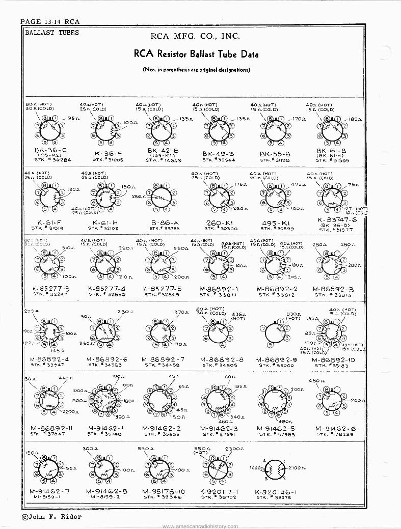
PAGE 13-14 RCA
BALLAST TUBES RCA MFG. CO., INC.
RCA Resistor Ballast Tube Data
(Nos. in parenthesis are original designations)
801. (HOT) 30 n (COLD)
BK -36-C (95-K2) STK .*30284
40n(HOT ) 25 n (COLD)
4p n (HOT) 151L (COLD)
ï01t O © ©
© O
K -36-F STK. * 31005
4O9. (HOT) 15 n (COLO)
1350 \
BK -42-B (135-K1)
STK. *14649 BK- 49-B STK.432544
40n(HOT) 15 n(COLD)
1350 \
BK -55-B STK.* 31198
409. (HOT) 150 (COLD)
1709. \\(_Q 185n
BK -61- B (BK -61-H) 5TK. *31585
K -6I -F STK.* 31019
409- (HOT) 259- (COLD)
40n (HOT) 25 it (COLD)
0 0 1
0©1501L 286 n
0 © © O
K-61- H STK.* 32109
B -86-A STK.* 33793
40n (HOT) 29n (COLD)
\O O 175n oimitee
O©6 01. © o 260 -XI
STK .*30300
409. (HOT) 20n (COLD)
495- K1 STK.*30599
4On. (HOT) 15 n (COLD)
755'.
27--_ (HOT 1021. (COL
K-83747-6 (BK- 36-8)
STK. 3 31577
(1.OT) 30;_(COLD)
51ofL
J `loon
K-85277-3 STK.* 32247
40n (HOT) 15 a (COLD)
40sL (HOT) 15n (COLD)
2.301. \
210 n
K-85277-4 STK. * 32850
K-85277-5 STK. *32849
O4 (HOT) 5A (COLD)
O4O O o © © o
9ÄjCÓ ó)
10011
M-86892-1 STK.* 33811
40.11040T) 404 (NOT) 159.(COLD) 15.n. (COLD) 0
O © (909 Q ©
© O 205 0.
M-86892-2 STK.* 33812
28Or- 280:_ \
2809.
M-86892-3 STK. 33813
205n.
loon
1451E
M-86892-4 STK. % 33947
2309_ i 3709-
M-86892-6 M-86892-7 STK.* 34563 STK. *34458
4On (HOT) 309- (COLD) 4369-
(HOT)
M-86892-8 STK.* 34605
40.9- (HOT) 8309. IS:. (COLO) (NOT) 1359-
809.
100,9.
O0 0©
o © © Q 4O: (HOT) , Isn(cOLq, 400. (HOT)
15fi (COLD)
M-86892-9 M-86892-10 STK. * 35000 STK. *35183
30A 440 n
1000 n
15004
22009.
M -86892-I1 STK. *37847
M-91462-1 STK. * 35748
4.5 n
M-91462-2 57K.* 35635
óO9-
18511.
340.n. 4804
M-91462-3 STK. * 37891
4609. Zoon \
4809- M-91462-5 STK. * 37983
o0 O ©
200n O© © O
M-91462-6 sTK. * 38289
559-
M-91462-7 MI -8159-I
300 n
OO O ©loon
O© 1000
M-91462-8 M-95178-10 STK. >R 39346 11-8159-2
2300n
K -920117-I STK.* 38702
K-920146-1 STK. * 39575
©John F. Rider www.americanradiohistory.com

RCA PAGE 13-15
X0 0 aá
n
N N
u
ó n4 N 0
D
O Q
-Mw
RCA MFG. CO., INC.
m
a.
vvvvr
INI
E mWE u.Z p dv W a uN
F
3dODEL 6X2
Chassis RC -1013
0,2,E
da ó
u
E9I p C O Fÿ
Cuw w9. r,Ó
s¡G
w ; Y C.. we OÊ
¿I o b E.L..
éE g
ei =É gr 3E
Ô FO i C O-
ú .':2,2 áL ú á+ p CJ
¡É Z: EñM
m>
. C : ú R.~ p Y
J W ...... s p o m_ C> W s« ' 0 Eÿ `Yw = ÿ.rú
W. wiw iiu
O< . i!;
Áa'Ei .. Ci áAú.
o ó.`1 º u p E ° á v ill-
tez,
^ o 'II y,ç º . óp Ç
u G üs mA u cs ñ v Aºu Va.; o- w% E+« A. á'
º - ç s E e
çt
'0L.. á
.0
80
W.r
Y
ti e
a n
Ví«+ Y V } C ^ i 3 e2 o . E E
i ©John F. Rider
www.americanradiohistory.com

PAGE 13-16 RCA
Y
MODELS 24BT-1,24BT-2 Chassis RC -1004F
LI 3GA
ANT. TO GRID 1.5 X
(Goo KC)
BOTTOM VIEW OF TUBE SOCKETS
RCA MFG. CO., INC.
CONV. GAIN 22 X I 6X- 120 X I .9X L 28 X
(600- 455 KC) (455 KC) (455 KC) (455 KC) (400 n) MEASURED WITH 1.5 V. FIXED BIAS
L2 0 4A
- CI
C9 C10 3-25 Ì1_442.2
O. I
RI 3.5 MEG.
T
IA7GT IST DET. G. OSC.
0 0 0...--.,0
so S.. G. 50V
C._
* -9v. (Goo KC) - 15V. (1500 KC)
- 3.5 V. APPROX. MAX AVC.
P-923033-1 24BT1,2 (RC 1004F)
IST I.F. TRAN,.
I NSGT I. F.
,_ ..., calk",
s 02 ÿ i IP 2 o LE 90v.
Ó TRANS.
-l--i---
IHSGT 2NDDET.-AF. ecAVC.
ú 1úRN
C12# #C13 15-90 LS óL6 15-90 uuz ,121. R3 L__ -----J
WM or RED-
:C2 .05
R2
220
_1 1.5V. FIXED RIAS
DATA FOR
G
L
90V.
r C14
15-90 LT
1 , I2.4
R4 V1M 10 MEG.
Ió C3 -_Y
W 120 älly _C,5 K Z 7,r,/ / R5 / 47M
GRN
ß ytCIS po L3
15-90
' lió =
.0018
/ A ñ
64 V.
RG _ VOL.CONTR
I MEG.
R7 lo MEG.
OSCILLOGRAPH CONNES VERTICAL "HI' TO THIS POINT VERTICAL 'O' TO CHASSIS.
20X (400 ni)
RB íS 1 MEG.
5Q50T OUTPUT
R9 2.2 MEG.
JREQUENCY RANGE 540-1,720 kc
INTERMEDIATE FREQUENCY 455 kc
Cathode Ray Alignment is the preferable method. Connections for the oscillograph are shown in the diagram.
Output Meter Alignment.-If this method is used, connect the meter across the voice coil and turn the receiver volume control to maximum.
Test Oscillator.-For all alignment operations, connect the low side of the test oscillator to the receiver chassis, and keep the output as low as possible to avoid AVC action.
Electronic Voltmeter.-The electronic voltmeter in the Chanalyst or VoltOhmyst provides an unexcelled output indicator. It should be connected to the AVC bus.
Pre -Setting Dial.-With gang condenser in full mesh, the pointer should be adjusted so that it is horizontal.
Step Connect high side gtest of test osc. to-
Tune osc. to-
Turn radio dial to-
Adjust the follow - ing for maximum
peak output
1 I -F grid
in series with .01 mfd.
455 kc Quiet point between 550 and 750 kc
C14, C15 (2nd I -F Trans.)
2 1st Det. grid in series with
.01 mfd. C12, C13
(1st I -F Trans.)
3 Antenna terminal in series with
220 mmfd.
1,720 kc
Tuning condenser
rotor plates all out
C17 (osc.)
4 1,300 kc 13 t0 0
1c C9 (ant.)
Precautionary Lead Dress. - 1. The lead from the 3Q5 plate to output transformer should be
dressed under clip and away from audio input leads. 2. Keep AVC lead connecting Cl away from the 1A7GT plate. 3. Keep blue plate leads coming from IF transformers short and
close to the chassis. 4. All filament wires should be dressed close to chassis.
CI611 10
MED.
TO FIL.
LA edN
52 -ED SW- ON
VOL. CONT R.
RIO wNTE _39O
B YELLOW
BATTERY CABLE PLUG (PRONG VIEW)
APPROX. GAIN DATA USING RCA RIDER CHANALYST
T1
VOLTAGES SHOULD HOLD WITHIN *20Y. WITH RATE O BATTERY SUPPLY.
* MEASURED WITH CHANALYST OR VOLTO H MYST.
BATTERY DRAIN 25 amperes ,B 14 m.3.
MAX. POWER OUTPUT 3 wat -
LOUDSPEAKER (5 -inch PM) Identification number RL -85-6 .... 92322-1 Voice coil impedance at 400 cycles 3 ohms 3 ohms
\ C9 -ANT 1300 Kc C12 -C13 Z C -c
455 t415
KC 455 KC.
+v IST.I.F
TRANS
ADAPTER CABLE
(z) THREE SEPARATE PLUG-IN BATTERIES
CHASSIS
BATTERY CABLE
BATTERY PACK
(1) '4-B' PACK BATTERY
24BT1-2
(3) THREE SEPARATE TERMINAL BATTERIES
©John F. Rider www.americanradiohistory.com

RCA PAGE 13-17
I
X 3N
Z
O N X ioa
Z N o o o U I .9
w v AK U ñ3 =LL NWW ov« -< Q» á mi G, (9)-(2
Z N
O
II i
0
2
RCA MFG. CO., INC.
H
+O O ̀ ó
et (DIP
© J nN W
Oe pi f
úó - úígol
L'H
m d
3(119
net,
/ A el?
> 2 , o
Co a o --- I
óo °'ñ *0
MODELS 25BK,25BT-3 Chassis RC -1004B CV -42 Electrifier
--J
s o
J J4I
U 1I---1"
vEL r
I- a O Q /'06
t7 î e¡ I \nos uf Q I
F II
eel',
Z ° 1 .
O /' 'nñó W F º 5 Y Ñ ÑT °< L li1 411 10
U uN ---I =Q D îo >m_F
FZW om `j:.No Ingo<< W LL l'- p. fOLLl70
W I F- W UÑ z1- 00 VZJ - ® Ll JiAAi+E W © 1 I
ZZ 3nI°O JlS
II
gag -0 a
I-
h
O ara ti--H +,>,
JC ° n10
N_ U` m o- m 7 v
C_ 0J
»Ó W 3(
a-
J
m LL
UF ó
M
0 0 my
<
IHI
G o
XXV I°
N
-
0 óiN UM
o
rn
X
á
©John F. Rider www.americanradiohistory.com

PAGE 13-18 RCA MODELS 25BK,25BT Chassis RC -1004B Electrifier CV -42
BLACK GROUND
RCA MFG. CO., INC.
'A -B" PACK BATTERY 1.5v. "A"- 90 V. "B"
' L-- - - - - -
1
BLUE/ ANTENNA
WHITE JBROWN
\ 4- ADAPTER 'I
CABLE.
ül i
BAT TERY CABLE
"...se -7z R YELLOW +45
45
45
ALTERNATIVES THREE SEPARATE THREE SEPARATE
PLUG-IN BATTERIES TERMINAL BATTERIES
Precautionary Lead Dress:- -
1. All filament wires should be dressed close to chassis.
2. Keep AVC lead cónnecting .1 Mfd. Filter to Ant. Coil away
from 1A7GT plate.
8. Keep grid lead coming from first IF transformer short.
4. Keep Blue leads coming from IF transformer short and close
to chassis.
5. Keep grid leads of 1N5GT and 1A7GT tubes away from each
other.
BLUE
ANT
GND
l fi \\ SHOWN WITH
GANG AT MAX. CAPACITY.
DRIVE CORD
POWER SUPPLY 05-125 V.
SO -60.., OR DC.
Circuit of CV -42 Elettrifier
ANT. COIL
C19 .05 BLUE,
ANT
AND
ADD THIS CAPACITOR 220 MMF.
DRUM
34. TURNS
C19 .05
ADO THIS JUMPER
A" SOLDER TO CHASSIS
Remove any external ground connections when using the Electrifier.
CAUTION: Turn power switch off (counter -clockwise) when installing or replacing tubes or batteries.
DO NOT TURN THE "BATTERY -ELECTRIC" SWITCH TO ELECTRIC POSITION WHILE THE RECEIVER IS
CONNECTED TO BATTERIES.
On a DC power supply, if no reception is obtained, reverse the plug in the outlet and retuve. Om an AC supply, reversal of the plug may reduce hum. CAUTION! Do not touch Radio Chassis unless power plug is removed from sobket.
Step Connect high
side of test osc. to- Tune
test -ose. to- Turn
radio -dial to- Adjust the f ollow- ing for maximum
peak output
1 I -F grid, in series with
.01 mid. 455 kc
"A" Band, Quiet point
between 550 and 750 kc
C14 and C15 (2nd I -F trans.)
2 1st Det. grid in series with
.01 mid. C12 and C13
(1st I -F trans.)
3
Antenna terminal in series with
220 mfd.
18 me 18 me C17 (Osc.)
4 1720 kc
Tuning condenser
rotor plates all out
C22 (Osc.)
5 600 kc 800 kc C29
(Rock )
6 1300 kc 1900 kc signal
C9 (Ant.) C25 (Det.)
7 Repeat steps 4, 5, and 6
8 Antenna termina(
in series with 300 ohms
11.5 me1.5nß 11.5 me C94 (Ant.)
TO PLATES AND SCRes.%
51
CABLE PLUG (PRONG VIEW) TERMINAL MARKINGS APPLY WHEN USING CV42 ELECTRIEIER
owner 2150 OERAF IF 30567 1NSGT INSET
52 s A
SwITCN ANN/NAGLE CONTROL
R1 2.2 Meó
R/4 050
53
RE IST DET05C INERT 1A -76T
Rtl RIO 390 390
C23 10 MFD.
CIE lo MFO
Simplified Diagram of Filament Circuit when using CV -42
Hum Modulation on Model 25BT9 When Using CV -42 "Electrifier."
The following changes should be made in cases where hum modula- tion is experienced when operating Model 25BT3 from a CV -42
electrifier power unit. It is not necessary to remove the chassis from the cabinet to make these changes.
(1) Connect a 220 mmfd. molded mica capacitor in series with the blue antenna lead as shown.
(2) Disconnect the black ground lead and C19 from the bottom lug on the antenna coil. Connect a jumper from this lug to chassis. Connect the black ground lead to C19 and tape the joint.
ORIGINAL CONNECTIONS 2SBT 3
NEW CONNECTIONS 2 Err The original and revised connections are shown at left.
John F. Rider www.americanradiohistory.com

RCA PAGE 13-19
RCA MFG. CO., INC. MDDEI. 25BP, Chas .RC -527D
X0 40
X
a n î G
Tr.%
Iv
VNz N^ m r^umî
z
o ó
á
r
[ Noó º uºf
N
V
c N
ó $
., . ° é
.
t1I °' ..o. O
qm a.5
aw á
c v
á ?' á- «
N¿ VE.
ú
ó
w UF
á
m: nt ó a
.. Cÿ Ó « ^ ÿ
B m o aó..'. ei Á á 5 'w
H b- b
.'tiq a dÄ y ü d qC
. ,u,
^ - g
a .o x ,s
F ú « a _ N N
m
v mÿ g. ó M t
m_ I = o .2
0 o '1 sU
CCC
f, ú °E
W ° ú «^ É
q .. C9
ñ n y O
ñ a N .. .,
)ri a .
«ó2 2 tt,
.d J.. 67.9 ti .. « N
Cp= Vt ur it. c ó U
v 3 éo m
a
.y N cn -+' lO to .112
©John F. Rider
www.americanradiohistory.com

PAGE 13-20 RCA
MODEL 25BT-2 RCA MFG. CO., INC. Chassis RC -1004A CY.42 Electrifier
POWER SUPPLY 1 "A" "B" 11-90 volt pack. Model 25BT2 can be operated on 105-125 volts AC, 50-60 cycles,
or 105-125 volts DC. by means of a RCA CV -42 Electrifies-. BATTERY DRAIN MAXIMUM POWER OUTPUT 3 watt "A" 3 amperes "B" 10 m.a. (Switch at "Battery Saver" position) "C" 14 m.a. (Switch at "Maximum Output" position)
POWER CONSUMPTION With CV -42 Electrifier Unit 22.6 watts
LOUDSPEAKER (5 -inch PM) Voice coil impedance at 400 cycles
RL -85-6 92322-1 3 ohms 3 ohms
Step Connect high side gtest of test osc. to-
Tune osc. to-
Turn radio dial to-
Adjust the follow - ing for maximum
peak output
1 I -F grid
in series with .01 mid.
455 kc Quiet point between 550 and 750 kc
C14, C15 (2nd I -F Trans.)
2 1st Det. grid in series with
01 mfd C12, C13
(1st I -F Trans.)
3
Antenna terminal in series with
200 mmfd.
1,720 kc
Tuning condenser
rotor plates all out
C17 (osc.)
4 1,300 kc 1,300 kc
signal C9 (ant.)
5 455 kc Quiet point
between 550 and 750 kc
Adjust C22 for minimum output
on strong 455 kc signal
Precautionary Lead Dress.- The lead from the 3Q5 plate to output transformer should be dressed under clip and away from audio input leads.
2. All filament wires should be dressed close to chassis. 3. Keep AVC lead connecting Cl to antenna coil away from the
1A7GT plate. 4. Keep blue plate leads coming from I.F. transformers short and
close to chassis. 5. Keep yellow leads connecting to oscillator coil away from trap coil. 6. Keep grid lead of 1N5GT RF tube away from 1A7GT grid.
1.
ANT. TO GRID 3X IX
(600 KC) (6OO KC)
DO NOT CONNECT INSGT TO GROUND WHEN R.F USING ' ELECTRI FIER'
BOTTOM VIEW of ruse SOCKET.
RI 3.3 MEG
- 3.2 V. APPRO%. MAX. AVG.
VOL. -
OH VOL. CONTROL
CIO 0-442.2
CONY. GAIN 24 X -+ .4x
(6OO- 435 KC) (455 KC) MEASURED WITH 1.5 VOLT FIXED
WIELD
t
e R12 5600
L11 28A
C22 10-70
I( -9V. (600KC) -13V.(1500KC)
BATTERY CABLE PLUG
(PRONG VIEW)
IA7GT IST OCT Et 05C.
LS C11 ßA
0 136.6
S3 FRONT
I ET TRANS.
POWER SUPPLY 105-125 V.
SO -60,- OR DC.
Remove any external ground connections when using the Electrifier.
CAUTION: Turn power switch off (counter -clockwise) when installing or replacing tubes or batteries.
DO NOT TURN THE "BATTERY -ELECTRIC" SWITCH TO ELECTRIC POSITION WHILE THE RECEIVER IS CONNECTED TO BATTERIES.
1 40X (4 400...)
BIAS
Sox I .1X 55 KC) (455 KC)
INS OT I. F.
[LO
I
22x APPROX. GAIN (400...) MTA MEASURED
WITS RCA RIDER CHANALYST
IIA5GT 3Q5GT 2HD OET-AR & AVC. OUTPUT
/ 2 N I.F. 90V. TRANS.
Ir
R4 IO MEG.
94 REAR'
OSCILLOGR.
VETVOTL TO THIS POI., VERTICAL`O" Tb CHASSIS
1 MEG
.001aI
R6-1ME6 VOL.CONTR
° C20 3 0 25 390 MED.
-7.4V. BATTERY SAVER POSITION -5.2V. MAX. OUTPUT POSTION
POWER SW. VIEWED FROM FRONT SHOWN IN P061TION No I
POSIT ON I_ BATTERY SAVER PO `ION 2- MAX OUTPUT -BATTERY POSITION 3- AC -DC OPERATION
R9 2.2 MEG.
VOLTAGES SHOULD HOLD WITHIN 420% WITH RATED SUPPLY VOLTAGE
M. MEASURED WITH GHANA LYST OR VOLTOHMYST.
P-923022-3 256,2 (RC 1004A)
©John F. Rider www.americanradiohistory.com

RCA PAGE 13-21
MODEL 25X, Chas.RC-100
N r N
O.
^
r
> m
i *b1,$ d L
` §----4,--,"~-11,
I
11 -1 -IP
Ñ L _ N$ 1 Ñ un N
a Oa NO
RCA MFG. CO., INC.
u r
N V
e - W- -
N, 219
r- -_ '
r- - - I . y{. I
1- Y n N1 aWU
.v 01115Óo 21 Y 1 { N 3 I r-
o 1 1
z 1
TU
V I V N
il
Ä-- - --r-III 1 11 I
T Y i _r Op.ßO0.9
p - I,
J
1H1
003h Nn =
+
oaa
N2í0 J aO umf
> li
F-
F In U Nu, tne nt
.! M
Q
e
, \l `';..n.
A a
O >
e d ^ s E MC
óa p u21 7 o ;e m < C
V a R. E V:.ó u.5.:
F
Y i. p, E U..ó m=.° U... `
F 3
-
éeEñóv:
U
To ç u.e A
áp I
o Fô« OYp °o tg- D
«J mE e._
C
¿p C
mp í. O `,+ y 4
w
u Y
g ! o o Y O F-.0.F -, o .r n
.r o M r. N
4 4 C R N)
i m G
O V
r E v";
ó Ó0I1
Am e
« ö mu.-. TqqE
.
úúE QC'. HI «ó
.. . ..... Wo o -...2 v á e- o"c u ..e .s ° <._ ix á
ú .-1 N d1 .. u] N
w j
0k0(;;ór(I) l ,ce
VY
©John F. Rider
www.americanradiohistory.com

PAGE 13-22 RCA 11ODELS 26X -1,26X-3 Chassis RC -1014A RCA MFG. CO., INC.
FREQUENCY RANGE Broadcast 540-1,720 kc Short Wave 8.7.15.6 me
INTERMEDIATE FREQUENCY 455 kc
PILOT LAMP Mazda No. 51, 6-8 volts, 0.2 amp.
POWER OUTPUT Undistorted 0.9 watts \laxitituln 1.4 watts
LOUDSPEAKER Rl. -81132 "PM," or RL -86B1, 'E11." Size 5 -inch V.('. Impedance 4 ohms at 400 cycles
POWER SUPPLY RATING 195-125 volts, AC, 50 or 60 cycles, or DC Precautionary Lead Dress 1.
2.
3.
4. 5.
ti.
30 watts
Dress output tubeplate lead to speaker and output bypass denser away from terminal board and yellow lead in cable.
Dress brown and yellow leads front 2nd I.F. transformer away front output plate and bypass condenser. Dress .02 capacitor C12 away front output capacitor C16. Dress all leads or parts as far as possible away from oscillator coil. Dress lead front C13 to band switch down along front apron of chassis. Dress lead front trimmer condenser on loop to S.W. Ant. coil around outside of rectifier tube. Other leads between rectifier and R.F. tube.
con -
`05(
1200CC t/ ®D5C7 6600KC
/!ó *w+Mw 1 eVE TRAG
AN7. toa / 9.SMC 4551(C
ANT. 4`
ID
C 22(Td4) 15MC.
O
e C21
C20
e C24
15MC.
.F. C28,C29d55Kt. TRtilANS.
125A7
C30 C31 455KC 2RI.LF.
TRANS.
ANT TO GRID
17 4X -
( GOO KC )
0 SHORT WAVE ANT. WIRE IN BKK OF CAINNET
La 1 JANT
NT. 9SMC
LOOP
1.25X (DOO KC)
25G7 RF
R17 20 .1M
Steps Connect high side
of the test oscillátor to-
Tune test osc. to- Turn radio
dial to- Adjust the follow - ing for maximum
peak output
1
I.F. grid in series with
0.1 mfd.
455 kc Quiet Point at 1,700 kc end of dial
C30, C31 2nd I -F trans.
2 1st det. grid
in series with 0.1 mfd.
C-28, C-29 1st I -F trans.
3 R.F. grid
in series with 0.1 mfd.
C-27** Wave trap
4 Ant, terminal in series with
47 mmf. (link open)
15 me C15," Ban me
d C-24 (osc.)* C-22 (ant.)
5 9.5 me 9.5 me
"C" Band L-10 (osc.) L-5 (ant.)
6 Repeat steps 4 and 5.
7 Ant. terminal in series with
220 mmf. (link open)
1,300 kc 1,300 kc A" Band
C-25 (osc.) C-23 (ant.)
8 600 kc 600 kc A Band C-28 (osc.)
9 Repeat steps 7 and 8.
( w 1C23 - ANT. 1300KC
CON V GAIN I 40 x 1- B X 200 X
(6D0-4S5KC)I(455KC) (455KC) MEASURED WITH SV. FIXED BIAS
*Use minimum Callao ty peak if two peaks can be obtained. **Adjust C-27 fór minimum signal with 455 kc applied to R.F.
grid.
12 SA7 BOTTOM VIEW OF TUBE SOCKET5
IsTDET.b OSC. 150 0.2
* -2V (LOoKc) -Av (*30000 -OSv(BMC1 -4v (I6NC)
SV
r -
ené C2B1 K I
LL13 LIA aeGr
rT1n
RA RS
2,000 15MEG.
C4 4T
125K7 LF.
Note. -Oscillator tracks 455 kc above signal ou all bauds.
J X _I(455 KC )
52
SO X (400
12SQ7 2!O DET.-A.F.-AVC.
Z'TP IF TRANS
©eo
0 ei 4dr
15X (400ti)
35L6 GT OUTPUT
APPROX. GAIN DATA USING RCA RIDER CHANALYST
Say
CIS 5
1 GRIEN Rene
-C29 C3D1 75-160 75-1G0'e
RED 1 LIS L. FIvELLCW
xSV APPROK NAK AVC
.=1 BLACK
C51 I
79- t4 J
C,>L .Doer 7
VÓLCONTROL 500,000 C12
11.02
C 1
v_ RED
2AOR BLS
BLUE Hn
gee 1 C21 °` ^'S,=rf` TS:2. á g(¡ #C22-
no FaLS , its 7c35
<O L j I.01
LC LOOP 1.5a
7
Sv FIVES I
BIAS FOR 1- AANT GAIH -
Ì23 DATA
-10
35Z5GT RECT.
t, 11.11 © A 6A550 01 ©
CES
SuPt v O C2t-Aso -Goo
FRONT 1SrANA¢OOADCAST(Lco..1 5 QjSANDADROADST NORwAITc(
H SNOWN tr.
OSTI ~- PNONO O N BAND SPREAD SNORT JAiN
N e PHCNc (1E.,cRw1TONG) N)
n0V
1 LINK ON ANT TERM SeAFO
7 0.1 _
VOLTAGES SHOULD HOLD WITHIN 205 WITH 117 V AC SUPPLY.
* MEASURED WITH CHANALYST OR VOLTOHMYST
D
C1B V * f19 30 I 1 50 =J.MFD.
I WO.
Y
VC
3.511
3SLVGT 12567 125A7 12557 12557
5
R S23034-4 2G01 (RC 1014)
R M. SPEAKER
CLOSE LINK FOR LOOP OPERATION CHASSIS
OROUND
©John F. Rider INDICATES COMMON WIRING INSULATED FROM CHASSIS
www.americanradiohistory.com
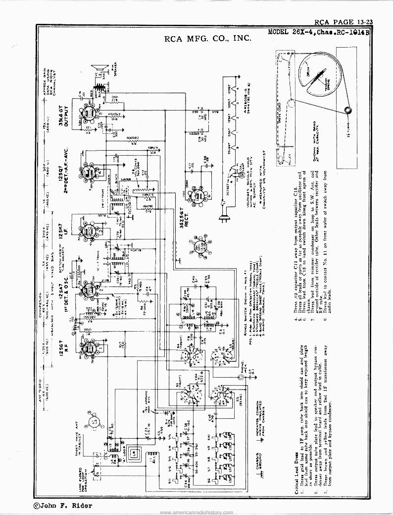
RCA PAGE 13-23
4
xÑ d
x y Oy1 O N Nd
00LI O b
i + 000bzz
6b 9ì11LY
^ L7
RCA MFG. CO., INC.
-g. ZJ
i e e 0C$
V N
pOj Q_
MMaba 1 -
in i NbG 9
d
L_ 3019
_I J} S
Ú.
lV
__24E.13;1
000
2 r
a 1°
0 Og d- N
uN, UO
e . ººnaGñn o . lo,ie
:a 9
f OÑ z uN
Ñ4 O - p0
VO
HI VO
ZY
so II -i
Ñ
s
MODEL 261-4, Chas .RC -1014B
©John F. Rider www.americanradiohistory.com

PAGE 13-24 RCA
MODEL 26X-4 Chassis RC -1014B RCA MFG. CO., INC.
FREQUENCY RANGE Broadcast 535.1,600 kc Short Wave 8.7.15.8 me
Intermediate Frequency 455 kc
PILOT LAMP Mazda No. 51, 6-8 volts, 0.2 amp.
POWER OUTPUT Undistorted 0.9 watts Maximum 1.4 watts
LOUDSPEAKER RL -81B2 "PM," or RL -86-B1 "EM." Size 5 -inch V.C. Impedance 4 ohms at 400 cycles
POWER SUPPLY RATING 105-125 volts, AC, 50 or 60 cycles, or DC 30 watts
Push Button
i /.NTTNNA-_
..... l, V. 4 3 2 1
-050ILATOK APMTKNT3 , AD.AASTM[NTS
sT5Oo rT3O0 TÓs 1590 /4201420030 1100 KC KC KC KC KC
EXT. AN?.- f 2 3 y-NECOIC-PLATER CONNECTION Tee get
) CONNECTION
REMOVE LINK' WHEN IRING EXT ANTES
o
The station push buttons connect to separate magnetite -core oscil- lator coils and separate antenna trimmers which must be adjusted for the desired stations. Use an insulated screwdriver or alignment tool such as RCA Stock No. 31031. Allow at least five minutes warm- up period before making adjustments.
In the event that the receiver is to be used with an external an- tenna use one or two feet of wire (as an antenna) to ensure sharp
3 2 1
PUSH-BUTTON RANGES One station between approximately 540-1,100 kc One station between approximately 610-1,250 kc Two stations between approximately 750-1,420 kc One station between approximately 950-1,560 kc
Adjustment peaking during the final adjustment procedure. For loop operation, the link should be strapped across terminals on back of set. In either case the procedure is as follows:
1. Make a list of the desired stations, arranged in order from low to high frequencies.
2. Turn the range selector to "A" band, and manually tune in the first station on the list.
3. Turn range selector to "PB" position, push in station button No. 1 (extreme left). Then adjust the No. 1 oscillator core to receive the station.
4. After oscillator core is set correctly, adjust No. 1 antenna trimmer for maximum output.
Clockwise adjustment of cores and trimmers tunes the circuits to lower frequencies.
5. Adjust for each of the remaining stations in the same manner.
8. Make a final careful adjustment of the oscillator cores and an- tenna trimmers.
On the 950 to 1,560 kc push-button, the higher frequency stations may be received with L24 either in or out (oscillator frequency either 455 kc below or 455 kc above the station frequency). The adjust- ment with this core in its out position (oscillator frequency 455 kc above the station frequency) is the correct one.
Alignment Procedure Test Oscillator.-For all alignment operations, keep the output as
low as possible to avoid a.v.c. action.
Output Meter Alignment.-If this method is used, connect the meter across the voice coil, and turn the receiver volume control to maximum.
Calibration Scale.-The glass tuning dial may be easily removed from the cabinet and temporarily attached to the dial backing plate for quick reference during alignment.
Power Supply Polarity.-For operation on d -c, the power plug must be inserted in the outlet for correct polarity. If the set does not function, reverse the plug. On a -c, reversal of the plug may reduce hum.
C28,C29-455KC.
LOOP w C23-ANT.1300KC
Steps Connect high side
of the test oscillator to--
Tune teat osc to- Turn radio
dal a to- Adjust the follow - ing for maximum
peak output
1 I.F. grid
in series with 0.1 mfd.
455 kc Quiet Point at 1,700 kc end of dial
C30, C31 2nd I -F trans.
2 1st det. grid
in series with 0.1 mfd.
C-28 C-29 lst I -F trans.
3 R.F. grid
in series with 0.1 mfd.
C-27 Wave trap
4 Ant. terminal in series with
47 0303!. (link open)
15 me 15 me
C" Band C-24 (osc.)* C-22 (ant.)
5 9.5 me 9.5 me
"C" Band L-10 (ac.) L-5 (ant.)
6 Repeat steps 4 and 5.
7 Ant. terminal in series with
220 mmf, (link open)
1,300 kc 1,300 kc
A" Band C-25 (osc.) C-23 (ant.)
8 600 kc 600 kc A" Band C-26 (osc.)
9 Repeat steps 7 and 8.
*Use minimum capacity peak if two peaks can be obtained. **Adjust C-27 for minimum signal with 455 kc applied to R.F.
grid.
Note.-Oscillator tracks 455 kc above signal on all bands.
©John F. Rider www.americanradiohistory.com
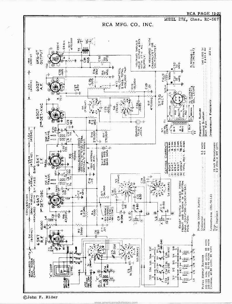
RCA PAGE 13-2e5
F- F--
.9 )-- Y O
fc,
> O T
> o ró >
jr,2-
ld hN
RCA MFG. CO., INC.
colt)
US
o
p
>
Q o -J
úr-
-Hp
1Ñó 2 {¡Ñ V î
11 Jo J n Ere,ce FH
u0 Z
\
o te o
SB
t9 o Cro
r-
W J7Z
e2
a
ZF
N I
0 0 o o muW o$ ªó
>Nd Etc° Mti
tt .
c
NO N(Y UO _tt
t- (1 U o
m
oÓ o O aó
0'
ol II N
o
Qp y(v0 dói ` óZZ ao<-
r * > 0;d _
In
I I I I
0>Y Zwo o
áH-)
erx LL
-cel o)
{
m
..lo VíTp
Cf
w r N N
m
1 e (9N dU NLX N 01
aN
d
u u E
O 0 mIn .. ó` ero
ro Á 3a
In
MODEL 27K, Chas. RC -567
o
111
i<dᢠI î S î 22 yNInTNt9
c>imóm
(71
©John F. Rider www.americanradiohistory.com

PAGE 13-26 RCA
MODEL 27K,Chas.RC-567 RCA MFG. CO., INC.
áae. ó'F m
o <
O
S;w a
ea
á v . á CO
.!
a .- .$
É
O.. ci
m
ei .r
a 8 ciá
Q
` g
ii á
K á
aie
R
á u
a
O I
CQ
a
.0V2° fAaga¿omeqnqepo .tú <a: i
1aoó aÿo .bN.OM. èv
.. ou°
<m
t iV «.i F.)"'
v Ego .bNi úw-
.o a ÿ .O k' -m
u
oro
I
á a .« ú F ó
A .o o v
u y p ...
ÿ e 0 m
u E cc
g
1O ai
..e
p '.. r
.ÿ o ro
ib á" aw UV
mC9
aéEq ces °
c9 <5;' mª
a
ñá gQ
02, ; a_ t.
^
dø 8º «e
o
_öpt°n "zW" áu O
3
N .. w . . . O r m d
s ô 'q H
3 g nit ñª?a.
gE
z.^;Ea
o
L ª
Ñ Óá d EE" 650ó E _ E uCe é á .$j
ua 0 ñ . ta Oú° --Eé
< .
ópóé.=E« / m C G aaJq E..:pE m. r{zsga
.2 á -e> u ú a.á3 '
V y mú Ñ zg`ÿ
Ó p yaa.;xro m3á óá 00 m,y$ ¿ u a
w á.aºviu « = s .éz ..°24.r.
A r.
«'y! ía.
º V.ó > ó Ci `u uiee
o a++ ; a Y+ r. u
,qB.óaY a.9.x s Fá d.'a8 a .
B 3 b a HP n
0 ~
1 wrae a uue, a 8F u
a a á e,s;
Pigco í0, iu ` ú o 42 *A
WgeW San' S a 4 a
a mZA
''s-
ó "r!
a ç u jyp
..T
q é
..O O
w a m 0 p t
ó E :1..18
u
ó É ; 2bÿ82
á1 «$,a u a 6'ùao,., «
a w tiu= 8 '6 ó u, o.} o8 3.2-g a
3 ó ú ¡F
«ç e Eçug ssjj
a.. o ,, a« >t
gg ua mG3 é ««'U :,y^ áa uá«u dó E 6 zE eÿtu
F.~o.e.°a .5. 0.14,J. .. N 4 4 4 m O et; Éa a«.e E_« ErEá
(3»-O
o G PN F á
<U ' ó
r
g. .o ( ell ©
I
g1f1
;
Q
ñ
g V a :d,o,= éTÿti ä; 'qé« ,ÿóó
pi 88 u&pp wá Ç ú« t Ó, esbEp ú Ó i O 0" o
q,,s o g$ uó
914:0£4 °.E8am «va:s °c°.'cu_8«ú«
ee c u i E«é v 7aái pt`a aF U:ô
á - Fuomam ó,'Tu+ a,c «m; út
.2-6.6..e.:;.1
' - o 'ú««m RaQú"8 "áó.ß,«.mi «8 ^, ü áa Z,^ó us:'.°-c..ñ a3Y.'úaa amuE
Qv $ u O a 1 g,2,,%, .e m á w u..? .
u:«e ' o'b9ó'^ ., a& Eá. oE 'óñ II Eu ... 3..2'r.mu
L aÁc« pw .°.ta.au ú
u « ¿ bo__.E« y`«FQv Éo--a «c Q p C2a ª - ua `^'0...' 8` «2 uWo EtaÇ`úQa+Eauñ Ia<Nó$
a «,n u
p pp p
aa Ia u úaw0a0ÓOoeúoa aÁ.7.e«.á .úáE . 3 ú '12.4 .a. y íJ a mi7 A wro m^a 6A c u.ö "'"t
- c
W«ó c$aú00FN.Ec«.+2 c c-4".Te.: C -'3c bváw
<a' ^'Sút«úu 'gs 4eo°a.3<1roo. ,« ..u^'ViouÇE_ wa«« 1^40cEEob eE«ó,ªaó uA uu .aO>¿
i^ g «bpcÉEé úri X« iñg«xm OOV aCCªYV°o.éFtZ36arov o wa,°iß uEO,.áy iñaa áuEoZ..:.«a. so.wq.a 7úu
uuOú F-0tUV-oáse«<v1«eÉa WwuQC1«w « EE ó? ávF.úii F7E ú« ú úmr
o
o
V
ú V
o
2; N
uuu
Ñ! LL ri
<
n Nt
co
n Nd co
tÿ eo
et-
R1(,) ev
Ñ
F d z 2 a
ºaci óFY
º O n a
2Oÿ Fa
J0. JO
O
º ^
o
O e
ó
o - co
O = OIE O O =
CD
E
3'
M
E N
e
M
E M
M
W
>
3
©John F. Rider www.americanradiohistory.com

RCA PAGE 13-27
X
N
XÑ -d
wM,ñxidN inmd ÑNpNp
N,fI4-nl9rm>
r--
(/ C9
H,,
N
4J 0,4- >
mº 4 / N
RCA MFG. CO., INC.
©O© CD to
T
vy ©L¡(j
U U ó >' 2 *T
v
N
mS
II
n
= a
Y
>
N m0 1v
e--
ró
m0 d0 Od m 1 m00 T
o' O
_ 7<ç
a°><ó NHd
0Ñ d v Ce- m ..iN'. y
U=O
V0 â0 m 0 î
0,N
-NI
o
K w1
h
en 9O UT Olr g
I- z
ro Nw
m
ó N
OJ a7 /N <no . \ 0
o o \ z0
úa \ =Q u
e7.
=o J J << UV Fr
>>
o
II
41 Ot
01-
/01
[II.j 0001i/CIS 'f.
' PF'Sbbif 6 0 J 0 0` m z z 0,33w
mg _0 .. 8 Ñ
MODEL 28T,Chas. RC -569
0 0 a,
NO U0 p .--IHI -.Mr ---M 0s U 0 .9<
w so
> *NnNmº1"
4l W
0 Um
Z Q
mo .O
m . R
ro UÑ
g U0 OyUti Ñ G 1/
II 9'12t II' o vR
á"Q42nd 49 0100 J dd0'"-Jm cd` m
Ut
NW
Ñ 0 UN
w N _ -< µ® 1
ú I
J
cri ªsev N U U N 5ä
ù OaX e *ll Qi
Y l
Mee
a O o -J
aaa Vi Ñ U tIJ
te
19 ln4 © ` Ñz1. NMy
I I--
2
o
W O r
N4 Ne
w
a
Ud
(^'jlQQ_y-Jp[
Q -19-22.1) II
F-
UN
HI
Ñ U
M
á
r Z
vfv 0 Nw
r J
©John F. Rider www.americanradiohistory.com

PAGE 13-28 RCA MODEL 28T,Chas. RC -569
RCA MFG. CO., INC.
Test-Oscillator.-For all alignment operations, connect the low side of the test -oscillator to the receiver chassis, and keep the output as
low as possible to avoid a -v -c action. Electronic Voltmeter.-The electronic voltmeter in the Chanalyst or
VoltOhmyst provides an unexcelled output indicator. It should lie connected to the AVC bus, and the test -oscillator output adjusted to produce several volts of AVC.
Calibration for Alignment.-The dial calibration for alignment pur- poses can be set up in two ways:
1. The dial may he very easily removed from the cabinet. The condenser plates should then be turned into full mesh, the pointer adjusted to the scratch at the left end of the dial back- ing plate, and the dial placed on the frame so that its extreme left calibration mark coincides with the pointer. The dial may be held in place with scotch tape. In this manner the actual receiver dial is used for alignment. When alignment is finished, the scale should lie replaced.
2. A calibration scale is attached to the tuning drum. The correct setting of the gang, in degrees, for each alignment frequency is given in the alignment table. Check the position of the drum, making sure that the 0 degree scale mark is horizontal with the gang in full mesh.
Pointer for Calibration Scale.-If method (2) is used, improvise a
pointer for the calibration scale by fastening a piece of wire to the chassis, and bend the wire so that it points to the O degree mark un the calibration scale when the plates are fully meshed.
C9 -A DET 1500 KC.
( L'
?. CIO- B DIT. 6.1 MC.
BOT TOM
i
C 11-C'DET 15.2 MC.
ee- C3- 6'ANT 6.1 MC.
&I_CI-C'ANT- 15.2 MC
te_C 12 2C' DE T. 9.5 MC.
50419
Á OSC 0 KC.
VIEW
C 17 -"C'OSC. 15.2 MC.
17
29 T q
L I2 -'A oSC.l3 6o0 KC
Cathode -Ray Alignment is the preferable method. Connections for the oscillograph are shown in the schematic diagram.
Output Meter Alignment.-If this method is used, connect the meter across the voice coil, and turn the receiver volume control to maximum.
External Antenna.-For best reception on "C" band with an out- side antenna, adjust C2 for peak output on a station in the 31 -meter
band.
Steps Connect the high
side of the test-osc. to-
Tune test 06c. to- Turn radio dial to-
Adj. the following for max. peak
output
1 I -F Grid
in series with .O1 mfd.
456 kc "A" Band
Quiet Point between
550-750 kc
L-15 and L-16 2nd I -F Trans.
2 Det. Grid
in series with .01 mfd.
L-13 and L-14 1st I -F Trans.
3 Ant. terminal in series with 200 mmfd. (link open)
1,500 kc 1500 kc (160°)
"A" Band
C-19 (osc.) C-9 (Det.)
C-5 (on loop)
4 600 kc 600 kc (30.5°) L-12 Rock Gang
5 Repeat (3) and (4)
6
Ant. terminal in series with
22 mm fd. (link open)
6,100 kc 8,100 kc (181°)
"B" Band
C-18 (osc.) C-10 (Det.) Rock Gang Gang C-3 (ant.)
7 15,200 kc 15,200 kc (167°)
"C" Band
C-17 (et.) Rock
(D Gang
C-1 (ant.)
8 9,500 kcC-12 9,500 kc (28.6°)
C-2 (ant.) (Det.)
Rock Gang
9 Repeat (7) and (8)
°Use minimum capacity peak if two peaks can be obtained. Note-Oscillator tracks 455 kc above signal on all bands.
LI3-BOTTOM Lt¢ -TOP 4S5 KC.
LIS -BOTTOM L16 -TOP 455 'KC.
Tt 1
LikPMONo. JACK
0 10 20 30 40 50 60 70 80 90 100 110 120 130 140 150 160 170 180
I II 11 Illy
POLICE
SPECIAL 2.3
55 A STAr1DARD
C SHORT WAVE 9.3
1 l
2.5
AIRCRAFT 90M
3.0 3.5 l l l l 1 t l 1
AMATEUR 60M AIRCRAFT 49M
4.0 5.0 6.0;11GN.LONDON
IMYDºººFºlIN SGN- HilA.
1 l l l a l t I a a l 1 l 1 l 1 1 1 l 1 1 1 1 1 I
60 70 80 100 120 140 160 I l 1 l 1 l 1 1 1 l 1 l t t 1 l l l l l t t 1 1 1 1 1 1 1 1 L t l I I t l l a l l I l 1 1 t
31M
Nºº NONG a. SCION', MIA. 10YO-ºlIlNO) LONDON ºFºIiN hare tW
l a 1 l 1 1
10 I I
11 1 1 l 1 1 1 1 l
25M AMATEUR 19M
'OA"° 12 A°:°O: 15 'óNoO BOSON l l l I l l l I i 1 I a l l 1º 1 ralliai I
B SERVICES
A BROADCAST
C InTE VAT lon RL
* * * 1111TIII I I11111111111I11I111I1II l l I lI 111111111111111
0 10 20 30 40 50 60 70 80 90 100 110 120 130 140 150 160 170 180
©John F. Rider www.americanradiohistory.com

RCA PAGE 13-29
MCOEL 28T, Chas .RC -569 RCA MFG. CO., INC.
Ric p Art O iu.4 ;44
n.LL Ni T- {OET M MfD1YM1 DM - e' Si{MOYIO M4{{cöl'
OFF LOUD SpaCCM
POWER-VOLU TUNING RAE NO CONTROLME TONE CONOTROL CONTROL CONTROL
I
DIAL POINTER ANTENNA-GROURO 0 0 0 0
TERMINAL BOARD g
1--i- ( 1 LINK PUSH SUTTON, TRIMMERS PU LLEV
CORD DRIVE
DRIVE CORK " DRUM
O 1 0 _-g)__®__©__¡ 1-J 0
SHOWN WITH GANG AT MAX. CAPACITY SPRING 2
,_,
3 TURNS
Insist on genuine factory
`-J PNONO-TELEV.-F.M. POWER CHASSIS JACK CORO
Replacement Parts -tested parts, which are readily identified and may be purchased from authorized dealers.
STOCK No.
DESCRIPTION Unit List Price
STOCK No.
DESCRIPTION Unit List Price
31025 33014
38368
38357 38363
35791
36424
38360
12814 14021 12948 13057 12720 34699 34700 13003 12694 38830 38831 30882 30303 33584
4937 36248 32787
4839 31581 38367Coil-Antenna 3603311 38358 38315 37638 38366 38364 38404 34662
35788 35871
38,859 38361 38365 31580
CHASSIS ASSEMBLIES (RC -569)
Board -"Antenna -Ground" board... Capacitor -Electrolytic, comprising 3 sections of
10 mfd., 450 volts, and 1 section of 20 mid., 25 volts
Adjustable trimmer (50-350 mmfd.) Cator coil for antenna
Capacitor -Mica trimmer -2-20 mmfd. Capacitor -Mica trimmer comprising 2 sections
of 8-80 mmfd. Capacitor -Mica trimmer comprising 3 sections
of mmfd. Capacitor -Mica trimmer comprising 1 section
of 10-160 mmfd., 2 sections of 25-250 mmfd., 2 sections of 50-400 mmfd., and 1 section of 100-540 mmfd... ..
Capacitor -Mica trimmer comprising 1 section of 50-350 mmfd., 1 section of 5-50 mmfd., and 2 sections of 2-20 mmfd
Capacitor -5.6 mmfd. Capacitor -22 mmfd. Capacitor -33 mmfd. Capacitor -68 mmfd. Capacitor -100 mmfd., moulded Capacitor -100 mmfd., unmoulded Capacitor -120 mmfd. Capacitor -180 mmfd. Capacitor -220 mmfd. Capacitor -226 mmfd. Capacitor -630 mmfd. Capacitor -2,200 mmfd. Capacitor -.0035 mfd. Capacitor -.005 mfd. Capacitor -.01 mid. Capacitor -.02 mfd. Capacitor -.05 mid. Capacitor -0.1 mfd. Cell -Bias cell
Coil -Loop primmarar y coìl Coil -Oscillator coil Coil -Push button oscillator coil -high frequency Coil -Push button oscillator coil -low frequency Coil-R.F. coil Condenser -3 -gang variable tuning condenser Control -Volume control and power switch Cord -Pointer cord (approx. 60 -in. overall
length) Core -Adjustable core and stud for oscillator coil Core -Adjustable core and stud for push button
oscillator coils Cup -Coil mounting cup and bushing Drum -Condenser drive drum Frame -Dial frame complete -less dial Holder -Bias cell holder
.25
1.90
.25
.25
.40 .50.20 1.10
,75 ,35 .35 .35 .35 ,35 .30 .30 ,35
.35
.45
.20
.40
.25
.25
.20 .30 .25
1.00 50 1.00 .30 .30
1.75 3.65 2.00
.25 .15
.55
.20
.50 1.75
.15
35798 38356
5040 31373 13220 34765 35885 30694, 14075 30436 35875 12266 30650
30648 30649 30992 35797 31364 35787 31251 31418 12007
38362 38384 38369 35636 35790 35588
35959
35969
38817 38373
5039 38374
38376 38375 37334 38378 38377 35814 11765 34317 33774 30900 34053
Indicator -Station selector indicator Loop -Antenna loop complete -less supports Plug -4 -contact female plug for speaker cable Pulley -Drive cord pulley Resistor -56 ohms, } watt Resistor -100 ohms, } watt Resistor -470 ohms, 2 watt Resistor -3,900 ohms, * watt Resistor -8,200 ohms, } watt Resistor -12,000 ohms, * watt Resistor -12,000 ohms, 3 watt Resistor -39,000 ohms, * watt Resistor -56,000 ohms, } watt Resistor-270,000 ohms, j watt Resistor -470,000 ohms, * watt Resistor -2.2 meg., * watt Resistor -10 meg., } watt Shaft -Tuning knob shaft Socket -Dial lamp socket Socket -Phono input socket Socket -Tube socket Spring -Pointer cord spring Spring -Retaining spring for oscillator coil core
and stud Switch -Range switch Switch -Selector switch Switch -Tone switch Transformer -First I.F. transformer Transformer-Secorrtd I.F. transformer Transformer -Power transformer -105-120 volts,
25 cycle Transformer -Power transformer -105-120 volts,
50-60 cycle --less shields Washer -"C" washer for tuning knob shaft
SPEAKER ASSEMBLIES (92196-3)
Coil -Field coil -1,060 ohms Cone -Cone complete with voice coil Plug -4 -prong male speaker plug Transformer -Output transformer
MISCELLANEOUS ASSEMBLIES
Bezel -Push button bezel Button -Push button Clip -Dial clip .
Decalcomania -Control panel decal-Pkg. 5 Dial -Glass dial scale Knob -Control knob Lamp -Dial lamp .
Marker -Station selector marker Mounting -Speaker mounting hardware Spring -Retaining spring for control knobs Spring -Retaining spring for push button
.20 2.60
.30
.08
.20
.20
.25 .20 .20 .20 .35 .20 .20 .20
.20
.20
.30 .20 .15 .25 .05
.02 2.85 2.90 1.00 1.70 1.60
6.30
3.75 .02
2.10 1.75
.30 1.65
.75
.20
.15
.02 1.40
.25
.15
.35
.30
.05
.02
ALL PRICES ARE SUBJECT TO CHANGE OR WITHDRAWAL WITHOUT NOTICE.
©John F. Rider www.americanradiohistory.com

PAGE 13-30 RCA MODEL 341, Ch.RC-1001E
C25
T10 °
RCA MFG. CO., INC.
CONVERSION GAIN 4X
CONVERSION
1
Ix I 100X- f 0.6X (600KC I (000-455 KC.) (4.55 KC.) (455 KC) (455 KC.)
BOTTOM VIEW OF TUBE SOCKETS
1 CI .035 I
`52 (REARVIW )
SHOWN IN BROADCAST POSITION
125A7 IE DET h OSC
c24 )
54 Tl /
RB 220,000
¡7m C21 - 0.1
12 5187 I.F. AHPL.
90 V
9oV 9 11E1 F TRANS
455 KC. 11Lu[
e tt CtO
n co4re jCly QG i -Z 120 3-2sr (. ó e.
R2 VOL CONTR (0Grt
. 3.3MEG, S00,000.0.gIl sas Ir-IOV. STOP AT
oC2 LCIB
Ax.AVC VOL TAGE 50,000n -r .os M
SO X (400 ti)
12507 2 DET A.F. A.V C.
4 3ov
I.F TRANS 455 KC
I GR 'N o CIO -5V C7 1 ó ó 11 75-160 ó e 175-1Go Y - 1 (i00Kc) 7S-IEMr T rla0ß0. -4V Rr0 9nó PI9n - - -- m (9MC.) I
,8n o0 ó Bn. )I
L. t__I,ca I I
i7'S'T7 75 160 -- -t- _____..1 ?7 x T
I
C12 - I
1-
L PHONO JACK C2
R3 4.7 MEG.
APPRQX GAIN 1OXDATA USING ) RCA RIDER
C HA NALYST SOLS G7 OUTPUT
(st o'' o Q
r óosi ]
O 0 9ov.
84
105 ,02
CIS r - 500 I
I- I' R4
2tctao0
RS 470,000
C
3V BIAS FOR I + GAIN DATA
CHAS SIS GROUND
1 COMMON WIRING INSULATED FROM CHASSIS
VOLTAGES SHOULD HOLD WITHIN *20; WITH I17 V. AC SUPPLY
Mt MEASURED WITH IS CHANALYST OR VOLTONMYST
FREQUENCY RANGE
Broadcast Band Short Wave Band 8.9 mc to 12 mc.
INTERMEDIATE FREQUENCY 455 kc
117V Ac DC
535-1,720 kc
Steps Connect the high
side of test- oscillator to-
Tune test-osc. to-
Turn radio dial to-
Adjust the fol - lowing for max. peak output-
1 12SK7 grid
in series with 0.1 mid.
455 kc Quiet Point at 1,800 kc end of dial
C10, CO 2nd I -F
Transformer
2 12SA7 grid
in series with 0.1 mid.
C8, C7 1st I -F
Transformer
3 Antenna term. in series with
47 mmf. 10 mc 10 me C21 (osc.)
C23 (ant.)
4 Antenna term. in series with
200 mmfd. 1,800 kc 1,600 kc C14 (osc.)
5 RaLoop diation
1,300 kc Resonance on Signal C15 (ant.)
6 Radiation LoopRock 600 kc 600 kcC22 Osc.
in
It is recommended that this step be repeated using a received station of known frequency.
Use minimum capacity if two peaks ctt-sec. CTS-OSe. ,e rc. eso nc.
", AnT cW
can be obtained.
35ë5GT RECT.
S
J575GT"--
C IF 30
MFD
FIELD
LI? ` 50 MFD.
3
ºx3015-4 IRC Io01e)
PILOT LAMP Mazda No. 51, 6.8 volts, 0.2 amp. POWER OUTPUT Undistorted .9 watts Maximum 1.3 watts LOUDSPEAKER
Type 5 -inch electro dynamic V.C. Impedance 4.0 ohms at 400 cycles POWER SUPPLY RATING 105.125 volts, AC 50 or 60 cycles, or TIC 25 watts
5 60 10 80 100 120 150 F.
3f77 10.5 11.5 25m I
mminzummormimmipanimmizorm The dial scale drawing shown is a full size
reproduction. It can be used as a direct substitute for regular dial scale in
alignment procedure.
VG
Jn
i
©John F. Rider www.americanradiohistory.com

RCA PAGE 13-3I
MODEL 28X, Chas.RC-1002
O
I rN UO
FZ
zz 001 U xú
á º
lp J ºaS
o>> g
0 ró roo CÑ 24o
d0 Go.
1--I, R 2r á N8
r m.:.
re
RCA MFG. CO., INC.
o N ctÿ O
¡-`All 1 If-
z
r J I Y
urn9 NI + I
c° Oó U C O 7p mN
O O
0
I " Vv, -1l.
QN NE G9 ocr.d =
zl
471 amw
o JI
o - u
m
Nl6
N ,
d> IiÌ? 1/49
á mr- W ro dz zr
`3°.1"
N U W
U I >
N
} Z
e 0
N
7r m o
--w! ̀ o r. ºº4º , :ºóóº O ' O u 4 0 O ó 0
J J
2; If,2 m
* > YWa ,Yp mrmo n> m á3r , ®
_o vh VN Ñ m
ie rJJ J~ O
äg
II
(so
tp. N
oN
Uó
IH
N J1
= N
u°2O
C9
q
000D'V N
Jr
O O m U ui
I\ -\fitº+
s O
s 4 v
a
© John F. Rider www.americanradiohistory.com

PAGE 13-32 RCA
MODEL 28X,Ch.RC-1002 RCA MFG. CO., INC.
FREQUENCY RANGES Standard Broadcast 595-1,720 kc
Short Wave 8.7-15.6 me
Intermediate Frequency 455 kc
Thermal relay cuts in the dial lamps after the set warms up.- This set incorporates a thermal relay to control the dial lamps. When
the set is "off," the relay contacts are closed. This shorts out the
two lamps. When the set is turned "on," the heater current flows
through the relay element R24. This heats up and causes the relay
contacts to open, permitting the heater current to flow through the
two dial lamps and light them. In normal operation, the lamps. light
about a half -minute after the set is turned on.
PULLEY --(-71
DRIVE CORD
SHOWN WITH GANG AT MAX. CAPACITY
Alignment Output Meter Alignment.-Connect the meter across the voice coil,
and turn the receiver volume control to maximum.
Test-Oscillator.-Connect the low side of the test -oscillator to the receiver chassis, through a .01 mid. capacitor, and keep the output as low as possible.
Antenna.-The set is equipped with a built-in loop antenna. If an outdoor antenna is used, it may be connected to the `ANT" terminal on rear of cabinet. It should not be longer than 100 feet, including lead-in. If it is longer, connect a 100 to 200 mmf. capacitor in series with the lead-in.
Power -Supply Polarity.-For operation on d -c, the power plug must be inserted in the outlet for correct polarity. if the set does not function, reverse the plug. On a -c, reversal of the plug may re-
duce hum.
Phono Attachment.-A jack is provided on the rear of cabinet for connecting a Phono Attachment into the audio -amplifying cir- cuit. The cable from the Phono Attachment should be terminated in a Stock No. 31048 plug to fit the jack.
Dial Pointer Adjustment.-The dial pointer should be set at the left hand end dial marks, with the gang in full mesh.
L 12 -ANT. 9.5 MC. -_
( BOT TOM)
I. 14 C-OSC 11.5 MC. rl
C51 c-osc 15 MC.
4® C>-0
C2
C27
\C2! 1O ® ÌS
MC
6567
a C 52 A -05C 1500 KC. / / C 33
el19 C26 WAVE TRAP 455 KC.
T. 1ST I.r TRANS
Kcs ac.ss
2 No. I.F TRANS
es x
C36 -C37 455 Sc
LOUDSPEAKER 92136-2 or 92136-8 Type PM EM Size 9k -inch 91 -inch
"Ellipticon" "Ellipticon" Voice Coil Impedance at 400 cycles 4 ohms 9 ohms
POWER OUTPUT RATING
Undistorted 2.5 watt Maximum 4.0 watt
POWER SUPPLY RATING 105-125 A.C. 50-60 cy. or D.C. 45 watts
Height Cabinet Dimensions (inches)
101 Chassis Base Dimensions (inches) Overall Chassis Height
Width Depth 15 .... 9Ii
12} .... 6 9¡
tex111811Prir PHONO JACK i/®
3
Procedure
C90 -ANT 1300 KC
TO L12
To 53
TO S2 TO C9 TO L11
Steps Connect the high
side of test osc. to-
Tune test osc. to-
Range Switch to-
Turn radio dial to-
Adjust the follow - ing for max. peak
output
1 I -F grid
in series with .01 rnfd.
kc A
Quiet Point near
C36, C37 2nd I.F. Trans.
455 middle of dial C34, C35
1st I.F. Trans. 2 Det. grid
in series with .01 mid.
3 Ant, lead in series with
15 me C 15 me C-31 (osc.)* C-29 (ant.)
9.5 me C 9.5 me L14 (osc.) L12. (ant.) 50 mmfd.
Repeat steps 3 and 4.
5 Antenna terminal
1,300 kc A 1,300 kc C-32 (oec.) C-30 (ant.)
600 kc A 600 kc C-33 Rock in 6 in series with 200 mmfd
Repeat steps 5 and 6. 7
8 R -F grid
in series with .01 mid.
455 kc A low en o{ Bind
C-2655
*Oscillator should track on high frequency side of signal.
If two peaks are obtained use high frequency (minimum capacity peak).
**Feed a high signal level of 455 kc into R.F. grid and adjust C-26 for minimum signal.
Critical Lead Dress 1. Dress all AC filament and power wiring down close to chassis and
as far as possible from all audio grid or plate wiring. 2. Dress all leads or parts as far as possible away from oscillator coil. 3. Dress audio coupling capacitor C38 from volume control to grid
of 6SQ7 away from filament wire connecting No. 8 pin socket 5
and No. 8 pin socket 7. 4. Dress lead from trimmer condenser on loop to S.W. ant, coil
between rectifier and R.F. tube and away from other coil leads. Dress IF plate and grid leads' back into shield can to keep ex- posed length as short as possible.
(c)John F. Rider www.americanradiohistory.com

RCA PAGE 13-3j
RCA MFG. CO., INC. MODEL 28X5,Ch.RC-1002A
o'>> $
2 roe'
Z5 000
mó
, U0'g d0
UO
1 --II º 8
mdVÓ pp 8
+ N O_ 40 N Ó YI
_..
X
00 _ __ UN .+L - II I ,
0ºC/3 . Gö Jm rc
` . Aó Av
T .oo" T.
:8 98 e d1.7bu44 g w T. , iii °. a- © Ó 4 0 © _-i rcjw
t+ ú(` u, 1 4xF
>(0 1,
J
V
N
-zit J_a:7
YWa g á3 ®
\ pN0
U,p Ñ
II
IF vk-4I ºó O,C1 Ni U0 V =
«g ú gß
g
J
OÓ ñ
U
Ud
Y 1
m
N
a óg 6.J 01
LLN
Hi
©John F. Rider
www.americanradiohistory.com

PAGE 13-34 RCA
MODEL 28%5,Ch.RC-1002A RCA MFG CO., INC.
LOUDSPEAKER Type Elliptical 9x6 inches Perm. Mag. V.C. Impedance 4 ohms at 400 cycles
POWER OUTPUT RATING Undistorted 2.5 watt
4.0 watt Maximum
POWER SUPPLY RATING 105-125 A.C. 50-60 cy. or D.C. 45 watts
Thermal relay cuts in the dial lamps after the set warms up.- This set incorporates a thermal relay to control the dial lamps. When the set is "off," the relay contacts are closed. This shorts out the two lamps. When the set is turned "on," the heater current flows through the relay element R24. This heats up and causes the relay contacts to open, permitting the heater current to flow through the two dial lamps and light them. In normal operation, the lamps light about a
half -minute after the set is turned on.
950 750 750 610 54.0 T0 TO To TO TO.
1560-1420-14-20- 1250 1100 KC KC KC KC KC
7.e g e OSCILLATOR ADJUSTMENTS
e zgxS
Push Button
The station push buttons connect to separate magnet -te -core oscil- lator coils and separate antenna trimmers which must be adjusted for the desired stations. Use an insulated screwdriver or a ignment tool "such as RCA Stock No. 31031. Allow at least five minutes warm-up period before making adjustments.
In the event that the receiver is to be used with an external an-
tenna use one or two feet of wire (as an antenna) to ensure sharp p,raking during the final adjustment procedure. 1. Make a list of the desired stations, arranged in order from low
to high frequencies.
Alignment Output Meter Alignment.-Connect the meter across the voice coil,
and turn the receiver volume control to maximum.
Test-Oscillator.-Connect the low side of the test -oscillator to the receiver chassis, through a .01 mfd., capacitor, and keep the output as low as possible.
Antenna.-The set is equipped with a built-in loop antenna. If an outdoor antenna is used, it may be connected to the "ANT" terminal on rear of cabinet. It should not be lor.ger than 100 feet, including lead-in. 1f it is longer, connect a 100 to 200 mmf. capacitor in series with the lead-in.
Power -Supply Polarity.-For operation on d -c, the power plug must he inserted in the outlet for correct polarity. If the set does not function, reverse the plug. On a -c, reversal of the plug may re- duce hum.
Phono Attachment.-A jack is provided on the rear of cabinet for connecting a Phono Attachment into the audio -amplifying circuit. The cable from the Phono Attachment should be terminated in a Stock No. 31048 plug to fit the jack.
Dial Pointer Adjustment.-The dial pointer should be set at the left-hand end dial marks, with the gang in full mesh.
L12 -ANT !.5 MC. -. .BOTTOM)
l 14 C-OSC 5.5 Mc.
C 31 C. 03C 13 MC.
41©
\C2, C . ANT. 15 MC
CD
C25
C27
C 52 A oSC 1300 KC. /
C35 A oSC
-600 KC. i 1 ¡v,cJy
C 26 WA./E TRAP
' 455 KC
IST. IF TRANS
LP /
2ND. I.F TRANS.
e, ea C34 -C35 c3a-C37 43e KC. -s5 KC.
es
DRIVE CORD --"-
SHOWN WITH GANG AT MAX. CAPACITY
PULLEN
Adjustment 2. Turn the range selector to "A" band, and manually tune in the
first station on the list.
3. After turning range selector to "PB" position, push in station button No. 1 (extreme left). Then adjust the No. 1 oscillator core to receive the station. It may be necessary to maintain ap- proximate tracking between antenna and oscillator to receive weak stations.
4. After oscillator core is adjusted properly, adjust antenna trimmer No. 1 for maximum output.
Clockwise adjustment of cores and trimmers tunes the circuit. to lower frequencies.
5. Adjust for each of the five remaining stations in the same manner.
6. Make a final careful adjustment of the oscillator cores and antenna trimmers.
On push-button No. 5, the higher frequency stations may be obtained with the oscillator core No. 5 either in or out. (Oscillator frequency either 455 kc below or above the signal.) The out position should be used so the oscillator is 455 kc above the signal.
Procedure
Steps Connect the high
side of test osc. to-
Tune test. oec. to-
Range Switch to-
Turn radio dial to-
Adjust the follow - ing for max. peak
output
1
I -F grid in series with
.01 mfd. 455 kc A
Quiet Point near
middle of dial
C38, C37 2nd I -F trans.
2 Det. grid
in series with .01 mfd.
C34, C35 1st I -F trans.
3
Ant. lead in series with
m 50 mfd.
15 me C 15 me C31 (osc.) C-29 (ant.)
4 9 5 me C 9.b me L-14 (we.) L-12 (ant.)
Repeat steps 3 and 4.
5 Antenna terminal
in series with 200 mmfd.
1,300 kc A 1,300 kc C-32 (an .) C-30 (ant.)
6 600 kc A 600 kc C-33 Rock in
7 Repeat steps 5 and 6.
8 R -F grid
in series with 455 kc A d low of dial C-28
.61 mfd.
"Oscillator *Oscillator should track on high frequency side of signal. If two peaks are obtained use high frequency (minimum
peak). *Feed a high signal level of 455
for minimum signal.
capacity
kc into R.F. grid and adjust C26
Critical Lead Dress 1. Dress all AC filament and power wiring down close to chassis and
as far as possible from all audio grid or plate wiring. 2. Dress all leads or parts as far as possible away from oscillator cod. 3. Dress audio coupling capacitor C38 from volume control to grid
of 6SQ7 away from filament wire connecting No. 8 pin socket 5 and No. 8 pin socket 7.
4. Dress lead from trimmer condenser on loop to S.W. ant. coil between rectifier and R.F. tube and away from other coil leads.
5. Dress I -F plate and grid leads hack into the shield can to keep exposed length as short as possible.
©John F. Rider
www.americanradiohistory.com

RCA PAGE 13-35
MC®EL 29K,Ch.RC-570; RCA MFG. CO., INC. 29K2,Ch.RC-570C
coN d N
T á©0. edible4 Y5©.
ógd
xz 0
ú Y
> 125_
V QIn lS1
r-
1/3 lÇ
LL (/1
m
r
U
T N
O3 CO Sr a h Ld lur
u N
oe iF
4O Nm
ino No U
-HI,
LL 0IH. Z
d Q .-o. Ñ- 006d +I
o Ñ Z.- Ì
d S_ t_Z o1/400Q -1
I .c 0 w _h
ym «
º f K
N P NO Ur
N
N n06
d 0` es 8
'-$ + º (00
6
ñ .H1. (D- UO.
N' v
Hi á ~ ú YW z
d el
+
I
M 2 ºz )- c.,1 F
!wQ0 V o /j¡ ó Q Od h>N
'NNO) N9f)OöH1
Ñtt */ ^^ LL V
z>Y r OjU
az
3
13N19VD ONnOtIV 1Nb' -'
V8
M me NO
04
-410J_ UN \ ? t 1/
nn.foOqq, Q'l9 'NN¡
H N ' 2
I -ce N o =
(...0
ÿ J N.4 eu
ºVJNÿFNZ Q 0 U âmôrmm °N
fn U w tn
J
--012M-03'1`
V
N
-f/
N. i,©
J
Q '\ .V,SCSt. \,l V t 1a_J Ñ J
d
-0+ HI
O N 11
U in
`N ( + I Q9D.©
oCt J QMJ
3 $
S-->-, 9) ¡,J/ºl-J w a
ú Ñ QDr-J
3.13.1-00,-1%QOr- . o
©John F. Rider
www.americanradiohistory.com

PAGE 13-36 RCA MODELS 29K,Ch.RC-570; 29X2,C11.RC-570C
RCA MFG. CO., INC.
POWER SUPPLY RATINGS Rating A 105-125 volts, 50-60 cycles, 100 watts Rating B 105-125 volts, 25-60 cycles, 100 watts
Calibration Scale on Indicator -Drive -Cord Drum-The tuning dial is fastened in the cabinet and cannot be used for reference during alignment, therefore a calibration scale is attached to the indicator - drive -cord drum which is mounted on the shaft of the gang condenser. The setting of the gang condenser is read on this scale, which is calibrated in degrees. The correct setting of the gang in degrees, for each alignment frequency, is given in the alignment table.
As the first step in R.F. alignment, check the position of the drum. The 135° mark on the drum scale must be vertical, and directly over the center of the gang -condenser shaft when the plates are in minimum capacity position. The drum is held to the shaft by means of plastic cement which must be securely fastened when the drum is in the correct position.
To determine the corresponding frequency for any setting of the calibration scales, refer to the accompanying drawing which shows the dial with 0-180° calibration scales drawn at top and bottom.
Pointer for Calibration Scale.-Improvise a pointer for the cali- bration scale by fastening a piece of wire to the gang -condenser frame, and bend the wire so that it points to the "0" mark on the calibration scale when the plates are fully meshed.
Dial -Indicator Adjustment. - After fastening the chassis in the cabinet, attach the dial indicator to the drive cable with indicator at the 540 kc mark, and gang condenser fully meshed. The indicator has a spring clip for attachment to the cable,
C36
RECT.
L15 -BOTTOM LIG- TOP
/455 K[.
651(7 () L17. BOTTOM LIe - TOP 455 KC
C37
T2
SRoww
C30 C31
Model 491(2 Speaker Connections
r)TrIFPWISE SAME AS 29K EUCEPT C 25 - 470 MME C?. -.015 MED.
C 33 - . nl MFr '0 10 20 30 40 50 60 70 80 90 100 110 120 130 140 150 160 170 160
HIGI FREo SPeAKER External Antenna,-When using an External Antenna, Peak C3 JIll1LLLLl
for max. output on a station in the 31 -meter band,
LOUDSPEAKERS (RL 703-1) Models. 29K and 29K2 Type 12 -inch electrodynamic V.C. Impedance - 2.2 ohms at 400 cycles
(RL 81B-6) 291(2
.. 5 -inch Perm. Magnet
.. 3 ohms at 400 cycles
Steps
Connect the high aide of
test-osc. to-
Tune test-osc. to-
Range Switch
Turn radio dial to- following
the for
max. peak output
6SK7 I -F grid in
series with .01 mfd
455 kc "A" Point near 160°
L17 and L18 (2nd(2nd I -F Trans.) -
2
6SA7 Det. grid in
series with .01 mfd.
L-15 and L-16 (1st I -F Trans.)
S Ant. section of Gang
Condenser
1,500 kc "A"
160° C-.12 (cac.)
4 600 kc 90.5° L-7 (osc.)
5
Ant. terminal "A"C-4
in series with 47 mmf.
link open(Rock 6,100 kc "B" 181° C-11 (osc.)
C-5 (ant.)
6 1b,200 kc "C"
167° C-10 (osc.) (ant.)
7 9,600 kc 32° C-3 (ant.) Gang)
8 Repeat steps 6 and 7.
9 Fasten chassis in cabinet, see that link is closed on antenna terminal board, indicator at left end of dial scales with gang at maximum capacity.
10 A radiation
loop consisting of two turns of
18 inches in diameter located 4 to 6 feet from
receiver
1,500 kc
"A"
I,500 kc signal
C-1 (ant.) on loop
11 600 kc 600 kc L-7 (am.) (Rock Gang)
12 Repeat steps 10 and 11.
'Use minimum capacity peak if two peaks can be obtained.
LOW FRED SPEAKER
HEAD PHONES 2000 OR 300D 1L
TO AUDIO CHANNEL OF CHANALTST OR AUDIO AMPLIFIER
"Phase Checker," using Headphones.
M)IKF
Note: Oscillator tracks above signal on all bands.
IEr1.il WM AMATte. MIM AMO.R 41M
2.3 2.5 3.0 3.5 4.0 5.0 6.0 727
55 60 70 80 100 120 140 160 11 MUDS )S MODS AMATEUR IT METERS
9.3éë:- = 2:10 II g:12:;:;: 13 14 15:;:
0 10 20 30 40 50 60
. , - 70 80 90
Phasing Speakers in 291(2 For correct tone, it is ESSENTIAL that the two speakers operate
"in phase." so that the two cones move In and out together. It is necessary to check the phasing whenever a new speaker, cone,
field coil, or output transformer is installed, or whenever the speaker connections are altered in any way.
The recommended procedure is as follows: 1. Hook up a "phase checker," using headphones or PM speaker
units as shown. Connect the checker to an audio amplifier that has an output meter. (The audio channel in the Chanalyst is excellent for this purpose.)
2. Feed a 400 -cycle modulated signal into the receiver. Turn volume up to medium. Hold both units of the checker in front of the large speaker in -set- Throw the toggle switch to each position and note which position gives maximum output on meter. Mark this position of the switch "in phase." Mark the other position "out of phase."
3. Place one unit of the phase checker in front of each speaker in the set. Throw the toggle switch to each position and leave it at the position that gives greatest output on the meter. Note the switch marking for this position. If it says "in phase," the set speakers are correctly phased. If it says "out of phase," reverse the leads to the voice -coil terminals of the small speaker in the receiver.
100 110 120 L30 140 ISO 160 170
2- BPI() SPEAKERS 3TK' 37807
D.P. D. T. TOGGLE SAN.
BP -10 OUTPUT TRANSFORMER 5TK_ 3780G
TO INPUT OF AN AUDIO AMPLIFIER ,
OR TO AUDIO CHANNEL OFCHANALYST, OR TD 200 MICROAMP. A.C. METER
"Phase Checker," suing small PM speakers.
180
©John F. Rider
www.americanradiohistory.com

RCA PAGE 13-37
MODEL 351, Ch.RC-1001C
00 dd
J á Y
x
O
o
« u
(1-770,.1
ï4
o o
m
4' f
N
J em o 7000-53)b--
RCA MFG. CO., INC.
1-4
V%/\,--
" Z O i7
m r r. ,L Ó a ú-
it QQ UM NÑI OOÚ
V u FJ o ó 0 ñ º-= r gaó uQI Urr >^ ~
1
/¡ /¡ (( VV ft_/
x
g M I yo ir0 00y <óá
c
VI u, .OiC C UM«
F
Y
u.: o miC U.le
F
.. g
. ,
U
.. : n ,.,
U
¡ V Fwi u 2- aq 7 0 1 He«
Li.
°ov 0.o...
..a (38c~
y Ñ "
cé C y om L e xp
.i
:81 u y n
ui
0 N 4 Hi.. v
c a
r v d v ` É: 12 m1
S
A. :.82 ;.aÉ N.. x ó
gE Nil <o
2iW ..,"Ab'
=,,. y P"
E o :
+ os wg.e me_r +.ó .+ á V S.. i.. i<V o. EN . x a
S L r. N VJ rl n G9
©John F. Rider
www.americanradiohistory.com
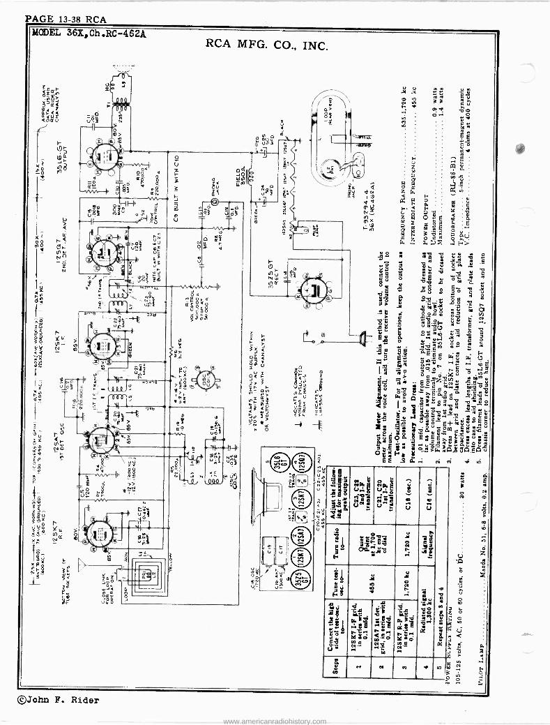
PAGE 13-38 RCA MODEL 36%,Ch .RC -462A
wé z>>°
Ja -e
r-
00 r dN v 8 a R
.-.VV1M1
(' \ \Ilric ql
1H miu
ZppZ O.J
r
RCA MFG. CO., INC.
s m __ N_yyd
U9: V ÓI
T T r '
.w0.3i.
o
. n f
O I
P
2:1 Ó O< u mp
C
.Q a
ó
lp
oae
Q
1 F VT,
JQ
hF 2 0 4
{.
O aª
ó aÿ 88 ati{ i.
I 0 0,
ttm
>>
J
a U J
ir wreJ
óOÿ Lu'
:12,-"'
y u- V
C
es is*
3 3 0>a o-.
1 n,
..0. 3 &
@O 3....
y b <.4 n
08 i we ur. q
up .
C V
u¡ó «.. ú,. a
Y á 0 u
^ 9
0 .. u
Q
O
V31.4 ÿyo
ÿ ñ 3 .i 'é i
ál Y
ÿ Al o
Ñ3 ., é ó ..c:.. 9 0 V Ça r« v C.a rr q O
.".o A Y 2ñIºsé'=é°''é:": .r n ia
oG f ó«
A4:~ö <ºó c`S`, á ' ó;ó u r
y O
.Nr_
103 4 d
O en .e ._ ix
S m
.. n d b ti
. C
Á i
m
C
b T
6.
©John F. Rider
www.americanradiohistory.com

RCA PAGE 13-39
X c0 0 Nd
>
I
r
L _oi W 0 um
'WV` oN ecv
CA MFG. CO., INC. MODEL B-50,Ch.RC-1004H
> Q
W -Ilk
3 o L- d
I« Ñ +A 'º ú Ñ LL Y Z .. I
1 ei
U p
O Ja (D ._U9 Q./
>>1"---1C1141 40 Nye -r9 I
R
Y 0 00 ON
00 o
W
oQ e d o.
i l i 0 U0F eze
O
>Q NZ d
Ill ,°('y Nm ----11---II,
e. 0 JmO 194º,
3
.. É N
N Nm
É má am
gg= y F
: N1 . x Ç
b! -..4 U
.1.5 Q.
N
,-1Ka ` UF ere U a
`-'
8
U
., : o, U
7
Ä
U á2.r m
5é[¿r«N+No
5p .S
o .o1
u
V 74 [. n b.eo á
u
n .+
J Ì o m ..
0
L. ú 8 o
I
.0
6
O r.p0 .E.=.
"iii .d v
g Ce s k
F«CC
w~ 6
= :s EN
N C .5 <
Y fÁ
.+ g 10v
Ú
u
cn V
©John F. Rider www.americanradiohistory.com

PAGE 13-40 RCA
MODEL B-52,Ch.RC-1004D
BATTERY DRAIN
RCA MFG. CO., INC. 3 amperes
10 m.a. (Switch at "Battery Saver" position)
14 m.a. (Switch at "Maximum Output" position)
POWER CONSUMPTION 22.5 watts
With CV -42 Conversion Unit
LOUDSPEAKER (5 -inch PM) RL -85-6 92322-1
Voice coil impedance at 400 cycles 3 ohms 3 ohms
CAUTION: Turn power switch off (counter -clockwise) when installing or replacing tubes or batteries.
DO NOT TURN THE "BATTERY -ELECTRIC" SWITCH TO ELECTRIC POSITION WHILE THE RECEIVER IS
CONNECTED TO BATTERIES.
Step Connect high side of test osc. to-
Tuns test ose. to-
Turn radio dial to-
Adjust the follow - ing for maximum
peak output
1 I -F grid
in series with .01 mid.
455 kc Quiet point
between 550 and 750 kc
C14, C15 (2nd I -F Trans.)
2 1st Det. grid in series with
.01 mid.
C12, C13 (1st I -F Trans.)
S
Antenna terminal in series with
200 mmfd.
kc
Tuning er co1,720
rotoro plates all out
C17 (osc,)
1,300 kc 1,300 kc
signal C9 (ant.)
5 455 kc Quiet point
between 550 and 750 kc
Adjust C22 for minimum output
on strong 455 kc signal
9.2 V. APPROX-. MAX. AVC.
-1 1.5 V. FIXED BIAS FOR /' GAIN DATA
Precautionary Lead Dress. - 1. The lead from the 3Q5 plate to output transformer should be
dressed under clip and away from audio input leads.
2. All filament wires should he dressed close to chassis.
3. Keep AVC lead connecting C1 to antenna coil away from the
1A7GT plate. 4. Keep blue plate leads coming from I.F. transformers short and
close to chassis. 5. Keep yellow leads connecting to oscillator coil away from trap coil.
6. Keep grid lead of 1N5GT RF tube away from 1A7GT grid.
POWER SUPPLY 1 "A" - "B" 1U-90 volt pack.
Model B-52 can be operated on 105125 volts AC, 50-60 cycles,
or 105-125 volts DC, by means of CV -42 Conversion Unit.
C22 DET. C IT- o3C. 455 KC. 1720 RC.
L-_/
1
ANT. TO GRID CON V. GAIN 5X 1 X 24 X I .4X --- 150 X
(600 KC) (600 KC) (600- 455 KC) (455 KC) ( 455 KC) MEASURED WITH 1.5 VOLT FIXED BIAS
BOTTOM VIEW OF runt 2_
SOCKETS
L2 a6 s
5.25
SI -
ON VOL. CONTROL
0-642.2
I NSGT R.F
NIELO
-t-
7V
.tA 40
es.l® © ce
R12 5600 LII 200.
C22 IO -7o
1,4 -9v. (600 1LC )
-13V.(1500 KC)
CIT 2-20
C IB 10 5s' WMRE MCD.
1A7GT 1sT OCT Q 05C.
R/3 3.3 MEi
52
M UAW
RED BATTERY
CABLE PLUG (PRONG VIEW)
y
/WV.
TRAN3. I M r=
OWI, C1 5-520,
RS L GB M .AAv-
mc .0C2
U
IS
L(. 20. 120.
FRED
14
SS FRONT
3+L
1, C2: 10
IN5GT I. F.
CS -ANT. 1500 KC. C12 -C19
455 KC.
/, IbT I.F TRANS.
C 14-C IS 455 KC.
`T2RAND.I.F
.OX (455 KC)
POWER SUPPLY 105-125 v.
00-1W, OE OC.
(400..)
11150T 2MD DET.-AF. a AVC.
T1 I
J
40 X -
22 X APPROX. GAIN (4o0 ,v) LATA MEASURED
WOK RCA RIDER CHANALYST
3Q 513T OUTPUT
54 REAR
f LIFO. RI -I 22
R14 R 10
sB0 SSO
Y1 C20
L 25 MFD.
i.4 V BATTERY SAVER Peen -tow -5.2 V. MAX. OUTPUT POSITION
POWER SW. VIEWED FRON FRONT SHOWN IN POSITION NO 1
POSITION 1_ BATTERY SAVER POSITION 2- MA%.OUTPUT- BATTERY POSITION 3- AC -DC OPERATION
VOLTAGES SHOULD HOLD WITHIN 420% WITH RATED SUPPLY VOLTAGE
* MEASURED WITH CNANALYST OR VOLTONMYST.
P-523022-3
eJohn F. Rider www.americanradiohistory.com

RCA PAGE 13-41
Ii 0 0
ANT. TO GRID 50 X
( GOO KC )
RCA MFG. CO., INC.
15 )( O.BX 200X Ix (600-455KC.) (455KC.) (455KC.) (455 KC.)
BOTTOM VIEW OF Tune SOCKETS.
MEASURED WITH -3V. FIXED BIAS ON AVC. BUS
12 5A7 ILT DET 6. OSC.
GIS
GI
LOOP
1ce
RI 22,000
R16 220,000
so v.
©rr,-,.,,© iT777 o.1
1]O 8o v. 80 v.
A ` to f`C>7
O/C. COIL Ce
b lUl 7-
-13 v APPROX /MAX. AVC. VOLTAGE
VOLTAGES SHOULD HOLD
® WITHIN ±20% WITH 117 V. AC SUPPLY )k MEASURED WITH
CHANALYST OR VOLTOHMY5T -1- GAIN DATA.
ILrI.F. TRANS. 455 K C. t0a I n
1 C650#o _, C7 75 1
ó 1 75-160 7A .7A
-1 s<AtK
R4 3.3 MEG
r
40X
MODEL 55X,Ch.RC-1003C
4.00 4v
125Q7 2ar CET. A.F Sc AVC.
0 17A
RS VOL.CONTQ 500,000 STOP AT 47,000
75- leo
CII BLK
- - 7 1201E
YEL. CIS -120 zJ m
C14 .02 4.7
HE6.
R/
I
APPROX. GAIN 14 X --+L DATA USING
400ív I RCA. RIDER CHANALYST.
50 Lb GT OUTPUT
4V.
R7 220,000
© -.71` © 225A.
4Bo v. EYE
CHASSIS GROUND
TO ANT. LEAD
3V. BIAS FOR
COMMON WIRING INSULATED FROM CHASSIS
Ac.
12 SK 7 I. F.
"RUN
35E5GT RECT.
110 V
CI8 .05
O
K
BLACK-. FREQUENCY RANGE 540-1,720 kc
t17 v. Intermediate Frequency. 455 k .
III
0n DIAL t) LNIP
1G 17 +.OY
RIS 1200
Steps Connect the high
side of test- oscillator to-
Tune test-osc. to-
Turn radio dial to-
Adjust the follow - ing for max. peak
output
1
I -F grid, in series with
.01 mfd. 455 kc
Quiet point 1,600 kc
end of dial
C8, C9 2nd I -F
Transformer
2 1st Det. grid in series with
.01 mfd.
C8, C7 1st I -F
Transformer
3 Ant. terminal in series with
100 mmfd. 1,720 kc Gang at
minimum CS (osc.)
4 Radiated signal 1300 kc Signal
Frequency Cl (ant.)
5 Repeat steps 3 and 4.
Phasing Speakers in Model 55X.- For correct sound quality, it is ESSENTIAL that the cones
of the two loudspeakers move in and out together. To check the phasing, connect a 111 -volt dry cell across the
secondary of the output transformer and observe, by sight or feel, whether the two cones move in the same direction. If one moves in while the other moves out, reverse the external connections to the voice coil of the permanent -magnet speaker.
3SZ5 GT RECT.
50LGGT OUTPUT
C18
R7
E.M.S. FIELD
C 20
C17
12A
WG
/777
2 -Pm SPEAKERS
vC
SPEAKER FRAME
R 925019-7 55x (Rc IooSC)
E. M. SPEAKER
N.C.
P. M. SPEAKER
3RPEAAM EaR
55 X
Above-Circuit of Model 55X Using one "PM" and one "EM" Speaker.
POWER SUPPLY RATINGS 105-125 volts, direct current, or 50-60 cycles 30 watts POWER OUTPUT (125 volts, 60 cycle supply) Undistorted 0.8 watts Maximum 1.2 watts
LOUDSPEAKERS RL -86-A3 5 -inch "EM," 4 -ohm voice coil RI.81-B2 .5 -inch "PM," 4 -ohm voice coil
Test-Oscillator.-For 1-F alignment, connect the low side of the test -oscillator to the common negative through a .01 mfd. capacitor, and keep the output as low as possible.
Pre -Setting Dial.-With gang condenser in full mesh, the pointer should be adjusted so that it is vertical.
Power -Supply Polarity.-For operation on d -c, the power plug must be inserted in the outlet for correct polarity. If the set does not function, reverse the plug. On a -c, reversal of the plug may -
reduce hum.
©John F. Rider www.americanradiohistory.com

PAGE 13-42 RCA
MODEL R-56 Phono RCA MFG. CO., INC.
POWER OUTPUT RATING
Undistorted 2.25 watts Maximum 4.50 watts
LOUDSPEAKER
RL -86-C1 5 -inch Electrodynamic V. C. Impedance at 400 cycles 4 ohms
PHONOGRAPH
Motor Self-starting Induction Drive Rim Drive, 78.25 R.P.M. Pickup Crystal
POWER SUPPLY
105-125 volts, 60 cycles 50 watts
PHONO JACK
50L6GT A.F
R1 9V. VOL. CONTROL OBI 1 MEG.. 11R2
50
e PICKUP
MC TOR 40 n
R3 820 M
RI 51
'^,A VIE VJ
MOTOR TURNTABLE OIL BOARD \
11 .A311 arm, IIIIWILI
1 TURNTABLE BEARING OIL
IDLER SPRING
C3 -.02
135V. 62 MA.
ON Ilell
À an -rte
R56
ï J
TI
145V- 5 MA.
R4 FIELD
68M iL RED 106OtL C5 16
220 V. 50Y6GT MFD, r BLK
w 68 MA.
REC T al1 GRì1 .74R5 I C -Ç02 MFD. MFD..
Y "J D
SOLGGT SOY6GT 125' .05C4
H.G.
° SI ON VOL. CONTR POwER
U U SUPPLY,
BOTTOM VIEW CF TUBE SOCKETS
IDLER __ MOTOR
SPINDLE
OIL PAD
OIL PAC
n
I
I
3.6 st ` EM.SPkR
COMMON WIRING CHASSIS INSULATED FROM GROL.N CHASSIS
M-95218-1 R56(RSI19)
STOCK No.
DESCRIPTION Unit List Price
STOCK DESCRIPTION Unit
PList rice
AMPLIFIER ASSEMBLY 39688 Coil -Field coil 2.10
39684 Capacitor -Electrolytic, one section of 10 mfd., 39689 Coil -Neutralizing coil .25 250 volts, and one section of 16 mfd., 150 volts 1.10 39539 Cone -Cone, voice coil, center suspension, and
36248 Capacitor -.02 mfd., 700 volts .20 dust cap 1.20
32787 Capacitor -.05 mfd., 400 volts .20 43763 Capacitor -0.1 mfd., 400 volts .30 MOTOR ASSEMBLY 39500 Capacitor -16 mfd., 150 volts .50 38410 Control -Volume control and power switch 1.50 36402 Arm -Idler arm and stud for motor .25 11565 Resistor -16 ohms, } watt .20 20134 Ball -Steel ball for turntable bearing .06 39685 Resistor -120 ohnT, 3.1 watt .45 36404 Motor -105-125 volts, 60 cycle motor 4.75 30785 Resistor -150 ohms, 1 watt .22 36403 Mounting -One set of mctor mounting grommets, 14138 Resistor -68,000 ohms, } watt .20 spacers, and washers .10 30161 Resistor -820,000 ohms, } watt .20 36406 Plate -Idler arm guide plate for motor .10 33742 Socket -Phono input socket .20 36401 Plate -Motor plate complete with bearing and 31251 Socket -Tube socket .25 ball .50 39683 Transformer -Output transformer 1.35 30340 Retainer -Motor fan retainer .02
30585 Spring -Motor idler arm tension spring .06 PICKUP AND ARM ASSEMBLY 36399 Turntable -Turntable and bushing complete with
33591
34482 34768
Arm -Pickup arm only -less cartridge, and pivot shaft and base assembly
Base -Pickup arm base -less pivot shaft Bushing -One rubber and one metal bushing for
.50
.30 33726 36405 36274
spindle Washer -"C" washer for motor idler wheel Washer -Flat washer for motor idler wheel Wheel -Motor idler wheel and bearing
1.50 .02 .01 .55
pickup arm .15 39686 Crystal -Pickup crystal cartridge 4.25 MISCELLANEOUS ASSEMBLIES 34311 Ring -Retaining ring for pivot shaft .05 33974 Screw -Needle screw .10 38990 Foot -Cabinet foot .20 34481 Shaft -Pickup arm pivot shaft .70 38710 Knob -Volume control knob .15
SPEAKER ASSEMBLY 33530 Mounting -Rubber grommet, washers, and nut
for mounting pickup arm .10 (RL -86C-1) 39690 Screw -Finish screw and washer for mounting
32907 Cap -Cone center dust cap .02 amplifier (1 set) .05
ALL PRICES ARE SUBJECT TO CHANGE OR WITHDRAWAL WITHOUT NOTICE.
()John F. Rider www.americanradiohistory.com

RCA PAGE 13-43
RCA MFG. CO., INCMODELS TRK-90,Chassis KC -4H, KK-7H;TREr120,Chassis KC -4F, KK -7F
General Description The TRK-120 consists of a console -type, high -picture -
definition, mirror -viewing, five channel, Television Receiver and an eleven -tube, three -band broadcast radio receiver en- closed in a handsomely styled modern cabinet. Features of the Television receiver include: Twelve -inch Kinescope; Styrol (humidity -resisting) r -f and i -f transformer forms; black and white pictures; single station selector switch; tem- perature compensated condensers; iron core i -f and r -f tun- ing; double safety switch protection; safety -glass viewing
shield; extra large viewing mirror for wide angle viewing; automatic brightness control; and automatic volume control.
The TRK-90 is a direct viewing, high -picture -definition console -type, five channel, Television Receiver and an eleven tube, three -band broadcast radio receiver in a deluxe upright modern cabinet. Television features of this receiver are the same as for the TRK-120, except that a nine -inch Kinescope is used.
General Specifications Model TRK-90
Height 471/2 in.; Depth 24%6 in. Width. 311/2 in.; Weight. 200 lb.
Shipping Weight 283 lb.
Model TRK-120 Height 405/8 in.; Depth 197/8 in. Width. 345/8 in.; Weight. 198 lb.
Shipping Weight 275 lb. Power Supply Rating 105-125 volts, 60 cycles, 420 watts (Total) Fuse Rating-T5 and T7 (T7 and T8 in 50 cycle model) 3 amperes Fuse Rating-T6 (T9 in 50 cycle model) 3/4 ampere
Mechanical Specifications Video Chassis Base Dimensions 17 in. x 16 in SPU Chassis Base Dimensions 15 in. -x 131/4 in.
Electrical Specifications RCA TUBE COMPLEMENT
In KC -4F (TRK-120), and KC -4H (TRK-90) Video Chassis (1) RCA -6ÁC7 (5) RCA -6ÁB7 (9) RCA-6SQ7 (13) RCA -6ÁB7 (2) RCA -6J5 (6) RCA-6AB7 (10) RCA -6ÁC7 (14) RCA -6H6 (3) RCA-6AB7 (7) RCA-6AC7 (11) Kinescope* (15) RCA -6N7 (4) RCA-6AB7 (8) RCA -6H6 (12) RCA-6SK7 (16) RCA -6Y6 -G
In.KK-7F (TRK-120), and KK -7H (TRK-90) Socket Power Units
(23) RCA -5U4 -G Low Voltage Rectifier (24) RCA -2V3 -G
TELEVISION CHANNELS (Selector Switch Positions) 1 44 to 50 mc. 3 66 to 72 mc. 2 50 to 56 mc. 4 78 to 84 mc.
5 84 to 90 mc. Over-all Video Band Width 4 mc. Scanning Interlaced, 441 Line Horizontal (Line) Scanning Frequency (Sawtooth Wave) 13,230 cps Vertical (Field) Scanning Frequency (Sawtooth Wave) 60 cps Frame Frequency (Picture Repetition Rate) 30 cps
PICTURE SIZE (Approx. Mask Dimensions)
Max. Height 81/2 in. Max. Height 10 in.
TRK-90 51/2 x 71/4 in.
(17) RCA -6N7 (18) RCA -6N7 (19) RCA -6L6 (20) RCA -5V4 -G
(21) RCA -6N7 (22) RCA -6J5 `RCA -1803-P4 (TRK-120) *RCA -1804-P4 (TRK-90)
High Voltage Rectifier
TRK-120 73/8 x 93/4 in.
Precautions in Handling Kinescopes The Kinescope bulb encloses a high vacuum and, due to
its large surface area, is subjected to considerable air pres- sure. For these reasons, Kinescopes must be handled with more care than ordinary receiving tubes.
The large end of the Kinescope bulb - particularly that part at the rim of the viewing surface-must not be struck, scratched or subjected to more than moderate pressure at any time If the tube sticks, or fails to slip into its socket or de- flecting yoke smoothly, investigate and remove the cause of trouble. Do not force the tube.
All RCA Kinescopes are shipped in special cartons and should always be left in the cartons until ready for installa- tion in the receiver. Keep the carton for future use.
The RCA -1803-P4 (12 -inch) Kinescope is equipped with a protective lid and shield. Do not at any time remove the close -fitting cone -shaped section of the protective shield from the Kinescope. This section should be installed with the tube in the cabinet and is designed to protect the user while handling the glass bulb.
CAUTION: Do not open the shipping carton, install, re- move, or handle the Kinescope in any manner, unless shatter- proof goggles and heavy gloves ape worn. People not so equipped should be kept away while handling Kinescopes. Keep Kinescope away from the body while handling.
©John F. Rider www.americanradiohistory.com

PAGE 13-44. RCA MODELS TEE- 90,TRK-120 RCA MFG. CO.. INC.
www.americanradiohistory.com

RCA PAGE 13-45
ó l/`
ee --/ áaä
1-k r9 <
d
<; rg nI-
ls$
-f 2Fú
»+ .-II--+
F-F $
et
r rca
RCA MFG, CO., INC.
a=. nenu
-
dg x
L
7áö
MODELS TRR-90, MX- 120
C a
is 1000090000000000001
en 10000000
iWîiá. R ;oÈ ' 0#
8ÿtI
[ r l
3n:5Ñ3 ..w.: z. <P 4
:WA ¿5 < i " 6.[ -i_ ' _ .._ "IM t'!I.^ _ +o . i ;+.'ß 3 'e
i : 1,
ce
Mg1 T "
^.I T331 é
H
=-h--,
C e j p íi 4y yyOis-pa-o-iH
, o)I ' ¡ ['¡~'.a c 13 ^ ,
I ,,,_. ..1... :` J 1: I--=..w -
t. ...M..: . .e=,
a=
I
45.
e
: : º IN
:8 - F
1
38
:$
4
ear 88' =ó
-,; ú
u
iF-
:4
I--;
4432
-iV Z 8i! Y 1. M
333111
ta~ :`l
w íi -ti S°S;
,Te" s h
aae i« 8;-
F & .e.,aao. S
`r4
... --IH .... : g6 : --u ei =á
-
E
II ó8i .4 .g H . .
w
,33 :2 :E.
e=
: ... HK ;8-
_ 5r.;
--1Ì s "^ S
ZZ' 128 G9 .T2
x.1I
,"
Ì e 4»
._.
.8:
út a
.i ;": >=1
º
.=r
ii
ï;
8
3
ea
º
A
IA
©John F. Rider www.americanradiohistory.com

PAGE 13-46 RCA
MODELS TRK-90,TRK-120 RCA MFG. CO., INC.
L512 B912 6512 0912 1l12 r912 MI z912 Il x
z ,
' = =, /(©i l o .t© ry i á-
Ñ O O O\< ñ © Ej 1 e
o«)© 1 ©° > a:
Or
O O OO © 11 r` ' O \d e© ,° á
© O Y
oj e
u! J
o
ó ) E o Z QEOG
aa_
w>
r i 8
a 7 ` r i
W, nañ
¢
g: O d ° i4 p O !r :ç 1n
© ujf 5$ i: -.;::E.3 >o. i
z : 4i oé fi e n;x _o
'Á a> W s :
ª J ó
t
Y 3 Y
` N m y \ oM QN :.
R
ú i, ,
n
4Y gg 1 d " F ,ga <;
"
nfI
yl
oQ
É n
¡
3 p © ©
Q1 ©
-+I
,
Si 5
; x> 4 .
°
v ó
;
á 1R yÑ >
yN . 4 NO
z a r<, C'1 i i yy, © ® « YI ® :7 ul d
El 0 -uw pp 0 fJ
(-- ÇY py -O _
i
O© 0 0 0 e;e
>< 3 T P. Q w
bó o 1s. © éì
Tr OO
o
d © r:i
LI
o ñ- ®
u
R
á \
p
0 >
.-.r 4: 4:
©O O O ,; á c p
Q c, ä-
0O° . p üell
i n© ® "
1 --ii cl t" -dd. o© n` ©o á n Y
- p
e o á, ° q a o
d ä r_ x oa ° tu ,..D W :© 0©
p " Q 0 0-< °,p
©o ® m 0-; ug ®,©
1 =
--- K
0® O o 0, O1®
ó U
m ?%19 .u.
x, ,Z \L
i.(©c+ ``°lá "t' O FJ, 59ei Z Q
i"s3, o
NOzao WLLWLu < O E< K O JNOI.W.,Z < 9e=In/, ZJLÓaó n;; Q} QJSp ì
_ A
^ f
spp
F _
r > ñ ._
á a .
d C © ááiRFg- f p: §1;.26 f-
º D %~SO= ` w WK<Zo&3
18 OO pmp Oto11
3 dYfl©O téi 3
N E
.A < d¿ö$°=_ U aYg+
o
îWJW O G : ó~><ªi
Z 0 HJ WU =<W L2GL= 22F-°OF- s
i . xXá
, i
v
.o O4,
2 c ^ o
ek p Y
LCD
f .!©0 Nrr`gs
CI -SrS °I)Q II
©O © mOw
OM
' c - ©0 O OyQr GI®
I '
=^ v
p¡E -ií ©© F : tl
7/
(
/ s 4 Ys
(,O ! FI© ~
p 0 ": É - QO
OF
0 0 I 1 p
« i
r i 1'>
L G
2 ß ;
E ó' ® ©© pmp_ O v i-pm© 00O
/I ®
° ° ®©p "- Y óo °1[
t,l ©
c D Y d P.
I Iv, ñ (. 4" á
'I
ki ~ Z ~ ZZ iF O Z Dr i>W3 ~D 'a=
r. avO
iii
! ,
1
S
J F+
©John F. Rider www.americanradiohistory.com

RCA PAGE 13-47
RCA MFG. CO.,INC. MODELS TRK- 90, TRK-120
DEFLECTION YOKE CABLE
RADIO CHASSI (RC -427
ANT. LEA TO RAD CHASSI
GND. LE TO RADI CHASSI
TELE VIS SOUND CABLE
KINESCa CATHODI LEAD (YELLOV
TEL EVIS RECEIVE CHASSI; (KC- 4H
TELE VI5I I NTERLC SWITCH (52)
VBLOCK KINESCOPE 2ND ANODE MOUNTING SOCKET LEAD SCREW (X It) HI -VOLTAGE
YOKE 17 DEFL. V ,BLOCK /. MOUNTING YOKE I KINESCOPE BLOCK( LEADS
D 0, 5
1D_
5
ION
y:lr (er
(XIe1 M (X20)
I
- °
I)
/ RN ì
)
DN
,CK
I221 (x4)
KIN GRID LEAD
M (X6) !
Ir "- --
I,IRa) .. lxs) Á ol M M (Xe F (X10) (%7)
SPEAKER - M(X12) \ /2 F(((2Ì2)
` 5i
f/ 1
RADIO POWER SUPPLY UNIT
( RS- 83- E)
PILOT LAMP
/ H, G2 8 1ANODE NO.1)
RADIO POWER SUPPLY CABLE
-AC. CABLE TO
INTERLOCKS. e_g
DEFLECTION ANY LEAD GND. LEAD YOKE Tb RADIO TO RADIO CABLE CHASSIS CHASSIS
(YE LOW) (BLACK)
2ND. ANODE LEAD HI- VOLTAGE
(TEL. RECEIVER CHASSIS (KC -4F)
M (X2)
RCA -1603- P4 KINESCOPE \ PROTECTIVL
BHILLD
-SPEAKER CABLE
FEED BACK CABLE
FLX23) M (X 24)
TELEVISION INTERLOCK SWITCH
(51)
TELEVISION -POWER
SUPPLY CABLE
TELEVISION POWER SUPPLY UNIT (KK -7H)
x105-125 V.
AC. CABLE v 60 "v SUPPLY
TO TELEVISION POWER SUPPLY M -91112-I
Figure 3-Cabinet Wiring-Model TRK-90
YOKE SOCKET
HOR. CENT (R9
19 MOR. OUT.
WIDTH (R 94
le' NOR. OSC.
NOR..DISCH
-RI
17 NOR. SYNC AMP. VERT. SYNC. AMP
VERT LIN. (R 113
21 VERT. OSC. VERT DISCM.
HEIGHT(R IOB
22 VERT OUT
-Ri
-I I
VERT CENT (RII4)--. ±
co
o
CN C104
Arr.' 420 410
M (X4)
M(X6)
DEFL. YOKE
RADIO CHASSIS (RC -427F)
M(XIB)
M(X201
KIN. GRID LEAD
KINESCOPE CATHODE LEAD (YELLOW)
\TELEVISION INTERLOCK 5w. (S2)
KIM. KIN.CABLE SOCKET LEADS (H.
)
I I
mom 'FIXT) SPEAKER
, XIO 1'F(x9)'I
PILOT LAMP M(X14)
1_1 MIX121
SPEAKER CABLE
AC. CABLE ro
/ INTERLOCKS
FEED BACK CA B LE
1M(X24) (K 24) M
TELEVISION
-F SOUND CABLE
TELEVISION INTERLOCK SW. (SI)
IA (22)
F(X2UJ
RADIO POWER SUPPLY UNIT IRS- 83-E)
L -
PILOT 105-25 V. LAMP 60,v SUPPLY CABLE
RADIO POWER
SUPPLY CABLE
\AC. CABLE TO LEV. P VITEER SUPPLY
TELEVISION PO w ER
SUPPLY CABLE
TELEVISION POWER
SUPPLY UNIT (KK -7r)
M -91113-I
Figure 3a-Cabinet iring-Model TRK-120
NOR HOLO(R9ÿ ,Lfl.-FINE TUNING (C9) CONTRAST (R4 S)
VERT HOLD (R)oe) I I STATION BRIGHTNESS (Ret Ll SELECTOR
1 n (51,52, S3)
HOR DAMPING
T2 HOR.OUTPUT
TRANS.
cr.
o o (le
VERT. OUTPUT
T4 TRANS.
2 DET TRANS. ASSEM
OSC 1ST DET PI
HOR.OSC, TRANS.
2ND SYNC. SEA
make
Cae Cae Cal
I I
VERT. OSC. TRANS.
CB
12 IST SOUND IF.
P2
21"7)., L20 ADJ. ADJ.
FOUND I.F TRANS.
13 2140.
SOUND IF
L48)
ADJ.
P
.
2/ ND SOUND IF TRANS.
IS \` ELI SYNC.
SEP. L SYNC. AMP
C51 1 `/ C104 1 t4
OrKINESCOPE G SOCK
T l,6SQ7
L18.)
ADJ.
o SOUND 2 N0..
9 DET. NOISE I A.V.C.
LIMITER S TH. PIX. I.F.
TRANS.
L 3711
I
ADJ o
Ii
PI
L 28 ADJ
- -3 IST PIX I F
IST PIXIE At Left-Figure 5 TRANS. ASSEM. Top View Video Chassis
ADJ.
10 VIDEO AMP
e PIx.2 ND.
DET.
4 2140 PIX I F
211 THREE TRANS ASSEM SECTIONS
S 3RD PIX I F
3RD PIX IF TRANS
e 4TH PIX. IF.
4TH FIX IF. TRANS.
7 STH. P1)1
IF. KC -4F, KC -4H
RINGS
(Above) Figure 6 Recommended Type 6L6 Identification
©John F. Rider www.americanradiohistory.com

PAGE 13-48 RCA
MODELS TR11-90,TRK-120 Chassis KK-^F,KK-7H
óZ= w OO
/ O43 VOZ
/ £ i-'a Z / I-- 14)
Z=Oo QZ O Go Lu Q19 >z>. v>Ó I
C1.-1- rcá 1-'2N I'llI Q 0~ I
`ut i \ á U O I F ,n \ l'-.2
CC \ W I
m r----
> ----
<a \ '/
<\ \ ai o`
w v0 OZB
1 I' \ \\ 01
©John F. Rider www.americanradiohistory.com

RCA PAGE 13-49
RCA MFG. CO., INC. The finest television receiver built may be said to be only
as good as the antenna design and installation. It is therefore important to use a correctly designed antenna, and use care in its installation.
The RCA Double Dipole Antenna, Stock No. 9871, is recommended for use with these receivers. Both this antenna and the "V" antenna described below are especially designed
for a sufficient broad frequency response to cover the con- templated television spectrum with good efficiency and are 'therefore superior to a single Dipole type antenna.
When greater signal pickup, or where a shielding effect from noise sources or image reflections are desired, a reflector assembly, Stock No. 9872, may be added to the Stock No. 9871 Antenna to obtain an improved signal-to-noise ratio.
The RCA Double "V" Wire Type Television Antenna is an alternative type of antenna designed for television sight and sound reception. Two points of support are necessary. It serves adequately in suburban areas, but may not be suffi- ciently flexible in congested city areas where bad reflections and interference are encountered. Antenna Installation.
In most cases, the antenna should not be installed per- manently on the apartment or residence roof until the quality of the picture reception has been observed on a Television receiver. A temporary transmission line can be run between receiver and the antenna allowing sufficient slack to permit moving the antenna. Then, with a telephone system con- necting an observer at the receiver and an assistant on the roof to find an antenna location, the anténna can be posi- tioned to give the most satisfactory results on the received signal. A shift of only a few feet in antenna position or di- rection may effect a tremendous difference in picture re- ception.
Whenever possible, the antenna location should be chosen or erected so the antenna is not only broadside to the trans- mitter but removed as far as possible from highways, hos- pitals and doctors' offices and similar sources of interference. Auto ignition and diathermy apparatus may cause noise in- terference spoiling the picture.
In mounting any antenna, care must be taken to keep the antenna rods or pickup wires proper at least i/4 wave length (at least 6 feet) away from other antennas, metal roofs and gutters or metal objects. Under certain extremely unusual conditions, it may be possible to rotate or position the an- tenna so it receives the cleanest picture over a reflected path. If such is the case, the antenna should be so positioned. However, such a position may give variable results as the nature of reflecting surfaces may vary with weather condi- tions, as a wet surface has been known to have different re- flecting characteristics than a dry surface.
In short, a television receiving antenna and its installation must conform to much higher standards than an antenna for reception of International Short Wave and Standard Broad- cast signals because:
(1) Intervening obstacles have a pronounced shielding effect on the ultra -high frequency waves producing low in- tensity signals. Severe trouble with multi -path transmissions may be experienced, especially in congested city areas.
(2) The picture signal is comprised of a very wide band or range of frequencies, all of which must be received with good efficiency.
(3) It must be continually remembered that the discern- ment for the eye is much more critical than that of the ear.
Transmission Line RCA Victor has made available two types of exterior trans-
mission lines. One is a special low loss weather -proofed line having the correct surge impedance to match the RCA Victor Television antennas and the RCA Victor Television receivers. It is carried as Stock No. 9882 in 1,000,foot rolls. The second type is a standard weather -proofed line, also having the correct surge impedance for proper antenna and receiver matching. It is carried as Stock No. 12430 in 90 -foot rolls, Stock No. 12429 in 45 -foot rolls and is available in 1,000 -foot spools as Stock No. 9881. Use of improper lines may result in excessive loss or may lead to line reflections, resulting in multiple images or "ghosts," thus marring the reception.
MODELS TRK-90,TRK-120
For transmission line runs up to 200 feet, and where the signal strength on the antenna is relatively high, the Stock No. 12430, or Stock No. 12429 transmission line may be used. For all other applications the Stock No. 9882 trans- mission line is recommended. In some areas of very high. signal intensity, a lead coverer
transmission line may be advantageous.
Five -Television -Channel, Receiver Kinescope Installation (TRK-90).
1. Remove back cover of cabinet. 2. Remove the two screws which secure the wooden block,
on which the yoke is mounted, to the upper shelf, and drop this block and yoke away from the shelf.
3. Loosen the thumb screw in the center of the slotted block of wood on the top shelf, pull this block of wood to- wards the rear of the cabinet and turn it so that the "V" slot on the front end of the block is to your right.
4. Wearing gloves and goggles, carefully slide the Kine- scope on the "V" in the block, and turn both the block and the Kinescope so that the Kinescope faces the viewing win- dow. Sl?de the Kinescope up to the mask in the window and fasten loosely in place by sliding the "V" block up to the bottom of the Kinescope face, and fastening it with the thumb screw.
5. Place the yoke änd the wooden block on which it is mounted, on the Kinescope neck, rotate the block 90° from its original mounting position in order to have it clear the top of the cabinet and slide it into position on the Kinescope neck. DO NOT FORCE YOKE. In some cases where the yoke lead is too short it may be necessary to loosen the "V" block and swing the Kinescope neck to the left in order to be able to place the yoke on the Kinescope neck without forcing.
6. Fit the upper part of the wooden yoke mounting block into the slot on the underside of the cabinet top and fasten the lower end of the block securely by means of the two screws. The Kinescope should be mounted loosely in ,place, so that the yoke is not forced on the Kinescope neck at any time.
7. Loosen the wing nuts on the yoke mounting bracket, and move the yoke forward on the neck of the Kinescope so that it pushes the Kinescope against the mask. Tighten the wing nuts to hold the Kinescope and yoke securely in this position. 8. It may be necessary to rotate the Kinescope, within the limits allowed by the high voltage second anode lead, with re- spect to the mask in order to obtain proper masking of the
edges on the Kinescope screen. Before rotating the Kine- scope, the screws holding the yoke mounting block should be loosened, so that the Kinescope neck will not be forced. 9. Move the "V" block forward so that it holds the bot- tom of the Kinescope in place. Tighten the thumb screw. 10. Place the second anode lead on the second anode cap at the side of the Kinescope. 11. After the receiver is operating, and if the picture is not squared with the mask, .using a screw driver loosen the clamping screws on the band around the yoke and rotate the yoke until the picture is squared with the mask, then tighten these clamping screws securely.
CAUTION: When removing the back cover of the cabi- net, after the screws have been removed do not allow the cover to slide down on the neck of the Kinescope, or the neck of the Kinescope may be snapped off. Kinescope Installation (TRK-120).-Refer to figure 4.
1. Remove back cabinet cover. 2. Remove the top safety glass cover by removing the three wing nuts "E" at the two front corners and right rear corner of tue cover and loosening the wing nut "E" at the left rear corner of the cover. 3. Lift the cover straight upwards, taking care not to scratch the cabinet finish with the protruding screws or the cover itself.
4. Loosen the two wing nuts "F" on the yoke holding frame, and allow the yoke to drop down as far as possible.
5. Using gloves and goggles, open the Kinescope shipping carton and remove the top cover on the Kinescope.
©John F. Rider
www.americanradiohistory.com
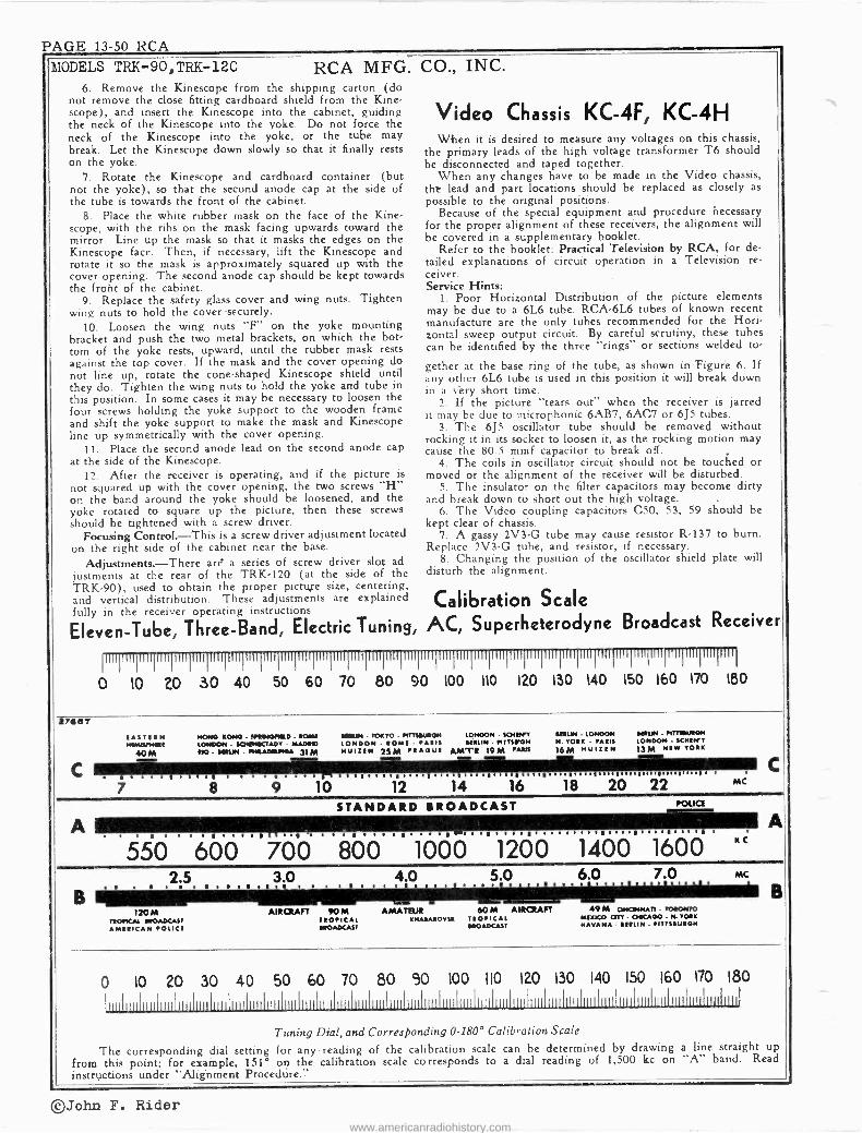
PAGE 13-50 RCA
MODELS TRK-90,TRK-120 RCA MFG. CO., INC. 6. Remove the Kinescope from the shipping carton (do
not remove the close fitting cardboard shield from the Kine- scope), and insert the Kinescope into the cabinet, guiding the neck of the Kinescope into the yoke. Do not force the neck of the Kinescope into the yoke, or the tube may break. Let the Kinescope down slowly so that it finally rests on the yoke.
7. Rotate the Kinescope and cardboard container (but not the yoke), so that the second anode cap at the side of the tube is towards the front of the cabinet.
8. Place the white rubber mask on the face of the Kine- scope, with the ribs on the mask facing upwards toward the mirror. Line up the mask so that it masks the edges on the Kinescope face. Then, if necessary, lift the Kinescope and rotate it so the mask is approximately squared up with the cover opening. The second anode cap should be kept towards the froht of the cabinet.
9. Replace the safety glass cover and wing nuts. Tighten wing nuts to hold the cover securely.
10. Loosen the wing nuts "F" on the yoke mounting bracket and push the two metal brackets, on which the bot- tom of the yoke rests, upward, until the rubber mask rests against the top cover. If the mask and the cover opening do not line up, rotate the cone -shaped Kinescope shield until they do. Tighten the wing nuts to hold the yoke and tube in this position. In some cases it may be necessary to loosen the four screws holding the yoke support to the wooden frame and shift the yoke support to make the mask and Kinescope line up symmetrically with the cover opening.
11. Place the second anode lead on the second anode cap at the side of the Kinescope.
12. After the receiver is operating, and if the picture is not squared up with the cover opening, the two screws "H" on the band around the yoke should be loosened, and the yoke rotated to square up the picture, then these screws should be tightened with a screw driver.
Focusing Control.-This is a screw driver adjustment located on the right side of the cabinet near the base.
Adjustments.-There are a series of screw driver slot ad justments at the rear of the TRK-120 (at the side of the TRK-90), used to obtain the proper picture size, centering, and vertical distribution. These adjustments are explained fully in the receiver operating instructions
Video Chassis KC -4F, KC -4H When it is desired to measure any voltages on this chassis,
the primary leads of the high voltage transformer T6 should be disconnected and taped together.
When any changes have to be made in the Video chassis, tilt lead and part locations should be replaced as closely as possible to the original positions.
Because of the special equipment and procedure necessary for the proper alignment of these receivers, the alignment will be covered in a supplementary booklet.
Refer to the booklet: Practical Television by RCA, for de- tailed explanations of circuit operation in a Television re- ceiver. Service Hints:
1. Poor Horizontal Distribution of the picture elements may be due to a 6L6 tube. RCA -6L6 tubes of known recent manufacture are the only tubes recommended for the Hori- zontal sweep output circuit. By careful scrutiny, these tubes can be identified by the three "rings" or sections welded to-
gether at the base ring of the tube, as shown in Figure 6. If any other 6L6 tube is used in this position it will break down in a vèry short time.
2. If the picture "tears out" when the receiver is jarred it may be due to microphonic 6AB7, 6AC7 or 6J5 tubes.
3. The 6J5 oscillator tube should be removed without rocking it in its socket to loosen it, as the rocking motion may cause the 80.5 mmf capacitor to break off.
4. The coils in oscillator circuit should not be touched or moved or the alignment of the receiver will be disturbed.
5. The insulator on the filter capacitors may become dirty and break down to short out the high voltage.
6. The Video coupling capacitors C50, 53, 59 should be kept clear of chassis.
7. A gassy 2V3 -G tube may cause resistor R-137 to burn. Replace 2V3 -G tube, and resistor, if necessary.
8. Changing the position of the oscillator shield plate will disturb the alignment.
Calibration Scale
Eleven -Tube, Three -Band, Electric Tuning, AC, Superheterodyne Broadcast Receiver
III
0 IO 20 30 40 50 601170 II
80 90 100 110 1 150 140 150 160 170 180
aee, EASTERN NIGIOPIIIE
0M HONG KONG - N'IMONELD - ROMS LONDON - SO*EICTADY - MASSIG SIO - MON - /MAMS+MA 31 M
Raul - TOKYO - PTTTIILMOH LONDON - sown LONDON - ROME - PARIS UM IN - ITTSEPON NYISIN 25M PRAGUE AMTS 19M PAID
IMUN - LONDON N. YORK - PARIS
16M NUIrEN
Ill// - NrTI1URON LONDON - $CHEWY 13M NEW YORK
. . . . I . . I I . . e . . . I . . . . R . . . . R . . i . R . . . . I . . . . I
550 600 700 800 1000 1200 1400 1600
. I 2.5 3.0 4.0 5.0 6. 7.0
. I .0 . 1 . . .
120 M TROPICAL MOADCAST AMERICAN POLICI
AIRCRAFT 90M TROPICAL MOADCAST
AMATEUR 60 M AIRCRAFT 49 M ONOMNATI - TORONTO
KHAEAROVSR TROPICAL MEMO QTY- OIICA00 - N. YORK
MOADCAST HAVANA - IMAN - PITTISUION
MC
0 10 20 30 40 501 60 70 80 90 100 110 120 130 140 150 160 170 180
IIl11IIIIlI
Tuning Dial, and Corresponding 0-180° Calibration Scale
The corresponding dial setting for any reading of the calibration scale can be determined by drawing a line straight up
from this point; for example, 151° on the. calibration scale corresponds to a dial reading of 1,500 kc on "A" band. Read instructions under "Alignment Procedure.'-'
©John F. Rider www.americanradiohistory.com

RCA PAGE 13-51
RCA MFG. CO INC MODELS TRK-90,TRK-120 Ch.RC-427(Receiver)
General Description Radio receiver chassis No. RC -427 is used in RCA Victor
Television Console Models TRK-90 and TRK-1[20. C t I C
IA AI The audio output of the television chassis is connected to
1
the audio input of the radio chassis by means cf jack X-17 B 6
and section S7 of the fidelity switch. The functions of this RANGE INDICATOR switch are tabulated on the following page.
A separate plug-in power unit, RS -83E, is used to supply 41414441441111:111 113I
heater to the Service data t z a o s e , e q and plate voltages radio chassis. and diagram for this power unit are shown below. pPoip
At Right-Location of Controls (Radio) soFT J'E`i1) ero
AQc
0,/, CODD 7 ,ò,1 my
POWER -VOLUME FIDELITY TUNING RANGE SEC Schrntatic Diagram, RS -83E CONTROL SELECTOR CONTROL SELECTOR
TI GREEN -RED TR. RED I
-_ i f. RECT 5V. 5 U4 G
FIL GREEN-FEDTR, RECT 3(O0 V.
1 BROWN PLATE loon© PLUG
3.5 I 10On + C1 o:CABLE 0 GA MFD.
10 HEATER gRowN Il -j I
b 6.5V -
PILOTP LAM
BFOwti-@LACK BROwrr 24 V. MOTOR BLUE BLUE 8R !í1 10 1n BLUE Bt Ac l< v 1
V.EI LOW- IEL LOW
YELLOW BREEN
REO BLACK- RED TR RED BLACK - iseo
Fidelity Switch (S4, S5, S6, S7) M 86727 RS 83E
- Switch Position For I -F
Amp. Audio Amp,
110-V. Supply Tele. for
Chassis Chassis Osc. +B Supply
Dial Lamps **
No. 1 (Counter-
clockwise) Victrola - Min. Highs Off Off On
No. 2 Victrola - Max. Highs Reduced Lows Off Off On
No. 3 Victrola - Full Range Off Off On
No. 1 Radio Sharp Min. Highs Max. Lows Off On On
No. 2 Radio SharpMax. Highs Reduced Lows Off On On
No. 3 Radio Sharp Max. Highs Full Lows Off On On
No. 4 Radio Broad Full Range Off On On
No. 1 Television - Min. Highs On Off Off
No. 2 Television - Med. Highs Reduced Lows On Off Off
No. 3 Television - Full Range On Off Off
* Controlled by switch (S12) on rear of fidelity switch. ** The 1st-I.F, heater is opened on television positions 1, 2 and 3.
©John F. Rider
www.americanradiohistory.com

PAGE 13-52 RCA MODELS TRK.-90,TRK-120 RCA MFG. CO., INC. Chas .RC -427
RED RED -BLACK TR.
Connections and Colors of Loud- speaker and Cable
TRK-120 for 105-125 Volts - General differences are as follows:
Miscellaneous Data for Radio Chassis FEED BACK Xg CONNECTOR - -
PLUG (PRONG VIEW)
BROWN
RED-YEL. YELLOW
31I-643 BLACK TERMINAL BOARD
Chassis KC -41
1. Tube No. 21 formerly RCA-5V4G changed to RCA - 25Z6 and socket wiring revised.
2. Circuit changes are indicated on the schematic diagram (Fig. 9).
Chassis KK -71
I. Capacitors C-118 (80 mfd.) and C-119 (10 mfd.) added in parallel with C-110.
2. Capacitor C-128 (0.25 mfd.) added in parallel with resistor R-166.
3. Capacitors C-11'3 (0.03 mfd.) and C-114 (0.03 mfd.) changed to C-121 (0.1 mfd.) and C-122 (0.1 mfd.)
4. Power transformer (T-5).changed to (T-8) having a 25v. heater winding to supply the RCA -25Z6 horizontal damping tube.
5. High voltage power transformer (T-6) changed to (T-9).
6. Resistor R-165 is added. 7. Inductance L-50 is 100 ohms in this model. 8. An RCA -5T4 replaces the RCA -5U4 -G.
In addition Kinescope shielding is provided as follows: 1. A metallic conical section is installed in the cabinet to
shield the Kinescope bulb. 2. A double metallic cylindrical section is installed with the
deflecting yoke mounting assembly to shield the deflecting yoke proper. The accompanying illustration shows its assem- bly.
CAUTION: The conical shield is of the proper size to permit installing the 1803P4 Kinescope with its protective cardboard sleeve. The latter should never be removed.
To prevent Kinescope breakage, when installing a Kine- scope, the deflecting yoke and shield assembly must be in place. To- prevent breakage of Kinescope when removing the deflecting yoke and shield assembly the Kinescope must be removed first, Replacing or orienting deflecting yoke:
1. Remove Kinescope. 2. Loosen yoke support bracket wing nuts and remove
complete yoke and shield assembly. 3. Remove outer shield. Loosen yoke clamp screws to
permit removal or orientation of yoke. If it is necessary to orient yoke, pull yoke out so it extends about one inch. Tighten screws just enough to hold yoke but not too tight as it may be necessary to turn it in this extended position. Replace the inner shield and yoke in the yoke mounting brackets.
4. Replace Kinescope and protective glass cover. 5. Move the inner shield and yoke assembly vertically
until yoke is gently touching Kinescope bulb. Tighten yoke bracket wing nuts.
(1)
(2) (3)
Precautionary Lead Dress
All A -C leads should be twisted together and dressed awa`.y from parts in chassis to prevent hum pickup.
Keep pilot light leads away from 6R7 grid.
Yellow, green, .and black leads from fidelity switch to 1st i -f transformer must be twisted together and dressed away from chassis. The same applies to the 2nd i -f transformer leads.
Victrola Attachment A jack (X-16) is located near the antenna terminal board
for convenience in plugging in a Victrola Attachment. The cable from the Victrola Attachment should be terminated in a Stock No. 31048 plug to fit the jack.
50-60 Cycle Power Supply 6. Rotate yoke carefully with one hand to orient raster or
picture. 7. Remove Kinescope. 8. Remove carefully (so as not to disturb yoke adjustment)
the inner shield and yoke assembly. Place the latter on a flat surface with the extended yoke end flush to surface. Press inner shield gently down until yoke edge is flush with inner shield edge. Tighten yoke clamp screws evenly by first pull- ing one up and then the other.
9. Assemble outer shield to inner shield and yoke assem- bly so bottoms of shields are flush.
10. Replace complete shield and yoke assembly in the yoke support bracket.
11. Replace Kinescope and tighten protective glass cover. 12. Push gently complete assembly up flush against the
Kinescope bulb. Tighten wing nuts.
IMPORTANT: 1. The hole in the conical metallic shield must line up with the hole in the protective sleeve to permit connection of the second anode cable.
2. Do not jar or drop the shields and keep away from the loudspeaker field coil to prevent magnetization.
KINESCOPE (1ß03-P4)
YOKE CLAMP (STOC Kr 32897)
2 R.H. MACH. SCRS 6-32 X
DEFLECTING YOKE
PROTECTIVE SLEEVE
(DO NOT REMOVE FROM TUBE)
CONICAL METALLIC SHIELD.
SLOT FOR WING NUT
OUTER SHIELD
WING NUT 10-32
INNER SHIELD
DEFLECTING YOKE SHIELD ASSEMBLY
M-91125
Assenzbly Details, Showing Kinescope and Deflecting Yoke Shielding
©John F. Rider www.americanradiohistory.com

RCA PAGE 13-53
MODELS TRK-90,TRK-120 RCA MFG. CO., INC.
IMPORTANT PRECAUTIONS A good ground should be connected to the receiver former have been unsoldered from the supply line,
at all times. and taped.
Always wear gloves and shatter -proof goggles when Use only one hand when working on the video or
handling Kinescope tubes. high voltage SPU chassis, and always connect a short- ing lead to ground (first), then to the high side of
Do not eliminate the protection afforded by the both high voltage filter capacitors. interlock switches. Make no voltage measurements on the high voltage
ALWAYS replace the shield can over the 2V3 -G (7,300 volts) SPU chassis.
high voltage rectifier. The most dangerous portion of Work on a television receiver should not be at - the H.V. supply is the plate lead of the 2V3 -G tube. tempted by anyone who is not thoroughly familiar
Do not measure any voltages on the video chassis with the precautions necessary when working on high
unless the primary leads of the high voltage trans- voltage equipment.
TUBE COVER SAFETY PROTECTIVE GLASS MIRROR (5033070 HINGE (S#33262)-,, KINESCOPE MA KING CUSHION S3307G MOUNTED IN LID
5328IS ÿ1 j' HANGER SC W 4 __ J
7 F-17 / 10-32x I.t' -ß_.1_r
1 i WING NUT
*10-32 O LID MECHANISM N' r
I ¡
1 I
LID MECHANISM ADJUSTING SCREW ADJUSTING SCREW =
k ,; j ,"""
_,l ///'''1J}}Ayyy\\\
R SCREWS PYJ PI/ 10-32 X 14'
, I
I
A _ et
2 R.H. MACH} SCRS.
LOTTEDIBRACKET)
2RH.MACH SCRS. 4-20x1\^J
2WING NUTS r \ lO
1
I D.H.MCH. SCR +
1# WASHER
2LOCKWASHr \ WING NUT 10.3 Q 2 FLAT WASHERS \ / `-{ 1.DUBBER : IyWOOD 1 BRACKET
^ F. o \\ RUBBER WASHER
CENTERING 4r
\
KINESCOPE
/
/
RADIO CHASSIS
(RC -42/F) SLEEVE
FLAT WASHER O N 0 ®
1 WIDTH
TELEVISION CHASSIS
(KC -4F)
(Igp+-pq) \ \ \
\ \V
/
//
e LOCK WASH ER
SCREW
DETAILA"
® LINEARITY
0
PROTECTIVE SLEEVE \
(DO NOT REMOVE FROM TUBE)
/ + /
7
I
/
} -'} "--1L
r
2
2 R.H.
2 R.H.WOOD
-SEE DETAIL Ä SELF TAP SCRS. #14X 2°
MACH. SCRS.;-2OX if
SCRS. 14 X I O U HEIGHT Ii I
1 -J- YOKE CLAMP
IíD,I ('-",32897) I 40
©2RHMACH.CRS. í
6-32X t 2WING NUTS 10-32 OF FLAT WASHER
CING T .-YOKE CLAMP BRACKET - NUT SCREW
4 ,u19: AM /' \ij l'I i SEE
,' 2 SELF
E R.H. MACH.
2R. H. WOOD
DEFLECTING DETAIL 'f\'' YOKE
TAP SCRS.I4X2' SCRS.4- 2O XIi2"O
SCRS.I4x12 O
13-- -0--- T BUSHING , -FLAT WASHER d -LOCKWASHEP. ®f NUT LOUDSPEAKER
RL -70-S )
SPEAKER MOUNTING
DETAIL
INTERLOCK SWITCH
INTERLOCK SWITCH
FOCUS CONTROL
K \ 7r-- 4 TELEVISION-HIGH AND
LOW VOLTAGE- POWE R SUPPLY (K K-7 F )
1
POWER SUPPLY CHASSIS xz+ xzz -FUSE COVER (R5 -83-E) FOR RADIO CHASSIS -a ®
O //wry
3/4AMP. FUSE 3 AMP FUSE
H. MACH SCRS. 6 D.H. MACH. SCRS. óC j-20 X Ii }-20 X If
4 FLAT WASHERS G FLAT WASHERS 1...G13145- Z
©John F. Rider
www.americanradiohistory.com

PAGE 13-54 RCA
©John F. Rider www.americanradiohistory.com

RCA PAGE 13-55
d 8
II`Ú 3 i QQQ J L
3-LL 4 uoi 3 .006'9
u
11
r u
RCA MFG. CO., INC. ODELS TR& -90, Chas .RC -427G TRg-120, Chas .RC -427F
uni
6-1E A$ pp
UMZ fl 's
u co
000
4
<,QS2ri' -'41.0 0 -- R
VI
t
u E
o r e.f
C o
O w
O a
N N (2, r
e ro
a O Nr
Á
O
w a
o
®John F. Rider www.americanradiohistory.com

PAGE 13-56 RCA.
MODELS TRK-90, TRK-120 Chas .RC -427G, 427F
Alignment Procedure (RADIO CHASSIS)
At Right-Tube and Trimmer Locations
Cathode -Ray Alignment is the preferable method. Connections for the oscillograph are shown in the chassis drawing.
Output Meter Alignment. - If this method is
used, connect the meter across the voice coil, and turn the receiver volume control to maximum.
Test -Oscillator. - For all alignment operations, connect the low side of the test -oscillator to the re- ceiver chassis, and keep the output as low as pos- sible to avoid a -v -c action.
Calibration Scale on Indicator -Drive -Cord Drum.-The tuning dial.is fastened in the cabinet and cannot be used for reference during alignment, therefore a calibration scale is at-
tached to the rear of the indicator -drive -cord drum which is
mounted on the front shaft of the gang condenser. The set- ting of the gang condenser is read on this scale, which is
calibrated in degrees. The correct setting of the gang in de- grees, for each alignment frequency, is given in the align- ment table.
As the first step in r -f alignment, check the position of the drum. The "0" mark on the drum scale must be vertical, and directly over the center of the gang -condenser shaft when the plates are fully meshed. The drum is held to the shaft by means of two set screws, which must be tightened securely when the drum is in the correct position.
RCA MFG. CO., INC.
C4 20MC
C9 1500KC
2n9 AUDIO AMPL
RE
Dsç
C2 1500KC
6K1 C15 1500KC
6J1
5111 ANT CI
DET C14
CI
CS GIOOKC
L 10
e
KC
6A8
212 DET -A F
AVC-50UELCH c]! ,c.9:
I¢ DET L12
455 KC
IU I F
6R1
LIE 3"_° IF POWER
455'' OUTPUT
TRANS 9
259 I.E
TELEVISION VICTROLA i 4
I;J I
516 X17 F
5
TRANS
6K1
6K1
INPUT SOCKET
X19
o o o
PHASE INV POWER OUTPUT
L14 ITRAN5J455KC
10
A G
To determine the corresponding frequency for any setting of the calibration scales, refer to the accompanying drawing which shows the dial with 0.180° calibration scales drawn at top and bottom.
Pointer for Calibration Scale.-Improvise a pointer for the calibration scale by fastening a piece of wire to the gang - condenser frame, and bend the wire so that it points to the "0" mark on the calibration scale when the plates are fully meshed.
Dial -Indicator Adjustment.-After fastening the chassis in the cabinet, attach the dial indicator to the drive cable with indicator approximately 1/16 -inch above end dots at low - frequency ends of bands with gang condenser fully meshed. See that pointer does not rub background screen or dial face. The indicator has a spring clip for attachment to the cable.
Steps Connect the high
side of test- osc. to-
Tune test- osc. to-
Set tuning gang to-
Adjust the following- To obtain-
Turn fidelity switch to No. 3 radio (sharp).
2 6K7 2nd I -F grid
cap, in series with .01 mfd.
455 kc
Quiet point
on "B" band
L15, L16 (3rd I -F Trans.) Coincidental
images on cathode-ray oscillograph, or max. out-
put on output meter.
3 6K7 1st I -F grid
cap, in series with .01 mfd.
L13, L14 (2nd I -F Trans.)
4 6A8 1st Det. grid
cap, in series with .01 mfd.
L11, L12 (1st I -F Trans.)
5 Turn fidelity switch to No. 4 radio (broad). The cu rve on CRO should broaden out to a double peak and reduce gain nearly 50%.
6 Turn fidelity switch to No. 3 radio for the following adjustments. Back out the "B" and "C" oscillator trimmers, C5 and C4. Preset "A" band oscillator trimmer, C9, approximately an inch out.
7
Antenna terminal, in series with 100 mmf.
600 kc 600kc (31°) "A" band L10 (osc.) Max. Output
8 1,500 kc 1,500 kc (151°) " "A" band
C9 (osc.) C2 (ant.) C15 (det.)
Max. Output
9 600 kc 600 kc "A" band L10 (osc.)
Rock in for Max. Output
10 Repeat step No. 8.
11 Antenna terminal, 6,100 kc 6,100kc (140°) "B" band C5 (osc.) Max. Output f
12
in series with 300 ohms 20 mc 20 me (146°)
"C" band C4 (osc.) Rock in for Max. Output s
Follow "Adjustments for Electric Tuning "
* Use minimum capacitance peak if two peaks can be obtained. Note: The oscillator tracks 455 kc above the signal on all bands.
©John F. Rider www.americanradiohistory.com

RCA PAGE 13-57
bIODELS,TRK-90,TRK-120
fiF§F K1tr.O O O
-N lV N N
r
RCA MFG. CO., INC. Chas,RC-427G.427F
d O
II
m +
<
\-N33119
NMOZIQ-".
to
W a 0. W J `f
6/ IU ;,,u l m
00
chi l
J
ot
M
r-
ZS J
ZS 7 i___.
Al iu 9172 ur m ' Ot® Kin i
.>IJvlfl
os
W
o
V
N Jvlfl - N/.\oae
NOvle-. >-)Ile-r{ae-.
pú ó W( WF
º 0.O\\ ix r- >
h-
O
w
LV D
,_:
z z J F-4'
Z
O
m
''r,'_" K
d s O
Tj3S.kirl 4 OI www.americanradiohistory.com

PAGE 13-58 RCA MODELS TRK-90,TRK-120 RCA MFG. CO., INC.
Electric Tuning Mechanism When a station button is pushed in, it completes the 24 -
volt circuit through the corresponding station -setting contact and one-half of the brass selector disc, which is connected to one side of the motor field coil. This energizes the motor, and the rotor is pulled forward,'engaging with the gear train that drives the tuning condenser and selector disc. The con- denser and disc rotate until the insulation line comes under the particular station -setting contact, and the motor circuit is broken.
When the electric tuning mechanism is in action, the motor -supply voltage is fed into a diode rectifier circuit which applies a high bias to the first -audio amplifier. This prevents audio amplification and makes the set quiet or "mute" while the mechanism is operating.
LUBRICATE GEARS WITH PETROLEUM JELLY USE LIGHT MACHINE OIL ON GEAR BEARINGS.
ROLLER, 32066
GEAR MESH ADJUSTMENT STUD (SET FOR MINIMUM BACK -LASH AND FREEDOM FROM BINDING BY ROTATING
ELECT POLY TI C 60 MFD., 320 88 (50-60e.)
REMOVE SPRING WREN MOTOR IS OPERATED IN VERTICAL POSITION
MOTOR 32095 (50-6o.
ROTOR 15 PULLED FORWARD WHEN MOTOR IS ENERGIZED AND THE ROLLER ENGAGES THE DISC.
DAMPER .32093
KNOB SHAFT
KNOB SHAFT PULLEY,31271
_CONDENSER DRUM DRIVE CORD
KNOB SHAFT DRIVE SAND HUB,31239
DISC AND PINION, 32096
le 01- PLAY
+ \ LUBRICATE KNOB SHAFT BEARINGS WITH PETROLEUM JELLY
USE LIGHT MACHINE OIL AT MOTOR BEARINGS
C WASHER
Adjustments for With power turned off, disconnect the antenna transmission
line' and ground connection, turn fidelity control to radio (3rd radio position -6th position from full counter -clock- wise). Remove the back from the cabinet and reconnect the antenna transmission line and ground connection. The two interlock switches on the side panels should not be touched and care should be taken not to press on them when making the push-button set-up. Then turn on power, set range -selector to "A," allow a few moments warm-up period and proceed as follows: 1. Make a list of the desired nine stations, arranged in order
from low to high frequencies. 2. Turn on power -volume control, turn range selector to
"A" band, and allow a few minutes for warming up. 3. Press down the "dial -tuning" (right-hand) button.
32231
LUG METAL WASHER
O SPRING SPRINGT CONTACT 31230 6ODY 31232 31231
maim' KgIMENE
32232 / 3M -EE]
NON
\ FIBRE
o FIBRE
WASHER
I
Components of Station Setting Contact
At Right-Dial Mechanism
The brass selector disc is fastened to the rear shaft of the tuning condenser by means of two set -screws. When the condenser is at maximum (plates fully meshed) the insula- tion line should be horizontal, with the operating -end at the left (viewed from rear). The brass is beveled at this end.
The selector disc should be set so that the contact -tip plungers in the station -setting contacts project not more than 1/16 -in. from the body of the contacts.
LUBRICATION Motor bearings and gear bearings; use light machine oil. Gear faces; use "Pure Oil No. 611" or petroleum jelly. Dial -indicator pulleys and rails; use "Castordag" or petro-
leum jelly. Selector disc; apply thin film of petroleum jelly.
PUSH BUTTON ADJUSTER PINS'
INSULATION LINE
GEAR BRASS `DISC
ANTENNA TERMINAL BOARD
TOG TO"A3- (ON BACK OF CABINET)
PILOT LIGMT
TELEV SION CONNECTOR
TO TELEVISION CHASSIS
VICTROLA CON N ECTOR
Color of Lead Station To Station -Setting Button Contact No. 1 Yellow -green No. 2 Black No. 3 Brown No. 4 Blue No. 5 Green
Electric Tuning
Color of Lead Station To Station -Setting Button Contact No. 6 Red No. 7 Red -black No. 8 Brown black No. 9 Red -yellow
4. Manually tune in the first station on the list.
5. Hold down the "dial -tuning" button and press down sta- tion button No. 1 (left-hand). Both buttons will stay down. Move station adjuster contact pin No. 1 to the insulating line on the disc at rear of gang. When the pin is correctly centered on the insulating line, the central dial lamp will go out completely.
6. Press down any other button in order to release the dial tuning button and station button No. 1. Tune to some other section on the dial, and then press down station button' No. I again; the electric tuning mechanism will function to tune in the first station, and the central dial lamp will stay on.
7. Repeat this process for the remaining stations.
INDICATOR DRIVE CABLE 32635
SPRING 1368 SPRING 31418
Il DRUM 31273
TUNING KNOB SHAFT PULLEY 31271
3TURNS
(TUNING CONDENSER IN FULL
K90600-0 RC-E2T
SPRING r INDICATOR 31279tÿ1 STRIP
ONDENSER DRUM DRIVE 1
CORD 32634
CORD 32634 I VBAND-SWITCH IN FRONT GROOVE OF DRUM) SHAFT PULLEY 31272
MESH POSITION) BAND DRIVE
INDICATORCORD
©John F. Rider www.americanradiohistory.com

RCA PAGE 13-59
MWELS -90,TRñ-120 RCA MFG. CO., INC.
Replacement Parts Insist on lsuulns factory -tested paru, which are readily identified and may be purchased from aa/serlsed dealers.
STOCK No.
DESCRIPTION Unit List Price
STOCK No. DESCRIPTION
Unit List Price
TELEVISION CHASSIS ASSEMBLIES 33208 Control -2.7 meg. "Height" control (R108) 1.00 KC -4F in TRK 120 (80 cycle) 4574 Plug -6 -prong male plug for Television chassis KC -4J in TRK 120 (50 cycle) power supply cable (X14) .48
KC -4H in TRK 90 (60 cycle) 16836 Plug -8 -prong male plug for Television chassis power supply cable (X12) .25
33387 Adjuster -Magnetite core and stud in tube for 14671 Resistor -SS ohms, } watt (R152) .20 high frequency oscillator circuit adjustment 35568 Resistor -Voltage divider comprising a 70, 7.4 (Used with L11, L12, L14, L15) .55 and 5 ohm section (R162, R163, R164).... .60
33835 Adjuster -Magnetite core and stud in tube, for 14074 Resistor -82 ohms, } watt (R64, R87, R14, high frequency oscillator circuit adjustment R21, R28, R34) .20 (Used with L13) .55 13428 Resistor -150 ohms, 4 watt (R39) .20
31259 Board -4 terminal antenna -ground terminal board .25 13454 Resistor -270 ohms, 4 watt (R141) .20 12884 Capacitor -Adjustable plunger type air trimmer 13219 Resistor -270 ohms, 2 watts (R97) .25
(C8) .60 30499 Resistor -470 ohms, 4 watt (R90, R95) .20 33097 Capacitor -4.7 mmfd. (neg. temp. coeff.) (C69) .35 35567 Resistor -Voltage divider comprising a 900- 33478 Capacitor -5.6 mmfd., 500 volts (C7) .40 3,100-6,600.7,800 and 1,470 ohm section 33476 Capacitor -8.2 mmfd., 500 volts (C8) .40 (R158, R159, R160, R161) 1.00 33381 Capacitor -8.2 mmfd., (neg. temp. coeff.) (C71) .40 14720 Resistor -1,000 ohms, 4 watt (R9, R65, R70, 33380 Capacitor -12 mmfd., 500 volts (C24) .40 R18, R41, R25, R31, R37, R42) .20 33100 Capacitor -18 mmfd., 500 volts (neg. temp. 14993 Resistor -1,200 ohms, 1/10 watt (R17) .15
coeff.) (C19, C23) .40 12267 Resistor -1,200 ohms, 4 watt (RI15) .20 33101 Capacitor -22 mmfd., (neg. temp. coeff.) (C64) .40 14499 Resistor -1,500 ohms, 4 watt (R8, R24) .20 33102 Capacitor -47 mmfd., (neg. temp. coeff.) (C30, 31920 Resistor -1,800 ohms, 1/10 watt (RIO, R23,
C35, C86, C72) .45 R30) .15 33103 Capacitor -88 mmfd., 500 volts (C31, C36, 12194 Resistor -1,800 ohms, 4 watt (R112) .20
C15, C25, C40, C44, C49) (neg. temp. coeff.) .35 11883 Resistor -2,200 ohms, 1/10 watt (R36) .15 33477 Capacitor -80.5 mmfd., 500 volts (Cl6) .45 13488 Resistor -2,200 ohms, 1 watt (R6) .22 33104 Capacitor -82 mmfd. (neg. temp. coeff.) (C21, 13031 Resistor -3,300 ohms, 1/10 watt (R19, R26) .15
C22) .45 12312 Resistor -3,300 ohms, I watt (R77, R87).... .20 33106 Capacitor -115 mmfd. (C5) .30 30150 Resistor -3,300 ohms, 1 watt (R7, R57) .22 33107 Capacitor -135 mmfd. (C4) - .30 12955 Resistor -3,900 ohms, 4 watt (R109) .20 12725 Capacitor -150 mmfd., 400 volts (C10, C87).. .35 35943 Resistor -3,900 ohms, } watt (R139) .20 33108 Capacitor -190 mmfd. (CS) .30 30146 Resistor -4,700 ohms, 4 watt (R83, R99) .20 12488 Capacitor -270 mmfd. (C81) ' .35 31789 Resistor -5,600 ohms, 1/10 watt (R12, R142,. 33109 Capacitor -320 mmfd. (C2) .30 R143) .15 33110 Capacitor -390 mmfd. (Cl) .30 12265 Resistor -8,800 ohms, } watt (R11, R140).. .20 31730 Capacitor -820 mmfd. (C123) .40 14075 Resistor -8,200 ohms, } watt (RI01, R102, 32788 Capacitor -820 mmfd., 400 volts (C84, C89) .40 R103) .20 12635 Capacitor -1,000 mmfd., 400 volts (C90) .50 14559 Resistor -10,000 ohms, } watt (R20, R27, RSS,
4881 Capacitor -3,300 mmfd., 400 volts (C102) .80 R13, R82, R84, R88, R100, R74, R147).. .20 34459 Capacitor -.0025 mfd., 1,400 volts (C124) .20 13097 Resistor -10,000 ohms, 1 watt (R79, R80)... .22 33584 Capacitor -.005 mfd., 1,200 volts (C11, C12, 13594 Resistor -15,000 ohms, 1/10 watt (R4S) .15
C13, C14, C18, C20, C26, C27, C29, C32, 35944 Resistor -15,000 ohms, } watt (R149) .20 C39, C94, C37, C38, C39, C41, C42, C43, 14284 Resistor -22,000 ohms, 1/10 watt (R71) .15 C45, C48, C47, C48, C52, C60, C82, CBS, 13998 Resistor -22,000 ohms, 3 watt (R47, R49) .20 C85, C67, C68, C70, C75, C98, C99, C100) .25 12738 Resistor -27,000 ohms, } watt (R91) .20
4937 Capacitor -.01 mfd., 1000 volts (C74) .25 11300 Resistor -33,000 ohms, 1/10 watt (R10) (early 4870 Capacitor -.025 mfd., 400 volts (C107) .20 production only) .15
30882 Capacitor -.05 mfd., 200 volts (C94, C95) .20 35945 Resistor -33,000 ohms, ; watt (R5, R13B)... .20 32787 Capacitor -.05 mfd., 400 volts (C28) .20 12412 Resistor -47,000 ohms, } watt (R99) (R10-
4888 Capacitor -.05 mfd., 400 volts (C91) .20 late production only) .20 4839 Capacitor -0.1 mfd., 400 volts (C7S, C53, C77, 12010 Resistor -68,000 ohms, 1/10 watt (R32, R38,
C78, C85, C59, C88, C103) .SO R69) .15 12484 Capacitor -0.25 mfd., 350 volts (C86, COS, 13715 Resistor -68,000 ohms, 4 watt (R6S, R66) .20
C101, C106, C80, C78, C105) .30 14138 Resistor -88,000 ohms, I watt (R15, R22, 12741 Capacitor -.5 mfd. (C57) .30 R29, R35, R40, R68) .20 32145 Capacitor -4 mfds., 450 volts -(Used in 50 cycle 14023 Resistor -82,000 ohms, 4 watt (R78) .20
chassis only) .70 30435 Resistor -82,000 ohms, 1 watt (R144) .22 33158 Capacitor -10 mfd., 150 volts, 20 mfd., 25 volts, 14560 Resistor -100,000 ohms, } watt (R72, R85,
(C97. C104) 1.00 R86, R89, R104, R145) .20 33878 Capacitor -10 mfd., 450 volts, 10 mfd., 450 30180 Resistor -120,000 ohms, ! watt (R4) .20
volts, 10 mfd., 150 volts (CI25, C126, C127) 1.85 12264 Resistor -220,000 ohms, } watt (R51, R111). .20 33160 Capacitor -10 mfd., 350 volts, 10 mfd., 150 12285 Resistor -470,000 ohms, 4 watt (R46, R59,
volts, 20 mfd., 25 volts, 20 mid., 25 volts R96) .20 (CO2, C79, C82, C93) 1.60 12488 Resistor -580,000 ohms, I watt (R151) .20
32045 Capacitor -15 mfd. (C96) .70 13730 Resistor -I meg., } watt (R1, R2, R76, R75, 33161 Capacitor -20-50 mfd.. 35 volts (C51, C108) 1.45 R73, R52, R60, R81) .20 33243 Coil -Oscillator coil with core and stud (L11).. .85 2546 Resistor -1 meg., 1 watt (R3) .22 35582 Coil -Il turn antenna coil, core, stud, and capa- 30206 Resistor -1.2 meg., } watt (R105) .20
citor assembly (C5, L9, L10) 1.10 5028 Resistor -1.8 meg., } watt (R107) .20 33647 Coil -2 turn antenna coil, core, stud and capa- 12679 Resistor -2.2 meg., 4 watt (R110) .20
citor assembly (C4t L7, L8) (yellow or purple) 1.10 33229 Roller -Rubber friction roller for oscillator con - 33648 Coil -3 turn antenna coil, core, stud and capac- denser drive. Part of range switch assembly .10
itor assembly (C3, L5, L8) (orange or white) 1.10 33165 Socket -2 -prong female socket for Video output 33845 Coil -5f turn antenna coil, core, stud and ca- to Kinescope (X3) .25
pacitor assembly (C2, LS, L4) (red or black) 1.10 33011 Socket -4 -contact female socket for Kinescope 33644 Coil -71 turn antenna coil, core, stud and ca- pacitor assembly (Cl, Ll, L2) (brown or blue) 1.10 deflecting yoke (X1) .25
35820 Coil -Peaking coil (1.51, R158) .55 31251 Socket -8 -contact octal type socket "Hor.
.25 35821 Coil -Peaking coil (L52, R146) .55 18007 Socket -Ceramic octal socket for 6L6
"Ose." 35818 Coil -Peaking coil (L53, R148) .55 out" and 8J5 .65 95817 Coil -Peaking coil (L54, R150) .55 14278 Socket -Television audio output pin socket (X5) .15
35815 Coil -Peaking coil (L55, R154) .55 33227 Switch -Range switch with shield plate and 35819 Coil -Peaking coil (L56, R153) .55 mounting studs -less coils, condenser and fric - 35816 Coil -Peaking coil (L57, R155) - .55 tion roller (SI, 52, S3) 4.85 33228 Condenser -Oscillator "Fine tuning" condenser, 33330 Transformer-"lst det. Pl" I -F transformer
located on range switch (C9) 2.10 (L17, L18) (br. and br.) 2.80 33164 Control -Dual 1.2 meg. and 30,000 ohms 33331 Transformer -"1st det. P2" I -F . transformer -
"Vertical hold" and "Horizontal hold" con- (L19, L20) (brown and red) 2.80 trois (R106, R92) 2.00 33334 Transformer -"1st pix P1" I -F transformer
33206 Control -6 ohm tapped "Horizontal centering" (L21, L22, L23, L24) (brown , and green).. 2.50 control (R98) 1.50 33335 Transformer -"1st pix P2" (L25) or "2nd pix
33210 Control -20 ohm tapped "Vertical centering" P2" (L30) I -F transformer (brown and blue) 1.85 control (R114) 1.50 33338 Transformer -"1st sound" I -F transformer (L45,
33209 Control -5,600 ohm, "Vertical linearity" control L46) (orange and red) (Used in early produc- (R11S) 1.00 tion) 2.40
35568 Control -50,000 ohm "Brightness' and 4,000 33526 Transformer -"let sound" I -F transformer (L45, ohm "Contrast" dual control 2.00 L46) (red and white) (Used in late produc-
33207 Control -560,000 ohm "Width(' control (R94) 1.00 tion) 2.50
33516 Transformer -"Ind pis Pl" i -N ra,tstormer 33337 Transformer -"5th pia" I -F transformer (L37, (L26, L27, L28, L29) (orange and orange). 2.60 LS8) (brown and white) 1.80
33339 Transformer -"2nd sound" I -F transformer 32899 Transformer -Horizontal oscillation transformer (L47, L48) (orange and orange)..... 2.60 (T1) 1.75
33333 Transformer -"3rd pis" I -F transformer (1.;31.,9862 Transformer -Horizontal output transformer (T2) 17.50 L32, L33) (orange and blue) 2.40 32900 Transformer -Vertical output transformer (T4). 5.50
33336 Transformer "4th pis" I -F transformer (L34, 32898 Transformer -Vertical oscillation transformer L35, L36) (brown and black) 2.00 (T3) 1.75
ALL PRICES ARE SUBJECT TO CHANGE OR WITHDRAWAL WITHOUT NOTICE.
©John F. Rider www.americanradiohistory.com

PAGE 13-60 RCA MODELS TRK- 90, TRK- 120 RCA MFG. CO., INC.
STOCK No. DESCRIPTION
UnitList
Price STOCK
No. DESCRIPTION Unit List Price
3 -BAND RADIO RECEIVER CHASSIS RC -427F in TRK-120 (60 cycle) RC -427F in TRK-120 (50 cycle)
13698 12199
R20, R32, R31) 20 Resistor -1E0,000 ohms, 4. watt (R17) 20 Resistor -270,000 ohms, 1.watt (R15, R33, .
31863
RC -427G in TRK-90 (80 cycle)
Board-Antenna-ground terminal board .20 18020 12486
R34) S0 Resistor -470,000 ohms, 1 watt (R24) 22 Resistor -560,000 ohms, } watt (R21) 20 32232 Body-Station setting contact body and spring. .15 12013 _ Resistor -1 meg., 1/10 watt (R8) 15
32090 32635
Bracket-Motor mounting bracket Cable drive 60
40
24
13730 12679 31548
Resistor -1 meg., 1 watt (141, R2, R19) 20 Resistor -2.2 meg., } watt (R9) 20 Resistor-Voltage divider consisting of one 1,500,
--Indicator pointer cable - -in. length
14392 31353 31270
Capacitor -4.7 mmfd. (C46) Capacitor -15 mmfd. (C6) Capacitor -100 mmfd. (C41, C42)
.35
.40 35 14887
one 2;950, one 3,400, one 30 and one 3,165 ohm section (R25, R28, R27, R28, R29).... .90
Retainer-Drive cord pulley retainer 01 12720 Capacitor -100 mmfd. (C38, C16) 35 32086 Roller-Rubber friction roller for front end of 12724 Capacitor -120 mmfd. (C12, C21) 35 motor shaft 10 13003 Capacitor -180 mmfd. (C3, C17) 35 31233 Rotor-Station selector rotor disc-mounts on 12952 Capacitor -330 mmfd. (C39) 35 rear of variable condenser shaft 1 16 31433 Capacitor -580 mmfd. (C8) 35 5042 Screw-No. 8-32 set screw for drive pulley.... .03 31552 Capacitor -680 mmfd. (C19, C20, C23, C24) .. .40 14350 Screw-No. 8-32 square head set screw for rotor 32197 Capacitor -3,900 mmfd., 500 volts (C7) 55 disc, Stock No. 31233 03 31405
5107
33584 11315
4870 32787
4839
12484
12741 18530 32088
31263 31265 31296 31980
31783 31234
12714 31292
31971
31972
Capacitor -6,000 mmfd., 500 volts (C10) 75 Capacitor-.0025 mfd., 700 volts (C35, C36,
C55) .20 Capacitor-.005 mfd., 1,200 volts (C53) 25 Capacitor-.015 mfd., 400 volts (C31) 20 Capacitor-.025 mfd., 400 volts (C32, C50)... .20 Capacitor-.05 mfd., 400 volts (C27, C25).... .20 Capacitor -0.1 mfd., 400 volts (C22, C18, C26,
C34, C52) .30 Capacitor-.25 mfd., 350 volts (C13, C28, C48,
C45, C51) .30 Capacitor -0.5 mfd., 150 volts (C47) 30 Capacitor -20-20 mfd., 350 volts (C33, C49).. 2.00 Capacitor-Motor capacitor 60 mfd., 40 volts
(C30) 90 Coil-"A" band antenna coil (L1, L2) 95 Coil-"A" band detector coil (L6, L7) 1 20 Coil-"A" band oscillator coil (L10) 105 Coil-"B" and "C" band antenna coil (LS, L4,
L5) 80 Coil-"B" and "C" band oscillator coil (L8, L9) 1.05 Condenser -3 -gang variable condenser (C1, C11,
C14, C2, C15) 8 45 Condenser-Air trimmer condenser (C9) 50 Condenser-Double section trimmer capacitor 3-30
mmfd., each section (C4, C5) 40 Contact-Push button switch contacts comprising
11 contacts riveted on insulating strip 65 Contact-Push button switch contacts comprising
14 contacts riveted on insulating strip 1 25
3.1681 31364 31251
14278
31279 13638 31970 31232 12007 31418
33447
31979 31968
31565
31551
31549
32231
32094
Shaft-Dial drive knob shaft 20 Socket-Dial or electric tuning set-up lamp socket .20 Socket-Octal type Radiotron or power supply socket 45
Socket-Pin socket for phono or television input with mounting plate, (X16) (X17) .25 Spring-Band indicator tension spring .03
Spring-Indicator drive cord tension spring.... .08. Spring-Push button switch lock bar spring... .05 Spring-Station setting tip spring .01 Spring-Stud retaining spring for I -F adjuster.' .02 Spring-Variable condenser drive cord tension
spring .05 Switch-H. F. tone 'control phono -radio -television and power switch (84, S5, S6, S7, S12).... 2.65
Switch-Range switch (Si. S2, S3) 1.55 Switch-Station selector push button switch complete 3.95
Transformer-Ist I -F transformer complete (L11, L12, C19, C20, L19) 2.40
Transformer -2nd I -F transformer complete (L13. L14. C23, C24, L20) 2.40
Transformer -3rd I -F transformer complete (L15, L16, C41, C42) 2.10
Washers-Comprising one metal washer, two fibre washers and one solder lug or retainer for station setting body .03
Washers-Assorted washers for mounting damper on motor shaft .10
31231 33446
Contact-Station setting contact tip 08 Control-"Power-volume control" - 1} meg. ' 'POWER SUPPLY UNIT
(R12. S10, S11) 2 00 TELEVISION AUDIO RECEIVER 32634 Cord-Band indicator and variable condenser drive RS -83E in TRK-120 (60 cycle)
cord 10 RS -83E in TRK-120 (50 cycle) 31269 Core-Core and stud for 1st, 2nd, or 3rd I -F RS -83E in TRK-90 (80 cycle)
transformer 15 32093 Damper-Flywheel for rear end of motor shaft.. .25 14531 Capacitor -25 mfi. filter capacitor (Cl) 1.55 32096 Disc-Friction disc and pinion gear 35 33606 Plug -8 -contact male plug for power supply cable 32091 Drive-Friction drive gear assembly 150 (X20) - .45 31273 Drum-Variable condenser drive drum 70 31251 Socket-5U4G Radiotron socket .25 31239 Gear-Knob shaft drive gear and hub 85 33445 Transformer -110 V. 60 cycle power transformer 31532 Indicator-Band indicating strip (Model TRK-12 (Ti) . , . 10.30
only) 15 31304 Indicator-Band indicating strip (Model TRK-9 7,500 VOLT TELEVISION POWER,
only) 15 UNIT 31480 Lamp -6.3 volt electric tuning set-up lamp Mazda Kk-7F in TRK-120 (60 cycle)
No. 47 20 KK -7J in TRK-120 (50 cycle) 11891 31969
Lamp -6.3 volt dial lamp Mazda No. 44 .17 Lockplate-Push button switch lockplate compris- KK -7H in TRK-90 (60 cycle)
ing 10 contact locks in 1 strip 75 33016 Bushing-Porcelain bushing and spring Cable-Insulated 32095 Motor-Electric tuning drive motor complete 33288
.25 connector complete with cable
for Kinescope (2nd anode) (M1) 525 2.10 31228 Plate-Station selector contact plate - less 30036 Capacitor-.005-.005 mfd., 1,000 v. (C115,
plungers 45 C116) 1.16 31227 Plate-Station selector mounting plate-mounts 33018 Capacitor -0.03 mfd., 7,500 volt (C113, C114) 3.75
on rear of variable condenser 50 34331 Capacitor -0.1 mfd., 7,500 volt (C121, C122) 12493 Plug-Female connector for speaker cable (X9). .30 (Used in 50 cycle model only) 7.50 31271 Pulley-Drive pulley fastens on station selector 18388 Capacitor -0.25 mfd., 600 volt (C128) .35
knob shaft 25 32400 Capacitor -20 mfd., 450 volt (C111, C112) 1.05 31280 Pulley-Indicator pointer drive cord pulley. .10 33023
.. Capacitor -80-10 mfd., 400 volt (C109, C110,
31272 Pulley-Range switch pulley 20 C118, C119) 2.80 14720 Resistor -1,000 ohms, } watt (R7) 20 14854 Choke-Filter choke (L49) 1.80 12267 Resistor -1,200 ohms, } watt (R6) 20 32940 Choke-Filter choke (L50) (Used in TRK-120, 12312 Resistor -3,300 ohms, } wait (R5) 20 50 cycle only) 3.75 14559 Resistor -10,000 ohms, } watt (R10) 20 35887 Choke-Filter choke (L50) (Used in TRK-90 12695 Resistor -15,000 ohms, } watt (R14) 20 and TRK-120, 60 cycle only) XX 12738 Resistor -27,000 ohms, } watt (R13) .20 30314 Clip-Plate connector for 2V3G Radiotron.'... .03 12454 Resistor -33,000 ohms, 3 watt (R3, R4) 20 3037 Control-Focus control, 400,000 ohms (R129) 12266 Resistor -39,000 ohms, } watt (R23) 20 (Used in TRK-90 only) 1.00 12286 Resistor -56,000 ohms, } watt (R30) 20 33971 Control-Focus control, 400,000 ohms (R129) 14560 Resistor -100,Q00 ohms, } watt (R11, R16, (Used in TRK-120 only) 1.00
33002 Coupling-Flexible bronze coupling .10
©John F. Rider www.americanradiohistory.com

RCA PAGE 13-61
MODEL; TRK-90, TRK-120
RCA MFG. CO., INC.
10907 34527 33015
32937
Fuse -3. ampere, 250 volt :08 Fuse -1 ampere glass type fuse .18 Insulator-Stand-off insulator only - less hard-
ware .30 Knob-Focus control knob .20
STOCK No. DESCRIPTION
Unit List
Price 33244
33166
35897 33501
33502
Plug -2 -prong male connector for A.C. power cord (X22) .45
Plug -2 -prong male plug for Kinescope grid - cathode cable (X4) .............. .20
Resistor -60 ohms, 10 watt (R165) 30 Resistor -330,000 ohms, 1W (1.000V.) (R126,
R130) .20 Resistor -470,001 ohms, 1W (1,000}7.) (R127,
33363
31456
32$15
33019
Connector -2 -prong female connector, used on interlock cable (X21)
Cover-Eight protective covers for push button markers .
Cushion-Kinescope masking cushion (Model TRK-120 only)
Cushion-Kinescope masking cushion (Model TRK-90 only)
145
08
2 30
190 R137, R166) .20 33643 Cushion-Television chassis mounting cushion 33593 Resistor -560,000 ohms, 1 watt (1,000V.) with screw, spacer and washer (sufficient for
33554. (R128) .20
Resistor -820,000 ohms, 1W (1,000V.) (R131, 35894 one chassis)
Decalcomania-"1-2-3-4-5" decal 40 10
33024 18007
R132, R133, R134, R135, R136) .20 Shaft-Bakelite shaft for focus control .50 Socket-Ceramic octal base socket and retaining
35890 35893 35891
Decalcomania-"Contrast-Brightness" decal.... Decalcomania-".Fine Tuning" decal Decalcomania-"Horizontal and Vertical Holding"
.05 05
33245 31251
ring for high voltage rectifier .65 Socket-Kinescope socket, less cable (X11) .35 Socket-Octal base 5T4 rectifier, or television
decal 35896 Decalcomania-"Power-Volume, tone, tuning,
range" decal
05
20
12143 power supply socket (X13) .25
Socket -6 -prong television power supply socket 35392 35892
Decalcomania-"RCA Victbr" decal Decalcomania-"Station selector' decal
05 05 (X15) .50 35895 Decalcomania-"Victrola-Radio-Television' decal .10 32909 Support-Rectifier socket, plate, and stand-off in- 33442 Dial-Three-band glass dial scale 125 sulator assembly..... 2.00 35889 Escutcheon-Dial escutcheon less buttons, button 32939 Transformer-Filament power transformer (T7), shaft and dial scale 2 60
105-125 volts, 60 cycle (Used in TRK-90, 32083 Frame-Dial frame with screen less pointer, car- TRK-120, 60 cycles and TRK-120 50 cycles) 5.65 riage and rod
32938 Transformer-Low voltage power transformer 33074 Glass -61 by 81 inch safety protective glass ,1.20
(T5), 105-125 volt, 60 cycle (Used in. TRK- (Model TRK-90 only) 2 40 90 and TRK-120, 60 cycles only) 10.00 33076 Glass -8i by 11k inch safety protective glass 34302 Transformer-Low voltage power transformer (Model TRK-120 only) 3 90 (T5), 105-125 volts, 50 cycle (Used in TRK- 33282 Hinge-Piano type lid hinge and 'crews 2 50 120, 50 cycle only) 10.00 33468 Knob-Radio tuning, volume or range selector
9861 Transformer-High voltage power transtormer knob 15 (T6), 105-125 volts, 60 cycle (Used in TRK- '33470 Knob-Television "Contrast," "Hor. hold" or 90 and TRK-120, 60 cycle only) 22.50 "Fine Tuning" knob 20
35888 Transformer-High voltage power transformer 33471 Knob-Television "Brightness" or "Vert. hold" (T6), 105-125 volts, 50 cycle (Used in TRK- knob 25 120, 50 cycle only) XX 33472 Knob-Television "Station selector" knob 25
33469 Knob-"Victrola-Radio-Television-Fidelity selec- tion" knob 20
11891 Lamp -6.3 V. pilot lamp, Mazda No. 44 17 31589 Marker-Complete set of call letter markers.... .35 31458 Marker-"Dial Tuning" push button marker... .01
SPEAKER ASSEMBLY 31457 Marker-"Victrola" push button marker 01 RL -70F-5 33075 Mirror -20} by 141 in. viewing mirror 9.00
33225 Nut-Speed nut for mounting high frequency 31825 Cap-Cone center dust cap .02 coil assemblies 01 11469 Coil-Hum neutralizing coil (L21) .30 4577 Plug -2 -prong male plug for power supply cir- 11234 Coil-Speaker field coil (L17) 3.85 cuit (X24) 45 31275 Cone-Speaker cone assembly (L18) 1.50 33244 Plug -2 -prong male plug, used on interlock 31567 Plug -3 -prong male feed back cable plug (X8). .15 cable (X22) .45 31539 Plug -5 -prong speaker plug (X10) .25 33166 Plug -2 -prong male plug for Kinescope grid - 31556 Speaker-Speaker complete (RL -70F-5) 13.45 cathode cable (X4) 20 31557 Transformer-Speaker output transformer (Ti). 3.20 32816 Plug -4 -prong male plug for deflecting yoke
cable (X2) .20 12493 Plug -5 -prong female speaker cable plug (X9). .30
4574 Plug -6 -prong male plug for Television chassis power supply cable (X14) 48
MISCELLANEOUS ASSEMBLIES 16836 Plug -8 -prong male plug for Television chassis TRK-120 power supply cable (X12) 25 TRK-90 31542 Pointer-Station selector pointer with carriage.. .35
31287 Rod-Dial frame pointer slide rod 15 31358 Button-Station selector push button. .15 32083 Screen-Dial frame diffusing screen with rivets. 1.20 33676 Cable -17}' -inch shielded audio lead with plugs 4560 Screw -1-20 by 11. in. long, machine screw,
33480 (X6, X18) (Model TRK-9 only) .85
Cable -38 -inch shielded audio lead with plugs (Model TRK-12 only) (X6, X18) 1.30 33517
washer and lockwasher for chassis mounting (12 required)
Sleeve-Bell mouth sleeve for screw -driver ad- 06
34600. Cable-Kinescope cable and socket (TRK-120 only) 2.50 14270
justments (Model TRK-90 only) Spring-Knob spring for Stock Nos. 33468,
05
34601 Cable-Kinescope cable and socket (TRK-90 only) 3.25 30330
33471, 33472, 33469 knobs Spring-Knob spring for Stock Nos. 33470,
05
33246
33605
33597 32897
Cable-, Low capacity Kinescope grid cable (Model TRK-120 only) 1.25
Cable-Low capacity Kinescope grid cable (Model TRK-90 only) 1.35
Cap-Blue pilot lamp "Bulls Eye" .20 Clamp-Deflecting yoke clamp assertrbly .65
33384 31522 31478
9857
knob Switch-Interlock switch and cover Support-Left hand lid support Support-Right hand lid support Yoke-Deflecting yoke complete with cable and
4 -prong plug (L43, L44, R62) 17
03 55
2 25 2 20
50 4573 Connector -2 -prong female connector for power
supply circuit (X23) .30
XX-Price upon application to your RCA Parts Distributor.
ALL PRICES ARE SUBJECT TO CHANGE OR WITHDRAWAL WITHOUT NOTICE.
©John F. Rider www.americanradiohistory.com

PAGE 13-62 RCA MODEL R-91 Phono.
RCA MFG. CO., INC.
General Description and Service Data The model R-91 Electric Victrola consists of a crystal pickup,
a four tube audio amplifier, a five -inch dust -proof dynamic speaker, and a motor turntable mechanism all combined in a hinged -top, table type walnut veneer cabinet. Any record, up to and including the 12 -inch size, may be played on this instrument.
The crystal pickup unit is securely sealed in a metal casing, against extreme changes of climate. If failure occurs due to a defective crystal unit, no attempt should be made to repair it, but a new replacement crystal unit should be installed.
Phonograph Motor The synchronous motor used in this instrument is designed to be
simple and foolproof. The parts that may require attention are plainly shown in figure 2. The motor' is started by turning "on" the power switch and giving the turntable a clockwise spin with the hand. Smooth starting and running will be insured by keeping the bearings well cleaned and oiled.
Hum and Vibration.-A small amount of hum when starting, decreasing to a negligible amount when running, is normal. If ex- cessive vibration occurs it may be due to:
1. Insufficient lubrication, or any failure that will cause binding. 2. Leather washer not oiled. (Check to make certain that the
leather washer is above the steel washer.) 3. Motor not properly supported from motor board. 4. Burrs on poles of rotor or stator. Remove with fine emery
cloth. 5. Stator should be free to rotate between limits of damping
assembly. Removing Rotor.-The rotor and turntable assembly simply rests
on the ball bearing at bottom of vertical bearing. Remove by lifting upward.
Rotor Adjustment.-Remove motor from cabinet. Loosen the three screws that hold the rotor to the turntable, insert three 16 -mil shims at equal distances around the gap between the rotor and stator, and then carefully tighten the three screws. The top of rotor must be flush with top of stator; add additional steel washers beneath the stator if necessary.
Pilot Lamp.-To replace pilot lamp, remove the screws from the small raised block at the front of the motor board, and remove the wooden block. The pilot lamp compartment is then accessible.
POWER SWITCH TONE CONTROL
'11111:111111111
Bñ
MIR VOLUME CONTROL
BK616 POWER OUTPUT
RECTIFIER
CD CD 6F5
BALLAST TUBE
POWER SUPPLY RATING A-5 105-125 volts, 50 cycles, 65 watts A-6 105-125 volts, 60 cycles, 65 watts POWER OUTPUT Undistorted 1.5 watts Maximum - 2.0 watts LOUDSPEAKER Type Electrodynamic Voice Coil Impedance 4.9 ohms at 400 cycles
Moron BOARD Motor Manual Starting Synchronous Turntable Speed 78 r.p.m.
PICKUP Type Crystal Impedance . 80,000 ohms at 1,000 cycles
LEATHER WASHER SHOULD BE OIL SOARED, DOES ABOVE STEEL WASHER.
6F5 AUDIO
OIL BALL BERRI NG USE LIGHT OIL
TURNTABLE HELD ON SHAFT BY RETAINING RINGE WASHER
AIR GAP SS .DIS r.000TE GA MUST BE UNIFORM.
OIL OUTER BEARING SURFACEUSE LIDHT OIL.
0 L INNER SEARING SURFACE:, USE LIGHT OIL.
Figure t-Motor Details
25L6 cs OUTPUT ns MED
PICK-UP
WV -115.0' VV MOTOR
IME4 MCD
/'IT'r1 VOLUME CHASSIS cONTROL
RI > I M[S
COMR'T LAMO
DEG
SLS
BALLAST RESISTOR
RT MAN. ensCOL
D
BK GIB
HEATERs
VOLTAGE AMPLIFIER
Figure 3-Tube Layout -.UC Hunan" o/ each coJ
Iw 110 vols o U oh*e
.2-
1-Motor Coil and Pickup Wiring
Figure 5 Wiring and Socket Voltages
NOTE: Values with star (A) are operating voltages in circuits with high series -resistance, and when measured will read lower depending on the voltmeter loading.
Measurements made to chassis uniess otherwise indicated, volume control at minimum. Values should hold within approximately ± 20% with 117 -volt a -c supply.
DIDAIN-- RLACE
CANA PLW--
l
R6
C2 .005 MED.
RS 2Tq000R
1
2526 RECT. º4
C7 40 MEO.
ISO n
CIELO ce
40 MEO
/ON TONE ) \ oNTR
-BROWN
SPEAKER CONNECT6N3
Figure 4 Schematic Diagram
52 TONE CONTROL
SWITCH
025 MCD
N MUM colt_
c4
U51í1
V. C. L2
Z=.
CATHODE CURRENTS
(1)6F5 0.2 INA
(2)25L6 50MA (3) 2526 53MA* *TOTAL RECTIFIED CURRENT
BOTTOM VIEW- REAR OF CHASSIS
C4
H-NJVC-o
©John F. Rider www.americanradiohistory.com

RCA PAGE 13-63
MODELS R-93B,R-93C RCA MFG. CO., INC. Phono
General Description These instruments employ a crystal pickup unit which depends upon torsional vibration to provide the necessary output
voltage. The crystal unit is contained in a metal case, securely sealed against extremes of climate. An offset mounting for the pickup head gives an ideal tracking angle between the needle and record grooves.
The motor Is a manual starting, synchronous type, designed to operate with good regularity of speed at the standard 78.26 r.p.m. Mechanically, the motor consists of a laminated stator having a large number of salient poles; a laminated rotor with a corresponding number of poles, which is affixed to the turntable; and two field coils, installed on the stator to furnish the energizing magnetic flux. The rotor, stator, and their bearing assembly are mechanically isolated from the turn- table, motor mounting, and cabinet by adequate flexible couplings and supports.
A volume control unit is associated with the record player, and its output is terminated in a twisted -pair cord with a pin -plug connector.
The two models are electrically and mechanically similar; they differ in that Model R -93B has a molded plastic cabinet, whereas Model R -93C has a veneer wood cabinet.
VOLTAGE RATINGS MOTOR AND PICKUP
A-6 105-125 volts, 60 cycles, 9 watts Type of Motor Synchronous (Manual Starting)
Y Turntable Speed 7.8 r.p.m.
A-5 105.125 volts, 50 cycles, 9 watts Type Pickup Crystal Pickup Impedance 80,000 ohms at 1,000 cycles
B-2 105.125 volts, 25 cycles, 9 watts Average Output Voltage. 1i/2 volts at 1,000 cycles with 250,000 ohm load
C-5 200-250 volts, 50 cycles, 9 watts Volume Control Resistance 250,000 ohms
RCA VICTOR RECEIVERS -DETAILS OF LEAD CONNECTIONS
MODEL METHOD OF CONNECTION GREEN YELLOW RED BLUE SHIELD SWITCH
5BT, 5T, 5T1, 6T4, 5T5, 5T6, 5T7, 5T8, 6K, 61(1, 6T, 6T5, BBK, 8BK6, BBT, 8BT6, 8K11, 8T2, 8T11 85T5, 86X4, 86T, 86T4, 86T44, 86BK, 86BT, 85BK, 85BT
Term. Board 1 2 Tape Tape 3 f
6BK, 6BK6, 6BT, 6BT6 Term. Board 1 2 Tape Tape 3 t t 7K, 7T, 7X, 7X1, 8K, 8K1, 8T, 81'10, 87K1, 88K, 812X, 810T4, 813K, 816K, 811K, 87EY, 87X, 87Y, 810T, 810K, 812K
Term. Board 1 2 Tape Tape 3 t
6K2, 6K3, 6K10, 6T2, 6T10, 7K1, 7X1, 86T3, 87T1,
Term. Board 2 1 Tape Tape 3 T
Tg -7, T9-8 Term. Board 2 3 Tape Tape 1 t
9K, 9K1, 9K2, 9K3, 9K10, 9T, 10K, 10K1, 10K11, l0T, 10T11, 13K, 16K
Term. Board 2 1 4 3 3 t t
C6-12, C7-14, C8-19, C8-20, T6-11, T7-12, T8-18, T9-10
Grid Clip Grid Cap Tube
Grid Clip Tape Tape Chassis t
C11-3, C13-3, C15-4 Adapter 1st Audio Cathode
Cathode Socket Contact
I -F Cathode *
I -F Cathode Socket Contact
Chassis t t
C6-8, T6-7 Adapter Grid Cap Tube
Grid Clip Tape Tape Both Adapter Cathode Terms.
t
85E Wired On R5 § R69=46 º2,000 4) 'Tape Tape Chassis t
85BT6 Wired On R5 § Junction of jR10&-R14
2 Ow
Tape Tape Chassis t
86X Wired On R5 § R11 2.2meg Tape Tape Chassis t 85T1 Wired On R5 § Junction of
R16 & R11 22,uoa m - Z. 2.nr
Tape i,
Tape Chassis t
851' Wired On R5 § 2
mR22 Tape Tape Chassis t
t Add Jumpers Jl and J2 to Phono -Radio Switch if not present. t t Remove Jumpers J1 and J2 to Phono -Radio Switch if present.
§ Open circuit between R5and other resistors named, and wire -in cable as instructed. See Figure 4.
* Use a second adapter. a Rs in 'ere volurq¢ coptrol.
©John F. Rider www.americanradiohistory.com
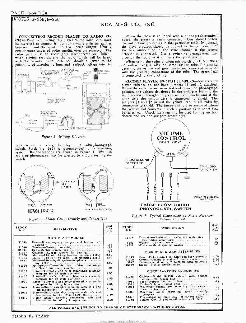
PAGE 13-64 RCA MODELS R-93B,R-93C
RCA MFG. CO., INC.
CONNECTING RECORD PLAYER TO RADIO RE- CEIVER-In connecting this player to the radio, care must be exercised to connect it at a point where sufficient gain is between it and the speaker to give normal output. Usually two or more stages of audio amplification are required. The radio part must be thoroughly disconnected or "killed" when playing records, else the radio signals will be heard with the record's music. Attention should be given to the possibility of introducing hum and feedback voltage into the
CABLE TO RADIO CNABSIJ
MOTOR DROWN FOR IIO VOLT- 60 C VC LE CONNECTION
Figure 1-Wiring Diagram
radio when connecting the player. A radio -phonograph switch, Stock No. 9824 is recommended for a switching system. Its connections are shown in Figure 1. With it, radio or phonograph may be selected by simply turning the switch.
BOTTOM VIEW OF
STATOR
RED YELLOW
IO VOLTS- 6OCYCLES a2O VOLTS -50 CYCLES
IO VOLTS- SO CYCLES
Figure 3-Motor Coil Assembly and Connections
When the radio is equipped with a phonograph terminal board, the player is easily connected. One should follow the instructions pertaining to that particular radio. In general, the player's output should be applied to the grid circuit of the first audio tube in the same manner as the second detector is connected. Use a switching arrangement that grounds the radio as it connects the phonograph.
When using the radio phonograph switch Stock No. 9824 on radios using a 6B'7 or some similar tube for second detector, the yellow and green leads are connected in series with the grid cap connections of this tube. The green lead is connected to the grid cap.
RECORD PLAYER SWITCH JUMPERS-Some record player switches do not have jumpers J1 and J2 attached. When the switch is so connected and turned to phonograph position, the voltage developed by the pickup is fed into the radio receiver through the green wire and shield, and at the same time the yellow wire is connected to shield. The jumpers J1 and J2 permit the yellow lead to kill radio by connection to shield. The jumpers should be removed where the yellow lead connects in such a position as to shord bias batteries, etc. Check the switch to be used for the method chosen and use the jumpers accordingly.
FROM SECOND DETECTOR i
O J W r
VOLUME CONTROL
REAR VIEW
.Ch ARM Ge
u
Z W W
O
0 Iv
d
?t,
I
0 J _W
2
CABLE FROM RADIO PHONOGRAPH SWITCH
TO AUDIO AMPLIFIER
©RCA MFG. CO.,INC. SN- 803-0
Figure 4-Typical Connections to Radio Receiver Volume Control
STOC DESCRIPTION Unit List
Price STOCKNo DESCRIPTION
Unit List
Price
MOTOR ASSEMBLIES Base-Motor damper, bearing
31039 Turntable-Finished turntable top plate only- less rubber mountings .95
31045 4083 Washer-Leather washer .02 support, and cup assembly .60 14231 Washer-Metal spacing washer .02
31046 Bearing-Bearing assembly .70 31041 Cap-Rubber spindle cap .05 31047 Cushion-Rubber cushion for bearing .15 PICKUP AND ARM ASSEMBLIES 31035 Motor -110 volt, 25 cycle-less mounting (M1) 9.50 31034 Motor -110 volt, 50 cycle-less mounting (M1) 8.90 31049 Base-Pickup arm pivot shaft and base assembly .65
9841 Motor -110 volt, 60 cycle-complete with mount- ing (M1) 6.50
31050 9842
Crystal-Pickup crystal and needle screw Pickup crystal and arm complete with mounting
3.75 4.95
31040 Mountings-Turntable top rubber mountings 12539 Screw-Pickup needle screw .22
sufficient for one turntable .25 31038 Rotor-Turntable and rotor lamination assembly MISCELLANEOUS ASSEMBLIES
31037 complete for 25 cycle operation
Rotor-Turntable and rotor lamination assembly 4.55
31055 Cabinet-Model R -93B cabinet with bottom complete for 50 cycle operation 4.55 cover-less rubber feet 2.05
31036 Rotor-Turntable and rotor lamination assembly complete for 60 cycle operation 4.55
31051 3961
Foot-Rubber foot for cabinet Knob-Volume control knob
.04
.10 31044 Stator-Stator assembly complete with coils and 31054 Mounting-Pickup arm mounting nuts, washer,
laminations for 25 cycle operation 3.10 and rubberspacer .15 31043 Stator-Stator assembly complete with coils and
laminations for 50 cycle operation 2.50 31053 Mounting-Motor mounting screw assembly
complete .30 31042 Stator-Stator assembly comprising coils and
laminations for 60 cycle operation 2.50 31048 31052
Plug -2 -contact male plug for output cable... Volume Control and on -off switch (Rl, Si)...
.15 1.50
ALL PRICES ARE SUBJECT TO CHANGE OR WITHDRAWAL WITHOUT NOTICE.
®John F. Rider www.americanradiohistory.com

RCA PAGE 13-65
MOTOR 78 r.p.m. POWER SUPPLY RATINGS 105-125 volts, 60 cycles 105-125 volts, 50 cycles 105-125 volts, 25 cycles
TURNTABLE HELD ON SHAFT BY RETAINING RING AND WASH E'....jtGAP MUST BE UNIFORM
LEATHER WASHER SHOULD BE OIL SOAKED - GOES ABOYÉ STEEL WASHER
OIL BALL BEARING USE LIGHT OIL
o1.,.,EW
,2:T..
AIR GAP IS .016"
LUBRICATE OUTER AND
INNER BEARING SURFACE
WITH LIGHT OIL
ROTOR CENTERING CALIPERS A special calipers (Stock No. 36950) is now
available for quickly and accurately centering the rotor in these motors.
Exact centering is essential for minimum hum and "wow." The precision of manufacture of these calipers provides checking and center- ing with an accuracy of .0005 inch.
RCA MFG. CO., INC.
Electrical and Mechanical Specifications CRYSTAL PICKUP
Synchronous ( Manual Starting)
10 watts 10 watts 10 watts
Impedance Average Output Voltage
MODEL R -93F Phono. 2nd Edition
100,000 ohms at 1,000 cycles 11 volts, at 1,000 cycles
Across 250,000 ohms load Cabinet Dimensions 3 x 9¡ x 112 inches Weight 61 lbs. (net), 81 lbs. (shipping)
At Left-Fig. I
At Right-Fig. 2
Lower Left-Motor Coil Connections
Lower Right- R-93F Schematic
Diagram
Rotor Centering Calipers
Motor Data Smooth starting and running will be insured by keeping the
bearings well cleaned and oiled. Hum and Vibration-A small amount of hum when starting,
decreasing to a negligible amount when running, is normal. If excessive vibration occurs, it may be due to: 1. Insufficient lubrication, or any failure that will cause binding. 2. Leather washer not oiled. (Check to make sure that the leather
and steel washers are arranged in proper sequence, as shown in the drawings.)
3. Motor not properly fastened in cabinet. 4. Burrs on poles of motor or stator. 5. Slight eccentricity of rotor or spindle. 6. Loose laminations of the stator. 7. Improper horizontal alignment of the rotor and stator (per-
taining only to the type motor shown in Figure 1). Correct
A6960-0
ROTOR ml stnnia:
LEAT STEEL iwSHER ¡ STEEL
EWHINERR STEEL WASHER
LEATHER WASHER SHOULD 6e OIL SOAKED GOES DETWEEN STEEL WASHERS
LUDRICATE INNER SEARING WITH LIGHT OIL
51
C
PICKUP
TIURNTADLE HELD ON SHAFT ET
RETAINING RING d HASHER
AIR GAP IS OIS = OW MUST
ISE UNIFORM
DRICATE OUTER SEARING WITH LIGHT GREASE
VOL CONTROL efflooA
K-90602
To use the calipers, lift out the turntable and rotor, slide the caliper onto the rotor shaft, and adjust the calipers to fit the internal radius of the rotor. Rotate the calipers and check for run out, or widening of the radius. Tap the edge of the rotor to move it in the desired direction. Recheck and tap as necessary until rotation of
the calipers indicates accurate centering.
horizontal alignment is as shown in the motor assembly drawing. The position of the stator is raised or lowered by adding or removing washers below the leather washer. In the type motor shown in Figure 2, no adjustment is necessary because correct horizontal alignment is provided by the design of the motor.
The damper spring must fit without binding or chattering, in the slot in the stator. The stator must be free to deflect in either direction between the limits of the damper spring. Any binding in the washers or stator bearing which prevents the movement of the stator may cause speed variations in the motor. The damper spring must exert equal force in restoring the stator to its mid -position when the stator is deflected manually in either direction.
Tone Compensation Because of the widely varying frequency characteristics of various
types of audio amplifiers with which the Player may be used, it may be desirable in some cases to make refinements in the pickup circuit of the Player to compensate for the characteristics of the amplifier. The following circuits show means of making such refinements.
In Figure 3, R1 controls the low -frequency response; larger values of R1 give increased lows: For maximum low -frequency re- sponse, remove R1. R2 controls pickup output, smaller values of R2 giving increased output. Cl controls high -frequency response; to increase highs, increase Cl.
C1 -82MME
CRYSTAL PICKUP
Where a decrease in high -frequency response may be desired (for example, as an aid in reducing "needle scratch" on worn records), the circuit in Figure 4 is applicable. In this circuit, C2 acts as loading on the pickup and is also a controlling factor on the high - frequency response. Smaller values of C2 give more pickup output and also more highs. R3 gives a sharper high -frequency reduction; increasing R3 decreases highs.
The suggested values shown in Figures 3 and 4 should serve as a basis from which slight alterations may be made to suit individual cases.
R3-22,00011
C2 CRYSTAL 2700
PICKUP MMF.
180,00011 VOL.
CONTROL
©John F. Rider www.americanradiohistory.com

PAGE 13-66 RCA MODEL R-93FPhono 2nd Edition
Connecting
RCA MFG. CO., INC.
Record Player to Radio Receivers
This Record Player consists of a motor -turntable mech anism, a crystal pickup unit and a volume control with motor switch. The player may be connected to the audio amplifier system of practically any type of radio receiver for the reproduction of records.
For convenience in connecting the player to receivers with out the conventional phono -jack, a new type switch (Stock No. 9824-A) is recommended.
This switch may be used for quickly connecting Record - Players, Television Attachments, Frequency -Modulation At- tachments, Microphones, and similar devices into the audio amplifier of the receiver.
The great majority of receivers in use have a grid -cap type
Stock No. 9824-A Record -Player Switch
1st -audio tube, and the new switch is designed for rapid con- nection to the grid cap, without removing the chassis from the cabinet. On other receivers, the switch can be readily installed by means of socket adapters or connection into the audio circuit.
The new switch is designed to provide:
1. Changeover from radio to record player, with retention of the original tone quality, and without introducing hum.
2. Suppression of radio on the "phono" position.
3. Maintenance of all original bias conditions in the radio circuit.
Complete instructions are furnished with the switch.
A í®
'RADIO"
lUI
PHONO"
Lj PHONO _ JACK
SHIELDED CABLE
9824 A SWITCH
4/
BLACK CABLE FROM 9824A SW.
SHIELD EX T.
GRID CAP BLACK-
BROwN
FIRST AUDIO TUBE 1
A typical hook-up as used on receivers with a grid -cap 1st -audio tube. (On a.c.-d.c. sets, a .25 mf d. condenser should be connected in the cable shield lead.)
Methods of connecting receivers (without the grid -cap 1st -audio tube) thru the use of adapters, etc. are explained in detail in the instructions packed with each switch.
Replacement Parts Insist on genuine factory -tested parts, which are readily identified and may be purchased from authorized dealen.
STOCK No.
DESCRIPTION Unit List
Price STOCK
No. DESCRIPTION
Unit List
Price
MOTOR ASSEMBLIES (See Figure 1) 33346 Coil -Motor field coil .65 (110 volts, 25 cycle) 33350 Frame -Motor mounting frame and bearing cup (110 volts, 50 cycle) assembled
Frame frame, lami- .45
31045 Base -Motor support, damper, and bearing cup 33344 -Rotor spindle shaft and nations assembly .60 2.45
31046 Bearing -Bearing assembly .70 34480 Hanger -Rubber hanger for mounting motor... .10 31041 Cap -Rubber spindle cap .05 34479 Lamination -Stator laminations and bearing 31047 Cushion -Rubber cushion for bearing .15 assembled -
1.30 32077 Motor -110 volt, 25 cycle -less mounting 14.60 33041 Ring -Retaining ring for turntable .06 31034 Motor -110 volt, 50 cycle -less mounting.... 8.90 31039 Turntable .95 31040 Mountings -Turntable top rubber mountings PICKUP AND ARM ASSEMBLIES
sufficient for one turntable .25 32073 Rotor -Turntable and rotor lamination assembly ,33591 Arm -Pickup arm only -less cartridge, base and
complete for 25 cycle operation 7.70 cable .50
31037 Rotor -Turntable and rotor lamination assembly 34481 Arm -Pickup pivot arm and shaft .70
complete for 50 cycle operation 4.55 34482 Base -Pickup mounting base .30
32072 Stator -Stator coil, laminations, and weights for 33122 Crystal -Pickup crystal cartridge and needle 105-120 volts, 25 cycles 5.00 screw 3.75
31043 Stator -Stator assembly complete with coils and 33123 Damper-Viscoloid damper for pickup armature .15
laminations for 50 cycle operation 2.50 34311 Ring -Retaining ring for pivot shaft ...... .. .05
31039 Turntable -Finished turntable top plate only- 33529 Screw -Needle screw .10
less rubber mountings .95 MISCELLANEOUS ASSEMBLIES 4083 Washer -Leather washer .02
14231 Washer -Metal spacing washer .02 31051 3961
Foot -Rubber foot for cabinet Knob -Volume control knob
.04
.10 MOTOR ASSEMBLIES (See Figure 2) 31054 Mounting -Pickup arm mounting nuts, washer,
(110 volts, 60 cycle) and rubber .spacer .15 30244 Bushing-Rubbcr bushing for turntable center. .25 31048 Plug -2 -contact male plug for output cable .15 33345 Cap -Rubber cap for turntable spindle........ .15 33359 Volume control and switch 1.50
ALL PRICES ARE SUBJECT TO CHANGE OR WITHDRAWAL WITHOUT NOTICE.
©John F. Rider www.americanradiohistory.com

RCA PAGE 13-67
Turntable Rim Driven
MOTOR
RCA MFG. CO., INC.
MODEL R -94B Type Self-starting Induction Turntable Speed 78 r.p.m. (Adjustable) Turntable Diameter 10 inches D -C Resistance 110 volts, 60 cycles, 96.3 ohms;
110 volts, 50-60 cycles, 72.3 ohms
POWER SUPPLY RATING A.6 105-125 volts, 60 cycles, 25 watts A-5-6 105.125 volts, 50-60 cycles, 25 watts
General Description The RCA Victor Record Player Model R -94B consists of a self-
starting motor turntable mechanism, a crystal pickup, an aurally com- pensated volume control, and a motor switch. This record player can be adapted to play records through the audio amplifier -loudspeaker system of practically every type of radio receiver. The cabinet is of walnut veneer, and has a hinged lid, which locks in the "open" posi- tion -but should be closed while records are being played. Any record up to and including the 12 -inch diameter size may be played on this instrument. An automatic switch turns the motor "off" when the end of a record has been reached.
Service Data The crystal pickup unit is thoroughly sealed in a metal casing,
against extreme changes of climate. The offset mounting of the crystal unit in the pickup arm insures ideal tracking between needle and record grooves. If failure occurs due to a defective crystal unit, no attempt should be made to repair the unit, but a new replacement crystal unit should be installed.
The turntable drive, is a self-starting, variable -speed, governor -type, induction motor. The motor speed adjusting screw is located under
LIODEL R -94B Phono
MODEL 0-3
PICKUP Type Crystal Impedance 80,000 ohms at 1,000 cycles Volume Control Resistance 250,000 ohms Average Output Voltage 12 volts at 1,000 cycles
across 250,000 ohm load CABINET DIMENSIONS Height 7.13/16 inches Depth 12-31/32 inches Width 151 inches Net Weight 122 pounds Shipping Weight 18 pounds
the turntable, which must be removed for speed adjustment. The motor speed should be 78 r.p.m., and may be checked by placing a piece of paper between a record and the turntable, with the paper protruding beyond the edge of the record, and then counting the number of revolutions of the turntable per minute. The motor is designed to be simple and foolproof in operation. Occasionally, how- ever, lubrication and certain adjustments may be required. These are illustrated and explained in figure 1. In addition, an application of oil to the felt pad, which rubs against the governor disc, will insure smooth operation.
The turntable is started by pushing to the rear the motor starting lever, which appears to the right of the turntable. The adjustment on the automatic motor stopping switch should be made so that the switch will snap to the "off" position when the needle in the pickup head is 15 inches away from the center of the turntable. The lock- ing screw and details of the switch mechanism are shown in figure 2.
The volume control is of the potentiometer type, tapped to give aural compensation at low volume settings. The output lead from the volume control is a single shielded wire, terminating: in a small, male, pin plug. See figure 3. This pin plug fits into the female jack receptacle on most of the RCA Victor 1939. "90" series of radio receivers.
STOCK No. DESCRIPTION
Unit List
Price STOCK
No. DESCRIPTION Unit List
Price
MOTOR ASSEMBLIES 14559 Resistor -10,000 ohms, I watt (R2) .20 11703 Governor -Motor governor complete 3.05 12264 Resistor -220,000 ohms, I watt (RS) .20 30475 Motor -105-125 volts, 50-60 cycle (M50).... 22.76 13573 Screw -Motor mounting screws, washers and 14800 Motor -105-125 volts, 60 cycle (M50) 19.75 30100
rubber cushions Spring -Tension springs for automatic brake - .30
PICKUP AND ARM ASSEMBLIES 31213 one long and one short spring
Support -Lid support -
.08
.40 31212 Base -Pickup arm pivot shaft, trip lever, and 14804 Switch -Motor switch -located on automatic
base assembly .95 brake (S1) .60 31050 Crystal -Pickup crystal and needle screw 3.75 14801 Turntable 4.36 31211 Pickup and arm complete -less rubber mount- 31108 Volume control (Rl) 1.00
12539 ing and nut
Screw -Pickup needle screw 7.10 ACCESSORIES
MISCELLANEOUS ASSEMBLIES
.22 9824 Switch and cable assembly - for use with re -
ceivers requiring a switch for changing from Phonograph to Radio -complete with mount -
14803 Brake -Automatic brake complete 2.95 ing screws, washers, and knob 1.00 4870 Capacitor -.025 mfd. (Cl) .20 14179 Adapter -Special octal base adapter with grid
11704 Damper -Turntable rubber damper and damper connection (pin No. 5) split and a 2,700 ohm plate .25 resistor internally connected from cathode (pin
31051 Foot -Rubber foot for cabinet .04 No. 8) to shell (pin No. 1), 3 terminals on 13085 Hinge -Lid hinge .22 side 1.85 3961 Knob -Volume control knob .10 14180 Adapter -Special octal base adapter with grid
31054 Mounting -Pickup mounting nut, washer, and - connection (pin No. 5) split, 2 terminals on rubber cushion .15 side 1.60
ALL PRICES ARE SUBJECT TO CHANGE OR WITHDRAWAL WITHOUT NOTICE.
105-125 volts, 60 cycles constant speed motor 78 rpm.
Mechanical Reproducer
Lubrication. -Motor drive bearings should be lubricated with a good grade of oil at least twice a year.
Caution. -Keep all rubber drive parts free from oil.
IDLER SPRING
01t. \\
MOTOR \\ BOARD
OIL.
MOTOR SPINDLE
IDLER
/ OIL
0-3 PHONOGRAPH MOTOR
MODEL O-3
OL
TURNTABLE SPINDLE
Electric Motor Driven Portable
STOCK No.
DESCRIPTION Unit List Price
39526
39530 39531 39533 39528 39534 39527 39532 39529
33691
33678 33680 36574 36575 36577 33692 33690
30368 39522 33694 33684 33689 39523 33688
MOTOR ASSEMBLY Motor -Complete motor including mounting
plate, spacers, screws, washers, and nuts Plate -Idler wheel plate Retainer -Retaining clip for turntable spindle Retainer -Retaining clip for idler wheel Spindle -Turntable spindle Spring -Idler wheel tension spring Turntable Washer -Fibre washer for turntable spindle.... Wheel -Idler wheel and tire
MISCELLANEOUS ASSEMBLIES Arm -Tone arm -less neck, base, washer, ring,
screw and lockwasher Cover -Needle cup cover Cup -Needle cup Foot -Cabinet foot (glide) Handle -Carrying handle _(black) Hinge -Cabinet lid hinge Neck -Tone arm neck Screw -Screw and lockwaaher to fasten neck on
tone arm Sound Box Spring -Conical spring to hold turntable. .
Support -Cabinet lid support Support -Sound box support Support -Taper tube support Switch -Motor switch Washer -Tone Arm Bearing washer and retain-
ing snap ring
5.25 .90 .02 .02 .30 .02
1.50 .02 .90
1.35 .30 .15 .10
1.40 .40 .70
.10 3.00
.90
.15
.35
.60
.10
John F. Rider www.americanradiohistory.com

PAGE 13-68 RCA
MODLE R -94B Phono RCA MFG. CO., INC.
Connecting Record Player to Radio Receivers A table giving methods of connecting the Record Player to various
types of audio systems is shown in the following text. Also included are the model numbers of the various RCA Victor Receivers to which the particular method shown applies. The data given in the table requires that an RCA Stock No. 9824 "Radio" -"Phono" switch be used for switching from radio to phonograph, as desired. For ease in connecting the "phono" lead to the Stock No. 9824 switch, the male plug on the end of the shielded lead should be removed by unsoldering, or cutting it off.
In general, the Record Player must be used with radio receivers having at least two stages of high -gain audio amplification. The Record Player output should be connected to the grid of the first audio tube, and at the same time the output of the radio receiver portion of the chassis should be shorted or opened, to prevent radio signals being heard while the Record Player is in operation. CONNECTING RECORD PLAYER TO:
1939 RCA RADIO RECEIVERS OF "90" SERIES :
Plug male jack on end of Record Player into female receptacle on receiver chassis. Push or turn "Phono" switch to "Phono" position, and operate Record Player according to instructions.
RADIO RECEIVERS HAVING "PHONO" TERMINAL BOARDS. 9924
!, qq p 5T
SWITCH
A l- E I ITI T I vrION4O VvoSEwwN ' '
O I I!I II Wild s r'` -1 GREEN
eLUE [ ( t r' , , I_ YELLOw ,
SHIELD TO TERM
NIELD
TAPE END OF REO AND BLUF DS
IM RECEIVER S FSWIPPEw Y'[ TERMINAL,Fa
n P440º
RCA Radio Receivers to which the above illustration applies 5T1, 5T4, 5T5 5T6, 5T7, 5T8, 6T5, 8T2, 8T11, 8K11, 85T5, 86E, 86K, 88'Ií, 86T1, 86T4, 86K7, 86T44, 87K, 87T, 87K1, 87K2, 87T2, 88K, 810K, 810K1, 810T, 810T4, 811K, 812K, 813K, 816K, 811T.
For following Receivers, Yellow lead should go on Terminal No. 1, Green lead on Terminal No. 2: 6K2, 6T2, 6K3, 6T10, 7T1, 7K1, 85T8, 86T3, 87T1, 86T2, 86T6, 6K10.
Insulate shield of switch wires from chassis, on following RCA Receivers: 5T, 6T, 6K, 6K1, 7T, 7K, 7X, 8T, 8K, 86X4, 87EY, 87X, 87Y, 8T10, 7X1, 8K1.
Receivers having a Four Terminal Board: 9K, 9T, 9K1, 9K2, 9K3, 9K10, 10T, 10K, 10K1, 13K, 15K. Reverse Red and Blue leads to Terminal Board of C9-6, T9-9, T8-16, C8-17.
PMONO
RADIO RECEIVERS USING 6C5 OR 6J5, 6C5G OR 6J5G. TUBE FOR FIRST AUDIO AMPLIFIER.
STOCK Nº 9824 r RADIO-P,IONO SWITCH
STOCK N9 1 STOCK Ng 1 (REAR VIEW) 14179 1 14180 1 -PHONO' POSITION
r TGAEEN
SHIELD1
ei - 1 BLUE I I Er NMFD. L J
RED NOTE- WHEN STOCK N4 14179 15 USED AND TUBE 15 OF 'G' TYPE CARE MUST BE TAKEN TO SEE THAT
SHIELD TERMINAL Nº 1 IS GROUNDED ON TUBE _ SOCKET. WHEN STOCK Nº 14180 IS USED RED LEAD SHOULD BE TAPED.OMITC. 5ß540B
Stock No. 14179 Adaptor opens grid circuit, and inserts 2.700 ohm resistor in cathode of 6C5 or 6J5 tubes, for bias on Phono reproduction.
Stock No. 14180 Adaptor opens grid circuit of 6C5 or 6J5 tube. Stock No. 14180 Adaptor necessary for RCA: C11-1, C13-2,
T10-1, C11-3, C13-3. Stock No. 14179 Adaptor necessary for RCA: C15.3, C15-4.
ELLOW
PHONO LE
RADIO RECEIVERS WHOSE FIRST AUDIO AMPLIFIER TUBE IS OF THE GRID CAP TYPE.
TAPE REMO,"
GRID _
LEAD
SHIELD)
LLOW
RED TAPE Cam BLU
NOTE'- THIS METHOD FOR USE ONLY WHEN BIAS FOR THE TUBE IS OBTAINED BY MEANS OF CATHODE RESISTOR MSL404
RCA Receivers for which above method applies: 125, 128, 128E, 224E, 225, 226, T6-1, C6-2, T6-9, T7-5, C7-6, T7.12, C7-14, T8-14, C8-15, T8-18, C8-19, C8-20, C9-4, T9-10.
STOCK Nº 9824 SW ITCH
(EAR PHONO- ONO POSITION
GRES
ONO EAD
RADIO RECEIVERS WHERE RECEIVER VOLUME CONTROL IS TO BE USED TO ALSO CONTROL "PHONO" VOLUME.
RADIO RECEIVERS WHOSE FIRST AUDIO TUBE IS OF THE GRID CAP TYPE. AND FIXED BIAS FOR TUBE IS OBTAINED THROUGH GRID LEAD.
.2S MFD CAPACITOR
NOTE- REMOVE BLUE ANO RED LEADS CONNECT YELLOW LEAD TO TERMINAL SHOWN.
SPEED ADJUSTMENT (SCREW) TO DECREASE SPEE TURN CLOCKWISE
RB- SPEED ADJUSTMENT LOCK NUT
TURN SPEED ADJUSTER SO THE FEL WILL PROTRUDE )46"WHEN ALL THE WAY IN. ADJUST GOVERNOR SO AS TO LEAVE As" BETWEEN FELT AND DISC, THEN SECURE BY MEANS OF GOVERNOR SCREW.
ADJUST SO THAT SHAFT IS FREE TO ROTATE WITHOUT END PLAY
REMOVE TO TAKE OFF GOVERNOR
POWER CORO
OIL 7, KEEP FILLED WITH LIGHT OIL TO INSURE SMOOTH OPERATION
Figure 1 -Motor Adjustments ADJUST SWITCH 70 r/fIP WHEN NC£DLC IS ON I I4 S6 RAO. FROM E OF MOTOR SPINDLE.
DO NOT CHANGE THIS ADJUSTMENT
FFCA PG CD.INC M-BIT4-P
Figure 2 -Motor Switch Adjustment
BROWN'
BLACK CRYSTAL PICKUP I
(BOTTOM VIEW)
BOTTOM VIEW
RI VOL. CONTROL 230,000 n
C I .025 MFG..
SHIELD EXTENSION
OUTPUT PL G
Figure 3 -Wiring Diagram
©John F. Rider www.americanradiohistory.com

RCA PAGE 13-69
RCA MFG. CO., INC.
Output Meter Alignment.-Connect the meter across the voice coil, and turn the receiver volume control to maximum.
Test-Oscillator.-Connect the low side of the test -oscillator to the receiver chassis, through a .01 mid. capacitor, and keep the output as low as possible.
Steps Connect the high
side of test- oscillator to-
Tune test-osc. to-
Turn radio dial to-
Adjust the follow - ing for max. peak
output
1
I -F grid, in series with
.01 mfd. 455 kc
Quiet point 1,600 lac
end of dial
L8 and L9 2nd I -H
transformer
2 1st Det. grid
in series with .01 mfd.
L6 and L7 1st I -F
transformer
3 Ant. terminal in series with
200 mmfd. 1,650 kc Gang at
minimum C25 (osc.) C31 (osc.)
4 Radiated signal 1300 kc Signal
Frequency C23 (ant.)
5 Repeat steps 3 and 4.
TURNTABLE
DRIVE WHEEL
MOTOR SPINDLE
MOTOR
NEEDLE PACKAGE HOLOER
TURNTABLE SPINDLE
PICKUP REST
NeEDLE SCREW
CUP FOR USED NEEDLES
PICKUP ARM
MODEL V-105,Ch.RC-517C
FREQI'ENCY RANGE 540-1,650 kc
INTERMEDIATE FREQUENCY 455 kc
PILOT LAMP 1-Mazda No. 51, 6-8 volts, 0.2 amps.
POWER SUPPLY RATING 105-125 volts, 50 cycles 5ß watts 105-125 volts, 60 cycles 55 watts
LOUDSPEAKER (RL -SIB -4) Type 5 -inch electrodynamic V.C. lmpedince 4 ohms at 400 cycles
Phonograph Motor Service Data:- The phonograph motor is of the self starting synchronous type and
operates the turntable through friction drive between the motor drive spindle and the rubber tired idler on the rim of the turntable.
The motor should be lubricated once or twice a year by placing a few drops of S. A. E. 20 (or equivalent) on the turntable spindle and saturating the oil retaining felt pads on the motor shaft with S. A. E. 10 oil. Caution-The motor drive spindle and the rubber tire on the idler must be kept clean and entirely free from oil and grease at all times.
Power Supply.-Although this model employs an ac -dc chassis, it is not suitable for use on d.c., as this would damage the motor.
ANT. TO GRID CONV. GAIN II
0.41( II
O.BX Nt. lox (GOO KC.)
1OOX(600-455KC)1(455KC.)+-160K (455KG.) (451.iKr1.)-
MEASURED WITH 3V. FIXrD flln i 125A7
1ST.DET. - OSC.
m
(=>
C8 .00
Q o
Loo P
L2 LOOP
LI
C23* -1C22 3-I0
T¢365RiW 22.1-1
j ¡U 3 L3 C31 m RED 3-10
g1 71 c.25
10 T45_170 X MAY.. AVC APPROX.
BL,K YEL.
G <N© 7: V.
¢c 5 80v L6 L7 F ! C
12r;K 7
78V.
C26; _ C27 100 8
A e.8n D ,
I.F.
ú
PHONO RADIO
LOUD -SOFT /Fit/LIN I MELLOW MELLOW'S
VOLUME PHONO- RADIO \TUNING CONTROL POWER -TONE CONTROL
CONTROL
4OX (4Oon.)
12SQ 7
2ND. DETAF, AVC.
1( Bev
LB L9
IC & a
C281 I 1023 R3 120 33 Al ñ 10n.i
$OV.
(Goo KC -9v. (1500 K .)
C0.1 RIS
3V. BIAS 1 rNVti FOR GAIN T _ 220 M m7 DATA
Top VIEW C25 -05C 1560 KC.
C 23 -ANT. 1300 KC.
VOLTAGES SHOULD HOLD WITHIN t 20% WITH 117 V. AC. SUPPLY.
ìF MEASURED WIT H CHANALYSTOR VOLTO/IMYST
I
CHASSIS GROUND
COMMON WIRING INSULATED FROM CHASSIS (B-)
C31-OSC\ 1560 KC
1ST. I.F. 2ND. I.F.
(TRANSI. íTRANSS. 12 ® I I2 12507
L6 -BOTTOM LB -BOTTOM L7 -TOP L9- TOP 4.35 KC. 435 KC.
C 20 1 220 I
R4 2.2 MEG.
R15 500 M VOLUME CONTR.
ó5 I RADIO- PHOI'Or TONE $,POWER SWITCH. SHOWN IN OFF P05IT ION -
121647M -C17 '.015
ö8 ._1(PICKUP_
MOTOR
C30 1001
C15 0025
C7
005
RI7 47M
SI FRONT r I
I
220M
f. C9 o1
R9 120
14. I4X ( 400 Ad) APPROX. GAIN DATA USING RCA RIDER CHANALYST
50L6 GT OUTPUT
4V
RIO 470M
IOV. C11 85v. .025
i RED
Iii50,`v I L10(11
RII l l
1500 BLUE
i
REO
GI4
SOED
56ME6.
50L6G 12 123K1 7 12507
4 3 Ì\ 3 -4-
> 35Z5GT RECT.
C12
DIAL LAMP
0.25
ºI 52
REAR
P-84667-2 VIOS (RC517C)
OR'Ni Ct3
MFD
POWER SUPPLY 117 V.
©John F. Rider www.americanradiohistory.com

PAGE 13-70 RCA
MODEL V-135,Ch.71C-517H RCA MFG. CO., INC.
POWER bUTPUT Undistorted 1.6 watts Maximum 'S watts Pilot Lamp (1) Mazda No. 51, 6.3 volts, 0.20 amps.
POWER SUPPLY RATING 105-125 Volts, 60 Cycles 65 watts
LOUDSPEAKER (RL86B6) Type 5 -inch Electrodynamic V.C. Impedance 4 ohms at 400 cycles
Steps Connect the high
side of test- oscillator to-
Tune test-osc.
to-- Turn
radio dial to- Adjust the follow - ing for max. peak
output
1 I -F grid, in series with .01 mfd.
455 kc Quiet point
1,800 kc end of dial
L8 and L9 2nd I -F
transformer
2 1st Det. grid in series with
.01 mfd.
LB and L7 1st I -F
transformer
3 Ant, terminal in series with
200 mmfd. 1,600 kc Gang at
minimum C5 (osc.) C6 (osc.)
4 Radiated signal 1,300 kc Signal
C3 (ant.) )
5 Repeat steps 3 and 4.
CS -OW. 1600 1C
LOOP
C6- OSC. ~1600 KC.
C3 -ANT. 1210o KC.
18- BOT. LS -TOP 455 KC.
2 12SK1
PHONO. JACK
-t2X50x -I (600-455KC)
MEASURED I2SA7
1ST. PET. & OSC. BOTTOM VIEW Of TUBE SOCKETS
L2 LOOP
LI
C Q oBÑJi
C, - C34C4A;=.. ,005 3-10 9-365
3V. 1 - FIXED BIAS NR T}
GAIN DATA I
m
R2
0 .6:
22M
H
3
12SQ1
Frequency Range 540-1,600 kc Intermediate Frequency 455 kc
PICKUP TURNTABLE. RECORD SUPPORTS MOTOR BO ARD
r - TURNTABLE
SPINDLE
; iáf'; rT-:.t:.____. 1- -+ - t- +
>---?Ii--- ; -- 1
MOTOR SPINDLÈ'?
IDLER WHEEL
`.' .. .+.í.
/17s I MOTOR,SY `
\I MOTOR e-'i r
I CABLE'- TWO SHIPPING BOLTS \CONNECTWILif
. WITH RED HEADS
CHASSIS r - -ï_ ; TWO CHASSIS BOLTS i -^ ICNUP LEAD r--"" t CONNECTION:
st
ri -
CHASSIS; BOARD
R I I
IS
O ex 200X I X - (4S5Kc) (4 551(C) I (455 -KC)
WITH 5V. F1XHD PIA3 ---- 1'l SK-/
1.1.
95`/O
) N© 15T. I.F. 95 TRANS.
ó -F-1 b _ ici $ - IIo
LG L7 D' 711 79. M
á *12V. (1500 KC) l9 - eV. (550 KC) L3
m
RG 33
2 HD. I.F. TRANS .
FOUR CHASSIS BOARD SCR WS R -sa,
) 40X (400 ti )
FIELD
750n Rio 330.n.
12Sß7 2ND. DE T., AF., AVC.
irr 52V.
D1 ó
1Ó 1
_ p 1C15 `1r, 120
I A -L8 LS 1- -- - 70 7n J
RED I d á CS C6 +C7 ó p3 -,O T3 -10T7.5_,70
L4 LS ER 7n
C II 0.1 - C1.5
.005 -
R9 1200
R7 47 M
C16 220
C 25 .0025
1(- -15V. APPROX MAX. AVC
C2 -- RI
0.1 220 M
PHONO JACK
C9 0.1
R4 82 C10 Isr,o
CATHODE CURRENTS I) 12547 - - - 11.0 MA.
(2) 1251(.7 - - 14.0MA. (3) 12507 - - - .4MA. (4) 3"-6GT -
- - 48. OMA. 15) TOT. ' RECT - - 74.0 MA.
1 CB
T0015
RB 2.2 MEG.
C21 -.05
Ç,120. CONN5 VERTICAL'HI" TO THIS TERMINAL VERTICAL' 0" TO CHASSIS.
R13 220 M
12X (400 ,v)
IC24 .01
35L6GT OUTPUT
-45v
C 2G .035
II
APPROX. GAIN DATA USING RCA RIDER CHANALYST
II7V. 125V.
Buie TI M.C.
R14 RIS 150 470 M
= C
R12 4.7 MEG.
820
PICKUP
RS VOL.CONTR,
500 M
SI FRONT
z
w I I .
SI REAR
-+o
x Raó3ft` 2b5V m 9 330 F1EL0
750,1.Ç I
g 1
`IC12 O
1.--11' 1 MFl). 1='
II '20 `619 1 ei (I
T7I MFU. MFD. m
RII IS
PILOT LAMP
{-92233-I ti/ t! /1G
v135 (HCSI7 H)
1604.21
RED
V. (1 lJ
E.M svKe
i VOLTAGES SHOULD
HOLD WITHIN WITH 117 V. AC. SUPPLY.
* MEASURED WITH CHANALYST OR VOLTOHMYST.
GET ILáA7 15357 IL507
2 I 9
SOY6 GT RECT.
©John F. Rider www.americanradiohistory.com

RCA PAGE 13-71
x2 00 0
RCA MFG. CO., INC. MODEL V-140,C$.RC-572A
OO O O O O O 11i ó 1['1 ('N O CO 111
Wt
. 00UÙ 032!
n,¡) )-O á = s
00 o, 4
_Jr Ny Of
[ZNN Jn i
U)
e u
N
u 11
V
a
Ei
m0 - N
ª-1 UoT
4", mó CfN
>x> c12&3
*Q4
p u0d0 r z :+
mNO ó ,..ii,' -q UO
cr ao º^o U
r r; X Qo
I O
l01 ó N
r.- Uyt, UO N
cú e
cp
03T2
0 ó
vMt 1 m úM1 a32 I ~ ji)419
J co
z W C
U W
o
M
; Io
N m
J N
© © eabo o ,, © oo
ÿ C/? Ch
"1:: _ á - b'^ Ch
o ó d
-, ó ÿ c:
ó v :_
L NQ ' Tl W 4G ?ç
(-,..,.z,.°
ö b G t= mr é O s a
_eÉc Ñó °j U H ç r V a H J ,,, a C 0:3 _ 0 (.2 t ?a 4- CO O ti
= 0 z w' riE-lPj ° .á_c á. t ÿ q U J :Y h L
IqOj Ó Ó 3 O . o! ._ Z t-... ÚÚ COMl/:
V, a W ""
// ó wrx.4
nó
ió
©John F. Rider www.americanradiohistory.com

PAGE 13-72 RCA MODEL V-140,Ch.RC-572A RCA MFG. CO., INC.
Alignment Procedure Cathode -Ray Alignment is the preferable method. Connections for
the oscillograph are shown in the schematic diagram. Output Meter Alignment. -1f this method is used, connect the
meter across the voice coil, and turn the receiver volume control to maximum.
Test -Oscillator. - For all alignment operations, connect the low side of the test oscillator to the common negative, and keep the output as low as possible to avoid a -v -c action.
Electronic Voltmeter. -The electronic voltmeter in the Chanalyst or VoltOhmyst provides an unexcelled output indicator. It should be connected to the AVC bus, and the test -oscillator output adjusted to produce several volts of AVC.
Calibration Scale. -The glass tuning dial may be easily removed from the .cabinet 'and temporarily attached to the chassis for 'quick reference during alignment. In the event that only the chassis is
-returned for service, and the cabinet with its tuning dial is left in the customer's, home, the scale printed in this service note can be used as an accurate and convenient substitute for the regular dial. With gang in full mesh, move the dial pointer to a point 1/16 inch to left of reference mark at left hand end of the dial backing plate. Place the dial under the pointer so that the extreme left scale gradua- tion coincides with the pointer. Use scotch tape to hold the dial in place.
Steps Connect the high
side of test- oscillator to-
Tune test-osc. to-
Turn radio dial to-
Adjust the follow - ing For max. peak
output
1 I -F grid, in series with
.01 mfd. 455 kc
Quiet point 1,600 kc
end of dial
L9 and L10 2nd I -F
transformer
2 1st Det. grid in series with
.01 mfd.
L6 and L7 1st I -F
transformer
S Ant. terminal in series with
200 mmfd. 1,720 kc Gangat
minimum C10 (osc.)
4 Radiated signal 1,500 kc Signal
Frequency Cl (ant.)
5 Radiated signal near 600 kc Frequel ncy (Rock gang)
6 Repeat steps 3, 4 and 5.
Critical Lead Dress: 1. Lead from 6SK7 i -f plate to last i -f transformer to be dressed
close to chassis and under all other leads. Prevents i -f beats.
2. 22,000 ohm R-10 i -f to audio isolating resistor to have end connecting to last i -f transformer as short as possible. Prevents i -f beats.
3. First audio grid coupling capacitor C-23 and C-24 to be dressed close to chassis and away from heater wiring. Prevents hum.
4. Dress phono power leads away from phono socket.
2516 GT
26
BK ,1 is BALLAST
K- 83747 (
L9- BOTTOM L10-TOP 455 KC
CI -ANT. Icon Kc.\
t5 -O SC. boo KC
L0 -BOTTOM L . TOP
00000 JACK 455 KC
FIELD
1- B 5ooss
CIo-osC 1710 KC
LOOP
B
SIMPLIFIED SCHEMATIC VOLTAGE DOUBLER CIRCUIT
V-140
Replacement Parts
STOCK No.
DESCRIPTION Unit List
Price STOCK
No. DESCRIPTION
Unit List Price
CHASSIS ASSEMBLIES 14560 Resistor -100,000 ohms, 4 watt .20 (RC -572-A) 14583 Resistor -220,000 ohms, * watt .20
14649 Ballast -Ballast tube resistor .80 30651 30648
Resistor -270,000 ohms, 4 watt Resistor-470,000ohms, * watt
.20
.20 37846 Capacitor -Electrolytic -30 mfd., 150 volts.... .50 30649 Resistor -2.2 * watt .20 37845 Capacitor -Electrolytic comprising 1 section of 30931 Resistor -4.7 meg., 4 watt .20
50 mfd., 250 volts, 1 section of 10 mfd., 250 35862 Shaft -Tuning knob shaft .20 volts, and 1 section of 30 mfd., 150 volts... 1.00 31365 Socket -Dial lamp socket .30
12720 Capacitor -100 mmfd., moulded -35 33742 Socket -Phono input socket .20 34699 Capacitor -100 mmfd., unmoulded .30 31251 Socket -Tube socket .25 31813 Capacitor -120 mmfd. .30 31418 Spring -Drive cord spring .05 36616 Capacitor -220 mmfd. .30 31261 Spring -Retaining spring for oscillator coil core 12537 Capacitor -560 mmfd. 35 and stud .01 33806 Capacitor -.0015 mfd. .25 39492 Switch -Toni switch 1.30 34459 Capacitor -.0025 mfd. .20 35636 Transformer -First I.F. transformer 1.70
4838 Capacitor -.005 mfd., 1,000 volts .25 36615 Transformer -Second I.F. transformer Tube
1.60 33584 Capacitor -.005 mfd., 1,200 volts .25 14649 .80 -Ballast tube resistor
Washer -"C" washer for tuning knob shaft 14393 Capacitor -.01 mfd. .30 33726 .02 36248 Capacitor -.02 mfd. .20 32787 Capacitor -.05 mid. .20 AUTOMATIC RECORD CHANGER 32786 Capacitor -0.1 mfd., 300 volts .25
4839 Capacitor -0.1 mfd., 400 volts .30 See sepaiate Service Bulletin RP -182 Record 30965 Capacitor -0.25 mfd..... .30 Changer. 39491 Coil -Loop primary coil .40 SPEAKER ASSEMBLIES 39487 Coil -Oscillator coil .75 (RL -79B-6) 39489 Condenser -Variable tuning condenser 3.40 38408 Control -Volume control and power switch 2.00 31825 Cap -Dust cap .02 32634 Cord -Drive cord (approx. 33 -in. overall lgth.) .10 37850 Coil -Field coil -500 ohms 1.70 36093 Core -Adjustable core and stud for oscillator coil .15 39495 Cone -Cone complete with voice coil 1.10 39493 Indicator -Station selector indicator. .20 5118 Plug -3 -prong male plug for speaker .25 37982 Insulator -Phono socket insulator .04 37844 Transformer -Output transformer 1.70 39490 30868
Loop -Antenna loop complete Plug -2 -contact female plug for motor cable
1.80 .35 MISCELLANEOUS ASSEMBLIES
5119 Plug -3 -contact female plug for speaker cable .25 38354 Clamp -Dial clamp .15 36230 Pulley -Drive cord pulley .04 39497 Deca comania-Control panel decal .15 14649 Resistor -Ballast tube resistor .80 36386 Decalcomania -Trade mark decal (His Master's 38859 Resistor -15 ohms, 1 watt .22 Voice) .25 30785 Resistor -150 ohms, 1 watt .22 35467 Decalcomania -Trade mark decal (RCA Victrola) .05 36743 Resistor -1,800 ohms, 2 watt .25 39496 Dial -Glass dial Ccale .90 30694 Resistor -3,900 ohms, * watt .20 13085 Hinge -Cabinet lid hinge .22 30734 Resistor -5,600 ohms, i watt .20 35814 Knob -Control knobs .25 22993 Resistor -6,800 ohms, 1 watt .22 31480 Lamp -Dial lamp .20 30492 Resistor -22,000 ohms, } watt .20 39351 Mounting -Spring mounting hardware for motor - 30409 )Resistor -27,000 ohms, } watt .20 board (2 required) .25 12454 Resistor -33,000 ohms, } watt .20 38873 Spring -Conical mounting spring for motorboard .05 12412 Resistor -47,000 ohms, } watt .20 30900 Spring -Retaining spring for knobs .05 14023 Resistor -82,000 ohms, * watt .20 39545 Support -Lid support .40
ALL PRICES ARE SUBJECT TO CHANGE OR WITHDRAWAL WITHOUT NOTICE
®John F. Rider www.americanradiohistory.com

RCA PAGE 13-73
O0p i.r) Ne NO
4 0)
r-. Y
1.D
U(!1 T
r
*
NI/1 N
a0.tI - LLZUN
o .ajQQr J ZNf J
Ñ m
- V1O_ 0ó
4 pN Jppi
4444áQ 222322 (n u1Nd0.
f- w
1 a' r r- 1*- É Q Y o o to (n ,¡ o l9 00.9N 1'
Ñ în d N L9
RCA MFG. CO., INC.
U Nä9 rze
N NO U9
MODEL V-175,Ch.RC-58f
ó O
O
Ñ N
o,
0 U
- - - - < N O -F
CC r R1a0LL00
111ó.
m v
/ ss Lo
LO Ú
C
O m W cc
UM U 0 N
Ñ-1á v u
t
.0
Q 4
p Q f0 Û
O oea üx-9
00 J1.
Uin U
4.0
f O
a J aJ
et-
OF Jo
N
9" UI I---
1
, feáó o
Ln a. -o NO J J
bnv'SU,S'6- t7W r6)'n5'>- 9f I(OH ovg) nti-
i
Z38
112- NO NIL
jpr4
!gr úLó4 in
<r ÛO 7911M1NrI
1.3
3 3 n
N met Up é I-----1
O
8
©John F. Rider www.americanradiohistory.com

PAGE 13-74 RCA
25M 19m
1
SPINDLE
RECORD SUPPORT ¡ TURNTABLE START -REJECT BUTTON
Refer to RP -158 Service Note for
The dial scale drawing shown is a full size reproduction. It can be used as a direct substitute for Automatic Mechanism.
regular dial scare in alignment procedure.
P:CKIJP TURNTABLE: .tOTOREIOARD
E PlNDt.I - 1
7 '17.4/4e.?! lüir si . MOTOR - 4 1 1
A¡¡Q
TERMINAL BOARD LIN .
--8989'. % /i/ ,//i, l//O%9 A
ZIIASSIS LOOP ANTENNA
CHASSIS MOUNTING BOARD
CG
MODEL V-175, Ch.RC-532' RCA MFG. CO., INC.
Output Meter Alignment.-If this method is used, connect the meter across the voice coil, and turn the receiver volume control to maximum.
Test-Oscillator.-For all alignment operations, connect the low side of the test -oscillator to the common negative wiring, and keep the output as low as possible to avoid a -v -c action.
Electronic Voltmeter.-The electronic voltmeter in the Chanalyst or Voltöhmyst provides an unexcelled output indicator. It should be connected to the AVC bus, and the test -oscillator output adjusted to produce several volts of AVC.
CS/ cw C -05C. A.OSC. 15.2 MC 1500 KC.
Calibration Scale.-The glass tuning dial may be easily removed frdm the cabinet and temporarily. attached to the chassis for quick reference during alignment. In the event that only the chassis is returned for service, and the cabinet with its tuning dial is left in the customer's home, the calibration scale printed full size in this service note can be used as an accurate and convenient substitute for the regular dial.
Each method is described below.
Using Tuning Dial. - 1. Remove the glass dial from the cabinet.
2. With gang in full mesh, move the dial pointer to the reference mark at the left-hand end of the dial backing plate.
3. Place the glass dial under the pointer so that the extreme left scale graduations coincide with the pointer. Use scotch tape to hold the glass dial in this position.
4. After completion of alignment, replace the glass dial in cabinet.
Using Calibration Scale. - 1. With gang in full mesh, move the dial pointer to the reference
mark at the left-hand end of the dial backing plate.
2. Temporarily fasten the dial scale drawing in this service note, to the dial backing plate with scotch tape, so that the extreme left scale graduation coincides with the pointh.
Dial Pointer Adjustment.-After the chassis is replaced in cabinet move the dial pointer (if necessary) so that it is at the left-hand graduation on the dial with the gang in full mesh.
Critical Lead Dress (1) Dress bias cell up from chassis and away from A.C. switch.
(2) Dress R13 (volume control compensation circuit) close to front apron.
(3) Dress CO between osc. coil and side apron.
(4) Black lead from AC switch should be kept away from tone con- trol leads and switch.
(5) Dress 1222, C32 (pickup compensation circuit) close to front apron.
(G) Keep 124 and C5 bus (1st det. grid circuit) (socket end) as short as possible.
(7) Blue lead to antenna terminal board should be dressed in back of I -F'S.
(8) Dress brown lead front volume control to tone switch close to front apron.
(9) Dress R18 (output grid cricuit) away from A.C. switch and A.C. leads.
(10) Dress lead to phono. socket up from chassis.
Steps Connect the high
side of test-osc. to-
Tune test- oac. to- Turn radio
dial to- Adjust the follow - ing for maximum p.ak output-
1.
I-F Grid in series with
.01 mfd. 455 kc "A" Band
540 kc
Lll L12 (2nd I -F Trans.)
2 1st-Det. Grid in series with
.01 mfd. LO, L10
(1st I -F Trans.)
3 "A" terminal on ant. terminal
board in series with
47 nunf. (link open)
16.2 me "C" Band 15.2 me
C37 (inc.)* C34 (ant.)
4 9.5 me "C" Band
9.5 me Cl (ant.)
(Rock Gang)
5 Repeat steps 3 and 4.
6 Middle terminal on ant. terminal
board in series with
200 mmf. (link open)
1,500 kc "A" Band0 C10 (osc.) C33 (ant.) (on loop)
7 600 kc "A" Band
600 kc L7
(Rock Gang)
8 Repeat steps 6 and 7.
* Use minimum capaci y peak. Oscillator tracks 455 kc above signal on both bands.
55 60 70 80 100 130 160' E allt i t / t t t t a is tib t a t 1 t t
1 1 1 i 1 II 1 1. r T 1 1. 1 1 1 t il 11 1.1111e1
q3 3"m HO II
RED BRACKET AND TWO SCREWS
TWO SNIPPING BOLTS WITH RED HEADS
13 14
- RECORD SUPPORT
MOTOR BOARD
PICKUP ARM
PICKUP
PICKUP REIT
SW ITCN
Data on
©John F. Rider www.americanradiohistory.com

RCA PAGE 13-75
(.0 d d
il1/49
>
RCA MFG. CO., INC.
m Wm (no u°
d a'
8-- 0 ,
ac N8 LL
oY< xá
>n Q
r + t
< ___111I-.
, - g i 06? vg
=îg re, r.,Iá".Qr. am D...^. ____ » s>' r *=m- . uln
s II
c
é 00
tNj
-LL ÌI/11{
ó HI Ó OQy'
y o O n HI,
>
m/ a ó
o
4
3 r
I 00
LL
N
H19 aaa
SS3S3333
(fl O
Ì1-1A
MODELS V-209iChItC-573; V-210,Ch.RC-573A
w n n óóó
ñ é w a:a
v.( 1.
Mh Nf fnp
N
3Zaa w Ñ
d ZU Z iY
IULL m0 _ o ZF il' -h' 04
Q O 7 0 °ci8ao
C20100 tow
ti
oY li1 -a xJ <sg
.R.9f Pr o5
go> z óco
©John F. Rider www.americanradiohistory.com

PAGE 13-76 RCA
MODELS V-209, V-210 RCA MFG. CO., INC.
Push Button The push buttons connect to separate magnetite -core oscillator coils
and separate ant, circuit trimmers which must be adjusted for the desired stations. Use an insulated screwdriver or alignment tool auch u RCA Stock No. 81081..AIlow about five minutes warm-up period before making adjustments.
The procedure is u follows: 1. Make a list of the desired stations, arranged in order from
low to high frequencies. 2. Turn the range switch to the broadcast position and manually
tune in the first station on the list.
8. Turn range switch to púsh-button position and press in the left-hand button.
LINK
960 TO 1600 KC
TRIMMER SCREWS CORE RODS
C3
2 SI (FRONT) 3
PLUGS
Do1O AI
le O1R ,13_2.7e
SOCKÉTS
10
9
C1
It
l.2
C
LOUD
C5 2
3
740 TO 1430 NC
® 5 4 0 0
Adjustments 4. Adjust No. 1 oscillator core to receive the first station. To
secure the best adjustment, rotate the set for least pickup, and adjust core for peak output.
5. Adjust No. 1 antenna trimmer capacitor for peak output on the first station.
6. Proceed in the same manner to adjust for the remaining stations.
On the 880 to 1,800 kc push-buttón, the higher frequency sta- tions may be received with osc. core either in or out (oscillator fre- quency either 466 kc below or 455 kc above the station frequency). The adjustment with this core in its out position (oscillatorfre- quency 455 kc above the station frequency) is the correct one.
NOTE: Clockwise adjustment of cores and trimmers tunes the cir- cuits to lower frequencies.
FOR CHANGE IN MODEL V-209 5ßh NEXT PAGE 610 TO 1210 1 640 TO
KC 110]06C
0 0 ® 3 2 1
0 ® I 0
ANT. COIL
c7_, QL4L5 a PRt. ersr
OSC. COI L
C L C8.9
i o =
SC 7971 (REAR)
C
9
53 (FRONT)
_LC9
LI LOOP GIG
K 9gt27 - V209 (RC573)
F.M. AND OFF \ SOFTf TELEV. \ 1 E PHONO
JJ
RADIO
POWER -VOLUME CONTROL
coerr.FtOLtf DIAL
PHONO- RADIO TONE CONTROL
P. M. AND
TELEV.
C12
A L9,
T NE BLE
FULL TONE
9 e
4 s
RECORDS SPINDLE RECORD SUPPORT
MOTOR BOARD
(PICKUP ARM
PICKUP
PICKUP REST
RECORD SUPPORT / TURNTABLE SWITCH MYNA START -REJECT BUTTON
Refer to RP -158 Service Note for Data on Automatic Mechanism
C17
S4 (REAR)
SASS
-FULL PHONO. TON2
SASE TREBLE
I
SPEECH-f I
} 04531
FULL TONE
RADIO
Control for both Models
,QA SHORT STANDARD WAVE BROADCAST
TUNING RANGE CONTROL CONTROL
Controls for Model V-209
ií8i%//'i /í0i
LOOP ANTENNA
PICKUP RECORD SUPPORTS C
SP:HOLE
TURNTABLE
MMOTOREH]ARD
TWO SHIPPING 1 BOLTS WITH
RED HEADS
MOTOR
AND BRACKETANDEO TWO
SCREWS
CHASSIS
I.1 CHASSIS MOUNTING BOARD
R-TST
Schematic diagram of antenna and oscillator switch connections for Model V-209. This model does not include push-button tuning. Other- wise the same as schematic of V-210.
f40*
SHOWN WITH GANG AT MAX. CAPACITY
LouS
PKONO
W /SOFT RADIO
POWER -VOLUME PHONO -RADIO CONTROL TONE CONTROL
DRIVE CORD
3 TURNS
liker STANDARD BROADCAST
TUNING RANGE CONTROL CONTROL
Controls for Model V-210
PUSH BUTTON ADJUSTMENTS `0se e0P
6 6 4 3 2 1
CHASSIS
JTERMINAL BOARD
G,
LINK
POWER CORD
A
4- -i-PICKtIf>MOTORBOARD I y TURNTABLE
o LOOP ° ANTENNA
'SPINDLE'_ - P
4 -fg -_A.'?
\ I -- i. er- _ `-.s,. -.è,7;;;;( . ...
- P
( MOTOR TO PHONO
F.M. & TELEV. JACK
SPEAKER TWO SHIPPING BOLTS
WITH RED HEADS
RED BRACKET AND TWO SCREWS
Model V-209 Model V-210
©John F. Rider www.americanradiohistory.com

RCA PAGE 13-77
RCA MFG. CO., INC. MODEL.) V-209,7-210
55 60 70 80 100 120 140 160 t t t t t t I t I I t t t t t I t I t t t a t
Ref uteeda s s I 7 T s s r r
9? 31m 1 10 II
i
r r s s fy r s z s r t -t s
25 m 13 14 i9m) The dial scale drawing shown is a full size reproduction. It can be used as a direct substitute for
regular dial scale in alignment procedure.
Cathode -Ray Alignment is the preferable method. Connections for the oscillograph are shown in the schematic diagram.
Output Meter Alignment.-If this method is used, connect the meter across the voice coil, and turn the receiver volume control to maximum.
Test-Oscillator.-For all alignment operations, connect the low side of the test -oscillator to the receiver chassis, and keep the output as low as possible to avoid a -v -c action.
Electronic Voltmeter.-The electronic voltmeter in the Chanalyst or VoltOhmyst provides an unexcelled output indicator. It should be connected to the AVC bus, and the test -oscillator output adjusted to produce several volts of AVC.
Calibration Scale.-The glass tuning dial may be easily removed from the cabinet and temporarily attacked to the chassis for quick reference during alignment. In the event that only the chassis is returned for service, and the cabinet with its tuning dial is left in the customer's home, the scale printed in this service note can be used as an accurate and convenient substitute for the regular dial.
Using Tuning Dial. - 1. Remove glass dial from the cabinet.
2. With gang in full mesh, move the dial pointer to a point 1/16 inch to left of reference mark at left hand end of the dial backing plate.
3. Place the glass dial under the pointer so that the extreme left scale graduation coincides with the pointer. Use scotch ape to hold the glass dial in place.
"C" Band Reception-For best reception on "C" band with an outside antenna, adjust the trimmer screw on the RF coil on the chassis. Turn screw carefully with a special screwdriver (RCA Stock No. 31081) while the receiver is tuned to a station in the 31 -meter band, and make setting for best reception. If returning to internal antenna at any time, close the link on the center terminal and adjust "C" band antenna trimmer for best reception on 31 -meter band.
L5- Á 'bSC. 600 KC.
C6-"C'OSC. /15.2 MC
C 10'ÁOSC. ® ANT 47 /1500 KC.
COIL z C7-"C"ANT. La.ts ., MC. C37
C39
2ND. I.F. TRANS.
Steps Connect test-osc. output to- Tune test
osc. to- Turn radio dial to-
Adjust the following for maximum
peak output-
1 I-F grid in series
with .01 mfd.(2nd 455 kc "A" band
540 kc
L12 and L13 I -F trans.)
2 1st Det. grid in
series with .01 mfd. L10 and L11
(1st I -F trans.)
3 A -Terminal in series
with 47 nunfd. (link closed)
15.2 me "C" band 15.2 me
C9 (osc.)* C7 (ant.)
4 9.5 me "C" band 9.5 me
C5 (ant.) (Rock gang)
5 Repeat steps 3 and 4
6 Yellow loop lead
in series with 200 mmfd.
(link closed)
1,500 kc 1,5 00 kc C10 (osc.)
7 600 kc "A" band
600 kc L9 (osc.)
8 Repeat steps 8 and 7
9
Install and connect chassis in cabinet with antenna link closed. Tune in a radiated oscillator signal at 1,500 kc. and 'Disk the "A" band trimmer C2 (on loop). Rock in L9 for peak output at 600 kc.
*Use minimum capacity peak if two peaks can be obtained. Oscill- ator tracks 455 kc. above signal on all bands.
Critical Lead Dress: 1. Bus from "C" oscillator coil to range switch must be held to
length and dressed close to coil. 2. C30 (audio coupling capacitor to volume control) should be
dressed close to front apron. 3. A.C. cord and motor leads must be dressed away from phono
and F.M. jack. 4. Excess trans. leads to be dressed between trans. and rectifier
socket. 5. Keep R5, C16 bus (in grid circuit of 6SA7 tube) as short as
possible. 6. Dress C28 (in plate circuit of 1st A.F.) close to socket. 7. Keep R15 (grid resister) C34 (coupling capacitor of output
tube) close to socket. 8. Keep C23 (tone compensating capacitor) close to back apron. 9. Keep R15, C48 (in tone compensating circuit) close to front
apron. 10. Dress green lead from osc. coil to trimmer close to oscillator
coil. 11. Dress cable from phono. socket to phono. switch up away from
base. 12. Dress red A.C. leads away from I.F. trans. and 6S07 socket. 13. RF choke in plate of 6SG7 must be dressed toward back apron.
©John F. Rider www.americanradiohistory.com

PAGE 13-78 RCA MOD 211K,
Ch.RC-571
I RCA MFG. CO., INC. ,000001
N
© Q , O_ © o gb(ermr4 °'. ofe
O'T © ;Oa ñ
v o u
40 ICN
1000' uo Z T
I. 000}- 00 001 t
é« W
LLY
(j U 153 : >
c^ .
I. O NO o a9 610
N ...n
t9
00 pN
N
I mo et
m( ¡nx
-o *á3 ÚO
LII. ; f a IH1 n or NO Npw U-î oCJr 0'"1
Ul < S N
Ó o UO
-.-1111111- Ï. > A11
id 16 313
x4 = Q W,
éi1,3
Y
d0 U4' I I
NNIyS NS
U
a
Ttt
7
m
I .no2 º ú 0 z
s2 H» mu1
/ÑÚ OZÌ« ÚO I I 9ó 1 no
UN OpsNFd
I--
vd
ur
o
UJ
o 10m+
II
00 52
He c
rt
o
IO
P
WO Úó , %ó ula
t^o MYI
u VN
um
N U
11-- I P
apc o pm® 0 J
// N A / 0Q/ TUJIv,mO YY
.(J<n C
ON um
i
o
mOd g Jr
Ì II e -II' Ñ 4, O 0o © 00, ©j0,®
u ti ,a3 J
IHI
UN
U
U)
íil
4(«f((l<( î313333î71 00larrO00OIq laam ÑÑNNM
19
9
k V
U. m
SoW JIZ
N út, ro va
ro
PA
N co H 4« fÁ
g WQá! 43 c T1 ,-
-, Á á o.5 m r:1 ` e
ro ao á ú O
ai ú N
ú 3 0 X v
,ó x a. á ó $ m IE .c p áL
^ ççF r.m
m bps
` U u- G6 84, íc « t O E- «« Q 0 tu aV- E
a 8^ v W u ú _ r "a 'á O m mn
..1...; .- o
._ ÿu R G 2 9Ñ L
A. 4 .b «AP,
a oim
o..
John F. Rider www.americanradiohistory.com
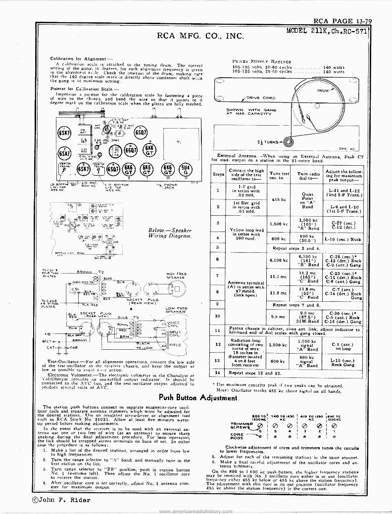
RCA PAGE 13-79
RCA MFG. CO., INC.
Calibration for Alignment.- A calibration scale is attached to the tuning drum. The correct setting of the gang, in degrees, for each alignment frequency is given in the alignment table. Check the position of the drum, making sure that the 140 degree scale mark is directly above condenser shaft wi.en the gang is at minimum setting.
Pointer for Calibration Scale.- Improvise a pointer for the calibration scale by fastening a piece
of wire to the chassis, and bend the wire so that it points to 0 degree mark on the calibration scale when the plates are fully meshed.
L5-eOTT6K LKl-TOP 459 KC.
To C50 L 7-5 TUBE PLATES
TO C49& 5 -IO TU&E
PLATES
+B
RECT.
Test-Oscillator.-For all alignment operations, connect the low side of the test -oscillator to the receiver chassis, and keep the output as low as possible to avoid a -v -c action.
Electronic Voltmeter.-The electronic voltmeter in the Chanalyst or VoltOhmyst provides an unexcelled. output indicator. It should be connected to the AVC bus, and the test -oscillator output adjusted to produce several volts of AVC.
ROW. T2 BIUt
GRO -RED TR
Below.-Speaker Wiring Diagram.
HIGK FREO. SPEAKSR
LOW FRED SPEAKER
VOICE COIL
NEUT ) COIL r
MODEL 211K, Ch .11C-571
POWER SUPPLY RATINGS 105-125 volts, 50-60 cycles 140 watts 105-125 volts, 25-60 cycles 140 watts
29K -K2
External Antenna.-When using an External Antenna, Peak C7 for max. output on a station in the 31 -meter band.
Steps Connect the high
side of the test oscillator to-
Tune test ma. to- Turn radio
dial to- Adjust the follow - ing for maximum
peak output-
1 I-F grid
in series with .01 mfd.
455 kc Quiet Point
on "A" Band
L-11 and L-12 (2nd I -F Trans.)
2 1st Det. grid in series with
.01 mfd. L-9 and L-10
(1st I -F Trans.)
3
Yellow loop lead in series with
200 mmf.
1,500 kc 1,500 kc (180.0)
"A" Band C-27 (osc.) C-12 (det.)
4 600 kc 800 kc (30.5°) L-15 (osc.) "Rock
5 Repeat teps 3 and 4.
6
Antenna terminal (A) in series with
47 mmfd. (link open)
6,100 kc 6,100 kc (161°)
"B" Band
C-26 (osc.) C-13 (det.) Rock C-2 (ant.) Gang
7 15.2mcC 15.2 me 165°)
sand
C-25 (osc.) C -il (det.) Rock C-8 (ant.) Gang
8 11.8 me 11.8 me (52°)
"C" Band
C-7 (ant.) C-14 (det.) Rock
Gang 9 Repeat teps 7 and 8.
10 9.5 me 9.5 me (87.5°)
SIM -Band
C-30 (osc.) C-5 (ant.) Rock
C-18 (det.) Gang
11 Fasten chassis in cabinet, close ant. link, alijust indicator to left-hand end of dial scales with gang closed.
12 Radiation loop
consisting of two turns of wire 18 inches in '
diameter located 4 to 6 feet
from receiver
1,500 kc 1,500 kc
signal "A' Band
Cl - (ant.) on loop
13 600 kc 600 kc signal
' A' Band R (osc.) g
14 Repeat steps 12 and 13.
Use minimum capacity peak if two peaks can be obtained. Note: Oscillator tracks 455 kc above signal on all bands,
Push Button Adjustment. The station push buttons connect to separate magnetite -core oscil-
lator coils and separate antenna trimmers which must be adjusted for the desired stations. Use an insulated screwdriver or alignment tool such as RCA Stock No. 31031. Allow at least five minutes warm- up period before making adjustments.
In the event that the receiver is to be used with an external an- tenna use one or two feet of wire (as an antenna) to ensure sharp peaking during the final adjustment procedure. For loop operation, the link should be strapped across terminals on back of set. In either case the procedure is as follows:
1. Make a list of the desired stations, arranged in order from low to high frequencies.
2. Turn the range selector to "A" band, and manually tune in the first station on the list.
3. Turn range selector to "PB" position, push in station button No. 1 (extreme left). Then adjust the No. 1 oscillator core to receive the station.
4. After oscillator core is set correctly, adjust No. 1 antenna trim- mer for maximum output.
seo To' T40 TO 1430 I 610 TO 1260 540 TO moo KC' KC I KC 1030 KC
TR1 PA SCREWS ® ® I ® 0 ® CRE ROODS
I,
e P 2
P P P
Clockwise adjustment of cores and trimmers tunes the circuits to lower frequencies.
5. Adjust for each of the remaining stations in the same manner. 6. Make a final careful adjustment of the oscillator cores and an-
tenna tritnmers. On the 880 to 1.600 kc push-button, the higher frequency stations
may be received with No. 1 oscillator core either in or out (oscillator frequency either 455 kc below or 455 kc above the station frequency). The adjustment with this core in its out position (oscillator frequency 455 kc above the station frequency) is the correct one.
©John F. Rider www.americanradiohistory.com

PAGE 13-80 RCA
MODELS V-215,V-221,Ch.RC-564; RCA MFG. CO., INC. V-219,Ch.RC-564Á;V-225,Ch.RC-564B
FOR -PUSH-BUTTON DATA SEE MODEL V-210 MODEL PICKUP V-219
POSH BUTTON AOJYSTMlNTS
CHASSIS AMINNA-MOONO TERMINAL BOARD
M MTILLv. JAG«
POWER CORO
CHASSIS SNIPPING SCREWS
SPAC
RECORD SUPPORT
RECORDS
SISHLÓPPIN6CK
¡T RECORD SUPPORT
SPINDLE TURNTABLE
/CCORD SUPPORT f MOTORBOA RD
'. TWO SNIPPPIryNG BOUS _` ( WITH RED HEADS .. . SNIPPING
KOCN TTTAOTORS
RECORD WELL
MOTOR \.------ ----- -r3HIPPI NG BRACKET
BOTTOM COVER
RECORD WELL LOOP ANTENNA SPEAKER RECORD STORAGE COMPARTMENT
c
A
Model V-225
RECORD SUPPORT
OFF
SPEECH FULL POWER -BASS
TONE CONTROL
R -BIB
CHASSIS MOUNTING BOARD
CHASSIS I PICKUP TURNTABLE MOTORBOARD
'SPINDLE
{ - ..1.1",ç
:l - - ri -;:
RED BRACKET AND TWO SCREWS.
TWO SHIPPING BOLTS WITH II RED HEADS
RECORD CHANGER SLIDE MECHANISM
(Models V215, V221)
-uo An adjustment is located on each of the rear legs so that the
angle of the cabinet may be adjusted to allow the record changer to slide out easily. Adjust so that the changer rolls out of the cabinet to a gradual sto at the front edge of he opened door.
RECORD SUPPORT
PICKUP AREC
MODELS V-215 V-221
MOTOR BOARD
PICKUP
INDEX LEVER
TURNTABLE SWITCH
START -REJECT BUTTON
AUTOMATIC PHONOGRAPH RP -161 for V-226 Type Pickups (2) Crystal
Record Capacity . Fifteen~10-in of Twelve 12 -in. Power consumption turntable - drrve motor.. (14 )watts Power consumption cycle motor (38) watts
/ PUSH BUTTONS
®g ®g FUL BASS
TREBLE TONE CONTROL
DIAL
F.M
/ PHONO. TEEV.
RADIO
VOLUME SERVICE SELECTOR CONTROL CONTROL
Ao
LOUD SOFT
LINK
G L1
ELECTRIC TUNING No. of Stations
1
2 2 1
ELECTRIC C TUNING
ANN
MANUAL TUNING RANGE' CONTROL CONTROL
R-794
For all Models
TO 51 (7) T0 52 ( I1)
C3
SOCKET
PLUG
PICKUP.
MOTOR
LOOP AND PHONO- MOTOR CONN'S V 219 (RC 564A)
External Antenna.-For best reception on "C" band with an ex-
ternal antenna, peak the trimmer on "C" antenna coil for maximum
output on a station in the 31 -meter band.
PUSH BUTTON ADJUSTMENTS \,,,eaeeeef
6 5 4 3 2 1
CHASSIS
ANTENNA -GROUND \ TERMINAL BOARD r
POWER CORO G T
1 K.A
TP{CICUP OTORBOA1iD I
TURNTABLE. .
CTC i- .. SPINDLE_ m-
- -.i. r. ; - -__-
MOTOR
LOOP ANTENNA
TO PHONO
F.M. & TELEV. JACK
SPEAKER
RED 'BRACKET AND TWO SCREWS
TWO SHIPPING BOLTS WITH RED HEADS
Removing Mechanism (a) Unplug the power cord and pickup cord. (b) Reach in behind the motor board and lift up the two metal'
tabs which act as stops and prevent the record changer from sliding out.
(c) Loosen the cable clamp holding the two cables in place. (d) Pull the record changer dut of the instrument,
RECORDS SPINDLE
540-1,080 kc 610-1,250 kc 740-1,430 kc 880-1,600 kc
I-
RECORD SUPPORT 7 TURNTABLE SWITCH START -REJECT LEVER R-801
R-790
RECORD SUPPORT
MOTOR BOARD
PICKUP ARM
PICKUP
PICKUP REST
Models V-215, V-219 and V-221
©John F. Rider www.americanradiohistory.com

RCA PAGE 13-81
MODELS V -215,V -219,V-221, V-225
^
_ ó _ ]J ó23of- W
Nóº w Jh J1Ñ3 OccNFV
Wd
Q*Q WJOU h = ZXj Jw9 ó
200 t Zr:
o = u>(0ÿ;
(Ya ó Ñ yy
l. N
1î111î0 dm<nooloR c`O
ÑÑNNH
,, ,,w II
w l l 1 .. KLY.
"""1 H ° p 19 0? Nog N F NJ+NNJIILIGC±° o. UN V (919191919191919N ó - C) - N m d u119r` aD_ 0`
OOO 00e mma
©John F. Rider www.americanradiohistory.com

PAGE 13-82 RCA
MODELS V -215,V -219,V-221,
V-225
POLICE
2.3 2.5 . 1 1
RCA MFG. CO., INC. AIRCRAFT 90M AMATEUR
3.0 t
55 60 70 I ! 1 1 1 1 1 1.1 l l t 1
31 METERS
9.3 HAVANA TOKYOMANIIA ANKARA LONDON BUENOS N' KONG BERLIN LISBON
60 M AIRCRAFT 49 M
3.5 4.0 5.0 6.0 sUÑtÉ GH
t 1 1 1 11 1 1 1 t41 J L 1 1 L1 1 1j 1 1 11J Ll 1_l_.1 t t.
80 100 t t l.1 L11 1 1 1Lta 1
10 II 1 l 1 1 J 1 t t
120 140 160 1 ! 1 J 1 t t
25 METERS AMATEUR 19 METERS
TOKYO CKING LONDON 1
2N' DELHI
SAIGON BERLIN 13 14 15 H. KONG LONDON BERLIN
4(.111 1 1 1 1 1 L / t l 1 1 1 t
The dial scale drawing shown is a full size reproduction. It can be used as a direct substitute for regular dial scale'in ali.
Cathode -Ray Alignment is the preferable method. Connections for the oscillograph are shown in the schematic diagram.
Output Meter Alignment. -If this method is used, connect the meter across the voice coil, and turn the receiver volume control to maximum.
Test -Oscillator. -For all alignment operations, connect the low side of the test -oscillator to the receiver chassis, and keep the output as low as possible to avoid a -v -c action.
Electronic Voltmeter. -The electronic voltmeter in the Chanalyst or VoltOhmyst provides an unexcelled output indicator. It should be connected to the AVC bus, and the test -oscillator output adjusted to produce several volts of AVC.
Calibration Scale. -The glass tuning dial may be easily removed from the cabinet and temporarily attached to the chassis for quick reference during alignment. In the event that only the chassis is returned for service, and the cabinet with its tuning dial is left in the customer's home, the full size calibration scale printed in this service note can be used as an accurate and convenient substitute for the regular dial.
Using Tuning Dial. - '1. Remove the dial glass from the cabinet. 2. With gang at full mesh move the pointer to a point (1/16)
inch to the left of the reference mark at the left hand end of the dial backing plate.
3. Place the glass dial under the pointer so that the extreme left scale graduations coincide with the pointer. Use scotch tape to hold the glass dial in place.
Using Dial Scale Printed In This Service Note. - Follow the procedure above, substituting the dial scale printed in
this service note for the glass dial in the cabinet.
LB A-osC. 600 KC.
Re7 ß6 C21 C 21A
A
C7-GOSC (¡¡¡3(Mc O C -ANT. v C8-213-OSC. 5%
'j - g .9 5MC, 6.1 MC. 6SQ/
C 94 C24 0 C49 L11- BOTTOM
C9-AOSe. L12- TOP 1500 kC. /455 KC . / /
rThSKL C2- B ANT. C5-t.-ANT.6.1 MC. 15.2 MC.T
L9 - BOTTc L10 -TOP
455 KC
FM - TELEV L -111 -.PHONO- JACK JAC K.
Steps Connect high
aide ofing test omc. to-
Tune test Osc to- Turn radio
dial to- Adjust the follow -
for maximum peak output -
1 I -F grid
in series with .01 mid.
455 kc "A" Band 540 kc
L12, Lll (2nd I -F Trans.)
2 in seriesries with series .01 mid.
L10, L9 (1st I -F Trans.)
3 Yellow loop lead in series with
200 mmf. (link closed)
1,500 kc "A" Band 1,500 kc C9 (osc.)
4 600 kc "A" Band
600 kc L8 (osc.)
5 Repeat steps 3 and 4
6 Ant. terminal in series with
47 mmf. (link closed)
8.1 me "B" Band
6.1 me C8 (osc.)* C2 (ant.)
7 lb 2 me "C" Band 15.2 me
Cl (oac.)* C6 (ant.)
8 9.5 me "C" Band
9.5 me C4 (ant.)
9 Repeat steps 7 and 8
10
Install and connect chassis in cabinet, with link closed. Tune in a radiated oscillator signal at 1,500 kc and peak the "A" band ant. trimmer C3 (on loop). Rock in L8 for peak out- put at 600 kc.
Use minimum capacity peak if two peaks can be obtained.
Oscillator tracks 455 kc above signal on all bands.
Critical Lead Dress 1. Push button, R.F. and oscillator leads should be separated as
much as possible to reduce degeneration on push button reception.
2. R.F. choke in plate circuit of 6SG7 should be dressed towards the back apron.
3. Dress green push button lead under clamp and away from "C" band series capacitor.
4. Dress heater leads away from grids and diodes.
5. Dress phono. cables up and away from all wiring. 6. Dress all excess leads from transformer towards back towards
transformer. 7. Keep output plate leads short and dressed close to chassis.
8. Dress green lead from 6SA7 screen to electrolytic down close to chassis.
9. Dress "C" band coil lead from oscillator coil to range switch down towards green lead.
10. Keep yellow loop lead clear of all wiring. 11. Dress ground bus of large electrolytic away from mounting lug.
12. Remove all excess slack from pilot light assembly and dress it close to chassis base away from volume control.
13. Dress oscillator grid capacitor (56 mmfd.) up and away from the screen and plate of 6SA7 socket.
14. A -C leads to "off -on" switch should be kept away from tone control cable to reduce hum.
15. Peaking coil should he dressed away from R -F grid resistor to reduce degeneration in R -F stage.
16. Dress oscillator push button lead in weld clamp on front apron away from 220 mmf. series condenser.
17. Keep all leads away from Phono. -FM jack to prevent audio oscillation and hum. Dress underneath the shield provided.
©John F. Rider www.americanradiohistory.com

RCA PAGE 13-83
x¿ 00 dd
J aN- EY <v) LL -
N
F Z 4
>
co
ocª
I
{I
RCA MFG. CO., INC.
é p 1 IpI I 1 w I ó
I 11=11ó --mow d0
L)911 e N
l.-sNr--4 'll z O 111 W of I
m z mf r. ; r _--1! - i!
i ei N
° u lue o 0 _J NoÌI pYf ogZY
> r o uNFlo¿o O *( I 1º LL 4 ó AN IL 1 0
d e ó- I--- o T < u_ > gM UQI
IY I F
Ñ LL
GY Q- I W Mti Y
Ñ, 'ono, ; rcif f 31. L N ,
VIpLL 2 F -F t In
ro _J uºÉ mF
N J Óm
+0001
r o{ o
m
UU YY ggo
>> 4mo
LYY/ QOQxv , o e i4
'000\ 81I wc N JÑ
d
r
o
ro
.140
MODELS 516,517 Chassis RC -1001C
S
Q@
¡
o ñ
n
")
® 0
á
VJ
N M .II IO
O o n
.0 c ro
r w ` ro
uh 3.d a ^ h
ú Ó ro ú E M o
- R
ó ny
Voc ro Ñ ro 4 u 3 ú E ro 7, E .
a «' 3 T v uO u..
-º 9 É ...0 A ó
u b Ñ a 0
ÓO
` .0 «
3v MW O q ro
u O, Ú..I u E « c `
ó Ov 3y áñ .5!,1
á 30
Á. oa ro
IG«
govó o n ÿ M c p
ú ú úE..71Ta U `' .oO ro
ßI ti N 1" d
©John F. Rider www.americanradiohistory.com

PAGE 13-84 RCA MODELS 526,527 Chassis RC -1001E
LOUDSPEAKER (RL -86-A3)
V Ce Impedance
POWER SUPPLY RATING
RCA MFG. CO., INC.
5 -inch electro dynamic 4.0 ohms at 400 cycles
105-125 volts, AC 50 or 60 cycles, or DC 25 watts
PRECAUTIONARY LEAD DRESS. - 1. Dress the power cable to switch on the volume control
close to the chassis and away from all grid and diode leads and condensers.
2. Dress capacitors in the 12SQ7 grid circuit away from all
wiring.
3. Green and black phono wires should be twisted and dressed away fròm other parts and leads.
4. 50L6 -GT filament wires should be dressed to rear of chassis and away from the second I -F transformer leads.
5. Dress brown lead from second I -F transformer to 12SQ7 away from power cable.
6. Dress wire to No. 1 grid of the 12SA7 away from pilot lamp leads.
7. Dress wire from loop to variable condenser away from chassis.
8. Dress all capacitors, leads, etc. which come close to oscil- lator coil rigidly and as far as possible from it.
C21-O0C. C22-050. 10 MC.. 000 KC.
C IS -ANT I S00 KC.
C 1 O5C. 1600 KC
R7
to
O ANT
L6
ANT COIL
1ST.I.0TRANS c7 -CO
465 H.C.
e` 1
4X
C 25 ANT. 10 MC
2140.I.R TTNII( CO -CIO 445 KC.
( 600 KC.)
BOTTOM VIEW OF TUBE SOCKETS
LI LOOP
14
_ C 23
Sc
oSn C20 o-S22.61
C15 3-25
CI .035 I
180-250
TOT
FREQUENCY RANGE
Broadcast Band 535-1,720 kc Short Wave Band 8.9 mc to 12 mc.
INTERMEDIATE FREQUENCY 455 kc
Steps Connect the high
side of test- oscillator to-
Tune test-osc. to-
Turn radio dial to-
Adjust the fol - lowing for max. peak output-
1 12SK7 grid
in series with 0.1 mid.
455 kc Quiet Point at 1,600 kc end of dial
CIO, C9 2nd I -F
Transformer
2 12SA7 grid
in series with 0.1 mid.
C8, C7 1st I -F
Transformer
9 Antenna term. in series with
47 mmf. 10 mc* 10 me 1
218 (coca** (ant.)
4 Antenna term. in series with 200 mmfd.
1,600 kc 1,600 kc C14 (osc.)
5 Radiation
Loop 1,300 kc Resonance on Signal C15 (ant.)
Radiationon Loop 600 kc 600 kc
C22 Osc.
* It is recommended that this step be repeated using a received station of known frequency.
** Use minimum capacity if two peaks can be obtained.
CONVERSION RAIN SOX -I IX I- 100X-06X--SOX
(Coo- 455 KC.) (455 KC.) (455 KC) (435 KC.) (400.v)
RI 2.000
L4
c261 160 S
125A7 1£' OCT ec OSC.
RB 220,000
12 5K7 I. F. AMPL.
90 V. On
C2+ ©T © 0.1 I
90V. soil pz, 30
112'1.F TRANS
C24
0 0 2 `O I.F TRANS
I wE 455 K. C- 455 KC 56 su6-
T i r'-- ,11 I ó ó I
GR N C 9
C2/ 5V' Cl y 11 75-160 1 u
(GOOKC) 75-160r g g y- T o ó 160"tor V Bn al 0 8n i 19ná ó19n
(9ÑC.) 1 + aspi L _Jca
;') 75 1443 y
SA.C144 1c19 sr° i 3-25r ó
R' -10V. MAX.AVC. VOL TAGE Ì
If 5127 27.f. DET. A.F &.A.V.C.
A
C22 31e- aor
R2 3.3 HEG:
19/KEN
C10 75-160 =
IiCN I I
- J -1 I
-_ -Y IC12. .2 120 K 0
** 2II 1C18 T .01
VOL. CONTR. 500,000.1 STOP AT 50,000 n
L PHONO - JAC K ó7i
C25 I /o 00
52 (REAR VIEW) SHOWN IN
BROADCAST POSITION
1-
R4
APPROX. GAIN IOX DATA USING
(400...) RCA RIDER C NANALYST_
SOL(GT OUT PUT
220,0°0
R5 470,000
RS 4.7 MEG.
ICs -.02
3V BIAS FOR -r+ GAIN DATA
477 CHASSIS GROUND
1 COMMON WIRING INSULATED FROM CHASSIS
VOLTAGES SHOULD HOLD WITHIN * 20% WITH 117 V. AC. SUPPLY.
* MEASURED WITH CHANALYST OR VOLTONMYST.
117V. e AC -OC. a
35F5GT RECT. c6 FIELD
4506 ---obööòoo'
C16 + 30 IJ MFD.
C17 + 50 Ll
MFD.
b r 35ZSGT" SOL 607 12 SA7 125K7 12307
a 2 3
l4DO10IS01 E)-4. (RC
©John F. Rider
www.americanradiohistory.com

RCA PAGE 13-85
6 ó J
RCA MFG. CO., INC.
TU
DRIVE WNIaL
MOTOR
NEEDLE PACKAGE NOLOER
SPINDLE
PICKUP ARM
PICKUP
NIMEOLS
REST \
scREw
CUP FOR USED NCEDL ES
POWER OUTPUT Undistorted Maximum
0.9 watts 1.2 watts
Output Meter Alignment.-Connect the meter across the voice coil. and turn the receiver volume control to maximum.
Test-Oscillator.-Connect the low side of the test -oscillator to the receiver chassis, through a .01 mfd. capacitor, and keep the output as low as possible.
Phonograph Motor Service Data:- The phonograph motor is of the self starting synchronous type and
operates the turntable through friction drive between the motor drive spindle and the rubber tired idler on the rim of the turntable.
The motor should be lubricated once or twice a year by placing a few drops of S. A. E. 20 (or equivalent) on the turntable spindle and saturating the oil retaining felt pads on the motor shaft with S. A. E. 10 oil. Caution-The motor drive spindle and the rubber tire on the idler must be kept clean and entirely free from oil and grease at all times.
Power Supply.-Although this model employs an ac -dc chassis, it is not suitable for use on d.c., as this would damage the motor.
FREQUENCY RANGE
INTERMEDIATE FREQUENCY
PILOT LAMP
MODEL R -560-P Chassis RC -517F
540-1,650 kc
455 kc
PHONO RADIO
10) FULL. OFFle LOUD \ SOFT IFULL\
'MELLOW MELLOW VOLUME PHONO- RADIO \TUNING
CONTROL POWER -TONE CONTROL CONTROL
1-Mazda No, 51, 6-8 'tufts, 0.2 amps.
POWER SUPPLY HATING 105.125 volts, 50 cycles 55 watts 105-125 volts, 60 cycles 55 watts
LOUDSPEAKER (11L -81B-4) Type 5 -inch P.M. V.C. Impedance 4 I,hms at 400 cycles
Steps Connect the high
side of test- oscillator to-
Tune test-osc. to-
Turn radio dial to-
Adjust the follow - ing for max. peak
output
1
I -F grid, in series with
.01 mfd. 455 kc
Quiet point 1,600 kc
end of dial
L8 and L9 2nd I -F
transformer
2 1st Det. grid in series with
.01 mfd.
L6 and L7 1st 1-F
transformer
3 Ant. terminal in series with
200 mmfd. 1,650 kc Gang at
minimum C25 (osc.) C31 (osc.)
4 Radiated signal 1300 kc Signal
Frequency C23 (ant.)
5 Repeat steps 3 and 4.
ANT. TO GRID CONY. GAIN II
0.4X I
O.At( I
10X (600 KC.)-+ 100E(600- 45311C:).1. (455 KC.) .F -150X (455 KC.) (455Kr.) 40X (400aV)---1 1,, MEASURED WITH 5V. FIEF -D F)IA i -
12SA7 125,K / 12SQ7 1ST. DET. _ OSC. 1.F 2ND. DET,AF. &AVC,
LE LOOP
Lt
C81 C25C22 cl 3-1o7- -4-5c5
e
Loo P
RI
t2 M
O .'
º 7- V.
8o v. -
c, C26; O 'C27 100, =07ó='100
A~J `--p r'YS
L6 L7
610. 8A J
c C28) l20!
A t
YEL
Ce O.I
R13
-BV. (600KC -9v. (1500 K -)
3V. BIAS 4- We FoR GAIN }i - 220 M if>r DATA 4 - Top VIEW
C2E O5CC.R ¡ 1560 K
C 23 -ANT 1300 KC.
C24
C 22
CTS 3-10
C24 Z5-170
VOLTAGES SHOULD HOLD WITHIN * 20% WITH 117 V. AC. SUPPLY.
at MEASURED WITH CHAHALYST 012 VOLTOHMYST.
at -17 V. APPROX. MAX. As/C.
I
,777 CHASSIS GROUND
COMMON WIRING INSULATED FROM CHASSIS (E-)
C31-o5C \ / 1560 KC
1/ L 1 LJ I\ LG -BOTTOM L,B_EOTTOM L7 -TOD L9 -TOP 455 KC. 455 KC.
C20 -L 220
2.2 MEG.
RIS 500 M VOLUME CONTR.
C5 OS1 I
RADIO-PHOtIOr TONE 2,,,POWER SWITCH. SHOWN IN OFF POSIT ION
47M> TTT
CI7
C181701.5 I, PICKUP 0.1
-- 405 5bME6.
SOLLG 1290 S[ 7 125Q7
4 E I 3 j
MOTOR
47M
51 FRONT
- 1
R9 120
F4 -14X (400 N) APPROX. GAIN DATA. USING RCA RIDER CH ANA LYST
50L6 GT OUTPUT
4v.
RIO 470M
35F5GT RECT.
DIAL LAM P
1C12 0.25
1
r &NWT
52 REAR
tIOV. C. 85V. .025
iRED
0. le" ó II4
1500 DIME
u
0
RID C14
500 NFL/
ßR'NI C13 Y 30 1 MFp,
t Pow ER r L SUPPLY
117V. 75w.
I
©John F. Rider www.americanradiohistory.com

PAGE 13-86 RCA
MODEL R -566-P RCA MFG. CO., INC.
Frequency Range 540-1,600 kc Intermediate Frequency 455 kc
POWER OUTPUT Undistorted 1.6 watts Maximum 3 watts Pilot Lamp (1) Mazda No. 51, 8.3 volts. 0.20 amps.
POWER SUPPLY RATING 105.125 Volts. 60 Cycles 65 watts
Steps Connect the high
side of test- oscillator to-
Tune test-osc. to-
Turn radio dial to-
Adjust the follow - ing for max. peak
output
1 I -F grid, in series with
.01 mfd. 455 kc
Quiet point 1,600 kc
end of dial
L8 and L9 2nd I -F
transformer.
2 1st Det. grid in series with
.01 mfd.
L6 and LI 1st I -F
transformer
S Ant. terminal in series with
200 mmfd. 1,600 kc Gan at
minimum C5 (osc.) C6 (osc.)
4 Radiated signal 1,300 kc Signal
Frequency .C3 (ant.)
5 Repeat steps 3 and 4.
5OY6GT 4
50Y6 GT
R
C19 16 MFD
C2422
MFD
FIELD
750n RIO 330n.
C22 MF'D
125v.
-B
SIMPLIFIED SCHEMATIC VOLTAGE DOUBLER CIRCUIT -
117 V. AC.
PICKUP TURNTABLE RECORD SUPPORTS MOTORBOARD
612x 50x O.BX 200X IX
OOKC) (600-455KC) (455KC) (455KC) I (455KC)
BOTTOM VIEW OF TUBE SOCKETS
e Cl 005
L2 LOOP
LI
®+ C3 T C4r 3-10 9.355
3V. 1 - FIXED BIAS 105 T}
GAIN DATA I
.
Sj220M 0140140 JACK
rr'ri
R2 22 M
x
W L3
MEASURED 125,47
1ST. PET.&OSC.
O .ß o',` o o o
095V.
I° `óó I
ITLA
iri;
9 V
W TH 3V. FIXED BIAS 12SK7
I.
IST. I.F. TRANS. 95
0pp
8o
1c,s - p ---
7A. 7A . I
iE - 12 V. 11500 KC) - B V. (550 KC)
RED I ('oCS-C6 yC7 3-10 31oT7.5-,70
L4 15 ER 7A m
*
C9 0.1
R4 82M
- ISV. APPROx MAX AVC
-/- Ce
156 CIDT
0
CATHODE CURRENTS (I) 12SÁ7 _ 11.0 MA. (2) 12SK7 - - 14.6MÁ. 13) 12501 - - - .4444. 141 35L6GT - 46.ÓMA. (S) TOTAL SECT. - - 74.0 MA.
LOUDSPEAKER (RL86B6)
.0015
PICKUP
r -
I.', r-- :
.
Kc ` _
---}--'-` t---3p----r-----
TURNTABLE SPINDLE
f--..7,.-... ..
;i MOTOR SPINDLE'!} -_ .
I ;IDLER WHEEL 1 _i-j" --`- tt'-
.:i- -
t /; t MOTOR ;7
MOTOR çj-a 1 CABLE¡ 1 TWO SHIPPING BOLTS `CONNECTOe7r WITH RED HEADS
CHASSIS r C ""--" HASSIS BOARD Ny; TWO CHASSIS BOLTS . r" %ICKUP LEAD
CONNECTION r11Y 7
RS VQL.CONTß
500 M
MOTO 32 ON MOTOR BOARD
FOUR CHASSIS BOARD SCREWS- OM,
4 -OX (400 ti )
12S O17 2ND. DET., AF., AVC.
© ,CI pMO 2TRANS 0 ND.I.F. 62V ©
A_A c 1pq,gT D1
FaI -odI á I120
A~L.a L! F -7A 7n _J
Type 5 -inch Electrodynamic V.C. Impedance 4 ohms at 400 cycles
R7 47 M
Y
GRO. CONN'^ VERTICAL *HI" TO THIS TERMINAL VERTICAL' 0" TO CHASSIS.
Rr--WV 600 l'n ú 330
5ÁS1 FIELD r 1C22 o
III I MF D. CC
I C19L r I . 2o 16 o1 MFD. MFD.
C24 .O1
12X (400 v)
R14 150
= C17
inII7V--AC
820
205 V.
C23 .05
iÓ
RII PILOT IS LAMP
P(,ú917Ñ) 1
35 L6 GT OUTPUT-
APPROx. GAIN DATA USING RCA RIDER CHANALYST
I(7V. 125 V.
BLU TI
1604
RED
H
VC
[.M. 5P K'R
VOLTAGES SHOULD HOLD WITHIN !207. WITH 117 V. AC. SUPPLY.
* MEASURED WITH CHANALYST OR VOLTOH MY ST.
2iL467 ItsA7 It557 IL507
50Y6 GT RECT.
©John F. Rider www.americanradiohistory.com

RCA PAGE 13-87
RCA MFG. CO., INC.
Model Mi -4803 Type Pt -16 Pickup - Low Impedance Voltage Rating of Motor - 105-125 volts AC
MAGNETIC
PICKUP
BLACK BLACK
-,;, a.
íh BLACK
,.. .......
IF SPLICE
Frequency - 60 cycles Power Consumption - 30 watts
PHONOGRAPH MOTOR
e e- ®e p_ 'eee.eeAleeeee
e\®`eeeeeeecee éeeeeeeece
,
Synchronous motor is adjusted for either 33 1/3 or 78 rpm
AUTOMATIC
SWITCH
Dimensions: Weight Shipping Weight Finish
MAGNETIC
PICKUP
BLACK
BLACK BLUE
MODEL MI -4810 This is the same as Model MI -4803 with TELEPHONE these exceptions: MI -4810 has no re- PLI1G aotor,L1; the frequency rating of the otor is 50/60 cycles.
BLACK
MODEL MI -4802 MODEL MI -4810
R-2
VOLUME
CONTROL
BLACK
REACTOR* SWITCH
R-1
18" x 15" x 9" high - 22 pounds - 37 pounds - Black Leatherette
SWITCH»
Pickup designed to match impedances from 60 to 500 ohms.
nn
' (MOO MOTOR 0e,
AUTOMATIC
SWITCH
R-1
I-2 L
POWER CORD
i,
L*
.« A.C. POWER
PLUG
I.-- i i
USED NEEDLE TURNTABLE CUP
SPEED SHIFTER
VOLUME CONTROL AUXILIARY SWITCH
NEEDLE SCREW
AUDIO CORD
VOLUME e COATROL
ELECTRIC STARTING TONE ARM PICKUP LEVER SUPPORT
©John F. Rider www.americanradiohistory.com

PAGE 13-88 RCA MODEL MI -4804 MODEL MI -4811
A. C.
POWER
PLUG
RCA MFG. CO., INC.
MODEL MI -4804 MODEL MI -4811 Type- PT -17
These two Double Turntable Phonographs are the same except that Model MI -4804 is for 60 -cycle operation only and Model MI -4811 is for 50 or
60 -cycle operation.
R -1
R-3
MIONOGAAPN M OTOM - -
FADER AND VOLUME
CONTROL
R-2 R-3 TELEPHONE R-1
Pickups are designed to match impedances from 60 to 500 ohms
MAGNETIC
PICKUP
a.
PLUG
1
( 00000 MOTOR
OÒOW
AUTOMATIC
SWITCH
SPEED SIUF FER
POWER TURNTABLE CORD
---J1 '
AUDIO USED NEEDLE CORO CUP
MAGNETIC
PICKUP
0000' MOTOR
eÒ0Òr
TONE ARM
SUPPORT
AUTOMATIC
SWITCH
NEEDLE SCREW
VOLUML CONTROL VOLUME ELECTRIC STATING AUXILIARY SWITCH CONTROL PICKUP LEVER
iADCR
®John F. Rider www.americanradiohistory.com

RCA PAGE 13-89
ruCDELS MI-4816,1tI-4817, RCA MFG. CO., INC.
The MI -4836, 48i8 equipments are designed for regular Public Address use, while the MI -4817 is designed for Sound Truck (6 volt) operation. Standard, 78 rpm,
records may be played on the MI -48i6 and MI -4818. The
MI -4817 has provision for changing the speed of the
turntable to enable both 78 rpm and 33-i/3 rpm re-
cords to be played. A low -impedance (125 ohm) mag-
netic pickup is used, designed primarily to use
chromium (RCA orange or green shank) needles. The
output of the pickup is fed through o volume control
into a standard phone plug, or, for permanent con-
nection, the plug may be removed, and the wires
soldered directly to the amplifier input. CAUTION:
Connect only to the type power supply specified on
name plate.
SPEED $NO TER <MX
gen oNy)
NEEDLE SCREW
For adjustments of magnetic pickup, see data on Yodel MI -12700.
II LD NILUZE TURNTABLE CUP
AUDIO CORD
MAGNETIC
PICKUP
MI -4818
POWER RATINGS MI -4816 105-125 volts, 60 cycles 30 watts MI -48i7 6 volts, d.c. 35 watts MI -4818 1O5 -i25 volts, 50 cycles 30 watts Pickup Impedance 125 ohms Turntable Speeds ... MI -4816, 4818 ... 78 rpm
MI -4817...78 rpm and 33-i/3 rpm Dimensions(lid closed) 20" x 15" x 9" high Weight(Net)....22 lbs.; Weight(Shipping)....37 lbs. Finish Gray Wrinkle
Operation
To operate turntable - connect to proper power sup, ply, place phono. plug into amplifier input, place record on turntable, set the speed selecting mechan- ism to the proper position to correspond to the type record used (MI -4817 only), then pull starting lever toward the front of the case, place pickup on re- cord, and regulate volume as desired. To stop turn- table, lift Pickup arm, place it on the pickup rest, and the automatic switch turns the motor off. When transporting equipment, be sure the pickup arm is on the pickup arm rest.
BLACK
BLACK
PHONOGRAPH MOTOR
AUTOMATIC
SWITCH
VOLUME 0 CONTROL
ELECTRIC STARTING ONE ARM PICKUP LOVER SUPPORT G
DESCRIPTION Pickup and Arm Assemblies
ARM - Pickup arm only 98íi BACK - Pickup back 11548 COIL - Pickup coil 12541 MECHANISM - Comprising an armature and spring
assembly, one armature clamp and one damper
SCREW - Needle screw 12539 Motor Assemblies (MI -4816 á 4818 only)
MOTOR - 60 cycle motor for MI -4816 8989 MOTOR - 50 cycle motor for MI -4818 8990 TURNTABLE 11696 DAMPER - Turntable rubber damper and damper
plate 33704 MOTOR MOUNTING - Comprising 2 cup washers,
4 springs and i "C" washer 3398 STUDS - 3 motor studs 381.7
Motor Assemblies (MI -4817 only) ARMATURE - Motor armature 26188 BRUSH - Set of 2 brushes for motor 23515
SPLICE
REPLACEMENT PARTS
STOCK NO.
14115
DESCRIPTION
BLACK
BLACK
68^
VOLUME
CONTROL
TELEPHONE
PLUG
POWER
PLUG STOCK NO.
DIAL - Speed indicator dial 23512 ESCUTCHEON - Speed shift lever escutcheon 23534 GOVERNOR - Motor governor complete 26189 LEVER - Speed shift lever 235i3 MOTOR - 6 volt d -c motor 27684 POINTER - Speed indicator pointer 26i87 TURNTABLE 27685
Motor Board Assemblies BRAKE - Automatic brake complete with cover 9809 BOX - Needle box 439i KNOB - Volume control knob 4085 VOLUME CONTROL 12392 REST - Pickup rest 1.1.551
SCALE - Volume control knob scale 3986 MOTOR BOARD MOUNTING - Comprising i bolt, i
top spring, i bottom spring, 2 cup washers, i "C" washer and i nut (MI -
4816 -4818 only) 32069
CABLE - Power cord and plug 13524
©John F. Rider www.americanradiohistory.com

PAGE 13-90 RCA
MODELS MI -4829, ICI -4829A RCA MFG. CO., INC.
Figure 1-MI-4829 Height (with cover) 8¡'z inches Length 219 inches Depth 18 inches Weight-net 32 pounds
General Description The MI -4829 and MI -4829A are portable turntables for
playing of laterally cut records up to 16 inches in diameter, at either 78 or 33/ r.p.m. They use a governor type motor which is adjustable over a wide range of speed, and operate on 105/125 volts 50 to 60 cycles. An output jack and shielded cable is provided for connection to an external amplifier. The MI -4829 is equipped with a high impedance crystal pickup. The MI -4829A uses a low impedance mag- netic pickup for connection to 250 -ohm amplifier inputs. Both have an integral volume control for controlling the input level to an external amplifier.
MI PICKUP R-1 R-2 C-1 4829 Crystal 500,000 100,000 0.0025 4829A I?agnetic 600
/05/025 VAC. SO/6o Cy, 1)
Operation 1. Plug pickup cable into motor board receptacle. 2. Connect shield lead to ground on the proper amplifier,
and red lead to "high" side of amplifier input. (To sleeve and tip of telephone plug respectively,'if used.)
3. Set speed selecting mechanism to the proper position, corresponding to type of record used.
4. If 16 -inch records are to be played, first place special 16 -inch flocked disc on the turntable.
5. When carrying records in cover, place 16 -inch flocked disc between records and clamping disc to prevent records from warping.
Speed regulation:-Check speed in the 78 r.p.m. position by placing a piece of paper between a record and the turn- table with the paper protruding beyond the edge of the rec- ord, and counting the number of revolutions of the turntable per minute while playing the record.
Should it be necessary to reset the pointer such that 78
r.p.m. can be obtained near the center of the "F -S" scale, remove motorboard from cabinet and take off the turntable first removing the "C" washer from the turntable spindle. Set pointer off scale approximately % inch beyond the "F" mark. Loosen slightly the pointer arm screw and nut that clamps it to the slotted cam shaft. Then with a screw driver, adjust the cam such that the minimum radius of the cam is against the governor adjustment ball bearing. Tighten the pointer arm screw and nut in this position.
No separate adjustment is_ provided for 33/ r.p.m. since
with the speed properly adjusted for 78 r.p.m. records, the
speed for long playing records will be. 33/ r.p.m. when
the control lever is set at 33/.
The crystal pickup:-If failure occurs, no attempt should be made to repair the unit, but a new replacement crystal unit should he installed.
For adjustments of the mag- netic pickup, see data on Model MI -12700
CABLE & PLUG
REl)
circoMCïTO2
5NIEI.
R -Z
R-1 o
z.9) LIEU) --` C
C
DESCRIPTION
MOTORBOARD ASSEMBLIES MI -4829 AND MI -4829A
STOCK No.l
Capacitor-.0025 mfd. (MI -4829 only) Connector -3 -prong female for input cable Control-Volume control (MI -4829 only) Control-Volume control (MI -4829A only) .
Cord-A.C. power cord Disc-Disc for 16 -inch records Escutcheon-Speed change escutcheon Escutcheon-Speed indicator escutcheon Knob-Volume control knob Motor-Turntable drive motor Pointer-Speed change pointer Pointer-Speed indicator pointer Resistor -100,000 ohms- 4 watt (MI -4829
only) Switch-Motor switch Turntable-Turntable complete
CARRYING CABE
Case-Carrying case complete Catch-Carrying case catch Poot-Pelt foot for carrying case Handle-Carrying case handle Hinge-Carrying case hinge complete ..
34459 36183 36182 37047 32098 371'6 23511 23512
7960 36180 23513 26187
3252 28322 36181
36184 36119 36118 36199 36200
DESCRIPTION
PICKUP ARM ASSEMBLY MI -4829
Base-Pickup arm base only Cable-Pickup cable Nut-Nut and washer for pickup arm base Pickup Unit Cartridge Ring-Retaining spring for pickup arm shaft Screw-Needle screw only Shaft-Pivot arm and shaft Shell-Tone arm shell Spring-Pickup arm spring
PICKUP ARM ASSEMBLY MI -4829A
Arm-Pickup arm with pivot arm and pickup spacer-less pickup unit, collar, pivot shaft and bearing, and base assembly ..
Base-Base assembly with bottom bearing Collar-Pivot shaft collar Pickup-Pickup unit complete Shaft-Pivot shaft and bearing
STOCK No.
36139 36141 33122 36427 34311 33529 36140 36137 36138
33577 33578 34679 32357 33579
©John F. Rider www.americanradiohistory.com

RCA PAGE 13-91
MODEL DII-12754
MO IA T Y1.
9,.._k00o0o6A490 s1101 031/
J b
N rc
din 4 SS00i SI -3 «
ñd IQB
030 s ÁD0
021 021 ; YP-Y .T -Y
30111
030
03YT 1118
4nno2Z
Of -3I
<46 VJ K.o
v oodzr rood..
r z Io
OI-Y
Y y 1 4 £ -11
RCA MFG. CO., INC. P -A Equipment
It.
ñ R
á
02'0 OLdI or* O09 fTiJ S -Y 04-41
i q -005.1
oodocc IIr.OoOc1 roodocc 0E -SI
Cf -Y ff -Y CC -II
"kri bh
.f -Y
112 ',Mudge.
LZ-Y o ;7. ' * ) 0421c2o î LI -0
u > 00Or001 000b01
o h .zw of -Y d z.
z b -1 >
i
Z,21 J R <01 co F- cr
ÌH4 I SZ -Y
s ó 00obcc N1MN,
11-tl
8
042101 Iç-F
041450.
9 1-2 8
000bcZ,
II
.-Y
0421SZ I C-3 000[f
f -Y .-Y
4'0321ZI voodGl
1-ìJ 2-ä
p1-
4
815
O 0 o.J40 aó o-
II OOS1 92-Y
<N> CC -GM
S- I
'4000-0S1 \W, -N f2-tl
DIME, ,..Ne LI -Y
OOOrrc
u+ -Y
4 03212I DOOt1
fl tl M-tl
-
i
I
F 77j-
e e eb ááá
In 2'4 e0 +
0 +1
3 d b m a d b
á. O. .°. .°a w
©John F. Rider
www.americanradiohistory.com

PAGE 13-92 RCA
MODEL MI -12754 RCA MFG. -CO., INC.
General Description The MI.12754 Sound Truck Equipment consists of a com-
bined 25 watt amplifier -turntable assembly, two permanent magnet speakers and an MI.6228A microphone. This equip- ment may be used on a 6 -volt D -C supply, or 110-vòlt A -C supply by merely changing the power supply cord and as- sociated plugs. The A -C and D -C cords are supplied with the equipment. This equipment may be used for permanent or mobile installations.
Input.-There are two input channels with separate volume controls. Each channel has provision for high impedance phonograph or microphone input, and both channels may be used simultaneously.
Channel No. 1 has provision for either microphone or phonograph input. Microphone input to this channel is through the receptacle at the rear of cabinet marked "MIC. 1." Phono. input is either through the jack at the rear of the cabinet marked "PHONO." or through the receptacle marked "MIC. 1." Proper connections to the input plug can be determined from the schematic diagram. Both micro- phone and phono. pickup may be used simultaneously on this channel if provision is made for controlling the volume of the pickup separately.
The phono. pickup located on the cabinet is permanently connected to channel No. 2. If it is desired to use channel No. 2 for a microphone, then the microphone should be connected to the receptacle marked "MIC. 2," located at the rear of the cabinet. Both microphone and phono. cannot be used simultaneously, due to a possible difference in sound level, because no provision is made for controlling the volume of either one separately.
If additional phono. pickup is desired, for a -c operation the RCA R-93 or MI.4816 portable turntable phono. pickup may be used. For 6 -volt d -c operation, the MI.4817 portable turntable may be used. For additional microphones, an RCA MI.4036 or an additional MI.6228A microphone may be used.
Due to the fact that the signal level of each channel is controlled electrically and not in the signal circuit, remote control is possible at any point removed from the amplifier at a distance not exceeding 2,000 ft. The remote control unit is available as a separate unit and is connected to the amplifier by a cable and plug which fits into a socket provided on the rear of the main amplifier case. The remote mixing controls available are: MI -4123 which comes without cord or plug for use where the amplifier and wiring are permanently installed. MI -4123A which is identical to the MI.4123 except that a 30 ft. five conductor cable with plug attached, is in- cluded in this assembly. A 50 ft. extension cable with male and female plugs is stocked as MI -4.685. MI -45, five con- ductor cable, is recommended for connecting the remote control to the amplifier. No. 18 R.C. wire may be used.
Two output receptacles are provided at the rear of the amplifier case. Output impedances of 4, 71/2, 15, 60 and 250 ohms are available.
BOTTOM VIEW OF PLUG
REMOTE CONTROL UNIT MI -4123A
BOTTOM VIEW
@PONS
Microphones Two recommended types of microphones are available for
use with the MI.12754 amplifier. For orchestrations, and where close talking is not necessary, the RCA type MI -4036 junior velocity microphone will give excellent results. The MI.4036 will operate into inputs of either 50, 250 or 15,000 ohms impedance, and therefore, by making the proper connections to the microphone transformer, the microphone can be used for the High Impedance input. For average announcing purposes the MI -6228A Aerodynamic Microphone is excel- lent. The output impedance of this microphone is 40,000
K 841827
Remote Control Wiring
ohms. Thus it may be directly plugged into the microphone input jack on the amplifier.
Stands for the MI.4036 microphone are available as follows:
Floor Stand MI -4068-A Table Stand MI -4065-A
Stands for the MI.6228-A are available as follows: Table Stand MI -6227
000 fl ""V
.005 MFD
VIBRATOR SOCKET
TWISTED PAIR
LESS THAN 1 n
TWISTED PAIR
-C> 9
Schematic Diagram of Vibrator Supply
II II
0.5 MFD
LESS THAN 1
---272n WHOLE WINDING
N.
M-417362
©John F. Rider www.americanradiohistory.com

RCA PAGE 13-93
RCA MFG. CO., INC. MODEL MI -12754
J Z
v0 JZ
ºs
rc
ú
3016 N33ä9
M01131
3n-re
N33H0
9 EJ
nN.
m
o 5(A,
L al-
ºaF
ola
ç , O
11111 g bYF-
ºah
I-
I { Hal -- u
03a- Z
I!
{ 61ö}-
u
<N e-
zz a ¿
ú
9Ia
Iza
eZ a
u
1
o W 2
T oEill-
{ eEa4
EEtl
k)
u UZ CC Y)
9? a {
-r Ob f
©©
ere rc
O
Zu
War
z
áz
C
H
f`^
30
bla
J Ñ 3
J Y -
Q
K
N33ö9-03a-
-
¢
R
-NA113A-.
tt
03ö II
N
9
UT/
11JV16
U I
`Óu W V i0¡Z
o
Y
J J
ºba
N
rl
u
Zb
u
v-3,
L -li- ú It, al
e 03d
Eba 0311 1 031SIM1
JDY19
J W z á
I--r--13A
ölVd 031SIM1
wl
NJV16
1
Md 031SIM1
03111 031SIMl
33x9 NMOtl6
<lq ON W
O
31I 'al 03ö -117V16
O
Y
tl- I
& m( Al
' U O
3NVd dO1 1 NO." 117V19 -03a y
I
031912
©John F. Rider www.americanradiohistory.com

PAGE -13-94 RCA
MODEL
grade sufficient. and net
desired.
rear front
control trol
as
is
counter position,
ing volume " " "MUSIC
the duction, scratch
to
MI -12754 RCA MFG. CO., INC.
The phono. motor should be oiled occasionally with a light The motor speed should be 78 r.p.m. and may be checked of high quality oil, a few drops each month being by placing a piece of paper between a record and the turn -
The oil wick is located near the turntable spindle, table, with the paper protruding slightly beyond the edge of is accessible through art opening in the top of the cabi the record, then counting the number of revolutions of the
located under the turntable. record per minute. The correct speed may be obtained by adjusting the speed reeulating lever.
Operating Instructions No. 1. -Set up amplifier assembly and speakers in location stop turntable, snap switch to "AC" position. A -C opera -
tion is the opposite. No. 2. -Plug a -c or d -c female plug into receptacle u n The input receptacle marked "Microphone No. 1" may be
of cabinet. If power supply is to be d -c, the switch at used for either microphone or additional phonograph input left of cabinet should be thrown to the d -c position. if the input plug is: connected as shown in the schematic
No. 3. -If remote control is to be used, plug in remote diagram. at the rear center of the cabinet. If no remote con. Care twist be taken when plugging the speakers in, to
id to be used, plug in dummy plug supplied with equip- match the correct speaker impedance to the correct output ment. impedance. Each speaker supplied with this unit has 15
No. 4. -Plug in microphone No. 1 or microphone No. 2 ohms impedance, and should be plugged into the 7.5 ohm desired. terminals of the receptacles marked on the rear of the ampli -
No. 5. -Turn "ON-OFF" switch to the "ON" position. fier case when both speakers are used. The assembly screw A pilot light on the control panel shows when the amplifier on the speaker plug shows the proper indexing point for
"ON., speaker impedance. Other speakers than those supplied may be used with this No. 6. -Turn both volume controls to the complete equipment. However, care must be taken that the proper -clockwise position, but do not snap to the remote impedance match is kept between the speaker and the ampli - unless remote control is to be used. fier output. If only one speaker is desired to take the full
No. 7. -Turn tone control completely clockwise. output of the amplifier, an RCA MI.6260 speaker may be No. 8. -Bring volume up on the channel desired by turn- used. This speaker provides large coverage with high effi-
the volume control slowly clockwise until the desired ciency, and is ideally suited for outdoor mobile or permanent level is obtained. If microphone is to be used on installations.
SPEECH, " snap " MUSIC SPEECH " switch to the IMPORTANT( The clip of the d -c black power lead must SPEECH " position. If phonograph is to be used, snap always be connected to the GROUND aide of the battery, -SPEECH" switch to the 'MUSIC" position. irregardless of whether (+) or (-) side of battery is No. 9. -Turn tone control slowly counter -clockwise until grounded. The vibrator should be inserted in its socket so
desired tonal quality is obtained. For phonograph repro- that the (+) sign marked on the vibrator is toward the the tone control should be turned until needle arrow on the metal cover if the (+) side of the battery is
is not objectionable. grounded to chassis. The (-) sign on vibrator should be No. 10. -To use turntable, when equipment is connected toward the arrow on the cover if the (-) aide of the battery d -c supply, snap phono. switch to DC" position. To is grounded to the chassis. STOCK DESCRIPTION STOCK
30314 12725 12694 12635 30303 4838
30852 4858
4886 12484 32019
32021 32018
32020 4358
10907 3848
30187 32058 32057 32059 30189 30197 30731 30654 30196
13204 3078
30436 12759 30685 30787 30650 30225 8084 3252
30493 30651 30784
30648
30181 30162 32055 13318 31251 14274 30195 32024
30247 5228
30198
AMPLIFIER ASSEMBLIES Cap -Grid cep for Radiotron Capacitor -150 mmfd. (C-25, C-26) Capacitor -220 mmfd. (C-29, C-30) Capacitor -.001 mfd. (C-24, C-27) Capacitor -0035 mfd. (C-19) Capacitor -.005 mid. (C-8) Capacitor -.005 mfd. (C-31, C-32) Capacitor -.01 mid. (C-7) Capacitor-.025 mfd. C-17, C-18, C-22, C-23) Capacitor -.05 mfd. (C-1, C-4, C-6, C-9, C-12, C-14) Capacitor -.25 mfd. (C-2, C-10) Capacitor Pack -10-10,10-10 mfd., 450 volts each (C-5,
C-13, C-15, C-20) Capacitor -20 mfd. (C-28) Capacitor Pack -20.20.20 mfd., 25 volts each (C-3,
C-11, C-16) Capacitor -30 mfd. (C-21) Clamp -Remote control plug locking clamp Fuse -3 amp. (F-1) Fuse -20 amp. (F-2) ]ask -Phonograph input jack Plug -8 -contact male remote control plug Plug -12 -contact male power plug Post -Extraction fuse post Resistor -120 ohms, }watt (R-48, R-49) Resistor -176 ohms. 25 watt (R-44) Resistor -1,200 ohms, 3 watt (R-6, R-18) Resistor -1,500 ohms, 4 watt (R-26, R-36) Resistor -6,200 ohms, tapped at 1,670, 3,590, 940 ohms
(R-45, R-46, R-50) Resistor -8,200 ohms, 2 watt (R-38) Resistor -10,000 ohms, 3 watt (R-31) Resistor -12,000 ohms, 3 watt (R-32) Resistor -15,000 ohms, 3 watt (R-2, R-14, R-34) Resistor -33,000 ohms, 3 watt (R-4, R-9, R-16, R-21) Resistor -47,000 ohms, 3 watt (R-12, R-24) Reaistor-56,000 ohms, 4 watt (R-3, R-15) Resistor -68,000 ohms, 2 watt (R-37) Resistor -82,000 ohms, 4 watt (R-39, R-40) Resistor -100,000 ohms, 3 watt (R-29, R-30) Resistor -150,000 ohms, 1 watt (R-10, R-22) Resistor -270,000 ohms, 4 watt (R-41, R-42) Resistor -330,000 ohms, 4 watt (R-11, R-23, R-33,
R-35) Resistor -470,000 ohms, 3 watt (R-27, R-28, R-43,
R-47) Resistor -820.000 ohms, 3 watt (R-7, R-19) Resistor -1.2 megohm, 1 watt (R-1, R-5, R-13, R-17) Socket -4 -contact socket for microphone plug Socket -4 -contact insulated rectifier tube socket Socket -Octal base tube, output, or remote control socket Socket -Pickup cable socket and ground plate Transformer -Output transformer (T-2) Transformer -Power transformer (T-1)
CONTROL PANEL ASSEMBLIES Jewel -Pilot lamp jewel bracket and socket. Yaxley Mfg.
Co. Cat. No. 310-R or equivalent; with red jewel. Knob -Volume control or tone control knob Lamp -6.3 volt pilot lamp Panel -Control panel only, less mounting
7900
30452 30164
MI -6227 MI -8228A
12035 30052
32036 32041 32042 32038 32040 32037
11762 92039 32084 17507 32070
14291 11732 14292 32044 31100
3811
32201 32202 32200
18075 18077 18080 18079 18079 4436
18076 18010
32098 32101 32100 14289 32054 25941 30188 30278 32056
Switch -"On -Off" power or "Musk -Speech" switch (S-1, 5-8)
Tone Control -1 megohm (R-25) Volume Control and Switch -250,000 ohms (R-8, R-20,
S-2, S-3) MICROPHONE ASSEMBLY
ro Microphone phone -Micro hone stand Stand-Microphone
Cable -30 ft. 2 -conductor shielded cable Transformer -Microphone transformer
MOTOR ASSEMBLIES Motor-A.C.-D.C. phonograph motor Plate -Metal support plate Plate -Rubber support plate Pointer -Speed indicator pointer Tip -Turntable shaft tip Turntable -l0 -inch turntable
MOTOR .BOARD ASSEMBLIES Box -Needle box and lid D -Speed indicator dial Rest -Pickup arm rest position bracket and spring Switch-D.P.D.T. Phonograph switch (S-5) Switeh-D.P.S.T. Power switch (S-4)
PICKUP AND ARM ASSEMBLIES Armature -Pickup armature assembly Coil -Pickup coil Damper -Pickup damper block with clamp and screw Pickup and Arm Pickup Unit only Screw -Needle holding screw
SPEAKER ASSEMBLY Cone -Speaker cone and voice coil, complete with dust cap Dust Cap -Dust cap for speaker cone Speaker -Complete
VIBRATOR POWER SUPPLY Capacitor -.005 mfd., 1,600 volts Capacitor -.05 mfd., 600 volts Capacitor -0.5 mfd., 50 volts Choke -"A' choke coil Choke-R.F. choke coil Resistor -5,000 ohms, 4 watt Transformer -Power transformer Vibrator -Plug-in unit
MISCELLANEOUS, CABLES & PLUGS, ETC. Cable-A.C. power cable and plug Cable-D.C. power cable --less battery clips and socket Cable -Speaker cable, less plug Clip -1 -set battery clips Plug -Microphone plug Plug -Power cord plug, 12 contact Plug -Speaker cable plug, 8 contact Screw -Cabinet thumb screw Socket -Power cable or battery cable socket
©John F. Rider www.americanradiohistory.com

RME PAGE 13-1
®John F. Rider www.americanradiohistory.com

PAGE 13-2 R M E MODEL 41-43
co
0 E. U7 FA U)
2ä
RADIO MFG. ENGINEERS, INC.
i. i. i. i, a) i, -F. i. + +. 4. m i-, i- i, i-' i. -P
.1-.' iJ i. i. r-1 i. i-' i-' i. 1-' i. ri i-' i-' i-' i-' i-' +. i-'
Ci ai p ai +' a1 ai A ai tò aa$ama+'iaáamaa MM MM L('1 6 M MMM M ti.r M M +1 ,-).-.1r1 MM l+ \\ cd **,--.'"--;\ \ ....yi ri ri r- 7 ri r1 ri ri ri ri 7 ri rY .--1 r -I .-.--1 r- r-
YÓó.ILE.EE.0.L 0 0
ó O a)
CD CD am)o m0O)n0>0000oo000O O0 zaO mOd r+10 OÚ100000000 00 0 Z20N O r10 r -1N1,1000000 ri r -i ó ri O
Ni ri N CD CD CD
O V1 N
(V ri N N Ni r -i
N ce O` O r --I N M d Ú1 ,O C.-op Os O ri N N N N N N N N M MM Mr+2 Mr'r)M MM d ri ri ri ri ri ri ri ri ri ri ri ri ri ri ri ri ri ri ri ri
+' a) +' +-' Y +' +' 4. A. +' +' +' +' 4-' 4. i-' +' A. i-' Q)
+' r-4 +' +' +' +' +' +' +' -P +' i-' i. +' +' +' +-' +'
fg +'.0
IS B B B g B á ni g W % d B g g g g .2
M B L M M M M M M M M M M M M M M M M M L
-i ri i ri r ri i ri ri ri ri ri ri ri ri r E. ri
O) a7 0) 0) 0) 0) CD el N 0) CO 0) V) O2 02 0) aee) al 0) 02 0)
p 0 0 0 0 0 0 0 0 0 0 0 0 0 0 0 0 0 0 0 0
0 0 0 0 0 0 0 0 0 0 0 0 0 0 0 0 0 0 0 0 0 0 0 0 0 0 0 0 0 0 0 0 0 0 0 0 0 0 0 0 0 0 O O O O O M O 0 0 0 0 0 O_ 0 M O O O O O O O O O N N O N N O O N N 0 N O 0 0 0 0 O V1 rn Ú\ O
r-01 OÚ 0 1 V1 Ú1
rA Ñ
OriNMdÚ\ r--co ci -- ri N M d Ú1 ,O a- O` ri ri ri ri ri ri ri ri ri ri (Ni N ri ri ri ri .ri ri ri ri ri ri ri ri ri ri ri ri ri ri ri ri ri
L r+ L L f. a)
L L P P P. [ P. P.
v 8.%, m m
b ó Ti d a ava11
b O mm Q) a+'
r-01 0.. g r-4 +' ........--1 C1. ri r -i
ai ai ai > m >> aY ai d ó ai >
U -ri U O V2 U U -ri -ri ri rUi C. 0
-ri i.. -rd -r4 0 0 0 -ri -rl : t r` 2 > ce z> od M ó ó'Z z> óá. . .. .
d.. . bTT . .
iw bb awbw 4.4i 000
O 00 ri rir1000000 ri 0 0rA 0 0 0 0U
r 0 0\ 0 n.--4 MO 0) ri O
G.
O, O r-4 ('1 M d V\ O c C) O O ri N M d Ú1 ,O t. --c0 O' O ri N tr)MrrlMMrrIMMMMd d d d d d d d d d Ú1V1
N N N N N N N N N N N N N N N N N N N N N N N
U U .r4 -H
L YL 3r
P. Ó Ó P. P. Ñ
e,.!.; fif.á U U
+' .1> M 4. 4. ri ri ri r+ ri +a +a O a) a) O O ri ri > id > > O O ai
U > > CD ni O O > -.i d V\ V\ d ó Ó ó s
^N N d d
R7 4i 'b 'O . .-C1 "Cf1
w w 4.
r40 1. 1- O 1O 0Ú1004i rir--IO N N N ri ri
O ri N M d Ú1 co N N N N N N N N N N N N N N N CJ N N
C. a) a) a) U) W CO
C C C
b e'OU L L L L L L L L L L L L L C C C a) a) a) a) a) a) 0 a) a) 4] a)
a) O 0 o aaa.aa a a.a.añ.aa
mmmáá8 °' á fiá.á.á.ad. á.á +' +' 4. i-' i-' 4-' +' i' +' i. +' i -H -r1 ri ri ri ri ri ri ri ri ri ri ri ri
ri C C O 0 0 0 0 O 0 0 0 0 0 0
É. Ei Ea > > > > >
o > ai
> > > > > >
00000--40 O 0000000 O C C 0000 O .ri -r4000000 O O O O d d d d d d á:2 d d d d d d d .r+ .ri .r ..
4' +' +'
a) a) a)'0'0'0'0'04. -.'0'0'0'00'0'0'd'0 b U2 U2 U2 W 4. 4-r 4+ 4-. 1 41 4. 4-r 4. 4. 4. 4+ 4. 4+
. . . 1.1. 1 1 1,1. 1
[s. 4-' U ri ri ri ri ri O ri ri ri r+ ri ri ri ri a) a)000000000000000 a A O ri V1 Ú1
O rt N M ti C) Q` r-1 N M d 2-c2,0 [-GD O, ri ri ri ri ri ri ri ri ri ri
N N N N N N N N (V N N N N N N N N N N
C O U
0 O R. -H
ó.C,C U] U U ri U ' >. N -i
AI O (ñ m Cr) T7 E. C 4 ri ai C O C ai
( 0 f2
4-,O X >~ ri .0 U ri U
0 +' 'i +' a) ri -i O ri ri o .e m a o ß. cri O cri 0. N N +' C) ri
^Ci m4 ó ó
-ri -H E. F. E.
ri
M m cf) (n m
ára .a.a á M U2 U2 U2 V1
ri N r1 d Ú1
M M M r") en
2 w
riNr.'1d'Ir, 1n V1 V1 V\ In
`John F. Rider www.americanradiohistory.com

RME PAGE 13-3
MODEL 41-43 RADIO MFG. ENGINEERS, INC.
CUE 'Mt _IIII: c=s°AI ju zz MIR 1-
em mweo ecwelecveae
rr
'0 (V
O9 nL m w O A
00 oC co b 0
1
4 PüeH
9 puag
PuBH (@)
1 L 1
1
44 b
Cti 'md K 'O 0
> P. 0 4)4)0 000 4) Á P.
L. m Y 0 m
C rI i U + U ..1 b) mmC
T c: 0 O. O .i U .0 H m
c0i m G 7 C R. m Ó. rl a á.Li E W B
1ti e 0 M O O' O N C ® O C B 0 0 O L L ee 0 Li .4 O O 0 L O .1 0 L W m 4 a b w m m m 4 ó A m L0 C U m y y b 0 L,C C B U T O C 0.1 0 0 U 0 0 + L 0 ri
C K . 4,0 ZWZ A L C U c .i CCC O
t O O W 0 O B 0N(:. SC ./ ri ttl C 7 O O. y 0> W r 11 0 T7 ri 7 m 0 0 U C pp b m C 0 C .i 4- O m 0
d o .1 C r+ C O T 0 fl C O .13 7 L
ri rl .Jp^ QI b 0 0 ri L 0 b 0 N V 0 0 0 C i- ,riv r1 + O + O 1{ 4 C 0 L G 0 W O -H L rl 4- W 01 b d 0 W 10 W U b J 0 : T O U {-i A{¡ rl W 0 m T7 0 L C j rO N l7. r-1 C 0 . u6 0 O .i ri pI -H 0 0 rl O W0 .O L M ri CC m O P.
U I m L .i U m T b .0 O rn 00.+ C E0 gg uf .i U C i- L W C: 0 0 0 .i S P. ,C
m + C m m T ctl 1 W 1C rl a V O 0 0 A W N b .i L m C m i'
pJ 0 O 0 0 0 0 4 C C O 0r1 C ri O r1 O' L C + .0 0 0 L 0
+ + 0 b L .-/ 0 V + 0 0 0 00 00 V O L O W P.,C 0 0 0 rl p, O L 0 ri Orl gy
rd C
C7 O Q O i 4.4-+ 6 0 z W y b N m rl L fa Q b
ÂSri
E.
ti
()John F. Rider www.americanradiohistory.com

PAGE 13-4 RME 1.10D EL 41-43
RME -41/43
5.1
Power Transformer
o Filter 2.34,2.35, 2.36
R -Meter Adj
RADIO MFG. ENGINEERS, INC.
80 R
1
tifier
G
7C5 utput
v
7A6 Automatic 7B6 2nd Detector 7C7 let Audio Nois Limiter :eat Oscillator
U O
O
R -Meter
RME -41/43
Band 1 and 2
Coils
I Tuning Cond.
B.O. Pad
f 787 R.F.
I.F T. Pads.
4
Q
3rd I.F.
qB7 2nd I.F.
Xtal Filter
Plug-in Unit
J7 Converter
2nd I.F.T.
B. Osc. Coil
let F.F.
1st I.F.T.
Xtal Adj.
Transmitter i
s Q
III
0 0 Jumper
0 O m006)mB
B
00o0 1
Break-in Relay Control Terminals Terminals
o Relay Coil Energy Supply 110 v. 0.5 Amp.
Relay to Control transmitter typical circuit diagram for connecting of relay control. Con- nect to terminal pair marked "R" on receiver.
Relay closes when Stand-by Switch is turned to
"Trans".
0
RIuA
Green
Yellow
r Black
Red ,500 ohm
I. Line Cord
To 6 ohm Voice Coil
5,500 ohm C.T. Speaker Field
To Transmitter Power Supply
Primary
Typical circuit for remote break-in control of re- ceiver. Terminal pair marked "B" on receiver connect to "B - B". Circuit between "B" pair is closed when relay or remote switch is closed during transmitter stand-by periods. Break-in terminals must be shorted if above circuit is not used.
©John F. Rider www.americanradiohistory.com

RME PAGE 13-5
1+ V ./ 0 0 0 o ...i Ó 0 0 0-.0 0 o 001. i. 1. A 1+ ...00. O 0
.me a.eom 0mm
+ 0 0.0 +' L 0 44 0. 4' 0 0 7 tri y r
0 C 0 .00 g 0 -ri 0 00 0 0 +i vA Vri oO0
+> H 00 >. 0 g 0 00-'-»-' m V .-OIV
mmm 70.
O > L m k .g
0.
0 O> O.. 0 rm/ Ñ 0 0 0
Y i' co L E.
> law. 1,0 O
teH9aj
+>..i O00 0 04. Y Ip 9 L
+0 8 O 4 ¡ FC L 000 rl m C C a .i 0+' 0 A C 00 C1
C m 0 O V 0El
0G:
0.N C 0O +' L 0 W .0 0 H 0 0m0 c0 V +' 4' C e 0 la -1 r.-1 .0
Et, L .1 . W
m 1-' Ú.m U 0 00 0 C I0.' .a ó m m0 L 0 0y 0L
A > E Vot Ca V.01'. ^0 Y L 0 >'
O O-»200 0 7 a CO 0>. 0 0 0 00 1. 0 0 0 7 0 7 > ..1 0 .0 .i O
C 0..I .-I C 0.i C
.mi 7 .0.000 m m K^00 O' 00 0 .00 itt,0 4 7 0 A 004.m0
0 W amply o F ..1
C 0.. ..-1 o 00 0 pf 0
m 0N Ó
0 L G V 0 0 0 L C 00 0 0 0 0 0 0' m 0.1 O 4' C O +' i'
10. t W` m á .-I m 4. 7 4. 4-4000 7 000.
CD .0 X 0 0. m..Li G 7 ó C.Cl
m In 4-10.44-. L O ,C Á o
.Oi L Z tr,á H P L 3 05 v>
00 0 -A W C 0 ..1 m C 0 0 C 0 .i .1 et Ty 4' o LN C L C O 0 L 0 L 0 0 0 0 4 o w +' +a W m 0 0 2.2 et.. -.0 C m
. +' i4. 4'
RADIO MFG. ENGINEERS, INC.
0 4.
CO m C V V m ' .CI r-1 V 0 e C+' 0+' 00 0.000 0 0 4' C 0 0
0 V Lm 00 L 1C. 0>N"7"a00 00 L
V 0 7 02444 V L a V O C .-4 .4 mm w+'+' CO C 0 0 0> O .a C 4.1 0 0 f+ 0 e .i ..i
W 0 ÿ C L 0 C 0!ti T 0 0+' ee rl 0. A 0++ ++ , o m 0./
r i e r-1 0 +' .i 0 Lo0 0 0 1. 0 'O T V 0 7 A
...to 00gg C 0r1r1 0.1 W+'++. tI. 0
T L e' 0 0.:.>) .g..... L+' 0 0.G O 0 ..... 0.0000,00 e+' 4'
0~ V Y OO.0 t7] 0 F 0 .0 y 0 W
.044 0 0 C 0 0 0.O V V W
... .-. 0, 4' y.1 0 .0 O C 7 7 0 0 WW .1 0 0 a > 0 0 0
C ' v E x W.0 0 C e O..i 0 0 H H 4a 0" 0 0 0
7 O V>HH' 7' 0 r' 0. L
ti.., A
L m >H m t E-. .%I A Ng W m W
Ñ C ÑAH ? 0 O Ó.HI E H m 0 -4,,,co~I ,
0 1s1 0 g 0 0 0 40 .A' 04-'M 0+' 1-'
0.-4 01+' ao me .i 1' 0 10 Ó.0 .0 7 00 0 00 0 0. .i C o E V F +' 0 .i .-1 0 0+-a
+' 4'0
m 0L.0 C 0 L
00' 4,00>1.0H 0 y 004. L. W. W O 0 4' Im 0.00 dyq
0 0+' 0 0 0.l .0 .+ A A +' H C P. 0 .0i
C 6 m
0 H >.
m rHg1 ó b 0 F 7 0 m 0 4a g 11-1
v >> 40 +' 0 L C>C O C .1 m 0 ....... 2.004.0 L O.-1 0 b L E
0 0 0 0.l 0 00 .I 0 7 C 0 0 0 0 +''.IA 0AAaa4'+' e 7..[] V+' 0 0 0 V 0 E 0 0 0 0 0 y EA
7
0 .0 0.0 0 0 A o.0 .t; T/n O V +' +' O O. O. +' 4- i' .1 0Q 0,40 i I.1 Ót.i0+'+'+4ÓYW +'ri
0 L
.0
é
m 4' .1
E .i o O -.i
O I. 4 4' 0 O C "440.'1-4
O 0000,100 ON t n N N N N 41 +4. . N . C
11 -11H44 C < o
j j m 180 ..I mmj
in in in 0 i' .S .0 100.0N
0 0 00COgg EE e 5
O O O O +' 4. WW 00.,100
.444 O.CL.C.C 0 0000 V 4'O~.4 4...40... .Ci t.000000>' -00 O O 70 00 W w O.i lntnMN .i .I \ntn .0 0 044 C H H to .i M.i ri .i In OH
N 0 H N 1.4 W
.tiNMdtnsO tVa^!
V 9 b be b 00C m
C C C 0 C
W F1G1Ci W V 0 1.
0
0 C
V C V C V '1
17 g 7 0 717
7 O 0 O 4' 14
{O .. mOW . m 4.4 o
LO C m C 7 C CV C C C 0 0
Ñ 7 ° 0 0..l 2] 0 evez
C çç C 0 Vr 00 01)
O Ó V F. m5. Gm 0V V
DO DD000 W L 00
0 01. V V V m 0
G.e--14.,...0 V 4'
}}++ H 01.43 .10 0 0 0 O.t. V.1 00L L. -i > 00, C H m 00 Ñ
.1 01 -0 0 ,..0, >n O
20201.5:g 1 C 0 O 4.1 0 CO 0 0 0 6 Q= W Io O 00 , ,0
MODEL 41-43
.O 1
m 0 0 0 0 0 I
4t> 1' +' +i i' ii 1 0.-i m 0 E 0 0 r-1 0 0.--1--400+3 I
+' O y ia 0+' +' 0 4' 4' 00.- ia O 1
H > .i H > rH .i > ti ri > > .i H > M >tn »In »In > >tn.i »In
-1 O t MO c- 10 O t- M M N M O tn M v TO .40.00.0 a ri O.O.i ' N ri M .i H N.ti ri co M
m . . . 0 0p V00 0 -00770 m C 7 0 0 0 7 O L L 00 O L 00 0O e>. L 0O V 'O 00 V V C 'O C H .4004 7 7 0 G m 0 0
O t0. 000 0 C V C C0 000
0 N 0 V 0000, 000
4' 0.0 rr 1-, 'O C 0.0 .1 ta 0 0 0 V 0 0 0 O. m 0 0 0 C 000
0 7 0 0 0+a
m Ñ m 0 0 m 10.. T .i .1 .i 'C O 0O .i O 0 H W W W o y 0.0 0 0. V V , ..I ..i i' C V 0.. e4 V ri .i ti C 0 C L 1. L 0 V C V 4.4.4.04.0000 C 7 o c 7 0 ee0.-- , .i ..I 0 7 0 L 7 0 0 0 0 .... T W W W 0 O 0 00 0 t. 00
C .i , .i , 00 /. 00 L 00 T T>. 0 0 0..i .i r-1 0 00 em 'O 0004300.0.0.0.42 '40 V C 000 0 L 7 fi e E.i V C 0 V 1; 0 7 7 P. 0
m a1t 0 aadd 0 0 0 0 0
d m m 4 0 00 Lti 1s. W 0 0 m Ó 0 m 0 L L L}} 0a' 0 4' . e 4' 0C +' 0.0 W W W 1...t.... 0
H H H 00 .0i t0] 0 .-1 t] 0 00000.-49243+0 0. 0 0 0. 0 0 ,,,>>,0000
V V V 0 0 O t. L t. .0 et- t- tilnlnln 0 0 0 0 0 0.l,. E 000000 COaCL00OG. W Wtittt-
m x C ..1
.-1
Ó
4. .0 m A ..I .00
t. h O
m il 0 p4 o .ti L V T .4 0 G O V 4' O C 0 4.1 O .N 0 e 0
L.4:1 0 4' Ñ .7 0\
--4--40--41, 0 r-1 W W 0 W.:J 0 0 1
0 rl .i C7 . .4 m 0. O .i 0. a L a .i O m ~ W B E C E ri :G 00 .rl 4' Q mQ 0. .i+'
ÁÿÚ ó ó.LwywmW
0 F4 H 0 a 7 E'r1 0 00 0 0 0 > 0 P.O., 3 0 I. 0+' V i' 4'4' 4' 0 O m O O O m C 0 0 0 7 7 0 . 0 O tn
m 0.1 N Ca .i O C OC D`.-.4 . o O e 00 ri
m 0 y ..1 0 +' .1 .i OC, ..
00,0A
0 O. 0 0 0 NI t-t-tOttn,O T> .i V
W ti W co 111v 0 d O 0 Y. C t e- t- t- t t- t- t oJ O tn 4' 7 O 0,24.0,-
E.r .yri 00 O 1' .ti ri 0 0 0..0 o V X
Ç ...O 07 ..-40 W 0 +' 00.
H N M a to.L tOO O. G a M
0 0m0.
'4. -g22 -2,-4E" 3 . C-. E O O M O V V O
>...1 T -r1 0 0 0
m áY Ñ m e Ñ á ó. á' .i
m
O C 4' O Ll a..I W 1,001, ......to >300>3+' us. 0 +a 0
11ln
L O O C L o JC
p0 W 3 Vo V Am- E. H0.¢ ¢c0J^> In0.
@John F. Rider
www.americanradiohistory.com

PAGE 13-6 RME LIODEL 41-43
L O O -H
O -.>i t. 3 r-1 m O O H U CO 4 O 0 U
W L 0 CO
T 0 .0 e P e m O t y y > m 7P..m, 0 y 0 7 E
L L G
P 0 .i H 0 0 y 0 L 4 0 b H c 0
00 m C L 0 a
.mi 00 00
C .-HI .0 H 0 m m
-0 m
-0 CO L O h0ÿ Y H ^ 0 0 0
.0 y 0 m
0. T .0 .+
OLD O U47
0 0 y .>i L L
0 C 0 0. 4) 0 V
H .H O 000 L
1 b m TJ -H 'O .0 0 0 0 V U > m
rc H 7 y
m O b C C O 0 -H C
O b b m
K O Y , H y 4 7 r1 0 0 0. y 4 3 co 7 0 L O C 0
m t m M 00 y .0 0.
y C I m 00 P
C m O L 2J V y m 0
00m Ç.. b Ci
W eL b C
RADIO MFG. ENGINEERS, INC.
m 0 X 0 1 1.m
la .4 y O 'O 0 y 7
O 0 Y O T Ç y m 0 0.0 .i OD 0
7 m0. C m y .0 0 E 0 in .i, U bill b 0 y > -H 0 Y 33 0 T7 6 r1 y E 7 0 V 4.0 0 m H
't7 y t. .0 .a 7 L 0 0 w 0 V O b 0 E 0 co L O y Cv,, E
E 6 3'~ m C0 0 0. 0.0 7 o P
[G 7 .-1 m 0 Z y
U 0+.I O -íH-i 7 L cQ0 É z .c > .c 0 H m y 0 y U 0.,..y W Le
co 00 o a 00 r U
m E 0 0 H
H -.i H O y 7 V 0 6 0 y 0 > 0. 0 e 0 b b y 00 0 .z -U, ä.,-m+ 7o..Ca
m [.. R7 y V C
tr01
H 0.Ci
O0I m 0 C 0 7 C
mH 0 U 0 0 0 C 01 G y .m U> H L U 0 T CO
L c 6 L O P 0 0 0 0 0 e 0C -ACO Z .>1 v P
cW, I
m y 0 0 0 0 V 0 U y 0 JC 0 4.0 0 V H U 47 4 y 4.000 0 V
C 3 m C>+ K 0 44 r s o 00 H O§
Y 0 V O E Ç y H b O 0 L 0 H O y s 0 .0
E H H 0.P V
o z
1 a m F ó ó..w P lr's H y P '0 b V U m H 0 0 y 7-- 0
b 4 4 7 co C O Ó
CO y V m
ú T m T y 0 y -H K 0 6 .-1 3 0 b a 7 0 7 W 0.0 O 0 V 0 S y L C L y 0 ,g W y U
C
O 30 0
L FH 070Lo m
.0
V y
.mC m X O y C 00 y 0 H u O m Cr.
it-, '0 V C 0 .-I m
C bCO
14 0 g 01 m m
-H 7 0. 004-- a.,4 H 0 m d m H L
.'44.43000 -1 P U 00
5 .0.- 'Vm y L
1 H -H O 7 O L -1.f> 0 0 y ß 0
m m L t .-1 L +y y m, C L C
W b 0 0[y 0 O
m 00
K H v T C H 0 0 U .H 0 b y C C C L m ; ÿ 11)O rt U
o' m U v o 0 . 0 m'G
o, E, .0 -H y 00
k. E yN -1 O m
H L . 0 C w y m 00
L m 'O F001 0 w co
0 O 0 m O .-1 P
HI CD
C H b . y r1 C m g, InC
m tp
OD Ú C m 1 C -1 t O H O{. m y . C 0 L 7 V 0 4, y 0
w .t .1 7 m L O y
Ó 0 H m
Ú Ó 0. WO
F ,,CC
m P L C O T O @ 0++ y L T L y O' .0.0 y 0.
U 3 Ó
4 V 4 y 4 c3 331 y 03
m w W O 0 +4 0.0 y T C
O y c 3 m m CyH {m.
.0 Tm m 000 O > y y H E T 0 -H
r'¡1 y CO -.4 0-H H U(.. e tm C > . .i .i 00 L V
-'31)
H H Ú 3 y H 4 0 0
0 0 L GOO U .-1 m y 0
O m H H 0 0 U H o O r E m. y w m y 0 y V
m m L 0 0 0 H y 0 3 T 0 K m mmH L t
.m, 0 y y 7 L C O y P L
y -H L 0 r C U, v E, m 7 0 >. 0 0 E Ó .. H
,mO-` . Ì.. Ó
O V m TO 0
++ 0 C O O4 C P 0 H L L y C O
c -.mi
FÚ 7 Om07p+O+ m
0 .0 00E+
O z
C L 0 7 y V 0
., j CO 0 V C H -H 7 T7 U C 0 4 0 U .0 m
-.Vi.y0 [.. g o H 00 H
-HÚ m Ç .H 0 IDy4. P r O O 0 >
m L L w O 0 W y ri
C H m -H y 0 O C
0. 7 v 0H^ V O .-1 V L
C C 00 C O -H
ú o O
L T m
ÿmÉ47 4 Gb 0 O bmm
00 RI P.
V O m m RI
0 ç m .0 0 7 y .0 O 0 y,- L x 0 U > F H H L
3 O 0 W U = m
y .0 L
3
G 00
m H C H m .-1
U0. 7 L SO
O O W U^ O 0 H 4 0
U .0 4a tV y O w
H O O W T -1 . V O P H m
H 0. r1 00 0 K 7 H C
E ,m+ tTi >. m O '.gg
y m m P
m 7 0 C L H O' .0 0
0 m C L 00 .0 -H W 7 > C y 0
.0O
P O y C H
W L -H y p y 0 0 H 0 m V 0 m y L
C C 0 O C O V .1 -H H H 4 H H 0 y G y 0 S7 03.0 y 0> C U 0. 0 H -H -.i y m ÿ L 0 ., T ;
. O
m m O 00
.-/
m m C L H L C Ó mmL 0 0 .., 0. 7 > m y -H y
C m O' -Hm y 9
W y0
., 0 OO
L U O L w m
H. yT el
HH >,
Ó
O C O
H L V
4+ m W
y O X y
43 OD
CO C O C C y O 0 0 H 0 G
W .H O y 0 0 iH-`
H
m 0 .0 C U b C.0 y 4 .0+3 +3
L C 0 +, 0 y L -H E .i V U m O rl G Ú U 7 H U y - wtli 0t. ó
.-, O W L > . 6 +P+
d>T 0 6
. m Hq ó
ti.-1 0 0. y 0 7 U
L Z g,.) H m 3 H C1 r -i y ó
O -^
DO 3 F
37)
C
m1
0 4 H
dT
7 C O
G0
1E
P
fR3AI
H
>
m
úOO
LH
to
Fry
1
QzbK .>7C
0 0
C L H Y 0 K 0 m T y 0 L .0 +-I 4
0 m U.m 0
H7
Ó
0 0 JUO
3 7 -64 .0 C C,,CC W b O 00 m L.
7 L.Ç 0 0 0
.,-
t y -H C 0 0 0 V cd -4,00e. H...D. K
VL m 0. yC
0 P 0 ., C 0030 LW
704HOOm E 4 b.1 0 4 0 H C
.°34 -°,30
0Vm40.m HC
o 0
.0 o .0 W CO .H H o m 1n D` 0 0 C w 0 0
CO
C 7 0 0 C 0 T vet -a-. .°0 0 L
m t. H
co 44 F C .0
Y m7 C C E O O K , g 0 . F C W y O ..-I
O W m
W (fli W
K O o
U CO
C
7 W y y U y LHpH OTOLmK yaa
0 0 co (.1 0 VH P 0 0 ~ mO O O0r CO 0 U Ym y
0mO E0
.2 0
- X O C
OP.l
V V 0
0.Ó
L. .0 ÿo y V 0
y O. 0 0 .0
03 0 0 0 Vm¢GGd Óq O OWy V t E m 0 L m y F > C 0 U 0
0 m 0 3 00m0L0 ym OL P b OP -H H b 0 4.3O
co
P. m m C 7 j V 0 0 C P. 0 w yO ú. mU m -H m V
E O b m m 00 V 0 . 0
L m gil K o 2 0 0 w -H L y 3 .---1
0
0 L b C 00 C C C T -1 O ç P -e_____ 0 G m C O .0 17 +-I P H Od y H H 0 T 4
0 W C T _b-
C 0: V w 6 C 0 21 0 0 0 H 7 74H m G43 '0 m 4-1 0 H H y 0 m 0 0
R1 H 1 y W 0 0 Le t. U m
0 C p m H .0
0 0 m P Ú .0 .1 7> .i Lym c ó ómÑm m m m 'O y P 0 m O H 0. V C O m m
0 0 Uby2TO00 0 m m m 0 m G
L 0 H 7 7 7 7 7 O w
mmL.,0 4m mm Lm
-LH m L b Pm L H H H U 0O'00O 000000 14.Y.4
mm W 00 U0.m m0. -H t SKmmmWOmm m mm m m P.H 0 0H H
HU 7 O C
ÿ OS) CI 0 0 T y L K BB C Ç H G C
t V ,-4J 4 0. HR0CCL 0 0 >m H0.ú a H H H H .y O > O
ÓÓ I0
0mEH00 yC00 e0Pm 0 W 0
H C H U > L. > m 0 M y 0 HO .0 L >, 00 . 0L H el +3 y W 0 7 y 0 r, L Ç y 03 40 0 0 C 0 0
L n .H
0 P
0 0 00. 0 0 0. CO O K 0 0 K 0 E H 4. .4 U U U V U C.J
W P 0 , CO m 0
U t 000T0L EmyOHH F > > F >1 Z 0 0 LO O
T 0 V L
y C .0 H 00 0 e 9
O.0 0.H U 0 O V V m V -s co
y Pmm Py N 0 m 1.Oy mL b.Ó r0
0 5 0 Om Lm LG
0Tb
0 .0 C
.0 L K C ..--, G O
MV } H 0Hd.-,-H P al ,...,--4 0 00 L .0 m 44 .0 L.. T 0 m N. P HV W y 0 0 L H TÚ N H O.tD r.1 C 0
W NUy0í( j0 0.> t.L, 0
> V 0 0. 0
3 E y H 1 O0 m .0 H H 0 0 H 0 0 C ri y r O H Ps! 0 0LVHH0UHwm0.L 10O C r1 0 y 0 Óy.,m0-0Y07m d W 0 0 0 -H Y co H 0 C.3 H P
I y m V 9 H O O V H ÿe o 0 0 0 0 o
LO
K L7 -aH
tH 4 H O
0U m3 .L0
L.0 H PU
ViA K 0 .0m O O> V e .-1 m 0 OCVL E
.0Om70 , w 8 H 0
GI C -H .-, T .H m O O 4 FV'O
m
0 0 0 LeT Pm 7 0 H 0 V y V V V V O mR
y
0 .0H .a .0 T 0 m H O..H 0 0 y 0 y yC C 6 0 -V -H T L 4O b0 0a y y
,C H 0 H m CD
V O C y L L. 7 0 H Ó C i -L0 Ú
0 m y y 6 y K V 0 OVa0 O C 0 C 0 C 0 -c
G O m Py m q7V m 0HO.H O. m DD 0 H
H F L00H OZ i P 0 K -, 1V 1 OO o
m U m
H 0: TU . . F0 0 0 H t wH .0 o 0 O C
C 0 P C
U V O H O Z W007 mL0CH y Ly 0 0.41 10
0.O L OV y
HC V
y E mo
H H 4H 7 0 HH L L .0 0 P 0.
H 0 0 CH
E 0 Uu
p 0. el +4 0. y C O
m b 0 m C 0 C .0 H m C CI, 0 O4mm
yV y m X pCO W -H 0 K V] 23
0^ mP 7
W F mO
Z -
O H T LH IL m -1 0 0
0,Q
co U L .Ó 70 7 HH
-H y
O W m .yH
V V.O bC P oVm2H y L m q m m y'>C m
g L 'D ri .i
Ñ .0 H H HH>H L H K U V mW
V .-I m -a
b y A 7O0 y 0 m y 0 mK
.2 c 0 OO m I. m V V U Tm RbbCVw m . 0 O N U -H LQ>ymK .CH m U 7 0 0H -H > V 0 0 V y 0 y 0L000 m> 000000 m,.C+
.o y 0 r1 mH ma 0L0 C0: P.
yi aj
m
QOH HH -H 00.[H 0ToT Á
O It
0 E-3m0VCF
L WO7áwóL RP RI F ÓL F ÌCFTGF 0 0 b ., -.1 4, Á Ó 0D 0 Ú
.0 0 .0 y O .H ÑH E L ++ C -, 0
co
4 V L y F 0 0 W 1 G O o
0 L
r, 0 y -H b Y K m0..E Hy Ó O
E V tmT 4-. 0
0L r1 OT
H0
m>mT 0 R
H .HV 0
.0 Ó ri 0 0 0 0 ., U 70
Cm m ID el
pOO
0. m L co LO m O O H P L m
0 0. P 01.0 0 .c .0 ommCy00w,@@ V 0 co L yH 0 m o O0VO 7P
0 .a
0 0 0 4. 0 0 L> E W O,.1
y C {2 y0 C o 0 W Q 0 V y y y y 4>
00 PO4H O 0 V m .m-1
Ç John F. Rider
www.americanradiohistory.com

RME PAGE 13-7
MODEL 41-43 RADIO MFG. ENGINEERS, INC.
a 1 L B i V m 0 0 mmÁG
O F .-I m V i x mÓ
10 l'A - k.--1 FL 5 FF fCV n m mm,V .1V O 00 m21 0 > O.-1 F 0 0 E . rl O
V r1 L x v10
L O M PPEGPG 0 .- P. O r 0 0
m 3I 1
m .1O m L O a m -A .0m.> >.0 T 0 m L L 0
.-Ve....."?. Y V.0 V L 4 Ó Ó> 0 C
0 m V V M C.0 m V 03 W 0 x 0 o y m >0 t.m
C V rl P w L O 1. m 4 m O m V y L -.l m H m o C 7 zz o A A 0 V 0> m G P 044 0' rf'
O t H m V..i p 0 V fi W C 0 0 O 0 b mpI y m 6 L . . H0 O 0 O b E -1 g m .-+ tl ú C C 0 6 C 0 V+ 7.-.0 - C 00000 U 0 0 V 7-.1 C d
E m m 0 V] O .N -H 0 V .0 m 0 L x P. E .0 O > L c V á L L - Ú C W x W00-rl . L V 0 0s V 0 .1 -.1 0rl ¡ 7 0.L 0O mo
O m V Z V M L V 0 V m B *' . U C V x r1 aC 0 y 0 7 0> 0 0 x.1 0.' 0 0. a 0 0 4. 7 0 0
70.-->-...
W m m ri m 0 V 0 O. CO U .1 .-1 m V m: W S 0 y V W P. 02 V [.v. 0 L e«,..-4 V U
1 0 ß. rl 0 0 -1 C V O m 7 .1 C '.1 + .0y m ti m 0 ~ Ú 7 U Ó C L b E .0
L. 1 C A .°
- Cm C > ó-a .,,,,-..4 0
,1 G V L m 00 L O .-1 -H V O m -.l .-i m N 0 0.0 O -M ..d o m y m .0 0 0 0 0 0 fi ..1 .1 0 Ve V ^ 0 V U x m V m L0. - j .'Oj O a 4 0 M .CI Ó. e>.040 Y C t m C rl m 0 T P. +1 9
.1 tl L 0 0 F V m O 0 y .-1 O.-1 V O.O U 7 V P 0 P s L 0 r1 m 0 x x .1 > L V C V O .0 L +> Ca w 1.0 m 0 m 0 -ri V 0 L V x 9 0. y V 0 0 0 0 0 L m O 0 L 0 -ri V y A x .'i P b 0
L 0 .1 V b 7 . L C 0 ++ 1 W V V 0 0 V o F m V H> O L O .00o s H m U C re). -1 O L 0 0.
'-'0 m C L V m T Om -rl
L 0 um y1 eat. -.1 BB O e-.00 0 V L i6 C 02E. 7 C m 0
ix V Crmi 'i x i B H V H fi -2 U
V >
U 0
CJ
m W
-- O V ¢
fi
m@@ m O mm' x m 0 mA
ÿ 4m -H O L
B T V 0 0 0L OTb
E V 0 H. V V O x V VU m C P. 7 gg 0 CGom Z c 13
LÓ
++
L > P. O.HK 01 -.4 M T tl~Q LO0 m r1 C>0E 00s V70 V0C y Ñ0V 4 CmZ
AWmy VW >H 0 V VN V.@
m -H Ó: P. 0 0 L H m b CO L44m 44 ÓF
W R>óg.H x to. -d 0Vx 1 -.1Y r1 0x 0 0 VV 0 m . 0 C -. co. Q WPP tl VmVL mÚ
0-22 O
0 V . C m C LTP1 mV L C Qm
-r H
V V 0 0 .1
m H C b m 0 m P. -r m 7.-/ o
00 Y 7 C 0 7 0 m 0 10 0 L 0 W CO b'11
0 m L 0 x 0. > O m V 0 . m F 0 V L 0 0 mO ÓC0Fm0WQ 0 7 0 t V y 7 C-.1 ti > t H e
00 0m
x Vr m . P. 0 m L '. q x O 0 0. i L.M M 0 y
0 s 0 m -r U 0 0 m 4 7 - 03 .0s-rl . 47TV0my L
0 L TV CV 0 V 0 L O' J. m S V V V L O 7LL Q mÓ Ó~ yÓ7
V-1 V 7 0 0 0>1 m V
A OAW OCm . m L P. 0 mV -H -H H .1 O .3-1 m O L 9 m w F 7 m. 44 V V 07
m A VP 0 m E T V O H H bye 0 t 0> CO 0 L C 0 0 r OH 00H>0000 T0 0bL 0C-1Nb 0 .HH0 O . T H UF .0 I. 01 0.L H-1 L tl Hx 0 0 0 0 mFLVVh UV H .a7 Ob Tm W
4
7 0 C A Q I 7 Ñ m
W
V 0 m x 10 .C 2
I
ÿ Ó m 0 L
m 0m
m ppY 0 m > C L L U m U: C C C mH 0 O
077V .i C V H 9 Ñ F _ 0 m T '0 L
+ m P. 0 H rI P. N P .0m
ti 0 m CF 0 I/ 0 OInV y t+1 > V
r0 7O V 0 0. 0 W
OL 'I0 0 bC 0 O E
L a U At7m Oa Z m0
a1 7 W> E O' 8 V H m U L V 0 0 W W L L m m 0 1 .ì L o.HZ -1 -H O V 0 b 0 VC
A s ..--77>T 0 .0 .r- 0 VL
0 0 V x w Q 0 V .i V M .- 0 V 0 Ú. O y 24{.m00 CG m y 0 U T X 7 Vr .] t1 T F.1
0H
W'1 tl m
mC0m8Y . H
OH07 .00 mm.0 m A m O Cr TV0L 4 y0CO070 F. VL>.0 F mB
H 7 00 óW V r x yymx 17r NV1LV NC Omm
V.i p TV eme O:LVHD Vx >.0>000 >. L
9g ^L b
1. tl 0 01. x y y ~VypUOEG >ZOO VP.WCOm .00
0 Q mm 03 .-1 m 0 L YL V 0 V L V V 7 7 6 0
0 L V V
mm
m o m m 0 2..t:2,21.,-2;' >.A01V T;C
-.m > V 0 O m 0 0 0 ç0 E xm-y m V mmwmOQ m ÓP7 7 ,Cv..+ 0+V 0 x H Lú .0 0 x6 Fm V F á ó ó m COCLF .0 alto. F7CCmoY F^ 0 fiA
0 4. 0 0 Orr0r0QH
0 I. 0 L CA -1 0E >.mÿ
"_x.-1 F V 0 ri m o P. .i 0 1 .r1x ti m
.0> C m xP O fi F 4. OL 0 s L d x 0 T
C 4r r V 0 ri 0 CO0 r1 7 t m 0 00V m O m y
O W 0 0 0 V9V7L00x0
O y 0 L I r1 0 W
L - m m U C V W L m m V b V O x T 0 0 7 0 C O O L t
+3 H m CL. 7 m 0 i m 0 V C A+ 0 CO 0 0 0 0 9 xáLV 0V0 -ó T+0 U H 0 0
V 0.0 TT CI
7V7 Pó P. á v É Ó0mm + d .i t. C m
V Z RF0
1 V 0óP 060mace
e O
V m
P -H 0 O t.A
O m Q
W L 0 0 0 Q 0 P. T m9 S L A m
7
0 0 C b T1 .01 1 .1 0 C .16
- 0 1 V W 0 Ó
¢ 0 .0
0 4 .0 L L. 0
ro m m Ci 0
00L mmTNb V Ó Q
E L e 0 0-.i V Ñ O y LL ^y m W O.O m
N U V H 0 0 0 li] 0 w 7 C 7 L Z HZ
m x L 4. ÿ U p Op CO 1-I
> 1
v o V P L O m 0 0 m 0 O - ti
Ó m> ü c L L 0 0 0 qq
0. ri L t7 C y z tl L m 0 M .P. m 0
Q I. 0 0 V W 1- W i! 0 > 0.O C1 L 0 s V t1 m oz 0 0 : y 0 O x L V O x y V 0. Cx 00_ü 00 V b C C 070
rm+ 0 m H m m x 0 C 27 rl V
'.pC_+ " V m > i0. V O
f. O W E > 0 C 0. m m t)
CO 0 m y Q m W .0 0: O.1 O 0 F
.B4-1 IOn
t. 6a ó
O y
0 W 0 L 0
0 0 L 7 .0 0
c 0 3 0 T
0 .40
w 0m
V O m V fi
^ 0 rn 0 .-I N A 0 0 Ó Pl 60. ÿ Ta - mm w
y ó
k. It 0 O V 0
0 0 .i m o fO V b -.i 0 V
P:1 E pmmp
á -r0mL1 ÿ
t mm
W 0 IC mei
0. Á
CO0
0 0 ,.Gi
mTm 0
É 0 F F B ; T H tf 0 m .-I
0 .-I O .-1 0
0 0. 7 m ÿ CO m T 0 L0 0
yi y P C y F U m
.'Clec
A 2
L V 0 0
. ....:0 0 C V M
Ó +xi 0 V0 U m
t7 0 T 7LLL 0 0 x 0 W
el y
m B Ó t. .0,m
.V1
N m V 0 x t L L A t0iO L 0
ce
Ñ.1 m
Pmt m 0+Oa (Z
O
-1 y L -Ci L gOg 4'..tl b P. 0 m 0 1 G mLL. 0cL 0 0 U
.2+' ''>>.
q C
L 10 L 0 L -et
S.
0 W > - t7i ú m0M
0. >
L T .'01 0 V L rl .1 0
O 0l B .c0 -00H
6..1b 0x 40X+ K t P C C o 0 O 49 É m LO B 9
p m
o
*
U o
1 C m1 0O K 0 L m
O
7
OÓ
fl L 0 sL 0 P.
y
+E
L.r%x V O L
H x WmmmLrmOVLsI
m U THCC0 0 I C. .B1 O. V0 m
sH V al,.
m L LL,V OCOV V00V rH -0,,o xAx m tl VEb0 m0CL
0
x O s 0 V ex0-qo..0L.1Wm m 0 0 m V
40M100xV1000 O V .0 N 0 b L L 0 m U 0 O ->tCOVV
O b W bCO V OFm0xV C Vopq7 0 tix V Pl x L
mVV0-H.
0 0 P. Ptl2.HmLmb
mVm X V 0 . O. 0 O V 0 x 0 .c e 0
m>. V + .-1 m'r m LVW 0 L 0 m r m m 0 0
CO > 0 0 V 4..3 A0mV WOU E m ot 1C 00 ,...>. C.OVxC OO .i L 0 0 . SC
OV mH.Nm mrm1L2
2 F2v0 m0 +Y 0 oV H VC Lx 0 0 CV i 01).0 L 0 T W P. x-1 0 0 P s C L
V 03 -.40 V C b T V F O A e. sm L
btCA0 V O m
L > V 0 C L-5rl m -.1 C s
0 0
C I. m0 LE V .1> VP y+1
OLOC00L m D. -.1 s O ' 07m ori 00 H V 0.. 0 0.rl 0 V O T O
O t o m 0t1 m E
'2 21:1 m > 0 0 04
0 0 4
O. rl C W U r1 L sm x 7 0 C. C
O y 0 0 0 0 .. 0 S C 0 O A m -H +d 0 0 .C
-rtVVx0A LmLxEmmm 7 xV yL)LE 'i U mM H V 0+i ri H U P. 7 0 V L 7 0 W 0 V 0 .0 V O 'r
OC
r+l V 002
A T 7 0 r
1PO m 0 0 0
tl0
C V H 0 0 O 0 0 .0 r1 1. 7 0 V V 0 L 0 0 0 O L
0 mH D 0 0 1
OexVm yWx 0 m O mg 0 0 V H 1 H V CV
T0 m i. 7x t OOVmm F O 4..
.i K 0
x 0 W V m
C d0 tl C 4. Ca 00Bm0 0
0 b ,C) V 0 0 0 0 C r1 C m tl V L m 1 s V L 0 40 H O E x C
K 0 0 C ^ 7 o
O0m
V
mV
x V b L L m -M m0.0+00 -0T7 .0>
L 000 O1V V mmmCO0. 0M00 V 0 I1 C U 0 V r L
ri0 C 7 0 V V á 0 K07V U1C-Cmm i' 1 CO O
m.N LV0Hä00 m00bxrmmM6 mC mO m CO 0 > r cA-r 0 0 0
V 7 tl tl A 7
Vx 00 0 04 0 0 r
xLLVtlmmmVCmmV
L 0 UNU HO
m
Ob 0 m U U 000 7O.x m 0 L rte CO 0 dÿ 0 W m CN 0
dt- d 0 s0 C xVlsi
m0 rml 0
L0 m0 W V T 0 V -mALB 7 W A W 00 0.r1 m
0 VN V O + O V O AmmOm T -10 m H H .0 0 m
UOFimmV r1 .. ...> .... 0 0 4. -H '. 0 0 C y C -H L V o V
.0 .0 0 0 C 1 0 0 s r1 C .0 m m
0 m CO m owe -pm V m x' C 0
B
mGV L0V C V m m 0. g . L B V 0
let C
0 x C m 9 y m y 0 -i 00047 oVtCL0 OVUYV > PmU'6 M O 0 G O 7 m m
V m l OO CO 0 m00 im
m H1 H H E . 0 V O OKVm Vm .1O tet9 A ' 9m m
0^2 E
0 ÓLCmÁW ,- m MAMA
hZm CO ei .0 of -c LO OD fi PÁ u F 7 m 00V L0 CL U t d
Ç ;e ptl k Mm 0 000. > 1.
A
0 W 4. 0 -H E W .0 0 W 0 0 m V: m 0 CO V L 0
m 0
C L O 0 B O O C 0 L O -r U m H
mC
0 0w>
1
m x .1
A0
m W
mC
V .0 0 V b
7 i0 P. 0 m
m7mB VAM b7 00 >.000 -2.0 0m
L U V p
T L H OC. 00m40 PO 1-1
ji ÿ0mmÓ m V tlm x8
V 0
HLV s m 0Ú W
ÓqV ÓmL m myCCVeC >. O
...':coOVPVL04
m. 0
W0x L Fi 0m c m0L?>Cm
L -V C0 0EV 1060001 .miCmVfiV0 mZmm U 44
c W C 0m H V 0. 1U 0 0 t L i P.00
-H V ri L Rl 1.0
Y m 0 L x 0 t
mT
l
-AL
',Jo
t9CLr+W V.m m1 0. 7 x T m m 0.: .0
V> m O' V U E
W 0 0 0 CL0
m V0
V tl P
L 7 .-44-o P. Vm0tCxLmV b TA 0 ym 0
V 7 Cr. .0 V L V
b 0 0 L W 0 m
.5 tl-0 0 L.05 ..--,g 1. mm L x L
V m m L 0
C x m W mm
A y m p
mm F7 L mxxV XîLm OL O 0 Vb TULmA V WA L 0LL s m -. L
V O .1 0V H . x C 0 Ho w I' 2. V 6 0 r mm V OsH 0 +-1
L O 7 E 0 AHN 0mW0 04
Cm L.04'0r0 400L x mH V o vV077gm0 0 O. B
OmHHm
0 K m V .pe m V C
C 0 Lm
L m
.0 g 7 0 m C V m L m T 0 0 0 0 ri V O 0 -.i Efifi
CO FV.1- yWOm.-OtiH6U
V UV x p 0 O b CO
L V O x L m A C T F r P. FV nVVV7
L C L I....00 m r1 V L
O U
m T m m r0 1 mm -m
m m
O m FT -r V W VViVCxm0 O N 0 0 0 V V 0
G U P. > O sm.i Ile Y V L T m 0 9
7 0 m L
H 0-O P -0
C O
O
O b m 0 o 0
yNbm WLLW U-Crlmk1xL 1 mLO mV x 7 -M 0 m 0
0am0.V0bbt 1 G V V 07'. 0>0 r0
0 -i+
LT
lm0.
0O V
L V O 0 x G C O OAGWUmV040 U M m 0 04
m 7L C L LA 4 E x
LO L W0.0 OC0 tltl.++mar YV-r1FOOmVmEUO P.7.0 OWA 4.0303
OJohn F. Rider www.americanradiohistory.com

PAGE 13-8 RME MODEL RME-99 Late
FIG -I
V0_TA0E REG VR 150
CARRIER METER ADJUSTMENT
OUTPUT 7C
4.2
RADIO MFG. ENGINEERS, INC.
Fig. 1 - Front View
Late Model 99 same as Early Model 99 in Vol. %II except that 7A7 tubes were replaced by 7B7 tubes. For Early Schematic, see RME pgs. 12-13.
RECTIFIER 60 U3 I.F
7A.7
COND. NOI LIMITER B.O. 7AS 7A4
2 ND. DET. IST AF AMR 7F7
U2 I.F 7A7 I.F TRIMMERS
COILS 8.4 NOS 1+2
MIIF 74.7
Q OSC. I 7A4 N
DET. 7BB
R.F 747
@John F. Rider
www.americanradiohistory.com

RME PAGE 13-9
MODEL R12E-39,Late RADIO MFG. ENGINEERS, INC.
Crystal Filter Circuit Tuning je,,,Jumper
Line Cora
000 00 o -o 00
R Red ar.k Break-in Relay SpeakerTo
4,000 o Trane
T.ransmittern==== `O Terminals Control Ter. 2500 ohm F.0 Yellow To 0 Relay Coil
Energy Supply Max. Value
X110 v. 0.5 Amp.
Relay to Control Transmitter. Typical Circuit diagram for con- necting of rely control. Con-
nect to terminal pair marked "R" on receiver. Relay closes when receiver is on stand-by.
;A)
(C)
For other data see
Volume SII
*moral Marconi connection. Optimum condition existe when A +B . 4-;97-54.17etc.
Optimum condition when A s . Not satisfactory fer wide range frequency. Excellent fer any ama -
iu e To Transmitter
ewer Supply Frimary
Typical circuit for remote break -its control of receiver. Terminal pair marked "B" on receiver connect to "B - B". Circuit between "B" pair closed when relay or remote switch is closed during transmitter stand-by periods. Break-in terminal must be shorted if above circuit is not used.
(B) ---- A . 1
77 Optimum signal input to receiver when A . , and feeder is tap-
ped at proper distance from cen- ter. This antenna works quite well usually on even harmonica also.
teur band if A e -1- is in the mid- H Dimensions same ae those of C.
dle of the band. Fer example: For Antenna good for one narrow band. 20 meter band antenna should be de- 74 (For example amateur band) Is not signed for 14,200 KC. A Approx-
directional. imately 33 feet, directionat at
Model RMB99 is the same as the Early model(see Riders right angle from line of wire. - yo1.SII) except that 7A7 tubes were replaced by 7B7 tubes. Jumper "Y" can usually be omitted TEST VOLTAGES OBTAINED AT VARIOUS POINTS, IN RECEIVER CIRCUIT
Measurements made with voltmeter having internal resistance of 1000 ohms per volt.. Instruments with other internal resistances give entirely different readings. NOTE: Line voltage should be 115 volts, Stand-by Switch on.
PIACE TEST PRODS BETWEEN CORRECT VOLTAGE
Radio frequency amplifïer plate and ground 225 volts Radio frequency amplifier screen and ground 130 volts Radio frequency amplifier cathode and ground 3.5 volts First detector plate and ground 2.45 volts First detector cathode and ground 4.2 volte First I.F.'amplifier plate and ground 225 volte First I.F. amplifier screen and ground 130 volts First I.F. amplifier cathode and ground 3.5 volts The same voltages apply to the 2nd and 3rd I.F. Amplifier stages) First detector screen and ground 45 volts First audio amplifier plate and ground. 130 volts First audio amplifier cathode and ground 1.75 volte 7C5 plate and ground 195 volts 7C5 screen and groúnd 210 volts 705 cathode and ground 10 volte 80 rectifier filament and ground. 310 volte
©John F. Rider www.americanradiohistory.com

_d
www.americanradiohistory.com