Revised IEEE 1547 Standard for Interconnecting Distributed Energy ...
200
TUT-04 Introduction: Revised IEEE 1547 Standard for Interconnecting Distributed Energy Resources with Electric Power Systems Dave Narang, IEEE 1547 Chair IEEE T&D, April 16, 2018 1
-
Upload
khangminh22 -
Category
Documents
-
view
0 -
download
0
Transcript of Revised IEEE 1547 Standard for Interconnecting Distributed Energy ...

TUT-04 Introduction: Revised IEEE 1547 Standard for
Interconnecting Distributed Energy Resources with Electric Power Systems
Dave Narang, IEEE 1547 ChairIEEE T&D, April 16, 2018
1

• This presentation on IEEE P1547 are the author’s views and are not the formal position, explanation or position of the IEEE or NREL.
• Many thanks to P1547 Officers, Working Group members, and balloters who contributed their time and efforts to develop this standard.
• Thanks also to the U.S. Department of Energy, Solar Energy Technologies Office for supporting the author’s participation.
Disclaimer & Acknowledgements2

IEEE STD 1547 TUTORIAL OUTLINE
3
1) Welcome, Babak Enayati, National Grid (10 minutes for both Welcome & Intro)2) 1547-2018 Introduction, Charlie Vartanian, MEPPI, for David Narang, NREL.
Charlie will provide a high level overview of IEEE 1547, i.e. drivers, scope, applicability, and ongoing activities
3) 1547-2018 VAR Capability and Voltage Regulation, Babak Enayati, National Grid. (30 minutes) Babak will present voltage regulation grid support functionality that can be provided by DER.
4) 1547-2018 Power Quality, Babak Enayati, National Grid. (30 minutes)Babak will present the Power Quality impact-limitations, that have been expanded in 1547-2018
5) 1547-2018 Voltage and Frequency Ride Through, Andy Hoke, NREL, for Jens Boemer, EPRI. (30 min’s) Andy will present ride through capability, and other requirements related to abnormal grid conditions, and DER
6) 1547-2018 Islanding and Energy Storage, Leo Casey, GoogleX. (30 minutes)Leo will present on islanding, and energy storage DER
7) 1547-2018, Interoperability, Mark Siira, Comrent, for Bob Fox, Sunspec. (30 minutes)Mark will talk about information exchange between the DER and the Area Electric Power System(EPS)
8) 1547-2018, Testing Requirements, Mark Siira, Comrent. (30 minutes)Mark will present the required tests that DER have to pass in order to be considered IEEE 1547 compliant
9) IEEE P1547.1 DER Interconnection Test Procedures, Revision, Andy Hoke, NREL. (30 minutes)Andy will present a status update on the IEEE 1547.1, the standard for testing the requirements set by IEEE 1547. (20 minutes)
10) Q&A & Wrap Up, Babak Enayati, National Grid
3

New Challenges in a Modern Grid • New energy technologies and services• Increasing penetration of variable renewables in grid• New communications and controls (e.g. Smart Grids)• Electrification of transportation• Integrating distributed energy storage• A modern grid needs increased system flexibility• updated standards – e.g. IEEE 1547-2018 (DER as grid assets)
Current Power System Future Power Systems• Carbon Intensive• Large Generation• Central Control• Highly Regulated
DRIVERS• Increased variable gen• More bi-directional flow at
distribution level• Increased number of
smart/active devices• Evolving institutional
environment
Slide courtesy of Dr. Ben Kroposki, NREL
Evolution of the Grid4

Importance of IEEE 15475
• Energy Policy Act (2005) Cites and requires consideration of IEEE 1547 Standards and Best Practices for Interconnection; all states use or cite 1547. • Energy Independence and Security Act (2007) IEEE cited as a standards development organization partner to NIST as Lead to coordinate framework and roadmap for Smart Grid Interoperability standards and protocols {IEEE 1547 & 2030 series being expanded}; • Federal ARRA (2009) Smart Grid & High Penetration DER projects {use IEEE stds}.

IEEE 1547 Uses• A technical standard—functional requirements for the
interconnection itself and interconnection testing
• A single (whole) document of mandatory, uniform, universal, requirements that apply at the point of common coupling (PCC) or point of DER connection (PoC)
• Technology neutral—i.e., it does not specify particular equipment or type
• Should be sufficient for most installations
IEEE 1547 is:
IEEE 1547 is not:
• A design handbook
• An application guide (see IEEE 1547.2)
• An interconnection agreement
• Prescriptive—i.e., it does not prescribe other important functions and requirements such as cyber-physical security, planning, designing, operating, or maintaining the area EPS with DER
6

Interconnection system: The collection of all interconnection equipment and functions, taken as a group, used to interconnect DERs to an area EPS. Note: In addition to the power interface, DERs should have a communications interface.
Interface: A logical interconnection from one entity to another that supports one or more data flows implemented with one or more data links.
IEEE 1547 Scope and Purpose, P1547 Revision
Distributed Energy Resource
(DER)
Electric Power
System
(Area EPS)
Communications interface
Power interface
Interconnection System
Image based on IEEE 1547-2018
Purpose: This document provides a uniform standard for the interconnection and interoperability of distributed energy resources (DER) with electric power systems (EPS). It provides requirements relevant to the interconnection and interoperability performance, operation, and testing, and, safety, maintenance and security considerations.
Title: Standard for Interconnection and Interoperability of Distributed Energy Resources with Associated Electric Power Systems Interfaces
Scope: This standard establishes criteria and requirements for interconnection of distributed energy resources (DER) with electric power systems (EPS), and associated interfaces.
7

New Expectations New Requirements
volt-
var
interoperability
comm
unications protocols
synchronizationpower quality
constant power factor
area EPS faultsmomentary cessation
performance categories
Intentional islanding
reactive power support
ROCOFLVRT
composite
AGIRr i d e - t h r o u g h
8

Increasing DER penetration was a major driver for revising IEEE 1547
Grid Planning and Operation Challenges9
Safety and reliability: Do no harm.
Grid performance support
Ride-through, stabilizing frequency response, voltage support
Anti-islanding, no interference with primary voltage regulation

IEEE 1547 Interconnection Example Use in United States
10
IEEE 1547
Interconnection System and Test Requirements
• Voltage Regulation• Ride-through• Interoperability• Islanding• ….
IEEE 1547.1
Conformance Test Procedures• Utility interactive
tests• Islanding• Reconnection• O/U Voltage
and Frequency• Synchronization• DC injection• ….
UL 1741
Interconnection Equipment Safety, PerformanceCertification• 1547.1 Tests• Protection against
risks of injury to persons
• Specific tests for various technologies
• ..
NFPA70 (NEC)
Installation Code• Article 690 PV
Systems• Article 705:
interconnection systems (shall be suitable per intended use per UL1741)
(NEC info. Based on NEC 2011)Local interconnection processes and
procedures

• Consensus standard – 120+ industry experts in Working Group, 4-year effort
• Robust public balloting – 389-member public ballot pool, 1500+ comments resolved
• 93% Approval (75% required)
• More coordinated operation under normal conditions• Maintain grid safety• Grid support under abnormal conditions• New guidance for interoperability & open communications• New guidance for intentional islands • Strikes a balance between needs for large and small installations.
Major 1547 Revision Achievements11

1. Overview2. Normative references3. Definitions and acronyms4. General specifications and requirements5. [normal grid] Reactive power, voltage/power control6. Response to Area EPS abnormal conditions7. Power quality8. Islanding9. Distribution secondary grid and spot networks10. Interoperability11. Test and verification
12. Seven new annexes (Informative)
IEEE 1547 Document Outline (Clauses)
12

• Applicable to all DERs connected at typical primary or secondary distribution voltage levels.
– Removed the 10 MVA limit from previous versions.
– BUT: Not applicable for transmission or networked sub-transmission connected resources.
• Specifies performance and not design of DER.
• Specifies capabilities and functions and not utilization of these.
• Does not address planning, designing, operating, or maintaining the Area EPS with DER.
• Emergency and standby DER are exempt from certain requirements of this standard.
– E.g., voltage and frequency ride-through, interoperability and communications.
• Gives precedence to synchronous generator (SG) design standards for DER with SG units rated 10 MVA and greater.
– E.g., IEEE Std C50.12, IEEE Std C50.13.
1.4 General remarks and limitations13

IEEE Standards Development Lifecycle14
Standards Process Overview: http://standards.ieee.org/develop/overview.html
Idea !
Project Authorization Request (PAR)
approved
WG developsthe draft standard
Sponsor ballot
IEEE-SASBapproves
the standard
Standard ispublished
Sponsor agrees to revise the standard
Standard withdrawnby the Sponsor
or the IEEE-SASB
Archive
Maximum of 10 years
Maximum of 4 years

• P1547.1 Test Procedures, RevisionAndy Hoke, Chair
• P1547.2 User’s Guide, RevisionWayne Stec, Chair
• P1547.9 Guide to ES-DER Interconnection, NewMike Ropp, Chair
Your Input and Participation is Needed
15

IEEE Std 1547-2018
Clause 5: Reactive Power and Voltage Regulation
Babak Enayati, PhD, PE
2018 IEEE PES T&D Date: April 16, 2018

P1547 Voltage regulation (Work In Progress-section 1.4)
Two performance categories are defined for DERs with voltage regulation capabilities:a) Category A covers minimum performance capabilities needed for
Area EPS voltage regulation and are reasonably attainable by all DER technologies as of the publication of this standard. This level of performance is deemed adequate for applications where the DER penetration in the distribution system is lower, and where the overall DER power output is not subject to frequent large variations
b) Category B covers all requirements within Category A and specifies supplemental capabilities needed to adequately integrate DERs in local Area EPSs where the aggregated DER penetration is higher or where the overall DER power output is subject to frequent large variations

P1547 Example New Reactive Power Requirements

Section 5.3.1: Voltage and Reactive Power Control
The DER shall provide voltage regulation capability by changes of reactive power. The approval of the Area EPS Operator shall be required for the DER to actively participate in voltage regulation. The voltage and reactive power control functions do not create a requirement for the DER to operate at points outside of the minimum reactive power capabilities specified in of 5.2.The DER shall, as specified in Table 6, provide the capabilities of the following mutually exclusive modes of reactive power control functions:- Constant power factor- Voltage-reactive power- Active power-reactive power- Constant reactive power

Constant Power factor mode
When in this mode, the DER shall operate at a constant power factor. The target power factor shall be specified by the Area EPS operator and shall not require reactive power exceeding the reactive capability requirements specified in 5.2. The power factor settings are allowed to be adjusted locally and/or remotely as specified by the Area EPS operator. The maximum DER response time to maintain constant power factor shall be 10 s or less.

VRef
(V2,Q2)V1 V4
Voltage (p.u.)
Re
act
ive
Po
we
r (%
of
Sta
ted
Ca
pa
bil
ity
)
Inje
ctin
g (
ove
r-e
xci
ted
)
Dead Band
VL: Voltage Lower Limit for DER Continuous operationVH: Voltage Upper Limit for DER Continuous operationA
bso
rbin
g (
un
de
r-e
xci
ted
) VL VH0
(V3,Q3)
(V1,Q1)
(V4,Q4)
Volt-Reactive Power Capability(Volt/Var Mode– Section 5.3.3)

The Volt/VAR characteristics curve is adjustable
Volt-varparameters Definitions Default Settings for
Cat A DERDefault Settings for
Cat B DERRange of Allowable settings
Minimum MaximumVRef Reference voltage Nominal voltage (VN) Nominal voltage
(VN)0.95 VN 1.05 VN
V2 Dead band lower voltage limit Nominal voltage (VN) VRef – 0.02 VN Cat A: VrefCat B; VRef – 0.03 VN
VRefc
Q2 Reactive power injection or absorption at voltage V2
0 0 0 100% of stated reactive capability
V3 Dead band upper voltage limit Nominal voltage (VN) VRef + 0.02 VN VRefc Cat A: Vref
Cat B: VRef + 0.03 VN
Q3 Reactive power injection or absorption at voltage V3
0 0 0 100% of stated reactive capability
V1 Voltage at which DER shall inject Q1 reactive power
0.9 VN VRef – 0.08 VN VRef - 0.18 VN V2c-0.02 VN
Q1 Reactive power injection at voltage V1
a25% of nameplate
kVA100% of stated
reactive capability0 100% of stated
reactive capabilityb
V4 Voltage at which DER shall absorb Q4 reactive power
1.1 VN VRef + 0.08 VN V3 c+0.02 VN VRef + 0.18 VN
Q4 Reactive power absorption at voltage V4
25% of Nameplate kVA
100% of stated reactive capability
0 100% of stated reactive capability b
Open loop response
time
Time to 90% of the reactive power change in response to the change in voltage
10 s 5 s 1 s 90 s
a The DER reactive power capability may be reduced at lower voltageb If needed DER may reduce active power output to meet this requirementc Improper selection of these values may cause system instability

Active Power – Reactive Power Capability (Watt-Var or P - Q – Section 5.3.4)
When in this mode, the DER shall actively control the reactive power output as a function of the active power output following a target piecewise linear active power–reactive power characteristic, without intentional time delay. In no case shall the response time be greater than 10s. The target characteristics shall be configured in accordance with the default parameter values shown in Table 9. The characteristics shall be allowed to be configured as specified by the Area EPS Operator using the values specified in the optional adjustable range .
(P1, Q1)(0,0)P’
3
(P’1,Q’
1)
Absorption/ Under Excited
Injection/ Over Excited
(P2, Q2)
(P3, Q3)
P3
(P’2,Q’
2)
(P’3,Q’
3)
Reactive Power
Active Power
(Generation)(Absorption)Active Power

Watt-Var settings for Category A and Category B types of DER
Point/ Parameter Default Range of allowable settingsCat A and B Min Max
P3 Prated P2+0.1Prated PratedP2 0.5Prated 0.4Prated 0.8PratedP1 The greater of 0.2Prated and Pmin Pmin P2- 0.1Prated
P’1 The lesser of 0.2P’rated and P’min P’2- 0.1P’rated P’
min
P’2
0.5P’rated 0.8P’
rated 0.4P’rated
P’3 P’
rated P’rated P’2+0.1P’
rated
Q3 40% of Nameplate Apparent Power (kVA) absorption or
Qmins
100% of nameplate
reactive power absorption capability
100% of nameplate
reactive power injection capability
Q2 0
Q1 0
Q’1 0
Q’2 0
Q’3 44% of
nameplate apparent power rating, injection
Note: Pmax is the maximum active power that the DER can deliver.

Constant Reactive Power Capability When in this mode, the DE shall operate at a constant power factor. The target power factor shall be specified by the Area EPS operator and shall not require reactive power exceeding the reactive capability requirements specified in 5.2. The power factor settings are allowed to be adjusted locally and/or remotely as specified by the Area EPS operator. The maximum DER response time to maintain constant power factor shall be 10 s or less.

Voltage Active Power Capability When in this mode, the DER shall actively limit the active power output as a function of the voltage following a Volt-Watt piecewise linear characteristic. Two example Volt-Watt characteristics are shown in Figure 7. The characteristic shall be configured in accordance with the default parameter values specified in Table 10 for the given DER normal operating performance category. The characteristic may be configured as specified by the Area EPS Operator using the values in the adjustable range.If enabled, the Volt-Watt function shall remain active while any of the voltage-reactive power modes are enabled.
Voltage
Active Power (Generation)
V1 V2 VH
VH: Voltage upper limit for DER continuous operation
Ppre-v
P2
(P1,V1)
(P2,V2)Voltage
Active Power (Generation)
V1
V2 VH
Ppre-v
P2′
(P1,V1)
(P2,V2)Active Power (Absorption)

Are the voltage regulation requirements proposed to be mandatory?
Voltage regulation capability is mandatory but the performance is proposed to be at the utility’s discretion (The DER will provide this capability and the utility will decide to enable/disable it and choose the proper operating modes).

Impacts of IEEE 1547 on Interconnection Screens used by some utilities
• System protection (Supplemental review and full impact studies)
• Anti-islanding protection screens may need to be revised
• System DER hosting capacity• Modeling the Advanced DER. Lack of
modeling tools that are widely used by the utilities for protection and load flow studies
Interconnection study time and cost
IEEE Std 1547-2018
Clause 7:Power Quality
Babak Enayati, PhD, PE
2018 IEEE PES T&D Date: April 16, 2018

New Power Quality Requirements Flicker (section 7.2.3)
Flicker- Flicker is the subjective impression of fluctuating luminance caused by voltage fluctuations. Assessment and measurement methods for flicker are defined in IEEE1453and IEC 61000-3-7. • EPst –Emission limit for the short-term flicker severity. If not specified differently, the Pst
evaluation time is 600 s. • EPlt – Emission limit for long-term flicker severity. If not specified differently, the Plt evaluation
time is 2 h.

New Power Quality Requirements Limitation of Current Distortion (section 7.3)
• Harmonic current distortion and total rated-current distortion (TRD) at the reference point of applicability (RPA) shall not exceed the limits stated inTable 26 and Table 27.
• The harmonic current injections shall be exclusive of any harmonic currents due to harmonic voltage distortion present in the Area EPS without the DER connected.

Transient vs Temporary overvoltage

Limitation of over-voltage over one fundamental frequency periodThe DER shall not contribute to instantaneous or RMS over voltages with the following limits: a) The DER shall not cause the fundamental frequency line-to-ground voltage on any portion of the Area EPS that is designed to operate effectively grounded, as defined by IEEE Std C62.92.1, to exceed 138% of its nominal line-to-ground fundamental frequency voltage for a duration exceeding one fundamental frequency period. b) The DER shall not cause the line-to-line fundamental frequency voltage on any portion of the Area EPS to exceed 138% of its nominal line-to-line fundamental frequency voltage for a duration exceeding one fundamental frequency period.
Limitation of cumulative instantaneous over-voltage The DER shall not cause the instantaneous voltage on any portion of the Area EPS to exceed the magnitudes and cumulative durations shown in Figure 13. The cumulative duration shall only include the sum of durations for which the instantaneous voltage exceeds the respective threshold over a one-minute time window
New Power Quality RequirementsLimitation of Over Voltage Contribution-
(section 7.4)

2
Vo
lta
ge
(P
er
Un
it o
f N
om
ina
l In
sta
nta
ne
ou
s P
ea
k B
ase
)
Cumulative* duration (ms)
1.7
1.4
1.3
1.6 3 16 166
Acceptable Region
Non- Acceptable Region
0
* means that 16 ms can be more than 1 cycle
P1547 Example New Power Quality RequirementsOver Voltage Contribution-Transient Over-voltage (TOV)
An example of the cumulative duration is provided in this figure

More Information on IEEE P1547
Go to IEEE SCC21’s P1547 Revision Grouper Website,http://grouper.ieee.org/groups/scc21/1547_revision/1547revision_index.html

TUT-04: IEEE Standard 1547-2018
Clause 6:Response to Area EPS Abnormal Conditions
Andy Hoke, PhD, PE (NREL) On behalf of Jens Boemer (EPRI)
IEEE T&D Conference TutorialApril 16, 2018
37

Disclaimer & Acknowledgements
• This presentation and discussion here on IEEE 1547-2018 are the author’s views and are not the formal explanation or position of the IEEE.
• Note that all information in the proposed standard is the output of IEEE’s balloting process and subject to editorial changes during publication of the standard.
• We thank Jens Boemer, Reigh Walling, and EPRI for the contribution of slides on the voltage and frequency ride-through requirements.
38

Contents• Normal and abnormal performance categories• Response to abnormal conditions
– Voltage and frequency trip– Voltage and frequency ride-through capability
• Dynamic voltage support capability• Frequency control capability
• Default values and ranges of allowable settings for the above
39

Driver for new ride-through requirements: Potential for widespread DER tripping
• Transmission faults can depress distribution voltage over very large areas
• Sensitive voltage tripping (i.e., 1547-2003) can cause massive loss of DER generation
• Resulting BPS event may be greatly aggravated
Voltage profile for 345 kV fault in East Mass., all BPS power plants online
• System frequency is defined by balance between load and generation
• Frequency is similar across entire interconnection; all DER can trip simultaneously during disturbance
• Impact the same whether or not DER is on a high-penetration feeder
Source: ISO-New England
40

Striking a new balance
Distribution Grid Safety
Bulk System
Reliability
• IEEE 1547-2018 mandates BOTH:• Tripping requirements, and• Ride-through requirements
• Ride-through is not a “setting”, it is a minimum capability of the DER
• “shall ride through for at least … seconds”• I.e., it is the minimum required DER robustness to
withstand voltage and frequency disturbances• May or may not be fully utilized, or it may be exceeded
• Trip thresholds and clearing times are maximum operational settings
• “shall trip at latest by … seconds”• May differ from default settings and are adjustable over a
‘range of allowable settings’• Specified ranges do not allow DER tripping to seriously
compromise bulk power system reliability• Tripping points specified by the distribution utility may
account for utility-specific practices but may also be constrained by the regional reliability coordinator
41

General tripping and reclose coordination requirements
• DER must trip for any short-circuit faults on the circuit to which it is connected– Exception for faults not detectable by Area EPS protections– At Area EPS Operator discretion, sequential tripping can be employed
• DER must detect and cease to energize for open phase condition directly at the reference point of applicability within two seconds
• DER must implement means such that Area EPS circuit reclosing does not result in unacceptable stress or disturbance. Possible means include:– Low DER penetration = no islanding sustained for reclose delay– Feeder reclosing “hot-line blocking”– Transfer trip– Anti-islanding detection proven to be faster than reclose delay
42

Disturbance performance categories• Not all DER technologies can meet the full extent of ride-through compatible with BPS
requirements– Synchronous generators have stability issues with LVRT– Some “prime mover” or “energy source” systems can also have potential issues– Example: Engine converting landfill CH4 to energy
• Solution: define “disturbance performance categories”– Authority Governing Interconnection Requirements (AGIR) decides which performance
category will be met by each DER type and application– Technical criteria: type, capacity, future penetration of DER, type of grid configuration, etc.
• AGIR may also limit cumulative capacity allowed to meet “lower-level” requirements– Non-technical criteria: DER use case, impacts on environment, emissions, and sustainability,
etc.• Making non-technical judgements is outside purview of IEEE standards
• Note: It’s currently hard/unfeasible to retroactively change DER performance in most cases. Think 30 years ahead when choosing performance category and settings!
43

Normal and abnormal operating performance categories
Category I
Category III
Ride-Through
VoltageRegulati
on
1 State Regulator, Area EPS or bulk system operator, etc.
Authorities Governing
Interconnection Requirements
(AGIRs)1
Impact Assessment• Technical conditions:
• Type, capacity, & future penetration of DERs
• Type of grid configuration, etc.• Non-technical issues: DER use case,
impacts on environment, emissions, and sustainability, etc.
DER Vendors
Market Analysis• Costs• Market
segment• Etc.
Control / trip settings• Ranges of allowable
settings• Default parameters
Stakeholder Engagement• Distribution utilities• Bulk system operators &
planners• DER developers• Others
Assignment of new IEEE 1547-2018 Performance Categories
• Category III ~ Greatest ride-through capabilities• Category B ~ Greatest voltage support capabilities (most inverter-based DERs)
Category A
Category II
Category B

Abnormal Performance Categories
45
Category
Objective Foundation
I
Essential bulk system needs and reasonably achievable by all current state-of-art DER technologies
German grid code for synchronous generator DER
II Full coordination with bulk power system needs
Based on NERC PRC-024, adjusted for distribution voltage differences (delayed voltage recovery)
IIIRide-through designed for distribution support as well as bulk system
Based on California Rule 21 and Hawaii Rule 14H
Category II and III are sufficient for bulk system reliability.

Disturbance performance terminology
DER performance
Operation under
normal conditions
Continuous operation
Operation under abnormal conditions
Ride-through
Permissive operation
Mandatory operation
Restore output
Momentary cessation
Cease to energize
Restore output
Trip Cease to energize
Return to service
Level 1 Level 2 Level 3 Level 4 Level 5 Level 6
Ride-through – ability to withstand voltage or frequency disturbances– Permissive operation – DER may either continue operation or may cease to energize, at its discretion
Mandatory operation – required active and reactive current delivery Momentary cessation – cessation of energization for the duration of a disturbance with rapid recovery
when voltage or frequency return to defined range– Restore output – DER recovery to normal output following a disturbance that does not cause a trip.
Trip – cessation of output without immediate return to service; not necessarily disconnection– Return to service – re-entry of DER to service following a trip; equivalent to start-up of DER
Post disturbanceDuring
disturbance
“Levels” of DER response showing hierarchy of terms/requirements:

Clarification of “Cease to Energize”
• Cease to energize– Refers to Point of DER Connection (PoC)
of individual DER unit(s)– No active power delivery– Limitations to reactive power exchange– Does not necessarily mean physical disconnection– Used either for momentary cessation or trip

Structure of VRT– Cat. I and II
Volta
geContinuous OperationMandatory Operation
Permissive Operation
Time
Volta
ge
Permissive
Shall Trip
Shall Trip
Category I
Continuous Operation
Mandatory Operation
Permissive Operation
Time
Permissive
Shall Trip
Shall Trip
1.0
p.u.
Category II
1.0
p.u.
Dashed lines indicate permissible range of trip adjustment, solid lines indicate default settings.Figure are approximate and solely for illustration. Refer to IEEE 1547-2018 for actual requirements.
DER performance
Operation under
normal conditions
Continuous operation
Operation under
abnormal conditions
Ride-through Permissive operation
Mandatory operation
Restore output
Momentary cessation
Cease to energize
Restore output
Trip Cease to energize
Return to service
48

Structure of VRT– Cat. III
• Category III introduces momentary cessationrequirement
• Requires a relatively long zero voltage ride-through requirement (in momentary cessation mode)
• If feeder is faulted and tripped at the substation, then DER in momentary cessation will not energize the islanded feeder– DER will eventually trip off if
grid voltage does not return
Continuous Operation
Momentary Cessation
Time
Momentary Cessation
Shall Trip
Shall Trip
Category III
Mandatory Operation
DER performance
Operation under
normal conditions
Continuous operation
Operation under
abnormal conditions
Ride-through Permissive operation
Mandatory operation
Restore output
Momentary cessation
Cease to energize
Restore output
Trip Cease to energize
Return to service
Volta
ge1.
0 p.
u.
49

IEEE Std 1547-2018 Abnormal Performance Category II
• Mandatory operation:– Continuance of
active current and reactive current exchange
• Momentary cessation: – Temporarily cease to
energize the utility’s distribution system
– Capability of immediately restoring output of operation
• Permissive operation: – Either mandatory
operation or momentary cessation.
0.00
0.10
0.20
0.30
0.40
0.50
0.60
0.70
0.80
0.90
1.00
1.10
1.20
1.30
0.01 0.1 1 10 100 1000
Vo
ltag
e (
p.u
.)
Time (s)(cumulative time for ride-through and clearing time for trip)
shall trip1.20 p.u.
13 s
1.10 p.u.
0.00 p.u.
0.88 p.u.
0.16 s
0.00 p.u.
0.50 p.u.
21 s
Continuous Operation Capability(subject to requirements of clause 5)
Mandatory OperationCapability
Permissive OperationCapability
shall trip
0.32 s 2 s
2 s
2
1 s1
2
1
may ride-through or may trip
may ride-throughor may trip
may ride-throughor may trip
0.88 p.u.
0.45 p.u.
0.65 p.u.
Permissive Operation Capability
0.16 s
mayride-through
0.16 s
Legend
range of allowable settings
default value
shall trip zones
may ride-through ormay trip zones
shall ride-through zonesand operating regionsdescribing performance
NERCPRC-024-2
Application of IEEE Std 1547-2018
Abnormal performance category II – IEEE Std 1547a-2014 default settings.
x
xx
x
xIEEE Std 1547a-2014 default settings.
x
Mandatory operation:– Continuance of active
current and reactive current exchange
Momentary cessation: – Temporarily cease to
energize the utility’s distribution system
– Capability of immediately restoring output of operation
Permissive operation: – Either mandatory
operation or momentary cessation.

0.00
0.10
0.20
0.30
0.40
0.50
0.60
0.70
0.80
0.90
1.00
1.10
1.20
1.30
0.01 0.1 1 10 100 1000
Vo
ltag
e (
p.u
.)
Time (s)(cumulative time for ride-through and clearing time for trip)
shall trip1.20 p.u.
13 s
1.10 p.u.
0.00 p.u.
0.88 p.u.
0.16 s
0.00 p.u.
0.50 p.u.
21 s
Continuous Operation Capability(subject to requirements of clause 5)
Mandatory OperationCapability
Permissive OperationCapability
shall trip
0.32 s 2 s
2 s
2
1 s1
2
1
may ride-through or may trip
may ride-throughor may trip
may ride-throughor may trip
0.88 p.u.
0.45 p.u.
0.65 p.u.
Permissive Operation Capability
0.16 s
mayride-through
0.16 s
Legend
range of allowable settings
default value
shall trip zones
may ride-through ormay trip zones
shall ride-through zonesand operating regionsdescribing performance
NERCPRC-024-2
Application of IEEE Std 1547-2018
Abnormal performance category II – IEEE Std 1547a-2014 default settings.
x
xx
x IEEE Std 1547a-2014 default settings.
x
DER Unintentional Islanding Detection and
Trip
x
Mandatory operation:– Continuance of
active current and reactive current exchange
Momentary cessation: – Temporarily cease to
energize the utility’s distribution system
– Capability of immediately restoring output of operation
Permissive operation: – Either mandatory
operation or momentary cessation.

Restore Output after Ride-through Performance
• DER must restore output to 80% of pre-disturbance active current within 0.4 s
• Time begins when applicable voltage returns to mandatory operation or continuous operation ranges
• Oscillatory power output is acceptable if positively damped (accommodates rotor angle swings of synchronous generators and imperfect control of inverters)
• If DER provides dynamic reactive power support (not mandatory), dynamic support must continue for 5 seconds before returning to pre-disturbance reactive control mode.
Mandatory OperationThreshold
VPost
I0.4s ≥ 0.8 x Ipre
0.4 s
I0.4s
Time
V
Ipre
Time
I
53

Frequency trip andride-through
• Frequency is an interconnection-wide parameter
• Underfrequency tripping needs to be coordinated with UFLS
• IEEE 1547-2018 allows wide range of must-trip settings to accommodate small, isolated grids– OF: 61.8 – 66.0 Hz– UF: 50.0 – 57.0 Hz– OF: 61.0 – 66.0 Hz– UF: 50.0 – 59.0 Hz
Continuous OperationMandatory Operation
Tim
Freq
uenc
y
Must Trip
Continuous Operation
Time
Must Trip
Must Trip
Mandatory Operation
Short duration0.16 – 1.0 s
Long duration180 – 1000 s
54
DER performance
Operation under
normal conditions
Continuous operation
Operation under
abnormal conditions
Ride-through Permissive operation
Mandatory operation
Restore output
Momentary cessation
Cease to energize
Restore output
Trip Cease to energize
Return to service

IEEE Std 1547-2018 Frequency Ride-Through and Trip
56.0
56.5
57.0
57.5
58.0
58.5
59.0
59.5
60.0
60.5
61.0
61.5
62.0
62.5
63.0
0.01 0.1 1 10 100 1000
Fre
qu
en
cy (
Hz)
Time (s)(cumulative time for ride-through and clearing time for trip)
Continuous Operation Capability(V/f ≤ 1.1)
(subject to requirements of section 6.5.2.6)
Mandatory OperationCapability
Mandatory OperationCapability
shall trip
shall trip
66.0 Hz 66.0 Hz
1 000 s0.16 s
180 s
61.8 Hz
50.0 Hz
0.16 s 1 000 s
50.0 Hz
57.0 Hz
1 000 s180 s1
2
2
161.0 Hz
1 000 s
59.0 Hz
Legend
range of of allowable settings
default value
shall trip zones
may ride-through ormay trip zones
shall ride-through zonesand operating regionsdescribing performance
may ride-throughor may trip
may ride-throughor may trip
may ride-through or may trip
Category I, II, and III
299 s
299 s
61.2 Hz
may ride-through or may trip
61.8 Hz
58.8 Hz
62.0 Hz
61.2 Hz
may ride-throughor may trip
Continuous operation:– Exchange of current
between the DER and EPS within prescribed behavior while connected to the Area EPS and
– while the applicable voltage and the system frequency is within specified parameters.
Mandatory operation:– Continuance of active
current and reactive current exchange

56.0
56.5
57.0
57.5
58.0
58.5
59.0
59.5
60.0
60.5
61.0
61.5
62.0
62.5
63.0
0.01 0.1 1 10 100 1000
Fre
qu
en
cy (
Hz)
Time (s)(cumulative time for ride-through and clearing time for trip)
Continuous Operation Capability(V/f ≤ 1.1)
(subject to requirements of section 6.5.2.6)
Mandatory OperationCapability
Mandatory OperationCapability
shall trip
shall trip
66.0 Hz 66.0 Hz
1 000 s0.16 s
180 s
61.8 Hz
50.0 Hz
0.16 s 1 000 s
50.0 Hz
57.0 Hz
1 000 s180 s1
2
2
161.0 Hz
1 000 s
59.0 Hz
Legend
range of of allowable settings
default value
shall trip zones
may ride-through ormay trip zones
shall ride-through zonesand operating regionsdescribing performance
may ride-throughor may trip
may ride-throughor may trip
may ride-through or may trip
Category I, II, and III
299 s
299 s
61.2 Hz
may ride-through or may trip
61.8 Hz
58.8 Hz
62.0 Hz
61.2 Hz
may ride-throughor may trip
Application of IEEE Std 1547-2018
Frequency disturbance requirements – IEEE Std 1547a-2014 default settings
x
x
x
x IEEE Std 1547a-2014 default settings.
x
Continuous operation:– Exchange of current
between the DER and EPS within prescribed behavior while connected to the Area EPS and
– while the applicable voltage and the system frequency is within specified parameters.
Mandatory operation:– Continuance of active
current and reactive current exchange

56.0
56.5
57.0
57.5
58.0
58.5
59.0
59.5
60.0
60.5
61.0
61.5
62.0
62.5
63.0
0.01 0.1 1 10 100 1000
Fre
qu
en
cy (
Hz)
Time (s)(cumulative time for ride-through and clearing time for trip)
Continuous Operation Capability(V/f ≤ 1.1)
(subject to requirements of section 6.5.2.6)
Mandatory OperationCapability
Mandatory OperationCapability
shall trip
shall trip
66.0 Hz 66.0 Hz
1 000 s0.16 s
180 s
61.8 Hz
50.0 Hz
0.16 s 1 000 s
50.0 Hz
57.0 Hz
1 000 s180 s1
2
2
161.0 Hz
1 000 s
59.0 Hz
Legend
range of of allowable settings
default value
shall trip zones
may ride-through ormay trip zones
shall ride-through zonesand operating regionsdescribing performance
may ride-throughor may trip
may ride-throughor may trip
may ride-through or may trip
Category I, II, and III
299 s
299 s
61.2 Hz
may ride-through or may trip
61.8 Hz
58.8 Hz
62.0 Hz
61.2 Hz
may ride-throughor may trip
Application of IEEE Std 1547-2018
Frequency disturbance requirements – IEEE Std 1547a-2014 default settings
x
x
x IEEE Std 1547a-2014 default settings.
DER Unintentional Islanding Detection
and Trip
x
x
Continuous operation:– Exchange of current
between the DER and EPS within prescribed behavior while connected to the Area EPS and
– while the applicable voltage and the system frequency is within specified parameters.
Mandatory operation:– Continuance of active
current and reactive current exchange

Frequency Support
• Overfrequency: all DERs required to provide droop response• Underfrequency: Cat II and III DERs required to provide droop response if
power is available• Only a functional capability requirement
– Utilization remains outside the scope of IEEE 1547-2018• Adjustable dead bands and droop• Response time requirements (not “as fast as technically possible”)
58
0%
20%
40%
60%
80%
100%
120%
56 57 58 59 60 61 62 63 64
Activ
e po
wer
out
put i
n pe
rcen
t of
nam
epla
te
Frequency-Droop
DER with 90% loading DER with 75% loading DER with 50% loading
shal
l trip
shall trip
Default value of frequency deadband was reduced from 100 mHz to 36 mHz.

Other conditions DERs must ride through
• If frequency remains in the continuous operation or ride-through frequency range, DER shall not trip for rate-of-change-of-frequency (ROCOF) < criterion:– Category I: ROCOF ≤ 0.5 Hz/s– Category II: ROCOF ≤ 2.0 Hz/s– Category III: ROCOF ≤ 3.0 Hz/s
• IEEE 1547-2018 voltage phase-jump ride-through requirements:– Up to 20° positive-sequence voltage phase angle step– Up to 60° individual phase voltage phase angle step
• Voltage unbalance ride-through:– Negative sequence voltage (V2) ≤ 5% for duration ≤ 60 s.– Negative sequence voltage (V2) ≤ 3% for duration ≤ 300 s.
• Recurring disturbances: see extra slides and 1547-2018 for details
• See additional notes in extra slides
59

Does ride-through compromise island detection?
• Sensitive undervoltage trip does help avoid an island being energized by DER, in most cases
• However, most detectable distribution faults reduce voltage on a substantial portion of a feeder to < 0.5 p.u. on at least one phase
– At least some DER will trip or momentarily cease in most cases– Tripping upsets generation-load balance required for island to sustain
• DERs are required by IEEE 1547-2018 to detect island in less than two seconds even with perfect generation-load balance and for any voltage or frequency trip setting within allowable range
• Duration of island (within 2 second limit) may be slightly lengthened– Only an issue if anti-islanding is used to coordinate with feeder reclosing
• In general, there is virtually no material increase of islanding risk due to ride-through requirements specified in IEEE 1547-2018
• NREL report on multi-inverter anti-islanding with ride-through and other grid support functions: NREL/TP--5D00-66732 6
0
60

Interconnection screening may need to address DER integration issues such as protection coordination, reclosing coordination and risk of islanding.
Majority of cases of IEEE 1547-2018-compliant applications• Voltage and frequency regulation• Frequency and voltage ride-through• 2s anti-islanding detection/clearing time
Preliminary Screens,
Fast Track
Some cases where DER may disrupt Area EPS protection coordination for high-impedance faults
Supplemental Screen for issues, then apply means:• DER overcurrent
protection or • DER voltage-
supervised overcurrent protection
Common cases with DER in distribution areas that use fast reclosing
Supplemental Screen for issues, then apply appropriate means, e.g.:• extend automatic
reclosing times, • block hot reclosing, • direct transfer trip, • very fast islanding
detection
Rare cases with reduced effectiveness of anti-islanding detection
Supplemental Screen for issues, also consider extending anti-islanding
detection/clearing time from 2s to up to 5s
• Trip for faults on the circuit where DER connected• UV2 close to the 1547a-2014 default value• “Momentary Cessation” for LVRT < 0.5 p.u.

Conclusions• IEEE 1547-2018 will help standardize “smart DERs” and accelerate state
of the art. It can provide high value to the power industry.
• IEEE 1547-2018 Working Group agreed on and specified safe, reliable, and cost-effective new interconnection and interoperability requirements for DERs.
• Specification of test and verification requirements is under way in P1547.1.
– Interim solutions via UL1741-SA exist. support offered in EPRI project
• IEEE 1547-2018 and P1547.1 will provide a solid and widely-accepted technical basis for regulatory proceedings.
– Action required from state regulators, et al.
62

For More Information
General information:http://grouper.ieee.org/groups/scc21/1547_revision/1547revision_index.html
Working Group meeting notes:http://grouper.ieee.org/groups/scc21/1547_revision/1547revision_logistics.html
Sign up for the 1547 email listserv:http://grouper.ieee.org/groups/scc21/1547_revision/1547revision_listserv.html
Contact Info:Andy Hoke, NREL | [email protected] C. Boemer, EPRI | [email protected] Narang, NREL | [email protected]
Thank You63

Further Reading• NERC (2017): Distributed Energy Resources. Connection, Modeling, and Reliability
Considerations. North American Electric Reliability Corporation (NERC). [Online]• Boemer, J.C., et al. (2017): Status of Revision of IEEE Std 1547 and 1547.1. In: 2017
IEEE PES General Meeting. Chicago, IL, 16-20 July. IEEE Power & Energy Society.• Boemer, J.C., et al. (2016): Status of Revision of IEEE Std 1547 and 1547.1. Informal
report based on IEEE P1547/Draft 5.0 (August 2016). In: 6th International Workshop on Integration of Solar Power into Power Systems. Vienna, Austria, November 14-15. [Online]
• van Ruitenbeek, E., et al. (2014): A Proposal for New Requirements for the Fault Behaviour of Distributed Generation Connected to Low Voltage Networks. In: 4th International Workshop on Integration of Solar Power into Power Systems. Berlin, Germany, November 10-11. [Online]
• Hoke, A., et al. (2016): Experimental Evaluation of PV Inverter Anti-Islanding with Grid Support Functions in Multi-Inverter Island Scenarios, National Renewable Energy Laboratory, NREL/TP-5D00-66732. [Online]
64

IEEE Std 1547-2018
Clause 6:Response to Area EPS abnormal conditions
Backup slides

Application of revised IEEE 1547-2018
• Definition: The range within which settings may be adjusted to values other than the specified default settings.
• Used for functional specifications, not for capabilities.
• Default values specify generic settings that do not harm.– May not be most effective.
Used throughout the standard• Voltage regulation
– 5.3 Voltage and reactive power control
– 5.4 Voltage and active power control
• Voltage and frequency trip– 6.4.1 Mandatory voltage tripping– 6.5.1 Mandatory frequency tripping
• Momentary cessation threshold during ride-through (6.4.2.7.3)
• Frequency regulation– 6.5.2.7 Frequency-droop
(frequency-power)
What are “ranges of allowable settings”?

Application of revised IEEE 1547-2018
• Appendix B: Selection of abnormal (and possibly also normal) performance categories.– Consideration of bulk system reliability with future penetration of DERs.
• 4.10.3 (Performance during entering service):– Approval of non-standard increase of output of active power by DER with a rating of
≥500 kVA that increase output with active power with steps greater than 20% of nameplate active power rating.
• 6.4.1 (Mandatory voltage tripping requirements) and 6.5.1 (Mandatory frequency tripping requirements):– Guidance on voltage / frequency trip settings different from default values and within
specified ranges of allowable settings.– Guidance on occasionally and selectively used trip settings of distribution grid
protective equipment that is not a DER and that may be set outside the ranges of allowable settings as specified by the new P1547 to accommodate worker safety practices or to safeguard distribution infrastructure while in an abnormal configuration.
Required Processes for Transmission and Distribution Utilities Coordination in the Context of IEEE 1547-2018

Application of revised IEEE P1547-2018
• 6.5.2.7.2 (Frequency-droop (frequency-power) operation): – Guidance on adjustments to the frequency-droop (frequency-power)
operation settings including parameters for the deadband (dbOF , dbUF), droop (kOF , kUF) and small-signal open-loop response time (Tresponse (small-signal)).
• 6.4.2.7.3 (Transition between performance operating regions for Category III DER): – Guidance on the non-mandatory capability to adjust and the setting of the
Momentary Cessation voltage threshold of category III DER.
• 6.5.2.8 (Inertial response): – Guidance on the non-mandatory capability and performance
requirements for inertial response, in which the DER active power is varied in proportion to the rate of change of frequency.
Required Processes for Transmission and Distribution Utilities Coordination in the Context of IEEE 1547-2018

Voltage-Reactive Power Control
Application of revised IEEE P1547
Example: Specify grid-specific voltage control settings to increase “hosting capacity”.
lower
higher
Hosting Capacity
PV at Unity Power Factor
2500 cases shownEach point = highest primary voltage
ANSI voltage limit
Max
imum
Fee
der V
olta
ges
(pu)
Increasing penetration (kW)
Minimum Hosting CapacityMaximum Hosting Capacity
PV with Volt/var Control
ANSI voltage limit
Increasing penetration (kW)
Max
imum
Fee
der V
olta
ge (p
u)
Minimum Hosting CapacityMax Hosting CapacityMax Hosting Capacity
Factors impacting hosting capacity:
Feeder Design and Operation DER Location DER Technology
– Variable vs. non-variable generation
– Synchronous vs. inverter-based
– Traditional vs. advanced inverters
Criteria evaluating hosting capacity:
Power quality/voltage Thermal overload Protection Reliability/SafetyRefer to 3002008848 for more info.
-50
-40
-30
-20
-10
0
10
20
30
40
50
0.9 0.92 0.94 0.96 0.98 1 1.02 1.04 1.06 1.08 1.1
Re
act
ive
Po
we
r (%
kV
A R
ati
ng)
Voltage (pu)
Increase hosting capacity by addressing
voltage issues with exchange of reactive power.
may require feeder-specific settings.

Ride-through of recurring voltage disturbances
• IEEE 1547-2018 mandates ride-through of multiple consecutive disturbances to accommodate:– Unsuccessful reclose attempts (transmission or other feeder)– Rapidly occurring fault events (e.g., during a severe storm)– Dynamic oscillations of bulk system causing voltage to swing in and out of
normal range
• Ride-through of multiple events in a disturbance set are defined by cumulative undervoltage (or overvoltage) duration – number of events not limited
• Voltage within the continuous operating range for a prescribed period (5 s – 20 s, depending on category) resets cumulative timers; any further disturbance is a new disturbance set.
• Maximum number of sets = 2 to 3, depending on category
• Disturbance set count reset after a period of 20 to 60 minutes
70

Consecutive disturbance rule example
Disturbance Set #1: V ≤ 0.75 p.u. for 1 s, V ≤ 0.35 p.u. for 0.4 sDisturbance Set #2: V ≤ 0.75 p.u. for 2.2 s, V ≤ 0.35 p.u. for 1.1 s
Disturbance Set #1
Reset, voltage within continuous
operating range > 5 sec.Disturbance Set #2
71

Bulk system post-fault dynamic swing (example of multiple disturbances)
V ≤ 0.88 p.u. for 1.82 sV ≤ 0.70 p.u. for 0.78 s
72

Technical justification for Category II requirements
Source: EPRI White Paper (3002006203), May 2015
• Geographic extent of voltage sag• Voltage sag propagation from T to D• Typical bulk system fault clearing times• Fault-induced delayed voltage recovery
(FIDVR)

0.00
0.10
0.20
0.30
0.40
0.50
0.60
0.70
0.80
0.90
1.00
1.10
1.20
1.30
0.01 0.1 1 10 100 1000
Vo
ltag
e (
p.u
.)
Time (s)(cumulative time for ride-through and clearing time for trip)
shall trip1.20 p.u.
13 s
1.10 p.u.
0.00 p.u.
0.88 p.u.
0.16 s
0.00 p.u.
0.50 p.u.
21 s
Continuous Operation Capability(subject to requirements of clause 5)
Mandatory OperationCapability
Permissive OperationCapability
shall trip
0.32 s 2 s
2 s
2
1 s1
2
1
may ride-through or may trip
may ride-throughor may trip
may ride-throughor may trip
0.88 p.u.
0.45 p.u.
0.65 p.u.
Permissive Operation Capability
0.16 s
mayride-through
0.16 s
Legend
range of allowable settings
default value
shall trip zones
may ride-through ormay trip zones
shall ride-through zonesand operating regionsdescribing performance
NERCPRC-024-2
Application of IEEE Std 1547-2018
Abnormal performance category II – Example of ISO NE
x
xx
Settings of UV1 and UV2 in areas need special attention
x
Mandatory operation:– Continuance of
active current and reactive current exchange
Momentary cessation: – Temporarily cease to
energize the utility’s distribution system
– Capability of immediately restoring output of operation
Permissive operation: – Either mandatory
operation or momentary cessation.

Comparison with IEEE Std C50.13 and NERC PRC-024-2
• Shaded areas indicate design specifications of IEEE Std C50.13 for synchronous generators ≥ 10 MVA
• Lines indicate frequency settings envelopes specified by NERC PRC-024-2
56.0
56.5
57.0
57.5
58.0
58.5
59.0
59.5
60.0
60.5
61.0
61.5
62.0
62.5
63.0
0.01 0.1 1 10 100 1000
Fre
qu
en
cy (
Hz)
Time (s)
50.0 Hz50.0 Hz
EasternWestern
Eastern
Western
ERCOT
ERCOT
Quebec
Quebec
Continuous Operation
Operation for short periods
58.8 Hz
61.8 Hz
57.0 Hz
61.2 Hz
Operation for short periods

56.0
56.5
57.0
57.5
58.0
58.5
59.0
59.5
60.0
60.5
61.0
61.5
62.0
62.5
63.0
0.01 0.1 1 10 100 1000
Fre
qu
en
cy (
Hz)
Time (s)(cumulative time for ride-through and clearing time for trip)
Continuous Operation Capability(V/f ≤ 1.1)
(subject to requirements of section 6.5.2.6)
Mandatory OperationCapability
Mandatory OperationCapability
shall trip
shall trip
66.0 Hz 66.0 Hz
1 000 s0.16 s
180 s
61.8 Hz
50.0 Hz
0.16 s 1 000 s
50.0 Hz
57.0 Hz
1 000 s180 s1
2
2
161.0 Hz
1 000 s
59.0 Hz
Legend
range of of allowable settings
default value
shall trip zones
may ride-through ormay trip zones
shall ride-through zonesand operating regionsdescribing performance
may ride-throughor may trip
may ride-throughor may trip
may ride-through or may trip
Category I, II, and III
299 s
299 s
61.2 Hz
may ride-through or may trip
61.8 Hz
58.8 Hz
62.0 Hz
61.2 Hz
may ride-throughor may trip
Application of IEEE Std 1547-2018
Frequency disturbance requirements – Example of ISO NE
x
x
x
x
x ISO NE example settings
Continuous operation:– Exchange of current
between the DER and EPS within prescribed behavior while connected to the Area EPS and
– while the applicable voltage and the system frequency is within specified parameters.
Mandatory operation:– Continuance of
active current and reactive current exchange

Voltage disturbances within continuous operating range
• DER must remain in operation for any voltage disturbances in which voltage magnitude remains within C84.1 Range B.– E.g., abrupt steps of voltage up or down could be such a disturbance
• Specific requirements for ride-through of recurring disturbances – see extra slides
• DER must deliver available active power as great as the pre-disturbance level prorated by per-unit voltage if voltage is less than nominal– Temporary deviations of active power < 0.5 seconds allowed
• Exceptions for unbalance:– Negative sequence voltage (V2) > 5% for duration > 60 s.– Negative sequence voltage (V2) > 3% for duration > 300 s.
77

Frequency rate-of-change ride-through• During severe grid disturbances, frequency can change rapidly
– Rate-of-change of frequency (ROCOF) can be greater in low-inertia grids– Displacement of synchronous generators by inverter-coupled resources
decreases inertia• If frequency remains in the continuous operation or ride-through frequency
range, DER shall not trip for ROCOF < criterion– Category I: ROCOF ≤ 0.5 Hz/s– Category II: ROCOF ≤ 2.0 Hz/s– Category III: ROCOF ≤ 3.0 Hz/s
• Some DER anti-islanding schemes have been based on sensitive ROCOF detection
• ROCOF ride-through requirement places limit on such schemes– Manufacturers using this scheme may need to adopt alternative
approaches
78

Phase jump ride-through• A phase jump is theoretically an infinite frequency for an infinitesimal period
– Without a phase-jump ride-through requirement, a phase jump is a loophole• Positive sequence voltage phase angle jumps occur from:
– Large abrupt load changes (load tripping)– Generator tripping– Change in impedance – line tripping– Faults – to a relatively small degree
• Individual phase voltage phase angle jumps are caused by unbalanced faults
• IEEE 1547-2018 ride-through requirements:– Up to 20° positive-sequence voltage phase angle step– Up to 60° individual phase voltage phase angle step– Damped power oscillations or momentary cessation
< 0.5 seconds allowed
Pre-fault phasors
Phasors during fault
Distribution voltages for transmission phase-to-phase
fault
79

Dynamic Voltage Support (not mandatory)Support during disturbances?• Very fast response within a few
cycles• Short-circuit contribution• Keep legacy DER online
Support after disturbances?• Fast response within 1 s … 10 s• Dynamic reactive support• Mitigate fault-induced delayed
voltage recovery (FIDVR)
Recent EPRI research:• Feeder-specific analysis
(3002011112)• System-wide analysis (3002011171)
80
Requirements in new IEEE 1547-2018:Not mandatory but allowed during mandatory or permissive operation
– Area EPS Operator must agree
Not specified in detail– Shall be designed not to cause
overvoltage during unbalanced faults
1.0
0.8
0.9
1.1
1
2
34
5
6
2 Delayed recovery as stalled A/Cs disconnect
3 Overvoltage due to capacitors still on line
4 Capacitors switch off due to overvoltage
5 A/C loads come back
6 Undervoltage due to capacitors off line
1 Fault & fault clearance
5 to 30 sec.
Time [s]
Vo
ltag
e [
p.u
.]
w/o “smart” ride-through
with “smart” ride-through
Source: EPRI White Paper on Ride-Through (3002006203)

TOP 5 concerns of distribution grid planners, operators, and line workers
Specify tests in IEEE P1547.1
Feel free to share your own questions and concerns now…
Address in DER interconnection
practices via screening
“Cease to energize” with or without galvanic separation?
Unintentional islanding risk with DERs that ride through disturbances and regulate voltage and/or frequency.
DER coordination with Area EPS automatic reclosing.
DER coordination with Area EPS protection.
DER impact on line workers’ safety during hot-line maintenance.

TOP 5 concerns of distribution grid planners, operators, and line workers
Distribution protection and operation engineers may be concerned about performance of DER during cease to energize,
especially for inverter-based DER.
However, IEEE 1547-2018 explicitly states that DER shall not deliver active power and that
DER shall limit reactive power exchange from passive devices.
Hence, the new standard allows solid-state means and does not require disconnection of the DER during cease to energize.
Therefore, get engaged in IEEE P1547.1 to specify robust cease to energize test procedures.
“Cease to energize” with or without galvanic separation?

TOP 5 concerns of distribution grid planners, operators, and line workers
Distribution operations engineers may be concerned about reduced effectiveness of anti-islanding detection when the new voltage and
frequency regulation and ride-through requirements enter into effect.
However, on an isolated resistive circuit section, voltage and frequency regulation of DERs tend to not effectively stabilize the island. Furthermore, IEEE 1547-2018
still requires the 2 s anti-islanding detection and clearing time – without compromise.
Note that anti-islanding detection may take longer than 2s on a limited number of distribution circuits with certain combinations of load and
DERs. Therefore, get engaged in IEEE P1547.1
to specify robust anti-islanding detection test procedures and consider extending the AID time from 2s to 5s, if distribution reclosing allows
for it.
Unintentional islanding risk with DERs that ride through disturbances and regulate voltage and/or frequency.

TOP 5 concerns of distribution grid planners, operators, and line workers
Distribution protection engineers may be concerned about out-of-phase reclosing onto a circuit remaining energized by DERs during low-voltage ride-through (LVRT) operation, especially on circuits with fast reclosing.
However, IEEE 1547-2018 explicitly requires appropriate means to ensure that automatic reclosing does not expose the grid to unacceptable stresses or
disturbances.
Even though out-of-phase reclosing may not be a big issue for inverter-based DERs themselves, it may cause high TrOV similar to capacitor restrike and severe
magnetic inrush that can cause overcurrent protective devices to operate.
Therefore, screen for DER and automatic reclosing coordination issues:Distribution utilities may either need to extend automatic reclosing times or deploy measures to block hot reclosing, or DER owners may need to deploy
means like direct transfer trip or very fast islanding detection.
DER coordination with Area EPS automatic reclosing.

TOP 5 concerns of distribution grid planners, operators, and line workers
Distribution protection engineers may be concerned about adverse impacts of DERs during low-voltage ride-through (LVRT)
on distribution protection schemes.
However, IEEE 1547-2018 requires a DER to trip for faults on the circuit to which the DER is connected, keeps the under voltage trip value UV2 close to the 1547a-2014 default value and requires “Momentary Cessation” for LVRT below 50% of
nominal voltage for Category III (very high penetration) DERs.
Hence, only high-impedance faults,for which the retained voltage remains high, may still be of concern.
Therefore, screen for issues where DER short-circuit current for high-impedance faults may exceed a defined threshold and
may not be out-of-phase with the fault current from other sources, as it may often be the case for inverter-based DERs.
DER coordination with Area EPS protection.

TOP 5 concerns of distribution grid planners, operators, and line workers
Distribution line workers may be concerned about increased risk of shock and burn and arc flash during hot-line maintenance,
due to DERs feeding a current during low-voltage ride-through (LVRT).
However, in addition to the previously mentioned requirements, IEEE 1547-2018 allows the utility to require and operate an isolation device or
shut off the DER via SCADA prior to the maintenance.
Note that shock and burn hazard is not uniquely related to fault ride-through of DERs. For arc flash, high-impedance faults during hot-line maintenance may still
be perceived as a concern, unless DERs are preventively tripped by the distribution operators.
Therefore, screen for conditions where arc power may exceed a defined threshold for high-impedance faults and the current contribution from inverter-based DERs may be in the same order of magnitude as the grid
contribution. For synchronous generator-based DERs, overcurrent protection or direct transfer trip can minimize DER fault contribution.
DER impact on line workers’ safety during hot-line maintenance.

Application of revised IEEE Std 1547
NRECA Revision of IEEE Standard 1547™ Articles Availability
1. The Background for Change, November 2016 NRECA + EPRI
2. New Reactive Power and Voltage Regulation Capability Requirements, December 2016.
NRECA + EPRI
3. New Disturbance Response Requirements, February 2017.
NRECA + EPRI
4. New Power Quality and Islanding Issues, April 2017.
NRECA + EPRI
NRECA articles and EPRI white papers give further insights
EPRI white papers Availability
5. Minimum Requirements for DERs Ride-Through Published
6. Communications interface and interoperability Published
7. Power quality considerations for DERs Published
6. Impacts of DER ride-through on anti-islanding and distribution protection Draft
Fact Sheetavailable on epri.com
+ IEEE PES plans to publish white papers in Q1 or Q2 of 2018

TUT-04: IEEE Standard 1547-2018
Clause 8: Islanding (& Energy Storage)Leo Casey, ScD
IEEE T&D Conference TutorialApril 16, 2018
88

Disclaimer & Acknowledgements
• This presentation and discussion here on IEEE 1547-2018 are the author’s views and are not the formal explanation or position of the IEEE.
• Note that all information in the proposed standard is the output of IEEE’s balloting process and subject to editorial changes during publication of the standard.
• Thanks to Dr. Michael Ropp for his work on this section of the Standard
89

Contents
• Islanding Background• IEEE 1547-2003 on Islanding• Major changes in IEEE 1547-2018 on Islanding
– High DER Penetration Challenges– Intentional Islanding– Impact on Area EPS
90
What is an island?
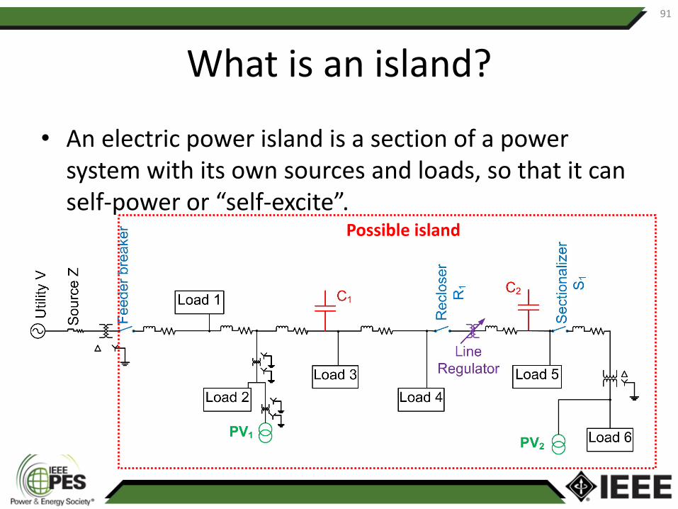
• An electric power island is a section of a power system with its own sources and loads, so that it can self-power or “self-excite”.
91
Possible island

Island terminology
• Intentional island: one that is planned, has a defined boundary, and has V/f regulation controls. Types:– Microgrid– Emergency/standby power supply– Island power system (as in, on an actual island)– Remote community grid– Military bases– Remote resource extraction operations
• Unintentional island: one that isn’t planned and doesn’t have V/f regulation control.
92

How can an unintentional island form?
• Two key things have to happen at once.– You have to have a close source-sink balance in the island
in both real and reactive power.– You have to have a breaker, recloser etc. open, without a
fault in the island. (If there is a fault, there’s almost no way to get a source-sink balance in the island.)
• The likelihood of either one of these events is low; the likelihood of both happening in sequence is verylow. So, an unintentional island is a very low-likelihood event.
93

Risks
• Unintentional islands pose the following risks:– Damage to equipment via asynchronous reclosure– Impediment to service restoration– Damage to equipment via uncontrolled voltage
and frequency– Potential risk to human health and safety—people
may be unaware that a line is energized from the customer side (line worker performing maintenance, “downed wire on a car” scenario)
94

Starting point: what IEEE 1547-2003 said
• On the subject of unintentional islanding:– Clause 4.1.5, “Inadvertent energization”: the DR shall not
energize the Area EPS when the Area EPS is de-energized.– Clause 4.4.1, “Unintentional islanding”: it’s the
responsibility of the DR to detect an unintentional island and trip offline within 2 s.
– Clause 4.2.2, “Area EPS reclosing coordination”: the DR shall cease to energize the Area EPS prior to reclosure by the Area EPS, even if that reclosure is in less than 2 s.
95

Starting point: what IEEE 1547-2003 said
• On the subject of intentional islanding:– Clause 4.4.2, “Intentional islanding”: punted to a
future revision.
96

Major changes in the new revision: unintentional islanding
• Now Clause 8.1.• The main change: There is a new, optional 5-s clearing time
limit that can be used upon mutual agreement between the DER operator and the Area EPS operator.– Allows the use of novel islanding detection that may work better in
high-pen cases but may need a bit more time to achieve sensitivity and selectivity.
• The default clearing time is still 2 s as it was in 1547-2003, so the default case is no change from the previous version.
• There is new emphasis placed on the recloser coordination clause, but not a new requirement.
97

New high-pen challenges
• Mixtures of different inverters—will they interact in such a way that degrades islanding detection? (Initial indications: yes, they can.)
• Ride-throughs—will requiring LVRT and L/HFRT degrade islanding detection? (Initial indications: yes, a little bit, but not much.)
• Mixtures of inverters and rotating machines—do these mess each other up? (Initial indications: definitely yes.)
98

Islanding detection methods
• Passive inverter-resident• Active inverter-resident• Non-inverter-resident
– Communication-based• DTT• Synchrophasors• PLCP
– System configuration changes• Capacitor toggling• Shorting switches
99

Intentional islands: what’s in-scope?100
An intentional island that contains any part of the Area EPS is in-scope.
Intentional island behavior at the PCC, and impacts on the Area EPS, are in-scope.
What happens “behind the meter” within a microgridthat does not include any Area EPS elements is out-of-scope.

1547-2018 and intentional islands
• In this presentation, Intentional Island = II• Two types of transitions into II mode (on-grid
to off-grid): scheduled and unscheduled.– Scheduled: initiated by manual action or dispatch.– Unscheduled: automatically initiated due to
abnormal Area EPS conditions.
• Power systems designated by the AHJ as Emergency, Legally Required, or Critical Operations are exempted.
101

When can an II leave the grid?
• When conditions are met that are mutually agreed-to by the Area EPS and DER operators;
• If any of the abnormal voltage or frequency trip conditions is met; or
• If an unintentional island is detected.
102
For these latter two cases, one may substitute entry into intentional island mode for tripping.

Limits on Area EPS impact when leaving the Area EPS
• If an II disconnects from the Area EPS for any of the reasons listed on the previous slide, it shall do so without causing a voltage fluctuation greater than ±5% of the nominal voltage at any PCC between the Area EPS and the intentional island.
• There are two exceptions to this requirement:– If the II “takes its load with it”—i.e., when the II leaves the
grid, it causes an amount of load equal to 90% to 110% of its rating to leave the grid also;
– The II is an emergency or standby generator that is on-grid for testing purposes only.
103

Limits on an II coming back onto the Area EPS
• An II can reconnect when the “return-to-service” requirements of Clause 4.10 are met (basically, the voltage and frequency are within defined limits).
• When the II reconnects, the requirements of Clause 4.10.4 (“synchronization”, which defines how well synched to the grid the II must be in both voltage and frequency).
104

Changes to relay settings in II mode
• You’re allowed to reduce the threshold and lengthen the time for OV2.
• You’re allowed to greatly lengthen the time limits on frequency trips OF1 and UF1 (range of adjustability goes up to 1000 s).
• The ranges of adjustability for the frequency droop gain are made wider.
105

DER categories for II use
• The standard defines four categories of DER for II use:– Uncategorized = not designed for off-grid operation at all.
These are not allowed to energize an II.– II Capable: can disable anti-islanding, and meet all the
settings adjustments requirements on the previous slide.– Black Start Capable: can energize an EPS that contains no
other energy sources.– Isochronous Capable: Black Start Capable, and can
regulate V and f in an EPS that does contain other sources.
106

• P1547.1 Test Procedures, RevisionAndy Hoke, Chair
• P1547.2 User’s Guide, RevisionWayne Stec, Chair
• P1547.9 Guide to ES-DER Interconnection, NewMike Ropp, Chair
Your Input and Participation is Needed
107

TUT-04: IEEE Standard 1547-2018 Clause 10:
Interoperability, information exchange, information models, and protocols
Mark Siira (ComRent) On behalf of Bob Fox (SunSpec Alliance)
IEEE T&D Conference TutorialApril 16, 2018
109

• Communication requirements• Identified functions to communicate• Scope of interoperability• Protocols
Interoperability Requirements
110

• A DER shall have provisions for an interface capable of communicating (local DER communication interface) to support the information exchange requirements specified in this standard for all applicable functions that are supported in the DER.
• Under mutual agreement between the Area EPS Operator and DER Operator additional communication capabilities are allowed.
• The decision to use the local DER communication interface or to deploy a communication system shall be determined by the Area EPS operator.
Communication Requirements
111

• Information to be exchanged:– Nameplate Data – As-built characteristics of the
DER.– Configuration Information – Each rating in
Nameplate Data may have a configuration setting.– Monitoring Information – Latest value measured.– Management information – This information is
used to update functional and mode settings for the DER.
Information Categories
112

• Constant power factor mode parameters• Voltage-Reactive power mode parameters• Active power-reactive power mode parameters• Constant reactive power mode parameters• Voltage-active power mode parameters• Voltage trip and momentary cessation parameters• Frequency trip parameters• Frequency droop parameters• Enter service parameters• Cease to energize and trip• Limit Maximum active power
Management Information113

Scope of Interoperability Requirements
114
NetworksDER Managing Entity
Individual DER
Out of Scope – Communication Network Specifics In Scope – Local DER Interface
Network Adapters /Modules
Out of Scope –Internal DER Specifics
DER with System/ Plant Controller
………
IEEE 1547 interface (mandatory) other interfaces (optional) out of scope

List of Eligible Protocols
115

Logical Combinations of Protocols
116
• Allowing for a couple of well-defined options gives vendors more flexibility and is still achievable for aggregators/integrators.

Communication Performance Requirements
117

IEEE Std 1547-2018
Clause 11:Verification and Testing
Mark Siira

Disclaimer
This presentation and discussion on IEEE 1547 are views of the individuals and are not the formal position, explanation, or position of the IEEE.
119

Index• General Remarks and Limitations• Key Decisions
– Determination of the Reference Point of Applicability– DER versus Composite Compliance
• Type Testing• Production Testing• Design Evaluation• As-Built Installation Evaluation• Commissioning• Periodic Testing• Application of IEEE 1547-2018 prior to revision of P1547.1• Summary and Conclusion
120

General remarks and limitations
• Applicable to all DERs connected at typical primary or secondary distribution voltage levels.– Not applicable for transmission or networked sub-
transmission connected resources.
• Specifies performance and not design of DER.• Specifies capabilities and functions
121

IEEE Std 1547-2003• Distribution system aspects.• Specifications for the
“interconnection system” sufficiently achieve the standard’s objective.
• Meant as DER interconnection standard but mainly used for equipment listing.
• Limited to electrical requirements.
Important changes
Area EPSInterconnection
System
Scope of IEEE Std 1547
DER unit
IEEE 1547-2018• Focused on distribution and bulk
system aspects.• Specifications encompass the
whole DER.• Can be used for equipment
listing as well as system-level verification.
• Includes both electrical as well as interoperability/communications requirements.
Area EPS
Communication Interface
Power Interface
Scope of IEEE 1547-2018
DER
122

IEEE 1547-2018 Performance CategoryRide Through Categories
Voltage Regulation Categories

Determination of Reference Point of Applicability
• Reference Point of Applicability (RPA) and Compliance with or without supplemental DER device determines the verification requirements
• RPA is determined by:– The characteristics of the Local EPS and DER – Default reference point is Point of Common Coupling
(PCC)– Point of DER Connection (PoC) is Allowed in Certain
Cases124

• Point of common coupling (PCC): The point of connection between the Area EPS and the Local EPS.
Point of DER connection (PoC): The point where a DER unit is electrically connected in a Local EPS and meets the requirements of this standard exclusive of any load present in the respective part of the Local EPS.
• Supplemental DER Device• capacitor banks • STATCOMs • harmonic filters not part
of a DER unit • protection devices • plant controllers
Reference Point of Applicability and Related Normative Definitions
Source: 1547-2018Standard for Interconnection and Interoperability of Distributed Energy Resources with Associated Electric Power Systems Interfaces
reference point of applicability (RPA): The location where the interconnection and interoperability performance requirements specified in this standard apply.

Determination of Reference Point of Applicability (RPA)
The reference point of
applicability (RPA) has
implications for testing & conformance requirements in IEEE 1547-
2018 & P1547.1 !
RPA depends on Zero-sequence continuity (or
not)
Aggregate DER nameplate rating (500kVA)
Annual average load demand (10%)
zero-sequence continuity: Circuit topology providing
continuity between two defined points in the zerosequence
network representation.
NOTE—A transformer having a delta or ungrounded-wye
winding in the topological path between the defined points
produces discontinuity of the zero-sequence network.

DER versus Composite Compliance
• For DER system that shall meet requirements at PCC– DER System – DER system is fully compliant at PCC
• No supplemental DER device needed
– Composite – Composite of partially compliant DER that is fully compliant at PCC
• May need one or more supplemental DER devices
• Examples for supplemental DER devices: capacitor banks, STATCOMs, harmonic filters that are not part of a DER unit, protection devices, plant controllers, etc.
127

High-level test and verification
IEEE 1547-2018Requirement XYZ
Applicability of Requirements
Point of DER Connection (PoC) Point of Common Coupling (PCC)
DER
Capa
bilit
y &
Con
form
ance
ac
hiev
ed b
y
DERno Supplemental
DER Device needed
Type Test of DER unit
+Basic Commissioning Test1)
Type Test of DER system+
Basic DER Evaluation+
Basic Commissioning Test1)
Compositeone or more
SupplementalDER Device(s)
needed
Type Test of DER unit+
Detailed DER Evaluation+
Detailed Commissioning Test1)
Type Test(s) of DER unit(s)+
Detailed DER Evaluation+
Detailed Commissioning Test1)
The test requirements give guidance, yet are flexible enough to consider the large variety of actual DER setups in the field:
1) As applicable, may depend on DER Design Evaluation.

High-Level Test and Verification Process
Type Tests• typically done in test lab or factory• Tests on representative DER Unit or DER system• Type test from a DER within a product family of the
same design
Design Evaluation
• Desk study• Check equipment together meet requirements• Typically done off-site before equipment is
delivered and installed, may include analysis and modeling/simulation
Interconnection review
Equipment conformanc
etesting
As-Built Installation Evaluation
• Performed on site at the time of commissioning• Basic: check components and connections• Detailed: engineering verification of
components, may do modeling and simulation
Post-installation
review
Production Tests
• Done in factory, or on equipment in field• Tests on every unit of DER and interconnection• Verify operability and document default function
settings
Commissioning Tests
• Performed on site at the time of commissioning• Basic: visual check equipment, isolation device • Detailed: check functionality and interoperability
as a system
PeriodicMaintenan
ce• Scheduled or other criteria• Reverification needed on important system
changes

Determination of Requirements Verification and Testing
130
Where’s the reference point of applicability?
PCC or
PoC
DER System(Unit)
no Supplemental
DER device needed
The type of evaluation or testing needed for each requirement depends on the reference point of applicability and whether there are any supplemental DER devices
-help in Annex F (informative) Discussion of Testing and Verification Requirements at PCC or PoC
Specific Require
ment
What’s the requirement?
Are supplemental DER device(s) needed?
Composite
one or more Supplemental DER device(s)
needed
Type Testing
DER Evaluation
Commissioning Tests
Type test of DER system(Unit)
Type test(s) of
DER Unit(s)
Basic DER evaluation
Detailed DER
evaluation
if at PCC
Basic Commissioning Test1
Detailed Commissioning Test1
1) As applicable, may depend on DER Design Evaluation.
Category of test and
verification needed
R: Required NR: Not requiredL: LimitedD: Depends on DER design evaluation.NA: Not applicable
R, NR, L, D, NA
R, NR, L, D, NA
R, NR, L, D, NA
R, NR, L, D, NA R, NR, L, D, NA
R, NR, L, D, NA
RPA at PCC (or
PoC)
PoC

High-level test and verification processVerification Requirement
Description
A distributed energy resource (DER) unit that is type tested and compliant with the standard.
A distributed energy resource (DER) system that is composed of DER units that are type tested and supplemental DER devices.
A basic DER evaluation shall be limited to verify that the DER has been designed and installed with the proper components and connections.
A detailed DER evaluation shall include an engineering verification of the chosen components and may require modeling and simulation of the composite of the individual partially compliant DERs forming a system.
A basic functional commissioning test includes visual inspection and an operability test on the isolation device.1)
A detailed functional commissioning test shall include a basic functional test and functional tests to verify interoperability of a combination of devices forming a system to verify that the devices are able to operate together as a system.1)
1) As applicable, may depend on DER Design Evaluation.
Detailed Commissionin
g Test1)
Basic Commissionin
g Test1)
Detailed DER Evaluation
Basic DER Evaluation
Type Test of DER System
Type Test of DER Unit

Test and verification requirements• Component Verification
– Type Tests– Production Tests
• DER System Verification– DER design evaluation (desk study)– DER as-built installation evaluation (on-site)– Commissioning tests and verifications
• DER versus Composite Compliance and related type testing limited to partial compliance of individual DER
• Requirements met at PCC or PoC

Type Testing• Tests on representative DER Unit or DER system• Done in test lab, factory, or on equipment in field• Type test from a DER within a product family of the same
design– Representative for power ratings between 50% to 200% of
the tested DER• For systems in field – allows replacement of DER equipment
with substitutive components compliant and tested with this standard– Does not invalidate previous type tests– Field demonstration of performance agreed upon by EPS
and DER operator.
133

Production Testing• Tests on every unit of DER and
interconnection prior to customer delivery• Verify the operability• Summary report provide
– List of normal and abnormal performance category capability
– Final function settings– Final operating mode setttings
134

DER EvaluationVerify that a system meet the interconnection and interoperability requirements of this standard• DER Design Evaluation
– Performed during the interconnection review process
• DER As-Built Evaluation– Performed on site at the time of
commissioning
135

DER Design Evaluation (desk study)
• Evaluation during interconnection review process
• Verifies the composite of the individually partially compliant DERs forming a system as designed:– Meets the interconnection and interoperability
requirements
• Usually done off-site before equipment is delivered and installed
136

DER As-Built Installation Evaluation (on-site)
At time of commissioning• Verifies the composite of the individually partially
compliant DERs forming a system as delivered and installed:– Meets the interconnection and interoperability
requirements
• This evaluation does not require testing
137

Commissioning Tests and Verifications• Tests and verifications on one device or
combinations forming a system:– To confirm the system designed, delivered, and installed meets
interconnection and interoperability requirements
• Include visual inspections• May include operability and functional
performance test• Written procedures required
– Provided by equipment manufacturer or system designer– Approved by equipment owner and Area EPS operator
138

Commissioning Tests and Verifications• Basic functional commissioning test
– Visual inspection– Operability test on isolation device
• Detailed functional commissioning test– Basic functional commissioning test– Functional tests verifying interconnection and
interoperability of a combination of devices forming a system – Verifies devices are able to operate together as a system
139

Periodic Tests and Verifications• According to scheduled time period or other criteria:
– Confirm already interconnected device or combination of devices meet interconnection and interoperability requirements
• Provided by interconnection equipment manufacturers and system integrators.
• Approved by AGIR or Area EPS operator• Periodic test reports or log for inspection
Area EPS operator may require commissioning test at any time to verify adherence to this standard
140

Periodic Tests and Verifications• Reverification of interoperability requirements of this
standard may be required when any of the following events occur:– Functional software or firmware changes have been
made on the DER.– Any hardware component of the DER has been
modified in the field or has been replaced or repaired with parts that are not substitutive components compliant with this standard.
– Protection settings have been changed after factory testing.
– Protection functions have been adjusted after the initial commissioning process.
141

DER System and Composite
• For DER system that shall meet requirements at PCC– DER System – DER system is fully compliant at PCC
– no supplemental DER device needed– Composite – Composite of partially compliant DER
that is, as a whole, fully compliant at PCC – may need one or more supplemental DER devices
142

High-level test and verification process - PCC
Commissioning Test1)DER EvaluationRequired Testing
DER Capability & Conformance achieved by
Reference Point of
Applicability
PCC
DER Systemno Supplemental
DER Device needed
Type Test of DER System
Basic DER Evaluation
Basic Commissioning
Test1)
Compositeone or more
Supplemental DER Device(s) needed
Type Test(s) of DER unit(s)
Detailed DER Evaluation
Detailed Commissioning
Test1)
1) As applicable, may depend on DER Design Evaluation.

High-level test and verification process - PoC
Commissioning Test1)DER EvaluationRequired Testing
DER Capability & Conformance achieved by
Reference Point of
Applicability
PoC
DER Unitno Supplemental
DER Device needed
Type Test of DER Unit
Basic Commissioning
Test1)
Compositeone or more
Supplemental DER Device(s) needed
Type Test of DER unit
Detailed DER Evaluation
Detailed Commissioning
Test1)
1) As applicable, may depend on DER Design Evaluation.

High-level test and verification processVerification
RequirementDescription
A distributed energy resource (DER) unit that is type tested and compliant with the standard.
A distributed energy resource (DER) system that is composed of DER units that are type tested and supplemental DER devices.
A basic DER evaluation shall be limited to verify that the DER has been designed and installed with the proper components and connections.
A detailed DER evaluation shall include an engineering verification of the chosen components and may require modeling and simulation of the composite of the individual partially compliant DERs forming a system.
A basic functional commissioning test includes visual inspection and an operability test on the isolation device.1)
A detailed functional commissioning test shall include a basic functional test and functional tests to verify interoperability of a combination of devices forming a system to verify that the devices are able to operate together as a system.1)
1) As applicable, may depend on DER Design Evaluation.
Detailed Commissionin
g Test1)
Basic Commissionin
g Test1)
Detailed DER Evaluation
Basic DER Evaluation
Type Test of DER System
Type Test of DER Unit

4. General interconnection technical specifications and performance requirements (PCC)
146
R – Required, NR – Not Required, L- Limited type testing, D – Dependent on DER Design Evaluation
RequirementCompliance at PCC achieved
by:
Type Tests
DER Evaluation
Commissioning Tests
4.2 Reference points of applicability
DER System NR R NR Composite NR R NR
4.3 Applicable voltages
DER System NR R NRComposite NR R NR
4.4 Measurement accuracy
DER System R R NRComposite L R NR
4.5 Cease to energize performance requirement
DER System R R DComposite L R D
Excerpt from Table 43 IEEE 1547-2018

4. General interconnection technical specifications and performance requirements (PoC)
Excerpt from Table 44 IEEE 1547-2018
RequirementCompliance at PoC achieved
by:
Type Tests
DER Evaluation
Commissioning Tests
4.2 Reference points of applicability
DER Unit NR R NR Composite NR R NR
4.3 Applicable voltages
DER Unit NR R NRComposite NR R NR
4.4 Measurement accuracy
DER Unit R NR NRComposite L R NR
4.5 Cease to energize performance requirement
DER Unit R NR NRComposite L R D
R – Required, NR – Not Required, L- Limited type testing, D – Dependent on DER Design Evaluation
Highlighted text indicates requirements that differ for DER that shall meet requirements at the PoC

4.6 Control, Prioritization, Isolation and Inadvertent Energization (PCC)
148
Requirement Compliance at PCC achieved by: Type Tests DER Evaluation Commissioning
Tests4.6 Control Capability Requirements
DER System R R D
Composite L R D
4.7 Prioritization of DER responses and execution of mode or parameter changes
DER System R R D
Composite L R D
4.8 Isolation device DER System R Design: NRInstallation: R
NR
Composite L Design: NRInstallation: R
D
4.9 Inadvertent energization of the Area EPS
DER System R Design: NRInstallation: R
D
Composite L R DExcerpt from Table 43 IEEE 1547-2018

4.6-4.9 Control, Prioritization, Isolation and Inadvertent Energization (PoC)
149
Requirement Compliance at PoC achieved by: Type Tests DER
EvaluationCommissioning
Tests4.6 Control Capability Requirements
DER Unit R NR NRComposite L R D
4.7 Prioritization of DER responses and execution of mode or parameter changes
DER Unit R NR NR
Composite L R D
4.8 Isolation device DER Unit R NR NR
Composite L Design: NRInstallation:
R
D
4.9 Inadvertent energization of the Area EPS
DER Unit R Design: NRInstallation:
R
D
Composite L R RExcerpt from Table 44 IEEE 1547-2018

4.10 Enter Service (PCC)
150
Requirement Compliance at PCC achieved by: Type Tests DER
EvaluationCommissioning
Tests
4.10.2 Enter service criteria
DER System R NR NR
Composite L R D
4.10.3 Performance during entering service
DER System R R D
Composite L R D
4.10.4 Synchronization
DER System R R D
Composite L R D
Excerpt from Table 43 IEEE 1547-2018

4.10 Enter Service (PoC)
151
Requirement Compliance at PoC achieved by: Type Tests DER
EvaluationCommissioning
Tests
4.10.2 Enter service criteria
DER Unit R NR NR
Composite L R D
4.10.3 Performance during entering service
DER Unit R R D
Composite L R D
4.10.4 Synchronization
DER Unit R R D
Composite L R D
Same as PCCExcerpt from Table 44 IEEE 1547-2018

4.11 Interconnect Integrity (PCC)
152
Requirement Compliance at PCC achieved by: Type Tests DER
EvaluationCommissioning
Tests
4.11.1 Protection from electromagnetic interference
DER System R NR NR
Composite L NR NR
4.11.2 Surge withstand performance
DER System R NR NR
Composite L NR NR
4.11.3 Paralleling device
DER System R NR NR
Composite L NR NR
4.12 Integration with Area EPS grounding
DER System NR R NR
Composite NR R NR
Excerpt from Table 43 IEEE 1547-2018

4.11 Interconnect Integrity (PoC)
153
Requirement Compliance at PoC achieved by: Type Tests DER
EvaluationCommissioning
Tests
4.11.1 Protection from electromagnetic interference
DER Unit R NR NR
Composite L NR NR
4.11.2 Surge withstand performance
DER Unit R NR NR
Composite L NR NR
4.11.3 Paralleling device
DER Unit R NR NR
Composite L NR NR
4.12 Integration with Area EPS grounding
DER Unit NR R NR
Composite NR R NR
Same as PCCExcerpt from Table 44 IEEE 1547-2018

5.2 – 5.3 Reactive Power Capability and Voltage/Power Requirements (PCC)
154
Requirement Compliance at PCC achieved by: Type Tests DER
EvaluationCommissioning
Tests
5.2 Reactive power capability of the DER
DER System R R D
Composite L R D
5.3 Voltage and reactive power control
DER System R Design: NRInstallation: R
NR
Composite L R D
5.4.2 Voltage-active power mode
DER System R Design: NRInstallation: R
NR
Composite L R R
Excerpt from Table 43 IEEE 1547-2018

5.2 – 5.4 Reactive Power Capability and Voltage/Power Requirements (PoC)
155
Requirement Compliance at PoC achieved by: Type Tests DER
EvaluationCommissioning
Tests
5.2 Reactive power capability of the DER
DER Unit R NR NR
Composite L R NR
5.3 Voltage and reactive power control
DER Unit R NR NR
Composite L R R
5.4.2 Voltage-active power mode
DER Unit R R NR
Composite L R R
Excerpt from Table 44 IEEE 1547-2018

6.2-6.3 Response to Area EPS abnormal conditions (PCC)
156
Requirement Compliance at PCC achieved by: Type Tests DER Evaluation Commissioning
Tests
6.2 Area EPS faults and open phase conditions
DER System R Design: RInstallation: NR
D
Composite L R D
6.3 Area EPS reclosing coordination
DER System NR Design: RInstallation: NR
NR
Composite NR Design: RInstallation: NR
R
Excerpt from Table 43 IEEE 1547-2018

6.2-6.3 Response to Area EPS abnormal conditions (PoC)
157
Requirement Compliance at PoC achieved by: Type Tests DER Evaluation Commissioning
Tests
6.2 Area EPS faults and open phase conditions
DER Unit R Design: RInstallation: NR
NR
Composite L R NR
6.3 Area EPS reclosing coordination
DER Unit NR Design: RInstallation: NR
NR
Composite NR Design: RInstallation: NR
D
Excerpt from Table 44 IEEE 1547-2018

6.4.1-6.4.2 Voltage and Voltage Ride Through (PCC)
158
Requirement Compliance at PCC achieved by: Type Tests DER
EvaluationCommissioning
Tests
6.4.1, 6.4.2 – Voltage requirement
DER System R R D
Composite L R D
6.4.2.3 Low-voltage ride-through
DER System R R NR
Composite L R D
6.4.2.4 High-voltage ride-through
DER System R NR NR
Composite L R D
6.4.2.5 Ride-through of consecutive voltage disturbances
DER System R NR NR
Composite L R D
Excerpt from Table 43 IEEE 1547-2018

6.4.1-6.4.2 Voltage and Voltage Ride Through (PoC)
159
Requirement Compliance at PCC achieved by: Type Tests DER
EvaluationCommissioning
Tests
6.4.1, 6.4.2 – Voltage requirement
DER Unit R R / NR NR / D
Composite L R D
6.4.2.3 Low-voltage ride-through
DER Unit R R NR / D
Composite L R D
6.4.2.4 High-voltage ride-through
DER Unit R NR NR
Composite L R / NR D
6.4.2.5 Ride-through of consecutive voltage disturbances
DER Unit R NR NR
Composite L R / NR D
Excerpt from Table 44 IEEE 1547-2018

6.4.2.6 – 6.4.2.7 Dynamic Voltage Support & Restore Output with Voltage Ride-Through (PCC)
160
RequirementCompliance at PCC achieved
by:Type Tests DER
EvaluationCommissioning
Tests
6.4.2.6 Dynamic voltage support
DER System R R NR
Composite L R D
6.4.2.7 Restore output with voltage ride-through
DER System R R NR
Composite L R D
Excerpt from Table 43 IEEE 1547-2018

6.4.2.6 – 6.4.2.7 Dynamic Voltage Support & Restore Output with Voltage Ride-Through (PoC)
161
RequirementCompliance at PoC achieved
by:Type Tests DER
EvaluationCommissioning
Tests
6.4.2.6 Dynamic voltage support
DER Unit R NR NR
Composite L R D
6.4.2.7 Restore output with voltage ride-through
DER Unit R NR NR
Composite L R D
Excerpt from Table 44 IEEE 1547-2018

6.5 Frequency (PCC)
162
Requirement Compliance at PCC achieved by: Type Tests DER Evaluation Commissioning
Tests6.5.1 Mandatory frequency tripping requirements
DER System R R D
Composite L R D
6.5.2 Frequency disturbance ride-through requirements
DER System R NR NR
Composite L R R
6.5.2.3.1 Low-frequency ride-through capability
DER System R NR NR
Composite NR NR NR
6.5.2.3.2 Low-frequency ride-through performance
DER System R NR NR
Composite L R R
6.5.2.4 High-frequency ride-through
DER System R NR NR
Composite L R R
6.5.2.5 Rate of change of frequency (ROCOF) ride-through
DER System R NR NR
Composite L R R
6.5.2.6 Voltage phase angle changes ride-through
DER System R NR NR
Composite L Design: RInstallation: NR
D
Excerpt from Table 43 IEEE 1547-2018

6.5 Frequency (PoC)
163
Requirement Compliance at PoC achieved by: Type Tests DER Evaluation Commissioning
Tests6.5.1 Mandatory frequency tripping requirements
DER Unit R R D
Composite L R D
6.5.2 Frequency disturbance ride-through requirements
DER Unit R NR NR
Composite L NR NR
6.5.2.3.1 Low-frequency ride-through capability
DER Unit R NR NR
Composite NR NR NR
6.5.2.3.2 Low-frequency ride-through performance
DER Unit R NR NR
Composite L NR NR
6.5.2.4 High-frequency ride-through
DER Unit R NR NR
Composite L NR NR
6.5.2.5 Rate of change of frequency (ROCOF) ride-through
DER Unit R NR NR
Composite L NR NR
6.5.2.6 Voltage phase angle changes ride-through
DER Unit R NR NR
Composite L NR NR
Excerpt from Table 44 IEEE 1547-2018

7. Power Quality (PCC)
164
Requirement Compliance at PCC achieved by: Type Tests DER
EvaluationCommissioning
Tests
7.1 Limitation of dc injection
DER System R NR NR
Composite NR R NR
7.2 Limitation of voltage fluctuation induced by the DER
DER System NR Design: RInstallation:
NR
D
Composite NR Design: RInstallation:
NR
D
7.3 Limitation of current distortion
DER System R NR NR
Composite L R D
7.4 Limitation of overvoltage contribution
DER System R R D
Composite L R D
Excerpt from Table 43 IEEE 1547-2018

7. Power Quality (PoC)
165
Requirement Compliance at PoC achieved by: Type Tests DER
EvaluationCommissioning
Tests
7.1 Limitation of dc injection
DER Unit R NR NR
Composite NR R NR
7.2 Limitation of voltage fluctuation induced by the DER
DER Unit NR Design: RInstallation:
NR
D
Composite NR Design: RInstallation:
NR
D
7.3 Limitation of current distortion
DER Unit R NR NR
Composite L R D
7.4 Limitation of overvoltage contribution
DER Unit R R D
Composite L R D
Same as PCC
Excerpt from Table 44 IEEE 1547-2018

Islanding• Unintentional islanding
– Requirements also in clauses related to response to Area EPS abnormal conditions
– Coordination with Area EPS automatic reclosing– Conditional extended clearing times
• Intentional islanding: An intentional island that includes any portion of the area EPS—an intentional area EPS island—while islanded shall be designed and operated in coordination with the area EPS operator.
– Scheduled: Formed through DER operator or area EPS operator manual action or other operating dispatch means (e.g., EMS, automatic generation control) that triggers the transition from being in parallel and synchronized with the area EPS to operation as an islanded system.
– Unscheduled: Unscheduled intentional islands are formed autonomously from local detection of abnormal conditions at the interface(s) with the area EPS and then automatic relay action that triggers switching to rapidly isolate the intentional island from the area EPS.
• Conditions and requirements for transition, voltage fluctuation limits, reconnection are coherent to those for DER.
166
Categories

8. Islanding (PCC)
167
RequirementCompliance at PCC achieved
by:Type Tests DER
EvaluationCommissioning
Tests
8.1.1 Unintentional islanding
DER System R NR NR
Composite L R R
8.1.2 Conditional extended clearing time
DER System R R NR
Composite L R R
8.1.3 Area EPS with automatic reclosing
DER System R R NR
Composite L R R
8.2 Intentional islanding
DER System NA NA NA
Composite L R R
Excerpt from Table 43 IEEE 1547-2018

8. Islanding (PoC)
168
RequirementCompliance at PoC achieved
by:Type Tests DER
EvaluationCommissioning
Tests
8.1.1 Unintentional islanding
DER Unit R NR NR
Composite L R R
8.1.2 Conditional extended clearing time
DER Unit R NR NR
Composite L R R
8.1.3 Area EPS with automatic reclosing
DER Unit R NR NR
Composite L R R
8.2 Intentional islanding
DER Unit NR NR NR
Composite L R R
Excerpt from Table 44 IEEE 1547-2018

9. DER on distribution secondary grid (PCC)
169
RequirementCompliance at PCC achieved
by:Type Tests DER
EvaluationCommissioning
Tests
9.2 Distribution secondary grid networks
DER System NR R D
Composite NR R D
9.3 Distribution secondary spot networks
DER System NR R D
Composite NR R D
Excerpt from Table 43 IEEE 1547-2018

9. DER on distribution secondary grid (PoC)
170
RequirementCompliance at PoC achieved
by:Type Tests DER
EvaluationCommissioning
Tests
9.2 Distribution secondary grid networks
DER Uni NR R D
Composite NR R D
9.3 Distribution secondary spot networks
DER Unit NR R D
Composite NR R D
Same as PCCExcerpt from Table 44 IEEE 1547-2018

Interoperability171
Limited Scope of Interoperability Requirements
NetworksDER Managing Entity
Individual DER
Out of Scope – Communication Network Specifics In Scope – Local DER Interface
Network Adapters /Modules
Out of Scope –Internal DER Specifics
DER with System/ Plant Controller
………
IEEE 1547 interface (mandatory) other interfaces (optional) out of scope
Source: 1547-2018 Standard for Interconnection and Interoperability of Distributed Energy Resources with Associated Electric Power Systems Interfaces

10. Interoperability (PCC)
172
Requirement Compliance at PCC achieved by: Type Tests DER
EvaluationCommissioning
Tests
10.1 Interoperability requirements
DER System R R NR
Composite L R D
10.2 Monitoring, control, and information exchange requirements
DER System R R NR
Composite L R D
10.3 – 10.8 Nameplate Information, Configuration Information, Monitoring Information, Management Information, Communication Protocol and Performance Requirements
DER System R NR NR
Composite L R D
Excerpt from Table 43 IEEE 1547-2018

10. Interoperability (PoC)
173
Requirement Compliance at PoC achieved by: Type Tests DER
EvaluationCommissioning
Tests
10.1 Interoperability requirements
DER Unit R NR NR
Composite L R D
10.2 Monitoring, control, and information exchange requirements
DER Unit R NR NR
Composite L R D
10.3 – 10.8 Nameplate Information, Configuration Information, Monitoring Information, Management Information, Communication Protocol and Performance Requirements
DER Unit R NR NR
Composite L R D
Excerpt from Table 44 IEEE 1547-2018

Application of IEEE 1547-2018 prior to IEEE P1547.1 RevisionStakeholder Challenges
FERCRequirements for Small Generating Facilities
Orders for Transmission ProvidersNo. 827 (reactive power)
No 828 (ride-through)
Authorities Governing Interconnection RequirementsAssignment of
Categories A, B (reactive power)Categories I, II, III (ride-through)
Coordination between new IEEE P1547.1 verification requirements and DER
interconnection procedures
UtilitiesUpdate of boilerplate interconnection
agreements with new capabilitiesGrid-specific tuning of DER settings
(e.g., determination of volt/var parameters for increased hosting capacity1)
Specification of local DER interface communication protocols
DER DevelopersInterconnection requests,
DER design
DER VendorsTesting of DER capabilities (type tests)
174
1 for example with EPRI’s Distribution Resource Integration and Value Estimation (DRIVE) Tool (3002008293)

Application of IEEE 1547-2018 prior to IEEE P1547.1 Revision
UL Certification:• Grid Support, Utility Interactive Product
Scope:• Safety & Electric Shock Certification to UL1741
including UL 1741 SA for grid support and general grid interconnection per IEEE 1547
Includes Testing to Verify: • 1.UL 1741 electric shock/fire tests• 2.UL 1741 SA grid support tests• 3.Unique tests of IEEE 1547 for general grid
interconnection not covered by UL 1741 SA tests
Deliverable: • UL Certification as a Grid Support Utility
Interactive product
UL Certification of Inverters
• Traditional UL1741• IEEE 1547 & 1547.1 (1st ed.)
Interconnection Requirements
Utility Interactive
• UL 1741 SA Grid Support Functions
• Source Requirements Documents like CA Rule 21, Hawai’ian Rule 14H, IEEE Std1547-2018 (2nd ed.)
Grid Support Utility
Interactive
• Specific Manufacturer / Utility Defined UL Verified Compliance
• Custom Source Requirements Documents
Special Purpose Utility
Interactive

Application of IEEE 1547-2018 prior to IEEE P1547.1 Revision
• Inverter-coupled DER applications shall be compliant with all utility-specific settings but only with parts of IEEE Std 1547-2018 (Revision)
– An informative annex to UL1741-SA is being prepared to specify a majority of capability requirements and settings of IEEE Std 1547-2018 (Revision) as the Source Requirements Document (SRD) that can be tested and verified per type test requirements of UL1741 Supplement-SA (September 2016).
– Re-certification of UL1741-SA (September 2016) certified equipment may become necessary for any IEEE Std 1547-2018 (Revision) “ranges of allowable settings” that are outside the CA Rule 21 and/or HI R 15H ranges.
• Utility-specific custom Source Requirements Document (SRD) should specify appropriate IEEE Std 1547-2018 (Revision) performance categories, and
– Refer to UL1741 and the above-mentioned annex in UL1741-SA without any modifications (re-certification may become necessary), or
– Specify a subset of the IEEE Std 1547-2018 (Revision) capability requirements such that existing Grid Support Utility Interactive inverters that were already UL1741-SA (September 2016) certified per the requirements of CA Rule 21 and/or Hawai’ian Rule 14H as the SRDs can be used
– Specify utility-specific settings, e.g., for voltage and frequency trip, within the applicable “ranges of allowable settings”.
Selected tests and verification- Certification of interconnection requirements for inverter-coupled DER units1)
V1.2 (Jan 24, 2018)1) not the whole DER facility/system

Application of IEEE 1547-2018 After IEEE P1547.1 Revision
• Inverter-coupled DER applications shall be compliant with all utility-specific settings and with all applicable parts of IEEE Std 1547-2018 (Revision)
– UL1741 Standards Technical Panel (STP) will replace UL1741-SA with a reference to IEEE Std 1547.1-20xx (Revision). IEEE Std 1547-2018 (Revision) is new Source Requirements Document (SRD).
– Re-certificaton of UL1741-SA (September 2016) certified equipment per IEEE Std 1547.1-20xx (Revision) test and verification procedures and certification via UL1741 will become necessary, based on the applicable IEEE Std 1547-2018 (Revision) performance category.
– Effective after transition period of [XX] months after IEEE Std 1547.1-20xx (Revision) is published.
• Utility-specific custom Source Requirements Document (SRD) should specify appropriate IEEE Std 1547-2018 (Revision) performance categories, and
– Refer to UL1741 and the revised IEEE Std 1547.1-20xx (Revision), and– Specify utility-specific settings, e.g., for voltage and frequency trip, within the “ranges of
allowable settings” specified in IEEE Std 1547-2018 (Revision).
All tests and verifications, after publication of the revised standard- Certification of interconnection requirements for inverter-coupled DER
units1)
V1.2 (Jan 24, 2018)1) not the whole DER facility/system

Summary and Takeaway• Reference Point of Applicability (RPA) and Compliance
with or without supplemental DER device(s) determines the verification requirements
• Detailed Verification Requirements are specified in Table 43 and Table 44 of IEEE 1547-2018
• Type testing can be performed on a DER unit or a DER system
• A composite of DER unit(s) and supplemental DER device(s) requires a detailed DER evaluation
• DER Evaluation and Commissioning Test may be either basic or detailed
178

Summary and Takeaway (Continued)• Test and Verification Procedures are being developed by
the IEEE P1547.1 - Standard Conformance Test Procedures for Equipment Interconnecting DER with EPS Working Group – Will be complete in late 2018– Stay tuned to IEEE for upcoming working group meetings to
assist in developing solutions in the interim.• Stakeholders will drive specific requirements based on
DER system complexity, Area EPS Conditions and location
179

More Information on IEEE 1547-2018
Go to IEEE SCC21’s 1547-2018 Revision Grouper Website,http://grouper.ieee.org/groups/scc21/1547_revision/1547revision_index.html

IEEE P1547.1 DER Interconnection Test Procedures: Revision Status
Dr. Andy Hoke, P.E.Senior Engineer, National Renewable Energy Laboratory (NREL)
Chair, IEEE P1547.1 Working Group

DISCLAIMER
This presentation and discussion here on IEEE P1547 and P1547.1 are individual’s views and are not the formal explanation or position of the IEEE.
182

Motivation for IEEE P1547.1
18
• In many locations the power system depends on DER support for proper operation during normal and abnormal conditions
• True for both distribution systems and bulk power systems• Number of DER-dependent locations is expected to continue to grow
• Major paradigm shift from “just get out of the way” to “stay connected (within limits) and support voltage and frequency”
• Now that the grid depends on DERs to perform a certain way, DER performance must be validated through testing to ensure the power system continues to be safe and reliable
• Some power systems failed to recognize this in time, sometimes at great cost.
• North America has a chance to get it right the first time!

IEEE 1547 Standards Example Use in U.S.
18
• Content list is for 1547-2003. Same relationship will exist for 1547-2018 and future revisions of 1547.1, 1741, and NEC.
• 1547-2018 cannot be fully applied until after revised P1547.1 is published!• Note: 1547-2018 contains many new requirements that are not fully
verified through lab testing DER evaluations and commissioning tests become more important

IEEE 1547 Content Growth
18
1547 technical content: 13 pages 127 pages 1547.1 technical content: 54 pages ??? pages
(currently ~200)
1st Edition 2nd Edition
4. General interconnection technical specifications and requirements4.2 Reference points of applicability4.3 Applicable voltages4.4 Measurement accuracy4.5 Cease to energize performance requirement4.6 Control capability requirements4.7 Prioritization of DER responses4.8 Isolation device4.9 Inadvertent energization of the Area EPS4.10 Enter service4.11 Interconnect integrity4.12 Integration with Area EPS grounding4.13 Exemptions for Emergency Systems and Standby DER
5. Reactive power capability and voltage/power control requirements5.2 Reactive power capability of the DER5.3 Voltage and reactive power control5.4 Voltage and active power control
6. Response to Area EPS abnormal conditions6.2 Area EPS faults and open phase conditions6.3 Area EPS reclosing coordination6.4 Voltage6.5 Frequency6.6 Return to service after trip
7. Power quality7.1 Limitation of dc injection7.2 Limitation of voltage fluctuations induced by the DER7.3 Limitation of current distortion7.4 Limitation of overvoltage contribution
8. Islanding8.1 Unintentional islanding8.2 Intentional islanding
9. DER on distribution secondary grid/area/street (grid) networks and spot networks9.1 Network protectors and automatic transfer scheme requirements9.1 Distribution secondary grid networks9.2 Distribution secondary spot networks
10. Interoperability, information exchange, information models, and protocols10.1 Interoperability requirements10.2 Monitoring, control, and information exchange requirements10.3 Nameplate information10.4 Configuration information10.5 Monitoring information10.6 Management information10.7 Communication protocol requirements10.8 Communication performance requirements10.9 Cyber security requirements
11. Test and verification requirements11.2 Definition of test and verification methods11.3 Full and partial conformance testing and verification11.4 Fault current characterization
New/significantly modified 1547-2018 content in red:

P1547.1: Full Revision
Standard Conformance Test Procedures for Equipment Interconnecting Distributed Energy Resources with Electric Power Systems and Associated Interfaces.
186
Scope: This standard specifies the type, production, commissioning and periodic tests, and evaluations that shall be performed to confirm that the interconnection and interoperation functions of equipment and systems interconnecting distributed energy resources with the electric power system conform to IEEE Standard 1547.
Purpose: Standardized test and evaluation procedures are necessary to establish and verify compliance with those requirements. These test procedures shall provide both repeatable results, independent of test location, and flexibility to accommodate a variety of DER technologies and functions.
186

P1547.1: Full Revision
187
187
• What needs to be revised?• What needs to be added? • What needs to be external to
P1547.1?
• Goal: to come up with P1547.1 contents that fulfill the PAR scope and purpose: addressing revised requirements in IEEE 1547
IEEE 1547.1-2005 CONTENTS
1. Overview2. Normative references3. Definitions and acronyms4. General requirements5. Type tests6. Production tests7. Commissioning test8. Periodic interconnection testsAnnex A (normative) Test signalsAnnex B (informative) Bibliography

P1547.1: Overview
188
• IEEE P1547.1 provides conformance test procedures to establish and verify compliance with the requirements of revised IEEE 1547
• IEEE P1547.1 is not just for type testing; conformance may be established through combination of type (aka “design” tests), production tests, design evaluation, installation evaluation, commissioning tests, and periodic tests
• Like 1547, applies to all DERs (not just PV, and not just inverter-based)
• Does not cover testing for safety
• Although this standard does not define a certification process, these P1547.1 tests can be used as part of such a process – e.g. UL 1741
• Need to keep objectives technically precise for P1547.1 – this is not a design guide, recommended practice, business, tariff, contractual, regulatory, or policy document

P1547.1: Types of Verification Methods
189
Test and evaluations in 1547-2018 show how to achieve compliance at PoC and PCC through various verification methods
Type test – Test of one or more devices made to a certain design to demonstrate that the design meets certain specifications
Production test – A test conducted on every unit of equipment prior to shipment
Design evaluation – A “paper study” evaluating a proposed DER installation
Installation evaluation – An inspection of the field-installed DER to verify correct installation
Commissioning test – A test conducted in the field when the equipment is installed to verify correct operation
Periodic test – A field test conducted periodically or as needed after the DER is installed and operating
Majority of 1547.1 content
Significant new
material

P1547.1: General Requirements
190
• The test results shall verify that the equipment under test (EUT) meets the requirements of IEEE Std 1547 within the manufacturer’s specified accuracy
How to derive test result accuracy from manufacturer’s specified accuracy and test uncertainty

General Requirements
191
• Simulated area EPS (utility) source requirements for testing
• Measurement system requirements
• Will need to look into grid simulator specs in terms of new ride-through requirements, ramp rates etc.
• Other equipment requirements? DC supply, prime mover etc.
• May provide guidance on how type tests, evaluations, and commissioning tests fit together to result in a fully compliant DER

Type Tests
192
• These are the tests we typically think of as being run by a NRTL as part of UL 1741 testing
• Some test from IEEE 1547.1/1547.1a (2005/2015) are largely valid e.g. temp. stability, synchronization, interconnection integrity etc.
• Some tests can be adopted from UL 1741 SA and revised to make suitable for testing 1547-2018 requirements e.g. ride-through, voltage regulation, islanding detection etc.
• Some tests need to be added e. g. temporary overvoltage, transient overvoltage, interoperability, fault
current characterization, “watt-var” control, etc.
Current UL 1741 SA takes 6-8 weeks if fully automated. Will take longer when P1547.1 is incorporated.

Type Testing of Communications
193
• 1547-2018 requires all DERs to be capable of communications using at least one of three communications methods:
• P1547.1 WG reached consensus that at least a subset of type tests shall be run using at least one of the three protocols• I.e. communications tests must be linked to power tests!• Can run all tests using protocol, if desired (automate?)• Full certification of each protocol is outside the scope of P1547.1
• Hopefully this will result in progress towards communications interoperability!

Production Tests
194
• Production tests verify the operability of every unit of interconnect equipment manufactured for customer use. These tests assume that the equipment has passed the type tests and may be conducted as a factory test or performed as part of a commissioning test
• Historically very limited:Response to abnormal voltage Response to abnormal frequencySynchronization ….

DER Design Evaluation and Commissioning Tests
195
• DER design evaluation (desk study) is an evaluation during the interconnection review process to verify that the composite of the individual partially-compliant DERs forming a system as designed meets the interconnection and interoperability requirements of 1547-2018
• DER installation evaluation is an evaluation performed in the field to confirm that the DER was installed in a manner compliant with 1547-2018 requirements
• Commissioning tests are tests and verifications on one device or a combination of devices forming a system to confirm that the system as designed, delivered and installed meets the interconnection and interoperability requirements of 1547-2018
Due to wide variations in DERs, distribution feeders, and utility practices, P1547.1 content on these installation-specific procedures will be much less detailed than type-test content.
If interested, please come contribute!

P1547.1 Subgroups (As of April 2018)
196
General requirements Overall document
Abnormal voltage and frequency
conditions tests
Voltage and frequency regulation
tests
Unintentional islanding tests Power quality tests Synchronization
tests
Modeling and simulation
Hardware-in-the-loop tests Interoperability tests
Installation, commissioning, and
periodic testing
DER microgrid capabilities
Results Reporting Prioritization of DER Responses
Chair: Andy Hoke (emeritus: Sudipta Chakraborty)Secretary: Jeannie AmberTreasurer: Charlie VartanianVice Chairs: Tim Zgonena, Babak Enayati, Karl Schoder
• A large number of new requirements are included in the revised IEEE 1547 – requires a number of writing subgroups in P1547.1

P1547.1 Subgroup Leaders (As of April 2018)
197
Subg
roup
Gen
eral
requ
irem
ents
Ove
rall
Docu
men
t
Abno
rmal
vol
tage
and
freq
uenc
y co
nditi
ons
test
s (rid
e-th
roug
h an
d tr
ip)
Prio
ritiza
tion
of D
ER R
espo
nses
Repo
rtin
g of
test
resu
lts
Volta
ge a
nd fr
eque
ncy
regu
latio
n te
sts
Uni
nten
tiona
l isl
andi
ng te
sts
Pow
er q
ualit
y te
sts
Sync
hron
izatio
n te
sts
Faul
t cur
rent
cha
ract
eriza
tion
test
s
Hard
war
e-in
-the
-loop
for 1
547.
1 ap
plic
atio
ns
Inte
rope
rabi
lity
(com
mun
icat
ions
) te
sts
Inst
alla
tion,
com
mis
sion
ing,
and
pe
riodi
c te
stin
g
DER
mic
rogr
id c
apab
ilitie
s an
d m
icro
grid
inte
rcon
nect
ion
devi
ces
Subg
roup
Cha
ir(s)
Andy Hoke
Andy Hoke
John Berdner
Bob White
John Berdner
Jon Ehlmann Sig Gonzalez Marcelo
AlgrainMarcelo Algrain Mike Ropp Karl
SchoderBrian Seal
Mark Siira
Babak Enayati
Mark Siira
Marcelo Algrain
Haile Gashaw
Aminul Huque Greg Kern Jeannie
AmberJesse
Leonard Bob Fox Wayne Stec
Jens Boemer
John Berdner
To join any of the subgroups, please contact a subgroup chair directly, or contact [email protected]

P1547.1 Tentative Timeline to Ballot (As of April 2018)
198
Dates Activities StatusJune 16, 2016 P1547.1 WG meeting – Draft 1 initiated DoneOctober 27-28, 2016 P1547.1 WG meeting – Draft 1 discussed DoneMarch 2, 2017 P1547.1 WG meeting – Draft 2 discussed DoneJune 20-21, 2017 P1547.1 WG meeting – Draft 3 discussed DoneNovember 14-16, 2017 P1547.1 WG meeting – Draft 4 discussed DoneFebruary 2018 P1547.1 Draft 5 posted for WG meeting DoneMarch 6-8, 2018 P1547.1 WG meeting – Draft 5 discussed DoneMay 25, 2018 Subgroups deliver Draft 6 contentJune 1, 2018 Draft 6 posted for WG reviewJune 12-14, 2018 P1547.1 WG meeting – Draft 6 discussedJune - August 2018 Subgroups finalize pre-ballot draft content (D7)September 2018 Pre-ballot draft to WG for reviewOctober 1, 2018 WG comments on D7 to subgroupsOctober 9-11, 2018 P1547.1 WG meeting – Finalize and approve D7November 2018 IEEE MEC review, IEEE-SA ballot pool formationDec 2018 - Jan 2019 P1547.1 IEEE-SA ballot Feb - June 2019 Ballot resolutionQ3 2019 IEEE RevCom reviewQ4 2019 – Q1 2020 1547.1 Publication
National Grid, Waltham MA, June 12-14, 2.5 days

Further Information
199
For further information, see http://grouper.ieee.org/groups/scc21/1547.1_revision/1547.1_revision_index.html
Sign up for the ListServ to receive occasional communications, including meeting information. Instructions are at the website above.

Acknowledgements
• This work was supported by the U.S. Department of Energy under Contract No. DE-AC36-08-GO28308 with the National Renewable Energy Laboratory
• We gratefully acknowledge the support of Department of Energy’s Solar Energy Technologies Office team for providing funding support for this work
• Personal thanks to Tom Basso (former Chair P1547, P1547.1) and Sudipta Chakraborty (former Chair P1547.1) for providing valuable inputs/materials
200


![[] IEEE 1120-2004 - IEEE Guide for the Planning, D(Book Fi org)](https://static.fdokumen.com/doc/165x107/63150fb6511772fe45103298/-ieee-1120-2004-ieee-guide-for-the-planning-dbook-fi-org.jpg)