Reviewing Performance Measures of the Die-Sinking ... - MDPI
17
Citation: Shastri, R.K.; Mohanty, C.P.; Dash, S.; Gopal, K.M.P.; Annamalai, A.R.; Jen, C.-P. Reviewing Performance Measures of the Die-Sinking Electrical Discharge Machining Process: Challenges and Future Scopes. Nanomaterials 2022, 12, 384. https://doi.org/10.3390/ nano12030384 Academic Editor: Jun Shimizu Received: 14 November 2021 Accepted: 17 January 2022 Published: 25 January 2022 Publisher’s Note: MDPI stays neutral with regard to jurisdictional claims in published maps and institutional affil- iations. Copyright: © 2022 by the authors. Licensee MDPI, Basel, Switzerland. This article is an open access article distributed under the terms and conditions of the Creative Commons Attribution (CC BY) license (https:// creativecommons.org/licenses/by/ 4.0/). nanomaterials Review Reviewing Performance Measures of the Die-Sinking Electrical Discharge Machining Process: Challenges and Future Scopes Renu Kiran Shastri 1,2 , Chinmaya Prasad Mohanty 1 , Sitaram Dash 1 , Karthick Muthaiah Palaniappan Gopal 1 , A. Raja Annamalai 3, * and Chun-Ping Jen 4,5, * 1 School of Mechanical Engineering, Vellore Institute of Technology, Vellore 632014, India; [email protected] (R.K.S.); [email protected] (C.P.M.); [email protected] (S.D.); [email protected] (K.M.P.G.) 2 School of Mechanical and Civil Engineering, MIT Academy of Engineering, Alandi, Pune 412105, India 3 Centre for Innovative Manufacturing Research, Vellore Institute of Technology, Vellore 632014, India 4 School of Dentistry, College of Dental Medicine, Kaohsiung Medical University, Kaohsiung 80708, Taiwan 5 Department of Mechanical Engineering and Advanced Institute of Manufacturing for High-Tech Innovations, National Chung Cheng University, Chia-Yi 62102, Taiwan * Correspondence: [email protected] (A.R.A.); [email protected] (C.-P.J.) Abstract: The most well-known and widely used non-traditional manufacturing method is elec- trical discharge machining (EDM). It is well-known for its ability to cut rigid materials and high- temperature alloys that are difficult to machine with traditional methods. The significant challenges encountered in EDM are high tool wear rate, low material removal rate, and high surface roughness caused by the continuous electric spark generated between the tool and the workpiece. Researchers have reported using a variety of approaches to overcome this challenge, such as combining the die-sinking EDM process with cryogenic treatment, cryogenic cooling, powder-mixed processing, ultrasonic assistance, and other methods. This paper examines the results of these association tech- niques on various performance measures, such as material removal rate (MRR), tool wear rate (TWR), surface roughness, surface integrity, and recast layer formed during machining, and identifies po- tential gap areas and proposes a solution. The manuscript is useful for improving performance and introducing new resolutions to the field of EDM machining. Keywords: EDM; surface integrity; microhardness; surface roughness; recast layer; energy consumption 1. Introduction The Electrical Discharge Machining Principle Electrical discharge machining (EDM) is a thermal erosion process in which a con- trolled electric spark discharge occurs between the tool and the workpiece. As this process produces an eroding effect on the workpiece, a replica of the tool form is created on it. An electrical discharge phenomenon causes erosion between the tool and the workpiece. There is no mechanical contact between the two electrodes throughout the operation. Since the electrical conductivity of the tool and workpiece is a requirement for this process [1,2], the electrical resistivity of both electrodes must be between 100 and 300 Ωcm. In a dielectric medium, usually liquid, spark plasma is induced across inter-electrode gaps [3–6]. Di- electrics should have a high breakdown strength, quick recovery after a breakdown event, low viscosity, effective quenching/cooling, and flushing capability [7–11]. As the tool electrode approaches the workpiece, dielectric breakdown occurs, resulting in the formation of a plasma channel [12]. When a spark fails, the voltage drops and the current skyrockets. Since ionization of the dielectric medium present in the conductivity gap has created a plasma channel, the applied current produces heat, generating around a temperature of 8000 to 20,000 ◦ C at the crater spot [13–15]. The size of a crater is determined by discharge energy, which can be controlled at the machine by adjusting the discharge Nanomaterials 2022, 12, 384. https://doi.org/10.3390/nano12030384 https://www.mdpi.com/journal/nanomaterials
-
Upload
khangminh22 -
Category
Documents
-
view
2 -
download
0
Transcript of Reviewing Performance Measures of the Die-Sinking ... - MDPI
Citation: Shastri, R.K.; Mohanty, C.P.;
Dash, S.; Gopal, K.M.P.; Annamalai,
A.R.; Jen, C.-P. Reviewing
Performance Measures of the
Die-Sinking Electrical Discharge
Machining Process: Challenges and
Future Scopes. Nanomaterials 2022, 12,
384. https://doi.org/10.3390/
nano12030384
Academic Editor: Jun Shimizu
Received: 14 November 2021
Accepted: 17 January 2022
Published: 25 January 2022
Publisher’s Note: MDPI stays neutral
with regard to jurisdictional claims in
published maps and institutional affil-
iations.
Copyright: © 2022 by the authors.
Licensee MDPI, Basel, Switzerland.
This article is an open access article
distributed under the terms and
conditions of the Creative Commons
Attribution (CC BY) license (https://
creativecommons.org/licenses/by/
4.0/).
nanomaterials
Review
Reviewing Performance Measures of the Die-Sinking ElectricalDischarge Machining Process: Challenges and Future ScopesRenu Kiran Shastri 1,2 , Chinmaya Prasad Mohanty 1 , Sitaram Dash 1, Karthick Muthaiah Palaniappan Gopal 1,A. Raja Annamalai 3,* and Chun-Ping Jen 4,5,*
1 School of Mechanical Engineering, Vellore Institute of Technology, Vellore 632014, India;[email protected] (R.K.S.); [email protected] (C.P.M.);[email protected] (S.D.); [email protected] (K.M.P.G.)
2 School of Mechanical and Civil Engineering, MIT Academy of Engineering, Alandi, Pune 412105, India3 Centre for Innovative Manufacturing Research, Vellore Institute of Technology, Vellore 632014, India4 School of Dentistry, College of Dental Medicine, Kaohsiung Medical University, Kaohsiung 80708, Taiwan5 Department of Mechanical Engineering and Advanced Institute of Manufacturing for High-Tech Innovations,
National Chung Cheng University, Chia-Yi 62102, Taiwan* Correspondence: [email protected] (A.R.A.); [email protected] (C.-P.J.)
Abstract: The most well-known and widely used non-traditional manufacturing method is elec-trical discharge machining (EDM). It is well-known for its ability to cut rigid materials and high-temperature alloys that are difficult to machine with traditional methods. The significant challengesencountered in EDM are high tool wear rate, low material removal rate, and high surface roughnesscaused by the continuous electric spark generated between the tool and the workpiece. Researchershave reported using a variety of approaches to overcome this challenge, such as combining thedie-sinking EDM process with cryogenic treatment, cryogenic cooling, powder-mixed processing,ultrasonic assistance, and other methods. This paper examines the results of these association tech-niques on various performance measures, such as material removal rate (MRR), tool wear rate (TWR),surface roughness, surface integrity, and recast layer formed during machining, and identifies po-tential gap areas and proposes a solution. The manuscript is useful for improving performance andintroducing new resolutions to the field of EDM machining.
Keywords: EDM; surface integrity; microhardness; surface roughness; recast layer; energy consumption
1. IntroductionThe Electrical Discharge Machining Principle
Electrical discharge machining (EDM) is a thermal erosion process in which a con-trolled electric spark discharge occurs between the tool and the workpiece. As this processproduces an eroding effect on the workpiece, a replica of the tool form is created on it. Anelectrical discharge phenomenon causes erosion between the tool and the workpiece. Thereis no mechanical contact between the two electrodes throughout the operation. Since theelectrical conductivity of the tool and workpiece is a requirement for this process [1,2], theelectrical resistivity of both electrodes must be between 100 and 300 Ωcm. In a dielectricmedium, usually liquid, spark plasma is induced across inter-electrode gaps [3–6]. Di-electrics should have a high breakdown strength, quick recovery after a breakdown event,low viscosity, effective quenching/cooling, and flushing capability [7–11].
As the tool electrode approaches the workpiece, dielectric breakdown occurs, resultingin the formation of a plasma channel [12]. When a spark fails, the voltage drops and thecurrent skyrockets. Since ionization of the dielectric medium present in the conductivitygap has created a plasma channel, the applied current produces heat, generating around atemperature of 8000 to 20,000 C at the crater spot [13–15]. The size of a crater is determinedby discharge energy, which can be controlled at the machine by adjusting the discharge
Nanomaterials 2022, 12, 384. https://doi.org/10.3390/nano12030384 https://www.mdpi.com/journal/nanomaterials
Nanomaterials 2022, 12, 384 2 of 17
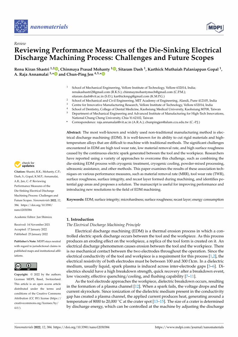
current and duration [16–19]. The mechanism of die-sinking EDM is depicted in Figure 1.As the workpiece material and electrode heat up quickly, a molten metal pool forms at theworkpiece’s surface [20,21]. A very small amount of metal is frequently evaporated in aninstant. A portion of the debris is flushed out with dielectric medium, while the remainderresolidifies as a recast layer. The material removal rate is determined by the crater size andfrequency of crater production, i.e., the discharge energy and frequency of discharges—thedepth and craters determine the roughness of the machined surface. EDM is economicallyfeasible due to its higher material removal rate with good accuracy and surface finish, whichis achieved by designing a variety of spark generators and thus increasing productivity forvarious industrial applications. Various scholars have conducted a substantial amount oftheoretical research on this topic [22–25].
Nanomaterials 2022, 12, x FOR PEER REVIEW 2 of 17
around a temperature of 8000 to 20,000 °C at the crater spot [13–15]. The size of a crater is determined by discharge energy, which can be controlled at the machine by adjusting the discharge current and duration [16–19]. The mechanism of die-sinking EDM is depicted in Figure 1. As the workpiece material and electrode heat up quickly, a molten metal pool forms at the workpiece’s surface [20,21]. A very small amount of metal is frequently evap-orated in an instant. A portion of the debris is flushed out with dielectric medium, while the remainder resolidifies as a recast layer. The material removal rate is determined by the crater size and frequency of crater production, i.e., the discharge energy and frequency of discharges—the depth and craters determine the roughness of the machined surface. EDM is economically feasible due to its higher material removal rate with good accuracy and surface finish, which is achieved by designing a variety of spark generators and thus increasing productivity for various industrial applications. Various scholars have con-ducted a substantial amount of theoretical research on this topic [22–25].
Figure 1. Mechanism of die-sinking EDM.
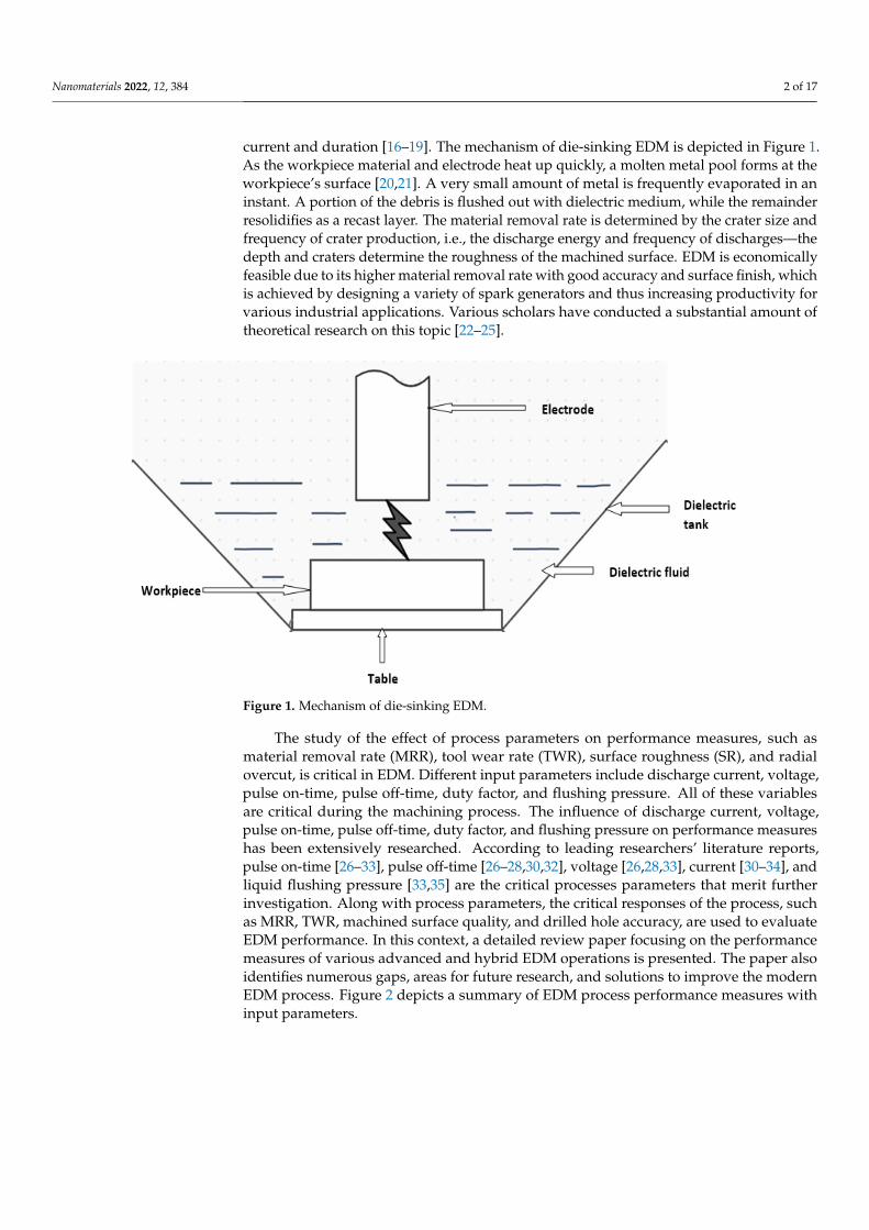
The study of the effect of process parameters on performance measures, such as ma-terial removal rate (MRR), tool wear rate (TWR), surface roughness (SR), and radial over-cut, is critical in EDM. Different input parameters include discharge current, voltage, pulse on-time, pulse off-time, duty factor, and flushing pressure. All of these variables are critical during the machining process. The influence of discharge current, voltage, pulse on-time, pulse off-time, duty factor, and flushing pressure on performance measures has been extensively researched. According to leading researchers’ literature reports, pulse on-time [26–33], pulse off-time [26–28,30,32], voltage [26,28,33], current [30–34], and liquid flushing pressure [33,35] are the critical processes parameters that merit further investiga-tion. Along with process parameters, the critical responses of the process, such as MRR, TWR, machined surface quality, and drilled hole accuracy, are used to evaluate EDM per-formance. In this context, a detailed review paper focusing on the performance measures of various advanced and hybrid EDM operations is presented. The paper also identifies numerous gaps, areas for future research, and solutions to improve the modern EDM pro-cess. Figure 2 depicts a summary of EDM process performance measures with input pa-rameters.
Figure 1. Mechanism of die-sinking EDM.
The study of the effect of process parameters on performance measures, such asmaterial removal rate (MRR), tool wear rate (TWR), surface roughness (SR), and radialovercut, is critical in EDM. Different input parameters include discharge current, voltage,pulse on-time, pulse off-time, duty factor, and flushing pressure. All of these variablesare critical during the machining process. The influence of discharge current, voltage,pulse on-time, pulse off-time, duty factor, and flushing pressure on performance measureshas been extensively researched. According to leading researchers’ literature reports,pulse on-time [26–33], pulse off-time [26–28,30,32], voltage [26,28,33], current [30–34], andliquid flushing pressure [33,35] are the critical processes parameters that merit furtherinvestigation. Along with process parameters, the critical responses of the process, suchas MRR, TWR, machined surface quality, and drilled hole accuracy, are used to evaluateEDM performance. In this context, a detailed review paper focusing on the performancemeasures of various advanced and hybrid EDM operations is presented. The paper alsoidentifies numerous gaps, areas for future research, and solutions to improve the modernEDM process. Figure 2 depicts a summary of EDM process performance measures withinput parameters.

Nanomaterials 2022, 12, 384 3 of 17
Nanomaterials 2022, 12, x FOR PEER REVIEW 3 of 17
Figure 2. Performance measures of the EDM process with input parameters.
2. Performance Measures 2.1. Material Removal Rate (MRR)
The MRR is an important performance measure in EDM because it is used to bench-mark machining processes from the industry’s perspective. The MRR of the material should be as high as possible based on industry demand. Various materials, such as nickel and titanium, are used in the production of aircraft, military vehicles, and gas turbine components. Some of the materials used in this context are difficult to machine using con-ventional techniques. As a result, non-traditional machining plays an important role in the machining of such complex materials. These materials should be easily machined with EDM, and the MRR must also be determined. The MRR is the weight difference between the workpiece before and after machining divided by the machining time. The MRR has been reported by researchers. Kuppan et al. [36] reported the effect of process parameters on the MRR and surface roughness of Inconel 718. Inconel 718 has applications in the aer-ospace industry. Therefore, the machinability of this material is assumed significant. The study reported that the MRR of this material increases from 5.533 to 46.88 mg/min with peak current, irrespective of the pulse duration. Peak current is the most significant pa-rameter related to the MRR of Inconel 718. Mohanty et al. [37] investigated the machina-bility of the Inconel 718 superalloy in EDM. The study showed that the MRR decreases from 11.22 to 4.45 mm3/min for brass, 25.54 to 12.38 mm3/min for copper, and 31.75 to 30.17 mm3/min for graphite electrodes, with an increase with open-circuit voltage. A machina-bility investigation on Inconel 718 was carried out on EDM by Kuppan et al. [38]. Mohan et al. [39] reported the EDM of the SiC/6025 Al composite. The study showed that the electrode produces a higher MRR (55 mm3/min) with a positive polarity electrode than a negative. As the volume percentage of SiC increases in the composite, the associated MRR exhibits a concomitant decline.
Pradhan et al. [40] used micro-EDM for machining of a titanium-based superalloy. In the machining of the titanium alloy, the MRR increases rapidly from 0.0062 to 0.033 mg/min with a pulse on-time. Yan et al. [41] used rotary EDM to cut the Al2O3/6061 Al composite. This study investigated the peak current and volume fraction of Al2O3 that have a significant effect on the MRR. Majumder et al. [42] used EDM to machine AISI 316LN stainless steel with a copper electrode. Mohanty et al. [43] reported that tool mate-rial, pulse on-time, and discharge current significantly affected machinability characteris-tics of Inconel 718 during the die-sinking EDM process. The study reported that the MRR increases from 20.05 to 48.9 mm3/min with the current when machined with a graphite electrode. Kapoor et al. [44] reported that the electrical conductivity of the brass wire is improved by cryogenic treatment during the wire EDM process. Gill et al. [45] investi-gated the machinability of a titanium alloy (Ti 6246) in an EDM-based drilling process
Figure 2. Performance measures of the EDM process with input parameters.
2. Performance Measures2.1. Material Removal Rate (MRR)
The MRR is an important performance measure in EDM because it is used to bench-mark machining processes from the industry’s perspective. The MRR of the materialshould be as high as possible based on industry demand. Various materials, such as nickeland titanium, are used in the production of aircraft, military vehicles, and gas turbinecomponents. Some of the materials used in this context are difficult to machine usingconventional techniques. As a result, non-traditional machining plays an important role inthe machining of such complex materials. These materials should be easily machined withEDM, and the MRR must also be determined. The MRR is the weight difference between theworkpiece before and after machining divided by the machining time. The MRR has beenreported by researchers. Kuppan et al. [36] reported the effect of process parameters on theMRR and surface roughness of Inconel 718. Inconel 718 has applications in the aerospaceindustry. Therefore, the machinability of this material is assumed significant. The studyreported that the MRR of this material increases from 5.533 to 46.88 mg/min with peakcurrent, irrespective of the pulse duration. Peak current is the most significant parameterrelated to the MRR of Inconel 718. Mohanty et al. [37] investigated the machinability of theInconel 718 superalloy in EDM. The study showed that the MRR decreases from 11.22 to4.45 mm3/min for brass, 25.54 to 12.38 mm3/min for copper, and 31.75 to 30.17 mm3/minfor graphite electrodes, with an increase with open-circuit voltage. A machinability inves-tigation on Inconel 718 was carried out on EDM by Kuppan et al. [38]. Mohan et al. [39]reported the EDM of the SiC/6025 Al composite. The study showed that the electrodeproduces a higher MRR (55 mm3/min) with a positive polarity electrode than a negative.As the volume percentage of SiC increases in the composite, the associated MRR exhibits aconcomitant decline.
Pradhan et al. [40] used micro-EDM for machining of a titanium-based superalloy. Inthe machining of the titanium alloy, the MRR increases rapidly from 0.0062 to 0.033 mg/minwith a pulse on-time. Yan et al. [41] used rotary EDM to cut the Al2O3/6061 Al compos-ite. This study investigated the peak current and volume fraction of Al2O3 that have asignificant effect on the MRR. Majumder et al. [42] used EDM to machine AISI 316LNstainless steel with a copper electrode. Mohanty et al. [43] reported that tool material,pulse on-time, and discharge current significantly affected machinability characteristicsof Inconel 718 during the die-sinking EDM process. The study reported that the MRRincreases from 20.05 to 48.9 mm3/min with the current when machined with a graphiteelectrode. Kapoor et al. [44] reported that the electrical conductivity of the brass wire isimproved by cryogenic treatment during the wire EDM process. Gill et al. [45] investigatedthe machinability of a titanium alloy (Ti 6246) in an EDM-based drilling process when thealloy undergoes deep cryogenic treatment. Most of the researchers reported that cryogenictreatment invariably improves the MRR [46–52].
Nanomaterials 2022, 12, 384 4 of 17
Most researchers reported powder-mixed EDM to improve the rate of EDM-basedmachining (PMEDM). Powder-mixed EDM (PMEDM) is an enhanced EDM technology inwhich the dielectric medium is mixed with a fine, abrasive, electrically conductive powder.Metallic powders suspended in the dielectric medium reduce their insulating strength,increasing the inter-electrode gap conditions, which improves EDM performance andresults in a better surface finish than conventional EDM. Tall et al. [53] reported machiningof the Al/Al2O3 metal matrix composite with the EDM process using aluminum powder(average size of 15 µm) in the kerosene dielectric medium. They found that the addition ofaluminum powder in the dielectric medium improves the MRR. Kolli et al. [54] reportedthat the MRR is improved when graphite powder (14 g/L) and surfactant (varied between0.25 and 15.0 g/L) are added to the dielectric fluid during EDM of the titanium alloy. Kansalet al. [55] used silicon powder (average particle size 30 µm) in a dielectric fluid to improvethe machining rate of die steel. The study reported an increase in machining rate from2.67 to 4.58 mm3/min at a 3 g/L silicon powder concentration. Singh et al. [56] studied theabrasive mixed PMEDM and reported the highest MRR (0.57 g/min) at the concentrationof SiC of 8 g/L. Kumar et al. [57] reported the peak current, powder concentration, andpulse duration. These were considered as influencing parameters during the PMEDM ofthe Al-SiCP metal matrix composite. The material contained 10% SiC particles (by volume)with an average particle size of 25 µm as reinforcement. The study reported a higherMRR, that is 2.93 mm3/min, at a silicon powder concentration of 4 g/L. According tothe PMEDM studies, increasing the powder concentration in dielectric fluid improvesmachining performance [58–63].
Some studies on ultrasonic-assisted EDM claimed that by applying ultrasonic vi-brations to the electrode, debris would be removed from the machining area via a high-frequency pumping action. Ultrasonic vibration (UV)-aided EDM is a hybrid method inwhich ultrasonic vibration is incorporated into the EDM process. Ultrasonic vibration (at afrequency of 20 kHz or higher) is used during the EDM process to improve the process’sflushing efficiency. Depending on the applications and challenges encountered during theEDM process, ultrasonic vibration can be used on the tool, workpiece, or even dielectricmedium. Kremer et al. [64] investigated how ultrasonic vibrations affected EDM perfor-mance. The application of ultrasonic vibrations to the electrode improves the flushingaction, resulting in an increase in MRR. Abdullah et al. [65] reported an improvement in theMRR from 0.018 to 0.0145 mm3/min using the ultrasonically vibrated tool during EDM ofcemented tungsten carbide. Ultrasonic vibrations produce a higher number of discharges,and due to this, the MRR is enhanced. Lin et al. [66] investigated machining characteristicsof Ti-6Al-4V using an ultrasonic approach coupled to EDM. The study found that whenEDM and USM are combined, the MRR (0.087 to 1.42 mm3/min) improves due to enhanceddischarge. Hence, several researchers combined the ultrasonic machining approach withEDM to enhance machining performance and efficiently improve the MRR [67–78].
2.2. Tool Wear Rate (TWR)
The TWR is the amount of material lost from the electrode during the machiningprocess. It is calculated by dividing the difference in electrode weight before and aftermachining by the time spent machining. TWR stands for the time rate of material loss. It isa critical performance measure in the industry because it affects cost and productivity. Theamount of material that erodes during the EDM process is determined by the material of theelectrode and the machining conditions. As a result, during the EDM process, researchersfocused not only on the MRR but also on the TWR. Researchers have investigated variouselectrode materials and machining conditions to optimize electrode wear during the EDMprocess. Electrode wear also depends on the thermal conductivity of the electrode material.As the electrode has high thermal conductivity, heat is quickly dissipated through theelectrode, resulting in reduced wear. Straka et al. [79] used copper electrodes to machinetool steel by EDM. The copper electrode was chosen because of its high thermal conductivity,which reduces the TWR. The impact of peak current, pulse off-time, voltage, and pulse
Nanomaterials 2022, 12, 384 5 of 17
on-time on the TWR was studied. The study reported an increase in the TWR from 0.3 to360 µm3/min with peak current. Amorim et al. [80] used die-sinking EDM to machine toolsteel with copper and graphite electrodes. The study showed that these two electrodesproduced similar volumetric relative wear for the positive polarity and relatively lowwears rates (that is, 30%) for negative polarity. Khan et al. [81] reported the machining ofaluminum and mild steel employing copper and brass electrodes. The lowest electrodewear ratio (0.012) was reported while machining aluminum with the copper electrode.
Zarepour et al. [82] have carried out a statistical analysis of electrode wear in EDM.The copper electrode has been used to cut the DIN 1.2714 tool steel, which is used tofabricate mandrels and forging dies. The electrode wear ratio increased up to 0.57% withan increase in current values. Wang et al. [83] formed a semiempirical model on workpiecematerial removal and tool wear. Khan et al. [84] reported the performance of aluminumand copper electrodes in the EDM process. As reported in their study, copper electrodesexhibited much less wear (approximately 1.8 g) than aluminum during the EDM processcarried out on stainless steel.
Some researchers have proposed composite electrodes for the EDM process. Theseresearchers have proposed a novel electrode material based on a copper and TiB2 com-posite. Before introducing Rapid Prototyping technology, sintering was used to establishbonding between copper and TiB2 [85]. Puertas et al. [86] proposed machining a ceramiccompound based on tungsten carbide with the copper electrode for industrial applica-tions. Kunieda et al. [87] reported spectroscopic measurements of the vapor density of theelectrode material for the determination of the electrode wear ratio. Mascaraque-Ramrezet al. [88] investigated tool degradation at the electrode workpiece interface, focusing onthe central and border zones of the active electrode area. Additional investigations onelectrode wear have been reported by the majority of the researchers [89–98].
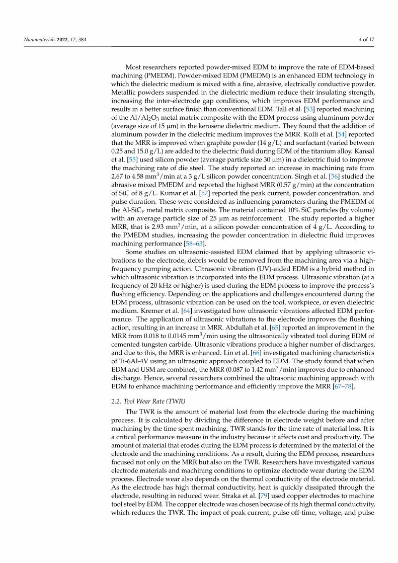
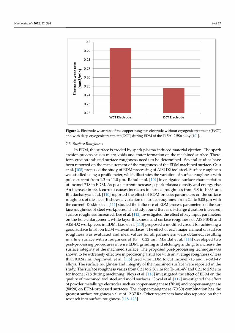
According to the literature review, prior cryogenic treatment reduces tool wear becauseit increases the material’s electrical conductivity. Kumar et al. [99] proposed that cryogeni-cally cooled electrodes have less tool wear than standard EDM electrodes. Kanth et al. [100]investigated the tool wear rate of cryogenically treated tool electrodes such as graphite, cop-per, and brass. According to the study, deep cryogenic treatment reduces tool wear whencompared to non-cryogenic tools. The electrode wear rate for a copper-tungsten electrodewith and without cryogenic treatment while EDM of the Ti-5Al-2.5Sn alloy is reported byKumar et al. [101]. Figure 3 shows the Electrode wear rate of the copper-tungsten electrodewithout cryogenic treatment (WCT) and with deep cryogenic treatment (DCT) during EDMof the Ti-5Al-2.5Sn alloy. Several studies [102,103] have found that cryogenic treatmentimproves the TWR compared to untreated tools.
Da Silva et al. [104] reported that cryogenically treated tools have performed better incomparison with the untreated ones in the Brandsma rapid facing test. In some cutting sit-uations, the difference was as high as 44%. Kumar et al. [105] utilized cryogenically treatedand untreated copper electrodes to machine Inconel 718 in PMEDM. This research wasconducted to find the machining efficiency concerning the TWR. This study reported im-provement in the TWR by using a cryogenically treated tool. Cryogenic treatment improvesthe electrode material’s hardness, wear resistance, and thermal and electrical properties.Kumar et al. [106] also proposed a TWR model based on PMEDM for cryogenically treatedelectrodes. Sundaram et al. [107] investigated the electrode wear ratio (EWR) of the copperelectrodes. Two different treatment methods, namely, deep cryogenic treatment and typicalstandard cold treatment, were adopted. The electrode wear ratio was lowered from 20.33%to 19.58% and 19.78%, for cold treatment and deep cryogenic treatment, respectively.
Nanomaterials 2022, 12, 384 6 of 17Nanomaterials 2022, 12, x FOR PEER REVIEW 6 of 17
Figure 3. Electrode wear rate of the copper-tungsten electrode without cryogenic treatment (WCT) and with deep cryogenic treatment (DCT) during EDM of the Ti-5Al-2.5Sn alloy [101].
2.3. Surface Roughness In EDM, the surface is eroded by spark plasma-induced material ejection. The spark
erosion process causes micro-voids and crater formation on the machined surface. There-fore, erosion-induced surface roughness needs to be determined. Several studies have been reported on the measurement of the roughness of the EDM machined surface. Guu et al. [108] proposed the study of EDM processing of AISI D2 tool steel. Surface roughness was studied using a profilometer, which illustrates the variation of surface roughness with pulse current from 1.3 to 11.0 µm. Rahul et al. [109] investigated surface characteristics of Inconel 718 in EDM. As peak current increases, spark plasma density and energy rise. An increase in peak current causes increases in surface roughness from 3.8 to 10.33 µm. Bhattacharyya et al. [110] reported the effect of EDM process parameters on the surface roughness of die steel. It shows a variation of surface roughness from 2.4 to 5.08 µm with the current. Keskin et al. [111] studied the influence of EDM process parameters on the surface roughness of steel workpieces. The study found that as discharge duration in-creased, surface roughness increased. Lee et al. [112] investigated the effect of key input parameters on the hole enlargement, white layer thickness, and surface roughness of AISI-1045 and AISI-D2 workpieces in EDM. Liao et al. [113] proposed a modified circuit for achieving a good surface finish on EDM wire-cut surfaces. The effect of each major ele-ment on surface roughness was evaluated and ideal values for all parameters were ob-tained, resulting in a fine surface with a roughness of Ra = 0.22 µm. Mandal et al. [114] developed two post-processing procedures in wire EDM: grinding and etching-grinding, to increase the surface integrity of the machined surface. The proposed post-processing technique was shown to be extremely effective in producing a surface with an average roughness of less than 0.024 µm. Aspinwall et al. [115] used wire EDM to cut Inconel 718 and Ti-6Al-4V alloys. The surface roughness and integrity of the machined surface were reported in the study. The surface roughness varies from 0.21 to 2.36 µm for Ti-6Al-4V and 0.21 to 2.93 µm for Inconel 718 during machining. Bleys et al. [116] investigated the effect of EDM on the quality of machined tool steel and mold surfaces. Goyal et al. [117] investigated the effect of powder metallurgy electrodes such as copper-manganese (70:30) and copper-manganese (80:20) on EDM-processed surfaces. The copper-manganese (70:30) combination has the greatest surface roughness value of 12.37 Ra. Other research-ers have also reported on their research into surface roughness [118–123].
Figure 3. Electrode wear rate of the copper-tungsten electrode without cryogenic treatment (WCT)and with deep cryogenic treatment (DCT) during EDM of the Ti-5Al-2.5Sn alloy [101].
2.3. Surface Roughness
In EDM, the surface is eroded by spark plasma-induced material ejection. The sparkerosion process causes micro-voids and crater formation on the machined surface. There-fore, erosion-induced surface roughness needs to be determined. Several studies havebeen reported on the measurement of the roughness of the EDM machined surface. Guuet al. [108] proposed the study of EDM processing of AISI D2 tool steel. Surface roughnesswas studied using a profilometer, which illustrates the variation of surface roughness withpulse current from 1.3 to 11.0 µm. Rahul et al. [109] investigated surface characteristicsof Inconel 718 in EDM. As peak current increases, spark plasma density and energy rise.An increase in peak current causes increases in surface roughness from 3.8 to 10.33 µm.Bhattacharyya et al. [110] reported the effect of EDM process parameters on the surfaceroughness of die steel. It shows a variation of surface roughness from 2.4 to 5.08 µm withthe current. Keskin et al. [111] studied the influence of EDM process parameters on the sur-face roughness of steel workpieces. The study found that as discharge duration increased,surface roughness increased. Lee et al. [112] investigated the effect of key input parameterson the hole enlargement, white layer thickness, and surface roughness of AISI-1045 andAISI-D2 workpieces in EDM. Liao et al. [113] proposed a modified circuit for achieving agood surface finish on EDM wire-cut surfaces. The effect of each major element on surfaceroughness was evaluated and ideal values for all parameters were obtained, resultingin a fine surface with a roughness of Ra = 0.22 µm. Mandal et al. [114] developed twopost-processing procedures in wire EDM: grinding and etching-grinding, to increase thesurface integrity of the machined surface. The proposed post-processing technique wasshown to be extremely effective in producing a surface with an average roughness of lessthan 0.024 µm. Aspinwall et al. [115] used wire EDM to cut Inconel 718 and Ti-6Al-4Valloys. The surface roughness and integrity of the machined surface were reported in thestudy. The surface roughness varies from 0.21 to 2.36 µm for Ti-6Al-4V and 0.21 to 2.93 µmfor Inconel 718 during machining. Bleys et al. [116] investigated the effect of EDM on thequality of machined tool steel and mold surfaces. Goyal et al. [117] investigated the effectof powder metallurgy electrodes such as copper-manganese (70:30) and copper-manganese(80:20) on EDM-processed surfaces. The copper-manganese (70:30) combination has thegreatest surface roughness value of 12.37 Ra. Other researchers have also reported on theirresearch into surface roughness [118–123].

Nanomaterials 2022, 12, 384 7 of 17
2.4. Surface Integrity
Some molten material resolidifies on the workpiece surface because the dielectric fluidcannot remove all of the molten material from the cutting region during EDM. As shownin Figure 4, the resolidified material produced a distinct layer on the machined surface,known as a recast layer.
Nanomaterials 2022, 12, x FOR PEER REVIEW 7 of 17
2.4. Surface Integrity Some molten material resolidifies on the workpiece surface because the dielectric
fluid cannot remove all of the molten material from the cutting region during EDM. As shown in Figure 4, the resolidified material produced a distinct layer on the machined surface, known as a recast layer.
Figure 4. Evolution of layered zones in an EDM-processed specimen.
Craters, pockmarks, white or recast layers, and cracks are generated on the work-piece’s surface during EDM machining and decrease the surface finish. Figure 5 shows an SEM image of the machined surface representing recast layer thickness.
Figure 5. SEM image of Recast layer thickness (RCT) for the Nimonic C-263 workpiece machined with a copper electrode.
2.4.1. RCT on Workpiece Rahul et al. [99] looked into the surface integrity of Inconel 825 machined with cryo-
genically treated copper electrodes. Cracks on the surface of the workpiece are smaller when machined with cryogenically treated electrodes, according to the study. The thick-ness of the recast layer was also found to be greater (approximately 26%) in the case of a cryogenically treated electrode compared to non-cryogenically treated electrodes.
Figure 4. Evolution of layered zones in an EDM-processed specimen.
Craters, pockmarks, white or recast layers, and cracks are generated on the workpiece’ssurface during EDM machining and decrease the surface finish. Figure 5 shows an SEMimage of the machined surface representing recast layer thickness.
Nanomaterials 2022, 12, x FOR PEER REVIEW 7 of 17
2.4. Surface Integrity Some molten material resolidifies on the workpiece surface because the dielectric
fluid cannot remove all of the molten material from the cutting region during EDM. As shown in Figure 4, the resolidified material produced a distinct layer on the machined surface, known as a recast layer.
Figure 4. Evolution of layered zones in an EDM-processed specimen.
Craters, pockmarks, white or recast layers, and cracks are generated on the work-piece’s surface during EDM machining and decrease the surface finish. Figure 5 shows an SEM image of the machined surface representing recast layer thickness.
Figure 5. SEM image of Recast layer thickness (RCT) for the Nimonic C-263 workpiece machined with a copper electrode.
2.4.1. RCT on Workpiece Rahul et al. [99] looked into the surface integrity of Inconel 825 machined with cryo-
genically treated copper electrodes. Cracks on the surface of the workpiece are smaller when machined with cryogenically treated electrodes, according to the study. The thick-ness of the recast layer was also found to be greater (approximately 26%) in the case of a cryogenically treated electrode compared to non-cryogenically treated electrodes.
Figure 5. SEM image of Recast layer thickness (RCT) for the Nimonic C-263 workpiece machinedwith a copper electrode.
2.4.1. RCT on Workpiece
Rahul et al. [99] looked into the surface integrity of Inconel 825 machined with cryo-genically treated copper electrodes. Cracks on the surface of the workpiece are smallerwhen machined with cryogenically treated electrodes, according to the study. The thick-ness of the recast layer was also found to be greater (approximately 26%) in the case of acryogenically treated electrode compared to non-cryogenically treated electrodes.
Guu et al. [108] published their findings on the EDM machining of AISI D2 tool steel.The thickness of the recast layer was measured in the study. The study also discovered that
Nanomaterials 2022, 12, 384 8 of 17
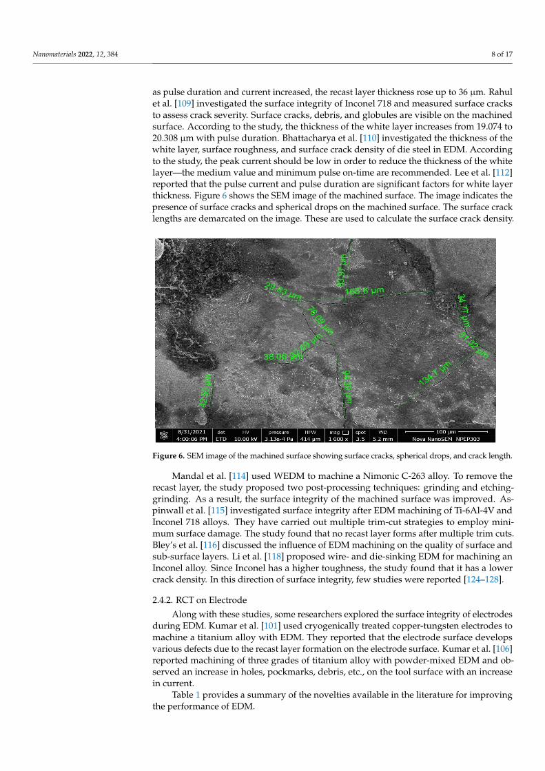
as pulse duration and current increased, the recast layer thickness rose up to 36 µm. Rahulet al. [109] investigated the surface integrity of Inconel 718 and measured surface cracksto assess crack severity. Surface cracks, debris, and globules are visible on the machinedsurface. According to the study, the thickness of the white layer increases from 19.074 to20.308 µm with pulse duration. Bhattacharya et al. [110] investigated the thickness of thewhite layer, surface roughness, and surface crack density of die steel in EDM. Accordingto the study, the peak current should be low in order to reduce the thickness of the whitelayer—the medium value and minimum pulse on-time are recommended. Lee et al. [112]reported that the pulse current and pulse duration are significant factors for white layerthickness. Figure 6 shows the SEM image of the machined surface. The image indicates thepresence of surface cracks and spherical drops on the machined surface. The surface cracklengths are demarcated on the image. These are used to calculate the surface crack density.
Nanomaterials 2022, 12, x FOR PEER REVIEW 8 of 17
Guu et al. [108] published their findings on the EDM machining of AISI D2 tool steel. The thickness of the recast layer was measured in the study. The study also discovered that as pulse duration and current increased, the recast layer thickness rose up to 36 µm. Rahul et al. [109] investigated the surface integrity of Inconel 718 and measured surface cracks to assess crack severity. Surface cracks, debris, and globules are visible on the ma-chined surface. According to the study, the thickness of the white layer increases from 19.074 to 20.308 µm with pulse duration. Bhattacharya et al. [110] investigated the thick-ness of the white layer, surface roughness, and surface crack density of die steel in EDM. According to the study, the peak current should be low in order to reduce the thickness of the white layer—the medium value and minimum pulse on-time are recommended. Lee et al. [112] reported that the pulse current and pulse duration are significant factors for white layer thickness. Figure 6 shows the SEM image of the machined surface. The image indicates the presence of surface cracks and spherical drops on the machined sur-face. The surface crack lengths are demarcated on the image. These are used to calculate the surface crack density.
Figure 6. SEM image of the machined surface showing surface cracks, spherical drops, and crack length.
Mandal et al. [114] used WEDM to machine a Nimonic C-263 alloy. To remove the recast layer, the study proposed two post-processing techniques: grinding and etching-grinding. As a result, the surface integrity of the machined surface was improved. Aspin-wall et al. [115] investigated surface integrity after EDM machining of Ti-6Al-4V and In-conel 718 alloys. They have carried out multiple trim-cut strategies to employ minimum surface damage. The study found that no recast layer forms after multiple trim cuts. Bley’s et al. [116] discussed the influence of EDM machining on the quality of surface and sub-surface layers. Li et al. [118] proposed wire- and die-sinking EDM for machining an In-conel alloy. Since Inconel has a higher toughness, the study found that it has a lower crack density. In this direction of surface integrity, few studies were reported [124–128].
2.4.2. RCT on Electrode Along with these studies, some researchers explored the surface integrity of elec-
trodes during EDM. Kumar et al. [101] used cryogenically treated copper-tungsten elec-trodes to machine a titanium alloy with EDM. They reported that the electrode surface develops various defects due to the recast layer formation on the electrode surface. Kumar
Figure 6. SEM image of the machined surface showing surface cracks, spherical drops, and crack length.
Mandal et al. [114] used WEDM to machine a Nimonic C-263 alloy. To remove therecast layer, the study proposed two post-processing techniques: grinding and etching-grinding. As a result, the surface integrity of the machined surface was improved. As-pinwall et al. [115] investigated surface integrity after EDM machining of Ti-6Al-4V andInconel 718 alloys. They have carried out multiple trim-cut strategies to employ mini-mum surface damage. The study found that no recast layer forms after multiple trim cuts.Bley’s et al. [116] discussed the influence of EDM machining on the quality of surface andsub-surface layers. Li et al. [118] proposed wire- and die-sinking EDM for machining anInconel alloy. Since Inconel has a higher toughness, the study found that it has a lowercrack density. In this direction of surface integrity, few studies were reported [124–128].
2.4.2. RCT on Electrode
Along with these studies, some researchers explored the surface integrity of electrodesduring EDM. Kumar et al. [101] used cryogenically treated copper-tungsten electrodes tomachine a titanium alloy with EDM. They reported that the electrode surface developsvarious defects due to the recast layer formation on the electrode surface. Kumar et al. [106]reported machining of three grades of titanium alloy with powder-mixed EDM and ob-served an increase in holes, pockmarks, debris, etc., on the tool surface with an increasein current.
Table 1 provides a summary of the novelties available in the literature for improvingthe performance of EDM.

Nanomaterials 2022, 12, 384 9 of 17
Table 1. Major findings available in the literature to improve the performance of EDM machiningduring the process.
Year Author Novelties in EDM
2004 Singh et al. [12] EDM was utilized to machine hardened tool steel with different toolelectrodes such as copper, copper-tungsten, brass, and aluminium.
2007 Khanra et al. [29] The ZrB2-Cu composite electrode was used to machine the material in EDM.High MRR and low TWR were reported by using this composite electrode.
2007 Abdullah and Shabgard [65] The effect of ultrasonic vibration-assisted copper tools on the machining ofcemented tungsten carbide was investigated.
2010 Abdulkareem et al. [26] Electrode cooling was carried out during EDM of titanium alloy. The effectof electrode cooling on electrode wear was deliberated.
2013 Gopalakannan et al. [28] EDM was employed to machine a metal matrix nanocomposite synthesizedby the ultrasonic cavitation method.
2015 Dewangan et al. [32] A Grey-Fuzzy logic-based hybrid optimization technique was reported toimprove the surface integrity of material during EDM processing.
2017 Kumar et al. [99] Surface integrity and metallurgical characteristics of Inconel 825 wereinvestigated by machining with cryogenically treated copper electrodes.
Figure 7 shows the percentage contribution of MRR, TWR, SR, and surface integritystudied in various works. In EDM, it can be seen that 39% of research publications focuson MRR, and 31% contribute to TWR. It can be seen that 23% of research work is carriedout on SR, and 7% of research work is carried out on surface integrity in EDM. From thechart, researchers have primarily focused on performance measures such as MRR, TWR,and surface roughness of the machined parts. Surface integrity, surface crack density,radial overcut, and microhardness of machined parts have not received sufficient attention.Since EDM is a thermal process and is commonly used in the machining of hard materials,which are widely used in a variety of industrial sectors, the heat generated during ma-chining can have a significant impact on the machined surface quality and the propertiesof the workpiece. As a result, an attempt must be made to comprehend and analyze theEDM process attributes on the surface crack density, radial overcut, and microhardness ofmachined parts.
Nanomaterials 2022, 12, x FOR PEER REVIEW 10 of 17
Figure 7. Percentage contribution of performance measures in the literatures.
3. Statistical Tools and Artificial Intelligence Techniques Applied in EDM Figure 8 demonstrates the statistical tools and artificial intelligence techniques which
are used for processing in EDM.
Figure 8. Statistical Tools and Artificial Intelligence Techniques applied in EDM.
Most of the researchers implemented the Taguchi method for analysis [27,37,40,44,54,55,57,82,83,105,106,112,113]. Some researchers used the response surface methodology (RSM) technique for analyzing the EDM process parameters [28,30–32,33,36,38,110,114]. The artificial neural network (ANN) model is implemented in some research work for finding optimum parameters in EDM [34]. The genetic algorithm model is adopted in [39]. In [42], desirability-based multi-objective particle swarm optimization (DMPSO) is used for EDM processing. A semiempirical model was developed based on machining parameters in [53].
According to reports, the essential factors of EDM are peak current, pulse duration, voltage, pulse off-time, and so on. It is critical to select optimal parameters when machin-ing. These parameters have a direct impact on the component’s MRR, TWR, surface roughness, and so on. As a result, determining the best EDM parameters is critical. Several optimization techniques have been reported in the literature, and a few of them are high-lighted in Table 2. The quantum behaved particle swarm optimization (QPSO) and PSO have been employed in [37] for optimization. The desirability function approach has been used in [30,38]. PSO is used for optimization in [43]. The principal component analysis-
Figure 7. Percentage contribution of performance measures in the literatures.
3. Statistical Tools and Artificial Intelligence Techniques Applied in EDM
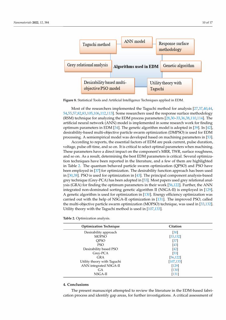
Figure 8 demonstrates the statistical tools and artificial intelligence techniques whichare used for processing in EDM.
Nanomaterials 2022, 12, 384 10 of 17
Nanomaterials 2022, 12, x FOR PEER REVIEW 10 of 17
Figure 7. Percentage contribution of performance measures in the literatures.
3. Statistical Tools and Artificial Intelligence Techniques Applied in EDM Figure 8 demonstrates the statistical tools and artificial intelligence techniques which
are used for processing in EDM.
Figure 8. Statistical Tools and Artificial Intelligence Techniques applied in EDM.
Most of the researchers implemented the Taguchi method for analysis [27,37,40,44,54,55,57,82,83,105,106,112,113]. Some researchers used the response surface methodology (RSM) technique for analyzing the EDM process parameters [28,30–32,33,36,38,110,114]. The artificial neural network (ANN) model is implemented in some research work for finding optimum parameters in EDM [34]. The genetic algorithm model is adopted in [39]. In [42], desirability-based multi-objective particle swarm optimization (DMPSO) is used for EDM processing. A semiempirical model was developed based on machining parameters in [53].
According to reports, the essential factors of EDM are peak current, pulse duration, voltage, pulse off-time, and so on. It is critical to select optimal parameters when machin-ing. These parameters have a direct impact on the component’s MRR, TWR, surface roughness, and so on. As a result, determining the best EDM parameters is critical. Several optimization techniques have been reported in the literature, and a few of them are high-lighted in Table 2. The quantum behaved particle swarm optimization (QPSO) and PSO have been employed in [37] for optimization. The desirability function approach has been used in [30,38]. PSO is used for optimization in [43]. The principal component analysis-
Figure 8. Statistical Tools and Artificial Intelligence Techniques applied in EDM.
Most of the researchers implemented the Taguchi method for analysis [27,37,40,44,54,55,57,82,83,105,106,112,113]. Some researchers used the response surface methodology(RSM) technique for analyzing the EDM process parameters [28,30–33,36,38,110,114]. Theartificial neural network (ANN) model is implemented in some research work for findingoptimum parameters in EDM [34]. The genetic algorithm model is adopted in [39]. In [42],desirability-based multi-objective particle swarm optimization (DMPSO) is used for EDMprocessing. A semiempirical model was developed based on machining parameters in [53].
According to reports, the essential factors of EDM are peak current, pulse duration,voltage, pulse off-time, and so on. It is critical to select optimal parameters when machining.These parameters have a direct impact on the component’s MRR, TWR, surface roughness,and so on. As a result, determining the best EDM parameters is critical. Several optimiza-tion techniques have been reported in the literature, and a few of them are highlightedin Table 2. The quantum behaved particle swarm optimization (QPSO) and PSO havebeen employed in [37] for optimization. The desirability function approach has been usedin [30,38]. PSO is used for optimization in [43]. The principal component analysis-basedgrey technique (Grey-PCA) has been adopted in [53]. Most papers used grey relational anal-ysis (GRA) for finding the optimum parameters in their work [56,122]. Further, the ANNintegrated non-dominated sorting genetic algorithm II (NSGA-II) is employed in [129].A genetic algorithm is used for optimization in [130]. Energy efficiency optimization wascarried out with the help of NSGA-II optimization in [131]. The improved PSO, calledthe multi-objective particle swarm optimization (MOPSO) technique, was used in [33,132].Utility theory with the Taguchi method is used in [107,133].
Table 2. Optimization analysis.
Optimization Technique Citation
Desirability approach [30]MOPSO [33,132]QPSO [37]PSO [43]
Desirability based PSO [42]Grey-PCA [53]
GRA [56,122]Utility theory with Taguchi [107,133]ANN integrated NSGA-II [129]
GA [130]NSGA-II [131]
4. Conclusions
The present manuscript attempted to review the literature in the EDM-based fabri-cation process and identify gap areas, for further investigations. A critical assessment of
Nanomaterials 2022, 12, 384 11 of 17
the operational efficiency of the EDM process has been carried out for various materialsand electrodes in terms of MRR, TWR, surface roughness, and crack density. EDM hassubstantially enhanced the standard of machining operations in recent years. A summaryof research trends in ultrasonic vibration EDM, EDM in different water-based dielectricfluids, EDM with powder compounds, dry EDM, and several modeling techniques for fore-casting EDM performances was presented. Researchers have recently used various typesof vegetable oils as a dielectric medium during EDM and discovered that they had a higherMRR, a better surface quality, and emit fewer hazardous gases than hydrocarbon-baseddielectric fluids. The researchers also concentrated their efforts on the micro-EDM and itsdiverse uses. EDM is also being studied for hard-to-machine materials such as metal matrixcomposites, high-hardness steel, and superalloys.
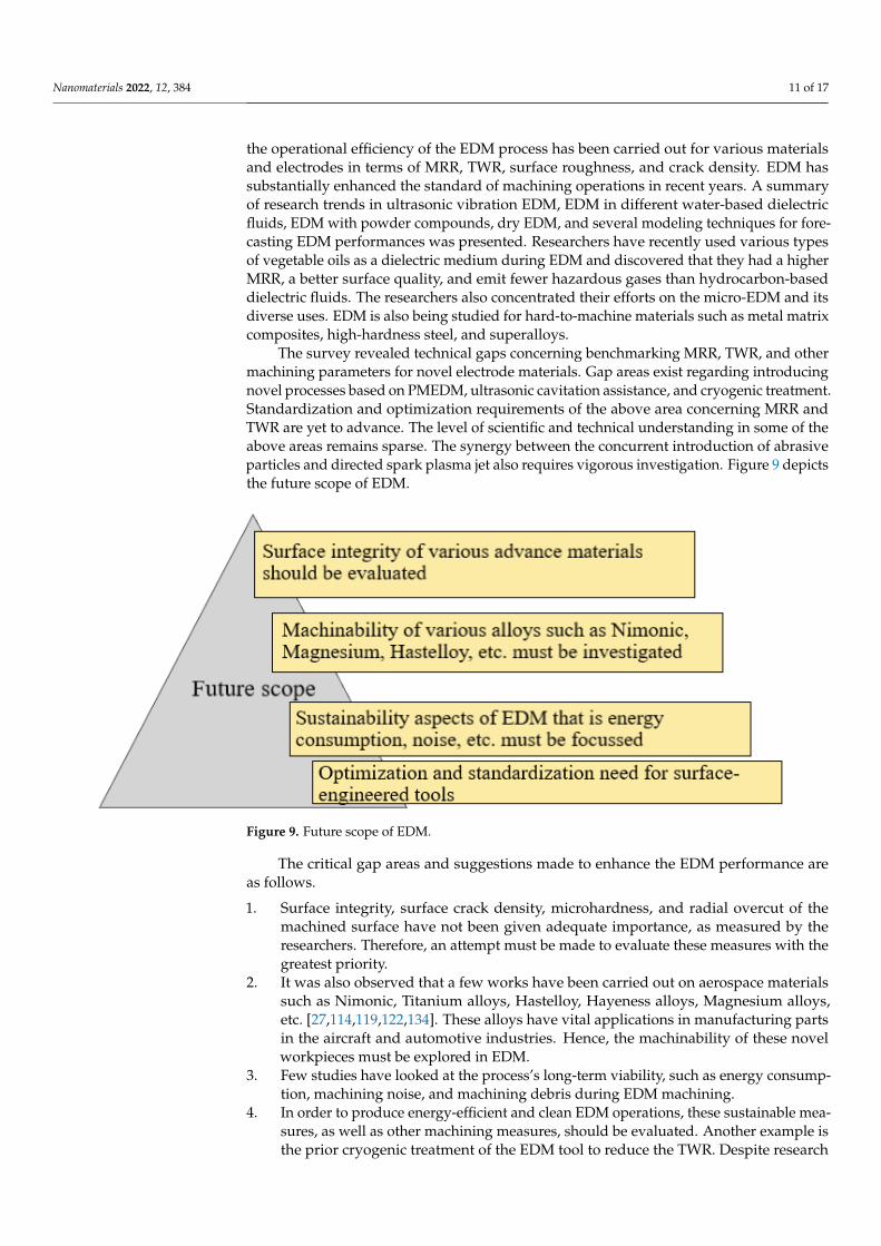
The survey revealed technical gaps concerning benchmarking MRR, TWR, and othermachining parameters for novel electrode materials. Gap areas exist regarding introducingnovel processes based on PMEDM, ultrasonic cavitation assistance, and cryogenic treatment.Standardization and optimization requirements of the above area concerning MRR andTWR are yet to advance. The level of scientific and technical understanding in some of theabove areas remains sparse. The synergy between the concurrent introduction of abrasiveparticles and directed spark plasma jet also requires vigorous investigation. Figure 9 depictsthe future scope of EDM.
Nanomaterials 2022, 12, x FOR PEER REVIEW 12 of 17
Figure 9. Future scope of EDM.
The critical gap areas and suggestions made to enhance the EDM performance are as follows. 1. Surface integrity, surface crack density, microhardness, and radial overcut of the ma-
chined surface have not been given adequate importance, as measured by the re-searchers. Therefore, an attempt must be made to evaluate these measures with the greatest priority.
2. It was also observed that a few works have been carried out on aerospace materials such as Nimonic, Titanium alloys, Hastelloy, Hayeness alloys, Magnesium alloys, etc. [27,114,119,122,134]. These alloys have vital applications in manufacturing parts in the aircraft and automotive industries. Hence, the machinability of these novel workpieces must be explored in EDM.
3. Few studies have looked at the process’s long-term viability, such as energy con-sumption, machining noise, and machining debris during EDM machining.
4. In order to produce energy-efficient and clean EDM operations, these sustainable measures, as well as other machining measures, should be evaluated. Another exam-ple is the prior cryogenic treatment of the EDM tool to reduce the TWR. Despite re-search demonstrating the method’s efficacy, no standardization of the procedure or refusal to establish a cutting process for hard materials has been proposed. A similar gap exists when it comes to the use of powder-mixed composites and the accompa-nying ultrasonic assistance.
5. Although not discussed, the thermal model of heat transfer efficiency and flushing characteristics needs to be addressed for novel ultra-hard material processing. In ad-dition, there is an optimization and standardization need for surface-engineered tools.
6. There are several reports in the literature for achieving low surface roughness in the EDM process. PMEDM (powder-mixed EDM) has been attempted for machining rigid material with the desired accuracy. However, quantitative correlation and benchmarking of process parameters remain to be implemented.
7. The survey revealed a considerable scope for further research. The discharge dynam-ics and heat transfer characteristic thermal modeling, flushing out effects, and assis-tance from ultrasonic cavitation need quantitative understanding. Enhanced MRR and reduced TWR are critical essential assessment criteria for an EDM process. Po-tential benefits from the use of surface-engineered tools also need further probing.
Figure 9. Future scope of EDM.
The critical gap areas and suggestions made to enhance the EDM performance areas follows.
1. Surface integrity, surface crack density, microhardness, and radial overcut of themachined surface have not been given adequate importance, as measured by theresearchers. Therefore, an attempt must be made to evaluate these measures with thegreatest priority.
2. It was also observed that a few works have been carried out on aerospace materialssuch as Nimonic, Titanium alloys, Hastelloy, Hayeness alloys, Magnesium alloys,etc. [27,114,119,122,134]. These alloys have vital applications in manufacturing partsin the aircraft and automotive industries. Hence, the machinability of these novelworkpieces must be explored in EDM.
3. Few studies have looked at the process’s long-term viability, such as energy consump-tion, machining noise, and machining debris during EDM machining.
4. In order to produce energy-efficient and clean EDM operations, these sustainable mea-sures, as well as other machining measures, should be evaluated. Another example isthe prior cryogenic treatment of the EDM tool to reduce the TWR. Despite research
Nanomaterials 2022, 12, 384 12 of 17
demonstrating the method’s efficacy, no standardization of the procedure or refusalto establish a cutting process for hard materials has been proposed. A similar gapexists when it comes to the use of powder-mixed composites and the accompanyingultrasonic assistance.
5. Although not discussed, the thermal model of heat transfer efficiency and flushingcharacteristics needs to be addressed for novel ultra-hard material processing. In ad-dition, there is an optimization and standardization need for surface-engineered tools.
6. There are several reports in the literature for achieving low surface roughness in theEDM process. PMEDM (powder-mixed EDM) has been attempted for machiningrigid material with the desired accuracy. However, quantitative correlation andbenchmarking of process parameters remain to be implemented.
7. The survey revealed a considerable scope for further research. The discharge dynamicsand heat transfer characteristic thermal modeling, flushing out effects, and assistancefrom ultrasonic cavitation need quantitative understanding. Enhanced MRR andreduced TWR are critical essential assessment criteria for an EDM process. Potentialbenefits from the use of surface-engineered tools also need further probing.
Author Contributions: Conceptualization, R.K.S., C.P.M., A.R.A. and C.-P.J.; methodology, C.P.M.and A.R.A.; investigation, R.K.S., C.P.M., A.R.A. and C.-P.J.; resources, R.K.S., C.P.M., A.R.A. andC.-P.J.; data curation, R.K.S., S.D. and K.M.P.G.; writing—original draft preparation, R.K.S., C.P.M.and A.R.A.; writing—review and editing, R.K.S., C.P.M. and A.R.A.; visualization, S.D.; supervision,C.P.M. and A.R.A.; project administration, C.-P.J.; funding acquisition, C.-P.J. All authors have readand agreed to the published version of the manuscript.
Funding: This research was funded by Ministry of Science and Technology of China (Taiwan), undergrant numbers MOST 109-2221-E-194-011-MY2 and MOST 111-2923-E-194-001-MY3.
Data Availability Statement: No new data were created or analyzed in this study. Data sharing isnot applicable to this article.
Conflicts of Interest: The authors declare that, no conflict of interest.
References1. Mordecai, N.L.; Lee, T.C.; Huddleston, J. Developments in spark erosion of ceramics. Br. Ceram. Trans. 1995, 94, 21–24.2. Zhang, J.H.; Lee, T.C.; Lau, W.S. Study on the electro-discharge machining of a hot-pressed aluminum oxide-based ceramic.
J. Mater. Processing Technol. 1997, 63, 908–912. [CrossRef]3. Kunieda, M.; Yoshida, M. Electrical Discharge Machining in Gas. CIRP Ann. 1997, 46, 143–146. [CrossRef]4. Kunieda, M.; Furudate, C. High Precision Finish Cutting by Dry WEDM. CIRP Ann. 2001, 50, 121–124. [CrossRef]5. Kunieda, M.; Miyoshi, Y.; Takaya, T.; Nakajima, N.; Yu, Z.; Yoshida, M. High-Speed 3D Milling by Dry EDM. CIRP Ann. 2003,
52, 147–150. [CrossRef]6. Furudate, C.; Kunieda, M. Gap Phenomena in Dry WEDM. Denki-Kakou-Gijutsu 2002, 26, 21–27. (In Japan)7. Wong, Y.S.; Lim, L.C.; Lee, L.C. Effects of Flushing on electro-discharge Machined Surfaces. J. Mater. Processing Technol. 1995,
48, 299–305. [CrossRef]8. Godinho, L.H.H.; Noble, C.F. The Use of Water as inter-electrode Medium in Pulsed EDM. In Proceedings of the Fifth International
Symposium for Electro-Machining, ISEM 6, Wolfsberg, Switzerland, 21–24 June 1977; pp. 63–67.9. Masuzawa, T. Machining Characteristics of EDM Using Water as a Dielectric Fluid. In Proceedings of the Twenty-Second Machine
Tool Design and Research Conference; Macmillan Education: London, UK, 1981; pp. 441–447. [CrossRef]10. Jilam, S.T.; Pandey, P.C. Experimental Investigations Into the Performance of Water as Dielectric in EDM. Int. J. Mach. Tool Des.
Res. 1984, 24, 31–43. [CrossRef]11. Masuzawa, T.; Tanaka, K. Water-based Dielectric Solution for EDM. CIRP Ann. 1983, 32, 119–122. [CrossRef]12. Singh, S.; Maheshwari, S.; Pandey, P.C. Some investigations into the electric discharge machining of hardened tool steel using
different electrode materials. J. Mater. Processing Technol. 2004, 149, 272–277. [CrossRef]13. Boothroyd, G.; Winston, A.K. Non-conventional machining processes. In Fundamentals of Machining and Machine Tools; Marcel
Dekker, Inc.: New York, NY, USA, 1989; p. 491.14. McGeough, J.A. Electro Discharge Machining in Advanced Methods of Machining; Chapman & Hall: London, UK, 1988; p. 130.15. Sen, B.; Kiyawat, N.; Singh, P.K.; Mitral, S.; Ykmd, J.H.; Purkait, P. Developments in Electric Power Supply Configurations for
Electrical-Discharge-Machining (EDM). In Proceedings of the Fifth International Conference on Power Electronics and DriveSystems, 2003. PEDS 2003, Singapore, 17–20 November 2003; IEEE: Piscataway, NJ, USA, 2003; pp. 659–664.

Nanomaterials 2022, 12, 384 13 of 17
16. Wong, Y.S.; Rahmana, M.; Lima, H.S.; Hanb, H.; Ravi, N. Investigation of Micro-EDM Material Removal Characteristics UsingSingle RC-Pulse Discharges. J. Mater. Processing Technol. 2003, 140, 303–307. [CrossRef]
17. Lee, H.T.; Tai, T.Y. Relationship between EDM parameters and surface crack formation. J. Mater. Processing Technol. 2003, 142,676–683. [CrossRef]
18. Guu, Y.H.; Ti-Kuang Hou, M. Effect of machining parameters on surface textures in EDM of Fe-Mn-Al alloy. Mater. Sci. Eng. 2007,466, 61–67. [CrossRef]
19. Kiyak, M.; Cakir, O. Examination of machining parameters on surface roughness in EDM of tool steel. J. Mater. Processing Technol.2007, 191, 141–144. [CrossRef]
20. Lee, L.C.; Lim, L.C.; Narayanan, V.; Venkatesh, V.C. Quantification of surface damage of tool steels after EDM. Int. J. Mach. ToolsManuf. 1988, 28, 359–372. [CrossRef]
21. Rebelo, J.C.; Dias, A.M.; Kremer, D.; Lebrun, J.L. Influence of EDM Pulse Energy on The Surface Integrity of Martensitic Steels.J. Mater. Processing Technol. 1998, 84, 90–96. [CrossRef]
22. Luo, Y.F. An Investigation into The Actual EDM Off-Time In SEA Machining. J. Mater. Processing Technol. 1998, 74, 61–68.[CrossRef]
23. Konig, W.; Dauw, D.F.; Levy, G.; Panten, U. EDM-future steps towards the machining of ceramics. CIRP Ann. 1988, 37, 623–631.[CrossRef]
24. Chen, Y.; Mahdivian, S.M. Analysis of electro-discharge machining process and its comparison with experiments. J. Mater.Processing Technol. 2002, 104, 150–157. [CrossRef]
25. Pawade, M.M.; Banwait, S.S. A brief review of die sinking electrical discharging machining process towards automation. Am. J.Mech. Eng. 2013, 1, 43–49. [CrossRef]
26. Abdulkareem, S.; Khan, A.A.; Konneh, M. Cooling effect on electrode and process parameters in EDM. Mater. Manuf. Processes2010, 25, 462–466. [CrossRef]
27. Choudhary, R.; Garg, H.; Prasad, M.; Kumar, D. Effect of Cryogenic Treatment of Tool Electrode on the Machining Performanceand Surface Finish during Electrical Discharge Machining of Hastelloy C-4. Mater. Today Proc. 2017, 4, 1158–1166. [CrossRef]
28. Gopalakannan, S.; Senthilvelan, T. A parametric study of electrical discharge machining process parameters on machining of castAl/B4C metal matrix nanocomposites. Proc. Inst. Mech. Eng. Part B J. Eng. Manuf. 2013, 227, 993–1004. [CrossRef]
29. Khanra, A.K.; Sarkar, B.R.; Bhattacharya, B.; Pathak, L.C.; Godkhindi, M.M. Performance of ZrB2–Cu composite as an EDMelectrode. J. Mater. Processing Technol. 2007, 183, 122–126. [CrossRef]
30. Kumar, S.; Dhingra, K.A.; Kumar, S. Parametric optimization of powder mixed electrical discharge machining for nickel-basedsuper alloy Inconel-800 using response surface methodology. Mech. Adv. Mater. Mod. Processes 2017, 3, 7. [CrossRef]
31. Kuppan, P.; Narayanan, S.; Oyyaravelu, R.; Balan, A.S.S. Performance evaluation of electrode materials in electric discharge deephole drilling of Inconel 718 superalloy. Procedia Eng. 2017, 174, 53–59. [CrossRef]
32. Dewangan, S.; Gangopadhyay, S.; Biswas, K.C. Multi-response optimization of surface integrity characteristics of EDM processusing grey-fuzzy logic-based hybrid approach. Eng. Sci. Technol. Int. J. 2015, 18, 361–368. [CrossRef]
33. Mohanty, P.C.; Mahapatra, S.S.; Singh, R.M. An experimental investigation of machinability of Inconel 718 in electrical dischargemachining. Procedia Mater. Sci. 2014, 6, 605–611. [CrossRef]
34. Rahman, M.M. Modeling of machining parameters of Ti-6Al-4V for electric discharge machining: A neural network approach.Sci. Res. Essays 2012, 7, 881–890. [CrossRef]
35. Rajesha, S.; Sharma, A.K.; Kumar, P. On electro-discharge machining of Inconel 718 with the hollow tool. J. Mater. Eng. Perform.2012, 21, 882–891. [CrossRef]
36. Kuppan, P.; Narayanan, S.; Rajadurai, A. Effect of process parameters on the material removal rate and surface roughness inelectric discharge drilling of Inconel 718 using graphite electrode. Int. J. Manuf. Technol. Manag. 2011, 23, 214–233. [CrossRef]
37. Mohanty, C.P.; Mahapatra, S.S.; Singh, M.R. An intelligent approach to optimize the EDM process parameters using utilityconcept and QPSO algorithm. Eng. Sci. Technol. Int. J. 2017, 20, 552–562. [CrossRef]
38. Kuppan, P.; Rajadurai, A.; Narayanan, S. Influence of EDM process parameters in deep-hole drilling of Inconel 718. Int. J. Adv.Manuf. Technol. 2008, 38, 74–84. [CrossRef]
39. Mohan, B.; Rajadurai, A.; Satyanarayana, K.G.G. Electric discharge machining of Al-SiC metal matrix composites using rotarytube electrode. J. Mater. Processing Technol. 2004, 153–154, 978–985. [CrossRef]
40. Pradhan, B.B.; Masanta, M.; Sarkar, B.R.; Bhattacharyya, B. Investigation of electro-discharge micro-machining of titanium superalloy. Int. J. Adv. Manuf. Technol. 2009, 41, 1094–1106. [CrossRef]
41. Yan, B.H.; Wang, C.C. The machining characteristics of Al2O3/6061Al composite using rotary electro-discharge machining with atube electrode. J. Mater. Processing Technol. 1999, 95, 222–231. [CrossRef]
42. Majumder, A.; Das, P.K.; Majumder, A.; Debnath, M. An approach to optimize the EDM process parameters using desirability-based multi-objective PSO. Prod. Manuf. Res. 2014, 2, 228–240. [CrossRef]
43. Mohanty, C.P.; Mahapatra, S.S.; Singh, M.R. A particle swarm approach for multi-objective optimization of the electrical dischargemachining process. J. Intell. Manuf. 2016, 27, 1171–1190. [CrossRef]
44. Kapoor, J.; Singh, S.; Khamba, J.S. Effect of cryogenic treated brass wire electrode on material removal rate in wire electricaldischarge machining. Proc. Inst. Mech. Eng. Part C J. Mech. Eng. Sci. 2012, 226, 2750–2758. [CrossRef]
Nanomaterials 2022, 12, 384 14 of 17
45. Gill, S.S.; Singh, J. Effect of deep cryogenic treatment on machinability of titanium alloy (Ti-6246) in electric discharge drilling.Mater. Manuf. Processes 2010, 25, 378–385. [CrossRef]
46. Kumar, S.V.; Kumar, M.P. Machining process parameter and surface integrity in conventional EDM and cryogenic EDM ofAl–SiCp MMC. J. Manuf. Processes 2017, 20, 70–78. [CrossRef]
47. Pandey, A.; Kumar, R. Some studies using cryogenically treated Rotary Cu-tool electrode Electrical Discharge Machining. Mater.Today Proc. 2018, 5, 7635–7639. [CrossRef]
48. Srivastava, V.; Pandey, P.M. Effect of process parameters on the performance of EDM process with ultrasonic assisted cryogenicallycooled electrode. J. Manuf. Processes 2012, 14, 393–402. [CrossRef]
49. Kumar, S.; Batish, A.; Singh, R.; Singh, T.P. A mathematical model to predict material removal rate during electric dischargemachining of cryogenically treated titanium alloys. Proc. Inst. Mech. Eng. Part B J. Eng. Manuf. 2015, 229, 214–228. [CrossRef]
50. Chaudhari, S.B.; Shekhawat, S.P.; Kushwaha, A.S. The advanced technology of cryo processing for the enhancement of toolmaterial machining characteristics: A Review. Int. J. Emerg. Technol. Adv. Eng. 2012, 2, 1–2.
51. Molinari, A.; Pellizzari, M.; Gialanella, S.; Straffelini, G.; Stiasny, K.H. Effect of deep cryogenic treatment on the mechanicalproperties of tool steels. J Mater. Process.Technol. 2001, 118, 350–355. [CrossRef]
52. Akincioglu, S.; Gökkaya, H.; Uygur, I. A review of cryogenic treatment on cutting tools. Int. J. Adv. Manuf. Technol. 2015, 78,1609–1627. [CrossRef]
53. Talla, G.; Sahoo, D.K.; Gangopadhyay, S.; Biswas, C.K. Modeling and multi-objective optimization of powder mixed electricdischarge machining process of aluminum/alumina metal matrix composite. Eng. Sci. Technol. Int. J. 2015, 18, 369–373. [CrossRef]
54. Kolli, M.; Kumar, A. Effect of dielectric fluid with surfactant and graphite powder on Electrical Discharge Machining of titaniumalloy using Taguchi method. Eng. Sci. Technol. Int. J. 2015, 18, 524–535. [CrossRef]
55. Kansal, H.K.; Singh, S.; Kumar, P. Effect of silicon powder mixed EDM on machining rate of AISI D2 die steel. J. Manuf. Process.2007, 9, 13–22. [CrossRef]
56. Singh, S.; Yeh, M.F. Optimization of abrasive powder mixed EDM of aluminum matrix composites with multiple responses usingGray relational analysis. J. Mater. Eng. Perform. 2012, 21, 481–491. [CrossRef]
57. Kumar, H.; Davim, J.P. Role of powder in the machining of Ale10%Sicp metal matrix composites by powder mixed electricdischarge machining. J. Compos. Mater. 2011, 45, 133. [CrossRef]
58. Ming, Q.H.; He, L.Y.Y. Powder-Suspension Dielectric Fluid for EDM. J. Mater. Process. Technol. 1995, 52, 44–54. [CrossRef]59. Narumiya, H.; Mohri, N.; Saito, N.; Otake, H.; Tsunekawa, Y.; Takawashi, T.; Kobayashe, K. EDM by Powder Suspended
Working Fluid. In Proceedings of the 9th International Symposium for Electrical Machining, Bucharest, Romania, 7–9 May 2015;pp. 207–210.
60. ÖZERKAN, B.; ÇOGUN, C. Effect of Powder Mixed Dielectric on Machining Performance in Electric Discharge Machining (EDM).GUU J. Sci. 2005, 18, 211–228.
61. Tzeng, Y.F.; Lee, C.Y. Effects of Powder Characteristics on Electro- Discharge Machining Efficiency. Int. J. Adv. Manuf. Technol.2001, 17, 586–592. [CrossRef]
62. Chow, H.-M.; Yan, B.H.; Huang, F.Y.; Hung, J.C. Study of Added Powder in Kerosene for the Micro-slit Machining of TitaniumAlloy using Electro-discharge Machining. J. Mater. Processing Technol. 2000, 101, 95103. [CrossRef]
63. Uno, Y.; Okada, A.; Hayashi, Y.; Tabuchi, Y. Surface Modification by EDM with Nickel Powder Mixed Fluid. Int. J. Electr. Mach.1998, 4, 4752.
64. Kremer, D.; Lebrun, J.L.; Hosari, B.; Moisan, A. Effects of Ultrasonic Vibrations on the Performances in EDM. CIRP Ann.-Manuf.Technol. 1989, 38, 199–202. [CrossRef]
65. Abdullah, A.; Shabgard, M.R. Effect of ultrasonic vibration of tool on electrical discharge machining of cemented tungsten carbide(WC-Co). Int. J. Adv. Manuf. Technol. 2007, 38, 1137–1147. [CrossRef]
66. Lin, Y.C.; Yan, B.H.; Chang, Y.S. Machining characteristics of titanium alloy(Ti-6Al-4V) using a combination process of EDM withUSM. J. Mater. Process. Technol. 2000, 104, 171–177. [CrossRef]
67. Jia, Z.; Zhang, J.; Ai, X. Combined machining of USM and EDM for advanced ceramics. J. Adv. Mater. 1995, 26, 16–20.68. Nikzad, M. Ultrasonic Assisted Electro Discharge Machining. Ph.D. Thesis, Amirkabir University of Technology, Tehran,
Iran, 2004.69. Wansheng, Z.; Zhenlong, W.; Shichun, D.; Guanxin, C.; Hongyu, W. Ultrasonic and electric discharge machining to deep and
small hole on titanium alloy. J. Mater. Processing Technol. 2002, 120, 101–106. [CrossRef]70. Yan, B.H.; Wang, A.C.; Huang, C.Y.; Huang, F.Y. Study of precision micro-holes in borosilicate glass using micro EDM combined
with micro ultrasonic vibration machining. Int. J. Mach. Tools Manuf. 2002, 42, 1105–1112. [CrossRef]71. Ghoreishi, M.; Atkinson, J. A comparative experimental study of machining characteristics in vibratory, rotary and vibro-rotary
electro-discharge machining. J. Mater. Processing Technol. 2002, 120, 374–384. [CrossRef]72. Shabgard, M.R.; Sadizadeh, B.; Kakoulvand, H. The effect of ultrasonic vibration of work piece in electrical discharge machining
of AISIH13 tool steel. World Acad. Sci. Eng. Technol. 2009, 3, 332–336.73. Huang, H.; Zhang, H.; Zhou, L.; Zheng, H.Y. Ultrasonic vibration assisted electro-discharge machining of microholes in Nitinol.
J. Micromechanics Microengineering 2003, 13, 693. [CrossRef]74. Lee, T.C.; Zhang, J.H.; Lau, W.S. Machining of engineering ceramics by ultrasonic vibration assisted EDM method. Mater. Manuf.
Process. 1998, 13, 133–146. [CrossRef]

Nanomaterials 2022, 12, 384 15 of 17
75. Yu, J.W.; Dabrowski, L.; Yin, S.H.; Lechniak, Z. Productivity of EDM process assisted by ultrasonic waves. In Solid State Phenomena;Trans Tech Publications Ltd.: Freienbach, Switzerland, 2011; Volume 175, pp. 157–160.
76. Murti, V.S.R.; Philip, P.K. An analysis of the debris in ultrasonic-assisted electrical discharge machining. Wear 1987, 117, 241–250.[CrossRef]
77. Thoe, T.B.; Aspinwall, D.K.; Killey, N. Combined ultrasonic and electrical discharge machining of ceramic coated nickel alloy.J. Mater. Processing Technol. 1999, 92, 323–328. [CrossRef]
78. Zhixin, J.; Jianhua, Z.; Xing, A. Study on a new kind of combined machining technology of ultrasonic machining and electricaldischarge machining. Int. J. Mach. Tools Manuf. 1997, 37, 193–199. [CrossRef]
79. Straka, L’.; Hašová, S. Optimization of material removal rate and tool wear rate of Cu electrode in die-sinking EDM of tool steel.Int. J. Adv. Manuf. Technol. 2018, 97, 2647–2654. [CrossRef]
80. Amorim, F.L.; Weingaertner, W.L. The behavior of graphite and copper electrodes on the finish die-sinking electrical dischargemachining (EDM) of AISI P20 tool steel. J. Braz. Soc. Mech. Sci. Eng. 2007, 29, 366–371. [CrossRef]
81. Khan, A.A. Electrode wear and material removal rate during EDM of aluminum and mild steel using copper and brass electrodes.Int. J. Adv. Manuf. Technol. 2008, 39, 482–487. [CrossRef]
82. Zarepour, H.; Tehrani, A.F.; Karimi, D.; Amini, S. Statistical analysis on electrode wear in EDM of tool steel DIN 1.2714 used inforging dies. J. Mater. Process. Technol. 2007, 187–188, 711–714. [CrossRef]
83. Wang, P.J.; Tsai, K.M. Semiempirical model on work removal and tool wear in electrical discharge machining. J. Mater. Process.Technol. 2001, 114, 1–17. [CrossRef]
84. Khan, A.A.; Mridha, S. Performance of copper and aluminum electrode during EDM of stainless steel and carbide. Int. J. Manuf.Sci. Prod. 2006, 7, 1–7. [CrossRef]
85. Zaw, H.M.; Fuh, J.Y.H.; Nee, A.Y.C.; Lu, L. Fabrication of a new EDM electrode material using sintering techniques. J. Mater.Process. Technol. 1999, 89–90, 182–186. [CrossRef]
86. Puertas, I.; Luis, C.J.; Alvarez, L. Analysis of the influence of EDM parameters on surface quality, MRR and EW of WC-Co.J. Mater. Process. Technol. 2004, 153–154, 1026–1032. [CrossRef]
87. Kunieda, M.; Kobayashi, T. Clarifying mechanism of determining tool electrode wear ratio in EDM using spectroscopic measure-ment of vapor density. J. Mater. Process. Technol. 2004, 149, 284–288. [CrossRef]
88. Mascaraque-Ramírez, C.; Franco, P. Experimental study of tool degradation in EDM processes: Electrode material loss at theborder and central zones. Int. J. Adv. Manuf. Technol. 2017, 95, 3497–3511. [CrossRef]
89. Joudivand Sarand, M.H.; Shabgard, M.R. Investigation of the effect of thermal diffusivity coefficient of tool material on electrode-tool Wear in the EDM process. Arch. Civil. Mech. Eng. 2015, 15, 806–821. [CrossRef]
90. Kiyak, M.; Aldemir, B.E.; Altan, E. Effects of discharge energy density on wear rate and surface roughness in EDM. Int. J. Adv.Manuf. Technol. 2015, 79, 513–518. [CrossRef]
91. Puthumana, G.; Bissacco, G.; Hansen, H.N. Modeling of the effect of tool wear per discharge estimation error on the depth ofmachined cavities in micro-EDMmilling. Int. J. Adv. Manuf. Technol. 2017, 92, 3253–3264. [CrossRef]
92. Venugopal, T.; Rao, A.K.M.R. Fabrication of differently shaped tool electrodes for micro-EDM. J. Mater. Sci. Surf. Eng. 2017,5, 641–646.
93. Torres, A.; Luis, C.J.; Puertas, I. Analysis of the influence of EDM parameters on surface finish, material removal rate, andelectrode wear of an INCONEL 600 alloy. Int. J. Adv. Manuf. Technol. 2015, 80, 123–140. [CrossRef]
94. Torres, A.; Luis, C.J.; Puertas, I. EDM machinability and surface roughness analysis of TiB2 using copper electrodes. J. AlloysComp. 2017, 690, 337–347. [CrossRef]
95. Uhlmann, E.; Domingos, D.C. Automated dressing of graphite electrodes for electrical discharge machining (EDM) of seal slots inturbine components. Proc. Manuf. 2016, 6, 45–52. [CrossRef]
96. Trych-Wildner, A.; Wildner, K. Multifilament carbon fibre tool electrodes in micro EDM—Evaluation of process performancebased on influence of input parameters. Int. J. Adv. Manuf. Technol. 2017, 91, 3737–3747. [CrossRef]
97. Barenji, R.V.; Pourasl, H.H.; Khojastehnezhad, V.M. Electrical discharge machining of the AISI D6 tool steel: Prediction andmodeling of the material removal rate and tool wear ratio. Prec. Eng. 2016, 45, 435–444. [CrossRef]
98. Haque, R.; Sekh, M.; Kibria, G.; Haidar, S. Comparative study of parametric effects on the performance of simple and powdermixed EDM using aluminium and graphite powder on Inconel X750 alloy. Mater. Today Proc. 2021, 46, 8366–8373. [CrossRef]
99. Kumar, V.; Kumar, P. Experimental investigation of the process parameters in cryogenic cooled electrode in EDM. J. Mech. Sci.Technol. 2015, 29, 3865–3871. [CrossRef]
100. Kanth Grover, N. Wear Properties of Cryogenic Treated Electrodes on Machining of En-31. Mater. Today Proc. 2015, 2, 1406–1413.101. Kumar, S.; Batish, A.; Singh, R.; Bhattacharya, A. Effect of cryogenically treated copper-tungsten electrode on tool wear rate
during electro-discharge machining of Ti-5Al-2.5 Sn alloy. Wear 2017, 386, 223–229. [CrossRef]102. Mathai, V.J.; Vaghela, R.V.; Dave, H.K.; Raval, H.K.; Desai, K.P. Study of the Effect of Cryogenic Treatment of Tool Electrodes
during Electro Discharge Machining. In Proceedings of the Eighth International Conference on Precision Meso, Micro & NanoEngineering (COPEN-8: 2013) At: National Institute of Technology, Calicut, India, 13–15 December 2013.
103. Shastri, R.K.; Mohanty, C.P.; Jadhav, P.S. Study of the Effect of Cryogenically treated tools during Rapid Drill Electro-dischargemachining of Ti-6Al-4V alloy. Mater. Today: Proc. 2019, 18, 3122–3127. [CrossRef]

Nanomaterials 2022, 12, 384 16 of 17
104. Da Silva, F.J.; Franco, S.D.; Machado, A.R.; Ezugwu, E.O.; Souza, A.M., Jr. Performance of cryogenically treated HSS tools. Wear2006, 261, 674–685. [CrossRef]
105. Kumar, A.; Maheshwari, S.; Sharma, C.; Beri, N. Machining efficiency evaluation of cryogenically treated copper electrode inadditive mixed EDM. Mater. Manuf. Processes 2012, 27, 1051–1058. [CrossRef]
106. Kumar, S.; Singh, R.; Batish, A.; Singh, T.P. Modeling the tool wear rate in powder mixed electro-discharge machining of titaniumalloys using dimensional analysis of cryogenically treated electrodes and work piece. Proc. Inst. Mech. Eng. Part E J. Process Mech.Eng. 2017, 231, 271–282. [CrossRef]
107. Sundaram, M.M.; Yildiz, Y.; Rajurkar, K.P. Experimental study of the effect of cryogenic treatment on the performance of electrodischarge machining. In Proceedings of the ASME 2009 International Manufacturing Science and Engineering Conference, WestLafayette, IN, USA, 4–7 October 2009; American Society of Mechanical Engineers Digital Collection: New York, NY, USA, 2009;pp. 215–222.
108. Guu, Y.H.; Hocheng, H.; Chou, C.Y.; Deng, C.S. Effect of electrical discharge machining on surface characteristics and machiningdamage of AISI D2 tool steel. Mater. Sci. Eng. A 2003, 358, 37–43. [CrossRef]
109. Rahul; Datta, S.; Masanta, M.; Biswal, B.B.; Mahapatra, S.S. Analysis on surface characteristics of electro-discharge machinedInconel 718. Int. J. Mater. Prod. Technol. 2018, 56, 135–168. [CrossRef]
110. Bhattacharyya, B.; Gangopadhyay, S.; Sarkar, B.R. Modelling and analysis of EDM ED job surface integrity. J. Mater. ProcessingTechnol. 2007, 189, 169–177. [CrossRef]
111. Keskin, Y.; Halkacı, H.S.; Kizil, M. An experimental study for determination of the effects of machining parameters on surfaceroughness in electrical discharge machining (EDM). Int. J. Adv. Manuf. Technol. 2006, 28, 1118–1121. [CrossRef]
112. Lee, H.T.; Yur, J.P.P. Characteristic analysis of EDMed surfaces using the Taguchi approach. Mater. Manuf. Processes 2000,15, 781–806. [CrossRef]
113. Liao, Y.S.; Huang, J.T.; Chen, Y.H. A study to achieve a fine surface finish in wire-EDM. J. Mater. Processing Technol. 2004,149, 165–171. [CrossRef]
114. Mandal, A.; Dixit, A.R.; Chattopadhyaya, S.; Paramanik, A.; Hloch, S.; Królczyk, G. Improvement of surface integrity of NimonicC 263 super alloy produced by WEDM through various post-processing techniques. Int. J. Adv. Manuf. Technol. 2017, 93, 433–443.[CrossRef]
115. Aspinwall, D.K.; Soo, S.L.; Berrisford, A.E.; Walder, G. Work piece surface roughness and integrity after WEDM of Ti– 6Al–4Vand Inconel 718 using minimum damage generator technology. CIRP Ann. 2008, 57, 187–190. [CrossRef]
116. Bleys, P.; Kruth, J.-P.; Lauwers, B.; Schacht, B.; Balasubramanian, V.; Froyen, L.; Van Humbeeck, J. Surface and Sub-Surface Qualityof Steel after EDM. Adv. Eng. Mater. 2006, 8, 15–25. [CrossRef]
117. Goyal, P.; Suri, N.M.; Kumar, S.; Kumar, R. Investigating the surface properties of EN-31 die-steel after machining with powdermetallurgy EDM electrodes. Mater. Today: Proc. 2017, 4, 3694–3700. [CrossRef]
118. Li, L.; Li, Z.Y.; Wei, X.T.; Cheng, X. Machining characteristics of Inconel 718 by sinking-EDM and wire-EDM. Mater. Manuf.Processes 2015, 30, 968–973. [CrossRef]
119. Sreenivasa Rao, M.; Venkaiah, N. Parametric optimization in machining of Nimonic-263 alloy using RSM and particle swarmoptimization. Procedia Mater. Sci. 2015, 10, 70–79. [CrossRef]
120. Datta, S.; Biswal, B.B.; Mahapatra, S.S. A novel satisfaction function and distance-based approach for machining performanceoptimization during electro-discharge machining on super alloy Inconel 718. Arab. J. Sci. Eng. 2017, 42, 1999–2020.
121. Shastri, R.K.; Mohanty, C.P. Machinability investigation on Nimonic C263 alloy in electric discharge machine. Mater. Today Proc.2019, 26, 529–533. [CrossRef]
122. Zhang, Z.; Yu, H.; Zhang, Y.; Yang, K.; Li, W.; Chen, Z.; Zhang, G. Analysis and optimization of process energy consumption andenvironmental impact in electrical discharge machining of titanium superalloys. J. Clean. Prod. 2018, 198, 833–846. [CrossRef]
123. Shastri, R.K.; Mohanty, C.P. Sustainable Electrical Discharge Machining of Nimonic C263 Superalloy. Arab. J. Sci. Eng. 2021, 46,7273–7293. [CrossRef]
124. Rajhi, W.; Alatawi, I.; Subhani, T.; Ayadi, B.; Al-Ghamdi, A.; Khaliq, A. A contribution to numerical prediction of surface damageand residual stresses on die-sinking EDM of Ti6Al4V. J. Manuf. Processes. 2021, 68, 1458–1484. [CrossRef]
125. Pei, H.; Wang, J.; Li, Z.; Li, Z.; Yao, X.; Wen, Z.; Yue, Z. Oxidation behavior of recast layer of air-film hole machined by EDMtechnology of Ni-based single crystal blade and its effect on creep strength. Surf. Coat. Technol. 2021, 419, 127285. [CrossRef]
126. Li, C.; Xu, X.; Li, Y.; Tong, H.; Ding, S.; Kong, Q.; Zhao, L.; Ding, J. Effects of dielectric fluids on surface integrity for the recastlayer in high speed EDM drilling of nickel alloy. J. Alloys Compd. 2019, 783, 95–102. [CrossRef]
127. Xavior, M.A.; Ashwath, P.; Ali, H.; Moideen, A.; Banu, P.; Raneez, M.; Sancylal, S. Effect of recast layer thickness on the mechanicalcharacteristics of INCONEL 718 machined by spark EDM process. Mater. Today Proc. 2018, 5, 8249–8255. [CrossRef]
128. Reddy, B.S.; Rao, A.K.; Janardhana, G.R. Multi-objective optimization of surface roughness, recast layer thickness and surfacecrack density in WEDM of Al2124/SiCp using desirability approach. Mater. Today Proc. 2021, 39, 1320–1326. [CrossRef]
129. Sahu, S.N.; Nayak, N.C. Multi-objective optimisation of EDM process using ANN integrated with NSGA-II algorithm. Int. J.Manuf. Technol. Manag. 2018, 32, 381–395. [CrossRef]
130. Kumar, V.; Jangra, K.K.; Kumar, V.; Sharma, N. GA-based optimisation using RSM in WEDM of Nimonic-90: A nickel-basedsuper alloy. Int. J. Ind. Syst. Eng. 2018, 28, 53–69. [CrossRef]

Nanomaterials 2022, 12, 384 17 of 17
131. Gostimirovic, M.; Pucovsky, V.; Sekulic, M.; Radovanovic, M.; Madic, M. Evolutionary multi-objective optimization of energyefficiency in electrical discharge machining. J. Mech. Sci. Technol. 2018, 32, 4775–4785. [CrossRef]
132. Mandal, P.; Mondal, S.C. Multi-objective optimization of Cu-MWCNT composite electrode in electro discharge machining usingMOPSO-TOPSIS. Measurement 2021, 169, 108347. [CrossRef]
133. Sahoo, S.K.; Thirupathi, N.; Saraswathamma, K. Experimental Investigation and Multi-Objective Optimization of Die sink EDMProcess Parameters on Inconel-625 alloy by using Utility Function Approach. Mater. Today Proc. 2020, 24, 995–1005. [CrossRef]
134. Kumari, S.; Sonia, P.; Singh, B.; Abhishek, K.; Saxena, K.K. Optimization of surface roughness in EDM of pure magnesium (Mg)using TLBO. Mater. Today Proc. 2020, 26, 2458–2461. [CrossRef]