Review on Energy and Fire Performance of Water Wall ...
28
Review on Energy and Fire Performance of Water Wall Systems as a Green Building Façade Rathnayake, Uthpala; Lau, Denvid; Chow, Cheuk Lun Published in: Sustainability Published: 01/10/2020 Document Version: Final Published version, also known as Publisher’s PDF, Publisher’s Final version or Version of Record License: CC BY Publication record in CityU Scholars: Go to record Published version (DOI): 10.3390/su12208713 Publication details: Rathnayake, U., Lau, D., & Chow, C. L. (2020). Review on Energy and Fire Performance of Water Wall Systems as a Green Building Façade. Sustainability, 12(20), [8713]. https://doi.org/10.3390/su12208713 Citing this paper Please note that where the full-text provided on CityU Scholars is the Post-print version (also known as Accepted Author Manuscript, Peer-reviewed or Author Final version), it may differ from the Final Published version. When citing, ensure that you check and use the publisher's definitive version for pagination and other details. General rights Copyright for the publications made accessible via the CityU Scholars portal is retained by the author(s) and/or other copyright owners and it is a condition of accessing these publications that users recognise and abide by the legal requirements associated with these rights. Users may not further distribute the material or use it for any profit-making activity or commercial gain. Publisher permission Permission for previously published items are in accordance with publisher's copyright policies sourced from the SHERPA RoMEO database. Links to full text versions (either Published or Post-print) are only available if corresponding publishers allow open access. Take down policy Contact [email protected] if you believe that this document breaches copyright and provide us with details. We will remove access to the work immediately and investigate your claim. Download date: 09/03/2022
-
Upload
khangminh22 -
Category
Documents
-
view
2 -
download
0
Transcript of Review on Energy and Fire Performance of Water Wall ...
Review on Energy and Fire Performance of Water Wall Systems as a Green Building Façade
Rathnayake, Uthpala; Lau, Denvid; Chow, Cheuk Lun
Published in:Sustainability
Published: 01/10/2020
Document Version:Final Published version, also known as Publisher’s PDF, Publisher’s Final version or Version of Record
License:CC BY
Publication record in CityU Scholars:Go to record
Published version (DOI):10.3390/su12208713
Publication details:Rathnayake, U., Lau, D., & Chow, C. L. (2020). Review on Energy and Fire Performance of Water Wall Systemsas a Green Building Façade. Sustainability, 12(20), [8713]. https://doi.org/10.3390/su12208713
Citing this paperPlease note that where the full-text provided on CityU Scholars is the Post-print version (also known as Accepted AuthorManuscript, Peer-reviewed or Author Final version), it may differ from the Final Published version. When citing, ensure thatyou check and use the publisher's definitive version for pagination and other details.
General rightsCopyright for the publications made accessible via the CityU Scholars portal is retained by the author(s) and/or othercopyright owners and it is a condition of accessing these publications that users recognise and abide by the legalrequirements associated with these rights. Users may not further distribute the material or use it for any profit-making activityor commercial gain.Publisher permissionPermission for previously published items are in accordance with publisher's copyright policies sourced from the SHERPARoMEO database. Links to full text versions (either Published or Post-print) are only available if corresponding publishersallow open access.
Take down policyContact [email protected] if you believe that this document breaches copyright and provide us with details. We willremove access to the work immediately and investigate your claim.
Download date: 09/03/2022
sustainability
Review
Review on Energy and Fire Performance of WaterWall Systems as a Green Building Façade
Uthpala Rathnayake 1, Denvid Lau 1,2 and Cheuk Lun Chow 1,*1 Department of Architecture and Civil Engineering, City University of Hong Kong, Hong Kong, China;
[email protected] (U.R.); [email protected] (D.L.)2 Department of Civil and Environmental Engineering, Massachusetts Institute of Technology, Cambridge,
MA 02139, USA* Correspondence: [email protected]
Received: 9 September 2020; Accepted: 13 October 2020; Published: 21 October 2020�����������������
Abstract: Glass façades are widely utilized in green buildings. Ensuring fire safety while reducingthe energy need without compromising occupants’ comfort is a challenge in the modern-day greenbuildings with glass façades. One way of achieving both aspects is to construct a water wall systemas a building façade. A water wall system has a water layer between two glass panes and canbe considered as a glass façade system. The focus of this review, which builds on the publishedstudies, is how water wall systems can help ensure fire safety and reduce energy demand in greenbuildings. The water layer within two glass panes of the water wall system store the solar radiationheat throughout the daytime, reducing the amount of heat transferred through the building facade.The reduced heat transfer effects lessen the need for air conditioning to sustain the thermal comfort ofthe building occupants. The stored energy is released during the nighttime. The transparency of thewater wall system also allows daylight to enter the building, thus reducing artificial lighting needs.Furthermore, the water layer acts as a fire safety mechanism in case of a fire. However, the waterwall systems are not much utilized in the modern-day green buildings due to their unpopularityand the unavailability of design guidelines. On the basis of the findings of the literature review,stakeholders and the public are encouraged to adopt water wall systems in green building projects asan energy-efficient strategy and a fire safety mechanism.
Keywords: green building; glass façade; water wall; energy; fire safety
1. Introduction
The façade, which is the skin of the building, separates the interior space from the externalenvironment. There is an urgent need to design and construct the building façades to be moreenergy-efficient, as an approximate 20–60% of building heating and cooling energy is influenced by thefaçade design and construction [1,2]. Therefore, the construction industry is moving towards greenfaçade constructions, putting much focus on the energy-efficiency of the façade [3], and glass is widelyused in the façade constructions [4]. Apart from energy efficiency, green building façades have a lessnegative impact on the environment and provide a better indoor environment that might contribute towellbeing, productivity, and performance of the occupants. For this purpose, a green building façadeshould satisfy several requirements, such as facilitating outside views, withstanding wind loads, airand water penetrations, sustaining its dead load weight, allowing daylight to the building interior,obstructing undesirable solar heat gain, blocking outside noise and reducing temperature fluctuations,and ultimately boosting the overall building performance [5–8]. The materials used in the façadeconstruction have a considerable effect in performing these green façade functions [9,10]. Glass isconsidered an appropriate material to be used in green building façades. In consideration of the
Sustainability 2020, 12, 8713; doi:10.3390/su12208713 www.mdpi.com/journal/sustainability
Sustainability 2020, 12, 8713 2 of 27
complete building life cycle, the negative environmental impact of glass is minimal [11]. The primaryconstituent of glass is sand, which is a non-polluting material, glass manufacturing processes areconsidered as energy-efficient as they require a low amount of water, and waste generation is less andrecyclable at the end of the life cycle [12,13]. The glass façades are transparent, allowing outside viewsand substantially reducing the energy use for artificial lighting as they allow sufficient daylight toenter the building during the daytime. However, if not correctly designed, solar gain through heattransmittance of glass façades can be as high as 85% of the incident radiation [14]. This transferredheat raises the air temperature inside the building, creating a high demand for air conditioners to keepup the occupants’ thermal comfort. It increases the building energy consumption, as air conditionersare high energy consumers and would result in high energy bills [15]. Furthermore, using moreenergy means more carbon emissions [16], and thereby is contrary to the primary aim of using a greenbuilding. Having a system to prevent heat transmittance through the façade lowers the building energydemand [17], which results in less carbon emissions [18,19]. Therefore, careful consideration is neededin designing the glass façades to get the delicate balance of energy over the building envelope togetherwith adequate daylight to reduce the artificial lighting [2,20–22].
Moreover, careful consideration of the fire safety qualities of glazed façades is essential in designing,as a glazed façade can be the most critical element of building fire spread if it is not designed withadequate fire resistance [23]. Façades or windows made of glass are the most fragile and weakestelements of buildings [24,25] owing to the comparatively poor tensile strength and the brittle behaviorof glass relative to other building materials [26,27]. In a fire situation, the breakage and fallout of glasswould create a new vent for fresh air entrainment and fire spread, which may significantly acceleratefire development [20,26–31]. Falling parts of façades onto the ground might create secondary fires,which is another problem associated with glass façades. Furthermore, in the absence of adequate fireprotection systems, fire would escalate carbon emissions by 30–40 kg of CO2/m2 over the life cycleof a standard building [32], and if exposed to extensive fire hazards, it can add up to an extra 14%.The effort to improve energy efficiency without considering fire safety has the potential to expand thefire risk by a factor of three [33]. Therefore, the integration of fire safety features is vital for a buildingto be considered green. Water wall systems (WWS) allow the integration of both of these aspects,making it a solution that is well suited for the green building façades.
WWS are traditionally considered as an excellent design to maintain the occupants’ thermalcomfort while reducing the building’s energy use [34–43]. WWS store the thermal energy during theday and release it during the night, reducing the energy need for summer cooling and winter heating.Furthermore, it reduces the energy consumption for artificial lighting in the daytime, as a portion ofthe solar energy enters the building through the WWS [35]. These advantages of WWS have beendiscussed by a significant number of authors in the literature. These studies have emphasized thatthe correct design of the WWS depends on a variety of comprehensive construction, building, andweather details. These include orientation of the facade glass transparency and thermal resistance,space thermal balance, façade thermal capacity, the openness of the interior, and local climate. Thisvery complex multi-parameter feature makes it very difficult to develop simple design rules based onmathematical models. Besides, the experimental results are strictly related to a unique morphology,thus generalizing the results is difficult. Advanced simulation studies are needed for this reason.
Apart from energy-saving, WWS offer an additional benefit for fire safety, as there is always awater layer between the two glass panes. The water layer absorbs the heat from interior fire or exteriorfire. As water has a high specific heat capacity of 4.2 kJ/K, water absorbs a large amount of energyfrom the fire before the glass temperature escalates to its breakage temperature. The glass panes heatup more slowly with the water layer and delay the glass breakage. With this effect, the WWS protectthe building from both inner and exterior fires compared to conventional glazed façades. Furthermore,the water layer helps in maintaining the glass panes at a uniform lower temperature and may noteasily break due to the sudden cooling by the water sprayed by the firemen during a fire. It reducesproperty damages during the firefighting. However, knowledge on the fire performance of WWS is
Sustainability 2020, 12, 8713 3 of 27
not available in the scientific literature. The assessment of the fire performance of a façade depends onthe investigation of flame spread, smoke spread, and the potential damage. A hybrid fire simulationmethod with the fire performance of the WWS tested in the laboratory and the remaining buildingnumerically simulated is beneficial [44], as it has the ability to study many aspects of fire propagationwhile avoiding the high costs of full-scale tests.
The objective of this paper is to review the existing literature on WWS and analyze the findings ofthe reviewed literature on the impact of WWS on the energy efficiency and fire safety of modern-daygreen buildings. Therefore, the central question of the review is formulated as “What is the stateof knowledge on water wall system impacts on green buildings’ energy efficiency and fire safety?”We formulated three sub-questions under the central question: 1. How do WWS affect energy efficiency?2. How do WWS affect fire safety? 3. How suitable are WWS for green buildings? This paper discussesthe applicability of WWS for both energy efficiency and fire safety, and in turn applicability for greenbuildings. This paper provides a useful reference for both industry practitioners and academics whoare interested in WWS developments in order to enhance energy efficiency and fire safety in greenbuildings while maintaining occupant comfort. In addition, the paper provides the engineers in theconstruction field with an overview of WWS as a new concept which they can integrate into theirbuilding designs.
2. Materials and Methods
The authors selected the literature published up until August 2020 to conduct the review for thisarticle. An overview of the literature search method is shown in Figure 1.
Sustainability 2020, 12, x FOR PEER REVIEW 3 of 28
potential damage. A hybrid fire simulation method with the fire performance of the WWS tested in the laboratory and the remaining building numerically simulated is beneficial [44], as it has the ability to study many aspects of fire propagation while avoiding the high costs of full-scale tests.
The objective of this paper is to review the existing literature on WWS and analyze the findings of the reviewed literature on the impact of WWS on the energy efficiency and fire safety of modern-day green buildings. Therefore, the central question of the review is formulated as “What is the state of knowledge on water wall system impacts on green buildings’ energy efficiency and fire safety?” We formulated three sub-questions under the central question: 1. How do WWS affect energy efficiency? 2. How do WWS affect fire safety? 3. How suitable are WWS for green buildings? This paper discusses the applicability of WWS for both energy efficiency and fire safety, and in turn applicability for green buildings. This paper provides a useful reference for both industry practitioners and academics who are interested in WWS developments in order to enhance energy efficiency and fire safety in green buildings while maintaining occupant comfort. In addition, the paper provides the engineers in the construction field with an overview of WWS as a new concept which they can integrate into their building designs.
2. Materials and Methods
The authors selected the literature published up until August 2020 to conduct the review for this article. An overview of the literature search method is shown in Figure 1.
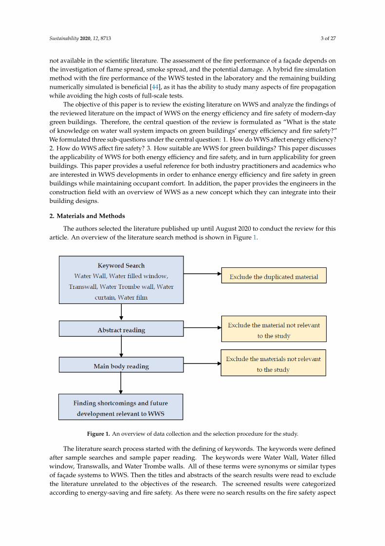
Figure 1. An overview of data collection and the selection procedure for the study.
The literature search process started with the defining of keywords. The keywords were defined after sample searches and sample paper reading. The keywords were Water Wall, Water filled window, Transwalls, and Water Trombe walls. All of these terms were synonyms or similar types of façade systems to WWS. Then the titles and abstracts of the search results were read to exclude the literature unrelated to the objectives of the research. The screened results were categorized according to energy-saving and fire safety. As there were no search results on the fire safety aspect of WWS; additionally, the key word Water curtain crossed with Fire safety was used to gain insight on fire safety from WWS. At last, the analysis of the contents of all the screened literature articles, books, chapters, proceeding papers, online publications, reports, standards, and theses revealed the up-to-
Figure 1. An overview of data collection and the selection procedure for the study.
The literature search process started with the defining of keywords. The keywords were definedafter sample searches and sample paper reading. The keywords were Water Wall, Water filledwindow, Transwalls, and Water Trombe walls. All of these terms were synonyms or similar typesof façade systems to WWS. Then the titles and abstracts of the search results were read to excludethe literature unrelated to the objectives of the research. The screened results were categorizedaccording to energy-saving and fire safety. As there were no search results on the fire safety aspect
Sustainability 2020, 12, 8713 4 of 27
of WWS; additionally, the key word Water curtain crossed with Fire safety was used to gain insighton fire safety from WWS. At last, the analysis of the contents of all the screened literature articles,books, chapters, proceeding papers, online publications, reports, standards, and theses revealed theup-to-date knowledge on the WWS performance for energy efficiency and fire safety, and uncoveredthe under-researched areas related to the application of WWS in green buildings.
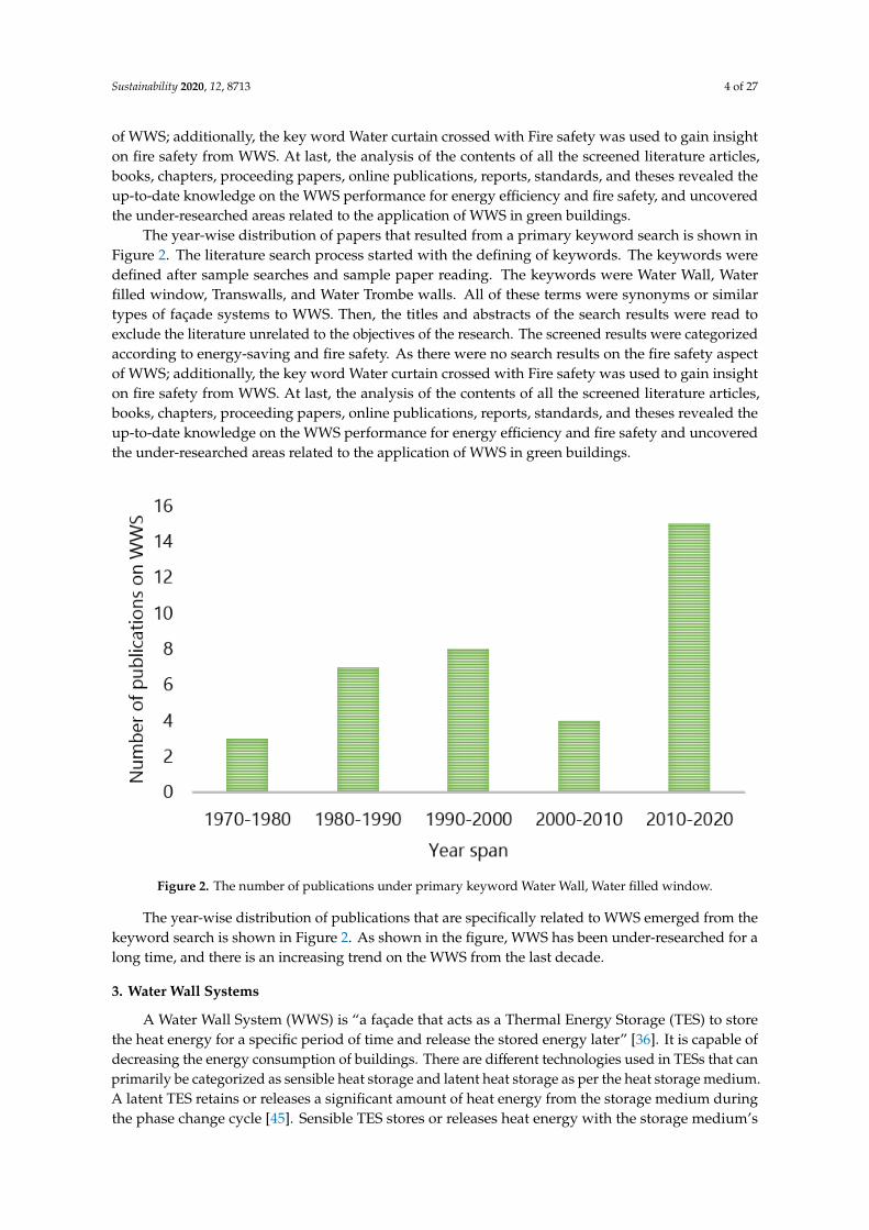
The year-wise distribution of papers that resulted from a primary keyword search is shown inFigure 2. The literature search process started with the defining of keywords. The keywords weredefined after sample searches and sample paper reading. The keywords were Water Wall, Waterfilled window, Transwalls, and Water Trombe walls. All of these terms were synonyms or similartypes of façade systems to WWS. Then, the titles and abstracts of the search results were read toexclude the literature unrelated to the objectives of the research. The screened results were categorizedaccording to energy-saving and fire safety. As there were no search results on the fire safety aspectof WWS; additionally, the key word Water curtain crossed with Fire safety was used to gain insighton fire safety from WWS. At last, the analysis of the contents of all the screened literature articles,books, chapters, proceeding papers, online publications, reports, standards, and theses revealed theup-to-date knowledge on the WWS performance for energy efficiency and fire safety and uncoveredthe under-researched areas related to the application of WWS in green buildings.
Sustainability 2020, 12, x FOR PEER REVIEW 4 of 28
date knowledge on the WWS performance for energy efficiency and fire safety, and uncovered the under-researched areas related to the application of WWS in green buildings.
The year-wise distribution of papers that resulted from a primary keyword search is shown in Figure 2. The literature search process started with the defining of keywords. The keywords were defined after sample searches and sample paper reading. The keywords were Water Wall, Water filled window, Transwalls, and Water Trombe walls. All of these terms were synonyms or similar types of façade systems to WWS. Then, the titles and abstracts of the search results were read to exclude the literature unrelated to the objectives of the research. The screened results were categorized according to energy-saving and fire safety. As there were no search results on the fire safety aspect of WWS; additionally, the key word Water curtain crossed with Fire safety was used to gain insight on fire safety from WWS. At last, the analysis of the contents of all the screened literature articles, books, chapters, proceeding papers, online publications, reports, standards, and theses revealed the up-to-date knowledge on the WWS performance for energy efficiency and fire safety and uncovered the under-researched areas related to the application of WWS in green buildings.
The year-wise distribution of publications that are specifically related to WWS emerged from the keyword search is shown in Figure 2. As shown in the figure, WWS has been under-researched for a long time, and there is an increasing trend on the WWS from the last decade.
Figure 2. The number of publications under primary keyword Water Wall, Water filled window.
3. Water Wall Systems
A Water Wall System (WWS) is “a façade that acts as a Thermal Energy Storage (TES) to store the heat energy for a specific period of time and release the stored energy later” [36]. It is capable of decreasing the energy consumption of buildings. There are different technologies used in TESs that can primarily be categorized as sensible heat storage and latent heat storage as per the heat storage medium. A latent TES retains or releases a significant amount of heat energy from the storage medium during the phase change cycle [45]. Sensible TES stores or releases heat energy with the storage medium’s temperature change [46]. High thermal capacity materials like concrete, brick, or water are used in sensible TES to regulate the variations in temperature. Among these materials, water is more efficient in energy storage due to the high specific heat compared to other materials. Sensible TES is further classified into short-term and long-term. The short-term TESs store the heat energy throughout the day and release it at night, while long-term TES also operates for a seasonal
Figure 2. The number of publications under primary keyword Water Wall, Water filled window.
The year-wise distribution of publications that are specifically related to WWS emerged from thekeyword search is shown in Figure 2. As shown in the figure, WWS has been under-researched for along time, and there is an increasing trend on the WWS from the last decade.
3. Water Wall Systems
A Water Wall System (WWS) is “a façade that acts as a Thermal Energy Storage (TES) to storethe heat energy for a specific period of time and release the stored energy later” [36]. It is capable ofdecreasing the energy consumption of buildings. There are different technologies used in TESs that canprimarily be categorized as sensible heat storage and latent heat storage as per the heat storage medium.A latent TES retains or releases a significant amount of heat energy from the storage medium duringthe phase change cycle [45]. Sensible TES stores or releases heat energy with the storage medium’s
Sustainability 2020, 12, 8713 5 of 27
temperature change [46]. High thermal capacity materials like concrete, brick, or water are used insensible TES to regulate the variations in temperature. Among these materials, water is more efficientin energy storage due to the high specific heat compared to other materials. Sensible TES is furtherclassified into short-term and long-term. The short-term TESs store the heat energy throughout theday and release it at night, while long-term TES also operates for a seasonal period [46]. WWS fallsunder the short-term TES category and is useful in reducing the energy consumption of the buildingwhile preserving the occupants’ thermal comfort.
3.1. Evolution of Water Wall Systems
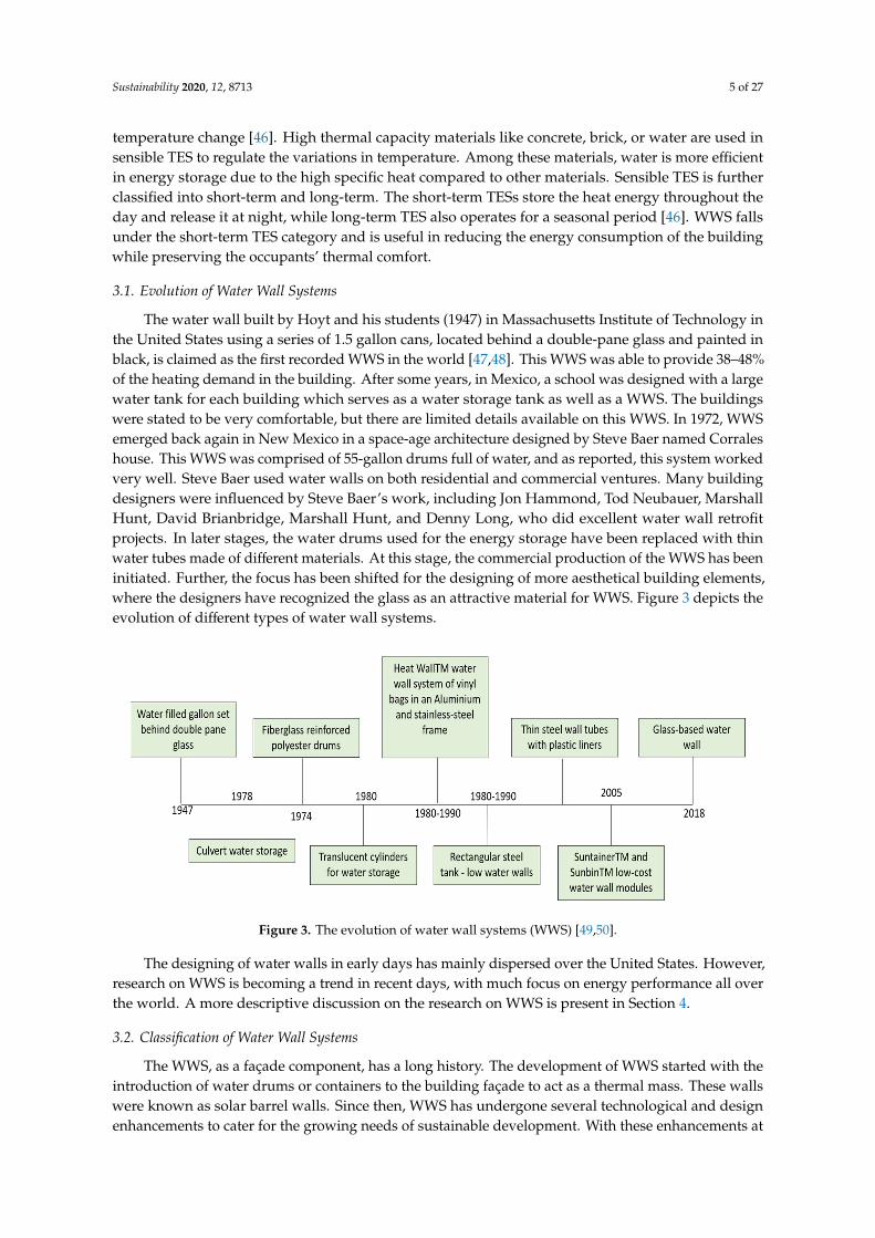
The water wall built by Hoyt and his students (1947) in Massachusetts Institute of Technology inthe United States using a series of 1.5 gallon cans, located behind a double-pane glass and painted inblack, is claimed as the first recorded WWS in the world [47,48]. This WWS was able to provide 38–48%of the heating demand in the building. After some years, in Mexico, a school was designed with a largewater tank for each building which serves as a water storage tank as well as a WWS. The buildingswere stated to be very comfortable, but there are limited details available on this WWS. In 1972, WWSemerged back again in New Mexico in a space-age architecture designed by Steve Baer named Corraleshouse. This WWS was comprised of 55-gallon drums full of water, and as reported, this system workedvery well. Steve Baer used water walls on both residential and commercial ventures. Many buildingdesigners were influenced by Steve Baer’s work, including Jon Hammond, Tod Neubauer, MarshallHunt, David Brianbridge, Marshall Hunt, and Denny Long, who did excellent water wall retrofitprojects. In later stages, the water drums used for the energy storage have been replaced with thinwater tubes made of different materials. At this stage, the commercial production of the WWS has beeninitiated. Further, the focus has been shifted for the designing of more aesthetical building elements,where the designers have recognized the glass as an attractive material for WWS. Figure 3 depicts theevolution of different types of water wall systems.
Sustainability 2020, 12, x FOR PEER REVIEW 5 of 28
period [46]. WWS falls under the short-term TES category and is useful in reducing the energy consumption of the building while preserving the occupants’ thermal comfort.
3.1. Evolution of Water Wall Systems
The water wall built by Hoyt and his students (1947) in Massachusetts Institute of Technology in the United States using a series of 1.5 gallon cans, located behind a double-pane glass and painted in black, is claimed as the first recorded WWS in the world [47,48]. This WWS was able to provide 38–48% of the heating demand in the building. After some years, in Mexico, a school was designed with a large water tank for each building which serves as a water storage tank as well as a WWS. The buildings were stated to be very comfortable, but there are limited details available on this WWS. In 1972, WWS emerged back again in New Mexico in a space-age architecture designed by Steve Baer named Corrales house. This WWS was comprised of 55-gallon drums full of water, and as reported, this system worked very well. Steve Baer used water walls on both residential and commercial ventures. Many building designers were influenced by Steve Baer’s work, including Jon Hammond, Tod Neubauer, Marshall Hunt, David Brianbridge, Marshall Hunt, and Denny Long, who did excellent water wall retrofit projects. In later stages, the water drums used for the energy storage have been replaced with thin water tubes made of different materials. At this stage, the commercial production of the WWS has been initiated. Further, the focus has been shifted for the designing of more aesthetical building elements, where the designers have recognized the glass as an attractive material for WWS. Figure 3 depicts the evolution of different types of water wall systems.
Figure 3. The evolution of water wall systems (WWS) [49,50].
The designing of water walls in early days has mainly dispersed over the United States. However, research on WWS is becoming a trend in recent days, with much focus on energy performance all over the world. A more descriptive discussion on the research on WWS is present in Section 4.
3.2. Classification of Water Wall Systems
The WWS, as a façade component, has a long history. The development of WWS started with the introduction of water drums or containers to the building façade to act as a thermal mass. These walls were known as solar barrel walls. Since then, WWS has undergone several technological and design enhancements to cater for the growing needs of sustainable development. With these enhancements at present, the designs of WWS are much focused on the inclusion of water as a layer between two panes made of different materials. This pane material should be chosen for the construction purpose. Based on the position of the water wall within the building, “Water Wall Systems” can be mainly categorized into two types, as direct gain systems and as collaborative systems, as shown in Figure 4. In both, water acts as a thermal mass for heating and cooling.
Figure 3. The evolution of water wall systems (WWS) [49,50].
The designing of water walls in early days has mainly dispersed over the United States. However,research on WWS is becoming a trend in recent days, with much focus on energy performance all overthe world. A more descriptive discussion on the research on WWS is present in Section 4.
3.2. Classification of Water Wall Systems
The WWS, as a façade component, has a long history. The development of WWS started with theintroduction of water drums or containers to the building façade to act as a thermal mass. These wallswere known as solar barrel walls. Since then, WWS has undergone several technological and designenhancements to cater for the growing needs of sustainable development. With these enhancements at
Sustainability 2020, 12, 8713 6 of 27
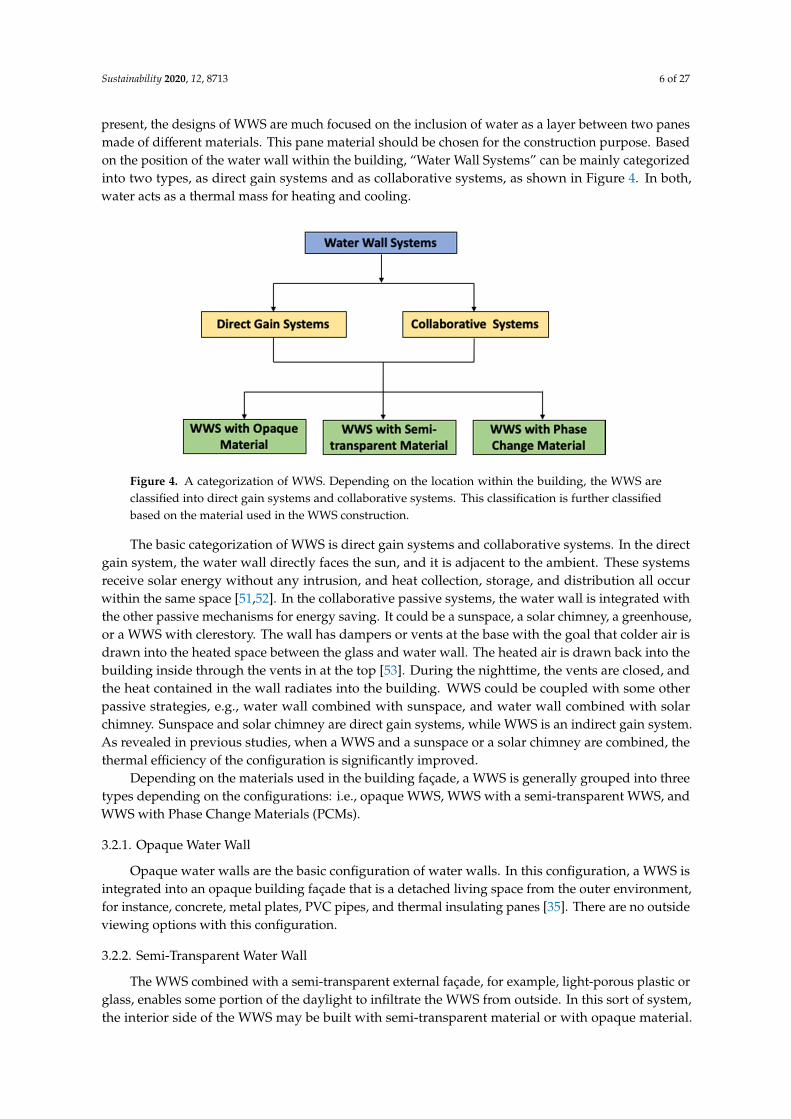
present, the designs of WWS are much focused on the inclusion of water as a layer between two panesmade of different materials. This pane material should be chosen for the construction purpose. Basedon the position of the water wall within the building, “Water Wall Systems” can be mainly categorizedinto two types, as direct gain systems and as collaborative systems, as shown in Figure 4. In both,water acts as a thermal mass for heating and cooling.Sustainability 2020, 12, x FOR PEER REVIEW 6 of 28
Figure 4. A categorization of WWS. Depending on the location within the building, the WWS are classified into direct gain systems and collaborative systems. This classification is further classified based on the material used in the WWS construction.
The basic categorization of WWS is direct gain systems and collaborative systems. In the direct gain system, the water wall directly faces the sun, and it is adjacent to the ambient. These systems receive solar energy without any intrusion, and heat collection, storage, and distribution all occur within the same space [51,52]. In the collaborative passive systems, the water wall is integrated with the other passive mechanisms for energy saving. It could be a sunspace, a solar chimney, a greenhouse, or a WWS with clerestory. The wall has dampers or vents at the base with the goal that colder air is drawn into the heated space between the glass and water wall. The heated air is drawn back into the building inside through the vents in at the top [53]. During the nighttime, the vents are closed, and the heat contained in the wall radiates into the building. WWS could be coupled with some other passive strategies, e.g., water wall combined with sunspace, and water wall combined with solar chimney. Sunspace and solar chimney are direct gain systems, while WWS is an indirect gain system. As revealed in previous studies, when a WWS and a sunspace or a solar chimney are combined, the thermal efficiency of the configuration is significantly improved.
Depending on the materials used in the building façade, a WWS is generally grouped into three types depending on the configurations: i.e., opaque WWS, WWS with a semi-transparent WWS, and WWS with Phase Change Materials (PCMs).
3.2.1. Opaque Water Wall
Opaque water walls are the basic configuration of water walls. In this configuration, a WWS is integrated into an opaque building façade that is a detached living space from the outer environment, for instance, concrete, metal plates, PVC pipes, and thermal insulating panes [35]. There are no outside viewing options with this configuration.
3.2.2. Semi-Transparent Water Wall
The WWS combined with a semi-transparent external façade, for example, light-porous plastic or glass, enables some portion of the daylight to infiltrate the WWS from outside. In this sort of system, the interior side of the WWS may be built with semi-transparent material or with opaque material. Depending on the material of the interior side, daylight can penetrate the room further. Transwall is a commonly used semi-transparent WWS which has a water layer in between two glass panes and a semi-transparent absorption plate at the middle In this kind of system, 80% of the incident solar radiation is absorbed by the semi-transparent plate and transmits the remaining 20% [54]. This form of wall thus incorporates both direct gain and indirect gain techniques, and is ideal for areas with high daytime temperatures [55]. In this type of system, baffles have often been used to lessen the flow of convective heat through the walls. To improve water viscosity and avoid micro-organisms from growing, bio-inhibiting agents and gelling need to be included in the water [55].
Figure 4. A categorization of WWS. Depending on the location within the building, the WWS areclassified into direct gain systems and collaborative systems. This classification is further classifiedbased on the material used in the WWS construction.
The basic categorization of WWS is direct gain systems and collaborative systems. In the directgain system, the water wall directly faces the sun, and it is adjacent to the ambient. These systemsreceive solar energy without any intrusion, and heat collection, storage, and distribution all occurwithin the same space [51,52]. In the collaborative passive systems, the water wall is integrated withthe other passive mechanisms for energy saving. It could be a sunspace, a solar chimney, a greenhouse,or a WWS with clerestory. The wall has dampers or vents at the base with the goal that colder air isdrawn into the heated space between the glass and water wall. The heated air is drawn back into thebuilding inside through the vents in at the top [53]. During the nighttime, the vents are closed, andthe heat contained in the wall radiates into the building. WWS could be coupled with some otherpassive strategies, e.g., water wall combined with sunspace, and water wall combined with solarchimney. Sunspace and solar chimney are direct gain systems, while WWS is an indirect gain system.As revealed in previous studies, when a WWS and a sunspace or a solar chimney are combined, thethermal efficiency of the configuration is significantly improved.
Depending on the materials used in the building façade, a WWS is generally grouped into threetypes depending on the configurations: i.e., opaque WWS, WWS with a semi-transparent WWS, andWWS with Phase Change Materials (PCMs).
3.2.1. Opaque Water Wall
Opaque water walls are the basic configuration of water walls. In this configuration, a WWS isintegrated into an opaque building façade that is a detached living space from the outer environment,for instance, concrete, metal plates, PVC pipes, and thermal insulating panes [35]. There are no outsideviewing options with this configuration.
3.2.2. Semi-Transparent Water Wall
The WWS combined with a semi-transparent external façade, for example, light-porous plastic orglass, enables some portion of the daylight to infiltrate the WWS from outside. In this sort of system,the interior side of the WWS may be built with semi-transparent material or with opaque material.
Sustainability 2020, 12, 8713 7 of 27
Depending on the material of the interior side, daylight can penetrate the room further. Transwall isa commonly used semi-transparent WWS which has a water layer in between two glass panes anda semi-transparent absorption plate at the middle In this kind of system, 80% of the incident solarradiation is absorbed by the semi-transparent plate and transmits the remaining 20% [54]. This formof wall thus incorporates both direct gain and indirect gain techniques, and is ideal for areas withhigh daytime temperatures [55]. In this type of system, baffles have often been used to lessen the flowof convective heat through the walls. To improve water viscosity and avoid micro-organisms fromgrowing, bio-inhibiting agents and gelling need to be included in the water [55].
3.2.3. Water Wall with Phase Change Materials (PCMs)
WWS could be coupled with Phase Change Material (PCM). The combination of the PCMswith WWS offers the benefits of both the WWS and the PCMs, thereby enhancing thermal efficiency.The configuration of PCMs with the water wall can have different arrangements as at the outer side,at the inner side, or both sides of the WWS. In the daytime, PCMs melt by absorbing energy fromthe surrounding environment and then re-solidify at night, releasing the stored energy. This processreduces the need for cooling in the daytime and heating at night [56,57].
Depending on the above-discussed characteristics of different types of WWS, semi-transparentWWS allow more liberty for energy saving through thermal heat storage and daylighting options.Moreover, the semi-transparent WWS provide more design options for better aesthetic appearancescompared to the other types. The following are the components of a semi-transparent WWS.
3.3. Components of a Semitransparent WWS
The essential components of a semi-transparent WWS are the two glazing panes and the waterlayer. The amount of heat transferred through the WWS mainly depends on the properties of thesetwo components. Apart from these, the properties of objects used for fixing WWS into the façadesuch as frames, screws, nuts, and bolts, need to be considered in calculating the exact amount of heattransferred through the system. This section discusses the function of glass panes and a water columnin a WWS.
3.3.1. Glazing
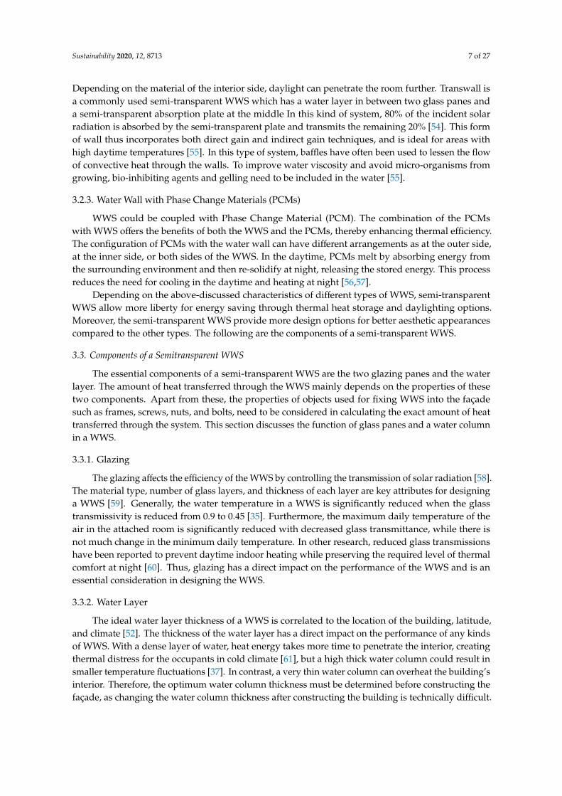
The glazing affects the efficiency of the WWS by controlling the transmission of solar radiation [58].The material type, number of glass layers, and thickness of each layer are key attributes for designinga WWS [59]. Generally, the water temperature in a WWS is significantly reduced when the glasstransmissivity is reduced from 0.9 to 0.45 [35]. Furthermore, the maximum daily temperature of theair in the attached room is significantly reduced with decreased glass transmittance, while there isnot much change in the minimum daily temperature. In other research, reduced glass transmissionshave been reported to prevent daytime indoor heating while preserving the required level of thermalcomfort at night [60]. Thus, glazing has a direct impact on the performance of the WWS and is anessential consideration in designing the WWS.
3.3.2. Water Layer
The ideal water layer thickness of a WWS is correlated to the location of the building, latitude,and climate [52]. The thickness of the water layer has a direct impact on the performance of any kindsof WWS. With a dense layer of water, heat energy takes more time to penetrate the interior, creatingthermal distress for the occupants in cold climate [61], but a high thick water column could result insmaller temperature fluctuations [37]. In contrast, a very thin water column can overheat the building’sinterior. Therefore, the optimum water column thickness must be determined before constructing thefaçade, as changing the water column thickness after constructing the building is technically difficult.
Sustainability 2020, 12, 8713 8 of 27
4. Energy Performance of Water Wall Systems
The energy efficiency or the energy loss of a glass façade depends on the design of the glassfaçade and the glass material used in the façade construction. The façade should be able to allow themaximum light gain while limiting the heat gain to the building interior. The optimum combination ofthese two requirements is the key to the glass façade energy performance. The appropriate selection ofglazing types for green buildings can result in a reduced space cooling load due to external impact aswell as the reduced power consumption for air-conditioning and artificial lighting [60,62].
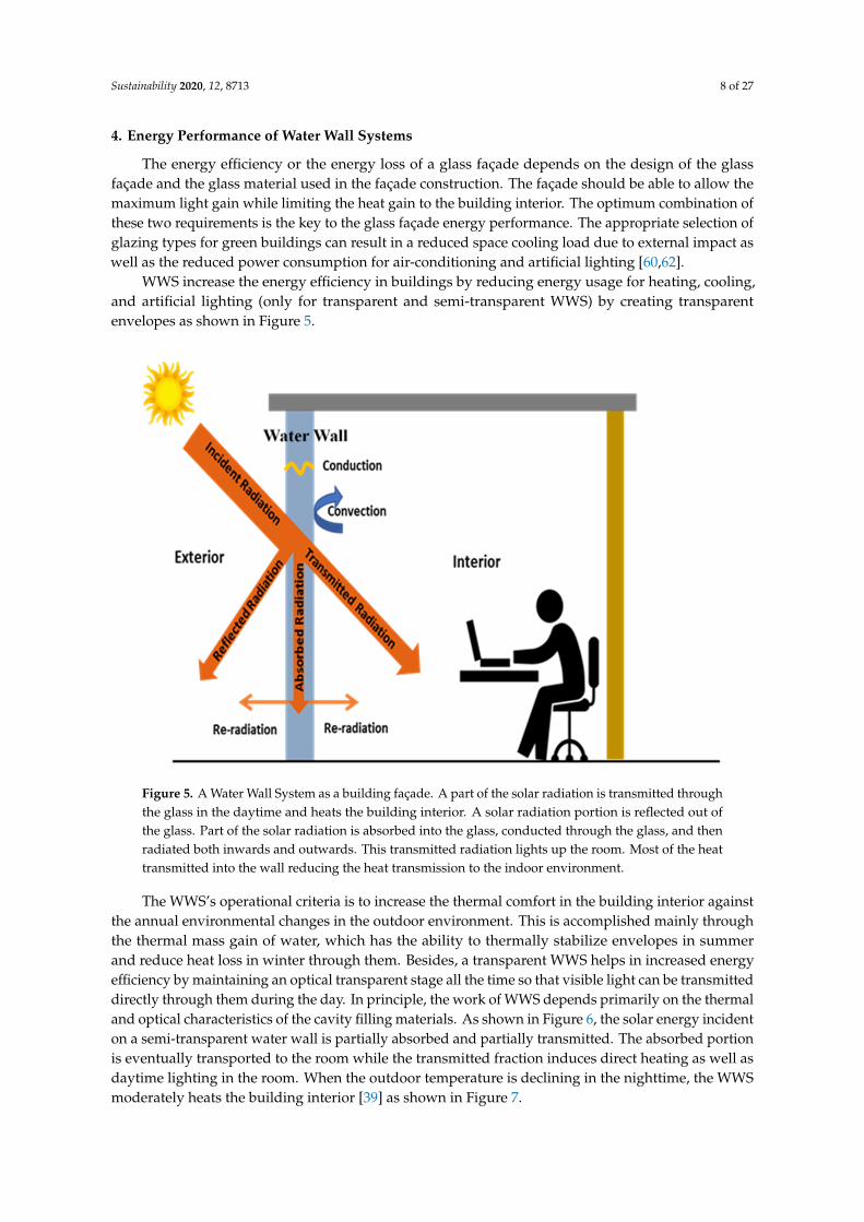
WWS increase the energy efficiency in buildings by reducing energy usage for heating, cooling,and artificial lighting (only for transparent and semi-transparent WWS) by creating transparentenvelopes as shown in Figure 5.
Sustainability 2020, 12, x FOR PEER REVIEW 8 of 28
Figure 5. A Water Wall System as a building façade. A part of the solar radiation is transmitted through the glass in the daytime and heats the building interior. A solar radiation portion is reflected out of the glass. Part of the solar radiation is absorbed into the glass, conducted through the glass, and then radiated both inwards and outwards. This transmitted radiation lights up the room. Most of the heat transmitted into the wall reducing the heat transmission to the indoor environment.
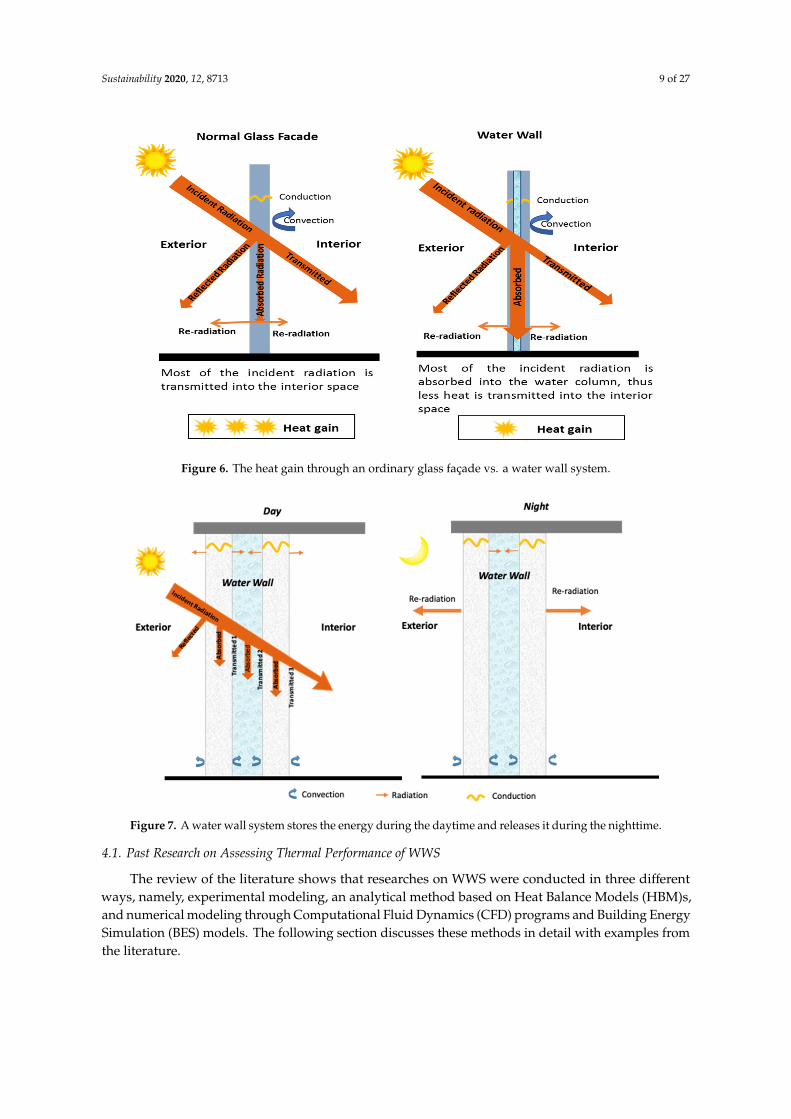
The WWS’s operational criteria is to increase the thermal comfort in the building interior against the annual environmental changes in the outdoor environment. This is accomplished mainly through the thermal mass gain of water, which has the ability to thermally stabilize envelopes in summer and reduce heat loss in winter through them. Besides, a transparent WWS helps in increased energy efficiency by maintaining an optical transparent stage all the time so that visible light can be transmitted directly through them during the day. In principle, the work of WWS depends primarily on the thermal and optical characteristics of the cavity filling materials. As shown in Figure 6, the solar energy incident on a semi-transparent water wall is partially absorbed and partially transmitted. The absorbed portion is eventually transported to the room while the transmitted fraction induces direct heating as well as daytime lighting in the room. When the outdoor temperature is declining in the nighttime, the WWS moderately heats the building interior [39] as shown in Figure 7.
Figure 5. A Water Wall System as a building façade. A part of the solar radiation is transmitted throughthe glass in the daytime and heats the building interior. A solar radiation portion is reflected out ofthe glass. Part of the solar radiation is absorbed into the glass, conducted through the glass, and thenradiated both inwards and outwards. This transmitted radiation lights up the room. Most of the heattransmitted into the wall reducing the heat transmission to the indoor environment.
The WWS’s operational criteria is to increase the thermal comfort in the building interior againstthe annual environmental changes in the outdoor environment. This is accomplished mainly throughthe thermal mass gain of water, which has the ability to thermally stabilize envelopes in summerand reduce heat loss in winter through them. Besides, a transparent WWS helps in increased energyefficiency by maintaining an optical transparent stage all the time so that visible light can be transmitteddirectly through them during the day. In principle, the work of WWS depends primarily on the thermaland optical characteristics of the cavity filling materials. As shown in Figure 6, the solar energy incidenton a semi-transparent water wall is partially absorbed and partially transmitted. The absorbed portionis eventually transported to the room while the transmitted fraction induces direct heating as well asdaytime lighting in the room. When the outdoor temperature is declining in the nighttime, the WWSmoderately heats the building interior [39] as shown in Figure 7.
Sustainability 2020, 12, 8713 9 of 27
Sustainability 2020, 12, x FOR PEER REVIEW 9 of 28
Figure 6. The heat gain through an ordinary glass façade vs. a water wall system.
Figure 7. A water wall system stores the energy during the daytime and releases it during the nighttime.
4.1. Past Research on Assessing Thermal Performance of WWS
The review of the literature shows that researches on WWS were conducted in three different ways, namely, experimental modeling, an analytical method based on Heat Balance Models (HBM)s, and numerical modeling through Computational Fluid Dynamics (CFD) programs and Building Energy Simulation (BES) models. The following section discusses these methods in detail with examples from the literature.
4.1.1. Experimental Modeling of Thermal Performance of WWS
The research on WWS started with the experimental modeling, whereas the history of experimental modeling of thermal performances of WWS could be traced back to 1947, which was
Figure 6. The heat gain through an ordinary glass façade vs. a water wall system.
Sustainability 2020, 12, x FOR PEER REVIEW 9 of 28
Figure 6. The heat gain through an ordinary glass façade vs. a water wall system.
Figure 7. A water wall system stores the energy during the daytime and releases it during the nighttime.
4.1. Past Research on Assessing Thermal Performance of WWS
The review of the literature shows that researches on WWS were conducted in three different ways, namely, experimental modeling, an analytical method based on Heat Balance Models (HBM)s, and numerical modeling through Computational Fluid Dynamics (CFD) programs and Building Energy Simulation (BES) models. The following section discusses these methods in detail with examples from the literature.
4.1.1. Experimental Modeling of Thermal Performance of WWS
The research on WWS started with the experimental modeling, whereas the history of experimental modeling of thermal performances of WWS could be traced back to 1947, which was
Figure 7. A water wall system stores the energy during the daytime and releases it during the nighttime.
4.1. Past Research on Assessing Thermal Performance of WWS
The review of the literature shows that researches on WWS were conducted in three differentways, namely, experimental modeling, an analytical method based on Heat Balance Models (HBM)s,and numerical modeling through Computational Fluid Dynamics (CFD) programs and Building EnergySimulation (BES) models. The following section discusses these methods in detail with examples fromthe literature.
Sustainability 2020, 12, 8713 10 of 27
4.1.1. Experimental Modeling of Thermal Performance of WWS
The research on WWS started with the experimental modeling, whereas the history of experimentalmodeling of thermal performances of WWS could be traced back to 1947, which was conducted byHoyt Hottel and his students [35]. However, after that, there are no records for the research on waterwalls until the 1970s. There is a significant number of researches carried out from the 1970s to the 2000son WWS. Much of the water wall researches have been conducted using experimental modeling inthe real climate conditions, while few were carried out in laboratories under controlled conditions.The results of a study conducted by Balcomb and Mcfarland [63] in 1977, comparing the performancesof five different WWS configurations, suggested that the WWS located at the rear side of a glass paneand the WWS located behind a transparent insulation panel worked with considerably higher thermalefficiency than other configurations in winter. The other configurations were the WWS located insidethe room with a temperature equivalent to the room temperature, the internal WWS located insidethe room, and the WWS located behind an opaque wall. Nayak, Bansal, and Sodha [64], in 1981,confirmed that a semi-transparent WWS works more efficiently than a concrete wall in terms of thermalperformance in the daytime in the Indian summer climates. The same study revealed that a water wallwith a 0.10 m thick water column in between a 0.22 m thick concrete wall gives nearly a continuousheat flux into the room at nighttime. In 1986, Sutton and McGregor [65] compared the efficiency ofa water wall with a concrete wall. The water wall was constructed with 27 galvanized steel tubesfilled with water and a concrete wall of 300 mm (12in) thickness. The study showed a significantheating energy saving in the house with a WWS relative to the concrete-walled house. The housewith WWS consumed 70.8% of the concrete-walled house’s energy consumption. Another study wasconducted by Turner et al. [66] in 1994 to show that during the summer daytime, the building insidecould be cooled by a WWS made-up of 7.6 cm diameter plastics tubes mounted on a traditional wallwhich was charged by cold ambient air at night. The performance of a WWS combined with PCMswas investigated in 1988 by Yadav and Tiwari [67]. The results revealed that the combined effect of aWWS with PCMs gave the best thermal performance over all other WWS arrangements considered.In 2003, Din et al. [68] conducted a study on a WWS attached to a greenhouse to record the planttemperature, the water temperature, and the room temperatures for a day in the winter season bychanging the factors such as absorptivity of the black colored WWS surface, water wall thickness, andthe transmitted solar energy fraction. The results showed that a north facing WWS with a thicknessof 27.5 cm could increase the room temperature by up to 4–5 ◦C at night and 3–4 ◦C in the daytime.In the later stages, the performance of water walls was assessed when they were combined with otherpassive systems. For example, in 1996, Tiwari and Singh [69] revealed that a semi-transparent waterwall in a sunspace could reduce temperature fluctuations significantly, and in 2018, Wang and Lei [39]revealed that incorporating a water wall system to a solar chimney could result in an increased thermalcomfort level in the attached room. For the literature reviewed, most of the previously conductedresearches on WWS focused on the heating ability of WWS for summer seasons, where less attention isgiven to the performance of WWS for the winter season.
Experimental modeling in real atmospheric conditions has several advantages and severaldisadvantages [35]. Experiments allow for the gathering of real-time performance data, for instance,solar irradiation and angle, atmospheric temperature, wind velocity and direction, and the like. At thesame time, the experiments are usually inflexible. When an experimental model is built up, it istypically troublesome or costly to adjust the model for various designs. Conversely, reduced-scalemodels might be flexibly adapted for different purposes. Furthermore, full-scale experiments are costlycompared with the reduced scale laboratory experiments. Full-scale design models demand a largeland area for the installation and entail substantial development expenses. If the experiment includesthe study of seasonal weather changes from winter to summer or the other way around, it might takeas long as a large portion of a year to finish the testing. Most importantly, it is typically challenging torehash full-scale experiments under real whether conditions. Even though experimental modeling isconsidered a compelling method of studying the thermal performance of WWS [35], the numerous
Sustainability 2020, 12, 8713 11 of 27
constraints of the experimental approach have kept it from being broadly practiced by researchers inthe recent past.
4.1.2. Analytical Modeling of Thermal Performance of WWS
The analytical modeling of WWS has been conducted mainly through the Heat Balance Model(HBM)s and has been used for analyzing the performances of WWS in different types and differentlocations from the 1970s. In 1979, a group of researchers studied the thermal performances of asemi-transparent WWS, a Trombe wall, and a direct gain system using HBM, which they calledthermal network models, and concluded the solar heat gain in a Transwall is very close to the solarheat gain of a Trombe wall [70,71]. Bansal and Thomas [72] in 1991 compared the performancesof semi-transparent WWS, mass wall, solarium, and a Trombe wall using steady-state heat transferequations and concluded that a water wall performs better than the others if night losses are reducedthrough the use of movable insulation. A similar type of research conducted by Bhandari and Bansalin 1994 confirmed that water walls and Trombe walls are more effective for marginally higher solarradiation applications [73]. Nisbet and Mthembu [74] in 1992 compared the performances of a WWSwith dyed water and water-gel solutions with an HBM based on the Fourier conduction equationand revealed that WWS with water-dye solution has a high heat release at evenings. The same studyshowed that a Transwall installed in a house in the west of Scotland can have an energy saving of 23%,while a fora house in the south of France is about 62%. This study further revealed that the optimumwall thickness should be about 150 mm for a maximum performance.
The HBMs were also used for the analysis of WWS attached to different other passive techniques.It was revealed in 1988 by Yadav and Tiwari [75] that an opaque WWS incorporated in a sunspacein a residential single-story house could significantly reduce the temperature changeability in thespace linked with the WWS. Tiwari and Kumar [76] compared the performances of an opaque WWS,a Transwall, and an air-collector in a sunspace using energy balances of the different components.The results revealed that a Transwall as a linking wall increases the room temperature on winter nightsand outperforms the other two systems.
The HBMs also can configure the optimum thickness of WWS. In 1991, Upadhya, Tiwari, andRai [77], who conducted a study in Sri Nagar, India, revealed that for maximum heat gain in the winterdaytime with less temperature fluctuations, the thickness of the trap material needs to be maximized,while the inner pane glass thickness needs to be minimized. Wang and Lei [38] in 2019 investigatedthe optimum configurations for a WWS including different glass pane thicknesses, different air gapwidths, different water column thicknesses, surface tinting, and the relative solar chimney locationusing a Transient Heat Balance Model (THBM). The results showed that increased glass pane thicknessor reduced water column thickness could result in better thermal performance of the combined system,while increased air gap results in better ventilation with decreased room temperature.
The water wall researches in the recent past involved with the BES programs too. The majority ofthe studies have utilized the TRNSYS whole building simulation model. Wang et al. (2012) utilizedTRNSYS to examine the energy utilization and thermal performance of an opaque WWS in China [78].The simulation results of a year-round period revealed that building architecture can have an effectin reducing 8.6% of annual energy usage and can raise the thermal comfort assessment index by12.9%. Sánchez-Ostiz et al. [79] in 2014 simulated the energy performance of sunspace with an opaqueWWS for both winter and summer climates using TRNSYS. The results of the study revealed that theenergy requirement for the heating of a sunspace with a WWS was 12.9–16.7% less than a sunspacewithout a WWS. However, due to the limitations of the available BES programs, direct analysis isrestricted to the opaque WWS. It requires external simulation programs such as CFD for the simulationof semi-transparent WWS.
In summary, much of the analytical research on WWS are based on HBM models, as it can foreseethe essential elements of a building. However, these calculations are based on many assumptions,such as constant convective heat transfer coefficients, uniform surface temperatures, gray radiative
Sustainability 2020, 12, 8713 12 of 27
surfaces, diffuse radiative surfaces, and one-dimensional heat transfer within the system. Furthermore,radiation interchanges between internal surfaces are often ignored in HBMs, while some modelsrecognize the radiation released from external surfaces. However, Wu and Lei [36] showed that theinternal surface-to-surface radiation exchange and time variations of heat transfer coefficients have asubstantial impact on system efficiency. Due to these limitations of the models, the real performance ofthe system could be varied from the calculated performances.
4.1.3. CFD Modeling of Thermal Performance of WWS
The application of CFD modeling to WWS research is a new approach, and still a limited numberof researches have been conducted by means of CFD modeling. Karabay, Arici, and Sandik [40],in 2013, researched the thermal efficiency of a concrete mass wall with built-in pipes filled with constanttemperature water using CFD where turbulent water flow was presumed. The simulations werelimited to steady-state conditions. In 2015, Moustafa and Aripin [41] assessed the steady-state thermalefficiency of a WWS combined with a porous ceramic pipes system, which is an advanced version ofa potter wall. Coupling of BES tools with CFD is a growing research direction. In 2018, Sameti [80],with the use of TRNSYS, together with CFD, showed that the thermal efficiency of an opaque solarWWS with a water storage tank was higher in thermal performance than a conventional opaque WWS.Furthermore, a new thermal network model was developed by Liu, Guo, and Wang [43] and wasused for the simulation of semi-transparent WWS through EnergyPlus together with a CFD study.The findings of these studies establish that the BES models together with CFD are useful in analyzingthe energy performance of WWS in detail. Some recent studies have developed and used transientCFD models that considered the time effect of solar energy fluctuations and ambient temperaturein evaluating the thermal efficiency of an opaque WWS and semi-transparent WWS [81]. However,many of the above researches have neglected the refractive radiation index and glass panes radiationreflection. These studies assumed a bulk value for the attenuation coefficient of solar radiation in waterwithin the wavelength spectrum. However, in actuality, the attenuation coefficient of solar radiation inwater depends on the wavelength. In this manner, a multiple-waveband attenuation model meritsfurther research to get progressively precise outcomes. The evolution of WWS research is summarizedin Table 1.
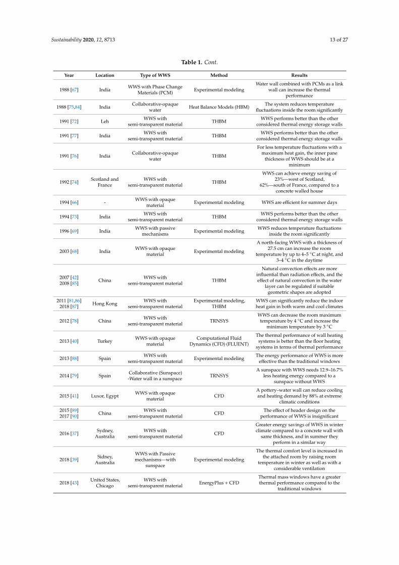
Table 1. A summary of past research on assessing thermal performance of WWS.
Year Location Type of WWS Method Results
1947 [35] United States WWS with opaquematerial Experimental modeling WWS has the capability to increase the
thermal comfort level
1978 [63] United States WWS withsemi-transparent material Experimental modeling Water drums behind glass panes improve
the thermal comfort inside the room
1979 [70] United States WWS withsemi-transparent material Thermal Network Models Solar heat gain in transwall is very close
to the solar heat gain of Trombe wall
1981 [82] India WWS withsemi-transparent material
Transient Heat BalanceModel (THBM)
The thermal performance of asemi-transparent water wall is moreefficient than a concrete mass wall
1986 [65] Tasmania WWS with opaquematerial Experimental modeling
Energy consumption of a house withWWS is less (70%) than that of a concrete
walled house
1987 [34] India WWS withsemi-transparent material Experimental modeling
Semi-transparent WWS is more efficientcompared to a concrete mass wall in
terms of thermal performance in daytime
1987 [83] India WWS with opaquematerial Mathematical model
Large drums full of water kept inside agreenhouse can increase the thermal
comfort
1987 [71] - WWS with opaquematerial Mathematical model Complex heat transfer coefficients for
WWS are developed
Sustainability 2020, 12, 8713 13 of 27
Table 1. Cont.
Year Location Type of WWS Method Results
1988 [67] India WWS with Phase ChangeMaterials (PCM) Experimental modeling
Water wall combined with PCMs as a linkwall can increase the thermal
performance
1988 [75,84] India Collaborative-opaquewater Heat Balance Models (HBM) The system reduces temperature
fluctuations inside the room significantly
1991 [72] Leh WWS withsemi-transparent material THBM WWS performs better than the other
considered thermal energy storage walls
1991 [77] India WWS withsemi-transparent material THBM WWS performs better than the other
considered thermal energy storage walls
1991 [76] India Collaborative-opaquewater THBM
For less temperature fluctuations with amaximum heat gain, the inner pane
thickness of WWS should be at aminimum
1992 [74] Scotland andFrance
WWS withsemi-transparent material THBM
WWS can achieve energy saving of23%—west of Scotland,
62%—south of France, compared to aconcrete walled house
1994 [66] - WWS with opaquematerial Experimental modeling WWS are efficient for summer days
1994 [73] India WWS withsemi-transparent material THBM WWS performs better than the other
considered thermal energy storage walls
1996 [69] India WWS with passivemechanisms Experimental modeling WWS reduces temperature fluctuations
inside the room significantly
2003 [68] India WWS with opaquematerial Experimental modeling
A north-facing WWS with a thickness of27.5 cm can increase the room
temperature by up to 4–5 ◦C at night, and3–4 ◦C in the daytime
2007 [42]2008 [85] China WWS with
semi-transparent material THBM
Natural convection effects are moreinfluential than radiation effects, and theeffect of natural convection in the water
layer can be regulated if suitablegeometric shapes are adopted
2011 [81,86]2018 [87] Hong Kong WWS with
semi-transparent materialExperimental modeling,
THBMWWS can significantly reduce the indoorheat gain in both warm and cool climates
2012 [78] China WWS withsemi-transparent material TRNSYS
WWS can decrease the room maximumtemperature by 4 ◦C and increase the
minimum temperature by 3 ◦C
2013 [40] Turkey WWS with opaquematerial
Computational FluidDynamics (CFD) (FLUENT)
The thermal performance of wall heatingsystems is better than the floor heating
systems in terms of thermal performance
2013 [88] Spain WWS withsemi-transparent material Experimental modeling The energy performance of WWS is more
effective than the traditional windows
2014 [79] Spain Collaborative (Sunspace)-Water wall in a sunspace TRNSYS
A sunspace with WWS needs 12.9–16.7%less heating energy compared to a
sunspace without WWS
2015 [41] Luxor, Egypt WWS with opaquematerial CFD
A pottery–water wall can reduce coolingand heating demand by 88% at extreme
climatic conditions
2015 [89]2017 [90] China WWS with
semi-transparent material CFD The effect of header design on theperformance of WWS is insignificant
2016 [37] Sydney,Australia
WWS withsemi-transparent material CFD
Greater energy savings of WWS in winterclimate compared to a concrete wall with
same thickness, and in summer theyperform in a similar way
2018 [39] Sidney,Australia
WWS with Passivemechanisms—with
sunspaceExperimental modeling
The thermal comfort level is increased inthe attached room by raising room
temperature in winter as well as with aconsiderable ventilation
2018 [43] United States,Chicago
WWS withsemi-transparent material EnergyPlus + CFD
Thermal mass windows have a greaterthermal performance compared to the
traditional windows
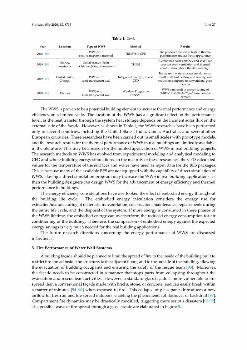
Sustainability 2020, 12, 8713 14 of 27
Table 1. Cont.
Year Location Type of WWS Method Results
2018 [80] - WWS withsemi-transparent material TRNSYS + CFD The proposed system is high in thermal
performance and aesthetic appearance
2019 [38] Sidney,Australia
Collaborative (SolarChimney)-Semi-transparent THBM
A combined solar chimney and WWS canprovide good ventilation and thermalcomfort throughout the day and night
2019 [91] United States,Chicago
WWS withsemi-transparent wall
Integrated Energy (IE) andCFD
Transparent water storage envelopes canresult in 70% of heating and cooling loadreduction compared to conventional glass
facades
2020 [92] 13 cities WWS withsemi-transparent wall
Window Program +TRNSYS
WWS can result in energy saving of3–84%/US$0.99–24.25/m2 based on the
climate
The WWS is proven to be a potential building element to increase thermal performance and energyefficiency on a limited scale. The location of the WWS has a significant effect on the performancelevel, as the heat transfer through the system heat storage depends on the incident solar flux on theexternal side of the façade. However, as shown in Table 1, the WWS researches have been performedonly in several countries, including the United States, India, China, Australia, and several otherEuropean countries. These researches have been carried out in small scales with prototype models,and the research results for the thermal performance of WWS in real buildings are limitedly availablein the literature. This may be a reason for the limited application of WWS in real building projects.The research methods on WWS has evolved from experimental modeling and analytical modeling toCFD and whole-building energy simulations. In the majority of these researches, the CFD calculatedvalues for the temperature of the surfaces and water have used as input data for the BES packages.This is because many of the available BES are not equipped with the capability of direct simulation ofWWS. Having a direct simulation program may increase the WWS in real building applications, asthen the building designers can design WWS for the advancement of energy efficiency and thermalperformance in buildings.
The energy efficiency considerations have overlooked the effect of embodied energy throughoutthe building life cycle. The embodied energy calculation considers the energy use forextraction/manufacturing of materials, transportation, construction, maintenance, replacements duringthe entire life cycle, and the disposal of the system. If more energy is consumed in these phases ofthe WWS lifetime, the embodied energy can overperform the reduced energy consumption for airconditioning of the building. Therefore, the comparison of embodied energy against the expectedenergy savings is very much needed for the real building applications.
The future research directions concerning the energy performance of WWS are discussedin Section 7.
5. Fire Performance of Water Wall Systems
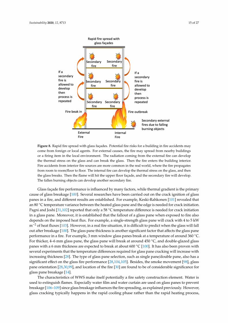
A building façade should be planned to limit the spread of fire to the inside of the building built torestrict fire spread inside the structure, to the adjacent floors, and to the outside of the building, allowingthe evacuation of building occupants and ensuring the safety of the rescue team [93]. Moreover,the façade needs to be constructed in a manner that stops parts from collapsing throughout theevacuation and rescue team activities. However, a standard glass façade is more vulnerable to firespread than a conventional façade made with bricks, stone, or concrete, and can easily break withina matter of minutes [94–96] when exposed to fire. This collapse of glass panes introduces a newairflow for fresh air and fire spread outdoors, enabling the phenomenon of flashover or backdraft [97].Compartment fire dynamics may be drastically modified, triggering more serious disasters [98,99].The possible ways of fire spread through a glass façade are elaborated in Figure 8.
Sustainability 2020, 12, 8713 15 of 27
Sustainability 2020, 12, x FOR PEER REVIEW 16 of 28
Figure 8. Rapid fire spread with glass façades. Potential fire risks for a building in fire accidents may come from foreign or local agents. For external causes, the fire may spread from nearby buildings or a firing item in the local environment. The radiation coming from the external fire can develop the thermal stress on the glass and can break the glass. Then the fire enters the building interior. Fire accidents from interior fire sources are more common in the real world, where the fire propagates from room to room/floor to floor. The internal fire can develop the thermal stress on the glass, and then the glass breaks. Then the flame will hit the upper floor façade, and the secondary fire will develop. The fallen burning objects can develop another secondary fire.
Glass façade fire performance is influenced by many factors, while thermal gradient is the primary cause of glass breakage [100]. Several researches have been carried out on the crack ignition of glass panes in a fire, and different results are established. For example, Keski-Rahkonen [101] revealed that an 80 rof dedeen si egde eht dna enap ssalg detaeh eht neewteb ecnairav erutarepmet C° crack initiation. Pagni and Joshi [31,102] reported that only a 58 dedeen si ecnereffid erutarepmet C° for crack initiation in a glass pane. Moreover, it is established that the fallout of a glass pane when exposed to fire also depends on the imposed heat flux. For example, a single lliw enap ssalg htgnerts-crack with 4 to 5 kW m−2 of heat fluxes [103]. However, in a real fire situation, it is difficult to predict when the glass will fall out after breakage [100]. The glass pane thickness is another significant factor that affects the glass pane performance in a fire. For example, 3 mm window glass panes break a tatemperature of around 3 ,rekciht roF .C° 06 4– 054 dnuora ta kaerb lliw enap ssalg eht ,enap ssalg mm 6°C, and double-glazed glass panes with a 6 mm thickness are expected to break at about 600 .]001[ C°It has also been proven with several experiments that the temperature differences required for glass pane cracking will increase with increasing thickness [28]. The type of glass pane selection, such as single pane/double pane, also has a significant effect on the glass fire performance [28,104,105]. Besides, the smoke movement [98], glass pane orientation [28,30,99], and location of the fire [30] are found to be of considerable significance for glass pane breakage [14].
The characteristics of WWS make itself potentially a fire safety construction element. Water is used to extinguish flames. Especially water film and water curtain are used on glass panes to prevent breakage [106–109] since glass breakage influences the fire spreading, as explained previously. However, glass cracking typically happens in the rapid cooling phase rather than the rapid heating process, owing to the thermal shock induced by sudden cooling, which is a problem associated with water films and water curtains [110]. This issue can be overcome by a WWS, as a WWS always has a
Figure 8. Rapid fire spread with glass façades. Potential fire risks for a building in fire accidents maycome from foreign or local agents. For external causes, the fire may spread from nearby buildingsor a firing item in the local environment. The radiation coming from the external fire can developthe thermal stress on the glass and can break the glass. Then the fire enters the building interior.Fire accidents from interior fire sources are more common in the real world, where the fire propagatesfrom room to room/floor to floor. The internal fire can develop the thermal stress on the glass, and thenthe glass breaks. Then the flame will hit the upper floor façade, and the secondary fire will develop.The fallen burning objects can develop another secondary fire.
Glass façade fire performance is influenced by many factors, while thermal gradient is the primarycause of glass breakage [100]. Several researches have been carried out on the crack ignition of glasspanes in a fire, and different results are established. For example, Keski-Rahkonen [101] revealed thatan 80 ◦C temperature variance between the heated glass pane and the edge is needed for crack initiation.Pagni and Joshi [31,102] reported that only a 58 ◦C temperature difference is needed for crack initiationin a glass pane. Moreover, it is established that the fallout of a glass pane when exposed to fire alsodepends on the imposed heat flux. For example, a single-strength glass pane will crack with 4 to 5 kWm−2 of heat fluxes [103]. However, in a real fire situation, it is difficult to predict when the glass will fallout after breakage [100]. The glass pane thickness is another significant factor that affects the glass paneperformance in a fire. For example, 3 mm window glass panes break at a temperature of around 360 ◦C.For thicker, 4–6 mm glass pane, the glass pane will break at around 450 ◦C, and double-glazed glasspanes with a 6 mm thickness are expected to break at about 600 ◦C [100]. It has also been proven withseveral experiments that the temperature differences required for glass pane cracking will increase withincreasing thickness [28]. The type of glass pane selection, such as single pane/double pane, also has asignificant effect on the glass fire performance [28,104,105]. Besides, the smoke movement [98], glasspane orientation [28,30,99], and location of the fire [30] are found to be of considerable significance forglass pane breakage [14].
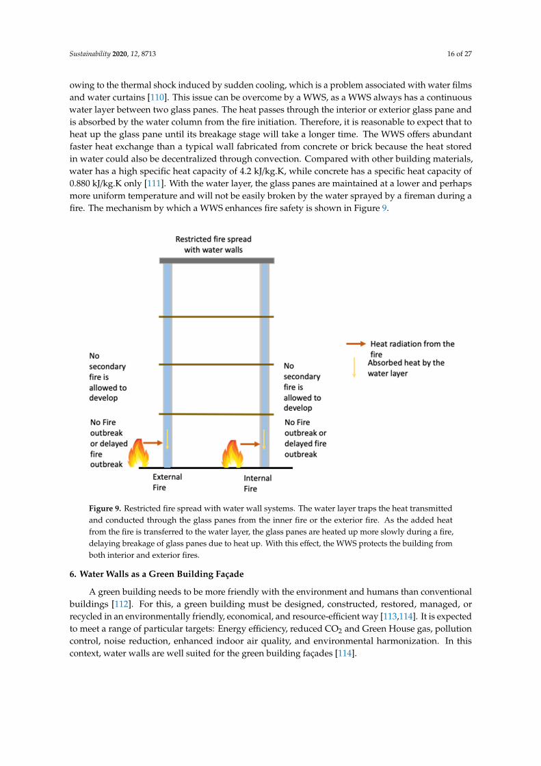
The characteristics of WWS make itself potentially a fire safety construction element. Water isused to extinguish flames. Especially water film and water curtain are used on glass panes to preventbreakage [106–109] since glass breakage influences the fire spreading, as explained previously. However,glass cracking typically happens in the rapid cooling phase rather than the rapid heating process,
Sustainability 2020, 12, 8713 16 of 27
owing to the thermal shock induced by sudden cooling, which is a problem associated with water filmsand water curtains [110]. This issue can be overcome by a WWS, as a WWS always has a continuouswater layer between two glass panes. The heat passes through the interior or exterior glass pane andis absorbed by the water column from the fire initiation. Therefore, it is reasonable to expect that toheat up the glass pane until its breakage stage will take a longer time. The WWS offers abundantfaster heat exchange than a typical wall fabricated from concrete or brick because the heat storedin water could also be decentralized through convection. Compared with other building materials,water has a high specific heat capacity of 4.2 kJ/kg.K, while concrete has a specific heat capacity of0.880 kJ/kg.K only [111]. With the water layer, the glass panes are maintained at a lower and perhapsmore uniform temperature and will not be easily broken by the water sprayed by a fireman during afire. The mechanism by which a WWS enhances fire safety is shown in Figure 9.
Sustainability 2020, 12, x FOR PEER REVIEW 17 of 28
continuous water layer between two glass panes. The heat passes through the interior or exterior glass pane and is absorbed by the water column from the fire initiation. Therefore, it is reasonable to expect that to heat up the glass pane until its breakage stage will take a longer time. The WWS offers abundant faster heat exchange than a typical wall fabricated from concrete or brick because the heat stored in water could also be decentralized through convection. Compared with other building materials, water has a high specific heat capacity of 4.2 kJ/kg.K, while concrete has a specific heat capacity of 0.880 kJ/kg.K only [111]. With the water layer, the glass panes are maintained at a lower and perhaps more uniform temperature and will not be easily broken by the water sprayed by a fireman during a fire. The mechanism by which a WWS enhances fire safety is shown in Figure 9.
Figure 9. Restricted fire spread with water wall systems. The water layer traps the heat transmitted and conducted through the glass panes from the inner fire or the exterior fire. As the added heat from the fire is transferred to the water layer, the glass panes are heated up more slowly during a fire, delaying breakage of glass panes due to heat up. With this effect, the WWS protects the building from both interior and exterior fires.
6. Water Walls as a Green Building Façade
A green building needs to be more friendly with the environment and humans than conventional buildings [112]. For this, a green building must be designed, constructed, restored, managed, or recycled in an environmentally friendly, economical, and resource-efficient way [113,114]. It is expected to meet a range of particular targets: Energy efficiency, reduced CO2 and Green House gas, pollution control, noise reduction, enhanced indoor air quality, and environmental harmonization. In this context, water walls are well suited for the green building façades [114].
6.1. Economic Cost of WWS
WWS are considered as simple and very economical for many reasons. WWS may also be built in new or renovated buildings with traditional construction techniques. WWS do not depend on auxiliary power, as no pumps or valves are incorporated. Therefore, WWS operate even though the electricity is off, which helps in reduced energy bills. Constructing and maintaining a WWS is less costly than other thermal storage systems, since WWS is constructed with standard materials and
Figure 9. Restricted fire spread with water wall systems. The water layer traps the heat transmittedand conducted through the glass panes from the inner fire or the exterior fire. As the added heatfrom the fire is transferred to the water layer, the glass panes are heated up more slowly during a fire,delaying breakage of glass panes due to heat up. With this effect, the WWS protects the building fromboth interior and exterior fires.
6. Water Walls as a Green Building Façade
A green building needs to be more friendly with the environment and humans than conventionalbuildings [112]. For this, a green building must be designed, constructed, restored, managed, orrecycled in an environmentally friendly, economical, and resource-efficient way [113,114]. It is expectedto meet a range of particular targets: Energy efficiency, reduced CO2 and Green House gas, pollutioncontrol, noise reduction, enhanced indoor air quality, and environmental harmonization. In thiscontext, water walls are well suited for the green building façades [114].
Sustainability 2020, 12, 8713 17 of 27
6.1. Economic Cost of WWS
WWS are considered as simple and very economical for many reasons. WWS may also be built innew or renovated buildings with traditional construction techniques. WWS do not depend on auxiliarypower, as no pumps or valves are incorporated. Therefore, WWS operate even though the electricityis off, which helps in reduced energy bills. Constructing and maintaining a WWS is less costly thanother thermal storage systems, since WWS is constructed with standard materials and also has a longlife [38]. For example, a water wall will cost about $9612 for 100,000 BTU storage, while a concretewall will cost about $14,426 for the same heat storage in San Francisco, CA, USA [50]. Thus, WWSis more economical than that of concrete walls for constructions in San Francisco, CA, USA. As theeconomic cost of the building elements may vary for different locations, the economic cost needs to becalculated before the building design. However, depending on the lower material volume, ease ofconstruction, lower maintenance needs, and the reduced energy consumption, it is expected that WWSare economical on the whole worldwide than that of high thermal mass façades such as concrete walls.
6.2. Embodied Energy of WWS
The embodied energy of WWS (which is the total energy required for extraction of raw materials,processing of WWS, delivery and construction of WWS, and the disposal after the building demolition)needs to be considered in assessing the suitability of WWS for green buildings. The embodied energyof a WWS primarily depends on the embodied energy of glass, as a WWS is built of two glass panesand a water layer. A material-wise comparison of the embodied energy of a WWS and a concrete wallis shown in Table 2. In all the selected countries, float glass has a much higher embodied energy thanconcrete for a unit mass. However, for effective comparison, embodied energies need to be comparedon a per area basis for façade elements.
Table 2. A WWS embodied energy comparison against a concrete facade for different countries.
LocationGlass EmbodiedEnergy per Unit
Mass (MJ/kg)
Concrete-EmbodiedEnergy per Unit
Mass (MJ/kg)
WWS EmbodiedEnergy per 1 m2 of
the Façade (MJ)
Concrete–EmbodiedEnergy per 1 m2 of
the Façade (MJ)
Western Australia [115] 15 1.39 885 1737.5
New Zealand [116] 15 2 885 2500
USA [117] 12.7 1.5 749.3 1875
The thickness of façade elements is usually decided based on the structural requirements and therequired U-value of the building envelope, which determines the amount of heat transfer through thebuilding envelope. The U-value of a building element depends on the thermal conductivity of thematerial, convection coefficient from the material surface, and the thickness of the building element.For example, a WWS with 100 mm water layer and two 25 mm thickness glass panes has a U-valueof 1.08 Wm−2 K−1. In order to have the same U-value, a concrete wall needs to have about 400 mmthickness. The mass of glass required for the construction of a WWS facade is lower than the massof concrete for a comparable concrete facade. A comparison of the embodied energy of WWS and acomparable concrete wall is presented in Table 2 and Figure 10.
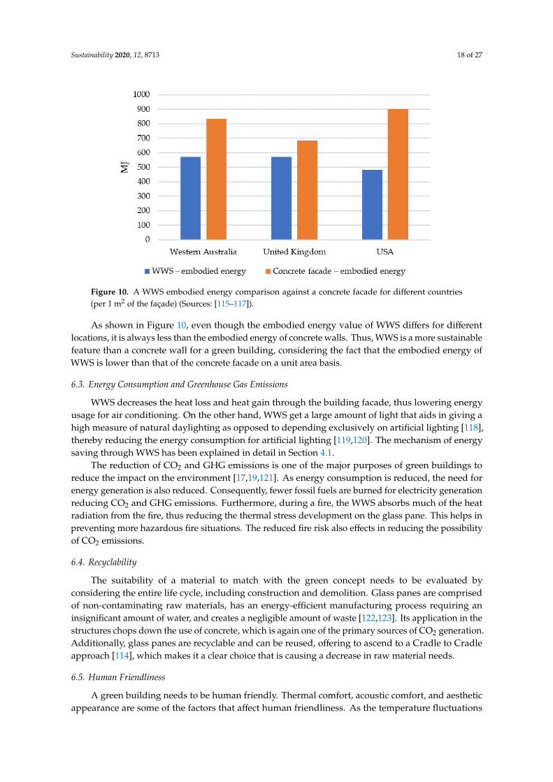
Sustainability 2020, 12, 8713 18 of 27
Sustainability 2020, 12, x FOR PEER REVIEW 19 of 28
Figure 10. A WWS embodied energy comparison against a concrete facade for different countries (per 1 m2 of the façade) (Sources: [115–117]).
As shown in Figure 10, even though the embodied energy value of WWS differs for different locations, it is always less than the embodied energy of concrete walls. Thus, WWS is a more sustainable feature than a concrete wall for a green building, considering the fact that the embodied energy of WWS is lower than that of the concrete facade on a unit area basis.
6.3. Energy Consumption and Greenhouse Gas Emissions
WWS decreases the heat loss and heat gain through the building facade, thus lowering energy usage for air conditioning. On the other hand, WWS get a large amount of light that aids in giving a high measure of natural daylighting as opposed to depending exclusively on artificial lighting [118], thereby reducing the energy consumption for artificial lighting [119,120]. The mechanism of energy saving through WWS has been explained in detail in Section 4.1.
The reduction of CO2 and GHG emissions is one of the major purposes of green buildings to reduce the impact on the environment [17,19,121]. As energy consumption is reduced, the need for energy generation is also reduced. Consequently, fewer fossil fuels are burned for electricity generation reducing CO2 and GHG emissions. Furthermore, during a fire, the WWS absorbs much of the heat radiation from the fire, thus reducing the thermal stress development on the glass pane. This helps in preventing more hazardous fire situations. The reduced fire risk also effects in reducing the possibility of CO2 emissions.
6.4. Recyclability
The suitability of a material to match with the green concept needs to be evaluated by considering the entire life cycle, including construction and demolition. Glass panes are comprised of non-contaminating raw materials, has an energy-efficient manufacturing process requiring an insignificant amount of water, and creates a negligible amount of waste [122,123]. Its application in the structures chops down the use of concrete, which is again one of the primary sources of CO2 generation. Additionally, glass panes are recyclable and can be reused, offering to ascend to a Cradle to Cradle approach [114], which makes it a clear choice that is causing a decrease in raw material needs.
6.5. Human Friendliness
A green building needs to be human friendly. Thermal comfort, acoustic comfort, and aesthetic appearance are some of the factors that affect human friendliness. As the temperature fluctuations within the buildings are reduced, the WWS deliver thermal comfort to the occupants. Furthermore,
Figure 10. A WWS embodied energy comparison against a concrete facade for different countries(per 1 m2 of the façade) (Sources: [115–117]).
As shown in Figure 10, even though the embodied energy value of WWS differs for differentlocations, it is always less than the embodied energy of concrete walls. Thus, WWS is a more sustainablefeature than a concrete wall for a green building, considering the fact that the embodied energy ofWWS is lower than that of the concrete facade on a unit area basis.
6.3. Energy Consumption and Greenhouse Gas Emissions
WWS decreases the heat loss and heat gain through the building facade, thus lowering energyusage for air conditioning. On the other hand, WWS get a large amount of light that aids in giving ahigh measure of natural daylighting as opposed to depending exclusively on artificial lighting [118],thereby reducing the energy consumption for artificial lighting [119,120]. The mechanism of energysaving through WWS has been explained in detail in Section 4.1.
The reduction of CO2 and GHG emissions is one of the major purposes of green buildings toreduce the impact on the environment [17,19,121]. As energy consumption is reduced, the need forenergy generation is also reduced. Consequently, fewer fossil fuels are burned for electricity generationreducing CO2 and GHG emissions. Furthermore, during a fire, the WWS absorbs much of the heatradiation from the fire, thus reducing the thermal stress development on the glass pane. This helps inpreventing more hazardous fire situations. The reduced fire risk also effects in reducing the possibilityof CO2 emissions.
6.4. Recyclability
The suitability of a material to match with the green concept needs to be evaluated byconsidering the entire life cycle, including construction and demolition. Glass panes are comprisedof non-contaminating raw materials, has an energy-efficient manufacturing process requiring aninsignificant amount of water, and creates a negligible amount of waste [122,123]. Its application in thestructures chops down the use of concrete, which is again one of the primary sources of CO2 generation.Additionally, glass panes are recyclable and can be reused, offering to ascend to a Cradle to Cradleapproach [114], which makes it a clear choice that is causing a decrease in raw material needs.
6.5. Human Friendliness
A green building needs to be human friendly. Thermal comfort, acoustic comfort, and aestheticappearance are some of the factors that affect human friendliness. As the temperature fluctuations
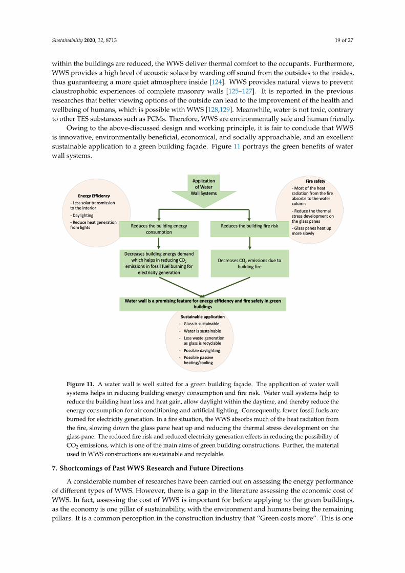
Sustainability 2020, 12, 8713 19 of 27
within the buildings are reduced, the WWS deliver thermal comfort to the occupants. Furthermore,WWS provides a high level of acoustic solace by warding off sound from the outsides to the insides,thus guaranteeing a more quiet atmosphere inside [124]. WWS provides natural views to preventclaustrophobic experiences of complete masonry walls [125–127]. It is reported in the previousresearches that better viewing options of the outside can lead to the improvement of the health andwellbeing of humans, which is possible with WWS [128,129]. Meanwhile, water is not toxic, contraryto other TES substances such as PCMs. Therefore, WWS are environmentally safe and human friendly.
Owing to the above-discussed design and working principle, it is fair to conclude that WWSis innovative, environmentally beneficial, economical, and socially approachable, and an excellentsustainable application to a green building façade. Figure 11 portrays the green benefits of waterwall systems.
Sustainability 2020, 12, x FOR PEER REVIEW 20 of 28
WWS provides a high level of acoustic solace by warding off sound from the outsides to the insides, thus guaranteeing a more quiet atmosphere inside [124]. WWS provides natural views to prevent claustrophobic experiences of complete masonry walls [125–127]. It is reported in the previous researches that better viewing options of the outside can lead to the improvement of the health and wellbeing of humans, which is possible with WWS [128,129]. Meanwhile, water is not toxic, contrary to other TES substances such as PCMs. Therefore, WWS are environmentally safe and human friendly.
Owing to the above-discussed design and working principle, it is fair to conclude that WWS is innovative, environmentally beneficial, economical, and socially approachable, and an excellent sustainable application to a green building façade. Figure 11 portrays the green benefits of water wall systems.
Figure 11. A water wall is well suited for a green building façade. The application of water wall systems helps in reducing building energy consumption and fire risk. Water wall systems help to reduce the building heat loss and heat gain, allow daylight within the daytime, and thereby reduce the energy consumption for air conditioning and artificial lighting. Consequently, fewer fossil fuels are burned for electricity generation. In a fire situation, the WWS absorbs much of the heat radiation from the fire, slowing down the glass pane heat up and reducing the thermal stress development on the glass pane. The reduced fire risk and reduced electricity generation effects in reducing the possibility of CO2 emissions, which is one of the main aims of green building constructions. Further, the material used in WWS constructions are sustainable and recyclable.
7. Shortcomings of Past WWS Research and Future Directions
A considerable number of researches have been carried out on assessing the energy performance of different types of WWS. However, there is a gap in the literature assessing the economic cost of WWS. In fact, assessing the cost of WWS is important for before applying to the green buildings, as the economy is one pillar of sustainability, with the environment and humans being the remaining pillars. It is a common perception in the construction industry that “Green costs more”. This is one of the reasons that WWS are limitedly applied in buildings
Figure 11. A water wall is well suited for a green building façade. The application of water wallsystems helps in reducing building energy consumption and fire risk. Water wall systems help toreduce the building heat loss and heat gain, allow daylight within the daytime, and thereby reduce theenergy consumption for air conditioning and artificial lighting. Consequently, fewer fossil fuels areburned for electricity generation. In a fire situation, the WWS absorbs much of the heat radiation fromthe fire, slowing down the glass pane heat up and reducing the thermal stress development on theglass pane. The reduced fire risk and reduced electricity generation effects in reducing the possibility ofCO2 emissions, which is one of the main aims of green building constructions. Further, the materialused in WWS constructions are sustainable and recyclable.
7. Shortcomings of Past WWS Research and Future Directions
A considerable number of researches have been carried out on assessing the energy performanceof different types of WWS. However, there is a gap in the literature assessing the economic cost ofWWS. In fact, assessing the cost of WWS is important for before applying to the green buildings,as the economy is one pillar of sustainability, with the environment and humans being the remainingpillars. It is a common perception in the construction industry that “Green costs more”. This is one
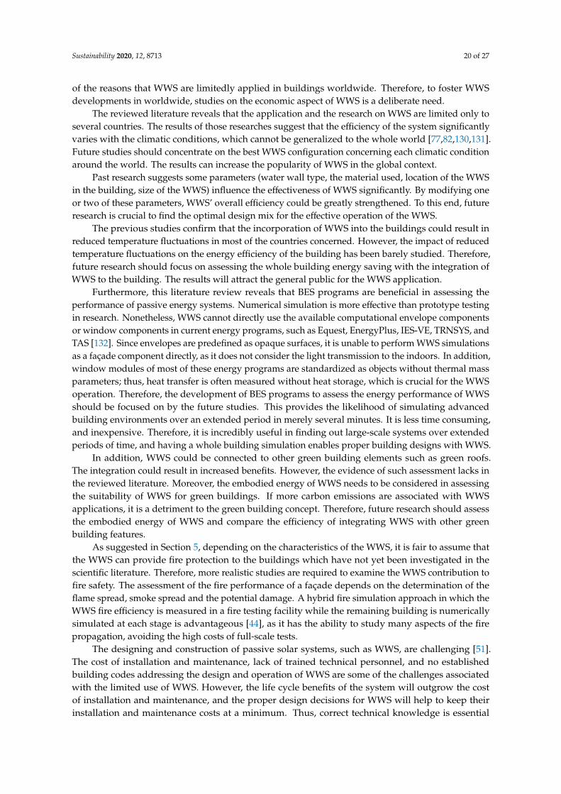
Sustainability 2020, 12, 8713 20 of 27
of the reasons that WWS are limitedly applied in buildings worldwide. Therefore, to foster WWSdevelopments in worldwide, studies on the economic aspect of WWS is a deliberate need.
The reviewed literature reveals that the application and the research on WWS are limited only toseveral countries. The results of those researches suggest that the efficiency of the system significantlyvaries with the climatic conditions, which cannot be generalized to the whole world [77,82,130,131].Future studies should concentrate on the best WWS configuration concerning each climatic conditionaround the world. The results can increase the popularity of WWS in the global context.
Past research suggests some parameters (water wall type, the material used, location of the WWSin the building, size of the WWS) influence the effectiveness of WWS significantly. By modifying oneor two of these parameters, WWS’ overall efficiency could be greatly strengthened. To this end, futureresearch is crucial to find the optimal design mix for the effective operation of the WWS.
The previous studies confirm that the incorporation of WWS into the buildings could result inreduced temperature fluctuations in most of the countries concerned. However, the impact of reducedtemperature fluctuations on the energy efficiency of the building has been barely studied. Therefore,future research should focus on assessing the whole building energy saving with the integration ofWWS to the building. The results will attract the general public for the WWS application.
Furthermore, this literature review reveals that BES programs are beneficial in assessing theperformance of passive energy systems. Numerical simulation is more effective than prototype testingin research. Nonetheless, WWS cannot directly use the available computational envelope componentsor window components in current energy programs, such as Equest, EnergyPlus, IES-VE, TRNSYS, andTAS [132]. Since envelopes are predefined as opaque surfaces, it is unable to perform WWS simulationsas a façade component directly, as it does not consider the light transmission to the indoors. In addition,window modules of most of these energy programs are standardized as objects without thermal massparameters; thus, heat transfer is often measured without heat storage, which is crucial for the WWSoperation. Therefore, the development of BES programs to assess the energy performance of WWSshould be focused on by the future studies. This provides the likelihood of simulating advancedbuilding environments over an extended period in merely several minutes. It is less time consuming,and inexpensive. Therefore, it is incredibly useful in finding out large-scale systems over extendedperiods of time, and having a whole building simulation enables proper building designs with WWS.
In addition, WWS could be connected to other green building elements such as green roofs.The integration could result in increased benefits. However, the evidence of such assessment lacks inthe reviewed literature. Moreover, the embodied energy of WWS needs to be considered in assessingthe suitability of WWS for green buildings. If more carbon emissions are associated with WWSapplications, it is a detriment to the green building concept. Therefore, future research should assessthe embodied energy of WWS and compare the efficiency of integrating WWS with other greenbuilding features.
As suggested in Section 5, depending on the characteristics of the WWS, it is fair to assume thatthe WWS can provide fire protection to the buildings which have not yet been investigated in thescientific literature. Therefore, more realistic studies are required to examine the WWS contribution tofire safety. The assessment of the fire performance of a façade depends on the determination of theflame spread, smoke spread and the potential damage. A hybrid fire simulation approach in which theWWS fire efficiency is measured in a fire testing facility while the remaining building is numericallysimulated at each stage is advantageous [44], as it has the ability to study many aspects of the firepropagation, avoiding the high costs of full-scale tests.
The designing and construction of passive solar systems, such as WWS, are challenging [51].The cost of installation and maintenance, lack of trained technical personnel, and no establishedbuilding codes addressing the design and operation of WWS are some of the challenges associatedwith the limited use of WWS. However, the life cycle benefits of the system will outgrow the costof installation and maintenance, and the proper design decisions for WWS will help to keep theirinstallation and maintenance costs at a minimum. Thus, correct technical knowledge is essential
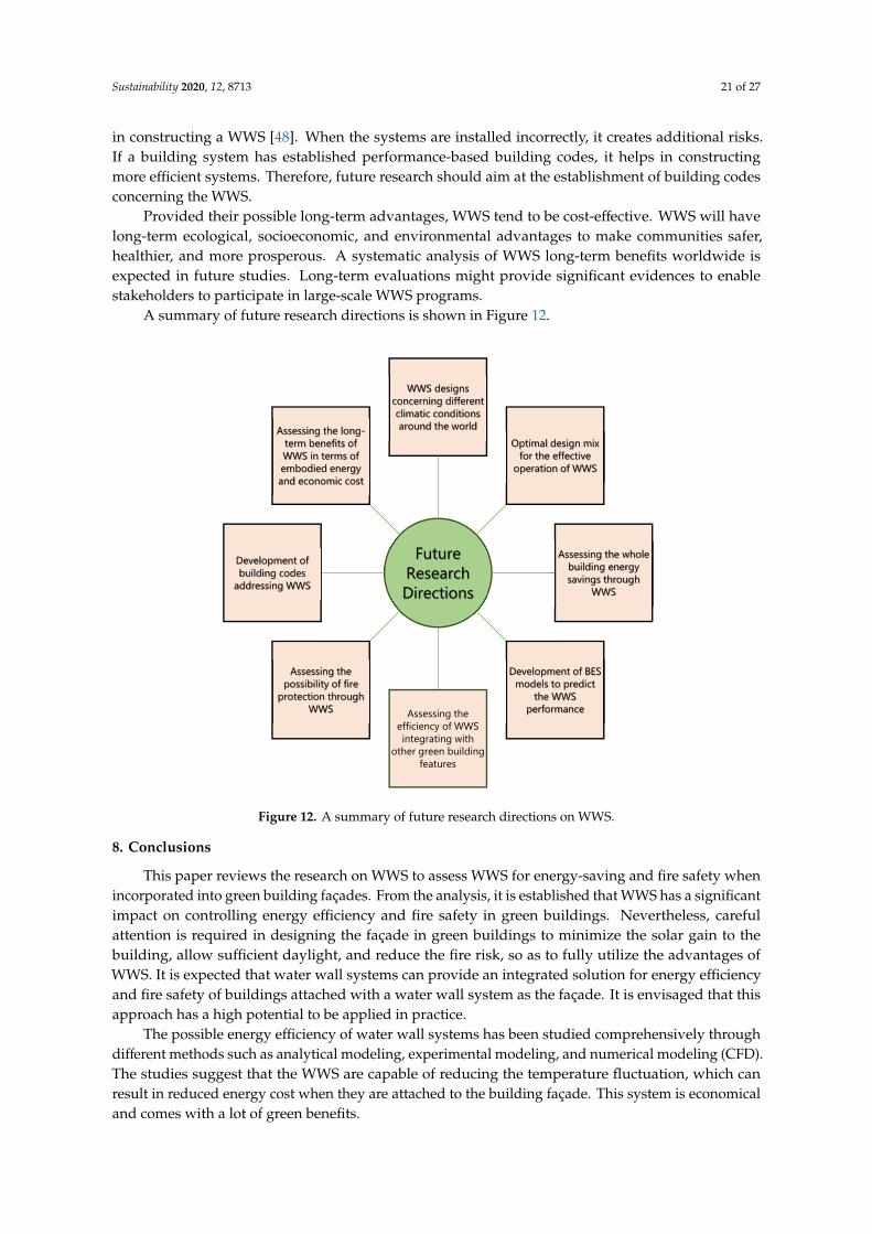
Sustainability 2020, 12, 8713 21 of 27
in constructing a WWS [48]. When the systems are installed incorrectly, it creates additional risks.If a building system has established performance-based building codes, it helps in constructingmore efficient systems. Therefore, future research should aim at the establishment of building codesconcerning the WWS.
Provided their possible long-term advantages, WWS tend to be cost-effective. WWS will havelong-term ecological, socioeconomic, and environmental advantages to make communities safer,healthier, and more prosperous. A systematic analysis of WWS long-term benefits worldwide isexpected in future studies. Long-term evaluations might provide significant evidences to enablestakeholders to participate in large-scale WWS programs.
A summary of future research directions is shown in Figure 12.
Sustainability 2020, 12, x FOR PEER REVIEW 22 of 28
system will outgrow the cost of installation and maintenance, and the proper design decisions for WWS will help to keep their installation and maintenance costs at a minimum. Thus, correct technical knowledge is essential in constructing a WWS [48]. When the systems are installed incorrectly, it creates additional risks. If a building system has established performance-based building codes, it helps in constructing more efficient systems. Therefore, future research should aim at the establishment of building codes concerning the WWS.
Provided their possible long-term advantages, WWS tend to be cost-effective. WWS will have long-term ecological, socioeconomic, and environmental advantages to make communities safer, healthier, and more prosperous. A systematic analysis of WWS long-term benefits worldwide is expected in future studies. Long-term evaluations might provide significant evidences to enable stakeholders to participate in large-scale WWS programs.
A summary of future research directions is shown in Figure 12.
Figure 12. A summary of future research directions on WWS.
8. Conclusions
This paper reviews the research on WWS to assess WWS for energy-saving and fire safety when incorporated into green building façades. From the analysis, it is established that WWS has a significant impact on controlling energy efficiency and fire safety in green buildings. Nevertheless, careful attention is required in designing the façade in green buildings to minimize the solar gain to the building, allow sufficient daylight, and reduce the fire risk, so as to fully utilize the advantages of WWS. It is expected that water wall systems can provide an integrated solution for energy efficiency and fire safety of buildings attached with a water wall system as the façade. It is envisaged that this approach has a high potential to be applied in practice.
The possible energy efficiency of water wall systems has been studied comprehensively through different methods such as analytical modeling, experimental modeling, and numerical modeling (CFD). The studies suggest that the WWS are capable of reducing the temperature fluctuation, which can result in reduced energy cost when they are attached to the building façade. This system is economical and comes with a lot of green benefits.
Future Research Directions
WWS designs concerning different climatic conditions around the world
Optimal design mix for the effective
operation of WWS
Assessing the whole building energy savings through
WWS
Development of BES models to predict
the WWS performanceAssessing the
efficiency of WWS integrating with
other green building features
Assessing the possibility of fire
protection through WWS
Development of building codes
addressing WWS
Assessing the long-term benefits of WWS in terms of embodied energy and economic cost
Figure 12. A summary of future research directions on WWS.
8. Conclusions
This paper reviews the research on WWS to assess WWS for energy-saving and fire safety whenincorporated into green building façades. From the analysis, it is established that WWS has a significantimpact on controlling energy efficiency and fire safety in green buildings. Nevertheless, carefulattention is required in designing the façade in green buildings to minimize the solar gain to thebuilding, allow sufficient daylight, and reduce the fire risk, so as to fully utilize the advantages ofWWS. It is expected that water wall systems can provide an integrated solution for energy efficiencyand fire safety of buildings attached with a water wall system as the façade. It is envisaged that thisapproach has a high potential to be applied in practice.
The possible energy efficiency of water wall systems has been studied comprehensively throughdifferent methods such as analytical modeling, experimental modeling, and numerical modeling (CFD).The studies suggest that the WWS are capable of reducing the temperature fluctuation, which canresult in reduced energy cost when they are attached to the building façade. This system is economicaland comes with a lot of green benefits.
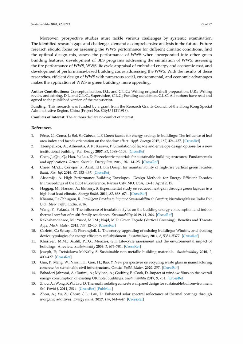
Sustainability 2020, 12, 8713 22 of 27
Moreover, prospective studies must tackle various challenges by systemic examination.The identified research gaps and challenges demand a comprehensive analysis in the future. Futureresearch should focus on assessing the WWS performance for different climatic conditions, findthe optimal design mix, assess the performance of WWS when incorporated into other greenbuilding features, development of BES programs addressing the simulation of WWS, assessingthe fire performance of WWS, WWS life cycle appraisal of embodied energy and economic cost, anddevelopment of performance-based building codes addressing the WWS. With the results of theseresearches, efficient design of WWS with numerous social, environmental, and economic advantagesmakes the application of WWS in green buildings more appealing.
Author Contributions: Conceptualization, D.L. and C.L.C.; Writing original draft preparation, U.R.; Writingreview and editing, D.L. and C.L.C., Supervision, C.L.C.; Funding acquisition, C.L.C. All authors have read andagreed to the published version of the manuscript.
Funding: This research was funded by a grant from the Research Grants Council of the Hong Kong SpecialAdministrative Region, China (Project No. CityU 11211918).
Conflicts of Interest: The authors declare no conflict of interest.
References
1. Pérez, G.; Coma, J.; Sol, S.; Cabeza, L.F. Green facade for energy savings in buildings: The influence of leafarea index and facade orientation on the shadow effect. Appl. Energy 2017, 187, 424–437. [CrossRef]
2. Tzempelikos, A.; Athienitis, A.K.; Karava, P. Simulation of façade and envelope design options for a newinstitutional building. Sol. Energy 2007, 81, 1088–1103. [CrossRef]
3. Chen, J.; Qiu, Q.; Han, Y.; Lau, D. Piezoelectric materials for sustainable building structures: Fundamentalsand applications. Renew. Sustain. Energy Rev. 2019, 101, 14–25. [CrossRef]
4. Chew, M.Y.L.; Conejos, S.; Azril, F.H. Bin Design for maintainability of high-rise vertical green facades.Build. Res. Inf. 2019, 47, 453–467. [CrossRef]
5. Aksamija, A. High-Performance Building Envelopes: Design Methods for Energy Efficient Facades.In Proceedings of the BEST4 Conference, Kansas City, MO, USA, 13–15 April 2015.
6. Haggag, M.; Hassan, A.; Elmasry, S. Experimental study on reduced heat gain through green façades in ahigh heat load climate. Energy Build. 2014, 82, 668–674. [CrossRef]
7. Khanna, T.; Chhugani, R. Intelligent Facades to Improve Sustainability & Comfort; NürnbergMesse India Pvt.Ltd.: New Delhi, India, 2016.
8. Wang, Y.; Fukuda, H. The influence of insulation styles on the building energy consumption and indoorthermal comfort of multi-family residences. Sustainability 2019, 11, 266. [CrossRef]
9. Rakhshandehroo, M.; Yusof, M.J.M.; Najd, M.D. Green Façade (Vertical Greening): Benefits and Threats.Appl. Mech. Mater. 2015, 747, 12–15. [CrossRef]
10. Carletti, C.; Sciurpi, F.; Pierangioli, L. The energy upgrading of existing buildings: Window and shadingdevice typologies for energy efficiency refurbishment. Sustainability 2014, 6, 5354–5377. [CrossRef]
11. Khasreen, M.M.; Banfill, P.F.G.; Menzies, G.F. Life-cycle assessment and the environmental impact ofbuildings: A review. Sustainability 2009, 1, 674–701. [CrossRef]
12. Joseph, P.; Tretsiakova-McNally, S. Sustainable non-metallic building materials. Sustainability 2010, 2,400–427. [CrossRef]
13. Guo, P.; Meng, W.; Nassif, H.; Gou, H.; Bao, Y. New perspectives on recycling waste glass in manufacturingconcrete for sustainable civil infrastructure. Constr. Build. Mater. 2020, 257. [CrossRef]
14. Bahadori-Jahromi, A.; Rotimi, A.; Mylona, A.; Godfrey, P.; Cook, D. Impact of window films on the overallenergy consumption of existing UK hotel buildings. Sustainability 2017, 9, 731. [CrossRef]
15. Zhou, A.; Wong, K.W.; Lau, D. Thermal insulating concrete wall panel design for sustainable built environment.Sci. World J. 2014, 2014. [CrossRef] [PubMed]
16. Zhou, A.; Yu, Z.; Chow, C.L.; Lau, D. Enhanced solar spectral reflectance of thermal coatings throughinorganic additives. Energy Build. 2017, 138, 641–647. [CrossRef]
Sustainability 2020, 12, 8713 23 of 27
17. Morakinyo, T.E.; Dahanayake, K.W.D.K.C.; Ng, E.; Chow, C.L. Temperature and cooling demand reductionby green-roof types in different climates and urban densities: A co-simulation parametric study. Energy Build.2017, 145, 226–237. [CrossRef]
18. Wang, F.; Yang, W.J.; Sun, W.F. Heat transfer and energy consumption of passive house in a severely coldarea: Simulation analyses. Energies 2020, 13, 626. [CrossRef]
19. Dahanayake, K.W.D.K.C.; Chow, C.L. Studying the potential of energy saving through vertical greenerysystems: Using EnergyPlus simulation program. Energy Build. 2017, 138, 47–59. [CrossRef]
20. Chow, W.K.; Kong, H.; Gao, Y.; Dong, H.; Zou, G.W.; Han, S.S.; Kong, H.; Chow, C.L.; Kong, H. Experimentalstudies on fire response of glass façade systems. IJEPBFC 2006, 8, 54–68.
21. Khalaf, M.; Ashrafian, T.; Demirci, C. Energy Efficiency Evaluation of Different Glazing and Shading Systemsin a School Building. E3S Web Conf. 2019, 111. [CrossRef]
22. Huang, Y.; Niu, J.L. Energy and visual performance of the silica aerogel glazing system in commercialbuildings of Hong Kong. Constr. Build. Mater. 2015, 94, 57–72. [CrossRef]
23. Wang, Y.; Wu, Y.; Wang, Q.; Liew, K.M.; Chen, H.; Sun, J.; He, L. Numerical study on fire response of glassfacades in different installation forms. Constr. Build. Mater. 2014, 61, 172–180. [CrossRef]
24. Stewart, M.G.; Netherton, M.D. Security risks and probabilistic risk assessment of glazing subject to explosiveblast loading. Reliab. Eng. Syst. Saf. 2008, 93, 627–638. [CrossRef]
25. Vedrtnam, A.; Bedon, C.; Youssef, M.A.; Wamiq, M.; Sabsabi, A.; Chaturvedi, S. Experimental andnumerical structural assessment of transparent and tinted glass during fire exposure. Constr. Build. Mater.2020, 250. [CrossRef]
26. Bedon, C.; Zhang, X.; Santos, F.; Honfi, D.; Kozłowski, M.; Arrigoni, M.; Figuli, L.; Lange, D. Performance ofstructural glass facades under extreme loads—Design methods, existing research, current issues and trends.Constr. Build. Mater. 2018, 163, 921–937. [CrossRef]
27. Debuyser, M.; Sjöström, J.; Lange, D.; Honfi, D.; Sonck, D.; Belis, J. Behaviour of monolithic and laminatedglass exposed to radiant heating. Constr. Build. Mater. 2017, 130, 212–229. [CrossRef]
28. Wang, Y.; Xie, Q.; Zhang, Y.; Wang, Q.; Sun, J. Sensitivity analysis of influencing factors on glass façadebreakage in fire. Fire Saf. J. 2018, 98, 38–47. [CrossRef]
29. Cuzzillo, B.R.; Pagni, P.J. Thermal breakage of Double-Pane Glazing by Fire. J. Fire Prot. Eng. 1998, 9,1–11. [CrossRef]
30. Wang, Y.; Wang, Q.; Sun, J.; He, L.; Liew, K.M. Influence of fire location on the thermal performance of glassfaçades. Appl. Therm. Eng. 2016, 106, 438–442. [CrossRef]
31. Pagni, P.J. Thermal glass breakage. Fire Saf. Sci. 2003, 3–22. [CrossRef]32. Cho, S.H.; Chae, C.U. A study on life cycle CO2 emissions of low-carbon building in South Korea. Sustainability
2016, 8, 579. [CrossRef]33. Tidwell, J. Bridging the Gap—Fire Safety and Green Buildings; National Association of State Fire Marshals:
Burns, OR, USA, 2010.34. Nayak, J.K. Thermal performance of a water wall. Build. Environ. 1987, 22, 83–90. [CrossRef]35. Wu, T.; Lei, C. A review of research and development on water wall for building applications. Energy Build.
2016, 112, 198–208. [CrossRef]36. Wu, T.; Lei, C. Thermal modelling and experimental validation of a semi-transparent water wall system for
Sydney climate. Sol. Energy 2016, 136, 533–546. [CrossRef]37. Wu, T.; Lei, C. CFD simulation of the thermal performance of an opaque water wall system for Australian
climate. Sol. Energy 2016, 133, 141–154. [CrossRef]38. Wang, H.; Lei, C. Theoretical modeling of combined solar chimney and water wall for buildings. Energy Build.
2019, 187, 186–200. [CrossRef]39. Wang, H.; Lei, C. Combined Solar Chimney and Water Wall for Ventilation and Thermal Comfort. In
Proceedings of the 4th International Conference on Building Energy, Environment, Melbourne, Australia,5–9 February 2018; pp. 705–710.
40. Karabay, H.; Arici, M.; Sandik, M. A numerical investigation of fluid flow and heat transfer inside a room forfloor heating and wall heating systems. Energy Build. 2013, 67, 471–478. [CrossRef]
41. Moustafa, M.A.; Aripin, S. CFD Evaluation of the pottery water wall in a hot adrid climate of Luxor, Egypt.J. Green Build. 2015. [CrossRef]
Sustainability 2020, 12, 8713 24 of 27
42. Xiangfeng, L.; Tianxing, S. Conceptual Development of Transparent Water Storage Envelopes. Archit. Sci.Rev. 2007, 50, 18–25. [CrossRef]
43. Liu, X.; Guo, J.; Wang, J. Numerical and experimental studies on the energy performance of thermal masswindows. J. Build. Phys. 2018, 42, 692–721. [CrossRef]
44. Wang, X.; Kim, R.E.; Kwon, O.S.; Yeo, I. Hybrid Simulation Method for a Structure Subjected to Fire and ItsApplication to a Steel Frame. J. Struct. Eng. 2018, 144, 1–11. [CrossRef]
45. Kuznik, F.; David, D.; Johannes, K.; Roux, J.J. A review on phase change materials integrated in buildingwalls. Renew. Sustain. Energy Rev. 2011, 15, 379–391. [CrossRef]
46. Tamme, R.; Laing, D.; Steinmann, W.D.; Bauer, T. Thermal Energy Storage. Sol. Energy 2013,688–714. [CrossRef]
47. Perlin, J. Let It Shine: The 6,000-Year Story of Solar Energy; New World Library: Novato, CA, USA, 2013;ISBN 9781608681327.
48. Bainbridge, D.A. A Water Wall Solar Design Manual; San Diego, CA, USA, 2005; Available online: https://www.solaripedia.com/files/472.pdf (accessed on 13 October 2020).
49. Maloney, T.J.; Habib, V. Design, Fabrication and Testing of a Marketable Waterwall Component; One Design, Inc.:Winchester, VA, USA, 1979; Volume 84.
50. Bainbridge, B.D.A.; Haggard, K.; Cooper, P. Return of the Water Wall. Sol. Today 2007, 38–41.51. Saadatian, O.; Sopian, K.; Lim, C.H.; Asim, N.; Sulaiman, M.Y. Trombe walls: A review of opportunities and
challenges in research and development. Renew. Sustain. Energy Rev. 2012, 16, 6340–6351. [CrossRef]52. Saadatian, O.; Sopian, K.; Salleh, E.; Lim, C.H.; Riffat, S.; Saadatian, E.; Toudeshki, A.; Sulaiman, M.Y.
A review of energy aspects of green roofs. Renew. Sustain. Energy Rev. 2013, 23, 155–168. [CrossRef]53. Bevilacqua, P.; Benevento, F.; Bruno, R.; Arcuri, N. Are Trombe walls suitable passive systems for the
reduction of the yearly building energy requirements? Energy 2019, 185, 554–566. [CrossRef]54. Agrawal, B.; Tiwari, G.N. Building Integrated Photovoltaic Thermal Systems: For Sustainable Development; Royal
Society of Chemistry: London, UK, 2011; ISBN 9781849732000.55. Al-Karaghouli, A.; Kazmerski, L.L. Renewable Energy Opportunities in Water Desalination.
Desalin. Trends Technol. 2011. [CrossRef]56. McLaggan, M.S.; Hadden, R.M.; Gillie, M. Fire Performance of Phase Change Material Enhanced Plasterboard.
Fire Technol. 2018, 54, 117–134. [CrossRef]57. Khan, R.J.; Bhuiyan, M.Z.H.; Ahmed, D.H. Investigation of heat transfer of a building wall in the presence of
phase change material (PCM). Energy Built Environ. 2020, 1, 199–206. [CrossRef]58. Richman, R.C.; Cianfrone, C.; Pressnail, K.D. More sustainable masonry façades: Preheating ventilation air
using a dynamic buffer zone. J. Build. Phys. 2010, 34, 27–41. [CrossRef]59. Stazi, F.; Mastrucci, A.; Munafò, P. Life cycle assessment approach for the optimization of sustainable building
envelopes: An application on solar wall systems. Build. Environ. 2012, 58, 278–288. [CrossRef]60. Kisilewicz, T. On the role of external walls in the reduction of energy demand and the mitigation of human
thermal discomfort. Sustainability 2019, 11, 61. [CrossRef]61. Yang, L.; Yan, H.; Lam, J.C. Thermal comfort and building energy consumption implications -A review.
Appl. Energy 2014, 115, 164–173. [CrossRef]62. Li, D.; Wu, Y.; Wang, B.; Liu, C.; Arıcı, M. Optical and thermal performance of glazing units containing PCM
in buildings: A review. Constr. Build. Mater. 2020, 233, 117327. [CrossRef]63. Balcomb, J.D.; Mcfarland, R.D. A simple empirical method for estimating the performance of a passive
solar heated building of the thermal storage wall type. In Proceedings of the 2nd National Passive Solar,University of Pennsylvania, Philadelphia, PA, USA, 16–18 March 1978.
64. Nayak, J.K.; Bansal, N.K.; Sodha, M.S. Analysis of passive heating concepts. Sol. Energy 1983, 30,51–69. [CrossRef]
65. Sutton, R.G.; McGregor, R.J. Solarwall project: Two demonstration houses with passive solar heating inTasmania. Archit. Sci. Rev. 1986, 29, 2–11. [CrossRef]
66. Turner, R.H.; Liu, G.; Cengel, Y.A.; Harris, C.P. Thermal Storage in the Walls of a Solar House. J. Sol. Eng.1994, 116, 183–193. [CrossRef]
67. Yadav, Y.P.; Tiwari, G.N. Analytical model of a solarium for cold climate-A new approach. Energy Convers.Manag. 1988, 28, 15–20. [CrossRef]

Sustainability 2020, 12, 8713 25 of 27
68. Din, M.; Tiwari, G.N.; Ghosal, M.K.; Srivastava, N.S.L.; Khan, M.I.; Sodha, M.S. Effect of thermal storage onthe performance of greenhouse. Int. J. Energy Res. 2003, 27, 79–92. [CrossRef]
69. Tiwari, G.N.; Singh, A.K. Comparative Studies of Different Heating Techniques of a Non-air ConditionedBuilding. Build. Environ. 1996, 31, 215–224. [CrossRef]
70. Fuchs, R.; McClelland, J.F. Passive solar heating of buildings using a transwall structure. Sol. Energy 1979, 23,123–128. [CrossRef]
71. Bansal, N.K.; Sodha, M.S.; Ram, S.; Singh, S.P. Evaluation of complex heat transfer coefficients for passiveheating concepts. Build. Environ. 1987, 22, 259–268. [CrossRef]
72. Bansal, N.K.; Thomas, P.C. A Simple Procedure for Selection and Sizing of Indirect Passive Solar HeatingSystems. Build. Environ. 1991, 26, 381–387. [CrossRef]
73. Bhandari, M.S.; Bansal, N.K. Solar heat gain factors and heat loss coefficients for passive heating concepts.Sol. Energy 1994, 53, 199–208. [CrossRef]
74. Nisbet, S.K.; Mthembu, N.S. Transwall modelling using effective conductivities. Sol. Energy 1992, 49,127–138. [CrossRef]
75. Yadav, Y.P.; Tiwari, G.N. Large scale solar water heater: Experimental and theoretical studies.Energy Convers. Manag. 1991, 31, 337–351. [CrossRef]
76. Tiwari, G.N.; Kumar, S. Thermal evaluation of solarium-cum-passive solar house. Energy Convers. Manag.1991, 32, 303–310. [CrossRef]
77. Upadhya, M.; Tiwari, G.N.; Rai, S.N. Optimum distribution of water-wall thickness in a transwall. Energy Build.1991, 17, 97–102. [CrossRef]
78. Wang, W.L.; Tian, Z.; Niu, X.L.; Xu, X. Investigation on a Passive Solar House Equipped with Water ThermalStorage Wall. Appl. Mech. Mater. 2012, 178–181, 193–196. [CrossRef]
79. Sánchez-Ostiz, A.; Monge-Barrio, A.; Domingo-Irigoyen, S.; González-Martínez, P. Design and experimentalstudy of an industrialized sunspace with solar heat storage. Energy Build. 2014, 80, 231–246. [CrossRef]
80. Sameti, M. A new design of a solar water storage wall: A system-level model and simulation. Energy Syst.2018, 9, 361–383. [CrossRef]
81. Chow, T.T.; Li, C.; Lin, Z. Thermal characteristics of water-flow double-pane window. Int. J. Therm. Sci. 2011,50, 140–148. [CrossRef]
82. Sodha, M.S.; Kaushik, S.C.; Nayak, J.K. Performance of trombe walls and roof pond systems. Appl. Energy1981, 8, 175–191. [CrossRef]
83. Yadav, Y.P.; Tiwari, G.N. Transient analysis of a winter greenhouse integrated with solar still. Energy Convers.Manag. 1987, 27, 267–273. [CrossRef]
84. Tiwari, G.N.; Yadav, Y.P.; Lawrence, S.A. Performance of a solarium: An analytical study. Build. Environ.1988, 23, 145–151. [CrossRef]
85. Xiangfeng, L.; Tianxing, S. The Development of Transparent Water Storage Envelopes (TWSE) throughTheoretical Thermal and Optical Analyses. Archit. Sci. Rev. 2008, 51, 109–123. [CrossRef]
86. Chow, T.T.; Li, C. Water-filled double reflective window and its year-round performance. Procedia Environ. Sci.2011, 11, 1039–1047. [CrossRef]
87. Lyu, Y.L.; Chow, T.T.; Wang, J.L. Numerical prediction of thermal performance of liquid-flow window indifferent climates with anti-freeze. Energy 2018, 157, 412–423. [CrossRef]
88. Gil-Lopez, T.; Gimenez-Molina, C. Influence of double glazing with a circulating water chamber on thethermal energy savings in buildings. Energy Build. 2013, 56, 56–65. [CrossRef]
89. Lyu, Y.L.; Chow, T.T. Evaluation of influence of header design on water flow characteristics in window cavitywith CFD. Energy Procedia 2015, 78, 97–102. [CrossRef]
90. Chow, T.T.; Lyu, Y. Effect of design configurations on water flow window performance. Sol. Energy 2017, 155,354–362. [CrossRef]
91. Liu, X.; Xu, M.; Guo, J.; Zhu, R. Numerical study on the energy performance of building zones withtransparent water storage envelopes. Sol. Energy 2019, 180, 690–706. [CrossRef]
92. Gutai, M.; Kheybari, A.G. Energy consumption of water-filled glass (WFG) hybrid building envelope.Energy Build. 2020, 218, 110050. [CrossRef]
93. Sedłak, B.; Kinowski, J.; Sulik, P.; Kimbar, G. The risks associated with falling parts of glazed facades in caseof fire. Open Eng. 2018, 8, 147–155. [CrossRef]
Sustainability 2020, 12, 8713 26 of 27
94. Hasheminasab, H.; Zolfani, S.H.; Bitarafan, M.; Chatterjee, P.; Ezabadi, A.A. The Role of Façade Materialsin Blast-Resistant Buildings: An Evaluation Based on Fuzzy Delphi and Fuzzy EDAS. Algorithms 2019,12, 119. [CrossRef]
95. Nguyen, K.; Weerasinghe, P.; Mendis, P.; Ngo, T.; Barnett, J. Performance of modern building facades in fire:A comprehensive review. Electron. J. Struct. Eng. 2016, 16, 69–86.
96. McKenna, S.T.; Jones, N.; Peck, G.; Dickens, K.; Pawelec, W.; Oradei, S.; Harris, S.; Stec, A.A.; Hull, T.R.Fire behaviour of modern façade materials – Understanding the Grenfell Tower fire. J. Hazard. Mater. 2019,368, 115–123. [CrossRef]
97. Wang, Y.; Zhang, Y.; Wang, Q.; Yang, Y.; Sun, J. The effect of glass panel dimension on the fire response ofglass façades. Constr. Build. Mater. 2018, 181, 588–597. [CrossRef]
98. Chow, W.K.; Hung, W.Y.; Gao, Y.; Zou, G.; Dong, H. Experimental study on smoke movement leading toglass damages in double-skinned façade. Constr. Build. Mater. 2007, 21, 556–566. [CrossRef]
99. Quinn, M.; Nadjai, A.; Ali, F.; Abu-Tair, A. Experimental and numerical investigation of localised fire onglazing facades having different orientations. J. Struct. Fire Eng. 2013, 4, 153–164. [CrossRef]
100. Babrauskas, V. Glass breakage in fires. Fire Sci. Technol. Inc. 2011, 6–11. Available online: http://doctorfire.com/GlassBreak.pdf (accessed on 13 October 2020).
101. Keski-Rahkonen, O. Breaking of window glass close to fire. Fire Mater. 1988, 12, 61–69. [CrossRef]102. Pagni, P.J.; Joshi, A.A. Glass breaking in fires. Fire Saf. Sci. Proc. Third Int. Symp. 2006, 791–802. [CrossRef]103. Mowrer, F. Window Breakage Induced by Exterior Fires; National Institute of Standards and Technology:
Gaithersburg, MD, USA, 1997.104. Chow, C.L. Numerical studies on smoke spread in the cavity of a double-skin façade. J. Civ. Eng. Manag.
2016, 22, 470–479. [CrossRef]105. Manzello, S.L.; Gann, R.G.; Kukuck, S.R.; Prasad, K.R.; Jones, W.W. An experimental determination of a real
fire performance of a non-load bearing glass wall assembly. Fire Technol. 2007, 43, 77–89. [CrossRef]106. Wang, X.; Tan, Q.; Wang, Z.; Kong, X.; Cong, H. Preliminary study on fire protection of window glass by
water mist curtain. Int. J. Therm. Sci. 2018, 125, 44–51. [CrossRef]107. Turco, M.; Lhotsky, P.; Hadjisophocleous, G. Investigation into the use of a water curtain over openings to
prevent fire spread. MATEC Web Conf. 2016, 46. [CrossRef]108. Tseng, C.C.; Viskanta, R. Absorptance and transmittance of water spray/mist curtains. Fire Saf. J. 2007, 42,
106–114. [CrossRef]109. Abdoh, D.A.; Ademiloye, A.S.; Liew, K.M. A meshfree analysis of the thermal behaviors of hot surface glass
pane subjects to down-flowing water film via smoothed particle hydrodynamics. Eng. Anal. Bound. Elem.2020, 120, 195–210. [CrossRef]
110. Shao, G.; Wang, Q.; Zhao, H.; Wang, Y.; Chen, H.; Su, Y.; Sun, J.; He, L. Maximum temperature to withstandwater film for tempered glass exposed to fire. Constr. Build. Mater. 2014, 57, 15–23. [CrossRef]
111. Braun, J.E. Load control using building thermal mass. J. Sol. Energy Eng. Trans. ASME 2003, 125,292–301. [CrossRef]
112. Shi, Y.; Liu, X. Research on the Literature of Green Building Based on the Web of Science: A ScientometricAnalysis in Citespace (2002–2018). Sustainability 2019, 11, 3716. [CrossRef]
113. Cakmakli, A.B. Environmental Analysis of Construction Materials. In Green Building Management and SmartAutomation; Solanki, A., Nayyar, A., Eds.; IGI Global: Pennsylvania, PA, USA, 2019; pp. 90–110. [CrossRef]
114. Akadiri, P.O.; Chinyio, E.A.; Olomolaiye, P.O. Design of A Sustainable Building: A Conceptual Frameworkfor Implementing Sustainability in the Building Sector. Buildings 2012, 2, 126–152. [CrossRef]
115. Biswas, W.K. Carbon footprint and embodied energy consumption assessment of building constructionworks in Western Australia. Int. J. Sustain. Built Environ. 2014, 3, 179–186. [CrossRef]
116. Baird, G.; Alcorn, A.; Haslam, P. The Energy Embodied in Building Materials—Updated New ZealandCoefficients and Their Significance. Trans. Inst. Prof. Eng. New Zeal. Civ. Eng. Sect. 1997, 24, 46–54.
117. Lawson, B. Building Materials, Energy and the Environment: Towards Ecologically Sustainable Development; RoyalAustralian Institute of Architects: Victoria, Australia, 1996; ISBN 9781863180283.
118. Straube, J. Can Highly Glazed Building Façades Be Green. Available online: https://www.buildingscience.com/documents/insights/bsi-006-can-fully-glazed-curtainwalls-be-green (accessed on 19 October 2020).
119. Bunjongjit, S.; Ngaopitakkul, A. Feasibility study and impact of daylight on illumination control forEnergy-saving lighting systems. Sustainability 2018, 10, 4075. [CrossRef]
Sustainability 2020, 12, 8713 27 of 27
120. Kaminska, A.; Ozadowicz, A. Lighting control including daylight and energy efficiency improvementsanalysis. Energies 2018, 11, 2166. [CrossRef]
121. Al-Mansour, A.; Chow, C.L.; Feo, L.; Penna, R.; Lau, D. Green concrete: By-products utilization and advancedapproaches. Sustainability 2019, 11, 5145. [CrossRef]
122. Albayyaa, H.; Hagare, D.; Saha, S. Energy conservation in residential buildings by incorporating Passive Solarand Energy Efficiency Design Strategies and higher thermal mass. Energy Build. 2019, 182, 205–213. [CrossRef]
123. Aboulnaga, M.M. Towards green buildings: Glass as a building element—The use and misuse in the gulfregion. Renew. Energy 2006, 31, 631–653. [CrossRef]
124. Altan, H.; Hajibandeh, M.; Aoul, T.K.A.; Deep, A. Passive design. In Springer Tracts in Civil Engineering;Springer: Cham, Switzerland, 2016; pp. 209–236. [CrossRef]
125. Burkett, K. The Hidden Architecture Behind 7 Deceiving Façades. Architizer, 2019. Available online:https://architizer.com/blog/inspiration/collections/deceiving-facades (accessed on 13 October 2020).
126. Nijsse, R.; Wenting, R. Designing and constructing corrugated glass facades. J. Facade Des. Eng. 2014, 2,123–131. [CrossRef]
127. Allen, E. How Buildings Work; Oxford UniversityPress: New York, NY, USA, 2005; Volume 53,ISBN 9788578110796.
128. Maller, C.; Townsend, M.; Pryor, A.; Brown, P.; St Leger, L. Healthy nature healthy people: “contact withnature” as an upstream health promotion intervention for populations. Health Promot. Int. 2006, 21, 45–54.[CrossRef] [PubMed]
129. De Been, I.; Beijer, M. The influence of office type on satisfaction and perceived productivity support.J. Facil. Manag. 2014, 12, 142–157. [CrossRef]
130. Adams, S.; Becker, M.; Krauss, D.; Gilman, C. Not a Dry Subject: Optimizing Water Trombe Walls. Sol. EnergySoc. Annu. Conf. 2010, 2010, 1334–1340.
131. Tiwari, G.N.; Upadhya, M.; Rai, S.N. Relative thermal performances of south walls in winter. Energy Build.1991, 17, 313–320. [CrossRef]
132. Crawley, D.B.; Hand, J.W.; Kummert, M.; Griffith, B.T. Contrasting the capabilities of building energyperformance simulation programs. Build. Environ. 2008, 43, 661–673. [CrossRef]
Publisher’s Note: MDPI stays neutral with regard to jurisdictional claims in published maps and institutionalaffiliations.
© 2020 by the authors. Licensee MDPI, Basel, Switzerland. This article is an open accessarticle distributed under the terms and conditions of the Creative Commons Attribution(CC BY) license (http://creativecommons.org/licenses/by/4.0/).