
REVIEW OF SHIP STRUCTURAL DETAILS - TU Delft ...
329
SSC-266 REVIEW OF SHIP STRUCTURAL DETAILS This document has been approved for public release and sale; its distribution is unlimited. SHIP STRUCTURE COMMITTEE 1977
-
Upload
khangminh22 -
Category
Documents
-
view
3 -
download
0
Transcript of REVIEW OF SHIP STRUCTURAL DETAILS - TU Delft ...
SSC-266
REVIEW OF SHIP STRUCTURAL DETAILS
This document has been approvedfor public release and sale; its
distribution is unlimited.
SHIP STRUCTURE COMMITTEE
1977
-
SHIP STRUCTURE COMMITIEEAN INTERAGENCY ADVISORY
COMMITTEE DEDICATED TO IMPROVINGTHE STRUCTURE OF SHIPS
MEMBER AGENCIES; ADDRESS CORRESPONDENCE TO
Unted States Coast Guard Secretary
Nouai Sea Systems Commasd Ship Structure Comm tee
Mitory Seolift Command U.S. Coast Guard He.dquatters
I Maritime Administration Washington. D C. 20590
I American Bureau of Shippirg
ISR-216
1 5 APR 1977
The fabrication of structural design details represents asignificant part of shipbuilding costs. These details also representpotential sources of premature failure, fatigue cracking, andbrittle fracture. At present, a unifying rationale for designdetails that includes consideration of reliability and maintainabilityis not available.
The Ship Structure Committee initiated a program with theinitial objective to conduct a state-of-the-art study in the area ofshipbuilding structural design details. This study was to evaluateand determine design and construction methods currently in use, andto recommend improved and optimal methods.
This is a final report of that task and is being publishedto assist in developing cost effective and safe design details. The
Ship Structure Committee expects to consider projects which willprovide the rationale for evaluating the reliability and maintain-ability of details. This effort is limited at present to an evalua-tion of the performance of details on ships in actual service. The
results of that study will be published when they are available.
/1.1W. M. BENKERTRear Admiral, U.S. Coast GuardChairman, Ship Structure Committee

FINAL TECHNICAL REPORT
On
Project SR-216
"Structural Details Design Review"
REVIEW OF SHIP STRUCTURAL DETAILS
by
R. GlasfeldD. JordanM. Kerr, Jr.D. Zoller
GENERAL DYNAMICS
Quincy Shipbuilding Division
under
Department of the NavyNaval Sea Systems Command
Contract No. N00024-74-C-5230
This doczvnent has been approved for public releaseand sale; its distribution is unlimited.
U. S. Coast Guard HeadquartersWashington, D.C.
1977
SSc ..2

r,
ABSTRACT
The review of structural detail design is intended to serve as a summary of thestate of the art and a guide to development of tools for design and analysis ofthese details.
The report includes a count of common structural details aboard two moderncommercial vessels, and labor estimates for representative sizes of thosedetails intended to provide a total cost per type of detail ranking for those ships.
Current shipyard practice is reported with sketches and application descriptionof about 160 ship structural details. Design improvements related to shipyardproducibility are suggested.
The most relevant rules promulgated by technical and classification societiesare excerpted, and comparison of rules is illustrated by application to specificexamples.
Damage induced by poor design or fabrication of details is reviewed andillustrated.
The relatively sparse technical literature related to analysis and design ofstructural details is reviewed and summarized.
A framework for fatigue criteria is developed as a suggestion for possibledetail strength criteria, and recommendations for future work in the areaof detail design are presented.

TABLE OF CONTENTS
111
4.3 Knee and Beam Brackets 4-114.3. 1 Brackets for Girders and Deep Webs 4-114.3.2 Brackets Connecting Rolled Sections 4-15
4. 4 Tripping Brackets, Lateral Support 4-154. 4. 1 Unbraced Length of Compression Flange 4-15
4. 5 Panel and Web Stiffeners 4-204. 5. 1 Center and Side Girders 4-204.5.2 Floors 4-214.5.3 Web Plate Stiffeners 4-21
4. 6 Stanchion Supports and End Connections 4-214 6.1 General
4-2140 6. 2 Compression and Bearing End Connections 4-214.6.3 Tensile End Connections 4-22
4. 7 Cutouts 4-244,7.1 General 4-244. 7. 2 Lightening Holes 4-244. 7. 3 Scallops and Snipes 4-24
PageSECTION 1 INTRODUCTION 1-1SECTION 2 COUNT AND RANKING OF STRUCTURAL DETAILS 2-1SECTION 3 SHIP STRUCTURAL DETAILS 3-1SECTION 4 DETAIL DESIGN GUIDELINES 4-1
4.1 General 4-14. 2 Openings in Ship Hull Structure 4-1
4. 2. 1 Shell Plating 4-24. 2. 2 Strength Deck Plating 4-64. 2.3 Bulkhead Plating 4-74. 2. 4 Girders and Other Strength Members 4-8
TABLE OF CONTENTS (CONT'D)
iv
Page
4. 8 Structural Intersections 4-25
4. 8. 1 End Connections 4-25
4. 9 List of Common Symbols 4-30
SECTION 5 DAMAGE HISTORY OF STRUCTURAL DETAILS 5-1
5.1 General 5-1
5.2 Brackets 5-1
5.3 Miscellaneous Openings 5-1
5.3.1 Ratholes 5-1
5.3. 2 Manholes and Lightening Holes 5-8
5.3.3 Slots and Scallops 5-8
5. 4 Local Discontinuities 5-8
5. 4. 1 Face Plate Transition Pieces 5-8
5.4,2 Hatchway Corners 5-15
5, 5 Miscellaneous 5-15
SECTION 6 STRENGTH CRITERIA 5- 1
6. 1 General 6-1
6. 2 Fatigue Criteria 6-3
SECTION 7 LITERATURE SURVEY ON DETAIL DESIGN 7-1
7.1 General 7-1
7.2 Openings 7-1
7. 3 Knees and Brackets 7-1
7. 4 Structural Intersections 7-5
SECTION 8 CONCLUSIONS AND RECOMMENDATIONS 8-1
SECTION 9 LIST OF REFERENCES 9-1
APPENDIX A - CLASSIFICATION SOCIETY RULES APPLICABLETO STRUCTURAL DETAILS
A-1
APPENDIX B - COMPARISON OF RULE APPLICATION B-1
APPENDIX C - GLOSSARY c-1

LIST OF ILLUSTRATIONS
PageFigure 4-1 Flat Bar Reinforcement Along the Edge of 4-3
an Opening
Figure 4-2 Flat Bar Reinforcement Around the Inside 4-3of an Opening
Figure 4-3 Openings in the Bottom Shell 4-5Figure 4-4 Recommended Dimensions of Elliptic or 4-5
Parabolic Corners for HatchwaysFigure 4-5 Long Openings or Groups of Long Openings 4-9
All in the Same SectionFigure 4-6 Long Openings or Groups of Openings 4-10
Shifted in Relation to Each OtherFigure 4-7 Short Openings with Relatively Large 4-10
Spacing in the Same Section or ShiftedFigure 4-8 Knee Bracket: Case 1 4-12Figure 4-9 Knee Bracket: Case 2 4-13Figure 4-10 Knee Bracket: Case 3 4-14Figure 4-11 Beam Bracket Connecting Two Sections Neither 4-16
of Which Extend Beyond the AssemblyFigure 4-12 Beam Bracket Connecting Two Sections 4-16Lying in Perpendicular PlanesFigure 4-13 Intermediate Beam Bracket Connecting 4-17
Members with Direct ContinuityFigure 4-14 Intermediate Beam Bracket Providing 4-17
Continuity of MembersFigure 4-15 Two Intermediate Beam Brackets Providing 4-18
Continuity of MembersFigure 4-16 Connection Details of Longitudinals to 4-27
Girder Webs
V

LIST OF ILLUSTRATIONS (CONT'D)
Page
Figure 5-1 Flexure of Unstiffened Plating About 5-2Bracket Toe Leading to Cracks
Figure 5-2 Cracks Initiating at Brackets Installed on 5-2Bottom Longitudinals
Figure 5-3 Cracks Occurring in Corrugated Bulkheads 5-3at the Toes of Tripping Brackets
Figure 5-4 Cracks Caused by Flexure of Unstiffened 5-3Bulkhead Plating at Bracket Details
Figure 5-5 Use of Horizontal Gusset or Stiffener to 5-4Stiffen Bulkhead Plating at Points of Flexure
Figure 5-6 Use of Doubler Plates to Eliminate Cracks 5-4at Tripping Brackets on Corrugated Bulkheads
Figure 5-7 Poor Bracket Details That Have Led to 5-5Cracks in Supported Members
Figure 5-8 Improved Bracket Details for Figure 5-7 5-6
Figure 5-9 Fracture of Hatch Side Girder and Deck Plate 5-7at Poor "Rathole" Cutout
Figure 5-10 Buckled Plating of Transverse Cofferdam 5-9
Figure 5-11 Cracks Occurring in Large Tankers at the 5-loJunction Between Side Longitudinals andWeb Frames
Figure 5-12 Cracks in a Deep Tank Stringer 5-11
Figure 5-13 Cracks in Deck Girder due to Poor Positioning 5-12of Pillar
Figure 5-14 Buckling of Bottom Transverse Web Plate 5-13
Figure 5-15 Cracks Occurring at the Junction of Bottom 5-13Longitudinals and Bottom Transverse s
Figure 5-16 Cracks Occurring at an Inadequate Transition 5-14Piece
Figure 5-17 Recommended Improvements for Face Plate 5-14Transition Pieces
vi

LIST OF ILLUSTRATIONS (CONT'D)
PageFigure 5-18 Crack Initiating at the Intersection of a 5-16
Transverse Girder and Center GirderFigure 5-19 Fractures Occurring in Hatchway Coamings 5-16Figure 5-20 Damage Occurrence Rate by Age of Vessel 5-17Figure 5-21 Cracks in Transverse Rings 5-18Figure 5-22 Cracks in Notches Through Longitudinals 5-19Figure 6-1 Stress Histogram 6-4Figure 6-2 Artificial S-N Diagram 6-8
Figure 6-3 Permissible Stress Histrograms 6-9Figure 7-1 Effective Breadth Ratio for Symmetrical 7-6
Curved Face PlateFigure 7-2 Effective Breadth Ratio for Asymmetrical 7-7
Face PlatesFigure 7-3 Detail of Conventional and Crab-Eye Slots 7-9Figure A-1 Streamlined Hatchway Corner - Recommended A-4
ByBVFigure A-2 Dimensions of Elliptic or Parabolic Corners - A-6
Recommended by GL.Figure A-3 Beam Bracket Connecting Two Sections None of A-12
Which Extend Beyond the Assembly - BVFigure A-4 Beam Bracket Connecting Two Sections Lying Â-12
in Perpendicular Planes - BV
Figure A-5 Intermediate Beam Bracket Connecting Members A-14to Insure Direct Continuity - BV
Figure A-6 Intermediate Beam Bracket Insuring Continuity A- 15of Members
Figure A-7 Intermediate Beam Brackets Providing A-15Continuity of Members
Figure A-8 Knee Bracket Configuration - DNV A-19Figure A-9 Beam and Knee Bracket Configurations - LR Â-20 to A-22Figure A-10 Flat Bar Reinforcement Along the Edge of an Â-42
Opening - DNV
Figure A-11 FIat Bar Reinforcement Around the Inside of A-42an Opening - DNV
vi'

LIST OF ILLUSTRATIONS (CONT'D)
Page
Figure À-12 Flat Bar Reinforcement Around the Inside A-43of an Opening - LR
Figure B-1 Hypothetical Example - Openings in the Shell B-2
Figure B-2 Hypothetical Example - Openings in the B-5Strength Deck on Tankers
Figure B-3 Hypothetical Example - Openings in the Strength B-6Deck on Dry Cargo Ships
Figure B-4 Hypothetical Example - Openings in Main B-7Transverse Bulkhead
Figure B-5 Hypothetical Example - Knee Bracket Detail B-11
Figure B-6 Hypothetical Example - Beam Bracket Detail B-11
Figure B-7 Hypothetical Transverse Section used for the B-12Comparison of Tripping Bracket DesignGuidelines
Figure B-8 Hypothetical Example - Tensile Pillar B-15Connection Design
Figure B-9 Hypothetical Example - Miscellaneous Cutouts B-17in a Non-tight Longitudinal Girder
vili
Table 7-4Table A-1
Table A-2
Table A-3
Table A-4
Table A-5A
Table A-5
Table A-6
Table A-7
Table A-8
LIST OF TABLES
ix
Page
Count and Ranking of Ship Structural Details 2-3
Guidelines for Openings in the Bottom Shell 4-4PlatingGuidelines for Openings in the Strength Deck 4-7
Guidelines for Openings in Longitudinal and 4-8Transverse GirdersGuidelines for Brackets Connecting Rolled 4-19Sections
Guidelines for Sizing Web Plate Stiffeners 4-23for TankersGuidance for Allowable Size of Lightening 7-2Holes
Minimum Length Between Holes 7-3
Proposed Guidance and Strength Ratio of 7-3Girders with Holes to Respective Girdersat Ends Without HolesCollection of Knee Bracket Test Results 7-4
DNV - Design Guidelines for Sh Openings A-1
DNV - Design Guidelines for Deck Openings A-3
DNV - Design Guidelines for Bulkhead Openings A-7
DNV - Design Guidelines for Openings in A-8GirdersABS - Thickness and Flanges of Brackets and A-iOKnees
BV - Thickness and Flanges of Brackets and A-16Knees
DNV - Thickness and Flanges of Brackets and A-17Knees
DNV - Girder Stiffening Requirements A-26
DNV - Recommended End Connection Area of A-aoPillar Attachments
Table 2-1
Table 4-1
Table 4-2Table 4-3
Table 4-4
Table 4-5
Table 7-1
Table 7-2Table 7-3

PageTable B-1 Comparison of Relevant Design Guidelines B-8
for Openings in Girders and Other StrengthMembers
Table B-2
Table B-3
Table B-4
LIST OF TABLES (CONT'D)
Comparison of Rule Design Guidelines for theDesign of Knee Brackets
Comparison of Rule Design Guidelines for theDesign of Beam Brackets
Comparison of Rule Design Guidelines for theDesign of Keelson Face Plates
X
B-10
B-10
B-16
NOMENCLA TURE
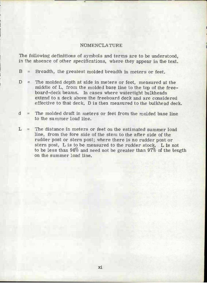
The following definitions of symbols and terms are to be understood,in the absence of other specifications, where they appear in the text.
B = Breadth, the greatest molded breadth in meters or feet.
D = The molded depth at side in meters or feet, measured at themiddle of L, from the molded base line to the top of the free-board-deck beams. In cases where watertight bulkheadsextend to a deck above the freeboard deck and are consideredeffective to that deck, D is then measured to the bulkhead deck.
d = The molded draft in meters or feèt from the molded base lineto the summer load line.
L = The distance in meters or feet on the estimated summer loadline, from the fore side of the stern to the after side of therudder post or stern post; where there is no rudder post orstern post, L is to be measured to the rudder stock. L is notto be less than 96% and need not be greater than 97% of the lengthon the summer load line.
xi

SHIP STRUCTURE COMMITTEE
The SHIP STRUCTURE COMMITTEE is constituted to prosecute a researchprogram to improve the hull structures of ships by an extension of knowledgepertaining to design, materials nd methods of fabrication.
RADM W. M. Benkert, USCGChief, Office of Merchant Marine Safety
U.S. Coast Guard Headquarters
tír. P. M. PalermoAsst. for StructuresNaval Ship Engineering CenterNaval Ship Systems Command
Mr. J. L. Foley
Vice PresidentAmerican Bureau of Shipping
SHIP STRUCTURE SUBCOMMITTEE
The SHIP STRUCTURE SUBCOMMITTEE acts for the Ship Structure Committeeon technical matters by providing technical coordination for the determinationof goals and objectives of the program, and by evaluating and interpreting theresults in terms of ship structural design, construction and operation.
NAVAL SEA SYSTEMS COMMAND AMERICAN BUREAU OF SHIPPING
Mr. C. Pohier - Member Mr. S. G. Stiansen - ChairmanMr. J. B. O'Brien - Contract Administrator Mr. I. L. Stern - MemberMr. G. Sorkin - Member Dr. H. Y. Jan - Member
U.S. COAST GUARD SOCIETY OF NAVAL ARCHITECTS & MARINEENGI NEERS
LCDR E. A. Chazal - SecretaryCAPT C. B. Glass - Iember Mr. A. B. Stavovy - LiaisonLCDR S. H. Davis - MemberICOR J. N. Naegle - Memb.r WELDING RESEARCH COUNCIL
MARITIME ADMINISTRATION Mr. K. H. Koopman Liaison
Mr. N. Hammer - Member INTERNATIONAL SHIP STRUCTURES CONGRESSMr. F. Dashnaw - MemberMr. F. Seibold - Member Prof. J. H. Evans - LiaisonMr. R. K. Kiss - Member
U.S. COAST GUARD ACADEMYMILITARY SEALIFT COMMAND
CAPT W. C. Nolan - LiaisonMr. D. Stein - MemberMr. T. W. Chapman - Member STATE UNIV. OF FLY. MARITIME COLLEGEMr. A. B. Stavovy - MemberCOR J. L. Sigons - Member Dr. W. R. Porter - Liaison
NATIONAL ACADE OF SCIENCES AMERICAN IRON & STEEL INSTITUTESHIP RESEARCH COMMITTEE
Mr. R. H. Sterne - LiaisonMr. R. W. Rumke - LiaisonProf. J. E. Goldberg - Liaison U.S. NAVAL ACAEJEMY
xiiDr. R. Bhattacharyya - Liaison
Mr. M. PitkinAsst. Administrator for
Commerci al Devel ooment
Maritime Administration
Mr. C. J. WhitestoneMaintenance & Repair OfficerMilitary Sealift Command
Section 1
ThÏTRODUC TION
The principal aim of this report is to review current practices related to thedesign of ship structural details. The importance of structural details isclear:
Their layout and fabrication represent a sizable fraction ofhull construction costs,.
Details are often the source of cracks and other failures which,under certain circumstances, could lead to serious damage tothe ship hull girder.
The trend toward decreasing ship hull scantlings (i. e. increasingaverage hull stresses) has the potential of increasing the damageat details discussed above.
Researchers have largely neglected the analysis of structuraldetails; at least in part because the configuration and purposeof these details vary greatly and are not commonly describedor discussed in the literature.
Due to the lack of analytical and experimental effort devoted to structuraldetails, their determination has been left up to draftsmen and designers,with only small engineering input.
In Sections 3 and 4 is presented a fairly comprehensive catalogue of commonstructural details and of published rules most applicable to their design.Review of those sections indicates that rule applicability is most tenuous:only for brackets is there some guidance on scantlings. Therefore the twosections are essentially independent of one another, with Section 4 servingmore to illustrate the lack of applicable guidance than to provide technicaldirection. This sufficiently defines the scope of the problem facing thedesigner, and should help to guide the needed efforts of interested researchers.
Welding details are not discussed in this review for two equally compellingreasons:
They are too varied in configuration, purpose and relevant materialand fabrication parameters to be properly considered as only partof a modest study effort, and
The Rules of the American Bureau of Shipping were in the processof drastic revision on this subject during the course of the Project.
1-1

The report makes evident both the need and possibility of standardization ofstructural details, but that can best be accomplished based on analytical orexperimental work that will provide a sound basis for such selection.
No analytical work related to detail design is included in this Report becauseexhaustive literature search provided a most inadequate background on whichto build further development within the limited scope of this Project.
1-2

Section 2
COUNT AND RANKING OF STRUCTURAL DETAILS
The specific and limited objective of this section was to establish a ranking,by total manhours, of broad categories of structural details. The importanceof structural details is based more on their effect on ship strength than onship cost, but the ranking provided herein can give insight into the need foranalytical and design effort geared to reduction in ship production costs.
The overall categories of details counted for which manhour estimates wereprepared are shown in Table 2-1. The count was made based on study of aboutfifty structural plans for each of two ships: a barge carrying ship and anLNG tanker. These two vessel types were selected solely because they repre-sent our most recent commercial shipbuilding experience.
Manhours were estimated using conventional cost engineering data for thefollowing individual activities involved in detail fabrication:
Layout and lofting.
Cutting and burning.
Subassembly (where applicable).
Installation, fitup, welding, inspection.Handling.
Estimates are not based on actual returned labor data because those are notavailable at such a fine work package breakdown level. Therefore the datapresented should not be construed as capable of accurately discerning betweenalternative designs.
Estimated manhours and corresponding typical scantlings are reported, whereapplicable, under the appropriate detail sketches in Section 3. This was donefor convenience only, to avoid repetition of the necessary sketches in thissection.
Approximate total hull steel weight (as an indication of ship size) for the twoships used is:
Barge Carrier: 14, 000 long tons
LNG Tanker: 22, 600 long tons
A rough estimate of the percentage of manhours required for all phases ofstructural detail fabrication and installation as compared to total manhoursrequired for all hull steel fabrication and erection is in the range of 10 to20 percent.
2-1

This proportion, which is high in terms of tonnages involved, is clearlyexplained in terms of the relative complexity of structural details andother components such as framing members and shell, deck and bulkheadplating.
Standardization and simplification of structural details can therefore beexpected to play a noticeable role in reducing shipbuilding costs.
2-2

TABLE 2-1
COUNT AND RANKING OF SHTP STRUCTURAL DETAILS
LNG CARRIER
Total 107, 440
BARGE CARRIER
Total 130, 573
RANK TYPE - DESCRIPTION TOTAL COUNTTOTAL
MANHOURS
i Panel Stiffeners 11090 51835
2 Brackets 1330 14760
3 Scallops 20020 10605
4 Openings in Girders 12700 10510
5 Structural Intersections 4950 8640
6 Chocks 1180 5080
7 Tripping Brackets 740 2530
8 Stanchion Support 190 2000
9 Stiffener Endings 1360 1180
10 Snipes 770 230
ii Miscellaneous Cutouts 150 70
i Structural Intersection 22880 62910
2 Stiffener Endings - Chocks 11590 27125
3 Panel Stiffeners 7050 26455
4 Brackets 1200 4550
5 Tripping Brackets 250 3333
6 Openings in Girders 7370 3270
7 Stanchion Support 390 2700
8 Snipes 500 140
9 Scallops 200 90

NOTES
2-4
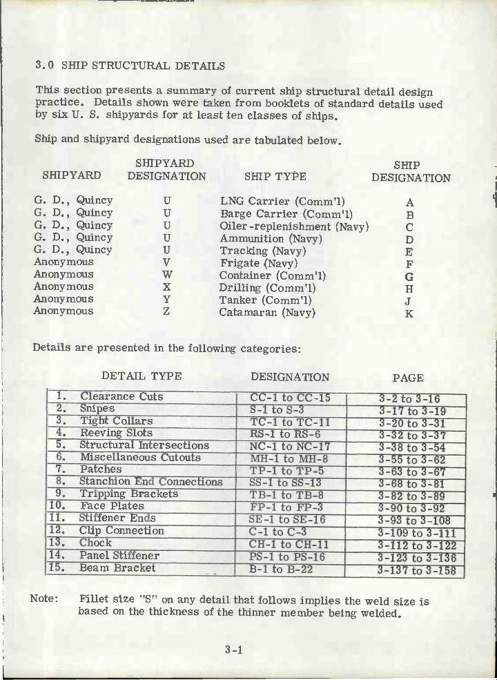
3.0 SHIP STRUCTURAL DETAILS
This section presents a summary of current ship structural detail designpractice. Details shown were taken from booklets of standard details usedby six U. S. shipyards for at least ten classes of ships.
Ship and shipyard designations used are tabulated below.
Details are presented in the following categories:
DETAIL TYPE DESIGNATION PAGE
3-1
Note: Fillet size "S'e on any detail that follows implies the weld size isbased on the thickness of the thinner member being welded.
1. Clearance Cuts CC-1 to CC-15 to 3-162. Snipes S-ltoS-3 3-17to3-193. Tight Collars TC-1 to TC-11 3-20 to 3-314. Reeving Slots RS-1 to RS-6 3-32 to 3-375. Structural Intersections NC-i to NC-i? 3-38 to 3-546. Miscellaneous Cutouts MH-1 to MH-8 3-55 to 3-627. Patches TP-i to TP-5 3-63 to 3-678. Stanchion End Connections SS-i to SS-13 3-68 to 3-819. Tripping Brackets TB-i to TB-8 3-82 to 3-89
10. Face Plates FP-1 to FP-3 3-90 to 3-9211. Stiffener Ends SE-1 to SE-16 3-93 to 3-10812. ClipConnection C-ltoC-3 3-iO9to3-ill13. Chock CH-i to CH-il 3-112 to 3-12214. Panel Stiffener PS-i to PS-16 3-123 to 3-13615. Beam Bracket B-i to B-22 3-137 to 3-158
SHIPYARDSHIPYARD
DESIGNATION SHIP TYPESHIP
DESIGNATION
G. D., Quincy U LNG Carrier (Comm'l) AG. D., Quincy U Barge Carrier (Comm'l) BG. D., Quincy U Oiler-replenishment (Navy) CG. D., Quincy U Ammunition (Navy) DG. D., Quincy U Tracking (Navy) EAnonymous V Frigate (Navy) FAnonymous W Container (Comm'l) GAnonymous X Drilling (Comm'l) HAnonymous Y Tanker (Comm?1) JAnonymous Z Catamaran (Navy) K

lì
RAD IUS
N
3-2
cc-1
DECK PLATING
Detail Type: CLEARANCE CUTS FOR LONGITUDINAL BEAMS
Comments: This detail is used by Shipyard "Y" on ship type "J" to provideopenings in non-tight structure for the passage of flat barlongitudinals. These details can be found in areas where decklongitudinals pass through transverse girders and non-tightbulkheads. Use is limited to members requiring no supportassistance from the penetrated members, such as in a tensiledomain.
FEN[TPJ\TEDNl E M B E R
'e
SNIPE
IL1xrRADIUS
31!FLAT BAR
DECK PLATING
SEE S-1
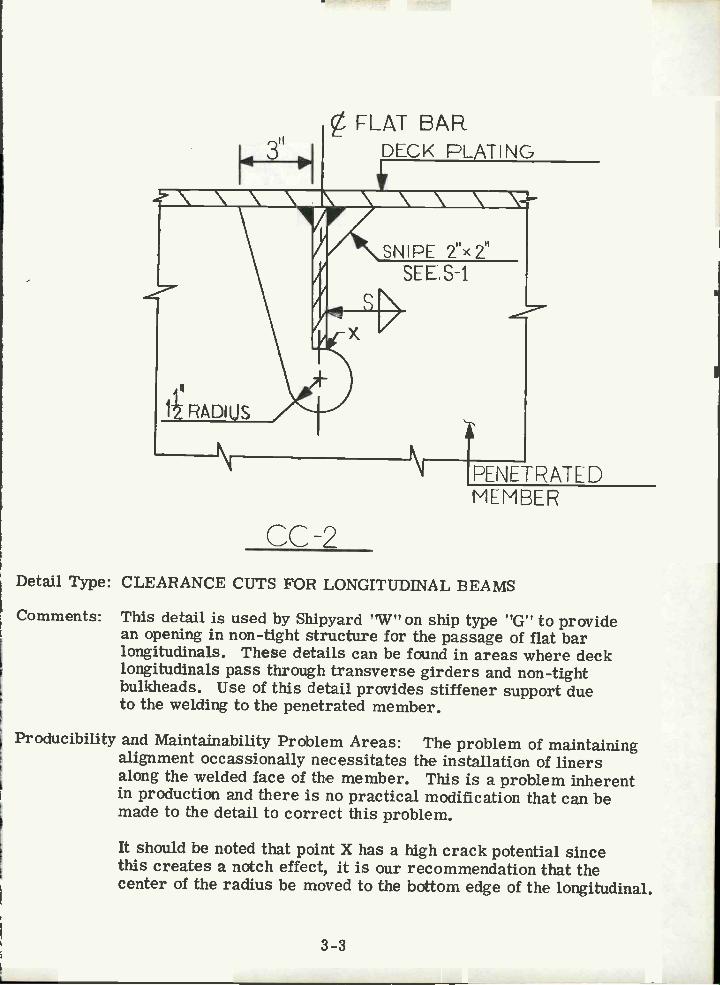
Detail Type: CLEARANCE CUTS FOR LONGITUDINAL BEAMS
Comments: This detail is used by Shipyard 'W" on ship type "G" to providean opening in non-tight structure for the passage of flat barlongitudinals. These details can be found in areas where decklongitudinals pass through transverse girders and non-tightbulkheads. Use of this detail provides stiffener support dueto the welding to the penetrated member.
Producibility and Maintainability Problem Areas: The problem of maintainingalignment occassionally necessitates the installation of linersalong the welded face of the member. This is a problem inherentin production and there is no practical modification that can bemade to the detail to correct this problem.
It should be noted that point X has a high crack potential sincethis creates a notch effect, it is our recommendation that thecenter of the radius be moved to the bottom edge of the longitudinal.
PENETRATE DMEMBER
CC2
3-3

N
I 4' I DECK PLATING\\\\\\ \\\ft<I'\12i
RADIUS
i1111'
EES-2
"RADIUS
1" RADI UPEN ETRATE D
CC3
3_4
Detail Type: CLEARANCE CUTS FOR LONGITUDINAL BEAMS
Comments: This detail is used by Shipyard 'tY" on ship type ,!J?! to providean opening in non-tight structure for the passage of flat barlongitudinals. These details can be found in areas where decklongitudinals pass through transverse girders and non-tightbulkheads. Use of this detail provides some degree of supportassistance due to the welding to the penetrated member.
Producibility and Maintainability Problem Areas: The problem of maintainingalignment occassionally necessitates the installation of linersalong the welded face of the member. This problem is inherentin production and can be improved by using NC-i.
NIEM REP.

DECK (DF SHELLFLAIThG
1Tfl
cc-4
3-5
//
/,\ 3"
4Tc)I RADIuS
¿-N
//
Detail Type: CLEARANCE CUTS FOR LONGITUDNALS
Comments: This detail used by Shipyards "U" and "W" for Ship Types "B" and'VG". This detail is used when the depth of the penetrating memberis one-half the depth of the penetrated member or less. It is usedfor rolled angles penetrating non-tight structure and can be foundin areas where deck and shell longitudinals penetrate transversegirders. Detail provides sorne end reaction capability.
Detail Count Ship "B": 770
i Manhours Required to Complete Typical Detail: 0. 6
Typical Scantlings: 7" x 4" x 1/2" ¿ penetrating 1/2" plate.
Producibility and Maintainability Problem Areas: A cut at the heel of theangle, similar to CC-7, is recommended since this will lessenthe notch effect. See Detail CC-2 for additional comments.
/
FENEJRATED MEMBER
/ /
TO
II
- II
3-6
t
I
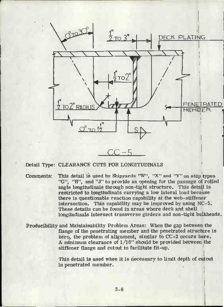
Detail Type: CLEARANCE CUTS FOR LONGITUDII'TALS
Comments: This detail is used by Shipyards 'W", "X" and "Y" on ship types"G", "H", and "J" to provide an opening for the passage of rolledangle longitudinals through non-tight structure. This detail isrestricted to longitudinals carrying a low lateral load becausethere is questionable reaction capability at the web-stiffenerintersection. This capability may be improved by using NC-5.These details can be found in areas where deck and shelllongitudinals intersect transverse girders and non-tight bulkheads.
Producibility and Maintainability Problem Areas: When the gap between theflange of the penetrating member and the penetrated structure iszero, the problem of alignment, similar to CC-2 occurs here.A minimum clearance of 1/16" should be provided between thestiffener flange and cutout to facilitate fit-up.
This detail is used when it is necessary to limit depth of cutoutin penetrated member.
DECK PLAT$NG
FEÑETPTE DMEM8ER
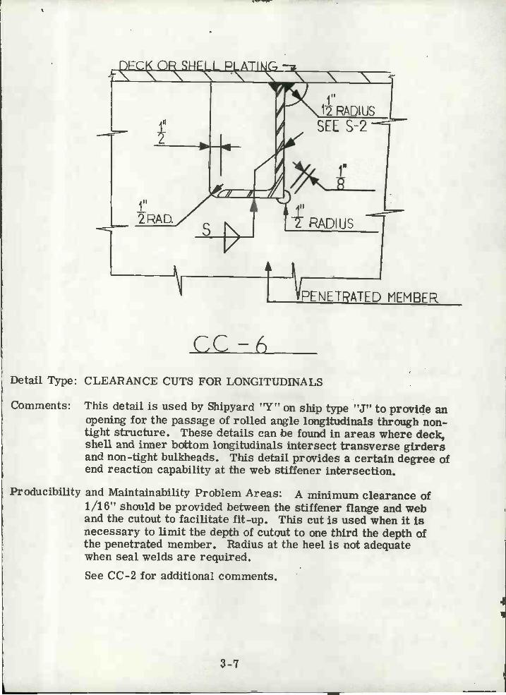
CC-6Detail Type: CLEARANCE CUTS FOR LONGITUDINALS
Comments: This detail is used by Shipyard "Y" on ship type "J" to provide anopening for the passage of rolled angle longitudinals through non-tight structure. These details can be found in areas where deck,shell and inner bottom longitudinals intersect transverse girdersand non-tight bulkheads. This detail provides a certain degree ofend reaction capability at the web stiffener intersection.
Producibility and Maintainability Problem Areas: A minimum clearance of1/16" should be provided between the stiffener flange and weband the cutout to facilitate fit-up. This cut is used when it isnecessary to limit the depth of cutout to one third the depth ofthe penetrated member. Radius at the heel is not adequatewhen seal welds are required.See CC-2 for additional comments.
MPENETRATED MEMBER
3-7

Comments:
DECK OP SHELL PLATING
Detail Count Ship Type "A": 10, 600
Manhours Required to Complete Typical Detail: 0. 9
Typical Scantlings: 14-5/8"x l/2"x 6-3/16"x l/2"/penetrating1/2" Plate.
Producibility and Maintainability Problem Areas: See CC-2 for details.
CC-/
3-8
Detail Type: CLEARANCE CUTS FOR LONGITTJDINALS
F'ENETFATED MEMEEF
This detail is used by Shipyard "U" on ship type "A" to provide anopening for the passage of fabricated angle longitudinals through non-tight structure. This detail may only be used when the depth of cutoutis equal to or less than one-third the depth of the penetratedmembers. These details can be found in areas where innerbottom and bottom shell longitudinals are penetrating non-tightfloors. This detail provides some end reaction capability. Shearcapacity of web attachment should be examined. The use of theradius cut at the heel of the angle minimizes welding and facilitatesinstallation of flat bar chocks, see chock CH-5, since the inclinedsnipe is now accessible from both sides. Also, this configurationreduces the notch effect found in details CC-4, CC-9.

DECK PLATING
CC-8
3-9
A D U
Detail Type: CLEARANCE CUTS FOR LONGITUDINALS
Comments: This detail is used by Shipyard "U" on ship type "A", to provide anopening for the passage of rolled angle longitudinals through non-tight structure. This detail is used when the depth of the cutout isnot critical to the penetrated member. These details can be foundin areas where deck and side shell longitudinals penetrate transversegirders and/or non-tight bulkheads. This detail provides some endreaction capability.
Detail Count Ship Type "A": 700
Manhours to Complete Typical Detail: 0. 6
Typical Scantlings: 7"x 4"x 1/2"penetrating 1,/2" Plate.
Producibility and Maintainability Problem Areas: When the depth of the cutoutbecomes critical a collar plate may be fitted or CC-9 may be used.See CC-2 for additional comments.
PENETRATEDM E M B E P.

iNNER ECTTC;M FLATNG
N 'TN NRADIUS
SEE S-2
4L9
RADIUS
N
I II1' RADIUS
Detail Type: CLEARANCE CUTS FOR LONGITUDINALS
Comments: This detail is used by Shipyard "Ti" on ship type "A" to provide anopening for the passage of rolled or fabricated angle longitudinalsthrough non-tight structure. It is to be used when the depth ofpenetrating member is greater than one-third the depth of thepenetrated member. These details can be found in areas whereinner bottom and bottom shell longitudinals penetrate shallowtransverse girders. This detail provides some end reaction capabilit
Detail Count Ship Type "A": 1400
Manhours Required to Complete Typical Detail: 0. 6 to 1. 0
Typical Scantlings: 7"x 4"x 1/2"Lto 10"x 1/2"-6-3/16"x 1/2"penetrating1/2" Plate.
Producibility and Maintainability Problem Areas: Detail CC-6, with a 1" heelradius is preferred over this detail since crack potential at theheel of the angle is removed. See CC-2 for additional comments.
3-10
PENETRATED MEMBER
CC-9
11 1"2TOt2
TOi RADIUS
NPENETRATED MEMBER.
3-11
DECK PLATING
r////
,J'f(dIthqgiI
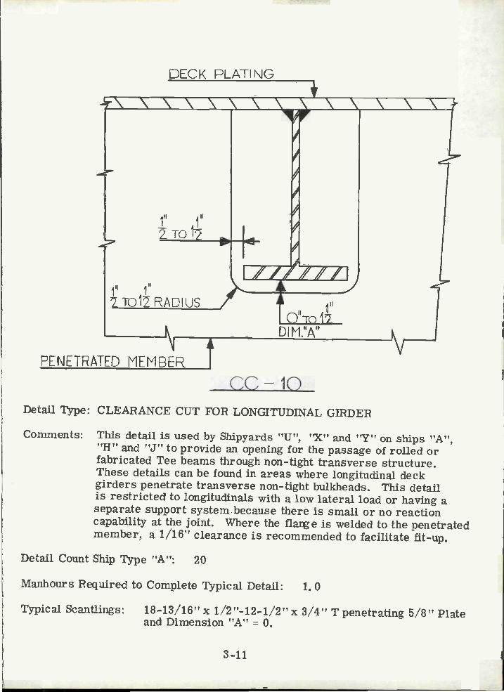
cc10Detail Type: CLEARANCE CUT FOR LONGITUDINAL GIRDER
Comments: This detail is used by Shipyards "U", "X" and "Y" on ships "A","H" and "J" to provide an opening for the passage of rolled orfabricated Tee beams through non-tight transverse structure.These details can be found in areas where longitudinal deckgirders penetrate transverse non-tight bulkheads. This detailis restricted to longitudina1s with a low lateral load or having aseparate support system because there is small or no reactioncapability at the joint. Where the flare is welded to the penetratedmember, a 1/16" clearance is recommended to facilitate fit-up.
Detail Count Ship Type "A": 20
Manhours Required to Complete Typical Detail: 1. 0
Typical Scantlings: 18-13/16"x 1/2"-12-1/2"x 3/4" T penetrating 5/8" Plateand Dimension "A" = 0.

NONTIGHT STRUCTURE
F APPLICABLE
N's'
DECK .,SHELL OR BULKHEAD
cc-ii
1"T03" RADIUS
SHIP ERECTION BUTT
Detail Type: CLEARANCE CUTS FOR WELDING (RATHOLES)
Comments: This detail is used by Shipyards "U", "W", "X" and "Z" on shipstc', "D", and ???, to facilitate welding
of erection and sub-assembly butts in non-tight structure. If thereis no weld at point "A" the detail is only applicable to butts in non-tight structure clear of tanks, Wrapping the weld at point "A"creates a water or oil stop and this permits the use of this detail innon-tight structure in tanks. The radius of the cut depends on thedepth of member being cut, a relationship of Radius = 1/4 Depth ofMember can be established with a maximum value of R = 3 inches.
Detail Count: Ship Type "A" = 1170; Ship Type "B" = 3040
Manhours Required to Complete Typical Detail: 0. 3
Typical Scantlings: 3" Radius penetrating 5/8" Plate.
Producibility and Maintainability Problem Areas: If the cut is made by hand, itis difficult to obtain a smooth cut. If ragged edges exist, stressconcentrations at these locations may lead to fracture failure. Tocorrect this situation the radius should be cut with a template or anautomatic burning machine. Where this solution is not practical, apatch may be installed (see TP-i for details). With this detail theshipyard also eliminates the possibility of cracks occurring due tofaulty chipping of the butt weld reinforcement.
3-12

3"x 3" SNIPESEE S-2
SHELL OR DECK
CC HZ
TRANSVERSE FLOOP
Li" ,.MAX.
Detail Type: CLEARANCE CUTS FOR ERECTION BUTTS
Comments: This detail is used by Shipyards "U", "V", 'W" and "Y"on ships "D", "E", "F", "G" and to provide weldingaccess for erection butts close to floors or bulkheads.The -welding rationale used for CC-11 is applicable tothis detail. This detail also provides clearance for theweld of the transverse floor to the shell or deck.
Producibility and Maintainability Problém Areas: The problem ofinsuring a smooth cut as mentioned in CC-11 alsooccurs here. If weld wrapping is desired, CC-13is preferable.
3-13
/
NONTIGHT MEMEE
1"1 RADIUS
ERECTION PUTT

2" RAPiU$SEE S-2
CC-13
TPANS\/LSE FLEXÙR.
)NTGHT MEMBER.
2"PDIjs
MAX.
Detail Type: CLEARANCE CUTS FOR ERECTION BUTTS
Comments: This detail is used by Shipyards "U" and 'X" on shipsIA??, 'TB", "C" and "H" to provide welding access forerection butts close to floors or bulkheads. Foradditional comments see CC-11 and CC-12.
Detail Count: Ship Type "A" = 150; Ship Type "B" = 200
Manhours Required to Complete Typical Detail: 0. 5
Producibility and Maintainability Problem Areas: For details seeCC-11.
3-14
EREC71OÑ BUTT

-- 6 ip,J 1H
I IRADIUS
\ \ \
cc- iEIRECTION BUTT
Detail Type: CLEARANCE CUTS AT ERECTION BUTTS
Comments: This detail is used by Shipyard "U" on ship type "A" toprovide welding access for the AVA welding machine inway of erection butts. When this cut is made in shallowmembers a patch may be required, see TP-5. Thisdetail is often used in lieu of CC-11.
Detail Count Ship Type "A": 19400
Manhours Required to Complete Typical Detail: 0. 5
Producibility and Maintainability Problem Areas: For details seeCC-11.
3-15

2'RADRJS
NONTIGHT MEMBER
CC-15
Detail Type: CLEARANCE CUTS FOR ERECTION BUTTS
Comments: This detail is used by Shipyard "Y" on ship type "J"to provide clearance for welding of erection butts andsub-assembly butts. For other comments see CC-11.
3-16
ERECTION DUTT
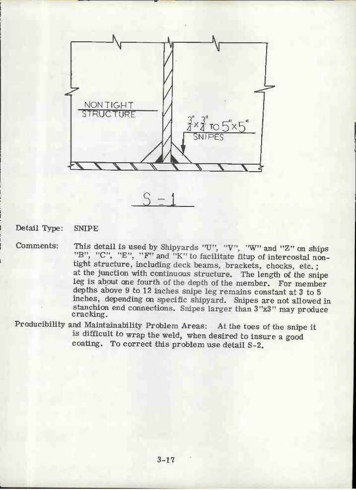
Detail Type: SNIPE
Comments: This detail is used by Shipyards "U", "V", "W" and "Z" on ships"B", "C", "E", "F" and "K" to facilitate fitup of intercostal non-tight structure, including deck beams, brackets, chocks, etc.;at the junction with continuous structure. The length of the snipeleg is about one fourth of the depth of the member. For memberdepths above 9 to 12 inches snipe leg remains constant at 3 to 5inches, depending on specific shipyard. Snipes are not allowed instanchion end connections. Snipes larger than 3"x3" may producecracking.
Producibility and Maintainability Problem Areas: At the toes of the snipe itis difficult to wrap the weld, when desired to insure a goodcoating. To correct this problem use detail S-2.
s-1
3-17

Detail Type: SNIPE
Comments: This detail is used by Shipyards "U", "W" and "X" onships 'A t t t, tt U, t t t, 'G'' aiid ''II'', tofacilitate fitup of intercostal non-tight structure atthe intersection with continuous structure. Sniperadius is a function of member depth: R = 1/4 depth.When depth is greater than 12 inches, R remainsconstant at 3 inches.
Detail Count: Ship Type "A" = 770; Ship Type "B" = 500
Manhours Required to Complete Typical Detail: 0. 3
Typical Scantlings: 3" Radius penetrating 5/8" Plate.
S-2
3-18

"4
TIGHTSTRUCTURE
ÏIx-tu22
Detail Type: SNIPE
Comments: This detail is used by all six shipyards surveyed. It isused in way of tank boundaries, stanchion end connections,and other tight structure. The straight edged snipe isfavored since this detail requires less weld metal toclose the gap. When the size of the fillet weld necessitatesusing detail S-1 or S-2, detail TP-4 provides an alternative.
FILL WITHWELD
S-3
3-19
HTSTRUCTURE
'US
FILL WITHWELD

2"
3"LAP
3-20
V
TIGHT MEMREP
FOP UT DETAILS SEE CC-i
TC-tDetail Type: LAPPED TIGHT COLLARS
Comments: This detail is used by Shipyard "Y't on ship type "J", for collaringlongitudinal flat bar deck beams penetrating tight bulkheads andin areas of high stress. Generally, the thickness of the collarplate is to be the same as the web of the penetrated member.
Producibility and Maintainability Problem Areas: Welding collar plate topenetrated member is a problem at the square corners becausethis requires striking a new arc along each side, this weldingmay also lead to a potential crack problem at the intersection.Fitup along the top will be difficult because the collar plate willinterfere with the weld of the web to the deck.
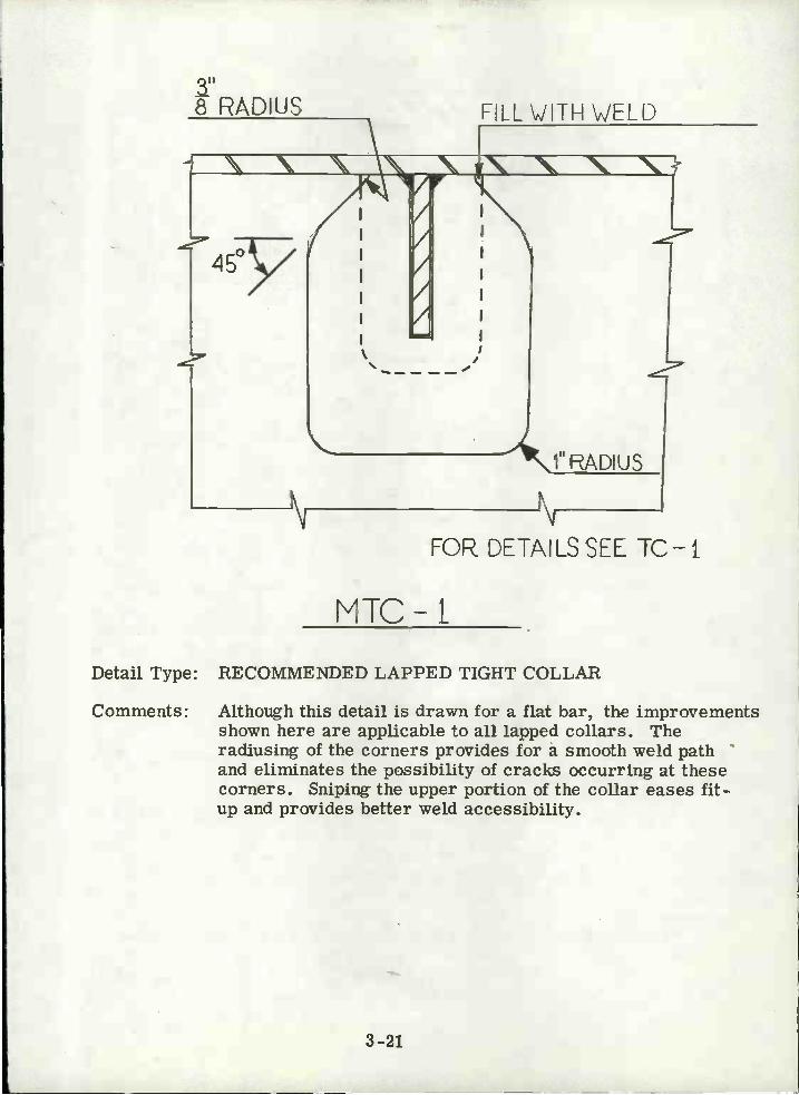
Proposed Modifications: Radius the lower corners of the collar plate and snipethe upper corners. See figure MTC-1, pg 3-2 1, for recommendedimprovements.
\ \ \ N8 RADIUS
N
3-21
FILL VJITH WELD
Detail Type: RECOMMENDED LAPPED TIGHT COLLAR
Comments: Although this detail is drawn for a flat bar, the improvementsshown here are applicable to all lapped collars. Theradiusing of the corners provides for a smooth weld pathand eliminates the possibility of cracks occurring at thesecorners. Sniping the upper portion of the collar eases fit-up and provides better weld accessibility.
1"ADIUS
FOR DETAILS SEE IC-I
MTC-t
FILL WITH WELD
3-22
8 PLT-H
/ FILL WITH WELD
V
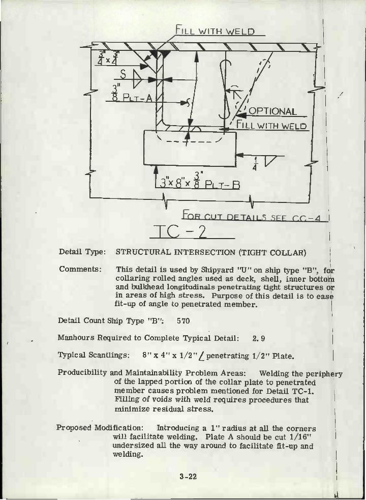
Detail Type: STRUCTURAL INTERSECTION (TIGHT COLLAR)
Comments: This detail is used by Shipyard "U" on ship type "B', forcollaring rolled angles used as deck, shell, inner bottomand bulkhead longitudinals penetrating tight structures orin areas of high stress. Purpose of this detail is to easefit-up of angle to penetrated member.
Detail Count Ship Type "B": 570
Manhours Required to Complete Typical Detail: 2. 9
Typical Scantlings: 8"x 4"x 1/2"penetrating 1/2" Plate.
Producibility and Maintainability Problem Areas: Welding the peripheryof the lapped portion of the collar plate to penetratedmember causes problem mentioned for Detail TC-1.Filling of voids with weld requires procedures thatminimize residual stress.
Proposed Modification: Jntroducing a 1" radius at all the cornerswill facilitate welding. Plate A should be cut 1/16"undersized all the way around to facilitate fit-up andwelding.
CUT nETAILS SSFF CC-4IL

FILL j'ITH WELD
SEE S-1
PLATE-A
SVsR
r'ORCUT DETAILS SEE CC-4
IC 3Detail Type: STRUCTURAL INTERSECTION (LAPPED TIGHT COLLAR)
Comments: This detail is used by Shipyard "U" on ship type "B" for collaringrolled angles used as deck, shell, inner bottom, and bulkheadlongitudinals penetrating tight structure and in areas of high stress.This detail requires less fit-up and should be used in lieu ofdetail TC-2 when shear or compressive stresses are less severe.(See TC-7)
Detail Count Ship Type "B": 2740
Manhours Required to Complete Typical Detail: 2. 6
Typical Scantlings: 8"x 4"x 1/2"/penetrating 1/2" Plate.
Producibility and Maintainability Problem Areas: Welding of the square cornersmay be improved by radiusing, and weld acc8ssibility may beimproved by increasing the snipe angle to 45 . See figure MTC-1for details. Collar plate A should be cut 1/16" undersize tofacilitate fitting and welding.
3-23
FILL \fIITH \1ELD
SFFLL WITH WELD
3Q0
LPPABOUT 2'
x
e
b
USED BYSHIP'X'ARD U
3U
PADIUSRLL \,JTH \JELD
' \ \ \\
J,I
2uTyp
FILL JITH 1ELD
Tc-
3-24
T03' LAP
2TO 3"LAP
B FLATE
NFÜR CUT DETAILS SEE CC-6
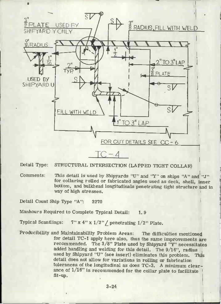
Detail Type: STRUCTURAL INTERSECTION (LAPPED TIGHT COLLAR)
Comments: This detail is used by Shipyards "U" and "Y" on ships "A" and "J"for collaring rolled or fabricated angles used as deck, shell, innerbottom, and bulkhead longitudinals penetrating tight structure and inway of high stresses.
Detail Count Ship Type "A": 2270
Manhours Required to Complete Typical Detail: 1. 9
Typical Scantlings: 7" x 4" x 1/2"L penetrating 1/2" Plate.
Producibility and Maintainability Problem Areas: The difficulties mentionedfor detail TC-1 apply here also, thus the same improvements arerecommended. The 3/8" Plate used by Shipyard "Y" necessitatesadded handling and welding for this detail. The 9/16", radiusused by Shipyard "U" (see insert) eliminates this problem. Thisdetail does not allow for variations in rolling or fabricationtolerances of the longitudinal as does TC-3. A minimum clear-ance of 1/16" is recommended for the collar plate to facilitatefit-up.

PLt\TE-B
2'To 3" LAP
TC-5
3-25
DECK PLATING
sV
2"T03" LAP
2 PLATE-A
FORCUT DETAILS SEE CC-5
Detail Type: STRUCTURAL INTERSECTION (LAPPED TIGHT COLLAR)
Comments: This detail is used by Shipyards "X" and "Y" on ship types "H"and "J" for collaring rolled angles used as deck longitudinalspenetrating tight bul.kheads. Other details and comments for thiscollar are similar to those recorded in TC-1. To facilitate fit-up, collar plate A should be cut 1/16" undersize.

kPLATL- B
\ \ \ \ \ '\\
TQ 3" LAP
POECUTD[TAlL SEE CC-5
C-6
Detail Type: STRUCTURAL INTERSECTION (LAPPED TIGHT COLLAR)
Comments: This detail is used by Shipyards "W", "X" and "Y" on ship types"G", "H" and "J" for collaring rolled angles used as decklongitudinals penetrating tanks and other tight structure. Otherdetails and problems for this collar are similar to those recordedin TC-1. Plate A should be cut 1/16" undersize to facilitatefit-up.
3-26
I O ri(_' f
t i"Il
l2TO3L,PJ PLATE-A
DECK PLATING
FILL JITH WELD
i" N2RADIUS, PILL \IJITH \,JELD
TC-7
3-27
SAME THICKNESS
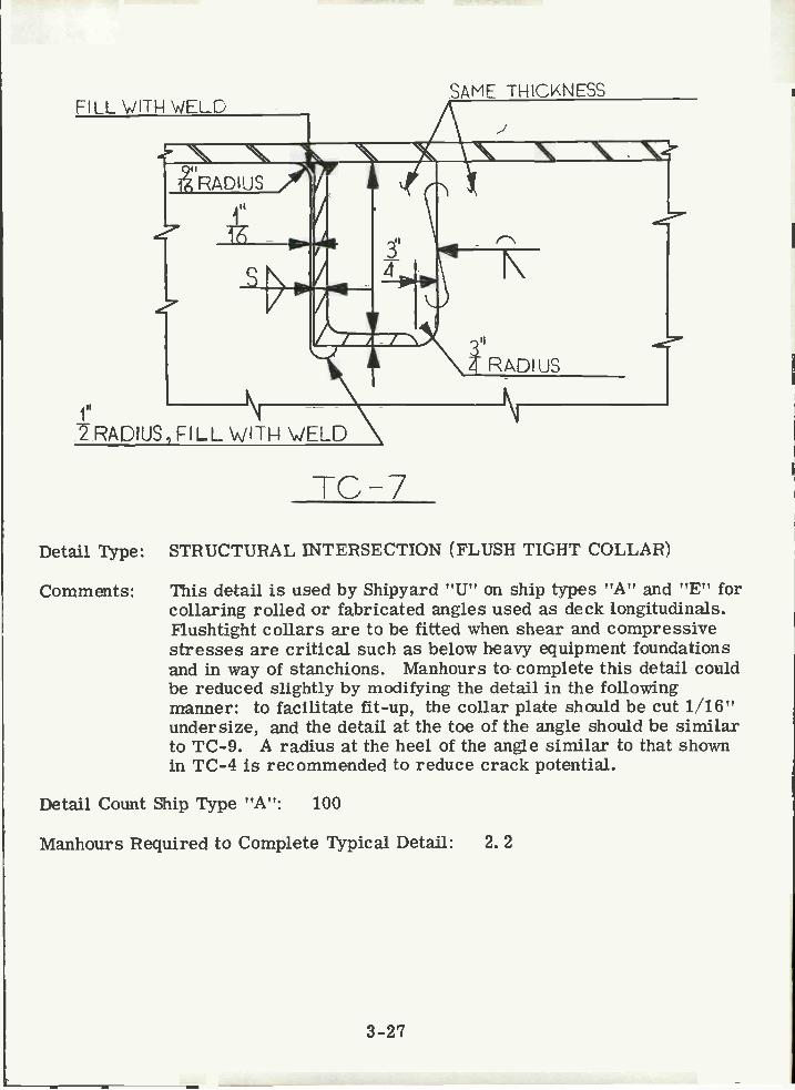
Detail Type: STRUCTURAL INTERSECTION (FLUSH TIGHT COLLAR)
Comments: This detail is used by Shipyard "U" on ship types "A" and "E" forcollaring rolled or fabricated angles used as deck longitudinals.Flushtight collars are to be fitted when shear and compressivestresses are critical such as below heavy equipment foundationsand in way of stanchions. Manhours to complete this detail couldbe reduced slightly by modifying the detail in the followingmanner: to facilitate fit-up, the collar plate should be cut 1/16"undersize, and the detail at the toe of the angle should be similarto TC-9. A radius at the heel of the angle similar to that shownin TC-4 is recommended to reduce crack potential.
Detail Count Ship Type "A": loo
Manhours Required to Complete Typical Detail: 2. 2

>
JC-8
3-28
SAME THICKNESS
I
OPTION A, L
FOPCJ1 DETMLS SEE CC-10
Detail Type: STRUCTURAL INTERSECTION (FLUSH TIGHT COLLAR)
Comments: This detail is used by Shipyard "U", "V" and "Z" on ship types"A", "C", "D", "F" and "K" for rolled or built-up Tee beams.Flushtight collars are to be fitted only when continuity of highlystressed structural members is required.
Detail Count Ship Type "A": 20
Manhours Required to Complete Typical Detail: 9. 5
Typical Scantlings: 18-13/16" x 1/2" x 12-1/2" x 3/4" Tee penetrating 5/8"Plate.
Producibility and Maintainability Problem Areas: Fitup time required for thisdetall could be reduced by substituting TC- 9.

N
F-ILL WITH \N'ELD
324
3-29
TC-9
SAME THICKNESS
3"4RADIUS
N
Detail Type: STRUCTURAL INTERSECTION (FLUSH TIGHT COLLAR)
Comments: This detail is used by Shipyard "U" on ship type "B" for collaringrolled or built-up Tee sections used as transverse or longitudinalgirders penetrating tight structure. Flush tight collars are to befitted only when continuity of highly stressed structural membersis required.
Detail Count Ship Type "B": 4270
Manhours Required to Complete Typical Detall: 9. 0
Typical Scantlings: 16" x 5" x 50# I cut to T penetrating 1/2" Plate.

LAP: 5Tw
FOR CUT DETAILS LEE CC-10
'c-10
Detail Type: STRUCTURAL INTERSECTION (LAPPED TIGHT COLLAR)
Comments: This detail is used by Shipyards "U", "V" and "Z" on ship types''c", "D", "E", "F", and "K" for collaring rolled or fabricatedTee beams used as longitudinal or transverse girders. Thisdetail is used extensively on Navy ships.
Producibility and Maintainability Problem Areas: For details of problem areasand proposed modifications see detail TC-1. Fit-up could besimplified by cutting the collar plate 1/16" undersized, and theplate itself straight across at the flange with the gap filled withweld similar to detail TC-3.
3-30
SAME THICKNES:

3-31
FOECUT DETAILS SEE CC- 10
TC-11
Detail Type: STRUCTuRAL INTERSECTION (LAPPED TIGHT COLLAR)
Comments: This detail is used by Shipyards "U", "W", "Y" and "Z" on shiptypes "A", "D", "G", "J" and "K" for collaring Tee sectionsused as longitudinal or transverse girders which penetrate tightstructure.
Detail Count Ship Type "A": 50
Manhours Required to Complete Typical Detail: 6. 5
Typical Scantlings: 18-13/16" x 1/2"-12-1/2" x 3/4" Tee penetrating 5/8" Plate.
Producibility and Maintainability Problem Areas: For details of problem areasand proposed modifications see detail TC-1 and TC-10.
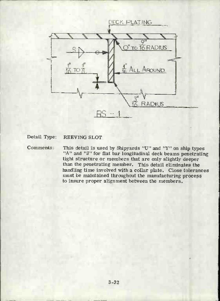
Detail Type: REEVING SLOT
Comments: This detail is used by Shipyards "U" and "Y" on ship types"A" and "J" for flat bar longitudinal deck beams penetratingtight structure or members that are only slightly deeperthan the penetrating member. This detail eliminates thehandling time involved with a collar plate. Close tolerancesmust be maintained throughout the manufacturing processto insure proper alignment between the members.
RS-1
DECK PLATING
3-32

N
Detail Type: REEVING SLOT
Comments: This detail is used by Shipyard "U" on ship type "A" Thisdetail was developed for use in way of deep (24'5c2" to 32"x2") slabs penetrating non-tight webs in the upper wing wallof the ship. The radius cut at the free edge of the slabseliminates the possibility of notching the slab by welding,thereby reducing its efficiency. See RS-1 for additionalcomments.
ERS-2
3'l SHELL PLATING
3-33

Detail Type: REEVING SLOT
Comments: This detail is used by Shipyards "U" and "Y" on ship types "A","B", 'VE" and "J" for rolled angles used as deck and bulkheadlongitudinals penetrating tight structure, or for bulkheadstiffeners penetrating shallow webs.
Comments for RS-1 apply, except that tolerances for this detailmust be tighter since assembly is possible only be reeving.
RS-3
DECK PLATING
3-34
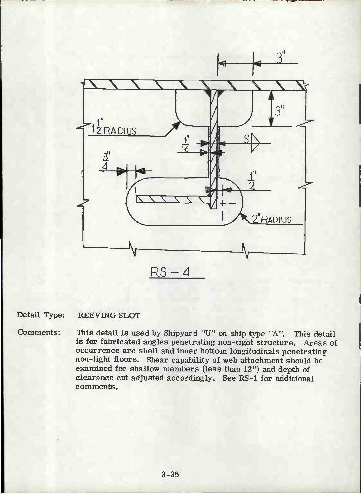
Detail Type: REEVING SLOT
RS-4
3-35
r
psy
Comments: This detail is used by Shipyard !?U on ship type ?A!?. This detailis for fabricated angles penetrating non-tight structure. Areas ofoccurrence are shell and inner bottom longitudinals penetratingnon-tight floors. Shear capability of web attachment should beexamined for shallow members (less than 12") and depth ofclearance cut adjusted accordingly. See RS-1 for additional

N
"RADIUS
Detail Type: REEVING SLOT
Comments: This detail is used by Shipyard "U" on ship type "A". This is anon-tight reeving slot for rolled or fabricated Tee sectionspenetrating areas such as non-tight floors or deep transversewebs. See RS-1 for additional comments.
3-36
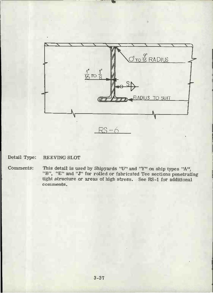
Detail Type: REEVING SLOT
Comments: This detail is used by Shipyards "U" and "Y" on ship types "A","B", "E" and "J" for rolled or fabricated Tee sections penetratingtight structure or areas of high stress. See RS-1 for additionalcomments.
3-37
DECK PLATING
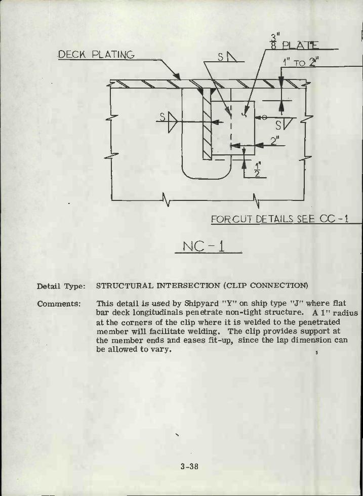
Detall Type: STRUCTURAL INTERSECTION (CLIP CONNECTION)
Comments: This detail is used by Shipyard "Y" on ship type "J" where flatbar deck longitudinals penetrate non-tight structure. A 1" radiusat the corners of the clip where it is welded to the penetratedmember will facilitate welding. The clip provides support atthe member ends and eases fit-up, since the lap dimension canbe allowed to vary.
3-38
N
II
PLATE
FORCUT DETAILS SEE CC-1
NC-I

II
3")<3'x PLATE
3-39
sN
NC -Z
Detail Type: STRUCTURAL INTERSECTION (CLIP CONNECTION)
Comments: This detail is used by Shipyard "U" on ship type "B" where rolledangle deck longitudinals penetrate non-tight structure. Usedwhere flange support is desirable. A 1" radius at the cornersof the clip where it is welded to the penetrated member willfacilitate welding. A cut similar to CC-7 would facilitate fit-upand reduce the crack potential at the heel of the angle.
Detall Count Ship Type "B": 3200
Manhours Required to Complete Typical Detail: 0. 7
Typical Scantlings: 7" x 4" x 1/2"L penetrating 1/2" plate.
PLATE
3-40
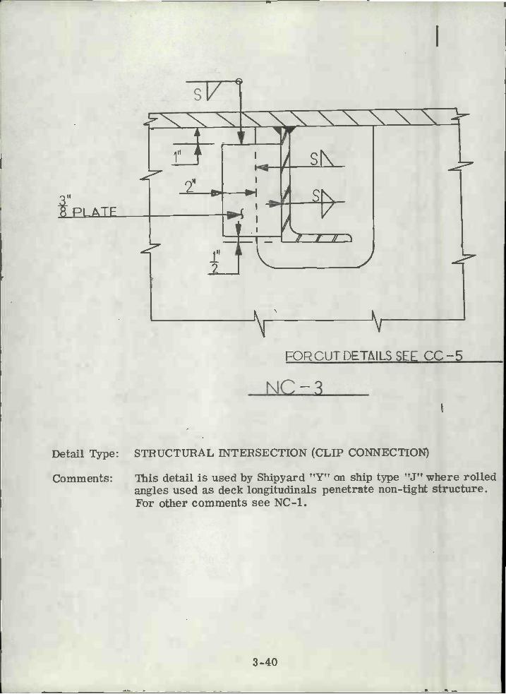
FORCUTL)ETAILS SEE CC-5
NC-3
Detail Type: STRUCTURAL iNTERSECTION (CLIP CONNECTION)
Comments: This detail is used by Shipyard "Y" on ship type "J" where rolledangles used as deck longitudinals penetrate non-tight structure.For other comments see NC-i.

Detail Type:
Comments:
NC-FORCUT DETALS5EE CC-4 TO CC-9
STRUCTURAL INTERSECTION (NON-TIGHT LAPPEDCOLLAR)
This detail is used by Shipyards "U" and "Y" on ship types"A" and "J" for rolled or fabricated angles used as decklongitudinals. The collar plate is added to replace arearemoved by the cut. To facilitate welding the corners ofthe collar plate should be cut with a 1" radius.
Detail Count Ship Type "A": 800
Manhours Required to Complete Typical Detail: 0. 8 To 1. 2.
Typical Scantlings: 7"x 4"x 1/2"Lto 14-5/8"x 1/2"-6-3,/16"x 1/2"/penetrating 1/2" Plate.
3-41

NC -b
3-42
FO CUT DTL SEE CC-5
Detail Type: STRUCTURAL INTERSECTION (NON-TIGHT LAPPEDCOLLAR)
Comments: This detail is used by Shipyard "X" on ship type "H". Thiscollar is used on fabricated angles or channels cut to anglesover 9" in depth. Areas of occurrence are shell stringerspenetrating deep web frames and longitudinal girderspenetrating deep transverses. This is not a common detail.If double clips are required consideration should be givento use of a balanced section. Radiusing the corners of thecollar plates improves welding.
In the absence of radii at the upper corners the snipe shownshould begin beyond the cutout to facilitate welding.

L
II NPLATEA
SII'rl-IA
N
3-43
\C-6
'I
FO CUT DETAILS SEL CC-LI
Detail Type: STRUCTURAL INTERSECTION (NON-TIGHT LAPPED COLLAR)
Comments: This detail is used by Shipyard "U" on ship type "B", for rolledor fabricated angles used as deck or shell longitudinals. Thecollar plate is installed to replace area removed by the cut, toprovide flange stability, and to provide improved end support.To facilitate welding, the lapped corners of the collar plateshould be cut with a 1" radius.
Detail Count Ship Type "B": 10100
Manhours Required to Complete Typical Detail: 1, 0
Typical Scantlings: 8" x 4" x 1/2"penetrating 1/2" Plate.
i lii
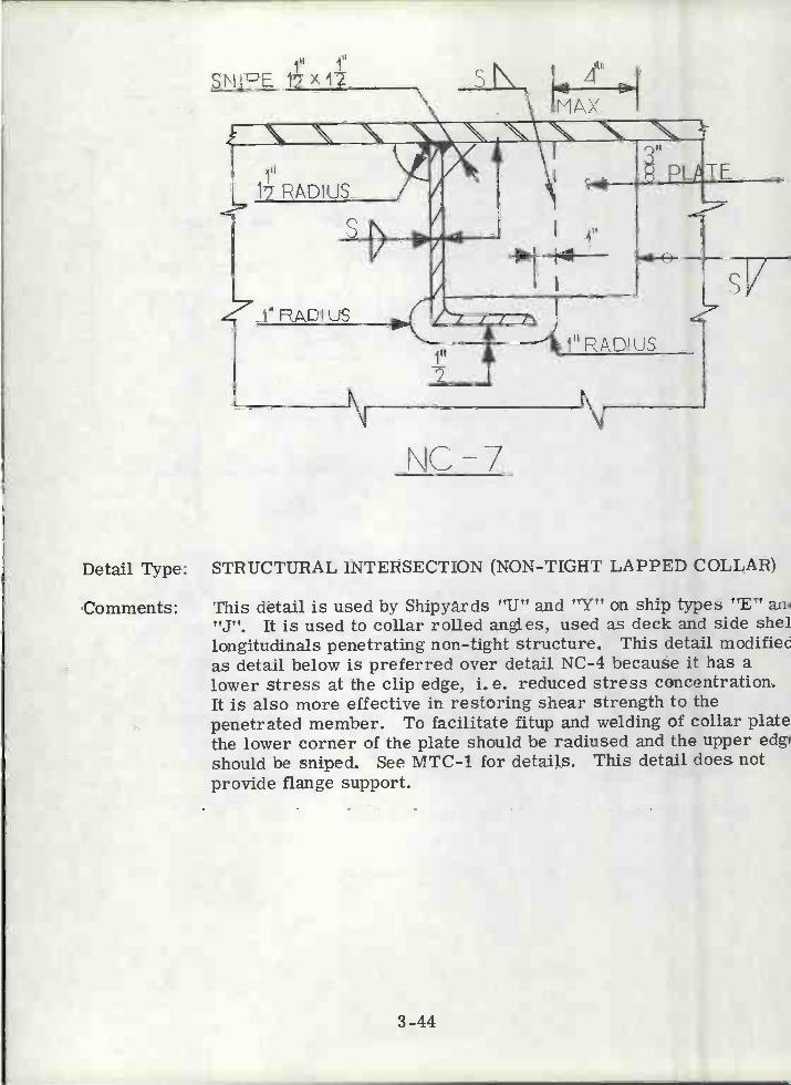
SNIPE 12X1Z
\C-7
3-44
ill
4'I
MAX.
Detail Type: STRUCTURAL INTERSECTION (NON-TIGHT LAPPED COLLAR)
Comments: This detail is used by Shipyards "U" and "Y" on ship types "E" am"J". It is used to collar rolled angles, used as deck and side shellongituclinals penetrating non- tight structure. This detail modifiecas detail below is preferred over detail NC-4 because it has alower stress at the clip edge, i. e. reduced stress concentration.It is also more effective in restoring shear strength to thepenetrated member. To facilitate fitup and welding of collar platethe lower corner of the plate should be radiused and the upper edgishould be sniped. See MTC-1 for details. This detail does notprovide flange support.

\C-8Detail Type: STRUCTURAL INTERSECTION (NON-TIGHT LAPPED COLLAR)
Comments: This detail is used by Shipyard "U" on ship type "B" for collaringrolled angles used as deck or side shell longitudinals penetratingnon-tight structure. This detail is used in areas of high shearstress when the member is carrying a large lateral load.Increasing the snipe angle to 450 and radiusing the lower cornersimilar to MTC-1 will improve welding. Cutting the collar 1/16"undersize will facilitate fit-up. The corners of the collar at theweb attachment require trimming. The clearance cut for NC-7is preferable.
Detail Count Ship Type "B": 1400
Manhours Required to Complete Typical Detail: 1. 9
Typical Scantlings: 8" x 4" x 1/2" L penetrating 1/2" Plate.
3-45
FORCLJT DETAILS SEE CC-4
SAME TI-UCKNESS
3-46
Nf
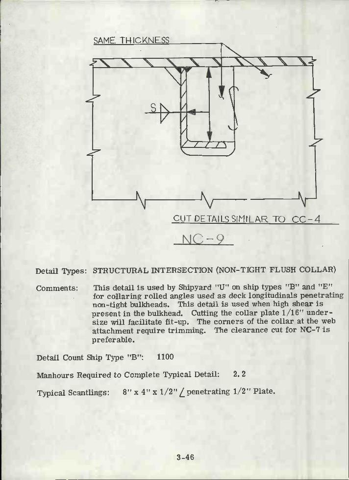
NC-9CUT DETAILS SIMIL A TO CC-4
Detail Types: STRUCTURAL INTERSECTION (NON-TIGHT FLUSH COLLAR)
Comments: This detail is used by Shipyard "U" on ship types "B" and "E"for collaring rolled angles used as deck longitudinals penetratingnon-tight bulkheads. This detail is used when high shear ispresent in the bulkhead. Cutting the collar plate 1/16" under-size will facilitate fit-up. The corners of the collar at the webattachment require trimming. The clearance cut for NC-7 ispreferable.
Detail Count Ship Type "B": 1100
Manhours Required to Complete Typical Detail: 2. 2
Typical Scantlings: 8" x 4" x 1/2"penetrating 1/2" Plate.

PLTL (UNLESSOTHER\i'JISL NOTED)
N N \
'li
3-47
\C10EORCUT DETAILS SEE CC-4
Detail Type: STRUCTURAL INTERSECTION (NON-TIGHT COLLAR)
Comments: This detail is used by Shipyard "U" on ship type "B", for collaringmembers penetratíng non-tight structure, subject to high shearin penetrated and penetrating members. Not frequently used.For other comments see TC-2.

DECK PLTlÑ@
NC-il
3-48
2
Detail Type: STRUCTURAL INTERSECTION (NON-TIGHT LAPPED COLLAR)
Comments: This detail is used by Shipyard "Y" on ship type "J" for collaringrolled or fabricated Tee sections penetrating non-tight structure.This detail provides no flange support or area replacement. Tofacilitate welding the corners should be radiused.

SAME TF-4!CKNESS
PT tONALSNIPE
'AL
NC-1
3-49
II
FOHCUT DETA$L3 SEE CC-10
Detail Type: STRUCTURAL INTERSECTION (NON-TIGHT LAPPED COLLAR)
Comments: This detail is used by Shipyards "TJ", "W" and "Z" on ship types"A", "C", "D", "G" and "K" for collaring rolled or fabricatedTee sections penetrating non-tight structure. To facilitatewelding the collar plate should have radiused corners. Providesflange support and partial web area replacement.
Detail Count Ship Type "A": 70
Manhours Required to Complete Typical Detail: 2. 6
Typical Scantlings: 18-13/16" x 1/2"-12-1/2" x 3/4" Tee penetrating 5/8" Plate.
Detail Type:
Comments:
TQ I
IIi -j/ 1T
SN
-i/I
L I I ixi ÑiP¡II 411
luI
SAME THICKNSS:'T'
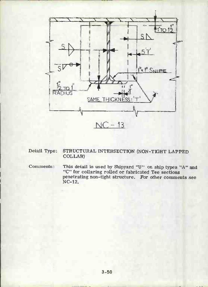
NC- 13
STRUCTURAL INTERSECTION (NON-TIGHT LAPPEDCOLLAR)
This detail is used by Shipyard "TJ" on ship types "A" and"C" for collaring rolled or fabricated Tee sectionspenetrating non-tight structure. For other comments seeNC-12.
3-50

l'i1
SNIPE 1712
NFLTE THICKNESS: J
\C-14
Detail Type: STRUCTURAL INTERSECTION (NON-TIGHT LAPPED COLLAR)
Comments: This detail is common to Navy ships and is included in the standarddetails library of the CASDOS program. To facilitate fabricationof collar plates they should be modified similar to MTC-1.
3-51
DECK EL/HNG

DECK PLATING
ThICKNESS: 'T
3-52
IISNiFE I x
NC-lb
'W \ \ \Wr9r
5'T' . 4 IIj'._I, aw
1" RADIUS
Detail Type: STRUCTURAL INTERSECTION (NON-TIGHT LAPPED COLLAR)
Comments: This detail is used by Shipyard "U" on ship types "A" and "D" forcollaring rolled or fabricated Tee sections penetrating non-tightstructure. This detail is used when the girder is carrying a largelateral load and transfer of shear stress is desired. To facilitatewelding this detail should be modified similar to MTC-1, Cuttingthe collar plate 1/16" undersize will facilitate fit-up.
1' r-ADIUS
SN
s/2"
F
NC-16
(S'
>
RADIUS
A DI US
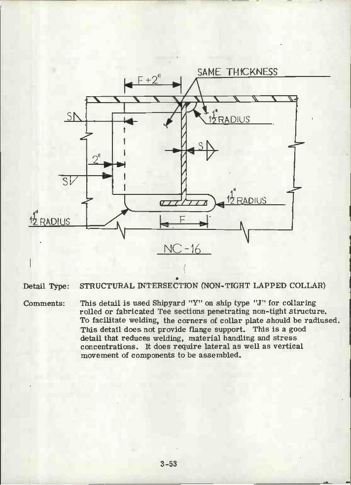
Detail Type: STRUCTURAL INTERSECTION (NON-TIGHT LAPPED COLLAR)
Comments: This detail is used Shipyard !?YI? on ship type "J" for collaringrolled or fabricated Tee sections penetrating non-tight structure.To faciLitate welding, the corners of collar plate should be radiused.This detail does not provide flange support. This is a gooddetail that reduces welding, material handling and stressconcentrations. It does require lateral as well as verticalmovement of components to be assembled.
3-53
SAME THICKNESSF +2"

RADIUS
2"LAPMIN.
sV°zSN
NNNe
A
VN N N
NC-17
Detail Type: STRUCTURAL INTERSECTION
Comments: This detail is used by Shipyard ??YU exclusively on single bottomships where center and side keelsons penetrate non-tightfloors and bulkheads, The thickness of the collar plate issized according to load on member. To improve shear flow,the two right side clips should be a single clip with a cutoutfor the weti stiffener. To facilitate welding, the lapped cornersof the collar plate should be radiused.
3_54
if' jN
SN
II
SNtFE 1xi
SHELL FLATING
\ N \
II / / / / J /
1DI US
CVKOR LONG'LBULKHEAD 0R
<.-SHELL LONG'L
3-55
MH-1
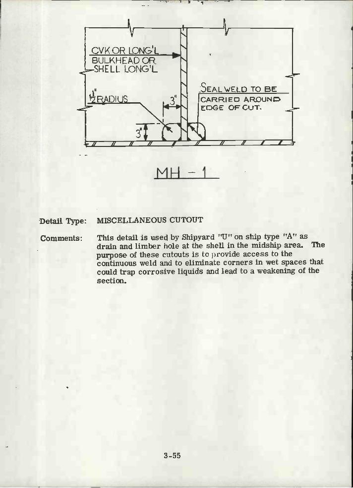
Detail Type: MISCELLANEOUS CUTOUT
Comments: This detail is used by Shipyard "Ut' on ship type "A" asdrain and limber hole at the shell in the midship area. Thepurpose of these c'touts is Lo ovide access to thecontinuous weld and to eliminate corners in wet spaces thatcould trap corrosive liquids and lead to a weakening of thesection.
SEAL /ELD TO BECARRIED ARCUNEDGE OF CUT.

NCVK OR LONG'L
Detail Type: MISCELLANEOUS CUTOUT
Comments: This detail is used by Shipyards "U" and "X" on ship types "B","C", "D", "E" and "H" as drain and limber holes at the shell.For additional comments see MB-L
BULKHEAD
6'RADIUS
Mil-2
3-56
SEAL WELD TO BECARRIED AROUNDEDGE OF CUT
SHELL

CON Ti NUOUSF1N1EER
BESMOOTH
Detail Type: MISCELLANEOUS CUTOUT
Comments: This detail is used by Shipyard "U" on ship types "A" and "B" asdrain holes in lieu of MH-1 or Mil-2. The diameter of the drainhole is a function of member depth. Up to a depth of 12" thediameter of the hole is 1/4 of the depth and above 12" the diameteris constant at 4". 11 this detail is used and the continuous memberis penetrating a tight boundary, a welded oil or water stop isrequired on one side of the structure being pierced. If used inlongitudinal members, sectional area lost should be considered.
Detail Count Ship Type "B": loo
Manhours Required to Complete Typical Detail: 0. 3
Typical Scantlings: 3" Diameter, 5/8" Plate.
3-57
N'1H-3
\JP\P \V/ELD
¼
CONTINUOUSMEMBER.
NIH-4
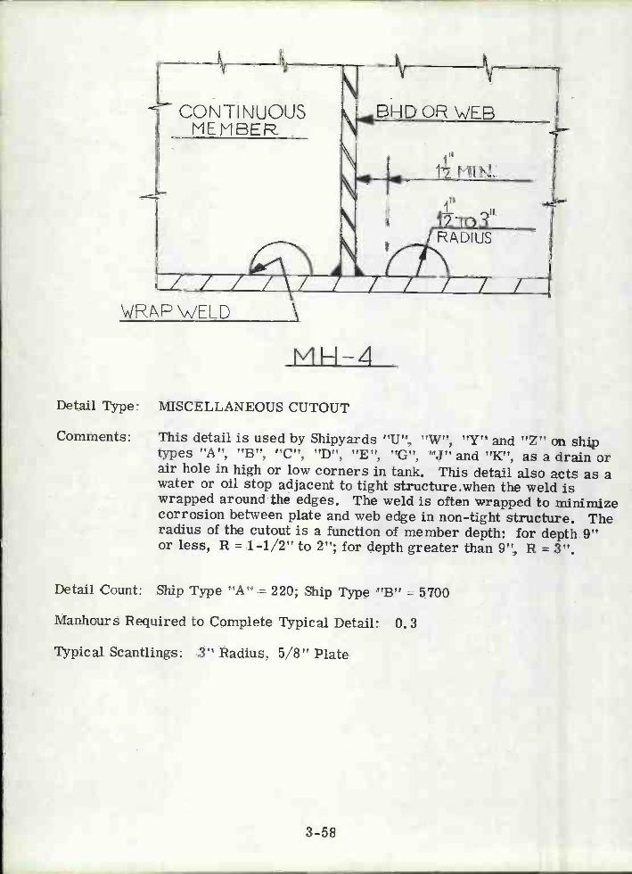
Detail Type: MISCELLANEOUS CUTOUT
Comments: This detail is used by Shipyards "U", "W", "Y" and "Z" on shipt3rpes ??!, ''C'', ''E'', VJ! and ''K'', as a drain orair hole in high or low corners in tank. This detail also acts as awater or oil stop adjacent to tight structure when the weld iswrapped around the edges. The weld is often wrapped to minimizecorrosion between plate and web edge in non-tight structure. Theradius of the cutout is a function of member depth: for depth 9"or less, R = 1-1/2" to 2"; for depth greater than 9", R = 3".
Detail Count: Ship Type "A" = 220; Ship Type "B" = 5700
Manhours Required to Complete Typical Detail: 0. 3
Typical Scantlings: 3" Radius, 5/8" Plate
3-58

3_59
NON-TKHT STRUCTURE
MH-5
Detail Type: MISCELLANEOUS CUTOUT
Comments: This detail is used by Shipyards "U' 'W', and "X" on ship types"A", "B", "C", "E", "G" and "H" as a typical air hole drilled inhigh corner in way of tight structure. Use in longitudinalstringers or stiffeners or in highly stressed areas. The size ofthe hole is based on the following rationale: For areas withspecial coatings, if "D" is less than 9", use 2" diameter; if "D" =9" and over use 3" diameter. Elsewhere use 1" diameter.
The detail seems superfluous in view of the fact that water oroil stops such as MB-4 are required and will also function asair vents. Furthermore "high-corner" is not adjacent to non-tight structure.

NONTIGHT STRUCTURE
VH-6
Detail Type: MISCELLANEOUS CUTOUT
Comments: This detail is used by Shipyards "U" and "Z" on ship types "D"and "K" as air holes in high corners in way of non-tight structure.Hole should be cut with a template, or by the ABM to insure noragged edges. Detail should properly be adjacent to tightboundary (high corner).
3-60
V H-7
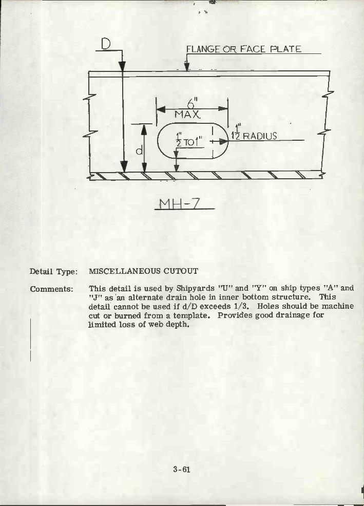
Detail Type: MISCELLANEOUS CUTOUT
Comments: This detail is used by Shipyards "U" and "Y" on ship tv-pes "A" and"J" as an alternate drain hole in inner bottom structure. Thisdetail cannot be used if d/D exceeds 1/3. Holes should be machinecut or burned from a template. Provides good drainage forlimited loss of web depth.
3-61
FLANGE CF? FACE PLATE
LOCATION INVJAYOF
BULKHEAD STIFFENER
EULVHEAD STIFFENERS
3'RADIUS
2"
LOCATION CLEAR OF LiBULKH[AD STIFFENERS
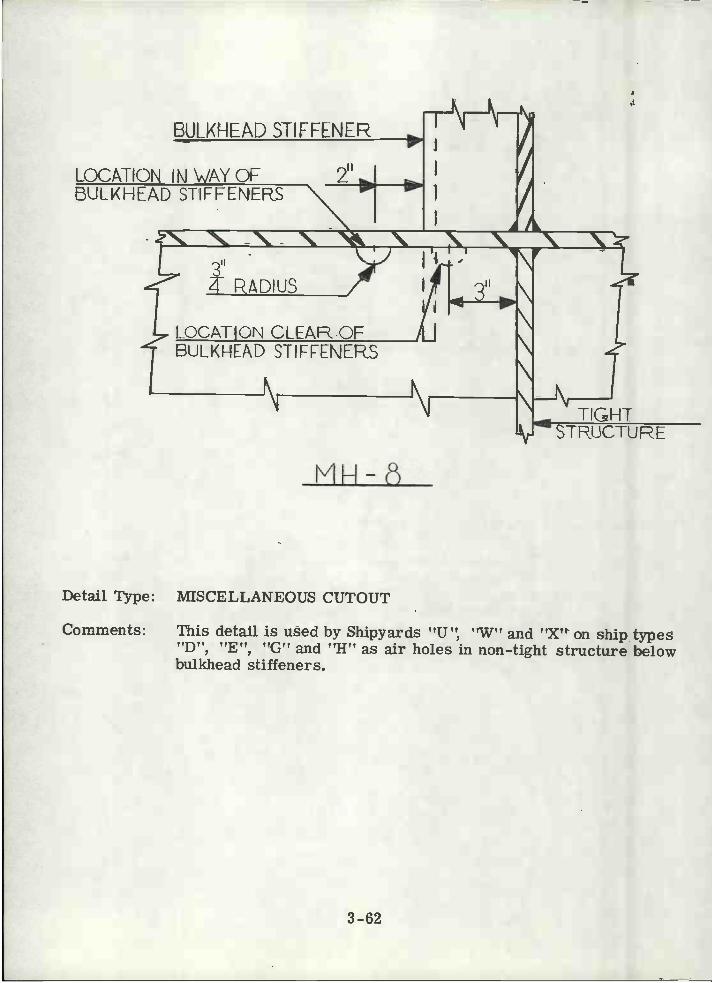
Detail Type: MISCELLANEOUS CUTOUT
Comments: This detail is used by Shipyards "U", 'W" and "X' on ship types"D", "E", "G" and "H" as air holes in non-tight structure belowbuikhead stiffeners.
3-62
TIGHTSTFUCTU RE

PATCH 10 BEUSED BULKHEADLONGITUDNALOR.'WHEN CLEARANCE CUTRADIUS 2
SAME THICKNESS
EOF CUT DETAILS SEE CC-11
Detail Type: PATCH
Comments: This detail is used by Shipyards "U", "V", 'W",'X'' and Z ' on ship trp es ''A 'V, 'E '', ,, F' v i V V
and "K", to patch clearance cut CC-11 in way of airtight, oil-tight or watertight structure, or to repair ragged cuts in non-tight structure. If clearance cut is in horizontal web, fit patchon top side. To facilitate welding, the corners should be radiused.
T
3-63
TRANS\/ERSE M EM EEP
V
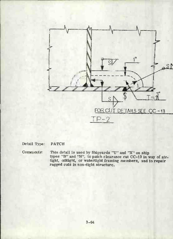
Detail Type: PATCH
Comments: This detail is used by Shipyards "U" and "X" on shiptypes "B" and "H", to patch clearance cut CC-13 in way of air-tight, oiltight, or watertight framing members, and to repairragged cuts in non-tight structure.
3-64
TP-2FOR CUT DETAILS SEE CC -13
sr
AII1r
, / / / ;___/ / /
TP-3
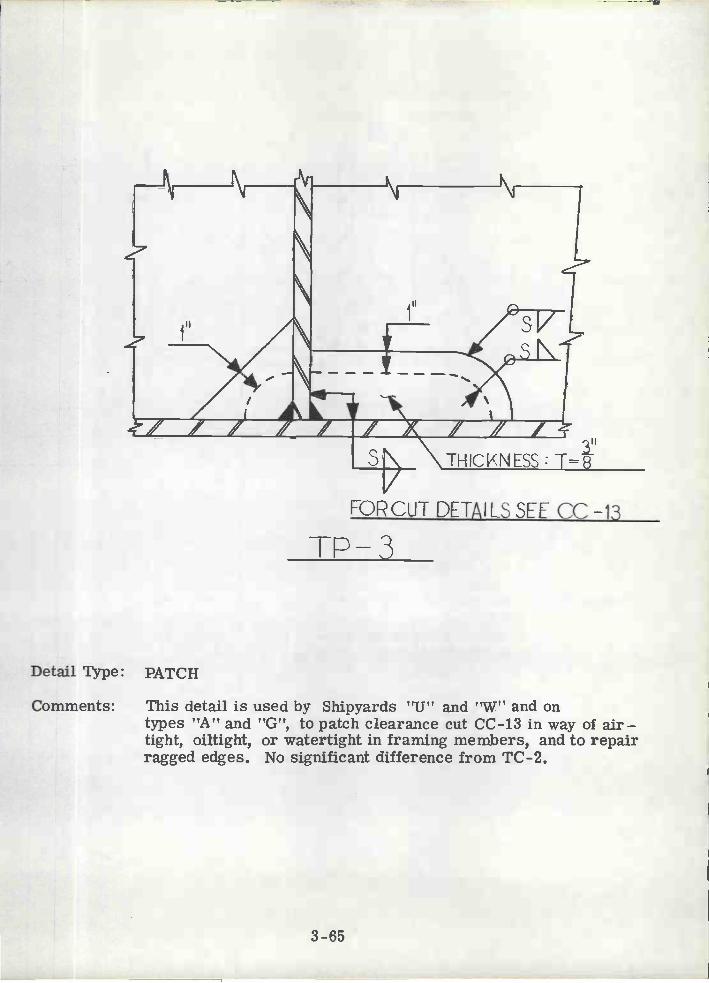
Comments: This detail is used by Shipyards "U" and 'W" and ontypes "A" and "G", to patch clearance cut CC-13 in way of air-tight, oiltight, or watertight in framing members, and to repairragged edges. No significant difference from TC-2.
3-65
F0Rcu1- DETAILS SEE CC-13
Detail Type: PATCH
PATCH TO BL USED VI4ENSNIPE 2ux2
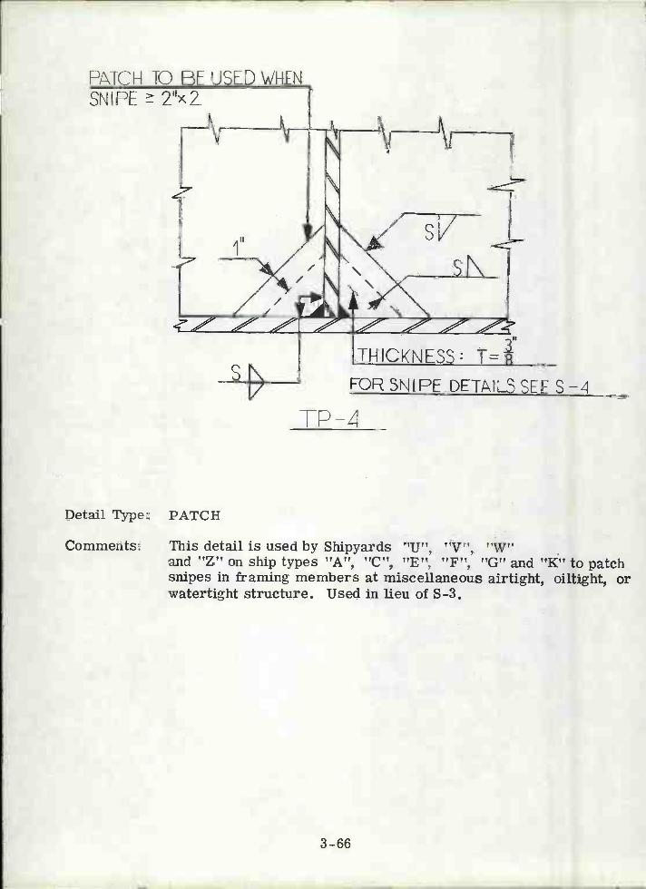
Detail Type: PATCH
Comments: This detail is used by Shipyards "Ut', "V", 'W"and "Z" on ship types "A", "C", "E", "F", "G" and "K" to patchsnipes in framing members at miscellaneous airtight, oiltight, orwatertight structure. Used in lieu of S-3.
TP-4
3-66
FOR SNIPE DETAILS SEE S-4

Detail Type: PATCH
Comments: This detail is used by Shipyard "W' on ship types "A" and"B", to patch clearance cut CC-14 in way of airtight, oiltight,or watertight structure, or when depth of clearance hole, "d"is greater than permissible cut, in non-tight structure.
3-67
I
PLATE
FOR CUT DETAILS SEE CC -14
7,
D

s
CHOCK
ss-I-
3-68
t'I'
Detail Type: STANCHION END CONNECTION
Comments: This detail is used by Shipyards "V", "Y" and "Z" on ship types"F", "J" and "K" to insure structural continuity between wideflange stanchions in the machinery space. No snipes are allowedin the chocks. Thickness of chock to be equal to the thickness ofthe greater flange. Chocks may be sloped to align stanchionflange s.
\F SECTION
FSECTION
CHOCF(Pc-s: THICK'JE
SAME AS FLANGEOF STANCHION
FILL WITH WELD

CHOCK4 PIECES: THICKNESSSAME AS FLANGE OFSTANCHION
Detail Type: STANCHION END CONNECTION
Comments: This detail is used by Shipyards "U" and "V" on ship types "A","B" and "F" to insure structural continuity between wide flangestanchions in the machinery space. No snipes are allowed in thechocks. Thickness of chock to be equal to the thickness of thegreater flanges. Chocks are to be sloped to align stanchionflanges.
Detail Count: Ship Type "A" = 30; Ship Type "B" = 170
Manhours Required to Complete Typical Detail: 12.4
Typical Scantlings: 3/4T chocks from 12" to 8" wide flanges.
3-69
SECTION
-y-
SLOPE AS REQUIRED FORFLANGE ALIGNMENT
IIIi 1SECTION
33-7

SOLE PLATE
\1FSECTIOÑ
N ii N
II
II
I I
SS -3
Detail Type: STANCHION END CONNECTION
Comments: This detail is used by Shìpyard "U" on ship type "A to insurestructural continuity between wide flange stanchions in the lowerlevels of the machinery space. For comments see SS-2.Use of sole plate is limited to areas where deck plating isthin, or where chocks may be slightly out of alignment.
Detail Count Ship Type "A": 50
Manhours Required to Complete Typical Detail: 12. 2
Typical Scantlings: 1" chock plate, 14" wide flange section.
3-70
VF SECTION
'1 PI ECES :TH ICKNESSSAHE AS FLANGE 0FSTANCHION
CHOCKS ARE INCLINED TcALIGN FLANGES

VF SECTION
\ \ _\ \ \ \ \ \
F SECTION
SS4
Detall Type: STANCHION END CONNECTION
Comments: This detail is used by Shipyard "Z" on ship type "K" to insurestructural continuity in areas of the machinery space. Foradditional comments see SS-2.
3-71
Ii PPECES:THICVNESsSAME AS FLANGE OF
STANCH ION
SLOPE C4OCKS TOALIGN FLANGES

SOLED! r-L1L_
37
VFSECTON
SECT ON
SAME THICKNESS
3-5
Detail Type: STANCHION END CONNECTION
Comments: This detail is used by Shipyard "U" on ship type "D" for wide flangestanchion end connection details. No snipes are allowed in thechock plates. Thickness of chock plates are based on the stanchionscantlings. Weld accessibility is poor for this detail. To easethe problem, the flanges of the stanchions should be aligned withthe girder web.
3-72
LI
SAME THICKNESS

SOLEPLATE
CAFrPLATE
SECTION
DECK PLATING
SAME TIICKNESS
Detail Type: STANCHION END CONNECTION
Comments: This detail has the same characteristics as SS-5.
3-73
r

DECK PLATING
SAME THICKNESS
III
F1Tol
-'r--V-FOR COMMENTARY SEE
PG. 3-75 SS-7
3-74
SECTION
SAME THICKNESS
Il

Detail Type: STANCHION END CONNECTION
Comments: Thi.s detail is used by Shipyard ?U? on ship types "13" and "D"for vidc flange stanchion end connections under heavy equipmentfoundations or under areas subject to high mobile loads. Usedonly when supporting structure in line with the stanchion web.For additional comments see SS- 2 and SS-5.
Detail Count Ship Type "D": 100
Manhours Required to Complete Typical Detail: 18. 0
3-75

DECK PLATINO
SAME THICKNESS
F.-
3-76
Detail Type: STANCHION END CONNECTION
Comments: This detail is used by Shipyard "U" on ship types "A", "B" and"D" for wide flange stanchions below the weather deck except inforward sections, and for stanchions below the house top. Thisdetail is not applicable to stanchions in the forward sections ofthe ship because the head and heel connections may be subjectto tensile loading. Chocks in way of other stanchion flange similarto SS-?. For additional comments see SS-2.
Detail Count Ship Type "B": 120
Manhours Required to Complete Typical Detail: 4. 9
Typical Scantlings: Chock plates 4" x 12" x 1/2".
OF? ____OR

\AFSECT ION
4 Pc: THCNE5SAME AS FLAÑG
33-9
Detail Type: STANCHION END CONNECTION
Comments: This detail is used by Shipyards "U", "V", "Y" and "Z" on shiptypes "A", "B", "F", "J" and "K" for wide flange stanchionsending on bulkheads, deep webs, or floors. No snipes are to beused; thickness of chock to be same thickness as flange.
3-77
'wDECK PLATING
N \ N N \ 'j4.5W
BULKH[ADOR DEEP WEB

1"DECK PLATING Tol
H< 1.5W
r
AL'
N N N N NIt
N1IJ\r\/
Detail Type: STANCHION END CONNECTION
Comments: This detail is used by Shipyards "U" and "V" on ship types "B" and"F" for wide flange section end connections. This detail is used orstanchions ending against a transverse or longitudinal girder. Foradditional comments see SS-2. When H 1.5 W detail SS-9 ise inployed.
3-78
SAME ThICKNESS
i" Tr-
DECKS ELATING
SAME THICKNESS
\ ' 'S'
ARCS REQ'DTO6ACK-UP STANCHIONFLANGES
3-79
ss-il
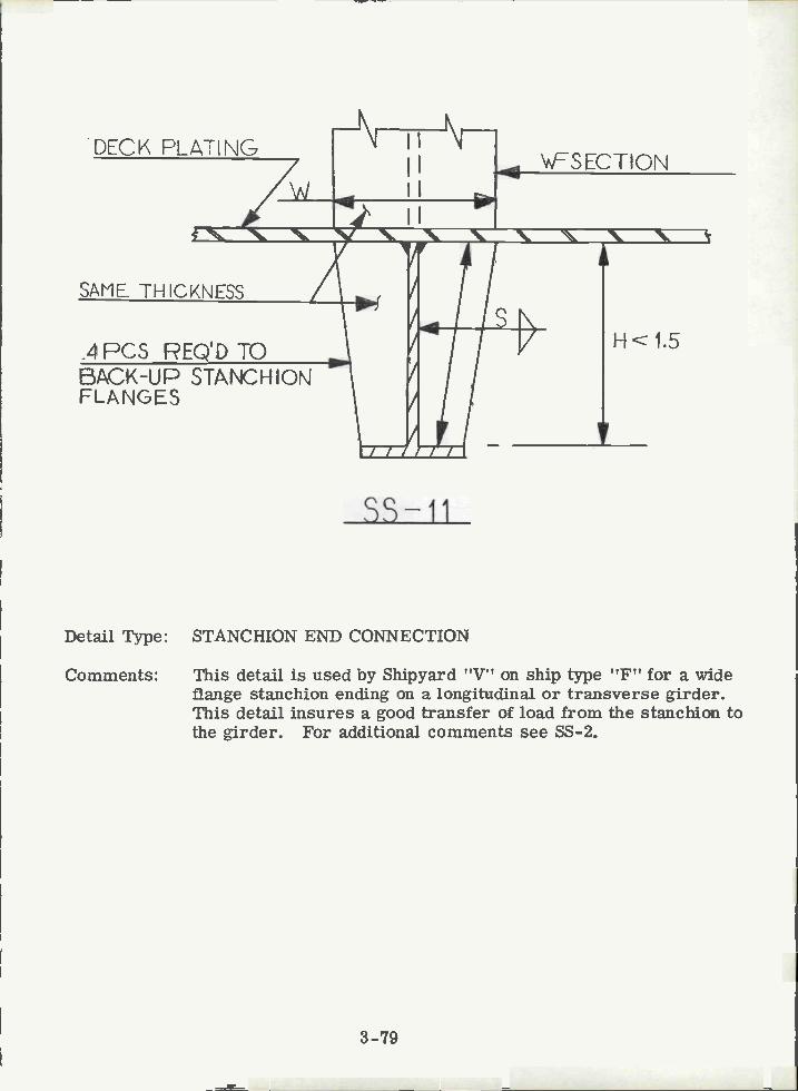
Detail Type: STANCHION END CONNECTION
Comments: This detail is used by Shipyard 'V" on ship type "F" for a wideflange stanchion ending on a longitudinal or transverse girder.This detail insures a good transfer of load from the stanchion tothe girder. For additional comments see SS-2.
\iFSECTION
H< 1.5
PIPE STANCH ION
SOLE PLATE
"W.. \__' \ \ \
PIPE STANCHION
J
mLWHM SNDA
83-12
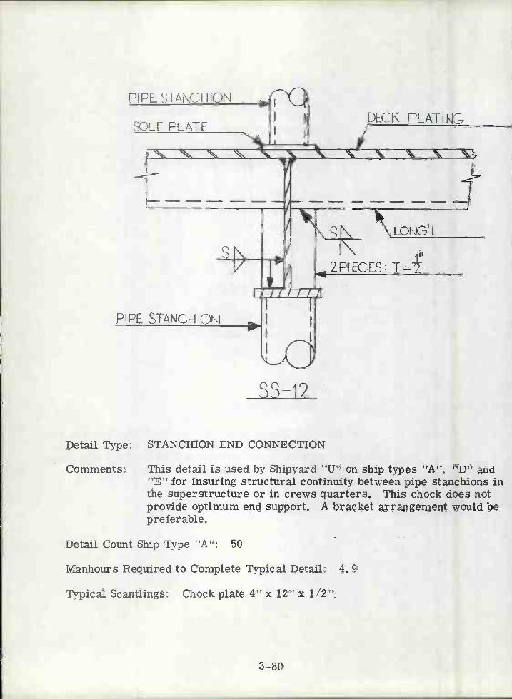
Detail Type: STANCHION END CONNECTION
Comments: This detail is used by Shipyard "U" on ship types "A", "D" arid"E" for insuring structural continuity between pipe stanchions inthe superstructure or in crews quarters. This chock does notprovide optimum end support. A bracket arrangement would bepreferable.
Detail Count Ship Type "A": 50
Manhours Required to Complete Typical Detail: 4. 9
Typical Scantlings: Chock plate 4" x 12" x
3-80
DECK PLAT
r
s
2PIECES: T
\ \LONG'LII

iSt\ME THICKNESS
4
3-81
S-13
Detail Type: STANCHION END CONNECTION
Comments: This detail is used by Shipyard "U' on ship type VID?? and it is alsoincluded in the CASDOS library. This detail insures an effectivetransfer of load from the pipe stanchion to the girder. The detailmay be modified to resemble SS-9, thus easing fitup.
PIPE STANCHION
p,
LDNG'L
SNIPE f212
DECK PLATINOSOLE PLATE

SIDE SHELL FLAT L
Detail Type: TRIPPING BRACKET
Comments: This detail is used by Shipyard "Y" on ship type "J", to provideflange stability to side shell stringers. This bracket effectivelyprovides torsional rigidity, but landing bracket against unstiffenedplating is undesirable. Not a commonly used detail.
TB-I
3-82
FLAT BR
11,X12SNIPE
SHELLSTRINGER
SIDE SHELL PLATING
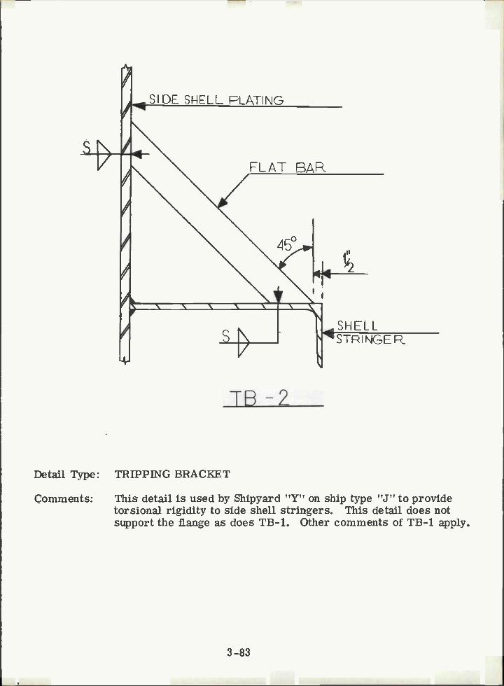
Detail Type: TRIPPING BRACKET
Comments: This detail is used by Shipyard "Y" on ship type "J" to providetorsional rigidity to side shell stringers. This detail does notsupport the flange as does TB-i. Other comments of TB-i apply.
TB -2
3-83
FLAT BAR
450
SHELL1STPINGER
4h IIxi SNIPE.
FLAT BARS
BOTTOM SHELL
s
3-84
ITb-3
DEEP TRANSVERSE \'EB
II ()Ihi TUL
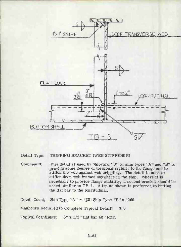
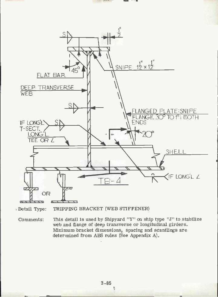
Detail Type: TRIPPING BRACKET (WEB STIFFENER)
Comments: This detail is used by Shipyard "U" on ship types "A" and "B" toprovide some degree of torsional rigidity to the flange and tostiffen the web against web crippling. The detail is used tostiffen deep web frames anywhere in the ship. Where it isnecessary to provide flange stability, a second bracket should beadded similar to TB-4. A lap as shown is preferred to buttingthe flat bar to the longitudinal.
Detail Count: Ship Type "A" = 430; Ship Type "B" = 4260
Manhours Required to Complete Typical Detail: 3. 0
Typical Scantlings: 6" x 1/2" flat bar 40" long.
LONGITUDI NAL/N
tR.
IP -
IF LONKELNT-SECT. /
LONG'L
DEEP TRANSVERSE
3-85
FLANGED FLAFESNI FEFLANGE 3P TO 1; EOTHENDS
Detail Type: TRIPPING BRACKET (WEB STIFFENER)
Comments: This detail is used by Shipyard "Y" on ship type "J" to stabilizeweb and flange of deep transverse or longitudinal girders.Minimum bracket dimensions, spacing and scantlings aredetermined from ABS rules (See Appendix A).
LONG'L
'L1 V
DEEP JRANSVERSE
\
I'
lii III
SNIPE tx1
Il
3-86
lB-5
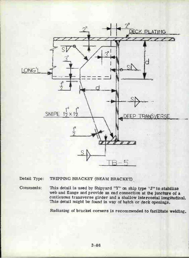
Detail Type: TRIPPING BRACKET (BEAM BRACKET)
Comments: This detail is used by Shipyard "Y" on ship type "J" to stabilizeweb and flange and provide an end connection at the juncture of acontinuous transverse girder and a shallow intercostal longitudinal.This detail might be found in way of hatch or deck openings.
Radiusing of bracket corners is recommended to facilitate welding.
2"PLATING
dsN
y-
TB-6
3-87
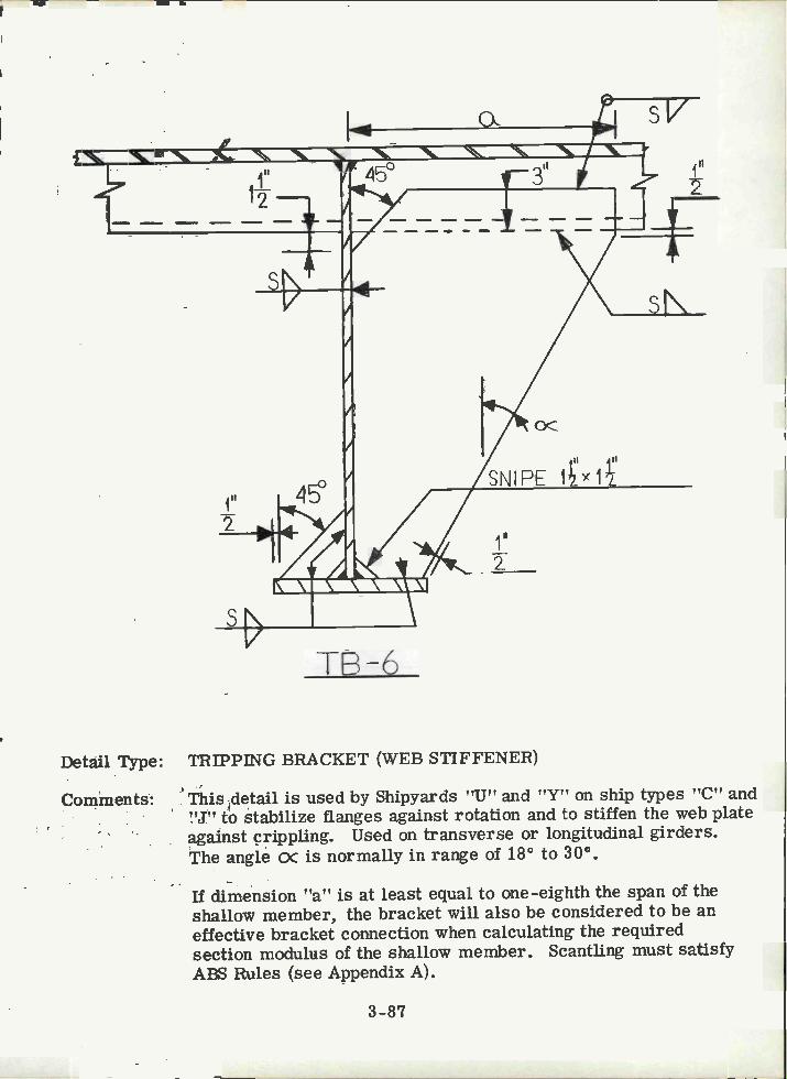
Detail Type: TRIPPING BRACKET (WEB STIFFENER)
Comments: This detail is used by Shipyards "U" and "Y" on ship types "C" and"J" to stabilize flanges against rotation and to stiffen the web plateagainst crippling. Used on transverse or longitudinal girders.The angle x is normally in range of 18° to 300.
If dimension "a" is at least equal to one-eighth the span of theshallow member, the bracket will also be considered to be aneffective bracket connection when calculating the requiredsection modulus of the shallow member. Scantling must satisfyABS Rules (see Appendix A).
2

SNIPE FLANGE 30°TO1H JOPANDEOTTOM
FLANGED PLATE
a
Detail Type: TRIPPING BRACKET
Comments: This detail is used by Shipyards 'VU" and !Y on ship types s'A" and"J", for the same purpose as TB-4. Producibility would beimproved by cutting back flange at top of bracket similar to base.For comments on angle c and dimension a, see TB-6.
Detail Count Ship Type "A": 1200
Manhours Required to Complete Typical Detail: 10. 6
Typical Scantlings: 1/2" plate, 25-1/8" x 72" w/6" x 1/2" flange.
FADIUS
18-7
3-88
ii'2
DEEP TRANSVERSE \'IEB
LONG ITUDI NAL
DECK PLí1ÏNG
N N N N N N
II
SN
THICKNESS:
TB8
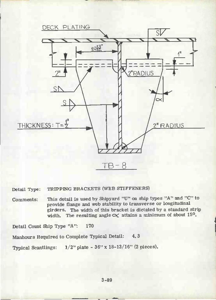
Detail Type: TRIPPING BRACKETS (WEB STIFFENERS)
Comments: This detail is used by Shipyard "U" on ship types "A" and "C" toprovide flange and web stability to transverse or longitudinalgirders. The width of this bracket is dictated by a standard stripwidth. The resulting angle c attains a minimum of about 15°.
Detail Count Ship Type "A": 170
Manhours Required to Complete Typical Detail: 4. 3
Typical Scantlings: 1/2" plate - 36" x 18-13/16" (2 pieces).
3-89

FACE PLATE
Detail Type: FACE PLATE DETAIL
Comments: This detail is used by Shipyard "Y" on ship type "J" for connectionsbetween face plates or flanges of different widths. The bevelshown should be reduced to about 200 to minimize the effect atchange of section.
rP-1
3-90
/ ,/(L=45°
FACE PLATE

SPLIT AND \'JELD
TAPERED PLATE
EPACKETDETAIL A
III
2i 1' PADIUS1' ,J
DET.A
Detail Type: FACE PLATE DETAIL
Comments: This detail was prepared for the CASDOS library of standardstructural details for use on Navy ships. It provides an effectivetransition detail of deck beam through a bulkhead, while maintainingstructural continuity. No snipes should be permitted in membersless than 3" in depth. The 1/2" radius shown in circle should beeliminated and seam extended into the web butt to simplifyfabrication. Navy practice requires tangency brackets at changeof section (see FP-3) that are not shown in this detail.
FP-2
3-91
GOLLAP PLATE
h1
Il sDECK FL ATINO
D
-yESAME THICKNESS

COLLAP FLATE
SAME SCANTLINGS
P3
Detail Type: FACE PLATE DETAIL
Comments: This detail was prepared for the CASDOS library of standardstructural details for use on Navy ships. It provides an effectivetransition detail for a continuous deck beam to reduce or increasethe depth of the member. No snipes should be permitted in membeless than 3" in depth.
3-92
TPEF FLANGE
2
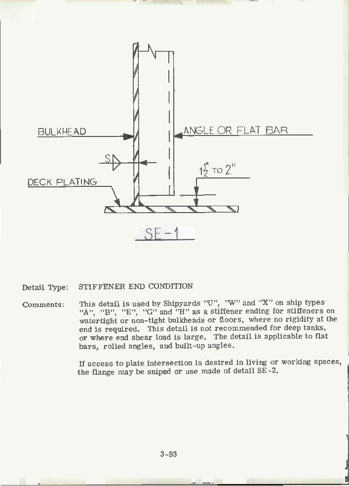
BULKHEAD
DECK PLATING
SE-1
Detail Type: STIFFENEH END CONDITION
Comments: This detail is used by Shipyards "U", "W" and "X" on ship types"A", "B", "E", "G" and "H" as a stiffener ending for stiffeners onwatertight or non-tight bulkheads or floors, where no rigidity at theend is required. This detail is not recommended for deep tanks,or where end shear load is large. The detail is applicable to flatbars, rolled angles, and built-up angles.
If access to plate intersection is desired in living or working spaces,the flange may be sniped or use made of detail SE -2.
3-93
ANGLE OP FLAT EAR
4 TO 2
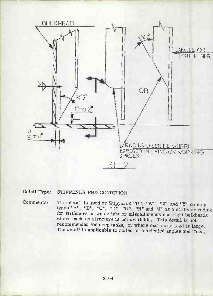
Toi
BUL KNEAD
Detail Type: STIFFENER END CONDITION
Comments: This detail is used by Shipyards "U", "W", "X" and "Y" on shiptypes "A", "B", "C", "D", "G", "H" and "J" as a stiffener endingfor stiffeners on watertight or miscellaneous non-tight bulkheadswhere back-up structure is not available. This detail is notrecommended for deep tanks, or where end shear load is large.The detail is applicable to rolled or fabricated angles and Tees.
3_94
ANGLE OR
RADIUS OftSN?PE \'iHERE
T-STIFFENER
EXFOSED IN LIVING OR VOKINGSPACES
SF-2

3.-95
Detail Type: STIFFENER END CONDITION
Comments: This detail is used by Shipyards "V" and "Z" on ship types "F" and"K" and is in the CASDOS library. This detail is used where littleor no end restraint is required and preferably in the presence ofback-up structure or heavy deck plating. Not recommended fordeep tanks, or where end shear load is large,
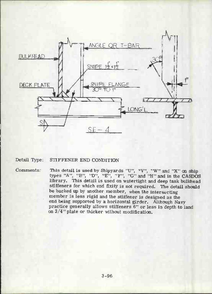
BU L V. H E A D
DECK FLTE
AÑGLE OP J-BAP
SNIPE
SNIFF FLt'NGE41 3Q0 TO jfl
f'
s 4
Detail Type: STIFFENER END CONDITION
Comments: This detail is used by Shipyards "U", "V", 'W" and "X" on shiptypes ''A'', ''B'', ''D", ''E'', ''F", "G'' and ''H" and in the CASDOSlibrary. This detail is used on watertight and deep tank bulkheadstiffeners for which end fixity is not required. The detail shouldbe backed up by another member, when the intersectingmember is less rigid and the stiffener is designed as theend being supported by a horizontal girder. Although Navypractice generally allows stiffeners 6" or less in depth to landon 3/4" plate or thicker without modification.
3-96
LONG' L
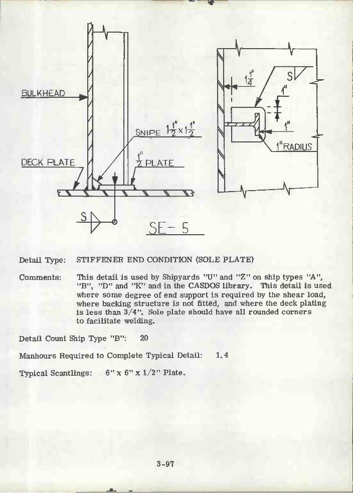
Detail Type: STIFFENER END CONDITION (SOLE PLATE)
Comments: This detail is used by Shipyards "U" and "Z" on ship types "A","B", "D" and "K" and in the CASDOS library. This detail is usedwhere some degree of end support is required by the shear load,where backing structure is not fitted, and where the deck platingis less than 3/4". Sole plate should have all rounded cornersto facilitate welding.
Detail Count Ship Type "B": 20
Manhours Required to Complete Typical Detail: 1. 4
Typical Scantlings: 6" x 6" x 1/2" Plate.
3-97

DECK PLATING
SL-6
3-98
FLAT BAR OR ANGLE
Detail Type: STIFFENER END CONDITION (LAPPED CONNECTION)
Comments: This detail is used by Shipyard UU on ship type 'IC" for the topconnection of watertight or deep tank bulkhead tee or anglestiffeners joined to continuous deck longitudinals. Weldingaccessibility is improved by adding a 300 snipe to the 1" radius.Removal of the flange limits the degree of end support.

DECK PLATING
3,'RADIUS
BULKHEAD
1TO2"f
SE-7
3-99
sN
T\,IEB 1i-1ICKNESS
Detail Type: STIFFENE} ENDING (LAPPED CONNECTION)
Comments: This detail is used by Shipyards "U", "V" and "X" on ship types"A", "B", "G" and "H" for the top connection of watertight ordeep tank bulkhead rolled or fabricated angle stiffeners. Toimprove weld accessibility the snipe should always be made witha 30° angle.
Detail Count: Ship Type "A" = 720; Ship Type "B" = 1600
Manhours Required to Complete Typical Detail: 0. 8
Typical Scantlings: 10"x 1/2"-6-3/16"x 1/2"L
Il2TO 2T+

BULk HLAE
DECK PLATING
'D
SE-R
Detail Type: STIFFENER END CONDITION
Comments: This detail is used by Shipyards "V" and "Z" on ship types "F" an"K" and it is in the CASDOS library. This detail is used primaril:on Navy ships for watertight and deep tank bulkhead rolled orfabricated angle or tee beam stiffeners when support is requiredthe ends.
Some type of back-up structure on the opposite side of the bulk-head is desirable. This is preferable to SE-5 for large stiffenerdepths or thin deck plating.
,P\NGLEOF T-BtP
SNIPE
SANiE SCANT LINCJS
DECK PLATIN(

SE-9
3-101
Detail Type: STIFFENER END CONDITION
Comments: This detall is used by Shipyard "U" on ship types "A" and "B" forrolled or fabricated angle stiffeners of transverse floors, supportedby bottom shell longitudinals. This detail provides continuity atthe end to resist shear and bending to the extent permitted by theintersecting shell longitudinal.
It'

BULKHEAD
ANGLE OR J-BARSTIFFENERS
SNIPE
SE-10
Detail Type: STIFFENEP END CONDITION
Comments: This detail is used by Shipyards "V" and "Z" on ship types "F" and"K" for watertight and deep tank bulkheads on Navy vessels.Detail provides good shear connection, and end fixity dependent ontorsional rigidity of the bottom member.
3-102
DECK PLATING
SAME SCANTLINGS

EULK HEAD
3-103
SE11
Detail Type: STIFFENER END CONDITION
Comments: This detail is used by Shipyards "V" and "Z" on ship types "F" and"K" for watertight and deep tank bulkhead rolled or fabricated angleand tee stiffeners where structural continuity must be maintained.This detail is common to Navy ship design. The flange of themake-up piece may have to be tapered to assure continuity.
SAME SCANTLINGS

DECK FLAT' NG
Detail Type: STIFFENER END CONDITION
Comments: This detail is used by Shipyards "V" and "Z" on ship types "F" and"K" for the intersection between longitudinal deck beams andvertical stiffeners on transverse bulkheads or vice versa. Thedetail is used on Navy vessels with rolled or fabricated tee beamsections where continuity must be maintained.
Chock would be easier to fit if configured as in SE-9.
SE -12
3-104

FLANGEIkW.Ik H
3-105
SE- 13
Detail Type: STIFFENER END CONDITION (TERMINAL BRACKET)
Comments: This detail is used by Shipyard "Z" on ship type "K" for thetermination of a deck girder in way of a deck opening. Thisdetail is employed when hatch side girders and deck coamingshave been excluded, and the bracket must be under a bulkheador other structure capable of supporting the end shear reaction.
II
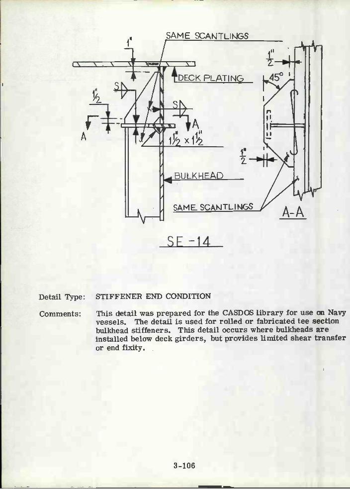
SAME SCAÑTLJÑGS
SE -14
Detail Type: STIFFENER END CONDITION
Comments: This detail was prepared for the CASDOS library for use on Navyvessels. The detail is used for rolled or fabricated tee sectionbulkhead stiffeners. This detail occurs where bulkheads areinstalled below deck girders, but provides limited shear transferor end fixity.
SAML SCAÑTLINGS
DECK PLATiNG 45°
3-106

ME SCANJLNG ASBEAM D
SAME THICKNESS
DECK PLATING
1"
200
00
3-107
I k
DEP .;
DET B SE-1F
Detail Type: STIFFENER END CONDITION
Comments: This detail was prepared for the CASDOS library of standarddetails for use on Navy vessels. It is used in way of intercostaldeck members and intercostal bulkhead stiffeners.
N
L BULKHEADSAME SCANTLNG
pjIl
I'
SNIPE 12X12 TYP
DEJA
SAME THICKNESS

DFT AA
Detail Type: STIFFENER END CONDITION
jIl ji'SNIPE 12'< 2
DET A SE-15SAME SCANTLING II DECK PLATING
2Y
MIN.
SAME THICKNESS
Comments: This detail was prepared for the CASDOS library of standarddetails for use on Navy vessels. This detail is used in way ofcontinuous deck members and intercostal bulkhead stiffeners.
3-108
SE-16
BULKHEAD
CONTI NLK3US MEMBER
DEI AA
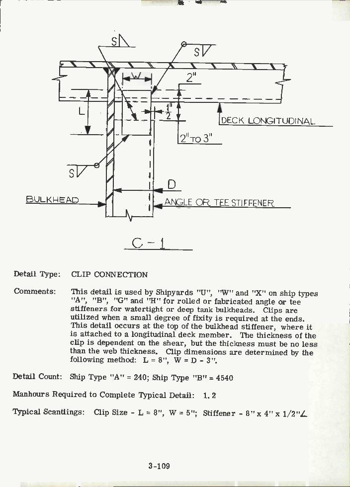
BULKkEAD
Detail Type: CLIP CONNECTION
Comments: This detail is used by Shipyards "U", "W'? and "X" on ship types"A", "B", "G" and "H" for rolled or fabricated angle or teestiffeners for watertight or deep tank bulkheads. Clips areutilized when a small degree of fixity is required at the ends.This detail occurs at the top of the bulkhead stiffener, where itis attached to a longitudinal deck member. The thickness of theclip is dependent on the shear, but the thickness must be no lessthan the web thickness. Clip dimensions are determined by thefollowing method: L = 8", W = D - 3".
Detail Count: Ship Type "A" = 240; Ship Type "B" = 4540
Manhours Required to Complete Typical Detail: 1. 2
Typical Scantlings: Clip Size - L 8", W = 5"; Stiffener - 8" x 4" x 1/2"L
G-1
3-109
r
2"To 3"
DECK LONGITUDINAL
ANGLE OR. TEE S11FLENE
sNV

ANGLE O TEE STIFFENER.
THICKNESS:
2T+1'1
Detail Type: CLIP CONNECTION
Comments: This detail is used by Shipyards "U", 'W", "X" and "Y' on shiptypes "A", "B", "G", "H" and "J" for rolled or fabricated angleand tee stiffeners for watertight or deep tank bulkheads. Thisdetail is similar to C-1, except that the clip is welded to the deckand L = 6". This detail eases fit-up, however, the clip is not backup by the deck longitudinal..
Detail Count: Ship Type "A" = 400; Ship Type "B" = 2550
Manhours Required to Complete Typical Detail: 0. 7
Typical Scantlings: Clip Size - L 6", W = 5"; Stiffener - 8" x 4" x 1/2" /.
3-110
C-2DECK LONGITUDINAL
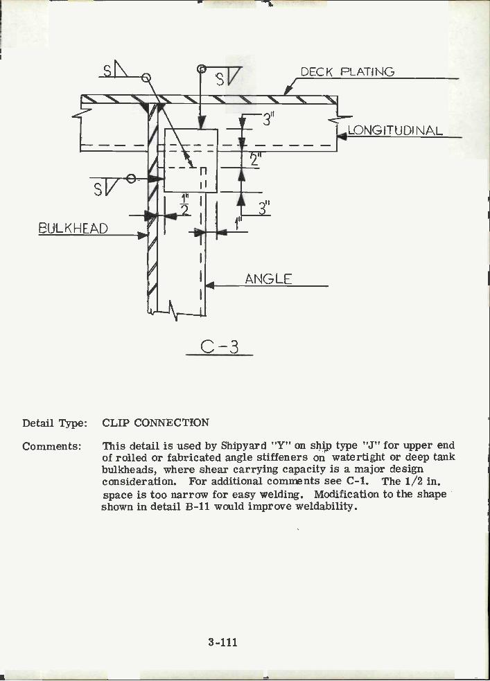
sV
BULKH LAD
r-
3"
Detail Type: CLIP CONNECTION
Comments: This detail is used by Shipyard "Y'T on shp type "J" for upper endof rolled or fabricated angle stiffeners on watertight or deep tankbulkheads, where shear carrying capacity is a major designconsideration. For additional comnnts see C-1. The 1/2 in.space is too narrow for easy welding. Modification to the shapeshown in detail B-11 would improve weldability.
4
C-3
3-ill
ANGLE
DECK PLATING
LONGITUD? NAL

Detail Type: CHOCK
Comments: This detail is used by Shipyards "U", 'W" and "X" on ship types"A", "B", "G" and "H" and is in the CASDOS library of standarddetails. This detail is used on deck, shell and bulkhead long-itudinals as a tripping bracket or as a support point in way ofequipment foundations. For rolled or fabricated angles.
c -i
3-112
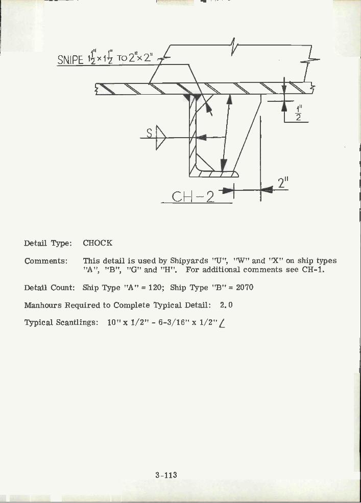
Detail Type: CHOCK
Comments: This detail is used by Shipyards "U", "W" and "X" on ship types"A", "B", "G" and "H". For additional comments see CH-i.
Detail Count: Ship Type "A" = 120; Ship Type "B" = 2070
Manhours Required to Complete Typical Detail: 2. 0
Typical Scantlings: lo" x 1/2" - 6-3/16" x 1/2"L
3-113
CH-2

Detail Type: CHOCK
Comments: This detail is used by Shipyard "Z" on ship type "K" for longitudinaland transverse framing member intersections. This detail may beused on rolled or fabricated angles or tee sections, as a trippingbracket. Detail CH-5 is recommended in lieu of above detailbecause of possible fitting and welding problems.
2T+1'
C-L
DECK PLATING
CH-3
3-114
THiOKNS3: J
SNIPE i (1

Detail Type: CHOCK
Comments: This detail is used by Shipyards "U" and "Z" on ship types "A" and"K" for longitudinal and transverse framing member intersections.For additional comments see CH-3. CH-5 is a better detail.
Detail Count Ship Type "A": 430
Manhours Required to Complete Typical Detail: 2. 0
Typical Scantlings: 12" x 6" x 1/2" Chock.
3-115
CH-A
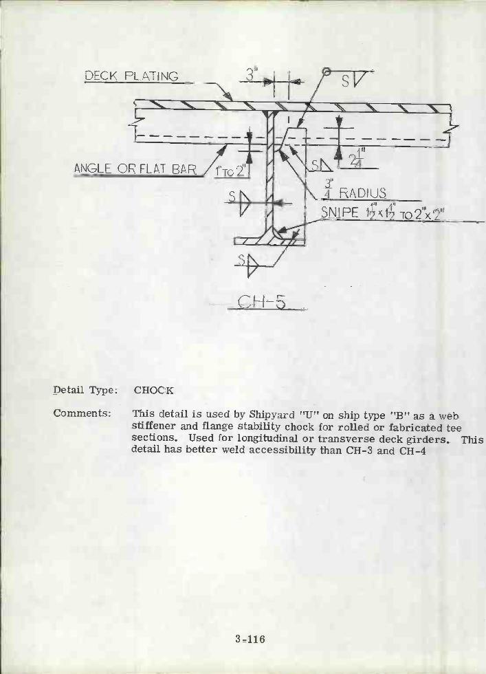
DECK PLATING
Detail Type: CHOCK
Comments: This detail is used by Shipyard 'TU" on ship type "B" as a webstiffener and flange stability chock for rolled or fabricated teesections. Used for longitudinal or transverse deck girders. Thisdetail has better weld accessibility than CH-3 and CH-4
3-116
CH-5
3t-4 ADIU
SNIEE i1z ro2"x2"
ANGLE O! FLAT BAR 1"TO 2

DECK LJING
Detail Type: CHOCK
Comments: This detail is used by Shipyards "U", "V" and "Z" on ship types"A", "B", "F" and "K". It is the same as CH-8 except it is usedwhen the depth of the member is 1-1/2 times or greater than thewidth of the flange. For additional comments see CH-8.
Detail Count: Ship Type "A" = 1050; Ship Type "B" = 3700
Manhours Required to Complete Typical Detail: 3. 8
Typical Scantlings: Chock plate, 18" x G" x 3/4".
"J! 4V.
CH-E
3-117

DECK PLTING
Detail Type: CHOCK
Comments: This detail is used by Shipyards "U", "V" and "Z" on ship types"A", "B", "D", "F" and "K" for longitudinal and transverseframing member intersections. This detail is applicable to rolledor fabricated tee sections.
Detail Count: Ship Type "A" = 120; Ship Type "B" 10
Manhours Required to Complete Typical Detail: 3. 5
Typical Scantlings: Chock plates, 7"x 6"x 1/2".
CH-7
3-118

Detail Type: CHOCK
Comments: This detail is used by Shipyards "U", "W" and "X" on ship types"B", "D", "A", "G" and "H" and it is in the CASDOS library. Thedetail is used as a flange stability chock for longitudinal andtransverse deck girders, for both rolled and fabricated tee sections.This detail is used when the depth of the member is less than1-1/2 times the flange width.
H
CH-8
3-119
DECK PLt\TÌNC

EULKHEAD Y ANGLE FLAT
DECK flLATNG
1.5 TO 2W
Detail Type: CHOCK (BRACKET)
Comments: This detail is used by Shipyards "U", "W" and "X" on ship types"A", "B", "G" and "K" for bulkhead stiffener web endings. It isapplicable to flat bars, and rolled and fabricated angles and teesections with sniped flanges which end on plating with non back-upstructure.
Detail Count: Ship Type "A" = 230; Ship Type "B" = 800
Manhours Required to Complete Typical Detail: 1. 8
Typical Scantlings: Chock, 15" x 10" x 1/2" Plate.
CH9
3-120
EAP OR TEE
1''
SNIP[ ix1

SHELL ELATING
/
Detail Type: FLANGE CHOCK
Comments: This detail is used by Shipyards "U", "V", "W", "X" and "Z" onship types "A", ''B", "D'', ''F'', "G", "H" and "K" and is in theCASDOS library of standard structural details. This detail occursat the intersection of a shell frame and a transverse deck girder.A plate bracket is often fitted in the corner of the intersectingmembers to eliminate the possibility of joint failure.
DECK PLATING
CH-lO
3-121
i''2
w

THICKNESS T
MAX.
CH 11
Detail Type: CHOCK (TRIPPING BRACKET)
Comments: This detail is used by Shipyard "Ut' on ship type t'C'T when alongitudinal or transverse deck girder passes under a bulkhead.This detail is applicable to rolled or fabricated tee sections.
3-122
BULKHEAD
DECK FLAT IN
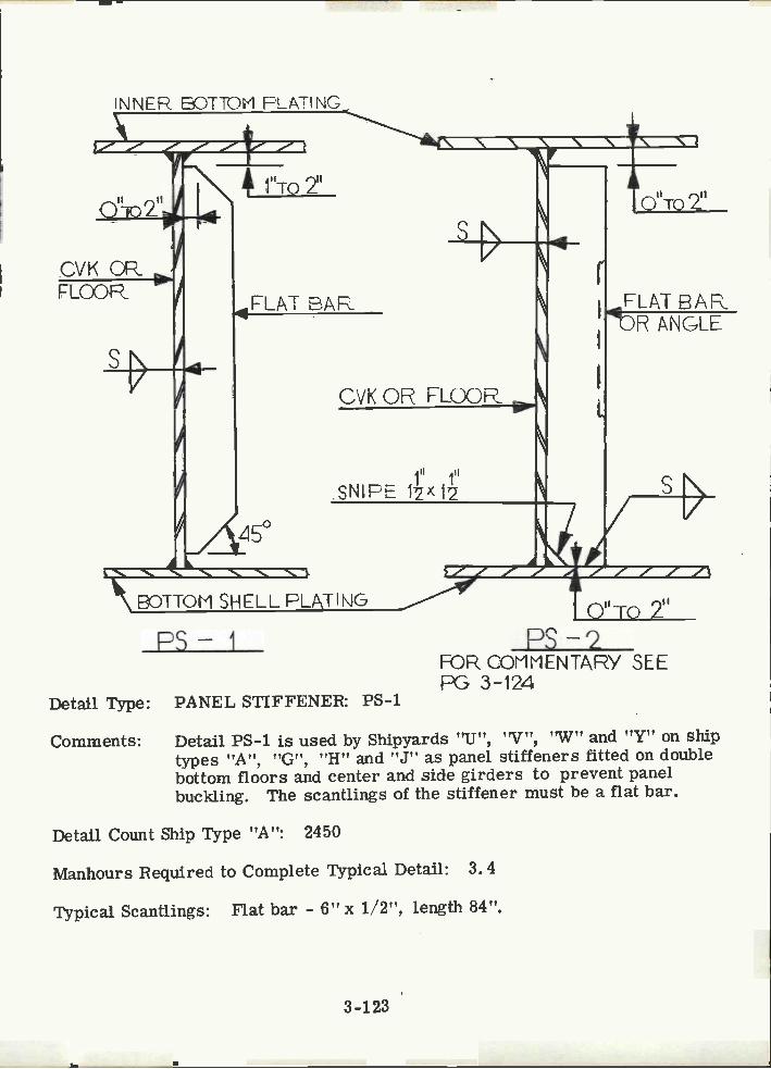
FLOOR
INNER BOTTOM FLAIl NG
LAT BAE
BOTTOM SHELL PLATIHG
Detail Type: PANEL STIFFENER: PS-i
CVK OP FLOOR
ill ill
SNIEE 12x12
Comments: Detail PS-i is used by Shipyards 'IJ", "V", 'W" and "Y" on shiptypes "A", "G", "H" and "J" as panel stiffeners fitted on doublebottom floors and center and side girders to prevent panelbuckling. The scantlings of the stiffener must be a flat bar.
Detail Count Ship Type "A": 2450
Manhours Required to Complete Typical Detail: 3. 4
Typical Scantlings: Flat bar - 6" x i/2", length 84".
3-i23
r
L
II il)T02
FL/\T EAFIDR t\NCLE
OTo 2"
PS-2FOR COMMENTARY SEEPG 3-124

PS-2
Detall Type:
Comments:
PANEL STIFFENER (see pg. 3-123 for detail)
Detail PS-2 is used by Shipyards "U", "V", "W", and "Y" onship types "A", "B", "G", "H" and "J" as panel stiffenerson tight double bottom floors to prevent panel buckling and tosupport lateral loading. The stiffener may be a flat bar ora rolled or fabricated section. Detail PS-2 (with no bottomgap) is based on civil engineering practice which recommendswelding to the compression flange and eliminates the weld tothe tension flange to improve fatigue life.
Detail Count Ship Type "A": 300
Manhours Required to Complete Typical Detail: 3. 4
Typical Scantlings: Flat bar - 6" x 1/2", length 74".
3-124

tNNFR BOTTOM PLATING
,
77
FLOOl
s
5HELL FLATÑG
SNIPE 1
B/\R.
15°
Detail Type: PANEL STIFFENEB
Comments: This detail is used by Shipyard "Y" on ship type "J" as a panelstiffener for double bottom floors. This detail is applicable toflat bars, rolled or fabricated tee sections or angles. See PS-2for additional comments.
3-125
ANGLEOR TEE

C-L
BULK H [AL)
\. N N \ \
I-
SNIPE FLANGE3 Toll' TO45 -ro 172)
ANGLE OR TEE
PSLi
Detail Type: PANEL STIFFENER
Comments: This detail is used by Shipyards "U", "X", "W" and "Y" on shiptypes "A", ''B", "D", ''E", "G", ''H" and "J" for rolled or fab-ricated tee sections or angles. Seldom used as a panel stiffenerin commercial practice. When used as a header in way of bulk-head or deck openings it is the same depth as mating members.Commonly used as backup in way of foundations. Designed as asimply supported beam.
Detail Count Ship Type "A": 400
Manhours Required to Complete Typical Detail: 4. 0
Typical. Scantlings: Header - 6" x 4" x 1/2"L, 33" long.
3-126
A

SNf PE
SN1E SCI\NJLING
Detail Type: PANEL STIFFENER
Comments: These details are used by Shipyard 'Z" on ship type UK!! assupports under heavy equipment foundations. They are usedprimarily on Navy ships. The brackets at the end of thestiffeners will provide flange stability.
F )
3-127
USE VJH[RE \J IS D/2 ORL ESS
>sSNIFE

III 1ISNfPE Xi
Detail Type: PANEL STIFFENER
Comments: This detail is used by Shipyard "Z" on ship type "K" to stabilizecompression panels and provide support for light loads orfoundations.
3-128
\FLÁT EAROF TEE
RS-7
SAME THCKNE55

Detail Type: PANEL STIFFENE1-
Comments: This detail is used by Shipyard "Y" on ship type "J" to supportlarge lateral loads such as in way of equipment foundations. Thisdetail is applicable to rolled or fabricated angles.
PS-A
3-129
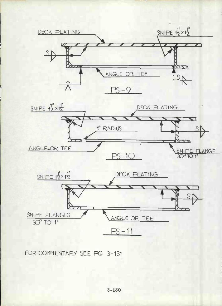
DECK PLATING
1NGLE OR TEE
In1uI
SNIFE 1X1-
3NIPE rLAÑGES30° TO 1"
ANGLE OR TEL
FOR COMMENTARY SEE R 3-131
ps-lo
3-130
DECK ELATING
ANGEO TEL
SNIPE 1xI\
SNIPE FLANGE30 TO 1"
SNIPE DECK FLATING
N N ". N
A P3-9

PS-9
Detail Type: PANEL STIFFENER (see pg. 3-130 for detail)
Comments: This detail is used by Shipyards "U", "W", "X" and "Y"onship types "B", "G", "H" and "J" to support large lateralloads such as in way of machinery foundations and to stiffenplating around openings. This detail is applicable to rolledor fabricated angles or tee sections.
Detail Count Ship Type "B": 2450
Manhours Required to Complete Typical Detail: 2. 8
Typical Scantlings: Header - 6" x 4" x 1/2" L Length - 60".
PS-lo
Detail Type: PANEL STIFFENER (see pg. 3-130 for detail)
Comments: This detail is used by Shipyard "Y" on ship type "J" as asupport in way of deck or bulkhead openings and undermachinery foundations. Left side flange snipe permitssimpler fit-up to stiffener with no noticeable sacrifice inend shear area. End bending stress not significant due tolocal load and weak rotational end support. Same applicabilityas PS-9.
PS -11
Detail Type: PANEL STIFFENER (see pg. 3-130 for detail)
Comments: This detail is used by Shipyard "Y" on ship type "J" as asupport in way of bulkhead or deck openings and in way ofequipment foundations. This detail is easier to fabricate,than PS-9, not as easy as PS-lO. Same applicability asPS-9.
3-131

Detail Type: PANEL STIFFENER
Comments: This detail is used by Shipyard "Y" on ship type "J" as theattachment of a panel stiffener on a floor to an inner bottomlongitudinal. This detail is applicable to rolled or fabricatedangles. Fixity of upper joint improve with increasing depthof members.
t\F'IGLE OR TE
SNIPE: 11/2X i
NOSNLFE TI) SNIPE30°To 1"
3-132
s PS- 12

Detail Type: PANEL STIFFENER
Comments: This detail is used by Shipyards "U" and "Y" on ship types "A",0"B" and "J" for panel stiffeners applied to tight floors. The 30web snipe at stiffener ends facilitates welding. Overlap is smallcompared to flange width, consequently the latter should not beconsidered effective when calculating the stiffener end sectionmodulus. If end moment is critical, overlap should be increased.This detail is applicable to rolled or fabricated angles.
Detail Count: Ship Type "A": 2300; Ship Type "B": 1000
Manhours Required to Complete Typical Detail: 3. 0
Typical Scantlings: 6" x 4" x 1/2" 7, Length - 60".
Ps- 13
3-133
LAP: 2TQ 3":
O"TO i' RADIUS
SHELL

Detail Type: PANEL STIFFENER
Comments: This detail is used by Shipyards "U" and "Y" on ship types "A","B" and "J" as flat bar panel stiffeners for transverse orlongitudinal girders. For additional comments see PS-4.
Detail Count Ship Type "A": 5520
Manhours Required to Complete Typical Detail: 4. 0
Typical Scantlings: 6" x 1/2" Flat bar, length - 74".
3-134
N N N N
r
IIi TO 12
4'N \ 'N
PS-iLl
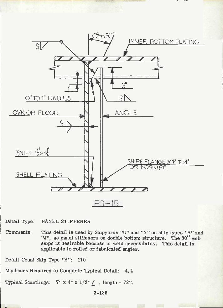
r,
O"TO" FDIUS
CVKOR FLOOF
SNE
SHELL PLATING
Detail Type: PANEL STIFFENER
Comments: This detail is used by Shipyards "U" and "Y" on ship types "A" and"J", as panel stiffeners on double bottom structure. The 30 websnipe is desirable because of weld accessibility. This detail isapplicable to rolled or fabricated angles.
Detail Count Ship Type "A": 110
Manhours Required to Complete Typical Detail: 4.4
Typical Scantlings: 7" x 4" x 1/2"/ , length - 72".
3-135
/-'o '-V.O
RS-15
3"
sNANGLE
INNEF 5OTTOM FLATNG
3NIPE FLt\NGE 300 TOI"Q NOSNIp

\W
-
s
il'
CVK CR FLR
-n
3H
3"
Detail Type: PANEL STIFFENEB
Comments: This detail is used by Shipyard "Y" on ship type "J" as rolled orfabricated angle panel stiffeners on tight double bottom structure.Two alternate lapped connection details are presented, theirapplication depends on the type of inner bottom longitudinals. SePS-2 for end connection comments. Welding accessibility is pooclip should be modified to provide better access along the edge ofthe clip closest to the bulkhead and across the top.
3-136
PS-16
INNER BOTTONI PLATING
SHELL PLTINC
SNIPE FLANGE 30° TO 1"
sV
li'SNIPE jx

2m 3"j DECKPLATING SNIPE:1ÇX1
Detail Type: BEAM BRACKET (UNFLANGED)
Comments: This detail is used by Shipyards "U", "W", "Y" and "Z" on shiptypes "B", "G", "J" and "K" as end connection for a bulkheadstiffener or longitudinal deck beam requiring end fixity. Bracketlength and thickness determined by ABS Pules, see Appendix A,Section A2. 1. 1. For the bracket to be considered effective,i. e. providing end restraint leading to reduction in requiredsection modulus, the leg length must be equal to one-eighth thespan of member A.
Detail Count Ship Type "B": 10
Manhours Required to Complete Typical Detail: 2. 4
Typical Scantlings: Equal legs = 30", Thickness = 1/2"
3-137

I"
-¡'u
BULKHEAD
B-2
Detail Type: BEAM BRACKET (UNFLANGED)
Comments: This detail is used by Shipyard "U" on ship type "B" as endconnection for bulkhead stiffener requiring end fixity. Endfixity depends on relative stiffness of members attached to thebracket. Bracket thickness determined by ABS Rules, seeAppendix A, Section A2. 1. 1.
Detail Count Ship Type "B": 300
Manhours Required to Complete Typical Detail: 2. 1
Typical Scantlings: 16" x 24", Thickness = 1/2"
3-138
SNIPE i-x4

BULKHEAD
DECK PLAT!NG
R-3
Detail Type: BEAM BRACKET (TJNFLANGED)
Comments: This detail is used by Shipyards 'W" and "X" on ship types "G" and"H" as an end connection for a bulkhead stiffener or deck beamrequiring fixity at ends. Rigidity at joint of bracket to supportingstiffener should be checked in terms of end moment. Bracketlength and thickness determined from ABS Rules, see AppendixA, Section A2. 1. 1. For additional comments see Detail B-1.
3-139
III jI2t21

DE(K FLATINCT
r
-n
e
Detail Type: BEAM BRACKET (UNFLANGED)
Comments: This detail is used by Shipyards "U", 'W", "X" and "Y" on shiptypes "B", "G", "H" arid "J" to provide end support for bulkheadstiffeners and deck beams. Bracket length and thickness to bedetermined from ABS Rules, see Appendix A, Section A2. 1. 1.For the bracket to be considered effective for both members, thebracket leg length should be equal to one-eighth the value of thelarger of the member spans.
Detail Count Ship Type "B": 20
Manhours Required to Complete Typical Detail: 2. 1
Typical Scantlings: Equal legs = 24", Thickness = 1/2".
3-140
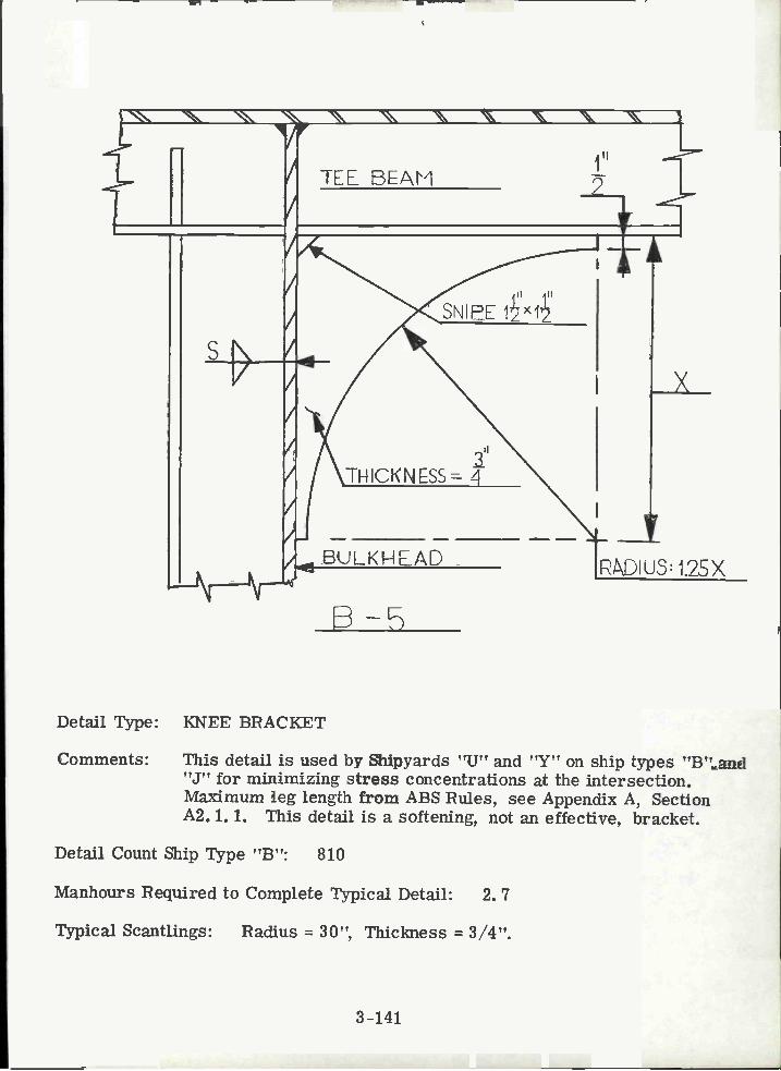
N N N \ \ \_r
0SNIPE
iI
ThICKNESS
BU L K H E AD
Detail Type: KNEE BRACKET
Comments: This detail is used by Shipyards "U" and "Y" on ship types "B" and"J" for minimizing stress concentrations at the intersection.Maximum leg length from ABS Rules, see Appendix A, SectionA2. 1. 1. This detail is a softening, not an effective, bracket.
Detail Count Ship Type "B": 810
Manhours Required to Complete Typical Detail: 2. 7
Typical Scantlìngs: Radius = 30", Thickness = 3/4".
3-141

E-6
Detail Type: BEAM BRACKET (UNFLANGED)
Comments: This detail is used by Shipyards "U", "W", "X" and "Y" on shiptypes "A", "B", "G", "H" and "J" to reduce stresses at discon-tinuities and corners. Maximum leg length and bracket thicknessto be determined from ABS Rules. See Detail B-1 for bracketeffectiveness criteria.
Detail Count: Ship Type "A" = 130; Ship Type "B" = 530
Manhours Required to Complete Typical Detail: 2. 1
Typical Scantlings: Equal legs = 24", Thickness = 1/2".
3-142

sV
Detail Type: BEAM BRACKET
Comments: This detail is used by Shipyards "U", 'W" and "X" on ship types"B", "G" and "H" for end connections of deck longitudinals totransverse bulkhead stiffeners. Bracket may not necessarily bein line with supporting stiffener. Purpose of bracket is tofacilitate end connection rather than to obtain reduced scantling.
Detail Count Ship Type "B": 130
Manhours Required to Complete Typical Detail: 2. 0
Typical Scantlings: 8" x 8" x 1/2" Plate.
-7
3-143
2To 6" DECK FLATING

SNIPE ') OPTICT.NAL
BULKHEAD
i''
Detail Type: BEAM BRACKET (UNFLANGED)
Comments: This detail is used by Shipyards "U", 'W", "X" and "Y" on shiitypes "B", "G", "H" and "J" to join a continuous longitudinal dbeam to an intercostal bulkhead stiffener where full fixity isrequired. Maximum leg length and thickness to be determinedfrom ABS Rules, see Section A2. 1. 1, Appendix A. See DetailB-4 for bracket effectiveness criteria.
Detail Count Ship Type "B": 490
Manhours Required to Complete Typical Detail: 2. 1
Typical Scantlings: Equal legs = 24", Thickness = 1/2".
3-144
DECK FLATNj&
450
To 3"TYPICAL

DECK, PLATING
BULKH EAD
TE BEAM
'7
t,'
3-145
Detail Type: BEAM BRACKET (FLANGED)
Comments: This detail is used by Shipyards "Y" and "Z" on ship types "J" and"K" to connect bulkhead stiffeners and longitudinal deck beams toobtain full fixity. Maximum leg length, face plate scantlings andbracket thickness to be determined from ABS Rules, see AppendixA, Section A2. 1. 1. For bracket effectiveness criteria, seebracket Detail B-4.
'I
SEE CH-5
i
I
450
FACE PLATE CEÑTERED
SNIPE FACE PLATE1H 3cFTO 1 NEAFFA

EULKHEL\D
li
/ 411Ii 2
/ FLANGED PLATE:SNjIPE 3TOi I_i OTHENDSI
/
B-10
Detail Type: BEAM BRACKET (STIFFENER END CONNECTION)
Comments: This detail is used by Shipyard "Y" on ship type "J" to connect anintercostal bulkhead stiffener and an intercostal deck member;primarily to resist shear. The need for flanging is questionable.This is not a common detail.
3-146
flECK

BULKHEAD
B- 11
Detail Type: BEAM BRACKET (UNFLANGED)
Comments: This detail is used by Shipyard "Y" on ship type "J" to connect ashallow continuous deck longitudinal to a deep intercostal bulkheadstiffener, primarily to resist shear. This is not a common detail.Bracket thickness to be determined from ABS Rules, see AppendixA, Section A2. 1. 1. See Detail B-4 bracket effectiveness criteria.
3-147
sN
3U DECK PLATiNE

DECK FLt\TIÑG
BIJ L KH EA D
/
/
Il
R-12
Detail Type: BEAM BRACKET (FLANGED)
Comments: This detail is used by Shipyard "Y" on ship type "J" to provide endsupport for continuous deck members penetrating bulkheads orfloors. Maximum leg length, bracket thickness, and flange areaare to be determined from ABS Rules, see Appendix A, SectionA2. 1. 1. For bracket effectiveness criteria, see bracket DetailB-4. Bracket more commonly on stiffener side of bulkhead, seeDetail B-13.
3-148
II
30°TOi" BOTH ENDS

DECK PLPT1HC
BULKHEAD
N
N'
Detail Type: BEAM BRACKET (FLANGED)
Comments: This detail is used by Shipyards "U", 'w", "X,' and "Y" on shiptypes "B", "G", "H" and "J" to provide end connections for anintercostal bulkhead stiffener to a continuous deck member. Foradditional comments see B-12.
II
VIIj,
450
3-149
2"To311
TYPICAL
A-13
FLAÑGEj) FJTE: SNJIPE45° TO luz BOTH EMDs
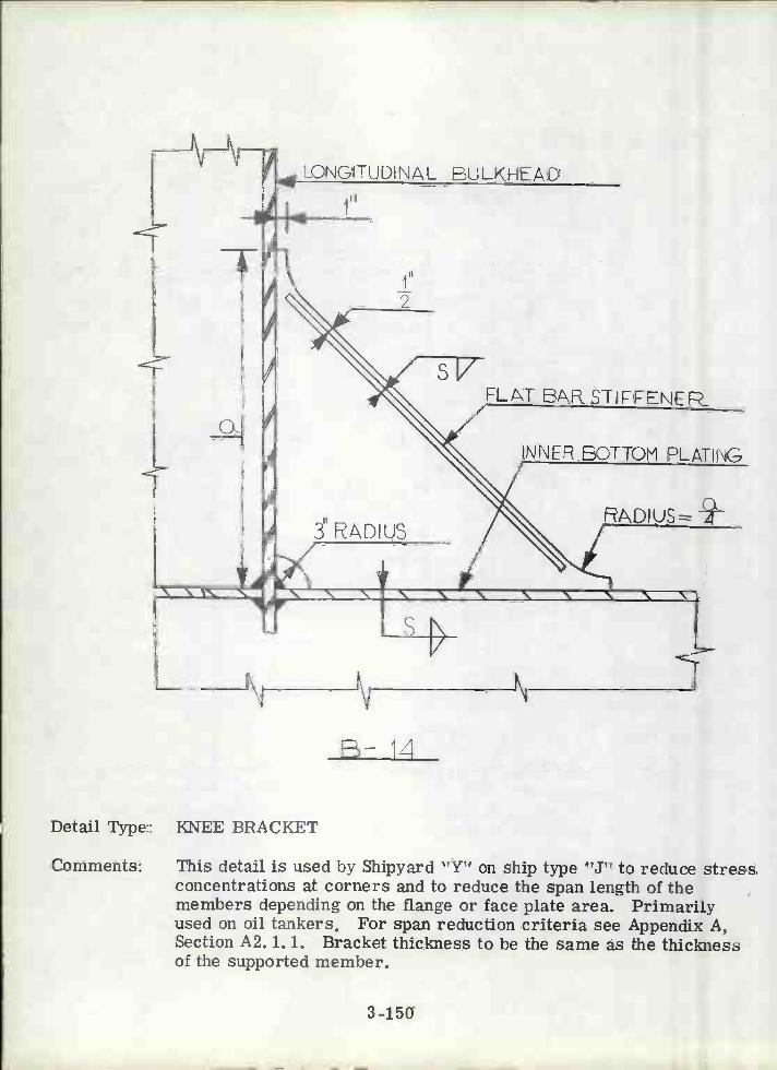
Detail Type: KNEE BRACKET
Comments: This detail is used by Shipyard "Y' on ship type "J" to reduce stressconcentrations at corners and to reduce the span length of themembers depending on the flange or face plate area. Primarilyused on oil tankers. For span reduction criteria see Appendix A,Section A2. 1. 1. Bracket thickness to be the same as the thicknessof the supported member.
LONGITUDINAL BULKHEAD
I
B-lzí
3-150
s VFLAT 6AFSTJrENEp
INNER BOTTOM PLATING
DIUS
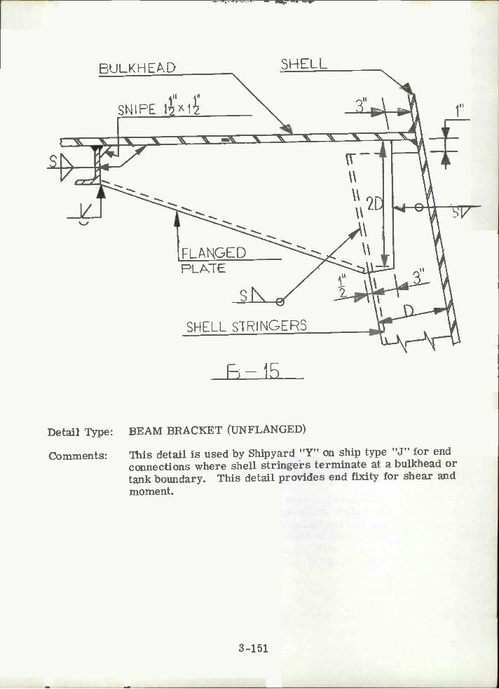
EULKHEAD
SNIPE 1x1
fLAkGEDPLJTE
SNELL
SHELL S1RINGERS
Fm 1E5
Detail Type: BEAM BRACKET (UNFLANGED)
Comments: This detail is used by Shipyard "Y" on ship type "J" for endconnections where shell stringers terminate at a bulkhead ortank boundary. This detail provides end fixity for shear andmoment.
3-151
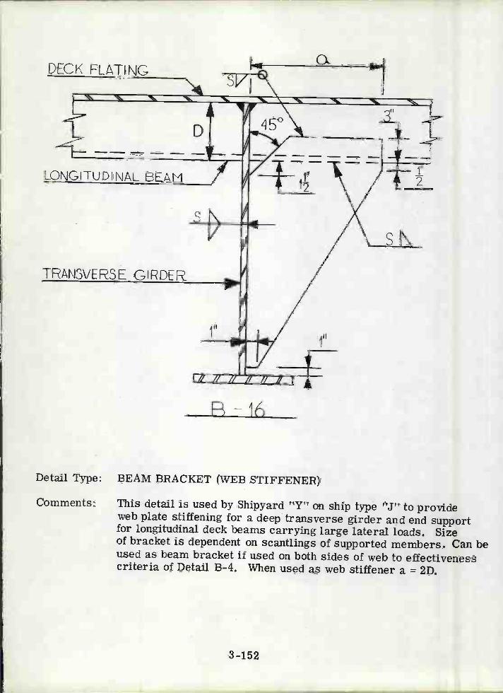
DECK FLATING
LONGITUDNAL EEAM
TPAN3VERSE GIRDER
.. N N
3-152
Detail Type: BEAM BRACKET (WEB STIFFENER)
Comments: This detail is used by Shipyard "Y" on ship type "J" to provideweb plate stiffening for a deep transverse girder and end supportfor longitudinal deck beams carrying large lateral loads. Sizeof bracket is dependent on scantlings of supported members. Can beused as beam bracket if used on both sides of web to effectivenesscriteria of Detail B-4. When used as web stiffener a = 2D.

J
DECK PLAIING
III III
SNIFE 12>12
HATCH SIDE CIRDE
Detail Type: BRACKET
Comments: This detail is used by Shipyard "Y" on ship type "J" to providedeck plating support around deck openings and to provide an endconnection for a deck member. The flange of the hatchside girderreceives support from the small chock. Not a commonly useddetail.
R-17
3-153
II
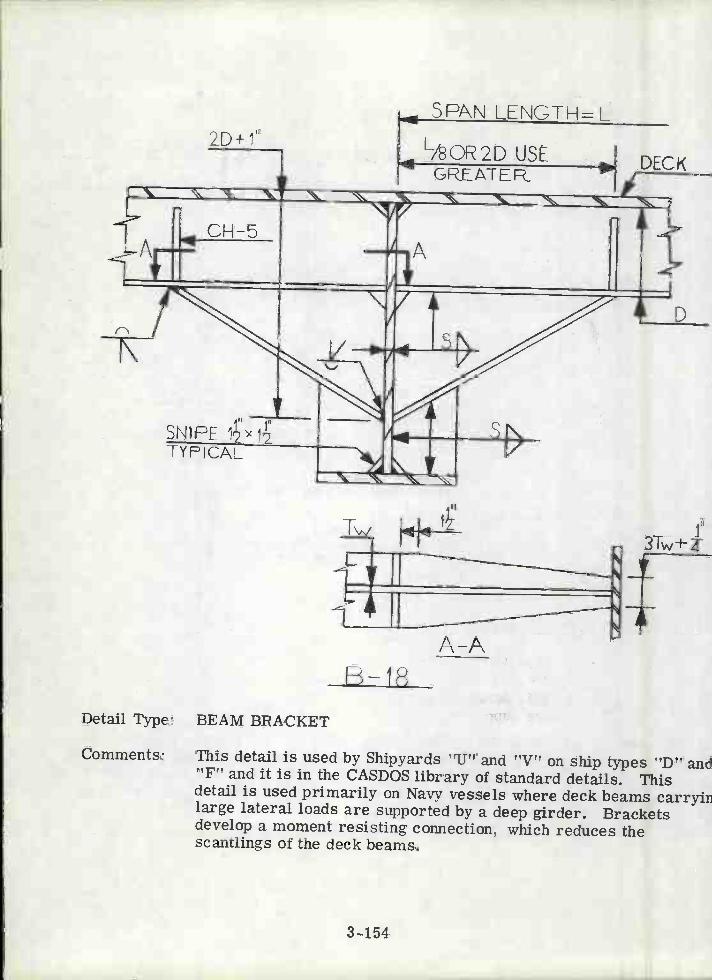
2D+1"
CH-5
SNFETYFICAL
Detail Type: BEAM BRACKET
Comments: This detail is used by Shipyards "U" and "V" on ship types "D" an"F" and it is in the CASDOS library of standard details. Thisdetail is used primarily on Navy vessels where deck beams carryiilarge lateral loads are supported by a deep girder. Bracketsdevelop a moment resisting connection, which reduces thescantlings of the deck beams.
SPP\N LENGTH=L
L/8oR2D USE DEC
3-154
GFEATER
A-AB-18
3Tw

LSPAN LENGTH
LZSOR2D USEGFE AT [R
\ N - N ____________ -
1_ /NA
L
SAME SCAN LING
411 1t
SNIPE 11zA
Detail Type: BEAM BRACKET
Comments: This detail is used by Shipyards "U", "V" and "Zr' on ship types"D", "F" and "K" and is in the CASDOS library of standard details.This detail is used primarily on Navy vessels where deck beamsare supported by shallow girders.
P-19
3-155
SEE CH-5
DECK
PLAN A-A B-1FO FLANCE SNIPE SEE

LSPAN LENGTH
L/8 QR2D USEGPEATEft
2D+1" V/HEND IS "TQ2O"
DECK PLATING 2DIÑOTHEP.CACES
ULKHEAD
Detail Type: STIFFENER BRACKET
Comments: This detail is used by Shipyards "U", "V" and "Z" on ship types"D", "F" and "K" and is in the CASDOS library of standard details.This detail is used primarily on Navy vessels where a deep deckbeam intersects a shallow bulkhead stiffener, where a rigidconnection is desired. Bracket is effective for bulkhead member.
3-156
N
SNIPE FLANGE SIMILAR B-18
SAME SCAÑTLINGS
N
>
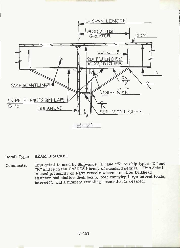
b1 bULKk EAD
Detail Type: BEAM BRACKET
Comments: This detail is used by Shipyards "U" and "Z" on ship types "D" and"K" and is in the CASDOS library of standard details. This detailis used primarily on Navy vessels where a shallow bulkheadstiffener and shallow deck beam, both carrying large lateral loads,intersect, and a moment resisting connection is desired.
LSPAN LENGTI-I
N N N N N -'f4
I.r
SAME SCANTLINCS
SNIFE X
I-. Ç\SNIPE FLANGES SIMILAH.
r4
3-157
NSEE DETAIL CH-7
n n
L0 ZD USLGPEATE DECK

2D3-1" VIREN LZ-PAN LENGTH OF DSAMESCANTLINGSD3 IS6ttTO2O1
USE2D3 OTHER GREATER's' ' s,, 's,, 's, 's,
VSCANTLI ÑGS
LQR2D USEGEATER
CH-5CH-6
Detail Type: BEAM BRACKET
Comments: This detail is in the CASDOS library of standard details, primarilyused on Navy ships where a longitudinal deck beam, deck girderand bulkhead stiffener, all carrying large lateral loads, intersect.Note that this detail uses ten pieces.
B-22
3-158
CH-5
III
SNJPE 1x1 TYP
SNFE FLANGE SIMILARe-18
CH-5
TYP. 2D2+1" V/HEN Dz56TO2O":2D IN
OTHER CASES

Section 4
DETAIL DESIGN GUIDELINES
4.1 GENERAL
Appendix A is an attempt to list all guidelines applicable to structural detaildesign contained in the rules of the world's major classification societiesand other applicable rule-making technical societies. This section reproducesonly those rules which are considered the most applicable available guidelinesfor each particular detail. Rules are supplemented by common ship designpractice where the latter is generally accepted.
In general agreement with the overall objective of reviewing the state of theart in regard to structural details, the aim of this section is to display themost explicit guidelines currently in use, rather than to attempt the formula-tion of new design rules.
The benefit of this approach is that the immediate application of such guide-lines is sanctioned by either a technical organization or by common usage.The shortcoming is that it fails to facilitate the choice between many of thedetail configurations shown in Section 3, and does not necessarily alwaysrepresent either a rational or optimum solution.
This section is background for future theoretical and rule making activitesin this important field of ship structures.
4.2 OPENINGS IN SHIP HULL STRUCTURE
Openings in ship hull structure are made for access, passage of piping,ventilation ducts and electrical cables, cargo handling, air escape, lighteningof structure, etc. Stress concentrations in structural members are a directresult of the introduction of holes in a member. Poor design procedures incombination with poor workmanship may result in serious structural failuresof penetrated members.
Guidelines have been assembled from the classification and technical societyrules and experience.
Because of the complexity of modern ships, it is recommended practice todevelop a set of holes record prints which maintain a composite and currentrecord of all penetrations through structural members. These prints may alsobe used for checking and anticipating interferences, and for influencing designand engineering decisions related to the location of service systems with respectto the structural arrangement, as well as monitoring the effect of holes on thestructural design.
4-1

The ideal situation is when all required penetrations are identified in thedesign stage, before steel fabrication begins: then cutouts can be made bythe automatic burning machine (ABM) which assures a smooth hole.Frequently the system's design lags behind steel fabrication for the firstship in a series, thus many of the penetrations which should be cut by theABM must be cut by hand, aboard ship. This practice frequently resultsin a poor cut, necessitating the addition of a patch plate or coaming whereone should normally not be required.
Openings in hull structure are discussed in relation to specific items of suchstructure.
4. 2. 1 Shell Plating
4.2.1.1 General
There are two main types of shell openings: sea chest and discharge.Sea chest openings and openings greater than 24 inches are compensated forby increasing the thickness of the strake of plating containing the opening.The discharge openings are compensated for by the pipe itself. Sea chestopenings are reviewed and approved by the classification society. Ballastdischarge overflows of up to 24 inches are approved by the classificationsociety shipyard representative. Small penetrations are inspected by theclassification society shipyard representative since they do not appear on theworking plans sent to the approval agency.
4.2.1.2 Sheerstrake (Pertains to the top full course of side shell plating)
Openings in the sheerstrake are to have well-rounded corners. In general,compensation will not be required for holes in the sheerstrake which areclear of any deck openings outside the line of the main hatchways, wherethe longitudinal strength of the hull is not critical, and whose depth does notexceed 20% of the depth of the sheerstrake or 15 inches, whichever is less.When the longitudinal strength of the hull is critical, or the size of the openingis greater than the aforementioned limiting dimension, then some compensationof area in judicious combination of the following will be required.
Increased plate thickness.Use of insert plates or doubler plates.Increase the area of the adjacent girders or longitudinals.Flat bar reinforcement along the edge of the opening. See Figure 4-1.Flat bar reinforcement around the inside of the opening. See Figure4-2.
4-2

-P5t
e 1.O±@1.5t
Fic4l: FLAT BAR REINFORCEMENT ALONGThE EExE or AN OFNG
t
_P 1.Ote1.5t
FIG.4-2 FLAT BAF F?EINFORMENT AROUNDTHE INS!DE OFAN OPNG
4-3

4. 2. 1 .3 Side Shell Plating
Openings in the side shell; such as cargo doors, freeing ports, side scuttles,etc., are to have well-rounded corners. Side shell openings are to be keptclear of discontinuities in the hull girder. Compensation will be required forall openings, except for circular openings with a diameter less than 12 inches.Compensation may be made as described in Section 4. 2. 1. 1.
4. 2. 1.4 Bilge Strake Plating (plating between the bottom shell andside shell)
Openings for sea inlets are to have well-rounded corners, and so far as possibleshould be kept clear of the bilge radius. Openings on or near the bilge radiusshould be elliptical in shape with the major axis in the longitudinal direction.
4. 2. 1.5 Bottom Shell Plating
Openings in the bottom shell are to have well rounded corners, and are to haveadequate compensation so as to maintain the longitudinal and transverse strengthof the hull. Considerations for compensation requirements will be based onthe following guidelines for 0. 6 L amidships.
TABLE 4-1
GUIDELINES FOR OPEMNGS IN THE BOTTOM SHELL PLATING
The transverse section is any strip measured along the bottom whose widthis B/iS (see Figure 4-3).
sum of transverse dimensions of all openings.
Strengthening for openings exceeding the limits of Table 4-1 shall usecompensation as described in Section 4.2.1.1.
4-4
Deduction-free OpeningsWithin the same Transverse
Section
BottomShell
Elliptical Circular
za 0.03B za 0.02B

1.2ER
L
O4
FIG4-3 OPENINGS IN THE BOTTOM SHELL
FR=O.04h
1.35R
B
Fic .4-Ai RECOMMEN,ED DIMEÑsI0ÑS FOR. ELLIPTIC ORPARIOL$C L..'ORNEFQS OF HATCH '..JYS
4-5
2.8R

4. 2. 2 Strength Deck Plating
4. 2. 2. 1 Plating Within the Line of Openings
Within the line of openings, the thickness of exposed plating, tph is not to beless than:
tplt = 0. OlSb + 0. 035 in., where Sb 30 in.tplt = 0. 00067Sb + 0.134 in., where Sb >30 in.Sb = spacing of transverses or longitudinals, (inches.)
4. 2. 2. 2 Hatch Corners
The corners of main hatchways are to be surrounded by strengthened plateswhich are to extend over at least one frame space fore and aft and athwartshipWithin 0. 5 L amidships, the thickness of the strengthened plates is to be equalto the deck thickness abreast of the hatchway plus the deck thickness betweenthe hatchways. At the ends, the strengthened plates need not exceed 1.6 timesthe thickness of the deck plating abreast of the hatchway. Where the hatchwaycorners are elliptic or parabolic, strengthening is not required, provided thatno greater thickness results from the strength calculation of hatchway girdersat the corners. The recommended dimensions of the elliptical or paraboliccorners should be as shown in Figure 4-4. In the event that radiused cornersare used at hatchway corners, that radius is not to be less than:
r = 0.1 (lbL/B) in.rmax. =0.O6bLrmin. =4in.bL= breadth of hatchway or hatchways
4.2.2.3 Openings
Shipyard practice generally does not require compensation for openings in thestrength deck less than 9 inches in diameter. The normal procedure of locatingdeck penetrations is a minimum of 2D (D mean diameter) center to center.
Elliptical openings, although not generally employed by U. S. Shipyards, are usebecause they cause less severe stress concentrations than circular or rectangulopenings do.The centerline of pipe penetrations shall not be less than one diameter awayfrom plate butts or seams.
Openings in deck plating are to have well-rounded corners, the distancebetween the outer edge of the openings for pipe, etc., and the ship's sideis not to be less than the opening diameter. Strength deck openings are tobe of suitable shape and design so as to minimize stress concentrations.The following table will provide guidelines for compensation of openings indeck plating.
4-6

TABLE 4-2
GUIDELINES FOR OPENINGS IN THE STRENGTH DECK
bL = hatch breadthStrengthening for openings exceeding the limits of Table 4-2 shall use compensationas described in Section 4.2.1.1.4.2.3 Bulkhead Plating
4. 2.3. 1 Main Longitudinal Bulkheads
Openings in the main longitudinal bulkhead should be avoided as much aspossible. However, when openings are unavoidable, the corners are to bewell-rounded. Care should be taken to maintain the tightness of the bulkhead,and adequate compensation should be provided to maintain the longitudinalstrength of the hull. Openings in the bulkhead are to be effectively framed soas to facilitate proper fitting, and to guarantee perfect tightness. Compensa-tion of area will be accomplished as discussed in Section 4. 2. 1. 1.
4.2.3.2 Main Transverse Bulkheads
Openings in the main transverse bulkhead are to be restricted to cutouts forwatertight doors and cuts for piping. Cuts for pipes, vent ducts and wirewaysmay be kept to a minimum by employing pipe tunnels or utility trunks. Whereopenings do exist in the bulkhead, the corners are to be well-rounded and careshould be taken to maintain the tightness of the bulkhead. Openings in the bulk-head are to be effectively framed to facilitate proper fitting and guaranteeperfect tightness.
4. 2.3.3 Miscellaneous Structural Bulkheads
Openings in miscellaneous structural bulkheads above doors and arches shouldbe avoided where possible, since this is a high stress area. Any vent spool,pipe or sleeve passing through a structural bulkhead, but not designed forcompensation need only be welded one side.
4-7
Deduction-free Openings Within the sameTransverse Section
Elliptical-I Circular-II
Decks,Tankers
a 0. 05B0.05 B 80 in.a35in.
a ' 0.03 B0.03 13 40 in.
a16in.
Decks, drycargoships
a 0. 03 (B-bL)a14in.
a 0. 03 (B-bL)a4in.
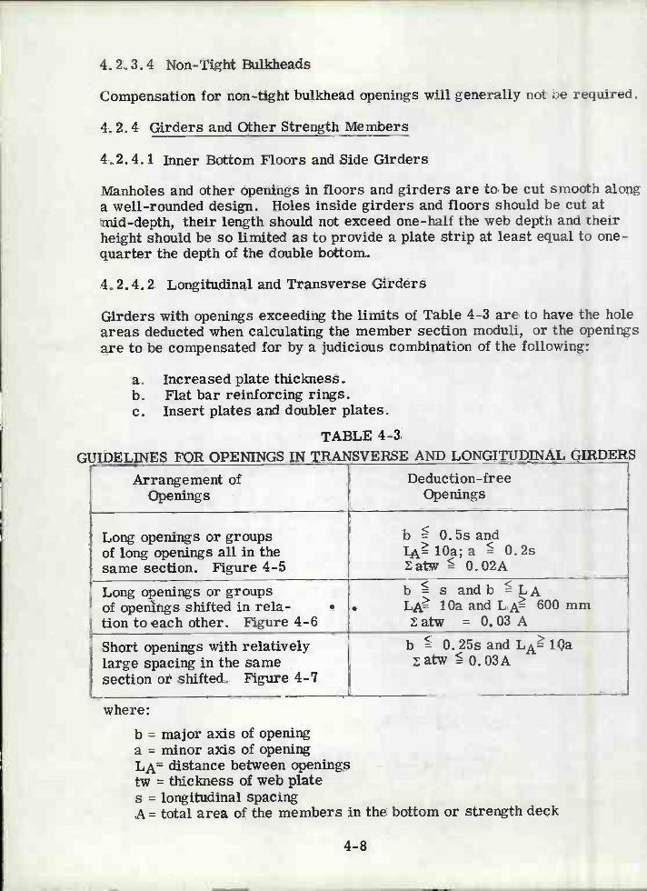
4. 2.3.4 Non-Tight Bulkheads
Compensation for non-tight bulkhead openings will generally not be required.
4. 2. 4 Girders and Other Strength Members
4. 2.4. 1 Inner Bottom Floors and Side Girders
Manholes and other openings in floors and girders are to be cut smooth alonga well-rounded design. Holes inside girders and floors should be cut atmid-depth, their length should not exceed one-half the web depth and theirheight should be so limited as to provide a plate strip at least equal to one-quarter the depth of the double bottom.
4. 2.4. 2 Longitudinal and Transverse Girders
Girders with openings exceeding the limits of Table 4-3 are to have the holeareas deducted when calculating the member section moduli, or the openingsare to be compensated for by a judicious combination of the following:
Increased plate thickness.Flat bar reinforcing rings.
e. Insert plates and doubler plates.
TABLE 4-3GUIDELINES FOR OPENINGS IN TRANSVERSE AND LONGITUDINAL GIRDERS
where:
b = major axis of openinga = minor axis of openingLA= distance between openingstw = thickness of web plates = longitudinal spacingA= total area of the members in the bottom or strength deck
4-8
Arrangement ofOpenings
Deduction-freeOpenings
Long openings or groupsof long openings allinthesame section. Figure 4-5
b 0. 5s andIA1Oa;a 0.2s
atw 0.02A
Long openings or groupsof openings shifted in rela-tion to each other. Figure 4-6
sb s and b LALA lOa and LA 600 mm
atw = 0.03 A
Short openings with relativelylarge spacing in the samesection or shifted. Figure 4-7
b 0. 25s and LA lOaatw 0. 03A

$
j
FL4PJ VIEW (os.)
ELEVATION o)
JPLAN VIEW (b.)
tELEVATION (b)
I
ç
PLAN VIEW (c.)
b4 LA)
FIG.4-5 LONG OPNGS ORGROUPS 0F LONGOPNGS ALL IN THE
SAME SECTION4-9

f
ç
4
FiG. ¿16: LONG OPNGS ORGROUFS OF LONG OPS SHIFTED INfELATIOÑ TO EItICH OTHER
b LA b L4
L)
4-10
FlG.4-/SHORT OPNGS WITH RELATIVELY LARGE SF,CING IN THI
SAME SECTION OR SHIFTEc

Openings in beams, girders, longitudinals, and stiffeners should be locatedin the web near the neutral axis of the member. No cuts in the flanges ofbeams and stiffeners should be made without compensation.
4.3 KNEE AND BEAM BRACKETS
4.3.1 Brackets for Girders and Deep Webs
In vessels constructed with deep webs, girders and transverses, it may bedesirable to reduce the scantlings of these members by introducing bracketsat the member ends. These brackets are fitted on the girders or webs toreduce the unsupported span of the members, to eliminate stress concentra-tions at the joint of two members or to assist in steel erection. The followingguidelines have been formulated to assist in the design of these brackets.
Where brackets are employed, they are to have a thickness thatis at least equal to the thickness of the web of the member supported.By varying the area of the face plate of the bracket, the unsupportedspan Lu of the member is defined as follows:
Case 1: When the area of the bracket face plate is at leastequal to one-half the area of the face plate or flange on thegirder or deep web and the girder flange is carried to thebulkhead or base, the unsupported span of the member maybe measured to a point 6 in. onto the bracket (see Figure 4-8).Case 2: When the area of the bracket face plate is less thanone-half the area of the face plate or flange of the girder ordeep web and the girder flange is carried to the bulkhead orbase, the value of the unsupported span is measured to apoint on the bracket where the area of the bracket and its flangeoutside the line of the girder or deep web, is equal to the areaof the flange on the girder. (see Figure 4-9).Case 3: When the area of the face plate or flange of thesupported girder or deep web is carried along the face of thebracket, which may be curved for this purpose, the unsupportedlength of the member is measured to the toe of the bracket(see Figure 4-10).
Brackets on girders and deep webs cannot be considered effectivebeyond the point where the arm on the girder or deep web is oneand one-half times the length of the arm on the bulkhead or base.In no case is the allowance in the unsupported length at either endto exceed one quarter of the overall span of the girder or deepweb.
4-11

dAIÑ
ABRKT FLG CAGIRD FLG)2 iN2
±RKT fGIFkD. IN.
o1.5dLsi4 INLuZ(6 Ñ.
Gft*DER. SPAN : L (iN.)
±BRKT CIN.)
F,GÀ8: KNEE BRCKET:CASE i
4-12
AFRKT FLG (iN2)
L. UNSUPPORTEDSPAN Lu (IN.)
AcIRD. FLÇ(iÑ)

dA(Ñ)
HG.4-9:
cRDE SPAN: LSJiH.)
ARKT FLG (N.2)
tBFKTGN)
tGÌRD(IN.)
OEL (IN.)
\BRKT FLG <(/\GIRD FLG)/2IBRKTtGIRD. iN,
o.5dA iN.
a -s/LI IN.
L&IRD,L&ABRKT L&lL IN.dBRKT
Lu L-2(odL) iN.
4-13
AGID FLG (IN?)
<NEE bRACKET :CASE 2
UNSUPPORTEDSFÑ' Lu:(IÑ.)
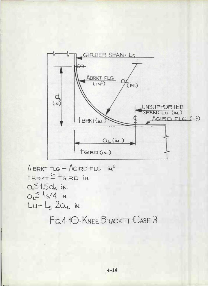
IJN.tGIRD ()
A 5RKT FLG AGI RD FLG>LfBRKT IRD IÑ.
O= I.UUA IN.
Ot ¡N.
Lu= 2L IN.
{G.4-O KNEE BRACKET :CASE 3
4-14
UNSU FPORTEDSF'AÑ: Lu (IN.)
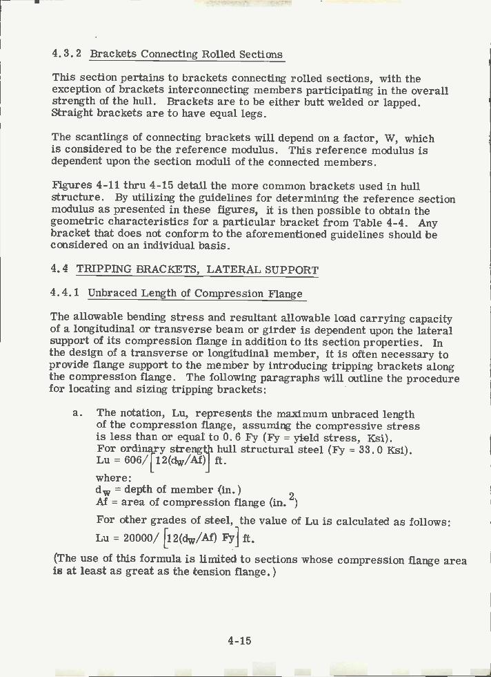
4.3.2 Brackets Connecting Rolled Sections
This section pertains to brackets connecting rolled sections, with theexception of brackets interconnecting members participating in the overallstrength of the hull. Brackets are to be either butt welded or lapped.Straight brackets are to have equal legs.
The scantlings of connecting brackets will depend on a factor, W, whichis considered to be the reference modulus. This reference modulus isdependent upon the section moduli of the connected members.
Figures 4-11 thru 4-15 detail the more common brackets used in hullstructure. By utilizing the guidelines for determining the reference sectionmodulus as presented in these figures, it is then possible to obtain thegeometric characteristics for a particular bracket from Table 4-4. Anybracket that does not conform to the aforementioned guidelines should beconsidered on an individual basis.
4.4 TRIPPING BRACKETS, LATERAL SUPPORT
4.4.1 Unbraced Length of Compression Flange
The allowable bending stress and resultant allowable load carrying capacityof a longitudinal or transverse beam or girder is dependent upon the lateralsupport of its compression flange in addition to its section properties. Inthe design of a transverse or longitudinal member, it is often necessary toprovide flange support to the member by introducing tripping brackets alongthe compression flange. The following paragraphs will outline the procedurefor locating and sizing tripping brackets:
a. The notation, Lu, represents the maximum unbraced lengthof the compression flange, assuming the compressive stressis less than or equal to 0. 6 Fy (Fy = yield stress, Ksi).For ordinary strength hull structural steel (Fy = 33. 0 Ksi).Lu = 606/[12(dw/Af)] ft.where:d = depth of member (in.)
2M = area of compression flange (in. )
For other grades of steel, the value of Lu is calculated as follows:Lu = 20000/ [12(dw/Ai) F37] ft.
(The use of this formula is Limited to sections whose compression flange areais at least as great as the tension flange.)
4-15
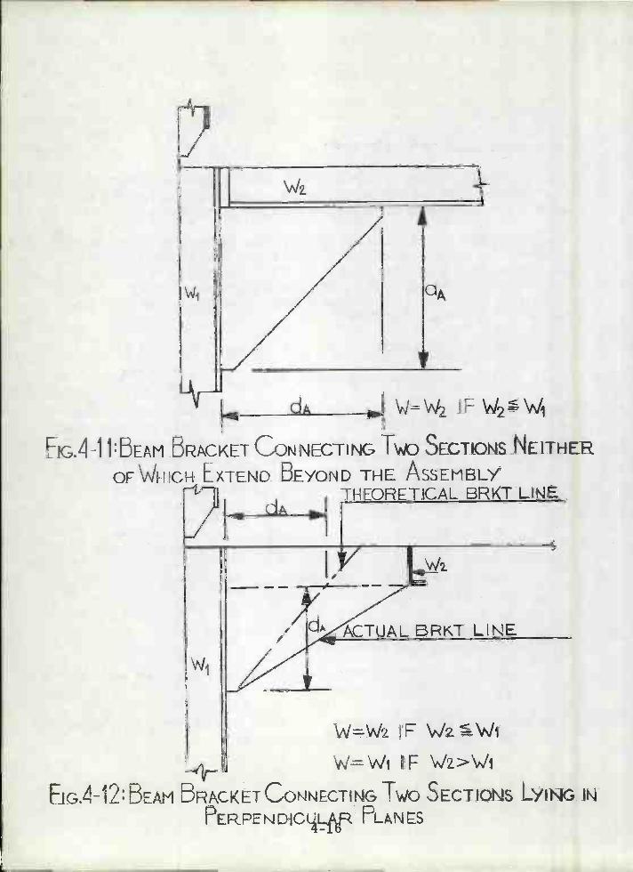
WI
dA
y
dA W=IFW2
E1G.41 l:DEAM BRACKET CONNEcTING Tv SECTIONS NEITHER
OF WHICH EXTEND BEYOND THE ASSEMBLYTHEORETICAL BRKT LINE
ACTUAL BRKT LINE
W=Wz IF VJzWi
W=Wt F W>JiEjG.4-12:BEÁM 5R\CKETCOÑNECTIÑG TWO SECTIONS N
PERPENDICLR PLANS

-kv-
WI
dA
f 4_j3: INTERMEDIATE BEAM BRACKET CONNECTING
MEMBERS WITh DIRECT CONTINUITY
WI
F1G.414:INTERMEDIATE BEAn BRACKET PFOVDING CONTINUITY OF4-17 MfMBER.S
dA
d W=W2lFW2W1+WA
W=WW IF W2WjW
W=Wi IF\.JiJz
\i/z IF Wi<'vJz
Y
w

W
WI
i
B
EIG. 4_15: INTERMEDIATE bEAM BRACKETS OV1DING
CONTINUITY OF MEMBERS
4-18
A
CA
y-WB=VJ
\Jt=Wi lFWiVJz
VJA=WZ IF \t<W2
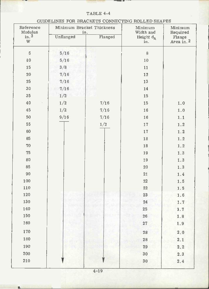
TABLE 4-4
GUIDELINES FOR BRACKETS CONNECTING ROLLED SHAPES
4-19
ReferenceModulus
in. 3W
Minimum Bracket Thicknessin.
MinimumWidth and
MinimumRequired
FlangeArea in.2
Unflanged Flanged Height dAin.
5 5/16 8
10 5/16 10
15 3/8 11
20 7/16 12
25 7/16 13
30 7/16 14
35 1/2 15
40 1/2 7/16 15 1.045 1/2 7/16 16 1.050 9/16 7/16 16 1.155 1/2 17 1.260 17 1.265 18 1.270 18 1.275 19 1.380 19 1.385 20 1.390 21 1.4
100 22 1.5110 22 1.5120 23 1.6130 24 1.7140 25 1.7150 26 1.8160 27 1.9
170 28 2.0180 28 2.1190 29 2.2200 30 2.3210 Y 30 2.4

Since only the compression flange is subject to tripping, the locationof tripping brackets should be selected to suit the actual loading condition.
Tripping brackets on girders are to be stiffened by a flange orstiffener along the free edge. If the length of that edge exceeds
224 inches, the area of the stiffening is not to be less than 0. bwhere b = length of bracket free edge (inches).
The width to thickness ratio of compression flanges should notexceed 9ÇPy, i.e., 16.5 for ordinary ship steel.
bf/t 95/JyUnstiffened compression elements whose width to thickness ratioexceeds the limit in section c. shall be subject to a reduction factorQs. The value of Qs shall be determined by the following formulas.When such elements comprise the compression flange of a flexuralmember the maximum allowable bending stress shall not exceed:
Fb = 0. 6 FyQs
When 95/\ly < (bf/tf) 176/ sJiy:Qs = 1.415 - 0.00437(bf/tf)J
When bf/t> 176/\ft:Qs = 20000/ [FY (bf/t)2]
Tripping brackets are normally placed on both sides of a tee-beam toinsure that one is always in tension.
4.5 PANEL AND WEB STIFFENERS
4. 5. 1 Center and Side Girders
Where longitudinal framing is used in the double bottom, transverse bracketsare to be fitted at a maximum spacing of 72 inches between solid floors. Whenthe bracket spacing exceeds 48 inches, additional stiffeners will be required.
The thickness of the brackets shall be the lesser of the following:
center girder thickness0.0131\/r + 0.10 (in.)
The additional stiffeners are to be flat bars with the same strength as thosewith the same thickness as the center girder and a depth equal to 0. 08 (depthof the center girder.)
4-20

For Side Girders, vertical stiffeners are to be provided at every openfloor. The scantlings for the vertical stiffeners are obtained usingthe same rationale as those for the center girder.
4.5.2 Floors
In vessels of 280 feet and above, stiffeners are to be fitted on solid floors.Stiffeners fitted on plate floors may consist of flat bars having a width of0. 10 times the floor depth and a thickness not to be less than:
t = O. 0354 /L in.L = length of ship in feet.
4. 5.3 Web Plate Stiffeners
4.6.1 General
Although stanchions and pillars are primarily employed as compressionmembers, it is possible for these members to experience an occasionaltensile loading. Because of this occurrence, care must be taken in thedesign of end connections.
When stanchions are employed, it is recommended that they Une up and notbe staggered.
4. 6. 2 Compression and Bearing End Connections
4. 6. 2. 1 Tubular and Hollow Square Pillars
Tubular and hollow square pillars are to be attached at the head to plates,supported by brackets, flanged where necessary, in order to transmit loadseffectively. Doublers or insert plates are to be fitted to inner bottom underheels of tubular or hollow square pillars, and to decks under pillars greaterthan 6 inches in diameter. Pillars are to have a bearing fit and are to beattached to the head and heel plates by continuous welding.
Stiffeners on web plates are to be located not more than 4 in. from the freeedge of cutouts for intersecting longitudinals, frames or stiffeners. If webstiffeners are fitted in line with intersecting members, they are to be attachedto the intersecting members. Stiffeners on the web plates that are perpendicularto the flange may be sniped toward the deck, side shell, or bulkhead plating.Web plate stiffeners for tankers may be sized per Table 4-5, which may alsoserve as overall guidance for web plate stiffening. Note that for deep girdersa choice may be made between vertical and longitudinal web stiffening.
4.6 STANCHTON SUPPORTS AND END CONNECTIONS
4-21
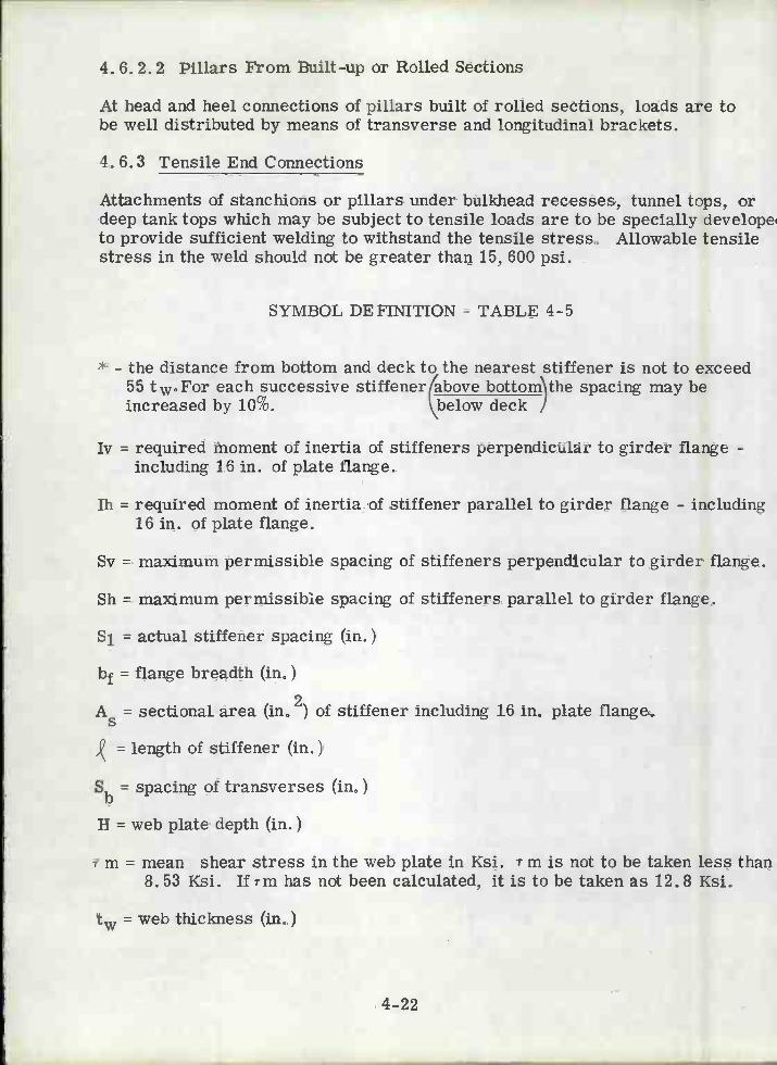
4. 6. 2. 2 Pillars From Built-up or Rolled Sections
At head and heel connections of pillars built of rolled sections, loads are tobe well distributed by means of transverse and longitudinal brackets.
4. 6.3 Tensile End Connections
Attachments of stanchions or pillars under bulkhead recesses, tunnel tops, ordeep tank tops which may be subject to tensile loads are to be specially develope'to provide sufficient welding to withstand the tensile stress. Allowable tensilestress in the weld should not be greater than 15, 600 psi.
SYMBOL DEFINITION - TABLE 4-5
* - the distance from bottom and deck to the nearest stiffener is not to exceed55 t.For each successive stiffener(above bottom'\the spacing may beincreased by 10%. \below deck J
Iv = required moment of inertia of stiffeners perpendicular to girder flange -including 16 in. of plate flange.
1h = required moment of inertia of stiffener parallel to girder flange - including16 in. of plate flange.
Sv = maximum permissible spacing of stiffeners perpendicular to girder flange.
Sh = maximum permissibie spacing of stiffeners parallel to girder flange.
S1 = actual stiffener spacing (in.)
= flange breadth (in.)
= sectional area (in0 2) of stiffener including 16 in. plate flange.
= length of stiffener (in.)
Sb = spacing of transverses (in0)
H = web plate depth (in.)
r m = mean shear stress in the web plate in Ksi. r m is not to be taken less than8.53 }çgj ji rm has not been calculated, it is to be taken as 12.8 Ksi.
= web thickness (in.)
4-22

TABLE 4-5
GUIDELINES FOR SIZING WEB PLATE STIFFENERS FOR TANKERS
The spacing of web plate stiffeners for very large crude carriers(VLCC's) is a critical condition and should be specially considered toavoid possible failure of the transverse. The following guidelines areonly minimum standards and each case should be individuallyconsidered. For bottom transverses, web plate stiffeners are to befitted for the full depth of the member and are to be spaced at eachlongitudinal frame, for side transverses, vertical webs and horizontalgirders stiffeners are to be fitted on alternate longitudinals and onevery third longitudinal frame for deck transverses. Special attentionis to be given to the stiffening of web plate panels close to changes incontour of the web, and for ships over 650 feet in length.
4-23
GirderType
Iv (in.4) 1hin.4
Sv (in.) Sh (in.)
Bottom cS i (tw+tc)3 A5,2 768 tw 853 twTransv. 16.4 4000 rm
Side andLong'l cS1(tw+tc3 A5, 2
768tw 853 twBulkhead 16.4 2000 rm rmVe rtic als
Long'lBottom A52 *
Girder 3000
Long'l A52 *Deck
Girder 3000
Deck cS1 (tw+tc)3 As 768 t 853 twTrans. 16.4 4000 rm Tm
Transv.Bulkhead A5k2
Vertical 2000
Stringers tw+tc)3 A5g2 768 t 853 t16.4 4000 7m rm
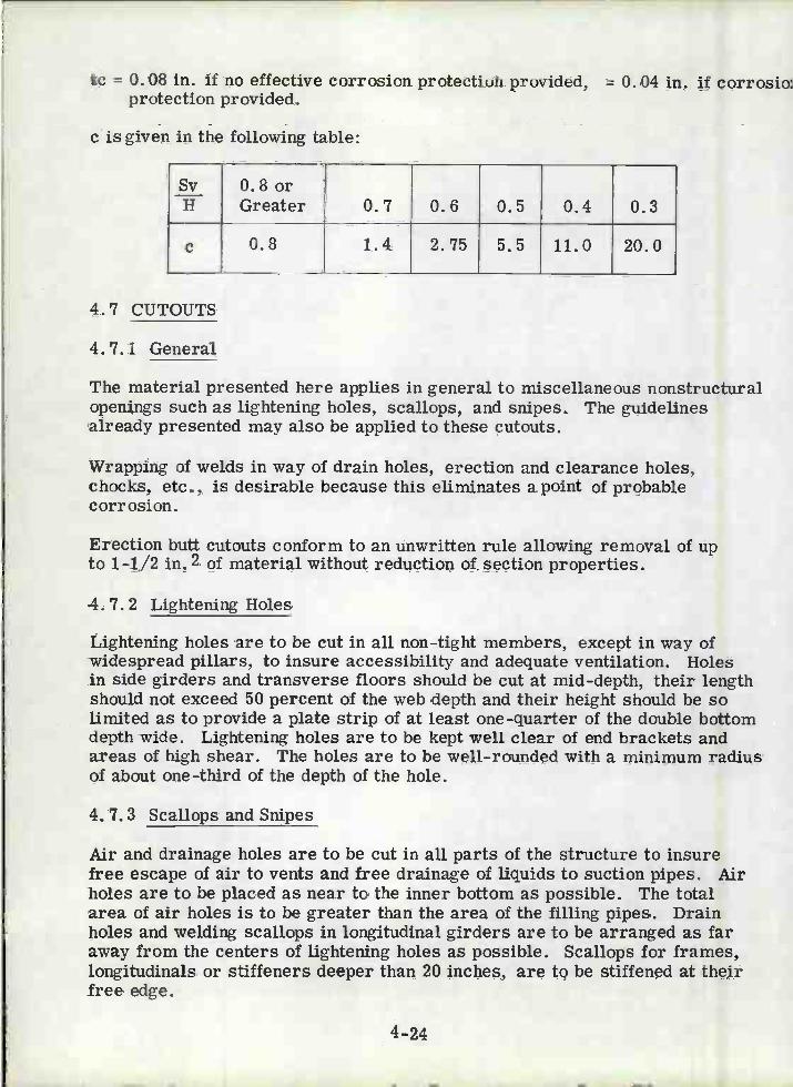
tc = 0. 08 in. if no effective corrosion protection provided, = 0. 04 in. if corrosio:protection provided.
cis given in the following table:
4.7 CUTOUTS
4.7.1 General
The material presented here applies in general to miscellaneous nonstructuralopenjngs such as lightening holes, scallops, and snipes. The guidelinesalready presented may also be applied to these cutouts.
Wrapping of welds in way of drain holes, erection and clearance holes,chocks, etc., is desirable because this eliminates a point of probablecorrosion.
Erection butt cutouts conform to an unwritten rule allowing removal of upto 1-1/2 in. 2 of material without reduction of section properties.
4. 7. 2 Lightening Holes
Lightening holes are to be cut in all non-tight members, except in way ofwidespread pillars, to insure accessibility and adequate ventilation. Holesin side girders and transverse floors should be cut at mid-depth, their lengthshould not exceed 50 percent of the web depth and their height should be solimited as to provide a plate strip of at least one-quarter of the double bottomdepth wide. Lightening holes are to be kept well clear of end brackets andareas of high shear. The holes are to be well-rounded with a minimum radiusof about one -third of the depth of the hole.
4. 7.3 Scallops and Snipes
Air and drainage holes are to be cut in all parts of the structure to insurefree escape of air to vents and free drainage of liquids to suction pipes. Airholes are to be placed as near to the inner bottom as possible. The totalarea of air holes is to be greater than the area of the filling pipes. Drainholes and welding scallops in longitudinal girders are to be arranged as faraway from the centers of lightening holes as possible. Scallops for frames,longitudinals or stiffeners deeper than 20 inches, are to be stiffened at theirfree edge.
4-24
Sv 0.8orH Greater 0.7 0.6 0.5 0.4 0.3
e 0.8 1.4 2.75 5.5 11.0 20.0
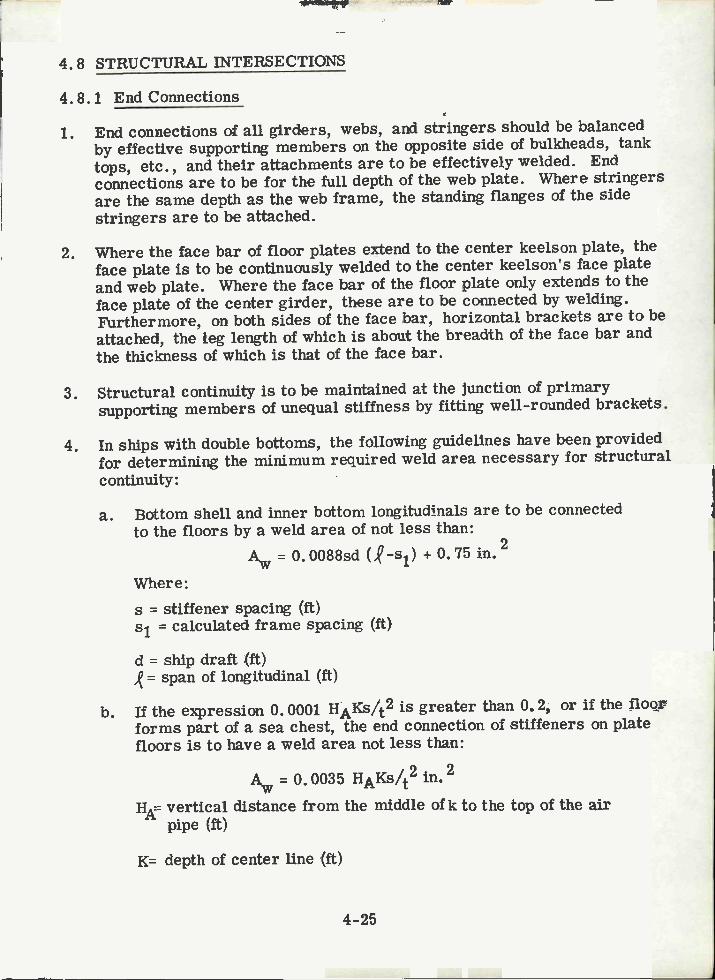
4.8 STRUCTURAL INTERSECTIONS
4.8.1 End Connections
End connections of all girders, webs, and stringers should be balancedby effective supporting members on the opposite side of bulkheads, tanktops, etc., and their attachments are to be effectively welded. Endconnections are to be for the full depth of the web plate. Where stringersare the same depth as the web frame, the standing flanges of the sidestringers are to be attached.
Where the face bar of floor plates extend to the center keelson plate, theface plate is to be continuously welded to the center keelson's face plateand web plate. Where the face bar of the floor plate only extends to theface plate of the center girder, these are to be connected by welding.Furthermore, on both sides of the face bar, horizontal brackets are to beattached, the leg length of which is about the breadth of the face bar andthe thickness of which is that of the face bar.
Structural continuity is to be maintained at the junction of primarysupporting members of unequal stiffness by fitting well-rounded brackets.
In ships with double bottoms, the following guidelines have been providedfor determining the minimum required weld area necessary for structuralcontinuity:
Bottom shell and inner bottom longitudia1s are to be connectedto the floors by a weld area of not less than:
= 0. 0088sd (-s1) + 0.75 in.2
Where:s = stiffener spacing (ft)s1 = calculated frame spacing (ft)
d = ship draft (ft)= span of longitudinal (ft)
Tithe expression 0. 0001 HAKS/t2 is greater than 0. 2, or if the floorforms part of a sea chest, the end connection of stiffeners on platefloors is to have a weld area not less than:
A 0. 0035 HAKS/t2 in.2
HA= vertical distance from the middle of k to the top of the airpipe (ft)
K= depth of center line (It)
4-25
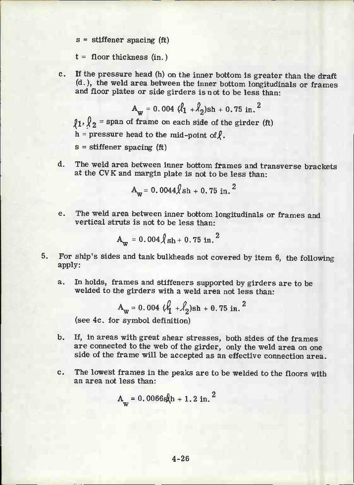
s = stiffener spacing (ft)
t = floor thickness (in.)
e. If the pressure head (h) on the inner bottom is greater than the draft(d.), the weld area between the inner bottom longitudinals or framesand floor plates or side girders is not to be less than:
A = 0.004 +2)sh + 0.75 in.2
1' = span of frame on each side of the girder (It)h pressure head to the mid-point of,.s = stiffener spacing (It)
The weld area between inner bottom frames and transverse bracketsat the CVK and margin plate is not to be less than:
Aw= 0.0044,Qsh + 0.75 in.2
The weld area between inner bottom longitudinals or frames andvertical struts is not to be less than:
A = 0.004,sh+ 2in.w
5. For ship's sides and tank bulkheads not covered by item 6, the followingapply:
In holds, frames and stiffeners supported by girders are to bewelded to the girders with a weld area not less than:
û 0 .2= 0.004 (A1 +,c2)sh + 0.75 in.
(see 4c. for symbol definition)
If, in areas with great shear stresses, both sides of the framesare connected to the web of the girder, only the weld area on oneside of the frame will be accepted as an effective connection area.
The lowest frames in the peaks are to be welded to the floors withan area not less than:
A= 0.0066h + 1.2 in.2
4-26

4-27
E1G.4ló :CONNEGTION DEJAILS OrLONGTUDINALS 10 C'i FDERS
AND/0R WEB IRAMES

Longitudinals, frames and bulkhead stiffeners in cargo tanks may beconnected to the web plate of girders and web frames in the following ways(see Figure 4-16):
Welded directly to the web plate on one or both sides of the frames.Connected by single or double-sided collars,With stiffener or bracket welded on top of frame.A combination of the above.
In locations with great shear stresses in the web plate, a double-sidedconnection is required. The connection may then be taken into accountwhen calculating the effective web area. Only one side of the connection,however, may then be included in the effective connection area betweenframe and web plate.
If the necessary area is not obtained by using a side connection only,a stiffener or bracket is to be provided on top of the frame.Minimum connection area:
Aw 0.O055,shin.2= span (ft)
s = spacing (ft)h pressure head (ft)
For bulkhead stiffeners not covered by item 6, the following apply:
The upper end of stiffeners which support deck beams orlongitudinals, is to be connected to the deck beam or longitudinalby a weld area not less than:
A =0. O079s, h in. 2w
h head on deck beam
The lower end of stiffeners which support deck beams or longitudinals,is to be connected to deck or tank top by a weld area not less than:
A.., =,2/19.36in.2 2.4 in.2
e. The end connection area at both ends of stiffeners is to be atleast:
= 2.1- in.2
z = required section modulus of stiffener (in. 3)
span of stiffener (ft)
4-28
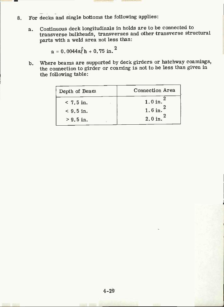
8. For decks and single bottoms the following applies:
Continuous deck longitudinals in holds are to be connected totransverse bulkheads, transverses and other transverse structuralparts with a weld area not less than:
a O. OO44s,h + 0. 75 in.2
Where beams are supported by deck girders or hatchway coamings,the connection to girder or coaming is not to be less than given inthe following table:
4-29
Depth of Beam Connection Area
<7.5 in.<9.Sin.>9.5in.
.21.Oin..21.6in..22.Oin.

4.9 LIST OF COMMON SYMBOLS
a = transverse dimension, or minor axis of an opening (in.)aL = bracket arm length (in.)
2A = total area of the members in the bottom shell or strength deck (in ),AJ3RKT FLG = area of bracket flange (in2).AGIRD FLG = area of girder flange (in2).
2As = sectional area of stiffener including 16 in. plate flange (in ).b dimension, major axis of an opening (in.).bf = flange breadth (in.)bi = breadth of hatchway or hatchways (in.).B = ship breadth (ft.).c = end condition reduction factord = ship draft (ft.), measured from the baseline to the summer loadline.da, db = bracket arm length (in.)dl = span reduction for case 2 brackets (in.).dw = member web depth (in.)D = depth of ship, measured at ship centerline from the baseline to the
bulkhead deck (ft.).Dp = mean diameter of deck penetrations (in.).e = thickness of flat bar reinforcement ring (in.).f = depth of fiat bar reinforcement ring (in.).Fy = yield stress of material (Ksi).h = pressure head to the midpoint of (ft.).hdb = head from top of the innerbottom to the top of the overflow (ft.).Iv = required moment of inertia of stiffeners perpendicular to girder flange -
including 16 in. of plate flange (in4).1h = required moment of inertia of stiffener parallel to girder flange -
including 16 in. of plate flange (in4).K depth of centerline girder (in.).2 = length of stiffener (in., ft.).
= length of bracket free edge (in.).L = distance measured along the summer loadline, from the fore side of the
stem to the after side of the rudder post or sternpost (ft.).La = distance between openings (in.).Ls = girder span (ft.).Lu = unsupported span or maximum unbraced length of a member (ft.).Qs = allowable stress reduction factor.r = radius of hatchway corners (in.).R = fairing radius for elliptic or parabolic hatchway corners (in.).s = spacing of longitudinais (in.).Sb = spacing of transverses or longitudinals (ft.).Sj = actual stiffener spacing (in.).Sh = maximum permissible spacing of stiffeners parallel to the girder flange (inSm = section modulus of panel or web stiffeners (in3).Sv = maximum permissible spacing of stiffeners perpendicular to girder
flange (in3),t = plating thickness (for deck, shell, bulkhead, etc.) (in.).
4-30

tf = flange thickness (in.).t pit = thickness of exposed plating (in.).tw = web plate thickness (in.)W = reference modulus used in determining bracket size andZ = section modulus of deck longitudinals (in3).
a = summation of transverse dimensions of all openings inplate (in.).
4-31
scantlings (in3)
the bottom shell

NOT E S
4-32

Section 5
DAMAGE HISTORY OF STRUCTURAL DETAILS
5.1 GENERAL
Haaland in his excellent paper on ship structural design (Ref. 1) indicates thatmany structural detail failures have very elementary causes. This is a generaland true observation of practicing surveyors: usually the deficiencies of adetail resulting in local failure are readily recognized, without need forextensive analysis. The bulk of failure examples and accompanying descriptionis taken from a booklet by Lloyd's Register of Shipping (Ref. 2).
Discussions with representatives of the American Bureau of Shipping and ofthe U. S. Salvage Association confirmed the damage descriptions in Refs. iand 2.
5.2 BRACKETS
When a bracket is fitted between a stiff member and unstiffened plating (asshown in Figure 5-1, the latter may flex about the toe of the bracket andcracks appear in the plating. This effect is not removed by fitting a secondbracket since the hard spot remains unaffected. Figures 5-2, 5-3, and 5-4show examples of this failure. The problem may be corrected by aligningthe toes of the bracket with a stiffener, by adding a doubler plate, or by fittinga stiffener to spread the load (see Figure 5-5 and 5-6). Whenever abracket is fitted, the structure to which it is attached should be strong enoughto transmit forces exerted by the bracket. Figure 5-7 shows examples ofinadequate brackets. Figure 5-8 gives an improved detail that will eliminatethe problem.
5.3 MISCELLANEOUS OPENINGS
5.3.1 Ratholes
Figure 5-9 shows a serious fracture which originated from a rathole madein the web of a hatchside girder in way of a butt weld in the web.
Such ratholes are commonly made to facilitate welding after erection, butcan be a source of fracture unless special care is taken in design andfabrication. In this case the girder web butt weld probably broke due to thedifficulty in providing good endings to the welds at "X", causing a high stressconcentration at the rathole. It is recommended that scallops and ratholesbe kept to a minimum but, if they are necessary for assembly, special careis required to avoid crater cracks, particularly at "X" in Figure 5-9.
5-1

LJERNATI NC7FLEXURE
STIFF MEMBER
5-2
UNSTIFFENED PLATING
PL
RFC KET
FIG,5l: FLEXURE OF UNSTIFFENED PLATING ABOUT BRACKETlOE LEADING TOCRACKS (EmM RERZ)
FIG.52:CRACKS INITIATING AT BRACKETS INSTALLED ON
BOTTOM LOI.JGITUDINPLS (FROM RF2j

FIG. S-3:CRACKS OCCURRING IN CORFZUGTED BULKHEADS AT
THE lOES OF TRiPPING BRACKETS (FROM REF.Z)
EICI5-4:CRACKS CAUSED BY FLEXURE OF UNSTIFFENED
PLkTING AT BRACKET DETAiLS (FROM REF.2)
5-3

FIG. 5-5:USEOF HORIZONTALGUSSETORSTIrFENER TO
STIFFEN BULKHEAD PLATING AT POINTS OF FLEXURE(FROM REFZ)
FIc,.5-6:USE0F DkDUBLER PLATES TO ELIMINATE CRCKSATTPPING BPACKETS ONCORftUGPTED BULKHEADS
(FROM REF 2)
5-4

CRACK N DECK
DE FRAME
DECK
DP HF
\JELD CRACKFD
L
o
FAC,E PLATF CRACK
F3IILKHEAD
CRACK
4FiG. 5-7. POOR BRPCKET DETAILS THAT HAVE LED TOCRACV
IN SUPPORTED MEM6ERS (FROM REF.2)
5-5
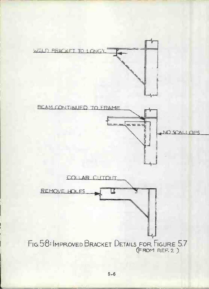
5-6
fIG. 58: IMPROVED BRACKET DETAILS FOR HGURE 51(FROM PEF.Z)

SECOND DECK,
EET
JTT INGIRDFRWFBWiTH RPJHOLES
I
5-7
f
FUTT IN DECKPEPTE WITHRATHOLE INGIRDER YEB
k HATCH-SIDE GIRDFR
RUTT IN GIRDPF LATE VJITHJATHOLE IN
1IEY9; FRACTURE OF HATCH SIDE GIRDER AND DECK PLATE
AT' RoeR. RATHOLE CUTOUT (FROfr1 REF 2)
5.3.2 Manholes and Lightening Holes
Manholes and lightening holes cut in the diaphragm plates of cofferdam bulk-heads have led to severe buckling of the plate. Figure 5-10 depicts thebuckled plate at the lowest strake of a transverse cofferdam bulkhead.
The recommended improvement of this situation is not to allow holes to becut in the bottom or top third of vertical web plates in cofferdam bulkheads.
5.3.3 Slots and Scallops
Another common location of damage is shown in Figures 5-11, 5-12, 5-13,
5-14 and 5-15. Figure 5-11 shows cracks occurring at the junction betweenside shell longitudinals and transverse web frames because the cross-sectionalarea of the connection is too small, thus causing high shear stresses at thesupport. Normally cracks occur in the fillet weld, and when the connectionhas first been broken secondary cracks will appear in the shell at the edge ofthe scallop in the vertical web for the longitudinal and at the weld connectionbetween the web and the shell.
This problem may be eliminated by increasing the cross-sectional area ofthe connection with brackets, collar plates or lapped stiffeners.
Figure 5-12 shows cracks in a deep tank stringer. The cracks have appearedat the end of the span where the shear force is greatest and where the cross-sectional area of the web plate is greatly reduced because of deep cutouts. Inthese sections the shear stresses should be determined and the cutout closedif necessary.
Figures 5-13 and 5-14 show the results of damages occurring where concentratloads have been applied in way of cutouts. It is advisable that all slots be cleancut with rounded corners and should be collared in way of concentrated loads.
Figure 5-15 is taken from Reference 3 and depicts a typical bottom longitudinaland bottom transverse intersection where cracks have developed (points Athrough I). Investigation reveals that approximately 75% of the total number offractures found around slots are of Type G, H and I. Since most the webshaving D, E, and F type fracture also have G, H and I type fracture, it isconsidered that the fractures around slots may have begun at the lower end ofthe web stiffener as type G, H and I and then developed to type D, E and F typefractures. Type A, B and C occur rarely and may be a result of vibration ofthe transverse webs.
5.4 LOCAL DISCONTNUTTIES
5.4. 1 Face Plate Transition Pieces
Figure 5-16 shows cracks that have developed because the transition from the
5-8
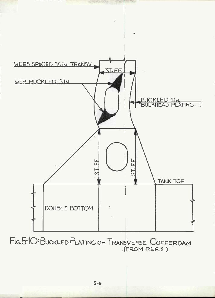
\N'FR F3IJCKLED 3iN
WEBE SPACED 3 ¡. TRANSV
DOU5LE BOTTOM
5-9
OULKHEAD FLPTING
TANK TOF
Eic,.5-1O: BUCKLED PLATING OF TRANSVERSE COFFER DAM(FROM FEF.2)
'1

IDL TRANSVFRSE
5-10
STRUT
EG.5-1 i :CRC OCCURRING IN LARGE TANKERS AT THE
J UNCTION OF SIDE LONGITUDINALS AND WEB H9AMES(FROM REF. i)
SIDESHELL
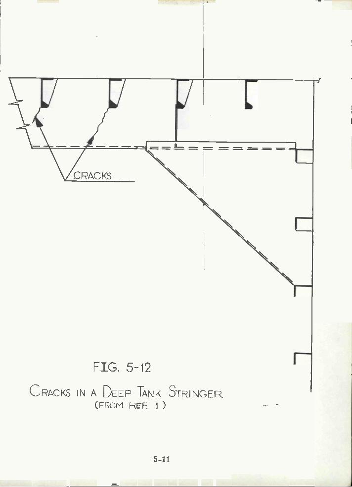
FIG. 5-12
CRACKS IN A DEEP TANK STRINGER(FRoM REF i )
5-11

115F TIC7HT COLLARS 7
ADD RACFT5
RFTTFR LOCA i
F1c5-13:CRACKs IN DECK GIRDER DUE TO POOR. FbSÎTIONING
OF P PILLAR (FROM REF. i)
5-12
g
PILLAR
L
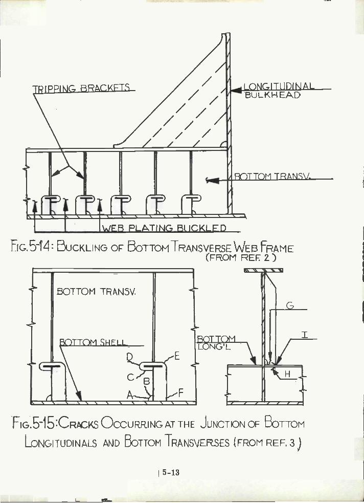
///// /// /
5-13
WEB PLATING ftICKLED
Fic.5iz1: DUCKLING 0F 5OTTOMJANSVERSE WEB FRAME(oM REEZ)
BOTTOM TRAN3V.
i ciAU
LONGITUDINALULKH EAD
FIG.bI5:CRCKS OCCURRING AT THE JUNCTION OF BOTTOM
ROTTOM TRANSV.
A_
/
LONGITUDINALS AND BOTTOM JRANSVESES (FRoM REF. 3)
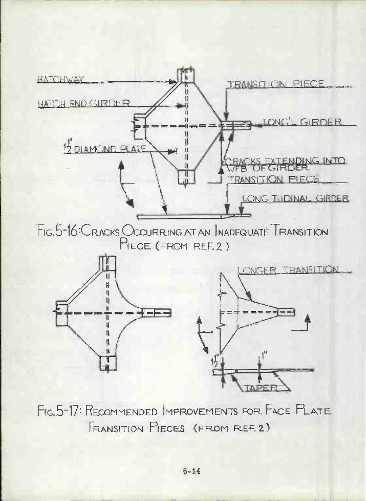
1D1AMOÑfl PLATE
Fio. 5l&CpcKs OCCURRING ATAN IN\DEQIJATE TRANSITION
PIECE FROM REL2)
5-14
TRAtLSITION PIFCE
J TRANSITION PIECE
LOÑC7ITUDINAL C7IRflR
Ec5-17: RECOMMENDED IMPROVEMENTS FOR FACE PLATE
TRANSITION PIECES (FROM REF.2.)

5-15
heavy member to the light longitudinal girder is too abrupt. Possible solutionsto this problem could be as follows:
Longer transition pieces (Figure 5-17).Taper the thickness of the transition pieces
Figure 5-18 shows a type of fracture which occurred at a number of positionson several ships. The problem here was the discontinuity of the upper flangeof the transverse girder at the intersection with the center girder where therewas little difference in the height of the two girders. Joining the two face-plates with a full penetration weld will correct this problem.
5.4.2 Hatchway Corners
Badly designed or constructed hatchway corners are a frequent source offracture. Fractures have occurred even in well rounded hatchway corners,where some detail of design has introduced a stress concentration or possiblya weld defect. Figure 5-19 shows such a case. In Figure 5-19 the source offracture was at the corner of the part of the deck plate which extended throughthe coaming. This is not only a point of stress concentration, but a difficultposition in which to produce a sound weld. It should be noted that in roundedhatchway corners the highest level of stress concentration occurs at aboutthe point where the corner radius meets the longitudinal side of the hatchwayand that fractures almost invariably begin at this point.
When designing hatchway corners the following guidelines are suggested:
Detail design should be simple, avoiding multiple connectionsresulting in an accumulation of difficult welds.
Attachments should not be welded to free deck edge.Elliptical corners in the deck are preferred to circular corners.
5.5 MISCELLANEOUS
Yamaguchi in Reference 4 discusses a survey conducted by the Ship ClassificationSociety of Japan on the inner structural members of 97 oil tankers. Figure 5-20gives the damage occurence rate by age of the vessel. Figures 5-21 and 5-22are sketches of details prone to early fatigue cracks. Yamaguchi concludesthat the most likely locations for fatigue cracks are:
Welded joints near structural discontinuities.Welded joints in highly stressed areas, such as corners.Areas of extremely high stress concentration, such as notchedlongitudinals.
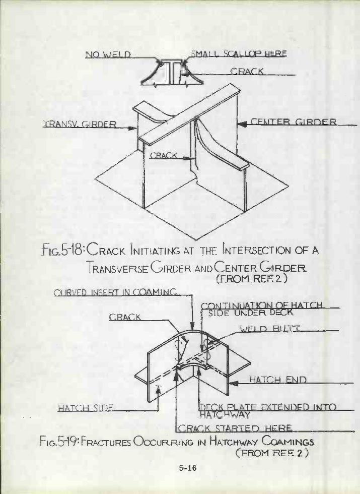
NO VJELD
fIGb-18CRcK INITIATING f ThE INTERSECTION OF A
TRANSVERSEGIRDEF& ANDCENTER GIRDER(FROMREEZ)
CIIRVFI) INSERT INCOAMINC
CRACK
5-16
CRACK
'1TI NUATIC)tUE UNDERE&
HATCH EJfl
-1ATCH SIDF FCK PLATE FXTEÑI)F1) IÑTC)-1ATCH\.JAY
CRACK S1ARTEn HEREFIG5IQ: FR4ACTU1ES OCCURRING IN HATC-tWPY CQMUGS
CFRoHREE2)
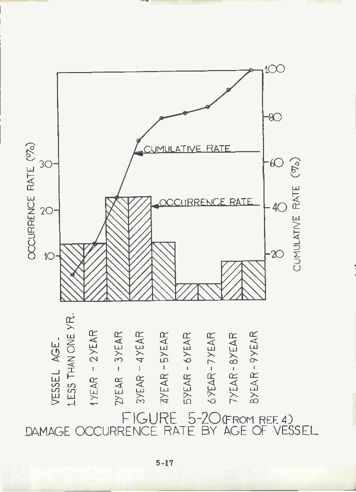
o 1) n mT
lz n >
rnm
ci-i
-<o
mO
-n <rn
(j)-1
(J) n E
VE
SS
EL
AG
E.
LES
S T
HA
N O
NE
.
i YE
AR
- 2
YE
A1
2YE
A-
3YE
AR
3YE
AR
-Y
EA
R
2YE
A -
5YE
AR
5YE
AR
- 6
YE
AR
ÓY
EA
R -
7 Y
EA
R
7YE
A -
BY
EA
R
YE
AR
- 9
YE
AJ,
OC
CU
RR
EN
CE
RP
JL(7
)
rm z n nl -4 rn
II
IN
) O
CU
MU
LAT
IVE
P\T
E (
°7)
R

C D
F1ri52iCRAcKs IN IRANSVERSE RINGS (FFDM REF. )
5-18
A D

NOTCHES THFUGH LONGITUDINALS(FROM RER4)
5-19

All of the above implies that the common sense guidelines for sound detaildesign recommended by D'Arcangelo in 1964 (Ref. 5) are and will continueto remain valid.
Haaland in Reference 1 shows how the problem of buckling at the edge oflightening holes is compounded by stress corrosion along an axis of highstress. The example cited is a web in an ore carrier, where protectivecoatings take constant abuse.
5-20

Section 6
STRENGTH CRITERIA
6.1 GENERAL
Abrahamsen in Reference 5 has suggested that based on ship experience overthe last fifteen years one may conclude that the longitudinal strength standardsnow applied are reasonable, provided that the detail design and the workmanshipare above a certain minimum standard.
That statement effectively describes the status of ship structural design today:there are adequate techniques and guidelines for establishing overall hullgirder strength requirements and the strength requirement of such majorstructural components as stiffened panels, but as discussed in Section 1 thereis little if any systematic quantitative approach leading to the design of structuraldetails.
The strength criteria required for structural details differ from other structuralcriteria only in emphasis. Before elaborating on this observation, it isdesirable to list the types of structural damage that could result from inadequatedetail design:
Failure of the detail to perform its intended function. For example:
Web buckling due to inadequately sized or spaced webstiffeners.Collapse of a deck beam due to inadequate end bracketsupport.
Failure of a detail or of adjacent material by ductile tearing as aresult of excessive stresses at the detail.
Fatigue cracks originating at a structural detail.
Brittle fracture starting at a fatigue or other crack at a structuraldetail.
Prevention of the first two categories of damage listed above requires knowledgeof the state of stress at or near the detail, and the assignment of allowable orpermissible values of stress.
It is not the purpose of this discussion to propose universal methods of stressanalysis applicable to structural details: the analysis of compressive stressin a web frame may be obtained by a simple strength of materials analysis,whereas the state of stress around a complex cutout may require a fine mesh
6-1

finite element solution. Neither method can hope to be precise since welding-induced residual stresses are particularly significant in welded details, andare not amenable to practical analysis.
The question of applicable criteria arises only upon completion of the stressanalysis. It is current shipbuilding practice to use a factor of safety of 1. 5on theoretical flat plate buckling stress and on yield stress.
With the more prevalent use of finite element analysis (which can convenientlyprovide principal stresses) it is practical to design against yielding by usingequivalent stresses calculated, for example, by the vonMises yield criterion.One ship classification society uses a factor of safety of about 1.2 on vonMiseequivalent yield stress (i. e., vonMises stress = 0. 85 yield stress) in evaluatinplate components of girders and other ship elements. By way of comparison,the ASME Pressure Vessel Code, Division II, requires a factor of safety onequivalent yield stress of 1. 5, except when it is a localized surface bendingstress, when the factor of safety becomes 1.0.
The above can be summarized by stating that criteria for the static strength ancstability of details need not differ from general ship structural practice,although the analytical effort involved in the analysis is disproportionately highif measured in such relative terms as engineering manhours per ton of structur
Damage mode 3; fatigue; is peculiar of detail design rather than of design forlongitudinal strength. It is primarily the stress concentrations inherent inmany structural details that make the hull girder susceptible to fatigue. Kline(6) quotes several authorities as stating that the time to consider the fatigueproblem is in the detail design stage rather than in the design for longitudinalstrength.
Again stress analysis of the detail and surrounding structure is essential tofatigue analysis, but unlike the problems of static strength and stability, thereare no accepted shipbuilding criteria for design against fatigue. A formatfor developing such criteria is proposed in a later section.
Regarding the effect of detail design on brittle fracture there is some ambiguityin the technical literature. Much of the early concern about fatigue cracks wasrelated to the possibility of such cracks leading to brittle fracture. Currentlythe feeling of some experts is that the quality of ship steel is such that largecritical crack lengths are the rule, consequently except for nuisance value orbecause of leaks in tight boundaries, crack lengths of up to one meter in lengthcould be acceptable (Committee 11, 1970 ISSC, Ref. 7). The above referencedCommittee has suggested that Classification Societies might accept the consequof crack tolerant design when shipowners become convinced that such designcan give large reductions in weight.
6-2
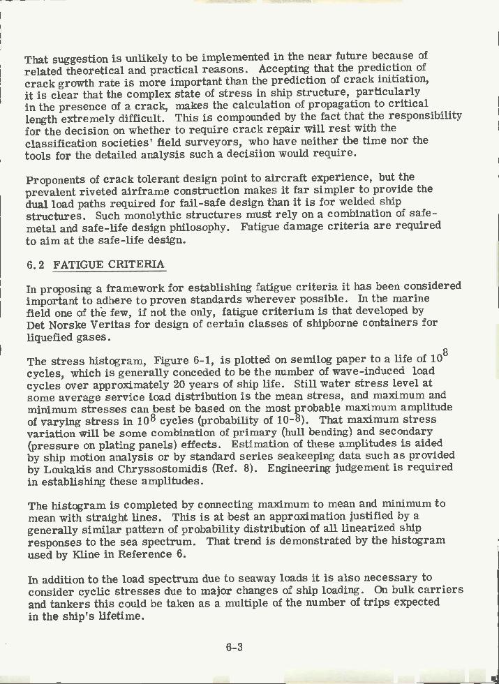
That suggestion is unlikely to be implemented in the near future because ofrelated theoretical and practical reasons. Accepting that the prediction ofcrack growth rate is more important than the prediction of crack initiation,it is clear that the complex state of stress in ship structure, particularlyin the presence of a crack, makes the calculation of propagation to criticallength extremely difficult. This is compounded by the fact that the responsibilityfor the decision on whether to require crack repair will rest with theclassification societies' field surveyors, who have neither the time nor thetools for the detailed analysis such a decisiion would require.
Proponents of crack tolerant design point to aircraft experience, but theprevalent riveted airframe construction makes it far simpler to provide thedual load paths required for fail-safe design than it is for welded shipstructures. Such monolythic structures must rely on a combination of safe-metal and safe-life design philosophy. Fatigue damage criteria are requiredto aim at the safe-life design.
6.2 FATIGUE CRITERIA
In proposing a framework for establishing fatigue criteria it has been consideredimportant to adhere to proven standards wherever possible. In the marinefield one of the few, if not the only, fatigue criterium is that developed byDet Norske Ventas for design of certain classes of shipborne containers forliquefied gases.
The stress histogram, Figure 6-1, is plotted on semilog paper to a life of 108
cycles, which is generally conceded to be the number of wave-induced loadcycles over approximately 20 years of ship life. Still water stress level atsome average service load distribution is the mean stress, and maximum andminimum stresses can best be based on the most probable maximum amplitudeof varying stress in 108 cycles (probability of 10-8). That maximum stressvariation will be some combination of primary (hull bending) and secondary(pressure on plating panels) effects. Estimation of these amplitudes is aidedby ship motion analysis or by standard series seakeeping data such as providedby Loukakis and Chryssostomidis (Ref. 8). Engineering judgement is requiredin establishing these amplitudes.
The histogram is completed by connecting maximum to mean and minimum tomean with straight lines. This is at best an approximation justified by agenerally similar pattern of probability distribution of all linearized shipresponses to the sea spectrum. That trend is demonstrated by the histogramused by Kline in Reference 6.
In addition to the load spectrum due to seaway loads it is also necessary toconsider cyclic stresses due to major changes of ship loading. On bulk carriersand tankers this could be taken as a multiple of the number of trips expectedin the ship's lifetime.
6-3
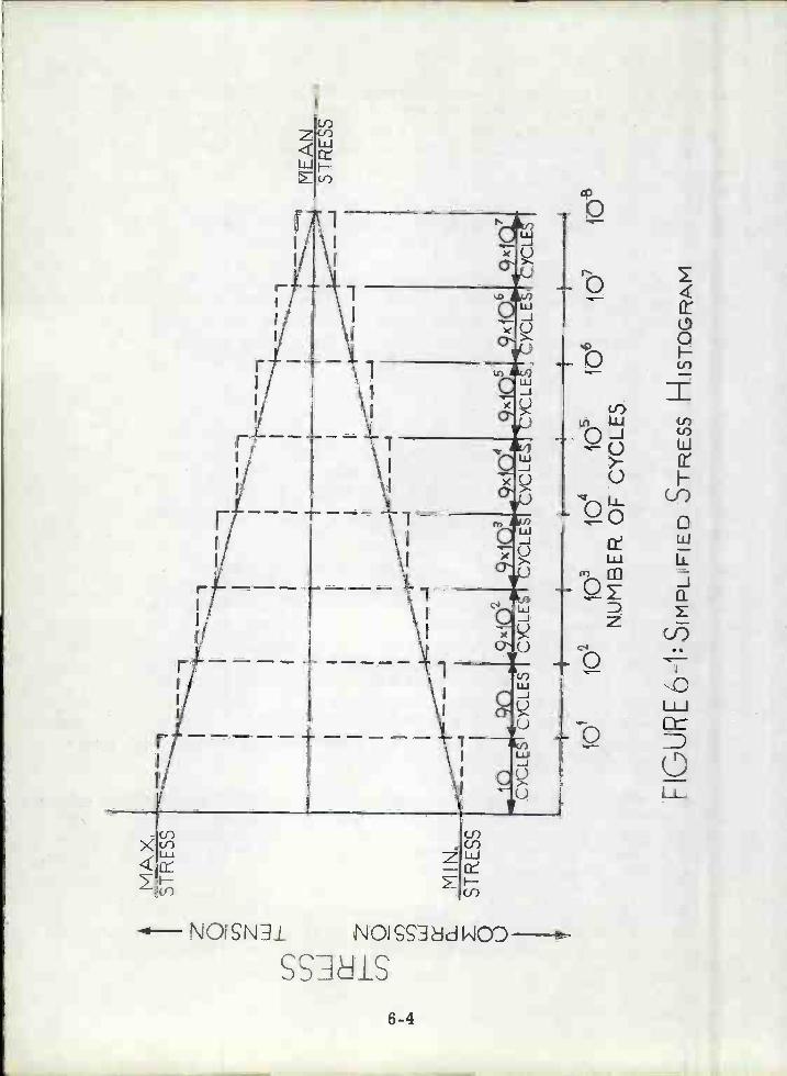
4M
AX
.S
T R
E S
S
ss
FIG
UR
E 6
-1: S
rMP
LF
lED
ST
RE
SS
HlS
TO
GR
tM
101
101O
106
io10
8N
UM
BE
R O
F C
YC
LES
ME
AN
ST
RE
SS
PfljN1
k+-N
LO
The one common theory for cumulative fatigue damage is that due to Palmgren-Miner, which in terms of the above discussion can be written as:
where
ni = number of cycles at stress level i
Ni, i = fatigue life at stress level i, j
P = number of stress increments into which total stress rangeis divided
k = number of cycles at stress level j
To simplify the summation it is proposed to subdivide the stress histograminto the eight equal blocks shown in Figure 6-1.
To apply the cumulative fatigue damage theory it is necessary to have thefatigue data for the material and structure in question. A great many suchdata have been collected in recent years. Those generally applicable toshipbuilding have been well summarized in each of the five ISSC (InternationalShip Structures Congress) Proceedings dating from 1961 to 1973. Tests havebeen performed on a variety of ship steels, wiLh various configurations,welding procedures, surface conitions and ading ranges. Yet out of thislarge body of data has not yet appeared the skeleton of a shipbuilding fatiguedesign criterion.
Professional societies such as the AWS, AASHO, and AISC have formulatedrules for fatigue design. These as well as many foreign organizations havegenerally based the allowable fatigue stress on the number of cycles at agiven stress and stress ratio or within a given stress range. Notice thatthese organizations are not concerned with a stress spectrum, although BritishStandard 153, which we have been unable to review, does apparently take aspectral load distribution implicitly into account.
The above rules generally give an allowable fatigue stress for discrete numbersof stress cycles, i. e., 100, 000, 5 or 600, 000 and 2, 000, 000. A factor of
safety of about 1. 5 is implicit in the allowable stress. Different values areprovided for various welding configurations and grades of steel. For example,and to illustrate the format of the specification, quoting from the AWS BridgeSpecifications (Ref. 9), for A36 base metal connected by fillet welds, theallowable fatigue stress at 2, 000, 000 cycles is given by:
6-5
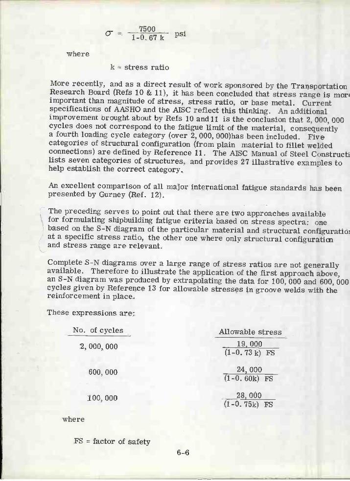
where
k = stress ratio
More recently, and as a direct result of work sponsored by the TransportationResearch Board (Refs 10 & 11), it has been concluded that stress range is moriimportant than magnitude of stress, stress ratio, or base metal. Currentspecifications of AASHO and the AISC reflect this thinking. An additionalimprovement brought about by Refs 10 and 11 is the conclusion that 2, 000, 000cycles does not correspond to the fatigue limit of the material, consequentlya fourth loading cycle category (over 2, 000, 000)has been included. Fivecategories of structural configuration (from plain material to fillet weldedconnections) are defined by Reference li. The AISC Manual of Steel Constructilists seven categories of structures, and provides 27 illustrative examples tohelp establish the correct category.
An excellent comparison of all major international fatigue standards has beenpresented by Gurney (Ref. 12).
The preceding serves to point out that there are two approaches availablefor formulating shipbuilding fatigue criteria based on stress spectra: onebased on the S-N diagram of the particular material and structural configuratioiat a specific stress ratio, the other one where only structural configuraticiiand stress range are relevant.
Complete S-N diagrams over a large range of stress ratios are not generallyavailable. Therefore to illustrate the application of the first approach above,an S-N diagram was produced by extrapolating the data for 100, 000 and 600, 000cycles given by Reference 13 for allowable stresses in groove welds with thereinforcement in place.
7500o-- psi1-0. 67 k
FS = factor of safety6-6
These expressions are:
No. of cycles Allowable stress
2, 000, 000 19, 000(1-0.73 k) FS
600, 000 24, 000(1-0.60k) FS
100, 000 28, 000(1-0.75k) FS
where
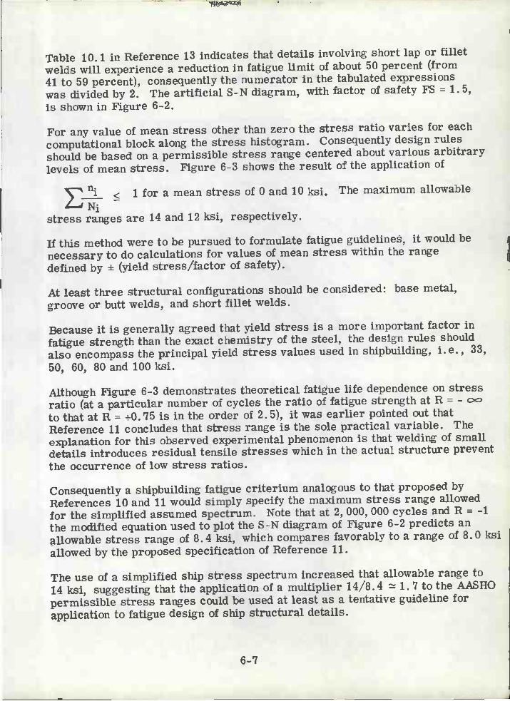
Table 10. 1 in Reference 13 indicates that details involving short lap or filletwelds will experience a reduction in fatigue limit of about 50 percent (from41 to 59 percent), consequently the numerator in the tabulated expressionswas divided by 2. The artificial S-N diagram, with factor of safety FS = 1. 5,is shown in Figure 6-2.
For any value of mean stress other than zero the stress ratio varies for eachcomputational block along the stress histogram. Consequently design rulesshould be based on a permissible stress range centered about various arbitrarylevels of mean stress. Figure 6-3 shows the result of the application of
< 1 for a mean stress of O and 10 ksi. The maximum allowableN
stress ranges are 14 and 12 ksi, respectively.
If this method were to be pursued to formulate fatigue guidelines, it would benecessary to do calculations for values of mean stress within the rangedefined by + (yield stress/factor of safety).
At least three structural configurations should be considered: base metal,groove or butt welds, and short fillet welds.
Because it is generally agreed that yield stress is a more important factor infatigue strength than the exact chemistry of the steel, the design rules shouldalso encompass the principal yield stress values used in shipbuilding, i.e., 33,
50, 60, 80 and 100 ksi.
Although Figure 6-3 demonstrates theoretical fatigue life dependence on stressratio (at a particular number of cycles the ratio of fatigue strength at R = -to that at R = +0. 75 is in the order of 2. 5), it was earlier pointed out thatReference 11 concludes that stress range is the sole practical variable. Theexplanation for this observed experimental phenomenon is that welding of smalldetails introduces residual tensile stresses which in the actual structure preventthe occurrence of low stress ratios.
Consequently a shipbuilding fatigue criterium analogous to that proposed byReferences 10 and 11 would simply specify the maximum stress range allowedfor the simplified assumed spectrum. Note that at 2, 000, 000 cycles and R = -1the modified equation used to plot the S-N diagram of Figure 6-2 predicts anallowable stress range of 8. 4 ksi, which compares favorably to a range of 8. 0 ksiallowed by the proposed specification of Reference 11.
The use of a simplified ship stress spectrum increased that allowable range to14 ksi, suggesting that the application of a multiplier 14/8.4 1. 7 to the AASHOpermissible stress ranges could be used at least as a tentative guideline forapplication to fatigue design of ship structural details.
6-7
A

¿lo
(j)
3.0
LU cf)
LJJ2
D 10
o
FG
UE
6-2:
AS
StJ
ME
D S
-\ D
IAG
RA
MF
OR
A36
ksi
'IELD
ST
RE
SS
ST
EE
L
.40 5
-lo
75.B
D .8
5 .9
0
101
102
io3
10N
UM
SE
R 0
F C
YC
LES
j510
6

-. 7C!)
(r)Cr)wo::
F(J) -7
16
4-10
MAX. STRESS = 7 ksiMN.STRESS=-7 ksiMEP\N STPESS= O KS IMAX. STRESS RANGE = 14 KSlSTRESS RAT 10= 1
MAX.STRESS lókst
MIN.STRESS 4ksifrIEAN STRESS= 10 VsiMAX.STRESS RANGE= 12 VsSTRESS FiATI0=(0.2b TO0.8)
1Ò1 lbz ib i6 ib5 ib6 i5NUMBER OF CYCLES
FGURE 6-3PERMISSIBLE STRESS HISTOGRAMS BASED ON
S-N CURVES OF FIG.62.
6-9

In the formulation of standards it will be necessary to establish not only thesafety factor on allowable fatigue stress, but on the Palmgren-Miner cumulativedamage criterium. The Det Norske Ventas Rules referred to earlier requirethat:
< 0. 5. Aircraft practice is to require a scatter factor of 4. 0,
6-10
which is equivalent to a four-fold extension of service life or, approximately,n.
< 0. 25. It should be noted that aircraft acceptance is based onN.
testing of components and assemblies, rather than on approval of calculationsbased on any given method or standard.
This discussion of fatigue criteria applicable to structural details would notbe complete without a mention of low cycle fatigue, which some authoritiesconsider of paramount importance to ship structural analysis. The reasonfor this belief is that so many cracks appear very early in the life of the ship.This has been partially explained as the growth of cracks resulting fromwelding defects or due to excessive residual stresses. In the latter case theproblem is more one of a ductile tensile failure than low cycle fatigue.
In the application of the cumulative failure criterium to various assumedstress spectra it is clear that the low cycle properties (to about 100, 000cycles) are as likely to be dominant as are the higher cycle properties. Forthe stress spectra shown in Figure 6-3 the first 100 cycles were decisive forthe spectrum with mean stress = 0, whereas the 100, 000 to 10, 000, 000 cycleblocks were dominant for the other spectrum shown.

Using, for example, the five sets of International Ship Structures Congress(ISSC) Transactions as a guide, it is possible to construct an extensivebibliography indirectly related to the design of ship structural details.Relevant subjects would be stress concentrations at openings and otherdiscontinuities, effect of residual stresses, limit design, fatigue testing ofstructural components and stability analysis of stiffened and unstiffenedplates.
During the course of this Project it became clear that the large extent ofthat bibliography is very misleading regarding the amount of publishedresearch with relatively direct applicability to the design of ship structuraldetails. Therefore, in the paragraphs which follow, only those reports withsome direct relevance to structural detail design are reviewed.
7.2 OPENINGS
The Ship Structure Committee of Japan (References 14 and 15) proposesrules for the allowable size of lightening holes in girders and provides justifyingtheoretical background. The proposed rules are reproduced as Tables 7-1,7-2 and 7-3, which specify allowable size of lightening holes, minimum lengthbetween holes, and strength ratio of girders with holes to girders at endswithout holes. The supporting calculations in Reference 15 are based largelyon plastic design criteria.
Reference 7 has a succinct discussion of buckling failures in large ships, manyin the vicinity of cutouts or lightening holes. The buckling characteristics of aspecific configuration can now be established by finite element calculations, butno general data suitable for design guidance have been developed.
7.3 KNEES AND BRACKETS
Section 7
LITERATURE SURVEY ON DETAIL DESIGN
7.1 GENERAL
Jaeger and Nibbering (Ref 16) ran an extensive series of static, buckling anddynamic tests on ten basic configurations of knees and brackets. They suggestthat assymetrical brackets date back to riveting, when a function of the bracketwas to maintain the angle between stiffeners. That function is no longer required,and emphasis should be placed on a second function, i.e., to lead the stressessmoothly around the corner.
The results of the test series are reproduced in Table 7-4, taken from theabove reference. Note that all specimens were annealed after welding, thusresidual stresses were not a factor in the results.
7-1
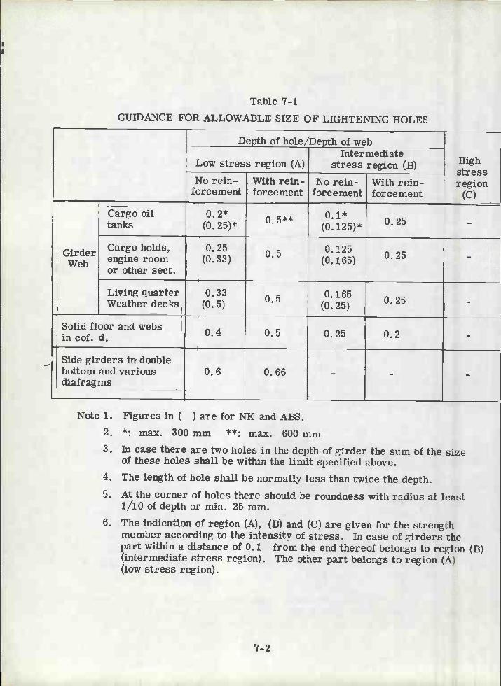
Table 7-iGUIDANCE FOR ALLOWABLE SIZE OF LIGHTENING HOLES
7-2
Note 1. Figures in ( ) are for NK and ABS.*: max. 300 mm **: max. 600 mm
In case there are two holes in the depth of girder the sum of the sizeof these holes shall be within the limit specified above.The length of hole shall be normally less than twice the depth.
At the corner of holes there should be roundness with radius at leasti/io of depth or min. 25 mm.The indication of region (A), (B) and (C) are given for the strengthmember according to the intensity of stress. In case of girders thepart within a distance of O. i from the end thereof belongs to region (B)(intermediate stress region). The other part belongs to region (A)(low stress region).
Depth of hole/Depth of web
Highstressregion
(C)
Low stress region (A)Intermediate
stress region (B)No rein-
forcementWith rein-forcement
No rein-forcement
With rein-forcement
GirderWeb
Cargo oiltanks
0.2*(o.25)*
0 5** 0.i(0. i25)* 0.25 -
Cargoholds,engine roomor other sect.
0.25(0.33) .
50.i25
(0.165) 0.25 -
Living quarterWeather decks
0.33(0.5)
O.i65(o. 25) 0.25 -
Solid floor and websin cof. d. 0.4 0.5 0.25 0.2 -
Side girders in doublebottom and variousdiafragms
0. 6 0. 66 - - -

Table 7-2MINTMtJM LENGTH BETWEEN HOLES (S)
7-3
Table 7-3PROPOSED GUIDANCE AND STRENGTH RATIO OF GIRDERS WITH HOLES
TO RESPECTWE GIRDERS AT ENDS WITHOUT HOLES
S
Low stressregion (A)
Intermediateregion (B)
High stressregion (C)
d1+d2
2
Section Region
'Standardof Lightening Holes"
Strengthratio
%
Allowabledepth
hole d/D
Allowable1/d
length
Cargo oiltanks
AB
0.20.1
2
2
8688
Cargo holds AB
0.250.125
2
2
8999
Livingquarter
AB
0.330.165
22
104142

TABLE 7-4
OBSERVATIONS: cliN COLUMNS 4,5.6,7,8,9 THE RELATIONS BETWEEN VALUES OF ALLTYPES OF IcHEES AND THE DEAL STRUCTURE ARE GIVEN.FRAMED VALUES IN COLUMNS QAND7 ARE MEASURED;SMALL FIGURES INDICATE ESTIMATIONS»1 LOO >7 >1 LOG " 6,6 70 7
.WIN COLUIINS 10111213 FIGURES OF QUALIFICATIONS ARE GIVENVARYING FROM i 10 5 1 INDICATING THE BEST STRUCTURE.
7-4
¿ ai 5 6 7 6 9 1011 12
SUBDIVI SICH
SYMBOLSINDICATE
N
ELASTICSTRESSES
PELArIGN UETWEENL0''t0F IDEAl.lJ MID LOG nEF0TIER CONSTRUCTI1IS.THE IDEALSTRUCTURE IS INDI-CATEOBYI,,.,,,,,ber or cyIoo
MOMENTLOAD
OF CJALIFICATIONCONSTRUCTION
OF
... U)
zoi
w
W'0W2O_
a.X
Z-Zoo
<
IQ"z
o'
a.
_I
z
Zo
w
CONSTRUC z°' (lIONS IN -Owij I6,OWjj ZE
û. z OO-j-O.zo - - o
FIG.42 f K <LJ OWIUJ2OWIAJZO
'8W 0Loi
,
Q
.Id) <
il_01-I-Q.<X
1I-'< Z>-
Z>-
t I-, 1/70 6/) Q Q
19A 1,2 1 1 1 »1 1 1 1 1 1 1
ZiA 2,85 2,74 2,74 0,92 1 2 1
0,61
21 B 24 232 2_U.J »1 1 4 1
21 BK 24 232 232 U.OI >i Z i
24 A 2.2 3,9 2 3_92 0.7E » 1 0.70 3 3 1
0,66 3
74 B' 2.8 5.08 5,08 0,54 »1 2 5 1
24B° 2,8 508 ,j,,06 3 1
058 0,71 4 3 3 131 4] 4,75 608 Lo . »1
0,63 »1 j 049 071 4 3 4 135 44 6,86 8,78
41 A 1,3 2,20 2,20 0,90 s> iC ,.
B 0 ],2O '.79 » i 83
(0,56 2 3 26 2,75 2,75 --J-
C 2.54 2,88 0,24issA 1,2 1,28 1,28
0,56 2 3 2c
D,. 1,01 1,1 6 0,8 S
44A 1,2 2,09 2,09 0.96 »1- , B > I >
C 170 1)70 OSI > i 0,56 2 2 3
O 2,71 3,10 094 s i-J-E 1,58 1,83 > 0,87 1
¿,6'A 2,09 2,09(393,9 0.79 031
D 2,58 3,i 9,66FACE
4, FI 47A 12 s il,.2,
Ci
2,12 2,12 8.89 o> I
1,74 2,3 » i a.96
A.. D 185 2,16 0,56 3 2 3
Fi 1,95 2,26 ,, i 0.8$REVERSE 02 1,33 t56 09U »1
S IDECa E6 Jj8T1, » iF2 3,56 9.73

Shama in Reference 17 extends Schade's effective breadth design charts tocover symmetrical and assymetrical curved face plates, as found on variousknee and bracket designs. The charts are reproduced here as Figure 7-1and 7-2.
7.4 STRUCTURAL INTERSECTIONS
Ciarkson in Reference 18 reports on the relative structural stiffness of varioustypes of T-beam intersections. Ciarkson defines an efficiency N1 as thepercentage of load required to produce a certain amount of overall plasticdeformation at the intersection in question, with respect to the load requiredfor equal deformation in a fully collared reference intersection. The efficiencyN2 is defined as the percentage of load required to produce a given relativedeflection between the members at the intersection with respect to that of thereference intersection. The results are shown in the table below:
Structural Efficiency of Welded Connections
7-5
Efficiency Main member, N1 Joint, N2
Depth passing member75 56 75 56depth main member
Joint A: no lug plus bracketor direct weld
75 90 75 85
Joint B: one lug 75 75 35 50
Joint C: one lug plus bracketor direct weld
75 90 80 90
Joint D: two lugs 90 90 50 80
Joint E: two lugs plus bracketor direct weld
90 - 95 -Joint F: two-piece insert collar 100 100 100 100--reference beam

1.Ô
0.9
o
0.7
Zo.60.5
0. 2
0. 1
o0. 5 1.0 1.5 2.0
Figure 7-1 Effective Breadth Ratio for Symmetrical Curved Face Plates
7-6
2.5 30 35 4. 0

7-7
0.5 1 0 1 5 2.0 2.5 3.0 3.5 4.0b/f
Figure 7-2 Effective Breadth Ratio for Asymmetrical Face Plates
1.0À
0. 9
0. 8
0. ri
0. 6
0. 5
0.4
0.3
0. 2
0. 1
o
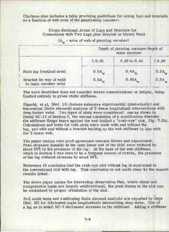
Clarkson also includes a table providing guidelines for sizing lugs and bracketsas a function of web area of the penetrating member:
Cross-Sectional Areas of Lugs and Brackets forConnections with Two Lugs plus Bracket or Direct Weld
(A = area of web of piercing member)
The work described does not consider stress concentrations or fatigue, beinglimited entirely to gross static stiffness.
Higuchi, et al, (Ref. 19) discuss extensive experimental (photoelastic) andtheoretical (finite element) analysis of T-beam longitudinal intersections withdeep tanker webs. Two types of slots were considered: one as shown inDetail NC-16 of Section 3, the second consisting of a modification wherebythe stiffener flange bears against the web (called a "crab-eye" slot, Fig. 7-3b).Calculations and tests for both slots were made with and without thelug, and with and without a bracket backing up the web stiffener in line withthe T-beam web.
The paper claims very good agreement between theory and experiment.Peak stresses (usually at the open lower end of the slot) were reduced byabout 30% by the presence of the lug. At the base of the web stiffener,which in Section 5 was seen to be a frequent source of cracks, the presenceof the lug reduced stresses by about 50%.
Reference 19 concludes that the crab-eye slot without lug is equivalent tothe conventional slot with lug. That conclusion is not made clear by the numeriresults listed.
The above paper makes the interesting observation that, where shear andcompressive loads are largely unidirectional, the peak stress in the slot canbe minimized by proper orientation of the slot.
Full scale tests and confirming finite element analysis are reported by Orge(Ref. 20) for fabricated angle longitudinals intersecting deep webs. Use ofa lug as in detail NC-7 decreased stresses in the stiffener. Adding a stiffener
7-8
Depth of piercing member/depth ofmain member
Each lug (vertical area)
Bracket (in way of weldto main member web)
0.65 0.65to0.40 0.40
0. 5Aw
0. 8AW
0. 4Aw
O .65AW
0. 3Aw
O .5AW

s'
(o) CO\VE
Ls'
\TIONÊ\L SLOT
7-9
L
T I
(b1) CRBL1E SLOTF,a7-3:DETAILOFCONVENTION.L ANDCRABEYE SLOT

on top of the longitudinal .decreased stresses in the lug but increased strin the longitudinal.
7-10
Discontinuous longitudinals are treated in several references. This is nolonger a common detail and is therefore not discussed herein.
esses
Section 8
CONCLUSIONS AND RECOMMENDATIONS
With few exceptions, the Ship Classification Societies do not define theconfigi.iration and scantlings of structural details. Guidelines from otherTechnical Societies are equally vague. That is probably a permanent stateof affairs as it is not practical to generalize the results of varied andindividual stress analyses.
The capability for theoretical stress analysis of details exists in terms ofknown conditions of loading. The capability for prediction of structuralintegrity based on such structural analysis is also possible in theory, anda discussion of a proposed fatigue analysis methodology is included herein.Yet the reliability of such analyses will remain in question unless the contributionsof residual stresses due to fabrication and welding can be quantitativelyestablished.
A certain amount of structural detail standardization has taken place asa possible result of professional migration and the attendant distributionof proprietary booklets of structural details. Additional standardizationin this field is, in principle, simpler than in other areas of shipbuilding:designers would welcome details accompanied by analytical and experimentalconfirmation of proposed design guidelines.
It is suggested that interested researchers do not hesitate unduly in selectingfor analysis one or another of several duplicate details as catalogued in thisreport. The promulgation of such guidelines should best be left to an ad-hoc technical committee rather than a Classification Society, whose legalresponsibilities would inhibit promulgation of highly qualified rules.
No readily accessible damage records of structural details are maintainedin the United States. It is recommended that a long range program be initiatedto monitor service performance of structural details. This could take theform of periodic surveys of selected locations aboard particular ships.
Initial observations should be made of detail configuration, workmanship,corrosion protection and expected load cycles. Subsequent observationsshould monitor condition of details with emphasis on crack initiation, crackpropagation, corrosion and buckling of detail or adjacent structure.
Surprisingly little performance feedback is currently available to the designer.
8-1

Damage to structural details is generally the result of obvious design orfabrication deficiencies. They could largely be avoided by consistent anddiligent quality control and inspection.
This common observation implies that if sound detail design practice ispossible with the scant analytical or experimental backup currently availableto the designer, there must remain a significant potential for hull girderscantling reduction based on more thorough detail design procedures.
Detail standardization potentially serves the dual purpose of minimizinganalysis and simplifying the material handling problems attendant to structuraldiversity. In practical terms the degree of structural standardization currentlyemployed is often of primary benefit to the drafting room in terms of providinga short cut notation.
The study reported herein also included review of the standards of relatedindustries, particularly aerospace. Although a great deal of data were compiledon the latter, the final conclusion was that their practices are not applicableto shipbuilding. This is due primarily to the types of materials used, theirmethod of joining (riveting and Huc k-bolting) and the extensive full-scaletesting of components.
( The conflicts between theory and practice are particularly evident in the areaof structural details. As an example, technical papers on brackets andstiffeners advocate symmetrical flanges because of improved structuralefficiency. The use of such sections, as in tanker bottoms, dictates panelstiffeners that butt end on the stiffener flange and are the cause of manyfailures. An assymetrical flange permits a more favorable lap weld of theweb stiffener.
The conclusion from the above is that all detail design must concern itself withthe most simple and common sense aspects of producibility, including permissibletolerances and misalignment.
The availability and increasing use of nesting programs and automatic burningmachines eliminates all practical objections to relatively complex shapes ofbrackets, cutouts, etc.
Judging from published data reviewed herein, the most significant damagepotential is exhibited by structural intersections. It is recommended that anyfollow-on studies emphasize this type of detail.
(Huck-bolts = mechanical fasteners, used in lieu of rivets, utilizing a pre-tensioned pin that swages a collar into a series of grooves onthe pin and creates a watertight connection.)
8-2

Failures of details can be minimized by the obvious means of reducingstress concentrations and providing adequate backup to components.Such stress concentrations arise due to inadequate analysis, design orconstruction.
Typical example of excessive stress due to faulty analysis is the absenceof partial or full collars at intersections subject to high shear stresses.
Poor design can lead to weld inaccessibility, which in turn results incracks and craters. Brackets, chocks, collars and other details shouldhave good welding accessibility and should be configured to minimizethe number of arc strikes. Shapes with gentle radii are to be preferred.
Construction is responsible for problems arising due to poor fitup ofmating components requiring field changes to clearance cuts andattachments. Such field changes are often made by casual manual burningor chipping resulting in a ragged cut outline. Design can minimize fieldadjustment errors by being aware of intended assembly operations. Clipsor collars should be provided at intersections where a neat fit againstwebs or flanges of structural members is impractical because it wouldrequire dimensional control incompatible with the procedures used.
The presence of deeper clearance cuts intended to facilitate fitup or toease stress concentrations should be considered when selecting the depthof the member. Complex arrangements of beam brackets can be minimizedby increasing the scantlings of joining members, a practice whose weightimplications makes it more applicable to merchant than to naval vessels.
8-3

NOTES
8-4
Section 9
LIST OF REFERENCES
Haaland, A., "Damages to Important Structural Parts of the Hull",European Shipbuilding, No. 6, 1967.
"Detail Design in Ships", Lloyd's Register of Shipping.
"Report by Slot Working Group of Hull StructuralCommittee of SNA of Japan, informal communication.
Yamagushi, I., "Fatigue Failures in Ship Structures and theirCountermeasures", Contribution to ISSC 1967, Committee 3d.
D'Arcangelo, A. M., "A Guide to Sound Ship Structures", CornellMaritime Press, 1964.
Kline, R. G., "Application of Higher Strength Steels to Great LakesVessels", Marine Technology, July 1966.
"Proceedings of the Fourth International Ship StructuresCongress", Tokyo, Sept. 1970.
Loukakis, T. A. & Chryssostomidis, C., "The Seakeeping Performanceof an Extended Series 60", SNAME Transactions, 1975 (to be published).
Blodgett, O. W., "Design of Welded Structures", Lincoln Arc WeldingFoundation, 1966.
Fisher, J. W., et al, "Effects of Weidments on the Fatigue Strength ofSteel Beams", NCHRP Report 102, 1970.
Fisher, J. W., et al, "Fatigue Strength of Steel Beams with WeldedStiffeners and Attachments", NCHRP Report 147, 1974.
Gurney, T. R., "A Comparison of Fatigue Design Rules", Proc. of theConference on Fatigue of Welded Structures, Cambridge, 1970.
Brockenbrough, R. L. & Johnston, B. G., "Steel Design Manual",U. S. Steel Corp, 1974.
"Guidance for Lightening Holes in Web of Girder", SNAJapan, Bulletin 428, 1965.
Ando, N., "Investigation on Standard for Cutout in Web of Girder, etc.,"SNA Japan, Bulletin 444, July 1966.
9-1

LIST OF REFERENCES (Cont'd)
Jaeger, H. E. & Nibbering, J. J. W., "Beam Knees and Other BracketedConnections", Netherlands Research Center Report No. 38S, Jan, 1961.
Shama, M. A. "Effective Breadth of Face Plates for Fabricated Sections",Shipping World and Shipbuilder, Aug. 1972.
Ciarkson, J., "The Elastic Analysis of Flat Grillages", CambridgeUniversity Press, 1965.
Higuchi, M., Horioka, M. & Tanaka, T., "Study on Hull Structure Analysis"Nippon Kokan Technical Report, June 1973.
Orje, A., "Stresses in Web Connections to Longitudinals", Swedish ShipResearch Foundation Report #80, 1972 (in Swedish).
ACKNOWLEDGE MENT
The authors wish to express their appreciation to the Chairman and Membersof the Project Advisory Group for their guidance and suggestions during thecourse of the Project. We are also indebted to personnel of the AmericanBureau of Shipping, the U. S. Salvage Association and the Convair Divisionof General Dynamics for valuable discussions on problems related to structuraldetails.
Last but not least we are grateful to our many colleagues at the Shipyard,among which we must single out Messrs. F., Rolfe and F. McCarthy.
9-2

i___=__
Appendix A
CLASSIFICATION SOCIETY RULES APPLICABLE TO STRUCTURAL DETAILS
This Appendix contains excerpts of the 1973 Rules of the major Ship ClassificationSocieties applicable to ship structural details. The Societies reviewed and theabbreviations used are:
American Bureau of Shipping - ABS.Bureau Ventas - BV.Det Norske Ventas - DNV.Germanisher Lloyd - GL.Lloyd's Register of Shipping - LR.Nippon Kaiji Kyokai - NKK.
Section Al. OPENINGS
Al. i SHELL PLATING
A1.1.i ABS: Section 15.9
Compensation is to be made where necessary for holes in shell plates. Allopenings are to have well rounded corners; those for cargo, gangway, fuelingports, etc., are to be kept well clear of discontinuities in the hull girder;local provision is to be made to maintain the longitudinal and transverse strengthof the hull.
Ai.i.2 DV: Section 6-26
Openings such as cargo doors, freeing ports, side scuttles, sea inlets are tohave well rounded corners. Compensation should be required except forcircular openings not greater than 300 mm in diameter.
A1.1.3 DNV: II Section 4.E: Table 102 (A-1)
Table A-1 is valid within 0. 6 L amidships for bottom and ship's side in aheight of 0. 15 D from bottom and deck.
TABLE A-1
A-i
Deduction-free Openings within thesame Transverse SectionElliptical-I Circular-II
Bottom -anyinnerbottomincluded:
a0.03B a0.02B

ifi - Strengthening for openings exceeding the limits of I, II;
Compensation of area in arbitrary combination of:
- increased plate thickness,- increased area of longitudinals or girders,- flat bar along the edge of the openings,- edge reinforcement of openings having a 1500 mm(a = sum of transverse dimensions of all openings)- elliptical openings are supposed to have an axis ratio not less than 2:1.In the ships side below the sheer strake and above the bilge plate, circularopenings are considered to be elliptical.
Total deduction for openings in plating in a transverse section is not to exceed0. 03A where A=bottom or deck area, i.e., total area of the members in bottom.
A1.1.4 GL: Section 6-G
Where openings are cut in the shell plating for windows or side scuttles,hawses, scuppers, sea valves, etc., they are to have well-rounded corners.If they exceed 500 mm in width in ships up to L=7Om and 700 mm in shipshaving a length L>70 m, the openings are to be surrounded by framing, doubling,or a thicker plate.
A1.1.5 LR: D514
Cargo door openings are to have well-rounded corners. Sea inlets, or otheropenings, are to have well-rounded corners, and so far as possible, should bekept clear of the bilge radius. Openings on or near the bilge radius should beelliptical. In general, compensation will not be required for holes in the sheer-strake which are clear of any deck openings outside the line of the main hatch-ways, and whose depth does not exceed 20% of the depth of the sheer strake or380 mm whichever is less.
Al. 1. 6 NKK: Part 15, Section 7; Article 16, 18.
All openings in the shell plating are to have well-rounded corners and to becompensated as necessary. Openings for cargo ports, gangway ports, coalingports, etc., are to be kept well clear of discontinuities in the hull construction,and they are to be locally compensated so as to maintain the longitudinal andtransverse strength of the hull.
Al. 2 STRENGTH DECK PLATING
Al.2.,l ABS: Section 16. 5. 1&3
Within the line of openings the thickness of exposed plating is not to be less than:
A-2

PLT = 0.OlSb + 0.035 in. where: Sb30in.PLT = 0.0067 Sb + 0.134 in. where: Sb>30 in.
* Sb = stiffener spacing
At the corners of hatchways orradii are to be provided.
A1.2.2 BV: Section 6-26
other openings in effective decks, generous
Within 0. 75 L amidships, the corners of hatchways are to be strengthened byinsert plates; the thickness of these will be that of the deck plating increasedby: (40.. -20) percent, without exceeding 38 mm, where a is the distancebetween consecutive hatchways and b is the breadth of the hatchways; the valuea/b is not to be less than 0.5 and not more than 2. Hatch corners are to berounded. The ratio of the blending radius to the breadth of the hatchway is tobe about 0. 05. Where no continuous deck girder is fitted in way of hatch coamings,this ratio may be increased to 0. 08. The opening may also have a streamlineddesign as shown in Figure A-1, it is determined by the radius R which is equalto 0. 04 times the breadth of the hatchway. For the extreme corners of endhatchways, a streamlined design may be required. The thickness of insertplates is to be 60% greater than that of adjacent deck plating.
A1.2.3 DNV: IISection4
Table A-2 is valid within 0. 6 L amidships for strength deck.
TABLE A-2
Strengthening of openings exceeding the limits of I, II - compensation of areain arbitrary combination of:
- increased plate thickness- increased area of longitudinals or girders- flat bar reinforcementa = transverse dimension of greatest opening
a = sum of transverse dimensions of all openingsbL= hatch breadth
A-3
Deduction-free Openings Within thesame Transverse SectionElliptical-I Circular-II
Deck,Tankers
at the same time:a.0.05B and
2000 mm anda 900 mm
at the same time:0.03B and
a 1000 mm anda 400 mm
Deck, drycargo ships
a0.03(B-bL)a 350 mm
a0.03 (B-bL)a 100 mm

1.25 R.
C
Fofr1 A TO B,THE STREAN1L.INEDCuVE ISAS DEFINEDSYTHESKETCH. F.or'i BTOCTHE.CUFVE SANAR.cOFAC I.CL .'/ITHA RADIUS R E UI\JPL JTT0TH RADIUOFCUVATUR AT B.
C
FCÙ
LINEOF DECK CUT
O5F
2.89
RE
Â-4
STREAMLINED HPTCH'/AY CORNER - RECOMMEP..JDED a B.V.
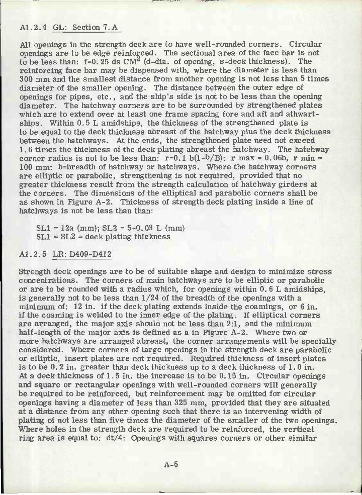
A1.2.4 GL: Section 7.A
All openings in the strength deck are to have well-rounded corners. Circularopenings are to be edge reinfoced. The sectional area of the face bar is notto be less than: f=0. 25 ds CM (d=dia. of opening, s=deck thickness). Thereinforcing face bar may be dispensed with, where the diameter is less than300 mm and the smallest distance from another opening is not less than 5 timesdiameter of the smaller opening. The distance between the outer edge ofopenings for pipes, etc., and the ship's side is not to be less than the openingdiameter. The hatchway corners are to be surrounded by strengthened plateswhich are to extend over at least one frame spacing fore and aft and athwart-ships. Within 0.5 L amidships, the thickness of the strengthened plate isto be equal to the deck thickness abreast of the hatchway plus the deck thicknessbetween the hatchways. At the ends, the strengthened plate need not exceed1. 6 times the thickness of the deck plating abreast the hatchway. The hatchwaycorner radius is not to be less than: r=0. 1 b(1_b/B): r max = 0. 06b, r min =100 mm: b=breadth of hatchway or hatchways. Where the hatchway cornersare elliptic or parabolic, strengthening is not required, provided that nogreater thickness result from the strength calculation of hatchway girders atthe corners. The dimensions of the elliptical and parabolic corners shall beas shown in Figure A-2. Thickness of strength deck plating inside a line ofhatchways is not be less than than:
SL1 12a (mm); SL2 5+0.03 L (mm)SL1 = SL2 = deck plating thickness
A1.2.5 LR: D409-D412
Strength deck openings are to be of suitable shape and design to minimize stressconcentrations. The corners of main hatchways are to be elliptic or parabolicor are to be rounded with a radius which, for openings within 0. 6 L amidships,is generally not to be less than 1/24 of the breadth of the openings with aminimum of: 12 in. if the deck plating extends inside the coamings, or 6 in.if the coaming is welded to the inner edge of the plating. If elliptical cornersare arranged, the major axis should not be less than 2:1, and the minimumhalf-length of the major axis is defined as a in Figure A-2. Where two ormore hatchways are arranged abreast, the corner arrangements will be speciallyconsidered. Where corners of large openings in the strength deck are parabolicor elliptic, insert plates are not required. Required thickness of insert platesis to be 0. 2 in. greater than deck thickness up to a deck thickness of 1. 0 in.At a deck thickness of 1. 5 in. the increase is to be 0. 15 in. Circular openingsand square or rectangular openings with well-rounded corners will generallybe required to be reinforced, but reinforcement may be omitted for circularopenings having a diameter of less than 325 mm, provided that they are situatedat a distance from any other opening such that there is an intervening width ofplating of not less than five times the diameter of the smaller of the two openings.Where holes in the strength deck are required to be reinforced, the verticalring area is equal to: dt/4: Openings with squares corners or other similar
Â-5

C
cL 2.0 ; C r ACCOF.DftJG TO
WHERE N-1ALL.. VLuE O ANI C AFE ADorE.E I N-i F O RC E I N S E RT PL.AT E A R. . QU I E \V H IC H
v/ILL. BECONSIEREINi EACH JNI/,.JAL_C4EFIGURE A-2
DIMENSIONS OF ELLIPTIC 0R. PAFAOLIC CORNERS-REGOMMENDEØ G.L.
À-6

stress risers will not generally be acceptable. d=diameter of opening,t=deck thickness.
Al. 2. 6 NKK: Part 16, Article 6
Hatchways or other openings on strength or effective decks are to have well-rounded corners, and suitable compensation is to be provided as necessary.
Al. 3 BULKHEAD PLATING
Al.3.l ABS: No Comment
Al.3.2 BV: No Comment
Al.3.3 DNV: IlSection4
For longitudinal bulkheads Table A-3 for openings in the shell applies.
TABLE A-3
Strengthening of openings exceeding the limits allowed in I and II: Compensationof area in arbitrary combination of: increased plate thickness, increased areaof longitudinals or girders, flat bar reinforcing rings.
Al.3.4 GL: Section 11.3
Openings in the bulkhead are to be effectively framed so as to facilitate properfitting and to guarantee perfect watertightness. Where bulkhead fittings arepenetrating watertight bulkheads care is to be taken to maintain watertightness.
Al. 3.5 LR: No Comment
Al. 3. 6 NKK: No Comment
Al.4 GIRDERS AND OTHER STRENGTH MEMBER OPENINGS
Al.4.1 ABS: Section9.5.2;13.3.4
Hold stringers are to have a depth of not less than 1. 5 in. per foot of span plus1/4 of the depth of the slot for frames, but need not exceed the depth of the web
A-7
Deduction-free openings within thesame Transverse SectionElliptical-I Circular-II
Bottom, anyinnerbottomincluded
a=O.O3B aO.O2B

frames to which they are attached; in general, the depth is not to be less than3 times the depth of the slots (in the web frame, Ed.) or the slots are to befitted with filler plate;
Girders, except deck girders, and webs are to have depths not less than 1. 75 in.per foot of span, where no struts or ties are fitted, and 1 in. per foot of span,where struts are fitted, plus 1/4 of the depth of the slots for frames orstiffeners; in general, the depth is not to be less than 3 times the depth of theslots.
A1.4.2 BV: Section 6.33
Manholes and openings in the floors and girders are to be cut smooth alonga well-rounded design: Holes in side girders and floors should be cut atmid-depth, their length should not exceed half the web depth and their heightshould be so limited as to provide around, as far as possible a plate stripat least 1/4 the depth of the double bottom.
Al .4. 3 DNV: Table 103 (A-4): II Section 4
TABLE A-4
If b, L, and a do not comply with the requirements in I, the total opening areais to be deducted when calculating the SM, or compensation is to be providedfor the total opening area. Shear stress in the web plate and weld attachmentto plating is to be examined.
b - major axis of openinga - minor axis of openingL - distance between openingse - thickness of web plates - longitudinal spacing
A-8
Arrangement ofOpenings
Deduction-freeOpenings-I
Opening exceedingRequirements in I.
Long openings orgroups of openingsall in the samesection.
b 0. 5s andL lOaa 0. 2s
ae 0.02A
Opening areasexceeding the allowed,is to be deducted whencalculating the SM, orto be compensated byan arbitrary combinationof: increased plate thick-ness, increase longitudin8scantlings, flat bar rein-forcing rings.
Long openings orgroups of openingsshifted in relationto each other.
b s and b LL lOa and L
E ae 0. 03A600mm
Short openingswith relatively largespacing in samesection or shifted.
b 0. 25s andL lOa
ae 0. 03A
A1.4.4 GL: No Comment
A1.4.5 LR: D933
Sufficient holes are to be cut in the inner bottom floors and side girders, toprovide adequate ventilation and access to all parts of the double bottom. Theedges of all holes are to be smooth. The size of the opening should not, ingeneral, exceed 50% of the double bottom depth, unless edge reinforcementis provided. In way of ends of floors and fore and aft girders at transversebulkheads, the number and size of holes should be kept to a minimum and theopenings are to be circular or elliptic. Edge stiffening may be required inthese positions.
A1.4. 6 NKK: No Comment
A-9

Section A2. GIRDER AND PANEL STIFFENING
A2. i KNEE AND BEAMrBRACKETS
A2.1.1 ABS: Section 9.3.2, 12.7.2
Where brackets are fitted having thicknesses not less than the girder or wbplates, the value of the unsupported span is as follows:
Where the face area on the bracket is not less than 1/2 that on thegirder or web and the face plate or flange on the girder or web iscarried to the bulkhead or base, the length may be measured to apoint 6 in. onto the bracket.
Where the face area on the bracket is less than 1/2 that on thegirder or web and the face plate or flange on the girder or webis carried to the bulkhead or base, L may be measured to apoint where the area of the bracket and its flange outside theline of the girder or web, is equal to the flange area of thegirder.
Where the face plate or flange area of the girder or web is carriedalong the face of the bracket, which may be curved for the purpose,L may be measured to the point of the bracket.
Brackets are not to be considered effective beyond the point wherethe arm on the girder or web is 1-1/2 times the length of the armon the bulkhead or base; in no case is the allowance in L at eitherend to exceed 1/4 of the overall length of the girder.
An effective beam bracket is to have the scantlings shown in the followingtable and is to extend on to the stiffener for a distance equal to one-eighthof the length , of the stiffener.
Table A-5A
A-10
Depth ofLonger Arm
(in)
Thickness Width ofFlange
(in)Plain(in)
Flanged(in)
6 0.267.5 0.289 0.30 0.26 11/4
10.5 0.32 0.26 11/412 0.34 0.28 11/213.5 0.36 0.28 11/215 0.38 0.30 1 3/416.5 0.40 0.30 1 3/4

A2.1.,2 13V: Section 5-54
Table A-SA (Continued)
The requirements below cover brackets for connectng rolled sections, withthe exception of brackets interconnecting members participating in the overallstrength of the structure. Brackets are either butt or overlap welded. Theend of one of two sections is always to be inside the extension of the other.The width and depth of straight brackets are measured from the inner edgesof assembled sections. With straight brackets, the depth and width are tohave the same minimum value d. Straight brackets may therefore have equalsides.
Curved brackets are to be treated like the largest equal-sided bracket thatmay be entirely contained in a curved brakcet. The scantlings of connectingbrackets depend on W-reference section modulus. Corner brackets connecttwo sections none of which extends beyond the assembly, as shown in FigureA-3. The reference modulus is equal to: W=W2 if W2 < Wi or W-Wi ifW2 W1. Where brackets connect two sections lying in per,endicular planes,
A-11
Depth ofLonger Arm
(in)
Thickness Width ofFlange
(in)Plain(in)
Flanged(in)
18 0.42 0.32 2
19.5 0.44 0.32 2
21 0.46 0.34 2 1/422. 5 0. 48 0. 34 2 1/424 0.50 0.36 21/225. 5 0. 52 0.36 2 1/227 0.54 0.38 23/428. 5 0. 56 0. 38 2 3/430 0.58 0.40 3
33 0.42 3 1/436 0.44 3 1/239 0.46 3 3/442 0.48 4
45 0.50 41/4
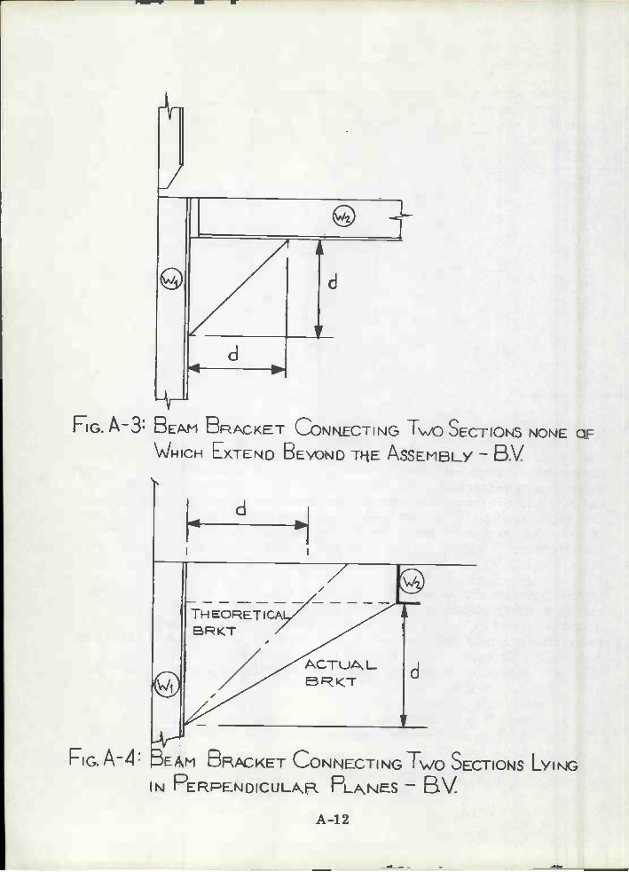
d
TH EORETICAEKT /
ACTuALeKT
A-12
d
y--V
FIG. A-4: BEAM BRACKET CONNECTING T\/O SECTIONS LYIÑG
N PERPEÑDICULAR PLINES - BV
FIG. A-3: BEANI RACET CONN.ECTING Tio SECTIONS NONE OF
WRICH EXTEND BEYoND TI-tE ASSEMBLY - B.V
d
H

the arm lengths of brackets are to be measured from the inner edge of theassembled sections, but the bracket is to extend up to the section perpendicularto the plane of the bracket as shown in Figure A-4. The reference modulusis equal to: W=W2 if W2 Wi or W=W1 if W2 Wi. Intermediate bracketsconnect two sectior of which at least one extends beyond the assembly bymeans of construction measures in such a way as to ensure whole or partialcontinuity of such section with the one located along its extension. Thereference modulus may differ according to the section moduli of the assembledsections, depending on whether the continuity between the sections locatedin each others extension is wholly or partially insured either directly or bymeans of another bracket, as shown in Figures A-5, A-G, and A-7. Thewidth or depth of a bracket in mm is not to be less than: d=4' /(W+30)/e (mm)'' flanged = 43. 5; unflanged = 48. 0; e = thickness of brackets.
The bracket thickness, in mm, is not to be less than the rule value shown inTable A-S: in terms of the reference modulus. Where the thickness of thebracket equals the rule thickness e0 the minimum value of its arm lengthsmay be read directly from the Table. All straight brackets in which the armlength-to-thickness ratio exceeds 32 are to be provided with a flange. Theminimum width of a flange is shown in the table against the reference modulus,whatever the bracket thickness.
A2.1.3 DNV: llSection5.F
The free edge of brackets in girder frames should be circular in shape toinsure a smooth transition to adjoining structural members. The radiusof curvature is not to be less than the depth of the largest adjoining member.The thickness of brackets on girders is not to be less than that of the girderweb plate. The thickness of brackets on frames or stiffeners not taking partin the longitudinal strength, is not to be less than shown in Table A-6.Flanges on girder brackets are to have a cross-sectional area not less thanA=0. iL t cm2. L=Length of free edge of brackets in cm. If L exceeds 150 cm,40% of the flange area is to be in a stiffener fitted parallel to free edge andmaximum 150 mm from the edge, (t = thickness of brackets in cm). Where Ais less than the flange area of the girder and the flange is continuous, the girderflange is to be tapered. If the flange is discontinuous, the free flange of thegirder is to extend well beyond the toe of the bracket. The general requirementto arm length is given by: a=C /Z/ t cm.
Z=Rule section modulus in cm3 of the strength member to which the memberis attached.
t = thickness of bracket (cm)C=2.0 for brackets on bottom and deck girders.=2. 8 for brackets on girders other than bottom and deck.=2. i for brackets on longitudinals discontinuous at transverse bulkheads incargo tanks.=1.4, 1. 5 for brackets; flanged and unflanged respectively, on stiffenersand frames not taking part in the longitudinal strength.
A-13

DIRECTCOTINUITY:
JHE EFRNCE NIODULU5 ISE UALTOVI Vv' I F V\/2 V.!1 + \J1VI \' W1 i VI2 > W4 ± Vv
\,'JTHOU1- ECEEDU- 2VJ1
FIGURE A-5INTEMEDIATE BEAM BRACPÇET'CONNECTING MEMBERS TO
INSURE DIRECT CONTINUITY - B.V1
A-14
d

CONIUITY 5YONE ßACKET
dA
d
dB
dA
+THE REFNC
ODULUS is
IF
IF \N<W2
FIG.A6: INTERMEDIATE BEAM BRACKET INSURING CONTINUITY OF
MEMBERS - BM
CONTIMUITY Y BACKT: JHE RFEREJCMODULUS ISEQUAJ_\i=W1 Fu1W2
IF WI <VI2\JB = Vi1VJIT-4OUT E.XCEEIÑG WI
t
F,c.A7: INTERMEDIATE BEAM BRACKETS PPDVIING CONTINUITY
OF EMbE-B.V.A-15

TABLE A-5
A-1G
ReferenceModulus
w3(cm)
Minimum Thickness e0 Minimum Widthand height d0corresponding
to e0(mm)
Minimum Widthof flange
(mm)Unflanged(mm)
Flanged(mm)
lo 7.0 6.0 11020 8.0 7.0 12030 8.5 7.0 13050 8. 5 7.0 15080 9.0 7. 5 170
loo 9.5 7. 5 180150 10.0 8.0 210200 10. 0 8.0 230250 10. 5 8.5 250300 11.0 8.5 270350 11.0 9.0 285400 11.5 9.0 300 60450 11.5 9.0 315 60500 12.0 9.5 330 60550 12.0 9.5 340 60600 12.0 9.5 350 65700 12.5 10.0 370 65800 13.0 10.5 390 70900 13.5 10.5 405 70
1000 13.5 11.0 420 75
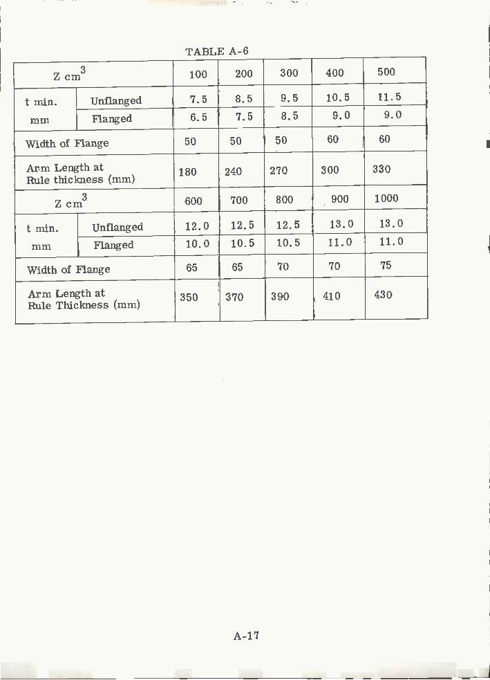
TABLE A-6
A-17
Z cm3 loo 200 300 400 500
t min.mm
Unflanged 7.5 8.5 9.5 10.5 11.5
Flanged 6.5 7.5 8.5 9.0 9.0
Width of Flange 50 50 50 60 60
Arm Length atRule thickness (mm)
180 240 270 300 330
Z cm3 600 700 800 900 1000
t min.mm
Unflanged 12.0 12.5 12.5 13.0 13.0
Flanged 10.0 10.5 10.5 11.0 11.0
Width of Flange 65 65 70 70 75
Arm Length atRule Thickness (mm)
350 370 390 410 430

The depth (a-H) see Figure A-8, of brackets on girders other than bottom anddeck girders need not exceed 0. 5H and L'/9 provided the bracket flange areais not less than the greater of the flange of the adjoining girders. L'-spanof adjoining girder.
A2.i.4 GL: Section 3.2
For the scantlings of brackets the required SM of the section is decisive.Where sections of different section moduli are connected to each other, thescantlings of the brackets are generally governed by the smaller section.The thickness of brackets is not to be less than: Smin6. 5 mm
for unflanged brackets: Si = 1. 26'W +1(mm)for flanged brackets: S2 = i.26'W - iTmm)W=section modulus of small section:The arm length of welded brackets is not to be less than:Lmin = 100(mm); L=16"WMi (mm)L=is the length of the welded connection.
Where flanged brackets are used the width of flange is to be determined:50(mm) <b=40-30/W) 90(mm)The thickness of tank side brackets and bilge brackets is not to be lessthan: S=0. 5H+5(mm) 15(mm)
For ships with 3 decks and more H need not be taken greater than L/i2. Forsingle deck ships the thickness is to be increased by 10%. If the sectionmodulus of the frame exceeds 30cm3, the bracket is to be flanged. The widthof the flange is to be at least 75mm. Where longitudinals abut at the transversebulkheads, brackets are to be passed through the transverse bulkheads. Withinthe upper and the lower girth the sectional area of the bracket at the bulkheadsis to be 1. 25 times the sectional area of longitudinals.
A2.1.5 LR: D726; D732; D733; D729
In ships having more than 3 tiers of beams and where large areas of deck arearranged for accommodations, or where particular conditions of loading arecontemplated, the requirements for beam knees will be considered with a viewto their omission in certain areas without an increase in modulus. When theeffective arm of the knee or bracket; L a, differs from the Rule arm; L, theframe modulus is to be multiplied by the following factors:
La< L: factor = 1.2-0.2 (La/L)La>L: factor = 1.1-0.1 (La/L)
For a beam knee the Rule length of arm L, measured as indicated in Figure A-9.a=b (21v' 1/Y - 51 (mm) with a minimum of 165 mm, where 1/Y is theRule section modulus in cm3 and is taken as follows:
A-18

___
FIG. A-8V KNEE BRACKET CONFIGUFATION- DNV
A-19
H
T

TYPE 1:
TYPE 3
FIG. A9: BM AND KNEE DRKET cONFiGURATIONS -Lft
A-20

TYPE 5:
FIG. A9:CONTD
A-21
TYPE 6:
T"(PE 7: lYRE 8

TYPE 9
FG. A-9:CONTD
A-22
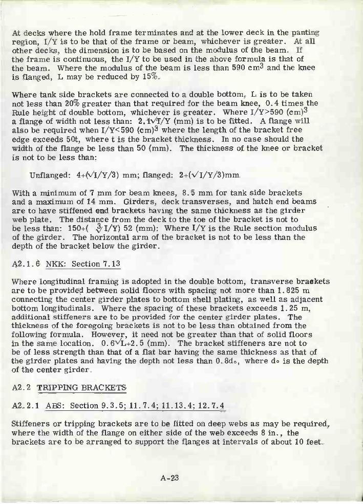
At decks where the hold frame terminates and at the lower deck in the pantingregion, 1/Y is to be that of the frame or beam, whichever is greater. At allother decks, the dimension is to be based on the modulus of the beam. Ifthe frame is continuous, the 1/Y to be used in the above formula is that ofthe beam. Where the modulus of the beam is less than 590 cm3 and the kneeis flanged, L may be reduced by 15%.
Where tank side brackets are connected to a double bottom, L is to be takennot less than 20% greater than that required for the beam knee, 0. 4 times theRule height of double bottom, whichever is greater. Where I/Y>590 (cm)3a flange of width not less than: 2.1Vr/Y (mm) is to be fitted. A flange willalso be required when I/Y<590 (cm)3 where the length of the bracket freeedge exceeds 5Qt, where t is the bracket thickness. In no case should thewidth of the flange be less than 50 (mm). The thickness of the knee or bracketis not to be less than:
Unflanged: 4+(V'I/Y/3) mm; flanged: 2+(v"I/Y/3)mm
With a minimum of 7 mm for beam knees, 8. 5 mm for tank side bracketsand a maximum of 14 mm. Girders, deck transverses, and hatch end beamsare to have stiffened end brackets having the same thickness as the girderweb plate. The distance from the deck to the toe of the bracket is not tobe less than: 150+( .'i/Y) 52 (mm): Where 1/y is the Rule section modulusof the girder. The horizontal arm of the bracket is not to be less than thedepth of the bracket below the girder.
A2.1.6 NKK: Section 7.13
Where longitudinal framing is adopted in the double bottom, transverse bracketsare to be provided between solid floors with spacing not more than 1. 825 mconnecting the center girder plates to bottom shell plating, as well as adjacentbottom longitudinals. Where the spacing of these brackets exceeds 1. 25 m,additional stiffeners are to be provided for the center girder plates. Thethickness of the foregoing brackets is not to be less than obtained from thefollowing formula. However, it need not be greater than that of solid floorsin the same location. 0. 6V'L+2. 5 (mm). The bracket stiffeners are not tobe of less strength than that of a flat bar having the same thickness as that ofthe girder plates and having the depth not less than 0. 8do, where do is the depthof the center girder.
A2. 2 TRIPPING BRACKETS
A2.2.1 ABS: Section 9.3.5; 11.7.4; 11.13.4; 12.7.4
Stiffeners or tripping brackets are to be fitted on deep webs as may be required,where the width of the flange on either side of the web exceeds 8 in., thebrackets are to be arranged to support the flanges at intervals of about 10 feet.
A-23

Tripping brackets arranged to support the flanges of deck girders are to befitted at every third frame where the breadth of the flanges on either side ofthe web exceeds 8 in.., at every second frame where it exceeds 16 in., andat every frame where it exceeds 24 in. Tripping brackets arranged to supportthe hatch end beams are to be located at intervals of about 10 feet. Trippingbrackets are to be fitted at intervals of about 10 feet and where the width ofthe flange exceeds 8 in. for bulkhead girders.
A2.2.2 BV: No Comment
A2. 2.3 DNV: Section 5. 13
Tripping brackets on girders are to be stiffened by a flange or stiffener alongthe free edge if the length of the edge exceeds 60 cm. The area of the stiffeningis not to be less than A=0. i Lcm2, where L is the length of the free edge incm. The tripping brackets are to have a smooth transition to adjoininglongitudinals or stiffeners exposed to large longitudinal stresses. Trippingbrackets are to be fitted near the toes of brackets, near the rounded cornersor girders, and in line with cross ties. The tripping brackets are to befitted in line with longitudinals or stiffeners, and are to extend the whole heightof the web plate. For longitudinal girders within 0. 5L amidships outside theline of hatchway openings and for deck transverses between hatches, trippingbrackets are to be fitted at distances not exceeding 14 x flange width, max. 4m.Otherwise, the distance between tripping brackets is not to exceed 20 x flangewidth, max. 4m. The web plate of low hatch side coamings is to be stiffenedover the entire height at every frame. Tripping brackets are to be fitted onevery second frame.
A2.2.4 GL: Section 3H; 9F; lOB
For preventing the face plates from tripping, adequately spaced stiffenersor tripping brackets are to be provided. The spacing of these tripping bracketsshould not exceed 12 b(b=flange width). Between the point of greatest depthof the ship at maximum draft and the collision bulkhead, tripping bracketsspaced not more than 2. 6m are to be fitted. In the same range in betweendecks and superstructures of 3m and more in height, tripping brackets are tobe fitted. At every second deck beam the face bars are to be stiffened bytripping brackets. At girders of symmetrical section they are to be arrangedalternately on both sides of the web.
A2.2.5 LR: D1314;D1916
Girders of unsymmetrical section are to be supported by tripping bracketsat alternate beams or equivalent, if the section is symmetrical the bracketsmay be 4 frame spaces apart. Where the ratio of the unsupported width ofthe girder face flat or flange to its thickness is 16 or greater, the trippingbrackets are to be connected to the face flat or flange. On girders of symmetricalsection tripping brackets are to be fitted on both sides when they are required
A-24

to be connected to the flange. Girders are to be supported by trippingbrackets at the toes of the end brackets and elsewhere at every third framestiffener or frame. Stiffeners or frames intermediate between thesebrackets are to be effectively connected to the girders.
A2.2.6 NKK: Parts 8; 9; 11
Web frames are to be provided with tripping brackets at intervals of about3m and stiffeners are to be provided on the webs at each longitudinal exceptfor the middle part of the span of web frames where they may be providedat alternate longitudinals. Side transverses are to be provided with intervalsof about 3m and with stiffeners at every longitudinal, except that thesestiffeners may be provided at alternate longitudinals in the middle part of thespans other than the lowest spans. Bottom transverses are to be providedwith tripping brackets at intervals of about 3m and stiffeners are to be providedon the webs at every longitudinal. Stiffeners or tripping brackets are to beprovided on deep webs as may be required. Tripping brackets are to bearranged at intervals of 3m. Tripping brackets arranged to support flangesare to be provided at every third frame where the breadth of flanges on eitherside of the web exceeds 200 mm, at every second frame where it exceeds405 mm, and at every frame where it exceeds 610 mm.
A2.3 PANEL AND WEB STIFFENERS
A2.3.1 ABS: Sections 7.3.7; 9.5.3
Stiffeners spaced not more than 5 feet apart are to be fitted on solid floorsforward and on every solid floor in ships of 280 feet and above. Where thedepth of the floor exceeds 3 feet, stiffeners on tank-end bulkheads spacingis not to exceed 3 feet. Stiffeners are to extend for full depth of the stringeron alternate frames at intervals of about 10 feet.
A2.3.2 BV: Sections 6.33; 6.35
Stiffeners fitted on plate floors, may consist of flat bars having a width of1/10 of the floor depth and a thickness not less than 0. 9v'Lmm or of sectionsof ciiivalent strength. The section modulus of vertical web stiffeners fittedon watertight floors is not to be less than: W1=8. 4C1E , 2:
C j = depth of shipE = spacing of floor web stiffenersi? = length of stiffenersW1=is for transverse framing or longitudinal framing when stiffenersare not welded to longitudinals. For longitudinal framing when longitudinalsare welded to the stiffeners. W2 = 5. 6C1E2.
rn ships over 80 m in length or where the floor depth exceeds 0. 85m, fordouble bottoms built on the transverse system, the floors are to be fitted withvertical stiffeners not spaced more than 1m0
A-25

A2.3.3 DNV: llSection5.E
Stiffeners on web plates are to be located not more than loo mm from freeedges of scallops for intersecting longitudinals, frames, or stiffeners. Ifthe web stiffeners are fitted in a line with the intersecting longitudinals,frames or stiffeners then are to be welded to the intersecting member.Stiffeners on the web plate perpendicular to the flange may be sniped towarddeck, side, or bulkhead plating. The web plate is to be especially stiffenedat openings when the mean sheer stress exceeds 600Kp/cm2. Stiffeners areto be fitted along the free edges of the opening parallel to the vertical andhorizontal axes of the opening. Stiffeners may be omitted in one direction ifthe shortest axis is less than 400 mm and in both directions is less than 300 mm.Edge reinforcement may be used as an alternative to stiffening.
Table A-7 lists the requirements for stiffening of different girder types.
TABLE A-7
GIRDER STIFFENING:
* - distance from bottom and deck to the nearest stiffener is not to exceed55t. For each successive plate stiffener( ove bottom) the spacing may bethcreased by 10%: below deck
** - for center girder, St is not to exceed S/2:
Iv - required moment of inertia of stiffeners perpendicular to girder flange,including 400 mm plate flange.
A-26
Girder Type Iv cm4 1h cm4 Sv cm Sh cm St cm
BottomTransv.
aS1 (t+O. 2) AL2 54000t 60000t 20fMax. 4004000 rm Tm
Side and Long'lBhd Vert.
aS1(t+0. 2) AL2 54000t 60000t 12f2000 rm
Long BottomGirder
AL2 * 14fMax S3000
Long'l DeckGirder
AL2 * 14fMax S3000
DeckTransv.
aS 1(t+0. 2) AL2 54000t 60000t 20f4000 Fm rm
Trans. BhdVertical
AL2 9f wash bhd12f others2000
Stringers aSi(t+0. 2) AL2 54000t 60000t 20fMax. 400Tm rm
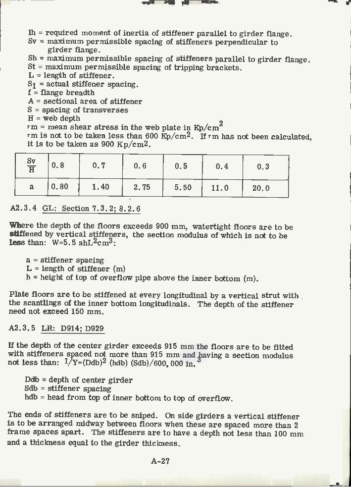
1h = required moment of inertia of stiffener parallel to girder flange.Sv = maximum permissible spacing of stiffeners perpendicular to
girder flange.Sh = maximum permissible spacing of stiffeners parallel to girder flange.St = maximum permissible spacing of tripping brackets.L = length of stiffener.S1 = actual stiffener spacing.f = flange breadthA = sectional area of stiffenerS = spacing of transversesH = web depth
2Tm = mean shear stress in the web plate in Kp/cm-m is not to be taken less than 600 Kp/cm2. If rm has not been calculated,it is to be taken as 900 Kp/cm2.
A2.3.4 GL: Section7.3.2;8.2.6
Where the depth of the floors exceeds 900 mm, watertight floors are to bestiffened by vertical stiffeners, the section modulus of which is not to beless than: W=5.5 ahL2cm3:
a = stiffener spacingL = length of stiffener (m)h = height of top of overflow pipe above the inner bottom (m).
Plate floors are to be stiffened at every longitudinal by a vertical strut withthe s.cantlings of the inner bottom longitudinals. The depth of the stiffenerneed not exceed 150 mm.
A2.3.5 LR: D914;D929
If the depth of the center girder exceeds 915 mm the floors are to be fittedwith stiffeners spaced not more than 915 mm and paving a section modulusnot less than: E/Y=(Ddb)2 (hdb) (Sdb)/600, 000 in.
Ddb = depth of center girderSdb = stiffener spacinghdb = head from top of inner bottom to top of overflow.
The ends of stiffeners are to be sniped. On side girders a vertical stiffeneris to be arranged midway between floors when these are spaced more than 2frame spaces apart. The stiffeners are to have a depth not less than 100 mmand a thickness equal to the girder thickness.
A-27
0.8 0.7 0.6 0.5 0.4 0.3
a 0.80 1.40 2.75 5.50 11.0 20.0

A2. 3. 6 NKK: Part 7; Part 8
Where the spacing of transverse brackets exceeds 1. 25 m, additional stiffenersare to be provided for the center girder. The stiffeners are not to be of lessstrength than that of a flat bar having the same thickness as that of the girderplates and having the depth not less than 0. 08 dv, where dv is the depth of thecenter girder in meters. Vertical stiffeners are to be provided to side girdersat every open floor or at a suitable distance if the double bottom is framedlongitudinally, and vertical struts are to be provided on half-height girders atevery floor. Vertical stiffeners are to be provided on the solid floors atsuitable spacing except where the double bottom is framed longitudinally, theyare to be provided at every longitudinal. Web frames are to be provided withtripping brackets at intervals of about 3m and stiffeners are to be provided onthe webs at each longitudinal except for the middle part of the span of webframes where they may be provided at alternate longitudinals.
A2.4 FACE PLATES
A2.4.1 ABS: Sections 7.1.1; 7.1.2
All single bottom vessels are to have center keelsons formed of continuousor intercostal center girder plates with horizontal top plates.Top-plate area at ends: A=0. 0033 VL3 -0. 15 in. 2Top-plate area at amidships: A=0. 000440"L3 -1.3 in. 2For side keelsons, the area of the horizontal top-plate is to be:
A=.001V'L3 =2.6in.2: Amidships:A=. 00065'L + 3. 1 in. 2: Ends
A2.4.2 BV: No Comment
A2.4.3 DNV: llSection5.D
Buckling of flanges on angles and T-sections:(Te=0. 8x10⁶ (tf/b)2 Kp/cm2=critical buckling stress
tf = flange thickness in (cm)b = flange width in (cm) for angles; half the flange width for T-sections.
Flanges on girders are to have a thickness not less than 1/30 of the flangevidth when the flange is symmetrical and 1/15 if the flange is asymmetrical.
A2.4.4 GL: Sections 3.2; 3.3; 7.2
Buckling strength of face plates of girders and transverses, the thicknessof the face plate is not to be less than: s=b/27v'K
b = unsupported width of face plateK = material factor = 1.0
A-28

Buckling strength of longidutinals; angles or T-sections: bf=19. 5tf/v'Kbf = flange widthtf = flange thickness
The sectional area of the top plate for the Center Keelson within the O. 7Lamidships is not to be less than: f=O. 7L + 12 cm2.
Towards the ends, the sectional area of the top plate may be reduced byLO%. The sectional area of the top plate for the side keelson within theO. 7L amidships is not to be less than: f = O. 2L + 6 cm2:
A2.4.5 LR: No Comment
A2. 4.6 NKK: Part 6, Article 5: Part 8; Article 15
Rider plates are not to be of less breadth than: b=16. 6L - 200 mm
A-29
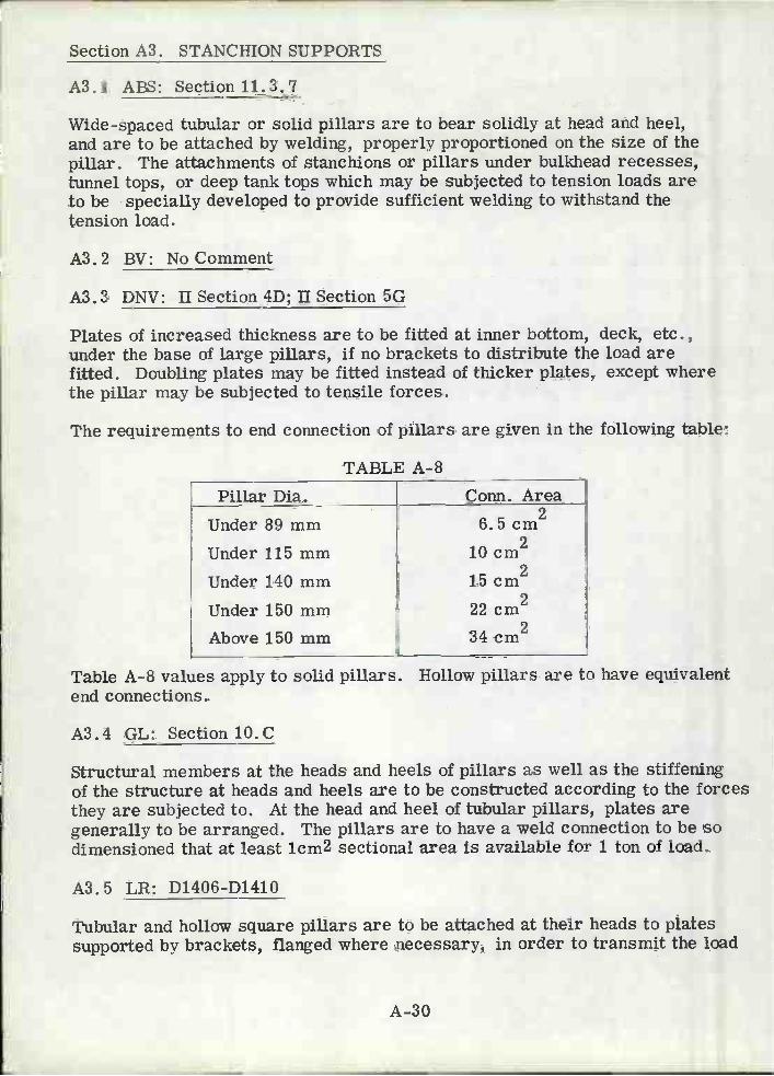
Section A3. STANCHION SUPPORTS
A3..1 ABS: Section 11.3.7
Wide-spaced tubular or solid pillars are to bear solidly at head and heel,and are to be attached by welding, properly proportioned on the size of thepillar. The attachments of stanchions or pillars under bulkhead recesses,tunnel tops, or deep tank tops which may be subjected to tension loads areto be specially developed to provide sufficient welding to withstand thetension load.
A3. 2 BV: No Comment
A3.3 DNV: II Section 4D; II Section 5G
Plates of increased thickness are to be fitted at inner bottom, deck, etc.,under the base of large pillars, if no brackets to distribute the load arefitted. Doubling plates may be fitted instead of thicker plates, except wherethe pillar may be subjected to tensile forces.
The requirements to end connection of pillars are given in the following table:
TABLE A-8
Table A-8 values apply to solid pillars. Hollow pillars are to have equivalentend connections.
A3.4 GL: Section 1O.0
Structural members at the heads and heels of pillars as well as the stiffeningof the structure at heads and heels are to be constructed according to the forcesthey are subjected to. At the head and heel of tubular pillars, plates aregenerally to be arranged. The pillars are to have a weld connection to be sodimensioned that at least 1cm2 sectional area is available for i ton of load.
A3.5 LR: D1406-D1410
A-30
Tubular and hollow square pillars are to be attached at their heads to platessupported by brackets, flanged where necessary, in order to transmit the load
Pillar Dia. Conn. Area
Under 89 mmUnder 115 mm
Under 140 mm
Under 150 mmAbove 150 mm
26.5cm10 cm2
215 cm
22 cm2234 cm

effectively. Doubling or insert plates are to be fitted to the inner bottomunder the heels of tubular or hollow square pillars, and to decks under largepillars. The pillars are to have a bearing fit and are to be attached to thehead and heel plates by continuous welding. At the head and heels of pillarsbuilt of rolled sections, the load is to be well distributed by means of longitudinaland transverse brackets. Where pillars are to be fitted inside tanks or underwatertight flats, the tensile stress in the pillar and its end connections is notto exceed 1100 Kg/cm2.
A3.6 NKK: Part 11: Section 8
The head and heels of built-up pillars are to be efficiently connected by meansof angles, brackets or foundation plates according to the form of the pillar.Where pillars are connected to the deck plating, the deck is to be properlystrengthened as necessary. The head and heel of pillars may be subjectedto tensile loads such as under bulkhead recesses, tunnel tops or deep tanksare to be efficiently welded to withstand the tensile loads.
Â-31
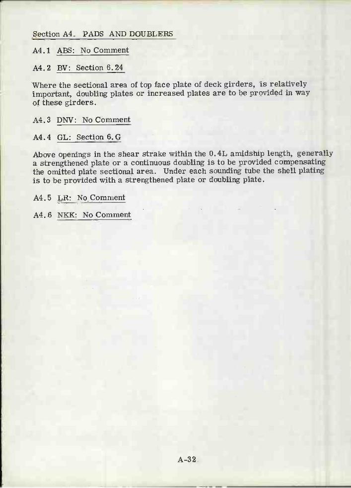
Section A4. PADS AND DOUBLERS
A4. i ABS: No Comment
A4. 2 BV: Section 6. 24
Where the sectional area of top face plate of deck girders, is relativelyimportant, doubling plates or increased plates are to be provided in wayof these girders.
A4.3 DNV: No Comment
A4.4 GL: Section 6.G
Above openings in the shear strake within the O. 4L amidship length, generallya strengthened plate or a continuous doubling is to be provided compensatingthe omitted plate sectional area. Under each sounding tube the shell platingis to be provided with a strengthened plate or doubling plate.
A4.5 LR: No Comment
A4. 6 NKK: No Comment
A-32

Section A5. CUTOUTS: LIGHTENING HOLES, SNIPES, SCALLOPS
A5.1 ABS: Section 7.1.7; 7.3.2
Where the girders are not required to be intact, manholes may be cut in everyframe space outside the midship 0. 75L in vessels under 90m in length providedthe depth of the hole does not exceed 1/3 the depth of the center girder; man-holes within the midship 0. 75L in vessels 90m and above are to be compensatedfor and specially approved. Manholes and lightening holes are to be cut in allnon-tight members, except in way of widespaced pillars to insure accessibilityand ventilation. Air and drainage holes are to be cut in all parts of the structureto insure the free escape of air to the vents and the free drainage to the suctionpipes.
A5.2 BV: Sections 6-32; 6-33
Drain holes are to be cut in the floors at centerline or on each side, accordingas the center keelsonis continuous or intercostal. In flat bottom ships, drainholes should be cut at the lower turn of the bilge, over 0. 5L at least amidships.side keelsons too are to be provided with drain holes for allowing for freerunning of water towards the pump suction. Holes in side girders and floorsshould be cut at mid depth; their length should not exceed 1/2 the web depthand their height should be so limited as to provide around, as far as possible,a plate strip at least 1/4 the double bottom depth wide.
A5.3 DNV: II Section 4E; II Section 5D; II Section lOA
Lightening holes may be cut in girders, except the centerline vertical ontransverse bulkheads, and only in exceptional cases in the centerline bottomand deck girder. The distance from the edge of the lightening hole to theedge of the face plate or other holes is not to be less than 0. 3 times the depthof the member. Lightening holes are to be kept well clear of end brackets andlocations of high shear. Scallops for longitudinals, frames, or stiffenersdeeper than 500mm are to be stiffened at their free edge. The vertical extensionof lightening holes in the bracket floors is not to be greater than 1/3 the breadthof the bracket. To insure the escape of air and water from each frame spaceto the air pipes and suctions, holes are to be cut in the floors and side girders.The air holes are to be placed as near to the inner bottom as possible. Thedrain holes are to be placed at the upper edge of the solid cement. The totalarea of the air holes is to be greater than the area of the filling pipes.
A5.4 GL: Sections 3.2.3; 3.2.4; 8.2; 8.3
Lightening holes in the side girders are to be of such size as to leave aremainder of web plate around the hole not less than 0. 2 of the height of sidegirder or of frame spacing respectively. Where the holes are fitted with flatbars the above value may be reduced to 0.15. In way of the strengthening ofthe bottom forward, any scalloping in the side girders is to be restricted to
A-33
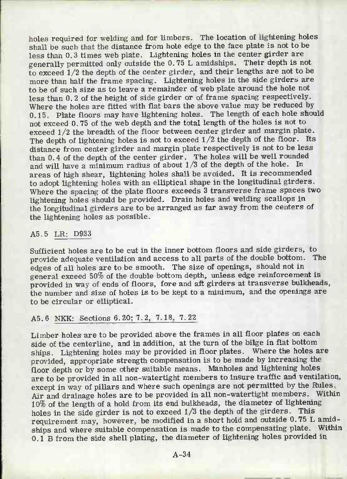
holes required for welding and for limbers. The location of lightening holesshall be such that the distance from hole edge to the face plate is not to beless than 0.3 times web plate. Lightening holes in the center girder aregenerally permitted only outside the 0. 75 L amidships. Their depth is notto exceed 1/2 the depth of the center girder, and their lengths are not to bemore than half the frame spacing. Lightening holes in the side girders areto be of such size as to leave a remainder of web plate around the hole notless than 0. 2 of the height of side girder or of frame spacing respectively.Where the holes are fitted with flat bars the above value may be reduced by0.15. Plate floors may have lightening holes. The length of each hole shouldnot exceed 0. 75 of the web depth and the total length of the holes is not toexceed 1/2 the breadth of the floor between center girder and margin plate.The depth of lightening holes is not to exceed 1/2 the depth of the floor. Itsdistance from center girder and margin plate respectively is not to be lessthan 0.4 of the depth of the center girder. The holes will be well roundedand will have a minimum radius of about 1/3 of the depth of the hole. Inareas of high shear, lightening holes shall be avoided. It is recommendedto adopt lightening holes with an elliptical shape in the longitudinal girders.Where the spacing of the plate floors exceeds 3 transverse frame spaces twolightening holes should be provided. Drain holes and welding scallops inthe longitudinal girders are to be arranged as far away from the centers ofthe lightening holes as possible.
A5.5 LR: D933
Sufficient holes are to be cut in the inner bottom floors and side girders, toprovide adequate ventilation and access to all parts of the double bottom. Theedges of all holes are to be smooth. The size of openings, should not ingeneral exceed 50% of the double bottom depth, unless edge reinforcement isprovided in way of ends of floors, fore and aft girders at transverse bulkheads,the number and size of holes is to be kept to a minimum, and the openings areto be circular or elliptical.
A5. 6 NKK: Sections 6. 20; 7. 2, 7. 18, 7. 22
Limber holes are to be provided above the frames in all floor plates on eachside of the centerline, and in addition, at the turn of the bilge in flat bottomships. Lightening holes may be provided in floor plates. Where the holes areprovided, appropriate strength compensation is to be made by increasing thefloor depth or by some other suitable means. Manholes and lightening holesare to be provided in all non-watertight members to insure traffic and ventilation,except in way of pillars and where such openings are not permitted by the Rules.Air and drainage holes are to be provided in all non-watertight members. Withinio% of the length of a hold from its end bulkheads, the diameter of lighteningholes in the side girder is not to exceed 1/3 the depth of the girders. Thisrequirement may, however, be modified in a short hold and outside 0. 75 L amid-ships and where suitable compensation is made to the compensating plate. Within0. 1 B from the side shell plating, the diameter of lightening holes provided in
A-34

the solid floors in the middle half length of a hold is not to exceed about 1/5the floor depth. This requirement may, however, be suitably modified atthe end parts of ship and in exceptionally short holds and where the solid floorsare suitably compensated for.
A-35

Section A6. STRUCTURAL INTERSECTIONS - INCLUDING COLLARS
A6.1 ABS: Sections 9.3.6; 9.5.4
End connections of all girders, webs and stringers should be balanced byeffective supporting members on the opposite side of bulkheads, tank tops,etc., and their attachments are to be effectively welded. End connectionsare to be for the full depth of the web plate. Where the stringers are thesame depth as the web frame, the standing flanges of the side stringers areto be attached.
A62 BV: Sections 6.32; 6.33; 6.55
The face plates of keelsons are to be connected to those of floors. Wherethe bottom and inner bottom longitudinals are cut at floors, their continuityis to be insured by means of rectangular brackets connecting the bottomlongitudinals. The connection length of these brackets should be 0. 5 timesthe double bottom depth, but need not exceed 3 times the bottom longitudinaldepth. Deck girders are to be securely connected to strong hatch end beams,are also to be provided with diamond plates attaching the face plates of girdersto those of beams.
A6.3 DNV: II Section 4D; II Section 5G
Structural continuity is to be maintained at the junction of primary supportingmembers of unequal stiffness by fitting well rounded brackets. In doublebottoms the following apply:
The bottom and inner bottom longitudinals are to be connected to thefloors by a weld area not less than:a=5+2sd(/-S1) cm2s - Spacing of longitudinals (m)J - Span (m)S1 - Rule frame spacing (m)d - Draft (m)If the expression 2. 5 Ha2s/t2 cm2 is greater than 0. 2 or the floor formspart of a sea chest, the end connection of stiffeners on plate floors is to havean area not less than: a=Hs cm2
- depth of center line girder (m)s = stiffener spacing (m)t - floor thickness (mm)Ha = vertical distance from middle of 1 to top of the air pipe. (m)
A-36

If the pressure head (h) on the inner bottom is greater than d: The
weld area between inner bottom longitudinals or frames and floor 2plates on side girders is not to be less than: a=5+O. 9 sh cmand the weld area between inner bottom frames and transverse bracketsat center girder and margin plate is not to be less than: a=5+, sh cm2and the weld area between inner bottom longitudinals on frames andvertical struts is not to be less than: a=5+O. 9,9\sh cm2
1' 2 = are the longitudinal or frame spans in (m) on eachof the floor plates on side girders.
= span (m)s = spacing (m)
For ship's side and tank bulkheads not covered by e, the following apply:
In holds, frames and stiffeners supported by girders are to be weldedto girders with a weld area not less than: a=5+O. 9 ,Q1+22)sh cm2
If, in areas with great shear stresses, both sides of the frames areconnected to the web of the girder, only the weld area on one side ofthe frame will be accepted as an effective connection area.
The lowest frames in the peaks are to be welded to the floors with anarea not less than: a=7. 5 + 1. 5Qsh cm2
Longitudinals, frames, and bulkhead stiffeners in cargo tanks may beconnected to the web plate of girders in the following ways:
Welded directly to the web plate on one or both sides of the frame.Connected by single -or -double - sided lug s.With stiffener or bracket welded on top of frame.A combination of the above.
In locations with great shear stress in the web plate, a double-sidedconnection is required. The connection may be taken into account whencalculating the effective web area. Only one side of the connection,however, may then be included in the effective connection area betweenframe and web plate.If the necessary area is not obtained by using a side connection only,a stiffener or bracket is to be provided on top of the frame.
Minimum connection area: a=1.25 sh cm2
ht = pressure headIf a stiffener or a bracket is welded to top of the frame, the net sectionalarea of stiffener may be included in the connection area, limited upwardsto 50% of the required area.
A-3?

f. For bulkhead stiffeners not covered by e, the following apply:The upper end of stiffeners which support deck beams orlongitudinals, is to be connected to the deck beam or
2longitudinal by a weld area not less than: a=1. 8sh cmh = head on stiffener
The lower end of stiffeners which support deck beams orlongitudinals, is to be conected to deck or tank top by aweld area not less than: cm = 6 cmThe end connection area at both ends of stiffeners is to beat least: a=0. 25Z/ cm2Z = rule section modulus of stiffener in cm3
= span of stiffener (m)
For decks and single bottoms, the following applies:Continuous deck longitudinals in holds are to be connectedto transverse bulkheads, transverses and other transverse
2structural parts with a weld area not less than: a=5+s h cmh =deckloadWhere beams are supported by deck girders or hatchwaycoamings, the connection to girder or coaming is not to beless than given in the following table:
g.
For cargo tank bottom and deck longitudinals, which are discontinuousat transverse bulkheads, the total connection area to bottom and deckplating for 20 o of the span from the ends is not to be less than: a=0. 1Z/cm
= span of longitudinal (m)3Z = rule section modulus of longitudinal (cm )
Minimum throat thickness of weld = 4mm
For cargo tank bottom and deck longitudinals which are continuous throughtransverse bulkheads, the connection area to the plating for 20% of thespan from the ends is not to be less than that a double continuous filletweld with a throat thickness: t=1. 5 + Z/iØO mm
Â-38
Depth of beam in mm Connection Area in cm2
Less than 190 6.5Less than 240 10
More than 240 13

For the remainder of the span in the cargo tanks, the connection area isnot to be less than that of a double continuous fillet weld with a throatthickness: t=i+Z/1502 mm
Transverse frames and beams in cargo tanks may for the complete spanbe connected to the plating according to the latter formula, with thefollowing exceptions:
- Where the frame spacing exceeds 760mm, the connection areaof transverse side frames to the shell plating is to be increasedby 10%.
- For built sections, the connections to the flange and plate areto be equal.
Â6.4 GL: Section 8.1.1
Where the face bar of the floor plates extend to the center keelson plate, thefloor plate is to be continuously welded to the keelson face plate and to thecenter keelson. Where the face bar of the floor plate only extends to the faceplate of the center keelson, those are to be connected by welding. Further-more, on both sides of the face bar horizontal brackets are to be attached,the leg length of which is about the breadth of the face bar and the thicknessof which is that of the face bar.
A6. 5 LR: No Comment
A6. 6 NKK: No Comment
Â-39

Section A?. SHEAR STRAKE CONNECTIONS
A?. 1 ABS: No Comment
A7.2 BV: No Comment
A7.3 DNV: llSection9.A
The upper edge of the shear strake is not to extend above top of the stringerplate.
A7.4 GL: Sections 6.4.3; 7.2.1
Where the conrection of the deck stringer with the shear strake is rounded,the radius is to be at least 15 times the plate thickness. For the weldedconnection between strength deck and shear strake use a fillet weld wheret = 20mm, where the plate exceeds 20mm a fully welded connection shallbe provided.
A7.5 LR: D511
Where a rounded shear strake is adopted, the radius should in general, notbe less than 15 times the thickness.
A7. 6 NKK: No Comment
A-40

Section A8. HATCH COAMINGS
A8.1 ABS: Section 18.3.2
Coaming plates are not to be less than 0. 34 in. thick in vessels not exceedingloo ft and 0.44 in. thick, in vessels 250 feet and above.
A8.2 BV: Section 6. 83.12
The thickness of hatch coamings is not to be less than: e=O. 082L+6mm:This thickness is in no case less than 8mm or more than 11mm.
A8.3 DNV: IlSection4
Compensation by flat bar rings: Figures A-10 and A-11.
A8.4 GL: Section 17.B.1
The thickness of hatchway coamings on exposed decks is to be 8. 5mm wherethe length L does not exceed 30m, and not less than 11 mm where the lengthL 60m.
A8.5 LR: D411
Compensation: See Figure A-12
A8.6 NKK: Section 18.5
The thickness of hatchway coamings is not to be less than:
L.10Om: t = 60.05LL>lOOm: t=llmm
* In all cases, L is the ship length, as previously described.
Â-41

f5t
e=1.Ot-1.5t G 5CMM<G<25Q
F10. A-1O:FLT BAR REINFORCEMENT ALONG THE EDGE OF AN
OPENING - DNV
tDç
r
e=lt-l.5tøpI
FIG. A-fl: FLAT BA REINFORCEMENT AROUND THE INSIDE
OF N OPENIÑG-DNVÀ-42
L
5f
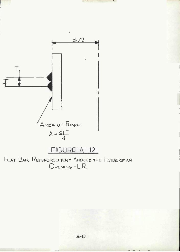
1-
FLAT BAR.
di/'
A REA OF RING:
= d1t
FIGURE A-12REINFORCEMENT ARDUÑD THE INSIDE OF AN
OPENING -L.R.
A-43

Section A9. STIFFENER ENDINGS
A9.1 ABS: Sections 10.3, 12.7, 13.3
Deck beams: Req'd Sm=0. OO4lchsL2 in.3
s = spacing of beams: (ft)L = span of deck beams: (ft)h = loading
End attachment factor: e:
=0. 54 for half beams, for beams with center line support only, for beamsbetween longitudinal bulkheads, and for beams over tunnels or tunnelrecesses
= 0. 585 for beams between longitudinal deck girders, for longitudinalbeams of platform decks and between all hatches.
= 0. 855 for longitudinal beams of effective second and third decks.= 0. 945 longitudinal beams of strength decks.= 0. 99 for beams at deep tank tops supported at one end or both ends
at the shell or on longitudinal bulkheads.= 1. 17 for beams at deep tank tops between longitudinal girders.
Watertight and (Deep Tank) Stiffeners: Req'd Sm=0. OO4lchsL2 in.
c-Factor:= 0. 3, (0. 594) - efficient brackets at both ends.= 0.43, (0. 747): effective bracket at one end and supported by clip
connections or by horizontal girders at the other end.= 0. 56, (0. 90): clip connections at both ends, or clip connections at one
end and supported by a horizontal girder at the other end.
= 0. 60, (1. 17): no end attachments, or supported by horizontal girdersat both ends.
A9.2 BV: No Comment
A9.3 DNV: No Comment
A9.4 GL: Sectionll.B.1
Bulkhead Stiffeners Req'd: Sm=KCs ahL2 cm3
K=1, material factorh = head inL = unsupported span (m).Cs = attachment factor:
A-44

Restrained:3.25 - Collision bhd2. 60 - all others
Simply supported:
4.30 - collision bhd3.50 - all others.
AO. 5 LR: No Comment
A9.6 NKK: Section 12.13
Bulkhead Stiffeners: Required section modulus: S m=ChsL 2c m3:
L = distance between adjacent supports of stiffeners including the lengthof connection (m)
s = stiffener spacing (m)
h = vertical distance (m), from the midpoint of L for vertical stiffeners,and from the midpoint of the supported panel for a horizontal stiffener,to the top of the bulkhead deck at center line.
Where h<6m: use h'=0.8h + 1.2 mC = attachment factor:
8 - effective bracket connections at each end.6 - bracket at one end and clip at one end, or girder at one end.
=4.4 - clips at both ends, clip at one end, girder at the other end orgirders at both ends.
=5. 5 - no end connections.
A-45

NOTES
A-46
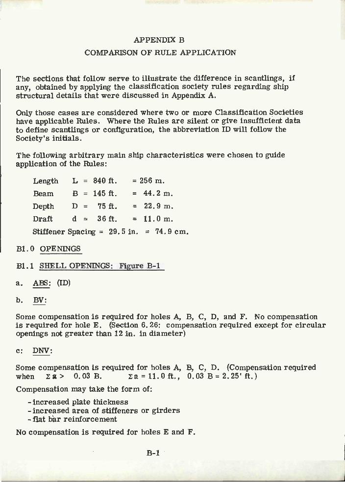
APPENDIX B
COMPARISON OF RULE APPLICATION
The sections that follow serve to illustrate the difference in scantlings, ifany, obtained by applying the classification society rules regarding shipstructural details that were discussed in Appendix A.
Only those cases are considered where two or more Classification Societieshave applicable Rules. Where the Rules are silent or give insufficient datato define scantlings or configuration, the abbreviation ID will follow theSociety's initials.
The following arbitrary main ship characteristics were chosen to guideapplication of the Rules:
Stiffener Spacing = 29.5 in. 74.9 cm.
Bi.0 OPENINGS
Bi. i SHELL OPENINGS: Figure B-i
ABS: (ID)
BV:
Some compensation is required for holes A, B, C, D, and F. No compensationis required for hole E. (Section 6. 26: compensation required except for circularopenings not greater than 12 in. in diameter)
C: DNV:
Some compensation is required for holes A, B, C, D. (Compensation requiredwhen a> 0.03B. a=ii.0ft., 0.03B=2.25'ft.)Compensation may take the form of:
-increased plate thickness- increased area of stiffeners or girders- flat bàr reinforcement
No compensation is required for holes E and F.
B-1
Length L = 840 ft. = 256 m.
Beam B = 145ft. = 44.2m.Depth D = 75ft. = 22.9m.Draft d = 36ft. 11.Om.
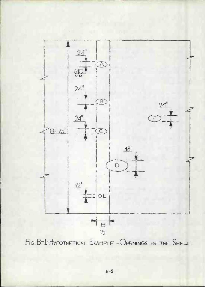
15
FG.B1:HYTNETICAL EXAMPLE -OPENINGS IN THE. SHELL
B-2

GL:
No compensation is required for holes A, B, C, E, and F. (No compensationwhen width of hole less than 700 mm). Hole D must be compensated for.Compensation may take the form of doublers, increased plate thickness,reinforcing framing members
LR: (ID)
NKK: (ID)
Bi. 2 STRENGTH DECK OPENINGS: Figures B2 & B3
ABS:
For Tankers: (ID)
For Dry Cargo Ships: Area between the cargo hatches, minimum platingthickness: tplt = 0.01 (29.5) + 0.035 = 0.33 in.
EV:
For Tankers: (ID)
For Dry Cargo Ships: The corners of the hatchway are to be radiused,R 0. 05b = 0.05 (70x12) = 42"
C: DNV:
For Tankers: Compensation will be required for openings A, Bi, B2, B3 andC, since they all exceed the limits of Table 102, Section 4. Reinforcement mustbe added in the form of: increased plating thickness, flat bar reinforcing,additional deck framing. No compensation is required for hole D.
For Dry Cargo Ships: All holes exceed the limits of Table 102, Section 4.Reinforcement must be provided as mentioned above.
d. GL:
For Tankers: No compensation required for openirg D. Openings A, B1, B2,B3, and C are to be edge reinforced. Required flat bar reinforcement of areaf = 0.25 ds:A = 6. 75 in. 2
B = 4.50 in.2C = 6. 75 in. 2
For Dry Cargo Ships: No compensation required for opening D. Openings A, B,
B-3

C require edge reinforcement, as calculated above. The hatchway cornerradius, r = 0.1 b (i_b/B)= 0.1(840) (1-70/140) = 42". The thickness ofstrength deck plating inside the line of hatchways is not to be less thant 5mm + 0. 03 L
t = 1/2 in. plate
LR:
For Tankers: Same as GL, Paragraph d.
For Dry Cargo Ships: For compensation details see GL, paragraph d. Cornersof main hatchways are to be rounded with a radius not less than(i/24)b =840/24 = 35 in. Where corners of large openings are radiused an insert plateis required whose thickness is 0. 2" greater than the deck plating thickness:t = 0. 75 + 0.20 = 0.95"
NKK:
For Tankers: (ID)
For Dry Cargo Ships: (ID)
Bi.3 BULKHEAD OPENINGS: Figure B-4
ABS: (ID)
BV: (ID)
e. DNV:
Openings A and B exceed the limits of Table 102; some form of strengtheningis required. No reinforcement is required for Opening C.
GL: (ID)
LR: (ID)
NKK: (ID)
Bi. 4 OPENINGS IN GIRDERS AND OTHER STRENGTH MEMBERS
Table B-1 provides a comparison of the relevant design guidelines. The followinghypothetical structure has been used to establish the results shown in the table:
Member depth = 1524 mm = 60 in. = HWeb thickness = l3mm = 0.512 in. =eStiffener spacing = 76 2 mm = 30 in. = s
B-4
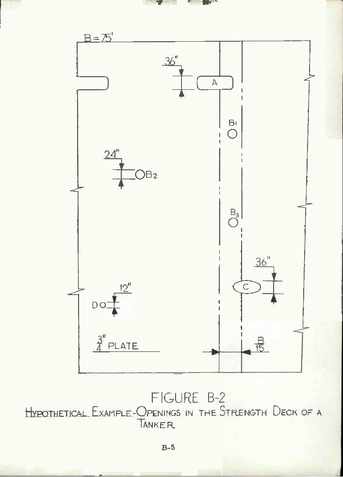
B=75'
24"
I
12"
L)
tIYPQTHETJCAL EXAMFLE-OPNINGS IN THE STRENGTH DECK OF ATANKER.
B-5
o
83
o
Do41
4 PLATER
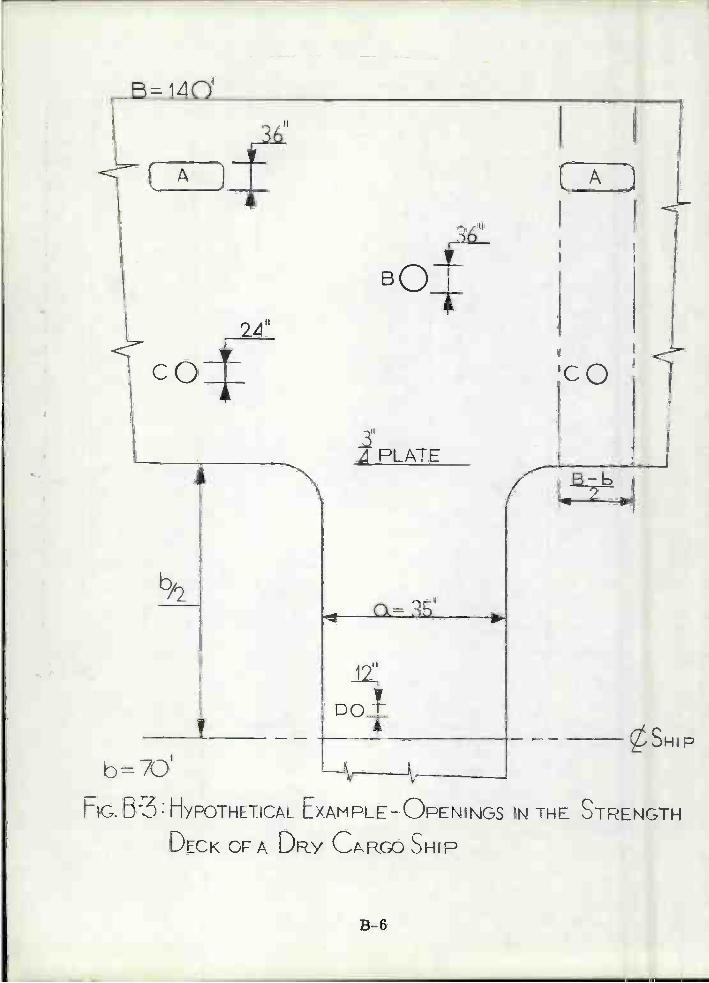
E= izO'
A
24"
COT
I,
4 PLATE
B-6
12"
no-tT
A
y
b=70'fl2.I1 E r'
hGD3nYPOTHTIC/\L LXAMPLE-L)PENINGS IN THE )TRENGTH
DECK OFA DRY CR SHIP
.SHIP

I
72.0
¿I21II
6 Co
lT
B
15
FIGURE 5-4HYPOTHETICAL EXAMPLE- OPENINGS IN A MAIN TRSVEE
SULKHEAD
B-7
B=60'

TABLE B-1
* Type 1: Long openings or groups of openings, all in the samesection (see Figure 4-5).
Type 2: Long openings or groups of openings shifted in relationto each other (see Figure 4-6).
Type 3: Short openings with relatively large spacing in samesection or shifted. (see Figure 4-7).
B-8
CLASSIFICATIONSOCIETY
HOLE DEPTH(a)
HOLE LENGTH(b)
MINIMUM HOLESPACING (1)
ABS
BV
DNV*
Type 1
Type 2
Type 3
GL
LR
NKK
762 mm
304 mm
152 mm
1/10
762 mm
762 mm
1524 mm
381 mm
3040 mm
1524 mm
10 a-762 mm 762 mm

B2. O BRACKETS
B2.1 KNEE BRACKETS
Table B-2 provides a comparison of Rule guidelines for the design of KneeBrackets. Figure B-5 shows a hypothetical transverse web frame intersectionthat requires bracketing to reduce the span of the bottom member. Scantlingsand spans are recorded on Figure B-5, and the design calculations willassume an equal-leg bracket. The brackets will be sized with the intent ofreducing the span by 1O?_O!.
B2. 2 BEAM BRACKETS
Table B-3 provides a comparison of Rule guidelines for the design of BeamBrackets. Figure B-6 shows an intersection between a vertical bulkheadstiffener and longitudinal deck beam. Scantlings are noted on the figure, andthe design will assume an equal-leg bracket. The purpose of these bracketsis to insure rigidity at the member ends.
B2. 3 TRIPPING BRACKETS
ABS:
Figure B-7 will be used to locate tripping brackets on the four designatedspans:
Span i - 30 feet; Transverse deck girder: add two pairs equallyspaced tripping brackets (both sides).
Span 2 - 26 feet; Transverse deck girder: add two pairs equallyspaced tripping brackets (both sides).
Span 3 - 26 feet; Side transverses: add two pairs equally spacedtripping brackets (both sides)
Span 4 - 30 feet; Side transverse: add two equally spaced trippingbrackets, both sides.
BV: (ID)
C. DNV:
Span i - add two pairs of equally spaced trpping brackets (both sides)with a flange area equal to 1.4 in. '
Span 2 - add one pair tripping brackets both sides equal distance fromeach end, with a flange area of 1. 4 in. 2
Span 3 - Add one pair of tripping brackets (both sides) that is equaldistance from both ends, with a flange area of 1.4 in.2.
B-9

TABLE B-2
TABLE B-3
B-10
ClassificationSociety
Bracket LegLength (a)
BracketThickness (t)
Bracket FlangeArea
ReducedSpan
ABS
Type 1 (Fig. 4-8) 66" 0. 75" 9.0 in_2 L -10'Type 2 (Fig. 4-9) depends on
flange area0.75" <9.0 in 2 L -10'
Type 3 (Fig. 4-10) 60" 0. 75" 18. 0 in. 2L -10'
BV
DNV - 0.75"GL 120" 0. 50" L -10'-LR
NKK
--- - -Classification
SocietyBracket Arm
LengthBracket
ThicknessBracket
Flange Width
ABS
BV
DNV
GL
LR
NKK
18m.12m.12 in.
12m.
0.32in.0.35in.0.35 in.0.3lin.0.32 in.
2.Oin.2.2in.2.2 in.2.Oin.1.Gin.- -
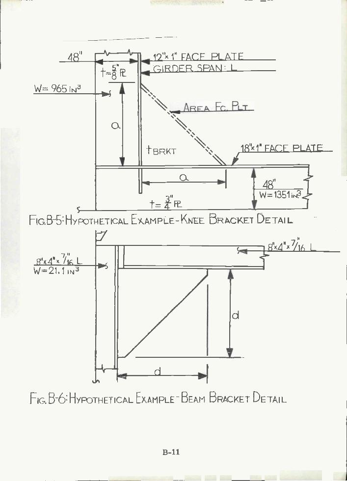
SI j"x 1" ACF PLTFu ÇIRDFRPAÑ L
W= 965 ÍÑ -4 '
ARF Fc. PLT
c
tBRKT iS<iM FACF PLATE'i
B-11
d
4R'W=135tr.?
St=Fe
HG. B-b: HYTkETCL EAM p- KNEE 5RI.CKE1 DETAI L
7"4H 'lE, LW=211 i IN3
-4--
/iL
FIG.B-6:HYPOTHETICALEXAMPLEBEAM BRACKET DETAIL

B-12
FIG. B-7, TRANSVERSE SECTION USED FOR THE COMFARISONI OF
TRiPPING BRACKET DEsIGN GUIDELINES
26' 3oI- Oil

Span 4 - add two equally spaced pairs of tripping brackets (both sides)Flange area = 2. 2 in. 2
GL:
Span 1 - add three equally spaced pairs of tripping brackets (both sides).
Span 2 - add two equally spaced pairs of tripping brackets (both sides).
Span 3 - add two equally spaced pairs of tripping brackets (both sides).
Span 4 - add three equally spaced pairs of tripping brackets (both sides).
LR: (ID)
NKK: same locations as ABS.
133.0 PANEL AND WEB STIFFENERS
Calculations for comparison of web and panel stiffener Rule guidelines havebeen made for (a) a plate floor with a depth of 10 feet and a stiffener spacingof 30 inches and (b) for a transverse deep girder with a depth of 8 feet anda stiffener spacing of 30 inches.
ABS:
Plate floor stiffeners: (ID)
Web stiffener s: (ID)
BV:
Plate floor stiffeners:depth =(/10)(floor depth) = 12"thickness = 0. 9'VL mm = 0. 574" use: 12" x 5/8" Flat bar
Web stiffeners:Toes of web stiffeners welded to longitudinals (longitudinal framing).
Section modulus= W = 5. 66C1EL = 327 cm3 = 20 in. use: 8"x4"x7/16" L
e. DNV:
Plate floor stiffeners:Floors are to be stiffened at every longitudinal with a 6" flat bar.
Web plate stiffeners:Iv = aS1(t + 0.2) = 153 in.4 use: 8"x4"x7/16" L
B-13

GL:
Plate floor stiffeners: (see DNV for details)Web Stiffeners:
Section Modulus: = W = 5. 5 ahL cm3 = 19. 6 in. use: 8"x4"x7/16" L
LR:Plate floor stiffeners:
Vertical stiffeners are to be fitted on each longitudinal, having adepth of 6" and a thickness equal to floor thickness.
Web stiffeners:Section Modulus: = SM = D2hs/600000 = 21.0 in.3 use: 8"x4"x 7/16' L
NKK:
Plate floor stiffeners:Use a flat bar 10" deep and the same thickness as the floor.
Web stiffeners:Use a flat bar 8" deep and a thickness equal to the girder web.
PA. O STANCHION SUPPORTS
Figure B-8 details a 4-inch pipe stanchion with a tensile load of 25 kips.The following is a comparison of the classification design guidelines fordetermining the type of stanchion end connection detail required to resistthe load.
ABS: (ID)
BV: (ID)
DNV:
An end connection must be provided with a minimum end connection area of13 cm2 (tabulated value). This can be accomplished by providing brackets atthe head and heel.
GL:
An end connection must be provided with a minimum end connection area of12. 5 cm2. This will be accomplished by providing brackets at the head and hee
LR:
An end connection must be provided with a minimum end connection area of11.4 cm2. This will be accomplished by providing brackets at the head and he
B-14

B-15
2
FG BB:JENSLENNECTlON PILLAR DESIGN
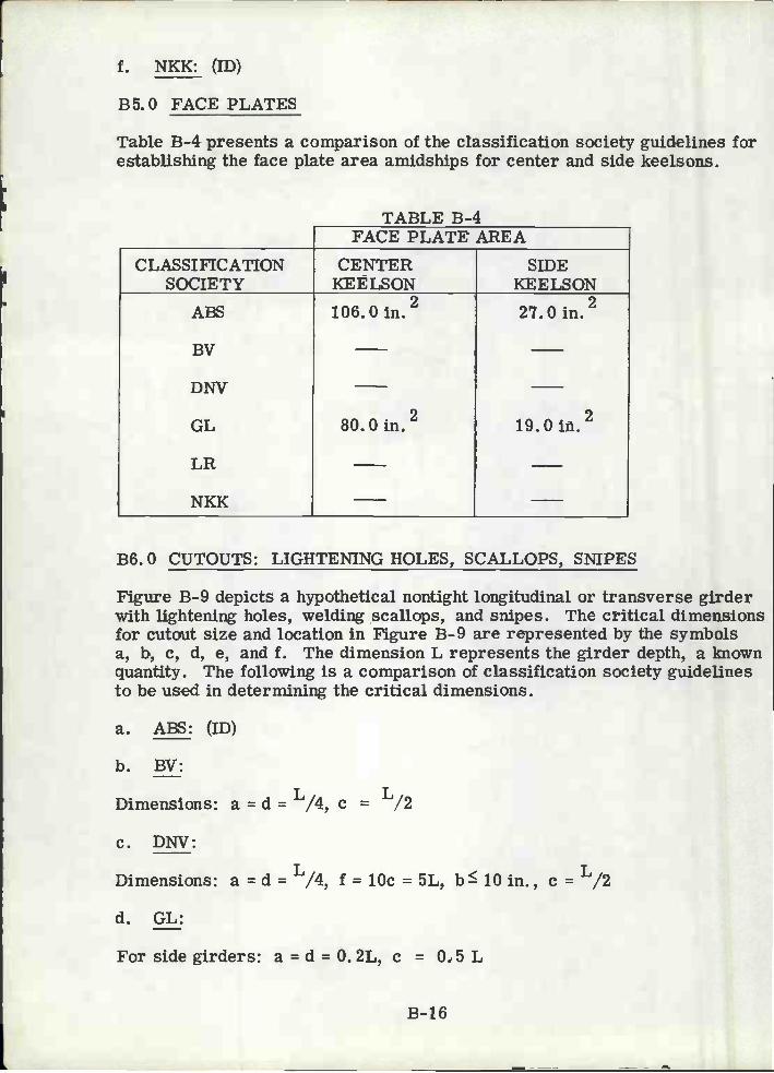
f. NKK: (ID)
B5.O FACE PLATES
Table B-4 presents a comparison of the classification society guidelines forestablishing the face plate area amidships for center and side keelsons.
TABLE B-4
B6. O CUTOUTS: LIGHTENING HOLES, SCALLOPS, SNIPES
Figure B-9 depicts a hypothetical nontight longitudinal or transverse girderwith lightening holes, welding scallops, and snipes. The critical dimensionsfor cutout size and location in Figure B-9 are represented by the symbolsa, b, c, d, e, and f. The dimension L represents the girder depth, a knownquantity. The following is a comparison of classification society guidelinesto be used in determining the critical dimensions.
ABS: (ID)
BV:
Dimensions: a = d = /4, e /2
e. DNV:
Dimensions: a = dL/4 f = 10e = 5L, b lOin., e
d. GL:
For side girders: a = d = O. 2L, e = 0. 5 L
B-16
FACE PLATE AREA
CLASSIFICATIONSOCIETY
CENTERKEELSON
SIDEKEELSON
ABS
BV
DNV
GL
LR
NKK
1O6.Oin.2 27.Oin.,2
80.Oin.2 19.0 in.,2

Y(T
B-17
FIG. B-9: MISCELLANEOUS CUTOUTS IN A NON-TIGHT
LONGITUDINAL GIRDER
i
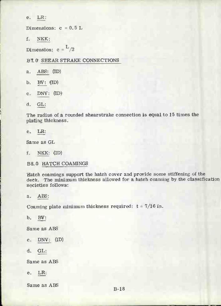
LR:
Dimensions: c = 0. 5 L
NKK:
Dimension: c L,3
B7. O SHEAR STRAKE CONNECTIONS
ABS: (ID)
BV: (ID)
DNV: (ID)
GL:
The radius of a rounded shearstrake connection is equal to 15 times theplating thickness.
LR:
Same as GL
NKK: (ID)
B8.O HATCH COAIVIINGS
Hatch coamings support the hatch cover and provide some stiffening of thedeck. The minimum thickness allowed for a hatch coaming by the classificationsocieties follows:
ABS:
Coaming plate minimum thickness required: t = 7/16 in.
BV:
Same as ABS
DNV: (ID)
GL:
Same as ABS
LR:
Same as ABSB-18

f. NKK:
Same as ABS.
B9.O STIFFENER ENDINGS
The following section presents Rule calculations that determine the requiredsection moduli based on the end connection. These calculations whereperformed assuming a watertight bulkhead with a stiffener spacing of 30",stiffener length = 10' and a head of 50'. Various end conditions have beeninvestigated and the results are recorded below.
ABS:
L = 1O'-O"H = 50'-O"s = 30"
Required section modulii:
Case a: efficient brackets at both ends. Sm=0. 0041 (0. 3)(50)(2. 5)(10)2= 15.4 in.3
Case b: bracket at one end, clip connection at the other end.Sm = 0.0041(0.43)(50)(2.5)(10)2 = 22.0 in.3
Case c: clip connections at each end: Sm=0.0041(0.56)(50)(2.5)(10)2= 28.7 in.3
Case d: no end connections: Sm=0. 0041(0. 6)(50)(2. 5)(10)2 = 30 75 in.
BV: (ID)
DNV: (ID)
CL:
Required Section Modulii: Sm=kC5 ahi3 cm3
Case a: Restrained: Cs=2. 60 Sm=1(2. 6)(. 76)(15. 2)(3. 05)2 = 17.1 in.3
Case c: Simply supported: Cs=3.50 Sm=1(3.5)(0.76)(152)(3.O5)2= 23.0 in.3
LR: (ID)
B-19

f. NKK:
2 3Required Section Modulii: Sm=ChsL cm
Case a: efficient bracket at both ends. Sm=2. 8(15. 2)(0. 76)(3. 05)2
= 18.43 in.3
Case b: bracket at one end and clip at the other end.Sm=4.4(15.2)(O. 76)(3. 05)2 = 29.0 in.3
Case C: no end connections: Sm= 5.5(15. 2)(0. 76)(3. 05)2 =
36.25 in.3
B-20

Appendix C
GLOSSARY
ABM: (AUTOMATIC BURNING MACHINE): - a multi-headed burningmachine, controlled by a punched tape.
ACCESS HOLES: - holes cut in the ship's structure to permit enteringor leaving various compartments.
AIR HOLES: - cuts provided in the upper part of floor plates and longitudinalsin double bottom structure so that when the water in the tank rises abovethe lightening holes, the air contained in the tank may still have amplemeans to escape.
AVA: (AUTOMATIC VERTICAL ARC) WELDING MACHINE: - an automaticwelding machine which is used to weld vertical erection butts with aconsummable copper shoe.
BEAM, DECK: - a transverse or longitudinal structural member, usuallya shallow rolled shape, supporting a deck or flat.
BEAM KNEE: - connections used in tying beams or girders to frames, makingthe ship more rigid at deck corners, and reinforcing the frames.
BILGE STRAKE: - course of shell plates at the turn of the bilge.
BRACKET, BEAM: - plate, flanged or unflanged, used to rigidly connectdeck beams, bulkhead stiffeners and secondary members to frames.By ABS Rules beam brackets must extend onto the stiffener for a distanceequal to one -eighth of the length of the stiffener.
BRACKET, KNEE: - flanged plates used to rigidly connect deep transverseand longitudinal girders to side frames. Use of knee brackets on deeptransverses allows for a reduction in span of the girder0
CASDOS: (COMPUTER-AIDED STRUCTURAL DETAILING SYSTEM): - Acomputer program developed for the U. S. Navy that produces instructionswhich are used for constructing the ship, material ordering and weightcontrol, plate fabrication, stiffener fabrication and assembly.
CHOCK: - a small piece of plate used primarily to backup load carryingmembers. The chock can be a filler plate in a load path and can alsobe used to provide flange stability.
CLIP: - a short length of angle or plate to attach webs of beams and stiffenersto plating or to other beams and stiffeners.
C-1

COAMING: - the vertical plating bounding a hatch, hatchway, orother opening for the purpose of stiffening the edge of the opening.
COFFERDAM: - the narrow void space between two tight bulkheads.
COLLAR (TIGHT OR NONTIGHT): - welded plate used to close aframe or beam penetration thrc*ìgh plating and webs of structuralmembers. Collars are used to insure tightness, replace cutoutmaterial, and/or provide flange stability.
DEEP TANKS: - tanks extending from the bottom or inner bottomup to or higher than the lowest deck.
DOUBLE BOTTOM: - compartments at the bottom of the shipbetween the inner bottom and the shell plating, used for ballastor fresh water, fuel oil, etc.
DOUBLER PLATE: - a plate fitted outside or inside of and fayingagainst another to give additional local strength or stiffness.
FRAME: - the closely spaced transverse stiffening members ofthe shell plating.
GIRDER: - a continuous member, usually running fore and aftunder a deck for the purpose of supporting deck beams andplating. Also the vertical fore and aft plate members on thebottom of single or double bottom ships.
HATCH: - openings in the deck for the passage of cargo, etc,
HATCHWAY: - opening in a deck through which passes a stairwayor an inclined ladder.
HEADER: - member added for local strength which is not parallelto main strength members of the vessel. Headers are used toprovide stiffening to large panels, replace area removed bystructural cuts, and to transfer load to main members.
INNERBOTTOM: - plating forming the upper surface of the doublebottom, also called the tank top.
INTERCOSTAL: - noncontinuous structural member between frames,floors or beams.
C-2
LIGHTENING HOLES: - holes cut in structural members forreducing weight.
LIMBER HOLE: - small hole or slot in a frame or plate for thepurpose of preventing water or oil from collecting; a drain hole.
LINER: - a flat or tapered strip of steel placed under a plate orshape to bring the member in line with another which it overlaps;a filler.
LONGITUDINALS: - fore and aft structural shape or plate membersattached to the underside of decks and flats, to the inner bottom orto shell plating.
MANHOLES: - holes, round or oval, cut in decks, tanks, etc. forthe purpose of providing access.
OILSTOP: - rathole modified by wrapping the weld around the plateedge. Located in continuous members on both sides of a tightboundary to prevent liquid from passing out of a tank by way of theroot gap in the member.
PILLAR: - vertical member or column giving support to deckgirders, flat or similar structure.
RATHOLE: - clearance cuts in continuous members for butt weldsin adjacent shell and deck plating.
REEVING SLOT: - clearance cut for continuous member passingthrough a bulkhead or deep girder where the penetrated memberis welded to the continuous members, thus eliminating collarplates.
SCALLOPS: - clearance cuts for members or welds passing throughbulkheads, decks, etc. (foreign usage).
SEA CHEST: - compartment through which sea water is admitted ordischarged.
SHEER STRAKE: - the top full course of side shell plating.
SIDE SCUTTLES: - openings in the side shell for the overboarddischarge of water.
SNIPES: - small cuts made in the web of intercostal members atthe junction of intercostal and continuous members and plating toclear the weld of the continuous member.
C-3

STANCHION: - see pillars.
STIFFENERS: - sections or shapes used for increasing the rigidityof plating, such as bulkhead plating.
STRINGERS: - fore and aft girders running along the side of theship at the shell.
TRIPPING BRACKETS: - flat bars, chocks or brackets placedalong the compression flange of girders, stiffeners or beams asreinforcement to prevent their free flanges from tripping.
C-4
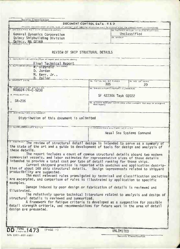
I
D DFORMNOV65
(PAGE 1)UNLIMITED
DOCUMENT CONTROL DATA - R & DSecurity cias sities (lorI of title. (v'de uf abstrae t arid ,ttdeotu1r i,lnOtatjr,n must lic e (cred when (Ile overall report is classified)
t O GINATINC ACTIVITY author)
General Dynamics CorporationQuincy Shipbuilding DivisionQuincy. MA O216
24. REPORT SECURITY CLASSIFICAFtON
Unclassified2b GROUP
3. REPORT TITLE
REVIEW OF SHIP STRUCTURAL DETAILS
4 DESCRIPTIVE NOTES (Type of report and inclusive dates)
Final Technical Report5 AU THORISI (First Te.tf ittftëPf Id). last name)
D. JordanNl. Kerr, Jr.,D. 7nller
6. REPORT DATE ?4. TOTAL NO OF PAGES
305t/r rio OF REFS
20Sa, CONTRACT OR GRANT ViO
N00024-74-C-5230
ti, PR3JET NO.
e. - i
d.
94. ORIGINATORS PERORT NUMBER/SI
SF 422306 Task 02022
9h. O TRER REPOR T riO/Sl (Any other numbers that may hr assignedthis report)
IS. DISTRIBUTION STATEMENT
Distribution of this document is unlimited
II SUPPLEMENTARY NOTES t2 SPONSORING MILITARY ACTVTs
Naval Sea Systems Command
3 AGSTRACTThe review of structural detail design is intended to serve as a summary of
the state of the art and a guide to development of tools for design and analysis ofthese details.
The report includes a count of common structural details aboard two moderncommercial vessels, and labor estimates for representative sizes of those detailsintended to provide a total cost per type of detail ranking for those ships.
Current shipyard practice is reported with sketches and application descrip-tion of about 160 ship structural details. Design improvements related to shipyardproducibility are suggested.
The most relevant rules promulgated by technical and classification societiesare excerpted, and comparison of rules is illustrated by application to specificexamples.
Damage induced by poor design or fabrication of details is reviewed andillustrated.
The relatively sparse technical literature related to analysis and design ofstructural details is reviewed and summarized.
A framework for fatigue criteria is developed as a suggestion for possibledetail strength criteria, and recommendations for future work in the area of detaildesign are presented.
S/N OlOt-807-6a01 Security Classification
Security CIassific ti

UNCLASSIFIEDSecurity Classification
D DFORM 1473 (BACK)
I NOV 65 I UNCLASSIFTFfl
4OCY WORDS
LINK A LINK B LINK CROLE WT ROLE WT ROLE WY
s
(PAGE 2) Security Classification

Syt
ubal
Who
, You
Keo
wM
ultr
0ly
byT
. Fin
dS
y.b.
I
LEN
GT
H-:
-in
inch
es2.
5ce
ntim
eter
s-:
fife
o!30
cenr
inie
ters
cri,
-ayd
yard
s0.
9rr
neio
,sm
mr
trum
,1.
6ki
ljurr
elor
ska
n
AR
EA
ri2sq
uare
inch
.,6.
5sq
uare
cen
hrrn
etnr
ecm
2t!2
squa
re fe
el0.
09sq
uare
mot
ors
at2
0d2
squa
re y
ards
0.8
squa
re m
ejor
arn
2in
ri2sq
uare
mile
s2.
6sq
uare
krlo
rnet
ors
km2
acre
s0.
4he
ctar
esha
MA
SS
(w
eigh
t)
* t
in2.
54 e
.act
iu i.
Fur
ulC
er e
Si.r
cou
u.rr
s,u,
*n a
mi m
ure
dnra
ind
aSie
n.un
e N
OS
Mis
c. P
uOi.
206.
Uni
ts u
t neu
em a
ol M
easu
res.
Puc
e 12
.255
0 C
arai
cu N
u. C
I3.iO
200
.
ME
TR
IC C
ON
VE
RS
ION
FA
CT
OR
S Sym
bol
Whi
n Y
a. fl
now
Mal
tiply
by
To
Fle
dS
ymbo
l
LEN
GT
H
inn
mill
imet
ers
0.04
undi
eSin
cmce
ntirr
mro
rs0.
4in
ches
innr
met
ers
3,3
feet
ltnr
mel
ons
1.1
yard
sed
kmkr
luyn
ntyr
s0.
6m
rtns
mr
AR
EA
cm2
squa
re c
eiifi
inrn
tors
0,16
squa
re in
ches
siju
aro
mot
ors
1.2
squa
re y
ards
yd2
,km
2sq
uare
kilc
nn,e
re.s
0.4
squa
re m
ila,
mi2
halin
dare
s 10
.000
ni2
)2.
5ac
res
MA
SS
(w
elgf
ft)
ggr
ams
0.03
5nu
eces
oc-
kgki
logr
ams
2.2
ponn
ilslb
tfo
nces
100
0 kg
)1.
1oh
uir
ou,
VO
U M
E
ml
mill
ilito
rs00
3flu
id O
ando
sflo
tm
Ilit
ers
2.1
pint
spl
flit
ers
1.06
quar
tsrI
tI
liter
s0.
26ga
llOns
got
en3
cubi
c m
eler
o35
cubo
h le
ntft3
at3
cubi
c m
eter
s1.
3cu
bic
paid
syd
3
TE
MP
ER
AT
UR
E (
exac
t)
er32
986
212
t.-4
00
4000
2016
020
0rr
fitu,
g-4
0-2
00
2040
60eo
100
un0c
17
eaou
nces
28gr
ains
poun
ds0.
45ki
lorjn
arrr
skg
shor
r lo
cO0.
9to
nnes
2000
IbI
VO
LUM
E
tsp
toas
poot
raS
rrrr
llrlrl
ers
rol
Tbs
pta
bles
poon
s15
milm
ilire
rsnl
)il
niflu
id m
rncs
s30
mill
ilite
rsm
lcu
ps0.
24lit
ers
Pt
piol
s0.
47lit
ers
qlqu
arts
0.95
hors
gal
gallo
ns3.
8lit
ers
fft
cubi
C fo
ot0.
03cu
bic
chen
ets
in3
y43
cubi
c ya
rds
0.76
cubi
c m
oler
onr
3
TE
MP
ER
AT
UR
E (
axac
l
Fah
renl
roir
59 a
ltee
Cel
siuS
tuni
pora
rure
subr
racf
isg
tem
pera
ta,,
32)
Cel
sius
9,i5
thon
Fak
nenh
oit
lerr
ipon
a lu
iread
d 32
)te
rnup
enat
uri,
App
roxi
mat
e C
onve
rsio
ni to
Met
ric M
acsu
nsA
ppro
xim
ate
Con
vers
ions
from
Met
ric M
easu
res