Rocket Science 101: Engineering and Propulsion - American ...
Upload
khangminh22Category
view
1download
0
Citation: Zhou, Y.; Dai, L.; Jiao, N.
Review of Bubble Applications in
Microrobotics: Propulsion,
Manipulation, and Assembly.
Micromachines 2022, 13, 1068.
https://doi.org/10.3390/
mi13071068
Academic Editors: Ran Peng and
Shuailong Zhang
Received: 7 June 2022
Accepted: 1 July 2022
Published: 4 July 2022
Publisher’s Note: MDPI stays neutral
with regard to jurisdictional claims in
published maps and institutional affil-
iations.
Copyright: © 2022 by the authors.
Licensee MDPI, Basel, Switzerland.
This article is an open access article
distributed under the terms and
conditions of the Creative Commons
Attribution (CC BY) license (https://
creativecommons.org/licenses/by/
4.0/).
micromachines
Review
Review of Bubble Applications in Microrobotics: Propulsion,Manipulation, and AssemblyYuting Zhou 1,2,3, Liguo Dai 4 and Niandong Jiao 1,2,*
1 State Key Laboratory of Robotics, Shenyang Institute of Automation, Chinese Academy of Sciences,Shenyang 110016, China; [email protected]
2 Institutes for Robotics and Intelligent Manufacturing, Chinese Academy of Sciences, Shenyang 110016, China3 University of Chinese Academy of Sciences, Beijing 100049, China4 College of Mechanical and Electrical Engineering, Zhengzhou University of Light Industry,
Zhengzhou 450002, China; [email protected]* Correspondence: [email protected]
Abstract: In recent years, microbubbles have been widely used in the field of microrobots due totheir unique properties. Microbubbles can be easily produced and used as power sources or tools ofmicrorobots, and the bubbles can even serve as microrobots themselves. As a power source, bubblescan propel microrobots to swim in liquid under low-Reynolds-number conditions. As a manipulationtool, microbubbles can act as the micromanipulators of microrobots, allowing them to operate uponparticles, cells, and organisms. As a microrobot, microbubbles can operate and assemble complexmicroparts in two- or three-dimensional spaces. This review provides a comprehensive overview ofbubble applications in microrobotics including propulsion, micromanipulation, and microassembly.First, we introduce the diverse bubble generation and control methods. Then, we review and discusshow bubbles can play a role in microrobotics via three functions: propulsion, manipulation, andassembly. Finally, by highlighting the advantages and current challenges of this progress, we discussthe prospects of microbubbles in microrobotics.
Keywords: microbubbles; microrobots; micromanipulation; microassembly
1. Introduction
Bubbles are attractive, magical, multifunctional, and ubiquitous in industrial produc-tion and our daily life. They have a variety of physical properties including large specificsurface area, low density, and surface hydrophobicity. Applications based on bubbleshave received extensive attention and research in recent decades [1,2]. Depending ontheir sizes, bubbles can be categorized into macrobubbles, microbubbles, and nanobub-bles. Macrobubbles are 2–5 mm in diameter. At the microscopic scale, bubbles can beclassified into microbubbles (diameters of 1–100 µm) and nanobubbles (diameters be-low 1 µm) [3]. Following the development of microfluidics and microrobotics in recentyears, micro/nanoscale bubbles have been seen as an emerging tool for solving numerouschallenges in various lab-on-a-chip (LOC) applications, and they are gaining increasingattention from researchers.
In the micro/nano research field, bubble-based applications have attracted increasingattention because of their simplicity, controllability, and biocompatibility. They can beflexibly integrated with different microfluidic devices or microrobots. For example, in mi-crofluidics, bubbles can be remotely excited by an acoustic field to act as micromixers [4,5],micropumps [6,7], or microvalves [8,9], and they can operate upon particles and cells [10,11].In addition, in microrobotics, bubbles can act as the manipulating or transmission com-ponents of microrobots [12,13], and the bubbles themselves can act as microrobots [14].However, the bubble generation methods and their applications in the microrobotics field
Micromachines 2022, 13, 1068. https://doi.org/10.3390/mi13071068 https://www.mdpi.com/journal/micromachines

Micromachines 2022, 13, 1068 2 of 31
(e.g., propulsion, micromanipulation, and microassembly) have not been classified andsummarized in detail.
In this review, we introduce and discuss the propulsion, manipulation, and assemblycapabilities of bubbles in microrobotics. We demonstrate the importance, flexibility, andversatility of bubbles, as described in typical research papers. A schematic diagram of thegeneration and control methods of bubbles and their roles in microrobotics is shown inFigure 1. In Section 2, we introduce the methods of bubble generation (chemical reaction,direct acquisition, and optothermal effect) and control (acoustic oscillation, optothermaleffect, and electrowetting-on-dielectric (EWOD) technology). In Section 3, we discuss howbubbles can be used as propulsion mechanisms for microrobots (e.g., tubular micromo-tors, Janus particles, and self-propelled micromachines). In Section 4, we demonstratehow bubbles act as the tools of microrobots and can be used for micromanipulation ortransmission. In Section 5, we introduce bubbles as microrobots to achieve micromanip-ulation and microassembly in two-dimensional (2D) and three-dimensional (3D) spaces.Finally, we summarize the current limitations of bubbles in microrobotics and discussfuture developments.
Micromachines 2022, 13, x FOR PEER REVIEW 2 of 31
[14]. However, the bubble generation methods and their applications in the microrobotics field (e.g., propulsion, micromanipulation, and microassembly) have not been classified and summarized in detail.
In this review, we introduce and discuss the propulsion, manipulation, and assembly capabilities of bubbles in microrobotics. We demonstrate the importance, flexibility, and versatility of bubbles, as described in typical research papers. A schematic diagram of the generation and control methods of bubbles and their roles in microrobotics is shown in Figure 1. In Section 2, we introduce the methods of bubble generation (chemical reaction, direct acquisition, and optothermal effect) and control (acoustic oscillation, optothermal effect, and electrowetting-on-dielectric (EWOD) technology). In Section 3, we discuss how bubbles can be used as propulsion mechanisms for microrobots (e.g., tubular micromo-tors, Janus particles, and self-propelled micromachines). In Section 4, we demonstrate how bubbles act as the tools of microrobots and can be used for micromanipulation or transmission. In Section 5, we introduce bubbles as microrobots to achieve micromanipu-lation and microassembly in two-dimensional (2D) and three-dimensional (3D) spaces. Finally, we summarize the current limitations of bubbles in microrobotics and discuss fu-ture developments.
Figure 1. The generation and control methods of the bubbles and their roles in microrobotics.
2. Generation and Control of Bubbles There are many methods to produce and control bubbles. In this section, we review
several of them. The bubble generation methods include chemical reactions, direct acqui-sition, and the optothermal effect. Bubble control methods include acoustic oscillation, optothermal effect, and EWOD technology. These methods can be effectively combined to develop diverse applications based on bubbles. For example, the direct acquisition of air to generate bubbles can be combined with acoustic oscillation to fabricate microswim-
Figure 1. The generation and control methods of the bubbles and their roles in microrobotics.
2. Generation and Control of Bubbles
There are many methods to produce and control bubbles. In this section, we reviewseveral of them. The bubble generation methods include chemical reactions, direct acqui-sition, and the optothermal effect. Bubble control methods include acoustic oscillation,optothermal effect, and EWOD technology. These methods can be effectively combined todevelop diverse applications based on bubbles. For example, the direct acquisition of air togenerate bubbles can be combined with acoustic oscillation to fabricate microswimmers via
Micromachines 2022, 13, 1068 3 of 31
facile production processes; these offer good propulsion performances. The combinationof EWOD technology and acoustic excitation can realize the movement and operationalabilities of bubble microrobots.
2.1. Chemical Reaction
Here, the principle of bubble formation via chemical reactions and its applicationin self-propelled microrobots are introduced. Many chemical reactions produce gas; fur-thermore, when the chemical reaction occurs in a liquid environment, gas agglomeratescan form gas bubbles. Among the bubble-generating chemical reactions, three types areeffective and widely applied: the decomposition of hydrogen peroxide (H2O2), water (H2O)electrolysis, and metal oxidation. For example, H2O2 decomposition generates oxygen (O2)to form bubbles via
H2O2catalyst→ H2O + O2 ↑ . (1)
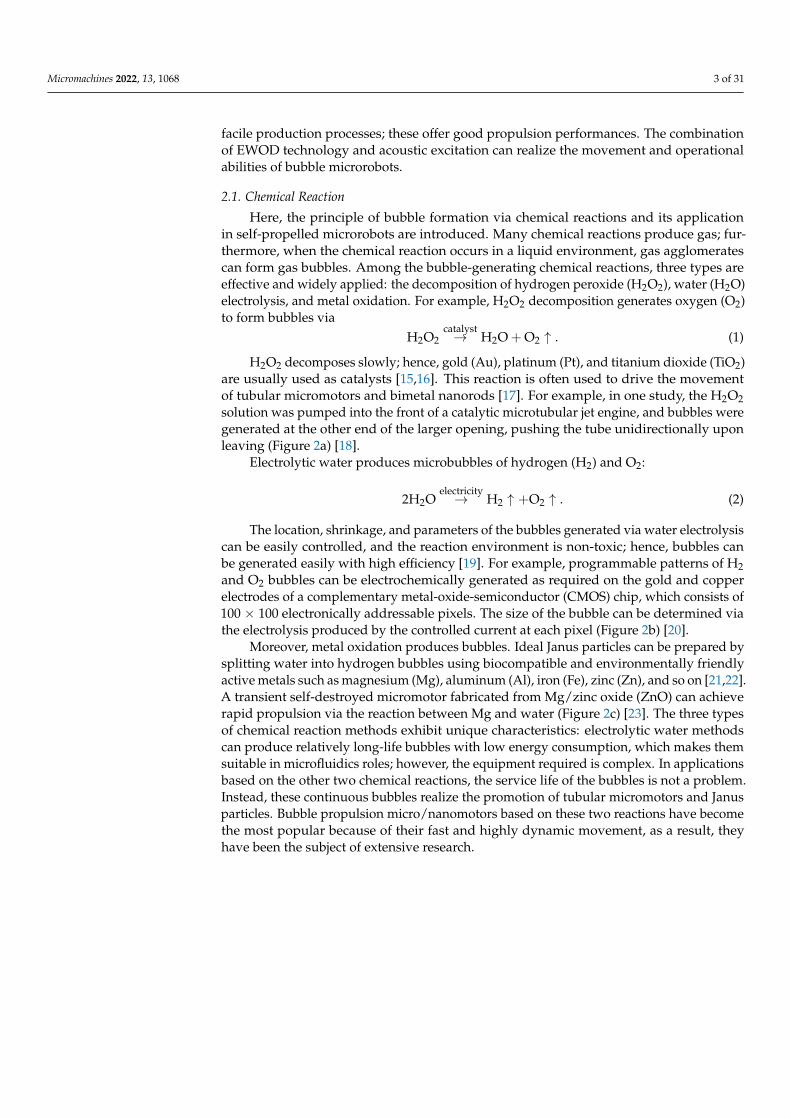
H2O2 decomposes slowly; hence, gold (Au), platinum (Pt), and titanium dioxide (TiO2)are usually used as catalysts [15,16]. This reaction is often used to drive the movementof tubular micromotors and bimetal nanorods [17]. For example, in one study, the H2O2solution was pumped into the front of a catalytic microtubular jet engine, and bubbles weregenerated at the other end of the larger opening, pushing the tube unidirectionally uponleaving (Figure 2a) [18].
Electrolytic water produces microbubbles of hydrogen (H2) and O2:
2H2Oelectricity→ H2 ↑ +O2 ↑ . (2)
The location, shrinkage, and parameters of the bubbles generated via water electrolysiscan be easily controlled, and the reaction environment is non-toxic; hence, bubbles canbe generated easily with high efficiency [19]. For example, programmable patterns of H2and O2 bubbles can be electrochemically generated as required on the gold and copperelectrodes of a complementary metal-oxide-semiconductor (CMOS) chip, which consists of100 × 100 electronically addressable pixels. The size of the bubble can be determined viathe electrolysis produced by the controlled current at each pixel (Figure 2b) [20].
Moreover, metal oxidation produces bubbles. Ideal Janus particles can be prepared bysplitting water into hydrogen bubbles using biocompatible and environmentally friendlyactive metals such as magnesium (Mg), aluminum (Al), iron (Fe), zinc (Zn), and so on [21,22].A transient self-destroyed micromotor fabricated from Mg/zinc oxide (ZnO) can achieverapid propulsion via the reaction between Mg and water (Figure 2c) [23]. The three typesof chemical reaction methods exhibit unique characteristics: electrolytic water methodscan produce relatively long-life bubbles with low energy consumption, which makes themsuitable in microfluidics roles; however, the equipment required is complex. In applicationsbased on the other two chemical reactions, the service life of the bubbles is not a problem.Instead, these continuous bubbles realize the promotion of tubular micromotors and Janusparticles. Bubble propulsion micro/nanomotors based on these two reactions have becomethe most popular because of their fast and highly dynamic movement, as a result, theyhave been the subject of extensive research.
Micromachines 2022, 13, 1068 4 of 31Micromachines 2022, 13, x FOR PEER REVIEW 4 of 31
Figure 2. (a) Actuation of the tubular micromotor via bubbles generated from the H2O2 reaction. Adapted from Solovev et al. [18] with permission from John Wiley and Sons, Copyright 2009. (b) The electrochemical generation of programmable on-demand H2 and O2 bubbles at the gold and copper electrodes. Adapted from Ma et al. [20] with permission under the terms of the CC BY 4.0 License, Copyright 2020. (c) Janus micromotor propelled by bubbles generated via the chemical re-action of Mg with water. Adapted from Chen et al. [23] with permission from the American Chem-ical Society, Copyright 2016.
2.2. Direct Acquisition The direct acquisition method uses the incompatibility of air (or other gases) with
liquids to form bubbles directly [24]. These methods can be divided into active and passive methods. The active method, also known as the injection method, involves injecting an appropriate amount of nitrogen into the liquid of a microfluidic device to generate bub-bles directly therein (Figure 3a) [25]. Passive trapping involves the use of hydrophobic materials to trap bubbles. Multiphase fluid systems tend to minimize their total surface energy, and higher contact angles and lower wettability are conducive to air trapping [26]. Therefore, hydrophobic surfaces can be used to capture bubbles floating nearby with rel-atively low surface tension [27], and realize controlled and directional bubble transport [28,29]. When grooves or other cavity structures are present inside the micropipe, air will be trapped because of the surface tension after water or other liquids are poured into the pipe and forced to become bubbles [30–32]. In addition, the hydrophobicity of the material facilitates the formation of bubbles in the cavity after a semi-enclosed cavity structure is placed in water (Figure 3b) [33,34]. Active and passive methods have their own ad-vantages and disadvantages, respectively. The injection method can flexibly control the generation position and sizes of the bubbles as needed. However, due to the influence of manual control and environmental variables, it is difficult to obtain batch bubbles of the same size. The passive method can quickly and conveniently produce a large number of bubbles with specifications corresponding to the shape and size of the cavity. In general, direct acquisition represents a simple and low-cost bubble generation method.
Figure 2. (a) Actuation of the tubular micromotor via bubbles generated from the H2O2 reaction.Adapted from Solovev et al. [18] with permission from John Wiley and Sons, Copyright 2009. (b) Theelectrochemical generation of programmable on-demand H2 and O2 bubbles at the gold and copperelectrodes. Adapted from Ma et al. [20] with permission under the terms of the CC BY 4.0 License,Copyright 2020. (c) Janus micromotor propelled by bubbles generated via the chemical reaction ofMg with water. Adapted from Chen et al. [23] with permission from the American Chemical Society,Copyright 2016.
2.2. Direct Acquisition
The direct acquisition method uses the incompatibility of air (or other gases) withliquids to form bubbles directly [24]. These methods can be divided into active and passivemethods. The active method, also known as the injection method, involves injecting anappropriate amount of nitrogen into the liquid of a microfluidic device to generate bubblesdirectly therein (Figure 3a) [25]. Passive trapping involves the use of hydrophobic materialsto trap bubbles. Multiphase fluid systems tend to minimize their total surface energy, andhigher contact angles and lower wettability are conducive to air trapping [26]. Therefore,hydrophobic surfaces can be used to capture bubbles floating nearby with relatively lowsurface tension [27], and realize controlled and directional bubble transport [28,29]. Whengrooves or other cavity structures are present inside the micropipe, air will be trappedbecause of the surface tension after water or other liquids are poured into the pipe andforced to become bubbles [30–32]. In addition, the hydrophobicity of the material facilitatesthe formation of bubbles in the cavity after a semi-enclosed cavity structure is placed inwater (Figure 3b) [33,34]. Active and passive methods have their own advantages anddisadvantages, respectively. The injection method can flexibly control the generationposition and sizes of the bubbles as needed. However, due to the influence of manualcontrol and environmental variables, it is difficult to obtain batch bubbles of the same size.The passive method can quickly and conveniently produce a large number of bubbleswith specifications corresponding to the shape and size of the cavity. In general, directacquisition represents a simple and low-cost bubble generation method.

Micromachines 2022, 13, 1068 5 of 31Micromachines 2022, 13, x FOR PEER REVIEW 5 of 31
Figure 3. Bubbles generated via the direct acquisition method. (a) Bubbles generated by injecting nitrogen into the microfluidic device. Adapted from Orbay et al. [25] with permission from the In-stitute of Physics Publishing, Copyright 2017. (b) Air bubble trapped in a hydrophobic microcavity. Adapted from Ren et al. [33] with permission under the terms of the CC-BY-4.0 License, Copyright 2019.
2.3. Optothermal Effect In daily life, air bubbles occur in cold water during heating because the solubility of
air decreases when the temperature increases, and gases originally dissolved in the water are released. This principle can also be used to generate bubbles at the micro/nanoscale levels. Bubbles can be generated and controlled optically via the optothermal effect, which converts light energy into heat energy. Due to the thermal flow, optothermal bubbles have an adsorptive capacity and can be directly used to manipulate micro-objects. The genera-tion and application of optothermal bubbles can be classified into two types: (1) Microbub-bles are generated on the solid surface of heat-absorbing materials, which are often de-scribed as micromanipulation microrobots and are introduced in this subsection. (2) Micro or nanobubbles generated at the interface of the colloidal suspension and at a plasmonic substrate via plasmon-enhanced photothermal effects; this can pattern colloidal particles on substrates, referred to as bubble-pen lithography (BPL). Zheng et al. proved that nano-particles could be written directly onto Ag films using optothermally generated surface bubbles (OGSB), and they realized single particle modes and particle combinations with different resolutions and structures [35]. This technology has attracted extensive attention from scholars in recent years, and the readers are invited to refer to the following refer-ences for more detailed discussions on this topic [36–42].
The optothermal effect is usually used to convert light energy into heat energy, and microbubbles are generated at the interface between heat-absorbing materials (e.g., metal, amorphous silicon, indium tin oxide, or their combination) and liquids [14]. The experi-mental device and movement of the optothermal bubble are shown in Figure 4a. Due to the different types of heat-absorbing materials, the applicable laser wavelength types also differ, primarily including near-infrared and ultraviolet light. The generation and size control of optothermal bubbles are related to the light absorptivity and laser spot density, and the light absorptivity is closely related to the material and thickness of the absorption layer as well as the laser wavelength. Because the irradiation range of the laser after fo-cusing is very small, bubbles can be generated and controlled using the thermal gradient field generated by the heat-absorbing material after light energy absorption. Therefore, the optothermal method can accurately control the generation positions of bubbles; fur-thermore, when the position of the spot changes, the bubbles follow the spot [43].
The laser light exposed onto the endothermic layer (after passing through the optical appendix and focusing objective) is circular with a Gaussian power density distribution, and the input thermal energy 𝑄 across the endothermic layer in unit time is [44,45] 𝑄 = 𝑃𝜂 𝜂2𝜋𝑅 𝑒𝑥𝑝 − 𝑟2𝑅 , (3)
Figure 3. Bubbles generated via the direct acquisition method. (a) Bubbles generated by injecting ni-trogen into the microfluidic device. Adapted from Orbay et al. [25] with permission from the Instituteof Physics Publishing, Copyright 2017. (b) Air bubble trapped in a hydrophobic microcavity. Adaptedfrom Ren et al. [33] with permission under the terms of the CC-BY-4.0 License, Copyright 2019.
2.3. Optothermal Effect
In daily life, air bubbles occur in cold water during heating because the solubility ofair decreases when the temperature increases, and gases originally dissolved in the waterare released. This principle can also be used to generate bubbles at the micro/nanoscalelevels. Bubbles can be generated and controlled optically via the optothermal effect, whichconverts light energy into heat energy. Due to the thermal flow, optothermal bubbles havean adsorptive capacity and can be directly used to manipulate micro-objects. The generationand application of optothermal bubbles can be classified into two types: (1) Microbubblesare generated on the solid surface of heat-absorbing materials, which are often describedas micromanipulation microrobots and are introduced in this subsection. (2) Micro ornanobubbles generated at the interface of the colloidal suspension and at a plasmonicsubstrate via plasmon-enhanced photothermal effects; this can pattern colloidal particleson substrates, referred to as bubble-pen lithography (BPL). Zheng et al. proved thatnanoparticles could be written directly onto Ag films using optothermally generatedsurface bubbles (OGSB), and they realized single particle modes and particle combinationswith different resolutions and structures [35]. This technology has attracted extensiveattention from scholars in recent years, and the readers are invited to refer to the followingreferences for more detailed discussions on this topic [36–42].
The optothermal effect is usually used to convert light energy into heat energy, andmicrobubbles are generated at the interface between heat-absorbing materials (e.g., metal,amorphous silicon, indium tin oxide, or their combination) and liquids [14]. The experi-mental device and movement of the optothermal bubble are shown in Figure 4a. Due to thedifferent types of heat-absorbing materials, the applicable laser wavelength types also differ,primarily including near-infrared and ultraviolet light. The generation and size control ofoptothermal bubbles are related to the light absorptivity and laser spot density, and thelight absorptivity is closely related to the material and thickness of the absorption layer aswell as the laser wavelength. Because the irradiation range of the laser after focusing is verysmall, bubbles can be generated and controlled using the thermal gradient field generatedby the heat-absorbing material after light energy absorption. Therefore, the optothermalmethod can accurately control the generation positions of bubbles; furthermore, when theposition of the spot changes, the bubbles follow the spot [43].

Micromachines 2022, 13, 1068 6 of 31
The laser light exposed onto the endothermic layer (after passing through the opticalappendix and focusing objective) is circular with a Gaussian power density distribution,and the input thermal energy Q across the endothermic layer in unit time is [44,45]
Q =PηAηT
2πR2 exp(− r2
2R2
), (3)
where P is the input power of the laser; R is the radius of the spot; r is the distance fromthe center of the spot; ηA is the laser’s photothermal efficiency; and ηT is its optothermalconversion efficiency. When a laser beam irradiates the chip, the heat-absorbing layerconverts the light energy into heat energy; this is transferred through the chip and intothe water solution. When the laser is temporarily turned off, the temperature decreasesaccordingly. In the fluid and solid regions, the temperature distribution can be determinedusing Fourier’s law [46,47], expressed as:
ρCp∂T∂t
+∇ · (−kT∇T) + ρCpu · ∇T = Q, (4)
where ρ is the density; Cp is the heat capacity; T is the temperature; t is the time; kT is thecoefficient of heat conduction; u is the liquid velocity; and Q is the input power density.Temperature is the main factor affecting the generation of microbubbles. In the fluid andbubble areas, heat transfer causes flow, and the flow velocity can be described by theNavier–Stokes equations [48,49], as:
ρ∂u∂t
+ ρ(u · ∇) = ∇ ·[−pI + µ
(∇u + (∇u)T
)]+ ρg, (5)
ρ∇ · u = 0, (6)
where p is the pressure; I is the identity matrix; u is the viscosity; and g is the gravitationalacceleration. A temperature gradient and convection flow pattern can be formed around theoptothermal bubbles (Figure 4b) [50]. The temperature decreases along the radial directionvia convective cooling along the top and bottom surfaces. This temperature gradient causesa corresponding convective flow that forms a clockwise flow pattern near the bubble–liquidinterface. This microscale circulation is caused by the Marangoni effect [51,52]. The velocityfield between the liquid layers (caused by the thermal Marangoni effect) can be describedas [53]
η
(∂µ
∂n
)= γT
(∂T∂t
), (7)
where η is the dynamic viscosity; µ is the tangential component of the fluid velocity vectorat the liquid–air interface; and n and t are the unit vectors of the normal and tangentialdirections of the interface, respectively. γT = ∂γ/∂T is the derivative of the surface tensionγ with respect to temperature. The Marangoni convection and surface tension of theoptothermal bubble exert forces on the particles suspended in solution to achieve particlemanipulation [54], cell deformations [55], cell perforation, and lysis [56,57]. Optothermalbubbles can be generated and moved flexibly to any position on the surface of a 2Dchip. Their size can be easily controlled, and they can attract and operate micro-objectswithout the assistance of other physical fields. However, the operation and applications ofoptothermal bubbles are limited by the 2D plane. Realizing multiple optothermal bubbleclusters requires complex and expensive equipment; however, the application value mustbe further developed.

Micromachines 2022, 13, 1068 7 of 31Micromachines 2022, 13, x FOR PEER REVIEW 7 of 31
Figure 4. The optothermal effect used to generate and control bubbles. (a) Experimental device and the movement of optothermal bubbles. Adapted from Ohta et al. [14] with permission from AIP Publishing, Copyright 2007. (b) The temperature distribution and convective flow pattern around an optothermally generated bubble. Adapted from Zhao et al. [50] with permission from The Royal Society of Chemistry, Copyright 2014.
2.4. Acoustic Oscillation The bubbles excited by acoustic waves and the bubble-oscillating mechanism used in
operation and propulsion are described in this section. Microbubbles can be used in large-scale propulsion and operation because they resonate under the action of acoustic waves and oscillate the gas–liquid interface, which changes the flow direction and speed of the microfluids. Oscillating bubbles include inertial and non-inertial cavitation [58]. Inertial cavitation occurs when the oscillation amplitude of a bubble is sufficiently high and ex-ceeds a certain threshold; then, the bubble expands and shrinks sharply or even collapses. This reaction can be used in biological applications such as cell sorting and cell lysis [59,60]. Most oscillating bubbles in microfluids are stable, non-inertial cavitated bubbles. Oscillating bubbles have natural frequencies, and when they have the same frequency as the excitation acoustic field, they reach a maximum vibration amplitude [1], expressed as
𝑓 = 12𝜋 1𝜌 3𝜅 𝑃 +2𝜎𝑅 −𝑃 − 2𝜎𝑅 −𝑃 +4𝜇𝜌𝑅 1𝑅 , (8)
where 𝜇 is the dynamic viscosity of the liquid; 𝑅 and 𝑅 are the initial and instantane-ous radii of the bubbles, respectively; 𝑃 is the constant far-field pressure; 𝜎 is the sur-face tension at the gas–liquid interface of the bubble; 𝑃 is the vapor pressure; and 𝜅 is the polytropic index. In addition, the 𝑓 of the bubbles in the tube or microchannel is
𝑓 = 12𝜋 𝜅𝑃𝜌𝐿 𝐿 , (9)
where 𝐿 and 𝐿 are the lengths of the liquid in the tube and the bubble column, respec-tively. Acoustically vibrating bubbles usually exhibit two typical oscillation modes: (1) volumetric or (2) reciprocal along the axis [61,62]. Under the excitation of acoustic waves, the particles close to the bubbles are primarily affected by the acoustic streaming force (estimated by Stokes drag force), that is, the viscous resistance caused by the streamline
Figure 4. The optothermal effect used to generate and control bubbles. (a) Experimental device andthe movement of optothermal bubbles. Adapted from Ohta et al. [14] with permission from AIPPublishing, Copyright 2007. (b) The temperature distribution and convective flow pattern aroundan optothermally generated bubble. Adapted from Zhao et al. [50] with permission from The RoyalSociety of Chemistry, Copyright 2014.
2.4. Acoustic Oscillation
The bubbles excited by acoustic waves and the bubble-oscillating mechanism usedin operation and propulsion are described in this section. Microbubbles can be used inlarge-scale propulsion and operation because they resonate under the action of acousticwaves and oscillate the gas–liquid interface, which changes the flow direction and speedof the microfluids. Oscillating bubbles include inertial and non-inertial cavitation [58].Inertial cavitation occurs when the oscillation amplitude of a bubble is sufficiently highand exceeds a certain threshold; then, the bubble expands and shrinks sharply or evencollapses. This reaction can be used in biological applications such as cell sorting andcell lysis [59,60]. Most oscillating bubbles in microfluids are stable, non-inertial cavitatedbubbles. Oscillating bubbles have natural frequencies, and when they have the samefrequency as the excitation acoustic field, they reach a maximum vibration amplitude [1],expressed as
f0 =1
2π
√1ρ
[3κ
(P0 +
2σ
R− PV
)−(
2σ
R− PV +
4µ2
ρR0
)]1
R0, (8)
where µ is the dynamic viscosity of the liquid; R0 and R are the initial and instantaneousradii of the bubbles, respectively; P0 is the constant far-field pressure; σ is the surfacetension at the gas–liquid interface of the bubble; PV is the vapor pressure; and κ is thepolytropic index. In addition, the f0 of the bubbles in the tube or microchannel is
f0 =1
2π
√κP0
ρL0LB, (9)
Micromachines 2022, 13, 1068 8 of 31
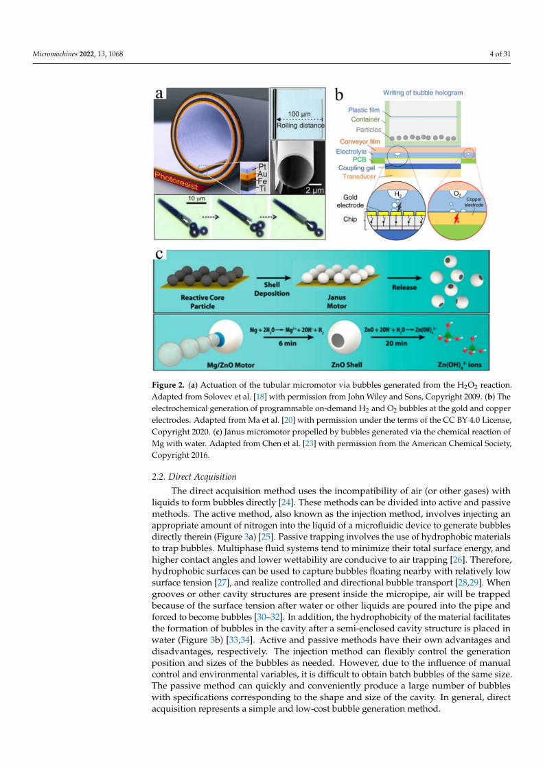
where L0 and LB are the lengths of the liquid in the tube and the bubble column, respectively.Acoustically vibrating bubbles usually exhibit two typical oscillation modes: (1) volumetricor (2) reciprocal along the axis [61,62]. Under the excitation of acoustic waves, the particlesclose to the bubbles are primarily affected by the acoustic streaming force (estimated byStokes drag force), that is, the viscous resistance caused by the streamline direction of themicro flow field, and the secondary acoustic radiation force (also known as the Bjerknesforce) caused by the scattering effect of the bubble on the incident acoustic wave. Thedominant force can be calculated by the ratio of magnitudes [63–65]. Acoustic bubbles cannot only be used to manipulate particles, cells, and other objects but also to manipulatefluid flows within microfluidic devices. For example, Ahmed et al. reported that usingultrasound to oscillate bubbles trapped in a “horse-shoe” structure inside microtubulescould affect fluid flow (Figure 5a) [66]. Under the action of acoustic waves, the contactsurface between the microbubbles and surrounding liquid vibrates, which triggers mi-crostreaming [67,68]. In addition, medical microbubble contrast agents driven by ultrasonicpulse can be used for treatment delivery and monitoring [69].
Micromachines 2022, 13, x FOR PEER REVIEW 8 of 31
direction of the micro flow field, and the secondary acoustic radiation force (also known as the Bjerknes force) caused by the scattering effect of the bubble on the incident acoustic wave. The dominant force can be calculated by the ratio of magnitudes [63–65]. Acoustic bubbles can not only be used to manipulate particles, cells, and other objects but also to manipulate fluid flows within microfluidic devices. For example, Ahmed et al. reported that using ultrasound to oscillate bubbles trapped in a “horse-shoe” structure inside mi-crotubules could affect fluid flow (Figure 5a) [66]. Under the action of acoustic waves, the contact surface between the microbubbles and surrounding liquid vibrates, which triggers microstreaming [67,68]. In addition, medical microbubble contrast agents driven by ultra-sonic pulse can be used for treatment delivery and monitoring [69].
Figure 5. The flow field around oscillating bubbles excited by acoustic waves. (a) Acoustic streaming pattern around a bubble located in the horse-shoe structure of the microfluidic pipe. Adapted from Ahmed et al. [66] with permission from The Royal Society of Chemistry, Copyright 2009. (b) Acous-tic streaming pattern around a bubble located in a tube closed at one end. Adapted from Dijkink et al. [70] with permission from the Institute of Physics Publishing, Copyright 2006.
In addition, Dijkink et al. reported that a semi-closed tube immersed in a liquid can be filled with a certain amount of gas. Under the action of acoustic waves, the gas is alter-nately discharged and pulled into the liquid through the open end of the tube (Figure 5b) [70]. The liquid leaves the pipe as a jet and enters the pipe simultaneously from the entire available stereo angle, forming a net momentum source that can drive this “acoustic scal-lop.” Therefore, the combination of acoustic bubbles with microtubules, microcavities, and various microstructures can generate forces for driving microrobots. In general, acoustic oscillation technology offers the selective excitation of bubbles, a wide range of action, simple equipment, easy implementation, and more.
2.5. Electrowetting-On-Dielectric (EWOD) This section introduces the mechanism of the electrowetting method for bubble con-
trol. EWOD technology can change the contact angle between the droplets and dielectric layer; it can be used to manipulate the generation, transportation, mixing, and splitting of droplets [71,72]. When an electric voltage 𝑉 is applied between the aqueous sessile drop-let and electrode, the droplet spontaneously spreads out on the dielectric surface. The contact angle 𝜃 is modulated by the applied voltage according to the Lippmann–Young equation [73]: cos𝜃 = cos𝜃 + 𝜀𝜀2𝛾 𝑡 𝑉 , (10)
where 𝜃 denotes the permittivity of the vacuum; 𝜀 is the dielectric constant of the die-lectric layer; 𝛾 is the gas-to-liquid interfacial tension; 𝑡 is the thickness of the dielectric layer; 𝑉 is the electric potential; and 𝜃 is the initial contact angle at 𝑉 = 0 V.
Similar to droplet operation, Zhao et al. realized bubble transportation in any direc-tion on a 2D surface using the EWOD principle [73]. The position of the bubble was con-trolled by the switching state of the electrodes underneath the hydrophobic dielectric
Figure 5. The flow field around oscillating bubbles excited by acoustic waves. (a) Acoustic streamingpattern around a bubble located in the horse-shoe structure of the microfluidic pipe. Adaptedfrom Ahmed et al. [66] with permission from The Royal Society of Chemistry, Copyright 2009.(b) Acoustic streaming pattern around a bubble located in a tube closed at one end. Adapted fromDijkink et al. [70] with permission from the Institute of Physics Publishing, Copyright 2006.
In addition, Dijkink et al. reported that a semi-closed tube immersed in a liquidcan be filled with a certain amount of gas. Under the action of acoustic waves, the gasis alternately discharged and pulled into the liquid through the open end of the tube(Figure 5b) [70]. The liquid leaves the pipe as a jet and enters the pipe simultaneouslyfrom the entire available stereo angle, forming a net momentum source that can drivethis “acoustic scallop.” Therefore, the combination of acoustic bubbles with microtubules,microcavities, and various microstructures can generate forces for driving microrobots. Ingeneral, acoustic oscillation technology offers the selective excitation of bubbles, a widerange of action, simple equipment, easy implementation, and more.
2.5. Electrowetting-On-Dielectric (EWOD)
This section introduces the mechanism of the electrowetting method for bubble con-trol. EWOD technology can change the contact angle between the droplets and dielectriclayer; it can be used to manipulate the generation, transportation, mixing, and splittingof droplets [71,72]. When an electric voltage V is applied between the aqueous sessiledroplet and electrode, the droplet spontaneously spreads out on the dielectric surface. Thecontact angle θ is modulated by the applied voltage according to the Lippmann–Youngequation [73]:
cos θ = cos θ0 +εε0
2γ1gtV2, (10)
Micromachines 2022, 13, 1068 9 of 31
where θ0 denotes the permittivity of the vacuum; ε is the dielectric constant of the dielectriclayer; γ1g is the gas-to-liquid interfacial tension; t is the thickness of the dielectric layer; Vis the electric potential; and θ0 is the initial contact angle at V = 0 V.
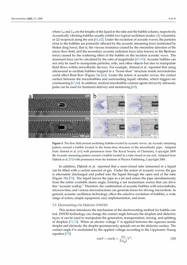
Similar to droplet operation, Zhao et al. realized bubble transportation in any directionon a 2D surface using the EWOD principle [73]. The position of the bubble was controlled bythe switching state of the electrodes underneath the hydrophobic dielectric layer. Activatingthe electrode on the left caused the bubble to move one step to the right. Likewise, thesequential activation of the subsequent electrodes produced continuous motion of thebubble. Subsequently, Chung et al. (of the same research group) combined the EWODtechnology with acoustic oscillation to generate cavitation microstreaming around thebubble, and they realized the capture, transportation, and release of glass microbeads,fish eggs, and Daphnia via the moving bubble (Figure 6) [74,75]. EWOD and acoustic-based microbubbles are effective and noninvasive tools for processing micro-objects. Thelimitation of the EWOD method is that it can only be used to control the bubble’s positionin the 2D plane. Therefore, it must be combined with other technologies (e.g., electrolyticwater) to generate bubbles alongside the acoustic waves to excite the bubbles and strengthenthe control thereof.
Micromachines 2022, 13, x FOR PEER REVIEW 9 of 31
layer. Activating the electrode on the left caused the bubble to move one step to the right. Likewise, the sequential activation of the subsequent electrodes produced continuous mo-tion of the bubble. Subsequently, Chung et al. (of the same research group) combined the EWOD technology with acoustic oscillation to generate cavitation microstreaming around the bubble, and they realized the capture, transportation, and release of glass microbeads, fish eggs, and Daphnia via the moving bubble (Figure 6) [74,75]. EWOD and acoustic-based microbubbles are effective and noninvasive tools for processing micro-objects. The limitation of the EWOD method is that it can only be used to control the bubble’s position in the 2D plane. Therefore, it must be combined with other technologies (e.g., electrolytic water) to generate bubbles alongside the acoustic waves to excite the bubbles and strengthen the control thereof.
Figure 6. Oscillating bubble micromanipulation process driven by EWOD technology and acoustic waves. (a–d) Capturing, carrying, and releasing of objects via an oscillating mobile bubble. Adapted from Chung et al. [74] with permission from the Institute of Physics Publishing, Copyright 2012.
3. Bubbles Serving as Propulsion System Bubbles can form an integral component in microrobots and provide their driving
force. In this section, we review the micro/nanomotors that are propelled by bubbles gen-erated via chemical reactions, and microswimmers propelled by bubbles driven by acous-tic waves. Note that researchers in various fields refer to artificially prepared, cableless, movable, and controllable microstructures differently, using terms such as microrobots, micromotors, micromachines, and microswimmers; these were all classified as micro-robots in this article.
3.1. Propulsion by Catalytic Reaction Generated Bubbles In the past few decades, researchers have developed many different methods to drive
and control micro/nanomotors. The propulsion mechanisms mainly include chemical pro-pulsion (concentration-gradient propulsion, self-electrophoresis propulsion, and bubble-propelled), external-physical-fields driving (light field, magnetic field, and ultrasound), and hybrid propulsion [76–78]. Micro/nanomotors can be controlled by magnetic field, electric field, acoustic field, and other methods [79,80], and they have broad applications in biomedical [81] and water environments [82]. Among these, the micro/nanomotors that use catalytic reactions to produce bubbles and self-propel via the bubble recoil mechanism
Figure 6. Oscillating bubble micromanipulation process driven by EWOD technology and acousticwaves. (a–d) Capturing, carrying, and releasing of objects via an oscillating mobile bubble. Adaptedfrom Chung et al. [74] with permission from the Institute of Physics Publishing, Copyright 2012.
3. Bubbles Serving as Propulsion System
Bubbles can form an integral component in microrobots and provide their driving force.In this section, we review the micro/nanomotors that are propelled by bubbles generatedvia chemical reactions, and microswimmers propelled by bubbles driven by acoustic waves.Note that researchers in various fields refer to artificially prepared, cableless, movable, andcontrollable microstructures differently, using terms such as microrobots, micromotors,micromachines, and microswimmers; these were all classified as microrobots in this article.
3.1. Propulsion by Catalytic Reaction Generated Bubbles
In the past few decades, researchers have developed many different methods to driveand control micro/nanomotors. The propulsion mechanisms mainly include chemical
Micromachines 2022, 13, 1068 10 of 31
propulsion (concentration-gradient propulsion, self-electrophoresis propulsion, and bubble-propelled), external-physical-fields driving (light field, magnetic field, and ultrasound),and hybrid propulsion [76–78]. Micro/nanomotors can be controlled by magnetic field,electric field, acoustic field, and other methods [79,80], and they have broad applications inbiomedical [81] and water environments [82]. Among these, the micro/nanomotors thatuse catalytic reactions to produce bubbles and self-propel via the bubble recoil mechanismrepresent successful cases. This section describes the bubble-based propulsion of hollowtubular micromotors, Janus particles, and micromachines.
3.1.1. Self-Propelled Tubular Micromotors
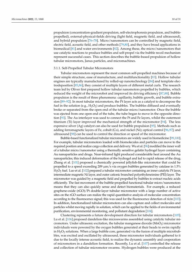
Tubular micromotors represent the most common self-propelled machines because oftheir simple structure, ease of manufacture, and multifunctionality [83]. Hollow tubularengines are typically manufactured by rolled-up nanotechnology [84] and template elec-trodeposition [85,86]; they consist of multiple layers of different metal curls. The researchteam led by Oliver first prepared hollow tubular nanomotors propelled by bubbles, whichreduced the weight of the microrobot and improved its driving efficiency [87,88]. Bubblepropulsion is the result of three phenomena: capillarity, bubble growth, and bubble extru-sion [89–92]. In most tubular micromotors, the Pt layer acts as a catalyst to decompose thefuel in the solution (e.g., H2O2) and produce bubbles. The bubbles diffused and eventuallybroke or separated from the open end of the tubular micro/nanomotor. Once the bubblewas ejected from one open end of the tube, the tube began to move in the opposite direc-tion [93]. The Au interlayer was used to connect the Pt and Fe layers, whilst the outermosttitanium (Ti) layer improved the mechanical strength of the micromotor [94]. The lessexpensive silver (Ag) catalyst can also be used for bubble propulsion [95]. Methods such asadding ferromagnetic layers of Fe, cobalt (Co), and nickel (Ni); optical control [96,97]; andultrasound [98] can be used to control the direction or speed of the micromotor.
Bubble-based functionalized tubular micromotors are widely used in biomedicine [99,100].For example, tubular micromotors loaded with biomolecules and particles can move to therequired position and realize cargo collection and delivery. Wu et al. [96] modified the inner wallof a tubular micro/nanomotor using a thermally sensitive gelatin hydrogel layer containingAu nanoparticles and drugs. Near-infrared light produced considerable heat around the Aunanoparticles; this induced deformation of the hydrogel and led to rapid release of the drug.Zhang et al. [101] proposed a chemically powered jellyfish-like micromotor that could bepropelled to a speed exceeding 209 µm/s via oxygen bubbles generated by catalase in 1.5%H2O2 fuel. Luo et al. [102] prepared a tubular micromotor containing an inner catalytic Pt layer,intermediate magnetic Ni layer, and outer cationic branched polyethyleneimine (PEI) layer. Themicromotor was guided by a magnetic field and propelled by bubbles to extract nucleic acidsefficiently. The fast movement of the bubble-propelled functional tubular micro/nanomotorsmeans that they can also quickly sense and detect biomaterials. For example, a reducedgraphene-oxide (rGO)/Pt double-layer tubular micromotor with a large number of activesites on the rGO surface can realize the rapid quantitative analysis of molecular concentrationaccording to the fluorescence signal; this was used for the fluorescence detection of ricin [103].In addition, functionalized tubular micromotors can also capture and collect molecules andparticles whilst moving rapidly in solution, which can be applied to the fields of environmentalpurification, environmental monitoring, and pollutant degradation [104].
Clustering represents a future development direction for tubular micromotors [105].Lu et al. [106] proposed dandelion-like microswarms assembled using catalytic tubular mi-cromotors. Under ultrasonic excitation, the tubular manganese dioxide (MnO2) micromotorindividuals were powered by the oxygen bubbles generated at their heads to swim rapidlyin H2O2 solutions. When a large bubble core, generated via the fusion of multiple microbub-bles, was excited and oscillated by ultrasound, these micromotor individuals gathered to itdue to the locally intense acoustic field, to realize the dynamic assembly and cooperationof micromotors in a dandelion formation. Recently, Lu et al. [107] controlled the releaseand collection of tubular micromotor swarms. Hydrogen bubbles were produced at the
Micromachines 2022, 13, 1068 11 of 31
tip of the charged electrode. When the bubbles oscillated driven by the acoustic field, theyproduced intensified vortexes, which spontaneously dispersed the tubular micromotorsinto the surrounding environment. By removing the attached bubbles, the sonoelectrodeworked at a higher ultrasonic frequency to collect the micromotors on a large-scale viaacoustic streaming (Figure 7a). Research into the precise control methods for individualsand clusters represents the inevitable development direction of bubble-propelled tubularmicromotors. Meanwhile, developing non-toxic and biodegradable materials to replace thecomponents and fuels of bubble-propelled tubular micromotors also represents a difficultproblem that must be overcome in in vivo applications.
3.1.2. Self-Propelled Janus Particles
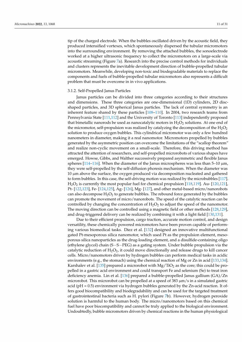
Janus particles can be divided into three categories according to their structuresand dimensions. These three categories are one-dimensional (1D) cylinders, 2D disc-shaped particles, and 3D spherical Janus particles. The lack of central symmetry is aninherent feature shared by these particles [108–110]. In 2004, two research teams fromPennsylvania State [111,112] and the University of Toronto [113] independently proposedthat bimetallic nanorods be used as nanocatalytic motors in H2O2 solutions. At one end ofthe micromotor, self-propulsion was realized by catalyzing the decomposition of the H2O2solution to produce oxygen bubbles. This cylindrical micromotor was only a few hundrednanometers in diameter, making it a real nanomotor. Micromotors propelled by bubblesgenerated by the asymmetric position can overcome the limitations of the “scallop theorem”and realize non-cyclic movement on a small-scale. Therefore, this driving method hasattracted the attention of researchers, and self-propelled microrobots of various shapes haveemerged. Howse, Gibbs, and Walther successively prepared asymmetric and flexible Janusspheres [114–116]. When the diameter of the Janus microspheres was less than 5–10 µm,they were self-propelled by the self-diffusion phoresis mechanism. When the diameter was10 µm above the surface, the oxygen produced via decomposition nucleated and gatheredto form bubbles. In this case, the self-driving motion was realized by the microbubbles [117].H2O2 is currently the most popular fuel for chemical propulsion [118,119]. Au- [120,121],Pt- [122,123], Fe- [124,125], Ag- [126], Mg- [127], and other metal-based micro/nanorobotscan also decompose H2O2 to generate bubbles. The rebound force generated by the bubblescan promote the movement of micro/nanorobots. The speed of the catalytic reaction can becontrolled by changing the concentration of H2O2 to adjust the speed of the nanomotor.The moving direction can be controlled using a magnetic field or other methods [128,129],and drug-triggered delivery can be realized by combining it with a light field [130,131].
Due to their efficient propulsion, cargo traction, accurate motion control, and designversatility, these chemically powered micromotors have been proven capable of perform-ing various biomedical tasks. Diez et al. [132] designed an innovative multifunctionalgated Pt-mesoporous silica nanomotor, which used Pt as the propulsion element, meso-porous silica nanoparticles as the drug-loading element, and a disulfide-containing oligo(ethylene glycol) chain (S−S−PEG) as a gating system. Under bubble propulsion via thecatalytic reduction of H2O2, it could move directionally and release drugs to kill cancercells. Micro/nanomotors driven by hydrogen bubbles can perform medical tasks in acidicenvironments (e.g., the stomach) using the chemical reaction of Mg or Zn in acid [133,134].Karshalev et al. [135] prepared a microrobot with Mg/TiO2 as the core; this could be pro-pelled in a gastric acid environment and could transport Fe and selenium (Se) to treat irondeficiency anemia. Lin et al. [136] prepared a bubble-propelled Janus gallium (GA)/Znmicrorobot. This microrobot can be propelled at a speed of 383 µm/s in a simulated gastricacid (pH = 0.5) environment via hydrogen bubbles generated by the Zn-acid reaction. It of-fers good biocompatibility and biodegradability and can be used for the targeted treatmentof gastrointestinal bacteria such as H. pylori (Figure 7b). However, hydrogen peroxidesolution is harmful to the human body. The micro/nanomotors based on this chemicalfuel have poor biocompatibility and cannot be truly applied to the biological environment.Undoubtedly, bubble micromotors driven by chemical reactions in the human physiological

Micromachines 2022, 13, 1068 12 of 31
environment have high biocompatibility and good development potential. For example,the micromotor based on the Mg/Zn-acid reaction is more likely to work in the humangastrointestinal tract.
3.1.3. Self-Propelled Micromachines
In 2002, the research team led by Whitesides manufactured a motor driven by anasymmetric chemical reaction [137]. We describe this groundbreaking work in this sectionbecause it is irregularly shaped and bears a closer resemblance to a miniature machine. Theself-driving machine consisted of a thin plate made of polydimethylsiloxane (PDMS) and aporous glass filter connected by a stainless-steel pin. Pt-coated glass can catalyze the de-composition of H2O2 to produce bubbles, which can be used as a motor to drive the PDMSplate. Zhu et al. [138] fabricated free-swimming microfish composed of poly(ethyleneglycol) diacrylate (PEGDA)-based hydrogels and functional nanoparticles using a rapid 3Dprinting technology called microscale continuous optical printing (µCOP). The catalytic Ptnanoparticles were polymerized in the tail of the microfish so that the fish could achieveself-propulsion by decomposing the H2O2 solution; this achieved a speed of 780 µm s−1 ina 15% peroxide solution. Magnetic Fe3O4 nanoparticles were polymerized at the head ofthe microfish, which facilitated alignment and guidance of the fish using a remote magnet.In addition, other functional toxin-neutralizing nanoparticles could be incorporated intothe hydrogel matrix of the fish body to explore their detoxification applications. The motionof a structure composed of multiple parts (connected by joints) can imitate the motion ofa biological system. In 2017, Yoshizumi et al. [139] connected two Au/Pt micromotorsusing a polymer tube as a joint formed by stacking cationic poly(allylamine hydrochloride)(PAH) and anionic poly (acrylic acid) (PAA) by layer-by-layer technology. The stiffness ofthe polymer joint could be accurately controlled by adjusting the thickness of the polymerlayer, and the equilibrium bending angle between the two motors could be adjusted byheat or chemical treatment. They realized bending and rotation of the Pt/Au–Au/Pt andPt/Au–Pt/Au structures, respectively.
Recently, Li et al. [140] used a two-photon absorption-based direct laser writingtechnique to prepare a fish-shaped microrobot with a serrated tail and used sputteringdeposition technology to coat a Ni layer with a thickness of 200 nm and a Pt layer witha thickness of 100 nm onto the vertical structure on the substrate. The Ni and Pt layerswere responsible for the external magnetic response and chemical catalysis, respectively.Therefore, the microrobot could achieve high-speed motion and magnetic steering con-trol in an H2O2 solution. More reaction channels mean that the number of propulsionbubbles and the speed of the microrobot increase. Therefore, the multi-channel and nanointerface on the serrated tail can considerably increase the catalytic reaction and allowthe microrobot to move at a high speed (Figure 7c). These micromachines have uniquestructures, which expand our range of possibilities and may inspire researchers to designmicrorobots with diverse architectures and efficient motion performances to explore thefurther applications of bubble-propelled microrobots based on catalytic reactions. Fur-thermore, intelligent micromotors integrating induction, judgments, and responses havebecome new development trends.
Although bubbles are not a part of these microrobots, they provide power to them. Inanother bubble driving method, the bubble is a component of the microrobot body andgenerates a driving force through vibration of the gas–liquid interface under the excitationof an acoustic field, as presented in Section 3.2.

Micromachines 2022, 13, 1068 13 of 31Micromachines 2022, 13, x FOR PEER REVIEW 13 of 31
Figure 7. Chemically driven microrobots. (a) Acoustic manipulation platform and sonoelectrode-enabled dual swarming modes including dispersion and aggregation. Adapted from Lu et al. [107] with permission from John Wiley and Sons, Copyright 2021. (b) Fabrication and antibacterial pro-cess of Janus Ga/Zn micromotors. Adapted from Lin et al. [136] with permission from John Wiley and Sons, Copyright 2020. (c) Chemical swimming microrobots with serrated-tail-enhanced propul-sion interfaces by O2 bubble production during H2O2 decomposition. Adapted from Li et al. [140] with permission from the RSC Pub, Copyright 2018.
Although bubbles are not a part of these microrobots, they provide power to them. In another bubble driving method, the bubble is a component of the microrobot body and generates a driving force through vibration of the gas–liquid interface under the excitation of an acoustic field, as presented in Section 3.2.
3.2. Propulsion by Acoustic Oscillating Bubbles Microswimmers have considerable potential for various biomedical applications in-
cluding targeted drug delivery [141], microsurgery [142,143], and medical innovations [144]. When considering the propulsion and control of microswimmers in actual biomed-ical environments, various propulsion principles have been studied including biofuel [145], chemical fuel [146], and magnetic drive [147]. However, their practical applications are limited. Acoustic actuation is promising and attractive because it is noninvasive and biocompatible [148,149]. In an acoustic bubble-driven microrobot, the bubble itself, as an “engine,” generates a driving force under the action of an acoustic field and becomes an indispensable part of the robot body [150]. The speed of microswimmers can be easily controlled using acoustic waves with different ultrasonic frequencies. In 2011, Won et al. first prepared a micron/milli-sized open box using an Al film and verified that when the acoustic wave propagated to the bubbles on the surface of the box in the liquid medium, those bubbles oscillated and generated cavitation microstreaming, which could be used to promote small floating objects [151]. In 2015, Ahmed et al. [152] demonstrated the use of oscillating bubbles to drive microswimmers. They used micro electro mechanical sys-tem (MEMS) technology to create a microstructure with a semi-closed pipe. The bubbles in the microchannel were excited by the acoustic field to generate thrust at the gas–liquid interface vibration. The microrobot could realize straight-line, turning, and other motions by selectively exciting bubbles in different positions. Subsequently, they prepared a type of soft microswimmer polymerized with a superparamagnetic particle chain, which could move under the action of acoustic bubbles; they controlled its direction using a magnetic field [153] (Figure 8a). The microrobot could push and pull particles and cells. Compared with chemical driving, microrobots driven by acoustic bubbles require no fuel and reduce
Figure 7. Chemically driven microrobots. (a) Acoustic manipulation platform and sonoelectrode-enabled dual swarming modes including dispersion and aggregation. Adapted from Lu et al. [107]with permission from John Wiley and Sons, Copyright 2021. (b) Fabrication and antibacterial processof Janus Ga/Zn micromotors. Adapted from Lin et al. [136] with permission from John Wiley andSons, Copyright 2020. (c) Chemical swimming microrobots with serrated-tail-enhanced propulsioninterfaces by O2 bubble production during H2O2 decomposition. Adapted from Li et al. [140] withpermission from the RSC Pub, Copyright 2018.
3.2. Propulsion by Acoustic Oscillating Bubbles
Microswimmers have considerable potential for various biomedical applications in-cluding targeted drug delivery [141], microsurgery [142,143], and medical innovations [144].When considering the propulsion and control of microswimmers in actual biomedicalenvironments, various propulsion principles have been studied including biofuel [145],chemical fuel [146], and magnetic drive [147]. However, their practical applications arelimited. Acoustic actuation is promising and attractive because it is noninvasive and bio-compatible [148,149]. In an acoustic bubble-driven microrobot, the bubble itself, as an“engine,” generates a driving force under the action of an acoustic field and becomes anindispensable part of the robot body [150]. The speed of microswimmers can be easilycontrolled using acoustic waves with different ultrasonic frequencies. In 2011, Won et al.first prepared a micron/milli-sized open box using an Al film and verified that when theacoustic wave propagated to the bubbles on the surface of the box in the liquid medium,those bubbles oscillated and generated cavitation microstreaming, which could be used topromote small floating objects [151]. In 2015, Ahmed et al. [152] demonstrated the use ofoscillating bubbles to drive microswimmers. They used micro electro mechanical system(MEMS) technology to create a microstructure with a semi-closed pipe. The bubbles inthe microchannel were excited by the acoustic field to generate thrust at the gas–liquidinterface vibration. The microrobot could realize straight-line, turning, and other motionsby selectively exciting bubbles in different positions. Subsequently, they prepared a type ofsoft microswimmer polymerized with a superparamagnetic particle chain, which couldmove under the action of acoustic bubbles; they controlled its direction using a magneticfield [153] (Figure 8a). The microrobot could push and pull particles and cells. Comparedwith chemical driving, microrobots driven by acoustic bubbles require no fuel and reducethe requirements of the liquid environment, which makes them more suitable for use inorganisms [154,155].
Micromachines 2022, 13, 1068 14 of 31
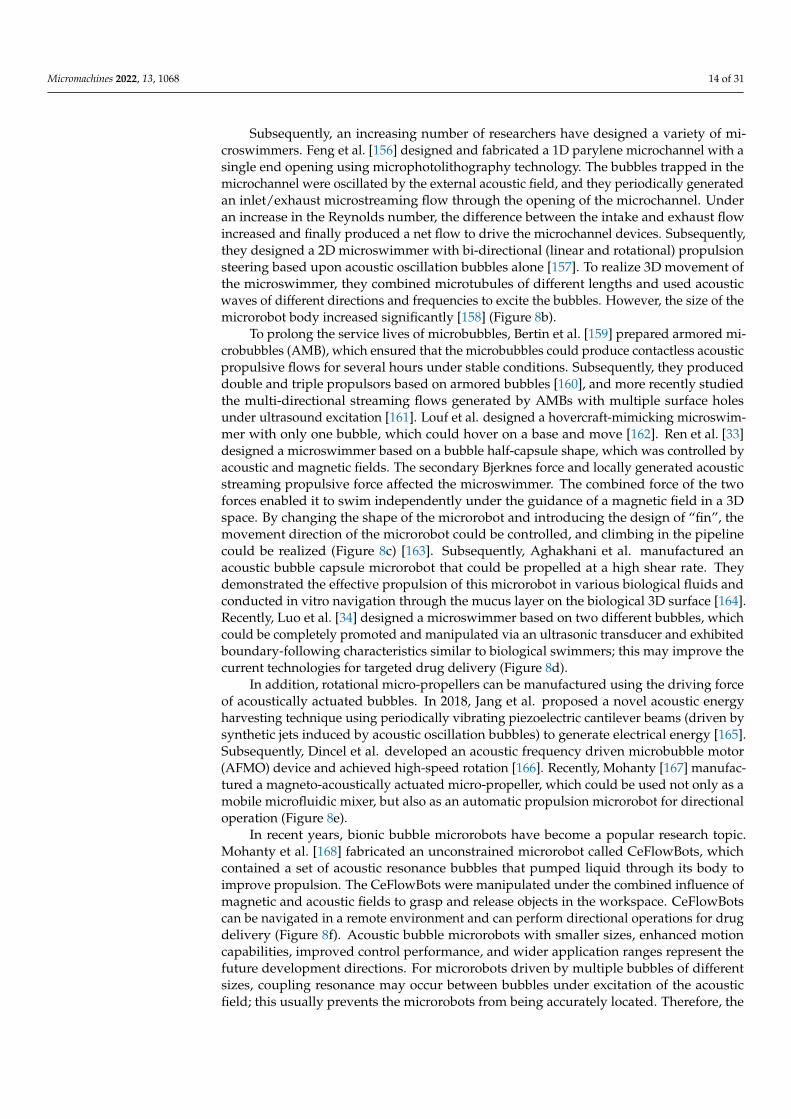
Subsequently, an increasing number of researchers have designed a variety of mi-croswimmers. Feng et al. [156] designed and fabricated a 1D parylene microchannel with asingle end opening using microphotolithography technology. The bubbles trapped in themicrochannel were oscillated by the external acoustic field, and they periodically generatedan inlet/exhaust microstreaming flow through the opening of the microchannel. Underan increase in the Reynolds number, the difference between the intake and exhaust flowincreased and finally produced a net flow to drive the microchannel devices. Subsequently,they designed a 2D microswimmer with bi-directional (linear and rotational) propulsionsteering based upon acoustic oscillation bubbles alone [157]. To realize 3D movement ofthe microswimmer, they combined microtubules of different lengths and used acousticwaves of different directions and frequencies to excite the bubbles. However, the size of themicrorobot body increased significantly [158] (Figure 8b).
To prolong the service lives of microbubbles, Bertin et al. [159] prepared armored mi-crobubbles (AMB), which ensured that the microbubbles could produce contactless acousticpropulsive flows for several hours under stable conditions. Subsequently, they produceddouble and triple propulsors based on armored bubbles [160], and more recently studiedthe multi-directional streaming flows generated by AMBs with multiple surface holesunder ultrasound excitation [161]. Louf et al. designed a hovercraft-mimicking microswim-mer with only one bubble, which could hover on a base and move [162]. Ren et al. [33]designed a microswimmer based on a bubble half-capsule shape, which was controlled byacoustic and magnetic fields. The secondary Bjerknes force and locally generated acousticstreaming propulsive force affected the microswimmer. The combined force of the twoforces enabled it to swim independently under the guidance of a magnetic field in a 3Dspace. By changing the shape of the microrobot and introducing the design of “fin”, themovement direction of the microrobot could be controlled, and climbing in the pipelinecould be realized (Figure 8c) [163]. Subsequently, Aghakhani et al. manufactured anacoustic bubble capsule microrobot that could be propelled at a high shear rate. Theydemonstrated the effective propulsion of this microrobot in various biological fluids andconducted in vitro navigation through the mucus layer on the biological 3D surface [164].Recently, Luo et al. [34] designed a microswimmer based on two different bubbles, whichcould be completely promoted and manipulated via an ultrasonic transducer and exhibitedboundary-following characteristics similar to biological swimmers; this may improve thecurrent technologies for targeted drug delivery (Figure 8d).
In addition, rotational micro-propellers can be manufactured using the driving forceof acoustically actuated bubbles. In 2018, Jang et al. proposed a novel acoustic energyharvesting technique using periodically vibrating piezoelectric cantilever beams (driven bysynthetic jets induced by acoustic oscillation bubbles) to generate electrical energy [165].Subsequently, Dincel et al. developed an acoustic frequency driven microbubble motor(AFMO) device and achieved high-speed rotation [166]. Recently, Mohanty [167] manufac-tured a magneto-acoustically actuated micro-propeller, which could be used not only as amobile microfluidic mixer, but also as an automatic propulsion microrobot for directionaloperation (Figure 8e).
In recent years, bionic bubble microrobots have become a popular research topic.Mohanty et al. [168] fabricated an unconstrained microrobot called CeFlowBots, whichcontained a set of acoustic resonance bubbles that pumped liquid through its body toimprove propulsion. The CeFlowBots were manipulated under the combined influence ofmagnetic and acoustic fields to grasp and release objects in the workspace. CeFlowBotscan be navigated in a remote environment and can perform directional operations for drugdelivery (Figure 8f). Acoustic bubble microrobots with smaller sizes, enhanced motioncapabilities, improved control performance, and wider application ranges represent thefuture development directions. For microrobots driven by multiple bubbles of differentsizes, coupling resonance may occur between bubbles under excitation of the acousticfield; this usually prevents the microrobots from being accurately located. Therefore, the
Micromachines 2022, 13, 1068 15 of 31
combination of acoustic and magnetic fields is necessary, particularly for microrobotsapplied inside the human body.
Micromachines 2022, 13, x FOR PEER REVIEW 15 of 31
field; this usually prevents the microrobots from being accurately located. Therefore, the combination of acoustic and magnetic fields is necessary, particularly for microrobots ap-plied inside the human body.
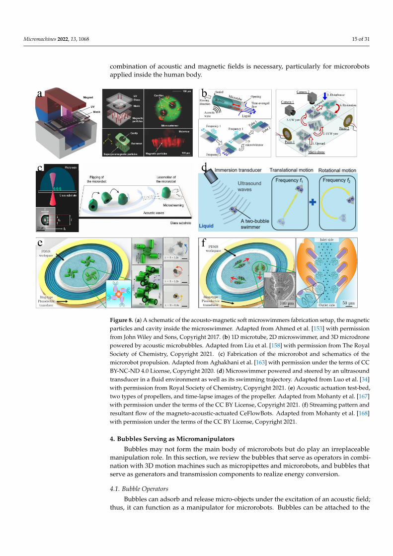
Figure 8. (a) A schematic of the acousto-magnetic soft microswimmers fabrication setup, the mag-netic particles and cavity inside the microswimmer. Adapted from Ahmed et al. [153] with permis-sion from John Wiley and Sons, Copyright 2017. (b) 1D microtube, 2D microswimmer, and 3D mi-crodrone powered by acoustic microbubbles. Adapted from Liu et al. [158] with permission from The Royal Society of Chemistry, Copyright 2021. (c) Fabrication of the microrobot and schematics of the microrobot propulsion. Adapted from Aghakhani et al. [163] with permission under the terms of CC BY-NC-ND 4.0 License, Copyright 2020. (d) Microswimmer powered and steered by an ul-trasound transducer in a fluid environment as well as its swimming trajectory. Adapted from Luo et al. [34] with permission from Royal Society of Chemistry, Copyright 2021. (e) Acoustic actuation test-bed, two types of propellers, and time-lapse images of the propeller. Adapted from Mohanty et al. [167] with permission under the terms of the CC BY License, Copyright 2021. (f) Streaming pat-tern and resultant flow of the magneto-acoustic-actuated CeFlowBots. Adapted from Mohanty et al. [168] with permission under the terms of the CC BY License, Copyright 2021.
4. Bubbles Serving as Micromanipulators Bubbles may not form the main body of microrobots but do play an irreplaceable
manipulation role. In this section, we review the bubbles that serve as operators in com-bination with 3D motion machines such as micropipettes and microrobots, and bubbles that serve as generators and transmission components to realize energy conversion.
4.1. Bubble Operators Bubbles can adsorb and release micro-objects under the excitation of an acoustic field;
thus, it can function as a manipulator for microrobots. Bubbles can be attached to the sur-face of the microrobot to perform operations. Chung et al. placed an acoustically excited
Figure 8. (a) A schematic of the acousto-magnetic soft microswimmers fabrication setup, the magneticparticles and cavity inside the microswimmer. Adapted from Ahmed et al. [153] with permissionfrom John Wiley and Sons, Copyright 2017. (b) 1D microtube, 2D microswimmer, and 3D microdronepowered by acoustic microbubbles. Adapted from Liu et al. [158] with permission from The RoyalSociety of Chemistry, Copyright 2021. (c) Fabrication of the microrobot and schematics of themicrorobot propulsion. Adapted from Aghakhani et al. [163] with permission under the terms of CCBY-NC-ND 4.0 License, Copyright 2020. (d) Microswimmer powered and steered by an ultrasoundtransducer in a fluid environment as well as its swimming trajectory. Adapted from Luo et al. [34]with permission from Royal Society of Chemistry, Copyright 2021. (e) Acoustic actuation test-bed,two types of propellers, and time-lapse images of the propeller. Adapted from Mohanty et al. [167]with permission under the terms of the CC BY License, Copyright 2021. (f) Streaming pattern andresultant flow of the magneto-acoustic-actuated CeFlowBots. Adapted from Mohanty et al. [168]with permission under the terms of the CC BY License, Copyright 2021.
4. Bubbles Serving as Micromanipulators
Bubbles may not form the main body of microrobots but do play an irreplaceablemanipulation role. In this section, we review the bubbles that serve as operators in combi-nation with 3D motion machines such as micropipettes and microrobots, and bubbles thatserve as generators and transmission components to realize energy conversion.
4.1. Bubble Operators
Bubbles can adsorb and release micro-objects under the excitation of an acoustic field;thus, it can function as a manipulator for microrobots. Bubbles can be attached to the

Micromachines 2022, 13, 1068 16 of 31
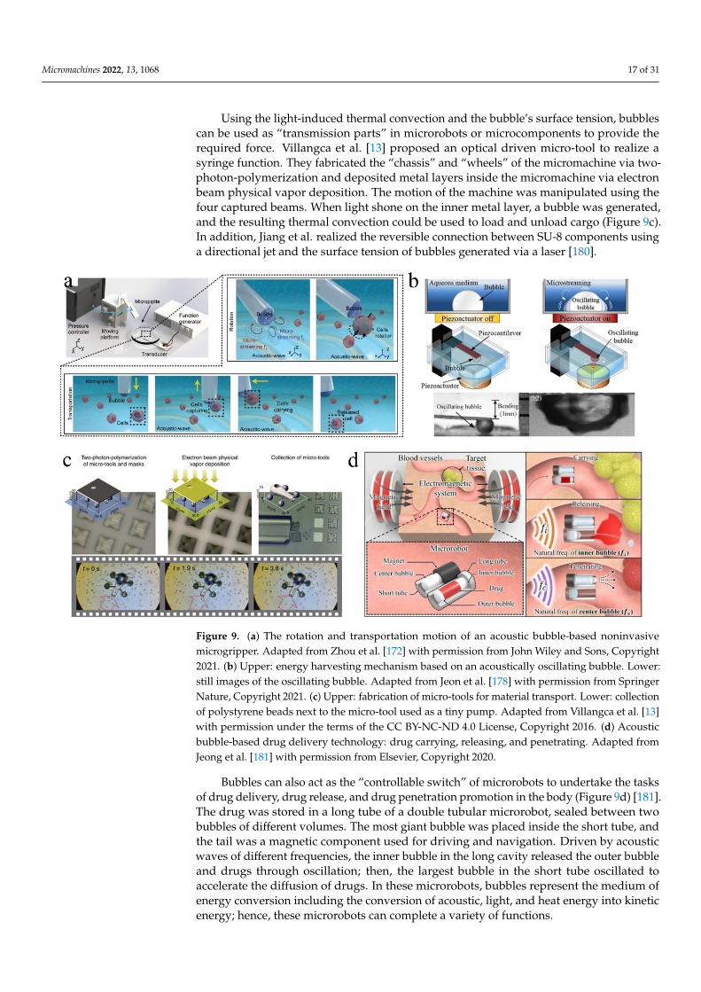
surface of the microrobot to perform operations. Chung et al. placed an acoustically excitedoscillating bubble at a hydrophobic micro-rod top to realize the adsorption and movementof particles in a 3D space [169]. Lee et al. [170] generated bubbles on a microfabricatedchip composed of tip-shaped electrodes by controlling the applied voltage and time ofelectrochemical methods. Subsequently, two bubbles were successively transferred to thetip of the U-shaped rod coated with a hydrophobic layer, and the fish eggs and glass beadswere manipulated under the excitation of the acoustic field. In 2016, Ahmed et al. realizedthe rotation of particles based on the torque induced by the hydrodynamic flow fieldgenerated by the acoustic bubble microstreaming. Inspired by this, the bubble operatorsfurther realized 3D rotation and graph reconstruction of the particles and cells. Recently,Li et al. contained a microbubble at the top of a micropipette, and generated secondaryradiation force and microstreaming to capture and rotate microbeads in an aqueous mediumvia acoustic vibrating microbubble near its resonant frequency [171]. Using the sameprinciple, Zhou et al. [172] generated a bubble at the tip of the micropipette of a 3D gripper,and the bubble volume was controlled by adjusting the pressure in the micropipette. Byreplacing the micropipette with different needle tip sizes, bubbles with diameters of 20 µmto 1 mm were obtained. Due to the secondary acoustic radiation force, the neighboringmicroparticles were attracted to the gas–liquid interface and transported to the desiredposition by the micropipette. When the transducer was turned off, the objects were released(Figure 9a).
For a microrobot moved and steered by a magnetic field, the bubble can be attached toits surface or contained in its interior. Kwon et al. realized the wireless control of bubblesusing a magnetic control microrobot instead of a micro-rod [173]. They used the injectionmethod to adsorb a bubble at the bottom of the magnetic plate, and the magnetic fieldgenerated by three pairs of electric coils could wirelessly control the robot and bubble in3D space. The acoustic oscillating bubble could grasp and move the microbeads or cellsto a designated position; then, the objects could be released by turning off the ultrasound.Park et al. [174,175] proposed a microrobot that primarily consisted of a compressiblebubble (that functioned as a gripping tool) and a pair of permanent magnets. Usingan external magnetic controller to control the 2D motion of the microrobot, the acousticoscillation bubble on the microrobot could carry out cell enucleation. Giltinan et al. [12]designed a magnetic microgripper using the bubble capillary force. The microgripper wascomposed of a cuboid containing at least one cavity and the bubbles thereby captured. Thebubbles bore the capillary force and maintained the grip of the parts during movementof the microgripper, which was controlled by a magnetic field. When the microrobotsizes are further reduced to the millimeter level, they are expected to be able to enterblood vessels or other biological pipelines to complete specific tasks [176,177]. Kwonet al. further realized micro-object manipulation in a microfabricated channel using anelectromagnetically driven microrobot with an acoustically oscillating bubble. The acousticoscillating bubble allowed the microrobot to realize more flexible, accurate, noninvasive,and harmless micromanipulation, which has great application value in the analysis ofliving cells and biological samples.
4.2. Bubble Generator and Transmission Components
Bubbles actuated by acoustic waves can be used as a source of mechanical energy for“generators.” Jeon et al. [178] suspended a bubble on a flexible piezocantilever. When thebubble was excited by acoustic waves near its resonance frequency, it oscillated and gen-erated cavitation microstreaming around it. The microstreaming bent the piezocantileverwith fine vibrations, which caused the piezocantilever to generate electric power (Figure 9b).The generated voltage mainly depended on the frequency of the applied acoustic field andthe size of the bubble, and it was inversely proportional to the distance between the bubbleand piezoelectric actuator [179]. They also discovered that the electrical output could beimproved by increasing the number of bubbles.
Micromachines 2022, 13, 1068 17 of 31
Using the light-induced thermal convection and the bubble’s surface tension, bubblescan be used as “transmission parts” in microrobots or microcomponents to provide therequired force. Villangca et al. [13] proposed an optical driven micro-tool to realize asyringe function. They fabricated the “chassis” and “wheels” of the micromachine via two-photon-polymerization and deposited metal layers inside the micromachine via electronbeam physical vapor deposition. The motion of the machine was manipulated using thefour captured beams. When light shone on the inner metal layer, a bubble was generated,and the resulting thermal convection could be used to load and unload cargo (Figure 9c).In addition, Jiang et al. realized the reversible connection between SU-8 components usinga directional jet and the surface tension of bubbles generated via a laser [180].
Micromachines 2022, 13, x FOR PEER REVIEW 17 of 31
required force. Villangca et al. [13] proposed an optical driven micro-tool to realize a sy-ringe function. They fabricated the “chassis” and “wheels” of the micromachine via two-photon-polymerization and deposited metal layers inside the micromachine via electron beam physical vapor deposition. The motion of the machine was manipulated using the four captured beams. When light shone on the inner metal layer, a bubble was generated, and the resulting thermal convection could be used to load and unload cargo (Figure 9c). In addition, Jiang et al. realized the reversible connection between SU-8 components using a directional jet and the surface tension of bubbles generated via a laser [180].
Figure 9. (a) The rotation and transportation motion of an acoustic bubble-based noninvasive mi-crogripper. Adapted from Zhou et al. [172] with permission from John Wiley and Sons, Copyright 2021. (b) Upper: energy harvesting mechanism based on an acoustically oscillating bubble. Lower: still images of the oscillating bubble. Adapted from Jeon et al. [178] with permission from Springer Nature, Copyright 2021. (c) Upper: fabrication of micro-tools for material transport. Lower: collec-tion of polystyrene beads next to the micro-tool used as a tiny pump. Adapted from Villangca et al. [13] with permission under the terms of the CC BY-NC-ND 4.0 License, Copyright 2016. (d) Acoustic bubble-based drug delivery technology: drug carrying, releasing, and penetrating. Adapted from Jeong et al. [181] with permission from Elsevier, Copyright 2020.
Bubbles can also act as the “controllable switch” of microrobots to undertake the tasks of drug delivery, drug release, and drug penetration promotion in the body (Figure 9d) [181]. The drug was stored in a long tube of a double tubular microrobot, sealed be-tween two bubbles of different volumes. The most giant bubble was placed inside the short tube, and the tail was a magnetic component used for driving and navigation. Driven by acoustic waves of different frequencies, the inner bubble in the long cavity re-leased the outer bubble and drugs through oscillation; then, the largest bubble in the short tube oscillated to accelerate the diffusion of drugs. In these microrobots, bubbles represent the medium of energy conversion including the conversion of acoustic, light, and heat energy into kinetic energy; hence, these microrobots can complete a variety of functions.
Figure 9. (a) The rotation and transportation motion of an acoustic bubble-based noninvasivemicrogripper. Adapted from Zhou et al. [172] with permission from John Wiley and Sons, Copyright2021. (b) Upper: energy harvesting mechanism based on an acoustically oscillating bubble. Lower:still images of the oscillating bubble. Adapted from Jeon et al. [178] with permission from SpringerNature, Copyright 2021. (c) Upper: fabrication of micro-tools for material transport. Lower: collectionof polystyrene beads next to the micro-tool used as a tiny pump. Adapted from Villangca et al. [13]with permission under the terms of the CC BY-NC-ND 4.0 License, Copyright 2016. (d) Acousticbubble-based drug delivery technology: drug carrying, releasing, and penetrating. Adapted fromJeong et al. [181] with permission from Elsevier, Copyright 2020.
Bubbles can also act as the “controllable switch” of microrobots to undertake the tasksof drug delivery, drug release, and drug penetration promotion in the body (Figure 9d) [181].The drug was stored in a long tube of a double tubular microrobot, sealed between twobubbles of different volumes. The most giant bubble was placed inside the short tube, andthe tail was a magnetic component used for driving and navigation. Driven by acousticwaves of different frequencies, the inner bubble in the long cavity released the outer bubbleand drugs through oscillation; then, the largest bubble in the short tube oscillated toaccelerate the diffusion of drugs. In these microrobots, bubbles represent the medium ofenergy conversion including the conversion of acoustic, light, and heat energy into kineticenergy; hence, these microrobots can complete a variety of functions.

Micromachines 2022, 13, 1068 18 of 31
5. Bubbles Serving as Microrobots
Bubbles can be used as microrobots to manipulate and assemble particles, cells, andmicrostructures. In this section, we review the bubble microrobots that can performdexterous and complex microassembly tasks in 2D and 3D spaces.
5.1. Bubble Microrobots Used in 2D Manipulation and Assembly
Whether driven by EWOD or optically, bubbles can move across the surface of thechip. Moreover, both methods can be combined with an acoustic field to vibrate the bubbleand realize the grasping and movement of micro-objects, although these operations areonly on the 2D scale. This section describes the EWOD-driven, optothermal, and bubblemicrorobots combining light and acoustic fields.
5.1.1. EWOD-Driven Bubble Microrobots
Researchers at the University of Pittsburgh have applied EWOD technology to manip-ulate bubbles. When the electrodes are energized in turn, bubbles can move on the electrodesurface (Figure 10a) [182], and the mixing and splitting of bubbles can also be realized [73].Alternating current-EWOD (AC-EWOD)-driven bubbles can be used to enhance fluid mix-ing in microfluidic chips and perform micromanipulation and particle separation [183,184].In 2012, Lee et al. used bubbles in EWOD to promote the mixing of microfluidics [184].Subsequently, they realized the driving of two bubbles in the EWOD [185]. To improvethe controllability of the manipulation, double bubbles were used to form a flow fieldwith a fixed direction; this could be used to realize the directional transport of fish eggs.Recently, Yan et al. induced the escape, coalescence, and departure of bubbles activated byan electric field by using a simple EWOD device [186]. When the copper electrode wire(inserted into deionized water) was placed on one side of the bubbles, the bubbles escapedfrom their initial positions with the opening of the voltage. The pin-on-one-side EWODdevice could continuously push bubbles out of their initial position under a low-frequencyvoltage, without the need for a complex patterned electrode array channel design. Sunet al. [187] observed standing waves on a millimeter-sized bubble surface on the substrate ofan EWOD device and discovered that the amplitudes of these waves varied with frequency,which could identify three formants. However, the limitation of EWOD technology inoperating bubbles is that, although it can control the positions of bubbles, MEMS chipswith electrodes must be designed and manufactured in advance, and the route of bubblemovement is limited by the arrangement of electrodes and is restricted to the 2D plane. Inaddition, bubbles must be excited by acoustic waves to have a strong adsorption capacityfor manipulating micro-objects.
5.1.2. Optothermal Bubble Microrobots
Compared to the EWOD method, the bubbles generated and controlled by the op-tothermal method can move freely on the chip under movement of the laser spot and donot require ultrasonic excitation to manipulate micro-objects. In 2007, Ohta et al. firstdemonstrated the movement of optothermal bubbles formed via laser absorption on anamorphous silicon substrate [14]. Hu et al. [51] showed that optothermally generatedbubbles could move and arrange multiple triangular SU-8 photoresist microstructures.Subsequently, they used a laser-induced bubble to drive a disc-shaped PEGDA hydrogelmicrorobot with a conical groove at the bottom [54]. One or a pair of cooperative bubblemicrorobots could assemble 20 µm-diameter polystyrene beads, operate individual yeastcells, and assemble a square agarose microgel encapsulated with cells into a 3 × 4 array.They also designed a T-shaped bubble-driven light-absorbing microrobot [188]. In 2014,Zhao proposed that under the synergistic action of Marangoni convection and the surfacetension of an optothermal bubble microrobot, an adsorption force could be applied to theparticles suspended in a solution. When the bubble moves on the solid–liquid interface, itcan pull the microparticles to move with it (Figure 10b) [44].

Micromachines 2022, 13, 1068 19 of 31
In terms of cell operation, optothermal bubble microrobots can realize cell movementand deformation [189], perforation, and lysis [190]. In 2013, Hu et al. [55] proposed anopto-thermocapillary micromanipulator (OTMm). Intermittent laser irradiation was usedto induce a bubble to quickly separate from the substrate and float upward, forming a lightthermocapillary convection around it to move the cells at a certain distance. When a fixed-frequency laser was used to irradiate the chip, an endless stream of bubble microrobotscould drive the cells to move continuously. This non-contact operation method caused al-most no damage to the cells. Later, Fan et al. of the same research group used the oscillationof microbubble size (caused by the opening and closing cycle of a laser pulse) to generateshear stress on the nearby cell membrane to realize cell perforation [56]. The perforationefficiency was further improved by generating microbubbles with size oscillations directlybelow the target cell [191]. Subsequently, they integrated a single-cell analysis platformfor cell perforation, lysis, and manipulation (Figure 10c) [190]. Yuan et al. [192] studiedthe cell membrane deformation and biological effects caused by the jet flow generated bylaser-induced tandem bubbles (TBS) at the single-cell level. In addition, Fujii et al. [193]demonstrated that optothermal bubbles could manipulate a single DNA nanowire andcross-wire formation, which means that optothermal bubbles can manipulate other bio-logical macromolecules. Visible-light thermal bubble microrobots have broad applicationprospects in biomedicine and assembly engineering [194,195]. Multiple bubble microrobotscan have a synergistic effect [196,197]. Rahman et al. generated and manipulated multipleopto-thermocapillary flow-addressed bubble (OFB) microrobots at the same time by usingthe spatial light modulator (SLM) to realize independent and cooperative operation tasks(Figure 10d) [198,199]. They realized the controllable movement of micromodules and glassbeads and improved the operation efficiency of bubble microrobots.
5.1.3. Bubble Microrobots Combining Light and Acoustic Fields
The high temperature on the surfaces of optothermal bubbles has benefits and draw-backs. It is conducive to cell perforation and lysis but causes severe damage when directlyoperating cells. To avoid possible thermal damage and improve the biocompatibility ofoptothermal bubbles, Xie et al. proposed optoacoustic tweeters [200]. They used theoptothermal effect to generate bubbles of appropriate sizes at the designated position ofthe chip; then, they turned off the laser and used acoustic waves to induce the surfacebubbles to oscillate at the resonant frequency. Thus, the particles/cells were capturedlocally around each bubble. Subsequently, they used acoustic microstreaming aroundthe oscillating bubble to measure the deformation ability of the cell (Figure 10e) [48]. Inaddition to the non-destructive operation of cells, researchers have discovered that bubblemicrorobots combined with light and acoustic fields also have other characteristics includ-ing the simultaneous collection or dispersion of batch objects as well as the classification ofparticles of different sizes. In 2017, Dai et al. [201] proposed a method for the simultaneousoperation and transmission of multitarget objects in an unclosed chip. The laser was turnedoff and the piezoelectric actuator turned on at a certain position, and the objects gatheredto the vibrating laser-generated bubble. When the laser was turned on again, the increas-ing volume and broken bubbles produced dispersion of the collected small objects. Theabove steps were repeated at another location to realize the transfer of the object groups.Shin et al. [202] observed that when a bubble oscillated around its resonance frequencyunder acoustic excitation, it attracted large particles and repelled small particles due to thecompetition between the secondary acoustic radiation force and drag force to classify theparticles. We anticipate more applications of microrobots based on light and acoustic fieldsin particle and microstructure operations.

Micromachines 2022, 13, 1068 20 of 31
5.2. Bubble Microrobots Used in 3D Manipulation and Assembly
Whether using EWOD technology or laser to drive and control bubbles, bubble mi-crorobots can only be used for the 2D operation and assembly of microparticles, cells,or microstructures. When microbubbles are blown into the liquid via an air injector, themicroflow floats the micromodule and contributes to the 3D assembly of the hydrogelmodules. Fukuda et al. used the flow field generated by bubble motions to perform a3D operation upon cell-laden hydrogel micromodules to manufacture biological tissuein vitro [203,204]. An air injector was used to blow microbubbles into the solution to makethe prepared micromodule float up. Simultaneously, another holding pipette was used tocollect the micromodules. When the holding pipette connected the blown micromodules inseries, the posture of each module had to be adjusted to align it. The flow caused by the bub-ble movement can also play a role in the arrangement of micromodules (Figure 10f) [205].Although the micromodules can realize 3D movement under the action of the flow field,the controllability of the bubbles and micromodules is limited. This micromodule operationand assembly method requires two actuators to control the syringe and collector. Moreover,the technology places certain requirements upon the shape of the micromodules, and theremust be holes in the center to allow it to be picked up, collected, and aligned.
To solve these problems, Dai et al. used a 2D optothermal bubble microrobot to realizethe 3D operation and assembly of micromodules, which provided more opportunities forthe construction of biological tissues in vitro (Figure 10g) [43]. When a bubble microrobotwas generated at the bottom of the micromodule, the micromodule could be lifted andturned over. The 3D gesture of the micromodule could be adjusted by changing the genera-tion position and movement direction of the bubble. For example, the circular structure of ahydrogel module could be assembled into a 3D tubular structure with the shape characteris-tics of vascular tissue. Two annular modules of different sizes could also be nested togetherto provide a possible method for analyzing the roles of cells at different positions in bloodvessels as well as the cross-vascular transmission of substances. On this basis, they used the3D operation abilities of microbubbles to assemble micromodules with different interfacesinto an interconnected whole, referred to as an integrated assembly (Figure 10h) [206].Multiple bubble microrobots cooperated to lift, put down, fix, and move the micromoduleto thereby realize the assembly of tenon and mortise, gear, chain, car, and various othermicrostructures. Integrated assembly technology based on microbubbles provides a newsolution for the manufacturing, assembly, and development of micro/nanostructures. Re-cently, Ge et al. used these bubble microrobots to manipulate cell-loaded microstructuresfabricated using a digital micromirror device (DMD)-based optical projection lithographysystem to form peritoneal tissue, which was similar to the biological peritoneum in terms ofthe mechanical properties, surface morphology, and internal microstructure [207]. The 3Doperation and assembly method proposed by Dai et al. have excellent application prospectsfor in vitro biological tissue construction, microassembly factories, and more.

Micromachines 2022, 13, 1068 21 of 31Micromachines 2022, 13, x FOR PEER REVIEW 21 of 31
Figure 10. (a) A: Schematic of a bubble-based manipulator with three operations: creation, transpor-tation, and elimination. B: Manipulation of micron-sized particles using the bubble transported by EWOD. Adapted from Chung et al. [182] with permission from the Institute of Physics Publishing, Copyright 2008. (b) A: Illustration of the particle manipulation process. B: Collecting and manipu-lating randomly distributed polystyrene particles to trace the letters “P”, “S”, and “U”. Adapted from Zhao et al. [50] with permission from The Royal Society of Chemistry, Copyright 2014. (c) A: The 3D structure of the microfluidic chamber to culture and lyse cells. B: Brightfield and fluorescent images before and after the adherent single-cell lysis. Adapted from Fan et al. [190] with permission under the terms of the CC BY 4.0 License, Copyright 2017. (d) A: A single laser beam shaped by a spatial light modulator to create dynamic optical patterns that facilitate the simultaneous control of multiple OFB microrobots. B: Manipulation of a microstructure using a pair of OFB microrobots. Adapted from Rahman et al. [199] with permission under the terms of the CC BY 4.0 License, Cop-yright 2017. (e) A: Schematic for the configuration of a microfluidic chamber and piezo transducer. B: Schematic for cell stretching around an acoustically activated oscillating bubble as well as images of a stretched spherical-shaped suspended cell. Adapted from Xie et al. [48] with permission from John Wiley and Sons, Copyright 2016. (f) A: Schematic of the sequential pickup of micromodules based on microbubble injection. B: Pickup of cell-laden micromodules with the hexagonal structure from the solution. Adapted from Wang et al. [205] with permission from The American Chemical Society, Copyright 2017. (g) A: Schematic of the system setup used to achieve the 3D manipulation of the microstructures via optothermal bubbles. B: The 3D manipulation and nested assembly of square ring microstructures. Adapted from Dai et al. [43] with permission from John Wiley and Sons, Copyright 2019. (h) A: Schematic of the integrated assembly process of two microparts using multifunctional optothermal bubble microrobots. B: The transmission of two gears and movement of the snake-shaped structure after assembly. Adapted from Dai et al. [206] with permission from The American Chemical Society, Copyright 2020.
Figure 10. (a) A: Schematic of a bubble-based manipulator with three operations: creation, trans-portation, and elimination. B: Manipulation of micron-sized particles using the bubble transportedby EWOD. Adapted from Chung et al. [182] with permission from the Institute of Physics Publishing,Copyright 2008. (b) A: Illustration of the particle manipulation process. B: Collecting and manipulat-ing randomly distributed polystyrene particles to trace the letters “P”, “S”, and “U”. Adapted fromZhao et al. [50] with permission from The Royal Society of Chemistry, Copyright 2014. (c) A: The3D structure of the microfluidic chamber to culture and lyse cells. B: Brightfield and fluorescentimages before and after the adherent single-cell lysis. Adapted from Fan et al. [190] with permissionunder the terms of the CC BY 4.0 License, Copyright 2017. (d) A: A single laser beam shaped by aspatial light modulator to create dynamic optical patterns that facilitate the simultaneous controlof multiple OFB microrobots. B: Manipulation of a microstructure using a pair of OFB microrobots.Adapted from Rahman et al. [199] with permission under the terms of the CC BY 4.0 License, Copy-right 2017. (e) A: Schematic for the configuration of a microfluidic chamber and piezo transducer.B: Schematic for cell stretching around an acoustically activated oscillating bubble as well as imagesof a stretched spherical-shaped suspended cell. Adapted from Xie et al. [48] with permission fromJohn Wiley and Sons, Copyright 2016. (f) A: Schematic of the sequential pickup of micromodulesbased on microbubble injection. B: Pickup of cell-laden micromodules with the hexagonal structurefrom the solution. Adapted from Wang et al. [205] with permission from The American ChemicalSociety, Copyright 2017. (g) A: Schematic of the system setup used to achieve the 3D manipulationof the microstructures via optothermal bubbles. B: The 3D manipulation and nested assembly ofsquare ring microstructures. Adapted from Dai et al. [43] with permission from John Wiley andSons, Copyright 2019. (h) A: Schematic of the integrated assembly process of two microparts usingmultifunctional optothermal bubble microrobots. B: The transmission of two gears and movement ofthe snake-shaped structure after assembly. Adapted from Dai et al. [206] with permission from TheAmerican Chemical Society, Copyright 2020.

Micromachines 2022, 13, 1068 22 of 31
6. Summary and Outlook
Micro/nanobubbles have become a general and diversified tool preferred by an in-creasing number of researchers as they have broad research prospects. Microrobot tech-nology, in which bubbles play an irreplaceable and pivotal role, has developed rapidly.This paper reviewed the recent research results for bubbles combined with microrobots.First, the methods for generating and controlling bubbles were introduced; these are animportant theoretical basis and prerequisite for manufacturing bubble-based microrobots.Then, the three functions of bubbles in the microrobot field—propulsion, manipulation, andassembly—were introduced. Based on their roles in the field of microrobots, bubbles weredivided into bubble-driven microrobots, bubble operators combined with microrobots, andbubble microrobots. The mechanisms related to these three roles are listed in Table 1. Inaddition, the bubbles’ production methods and service lives as well as the advantages,limits, and applications of each mechanism, were summarized.
Microbubbles have opened up a novel path for the development of microrobot tech-nology and are playing a more important role in microrobotics; however, bubble-basedmicrorobots still suffer from some problems including short bubble service lives, reducedcontrollability of bubbles (because of time offsets), simple functions, lack of intelligence,and so on. To solve these problems, several simple methods have been proposed suchas applying chemical hydrophobic surface modification [163] or designing special cavi-ties of microstructures [164] to enhance the stability of bubbles and prolong their servicelives, combining multiple fields to expand the functions of microrobots, and introducingcontrol algorithms to improve their intelligence. The challenges and possible directionsfor the future development of bubbles in the field of micro/nanorobots are discussed indetail below.
• Multi-field combination of bubble microrobots
Aside from the optothermal effect, it is difficult to drive and control a bubble micro-robot relying only upon a single physical field. For example, microswimmers must relyon bubbles excited by an acoustic field (to provide a driving force) and magnetic field (tocontrol the motion trajectory) [34]. Recently, the combination of bubble propulsion basedon chemical reactions with acoustic [107] or magnetic fields [140] has become a researchhotspot. The combination of multiple physical fields not only satisfies more complex andmultifunctional applications, but also solves the problems and limitations of a single physi-cal field. For example, to avoid the influence of high temperature in the laser area of anoptothermal bubble microrobot on cells, non-contact operation was realized by combiningit with an acoustic field [200]. The compatibility of multiple physical fields may form thebasis for the integrated functionalization of bubble microrobots in the future. We hopethat bubble microrobots can achieve richer capabilities and perform more comprehensivefunctions through the combination of multiple fields.
• Research and application of bionic microrobots based on bubbles
In recent years, functional bionic robots have become a focus of scientific research.When a jellyfish swims in seawater, the umbrella shrinks and relaxes constantly, and thewater pressure in the umbrella cavity is pushed out of the body, allowing it to swim slowlyin the opposite direction. Other marine creatures such as octopuses and squid also swimby spraying seawater, which is similar to the microrobot driven by the jet flow generatedvia acoustically actuated bubbles. Hence, several bubble-driven bionic microrobots andmicroswimmers based on acoustic and magnetic fields have been manufactured, andtheir movement and operation abilities have been demonstrated in fluids [168]. However,in addition to imitating the motion characteristics of organisms, bubble-based bionicmicrorobots can combine real-time monitoring and imaging, intelligent motion control,image processing, and other technologies, making them more intelligent and furtherexpanding their practical applicability in microfluidics.

Micromachines 2022, 13, 1068 23 of 31
Table 1. The role of bubbles in the field of microrobots.
Role/Mechanism Production Service Life Advantage Limit Application Ref.
Propulsion/chemical reaction
generatedbubbles
Chemical reaction
Short, bubbles aregenerated and
quickly separatedfrom the
microrobot
Fast drivingspeed
The generation ofbubbles and the
movementperformance ofmicrorobot is
affected by theconsumption of
chemical fuel; lowbiocompatibility
Biomedicine,biologicaldetection,
environmentalpurification
[107,136,140]
Propulsion/acoustically
excited bubblesDirect acquisition
Related to theshape and
hydrophobicproperties of the
bubble-containing
structures andacoustic
excitationparameters
Simple andbiocompatible
equipment
Under long-timeacoustic
excitation, thechange of bubblevolume leads to a
change ofresonance
frequency, whichaffects the motion
performance ofthe microrobots
Targeted drugdelivery,
microsurgery,manipulation
[34,153,158,163,167,168]
Manipulator/manipulator
based on acousticbubble
Direct acquisition
Related to theacoustic
excitationparameters
Adsorbable,removable,
noninvasive, andflexible
Combined withmanipulator,
acoustic field, ormagnetic field;
complex structure
Analysis of livingcells andbiologicalsamples,
manipulation
[172]
Manipulator/bubble engine
and transmissioncomponent
Direct acquisition,optothermal
effect
For acousticbubbles, servicelife relates to thestructural design
and acousticexcitation
parameters. Foroptothermalbubbles, it
depends on theopening andclosing of the
laser
Energyconversion,
simple structure,and strong
controllability
Weak change offlow field caused
by bubblegeneration,
oscillation orrupture; limited
energyconversion
Energyconversion, cargo
transportation,drug delivery
[13,178,181]
Microrobot/EWODtechnology (2D)
Direct acquisition,chemical reaction
Related to thesize of generated
bubbles andacoustic
excitationparameters
Controllablemovement and
low energyconsumption
Limitedmovement of
bubbles due tothe electrode
arrangement onthe chip
Fluid mixing,micro-object
manipulation[182]
Microrobot/combining light
field and acousticfield (2D)
Optothermaleffect
Related to theopening andclosing of the
laser and acousticexcitation
parameters
Improves thebiocompatibilityof optothermal
bubbles
Narrowapplication range
Manipulation,particle
classification[48]
Microrobot/optothermal
effect (2D/3D)
Optothermaleffect
Depends on theopening andclosing of the
laser
Controllable andflexible bubbleposition and
volume
Limitedbiomedical
applicationsbecause of the
high temperaturearound bubbles
Fluid control, celllysis,
manipulation,and assembly
[43,50,190,199,206]
• In vivo microrobots based on bubbles
The ultimate goal of microrobots is to enter the human body and improve humanhealth. Countless researchers are tackling the key technical problems. We can put forwarda bold vision for the future development of bubble-based microrobots: clustered bubblemicrorobots are injected into the human body [208]; under excitation of the acoustic field

Micromachines 2022, 13, 1068 24 of 31
and control of the magnetic field [164], or using ultrasound for in vivo micromanipula-tion [209], these bubble microrobots can access specific parts of the body; under the actionof different excitation frequencies or external fields, they can perform drug delivery or sur-gical tasks [179]; meanwhile, several bubble-based microrobots simultaneously completereal-time volumetric optoacoustic tomography imaging and monitoring [210]; finally, thesebubble microrobots collapse or dissolve in the body. A variety of artificial intelligence (AI)strategies can be combined to make them more intelligent and autonomous [150].
Microrobotics is a highly interdisciplinary field involving physics, chemistry, biology,and medicine. From theoretical exploration to practical application, innovative ideasand a thorough exploration by numerous researchers from different backgrounds arealso required. Micro/nanobubbles have played a variety of functions and roles and arebringing more surprises to researchers. We expect that micro/nanobubbles will realizemore important and diverse applications in the future.
Author Contributions: Conceptualization, L.D. and N.J.; Writing—original draft preparation, Y.Z.and L.D. All authors have read and agreed to the published version of the manuscript.
Funding: This work was supported by the National Natural Science Foundation of China (Grant Nos.62127811, 91748212, 61821005) and the CAS/SAFEA International Partnership Program for CreativeResearch Teams.
Institutional Review Board Statement: Not applicable.
Informed Consent Statement: Not applicable.
Data Availability Statement: Not applicable.
Conflicts of Interest: The authors declare no conflict of interest.
References1. Li, Y.; Liu, X.; Huang, Q.; Ohta, A.T.; Arai, T. Bubbles in microfluidics: An all-purpose tool for micromanipulation. Lab Chip 2021,
21, 1016–1035. [CrossRef] [PubMed]2. Gao, Y.; Wu, M.; Lin, Y.; Xu, J. Trapping and control of bubbles in various microfluidic applications. Lab Chip 2020, 20, 4512–4527.
[CrossRef] [PubMed]3. Qiao, C.; Yang, D.; Mao, X.; Xie, L.; Gong, L.; Peng, X.; Peng, Q.; Wang, T.; Zhang, H.; Zeng, H. Recent advances in bubble-based
technologies: Underlying interaction mechanisms and applications. Appl. Phys. Rev. 2021, 8, 011315. [CrossRef]4. Kharaji, Z.G.; Bayareh, M.; Kalantar, V. A review on acoustic field-driven micromixers. Int. J. Chem. React. Eng. 2021, 19, 553–569.
[CrossRef]5. Bayareh, M.; Ashani, M.N.; Usefian, A. Active and passive micromixers: A comprehensive review. Chem. Eng. Process. Process
Intensif. 2020, 147, 107771. [CrossRef]6. Liu, B.; Ma, C.; Yang, J.; Li, D.; Liu, H. Study on the Heat Source Insulation of a Thermal Bubble-Driven Micropump with
Induction Heating. Micromachines 2021, 12, 1040. [CrossRef]7. Mohith, S.; Karanth, P.N.; Kulkarni, S.M. Recent trends in mechanical micropumps and their applications: A review. Mechatronics
2019, 60, 34–55. [CrossRef]8. Oskooei, A.; Günther, A. Bubble pump: Scalable strategy for in-plane liquid routing. Lab Chip 2015, 15, 2842–2853. [CrossRef]9. Qian, J.Y.; Hou, C.W.; Li, X.J.; Jin, Z.J. Actuation Mechanism of Microvalves: A Review. Micromachines 2020, 11, 172. [CrossRef]10. Läubli, N.F.; Shamsudhin, N.; Vogler, H.; Munglani, G.; Grossniklaus, U.; Ahmed, D.; Nelson, B.J. 3D Manipulation and Imaging
of Plant Cells using Acoustically Activated Microbubbles. Small Methods 2019, 3, 1800527. [CrossRef]11. Tang, Q.; Liang, F.; Huang, L.; Zhao, P.; Wang, W. On-chip simultaneous rotation of large-scale cells by acoustically oscillating
bubble array. Biomed. Microdevices 2020, 22, 13. [CrossRef] [PubMed]12. Giltinan, J.; Diller, E.; Sitti, M. Programmable assembly of heterogeneous microparts by an untethered mobile capillary microgrip-
per. Lab Chip 2016, 16, 4445–4457. [CrossRef] [PubMed]13. Villangca, M.J.; Palima, D.; Banas, A.R.; Gluckstad, J. Light-driven micro-tool equipped with a syringe function. Light. Sci. Appl.
2016, 5, e16148. [CrossRef] [PubMed]14. Ohta, A.T.; Jamshidi, A.; Valley, J.K.; Hsu, H.Y.; Wu, M.C. Optically actuated thermocapillary movement of gas bubbles on an
absorbing substrate. Appl. Phys. Lett. 2007, 91, 074103. [CrossRef]15. Guix, M.; Mayorga-Martinez, C.C.; Merkoçi, A. Nano/micromotors in (bio)chemical science applications. Chem. Rev. 2014, 114,
6285–6322. [CrossRef]16. Tasoglu, S.; Gurkan, U.A.; Wang, S.Q.; Demirci, U. Manipulating biological agents and cells in micro-scale volumes for applications
in medicine. Chem. Soc. Rev. 2013, 42, 5788–5808. [CrossRef]
Micromachines 2022, 13, 1068 25 of 31
17. Lin, Y.; Geng, X.; Chi, Q.; Wang, C.; Wang, Z. Driving Forces of the Bubble-Driven Tubular Micromotor Based on the FullLife-Cycle of the Bubble. Micromachines 2019, 10, 415. [CrossRef]
18. Solovev, A.A.; Mei, Y.; Urena, E.B.; Huang, G.; Schmidt, O.G. Catalytic microtubular jet engines self-propelled by accumulatedgas bubbles. Small 2009, 5, 1688–1692. [CrossRef]
19. Surdo, S.; Diaspro, A.; Duocastella, M. Micromixing with spark-generated cavitation bubbles. Microfluid. Nanofluidics 2017, 21, 82.[CrossRef]
20. Ma, Z.; Melde, K.; Athanassiadis, A.G.; Schau, M.; Richter, H.; Qiu, T.; Fischer, P. Spatial ultrasound modulation by digitallycontrolling microbubble arrays. Nat. Commun. 2020, 11, 1–7. [CrossRef]
21. Ye, Y.C.; Luan, J.B.; Wang, M.; Chen, Y.M.; Wilson, D.A.; Peng, F.; Tu, Y.F. Fabrication of Self-Propelled Micro- and NanomotorsBased on Janus Structures. Chem. A Eur. J. 2019, 25, 8663–8680. [CrossRef]
22. Chen, C.; Karshalev, E.; Guan, J.; Wang, J. Magnesium-Based Micromotors: Water-Powered Propulsion, Multifunctionality, andBiomedical and Environmental Applications. Small 2018, 14, 1704252. [CrossRef] [PubMed]
23. Chen, C.; Karshalev, E.; Li, J.; Soto, F.; Castillo, R.; Campos, I.; Mou, F.; Guan, J.; Wang, J. Transient Micromotors That DisappearWhen No Longer Needed. ACS Nano 2016, 10, 10389–10396. [CrossRef] [PubMed]
24. Battino, R.; Rettich, T.R.; Tominaga, T. The Solubility of Nitrogen and Air in Liquids. J. Phys. Chem. Ref. Data 1984, 13, 563–600.[CrossRef]
25. Orbay, S.; Ozcelik, A.; Lata, J.; Kaynak, M.; Wu, M.; Huang, T.J. Mixing high-viscosity fluids via acoustically driven bubbles. J.Micromech. Microeng. 2017, 27, 015008. [CrossRef]
26. Pereiro, I.; Khartchenko, A.F.; Petrini, L.; Kaigala, G.V. Nip the bubble in the bud: A guide to avoid gas nucleation in microfluidics.Lab Chip 2019, 19, 2296–2314. [CrossRef]
27. Peng, T.; Zhou, M.; Yuan, S.; Jiang, B. Trapping stable bubbles in hydrophobic microchannel for continuous ultrasonic microparticlemanipulation. Sens. Actuators A Phys. 2021, 331, 113045. [CrossRef]
28. Yu, C.; Zhu, X.; Cao, M.; Yu, C.; Li, K.; Jiang, L. Superhydrophobic helix: Controllable and directional bubble transport in anaqueous environment. J. Mater. Chem. A 2016, 4, 16865–16870. [CrossRef]
29. Yu, C.; Cao, M.; Dong, Z.; Wang, J.; Li, K.; Jiang, L. Spontaneous and Directional Transportation of Gas Bubbles on Superhy-drophobic Cones. Adv. Funct. Mater. 2016, 26, 3236–3243. [CrossRef]
30. Ahmed, D.; Ozcelik, A.; Bojanala, N.; Nama, N.; Upadhyay, A.; Chen, Y.; Hanna-Rose, W.; Huang, T.J. Rotational manipulation ofsingle cells and organisms using acoustic waves. Nat. Commun. 2016, 7, 11085. [CrossRef]
31. Lin, Y.; Gao, C.; Gao, Y.; Wu, M.; Yazdi, A.A.; Xu, J. Acoustofluidic micromixer on lab-on-a-foil devices. Sens. Actuators B Chem.2019, 287, 312–319. [CrossRef]
32. Liu, J.; Li, S.; Mitra, D. Multiphysical phenomenon of air bubble growth in polydimethylsiloxane channel corners undermicrofluidic negative pressure-driven flow. Int. J. Heat Mass Transf. 2015, 91, 611–618. [CrossRef]
33. Ren, L.; Nama, N.; McNeill, J.M.; Soto, F.; Yan, Z.; Liu, W.; Wang, W.; Wang, J.; Mallouk, T.E. 3D steerable, acoustically poweredmicroswimmers for single-particle manipulation. Sci. Adv. 2019, 5, eaax3084. [CrossRef] [PubMed]
34. Luo, T.; Wu, M. Biologically inspired micro-robotic swimmers remotely controlled by ultrasound waves. Lab Chip 2021, 21,4095–4103. [CrossRef] [PubMed]
35. Zheng, Y.; Liu, H.; Wang, Y.; Zhu, C.; Wang, S.; Cao, J.; Zhu, S. Accumulating microparticles and direct-writing micropatternsusing a continuous-wave laser-induced vapor bubble. Lab Chip 2011, 11, 3816–3820. [CrossRef]
36. Ghosh, S.; Ranjan, A.D.; Das, S.; Sen, R.; Roy, B.; Roy, S.; Banerjee, A. Directed Self-Assembly Driven Mesoscale LithographyUsing Laser-Induced and Manipulated Microbubbles: Complex Architectures and Diverse Applications. Nano Lett. 2021, 21,10–25. [CrossRef]
37. Hayashi, K.; Yamamoto, Y.; Tamura, M.; Tokonami, S.; Iida, T. Damage-free light-induced assembly of intestinal bacteria with abubble-mimetic substrate. Commun. Biol. 2021, 4, 385. [CrossRef]
38. Zhang, Q.; Pang, Y.; Schiffbauer, J.; Jemcov, A.; Chang, H.-C.; Lee, E.; Luo, T. Light-Guided Surface Plasmonic Bubble Movementvia Contact Line De-Pinning by In-Situ Deposited Plasmonic Nanoparticle Heating. ACS Appl. Mater. Interfaces 2019, 11,48525–48532. [CrossRef]
39. Lin, L.; Peng, X.; Mao, Z.; Li, W.; Yogeesh, M.N.; Rajeeva, B.B.; Perillo, E.P.; Dunn, A.K.; Akinwande, D.; Zheng, Y. Bubble-PenLithography. Nano Lett. 2016, 16, 701–708. [CrossRef]
40. Baffou, G.; Polleux, J.; Rigneault, H.; Monneret, S. Super-Heating and Micro-Bubble Generation around Plasmonic Nanoparticlesunder cw Illumination. J. Phys. Chem. C 2014, 118, 4890–4898. [CrossRef]
41. Ghosh, S.; Biswas, A.; Roy, B.; Banerjee, A. Self-assembly and complex manipulation of colloidal mesoscopic particles by activethermocapillary stress. Soft Matter 2019, 15, 4703–4713. [CrossRef] [PubMed]
42. Wang, Y.; Zaytsev, M.E.; Lajoinie, G.; The, H.L.; Eijkel, J.C.T.; van den Berg, A.; Versluis, M.; Weckhuysen, B.M.; Zhang, X.;Zandvliet, H.J.W.; et al. Giant and explosive plasmonic bubbles by delayed nucleation. Proc. Natl. Acad. Sci. USA 2018, 115,7676–7681. [CrossRef] [PubMed]
43. Dai, L.; Ge, Z.; Jiao, N.; Liu, L. 2D to 3D Manipulation and Assembly of Microstructures Using Optothermally Generated SurfaceBubble Microrobots. Small 2019, 15, 1902815. [CrossRef] [PubMed]
Micromachines 2022, 13, 1068 26 of 31
44. Matthews, M.J.; Yang, S.T.; Shen, N.; Elhadj, S.; Raman, R.N.; Guss, G.; Bass, I.L.; Nostrand, M.C.; Wegner, P.J. Micro-Shaping,Polishing, and Damage Repair of Fused Silica Surfaces Using Focused Infrared Laser Beams. Adv. Eng. Mater. 2015, 17, 247–252.[CrossRef]
45. Song, B.-S.; Noda, S.; Asano, T.; Akahane, Y. Ultra-high-Q photonic double-heterostructure nanocavity. Nat. Mater. 2005, 4,207–210. [CrossRef]
46. Wong, B.T.; Francoeur, M.; Mengüç, M.P. A Monte Carlo simulation for phonon transport within silicon structures at nanoscaleswith heat generation. Int. J. Heat Mass Transf. 2011, 54, 1825–1838. [CrossRef]
47. Garrido, P.L.; Hurtado, P.I.; Nadrowski, B. Simple one-dimensional model of heat conduction which obeys Fourier’s law. Phys.Rev. Lett. 2001, 86, 5486–5489. [CrossRef]
48. Xie, Y.; Nama, N.; Li, P.; Mao, Z.; Huang, P.H.; Zhao, C.; Costanzo, F.; Huang, T.J. Probing Cell Deformability via AcousticallyActuated Bubbles. Small 2016, 12, 902–910. [CrossRef]
49. Holdeman, J.T.; Kim, J.W. Computation of incompressible thermal flows using Hermite finite elements. Comput. Methods Appl.Mech. Eng. 2010, 199, 3297–3304. [CrossRef]
50. Zhao, C.; Xie, Y.; Mao, Z.; Zhao, Y.; Rufo, J.; Yang, S.; Guo, F.; Mai, J.D.; Huang, T.J. Theory and experiment on particle trappingand manipulation via optothermally generated bubbles. Lab Chip 2014, 14, 384–391. [CrossRef]
51. Hu, W.; Ishii, K.S.; Ohta, A.T. Micro-assembly using optically controlled bubble microrobots. Appl. Phys. Lett. 2011, 99, 094103.[CrossRef]
52. Karbalaei, A.; Kumar, R.; Cho, H.J. Thermocapillarity in Microfluidics-A Review. Micromachines 2016, 7, 13. [CrossRef] [PubMed]53. Higuera, F.J. Steady thermocapillary-buoyant flow in an unbounded liquid layer heated nonuniformly from above. Phys. Fluids
2000, 12, 2186–2197. [CrossRef]54. Hu, W.; Ishii, K.S.; Fan, Q.; Ohta, A.T. Hydrogel microrobots actuated by optically generated vapour bubbles. Lab Chip 2012, 12,
3821–3826. [CrossRef] [PubMed]55. Hu, W.; Fan, Q.; Ohta, A.T. An opto-thermocapillary cell micromanipulator. Lab Chip 2013, 13, 2285–2291. [CrossRef]56. Fan, Q.; Hu, W.; Ohta, A.T. Laser-induced microbubble poration of localized single cells. Lab Chip 2014, 14, 1572–1578. [CrossRef]57. Chen, Y.; Wu, T.H.; Kung, Y.C.; Teitell, M.A.; Chiou, P.Y. 3D pulsed laser-triggered high-speed microfluidic fluorescence-activated
cell sorter. Analyst 2013, 138, 7308–7315. [CrossRef]58. Hashmi, A.; Yu, G.; Reilly-Collette, M.; Heiman, G.; Xu, J. Oscillating bubbles: A versatile tool for lab on a chip applications. Lab
Chip 2012, 12, 4216–4227. [CrossRef]59. Wu, J.; Nyborg, W.L. Ultrasound, cavitation bubbles and their interaction with cells. Adv. Drug Deliv. Rev. 2008, 60, 1103–1116.
[CrossRef]60. Yang, D.X.; Zhang, Q.; Zhang, Z.Z.; Yuan, Z.Y.; Xu, G.Y.; Wu, J.; Zhang, M.S.; Guo, X.S.; Tu, J.; Zhang, D. The influence of
ultrasound-induced microbubble cavitation on the viability, migration and cell cycle distribution of melanoma cells. Appl. Acoust.2021, 179, 108056. [CrossRef]
61. Longuet-Higgins, M.S. Viscous streaming from an oscillating spherical bubble. Proc. R. Soc. A-Math. Phys. Eng. Sci. 1998, 454,725–742. [CrossRef]
62. Wu, J.R.; Du, G.H. Streaming generated by a bubble in an ultrasound field. J. Acoust. Soc. Am. 1997, 101, 1899–1907. [CrossRef]63. Chen, Y.; Lee, S. Manipulation of Biological Objects Using Acoustic Bubbles: A Review. Integr. Comp. Biol. 2014, 54, 959–968.
[CrossRef]64. Chen, Y.; Fang, Z.C.; Merritt, B.; Strack, D.; Xu, J.; Lee, S. Onset of particle trapping and release via acoustic bubbles. Lab Chip
2016, 16, 3024–3032. [CrossRef] [PubMed]65. Rogers, P.; Neild, A. Selective particle trapping using an oscillating microbubble. Lab Chip 2011, 11, 3710–3715. [CrossRef]
[PubMed]66. Ahmed, D.; Mao, X.; Shi, J.; Juluri, B.K.; Huang, T.J. A millisecond micromixer via single-bubble-based acoustic streaming. Lab
Chip 2009, 9, 2738–2741. [CrossRef]67. Marmottant, P.; Hilgenfeldt, S. A bubble-driven microfluidic transport element for bioengineering. Proc. Natl. Acad. Sci. USA
2004, 101, 9523–9527. [CrossRef]68. van der Wijngaart, W.; Chugh, D.; Man, E.; Melin, J.; Stemme, G. A Low-Temperature Thermopneumatic Actuation Principle for
Gas Bubble Microvalves. J. Micromech. Syst. 2007, 16, 765–774. [CrossRef]69. Ferrara, K.; Pollard, R.; Borden, M. Ultrasound microbubble contrast agents: Fundamentals and application to gene and drug
delivery. Annu. Rev. Biomed. Eng. 2007, 9, 415–447. [CrossRef]70. Dijkink, R.J.; van der Dennen, J.P.; Ohl, C.D.; Prosperetti, A. The ‘acoustic scallop’: A bubble-powered actuator. J. Micromech.
Microeng. 2006, 16, 1653–1659. [CrossRef]71. Fair, R.B. Digital microfluidics: Is a true lab-on-a-chip possible? Microfluid. Nanofluidics 2007, 3, 245–281. [CrossRef]72. Chae, J.B.; Lee, S.J.; Yang, J.; Chung, S.K. 3D electrowetting-on-dielectric actuation. Sens. Actuators A Phys. 2015, 234, 331–338.
[CrossRef]73. Zhao, Y.; Cho, S.K. Micro air bubble manipulation by electrowetting on dielectric (EWOD): Transporting, splitting, merging and
eliminating of bubbles. Lab Chip 2007, 7, 273–280. [CrossRef]74. Chung, S.K.; Cho, S.K. On-chip manipulation of objects using mobile oscillating bubbles. J. Micromech. Microeng. 2008, 18, 125024.
[CrossRef]

Micromachines 2022, 13, 1068 27 of 31
75. Chung, S.K.; Kwon, J.O.; Cho, S.K. Manipulation of Micro/Mini-objects by AC-Electrowetting-Actuated Oscillating Bubbles:Capturing, Carrying and Releasing. J. Adhes. Sci. Technol. 2012, 26, 1965–1983. [CrossRef]
76. Cheng, M.; Xiao, M.; Shi, F. Self-propelling mini-motor and its applications in supramolecular self-assembly and energyconversion. Sci. Sin. Chim. 2017, 47, 40–61. [CrossRef]
77. Li, T.; Li, L.; Zhang, G.; Zhou, D.; Chang, X. Propulsion mechanisms and applications of multiphysics- driven micro- andnanomotors. Chin. Sci. Bull. 2016, 62, 122–135. [CrossRef]
78. Ren, B.; Cai, Y.; Dong, R. Light-driven micro/namomotors: Mechanisms and performances. Chin. Sci. Bull. 2016, 62, 152–166.[CrossRef]
79. Xu, T.; Song, Y.; Zhang, X.; Huang, J.; Liu, C. Controlling the micro/nanomotors motion and their application in precisionmedicine. Sci. Sin. Chim. 2017, 47, 29–38. [CrossRef]
80. Huang, T.; Yu, J.; Zhang, L.; Jin, D.; Duan, H. Magnetic micro-/nanoscale swimmers: Current status and potential applications.Chin. Sci. Bull. 2016, 62, 136–151. [CrossRef]
81. Si, T.; Lin, X.; Wu, Z.; He, Q. Controlled molecular assembly of self-propelled colloid motors and their biomedical applications.Sci. Sin. Chim. 2016, 47, 3–13. [CrossRef]
82. Zheng, X.; Zhang, J.; Cui, H.; Wang, L. Research progress about the applications of self-propellant Janus particles in waterenvironment. Sci. Sin. Chim. 2016, 47, 70–81. [CrossRef]
83. Zha, F.; Wang, T.; Luo, M.; Guan, J. Tubular Micro/Nanomotors: Propulsion Mechanisms, Fabrication Techniques and Applica-tions. Micromachines 2018, 9, 78. [CrossRef] [PubMed]
84. Schmidt, O.G.; Eberl, K. Nanotechnology—Thin solid films roll up into nanotubes. Nature 2001, 410, 168. [CrossRef] [PubMed]85. Manesh, K.M.; Cardona, M.; Yuan, R.; Clark, M.; Kagan, D.; Balasubramanian, S.; Wang, J. Template-Assisted Fabrication of
Salt-Independent Catalytic Tubular Microengines. ACS Nano 2010, 4, 1799–1804. [CrossRef] [PubMed]86. Zhao, G.; Ambrosi, A.; Pumera, M. Self-propelled nanojets via template electrodeposition. Nanoscale 2013, 5, 1319–1324. [CrossRef]87. Mei, Y.; Huang, G.; Solovev, A.A.; Ureña, E.B.; Mönch, I.; Ding, F.; Reindl, T.; Fu, R.K.Y.; Chu, P.K.; Schmidt, O.G. Versatile
Approach for Integrative and Functionalized Tubes by Strain Engineering of Nanomembranes on Polymers. Adv. Mater. 2008, 20,4085–4090. [CrossRef]
88. Solovev, A.A.; Xi, W.; Gracias, D.H.; Harazim, S.M.; Deneke, C.; Sanchez, S.; Schmidt, O.G. Self-Propelled Nanotools. Acs Nano2012, 6, 1751–1756. [CrossRef]
89. Wrede, P.; Medina-Sánchez, M.; Fomin, V.M.; Schmidt, O.G. Switching Propulsion Mechanisms of Tubular Catalytic Micromotors.Small 2021, 17, 2006449. [CrossRef]
90. Manjare, M.; Yang, B.; Zhao, Y.P. Bubble-Propelled Microjets: Model and Experiment. J. Phys. Chem. C 2013, 117, 4657–4665.[CrossRef]
91. Li, L.; Wang, J.; Li, T.; Song, W.; Zhang, G. Hydrodynamics and propulsion mechanism of self-propelled catalytic micromotors:Model and experiment. Soft Matter 2014, 10, 7511–7518. [CrossRef] [PubMed]
92. Klingner, A.; Khalil, I.S.M.; Magdanz, V.; Fomin, V.M.; Schmidt, O.G.; Misra, S. Modeling of Unidirectional-Overloaded Transitionin Catalytic Tubular Microjets. J. Phys. Chem. C 2017, 121, 14854–14863. [CrossRef]
93. Li, J.; Huang, G.; Ye, M.; Li, M.; Liu, R.; Mei, Y. Dynamics of catalytic tubular microjet engines: Dependence on geometry andchemical environment. Nanoscale 2011, 3, 5083–5089. [CrossRef]
94. Mei, Y.; Solovev, A.A.; Sanchez, S.; Schmidt, O.G. Rolled-up nanotech on polymers: From basic perception to self-propelledcatalytic microengines. Chem. Soc. Rev. 2011, 40, 2109–2119. [CrossRef] [PubMed]
95. Teo, W.Z.; Wang, H.; Pumera, M. Beyond platinum: Silver-catalyst based bubble-propelled tubular micromotors. Chem. Commun.2016, 52, 4333–4336. [CrossRef]
96. Wu, Z.; Lin, X.; Zou, X.; Sun, J.; He, Q. Biodegradable protein-based rockets for drug transportation and light-triggered release.ACS Appl. Mater. Interfaces 2015, 7, 250–255. [CrossRef]
97. Solovev, A.A.; Smith, E.J.; Bof’ Bufon, C.C.; Sanchez, S.; Schmidt, O.G. Light-controlled propulsion of catalytic microengines.Angew. Chem. Int. Ed. Engl. 2011, 50, 10875–10878. [CrossRef]
98. Xu, T.; Soto, F.; Gao, W.; Garcia-Gradilla, V.; Li, J.; Zhang, X.; Wang, J. Ultrasound-modulated bubble propulsion of chemicallypowered microengines. J. Am. Chem. Soc. 2014, 136, 8552–8555. [CrossRef]
99. Zhao, G.; Viehrig, M.; Pumera, M. Challenges of the movement of catalytic micromotors in blood. Lab Chip 2013, 13, 1930–1936.[CrossRef]
100. Zhang, P.; Huang, G.; Mei, Y.; Men, C. Manipulation and applications of rolled-up microtubular engine. Sci. Sin. Chim. 2016, 47,14–28. [CrossRef]
101. Zhang, X.; Chen, C.; Wu, J.; Ju, H. Bubble-Propelled Jellyfish-like Micromotors for DNA Sensing. ACS Appl. Mater. Interfaces 2019,11, 13581–13588. [CrossRef] [PubMed]
102. Luo, M.; Jiang, Y.; Su, J.; Deng, Z.; Mou, F.; Xu, L.; Guan, J. Surface Charge-Reversible Tubular Micromotors for Extraction ofNucleic Acids in Microsystems. Chem. Asian J. 2019, 14, 2503–2511. [CrossRef] [PubMed]
103. de Ávila, B.E.F.; Lopez-Ramirez, M.A.; Báez, D.F.; Jodra, A.; Singh, V.V.; Kaufmann, K.; Wang, J. Aptamer-Modified Graphene-Based Catalytic Micromotors: Off–On Fluorescent Detection of Ricin. ACS Sens. 2016, 1, 217–221. [CrossRef]
104. Liang, C.; Zhan, C.; Zeng, F.; Xu, D.; Wang, Y.; Zhao, W.; Zhang, J.; Guo, J.; Feng, H.; Ma, X. Bilayer Tubular Micromotors forSimultaneous Environmental Monitoring and Remediation. ACS Appl. Mater. Interfaces 2018, 10, 35099–35107. [CrossRef]

Micromachines 2022, 13, 1068 28 of 31
105. Wang, W.; Zhou, C.; Zhang, H. Individual behaviors and dynamic self-assembly of active colloids. Chin. Sci. Bull. 2016, 62,194–208. [CrossRef]
106. Lu, X.; Shen, H.; Wei, Y.; Ge, H.; Wang, J.; Peng, H.; Liu, W. Ultrafast Growth and Locomotion of Dandelion-Like Microswarmswith Tubular Micromotors. Small 2020, 16, e2003678. [CrossRef]
107. Lu, X.; Wei, Y.; Ou, H.; Zhao, C.; Shi, L.; Liu, W. Universal Control for Micromotor Swarms with a Hybrid Sonoelectrode. Small2021, 17, e2104516. [CrossRef]
108. Walther, A.; Muller, A.H.E. Janus particles. Soft Matter 2008, 4, 663–668. [CrossRef]109. Yang, S.K.; Guo, F.; Kiraly, B.; Mao, X.L.; Lu, M.Q.; Leong, K.W.; Huang, T.J. Microfluidic synthesis of multifunctional Janus
particles for biomedical applications. Lab Chip 2012, 12, 2097–2102. [CrossRef]110. Kong, L.; Mou, F.; Jiang, Y.; Li, X.; Guan, J. Design strategies and structure simplification methods of self-propelled micro-
/nanomotors. Chin. Sci. Bull. 2016, 62, 107–121. [CrossRef]111. Paxton, W.F.; Kistler, K.C.; Olmeda, C.C.; Sen, A.; Angelo, S.K.S.; Cao, Y.; Mallouk, T.E.; Lammert, P.E.; Crespi, V.H. Catalytic
nanomotors: Autonomous movement of striped nanorods. J. Am. Chem. Soc. 2004, 126, 13424–13431. [CrossRef] [PubMed]112. Paxton, W.F.; Sen, A.; Mallouk, T.E. Motility of catalytic nanoparticles through self-generated forces. Chemistry 2005, 11, 6462–6470.
[CrossRef] [PubMed]113. Fournier-Bidoz, S.; Arsenault, A.C.; Manners, I.; Ozin, G.A. Synthetic self-propelled nanorotors. Chem. Commun. 2005, 4, 441–443.
[CrossRef]114. Howse, J.R.; Jones, R.A.L.; Ryan, A.J.; Gough, T.; Vafabakhsh, R.; Golestanian, R. Self-motile colloidal particles: From directed
propulsion to random walk. Phys. Rev. Lett. 2007, 99, 048102. [CrossRef] [PubMed]115. Gibbs, J.G.; Zhao, Y.P. Autonomously motile catalytic nanomotors by bubble propulsion. Appl. Phys. Lett. 2009, 94, 163104.
[CrossRef]116. Walther, A.; Muller, A.H.E. Janus Particles: Synthesis, Self-Assembly, Physical Properties, and Applications. Chem. Rev. 2013, 113,
5194–5261. [CrossRef] [PubMed]117. Cui, H.; Li, Z.; Zheng, X. The mechanisms of the self-propelled spherical Janus micromotor: Self-diffusiophoresis and microbubble
propulsion. Chin. Sci. Bull. 2016, 62, 167–185. [CrossRef]118. Zhang, Y.; Hess, H. Chemically-powered swimming and diffusion in the microscopic world. Nat. Rev. Chem. 2021, 5, 500–510.
[CrossRef]119. Naeem, S.; Naeem, F.; Mujtaba, J.; Shukla, A.K.; Mitra, S.; Huang, G.; Gulina, L.; Rudakovskaya, P.; Cui, J.; Tolstoy, V. Oxygen
generation using catalytic nano/micromotors. Micromachines 2021, 12, 1251. [CrossRef]120. Hu, L.; Miao, J.; Grüber, G. Temperature effects on disk-like gold-nickel-platinum nanoswimmer’s propulsion fuelled by hydrogen
peroxide. Sens. Actuators B Chem. 2017, 239, 586–596. [CrossRef]121. Wu, Y.; Lin, X.; Wu, Z.; Mohwald, H.; He, Q. Self-propelled polymer multilayer Janus capsules for effective drug delivery and
light-triggered release. ACS Appl. Mater. Interfaces 2014, 6, 10476–10481. [CrossRef] [PubMed]122. Zhou, C.; Gao, C.; Lin, Z.; Wang, D.; Li, Y.; Yuan, Y.; Zhu, B.; He, Q. Autonomous motion of bubble-powered carbonaceous
nanoflask motors. Langmuir 2020, 36, 7039–7045. [CrossRef]123. Rao, D.V.; Reddy, N.; Fransaer, J.; Clasen, C. Self-propulsion of bent bimetallic Janus rods. J. Phys. D Appl. Phys. 2018, 52, 014002.124. Ye, H.; Ma, G.; Kang, J.; Sun, H.; Wang, S. Pt-Free microengines at extremely low peroxide levels. Chem. Commun. 2018, 54,
4653–4656. [CrossRef] [PubMed]125. Ye, H.; Wang, Y.; Liu, X.; Xu, D.; Yuan, H.; Sun, H.; Wang, S.; Ma, X. Magnetically steerable iron oxides-manganese dioxide
core–shell micromotors for organic and microplastic removals. J. Colloid Interface Sci. 2021, 588, 510–521. [CrossRef] [PubMed]126. Shah, Z.H.; Wang, S.; Xian, L.; Zhou, X.; Chen, Y.; Lin, G.; Gao, Y. Highly efficient chemically-driven micromotors with controlled
snowman-like morphology. Chem. Commun. 2020, 56, 15301–15304. [CrossRef] [PubMed]127. Wang, S.; Liu, K.; Zhou, Q.; Xu, C.; Gao, J.; Wang, Z.; Wang, F.; Chen, B.; Ye, Y.; Ou, J. Hydrogen-Powered Microswimmers for
Precise and Active Hydrogen Therapy Towards Acute Ischemic Stroke. Adv. Funct. Mater. 2021, 31, 2009475. [CrossRef]128. Zhao, G.; Pumera, M. Magnetotactic artificial self-propelled nanojets. Langmuir 2013, 29, 7411–7415. [CrossRef]129. Reddy, N.K.; Clasen, C. Self-propelling micro-disks. Korea-Aust. Rheol. J. 2014, 26, 73–79. [CrossRef]130. Mena-Giraldo, P.; Orozco, J. Polymeric Micro/Nanocarriers and Motors for Cargo Transport and Phototriggered Delivery.
Polymers 2021, 13, 3920. [CrossRef]131. Wu, Z.; Si, T.; Gao, W.; Lin, X.; Wang, J.; He, Q. Superfast Near-Infrared Light-Driven Polymer Multilayer Rockets. Small 2016, 12,
577–582. [CrossRef] [PubMed]132. Díez, P.; Lucena-Sánchez, E.; Escudero, A.; Llopis-Lorente, A.; Villalonga, R.; Martinez-Manez, R. Ultrafast Directional Janus
Pt–Mesoporous Silica Nanomotors for Smart Drug Delivery. ACS Nano 2021, 15, 4467–4480. [CrossRef] [PubMed]133. de Avila, B.E.F.; Angsantikul, P.; Li, J.X.; Lopez-Ramirez, M.A.; Ramirez-Herrera, D.E.; Thamphiwatana, S.; Chen, C.R.; Delezuk,
J.; Samakapiruk, R.; Ramez, V.; et al. Micromotor-enabled active drug delivery for in vivo treatment of stomach infection (vol 8,272, 2017). Nat. Commun. 2017, 8, 1299. [CrossRef] [PubMed]
134. Fernández-Medina, M.; Ramos-Docampo, M.A.; Hovorka, O.; Salgueiriño, V.; Städler, B. Recent advances in nano-and micromo-tors. Adv. Funct. Mater. 2020, 30, 1908283. [CrossRef]
Micromachines 2022, 13, 1068 29 of 31
135. Karshalev, E.; Zhang, Y.; de Avila, B.E.F.; Beltran-Gastelum, M.; Chen, Y.J.; Mundaca-Uribe, R.; Zhang, F.Y.; Nguyen, B.; Tong,Y.; Fang, R.H. Micromotors for active delivery of minerals toward the treatment of iron deficiency anemia. Nano Lett. 2019, 19,7816–7826. [CrossRef]
136. Lin, Z.; Gao, C.; Wang, D.; He, Q. Bubble-Propelled Janus Gallium/Zinc Micromotors for the Active Treatment of BacterialInfections. Angew. Chem. Int. Ed. 2021, 60, 8750–8754. [CrossRef]
137. Ismagilov, R.F.; Schwartz, A.; Bowden, N.; Whitesides, G.M. Autonomous Movement and Self-Assembly. Angew. Chem. Int. Ed.2002, 41, 652–654. [CrossRef]
138. Zhu, W.; Li, J.; Leong, Y.J.; Rozen, I.; Qu, X.; Dong, R.; Wu, Z.; Gao, W.; Chung, P.H.; Wang, J.; et al. 3D-Printed Artificial Microfish.Adv. Mater. 2015, 27, 4411–4417. [CrossRef]
139. Yoshizumi, Y.; Suzuki, H. Self-Propelled Metal-Polymer Hybrid Micromachines with Bending and Rotational Motions. Acs Appl.Mater. Interfaces 2017, 9, 21355–21361. [CrossRef]
140. Li, D.; Liu, Y.; Yang, Y.; Shen, Y. A fast and powerful swimming microrobot with a serrated tail enhanced propulsion interface.Nanoscale 2018, 10, 19673–19677. [CrossRef]
141. Singh, A.V.; Sitti, M. Targeted Drug Delivery and Imaging Using Mobile Milli/Microrobots: A Promising Future TowardsTheranostic Pharmaceutical Design. Curr. Pharm. Des. 2016, 22, 1418–1428. [CrossRef] [PubMed]
142. Burgner-Kahrs, J.; Rucker, D.C.; Choset, H. Continuum Robots for Medical Applications: A Survey. IEEE Trans. Robot. 2015, 31,1261–1280. [CrossRef]
143. Shi, C.; Luo, X.; Qi, P.; Li, T.; Song, S.; Najdovski, Z.; Fukuda, T.; Ren, H. Shape Sensing Techniques for Continuum Robots inMinimally Invasive Surgery: A Survey. IEEE Trans. Biomed. Eng. 2017, 64, 1665–1678. [CrossRef] [PubMed]
144. Sitti, M. Voyage of the microrobots. Nature 2009, 458, 1121–1122. [CrossRef] [PubMed]145. Behkam, B.; Sitti, M. Bacterial flagella-based propulsion and on/off motion control of microscale objects. Appl. Phys. Lett. 2007,
90, 023902. [CrossRef]146. Simmchen, J.; Katuri, J.; Uspal, W.E.; Popescu, M.N.; Tasinkevych, M.; Sánchez, S. Topographical pathways guide chemical
microswimmers. Nat. Commun. 2016, 7, 10598. [CrossRef]147. Rikken, R.S.; Nolte, R.J.; Maan, J.C.; van Hest, J.C.; Wilson, D.A.; Christianen, P.C. Manipulation of micro-and nanostructure
motion with magnetic fields. Soft Matter 2014, 10, 1295–1308. [CrossRef]148. Kaynak, M.; Ozcelik, A.; Nourhani, A.; Lammert, P.E.; Crespi, V.H.; Huang, T.J. Acoustic actuation of bioinspired microswimmers.
Lab Chip 2017, 17, 395–400. [CrossRef]149. Rao, K.J.; Li, F.; Meng, L.; Zheng, H.; Cai, F.; Wang, W. A force to be reckoned with: A review of synthetic microswimmers
powered by ultrasound. Small 2015, 11, 2836–2846. [CrossRef]150. Chen, Q.Y.; Liu, F.W.; Xiao, Z.D.; Sharma, N.; Cho, S.K.; Kim, K. Ultrasound Tracking of the Acoustically Actuated Microswimmer.
IEEE Trans. Biomed. Eng. 2019, 66, 3231–3237. [CrossRef]151. Won, J.M.; Lee, J.H.; Lee, K.H.; Rhee, K.; Chung, S.K. Propulsion of water-floating objects by acoustically oscillating microbubbles.
Int. J. Precis. Eng. Manuf. 2011, 12, 577–580. [CrossRef]152. Ahmed, D.; Lu, M.; Nourhani, A.; Lammert, P.E.; Stratton, Z.; Muddana, H.S.; Crespi, V.H.; Huang, T.J. Selectively manipulable
acoustic-powered microswimmers. Sci. Rep. 2015, 5, 9744. [CrossRef] [PubMed]153. Ahmed, D.; Dillinger, C.; Hong, A.; Nelson, B.J. Artificial Acousto-Magnetic Soft Microswimmers. Adv. Mater. Technol. 2017, 2,
1700050. [CrossRef]154. McNeill, J.M.; Nama, N.; Braxton, J.M.; Mallouk, T.E. Wafer-Scale Fabrication of Micro- to Nanoscale Bubble Swimmers and Their
Fast Autonomous Propulsion by Ultrasound. ACS Nano 2020, 14, 7520–7528. [CrossRef]155. Qiu, T.; Palagi, S.; Mark, A.G.; Melde, K.; Adams, F.; Fischer, P. Active Acoustic Surfaces Enable the Propulsion of a Wireless
Robot. Adv. Mater. Interfaces 2017, 4, 1700933. [CrossRef]156. Feng, J.; Yuan, J.; Cho, S.K. Micropropulsion by an acoustic bubble for navigating microfluidic spaces. Lab Chip 2015, 15, 1554–1562.
[CrossRef]157. Feng, J.; Yuan, J.; Cho, S.K. 2-D steering and propelling of acoustic bubble-powered microswimmers. Lab Chip 2016, 16, 2317–2325.
[CrossRef]158. Liu, F.W.; SCho, K. 3-D swimming microdrone powered by acoustic bubbles. Lab Chip 2021, 21, 355–364. [CrossRef]159. Bertin, N.; Spelman, T.A.; Stephan, O.; Gredy, L.; Bouriau, M.; Lauga, E.; Marmottant, P. Propulsion of Bubble-Based Acoustic
Microswimmers. Phys. Rev. Appl. 2015, 4, 064012. [CrossRef]160. Bertin, N.; Spelman, T.A.; Combriat, T.; Hue, H.; Stephan, O.; Lauga, E.; Marmottant, P. Bubble-based acoustic micropropulsors:
Active surfaces and mixers. Lab Chip 2017, 17, 1515–1528. [CrossRef]161. Spelman, T.A.; Stephan, O.; Marmottant, P. Multi-directional bubble generated streaming flows. Ultrasonics 2020, 102, 106054.
[CrossRef] [PubMed]162. Louf, J.-F.; Bertin, N.; Dollet, B.; Stephan, O.; Marmottant, P. Hovering Microswimmers Exhibit Ultrafast Motion to Navigate
under Acoustic Forces. Adv. Mater. Interfaces 2018, 5, 1800425. [CrossRef]163. Aghakhani, A.; Yasa, O.; Wrede, P.; Sitti, M. Acoustically powered surface-slipping mobile microrobots. Proc. Natl. Acad. Sci. USA
2020, 117, 3469–3477. [CrossRef]164. Aghakhani, A.; Pena-Francesch, A.; Bozuyuk, U.; Cetin, H.; Wrede, P.; Sitti, M. High shear rate propulsion of acoustic microrobots
in complex biological fluids. Sci. Adv. 2022, 8, eabm5126. [CrossRef]

Micromachines 2022, 13, 1068 30 of 31
165. Jang, D.; Jeon, J.; Chung, S.K. Acoustic bubble-powered miniature rotor for wireless energy harvesting in a liquid medium. Sens.Actuators A Phys. 2018, 276, 296–303. [CrossRef]
166. Dincel, O.; Ueta, T.; Kameoka, J. Acoustic driven microbubble motor device. Sens. Actuators A Phys. 2019, 295, 343–347. [CrossRef]167. Mohanty, S.; Zhang, J.; McNeill, J.M.; Kuenen, T.; Linde, F.P.; Rouwkema, J.; Misra, S. Acoustically-actuated bubble-powered
rotational micro-propellers. Sens. Actuators B Chem. 2021, 347, 130589. [CrossRef]168. Mohanty, S.; Paul, A.; Matos, P.M.; Zhang, J.; Sikorski, J.; Misra, S. CeFlowBot: A Biomimetic Flow-Driven Microrobot that
Navigates under Magneto-Acoustic Fields. Small 2021, 18, e2105829. [CrossRef] [PubMed]169. Chung, S.K.; Cho, S.K. 3-D manipulation of millimeter- and micro-sized objects using an acoustically excited oscillating bubble.
Microfluid. Nanofluidics 2008, 6, 261–265. [CrossRef]170. Lee, K.H.; Lee, J.H.; Won, J.M.; Rhee, K.; Chung, S.K. Micromanipulation using cavitational microstreaming generated by
acoustically oscillating twin bubbles. Sens. Actuators A Phys. 2012, 188, 442–449. [CrossRef]171. Li, Y.; Liu, X.; Huang, Q.; Arai, T. Controlled rotation of micro-objects using acoustically driven microbubbles. Appl. Phys. Lett.
2021, 118, 063701. [CrossRef]172. Zhou, Y.; Liu, J.; Yan, J.; Guo, S.; Li, T. Soft-Contact Acoustic Microgripper Based on a Controllable Gas-Liquid Interface for
Biomicromanipulations. Small 2021, 17, 2104579. [CrossRef]173. Kwon, J.O.; Yang, J.S.; Lee, S.J.; Rhee, K.; Chung, S.K. Electromagnetically actuated micromanipulator using an acoustically
oscillating bubble. J. Micromech. Microeng. 2011, 21, 115023. [CrossRef]174. Park, I.S.; Lee, Y.R.; Hong, S.J.; Lee, K.Y.; Chung, S.K. On-chip enucleation using an untethered microrobot incorporated with an
acoustically oscillating bubble. In Proceedings of the 28th IEEE International Conference on Micro Electro Mechanical Systems(MEMS), Estoril, Portugal, 18–22 January 2015.
175. Park, I.S.; Shin, J.H.; Lee, Y.R.; Chung, S.K. On-chip micromanipulation using a magnetically driven micromanipulator with anacoustically oscillating bubble. Sens. Actuators A Phys. 2016, 248, 214–222. [CrossRef]
176. Kwon, J.O.; Yang, J.S.; Chae, J.B.; Chung, S.K. A novel drug delivery method by using a microrobot incorporated with anacoustically oscillating bubble. In Proceedings of the 26th IEEE International Conference on Micro Electro Mechanical Systems(MEMS), Taipei, Taiwan, 20–24 January 2013.
177. Kwon, J.O.; Yang, J.S.; Chae, J.B.; Chung, S.K. Micro-object manipulation in a microfabricated channel using an electromagneticallydriven microrobot with an acoustically oscillating bubble. Sens. Actuators A Phys. 2014, 215, 77–82. [CrossRef]
178. Jeon, J.P.; Hong, J.; Lee, Y.R.; Seo, J.H.; Oh, S.H.; Chung, S.K. Novel energy harvesting using acoustically oscillating microbubbles.In Proceedings of the 18th International Conference on Solid-State Sensors, Actuators and Microsystems (TRANSDUCERS),Anchorage, AK, USA, 21–25 January 2015.
179. Jeon, J.; Hong, J.; Lee, S.J.; Chung, S.K. Acoustically Excited Oscillating Bubble on a Flexible Structure and Its Energy-HarvestingCapability. Int. J. Precis. Eng. Manuf. Green Technol. 2019, 6, 531–537. [CrossRef]
180. Jiang, L.; Erickson, D. Directed self-assembly of microcomponents enabled by laser-activated bubble latching. Langmuir 2011, 27,11259–11264. [CrossRef] [PubMed]
181. Jeong, J.; Jang, D.; Kim, D.; Lee, D.; Chung, S.K. Acoustic bubble-based drug manipulation: Carrying, releasing and penetratingfor targeted drug delivery using an electromagnetically actuated microrobot. Sens. Actuators A Phys. 2020, 306, 111973. [CrossRef]
182. Chung, S.K.; Zhao, Y.; Cho, S.K. On-chip creation and elimination of microbubbles for a micro-object manipulator. J. Micromech.Microeng. 2008, 18, 095009. [CrossRef]
183. Chung, S.K.; Rhee, K.; Cho, S.K. Bubble actuation by electrowetting-on-dielectric (EWOD) and its applications: A review. Int. J.Precis. Eng. Manuf. 2010, 11, 991–1006. [CrossRef]
184. Lee, J.H.; Lee, K.H.; Won, J.M.; Rhee, K.; Chung, S.K. Mobile oscillating bubble actuated by AC-electrowetting-on-dielectric(EWOD) for microfluidic mixing enhancement. Sens. Actuators A Phys. 2012, 182, 153–162. [CrossRef]
185. Lee, J.H.; Lee, K.H.; Chae, J.B.; Rhee, K.; Chung, S.K. On-chip micromanipulation by AC-EWOD driven twin bubbles. Sens.Actuators A Phys. 2013, 195, 167–174. [CrossRef]
186. Yan, R.; Pham, R.; Chen, C.L. Activating Bubble’s Escape, Coalescence, and Departure under an Electric Field Effect. Langmuir2020, 36, 15558–15571. [CrossRef] [PubMed]
187. Sun, Z.; Zhuang, L.; Wei, M.; Sun, H.; Liu, F.; Tang, B.; Groenewold, J.; Zhou, G. Bubble Manipulation Driven by AlternatingCurrent Electrowetting: Oscillation Modes and Surface Detachment. Langmuir 2021, 37, 6898–6904. [CrossRef]
188. Hu, W.Q.; Fan, Q.H.; Tonaki, W.; Ohta, A.T. Bubble-Driven Light-Absorbing Hydrogel Microrobot for the Assembly of Bio-Objects.In Proceedings of the 35th Annual International Conference of the IEEE-Engineering-in-Medicine-and-Biology-Society (EMBC),Osaka, Japan, 3–7 July 2013.
189. Quinto-Su, P.A.; Kuss, C.; Preiser, P.R.; Ohl, C.D. Red blood cell rheology using single controlled laser-induced cavitation bubbles.Lab Chip 2011, 11, 672–678. [CrossRef]
190. Fan, Q.; Hu, W.; Ohta, A.T. Localized Single-Cell Lysis and Manipulation Using Optothermally-Induced Bubbles. Micromachines2017, 8, 121. [CrossRef]
191. Fan, Q.; Hu, W.; Ohta, A.T. Efficient single-cell poration by microsecond laser pulses. Lab Chip 2015, 15, 581–588. [CrossRef][PubMed]
192. Yuan, F.; Yang, C.; Zhong, P. Cell membrane deformation and bioeffects produced by tandem bubble-induced jetting flow. Proc.Natl. Acad. Sci. USA 2015, 112, E7039–E7047. [CrossRef] [PubMed]

Micromachines 2022, 13, 1068 31 of 31
193. Fujii, S.; Kobayashi, K.; Kanaizuka, K.; Okamoto, T.; Toyabe, S.; Muneyuki, E.; Haga, M.-A. Manipulation of single DNA using amicronanobubble formed by local laser heating on a Au-coated surface. Chem. Lett. 2010, 39, 92–93. [CrossRef]
194. Ceylan, H.; Giltinan, J.; Kozielski, K.; Sitti, M. Mobile microrobots for bioengineering applications. Lab Chip 2017, 17, 1705–1724.[CrossRef] [PubMed]
195. Xie, Y.; Zhao, C. An optothermally generated surface bubble and its applications. Nanoscale 2017, 9, 6622–6631. [CrossRef]196. Takahashi, N.; Wang, Z.D.; Rahman, M.A.; Cheng, J.L.; Ohta, A.T. Automated Micro-object Caging Using Bubble Microrobots. In
Proceedings of the 11th IEEE Annual International Conference on Nano/Micro Engineered and Molecular Systems (NEMS),Sendai, Japan, 17–20 April 2016.
197. Rahman, M.A.; Cheng, J.L.; Fan, Q.H.; Ohta, A.T. Automated Actuation of Multiple Bubble Microrobots Using Computer-Generated Holograms. In Proceedings of the Conference on Next-Generation Robotics II and Machine Intelligence and Bio-inspired Computation—Theory and Applications IX, Baltimore, MD, USA, 21–22 April 2015.
198. Rahman, M.A.; Chong, J.L.; Ohta, A.T. Parallel Actuation and Independent Addressing of Many Bubble Microrobots. InProceedings of the 11th IEEE Annual International Conference on Nano/Micro Engineered and Molecular Systems (NEMS),Sendai, Japan, 17–20 April 2016.
199. Rahman, M.A.; Cheng, J.; Wang, Z.; Ohta, A.T. Cooperative Micromanipulation Using the Independent Actuation of FiftyMicrorobots in Parallel. Sci. Rep. 2017, 7, 3278. [CrossRef]
200. Xie, Y.; Zhao, C.; Zhao, Y.; Li, S.; Rufo, J.; Yang, S.; Guo, F.; Huang, T.J. Optoacoustic tweezers: A programmable, localized cellconcentrator based on opto-thermally generated, acoustically activated, surface bubbles. Lab Chip 2013, 13, 1772–1779. [CrossRef]
201. Dai, L.; Jiao, N.; Wang, X.; Liu, L. A Micromanipulator and Transporter Based on Vibrating Bubbles in an Open Chip Environment.Micromachines 2017, 8, 130. [CrossRef]
202. Shin, J.H.; Seo, J.; Hong, J.; Chung, S.K. Hybrid optothermal and acoustic manipulations of microbubbles for precise andon-demand handling of micro-objects. Sens. Actuators B Chem. 2017, 246, 415–420. [CrossRef]
203. Zheng, Z.; Wang, H.; Li, J.; Shi, Q.; Cui, J.; Sun, T.; Huang, Q.; Fukuda, T. 3D Construction of Shape-Controllable Tissues throughSelf-Bonding of Multicellular Microcapsules. ACS Appl. Mater. Interfaces 2019, 11, 22950–22961. [CrossRef]
204. Liu, X.; Shi, Q.; Wang, H.; Sun, T.; Yu, N.; Huang, Q.; Fukuda, T. Automated Fluidic Assembly of Microvessel-Like StructuresUsing a Multimicromanipulator System. IEEE/ASME Trans. Mechatron. 2018, 23, 667–678. [CrossRef]
205. Wang, H.; Cui, J.; Zheng, Z.; Shi, Q.; Sun, T.; Liu, X.; Huang, Q.; Fukuda, T. Assembly of RGD-Modified Hydrogel Micromodulesinto Permeable Three-Dimensional Hollow Microtissues Mimicking in Vivo Tissue Structures. ACS Appl. Mater. Interfaces 2017, 9,41669–41679. [CrossRef]
206. Dai, L.; Lin, D.; Wang, X.; Jiao, N.; Liu, L. Integrated Assembly and Flexible Movement of Microparts Using MultifunctionalBubble Microrobots. ACS Appl. Mater. Interfaces 2020, 12, 57587–57597. [CrossRef]
207. Ge, Z.; Dai, L.; Zhao, J.; Yu, H.; Yang, W.; Liao, X.; Tan, W.; Jiao, N.; Wang, Z.; Liu, L. Bubble-based microrobots enable digitalassembly of heterogeneous microtissue modules. Biofabrication 2022, 14, 025023. [CrossRef]
208. Wang, S.; Guo, X.; Xiu, W.; Liu, Y.; Ren, L.; Xiao, H.; Yang, F.; Gao, Y.; Xu, C.; Wang, L. Accelerating thrombolysis using a precisionand clot-penetrating drug delivery strategy by nanoparticle-shelled microbubbles. Sci. Adv. 2020, 6, eaaz8204. [CrossRef][PubMed]
209. Jooss, V.M.; Bolten, J.S.; Huwyler, J.; Ahmed, D. In vivo acoustic manipulation of microparticles in zebrafish embryos. Sci. Adv.2022, 8, eabm2785. [CrossRef] [PubMed]
210. Wrede, P.; Degtyaruk, O.; Kalva, S.K.; Dean-Ben, X.L.; Bozuyuk, U.; Aghakhani, A.; Akolpoglu, B.; Sitti, M.; Razansky, D.Real-time 3D optoacoustic tracking of cell-sized magnetic microrobots circulating in the mouse brain vasculature. Sci. Adv. 2022,8, 13. [CrossRef] [PubMed]
Copyright © 2022 FDOKUMEN