Reversible Photo-Induced Reshaping of Imprinted ... - MDPI
15
Citation: Kaban, B.; Bagatur, S.; Soter, M.; Hillmer, H.; Fuhrmann-Lieker, T. Reversible Photo-Induced Reshaping of Imprinted Microstructures Using a Low Molecular Azo Dye. Polymers 2022, 14, 586. https://doi.org/ 10.3390/polym14030586 Academic Editor: Giulia Fredi Received: 15 December 2021 Accepted: 28 January 2022 Published: 31 January 2022 Publisher’s Note: MDPI stays neutral with regard to jurisdictional claims in published maps and institutional affil- iations. Copyright: © 2022 by the authors. Licensee MDPI, Basel, Switzerland. This article is an open access article distributed under the terms and conditions of the Creative Commons Attribution (CC BY) license (https:// creativecommons.org/licenses/by/ 4.0/). polymers Article Reversible Photo-Induced Reshaping of Imprinted Microstructures Using a Low Molecular Azo Dye Burhan Kaban 1,† , Sekvan Bagatur 2,† , Marcus Soter 1 , Hartmut Hillmer 1 and Thomas Fuhrmann-Lieker 2, * 1 Institute of Nanostructure Technologies and Analytics (INA) and Center for Interdisciplinary Nanostructure Science and Technology (CINSaT), University of Kassel, Heinrich-Plett-Straße 40, 34132 Kassel, Germany; [email protected] (B.K.); [email protected] (M.S.); [email protected] (H.H.) 2 Physical Chemistry of Nanomaterials, Institute of Chemistry and Center for Interdisciplinary Nanostructure Science and Technology (CINSaT), University of Kassel, Heinrich-Plett-Straße 40, 34132 Kassel, Germany; [email protected] * Correspondence: [email protected]; Tel.: +49-561-804-4720 † These authors contributed equally to this work. Abstract: A blend of low molecular azo glass (AZOPD) and polystyrene (PS) were used for the systematic investigation of photo-induced stretching and recovery of nanoimprinted structures. For this purpose, light and heat was used as recovery stimuli. The AZOPD/PS microstructures, fabricated with thermal nanoimprint lithography (tNIL), comprises three different shapes (circles, crosses and squares) and various concentrations of AZOPD fractions. The results show a concentration- dependent reshaping. Particularly the sample with 43 w-% of the AZOPD fraction have shown the best controllable recovery for the used parameters. A possible explanation for shape recovery might be the stabilizing effect of the PS-matrix. Keywords: azo materials; azo glass; directional photo-fluidization; reversible photo-induced reshap- ing; stimuli-sensitive structures; nanoimprint lithography 1. Introduction For several decades, manufacturing methods have been further developed to fabricate micro- and nanostructures cost- and time-efficiently, while maintaining high precision in shape and in high throughput [1–3]. Ruprecht et al. demonstrated a high aspect ratio microstructuring using LIGA process (German acronym for lithography, electroplating, and molding) already in 1993 [4]. Two years later, Chou et al. published for the first time on thermal nanoimprint lithography process (tNIL) showing sub-25 nm structures [5–7]. Since then it has been complemented by different techniques (e.g., thermal NIL, reverse NIL, UV NIL, combination of NIL with photolithography) [3,8–13] to fabricate programmable and functional micro- and nanoparticles [14,15]. One important advantage of this method is the wide range of materials that can be used depending on the desired application, e.g., biodegradable materials for drug delivery [16,17], stimuli-responsive materials for optical systems, sensor technology, etc. [9,18–21]. A challenging but important ability for those applications is represented by reversible deformation of micro- and nanostructures with following access to initial geometry. In particular, photo-induced reversible deformation enables a wide range of applications, especially in actuators [22,23], soft and micro robotics [23,24], photo-switches [25–27] and surface functionalization [28–30]. Probably the first work on reversible photo-induced deformation of an azo dye containing material was done by Merian in 1966. Here, different tissues colored with azo dyes were shrinked after illumination with a daylight lamp. The initial geometry was recovered in darkness [31]. About 40 years later, the anisotropic light-driven stretching of colloids made of side-chain azo polymers was performed by the group of Xiaogong Wang probably for the first time. The stretching was achieved by Polymers 2022, 14, 586. https://doi.org/10.3390/polym14030586 https://www.mdpi.com/journal/polymers
-
Upload
khangminh22 -
Category
Documents
-
view
1 -
download
0
Transcript of Reversible Photo-Induced Reshaping of Imprinted ... - MDPI
�����������������
Citation: Kaban, B.; Bagatur, S.; Soter,
M.; Hillmer, H.; Fuhrmann-Lieker, T.
Reversible Photo-Induced Reshaping
of Imprinted Microstructures Using a
Low Molecular Azo Dye. Polymers
2022, 14, 586. https://doi.org/
10.3390/polym14030586
Academic Editor: Giulia Fredi
Received: 15 December 2021
Accepted: 28 January 2022
Published: 31 January 2022
Publisher’s Note: MDPI stays neutral
with regard to jurisdictional claims in
published maps and institutional affil-
iations.
Copyright: © 2022 by the authors.
Licensee MDPI, Basel, Switzerland.
This article is an open access article
distributed under the terms and
conditions of the Creative Commons
Attribution (CC BY) license (https://
creativecommons.org/licenses/by/
4.0/).
polymers
Article
Reversible Photo-Induced Reshaping of ImprintedMicrostructures Using a Low Molecular Azo DyeBurhan Kaban 1,† , Sekvan Bagatur 2,† , Marcus Soter 1, Hartmut Hillmer 1 and Thomas Fuhrmann-Lieker 2,*
1 Institute of Nanostructure Technologies and Analytics (INA) and Center for Interdisciplinary NanostructureScience and Technology (CINSaT), University of Kassel, Heinrich-Plett-Straße 40, 34132 Kassel, Germany;[email protected] (B.K.); [email protected] (M.S.); [email protected] (H.H.)
2 Physical Chemistry of Nanomaterials, Institute of Chemistry and Center for Interdisciplinary NanostructureScience and Technology (CINSaT), University of Kassel, Heinrich-Plett-Straße 40, 34132 Kassel, Germany;[email protected]
* Correspondence: [email protected]; Tel.: +49-561-804-4720† These authors contributed equally to this work.
Abstract: A blend of low molecular azo glass (AZOPD) and polystyrene (PS) were used for thesystematic investigation of photo-induced stretching and recovery of nanoimprinted structures. Forthis purpose, light and heat was used as recovery stimuli. The AZOPD/PS microstructures, fabricatedwith thermal nanoimprint lithography (tNIL), comprises three different shapes (circles, crossesand squares) and various concentrations of AZOPD fractions. The results show a concentration-dependent reshaping. Particularly the sample with 43 w-% of the AZOPD fraction have shown thebest controllable recovery for the used parameters. A possible explanation for shape recovery mightbe the stabilizing effect of the PS-matrix.
Keywords: azo materials; azo glass; directional photo-fluidization; reversible photo-induced reshap-ing; stimuli-sensitive structures; nanoimprint lithography
1. Introduction
For several decades, manufacturing methods have been further developed to fabricatemicro- and nanostructures cost- and time-efficiently, while maintaining high precision inshape and in high throughput [1–3]. Ruprecht et al. demonstrated a high aspect ratiomicrostructuring using LIGA process (German acronym for lithography, electroplating,and molding) already in 1993 [4]. Two years later, Chou et al. published for the first time onthermal nanoimprint lithography process (tNIL) showing sub-25 nm structures [5–7]. Sincethen it has been complemented by different techniques (e.g., thermal NIL, reverse NIL, UVNIL, combination of NIL with photolithography) [3,8–13] to fabricate programmable andfunctional micro- and nanoparticles [14,15]. One important advantage of this method isthe wide range of materials that can be used depending on the desired application, e.g.,biodegradable materials for drug delivery [16,17], stimuli-responsive materials for opticalsystems, sensor technology, etc. [9,18–21].
A challenging but important ability for those applications is represented by reversibledeformation of micro- and nanostructures with following access to initial geometry. Inparticular, photo-induced reversible deformation enables a wide range of applications,especially in actuators [22,23], soft and micro robotics [23,24], photo-switches [25–27] andsurface functionalization [28–30]. Probably the first work on reversible photo-induceddeformation of an azo dye containing material was done by Merian in 1966. Here, differenttissues colored with azo dyes were shrinked after illumination with a daylight lamp. Theinitial geometry was recovered in darkness [31]. About 40 years later, the anisotropiclight-driven stretching of colloids made of side-chain azo polymers was performed bythe group of Xiaogong Wang probably for the first time. The stretching was achieved by
Polymers 2022, 14, 586. https://doi.org/10.3390/polym14030586 https://www.mdpi.com/journal/polymers

Polymers 2022, 14, 586 2 of 15
irradiation with a polarized and monochromatic single laser beam [32–35]. It could bedemonstrated by several groups that the photo-induced stretching could be recovered tothe initial geometry by irradiating the same area again with perpendicularly polarizedlight (compared to first irradiation) [36–38]. To name but a few examples, Wang et al. [36]demonstrated photo-induced recovery to the initial shape on breath figure arrays using anazo polymer, Ichikawa et al. [37] have done the same on irregularly shaped particles of low-molecular azo compounds (azo glasses) embedded in agar gel, and Pirani et al. [38] haveused imprinted micro-pillars consisting of a mixture of an azo polymer and poly(methylmethacrylate) (PMMA) for reversible reshaping. It is noteworthy that the above mentionedgroups demonstrated shape change and recovery by alternating the laser polarizationof incident light. Furthermore, the important work of Ryabchun et al. shows shaperecovery upon irradiation with non-polarized UV-light or annealing above glass transitiontemperature (Tg) after stretching spherical particles of azo polymers in a blend of liquid-crystalline side-chain azo copolymer and an elastomeric triblock copolymer with linearpolarized UV-light [39].
The major research on directional stretching of micro- and nanostructures containingazo materials has been done with azo polymers because of their diverse properties rangingfrom amorphous to liquid crystalline features [15,18,28,32,33,35,36,38–46]. However, it wasshown that low molecular azo glasses are good candidates for directional photo-induceddeformation, too [37,47–51]. In comparison to polymers, the synthesis of azo glasses allowsan advantageous control for uniform molecular weight. In addition to an easier purificationafter synthesis, a good utilization and reproducibility of thermodynamic properties like Tgis possible [52,53]. A very interesting molecule for this work is the low molecular azo glassnamed N,N’-bis(phenyl)-N,N’-bis((4-phenylazo)-phenyl)benzidine (AZOPD), which canbe used for photo-induced structuring for holographic data storage devices [52]. Becauseof its extraordinary electrochemical properties it can be considered as a multifunctionalorganic semiconductor (e.g., as an hole transporting material in organic light emittingdevices (OLED) or as a photo-switch in organic transistors) [54,55].
In this work, we present reversible photo-induced stretching of microstructures fabri-cated via tNIL consisting of a blend of the self-synthesized low molecular glass AZOPDas the chromophoric part and polystyrene (PS). Such a dimeric molecule as AZOPD hasa low tendency of crystallization and, therefore, an amorphous nature can be obtainedeasily. The structured films were prepared to be in the amorphous phase by molding thedropcasted AZOPD/PS mixture. Photo-induced stretching was performed using a hori-zontally polarized (along x-axis in Figure 1) laser beam, whereas the recovery of structureswas performed with either a second exposure by stretching in perpendicular direction orannealing the sample above Tg. In order to evaluate the tunability, the reversible photo-induced stretching and recovery via light and heat were performed systematically. For thispurpose, the reversibility experiments were done with three different fractions of AZOPDfor three different imprinted microstructure geometries and compared with one another.
Figure 1. Schematic representation of the structures (circles, crosses and squares) on the silicon mastertemplate. The width w and length l of the structures and the spacing were each designed to be 3 µmlong in an array over 1 × 1 mm. Each arrow is 3 µm in length.

Polymers 2022, 14, 586 3 of 15
2. Materials and Methods2.1. Fabrication of the PDMS Stamp
To fabricate the silicon master template, e-beam lithography (eLine Plus, Raith, Ger-many) was used. For this purpose, circular, cross, and square shaped structures with awidth w, length l and spacing of 3 µm each was designed (see Figure 1). The polydimetyl-siloxane (PDMS) stamp was fabricated as a hybrid stamp comprising hard-PDMS (h-PDMS)and soft-PDMS (s-PDMS) on a glass carrier. h-PDMS is prepared by mixing componentA (100 g vinylmethylsiloxane–dimethylsiloxane trimethylsiloxy-terminated copolymer(AB112958), 0.38 g platinum–divinyltetramethyldisiloxane complex (AB153234) and 1.27 g1,3,5,7-tetravinyl-1,3,5,7-tetramethylcylotetrasiloxane (AB109175) purchased from ABCRGmbH) and B (methylhydrosiloxane–dimethylsiloxane copolymer (AB109380), purchasedfrom ABCR GmbH)) in a weight ratio of 3:1. The mixture was spin-coated for 20 s at1000 rpm on the silicon master. After drying for 20 min at 65 ◦C, s-PDMS was drop castedonto h-PDMS and covered with the pre-cleaned glass carrier. s-PDMS is prepared by mixingthe base and curing agent SYLGARDTM 184 (purchased from Dow Corning) in a weightratio of 10:1. Afterward, the construction was cured overnight at 65 ◦C. The silicon mastertemplate can separated gently and the hybrid mold can be used for imprinting [9,10].
2.2. Fabrication of Structured AZOPD-PS Film
To investigate the stretching behavior, a structured AZOPD-PS film was fabricated. Thesynthesis of AZOPD is reported elsewhere [52]. For film fabrication, AZOPD (Figure 2a)and PS (Mw ≈ 280, 000 by GPC, Tg = 100 ◦C, purchased from Sigma Aldrich, St. Louis, MO,USA, Figure 2b) were solved in tetrahydrofuran (THF) each. The Tg values for each mixturewere found out by measuring with a differential scanning calorimeter (DSC, PerkinElmerDSC 7, Waltham, MA, USA) in the frame of a thermal profile from 40 ◦C to 150 ◦C witha heating rate of 5 ◦C/min under nitrogen atmosphere (90 mL/min). The measurementresulted in a glass transition temperature of about Tg ≈ 93 ◦C for each mixture (seeFigure A1). This is close to the Tg of each component (AZOPD: Tg = 101 ◦C [52]. andPS: Tg = 100 ◦C (according Sigma Aldrich)).
NN
NN
N N
n
(a) AZOPD (b) PS
Figure 2. Chemical structures of (a) AZOPD and (b) polystyrene.
Solutions of AZOPD with c = 30 mg/mL and PS with c = 40 mg/mL were mixed ina ratio of 1:1 and stirred for 24 h to guarantee a homogeneous mixture. The solution withthis AZOPD concentration and the respective film, which has an amount of 43 w-% of theAZOPD fraction, will be called Azo30. Analogously, a solution of AZOPD 10 mg/mL andPS 40 mg/mL (Azo10) and AZOPD 50 mg/mL and PS 40 mg/mL (Azo50) were preparedand mixed with the same ratio. The respective films of Azo10 (20 w-% of AZOPD fraction)and Azo 50 (56 w-% of AZOPD fraction) will be called equally. The glass substrate ispre-cleaned with bidest. water, acetone and with isopropyl alcohol afterwards. 300 µL ofeach AZOPD-PS-solution was drop casted on the pre-cleaned substrate. Then the coatedsubstrate was heated at 40 ◦C for 30 s to evaporate the major part of the solvent. ThePDMS stamp was placed onto the AZOPD-PS film. Pressure was applied on top of thePDMS stamp to ensure a homogeneous contact between the AZOPD-PS layer and the

Polymers 2022, 14, 586 4 of 15
PDMS stamp (see Figure 3). Afterwards, the construction was heated at 120 ◦C for 30 min,which is above the Tg of the mixture (Figure 3b). After annealing, the sample was cooleddown slowly below 60 ◦C and the PDMS stamp was separated. Finally, the structures aretransferred onto the AZOPD-PS film (Figure 3c).
Figure 3. Schematic representation of structuring the AZOPD-PS film via tNIL. (a) 300 µL of anAZOPD-PS solution was dropcasted on a glass substrate and heated at 40 ◦C for 30 s to remove partlythe solvent. (b) The PDMS stamp was placed onto the AZOPD-PS layer and a pressure of 80 kPa wasapplied for 30 min at 120 ◦C. (c) After cooling below 60 ◦C the PDMS stamp was separated.
2.3. Actuation
For stretching the structures on the AZOPD-PS film, linearly polarized light was used(DPSS-laser, 473 nm, fluence ≈1200 mW/cm2) as shown in Figure 4. This wavelengthaddresses either, cis- and trans-configuration, which results in a repetitive isomerizationbehavior (photo-orientation). The duration of irradiation was controlled by using anelectronic shutter in front of the laser. The linear polarization orientation ~E of the laserbeam along x-axis is ensured by a polarization filter. The recovery of unstretched structureswas done either by relaxing with thermal treatment on a hotplate at 120 ◦C for 5 min orby photo-induced restretching along l-direction (perpendicular to first stretching axis) for10 min. The spots for the different actuation and reactuation steps were marked and thesample is placed at a moveable sample holder to ensure the same placement of the samplefor each treatment step.
Figure 4. Schematic draw of the experimental setup. The linear polarization orientation ~E alongx-axis is ensured by a polarization filter P. The sample S was placed into a movable sample holder toalign it in x-y-plane, which is perpendicular to the beam propagation (z-axis). The automated shutterSH was placed in front of the laser to block the laser beam after the illumination duration.
2.4. Measurement
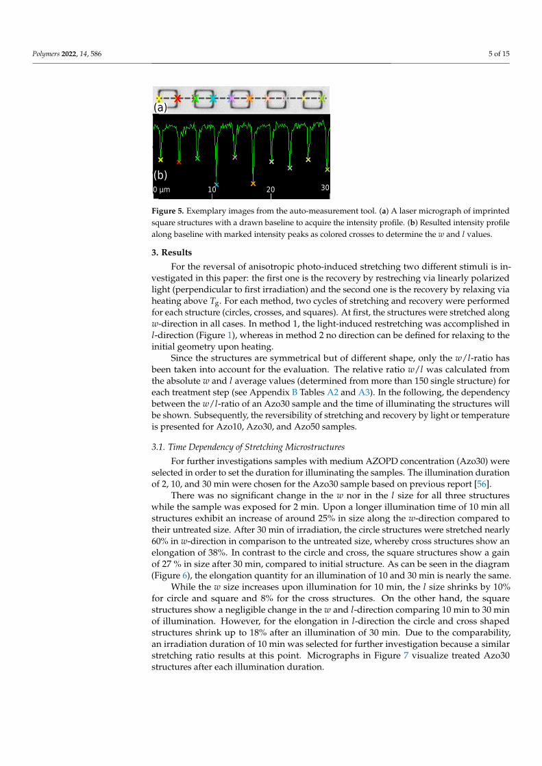
Displacement measurements were performed using a confocal laser scanning micro-scope (VK-X1100, Keyence). The samples were neither affected by the laser beam of theVK-X1100 nor by daylight. Using the company provided VK-Analyzer, the intensity profilewas acquired by using a baseline along w- or l-direction. By using the auto-measurementtool, the absolute values of w and l lengths of more than 150 single structures were mea-sured for each treatment step. As an example, the laser image of nanoimprinted structures(Figure 5a) and the intensity profile (Figure 5b) along the baseline (dashed line) is shown.The absolute w values were determined from the distance between the intensity peaks(colored crosses). The l values were determined analogously. With a self written Pythonprogram the mean average for the w and l values within a confidential interval of 0.95were determined.
Polymers 2022, 14, 586 5 of 15
Figure 5. Exemplary images from the auto-measurement tool. (a) A laser micrograph of imprintedsquare structures with a drawn baseline to acquire the intensity profile. (b) Resulted intensity profilealong baseline with marked intensity peaks as colored crosses to determine the w and l values.
3. Results
For the reversal of anisotropic photo-induced stretching two different stimuli is in-vestigated in this paper: the first one is the recovery by restreching via linearly polarizedlight (perpendicular to first irradiation) and the second one is the recovery by relaxing viaheating above Tg. For each method, two cycles of stretching and recovery were performedfor each structure (circles, crosses, and squares). At first, the structures were stretched alongw-direction in all cases. In method 1, the light-induced restretching was accomplished inl-direction (Figure 1), whereas in method 2 no direction can be defined for relaxing to theinitial geometry upon heating.
Since the structures are symmetrical but of different shape, only the w/l-ratio hasbeen taken into account for the evaluation. The relative ratio w/l was calculated fromthe absolute w and l average values (determined from more than 150 single structure) foreach treatment step (see Appendix B Tables A2 and A3). In the following, the dependencybetween the w/l-ratio of an Azo30 sample and the time of illuminating the structures willbe shown. Subsequently, the reversibility of stretching and recovery by light or temperatureis presented for Azo10, Azo30, and Azo50 samples.
3.1. Time Dependency of Stretching Microstructures
For further investigations samples with medium AZOPD concentration (Azo30) wereselected in order to set the duration for illuminating the samples. The illumination durationof 2, 10, and 30 min were chosen for the Azo30 sample based on previous report [56].
There was no significant change in the w nor in the l size for all three structureswhile the sample was exposed for 2 min. Upon a longer illumination time of 10 min allstructures exhibit an increase of around 25% in size along the w-direction compared totheir untreated size. After 30 min of irradiation, the circle structures were stretched nearly60% in w-direction in comparison to the untreated size, whereby cross structures show anelongation of 38%. In contrast to the circle and cross, the square structures show a gainof 27 % in size after 30 min, compared to initial structure. As can be seen in the diagram(Figure 6), the elongation quantity for an illumination of 10 and 30 min is nearly the same.
While the w size increases upon illumination for 10 min, the l size shrinks by 10%for circle and square and 8% for the cross structures. On the other hand, the squarestructures show a negligible change in the w and l-direction comparing 10 min to 30 minof illumination. However, for the elongation in l-direction the circle and cross shapedstructures shrink up to 18% after an illumination of 30 min. Due to the comparability,an irradiation duration of 10 min was selected for further investigation because a similarstretching ratio results at this point. Micrographs in Figure 7 visualize treated Azo30structures after each illumination duration.

Polymers 2022, 14, 586 6 of 15
0 5 10 15 20 25 30Irradiation Duration [min]
1.0
1.2
1.4
1.6
1.8
Rela
tive
Ratio
w/l
CircleCrossSquare
Figure 6. Relative w/l-ratio as a function of irradiation duration for Azo30. An increase in size canbe observed for circle and cross structures at longer illumination, whereas the increase in size forsquare structures is negligible after 10 min.
(a) (b) (c) (d)
t = 0 min t = 2 min t = 10 min t = 30 min
Figure 7. Micrographs of treated Azo30 structures. (a) Structures after the fabrication processwith tNIL. (b) After 2 min of illumination with horizontally polarized light, a slight change can bemeasured. (c) Upon 10 min, a clear stretching in w-direction was measured. (d) Larger stretching isobtained after an illumination for 30 min.
3.2. Reversible Change of the Structure Sizes by Light
Based on the results in Section 3.1, an irradiation duration of 10 min was chosen asappropriate for each reshaping step. To investigate these behavior, the untreated samples(designated as L0; “L” for light-induced recovery) were illuminated with horizontallypolarized light for 10 min in the w-direction during the first treatment step (L1). Thesecond treatment (L2) is done analogously in l-direction. Subsequently, a second cycle withtreatment L3 and L4 were performed as in L1 and L2.
While there is no significant reversible stretching measurable for the Azo10 samples(Figure 8a, top), the Azo30 (a, middle) and Azo50 (a, bottom) samples show a clear behaviorin stretching and restretching to the initial size. During treatment L3, the structures can bestretched by 20%, while for treatment L4 the initial geometry could be restored as it canbe seen in Figure 8. Azo50 seems to be unsuitable for a controlled recovery of the initialsize. Additionally, by illuminating the structures in step L2, the l-size extends while thew-size decreases for circle and cross. For square structures, the second treatment L2 seemsinsufficient to recover the structures completely. Irradiation during treatment L3 leadsagain to an increase in w-size up to 23% for cross and square and around 55% for circlestructures. The treatment step L4 results in a similar behavior as in L2, whereby for allthree structures the sizes remain similar. Even though, the structure types behave different

Polymers 2022, 14, 586 7 of 15
in their reshaping, there is no clear geometry dependency visible for all samples (Figure 8b).Micrographs in Figure 9 visualize Azo30 structures after each treatment step.
0.5
1.0
1.5
2.0
2.5
Azo10Azo10Azo10
(a) Light-Reversed (concentration)Circle Cross Square
CircleCircleCircle
(b) Light-Reversed (geometry)Azo10 Azo30 Azo50
0.5
1.0
1.5
2.0
2.5
Rela
tive
Ratio
w/l
Azo30Azo30Azo30 CrossCrossCross
0 1 2 3 4Treatment
0.5
1.0
1.5
2.0
2.5
Azo50Azo50Azo500 1 2 3 4
Treatment
SquareSquareSquare
Figure 8. The ordinate shows the relative w/l-ratio of the mean values corresponding to differentconcentrations (Azo10, Azo30 and Azo50) in (a) and each geometry (circle, square and cross) in (b).The abscissa shows the treatment steps (L0: untreated, L1: stretching for 10 min in w-direction, L2:stretching for 10 min in l-direction, L3: same as L1, L4: same as L2.
(a) (b) (c) (d) (e)
L0 L1: ↔ L2: l L3: ↔ L4: l
Figure 9. Micrographes of treated Azo30 structures. (a) Structures after the fabrication process withtNIL. (b) All three structures get stretched after the first treatment in the w-size while the l-size shrinks.(c) After L2, the w-size shrinks again while the l-size elongates. (d) By repeating the stretching inw-direction (L3), the structures increase in size again. (e) In L4, the structures are mainly recoveredafter restretching along l-direction.
3.3. Reversible Change of the Structure Sizes by Temperature
As already mentioned, the light-induced stretching can additionally be relaxed bymeans of temperature. Here, treatment steps T0, T1 and T3 (“T” for thermal-inducedrecovery) remain the same as for L0, L1, and L3, but treatment steps T2 and T4 are replacedby a temperature step. During these steps, the samples were heated at 120 ◦C for 5 min torelax the stretched structures to the initial size. Again, the investigation of the reversibilityresults in a dependency on AZOPD-concentration (Figure 10). Micrographs in Figure 11visualize Azo30 structures after each treatment step.

Polymers 2022, 14, 586 8 of 15
0.5
1.0
1.5
2.0
2.5
Azo10Azo10Azo10
(a) Heat-Reversed (concentration)Circle Cross Square
CircleCircleCircle
(b) Heat-Reversed (geometry)Azo10 Azo30 Azo50
0.5
1.0
1.5
2.0
2.5Re
lativ
e Ra
tio w
/l
Azo30Azo30Azo30 CrossCrossCross
0 1 2 3 4Treatment
0.5
1.0
1.5
2.0
2.5
Azo50Azo50Azo500 1 2 3 4
Treatment
SquareSquareSquare
Figure 10. The ordinate shows the relative w/l-ratio of the mean values considering each concen-tration (Azo10, Azo30 and Azo50) in (a) and each geometry (circles, crosses and squares) in (b).The abscissa shows the treatment steps (T0: untreated, T1: stretching for 10 min in w-direction, T2:heating at 120 °C for 5 min, T3: same as T1, T4: same as T2).
(a) (b) (c) (d) (e)
T0 T1: ↔ T2: 120 ◦C T3: ↔ T4: 120 ◦C
Figure 11. Micrographes of treated Azo30 structures. (a) Structures after the fabrication processwith tNIL. (b) All three structures get stretched after the first treatment in the w-size while the l-sizeshrinks. (c) During T2, the w and l-sizes relax. (d) By repeating the stretching in w-direction (T3), thestructures increase in size again. (e) During T4, the structures are mainly recovered after relaxing.
The results of the Azo10 sample (Figure 10a, top) show no significant change in thestructures for both stretching and relaxing (below 10%). In contrast, the Azo30 sample (a,middle) shows a clear stretching (T1 and T3) and relaxation in T2 and T4 about 25% of theinitial size. For the Azo50 sample (a, bottom), the first stretching with light is irreversiblyhigh (approx. 70%). It was not possible to relax the stretched structures to initial size after5 min of heating during T2 (nearly 45% remains). Even after the second cycle, the initialsize could not be recovered. However, a slight stretching was still possible during T3.
The calculated w/l-ratio of square structures is higher for Azo50 samples than forcircle or cross structures (best visible after T1 in Figure 10a, middle and bottom). However,likewise as light-reversed shape deformation, it is not possible to identify a significantdependency for the geometries (Figure 10b).
4. Discussion
The experiments demonstrate that the reversible stretching of imprinted structures,made out of an AZOPD/PS-mixture, can be implemented by a second stretching along

Polymers 2022, 14, 586 9 of 15
l-direction or relaxing by annealing above Tg. The reversible shape deformation was per-formed twice to recover the initial structure geometry. Depending on irradiation durationand the concentration of the AZOPD fraction, the relative stretching quantity ranges be-tween 10–70%, which is comparable with results from literature. Comparable experimentsshow relative stretching ranges between 30–140% [38,39,48–50]. However, a small degreeof degradation was obtained after the second reversion, which is observable in a decreasein the w/l-ratio. Findings of Pirani et al. show a similar degradation effect [38]. A possibleexplanation is that a small amount of AZOPD and/or PS remain in the stretched orientationand are not able to be addressed.
Comparing the light- and heat-treated reversible reshaping, it is visible that therecovery of initial geometry is less deviating with heat-reversion (see micrographs inFigures 9 and 11). This effect can be understood when it is taken into account that thermalreversal is accomplished only by relaxing the stretched structure, whereas light-reversedstructures experience an additional perpendicular stretching in l-direction (as seen inFigure 9). Consequently, light-recovered structures are not only relaxed, but also stretched,whereas heat-recovered structures are only relaxed to initial geometry. For better resultsin recovery by polarized light, the duration of irradiation should be readjusted, i.e., thestructures should not be irradiated in l-direction as long as in w-direction. The l-directionneeds shorter irradiation duration to prevent an unintended l-stretching after the firsttreatment in w-direction. In contrast, the thermal recovery at the chosen temperatureprevents an additional stretching and the last achievable condition is the initial geometry.Another observation is that the amplification of the stretching effect with higher AZOPDconcentration does not behave in a linear way as seen in Figures 8 and 10. A five-foldAZOPD concentration between Azo10 and Azo50 does not result in a five-fold higherstretching value. Therefore, it is suspected that the stretching quantity behaves similar tothe stretching behavior itself, namely with a fast beginning increase and ending in reachingslowly a saturation point. This behavior is very similar to well known photo-inducedsurface and bulk structuring of azo films [56–59].
The mechanism of stretching can be divided into three different steps: (1) photo-isomerization, (2) photo-orientation, and (3) photo-induced mass transport/flow. Thestep (1) of photo-isomerization is the fastest step and describes the trans-cis-isomerization,whereas the second step (2) of photo-orientation occurs under the condition of constantlyirradiating the azo material with polarized light with a wavelength within the n-π*-absorption. Here, the isomerization has a repetitive behavior and azo molecules undergo acyclic trans-cis-trans-isomerization since either configurations are addressed [57,60]. Theprobability of isomerization W decreases, when the angle θ between the polarization plane,e.g., the E-field vector of polarized light, and the dipole moment of the azo molecule tendsto 90◦: W ∝ cos2 θ [57,60]. Once the dipole moment of the azo molecule and the polar-ization orientation of incident light is perpendicular to each other, photo-isomerizationdoes not occur anymore. Afterwards, the third step (3) of directional photo-induced massflow along the polarization orientation starts. It can be assumed that the transition be-tween each step is continuous. At this step, azo molecules move or flow parallel to thepolarization plane. This process is temporally limited and stops after reaching a satura-tion point [27,34,37,39,46,47,56,57]. As can be seen in Figure 6, the time dependency oflight-induced stretching can be confirmed.
An interesting idea for the mechanism is described by the group of Hideyuki Nakano [37,47].They describe the elongation process of azo particles in agar-gel as a push-pull effectbetween particles of the azo glass and surrounding agar-gel. Ryabchun et al. made a similarassumption. Our results may support the hypothesis that recovery of a deformed structureto initial geometry is highly supported by the elastic polymer matrix, which is embeddingthe azo material. The AZOPD material within the PS-matrix undergoes photo-inducedstretching (mechanical strain), which in turn, stretches the polymer matrix of PS and keepsit under stress. Upon annealing above Tg, the polymer matrix of PS relaxes and compressesthe stretched AZOPD material. A hint for this is that the results presented here show a
Polymers 2022, 14, 586 10 of 15
significant increasing of the stretching behavior with higher relative proportion of AZOPDin the AZOPD/PS-mixture. It is reasonable that a higher concentration of chromophorecan apply a bigger force on the surrounding polymer matrix during stretching, which leadsto higher degree of relative stretching and restretching. However, systematic experimentsneed to be done with various molecular weights of PS.
5. Conclusions
Reversible reshaping of imprinted periodic structures by using linearly polarizedlight or heat as the stimuli for recovery has been shown successfully. The dependency onAZOPD-concentration and structure geometry for stretching and restretching/relaxingwere investigated in a systematic way for either recovery-stimuli. A good controllablestretching can be achieved with a specific concentration ratio, which is represented byAzo30 samples. The results can be applied for functional structures produced by meansof diverse NIL-techniques. Another application is to use the cross-structure as a light-driven switch in electronic micro- or nano-circuits by stretching the opposite cross-armstoward or away a circuit, whereas an orthogonal stretching would address a second circuit.However, the reaction time of photo-induced stretching has to be improved significantlyfor electronic circuits.
Author Contributions: Conceptualization, B.K. and S.B.; methodology, B.K. and S.B.; software, S.B.and M.S.; validation, B.K., S.B. and M.S.; formal analysis, B.K., S.B. and M.S.; investigation, B.K.,S.B. and M.S.; resources, H.H. and T.F.-L.; data curation, B.K., S.B. and M.S.; writing—original draftpreparation, B.K., S.B. and M.S.; writing—review and editing, B.K., S.B., M.S., H.H. and T.F.-L.;visualization, B.K. and S.B.; supervision, B.K., S.B., H.H. and T.F.-L.; project administration, B.K., S.B.,H.H. and T.F.-L. All authors have read and agreed to the published version of the manuscript.
Funding: This research received no external funding.
Institutional Review Board Statement: Not applicable.
Informed Consent Statement: Not applicable.
Data Availability Statement: The datasets used and/or analyzed during the current study areavailable from the corresponding author on reasonable request, including the used python code.
Acknowledgments: We gratefully thank Marilia Horn for performing DSC-measurements and theiranalysis for determination of Tg.
Conflicts of Interest: The authors declare no conflict of interest.
AbbreviationsThe following abbreviations are used in this manuscript:
AZOPD N,N′-bis(phenyl)-N,N′-bis((4-phenylazo)-phenyl)benzidinePS PolystyrenetNIL Thermal nanoimprint lithographyPMMA Poly(methyl methacrylate)Tg Glass transition temperatureOLED Organic light emitting devicePDMS PolydimetylsiloxaneTHF TetrahydrofuranDSC Differential scanning calorimetryDPSS Diode pumped solid stateW Probability of isomerization
Polymers 2022, 14, 586 11 of 15
Appendix A. DSC-Measurement of Azo30
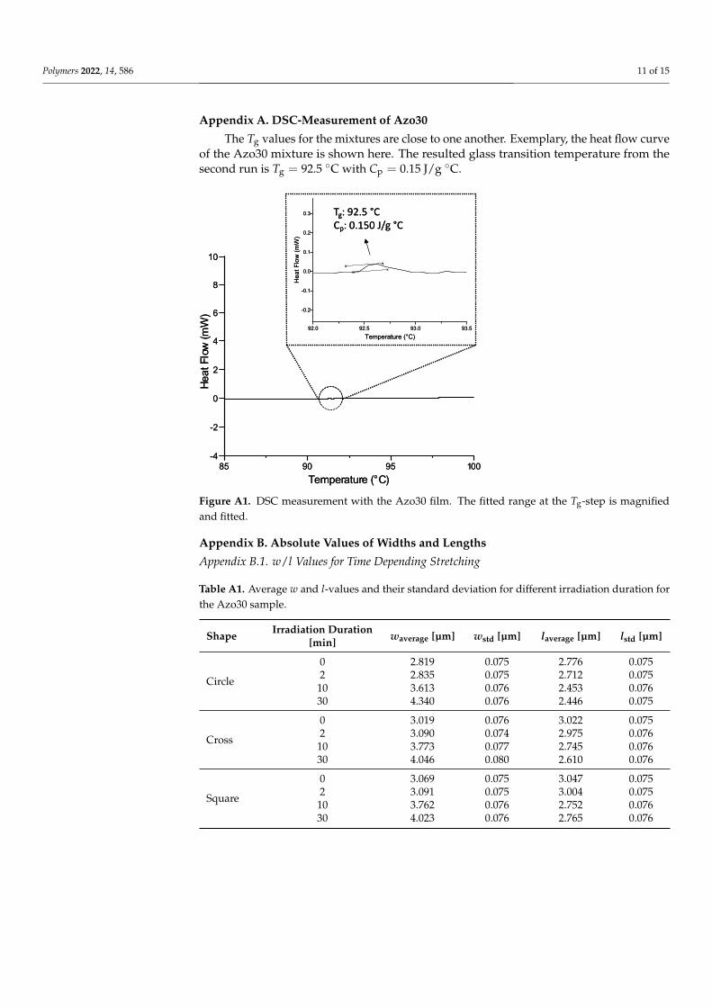
The Tg values for the mixtures are close to one another. Exemplary, the heat flow curveof the Azo30 mixture is shown here. The resulted glass transition temperature from thesecond run is Tg = 92.5 ◦C with Cp = 0.15 J/g ◦C.
Figure A1. DSC measurement with the Azo30 film. The fitted range at the Tg-step is magnifiedand fitted.
Appendix B. Absolute Values of Widths and Lengths
Appendix B.1. w/l Values for Time Depending Stretching
Table A1. Average w and l-values and their standard deviation for different irradiation duration forthe Azo30 sample.
Shape Irradiation Duration[min] waverage [µm] wstd [µm] laverage [µm] lstd [µm]
Circle
0 2.819 0.075 2.776 0.0752 2.835 0.075 2.712 0.075
10 3.613 0.076 2.453 0.07630 4.340 0.076 2.446 0.075
Cross
0 3.019 0.076 3.022 0.0752 3.090 0.074 2.975 0.076
10 3.773 0.077 2.745 0.07630 4.046 0.080 2.610 0.076
Square
0 3.069 0.075 3.047 0.0752 3.091 0.075 3.004 0.075
10 3.762 0.076 2.752 0.07630 4.023 0.076 2.765 0.076
Polymers 2022, 14, 586 12 of 15
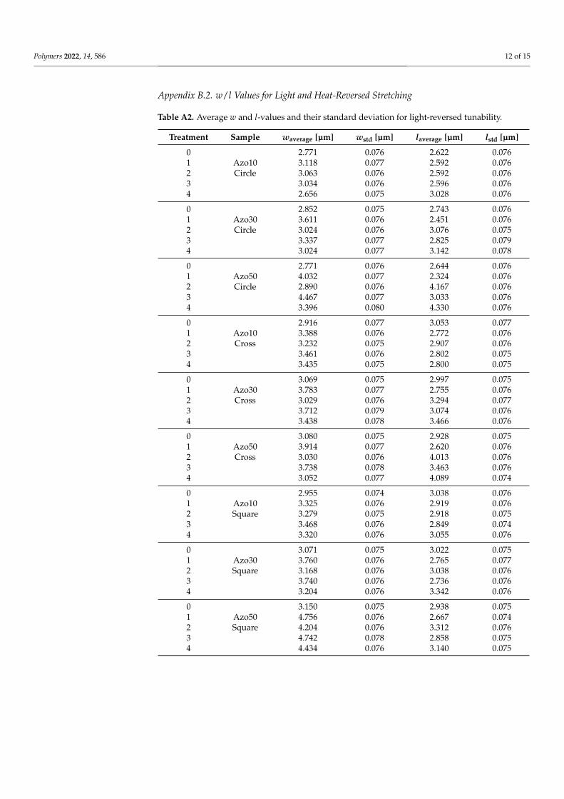
Appendix B.2. w/l Values for Light and Heat-Reversed Stretching
Table A2. Average w and l-values and their standard deviation for light-reversed tunability.
Treatment Sample waverage [µm] wstd [µm] laverage [µm] lstd [µm]
0 2.771 0.076 2.622 0.0761 Azo10 3.118 0.077 2.592 0.0762 Circle 3.063 0.076 2.592 0.0763 3.034 0.076 2.596 0.0764 2.656 0.075 3.028 0.076
0 2.852 0.075 2.743 0.0761 Azo30 3.611 0.076 2.451 0.0762 Circle 3.024 0.076 3.076 0.0753 3.337 0.077 2.825 0.0794 3.024 0.077 3.142 0.078
0 2.771 0.076 2.644 0.0761 Azo50 4.032 0.077 2.324 0.0762 Circle 2.890 0.076 4.167 0.0763 4.467 0.077 3.033 0.0764 3.396 0.080 4.330 0.076
0 2.916 0.077 3.053 0.0771 Azo10 3.388 0.076 2.772 0.0762 Cross 3.232 0.075 2.907 0.0763 3.461 0.076 2.802 0.0754 3.435 0.075 2.800 0.075
0 3.069 0.075 2.997 0.0751 Azo30 3.783 0.077 2.755 0.0762 Cross 3.029 0.076 3.294 0.0773 3.712 0.079 3.074 0.0764 3.438 0.078 3.466 0.076
0 3.080 0.075 2.928 0.0751 Azo50 3.914 0.077 2.620 0.0762 Cross 3.030 0.076 4.013 0.0763 3.738 0.078 3.463 0.0764 3.052 0.077 4.089 0.074
0 2.955 0.074 3.038 0.0761 Azo10 3.325 0.076 2.919 0.0762 Square 3.279 0.075 2.918 0.0753 3.468 0.076 2.849 0.0744 3.320 0.076 3.055 0.076
0 3.071 0.075 3.022 0.0751 Azo30 3.760 0.076 2.765 0.0772 Square 3.168 0.076 3.038 0.0763 3.740 0.076 2.736 0.0764 3.204 0.076 3.342 0.076
0 3.150 0.075 2.938 0.0751 Azo50 4.756 0.076 2.667 0.0742 Square 4.204 0.076 3.312 0.0763 4.742 0.078 2.858 0.0754 4.434 0.076 3.140 0.075

Polymers 2022, 14, 586 13 of 15
Table A3. Average w and l-values and their standard deviation for thermal-reversed tunability.
Treatment Sample waverage [µm] wstd [µm] laverage [µm] lstd [µm]
0 2.615 0.076 2.739 0.0761 Azo10 3.033 0.076 2.545 0.0772 Circle 2.623 0.076 2.627 0.0763 2.829 0.077 2.627 0.0764 2.623 0.076 2.543 0.078
0 2.683 0.076 2.750 0.0761 Azo30 3.301 0.076 2.460 0.0762 Circle 2.788 0.075 2.609 0.0763 3.407 0.077 2.606 0.0764 2.683 0.076 2.647 0.076
0 2.777 0.076 2.737 0.0761 Azo50 4.252 0.079 2.430 0.0752 Circle 4.124 0.078 2.480 0.0763 4.382 0.076 2.414 0.0764 4.207 0.076 2.442 0.075
0 2.897 0.076 2.940 0.0751 Azo10 3.072 0.076 2.835 0.0772 Cross 2.975 0.075 2.794 0.0753 2.950 0.074 2.807 0.0744 2.782 0.078 2.653 0.076
0 3.021 0.076 2.895 0.0761 Azo30 3.733 0.082 2.675 0.0782 Cross 3.068 0.076 2.823 0.0783 3.615 0.076 2.761 0.0774 2.999 0.075 2.823 0.077
0 2.777 0.076 2.927 0.0751 Azo50 4.587 0.076 2.630 0.0762 Cross 4.568 0.076 2.692 0.0773 4.874 0.076 2.640 0.0764 4.631 0.079 2.621 0.076
0 3.042 0.076 3.140 0.0751 Azo10 3.312 0.076 2.970 0.0752 Square 3.065 0.075 3.042 0.0763 3.196 0.076 2.995 0.0754 3.018 0.075 2.970 0.077
0 3.073 0.075 2.956 0.0741 Azo30 4.027 0.076 2.658 0.0752 Square 3.037 0.076 2.892 0.0763 4.004 0.075 2.914 0.0764 3.285 0.075 2.929 0.075
0 3.095 0.074 2.935 0.0751 Azo50 5.155 0.076 2.727 0.0752 Square 5.013 0.076 2.739 0.0763 5.606 0.076 2.791 0.0754 5.317 0.090 2.733 0.075
References1. Löber, D.; Dey, S.; Kaban, B.; Roesler, F.; Maurer, M.; Hillmer, H.; Pietschnig, R. 3D micro/nanopatterning of a vinylferrocene
copolymer. Molecules 2020, 25, 2438. [CrossRef] [PubMed]2. Roesler, F.; Kaban, B.; Klintuch, D.; Ha, U.M.; Bruhn, C.; Hillmer, H.; Pietschnig, R. Tailoring Phospholes for Imprint of Fluorescent
3D Structures. Eur. J. Inorg. Chem. 2019, 2019, 4820–4825. [CrossRef]3. Cox, L.M.; Martinez, A.M.; Blevins, A.K.; Sowan, N.; Ding, Y.; Bowman, C.N. Nanoimprint lithography: Emergent materials and
methods of actuation. Nano Today 2020, 31, 100838. [CrossRef]
Polymers 2022, 14, 586 14 of 15
4. Michel, A.; Ruprecht, R.; Harmening, M.; Bacher, W. Abformung von Mikrostrukturen auf prozessierten Wafern. Ph.D. Thesis,Universitat Karlsruhe, Karlsruhe, Germany, 1993. [CrossRef]
5. Chou, S.Y.; Krauss, P.R.; Renstrom, P.J. Imprint lithography with 25-nanometer resolution. Science 1996, 272, 85–87. [CrossRef]6. Chou, S.Y.; Krauss, P.R.; Renstrom, P.J. Imprint of sub-25 nm vias and trenches in polymers. Appl. Phys. Lett. 1995, 67, 3114–3116.
[CrossRef]7. Tan, H. Roller nanoimprint lithography. J. Vac. Sci. Technol. Microelectron. Nanometer Struct. 1998, 16, 3926. [CrossRef]8. Guo, L.J. Nanoimprint Lithography: Methods and Material Requirements. Adv. Mater. 2007, 19, 495–513. [CrossRef]9. Ha, U.M.M.; Kaban, B.; Tomita, A.; Krekic, K.; Klintuch, D.; Pietschnig, R.; Ehresmann, A.; Holzinger, D.; Hillmer, H. Multifunc-
tional guest–host particles engineered by reversal nanoimprint lithography. Appl. Nanosci. 2018, 8, 1161–1169. [CrossRef]10. Reuter, S.; Smolarczyk, M.A.; Istock, A.; Ha, U.M.; Schneider, O.; Worapattrakul, N.; Nazemroaya, S.; Hoang, H.; Gomer, L.; Pilger,
F.; et al. Bending properties of two- and three-dimensional-shaped nanoparticles fabricated via substrate conformal imprintlithography. J. Nanopart. Res. 2017, 19, 184. [CrossRef]
11. Kolli, V.; Woidt, C.; Hillmer, H. Residual-layer-free 3D nanoimprint using hybrid soft templates. Microelectron. Eng. 2016,149, 159–165. [CrossRef]
12. Schift, H. Nanoimprint lithography: An old story in modern times? A review. J. Vac. Sci. Technol. Microelectron. Nanometer Struct.2008, 26, 458. [CrossRef]
13. Haisma, J. Mold-assisted nanolithography: A process for reliable pattern replication. J. Vac. Sci. Technol. Microelectron. NanometerStruct. 1996, 14, 4124. [CrossRef]
14. Qi, S.; Guo, H.; Fu, J.; Xie, Y.; Zhu, M.; Yu, M. 3D printed shape-programmable magneto-active soft matter for biomimeticapplications. Compos. Sci. Technol. 2020, 188, 107973. [CrossRef]
15. Lee, H.; Kim, J.; Kim, H.; Kim, J.; Kwon, S. Colour-barcoded magnetic microparticles for multiplexed bioassays. Nat. Mater. 2010,9, 745–749. [CrossRef] [PubMed]
16. Cho, D.I.D.; Yoo, H.J. Microfabrication methods for biodegradable polymeric carriers for drug delivery system applications:A review. J. Microelectromech. Syst. 2015, 24, 10–18. [CrossRef]
17. Glangchai, L.C.; Caldorera-Moore, M.; Shi, L.; Roy, K. Nanoimprint lithography based fabrication of shape-specific, enzymatically-triggered smart nanoparticles. J. Control. Release 2008, 125, 263–272. [CrossRef] [PubMed]
18. Ohdaira, Y.; Ikeda, Y.; Oka, H.; Shinbo, K. Optically reversible deformation of azobenzene particles prepared by a colloidalmethod. J. Appl. Phys. 2019, 125, 103104. [CrossRef]
19. Stuart, M.A.C.; Huck, W.T.S.; Genzer, J.; Müller, M.; Ober, C.; Stamm, M.; Sukhorukov, G.B.; Szleifer, I.; Tsukruk, V.V.; Urban,M.; et al. Emerging applications of stimuli-responsive polymer materials. Nat. Mater. 2010, 9, 101–113. [CrossRef]
20. Fan, X.; Chung, J.Y.; Lim, Y.X.; Li, Z.; Loh, X.J. Review of Adaptive Programmable Materials and Their Bioapplications. ACS Appl.Mater. Interfaces 2016, 8, 33351–33370. [CrossRef]
21. Ionov, L. Soft microorigami: Self-folding polymer films. Soft Matter 2011, 7, 6786–6791. [CrossRef]22. Wani, O.M.; Zeng, H.; Priimagi, A. A light-driven artificial flytrap. Nat. Commun. 2017, 8, 15546. [CrossRef]23. Yu, Y.; Ikeda, T. Soft actuators based on liquid-crystalline elastomers. Angew. Chem. Int. Ed. 2006, 45, 5416–5418. [CrossRef]
[PubMed]24. Yu, Y.; Nakano, M.; Ikeda, T. Directed bending of a polymer film by light. Nature 2003, 425, 145. [CrossRef]25. Perschke, A.; Fuhrmann, T. Molecular azo glasses as grating couplers and resonators for optical devices. Adv. Mater. 2002,
14, 841–843. [CrossRef]26. Fuhrmann, T.; Samse, K.; Salbeck, J.; Perschke, A.; Franke, H. Guided electromagnetic waves in organic light emitting diode
structures. Org. Electron. 2003, 4, 219–226. [CrossRef]27. Yager, K.G.; Barrett, C.J. Novel photo-switching using azobenzene functional materials. J. Photochem. Photobiol. A Chem. 2006,
182, 250–261. [CrossRef]28. Oscurato, S.L.; Borbone, F.; Maddalena, P.; Ambrosio, A. Light-Driven Wettability Tailoring of Azopolymer Surfaces with
Reconfigured Three-Dimensional Posts. ACS Appl. Mater. Interfaces 2017, 9, 30133–30142. [CrossRef]29. Jo, W.; Choi, J.; Kang, H.S.; Kim, M.; Baik, S.; Lee, B.J.; Pang, C.; Kim, H.T. Programmable Fabrication of Submicrometer Bent
Pillar Structures Enabled by a Photoreconfigurable Azopolymer. ACS Appl. Mater. Interfaces 2020, 12, 5058–5064. [CrossRef][PubMed]
30. Choi, J.; Jo, W.; Lee, S.Y.; Jung, Y.S.; Kim, S.H.; Kim, H.T. Flexible and Robust Superomniphobic Surfaces Created by LocalizedPhotofluidization of Azopolymer Pillars. ACS Nano 2017, 11, 7821–7828. [CrossRef]
31. Merian, E. Steric Factors Influencing the Dyeing of Hydrophobic. Fibers. Text. Res. J. 1966, 36, 612–618. [CrossRef]32. Li, Y.; He, Y.; Tong, X.; Wang, X. Photoinduced deformation of amphiphilic azo polymer colloidal spheres. J. Am. Chem. Soc. 2005,
127, 2402–2403. [CrossRef] [PubMed]33. Li, Y.; He, Y.; Tong, X.; Wang, X. Stretching effect of linearly polarized Ar+ laser single-beam on azo polymer colloidal spheres.
Langmuir 2006, 22, 2288–2291. [CrossRef] [PubMed]34. Li, J.; Chen, L.; Xu, J.; Wang, K.; Wang, X.; He, X.; Dong, H.; Lin, S.; Zhu, J. Photoguided Shape Deformation of Azobenzene-
Containing Polymer Microparticles. Langmuir 2015, 31, 13094–13100. [CrossRef]35. Zhou, Y.; Wang, X.G. Photodeformable Microspheres from Amphiphilic Azo Polyurethane. Macromol. Chem. Phys. 2015,
216, 2040–2047. [CrossRef]

Polymers 2022, 14, 586 15 of 15
36. Wang, W.; Du, C.; Wang, X.; He, X.; Lin, J.; Li, L.; Lin, S. Directional Photomanipulation of Breath Figure Arrays. Angew. Chem.Int. Ed. 2014, 53, 12116–12119. [CrossRef]
37. Ichikawa, R.; Nakano, H. Photoinduced change in the shape of azobenzene-based molecular glass particles fixed in agar gel. RSCAdv. 2016, 6, 36761–36765. [CrossRef]
38. Pirani, F.; Angelini, A.; Frascella, F.; Rizzo, R.; Ricciardi, S.; Descrovi, E. Light-Driven Reversible Shaping of IndividualAzopolymeric Micro-Pillars. Sci. Rep. 2016, 6, 31702. [CrossRef]
39. Ryabchun, A.; Bobrovsky, A. Photocontrollable Deformations of Polymer Particles in Elastic Matrix. Adv. Opt. Mater. 2019, 7.[CrossRef]
40. Lee, S.; Kang, H.S.; Park, J.K. High-resolution patterning of various large-area, highly ordered structural motifs by directionalphotofluidization lithography: Sub-30-nm line, ellipsoid, rectangle, and circle arrays. Adv. Funct. Mater. 2011, 21, 1770–1778.[CrossRef]
41. Lee, S.; Kang, H.S.; Ambrosio, A.; Park, J.K.; Marrucci, L. Directional superficial photofluidization for deterministic shaping ofcomplex 3d architectures. ACS Appl. Mater. Interfaces 2015, 7, 8209–8217. [CrossRef] [PubMed]
42. Wang, J.; Wu, B.; Li, S.; Sinawang, G.; Wang, X.; He, Y. Synthesis and characterization of photoprocessable lignin-based azopolymer. ACS Sustain. Chem. Eng. 2016, 4, 4036–4042. [CrossRef]
43. Pirani, F.; Angelini, A.; Frascella, F.; Descrovi, E. Reversible Shaping of Microwells by Polarized Light Irradiation. Int. J. Polym.Sci. 2017, 2017, 6812619. [CrossRef]
44. Wang, W.; Yao, Y.; Luo, T.; Chen, L.; Lin, J.; Li, L.; Lin, S. Deterministic reshaping of breath figure arrays by directionalphotomanipulation. ACS Appl. Mater. Interfaces 2017, 9, 4223–4230. [CrossRef] [PubMed]
45. Choi, J.; Kang, H.S.; Jo, W.; Kim, S.H.; Jung, Y.S.; Kim, H.T. Photo-Reconfigurable Azopolymer Etch Mask: Photofluidization-Driven Reconfiguration and Edge Rectangularization. Small 2018, 14. [CrossRef]
46. Loebner, S.; Lomadze, N.; Kopyshev, A.; Koch, M.; Guskova, O.; Saphiannikova, M.; Santer, S. Light-Induced Deformation ofAzobenzene-Containing Colloidal Spheres: Calculation and Measurement of Opto-Mechanical Stresses. J. Phys. Chem. B 2018,122, 2001–2009. [CrossRef]
47. Nakano, H.; Ichikawa, R.; Ukai, H.; Kitano, A. Photoinduced Shape Changes of Mixed Molecular Glass Particles ContainingAzobenzene-Based Photochromic Amorphous Molecular Materials Fixed in Agar Gel. J. Phys. Chem. B 2018, 122, 7775–7781.[CrossRef]
48. Wang, Y.; Hu, L.; Yin, Q.; Du, K.; Zhang, T.; Yin, Q. Multi-responsive hollow nanospheres self-assembly by amphiphilic randomcopolymer and azobenzene. Polymer 2019, 175, 235–242. [CrossRef]
49. Huang, H.; Su, Y.; Xu, J.; Wang, X. Asymmetric Morphology Transformation of Azo Molecular Glass Microspheres Induced byPolarized Light. Langmuir 2019, 35, 15295–15305. [CrossRef]
50. Huang, H.; Wang, Z.; Li, X.; Yang, F.; Su, Y.; Xu, J.; Wang, X. Directional mass transfer of azo molecular glass microsphere inducedby polarized light in aqueous immersion media. RSC Adv. 2021, 11, 15387–15399. [CrossRef]
51. Wang, Z.; Hsu, C.; Wang, X. Topographical transition of submicron pillar array of azo molecular glass induced by circularlypolarized light. Sci. Rep. 2021, 11, 7327. [CrossRef] [PubMed]
52. Fuhrmann, T.; Tsutsui, T. Synthesis and properties of a hole-conducting, photopatternable molecular glass. Chem. Mater. 1999,11, 2226–2232. [CrossRef]
53. Tanino, T.; Yoshikawa, S.; Ujike, T.; Nagahama, D.; Moriwaki, K.; Takahashi, T.; Kotani, Y.; Nakano, H.; Shirota, Y. Creationof azobenzene-based photochromic amorphous molecular materials-Synthesis, glass-forming properties, and photochromicresponse. J. Mater. Chem. 2007, 17, 4953–4963. [CrossRef]
54. Reinke, N.; Fuhrmann, T.; Perschke, A.; Franke, H. Improved outcoupling of light in organic light emitting devices, utilizing aholographic DFB-structure. J. Lumin. 2004, 110, 413–417. [CrossRef]
55. Arlt, M.; Scheffler, A.; Suske, I.; Eschner, M.; Saragi, T.P.; Salbeck, J.; Fuhrmann-Lieker, T. Bipolar redox behaviour, field-effectmobility and transistor switching of the low-molecular azo glass AZOPD. Phys. Chem. Chem. Phys. 2010, 12, 13828–13834.[CrossRef] [PubMed]
56. Bagatur, S.; Schlesag, M.; Fuhrmann-Lieker, T. Polarization Dependent Photoinduced Supramolecular Chirality in High-Performance Azo Materials. Molecules 2021, 26, 2842. [CrossRef]
57. Natansohn, A.; Rochon, P. Photoinduced motions in azo-containing polymers. Chem. Rev. 2002, 102, 4139–4175. [CrossRef]58. Rochon, P.; Batalla, E.; Natansohn, A. Optically induced surface gratings on azoaromatic polymer films. Appl. Phys. Lett. 1995,
66, 136–138. [CrossRef]59. Kim, D.Y.; Tripathy, S.K.; Li, L.; Kumar, J. Laser-induced holographic surface relief gratings on nonlinear optical polymer films.
Appl. Phys. Lett. 1995, 66, 1166–1168. [CrossRef]60. Shibaev, V.P. Liquid-crystalline polymers: Past, present, and future. Polym. Sci. Ser. A 2009, 51, 1131–1193. [CrossRef]