HEAT RECOVERY SINGLE-ROOM REVERSIBLE ...
32
VENTO Expert A50-1 W VENTO Expert DUO A30-1 W HEAT RECOVERY SINGLE-ROOM REVERSIBLE VENTILATION UNIT OPERATION MANUAL EN
-
Upload
khangminh22 -
Category
Documents
-
view
0 -
download
0
Transcript of HEAT RECOVERY SINGLE-ROOM REVERSIBLE ...

VENTO Expert A50-1 W VENTO Expert DUO A30-1 W
HEAT RECOVERY SINGLE-ROOM REVERSIBLE VENTILATION UNIT
OPERATION MANUAL EN

2
www.blaubergventilatoren.deVENTO Expert A50-1 W / DUO A30-1 W
Read the user’s manual carefully prior to installing and operating the unit.Fulfil the user’s manual requirements as well as the provisions of all the applicable local and national construction, electrical and technical norms and standards.The warnings contained in the user’s manual must be considered most seriously since they contain vital personal safety information.Failure to follow the rules and safety precautions noted in this user’s manual may result in an injury or unit damage.After a careful reading of the manual, keep it for the entire service life of the unit.While transferring the unit control the User’s manual must be turned over to the receiving operator.
Symbol legend:
The user’s manual consisting of the technical details, operating instructions and technical specification applies to the installation and mounting of the single-room reversible ventilation unit with energy regeneration VENTO Expert (Duo) (hereinafter «the unit» as mentioned in the «Safety Requirements» and «Manufacturer’s Warranty» sections as well as in warnings and information blocks).
Safety requirements ..................................................................................................................................2Purpose ..............................................................................................................................................................4Delivery set .......................................................................................................................................................4Technical data .................................................................................................................................................5Design and functioning ...........................................................................................................................6Mounting and set-up .................................................................................................................................9Connection to power supply and control .................................................................................12Maintenance.................................................................................................................................................27Troubleshooting .........................................................................................................................................29Storage and transportation regulations ....................................................................................29Manufacturer’s warranty .......................................................................................................................30Acceptance certificate ...........................................................................................................................31Seller information ......................................................................................................................................31Installation certificate ..............................................................................................................................31Warranty card ...............................................................................................................................................31
WARNING!
DO NOT!
UNIT MOUNTING AND OPERATION SAFETY PRECAUTIONS
• Disconnect the unit from power mains prior to any installation operations.
• Unpack the unit with care.
• Do not lay the power cable of the unit in close proximity to heating equipment.
• While installing the unit follow the safety regulations specific to the use of electric tools.
CONTENTS
SAFETY REQUIREMENTS

www.blaubergventilatoren.de
3
VENTO Expert A50-1 W / DUO A30-1 W
• Do not use damaged equipment or cables when connecting the unit to power mains.
• Do not operate the unit outside the temperature range stated in the user's manual.
• Do not operate the unit in aggressive or explosive environments.
• Do not touch the unit controls with wet hands. • Do not carry out the installation and
maintenance operations with wet hands.
• Do not wash the unit with water. • Protect the electric parts of the unit against
ingress of water.
UNIT MOUNTING AND OPERATION SAFETY PRECAUTIONS
• Do not allow children to operate the unit.• Disconnect the unit from power mains prior to
any technical maintenance.
• Do not store any explosive or highly flammable substances in close proximity to the unit.
• When the unit generates unusual sounds, odour or emits smoke disconnect it from power supply and contact the Seller.
• Do not open the unit during operation.• Do not direct the air flow produced by the unit
towards open flame or ignition sources.
• Do not block the air duct when the unit is switched on.
• In case of continuous operation of the unit periodically check the security of mounting.
• Do not sit on the unit and avoid placing foreign objects on it.
• Use the unit only for its intended purpose.
THE PRODUCT MUST BE COLLECTED SEPARATELY AT THE END OF SERVICE LIFE. DO NOT DISPOSE OF AS UNSORTED MUNICIPAL WASTE.

4
www.blaubergventilatoren.deVENTO Expert A50-1 W / DUO A30-1 W
The ventilation unit is designed to ensure continuous mechanical air exchange in houses, offices, hotels, cafes, conference halls and other utility and public spaces. The ventilation unit is equipped with a ceramic regenerator that enables supply of fresh filtered air heated by means of extract air heat energy regeneration. The unit is designed for through-the-wall mounting.
The unit is rated for continuous operation.Transported air must not contain any flammable or explosive mixtures, evaporation of chemicals, sticky substances, fibrous materials, coarse dust, soot and oil particles or environments favourable for the formation of hazardous substances (toxic substances, dust, pathogenic germs).
THE UNIT MAY NOT BE OPERATED BY CHILDREN OR PERSONS WITH REDUCED PHYSICAL, MENTAL OR SENSORY CAPACITIES, OR LACKING THE APPROPRIATE TRAINING.
THE UNIT MUST BE INSTALLED AND CONNECTED ONLY BY PROPERLY QUALIFIED PERSONNEL AFTER THE APPROPRIATE BRIEFING.
THE CHOICE OF UNIT INSTALLATION LOCATION MUST PREVENT UNAUTHORIZED ACCESS BY UNATTENDED CHILDREN.
Name Quantity
VENTO Expert A50-1 W
VENTO Expert DUO A30-1 W
Indoor unit 1 item 1 item Air duct 1 item 1 item Air flow separator - 3-6 itemsSound absorbing material 1 item -Cartridge 1 item 1 item Outer ventilation hood 1 item 1 item Remote control 1 item 1 item Cardboard template 1 item 1 item Mini-USB-B/USB A cable 1 item 1 item Fastening kit 2 packings 2 packingsUser's manual 1 item 1 item Outer hood installation instruction 1 item 1 item Packing box 1 item 1 item
PURPOSE
DELIVERY SET

www.blaubergventilatoren.de
5
VENTO Expert A50-1 W / DUO A30-1 W
The unit is rated for indoor application with the ambient temperature ranging from -30 °C (-22 °F) up to +50 °C (+122 °F) and relative humidity up to 97 %. The unit is rated as a class II electric appliance. Ingress Protection (IP) rating from solid objects and liquids IP 24. The unit design is regularly improved, so some models may slightly differ from those ones described in this manual.
TECHNICAL DATA
Speed VENTO Expert A50-1 W VENTO Expert DUO A30-1 W
I II III I II IIISupply voltage. 50-60 Hz [V] 1~100-240 1~100-240
Power consumption [W] 4.45 5.08 7.06 2.17 3.66 6.62
Current consumption [A] 0.035 0.040 0.059 0.026 0.039 0.066
Air capacity [m3/h] (CFM) 15 (9) 30 (18) 50 (29) 10(6) 20(12) 30(18)
Filters G3 (MERV 7);
F8 (MERV 13) optionG3 (MERV 7)
Transported air temperature [˚C] (˚F) from -30 (-22) up to 50 (122)
Noise level. 1 m [dB(A)] (Sones) 20 (0.6) 27 (1.0) 30 (1.2) 33(1.2) 40(2.0) 43(2.5)
Noise level. 3 m [dB(A)] (Sones) 11 (0.3) 18 (0.5) 21 (0.6) 24(0.5) 31(1.0) 34(1.2)
Noise level attenuation [dB(A)] (Sones) 42 (2.5) 42(2.5)
Heat recovery efficiency [%] 97 90 82 85 80 75
Ingress Protection (IP) IP 24 IP 24
WI-FI TECHNICAL DATA
Standard: IEEE 802.11 b/g/n
Frequency band [GHz] 2.4
Transmission power [mW] (dBm) 100 (+20)
Network DHCP
WLAN safety WPA. WPA2
The air duct length depends on the unit model.
Air duct length
VENTO Expert A50-1 W VENTO Expert DUO A30-1 W
_ - 250(150*)-500 (9 13/16
”(5 7/8”)-19 11/
16”) _ - 280-500 (11”-19 11/
16”)
L - 250 (150*)-700 (9 13/16
”(5 7/8”)-27 9/
16”) L - 280-700 (11”-27 9/
16”)
* — is the minimum air duct length for VENTO Expert A50-1 (L) S W
The ventilation hood model depends on the unit model. The overall dimensions of the outer ventilation hood are stated in the mounting instruction for the outer hood. The overall dimensions of the front panel see below.
160 ( 6 5⁄16")
Air duct length
Outer ventilation hood
Front panel
OVERALL DIMENSIONS OF THE INDOOR UNIT [MM] (INCH)
TECHNICAL DATA
207(8 1/8")
85(3 3/8")
137(5 3/8")50,4
(2")
138(5 7/16")
235(9 1/4")
71(2 13/16")
285(11 1/4")
207(8 1/8")
85(3 3/8")
32,5(1 1/4")
137(5 3/8")
42,5(1 11/16")
105,5(4 1/8")
138(5 7/16")
VENTO Expert A50-1 W VENTO Expert DUO A30-1 W

6
www.blaubergventilatoren.deVENTO Expert A50-1 W / DUO A30-1 W
VENTILATION UNIT DESIGN
VENTO Expert A50-1 W The ventilation unit consists of an indoor assembly unit with a decorative front panel, a cartridge, an air duct with a sound absorbing material and an outer ventilation hood. Cartridge is the basic functioning part of the unit. It consists of a fan, a regenerator and two filters that ensure primary air filtration and prevent ingress of dust and foreign objects into the regenerator and the fan. The air shutters in the indoor unit close during the unit standstill and prevent back air drafting.VENTO Expert DUO A30-1 W The ventilation unit consists of an indoor assembly unit with a decorative front panel with filters, a cartridge, an air duct with air flow separators and an outer ventilation hood. The filters ensure rough air filtration and prevent ingress of dust and foreign objects into the regenerator and the fan. Cartridge is the basic functioning part of the unit. It consists of a fan and a regenerator. The ventilation hood to be installed on the outer wall prevents ingress of water and foreign objects into the unit.
DESIGN AND FUNCTIONING
Filters Designed for filtration of the air streams of dust and foreign objects and prevention of the regenerator contamination.
Front part of the indoor unit For decoration purpose and closing of the air duct during the ventilation unit standstill.The indoor unit front part of the VENTO Expert DUO A30-1 W is used for air filtration as well.
Back part of the indoor unit It is an built-up structure consisting of a control board and basic controls on the side wall of the indoor unit.
Back part of the indoor unit Consists of the control board and
basic controls on the side wall of the indoor unit.
Cartridge It is an built-up structure consisting of fans and a regenerator. It is designed for air flow generation and energy regeneration.
CartridgeIt is an built-up structure
consisting of a fan, a regenerator and filters. It is designed for air flow
generation, energy regeneration and air filtration.
Air duct Plastic air duct.
Air �ow separatorsDesigned for separation of supply and exhaust air streams.
Outer ventilation hood Prevents ingress of water and foreign
objects into the unit. Each ventilation unit model has a matching outer hood model.
Sound absorbing material Prevents ingress of outer noise
into the room.
Blauberg VENTO Expert A50-1 W
Blauberg VENTO Expert DUO A30-1 W

www.blaubergventilatoren.de
7
VENTO Expert A50-1 W / DUO A30-1 W
CARTRIDGE DESIGN
VENTO EXPERT A50-1 W OPERATION MODES
Operation modes: Ventilation. The ventilation unit operates in the permanent air supply or air extract mode at set speed.Regeneration. The ventilation unit operates in reversible mode with heat and humidity regeneration in two cycles.Air supply (available from a mobile device only). All the connected ventilation units in the network switch to the air supply mode.
In Regeneration mode each operation cycle lasts 70 seconds. Cycle I. Warm stale air is extracted from the room. As it flows through the regenerator, it heats and moisturizes the regenerator, transferring up to 97 % heat energy. In 70 seconds as the ceramic regenerator gets warmed the unit is switched to the air supply mode.
Cycle II. Fresh intake air from outside flows through the ceramic regenerator and absorbs accumulated moisture and heat up to the room temperature. In 70 seconds after cooling of the ceramic regenerator the unit is switched to the air extract mode and the cycle is renewed.
Cartridge is a solid block and cannot be dismantled. VENTO Expert A50-1 W has a cartridge with removable filters. They are removed for maintenance needs.A socket connector to be connected to the control board in the back part of the indoor unit is routed from the cartridge.
Filter Designed for filtration of the air stream of dust and foreign objects and prevention of the regenerator contamination.
Fan Designed for air flow generation.
RegeneratorDesigned for extract air energy regeneration for warming up of supply air flow.
RegeneratorDesigned for extract air energy regeneration for warming up of supply air flow.
Socket connector Provides connection to the control board.
Fan Designed for air flow generation.
Blauberg VENTO Expert A50-1 W Blauberg VENTO Expert DUO A30-1 W
Air extract
Air sup
ply
+20 ˚C
-7 ˚C
+20 ˚C
-7 ˚C
+17 ˚C
-10 ˚C
+17 ˚C
-10 ˚C
70 sec.
70 sec.
19.4 ˚F
19.4 ˚F14 ˚F
14 ˚F
62.6 ˚F
62.6 ˚F
68 ˚F
68 ˚F

8
www.blaubergventilatoren.deVENTO Expert A50-1 W / DUO A30-1 W
VENTO EXPERT DUO A30-1 W OPERATION MODESOperation modes:Ventilation. One fan operates in the air extract mode and the other fan operates in the air supply mode at set speed. The fans do not change their rotation direction. Air extract. Both fans operate in air extract mode at set speed. In case of a sensor activation the ventilation unit follows one of two functioning algorithms to be set during setup of the ventilation unit via a PC. For details, refer to the page 15. Regeneration. One of the fans operates in the air extract mode and the other one operates in the air supply mode. The fans change their rotation direction every 70 seconds. Air supply (available from a mobile device only). All the connected ventilation units in the network switch to the air supply mode.
Air exhaust Air extract
Air intake Air supply
Air intake
70 seconds
70 seconds
Air supply
Air exhaust Air extract
Shutters are closed Shutters are open The indoor unit is equipped with air shutters. During the unit operation the shutters open to let the air stream flow freely though the unit. After the unit shutdown the shutters close within 2 minutes.
FUNCTIONING OF VENTO EXPERT A50-1 W SHUTTERS

www.blaubergventilatoren.de
9
VENTO Expert A50-1 W / DUO A30-1 W
READ THE USER’S MANUAL PRIOR TO MOUNTING THE UNIT.
DO NOT BLOCK THE AIR DUCT OF THE INSTALLED UNIT WITH DUST ACCUMULATING MATERIALS, SUCH AS CURTAINS, CLOTH SHUTTERS, ETC. AS IT PREVENTS AIR CIRCULATION IN THE ROOM.
1. Prepare a round core hole in the outer wall. The hole size in the wall is shown below. While preparing a core hole make preparations for layout of the power cable and other required cables.
Ø 180Ø 7 1/16"
min 500min 19 11/16"
min 500min 19 11/16"
min
500
min
19
11/ 16
"
A
AA-A
2. Insert the air duct in the wall using the supplied polystyrene wedges. The air duct end must protrude for the distance that enables installation of the outer ventilation hood. For details, refer to the installation instruction for the ventilation hood.
0 - 3 mm(0 - 1/8")
Fill the gap between the air duct and the wall
with mounting foam.
A
Polystyrene wedge
min 3 mm
Install the air duct in the wall in such a way as shown on the left. Install the air duct with the minimum slope 3 mm downwards. On the outer wall side the air duct end must protrude to a distance that enables installation of the outer ventilation hood. Distance A is stated in the installation instruction for the ventilation hood.
Adjustment of the air duct length is possible before and after fixation of the air duct in the wall. In the first case the required length must be calculated before mounting and in the second case sufficient access must be provided on the outer wall after installation of the air duct.
MOUNTING AND SET-UP

10
www.blaubergventilatoren.deVENTO Expert A50-1 W / DUO A30-1 W
3. Stick the supplied cardboard template on the inner wall using a sticker. A big opening must be coaxial with the air duct. Use a builder’s level for horizontal alignment of the mounting template. Mark the openings for dowels from the fastening kit and drill holes to a required depth. Route the power cable from the ventilation unit outside through the marked opening on the mounting template.
HOLE MARKING FOR FASTENERS OF THE VENTILATION UNIT, MM (INCH)
207(8 1⁄8’’) Ø 5 (Ø 3⁄16’’)
4 holes
Ø 180 (Ø 7 1⁄16’’)
87,5
(3 7⁄
16’’)
50,4
(2’’)
138
(5 7⁄
16’’)
103,5(4 1⁄16’’)
137
(5 3⁄
8’’)
42,5
(1 11
⁄16’’)
105,
5(4
1⁄8’’)
85 (8’’)
Ø 23 (Ø 15⁄16’’)
4. Press the side tabs to detach the front part of the indoor unit from its back part.
Prior to mounting the front panel make sure that the thermal actuator rod is in
the lowest position and the light indicator is at least two
minutes off.
5. Fix the back part of the indoor unit on the wall with the supplied screws. Remove the two screws from the left transparent cover to enable access to the terminals.
6. Route the power cable as shown in the figure and connect the ventilation unit to power supply in compliance with the wiring diagram, page 12. Fix the power cable and the control cables with the cable clamp. After connection re-install the transparent cover.
Cable clamp Cable clamp

www.blaubergventilatoren.de
11
VENTO Expert A50-1 W / DUO A30-1 W
7. Insert the cartridge in the air duct as shown below. Be sure the pointer is directed upwards. Then fix the cable with a clamp and connect the socket connector to the control board.
Lay the cables under the clamp and connect the socket connector to the control board.
The pointer must be directed upwards
8. Install the front part of the indoor unit.
VENTO Expert A50-1 W VENTO Expert DUO A30-1 W
9. Insert the sound absorbing layer into the air duct. Roll the sound absorbing layer to match the air duct diameter with the protecting paper layer outside. Do not remove the paper layer! Insert the roll in the air duct against stop to the cartridge. Make a mark at the end of the air duct, remove the material and cut the roll as marked. Insert the ready roll into the air duct.
9. Install the sectional air flow separators from outside. Install a required quantity of the air flow separators in the air duct against stop to the cartridge. Mark the last air flow separator to be flush with the air duct face, remove the last air flow separator from the air duct and cut it according to the marking. Install the adjusted air flow separators to the air duct.
10. Install the outer ventilation hood. For mounting guidelines please refer to the installation instruction for the outer hood.

12
www.blaubergventilatoren.deVENTO Expert A50-1 W / DUO A30-1 W
DISCONNECT THE UNIT FROM POWER SUPPLY PRIOR TO ANY ELECTRIC INSTALLATION OPERATIONS.
INSTALLATION SHALL ONLY BE PERFORMED BY A PROFESSIONAL ELECTRICIAN QUALIFIED FOR UNASSISTED OPERATIONS WITH ELECTRICAL INSTALLATIONS UP TO 1000 V AFTER CAREFUL STUDY OF THE PRESENT USER’S MANUAL.
THE RATED ELECTRICAL PARAMETERS ARE STATED ON THE RATING PLATE. ANY TAMPERING WITH THE INTERNAL CONNECTIONS IS PROHIBITED AND WILL VOID THE WARRANTY.
The ventilation unit is rated for connection to single-phase ac 100-230 V/ 50-60 Hz power mains.The installation steps for laying the power and control cables are described in «Mounting and set-up». For electric installations use insulated, durable and heat-resistant electric leads (cables, wires). The minimum total cross section is 0.5 up to 0.75 mm2 for the power cable and 0.25 mm2 for the control cables. The above wire cross section value is tentative. The control cable must be shielded. While selecting the required wire cross section consider the cable type, its maximum heating temperature, insulation, length and installation method.Use copper wires only for all the electric connections! Connect the wires to the terminal block located on the control board in compliance with the wiring diagram and terminal designations. Connect the ventilation unit to power supply through an automatic circuit breaker with magnetic trip integrated into the home wiring system. The trip current of the circuit breaker must be in compliance with the consumption current of the ventilation unit, refer to Technical data.
The ventilation unit design enables connection of an external control device with a normally open contact (no contact), such as an external CO
2 sensor, humidity sensor,
on/off switch, etc. If electric power 110-230 V 50/60 Hz is supplied to the NO1 and NO2 terminals the ventilation unit switches to the high speed.
An analogue sensor with output voltage 0-10 V is also compatible with the unit.
N
L
N
L (~)N (~)
L
In
Gnd
NO1
NO2
+12V
Power supply to the next
ventilation unit
Input for 0-10 V analogue sensor
NO contact of an external control
unit
100-230 V 50-60 Hz
power supply
EXTERNAL WIRING DIAGRAM
Prior to operating the unit set it up using the DIP switch located on the control board. For accessing the DIP switch take off the front part of the indoor unit and uplift the rubber cover. The USB socket that enables connection of the unit to a PC is located under the rubber cover.
VENTILATION UNIT SET-UP
ON
DIP
1 2
3 4
DIP switch and USB socket under the cover
CONNECTION TO POWER SUPPLY AND CONTROL

www.blaubergventilatoren.de
13
VENTO Expert A50-1 W / DUO A30-1 W
UNIT CONTROL
The ventilation unit may be operated with the following controls: - Infra-red remote controller- Control buttons located on the side wall of the indoor unit. For details, refer to the figure below- The application «Blauberg Vento» from a mobile device (smartphone or tablet).
POSITIONING OF THE DIP SWITCH
Ventilation unit operation mode1
2 User settings of the ventilation unit and Wi-Fi: set the first and the second jumpers to OFF position. Turn power supply to the unit off and on to apply the parameters.
12 Demo Slave mode: set the first jumper to ON position and set the second jumper to OFF position.
The mode description see below. Turn power supply to the unit off and on to apply the parameters.
12 Demo Master mode: set the first and the second jumper to ON position.
The mode description see below. Turn the power supply to the unit off and on to apply the parameters.
12 Resetting to factory settings: set the first jumper to OFF position and the second jumper to ON position.
Turn the power supply to the unit off and on to apply the parameters.
Resetting timer filter
3 To reset the filter timer set the third jumper to ON position and then revert it to OFF position.
Service mode
4 Download mode for the basic firmware: set the fourth jumper to OFF position. Turn the power supply to the unit off and on to apply the parameters.
4 Normal operation of the unit: set the fourth jumper to ON position. Turn the power supply to the unit off and an to apply the parameters.
Filter
Alarm
Master
SpeedOFF
Turning unit ON/OFF
Party mode. Activation of the high speed timer for 4 hours.
Night mode. Activation of the low speed timer for 8 hours.
Speed selection
Ventilation mode
VENTO Expert A50-1 W The unit operates in the supply or extract mode at set speed.
VENTO Expert DUO A30-1 W One of the fans of the ventilation unit operates in the extract mode and the other one in the supply mode at set speed. The air flow direction remains constant.
Regeneration modeVENTO Expert A50-1 W In this mode the fan rotation direction changes to opposite every 70 seconds. This operation mode enables heat recovery.
VENTO Expert DUO A30-1 W In this mode the fan rotation direction changes to opposite each 70 seconds. This operation mode enables heat recovery.
Speed/off. The speed selection sequence is follows: low-medium-high speed-Off.
Buttons on the unit casing
Remote control

14
www.blaubergventilatoren.deVENTO Expert A50-1 W / DUO A30-1 W
OPERATION OF THE VENTILATION UNIT WITH THE BUTTONS ON THE INDOOR UNIT
SpeedOFF
The speed selection sequence is as follows: low-medium-high-OFF. All the units integrated in a single network operate according to the speed settings of the Master unit.I: permanent glowing of the lamp indicator indicates operation of the unit with low speed. Blinking of the lamp indicates activation of the low speed mode timer. I and II: permanent glowing of the lamp indicators I and II indicates operation of the unit with medium speed. I, II and III: permanent glowing of the lamp indicators I, II and III indicates operation of the ventilation unit the medium speed. Blinking of the lamp indicators I, II and III indicates activation of the timer for Party mode or the turn-off delay timer triggered by any connected external sensors or the integrated humidity sensor. Alternate blinking of the lamp indicators I, II and III indicates operation of the ventilation unit with with a set speed according to the settings of the connected mobile device.
Regeneration mode. VENTO Expert A50-1 WThe fan rotation direction changes to opposite every 70 seconds. This mode enables heat recovery.VENTO Expert DUO A30-1 WThe fan rotation direction changes to opposite every 70 seconds. This mode enables heat recovery.
Ventilation mode. VENTO Expert A50-1 WThe ventilation unit operates in the supply or extract mode with a set speed. The fan rotation direction depends on PC setting (extract mode by default).VENTO Expert DUO A30-1 WOne of the fans of the ventilation unit operates in the extract mode and the other one operates in the supply mode with a set speed. The air flow direction remains constant.
No glowing of the indicator lamps «Regeneration» and «Ventilation» indicates forced operation of the ventilation unit in the supply mode. This mode may be activated via the mobile application only.
FilterFilter replacement indicator. 90 days after installation of the cartridge the filter replacement indicator starts glowing. In this case replace or clean the filters as described in Maintenance section. After replacement of the filters reset the timer using the DIP switch, the mobile application or PC application.
Alarm
Alarm indicator for emergency shutdown of the unit. Permanent glowing of the Alarm indicator of the Master unit indicates an alarm in the network of the connected ventilation units. Its blinking indicates shutdown of a specific ventilation unit in the network. In case of an emergency shutdown of a Vento Expert unit in the network the defective ventilation unit is marked with the blinking Alarm indicator.All the connected Vento Expert ventilation units are also stopped. All the connected Vento Expert Duo ventilation units continue to operate. In case of an emergency shutdown of a Vento Expert Duo unit in the network the defective ventilation unit is marked with the blinking Alarm indicator. The defective ventilation unit shuts down and the other connected ventilation units continue to operate.
MasterPermanent glowing of the lamp indicator indicates the leading unit in the network (Master unit). Blinking of the indicator indicates the driven unit (Slave) and no connection to the Master unit. No glowing of the lamp indicator means that this ventilation unit is a Slave ventilation unit and it is connected to the Master unit.
Synchronous blinking of all the lamp indicators on the casing of the ventilation unit means activated setup mode performed by a PC. In this case the fan shuts down.
REMOTE CONTROL OF THE VENTILATION UNIT
Turning the unit on/off. The unit may be turned off only if it is enabled by the settings. Reset of alarm and timer settings.
Speed selection: high-medium-low respectively.
Regeneration mode. VENTO Expert A50-1 WThe fan rotation direction changes to opposite every 70 seconds. This mode enables heat recovery.VENTO Expert DUO A30-1 WThe fan rotation direction changes to opposite every 70 seconds. This mode enables heat recovery.
Ventilation mode. VENTO Expert A50-1 WThe ventilation unit operates in the supply or extract mode at set speed. The fan rotation direction depends on PC setting (extract mode by default). VENTO Expert DUO A30-1 WOne of the fans of the ventilation unit operates in the extract mode and the other one operates in the supply mode with a set speed. The air flow direction remains constant.
Timer control button:
Party mode: the timer activates operation of the unit with the high speed for a set time period, 4 hours by default. The setting may be edited during setup of the unit or using the mobile application.
Night mode: the timer activates operation of the ventilation unit with the low speed for a set time period, 8 hours by default. The timer setting may be changed during setup of the unit or using the mobile application. The ventilation unit reverts to operation with a previous speed setting upon elapse of the set time period. Press any speed setting key to deactivate the timer or press the timer control button once again.

www.blaubergventilatoren.de
15
VENTO Expert A50-1 W / DUO A30-1 W
VENTILATION UNIT SETUPDownload and install the software to setup the ventilation unit. The link for downloading is available at: http://eng.blaubergventilatoren.de/files/downloads/bl_vento_expert_w_pcv.1.0.4.zip and install in to your PC. Optionally you can download the link from the QR code.
Download the Blauberg VENTO program to control the ventilation unit and install it to your smart phone or tablet. Download link:Play Market: https://play.google.com/store/apps/details?id=com.embarcadero.Blauberg_VentoApp Store: https://itunes.apple.com/us/app/blauberg-vento/id1050972173?l=ru&ls=1&mt=8
Connection of the ventilation unit to PC:Start the application «Bl_Vento-Expert_W_PC» at your PC. • Take off the front part of the indoor unit for accessing the DIP switch and USB connector on the control board under the rubber cover. For details,
please refer to Ventilation Unit Setup, page 11. • Connect the ventilation unit and PC using a USB to mini USB cable. • Select the menu language prior to starting operation(3).
Select a required unit from the dropdown list Select device. When a ventilation unit is connected to a PC, the program automatically detects the connected ventilation unit and it is displayed in the dropdown list Select device.Select an operation mode for the ventilation unit in the network. Available parameters for the Master mode: 4-13. Available parameters for the Slave mode: 4-5.
1
2
Fan tab
47
691011
3
5
812
13
14
Unit setup: Prior to starting setup of the unit open the tab Fan. • Receive current parameters: reading the settings from the connected unit and saving the in the program. • Restore default parameters: resetting the factory settings in the connected unit. • Available OFF device (active by default): enabling/disabling of the unit turning off. The attempt to turn the unit off will turn it to low speed
mode. To disable the function uncheck «Available OFF device». • Direction (applicable only for Vento Expert A50-1 W): setting rotation direction of the fan in the Ventilation mode. This parameter sets the
fan rotation direction in the Regeneration mode.
IF SEVERAL VENTILATION UNITS ARE INTEGRATED IN A COMMON NETWORK, IT IS RECOMMENDED TO SET OPPOSITE ROTATION DIRECTION FOR EACH VENTILATION SET CONSISTING OF 2 UNITS TO AVOID EXCESSIVE OR NEGATIVE PRESSURE IN A PREMISE.
• Humidity control scenario (for VENTO Expert DUO A30-1 W): setting reaction of the ventilation unit for activation of any sensor. • Turn-off delay timer: setting reset time to a previous operation mode for the ventilation unit after activation of any connected sensors or the
built-in humidity sensor. • Night mode timer: setting reset time to the low speed mode after activation of the night mode, factory setting 8 hours.
Download software at blaubergventilatoren.de

16
www.blaubergventilatoren.deVENTO Expert A50-1 W / DUO A30-1 W
• Party mode timer: setting changeover time for high-speed mode after activation of the Party mode, factory setting 4 hours. • Humidity sensor: activation of the humidity sensor. When the indoor humidity exceeds the set point (12), the unit changes to the high speed.
When the indoor humidity drops down below the set point, the turn-off timers starts countdown and then the unit changes to the previous speed. • Relay sensor: activation of the external relay sensor. When the no-contact of the external relay sensor is closed, the unit changes to the high speed.
When the no-contact is open the turn-off timers starts countdown and then the unit changes to the previous speed. • 0 - 10 V sensor: activation of the external analogue sensor 0-10 V. When a 0-10 V control signal value exceed the set point (13), the ventilation unit
changes to the high speed. As the control signal value falls down below the set point, the turn-off timer starts its countdown and upon its elapsing the ventilation unit reverts to operation with the previous speed.
• Apply: press the button (14) to apply the parameters in the selected tab.
RESET FILTER TIMER • Start the program Bl_Vento_Expert_W.exe at your PC. • Connect the ventilation unit and PC using a USB to mini USB cable. • Select a required unit from the dropdown list Select the unit (1). • Select the tab Filter. • Press the button Reset filter timer (3) to reset the timer. After replacement of the filters the operating hours are displayed above the button (2).
3
1
2
EMERGENCY SHUTDOWN OF THE UNIT Emergency shutdown of the unit appears if the fan shutdown lasts above 5 seconds. In case of emergency shutdown of any VENTO Expert A50-1 W unit in a chain all the VENTO Expert A50-1 W units stop. The VENTO Expert DUO A30-1 W units continue to operate. In case of emergency shutdown of any VENTO Expert DUO A30-1 W unit all the other units in the chain continue to operate. Alarm is confirmed by a respective alarm indication for all the ventilation units in the network, see page 14. To reset the alarm indication troubleshoot the fan shutdown and restart the unit using the button on the indoor unit or the remote control. If the alarm indication is still active, please refer to the Seller. Cut off power supply to a defective unit to enable operation of the other units in the network.

www.blaubergventilatoren.de
17
VENTO Expert A50-1 W / DUO A30-1 W
VENTILATION UNIT OPERATION WITH THE MOBILE APPLICATION To enable operation of the unit with a mobile device install the Blauberg VENTO application to your mobile device. The application is available for download at App Store, Play Market (see page 15) or via the QR code at the bottom of the page. You mobile device must have the operation system matching the following parameters:
• Version 7 or later for iOS. Compatible with iPhone, iPad, iPod. • Version 4 or later for Android.
After installation of the application turn the unit on and connect your mobile device to a wireless access point. Start the application for operation of the unit at your mobile device. Detailed description of the connection to Wi-Fi read at page 20, 23.
Turn unit on/off.
Selection of pre-set speed. Low, medium, high speed respectfully.
MANUAL SPEED9 % Manual speed setup. To activate the scroll bar check it.
Ventilation mode. VENTO Expert A50-1 WThe ventilation unit operates in the supply or extract mode with a set speed. The fan rotation direction depends on PC setting (extract mode by default).VENTO Expert DUO A30-1 WOne of the fans of the ventilation unit operates in the extract mode and the other one operates in the supply mode with a set speed. The air flow direction remains constant.
Regeneration mode.The fan rotation direction changes every 70 seconds. This mode enables heat recovery.
Supply mode. The ventilation unit operates exclusively in the supply mode.
Night mode: low speed timer activation, by default for 8 hours. The timer setting is set during setup of the ventilation unit via a PC or the mobile application.
Party mode: high speed timer activation, by default for 4 hours. The timer setting is set during unit setup via a PC or the mobile application.
Current type of connection to the ventilation unit. Home connection or connection via a cloud server through Internet respectively.
Wi-Fi connection indicator.
High speed activation indicator. It goes on after activation of any sensor. This mode has higher priority as compared to the Party timer or Night timer mode. When this mode is activated, all the other modes are deactivated. Upon elapse of the turn-off delay timer countdown (from 0 up to 24 hours, factory setting 30 minutes) the ventilation unit reverts to the previous mode. Press Power to deactivate this operation mode.
Humidity indicator. It glows if the indoor humidity is above the set point.
Indicator of external relay sensor. It glows if the external relay sensor is activated.
Indicator of external analogue sensor 0-10 V. It glows if a set value of the external sensor is exceeded.
Emergency shutdown indicator. It glows in emergency case.
Indicator button for resetting the filter timer. It glows after 90 days of non-stop operation of the unit. Pressing the button will reset the filter timer of the Master unit only. All the units are equipped with a filter timer that has a nonvolatile medium. To reset the filter timer of the Slave units set the DIP switch 3 to a respective position or use a downloaded program at your PC.
Download application at App Store Download application at Play Market.

18
www.blaubergventilatoren.deVENTO Expert A50-1 W / DUO A30-1 W
Configuration menu Press the Menu button ( ) to open the configuration menu and select item Settings. This menu settings are similar to the settings described for the application for PC, page 15.
WIRELESS CONNECTION OF SEVERAL VENTILATION UNITS The unit operates in two modes: Master. The unit acts as a leading unit in the network. All the Slave unit and mobile devices are connected to the Master unit via Wi-Fi. The Master unit is operated by means of a mobile device, the remote control or the touch buttons on the unit casing. The control signal is automatically transferred to the connected Slave units. In this mode the unit responds to a signal from sensors, as a humidity sensor, an external digital sensor, an external analogue sensor 0-10 V and changes its operation mode respectively. Slave. The unit acts as a driven unit in the network. The Slave unit responds to a signal from the Master unit only. Any other signals from other controls are ignored. In this mode the VENTO Expert A50-1 W unit ignores any other signals from the sensors. In case of communication loss with the Master unit above 10 seconds the unit is turned off. Operation according to sensors The VENTO Expert A50-1 W units react to sensor signals only in Master mode. The VENTO Expert DUO A30-1 W units react to sensor signals in any mode (both Master and Slave mode). If any sensor is triggered in a chain of Vento Expert A50-1 W ventilation units, all the connected VENTO Expert A50-1 W ventilation units in the chain switch to the high speed. The VENTO Expert DUO A30-1 W ventilation units to not change their speed. If any sensor is triggered in a chain of VENTO Expert DUO A30-1 W ventilation units, only the corresponding unit switches to the high speed according to the humidity control scenario. All the other ventilation units do not increase their speed.
There are two wireless connection options:
1. Connection of up to 4 Slave units or mobile devices to the Master unit with its own wireless access point. In case of connection of four Slave units to the Master unit with its own wireless access point a mobile device may not be connected.
2. The Master units, the Slave units and the mobile devices are connected to a wireless access point of the Wi-Fi router.In this case the Master unit is able to operate 32 Slave units. Please note that the Wi-Fi routers may have individual limitations for the maximum number of connected devices.
Master with its wireless
access point
Slave №1 Slave №2 Slave №3 Mobile device
Router with its wireless
access point
Master Slave №1 ... ...Slave №32 Mobile device
Mobile device

www.blaubergventilatoren.de
19
VENTO Expert A50-1 W / DUO A30-1 W
If the Wi-Fi router capacity is not enough to connect a required number of the units, you may use an extra wireless access point to connect the other units. Optionally connection of several Master units to the network for arranging a zone control is also possible.
Router with its wireless
access point
Master Slave №1 ... Slave № n Mobile device
Extra wireless access point
Slave № n ... ...Slave №32 Mobile device
Mobile device
CONFIGURING THE UNIT IN MASTER MODE ACCORDING TO THE DIAGRAM NO. 1:• Start the software at your PC to set up the unit. • Connect the unit and PC using a USB to mini USB cable. • Select a required device from the dropdown list (1).• Select Master for required device mode (2).• Select No Wi-Fi router for the connection type (3).• Open the tab Wi-Fi (4).• Select the type of security for the Master point (5). It is an optional requirement.
• Open means no password protection.• WPA_PSK means a password protected encryption.• WPA2_PSK means a password protection encryption.• WPA_WPA2_PSK means a password protection encryption.
Enter a password for the Master wireless access point (6). The default Wi-Fi password is 11111111.Select a channel for the Master wireless access point (7). It is an optional requirement. Apply and save the selected parameters (8).
S/N: a unique serial number of the device. It is displayed in the name of the Master wireless access point and is stated on the unit control board.
1
4
5
6
7
2 3

20
www.blaubergventilatoren.deVENTO Expert A50-1 W / DUO A30-1 W
CONNECTION OF A MOBILE DEVICE TO THE UNIT ACCORDING TO THE DIAGRAM NO. 1:• Install the software to your mobile device. • Connect the Master unit with configurations according to the diagram No. 1. • Activate Wi-Fi in the system menu of the mobile device. • Connection to a wireless access point of the Master unit is as follows: - Wi-Fi name: «VENTO» + 16 characters of the serial number of the Master unit as stated on the control board. - Wi-Fi password by default: 11111111 (editable).• Start the installed application in your mobile device. In the program menu open the connection page (1-2) and select the connection type Default (3). The connection name is generated automatically and it can not be edited or deleted. It is specifically designed for connection to a device according to the diagram No. 1
2
1
3
Note: If you use a ventilation unit that was previously connected to a PC and has edited settings, first apply the settings of the Master unit and set the unit up for operation according to the diagram No. 1.
CONFIGURING THE UNIT IN SLAVE MODE ACCORDING TO THE DIAGRAM NO. 1:
1
4
5
7
8
9
6
1011
2 3• Start the software at your PC to set up the ventilation unit.
• Connect the ventilation unit to PC using a USB to mini USB cable.
• Select a required device from the dropdown list (1).
• Select Slave for required device mode (2).• Select No Wi-Fi router for the connection
type (3).• Open the tab Wi-Fi (4).• Press Search Wi-Fi for the Master unit (5). It is
an optional requirement. • Enter or select from the list the name of a
wireless access point of the Master unit (6). The Wi-Fi name must be as follows: Vento + 16 characters of the serial number of the Master unit as stated on the control board.
• Enter the Wi-Fi password of the Master unit (7). Wi-Fi password by default: 11111111.
• Set a unique number for each Slave unit (8) from 1 to 32 in a consequent order.
• Apply and save the selected parameters (9).• If all the parameters are entered correct
and the Master unit is turned on, within 10 seconds the tab (10) is displayed as Master connected the tab (11) as Wi-Fi connected.

www.blaubergventilatoren.de
21
VENTO Expert A50-1 W / DUO A30-1 W
Check the busy numbers using the installed mobile application. For doing that open the connection menu (1-2), select the connection to the Master unit (3) and open the Slave status page (4). All the free numbers are highlighted grey.
2
1
4
3
CONFIGURING THE UNIT IN MASTER MODE ACCORDING TO THE DIAGRAM NO. 2:
1
4
5
7
9
6
108
2 3• Start the software at your PC to set up the unit. • Connect the ventilation unit to PC using a USB to
mini USB cable. • Select a required device from the dropdown list
(1).• Select Master for required device mode (2).• Select with Wi-Fi router for the connection type
(3).• Open the tab Wi-Fi (4).• Press Search Wi-Fi (5). It is an optional
requirement. • Enter or select from the list the name of a wireless
access point of the router (6). • Enter Wi-Fi password for the router (7).• Set a free IP address for the Master unit (8). The
IP address must be consistent with the current network and be unique. Detection of a free IP address is described below.
• Apply «Standard gateway» for the Master unit (9). It must match the IP-address of the router. This parameter enables coordinated operation of the ventilation unit with a cloud server through internet.
• Apply and save the selected parameters (10).• If all the parameters are entered correct and the
Wi-Fi router point is turned on, within 10 seconds the tab (11) is displayed as Wi-Fi connected.
Detection of a free IP address for the Master unit and standard gateway address is as follows: 1. Open the window of the command line: press combination Win+R and enter «cmd» in the appeared window «Run», then press Enter.2. Select the command «ipconfig» in the appeared window and press Enter.3. The line «Basic gateway» indicates the router IP-address. Example: «Basic gateway . . . . . . . : 192.168.0.1»4. Enter this address in the field «Basic gateway» (9) in the programme for setup of the ventilation unit.5. Detect a free IP address for the Master unit: enter the command «ping» in the command line, IP-address of the router, change the fourth address field from 1 to 254 and press Enter until the line «This unit is not available» appears. Example: «ping 192.168.0.2»+»Enter».6. Enter the selected available address in the field «Master IP address» for setup of the ventilation unit.

22
www.blaubergventilatoren.deVENTO Expert A50-1 W / DUO A30-1 W
CONFIGURING THE UNIT IN SLAVE MODE ACCORDING TO THE DIAGRAM NO. 2:• Start the software at your PC to set up the unit. • Connect the ventilation unit to PC using a USB to mini USB cable. • Select a required device from the dropdown list (1).• Select Slave for required device mode (2).• Select With Wi-Fi router for the connection type (3).• Open the tab Wi-Fi (4).• Press Search Wi-Fi. It is an optional requirement. • Enter or select from the list the name of a wireless access point of the router (6). • Enter Wi-Fi password for the router (7).• Set a unique number for each Slave unit (8) from 1 to 32 in the consequent order. Check the busy numbers using the installed mobile application,
see page 20.• Enter the IP address of the Master unit (10) for the Slave unit to be connected. • Set the Slave IP address (9). It is an optional requirement. - Set DHCP to enable automatic assigning of the IP address during connection to router. - Set Static to enable manual assigning of the IP address for the Slave unit. The assigned address must be consistent with the current network and be unique. Detection of a free IP address is described below. • Apply and save the selected parameters (11).• If all the parameters are entered correct and the Master unit is turned on, within 10 seconds the tab (12) is displayed as Master connected and the
tab (13) as Wi-Fi connected.
Detection of a free IP address for the Slave unit is as follows:1. Open the window of the command line: press combination Win+R and enter «cmd» in the appeared window «Run», then press Enter.2. Select the command «ipconfig» in the appeared window and press Enter.3. The line «Basic gateway» indicates the router IP-address. Example: «Basic gateway . . . . . . . : 192.168.0.1».4. Detect a free IP address for the Slave unit: enter the command «ping» in the command line, IP-address of the router, change the fourth address field from 1 to 254 and press Enter until the line «Set unit is not available» appears. Example: «ping 192.168.0.3»+»Enter».5. Enter the selected available address in the field «Master IP address» for setup of the ventilation unit.
1
4
5
7
8
6
911
2 3 1312 10

www.blaubergventilatoren.de
23
VENTO Expert A50-1 W / DUO A30-1 W
CONNECTION OF A MOBILE DEVICE TO THE UNIT ACCORDING TO THE DIAGRAM NO. 2:• Install the software to your mobile device. • Connect the Master unit with configurations according to the diagram No. 2. • Activate Wi-Fi in the system menu of the mobile device. • Connect to a wireless access point as follows: • Start the installed mobile application. • In the menu program, open the connection page (1-2) and create a new connection.
Manual connection:• Press the button (3) to add new connection.• Enter the connection name (7). • Enter the Master IP address (8). • Press the button (9) to confirm.
Automatic connection:• Press the button (4) to search new Master units. • Connect the mobile device to the detected Master unit displayed as New (5).• Press the button (6) to edit the connection. • Enter the connection name (7). • Press the button (9) to confirm.
2
1
3 4 6
5
8 9
7
MASTER UNIT DEMO MODE This mode is for demonstration of the unit operation in a sales shop. No connection to a PC is required. In the demo mode the unit operates in Master mode with its own wireless access point. Only one Slave unit and three mobile devices may be connected to the wireless access point. However it is recommended to connect one mobile device only. Several parallel connected Slave unit in Master demo mode will have the same name and it may result in their conflict.Master Wi-Fi name: Vento Master Wi-Fi password: 11111111.
SLAVE UNIT DEMO MODE This mode is for demonstration of the unit operation in a sales shop. It is easy to use because of the quick configuration and requires no connection to a PC. The ventilation unit operates in Slave mode and is automatically connected to a wireless connection point of the Master unit set for demo mode.
24
www.blaubergventilatoren.deVENTO Expert A50-1 W / DUO A30-1 W
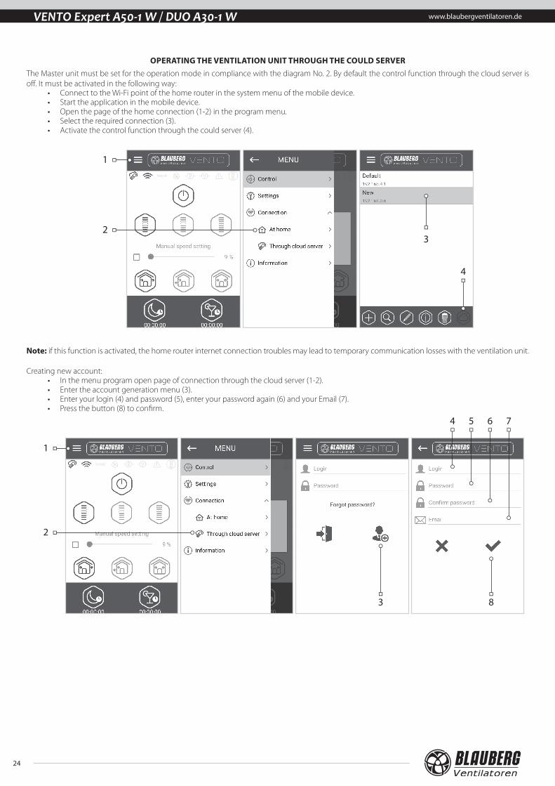
OPERATING THE VENTILATION UNIT THROUGH THE COULD SERVER The Master unit must be set for the operation mode in compliance with the diagram No. 2. By default the control function through the cloud server is off. It must be activated in the following way:
• Connect to the Wi-Fi point of the home router in the system menu of the mobile device. • Start the application in the mobile device. • Open the page of the home connection (1-2) in the program menu. • Select the required connection (3).• Activate the control function through the could server (4).
2
1
4
3
Note: if this function is activated, the home router internet connection troubles may lead to temporary communication losses with the ventilation unit.
Creating new account:• In the menu program open page of connection through the cloud server (1-2).• Enter the account generation menu (3).• Enter your login (4) and password (5), enter your password again (6) and your Email (7).• Press the button (8) to confirm.
2
1
83
4 5 6 7

www.blaubergventilatoren.de
25
VENTO Expert A50-1 W / DUO A30-1 W
Entering account:• Enter your login (1) and password (2) on the page of connection through the cloud server. • Press the button (3) to enter the account.
1
2
3
Adding new connection:• Press the button (1) to add the new connection at the page of connection through the cloud server. • Enter the connection name (2).• Enter ID number of the Master unit (3) containing of 16 symbols of the serial number indicated on the circuit board of the Master unit. • Press the button (4) to confirm.
1
2
3
4

26
www.blaubergventilatoren.deVENTO Expert A50-1 W / DUO A30-1 W
AIR FLOW BLOCKING FOR VENTO EXPERT A50-1 W
Press the front panel to close the air duct. The fan is stopped. The unit functionality is not changed. To open the air duct pull the front panel through the specially designed recessions. The fan automatically starts operating according to the actual speed setting.
Air duct blocking
Air duct opening
The light operating indicator is located on the front panel. In the night time the indicator glowing goes down.
AIR FLOW BLOCKING FOR VENTO EXPERT DUO A30-1 W
Press the side tabs to detach the front part of the indoor unit from its back part and close the air duct. Then open the latches and remove the front part of the front panel. Remove the air flow separator by pulling one of the side clamps. Install the front part of the front panel and press it gently to close the air duct. The fan is stopped. The unit functionality is not changed. Open the air duct in the reverse order. The fan starts operating according to the actual speed setting.
The light operating indicator is located on the front panel. In the night time the indicator glowing goes down.

www.blaubergventilatoren.de
27
VENTO Expert A50-1 W / DUO A30-1 W
Maintenance of the ventilation unit means regular cleaning of the surfaces of dust and cleaning or replacement of the filters.To enable access to the main units follow the procedure:Turn the unit off using the remote control or with the buttons on the indoor unit.
VENTO Expert DUO A30-1 W
1. Press the side tabs to release the front part of the indoor unit. Then open the latches and disconnect the front panel from the indoor unit. Remove the filters for cleaning. Assemble in the reverse order.
VENTO Expert A50-1 W
1. Press the side tabs to release the front part of the indoor unit.
Please make sure the thermal actuator rod is in lower position during re-installation of the front panel. If the thermal actuator rod is up, please wait about 2 minutes until it goes down.
Attention! Prior to mounting the front panel make sure
that the thermal actuator rod is in the lowest position and the light indicator is at least
two minutes off.
2. Remove the socket connector from the control board. Do not remove the socket connector by pulling the wires. Use a flat screwdriver to uplift it.
Use a flat screwdriver to disconnect the socket.
Do not pull the wires!
Disconnect the socket con-nector from the control board
Disconnect the socket con-nector from the control board
VENTO Expert A50-1 W VENTO Expert DUO A30-1 W
Attention! Never remove the control board! It may cause an alarm! After completion of the servicing and assembly of the ventilation unit and re-installation of the socket reset an alarm following the procedure at page 16.
MAINTENANCE

28
www.blaubergventilatoren.deVENTO Expert A50-1 W / DUO A30-1 W
3. Pull the band to remove the cartridge.
VENTO Expert A50-1 W VENTO Expert DUO A30-1 W
Clean the filters as often as required, but at least 3 times a year. • Upon elapse of the set time period (factory setting 90 days) the filter replacement indicator (Filter) starts glowing. • Resetting of the filter timer settings is performed with the DIP switch on the control board or using the application at your PC, see page 16 or
mobile device.• Wash the filters and let those dry out completely.• Install the dry filters in the air duct. • Vacuum cleaning is allowed. • The filter rated service life is 3 years.
Even regular technical maintenance may not completely prevent dirt accumulation on the regenerator and the fan.
• Clean the regenerator regularly to ensure its high heat recovery efficiency.
• Clean the regenerator with a vacuum cleaner at least once in a year.
4. Battery replacement in the remote control (as required).
In case of a long operation of the remote control the battery must be replaced. No response of the unit for pressing the remote control buttons indicates the need to replace the battery.
The battery type is CR2025.
Remove the holder with the battery from the lower part of the remote control.Then replace the battery and re-install the holder with a new battery in site.
+CR2025 3V
+CR2025 3V
Remove the filters from the cartridge.

www.blaubergventilatoren.de
29
VENTO Expert A50-1 W / DUO A30-1 W
TROUBLES AND TROUBLESHOOTING
Trouble Possible reasons Troubleshooting
The fan does not move up during start-up of the unit.
No power supply.Make sure that the ventilation unit is properly connected to power mains and troubleshoot a connection error, if required.
Motor is jammed, the impeller blades are clogged. Turn the ventilation unit off. Troubleshoot the motor jam and impeller clogging. Clean the blades. Restart the unit.
Circuit breaker tripping during the ventilation unit start-up.
Overcurrent as a result of short circuit in the electric circuit.
Turn the unit off. Contact the Seller for further information.
Low air flow.
Low set fan speed. Set higher speed.
The filter is clogged, the fan or the regenerator is contaminated.
Clean or replace the filter. Clean the fan and the regenerator.
High noise, vibration.
The impeller is contaminated. Clean the impeller.
Loose screw connection of the unit casing or the outer ventilation hood.
Tighten the screws of the unit or the outer ventilation hood.
Store the unit in the manufacturer’s original packing box in a dry ventilated premise at ambient temperatures from +5 °C ( +41 °F) up to +40 °C (104 °F).Storage environment must not contain aggressive vapours and chemical mixtures provoking corrosion, insulation and sealing deformation.Use suitable hoist machinery for handling and storage operations to prevent possible damage to the unit.Follow the handling requirements applicable for the particular type of cargo. The unit can be carried in the original packing by any mode of transport provided proper protection against precipitation and mechanical damage. Avoid sharp blows, scratches or rough handling during loading and unloading.Do not expose the unit to abrupt temperature drops.It may lead to condensation inside the unit and performance disturbance during the unit start-up. Prior to the initial power-up after transportation at sub-zero temperatures allow the unit to warm up at room temperature for at least 2 hours.
TROUBLESHOOTING
STORAGE AND TRANSPORTATION REGULATIONS

30
www.blaubergventilatoren.deVENTO Expert A50-1 W / DUO A30-1 W
The warranty period is 24 months after the retail sale date provided the user’s observance of the transportation, storage, mounting and operation regulations. Should any malfunctions occur in the course of the unit operation through the Manufacturer’s fault during the guaranteed period of operation the user is entitled to elimination of faults by the manufacturer by means of warranty repair at the factory free of charge.The warranty repair shall include work specific to elimination of faults in the unit operation to ensure its intended use by the user within the guaranteed period of operation. The faults are eliminated by means of replacement or repair of the unit components or a specific part of such unit component.
The warranty repair does not include: • Routine technical maintenance;• Unit installation / dismantling; • Unit setup.
To benefit from warranty repair the user must provide the unit, the user’s manual with the purchase date stamp and the payment document certifying the purchase. The unit model must comply with the one stated in the user’s manual. Contact the Seller for warranty service.
The manufacturer’s warranty does not apply to the following cases: • User’s failure to submit the unit with the entire delivery package as stated in the user’s manual including submission with missing component parts
previously dismounted by the user.• Mismatch of the unit model and the brand name with the information stated on the unit packing and in the user’s manual.• User’s failure to ensure timely technical maintenance of the unit.• External damage to the unit casing (excluding external modifications as required for installation) and internal components caused by the user.• Redesign or engineering changes to the unit.• Replacement and use of any assemblies, parts and components not approved by the manufacturer.• Unit misuse.• User’s violation of the unit installation regulations.• User’s violation of the unit control regulations.• Unit connection to the power mains with a voltage different from the one stated in the user’s manual.• Unit breakdown due to voltage surges in the power mains.• Discretionary repair of the unit by the user.• Unit repair by any persons without the manufacturer’s authorization.• Expiration of the unit warranty period.• User’s violation of the unit transportation regulations.• User’s violation of the unit storage regulations.• Wrongful actions against the unit committed by third parties.• Unit breakdown due to circumstances of insuperable force (fire, flood, earthquake, war, hostilities of any kind, blockades).• Missing seals if provided by the user’s manual.• Failure to submit the user’s manual with the unit purchase date stamp.• Missing payment document certifying the unit purchase.
FOLLOWING THE REGULATIONS STIPULATED HEREIN WILL ENSURE A LONG AND TROUBLE-FREE OPERATION OF THE UNIT.
USERS’ WARRANTY CLAIMS SHALL BE SUBJECT TO REVIEW ONLY UPON PRESENTATION OF THE UNIT, THE PAYMENT DOCUMENT AND THE USER’S MANUAL WITH THE PURCHASE DATE STAMP.
MANUFACTURER’S WARRANTY

www.blaubergventilatoren.de
31
VENTO Expert A50-1 W / DUO A30-1 W
Heat recovery single-room reversible ventilation unit
VENTO Expert (Duo) A___________ W
is recognized as serviceable.
The unit complies with the requirements according to the EU norms and directives, to the relevant EU-Low Voltage Equipment Directives, EU-Directives on Electromagnetic Compatibility.We hereby declare that the unit complies with the essential protection requirements of Electromagnetic Council Directive 2004/108/EC, 89/336/EEC and Low Voltage Directive 2006/95/EC, 73/23/EEC and CE-marking Directive 93/68/EEC on the approximation of the laws of the Member States relating to electromag-netic compatibility, which relate to electrical appliances used in set voltage classes.This certificate is issued following test carried out on samples of the product referred to above.
Quality Inspector’s Stamp Manufacture Date ____________________
Company:
Expert’s Full Name
Date Signature
Heat recovery single-room reversible ventilation unit
VENTO Expert (Duo) A___________ W
is connected to power mains in compliance with the operation manual requirements by the professional:
SELLER
PURCHASE DATE
REPRESENTATIVE IN EU
BLAUBERG Ventilatoren GmbHAidenbachstr. 52a,D-81379 Munich, Germany
ACCEPTANCE CERTIFICATE
CONNECTION CERTIFICATE
WARRANTY CARD
VENTO Expert (Duo) A___________ W

www.blaubergventilatoren.deVENTO Expert (DUO) A50(30)-1 W EN v.4(4)