Rethinking LiFi for Low-Power and Long Range RF Backscatter
13
PassiveLiFi: Rethinking LiFi for Low-Power and Long Range RF Backscaer Muhammad Sarmad Mir IMDEA Networks Universidad Carlos III de Madrid Madrid, Spain [email protected] Borja Genoves Guzman IMDEA Networks Madrid, Spain [email protected] Ambuj Varshney Uppsala University Uppsala, Sweden [email protected] Domenico Giustiniano IMDEA Networks Madrid, Spain [email protected] ABSTRACT Light bulbs have been recently explored to design Light Fidelity (LiFi) communication to battery-free tags, thus complementing Radiofrequency (RF) backscatter in the uplink. In this paper, we show that LiFi and RF backscatter are complementary and have unexplored interactions. We introduce PassiveLiFi, a battery-free system that uses LiFi to transmit RF backscatter at a meagre power budget. We address several challenges on the system design in the LiFi transmitter, the tag and the RF receiver. We design the first LiFi transmitter that implements a chirp spread spectrum (CSS) using the visible light spectrum. We use a small bank of solar cells for communication and harvesting and reconfigure them based on the amount of harvested energy and desired data rate. We further alleviate the low responsiveness of solar cells with a new low-power receiver design in the tag. Experimental results with an RF carrier of 17 dBm show that we can generate RF backscatter with a range of 80.3 meters/ W consumed in the tag, which is almost double with respect to prior work. CCS CONCEPTS • Computer systems organization → Sensor networks; • Hard- ware → Networking hardware; Sensor devices and platforms; Wire- less devices. ACM Reference Format: Muhammad Sarmad Mir, Borja Genoves Guzman, Ambuj Varshney, and Dom- enico Giustiniano. 2022. PassiveLiFi: Rethinking LiFi for Low-Power and Long Range RF Backscatter. In The 27th Annual International Conference on Mobile Computing and Networking (ACM MobiCom ’21), January 31- February 4, 2022, New Orleans, LA, USA. ACM, New York, NY, USA, 13 pages. https://doi.org/10.1145/3447993.3483262 ∗ Ambuj Varshney is presently a Postdoctoral scholar with UC Berkeley (EECS) ACM MobiCom ’21, January 31-February 4, 2022, New Orleans, LA, USA © 2022 Association for Computing Machinery. This is the author’s version of the work. It is posted here for your personal use. Not for redistribution. The definitive Version of Record was published in The 27th Annual International Conference on Mobile Computing and Networking (ACM MobiCom ’21), January 31-February 4, 2022, New Orleans, LA, USA, https://doi.org/10.1145/3447993. 3483262. Figure 1: PassiveLiFi: hardware prototypes of LiFi transmit- ter and passive tag. The tag comprises LiFi module for down- link (backside), solar cell array for energy harvesting and downlink communication (frontside), and RF backscatter module for uplink. 1 INTRODUCTION The large scale deployment of Internet of Things (IoT) devices leads to massive use of batteries, as they provide energy to IoT devices. Although batteries in tiny form factor may last for a long time, even years, any computation and communication can quickly deplete them, and it calls for solutions that do not need batteries at all. Additionally, batteries have also a negative environmental impact, as consumers currently dispose of billions of batteries per year and battery recycling is a delicate matter [6, 36]. The research efforts in battery-free systems exploits low-power electronics, communication and processing techniques [8, 19, 35, 40]. RF backscatter is now a consolidated technology for transmit- ting IoT data to the network because of its energy efficiency and absence of power-hungry active radio for transmission. In fact, the scarce amount of harvested energy from the environment limits the communication and processing capabilities. In particular, energy is mainly harvested from RF [32], light [8, 40, 44] and kinetic [14] sources. A solar cell is typically used for harvesting energy from
-
Upload
khangminh22 -
Category
Documents
-
view
1 -
download
0
Transcript of Rethinking LiFi for Low-Power and Long Range RF Backscatter

PassiveLiFi: Rethinking LiFi for Low-Power andLong Range RF Backscatter
Muhammad Sarmad MirIMDEA Networks
Universidad Carlos III de MadridMadrid, Spain
Borja Genoves GuzmanIMDEA NetworksMadrid, Spain
Ambuj VarshneyUppsala UniversityUppsala, Sweden
Domenico GiustinianoIMDEA NetworksMadrid, Spain
ABSTRACTLight bulbs have been recently explored to design Light Fidelity(LiFi) communication to battery-free tags, thus complementingRadiofrequency (RF) backscatter in the uplink. In this paper, weshow that LiFi and RF backscatter are complementary and haveunexplored interactions. We introduce PassiveLiFi, a battery-freesystem that uses LiFi to transmit RF backscatter at a meagre powerbudget. We address several challenges on the system design in theLiFi transmitter, the tag and the RF receiver. We design the firstLiFi transmitter that implements a chirp spread spectrum (CSS)using the visible light spectrum. We use a small bank of solar cellsfor communication and harvesting and reconfigure them based onthe amount of harvested energy and desired data rate. We furtheralleviate the low responsiveness of solar cells with a new low-powerreceiver design in the tag. Experimental results with an RF carrierof 17 dBm show that we can generate RF backscatter with a rangeof 80.3 meters/`W consumed in the tag, which is almost doublewith respect to prior work.
CCS CONCEPTS•Computer systems organization→ Sensor networks; •Hard-ware→ Networking hardware; Sensor devices and platforms;Wire-less devices.
ACM Reference Format:Muhammad SarmadMir, Borja Genoves Guzman, Ambuj Varshney, andDom-enico Giustiniano. 2022. PassiveLiFi: Rethinking LiFi for Low-Power andLong Range RF Backscatter. In The 27th Annual International Conferenceon Mobile Computing and Networking (ACM MobiCom ’21), January 31-February 4, 2022, New Orleans, LA, USA. ACM, New York, NY, USA, 13 pages.https://doi.org/10.1145/3447993.3483262
∗Ambuj Varshney is presently a Postdoctoral scholar with UC Berkeley (EECS)
ACM MobiCom ’21, January 31-February 4, 2022, New Orleans, LA, USA© 2022 Association for Computing Machinery.This is the author’s version of the work. It is posted here for your personal use. Notfor redistribution. The definitive Version of Record was published in The 27th AnnualInternational Conference on Mobile Computing and Networking (ACM MobiCom ’21),January 31-February 4, 2022, New Orleans, LA, USA, https://doi.org/10.1145/3447993.3483262.
Figure 1: PassiveLiFi: hardware prototypes of LiFi transmit-ter and passive tag. The tag comprises LiFimodule for down-link (backside), solar cell array for energy harvesting anddownlink communication (frontside), and RF backscattermodule for uplink.
1 INTRODUCTIONThe large scale deployment of Internet of Things (IoT) devices leadsto massive use of batteries, as they provide energy to IoT devices.Although batteries in tiny form factor may last for a long time, evenyears, any computation and communication can quickly depletethem, and it calls for solutions that do not need batteries at all.Additionally, batteries have also a negative environmental impact,as consumers currently dispose of billions of batteries per year andbattery recycling is a delicate matter [6, 36].
The research efforts in battery-free systems exploits low-powerelectronics, communication and processing techniques [8, 19, 35,40]. RF backscatter is now a consolidated technology for transmit-ting IoT data to the network because of its energy efficiency andabsence of power-hungry active radio for transmission. In fact, thescarce amount of harvested energy from the environment limits thecommunication and processing capabilities. In particular, energyis mainly harvested from RF [32], light [8, 40, 44] and kinetic [14]sources. A solar cell is typically used for harvesting energy from

ACM MobiCom ’21, January 31-February 4, 2022, New Orleans, LA, USA Muhammad Sarmad Mir, Borja Genoves Guzman, Ambuj Varshney, and Domenico Giustiniano
0110010011
Downlink Uplink
Data Visible Light Chirp
10
11
Figure 2: Downlink (left): Light intensity is changed to send data to passive tag at a fixed clock rate. Uplink (right): Carrier andbaseband delegated to the infrastructure. Chirps are complex to generate at the tag, and hence we delegate them to the lightinfrastructure. The light intensity is changed to generate visible light chirp at a varying clock rate. This chirp is then mixedin the tag with the input RF carrier for RF backscatter.
light, and it provides the best trade-off between the level of energyprovided and the availability of sources [12, 45].
Only limited work has been conducted to exploit commoditysolar cells in battery-free IoT devices also for communication. EDI-SON [12] has shown the design of a battery-free IoT tag that receivesdata through light, a concept commonly called Visible Light Com-munication (VLC) or Light Fidelity (LiFi) in a networked system. Itthen sends data through RF backscatter. It achieved an uplink rangeof about 20m indoors, co-locating the RF receiver with the LiFi bulb,and consuming 70 `W of energy for uplink communication. EDI-SON demonstrated that LiFi and RF backscatter are incomplete asstandalone technologies for passive communication, but have com-plementary properties that can be exploited to use LiFi in downlinkand RF backscatter in uplink.
In this work, we introduce PassiveLiFi, shown in Fig. 1, whichexploits the unexplored interactions between LiFi communicationin downlink and RF backscatter in uplink. As we will show in thiswork, these interactions allow us to significantly increase both therange for RF backscatter and the energy efficiency of the IoT tag.We use LiFi not only to transmit downlink data, but also to generatethe clock signal needed by the IoT tag to transmit RF backscatterin uplink, thus removing the need of a clock in the IoT tag. A firstapproach could be to modulate the LiFi bulb with a simple On-OffKeying (OOK) modulation and use this signal as clock in the IoT tag.This approach would already result in energy saving in the IoT tag.However the RF backscatter communication range would be similarto the traditional design that uses oscillators in the IoT tag for thesame purpose [12]. In order to increase both the communicationrange in RF backscatter and decode signals drowned by the noise,we present the first implementation of chirp spread spectrum (CSS)using the visible light spectrum. This visible light signal is receivedby the solar cells in the IoT tag, and used there as baseband signalto communicate with RF backscatter by turning the chirp on and offbased on the bit stream. Generating chirp spread spectrum in the tagconsumes around 10mW using off-the-shelf components [34], andoffloading it to the infrastructure while completely removing theneed of oscillators for passive chirp spread spectrum has been notshown so far. A high level illustration of PassiveLiFi is presented inFig. 2, where we show the operations both in downlink and uplink.
A first problem we have to solve in order to implement chirpspread spectrum in LiFi is that commercial light bulbs could modu-late the light intensity at speeds in the order of a fewMb/s. However,solar cells have not been designed for communication, and thus they
have inefficiencies as receivers that must be addressed to sustainsufficient high data rate. Furthermore, delegating chirp generationto the infrastructure requires that the LiFi receiver in the IoT tagconsumes low power, smaller than the one consumed by the localoscillators for performing CSS modulation. Yet, low-power LiFireceivers are based on light power envelope and are sensitive toany source of light interference, like other light fixtures and sun.
A second problem is that prior work used two different solarcells, one for communication and one for harvesting [12]. However,this has two drawbacks: it increases the size of tag or, if we keepthe same tag area, it does not exploit all available light energyfor both communication and harvesting. Besides, solar cells aretypically designed to work with solar energy, but its effectivenesswith indoor and artificial lighting conditions is less known.
Our contributions can be summarized as follows.
• We present the first design of chirp spread spectrum using LiFi,and propose to use LiFi in two modes of operation: the firstone for communicating downlink data, and the second one forgenerating the chirp signal needed by uplink RF backscatter. Inthe first mode, it uses a traditional constant clock rate, while, inthe second mode, the clock rate changes based on the desiredbandwidth and spreading factor;
• We propose a design that uses a single solar cell both for commu-nication and harvesting, decoupling the modulated LiFi signalsreceived from light bulbs from the light energy that can be usedfor harvesting. We show that the problem of optimizing bothcommunication and harvesting with a solar cell follows a Paretocurve and we propose a criterion to select the best solar cells forboth communication and harvesting;
• We implement PassiveLiFi with customized hardware both onthe LiFi transmitter and IoT tag, and we evaluate our system in avariety of scenarios. Our experiments show that PassiveLiFi cantransmit RF backscatter signals with a meter/power consumedmetric that is almost doubled with respect to the state of the art.
The rest of the paper is structured as follows: In Section 2, wepresent challenges faced by state-of-the-art systems, and we placeour system in context to them.We also provide a high-level overviewof our system. Next, in the Sections 3 and 4, we describe the designof the LiFi transmitter and the tag. We describe in detail the oper-ation of our system. In Section 5 we evaluate the system in termsof range, energy harvesting and power consumption in differentscenarios. Next, in Section 6, we present application scenarios that

PassiveLiFi: Rethinking LiFi for Low-Power andLong Range RF Backscatter ACM MobiCom ’21, January 31-February 4, 2022, New Orleans, LA, USA
our system could enable. Finally, we discuss prior works related toour system, and we conclude the paper.
2 CHALLENGESWe discuss the challenges we address in this work and positionthem with respect to prior work in the literature.
2.1 Delegating oscillatorsRF backscatter absorbs and reflects the surrounding radio waves tocommunicate with battery-free devices. On these devices, achiev-ing low energy consumption for every device is essential to enableits operation on the small amounts of energy harvested from theambient environment. On the backscatter tags, the oscillator’s en-ergy dominates the overall energy consumption, and it is the orderof tens of `Ws (demonstrated through simulation or implementa-tion [31]). Further, these oscillators are often combined with othercircuits such as those to generate chirps for communication, whichfurther pushes the complexity and energy consumption [29]. Itmakes it prohibitive to operate these platforms on the harvestedenergy. Recent systems overcome the oscillators’ energy-expensivenature by delegating oscillations to an external and powered RFinfrastructure [31]. This leads to lowering the power consumptionand complexity of the backscatter tag. However, the communica-tion range is not sufficient for most applications, and it is in theorder of 2m. One possible approach to increase the communicationrange is to employ chirps for communication. However, generatingthese chirps locally at the tag is an energy-expensive operation.Prior work has also tried to delegate the energy-expensive processof generating chirps [29]. However, it still required an oscillator atthe tag to shift this signal by 1-2 MHz to avoid self-interferenceand backscatter it back to the RF receiver. This leads to an increasedcomplexity and power consumption of the backscatter tag.
Offloading chirp spread spectrum signals to the infrastructurewhile completely removing the need of oscillators for passive chirpspread spectrum has been not shown so far. Yet, the ability tooffload chirp signals could result in a much larger communicationrange than using simpler modulations which are prone to error [17].Delegating oscillations to the infrastructure requires that the powerbudget needed for downlink reception in the tag is lower than theone consumed by its local oscillators. Furthermore, the receivedsignal must be also sufficiently precise to be used as oscillator. Thisis difficult to achieve because of the limitation of passive envelopedetectors, commonly used as RF receivers in tags. In fact, passiveenvelope detectors aggregate all energy received in the band, andcannot select a desired frequency as clock. Besides, any ambienttraffic could trigger simple RF envelope detectors, increasing theconsumption of the tag [12].
Instead of delegating the chirp spread spectrum to the RF in-frastructure, we propose to use light bulbs for generating visiblelight chirps that can be detected by low power LiFi receivers. Thesereceivers can provide better baseband signals than their RF coun-terparts for two reasons:
• LiFi transmission follows an Intensity Modulation (IM) basebandprocedure, where the modulation of the optical power of theLiFi transmission carries the information, and the signal phasedoes not carry the information. Instead, the receiver carries out aDirect Detection (DD) to convert the optical received signal into
an electrical signal. In its simplest form, LiFi requires to just turnon and off the Light Emitting Diode (LED) in the bulb with thedesired pattern to transmit a bit stream. We instead cannot sendRF signals in the baseband and they require an RF carrier.
• Passive LiFi receivers can be designed with low-power consump-tion, yet the light propagation can be much better controlledthan the RF propagation. Light is more confined than RF and,as a consequence, LiFi receivers may receive fewer interferingsignals. The main source of interference is the sunlight, which isnot modulated, and therefore can be filtered out at the receiver,and other sources from older technologies, such as fluorescentlights, are disappearing.
2.2 Communication and harvestingIn passive LiFi systems, the receiver relies on solar cells both forcommunication and harvesting. Solar cells are advantageous withrespect to other optical receivers such as photodiodes because theyoperate fully passive, without the usage of any active amplifier [12].In order to use the overall light sensitive area, we advocate for adesign that uses the same solar cell for both communication andharvesting. A simple approach would be to slice the time such thata certain portion of time is dedicated to harvesting and the restto communication. However, this would result in poor efficiency.More formally, let us define 𝑇𝑐 as the time to communicate 𝑁 bitsand 𝑇ℎ as the time to harvest enough energy to transmit 𝑁 bits.Because of the latency required for harvesting, the time left for asingle battery-free device to communicate data would be largelyreduced and 𝑇𝑐 would increase significantly. Furthermore, the timeneeded to harvest energy could disrupt any protocol that needs touse the same solar cell for communication.
Rather than using the same solar cell in different slices of time,we aim to use it at the same time both for communication andharvesting, without losing any energy that could be useful for har-vesting. However, the photonics community has always consideredthis unrealistic because of how photodetectors (and solar cells arejust one type of them) work. Fundamentally, in order to receivedata, photodetectors are bias in reverse mode, meaning that there isa higher voltage to the negative pin with respect to the positive pinof the photodetector. In contrast, when the photodetector operatesin photovoltaic mode to harvest energy, it is positive bias, and hencethe voltage is with opposite sign with respect to communicationmode. In this work, we present a new low-power LiFi receiver tosolve this problem, leveraging the fact that communication andharvesting use different frequency components of the same signal.Therefore, we take as input the voltage signal given by the solar cell,and disentangles it into two components, one for harvesting andanother for communication. We further propose to use a small set ofsolar cells instead of a single larger one to optimize communicationand harvesting depending on the needs.
In what follows, we address the limitations presented in thissection for low-power battery-free devices and present PassiveLiFi,composed of:
• LiFi transmitter to communicate to the tag and generate thebaseband signal for uplink communication (Section 3);
• battery-free tag to receive and process LiFi signal, harvest en-ergy from the solar cells, and provide uplink mixing the input

ACM MobiCom ’21, January 31-February 4, 2022, New Orleans, LA, USA Muhammad Sarmad Mir, Borja Genoves Guzman, Ambuj Varshney, and Domenico Giustiniano
ON
OFF
ON
OFF
Average
Average
Lightpower
Time
(a) LED for light dimming.
ON
OFF
(b) LED as communication source.
Upchirp Clock (constant frequency)
ON
OFF
ON
OFF
(c) LED as clock generator.
Figure 3: Varying LED intensity can serve multiple require-ments. Its first application was light dimming (a); with LiFi,it has been used to transmit downlink data (b); in this workwe propose to use it as clock generator, varying its frequencyover time, to generate the baseband signal for uplink com-munication (c).
RF carrier and the LiFi baseband signal for RF backscatter com-munication (Section 4);The system is complemented by the RF infrastructure to provide
carrier signal for RF backscatter and process the received backscat-ter signal.
3 LIFI TRANSMITTERIn PassiveLiFi, the LiFi transmitter provides the illumination tofulfill the requirements of indoor lighting standards. It providesthe energy to the tag to support battery-free operation for indoordeployments, and the baseband signals to support downlink com-munication and oscillations to support the RF backscatter-baseduplink channel. The prototype we have built of the LiFi transmitteris shown on the top of Fig. 1.3.1 Multiple roles of light bulbsWe are observing a rapid deployment of LED lighting in homes,offices and streetlights because of their energy efficiency and longlifespan. We refer to Fig. 3. Typically LEDs are driven by a switchingpower circuitry that operates at high frequency. This driver hasbeen first used for light dimming by controlling the amount of timethe light is on with respect to the time is off1. More recently, LEDshave started to be employed to generate LiFi signals, where theintensity of light is modulated to convey information. In its simplestform, LiFi communication associates bit 1 to high light intensityand bit 0 to low light intensity. In turn, a baseband signal is emittedby the bulb in the visible spectrum.
In this work, we propose to change the light intensity of LEDbulbs for a third purpose, suitable for creating passive LiFi commu-nication. We create a baseband signal with LiFi that can be mixedat the IoT tag with a RF carrier signal. This super-imposed signalcan then be modulated by the tag, simply turning on and off theRF signal that is reflected. This clock signal can be used to offload
1Pulse width modulation is typically used for this purpose.
(a) OpenVLC transmit signals.
(b) New LiFi TX signals.Figure 4: Comparison of 100kHz signals transmitted byOpenVLC1.3 (only 10.9-9.5=1.4Vpp and also with relevantcapacitance effect) and our LiFi (peak-to-peak voltage is 12V,with a very sharp waveform).
the oscillator in the IoT tag to the LiFi transmitter. One key advan-tage of this approach is the energy saving in the IoT tag thanks tooffloading of the oscillator to the LiFi transmitter and removal ofpower-hungry elements on the tag.
3.2 Bandwidth in passive downlinkAs discussed in Section 2.1, passive downlink communication re-quires a very low-power receiver. Any distortion in the signal re-ceived by the tag could inevitably cause errors in the interpretationof the bit pattern. We study this problemmeasuring the signal trans-mitted using the open source and low-cost OpenVLC1.3 board [11].This platform has been also used by EDISON as LiFi transmitter. Wetransmit a 100 kHz signal using OpenVLC1.3, measure the voltageat the LED pins and plot the result in Fig. 4. We observe that theshape of transmitter signal distorts at higher frequencies, with atransient time from 90% to 10% of about 0.8 `s, which is 16% of theduration of one bit.
An active receiver could easily handle this transition time andoperate up to 1 Msample/sec (as shown in OpenVLC [11]). On thecontrary, passive LiFi communication requires a baseband signal assharp as possible, such that a simple comparator of light intensitycould be effective to distinguish high and low light intensity. An-other problem is that OpenVLC operates the LED at low forwardvoltage of 10.9 V and current of 175mA. As the relation betweenLED current and the output luminous flux is approximately linear,this design leads to poor harvesting and communication capabili-ties.
We modify the OpenVLC design with the goal of achievinga sharper baseband signal with low-cost hardware, and exploitthe full dynamic range of the LED. We use the same LED as inOpenVLC, but we largely improve the front-end design.We increasethe harvesting capabilities and range of communication operatingthe LED at higher forward voltage. OpenVLC uses a resistancein series to the LED, which wastes energy, and it cannot work athigher current levels. We instead use switching regulator based LEDtransmitter design, widely used for commercial LED luminaries.This allows us to operate the same LED at the highest currentpossible (550mA), provide sharper transmitted signal at higherfrequencies and dissipate only 10% energy as heat and switchinglosses, contrary to 51.6% for linear regulator such as OpenVLC1.3.

PassiveLiFi: Rethinking LiFi for Low-Power andLong Range RF Backscatter ACM MobiCom ’21, January 31-February 4, 2022, New Orleans, LA, USA
DC-DC Converter
5V 14V
Switching Regulator
Vin SWL
DLED
CS
RSNS
DIMCo
Vs
Cin
GateDriver
Baseband Signal (S1)
S1
(a) LiFi transmitter design.
Solar Cells
MCU
HarvesterVoltage
RegulatorC
Comparator
MUX
Sensor
Z1
HPF
LPF
RF Switch
(b) Block diagram of battery-free IoT tag.Figure 5: LiFi transmitter and battery-free IoT tag.
0.5 1 1.5 2 2.5 3 3.5 4
Distance (m)
0
1000
2000
3000
4000
Illu
min
atio
n (
Lu
x)
OpenVLC TX
Switching based Transmitter
Figure 6: Comparison of illumination provided byOpenVLCTX and our design. Illuminance is multiplied by 10 at a dis-tance of 1m (1350 lux vs. 134 lux) and larger distance can beachieved while illuminating at typical illuminance values.
The schematic of our LiFi transmitter is shown in Fig. 5a, and thehardware prototype in Fig. 1. The regulator that we use operates incontinuous conduction mode to maintain positive current throughthe inductor L and rectifies the biggest delay in turning the LEDon and off. The parallel N-channel MOSFET is used to increase theslew rate of LED to achieve high switching frequency. The MOSFETgate driver is used to provide high current in order to overcome theeffect of gate capacitance in high switching frequencies required togenerate the chirp signal.
We outperform OpenVLC design. From our tests, we observethat setting V𝑠 at 5V, we achieve a sharper signal across the LED,as it can be seen in Fig 4. The experiments in Fig. 6 show thatthe measured illuminance with a luxmeter is multiplied by 10 at adistance of 1m with respect to OpenVLC, enabling larger scenarioswith LED lighting [20].3.3 Visible light chirpsAs discussed in Section 2.1, we propose to use light bulbs for dele-gating oscillations. For instance, with PassiveLiFi, we can generatethe RF signal at 880MHz and the LiFi signal at 100 kHz. The IoTtag can passively mix them to generate an operation frequency of880.1MHz for the uplink RF communication. Yet, this approachwould improve only the energy efficiency, but not the range ofcommunication.
Instead we propose to delegate the generation of chirp signals toLiFi, as shown in Fig. 2. Chirp spread spectrum (CSS) can achievelonger range with respect to simpler modulations (e.g., On-Off key-ing), as successfully shown in LoRa [1] thanks to the property below
1000 1500 2000 2500 3000
Area of Solar cells (mm2)
0
100
200
300
Tim
e t
o c
ha
rge
(se
c)
100
200
300
400
500
Vp
p (
mV
)
Time to charge (parallel)
Time to charge (series)
Vpp (parallel)
Vpp (series)
Figure 7: Effect of solar cell area on communication and har-vesting using up to five solar cells in parallel or series. Theenergy harvesting ability improves when the solar cells areconnected in parallel. Whereas, when the solar cells are con-nected in series, the ability to receive downlink communica-tion is enhanced.
CSS to demodulate signals below the noise level, being also morerobust to multipath. We propose to use light bulbs for generatingvisible light chirps, with the objective of improving both energy effi-ciency and range of uplink communication. In PassiveLiFi, the LiFitransmitter sends a clock with varying frequency over the visiblelight channel that increases over time (up-chirp signal). Note thatthere is no light flicker with our implementation of CSS as we workat sufficient high frequency, starting from 40 kHz. Next, the tagreceives these transmissions using low-power solar cell-based LiFireceiver and further modulates the signal based on the informationto be transmitted. On the receiver side, symbols are detected bythe energy observed at different FFT bins, correlating the receivedsignal with a down-chirp signal (cf. Fig. 2).4 IOT TAGThe core of our end-to-end communication system is the battery-free IoT tag. The tag operates solely on harvested energy from solarcell. Solar cells are preferred for harvesting because of the wide-spread availability of light sources and higher level of harvestedenergy with respect to RF [45]. RF sources are also limited in spaceand deploying dedicated RF source has practicality issues. Further-more, high RF power sources are needed to achieve reasonableharvesting (3W transmitters to achieve less than 200 `W of powerharvested at 5m [24]). For the solar cells, we consider a total sizeof 30 cm2 (4.6 inch2), which is similar or smaller with respect tothe state of the art [8, 12, 40].
The design goals for the tag include:• Use of single solar cell for both harvesting energy and downlinkcommunication;
• Energy thresholding circuit design in the tag robust to indoorlighting and LiFi communication frequency;
• Use of downlink chirp signal to enable long-range and low-poweruplink backscatter communication;
• Ultra low-power design to enable maximum operation time onharvested energy.
The block diagram of the IoT tag is shown in Fig. 5b.4.1 Trade-offs with solar cellsIn this work, we propose to use a small set of solar cells insteadof a single larger one, and use all of them for both harvesting andcommunication. Yet, we find that there exists a dichotomy betweenharvesting and communication that we have to solve. We perform

ACM MobiCom ’21, January 31-February 4, 2022, New Orleans, LA, USA Muhammad Sarmad Mir, Borja Genoves Guzman, Ambuj Varshney, and Domenico Giustiniano
Solar Cell 1
Solar Cell 2
Solar Cell 3
SP
SP
SP
SP
SN
SN
Battery_OK
openSNclosed
SP
openSN
closedSP
Figure 8: Combination of solar cell array in series or paralleldepending on the charge level of battery/capacitor.an experiment where we measure the time the solar cell takes tocharge a capacitor of a specific value, time to charge (𝑇𝑐 ) as well asthe peak-to-peak value of the voltage measured at the receiver afterthe solar cells (𝑉pp). The experiment is performed at a distance of1.5m between our LiFi transmitter and receiver at 50 kHz frequencywithout background light.
We need small time to charge (we can harvest more quickly)and a high 𝑉pp (we can operate at longer range). As represented inFig. 7, this can be obtained using a larger total area of the solar cells,thus using all solar cells for both harvesting and communication.However, the harvesting improves considerably (time-to-chargedecreases) with multiple (up to five) solar cells connected in parallel,while the communication worsens slightly, due to a lower𝑉pp value.On the other hand, when multiple solar cells are connected in series,the communication is boosted (larger 𝑉pp) and the time-to-chargeslightly decreases.4.2 Reconfiguring the solar cellsThe decision of parallel or series connection of solar cells is basedon𝑉BAT which is the voltage across the capacitor to store harvestedenergy. The harvester BQ25570 generates a Battery_OK digital sig-nal depending on the state of 𝑉BAT. When 𝑉BAT is above threshold(programmable by resistors), the Battery_OK is high and it toggleswhen 𝑉BAT drops below the threshold. The configuration of solarcells can be switched between series and parallel by connectingthe Battery_OK signal to gates of N-channel MOSFETs (𝑆N) and P-channels MOSFETs (𝑆P) as shown in Fig. 8. We need ‘n-1’ N-channeland ‘2n-2’ P-channel MOSFETs for the design where ‘n’ is the num-ber of solar cells used. ADG72X [4] switches can be used due totheir low power dissipation (< 0.1 µW) and tiny package. In thisway, connection among solar cells is reconfigurable automatically:when harvesting is the priority due to low charge on capacitor,solar cells are connected in parallel; when harvesting is not priority,to boost the communication they are connected in series. Note that,although harvesting or communication is being prioritized eachtime, both actions occurs simultaneously.4.3 Comparison of commodity solar cellsThere exist several solar cells in the market for IoT applications, andwe study how to select the best performing solar cell in terms ofharvesting and communication performance. Although solar cellsin the market are all low cost (4-5 dollars each), their efficiencyfor harvesting varies largely (from 3 to 25%) as well as their size.Specifications of the communication performance are not given, assolar cells are designed typically only for harvesting. We study atotal of six different commodity solar cells, and shortlisted three
200 600 1000 1400
Illuminance (Lux)
0
50
100
150
200
250
300
Tim
e to c
harg
e (
sec)
0
500
1000
1500
2000
Vp
p (
mV
)
SLMD121H04L
SLMD600H10L
SLM141K06L
(a) LiFi at 50 kHz.
200 600 1000 1400
Illuminance (Lux)
0
50
100
150
200
250
300
Tim
e t
o c
ha
rge
(se
c)
0
500
1000
1500
2000
Vpp (
mV
)
SLMD121H04L
SLMD600H10L
SLM141K06L
(b) LiFi at 100kHz.
Figure 9: Comparison of peak-to-peak voltage and time tocharge 100µF capacitor for shortlisted solar cells at differ-ent LiFi transmission rates. For the three solar cell types theexposed area is 30 cm2.
based on good performance both in communication, (𝑉pp), and inharvesting, time-to-charge.
Fig. 9 compares the three best solar cell types under evaluation.As the selected solar cells have different size, for carrying out a faircomparison, we connect several solar cell of each type in order tocreate the same total area. In total, we create a solar cell of approxi-mately 3000 mm2 by unifying 5, 4, 3 solar cells of ‘SLMD121H04L’,‘SLMD600H10L’ and ‘SLM141K06L’, respectively. Following ouranalysis in Section 4.1, solar cells are connected in series for 𝑉ppresults, as the voltage in the output of each solar cell is summedup. Differently, they are connected in parallel for time-to-chargeresults, as the current in the output of each solar cell is added tocontribute to a faster harvesting. We observe that time-to-chargemonotonically decreases with illuminance, whereas 𝑉pp monoton-ically increases with illuminance, which contributes to a fasterharvesting and a better communication, respectively. However, thefrequency of LiFi transmission does not affect the time-to-charge,but the𝑉pp decreases when LiFi rate increases due to the low band-width of the solar cell. In fact, the capacitance of solar cells distortsthe received signal and, as a consequence, the𝑉pp value. In the nextsection, we search for a Pareto-optimal solution [27], as there isnot a single solar cell type that provides the best performance inboth communication and harvesting.4.4 Criterion to choose the solar cellThe aim of this subsection is to choose the best solar cell typein terms of communication and harvesting. Communication isoptimized by maximizing 𝑉pp, i.e., minimizing –𝑉pp, while timeto charge (𝑇c) is optimized by minimizing it. Fig. 10 shows thePareto fronts for fixed illuminance and frequency, which demon-strates that the solar cell ‘SLM141K06L’ is Pareto-dominated by‘SLMD121H04L’. However, we observe that both ‘SLMD121H04L’and ‘SLM600H10L’ are within the Pareto-front, which means thatboth are Pareto efficient. To select a single solar cell type as the bestsolar cell for our scenario, we convert the problem into a uniqueobjective function to be minimized, by using the weighted summethod as
𝑓1 = 𝛼 ·𝑇c,norm (𝑇, 𝑙, 𝑓 ) − (1 − 𝛼) ·𝑉pp,norm (𝑇, 𝑙, 𝑓 ), (1)
where 𝛼 is the weight that is typically set by the decision maker,𝑇 ∈ {𝐴, 𝐵,𝐶} = {‘SLMD121H04L’, ‘SLM600H10L’, ‘SLM141K06L’}

PassiveLiFi: Rethinking LiFi for Low-Power andLong Range RF Backscatter ACM MobiCom ’21, January 31-February 4, 2022, New Orleans, LA, USA
-2000 -1000 0
-Vpp
(mV)
0
100
200
300
Tim
e t
o c
ha
rge
(se
c)
SLMD121H04L
SLMD600H10L
SLM141K06L
(a) LiFi at 50 kHz.
-800 -600 -400 -200 0
-Vpp
(mV)
0
100
200
300
Tim
e to c
harg
e (
sec)
SLMD121H04L
SLMD600H10L
SLM141K06L
(b) LiFi at 100kHz.
Figure 10: Representation of Pareto fronts for each illumi-nance value when considering shortlisted solar cells at dif-ferent LiFi transmission rates.
200 600 1000 1400
Illuminance (lux)
-0.1
-0.05
0
0.05
0.1
f 1
SLMD121H04L
SLMD600H10L
SLM141K06L
(a) 𝑓 =50kHz, 𝛼 = 0.5.
200 600 1000 1400
Illuminance (lux)
-0.1
-0.05
0
0.05
0.1
f 1
SLMD121H04L
SLMD600H10L
SLM141K06L
(b) 𝑓 =100kHz, 𝛼 = 0.5.
Figure 11: Representation of function to minimize ver-sus illuminance. The figure shows how the solar cell‘SLMD121H04L’ provides the best performance both in com-munication and harvesting. Note that curve belonging to‘SLMD600H10L’ is zero for all illuminance values becausethis solar cell achieves 𝑇c,max (𝑙, 𝑓 ) and 𝑉pp,max (𝑙, 𝑓 ) values.
represents the solar cell type, and 𝑙 and 𝑓 are the illuminance andLiFi frequency, respectively.
The computation of the optimal solar cell can be derived fromthe analysis we conduct in the Appendix. From there, Fig. 11 rep-resents 𝑓1 for each solar cell type versus illuminance for 50 kHzand 100 kHz of transmission rate and considering 𝛼 = 0.5 (an equalimportance for communication and harvesting). In such figure, so-lar cell ‘SLMD121H04L’ provides the lowest 𝑓1 value for typicallighting conditions in indoor environments [20] [30]. However, forlarger illuminance values ‘SLMD600H10L’ becomes the best solarcell due to the larger differences in 𝑉pp (see Fig. 9). Considering theresults obtained in Fig. 11 and as illuminance values for indoor workplaces are typically lower than 1200 lux [20], the solar cell with thebest harvesting and communication capability is ‘SLMD121H04L’.
After the selection of the solar cell, we select the number of solarcells to use and their configuration. As the size of our prototypetag is 75 x 50mm, and as the larger the number of solar cells, thebetter are communication and harvesting (see Fig. 7), we place 5SLMD121H04L solar cells on the back side of the tag to fully coverthe area, as shown in Fig. 1.4.5 Receiver circuitryAs next step, the DC and AC components at the output of the solarcell are separated using low pass filter (LPF) and high pass filter(HPF) respectively, as shown in Fig. 12b. The photocurrent fromsolar cell consists of both AC (i𝑠𝑐 ) and DC component (I𝑠𝑐 ). TheDC component is blocked by C1 and passes through the branchfor harvesting energy. The AC components flows through both the
R
C
Output
(a) Thresholding circuit design for EDISON.
R1
C1
(b) Proposed thresholding circuit.
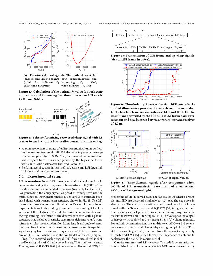
Figure 12: Configuration of the thresholding circuit. We in-tegrate LPF and HPF, for harvesting and communicationpurposes, respectively. This improves the robustness of thethresholding circuit.branches but it is highly attenuated by C2 [41]. The optimization ofR2 is important, and it causes a trade-off between communicationrange and time to charge. Larger the value of R2 greater will Vpp and𝑇c be as shown in Fig. 13a. However, note that 𝑉pp is not improvedfrom a 𝑅2 value on, whereas the time to charge keeps increasing.In order to find the optimal 𝑅2 value to operate by optimizing bothcommunication and harvesting simultaneously, we develop thesame method as the one used for finding the optimal solar cell type.The optimal 𝑅2 value is 4 kΩ, where 𝑉pp starts saturating and fromthis point on the harvesting (time to charge) worsens dramatically.However, we identify that the optimum 𝑅2 depends on the datarate: at low data rates (shown in Fig. 13a),𝑉pp is larger than𝑉pp,minfor all 𝑅2 values.
For the sake of simplicity, unless other data is specified, from thispoint on, we will perform with the optimal solar cell and optimum𝑅2 value, i.e., solar cell type ‘SLMD121H04L’ and 𝑅2 = 4 kΩ. Thevalues of C1 and R1 are selected to rectify the low frequency noisefrom ambient lighting. Also, the HPF removes the DC componentof the signal and translates signal down to ground as average.4.6 Backscatter CircuitryWe describe the backscatter circuitry, referring to Fig. 14. The ACcomponent of the received signal contains LiFi data and chirps.The chirps are originally transmitted by the LiFi infrastructure andreceived by the solar cell-based LiFi receiver. The optical chirpsvarying from frequency 𝑓1 to 𝑓2 are converted to electrical chirps bythe solar cell and further processed by the HPF and comparator. Therecovered chirps are fed into the RF switch to toggle the RF antennabetween absorption and reflection state. The antenna mixes thechirps with RF carrier signal and backscatters the signal varyingfrom 𝑓c+𝑓1 to 𝑓c+𝑓2.5 EVALUATIONIn this section we present the experimental evaluation of our designand comparison with state-of-the-art work. The results are focusedon the following points:• Ability of our end-to-end system to detect the chirps in CSSmodulated signal below the noise floor. Our backscatter receivershows detection of upchirps up to -17 dB below the noise floor.
ACM MobiCom ’21, January 31-February 4, 2022, New Orleans, LA, USA Muhammad Sarmad Mir, Borja Genoves Guzman, Ambuj Varshney, and Domenico Giustiniano
0 2000 4000 6000 8000
R2 [ ]
150
200
250
300
350
Tim
e to c
harg
e [s]
0
100
200
300
400
500
600
700
Vpp [m
V]
LiFi rate = 1 kHz
LiFi rate = 50 kHz
(a) Peak-to-peak voltage(dashed) and Time to charge(solid) for different 𝑅2values and LiFi rates.
0 5000 10000 15000
R2 [ ]
-0.3
-0.25
-0.2
-0.15
-0.1
-0.05
0
0.05
f 1
LiFi rate = 50 kHz, = 0.5
(b) The optimal point forboth communication andharvesting is 𝑅2 = 4kΩ,when LiFi rate = 50kHz.
Figure 13: Calculation of the optimal 𝑅2 value for both com-munication and harvesting functionalities when LiFi rate is1 kHz and 50kHz.
Z1
Optical signal
(f1 to f2) Electrical signal
(f1 to f2)
Solar
Cell
HPF +
Comparator
RF switch
RF ca
rrier
sign
al
(f c =
868 M
Hz)
Modulat
ed B
acks
catte
red
signal
(f c+f 1
to f c
+f 2)
IoT Tag
Figure 14: Scheme formixing recovered chirp signal with RFcarrier to enable uplink backscatter communication on tag.
• A 2x improvement in range of uplink communication in outdoorand indoor environment with 90% decrease in power consump-tion as compared to EDISON. Also, the range of communicationwith respect to the consumed power by the tag outperformsworks like LoRa backscatter [34] and Lorea [39].
• Performance of system in terms of harvesting and LiFi downlinkin indoor and outdoor environment.
5.1 Experimental setupLiFi transmitter. In our LiFi transmitter, the baseband signal couldbe generated using the programmable real-time unit (PRU) of theBeaglebone used as embedded processor (similarly to OpenVLC).For generating the chirp signal, as proof of concept, we use themulti-function instrument Analog Discovery 2 to generate base-band signal with transmission structure shown in Fig. 15. The LiFitransmitter provides constant illumination. Downlink transmissionimplements Manchester coding to guarantee constant light level re-gardless of the bit stream. The LiFi transmitter communicates withthe tag sending LiFi frame at the desired data rate with a packetstructure that includes preamble, start frame delimiter (SFD), trans-mitter identifier, receiver identifier, frame length and payload. Afterthe downlink frame, the transmitter recurrently sends up-chirpsignal varying from a minimum frequency of 40 KHz to a maximumone of (40 + BW), where BW is the bandwidth of the chirp signal.
Tag. The received analog signal (LiFi frame and chirp) is digi-tized by using 1-bit ADC implemented using TS881 [33] comparator.The tag uses MSP430FR5969 [38] microcontroller unit (MCU) for
4
SFD
2
TX ID
1
RX ID
1
Frame Length
4
Payload
0 to 229
LiFi frame Up-chirp signal Up-chirp signal
Preamble
. . .t1 t2
LiFi frame LiFi frame
Figure 15: Transmission of LiFi frame and up-chirp signals(size of LiFi frame in bytes).
0 500 1000 1500 2000 2500 3000 3500 4000
Background illuminance [lux]
0
0.1
0.2
0.3
0.4
0.5
BE
R
EDISON comparator (50 kHz)
Our comparator (50 kHz)
EDISON comparator (100 kHz)
Our comparator (100 kHz)
Figure 16: Thresholding circuit evaluation: BER versus back-ground illuminance provided by an external unmodulatedLEDwhen LiFi transmission rate is 50 kHz and 100kHz. Theilluminance provided by the LiFi bulb is 550 lux in dark envi-ronment and at a distance between transmitter and receiverof 1.5m.
0 0.5 1
10-4
0
1
2
vo
lta
ge
aft
er
co
mp
ara
tor
[V]
EDISON comparator
0 0.5 1time [s]
10-4
0
1
2
vo
lta
ge
aft
er
co
mp
ara
tor
[V]
Our comparator
(a) Time-domain signals.
0 1 2 3
voltage after comparator [V]
0
0.2
0.4
0.6
0.8
1
cdf
EDISON comparator
Our comparator
(b) CDF of signal values.
Figure 17: Time-domain signals after comparator when50kHz of LiFi transmission rate, 1.5m of distance and1800 lux of background light.
processing of LiFi received data. The tag wakes up when a pream-ble and SFD are detected, similarly to [12], else the tag stays insleep mode. The energy harvesting is performed by solar cell com-bined with the Texas Instrument BQ25570 [37] integrated circuitto efficiently extract power from solar cell using ProgrammableMaximum Power Point Tracking (MPPT). The voltage at the outputof harvester is regulated to 2.4 V using S-1313 [2] voltage regulator.For uplink communication, the multiplexer ADG704 [3] selectsbetween chirp signal and Ground depending on uplink data ‘1’ or‘0’ to transmit (e.g. directly received from the sensor), respectively.RF switch ADG902 [5] is used to vary the impedance of antenna tobackscatter the 868 MHz carrier signal.
Carrier emitter and RF receiver. The uplink communicationis established by backscattering the 868MHz tone transmitted by

PassiveLiFi: Rethinking LiFi for Low-Power andLong Range RF Backscatter ACM MobiCom ’21, January 31-February 4, 2022, New Orleans, LA, USA
1 2 3 4
Downlink distance [m]
0
0.1
0.2
0.3
0.4
0.5
BE
R
EDISON comparator
Our comparator
(a) BER versus distance.
5 10 15LiFi transmission rate [Hz]
104
0
0.1
0.2
0.3
0.4
BE
R
EDISON comparator
Our comparator
(b) BER versus LiFi rate.Figure 18: Threshold circuit evaluation: BER versus distance(at 50 kHz of LiFi transmission rate) and BER versus LiFitransmission rate (at a distance of 1.5m) with 800 lux back-ground light.
the carrier wave (CW) generator. Any off-the-shelf modem or trans-mitter chipset can be used to generate the tone [16, 39]. In ourexperiments, we use two software defined radio USRPs B210 [10] totransmit the RF carrier at 868MHz and receive the RF backscattersignal, respectively.
We use the open source standard compliant LoRa receiver forthe detection of upchirps [23]. The design is implemented in Pothosflow software. To exploit the CSS synchronization method, we mod-ify the receiver to detect one synchronizationword that correspondsto one upchirp. Once synchronized, later upchirps are consideredas data symbols. Then, note that although we invoke the CSS fun-damentals of LoRa standard, we do not transmit standardized LoRacodewords. We rather exploit the CSS concept for increasing up-link distance. However, this could be implemented with a strictsynchronization, at the expense of an increase in complexity.5.2 LiFi ReceiverFor our LiFi receiver, we observe three main findings. First, it ismore robust to background illumination as shown in Fig. 16 withrespect to prior work. The bit error rate (BER) is plotted againstthe background illuminance. The plot depicts the improved per-formance of our comparator design with 0% BER in presence of1000 lux and 3000 lux when operating at 100 kHz and 50 kHz LiFitransmission frequency, respectively.
Second, the output of the comparator is independent from theinput frequency and symmetry is maintained as shown in Fig. 17.This makes sampling of bits at the LiFi receiver less prone to error.Differently from our thresholding circuit, we notice that the dutycycle of signal after EDISON comparator is not 50%, and sometimesit is even 100%, which introduces a large number of errors in thedecoding process.
Finally, the improvement in range is displayed in Fig. 18a. Ourdesign can reach up to 3.5m with 0% BER with a background of800 lux. Fig. 18b shows the improvement in terms of data rate. Oursystem can achieve transmission frequency of 140 kHz correspond-ing to 280 kbps as compared to 120 kbps by EDISON design. As thedata rate of LiFi transmitter increases, PassiveLiFi can better copewith capacitance effect from the solar cell, thanks to the highersymmetry and higher dynamic range of our LiFi transmitter, andhigher robustness to noise of our passive LiFi receiver.5.3 Uplink receptionWe evaluate PassiveLiFi in terms of its ability to detect the chirpsbelow the noise floor. The LiFi downlink generates the upchirps
-140 -135 -130 -125 -120 -115 -110
Received Signal Power (dBm)
0
0.2
0.4
0.6
0.8
1
BE
R
SF=12, BW=70kHz
SF=11, BW=70kHz
SF=10, BW=70kHz
Noise floor
(a) Effect of SF on SNR limit.
-140 -135 -130 -125 -120 -115 -110 -105
Received Signal Power (dBm)
0
0.2
0.4
0.6
0.8
1
BE
R
SF=12, BW=60kHz
SF=12, BW=70kHz
SF=12, BW=80kHz
SF=12, BW=90kHz
Noise floor
(b) Effect of BW on SNR limit.
Figure 19: Evaluation of backscatter receiver to detect chirpsbelow the noise floor.
at the tag which are used by the backscatter module to vary theantenna impedance. The distance between the tag and carrier wavegenerator is fixed at 1.4m. Note that although we conduct experi-ments with a relative short range in LiFi link between the LED andthe tag, we may require a long range for RF backscatter in orderto transmit sensed data to the edge device. This enables to have aunique (or a few) edge devices for multiple rooms (indoors) or alarge coverage area (outdoors). The transmission power of carriergenerator is varied to evaluate system for different received power.The results are shown in Fig. 19 for OOK modulation scheme usedin EDISON (demodulates only above noise floor), and CSS usedin our design. Fig. 19a and Fig. 19b show the effect of spreadingfactor (SF) and bandwidth (BW) on SNR limit, respectively. Withthe increase of SF, the SNR limit decreases and with increase inBW, SNR limit increases which is consistent with LoRa standard. Inthe best configuration (SF 12 and BW 60 kHz), our receiver decodes17 dB below the noise floor.
We are limited by the noise floor of the USRP. However, we cansignificantly improve the communication performance through theusage of commodity transceivers for reception which gives up to25-30 dB lower noise floor when compared to the SDR [34]. Theselection of chirp BW is important here, as on lower side we arelimited by the interference from the carrier generator tone and onhigher side limited by the BW of solar cell. For generating chirpswe use 40 kHz as lower limit and upper limited is selected basedon the value of chirp BW i.e. 100 kHz for chirp with 60 kHz BW. InFig. 19b, with 90 kHz BW. it can be seen that the highest BER is0.18 due to the limitation of solar cell’s BW.5.4 Uplink range and energy consumptionWe evaluate the uplink range in both indoor and outdoor scenarios.In indoor environment, we perform the test inside a building inground floor by keeping the tag and CW generator in a room atdistance of 1.4m. We place the RF receiver at position P1, P2, P3, P4,P5, P6, P7 at distance of 5.5, 13, 18, 23, 36, 40 and 47m, respectively,

ACM MobiCom ’21, January 31-February 4, 2022, New Orleans, LA, USA Muhammad Sarmad Mir, Borja Genoves Guzman, Ambuj Varshney, and Domenico Giustiniano
Figure 20: Plan of indoor scenario. Positions of tag and CWgenerator are highlighted, and positions of RF receiver aremarked with P1-7.
0 50 100 150 200 250 300 350
Distance (m)
0
0.5
1
BE
R
CSS - Indoor
OOK - Indoor
CSS - Outdoor
OOK - Outdoor
P7P4
P5
P6
P1-3
Figure 21: Range of tag at indoor and outdoor scenarios. Tagand CW generator are located at a distance of 1.4 for indoorand 1m for outdoor, and the RF receiver is moved away.
Same room
Room P1 (nearby w
all)
Room P1 (distant w
all)
Room P20
0.5
1
BE
R
Figure 22: Range of tag when it is moved away while CWgenerator and RF receiver are placed at a different room ata distance of around 7m from the tag.
from tag as shown in Fig. 20. As shown in Fig. 21, we observe asignificant increase in range by PassiveLiFi as compared to EDISON.With our design, we get range as large as 40m with normalized bitloss rate less than 0.20, which is 2x improvement over EDISON.
In outdoor scenario, we perform the experiment in an openspace. We use the same configuration for tag and CW generator asin indoor andwe place the backscatter receiver at different distancesin open space. Note that outdoor light sources such as streetlightsmay be located at a larger distance, but their transmission power isalso larger than the power of our LiFi transmitter, which enablesthese outdoor experiments. Thus, these outdoor results are still veryvaluable to evaluate. The results are presented in Fig. 21. We obtainaround 2x improvement over EDISON, with range up to 305mfor our design. The energy consumption of backscatter module issignificantly reduced by offloading the oscillators which are themost power hungry components in backscatter module. The energyis reduced from 70 µW (as in EDISON) to 3.8 µW. Only comparator,multiplexer and RF switch are the active elements in backscattermodule with typical power consumption < 1 µW.
Table 1 presents a comparison in ratio between achieved distanceover uplink consumption. Note that the reported effective isotropicradiated power (EIRP) is different at every state-of-the-art work,which is unfair. To make a fair comparison, we consider the Friis’path model to get the corresponding sensitivity of receivers. Know-ing that and setting up the same EIRP as in our scenario (20 dBm),
Table 1: Computation of maximum achieved range versusuplink power consumption.
Lorea [39]EIRP 28 dBm Max. dist. RatioMax. distance 3.4 km when 20 dBm: distance-consumption:Operation freq. 868MHz 950m 13.6m/`WUplink consumption 70 `WLora Backscatter [34]EIRP 36 dBm Max. dist. RatioMax. distance 2.8 km when 20 dBm: distance-consumption:Operation freq. 915MHz 435m 47m/`WUplink consumption 9.25 `WEDISON [12]EIRP 20 dBm RatioMax. distance 160m distance-consumption:Operation freq. 868MHz 2.29m/`WUplink consumption 70 `WPassiveLiFi (Proposal)EIRP 20 dBm RatioMax. distance 305m distance-consumption:Operation freq. 868MHz 80.3m/`WUplink consumption 3.8 `W
we are able to compute the maximum achieved distance in uplinkunder same configuration. Note that the maximum distance consid-ered for LoRea is the one that provides a BER=10−2 and 2.9 kbps,whereas the maximum distance considered for LoRa Backscatter isthe one that obtains 200 bps. As seen in ratio distance-consumptionresults, our PassiveLiFi tag shows an uplink efficiency much larger(x2) than previous works, which makes it much more sustainablewhile achieving longer ranges.
Last indoor experiment demonstrates the possibility of locatingthe tag at a different room as CW generator and RF receiver. Fig. 22shows that, when placing CW generator and RF receiver in sameroom at a distance of 2.3m, the signal can be decoded when the tagis located at a different room at a distance of around 7m. Unlikeprior works [12], we enable the possibility of separating tag fromeither RF receiver or CW generator, increasing the flexibility of thesetup indoors.5.5 Harvesting and LiFi downlinkThe energy harvested by the IoT tag and the BER in LiFi down-link are represented in Fig. 23a and Fig. 23b, respectively. We showthe performance when the two configurations of solar cells areestablished. Note that, when solar cells are connected in series theachieved range may be increased due to providing a larger peak-to-peak voltage in the output of solar cells. However, at low LiFirates this difference is not noticeable (subject to some minor ex-perimental errors), because the speed response of solar cell doesnot clip the peak-to-peak voltage and then allowing to achievesimilar results. Differently, the harvested energy provided by solarcells in parallel are always better than when they are connected inseries. Then, at lower rates, it is better to configure solar cells inparallel, while at higher rates, it is convenient that connection inseries and in parallel are switched adaptively to optimize decodingand harvesting, respectively.5.6 Self-sustainability of tagWe study the self-sustainability of tag at different LiFi bit rates andpresent the results in Fig. 24. For this experiment, we optimize 𝑅2 as

PassiveLiFi: Rethinking LiFi for Low-Power andLong Range RF Backscatter ACM MobiCom ’21, January 31-February 4, 2022, New Orleans, LA, USA
1 1.5 2 2.5 3
Downlink distance (m)
0
5
10
Ha
rve
ste
d p
ow
er
(uW
)
series
parallel
(a) Harvested power at different downlink distances when solarcells are connected in parallel or series.
0.5 1 1.5 2 2.5 3 3.5 4
Downlink distance [m]
0
0.1
0.2
0.3
0.4
BE
R
50 kHz - solar cells in series
50 kHz - solar cells in parallel
100 kHz - solar cells in series
100 kHz - solar cells in parallel
(b) BER at different downlink distances when solar cells are con-nected in parallel or series.
Figure 23: Evaluation of solar cells configuration. Energyharvesting improves with solar cells connected in parallel,while communication reliability improves with solar cellsconnected in series (lower BER, reliable link).
0 500 1000 1500
LiFi bitrate (bps)
0
0.5
1
BE
R
Only downlink
Downlink + Uplink
Figure 24: Self-sustainability of tag at 250 bps with continu-ous downlink without any intermittent behaviour. In caseof both downlink and uplink sequentially, the tag achieves1000 bps without outages to harvest energy at 500 lux.
explained in Sec. 4, i.e., 𝑅2 is the lowest possible value that enablescommunication, then boosting harvested energy. Concretely, 𝑅2 =350Ω and LiFi transmitter and tag are separated by 1.5m. Noteas PassiveLiFi tag is self-sustainable at a LiFi bitrate of 250 bps(corresponding to 500 ksamples per second, due to the usage ofManchester coding to guarantee an equal number of high and lowsymbols) when constant LiFi frames are received. When a time-division duplexing is carried out for downlink (0.5 s) and uplink (1 s)transmission as specified in Fig. 15, the LiFi rate while guaranteeingself-sustainability of tag may increase up to 1 kbps thanks to thegreater power efficiency of uplink communication.
6 APPLICATION SCENARIOSThere has been interest in IoT and mobile systems that leveragelight and RF for sensing and communication. For example, LiFisystems are currently being deployed in large numbers to supporthigh-speed downlink communication applications. These systemspredominately use RF to support uplink transmissions, commonlythrough energy-expensive WiFi radios. Our system builds on theseefforts and develops mechanisms to support energy-efficient uplink
for battery-free devices through RF backscatter. LiFi for battery-freedevices is largely unexplored, and our system targets this vital areaand paves the way to enable numerous scenarios. We discuss someof these application scenarios.
Outdoor deployments. The deployment of sensors in outdoorsettings enables numerous applications. For example, they maybe deployed at a large scale to enable the concept of smart cities.These applications require a large deployment of sensors and thesesensors transmit their information to a reasonably large range. Oursystem benefits from these scenarios, as most outdoor settings pro-vide access to lighting infrastructure that could be re-purposed fordelegation of the oscillations or to support downlink communica-tion. Further, our system enables us to lower the complexity andpower consumption of the tags, which is necessary for large-scaledeployments in outdoor settings.
Smart homes. We are automating homes and deploying IoTdevices in large numbers. Today, almost all of these IoT devices areenergy-expensive and are reliant on batteries. Backscatter may helpovercome this reliance. However, backscatter in devices deployed inhomes is challenging due to lack of downlink communication andlimited range. Our system is well suited for indoor environments asthe artificial lighting is omnipresent indoors, providing a downlinkchannel to the backscatter tags. Further, the large communicationrange due to CSS can enable flexibility in the receiver-equippededge device’s placement. One main limitation of LiFi is that thebest communication range is achieved on a Line-Of-Sight (LoS)link. However, the trend is toward deploying lighting infrastructurecomposed by dense light fixtures [7], where every point in the roomis illuminated by more than one fixture in order to comply withlighting standards (illuminance homogeneity, average illuminance,etc.). This will ensure receiving a signal from more than one lightfixture, which reduces enormously the blockage probability.
Farming. Growing plants in an indoor environment such as ingreenhouses are attracting significant interest. These environmentsrequire a deployment of sensors to track soil moisture, temperature,etc. Further, artificial lighting is omnipresent to help plants grow.Our system could benefit such applications by taking advantage ofalready present lighting and enabling the low-cost and deploymentof sensors that require lesser deployment efforts.
7 RELATEDWORKWe discuss works that are most related to our system.
Backscatter Communication Recent systems show ability tosynthesise transmissions compatible with WiFi [17], ZigBee [16],BLE [9], and LoRa [34], other systems have achieved an enormouscommunication range [34, 39]. It enables new scenarios and possi-bilities. However, backscatter systems have a poor ability to receivetransmissions. These tags are limited due to the passive envelopedetectors employed to perform reception. They suffer from poorsensitivity, susceptibility to cross-technology interference, and theirinability to support complex modulation schemes. In this regard,we take a step to overcome these limitations by building on recentsystems that advocate LiFi as an alternative to RF to receive down-link information [12, 13]. When compared to these systems, wesignificantly improve design, exploring the trade off between solarcell size, energy harvesting and communication, improve the ro-bustness of the LiFi receiver through various energy-efficient filters

ACM MobiCom ’21, January 31-February 4, 2022, New Orleans, LA, USA Muhammad Sarmad Mir, Borja Genoves Guzman, Ambuj Varshney, and Domenico Giustiniano
and the RF backscatter ability by leveraging chirp spread spectrumscheme enabled through the concept of LiFi as an oscillator.
Offloading Computing, Processing and Oscillations Thepast decade has seen a dramatic improvement in the energy ef-ficiency of sensors, with microphones [35] and cameras [28] con-suming tens of microwatts of power. It has made computation andcommunication significantly more energy expensive than sensing.Backscatter reduces this energy asymmetry, as it brings the energycost for performing transmissions to a level similar to that for per-forming sensing. Consequently, computational elements such asFPGAs and MCUs are a crucial bottleneck. Recent systems haveadvocated eliminating computational elements. They couple thesensor directly to a backscatter transmitter and delegate all the nec-essary sensor readings to a powerful edge device. Building on thisarchitecture: [35] designs a battery-free cellphone that transmits au-dio signals. Further, recent systems even demonstrate battery-freevideo streaming cameras [28].
Recent systems have explored delegating oscillators to externallypowered infrastructure. [31] generates a twin carrier tone by re-purposing a WiFi device. This enables them to provide energyexpensive oscillations to a tag. We build on these insights anddelegate the energy expensive oscillations to the infrastructure.Our work differs in using LiFi signals to deliver oscillations. Ourwork is most closely related to EDISON [12], which has shownin a dedicated experiment the possibility to deliver clock signalsthrough light. As shown in our evaluation, we significantly improvetheir design by enhancing the LiFi transmitter and receiver anddemonstrating the ability to receive chirps signals, thus broadlyimproving the overall performance.
There have also been efforts to recover clock signals from opticalcommunication, leading to energy-efficient integrated circuits (IC).In particular, some of these systems demonstrate recovery of clocksignals from the Manchester encoded data using low-power digitalcircuits [42][22]. Our system is complementary to these systems,and goes much beyond the capabilities demonstrated by prior de-signs. We demonstrate the recovery of complex baseband signalsthat employ a complex chirp spread spectrum (CSS) modulationscheme, whichwe then used tomodulate an RF carrier. Nevertheless,we can also employ techniques presented in prior works to improveour system’s energy efficiency, helping us realise low-power ICs.
Solar cell for LiFi. Solar cells have seen interest beyond theirtraditional role of harvesting energy from light. There has been aneffort to repurpose them for LiFi communication. It has enabled asignificant reduction in the energy consumption of the LiFi fron-tend. Some works have designed application-specific integratedcircuits [42] [21] which are difficult to replicate or use in a differentcontext, such as low-power backscatter communication. Other sys-tems have only used solar cells for harvesting or communication,and they lack the necessary design to optimise for both energy har-vesting and communication [25] [41]. As opposed to these systems,we design a low-power mechanism that can harvest and communi-cate using the LiFi infrastructure and enable various applications.
LiFi Communication for IoT devices Active LiFi aims to cre-ate a networked system that uses modulated light bulbs and activereceivers. More and more often, uplink communication relies onRF [15]. However, these systems use energy-expensive components,
which pushes them beyond the means of IoT devices. Recent sys-tems have tackled the challenge of LiFi on battery-free devices.RetroVLC and PassiveVLC demonstrate a battery-free tag that canreceive downlink transmissions using LiFi and uplink through visi-ble light backscatter [18, 44]. [43] builds on these systems and im-prove the throughput and range of visible light backscatter systems.However, these systems suffer from the challenge of directional-ity of visible light backscatter links. Further, their downlink LiFireception suffered from challenges of ambient noise. We design anefficient LiFi receiver. Further, we adopt the EDISON approach ofusing RF backscatter to support uplink transmissions and signifi-cantly improve their design by using chirps to improve the range.We expect that RF (backscatter) will likely become the predominanttechnology for uplink communication and passive LiFi.
8 CONCLUSIONWe have presented PassiveLiFi. It explores the interactions betweenLiFi downlink and RF backscatter uplink to achieve very low-powerand long-range uplink communication. Our design introduces vis-ible light chirps that are sent by the LiFi transmitter, which arereceived and mixed by the IoT tag with the input RF carrier totransmit uplink RF backscatter signals. We have extensively evalu-ated our system and shown promising results in reducing powerconsumed by the tag (3.8 `W) while communicating at a distanceof up to 305m using an RF carrier emitting at 17 dBm.
9 ACKNOWLEDGMENTSThis work has been funded by the European Union’s Horizon 2020research and innovation programme under the Marie SkłodowskaCurie grant agreement ENLIGHTEM No. 814215. Besides, this workhas been partially funded by Juan de la Cierva Formación grant(FJC2019-039541-I / AEI / 10.13039/501100011033) granted to authorB. Genoves Guzman, and Vinnova (Sweden Innovation Agency)under the grant (2018-04305) awarded to Ambuj Varshney.
APPENDIXAs variables 𝑇𝑐 and 𝑉pp have different ranges, they must be nor-malized to get 𝑇c,norm (𝑇, 𝑙, 𝑓 ) =
𝑇𝑐 (𝑇,𝑙,𝑓 )𝑇c,max (𝑙,𝑓 ) and 𝑉pp,norm (𝑇, 𝑙, 𝑓 ) =
𝑉pp (𝑇,𝑙,𝑓 )𝑉pp,max (𝑙,𝑓 ) , respectively, where𝑇c,max (𝑙, 𝑓 ) and𝑉pp,max (𝑙, 𝑓 ) are themaximum 𝑇𝑐 (𝑙, 𝑓 ) and 𝑉pp (𝑙, 𝑓 ) values for such illuminance 𝑙 andLiFi frequency 𝑓 . Note that 𝑇c,max (𝑙, 𝑓 ) (𝑉pp,max (𝑙, 𝑓 )) also corre-sponds to the 𝑇𝑐 (𝑙, 𝑓 ) (𝑉pp (𝑙, 𝑓 )) value whose 𝑉pp (𝑙, 𝑓 ) (𝑇𝑐 (𝑙, 𝑓 )) ismaximum (minimum) [26].
The optimal solar cell type can be finally formulated as
𝑇 (𝑙, 𝑓 ) =
𝐴, if {𝑉pp (𝐵, 𝑙, 𝑓 ),𝑉pp (𝐶, 𝑙, 𝑓 )} < 𝑉pp,min𝐵, if {𝑉pp (𝐴, 𝑙, 𝑓 ),𝑉pp (𝐶, 𝑙, 𝑓 )} < 𝑉pp,min𝐶, if {𝑉pp (𝐴, 𝑙, 𝑓 ),𝑉pp (𝐵, 𝑙, 𝑓 )} < 𝑉pp,minargmin
𝑇 ∈{𝐴,𝐵,𝐶 }𝑓1, otherwise
(2)
where 𝑉pp,min is the minimum 𝑉pp value required for decoding thedata correctly. Due to experiments, we conclude that 𝑉pp,min =
30mV, i.e., this is the minimum 𝑉pp value required for decodingthe signal on the tag. As can be seen in Fig. 9 and Fig. 10, under lowilluminance conditions in our setup, 𝑉pp is still above 𝑉pp,min. Thissimplifies (2) as
𝑇 (𝑙, 𝑓 ) = argmin𝑇 ∈{𝐴,𝐵,𝐶 }
𝑓1 . (3)

PassiveLiFi: Rethinking LiFi for Low-Power andLong Range RF Backscatter ACM MobiCom ’21, January 31-February 4, 2022, New Orleans, LA, USA
REFERENCES[1] LoRa Alliance. https://lora-alliance.org/.[2] Ablic. S-1313.
https://www.ablic.com/en/doc/datasheet/voltage_regulator/S1313_E.pdf.[3] Analog Devices. ADG704. https://www.analog.com/media/en/technical-
documentation/data-sheets/adg704.pdf.[4] Analog Devices. ADG72X switches. https://www.analog.com/media/en/technical-
documentation/data-sheets/adg721_722_723.pdf.[5] Analog Devices. ADG902. https://www.analog.com/media/en/technical-
documentation/data-sheets/adg901_902.pdf.[6] M. Anderson. Potential Hazards at Both Ends of the Lithium-Ion Life Cycle. IEEE
Spectrum, 2013.[7] J. Beysens, A. Galisteo, Q. Wang, D. Juara, D. Giustiniano, and S. Pollin. Den-
seVLC: A Cell-Free Massive MIMO System with Distributed LEDs. In Proceedingsof the 14th International Conference on Emerging Networking EXperiments andTechnologies, CoNEXT ’18, page 320–332, New York, NY, USA, 2018. Associationfor Computing Machinery.
[8] J. de Winkel, V. Kortbeek, J. Hester, and P. Pawełczak. Battery-free game boy.Proc. ACM Interact. Mob. Wearable Ubiquitous Technol., 4(3), Sept. 2020.
[9] J. F. Ensworth and M. S. Reynolds. Every smart phone is a backscatter reader:Modulated backscatter compatibility with bluetooth 4.0 low energy (BLE) devices.In 2015 IEEE international conference on RFID (RFID), pages 78–85. IEEE, 2015.
[10] Ettus Research. USRP B210. https://www.ettus.com/wp-content/uploads/2019/01/b200-b210_spec_sheet.pdf.
[11] A. Galisteo, D. Juara, and D. Giustiniano. Research in visible light communicationsystems with OpenVLC1.3. In Proc. IEEE WF-IoT, 2019.
[12] A. Galisteo, A. Varshney, and D. Giustiniano. Two to tango: Hybrid light andbackscatter networks for next billion devices. In Proceedings of the 18th Interna-tional Conference on Mobile Systems, Applications, and Services, MobiSys ’20, page80–93, New York, NY, USA, 2020. Association for Computing Machinery.
[13] D. Giustiniano, A. Varshney, and T. Voigt. Connecting Battery-Free IoT TagsUsing LED Bulbs. In Proceedings of the 17th ACM Workshop on Hot Topics inNetworks, HotNets ’18, page 99–105, New York, NY, USA, 2018. Association forComputing Machinery.
[14] M. Gorlatova, J. Sarik, G. Grebla, M. Cong, I. Kymissis, and G. Zussman. Moversand shakers: Kinetic energy harvesting for the internet of things. IEEE Journalon Selected Areas in Communications, 33(8):1624–1639, 2015.
[15] H. Haas, L. Yin, C. Chen, S. Videv, D. Parol, E. Poves, H. Alshaer, and M. S. Islim.Introduction to indoor networking concepts and challenges in LiFi. IEEE/OSAJournal of Optical Communications and Networking, 12(2):A190–A203, 2020.
[16] V. Iyer, V. Talla, B. Kellogg, S. Gollakota, and J. Smith. Inter-technology backscat-ter: Towards internet connectivity for implanted devices. In Proceedings of the2016 ACM SIGCOMM Conference, pages 356–369, 2016.
[17] B. Kellogg, V. Talla, S. Gollakota, and J. R. Smith. Passive Wi-Fi: Bringing LowPower to Wi-Fi Transmissions. In NSDI’16, Berkeley, CA, USA, 2016. USENIX.
[18] J. Li, A. Liu, G. Shen, L. Li, C. Sun, and F. Zhao. Retro-VLC: enabling battery-free duplex visible light communication for mobile and IoT applications. InProceedings of the 16th International Workshop on Mobile Computing Systems andApplications, pages 21–26. ACM, 2015.
[19] Y. Li, T. Li, R. A. Patel, X.-D. Yang, and X. Zhou. Self-powered gesture recognitionwith ambient light. In Proceedings of the 31st Annual ACM Symposium on UserInterface Software and Technology, pages 595–608, 2018.
[20] C. Light. Lighting—lighting of work places—part 1: Indoor work places. EuropeanCommittee for Standardization, Brussels, Belgium, 2002.
[21] J. Lim, E. Moon, M. Barrow, S. R. Nason, P. R. Patel, P. G. Patil, S. Oh, I. Lee,H.-S. Kim, D. Sylvester, D. Blaauw, C. A. Chestek, J. Phillips, and T. Jang. 26.9A 0.19×0.17mm2 Wireless Neural Recording IC for Motor Prediction with Near-Infrared-Based Power and Data Telemetry. In 2020 IEEE International Solid- StateCircuits Conference - (ISSCC), pages 416–418, 2020.
[22] W. Lim, T. Jang, I. Lee, H.-S. Kim, D. Sylvester, and D. Blaauw. A 380pW dualmode optical wake-up receiver with ambient noise cancellation. In 2016 IEEESymposium on VLSI Circuits (VLSI-Circuits), pages 1–2, 2016.
[23] LoRa modem with LimeSDR. https://github.com/myriadrf/lora-sdr.[24] X. Lu, P. Wang, D. Niyato, D. I. Kim, and Z. Han. Wireless Networks With RF
Energy Harvesting: A Contemporary Survey. IEEE Communications Surveys
Tutorials, 17(2):757–789, 2015.[25] S. Ma, F. Zhang, H. Li, F. Zhou, Y. Wang, and S. Li. Simultaneous lightwave
information and power transfer in visible light communication systems. IEEEtransactions on wireless communications, 18(12):5818–5830, 2019.
[26] J. Marler, R.T.; Arora. Review ofMulti-Objective Optimization Concepts andMethodsfor Engineering. University of Iowa, Optimal Design Laboratory, Iowa City, IA.2003.
[27] R. Marler and J. Arora. Survey of multi-objective optimization methods forengineering. Structural and Multidisciplinary Optimization, 26:369–395, 2004.
[28] S. Naderiparizi, M. Hessar, V. Talla, S. Gollakota, and J. R. Smith. Towards battery-free HD video streaming. In 15th USENIX Symposium on Networked SystemsDesign and Implementation (NSDI’18), pages 233–247, 2018.
[29] R. Nandakumar, V. Iyer, and S. Gollakota. 3D localization for sub-centimetersized devices. In Proceedings of the 16th ACM Conference on Embedded NetworkedSensor Systems, pages 108–119, 2018.
[30] I. E. S. of North America. Lighting handbook: Reference & application. IlluminatingEngineering Society of North America, 2000.
[31] M. Rostami, K. Sundaresan, E. Chai, S. Rangarajan, and D. Ganesan. Redefiningpassive in backscattering with commodity devices. In Proceedings of the 26thAnnual International Conference on Mobile Computing and Networking, pages1–13, 2020.
[32] A. Saffari, M. Hessar, S. Naderiparizi, and J. R. Smith. Battery-free wireless videostreaming camera system. In 2019 IEEE International Conference on RFID (RFID),pages 1–8, 2019.
[33] STMicroelectronics. TS881.https://www.st.com/resource/en/datasheet/ts881.pdf.
[34] V. Talla, M. Hessar, B. Kellogg, A. Najafi, J. R. Smith, and S. Gollakota. LoRaBackscatter: Enabling The Vision of Ubiquitous Connectivity. Proc. ACM Interact.Mob. Wearable Ubiquitous Technol., 1(3):105:1–105:24, Sept. 2017.
[35] V. Talla, B. Kellogg, S. Gollakota, and J. R. Smith. Battery-free cellphone. Pro-ceedings of the ACM on Interactive, Mobile, Wearable and Ubiquitous Technologies,1(2):1–20, 2017.
[36] M. M. Tentzeris, A. Georgiadis, and L. Roselli. Energy harvesting and scavenging.Proc. IEEE, 102(11), 2014.
[37] Texas Instruments. bq25570. http://www.ti.com/lit/ds/symlink/bq25570.pdf.[38] Texas Instruments. MSP430FR5949.
http://www.ti.com/lit/ds/symlink/msp430fr5949.pdf.[39] A. Varshney, O. Harms, C. Pérez-Penichet, C. Rohner, F. Hermans, and T. Voigt.
LoRea: A Backscatter Architecture That Achieves a Long Communication Range.In Proceedings of the 15th ACM Conference on Embedded Network Sensor Systems,SenSys ’17, pages 18:1–18:14, New York, NY, USA, 2017. ACM.
[40] A. Varshney, A. Soleiman, L. Mottola, and T. Voigt. Battery-free visible lightsensing. In Proceedings of the 4th ACM Workshop on Visible Light CommunicationSystems, VLCS ’17, pages 3–8, New York, NY, USA, 2017. ACM.
[41] Z. Wang, D. Tsonev, S. Videv, and H. Haas. On the design of a solar-panel receiverfor optical wireless communications with simultaneous energy harvesting. IEEEJournal on Selected Areas in Communications, 33(8):1612–1623, 2015.
[42] X. Wu, I. Lee, Q. Dong, K. Yang, D. Kim, J. Wang, Y. Peng, Y. Zhang, M. Saligane,M. Yasuda, K. Kumeno, F. Ohno, S. Miyoshi, M. Kawaminami, D. Sylvester, andD. Blaauw. A 0.04MM316NW Wireless and Batteryless Sensor System withIntegrated Cortex-M0+ Processor and Optical Communication for Cellular Tem-perature Measurement. In 2018 IEEE Symposium on VLSI Circuits, pages 191–192,2018.
[43] Y. Wu, P. Wang, K. Xu, L. Feng, and C. Xu. Turboboosting visible light backscattercommunication. In Proceedings of the Annual Conference of the ACM Special Inter-est Group on Data Communication on the Applications, Technologies, Architectures,and Protocols for Computer Communication, SIGCOMM ’20, page 186–197, NewYork, NY, USA, 2020. Association for Computing Machinery.
[44] X. Xu, Y. Shen, J. Yang, C. Xu, G. Shen, G. Chen, and Y. Ni. PassiveVLC: EnablingPractical Visible Light Backscatter Communication for Battery-free IoT Appli-cations. In Proceedings of the 23rd Annual International Conference on MobileComputing and Networking, MobiCom ’17, pages 180–192, New York, NY, USA,2017. ACM.
[45] Y. Zhang, Y. Iravantchi, H. Jin, S. Kumar, and C. Harrison. Sozu: Self-poweredradio tags for building-scale activity sensing. UIST ’19, page 973–985, New York,NY, USA, 2019. Association for Computing Machinery.