RESOL DeltaSol® BS - MHG Heating
20
DeltaSol ® BS www.resol.de Thank your for buying this RESOL product. Read this manual carefully to get the best perfomance from this unit. RESOL DeltaSol ® BS Mounting Connection Operation Troubleshooting Examples manual B *48003580* 48003580
-
Upload
khangminh22 -
Category
Documents
-
view
1 -
download
0
Transcript of RESOL DeltaSol® BS - MHG Heating
De
lta
So
l®
BS
www.resol.deThank your for buying this RESOL product.Read this manual carefully to get the best perfomance from this unit.
RESOL D e lt a S o l® BS
Mounting
Connection
Operation
Troubleshooting
Examples
manual
B
*48003580*
4800
3580
D e lt a S o l® BS
© R
ESO
L 10
082_
delta
sol_
bs2.
mon
en.in
dd
| 2
Table of contentsSafety instructions ....................................................................................2
Technichal data and overview of functions ............................................3
1. Installation ...........................................................................................51.1 Mounting ......................................................................................................51.2 Electrical wiring ..........................................................................................51.2.1 Data communication / Bus ........................................................................61.2.2 Standard solar system ...............................................................................6
2. Operation and function .....................................................................72.1 Buttons for adjustment .............................................................................72.2 System monitoring display .......................................................................72.2.1 Channel display ...........................................................................................72.2.2 Tool bar ........................................................................................................72.2.3 System screen .............................................................................................82.3 Flashing codes .............................................................................................82.3.1 System-Screen flashing codes .................................................................82.3.2 LED flashing codes .....................................................................................8
3. Control parameter and display channels .........................................93.1 Overview .....................................................................................................93.1.1-6 Display channels .......................................................................................103.1.7-18 Adjustment channels ...............................................................................11
4. Troubleshooting ................................................................................164.1 Various........................................................................................................17
5. Accessory ..........................................................................................19
Imprint ..............................................................................................20
Safety advice
Please pay attention to the following safety advice in order to avoid danger and damage to people and property.
Instructions:
Attention should be paid to
- valid local regulations
- the statutory provisions for preven-tion of industrial accidents,
- the statutory provisions for environ-mental protection,
- the Health and Safety at Work Act 1974
- Part P of the Building Regulations 2005
- BS7671 Requirements for electrical installations and relevant safety re-gulations of DIN, EN, DVGW, TRGI, TRF and VDE.
These instructions are exclusively addressed to authorised skilled per-sonnel.
- Only qualified electricians should carry out installation and mainte-nance work.
- Initial installation should be carried out by named qualified personnel
Appropriate usage
This product is to be used in solar thermal systems in com pliance with the technical data specified in these instructions.
Improper use excludes all liability claims
Declaration of conformity
The product complies with the relevant direc-tives and is therefore labelled with the CE mark. The Declaration of Conformity is available upon request, please contact RESOL.
Subject to change without prior no-tice. Errors excepted
D e lt a S o l® BS©
RES
OL
1008
2_de
ltaso
l_bs
2.m
onen
.indd
3 |
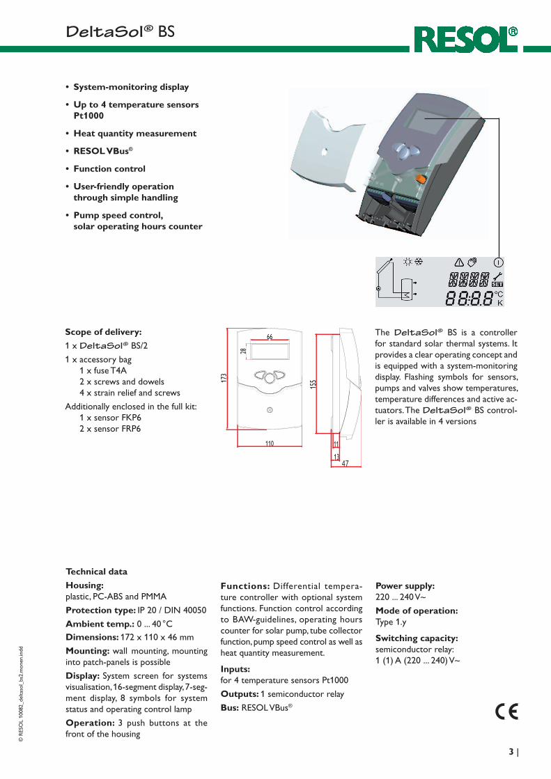
• System-monitoring display
• Up to 4 temperature sensors Pt1000
• Heat quantity measurement
• RESOL VBus®
• Function control
• User-friendly operation through simple handling
• Pump speed control, solar operating hours counter
Technical data
Housing: plastic, PC-ABS and PMMA
Protection type: IP 20 / DIN 40050
Ambient temp.: 0 ... 40 °CDimensions: 172 x 110 x 46 mm
Mounting: wall mounting, mounting into patch-panels is possible
Display: System screen for systems visualisation, 16-segment display, 7-seg-ment display, 8 symbols for system status and operating control lamp
Operation: 3 push buttons at the front of the housing
Functions: Differential tempera-ture controller with optional system functions. Function control according to BAW-guidelines, operating hours counter for solar pump, tube collector function, pump speed control as well as heat quantity measurement.
Inputs: for 4 temperature sensors Pt1000
Outputs: 1 semiconductor relay
Bus: RESOL VBus®
Power supply: 220 ... 240 V~
Mode of operation: Type 1.y
Switching capacity: semiconductor relay: 1 (1) A (220 ... 240) V~
The D e lt a S o l® BS is a controller for standard solar thermal systems. It provides a clear operating concept and is equipped with a system-monitoring display. Flashing symbols for sensors, pumps and valves show temperatures, temperature differences and active ac-tuators. The D e lt a S o l® BS control-ler is available in 4 versions
Scope of delivery:
1 x D e lt a S o l® BS/2
1 x accessory bag 1 x fuse T4A 2 x screws and dowels 4 x strain relief and screws
Additionally enclosed in the full kit: 1 x sensor FKP6 2 x sensor FRP6
D e lt a S o l® BS
© R
ESO
L 10
082_
delta
sol_
bs2.
mon
en.in
dd
| 4
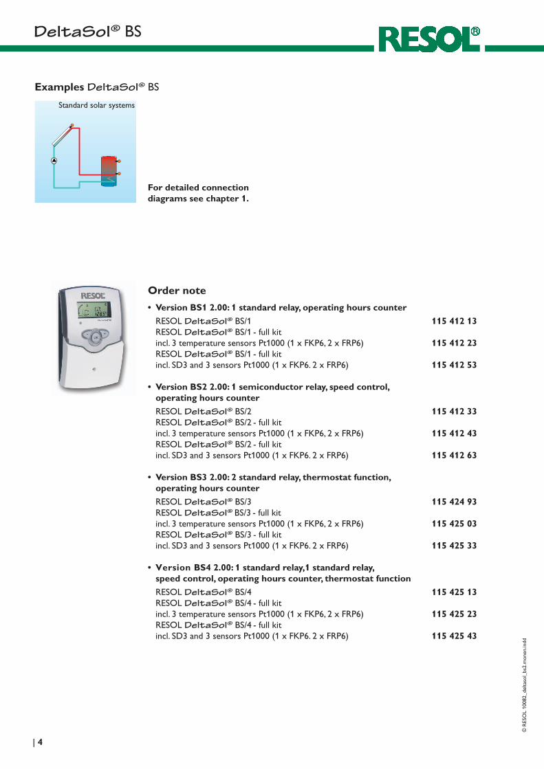
Examples D e lt a S o l® BS
Order note
• Version BS1 2.00: 1 standard relay, operating hours counter
RESOL D e lt a S o l® BS/1 115 412 13RESOL D e lt a S o l® BS/1 - full kitincl. 3 temperature sensors Pt1000 (1 x FKP6, 2 x FRP6) 115 412 23RESOL D e lt a S o l® BS/1 - full kitincl. SD3 and 3 sensors Pt1000 (1 x FKP6. 2 x FRP6) 115 412 53
• Version BS2 2.00: 1 semiconductor relay, speed control, operating hours counter
RESOL D e lt a S o l® BS/2 115 412 33RESOL D e lt a S o l® BS/2 - full kitincl. 3 temperature sensors Pt1000 (1 x FKP6, 2 x FRP6) 115 412 43RESOL D e lt a S o l® BS/2 - full kitincl. SD3 and 3 sensors Pt1000 (1 x FKP6. 2 x FRP6) 115 412 63
• Version BS3 2.00: 2 standard relay, thermostat function,operating hours counter
RESOL D e lt a S o l® BS/3 115 424 93RESOL D e lt a S o l® BS/3 - full kitincl. 3 temperature sensors Pt1000 (1 x FKP6, 2 x FRP6) 115 425 03RESOL D e lt a S o l® BS/3 - full kitincl. SD3 and 3 sensors Pt1000 (1 x FKP6. 2 x FRP6) 115 425 33
• Version BS4 2.00: 1 standard relay,1 standard relay, speed control, operating hours counter, thermostat function
RESOL D e lt a S o l® BS/4 115 425 13RESOL D e lt a S o l® BS/4 - full kitincl. 3 temperature sensors Pt1000 (1 x FKP6, 2 x FRP6) 115 425 23RESOL D e lt a S o l® BS/4 - full kitincl. SD3 and 3 sensors Pt1000 (1 x FKP6. 2 x FRP6) 115 425 43
For detailed connection diagrams see chapter 1.
Standard solar systems
D e lt a S o l® BS©
RES
OL
1008
2_de
ltaso
l_bs
2.m
onen
.indd
5 |
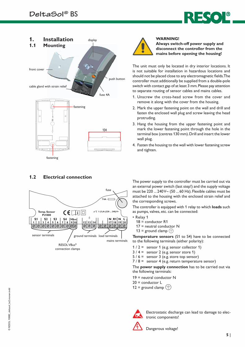
display
push button
fuse 4A
cable gland with strain relief
front cover
1 2S1 S2 S3
3 4 5 6
Temp. SensorPt1000
LNR1N20191817
S47 8 141312
1 (1) A (220 ... 240)V~
T4A
VBus9 10
1.1 Mounting
The unit must only be located in dry interior locations. It is not suitable for installation in hazardous locations and should not be placed close to any electromagnetic fields. The controller must additionally be supplied from a double-pole switch with contact gap of at least 3 mm. Please pay attention to separate routing of sensor cables and mains cables.
1. Unscrew the cross-head screw from the cover and remove it along with the cover from the housing.
2. Mark the upper fastening point on the wall and drill and fasten the enclosed wall plug and screw leaving the head protruding.
3. Hang the housing from the upper fastening point and mark the lower fastening point through the hole in the terminal box (centres 130 mm). Drill and insert the lower wall plug.
4. Fasten the housing to the wall with lower fastening screw and tighten.
1. Installation WARNING!Always switch-off power supply and disconnect the controller from the mains before opening the housing!
1.2 Electrical connectionThe power supply to the controller must be carried out via an external power switch (last step!) and the supply voltage must be 220 ... 240 V~ (50 ... 60 Hz). Flexible cables must be attached to the housing with the enclosed strain relief and the corresponding screws.The controller is equipped with 1 relay to which loads such as pumps, valves, etc. can be connected:• Relay 1
18 = conductor R1 17 = neutral conductor N 13 = ground clamp
Temperature sensors (S1 to S4) have to be connected to the following terminals (either polarity):
1 / 2 = sensor 1 (e.g. sensor collector 1)3 / 4 = sensor 2 (e.g. sensor store 1)5 / 6 = sensor 3 (e.g. store top sensor)7 / 8 = sensor 4 (e.g. return temperature sensor)The power supply connection has to be carried out via the following terminals:
19 = neutral conductor N20 = conductor L12 = ground clamp
mains terminals
fuse
load terminalssensor terminals
fastening
fastening
ground terminals
Electrostatic discharge can lead to damage to elec-tronic components!
Dangerous voltage!
RESOL VBus®
connection clamps
D e lt a S o l® BS
© R
ESO
L 10
082_
delta
sol_
bs2.
mon
en.in
dd
| 6
VBus109
S1
S2S4 / TRF
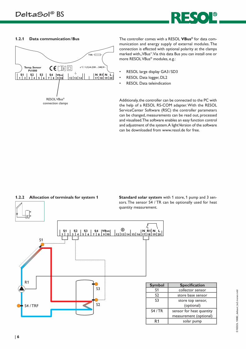
1.2.2 Allocation of terminals for system 1 Standard solar system with 1 store, 1 pump and 3 sen-sors. The sensor S4 / TR can be optionally used for heat quantity measurement.
R1
S3Symbol Specification
S1 collector sensorS2 store base sensorS3 store top sensor,
(optional)S4 / TR sensor for heat quantity
measurement (optional)R1 solar pump
1.2.1 Data communication / Bus The controller comes with a RESOL VBus® for data com-munication and energy supply of external modules. The connection is effected with optional polarity at the clamps marked with„VBus“. Via this data Bus you can install one or more RESOL VBus® modules, e.g.:
• RESOL large display GA3 / SD3• RESOL Data logger, DL2• RESOL Data teleindication
Additionaly, the controller can be connected to the PC with the help of a RESOL RS-COM adapter. With the RESOL ServiceCenter Software (RSC) the controller parameters can be changed, measurements can be read out, processed and visualised. The software enables an easy function control and adjustment of the system. A light Version of the software can be downloaded from www.resol.de for free.
RESOL VBus®
connection clamps
1 2S1 S2 S3
3 4 5 6
Temp. SensorPt1000
LNR1N20191817
S47 8 141312
1 (1) A (220 ... 240)V~
T4A
VBus9 10
D e lt a S o l® BS©
RES
OL
1008
2_de
ltaso
l_bs
2.m
onen
.indd
7 |
132
backwards (-) forward (+)
OK(selection / adjustment mode)
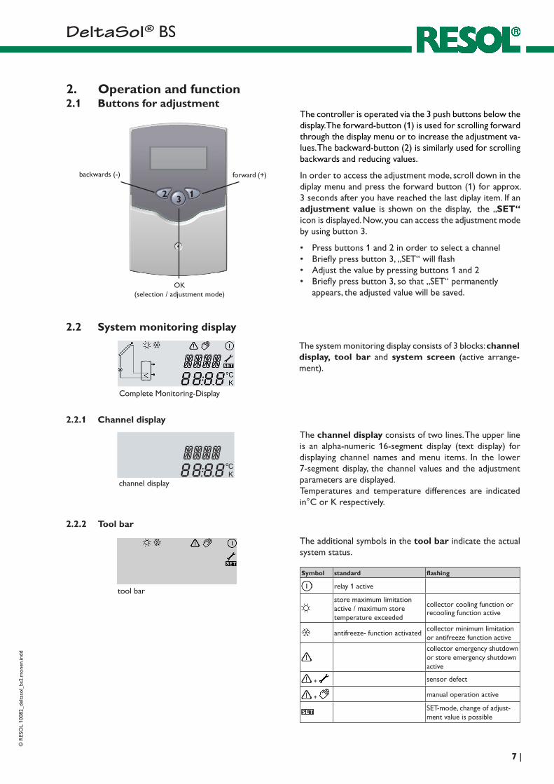
The system monitoring display consists of 3 blocks: channel display, tool bar and system screen (active arrange-ment).
The channel display consists of two lines. The upper line is an alpha-numeric 16-segment display (text display) for displaying channel names and menu items. In the lower 7-segment display, the channel values and the adjustment parameters are displayed.Temperatures and temperature differences are indicated in°C or K respectively.
2.2.1 Channel display
channel display
2.2.2 Tool bar
The additional symbols in the tool bar indicate the actual system status.
tool bar
2. Operation and function2.1 Buttons for adjustment
The controller is operated via the 3 push buttons below the display. The forward-button (1) is used for scrolling forward through the display menu or to increase the adjustment va-lues. The backward-button (2) is similarly used for scrolling backwards and reducing values.
In order to access the adjustment mode, scroll down in the diplay menu and press the forward button (1) for approx. 3 seconds after you have reached the last diplay item. If an adjustment value is shown on the display, the „SET“ icon is displayed. Now, you can access the adjustment mode by using button 3.
• Press buttons 1 and 2 in order to select a channel• Briefly press button 3, „SET“ will flash• Adjust the value by pressing buttons 1 and 2• Briefly press button 3, so that „SET“ permanently
appears, the adjusted value will be saved.
2.2 System monitoring display
Complete Monitoring-Display
Symbol standard flashing
relay 1 active
store maximum limitationactive / maximum storetemperature exceeded
collector cooling function or recooling function active
antifreeze- function activatedcollector minimum limitation or antifreeze function active
collector emergency shutdown or store emergency shutdown active
+ sensor defect
+ manual operation active
SET-mode, change of adjust-ment value is possible
D e lt a S o l® BS
© R
ESO
L 10
082_
delta
sol_
bs2.
mon
en.in
dd
| 8
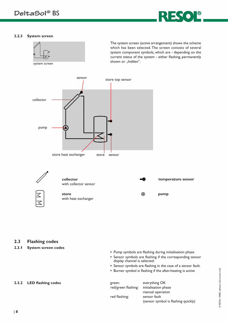
The system screen (active arrangement) shows the scheme which has been selected. The screen consists of several system component symbols, which are - depending on the current status of the system - either flashing, permanently shown or „hidden“.
sensor
collector
pump
storestore heat exchanger sensor
store top sensor
collectorwith collector sensor
pumpstorewith heat exchanger
temperature sensor
2.2.3 System screen
system screen
green: everything OKred/green flashing: initialisation phase
manual operationred flashing: sensor fault
(sensor symbol is flashing quickly)
2.3 Flashing codes
2.3.2 LED flashing codes
2.3.1 System screen codes• Pump symbols are flashing during initialisation phase• Sensor symbols are flashing if the corresponding sensor
display channel is selected.• Sensor symbols are flashing in the case of a sensor fault.• Burner symbol is flashing if the after-heating is active
D e lt a S o l® BS©
RES
OL
1008
2_de
ltaso
l_bs
2.m
onen
.indd
9 |
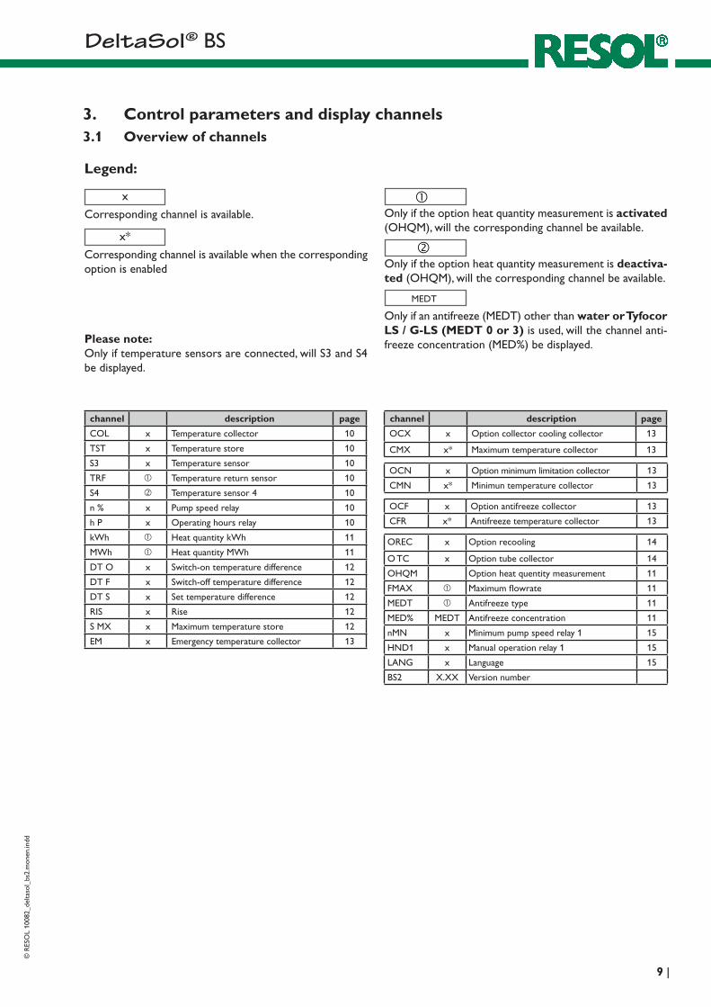
3. Control parameters and display channels3.1 Overview of channels
Legend:
x
Corresponding channel is available.
x*
Corresponding channel is available when the corresponding option is enabled
Only if the option heat quantity measurement is activated (OHQM), will the corresponding channel be available.
MEDT
Only if an antifreeze (MEDT) other than water or Tyfocor LS / G-LS (MEDT 0 or 3) is used, will the channel anti-freeze concentration (MED%) be displayed.
Only if the option heat quantity measurement is deactiva-ted (OHQM), will the corresponding channel be available.
Please note: Only if temperature sensors are connected, will S3 and S4 be displayed.
channel description page
COL x Temperature collector 10
TST x Temperature store 10
S3 x Temperature sensor 10
TRF Temperature return sensor 10
S4 Temperature sensor 4 10
n % x Pump speed relay 10
h P x Operating hours relay 10
kWh Heat quantity kWh 11
MWh Heat quantity MWh 11
DT O x Switch-on temperature difference 12
DT F x Switch-off temperature difference 12
DT S x Set temperature difference 12
RIS x Rise 12
S MX x Maximum temperature store 12
EM x Emergency temperature collector 13
channel description page
OCX x Option collector cooling collector 13
CMX x* Maximum temperature collector 13
OCN x Option minimum limitation collector 13
CMN x* Minimun temperature collector 13
OCF x Option antifreeze collector 13
CFR x* Antifreeze temperature collector 13
OREC x Option recooling 14
O TC x Option tube collector 14
OHQM Option heat quentity measurement 11
FMAX Maximum flowrate 11
MEDT Antifreeze type 11
MED% MEDT Antifreeze concentration 11
nMN x Minimum pump speed relay 1 15
HND1 x Manual operation relay 1 15
LANG x Language 15
BS2 X.XX Version number
D e lt a S o l® BS
© R
ESO
L 10
082_
delta
sol_
bs2.
mon
en.in
dd
| 10
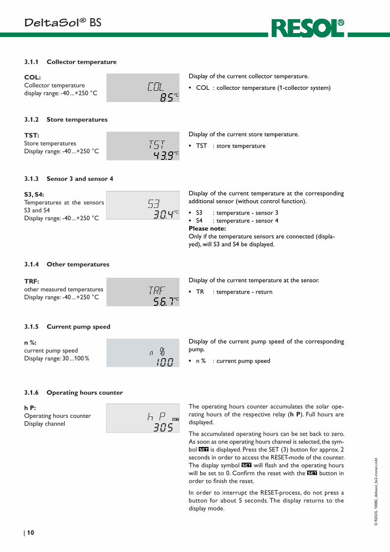
3.1.1 Collector temperature
Display of the current collector temperature.
• COL : collector temperature (1-collector system)
COL:Collector temperaturedisplay range: -40 ... +250 °C
3.1.2 Store temperatures
Display of the current store temperature.
• TST : store temperature
TST:Store temperaturesDisplay range: -40 ... +250 °C
3.1.3 Sensor 3 and sensor 4
Display of the current temperature at the corresponding additional sensor (without control function).
• S3 : temperature - sensor 3• S4 : temperature - sensor 4Please note: Only if the temperature sensors are connected (displa-yed), will S3 and S4 be displayed.
S3, S4:Temperatures at the sensors S3 and S4Display range: -40 ... +250 °C
3.1.4 Other temperatures
Display of the current temperature at the sensor.
• TR : temperature - return
TRF:other mea sured tempe raturesDisplay range: -40 ... +250 °C
3.1.5 Current pump speed
Display of the current pump speed of the corresponding pump.
• n % : current pump speed
n %:current pump speedDisplay range: 30 ... 100 %
3.1.6 Operating hours counter
h P:Operating hours counter Display channel
The operating hours counter accumulates the solar ope-rating hours of the respective relay (h P). Full hours are displayed.
The accumulated operating hours can be set back to zero. As soon as one operating hours channel is selected, the sym-bol is displayed. Press the SET (3) button for approx. 2 seconds in order to access the RESET-mode of the counter. The display symbol will flash and the operating hours will be set to 0. Confirm the reset with the button in order to finish the reset.
In order to interrupt the RESET-process, do not press a button for about 5 seconds. The display returns to the display mode.
D e lt a S o l® BS©
RES
OL
1008
2_de
ltaso
l_bs
2.m
onen
.indd
11 |
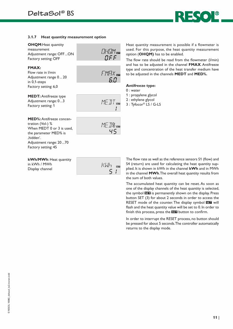
3.1.7 Heat quantity measurement option
OHQM:Heat quantity measurement Adjustment range: OFF ... ON Factory setting: OFF
Heat quantity measurement is possible if a flowmeter is used. For this purpose, the heat quantity measurement option (OHQM) has to be enabled.
The flow rate should be read from the flowmeter (l/min) and has to be adjusted in the channel FMAX. Antifreeze type and concentration of the heat transfer medium have to be adjusted in the channels MEDT and MED%.
Antifreeze type:0 : water 1 : propylene glycol 2 : ethylene glycol 3 : Tyfocor® LS / G-LS
FMAX: Flow rate in l/min Adjustment range 0 ... 20 in 0,1-steps Factory setting: 6,0
kWh/MWh: Heat quantity in kWh / MWh Display channel
MEDT: Antifreeze type Adjustment range: 0 ... 3 Factory setting: 1
MED%: Antifreeze concen-tration (Vol-) % When MEDT 0 or 3 is used, the parameter MED% is ‚hidden‘. Adjustment range: 20 ... 70 Factory setting: 45
The flow rate as well as the reference sensors S1 (flow) and S4 (return) are used for calculating the heat quantity sup-plied. It is shown in kWh in the channel kWh and in MWh in the channel MWh. The overall heat quantity results from the sum of both values.
The accumulated heat quantity can be reset. As soon as one of the display channels of the heat quantity is selected, the symbol is permanently shown on the display. Press button SET (3) for about 2 seconds in order to access the RESET mode of the counter. The display symbol will flash and the heat quantity value will be set to 0. In order to finish this process, press the button to confirm.
In order to interrupt the RESET process, no button should be pressed for about 5 seconds. The controller automatically returns to the display mode.
D e lt a S o l® BS
© R
ESO
L 10
082_
delta
sol_
bs2.
mon
en.in
dd
| 12
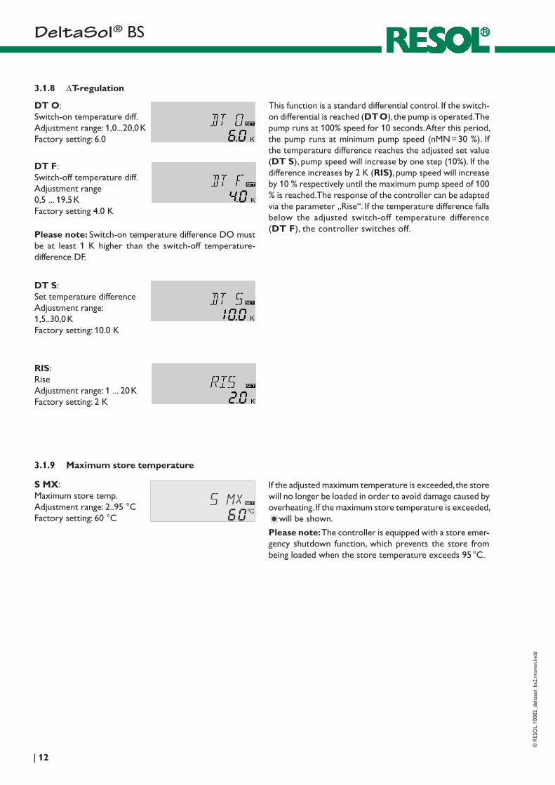
3.1.8 ∆T-regulation
Please note: Switch-on temperature difference DO must be at least 1 K higher than the switch-off tempe rature-difference DF.
DT O: Switch-on temperature diff. Adjustment range: 1,0...20,0 K Factory setting: 6.0
DT F:Switch-off temperature diff. Adjustment range 0,5 ... 19,5 K Factory setting 4.0 K
3.1.9 Maximum store temperature
If the adjusted maximum temperature is exceeded, the store will no longer be loaded in order to avoid damage caused by overheating. If the maximum store temperature is exceeded,
will be shown.
Please note: The controller is equipped with a store emer-gency shutdown function, which prevents the store from being loaded when the store temperature exceeds 95 °C.
S MX: Maximum store temp. Adjustment range: 2..95 °C Factory setting: 60 °C
DT S: Set temperature difference Adjustment range: 1,5..30,0 K Factory setting: 10.0 K
RIS: Rise Adjustment range: 1 ... 20 K Factory setting: 2 K
This function is a standard differential control. If the switch-on differential is reached (DT O), the pump is operated. The pump runs at 100% speed for 10 seconds. After this period, the pump runs at minimum pump speed (nMN = 30 %). If the temperature difference reaches the adjusted set value (DT S), pump speed will increase by one step (10%). If the difference increases by 2 K (RIS), pump speed will increase by 10 % respectively until the maximum pump speed of 100 % is reached. The response of the controller can be adapted via the parameter „Rise“. If the temperature difference falls below the adjusted switch-off temperature difference (DT F), the controller switches off.
D e lt a S o l® BS©
RES
OL
1008
2_de
ltaso
l_bs
2.m
onen
.indd
13 |
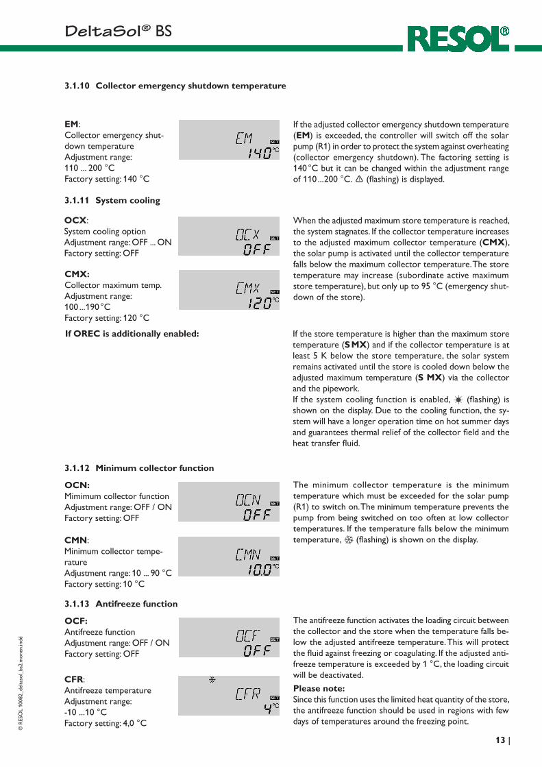
CMN:Minimum collector tempe-rature Adjustment range: 10 ... 90 °C Factory setting: 10 °C
CMX: Collector maximum temp. Adjustment range: 100 ... 190 °C Factory setting: 120 °C
3.1.11 System cooling
When the adjusted maximum store temperature is reached, the system stagnates. If the collector temperature increases to the adjusted maximum collector temperature (CMX), the solar pump is activated until the collector temperature falls below the maximum collector temperature. The store tempe rature may increase (subordinate active maximum store temperature), but only up to 95 °C (emergency shut-down of the store).
OCX: System cooling option Adjustment range: OFF ... ON Factory setting: OFF
3.1.12 Minimum collector function
OCN: Mimimum collector function Adjustment range: OFF / ON Factory setting: OFF
The minimum collector temperature is the minimum temperature which must be exceeded for the solar pump (R1) to switch on. The minimum temperature prevents the pump from being switched on too often at low collector temperatures. If the temperature falls below the minimum temperature, (flashing) is shown on the display.
CFR:Antifreeze temperature Adjustment range: -10 ... 10 °C Factory setting: 4,0 °C
3.1.13 Antifreeze function
OCF: Antifreeze function Adjustment range: OFF / ON Factory setting: OFF
The antifreeze function activates the loading circuit between the collector and the store when the temperature falls be-low the adjusted antifreeze temperature. This will protect the fluid against freezing or coagulating. If the adjusted anti-freeze temperature is exceeded by 1 °C, the loading circuit will be deactivated.
Please note:Since this function uses the limited heat quantity of the store, the antifreeze function should be used in regions with few days of temperatures around the freezing point.
3.1.10 Collector emergency shutdown temperature
If the adjusted collector emergency shutdown temperature (EM) is exceeded, the controller will switch off the solar pump (R1) in order to protect the system against overheating (collector emergency shutdown). The factoring setting is 140 °C but it can be changed within the adjustment range of 110 ... 200 °C. (flashing) is displayed.
EM:Collector emergency shut-down temperature Adjustment range: 110 ... 200 °C Factory setting: 140 °C
If OREC is additionally enabled: If the store tempe rature is higher than the maximum store temperature (S MX) and if the collector temperature is at least 5 K below the store temperature, the solar system remains activated until the store is cooled down below the adjusted maximum temperature (S MX) via the collector and the pipework. If the system cooling function is enabled, (flashing) is shown on the display. Due to the cooling function, the sy-stem will have a longer operation time on hot summer days and guarantees thermal relief of the collector field and the heat transfer fluid.
D e lt a S o l® BS
© R
ESO
L 10
082_
delta
sol_
bs2.
mon
en.in
dd
| 14
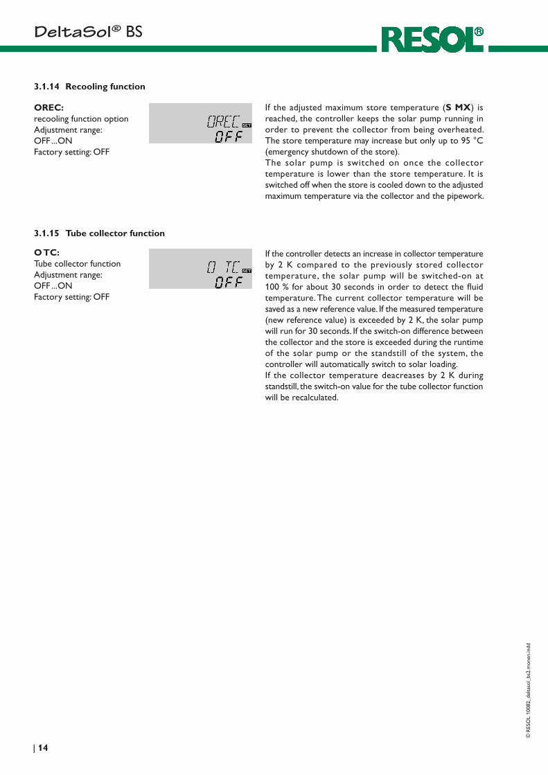
3.1.15 Tube collector function
If the controller detects an increase in collector temperature by 2 K compared to the previously stored collector temperature, the solar pump will be switched-on at 100 % for about 30 seconds in order to detect the fluid temperature. The current collector temperature will be saved as a new reference value. If the measured temperature (new reference value) is exceeded by 2 K, the solar pump will run for 30 seconds. If the switch-on difference between the collector and the store is exceeded during the runtime of the solar pump or the standstill of the system, the controller will automatically switch to solar loading.If the collector temperature deacreases by 2 K during standstill, the switch-on value for the tube collector function will be recalculated.
O TC:Tube collector function Adjustment range: OFF ... ON Factory setting: OFF
3.1.14 Recooling function
If the adjusted maximum store temperature (S MX) is reached, the controller keeps the solar pump running in order to prevent the collector from being overheated. The store temperature may increase but only up to 95 °C (emergency shutdown of the store).The solar pump is switched on once the collector temperature is lower than the store temperature. It is switched off when the store is cooled down to the adjusted maximum temperature via the collector and the pipework.
OREC:recooling function option Adjustment range: OFF ... ON Factory setting: OFF
D e lt a S o l® BS©
RES
OL
1008
2_de
ltaso
l_bs
2.m
onen
.indd
15 |
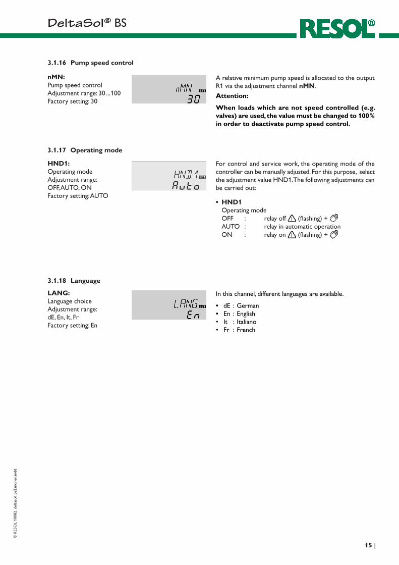
For control and service work, the operating mode of the controller can be manually adjusted. For this purpose, select the adjustment value HND1. The following adjustments can be carried out:
3.1.17 Operating mode
• HND1Operating mode OFF : relay off (flashing) + AUTO : relay in automatic operation ON : relay on (flashing) +
HND1:Operating mode Adjustment range: OFF, AUTO, ONFactory setting: AUTO
3.1.16 Pump speed control
A relative minimum pump speed is allocated to the output R1 via the adjustment channel nMN.
Attention:
When loads which are not speed controlled (e.g. valves) are used, the value must be changed to 100 % in order to deactivate pump speed control.
nMN:Pump speed controlAdjustment range: 30 ... 100Factory setting: 30
3.1.18 Language
In this channel, different languages are available.
• dE : German• En : English• It : Italiano• Fr : French
LANG:Language choiceAdjustment range: dE, En, It, FrFactory setting: En
D e lt a S o l® BS
© R
ESO
L 10
082_
delta
sol_
bs2.
mon
en.in
dd
| 16
1 2S1 S2 S3
3 4 5 6
Temp. SensorPt1000
LNR1N20191817
S47 8 141312
1 (1) A (220 ... 240)V~
T4A
VBus9 10
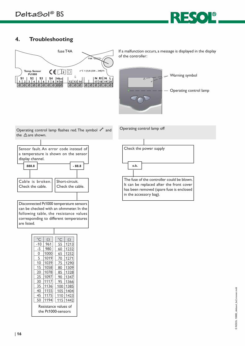
4. Troubleshooting
fuse T4A If a malfunction occurs, a message is displayed in the display of the controller:
Operating control lamp
Warning symbol
Operating control lamp off
Check the power supply
o.k.
The fuse of the controller could be blown. It can be replaced after the front cover has been removed (spare fuse is enclosed in the accessory bag).
Operating control lamp flashes red. The symbol and the are shown.
Sensor fault. An error code instead of a temperature is shown on the sensor display channel.
- 88.8888.8
Cable is broken. Check the cable.
Short-circuit. Check the cable.
Disconnected Pt1000 temperature sen sors can be checked with an ohmmeter. In the following table, the resistance values corresponding to different temperatures are listed.
Resistance values of the Pt1000-sensors
D e lt a S o l® BS©
RES
OL
1008
2_de
ltaso
l_bs
2.m
onen
.indd
17 |
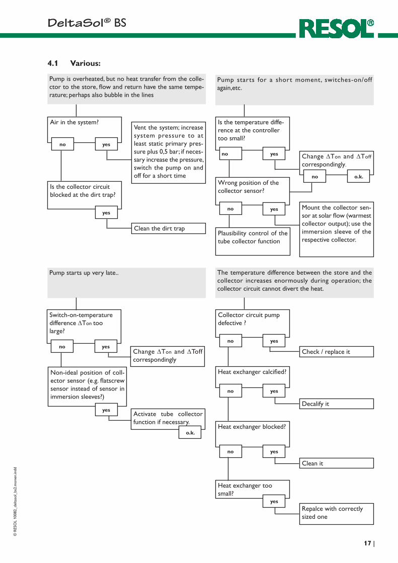
Pump starts for a short moment, switches-on/off again,etc.
Is the temperature diffe-rence at the controller too small?
no yes
Wrong position of the collector sensor?
yes
Change∆Ton and ∆Toff
correspondingly.
Mount the collector sen-sor at solar flow (warmest collector output); use the immersion sleeve of the respective collector.
Pump starts up very late.. The temperature difference between the store and the collector increases enormously during operation; the collector circuit cannot divert the heat.
Collector circuit pump defective ?
no yes
Heat exchanger calcified?
yes
Check / replace it
Decalify it
no
Heat exchanger blocked?
yesno
Clean it
Heat exchanger too small?
yesRepalce with correctly sized one
no
Plausibility control of the tube collector function
Change∆Ton and ∆Toff correspondingly
Switch-on-temperature difference ∆Ton too large?
no yes
Non-ideal position of coll-ector sensor (e.g. flatscrew sensor instead of sensor in immersion sleeves?)
o.k.no
Pump is overheated, but no heat transfer from the colle- ctor to the store, flow and return have the same tempe- rature; perhaps also bubble in the lines
Vent the system; in crease system pressure to at least static primary pres-sure plus 0,5 bar; if neces-sary increase the pressure, switch the pump on and off for a short time
Air in the system?
no yes
Is the collector circuit blocked at the dirt trap?
yes
Clean the dirt trap
4.1 Various:
Activate tube collector function if necessary.
yes
o.k.
D e lt a S o l® BS
© R
ESO
L 10
082_
delta
sol_
bs2.
mon
en.in
dd
| 18
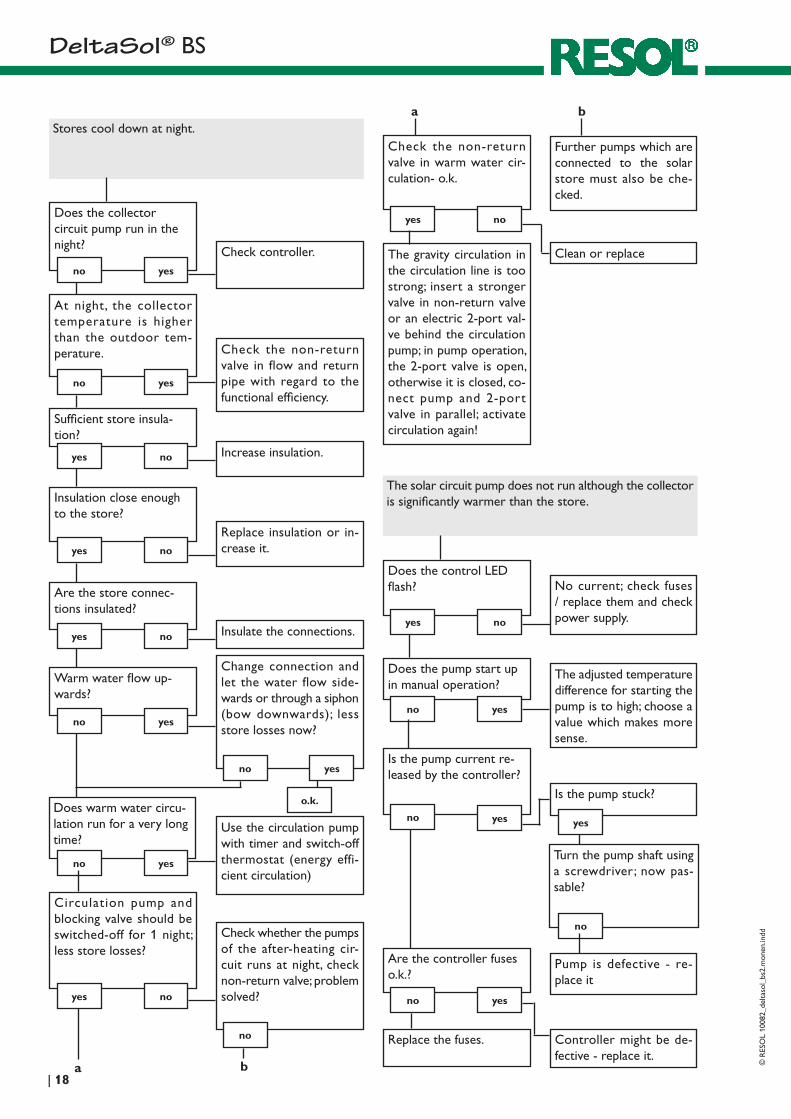
Stores cool down at night.
Does the collector circuit pump run in the night?
no yes
Check controller.
At night, the collector temperature is higher than the outdoor tem-perature.
no yes
Check the non-return valve in flow and return pipe with regard to the functional efficiency.
Sufficient store insula-tion?
yes no Increase insulation.
Insulation close enough to the store?
yes no
Replace insulation or in-crease it.
Are the store connec-tions insulated?
yes no Insulate the connections.
Warm water flow up-wards?
no yes
Change connection and let the water flow side-wards or through a siphon (bow downwards); less store losses now?
Does warm water circu-lation run for a very long time?
no yes
Use the circulation pump with timer and switch-off thermostat (energy effi-cient circulation)
The solar circuit pump does not run although the collector is significantly warmer than the store.
Does the control LED flash?
yes no
Does the pump start up in manual operation?
yes
No current; check fuses / replace them and check power supply.
The adjusted temperature difference for starting the pump is to high; choose a value which makes more sense.
no
Is the pump current re-leased by the controller?
yes
Is the pump stuck?
Turn the pump shaft using a screwdriver; now pas-sable?
Pump is defective - re-place it
Are the controller fuses o.k.?
Controller might be de- fective - replace it.
no yes
no
no yes
Replace the fuses.
Circulation pump and blocking valve should be switched-off for 1 night; less store losses?
yes no
Check whether the pumps of the after-heating cir-cuit runs at night, check non-return valve; problem solved?
no
no yes
o.k.
Check the non-return valve in warm water cir-culation- o.k.
yes no
Further pumps which are connected to the solar store must also be che- cked.
The gravity circu lation in the circulation line is too strong; insert a stronger valve in non-return valve or an electric 2-port val-ve behind the circulation pump; in pump operation, the 2-port valve is open, other wise it is closed, co-nect pump and 2-port valve in parallel; activate circulation again!
Clean or replace
a
a b
b
D e lt a S o l® BS©
RES
OL
1008
2_de
ltaso
l_bs
2.m
onen
.indd
19 |
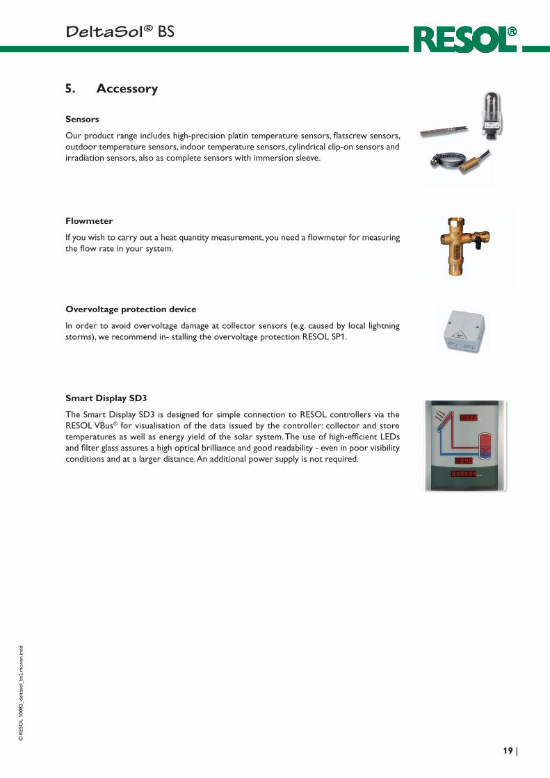
5. Accessory
Overvoltage protection device
In order to avoid overvoltage damage at collector sensors (e.g. caused by local lightning storms), we recommend in- stalling the overvoltage protection RESOL SP1.
Sensors
Our product range includes high-precision platin temperature sensors, flatscrew sensors, outdoor temperature sensors, indoor temperature sensors, cylindrical clip-on sensors and irradiation sensors, also as complete sensors with immersion sleeve.
Flowmeter
If you wish to carry out a heat quantity measurement, you need a flowmeter for measuring the flow rate in your system.
Smart Display SD3
The Smart Display SD3 is designed for simple connection to RESOL controllers via the RESOL VBus® for visualisation of the data issued by the controller: collector and store temperatures as well as energy yield of the solar system. The use of high-efficient LEDs and filter glass assures a high optical brilliance and good readability - even in poor visibility conditions and at a larger distance. An additional power supply is not required.
D e lt a S o l® BS
© R
ESO
L 10
082_
delta
sol_
bs2.
mon
en.in
dd
| 20
Distributed by: RESOL - Elektronische Regelungen GmbH
Heiskampstraße 10 45527 Hattingen / Germany
Tel.: +49 (0) 23 24 / 96 48 - 0 Fax: +49 (0) 23 24 / 96 48 - 755
www.resol.de [email protected]
Please note:The design and the specifications can be changed without prior notice.The illustrations may differ from the original product.
Reprinting / copyingThis mounting- and operation manual including all parts is copyrighted. Another use outside the copyright re-quires the approval of RESOL - Elektronische Regelungen GmbH. This especially applies for copies, translations, micro films and the storage into electronic systems. Editor: RESOL - Elektronische Regelungen GmbH
Important notice:We took a lot of care with the texts and drawings of this manual and to the best of our knowledge and consent. As faults can never be excluded, please note: Your own calcu-lations and plans, under consideration of the current stan-dards and DIN-directions should only be basis for your projects. We don´t offer a guarantee for the completeness of the drawings and texts of this manual - they only repre-sent some examples. They can only be used at your own risk. No liability is assumed for incorrect, incomplete or false information and / or any resulting damages.