Resistance thermometer Without thermowell Model TR10-H
13
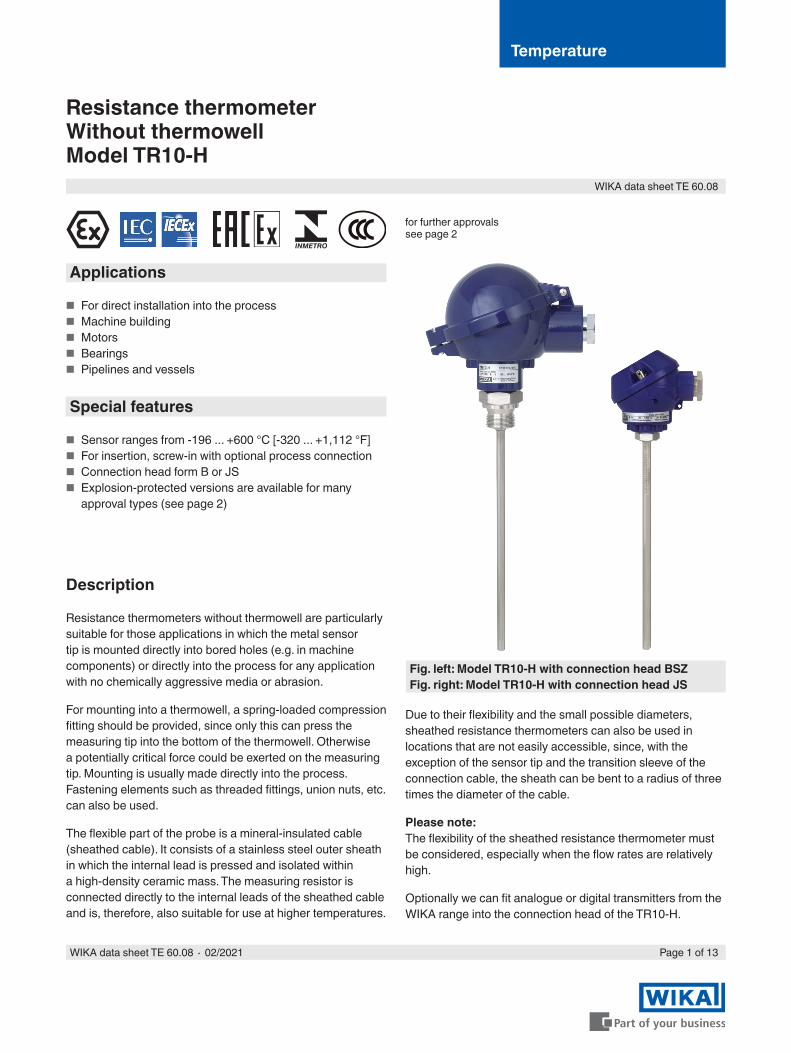
Temperature Resistance thermometer Without thermowell Model TR10-H Applications ■ For direct installation into the process ■ Machine building ■ Motors ■ Bearings ■ Pipelines and vessels Special features ■ Sensor ranges from -196 ... +600 °C [-320 ... +1,112 °F] ■ For insertion, screw-in with optional process connection ■ Connection head form B or JS ■ Explosion-protected versions are available for many approval types (see page 2) Description Resistance thermometers without thermowell are particularly suitable for those applications in which the metal sensor tip is mounted directly into bored holes (e.g. in machine components) or directly into the process for any application with no chemically aggressive media or abrasion. For mounting into a thermowell, a spring-loaded compression fitting should be provided, since only this can press the measuring tip into the bottom of the thermowell. Otherwise a potentially critical force could be exerted on the measuring tip. Mounting is usually made directly into the process. Fastening elements such as threaded fittings, union nuts, etc. can also be used. The flexible part of the probe is a mineral-insulated cable (sheathed cable). It consists of a stainless steel outer sheath in which the internal lead is pressed and isolated within a high-density ceramic mass. The measuring resistor is connected directly to the internal leads of the sheathed cable and is, therefore, also suitable for use at higher temperatures. WIKA data sheet TE 60.08 Page 1 of 13 WIKA data sheet TE 60.08 ∙ 02/2021 Due to their flexibility and the small possible diameters, sheathed resistance thermometers can also be used in locations that are not easily accessible, since, with the exception of the sensor tip and the transition sleeve of the connection cable, the sheath can be bent to a radius of three times the diameter of the cable. Please note: The flexibility of the sheathed resistance thermometer must be considered, especially when the flow rates are relatively high. Optionally we can fit analogue or digital transmitters from the WIKA range into the connection head of the TR10-H. for further approvals see page 2 Fig. left: Model TR10-H with connection head BSZ Fig. right: Model TR10-H with connection head JS
-
Upload
khangminh22 -
Category
Documents
-
view
0 -
download
0
Transcript of Resistance thermometer Without thermowell Model TR10-H
Temperature
Resistance thermometerWithout thermowellModel TR10-H
Applications
■ For direct installation into the process ■ Machine building ■ Motors ■ Bearings ■ Pipelines and vessels
Special features
■ Sensor ranges from -196 ... +600 °C [-320 ... +1,112 °F] ■ For insertion, screw-in with optional process connection ■ Connection head form B or JS ■ Explosion-protected versions are available for many
approval types (see page 2)
Description
Resistance thermometers without thermowell are particularly suitable for those applications in which the metal sensor tip is mounted directly into bored holes (e.g. in machine components) or directly into the process for any application with no chemically aggressive media or abrasion.
For mounting into a thermowell, a spring-loaded compression fitting should be provided, since only this can press the measuring tip into the bottom of the thermowell. Otherwise a potentially critical force could be exerted on the measuring tip. Mounting is usually made directly into the process. Fastening elements such as threaded fittings, union nuts, etc. can also be used.
The flexible part of the probe is a mineral-insulated cable (sheathed cable). It consists of a stainless steel outer sheath in which the internal lead is pressed and isolated within a high-density ceramic mass. The measuring resistor is connected directly to the internal leads of the sheathed cable and is, therefore, also suitable for use at higher temperatures.
WIKA data sheet TE 60.08
Page 1 of 13WIKA data sheet TE 60.08 ∙ 02/2021
Due to their flexibility and the small possible diameters, sheathed resistance thermometers can also be used in locations that are not easily accessible, since, with the exception of the sensor tip and the transition sleeve of the connection cable, the sheath can be bent to a radius of three times the diameter of the cable.
Please note:The flexibility of the sheathed resistance thermometer must be considered, especially when the flow rates are relatively high.
Optionally we can fit analogue or digital transmitters from the WIKA range into the connection head of the TR10-H.
for further approvals see page 2
Fig. left: Model TR10-H with connection head BSZFig. right: Model TR10-H with connection head JS

Page 2 of 13WIKA data sheet TE 60.08 ∙ 02/2021
Explosion protection (option)
The permissible power, Pmax, as well as the permissible ambient temperature, for the respective category can be seen on the certificate for hazardous areas or in the operating instructions.
Transmitters have own certificates for hazardous areas. The permissible ambient temperature ranges of the built-in transmitters can be taken from the corresponding transmitter operating instructions and approvals.
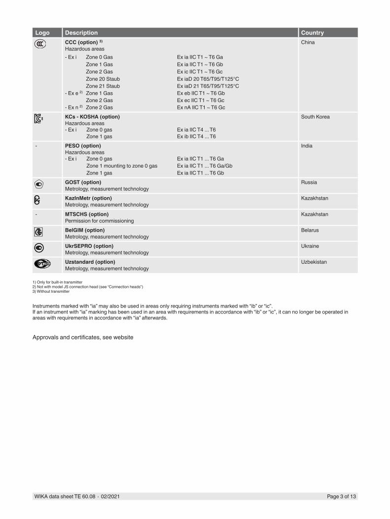
Approvals (explosion protection, further approvals)
Logo Description CountryEU declaration of conformity
■ EMC directive 1)
EN 61326 emission (group 1, class B) and immunity (industrial application) ■ RoHS directive ■ ATEX directive (option)
Hazardous areas- Ex i Zone 0 gas II 1G Ex ia IIC T1 ... T6 Ga
Zone 1 mounting to zone 0 gas II 1/2G Ex ia IIC T1 ... T6 Ga/GbZone 1 gas II 2G Ex ia IIC T1 ... T6 GbZone 20 dust II 1D Ex ia IIIC T125 ... T65 °C DaZone 21 mounting to zone 20 dust II 1/2D Ex ia IIIC T125 ... T65 °C Da/DbZone 21 dust II 2D Ex ia IIIC T125 ... T65 °C Db
- Ex e 2) Zone 1 gas II 2G Ex eb IIC T1 ... T6 Gb 3)
Zone 2 gas II 3G Ex ec IIC T1 ... T6 GcZone 21 dust II 2D Ex tb IIIC TX °C Db 3)
Zone 22 dust II 3D Ex tc IIIC TX °C Dc- Ex n 2) Zone 2 gas II 3G Ex nA IIC T1 ... T6 Gc X
Zone 22 dust II 3D Ex tc IIIC TX °C Dc
European Union
IECEx (option) - in conjunction with ATEXHazardous areas- Ex i Zone 0 gas Ex ia IIC T1 ... T6 Ga
Zone 1 mounting to zone 0 gas Ex ia IIC T1 ... T6 Ga/GbZone 1 gas Ex ia IIC T1 ... T6 GbZone 20 dust Ex ia IIIC T125 ... T65 °C DaZone 21 mounting to zone 20 dust Ex ia IIIC T125 ... T65 °C Da/DbZone 21 dust Ex ia IIIC T125 ... T65 °C Db
International
EAC (option)Hazardous areas- Ex i Zone 0 gas 0 Ex ia IIC T6 ... T1 Ga X
Zone 1 gas 1 Ex ia IIC T6 ... T1 Gb XZone 20 dust Ex ia IIIC T80 ... T440 °C Da XZone 21 dust Ex ia IIIC T80 ... T440 °C Db X
- Ex n 2) Zone 2 gas 2Ex nA IIC T6 ... T1 Gc X
Eurasian Economic Community
Ex Ukraine (option)Hazardous areas- Ex i Zone 0 gas II 1G Ex ia IIC T1 ...T6 Ga
Zone 1 gas II 2G Ex ia IIC T1 ... T6 GbZone 20 dust II 1D Ex ia IIIC T65°C DaZone 21 dust II 2D Ex ia IIIC T65°C Db
Ukraine
INMETRO (option)Hazardous areas- Ex i Zone 0 gas Ex ia IIC T3 ... T6 Ga
Zone 1 mounting to zone 0 gas Ex ia IIC T3 ... T6 Ga/GbZone 20 dust Ex ia IIIC T125 ... T65 °C DaZone 21 mounting to zone 20 dust Ex ia IIIC T125 ... T65 °C Da/Db
Brazil
Page 3 of 13WIKA data sheet TE 60.08 ∙ 02/2021
Logo Description CountryCCC (option) 3)
Hazardous areas- Ex i Zone 0 Gas Ex ia IIC T1 ~ T6 Ga
Zone 1 Gas Ex ia IIC T1 ~ T6 GbZone 2 Gas Ex ic IIC T1 ~ T6 GcZone 20 Staub Ex iaD 20 T65/T95/T125°CZone 21 Staub Ex iaD 21 T65/T95/T125°C
- Ex e 2) Zone 1 Gas Ex eb IIC T1 ~ T6 GbZone 2 Gas Ex ec IIC T1 ~ T6 Gc
- Ex n 2) Zone 2 Gas Ex nA IIC T1 ~ T6 Gc
China
KCs - KOSHA (option)Hazardous areas- Ex i Zone 0 gas Ex ia IIC T4 ... T6
Zone 1 gas Ex ib IIC T4 ... T6
South Korea
- PESO (option)Hazardous areas- Ex i Zone 0 gas Ex ia IIC T1 ... T6 Ga
Zone 1 mounting to zone 0 gas Ex ia IIC T1 ... T6 Ga/GbZone 1 gas Ex ia IIC T1 ... T6 Gb
India
GOST (option)Metrology, measurement technology
Russia
KazInMetr (option)Metrology, measurement technology
Kazakhstan
- MTSCHS (option)Permission for commissioning
Kazakhstan
BelGIM (option)Metrology, measurement technology
Belarus
UkrSEPRO (option)Metrology, measurement technology
Ukraine
Uzstandard (option)Metrology, measurement technology
Uzbekistan
1) Only for built-in transmitter2) Not with model JS connection head (see “Connection heads”)3) Without transmitter
Instruments marked with “ia” may also be used in areas only requiring instruments marked with “ib” or “ic”.If an instrument with “ia” marking has been used in an area with requirements in accordance with “ib” or “ic”, it can no longer be operated in areas with requirements in accordance with “ia” afterwards.
Approvals and certificates, see website
Page 4 of 13WIKA data sheet TE 60.08 ∙ 02/2021
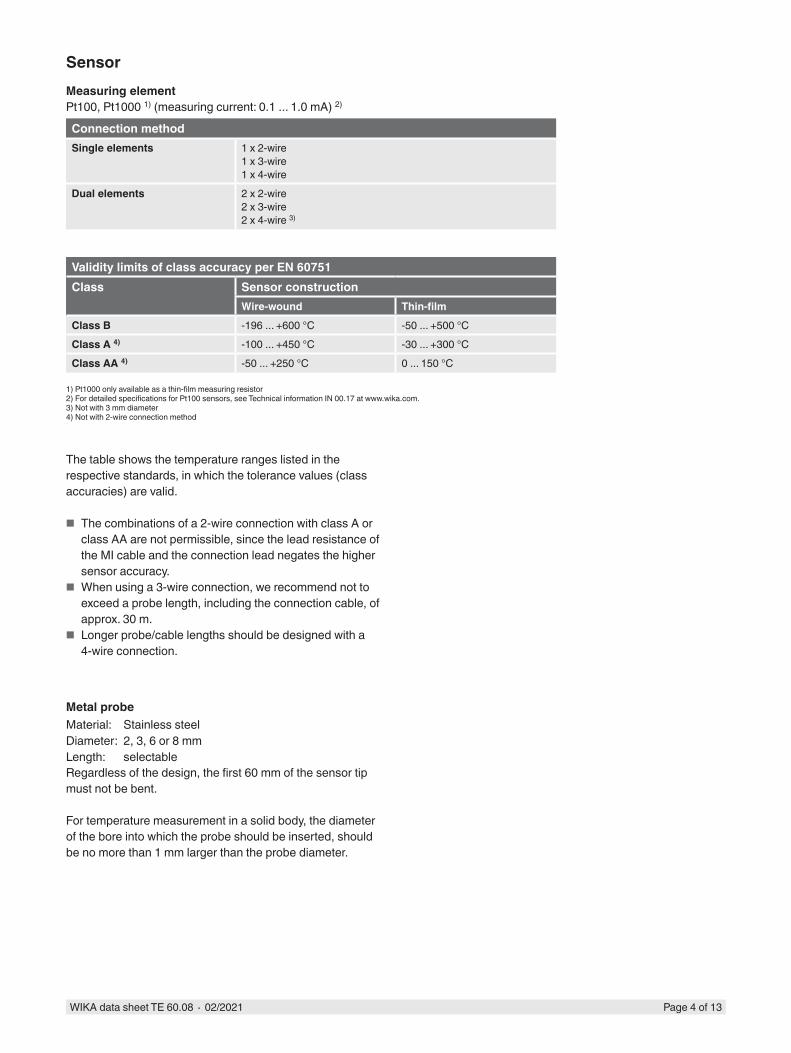
Connection methodSingle elements 1 x 2-wire
1 x 3-wire1 x 4-wire
Dual elements 2 x 2-wire2 x 3-wire2 x 4-wire 3)
Validity limits of class accuracy per EN 60751Class Sensor construction
Wire-wound Thin-filmClass B -196 ... +600 °C -50 ... +500 °CClass A 4) -100 ... +450 °C -30 ... +300 °CClass AA 4) -50 ... +250 °C 0 ... 150 °C
SensorMeasuring elementPt100, Pt1000 1) (measuring current: 0.1 ... 1.0 mA) 2)
1) Pt1000 only available as a thin-film measuring resistor2) For detailed specifications for Pt100 sensors, see Technical information IN 00.17 at www.wika.com.3) Not with 3 mm diameter4) Not with 2-wire connection method
Metal probeMaterial: Stainless steelDiameter: 2, 3, 6 or 8 mmLength: selectableRegardless of the design, the first 60 mm of the sensor tip must not be bent.
For temperature measurement in a solid body, the diameter of the bore into which the probe should be inserted, should be no more than 1 mm larger than the probe diameter.
The table shows the temperature ranges listed in the respective standards, in which the tolerance values (class accuracies) are valid.
■ The combinations of a 2-wire connection with class A or class AA are not permissible, since the lead resistance of the MI cable and the connection lead negates the higher sensor accuracy.
■ When using a 3-wire connection, we recommend not to exceed a probe length, including the connection cable, of approx. 30 m.
■ Longer probe/cable lengths should be designed with a 4-wire connection.

Page 5 of 13WIKA data sheet TE 60.08 ∙ 02/2021
Electrical connection (colour code per IEC/EN 60751)
■ Connection head form B
■ Connection head model JS
1 x Pt100, 2-wire 1 x Pt100, 3-wire 1 x Pt100, 4-wire 2 x Pt100, 2-wire
3383
942.
03
white red white red white red white red
black yellow
white
red
white
redred
white
redred
white
white
red
black
yellow
For the electrical connections of built-in temperature transmitters see the corresponding data sheets or operating instructions.
1 x Pt100, 2-wire 1 x Pt100, 3-wire 1 x Pt100, 4-wire
whitered
red
white
redred
white
redredwhitewhite
3160
629.
06
white red
white red
redredwhitewhite
red
black
red
yellow
black
red
yellow
white
black
white
redredwhite
red
white
black
yellow
blackblack
yellow
blackblackyellowyellow
2 x Pt100, 2-wire 2 x Pt100, 3-wire 2 x Pt100, 4-wire
red
white red
yellow
white

Page 6 of 13WIKA data sheet TE 60.08 ∙ 02/2021
Model Material Cable entry thread size
Ingress protection (max.) 1)
IEC/EN 60529
Cap Surface Connection to neck tube
JS Aluminium M16 x 1.5 3) IP65 Cover with 2 screws Blue, lacquered 5) M24 x 1.5, ½ NPTBS Aluminium M20 x 1.5 or ½ NPT 3) IP65 4) Flat cap with 2 screws Blue, lacquered 5) M24 x 1.5, ½ NPTBSZ Aluminium M20 x 1.5 or ½ NPT 3) IP65 4) Spherical hinged cover
with cylinder head screwBlue, lacquered 5) M24 x 1.5, ½ NPT
BSZ-H Aluminium M20 x 1.5 or ½ NPT 3) IP65 4) Raised hinged cover with cylinder head screw
Blue, lacquered 5) M24 x 1.5, ½ NPT
BSZ-H(2x cable outlet)
Aluminium 2 x M20 x 1.5 or 2 x ½ NPT 3)
IP65 4) Raised hinged cover with cylinder head screw
Blue, lacquered 5) M24 x 1.5
BSZ-H / DIH10 2)
Aluminium M20 x 1.5 or ½ NPT 3) IP65 Raised hinged cover with cylinder head screw
Blue, lacquered 5) M24 x 1.5, ½ NPT
BSS Aluminium M20 x 1.5 or ½ NPT 3) IP65 Spherical hinged cover with clamping lever
Blue, lacquered 5) M24 x 1.5, ½ NPT
BSS-H Aluminium M20 x 1.5 or ½ NPT 3) IP65 Raised hinged cover with clamping lever
Blue, lacquered 5) M24 x 1.5, ½ NPT
BVS Stainless steel
M20 x 1.5 3) IP65 Precision-cast screw-on lid
Blank, electropolished
M24 x 1.5
BSZ-K Plastic M20 x 1.5 or ½ NPT 3) IP65 Spherical hinged cover with cylinder head screw
Black M24 x 1.5
BSZ-HK Plastic M20 x 1.5 or ½ NPT 3) IP65 Raised hinged cover with cylinder head screw
Black M24 x 1.5
Model Explosion protectionWithout Ex i (gas)
Zone 0, 1, 2Ex i (dust)Zone 20, 21, 22
Ex e (gas) Zone 1, 2
Ex t (dust)Zone 21, 22
Ex nA (gas)Zone 2
JS x x x - - -BS x x x - - -BSZ x x x x 6) x 6) x 7)
BSZ-H x x x x 6) x 6) x 7)
BSZ-H (2x cable outlet) x x x x 6) x 6) x 7)
BSZ-H / DIH10 2) x x - - - -BSS x x - - - -BSS-H x x - - - -BVS x x - - - -BSZ-K x x - - - -BSZ-HK x x - - - -
7/8000 DIH50 KN4-PBVS BVS (NuG)JS 7/80005/60001/4000 andere AnschlussgehäuseBS BSZ, BSZ-K BSZ-H, BSZ-HK BSS BSS-H BVCBS BSZ, BSZ-K
BSZ-H, BSZ-HK, BSZ-H / DIH10
BSS BSS-H BVS
Connection head
1) IP ingress protection of the connection head. The IP ingress protections of the complete instrument TR10-H must not inevitably correspond to the connection head.2) LED display DIH103) Standard (others on request)4) Ingress protections, which describe temporary or lasting submersion, available on request5) RAL 50226) Only ATEX and CCC7) Only ATEX, CCC and EAC
JS

Page 7 of 13WIKA data sheet TE 60.08 ∙ 02/2021
Connection head with digital display (option)
Connection head BSZ-H with LED display model DIH10see data sheet AC 80.11
To operate the digital displays, a transmitter with a 4 ... 20 mA output is always required.
Cable entry Cable entry thread size Min./max. ambient temperatureStandard cable entry 1) M20 x 1.5 or ½ NPT -40 ... +80 °CPlastic cable gland (cable Ø 6 ... 10 mm) 1) M20 x 1.5 or ½ NPT -40 ... +80 °CPlastic cable gland (cable Ø 6 ... 10 mm), Ex e 1) M20 x 1.5 or ½ NPT -20 ... +80 °C (standard)
-40 ... +70 °C (option)Nickel-plated brass cable gland (cable Ø 6 ... 12 mm) M20 x 1.5 or ½ NPT -60 2) / -40 ... +80 °C
Cable entry Colour Ingress protection (max.) 3)
IEC/EN 60529
Explosion protectionwithout Ex i (gas)
Zone 0, 1, 2
Ex i (dust)Zone 20, 21, 22
Ex e (gas) Zone 1, 2
Ex t (dust)Zone 21, 22
Ex nA (gas)Zone 2
Standard cable entry 1) Blank IP65 x x - - - -Plastic cable gland 1) Black or
greyIP66 4) x x - - - -
Plastic cable gland, Ex e 1) Light blue IP66 4) x x x - - -Plastic cable gland, Ex e 1) Black IP66 4) x x x x x xNickel-plated brass cable gland Blank IP66 4) x x x - - -Nickel-plated brass cable gland, Ex e
Blank IP66 4) x x x x x x
1) Not available for BVS connection head2) Special version on request (only available with selected approvals), other temperatures on request3) IP ingress protection of the connection head. The IP ingress protections of the cable entry must not inevitably correspond to the IP ingress protections of the complete instrument TR10-H.4) Ingress protections, which describe temporary or lasting submersion, available on request
Cable entry
Standard Brass, nickel-plated
Plastic Plastic (Ex)
The figures show examples of connection heads.
Page 8 of 13WIKA data sheet TE 60.08 ∙ 02/2021
Ingress protection per IEC/EN 60529
Degrees of protection against solid foreign bodies (defined by the first index number)
First index number Degree of protection / short description Test parameter5 Dust-protected per IEC/EN 605296 Dust-tight per IEC/EN 60529
Degrees of protection against water (defined by the second index number)
Second index number Degree of protection / short description Test parameter4 Protected against splash water per IEC/EN 605295 Protected against water jets per IEC/EN 605296 Protected against strong water jets per IEC/EN 605297 1) Protected against the effects of temporary immersion in water per IEC/EN 605298 1) Protected against the effects of continuous immersion in water by agreement
1) Ingress protections, describing temporary or permanent immersion, on request
Standard ingress protection of model TR10-H is IP65.
The stated degrees of protection apply under the following conditions:
■ Use of a suitable cable gland ■ Use of a cable cross-section appropriate for the gland or
select the appropriate cable gland for the available cable ■ Adhere to the tightening torques for all threaded
connections
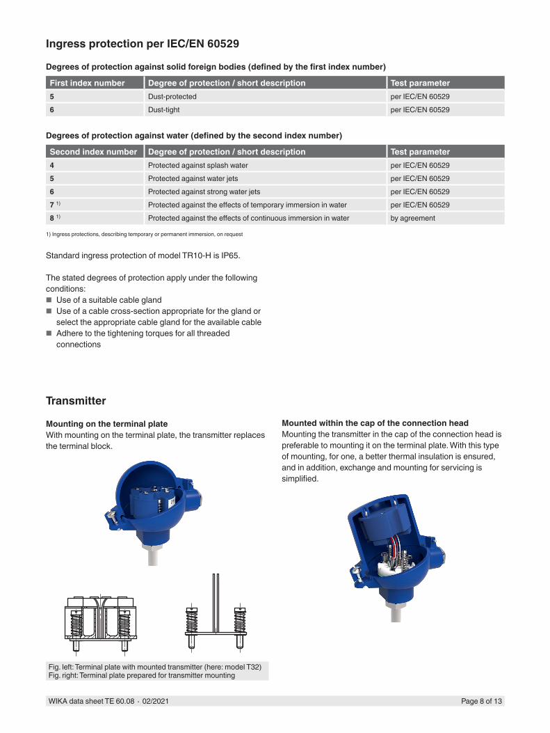
Transmitter
Mounting on the terminal plateWith mounting on the terminal plate, the transmitter replaces the terminal block.
Mounted within the cap of the connection headMounting the transmitter in the cap of the connection head is preferable to mounting it on the terminal plate. With this type of mounting, for one, a better thermal insulation is ensured, and in addition, exchange and mounting for servicing is simplified.
Fig. left: Terminal plate with mounted transmitter (here: model T32)Fig. right: Terminal plate prepared for transmitter mounting

Page 9 of 13WIKA data sheet TE 60.08 ∙ 02/2021
Possible mounting positions for transmitters
Connection head T15 T32 T91.20JS - - ○BS ○ - -BSZ, BSZ-K ○ ○ -BSZ-H, BSZ-HK ● ● -BSZ-H (2x cable outlet) ● ● -BSZ-H / DIH10 ○ ○ -BSS ○ ○ -BSS-H ● ● -BVS ○ ○ -
○ Mounted instead of terminal block ● Mounted within the cap of the connection head – Mounting not possible
The mounting of a transmitter on the terminal plate is possible with all the connection heads listed here. The fitting of a transmitter in the (screw) cap of a connection head is not possible.Mounting of 2 transmitters on request.For a correct determination of the overall measuring deviation, the sensor and transmitter measuring deviations must be added.
Transmitter models
Output signal 4 ... 20 mA, HART® protocolTransmitter (selectable versions) Model T15 Model T32 Model T91.20Data sheet TE 15.01 TE 32.04 TE 91.01Output
4 ... 20 mA x x xHART® protocol - x -
Connection method1 x 2-wire, 3-wire or 4-wire x x x
Measuring current < 0.2 mA < 0.3 mA 0.8 ... 1 mAExplosion protection Optional Optional -
Functional safety (option)with temperature transmitter model T32
In safety-critical applications, the entire measuring chain must be taken into consideration in terms of the safety parameters. The SIL classification allows the assessment of the risk reduction reached by the safety installations.
Selected TR10-H resistance thermometers, in combination with a suitable temperature transmitter (e.g. model T32.1S, TÜV certified SIL version for protection systems developed
in accordance with IEC 61508), are suitable as sensors for safety functions to SIL 2.
For detailed specifications, see Technical information IN 00.19 at www.wika.com.
Page 10 of 13WIKA data sheet TE 60.08 ∙ 02/2021
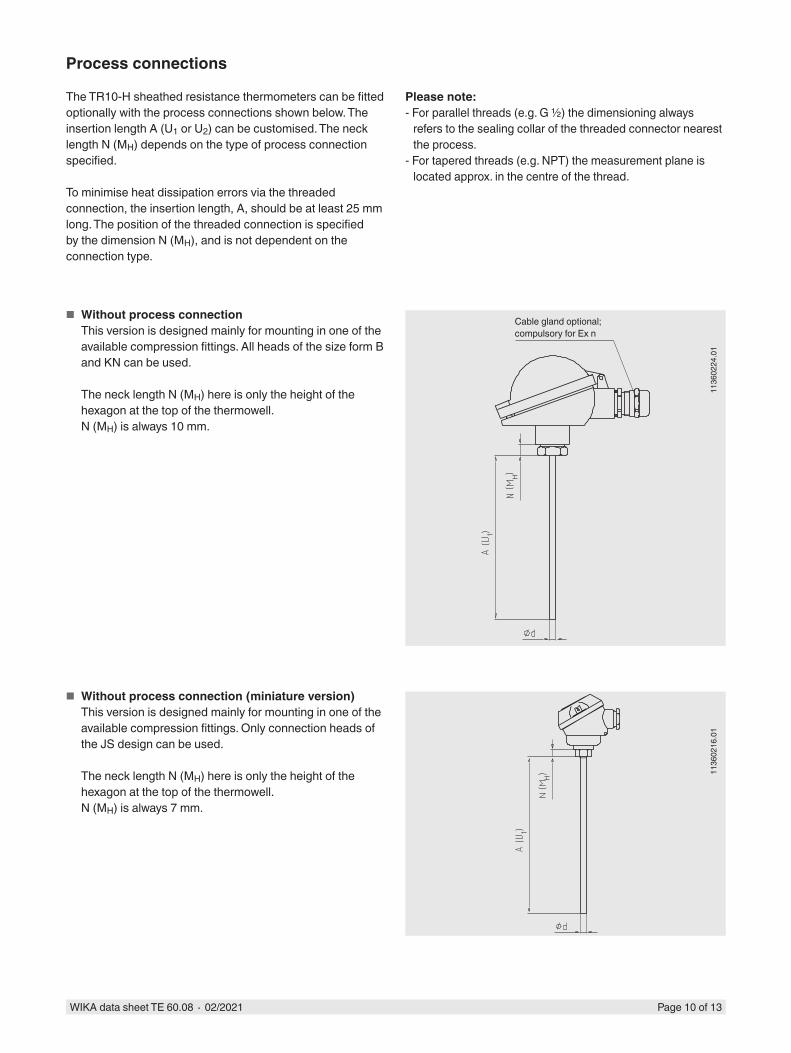
Process connections
The TR10-H sheathed resistance thermometers can be fitted optionally with the process connections shown below. The insertion length A (U1 or U2) can be customised. The neck length N (MH) depends on the type of process connection specified.
To minimise heat dissipation errors via the threaded connection, the insertion length, A, should be at least 25 mm long. The position of the threaded connection is specified by the dimension N (MH), and is not dependent on the connection type.
1136
0224
.01
Cable gland optional; compulsory for Ex n
■ Without process connectionThis version is designed mainly for mounting in one of the available compression fittings. All heads of the size form B and KN can be used.
The neck length N (MH) here is only the height of the hexagon at the top of the thermowell.N (MH) is always 10 mm.
Please note:- For parallel threads (e.g. G ½) the dimensioning always
refers to the sealing collar of the threaded connector nearest the process.
- For tapered threads (e.g. NPT) the measurement plane is located approx. in the centre of the thread.
1136
0216
.01
■ Without process connection (miniature version)This version is designed mainly for mounting in one of the available compression fittings. Only connection heads of the JS design can be used.
The neck length N (MH) here is only the height of the hexagon at the top of the thermowell.N (MH) is always 7 mm.

Page 11 of 13WIKA data sheet TE 60.08 ∙ 02/2021
1136
0232
.01
■ Protruded fixed threaded connectionThis version is used for the mounting of thermometers into threaded couplings with female threads.
Insertion length A: In accordance with customer specificationMaterial: Stainless steel, others on request
The probe must be rotated in order to screw it into the process. Therefore, this design must first be mounted mechanically and it can then be electrically connected.
Thread Thread(NPT)
1136
0241
.01
■ Compression fittingThis version allows simple adjustment to the required insertion length at the mounting point.
Since the compression fitting is movable on the probe, the A and N (MH) dimensions define the as-delivered condition. The length of the compression fitting determines the smallest possible neck length N (MH) of approx. 40 mm.
Material: Stainless steelFerrule material: Stainless steel or PTFE
Stainless steel ferrules can be adjusted once; once they have been unscrewed, sliding along the sheath is no longer possible.
■ Max. temperature at process connection 500 °C (unpressurised)
■ Max. pressure load 20 bar (at max. 150 °C, Ø 6 mm)
PTFE ferrules can be adjusted several times, after unscrewing, repeated sliding along the sheath is still possible.
■ Max. temperature at process connection 150 °C ■ For use without pressure
For sheathed resistance thermometers with a Ø of 2 mm, only PTFE ferrules are approved.
Thread Thread(NPT)

Page 12 of 13WIKA data sheet TE 60.08 ∙ 02/2021
1136
0267
.01
■ Spring-loaded compression fittingThis version allows easy adjustment to the desired mounting length at the mounting point, while at the same time sustaining the spring pre-tension
Since the compression fitting is movable on the probe, the A and N (MH) dimensions define the as-delivered condition. The length of the compression fitting determines the smallest possible neck length N (MH) of approx. 100 mm.
Material: Stainless steelFerrule material: Stainless steel
Stainless steel ferrules can be adjusted once; once they have been unscrewed, sliding along the sheath is no longer possible.
■ Max. temperature at process connection 150 °C ■ For use without pressure
1136
0372
.02
■ Double threaded hex bushingUsing a double-sided threaded nipple, the thermometer can be screwed directly into the process. In this case the permissible temperature ranges must be observed.
The neck length, N (MH), for parallel threads depends on the height of the hexagon. This is 13 mm.
The neck length, N (MH), of NPT threads not only includes the hexagon height but also half of the thread height. This gives us a neck length, N (MH), of approx. 25 mm.
Thread Thread(NPT)
Thread
Thread(NPT)
WIKA Alexander Wiegand SE & Co. KGAlexander-Wiegand-Straße 3063911 Klingenberg/GermanyTel. +49 9372 132-0Fax +49 9372 [email protected]
02/2
021
EN Page 13 of 13WIKA data sheet TE 60.08 ∙ 02/2021
Maximum working temperatures
The maximum temperatures for this thermometer are limited by different parameters:
■ SensorThe temperature measuring range is limited by the sensor itself. Depending on the accuracy class and operating conditions the optimum can be chosen.
Outside of the defined measuring range the measurement is no longer accurate and the sensor can be damaged.
■ Connection headPermissible ambient temperature of the connection head:80 °C
■ Working temperatureIf the temperature to be measured is higher than the permissible temperature at the connection head, the metal part of the sensor must be long enough to be outside of the hot zone.
■ Ambient and storage temperature-40 ... +80 °COther ambient and storage temperatures on request
© 06/2008 WIKA Alexander Wiegand SE & Co. KG, all rights reserved.The specifications given in this document represent the state of engineering at the time of publishing.We reserve the right to make modifications to the specifications and materials.
Ordering informationModel / Explosion protection / Connection head / Cable outlet or connection head / Terminal block, transmitter / Process connection / Measuring element / Connection method / Temperature range / Probe diameter / Insertion length / Neck length / Certificates / Options
Certificates (option)
Certification type Measurement accuracy
Material certificate
2.2 test report x x3.1 inspection certificate x xDKD/DAkkS calibration certificate
x -
The different certifications can be combined with each other.
The minimum length (metal part of the probe or the length of the probe below the process connection) for carrying out a measurement accuracy test 3.1 or DKD/DAkkS is 100 mm.Calibration of shorter lengths on request.
Operating conditions
Mechanical requirements
VersionStandard 6 g peak-to-peak, wire-wound measuring resistor or
thin filmOption Vibration-resistant sensor tip, max. 20 g peak-to-peak,
thin-film measuring resistorHighly vibration-resistant sensor tip, max. 50 g peak-to-peak, thin-film measuring resistor
The information on the vibration resistance refers to the tip of the measuring insert.
For detailed specifications for vibration resistance of Pt100 sensors, see Technical information IN 00.17 at www.wika.com.