Residence - Christenson Corporation
156
Christenson Residence 0617.2R Construction Package Issue date: June 12, 2017 ARCHITECT: TEA2 Architects 2724 West 43 rd Street Minneapolis, MN 55410 Contact: Eric Johnson 612.929.2800 STRUCTURAL ENGINEER: Bunkers & Associates 6687 Forest Street Farmington, MN 55024 651.336.2853 SITE ADDRESS: 4925 Thomas Ave. S. Minneapolis, MN 55410
-
Upload
khangminh22 -
Category
Documents
-
view
0 -
download
0
Transcript of Residence - Christenson Corporation

Christenson Residence 0617.2R
Construction Package
Issue date: June 12, 2017 ARCHITECT: TEA2 Architects 2724 West 43rd Street Minneapolis, MN 55410 Contact: Eric Johnson 612.929.2800 STRUCTURAL ENGINEER: Bunkers & Associates 6687 Forest Street Farmington, MN 55024 651.336.2853 S ITE ADDRE SS: 4925 Thomas Ave. S . Minn eap ol i s , MN 55410

Copyright TEA2 Architects Printed: 6/12/17 8:45 AM
PART 1 — SPECIFICATIONS (WHITE PAGES)
TABLE OF CONTENTS FOLLOWS
PART 2 — SCHEDULES & GUIDES (YELLOW PAGES)
ROOM FINISH SCHEDULE INTERIOR DOOR & HARDWARE SCHEDULE EXTERIOR WINDOW, DOOR, & SKYLIGHT SCHEDULE LIGHT FIXTURE SCHEDULE TILE SCHEDULE SOLID SURFACE SCHEDULE NOTCHING AND HOLE BORING GUIDE (for Dimension Lumber) AIR-SEALING REQUIREMENTS NOTCHING AND HOLE BORING GUIDE (for I-Joists) REBAR BENDING SCHEDULE City of Minneapolis New Home Construction Guide
PART 3 — STRUCTURAL DETAILS (BLUE PAGES)
HEADER SCHEDULE STRUCTURAL NOTES
PART 4 – PRODUCT LITERATURE (TAN PAGES)
MAXXON FLOOR UNDERLAYMENTS TRUSS JOIST TREATED SILL PLATES Tuff-N-Dri APPLICATION HYDRODOCT 660 DRAIN BOARD STEGO WRAP UNDER-SLAB VAPOR BARRIER MTI SURE CAVITY RAINSCREEN DRAINAGE PLANE TYVEK WATER-RESISTIVE AND AIR-BARRIER INSTALLATION PROLINE DRAIN

TEA2 ARCHITECTS - PART 1 TABLE OF CONTENTS
Christenson Residence – 0617.2R Issue: 06.12.2017
Copyright TEA2 Architects Printed: 6/12/17 8:45 AM
DIVISION 0 - BIDDING AND CONTRACT REQUIREMENTS ................................................................................... 0-1 00110. General 00120. Scope of Work 00130. Consideration of Bids 00140. Verification of Field Conditions 00150. Design-Build Subcontracts - General Requirements 00180. Alternates 00190. Substitutions 00700. Required Contract
DIVISION 1 –GENERAL REQUIREMENTS ................................................................................................................... 1-1 01020. Construction Schedule 01030. Use of Contract Documents 01210. Governing Building Codes 01215. City of Minneapolis Community Planning and Economic Development (CPED) Requirements 01220. Standards 01222. Drainage Plane System Coordination Responsibility 01225. Detail Responsibility For Undocumented Areas 01300. Submittals 01410. Field Observations 01420. Architect’s Job Sign 01510. Project Clean-Up 01590. Temporary Bracing 01700. Site Utilities 00180. Smoking Policy 01900. Abbreviations
DIVISION 2-SITE WORK ................................................................................................................................................... 2-1 02010. Soil Quality 02020. Certificate of Survey 02025. Survey Requirments During Construction 02050. Demolition 02090. Soil Stabilization 02200. Site Preparation 02300. Earthwork 02600. Drainage 02720. Mortar Set Stone Pavers 02750. Dry Laid Sand Set Stone Paving 02900. Landscapping
DIVISION 3 –CONCRETE .................................................................................................................................................. 3-1 03300. Cast-In-Place Concrete
DIVISON 4 –MASONRY ...................................................................................................................................................... 4-1 04200. Concrete Unit Masonry 04300. Veneer Brick 04340. Brick Accessories 04400. Cut Stone

TEA2 ARCHITECTS - PART 1 TABLE OF CONTENTS
Christenson Residence – 0617.2R Issue: 06.12.2017
Copyright TEA2 Architects Printed: 6/12/17 8:45 AM
DIVISION 5 –METALS ........................................................................................................................................................ 5-1 05120. Structural Steel 05520. Architectural Metals
DIVISION 6 –WOOD ............................................................................................................................................................ 6-1 06100. Rough Carpentry 06200. Exterior Finish Carpentry 06250. Exterior Composite Trim 06300. Interior Finish Carpentry 06400. Architectural Wood Work
DIVISION 7 –THERMAL AND MOISTURE PROTECTION ........................................................................................ 7-1 07010. Drainage Plane System 07100. Waterproofing 07135. Drainage Board Composite 07150. Vapor Barrier ( Under Slab) 07190. Building Sheathing Paper & Rainscreen 07210. Insulation 07300. Ice Barrier 07310. Fiberglass Asphalt Shingles 07500. Rubber Membrane Roofing 07600. Flashing And Sheet Metal 07610. Copper Flashing And Sheet Metal 07630. Gutters, Downspouts And Scuppers 07650. Flexible Flashing 07840. Roof Ventilation System 07900. Sealants
DIVISION 8 –OPENINGS .................................................................................................................................................... 8-1 08100. Metal Doors 08210. Custom Wood Doors 08250. Finish Hardware 08300. Overhead Doors 08310. Carriage Doors 08350. Shower Doors 08600. WIndows and Exterior Doors 08630. Retractable Insect Screens 08800. Skylights
DIVISION 9 –FINISHES ...................................................................................................................................................... 9-1 09200. Stucco 09260. Gypsum Wallboard 09300. Tile Work 09550. Wood Flooring 09555. Wood Floor Grills (For In-Floor Forced-Air Supplies) 09600. Stone Flooring 09680. Carpeting 09700. Accoustical Ceiling Plank 09770. Vinyl Lettering 09800. Special Coatings 09900. Painting 09940. Painting And Finishing Schedule (All Colors Selected By Owner)

TEA2 ARCHITECTS - PART 1 TABLE OF CONTENTS
Christenson Residence – 0617.2R Issue: 06.12.2017
Copyright TEA2 Architects Printed: 6/12/17 8:45 AM
DIVISION 10 –SPECIALTIES .......................................................................................................................................... 10-1 10280. Toilet, Bath & Laundry Accessories 10310. Manufactured Fireplaces 10536. Awnings 10570. Wardrobe & Closet Specialties
DIVISION 11 –EQUIPMENT ............................................................................................................................................ 11-1 11100. Mechanical Equipment 11310. Appliances 11330. Attic Access 11520. -TV Mounts & Lifts
DIVISION 12 –FURNISHINGS ......................................................................................................................................... 12-1 12240. Window Shades
DIVISION 14 –CONVEYING SYSTEMS ........................................................................................................................ 14-1 14100. Elevator
DIVISION 22 –PLUMBING ............................................................................................................................................... 22-1 22100. Plumbing System
DIVISION 23 –HEATING, VENTILATING, AND AIR-CONDITIONING (HVAC) ................................................. 23-1
23000. Overview 23100. Heating, Ventilating & Air Conditioning System (HVAC)
DIVISION 26 –ELECTRICAL .......................................................................................................................................... 26-1 26100. Electrical System

TEA2 ARCHITECTS - PART 1 DIVISION 00– BIDDING & CONTRACT
Christenson Residence – 0617.2R Issue: 06.12.2017
Div 0-1 Copyright TEA2 Architects Printed: 6/12/17 8:45 AM
DIVISION 0 - Bidding and Contract Requirements
00110. GENERAL
A. Written proposals for the construction of the Christenson Residence will be provided to the Owner. A copy will be forwarded to the Architect for verification
B. All bids must be submitted on the Bid Proposal Form, with all blanks filled in, signed, and dated.
C. See the Bid Proposal Form for the required bid breakdown and instructions for completing the form.
00120. SCOPE OF WORK
A. The G.C. will oversee and include pricing for all work for the construction of the Christenson Residence, except for softscape (sod and plantings) and irrigation, which is Not in Contract (NIC).
00130. CONSIDERATION OF BIDS
A. No bids shall be withdrawn for a period of 30 calendar days subsequent to the opening of the bids.
B. The Owner reserves the right to reject any and all bids and to waive any irregularities therein.
00140. VERIFICATION OF FIELD CONDITIONS
A. The submittal of a bid indicates that the bidder and his subcontractors have visited the site and are familiar with existing conditions including all required mechanical and electrical modifications to existing systems.
B. No oral instructions or interpretations by the Architect, Owner, or their representatives made during the bidding period will alter the Contract Documents. Modifications, additions, and interpretations to the Contract Documents will be made by written Addenda only.
C. Survey on file at Architect’s office.
D. See Section 02010. SOIL TESTS for additional information.
00150. DESIGN-BUILD SUBCONTRACTS – GENERAL REQUIREMENTS
A. See the following specification divisions for additional Design-Build Subcontract requirements and specific Design-Build performance criteria/requirements: 22 Plumbing, 23 HVAC, 26 Electrical.
B. BIDDING DOCUMENTS 1. All of the Design-Build information contained in this Project Manual, including information in each
specification division that is specifically related to Design-Build Subcontracts, is preliminary and included for the purposes of bidding only, unless noted otherwise. The Design-Build Subcontractor must re-assess and review all of this preliminary information with the Owner and the Architect during the Design-Build Subcontractor’s Design Phase.
C. DESIGN PHASE REQUIREMENTS – (After the award of the Construction Contract, the Design-Build Subcontractor shall begin their Design Phase as outlined below and in the individual specification divisions.) 1. The Design-Build Subcontractor shall initiate communication with the Owner and Architect and secure all of
the performance and design criteria from the Owner and Architect that will be required for the design of a complete, high quality system or component.
2. The Design-Build Subcontractor shall provide professional design/engineering services or contract for those services when they are required to execute the design and performance criteria outlined in C.1 above and the individual specification divisions.
3. Prior to the commencement of design work, the Design-Build Subcontractor must inform the Owner and the Architect if professional design/engineering services will be utilized or not, if these services are in-house or if they are contracting them out, and who will be performing these services.

TEA2 ARCHITECTS - PART 1 DIVISION 00– BIDDING & CONTRACT
Christenson Residence – 0617.2R Issue: 06.12.2017
Div 0-2 Copyright TEA2 Architects Printed: 6/12/17 8:45 AM
4. At the completion of design work, the Design-Build Subcontractor must review the design with the Owner and the Architect.
00180. ALTERNATES (All bidders shall include an amount in their Bid for all labor, materials, overhead and profit, services, fees, insurance, taxes, and equipment for deducting or adding the following work as applicable. All alternates that remove integral parts of the construction must include replacing the component with the typical construction for which it is removed [where applicable].) 1) Add-Alternate: add raked bed joints and flush head joints. (See Division 4) 2) Add-Alternate: add copper hot & cold water supply piping. (See Division 22) 3) Add-Alternate: add Driveway and Terrace Snow Melt System. (See Division 23) 4) Deduct-Alternate: deduct wood wall plank from M.Bedroom and M.Bath (See Division 9) 5) Deduct-Alternate: deduct Retractable Awning. (See Division 10) 6) Deduct-Alternate: deduct Recessed Lighting substitution (see Light Fixture Schedule)
00190. SUBSTITUTIONS Products, materials, and equipment may be substituted for those specified only if all of the following conditions are met:
A. They are specified in writing on the bid proposal form.
B. Product specifications and general information are submitted with the bid.
C. The originally specified item has been and is shown on the proposal form.
D. They have been approved by the Architect.
00700. REQUIRED CONTRACT
A. The STANDARD FORM OF AGREEMENT BETWEEN OWNER AND CONTRACTOR, AIA Document A101 - 2007, as published by the American Institute of Architects, will form the basis of the contract with the following amendments: 1. AMENDMENT OF ARTICLE 5 - PROGRESS PAYMENTS
a. 5.1.6.1. Insert percentage amount making the first sentence read: Take that portion of the Contract Sum properly allocable to completed Work as determined by multiplying the percentage completed of each portion of the Work by the share of the total Contract Sum allocated to that portion of the Work in the Schedule of Values, less a retainage of ten percent (10%) for first 50% of work, then 0%.
b. 5.1.6.2. Insert percentage amount making the sentence read: Add that portion of the Contract Sum properly allocable to materials and equipment delivered and suitably stored at the site at for subsequent incorporation into the completed construction (or, if approved in advance by the Owner, suitably stored off the site at a location agreed upon in writing), less a retainage of ten percent (10%) for first 50% of work, then 0%.
c. Add the following subparagraph: 1) 5.1.6.5: Retainage shall be applied to all Change Orders.
B. GENERAL CONDITIONS 1. The GENERAL CONDITIONS, AIA Document A201 - 2007, are hereby made part of this Specification, except
where its provisions are at variance here from, in which case this Specification will take precedence. Copies of A201 are available upon request. SPECIAL NOTE: The Contractor shall take special note of paragraph 5.3.1 of the General Conditions (A201) in relation to the Contractor ‘s relationship to all Subcontractors.
C. SUPPLEMENTARY CONDITIONS: The following modify AIA DOCUMENT A201. 1. AMENDMENT OF ARTICLE 1 - GENERAL PROVISIONS

TEA2 ARCHITECTS - PART 1 DIVISION 00– BIDDING & CONTRACT
Christenson Residence – 0617.2R Issue: 06.12.2017
Div 0-3 Copyright TEA2 Architects Printed: 6/12/17 8:45 AM
a. 1.1.1 THE CONTRACT DOCUMENTS: Omit the last sentence and add the following sentence: “The Contract Documents shall include the entire Division of the Specifications entitled DIVISION 0 - BIDDING AND CONTRACT REQUIREMENTS.”
2. AMENDMENT OF ARTICLE 3 - CONTRACTOR a. Add the following three paragraphs at the beginning of paragraph 3.12.10:
1) The Architect’s responsibility includes setting forth, in detail, the requirements for the construction of the Project, only to the extent that they are contained in the Construction Documents.
2) The Owner assigns to the Contractor responsibility for the design and detailing of all components or portions of components of the project that are not shown or detailed in the construction documents and for the proper structural design and assembly of all components that are drawn or specified but not detailed in the Contract Documents. All of the Contractor’s technical design detailing services shall be consistent with or better than industry standards
3) All components designed and detailed by the Contractor shall be consistent with the quality of components that are shown in the construction documents. For any component of the project which the Contractor cannot conform to the profiles or design intent shown in the construction documents, the Contractor shall notify the Architect and the Contractor and Architect shall cooperate with each other in determining a construction detail that will satisfy the design intent, subject to the Owner’s approval. The Contractor shall not be required to proceed with construction of any component for which the Contractor is not willing to accept responsibility. By commencement of construction or ordering of materials without notification of the Architect the Contractor assumes this responsibility. The Architect shall not become responsible for any component designed and detailed by the Contractor by reason of cooperating with the Contractor in determining the general aesthetic design conformance of the component.
b. Add the following sentence after the 3rd sentence of paragraph 3.12.10: 1) It is the responsibility of the Contractor and Design Build Subcontractors to initiate communication
and secure all of the performance and design criteria from the Owner and the Architect that is required for a top quality system or component.
c. Add Section 3.12.11 to Section 3.12 1) 3.12.11 The Architect’s review of the Contractor’s submittals will be limited to two reviews, one initial
review and one re-submittal review. For additional reviews beyond the first two as outlined above, the Architect will bill the Owner on an hourly basis. The Owner is entitled to obtain reimbursement from the Contractor for these additional review charges.
d. Add the following section: 3.19 LIEN WAIVERS 1) 3.19.1 Immediately upon receipt of a Progress Payment by the Owner, the Contractor must submit
to the Owner signed lien waivers from the Contractor, all Subcontractors, and all major material suppliers covered in the Application for Payment only for that portion of work performed by their forces. The Contractor cannot provide lien wavers to “cover” for missing lien wavers, which he has not received from his subcontractors or material suppliers.
2) 3.19.2 Each individual lien waiver submitted to the Owner must fall into one of the categories of work as defined on the Application and Certificate for Payment. Each lien waiver must be coded or clearly noted as to which of these categories it falls into.
3) 3.19.3 At each submittal, the sum of the lien wavers for each of the separate categories of work must match the amount (less retainage) of each of the categories of work on the Application and Certificate for Payment; and the sum of all lien waivers must equal the payment amount certified by the Architect on the Application and Certificate for Payment.
3. AMENDMENT OF ARTICLE 4 - ADMINISTRATION OF THE CONTRACT a. 4.2.7: Change the second to the last sentence to read: The Architect’s review shall not constitute
approval of safety precautions or, unless otherwise specifically stated by the Architect in writing, of any construction means, methods, techniques, sequences, or procedures.
4. AMENDMENT OF ARTICLE 7 - CHANGES IN THE WORK a. Add the following subparagraphs to section 7. 2 CHANGE ORDERS

TEA2 ARCHITECTS - PART 1 DIVISION 00– BIDDING & CONTRACT
Christenson Residence – 0617.2R Issue: 06.12.2017
Div 0-4 Copyright TEA2 Architects Printed: 6/12/17 8:45 AM
1) 7.2.3 In order to facilitate checking of quotations for Change Orders, all proposals, except those so minor that their propriety can be readily determined, shall be accompanied by a complete itemization of costs including labor, materials, and Subcontracts. The Contractor’s overhead and profit shall be separately itemized. Separate itemization of Subcontracts, including separation of overhead and profit, are also required.
2) 7.2.4 When a Change is a substitution for work that is specified, the Contractor shall list the original bid price of the work that is to be substituted as a deduction in the Change Order.
3) 7.2.5 The percentage of Overhead and Profit shall be consistent with the original contract sum for all Change Orders unless stated specifically, otherwise, in the Contractor’s bid or on the Bid Form received by the Owner.
4) 7.2.6 Contractor to state in their original bid or on the Bid Form the labor rate charged to the Owner for all on-site construction forces that are directly part of the Contractor’s company.
5. AMENDMENT OF ARTICLE 9 - PAYMENTS AND COMPLETION a. 9.3.1: Change the first sentence to read: “At least fourteen days before the date established for each
progress payment, the Contractor will submit to the Architect an itemized Application for Payment for operations completed in accordance with the Schedule of Values.”
b. Add the following sub-subparagraph to section 9.3 APPLICATIONS FOR PAYMENT: 1) 9.3.1.3 Application for Payment must be submitted typewritten on AIA forms G702 and G703 or,
subject to the Architects approval, on the Contractors own forms provided it contains all of the same information as AIA forms G702 and G703. Submit three copies.
6. AMENDMENT OF ARTICLE 11 - INSURANCE AND BONDS a. Add the following sub-subparagraph to section 11.1 CONTRACTOR’S LIABILITY INSURANCE:
1) 11.1.3.1 The Contractor shall furnish one copy of the Certificate of Insurance (AIA Form G715) to the Owner and to the Architect.

TEA2 ARCHITECTS - PART 1 DIVISION 01– GENERAL REQUIREMENTS
Christenson Residence – 0617.2R Issue: 06.12.2017
Div 1-1 Copyright TEA2 Architects Printed: 6/12/17 8:46 AM
DIVISION 1 – General Requirements
01020. CONSTRUCTION SCHEDULE
A. The G.C. will propose, with his bid, a Construction Start Date and the date of Substantial Completion.
B. The Contractor is responsible for the construction schedule as defined in the General Conditions of the Contract. This responsibility extends to securing all decisions that are required to complete the project. The Contractor shall notify the Owner and the Architect of the required schedule and deadline dates for all decisions. This schedule must be written/graphical and must be updated each time there is change in the schedule. The Contractor shall give the Owner adequate time for making the decisions (two weeks minimum or longer if it is appropriate).
01030. USE OF CONTRACT DOCUMENTS
A. Field Conditions: The contractors shall take field measurements and verify field conditions and shall carefully compare such measurements and conditions with the Contract Documents and any Shop Drawings before commencing any work. Any error, inconsistency, or omission shall be reported to the Architect at once. No change in the Contract Sum will be allowed for minor differences between actual field conditions and the Contract Documents. See Section 01600. for Special Remodeling Requirements.
B. Discrepancies: Should the Contractor find any discrepancies in or omissions from the Drawings or Specifications, or should the Contractor be in doubt as to their meaning, the Contractor shall at once notify the Architect. The Contractor shall in no case proceed with construction in the case of uncertainty.
C. Information Location: Items called for in the Specifications but not shown on the Drawings, or items shown on the Drawings but not called for in the Specifications, shall be supplied and installed as if shown in both documents. The Drawings and Specifications are not intended to be redundant to each other. The better quality or greater quantity of work shall be provided in accordance with the Architect’s interpretation.
D. Product Literature Inserts: Inserts are included in this Project Manual to provide the Contractor with some information on the product specified. The Product Literature Inserts are NOT part of the Contract Documents. If information on the Inserts is in conflict with the Documents the Contractor is to notify the Architect immediately. The Insert may also not be complete in the information required for proper ordering or installation by the Contractor. The Contractor is responsible for obtaining all required information from the manufacturer.
E. Substitutions: At no time during the project may products be substituted for those specified without the written permission of the Architect. No substitutions are allowed during bidding unless the requirements of 00190. A are followed.
F. Contract Documents Field Set: The Contractor is required to have a complete set of Contract Documents including all addendums and Revisions at the site at all times.
G. As-Built Drawing Set: The Contractor shall mark changes made in the field in red on a clean set of drawings throughout the project and shall submit to the Owner upon completion. See General Conditions 3.11.1
01210. GOVERNING BUILDING CODES
A. All building, fire, heating, ventilating, plumbing, and electrical codes of the State of Minnesota and local laws and ordinances of those authorities having jurisdiction over the location of the building site are hereby incorporated by reference into this Project Manual and shall become a part of the Contract Documents. The most recently adopted edition of the IRC International Residential Code is hereby declared to be part of these Specifications, and all work must conform to its requirements unless: 1. Local codes and ordinances are more restrictive, in which case the local codes or ordinances shall prevail. 2. The requirements of these Specifications are more stringent or restrictive, in which case these
Specifications shall prevail.

TEA2 ARCHITECTS - PART 1 DIVISION 01– GENERAL REQUIREMENTS
Christenson Residence – 0617.2R Issue: 06.12.2017
Div 1-2 Copyright TEA2 Architects Printed: 6/12/17 8:46 AM
01215. CITY OF MINNEAPOLIS COMMUNITY PLANNING AND ECONOMIC DEVELOPMENT (CPED) REQUIREMENTS
A. The Contractor is responsible for reviewing and complying with all additional requirements for demolition and new construction set forth by the City of Minneapolis, including but not limited to the following: 1. New One- or Two-Family Home Construction Process Guide and Checklist (attached)
a. The Contractor is responsible for retaining a Minnesota Licensed Surveyor for the following additional Surveys required throughout the Construction Process: 1) Survey Indicating Top of Foundation Elevation (refer to attached Checklist) 2) Survey Indicating As-built Final Site Conditions (refer to attached Checklist)
b. Refer to Division 2 – Site Work, 02025. SURVEY REQUIREMENTS DURING CONTRUCTION for additional Survey requirements.
2. Minneapolis Residential Construction Management Agreement (attached) a. The Contractor must sign and adhere to the requirements of this agreement prior to construction and
throughout the construction process. b. Note: This agreement must be attached to approved site plans and be present on-site at all times
during active construction.
01220. STANDARDS
A. It is the intent of these Drawings and Specifications to require work to be a minimum of “good” and “custom” quality, U.N.O., and to be in conformance with good trade practice and industry standards.
B. All manufacturer’s recommended procedures are hereby adopted as requirements unless otherwise specified or designated on the Drawings.
01222. DRAINAGE PLANE SYSTEM COORDINATION RESPONSIBILITY
A. The General Contractor has the responsibility of coordinating the work of all subcontractors and suppliers related to the installation of a complete properly functioning “Drainage Plane System”. Refer to Division 7 – THERMAL AND MOISTURE PROTECTION.
01225. DETAIL RESPONSIBILITY FOR UNDOCUMENTED AREAS
A. Contractors have certain detail responsibility for the Project. This responsibility is defined in the Supplemental Conditions of the Contract in Division 0 Bidding and Contract Requirements of this Project Manual. See 00700.C.2 of AMENDMENT TO ARTICLE 3 – CONTRACTOR.
01300. SUBMITTALS
A. GENERAL REQUIREMENTS 1. This section is intended as a summary of Submittals for the Contractor’s convenience and it may not be all
inclusive; see Section 3.10 through 3.12, of A201 General Conditions of the Contract for Construction for a more comprehensive description of the Contractor’s responsibilities for the submittals listed below.
2. Send all submittals directly to the Architect and copies to the Owner. 3. See individual specification sections for additional Shop drawings, Product Data, and Sample
requirements. 4. Submit all shop drawings, product data, and samples only after review (including dimensions, quantities,
etc.) and written approval by the General Contractor. 5. Submit shop drawings in the form of one set of .pdf files and/or two sets of opaque reproductions. After
Architect/Engineer review of the submittal, revise and resubmit as required identifying changes made since previous submittal.
6. Distribute copies of reviewed submittals to concerned persons. Instruct recipients to promptly report any inability to comply with provisions.
7. A list of required submittals is as follows under items 01300.B, C, D and E below.
B. SHOP DRAWINGS, PRODUCT DATA AND SAMPLES

TEA2 ARCHITECTS - PART 1 DIVISION 01– GENERAL REQUIREMENTS
Christenson Residence – 0617.2R Issue: 06.12.2017
Div 1-3 Copyright TEA2 Architects Printed: 6/12/17 8:46 AM
1. Summary of items that will need shop drawings or product specification sheets is as follows: a. Metals
1) Structural Steel 2) Architectural Metals 3) Railings
b. Trusses c. Millwork profiles
1) Interior 2) Exterior
d. Cabinetry e. Metal Doors f. Custom Wood Doors g. Overhead Doors h. Windows and doors mfg’d by window manufacturer i. Skylights j. Window and door hardware k. Finishes
1) Stucco 2) Tile 3) Wood Flooring 4) Stone Flooring 5) Carpet 6) Wall and Ceiling Covering 7) Paint 8) Acoustic ceiling planks
l. Fireplaces –gas inserts and prefabricated units m. Elevator n. Appliances o. Mechanical/Plumbing equipment- including
1) Furnaces 2) Central air conditioners 3) HRV’s/ERV’s 4) Ventilation/exhaust fans 5) Make-up air system 6) Air filtration 7) Humidity control 8) Hot water heaters 9) Control systems for all of the above 10) Plumbing fixtures and fittings 11) Sump pumps
p. Garbage disposals q. Garage door openers r. Light fixtures, lighting controls s. Electrical layout t. Radon control system layout and equipment specifications.
2. Summary of items that will require samples is as follows: a. Brick Veneer
1) Submit Individual brick samples (see Division 4 for additional requirements) 2) Erect a sample panel (see Division 4 for additional requirements)
b. Cut Stone c. Stone Veneer d. Architectural Metals (including cable and fittings)

TEA2 ARCHITECTS - PART 1 DIVISION 01– GENERAL REQUIREMENTS
Christenson Residence – 0617.2R Issue: 06.12.2017
Div 1-4 Copyright TEA2 Architects Printed: 6/12/17 8:46 AM
e. Exterior Millwork Profiles f. Interior Millwork Profiles g. Wood Flooring h. Wood Wall Plank i. Acoustical Ceiling Plank j. Cabinetry k. NanaWall glazing l. Skylight glazing m. Door & window hardware n. Paint and Stain finishes
C. SCHEDULE OF VALUES 1. Submit a Schedule of Values to the Architect within seven (7) days of the bid acceptance. The Schedule of
Values shall break down portions of the Work that have a value of $500 or more.
D. SUBCONTRACTORS and SUPPLIERS LIST 1. Submit this list within seven (7) days of the bid acceptance. 2. This list shall be a complete list of all major Subcontractors and major suppliers including anyone
providing a warranty, operation manual or maintenance schedule and shall include their telephone numbers and mailing addresses. This list to include but not be limited to: a. Electrical Design-Build Subcontractor b. Mechanical Design-Build Subcontractor c. Plumbing Design-Build Subcontractor d. Framing Subcontractor e. Roofing Subcontractor f. Window supplier g. Cabinetry & Millwork Subcontractor h. Flooring Subcontractor i. Painting/Finishing Subcontractor
3. Changes to these lists shall be immediately submitted to Owner.
E. WARRANTIES, OPERATION MANUALS AND MAINTENANCE SCHEDULES 1. The Contractor shall submit to the Owner upon substantial completion copies of warranties for materials
and work that are contained in the Work, operation manuals and maintenance schedules for equipment and appliances that are installed in the Work, and a list of relevant Subcontractors.
01410. FIELD OBSERVATIONS
A. The Contractor shall notify the Architect for field observations at the following times. Contractor to notify Architect 48 hours before observation is required. 1. Near completion of excavation contact Soils Engineer and Architect. 2. After the footings are formed but before they are poured. 3. At commencement of all soil compaction procedures contact Soil Engineer and Architect. 4. Before commencement of core-filling of concrete block or pouring of poured concrete walls. 5. During exterior wall waterproofing installation. 6. Just before the concrete floor slab is to be poured. 7. After rough framing is complete. 8. After building paper and window flashing are installed (Drainage Plane), but before exterior finish
material is applied. 9. After plumbing, electrical, and mechanical rough-in work is completed 10. After the vapor retarder is complete but before installation of gypsum wallboard. 11. At substantial completion.
01420. ARCHITECT’S JOB SIGN

TEA2 ARCHITECTS - PART 1 DIVISION 01– GENERAL REQUIREMENTS
Christenson Residence – 0617.2R Issue: 06.12.2017
Div 1-5 Copyright TEA2 Architects Printed: 6/12/17 8:46 AM
A. The Contractor must protect Architect’s job sign from damage. This responsibility extends to paying for damaged sign repairs. 1. Damage Deposit (Required): Before construction begins, the Contractor must provide the Architect with
a $1,000 damage deposit, which will be returned to the Contractor, in full, at the end of Construction provided the sign is not damaged during Construction. If the sign is damaged, the Architect will use the damage deposit money for repairs to the sign, and return any remaining amount to the Contractor.
B. The Contractor is allowed to move the sign on a temporary basis to allow for construction. To remove or reset the sign: 1. First, remove the sign from the posts and remove iron posts without bending them. 2. Reset posts by setting the sign on the ground and running the posts thru the sleeves of the sign. Raise the
sign into place only after the posts are completely set. DO NOT POUND ON THE SIGN TO DRIVE OR MOVE THE POSTS.
3. Make sure the sign is set true and level in all directions.
01510. PROJECT CLEAN-UP
A. PROJECT CLEAN UP DURING CONSTRUCTION 1. The Contractor will provide daily on-site cleanup and will provide for the removal of all construction
debris. 2. Subcontractors are to remove their construction debris as their work progresses. They must leave their
portion of the job broom-clean at finish of their work (broom sweep each day).
B. FINAL CLEAN UP 1. The Contractor will provide high quality cleaning of all finish surfaces (including areas such as interior of
cabinets and toe-kick areas) that is affected by dust, debris, etc. of construction. 2. The Contractor shall wash all new windows, inside and out, at the completion of the job.
C. PROJECT CLEAN UP AFTER SUBSTANTIAL COMPLETION 1. Once the project has been completed and occupied by the Owner, the Contractor and Subcontractors are
responsible for protecting and covering where necessary all furnishings, artwork, and other belongings of the Owner in areas where additional or corrective work is being performed.
2. The Contractor and Subcontractors are to thoroughly clean up those areas affected by debris and dust resulting from any additional or corrective work.
01590. TEMPORARY BRACING
A. The Contractor is responsible for bracing, without overstressing, all structural elements as required at all stages of construction until completion of this project. Provide temporary lateral support for all walls until walls are adequately braced by permanent structure. Shore foundation walls retaining earth until floor framing and basement slab are in place. Use caution when operating equipment adjacent to foundation walls.
01700. SITE UTILITIES
A. The General Contractor is to verify underground utility and service locations (req’d by Minn. State law). Contact Gopher State One Call at (800)252-1166 or (651)454-0002
B. The energy and use charges for all utilities that are extended from the Owner’s existing services shall be paid by the Owner. This includes gas, electricity, and telephone service.
C. All special purpose utilities required shall be installed and paid for by the Contractor.
00180. SMOKING POLICY
A. No smoking is allowed in existing structures or remodeling projects or in new structures throughout the construction process.

TEA2 ARCHITECTS - PART 1 DIVISION 01– GENERAL REQUIREMENTS
Christenson Residence – 0617.2R Issue: 06.12.2017
Div 1-6 Copyright TEA2 Architects Printed: 6/12/17 8:46 AM
01900. ABBREVIATIONS
A.F.F. Above Finish Floor Mech Mechanical Alum. Aluminum Mfg. Manufacturer Approx. Approximately Mfgd. Manufactured @ At Min. Minimum B.O. Bottom Of Misc. Miscellaneous Bd. Board M.O. Masonry Opening Blk. Block N.I.C. Not in contract Blkg. Blocking N.T.S. Not to scale Bldg. Building Opng. Opening Btwn. Between O.D. Outside diameter C.M.U. Concrete Masonry Unit O.C. On center Col. Column PLam. Plastic Laminate Conc. Concrete Plywd Plywood Const. Construction Prefin. Prefinished Cont. Continuous PSF Pounds per Square Foot C.T. Ceramic Tile PSI Pounds per Square Inch D-B Design-Build Dia. Diameter PSL Parallel Strand Lumber Dim. Dimension P.T. Pressure Treated with Preservative Dr. Door P.T.F. Pound To Fit Dtl. Detail P.T.M. Paint To Match Elect. Electrical Reinf. Reinforcing Elev. Elevation Reqd. Required EPDM Ethylene Propylene Diene Monomer R.O. Rough Opening Eq. Equal to S.F. Square Foot Exh. Exhaust Sht. Sheet Exist. Existing Sim. Similar F.D. Floor Drain Specs. Specifications Fdn. Foundation Struct. Structural FIN Finish T&G Tongue & Groove Flr. Floor T.O. Top Of Ftg. Footing Typ. Typical Ga. Gauge U.N.O. Unless Noted Otherwise Gyp. Bd. Gypsum Wall Board Vert. Vertical Hdwd. Hardwood V.G. Vertical Grain Hdwr. Hardware W.C. Water Closet (Toilet) Hor. Horizontal Wdw. Window I.D. Inside Diameter W.W.F. Welded Wire Fabric (Mesh) Insul. Insulation W/ With Lav. Lavatory W/O With Out LVL Laminated Veneer Lumber
TEA2 ARCHITECTS - PART 1 DIVISION 02– SITE WORK
Christenson – 0617.2R Issue: 06.12.2017
Div 2-1 Copyright TEA2 Architects Printed: 6/12/17 8:46 AM
02010. SOIL QUALITY
A. Soil Bearing Design Value: The structure has been designed using a presumptive load-bearing value of 2000 psf in accordance with Table R401.4.1 of the 2006 IRC on virgin soil or compacted fill for footings. The Architect has advised the owner to perform a soils test prior to construction to verify this value. If unacceptable soils found, contact Soils Engineer immediately.
B. The Contractor shall notify the Architect of the excavation schedule and coordinate with the soil engineer to have the soil inspected after excavation. The Contractor shall not proceed with the construction of the footings until the soil has been inspected and results reviewed by the Architect.
C. Costs for soil testing and for inspections by soil engineers will be paid by the Owner.
02020. CERTIFICATE OF SURVEY
A. If no certificate of survey is available or existing surveys are not suitable then the Contractor shall be responsible for providing one when required by local municipalities.
02025. SURVEY REQUIREMENTS DURING CONSTRUCTION
A. The Contractor is required to retain a Minnesota Licensed Surveyor to provide the following survey work during construction:
1. Prior to Excavation – Surveyor to stake the house and double check required elevation benchmarks.
2. Prior to Foundation Inspection – Surveyor to provide a Survey Indicating Top of Foundation Elevation (refer to attached New One or Two Family Home Construction Process Guide and Checklist for specific requirements).
3. Prior to issuance of Certificate of Occupancy – Surveyor to provide a Survey Indicating As-built Final Site Conditions (refer to attached New One or Two Family Home Construction Process Guide and Checklist for specific requirements).
02050. DEMOLITION
A. EXECUTION 1. The Contractor shall demolish the existing houses, garages and retaining walls as indicated on drawings. The
Contractor shall remove all debris from the site and leave the area raked clean. 2. The demolition contractor shall verify locations of all major utilities and ensure that the lines may be reused if
required. 3. Prior to demolition, the Contractor shall take the necessary steps to provide thorough protection for the
portions of the work to remain, as indicated on the Drawings, from damage during demolition. 4. The Contractor shall provide protection of adjacent properties during construction. 5. The Contractor shall provide weatherproof enclosures for all exterior openings during demolition. 6. The Contractor shall verify the locations of all bearing walls and structural members prior to demolition. The
Architect shall be notified immediately if any discrepancies are found to exist between actual conditions and the Drawings concerning the location of the aforementioned building components.
7. Demolish in an orderly and careful manner. 8. Do not burn or bury materials on the site. 9. Remove demolished materials from the site as work progresses. Upon completion of daily work, leave area of
work in clean condition. 10. Salvage Value: All items that are indicated to be removed as a part of the demolition and not to be reused,
but determined to be of value (including, but not limited to, doors, windows, cabinets, plumbing fixtures, and light fixtures) shall be retained by the Owner at the Owner’s option. The Contractor is to verify the disposal of such items with the Owner prior to demolition.
02090. SOIL STABILIZATION

TEA2 ARCHITECTS - PART 1 DIVISION 02– SITE WORK
Christenson – 0617.2R Issue: 06.12.2017
Div 2-2 Copyright TEA2 Architects Printed: 6/12/17 8:46 AM
A. GENERAL 1. City of Minneapolis Requirement for Protection of Adjoining Properties
a. Contractor shall provide and install the required Soil Retention measures according to the direction of the Owner’s Soils Retention Engineer. 1) Contractor to coordinate with the Owner’s Soils Retention Engineer.
b. The Owner’s Soil Retention Engineer shall monitor the condition and effectiveness of any measures installed as long as the measures are needed to protect adjoining property.
02200. SITE PREPARATION
A. GENERAL 1. Remove completely all trees (grind all stumps), shrubs, and brush, including roots occurring under buildings,
areas to be paved, and areas required for excavation only. (Remove no other trees or shrubs without the Architect’s approval.) a. All large limbs (3 inches and larger) and trunks of trees shall be cut into ten-foot maximum lengths,
stacked and stored for the Owner’s use. b. The Contractor shall strip and remove all turf, topsoil, uncompacted fill or other poor soil and soils
required by the Contract Documents and store the topsoil separately on the site away from construction area. (location to be approved by the Owner) for replacement under landscaped areas. (See Section 02300. LANDSCAPING)
02300. EARTHWORK
A. EXCAVATION 1. Verify with all Detail Drawings the required subgrades for excavation.
a. Contractor’s Surveyor to double check all vertical benchmarks. 2. There shall be no stockpiling of earth materials, changing of existing grade, or driving of vehicles of any kind
within the drip line of the trees shown on the site plan, and or, all trees marked with a surveyor’s ribbon. 3. Contractors shall be responsible for the replacement costs of all damaged landscape materials that have been
designated to be saved either on the site plan drawing or marked directly on the site. The Owner shall select the replacement materials and the installer.
4. The completed excavation shall provide temporary drainage for all excavated areas.
B. FILL AND COMPOSITION 1. FILL PLACEMENT LOCATION
a. All excavated soil to be placed on the site as shown on the site plan and or as directed by the Owner. 2. MATERIALS
a. Fill: All fill shall be earth free of debris, cinders, combustibles, frost, ice, roots, sod, wood, cellulose, and organic materials. (No construction debris will be allowed in the filled areas.) If additional fill is required beyond the site-excavated materials, the Owner shall pay for the cost of bringing the new material to the site (all under slab and under paving granular materials shall be supplied by the Contractor). The Contractor shall be responsible for placing and grading the material as required by this Specification.
b. Engineered Fill: All fill, where required to raise subgrades under buildings, concrete slabs supported by grade, and bituminous paving, shall consist of clean, well-graded, granular material free of organic material, debris, cinders, frost, and ice. Material shall be capable of being compacted as specified elsewhere herein.
3. EXECUTION a. Do not place fill in water, on muddy, frozen, or frosty areas, or over debris, wood, snow, or foreign
material. See compaction requirements below.
C. COMPACTION 1. AREAS REQUIRED TO BE COMPACTED: Soils so designated on the Drawings and those areas listed below shall
be compacted to the densities listed below:

TEA2 ARCHITECTS - PART 1 DIVISION 02– SITE WORK
Christenson – 0617.2R Issue: 06.12.2017
Div 2-3 Copyright TEA2 Architects Printed: 6/12/17 8:46 AM
a. Under concrete walks, concrete driveways, slabs on grade, and all areas within the area of the building shall be compacted to not less than 95% of Modified Proctor Density (ASTM D-1557– Modified Proctor Density).
b. Areas within 8 ft. of new construction/excavation of the building or new retaining walls to be compacted to not less than 90% of Modified Proctor Density.
c. Around items of Mechanical, Geothermal, Plumbing, or Electrical work, and utility lines shall be compacted as specified above for the condition indicated. The compaction of items listed in this paragraph is to be performed by the trade installing the construction involved.
2. EXECUTION a. All soil to be compacted must be placed in layers not exceeding a depth appropriate for the type of soil.
In no case shall the layers exceed 12” in depth. b. The type of compaction equipment must be appropriate for the type of soil.
3. TESTING a. The Owner will have a Soils Testing Company test all fill areas for compaction. The Owner will bear the
costs for these tests. b. Contractor to contact Soils Engineer. See Section 01410. Soils Engineer shall be present during
compaction.
D. ROUGH GRADING 1. The Contractor is responsible for verifying all required subgrades levels for the top of the rough grading. 2. All areas of the site to receive sod are to be rough graded to 6” below the finish grade unless otherwise noted.
02600. DRAINAGE
A. MATERIALS 3. Foundation drainpipe: Shall be 4-inch diameter corrugated, flexible, perforated polyethylene or rigid PVC
pipe. Foundation drain with filter fabric wrap is not an acceptable substitute for filter mats wrapped around aggregate surrounding drainpipe as shown on the drawings.
4. Drain pipe filter mats: a. Shall comply with Mn/DOT 3733, Type II, and as follows:
1) Mirafi 140NC, as manufactured by TenCate, or approved equal. 5. Foundation Drain Aggregate: Shall be minimum 1 ½” aggregate. Provide a minimum of 5” of drainable
aggregate around all sides of drainpipe filter mats unless noted otherwise on the drawings. 6. Sump Basin (for Foundation Drain systems): shall be JACKEL INC. structural foam sump basin, or approved
equal. Available (In Minnesota) at Dakota Supply Group, (651-558-5779). 7. Garage Floor Drains: Shall be by PolyDrain, Zurn, or approved equal. See drawings for preferred sizes.
a. Contractor to propose Garage Floor Drain assembly to be used in each garage stall. b. Provide Heel Proof grates.
E. EXECUTION 1. Foundation Drain:
a. The foundation drainpipe shall be laid straight without dips and with a continuous fall in the direction of the flow to the outfall or sump elevation as much as possible. At MINIMUM drainpipe should be laid level due to limitations on allowable length of run and/or elevation change.
b. See Drawings for Drainpipe locations. At highest point in the run of pipe the middle of the pipe shall not be higher than the top of the adjacent interior concrete slab.
c. Amount of drainage aggregate directly under drainpipe may be less than 5” only to accommodate a continuous slope to outfall near the “end” of the run of pipe.
d. See Drawings for filter mat configuration around the drainpipe and aggregate. e. For outfall conditions the portion of the foundation drain that extends beyond the house shall be a 4-inch
diameter Schedule 40 PVC or A.B.S. type solid unperforated pipe. f. For sump pump conditions place the sump pump in a mechanical room with a floor drain. Top elevation
of the sump pump shall be above the elevation of the floor drain. 2. Garage Floor Drains:

TEA2 ARCHITECTS - PART 1 DIVISION 02– SITE WORK
Christenson – 0617.2R Issue: 06.12.2017
Div 2-4 Copyright TEA2 Architects Printed: 6/12/17 8:46 AM
a. Install as per manufacturer’s recommendations. 3. Rough grade: shall slope away from foundations at a rate of 5% or 6” in 10’-0” minimum. If Construction
Documents are in conflict with this minimum and/or site conditions dictate less slope then this minimum, then do not begin work on this component and contact Architect immediately.
02720. MORTAR SET STONE PAVERS
A. STANDARDS 1. All work and materials shall conform to the recommended practices of the Install all flooring according to
recommendations of the Building Stone Institute and the International Masonry Institute
B. MATERIAL 1. Mortar: Type S, custom color to be selected by Architect. 2. Stone Paving: 1" Cocoa Sandstone Planking. 5” wide, 48” long, as supplied by Orijin Stone.
a. Pattern: 1/3 “running bond” as shown in drawings. b. Verify suitability of Planking size for this application with the supplier. Make adjustments as
recommended by supplier. Notify Architect of proposed changes before proceeding. 3. Stone Treads: 2” Cocoa Sandstone tread with thermal square edge.
C. EXECUTION 1. Install stone pavers in a 1/3 running bond pattern, on a full mortar setting bed at Front Entry and Lounge steps
& landing. 2. Treads to be no more than two pieces, one is preferable. 3. Review expansion joints as needed with Architect. 4. Install expansion joints at the junction of dissimilar materials. 5. All paving stones and steps to be set with tight joints. Some tooling may be required. Review mortar joints
size with Architect prior to commencement of work.
02750. DRY LAID SAND SET STONE PAVING
D. MATERIAL 1. Base: Class 5 gravel fully compacted to 100% of Standard Proctor Density. 2. Sand setting bed: 1” thick coarse grain sand such as concrete sand. 3. Flagstone Paving: 1" Cocoa Sandstone Planking. 5” wide, 48” long, as supplied by Orijin Stone.
a. Pattern: 1/3 “running bond” as shown in drawings. b. Verify suitability of Planking size for this application with the supplier. Make adjustments as
recommended by supplier. Notify Architect of proposed changes before proceeding. 4. Monolithic Stone Steps: Cocoa Sandstone with thermal square edge, full 6” tall x 16” deep x 48” long or
specified width, with sawn end joints. 5. Joint Sand: Use a Polymeric sand – verify the color of the sand with the Owner prior to installation
E. EXECUTION 1. Verify that subgrade is properly compacted and ready for the work of this Section. 2. Compact soil subgrade uniformly. 3. Place aggregate base, compact by tamping with plate vibrator, and screed to depth indicated in 2 inch lifts. 4. Place drainage geotextile over compacted base course, above soils, overlapping ends and edges at least 12
inches. 5. Provide edge restraints as indicated. Install edge restraints before placing pavers. 6. Place leveling course and screed to a thickness of 1 to 1-1/2 inches, taking care that moisture content remains
constant and density is loose and uniform until pavers are set and compacted. 7. Treat leveling course with herbicide to inhibit growth of grass and weeds. 8. Place Pavers in 1/3 running bond pattern. Make sure that all of the substrates have been fully compacted
before setting stones. 9. All paving stones and steps to be set with no joints. Edges may have to be re-sawn and some tooling may be
required. Review joints with Architect prior to commencement of work.

TEA2 ARCHITECTS - PART 1 DIVISION 02– SITE WORK
Christenson – 0617.2R Issue: 06.12.2017
Div 2-5 Copyright TEA2 Architects Printed: 6/12/17 8:46 AM
10. Joint Sand: a. Verify that pavers are completely dry. b. Spread Polymeric sand and fill joints completely. c. Sweep surface clean of sand prior to compaction to avoid staining. d. Compact pavers and add more sand if necessary until joints are completely filled.
11. Polymeric Sand Wetting: a. Perform wetting in three or more applications of water. b. Do not flood pavement or generate runoff. c. Spot check joints. d. Allow joints to dry at least 24 hours before allowing traffic on pavers.
02900. LANDSCAPING
A. GENERAL (FINISH GRADING and SODDING) Not In Contract

TEA2 ARCHITECTS - PART 1 DIVISION 03 – CONCRETE
Christenson Residence – 0617.2R Issue: 06.12.2017
Div 3 -1 Copyright TEA2 Architects Printed: 6/12/17 8:47 AM
DIVISION 3 –Concrete
03300. CAST-IN-PLACE CONCRETE
A. Structural Notes from the Structural Engineer of Record (SER) have been incorporated into this Division/Section of the Project Manual, and Supplemental Structural Notes have been included as an attachment. Unless noted otherwise on the plans and/or in the details, the information in this Division/Section and the attached supplement shall apply. If there are discrepancies between the plans/details and this information, the contractor shall conform to the more stringent requirements, unless clarified with the SER and the Architect prior to work.
B. STANDARDS 1. Concrete work shall conform to all requirements of ACI 301-10, "Specifications for Structural Concrete,"
published by the American Concrete Institute, Farmington Hills, Michigan, except as modified by the Supplemental Requirements below. a. SUPPLEMENTAL REQUIREMENTS TO ACI 301-10.
1) SECTION 2 – FORMWORK AND FORMWORK ACCESSORIES a) Add the following: Formwork must be used at all footings.
2) SECTION 3 – REINFORCEMENT AND REINFORCEMENT SUPPORTS a) 3.2.1.1: Add the following: Strength of reinforcing steel, unless otherwise noted on the
Drawings or specified herein, shall be 60,000 psi yield point, intermediate grade ASTM A615 Grade 60 for Deformed Bars, and ASTM A706, Grade 60 for Weldable Bars. Epoxy coating for reinforcing steel shall conform to ASTM A775.
b) 3.2.1.6: Add the following: Unless noted otherwise on the Drawings, provide 6 x 6-W1.4 x W1.4 welded wire fabric, conforming to ASTM A185, Fy = 70,000 psi, in all slabs (including garage slabs), and stair slabs on grade, center reinforcement in slab.
3) SECTION 4 – CONCRETE MIXTURES a) 4.2.3: Unless otherwise indicated on the Drawings, the compressive strength in 28 days (f’c)
of the concrete shall be 5000 psi for footings (MN Energy Code Requirement), 3500 psi for masonry corefill & concrete floor deck, 3500 psi for lightweight concrete on metal deck. All concrete exposed to weather, freeze-thaw conditions or de-icing chemicals shall contain 5% - 7% entrained air. Slump shall be determined as follows: Footings 3” – 4” Walls, columns 3” – 5” Slabs on grade 3” – 4” Structural slabs, beams 3” – 4” Masonry grout 8” – 11”
b) 4.2.3.1: Provide ready-mixed concrete per ASTM C94. Portland cement shall be ASTM C150, Type 1. Use only one brand of cement throughout the work. Provide aggregates meeting the requirements of ASTM C33. Maximum aggregate size shall be 3/4" for grade beams and slabs. Water shall be clean, free of deleterious amounts of acids, alkalis, or organic materials, and shall be considered potable. Provide admixtures to reduce water content, provide air-entrainment, or alter the quality of the concrete to meet the job conditions. Contractor to submit concrete mix designs to Architect for approval.
4) SECTION 5 – HANDLING, PLACING AND CONSTRUCTING a) 5.3.1.4: All slabs on grade shall have a granular fill base of at least 4 inches of compacted
depth (unless otherwise shown). Granular fill shall consist of sand, clean crushed stone, or gravel, ASTM C33-78, Size 67 compacted by vibrating or rolling.
b) 5.3.3.1: Add the following: All surfaces to receive waterproofing shall receive a Smooth-Form Finish as described in 5.3.3.3.b.
c) 5.3.4.2.c: All interior slabs shall be a Class A -Steel Troweled Finish except as noted in 11.8. d) 5.3.4.2.d: All exterior slabs shall receive a Broom Finish after the concrete has received a
Float Finish, except where otherwise noted on the Drawings or as noted in 11.8.

TEA2 ARCHITECTS - PART 1 DIVISION 03 – CONCRETE
Christenson Residence – 0617.2R Issue: 06.12.2017
Div 3 -2 Copyright TEA2 Architects Printed: 6/12/17 8:47 AM
e) 5.3.7: This section shall apply only to concrete surfaces exposed to view, or where surfaces are to be waterproofed.
f) Furnish and install a 15 mil polyolefin vapor barrier under all interior slabs. Lap all joints a minimum of 6 inches and turn the vapor barrier up at all slab edges above the top of the slab 6 inches.
2. Cold weather concreting shall conform to all requirements of ACI 306.1-90 (Reapproved 2002), Standard Specification for Cold Weather Concreting, published by the American Concrete Institute, Farmington Hills, Michigan. a. The following are excerpts from ACI 306.1-90 (Reapproved 2002) and should be used only for
reference, see the complete document for all of the requirements. 1) PART 1.2 - DEFINITIONS
a) Cold weather: - A period when for more than three successive days the average daily outdoor temperature drops below 40° F. The average daily temperature is the average of the highest and lowest temperature during the period from midnight to midnight. When temperatures above 50° F occur during more than half of any 24-hour duration, the period shall no longer be regarded as cold weather.
b) Day: – A time period of 24 consecutive hours. c) Protection period: - The required time during which the concrete is maintained at or above
a specific temperature in order to prevent freezing of the concrete or to ensure the necessary strength development for structural safety.
2) PART 1.5 - SUBMITTAL OF PROCEDURES a) 1.5.1 Detailed procedures: - If required, submit detailed procedures for the production,
transportation, placement, protection, curing and temperature monitoring of concrete during cold weather. In the submittal, include procedures to be implemented upon abrupt changes in weather conditions or equipment failures. Do not begin cold weather concreting until these procedures have been reviewed and accepted.
3) PART.3 – EXECUTION a) 3.1 Preparation before concreting: - Remove all snow, ice and frost from the surfaces,
including reinforcement, against which the concrete is to be placed. Before beginning concrete placement, thaw the subgrade to the depth specified in the Contract Documents. Do not place concrete around massive embedments identified in the Contract Documents unless such embedments are at a temperature above freezing.
b) 3.2.1 Placement temperature: - The minimum temperature of concrete immediately after placement shall be as specified in Line 1 of Table 3.2.1. The temperature of concrete as placed shall not exceed the values shown in Line 1 of Table 3.2.1 by more than 20° F.
Table 3.2.1 Concrete Temperature Section size, minimum dimension Less than
12" 12" to less than 36"
36" to 72" Greater than 72”
Line 1 - Minimum temperature of concrete as placed and maintained during the protection period.
55° F 50° F 45° F 40° F
Line 2 - Maximum gradual decrease in surface temperature during any 24-hour period after end of protection.
50° F 40° F 30° F 20° F
c) 3.2.2 Protection temperature: - Unless otherwise specified, the minimum temperature of
concrete during the protection period shall be as specified in Line 1 of Table 3.2.1. Temperatures specified to be maintained during the protection period shall be those measured at the concrete surface, whether the surface is in contact with formwork, insulation or air. Measure the temperature with a surface temperature measuring device

TEA2 ARCHITECTS - PART 1 DIVISION 03 – CONCRETE
Christenson Residence – 0617.2R Issue: 06.12.2017
Div 3 -3 Copyright TEA2 Architects Printed: 6/12/17 8:47 AM
having an accuracy of ±2° F. Measure the temperature of concrete in each placement at regular time intervals as specified in the Contract Documents.
d) 3.2.3 Termination of protection: - The maximum decrease in temperature measured at the surface of the concrete in a 24-hour period shall not exceed the values shown in Line 2 of Table 3.2.1. Do not exceed these limits until the surface temperature of the concrete is within 20° F of the ambient or surrounding temperatures. When the surface temperature of the concrete is within 20° F of the ambient or surrounding temperature, all protection may be removed.
e) 3.3 Curing of concrete: - Prevent concrete from drying during the required curing period. If water curing is used, terminate use at least 24 hours before any anticipated exposure of the concrete to freezing temperatures.
f) 3.4. Protection against freezing: - Cure and protect concrete against damage from freezing for a minimum period of 3 days, unless otherwise specified. Maintain the surface temperature of the concrete during that period in accordance with Line 1 of Table 3.2.1, unless otherwise specified. The protection period may be reduced to 2 days if use of one or more of the following to alter the concrete mixture is accepted:
• Type III portland cement meeting the requirements of ASTM C 150 • A strength accelerating admixture meeting the requirements of ASTM C 494 • 100 lb/yd3 of additional cement
During periods not defined as cold weather, but when freezing temperatures may occur, protect concrete surfaces against freezing for the first 24 hours after placing.
3. Hot weather concreting shall conform to all requirements of ACI 305.1-06, “Specification for Hot Weather Concreting”, published by the American Concrete Institute, Farmington Hills, Michigan.
4. Place all reinforcing according to "Manual of Standard Practice for Detailing Concrete Structures."
C. MATERIALS 1. Anchor bolts: shall be 5/8 inch diameter hot-dipped galvanized or stainless steel bolts to extend 9 inches
minimum into concrete or solidly grouted reinforced masonry, or 15 inches into un-reinforced solidly grouted masonry, spaced no more than 2’-8” feet apart. There shall be a minimum of 2 bolts per sill plate, with one bolt located not more than 12 inches or less than 4 ½ inches from each end of the plate section. Use 1/8”x2” washers, slightly crushing plate.
2. Epoxy Anchors: shall be 1/2 inch diameter epoxy anchors with 7” minimum embedment, U.N.O., use HIT HY 150 as manufactured by Hilti USA, or approved equal.
3. Adhesive/Expansion Anchors: shall be provided and installed in strict accordance with the manufacturer’s instructions. Adhesive anchoring system to be Hilti HIT-RE 500-SD adhesive. Expansion anchoring system to be Hilti Kwik Bolt TZ. Alternate anchoring system may be submitted for approval. Note: “Fast Set Epoxy” is not permitted. Reference the drawings for additional information and requirements.
4. Non-conductive Dowels: shall be V-Rod fiber-reinforced polymer (FRP) rebar as manufactured by Pultrall, Inc. a. For dowels between exterior and interior slabs.
5. Non-Shrink Grout (for steel column bases and underpinning): Premixed compound with non-metallic aggregate, cement, water reducing and plasticizing agents; capable of a minimum compressive strength of 11,000 psi in 28 days; manufactured by U.S. Grout Corporation or Euclid N-S Grout; or 1 part Portland cement and 2 parts sand by volume.
6. Epoxy (for installation of dowels, etc. between existing and new cast in place concrete components): 2 – part epoxy as manufactured by Hilti USA or approved alternate. Verify appropriate Hilti or alternate manufacturer product with Structural Engineer. Note: “Fast Set Epoxy” is not permitted.
7. Void Forms: shall be SlabVoid corrugated paper forms as manufactured by SureVoid Products, Inc. or approved equal.
8. Void Form Protection Board: shall be SureCover Board, 1/8” or 1/4” hardboard, as manufactured by SureVoid Products, Inc., or approved equal.

TEA2 ARCHITECTS - PART 1 DIVISION 03 – CONCRETE
Christenson Residence – 0617.2R Issue: 06.12.2017
Div 3 -4 Copyright TEA2 Architects Printed: 6/12/17 8:47 AM
9. Clear Curing, Sealing and Dustproofing Compound (interior & exterior concrete slabs): shall be Kure-N-Seal by Sonneborn, CS309 by W.R. Meadows, Rez-Seal by Euclid Chemical Co., or Crete Seal W by Brock White, conforming to ASTM C309, Type 1.
D. EXECUTION 1. All reinforcing shall be as shown on the Drawings. 2. Lap continuous rebar at all splices a minimum of (40) bar diameters U.N.O. 3. All stumps, roots and debris must be removed from the soil to a depth of at least 12” below the surface of
the ground in the area occupied by the building. 4. All basement and garage slabs are to be sealed. 5. Concrete shall not bear permanently on wood members. 6. Footings:
a. Footings shall be placed on undisturbed soil. All forms shall be removed from cast concrete. b. Wall footings are cast-in-place concrete with continuous reinforcing placed 3” clear of bottom and 2”
clear at top and sides.. c. Provide (30) bar diameter lap at splices and full crossing lap at corners and intersections. d. Tie all reinforcing in place. Set footing reinforcing on chairs or masonry brick to obtain 3” clearance
from bottom of footing. e. Unless noted otherwise, wall footings are centered under walls and column footings under columns. f. Unless noted otherwise, footing elevations shown on the Drawings are to top of footing. g. Cast dowels in footing for foundation wall above. Dowels are to be the same quantity, size, and
spacing as the vertical wall reinforcing. Dowels shall be 30” long and extend 9” into footing U.N.O. with standard hook and develop a class-B splice with wall reinforcing.
h. Footings for walls not noted otherwise on the Drawings shall be 10" thick with a minimum projection of 4" on each side of the wall with 2-#4 reinforcing bars continuous.
i. Footings for columns shall be a minimum of 12” thick, plan dimension as shown on drawing, reinforce with #4 bottom bars at 8” o.c. each way, unless noted otherwise on the Drawings.
j. Top of footing shall be placed 8” below the top of slabs on grade, or placed to maintain frost depth, whichever is deeper.
k. Unless noted otherwise, bottom of footings shall be a minimum of 42" below the lowest finished grade elevation on either side of the wall, and 60" below the lowest finished grade elevation on either side of the wall for retaining walls and unheated areas.
7. Step footings: a. Step footing as required to clear utilities and or to maintain frost coverage. Reinforcing shall be
continuous through steps. b. The step footings, as shown on the Drawings, represent the maximum allowable step sizes. Smaller
steps must be used if the soil conditions are not adequate for the footings shown. c. Step footings in a uniform manner using a 2:1 horizontal to vertical slope, U.N.O.
8. Poured concrete walls - unless noted otherwise on Drawings: a. Place reinforcing 2” clear to outside face and 1” clear to inside face of concrete wall. b. Reinforce with #4 @ 12" o.c. horizontally and #4 @ 12" o.c. vertically each face. c. At outside corners of wall provide #4 x 4’-0" (2’-0" each leg) corner bars @ 12" o.c. horizontally with
3-#4 vertical support bars. d. All wall openings larger than 12" shall have 2-#5 all sides - extend 2’-0" beyond each edge of opening
with (2) - #5 x 4’-0” diagonal bars at each corner of opening. e. Wall reinforcing shall be continuous through columns. f. Vertical wall reinforcing shall be continuous with a minimum lap of (48) bar diameters at all splices. g. Shore all foundation walls appropriately before backfilling and compacting. h. Foundations supporting wood shall extend at least 6” above the adjacent finished grade, U.N.O. i. Wood beams pocketed into concrete shall be provided with a ½” air space on top, end, and sides
unless treated wood or steel plates are used. 9. Slabs on grade:

TEA2 ARCHITECTS - PART 1 DIVISION 03 – CONCRETE
Christenson Residence – 0617.2R Issue: 06.12.2017
Div 3 -5 Copyright TEA2 Architects Printed: 6/12/17 8:47 AM
a. Unless noted otherwise, all slabs on grade shall be reinforced with either WWF6x6-W1.4xW1.4 in center of slab or 3.0 pounds per cubic yard polypropelene fiber reinforcement at contractor’s option. Note: fiber reinforcement shall not be used when concrete slab will remain exposed or have a polished concrete finish. Verify locations with Architect.
b. Unless noted otherwise, Concrete cover over all other reinforcing steel shall be 1". c. Unless noted otherwise on the Drawings, all slabs on grade are to be 4" thick. d. Unless noted otherwise on the Drawings, all stair slabs on grade are to be 6" thick. e. Thickened slabs:
1) Where no footing or foundation wall is shown under a masonry wall or wood framed bearing wall, slabs under such walls shall include a thickened slab.
2) Unless noted otherwise, thickened slab shall be minimum 8" thick, projected a minimum of 4" on each side of wall above, centered on wall above, and reinforced with 2-#4 reinforcing bars continuous.
f. Construction and/or Control Joints shall occur at a maximum of 10’-0” o.c. at exterior slabs, and at a maximum of 16’-0” o.c. at interior slabs and shall be cleaned and sealed for curing purposes as soon as possible. Verify floor finishes and control/construction joint locations with architect.. 1) Do not cut structural slabs or topping slabs. 2) Construction and/or Control Joints shall be laid out in a rectangular pattern with long to short
side ratio less than or equal to 1.5 and with no re-entrant corners. 3) Control Joints for slabs on grade shall be saw cut as soon as concrete can accept it without
raveling. 4) All Construction/Control Joints shall be continuous and not staggered or offset. 5) Control joints shall be cleaned and sealed for curing purposes as soon as possible.

TEA2 ARCHITECTS - PART 1 DIVISION 04 – MASONRY
Christenson Residence – 0617.2R Issue: 06.12.2017
Div 4 -1 Copyright TEA2 Architects Printed: 6/12/17 8:47 AM
DIVISON 4 –Masonry
04200. CONCRETE UNIT MASONRY
A. Structural Notes from the Structural Engineer of Record (SER) have been incorporated into this Division/Section of the Project Manual, and Supplemental Structural Notes have been included as an attachment. Unless noted otherwise on the plans and/or in the details, the information in this Division/Section and the attached supplement shall apply. If there are discrepancies between the plans/details and this information, the contractor shall conform to the more stringent requirements, unless clarified with the SER and the Architect prior to work.
B. STANDARDS 1. Masonry construction and materials shall conform to all requirements of "Specifications for Masonry
Construction (ACI 530 and 530.1-05)," published by the American Concrete Institute, Detroit, MI, except as modified by the Supplemental Requirements below. a. SUPPLEMENTAL REQUIREMENTS TO ACI 530 and 530.1-05:
1) SECTION 1 - GENERAL REQUIREMENTS a) 1.5.2 Compressive strength of masonry in each masonry wythe and grouted collar joint shall equal or
exceed f’m=2,000 p.s.i. unless noted otherwise. b) 1.6.1 Compressive strength shall be determined using net area compressive strength of masonry based
on IBC Table 2105.2.2.1.2. 2) SECTION 2 - MASONRY
a) 2.2.1 Hollow load-bearing concrete masonry units shall conform to ASTM C90, Grade N. b) 2.2.2 Mortar shall conform to ASTM C-270: Type M or S for below grade and exterior masonry; Type N
for all interior above grade masonry. 3) SECTION 3 - REINFORCEMENT AND METAL ACCESSORIES
a) 3.2.1 Strength of reinforcing steel, unless otherwise noted on the Drawings or specified herein, shall be 60,000 psi yield point, intermediate grade ASTM A615 Grade 60. Masonry Joint Reinforcing shall conform to ASTM A951, Fy = 70,000 psi.
4) SECTION 4 - GROUT a) 4.2.1 Unless noted otherwise, masonry grout shall conform to ASTM C 476 and shall have a
compressive strength equal to or greater than F’c=3,000 p.s.i. 2. Cold weather concrete masonry construction shall conform to all requirements of "Recommended
Practices and Guide Specifications of Cold Weather Masonry Construction" published by the International Masonry Industry All-Weather Council. (The following table is an excerpt; see the complete document for all of the requirements.)
Work Day Temperature
Construction Requirement Protection Requirement
Above 40° F Normal masonry procedure Cover walls with plastic or canvas at end of the work day to prevent water from entering the masonry.
40° F to 32° F Heat mixing water to produce mortar temperatures between 40° F and 120° F
Cover walls and materials to prevent wetting and freezing. Covers should be plastic or canvas.
32° F to 25° F Heat mixing water and sand to produce mortar temperatures between 40° F and 120° F
With wind velocities over 15 M.P.H. provide windbreaks during the work day and cover walls and materials at the end of the work day to prevent wetting and freezing.
25° F to 20° F Mortar on boards should be maintained above 40° F
Maintain masonry above freezing for 16 hours using auxiliary heat or insulating blankets.

TEA2 ARCHITECTS - PART 1 DIVISION 04 – MASONRY
Christenson Residence – 0617.2R Issue: 06.12.2017
Div 4 -2 Copyright TEA2 Architects Printed: 6/12/17 8:47 AM
20° F to 0° F Heat mixing water and sand to produce mortar temperatures between 40° F and120° F
Provide enclosures and supply sufficient heat to maintain enclosure above 32° F for 24 hours.
C. REQUIREMENTS OF OTHER SECTIONS 1. See Division 7 and the Drawings for waterproofing requirements at foundations walls and concrete block
retaining walls.
D. MATERIALS 1. Open Core CMU: Note: Contractor’s option for interior bearing wall starter courses only. All segments
of concrete masonry walls which are to be reinforced with vertical steel reinforcing bars and grouted shall be constructed of "open core" blocks. Examples of these blocks are No. 801, No. 1201, and No. 1601 for 8", 12", and 16" respectively, as manufactured by Anchor Block Company or equal.
2. Anchor bolts: shall be 5/8 inch diameter hot-dipped galvanized or stainless steel bolts to extend 13 inches minimum into concrete or solidly grouted reinforced masonry, or 15 inches into solidly grouted unreinforced masonry, spaced no more than 2’-8” feet apart. There shall be a minimum of 2 bolts per sill plate, with one bolt located not more than 12 inches or less than 4 ½ inches from each end of the plate section. Use 1/8”x2” washers, slightly crushing plate. Refer to dimension lumber notes for anchor bolt requirements
3. Epoxy Anchors: shall be 1/2 inch diameter epoxy anchors with 7” minimum embedment, U.N.O. a. For Solid Base: concrete, grouted block and stone, use Hilti HIT HY 150 or approved equal. b. For Hollow Base: masonry construction with voids, use Hilti HIT HY 20. Verify correct product
application with structural engineer. 4. Adhesive/Expansion Anchors: shall be provided and installed in strict accordance with the
manufacturer’s instructions. Adhesive anchoring system to be Hilti HIT-RE 500-SD adhesive. Expansion anchoring system to be Hilti Kwik Bolt TZ. Alternate anchoring system may be submitted for approval. Note: “Fast Set Epoxy” is not permitted. Reference the drawings for additional information and requirements.
E. EXECUTION 1. Place vertical reinforcing steel in block cores at:
a. Intervals and locations as noted on the Drawings. b. At all point loads. #2 ties 8” oc in mortar joints.
2. Unless noted otherwise on the Drawings, when one bar is in a single core, place vertical reinforcing bar in center, U.N.O., when two bars are in a single core, place vertical reinforcing bars near each face of the masonry wall.
3. Vertical reinforcing steel shall be continuous with a minimum lap of 48 bar diameters at all splices unless noted otherwise.
4. All reinforcing shall be in place prior to grouting. Vertical bars shall be held in position by bar positioners. 5. Fill block cores at vertical reinforcing bars with 3,000 p.s.i. grout, rodded or vibrated in place. 6. First block course on footing shall be set in full mortar bed. 7. All materials used and surfaces built upon shall be free of snow and ice. See plans for location and spacing
of reinforcement.
04300. VENEER BRICK
A. STANDARDS 1. All work and materials shall conform to the recommended practices of the Brick Industry Association for
brick veneer construction.
B. MATERIALS 1. Face Brick: Shall be Dark Ironspot. Norman size, Smooth Finish, by Endicott Brick Company. Brick shall
conform to ASTM C 216 and shall be Grade SW. Contact Metro Brick, Inc. 952-417-0200.

TEA2 ARCHITECTS - PART 1 DIVISION 04 – MASONRY
Christenson Residence – 0617.2R Issue: 06.12.2017
Div 4 -3 Copyright TEA2 Architects Printed: 6/12/17 8:47 AM
2. Mortar: To be Portland Cement Lime Mortar Type S conforming to ASTM C 270. Color to be Prism P4910 Koala. Note: Colored mortar must not be retempered. a. Add-Alternate: all bed joints to be raked and all head joints to be flush.
3. Brick Ledge Flashing (Wall Flashing): See Section 07650 for Perm-A-Barrier wall flashing as manufactured by Grace Construction Products.
4. Brick Veneer Wall Ties (Wood frame backing): shall be DW-10HS Veneer Anchor 14 ga. screw on plate with VBT – Vee Byna-Tie Standard 3/16”, Stainless Steel, as manufactured by HOHMANN & BARNARD or approved equal.
5. Brick Veneer Wall Ties (Poured Concrete backing): shall be HB-5213-2X Adjustable Veneer Anchor w/Brass Expansion Bolt, 14 ga. screw on plate with 3/16” 2X Hook Ties, Stainless Steel, as manufactured by HOHMANN & BARNARD or approved equal.
6. Expansion Joints: See Drawings and Details. Use preformed joint fillers, expanded closed cell neoprene, Type S.
7. Weep Holes: Provide 1/4” to 3/8” diameter 100% cotton rope wicks at all weep hole locations. At bottom of air space run continuous horizontal rope wicks.
8. Drainage Mat: shall be Sure Cavity rainscreen material as manufactured by MTI.
C. EXECUTION 1. Lay brick masonry units with mortar of the types and strengths specified and as noted on the Drawings.
Install each masonry unit with full mortar coverage on all adjoining ends, backs, and bearing surfaces as required to provide completely solid bed joints, head joints, and collar joints. Mortar shall not be slushed into joints between units after laying. Keep all voids clean and unobstructed of mortar or debris, including ungrouted masonry cavities, expansion joints, control joints, chases, and similar spaces.
2. Install Cavity Protection/Drainage Mat as per manufacturer’s specifications. 3. Maintain 1” minimum air space between the veneer and the backing and make provisions to keep air
space clean and free of all mortar droppings. 4. Spot bed mortar at all metal anchor ties. Spot bedding shall completely encase the ties. 5. Lay face brick units in a 1/3 running bond with running stretchers in straight level courses, all vertical
joints staggered, and cross-bonded at all corners, unless otherwise specifically indicated on the Drawings. Provide special trim coursing where shown on the Drawings.
6. Mortar Joints: Lay all brick masonry units as uniformly as possible with solid mortar joints of 3/8” width, unless otherwise shown. While setting mortar is still damp, compact firmly as required. Tool horizontal joints to provide a “weather-struck” joint, as shown in the Drawings. Vertical joints shall have a “flush” joint
7. Brick Lintels: All openings in brick faced walls not specifically indicated to have other types of lintels shall have: L 5 x 5 x 3/8 for each nominal 4” of masonry to a maximum of 5’-0”. L 5 x 5 x5/8 for each nominal 4” of masonry to a maximum span of 8’-0”. Build in all loose steel lintels, bear 8” on each end unless noted otherwise. Adjust horizontal leg to be ½” less than the nominal masonry width for walls that are not comprised of 4” wythes. Prime and paint or galvanize all lintels.
8. Place and install masonry brick wall ties in accordance with Chapter 7 of the IRC (and Chapter 21 of the IBC) for masonry and stud back up walls. Unless noted otherwise, install brick ties at a maximum of 24"o.c. so that there is (1) tie for every 2 2/3 sq. ft. of wall area.
9. Mason to install waterproofing sealant before fastening anchor plates for ties at all penetrations into Foundation Waterproofing system (-see Div. 7) at concrete or wood framed walls. Sealant type to be compatible with the waterproofing material and supplied by the Waterproofing Manufacturer, or must be approved by the Waterproofing Manufacturer for this use.
10. Flashing and weep holes should be located above or as near to grade as possible at the bottom of the wall, above all openings, and beneath sills.
11. Weep holes shall be located in the head joint immediately above all flashings and shall be installed at 16" o.c. maximum. Run additional wick material horizontal in cavity above flashing and braid with adjacent weeps to provide a continuous means for moisture to escape above through-wall flashing. Maintain weep holes and all of the cavity above the flashing, free from mortar droppings and debris.

TEA2 ARCHITECTS - PART 1 DIVISION 04 – MASONRY
Christenson Residence – 0617.2R Issue: 06.12.2017
Div 4 -4 Copyright TEA2 Architects Printed: 6/12/17 8:47 AM
12. Flashing shall be securely fastened to the backing system as per manufacturers recommendations and extend through the face of the brick. Flashing shall turn up the wall 8" minimum and be overlapped by the building paper 4" minimum. Joints in flashing shall be lapped a minimum of 6" and joints sealed with an appropriate sealant. Where flashing is not continuous, such as over and under openings in the wall, the ends of the flashing should be turned up into the head joint at least 2" to form a dam.
13. Step flashing to be “thru-wall” flashing. Flashing to be integral in construction of the masonry work. Provide true, level and evenly stepped ledges for step flashing. No saw-cutting of the finished veneer to be permitted.
14. All brick work must be protected from rain during construction. Cover the work at the close of each day including all gaps and openings to cavity area.
15. Fabricate a 4 ft. x 4 ft. test panel showing brick patterns, color mixes, and mortar colors and joint treatments for the Owner's approval.
16. Brick is to be cleaned of mortar as the brick is installed.
04340. BRICK ACCESSORIES
A. Brick Lights: See the LIGHT FIXTURE SCHEDULE.
04400. CUT STONE
A. STANDARDS 1. Install all stone according to the recommendations of the Indiana Limestone Institute of America.
B. MATERIALS 1. Stone Treads: See Division 2. 2. Paver Stone: See Division 2. 3. Coping: 2” Cocoa Sandstone Cap with thermal square edge. See drawings for Details. Contact: John
Richards at Orijin Stone, (952) 426-1141 4. Cap Stone: 2” Cocoa Sandstone Cap with thermal square edge. Width varies. See drawings for Details.
Contact: John Richards at Orijin Stone, (952) 426-1141 5. Wall Stone Type 1: NOT USED 6. Wall Stone Type 2 (Fireplace Stone Surround): Kasota Ash Blend, Veine Cut, Honed Finish. See drawings
for Details. Contact: Mankato Kasota Stone, (507) 625-2746 7. Wall Stone Type 3 (Fireplace Stone Inset): Brazilian Black Slate, Preta Ardosia, Honed Finish. See drawings
for details. Contact: Prime Stone, Inc., (800) 655-4373 8. Mortar: per manufacturer’s recommendations. 9. Grout: per manufacturer’s recommendations with macro fibers. Custom color to be selected by the
Architect. 10. Sealant: per manufacturer’s recommendations

TEA2 ARCHITECTS - PART 1 DIVISION 05 – METALS
Christenson Residence – 0617.2R Issue: 06.12.2017
Div 5 -1 Copyright TEA2 Architects Printed: 6/12/17 8:37 AM
DIVISION 5 –Metals
05120. STRUCTURAL STEEL
A. Structural Notes from the Structural Engineer of Record (SER) have been incorporated into this Division/Section of the Project Manual, and Supplemental Structural Notes have been included as an attachment. Unless noted otherwise on the plans and/or in the details, the information in this Division/Section and the attached supplement shall apply. If there are discrepancies between the plans/details and this information, the contractor shall conform to the more stringent requirements, unless clarified with the SER and the Architect prior to work.
B. STANDARDS 1. All structural steel work shall conform to the American Institute of Steel Construction’s (AISC)
"Specification for the Design, Fabrication and Erection of the Structural Steel for Buildings," latest edition. 2. All welding shall be done by the shielded arc process using E70 electrodes in accordance with the rules of
the American Welding Society (AWS) D1.1 "Structural Welding Code," latest edition. 3. All welders shall be certified by the American Welding Society.
C. MATERIALS 1. W and WT shapes (wide flange): shall conform to ASTM—A992 (Fy=50,000 p.s.i.), latest revision. 2. Misc. Structural Steel (channels, angles and plates): shall conform to ASTM—A36 (Fy=36,000 p.s.i.),
latest revision. 3. HSS Rectangular and Square: shall conform to ASTM--A500 grade B (Fy=46,000 p.s.i.), latest revision. 4. HSS Round: shall conform to ASTM--A500 grade B (Fy=42,000 p.s.i.), latest revision. 5. Steel pipes: shall conform to ASTM--A53 type E grade B (Fy=35,000 p.s.i.), latest revision. 6. Connection Bolts: shall conform to ASTM--A325, latest revision or F1852, Fu = 120,000 psi. All bolts to be
3/4" diameter unless otherwise specified. 7. Anchor Rods: shall conform to ASTM – F1554, Gr. 36, Fy = 36,000 psi. 8. Threaded Rods: shall conform to ASTM – A36, Fy = 36,000 psi. 9. Structural steel supplier shall supply all cap plates, bearing assemblies, base plates, stiffeners, splices and
connections, and shall design same unless noted on drawings. 10. Clean all materials thoroughly and shop-apply one coat of Rust-Oleum #769 Primer or approved equal. 11. Non-Shrink Grout: See Section 3300.
D. EXECUTION 1. Make provision for erection loads and for sufficient temporary bracing to maintain that the structure is
safe, plumb, and in true alignment until completion of erection and installation of permanent bracing. 2. Do not field cut or alter structural members without approval of the Architect/Engineer. 3. Tighten anchor bolts and grout column base plates before installing steel beams. 4. After erection, prime all welds, abrasions, and any surfaces not shop-primed, except for surfaces to be in
contact with concrete; use primer compatible with the shop coat. 5. Furnish complete Shop Drawings for all work, according to provisions in Section 01300.
05520. ARCHITECTURAL METALS
A. STANDARDS 1. All metal rail work to shall conform to Nomma’s (National Ornamental and Miscellaneous Metals
Association) Metal Handrail Manual, and NAAMM (National Association of Architectural Metal Manufacturers) Metal Finishes Manual. a. Welds to be finished to Joint Finish #1.
B. MATERIALS 1. Provide architectural metals and supports with profiles as shown on the Drawings.
TEA2 ARCHITECTS - PART 1 DIVISION 05 – METALS
Christenson Residence – 0617.2R Issue: 06.12.2017
Div 5 -2 Copyright TEA2 Architects Printed: 6/12/17 8:37 AM
2. Cable and fittings to be CableRail manufactured by Feeney, Inc. System shall include all required parts and accessories for a complete installation. a. Cables: 3/16” diameter, 1x19 construction, Type 316 stainless steel, b. Fittings: “Quick-Connect” style, Typ3 316 stainless steel.
1) Fixed Ends (FE): Original Quick-Connect SS Fitting. 2) Tension Adjustment Fitting (TAF): Quick-Connect Internal Thread Adjuster. 3) Use beveled washers for angled stair terminations. System shall include all required
parts and accessories for a complete installation. 3. Interior steel handrail fabricated and installed by Netter’s Welding & Fabrication.
a. See drawings for details. b. Finish: Powdercoated. (See division 9)
C. EXECUTION 1. All welds are to be continuous on all sides and ground smooth so as to achieve a clean, crisp connection
between components; there shall be no visible joints. All gaps are to be filled and ground smooth. 2. Contractor shall guarantee the work to be free from surface rust and rust at all welded joints for a period
of one year after Date of Substantial Completion. 3. Floor and wall flanges shall be continuously welded to bars and ground smooth. Countersink (2) screw
holes at wall flanges and (4) screw holes at floor flanges. 4. Field measure openings prior to installation. 5. Finish (where noted) shall be shop applied. Touch up all scratches and other abrasions in the field. See
Section 09940. PAINTING SCHEDULE for the required finish. Color to be selected by Architect. 6. Provide Shop Drawings to the Architect according to Section 01300.
TEA2 ARCHITECTS - PART 1 DIVISION 06 – WOOD
Christenson Residence – 0617.2R Issue: 06.12.2017
Div 6 -1 Copyright TEA2 Architects Printed: 6/12/17 8:48 AM
DIVISION 6 –Wood
06100. ROUGH CARPENTRY
A. Structural Notes from the Structural Engineer of Record (SER) have been incorporated into this Division/Section of the Project Manual, and Supplemental Structural Notes have been included as an attachment. Unless noted otherwise on the plans and/or in the details, the information in this Division/Section and the attached supplement shall apply. If there are discrepancies between the plans/details and this information, the contractor shall conform to the more stringent requirements, unless clarified with the SER and the Architect prior to work.
B. Note: refer to 07840. Roof Ventilation System – for Soffit Vents, Ridge Vent, Mid-Roof Vent and Attic & Cathedral Ceiling Ventilation Chutes specifications. Roof Ventilation System, including Soffit Vents, Ridge Vents and Mid Roof Vents to be bid by Roofing Subcontractor. Attic & Cathedral Ceiling Ventilation Chutes to be bid by Insulation Subcontactor. General Contractor shall assist Framing Subcontractor coordinate their work with Insulation Subcontractor and Roofing Subcontractor to assure the proper integration of the balanced Roof Ventilation System into the framing, sheathing and soffit construction.
C. STANDARDS 1. Dimension Lumber: All lumber must be grade-stamped by an agency certified by the Board of Review of the
American Lumber Standards Committee and manufactured in accordance with Voluntary Product Standard PS 20-99, as published by the Department of Commerce.
2. Plywood and Structural Use Panels: Performance requirements, adhesive bond performance, panel construction and workmanship, dimensions and tolerances, marking, and moisture content of Wood-based Structural-use Panels shall conform to Voluntary Product Standard PS 2-04, as published by the Department of Commerce.
3. Prefabricated Trusses: The design and manufacture of prefabricated trusses shall conform to “TPI 1-2002 National Design Standard for Metal Plate Connected Wood Truss Construction.
D. MATERIALS 1. Dimension Lumber:
a. The contractor shall visually inspect the lumber during installation. All installed lumber shall be free of significant splits and checks.
b. Moisture Content: The moisture content of rough construction lumber, 2" or less in thickness, shall be 19% or less at the time of installation and shall be stamped "S-Dry."
c. Grades: All wood except pre-manufactured trusses and engineered lumber shall be of the following minimum grades: 1) Wall studs, plates, blocking: Stud Grade #2 SPF or equal. 2) Dimension lumber joists, rafters, beams, headers and posts: #2 SPF or better. 3) Where noted on the Drawings - dimension lumber joists, rafters, beams, headers and posts: Douglas
Fir-Larch #2 or better. 4) Treated Lumber: #2 Southern Pine or equal. 5) Note: all wall plates, headers, and all framing for walls to receive cabinetry are to be LSL, see below.

TEA2 ARCHITECTS - PART 1 DIVISION 06 – WOOD
Christenson Residence – 0617.2R Issue: 06.12.2017
Div 6 -2 Copyright TEA2 Architects Printed: 6/12/17 8:48 AM
d. Dimension Lumber to be used in all areas unless LSL framing is specified. 2. Pressure-Treated Lumber and Plywood:
a. All lumber and plywood designated as "Pressure-Treated" or "PT" on the Drawings, and all lumber (including sills) and plywood that comes in direct contact with masonry or concrete, or within 6” of finished grade, shall be pressure-treated with a preservative to protect against wood decay.
b. In crawlspaces or unexcavated areas with the building foundation, wood shall be preservative treated for joists within 18” of exposed ground and/or girders within 12” of exposed ground.
c. Preservative treated wood shall be in accordance with American Wood Protection Association (AWPA) Standard U1, and shall bear a clearly legible tag containing the following elements: 1) AWPA U1 – this shows the applicable AWPA Standard 2) AWPA Use Category – (Ex. UC2, UC3B, UC4A) which describe the proper application for the treated
wood product. 3) Preservative name and/or code – (Ex. Alkaline copper quat (ACQ), copper azole (CBA-A & CA-B, and
sodium borates (SBX)). 4) Preservative retention – amount of preservative retained in the wood. 5) Inspection agency logo 6) Manufacturer and Location
d. All pressure-treated materials cut in the field must be field-treated until the wood absorbs no more preservative. (Treat with the same preservative used in original treatment.)
e. Sized as shown on the Drawings. 3. Laminated Strand Lumber (LSL): shall be Timberstrand LSL and “Pressure-Treated” Timberstrand
StrandGuard LSL Sill Plates as manufactured by Weyerhaeuser (Or) LP SolidStart LSL as manufactured by Louisiana Pacific, or approved equal. a. Sill plates shall be “Pressure Treated” LSL. b. Base plates, top plates, headers, and all framing at walls to receive cabinetry shall be LSL. c. Laminated strand lumber shall have the following minimum properties:
1) E = 1,550,000 psi, Fb = 2,235 psi
TEA2 ARCHITECTS - PART 1 DIVISION 06 – WOOD
Christenson Residence – 0617.2R Issue: 06.12.2017
Div 6 -3 Copyright TEA2 Architects Printed: 6/12/17 8:48 AM
4. Wood I-Joists: shall be Trus Joist TJI 230, as manufactured by the Weyerhaeuser, or approved equal. Sizes shown on plan are actual. Floor joist type and spacing are to be confirmed by contractor and supplier. Ensure that joists are designed to support all dead loads in addition to the code required live loads. Dead loads include ceilings, soffits, insulation, plumbing, lighting, and floor finishes such as cementitious topping for in-floor heat of tile base. a. Deflection: Total load deflection of joists to be limited to L/480. Live Load deflection of joists to be
limited to L/600. All framing connections and sheathing fastening to comply with the IRC. b. Certain I-joist series are specified to meet specific criteria and may not be readily available or are only
kept in stock in small quantities or inconsistently. General Contractor to verify availability and pre-order I-joists as required ahead of typical lead times.
c. Supplier to provide a detailed plan layout of all members and submit to the architect and Contractor for approval.
d. Installation of manufactured wood I-joists shall be in strict accordance with all of the manufacturer’s requirements and recommendations including, but not limited to: 1) the installation of web stiffeners, squash blocks, filler blocks, backer blocks, joist reinforcements and
cross bracing. 2) providing proper minimum bearing lengths, nailing patterns and mechanical connections. 3) placement, sizing and requirements of all cut-outs in web for mechanical, electrical and other
installations. 4) Notching or cutting of I-Joist flanges is not permitted. 5) Depths shown on plans are actual.
5. Rim Joist Material: shall be APA/PFS rated, 1 1/8” thick OSB Rim Board from Structural Wood Corporation, St. Paul MN, (612) 426-8111. (Thickness of 1” is not acceptable.)
6. Laminated Veneer Lumber (LVL): shall be Microllam LVL as manufactured by Weyerhaeuser, or approved equal of member design properties. Sizes shown on plan are actual. a. Laminated veneer lumber shall have the following minimum properties:
1) Fb = 2600 psi, E = 1,900,000 psi 2) DIHLR Approval No. 920016-W or equal
b. The supplier of laminated veneer lumber is to design and provide metal connectors for all structural beam connections which are not indicated on the Drawings. Connections for applicable loading conditions shall be designed by a professional structural engineer.
c. Sizes shown on Drawings are actual size. d. Provide Shop Drawings for all beams and metal connectors for these beams according to Section 01300.
7. Parallel Strand Lumber (PSL): shall be Parallam PSL as manufactured by Weyerhaeuser, or approved equal. a. Parallel strand lumber shall have the following minimum properties:
1) Fb = 2900 psi Fv = 290 psi Fc = 2900 psi E = 2,000,000 psi b. The supplier of parallel strand lumber is to design and provide metal connectors for all structural beam
connections which at not indicated on the Drawings. Connections for applicable loading conditions shall be designed by a professional structural engineer.
c. Sizes shown on Drawings are actual size. d. Provide Shop Drawings for all beams and metal connectors for these beams according to Section 01300.
8. Prefabricated trusses: a. The General Contractor and the truss manufacturer are solely responsible for the full structural design,
specification, and manufacture of all prefabricated trusses, girder trusses, hip jacks and step down trusses, metal truss connectors, and other structural components of the truss system. Provide hip-sets, dormers, and piggy-back trusses as required.
b. All trusses, girder trusses, metal truss connectors, and other components of the truss system are to be designed by a registered structural engineer.
c. The truss manufacturer's structural engineer is to coordinate with the Architect's Structural Engineer of Record (SER) to provide and ascertain all loading data and other information necessary for the design of the truss system. The trusses must be designed to support all of the framing members for the "hand-framed" portions of the structure. The reactions of these members will be given in Pounds and shown on

TEA2 ARCHITECTS - PART 1 DIVISION 06 – WOOD
Christenson Residence – 0617.2R Issue: 06.12.2017
Div 6 -4 Copyright TEA2 Architects Printed: 6/12/17 8:48 AM
the Drawings. Verify allowable bearing locations for girder trusses with SER prior to final design stage. Truss manufacturer shall provide a truss layout and certified truss drawings prior to beginning construction.
d. Trusses shall be designed for top and bottom chord superimposed dead and live loads as indicated by the SER.
e. Truss supplier shall design trusses to support additional dead load from, but not limited to, sprinkler lines, and rain leader systems, piping, cable trays, ductwork, etc., as per the IRC/IBC. Coordinate with mechanical/electrical as required. General Contractor to verify location and magnitude of all such loads with truss supplier and SER prior to fabrication of trusses.
f. Trusses shall be designed for top chord bearing or bottom chord bearing as shown on the drawings. g. Truss configuration, pitch, overhang, etc. shall be indicated on the architectural drawings. h. The truss manufacturer shall specify if roof sheathing needs to be applied before placing “over-framing”. i. The truss manufacturer shall notify the SER of any proposed revisions to the layout indicated on this plan.
Revisions that affect the structural design will not be allowed without prior written approval by the SER. j. Spacing of roof trusses shall not exceed 24" o.c. k. Spacing of floor trusses shall not exceed 19.2” o.c. l. Deflection Criteria:
1) Roof Trusses: Live Load Deflection on all roof trusses shall be limited to L/360 unless otherwise specified.
2) Floor Trusses: Live Load Deflection on all floor trusses shall be limited to L/600 unless otherwise specified.
m. Provide metal bearing enhancers as necessary to utilize stud columns shown on plan. n. Provide metal framing anchors at truss bearing to mechanically fasten truss to bearing wall or supporting
member. Truss manufacturer shall provide truss to truss connection hangers. o. Bridging and bracing of truss compression members shall be installed in accordance with the truss
manufacturer’s design and directions. p. Provide metal framing anchors at truss bearing to mechanically fasten truss to bearing wall or supporting
member. q. Contractor shall provide permanent and temporary diagonal, lateral, and cross bracing in accordance with
the publication “BCSI 1-03 Building Component Safety Information, Guide to Good Practice for Handling, Installing and Bracing of Metal Plate Connected Wood Trusses” by the Truss Plate Institute and Wood Truss Council of America and as otherwise necessary. For spans longer than 60ft., contractor shall hire a structural engineer to design the necessary bracing.
r. Permanent bottom chord bracing and web bracing shall be located as shown on the truss drawings and shall be minimum 2 x4 with (2)-16d nails to end walls and trusses, lapping two truss spaces at splices.
s. No field modifications will be allowed without the written approval of the truss manufacturer. t. Provide Shop Drawings and certified calculations for all trusses and metal connectors according to Section
01300. u. Temporary brace trusses in accordance with manufacturer’s recommendations and/or Truss Plate
Institute HIB-91. v. No cutting, notching, or modification of trusses will be allowed without the manufacturer’s written
approval. 9. Structural Connectors: The Contractor is solely responsible for providing structural metal connectors for all
wood framing connections that are designated on the Drawings and as noted below: a. All connections that are shown on the Drawings with a load in Pounds. The Contractor is solely
responsible for ensuring that these connections are designed by a registered structural engineer, using the loading shown on the Architect's Drawings. This requirement includes beam to beam, post to beam, truss to beam, and truss to truss connections, as well as all other areas that require metal connectors to carry any part of structural loads.
b. All miscellaneous metal connectors such as joist hangers, straps, post connectors, etc. c. All Structural Connectors in contact with treated lumber shall be ASTM A653, G185 – Hot dipped
galvanized (zinc coated) or stainless steel.

TEA2 ARCHITECTS - PART 1 DIVISION 06 – WOOD
Christenson Residence – 0617.2R Issue: 06.12.2017
Div 6 -5 Copyright TEA2 Architects Printed: 6/12/17 8:48 AM
10. Rough Hardware and Fasteners: Hardware shall be of commercial quality of type and sizes required to suit conditions or as designated on the Drawings. a. All nails, screws, and hardware exposed to the weather shall be double hot-dipped galvanized (zinc
coated), or stainless steel. b. All fasteners in contact with treated lumber shall be ASTM A653, G185 – Hot dipped galvanized (zinc
coated) or equal. c. All joist hangers, angles, brackets, and connections are to be manufactured by Simpson Strong Tie
Company, Kant Sag, USP Lumber Connectors, 1.800.328.5934, or equal approved by Architect. All connectors shall be located as shown on the Drawings, installed according to the manufacturer's recommendations to yield maximum joint strength, and shall conform to ASTM 1S26, latest revision.
d. All concrete anchors shall be by the Rawlplug Company, 200 Petersville Road, New Rochelle, New York 10802 (912) 235-6300. Use Rawl-Stud anchors.
e. Below grade fasteners: Fasteners shall be stainless steel. f. Decking fastener system: Shall be galvanized (stainless steel) Deckmaster fasteners, as manufactured by
Deckmaster (1-800-869-1375). 1) Install according to manufacturer’s recommendations. 2) Paint the top of the fastener flat black before installation.
11. Adhesives: a. Structural Glue: All gluing of structural members shall be done with 3M Scotch Grip 5230 Wood
Adhesive, strictly according to the manufacturer's recommendations. b. Subfloor Decking Adhesive: Only adhesives conforming with Performance Specification AFG-01
developed by APA (American Plywood Association) are acceptable, including: Loctite PL400 Subfloor Adhesive as manufactured by Henkel Corporation, DAP 4000 Subfloor & Deck Construction Adhesive as manufactured by DAP Products, Inc.; Liquid Nails LN-902/LNP-902 Subfloor & Deck Construction Adhesive as manufactured by Akzo Nobel Paints LLC, or approved equal.
c. Epoxy (for Timber Framing): shall be ET Epoxy Tie Anchoring System as manufactured by Simpson Strong-Tie Company, Inc.
12. Subfloor Sheathing (2nd Floor. See Division 15 for 1st Floor Subfloor Material): shall be 3/4" thick APA Rated Sturd-I-Floor panels,-Exposure 1, Tongue and Groove Plywood with a minimum span rating of 48/24, Plywood Sturd-I-Floor as manufactured by Boise Cascade. (Or) Plytanium plywood Sturd-I-Floor as manufactured by Georgia Pacific (Or) DryPly plywood Sturd-I-Floor panels as manufactured by Georgia Pacific. Tongue and Groove OSB with same ratings acceptable only at areas to receive carpeting, DryGuard Enhanced OSB as manufactured by Georgia Pacific. Attach sheathing with adhesive and nail with 10d Ring Shank nails at 4 inches on center along panel edges and at 8 inches along intermediate supports. Glue all sheathing continuously along all supports.
13. Exterior Wall Sheathing (for stucco and masonry veneer): Shall be 1/2" APA Rated Sheathing-Exposure 1 Plywood (commonly called CDX Plywood), with minimum span rating of 32/16. Sheathing shall be nailed at 4 inches on center along panel edges and at 8 inches on center along intermediate supports with 8d common nails.
14. Pitched Roof Sheathing (at fiberglass asphalt roofs): Shall be 5/8" APA Rated Sheathing-Exposure 1 Plywood (commonly called CDX Plywood), with a minimum span rating of 40/20. Nail 8d common nails at 4 inches on center along panel edges and 8 inches along intermediate supports.
15. Flat Roof Sheathing: Shall be 3/4" thick APA Rated Sturd-I-Floor-Exposure 1 Tongue and Groove Plywood with a minimum span rating of 48/24. Attach sheathing with adhesive and nail with 8d Ring Shank nails at 4 inches on center along panel edges and at 8 inches along intermediate supports. Glue all sheathing continuously along all supports.
16. Sill Seal: shall be FoamSealR sill sealer by Owens Corning, SILL SEAL Foam Gasket by DOW. Install between all plates and wood studs in contact with masonry or concrete.
17. Interior Walls Framing: Shall be constructed of 2 x 4 wood studs at 16 inches on center, unless noted otherwise on the Drawings.
18. Exterior Wall Framing: Shall be constructed of 2 x 6 wood studs at 16 inches on center, unless noted otherwise on the Drawings.

TEA2 ARCHITECTS - PART 1 DIVISION 06 – WOOD
Christenson Residence – 0617.2R Issue: 06.12.2017
Div 6 -6 Copyright TEA2 Architects Printed: 6/12/17 8:48 AM
E. EXECUTION 1. On Site Storage: All lumber and woodwork must be covered, protected, properly ventilated, supported above
ground on level runners, and prevented from warping. 2. Coordination With Other Trades: All framing shall be coordinated with the location of plumbing pipes,
heating ducts, and electrical wiring to avoid cutting structural members. The cutting of structural members requires prior approval of the Architect and the Structural Engineer.
3. Treated Sill Plates: To be bolted to foundation wall with 5/8” anchor bolts @ 4’-0” o.c. max., anchor bolts to extend 13” minimum into concrete or solidly grouted CMU foundation wall. Each sill plate to have a minimum of 2 bolts with one bolt located within 12” of each end of each piece but not less than 4” from each end. a. Install with Sill Seal material between top of foundation wall and sill plate. Sill Seal to extend the full
width of the foundation wall as per the IRC. 4. Wall Framing:
a. Plates: All walls shall have a single bottom plate and double top plates, U.N.O. Curved wall plates shall be comprised of (2) Layers of 3/4" plywood for each plate, see materials above for additional curved plate requirements.
b. Top Plates: All double top plate joints must be staggered as much as possible (a minimum of 4'-0"), and joints must be made over the tops of studs.
c. Studs: 1) Install studs in width and spacing as noted on the drawings.
a) Exterior walls to have minimum 2x6 studs @16” o.c., U.N.O. b) Interior bearing walls to have minimum 2x4 studs @ 16” o.c., U.N.O. c) Interior non-load bearing walls to have minimum 2x4 studs @ 16” o.c., U.N.O.
2) Install LSL studs at all walls to receive cabinetry. 3) Openings to have a minimum of (2) bearing Trimmer (or jack) studs and (1) full-height King stud,
U.N.O. d. Provide solid vertical blocking at all joist spaces below wood columns. Provide matching columns to
foundation at lower levels below columns comprised of (3) or more studs. 5. Headers:
a. All headers shall be engineered lumber, see Structural for header material specifications, sizes and additional installation requirements.
b. Headers not noted on the drawings shall be minimum (2) 2x6 LSL up to 4’-0” and (2) 2x8 LSL from 4’-0” to 6’-0”, with the long side vertical, and shall include an LSL stud plate top and bottom with long side horizontal.

TEA2 ARCHITECTS - PART 1 DIVISION 06 – WOOD
Christenson Residence – 0617.2R Issue: 06.12.2017
Div 6 -7 Copyright TEA2 Architects Printed: 6/12/17 8:48 AM
6. Wood Beams (Built-up): Wood beams made of 2 or more 2x’s shall be thru-bolted with 3/8" round machine bolts at 2’-0" o.c. or equivalent spikes (ex. beams or headers made of (2) – 2x’s with with 1/2" max. spacer shall be nailed together with 16d nails (.162” x 3 ½”) at 16” o.c. along each edge, typical for each lumber ply).
7. Floor Joists: a. Double joists under partitions running parallel to joists. b. Joist spacing for floors to receive tile shall not exceed 16 inches on center.
8. Rim Joists: a. Where foundation walls support unbalanced load on opposite sides of the building, such as a daylight
basement, the rim joist shall be attached to the sill with a 20 gauge metal angle clip at 24” o.c., with five 8d nails per leg, or a connector supplying 230 pounds per lineal foot capacity.
9. Bearing Condition (Minimums): a. Wood joists shall bear on full width of supporting members (stud walls, beams, etc.) unless noted
otherwise on the Drawings. b. Wood lintels and headers shall have a minimum 3" length of bearing at each end and bear the entire
length of the jack (shoulder) studs, unless noted otherwise. c. Beams shall bear on a minimum of 3” along their length and fully along their width and have a minimum
of (2) typical wall studs supporting them. d. All beams and joists not bearing on supporting members shall be framed with "USP" beam or joist hangers
or approved equal. All beams and joists supported by hangers to be glued into place in addition to being fastened as required (to minimize squeaking at connections).
10. Blocking & Bridging: Install wood blocking & bridging as shown on the Drawings and as follows: a. Install wood blocking (2 x 6 minimum size) at stud walls for the support of cabinets, toilet accessories,
equipment, shelving, etc. 1) Note: blocking material to match adjacent framing material.

TEA2 ARCHITECTS - PART 1 DIVISION 06 – WOOD
Christenson Residence – 0617.2R Issue: 06.12.2017
Div 6 -8 Copyright TEA2 Architects Printed: 6/12/17 8:48 AM
b. Install all solid wood fire blocking required by code. c. Install all other blocking required for gypsum wallboard (minimum 16 inches on center), interior wall
support, and all other locations as necessary for secure and sound construction. d. Where floor joists span parallel to foundation wall, install perpendicular full-height blocking at 24” o.c. in
the first three joist spaces. Glue and nail to joists and subfloor. Attach to sill plate with (2) – USP MP5 clips or equal.
e. Install bridging or solid blocking for joists with spans over 8 feet long. f. Spacing of bridging for dimension lumber joists shall not exceed 8’-0".
11. Wall Sheathing: Install wall sheathing plywood with the long dimension of panel either perpendicular or parallel to supports. Panels shall be continuous over two or more spans. Leave 1/8” gap at all end and edge joints to allow for expansion. Stagger end joints of panels. Refer to plan and notes for any shear wall nailing and bolting conditions. Fasten wall sheathing with 8d nails spaced at 6” on center at supported edges and 12” on center at intermediate supports. Refer to pland and notes for any special shear wall nailing and bolting conditions. Gypsum sheathing to be min. ½” fastened with 6d cooler or wallboard nails at 7” o.c. to all framing members U.N.O.
12. Roof Sheathing: Install roof sheathing plywood with the long dimension perpendicular to the supports. Panels shall be continuous over two or more spans. Leave 1/8” gap at all end and edge joints to allow for expansion. Install with end joints staggered 4'-0". Provide panel clips, one between each support, for supports spaced greater than 16”o.c. Design of roof sheathing assumes that the roof will be properly insulated and ventilated. Fasten roof sheathing with 8d nails spaced at 6” on center at supported edges and 12” on center at intermediate supports. Refer to APA publication N335N “Proper Installation of APA Rated Sheathing for Roof Applications.
13. Floor Sheathing: Install floor sheathing plywood with the long dimension perpendicular to the supports. Panels shall be continuous over two or more spans, and long dimension of panel shall be perpendicular to supports.
14. Minimum Nailing: Unless Noted Otherwise, shall be in accordance with Table R602.3(1) in the IRC or the State of Minnesota currently approved equivalent.
15. Existing Framing: The Contractor is responsible for the correction of minor deviations in the existing framing by furring and shimming so that all finish materials are plumb, straight, and level.
16. Notching and Hole Boring: See Notching and Hole Boring Guide for allowable locations, sizes and requirements for cut-outs in dimension lumber joists, rafters, bearing studs and non-bearing studs. Any cutting or boring of structural members not in accordance with this guide is to be performed only with prior approval of the Structural Engineer.
06200. EXTERIOR FINISH CARPENTRY
A. MATERIALS 1. Exterior Trim and Miscellaneous Woodwork:
NOTE: All trim sizes and moulding profiles are not necessarily called out in this specification. See detail drawings for sizes, profiles, and locations of individual trim pieces and mouldings.
Component Material & Size a. Miscellaneous trim: “ B & Better Clear” vertical grain S4S Kiln Dried,
Western Red Cedar,
b. Window and Door Trim in contact with grade, stone terrace, driveway, or stone sills:
Boral TruExterior Trim. See Section 06250
c. Window sills: “ B & Better Clear” vertical grain S4S Kiln Dried,
Western Red Cedar,
d. Eave Soffits and Exterior Ceilings: “D & Better”, (Vertical Grain), S1S2E, (or S4s), Kiln Dried, Western Red Cedar. 1x6 tongue and

TEA2 ARCHITECTS - PART 1 DIVISION 06 – WOOD
Christenson Residence – 0617.2R Issue: 06.12.2017
Div 6 -9 Copyright TEA2 Architects Printed: 6/12/17 8:48 AM
groove boards.
e. Fascias: Boral TruExterior Trim. See Section 06250
f. Box column @ terrace: g. Roof Deck: h. Roof Deck wall cap:
Boral TruExterior Trim. See Section 06250 1” x 6” Ipe, panelized (for accessibility) 5/4” x 4” Ipe
2. Exterior Fasteners: a. All nails, screws, and hardware exposed to the weather shall be double hot-dipped galvanized (zinc
coated), or stainless steel. b. All fascia, trim, siding, and exterior boards are to be nailed with ringshank type Stormguard double hot
dipped galvanized nails manufactured by W.H. Maze Company (800) 435-5947 specifically for nail guns (see website for applicable models of nail guns www.mazenails.com). Use Stormguard Split-less nails for boards, trim, and fascia. Coordinate color with wood finish. No substitutions allowed without architects approval.
c. Deck Fasteners: See Section 06100.B.10
B. EXECUTION (This section applies to all exterior finish carpentry.) 1. On Site Storage: All wood must be kept clean, covered, properly ventilated, and supported above ground on
level supports and prevented from warping. 2. Coordination With Other Trades: Verify that mechanical, electrical, and building items affecting this Section
are placed and ready to receive this work. 3. Set and secure materials and components in place, plumb and level. 4. Priming Requirements:
a. All wood siding and trim shall be back and edge primed with suitable paint primer. b. Prime and paint all surfaces of items or assemblies that will be in contact with cementitious materials.
5. Joints: a. All joints in linear trim boards shall be scarf joints. b. Joints in window and door casings shall be biscuit jointed. c. Cope (do not miter) all inside corner joints at wood base trim and cove or crown mouldings. d. Soffits with T&G cedar shall “herringbone” around corners.
6. Fastener Requirements: a. Concealed fasteners are to be used wherever possible. All T&G boards to be blind nailed. All T&G boards
8 inches and wider must also be face nailed as recommended by the Cedar Association. Where face nailing is necessary set all fasteners below the surface and fill and sand smooth.
b. Wood paneling stiles and rails to be fastened with countersunk wood screws and flush wood plugs installed with waterproof glue. Wood plugs to be the maximum length possible and of the same type of wood as the surrounding wood.
c. NO POWER NAILERS EXCEPT WHEN USED ON THE FOLLOWING: 1) Finish surfaces that are to be painted or stained and all nails have been properly set, filled, and
sanded smooth. 2) Finish surfaces that will have a clear finish if the power nailer pressure is carefully monitored and the
nails are not overdriven or leave marks outside the nail head either from being overdriven or by the style of the nailset and are filled and sanded smooth.
06250. EXTERIOR COMPOSITE TRIM
A. MATERIALS: TruExterior Trim to be by Boral –smooth side out. Use appropriate standard sizes to rip to sizes in Drawings.
B. EXECUTION 1. Composite trim
a. Smooth side out.

TEA2 ARCHITECTS - PART 1 DIVISION 06 – WOOD
Christenson Residence – 0617.2R Issue: 06.12.2017
Div 6 -10 Copyright TEA2 Architects Printed: 6/12/17 8:48 AM
b. Trim to be continuous -spliced only at lengths longer than 16’. c. Install trim with screws as per manufacturer’s recommendations.. d. Finishes see Div. 9 for field coating and color selections.
06300. INTERIOR FINISH CARPENTRY
A. MATERIALS 1. NOTE: All trim sizes and moulding profiles are not necessarily called out in this specification. See detail
drawings for sizes, profiles, and locations of individual trim pieces and mouldings.
Component Material & Size a. Base Type 1 Paint Grade Soft Red Maple, ¾” thickness,
approximately 6” tall. See Drawings for inset installation details.
b. Door Casing: None, see Drawings for use of Aluminum
extrusions. 1 ¼” thick door jamb serves as casing. c. Window Components:
1) Typical Window Stool: Rift-Sawn White Oak to match wood floor (see Division 9 for wood flooring). See drawings for profiles.
2) Dining Room Window Stool: Rift Sawn White Oak to match wood floor (see
Division 9 for wood flooring). See drawings for profile
d. Stair Components: 1) Stair Handrail and Guardrail: Steel Bar, powder coated. Cable Rail. See Division
5 Metals.
2) Stair Tread @ Upper Stair: Rift-Sawn White Oak. Three equal width pieces with alternating flitch faces. 1 1/2 inch thick.
3) Stair Tread @ Lower Stair: Rift-Sawn White Oak. ¾” tread with 1 ½” square
nosing to match Upper Stair Profile
4) Stair Landing @ Upper Stair: Rift-Sawn White Oak. Alternating flitch faces to match Stair Tread flitch width. 1 1/2 inch thick with exposed end grain.
5) Stair Landing @ Lower Stair: To match wood floor.
6) Stair Riser @ Lower Stair: To match wood floor.
7) Skirtboard@ Lower Stair:
8) Stair Handrail Cap:
3/4 inch thickness paint grade Poplar, flush with wall like typical; baseboard. See drawings for installation details. Rift-Sawn White Oak. Horizontal & Vertical faces. See drawings for details.

TEA2 ARCHITECTS - PART 1 DIVISION 06 – WOOD
Christenson Residence – 0617.2R Issue: 06.12.2017
Div 6 -11 Copyright TEA2 Architects Printed: 6/12/17 8:48 AM
b. Closet Components:
1) Closet Shelving and Dividers: 3/4 inch thickness Redishelf melamine, particleboard core, with vinyl edge banding, as manufactured by Roseburg Forest Products, or equal. Color to be white.
2) Wood Closet Rod: 1 1/4” Diameter Hardwood

TEA2 ARCHITECTS - PART 1 DIVISION 06 – WOOD
Christenson Residence – 0617.2R Issue: 06.12.2017
Div 6 -12 Copyright TEA2 Architects Printed: 6/12/17 8:48 AM
B. EXECUTION (This section applies to all interior finish carpentry.) 1. On Site Storage: All wood must be kept clean, covered, properly ventilated, and supported above ground on
level supports and prevented from warping. 2. Coordination With Other Trades: Verify that mechanical, electrical, and building items affecting this Section
are placed and ready to receive this work. 3. Set and secure materials and components in place, plumb and level. 4. Joints:
a. All joints in linear trim boards shall be scarf joints. b. Joints in window and door casings shall be biscuit jointed. c. Cope (do not miter) all inside corner joints at wood base trim and cove or crown mouldings.
5. Fastener Requirements: a. Concealed fasteners are to be used wherever possible. All tongue and groove boards to be blind nailed.
Where face nailing is necessary set all fasteners below the surface and fill and sand smooth. b. NO POWER NAILERS EXCEPT WHEN USED ON:
1) On finish surfaces that are to be painted or stained and all nails have been properly set, filled, and sanded smooth.
2) On finish surfaces with a clear finish if the power nailer pressure is carefully monitored and the nails are not overdriven or leave marks outside the nail head either from being overdriven or by the style of the nailset and are filled and sanded smooth.
06400. ARCHITECTURAL WOOD WORK
A. STANDARDS 1. All cabinetry shall conform to A.W.I. (American Woodworking Institute) Premium Grade (Custom Grade)
Architectural Cabinetry Standards.
B. MATERIALS Area Material and Size
1. Main Level and Master Suite Cabinets a. Back Wall Countertop 4030 Honed “Pebble” by Caesarstone 3cm with built-up
edge
b. Island Countertop 4600 “Organic White” by Caesarstone 3cm with built-up edge
c. Cabinet doors, drawer fronts and panels Rift-sawn White Oak – (VC ply panels, End and Book
Matched)
d. Cabinet box interiors, interior shelves, cabinet drawer boxes
UV Maple and 4/4 VC Ply shelves with ½” nosing. Drawer box shall be Maple Dovetail
e. Cabinet Hardware
1) Pulls Emtek Bauhuas Pulls – 4” 86325, 13.60 Podium Knob 86319, 1 ¼”. US15 Satin Nickel. See drawings for location.
2) Appliance Pulls Emtek Bauhuas – 12” & 18” 86325. US15 Satin Nickel. See drawings for location.
f. Open Shelves 3/16” tempered glass
g. Drawer Slides: Blum TANDEM Plus BLUMOTION 560 Series, full extension,
concealed drawer runners (slides).
h. Door Hinges: Blum CLIP top 120°, with BLUMOTION for doors, self-closing

TEA2 ARCHITECTS - PART 1 DIVISION 06 – WOOD
Christenson Residence – 0617.2R Issue: 06.12.2017
Div 6 -13 Copyright TEA2 Architects Printed: 6/12/17 8:48 AM
feature.
i. Pullout Pantry: j. Glass panel stop: at wood frame door k. Drawer slides: (Wood box framed
drawers):
l. Pull-out shelves:
m. Adjustable Shelf Pins: n. Pencil drawer slides: o. Drawer Organization System (Wood):
p. TV Mount for Flat Screen:
Hafele Tandem Chef’s Pantry Set, steel, 21” x 68”. Include 12 back frame tray sets and 12 door tray sets. To be continuous wood stop Blum TANDEM Plus BLUMOTION 563Series. Blum TANDEMBOX plus BLUMOTION M back height, full extension, concealed drawer runners (slides). Knape & Vogt 331, or equal. Accuride Specialty Slide Model C2006. Blum ORGA-LINE for TANDEM, stainless steel, adjustable organization system for wood drawers. N.I.C., provided by A/V supplier, verify support requirements.
2. All Other Cabinetry
a. Countertops and Desk Tops 2141 “Blizzard” by Caesarstone 3 cm with built-up edge
b. Cabinet doors, drawer fronts and panels Paint Grade Poplar and MDF Panels
c. Open Shelves Paint Grade Poplar and MDF Panels
d. Cabinet box interiors and interior shelves UV Maple by Columbia Forest Products or approved equal. Interior Shelves shall be 5/4 veneer-core plywood w/ ½” edge-banding.
e. Cabinet Drawer Boxes Pre-finished Maple with Dovetailed corners
C. EXECUTION 1. Coordination With Other Trades: Coordinate all work with other related trades. 2. Cabinetmaker Responsibilities:
a. The cabinetmaker/millwork fabricator is responsible for verifying all field dimensions and conditions prior to fabrication.
b. Cabinetmaker shall verify locations for all cabinet knobs if not shown on drawings. c. The cabinetmaker shall install all cabinets and countertops and will be responsible for on-site storage of
materials and cabinets until all work under this Contract is complete. d. The cabinetmaker shall submit (1) finished sample of a typical cabinet door. This door will be used both
for the Owner's approval and as a quality guide. 3. Shop Drawings: Shop Drawings must be submitted to the Architect for approval prior to fabrication or
ordering of materials. 4. Cabinet Construction Style:
a. All cabinets shall be constructed to match interior elevation drawings, mainly Flush Overlay.

TEA2 ARCHITECTS - PART 1 DIVISION 07 – THERMAL AND MOISTURE PROTECTION
Christenson Residence – 0617.2R Issue: 06.12.2017
Div 7 -1 Copyright TEA2 Architects Printed: 6/12/17
DIVISION 7 –Thermal and Moisture Protection
07010. DRAINAGE PLANE SYSTEM
A. RESPONSIBILITY 1. The General Contractor is responsible for coordinating the work of all subcontractors and suppliers
related to the installation of a complete and properly functioning “Drainage Plane System” for all new exterior envelope construction as part of a new house, addition, or portion of a remodel. This responsibility includes applying the principles of an effective “Drainage Plane System” to all new exterior envelope construction areas of the project, including areas that have not been detailed in these documents.
2. For Additions and Remodels, the General Contractor is also responsible for the appropriate integration of the new drainage plane system with the existing. If the Contractor identifies that this integration cannot be done successfully or that the existing drainage plane that is exposed is deficient in some manner, the Contractor is to notify the Owner and Architect immediately.
B. DEFINITIONS 1. “Drainage Plane System”: For the purposes of this specification, “Drainage Plane System” applies to the
whole house and refers to the layering of materials to shed water. The “Drainage Plane System” encompasses all of the materials, components and sub-systems of construction (i.e. roofing, flashing, diverters, kick-out flashing, etc.) that are intended for the control of rain water (and melting snow).
2. Drainage Plane: Drainage Planes are a primary feature of the “Drainage Plane System”, and are defined as water repellent materials that are designed and installed to drain water that passes through the exterior wall cladding. Drainage plane materials must overlap each other shingle fashion (verify the requirements for each type of material to determine if laps must be sealed) so that water drains down and out the exterior of the wall. They must also be correctly interconnected with flashings, window and door openings, and other penetrations of the building enclosure to provide drainage of water to the exterior of the building.
07100. WATERPROOFING
A. STANDARDS 1. Contractor must follow all of the Tremco Barrier Solutions, Inc. recommendations for a complete and
proper installation of a polymer enhanced asphalt, liquid-applied, membrane waterproofing system, including suitability of substrates, materials and installation procedures.
2. Waterproofing system must meet or exceed ASTM Standard tests for Hydrostatic Head Resistance, Adhesion to Concrete, Elongation, Crack Bridging Ability, Water Vapor Permeance, Tensile Strength, Resistance to Degradation in Soil, etc.
3. Important Note: Contractor is responsible for pre-qualifying and obtaining manufacturer’s 30 year transferable performance warranty.
B. MATERIALS 1. Waterproofing System: shall be Tuff-N-Dri XTS Waterproofing System as manufactured by Tremco
Barrier Solutions, Inc. 2. Insulation Drainage/Protection Board: shall be Warm-N-Dri board, 2 3/8” thick, as distributed by Tremco
Barrier Solutions, Inc. and as manufactured by Owens Corning, Inc. 3. Insulation Drainage/Protection Board Flashing: shall be copper as per Section 07610 (or prefinished
metal flashing per Section 07620).
C. EXECUTION 1. Tuff-N-Dri XTS Waterproofing System to be installed as per manufacturer’s instructions. Refer to
attached Tuff-N-Dri XTS Waterproofing System –Detailed Application Instructions and Sample Manufacturer’s 30-year Transferable Performance Warranty in PART 4 – PRODUCT LITERATURE.
2. Preparation
TEA2 ARCHITECTS - PART 1 DIVISION 07 – THERMAL AND MOISTURE PROTECTION
Christenson Residence – 0617.2R Issue: 06.12.2017
Div 7 -2 Copyright TEA2 Architects Printed: 6/12/17
a. Contractor must inspect the surfaces to be coated with waterproofing membrane and ensure that they are clean, smooth, firm, free of dust, mud, loose mortar, wires, fins, metal projections or any other substances which might prevent placement and bonding of a continuous film. Take particular care to ensure that the footing and cove are clean. Repair any cracks, honeycombs or large voids in the wall or footing with non-shrinking grout such as Thoroseal Waterproofing or 50/50 mix of Waterplug and cement. 1) For poured concrete walls: Remove wall ties on outside and inside of wall. Tie holes and other
small voids shall be patched with an asphalt-based mastic. 2) For concrete block walls: Mortar joints must be struck (made flush) and filled in order to ensure
a void free surface. All brick ledges shall be properly capped or filled. All patching or repair shall be done with a quick-setting and non-shrinking mortar or grout. Note: If any cores are to be filled, they must be filled with concrete and allowed to dry BEFORE the waterproof membrane is applied.
3. Membrane Application a. Materials must be installed according to the manufacturer's recommended procedure. b. Do not apply membrane over standing water, or a water film, or ice or snow. c. TUFF-N-DRI XTS membrane is sprayed evenly over entire foundation wall. The WARM-N-DRI board is
applied over the waterproofing membrane as it cures. d. TUFF-N-DRI XTS basement waterproofing system cannot be applied when surface and ambient
temperatures are at 20° F or below. See manufacturer’s recommendations for complete temperature requirements.
e. Important Note: Membrane material cannot be exposed to sunlight for over 15 days. 4. Insulation Drainage/Protection Board
a. Install Warm-N-Dri board over the membrane with tight-fitting joints and maintain completely tight before and during backfilling, ensuring that NO dirt or foreign particles get behind the board.
5. Insulation Drainage/Protection Board Flashing a. Install flashing over insulation protection/drainage board where exposed between grade and bottom
of wall finish for protection and visual appearance.
D. GUARANTEE 1. Provide Architect with signed copies of the Contractor’s and Manufacturer’s Warranties.
a. Contractor’s 5 Year Workmanship Guarantee: Contractor to provide a 5 year workmanship guarantee on all waterproofing covered in this section.
b. Manufacturer’s 30 Year Material Performance Warranty: Contractor to Pre-qualify and provide Tremco Barrier Solutions’ manufacturer’s 30-year transferable performance warranty. This is in addition to the Contractor’s 5 year workmanship guarantee.
2. Contractor shall correct defective Work within a five year period after Date of Substantial Completion; remove and replace materials concealing waterproofing at no extra cost to Owner.
07135. DRAINAGE BOARD COMPOSITE
A. MATERIALS 1. Drainage Board Composite (Horizontal): Shall be Hydroduct 660 by Grace Construction Products. 2. Drainage Composite Tape: Shall be Hydroduct Tape by Grace Construction Products.
B. EXECUTION 1. Horizontal installation as part of Front Entry, Lounge Steps and Lounge: install as indicated on the
Drawings and according to the manufacturer’s specifications. Refer to attached Hydroduct 660 Product Data Sheet in PART 4 – PRODUCT LITERATURE.
07150. VAPOR BARRIER
A. MATERIALS

TEA2 ARCHITECTS - PART 1 DIVISION 07 – THERMAL AND MOISTURE PROTECTION
Christenson Residence – 0617.2R Issue: 06.12.2017
Div 7 -3 Copyright TEA2 Architects Printed: 6/12/17
1. Vapor Barrier (Below Slab-on-Grade): Shall be 15 mil polyolefin Stego Wrap as manufactured by Stego Industries, LLC (1-877-464-7834). Vapor Barrier shall conform to ASTM E 1745 Class A.
2. Vapor Barrier Tape: Shall be Stego Tape (Stego Wrap red polyethylene tape) as manufactured by Stego Industries, LLC (1-877-464-7834).
3. Silicone Sealant: shall be Silpruf Weatherproofing Sealant as manufactured by GE. See 07900
B. EXECUTION 1. Vapor Barrier Under Slab-on-Grade:
a. Install materials as indicated on the Drawings and according to the manufacturer’s specifications. Refer to attached Stego Wrap Vapor Barrier/Retarder Installation Instructions in PART 4 – PRODUCT LITERATURE.
b. Install continuous vapor barrier directly below the concrete slab in accordance with manufacturers recommendations (based on ASTM E1643).
c. The vapor barrier should completely cover the pour area. d. Provide minimum 6 inch lap between pieces. All joints/seams both lateral and butt should be taped
using Vapor Barrier Tape. e. Turn edges up to top of slab (minimum 4”) at perimeter, U.N.O. f. All penetrations must be sealed as per manufacturer’s instructions. g. Damage to the vapor barrier must be repaired as per manufacturer’s instructions prior to placement
of concrete.
07190. BUILDING SHEATHING PAPER & RAINSCREEN
A. STANDARDS 1. No. 15 (Type I) asphalt saturated felt shall conform to ASTM D-226. 2. Grade “D” Type 1 building paper (weather-resistant barrier) shall conform to Federal Specification UU-B-
790a, Type 1, Grade “D”, Style 2; ASTM D-779; ASTM D-828; ASTM E-96(A).
B. MATERIALS 1. Building Sheathing Paper & Rainscreen System: shall be 3 layers, comprised of:
a. Base Layer: shall be Tyvek Stucco Wrap as manufactured by DuPont. b. Middle Layer: shall be Super Jumbo Tex HD 60 Minute Grade “D” Type 1 building paper as
manufactured by Fortifiber Building Systems, or equal. c. Top Layer: shall be Sure Cavity rainscreen material as manufactured by MTI.
2. Self-Adhering Flexible Flashing: shall be FlexWrap as manufactured by Dupont. 3. Self-Adhering Straight Flashing: shall be StraightFlash as manufactured by Dupont. 4. Sealing Tape (for Tyvek): shall be Tyvek Tape as manufactured by Dupont.
C. EXECUTION 1. Install building sheathing paper system components as per manufacturers recommendations. Building
sheathing paper shall be applied horizontally. All laps to be done with paper above lapping over paper below (2” minimum lap) to allow for shedding of water. Where joints occur, building sheathing paper shall be lapped a minimum of 6 inches.
2. Building sheathing paper is to wrap over the flashing at the heads of all windows and behind at the sides of all windows.
3. Self-Adhering Flexible Flashing and Straight Flashing are to be installed as per manufacturer’s instructions. Refer to attached FlexWrap Guide in PART 4 – PRODUCT LITERATURE.
4. Use Sealing Tape to seal laps of Tyvek building paper. 5. Use Seam Tape to seal laps of building paper.

TEA2 ARCHITECTS - PART 1 DIVISION 07 – THERMAL AND MOISTURE PROTECTION
Christenson Residence – 0617.2R Issue: 06.12.2017
Div 7 -4 Copyright TEA2 Architects Printed: 6/12/17
07210. INSULATION
A. Blower Door Test: The General Contractor and the Insulation Subcontractor shall provide third party field-testing (Blower Door Test) of the house after the insulation system has been completed. All leaks in the Insulation system shall be fixed at this time.
B. Note: refer to 07840. Roof Ventilation System – for Soffit Vents, Ridge Vent and Mid-Roof Vent specifications. Roof Ventilation System, including Soffit Vents, Siding Vents, and Ridge Vents to be bid by Roofing Subcontractor. Coordinate bidding and work with General Contractor. GC to coordinate installation of attic & cathedral ceiling ventilation chutes by Insulation Subcontractor with Roof Ventilation system by Roofing Subcontractor. GC to coordinate installation of roof-to-wall ventilation with Framing Subcontractor.
C. MATERIALS 1. Blown-In Insulation Type 1: (Attic Insulation) – shall be AttiCat Expanding Blown-In, Loosefill Fiberglass
Insulation as manufactured by Owens Corning, or approved equal. 2. Spray Foam Insulation Type 1: (Closed Cell, Impermeable) Spray Polyurethane Foam (SPF) – shall be MD-
R-210, medium density, closed-cell SPF as manufactured by Icynene. R-Value 5.2/Inch. See drawings for locations and for required Total R-Value of SPF. This insulation is to be used without a separate vapor retarder because the foam itself has a perm rating of less than 1. This insulation also requires an approved thermal barrier.
3. Rigid Foam Insulation Type 1: (Closed Cell, Impermeable) Rigid Extruded Polystyrene (XPS) – shall be FOAMULAR rigid XPS as manufactured by Owens Corning, or approved equal. Aged R-Value 5.0/Inch. Provide in the compressive strengths as indicated below. Provide in thicknesses shown on drawings. Use as under slab insulation, and as noted on the drawings. a. Type 1-25: Shall be FOAMULAR 250, 25 PSI compressive strength. b. Type 1-40: Shall be FOAMULAR 400, 40 PSI compressive strength (For under Concrete Slabs).
4. Non-Combustible Rigid Insulation Board: (Mineral Wool)–shall be COMFORTBOARD IS as manufactured by ROXUL or approved equal. R-Value is 4.0/Inch. Provide 3” total thickness at exterior of chimney.
5. Foam Sealant (Windows & Doors): (Low Expansion) – shall be CF 812Window and Door Pro low-pressure polyurethane filler foam, (low-expansion) insulating foam as manufactured by Hilti. Foam shall be used in all spaces between exterior window frames, door frames and adjacent framing.
6. Foam Sealant: (Expansive) – shall be CF 116 Filler Foam as manufactured by Hilti. Foam shall be used for filling miscellaneous gaps in construction where deformation from foam expansion is not a concern.
7. Ventilation Chutes: See Section 07840.
D. EXECUTION 1. SPF Insulation:
a. Install as per manufacturer’s instructions. Maintain required clearances between SPF and to recessed can light fixtures.
2. Below-Grade Rigid Insulation (Slabs): a. Under slab rigid insulation shall be Type 1-40, U.N.O.
07300. ICE BARRIER
A. Note: refer to 07840. Roof Ventilation System – for Soffit Vents, Ridge Vent and Mid-Roof Vent specifications. Roof Ventilation System, including Soffit Vents, Siding Vents, and Ridge Vents to be bid by Roofing Subcontractor. Coordinate bidding and work with General Contractor. GC to coordinate installation of attic & cathedral ceiling ventilation chutes by Insulation Subcontractor with Roof Ventilation system by Roofing Subcontractor. GC to coordinate installation of roof-to-wall ventilation with Framing Subcontractor.
B. MATERIALS 1. Ice Barrier: Shall be 40 mil thickness Ice & Water Shield as manufactured by W.R. Grace & Co. 2. Ice Barrier (High Temperature): Shall be 30 mil thickness Grace Ultra self-adhered roofing underlayment
for high temperature applications as manufactured by W.R. Grace & Co. Grace Ultra shall be used as underlayment for metal dormer pan.

TEA2 ARCHITECTS - PART 1 DIVISION 07 – THERMAL AND MOISTURE PROTECTION
Christenson Residence – 0617.2R Issue: 06.12.2017
Div 7 -5 Copyright TEA2 Architects Printed: 6/12/17
C. EXECUTION 1. Install barrier material as indicated on the Drawings and according to the manufacturer’s specifications. 2. Install ice barrier material at all ridges and valleys a minimum of 3 feet on each side. At ridges, ice barrier
material must overlap roofing felt. 3. At roof eaves and rake edges install ice barrier material from the edge of the roof to a point a minimum of
3 feet beyond the face of the exterior wall below. 4. Install ice barrier material at all intersections between roof and vertical walls. Extend a minimum of 3 feet
on roof surface and 18 inches up the wall surface (behind wall finish material and building paper).
07310. FIBERGLASS ASPHALT SHINGLES
A. Note: refer to 07840. Roof Ventilation System – for Soffit Vents, Ridge Vent and Mid-Roof Vent specifications. Roof Ventilation System, including Soffit Vents, Siding Vents, and Ridge Vents to be bid by Roofing Subcontractor. Coordinate bidding and work with General Contractor. GC to coordinate installation of attic & cathedral ceiling ventilation chutes by Insulation Subcontractor with Roof Ventilation system by Roofing Subcontractor. GC to coordinate installation of roof-to-wall ventilation with Framing Subcontractor.
B. MATERIALS 1. Fiberglass Asphalt Shingles: shall be Slateline, 17" x 40", self-sealing fiberglass asphalt shingle as
manufactured by GAF. Exposure and head lap as per manufacturer’s recommendations. Ridge and Hip shingles shall be Timbertex as manufactured by GAF. Color shall be “Antique Slate”. Provide manufacturer’s Lifetime limited warranty.
2. Roofing Felt (Underlayment): Shall conform to ASTM D 226-97a. a. Shall be 1 layer of best quality No. 15 (Type I) asphalt saturated roofing felt, conforming to ASTM D
226-97a
C. EXECUTION 1. All surfaces to receive roofing must be dry, free from defects and loose materials, and must be thoroughly
clean. 2. Install ice dam protection material as described in Section 07300 and as indicated on Drawings. 3. Apply a single layer of roofing felt with upper courses overlapping lower courses a minimum of 2 inches,
with 4 inch minimum end laps. End laps shall be offset a minimum of 6 feet. 4. All roof flashing exposed to the eye is to be Colorklad prefinished metal flashing. Color shall match the
color of the shingles. 5. Valley’s to be “closed valley”. Use “W” flashing at valleys. Run shingles tightly into ridge of “W” flashing.
Verify amount of exposure and taper to exposed flashing with Architect. 6. Install shingles in accordance with the manufacturer's recommendations, including nailing procedures. 7. Use hot-dipped galvanized roofing nails of proper length which will not project below the bottom of the
roof sheathing. (Proper sized galvanized staples are acceptable.) 8. The General Contractor is responsible for verifying that color dye lots of the shingles match so that the
roof has an evenly colored, monolithic appearance.
D. GUARANTEE 1. The Contractor shall guarantee the roof to be weather-tight for five years after the date of substantial
completion.
07500. RUBBER MEMBRANE ROOFING
A. MATERIALS 1. Rubber Membrane: Shall be Sure-Seal 60 mil E.P.D.M. fully-adhered membrane as manufactured by
Carlisle SynTec Inc., P.O. Box 7000, Carlisle, PA 17013-0925. 2. Rubber Flashing: Shall be 1/16 inch thick Sure-Seal Elastoform Flashing by Carlisle SynTec, Inc. 3. Bonding Adhesive and Seaming Cement: To be manufactured by Carlisle SynTec, Inc. 4. Carlisle’s prefabricated accessories (Pre-molded Pipe Seals and Pourable Sealer Pockets) should be used,
when feasible, at roof penetrations in lieu of Elastoform Flashing.

TEA2 ARCHITECTS - PART 1 DIVISION 07 – THERMAL AND MOISTURE PROTECTION
Christenson Residence – 0617.2R Issue: 06.12.2017
Div 7 -6 Copyright TEA2 Architects Printed: 6/12/17
B. EXECUTION 1. All roofing must be thoroughly cleaned, removing all grit, etc. before placing decking, pavers, etc. on roof. 2. Check the plywood deck for smoothness, remove all splinters, ridges, and debris, and sink all nails flush or
slightly below the surface. 3. Install a fully-adhered membrane and flashing in strict accordance with ALL of the manufacturer's
recommendations. 4. All flat roof areas to slope to 1/4” min per foot or manufacturers required minimum slope, whichever is
greater. If drawings conflict with this minimum or none is shown contact the Architect immediately before starting this component of the work.
C. GUARANTEE 1. The Contractor shall guarantee the roof to be weather tight for five years after the date of Substantial
Completion.
07600. FLASHING AND SHEET METAL
A. STANDARDS 1. Sheet Metal and Air Conditioning Contractors National Association (SMACCNA)
B. MATERIALS 1. Pre-Finished Metal Flashing: shall be 24 gauge galvanized steel (Colorklad Duraner 200 fluoropolymer
coating). The finishes are to be approved by the Architect. Use continuous pieces to minimize the joints in the installation. See the Drawings for locations. a. All roof valley flashing and flashing between roof surfaces and vertical surfaces that is visible shall be
prefinished metal flashing that matches the roof material color. b. All flashing adjacent to painted trim will be a custom color to exactly match trim, window, brick, or
stone color. 2. Fasteners: such as nails, screws, etc. shall be galvanized for sheet metal work, aluminum for aluminum
work, and stainless steel for stainless steel work. 3. Brick Ledge Flashing: See Section 07650 below.
C. EXECUTION 1. Comply with manufacturer’s installation instructions and recommendations. Anchor units of work
securely in place by methods indicated, providing for thermal expansion of units; conceal fasteners where possible, and set units true to lines and level as indicated. Install work with laps, joints, and seams that will be permanently weathertight and weatherproof.
2. Form all sections as detailed on the Drawings. Lines, arises, and angles shall be sharp and true. Plain surfaces shall be free from waves or buckles. Provide for expansion and contraction. Clean surfaces of film, dirt, and other blemishes after the work is finished. Provide and install the miscellaneous flashings, fasteners, etc. required for a complete installation. Upon completion, touch up all solder joints, scratches, or damaged finishes of prefinished galvanized steel items with matching touch-up paint provided by the manufacturer. Pre-Finished Metal: Remove the protective sheet from the material immediately after installation. The Contractor will install acceptable protection on exposed finish metal to protect against damage during construction.
3. Step Flashing: Concealed flashing to be lock-jointed with typical flashing. Seams, edges and terminations to be plum vertically and level horizontally.
4. Kick-out Flashing: Required at all roof eave to wall transitions, unless noted otherwise. 5. Underlayment: Where units are to be installed directly on cementitious or wood substrates, install a slip
sheet of red rosin paper on a course of asphalt saturated felt. 6. Bed flanges of work in a thick coat of bituminous roofing cement where required for waterproof
performance. 7. See SECTION 09900. PAINTING for painting requirements for unfinished galvanized metal.
D. CLEANING AND PROTECTION

TEA2 ARCHITECTS - PART 1 DIVISION 07 – THERMAL AND MOISTURE PROTECTION
Christenson Residence – 0617.2R Issue: 06.12.2017
Div 7 -7 Copyright TEA2 Architects Printed: 6/12/17
1. Clean exposed copper surfaces, removing substances that might cause discoloration of metal. 2. Protection: Advise Contractor of required procedures for surveillance and protection of flashings and
sheet metal work during construction to ensure that work will be without damage or deterioration other than natural weathering at time of Substantial Completion.
E. GUARANTEE 1. Guarantee all work to be weatherproof and free of defects for a period of five years after the date of
substantial completion.
07610. COPPER FLASHING AND SHEET METAL
A. STANDARDS 1. Sheet Metal and Air Conditioning Contractors National Association (SMACCNA) 2. Copper Development Association (CDA)—Copper in Architecture Design Handbook.
B. MATERIAL 1. Door-Apron Flashing, Balcony Coping and Dormer Pan, and specifically noted locations: shall be
minimum 20 oz. Copper. Form all sections as detailed on the Drawings. Lines, arises, and angles shall be sharp and true. Plain surfaces shall be free from waves or buckles. Provide for expansion and contraction. Clean surfaces of film, dirt, and other blemishes after the work is finished. Provide and install the miscellaneous copper flashings, fasteners, etc. required for a complete installation.
2. Fasteners: such as nails, screws, etc. shall be copper for copper work, aluminum for aluminum work, stainless steel for stainless steel work, and galvanized for iron work.
C. EXECUTION 1. Comply with manufacturer’s installation instructions and recommendations and with CDA “Copper in
Architecture Handbook”. Anchor units of work securely in place by methods indicated, providing for thermal expansion of copper units; conceal fasteners where possible, and set units true to lines and level as indicated. Install work with laps, joints, and seams that will be permanently weathertight and weatherproof.
2. Form all sections as detailed on the Drawings. Lines, arrises, and angles shall be sharp and true. Plain surfaces shall be free from waves or buckles. Provide for expansion and contraction. Clean surfaces of film, dirt, and other blemishes after the work is finished. Provide and install the miscellaneous flashings, fasteners, etc. required for a complete installation. Upon completion, touch up all solder joints, scratches, or damaged finishes of prefinished galvanized steel items with matching touch-up paint provided by the manufacturer.
3. Underlayment: Where units are to be installed directly on cementitious or wood substrates, install a slip sheet of red rosin paper on a course of asphalt saturated felt.
4. Bed flanges of work in a thick coat of bituminous roofing cement where required for waterproof performance.
D. CLEANING AND PROTECTION: 1. Clean exposed copper surfaces, removing substances that might cause discoloration of metal. 2. Protection: Advise Contractor of required procedures for surveillance and protection of flashings and
sheet metal work during construction to ensure that work will be without damage or deterioration other than natural weathering at time of Substantial Completion.
E. GUARANTEES: Guarantee all work to be weatherproof and free of defects for a period of five years after the date of substantial completion
07630. GUTTERS, DOWNSPOUTS AND SCUPPERS
A. GENERAL

TEA2 ARCHITECTS - PART 1 DIVISION 07 – THERMAL AND MOISTURE PROTECTION
Christenson Residence – 0617.2R Issue: 06.12.2017
Div 7 -8 Copyright TEA2 Architects Printed: 6/12/17
1. Design-Build Responsibility: Gutter/downspout calculation/sizing/design (including leader location), is a design-build responsibility unless specifically noted otherwise in these documents. The General Contractor is responsible for assuring that this work is included in the bid, and for coordinating this work with the appropriate subcontractors.
B. STANDARDS 1. Sheet Metal and Air Conditioning Contractors National Association (SMACCNA)--Architectural Sheet Metal
Manual. 2. ASTM B32--Solder Metal. 3. ASTM-AS25--General requirements for steel sheet, zinc coated by the hot-dip process.
C. MATERIALS 1. Gutters:
a. Prefinished steel gutters shall be 24 gauge steel Colorklad or equal approved by the Architect. Colors shall be selected by the Architect.
b. Gutter Cover Guards: 20 gauge bronze mesh c. Provide wire basket strainers at each gutter outlet. d. Galvanized steel gutters shall be 24 gauge core steel, painted. e. Provide wire basket strainers at each gutter outlet.
2. Downspouts, Diverters, and Scuppers: a. Colorklad, 26 gauge galvanized steel, color to match gutters. b. Galvanized steel 26 gauge, painted.
3. Downspout brackets: a. Colorklad, 22 gauge prefinished galvanized steel, color to match gutters. b. Galvanized steel 22 gauge, painted.
D. EXECUTION a. Install expansion joints at a maximum distance of (24) feet between fixed points (downspouts). b. Install 22 gauge (galvanized steel) downspout hangers at the top and bottom of downspouts, and at
intermediate joints. Secure brackets with galvanized or copper fasteners, respectively.
07650. FLEXIBLE FLASHING
A. STANDARDS 1. ASTM D1970 Standard Specification for Self-Adhering Polymer Modified Bituminous Sheet Materials Used
as Steep Roofing Underlayment for Ice Dam Protection. 2. ASTM D6221 Standard Specification for Reinforced Bituminous Flashing Sheets for Roofing and
Waterproofing.
B. MATERIALS 1. Wall Flashing (for Masonry): shall be Perma-A-Barrier Wall Flashing as manufactured by Grace
Construction Products. Available in 12”, 18” 24” and 36” widths. Contractor to choose appropriate width to provide coverage as shown in the Drawings.
2. Wall Flashing Primer: shall be WB Primer as manufactured by Grace Construction Products.
C. EXECUTION 1. Install Flexible Wall Flashing as per manufacturer’s recommendations.

TEA2 ARCHITECTS - PART 1 DIVISION 07 – THERMAL AND MOISTURE PROTECTION
Christenson Residence – 0617.2R Issue: 06.12.2017
Div 7 -9 Copyright TEA2 Architects Printed: 6/12/17
07840. ROOF VENTILATION SYSTEM
A. Roof Soffit Ventilation: Install a continuous soffit vent as shown on the Drawings. Note: material ventilation area expressed in Net Free Ventilating Area (NFVA). 1. Soffit Vents: shall be S-400 Strip Vent (10.0 sq. inches NFVA per linear foot) as manufactured by Cor-A-
Vent (800) 837-8368.
B. Roof-to-Wall Intersections: Install in locations specified on the Drawings (where lower roofs/soffits meet walls) 1. Siding Ventilation Core Material: shall be SV-5 (8.5 sq. inches NFVA per linear foot) as manufactured by
Cor-A-Vent (800) 837-8368.
C. Roof Ridge Ventilation: Install continuous vent strips below each side of the ridges as shown on the Drawings. Install vent strips around the ends of all hips. Provide 1” slot in roof sheathing per manufacturer’s recommendations. Note: material ventilation area expressed in Net Free Ventilating Area (NFVA). 1. Ridge Vents: shall be In-Vent as manufactured by Cor-A-Vent (800) 837-8368. (20.0 sq. inches NFVA per
linear foot)
D. Attic Ventilation Chutes: Install ventilation chutes in each truss bay as shown on the Drawings. Ventilation Chutes: Shall be AccuVent Cathedral Ceiling Vent Extensions made of PVC, designed for use with spray foam insulation, as manufactured by Brentwood Industries (877) 739-9193 or approved equal. 23”x48” extension pieces to extend past wall sheathing as shown in the drawings.
07900. SEALANTS
A. MATERIALS 1. Exterior Sealants:
a. Silicone Sealant: shall be Silpruf weatherproofing sealants as manufactured by GE. Colors shall be selected by the Architect. To be used as an all-purpose sealant. All wood surfaces are to be primed, painted, and allowed to dry before applying sealant.
b. Polyurethane Sealant: shall be Vulkem 116, Single Component, moisture curing, general purpose, gun-grade, polyurethane sealant as manufactured by Tremco – alternative general purpose sealant. Sealant shall conform to ASTM C 920, Type S, Grade NS, Class 25, Uses: Non-Traffic, Mortar, Aluminum, metals, brick, stone, tile, wood. Colors shall be selected by the Architect. Substitutions must meet or exceed Fed. Spec. TT-S-00230C, Type II, and must be approved by Architect prior to purchase.
c. Polyurethane Traffic Sealant (Self-Leveling): shall be Vulkem 45, Single Component, moisture curing, pourable grade, self-leveling, vehicle traffic rated, polyurethane sealant as manufactured by Tremco, or approved equal. Sealant shall comply with ASTM C 920, Type S, Grade P, Class 25. Uses: Traffic, for exterior horizontal joints up to 1” between concrete slabs, pavement, walks, and masonry walls. Colors shall be selected by the Architect. Substitutions must meet or exceed Fed. Spec. TT-S-00230C, Type II, and must be approved by Architect prior to purchase.
2. Interior Sealants: a. Latex Sealant (Acoustical): shall be Tremflex 834, single component, solvent curing, Latex Sealant as
manufactuered by Tremco, or approved equal. Sealant must comply with ASTM C834, Uses: interior general purpose applications, door frames, non-sanitary joints, and acoustical sealant applications. Color to be selected by Architect.
b. Silicone Sealant (Sanitary): shall be Tremsil 200, single component, silicone sealant as manufactured by Tremco, or approved equal. Sealant must comply with ASTM C920, Type S, Grade NS, Class 25, Uses: Interior sanitary applications: countertops, backsplashes, sinks, plumbing fixtures. Color to be selected by Architect.
3. Accessories: a. Backer Rod: shall be SOF Rod bi-cellular polyolefin foam as manufactured by Construction Foam
Products, 1.800.345.7279, or approved equal. Backer rod must be oversized (25-50%) to fit tightly

TEA2 ARCHITECTS - PART 1 DIVISION 07 – THERMAL AND MOISTURE PROTECTION
Christenson Residence – 0617.2R Issue: 06.12.2017
Div 7 -10 Copyright TEA2 Architects Printed: 6/12/17
into the joint and function as a bond-breaker to prevent back-side adhesion of the sealant. Do not use with hot applied sealants.
b. Bond Breaker Tape: pressure sensitive tape as recommended by sealant manufacturer to suit application.
B. EXECUTION 1. Install as per manufacturer’s instructions, including temperature range. If cold weather installation is
required, consult with Manufacturer. 2. Clean substrate carefully, and prime if required before installation. 3. Apply sealant with a hand gun or pressure equipment. Tool all joints within the period indicated by the
caulk manufacturer's recommendations. Tool all joints, neatly removing all excess caulk and cleaning off smeared areas on adjacent surfaces. Clean excess caulk or sealant off surfaces with solvents as recommended by the caulk or sealant manufacturer.

TEA2 ARCHITECTS - PART 1 DIVISION 08 – OPENINGS
Christenson Residence – 0617.2R Issue: 06.12.2017
Div 8 -1 Copyright TEA2 Architects Printed: 6/12/17 8:49 AM
DIVISION 8 –Openings
08100. METAL DOORS
A. STANDARDS 1. See Door Schedule for number and locations.
B. MATERIALS 1. See Door Schedule (Yellow Pages in Project Manual)
08210. CUSTOM WOOD DOORS
A. STANDARDS 1. All doors shall meet A.W.I. custom grade specifications.
B. SUBMITTALS 1. Submit Shop Drawings according to Section 01300 (Submittals).
C. MATERIALS: 1. Custom Interior door – Custom 1 3/4" Square Sticking Doors with Raised Flat Panel by Champion Doors,
Champion Wood Specialties, http://www.champdoor.com/_new/index.html ,or approved equal. See Door Schedule and Drawings for Types, Description, and Locations.
2. Custom Wood Front door –Custom 2 ¼” White Oak, match interior door profile by Brainerd Door & Woodwork, coordinate with window supplier.
3. Custom Wood Screen Combination Door – 5/4 white oak full-view combination door with separate removable screen and sashes by Brainerd Door & Woodwork.
08250. FINISH HARDWARE 1. See Door Schedule for Interior door hardware (Yellow pages in this manual).
B. EXECUTION 1. See Section 09900.C for removal or hardware for finishing.
08300. OVERHEAD DOORS
A. MATERIALS 1. Garage Doors: Supply and install two custom Pioneer Paneled, Insulated, and weather-stripped, Wood
Garage Doors by Designer Doors, in Stain Grade Select Western Red Cedar, and Stain Grade v-groove interiors, see drawings for Garage Door elevations and quantities. Insulation shall be 1 3/8” Polystyrene. This includes required track, torsion springs and miscellaneous materials and hardware for a complete installation.
2. Openers and Keypads: Automatic garage door openers shall be Lift Master, Premium Series 8355, verify or approved equal. Provide 3 remote door openers for each door and a keypad entry panel for each door. Verify location of the keypads with Architect prior to installation.
3. Execution: a. Install according to manufacturer's specifications. b. Do not install hardware on exterior surface of door.
08310. CARRIAGE DOORS
A. MATERIALS 1. Garage Carriage Doors: Supply and install a pair of custom Pioneer Paneled, Insulated, and weather-stripped,
Wood Carriage Doors by Designer Doors, in Stain Grade Select Western Red Cedar, and Stain Grade v-groove interiors, see drawings for Carriage Door elevations and quantities. Insulation shall be 1 3/8” Polystyrene. This includes all required door hardware, including but not limited to mortised lockset, hinges, flush bolt, etc.
2. Execution: a. Install according to manufacturer's specifications.
TEA2 ARCHITECTS - PART 1 DIVISION 08 – OPENINGS
Christenson Residence – 0617.2R Issue: 06.12.2017
Div 8 -2 Copyright TEA2 Architects Printed: 6/12/17 8:49 AM
08350. SHOWER DOORS
A. MATERIALS – See 10280. TOILET, BATH & LAUNDRY ACCESSORIES
08600. WINDOWS AND EXTERIOR DOORS -
A. All Windows and doors: The Contractor shall scrape all excess glazing compound from both the exterior and interior of windows before painting. This is to make a clean finish line between the glass and the frame.
B. MATERIALS 1. Wood Windows and Doors – shall be by Loewen, Steinbach, MB Canada. U.N.O. Contact: Doug Truax with
Synergy Products: (952) 224-2202. a. Frame:
1) Exterior: Extruded aluminum, .050" thick 2) Interior: Natural, clear Douglas Fir (Std).
b. Sash: 1) Exterior: Extruded aluminum, .050 thick 2) Interior: Natural, clear Douglas Fir (Std).
c. Exterior Finish: Kynar two coat finish system - color to be Graphite (Standard Color Pallette). d. Interior Finish: Unfinished, ready for site finishing. e. Glazing: to be “Heat- Smart” LoE3-366 w/Argon, double insulating glass at all exposures. f. Weather Strip: dual weather stripping, color to be black. g. Jamb Extensions: Supplied and installed by finish carpenter. h. Sticking Profile: to be Square. i. Simulated Divided Lites (SDL): 5/8” muntins with Putty profile in patterns as shown on Elevations. j. Spacer bar (between glass): To be included in Bronze k. Multi-Slide Door Hardware: Three point lock system with “Flush Handle” in Black finish. Verify
keying/locking options with Owner. l. Window Hardware: to be “Tango” in Black finish. m. Screens: Windows shall be supplied with screens with Black surrounds. Screen mesh material to be
Charcoal High Transparency (CH Hi-Tran) fiberglass. 2. Folding Glass Wall (Lounge) – shall be HSW60 by NanaWall Systems, Inc. Contact: Katie Stombaugh with
Aluma Spec, Inc. : (651) 451-9522. a. Frame: Thermally broken Extruded aluminum, .078” thick b. Muntin Bar: at height shown on Elevations. c. Simulated Divided Lites (SDL): 5/8” muntins with in patterns as shown on Elevations. d. Spacer bar (between glass): To be included in black e. Exterior Finish: Custom powder coat finish – custom color to match Loewen windows “Graphite”. f. Interior Finish: Custom powder coat finish – custom color to match Loewen windows “Graphite”. g. Glazing: to be LoE3-366 w/Argon, double insulating glass at all exposures or equivalent. Submit sample
per Section 01300. h. Weather Strip: dual weather stripping, color to be black. i. Threshold: to be Dark Bronze anodized thermally broken “Low Profile Saddle Sill”. j. Door Hardware: Provide multi point lock system, inside and out, on main entry panel with Stainless Steel
“Flat Handle” in Black Titanium finish. Verify keying/locking options with Owner. 3. Folding Glass Wall (Lounge) – shall be floor mounted SL60 by NanaWall Systems, Inc. Contact: Katie
Stombaugh with Aluma Spec, Inc. : (651) 451-9522. a. Frame: Thermally broken Extruded aluminum, .078” thick b. Muntin Bar: at height shown on Elevations. c. Simulated Divided Lites (SDL): 5/8” muntins with in patterns as shown on Elevations. d. Spacer bar (between glass): To be included in black e. Exterior Finish: Custom powder coat finish – custom color to match Loewen windows “Graphite”. f. Interior Finish: Custom powder coat finish – custom color to match Loewen windows “Graphite”.

TEA2 ARCHITECTS - PART 1 DIVISION 08 – OPENINGS
Christenson Residence – 0617.2R Issue: 06.12.2017
Div 8 -3 Copyright TEA2 Architects Printed: 6/12/17 8:49 AM
g. Glazing: to be LoE3-366 w/Argon, double insulating glass at all exposures or equivalent. Submit sample per Section 01300.
h. Weather Strip: dual weather stripping, color to be black. i. Threshold: to be Dark Bronze anodized thermally broken “Low Profile Saddle Sill”. j. Door Hardware: Provide multi point lock system, inside and out, on main entry panel with Stainless Steel
“Flat Handle” in Black Titanium finish. Verify keying/locking options with Owner. 4. See Exterior Window and Door Schedule included in this manual (Yellow Pages)
a. Window and Door Hardware: See Exterior Window and Door Schedule (yellow pages in this manual).
C. EXECUTION 1. Examine substrates and conditions in which units will be installed. Do not proceed with installation until
unsatisfactory conditions are corrected. 2. Strictly comply with manufacturer's instructions and recommendations, except where more restrictive
requirements are specified in this section. Coordinate installation with adjacent work to ensure proper sequence of construction, clearances and support.
3. Install units plumb, level, complete with drip flashing and in proper relationship with adjacent work. Install without twisting, bowing or springing. Anchor units securely in place.
4. Adjust hardware and operating parts for proper operation. 5. Clean exposed surfaces using manufacturer recommended materials and methods. Remove labels and visible
markings. Remove and replace work that cannot be successfully cleaned. 6. Touch-up damaged coatings and finishes using non-abrasive materials and methods recommended by
manufacturer. Eliminate all visible evidence of repair. 7. Contractor to confirm size limitations, egress requirements and tempering requirements for all windows.
08630. RETRACTABLE INSECT SCREENS
A. MATERIALS 1. Retractable Screens – shall be Executive by Phantom Mfg., recessed and fully programmable. See Drawings
for size and location. a. Screen with 3.0 inch Vinyl Bottom Seal. Color and type to be selected by Owner.
08800. SKYLIGHTS
A. MATERIALS 1. Skylights – shall be FCM Fixed Curb-Mounted Skylight by Velux USA. See Drawings and Window Schedule for
model No., size, and location. a. Glazing: shall be ComfortPlus, Low-E, Argon-filled. b. Flashing: shall be model ECL Step Flashing systems by Velux.

TEA2 ARCHITECTS - PART 1 DIVISION 09 – FINISHES
Christenson Residence –0617.2R Issue: 06.12.2017
Div 9 -1 Copyright TEA2 Architects Printed: 6/12/17 8:49 AM
DIVISION 9 –Finishes
09200. STUCCO
A. GENERAL 1. Work required under this Section includes furnishing and complete installation of all stucco work
indicated on the Drawings and herein specified. All stucco work shall be (3) coats over metal lath.
B. STANDARDS 1. ASTM C926 - Application of Portland Cement Plaster. 2. ASTM C1063 - Installation of lathing and furring for Portland Cement Plaster. 3. Portland Cement Manual (Portland Cement Association).
C. MATERIALS
(STUCCO SUBCONTRACTOR TO CAREFULLY REVIEW THIS LIST AND PLAN FOR ALL LEAD TIMES FOR SPECIALTY COMPONENTS. Contact Art at Tamarack Materials for Stockton Products, 952-888-5556).
1. Metal Lath: Shall be 3.4# galvanized self-furring metal lath as manufactured by Stockton, USG, or equal. 2. Weep Screed: shall be galvanized steel #7 weep screed with integral nailing flange and “V” shaped
cant/stop as manufactured by Stockton or equal. 3. Stucco Screed Flashing (at roof-to-wall venting): shall be galvanized SSF (#3) by Stockton with ¼” weep
holes. SHOP-FINISH WITH PRIMER/PAINT SYSTEM FOR GALVANIZED METAL (SEE 09900 – PAINT BELOW). Dimensions: x=1”, y=2”, z= 1½”
4. Sill Screed (Stucco Stop): shall be galvanized steel #36 sill screed with integral nailing flange as manufactured by Stockton, or equal.
5. Control Joints: ClarkDietrich XJ15, or AMICO Griplock “J”. 6. Portland Cement: Shall conform to ASTM C-150, Type 1. 7. Masonry Cement: ASTM C-91 Type 11 of the same manufacturer as Portland cement. 8. Lime: Shall conform to ASTM Specification C-206, Type 3, with no more than 8% unhydrated oxides. 9. Sand: Shall conform to ASTM Specification C897. Finish sand shall be fine white silica. 10. Water: Shall be potable, clean, and free of all foreign matter. 11. Glass Fibers: 1/2" chopped fiberglass strands. 12. Acrylic Admix: Acryl 60 as manufactured by Thoro Systems Products or approved equal. 13. Acrylic Finish: 100 % acrylic elastomeric finish with factory blend aggregate and color as manufactured by
Dryvit Systems, Inc., applied strictly according to manufacturer’s instructions. The finish shall be “Lymestone”, with the color to be #454A “Stone Gray”.
D. EXAMINATION OF SURFACES 1. The stucco contractor shall examine all surfaces to receive stucco finish. Should there be any defective
work, the Contractor shall be notified and required to make good such defective work before stuccoing is started. Patch defects in existing adjacent stucco finishes as required.
2. The application of stucco on surfaces shall be construed as an acceptance of the surfaces. The stucco contractor shall be held responsible for any subsequent defects in stucco work, and the work shall be replaced at his expense.
3. Install building paper system components as per 07190.B., and as per manufacturer’s instructions, at all areas where plywood is used as sheathing under stucco.
E. EXECUTION 1. Apply to a total minimum thickness of 3/4 inch in at least three coats. 2. All mixing water shall be 1 part Acrylic Admix to 3 parts water to reduce shrinkage and cracking.
a. Scratch Coat: 1) Components:
a) 1 cu. ft. Portland cement b) 1 cu. ft. masonry cement

TEA2 ARCHITECTS - PART 1 DIVISION 09 – FINISHES
Christenson Residence –0617.2R Issue: 06.12.2017
Div 9 -2 Copyright TEA2 Architects Printed: 6/12/17 8:49 AM
c) 4 cu. ft. of sand 2) Apply the scratch coat of cement plaster with sufficient force (by hand or machine) to solidly fill
the openings in the lath. 3) Horizontally cross-rake the scratch coat slightly to provide key for second base coat. Coat must
be uniform in thickness. b. Brown Coat:
1) Components: a) 1 cu. ft. Portland cement b) 1 cu. ft. masonry cement c) 5 to 6 cu. ft. of sand d) 1 lb. 1/2" glass fibers e) Note: Brown coat shall be level and free of imperfections for the finish coat.
2) The double-back method of application (first and second coats are applied and cured as one system) may be used. If the contractor chooses this option, apply the second coat (brown) as soon as the scratch coat is rigid.
3) Apply second coat to provide the required total thickness. Coat must be uniform in thickness. Rod off level to screeds to provide a true flat plane. Follow this by wood floating or darbying the surface. Fill voids and dress surface to be free of imperfections for the finishcoat.
4) Completed second coat of cement plaster shall cure a minimum of 7 days, prior to application of the finish coat.
c. Acrylic Finish Coat: 1) Comply with manufacturer’s instructions for mixing and application of acrylic primer (if required)
and acrylic finish. 2) Apply finish continuously and in one operation to the entire wall/soffit area maintaining a “wet”
edge so that the completed finish is free of scaffold lines and other imperfections due to application methods.
3) Completed finish texture and color shall be consistent with the field mock-ups.
F. PROTECTION AND CLEANING 1. The Contractor shall exercise all care necessary to protect the stucco from damage by exposure to the
weather. Sufficient care through the use of overcloths or other approved methods shall be exercised by the Contractor to avoid spattering or injury to other work or equipment.
2. A minimum temperature of 40° F is required for stuccoing. Protect stucco from freezing or overly-rapid drying.
3. Provide control and expansion joints as indicated on the Drawings. 4. Install accessories as shown on the Drawings. 5. Submit (1) 6 sq. ft. sample of the proposed stucco finish to the Architect for approval prior to application.
09260. GYPSUM WALLBOARD
A. STANDARDS 1. Materials
a. Gypsum Wallboard: Shall meet ASTM Standard C36 and C442 and Fed. Spec. SS-L-30D, Type III, Grade R Class 1, and Grade X Class 1.
b. Joint Compound: To meet ASTM Standard C474 and C475 and Fed. Spec. SS-J-570a, Type I. c. Acceptable manufacturers (subject to the above specifications) are U.S. Gypsum and National
Gypsum Co. 2. Installation
a. Installation of gypsum wallboard and accessories shall conform to the recommended practices in the latest edition of United States Gypsum's "Gypsum Construction Handbook."
b. Contractor to install “lid” (2nd floor ceiling) before insulating (roof insulation requires 2nd floor ceiling in place). After insulation, blower-door testing, and air-sealing, contractor to return to install remaining wallboard (2- phases).
3. Finish Level:

TEA2 ARCHITECTS - PART 1 DIVISION 09 – FINISHES
Christenson Residence –0617.2R Issue: 06.12.2017
Div 9 -3 Copyright TEA2 Architects Printed: 6/12/17 8:49 AM
a. Contractor to provide a Level 4 Finish on walls and ceilings that are to be painted, except a Level 5 Finish at the following rooms: 1) Front Entry (100), Dining Room (101), Living Room (102), Stair Hall (109 &200) including sloped
ceiling at skylight
B. MATERIALS 1. Gypsum Wallboard: Unless noted otherwise on drawings:
a. 5/8" on walls b. 5/8" on ceilings c. 5/8" type X where required by code.
2. Joint Reinforcing Tape: USG PERF-A-TAPE or equal. 3. Avoid puncturing the VAPOR RETARDER during the installation of wallboard. Repair all punctures, tears,
and rips in the vapor retarder. (See Section 07150) 4. Screws: USG 1 1/4" type W or S - bugle head. 5. Accessories:
a. Corner bead: Shall be USG Dur-A-Bead or approved equal. b. L-Bead: Shall be U.S.G. No. 200-B-Metal Trim. c. J-Bead: Shall be U.S.G. No. 200-A Metal Trim. d. Tear-away bead: Shall be Trim-Tex Tear Away L-Bead or approved equal. Distributed locally by
Tamarack Materials, 952-888-5556. e. Z-Reveal Molding: Shall be Fry Reglet DRMZ 625-375 f. Reveal Base: shall be Fry Reglet DRMB -625-600 g. Reveal Molding: shall be Fry Reglet VPR-375-375 h. L-Trim Molding: shall be Fry-Reglet DRML-300
6. Joint Compound: Shall be pre-mixed joint compound as manufactured by U.S. Gypsum, or approved equal.
7. Glass mesh mortar units: See Section 09300 Tile Work for material and installation requirements.
C. EXECUTION 1. All gypsum board shall be attached with screws fastened as follows (U.N.O.):
a. Ceilings: 12 inches on center (maximum). b. Sidewalls: 16 inches on center (maximum).
2. Garage ceilings below a habitable room have the following code requirements: a. 5/8” Type X installed perpendicular to ceiling framing. b. Fastening 6” on center (maximum). c. Joist spacing is 24” on center (maximum).
3. All accessories such as "J" bead, "L" bead, and corner bead must be nailed or screwed at a maximum of 6 inches on center on both sides, with or without crimping.
4. Finish all joints and screw depressions with three layers of joint compound. All joints and corners must have joint reinforcing tape embedded in the first layer application.
5. All joints between wallboard and "J" or "L" bead and other materials shall be carefully caulked, leaving no visible cracks between the two materials.
6. All ceilings shall receive a smooth sanded finish (same as walls); spray or rolled coatings are not acceptable.
D. GUARANTEE 1. The Contractor shall repair and repaint, as required, all cracks and fastener pops that are visible and occur
within 18 months of substantial completion.
09300. TILE WORK
A. STANDARDS 1. All tile work shall conform to the recommendations of the Tile Council of North America, Inc. (TCNA), TCA
Handbook for Ceramic Tile Installation, latest edition, and to the requirements of American National

TEA2 ARCHITECTS - PART 1 DIVISION 09 – FINISHES
Christenson Residence –0617.2R Issue: 06.12.2017
Div 9 -4 Copyright TEA2 Architects Printed: 6/12/17 8:49 AM
Standards Institute (ANSI). Tile shall conform to Federal Specification SS-T-308b. All colors shall be selected by the Owner.
B. MATERIALS 1. See Part 2 – Schedules for Tile selections. All preparation work and materials such as cement mortar
base, glass mesh mortar units, reinforcing, underlayment, etc. shall be part of base bid. 2. Glass Mesh Mortar Units: Durock tile backer board, as manufactured by United States Gypsum Co., or
approved equal. 3. Bathroom Shower Wall/Ceiling Waterproofing Liner (Thin-Bed): shall be NobleSeal TS, CPE thin-bed
waterproofing liner as manufactured by Noble Company. 4. Bathroom Shower Pan Liner (Full Mortar Bed): shall be formed using Chloraloy, .040” thick, CPE Shower
Pan Liner for full mortar bed waterproofing applications as manufactured by Noble Company. a. Chloraloy Accessories:
1) Sheet Membrane Seaming Cement: shall be NobleWeld as manufactured by Noble Company. 2) Preformed Corners (Optional): shall be Dam/Outside & Inside Corners, CPE preformed corners
as manufactured by Noble Company. 3) Code Required Preslope (Optional Preslope Method for Full Mortar Bed Applications): shall be
PRO-SLOPE, preformed composite, EPS as manufactured by Noble Company. 5. Bathroom Shower Pan Liner & Lounge Floor (Thin-Bed): shall be NobleSeal TS, .030” thick, CPE, crack
isolation, joint bridging, thin-bed waterproofing liner as manufactured by Noble Company. a. NobleSeal TS Accessories:
1) Sheet Membrane Bonding Adhesive: shall be NobleBond EXT wet-set adhesive as manufactured by Noble Company.
2) Sheet Membrane Seaming Sealant: shall be NobleSealant 150 polymeric sealant as manufactured by Noble Company.
3) Drain Flashing: shall be NobleFlex drain flashing for thin-set waterproofing sheet membrane as manufactured by Noble Company.
6. Shower Drains & Lounge Floor Drains: shall be provided and installed by Plumbing Design-Build Subcontractor. Refer to Division 22 – Plumbing for drain specification. General Contractor to assure that Tile Subcontractor and Plumbing Design-Build Subcontractor coordinate their work during Bidding and Construction phases to provide a complete waterproof shower installation.
7. Tile Setting Materials: a. Thin-set locations: Latex-Portland Cement Mortar conforming to ANSI A108.5 and ANSI A118.4.
Verify compatibility of mortar with tile selections and types of exposure at all installations. b. Thick-set locations: Portland Cement Mortar conforming to ANSI A108.1A, B, & C. Verify
compatibility of mortar with tile selections and types of exposure at all installations. 8. Grout: Latex-Portland Cement grout conforming to ANSI A108.10 and ANSI A118.6. Verify compatibility
of grout with tile selections and types of exposure at all installations. Color to be selected by the Architect.
9. Grout Sealant: DuPont StoneTech Professional Advanced Grout Sealer as manufactured by DuPont, or approved equal.
10. Tile Sealant (Stone): DuPont StoneTech Professional BulletProof Sealer as manufactured by DuPont, or approved equal.
C. EXECUTION 1. Glass Mesh Mortar Units: Unless noted otherwise on the Drawings, install glass mesh mortar units as a
substrate at walls, ceilings and thin-set floors at all locations subject to moisture including (but not limited to): a. Locations noted on Drawings b. Tub and shower enclosures (including all shower ceilings U.N.O.). c. Steam showers d. Kitchen and bathroom backsplashes e. Counter tops and tub decks (if finished with tile)

TEA2 ARCHITECTS - PART 1 DIVISION 09 – FINISHES
Christenson Residence –0617.2R Issue: 06.12.2017
Div 9 -5 Copyright TEA2 Architects Printed: 6/12/17 8:49 AM
f. Behind pre-fabricated tub and shower units 2. Bathroom Shower Pan Liner (Full Mortar Bed): install as per manufacturer’s installation instructions,
including all recommended installation materials and accessories including, but not limited to, those listed herein. Waterproofing liner must be installed in compliance with local building codes, appropriate ANSI Standards, and TCNA recommendations. Provide a complete waterproof shower pan installation.
3. Tile Floors abutting Wood Base or Tile Base: a. Tile must be cut and laid so that there is a full and typical grout joint abutting the wall base material.
This is required for both tile and wood base material. Coordinate work so that the base material is completely finished prior to setting the tile. In no cases should wood or tile base material be laid on top of floor tile.
4. Tile Floors abutting adjacent floors: a. Provide transition strips out of stone or marble. Verify with Architect material and width of transition
strips before ordering.
09550. WOOD FLOORING
A. STANDARDS 1. Install in strict compliance with the NWFA/NOFMA guidelines established by the National Wood Flooring
Association (NWFA) and the National Oak Flooring Manufacturers Association (NOFMA). 2. Install in strict compliance with the guidelines established by the Maple Flooring Manufacturers
Association, Inc. (MFMA)
B. MATERIALS 1. Wood flooring (and Wood Wall Plank – Deduct-Alternate): shall be Owens, unfinished, square edge,
Select rift and quarter-sawn, tongue and groove, end matched, White Oak. Size shall be 8 inches wide by 5/8” inch thick. Order 10% surplus material to maximize long lengths and sort for quality. Contact: Debbie Neely at Lon Musolf Distributing, 651-484-3020.
2. Accessories: including nosings, mouldings, etc., shall match species and cut.
C. EXECUTION 1. Install flooring in directions indicated on the Drawings, verify w/Architect prior to installation. 2. Wood flooring installer shall provide approx. 2 ½” wood border, mitered, around all grills in wood floors.
Material shall be from same stock as field material. 3. Wood flooring installer shall provide approx. 2 ½” wood border, mitered, around hearth in wood floor.
Material shall be from same stock as field material.
09555. WOOD FLOOR GRILLS (FOR IN-FLOOR FORCED-AIR SUPPLIES)
A. MATERIALS 1. Grills to be supplied by by Pacific Register Company, (805) 487-7500. Grills to be installed at all supply
penetrations in any wood floor. 2. Flush mount without frame, Blades long direction, hidden dividers. Dampers as required. 3. Species to be rift-and-quartered white oak, unfinished (finished on site to match floor).
B. EXECUTION 1. Grills to be sized at twice normal size to allow for reduced air flow (50%).
09600. STONE FLOORING
A. STANDARDS 1. Install all flooring according to recommendations of the Building Stone Institute, New York, New York.
B. MATERIALS 1. Fireplace Hearth: See Section 04400 for stone types. 2. Mortar: Shall be cement mortar Type S. Verify color with Architect.

TEA2 ARCHITECTS - PART 1 DIVISION 09 – FINISHES
Christenson Residence –0617.2R Issue: 06.12.2017
Div 9 -6 Copyright TEA2 Architects Printed: 6/12/17 8:49 AM
3. Grout: Latex-Portland Cement (premixed) mortar shall conform to ANSI-A118.6. Colors shall be selected by the Architect.
4. Floor Sealant: Sure Klean Weather Seal Natural Stone Treatment as manufactured by Prosoco, or approved equal.
C. EXECUTION: 1. Test Panel: Prior to flooring installation, the Flooring subcontractor shall prepare a test panel of the
flooring material, grout & sealant for approval by the Architect. Apply proposed Floor sealant to a portion of the panel as per manufacturer’s instructions, including adequate dry time.
09680. CARPETING
A. GENERAL REQUIREMENTS 1. The work of this Section shall conform to applicable requirements and standards of the Carpet and Rug
Institute, P.O. Box 8, Dalton, GA 30720. 2. The carpet installer shall guarantee his workmanship for a period of one year. 3. Store materials within the space in which they are to be installed for at least 24 hours prior to their
installation at the specified temperature. 4. For a period of at least 24 hours before installation and at least 48 hours after installation, the
temperature within the space shall not exceed 90° F nor drop below 70° F. Maintain a minimum temperature of at least 55° F after installation.
5. Spaces in which the Work of this Section has been completed shall be closed to other work until the date of substantial completion.
B. MATERIALS 1. Carpet: shall be J-Mish “G3013 Alfa” 100% wool. 2. Carpet Pad: 7/20” Synthetic 40 oz Fiber Cushion. Contact Intersource: (612) 377-0499.
09700. ACOUSTIC CEILING PLANKS
A. STANDARDS 1. Install in strict compliance with manufacturers guidelines.
B. MATERIALS 1. Acoustic Ceiling Planks: shall be SOUNDPLAY LR M25 manufactured by Navy Island Inc., rift and quarter-
sawn, end matched, white oak wood veneer. Size shall be 8 inches wide by 12’. Finish shall be applied in shop as selected by architect. Panels to be edge banded with matching material and finish, to match panel face. Contact: Kent Asleson (651) 303-6381.
C. EXECUTION 1. Install Acoustic Ceiling Planks in directions indicated on the Drawings, verify w/Architect prior to
installation. 2. Lay out ceiling pattern per approved shop drawings. Lighting to be coordinated with Acoustic Ceiling
Plank pattern. Manufacturer to pre-cut and edge band openings for recessed lighting.
09770. VINYL LETTERING
A. Address Numbers on glass over front door a. “4925” custom cut in 6” height, white vinyl, matching typeface
09800. SPECIAL COATINGS
A. Apply materials in strict conformance with the manufacturer's recommendations and in such a manner that the following results are obtained: 1. Smooth uniform appearance. 2. Complete coverage.

TEA2 ARCHITECTS - PART 1 DIVISION 09 – FINISHES
Christenson Residence –0617.2R Issue: 06.12.2017
Div 9 -7 Copyright TEA2 Architects Printed: 6/12/17 8:49 AM
3. Work free of runs, sags, and skips. 4. Surfaces free of defects and damage.
B. Concrete Floors: 1. Clear Sealer (interior and exterior concrete slabs): see DIVISION 3 – Concrete. for 1 coat of CreteSeal W
by Brock White Co. 2. Epoxy Finish: to be Polyaspartic Epoxy with solid paint chip color chosen by Owner.
09900. PAINTING
A. GENERAL 1. The General Contractor and the Painting Subcontractor are required to thoroughly examine the Drawings
and the other Sections of the Specifications for all items requiring painting. 2. The Subcontractor is responsible for a careful inspection of all building components to be painted and to
determine their suitability for receiving the finish indicated. If the components are not suitable the Subcontractor must notify the General Contractor immediately and not proceed without correction of the problem or a specific approval to do so.
3. No additives are to be used without prior approval of Architect.
B. MATERIALS 1. Interior & Exterior Painted Surfaces: All paint, enamels, fillers, etc. shall be "top of the line" quality by
Benjamin Moore. 2. Interior Natural or Stained Surfaces: All stains, urethanes, varnishes, etc. shall be "top of the line" quality
by Benjamin Moore, Cabot, or approved equal in a flat finish. 3. Hardwood Floors: All wood floor finishes shall be from the Basic Coatings “Super Matte” System. Follow
Manufacturer’s recommended four-coat application procedure. 4. Exterior Natural or Stained Surfaces: All stains, urethanes, varnishes, etc. shall be “top of the line”
quality by Benjamin Moore or Cabot. Exterior stains shall include a mildewcide. 5. Clear Water Repellents: shall have a mildewcide.
C. EXECUTION 1. The Contractor shall protect all existing work in close proximity to the area being painted. Provide and
place dropcloths or other suitable protective material over the work which is affected. Clean, repair, and restore all damaged surfaces to their original finish.
2. Exterior Wood Trim: All nails in exterior wood trim that is to receive a paint finish are to be set, filled, and sanded smooth prior to the application of the primer coat of paint. Note: All exterior wood trim is to be back-primed, U.N.O.
3. Interior Wood: Wood shall be sanded smooth, working in the direction of the grain. Fill small cracks, nail holes, etc. with putty of the color to match the finish. Putty after the first coat has dried. Sand between coats of finish.
4. Interior Doors: a. Shall typically be shop finished by the Painting Subcontractor in a controlled dust-free environment. b. If field finishing is required, the finishing area must be kept dust free and the room temperature must
be kept at an appropriate and constant temperature for finishing. 5. Hardware: Shall be fitted before painting has been started and then removed until after painting has
been completed. Hardware shall be reinstalled only after all painting or other finishing have been completed.
6. Interior Mechanical and Electrical Devices: U.N.O., interior mechanical grilles, recessed light trims [and smoke alarms (to be painted only if manufacturer allows site painting of smoke alarm device)] are to be painted to match surrounding wall or ceiling when colors are distinctly different. Verify colors with Architect.
7. Exterior Mechanical and Electrical Devices: U.N.O., exterior mechanical grilles, recessed light trims, plumbing vents, etc. are to be painted to match surrounding wall, soffit or roof colors when colors are distinctly different.

TEA2 ARCHITECTS - PART 1 DIVISION 09 – FINISHES
Christenson Residence –0617.2R Issue: 06.12.2017
Div 9 -8 Copyright TEA2 Architects Printed: 6/12/17 8:49 AM
8. Metal: Shall be thoroughly cleaned to remove rust, grease, and dirt. Where rust or scale is present, it shall be sandpapered clean before painting. All galvanized metal surfaces shall be chemically treated with a compound designed for this purpose before applying the first coat of galvanized primer. All ferrous metal shall have a shop-applied primer.
9. Cracks and Gaps: Carefully caulk all gaps in finish materials before painting. This includes the joint between metal "J" and "L" type gypsum board accessories and other materials, wood mouldings and walls, separate wood moulding pieces, etc.
10. Apply exterior or interior paint only when temperatures exceed 50° F. All exterior painting must be applied during dry weather periods which are long enough for paint to dry fully.
11. Apply materials in strict conformance with the manufacturer's recommendations and in such a manner that the following results are obtained: a. Smooth uniform appearance. b. Complete coverage. c. Close match with approved color. d. Work free of runs, sags, and skips. e. Sharp, clean edges where the finish adjoins other materials and/or colors. f. Surfaces free of defects and damage.
09940. PAINTING AND FINISHING SCHEDULE (ALL COLORS SELECTED BY OWNER)
A. Walls (gypsum wallboard): 1 coat Benjamin Moore FRESH START Multi-Purpose Latex Primer (N023), 100%
Acrylic 1 – 2 coats Walls: Benjamin Moore REGAL SELECT “White Dove”, flat finish (Eggshell
finish in bathrooms). Walls in Powder Room: Benjamin Moore AURA “Pearl River”, Eggshell finish.
B. Ceiling (gypsum wallboard): 1 coat Benjamin Moore FRESH START Multi-Purpose Latex Primer (N023), 100%
Acrylic. 1 – 2 coat Benjamin Moore WATERBORNE CEILING PAINT (508), Acrylic, Flat Finish.
C. Interior Woodwork - Premium Enamel System: 1 coat Benjamin Moore FRESH START Multi-Purpose Latex Primer (N023), 100%
Acrylic. 2 coats Benjamin Moore ADVANCE Waterborne Interior Alkyd SATIN “White
Dove”, Satin Finish.
D. Interior Woodwork – Stain System: MATCH SAMPLE AT ARCHITECT’S OFFICE 1 coat Valspar Aqueous Wiping Stain, verify color w/Owner. 1 coat Valspar Matte Seal. 1 coat 1 coat
Valspar Waterbourne Glaze, verify color w/Owner. Valspar Matte top-coat.
E. Interior Woodwork – Stain System (Master Vanities): MATCH SAMPLE AT ARCHITECT’S OFFICE 1 coat Valspar Aqueous Wiping Stain, verify color w/Owner. 1 coat Valspar Matte Seal. 1 coat 1 coat
Valspar Waterbourne Glaze, verify color w/Owner. Valspar Matte top-coat.
F. Wood Floor: MATCH SAMPLE AT ARCHITECT’S OFFICE 2 coats Stains to match sample. 2 coats “StreetShoe” Water-based Wood Floor Finish in the “Super Matte”
sheen or equal.

TEA2 ARCHITECTS - PART 1 DIVISION 09 – FINISHES
Christenson Residence –0617.2R Issue: 06.12.2017
Div 9 -9 Copyright TEA2 Architects Printed: 6/12/17 8:49 AM
G. Wood Wall Plank (M.Bedroom & M.Bath) Deduct-Alternate: MATCH SAMPLE AT ARCHITECT’S OFFICE 2 coats Lock ’N Seal” Water-based Wood Floor Sealer 2 coats “StreetShoe” Water-based Wood Floor Finish in the “Super Matte”
sheen or equal.
H. Exterior Wood Trim: – refer to Division 6 for additional information on extent of primer application. 1 coat Benjamin Moore FRESH START Multi-Purpose Latex Primer (N023), 100%
Acrylic Latex. 2 coats Benjamin Moore AURA Premium Exterior Paint, Semi-Gloss Finish, 100%
Acrylic Latex. Color to match aluminum window cladding by Loewen.
I. Exterior Galvanized Metal (stucco flashing and roof edge flashing, non-ColorKlad metal) 1-2 coats 2 coats
Benjamin Moore SUPER SPEC HP D.T.M. Acrylic Metal Primer (P04). Tint as required. (Verify with Architect). Primer shall be shop-applied. Benjamin Moore AURA Premium Exterior Paint, Semi-Gloss Finish, 100% Acrylic Latex. Color to match aluminum window cladding by Loewen.
J. Steel Stringers at Interior Stair: Clean Benjamin Moore SUPER SPEC HP Oil & Grease Emulsifier (P83) 1 coat Benjamin Moore SUPER SPEC HP Acrylic Metal Primer (P04) 1 – 2 coats Benjamin Moore SUPER SPEC HP D.T.M. Alkyd Low Lustre (P23) “Kendall
Charcoal”, Satin Finish.
K. Note: All abrasions and scratches shall be touched up in the field with the same paint coats as required above. Sand thoroughly all imperfections between each coat.

TEA2 ARCHITECTS - PART 1 DIVISION 10– SPECIALTIES
Christenson Residence – 0617.2R Issue: 06.12.2017
Div 10 -1 Copyright TEA2 Architects Printed: 6/12/17 8:49 AM
DIVISION 10 –Specialties
10280. TOILET, BATH & LAUNDRY ACCESSORIES: 1. Lower Level (006)
a. Towel Bar – Emtek, Modern Brass series, 28022, Square rosettes, Satin Nickel US15 b. Robe Hook – Emtek, Modern Brass series, 2809, Square rosettes, Satin Nickel US15 c. TP Holder – Emtek, Modern Brass series, 2804, Square rosettes, Satin Nickel US15 d. Shower Rod - to be “Sine” by Ginger, available at Nob Hill.
2. Powder Room (104) a. Sink – Duravit, Vero Furniture, 032985 (33 ½”), 00 White b. Faucet – Rohl, Quartile, CUC49, Satin Nickel c. Toilet – American Standard, Champion PRO, 3195A.101, 020 White. W/ Tank 4225A.004 d. TP Holder – Emtek, Modern Brass series, 2804, Square rosettes, Satin Nickel US15 e. Towel Bar – Emtek, Modern Brass series, 28022, Square rosettes, Satin Nickel US15
3. Bath (203) a. Towel Bar – Emtek, Modern Brass series, 28022, Square rosettes, Satin Nickel US15 b. Robe Hook – Emtek, Modern Brass series, 2809, Square rosettes, Satin Nickel US15 c. TP Holder – Emtek, Modern Brass series, 2804, Square rosettes, Satin Nickel US15 a. Mirror – to be Integrity Lighted Mirror by Electric Mirror, 54” W x 36”H (INT-54.00x36.00) d. Shower Door – 3/8” ‘Eurostyle’ frameless glass door, channel and header-free. Coordinate between tile-setter
and glass-installer. Glass Panels are inserted between tiles. Include “Shower Guard” glass coating. Satin-Nickel Hardware to be included by glass provider.
5. Master Bath (206) b. Towel Bar – Emtek, Modern Brass series, 28022, Square rosettes, Satin Nickel US15 c. Towel Ring (2) – Emtek, Modern Brass series, 2801, Square rosettes, Satin Nickel US15 d. Robe Hooks – Emtek, Modern Brass series, 2809, Square rosettes, Satin Nickel US15 e. TP Holder – Emtek, Modern Brass series, 2804, Square rosettes, Satin Nickel US15 f. Mirror (2) – to be Integrity Lighted Mirror by Electric Mirror, 54” W x 36”H (INT-54.00x36.00) g. Shower Door – 3/8” ‘Eurostyle’ frameless glass door, channel and header-free. Coordinate between
tile-setter and glass-installer. Glass Panels are inserted between tiles. Include “Shower Guard” glass coating. Satin-Nickel Hardware to be included by glass provider.
10310. MANUFACTURED FIREPLACES:
A. Direct Vent Gas Fireplace @ Living Room: shall be model R-Series R520 as supplied by Montigo. Provide with model PVHFL510-300 Flush Mounted Horizontal Power Vent sidewall vent termination. All venting components to be supplied by fireplace manufacturer. 1. Firestones to be selected by owner. 2. Install per manufacturer’s recommendations including required clearances and use of non-combustible
materials for hearth, surround, and vent termination.
B. Gas Fire Pit (Terrace): shall be Robata Linear Fire Pit, 54” x 24”, electric ignition, natural gas, stainless steel top w/ cover plate and all-weather cover as supplied by Paloform. Requires 120V 15A dedicated circuit. System shall include all required parts and accessories for a complete installation. 1. Include Dark Grey River Rock by Paloform. 2. Color to be selected by Owner. 3. Include Decorative Key Valve Kit by HPC for maintenance shutoff. 4. Install per manufacturer’s recommendations, including required clearances, and use of non-combustible
materials.
10536. AWNINGS
A. Retractable Awning (Deduct-Alternate): shall be Solair Pro Lateral Arm Awning manufactured by Trivantage. System shall include all required parts and accessories for a complete installation.

TEA2 ARCHITECTS - PART 1 DIVISION 10– SPECIALTIES
Christenson Residence – 0617.2R Issue: 06.12.2017
Div 10 -2 Copyright TEA2 Architects Printed: 6/12/17 8:49 AM
1. Size: 10’-6” wide and 11’-6” projection 2. Frame: Wall mounted, Cocoa color 3. Operation: Motorized. 110 AC required. 4. Accessories: Protective Hood, Remote control. 5. Fabric: Sunbrella. Final color to be determined, Owner to select 6. Install per manufacturer’s recommendations, including required clearances.
10570. WARDROBE & CLOSET SPECIALTIES
A. Closet Rods: shall be supplied by Knape & Vogt, Lido Designs, Hafele, or equal. Finish to be Brushed Stainless Steel or Satin NIckel.
B. Closet Rod Flange Set: shall be supplied by Knape & Vogt, Lido Designs, Hafele, or equal. Finish to be Brushed Stainless Steel or Satin Nickel.
C. Closet Rod Brackets: shall be supplied by Knape & Vogt, Lido Designs, Hafele, or equal. Finish to be Brushed Stainless Steel or Satin Nickel.
TEA2 ARCHITECTS - PART 1 DIVISION 11– EQUIPMENT
Christenson Residence – 0617.2R Issue: 06.12.2017
Div 11 -1 Copyright TEA2 Architects Printed: 6/12/17 8:50 AM
DIVISION 11 –Equipment
11100. MECHANICAL EQUIPMENT
A. (SEE MECHANICAL - DIVISION 15 for mechanical equipment.)
11310. APPLIANCES
A. Provide and install the following appliances, including all attachments necessary for a complete working installation: 1. Refrigerator/Freezer – Miele KF 1913 vi, Integrated Panel Ready, with ice maker. 2. Cooktop – Wolf 36” CG365 C/S, Gas, Stainless Steel knobs, flush installation. 3. Cooktop Hood – Best 36” U102E Range Hood, 304 Stainless Steel #4 Brushed, 600 CFM attic installed
inline blower (model# ILB6). a. See floor plan for proposed route and roof plan for proposed exhaust location. Contractor to verify
route with Architect prior to ordering. 4. Wall Oven – Gaggenau 400 Series BO480611, Stainless Steel, 30”. 5. Microwave – Gaggenau 200 Series BM281710, Stainless Steel, include built-in trim kit. 6. Dishwasher – Asko D5656XXLHS/TH 7. Garbage Disposal - Insinkerator Evolution Excel with Air Switch 8. Under-counter Refrigerator/Freezer (Lounge) – SubZero 30” Ref. Drawers ID-30CI, Panel Ready. 9. Washer – LG WT7600H_A, Black Stainless Steel 10. Dryer – LG DLEX7600_E, , Black Stainless Steel
a. Note: Contractor to verify venting route and termination location w/Architect, prior to ordering dryer side venting kit.
B. At dryer, exhaust hood and other exhausting equipment: 1. Duct work must be insulated for a minimum of 4 feet of run inside an exterior wall or roof. 2. All exterior duct cover locations must be reviewed and approved by Architect. 3. Duct cover must have built-in back draft damper and bird screen.
a. Duct covers shall be: "standard" aluminum roof caps. Paint to match roof-flashing color.
11330. ATTIC ACCESS
A. Attic Access Panel shall be model 22x30 Attic Access Door System as manufactured by Battic Door Energy Conservation Products, or equal. 1. Provide access location as shown in the drawings. 2. Wood Frame and Door installs into a 22 5/8” x 30 ½” framed opening (fits between trusses 24” o.c.). 3. System is an 10” thick, R-42 insulated and triple-gasketed door. 4. Do not install factory-provided 2” trim. Return drywall 1 ½” to panel and finish with corner bead. 5. Paint to match adjacent ceiling
11520. TV MOUNTS & LIFTS
A. Flat Panel TV Mounts (Adjustable): shall be model VLF320 Super Slim Full-Motion Wall Mount by Sanus, or equal. (Or) shall be model (#?) by Draper, or equal.
B. Flat Panel TV Lifts: shall be model L-45ens Flatscreen Swivel Lift by Nexus21, or equal.

TEA2 ARCHITECTS - PART 1 DIVISION 12– FURNISHINGS
Christenson Residence – 0617.2R Issue: 06.12.2017
Div 12 -1 Copyright TEA2 Architects Printed: 6/12/17 8:50 AM
DIVISION 12 –Furnishings
12240. WINDOW SHADES
A. Motorized Roller Shades: shall be Lutron, or equal. 1. Fabric selection by Owner and Architect.

TEA2 ARCHITECTS - PART 1 DIVISION 14– CONVEYING SYSTEMS
Christenson Residence – 0617.2R Issue: 06.12.2017
Div 14 -1 Copyright TEA2 Architects Printed: 6/12/17 8:50 AM
DIVISION 14 –Conveying Systems
14100. ELEVATOR
A. MATERIALS 1. Elevator: shall be a 1,000 lb. capacity, three-stop, Series 115 – Paca-Glide, winding drum elevator by
Waupaca Elevator Company. a. Hoistway layout: Configuration - ABR DCR, Code 4. Note: Contractor to verify hoistway layout and
elevator configuration prior to ordering. 1) Minimum Hoistway Overhead Dimension at Top Floor is 9’-6” for 7’-4” Cab Height. 2) Pit Depth Minimum 8” (or 15” with Buffer Springs). 3) Contractor to verify all required Hoistway dimensions, including pit dimensions.
b. Controller: the controller, battery lowering and disconnect shall be located in adjacent Elevator/Mechanical Room, see drawings. Note: Contractor to confirm remote controller location is acceptable with manufacturer.
c. Car Size: 54”x40” d. Cab: shall be the Estate model, with unfinished Oak wall panels.
1) Cab Ceiling Height: shall be 7’-4”. 2) Handrails: shall be round metal, Finish: Brushed Stainless Steel. 3) Car Operating Panel: shall be Rectangular shape, with round buttons, light switch, alarm button,
emergency stop, emergency light, and LED position indicator. Finish: Brushed Stainless Steel. 4) Overhead Light Trim Rings Finish: Polished Chrome. 5) Accordion Gates: shall be Metal, Finish: Solid Aluminum.
e. Hall Stations: provide (3) rectangular Hall Stations with “Call/In-Use” and “Car Here” buttons. Finish: Brushed Stainless Steel.
B. EXECUTION 1. Contractor is responsible for a code compliant installation, including, but not limited to the elevator shaft
rough framing, gyp. bd. enclosure and electrical requirements. Refer to Manufacturers Hoistway Specifications – Series 115 for Hoistway Construction Requirements.
2. Elevator to be installed according to Manufacturers instructions.

TEA2 ARCHITECTS - PART 1 DIVISION 22– PLUMBING
Christenson Residence – 0617.2R Issue: 06.12.2017
Div 22-1 Copyright TEA2 Architects Printed: 6/12/17 8:51 AM
DIVISION 22 –Plumbing
22100. PLUMBING SYSTEM
A. See 00150 DESIGN-BUILD SUBCONTRACTS – GENERAL REQUIREMENTS, for general Design-Build bidding requirements relating to this section.
B. DESIGN-BUILD SUBCONTRACT 1. The Plumbing System is to be designed and built under a Design-Build Subcontract.
a. The specifications in this division are intended as bidding requirements only. All of the requirements listed below need to be reviewed & re-evaluated by the Design-Build Subcontractor during their Design Phase and only included in the final design if they are appropriate, except as follows:
1. All piping chases and pathways planned and provided by the Architect shall be maintained in the Design-Build Subcontractor’s design.
2. All roof and side wall penetrations and the location of exterior mechanical equipment planned by the Architect shall be maintained in the Design-Build Subcontractor’s design. All plumbing vents are to terminate on roof exposures indicated by the Architect, U.N.O.
3. The Mechanical Room size and location as planned and provided by the Architect shall be maintained in the Plumbing Design-Build Subcontractor’s design. All required equipment shall be located within this room, U.N.O.
b. The Plumbing Design-Build Subcontractor shall coordinate with the General Contractor, HVAC Design-Build Subcontractor and the Electrical Design-Build Subcontractor during the Bidding and Design-Build Design phases.
C. DIVISION OF RESPONSIBILITY BETWEEN ARCHITECT, GENERAL CONTRACTOR, AND PLUMBING DESIGN-BUILD SUBCONTRACTOR (Plumbing D-B Subcontractor) 1. Architect
a. Will review the Plumbing D-B Subcontractor’s proposed design and submittals for conformance with the aesthetic design intent of the Project only. This review will include planned piping locations, roof and wall penetrations, etc, and other aesthetic considerations only.
2. General Contractor a. Retains all of the normal overall responsibilities typical of the General Contractor and Subcontractor
relationship, including General Contractor’s review of Plumbing D-B Subcontractor’s proposed design. The General Contractor has ultimate responsibility for timely submittal of the Plumbing design and corresponding submittals.
b. Is responsible for coordination between Plumbing D-B Subcontractor’s work and the work of other trades. 3. Plumbing Design-Build Subcontractor:
a. Design Phase - to commence immediately after Owner & Contractor Agreement (construction contract) is executed, and shall include the following:
1. Programming Meeting - Plumbing D-B Subcontractor and/or the General Contractor to initiate communication with the Owner and the Architect to set up a design programming meeting to discuss Owner preferences and any additional design issues.
2. Plumbing Design Standards a) Building Codes - The Plumbing Design to conform to all local and national codes. b) Best Practices - The Plumbing Design shall include the best engineering & construction practices.
3. Plumbing Design Review Meeting a) Initiate a review of the Plumbing System Design and Components with the Owner, Architect,
General Contractor and HVAC D-B Subcontractor prior to Final Plumbing Design Submittals. Provide a “walkthrough” explanation of the complete system including other components that are recommended by the Plumbing D-B Subcontractor.
b. Plumbing Design Submittals Phase

TEA2 ARCHITECTS - PART 1 DIVISION 22– PLUMBING
Christenson Residence – 0617.2R Issue: 06.12.2017
Div 22-2 Copyright TEA2 Architects Printed: 6/12/17 8:51 AM
1. Brief Description of System and Components - Revise and update the preliminary description required in the Bidding Phase with a description of the final complete system and other components that are recommended by the Plumbing D-B Subcontractor and as follows:
a) Piping Layout – submit a piping layout with all sizes shown to architect for an architectural design review. Note, no piping is to be placed in unconditioned spaces such as attics or outside of the vapor retarder.
b) Mechanical Room Layout Submittal – including anticipated wall, footing and foundation penetrations. General Contractor to assist Plumbing D-B Subcontractor in coordination of Mechanical Room space allocation with other trades including Mechanical, Electrical, Low Voltage, Data, AV, Irrigation, Central Vac subs, etc.
c) Shop Drawings & Spec Sheet Submittals: Submit cut sheets of all equipment including fixtures & fittings, etc.
c. Permits, Licenses, Taxes, and Fees – to be paid by Plumbing D-B Subcontractor. d. Testing after completion by Plumbing D-B Subcontractor. e. Owner Training at completion of Project.
1. Plumbing D-B Subcontractor to assemble a - Maintenance Manual - 3 ring binder at completion of project for all equipment manuals , cut sheets and warrantees.
2. Training session for the Home Owner at the completion of the project. f. Two year Guarantee - for materials and labor is to be provided by Plumbing D-B Subcontractor.
D. PLUMBING SYSTEM – PERFORMANCE CRITERIA 1. Water Supply System
a. Domestic Hot Water 1. The system must be capable of supplying the hot water demands of a typical household of (4)
number of occupants. 2. The system must be capable of instant-on hot water.
b. Contractor to verify fixtures requirements and size supply lines appropriately for the specified fixtures. c. Provide high quality shut-off valves at main branch supply lines to each room with plumbing fixtures as
well as hot and cold water system shut-off valves. Provide hot and cold water isolating valves for each plumbing fixture.
2. Waste Piping System a. Provide a system that operates quietly. b. Provide a system that utilizes Green Building concepts such as Gray Water Recovery, etc. c. Contractor to verify and size drain lines appropriately to accommodate large volume fixtures like fast
filling tub fillers.
E. PLUMBING SYSTEM – BIDDING REQUIREMENTS 1. The Plumbing system is to be an integrated, complete system. For Bidding purposes, use the following list of
equipment and performance criteria (Note: this is not an all-inclusive list of the required system components): 2. Information required to be Submitted with Bid
a. Submit a brief system description including concepts and components proposed for the Project. Including but not limited to:
1. Proposed equipment (including efficiency ratings). 2. Proposed control system, if applicable. 3. Proposed drinking water purification/filtration system. 4. Proposed energy efficiency attributes of system. 5. Proposed extent of waste system Cast Iron lines. 6. Proposed drain cleanout locations. 7. Proposed size and layout of gas piping system. 8. Proposed internal roof deck drain system. 9. Proposed internal Lounge floor drain system.

TEA2 ARCHITECTS - PART 1 DIVISION 22– PLUMBING
Christenson Residence – 0617.2R Issue: 06.12.2017
Div 22-3 Copyright TEA2 Architects Printed: 6/12/17 8:51 AM
b. Indicate if professional engineering services will be utilized. (Prior to the commencement of the D-B Design Phase, provide the Owner and Architect with the identity of who will be performing these services.)
3. Equipment and Materials Quality a. All equipment and fixtures to be top of the line, e.g. water heaters by A.O. Smith, Rheem, State or
approved equal, plumbing valves by AY McDonald, Arrowhead Brass or equal. 4. Water Supply System
a. Hot and Cold Water Supply Piping – shall PEX tubing. Copper as Add-Alternate. (See Division 0). b. Valves – shall be high quality brass ball valves, or approved equal. c. Wall Hydrants (exterior hose bibs) – all exterior hose bibs shall be Woodford Model 25 series non-freeze
type wall hydrants. (Verify wall thickness and order correct lengths in time for installation. See the first floor plan and basement plan for locations.)
d. Water Heaters – shall be gas-fired power vent or power direct vent, or electric. 1. Performance Criteria – low emission, minimum .70 EF rating, ENERGY STAR qualified.
e. Water Heaters (Hybrid) - shall be gas fired. 1. Performance Criteria – minimum 90% thermal efficiency
f. Water Heaters(Point of use) – shall be tankless electric g. Water Purification Systems – shall be RO (reverse osmosis) purification system. h. Washing Machine Outlet Boxes: Provide recessed Washing Machine Outlet Boxes as manufactured by
GUY GRAY, or approved equal for each washing machine location. i. Insulation: All below-grade hot water lines shall be insulated with 1/2" thick Armaflex or equal.
5. Waste Piping System a. Above Slab Waste Pipes – shall be Cast Iron
1. Use from 2nd floor and 1st floor (over finished basement areas) bathrooms, laundry rooms etc. Use cast iron waste piping only to the extent needed to reduce sound to any adjacent living spaces or floors below (closets, storage rooms, and mechanical rooms, not included).
2. Hub less cast iron shall be used for under slab waste piping. b. Under Slab Waste Pipes – shall be PVC or ABS Schedule 40 piping
1. Use for all under slab waste piping and all above ground waste piping that is not required to be cast iron.
c. Sewer Pipes – shall be PVC or ABS Schedule 40 piping 1. Use for all building sanitary sewer pipes that extend from building to Septic Tank.
d. Drain Cleanouts – shall be provided as required so all parts of the drain system are easily accessible for cleaning. Verify cleanout locations with Owner and Architect prior to construction.
e. Plumbing Vents – shall terminate in locations identified by the Architect. f. Bathroom Shower Pans – shall be provided and installed by Tile Subcontractor, refer to Division 9 –
Finishes. General Contractor to assure that Plumbing Design-Build Subcontractor and Tile Subcontractor coordinate their work during Bidding and Construction phases to provide a complete waterproof shower installation.
g. Bathroom Shower Floor Drains & Lounge Floor Drains – shall be Proline, 18 Gauge, 316L Stainless Steel, , fully pitched trough linear drains by QuickDrain USA. Contact: Craig @ Proline (720) 483-2033. The Shower floor drain shall be installed following manufacturers installation instructions. General Contractor and Plumbing Design-Build Subcontractor shall coordinate Shower Drain installation with Tile Subcontractor and provide a watertight installation.
1. Cover: shall be QuickDrain Tilein design. Cover must be cut to size to extend from wall to wall. 2. Spacer: provide custom height spacers from manufacturer to assure proper finish drain height. 3. Drain Body: shall be ordered after field measurements to assure proper sizing.
a) Drain to be supplied with all necessary accessories for a complete installation, including but not limited to – Placement Brackets, Leveling Brackets, Trough Extensions, Spacers, etc.
h. Washing Machine Drain Pans - Provide and install a Durapan fiberglass unit as manufactured by E.L. Mustee & Sons, or equal approved by Architect.

TEA2 ARCHITECTS - PART 1 DIVISION 22– PLUMBING
Christenson Residence – 0617.2R Issue: 06.12.2017
Div 22-4 Copyright TEA2 Architects Printed: 6/12/17 8:51 AM
i. All under slab piping must be installed on solid undisturbed soil. All fill around and above piping must also be compacted to 95% Modified Proctor density.
j. See Drawings for future fixture locations. 6. Plumbing Fixtures
a. Lower Level Bath (006) 1. Sink – Duravit, Vero, 033048 (19 1/8”), 00 White 2. Faucet – Moen, 90 Degree, S6700, Polished Chrome 3. Toilet – American Standard, Champion PRO, 3195A.101, 020 White. W/ Tank 4225A.004 4. Towel Bar – Emtek, Modern Brass series, 28022, Square rosettes, Satin Nickel US15 5. Robe Hook – Emtek, Modern Brass series, 2809, Square rosettes, Satin Nickel US15 6. Tub – Kohler, Bellwether, K-875, 0 White. W/ K-7259 Clearflo Bath Drain, Clear Finish 7. Shower and Tub Plumbing – Moen, 90 Degree Posi-Temp, TS2713
b. Mechanical/Elevator Equipment Room (004) 1. Utility Tub – Mustee 19F with Faucet: (Model 93.600)
c. Kitchen (103) 1. Sink – Kohler, Riverby, K-8679-5UA3, 0 White 2. Faucet – Rohl, Modern Side Lever, R7520SS, Stainless Steel 3. Garbage Disposal – Insinkerator, Evolution, IPRO750 4. Soap Dispenser – KWC EVE z.536.063.00 Chrome Finish 5. Chilled Water Dispenser - Hansgrohe Hansgrohe Talis S Beverage Faucet 04301000 Chrome Finish,
with water chiller. 6. Water Chiller – Mountain Chill Water Chiller MT670. 7. Chilled Water Dispenser Filtration System Hansgrohe 04303000.
d. Powder Room (104) 1. Sink – Duravit, Vero Furniture, 032985 (33 ½ “), 00 White 2. Faucet – Rohl, Quartile, CUC49, Satin Nickel 3. Toilet – American Standard, Champion PRO, 3195A.101, 020 White. W/ Tank 4225A.004
g. Lounge (105) 1. Sink – Native trials, Cantina, CPS534, Brushed Nickel 2. Faucet – Brizo, Coltello, 61996, Stainless Steel
e. Hall Bath (203) 1. Sink – Duravit, Vero, 033048 (19 1/8”), 00 White 2. Faucet – Moen, 90 Degree, S6700, Polished Chrome 3. Toilet – American Standard, Champion PRO, 3195A.101, 020 White. W/ Tank 4225A.004 4. Shower – Moen, 90 Degree, S3879EP. & Moen, 90 Degree Posi-Temp, TS2712. & 3-Function Transfer
Valve Trim Kit, TS4172 f. Master Bath (206)
1. Sinks (2) – Duravit, Vero, 033048 (19 1/8”), 00 White 2. Faucets (2) – Moen, 90 Degree, S6700, Polished Chrome 3. Tub – Kohler, Tea-for-Two, K-865-H2, 0 White. & Kohler, Tea-for-Two, K-7147-AF, Polished Chrome. &
Moen, 90 Degree, TS904, Polished Chrome W/ M9792 Valve. 4. Toilet – American Standard, Champion PRO, 3195A.101, 020 White. W/ Tank 4225A.004 5. Shower – Moen, 90 Degree, S3879EP, Polished Chrome. & Moen, 90 Degree Posi-Temp, TS2712. & 3-
Function Transfer Valve Trim Kit, TS4172 h. Laundry (204)
1. Sink – Kohler, Glen Falls, K-19017-1, 0 White 2. Faucet – Delta, Collins, 4140-DST, Polished Chrome
i. Potting Room Sink (106) 1. Sink – Kohler, Glen Falls, K-19017-1, 0 White
Faucet – Delta, Collins, 4140-DST, Polished Chrome

TEA2 ARCHITECTS - PART 1 DIVISION 23– HEATING, VENTILATING, AND AIR CONDITIONING (HVAC)
Christenson Residence – 0617.2R Issue: 06.12.2017
Div 23-1 Copyright TEA2 Architects Printed: 6/12/17 8:51 AM
DIVISION 23 –Heating, Ventilating, and Air-Conditioning (HVAC)
23000. OVERVIEW OF SECTION 23100. HEATING, VENTILATING & AIR CONDITIONING SYSTEM (HVAC)
Note: This Division of the specifications has been formatted for a Design-Build process. Section 23100. HVAC has been divided into following four subsections:
A. DESIGN-BUILD SUBCONTRACT (HVAC) – this subsection describes the general bidding requirements for the HVAC Design-Build Subcontract.
B. DIVISION OF RESPONSIBILITY BETWEEN ARCHITECT, GENERAL CONTRACTOR, AND HVAC DESIGN-BUILD SUBCONTRACTOR (HVAC D-B Subcontractor) – this subsection outlines the Design-Build division of responsibilities and outlines the Design-Build process for the Architect, General Contractor and HVAC Design-Build Subcontractor.
C. HVAC SYSTEM – DESIGN STANDARDS & PERFORMANCE CRITERIA – this subsection lists the Design Standards and Performance Criteria that must be adhered to by the system that the HVAC Bid is based on as well as by the final (installed) HVAC system design.
D. HVAC SYSTEM – BIDDING REQUIREMENTS – this subsection lists the HVAC System equipment and related equipment performance criteria that must be included in the bids. This is intended to provide an apples to apples comparison of the HVAC bids as well as a baseline for the final HVAC Design-Build Subcontractor’s final system design.
23100. HEATING, VENTILATING & AIR CONDITIONING SYSTEM (HVAC)
A. DESIGN-BUILD SUBCONTRACT (HVAC) 1. See 00150 DESIGN-BUILD SUBCONTRACTS – GENERAL REQUIREMENTS, for general Design-Build bidding
requirements relating to this section. 2. The Heating, Ventilating & Air Conditioning System is to be designed and built under a Design-Build
Subcontract. a. The specifications in this division are intended as bidding requirements only. All of the requirements
listed below need to be reviewed & re-evaluated by the Design-Build Subcontractor during their Design Phase and only included in the final design if they are appropriate, except as follows: 1) All supply and return ductwork chases and pathways planned and provided by the Architect shall
be maintained in the Design-Build Subcontractor’s design, unless alternate pathway is pre-approved by Architect for all Bidders.
2) All roof and side wall penetrations and the location of exterior mechanical equipment planned by the Architect shall be maintained in the Design-Build Subcontractor’s design.
3) The Mechanical Room size and location as planned and provided by the Architect shall be maintained in the HVAC Design-Build Subcontractor’s design. All required equipment shall be located within this room, U.N.O.
b. The HVAC Design-Build Subcontractor shall coordinate with the General Contractor, Plumbing Design-Build Subcontractor and the Electrical Design-Build Subcontractor during the Bidding Phase.
B. DIVISION OF RESPONSIBILITY BETWEEN ARCHITECT, GENERAL CONTRACTOR, AND HVAC DESIGN-BUILD SUBCONTRACTOR (HVAC D-B Subcontractor) 1. Architect
a. Will review the HVAC D-B Subcontractor’s proposed design and submittals only for conformance/integration with the Architect’s aesthetic design intent for the Project. This review will be limited to aesthetic design intent conformance/integration of planned duct run locations, roof and wall penetrations, control locations, supply and return grille locations, and other architectural design/aesthetic considerations, only.
2. General Contractor

TEA2 ARCHITECTS - PART 1 DIVISION 23– HEATING, VENTILATING, AND AIR CONDITIONING (HVAC)
Christenson Residence – 0617.2R Issue: 06.12.2017
Div 23-2 Copyright TEA2 Architects Printed: 6/12/17 8:51 AM
a. Retains all of the normal overall responsibilities typical of the General Contractor and Subcontractor relationship, including General Contractor’s review of HVAC D-B Subcontractor’s proposed design. The General Contractor has ultimate responsibility for timely submittal of the HVAC design and corresponding submittals.
b. Is responsible for coordination between HVAC D-B Subcontractor’s work and the work of other trades.
c. Is responsible for informing the HVAC D-B Subcontractor of any Owner/Architect proposed changes to the Architectural Design during construction, and is responsible for coordinating any necessary changes to the HVAC system with the HVAC D-B Subcontractor and other trades.
3. HVAC Design-Build Subcontractor (HVAC D-B Subcontractor): a. Design Phase - to commence immediately after the Owner & Contractor Agreement (construction
contract), and the HVAC D-B Subcontract have been executed. The Design Phase shall include the following: 1) Design Phase Schedule – HVAC D-B Subcontractor must complete their Design work within 3
weeks of the beginning of the Design Phase. 2) Programming Meeting - HVAC D-B Subcontractor and or the General Contractor to initiate
communication with the Owner and the Architect to set up a design programming meeting to discuss Owner preferences and any additional design issues.
3) HVAC Design Standards a) Building Codes - The HVAC Design to conform to the Minnesota Residential Energy Code,
and all applicable local and national codes. b) Best Practices - The HVAC Design shall include the best engineering & construction practices. c) Heat Loss / Heat Gain Calculations –comprehensive energy calculations are to be performed
separately on each room or area of the house. 4) HVAC Design Review Meeting
a) Initiate a review of the HVAC System Design and Components with the Owner, Architect and General Contractor prior to Final HVAC Design Submittals. Provide an explanation of the complete system including proposed zones, control system, and other components that are recommended by the HVAC D-B Subcontractor.
b. HVAC Design Submittals Phase 1) Brief Description of System and Components - Revise and update the preliminary description
required in the Bidding Phase with a description of the final complete system including proposed zones, control system, and other components that are recommended by the HVAC D-B Subcontractor and as follows: a) Duct Layout Submittal – submit a duct layout, with all trunk and branch line sizes shown, to
architect for an architectural design review. Note, no ductwork is to be placed in unconditioned spaces such as attics or outside of the vapor retarder.
b) Radiant Tubing Layout – submit a radiant tubing layout to the architect for an architectural desing review.
c) Mechanical Room Layout Submittal (including room size and location) - General Contractor to assist HVAC D-B Subcontractor in coordination of Mechanical Room space allocation with other trades including Plumber, Electrician, Lighting, Low Voltage, Data, AV, Irrigation, Central Vac subs, etc. Identify anticipated wall, footing and foundation penetration locations.
d) AC Condensers – indicate proposed Air Conditioning condenser locations. e) Roof & Wall Penetrations Layout – Verify acceptable locations with Architect, and identify
anticipated roof and wall penetrations. Coordinate penetrations thru footing and foundation walls with General Contractor and other trades.
f) Shop Drawings & Spec Sheet Submittals: Submit cut sheets of all equipment including air supply and return registers, all thermostats and other control devices , proposed exterior hoods and other exterior terminations, etc.
g) Heat Loss/Heat Gain Calculations – submit final calculations for review.

TEA2 ARCHITECTS - PART 1 DIVISION 23– HEATING, VENTILATING, AND AIR CONDITIONING (HVAC)
Christenson Residence – 0617.2R Issue: 06.12.2017
Div 23-3 Copyright TEA2 Architects Printed: 6/12/17 8:51 AM
c. Construction Phase – the HVAC Design-Build Subcontractor shall provide and install a complete HVAC system in accordance with their final design, and as described to the Owner and Architect. 1) Changes to Architectural Design during Construction – the HVAC D-B Subcontractor has the
responsibility to review all proposed changes (if any) to the Architectural Design during Construction and assess the impact on their Final HVAC Design. HVAC D-B Subcontractor to inform the Architect through the General Contractor if proposed change impacts the HVAC Design.
d. Permits, Licenses, Taxes, and Fees – to be paid for by HVAC D-B Subcontractor. e. Testing and Air Balancing – to be coordinated and paid for by HVAC D-B Subcontractor
1) Final testing and air balancing after completion by HVAC D-B Subcontractor. f. Owner Training at completion of Project.
1) HVAC D-B Subcontractor to assemble a - Maintenance Manual - 3 ring binder at completion of project for all equipment manuals , cut sheets and warrantees.
2) Training session for the Home Owner at the completion of the project on using the thermostats, control system, HVAC and Water filter maintenance, and all other required equipment controls/maintenance.
g. Two year Guarantee - for materials and labor is to be provided by HVAC D-B Subcontractor.
C. HVAC SYSTEM – DESIGN STANDARDS & PERFORMANCE CRITERIA 1. Equipment Sizing
a. Heating and cooling equipment shall be sized as per the MN Mechanical Code and ACCA Manual J. 2. Temperature Range
a. The system must be capable of maintaining a temperature range of 75 degrees in Summer to 70 degrees in Winter for all living spaces.
b. Verify with Owner during the Design Phase if there are different temperature criteria for some rooms, e.g. bedrooms may want to have lower temperature ratings.
c. For in-floor Radiant Heat zones with Engineered Hardwood Floors – follow the Manufacturer’s recommendation for maximum floor surface temperature. Owens Engineered Hardwood (as specified) recommends a maximum floor surface temperature of 85˚F for engineered floors.
d. Zone Breakdowns: 1) Lower Level 2) Main Level (except Lounge) 3) Lounge 4) Upper Level (except Master Suite) 5) Master Suite; Bedroom, Closet, Bathroom, Toilet Room
e. Forced Air Zones – each living area that will experience different heat loss or heat gain, and living areas the owner wishes to keep at different temperatures should be separated into their own zones.
f. Verify with Owner during the Design Phase if there are specific areas that the Owner would like to have zoned.
3. Ventilation a. Design a high efficiency system that can distribute fresh air through-out all living spaces in
accordance with the MN Residential Energy Code. b. Provide ventilation to all unfinished basements, crawlspaces, levels & rooms as per the MN
Mechanical Code. c. System shall maintain good indoor air quality.
1) System to remove point source pollutants immediately. 2) System to use general ventilation for disperse pollutants. 3) System shall control indoor moisture.
d. The systems ventilation rates (CFM) must meet or exceed the current requirements of the MN Residential Energy Code.
e. Provide filtration of mechanically supplied outdoor air as per ASHRAE Standard 52.2. f. Fans must meet the requirements of this specification as well as HVI recommendations.
4. Make-up Air and Combustion Air
TEA2 ARCHITECTS - PART 1 DIVISION 23– HEATING, VENTILATING, AND AIR CONDITIONING (HVAC)
Christenson Residence – 0617.2R Issue: 06.12.2017
Div 23-4 Copyright TEA2 Architects Printed: 6/12/17 8:51 AM
a. Design and install a Make-up Air system that accommodates Kitchen, Bathroom and other Exhaust Fans as per the MN Mechanical and Fuel Gas Codes and other governing state and local codes.
b. Design and install a Combustion Air system for combustion appliances (gas or oil), solid fuel appliances (ex. wood burning masonry fireplaces), etc. as per the MN Mechanical and Fuel Gas Codes and other governing state and local codes.
c. Verify Kitchen exhaust hood size, other exhaust fan sizes & combustion air requirements for combustion appliances and solid fuel appliances.
5. Air Filtration a. The HVAC system must include an air filtration system. Refer to E. HVAC SYSTEM – BIDDING
REQUIREMENTS for air filtration options. 6. Humidity Control
a. The HVAC system must include a supplemental Humidity Control System. The system must be capable of maintaining a relative humidity range of 30% to 50% (EPA Indoor air quality recommendation & NWFA Wood Flooring recommendation). Coordinate type of control w/Owner.
7. Controls a. Controls must be capable of integrating with variable speed blower/fan motors, two stage burners, 2
stage compressors and provide efficient control for appropriate cfm when smaller zones are calling for demand. Controls must be capable of interface with Thermostat sensors.
b. HVAC D-B Subcontractor to determine if with their zoning layout, there may be times between seasons (shoulder seasons) when part of the building may need heating while other parts need cooling – and if so, design the system & controls that allow this.
8. Energy Efficiency a. Refer to HVAC – Additional Bidding Requirements for specific equipment Performance Criteria as
indicated above. b. All piping in mechanical rooms is to be insulated to limit heat transfer or condensation.
9. Noise Control a. The HVAC system and its components must meet or exceed the noise control requirements of the
MN Residential Energy Code. b. Ductwork, Registers and Grilles:
1) Size ducts appropriately to minimize supply noise. 2) Supply & Return ducts to have 1” thick interior sound insulation for a distance of 20 ft. from
outlet and inlets of furnaces/air handlers. 3) Provide “belled housing” ductwork transitions to supply registers with wood grilles, and to wood
return grilles – verify air flow reduction for wood grilles, refer to Hardwood Floor section. c. Mechanical Room - HVAC D-B Subcontractor to take steps to limit the amount of noise emanating
from the Mech Rm including but not limited to: interior duct sound insulation, special mounting techniques for equipment vibration noise transfer.
D. HVAC SYSTEM – BIDDING REQUIREMENTS
The HVAC system is to be an integrated, complete system. For Bidding purposes, use the HVAC System Design Standards & Performance Criteria listed in Item D. above, as well as the following list of equipment and related equipment performance criteria (Note: this is not an all-inclusive list of the required system components): 1. Information required to be Submitted with Bid
a. Submit a brief system description including concepts and components proposed for the Project. Including but not limited to: 1) Proposed Equipment (including efficiency ratings) 2) Proposed Zones 3) Proposed Control System 4) Proposed Air Filtration 5) Proposed Humidity Control 6) Gas Piping - Identify which equipment needs to have gas lines installed. HVAC D-B Subcontractor
and or General Contractor to coordinate with Plumbing D-B Subcontractor.

TEA2 ARCHITECTS - PART 1 DIVISION 23– HEATING, VENTILATING, AND AIR CONDITIONING (HVAC)
Christenson Residence – 0617.2R Issue: 06.12.2017
Div 23-5 Copyright TEA2 Architects Printed: 6/12/17 8:51 AM
b. Indicate if professional engineering services will be utilized. (Prior to the commencement of the Design Phase, provide the Owner and Architect with the identity of who will be performing these services).
2. Equipment and Material Quality a. All equipment to be top of the line, e.g. furnaces, air-conditioners, heat pumps by Carrier, Lennox or
approved equal; HRV’s & ERV’s by Venmar, Carrier, Lennox or approved equal; boilers by Triangle or approved equal; make-up air unit by Electro Industries, or approved equal, etc.
3. Forced Air Heating & Cooling System (Split System) –shall be the primary heating and cooling system (Or) [a supplemental system for heating and cooling], U.N.O. a. Furnaces - shall be minimum two stage, with variable speed blower motors.
1) Performance Criteria - minimum 95% AFUE efficiency rating. b. Central Air Conditioners - shall be two stage, and matched with appropriate indoor coil components.
1) Performance Criteria - minimum SEER rating of 17.0. 2) Proposed unit locations to be reviewed and approved by Owner and Architect.
c. See floor plans for preferred locations of additional supply registers and air returns. d. Heating supply ducts are prohibited from running in the exterior walls unless absolutely necessary. If
this is required, the duct must be as flat as possible and insulated on the exterior with full thickness rigid insulation or SPF insulation, carefully installed, to achieve a minimum R-value of R19.
e. Flues and Vents: All flues and vents shall terminate through the north side of the roof or as indicated on the Roof Plan.
f. Air Balancing: All ventilating systems in the rooms shall be balanced by the HVAC D-B Subcontractor. The HVAC D-B Subcontractor shall properly make any adjustments necessary to dampers and other equipment to meet the required air volume.
4. Radiant Snow Melt System – Add-Alternate (See Division 0) a. An in-slab hot water radiant snow melt system is to be installed in the Driveway and Terrace. b. Boiler - Provide a gas-fired boiler for Snow Melt System.
1) Performance Criteria – minimum 90% AFUE efficiency rating. c. Tubing – to be installed at bottom of slab for protection.
1) Slab on grade – shall be Pex tubing to be attached to foam underlayment and encased in concrete driveway slab.
d. Coordinate manifold locations with Architect during HVAC D-B Subcontractor’s Design Phase. 5. Radiant Heating System – Electric – to be used as a supplemental heating system for providing added
comfort. 1) An in-floor electric mat radiant heat system is to be installed in the Lounge & Master Bath Floor in
shower, sink and tub area, and toilet room. b. Mat System – Nuheat or approved equal. c. Cable System – Nuheat or approved equal. d. Thermostats - Nuheat or approved equal compatible
1) Locate in a concealed location. 6. Ventilation - Shall be a Balanced, and HRV/ERV System (integrated supply and exhaust), Volume Source
Approach, using HRV/ERV and Bath Fans. a. HRV’s/ERV’s – install HRV’s or ERV’s for whole house fresh air ventilation system.
1) Performance Criteria – shall be HVI certified, high efficiency, with filtration 2) Incoming fresh air to be distributed into air return side of the forced air duct system.
b. Ventilation Fans – Bathroom intermittent ventilation. 1) Electrical Design-Build Subcontractor to supply and install ventilation fans. Refer to Division 26. 2) Performance Criteria – Ventilation Fans shall be high efficiency units with very low Sone ratings.
Refer to Division 26 – Electrical for Ventilation Fan specs for bidding purposes only. 3) HVAC D-B Subcontractor to install the ductwork and exterior vent hood. Insulate the ducts for a
minimum of 4 ft inside roof. a) Exterior vent hood to be standard aluminum with integrated back draft damper and bird
screen. Paint to match roof flashing color.
TEA2 ARCHITECTS - PART 1 DIVISION 23– HEATING, VENTILATING, AND AIR CONDITIONING (HVAC)
Christenson Residence – 0617.2R Issue: 06.12.2017
Div 23-6 Copyright TEA2 Architects Printed: 6/12/17 8:51 AM
7. Make-Up Air and Combustion Air – shall be as required based on Kitchen exhaust hood size, other exhaust fan sizes and combustion air requirements for combustion appliances (gas or oil) & solid fuel appliances (wood burning masonry fireplaces). a. Make-Up Air Heater Unit – shall be electrically heated and equipped with a motorized damper, filter,
blower and adjustable outlet temperature sensing relay. 1) Electrical requirements will vary based on required cfm capacity of unit. HVAC D-B Subcontractor
to coordinate electrical requirements with General Contractor and Electrical Design-Build Subcontractor.
2) Install into return air plenum of appropriate furnace. 3) Make-up air supply location must be approved by Architect.
8. Air Filtration – install an integrated air filtration system a. Cabinet/Box Air Filter System – shall be pleated media filtration system.
1) Performance Criteria – minimum efficiency rating of MERV 10. b. Air Cleaner/Purifier – shall be a three-stage, electronic and media filtration system.
1) Performance Criteria – media filter with minimum efficiency rating of MERV 15. c. Hepa Filtration System – shall be sealed bypass filtration system.
1) Performance Criteria – meets HEPA filtration efficiency of 99%, complies with ASTM E981. 9. Humidity Control – install an integrated, whole-home humidity control system.
a. Humidifier – shall be a drain through, bypass style with humidistat or comparable controls. 1) Performance Criteria – Low noise operation
10. Controls – shall be as required for a fully integrated HVAC system. a. Thermostat: Wi-Fi 7-day Programmable Thermostat (Honeywell RTH6580WF or approved equal) with
remote access via smartphone b. Humidistats – shall be installed in location/locations recommended by HVAC D-B Subcontractor. c. Control Locations - all control locations to be approved by Owner & Architect.
11. Ductwork, Registers and Grilles a. Ductwork (including Kitchen exhaust fans, Bath fans, etc.) - to be sealed with the highest quality
sealant or mastic and in accordance with the Minnesota Residential Energy Code. 1) Ductwork shall be insulated in accordance with the Minnesota Residential Energy Code, the IRC,
local codes and as noted here-in. b. Wood & Decorative Metal Grilles – All supply registers set in wood flooring shall have flush wood
grilles to match floor material, refer to Section 09555 - Wood Floor Grills. 1) Size Bell Housing ductwork termination to anticipate 50% air-flow rate reduction with wood &
decorative metal grilles. c. Air supply & return registers and grilles shall match the adjacent wall color, U.N.O. d. Air supply & return registers on the main floor shall be Cast Aluminum in a Linear Pattern with a
Flush Mount Frame by Pacific Register Company, (805) 389-3601. Provide opposed blade dampers as required. See 09900 for painting requirements.
e. HVAC D-B Subcontractor must receive Architect’s approval for final location of all proposed supply and air return registers.
12. Sleeves & Covers for Roof & Wall penetrations a. Provide ColorKlad cover extensions for any penetrations that are not self-flashed or do not match the
roof or trim or stucco color (i.e. Power-Vent Equipment). 13. Labeling
a. Provide permanent labels and post permanent certificates as required by the MN Residential Energy Code, including but not limited to: 1) Labels on outdoor intake and exhaust air outlets. 2) Labels on ventilation controls.
E. RADON CONTROL SYSTEM 1. The HVAC D-B Subcontractor is responsible for retaining a State Certified Radon Mitigation Contractor for
the Code-compliant design, installation, and testing of a complete Radon Control System.

TEA2 ARCHITECTS - PART 1 DIVISION 23– HEATING, VENTILATING, AND AIR CONDITIONING (HVAC)
Christenson Residence – 0617.2R Issue: 06.12.2017
Div 23-7 Copyright TEA2 Architects Printed: 6/12/17 8:51 AM
a. The Radon Mitigation Subcontractor shall design and install a (Passive) Sub-slab Depressurization System. The system shall be designed to be easily converted to an (Active) Sub-slab Depressurization System.
b. Include electrical supply in attic at each vertical stack location for future installation of continuously running in-line exhaust fans (Active System).
c. The HVAC D-B Subcontractor, Radon Mitigation Subcontractor and the General Contractor must coordinate with the work of other trades to assure that the completed system functions properly.

TEA2 ARCHITECTS - PART 1 DIVISION 26– ELECTRICAL
Christenson Residence – 0617.2R Issue: 06.12.2017
Div 26-1 Copyright TEA2 Architects Printed: 6/12/17 8:52 AM
DIVISION 26 –Electrical
26100. ELECTRICAL SYSTEM
A. See 00150 DESIGN-BUILD SUBCONTRACTS – GENERAL REQUIREMENTS, for general Design-Build bidding requirements relating to this section.
B. DESIGN-BUILD SUBCONTRACT 1. The Electrical System is to be designed and built under a Design-Build Subcontract.
a. The Drawings and Specifications in this division are intended as bidding requirements only. The electrical contractor shall furnish all labor and materials and equipment necessary to complete the electrical installation whether or not they are shown on the plans. All of the requirements listed below need to be reviewed & re-evaluated by the Design-Build Subcontractor during their Design Phase and only included in the final design if they are appropriate, except as follows: 1) All lighting locations planned and provided by the Architect shall be maintained in the Design-
Build Subcontractor’s design. 2) All light fixtures specified by the Architect shall be maintained in the Design-Build
Subcontractor’s design. 3) All required electrical service wall penetrations, panel locations and the location of exterior
electrical equipment planned by the Architect shall be maintained in the Design-Build Subcontractor’s design, U.N.O.
4) The Mechanical Room size and location as planned and provided by the Architect shall be maintained in the Electrical Design-Build Subcontractor’s design. All required equipment shall be located within this room, U.N.O.
b. The Electrical Design-Build Subcontractor shall coordinate with the General Contractor and Mechanical Design-Build Subcontractor during the Bidding Phase.
C. DIVISION OF RESPONSIBILITY BETWEEN ARCHITECT, GENERAL CONTRACTOR, AND ELECTRICAL DESIGN-BUILD SUBCONTRACTOR (Elec. D-B Subcontractor) 1. Architect
a. Will review the Elec. D-B Subcontractor’s proposed design and submittals for conformance with the aesthetic design intent of the Project only. This review will include planned lighting, switching, controls and power locations, etc., and other aesthetic considerations, only.
2. General Contractor a. Retains all of the normal overall responsibilities typical of the General Contractor and Subcontractor
relationship, including General Contractor’s review of Elec. D-B Subcontractor’s proposed design. The General Contractor has ultimate responsibility for timely submittal of the Electrical design and corresponding submittals.
b. Is responsible for coordination between Elec. D-B Subcontractor’s work and the work of other trades. 3. Elec. D-B Subcontractor:
a. Design Phase - to commence immediately after Owner & Contractor Agreement (construction contract) is executed, and shall include the following: 1) Programming Meeting – Elec. D-B Subcontractor and or the General Contractor to initiate
communication with the Owner and the Architect to set up a design programming meeting to discuss Owner preferences and any additional design issues.
2) Electrical Design Standards a) Building Codes - All work shall comply with the most recently adopted edition of the
National Electrical Code, applicable state and local codes, and requirements of the local utility.
b) Best Practices - The Electrical Design shall include the best engineering & construction practices.
3) Electrical Design Review Meeting

TEA2 ARCHITECTS - PART 1 DIVISION 26– ELECTRICAL
Christenson Residence – 0617.2R Issue: 06.12.2017
Div 26-2 Copyright TEA2 Architects Printed: 6/12/17 8:52 AM
a) Initiate a review of the Electrical System Design and Components with the Owner, Architect and General Contractor prior to Final Electrical Design Submittals. Provide a “walkthrough” explanation of the complete system including other components that are recommended by the Elec. D-B Subcontractor.
b. Electrical Design Submittals Phase 1) Brief Description of System and Components - Revise and update the preliminary description
required in the Bidding Phase with a description of the final complete system and other components that are recommended by the Elec. D-B Subcontractor and as follows: a) Electrical Plan – submit an electrical plan with all fixtures and devices shown to architect for
an architectural design review. b) Mechanical Room Layout Submittal – submit a plan indicating equipment space
requirements and include all anticipated wall, footing and foundation penetrations. General Contractor to assist Elec. D-B Subcontractor in coordination of Mechanical Room space allocation with other trades including Mechanical, Plumbing, Data, Low Voltage subs, etc.
c) Shop Drawings & Spec Sheet Submittals: Submit product specification sheets to the Architect for all specified and unspecified products which will be included in the installation. This includes, but is not limited to: surface-mounted light fixtures and trims; recessed light fixtures and trims; switches, dimmer controls, receptacles, TV and telephone jacks and their wall plates; and all other electrical equipment. Product specification sheets shall be submitted according to the provisions of Section 01300.
c. Permits, Licenses, Taxes, and Fees – to be paid by Elec. D-B Subcontractor. d. Owner Training – at completion of Project.
1) Elec. D-B Subcontractor to assemble a - Maintenance Manual - 3 ring binder at completion of project for all equipment manuals , cut sheets and warrantees.
2) Training session for the Home Owner at the completion of the project. e. Two year Guarantee - for materials and labor is to be provided by Elec. D-B Subcontractor.
D. ELECTRICAL SYSTEM – BIDDING REQUIREMENTS – The Electrical system shall be an integrated, complete system. For Bidding purposes, use the following list of fixtures, equipment and performance criteria. (Note: this is not an all-inclusive list of the required system components): 1. Information required to be Submitted with Bid
a. Submit a brief system description including concepts and components proposed for the Project. Including but not limited to: 1) Proposed Equipment
2. Equipment and Material Quality a. All electrical equipment and lighting materials to be top of the line, e.g. power distribution products
from Siemens or approved equal, recessed fixtures by Juno, or approved equal. 3. Electrical System Materials
a. Dimmer Switches & Fan Speed Controls (Paddle/Rocker Style): All (paddle/rocker style) dimmer switches and fan-speed controls shall be chosen from the Maestro series as manufactured by Lutron. Verify the color and finish with the Architect and Owner prior to ordering. 1) Wallplates shall be screwless as manufactured by Lutron. Verify the color and finish with the
Architect and Owner prior to ordering. b. Specialty Devices:
1) Charging Outlets – shall be Cooper Wiring Devices TR7740, colors to be selected. 2) Timer Switches – shall be Pass & Seymour RT1 7-Button Preset, colors to be selected.
c. Exhaust Fans: All bath room and laundry room fans shall have a minimum of 5 air changes per hour (6 – 8 air changes per hour (ACH)). Verify both the discharge direction and that the overall unit size will fit within the available construction. Exhaust fans to be supplied and installed by the Elec. D-B Subcontractor and ducted by the HVAC D-B Subcontractor. 1) Fan at Guest Bath 006 shall be FV-05VK3. 2) Fan at Powder Room 104 shall be FV-05VK3. 3) Fan at Bath Room 203 shall be FV-05VK3.

TEA2 ARCHITECTS - PART 1 DIVISION 26– ELECTRICAL
Christenson Residence – 0617.2R Issue: 06.12.2017
Div 26-3 Copyright TEA2 Architects Printed: 6/12/17 8:52 AM
4) Fan at Master Bathroom Toilet 206 shall be FV-05VK3. 5) Fan at Master Bathroom Shower 206 shall be FV-08VK3.
Model Volume of fan (CFM) Max. volume (cu. ft.) of room @: Sones Panasonic WhisperGreen:
(6 air ch/hr.) (8 air ch/hr.)
FV-05VK3 50 500 375 0.3 FV-08VK3 80 800 600 0.3
d. All electrical boxes in exterior insulated walls and ceilings shall be installed within an air/vapor barrier box. See Section 07150 Vapor Barrier for requirements.
e. Floor Receptacles: Shall be Hubbell-Raco 6239BP Brass Plated Concealed Receptacle Floor Box Kit with removable neoprene gaskets.
f. Exterior Receptacles: Shall be Arlington Industries In-Box, #DBHM1W recessed horizontal box with white cover. Boxes shall be painted to match adjacent siding color.
g. Smoke Detectors: Shall be Kidde Silhouette Low-Profile Series. 1) Propose locations to Owner and Architect prior to installation.
h. Carbon Monoxide Detectors: Shall be Kidde Silhouette Low-Profile Series. Propose locations to Owner and Architect prior to installation.
i. Service Entrance: Service panel to be 200 AMP. 1) The Elec. D-B Subcontractor may suggest an alternate location for the electric meter and service
panel if the meter is not on the front of the house and the alternate location is stated on the proposal form, including any change in the Bid Price.
j. Circuit Breakers – shall be Siemens or approved equal. k. Other Equipment to be wired:
1) Dishwasher 2) Garbage Disposal 3) Doorbell and Chimes 4) Electric mat in-floor heating system 5) Elevator 6) Furnace 7) Heat Exchanger 8) Fireplace 9) Terrace Fire Pit – Gas w/Electric Start 10) Garage Door Openers 11) Kitchen Fan 12) Bathroom Fan 13) Make-up Air System (for cook-top vent) 14) Make-up Air System (for Fireplaces) 15) Ovens 16) Range Hood 17) Refrigerator 18) Freezer 19) Built-in Microwave 20) Under-counter refrigerator (Lounge) 21) Washer/Dryer 22) Water Softener 23) Retractable Awning
l. The local cable television company shall provide coaxial cable and rough-ins for all cable television outlets shown on the Drawings. The Elec. D-B Subcontractor shall coordinate the work and locations. 1) All cable television receptacles shall be nonmetallic boxes with no holes other than those for
wiring.

TEA2 ARCHITECTS - PART 1 DIVISION 26– ELECTRICAL
Christenson Residence – 0617.2R Issue: 06.12.2017
Div 26-4 Copyright TEA2 Architects Printed: 6/12/17 8:52 AM
2) All cable television jacks shall be mounted on cover plates to match the color of the other receptacles.
4. Lighting System a. The Elec. D-B Subcontractor shall verify the color and technical compatibilities with all fixtures (ballast
type, transformer type, component size, allowable wattage, etc.) and notify the Architect with any conflicts prior to ordering.
b. The Elec. D-B Subcontractor shall install all light fixtures shown on the Drawings. 1) The Elec. D-B Subcontractor shall furnish all specified recessed light housings and all trims. All
trims not specified shall be part of the lighting allowance. 2) The Elec. D-B Subcontractor shall furnish all other specified light fixtures. 3) The Elec. D-B Subcontractor shall verify fixture lead times immediately upon receipt of the fixture
schedule. Some specified recessed light fixtures may be special orders with longer lead times. The Electrical D-B Subcontractor must order all special order fixtures as soon as possible in order to avoid delays in the fixture rough-in schedule.
4) The Elec. D-B Subcontractor shall supply and install lamps for all light fixtures. Care to be taken to install correct lamp beam spread, etc. into correct fixture.
5) The Elec. D-B Subcontractor to notify the Architect to all light fixtures unable to be installed due to conflict in framing, mech. ducts, soffits, etc.
6) The Elec. D-B Subcontractor shall aim all of the recessed lights during the installation based on a walk-thru with the Architect.
7) The Elec. D-B Subcontractor will meet with the Owner and Architect for an after dark, final beam aiming for all adjustable recessed lights.
c. Recessed can fixtures conflicts: If a recessed fixture cannot be located as shown or dimensioned on the plans because of framing conditions, the Elec. D-B Subcontractor must coordinate the revised locations of the fixtures with the Architect.
d. Low-Voltage Transformer Locations – Elec. D-B Subcontractor shall propose transformer locations and review them with the Architect, Owner and Cabinet-Maker prior to installation for the following fixtures: 1) Strip Lights @ Cabinets
e. Lighting Programming Meeting - Elec. D-B Subcontractor shall initiate a meeting with the Owner, General Contractor and the Architect to discuss the lighting controls and desired scene concepts. Proceed with lighting programming based on this initial meeting.
f. The Elec. D-B Subcontractor shall include an allowance for unspecified light fixtures. See Light Fixture Schedule for allowance amounts.
5. Lighting System Materials a. Lighting Control System – shall be Lutron Radio RA2, or approved equal.
1) Keypads shall match the finishes of other devices. 2) Locate dimmer “banks” as shown on the drawings. 3) Buttons are to be engraved once the Owner is comfortable with the lighting scenes and has
determined appropriate names. 4) The Elec. D-B Subcontractor to verify if more than one repeater is necessary. If additional
repeaters are required, the cost must be included in the bid. b. Recessed Light Protective Covers at Insulated Ceilings – Shall be Insulite non-vented protective
covers by InsulationSolutions (www.insulationsolutions.com) c. Lamps – shall be Osram/Sylvania. No other manufacturers are allowed without approval of the
Architect. d. Low Voltage Transformers – shall be electronic where applicable. Some fixtures may need remote
transformers. Locations of remote transformers to be verified with architect prior to installation.

Kahn, 3,f, Door Schedule Updated 4.25.95 Printed 6/11/2017 10:41 PM
INTERIOR DOOR SCHEDULEPage 1 of 2
0617.00 Christenson Residence June 12, 2017
[p]612.929.2800 [f] 612.929.2820
Dr. No. Room QtyDoor Type
Hdwe Notes
000 Mech/Storage 000 1 3/4" x 5' 0" x 6'-8" 2 1 B Double door001 Under Stair 1 3/4" x 2' 6" x 6'-8" 1 3 C002 Mech/Elevator Equip. 002 1 3/4" x 3' 0" x 6'-8" 1 1 B004 Elevator 004 1 3/4" x 3' 0" x 6'-8" 1 1 Elev. Door Hardware006 Bath 006 1 3/4" x 2' 8" x 6'-8" 1 1 B007A Guest Bedroom 007 1 3/4" x 2' 8" x 6'-8" 1 1 B007B Guest Bedroom 007 - closet 1 3/4" x 5' 0" x 6'-8" 2 4 C
100 Front Entry 100 2 1/4" x 3' 2" x 7'-0" 1 F+G Custom Front Door - gasket and sealFront Entry 100 - Screen Door 1 3/4" x 3'2" x 7'-0" 1 Custom screen door w/ storm
104 Powder Room 104 1 3/4" x 2' 8" x 7'-0" 1 1 B105 Lounge 1 3/4" x 3' 0" x VFY 1 5 D Ext. Door - gasket and seal106A Mudroom 106 - from garage 1 3/4" x 3' 0" x 7'-0" 1 7 F 20 min fire rated106B Mudroom 106 - closet 1 3/4" x 5' 4" x 7'-0" 2 4 C106C Mudroom 106 - broom closet 1 3/4" x 2' 8" x 7'-0" 1 3 C108 Elevator 108 1 3/4" x 3' 0" x 7'-0" 1 1 Elev. Door Hardware110 Kitchen Pass-thru 1 3/4" x 2' 0" x 2' 0" 1 6 F Small pass-thru - Ext. Door - gasket and seal
201 Ron's Office 201 1 3/4" x 2' 8" x 6'-8" 1 1 B Glass Panel Size: 1'-9" x 5'-6" (Minneapolis Glass)202A Gloria's Office 202 1 3/4" x 2' 8" x 6'-8" 1 1 B Glass Panel Size: 1'-9" x 5'-6" (Minneapolis Glass)202B Gloria's Office 202 - file closet 1 3/4" x 6' 0" x 6'-8" 2 4 C202C Gloria's Office 202 - closet 1 3/4" x 5' 0" x 6'-8" 2 4 C203A Bath 203 1 3/4" x 2' 8" x 6'-8" 1 1 B203B Bath 203 - shower door x 2' 4" x 6'-0" 1 Glass Shower Door (Minneapolis Glass)204A Laundry 204 - from vestibule 1 3/4" x 3' 0" x 6'-8" 1 5 E
204B Laundry 204 - from deck 2 1/4" x 3' 0" x 6'-8" 1 F&G Exterior Door w/ Insul. Glass Panel - gasket and seal
206A Master Bath 206 1 3/4" x 3' 0" x 6'-8" 1 5 D206B Master Bath 206 - toilet 1 3/4" x 2' 4" x 6'-8" 1 1 B206C Master Bath 206 - shower x 2' 2" x 6'-0" 1 Glass Shower Door (Minneapolis Glass)207A Master Closet 207 - from bed 1 3/4" x 2' 8" x 6'-8" 1 5 E207B Master Closet 207 - from bath 1 3/4" x 2' 8" x 6'-8" 1 5 E208 Master Bedroom 1 3/4" x 3' 7 1/2" x 6'-8" 1 B Custom plank door.209 Storage 209 1 3/4" x 2' 8" x 6'-8" 1 1 A211 Elevator 211 1 3/4" x 3' 0" x 6'-8" 1 1 Elev. Door Hardware
Not supplied by Champion Door
Upper Level
Lower Level
Main Level
Door Size (TxWxH)
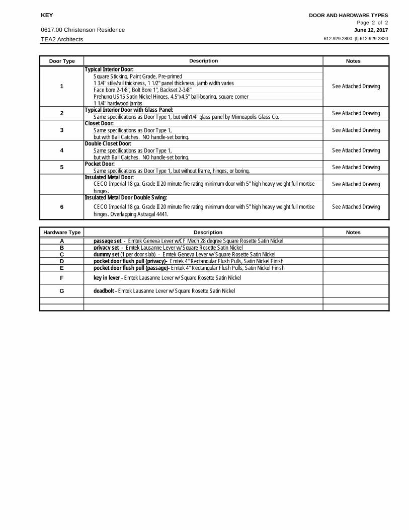
KEY DOOR AND HARDWARE TYPESPage 2 of 2
0617.00 Christenson Residence June 12, 2017
TEA2 Architects 612.929.2800 [f] 612.929.2820
Door Type Notes
Square Sticking, Paint Grade, Pre-primed 1 3/4" stile/rail thickness, 1 1/2" panel thickness, jamb width variesFace bore 2-1/8", Bolt Bore 1", Backset 2-3/8"Prehung US15 Satin Nickel Hinges, 4.5"x4.5" ball-bearing, square corner1 1/4" hardwood jambs
Same specifications as Door Type 1, but with1/4" glass panel by Minneapolis Glass Co.
Same specifications as Door Type 1,but with Ball Catches. NO handle-set boring.
Same specifications as Door Type 1,but with Ball Catches. NO handle-set boring.
Same specifications as Door Type 1, but without frame, hinges, or boring.
CECO Imperial 18 ga. Grade II 20 minute fire rating minimum door with 5" high heavy weight full mortise hinges. Overlapping Astragal 4441.
Hardware Type Description NotesA passage set - Emtek Geneva Lever w/CF Mech 28 degree Square Rosette Satin NickelB privacy set - Emtek Lausanne Lever w/ Square Rosette Satin NickelC dummy set (1 per door slab) - Emtek Geneva Lever w/ Square Rosette Satin NickelD pocket door flush pull (privacy)- Emtek 4" Rectangular Flush Pulls, Satin Nickel FinishE pocket door flush pull (passage)- Emtek 4" Rectangular Flush Pulls, Satin Nickel FinishF key in lever - Emtek Lausanne Lever w/ Square Rosette Satin Nickel
G deadbolt - Emtek Lausanne Lever w/ Square Rosette Satin Nickel
See Attached Drawing
See Attached Drawing
Pocket Door:
See Attached Drawing
See Attached Drawing
1
Typical Interior Door:
4Double Closet Door:
Description
2 Typical Interior Door with Glass Panel:
3Closet Door:
6
CECO Imperial 18 ga. Grade II 20 minute fire rating minimum door with 5" high heavy weight full mortise hinges.
See Attached DrawingInsulated Metal Door Double Swing:
5 See Attached Drawing
See Attached DrawingInsulated Metal Door:

PART 2 - SCHEDULES See next page for pricing alternates Light Fixture Schedule - Recessed TEA2 Architects Page: 1 of 3
Christensen Residence - 1617.00 Date: 06.12.17
No. Mfgr Housing Trim Flange Enviroment Install Lamping
3" Square MR-16 (Non-IC) 3” Square Adjustable Pinhole flangeless N/Aflangeless
installationTC43SQ 3SQAPIN FM N/A FMA3SQ
3" Square MR-16 (IC-Rated) 3” Square Adjustable Pinhole flangeless N/Aflangeless
installationIC43SQ 3SQAPIN FM N/A FMA3SQ
3" Square MR-16 (Non-IC) 3” Square Lensed Wall Wash flangeless N/Aflangeless
installationTC43SQ 3SQWW FM N/A FMA3SQ
3" Square MR-16 (IC-Rated) 3” Square Lensed Wall Wash flangeless N/Aflangeless
installationIC43SQ 3SQWW FM N/A FMA3SQ
6" Universal IC Housing6” Adj. Tapered Cone Trim - Black
Alzak® ConeWhite Trim Ring N/A N/A
IC2 267 B WH N/A N/A
3" Square MR-16 (Non-IC) 3” Square Adjustable Pinholeself flanged, white
painted flangeN/A
self-flangedinstallation
TC43SQ 3SQAPIN WHSF N/A CTA3SQ
3" Square MR-16 (Non-IC) 3” Square Adjustable Pinholeself flanged, white
painted flangeN/A
self-flangedinstallation
TC43SQ 3SQAPIN WHSF N/A CTA3SQ
3" Square MR-16 (Non-IC) 3” Square Adjustable Pinholeself flanged, white
painted flangeN/A
self-flangedinstallation
TC43SQ 3SQAPIN WHSF N/A CTA3SQ
3" Square MR-16 (IC-Rated) 3” Square Adjustable Pinholeself flanged, white
painted flangeN/A
self-flangedinstallation
IC43SQ 3SQAPIN WHSF N/A CTA3SQ
3" Square MR-16 (IC-Rated) 3” Square Adjustable Pinholeself flanged, white
painted flangeN/A
self-flangedinstallation
IC43SQ 3SQAPIN WHSF N/A CTA3SQ
3" Square MR-16 (Non-IC) 3” Square Adjustable Pinholeself flanged, white
painted flangewet location
self-flangedinstallation
TC43SQ 3SQAPIN WHSF WET CTA3SQ
Osram Silvania 71W MR16
R3 Aculux
AculuxOsram Silvania
50W MR16
R4 AculuxOsram Silvania
50W MR16
R6Osram Silvania
71W MR16
R7 AculuxOsram Silvania
71W MR16
R9 AculuxOsram Silvania
50W MR16
AculuxOsram Silvania
71W MR16
Aculux
R1
R2Osram Silvania
50W MR16
3. Separation from Insulation: GC to verify whether any of the recessed fixtures will be located within insulated ceilings and verify what steps must be taken to separate the fixture from the insulation.
NOTES:1. Linear spread lenses: To be supplied for all MR16 fixtures.
Aculux
2. Beam spreads: TBD per location
R11 AculuxOsram Silvania
71W MR16
Osram Silvania 50W MR16
R10
R8 Aculux
R5 JunoOsram Silvania
75W PAR30

PART 2 - SCHEDULES Light Fixture Schedule - Recessed AlternatesTEA2 Architects Page: 2 of 3Christensen Residence - 1617.00 Date: 06.12.17
No. Mfgr Housing Trim Flange Enviroment Install Lamping
3" Square MR-16 (Non-IC) 3” Square Adjustable Pinholeself flanged, white
painted flangeN/A
self-flangedinstallation
TC43SQ 3SQAPIN WHSF N/A CTA3SQ
3" Square MR-16 (IC-Rated) 3” Square Adjustable Pinholeself flanged, white
painted flangeN/A
self-flangedinstallation
IC43SQ 3SQAPIN WHSF N/A CTA3SQ
3" Square MR-16 (Non-IC) 3” Square Lensed Wall Washself flanged, white
painted flangeN/A
self-flangedinstallation
TC43SQ 3SQWW WHSF N/A CTA3SQ
3" Square MR-16 (IC-Rated) 3” Square Lensed Wall Washself flanged, white
painted flangeN/A
self-flangedinstallation
IC43SQ 3SQWW WHSF N/A CTA3SQ
R5(alt.)
N/A N/A N/A N/A N/A N/A N/A
R6(alt.)
N/A N/A N/A N/A N/A N/A N/A
4” miniature universal TC new construction housing (Non-IC)
Black Square Downlight,White Trim Ring
N/A N/A N/A
TC1 17SQ BWH N/A N/A N/A
4” miniature universal TC new construction housing (Non-IC)
Square Flush Gimbal, White N/A N/A N/A
TC1 440SQ WH N/A N/A N/A
4” miniature universal IC new construction housing (IC-Rated)
Black Square Downlight,White Trim Ring
N/A N/A N/A
IC1 17SQ BWH N/A N/A N/A
4” miniature universal IC new construction housing (IC-Rated)
Square Flush Gimbal, White N/A N/A N/A
IC1 440SQ WH N/A N/A N/A
4” miniature universal new construction housing (IC-Rated)
Square Frosted Lens w/ Clear Center, White Trim Ring
N/A N/A N/A
IC1 12SQ WWH N/A N/A N/A
R1(alt.)
AculuxOsram Silvania
71W MR16
R2(alt.)
AculuxOsram Silvania
50W MR16
R4(alt.)
AculuxOsram Silvania
50W MR16
R3(alt.)
AculuxOsram Silvania
71W MR16
R8(alt.)
JunoOsram Silvania
35W MR16
R7(alt.)
JunoOsram Silvania
50W PAR20
2. Beam spreads: TBD per location3. Separation from Insulation: GC to verify whether any of the recessed fixtures will be located within insulated ceilings and verify what steps must be taken to separate the fixture from the insulation.
R11(alt.)
JunoOsram Silvania
50W PAR20
NOTES:1. Linear spread lenses: To be supplied for all MR16 fixtures.
R10(alt.)
JunoOsram Silvania
35W MR16
R9(alt.)
JunoOsram Silvania
50W PAR20

PART 2 - SCHEDULES Light Fixture Schedule - Utility & DecorativeTEA2 Architects Page: 1 of 1
Date: 06.12.17
Fixt No.
Model Accessories Lamp
6-1/4" x 6-1/4" x 8-1/4"
22 453machined brass square LED step
light B-SQ-LED-e101-A9-MAC
High-Output Warm White Dimable LED strip
aluminum track w/ frosted diffuser
ww3528-120-10-reel (2700K)
White
10301WH
Fixt No.
Model Accessories Lamp
T-8
P Standard Porcelain Fixture A Lamp
S1 EnvironmentalLights.com
Christensen Residence - 1617.00
LED - by Mfgr
RW1 B-K Lighting Square Step Starby Mfgr.; confirm color
temperature with owner
Manuf. & Series
by Mfgr.; 2400K also available - confirm color temperature with owner
N/A
N/A
Deco
rativ
e Fi
xtur
es
FKichler
2 Light Fluorescent
Util
ity F
ixtu
res
L1BEGA Surface Wall and Ceiling - Glass
Block
Manuf. & Series
N/A
N/A
N/A
See architectural lighting plans for decorative fixture & electric mirror
locations.
Selections to be provided by Interior Designer
N/A N/A
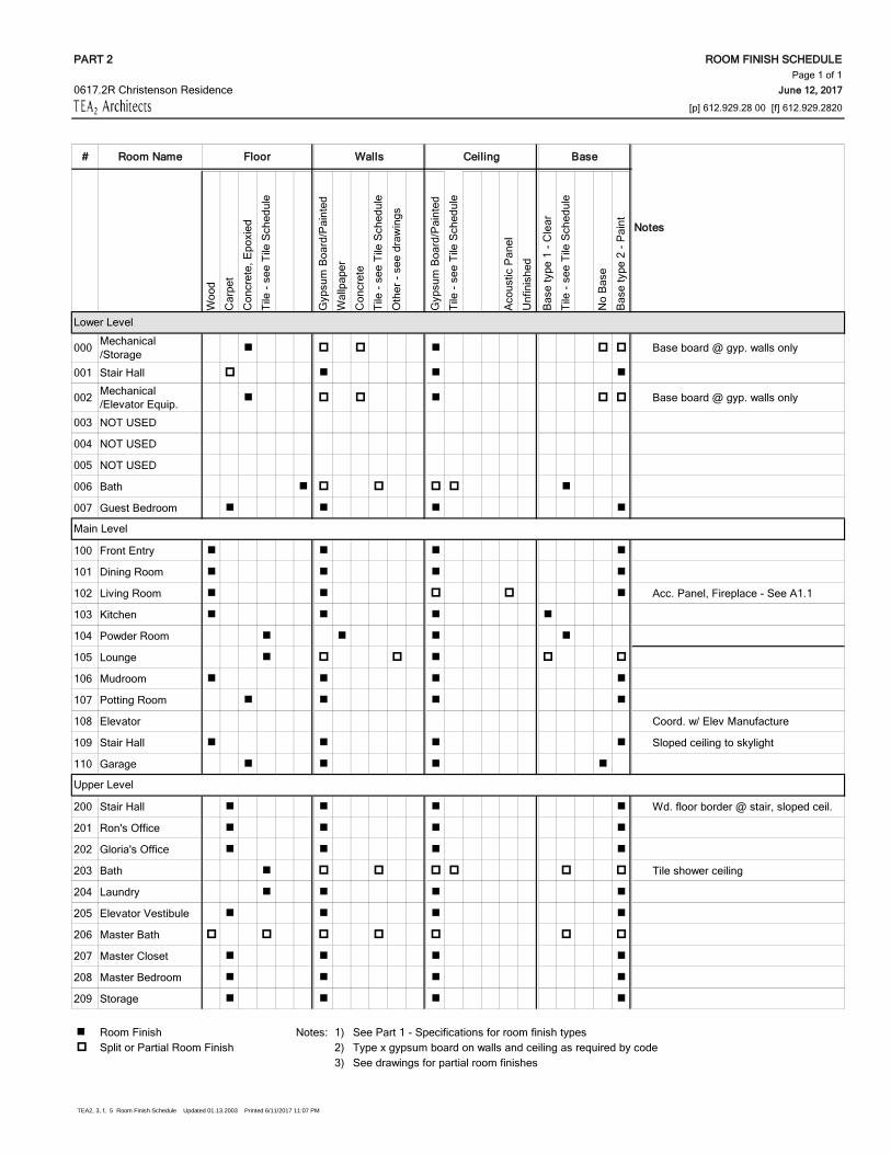
TEA2, 3, f, 5 Room Finish Schedule Updated 01.13.2003 Printed 6/11/2017 11:07 PM
PART 2 ROOM FINISH SCHEDULEPage 1 of 1
June 12, 2017
[p] 612.929.28 00 [f] 612.929.2820
# Room Name Floor Walls Ceiling Base
Woo
d
Car
pet
Con
cret
e, E
poxi
ed
Tile
- se
e Ti
le S
ched
ule
Gyp
sum
Boa
rd/P
aint
ed
Wal
lpap
er
Con
cret
e
Tile
- se
e Ti
le S
ched
ule
Oth
er -
see
draw
ings
Gyp
sum
Boa
rd/P
aint
ed
Tile
- se
e Ti
le S
ched
ule
Aco
ustic
Pan
el
Unf
inis
hed
Bas
e ty
pe 1
- C
lear
Tile
- se
e Ti
le S
ched
ule
No
Bas
e
Bas
e ty
pe 2
- P
aint
000 Mechanical /Storage Base board @ gyp. walls only
001 Stair Hall
002 Mechanical /Elevator Equip. Base board @ gyp. walls only
003 NOT USED
004 NOT USED
005 NOT USED
006 Bath
007 Guest Bedroom
100 Front Entry
101 Dining Room
102 Living Room Acc. Panel, Fireplace - See A1.1
103 Kitchen
104 Powder Room
105 Lounge
106 Mudroom
107 Potting Room
108 Elevator Coord. w/ Elev Manufacture
109 Stair Hall Sloped ceiling to skylight
110 Garage
200 Stair Hall Wd. floor border @ stair, sloped ceil.
201 Ron's Office
202 Gloria's Office
203 Bath Tile shower ceiling
204 Laundry
205 Elevator Vestibule
206 Master Bath
207 Master Closet
208 Master Bedroom
209 Storage
Room Finish Notes: 1) See Part 1 - Specifications for room finish types Split or Partial Room Finish 2) Type x gypsum board on walls and ceiling as required by code
3) See drawings for partial room finishes
0617.2R Christenson Residence
Notes
Upper Level
Main Level
Lower Level

PART 2 - SCHEDULES Window ScheduleTEA2 Architects Page: 1 of 3
Date: 06.12.2017
Frame Size (W x H)
Jamb Size Ext./ Int. OperationFall
ProtectionMull
CoverSub- Sill
Screen
W101A PS1 0506 19 11/16" x 23 5/8" 4 9/16"Clad / Bare
Picture
W101B PS1 05CUSTOM 19 11/16" x 86 1/2" // // Picture Safety Glazing
W102 PS1 1006 39 3/8" x 23 5/8" // // Picture
W103A PS1 0506 19 11/16" x 23 5/8" // // Picture
W103B PS1 05CUSTOM 19 11/16" x 86 1/2" // // Picture Safety Glazing
CORNER UNIT DIRECT SET 31" x 31" x 23 5/8" // //Corner Picture
CORNER UNIT DIRECT SET 31" x 31" x 70 7/8" // //Corner Picture
PS1 0906 35 7/16" x 23 5/8" // // Picture
PS1 0906 35 7/16" x 23 5/8" // // Picture
PS1 0906 35 7/16" x 23 5/8" // // Picture
CA1 0918 35 7/16" x 70 7/8" // // Casement X
CA1 0918 35 7/16" x 66" // // Fixed
CA1 0918 35 7/16" x 66" // // Casement X
CORNER UNIT DIRECT SET 31" x 31" x 23 5/8" // //Corner Picture
CORNER UNIT DIRECT SET 31" x 31" x 70 7/8" // //Corner Picture
W201 CORNER UNIT DIRECT SET 21" X 21" X 41 1/4" // //Corner Picture
X
Casement x X
Casement x X
W203 CA1 7511 29 1/2" x 41 1/4" // // Casement x X X
W204 CORNER UNIT DIRECT SET 21" x 38" x 47 1/4" // //Corner Picture
x
CA1 0512 19 11/16" x 47 1/4" Casement x X
CUSTOM 43 1/2" x 47 1/4" Fixed Csmt
CA1 0512 19 11/16" x 47 1/4" Casement x X
W206 CA1 0612 23 5/8" x 47 1/4" // // Casement x x X
W207 CORNER UNIT DIRECT SET 21" X 21" X 41 1/4" // //Corner Pciture
X
CA1 0512 19 11/16" x 47 1/4" Casement x X
CUSTOM 43 1/2" x 47 1/4" Fixed Csmt
CA1 0512 19 11/16" x 47 1/4" Casement x X
W209 CORNER UNIT DIRECT SET 21" X 21" X 41 1/4" // //Corner Pciture
X
Christenson - 0617.2R
Size TypeMfr Code Notes
Additional Components
W205
W208
47 1/4" x 41 1/4"
x x//
No.
W104
W105
W106
W202
Direct Mullx x
Direct MullX
Direct Mull
Direct Mull
Direct MullX
Direct MullX
X XCA2 1211 // //
// //
//

PART 2 - SCHEDULES Window ScheduleTEA2 Architects Page: 2 of 3
Date: 06.12.2017
N001 CA1 0911 35 7/16" x 41 1/4" // // Casement X Window Well
PS1 0975 35 7/16" x 29 1/2" // // Picture
PS1 0975 35 7/16" x 29 1/2" // // Picture
PS1 0975 35 7/16" x 29 1/2" // // Picture
PS1 0975 35 7/16" x 29 1/2" 4 9/16" Clad/Std Picture
PS1 0975 35 7/16" x 29 1/2" // // Picture
PS1 0975 35 7/16" x 29 1/2" // // Picture
CORNER UNIT DIRECT SET 46" x 30" x 23 5/8" // //Corner Picture
CORNER UNIT DIRECT SET 46" x 30" x 44" // //Corner Picture
N104 NOT USED
CA1 CUSTOM 19 11/16" x 50 3/4" Casement x x
CA1 0910 39 3/8" x 50 3/4" // // Picture
N201 CA1 0910 35 7/16" x 39 3/8" // // Casement X X Safety, Reeded Glass
N202 CA1 0710 27 9/16" x 39 3/8" // // Casement X X Reeded Glass
N203 CA1 0611 23 5/8" x 41 1/4" // // Casement X X
N204 CA1 0712 27 9/16" x 47 1/4" // // Casement X X X
N205 CA1 0912 35 7/16" x 47 1/4" // // Fixed Csmt X
N206 CA1 0712 27 9/16" x 47 1/4" // // Casement X X X
E001 CA1 0911 35 7/16" x 41 1/4" // // Casement X Window Well
PS1 0906 35 7/16" x 23 5/8" // //
PS1 0906 35 7/16" x 23 5/8" // //
PS1 0906 35 7/16" x 23 5/8" // //
E102 MULTI-SLIDE 132 1/4" x 86 11/16" // // OX-XO X Field mull to E101
E103 NANAWALL SL60 106" x 113 3/4"Outswing Folding
3 Panels
E104 PS1 0810 31 1/2" x 39 3/8" // // Picture
E105 PS1 0810 31 1/2" x 39 3/8" // // Picture
E201 CA1 0711 27 9/16" x 47 1/4" // // Casement X ee X
E202 CA1 0711 27 9/16" x 47 1/4" // // Casement X X X
CA1 0915 35 7/16" x 70 7/8" // // Casement X X
CA1 0915 35 7/16" x 70 7/8" // // Fixed Csmt
CA1 0915 35 7/16" x 70 7/8" // // Casement X X
E204 PS1 0910 35 7/16" x 39 3/8" // // Picture X X Safety Glazing
E205 CORNER UNIT DIRECT SET 31" x 21" x 39 3/8" // //Corner Picture
Safety Glazing
Direct Mullx
x
x
X
Christenson - 0617.2R
N105
Direct Mull
N101
N102
N103
E203
Direct Mull
Direct Mull
Direct Mull
E101 Picture
Direct Mull - Provide vertical 1/2" mull cover & 2 1/2" horizontal mull cover attach E102. Field applied.
X

PART 2 - SCHEDULES Window ScheduleTEA2 Architects Page: 3 of 3
Date: 06.12.2017
S001 CA2 1411 55 1/8" x 41 1/4" // //Double
CasementX Window Well
S002 CA2 1411 55 1/8" x 41 1/4" // //Double
CasementX Window Well
S003 CA2 1411 55 1/8" x 41 1/4" // //Double
CasementX Window Well
PS1 CUSTOM 42 5/8" x 23 5/8" // // Picture
PS1 CUSTOM 42 5/8" x 23 5/8" // // Picture
PS1 CUSTOM 42 5/8" x 23 5/8" // // Picture
NOT USED
NOT USED
NOT USED
NOT USED
S104 MULTI-SLIDE (FIXED) 143" x 86 11/16" // // Fixed Slider X
S105 PS1 1206 47 1/4"" x 23 5/8" // // Picture
S105 PS1 1206 47 1/4"" x 23 5/8" // // Picture
S105 PS1 1206 47 1/4"" x 23 5/8" // // Picture
S106 NANAWALL HSW60 106" x 192"Sliding Pocket
4 Panels
S201 CA1 0712 27 9/16" x 47 1/4" // // Casement X X X
S202 CA1 0715 27 9/16" x 59 1/16" // // Casement X X X Safety Glazing
S203 CA1 0715 27 9/16" x 59 1/16" // // Casement X X X Safety Glazing
S204 CA1 0715 27 9/16" x 59 1/16" // // Casement X X X
S205 CA1 0715 27 9/16" x 59 1/16" // // Casement X X X
S206 CA10915 35 7/16" x 59 1/16" // // Casement X X X
S207 CA10915 35 7/16" x 59 1/16" // // Casement x X x
R301 VELUX - FCM 3434 37 1/2" x 37 1/2" Fixed Skylight
Notes:
1. - Shop Drawings - Manufacturer to provide (24X36) shop drawings for review and approval.
2. - Jamb extensions - supplied and installed by Contractor as needed.
3. - Egress Locations - Contractor to identify required egress locations.
4. - Safety Glazing Locations - Contractor to identify required safety glazing locations.
5. - Fall Protection Hardware Locations - Contractor to identify required fall hardware locations.
6. - Factory Mulling - Manufacturer to advise GC if Factory Mulled units exceed shipping/installation limitations.
7. - Simulated Divided Lites (SDL) - 5/8" typical
S102
S103
Direct MullX
Christenson - 0617.2R
Direct Mull. 2 1/2" horiz. & 1/2" vertical
mull covers.X
S101
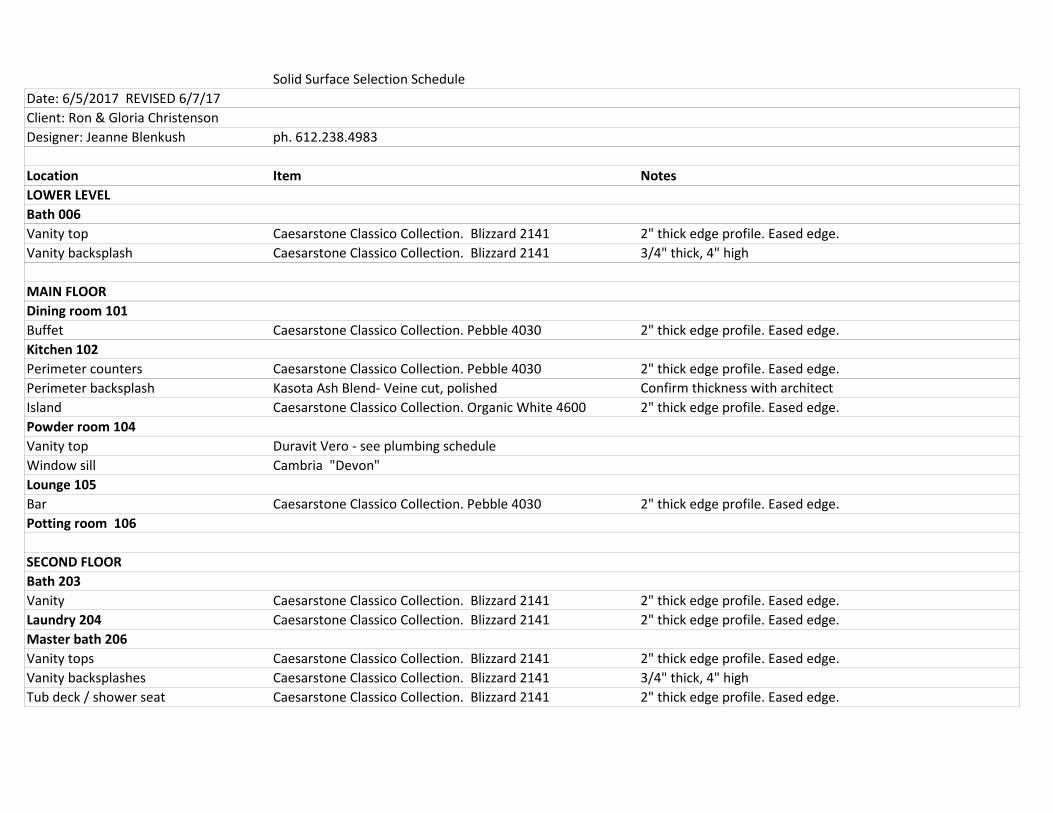
Solid Surface Selection ScheduleDate: 6/5/2017 REVISED 6/7/17Client: Ron & Gloria ChristensonDesigner: Jeanne Blenkush ph. 612.238.4983
Location Item NotesLOWER LEVELBath 006Vanity top Caesarstone Classico Collection. Blizzard 2141 2" thick edge profile. Eased edge.Vanity backsplash Caesarstone Classico Collection. Blizzard 2141 3/4" thick, 4" high
MAIN FLOORDining room 101Buffet Caesarstone Classico Collection. Pebble 4030 2" thick edge profile. Eased edge.Kitchen 102Perimeter counters Caesarstone Classico Collection. Pebble 4030 2" thick edge profile. Eased edge.Perimeter backsplash Kasota Ash Blend- Veine cut, polished Confirm thickness with architectIsland Caesarstone Classico Collection. Organic White 4600 2" thick edge profile. Eased edge.Powder room 104Vanity top Duravit Vero - see plumbing scheduleWindow sill Cambria "Devon" Lounge 105Bar Caesarstone Classico Collection. Pebble 4030 2" thick edge profile. Eased edge.Potting room 106
SECOND FLOOR Bath 203 Vanity Caesarstone Classico Collection. Blizzard 2141 2" thick edge profile. Eased edge.Laundry 204 Caesarstone Classico Collection. Blizzard 2141 2" thick edge profile. Eased edge.Master bath 206Vanity tops Caesarstone Classico Collection. Blizzard 2141 2" thick edge profile. Eased edge.Vanity backsplashes Caesarstone Classico Collection. Blizzard 2141 3/4" thick, 4" highTub deck / shower seat Caesarstone Classico Collection. Blizzard 2141 2" thick edge profile. Eased edge.

Tile Selection ScheduleDate: 6/5/2017 REVISED 6/7/2017 Client: Ron & Gloria ChristensonDesigner: Jeanne Blenkush
*Prices are per square foot of tile unless otherwise explained in "Notes" column
Location Material Grout Application Source NotesLOWER LEVEL Bath 006
Floor Uni Opus Bone White 12 x 24 TBD1/3 Running Bond pattern.
Ceramic Tileworks Attn: Deanne or Jennifer. 612-333-7100
Tub shower wallsCTW GLO 4x10 WHIT. Glossy White Ice. TBD
1/3 Running Bond pattern. Ceramic Tileworks.
If needed: 3x10 bullnose available at $3.97 per piece.
Tub shower ceiling TBD?
MAIN LEVELPowder room 104
Floor CTW FLA Crete Night 12x24. TBD1/3 Running Bond pattern. Ceramic Tileworks.
Lounge 105
FloorBack Bay Dwell DWF702 Matte. 12 x 24 TBD
1/2 Running Bond pattern.
RBC Tile and Stone Plymouth 763-559-5531

SECOND FLOORLocation Material Grout Application Source Notes
Guest bath 203
Bath floor Maltese Roman Grey 12x24 TBD1/2 Running Bond pattern.
Minnesota Tile and Stone. Attn: Judy or Lynn. 612-330-9899
Shower walls Maltese Roman Grey 12x24 TBD1/2 Running Bond pattern.
Minnesota Tile and Stone.
Shower floor Maltese Roman Grey 2x2 TBDMeshed, straight lay.
Minnesota Tile and Stone. Meshed.
Shower ceiling Maltese Roman Grey 2x2 TBDMeshed, straight lay.
Minnesota Tile and Stone. Meshed.
Shower curb TBDPending: solid material for curb.
Laundry 204
FloorBack Bay Dwell DWF702 Matte. 12 x 24 TBD
1/2 Running Bond pattern. RBC Tile and Stone

Location Material Grout Application Source NotesMaster bath 206Floor, excluding vanity area.
FLOAT5RA12x24. Aventis AT5RA 12x24 Cotton TBD
1/3 Running Bond pattern.
Minnesota Tile and Stone.
Floor at vanity area to be wood
Tub skirt, North wall (excluding vanity area), East wall, Shower walls.
FLOAT5RA12x24. Aventis AT5RA 12x24 Cotton TBD
1/3 Running Bond pattern.
Minnesota Tile and Stone.
Walls at vanity area to be painted, faux finish, or papered.
Shower floor Aventis AT5RA 2x2 Cotton TBDMeshed, straight lay.
Minnesota Tile and Stone. Meshed.
Shampoo niche in shower TBDMaster water closet 206B
FloorFLOAT5RA12x24. Aventis AT5RA 12x24 Cotton TBD
1/3 Running Bond pattern.
Minnesota Tile and Stone.

18 NOTES(1) Above tables may be used for Power Joist spacing of 24” on center or less.(2) Hole location distance is measured from inside face of supports to center of hole.(3) Distances in this chart are based on uniformly loaded joists.(4) Hole sizes and/or locations that fall outside of the scope of this table may be acceptable based on analysis of actual hole size, span, spacing, and loading conditions.(5) SAF stands for Span Adjustment Factor. SAF is used as defined below.OPTIONALTable 9 is based on the Power Joists being used at their maximum span. If the Power Joists are placed at less than their full allowable span, the maximum distance from the centerline of the hole to the face of any support (D) as given above may be reduced as follows. Dreduced = Lactual x D SAF
Where: Dreduced = Distance from the inside face of any support to center of hole is reduced for less-than-maximum span applications (ft). The reduced distance shall not be less than 6” from the face of support to edge of the hole. Lactual = The actual measured span distance between the inside faces of supports (ft) SAF = Span Adjustment Factor is given in the table above. D = The minimum distance from the inside face of any support to center of hole from Table 9 aboveIf Lactual is greater than 1, use 1 in the above calculation for Lactual. SAF SAF
Figure 6
Power Joist Typical HolesMinimum distance from face of support to the center of hole (See Table 3)
2x diameter of larger hole
3/4x diameter
See rule 11.
Knockouts are prescored holes often provided by Power Joists manufacturers for the contractor’s convenience rto install electrical or small plumbing lines. They are typically 1-3/8 to 1-3/4 inches in diameter, and are spaced 12 to 24 inches on center along the length of the Power Joists. Where possible, it is preferable to use knockouts instead of field-cutting holes.
Power Joists
Web Hole Rules and Specifications (Continued)
Cutting the Holes • Never drill, cut, or notch the flange. Never over-cut the web. • Holes in webs should be cut with a sharp saw. • For rectangular holes avoid over cutting the corners as this can cause unnecessary stress
concentrations. Slightly rounding the corners is recommended. Starting the rectangular hole by drilling a 1” diameter hole in each of the 4 corners and then making the cuts between the holes is another good method to minimize damage to I-Joist.
Table 9
Location Of Circular Holes In PJI Joist Webs Simple or Multiple Span for Dead Loads up to 10 psf and Live Loads up to 40 psf(1)(2)(3)(4)
Minimum Distance from Inside Face of Any Support to Center of Hole (ft-in.)Round Hole Diameter (in.)
Depth Joist SAF(5) 2 3 4 5 6 6 1/4 7 8 8 5/8 9 10 10 3/4 11 12 12 3/4
9-1/2” PJI 40 14’-6” 0’-7” 1’-8” 3’-0” 4’-4” 5’-9” 6’-3”
PJI 60 15’-3” 1’-8” 3’-0” 4’-4” 5’-8” 7’-3” 7’-8” PJI 40 16’-7” 0’-7” 0’-8” 1’-2” 2’-5” 3’-9” 4’-1” 5’-1” 6’-8” 7’-11” 11-7/8” PJI 60 18’-2” 0’-8” 1’-10” 3’-2” 4’-5” 5’-10” 6’-2” 7’-4” 8’-11” 10’-0” PJI 80 19’-10” 1’-11” 3’-2” 4’-6” 5’-10” 7’-3” 7’-8” 8’-10” 10’-6” 11’-7” PJI 90 20’-5” 2’-1” 3’-4” 4’-8” 6’-0” 7’-6” 7’-10” 9’-0” 10’-8” 11’-11” PJI 40 18’-3” 0’-7” 0’-8” 0’-8” 0’-9” 1’-10” 2’-2” 3’-2” 4’-7” 5’-5” 6’-0” 7’-7” 9’-4” 14” PJI 60 19’-9” 0’-7” 0’-8” 0’-8” 1’-7” 3’-2” 3’-6” 4’-9” 6’-6” 7’-8” 8’-4” 10’-4” 11’-11” PJI 80 22’-7” 0’-7” 1’-9” 3’-0” 4’-4” 5’-8” 6’-1” 7’-1” 8’-7” 9’-7” 10’-3” 12’-2” 13’-10” PJI 90 23’-2” 0’-7” 1’-9” 3’-0” 4’-4” 5’-8” 6’-1” 7’-1” 8’-8” 9’-10” 10’-7” 12’-8” 14’-4” PJI 40 19’-8” 0’-7” 0’-8” 0’-8” 0’-9” 0’-9” 0’-10” 1’-5” 2’-9” 3’-7” 4’-1” 5’-6” 6’-7” 7’-0” 8’-9” 10’-9” 16” PJI 60 19’-9” 0’-7” 0’-8” 0’-8” 0’-9” 0’-9” 0’-10” 1’-10” 3’-6” 4’-6” 5’-2” 7’-3” 8’-11” 9’-6” 11’-10” 13’-9” PJI 80 23’-11” 0’-7” 0’-8” 0’-8” 1’-7” 3’-2” 3’-7” 4’-10” 6’-6” 7’-7” 8’-3” 10’-2” 11’-8” 12’-2” 14’-3” 16’-0” PJI 90 25’-5” 0’-7” 0’-8” 1’-8” 2’-11” 4’-3” 4’-7” 5’-7” 7’-0” 8’-1” 8’-9” 10’-8” 12’-2” 12’-8” 14’-10” 16’-7” 18” PJI 80 27’-3” 0’-7” 0’-8” 0’-8” 0’-11” 2’-3” 2’-8” 3’-9” 5’-2” 6’-1” 6’-8” 8’-3” 9’-6” 9’-11” 11’-8” 13’-0” PJI 90 27’-11” 0’-7” 0’-8” 0’-8” 1’-6” 2’-11” 3’-4” 4’-5” 5’-10” 6’-10” 7’-5” 9’-0” 10’-3” 10’-8” 12’-5” 13’-9” 20” PJI 80 29’-6” 0’-7” 0’-8” 0’-8” 0’-9” 1’-9” 2’-1” 3’-1” 4’-5” 5’-3” 5’-10” 7’-3” 8’-4” 8’-8” 10’-3” 11’-5” PJI 90 30’-3” 0’-7” 0’-8” 0’-8” 0’-10” 2’-2” 2’-6” 3’-6” 4’-10” 5’-8” 6’-2” 7’-8” 8’-9” 9’-1” 10’-8” 11’-11” 22” PJI 80 31’-5” 0’-7” 0’-8” 0’-8” 0’-9” 0’-9” 1’-1” 2’-0” 3’-3” 4’-0” 4’-6” 5’-9” 6’-9” 7’-1” 8’-6” 9’-9” PJI 90 31’-5” 0’-7” 0’-8” 0’-8” 0’-9” 0’-10” 1’-1” 2’-0” 3’-3” 4’-2” 4’-9” 6’-4” 7’-7” 8’-0” 9’-8” 11’-0 24” PJI 80 31’-5” 0’-7” 0’-8” 0’-8” 0’-9” 0’-9” 0’-10” 0’-10” 1’-11” 2’-7” 3’-1” 4’-4” 5’-5” 5’-10” 7’-4” 8’-6” PJI 90 31’-5” 0’-7” 0’-8” 0’-8” 0’-9” 0’-9” 0’-10” 0’-10” 2’-4” 3’-2” 3’-9” 5’-3” 6’-4” 6’-9” 8’-4” 9’-6”
Joist

17
Web Hole Rules and Specifications
One of the benefits of using Power Joists in residential floor construction is that holes may be cut in the joist webs to accommodate electrical wiring, plumbing lines, and other mechanical systems, thereby minimizing the depth of the floor system.
Rules for Cutting Holes in PJI Joists 11. The distance between the inside edge of the support and the centerline of any hole shall be in compliance with the
requirements of Table 9. 12. Power Joist top and bottom flanges must NEVER be cut, notched, or otherwise modified. 13. Whenever possible field-cut holes should be centered on the middle of the web. 14. The maximum size hole that can be cut into a Power Joist web shall equal the clear distance between the flanges
of the Power Joist minus 1/4”. A minimum of 1/8” should always be maintained between the top or bottom of the hole and the adjacent Power Joist flange.
15. The sides of square holes or longest sides of rectangular holes should not exceed three-fourths of the diameter of the maximum round hole permitted at that location.
16. Where more than one hole is necessary, the distance between adjacent hole edges shall exceed twice the diameter of the largest round hole or twice the size of the largest square hole (or twice the length of the longest side of the longest rectangular hole) and each hole must be sized and located in compliance with the requirements of Table 9.
17. Holes measuring 1-1/2” shall be permitted anywhere in a cantilevered section of a Power Joist. Holes of greater size may be permitted subject to verification.
18. A 1-1/2” hole can be placed anywhere in the web provided that it meets the requirements of rule 6 above. 19. All holes shall be cut in a workman-like manner in accordance with the restrictions listed above and as illustrated in
Figure 6. 10. Limit of 3 maximum size holes per span 11. A group of round holes at approximately the same location shall be permitted if they meet the requirements for
a single round hole circumscribed around them.
Typical Floor Framing Installation Notes
1. Installation of PJI Power Joist shall be in accordance with Figure 1.
2. Except for cutting joist to length, Power Joist flanges should NEVER be cut, drilled, or notched.
3. Concentrated loads should be applied only to the top surface of the top flange. At no time should concentrated loads be suspended from the bottom flange with the exception of light loads such as ceiling fans, light fixtures, etc.
4. Power Joists must be protected from the weather prior to installation.
5. Power Joists must not be used in applications where they will be permanently exposed to weather or will reach a moisture content greater than 16% such as in swimming pool or hot tub areas. They must not be installed where they will remain in direct contact with concrete or masonry.
6. End-bearing length must be at least 1-3/4”. For multiple span joists, intermediate bearing length must be at least 3-1/2”.
7. Ends of floor joists shall be restrained to prevent rollover. Use Certified Rim Board or Power Joist blocking panels.
8. Power Joists installed beneath bearing walls perpendicular to the joists require full depth blocking panels, Certified Rim Board, or squash blocks (cripple blocks) in order to transfer gravity loads from above the floor system to the wall or foundation below. See note 1g page 11.
9. For Power Joists up to 18” deep installed as rim board directly beneath bearing walls parallel to the joists, the maximum vertical load using a single Power Joist is 2000 plf and using double Power Joists is 4000 plf. Full bearing is required under Power Joist used as rim board.
10. Continuous lateral support of the Power Joist’s compression flange is required to prevent rotation and buckling. In simple span uses, lateral support of the top flange is normally supplied by the floor sheathing. In multiple span or cantilever applications, bracing of the Power Joist’s bottom flange is also required at interior supports of multiple-span joists and at the end support next to the cantilever extension. The ends of all cantilever extensions must be laterally braced as shown in Figure 3 or 4.
11. Nails installed perpendicular to the wide face of the flange shall be spaced in accordance with the applicable building code requirements or approved building plans but should not be closer than 2” o.c. per row.
12. Figure 1 details show only Power Joist-specific fastener requirements. For other fastener requirements, see the applicable building code.
13. For Fire-Resistance ratings, typical Sound Transmission Class (STC), and typical Impact Insulation Class (IIC) refer to ICC ESR 1405 Section 4.2.2 or DCA 3 - Fire Rated Wood Floor and Wall Assemblies at www.awc.org .
Cantilever Detail for Vertical Building Offset – (Concentrated Wall Load)

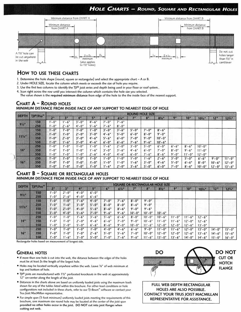


MARK
WOOD HEADER SCHEDULE
SIZE
2-2x6
2-2x8
3-2x8
2-2x10
3-2x10
2-2x12
3-2x12
2-1 3/4x7 1/4 LVL
H24
H23
H22
H21
H20
H19
H18H1
H2
H3
H4
H5
H6
H7
H8
H9
H10
H11
H12
H13
H14
H15
H16
H17
3-1 3/4x7 1/4 LVL
2-1 3/4x9 1/2 LVL
3-1 3/4x9 1/2 LVL
4-1 3/4x9 1/2 LVL
2-1 3/4x11 7/8 LVL
3-1 3/4x11 7/8 LVL
4-1 3/4x11 7/8 LVL
2-1 3/4x14 LVL
3-1 3/4x14 LVL
4-1 3/4x14 LVL
2-1 3/4x16 LVL
3-1 3/4x16 LVL
4-1 3/4x16 LVL
2-1 3/4x18 LVL
3-1 3/4x18 LVL
4-1 3/4x18 LVL
XF
(BOTTOM OF BEAM=BOTTOM OF JOISTS)
INDICATES "BOTTOM" BEAM/HEADER
(TOP OF BEAM=TOP OF JOIST)
NOTE: INDICATES "FLUSH" BEAM/HEADER
XB

MAIN FLOOR FRAMING NOTES See attached structural notes for more information. Attach all floor truss ends to sill plate with 2 – Simpson LS50 clips each end. Use 3/4” T&G plywood floor sheathing, see structural notes for nailing. Provide minimum 2 – 2x6 trimmer studs and 1 – 2x6 king stud unless noted. Block solid below all posts to foundation. Locate girders as shown. Marks thus, “2”, indicate number of bearing studs required. If number not shown, provide minimum of 2 studs (3” bearing length), full width of beam/header/girder truss must be supported. Interior bearing stud walls to be 2x6 at 16” o.c. Provide bolted 2x top plates with 3/8” diameter bolts at 32” oc to top flanges at steel beams. Block web full height and width and bolt to web with 2 – rows 3/8” bolts 24” oc. Provide 2x8 treated sill plate with galvanized 5/8”x12” anchor bolts at 32” oc with 1/8”x2” galvanized washers slightly crushing plate. At all endwalls, install 2x blocks on edge (ripped to fit) in first 3 truss spaces at 16” oc and place tight to sill plate and floor truss top chords and subfloor glued and screwed. Attach exterior wall sole plates with 5 – 16d nails per ft. Use triple zinc coated fasteners and hangers for green treated members. If mid-chord bearing floor trusses, shim bottom chord tight to foundation wall.

2ND FLOOR PLAN NOTES See attached structural notes for more information. Attach all roof truss ends with Simpson H2.5A ties to wall plates. Attach all floor truss ends with 2 – 1/4”x5” SDS screws each end to wall plates. Use 1/2” plywood roof sheathing, see structural notes for nailing. Use 3/4” T&G plywood floor sheathing at floors and flat roofs, see structural notes for nailing. Provide minimum 2 – 2x6 trimmer studs and 1 – 2x6 king stud unless noted. Block solid below all posts to foundation. Locate girders as shown. Marks thus, “2”, indicate number of bearing studs required. If number not shown, provide minimum of 2 studs (3” bearing length), full width of beam/header/girder truss must be supported. Extend plywood wall sheathing up face of truss heel and nail to trusses. Stop short for venting as required. Exterior stud walls to be 2x6 at 16” o.c. Attach endwall ladder floor truss bottom chord to wall plates with 4 – 16d nails per ft. Provide bolted 2x top plates with 3/8” diameter bolts at 32” oc to top flanges at steel beams. Block web full height and width and bolt to web with 2 – rows 3/8” bolts 24” oc. Provide full height 2x6 top and bottom blocks with 1/2” plywood gusset at 3ft.oc glued and nailed to wall top plates, rim, subfloor, and first truss chords with glue and 4 – 16d nails each end at all endwalls. Verify tub weight with truss manufacturer. Verify if any zero-clearance showers with truss manufacturer.
ROOF FRAMING NOTES See attached structural notes for more information. Attach all truss ends with Simpson H2.5A ties to wall plates. Use 1/2” plywood roof sheathing, see structural notes for nailing. Provide minimum 2 – 2x trimmer studs and 1 – 2x king stud unless noted. Block solid below all posts to foundation. Locate girders as shown. Marks thus, “2”, indicate number of bearing studs required. If number not shown, provide minimum of 2 studs (3” bearing length), full width of beam/header/girder truss must be supported. Mend all fascia board butt splices with Simpson LSTA24 horizontal strap. Extend plywood wall sheathing up face of truss heel and nail to trusses. Stop short for venting as required. Exterior studs to be 2x6 at 16” oc.

STRUCTURAL NOTES Unless noted otherwise on the plans and/or in the details, these notes shall apply. If there are discrepancies between the plans/details and these notes, the contractor shall conform to the more stringent requirements, unless clarified with the Structural Engineer of Record (SER) prior to work. MATERIAL STRENGTHS Structural Steel HSS Rectangular and Square – ASTM A500 Gr. B, Fy = 46 ksi W and WT shapes – ASTM A992, Fy = 50 ksi Misc. structural steel – ASTM A36, Fy = 36 ksi Structural Steel Fasteners Connection bolts – ASTM A325 or F1852, Fu = 120 ksi Anchor rods – ASTM F1554, Gr. 36, Fy = 36 ksi Threaded rods – ASTM A36, Fy = 36 ksi Reinforcing Steel Deformed Bars – ASTM A615, Gr. 60, Fy = 60 ksi Fabric – ASTM A185, Fy = 70 ksi Concrete f 'c = compressive strength in 28 days 4,000 psi unless noted otherwise 5,000 psi for footings Structural Lumber All dimensional lumber - #2 Spruce Pine Fir (SPF) or equal Laminated Veneer Lumber (LVL) E = 2,000,000 psi Fb = 2600 psi Laminated Strand Lumber (LSL) E = 1,550,000 psi Fb = 2,325 psi Parallel Strand Lumber (PSL) E = 2,000,000 psi Fb = 2900 psi Treated lumber - #2 Southern Pine or equal DESIGN LOADS Roof Dead load 17 psf (7 psf top chord + 10 psf bottom chord) Snow load Roof snow load = 35 psf Floors Dead load 20 psf (10 psf top chord + 10 psf bottom chord) Live loads 40 psf Wind Nominal Design Wind Speed 90 mph, (Ultimate Design Wind Speed 115 mph)

3 second gust. Exposure B, I = 1.0 Risk Category II EXISTING CONDITIONS Contractor shall verify all dimensions, elevations, and details of existing structure where they affect this construction prior to fabrication. Contractor shall take precautions to avoid adding load or stress to any adjacent structures during construction. TEMPORARY BRACING Contractor is responsible for bracing, without overstressing, all structural elements as required at all stages of construction until completion of this project. Provide temporary lateral support for all walls until walls are adequately braced by permanent structure. Shore foundation walls retaining earth until floor framing and basement slab are in place. Use caution when operating equipment adjacent to foundation walls. GENERAL SOIL NOTES The structure has been designed using a presumptive load-bearing value of 2000 psf in accordance with Table R401.4.1 of the 2012 IRC on virgin soil or compacted granular fill for footings. Presumptive soil bearing value to be verified by geotechnical engineer where required by the building official per R401.4. Any discrepancies in the assumed allowable soil bearing pressure shall be reported immediately. The existing footings have been assumed to be typical spread footings on good soils that are assumed to be performing adequately. Remove all top soil, uncompacted fill, or other poor soil from the construction area. Slope the site to drain away from the building. Install gutters and downspouts with long extensions recommended. Install drain tile recommended. Backfill with granular soils recommended. FOOTINGS/FOUNDATIONS All footings are to be formed. All stumps, roots and debris must be removed from the soil to a depth of at least 12" below the surface of the ground in the area occupied by the building. Footings shall be placed on virgin soil or compacted granular fill. Wall footings are cast-in-place concrete with continuous reinforcing placed 3" clear of bottom and 2" clear at top and sides. Wall footings are centered under walls and column footings under columns. Wall footings shall be a minimum of 8" thick with a 4" projection each side of wall. Reinforce with 2 - #4 continuous bottom bars. Column footings shall be a minimum of 12" thick, with plan dimensions as shown on drawing. Reinforce with #4 bottom bars at 8" o.c. each way. Provide 30 bar diameter lap at splices and full crossing lap at corners and intersections. Tie all reinforcing in place. Set footing reinforcing on chairs or masonry brick to obtain 3" clearance from bottom of footing. Maintain minimum frost depth of 42" for all exterior footings. Top of footing shall be placed 8" below the top of slabs on grade, or placed to maintain frost depth, whichever is deeper. Step footings in a uniform manner using a 2:1 horizontal to vertical slope. Cast dowels in footing for foundation walls above. Dowels shall be the same quantity, size, and spacing as the vertical wall reinforcing. Dowels shall be 30" long and extend to 3" clear of bottom of footing. Contractor shall be responsible for implementing hot weather concrete requirements per ACI 305 and cold weather concrete requirements per ACI 306.

Shore all foundation walls appropriately before backfilling and compacting. Where foundation walls support unbalanced load on opposite sides of the building, such as a daylight basement, the rim board shall be attached to the sill with a 20 gage metal angle clip at 24" o.c., with five 8d nails per leg, or a connector supplying 230 pounds per lineal foot capacity. Foundations supporting wood shall extend at least 6" above the adjacent finished grade. At foundation endwalls, provide perpendicular full-height blocking at 24" o.c. in the first three joist spaces. Glue and nail to joists and subfloor. Attach to sill plate with 2 – Simpson LS50 clips or equal. The contractor shall verify the location of all existing underground utilities and tanks prior to beginning excavation. The contractor shall follow IRC Figure R403.1.7.1 for foundation clearances to slopes unless indicated otherwise by the soils engineer. CONCRETE Provide ready-mixed concrete per ASTM C94. Portland cement shall be ASTM C150, Type I. Use only one brand of cement throughout the work. Provide concrete aggregates meeting the requirements of ASTM C33. Maximum aggregate size shall be 3/4" for grade beams and slabs. Water shall be clean, free of deleterious amounts of acids, alkalis, or organic materials, and shall be considered potable. Provide admixtures to reduce water content, provide air-entrainment, or alter the quality of the concrete to meet the job conditions. Place reinforcing 2" clear to outside face and 1 1/2" clear to inside face of concrete wall. Provide #4 x 4'-0" long (equal legs) horizontal reinforcing corner bars at 18" o.c. at outside corner of wall and 2 - #4 vertical support bars. All wall openings larger than 12" shall have 2 - #5 at all sides extending 2'-0" beyond each edge of opening with 2 - #5 x 4'-0" diagonal bars at each corner of opening. Wall reinforcing shall be continuous through columns and pilasters. Provide full development and splice lengths per Concrete Reinforcing Steel Institute (CRSI) or ACI 318 requirements. All concrete exposed to weather, freeze-thaw conditions or de-icing chemicals shall contain 5% - 7% entrained air. Slump shall be determined by ASTM C143 as follows: Footings 3" - 4" Walls, columns 3" - 5" Slabs on grade 3" - 4" Structural slabs, beams 3" - 4" Concrete shall not be laid when the temperature of the outside air is below 40 degrees Fahrenheit, unless approved methods are used during construction to prevent damage to the concrete. All materials used and surfaces built upon shall be free of snow and ice. Wood beams pocketed into concrete shall be provided with a 1/2" air space on top, end, and sides unless treated wood or steel plates are used. Concrete shall not bear permanently on wood members. SLABS ON GRADE All slabs on grade shall be reinforced with either WWF6x6-W1.4 x W1.4 in center of slab or polypropylene fiber reinforcement. Slabs on grade adjacent to foundation walls retaining earth shall be a minimum of 3 1/2" thick. Construction and/or control joints shall occur at a maximum of 10'-0" o.c. at exterior slabs on grade, and at a maximum of 16’-0" o.c. at interior slabs on grade. Construction and/or control joints shall be laid out in a rectangular pattern with long to short side ratio less than or equal to 1.5 and with no re-entrant corners. Control joints for slabs on grade shall be saw cut as soon as concrete can accept it without raveling Do not cut structural slabs or topping slabs. All control/construction joints shall be continuous and not staggered or offset. Control joints shall be cleaned and sealed for curing purposes as soon as possible.

Verify floor finishes and control/construction joint locations with owner and architect. MASONRY LINTELS All openings in brick-faced or brick walls not specifically indicated to have other types of lintels shall have galvanized or primed and painted: L 3 1/2 x 3 1/2 x 3/8 for each nominal 4" of masonry to a maximum span of 5'-0". L 6 x 3 1/2 x 3/8 LLV for each nominal 4" of masonry to a maximum span of 8'-0". Bear 8" each end unless noted otherwise. Adjust horizontal leg to be 1/2" less than the nominal masonry width for walls that are not comprised of 4" wythes. Place and install masonry brick wall ties as described in chapter 21 of the IBC for masonry and stud back up walls. Place control joints in brick veneer such that no straight run of wall exceeds the lesser of 25 feet or 1.5 times the height. STRUCTURAL STEEL All structural steel shall be designed, fabricated, and erected according to the specifications of the American Institute of Steel Construction (A.I.S.C.) Latest Adoption. Structural steel supplier shall supply all cap plates, bearing assemblies, base plates, stiffeners, splices, and connections, and shall follow standard AISC details unless noted on drawings. All welding shall be done by the shielded arc process using E70 electrodes in accordance with the rules of the American Welding Society (A.W.S.) Structural Welding Code, Latest Adoption. All welders shall be certified by the rules of the American Welding Society. Tighten anchor bolts and grout column base plates before installing steel beams. Provide complete detailed shop drawings to the contractor for review and approval prior to fabrication. Provide 5/16” full height web stiffeners at all column and support locations. DIMENSION LUMBER Design assumes lumber is free of significant splits and checks, and contractor will visually inspect during installation. Sills and all other lumber in contact with concrete or masonry and within 8" of finished grade shall be preservative treated wood. In crawlspaces or unexcavated areas within the building foundation, wood shall be preservative treated for joists within 18" of exposed ground and/or girders within 12" of exposed ground. Preservative treated wood shall be in accordance with the American Wood Protection Association, Standard U1. All lumber is to be grade stamped, which is to contain grading agency, mill number or name, grade of lumber, species or species grouping or combination designation, rules under which graded, where applicable, and condition of seasoning at time of manufacture. All lumber shall be seasoned to a moisture content of 19% or less, with the indication of "S-Dry" on the grade stamp. All lumber shall be protected from the elements. Sill plates to be bolted to foundation wall with 5/8" diameter galv anchor bolts at 2'-8” o.c. maximum. Bolts to extend 9" minimum into solidly grouted foundation wall. Each sill plate to have a minimum of 2 bolts with one bolt located not more than 12 inches or less than 4 1/2 inches from each end of the plate section. Use 1/8" x 2" galv washers, slightly crushing plate. Minimum nailing shall be in accordance with Table R602.3(1) of the 2012 IRC unless noted otherwise. All walls shall have a single bottom plate and double top plate. Exterior walls shall be 2 x 6 studs @ 16" o.c. unless noted otherwise. Interior bearing walls shall be 2 x 6 studs @ 16" o.c. with sheetrock unless noted otherwise. Interior non-load-bearing walls shall be 2 x 4 studs @ 16" o.c. unless noted otherwise,sheathed. Typical openings to have a minimum of 2 bearing (trimmer or jack) studs and 1 full-height king stud. Headers not noted to be 2 – 2 x 6 up to 4'-0" span and 2 – 2 x 8 from 4'-0" to 6'-0" span. Wood headers shall have a minimum 3" length of bearing at each end or bear the entire length of the

bearing studs. Beams shall bear on a minimum of 3" along their length and fully along their width and have a minimum of 2 typical wall studs supporting them. Joists shall bear the full width of supporting members (stud wall, beams, etc.). Provide solid vertical blocking at all joist spaces below wood columns. Provide matching columns to foundation at lower levels below columns comprised of 3 or more studs. All beams and joists not bearing on supporting members shall be framed with prefabricated joist hangers. Beams or headers made of 2 - 2x's with 1/2" spacer shall be nailed together with 16d nails (.162" x 3 ½") at 16" o.c. along each edge, typical for each lumber ply. Nail built up posts made of 2x stud material with 2 – rows 16d nails 12” oc each ply, up to 3-plies. Screw built up posts made of 2x stud material with ¼”x6” SDS screws 8” oc staggered for 4-plies. Spacing of bridging for joists shall not exceed 8'-0". Double all joists under parallel partitions or single floor truss. All plywood and OSB shall be installed per American Plywood Association standards, including the use of construction adhesive for fastening to floor joists. All fasteners and hangers in contact with treated lumber shall be G185 hot dipped galvanized or equal. Lumber grading rules and wood species shall conform to Voluntary Product Standard PS 20-99 as published by the Department of Commerce. Grading rules shall be by an agency certified by the Board of Review of the American Lumber Standards Committee. Performance requirements, adhesive bond performance, panel construction and workmanship, dimensions and tolerances, marking, and moisture content of Wood-based Structural-use Panels shall conform to Voluntary Product Standard PS 2-92, as published by the Department of Commerce. Place sheetrock wall control joints max 30ft apart. WOOD TRUSSES Responsibilities of the contractor, building designer, truss manufacturer, and truss designer shall follow the publication "TPI 1-2002 National Design Standard for Metal Plate Connected Wood Truss Construction." Truss supplier shall notify SER of any proposed revisions to the layout indicated on this plan. Revisions that affect the structural design will not be allowed without prior written approval by the SER. Verify allowable bearing locations for girder trusses with SER prior to final design stage. Provide metal bearing enhancers as necessary to utilize stud columns shown on plan. All prefabricated wood trusses shall be furnished in accordance with designs prepared by a professional engineer licensed in the state in which the project is located, using the design loads and span conditions indicated, including designing gable end truss webs for perpendicular to face wind loads. Submit certified calculations with shop drawings. Truss manufacturer shall provide a truss layout and certified truss drawings prior to beginning construction. Trusses shall be designed for top and bottom chord superimposed dead and live loads as indicated above. Truss supplier shall design trusses to support additional dead load from, but not limited to, sprinkler lines, and rain leader systems, piping, cable trays, ductwork, etc., as per IBC. Coordinate with mechanical/electrical as required. General contractor to verify location and magnitude of all such loads with truss supplier and SER prior to fabrication of trusses. See architectural plans for attic draft stop locations and design roof trusses accordingly. Live load deflection of roof trusses shall be limited to 1/360 of the span. Live load deflection of floor trusses shall be limited to 1/600 of the span. Design trusses for top chord bearing or bottom chord bearing as shown on drawings. Truss configuration, pitch, overhang, etc. shall be indicated on the architectural drawings. Spacing of roof trusses shall not exceed 24" o.c. Spacing of floor trusses shall not exceed 19.2" o.c. Lumber for wood trusses shall be in accordance with manufacturer’s recommendations. Truss manufacturer to provide girder trusses, hip jacks, and step-down trusses as required and designed to support all superimposed loads. Provide hip-sets, dormers, and piggy-back trusses as required. Truss manufacturer to specify if roof sheathing needs to be applied before placing "over-framing".

Provide metal framing anchors at truss bearing to mechanically fasten truss to bearing wall or supporting member as shown in details. Truss manufacturer shall provide truss to truss connection hangers. Bridging, and bracing of truss compression and tension members, shall be installed in accordance with the truss manufacturer's design and directions. No cutting, notching, or modifications of trusses will be allowed without the manufacturer's written approval. Contractor shall provide permanent and temporary diagonal, lateral, and cross bracing in accordance with the publication "BCSI 1-03 Building Component Safety Information, Guide to Good Practice for Handling, Installing and Bracing of Metal Plate Connected Wood Trusses" by the Truss Plate Institute and Wood Truss Council of America and as otherwise necessary. For spans longer than 60ft., contractor shall hire a structural engineer to design the necessary bracing. Permanent bottom chord bracing and web bracing shall be located as shown on the truss drawings and shall be minimum 2 x 4 with 2 - 16d nails to end walls and trusses, lapping two truss spaces at splices. WALL SHEATHING Wall sheathing shall be minimum 15/32" thick APA rated panels, rated for spacing of supporting members. A minimum 32/16 span rating is recommended. Block all joints. Provide Exterior or Exposure 1 grade. Panels shall be continuous over two or more spans, and long dimension of panel shall be either perpendicular or parallel to supports. Fasten wall sheathing with 8d nails spaced at 4" o.c. at supported edges and 8" o.c. at intermediate supports. Leave an 1/8" gap at all end and edge joints to allow for expansion. Stagger end joints of panels. Refer to plan and notes for any special shear wall nailing and bolting conditions. Gypsum sheathing to be a minimum of 1/2" thick fastened with 6d cooler or wallboard nails at 7" o.c. to all framing members unless noted otherwise. ROOF SHEATHING Roof sheathing shall be minimum 15/32" thick APA rated panels at sloped roofs, 23/32” at flat roofs, rated for spacing of supporting members. A minimum of 40/20 span rating is recommended. Provide panel clips, one between each support, for supports spaced greater than 16" o.c. Provide Exterior or Exposure 1 grade. Panels shall be continuous over two or more spans, and long dimension of panel shall be perpendicular to supports. Fasten roof sheathing with 8d nails spaced at 4" o.c. at supported edges and 8" o.c. at intermediate supports. Leave an 1/8" gap at all end and edge joints to allow for expansion. Design of roof sheathing assumes that the roof will be properly insulated and ventilated. Refer to APA publication N335N "Proper Installation of APA Rated Sheathing for Roof Applications." FLOOR SHEATHING Floor sheathing shall be minimum 23/32" thick tongue and groove APA rated panels, rated for spacing of supporting members. A minimum of 48/24 span rating is recommended. Provide Exposure 1 grade. Panels shall be continuous over two or more spans, and long dimension of panel shall be perpendicular to supports. Fasten sheathing with construction adhesive and 8d nails spaced at 4" o.c. at supported edges and 8" o.c. at intermediate supports. LVL WOOD MEMBERS LVL members noted on drawings are engineered laminated veneer lumber as manufactured by the iLevel - Weyerhaeuser Company. Alternate at contractor’s option of equal design properties. Sizes shown on plan are actual size. PSL WOOD MEMBERS PSL members noted on drawings are engineered parallel strand lumber as manufactured by the iLevel - Weyerhaeuser Company. Alternate at contractor’s option of equal design properties.

Sizes shown on plan are actual size. LSL WOOD MEMBERS LSL members noted on drawings are engineered laminated strand lumber as manufactured by the iLevel - Weyerhaeuser Company. Alternate at contractor’s option of equal design properties. Sizes shown on plan are actual size. ADHESIVE/EXPANSION ANCHORS Adhesive and expansion anchors shall be provided and installed in strict accordance with the manufacturer’s instructions. Adhesive anchoring system to be Simpson SET adhesive. Concrete screws shall be Simpson Titen. Alternate anchoring system may be submitted for approval. "Fast Set epoxy" is not permitted. Reference drawings for additional information and requirements.

or 2b – Maxxon Acrylic Sealer or Maxxon Overspray (Optional)
or 2c – Maxxon UWR (optional)
Maxxon Floor Underlayments are smooth and dense enough to receive all types of finished floor materials.
Before, during, and after installation of a Maxxon Underlayment, building interior shall be enclosed and maintained at a temperature above 50 °F (10 °C) until structure and subfloor temperatures are stabilized.
Maxxon Underlayments are inorganic and provide no source of nutrients to sustain mold growth. The general contractor must provide and maintain correct environmental conditions to keep the building clean, dry, and protected against infestation of moisture from a variety of potential sources.
Controlling moisture levels in the building through appropriate trade sequencing and prevention of potential damage by other trades is the responsibility of the general contractor. The general contractor must supply mechanical ventilation and heat if necessary. These controls fall under the scope of work of the general contractor — not Maxxon Corporation or the Maxxon Underlayment installer. See the Building Conditions Guide for more drying conditions.
Provide mechanical ventilation if necessary. Under the above conditions, a 3/4" (19 mm) thick underlayment is usually dry in 5 to 7 days. Low temperatures or high humidity will lengthen the drying time.
If any gouges or nicks occur from construction traffic, contact your Maxxon dealer for repair procedures.
To ensure the most effective bonding possible, the following steps are recommended.
1 – CHECK FOR DRYNESS Follow ASTM F2170, Standard Test Method for Determining Relative Humidity in Concrete Floor Slab Using in situ Probes by using the Rapid RH by Wagner Electronics. The Rapid RH is an accurate relative humidity probe that significantly decreases the time it takes to measure moisture. Follow the respective floor goods manufacturer’s recommendations for relative humidity requirements. For example, most flooring manufacturers typically require RH not exceeding 75-80%. Moisture meters can be used to determine approximate Moisture Content (MC) and determine where to place RH tests.
When a moisture meter is required use a pin invasive type such as a Delmhorst model G-79 or Delmhorst BD2100. (On the model BD2100, make sure you are on Scale 3 “gypsum,” then use the digital display only, do not use the color coded LED indicators). In pours over 11⁄2" thick, use insulated pins in drilled holes at various points and thicknesses. Check with the floor goods manu-facturer’s recommendations for moisture content — typically 5% or less on the above meters. Perform additional tests if necessary.
Maxxon Corporation and ASTM F1869,
Standard Test Method for Measuring Moisture Vapor Emission Rate of Concrete Subfloor Using Anhydrous Calcium Chloride, do not condone the use of calcium chloride tests to determine moisture content in Maxxon Underlayments. Based on our experience and test comparisons the calcium chloride test generates erroneous data. This is due to the fact that Maxxon Underlayments are porous and the calcium chloride absorbs moisture from the air through the underlayment.
Maxxon Underlayments shall be completely dry before a floor covering adhesive is applied.
2a – APPLY MAXXON OVERSPRAYDILUTION RATE Maxxon Overspray — 4 parts water to 1 part overspray.Porosity of the floor is a prime factor in the drying rate of adhesives. This porosity factor may reduce the effective adhesive open time. An application of Maxxon Overspray will minimize the porosity factor.
Before priming, test the underlayment for dryness. The underlayment must be fully dry before priming.
After diluting per the above rate, spray or roll the Maxxon Overspray at a rate of 300 sq. ft. (27.87 m2) per gallon of mix.
Make certain the surface to receive the Overspray is free of mud, oil, grease and other contaminants. For maximum results, the Overspray is applied about 1–2 hours prior to adhesive application. Latex adhesives will not achieve maximum bond until moisture has dissipated. (Note: Level-Right® FS-10 and Level-Right® Plus do not need to be primed.)
2b – MAXXON ACRYLIC SEALER OR MAXXON OVERSPRAY (OPTIONAL)Occasionally the underlayment surface needs to be left open for long periods of time during demountable partition construction and office leasing. Maxxon Acrylic Sealer as well as Maxxon Overspray were developed to act as a temporary wearing surface during this time.After Step 1 is completed, dilute Acrylic Sealer or Overspray 4:1 by adding 4 gallons (15.1 L) of water to 1 gallon (3.8 L) of Acrylic Sealer or Overspray. Spray or roll this dilution at a rate of
200 sq. ft. (18.58 m2) per gallon of mix.
Maxxon UWR can be used over Maxxon Underlayments in low traffic areas such as utility rooms, storage rooms and closets as a protective surface.
IMPORTANT1. Maxxon Underlayments are “breathable” and not
a vapor barrier. The general contractor, architect, specifier, or building owner shall test slabs-on-ground or elevated slabs for MVER (ASTM F1869-09) or RH (ASTM F2170). If the MVER or RH of the concrete substrate exceeds the floor covering manufacturer’s respective requirements for the finished flooring system, the concrete must be treated with a damp proof membrane, such as Maxxon DPM or Maxxon MVP, before installation of a Maxxon Underlayment.
2. Maxxon Overspray and Acrylic Sealer are non-flammable. Do not freeze. Do not ingest. Overspray or Acrylic Sealer equipment may be cleaned with soap and water.
3. Where floor goods manufacturers require special adhesive or installation systems, their requirements supersede these recommendations.
4. Finished floor goods may be damaged by impact, rolling or static loads (stiletto heels, for example) that exceed the flooring manufacturer’s recommendations. Maxxon Corporation will not accept responsibility for damage resulting from these conditions. Warranties for these conditions rest with the floor covering manufacturer.
5. The structural subfloor and floor joist must comply with manufacturers’ maximum span criteria. Typically a deflection limitation of L/360 is adequate for Maxxon Underlayments. Some floor coverings such as marble, stone, travertine, and ceramic tile may require a stiffer floor system. Maxxon Underlayments are non-structural and therefore cannot be expected to reinforce structurally deficient subfloors. The general contractor, architect, specifier, or building owner should make necessary allowances for expected live, concentrated, impact, and/or dead loads including the weight of finished floor goods and setting beds.
6. For installation of seamless epoxy floors over Maxxon Underlayments, contact your Maxxon Regional Representative at 800-356-7887 for application recommendations.
7. Recommended adhesives are included in this brochure. Perform a sample installation to test bond compatibility.
8. Maxxon Underlayments shall be completely dry before a floor covering adhesive is applied.
for Attaching Finished Floor Goods to Maxxon® Underlayments
Good ventilation is necessary. Open windows until underlayment is dry.
15 Year Anti-Fracture Warranty
See page 2PROCEDURES
Notice: These procedures and recommendations are current with the Maxxon Quality Assurance Department as of this printing. Any questions concerning the context should first be addressed to your Maxxon applicator.

800-356-7887 www.MaxxonCorporation.com2
CERAMIC, QUARRY & MARBLE TILELEVEL-RIGHT® CEMENTITIOUS UNDERLAYMENTS For Level-Right®, Level-Right® FS-10, and Level-Right® Plus Self-Leveling Floor Underlayments, ceramic, quarry or marble tile can be thin-set 2–4 hours after the pour, or as soon as the underlayment can be walked on.
MAXXON GYPSUM UNDERLAYMENTSFor all Maxxon gypsum floor underlayments, prepare the underlayment according to Steps 1 and 2 on the cover of this brochure.
Maxxon and the Tile Council of North America recommend an anti-fracture membrane (ANSI A-118.12) to be installed over all poured gypsum underlayments prior to the application of all tile or stone installations. Anti-fracture membranes help reduce cracking caused by structural movement. Note: Detail A.1 & A.2 for proper placement. For positive waterproofing, (ANSI A-118.10) use Merkrete Hydro Guard 1 Membrane. See Detail B.The Maxxon Underlayment must be dry before the installation of these membranes unless otherwise stated by the membrane manufacturer.
Follow the respective manufacturer’s recommendations for installation of the membrane and of the latex modified thin-set.
EXPANSION JOINTSIf expansion joints are needed, follow the procedures and installation requirements of specification EJ171 in the Handbook for Ceramic Tile Installation. This handbook is published by the Tile Council of North America (TCNA). Call the TCNA at 864-646-8543, or view their website www.tileusa.com.
This one-step, mold resistant anti-fracture membrane is composed of a modified latex elastomer that produces a monolithic surface. Its thin section (approx. 25 mils) and excellent elongation inhibit the transferal of cracks from the substrate to the finished surface. The membrane is installed in a semi-fluid state and can be applied to any form or irregular shape (i.e. base moldings, corners, walls, etc.).
USE Fracture Guard 7000 may be installed over any sound Maxxon approved underlayment to receive ceramic, quarry, porcelain and stone tiles and is ideal for residential and light commercial applications. Maxxon 101 Overspray Primer MUST be used prior to application of the Merkrete membrane system. When installed in accordance with manufacturer’s specifications, Fracture Guard will inhibit cracking caused by movement in the subfloor when tile and stone overlays are used. Overlays should be adhered using Merkrete 200 Krete Latex and 211 Krete Filler or 710 Premium Set Plus or any Merkrete latex fortified mortar to ensure compatibility. Fracture Guard 7000 may also be used as a moisture resistant product.
BENEFITS • Installs quickly.
• Cures in 2 hours at 70 °F, 50% R.H.
• Installed over dry Maxxon Underlayments.
• Excellent adhesion to most common substrates.
• Thin section – does not interfere with elevations.
• Apply with brush, roller or trowel.
• Will not support mold growth.
TECHNICAL ASSISTANCESpecification assistance is highly recommended prior to a proposed installation. Contact any Merkrete technical representative for recommendations over existing substrates or problem areas.
15-YEAR WARRANTY Contact Merkrete Systems for details, 800-851-6303.
MAxxon ® recoMMendAtions For AttAchinG...Correlates to TCNA Handbook Method F180-07
Additional TCNA Installation Methods for Gypsum Underlayments: • Concrete Subfloor F200-07 • Radiant Heat on Wood Subfloor RH122-07 • Radiant Heat on Concrete RH111-07
Additional TCNA Installation Methods for Cementitious Self-Leveling Underlayments • SLU Wood Joist F185-07 • SLU Bonded/Concrete F205-07 • SLU Hydronic/Concrete RH112-07 • SLU Electric/Concrete RH116-07 • SLU Hydronic/Wood Joist RH123-07
MeMbrANe AppliCATiON
MERKRETE FRACTURE-GUARD 7000
MERKRETEMODIFIED THIN-SET
MAXXON OVERSPRAY
CONCRETE
MAXXON GYPSUM AND CEMENT-BASED
UNDERLAYMENTS
®
PRIMER
TILE OR STONE
®
MERKRETE MODIFIED THIN-SET
MERKRETE FRACTURE-GUARD 7000
SUBFLOOR
MAXXON GYPSUM AND CEMENT-BASED
UNDERLAYMENT
JOIST
MAXXONOVERSPRAY
TILE OR STONE
GYPSUM BOARD
®
®
MerkreTe FrACTure GuArd 7000 OVer MAXXON uNderlAYMeNT OVer plYWOOd
MerkreTe FrACTure GuArd 7000 OVerMAXXON uNderlAYMeNT OVer CONCreTe
PLYWOOD
MAXXON GYPSUM AND CEMENT-BASED
UNDERLAYMENT
MERKRETE MODIFIED THIN-SET
TILE OR STONE
MERKRETE HYDRO-GUARD ONE
®
MAXXONOVERSPRAY
®
b WATerprOOFiNG MeMbrANe
A.1
A.2
Merkrete™ Fracture Guard 7000 ®
15-Year Warranty
800-851-6303 • Merkrete.com
Anti
-FrA
ctUr
e re
coM
Men
dAti
ons

800-356-7887 www.MaxxonCorporation.com 3
LAMINATE AND PARQUET WOOD FLOORING*Prepare the underlayment according to Steps 1 and 2 on the cover of this brochure.
GLUE-DOWN INSTALLATIONSSee the table below for Maxxon® Corporation’s recommended adhesives. Other adhesives may also be compatible. Before applying any adhesive, make sure the underlayment is clean and has passed a dryness test. Apply primers and adhesives according to the manufacturer’s instructions. If you have any questions about the compatibility of primers and adhesives perform a small test patch installation. Let the test area set for 72 hours before removing the flooring.
GLUE-DOWN INSTALLATIONS OVER RADIANT FLOOR HEATINGGlue-down laminated hardwood systems tend to be the most stable flooring systems for use with radiant heat. The cross-plies of the flooring boards make the flooring very stable and resistant to excessive expansion and contraction. Many wood flooring manufacturers produce pre-finished, square-edge laminated hardwood floors that are indistinguishable from nail-down systems. Since laminated systems are generally thinner than nail-down systems, the radiant system performance is improved due to lower resistance from the floor covering. See Detail C†
MECHANICAL ATTACHMENT OF LAMINATED AND PARQUET WOOD FLOORINGFollow the manufacturer’s recommendations for installations over a cementitious underlayment.
FLOATING FLOORS “FLOATING FLOORS” OVER RADIANT FLOOR HEATINGFlooring boards are glued edge to edge and floated on a 1/8" (3 mm) foam pad. Since the flooring is laminated, it is a very stable system.
Radiant system performance is about as good as with glue-down laminate systems. The foam pad adds some additional thermal resistance, but the floating floor laminates are generally thinner than glue-down laminates so the net performance effect is similar. See Detail I†
“FLOATING FLOORS” OVER SOUND CONTROL SYSTEMSSee Detail J†
SOLID WOOD FLOORINGPrepare the underlayment according to Steps 1 and 2 on the cover of this brochure.
MECHANICAL ATTACHMENTAttach solid wood flooring according to the instructions published by the National Wood Flooring Association (NWFA). Call NWFA at 800-422-4556, or view their website at www.nwfa.org.
MECHANICAL ATTACHMENT OVER RADIANT FLOOR HEATINGNail-down Sleeper SystemWith this system, 2"x 4" (50 mm x 101 mm) sleepers are installed directly on the subfloor and tubing is installed between the sleepers. The spaces are then filled with approved Maxxon Underlayment to provide a thermal mass. Once the underlayment has dried, a vapor barrier is laid down and the flooring boards are nailed directly into the nailing sleepers that were installed on the subfloor. The advantage of this system is that the flooring creates minimal insulation above the heating system. The disadvantage is that the flooring can only be nailed to a sleeper which may not provide enough fastening. See Detail E†
Single-layer Nail-down SystemThe 2" x 4" (50 mm x 101 mm) sleepers, radiant system tubing and approved Maxxon Underlayment are installed as above. Once the
underlayment has dried, a vapor barrier is laid down and 3/4" (19 mm) ACX plywood is nailed to the sleepers. The wood flooring is then installed in a conventional fashion to the plywood. Care must be taken to prevent nails from penetrating into the underlayment and puncturing a tube. See Detail F†
dual-layer Nail-down System This system is considered a floating floor. The radiant system tubing and approved Maxxon Underlayment are installed conventionally. Once the underlayment is dry, place a vapor barrier and lay 1/2" (13 mm) ACX plywood on top of the underlayment, alternating directions. Spread a thin layer of adhesive and screw a top layer of 1/2" (13 mm) ACX plywood to the previous layer. Leave 1/16" to 1/8" (1.5 mm to 3 mm) gaps between all sheets and put the ACX side down on the bottom layer and up on the top layer. The wood flooring is then installed in a conventional fashion to the plywood. Care must be taken to prevent nails from penetrating into the underlayment and puncturing a tube. See Detail G & G2†
WHERE PLYWOOD SUBSTRATE OVER MAXXON UNDERLAYMENT IS REQUIREDUsing a 1/4" x 1/4" square-notched trowel to apply adhesive, set 4' x 4' sheets of 3/4" exterior grade plywood into wet adhesive. Score plywood sheets on the backside every 8" to 10" using a circular saw and cutting one half the thicknesses of the sheets. Scoring or “kerfing” takes the tension out of plywood and helps prevent possible warping or curling. Allow to fully cure before nailing strip or using Bostik’s Best in a wet-lay or work-on-work method of installation.
MECHANICAL ATTACHMENT OVER SOUND CONTROL SYSTEMSNail-down Sleeper SystemSee Detail K†
dual-layer Nail-downSee Detail L†
Single-layer Nail-downSee Detail M†
* When laminated, parquet, or solid wood floors are installed
over radiant heating systems, the maximum floor temperature
should never exceed 85 °F (29 °C).
† See Installation Details, Page 5
Adhesive primer Apac U-989 Universal Urethane Maxxon Overspray – Optional 1-800-747-2722
Bostik Ultra-Set Hardwood Adhesive Maxxon Overspray – Optional Bostik’s Best Adhesive Bostik’s TKO Urethane Bostik’s BST Urethane Bostik’s EFA Bostik Vapor-Lock 1-800-523-6530
DriTac 7400, 7500, 7600 Urethane Adhesive Maxxon Overspray – Optional 1-800-394-9310
Roberts Consolidated Industries Maxxon Overspray – Optional 1407,1408 Urethane 1-800-423-9467
SikaBond T21, T35, T54FC, T55 1-800-933-SIKA Maxxon Overspray – Optional
UFLOOR UZIN MK 95, MK 97 720-374-4810 Maxxon Overspray – Optional
W.W. Henry Adhesives 971 Urethane Maxxon Overspray – Optional Henry 1171 Acrylic Urethane 1-800-232-4832Adhe
siVe
/Pri
Mer
rec
oMM
endA
tion
s

800-356-7887 www.MaxxonCorporation.com4
SHEET VINYL AND VINYL COMPOSITION TILESPrepare the underlayment according to Steps 1 and 2 on the cover of this brochure. Unless stated otherwise, Step 2 (priming) is always recommended.
NOTE:For further information see ASTM F2419-05, Standard Practice for Installation of Thick Poured Gypsum Concrete Underlayments and Preparation of the Surface to Receive Resilient Flooring and ASTM F2678, Standard Practice for Preparing Panel Underlayments, Thick Poured Gypsum Concrete Underlayments, Thick Poured Lightweight Cellular Concrete Underlayments, and Concrete Subfloors with Underlayment Patching Compounds to Receive Resilient Flooring.
INSTALLATIONS OVER RADIANT FLOOR HEATINGThe vinyl industry recommends that the floor surface temperature never exceed 85 °F (29 °C). Floor temperature can affect open time and working time of adhesive. Lower the floor temperature during adhesive and tile installation.
SOLARBRITE ALL-VINYL TILEPrepare the underlayment according to Steps 1 and 2 on the cover of this brochure. Apply tile according to Solarbrite Adhesive Program.
WOOD OR METAL BASE PLATESMECHANICAL ATTACHMENTShoot power-actuated nails through the base plate and into the wood or concrete subfloor. The nail should be long enough to penetrate at least 1/2" (13 mm) into the subfloor. If the underlayment is too thick for the nails to penetrate the subfloor, use one of the following adhesives in addition to nailing:· Chemrex CX-948 1-800-433-9517· Durabond D 819 manufactured by Bostik
1-800-523-6530· Polyseamseal All Purpose Adhesive
manufactured by Henkel Corporation 1-800-999-8920
· PL 400 manufactured by Henkel Corporation 1-800-999-8920
· Roadware Molding and Tack Strip Cement 1-800-288-8322
· Any construction grade adhesive suitable for use with a cementitious underlayment
Before applying any adhesive, prepare the underlayment according to Steps 1 and 2 on the cover of this brochure.
ATTACHING BASE PLATES OVER RADIANT FLOOR HEATINGBase plates should not be mechanically fastened to the floor. Use one of the adhesives listed under Mechanical Attachment.
CARPET AND PADMECHANICAL ATTACHMENT OF TACKLESS STRIPS OVER WOOD SUBFLOORSIf the underlayment is 3/4" (19 mm) thick, use “Acoustical Concrete” tackless strips (i.e. Roberts Consolidated Industries #20-451). If the underlayment is thicker than 3/4" (19 mm), use filler nails every 12" to 18" (305 mm to 457 mm) o.c. Use a filler nail long enough to penetrate at least 1/4" (6 mm) into the subfloor.
MECHANICAL ATTACHMENT OF TACKLESS STRIPS OVER CONCRETE1) Use standard tackless strips with concrete nails every 18" to 24" (457 mm to 609 mm). Use a concrete nail long enough to penetrate through the underlayment a minimum of 1/4" (6 mm) into the subfloor.2) Use an air compressor-driven automatic nailer to install diamond point nails through the tackless strip and underlayment. One type of nailer is the Duo-Fast Coil Gun (Models 1N-123, 1N-124, 1N-125) and 11⁄4" (32 mm) Duo-Fast #054 nails.When Maxxon Underlayments have been poured over expanded or extruded polystyrene, mechanical attachment of tackless strips is not recommended.
MECHANICAL ATTACHMENT OF TACKLESS STRIPS OVER MAXXON UNDERLAYMENTS OVER SOUND CONTROL SYSTEMSUse standard pre-nailed “Acoustical Concrete/Elastizell” carpet tack strip with 12 ga. spiral shank nail (nail exposure 1 inch). Halex Corporation 1-800-576-1636 Part No. PW-180.
GLUE-DOWN ATTACHMENT OF TACKLESS STRIPSPrepare the underlayment according to Steps 1 and 2 on the cover of this brochure. The following products are compatible with Maxxon Underlayments:· Chemrex CX-948 1-800-433-9517· Roberts 0167 Carpet Gripper Cement
1-800-423-9467· Durabond D 819 Tack Strip manufactured
by Bostik 1-800-523-6530· Polyseamseal All Purpose Adhesive
manufactured by Henkel Corporation 1-800-999-8920
GLUE-DOWN ATTACHMENT OF CARPET AND PADPrepare the underlayment according to Steps 1 and 2 on the cover of this brochure. Maxxon Underlayments can be used with many different carpets, carpet pads, and adhesives. Follow manufacturer’s recommendations for adhesives. perform a sample installation to test bond compatibility.
FREE-LYING CARPET MODULESPrepare the underlayment according to Steps 1 and 2 on the cover of this brochure. Step 2 is mandatory. It is recommended the carpet modules be laid with 100% adhesive coverage.
OVER RADIANT FLOOR HEATINGIn these installations, use a low R-value carpet cushion to allow proper heat transfer from the floor. Maxxon® Carpet Cushion is recommended.It can be installed using any of the tackless methods previously described.
MAxxon ® recoMMendAtions For AttAchinG...
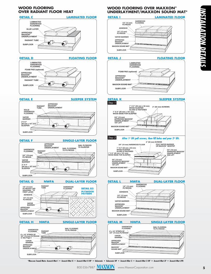
800-356-7887 www.MaxxonCorporation.com 5
74
HARDWOOD FLOORING
RADIANT TUBE1/2" (13 mm)
PLYWOOD LAID DIAGONAL TOFIRST LAYER
1/2" (13 mm) PLYWOOD
ADHESIVE
VAPOR BARRIER
SUBFLOOR
APPROVEDMAXXONUNDERLAYMENT
®
70
RADIANT TUBE
GLUE LAYER
SUBFLOOR
LAMINATED HARDWOOD FLOORING
APPROVEDMAXXONUNDERLAYMENT
®
deTAil C lAMiNATed FlOOr
71
RADIANT TUBE
FOAM PAD (optional)
SUBFLOOR
LAMINATED HARDWOOD FLOORING
APPROVEDMAXXONUNDERLAYMENT
®
deTAil d FlOATiNG FlOOr
72
SOLID HARDWOOD FLOORING
VAPORBARRIER
RADIANTTUBE
2" X 4" (50 mm x 101 mm) SLEEPER
SUBFLOOR
APPROVEDMAXXONUNDERLAYMENT
®
deTAil e Sleeper SYSTeM
HARDWOOD FLOORING RADIANT
TUBE
NAIL FLOORING TO PLYWOOD
NAIL PLYWOOD TO SLEEPER
3/4" (19 mm) PLYWOOD
VAPOR BARRIER2" X 4" (50 mm x 101 mm) SLEEPER
73
SUBFLOOR
APPROVEDMAXXONUNDERLAYMENT
®
deTAil F SiNGle-lAYer FlOOr
deTAil G NWFA duAl-lAYer FlOOr
MAXXON SOUND MAT*
SUBFLOOR
3/4" (19 mm) APPROVED MAXXON® UNDERLAYMENT1ST LIFT
1" X 4" (25 mm x 101 mm)WOOD BASE FOR SLEEPER
1" X 2" (25 mm x 50 mm) WOOD SLEEPERGLUED & FASTENED
2" (50 mm) SCREWS
MAXXON SOUND MAT*
SUBFLOOR
3/4" (19 mm) APPROVED MAXXON® UNDERLAYMENT 1ST LIFT
3/4" (19 mm)APPROVED MAXXON® UNDERLAYMENT 2ND LIFT
1" X 4" (25 mm x 101 mm)WOOD BASE FOR SLEEPER
3/4" (19 mm) HARDWOOD FLOOR POLY VAPOR BARRIEROR MAXXON MOISTOP®
1" X 2" (25 mm x 50 mm)WOOD SLEEPERGLUED & FASTENED
2" (50 mm) SCREWS
HARDWOOD FLOORING1/2" (13 mm)
PLYWOOD
1/2" (13 mm) PLYWOOD
ADHESIVE
VAPOR BARRIER
SUBFLOOR
APPROVEDMAXXONUNDERLAYMENT
®
MAXXON SOUND MAT*
deTAil i lAMiNATed FlOOr
FOAM PAD (optional)
SUBFLOOR
LAMINATED HARDWOOD FLOORING
APPROVEDMAXXONUNDERLAYMENT
®
MAXXON SOUND MAT*
deTAil J FlOATiNG FlOOr
WOOd FlOOriNG OVer MAXXON® uNderlAYMeNT/MAXXON SOuNd MAT*
WOOd FlOOriNG OVer rAdiANT FlOOr HeAT
7/8" (22 mm) SCREWS ON A 6" (152 mm) GRID PATTERN
deTAil G2plYWOOdpATTerN
HARDWOOD FLOORING1/2" (13 mm)
PLYWOOD
1/2" (13 mm) PLYWOOD
ADHESIVE
VAPOR BARRIER
SUBFLOOR
APPROVEDMAXXONUNDERLAYMENT
®
MAXXON SOUND MAT*
deTAil l NWFA duAl-lAYer FlOOr
Step 1
Step 2 After 1st lift pull screws, then fill holes and pour 2nd lift.
deTAil k Sleeper SYSTeM
HARDWOODFLOORING RADIANT
TUBE
NAIL FLOORING TO PLYWOOD
VAPORBARRIER
SUBFLOOR
APPROVEDMAXXONUNDERLAYMENT
8' x 16" STRIPS OF3/4" (19 mm) PLYWOODor See Page 3
®
deTAil H NWFA SiNGle-lAYer FlOOrHARDWOODFLOORING
NAIL FLOORING TO PLYWOOD
VAPORBARRIER
73
SUBFLOOR
APPROVEDMAXXONUNDERLAYMENT
®
8' x 16" STRIPS OF3/4" (19 mm) PLYWOOD
MAXXONSOUND MAT*
®
deTAil M NWFA SiNGle-lAYer FlOOr
*Maxxon Sound Mats: Acousti-Mat I • Acousti-Mat II • Acousti-Mat II HP • Enkasonic • Enkasonic HP • Acousti-Mat 3 • Acousti-Mat 3 HP • Acousti-Mat LP • Acousti-Mat LPR
instALLAtion detAiLs
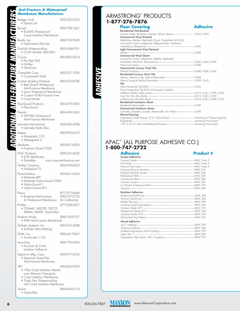
800-356-7887 www.MaxxonCorporation.com6
Anti-Fracture & Waterproof Membrane Manufacturers
Badger Cork 800-255-2675 • StressCork
Bonsal 800-738-1621 • B-6000 Waterproof
Crack Isolation Membrane
Bostik, Inc. 800-726-7845 • Hydroment Ultra-Set
Carlisle Waterproofing 800-338-8701 • CCW MiraDri 860/861
C-Cure 800-895-2874 • Pro Red 963 • Uniflex • UltraCure
Compotite Corp. 800-221-1056 • Composeal Gold
Custom Building Products 800-272-8786 • Red Guard Waterproof
Anti-Fracture Membrane • Jamo Waterproof Membrane • Custom 9240 Fracture Free • Crack Buster
Flex-Guard Products 800-279-7600 • Flex-Guard
Flextile 800-699-3623 • WP-980 Waterproof
Anti-Fracture Membrane
Laticrete International 800-243-4788 • Laticrete Hydro Ban
Mapei 800-992-6273 • Mapelastic 315 • Mapeguard 2
Merkrete 800-851-6303 • Fracture Guard 7000
NAC Products 800-633-4622 • ECB Membrane • Strataflex www.nac-anti-fracture.com
Noble Company 800-678-6625 • Nobleseal TS
ParexLahabra 800-851-6303 • Merkrete BFP • Merkrete Hydro-Guard 2000 • Hydro-Guard 1 • Hydro-Guard SP-1
Pasco 877-377-6466 • Baseline Anti-Fracture 800-737-2726
& Waterproof Membrane (in California)
Proflex 877-538-3437 • CISM40, MSC90, SSC70
SIM40, SIM90, Hydra-Mat
Protecto Wrap 800-759-9727 • AFM Anti-Fracture Membrane
Schluter Systems, Inc. 800-472-4588 • Schluter Ditra Matting
SGM, Inc. 800-641-9247 • Southcrete 1132
SonoGrip 888-770-3434 • Acoustic & Crack
Isolation Adhesive
Spectrum Mfg. Corp. 800-977-3703 • Spectrum Super-Flex
Anti-Fracture Membrane
TEC 800-832-9023 • 1Flex Crack Isolation Mortar
over Maxxon Overspray • Crack Isolation Membrane • Triple Flex Waterproofing
and Crack Isolation Membrane
Texrite 800-669-0115 • Hydro-Rite
Addi
tion
AL A
nti-F
rAct
Ure
MAn
UFAc
tUre
rs
APAC® (ALL PURPOSE ADHESIVE CO.) 1-800-747-2722
Carpet Adhesive Contract Grade -------------------------------------------------------------------------------------------------------------------APAC Turbo 2 Fast Grab ---------------------------------------------------------------------------------------------------------------------------------APAC Turbo 4 Premium Fast Grab --------------------------------------------------------------------------------------------------------------APAC Turbo 6 Universal Pressure Sensitive --------------------------------------------------------------------------------------------APAC 610 Polyoletin Backed Carpet -------------------------------------------------------------------------------------------------APAC 620 Professional Multi -----------------------------------------------------------------------------------------------------------------APAC 200 Commercial Multi -----------------------------------------------------------------------------------------------------------------APAC 400 Contract Carpet --------------------------------------------------------------------------------------------------------------------APAC 220 w/ Solvent Commercial Multi ----------------------------------------------------------------------------------------APAC 330 Supreme------------------------------------------------------------------------------------------------------------------------------------APAC 440
resilient Adhesive Professional Solid-Vinyl-------------------------------------------------------------------------------------------------------APAC 564 Premium Solid-Vinyl -------------------------------------------------------------------------------------------------------------APAC 584 Rubber Flooring --------------------------------------------------------------------------------------------------------------------APAC 594 Universal 2-part Polyurethane ----------------------------------------------------------------------------------------APAC 569 Contract Grade VCT-----------------------------------------------------------------------------------------------------------APAC 510 Professional Grade VCT ---------------------------------------------------------------------------------------------------APAC 530 Supreme Grade VCT ----------------------------------------------------------------------------------------------------------APAC 529 Felt backed Vinyl Sheet ------------------------------------------------------------------------------------------------------APAC 521
Wood Adhesive 3-in-1 Urethane ---------------------------------------------------------------------------------------------------------------------APAC 999 Universal Urethane --------------------------------------------------------------------------------------------------------------APAC 989 Urethane Engineered Wood Framing ------------------------------------------------------------------------APAC 979 Super Set ---------------------------------------------------------------------------------------------------------------------------------APAC 859 Engineered, High Solids, VOC Compliant --------------------------------------------------------------APAC 757
ARMSTRONG® PRODUCTS 1-877-276-7876
residential Felt-backed Canyon Creek, Memories, Starstep, Station Square --------------------------------------------S-235, S-254 Commercial Vinyl backed Medintone, Medley, Medintech, Royal, Possibilities Petit Point, Connection Corlon, Safeguard, Safeguard Spa, Timberline, Translations, Perspectives ---------------------------------------------------------------------------------------------------S-543 light Commercial Vinyl backed Adobe ------------------------------------------------------------------------------------------------------------------------------------------S-288 Commercial Vinyl Sheet Connection Corlon, Medintone, Medley, Medintech, Possibilities Petit Point, Rejuvenations ---------------------------------------------------------------------------S-240, S-543, S-599 Flash Cove Areas -------------------------------------------------------------------------------------------------------------------S-580 Commercial luxury Vinyl Tile Natural Creations ------------------------------------------------------------------------------------------------------------------S-240, S-288, S-543 residential luxury Vinyl Tile Alterna, Natural Living, Natural Personality -------------------------------------------------------------S-288 Natural Living & Natural Personality ----------------------------------------------------------------------------S-289, S-543 Tile Static Dissipative Tile (SDT) -----------------------------------------------------------------------------------------------S-202 Vinyl Composition Tile (VCT) (Chromaspin, Excelon, Arteffects, Raffia, Safety Zone) ----------------------------------------------------------------------------------------S-515, S-521, S-700, S-750 Vinyl No Wax (Dry Back) --------------------------------------------------------------------------------------------------S-515, S-521, S-750 Urethane No Wax (Dry Back) -----------------------------------------------------------------------------------------S-515, S-521, S-700, S-750 residential linoleum Sheet Residential Marmonette -------------------------------------------------------------------------------------------------------S-780 Commercial linoleum Sheet Colorette, Granette, Linorette, Marmonette, Uni Walton ------------------------------------S-780 Wood Flooring Engineered, Solid Parquet, 5/16" Solid Wood -----------------------------------------------------Armstrong 57, Bruce Equalizer Engineered --------------------------------------------------------------------------------------------------------------------------------Armstrong ProConnect 1/4" to 5/16" Solid Wood-Backed Parquet -----------------------------------------------------------Armstrong ProConnect
Adhe
siVe
Floor Covering Adhesive
Adhesive product #

800-356-7887 www.MaxxonCorporation.com 7
BOSTIK® INC. DURABOND BRAND PRODUCTS 1-800-523-6530
Carpet by backing Jute ---------------------------------------------------------------------------------D 920, D 910, D 850, D 905 Rubber --------------------------------------------------------------------------D 1400, D 1500 Action Bac (Latex & Polyurethane) -----------------------------D 920 Unitary (Latex & Polyurethane) -------------------------------------D 920, D 670 Hot Melt -----------------------------------------------------------------------D 990, D 920 double Stick Carpet installation Carpet To Pad ---------------------------------------------------------- LE-6000 D 860, D 910 Pad To Sub-Floor ----------------------------------------------------- LE-2PR, D 870 (Pressure Sensitive) Pad To Sub-Floor (Permanent) --------------------------------- LE-8000, D 870, D 850, D 807 Carpet Squares by backings PVC & Polyurethane Cushion ---------------------------- LE-2PR, D 870 resilient Tile Solid & Laminated Vinyl -------------------------------------- LE-4000, D 640 VCT -------------------------------------------------------------------------------- LE-5000, D 640 Sheet Goods Mineral & Synthetic Felt --------------------------------------- LE-3000, LE-7000, D 670 Vinyl Backed, Full Spread Only ----------------------------------------------------- LE-4000, D 640
DRITAC® WATERBASED ADHESIVE 1-800-394-9310
Wood Laminated Wood Plank Wood Parquet Foam Back Parquet Acrylic Vinyl Tile Solid Vinyl Tile VCT Luxury Vinyl Tile Luxury Vinyl Plank rubber Rubber Tile Cork Cork Tile Terrazzo Composite Terrazzo Tile Carpet Vinyl Backed Carpet Tile
Carpet Adhesive Standard --------------------------------------------------------------------------------------- Ultrabond ECO 20 Standard Quick-Grab--------------------------------------------------------------- Ultrabond ECO 85 Professional ----------------------------------------------------------------------------------- Ultrabond ECO 120, Ultrabond ECO 185 Professional Carpet Tile ---------------------------------------------------------- Ultrabond ECO 810 Premium ------------------------------------------------------------------------------------------ Ultrabond ECO 220 Premium Wet Set ------------------------------------------------------------------------ Ultrabond ECO 285 Premium Polyolefin-Backed ---------------------------------------------------- Ultrabond ECO 885
resilient Flooring Adhesive Standard Felt-backed Vinyl Sheet ------------------------------------- Ultrabond ECO 190 Premium Sheet Goods ------------------------------------------------------------- Ultrabond ECO 290 Professional Solid Vinyl ----------------------------------------------------------- Ultrabond ECO 300 High-Tack Universal ------------------------------------------------------------------ Ultrabond ECO 350 Premium Solid Vinyl Sheet, Tile and Plank -------------------- Ultrabond ECO 360 Premium Linoleum ---------------------------------------------------------------------- Ultrabond ECO 390 Premium Universal Rubber ----------------------------------------------------- Ultrabond ECO 560 Standard Thin-Spread VCT ---------------------------------------------------- Ultrabond ECO 611 Professional Thin-Spread VCT ---------------------------------------------- Ultrabond ECO 711 Urethane ----------------------------------------------------------------------------------------- Ultrabond G19 engineered Wood Adhesive Professional Urethane -------------------------------------------------------------- Ultrabond ECO 960, Ultrabond ECO 975
For Mapei’s recommendations on properly bonding floor coverings, surface preparation requirements, and other technical information, see Mapei’s Technical Bulletin 010313-TB – Gypsum-Based Floors and Walls: Which Mapei Products Can Be Applied?
Solid Wood Adhesive Professional Urethane -------------------------------------------------------------- Ultrabond ECO 980
CONGOLEUM® PRODUCTS 1-800-274-3266 Floor Covering Adhesive Ultima, Fast Track, Flor-Ever Plus, Prelude, Pacesetter, Forecast --------------------------3044 Premium Flooring Composition Commercial Tile ------------------------AD-42 Clear Thin Spread Endurance Plank, Endurance Tile, Ovations -------------------------------------------------------------------AD-32 AirStep Advantage, AirStep Evolution, AirStep Plus, AirStep Basix ------------------------------AS-01 DuraCeramic, DuraPlank II, Endurance Plank, Endurance Tile, Ovations -------------------DS-100
CENTIVA® FLOORING 1-800-633-3380 Vinyl Adhesive Victory -----------------------------------------------------------------------Centi 6000 SP Contour ---------------------------------------------------------------------Centi 6000 SP Event ---------------------------------------------------------------------------Centi 6000 SP
continued on Page 8
Floor Covering Adhesive
MANNINGTON® FLOORS1-800-356-6787
Carpet Vinyl Backed ------------------------------------------------------------- Infinity, Intengra-2, M-Guard 718 Polyurethane Backed ---------------------------------------------M-Guard Ultra Carpet Tile ------------------------------------------------------------------ RV-500 Woven Synthetic -----------------------------------------------------Ultra Premium Hard Surface VCT --------------------------------------------------------------------------------M-Guard V-11 Premium Tile PT --------------------------------------------------------M-Guard V-11 Resilient Sheet -----------------------------------------------------------V-81 Vinyl Backed -------------------------------------------------------------V-82, V-88 Luxury Vinyl Tile (LVT)--------------------------------------------V-88 Luxury Vinyl Plank ---------------------------------------------------V-88 rubber Sports Flooring Tile-------------------------------------------------MR-710 Rubber Floor Covering -----------------------------------------MR-721 Rubber Tile -----------------------------------------------------------------MR-725 Amtico Luxury Vinyl Tile -------------------------------------------------------Amtico 373
MAPEI®
1-800-992-6273
EXPANKO® CORK1-800-345-6202 Vinyl Adhesive Expanko Heirloom Cork -----------------------------------Expanko Water Based Expanko Reztec Chunk Tile -----------------------------Expanko Reztec Expanko XCR4 ------------------------------------------------------Expanko XCR4 Adhesive
EARTHWERKS®
1-800-275-7943 Floor Covering Adhesive Earthwerks Luxury Vinyl Plank ------------------------ EW 250 Wet Lay Acrylic, ST
100 Pressure Sensitive, APAC 564, APAC 584, Chapco 299, Henry 640, Mapei Ultrabond ECO 300, Mapei Ultrabond ECO 360, Taylor 2091
LOBA-WAKOL®, LLC1-800-230-6456 Floor Covering product # Engineered Wood Flooring ----------------------------Wakos MS250
KARNDEAN® INTERNATIONAL, LLC1-888-266-4343 Floor Covering Adhesive Vinyl Tile Plank ------------------------------------------------------Karndean 2-part --------------------------------------------------------------------------------------Epoxy Flooring Adhesive
--------------------------------------------------------------------------------------Karndean Tuff-Grip --------------------------------------------------------------------------------------TPS Adhesive
Floor Covering Adhesive
Floor Covering Adhesive Adhesive product #driTac 6200
Premium Wood & Vinyl Tile Adhesive (Use for all floor types)

©2004-2014 Maxxon Corporation. All Rights Reserved. Level-Right®, Level-Right® FS-10, and Level-Right® Plus and associated logos are trademarks of Maxxon® Corporation, Hamel, Minnesota. Printed in USA. Item #60055, TA500-6757, 4/14.
For more info: 800-356-7887 • Email: [email protected] www.MaxxonCorporation.com
Another superior product from: Maxxon® Corporation • 920 Hamel Road • P.O. Box 253 Hamel, MN 55340 USA • 763-478-9600 • Fax: 763-478-2431
MADE IN THE USA
Adhe
siVe
(con
t)
W.W. HENRY ADHESIVES1-800-232-4832 Floor Covering product # Carpet & pad Commercial Carpet -----------------------------------------------------------176, 256, 351, 356C Vinyl Felt Backed ----------------------------------------------------------------------------256, 356C, 660 Felt Backed Rotto ----------------------------------------------------------------176, 346, 660 Vinyl Composition --------------------------------------------------------------130, 420, 430 Vinyl Backed Sheet -----------------------------------------------------------422, 622, 640, 650P, 650R linoleum Linoleum ----------------------------------------------------------------------------------356C Tile Rubber -------------------------------------------------------------------------------------412 Ceramic ----------------------------------------------------------------------------------314 Marble -------------------------------------------------------------------------------------317 Wood Flooring Engineered Wood -------------------------------------------------------------971, 1171N Solid Wood --------------------------------------------------------------------------971, 1171N Parquet ------------------------------------------------------------------------------------971, 1171N
ROBERTS® CONSOLIDATED INDUSTRIES1-800-423-9467
Carpet & pad Polypropylene, Latex Foam, Rubber-backed --------- 3050, 3085, 3095, 3200, 3300, 3500, 3900, R3080 Urethane Foam, Hot Melts, Latex Unitary Needle Punched (indoor only) -------------------- 3050, 3085, 3095, 3300, 3500, 3900 Woven, Polyurethane ------------------------------------------------------- 3300, 3900 Carpet Tiles --------------------------------------------------------------------------- 2077 Vinyl Felt-back Vinyl/Mineral-backed Sheet vinyl ----------------------------------------------------------------------------- 2001, 3000, 3085, 3200 VCT ------------------------------------------------------------------------------------------- v2057 Vinyl & Rubber -------------------------------------------------------------------- 7200 plank/Wood Engineered Laminated Plank and Parquet Wood ----------------------------------------------------------- 1404, 1407 Solid Plank----------------------------------------------------------------------------- 1408, R1509, R1530
STAUF ADHESIVES 1-866-458-3872
Carpet & pad High Tack ------------------------------------------------------------------------------ D737 Vinyl High Tack------------------------------------------------------------------------------- D737 Wood EZ Tack ----------------------------------------------------------------------------------- AUM800 High Tack------------------------------------------------------------------------------- D737 Contractor’s Urethane ------------------------------------------------------ PIC850 Power Mastic------------------------------------------------------------------------ PUM950
Floor Covering Adhesive
Floor Covering product #
SHAW® FLOORS1-800-441-7429 Floor Covering Adhesive Resilient Vinyl Flooring -------------------------------------------------------- Shaw 200

Featuring 1½" x 6¼" and 1½" x 8¼" Strandguard® TimberStrand® LSL
#TJ-8104 SPECIFIER’S GUIDE
WOODBYWY.COM 1.888.453.8358
TREATED SILL PLATES WITH HANGING TJI® JOISTS
Si ate treated it in b rate u ing a r rietar r e r r te ti n again t in e t and de a
ICC ES a e ted and meet AWPA treating tandard r dr interi r a i ati n e Categ r
D e n t re uire t e u e G185 r tain e tee nne t r in C a i ati n
Treated t r ug ut n need t e d treat a ter utting r dri ing
Extra idt ermit b t nai ing eat ing n t e exteri r and t m unt i t anger n t e interi r
Limited r du t arrant

TREATED SILL PLATES WITH HANGING TJI® JOISTS
3⁄8" maximum overhang
Floor sheathing
1⁄8" minimum gap between TJI® joist and foundation wall
Stud
Wall sheathing
Anchor bolts and washers as required
Treated TimberStrand® LSL sill plate
Use sill plate seal when required by design professional of record or local code
Foundation wall
General Notes® TimberStrand® LSL is treated during manufacture with zinc borate,
an EPA-registered biocide, using a proprietary process for protection against
insects and decay.
® treatment process does not reduce the allowable design
stresses for TimberStrand® LSL.
wall framing with
TimberStrand® LSL, refer to the Trus Joist® Wall Guide for your region, TJ-9003
or TJ-9004.
Connector Notes
Bolted Connectionsparallel to grain, use a
specific gravity of 0.50.
perpendicular to grain, use
a specific gravity of 0.58.
Nailed Connections
in the face.
Shear Walls® TimberStrand® LSL sill plates are used in shear-wall
construction, use the specific gravity of the studs when determining allowable shear.
C de E a uati n See ICC ES ESR-138
(1) Value shown is for thickness up to 3½".
c⊥ must not be increased for duration of load.
Plank OrientationE = 6 psi
Fb = 1,900 psi(1)
Compression perpendicular to grain Fc⊥ =
Horizontal shear parallel to grain Fv = 150 psi
Allowable Design Stresses
WARNING: Drilling, sawing, sanding or machining wood products generates wood dust. The paint and/or coatings on this product may contain titanium dioxide.
Wood dust and titanium dioxide are substances known to the State of California to cause cancer. For more information on Proposition 65, visit wy.com/inform.
Use support blocks at 10' on-center to keep products out of mud and water
Align stickers directly over support blocks
CAUTION: Wrap is slippery when wet or icy
Protect products from sun and water
PRODUCT STORAGE
TrusJoist.com
888.453.8358
TrusJoist.com
888.453.8358
TrusJoist.com
888.453.8358
TrusJoist.com
888.453.8358
TrusJoist.com
888.453.8358
TrusJoist.com
888.453.8358
TrusJoist.com
888.453.8358
StrandGuard® TimberStrand® LSL framing materials are intended for use in aboveground, protected applications such as sill plates, columns, and studs.
The American Wood Protection Association (AWPA) standards classify such applications as Use Category 2.
StrandGuard® TimberStrand® LSL may be supported by masonry or concrete foundations, but must not come into contact with the ground, nor can it be
substituted for studs in a treated-wood foundation.
For complete warranty information, see the limited warranty for StrandGuard® TimberStrand® LSL, TJ-1005.
CONTACT S
1.888.453.8358 db . m d e er aeu er. m
Ju 013 Re rder TJ-8104This document supersedes all previous versions. If this is more than one year old, contact your dealer or Weyerhaeuser rep.
, Weyerhaeuser, Strandguard, TimberStrand, TJI and Trus Joist are registered trademarks of Weyerhaeuser NR. © 2013 Weyerhaeuser NR Company. All rights reserved. Printed in the USA.
Strandguard® TimberStrand® LSL sill plates are manufactured to be straight and true for fast installation and minimal waste.

TUFF-N-DRI® Basement Waterproofing
System Detailed Membrane and Board (Full System) Application Instructions
Product DescriptionThe TUFF-N-DRI Basement Waterproofing System is comprised of the TUFF-N-DRI Waterproofing Membrane and either the WARM-N-DRI® or TUFF-N-DRI Barrier Board insulation and drainage board. The TUFF-N-DRI membrane is a fluid-applied, single-component, polymer-modified asphalt emulsion, manufactured by Tremco Barrier Solutions, Inc. (TBS). This material is specifically designed for spray applications on below-grade exterior foundation walls, or above-grade walls when covered by other material. The WARM-N-DRI and TUFF-N-DRI Barrier Boards are fiberglass insulation and drainage boards manufactured for Tremco Barrier Solutions by Owens Corning. The TUFF-N-DRI membrane can be applied to many different substrates, but the TUFF-N-DRI Full-System Limited Warranty applies only for new construction, below-grade vertical foundation walls for residential applications. The TUFF-N-DRI Full-System Limited Warranty is for poured concrete walls, bare block walls, parged block walls or pre-cast concrete walls.
Proper installation of the TUFF-N-DRI Full-System is critical to ensuring the quality of the final cured membrane. It is the responsibility of the waterproofing contractor and/or his applicator, to achieve the goal of creating a uniform, continuous, fully adhered, cured waterproofing membrane with a minimum thickness of 40-mils in all areas of the application. The applicator must consider and respond appropriately to any impediments to achieving that goal. This includes, but is not limited to, site conditions, the condition and quality of the foundation wall, current and expected weather, as well as backfill composition, procedure and timing. The applicator should proactively communicate with the builder and/or other trades to surface and resolve any issues that would impede achieving the goal of a quality waterproofing application. The following instructions detail the recommended practices for product application and, if followed, will be instrumental in the creation of a quality finished waterproofing system. However, an applicator may deviate from specific items contained in these instructions, as long as he is able to achieve the goal of creating the quality finished waterproofing system by alternate, but effective, means.
If you suspect that there may be a quality issue with the product or that it may not conform to its published specifications, do not apply the product. Contact your TBS Territory Manager or Technical Representative for investigation or resolution of the suspected quality issue.
StorageTUFF-N-DRI membrane, like all asphalt emulsions, must be kept from freezing. It is recommended that TUFF-N-DRI be stored indoors off the floor at an ambient temperature above 50°F (10°C). Opened drums should be tightly sealed before storage to avoid a skin developing on top of the liquid.
When shipping emulsion-based products during the winter months, there is a risk of the material freezing while in transport. The risk is much higher on shipments of less than 40 drums because these shipments go as “less than truckload” and do not go directly from our warehouse to yours.

If you suspect that a product has frozen, contact your TBS Technical Representative or Territory Manager. If you inspect and determine that incoming material is frozen, do not accept delivery from the freight carrier.
SafetyUse the following safety instructions when handling TUFF-N-DRI membrane. Also review the Material Safety Data Sheet (MSDS), as well as the safety precautions provided by the spray equipment manufacturer.
1. Avoid direct contact with the material. Prolonged or repeated contact can cause skin irritation. If prolonged contact is anticipated, impervious gloves should be worn.
2. In a confined space at temperatures greater than 212°F (100°C), sufficient vapors can accumulate and flash if a source if ignition is present. TUFF-N-DRI Membrane will not support sustained combustion, and will not burn under normal circumstances.
3. Mist from spray application in a confined area can possibly cause a headache, nausea, and irritation of the nose, throat and lungs. To prevent this, a dust mask or cartridge respirator may be worn but is not required.
4. To protect the eyes from contact with high-pressure spray, wear chemical safety glasses with side shields. If contact with eyes occurs, flush with large amounts of cool water while holding eyelids open. Get medical attention if irritation persists.
Application InstructionsPreparation and Limitations
1. The block, parged block, poured concrete or pre-cast concrete must be clean, smooth, firm, free of dust, mud, ice, snow, loose mortar, wires, fins, metal projections, wall ties, or any other substance which might prevent placement and bonding of a continuous film. Take particular care to ensure that the footing and/or cove area are clean.
2. On poured concrete walls, remove wall ties on the outside and inside of wall. This must be done prior to the application of TUFF-N-DRI Membrane.
3. On poured concrete walls, the tie holes must be patched with hydraulic cement, vinyl concrete patch, or non-shrinking grout. Flat snap ties that break off cleanly without chipping the surrounding concrete, only require pre-spraying with a 10 to 15-mil wet coating of TUFF-N-DRI Membrane, but may be treated as above as well. Whichever method the applicator chooses, the tie holes must be prepared prior to the standard 60 mil wet application. Honeycombs or voids in the wall must be patched with hydraulic cement, vinyl concrete patch, or non-shrinking grout.
4. For bare block walls, all mortar joints between the masonry units shall be compressed and tooled or struck smooth. All voids in the mortar joints between masonry units shall be patched with hydraulic cement, vinyl concrete patch or non-shrinking grout.
5. For parged block walls, the parging must be firm and smooth. It must not crumble to the touch or have too high of a sand content. Any patching of the parging must be done with hydraulic cement, vinyl concrete patch or non-shrinking grout.
6. For block or parged block walls, find out whether any or all of the cores of the block foundation are to be filled with concrete. If any of the cores are to be filled, the filling must be completed

and cured before the wall is waterproofed. Filling of the cores after the TUFF-N-DRI Membrane is installed can damage the membrane, and will render the warranty invalid.
7. For block or parged block walls, brick ledges should be capped and solid. The TUFF-N-DRI System Limited Warranty covers neither the horizontal surface of the brick ledge nor the vertical wall surface above the ledge regardless of wall type. The performance warranty covers only the vertical wall coated with TUFF-N-DRI Membrane and Insulation from the footing/wall joint up to the brick ledge.
8. TUFF-N-DRI Full System may be applied to damp or green concrete. However, the product must not be applied over standing water, a water film, ice, frost or snow.
9. Before waterproofing a monolithic slab/footing foundation (where the floor slab and footing area are a single slab), contact a TBS Technical Representative. The cold joint between the slab/footing and the vertical wall must be prepared with a urethane based cold liquid-applied waterproofing material, applied and fully cured per manufacturers instructions, to a minimum of 4 inches above and below the joint. This cold joint must also have a protection/drainage board over the cold joint and a minimum of four feet up the vertical foundation wall. The top of the drain tile shall also be a minimum of four inches below the wall/slab joint and the gravel over the tile shall extend 10 inches above the wall/slab joint.
10. For block or parged block wall lintels, all gaps in the mortar must be filled. TUFF-N-DRI Membrane should be applied to both sides of the lintel and beyond the lintel at least one block into the non-living space.
11. For pre-cast walls, the joints between the panels of high tensile strength concrete must be caulked and sealed in accordance to manufacturer instructions (non-silicone based caulks only). Similar to tie holes, these caulked joints should be pre-sprayed with 10 to 15 mils of TUFF-N-DRI Membrane prior to the standard 60 mil wet application.
12. The foundation must be of such strength and design to ensure structural integrity. Foundation walls must be properly cured according to local building code regulations. If these are not available, consult the National Concrete Masonry Association for specifications or the Concrete Foundation Association.
TUFF-N-DRI Application1. TUFF-N-DRI Membrane can be applied to surfaces using standard application procedures down to 20°F (-7° C). For colder applications, see the section on Cold and Inclement Weather Application below. Material temperature at the spray tip should be between 110°F (43°C) and 130°F (54°C).
2. To ensure proper temperature at the spray gun, insulate the lines and pump housing of the spray pump. When spraying below 50°F (10°C) ambient temperature, it is highly recommended to have your equipment and material enclosed in a heated compartment.
3. Spray TUFF-N-DRI Membrane in a pressure range between 2200 and 2800 psi. For best results use a .035 or .039 tip. For atomization and curing reasons, do not use any tip larger than a .039.
4. The membrane should be applied to a minimum thickness of 60 mils wet, measured in-place on the wall with a notch film gauge. The product will cure to dry film thickness of 40 mils. Use a notch film mil gauge to ensure proper application thickness. Gauges can be obtained from
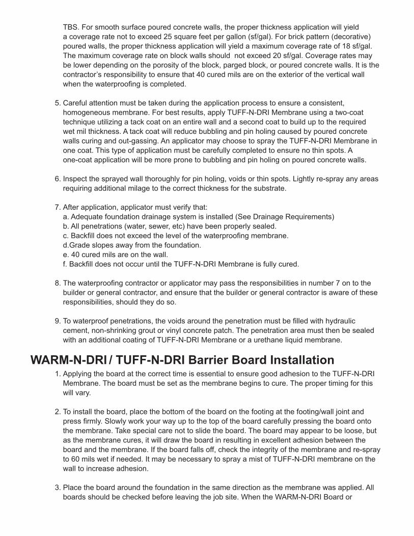
TBS. For smooth surface poured concrete walls, the proper thickness application will yield a coverage rate not to exceed 25 square feet per gallon (sf/gal). For brick pattern (decorative) poured walls, the proper thickness application will yield a maximum coverage rate of 18 sf/gal. The maximum coverage rate on block walls should not exceed 20 sf/gal. Coverage rates may be lower depending on the porosity of the block, parged block, or poured concrete walls. It is the contractor’s responsibility to ensure that 40 cured mils are on the exterior of the vertical wall when the waterproofing is completed.
5. Careful attention must be taken during the application process to ensure a consistent, homogeneous membrane. For best results, apply TUFF-N-DRI Membrane using a two-coat technique utilizing a tack coat on an entire wall and a second coat to build up to the required wet mil thickness. A tack coat will reduce bubbling and pin holing caused by poured concrete walls curing and out-gassing. An applicator may choose to spray the TUFF-N-DRI Membrane in one coat. This type of application must be carefully completed to ensure no thin spots. A one-coat application will be more prone to bubbling and pin holing on poured concrete walls.
6. Inspect the sprayed wall thoroughly for pin holing, voids or thin spots. Lightly re-spray any areas requiring additional milage to the correct thickness for the substrate.
7. After application, applicator must verify that: a. Adequate foundation drainage system is installed (See Drainage Requirements) b. All penetrations (water, sewer, etc) have been properly sealed. c. Backfill does not exceed the level of the waterproofing membrane. d.Grade slopes away from the foundation. e. 40 cured mils are on the wall. f. Backfill does not occur until the TUFF-N-DRI Membrane is fully cured.
8. The waterproofing contractor or applicator may pass the responsibilities in number 7 on to the builder or general contractor, and ensure that the builder or general contractor is aware of these responsibilities, should they do so.
9. To waterproof penetrations, the voids around the penetration must be filled with hydraulic cement, non-shrinking grout or vinyl concrete patch. The penetration area must then be sealed with an additional coating of TUFF-N-DRI Membrane or a urethane liquid membrane.
WARM-N-DRI / TUFF-N-DRI Barrier Board Installation1. Applying the board at the correct time is essential to ensure good adhesion to the TUFF-N-DRI Membrane. The board must be set as the membrane begins to cure. The proper timing for this will vary.
2. To install the board, place the bottom of the board on the footing at the footing/wall joint and press firmly. Slowly work your way up to the top of the board carefully pressing the board onto the membrane. Take special care not to slide the board. The board may appear to be loose, but as the membrane cures, it will draw the board in resulting in excellent adhesion between the board and the membrane. If the board falls off, check the integrity of the membrane and re-spray to 60 mils wet if needed. It may be necessary to spray a mist of TUFF-N-DRI membrane on the wall to increase adhesion.
3. Place the board around the foundation in the same direction as the membrane was applied. All boards should be checked before leaving the job site. When the WARM-N-DRI Board or

TUFF-N-DRI Barrier Board is applied, the foundation can be backfilled in 24 hours. It may take longer during some weather conditions for the TUFF-N-DRI Membrane to cure, and the foundation should not be backfilled until the membrane is fully cured.
4. When installing 4x4 boards, install the bottom board first then immediately place the top board. This prevents any excess TUFF-N-DRI Membrane from running down and onto the top edge of the bottom board.
5. It may be difficult to achieve the desired adhesion characteristics when applying the thicker WARM-N-DRI or TUFF-N-DRI Barrier Boards, or if the foundation wall is not smooth. Adhesives, or non-corroding masonry nails and mechanical fasteners can be considered. Consult your TBS Technical Representative for availability and detailed application instructions on these products.
6. Another technique to enhance board adhesion is to wet the back-side of the WARM-N-DRI or TUFF-N-DRI Barrier Boards with a calcium chloride solution before installing the board to the membrane. The solution is simply prepared by mixing up a ratio of approximately 2-3 pounds of granular calcium chloride per 1 gallon of water. Be aware that dissolving the calcium chloride can heat the water significantly, up to 150°F (66°C).
7. Wet the board with the solution using a watering can or weed sprayer or similar device. It is not necessary to drench the board; simply dampen it. Install the wet side of the board into the wet TUFF-N-DRI membrane. Consult your TBS Technical Representative for more instruction on this procedure.
Cold Weather and Inclement Weather Application Information1. It is possible for the TUFF-N-DRI Membrane to be applied at temperatures lower than 20°F (-7°C). The Contractor assumes responsibility for ensuring the TUFF-N-DRI fully cures to a dry film thickness of 40 mils. Applying the 60-mil wet thickness of the TUFF-N-DRI membrane in one coat is recommended for application temperatures below 20°F(-7°C). Heating the product to the maximum application temperature of 130°F (54°C) at the spray tip is also recommended.
2. It may take longer than 24 hours for the TUFF-N-DRI membrane to fully cure during periods of low temperatures, high humidity, rainfall or snowfall following the membrane application. Therefore, wash-offs due to the application of TUFF-N-DRI membrane during or immediately
before inclement weather are possible. The TBS Contractor assumes responsibility for ensuring the TUFF-N-DRI fully cures to a dry film thickness of 40 mils in all areas of application.
Additional Application Information and Limitations CrawlspacesThe TUFF-N-DRI Full-System Limited Warranty includes crawlspaces only when the following criteria are met:
1. The crawlspace must have a proper exterior drainage system that channels water to the lower foundation footing drains which drain to a functional sump or to drainage pipe properly sloped to daylight. See Drainage Requirements listed below.
2. The crawlspace must have a finished concrete floor. Crawlspaces with dirt or gravel floors do not meet warranty requirements.
3. Exterior crawlspace walls must be block, parged block, poured concrete, or pre-cast concrete and must meet preparation requirements listed above.

AdditionsThe TUFF-N-DRI Full-System Limited Warranty includes foundation additions only when the following criteria are met:
1. The addition must have a proper exterior drainage system that channels water to a functional sump or to drainage pipe properly sloped to a daylight exit. See Drainage Requirements listed below.
2. The addition walls must be block, parged block, poured concrete, or pre-cast concrete and must meet preparation requirements listed above.
3. The cold joint between the existing foundation wall and the new addition wall must be prepared with a urethane based cold liquid-applied waterproofing material, applied and fully cured per manufacturers instructions, to a minimum of four inches on both sides of the joint prior to the 60-mil application of TUFF-N-DRI Membrane. This cold joint area must also have a drainage/ protection board applied over the urethane liquid membrane and TUFF-N-DRI Membrane. This
cold joint area is not covered under the terms of the TUFF-N-DRI Full-System Limited Warranty, but if the proper preparations are taken, the area should not leak.
Top of Wall TransitionsIn some building markets, it is common to see a few rows of block masonry on top of a poured wall, or a short poured wall on top of a block masonry wall. The cold joint between the two different foundation materials must be prepared by an application of a urethane based, cold liquid-applied waterproofing material, applied and fully cured per manufacturers instructions, spanning the joint and extending a minimum of four inches above and below the joint, prior to the 60-mil application of TUFF-N-DRI Membrane. Although this cold joint transition area is not covered under the terms of the TUFF-N-DRI Full-System Limited Warranty, if this procedure is followed, the area should not leak.
If the entire wall is parged with one continuous smooth coating covering both the block and poured sections without interruption, apply the TUFF-N-DRI Membrane following the normal procedure for parged walls.
Brick LedgesThe horizontal brick ledge area of a foundation wall is not covered under the terms of the TUFF-N-DRI Full-System Limited Warranty. Brick ledge areas are not covered for the following reasons:
1. Brick ledges are almost always left exposed to ultraviolet rays for longer than 15 days. 2. The brick application process can puncture and/or scrape the TUFF-N-DRI Membrane. 3. Water that penetrates into the brick or stone below the sill plate may have no drainage exits, and may accumulate on the brick ledge.
Drainage RequirementsIn order to qualify for the 30-Year Limited Warranty, a proper drainage system must be installed. TUFF-N-DRI requires a positive drainage system that is consistent with good construction practices and that meets local code requirements. An exterior drainage system consisting of a 3-inch minimum diameter perforated drainage pipe, with gravel covering the pipe and footing and extending at least one foot (12”) up the face of the WARM-N-DRI or TUFF-N-DRI Barrier Board on the vertical wall is required. The drain tile must channel the water to either an operating sump pump or to a gravity (daylight) drain. DrainStar® Foundation Strip Drain, installed so that it can drain the WARM-N-DRI BOARD, is also an approved exterior drainage system, where accepted by code.

Equipment Set-Up1. A pump capable of spraying 3000 psi is required. The Graco 733, Graco 833 or the Speedflow Hydra-M is recommended. Contact a TBS Technical Representative for assistance with equipment purchases.
2. The diameter and length of the interlinking suction side (low pressure) lines are crucial to ensuring a good flow of material to and from the pump. Larger diameters and shorter lengths of all interlinking lines decrease the flow resistance and optimize product transfer. The siphon line from the truck tank or drum dip tube to the heat exchanger should not be longer than six feet if possible, and a 2-inch or 1.5-inch diameter is recommended. The line from the heat exchanger to the pump should have a minimum inside diameter of 1 ¼-inch and be no longer than 4 feet. All connections should be as tight as possible to prevent air from entering the lines.
3. Make sure the lower piston ball check is on the high setting. Consult your equipment manual for adjustment procedures.
4. A single-pass heat exchanger connected to an engine’s coolant system is the best way to heat the TUFF-N-DRI Membrane to the recommended application temperature of 110°F (43°C) to 130°F (54°C) at the spray tip. One heat exchanger that produces good heat transfer is the API Basco Model 500. Contact a TBS Technical Representative for assistance with equipment purchases. All heat exchangers must have a ball valve attached to the inlet side of the coolant hose. The applicator must turn off the flow of coolant to the heat exchanger when the truck is driving to and from jobsites and when the spray pump is not in use. The flow of coolant is to be used only when circulating or spraying TUFF-N-DRI Membrane.
5. The spray hose must be a “high-pressure” type, capable of withstanding 4000 psi. A maximum of ½-inch diameter line is recommended for the first 100 feet of hose. It can then be reduced do 3/8-inch for the next 100 feet. No more than 200 feet of hose is recommended.
6. Many different airless spray guns can be used to spray TUFF-N-DRI. The most widely used brand is Graco, and the Graco Silver Plus gun is the most popular for polymer-modified asphalt emulsion spraying. You may also use the Graco Heavy Duty Texture gun or the Graco Flex Plus gun. The Graco Contractor II line of guns can also be used if the handle filters are removed.
Equipment Troubleshooting If you lose pressure while spraying:
1. Check suction side lines for air leaks.2. Reduce the heat to the heat exchanger.3. Re-prime pump.4. Inspect the piston ball check and packings.5. Check heat exchanger for blockage.6. If procedures do not work, contact a TBS Technical Representative or pump manufacturer
Operational Maintenance Consult your pump service manual for maintenance scheduling or replacing of vital parts (piston packings, ball check, etc.).
1. Many different solvents can be used to flush the system, but mineral spirits are recommended because it acts as a lubricant for the pump packings.

2. Do not use water to flush the TUFF-N-DRI Membrane. This will “shock” the emulsion and cause it to break in the lines. A soap solution consisting of ½ cup Dawn dishwashing liquid per gallon of water may be used to remove uncured liquid material.
3. Mineral spirits, toluene and most other solvents are flammable and/or hazardous. Be sure to check with the suppliers of these solvents for the correct safety and handling procedures and follow the supplier’s recommendations when using clean up solvents.
TransportationTUFF-N-DRI membrane is classified as a non-hazardous emulsion and does not require placarding.
Foundation TroubleshootingTroubleshooting a foundation to determine if a leak is penetrating through the TUFF-N-DRI Full System is very important. The standard troubleshooting procedure for below grade waterproofing is called a water test, or flood test. A water test isolates water from a garden hose directly into the waterproofing system, introducing the water to only the below-grade treated area of the foundation. To water test a suspect area on any type of below-grade foundation wall, follow these basic steps:
1. Locate the suspect area on the outside of the foundation. This may require measuring the problem area on the inside of the foundation wall. A picture of the suspect area should be taken.
2. Using a shovel, dig a small trench approximately three feet wide in the suspect area. Expose the top four to five inches of the TUFF-N-DRI System. This will also give the applicator a good idea of any over-grading that may have occurred.
3. Isolate water from the garden hose directly into the trench. Ensure that no water gets above the final waterproofing grade line. Note the time, and run water for up to 30 minutes.
4. Check the suspect area in the basement every few minutes. If the suspect area begins to show water penetration during or immediately after the water testing, it proves that the waterproofing membrane is allowing water to penetrate through it. Further investigations may be necessary to determine why the waterproofing membrane did not function properly.
5. If the suspect area does not show water penetration, there may be other issues causing the water penetration into the foundation. Other issues include, but are not limited to, brick ledge leaks, wind driven rain seeping into block above grade, window leaks, penetration leaks, and above grade cracks in foundation walls or stucco.
6. Before and after pictures are good ideas for a waterproofing applicator during investigations.
7. Contact a TBS Technical Representative concerning any leaking water tests that will result in warranty repairs.
© 2015 Tremco Barrier Solutions. TUFF-N-DRI® is a registered trademark of Tremco Barrier Solutions. WARM-N-DRI® is a registered trademark of Owens Corning
TBS-0045Rev. 4/15
If you have any further questions please call us at 800.876.5624 Tremco Barrier Solutions 6402 East Main Street Reynoldsburg, OH 43068


Advantages• Universal horizontal application
– suitable for all overburdensincluding concrete
• Damage and creep-resistant –high compressive strength core resists traffic loads and site damage to maintaindrainage flow
• High flow capacity – drains 186L/min./m (15 gals/min./ft) width
• Enhances waterproofing –eliminates hydrostatic head build up
• Securely bonded fabric – restricts intrusion into core
• Polymeric backing film –compatible with both sheet andliquid waterproofing membranes
• Lightweight – easy to installwithout special equipment
• Simple, convenient, drainage andprotection layer – robustmembrane protection
DescriptionHydroduct® 660 is a highly robust,preformed, 10 mm (0.375 in.) thickgeocomposite drainage sheetsystem, comprising a high impact,studded polystyrene core. This iscovered on one side with a non-woven, needle punched polypropy-lene filter fabric and on the otherside with a high backing film.
Use Hydroduct 660 DrainageComposite is designed to collectand transport water to drainageoutlets. It can be used on allhorizontal applications regardlessof the type of overburden andserves as a combination drainageand protection course for all Gracewaterproofing membranes.
The high strength, nonwoven geotextile is designed to maintainpemittivity while protecting thedrainage composite from job sitedamage prior to, and during, the
installation of the overburden. Thehigh permittivity of the nonwovengeotextile facilitates the removal ofwater from a concrete pour, thusenhancing the concrete cure, aswell as providing drainage afterinstallation. The geotextile issecurely bonded to the core toprevent intrusion of the fabric intothe core during service. The highmodulus backing film ensurescompatibility when used witheither Procor® fluid applied water-proofing membranes, or withBituthene® waterproofingmembranes.
Hydroduct® 660High impact, creep-resistant geocomposite and protection layer for use with Grace waterproofing membranes on all horizontal applications
Drainage Composites
Procor 75/10
Weatherable flashing
Hydroduct 660
w w w. g r a c e c o n s t r u c t i o n . c o mPRODUCT DATA UPDATES TECH LETTERS DETAILS MSDS CONTACT FAQS

Application Procedures Safety, Storage and HandlingInformationAll construction products must be handled properly. GraceProtection Board Adhesive isextremely flammable. MaterialSafety Data Sheets (MSDS) are available at www.graceconstruction.com
and users should acquaint them-selves with this information.Carefully read detailed precautionstatements on product labels andthe MSDS before use.
InstallationHydroduct 660 can be placed over waterproofing membranes,concrete or wood providing job siteconditions allow the composite to
remain as placed. Additionalballast consideration should begiven in high wind exposures. Abutall edges tightly with the excessgeotextile placed over the adjacentroll in shingle fashion.
To secure Hydroduct 660 aroundprotrusions, apply Hydroduct®
Tape around the protrusion in apicture frame configuration. Cut Hydroduct 660 to fit snuglyaround the protrusion. PressHydroduct 660 core firmly into the Hydroduct Tape.
Hydroduct 660 should be coveredpromptly. Do not leave Hydroduct660 exposed to sunlight for morethan two weeks. Motor vehicles,construction equipment or othertrades should not be alloweddirectly on the Hydroduct 660.
W. R. Grace & Co. - Conn. 62 Whittemore Avenue Cambridge, MA 02140
Bituthene, Procor and Hydroduct are registered trademarks of W. R. Grace & Co. - Conn.
We hope the information here will be helpful. It is based on data and knowledge considered to be true and accurate and is offered for the users’ consideration, investigationand verification, but we do not warrant the results to be obtained. Please read all statements, recommendations or suggestions in conjunction with our conditions of sale,which apply to all goods supplied by us. No statement, recommendation or suggestion is intended for any use which would infringe any patent or copyright. W. R. Grace & Co. - Conn., 62 Whittemore Avenue, Cambridge, MA 02140. In Canada, Grace Canada, Inc., 294 Clements Road, West, Ajax, Ontario, Canada L1S 3C6.
These products may be covered by patents or patents pending. Copyright 2002. W. R. Grace & Co. - Conn. HYD-88A Printed in USA 12/02 EPD/LI/1.5M
Visit our web site at www.graceconstruction.com printed on recycled paper
For Technical Assistance call us toll free at 866-333-3SBM (3726).
Hydroduct 660Roll Size 1.2 m x 15.2 m (4 ft x 50 ft) 18.6 m2 (200 ft2)
Packaging 6 rolls/pallet
Weight 21 kgs (50 lbs)/ roll
Complementary MaterialsHydroduct Tape 25 mm x 61.0 m (1 in. x 200 ft) rolls
[2 x 15.2 m (50 ft) stripes per roll of Hydroduct]
Hydroduct Coil 600 15.2 m (50 ft) roll
Supply
Physical PropertiesProperty Test Method Typical Value
Drainage Core
Polymer High Impact Polystyrene
Thickness ASTM C 366 Method B 9.5 mm (0.375 in.) nominal
Compressive Strength ASTM D 1621 860 kPa (18, 000 lbs/ft2)
Flow Rate ASTM D 4716 186 L/min./m (gradient 1.0, load 172 kPa) (15 gal/min./ft)
Geotextile
Type Nonwoven
Polymer Polypropylene
Weight ASTM D 3776 270 g/m2 (8.0 oz/yd2)
Tensile Strength ASTM D 4632 1000 N (225 lbs)
Trapezoidal Tear ASTM D 4533 555 N (125 lbs)
Apparent Opening Size ASTM D 4751 0.147 mm (100 U.S. sieve)
Permittivity ASTM D 4491 3050 L/min./m2
(80 gal/min./ft2)
Mullen Burst ASTM D 3786 4750 kPa (690 lbs/in.2)
Puncture Strength ASTM D 4833 68 kg (150 lbs)
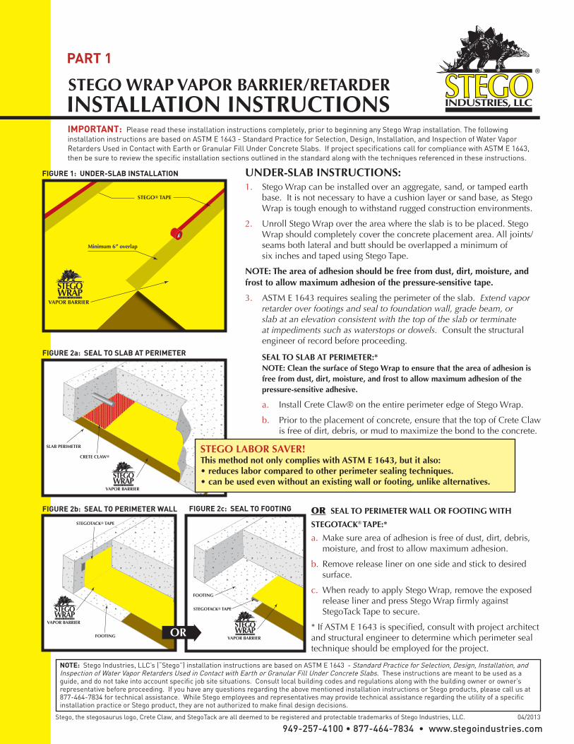
UNDER-SLAB INSTRUCTIONS:1. Stego Wrap can be installed over an aggregate, sand, or tamped earth
base. It is not necessary to have a cushion layer or sand base, as Stego Wrap is tough enough to withstand rugged construction environments.
2. Unroll Stego Wrap over the area where the slab is to be placed. Stego Wrap should completely cover the concrete placement area. All joints/seams both lateral and butt should be overlapped a minimum of
six inches and taped using Stego Tape.
NOTE: The area of adhesion should be free from dust, dirt, moisture, and frost to allow maximum adhesion of the pressure-sensitive tape.
3. ASTM E 1643 requires sealing the perimeter of the slab. Extend vapor retarder over footings and seal to foundation wall, grade beam, or slab at an elevation consistent with the top of the slab or terminate at impediments such as waterstops or dowels. Consult the structural engineer of record before proceeding.
SEAL TO SLAB AT PERIMETER:* NOTE: Clean the surface of Stego Wrap to ensure that the area of adhesion is free from dust, dirt, moisture, and frost to allow maximum adhesion of the pressure-sensitive adhesive.
a. Install Crete Claw® on the entire perimeter edge of Stego Wrap.
b. Prior to the placement of concrete, ensure that the top of Crete Claw is free of dirt, debris, or mud to maximize the bond to the concrete.
STEGO WRAP VAPOR BARRIER/RETARDERINSTALLATION INSTRUCTIONS IMPORTANT: Please read these installation instructions completely, prior to beginning any Stego Wrap installation. The following installation instructions are based on ASTM E 1643 - Standard Practice for Selection, Design, Installation, and Inspection of Water Vapor Retarders Used in Contact with Earth or Granular Fill Under Concrete Slabs. If project specifications call for compliance with ASTM E 1643, then be sure to review the specific installation sections outlined in the standard along with the techniques referenced in these instructions.
VAPOR BARRIER
STEGO® TAPE
Minimum 6” overlap
FIGURE 1: UNDER-SLAB INSTALLATION
PART 1
949-257-4100 • 877-464-7834 • www.stegoindustries.comStego, the stegosaurus logo, Crete Claw, and StegoTack are all deemed to be registered and protectable trademarks of Stego Industries, LLC. 04/2013
NOTE: Stego Industries, LLC’s (“Stego”) installation instructions are based on ASTM E 1643 - Standard Practice for Selection, Design, Installation, and Inspection of Water Vapor Retarders Used in Contact with Earth or Granular Fill Under Concrete Slabs. These instructions are meant to be used as a guide, and do not take into account specific job site situations. Consult local building codes and regulations along with the building owner or owner’s representative before proceeding. If you have any questions regarding the above mentioned installation instructions or Stego products, please call us at 877-464-7834 for technical assistance. While Stego employees and representatives may provide technical assistance regarding the utility of a specific installation practice or Stego product, they are not authorized to make final design decisions.
VAPOR BARRIER
CRETE CLAW®
SLAB PERIMETER
VAPOR BARRIER
FOOTING
STEGOTACK® TAPE
FIGURE 2a: SEAL TO SLAB AT PERIMETER
FIGURE 2b: SEAL TO PERIMETER WALL
STEGO LABOR SAVER! This method not only complies with ASTM E 1643, but it also:• reduces labor compared to other perimeter sealing techniques.• can be used even without an existing wall or footing, unlike alternatives.
OR SEAL TO PERIMETER WALL OR FOOTING WITH
STEGOTACK® TAPE:*
a. Make sure area of adhesion is free of dust, dirt, debris, moisture, and frost to allow maximum adhesion.
b. Remove release liner on one side and stick to desired surface.
c. When ready to apply Stego Wrap, remove the exposed release liner and press Stego Wrap firmly against StegoTack Tape to secure.
* If ASTM E 1643 is specified, consult with project architect and structural engineer to determine which perimeter seal technique should be employed for the project.
FIGURE 2c: SEAL TO FOOTING
VAPOR BARRIER
FOOTING
STEGOTACK® TAPE
OR

949-257-4100 • 877-464-7834 • www.stegoindustries.com
NOTE: Stego Industries, LLC’s (“Stego”) installation instructions are based on ASTM E 1643 - Standard Practice for Selection, Design, Installation, and Inspection of Water Vapor Retarders Used in Contact with Earth or Granular Fill Under Concrete Slabs. These instructions are meant to be used as a guide, and do not take into account specific job site situations. Consult local building codes and regulations along with the building owner or owner’s representative before proceeding. If you have any questions regarding the above mentioned installation instructions or Stego products, please call us at 877-464-7834 for technical assistance. While Stego employees and representatives may provide technical assistance regarding the utility of a specific installation practice or Stego product, they are not authorized to make final design decisions.
MULTIPLE PIPE PENETRATION SEALING: Multiple pipe penetrations in close proximity and very small pipes may be sealed using Stego Wrap and Stego Mastic for ease of installation (see figure 5, Multiple Pipe Penetration Sealing).
STEGO® TAPE
STEGO® MASTICCOMPLETELY FILL ALL VOIDS
FIGURE 5: MULTIPLE PIPE PENETRATION SEALING
STEGO WRAP PIPE PENETRATION REPAIR DETAIL:1: Install Stego Wrap around pipe penetrations by slitting/cutting material as needed. Try to minimize the void space created.2: If Stego Wrap is close to pipe and void space is minimized then seal around pipe penetration with Stego Tape and/or Stego Mastic.(See Figure 4a)
3: If detail patch is needed to minimize void space around penetration, then cut a detail patch to a size and shape that creates a six inch overlap on all edges around the void space at the base of the pipe. Stego Pre-Cut Pipe Boots are also available to speed up the installation.4: Cut an “X” the size of the pipe diameter in the center of the pipe boot and slide tightly over pipe.5: Tape down all sides of the pipe boot with Stego Tape.6: Seal around the base of the pipe using Stego Tape and/or Stego Mastic.(See Figure 4b)
STEGO® TAPE
LARGE VOID SPACE CREATED
STEGO® MASTICSTEGO® TAPE
CUT AN “X” THE SIZE OFPIPE DIAMETER OR
STEGO®PRE-CUTPIPE BOOT
STEGO®PRE-CUTPIPE BOOT
STEGO®PRE-CUTPIPE BOOT
STEGO®PRE-CUTPIPE BOOT
FIGURE 4b: DETAIL PATCH FOR PIPE PENETRATION SEALING
MINIMAL VOID SPACE CREATED
STEGO® MASTICSTEGO® TAPE
OR
FIGURE 4a: PIPE PENETRATION SEALING
5. IMPORTANT: ALL PENETRATIONS MUST BE SEALED. All pipe, ducting, rebar, wire penetrations and block outs should be sealed using Stego Wrap, Stego Tape and/or Stego Mastic (see figure 4a, Pipe Penetration Sealing).
STEGO® TAPE
DAMAGED AREA
STEGO® TAPE STEGO® TAPE
SMALL HOLEOR
FIGURE 3: SEALING DAMAGED AREAS
4. In the event that Stego Wrap is damaged during or after installation, repairs must be made. Stego Tape can be used to repair small holes in the material. For larger holes, cut a piece of Stego Wrap to a size and shape that covers any damage by a minimum overlap of six inches in all directions. Clean all adhesion areas of dust, dirt, moisture, and frost. Tape down all edges using Stego Tape (see figure 3, Sealing Damaged Areas).
Stego, the stegosaurus logo, Crete Claw, and StegoTack are all deemed to be registered and protectable trademarks of Stego Industries, LLC. 04/2013

What Sure Cavity does:The adhered fabric blocks mortar or stucco fromfilling the drainage channels and acts as a bugscreen at terminationsIt has superior appearance on thin veneers vs.furring strips due to less ridging, cracking, andwavinessIt saves installation time (half the time of furringstrips and backer board)High impact polystyrene ensures durability,rigidity, and longevityVertical channels promote rapid drainagePerforations allow cross-ventilation for betterdryingCompartmentalized channels promote pressureequalizationIt prevents bridgingExceeds ASTM E-2273UV Tested - Over 9 Weeks
How to install Sure Cavity*Position Sure Cavity™ with the spunbond fabricfacing to weather with 4" fabric skirt wrappedback under bottom on first course.Spunbond fabric 4" skirt should overlap the top ofthe lower course of Sure Cavity™.Construction paper, Sure Cavity™ and metal lathto extend down over top of foundation wall aminimum of 2".
Sure Cavity™ Rainscreen Drainage PlaneSC5016, SC5032
1 of 2
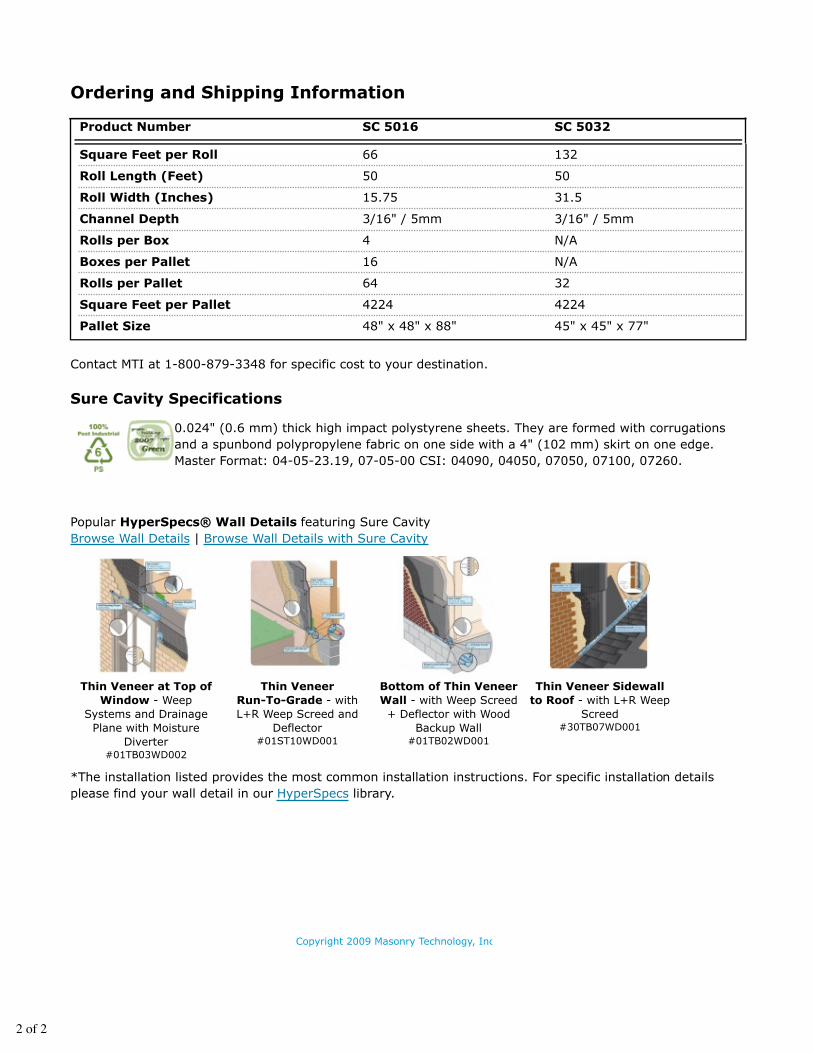
Copyright 2009 Masonry Technology, Inc |
Thin Veneer at Top ofWindow - Weep
Systems and DrainagePlane with Moisture
Diverter#01TB03WD002
Thin VeneerRun-To-Grade - withL+R Weep Screed and
Deflector#01ST10WD001
Bottom of Thin VeneerWall - with Weep Screed+ Deflector with Wood
Backup Wall#01TB02WD001
Thin Veneer Sidewallto Roof - with L+R Weep
Screed#30TB07WD001
Square Feet per Roll 66 132
Roll Length (Feet) 50 50
Roll Width (Inches) 15.75 31.5
Channel Depth 3/16" / 5mm 3/16" / 5mm
Rolls per Box 4 N/A
Boxes per Pallet 16 N/A
Rolls per Pallet 64 32
Square Feet per Pallet 4224 4224
Pallet Size 48" x 48" x 88" 45" x 45" x 77"
Contact MTI at 1-800-879-3348 for specific cost to your destination.
Sure Cavity Specifications
0.024" (0.6 mm) thick high impact polystyrene sheets. They are formed with corrugationsand a spunbond polypropylene fabric on one side with a 4" (102 mm) skirt on one edge.Master Format: 04-05-23.19, 07-05-00 CSI: 04090, 04050, 07050, 07100, 07260.
Popular HyperSpecs® Wall Details featuring Sure CavityBrowse Wall Details | Browse Wall Details with Sure Cavity
*The installation listed provides the most common installation instructions. For specific installation detailsplease find your wall detail in our HyperSpecs library.
2 of 2
Ordering and Shipping Information
Product Number SC 5016 SC 5032