Reshetov LA Autoregressive model for high-resolution wavenumber estimation in a shallow water
7
Autoregressive model for high-resolution wavenumber estimation in a shallow water environment using a broadband source Florent Le Courtois and Julien Bonnel Lab-STICC (UMR CNRS 6285), ENSTA Bretagne (Universit e Europ eenne de Bretagne), 2 rue Franc ¸ois Verny, 29806 Brest Cedex 9, France fl[email protected], [email protected] Abstract: In a shallow water environment, wavenumbers can be esti- mated by computing time and spatial Fourier transforms of horizontal array measurements. The frequency-wavenumber representation allows wide band estimation but a sufficient number of hydrophones are required for accurate wavenumber resolution. This paper presents the application of an autoregressive (AR) model to compute the high reso- lution wavenumber spectrum. The smallest number of required sensors for the AR model is found using a stabilization diagram. The method is validated on simulated and experimental data. The wavenumbers are accurately estimated over a wide frequency band using fewer sensors than are needed for the spatial Fourier Transform. V C 2014 Acoustical Society of America PACS numbers: 43.30.Pc, 43.30.Wi, 43.60.Jn, 43.30.Bp [AL] Date Received: August 27, 2013 Date Accepted: March 18, 2014 1. Introduction At low frequency, the shallow water zone is equivalent to a dispersive waveguide. The propagative horizontal wavenumbers, k l , depend on the water column properties and on the seabed composition. They are commonly used as input data of inversion algo- rithms to retrieve the seafloor characteristics. For a Horizontal Line Array (HLA), wavenumber estimation is equivalent to a spectrum analysis. Indeed, k l values can be obtained by performing a two- dimensional Fourier transform (2D-FT) on the array measurements: The 2D-FT is computed along time and range. For dispersive and multimodal media, the frequency wavenumber (f - k) diagram allows a wavenumber identification on a wide frequency band. 1 It has been applied in underwater acoustics domain by Nicolas et al. 2 Note that because of FT properties, the resolution in the k dimension of the f - k diagram depends on the HLA hydrophone number. High resolution methods were developed to perform spectral analysis without the FT limitations. The subspace decomposition methods ESPRIT and MUSIC (Ref. 3) and parametric models, such as the Prony algorithm 4 and the autoregressive (AR) models, 5 have been proposed for modal identification in shallow water simula- tions and measurements in a narrow band context. In Ref. 6, the Prony method is combined to a holographic processing for a vertical array; several acquisitions of the noise from a moving ship are realized to represent the wavenumbers on histograms. The Prony algorithm was later applied to ultrasound measurements in a tank 7 with HLA measurements using several inter-sensor spaces for the computation of high reso- lution f - k diagrams. Nonetheless those high resolution methods are sensitive to noise; i.e., for AR models, the order and number of elements in the HLA have to be sufficient to provide suitable results. This article presents the application of an AR model in order to reduce the number of HLA sensors without downgrading the wavenumber resolution on f - k J. Acoust. Soc. Am. 135 (4), April 2014 V C 2014 Acoustical Society of America EL199 F. Le Courtois and J. Bonnel: JASA Express Letters [http://dx.doi.org/10.1121/1.4869821] Published Online 28 March 2014 Redistribution subject to ASA license or copyright; see http://acousticalsociety.org/content/terms. Download to IP: 5.144.97.19 On: Tue, 10 Jun 2014 18:24:19
-
Upload
independent -
Category
Documents
-
view
3 -
download
0
Transcript of Reshetov LA Autoregressive model for high-resolution wavenumber estimation in a shallow water
Autoregressive model for high-resolutionwavenumber estimation in a shallow water
environment using a broadband sourceFlorent Le Courtois and Julien Bonnel
Lab-STICC (UMR CNRS 6285), ENSTA Bretagne (Universit�e Europ�eennede Bretagne), 2 rue Francois Verny, 29806 Brest Cedex 9, France
[email protected], [email protected]
Abstract: In a shallow water environment, wavenumbers can be esti-mated by computing time and spatial Fourier transforms of horizontalarray measurements. The frequency-wavenumber representation allowswide band estimation but a sufficient number of hydrophones arerequired for accurate wavenumber resolution. This paper presents theapplication of an autoregressive (AR) model to compute the high reso-lution wavenumber spectrum. The smallest number of required sensorsfor the AR model is found using a stabilization diagram. The method isvalidated on simulated and experimental data. The wavenumbers areaccurately estimated over a wide frequency band using fewer sensorsthan are needed for the spatial Fourier Transform.VC 2014 Acoustical Society of AmericaPACS numbers: 43.30.Pc, 43.30.Wi, 43.60.Jn, 43.30.Bp [AL]Date Received: August 27, 2013 Date Accepted: March 18, 2014
1. Introduction
At low frequency, the shallow water zone is equivalent to a dispersive waveguide. Thepropagative horizontal wavenumbers, kl, depend on the water column properties andon the seabed composition. They are commonly used as input data of inversion algo-rithms to retrieve the seafloor characteristics.
For a Horizontal Line Array (HLA), wavenumber estimation is equivalent toa spectrum analysis. Indeed, kl values can be obtained by performing a two-dimensional Fourier transform (2D-FT) on the array measurements: The 2D-FT iscomputed along time and range. For dispersive and multimodal media, the frequencywavenumber (f - k) diagram allows a wavenumber identification on a wide frequencyband.1 It has been applied in underwater acoustics domain by Nicolas et al.2 Note thatbecause of FT properties, the resolution in the k dimension of the f - k diagramdepends on the HLA hydrophone number.
High resolution methods were developed to perform spectral analysis withoutthe FT limitations. The subspace decomposition methods ESPRIT and MUSIC(Ref. 3) and parametric models, such as the Prony algorithm4 and the autoregressive(AR) models,5 have been proposed for modal identification in shallow water simula-tions and measurements in a narrow band context. In Ref. 6, the Prony method iscombined to a holographic processing for a vertical array; several acquisitions of thenoise from a moving ship are realized to represent the wavenumbers on histograms.The Prony algorithm was later applied to ultrasound measurements in a tank7 withHLA measurements using several inter-sensor spaces for the computation of high reso-lution f - k diagrams.
Nonetheless those high resolution methods are sensitive to noise; i.e., for ARmodels, the order and number of elements in the HLA have to be sufficient to providesuitable results. This article presents the application of an AR model in order to reducethe number of HLA sensors without downgrading the wavenumber resolution on f - k
J. Acoust. Soc. Am. 135 (4), April 2014 VC 2014 Acoustical Society of America EL199
F. Le Courtois and J. Bonnel: JASA Express Letters [http://dx.doi.org/10.1121/1.4869821] Published Online 28 March 2014
Redistribution subject to ASA license or copyright; see http://acousticalsociety.org/content/terms. Download to IP: 5.144.97.19 On: Tue, 10 Jun 2014 18:24:19
diagrams. The main idea is to compute a simple simulation with approximated valuesof the environment parameters to predict the measurement setup. The document isorganized as follows. In Sec. 2, the calculation of the f - k diagram by FT is presentedfor a Pekeris waveguide. Then, the AR modeling for spectral estimation is introducedin Sec. 3. The AR coefficients are computed using the modified covariance algorithm(MCA) as used in Ref. 5. The point is to identify the number of required sensors toprovide an accurate wavenumber separation. We propose an a posteriori analysis ofthe stabilization diagram to determine the minimum number of sensors to achieve anaccurate modal separation on the f - k diagram. Finally, the method is applied onsimulated and experimental data from North Sea measurements.
2. Frequency-wavenumber representation: f - k diagram
In shallow water, considering a wideband source S located at depth zs and an arraycomposed of M hydrophones spaced from Dr, the pressure received at the frequency fon a hydrophone at [r, zr] is expressed as a modal summation,8
Pðf ; rÞ ¼ QSðf ÞXL
l¼1
Wlðzs; f ÞWlðzr; f Þe�iktrue
l ðf Þrffiffiffiffiffiffiffiffiffiffiffiffiffiffiffiffiffiktrue
l ðf Þrp ; (1)
where Q is a constant, Wl and kl are the modal depth function and the horizontalwavenumber for the lth mode respectively, and L is the number of propagating modes.
Before going to the frequency-wavenumber f - k domain, the received signalcan be time-shifted so that the direct wave impinges on all sensors at the same time.2
Considering that the direct wave travels as a plane wave with speed cw, the correctedpressure field becomes Pcorrðf ; rÞ ¼ Pðf ; rÞei2pf ðr=cwÞ. The kl observed after correction arelinked to the true waveguide wavenumber ktrue
l through ktruel ðf Þ ¼ klðf Þ � f =cw. This
correction allows a better readability of the wavenumbers in the f - k domain since thekl values tend to 0 when the frequency increases. Note that this operation can easily beperformed on the received signal in the time-distance domain and is a classical seismicprocessing.1
A frequency-wavenumber representation of the received signal, i.e., the f - kdiagram, can then be calculated by taking the modulus of the spatial FT of Eq. (1),1
PFTðf ; kÞ ¼����ð
Pcorrðf ; rÞei2pkrrdr
����: (2)
As an example, Fig. 1(a) presents a simulated f - k diagram for a Pekeris waveguide(the Pekeris model parameters are given in Sec. 3.2). This diagram allows a good rep-resentation of the dispersion relationship between wavenumber and frequency over awide frequency band.
In the f - k domain, the resolution of the wavenumber spectrum is given byclassical FT properties DFT
k ¼ 1=ðMDrÞ, where M is the number of hydrophones in theHLA. For a specified inter-sensor space, a large number of hydrophones are thusrequired to achieve a good wavenumber separation. However, high-resolution methodshave been developed to overcome this FT limit. In Sec. 3, we propose the applicationof an AR model for the f - k diagram computation.
3. AR model of the shallow water waveguide
Modeling the array signal as an AR process consists in estimating the mth spatial sam-ple as a summation of the NAR previous samples and an additive, zero-mean Gaussiannoise w.9 Considering equally spaced sensors and a given frequency f0, the pressurereceived on the mth sensor at range r¼mDr becomes
F. Le Courtois and J. Bonnel: JASA Express Letters [http://dx.doi.org/10.1121/1.4869821] Published Online 28 March 2014
EL200 J. Acoust. Soc. Am. 135 (4), April 2014 F. Le Courtois and J. Bonnel: Wavenumber estimation in shallow water
Redistribution subject to ASA license or copyright; see http://acousticalsociety.org/content/terms. Download to IP: 5.144.97.19 On: Tue, 10 Jun 2014 18:24:19
P½f0;m� ¼ �XNAR
n¼1
af0 ½n�Pcorr½f0;m� n� þ wf0 ½m�; (3)
where af0[n] are the AR coefficients and NAR is the order of the AR model. The signalat frequency f0 is now described by the AR coefficients and the variance r2
f0of the
noise wf0. The AR model could be interpreted as the prediction of the mth samplevalue from a linear combination of the NAR previous ones.
The computation of Eq. (3) autocorrelation leads to the Yule Walker equa-tions; their resolution provides AR parameters af0[n] and r2
f0. Several algorithms were
introduced for solving this system: Levinson, Burg, etc. The MCA proposed byMarple9 minimizes in the least square sense the backward and forward predictionerrors. It is the most appropriate algorithm for spectral estimation and will be used inthis study. It is known that the MCA algorithm could be unstable and necessitatesthat NAR� 2/3M.9
3.1 Spectral density of an AR model
The power spectral density (PSD) corresponding to Eq. (3) is given by9
PARðf0; kÞ ¼
r2f0����1þ
XNAR
n¼1
af0 ½n�e�i2pknDr
����2: (4)
Equation (4) is an all pole filter which is adapted for describing modal behavior. Itpossesses peaks at the wavenumber values kl, but it is not accurate for the estimationof the mode amplitudes.5
The theoretical resolution of the PSD has been calculated by Marple9 for thecase of two sines with the same amplitude,
DARk ¼ 1:03
DrNAR að1þNARÞ½ �0:31 ; (5)
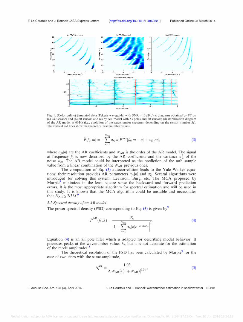
Fig. 1. (Color online) Simulated data (Pekeris waveguide) with SNR¼ 10 dB: f - k diagrams obtained by FT on(a) 240 sensors and (b) 80 sensors and (c) by AR model with 53 poles and 80 sensors; (d) stabilization diagramof the AR model at 60 Hz (i.e., evolution of the wavenumber spectrum depending on the sensor number M).The vertical red lines show the theoretical wavenumber values.
F. Le Courtois and J. Bonnel: JASA Express Letters [http://dx.doi.org/10.1121/1.4869821] Published Online 28 March 2014
J. Acoust. Soc. Am. 135 (4), April 2014 F. Le Courtois and J. Bonnel: Wavenumber estimation in shallow water EL201
Redistribution subject to ASA license or copyright; see http://acousticalsociety.org/content/terms. Download to IP: 5.144.97.19 On: Tue, 10 Jun 2014 18:24:19

where a is the linear expression of the signal-to-noise ratio (SNR). In general, spectrumresolution is better with the AR model than with FT: DAR
k < DFTk , but, for some cases
of low SNR and low AR order, the FT presents a better spectrum resolution than theAR model.
Because of Eq. (4), an intuitive approach is to choose the pole number NAR
equal to the mode number L, so that PARðf0; kÞ possesses NAR¼L peaks (in the k
dimension) that correspond to the L wavenumbers kl(f0). However, in a noisy context,additional poles are required to reduce the model errors due to noise. Then, poles canbe separated into two sets: Some of them are physical poles and correspond to thewaveguide modes, while the other poles are mathematical poles reducing the noiseinfluence on the estimation. Several a posteriori criteria have been proposed for findingthe optimal model order, but they are generally ineffective with real noisy data.9
Empirical approaches are often preferred. For narrowband signals, the order can beselected when two close wavenumbers are well resolved for several SNR.4,5 For a wide-band analysis, as mode number increases with the frequency, both physical and mathe-matical pole numbers increase.
The separation of an unknown number of wavenumbers L has to be consid-ered. The pole number NAR (which comprises both physical and mathematical poles)must thus be big enough to describe the corresponding noisy spectrum. The pole num-ber NAR and the hydrophone number M must also be linked through NAR� 2M/3. Toavoid unstable behavior of the MCA, NAR is usually chosen between M/2 and2M/3.5,9 In order to have enough poles to describe the wavenumber spectrum while atthe same time minimizing the hydrophone number M, we propose to fix the orderNAR as the floor of 2M/3 such as
NAR ¼23
M� �
: (6)
Our aim is to minimize the sensor number M, and Eq. (6) allows to jointly minimizeM and NAR. In the following, we show how to choose the minimal pole number, andthus the minimal number of sensors to ensure a stable MCA.
3.2 Stabilization diagram for finding the smallest number of sensors
The stabilization diagram has been introduced to help identify the physical poles fromthe mathematical poles.10 The main idea is to plot the wavenumber spectrum forincreasing values of NAR. The minimal order NAR is selected when the spectrumpresents a sufficiently good modal separation. In our case, as the order is linked to thenumber of hydrophones by Eq. (6), the operation is equivalent to finding the minimumnumber of hydrophones. Thus, the stabilization diagrams will be plotted as a functionof hydrophone number M.
Considering the multimodal behavior of the waveguide and the widebandanalysis of the f - k diagram, the stabilization diagram has to be computed at the high-est frequency, which is the worst case frequency. Indeed, the highest mode number andthe closest spaced wavenumbers are related to the highest frequency. If the modes areseparated at this frequency, the separation for lower frequencies is straightforward.
To illustrate the operation, the stabilization diagram is applied to a simulatedPekeris waveguide with the following parameters: Water sound speed cw¼ 1520 m/s, den-sity qw¼ 1 kg/m3, depth D¼ 130 m; and seabed sound speed cs¼ 1876 m/s and densityqs¼ 3 kg/m3. An impulsive source is simulated, and the impulse response of the waveguideis computed up to 60 Hz. A zero-mean Gaussian noise is added on each sensor of the arraysignal with a 10 dB SNR. Sampling frequency is 250 Hz while hydrophones are separatedby Dr¼ 25 m. The stabilization diagram associated with the simulation is represented inFig. 1(d) for the highest considered frequency f¼ 60 Hz. The red lines are added at the the-oretical values of the wavenumbers for the Pekeris waveguide. Five modes are sufficientlyseparated for M � 80 hydrophones (corresponding model order NAR � 53): Adding more
F. Le Courtois and J. Bonnel: JASA Express Letters [http://dx.doi.org/10.1121/1.4869821] Published Online 28 March 2014
EL202 J. Acoust. Soc. Am. 135 (4), April 2014 F. Le Courtois and J. Bonnel: Wavenumber estimation in shallow water
Redistribution subject to ASA license or copyright; see http://acousticalsociety.org/content/terms. Download to IP: 5.144.97.19 On: Tue, 10 Jun 2014 18:24:19
poles does not change wavenumber values: �6.3, �4.3, �3, �2, and �1 km�1. The twofirst modes correspond to their theoretical values for M � 200 sensors; in fact, their ampli-tudes are really low at 60 Hz as shown in Fig. 1(a). Without the a priori knowledge aboutthe mode number and values, NAR¼ 53 and M¼ 80 seems to be a sufficient condition toachieve an adequate modal separation.
3.3 Comparison with classical f - k diagrams
To demonstrate that chosen model order N and sensor numbers M are relevant, f - kdiagrams computed using FT and AR methods are compared. Diagrams in Figs. 1(a)and 1(b) are respectively obtained by FT on 240 and 80 sensors. The f - k diagramobtained with an AR model using NAR¼ 53 and M¼ 80 is plotted in Fig. 1(c).Visually, the wavenumber resolution is better than the one obtained by the FT on 240sensors [Fig. 1(a)]. For this case, the theoretical resolutions are calculated: DFT
k¼ 0:17 km�1 with 240 sensors, DFT
k ¼ 0:50 km�1 with 80 sensors, and DARk ¼ 0:16 km�1.
Because of its low resolution, the 80-sensor FT does not allow resolution of nearbymodes. As an example, modes 1 and 2 overlap for frequencies higher than 25 Hz andmodes 2 and 3 for frequencies higher than 45 Hz [Fig. 1(b)]. Note that the first twomodes were not separated at 60 Hz in the stabilization diagram for M¼ 80 [Fig. 1(d)].However, modes 1 and 2 are suitably resolved with the AR model for lower frequencies[Fig. 1(c)]. The use of the AR model thus allows to reduce greatly the sensor numberand to enhance the wavenumber resolution.
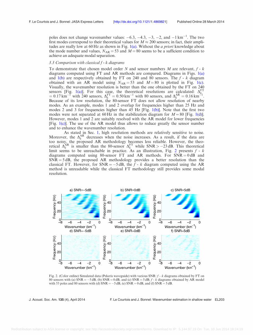
As stated in Sec. 1, high resolution methods are relatively sensitive to noise.Moreover, the DAR
k decreases when the noise increases. As a result, if the data aretoo noisy, the proposed AR methodology becomes less reliable. However, the theo-retical DAR
k is smaller than the 80-sensor DFTk while SNR>�23 dB. This theoretical
limit seems to be unreachable in practice. As an illustration, Fig. 2 presents f - kdiagrams computed using 80-sensor FT and AR methods. For SNR¼ 0 dB andSNR¼ 5 dB, the proposed AR methodology provides a better resolution than theclassical FT. However, for SNR¼�5 dB, the f - k diagram computed using the ARmethod is unreadable while the classical FT methodology still provides some modalresolution.
Fig. 2. (Color online) Simulated data (Pekeris waveguide) with various SNR: f – k diagrams obtained by FT on80 sensors with (a) SNR¼�5 dB, (b) SNR¼ 0 dB, and (c) SNR¼ 5 dB; f - k diagrams obtained by AR modelwith 53 poles and 80 sensors with (d) SNR¼�5 dB, (e) SNR¼ 0 dB, and (f) SNR¼ 5 dB.
F. Le Courtois and J. Bonnel: JASA Express Letters [http://dx.doi.org/10.1121/1.4869821] Published Online 28 March 2014
J. Acoust. Soc. Am. 135 (4), April 2014 F. Le Courtois and J. Bonnel: Wavenumber estimation in shallow water EL203
Redistribution subject to ASA license or copyright; see http://acousticalsociety.org/content/terms. Download to IP: 5.144.97.19 On: Tue, 10 Jun 2014 18:24:19
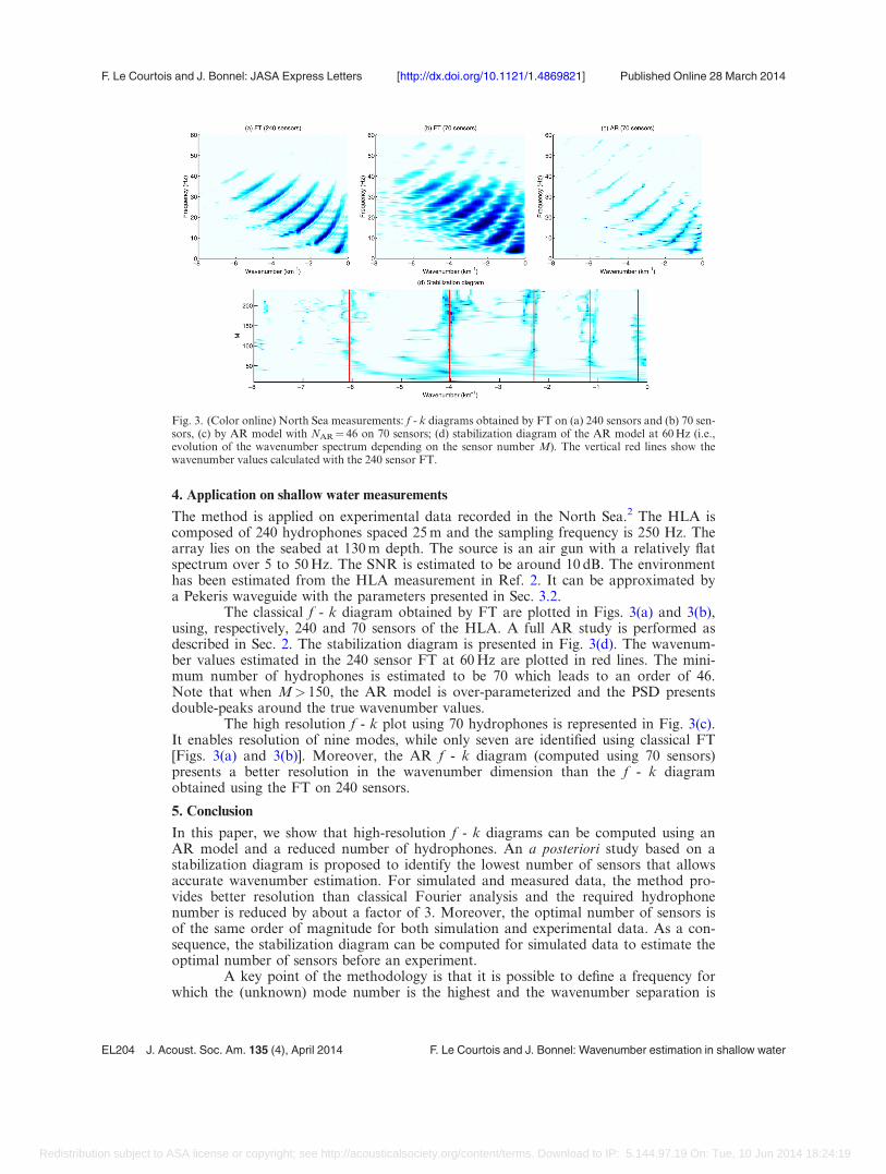
4. Application on shallow water measurements
The method is applied on experimental data recorded in the North Sea.2 The HLA iscomposed of 240 hydrophones spaced 25 m and the sampling frequency is 250 Hz. Thearray lies on the seabed at 130 m depth. The source is an air gun with a relatively flatspectrum over 5 to 50 Hz. The SNR is estimated to be around 10 dB. The environmenthas been estimated from the HLA measurement in Ref. 2. It can be approximated bya Pekeris waveguide with the parameters presented in Sec. 3.2.
The classical f - k diagram obtained by FT are plotted in Figs. 3(a) and 3(b),using, respectively, 240 and 70 sensors of the HLA. A full AR study is performed asdescribed in Sec. 2. The stabilization diagram is presented in Fig. 3(d). The wavenum-ber values estimated in the 240 sensor FT at 60 Hz are plotted in red lines. The mini-mum number of hydrophones is estimated to be 70 which leads to an order of 46.Note that when M> 150, the AR model is over-parameterized and the PSD presentsdouble-peaks around the true wavenumber values.
The high resolution f - k plot using 70 hydrophones is represented in Fig. 3(c).It enables resolution of nine modes, while only seven are identified using classical FT[Figs. 3(a) and 3(b)]. Moreover, the AR f - k diagram (computed using 70 sensors)presents a better resolution in the wavenumber dimension than the f - k diagramobtained using the FT on 240 sensors.
5. Conclusion
In this paper, we show that high-resolution f - k diagrams can be computed using anAR model and a reduced number of hydrophones. An a posteriori study based on astabilization diagram is proposed to identify the lowest number of sensors that allowsaccurate wavenumber estimation. For simulated and measured data, the method pro-vides better resolution than classical Fourier analysis and the required hydrophonenumber is reduced by about a factor of 3. Moreover, the optimal number of sensors isof the same order of magnitude for both simulation and experimental data. As a con-sequence, the stabilization diagram can be computed for simulated data to estimate theoptimal number of sensors before an experiment.
A key point of the methodology is that it is possible to define a frequency forwhich the (unknown) mode number is the highest and the wavenumber separation is
Fig. 3. (Color online) North Sea measurements: f - k diagrams obtained by FT on (a) 240 sensors and (b) 70 sen-sors, (c) by AR model with NAR¼ 46 on 70 sensors; (d) stabilization diagram of the AR model at 60 Hz (i.e.,evolution of the wavenumber spectrum depending on the sensor number M). The vertical red lines show thewavenumber values calculated with the 240 sensor FT.
F. Le Courtois and J. Bonnel: JASA Express Letters [http://dx.doi.org/10.1121/1.4869821] Published Online 28 March 2014
EL204 J. Acoust. Soc. Am. 135 (4), April 2014 F. Le Courtois and J. Bonnel: Wavenumber estimation in shallow water
Redistribution subject to ASA license or copyright; see http://acousticalsociety.org/content/terms. Download to IP: 5.144.97.19 On: Tue, 10 Jun 2014 18:24:19

the smallest. For a Pekeris waveguide, or more generally for a reflection-dominatedwaveguide, this frequency is usually the highest considered frequency. If one considersa waveguide with mode crossing in the f - k domain, the proposed methodology cannotbe applied.
Future improvements could be envisaged by introducing wideband physical apriori information. Tracking algorithms in the frequency dimension would thenenhance the performances of the wavenumber estimation.
References and links1 €O. Yilmaz, “Seismic data analysis: Processing, inversion, and interpretation of seismic data,” SEGInvestigations in Geophysics, 2nd ed. (Society of Exploration Geophysicists, Tulsa, OK, 2001), Vol. 10, 48pp.
2B. Nicolas, J. Mars, and J. Lacoume, “Geoacoustical parameters estimation with impulsive and boat-noise sources,” IEEE J. Ocean. Eng. 28(3), 494–501 (2003).
3S. D. Rajan and S. D. Bhatta, “Evaluation of high-resolution frequency estimation methods for deter-mining frequencies of eigenmodes in shallow water acoustic field,” J. Acoust. Soc. Am. 93, 378–389(1993).
4E. C. Shang, H. P. Wang, and Z. Y. Huang, “Waveguide characterization and source localization inshallow water waveguides using the Prony method,” J. Acoust. Soc. Am. 83(1), 103–108 (1988).
5K. M. Becker and G. V. Frisk, “Evaluation of an autoregressive spectral estimator for modal wavenumber estimation in range-dependent shallow water waveguides,” J. Acoust. Soc. Am. 120, 1423–1434(2006).
6P. Roux, D. Cassereau, and A. Roux, “A high-resolution algorithm for wave number estimation usingholographic array processing,” J. Acoust. Soc. Am. 115(3), 1059–1067 (2004).
7F. D. Philippe, P. Roux, and D. Cassereau, “Iterative high-resolution wavenumber inversion applied tobroadband acoustic data,” IEEE Trans. Ultrason. Ferroelectr., Freq. Control 55(10), 2306–2311 (2008).
8F. Jensen, W. Kuperman, M. Porter, and H. Schmidt, Computational Ocean Acoustics, 2nd ed. (AIP,New York, 2011), 340 p.
9S. L. Marple, Digital Spectral Analysis with Applications (Signal Processing, Prentice Hall, NJ, 1987),206 p.
10H. V. der Auweraer, “Structural dynamics modeling using modal analysis: Applications, trends andchallenges,” Proceedings of the IEEE Instrumentation and Measurement Technology Conference, 2001,pp. 1502–1509.
F. Le Courtois and J. Bonnel: JASA Express Letters [http://dx.doi.org/10.1121/1.4869821] Published Online 28 March 2014
J. Acoust. Soc. Am. 135 (4), April 2014 F. Le Courtois and J. Bonnel: Wavenumber estimation in shallow water EL205
Redistribution subject to ASA license or copyright; see http://acousticalsociety.org/content/terms. Download to IP: 5.144.97.19 On: Tue, 10 Jun 2014 18:24:19