RESEARCH PROJECT SUMMARIES - Operations ...
272
RESEARCH PROJECT SUMMARIES 2020
-
Upload
khangminh22 -
Category
Documents
-
view
0 -
download
0
Transcript of RESEARCH PROJECT SUMMARIES - Operations ...
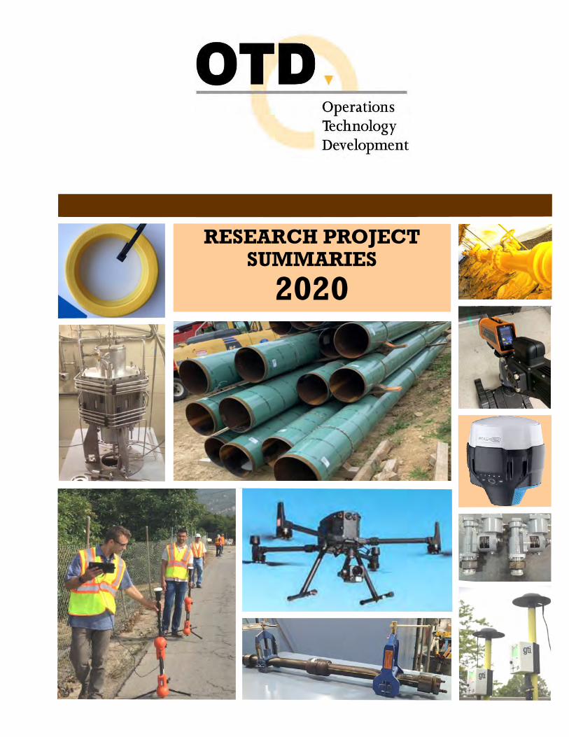
RESEARCH PROJECT SUMMARIES
2020


Operations Technology Development, NFP
RESEARCH PROJECT SUMMARIES
2020
Legal Notice
This report was prepared by Operations Technology Development, NFP (OTD), as an account of the results of work sponsored by OTD. Neither OTD, the members of OTD, nor any person acting on behalf of any of them: Makes any warranty or representation, express or implied, with respect to the accuracy, completeness, or
usefulness of the information contained in this report, or that the use of any information, apparatus, method, or process disclosed in this report may not infringe privately-owned rights. Inasmuch as many projects are experimental in nature, the technical information, results, or conclusions cannot be predicted. Conclusions and analysis of results by OTD represent OTD’s opinion based on inferences from measure-ments and empirical relationships, which inferences and assumptions are not infallible, and with respect to which competent specialists may differ.
Assumes any liability with respect to the use of, or for any and all damages resulting from the use of, any
information, apparatus, method, or process disclosed in this report; any other use of, or reliance on, this report by any third party is at the third party’s sole risk.

Chairman / President’s Letter
The natural gas system infrastructure provides the vital link in delivering energy to millions of homes, businesses, and industrial customers. Serving to maintain and improve the safety, efficiency, and reliability of this infrastructure is OTD – a not-for-profit collaborative representing 26 member companies who serve over 50 million homes and businesses in the U.S. and Canada. OTD’s members provide the vision, guidance, and support for a program focusing on the most critical needs of the safe and efficient delivery and storage of gas. OTD plays a valuable role in helping our members address the challenge of dramatically reducing GHG emissions by mid-century while cost effectively providing resilient and reliable energy. The OTD program is robust, more varied than ever, and provides greater benefits to the energy industry and its customers than ever before. This report provides summaries of more than 100 projects in the 2020 OTD program and includes an overview of some of the program's most significant past achievements. This year, work continues on several projects awarded to OTD by federal agencies such as U.S. DOT/PHMSA and U.S. DOE/ARPA-E. These projects provide leverage and further demonstrates the importance and impact OTD has for its stakeholders. Projects include technologies to prevent third-party damage, methodologies to understand and mitigate methane emissions, enable renewable fuels such as hydrogen and RNG, and technologies to understand and validate risks to pipeline integrity. All of these projects are core to the industry’s success in delivering a safe, reliable, affordable, and environmentally conscious energy solution. OTD continues to provide solutions that are smarter and safer with a focus on information management, risk management, system inspections, cybersecurity, material tracking, and other areas. The key to OTD’s success is the involvement and support of its members – subject-matter experts from North America’s leading energy providers – who identify, select, fund, and oversee research efforts aimed at their specific customer needs. We appreciate your interest and support and look forward to a future of even better things to come! Christine Cowsert Ronald Snedic Chairman of the Board President
OTD Members > Ameren Illinois > APGA Research Foundation > Atmos Energy Corporation > Avista Utilities > Black Hills Energy > Consolidated Edison Co. of NY, Inc./ Orange & Rockland Utilities, Inc. > Dominion Energy > Duke Energy Corporation > Enbridge Gas Distribution Inc. > Intermountain Gas Company > Liberty Utilities > Louisiana RDC - Atmos Energy Corporation - CenterPoint Energy, Inc. - Entergy Corporation > National Fuel Gas Distribution Corporation > National Grid > New York State Electric & Gas Corp. / Rochester Gas and Electric > Nicor Gas > NiSource Inc. > NW Natural > Oklahoma Natural Gas > Pacific Gas and Electric Company > Peoples Gas > Southern California Gas Co., a Sempra Energy Utility > Southwest Gas Corporation > Spire (Alabama) > TECO Peoples Gas > Washington Gas

Results in Use Since 2003, the OTD program has provided utilities, pipeline companies, service providers, and others in the natural-gas-delivery business with innovative tools, enhanced processes, and advanced equipment for improving gas system operations.
These products represent the results of OTD efforts to build a stronger industry infrastructure, enhance system integrity, and improve the efficiency of a wide range of operations activities.
Selected OTD-Developed Products in the Marketplace
UtilAlert Excavation Notification System Hydromax USA
A GPS monitoring system for excavation equipment was developed to periodically transmit active excavation-equipment-location information to a portal. The system monitors the behavior of excavators and other equipment entering a utility right of way to characterize its behavior as safe or threatening. The proper alerts are generated to notify the excavator operator and the utility to take the necessary actions.
Contact: Andy Scott 281-684-7673 www.utilialert.com .
Jameson Directional Entry Tool and Live Tracer Jameson, a Spartaco Company
This directional tool enables vertical insertion of tracer rods and cameras into live gas mains, facililtating the difficult first bend of the entry. It operates on live mains with no blow by and is compatible with keyhole procedures (fits 24-inch minimum keyhole). The tool can be used on mains as small as two inches in diameter; rotates 360 to insert in either direction; and fits most camera heads.
Contact: Brad Kokoski 803-222-8454 www.jamesonllc.com
Large-Diameter, Medium-Pressure Inflatable Stoppers Mainline Control Systems
The Kleiss MCS Flow Stopping System is used to stop the flow of gas in polyethylene, steel, cast-iron, and PVC pipes at diameters up to 18 inches and pressures up to 60 psig. The system, which is manufactured in Europe, was investigated through OTD to validate its operation and potential savings in the U.S. gas industry.
Contact: Wade Farr 812-459-3936 [email protected] www.mailinecontrolsystems.com
Virtual Reality Training Pixo VR
OTD partnered with PIXO VR to create a proof-of-concept Virtual Reality Training module designed to make emergency-response training more efficient and effective for a new generation of field technicians. The team created a new suite of highly relevant and fully immersive training simulations with valuable features such as interactive 3D environments for superior trainee immersion. This groundbreaking new training delivers more meaningful experiences, reinforcing critical, multi-step, inspection and safety protocols.
Contact: Sean Hurwitz 248-996-8298 [email protected]

Portable Methane Detector (PMD) SENSIT Technologies
This handheld SENSIT® PM uses optical detection to provide sensitivity and cost advantages over conventional techniques employing flame ionization detectors. The PMD provides the efficiency of leak surveys, is less costly to maintain than other technologies, and can detect leaks from low ppm to 100% gas.
Contact: Scott Kleppe 219-465-2700 [email protected] [email protected]
IRED Infrared Portable Ethane Detector SENSIT Technologies
This easy-to-use handheld detector was developed for use in the field to discriminate natural gas leaks from other sources of methane (e.g., swamp gas, landfill gas, and engine exhaust) and detect trace levels of ethane. The detection of ethane can be used as a fingerprint for natural gas in situations where the origin of a methane leak signal is questioned.
Contact: Scott Kleppe 219-465-2700 [email protected] [email protected]
Acoustic Pipe Locator (APL) SENSIT Technologies
SENSIT’s ULTRA-TRAC® APL acoustic-based pipe locator provides the ability to locate plastic pipes before excavations and construction. Now commercially available, in tests the system was shown to be capable of detecting multiple buried plastic pipes at depths up to five feet.
Contact: Scott Kleppe 219-465-2700 [email protected] [email protected]
LocusIQ for Intelligent Inspections LocusView
A software platform developed through OTD is now part of the LocusView mobile product suite to allow users to collect new installation data directly within a GIS environment. Applications to integrate real-time, sub-foot accurate GPS and barcode scanning are included.
Contact: Alicia Farag 847-387-9412 [email protected] www.locusview.com
LocusMap Mobile GIS Solution LocusView
This system maps new installations with comprehensive tracking and traceability data, creating GIS features in a format that allows field-collected data to be directly integrated into the enterprise GIS. Barcode scanning and high-accuracy GPS automate the system and help create high-accuracy maps.
Contact: Alicia Farag 847-387-9412 [email protected] www.locusview.com
LocusSurvey for Tracking Leak-Survey Routes LocusView
LocusSurvey uses tablet computers and GPS to track leak-survey routes. The GPS breadcrumb trail is overlaid in a GIS to track pipe segments that are surveyed to provide real-time re-porting and monitoring. LocusSurvey eliminates paper maps and records, automating the process of documenting surveys and leak locations.
Contact: Alicia Farag 847-387-9412 [email protected] www.locusview.com

Information on additional available products can be found at the OTD website: www.otd-co.org
Pipeline Purging Program Update Bradley Bean
The Pipeline Purging Program calculates the purge time, purge pressure, gas flow rate, and the required inert gas volume for the user’s specific pipe geometry. The updated program uses a modern web-based platform will allow utilities to utilize the program for planning pipeline purging operations.
Contact: Bradley Bean 719-578-9391 [email protected]
Synergi Pipeline Simulator DNV GL
DNV GL’s pipeline integrity software, Synergi Pipeline, is a scalable company-wide risk- and integrity-management system. It enables safe and efficient pipeline operations, documents risk, and provides users, including upper management, with a clear overview of the integrity of distribution networks and offshore and onshore pipelines.
Contact: Michael Moore 717-724-1900 [email protected] www.dnvgl.com
Lift Assists for Pavement Breakers and Rock Drills Integrated Tool Solutions, LLC
These devices assist workers in lifting pavement breaker and rock drills after the bits break through surface pavements and rocks and need to be repositioned for the next penetration. By eliminating the need to manually lift and re-position the heavy tools, the lift assists make breaking easier and less physically demanding.
Contact: Ryan Purczynski 951-929-4808 [email protected] www.integratedtoolsolutions.com
Keyhole Pipeline Inspection Camera System ULC Robotics
The PRX250K keyhole camera is an internal inspection system designed for visual assessment of live mains through conventional pits or small keyholes. The system is easily maneuverable through tight bends, allowing utilities to examine pipe segments without the need to drill additional access holes.
Contact: Greg Penza 631-667-9200 [email protected] www.ulcrobotics.com
Metallic Joint Locator (MJL) SENSIT Technologies
The SENSIT Ultra-Trac® MJL accurately locates bell joints, repair clamps, and service connections on metallic piping systems, significantly reducing excavation areas and pavement restoration costs. In field tests, the MJL was also able to detect bell and spigot joints for an eight-inch-diameter water main buried at a depth of six feet.
Contact: Scott Kleppe 219-465-2700 [email protected] [email protected]

Informational Products Selected OTD-Developed Technical Reports In addition to the development of new tools, processes, and products, OTD supports research that results in useful information on various aspects related to gas delivery and operations. Listed here are some of the key reports developed under OTD sponsorship. PIPE & LEAK LOCATION
RFID Marker Technology Implementation Guidelines A set of guidelines was developed for the implementation and application of integrated Global Positioning Systems (GPS), Geographic Information Systems (GIS), and “Smart Tag” technologies to streamline public-improvement project planning and prevent damage caused by excavations.
Cross Bores Best Practices Guide & Video Significant research was conducted to investigate gas line/sewer line cross bores. The Guide and “how-to” videos (available through the OTD website) provide recommendations and procedures for preventing and detecting cross bores. (OTD-12/0003)
Residential Methane Gas Detector Program This report provides results of a project initiated to determine whether commercially available combustible gas detectors are susceptible to giving false positive responses to an assortment of typical household chemicals, including ammonia, ethanol, acetone, toluene, isobutane, ethyl acetate, isopropanol, heptane, and hydrogen. (OTD-13/0003)
PIPE MATERIALS, REPAIR & REHABILITATION
Repair Wrap for Polyethylene (PE) Systems Researchers evaluated a new composite pipe wrap system for the repair of mechanically damaged polyethylene gas pipe. The repair system has the potential to lower repair costs, reduce repair times, and minimize disruptions. (OTD-17/0001)
Liners/Composites for the Rehabilitation of Distribution and Transmission Lines A report titled Transmission Infrastructure Roadmap was prepared to address the implementation of composite piping materials in the rehabilitation of gas transmission systems. This report includes information on composite pipes, trenchless repairs, and cured- in-place structural liners.
Evaluation of Structural Liners for the Rehabilitation of Liquid and Natural Gas Piping Systems This report details the results of testing conducted to evaluate the long-term performance of liners and composites used in trenchless operations for the rehabilitation of aging gas distribution and transmission lines.
Polyurea Coating Testing and Assessment for Gas-Industry Use A Final Report is available on research into field-applied polyurea coatings for gas industry use. Through a new initiative, long-term field trials will be conducted to evaluate these additional coatings and determine a cost-effective coating-application method and process. (Project Summary, p. 15)
Electrofusion Coupling Evaluation and Best Practices Researchers investigated techniques used to perform electrofusion joining of plastic gas pipe in an effort to develop guidelines for the use and operation of electrofusion coupling. With a detailed set of guidelines, the gas industry can enhance the performance and safety of its plastic piping systems.

Risk-Based Atmospheric Corrosion / Leak Survey Considerations To address new regulations, researchers reviewed historical and current data on indoor gas service piping. In addition, thousands of recent inspections on outdoor and indoor services were collected and statistically analyzed to determine the trends and drivers behind corrosion rates. A White Paper is available (OTD-15/0004).
Evaluation of Lightweight Jackhammers A research team evaluated the performance of currently available lightweight pneumatic and hydraulic jackhammers with respect to their effectiveness in breaking asphalt and concrete pavement, while considering other operational factors such as noise, vibrations, operator impact, and performance.
Cold-Patch Products Performance Results This report provides the results of a testing program that evaluated nine commercially available cold-patch products, including two products introduced in the market as “green” patches. Cold- and warm-weather tests were performed and repeated moving loads were applied with a wheel-loading machine that conducted 50,000 wheel passes.
Evaluation of Flowable Fill Around Buried Pipes Flowable fill is required by some agencies for use as backfill material for pipe repairs, rehabilitations, and other operations. Presented in this report are the results of performance tests of flowable fill, including the effects of flowable fill on pipeline corrosion and on the detection of gas flow and leaks through the backfill. (OTD-07/0004)
EXCAVATION & SITE RESTORATION
Correlating Pipeline Operations to Potential Crack Initiation, Growth, and Arrest To help to reduce risks associated with vintage transmission pipeline materials, researchers developed and validated a model for pipeline operations that correlates pressurization to pipe crack-growth rates, crack initiation, and crack arrest. A Final Report was issued in 2016 that includes a training manual on the use of a Critical Crack Propagation Pressure Calculator that provides a convenient and simple way to calculate the critical pressure at which an axial crack will propagate.
Hydro-Testing Alternative Program Researchers developed and deployed a Critical Flaw and Critical Wall Loss Calculator that allows pipeline operators to determine if an inspection technology could detect a crack-like flaw and/or wall loss that would fail a pressure/hydro-test at a particular pressure. A Phase 3 Final Report was issued in 2016.
Establishment of Yield Strength Using Sub-Size Samples Without Gas-Line Shutdown This report presents the results of a multi-phase project is to develop, validate, and obtain regulatory acceptance for a method to establish pipeline yield strength that allows for a less expensive sampling procedure that does not require the line to be taken out of service. (OTD-13/0005).
Leak-Rupture Boundary Report and Calculator This report and associated software allows operators to determine the leak-rupture boundary for a pipe segment based on properties such as the diameter, toughness, and yield strength. Operators can use the calculator for risk modeling and consequence analysis. (OTD-13/0002 and OTD 13/0004 )
Field-Applied Pipeline Coatings: Short- and Long-Term Performance This report presents the culmination of a 10-year research program to assess more than 80 different commercially available field-applied pipeline-coating products. The goal was to establish an unbiased, third-party basis for operators to select the most appropriate coating system for particular applications.
PIPELINE INTEGRITY MANAGEMENT & AUTOMATION

Evaluation of Guided Wave Technology as a Hydrotest Equivalent This report details an evaluation conducted to demonstrate and validate the use of Guided Wave Ultrasonic Testing as an equivalent to a hydrotest. A standard was developed and incorporated by the National Association of Corrosion Engineers (NACE) into the NACE TG410 committee standard. (OTD-11/0001)
Black Powder Contamination in the Gas Industry: Survey and Best Practice Manual Black powder – a substance composed mainly of iron sulfides and iron oxides – can cause corrosion and create wear on pipelines. This report provides information on issues, cleanup techniques, and management methods related to black powder contaminants. Results were compiled into a “best practices” industry manual. (OTD-07/0002)
Literature Review for Elemental Sulfur Deposits in Natural Gas Transmission Pipelines Deposits of elemental sulfur – which can block natural gas pipes and equipment – are becoming an increasing concern in the natural gas industry. This report summarizes a literature review to develop a better understanding of the sources, causes, and mitigation possibilities for sulfur deposits found in gas pipelines. (OTD-09/0001)
Flaw Acceptance Criteria and Repair Options for Low-Stress Natural Gas Pipelines Researchers partnered with pipeline companies and industry organizations to develop modified assessment criteria for low-stress pipelines. The goal was to develop criteria for discriminating flaws that truly affect pipeline integrity from flaws that have no signifi-cant impact.
In-Field Corrosion Rate Measurement/Determination for Integrity Reassessment Intervals and Risk Prioritization Research was conducted to develop a systematic and simple method to calculate realistic corrosion growth rates for determining pipeline-reassessment intervals.
CONSTRUCTION/INFRASTRUCTURE TECHNIQUES
Evaluation of Meter Set Placement and Clearances This report presents the results of a testing program to evaluate the distribution of natural gas concentrations around leaks in out-door meters and regulators. The report summarizes the risk of gas accumulation, gas ignition, and/or gas migration into a building for the various situations tested. (OTD-17/0002)
Assessment of Frost Impact on Cast-Iron Pipes This study of winter leak-breakage records correlated pipe breakage due to freeze conditions with local site conditions, such as soil properties, weather patterns, and pipe attributes (e.g., depth, diameter, and age). Statistical analysis established relationships between various parameters to enhance winter leak-surveillance procedures. (OTD-15/0001)
Evaluation of Static Suppressors on Existing Polyethylene Piping Systems Researchers evaluated selected commercially available static suppressors for suitability for use on polyethylene piping systems to eliminate static charge and assess their effects on heat-fusion-joint performance and pipe materials.
Evaluation of Commercial/Light-Industrial-Sized Excess Flow Valves (EFVs) This reports presents the results of an evaluation of the performance of high-volume EFVs for commercial, multi-residential, and light-industrial applications in response to regulations requiring an expanded use of EFVs.
Natural Gas & Indoor Air Quality Website A website of vital information on indoor air quality and safety issues was developed for OTD members through the OTD website (otd-co.org). The site provides a center of expertise and a single-point access to scientific data, performance information, and natural-gas-related issues.

Ignition Testing of Electronic Devices In this project, handheld electronic devices were tested to determine if ignition occurs in the presence of a flammable methane/ air mixture. Laboratory tests demonstrated a large margin of safety under the scenarios investigated. (OTD-12/0001)
Intelligent Utility Installation Process This report provides a methodology, field process, and a data model for capturing data during new utility installations. The process is used to capture information regarding the location, materials, installation process, environmental considerations, and other factors. (OTD-12/0002)
Tracer Wire for HDD Applications Extensive research and testing culminated in the release of a report that provides valuable information on the properties and performance of various tracer-wire products for use in horizontal directional drilling (HDD) operations. (OTD-13/0001)
Enterprise Decision Support System This report presents the results of efforts to create a technology roadmap for the development of an Enterprise Decision Support System to integrate gas-system data and knowledge from various sources into a single information source to support decision making.
Assessment of Vehicle-Barrier Design for Aboveground Facility Protection Investigators compiled the latest information on the design, regulations, and installation practices of structural vehicle barriers used to protect aboveground utility facilities from vehicular damages. The Final Report also includes a review of various state and federal safety guidelines.
Study of Low-Impact Markings A variety of paints, materials, and techniques were tested and characterized in an effort to identify products and methods that can be used for temporary utility marking. Information developed in this study allows users to identify the most appropriate marker type for a given environment to achieve the desired marking duration. (OTD-11/0002)
Solar-Powered Remote Monitoring In this study, solar-powered devices were investigated as power sources for the remote monitoring of various gas utility facilities to more cost-effectively obtain rectifier data, pipe-to-soil measurement, pipe-to-casing readings, and other information.
Integrating GPS into Routine Operations This report provides a set of recommendations and GPS implementation strategies developed through pilot programs, literature searches, and reviews of existing applications. Operations that were considered included meter reading, leak surveying, new installations, corrosion monitoring, and valve inspections.
DVDs for Training First Responders DVD training products help gas companies better educate first-responding personnel about natural gas emergencies. Learning modules with realistic scenarios cover a variety of issues to enhance public and worker safety. The product also serves to improve emergency-response effectiveness and coordination.
UV Degradation and Static Buildup Testing of Personal Protection Equipment Fabrics Researchers tested various utility-vest materials to determine if degradation is caused by ultraviolet light and to evaluate the potential for static buildup to become hazardous. The results of safety vest testing are available in technical reports.
Siloxane Concentrations in Biomethane Biomethane from various waste products could provide consumers with a significant source of “green” renewable energy. In efforts to help develop this green resource, a study was conducted into siloxane – one of the potential constituents in biomethane – to assess its influence on health, the environment, and gas-fired appliances.
METHANE EMISSIONS/DETECTION & GAS QUALITY
Field Measurement Program to Improve Uncertainties for Key Greenhouse Gas Emission Factors for Distribution Sources This report summarizes the results of field surveys conducted at six natural gas utilities. With the support of the American Gas Association, research updated emissions factors for metering stations, regulating stations, and customer meters. (OTD-10/0002)
Improving Methane Emission Estimates for Natural Gas Distribution Companies This report details Phase 2 of a four-phase field-testing program to evaluate gas leak rates from belowground pipelines, provide a simplified procedure that can be used to monitor pipeline leaks from surface measurements, and update the methane emission estimates for the main lines in a distribution system.
Pipeline-Quality Methane: North American Guidance Document for Introduction of Dairy-Waste-Derived Biomethane into Existing Natural Gas Networks The guidance document provides reference and recommendations for the consideration of biomethane from dairy-waste digestion for introduction into gas pipeline networks. The report details results of a biogas/biomethane Gas Technology Institute research program.
For more information:
Michael Adamo, P.E. Vice President, Operations Operations Technology Development, NFP Phone: 847/544-3428 [email protected]


OTD RESEARCH PROJECT SUMMARIES 2020
Table of Contents Project Page
PIPE MATERIALS, REPAIR & REHABILITATION
2.10.b In-Service Field Evaluation of Polyurea Coating Systems ................................................ 3 2.14.a Composite Repair Wrap for Polyethylene Systems............................................................ 5 2.14.b Pipe System Repair Technique.............................................................................................. 7 2.14.c Assessment of Squeeze-Off Location for Small-Diameter Polyethylene (PE) Pipe and Tubing ..................................................................................... 9
INSPECTION & VERIFICATION
4.12.c Tool for Detection of of Cathodic Disbondment and Metal Loss ................................ 13 4.14.c Correlation of Surface to Through-Wall Properties of Pipe ............................................. 15 4.17.a Development of a Long-Term Enhancement of Direct Assessment.............................. 17 4.17.c Underground Natural Gas Storage Corrosion Risk – MIC/Gas Quality........................ 19 4.17.d MAOP and Materials Verification......................................................................................... 21 4.19.b Coatings Collaborative............................................................................................................ 23 4.19.d Remote Monitoring of Pipe-to-Soil Readings, Equipment Identification, and Evaluation............................................................................................... 25 4.20.a Safety Impact of Hoop Stress and Percentage of Specific Yield Stress Boundaries ..... 27 4.20.c Self-Healing Coatings – Development and Laboratory Testing for Gas Utility Applications ............................... 29
CONSTRUCTION/INFRASTRUCTURE TECHNIQUES
5.13.b GPS-Based GIS Conflation System...................................................................................... 33 5.14.w Testing Program for Iltron-100T-GRRD Valve with Water Sensor for Storm Hardening ...................................................................................... 35 5.15.a Cybersecurity Collaborative.................................................................................................... 37 5.15.h Evaluation of Meter Set Placement and Clearances............................................................ 39 5.16.b Alternative Caps for PE Service Tees ................................................................................... 41 5.16.c Piercing Tool Redevelopment – Enhancement to Remove “Mole” From Small Excavations............................................. 43 5.16.f Improved Safe Excavation Productivity for Locating Buried Utilities ............................ 45 5.16.k Evaluation of the ORFEUS Look-Ahead Technology for Horizontal Directional Drilling ................................................................. 47 5.16.r Polyethylene Systems Joint Industry Program (JIP) – A Total Quality Approach.......... 49 5.17.a Guidelines for Indoor Meters, Regulators, and Piping ....................................................... 51 5.17.d Best Practices to Address Odor Fade in High-Rise, Low-Occupancy Buildings............ 53
Project Page CONSTRUCTION/INFRASTRUCTURE TECHNIQUES (cont.)
5.17.g Material-Supplier Quality-Assurance Program .................................................................... 55 5.17.k Protecting Tracer Wires From Corrosion – Best Practices and New Methods.............. 57 5.17.p Field Test of Nano-Technology Coatings to Reduce Aboveground Corrosion .......................................................................................... 59 5.18.a Leak Seal for Meter Set Joints ................................................................................................ 61 5.18.d Determining Minimum Recovery Time from PE Pipe Pullback...................................... 63 5.18.g Advanced Metering Infrastructure Communications Protocol......................................... 65 5.18.m Uniform Frequency Code....................................................................................................... 67 5.18.n Performance, Durability, and Service Life of Residential Gas Regulators ...................... 69 5.18.o Abandoned-Line Detector...................................................................................................... 71 5.18.p Noncamera-Based Technology to Detect Cross Bores...................................................... 73 5.18.r Clothing Performance Guidelines to Reduce Heat Stress for Natural Gas Workers..... 75 5.18.s Thermally Activated Gas Shut-Off Devices......................................................................... 77 5.18.t Virtual Reality Training .......................................................................................................... 79 5.19.a Polyethylene Squeeze Tool Gap Stop Evaluation ............................................................... 81 5.19.f Purging Gas Pipes into Service without Venting Gas to the Atmosphere...................... 83 5.19.h Single-Path Ultrasonic Meter Performance Testing ........................................................... 85 5.19.k Evaluation and Demonstrations of the Utonomy Smart Regulator................................. 87 5.19.n Best Practices for Squeeze-Off of Vintage Polyethylene Pipe .......................................... 89 5.19.p Emergency Leak Tool for Stopping Blowing Gas .............................................................. 91 5.19.q Over-Pressure Protection Options for Low-Pressure Gas Distribution Customers..... 93 5.19.s Identify and Validate Best Practices for Applying Heat to Steel Near PE Materials .... 95 5.19.t Workshop on NDE Capabilities for Polyethylene Piping Systems.................................. 97 5.20.a Subsurface Multi-Utility Asset Location Detection........................................................... 99 5.20.b Procedures for Selecting Locating and Excavation Technologies .................................. 101 5.20.c Training Technologies Consortium ..................................................................................... 103 5.20.d Pipe Thread Conformance to B1.20.1 Standard – Pipe Supplier Quality Assurance... 105 5.20.e Single-Path Ultrasonic Meter Long-Term Performance Testing and Monitoring ....... 107 5.20.f Barholing and Worker Injuries ............................................................................................. 109 5.20.g Horizontal Directional Drilling Weak Links....................................................................... 111 5.20.h Wet Spoils Remediation......................................................................................................... 113 5.20.i Removing Water-Vapor Impurities to Improve Gas Quality in a Distribution Pipeline................................................................ 115 5.20.k Smart Shutoff Technology for Commercial and Residential Buildings .......................... 117 5.20.l Enhancing a Live-Gas Mapping System with Camera Integration.................................. 119 5.20.m Product Performance and Validation Program.................................................................. 121 5.20.n Pipeline System Management Training Development...................................................... 123
Project Page CONSTRUCTION/INFRASTRUCTURE TECHNIQUES (cont.)
6.14.a Quality Audit Program for Natural Gas Utility Suppliers ................................................. 125 6.14.b Initial Assessment of Effects of Hydrogen Blending in Natural Gas ............................. 127 6.19.d Adsorbed Natural Gas Storage Options for Operations Applications ............................ 129
METHANE EMISSIONS/DETECTION & GAS QUALITY
1.14.g Residential Methane Detectors Program............................................................................. 133 7.11.a Gas Quality Resource Center................................................................................................. 135 7.15.a Real-Time Gas Quality Sensor............................................................................................... 137 7.15.b Remote Gas Sensing and Monitoring................................................................................... 139 7.15.c Evaluating Leaks from Slow Crack Growth and the Impact on Pipeline Emissions.... 141 7.16.a Leak Repair Prioritization....................................................................................................... 143 7.16.b Evaluation of Gas-Imaging Techniques for Utility Applications ..................................... 145 7.16.d Implications of Odorant Dispersion in a Natural Gas Pipeline ....................................... 147 7.16.e On-Line Biomethane Gas Quality Monitoring ................................................................... 149 7.16.f Investigation of State-of-the-Art Methane Sensors............................................................ 151 7.16.h Distribution System Characterization................................................................................... 153 7.17.a Leak Detection and Repair Modeling for Distribution Systems....................................... 155 7.17.d Methodology to Estimate Flow Rate of Aboveground Leaks Using a Soap Test ......... 157 7.17.e Evaluation of Methane-Detection Devices for Utility Operations................................... 159 7.18.b Biomethane Justification Study for Improved/Accepted Gas Quality Standard........... 161 7.18.c Robot for Remote Methane Detection................................................................................. 163 7.18.d Drone-Based Methane Detection.......................................................................................... 165 7.18.f Evaluation of ‘Point-and-Shoot’ Methane-Detection Technologies................................ 167 7.18.g Impact of RNG on End-Use Applications ......................................................................... 169 7.18.h Trace Constituent Database ................................................................................................... 171 7.18.k Evaluation and Demonstration of Stationary Continuous Methane-Monitoring Systems.......................................................................... 173 7.19.b Advanced Leak-Detection Technologies for Grading Leaks............................................ 175 7.19.c OptoMole® Leak-Detection System...................................................................................... 177 7.19.e A Framework for Company-Specific Emission Factor Development ............................ 179 7.19.f Impacts of Repairing Non-Hazardous Leaks vs. Monitoring ........................................... 181 7.19.g RMDs – Sensor Drift and False Negatives.......................................................................... 183 7.19.h Hydrogen Working Group..................................................................................................... 185 7.20.a Develop Remote Sensing and Leak-Detection Platform with Multiple Sensors ........... 187 7.20.b Validation of Remote-Sensing Leak-Detection Technologies under Realistic Conditions............................................................................. 189

Project Page METHANE EMISSIONS/DETECTION & GAS QUALITY (cont.)
7.20.e Gas Dispersion Modeling for Venting Natural Gas from Structures.............................. 191 7.20.f Characterizing Methane Emissions from Purging Activities............................................. 193 7.20.h Laboratory Evaluation of Personal Gas Monitors.............................................................. 195 7.20.l Methane Mitigation Using Linear Leak Recovery Motor Compressor............................ 197 7.20.m Residential Methane Detectors (RMDs) – Test Response to Natural Gas/Hydrogen Blends.............................................................. 199
INTELLIGENT UTILITIES
8.16.b Remote QA/QC: Fusion Inspection and Reporting.......................................................... 203 8.17.b Tracking and Traceability Marking Standard for Natural Gas Transmission Components.............................................................................. 205 8.17.c GNSS Smart Applications for Field Data Collection......................................................... 207 8.17.d Low-Cost RTK Base Station.................................................................................................. 209 8.18.a Component Marking and Laser Etching Development..................................................... 211 8.18.e Technology for 24/7 Leak Detection................................................................................... 213 8.18.f Incorporating Pipeline Safety Management Concepts into Existing Programs ............. 215 8.19.a Smart Phone Tools ................................................................................................................. 217 8.19.c Wearable Computing Technology........................................................................................ 219 8.19.k Augmented Reality (AR) Technology for Performing O&M Tasks ................................ 221 8.19.m High-Accuracy Mapping of Leak Surveys............................................................................ 223 8.20.a B31Q Training Documentation Portal................................................................................. 225 8.20.b Augmented Reality Technology Evaluation ........................................................................ 227 8.20.d Regulatory-Complaint Smart Forms..................................................................................... 229 8.20.e Expertise Portal and Forum................................................................................................... 231 8.20.i Automations for Tracking and Traceability......................................................................... 233 8.20.j Above-Ground Service Tee Identification and 3D Mapping ........................................... 235 8.20.l Enhancing Locating Technologies with Better Accuracy for Underground Pipelines . 237 8.20.m 3D Visualization Software for Mapping Underground Pipelines and Improving Pipeline Asset Management........................................................................ 239
RISK & DECISION ANALYSIS/MODELS
9.16.a Determining Data-Quality Implications ............................................................................... 243 9.16.c Best Practices and Methodology for Implementing RCV and ASV Programs............... 245 9.16.d Model of AC Earth Faults and Associated Risks................................................................. 247 9.18.b Modernizing Tools to Assess Third-Party Damage Risk.................................................... 249 9.20.a Data Collection, Normalization, and Integration Methods to Enhance Risk Assessment Tools for Decision Making...................................................... 251
PIPE MATERIALS, REPAIR & REHABILITATION In this area, researchers focus on various aspects related to
the evaluation and development of materials and processes used to maintain, repair, and rehabilitate gas piping systems.
Current efforts include projects to evaluate pipe coatings,
composite repair wrap, and pipe squeeze off.
R&D results from this area – developed in state-of-the-art testing facilities and demonstrated in the field – contribute to improvements
in system safety, deliverability, and integrity. .

PIPE MATERIALS, REPAIR & REHABILITATION PROJECT No. 2.10.b SUMMARY REPORT
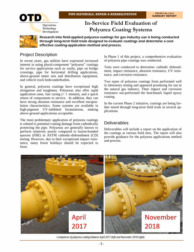
Research into field-applied polyurea coatings for gas industry use is being conducted through long-term field trials designed to evaluate coatings and determine a cost-effective coating-application method and process.
In-Service Field Evaluation of Polyurea Coating Systems
In Phase 1 of this project, a comprehensive evaluation of polyurea pipe coatings was conducted.
Tests were conducted to determine: cathodic disbond-ment, impact resistance, abrasion resistance, UV resis-tance, and corrosion resistance.
Two types of polyurea coatings from performed well in laboratory testing and appeared promising for use in the natural gas industry. Their impact and corrosion resistance out-performed the benchmark liquid epoxy coating.
In the current Phase 2 initiative, coatings are being fur-ther tested through long-term field trials in several ap-plications.
Deliverables Deliverables will include a report on the application of the coatings at various field sites. The report will also provide guidance for the polyurea applications method and process.
- 3 -
Project Description In recent years, gas utilities have expressed increased interest in using plural-component “polyurea” coatings for service applications such as vaults, pipe on bridge crossings, pipe for horizontal drilling applications, above-ground meter sets and distribution equipment, and vehicle truck beds/underbodies.
In general, polyurea coatings have exceptional high elongation and toughness. Polyureas also offer rapid application rates, fast curing (< 1 minute), and a quick return of components to service. In addition, they can have strong abrasion resistance and excellent encapsu-lation characteristics. Some systems are available in high-pigment UV-inhibited formulations, making above-ground applications acceptable.
The most problematic application of polyurea coatings is related to potential coating damage from cathodically protecting the pipe. Polyureas are generally known to perform relatively poorly compared to fusion-bonded epoxies (FBE) in ASTM cathodic-disbondment (CD) testing. However, due to their exceptional impact resis-tance, many fewer holidays should be expected to form.
Comparison of polyurea coating between April 2017 (left) and November 2018 (right).
- 4 -
At the site, coating-thickness measurements were taken at 12 locations along pipe sections in sets of four places around the diameter of the pipe at each location, for a total of 48 measurements.
A component of the inspection focused on rust forma-tion. At first glance, very small pinpoint-style rusting seems to have formed in areas along the pipe. A possi-ble explanation for this formation is overspray, which is a common issue with the application of polyureas due to its fast curing time. If it is only deposited on top of the coating, overspray should not be detrimental. If overspray occurs on the pipe surface prior to the appli-cation of the coating, however, delamination could re-sult. The pattern will not be classified as rust at this time, but dark, dotted areas will be monitored and their growth patterns will be noted.
Very small paint blistering was observed in a few loca-tions along the length of the aboveground pipe. These blisters are very small and few in concentration. The blisters are most likely osmotic blistering due to tem-perature variations of the effluent and ambient tem-peratures. They are hard, firm blisters and if they are cut open, we can assume that one will find moisture but no corrosion below. The liner keeps the moisture from contacting the pipe surface and since no oxygen is present, there is no corrosion.
In 2018, researchers went to the site of a pipe to inspect the polyurea coating again. The coating was installed three years prior to the time of inspection. No major sizes of corrosion were found during the inspection and the coating thickness, surface salt concentration, rust pattern development, and paint blistering was meas-ured at multiple locations on the pipe surface.
The most noticeable difference observed occurred in the coatings color. The coating is a slightly paler yel-low than it had been at the one-year inspection. Some spots of rust are also visible at the flange locations on the valves.
Status The next coating inspection was planned to be per-formed after five years of service (November 2020); however, COVID-19 prohibited inspections at that time. The final inspection is planned to be completed in 2021.
Benefits This research will provide utilities with the comparative, sound engineering data necessary to make decisions regarding the use of polyurea coatings.
Technical Concept & Approach Identification of Field Test Sites and Coating Appli-
cators
Establishment of a Field Testing Matrix
Evaluation of Field-Coating Applications
Coating Evaluation, and
Guidance for Polyurea Applications.
Results The overall performance of polyurea coating was evalu-ated and compared with a benchmark liquid epoxy coat-ing.
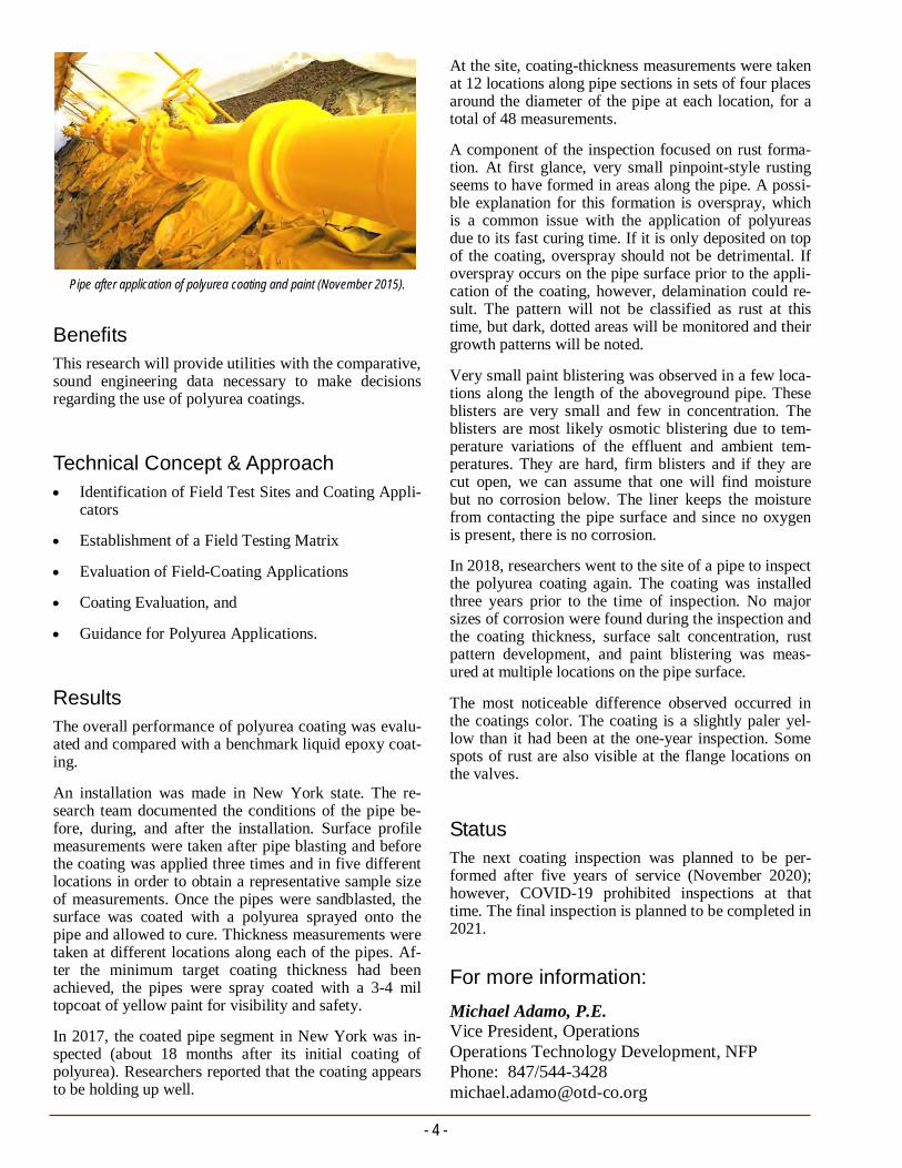
An installation was made in New York state. The re-search team documented the conditions of the pipe be-fore, during, and after the installation. Surface profile measurements were taken after pipe blasting and before the coating was applied three times and in five different locations in order to obtain a representative sample size of measurements. Once the pipes were sandblasted, the surface was coated with a polyurea sprayed onto the pipe and allowed to cure. Thickness measurements were taken at different locations along each of the pipes. Af-ter the minimum target coating thickness had been achieved, the pipes were spray coated with a 3-4 mil topcoat of yellow paint for visibility and safety.
In 2017, the coated pipe segment in New York was in-spected (about 18 months after its initial coating of polyurea). Researchers reported that the coating appears to be holding up well.
For more information:
Michael Adamo, P.E. Vice President, Operations Operations Technology Development, NFP Phone: 847/544-3428 [email protected]
Pipe after application of polyurea coating and paint (November 2015).

PIPE MATERIALS, REPAIR & REHABILITATION PROJECT No. 2.14.a SUMMARY REPORT
Researchers are evaluating a composite pipe wrap system for the repair of mechanically damaged polyethylene gas pipe. The repair system has the potential to lower repair costs, reduce repair times, and minimize service disruptions.
Composite Repair Wrap for Polyethylene Systems
A research team is conducting a thorough evaluation of the pipe-wrap system to develop information on the permanency and life expectancy of the repairs.
Deliverables The deliverables for this project include testing reports detailing the performance of repairs made with the pipe-wrap system.
Benefits PE pipe systems experience two common types of damages. The first type is third-party mechanical dam-age that results in pipe wall loss that requires immedi-ate remediation where the only available option is to remove and replace the damaged section. The second type is longer-term damage which manifests from ei-ther crimp-type fittings or the crimping operation re-quired to conduct a cut-and-replace operation, which introduces micro-cracks into the pipe wall. These mi-cro-cracks can become problematic and can be consid-ered as deferred remediation projects. Both types of damage, if left in their natural state, will result in leaks and/or other hazards. A practical PE permanent repair system will save time and money while minimizing service disruptions.
- 5 -
Project Description With existing polyethylene (PE) pipe repair methods, typically a short section of the distribution system is shut down and bypassed while the damaged pipe sec-tion is cut out and replaced. This approach is time con-suming, expensive, and requires multiple excavations and complicated procedures.
In this project, researchers are investigating a pipe wrap system for the repair of PE pipe components that shows promise of being a fast, easy-to-use, durable, and cost-effective method for PE pipe repair. This method pro-vides direct bonding of composite materials to the PE pipe surface with minimal surface preparation. The composite material may be either resin pre-impregnated fiberglass cloth or field-impregnated fiberglass that ad-heres to PVC, fiberglass, concrete, and all metal pipes. According to the manufacturer, the PE pipe repair method and materials will also provide abrasion and impact resistance to the PE pipe. A single system can be used to repair pipes and/or fittings of various diameters, sizes, and shapes.
Although composites have been used for more than 20 years to remediate steel piping, the ability to repair PE pipe was limited due to the inability of composites to bond to the PE material. The patent-pending pipe wrap technology overcomes this limitation.
Machine detensifier.
Technical Concept & Approach The investigation of the pipe-wrap PE pipe-repair sys-tem focuses on applying the repair technique to differ-ent gas system components to evaluate effectiveness. Simulated defects are machined in each pipe specimen.
Prepared samples undergo the following:
Short-term hydrostatic burst testing.
Rate Process Method (RPM) analysis by perform-ing long-term hydrostatic pressure testing at ele-vated temperatures. Then, failure data obtained at all temperatures will be used to predict the per-formance of the repaired pipe samples at end-use temperature and pressure conditions.
Impact testing in general accordance with ASTM D2444 Standard Test Method for Determination of the Impact Resistance of Thermoplastic Pipe and Fittings by Means of a Tup (falling weight).
Results
In this project, various pipe specimens were prepared with simulated defects and subjected to testing. Based on specimens subjected to hydrostatic burst testing, it appears that the repaired two-inch-diameter pipe sam-ples, irrespective of the pipe sample being heated or not during the repair process, are performing well.
Specimens were notched during preparation with gen-erally four-inch-long longitudinal notches milled in the center of the pipe specimen to a depth of 80% of the measured minimum wall thickness of the specimen. Repair-system applications were conducted while the pipe was both heated and unheated. Plaques of high-density PE measuring 12 inches x 12 inches x ¼ inch were prepared and underwent lap shear testing.
Notched (gouged) pipe specimens were sent to the manufacturer, who designed and built a prototype heat-gun field tool used to apply the repair technology. This device is designed to clamp onto a pipe at either end of the repair area. The device has a variable temperature heating device and a custom-built nozzle that applies a constant temperature heat circumferentially around the pipe.
In 2017, the project team initiated RPM testing and performed tensile pull testing on butt-fusion speci-mens. Test results were compared with those of a con-trol pipe (i.e., straight pipe) and an actual butt-fused pipe. It was shown that the adhesive is required to make an adequate bond to the pipe and the wrap. It was also shown that the butt-joint has a higher peak load than those of the control and butt-fused samples. For all the eight butt-joint specimens tested, the ultimate failure occurred by yielding of the pipe material out-side the repair area.
- 6 -
In 2018, dynamic thermo-mechanical analysis and squeeze-off evaluations were completed. Pipe speci-mens were squeezed-off in accordance with ASTM F1041 and D2513 under 60 psig internal pressure at room temperature. Technicians prepared and wrapped two-inch-diameter medium-density PE pipe samples for burst and long-term hydrostatic strength testing at vari-ous temperatures. Dynamic mechanical thermal analy-sis of the wrap material was also completed.
In 2019, burst testing was completed on wrapped sam-ples at 140°F, 176°F, and 194°F.
In 2020, the project team experienced significant down-time with its test rig. Researchers also encountered is-sues with the leak-detection system of the test rig. Due to restrictions in accessing laboratory facilities as a re-sult of COVID-19 pandemic situation, the troubleshoot-ing and repair of the test rig is behind schedule.
Researchers
Identified an issue where pressure buildup in the water piston during the leak check phase was caus-ing improper pressure profile following
Identified the solution to the pressure buildup is to purge the water piston at the end of the leak check phase
Added a solenoid purge valve to be controlled via the test rig controller, and
Added automatic control of the solenoid purge valve to the test rig controller and verified that the automatic control will resolve the pressure follow-ing issue.
Status
Researchers propose to test squeezed and wrapped sam-ples at 176°F (80°C). Test conditions are based on the elevated temperature sustained pressure test of ASTM D2513-18a.
A trapezoid pressure waveform will be arranged so that the highest pressure corresponds to 670 psi hoop stress where the specimens will be subjected to this stress for approximately 40% of the total cycle time. Specimens will be periodically removed from the cyclic pressure fatigute machine and inspected to see if there has been any delamination of the wrap material from the pipe.
For more information:
Michael Adamo, P.E. Vice President, Operations Operations Technology Development, NFP Phone: 847/544-3428 [email protected]
PIPE MATERIALS, REPAIR & REHABILITATION PROJECT No. 2.14.b SUMMARY REPORT
Pipe System Repair Technique
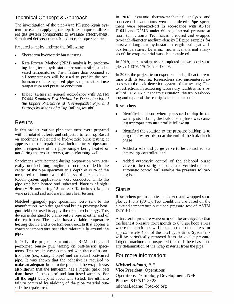
Deliverables Deliverables for this project included details on the performance of the repair technique applied to leaking steel pipe segments and leaking mechanical couplings.
Benefits The goal of this project was to advance the develop-ment of a permanent in-situ (i.e., without shutdown/bypass and cut out) method to repair leaking gas-system components and simultaneously provide axial pullout restraint for non-restraint type couplings. The commercial introduction of such a method would re-duce operational costs and time, and improve the integ-rity of the gas piping systems.
This research also provider utilities and potential com-mercializers with the sound engineering test data nec-essary to determine the permanence and effectiveness of this innovative in-situ repair method.
Technical Concept & Approach Initially, this project focused on a repair technique used to seal leaking couplings. This project included tests to validate the technique on various steel gas-system components to evaluate its effectiveness and refine the process. For testing, the research team
- 7 -
Project Description For the natural gas industry, leaking infrastructure has always been a challenge to repair or replace. The op-tions that currently exist involve line blow-down, by-pass, cut out and replace, or encapsulation type fit-tings. There are very few options for the live in-situ repair of leaking infrastructure components, and the repair of leaking couplings and threaded joints are of-ten nonexistent, costly, or unreliable.
A method was developed and tested that can seal a live leaking mechanical coupling up to a 60 psig gas line and provide axial restraint that exceeds that of a prop-erly installed new pipe. A follow-on project attempted to further that method, but ran into several difficulties with the technique while applying a wrap under pres-sure. A decision to alter the design was made and the project focused on repair of steel couplings. Prototypes were made of three different designs.
The designs included:
1. A foam mold was created that forms around the pipe and is installed adjacent to the leaking cou-pling. There is a gap and a vent port that allows for the injection of the epoxy to seal the leak. The cou-pling is then wrapped with a composite wrap.
2. A removal steel mold was made that can be reused for multiple repairs. The mold is attached to the leaking coupling and the epoxy is injected and cured. The mold is then removed and the epoxy is wrapped with the composite.
3. A removable mold was created to seal pinhole-type corrosion leaks. The mold is very similar to the coupling mold, but seals to the pipe on both sides. Epoxy in injected in a similar fashion and when cured the mold is removed and is wrapped in the composite material.
This new project focused on validating, finalizing, and applying the repair technique to various steel compo-nents.
Pipe samples for testing.
In this project, researchers developed and tested a novel repair method for live leaking steel-infrastructure applications. The goal was to have the repair method applicable to steel couplings, threaded joints, cast-iron bell joints, and service tees.
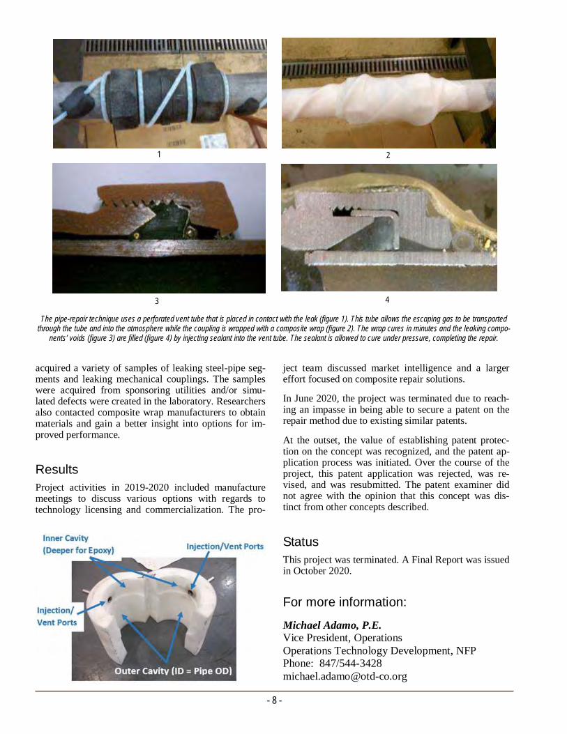
The pipe-repair technique uses a perforated vent tube that is placed in contact with the leak (figure 1). This tube allows the escaping gas to be transported through the tube and into the atmosphere while the coupling is wrapped with a composite wrap (figure 2). The wrap cures in minutes and the leaking compo-
nents’ voids (figure 3) are filled (figure 4) by injecting sealant into the vent tube. The sealant is allowed to cure under pressure, completing the repair.
3 4
2 1
- 8 -
ject team discussed market intelligence and a larger effort focused on composite repair solutions.
In June 2020, the project was terminated due to reach-ing an impasse in being able to secure a patent on the repair method due to existing similar patents.
At the outset, the value of establishing patent protec-tion on the concept was recognized, and the patent ap-plication process was initiated. Over the course of the project, this patent application was rejected, was re-vised, and was resubmitted. The patent examiner did not agree with the opinion that this concept was dis-tinct from other concepts described.
Status This project was terminated. A Final Report was issued in October 2020.
acquired a variety of samples of leaking steel-pipe seg-ments and leaking mechanical couplings. The samples were acquired from sponsoring utilities and/or simu-lated defects were created in the laboratory. Researchers also contacted composite wrap manufacturers to obtain materials and gain a better insight into options for im-proved performance.
Results Project activities in 2019-2020 included manufacture meetings to discuss various options with regards to technology licensing and commercialization. The pro-
For more information:
Michael Adamo, P.E. Vice President, Operations Operations Technology Development, NFP Phone: 847/544-3428 [email protected]
PIPE MATERIALS, REPAIR & REHABILITATION PROJECT No. 2.14.c SUMMARY REPORT
Project Description This project involved an examination of the potential for reducing current minimum polyethylene (PE) pipe squeeze-off distances from fittings in order to facilitate routine operations and maintenance tasks.
In Phase 1 of the project, the applicability of minimum squeeze-off distances from fittings and other appurte-nances for the case of small-diameter (two inches or less) PE pipe and tubing was addressed. Through this study, researchers developed and experimentally vali-dated a model for predicting the effects of squeeze-off incurred as a function of pipe diameter, temperature, and pinch-point location in relation to the proximity of fit-tings and other appurtenances. In addition, this study presented an opportunity to investigate modern bimodal (medium-density and high-density) materials which had not previously been formally evaluated for squeeze-off applications. Phase 2 focused on the investigation of modern PE materials that were not previously evaluated for squeeze-off in Phase 1 of the project.
Through this project, researchers developed a model for predicting the effects of squeeze-off on small-diameter PE pipe. Study findings may result in changes to current standards that could facilitate natural gas operations and provide efficiency and economic benefits.
Assessment of Squeeze-Off Location for Small-Diameter Polyethylene (PE) Pipe and Tubing
Deliverables The deliverables for the project include a project report that details findings from the modeling and experimen-tal efforts, along with a recommendation for minimum squeeze-off locations relative to pipe joints in smaller-diameter pipes for each material included in the study.
Benefits The ability to perform squeeze-offs within one foot of pipe joints and couplings may significantly reduce re-quired excavation sizes. Study findings may result in recommended changes to current squeeze-off proce-dures with potential efficiency and economic benefits.
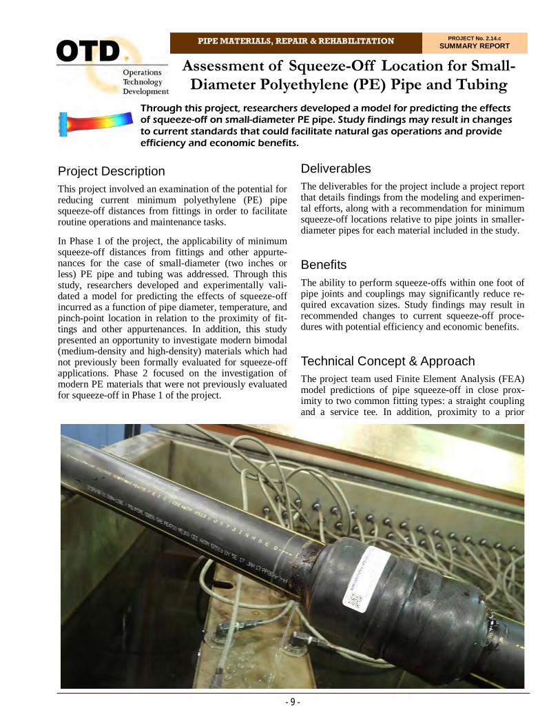
Technical Concept & Approach The project team used Finite Element Analysis (FEA) model predictions of pipe squeeze-off in close prox-imity to two common fitting types: a straight coupling and a service tee. In addition, proximity to a prior
- 9 -

and a service tee. In addition, proximity to a prior Ac-celerated hydrostatic sustained pressure testing was conducted at three temperatures, each with three repli-cates.
The goal was to determine critical proximity for which detrimental effect is equally likely to be sustained in the pipe at the squeeze location or at the fitting, and then back-off the squeeze location such that a 10% stress reduction is observed at the fitting. Researchers experi-mentally validated crossover location predicted by the FEA model for a single temperature (e.g. 80ºC) for a coupling scenario.
Microscopic assessments were conducted of pipe dam-age imparted by squeeze-off performed at a range of distances from the nearest fitting.
Results In this project, researchers successfully developed an advanced constitutive model for various types of PE pipe, performed FEM simulations of squeeze-off, and conducted multiple long-term pressure tests pipes squeezed-off near various fitting types.
The overall conclusion of the work performed in this project is that a distance of three pipe diameters (outside diameter) between a squeeze-off location and any joint or fusion is acceptable for smaller-diameter PE pipes (three inches or less).
The following findings support this conclusion:
Finding 1: FEM simulations of squeeze-offs indicated that at a distance of three times the outside pipe diame-ter (3XOD) (or greater) from a squeeze-off location there is negligible disturbance to the pipe, regardless of joint or fitting type, temperature, and PE class.
Finding 2: Long-term pressure tests have shown that squeeze-offs performed at a 3xOD distance from vari-ous joint types resulted in failures that fell within the expected performance of the pipe and were comparable to results from 12-inch distance squeeze-offs.
- 10 -
Finding 3: An assessment of damage induced by squeeze-offs at 12 inches and 3xOD distances showed no significant distribution difference from nominal pipe without squeeze-offs. This finding provides support to the acceptability of squeeze-off on PE pipe as well as to a 3xOD squeeze-off distance from various appurte-nances for smaller diameter pipes.
It should be noted that the squeeze-off simulations per-formed in this project measured the squeeze-off dis-tance from the center of the squeeze bar. However, from a practical perspective, field operators may not be able to precisely place the center of a squeeze bar at a given distance from a joint or fitting, especially with pipes with a diameter smaller than the squeeze-bar diameter. It is therefore suggested that the squeeze-off distance be measured from the edge of the squeeze bar, rather than its center.
In 2019, the project team completed the long-term hy-drostatic pressure testing, material properties testing, and finite element simulation of various squeeze-off scenarios.
In the first half of 2020, researchers addressed out-standing concerns raised by project sponsors and other industry stakeholders related to acceptance of a 3xOD minimum distance instead of the current 12-inch mini-mum for small-diameter pipes and tubing.
Status
This project is complete. A Phase 2 Final Report was issued in September 2020. The ASTM F1041 standard was updated based on the results from this project.
Sample with mechanical coupling, squeeze-off performed on both ends.
For more information:
Michael Adamo, P.E. Vice President, Operations Operations Technology Development, NFP Phone: 847/544-3428 [email protected]
INSPECTION & VERIFICATION Projects in this area focus on the development of tools and techniques
to assist companies in enhancing safety and meeting integrity requirements in a cost-effective manner.
To meet the challenges of pipeline integrity management,
researchers are developing pipe-inspection systems and other technologies for gas delivery systems.
Through R&D in this area, pipeline and distribution system integrity can be maintained and improved based on sound, scientific developments
related to inspection, testing, and other activities.
Initiatives include efforts to develop a butt-fusion inspection device for use in the field, self-healing coatings, and a tool to detect coating
disbondment and metal loss. .

INSPECTION & VERIFICATION PROJECT No. 4.12.c SUMMARY REPORT
This project is focused on the development of a practical tool for detecting cathodic disbondment and metal loss. The technology would enhance the safety of steel gas piping systems by providing the ability to locate potential pipe-corrosion sites before leaks or serious metal loss occurs.
Tool for Detection of Cathodic Disbondment and Metal Loss
This technology can increase system knowledge of coated steel pipe without the need for excavation. In addition to providing assessment data, the method also generates Global Navigation Satellite System refer-enced maps of the facility surveyed. The ability to cap-ture both by executing a single procedure would streamline the capture of integrity management data.
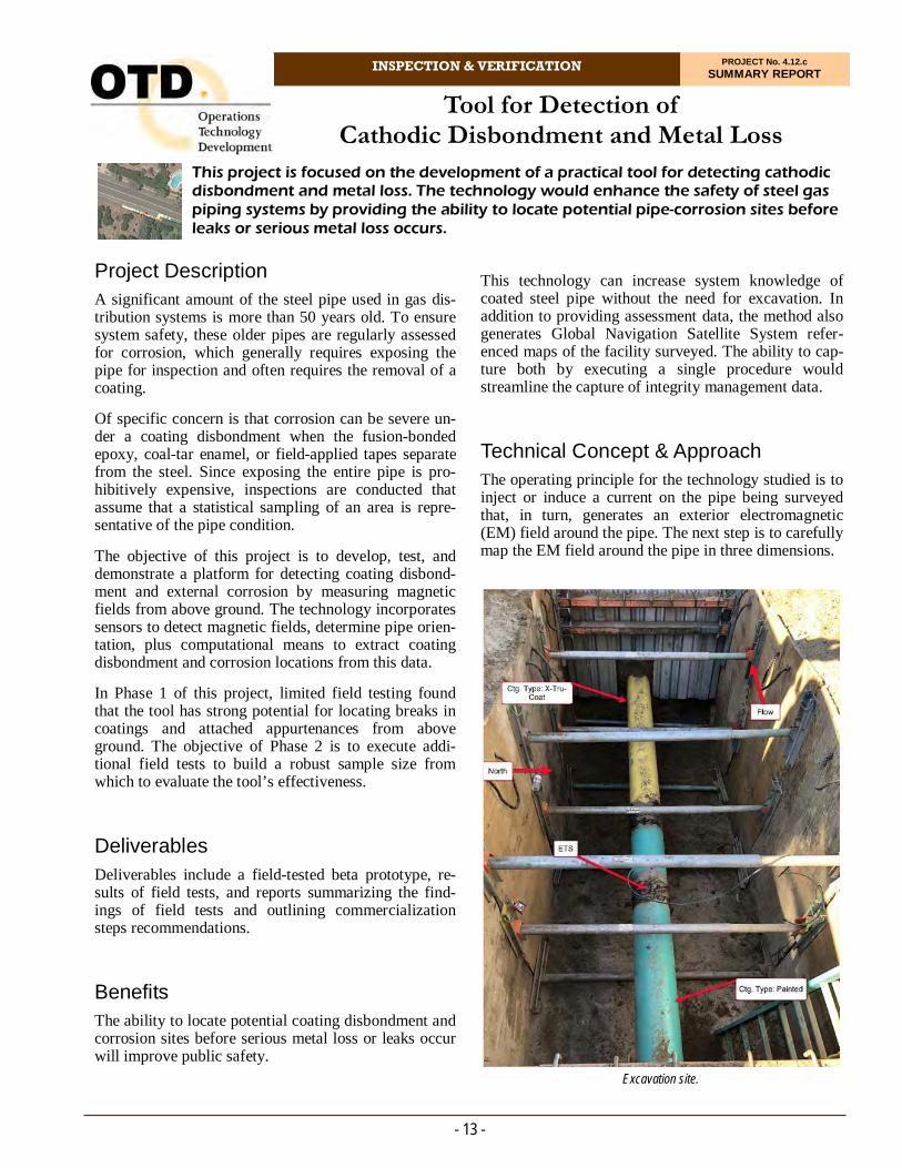
Technical Concept & Approach The operating principle for the technology studied is to inject or induce a current on the pipe being surveyed that, in turn, generates an exterior electromagnetic (EM) field around the pipe. The next step is to carefully map the EM field around the pipe in three dimensions.
- 13 -
Project Description A significant amount of the steel pipe used in gas dis-tribution systems is more than 50 years old. To ensure system safety, these older pipes are regularly assessed for corrosion, which generally requires exposing the pipe for inspection and often requires the removal of a coating.
Of specific concern is that corrosion can be severe un-der a coating disbondment when the fusion-bonded epoxy, coal-tar enamel, or field-applied tapes separate from the steel. Since exposing the entire pipe is pro-hibitively expensive, inspections are conducted that assume that a statistical sampling of an area is repre-sentative of the pipe condition.
The objective of this project is to develop, test, and demonstrate a platform for detecting coating disbond-ment and external corrosion by measuring magnetic fields from above ground. The technology incorporates sensors to detect magnetic fields, determine pipe orien-tation, plus computational means to extract coating disbondment and corrosion locations from this data.
In Phase 1 of this project, limited field testing found that the tool has strong potential for locating breaks in coatings and attached appurtenances from above ground. The objective of Phase 2 is to execute addi-tional field tests to build a robust sample size from which to evaluate the tool’s effectiveness.
Deliverables Deliverables include a field-tested beta prototype, re-sults of field tests, and reports summarizing the find-ings of field tests and outlining commercialization steps recommendations.
Benefits The ability to locate potential coating disbondment and corrosion sites before serious metal loss or leaks occur will improve public safety.
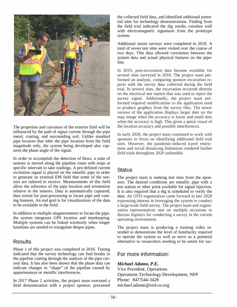
Excavation site.
- 14 -
the collected field data, and identified additional poten-tial sites for technology demonstrations. Finding from the field trial indicated the dig results correlate well with electromagnetic signatures from the prototype system.
Additional onsite surveys were completed in 2018. A total of seven test sites were visited over the course of two days. This data allowed correlation between the system data and actual physical features on the pipe-line.
In 2019, post-excavation data became available for several sites surveyed in 2018. The project team per-formed an analysis, comparing sponsor excavation re-ports with the survey data collected during the field trial. In several sites, the excavation occurred directly on the electrical test station that was used to inject the survey signal. Additionally, the project team per-formed required modifications to the application used to produce graphics from the survey files. The newer version of the application displays larger dots on the map image when the accuracy is lower and small dots when the accuracy is high. This gives a quick visual of the location accuracy and possible interferences.
In early 2020, the project team continued to work with sponsors to focus on identifying additional field trail sites. However, the pandemic-induced travel restric-tions and social distancing limitations rendered further field trials throughout 2020 unfeasible.
Status
The project team is seeking test sites from the spon-sors. The desired conditions are metallic pipe with a test station or other point available for signal injection. It is also required that a dig is scheduled to verify the data. An OTD organization came forward in late 2020 expressing interest in leveraging the system to conduct a large-scale field survey. The project team and organi-zation representatives met on multiple occasions to discuss logistics for conducting a survey in the current operating environment.
The project team is producing a training video in-tended to demonstrate the level of familiarity required to operate the system as well as serve as a potential alternative to researchers needing to be onsite for sur-
The properties and curvature of the exterior field will be influenced by the path of signal current through the pipe metal, coating, and surrounding soil. Unlike standard pipe locators that infer the pipe location from the field magnitude only, the system being developed also cap-tures the phase angle of the signal.
In order to accomplish the detection of flaws, a suite of sensors is moved along the pipeline route with stops at specific intervals to take readings. A pre-defined current excitation signal is placed on the metallic pipe in order to generate an external EM field that some of the sen-sors are tailored to receive. Measurements of this field allow the inference of the pipe location and orientation relative to the sensors. Data is automatically captured, then stored for post-processing to locate pipe and coat-ing features. An end goal is for visualizations of the data to be available in the field.
In addition to multiple magnetometers to locate the pipe, the system integrates GPS location and timekeeping. Multiple systems can be linked wirelessly when longer baselines are needed to triangulate deeper pipes.
Results Phase 1 of this project was completed in 2016. Testing indicated that the survey technology can find breaks in the pipeline coating through the analysis of the pipe cur-rent data. It has also been shown that the phase data can indicate changes in “shape” of the pipeline caused by appurtenances or metallic interferences.
In 2017 Phase 2 activities, the project team executed a field demonstration with a project sponsor, processed
For more information:
Michael Adamo, P.E. Vice President, Operations Operations Technology Development, NFP Phone: 847/544-3428 [email protected]

Correlation of Surface to Through-Wall Properties of Pipe
INSPECTION & VERIFICATION PROJECT No. 4.14.c SUMMARY REPORT
Efforts are under way to develop a technique that allows pipeline operators to determine the material properties of in-service pipe with minimal disruption to system operations. In this project, specific activities are focused on the correlation factors to relate surface properties to actual material properties to allow surface-indentation techniques to be used for material characterization.
Technical Concept & Approach The scope of this project includes the development of factors to correlate surface properties with through-wall material properties based on vintage.
Testing included full-size tensile, probe, Charpy V-notch toughness, metallography and microstructure, hardness, and other metallurgical and mechanical tests as warranted.
The approach taken to validate the surface-inter-rogation methods was to assemble a comprehensive database of material properties of pipeline steels, in-cluding surface and bulk chemistry; surface and bulk mechanical properties; and surface and bulk metallur-gical grain size.
- 15 -
Project Description Regulations may require natural gas pipeline operators to perform material testing for all transmission pipe that does not have validated and traceable material-property records. Compliance with this regulation us-ing currently allowed techniques could be extremely expensive.
This project addresses the need for a technique that allows operators to determine the material properties of in-service pipe with minimal disruption to system operations.
Past research proved the ability of surface indentation techniques (e.g., stress-strain microprobes and hard-ness testing) to accurately determine material proper-ties of pipes within a localized area; however, varia-tions in material properties through the wall are prob-lematic for local interrogation techniques. This project focuses on the development of correlation factors to relate surface properties to through-wall material prop-erties to allow surface techniques to be used for mate-rial property validation for pipelines.
Deliverables Deliverables include a database of through-wall prop-erties by vintage for typical pipelines in service in the natural gas industry. The probability distributions of these properties can be used to correlate existing and future surface-based measurement techniques to an aggregate through-wall property to comply with and pipeline safety and integrity requirements.
Benefits The ability to characterize material properties –particularly yield strength – of in-service pipelines without taking the line out of service or removing sam-ples will significantly reduce the cost of complying with existing and pending federal regulations. Backfil-ing records with material-property information also improves integrity management through system knowledge that allows for enhanced modeling and analysis.

The project team:
Analyzed the variance of the difference between surface and bulk measurements
Developed a simple in-field procedure to remove a minimal outer layer from the pipe surface to reduce the variance between surface and bulk properties to an acceptable level
Determined the robustness of recognized chemical mechanical models for predicting the mechanical properties of the steels and selected the most appro-priate models, and
Adjusted and validated the model.
To address the issue of non-uniformity, a technique was developed to remove a full-wall thickness, sub-sized samples from a standard six-inch hot tap coupon to al-low yield strength testing to be performed. An extensive testing program validated the equivalence of the sub-sized samples to the full-size samples.
Results
In this project, researchers investigated the use of a chemistry-based approach vs. a mechanical-property approach for bounding bulk properties. Early in the pro-ject, it was decided that the primary methodology would be to use in-situ chemistry and micro-structure to iden-tify material properties of interest rather than through mechanical testing alone. Researchers tested the chemi-cal models on 18 pipe steels, showing more promising results than with the indentation technique.
In 2018, the project team executed an agreement with the U.S. Department of Transportation’s Pipeline and Hazardous Materials Safety Administration for Phase 2 of the project. In Phase 2, researchers are reviewing pipe samples and existing data for gaps in the baseline data (e.g., yield and tensile strength, toughness, grain size, and chemistry).
New data was introduced into the pipe sample library – including bulk nitrogen chemical composition and grain size for select samples – and data was reorganized and simplified.
In 2019, researchers enhanced the laboratory with a high-weight capacity worktable, pipe stands, and a plasma cutter for efficient and safe pipe handling, cut-ting, and testing.
Researchers established the testing regime/matrix for: yield and tensile strength; toughness; chemistry; micro-structure and grain size; and hardness.
A detailed Bayesian Model Averaging (BMA) analysis was conducted to determine the efficacy and use of this
- 16 -
approach to improve modeling results. It was shown that the BMA can provide better/similar performance with a surface-only indentation technique and linear regression with complete data.
Research focused on the effect of adding quadratic (non-linear) terms to this linear model and the com-parison between the linear and quadratic models. The previously developed BMA method for multimodality information fusion for strength estimation was utilized. The full calibration dataset was used for model com-parison according to posterior model probabilities. The validations were made by splitting the data 100 times to evaluate the models according to predictive per-formance. Results showed that the linear model be-haves as well as the top quadratic models. The linear model also shows robustness for prediction.
In 2020, testing of all 70 pipe samples was complete. The project team extended the validation and demon-stration with the newly provided data sets for both yield strength and ultimate strength.
Researchers completed the remaining plots of the three Charpy measures to definitively determine the upper shelf location and associated toughness values. With the Charpy testing now complete, 100% of all labora-tory testing is done.
A new rank list of useful variables obtained by using BMA with new 53-point dataset was developed. Sub-sequently, the best linear model and the best quadratic were achieved. Both specific case and general cases were analyzed to evaluate the performance of this new method in terms of doing yield strength prediction.
It was found that the linear model is the best among the three model types. The preliminary results of using manifold learning demonstrated the potential ability to handle a high-dimension regression problem..
Status The team completed the nondestructive fracture tough-ness testing and is in the process of data conversion and correlation to Charpy destructive toughness test-ing.
The project team is also completing a summary of data analysis and model generation and optimization.
For more information:
Michael Adamo, P.E. Vice President, Operations Operations Technology Development, NFP Phone: 847/544-3428 [email protected]

Development of a Long-Term Enhancement of Direct Assessment
INSPECTION & VERIFICATION PROJECT No. 4.17.a SUMMARY REPORT
The objective of this project is to provide a technically justifiable, augmented method to retain direct assessment as an acceptable integrity-assessment process for pipeline segments.
Identification of the strengths, weaknesses, oppor-tunities, and threats for DA use in the highest-priority cases for ECDA
A set of process enhancements for the selected use cases for ECDA, including augmented inspections and P&M measures, and
A statistical analysis process for ECDA that will establish confidence, uncertainty, and prediction limits for ECDA assessments.
Benefits An enhanced DA technique, with technical justifica-tion and eventual standard support, would allow opera-tors to comply with regulations for challenging assets such as: vintage pipe that could be damaged by pres-sure or ILI testing, short tap/tee sections, cased pipe, non-full-bore sections, and other pipeline assets.
Technical Concept & Approach Specific tasks in this project include:
The Development of a Prioritized List of DA Applications
This task includes determining the system configu-rations where use of DA is most critical and where
- 17 -
Project Description The use of direct assessment (DA) – an approved, structured process for determining pipeline conditions – is expected to be restricted from use as the sole in-spection method if any one of five other inspection methods are “capable” of being used, namely: in-line inspection (ILI), pressure testing, hydrostatic spike testing, excavation and direct examination, and guided-wave testing. However, pipeline operators have a sig-nificant number of covered transmission assets that are not conducive to ILI and/or pressure or spike testing. Full pipe excavation and direct examination is often not possible or practical, and guided-wave inspection has limited range and restrictions on use.
The gas industry has expressed interest in a process improvement or enhancement to the current practice that would allow DA’s continued, justified use for spe-cific categories of transmission lines. This enhance-ment might include supplementation with other data or inspection technologies and increased preventative and mitigative (P&M) measures and surveys, but not re-quire the same operational actions of ILI or pressure/spike testing.
This project builds upon two previous projects:
1. A hands-on, demonstration, testing, and analysis project titled Demonstration of ECDA Applicabil-ity and Reliability for Demanding Situations, and
2. A study titled Improving the Performance of the External Corrosion Direct Assessment (ECDA) Methodology.
The overall objective for this project is to develop a technically justifiable, augmented method to retain DA as an acceptable integrity-assessment process for pipe-line segments.
Deliverables
This project provides the following:
A prioritized list of DA applications from an op-erator’s perspective
Congested meter regulator station DA site with crossing situations.

- 18 -
tion of those expressed in the publications reviewed in the literature search, coupled with those from a spon-sor survey.
The opportunities were divided into seven categories:
1. Data and Pre-Assessment
2. Inspection Tools
3. Training
4. Casings, Facilities/Stations, and Pavement
5. Failure Analysis; Corrosion Rates; and Tracking, Trending, and Effectiveness
6. Risk-Based and Probabilistic Analysis, and
7. Accelerate and Simplify.
The report also includes responses to a sponsor survey and information on ECDA strengths and weaknesses.
In 2020, prior tasks were combined into an outline that now contains the prioritized enhancements.
Status The project team is addressing the 14 prioritized en-hancements studied, organized, surveyed, and priori-tized.
the loss of this option would be of the most detri-ment. The list will be prioritized by both the type of DA being used (i.e., external corrosion, internal cor-rosion, and stress corrosion cracking) and also by the physical and operational category of the asset (i.e., station piping and systems, non-full-bore sys-tems, tees, single feeds, vintage pipe, etc.).
The Identification of the Strengths, Weaknesses, and Gaps for DA in High-Priority Applications
Based on the findings, researchers may select some applications for enhancement development.
The Development of Process Augmentations
The project team will develop the augmentations to specific ECDA processes. This task will focus on bolstering the current DA practice for the selected applications with additional preliminary data re-quirements, indirect inspection tool technology and use, changes to current practices such as close inter-val survey spacing requirements and post-assess-ment efforts
Researchers will leverage the lessons learned and statistical and probabilistic methods developed for two earlier projects. These projects successfully de-veloped a statistical and probabilistic method to de-termine the likely damage, corrosion, and leak con-ditions of assets. The method uses Bayesian statis-tics and probability theory to provide these predic-tions based on historical and operator data and al-lowed the setting of a mutually accepted confidence level (between the operators and the regulators) to determine the best- and worst-case scenario for damage, corrosion, and leak conditions.
Researchers will adapt these statistical techniques to be used with ECDA data and allow the operators to apply the results and associate a confidence level and prediction limits to the DA predictions.
Results In 2019, the project took a temporary turn with an op-portunity to join another project developing enhanced statistical and probabilistic analysis techniques that could be fully leveraged for the DA project.
A report was released that contained the ECDA litera-ture review. The review includes 53 summaries of stan-dards and peer review papers related to direct assess-ment, primarily to external corrosion direct assessment.
The report also includes information on the ECDA strength/weakness analysis and a key section on oppor-tunities to enhance the ECDA process and data analysis. This section lists 48 opportunities, which are a combina-
Congested meter-regulator station DA site with tees, stubs, and tap lines.
For more information:
Michael Adamo, P.E. Vice President, Operations Operations Technology Development, NFP Phone: 847/544-3428 [email protected]
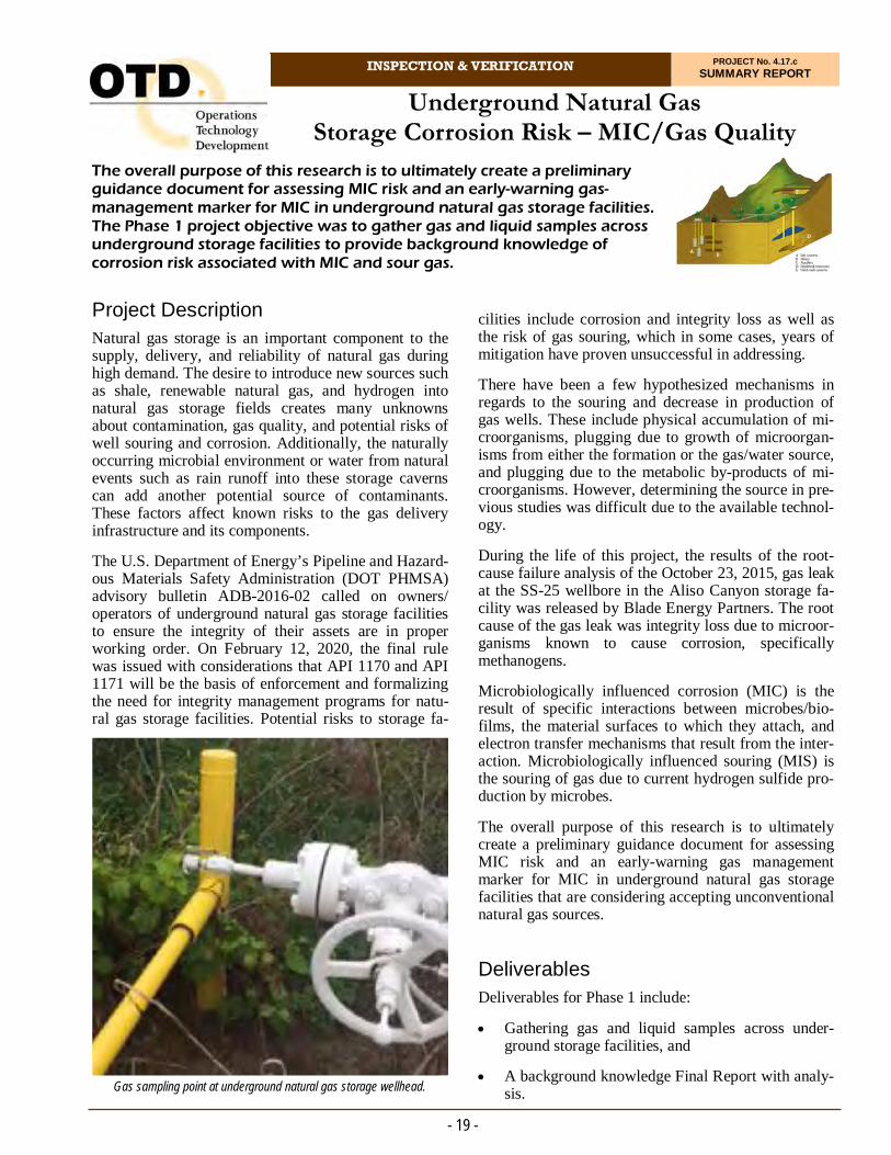
Underground Natural Gas Storage Corrosion Risk – MIC/Gas Quality
INSPECTION & VERIFICATION PROJECT No. 4.17.c SUMMARY REPORT
cilities include corrosion and integrity loss as well as the risk of gas souring, which in some cases, years of mitigation have proven unsuccessful in addressing.
There have been a few hypothesized mechanisms in regards to the souring and decrease in production of gas wells. These include physical accumulation of mi-croorganisms, plugging due to growth of microorgan-isms from either the formation or the gas/water source, and plugging due to the metabolic by-products of mi-croorganisms. However, determining the source in pre-vious studies was difficult due to the available technol-ogy.
During the life of this project, the results of the root-cause failure analysis of the October 23, 2015, gas leak at the SS-25 wellbore in the Aliso Canyon storage fa-cility was released by Blade Energy Partners. The root cause of the gas leak was integrity loss due to microor-ganisms known to cause corrosion, specifically methanogens.
Microbiologically influenced corrosion (MIC) is the result of specific interactions between microbes/bio-films, the material surfaces to which they attach, and electron transfer mechanisms that result from the inter-action. Microbiologically influenced souring (MIS) is the souring of gas due to current hydrogen sulfide pro-duction by microbes.
The overall purpose of this research is to ultimately create a preliminary guidance document for assessing MIC risk and an early-warning gas management marker for MIC in underground natural gas storage facilities that are considering accepting unconventional natural gas sources.
Deliverables Deliverables for Phase 1 include:
Gathering gas and liquid samples across under-ground storage facilities, and
A background knowledge Final Report with analy-sis.
- 19 -
Project Description Natural gas storage is an important component to the supply, delivery, and reliability of natural gas during high demand. The desire to introduce new sources such as shale, renewable natural gas, and hydrogen into natural gas storage fields creates many unknowns about contamination, gas quality, and potential risks of well souring and corrosion. Additionally, the naturally occurring microbial environment or water from natural events such as rain runoff into these storage caverns can add another potential source of contaminants. These factors affect known risks to the gas delivery infrastructure and its components.
The U.S. Department of Energy’s Pipeline and Hazard-ous Materials Safety Administration (DOT PHMSA) advisory bulletin ADB-2016-02 called on owners/operators of underground natural gas storage facilities to ensure the integrity of their assets are in proper working order. On February 12, 2020, the final rule was issued with considerations that API 1170 and API 1171 will be the basis of enforcement and formalizing the need for integrity management programs for natu-ral gas storage facilities. Potential risks to storage fa-
Gas sampling point at underground natural gas storage wellhead.
The overall purpose of this research is to ultimately create a preliminary guidance document for assessing MIC risk and an early-warning gas-management marker for MIC in underground natural gas storage facilities. The Phase 1 project objective was to gather gas and liquid samples across underground storage facilities to provide background knowledge of corrosion risk associated with MIC and sour gas.
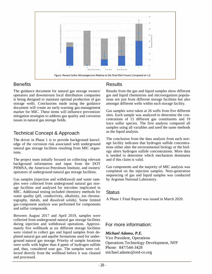
- 20 -
Results Results from the gas and liquid samples show different gas and liquid chemistries and microorganism popula-tions not just from different storage facilities but also amongst different wells within each storage facility.
Gas samples were taken at 26 wells from five different sites. Each sample was analyzed to determine the con-centrations of 15 different gas constituents and 19 trace sulfur species. The first analysis compared all samples using all variables and used the same methods as the liquid analysis.
The conclusion from the data analysis from each stor-age facility indicates that hydrogen sulfide concentra-tions either alter the environmental biology or the biol-ogy alters hydrogen sulfide concentrations. More data is needed to determine which mechanism dominates and if this claim is valid.
Gas components and the majority of MIC analysis was completed on the injection samples. Next-generation sequencing of gas and liquid samples was conducted by Argonne National Laboratory.
Status A Phase 1 Final Report was issued in March 2020.
Benefits The guidance document for natural gas storage owners/operators and downstream local distribution companies is being designed to maintain optimal production of gas storage wells. Conclusions made using the guidance document will create an early-warning gas-management marker for MIC. These items will influence prevention/mitigation strategies to address gas quality and corrosion issues in natural gas storage fields.
Technical Concept & Approach The driver in Phase 1 is to provide background knowl-edge of the corrosion risk associated with underground natural gas storage facilities resulting from MIC organ-isms.
The project team initially focused on collecting relevant background information and input from the DOT PHMSA, the American Petroleum Institute, and owners/operators of underground natural gas storage facilities.
Gas samples (injection and withdrawal) and water sam-ples were collected from underground natural gas stor-age facilities and analyzed for microbes implicated in MIC. Additional testing included chemistry methods for water quality (pH, conductivity, alkalinity, ion chroma-tography, metals, and dissolved solids). Some limited gas-component analysis was performed for components and sulfur compounds.
Between August 2017 and April 2019, samples were collected from underground natural gas storage facilities during injection and withdrawal operations. Approxi-mately five wellheads at six different storage facilities were visited to collect gas and liquid samples from de-pleted natural gas and aquifer formations used for under-ground natural gas storage. Priority of sample locations were wells with higher than 4 ppmv of hydrogen sulfide and, thus, considered sour gas. The samples were col-lected directly from the wellhead before it was cleaned and processed.
For more information:
Michael Adamo, P.E. Vice President, Operations Operations Technology Development, NFP Phone: 847/544-3428 [email protected]

MAOP and Materials Verification
INSPECTION & VERIFICATION PROJECT No. 4.17.d SUMMARY REPORT
This project leverages four significant OTD-sponsored efforts that each addresses a part of the MAOP and materials verification requirements, but currently operate with different software platforms and are not interconnected.
1. 4.12.b - Correlating Pipeline Operations to Poten-tial Crack Initiation, Growth, and Arrest - This project successfully developed and validated the material models necessary to properly model crack initiation in pipeline steels. A detailed calculator using the response surfaces was developed.
2. 4.13.d - Hydro-Testing Alternative Program - This project successfully developed a convenient way to calculate the critical crack axial-flaw sizes and/or non-crack wall loss (e.g., corrosion pitting) that will result in predicted failure at the given pressure.
3. 4.9.a Leak-Rupture Boundary Determination - A study was conducted using incident and laboratory testing data with advanced modeling techniques to calculate the boundary between failure by leak and failure by rupture as a function of the pipe’s Speci-fied Minimum Yield Strength.
- 21 -
Project Description The objective for this project is to provide a compre-hensive and easy-to-use web-based software solution to assist operators in complying with maximum allow-able operating pressure (MAOP) and materials verifi-cation requirements for the integrity verification proc-ess (IVP) used by gas companies to help maintain safety and reliability.
Regulations allow for the use of Engineering Critical Assessments (ECA) in lieu of a hydro-test, de-rating, or pipe replacement. This will also support the use of structured pipe-surface-based non-destructive measure-ments in lieu of cut-outs and minimize the number of destructive tests when those are absolutely necessary.
This project leverages four significant OTD-sponsored efforts that each addresses a part of the MAOP and materials verification requirements, but currently oper-ate with different software platforms and are not inter-connected:
Information from four key OTD projects is being combined into one easy-to-use format.

- 22 -
also establish the output requirements of the soft-ware platform to be able to provide a technically justifiable report to support MAOP and materials verification requirements.
Results In 2018, the project incorporated two actual transmis-sion pipeline field studies with full IVP/ECA imple-mentations. Physical inspection and analysis of the two transmission lines were made with the pilot study operator and service provider. The pilot project ran multiple in-line inspection (ILI) tools and in-the-ditch nondestructive evaluation (NDE) testing to develop the IVP/ECA process and the framework for the asso-ciated engineering analysis software. A number of in-dentation were cut out of the pipe and sent for labora-tory analysis.
In 2019, both of the pilot transmission lines completed four ILI runs.
In 2020, a combination of the delays due to ILI issues, budget increases due to timing, and COVID-19 made the year very challenging. The project team will com-plete the project with the use of data that is now being assembled for another OTD project (4.20.a). This will include realistic material, mechanical, and physical properties as well as defect geometries for both wall loss and crack-like defects.
A set of closed-form model solutions for the ASME B31G modified (wall loss defects) and the Maxey-Folias Leak-Rupture Boundary model were created and checked. Additionally, the latest Mat8 Model for crack-type failures was set up and run. This covers the predicted failure pressures for wall loss and cracks as well as the failure mode (stable leak vs. rupture).
Status A data set is being leveraged for this project to estab-lish a set of examples and the associated ECA frame-work.
The calculators for ASME B31G Mod, LRB, and Mat8 will be leveraged for use in the ECA solution for this project.
4. 4.14.c Surface Indentation for Material Characteri- zation: Correlation of Surface Properties Based on Vintage - The objective of this ongoing project is to develop correlation factors to relate surface proper- ties to bulk material properties for material property validation for pipelines.
The data from OTD project 4.20.a – a project sponsored by U.S. Department of Energy – will be used as a surro-gate in lieu of pilot project data.
Deliverables
The major deliverable for Phase 1 of this project is a vetted software framework that will integrate multiple OTD project models into a single system to assist opera-tors perform MAOP and materials verifications. A Sub-ject-Matter Expert (SME) Group will be established re-lated to IVP and ECA and this group’s needs.
Benefits An integrated solution will provide the benefits from the four foundational OTD projects, but in an easier-to-use, single platform that is also mapped to the most recent, pending code requirements. This approach leverages research that is already completed and focuses the solu-tions on the newest code-compliance requirements.
Technical Concept & Approach Specific tasks for this project include:
Establishing an SME Group for MAOP and Ma-terials Verifications
In this task, researchers and sponsors will establish an expert group focused on the use of MAOP and materials verification processes and procedures. The goal is to develop use cases that the sponsor compa-nies will consider to comply with the IVP/ECA process for verifications.
Correlating Verification Requirements to the OTD Body of Work and Models
In this task, the project team will document the de-tailed requirements for material verification sam-pling requirements, including allowed accuracy and margin of errors. Researchers will map the require-ments for ECA, materials sampling, fracture me-chanics, and metallurgical considerations, toughness assumptions to current model solutions.
Developing an Integrated Software Framework
The research team will establish requirements and functionality to meet the use cases. Researchers will
For more information:
Michael Adamo, P.E. Vice President, Operations Operations Technology Development, NFP Phone: 847/544-3428 [email protected]

Coating Collaborative
INSPECTION & VERIFICATION PROJECT No. 4.19.b SUMMARY REPORT
Researchers are establishing a collaborative program for natural gas system operators that tests and evaluates new coatings or existing coatings with reformulations. Ongoing deliverables include a recurring process of coating selection, testing, and reporting in following phases.
After the first year, the ongoing deliverables for this program will be a recurring process of coating selec-tion, testing, and reporting in following phases.
Benefits The goals of the coatings collaborative are to:
Reduce Risks
This program provides third-party, independent testing of coating performance for specification development, avoiding the specification of a coat-ing system that may result in system failures and costly replacements, repairs, or incidents.
Implementable Results
Efforts will be made to ensure that the coating test-ing will be timely and meaningful; with results organized so end users can apply and implement them efficiently.
- 23 -
Project Description This project involves the establishment of a collabora-tive program for natural gas system operators that tests and evaluates new coatings or existing coatings with reformulations.
The AGA Corrosion Control Committee supports this effort and has agreed to act as a technical sounding board for the collaborative program.
The goal of the collaborative is to independently and objectively evaluate coatings for the natural gas indus-try – specifically, for buried and aboveground pipeline and distribution systems.
Each year, a set of coatings will be selected and tested, and performance results will be provided as a set of objective, third-party information, similar to a Con-sumer Reports report with clear, concise test results.
Deliverables
The main deliverable for the first year of the collabora-tive is an agreed upon set of laboratory and field test-ing protocols and an associated testing roadmap/plan.
- 24 -
The project team will draft a laboratory- and field-testing plan. Investigators will estimate how many coatings will be tested each year and at what cost. Each year, a set of coatings will be selected and tested, and performance results will be provided.
Results In 2019, the project team began a review of related projects completed over the last 10 years. A product matrix was created and is being populated with the prior testing results.
The team also created a first draft of the typical and extended/specialized coating test methods, will con-tinue to add to this list, and then prioritize and catego-rize the tests in groups applicable for specific generic coating classes.
The team also reviewed coating tests and is research-ing the required sample numbers and sizes, durations, and approximate costs per test.
In 2020, the research team developed a product matrix with 44 product/coating systems, detailing color, sur-face preparation requirements, application require-ments, potential life, and other features. The team also continued to develop a list of coating tests to prioritize and is researching the required sample numbers and sizes, durations, and approximate costs per test.
Tests are organized by groups related to corrosion, mechanical coating strength, disbondment, exposure, etc., and listed the test method, use case service envi-ronment that the tests are applicable to, priority of tests, and other parameters.
Status
In 2021, the project team will begin to develop the testing roadmap, which pulls the results together into a comprehensive plan for execution of the coating col-laborative program moving forward.
Collaborative Efficiency
Individual sponsors can submit requests for particu-lar coating systems that would then be put into the program cycle for testing.
Technical Concept & Approach The focus of this project is placed on existing, new, and improved coatings, such as:
Two-part liquid epoxies for buried and aboveground assets
Fusion-bonded epoxy coatings
Quick-curing fiberglass fabric wraps
Bore and horizontal directional drilling coatings, abrasion-resistant overlays, and polymer concretes
Wax and petrolatum tapes
Mastic-based and modern visco-elastic polyolefin coatings soil-to-air transition coatings, e.g. at risers
Vault application coatings
Keyhole maintenance and installation coatings
Composite-based coatings and tape wraps, and
Other coatings submitted by the collaborative mem-bership.
Coating systems will be applied to full-size gas pipe with girth welds vs. coupon testing alone.
Testing will include the key performance metrics impor-tant to the industry, such as testing for:
Adhesion
Impact resistance
Abrasion resistance
Cathodic-disbondment resistance
Cyclical corrosion (salt-fog)
UV resistance (aboveground applications), and
Other, application-specific measures.
These shorter, laboratory-based tests will be supple-mented with burial testing to correlate short- to long-term testing results.
For more information:
Michael Adamo, P.E. Vice President, Operations Operations Technology Development, NFP Phone: 847/544-3428 [email protected]
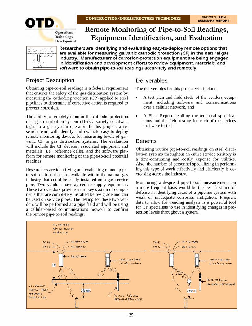
CONSTRUCTION/INFRASTRUCTURE TECHNIQUES PROJECT No. 4.19.d SUMMARY REPORT
Project Description Obtaining pipe-to-soil readings is a federal requirement that ensures the safety of the gas distribution system by measuring the cathodic protection (CP) applied to steel pipelines to determine if corrective action is required to prevent corrosion.
The ability to remotely monitor the cathodic protection of a gas distribution system offers a variety of advan-tages to a gas system operator. In this project, a re-search team will identify and evaluate easy-to-deploy remote monitoring devices for measuring levels of gal-vanic CP in gas distribution systems. The evaluation will include the CP devices, associated equipment and materials (i.e., reference cells), and the software plat-form for remote monitoring of the pipe-to-soil potential readings.
Researchers are identifying and evaluating remote pipe-to-soil options that are available within the natural gas industry that could be easily installed on a gas service pipe. Two vendors have agreed to supply equipment. These two vendors provide a turnkey system of compo-nents that are completely installed below grade and can be used on service pipes. The testing for these two ven-dors will be performed at a pipe field and will be using a cellular-based communications network to confirm the remote pipe-to-soil readings.
Researchers are identifying and evaluating easy-to-deploy remote options that are available for measuring galvanic cathodic protection (CP) in the natural gas industry. Manufacturers of corrosion-protection equipment are being engaged in identification and development efforts to review equipment, materials, and software to obtain pipe-to-soil readings accurately and remotely.
Remote Monitoring of Pipe-to-Soil Readings, Equipment Identification, and Evaluation
Deliverables The deliverables for this project will include:
A test plan and field study of the vendors equip-ment, including software and communications over a cellular network, and
A Final Report detailing the technical specifica-tions and the field testing for each of the devices that were tested.
Benefits Obtaining routine pipe-to-soil readings on steel distri-bution systems throughout an entire service territory is a time-consuming and costly expense for utilities. Also, the number of personnel specializing in perform-ing this type of work effectively and efficiently is de-creasing across the industry.
Monitoring widespread pipe-to-soil measurements on a more frequent basis would be the best first-line of defense in identifying areas of a pipeline system with weak or inadequate corrosion mitigation. Frequent data to allow for trending analysis is a powerful tool for CP specialists to use in identifying changes in pro-tection levels throughout a system.
- 25 -

- 26 -
For more information:
Michael Adamo, P.E. Vice President, Operations Operations Technology Development, NFP Phone: 847/544-3428 [email protected]
Field Testing of CP Devices and Software Appli-cations
This task will include installing the selected CP devices on different-sized steel piping, with differ-ent types of coatings, levels of anode protection, and types of soils. The project team will record regular readings remotely and manually for com-parison.
Results
Activities for this project included identification of the project team, conducting a project kick-off call with sponsors, performing a search of existing products, and speaking with industry subject-matter experts on avail-able products. Two vendors were chosen and their equipment has been installed at the Gas Technology Institute pipe field in Des Plaines, IL.
Status Equipment from both vendors has been installed at
the pipe field
Implementation of the test plan to the end of the project (potential testing of an AMI network) is ongoing
Continuous field verification of remote data is be-ing obtained
Preparation of the Final report with test results is under way.
The ability to remotely monitor the CP of a gas distribu-tion system offers the following advantages to a gas system operator:
Improves safety by reducing human error related to improper pipe-to-soil readings by employees
Improves compliance by alerting and providing needed information in a timely manner
Provides the ability to have readings more fre-quently and readily available to allow for trending analysis for future estimating and planning, and
Will reduce or potentially eliminate the total num-ber of labor hours required to perform pipe-to-soil readings and to determine corrosion-related correc-tive action workloads
Technical Concept & Approach Specific tasks include:
Identification of Existing Easy-to-Use Turnkey Remote Pipe-to-Soil Vendors
This task includes project kick-off activities, identi-fication of CP telemetry needs, sponsor interactions, needs analysis, tasks preparation, and other related activities.
Identification and Evaluation of Available CP Devices
In this task, researchers will identify and evaluate current CP telemetry devices available in the mar-ket. The evaluation will include the CP device oper-ating features, associated equipment and materials needed, and the software requirements for transmit-ting and receiving the remote readings.
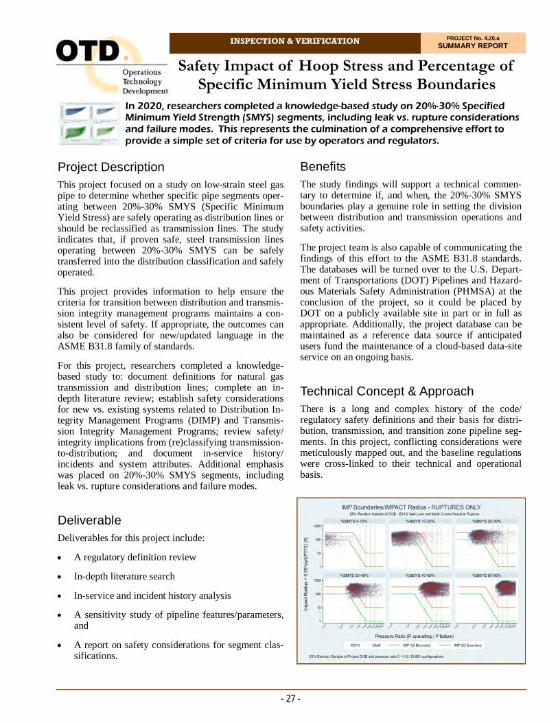
INSPECTION & VERIFICATION PROJECT No. 4.20.a SUMMARY REPORT
Project Description This project focused on a study on low-strain steel gas pipe to determine whether specific pipe segments oper-ating between 20%-30% SMYS (Specific Minimum Yield Stress) are safely operating as distribution lines or should be reclassified as transmission lines. The study indicates that, if proven safe, steel transmission lines operating between 20%-30% SMYS can be safely transferred into the distribution classification and safely operated.
This project provides information to help ensure the criteria for transition between distribution and transmis-sion integrity management programs maintains a con-sistent level of safety. If appropriate, the outcomes can also be considered for new/updated language in the ASME B31.8 family of standards.
For this project, researchers completed a knowledge-based study to: document definitions for natural gas transmission and distribution lines; complete an in-depth literature review; establish safety considerations for new vs. existing systems related to Distribution In-tegrity Management Programs (DIMP) and Transmis-sion Integrity Management Programs; review safety/integrity implications from (re)classifying transmission-to-distribution; and document in-service history/incidents and system attributes. Additional emphasis was placed on 20%-30% SMYS segments, including leak vs. rupture considerations and failure modes.
Deliverable Deliverables for this project include:
A regulatory definition review
In-depth literature search
In-service and incident history analysis
A sensitivity study of pipeline features/parameters, and
A report on safety considerations for segment clas-sifications.
In 2020, researchers completed a knowledge-based study on 20%-30% Specified Minimum Yield Strength (SMYS) segments, including leak vs. rupture considerations and failure modes. This represents the culmination of a comprehensive effort to provide a simple set of criteria for use by operators and regulators.
Safety Impact of Hoop Stress and Percentage of Specific Minimum Yield Stress Boundaries
Benefits The study findings will support a technical commen-tary to determine if, and when, the 20%-30% SMYS boundaries play a genuine role in setting the division between distribution and transmission operations and safety activities.
The project team is also capable of communicating the findings of this effort to the ASME B31.8 standards. The databases will be turned over to the U.S. Depart-ment of Transportations (DOT) Pipelines and Hazard-ous Materials Safety Administration (PHMSA) at the conclusion of the project, so it could be placed by DOT on a publicly available site in part or in full as appropriate. Additionally, the project database can be maintained as a reference data source if anticipated users fund the maintenance of a cloud-based data-site service on an ongoing basis.
Technical Concept & Approach
There is a long and complex history of the code/regulatory safety definitions and their basis for distri-bution, transmission, and transition zone pipeline seg-ments. In this project, conflicting considerations were meticulously mapped out, and the baseline regulations were cross-linked to their technical and operational basis.
- 27 -
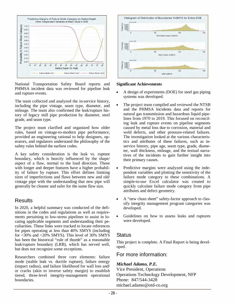
- 28 -
For more information:
Michael Adamo, P.E. Vice President, Operations Operations Technology Development, NFP Phone: 847/544-3428 [email protected]
Significant Achievements
A design of experiments (DOE) for steel gas piping systems was developed.
The project team compiled and reviewed the NTSB and the PHMSA Incidents data and reports for natural gas transmission and hazardous liquid pipe-lines from 1970 to 2019. This focused on reconcil-ing leak and rupture events on pipeline segments caused by metal loss due to corrosion, material and weld defects, and other pressure-related failures. The investigation looked at the various characteris-tics and attributes of these failures, such as in-service history, pipe age, seam type, grade, diame-ter, wall thickness, mileage, and the textual narra-tives of the incidents to gain further insight into their primary causes.
Predictive margins were analyzed using the inde-pendent variables and plotting the sensitivity of the failure mode category to these combinations. A simple-to-use Excel calculator was created to quickly calculate failure mode category from pipe attributes and defect geometry.
A “new clean sheet” safety-factor approach to clas-sify integrity management program categories was developed.
Guidelines on how to assess leaks and ruptures were developed.
Status This project is complete. A Final Report is being devel-oped.
National Transportation Safety Board reports and PHMSA incident data was reviewed for pipeline leak and rupture events.
The team collected and analyzed the in-service history, including the pipe vintage, seam type, diameter, and mileage. The team also confirmed the leak/rupture his-tory of legacy mill pipe production by diameter, steel grade, and seam type.
The project team clarified and organized how older rules, based on vintage-to-modern pipe performance, provided an engineering rational to help designers, op-erators, and regulators understand the philosophy of the safety rules behind the earliest codes.
A key safety consideration is the leak vs. rupture boundary, which is heavily influenced by the shape/aspect of a flaw, normal to the load direction. Those with longer and deeper features have a higher probabil-ity of failure by rupture. This effort defines limiting sizes of imperfections and flaws between new and old/vintage pipe with the understanding that new pipe will generally be cleaner and safer for the same flaw size.
Results In 2020, a helpful summary was conducted of the defi-nitions in the codes and regulations as well as require-ments pertaining to low-stress pipelines to assist in lo-cating applicable segments and understanding their pe-culiarities. These links were tracked to locate references for pipes operating at less than 40% SMYS (including for <30% and <20% SMYS). This level of 30% SMYS has been the historical “rule of thumb” as a reasonable leak/rupture boundary (LRB), which has served well, but does not recognize some exceptions.
Researchers combined three core elements: failure mode (stable leak vs. ductile rupture), failure energy (impact radius), and failure likelihood for wall loss and/or cracks (akin to inverse safety margin) to establish tiered, three-level integrity-management operational boundaries.

INSPECTION & VERIFICATION PROJECT No. 4.20.c SUMMARY REPORT
Project Description Natural gas utilities have long invested in solutions to prevent the causes of coating failures, but few have ad-dressed the underlying problem of stopping corrosion once the coating is breached. A review of nanotechnol-ogy found that self-healing coatings employing micro-encapsulation technology may have the potential to re-store a failure point and prevent further corrosion.
Self-passivating coatings using sacrificial zinc are in the market and are applied by some gas utilities; however, most utilities dislike the thickness, surface preparation, and cost requirements.
Self-healing coatings have been available for years, but most require some sort of external activation (e.g., heat or a solvent). This current effort involves tests of hydro-phobic topcoats for aboveground assets to prevent the permeation of water on sites with easily pooling water.
Applications already developed are for more extreme environments in aerospace, turbines, and cooling tow-ers. However, manufacturers are interesting in expand-ing into the utility market, noting that their products can transfer easily, even with cathodic protection.
The benefits are a significant, but utilities must first confirm performance and coating integrity for their spe-cific applications.
Research is under way to test a market-ready self-healing pipe coating and a developing self-inhibiting coating. Investigators will compare corrosion resistance, mechanical properties, and preparation requirements in the laboratory to determine relative cost differences.
Self-Healing Coatings – Development and Laboratory Testing for Gas Utility Application
Deliverable The project deliverable will be an evaluation of self-healing and self-inhibiting coatings in terms corrosion resistance (creep), mechanical integrity, cost, and preparation requirements. If results are promising, in-vestigators will recommend field studies for a Phase 2 evaluation.
Benefits Corrosion costs gas utilities $5 billion each year and is the culprit of many gas leaks and service shutoffs. Even the latest coatings with high corrosion resistance and adhesion will peel once the coating layer has been breached. The ability to mend exposed metal without active personnel would be a breakthrough technology for the gas industry.
Technical Concept & Approach
In this project, testing laboratories will validate per-formance, investigate changes in mechanical integrity, compare surface-preparation requirements, and the determine relative costs of self-healing coating.
Specific tasks include:
- 29 -
Salt fog tests by ASTM B117. Left: scribed polyurethane after 1,000 hours. Right (a-d) - scribed acrylic primer after a) 250, b) 500, c) 1,000, and d) 4,000 hours.

- 30 -
For more information:
Michael Adamo, P.E. Vice President, Operations Operations Technology Development, NFP Phone: 847/544-3428 [email protected]
The self-healing coating use case was narrowed to aboveground applications with liquid polyurethane or epoxy coatings to minimize project risks. The self-healing additive providers are more experienced with aboveground applications, liquid polyurethane/epoxy present larger markets, and the relevant coating per-formance tests are more affordable. Findings from this study will decide if and how the project team will ex-pand into belowground use cases.
Both companies will recommend coating formulators depending on the identified use case and expected capacity. Researchers gathered technical questions from the technology providers to include in the sponsor survey.
The survey asks a series of technical questions that de-termine the ideal use case for self-healing coatings and minimum specifications for coating application and performance. Risers (soil-to-air transition zone) are the leading use case.
Status Researchers are reviewing survey responses, identify-ing ideal self-healing coating use case(s), estimating capacity from usage, and determining minimum coat-ing application and performance specifications.
Selecting Coating Formulators
The project team and sponsors will decide on the ideal coating application and the corresponding coating specifications.
Determining Coating Formulas
The project team will approach coating formulators with the specifications of the intended application and develop the test matrix using software that ap-plies design-of-experiment methodology. A Go/No-Go Decision will be held in the event the coating formulators present doubt in critical specifications.
Developing Coating and Assessing Costs
If the companies determine the expected formula-tions can meet applications, then researchers will contract to develop samples. Upon completion, the team will assess relative costs of the coating. A Go/No-Go Decision will be held if the coating formula-tion does not deliver.
Laboratory Performance Tests
Researchers will test the performance of the self-healing coatings by measuring corrosion creep against a representative control. Mechanical proper-ties (e.g., hardness, abrasion resistance, adhesion, chip resistance, and cathodic disbondment will also be investigated.
Results In 2020, the project team confirmed participation from two self-healing additive providers and submitted a sponsor survey to determine the ideal use case.
Smart corrosion-detector beads fluoresce a specific wavelength of light when in the presence of rust.
CONSTRUCTION/INFRASTRUCTURE
TECHNIQUES Addressing issues often beyond the traditional areas, this research
involves the development of tools and techniques for metering, gas shutoff, remote monitoring, cathodic protection, data collection,
and other applications.
Developed technologies are subjected to a regimen of laboratory and field evaluations to ensure their safety and efficiency.
Efforts include projects to enhance and broaden the knowledge
base for plastic pipe materials, virtual reality training, development of technology for remote service abandonment without excavation,
cybersecurity, addressing gas odor fade, and re-development of underground piercing tools .
.


CONSTRUCTION/INFRASTRUCTURE TECHNIQUES PROJECT No. 5.13.b SUMMARY REPORT
Activities in this project focused on increasing the awareness of a GPS-based conflation system designed to enhance the accuracy of a GIS using GPS data collected as part of routine operations.
GPS-Based GIS Conflation System
Benefits Higher-accuracy maps could be extremely beneficial in emergency situations where valves, meter sets, and other assets need to be located quickly.
Some of the benefits of a high accuracy GIS include:
Reduced Buffer for One-Call Tickets and High-Consequence Areas
Higher-accuracy maps allow buffer zones around assets to be decreased. A reduced buffer would eliminate one-call tickets that would normally be issued but that are not near any facilities.
Ability to Relocate Facilities
Better maps will reduce the occurrence of the wrong facility being located and will provide information that will help the overall locate proc-ess. Additionally, having the GPS coordinates of assets will potentially allow GPS to be used to as-sist in the locate process.
- 33 -
Project Description Many natural gas system operators improved the accu-racy of their geographic information systems (GIS) through conflation – a process that typically uses a commercial land base to shift the position of assets in the GIS to more accurate real-world coordinates. Use of a commercial land base allows the GIS to be blended with (or, conflated) to an existing data set with an accuracy of one to 10 meters.
Research suggests that GPS can potentially be used as an alternative data source for performing GIS confla-tion to provide a higher level of GIS accuracy. Confla-tion to GPS coordinates of features within the GIS will not only result in a higher level of spatial accuracy in relation to real-world features, but it will also poten-tially improve the underlying accuracy of the data be-cause it will allow inaccurate “as-built” data to be cor-rected. Collecting the GPS coordinates of features when exposed or located would allow features to be conflated to a truly accurate position. Furthermore, conflation to centerline data is very difficult in rural areas where landmarks are not present and conflating to GPS may be the only feasible option for improving the accuracy of the GIS.
The results of research indicated that conflating to GPS coordinates can provide superior accuracy com-pared to a commercial land base and, in some situa-tions, may be the only feasible option for GIS confla-tion. In this project, high-accuracy GPS receivers were incorporated to provide survey-grade data without the need for post processing. Building on these technolo-gies, it is now possible to develop tools that can cost-effectively collect high-quality GPS data and perform GIS conflation.
The main objective for Phase 3 of this project was to conduct two pilot projects with sponsor utilities while focusing on a more extensive study area. Researchers completd two separate pilots – one in Illinois, one in Texas.
Deliverables
The deliverables for Phase 3 of this project include a Final Report, sponsor webinar, and pilot project con-flated data. Example of locatable non-compliance valve.
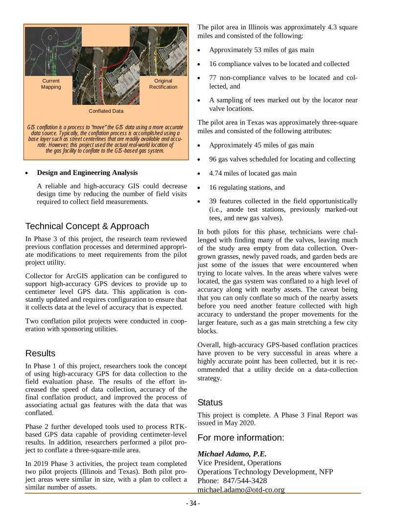
The pilot area in Illinois was approximately 4.3 square miles and consisted of the following:
Approximately 53 miles of gas main
16 compliance valves to be located and collected
77 non-compliance valves to be located and col-lected, and
A sampling of tees marked out by the locator near valve locations.
The pilot area in Texas was approximately three-square miles and consisted of the following attributes:
Approximately 45 miles of gas main
96 gas valves scheduled for locating and collecting
4.74 miles of located gas main
16 regulating stations, and
39 features collected in the field opportunistically (i.e., anode test stations, previously marked-out tees, and new gas valves).
In both pilots for this phase, technicians were chal-lenged with finding many of the valves, leaving much of the study area empty from data collection. Over-grown grasses, newly paved roads, and garden beds are just some of the issues that were encountered when trying to locate valves. In the areas where valves were located, the gas system was conflated to a high level of accuracy along with nearby assets. The caveat being that you can only conflate so much of the nearby assets before you need another feature collected with high accuracy to understand the proper movements for the larger feature, such as a gas main stretching a few city blocks.
Overall, high-accuracy GPS-based conflation practices have proven to be very successful in areas where a highly accurate point has been collected, but it is rec-ommended that a utility decide on a data-collection strategy.
Status This project is complete. A Phase 3 Final Report was issued in May 2020.
Design and Engineering Analysis
A reliable and high-accuracy GIS could decrease design time by reducing the number of field visits required to collect field measurements.
Technical Concept & Approach In Phase 3 of this project, the research team reviewed previous conflation processes and determined appropri-ate modifications to meet requirements from the pilot project utility.
Collector for ArcGIS application can be configured to support high-accuracy GPS devices to provide up to centimeter level GPS data. This application is con-stantly updated and requires configuration to ensure that it collects data at the level of accuracy that is expected.
Two conflation pilot projects were conducted in coop-eration with sponsoring utilities.
Results In Phase 1 of this project, researchers took the concept of using high-accuracy GPS for data collection to the field evaluation phase. The results of the effort in-creased the speed of data collection, accuracy of the final conflation product, and improved the process of associating actual gas features with the data that was conflated.
Phase 2 further developed tools used to process RTK-based GPS data capable of providing centimeter-level results. In addition, researchers performed a pilot pro-ject to conflate a three-square-mile area.
In 2019 Phase 3 activities, the project team completed two pilot projects (Illinois and Texas). Both pilot pro-ject areas were similar in size, with a plan to collect a similar number of assets.
GIS conflation is a process to “move” the GIS data using a more accurate data source. Typically, the conflation process is accomplished using a
base layer such as street centerlines that are readily available and accu-rate. However, this project used the actual real-world location of
the gas facility to conflate to the GIS-based gas system.
Current Mapping
Original Rectification
Conflated Data
- 34 -
For more information:
Michael Adamo, P.E. Vice President, Operations Operations Technology Development, NFP Phone: 847/544-3428 [email protected]
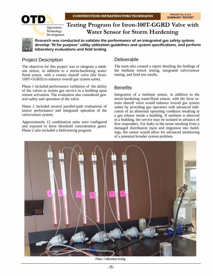
CONSTRUCTION/INFRASTRUCTURE TECHNIQUES PROJECT No. 5.14.w SUMMARY REPORT
Research was conducted to validate the performance of an integrated gas safety system, develop “fit for purpose” utility utilization guidelines and system specifications, and perform laboratory evaluations and field testing.
Testing Program for Itron-100T-GGRD Valve with Water Sensor for Storm Hardening
Deliverable The team also created a report detailing the findings of the methane sensor testing, integrated valve/sensor testing, and field test results.
Benefits Integration of a methane sensor, in addition to the storm-hardening water/flood sensor, with the Itron re-mote shutoff valve would enhance overall gas system safety by providing gas operators with advanced indi-cation of an abnormal operating condition resulting in a gas release inside a building. If methane is detected in a building, the service may be isolated in advance of first responders. For leaks in the street resulting from a damaged distribution main and migration into build-ings, the sensor would allow for advanced monitoring of a potential broader system problem.
- 35 -
Project Description The objective for this project was to integrate a meth-ane sensor, in addition to a storm-hardening water/flood sensor, with a remote shutoff valve (the Itron-100T-GGRD) to enhance overall gas system safety.
Phase 1 included performance validation of the ability of the valves to isolate gas service to a building upon remote activation. The evaluation also considered gen-eral safety and operation of the valve.
Phase 2 included several parallel-path evaluations of sensor performance and integrated operation of the valve/sensor system.
Approximately 12 combination units were configured and exposed to three threshold concentration gases. Phase 2 also included a field-testing program.
Phase 1 laboratory testing.

- 36 -
remotely open and close. The valve was left sub-merged at each depth for a period of 48 hours, then an attempt was made to remotely open and close the valve while it was submerged, and then again outside of water. If the attempt to open and close the valve was successful while it was underwater, then the wa-ter level was increased and the test was repeated.
The valve was placed into a salt fog chamber in order to test its performance in a corrosive environment.
Two Itron remote shutoff valves were placed outside to test the valves’ performance in an outdoor environ-ment.
Phase 2 focused on various evaluations, including the methane sensor performance and then the integrated operation of the valve/methane sensor system.
Prior to the start of the project, some initial evaluation of the sensor was conducted, along with developing “fitness for purpose” guidelines for the system.
Itron announced in 2018 that the company is now working with a Japanese-based safety device manu-facturer to integrate their ML-310 hot wire semicon-ductor type gas sensor with MEMS technology and Itron’s Milli 5 network communication module. The project sponsors initially decided to keep the project active and continue to identify remote shutoff valves and methane and other safety sensors, agreeing that there is still a need for these safety devices. However, subsequent sponsor interactions recommended closing this project and future work will be performed as a new project.
Status
This project is complete. A Final Report was issued in November 2020.
Technical Concept & Approach Phase 2 tasks included:
Development of “Fit for Purpose” Utility Utiliza-tion Guidelines and System Specifications
This task included facilitating a utility technical workshop to provide the opportunity for technology providers to obtain a better understand how to fur-ther enhance device specifications and options and optimize designs to meet the needs of operators in a fit-for-purpose manner.
Laboratory Performance Evaluation of Methane Sensor
This phase of work included performance evalua-tion of a methane sensor. This task required a mini-mum of 12 sensor devices to facilitate performance testing.
Evaluation of Integrated Gas Gate Shutoff Valve/Methane Sensor/Moisture Sensor Com-munication Performance
This task included benchscale testing of the inte-grated valve/sensor device, including communica-tion protocols. Combination units were configured and exposed to three threshold concentration (low-medium-high) gases (methane/air mixtures) to con-firm integrated performance of the sensor/valve technology. This evaluation also included simulated remote communication back to a central monitoring source and the ability to remotely isolate service via valve operation.
Results In Phase 1 of the project, a series of laboratory testing was conducted to fully evaluate the remote shutoff valve. The research team was supplied 10 valves along with a handheld remote-control device to actuate the valve.
A series of pressure tests were conducted to determine the valves ability to shut off the flow of gas and sustain shutoff. Since the valves could be installed indoors or outdoors, pressure testing was also conducted at various temperatures. Finally, the valves were open and closed repeatedly (100 times) and checked for leaks, battery life, and overall mechanical performance (wear and tear).
An experimental set-up was used to investigate the ef-fect that debris has on the valve’s ability to close to a bubble-tight seal.
The valve’s inlet and outlet was sealed and units were submerged under various depths of water to examine the effect of water intrusion on the valve’s ability to
For more information:
Michael Adamo, P.E. Vice President, Operations Operations Technology Development, NFP Phone: 847/544-3428 [email protected]
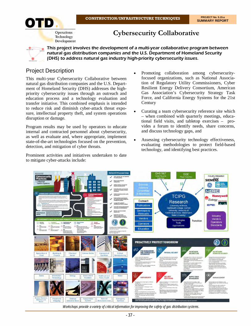
CONSTRUCTION/INFRASTRUCTURE TECHNIQUES PROJECT No. 5.15.a SUMMARY REPORT
This project involves the development of a multi-year collaborative program between natural gas distribution companies and the U.S. Department of Homeland Security (DHS) to address natural gas industry high-priority cybersecurity issues.
Cybersecurity Collaborative
Promoting collaboration among cybersecurity-focused organizations, such as National Associa-tion of Regulatory Utility Commissioners, Cyber Resilient Energy Delivery Consortium, American Gas Association’s Cybersecurity Strategy Task Force, and California Energy Systems for the 21st Century
Curating a team cybersecurity reference site which – when combined with quarterly meetings, educa-tional field visits, and tabletop exercises – pro-vides a forum to identify needs, share concerns, and discuss technology gaps, and
Assessing cybersecurity technology effectiveness, evaluating methodologies to protect field-based technology, and identifying best practices.
- 37 -
Project Description This multi-year Cybersecurity Collaborative between natural gas distribution companies and the U.S. Depart-ment of Homeland Security (DHS) addresses the high-priority cybersecurity issues through an outreach and education process and a technology evaluation and transfer initiative. This combined emphasis is intended to reduce risk and diminish cyber-attack threat expo-sure, intellectual property theft, and system operations disruption or damage.
Program results may be used by operators to educate internal and contracted personnel about cybersecurity, as well as evaluate and, where appropriate, implement state-of-the-art technologies focused on the prevention, detection, and mitigation of cyber threats.
Prominent activities and initiatives undertaken to date to mitigate cyber-attacks include:
Workshops provide a variety of critical information for improving the safety of gas distribution systems.
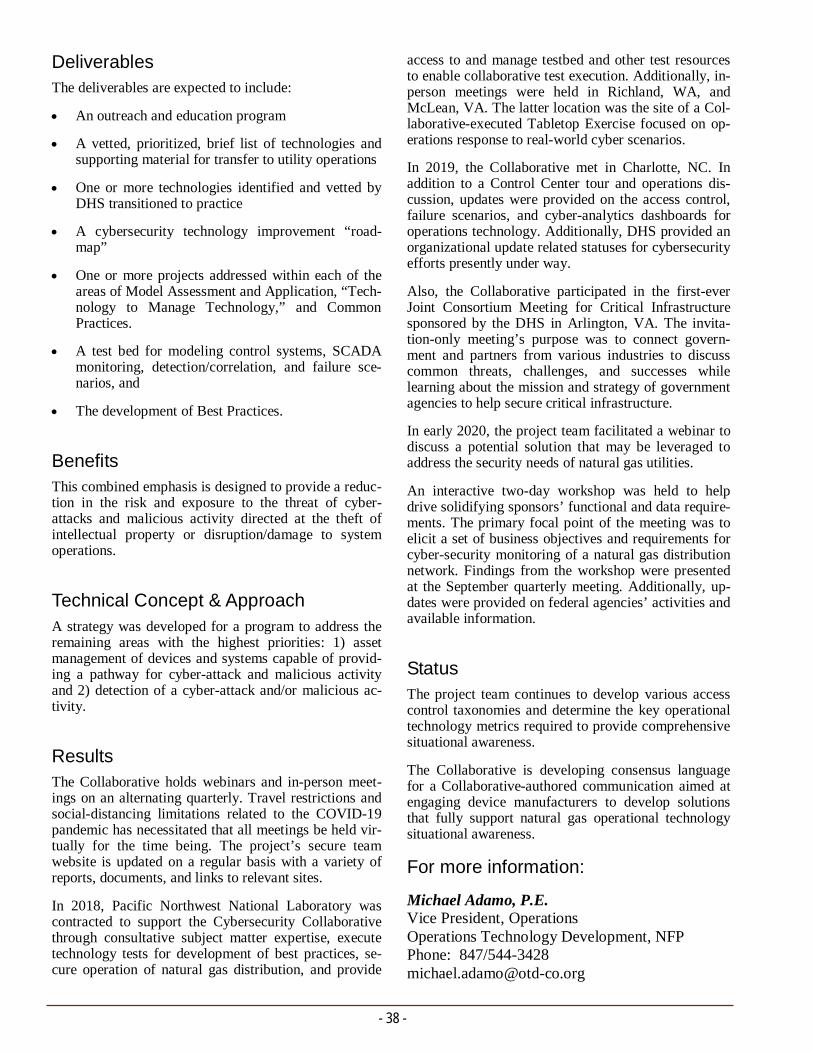
Deliverables The deliverables are expected to include:
An outreach and education program
A vetted, prioritized, brief list of technologies and supporting material for transfer to utility operations
One or more technologies identified and vetted by DHS transitioned to practice
A cybersecurity technology improvement “road-map”
One or more projects addressed within each of the areas of Model Assessment and Application, “Tech-nology to Manage Technology,” and Common Practices.
A test bed for modeling control systems, SCADA monitoring, detection/correlation, and failure sce-narios, and
The development of Best Practices.
Benefits This combined emphasis is designed to provide a reduc-tion in the risk and exposure to the threat of cyber-attacks and malicious activity directed at the theft of intellectual property or disruption/damage to system operations.
Technical Concept & Approach A strategy was developed for a program to address the remaining areas with the highest priorities: 1) asset management of devices and systems capable of provid-ing a pathway for cyber-attack and malicious activity and 2) detection of a cyber-attack and/or malicious ac-tivity.
Results The Collaborative holds webinars and in-person meet-ings on an alternating quarterly. Travel restrictions and social-distancing limitations related to the COVID-19 pandemic has necessitated that all meetings be held vir-tually for the time being. The project’s secure team website is updated on a regular basis with a variety of reports, documents, and links to relevant sites.
In 2018, Pacific Northwest National Laboratory was contracted to support the Cybersecurity Collaborative through consultative subject matter expertise, execute technology tests for development of best practices, se-cure operation of natural gas distribution, and provide
- 38 -
access to and manage testbed and other test resources to enable collaborative test execution. Additionally, in-person meetings were held in Richland, WA, and McLean, VA. The latter location was the site of a Col-laborative-executed Tabletop Exercise focused on op-erations response to real-world cyber scenarios.
In 2019, the Collaborative met in Charlotte, NC. In addition to a Control Center tour and operations dis-cussion, updates were provided on the access control, failure scenarios, and cyber-analytics dashboards for operations technology. Additionally, DHS provided an organizational update related statuses for cybersecurity efforts presently under way.
Also, the Collaborative participated in the first-ever Joint Consortium Meeting for Critical Infrastructure sponsored by the DHS in Arlington, VA. The invita-tion-only meeting’s purpose was to connect govern-ment and partners from various industries to discuss common threats, challenges, and successes while learning about the mission and strategy of government agencies to help secure critical infrastructure.
In early 2020, the project team facilitated a webinar to discuss a potential solution that may be leveraged to address the security needs of natural gas utilities.
An interactive two-day workshop was held to help drive solidifying sponsors’ functional and data require-ments. The primary focal point of the meeting was to elicit a set of business objectives and requirements for cyber-security monitoring of a natural gas distribution network. Findings from the workshop were presented at the September quarterly meeting. Additionally, up-dates were provided on federal agencies’ activities and available information.
Status The project team continues to develop various access control taxonomies and determine the key operational technology metrics required to provide comprehensive situational awareness.
The Collaborative is developing consensus language for a Collaborative-authored communication aimed at engaging device manufacturers to develop solutions that fully support natural gas operational technology situational awareness.
For more information:
Michael Adamo, P.E. Vice President, Operations Operations Technology Development, NFP Phone: 847/544-3428 [email protected]

Evaluation of Meter-Set Placement and Clearances
CONSTRUCTION/INFRASTRUCTURE TECHNIQUES PROJECT No. 5.15.h SUMMARY REPORT
This project provides utilities and their customers additional knowledge and more options regarding the placement of gas meter sets. Phase 1 developed a method to measure natural gas leaks around meter sets in relation to house openings such as windows, vents, and doors. Phase 2 included tests on leaks in regulator sets.
- 39 -
Project Description Utilities are frequently challenged to find suitable loca-tions to place natural gas meter-set assemblies (MSAs) that satisfy the various codes and operation require-ments. Additionally, meter-replacement services are on the rise due to the increase in main and service replace-ment efforts and increased customer loads.
In response, this project involved a testing program to evaluate the distribution of natural gas concentrations around leaks in outdoor meters and regulators. Phase 1 of the project developed a method to measure natural gas leaks around meter sets to provide clearance dis-tances. Phase 2 involved additional tests with more arrays of sensors to address specific regulators’ leaks that utilities encounter at their service areas.
Deliverables
The deliverables from this project include a Final Re-port summarizing the risk of gas accumulation for the various situations tested.
Benefits This project provides utilities and their customers with additional knowledge and more options regarding the placement of meter sets. Utilities are provided data to support meter set placement options and potentially support changes to applicable codes. Additionally, in-formation developed through this project can be used to better manage risks through a company’s distribu-tion integrity management program.
Technical Concept & Approach Specific tasks in this project included:
Codes and Standards Review
Researchers performed a review of the various utility codes to determine the restrictions currently in place. The project team also reviewed the his-tory in regards to how the current “clearance zones” were determined and if any prior research in this area exist.
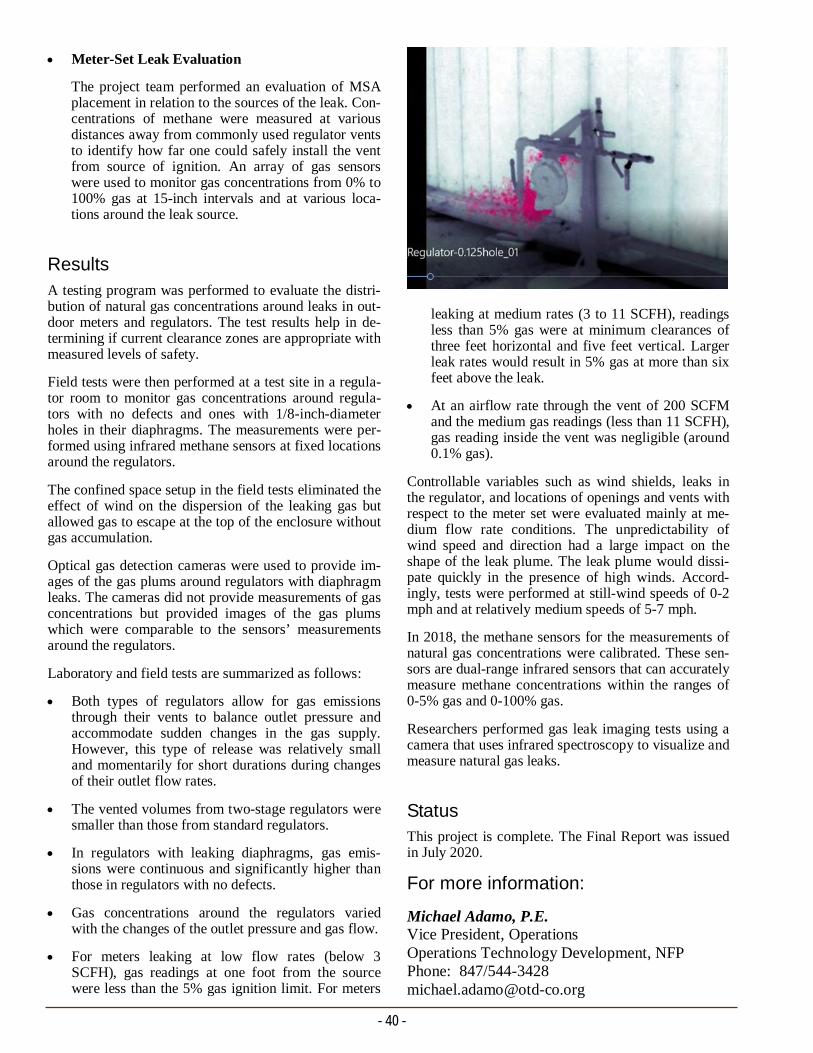
- 40 -
leaking at medium rates (3 to 11 SCFH), readings less than 5% gas were at minimum clearances of three feet horizontal and five feet vertical. Larger leak rates would result in 5% gas at more than six feet above the leak.
At an airflow rate through the vent of 200 SCFM and the medium gas readings (less than 11 SCFH), gas reading inside the vent was negligible (around 0.1% gas).
Controllable variables such as wind shields, leaks in the regulator, and locations of openings and vents with respect to the meter set were evaluated mainly at me-dium flow rate conditions. The unpredictability of wind speed and direction had a large impact on the shape of the leak plume. The leak plume would dissi-pate quickly in the presence of high winds. Accord-ingly, tests were performed at still-wind speeds of 0-2 mph and at relatively medium speeds of 5-7 mph.
In 2018, the methane sensors for the measurements of natural gas concentrations were calibrated. These sen-sors are dual-range infrared sensors that can accurately measure methane concentrations within the ranges of 0-5% gas and 0-100% gas.
Researchers performed gas leak imaging tests using a camera that uses infrared spectroscopy to visualize and measure natural gas leaks.
Status This project is complete. The Final Report was issued in July 2020.
Meter-Set Leak Evaluation
The project team performed an evaluation of MSA placement in relation to the sources of the leak. Con-centrations of methane were measured at various distances away from commonly used regulator vents to identify how far one could safely install the vent from source of ignition. An array of gas sensors were used to monitor gas concentrations from 0% to 100% gas at 15-inch intervals and at various loca-tions around the leak source.
Results
A testing program was performed to evaluate the distri-bution of natural gas concentrations around leaks in out-door meters and regulators. The test results help in de-termining if current clearance zones are appropriate with measured levels of safety.
Field tests were then performed at a test site in a regula-tor room to monitor gas concentrations around regula-tors with no defects and ones with 1/8-inch-diameter holes in their diaphragms. The measurements were per-formed using infrared methane sensors at fixed locations around the regulators.
The confined space setup in the field tests eliminated the effect of wind on the dispersion of the leaking gas but allowed gas to escape at the top of the enclosure without gas accumulation.
Optical gas detection cameras were used to provide im-ages of the gas plums around regulators with diaphragm leaks. The cameras did not provide measurements of gas concentrations but provided images of the gas plums which were comparable to the sensors’ measurements around the regulators.
Laboratory and field tests are summarized as follows:
Both types of regulators allow for gas emissions through their vents to balance outlet pressure and accommodate sudden changes in the gas supply. However, this type of release was relatively small and momentarily for short durations during changes of their outlet flow rates.
The vented volumes from two-stage regulators were smaller than those from standard regulators.
In regulators with leaking diaphragms, gas emis-sions were continuous and significantly higher than those in regulators with no defects.
Gas concentrations around the regulators varied with the changes of the outlet pressure and gas flow.
For meters leaking at low flow rates (below 3 SCFH), gas readings at one foot from the source were less than the 5% gas ignition limit. For meters
For more information:
Michael Adamo, P.E. Vice President, Operations Operations Technology Development, NFP Phone: 847/544-3428 [email protected]
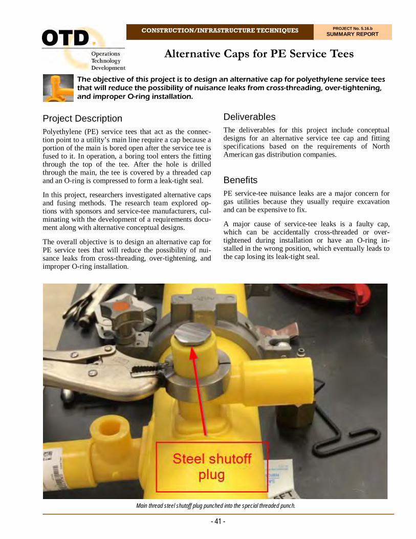
CONSTRUCTION/INFRASTRUCTURE TECHNIQUES PROJECT No. 5.16.b SUMMARY REPORT
Project Description Polyethylene (PE) service tees that act as the connec-tion point to a utility’s main line require a cap because a portion of the main is bored open after the service tee is fused to it. In operation, a boring tool enters the fitting through the top of the tee. After the hole is drilled through the main, the tee is covered by a threaded cap and an O-ring is compressed to form a leak-tight seal.
In this project, researchers investigated alternative caps and fusing methods. The research team explored op-tions with sponsors and service-tee manufacturers, cul-minating with the development of a requirements docu-ment along with alternative conceptual designs.
The overall objective is to design an alternative cap for PE service tees that will reduce the possibility of nui-sance leaks from cross-threading, over-tightening, and improper O-ring installation.
The objective of this project is to design an alternative cap for polyethylene service tees that will reduce the possibility of nuisance leaks from cross-threading, over-tightening, and improper O-ring installation.
Alternative Caps for PE Service Tees
Deliverables The deliverables for this project include conceptual designs for an alternative service tee cap and fitting specifications based on the requirements of North American gas distribution companies.
Benefits PE service-tee nuisance leaks are a major concern for gas utilities because they usually require excavation and can be expensive to fix.
A major cause of service-tee leaks is a faulty cap, which can be accidentally cross-threaded or over-tightened during installation or have an O-ring in-stalled in the wrong position, which eventually leads to the cap losing its leak-tight seal.
- 41 -
Main thread steel shutoff plug punched into the special threaded punch.

Creating an alternative cap that is more reliable than the current threaded caps, such as a fusible-type cap, could save money and time because of the reduced amount of nuisance leaks.
Technical Concept & Approach Initial tasks in this project included a sponsor survey to identify the needs and applications for a fusible cap de-vice. A summary of sponsor requirements was com-piled. Based on the needs and requirements, the project team developed conceptual alternative cap designs.
Project representatives contacted various tapping tee manufacturers to determine interest in developing alter-native caps for their tapping tees. A method of connec-tion with a fusible cap for tapping tees was investigated. A cap with more robust threads to prevent cross-threading was also studied.
After developing a comprehensive set of sponsor re-quirements and conceptual designs, there could be fol-low-on efforts with interested fitting manufacturers in the development and testing of tapping tees with fused caps. Results
In 2018, the scope of the project was narrowed to con-sider only caps for new installations and not retrofits. There are three possible options for alternative PE caps: improved mechanical cap, socket fusion cap, and elec-trofusion cap. An improved mechanical cap would ad-dress the issues with current mechanical caps. For op-erators that prefer a fusible cap, either socket fusion or electrofusion caps are possible, the former being sim-pler to design and manufacture. In both fusible cases, the tower of the respective tapping-tee may need modi-fication or machining/scraping tools may need to be developed. Additionally, both fusible-cap types would require a method to stop blow-by around the cutter.
Discussions with one manufacturer showed promise. The manufacture would like an estimate of product vol-ume to justify development costs. A survey was re-sent to ascertain the sponsors’ preference regarding a fusible tapping-tee cap type. The manufacturer is developing two types of caps (an electrofusion cap and a socket fusion cap), but is much further along on the socket-fusion solution. The company has made some alumi-num cavities to remove the tower threads on the service tee and should have some molded samples soon to test the theory.
The first round of cap fusion tests at 100 psig pressure were completed, followed by 1,000-hour hydrostatic
- 42 -
pressure testing. The company is also developing coil designs for the electrofusion cap and evaluating the changes required for the tee body.
In 2019, the manufacturer molded additional fittings. and refined the procedure for installing socket-fused caps following the tapping operation (into a live main).
A custom mold cavity was built to produce a service tee fitting without the tower threads for a standard threaded cap.
The manufacturer’s opinion is that in order to safely and consistently perform the cap fusion process, a new sidewall tool needs to be developed that combines both the sidewall fusion and the socket fusion to keep every-thing in alignment.
An electrofusion cap was developed by the manufac-turer’s sister company in Switzerland. The cap is de-signed to permanently seal the tower of a tapping tee after the line is tapped.
In 2020, several concepts were explored:
1. Threads removed from top of tower to create a fu-sion zone
2. Thread length shortened to create a fusion zone at the bottom of the tower, and
3. An electrofusion coil placed within the pitch of thread.
Option 3 seems to be the best and least invasive design as it would work with existing service tee fittings. It would also be the lowest cost to implement.
Based on sponsor feedback, the preferred solutions are new fusible caps for the installation of electrofusion and socket-fusion saddle fitting types.
Status The project team is organizing a webinar with the spon-sors and relevant personnel from the manufacturer to discuss the sponsors’ needs.
For more information:
Michael Adamo, P.E. Vice President, Operations Operations Technology Development, NFP Phone: 847/544-3428 [email protected]

CONSTRUCTION/INFRASTRUCTURE TECHNIQUES PROJECT No. 5.16.c SUMMARY REPORT
Project Description In recent years, the use of keyhole technologies has in-creased significantly due to the ability to reduce pave-ment-restoration and landscaping costs by avoiding trenching. Recent tool development now allows utilities and their contractors to install and replace gas services through a 24-inch keyhole excavation.
One remaining item needing to be addressed is the process of installing the service line from the house to the keyhole. Piercing tools can be used today to trench-lessly install a new service from the house to a small excavation; however, extracting the tool (“mole”) from a small keyhole excavation cannot be accomplished as the tool is too long to be removed. The crews must back up the piercing tool to the entrance pit; taking more time and effort.
This project is focused on making enhancements to cur-rently used piercing tools to allow them to be removed through small excavations (24 inches in diameter).
Deliverables The deliverables for this project will include a summary of the sponsors’ requirements and conceptual designs for the piercing tool.
The focus of this project is on the design and development of a concept for a piercing tool that will enable the installation of gas services and removal of the piercing tool through small keyhole excavations.
Piercing Tool Redevelopment – Enhancement to Remove “Mole” from Small Excavations
Benefits Keyhole and trenchless technologies have provided several utilities with considerable advantages over standard excavation and restoration techniques. How-ever, most utilities state that additional equipment/tool development needs to be conducted to fully realize the benefits of these practices.
This project addresses one of the final processes of renewing and/or installing gas services through small holes by working with existing trenchless equipment manufacturers to develop piercing tool concepts that can be used in conjunction with keyholes. This will reduce the cost of serving customers, especially in ur-ban environments that have mains under pavement.
Right-of-way excavations have become expensive, cumbersome, and require traffic control that may cause congestion. Municipal mandates and fees are also be-ing applied, which can substantially increase the cost of reinstating pavement.
Both keyhole and trenchless construction practices provide opportunities to address today’s complex un-derground infrastructure issues economically, safely, and with a minimum of inconvenience to the public and impact to the environment.
- 43 -

Technical Concept & Approach An initial survey was conducted to better identify the needs and piercing equipment used by the project spon-sors and their construction partners. A summary of the sponsor requirements for installing/replacing services using trenchless methods will be compiled.
Based on identified needs and requirements, the project team will develop conceptual piercing-tool designs aimed at developing a tool to be used more efficiently with small excavations. This may include various de-signs to allow the piercing tool to either be started in the small excavation or removed from the excavation (no need to reverse the tool all the way back to the entry pit).
The project team will meet with various piercing tool (trenchless technology) manufacturers to determine in-terest in developing an enhanced piercing tool.
Results
The project team, along with the project sponsors, iden-tified several concepts and designs for a mole so it can be removed from a 24-inch keyhole. Subsequently, pro-ject representatives contacted trenchless-equipment manufacturers to discuss a potential partnership to de-sign a mole based on the various concepts. One com-pany presented a concept it developed for launching a mole from the keyhole to the house.
The project team reviewed various practices that are currently being performed by utilities and reviewed the designs from manufacturers. It was discovered that one manufacturer offers a piercing tool that is approxi-mately 30 inches long for a two-inch-diameter bore. The company has agreed to investigate its current mole design to see if the tool, with slight modifications, can be used in a 24-inch-diameter keyhole. The project team visited the manufacturer to discuss design specif-ics for a mole that can be used while utilizing keyhole excavations. They are hesitant in creating a new mole design without first testing its series of moles (new shorter designs) in order to insert a service through a keyhole.
In 2018, preparations were made for the testing at the manufacturer’s facility to determine if the company’s existing pneumatic moles can be removed or inserted through a 24-inch keyhole. However, tests were can-celled due to lack of sponsor involvement. The manu-facturer was seeking direct sponsor input prior to mak-ing decisions about modifying their current shorter mole design. This field trial of the shorter tool will help determine the need for possible modifications (i.e., shortening the length, making pneumatic hose articulat-ing, etc.) to use it in keyholes.
- 44 -
In 2019, one of the project sponsors stated interest in testing the 30-inch piercing tool on one of their con-struction sites with the minor changes the manufacturer suggested. The company’s system was subsequently demonstrated in the field and launched from a 24-inch keyhole with a custom 90-degree adapter. The system was able to successfully enter into the vacuum-excavated keyhole using the custom adapter. The adapter was then removed so that the flexible pneu-matic hosewhip could be installed for the rest of the piercing tool operation. With both of these operations, the system was successful at reaching a trench on the far side of a residential street. However, there were con-cerns with how the adapter would be removed and the flexible hosewhip would be installed at the bottom of the 24-inch-diameter keyhole. Therefore there were discussions regarding the development of a permanent adapter which could change angles.
The company will develop other adapter designs, such as a swivel or pivot that would allow the adapter to re-main on the system for the entire trenchless piercing operation. The project team will support this design process.
Status
The project team is is continuing to support the effort of the piercing tool company in developing and imple-menting hose adapters to allow their tool to be launched in 24-inch-diameter keyholes.
For more information:
Michael Adamo, P.E. Vice President, Operations Operations Technology Development, NFP Phone: 847/544-3428 [email protected]
90-degree adapter on rear of piercing system.
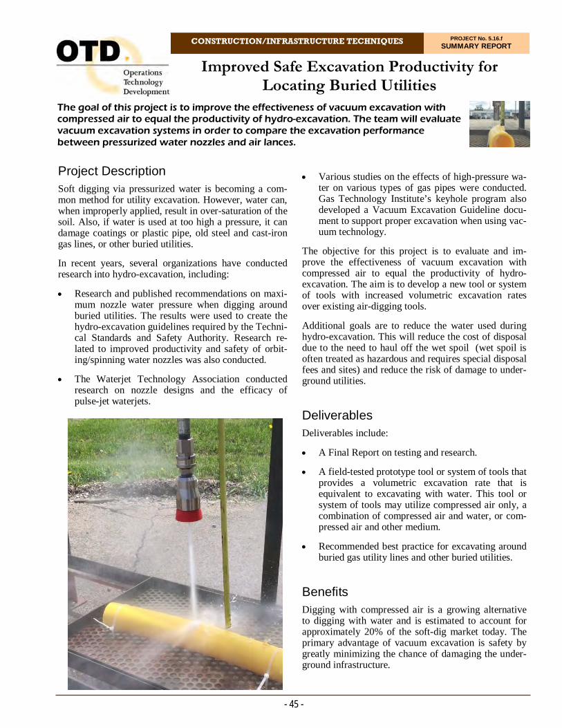
CONSTRUCTION/INFRASTRUCTURE TECHNIQUES PROJECT No. 5.16.f SUMMARY REPORT
The goal of this project is to improve the effectiveness of vacuum excavation with compressed air to equal the productivity of hydro-excavation. The team will evaluate vacuum excavation systems in order to compare the excavation performance between pressurized water nozzles and air lances.
Improved Safe Excavation Productivity for Locating Buried Utilities
- 45 -
Project Description Soft digging via pressurized water is becoming a com-mon method for utility excavation. However, water can, when improperly applied, result in over-saturation of the soil. Also, if water is used at too high a pressure, it can damage coatings or plastic pipe, old steel and cast-iron gas lines, or other buried utilities.
In recent years, several organizations have conducted research into hydro-excavation, including:
Research and published recommendations on maxi-mum nozzle water pressure when digging around buried utilities. The results were used to create the hydro-excavation guidelines required by the Techni-cal Standards and Safety Authority. Research re-lated to improved productivity and safety of orbit-ing/spinning water nozzles was also conducted.
The Waterjet Technology Association conducted research on nozzle designs and the efficacy of pulse-jet waterjets.
Various studies on the effects of high-pressure wa-ter on various types of gas pipes were conducted. Gas Technology Institute’s keyhole program also developed a Vacuum Excavation Guideline docu-ment to support proper excavation when using vac-uum technology.
The objective for this project is to evaluate and im-prove the effectiveness of vacuum excavation with compressed air to equal the productivity of hydro-excavation. The aim is to develop a new tool or system of tools with increased volumetric excavation rates over existing air-digging tools.
Additional goals are to reduce the water used during hydro-excavation. This will reduce the cost of disposal due to the need to haul off the wet spoil (wet spoil is often treated as hazardous and requires special disposal fees and sites) and reduce the risk of damage to under-ground utilities.
Deliverables Deliverables include:
A Final Report on testing and research.
A field-tested prototype tool or system of tools that provides a volumetric excavation rate that is equivalent to excavating with water. This tool or system of tools may utilize compressed air only, a combination of compressed air and water, or com-pressed air and other medium.
Recommended best practice for excavating around buried gas utility lines and other buried utilities.
Benefits Digging with compressed air is a growing alternative to digging with water and is estimated to account for approximately 20% of the soft-dig market today. The primary advantage of vacuum excavation is safety by greatly minimizing the chance of damaging the under-ground infrastructure.
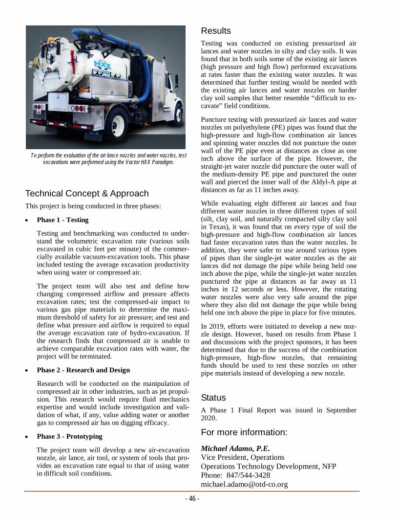
Technical Concept & Approach This project is being conducted in three phases:
Phase 1 - Testing
Testing and benchmarking was conducted to under-stand the volumetric excavation rate (various soils excavated in cubic feet per minute) of the commer-cially available vacuum-excavation tools. This phase included testing the average excavation productivity when using water or compressed air.
The project team will also test and define how changing compressed airflow and pressure affects excavation rates; test the compressed-air impact to various gas pipe materials to determine the maxi-mum threshold of safety for air pressure; and test and define what pressure and airflow is required to equal the average excavation rate of hydro-excavation. If the research finds that compressed air is unable to achieve comparable excavation rates with water, the project will be terminated.
Phase 2 - Research and Design
Research will be conducted on the manipulation of compressed air in other industries, such as jet propul-sion. This research would require fluid mechanics expertise and would include investigation and vali-dation of what, if any, value adding water or another gas to compressed air has on digging efficacy.
Phase 3 - Prototyping
The project team will develop a new air-excavation nozzle, air lance, air tool, or system of tools that pro-vides an excavation rate equal to that of using water in difficult soil conditions.
- 46 -
Results Testing was conducted on existing pressurized air lances and water nozzles in silty and clay soils. It was found that in both soils some of the existing air lances (high pressure and high flow) performed excavations at rates faster than the existing water nozzles. It was determined that further testing would be needed with the existing air lances and water nozzles on harder clay soil samples that better resemble “difficult to ex-cavate” field conditions.
Puncture testing with pressurized air lances and water nozzles on polyethylene (PE) pipes was found that the high-pressure and high-flow combination air lances and spinning water nozzles did not puncture the outer wall of the PE pipe even at distances as close as one inch above the surface of the pipe. However, the straight-jet water nozzle did puncture the outer wall of the medium-density PE pipe and punctured the outer wall and pierced the inner wall of the Aldyl-A pipe at distances as far as 11 inches away.
While evaluating eight different air lances and four different water nozzles in three different types of soil (silt, clay soil, and naturally compacted silty clay soil in Texas), it was found that on every type of soil the high-pressure and high-flow combination air lances had faster excavation rates than the water nozzles. In addition, they were safer to use around various types of pipes than the single-jet water nozzles as the air lances did not damage the pipe while being held one inch above the pipe, while the single-jet water nozzles punctured the pipe at distances as far away as 11 inches in 12 seconds or less. However, the rotating water nozzles were also very safe around the pipe where they also did not damage the pipe while being held one inch above the pipe in place for five minutes.
In 2019, efforts were initiated to develop a new noz-zle design. However, based on results from Phase 1 and discussions with the project sponsors, it has been determined that due to the success of the combination high-pressure, high-flow nozzles, that remaining funds should be used to test these nozzles on other pipe materials instead of developing a new nozzle.
Status A Phase 1 Final Report was issued in September 2020.
For more information:
Michael Adamo, P.E. Vice President, Operations Operations Technology Development, NFP Phone: 847/544-3428 [email protected]
To perform the evaluation of the air lance nozzles and water nozzles, test excavations were performed using the Vactor HXX Paradigm.
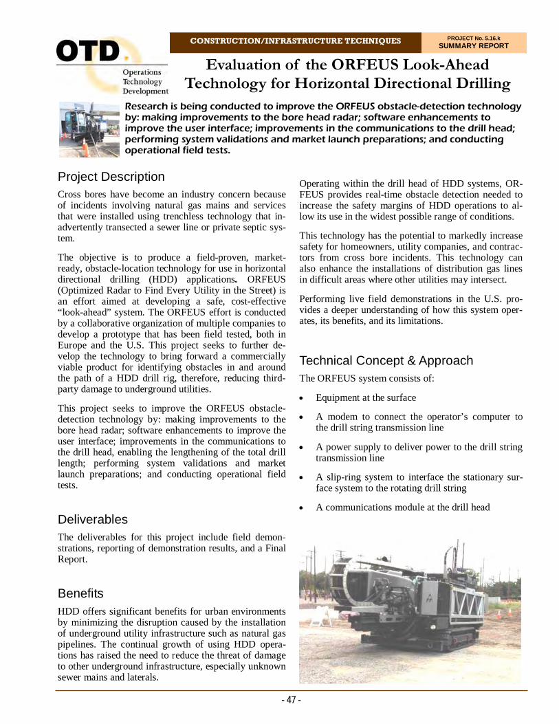
CONSTRUCTION/INFRASTRUCTURE TECHNIQUES PROJECT No. 5.16.k SUMMARY REPORT
Research is being conducted to improve the ORFEUS obstacle-detection technology by: making improvements to the bore head radar; software enhancements to improve the user interface; improvements in the communications to the drill head; performing system validations and market launch preparations; and conducting operational field tests.
Evaluation of the ORFEUS Look-Ahead Technology for Horizontal Directional Drilling
- 47 -
Project Description Cross bores have become an industry concern because of incidents involving natural gas mains and services that were installed using trenchless technology that in-advertently transected a sewer line or private septic sys-tem.
The objective is to produce a field-proven, market-ready, obstacle-location technology for use in horizontal directional drilling (HDD) applications. ORFEUS (Optimized Radar to Find Every Utility in the Street) is an effort aimed at developing a safe, cost-effective “look-ahead” system. The ORFEUS effort is conducted by a collaborative organization of multiple companies to develop a prototype that has been field tested, both in Europe and the U.S. This project seeks to further de-velop the technology to bring forward a commercially viable product for identifying obstacles in and around the path of a HDD drill rig, therefore, reducing third-party damage to underground utilities.
This project seeks to improve the ORFEUS obstacle-detection technology by: making improvements to the bore head radar; software enhancements to improve the user interface; improvements in the communications to the drill head, enabling the lengthening of the total drill length; performing system validations and market launch preparations; and conducting operational field tests.
Deliverables The deliverables for this project include field demon-strations, reporting of demonstration results, and a Final Report.
Benefits HDD offers significant benefits for urban environments by minimizing the disruption caused by the installation of underground utility infrastructure such as natural gas pipelines. The continual growth of using HDD opera-tions has raised the need to reduce the threat of damage to other underground infrastructure, especially unknown sewer mains and laterals.
Operating within the drill head of HDD systems, OR-FEUS provides real-time obstacle detection needed to increase the safety margins of HDD operations to al-low its use in the widest possible range of conditions.
This technology has the potential to markedly increase safety for homeowners, utility companies, and contrac-tors from cross bore incidents. This technology can also enhance the installations of distribution gas lines in difficult areas where other utilities may intersect.
Performing live field demonstrations in the U.S. pro-vides a deeper understanding of how this system oper-ates, its benefits, and its limitations.
Technical Concept & Approach The ORFEUS system consists of:
Equipment at the surface
A modem to connect the operator’s computer to the drill string transmission line
A power supply to deliver power to the drill string transmission line
A slip-ring system to interface the stationary sur-face system to the rotating drill string
A communications module at the drill head

A modem to connect the radar system to the drill string transmission line, and
A unit to receive power transmitted along the drill string and convert it into the various voltages re-quired by the modem and radar system,
The technology has a look-ahead range of up to about 20 inches, which includes both straight ahead of the drill tip and to the sides of the drill tip.
The robustness of the system was proven, as well as the ability to fulfill the requirement of locating and recogniz-ing obstacles within the drilling envelope. Most of the engineering challenges have been overcome, and the task ahead is to refine the technology to produce a marketable system.
Results
A field trial of the ORFEUS system was conducted in April of 2017 in California. The equipment was tested on a purposely built testing area including several targets (utilities and boulders). Results from the trial confirmed the performance of the ORFEUS system and the suitabil-ity of the technology for preventing the striking of utili-ties and other objects when drilling through the ground.
Specifically, a selection of non-conductive and metallic pipes with different diameters and layout with respect to the expected drilling path were used for the trial. The ground in the testing area consisted of moderately wet clay mixed with gravel/crushed rocks.
Superficially, the development in this project appears to be a straight-forward extension of ground-probing radar, a technology that has been in existence for many dec-ades. There are, however, some significant differences, including:
A very demanding spatial restriction, both in terms of volume and geometry, which is not a serious de-sign constraint in conventional GPR systems. The principal consequence of this is a limitation in an-tenna size, which prevents the propagation of low-frequency radar signals, required for the penetration of the ground.
The detection and recognition of targets requires the integration of many radar signals, assembled as a coherent set, from a well-defined and well-understood strategy of scanning the ground as a rec-tangular grid. This is not possible with a drill string radar, where the scanning produces data in a cylin-drical format.
Processing and reducing the volume of data pro-duced by the radar requires the application of signifi-cant computing resources with associated high-power requirements. In addition, the transmission of
- 48 -
even a reduced set of data to the surface by a wireless method, with the present available tech-nology, is not possible. It is, therefore, necessary to transmit large volumes of radar data to the sur-face, and power from the surface, along the drill string.
A high shock, vibration, and temperature environ-ment within the drill head need a careful engi-neering approach to the protection of the elec-tronic systems to ensure robustness and reliabil-ity.
Producing a workable, integrated technical solu-tion to the issues has required close cooperation between engineering organizations.
This project resulted in the evaluation of a practical drill string radar system that has now undergone a series of demanding operational field trials in Europe and a successful demonstration on a prepared test site in the U.S.
In 2019, the project team reached a new path forward with a group of European technical partners, includ-ing Tracto-Technik and additional speciality subcon-tractors.
A review of the requirements for the system was exe-cuted; these main requirements are the basis of the specifications for all the subsystems composing the ORFEUS system and will guide the development of the project. This activity was conducted during some technical meetings of the consortium which analyzed key aspects for the system.
An angular sensor prototype was built during the pre-vious ORFEUS project, showing very promising re-sults. In the current project, the angular sensor shall be re-designed because some fundamental electronic components are discontinued, mechanical constraints are changed, and to be compliant with the final re-quirements concerning the construction of a final mar-ketable device.
Status The next steps will be to continue the conceptual de-sign studies and detailed design specifications specifi-cally related to the objective of achieving a communi-cation and DC power delivery range of 300 meters.
For more information:
Michael Adamo, P.E. Vice President, Operations Operations Technology Development, NFP Phone: 847/544-3428 [email protected]
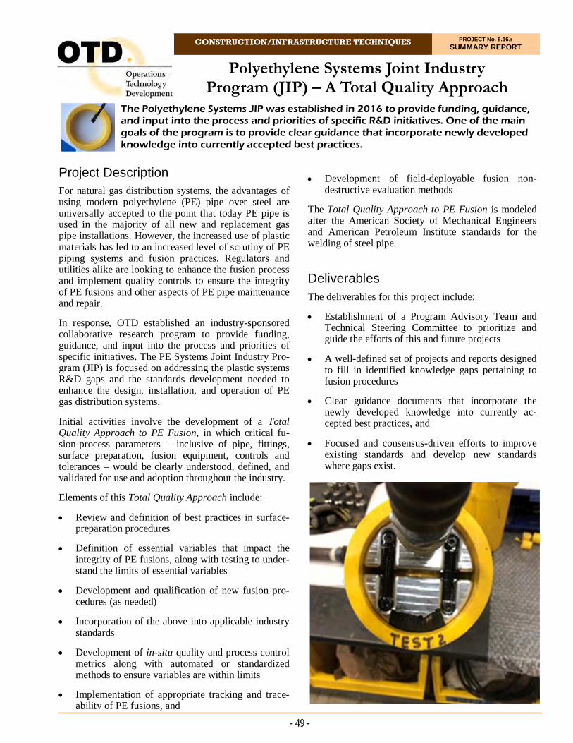
CONSTRUCTION/INFRASTRUCTURE TECHNIQUES PROJECT No. 5.16.r SUMMARY REPORT
Project Description For natural gas distribution systems, the advantages of using modern polyethylene (PE) pipe over steel are universally accepted to the point that today PE pipe is used in the majority of all new and replacement gas pipe installations. However, the increased use of plastic materials has led to an increased level of scrutiny of PE piping systems and fusion practices. Regulators and utilities alike are looking to enhance the fusion process and implement quality controls to ensure the integrity of PE fusions and other aspects of PE pipe maintenance and repair.
In response, OTD established an industry-sponsored collaborative research program to provide funding, guidance, and input into the process and priorities of specific initiatives. The PE Systems Joint Industry Pro-gram (JIP) is focused on addressing the plastic systems R&D gaps and the standards development needed to enhance the design, installation, and operation of PE gas distribution systems.
Initial activities involve the development of a Total Quality Approach to PE Fusion, in which critical fu-sion-process parameters – inclusive of pipe, fittings, surface preparation, fusion equipment, controls and tolerances – would be clearly understood, defined, and validated for use and adoption throughout the industry.
Elements of this Total Quality Approach include:
Review and definition of best practices in surface-preparation procedures
Definition of essential variables that impact the integrity of PE fusions, along with testing to under-stand the limits of essential variables
Development and qualification of new fusion pro-cedures (as needed)
Incorporation of the above into applicable industry standards
Development of in-situ quality and process control metrics along with automated or standardized methods to ensure variables are within limits
Implementation of appropriate tracking and trace-ability of PE fusions, and
The Polyethylene Systems JIP was established in 2016 to provide funding, guidance, and input into the process and priorities of specific R&D initiatives. One of the main goals of the program is to provide clear guidance that incorporate newly developed knowledge into currently accepted best practices.
Polyethylene Systems Joint Industry Program (JIP) – A Total Quality Approach
Development of field-deployable fusion non-destructive evaluation methods
The Total Quality Approach to PE Fusion is modeled after the American Society of Mechanical Engineers and American Petroleum Institute standards for the welding of steel pipe.
Deliverables The deliverables for this project include:
Establishment of a Program Advisory Team and Technical Steering Committee to prioritize and guide the efforts of this and future projects
A well-defined set of projects and reports designed to fill in identified knowledge gaps pertaining to fusion procedures
Clear guidance documents that incorporate the newly developed knowledge into currently ac-cepted best practices, and
Focused and consensus-driven efforts to improve existing standards and develop new standards where gaps exist.
- 49 -

Benefits The PE Systems JIP is designed to establish a roadmap and prioritize tasks by identifying the most pressing industry needs and defining the scope of projects to ad-dress the identified needs. The JIP helps to secure and coordinate funding sources; coordinate and facilitate interaction and communication among various stake-holders; and communicate results.
Technical Concept & Approach A Program Advisory Team oversees the entire program and a Technical Steering Committee was established to provide guidance to the program. The Technical Steer-ing Committee guides the development of the research projects and scopes of work that will be performed. Results The PE systems JIP was established in 2016.
Program members include: OTD members, associa-tions, various other utilities, manufacturers, and con-tractors.
The major focus of the JIP participants is to identify and discuss industry needs, achieve consensus on prioritiza-tion of issues for project research, and participate in the direction and review of the various project efforts.
Recent industry discussions identified agroup of needs to help enhance the overall quality of plastic piping sys-tems. The identified needs include:
Fusion joining preparation best practice develop-ment
Creation of ovality and out-of-round standards, in-cluding re‐rounding guidelines
A more thorough understanding of the durability of elastomers used in mechanical fittings
Development of design guidelines for fittings, in-cluding the interaction of multiple materials with elastomeric seals
Understanding the impact of heavy hydrocarbon permeation in PE pipe on mechanical joints.
Best practices for evaluating new appurtenances
Best practices for evaluating fusion procedures, and
Evaluation of repair methods for plastic piping sys-tems.
In 2018, pipe-fusion preparation guidelines were devel-oped. The effort focused on cleaning and pipe prepara-
- 50 -
tion – how to properly clean pipe based on different field conditions (e.g., wind, moisture, and water in a ditch); using the “one-and-done” approach by using an approved single-use towel once and discarding the used towel after each cleaning step; peeling or scraping the pipe correctly, ensuring that if any remaining contami-nation is present, it is fully removed; and installing and fusing the fitting promptly after scraping to minimize any future contamination.
In 2019, a series of fusion joining preparation projects were completed. Various scrapers were tested with re-spect to scrape depth, scrape uniformity, and contami-nation (bentonite powder) removal, at different tem-peratures. Three solvents were tested with respect to contamination removal (talc, bentonite powder, and silicone grease), with three different cleaning tools (polyester fiber wipe, paper towel, and cotton rag).
In 2020, researchers performed tensile testing on me-chanical fitting joints that were permeated with a heavy hydrocarbon cocktail. The permeated mechanical joints passed the 25% pipe-elongation requirement. Analysis of the peak forces indicated that the permeated joints behaved as if they were at elevated temperature. This observation agrees with the findings in the U.S. Depart-ment of Transportation report Effects of Hydrocarbon Permeation on Plastic Pipe Strength and Fusion Per-formance.
Status The project team is currently focusing on heavy-hydrocarbon permeation projects. Projects related to hydrogen blending are expected to gain focus in 2021 and over the next few years.
For more information:
Michael Adamo, P.E. Vice President, Operations Operations Technology Development, NFP Phone: 847/544-3428 [email protected]
- Dr. Gene Palermo President Palermo Plastics Pipe Consulting
“As a member of the JIP Steering Committee, I fully support the effort to improve the quality of polyethylene fusion joints. A chain is as strong as its weakest link, and a plastic pipeline is as strong as its weakest joint. Although polyethylene components are easily joined by the heat-fusion method, there continues to be an industry need to improve the overall quality of the joining method used in the field by incorporating the latest technology into our best practices.”
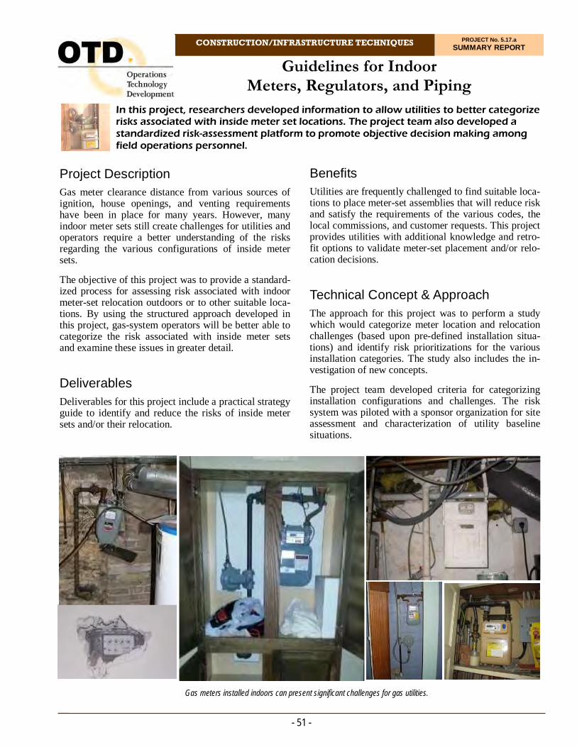
Guidelines for Indoor Meters, Regulators, and Piping
CONSTRUCTION/INFRASTRUCTURE TECHNIQUES PROJECT No. 5.17.a SUMMARY REPORT
In this project, researchers developed information to allow utilities to better categorize risks associated with inside meter set locations. The project team also developed a standardized risk-assessment platform to promote objective decision making among field operations personnel.
- 51 -
Project Description Gas meter clearance distance from various sources of ignition, house openings, and venting requirements have been in place for many years. However, many indoor meter sets still create challenges for utilities and operators require a better understanding of the risks regarding the various configurations of inside meter sets.
The objective of this project was to provide a standard-ized process for assessing risk associated with indoor meter-set relocation outdoors or to other suitable loca-tions. By using the structured approach developed in this project, gas-system operators will be better able to categorize the risk associated with inside meter sets and examine these issues in greater detail.
Deliverables
Deliverables for this project include a practical strategy guide to identify and reduce the risks of inside meter sets and/or their relocation.
Gas meters installed indoors can present significant challenges for gas utilities.
Benefits Utilities are frequently challenged to find suitable loca-tions to place meter-set assemblies that will reduce risk and satisfy the requirements of the various codes, the local commissions, and customer requests. This project provides utilities with additional knowledge and retro-fit options to validate meter-set placement and/or relo-cation decisions.
Technical Concept & Approach The approach for this project was to perform a study which would categorize meter location and relocation challenges (based upon pre-defined installation situa-tions) and identify risk prioritizations for the various installation categories. The study also includes the in-vestigation of new concepts.
The project team developed criteria for categorizing installation configurations and challenges. The risk system was piloted with a sponsor organization for site assessment and characterization of utility baseline situations.
- 52 -
The risk-assessment form was developed that uses the following variables to assess the meter set’s current indoor installation location:
Building type
Accessibility of meter set and piping
Number of meters installed in area
Volume of space where meter is installed
Length of piping
Ability to shut off gas flow
Proximity to ignition sources, and
Regulator vent configuration.
In 2019, a two-day field trial was conducted to assess the form’s completeness and usability in a real-world setting. It is intended that the wide adoption of the form across the industry will lead to continued refine-ment and improvement over time.
This form is fully customizable to best suit a specific utility’s interests and is easily integrated into a utility’s existing geographic information system asset-manage-ment system.
This form and platform allow for utilities to identify risks in a timely manner, mitigate these risks, avoid incidents, and create a much safer environment for both customers and utility crew members.
Status
This project is complete. A Final Report was issued in June 2020.
First iteration of the risk-based form is publicly avail-able via Esri’s Survey123 Connect application. Addi-tionally, the project team developed a tentative plan over multiple project phases to mature the prototype created in this project into a robust solution that may be easily integrated with a utility’s existing meter-set inspection business function. The complete toolset will allow a gas utility to set up, configure, and execute indoor meter location risk assessments and design stra-tegic approaches to address the highest risk installa-tions.
Random field surveys were conducted to better define and quantify the developed categories. Results from the field surveys were analyzed, categorized, and reviewed with each participating utility. Results were translated into risk mitigation recommended actions geared for specific categories of installation configurations.
Results For this project, a research team successfully devised a systematic process and related technology to objectively quantify and categorize the risk associated with an in-door meter’s existing location.
Tools developed for this project enable an operator to bring objectivity to the meter-relocation decision-making process by taking a systematic approach for ana-lyzing the risk profile of each meter’s current location.
The project team identified a set of existing codes and regulations that specify parameters and guidance for safely locating meter-set assemblies inside a building and created a risk-assessment form that quantifies the degree of risk that a meter’s current indoor location poses for an operator.
The resulting risk-based form is built upon Esri’s Survey 123 platform and capable of being deployed on any mo-bile device to support field-data collection during meter-inspection operations. The system leverages a simple user interface platform. Additionally, easy-to-understand results are displayed via a dashboard with drill-down capabilities to access more detailed information. Fur-thermore, actionable mitigation actions are provided relative to the composite score generated for a particular meter set.
Through the review of various meter-set installation handbooks, the following guidelines are commonly found:
The regulator vent is defined as the point at which clearance distances from the meter set are measured
The regulator vent must be at least 36 inches from all ignition sources
Ignition sources are defined as electric panels, appli-ances, and pilot lights
Regulator vent must be at least eight feet away from any air-intake ports (mainly concerning outdoor me-ter sets)
Regulators installed indoors must not vent openly indoors; he vent outlet must be piped outdoors, and
The meter-set assembly (MSA) should be readily accessible by the utility, and there should be avail-able floorspace so that crew members can easily work on the meter set connections.
For more information:
Michael Adamo, P.E. Vice President, Operations Operations Technology Development, NFP Phone: 847/544-3428 [email protected]
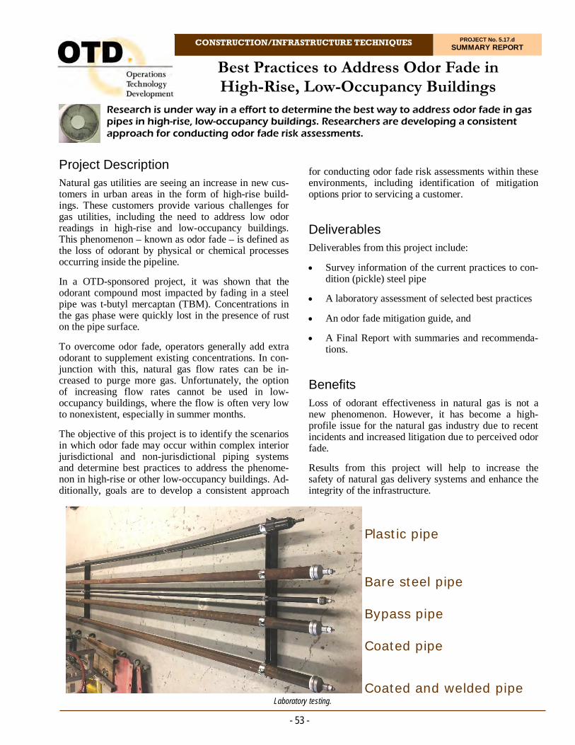
Best Practices to Address Odor Fade in High-Rise, Low-Occupancy Buildings
CONSTRUCTION/INFRASTRUCTURE TECHNIQUES PROJECT No. 5.17.d SUMMARY REPORT
Research is under way in a effort to determine the best way to address odor fade in gas pipes in high-rise, low-occupancy buildings. Researchers are developing a consistent approach for conducting odor fade risk assessments.
- 53 -
Project Description Natural gas utilities are seeing an increase in new cus-tomers in urban areas in the form of high-rise build-ings. These customers provide various challenges for gas utilities, including the need to address low odor readings in high-rise and low-occupancy buildings. This phenomenon – known as odor fade – is defined as the loss of odorant by physical or chemical processes occurring inside the pipeline.
In a OTD-sponsored project, it was shown that the odorant compound most impacted by fading in a steel pipe was t-butyl mercaptan (TBM). Concentrations in the gas phase were quickly lost in the presence of rust on the pipe surface.
To overcome odor fade, operators generally add extra odorant to supplement existing concentrations. In con-junction with this, natural gas flow rates can be in-creased to purge more gas. Unfortunately, the option of increasing flow rates cannot be used in low-occupancy buildings, where the flow is often very low to nonexistent, especially in summer months.
The objective of this project is to identify the scenarios in which odor fade may occur within complex interior jurisdictional and non-jurisdictional piping systems and determine best practices to address the phenome-non in high-rise or other low-occupancy buildings. Ad-ditionally, goals are to develop a consistent approach
for conducting odor fade risk assessments within these environments, including identification of mitigation options prior to servicing a customer.
Deliverables Deliverables from this project include:
Survey information of the current practices to con-dition (pickle) steel pipe
A laboratory assessment of selected best practices
An odor fade mitigation guide, and
A Final Report with summaries and recommenda-tions.
Benefits Loss of odorant effectiveness in natural gas is not a new phenomenon. However, it has become a high-profile issue for the natural gas industry due to recent incidents and increased litigation due to perceived odor fade.
Results from this project will help to increase the safety of natural gas delivery systems and enhance the integrity of the infrastructure.
Laboratory testing.
Plastic pipe Bare steel pipe Bypass pipe Coated pipe
Coated and welded pipe

- 54 -
the pipe dope and allowing it to spread out beyond the joints where it was applied, possibly in excess.
Additionally, the research team completed test execu-tion and results reporting of all activities performed under the laboratory evaluation portion of the project scope. Sponsors indicated they have an interest in un-derstanding the impact of rust on time to saturation for uncoated steel pipe, and calculate during project plan-ning when odor fade may occur, which was not part of the original scope. In the interim, the team produced an initial time to saturation analysis to outline the methodology a utility could use to develop a “rule of thumb” estimate the risk of odor fade for a given sce-nario.
Two distinct methodologies for incorporating rust into the time to saturation analysis were identified. The project team and sponsors agreed on a hybrid of the two approaches in which pipe samples from project sponsors would be combined with samples environ-mentally conditioned to perform the rust characteriza-tion analysis.
The project team completed an additional scope pro-posal and met with project sponsors in the fourth quar-ter of 2020 to review the task descriptions and level of effort estimates. Project sponsors agreed to move for-ward with the scope addition.
Status
A 15-month extension to the project will begin in 2021 to analyze the impact of rust on time to saturation val-ues for uncoated steel pipe.
Technical Concept & Approach The project has two parallel paths: one involves a sur-vey of industry best practices and combining it with knowledge to date. The second path involves laboratory testing of a selected mitigation pathway.
Project sponsors and others will be surveyed for their typical practices in low-flow or locked-in situations. Information gleaned from odor-fade projects will be added. The American Gas Association also publishes information that will be included. This information will be summarized, chemically evaluated, and presented to project sponsors.
Selected techniques will be evaluated under laboratory conditions. The gas will initially be odorized with tetra-hydothiophene and/or TBM, using house gas or syn-thetic odorized gas.
Results
During 2018, researchers constructed a testing matrix, itemizing the pipe materials to be included in the test-ing. Pipe sizes, lengths, and material compositions were finalized by the team based on sponsor requirements and gaps in past tested materials. Multiple average Btu usage scenarios were computed to assist in the burner and other requirements specifications. Other design top-ics included the incorporation of venting and flaring of gas, gas on/off switches, flow valves, and sensors. The plastic pipe sticks were purchased and butt fused with fittings. Electronic controls and sensors were purchased and assembled.
The test rig was constructed, and safety and sensor-related devices were installed and tested. The first test was initiated with gas containing TBM at a trickle flow. Preliminary results indicated the coated steel pipe suc-cessfully prevented odorant fade. A weld joint present in a second pipe had no effect. The plastic pipe experi-enced a slight amount of odorant loss. The uncoated steel pipe experienced significant odorant loss.
For the tests, a series of ball valves was used to control the flow of the gas and ensure limited interaction with non-inerted surfaces. By comparing the difference in concentration between the inlet and outlet sample points, the amount of odorant loss can be quantified.
In 2019, a new task was performed for a project sponsor investigating a pipe implicated in odorant fade in an apartment building. An oily residue and pipe dope was found on the interior surface. Visual examination of the pipe interior found a white/gray colored surface con-tamination on the pipe interior that was oily to the touch. This material was isolated and identified as the same pipe dope used to connect the pipe to the tees. The oily residue is surmised to be from cutting fluid used to make the pipe threads. This oil appears to have softened
For more information:
Michael Adamo, P.E. Vice President, Operations Operations Technology Development, NFP Phone: 847/544-3428 [email protected]
Scanning electron microscope image of residue on pipe interior wall.
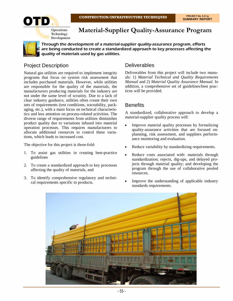
Material-Supplier Quality-Assurance Program
CONSTRUCTION/INFRASTRUCTURE TECHNIQUES PROJECT No. 5.17.g SUMMARY REPORT
Through the development of a material-supplier quality-assurance program, efforts are being conducted to create a standardized approach to key processes affecting the quality of materials used by gas utilities.
- 55 -
Project Description Natural gas utilities are required to implement integrity programs that focus on system risk assessment that includes purchased materials. However, while utilities are responsible for the quality of the materials, the manufacturers producing materials for the industry are not under the same level of scrutiny. Due to a lack of clear industry guidance, utilities often create their own sets of requirements (test conditions, traceability, pack-aging, etc.), with a main focus on technical characteris-tics and less attention on process-related activities. The diverse range of requirements from utilities diminishes product quality due to variations infused into material operation processes. This requires manufacturers to allocate additional resources to control these varia-tions, which leads to increased cost.
The objective for this project is three-fold:
1. To assist gas utilities in creating best-practice guidelines
2. To create a standardized approach to key processes affecting the quality of materials, and
3. To identify comprehensive regulatory and techni-cal requirements specific to products.
Deliverables Deliverables from this project will include two manu-als: 1) Material Technical and Quality Requirements Manual and 2) Material Quality Assurance Manual. In addition, a comprehensive set of guidelines/best prac-tices will be provided.
Benefits A standardized, collaborative approach to develop a material-supplier quality process will:
Improve material quality processes by formalizing quality-assurance activities that are focused on: planning, risk assessment, and suppliers perform-ance monitoring and evaluation.
Reduce variability by standardizing requirements.
Reduce costs associated with: materials through standardization; rejects, dig-ups, and delayed pro-jects through material quality; and developing the program through the use of collaborative pooled resources.
Improve the understanding of applicable industry standards requirements.

- 56 -
In this task, a review will be conducted of utilities internal material-quality practices to identify best practices in material-supplier quality-assurance activities by benchmarking gas utilities and other industries that have successfully implemented pro-grams.
Development of Material Technical and Qual-ity Requirements Manual for Material Suppli-ers
This task includes the development of a manual that incorporates material technical specifications and quality requirements (e.g., certification, docu-mentation, inspection and testing, management of change, traceability and identification, delivery, packaging, recall plan, contingency plan, and right of access).
Development of Material Quality-Assurance Manual for Utilities
This task includes the development of a manual that incorporates best-practices material-quality-assurance processes.
Results Throughout this program, the project team collected more than 190 technical specifications, conducted a gap analysis, and created comprehensive technical product specifications for 22 product families.
Researchers reviewed and created eight best practice quality procedures for utilities’ internal use, including a Purchasing Quality Manual.
Also, 25 quality forms were created to collect qualita-tive and quantitative data. These forms will be con-verted into electronic smart forms available on mobile devices to simplify digital data collection, monitoring, and analysis during Phase 2.
Status
Phase 1 is nearly complete. One specification for FBE Coating is pending.
In 2021, the project team will submit the remaining specifications and initiate Phase 2.
Improve communication, collaboration, and infor-mation sharing with suppliers and make more in-formed decisions based on data derived from sup-plier quality-assurance activities.
Raise the bar of overall material quality and system integrity by collaborating as a group and creating an industry standard approach to material quality-assurance processes.
Identify possible gaps in current standards and regu-latory requirements.
Technical Concept & Approach This is a collaborative program that includes a steering committee comprised of representatives from each par-ticipating sponsor along with subject-matter experts (SMEs). The steering committee is responsible for pro-viding relevant information, communicating expecta-tions as to the direction of the program, participating and providing feedback in the development of the manuals, and identifying priorities as to the project deliverables.
This program will define a manual/handbook with com-prehensive material requirements and best practices of material-supplier quality-assurance processes (methods, policies, and procedures) that will help utilities to con-trol and improve material quality and, therefore, overall system integrity.
Specific tasks include:
Project Scoping and Gathering of Information
The work in this task includes contracting and sub-contracting the industry SMEs to assist in creating the program and gathering material information.
Gap Analysis of Product and Process Require-ments
A review of the product types selected by the spon-sors will be performed to determine their technical specifications and quality requirements.
Gap Analysis of Utilities’ Internal Material-Supplier Quality Processes
For more information:
Michael Adamo, P.E. Vice President, Operations Operations Technology Development, NFP Phone: 847/544-3428 [email protected]
- Jerrod Meier Principal Engineer, Risk Register Pacific Gas and Electric Company
“PG&E was pleased to collaborate with our peer companies to create a better standard methodology we can all incorporate into our risk-management programs. We have all too often heard from our suppliers that ‘we are the only one that does this,’ but the teamwork on this project created a set of documents we can all leverage to make our programs stronger together.”

Protecting Tracer Wires from Corrosion – Best Practices and New Methods
CONSTRUCTION/INFRASTRUCTURE TECHNIQUES PROJECT No. 5.17.k SUMMARY REPORT
In this project, researchers reviewed best practices for protecting buried tracer wires from corrosion. The focus was on developing a cost-effective means that does not impair the ability of the wire to carry the tracing signal.
- 57 -
Project Description To help locate buried plastic pipe, the natural gas in-dustry has a large base of tracer wire installed along-side its plastic pipe, and continually adds to it. Tracer wire is typically solid copper or a copper layer on a steel core. High-quality tracer wire will have poly-ethylene insulation at least 30 mils thick.
OTD-developed Guidelines for Use of Copper-Clad Steel Tracer Wire (OTD project 5.7.c) covers the in-stallation practices for such wire. However, even ap-propriate insulation can be damaged during horizontal directional drilling and other operations. Once tracer wire is installed, it needs some form of corrosion pro-tection to ensure that it has a long working life. This protection must be implemented in a way that does not compromise the tracing function of the wire.
Cathodic protection can significantly extend tracer-wire life. Magnesium or zinc sacrificial anodes can provide sufficient negative potential on the copper to retard corrosion of the exposed or wet surfaces. The tracer-wire surface area is small compared to that of pipe, so modestly-sized anodes will suffice. However, using anodes to protect tracer wire can drain the tracing signal-to-ground. If the tracing signal is injected into a free end of the wire, this signal can be followed only as far as the first anode on the tracer wire or the first break in the tracer wire. Either will stop the signal from travelling further. The locator personnel tracing
the wire cannot distinguish between a break or a “hidden” anode without making an excavation. The limitations of tracing-signal interaction with anodes has prevented widespread adoption of this protection method.
The accurate documenting and marking of anodes used to protect tracer wire is also a critical aspect of effec-tive tracing operations. Locator personnel require the ability to disconnect anodes in the work area. Alterna-tively, the anode may be connected in a manner that passes the DC protective current and blocks the AC tracing signal. This removes the necessity to discon-nect the anodes, simplifying the operation.
The objective of this project was to review best prac-tices to protect buried tracer wires from corrosion. Deliverable The project team delivered:
A Recommended Practices Report that details the results of this project’s survey effort, analyzes those results in relation to AGA reports, and pre-sents tracer wire guideline statements from best practice organizations, and
A project Final Report.
Three connector types for testing.

- 58 -
system in good operating order. The project team re-viewed multiple aspects of tracer wire technology, including variety and physical attributes of wire cur-rently in use and best practices for wire installation.
The items used for the life-cycle testing included 12-gauge copper clad steel tracer wire with a polyethylene jacket and three different connector types, representing the major methods for mechanically joining wire in the field. Three “strings” of connectors were assembled for testing at an elevated temperature for 2,000 hours. The resistance of each string was measured at the be-ginning of the test, monitored and recorded throughout the duration of the experiment, and measured once again at the end of testing.
The basic finding was that the resistance of the tracer wire connectors changed very little over the duration of the test. Only one connector out of 15 showed a notable change; that connector was damaged during the process of taking the system apart for the post-test analysis. No corrosion of the tracer wires or the con-nectors was observed.
Status This project is complete. A Final Report was issued in September 2020.
Benefits Results from this project provide gas system operators with information on the optimal methods for maintain-ing installed tracer wire and enhance the safety and effi-cient operation of plastic piping gas distribution sys-tems.
Technical Concept & Approach Project personnel reviewed multiple aspects of tracer wire technology, including:
The variety and physical attributes of wire
The standard and best practices for installation of tracer wire
Connectors and appurtenances used in tracer wire installations
Signal generators and receivers for tracer wire, and
New technologies related to tracer wire.
Findings from all the tasks were compiled into a report detailing the technologies and practices currently ap-plied to tracer wire.
Results For this project, a research team initially conducted a comprehensive literature and standards document search, data collection, and analysis effort to present current best-practice guidance on maintaining and pro-tecting tracer wire systems. Through a multi-faceted approach, investigators surveyed the current technology state to uncover any emerging or significantly improved methodologies for tracer wire installation, system corro-sion control, and signal and anodes management.
As the starting point for the review, researchers accessed the results from the American Gas Association’s 2008 report on tracer wire to collect information on related practices previously reported by gas operating compa-nies. This rich set of information provided a basis against which practices and trends within the project sponsors’ organizations could be compared and con-trasted.
A detailed questionnaire was devised and a follow-up interview process implemented to develop a solid under-standing of tracer-wire processes, system components, present-day challenges, and future needs and require-ments.
Industry regulations, standards, and guidance documents were consulted to build a knowledge base of the current, widely-regarded best practices for keeping a tracer wire
For more information:
Michael Adamo, P.E. Vice President, Operations Operations Technology Development, NFP Phone: 847/544-3428 [email protected]
Three-way lockable connector.

Field Testing of Nano-Technology Coatings to Reduce Aboveground Corrosion
CONSTRUCTION/INFRASTRUCTURE TECHNIQUES PROJECT No. 5.17.p SUMMARY REPORT
To address corrosion concerns with aboveground utility assets, field trials were performed with unique and promising coatings for challenging utility corrosion-prevention applications. These coatings have the potential to substantially reduce wet/dry aboveground corrosion in various areas of application.
- 59 -
Project Description Utilities have long expressed interest in the develop-ment of improved pipeline coatings for challenging environments. Of particular concern are applications for aboveground facilities.
The concept for this project came from needs ex-pressed by a utility group wanting to explore super-hydrophobic nano-coatings to improve corrosion resis-tance in high-risk areas. Other utilities are interested in testing these novel coatings in snow/ice areas, as well as bridge crossings that have significant, industry-wide issues with caustic leafing corrosion from bird drop-pings.
For this project, field trials are being performed with three relatively new, unique coating systems.
A calcium-sulfonate-based coating
A water-based zinc-galvanizing compound, and
A zinc silicate waterborne coating.
The high-ratio co-polymerized calcium sulfonate pro-prietary formulation has the unique ability to neutralize acidity (passivating), create a hydrophobic barrier that repels water, bond ionically, and thoroughly wet the surface profile, making it suited for the reclamation and long-term protection of bridges, steel structures, cable-suspension systems, industrial infrastructures, highway overpasses, utility towers, and potentially pipelines.
Deliverables Specific deliverables from this project include:
A set of applicable use cases in a gas utility for these coating systems
Completion of set of field tests
A coating-performance summary
Recommendations for specific uses of the product, and
A Final Report detailing all activities.
Benefits New coatings have the potential to substantially reduce wet/dry aboveground corrosion in various areas of ap-plication.
For aboveground assets, operators cannot rely on ca-thodic protection to backup coating protection; there-fore, operators seek to specify and apply the most ap-propriate and best-performing coating system avail-able. By providing long-lasting coating protection, op-erators can reduce the amount of rework needed on their aboveground systems.
Some aboveground piping locations are very difficult to access and require permitting, multiple crew mem-bers, and special equipment and vehicles to inspect and/or repair coatings. These include highway and bridge crossings, water crossings, and vaults. Opera-tors that have outdoor meter sets and regulators also experience snow and ice damage of these assets.
Field testing these unique coatings in the natural gas utility environment will give operators data to support their use to reduce system damage and loss of integ-rity, thereby reducing the risk of system leaks or fail-ures. By testing the coatings under varying climate and system configurations with different operators, re-searchers will obtain a more complete picture of product performance in a variety field sites.

- 60 -
standing set of field sites that will go through four sea-sons of exposure and then be assessed for perform-ance.
In 2020, field applications continued. Five sites are being used for testing. These include: 1) a desert site with hot, dry sunshine; 2) gate station regulator piping on the ocean shore containing complex shapes, salt contamination, and temperature changes; 3) a bridge crossing with caustic bird droppings, wet/dry mois-ture, and road salts; 4) ice-formation sites at regulator stations; and 5) a compressor station with high/low temperature swings.
This phase of the project will continue into 2021 when assessments will be scheduled and undertaken once the COVID-19 restrictions are lifted.
Status The project is now in the field-exposure phase, with the coatings logging time at their respective applica-tion sites. In approximately a year, researchers will start the assessment of the coating performance with visual inspections, photography, root-cause analysis, and quantitative testing for rust and blistering.
Technical Concept & Approach Use case and field site selection (completed)
Product review and selection (completed)
Development of a field-testing protocol and testing matrix (completed)
Field trials and performance assessment (in pro-gress).
Results Field trials were successfully completed in 2019.
The project team completed and distributed the:
Concise Field Applied, Aboveground Coating Best Practices
General Surface Preparation Guidelines
Guidance on what type of scribe tool to use and how to purchase that option
Manufacturer recommendation for application brush type for zinc coatings, and
Field site key lessons learned.
All of the coatings have temperature/humidity/dew-point restrictions. This will most likely be a challenge on the low-pressure side of regulators. Each field site spon-sor invested a significant amount of time and expertise towards the field trials. The project now has an out-
For more information:
Michael Adamo, P.E. Vice President, Operations Operations Technology Development, NFP Phone: 847/544-3428 [email protected]
Water-based, two-part zinc galvanizing compound
Zinc/zinc oxide powder + liquid binder free of all solvents and volatile organic compounds
The dry film is 93 wt% zinc
Per the manufacturer’s own tests, it is rated at 10,000 hours on the ASTM B117 salt spray test
Requires a bare metal surface
Power tool cleaning is sufficient
Can be applied by brush, roller, airless, or conventional spray.
Application is by conventional spray.
Overview of Coatings
Single-component high-ratio, co-polymerized calcium-sulfonate alkyd coating
Sulfonate-carbonate crystals form a path that water must pass through before it can reach the substrate
Surface tolerant, hydrophobic and moisture displacing
Alkaline pH (~10.5) neutralizes active corrosion cells in existing rust
Primary commercial application is overcoating of steel bridges
Resist cracking from thermal and hygro-thermal stresses.
An inorganic zinc silicate waterborne coating system consisting of two components: potassium silicate binder and zinc powder
Developed by NASA to protect launch facilities in the highly corrosive environment of Florida’s coast
The potassium silicate binder allows the coating to be applied across a broad range of temperature (40F°- 118°F) and humidity (0-94% RH)
Can be top-coated after two hours
Bonds chemically to the steel substrate and is highly resistant to undercutting
Application is by conventional spray.
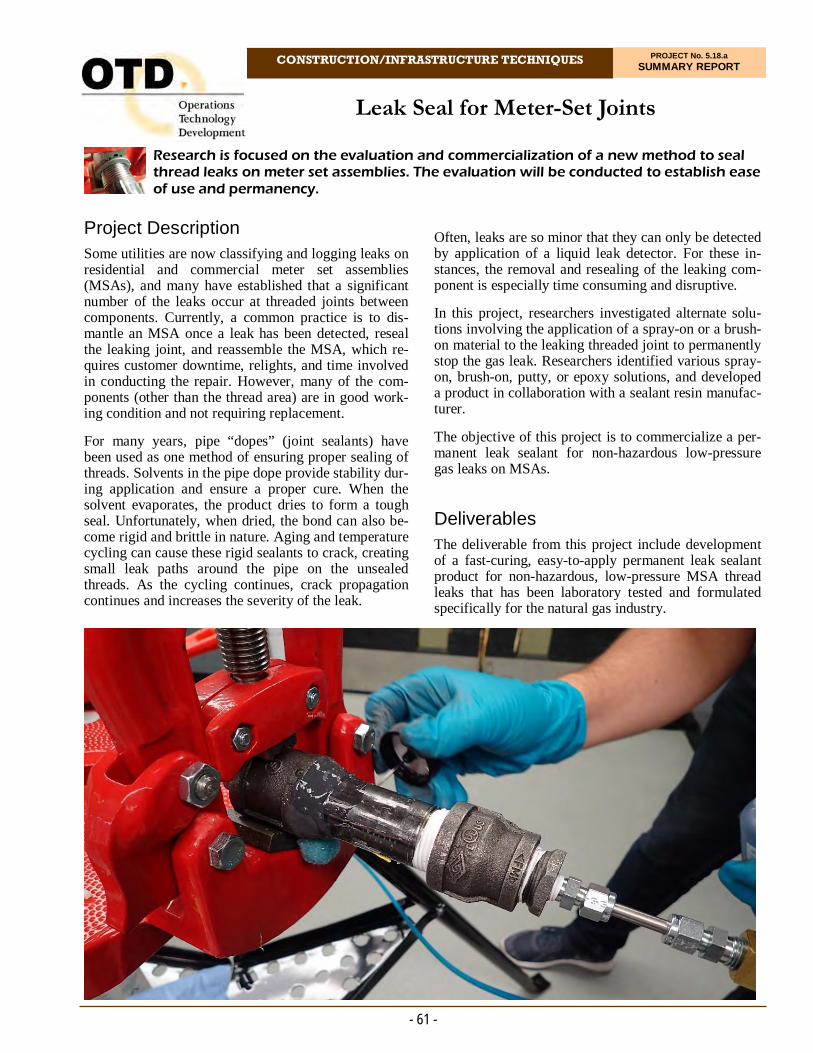
CONSTRUCTION/INFRASTRUCTURE TECHNIQUES PROJECT No. 5.18.a SUMMARY REPORT
Project Description Some utilities are now classifying and logging leaks on residential and commercial meter set assemblies (MSAs), and many have established that a significant number of the leaks occur at threaded joints between components. Currently, a common practice is to dis-mantle an MSA once a leak has been detected, reseal the leaking joint, and reassemble the MSA, which re-quires customer downtime, relights, and time involved in conducting the repair. However, many of the com-ponents (other than the thread area) are in good work-ing condition and not requiring replacement.
For many years, pipe “dopes” (joint sealants) have been used as one method of ensuring proper sealing of threads. Solvents in the pipe dope provide stability dur-ing application and ensure a proper cure. When the solvent evaporates, the product dries to form a tough seal. Unfortunately, when dried, the bond can also be-come rigid and brittle in nature. Aging and temperature cycling can cause these rigid sealants to crack, creating small leak paths around the pipe on the unsealed threads. As the cycling continues, crack propagation continues and increases the severity of the leak.
Research is focused on the evaluation and commercialization of a new method to seal thread leaks on meter set assemblies. The evaluation will be conducted to establish ease of use and permanency.
Leak Seal for Meter-Set Joints
Often, leaks are so minor that they can only be detected by application of a liquid leak detector. For these in-stances, the removal and resealing of the leaking com-ponent is especially time consuming and disruptive.
In this project, researchers investigated alternate solu-tions involving the application of a spray-on or a brush-on material to the leaking threaded joint to permanently stop the gas leak. Researchers identified various spray-on, brush-on, putty, or epoxy solutions, and developed a product in collaboration with a sealant resin manufac-turer.
The objective of this project is to commercialize a per-manent leak sealant for non-hazardous low-pressure gas leaks on MSAs.
Deliverables The deliverable from this project include development of a fast-curing, easy-to-apply permanent leak sealant product for non-hazardous, low-pressure MSA thread leaks that has been laboratory tested and formulated specifically for the natural gas industry.
- 61 -

- 62 -
For more information:
Michael Adamo, P.E. Vice President, Operations Operations Technology Development, NFP Phone: 847/544-3428 [email protected]
In 2019, activities for this quarter included completing the short-term testing of the different leak-sealant prod-ucts. This short-term testing consisted of applying the sealant product to one-inch threaded pipe joints. The short-term testing included evaluation of sealant reac-tion to leak soap and gray meter paint along with the overall cure time of the product. The products that suc-cessfully passed the short-term test protocol were then put through the long-term test protocol. The repaired specimens were evaluated by subjecting them to tem-perature cycling in an environmental chamber. The specimens were subjected to temperature cycling on a 24-hour cycle from -20°F to 140°F at 2 PSIG for 10 cycles (10 days).
Resin manufacturers with sealants that tested favorably during Phase 1 were contacted to gauge their interest in participating in the Phase 2 commercialization project.
Status
The project team is ensuring that agreements are in place with resin manufacturers.
The hand-applied product formulation and packaging needs to be customized for use by utilities (i.e., low level of VOCs, short cure time, paintable, etc.). The project team and the resin manufacturers of existing products will create and commercialize a product that is specifically designed to repair low-pressure leaks on MSAs.
The project team will also execute a field pilot study for the product.
Benefits Utilities could more effectively and efficiently address leaks on MSAs if an easy-to-apply system was identi-fied and validated for use on low-pressure natural gas leaks. Addressing these very small “nuisance” leaks on MSAs will assist the industry in minimizing the effect of one source of methane emissions and reduce the time and cost associated with performing this maintenance operation.
Technical Concept & Approach The initial task for this project included an in-depth re-view of the commercially available products that can be applied to metallic MSA components to stop leaks.
Other tasks included:
Resin Manufacturer Collaboration and Refor-mulation
The project team collaborated with an existing resin manufacturer who already markets a product that was tested in this program.
Short-Term and Long-Term Leak Repair Test-ing
Different formulations of the product will be labo-ratory tested to evaluate the short-term and long-term performances.
Field Pilot Study
Researchers will organize a field pilot study to evaluate performance when used in day-to-day util-ity repair work.
Commercialization of Reformulated Product
If the product proves to be useful and has satisfac-tory results, the project team will move to commer-cialize phase of the final product.
Results
In Phase 1, researchers evaluated more than 20 leak-sealant products. Through this evaluation, several putty-style leak-sealant products were identified that could potentially provide efficient and effective ways to per-manently repair small non-hazardous low-pressure gas leaks.
- Stephen Ramos Gas Operations R&D and Innovation Pacific Gas and Electric Company
“Currently, meter-set emissions account for 20% of PG&E’s overall emissions. The leak seal for meter-set joints project has the potential to repair these meter-set leaks sooner, thus reducing our overall emissions. In addition, there is the added safety benefit by reducing the amount of strain and physical work to break down meter sets to repair these leaks.”
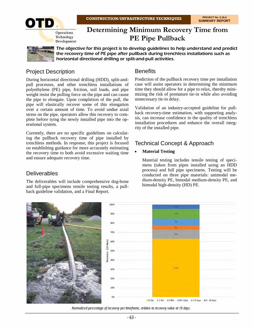
CONSTRUCTION/INFRASTRUCTURE TECHNIQUES PROJECT No. 5.18.d SUMMARY REPORT
Project Description During horizontal directional drilling (HDD), split-and-pull processes, and other trenchless installations of polyethylene (PE) pipe, friction, soil loads, and pipe weight resist the pulling force on the pipe and can cause the pipe to elongate. Upon completion of the pull, the pipe will elastically recover some of this elongation over a certain amount of time. To avoid undue axial stress on the pipe, operators allow this recovery to com-plete before tying the newly installed pipe into the op-erational system.
Currently, there are no specific guidelines on calculat-ing the pullback recovery time of pipe installed by trenchless methods. In response, this project is focused on establishing guidance for more accurately estimating the recovery time to both avoid excessive waiting time and ensure adequate recovery time.
Deliverables The deliverables will include comprehensive dog-bone and full-pipe specimens tensile testing results, a pull-back guideline validation, and a Final Report.
The objective for this project is to develop guidelines to help understand and predict the recovery time of PE pipe after pullback during trenchless installations such as horizontal directional drilling or split-and-pull activities.
Determining Minimum Recovery Time from PE Pipe Pullback
Benefits Prediction of the pullback recovery time per installation case will assist operators in determining the minimum time they should allow for a pipe to relax, thereby mini-mizing the risk of premature tie-in while also avoiding unnecessary tie-in delay.
Validation of an industry-accepted guideline for pull-back recovery-time estimation, with supporting analy-sis, can increase confidence in the quality of trenchless installation procedures and enhance the overall integ-rity of the installed pipe.
Technical Concept & Approach Material Testing
Material testing includes tensile testing of speci-mens (taken from pipes installed using an HDD process) and full pipe specimens. Testing will be conducted on three pipe materials: unimodal me-dium-density PE, bimodal medium-density PE, and bimodal high-density (HD) PE.
- 63 -
Normalized percentage of recovery per timeframe, relative to recovery value at 10 days.
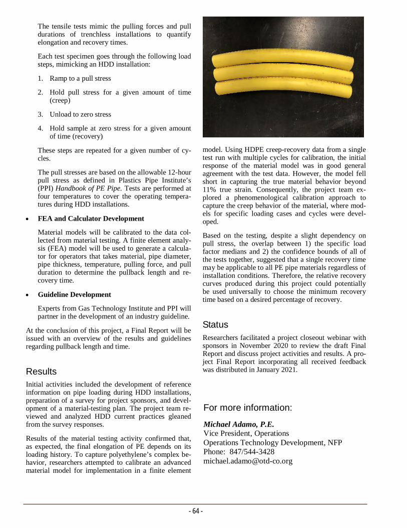
- 64 -
For more information:
Michael Adamo, P.E. Vice President, Operations Operations Technology Development, NFP Phone: 847/544-3428 [email protected]
model. Using HDPE creep-recovery data from a single test run with multiple cycles for calibration, the initial response of the material model was in good general agreement with the test data. However, the model fell short in capturing the true material behavior beyond 11% true strain. Consequently, the project team ex-plored a phenomenological calibration approach to capture the creep behavior of the material, where mod-els for specific loading cases and cycles were devel-oped.
Based on the testing, despite a slight dependency on pull stress, the overlap between 1) the specific load factor medians and 2) the confidence bounds of all of the tests together, suggested that a single recovery time may be applicable to all PE pipe materials regardless of installation conditions. Therefore, the relative recovery curves produced during this project could potentially be used universally to choose the minimum recovery time based on a desired percentage of recovery.
Status
Researchers facilitated a project closeout webinar with sponsors in November 2020 to review the draft Final Report and discuss project activities and results. A pro-ject Final Report incorporating all received feedback was distributed in January 2021.
The tensile tests mimic the pulling forces and pull durations of trenchless installations to quantify elongation and recovery times.
Each test specimen goes through the following load steps, mimicking an HDD installation:
1. Ramp to a pull stress
2. Hold pull stress for a given amount of time (creep)
3. Unload to zero stress
4. Hold sample at zero stress for a given amount of time (recovery)
These steps are repeated for a given number of cy-cles.
The pull stresses are based on the allowable 12-hour pull stress as defined in Plastics Pipe Institute’s (PPI) Handbook of PE Pipe. Tests are performed at four temperatures to cover the operating tempera-tures during HDD installations.
FEA and Calculator Development
Material models will be calibrated to the data col-lected from material testing. A finite element analy-sis (FEA) model will be used to generate a calcula-tor for operators that takes material, pipe diameter, pipe thickness, temperature, pulling force, and pull duration to determine the pullback length and re-covery time.
Guideline Development
Experts from Gas Technology Institute and PPI will partner in the development of an industry guideline.
At the conclusion of this project, a Final Report will be issued with an overview of the results and guidelines regarding pullback length and time.
Results Initial activities included the development of reference information on pipe loading during HDD installations, preparation of a survey for project sponsors, and devel-opment of a material-testing plan. The project team re-viewed and analyzed HDD current practices gleaned from the survey responses.
Results of the material testing activity confirmed that, as expected, the final elongation of PE depends on its loading history. To capture polyethylene’s complex be-havior, researchers attempted to calibrate an advanced material model for implementation in a finite element
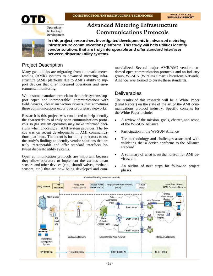
CONSTRUCTION/INFRASTRUCTURE TECHNIQUES PROJECT No. 5.18.g SUMMARY REPORT
Project Description Many gas utilities are migrating from automatic meter-reading (AMR) systems to advanced metering infra-structure (AMI) platforms due to AMI’s ability to sup-port devices that offer increased operations and envi-ronmental monitoring.
While some manufacturers claim that their systems sup-port “open and interoperable” communications with field devices, closer inspection reveals that sometimes these communications occur over proprietary networks.
Research is this project was conducted to help identify the characteristics of truly open communications proto-cols so gas system operators may make informed deci-sions when choosing an AMI system provider. The fo-cus was on recent developments in AMI communica-tions platforms. The intent is for utility operators to use the study’s findings to identify vendor solutions that are truly interoperable and offer standard interfaces be-tween disparate utility systems.
Open communication protocols are important because they allow operators to implement the various smart sensors and other devices (e.g., shutoff valves, methane sensors, etc.) that are now being developed and com-
In this project, researchers investigated developments in advanced metering infrastructure communications platforms. This study will help utilities identify vendor solutions that are truly interoperable and offer standard interfaces between disparate utility systems.
Advanced Metering Infrastructure Communications Protocols
mercialized. Several major AMR/AMI vendors en-dorsed open communication protocols and an industry group, Wi-SUN (Wireless Smart Ubiquitous Network) Alliance, was formed to curate these standards.
Deliverables The results of this research will be a White Paper (Final Report) on the state of the art of the AMI com-munications protocol industry. Specific contents for the White Paper include:
A review of the mission, goals, charter, and scope of the Wi-SUN Alliance
Participation in the Wi-SUN Alliance
The methodology and challenges associated with validating that a device conforms to the Alliance standard
A summary of what is on the horizon for AMI de-vices, and
An outline of next steps for follow-on project phases.
- 65 -

- 66 -
For more information:
Michael Adamo, P.E. Vice President, Operations Operations Technology Development, NFP Phone: 847/544-3428 [email protected]
The project team purchased hardware sensor devices and successfully executed a demonstration program in support of the standard endorsed by the Wi-SUN Alli-ance.
In 2018, the Wi-SUN Alliance launched a Field Area Network (FAN) certification program. The FAN certi-fication process is intended to address two goals: 1) to verify that FAN devices from different manufacturers are interoperable and 2) to verify that certified devices provide a reasonable level of security for that device’s purpose. This framework is intended to create an eco-system of devices that can readily interoperate.
The Wi-SUN Alliance is promoting open standards for communication based on the IEEE 802.15.4g wireless standard. On top of this communication, Wi-SUN is also promoting IPv6 addressing and security protocols based on best practices.
The project team identified various equipment, such as wireless sensors, that adhere to the communication standard. The purpose of this activity is to investigate the feasibility of adapting these existing components to the Wi-SUN framework.
The research team identified that the use case of high-est interest to the gas industry at this time (excluding metering) is the monitoring of methane. This is being driven both by safety considerations and by increased scrutiny of greenhouse gas emissions. There is also interest in the use cases of cathodic-protection monitor-ing and pressure monitoring.
Several approved testing laboratories for Wi-SUN compliance are now operating. The first five products completed and passed Wi-SUN certification during 2019.
Project activities in 2020 included investigating addi-tional hardware that may be useful to gas utilities.
Status The next goal that needs to be achieved is Wi-SUN certification of battery-powered devices. With the pro-ject nearing its end and the low number of Wi-SUN events that occur in the US, it was decided not to use project funds to renew membership.
The project team is drafting a Final Report.
Benefits The primary benefit of using systems that operate on open AMI standards is the ability to realize additional value from the infrastructure beyond customer meter reading. For example, companies that have invested in AMI would also gain the ability to add sensors and ac-tuators to that infrastructure, including distributed meth-ane sensors and gas shutoff valves. Interoperable AMI standards would eliminate the need to buy devices from a single vendor, keeping the market competitive.
An open AMI connection standard will also accelerate innovation of goods and services in this space. The challenge in the current AMI environment is being able to ascertain which vendor solutions are truly interoper-able and which make interoperability claims but rely on proprietary network communications. This project will help overcome this hurdle by providing a methodology to sort through a vendor’s claims and identify truly open AMI solutions.
Technical Concept & Approach In this project, researchers investigated the Wi-SUN Alliance to determine if any of the current Wi-SUN-certified devices are of value to gas distribution compa-nies.
Specific activities include:
Wi-SUN Alliance Engagement
Researchers engaged Wi-SUN and determined how well its activities and standards align with gas in-dustry needs.
Apply Wi-SUN Standards to AMI Open Stan-dard Devices
The project team analyzed the open and interoper-able standard(s) endorsed by the Wi-SUN Alliance.
Define AMI Open Standard Device Use Cases
In this task, the project team identified the AMI application devices that are of greatest interest to the project sponsors.
Results The project team gained familiarity with the Wi-SUN Alliance organization through a review of website documentation, videos, and supporting materials A Contributor membership to the Wi-SUN Alliance was approved, which allows participation in and voting privileges for working groups and committees, among many other benefits.

CONSTRUCTION/INFRASTRUCTURE TECHNIQUES PROJECT No. 5.18.m SUMMARY REPORT
Project Description In the past, as utilities buried their infrastructure, many locators relied on hand drawings or computer models based on estimated distances of buried pipe or cable. This created a difficult situation in identifying where to excavate for construction and repairs without running the risk damaging the buried utility.
In response, underground frequency markers have be-come a tool used in marking and identifying buried utilities. Underground frequency markers provide a low-cost, efficient option of placing the marker with the buried utility and locating the marker through use of locators tuned to the marker’s specific frequency.
Underground frequency markers are devices that gener-ate an electromagnetic radio wave frequency to signal the location of an underground facility. Underground utility markers can locate and identify an underground utility in two ways:
1. The electronic marker radio wave can carry identi-fying data from the chipset in the marker associated with the underground utility, and
2. The underground utility marker can transmit a radio wave frequency that is a match to a pre-defined utility type.
The goal for this project is to create an industry standard, guideline, or best practice for underground utility markers used to locate buried facilities. This best practice would en-sure consistency among stakeholders’ future identification of underground assets.
Uniform Frequency Code
As these markers became more popular in the industry, different arrays of tools utilizing this technology were developed. However, as many utility sectors such as water, gas, and electric encompass the same buried areas, it became beneficial to assign a frequency signal to each respective utility. To distinguish between sepa-rate utilities, a range of frequencies was developed for each utility and a color applied to each marker. How-ever, there is no official standard of frequencies used for markers with separate utility designations.
The objective for this project is to create an industry standard, guideline, or best-practice uniform frequency code for underground frequency tags/markers used to locate buried utilities. This code would establish a consistent frequency setting for markers based on their respective utility designation (gas, electric, water, etc.).
The project team is making efforts to formalize the adoption of frequencies based on the most popularly used settings in the industry today. The team will then seek to publish the adopted frequencies as an appendix section in the appropriate standard.
- 67 -
PE pipe with locatable tags attached.
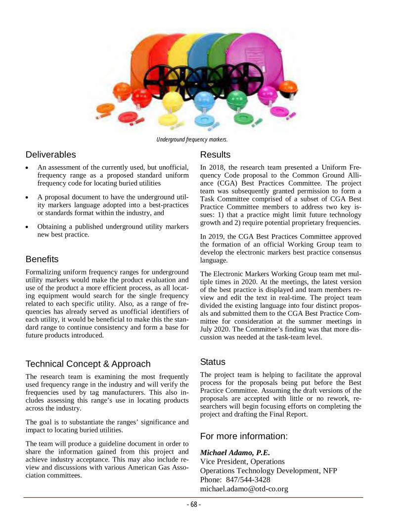
- 68 -
For more information:
Michael Adamo, P.E. Vice President, Operations Operations Technology Development, NFP Phone: 847/544-3428 [email protected]
Results In 2018, the research team presented a Uniform Fre-quency Code proposal to the Common Ground Alli-ance (CGA) Best Practices Committee. The project team was subsequently granted permission to form a Task Committee comprised of a subset of CGA Best Practice Committee members to address two key is-sues: 1) that a practice might limit future technology growth and 2) require potential proprietary frequencies.
In 2019, the CGA Best Practices Committee approved the formation of an official Working Group team to develop the electronic markers best practice consensus language.
The Electronic Markers Working Group team met mul-tiple times in 2020. At the meetings, the latest version of the best practice is displayed and team members re-view and edit the text in real-time. The project team divided the existing language into four distinct propos-als and submitted them to the CGA Best Practice Com-mittee for consideration at the summer meetings in July 2020. The Committee’s finding was that more dis-cussion was needed at the task-team level.
Status
The project team is helping to facilitate the approval process for the proposals being put before the Best Practice Committee. Assuming the draft versions of the proposals are accepted with little or no rework, re-searchers will begin focusing efforts on completing the project and drafting the Final Report.
Deliverables An assessment of the currently used, but unofficial,
frequency range as a proposed standard uniform frequency code for locating buried utilities
A proposal document to have the underground util-ity markers language adopted into a best-practices or standards format within the industry, and
Obtaining a published underground utility markers new best practice.
Benefits Formalizing uniform frequency ranges for underground utility markers would make the product evaluation and use of the product a more efficient process, as all locat-ing equipment would search for the single frequency related to each specific utility. Also, as a range of fre-quencies has already served as unofficial identifiers of each utility, it would be beneficial to make this the stan-dard range to continue consistency and form a base for future products introduced.
Technical Concept & Approach The research team is examining the most frequently used frequency range in the industry and will verify the frequencies used by tag manufacturers. This also in-cludes assessing this range’s use in locating products across the industry.
The goal is to substantiate the ranges’ significance and impact to locating buried utilities.
The team will produce a guideline document in order to share the information gained from this project and achieve industry acceptance. This may also include re-view and discussions with various American Gas Asso-ciation committees.
Underground frequency markers.

CONSTRUCTION/INFRASTRUCTURE TECHNIQUES PROJECT No. 5.18.n SUMMARY REPORT
Project Description As with other components in the gas-delivery infra-structure, regulators are expected to be replaced in ac-cordance with their service-lifetime predictions. Many parameters affect the life performance of regulators and manufacturers do not commonly provide the expected lifetime of their products. Utilities accordingly rely on short-term data, repair history, and experience with cer-tain types of regulators to set the number of years for regulator replacements.
Traditional internal relief valve (IRV) regulators have a cast-iron body and a die-cast aluminum case that houses the diaphragm. These materials are usually coated in order to prevent corrosion. Moisture intrusion into the main body cavity of the regulator can corrode the regu-lator’s inner components, hinder its ability to accurately regulate gas pressure, and could potentially cause a leak.
The inner components of the regulator (e.g., the springs and elastometric diaphragms) also may slowly wear during temperature changes and normal operations over time and contaminate the gas stream. The long-term performance of regulators would vary for different manufacturers, regulator models, age, and various ser-vice and environmental conditions.
The objective of this project is to determine the durabil-ity and expected service life of common residential natural gas service regulators. Utilities can include ser-vice-life predictions as a basis for their residential regu-lator replacement plan.
Deliverables The following deliverables are anticipated from this project: 1) Identification and information gathering of regulator models regarding their long-term performance and durability; 2) Analysis findings of in-service regu-lators, and 3)A Final Report.
Benefits Utilities will be provided with results and technical sup-port for a better understanding of the expected service life of regulators. They may build on the results to opti-
The objective of this project is to determine the durability and expected service life of common residential natural gas service regulators. Utilities can include service- life predictions as a basis for their residential regulator replacement plan.
Performance, Durability, and Service Life of Residential Gas Regulators
- 69 -
mize their replacement programs by identifying the regulators that are past their recommended lifetime service and avoiding the replacement of good regula-tors that are not yet at the end of their service life. This will result in savings to utilities and avoid costs associ-ated with labor, material, and unnecessary customer service interruption.
Technical Concept & Approach In this project, multiple models of IRV regulators are being investigated to select the most common ones for the testing program. A comprehensive study of failure modes of regulators is being conducted. In addition, a study of previous research and testing requirements on regulator performance will be conducted.
Researchers are testing a statistically significant set of residential regulators which were in use for a various number of years (failed and non-failed regulators). The set represents various ages, manufacturers, types, ser-vice environments, and service conditions. These regu-lators are being subjected to failure analysis to identify their failure modes and/or state of performance.
The project team will develop test protocols that are valid for lifetime prediction/reliability testing of new and used regulators. The testing protocol is envisioned to be long-term cycling flow/lock-up and pressure re-lief capacity tests at various percentages of the outlet set pressure and at various environmental and gas quality conditions.
Regulator flow testing.
- 70 -
For more information:
Michael Adamo, P.E. Vice President, Operations Operations Technology Development, NFP Phone: 847/544-3428 [email protected]
Status The project team identified the causes of service regu-lator failures through surveys and interaction with gas utility managers. The main causes of failure of service regulators are debris/contaminant buildup typically at the orifice, diaphragm rupture (typically seen in old regulators) triggered by flow surge/over pressuriza-tion, material deterioration due to exposure to severe environmental condition such as high humidity, pres-sure fluctuations during service lifetime, etc. However, due to the limited availability of service regulator fail-ure records, it waseen a challenge to determine a rank-ing of failure causes, although anecdotally many opera-tors mention debris/contaminant buildup at the orifice as the more common cause of regulator failure. In light of these findings, it is evident that the service lifetime of regulators depends not only on the build quality of the regulator but also on the external factors such as quality of gas and presence of debris/contaminants among others.
The long-term endurance of service regulators is tested per ANSI B109.4 Endurance Test protocol, which pri-marily is concerned with the build quality of regulators and does not provide any guidance on the lifetime of service regulators. One of the regulator manufacturers had tested service regulators by subjecting them to more than a million endurance testing cycles, well above the 100,000 cycles stipulated by ANSI B109.4 standard, and they did not observe regulator failures. This information suggests that the endurance test proto-col may not cause regulator failure and that the failure envelope of regulators is not well established. Based on the empirical evidence of low failure rate of service regulator and performance of service regulators sub-jected to endurance test and other laboratory tests, it can be implied qualitatively that the reliability and du-rability of service regulators are high. In order to estab-lish the failure envelope of these regulators, significant resources may have to be allocated to set up test facili-ties, and the informational value of the such an effort may be limited given that operational experience indi-cates that regulators are reliable over long periods of time. The project team believes that it may be more prudent to focus research on regulator design improve-ments to reduce the impact of gas contaminants, which appears to be one of the main external causes of service regulator failures, rather than to invest in establishing the failure envelopes of service regulators.
A test rig will be configured for long-term cyclic load-ing and will allow testing at various temperatures and other environmental conditions. The design of the sys-tem will allow for applying an air-pressurized system for mechanical failure in selected environmental-controlled tests. Construction of the test rig will col-laborate with other projects to build a flow-controlled testing facility for evaluating valves at various upstream and downstream pressures and flows.
New regulators and selected units extracted from the field will be subjected to various cyclic pressures and environmental tests (temperature, water intrusion, etc.) to failure.
Results Initial activities in 2018 included the development of a survey to gather regulator-failure data. From the re-sponses, the project team was able to identify the resi-dential regulator models of interest and understand common failure modes and failure root causes, if any.
In 2019, researchers received regulators from project sponsors and performed preliminary evaluations of the regulators. Preliminary results indicated that all of the tested regulators are in working condition. Researchers also reviewed regulator standards to determine the long-term testing protocol.
In 2020, the research team completed the flow testing of 17 regulators. Out of 17 regulators, only one regulator that was installed in the year 1977 did not pass the flow test. Further, the failed regulator was subjected to non-destructive scanning to determine the cause of failure. In addition to non-destructive evaluation, destructive evaluation of the failed regulator will be undertaken to determine the failure mode.
Restrictions in accessing lab facilities due to COVID-19 pandemic situation affected the testing schedule of this project.
The project team reviewed computed tomography (CT) scans of failed regulator samples; however, no clear failure mode was evident from the scans. A more thor-ough failure analysis of these regulators will be con-ducted to help interpret the CT scans. In addition, the team programmed the endurance testing in the flow control software.
The project team performed a thorough failure analysis of one regulator and found that the regulator orifice was blocked by debris which had coalesced over time, even-tually blocking the flow of gas. Additionally, the project team reached out to a manufacturer and discussed the industry practices and testing methods adopted to en-sure reliability of residential regulator.
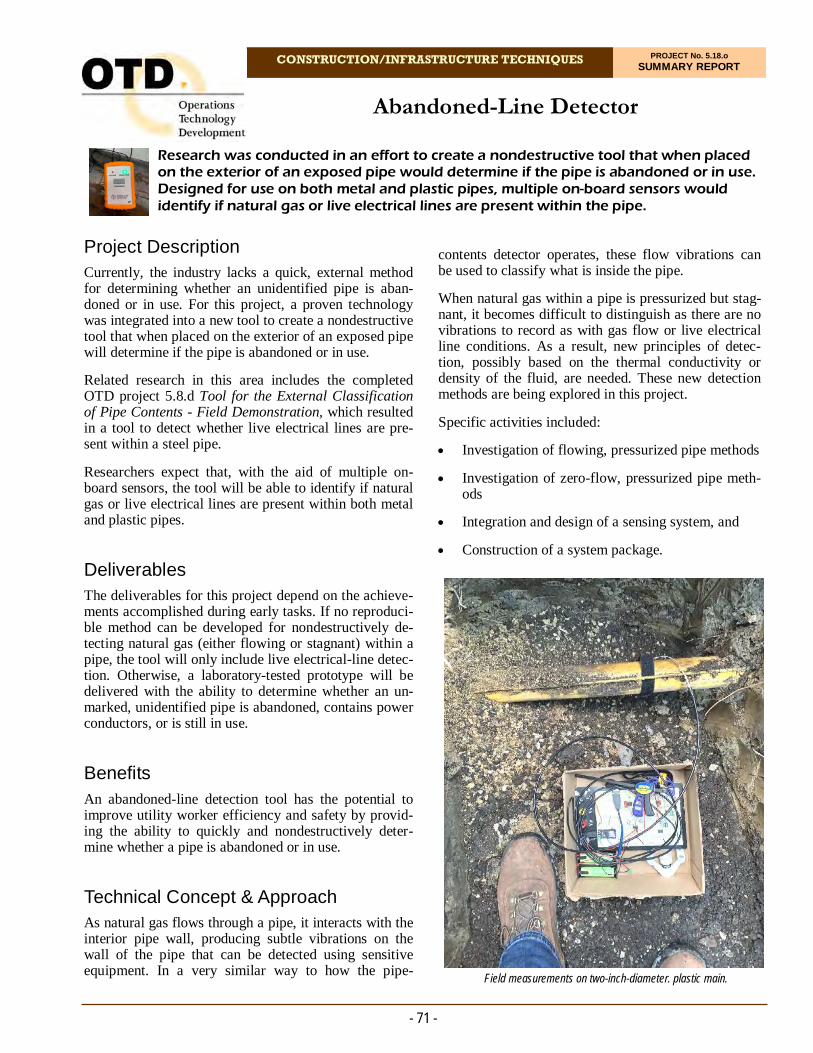
CONSTRUCTION/INFRASTRUCTURE TECHNIQUES PROJECT No. 5.18.o SUMMARY REPORT
Project Description Currently, the industry lacks a quick, external method for determining whether an unidentified pipe is aban-doned or in use. For this project, a proven technology was integrated into a new tool to create a nondestructive tool that when placed on the exterior of an exposed pipe will determine if the pipe is abandoned or in use.
Related research in this area includes the completed OTD project 5.8.d Tool for the External Classification of Pipe Contents - Field Demonstration, which resulted in a tool to detect whether live electrical lines are pre-sent within a steel pipe.
Researchers expect that, with the aid of multiple on-board sensors, the tool will be able to identify if natural gas or live electrical lines are present within both metal and plastic pipes.
Deliverables The deliverables for this project depend on the achieve-ments accomplished during early tasks. If no reproduci-ble method can be developed for nondestructively de-tecting natural gas (either flowing or stagnant) within a pipe, the tool will only include live electrical-line detec-tion. Otherwise, a laboratory-tested prototype will be delivered with the ability to determine whether an un-marked, unidentified pipe is abandoned, contains power conductors, or is still in use.
Benefits An abandoned-line detection tool has the potential to improve utility worker efficiency and safety by provid-ing the ability to quickly and nondestructively deter-mine whether a pipe is abandoned or in use.
Technical Concept & Approach As natural gas flows through a pipe, it interacts with the interior pipe wall, producing subtle vibrations on the wall of the pipe that can be detected using sensitive equipment. In a very similar way to how the pipe-
Research was conducted in an effort to create a nondestructive tool that when placed on the exterior of an exposed pipe would determine if the pipe is abandoned or in use. Designed for use on both metal and plastic pipes, multiple on-board sensors would identify if natural gas or live electrical lines are present within the pipe.
Abandoned-Line Detector
contents detector operates, these flow vibrations can be used to classify what is inside the pipe.
When natural gas within a pipe is pressurized but stag-nant, it becomes difficult to distinguish as there are no vibrations to record as with gas flow or live electrical line conditions. As a result, new principles of detec-tion, possibly based on the thermal conductivity or density of the fluid, are needed. These new detection methods are being explored in this project.
Specific activities included:
Investigation of flowing, pressurized pipe methods
Investigation of zero-flow, pressurized pipe meth-ods
Integration and design of a sensing system, and
Construction of a system package.
- 71 -
Field measurements on two-inch-diameter. plastic main.

- 72 -
For more information:
Michael Adamo, P.E. Vice President, Operations Operations Technology Development, NFP Phone: 847/544-3428 [email protected]
microphone, preamplifier, and microcontroller on pipe in flowing gas and zero-flow states. Using the acquired data, a preliminary machine learning model was trained and proven to, with 88% accuracy, detect whether never-before-seen signal data contained 20 scfh or zero flow.
In 2020, researchers collected signal data from labora-tory and field environments. A prototype system was developed. It was possible to take large sets of sensor data and train a classification model to infer, with over 85% accuracy, the state of flow within a pipe. The pro-totype system was demonstrated on a laboratory setup simulating gas flow with compressed air at 0, 10, and 20 SCFH at 60 psi. The steel pipe under test was two feet in length with a diameter of 1.25 inches, contain-ing bend and reducer fittings. The sensing method was a nondestructive contact microphone measuring subtle vibrations on the pipe.
The team reviewed and analyzed all project results and assembled them into a cohesive structure for inclusion in the project Final Report.
Status The project Final Report was completed and a closeout webinar facilitated with project sponsors in the second quarter of 2021.
Results In 2018, the project team began investigating the cur-rent state of the art to develop a clear understanding of the pipe content identification capabilities that currently exist. Additional initial-stage tasks focused on clearly defining the set of frequency ranges for detecting gas in pipe.
Sensors were examined that are potentially less expen-sive alternatives to the accelerometer used in the origi-nal tool developed in OTD 5.8.d. Some of these up-graded sensors include:
Contact microphones
Micro-electro-mechanical (MEM) microphones, and
Piezoelectric sensors.
In 2019, the project team continued its efforts to iden-tify if a pipeline exposed in an excavation is active or abandoned by purely external methods. An acoustic transducer was identified and tested that shows good promise for being able to detect flow noise. A mecha-nism to apply the transducer to the pipe under field con-ditions was prototyped and tested. Several software li-braries for signal processing and machine learning that can run on inexpensive microprocessors have been ex-amined. These can be used to help make the determina-tion less ambiguous under field conditions.
A high-sensitivity contact microphone was selected as the primary transducer for the system. When placed in contact with a pipe, it converts vibrations into electrical signals to be processed by the microcontroller. A micro-controller will analyze the signal from the contact mi-crophone and deliver a result on whether the pipe is abandoned or not.
To test the contact microphone, the device was con-nected to the tool developed from OTD Project 5.8.d. After confirming basic functionality of the contact mi-crophone, it advanced to further testing on flowing and zero-flow pressurized pipe conditions.
A mechanism for holding the contact microphone to the pipe was developed and 3D printed. The mechanism consists of a collection of magnets that hold the sensor to the pipe and a spring-loaded center column that se-curely presses the contact microphone rubber tip to the surface of the pipe.
A microcontroller was selected to process acoustic sig-nals from the contact microphone on the exterior of the pipe. A printed circuit board containing a preamplifier circuit needed for the contact microphone was designed.
Technicians constructed a controlled environment to produce various levels of flowing gas through steel pipe. Sensor readings were acquired using the contact
Laboratory setup simulating gas flow with compressed air.
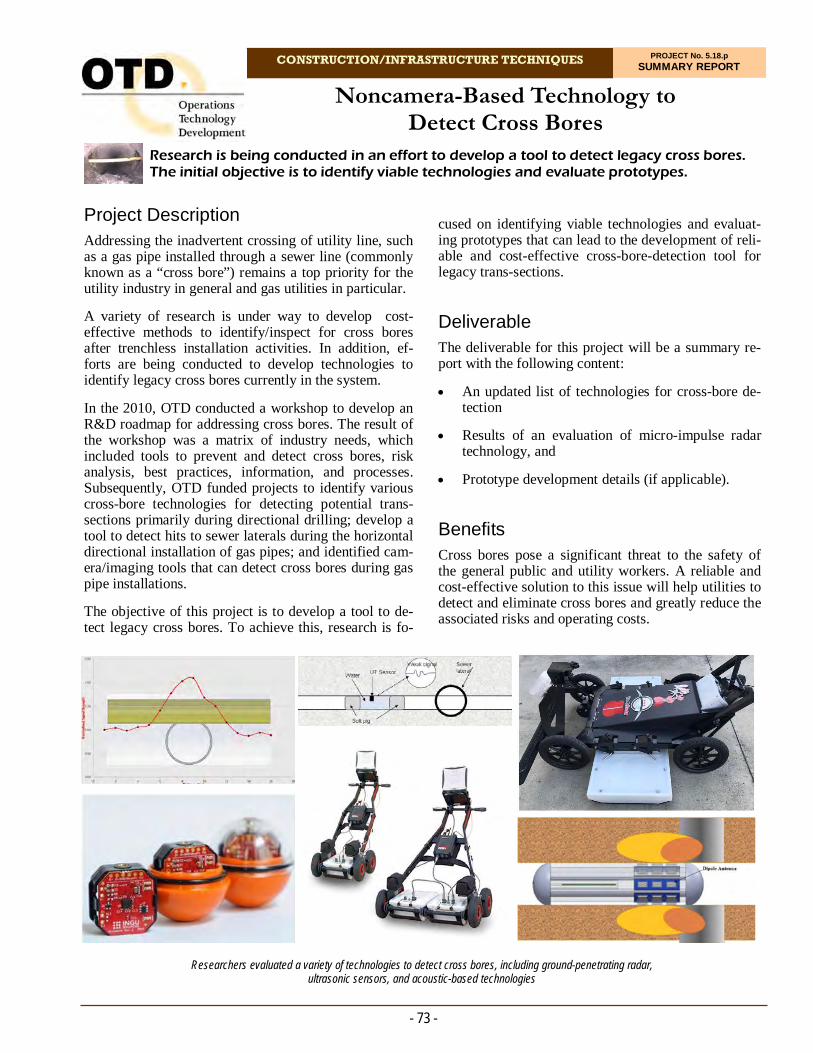
CONSTRUCTION/INFRASTRUCTURE TECHNIQUES PROJECT No. 5.18.p SUMMARY REPORT
Project Description Addressing the inadvertent crossing of utility line, such as a gas pipe installed through a sewer line (commonly known as a “cross bore”) remains a top priority for the utility industry in general and gas utilities in particular.
A variety of research is under way to develop cost-effective methods to identify/inspect for cross bores after trenchless installation activities. In addition, ef-forts are being conducted to develop technologies to identify legacy cross bores currently in the system.
In the 2010, OTD conducted a workshop to develop an R&D roadmap for addressing cross bores. The result of the workshop was a matrix of industry needs, which included tools to prevent and detect cross bores, risk analysis, best practices, information, and processes. Subsequently, OTD funded projects to identify various cross-bore technologies for detecting potential trans-sections primarily during directional drilling; develop a tool to detect hits to sewer laterals during the horizontal directional installation of gas pipes; and identified cam-era/imaging tools that can detect cross bores during gas pipe installations.
The objective of this project is to develop a tool to de-tect legacy cross bores. To achieve this, research is fo-
Research is being conducted in an effort to develop a tool to detect legacy cross bores. The initial objective is to identify viable technologies and evaluate prototypes.
Noncamera-Based Technology to Detect Cross Bores
cused on identifying viable technologies and evaluat-ing prototypes that can lead to the development of reli-able and cost-effective cross-bore-detection tool for legacy trans-sections.
Deliverable The deliverable for this project will be a summary re-port with the following content:
An updated list of technologies for cross-bore de-tection
Results of an evaluation of micro-impulse radar technology, and
Prototype development details (if applicable).
Benefits Cross bores pose a significant threat to the safety of the general public and utility workers. A reliable and cost-effective solution to this issue will help utilities to detect and eliminate cross bores and greatly reduce the associated risks and operating costs.
- 73 -
Researchers evaluated a variety of technologies to detect cross bores, including ground-penetrating radar, ultrasonic sensors, and acoustic-based technologies
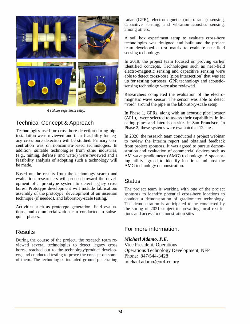
- 74 -
For more information:
Michael Adamo, P.E. Vice President, Operations Operations Technology Development, NFP Phone: 847/544-3428 [email protected]
radar (GPR), electromagnetic (micro-radar) sensing, capacitive sensing, and vibration-acoustics sensing, among others.
A soil box experiment setup to evaluate cross-bore technologies was designed and built and the project team developed a test matrix to evaluate near-field sensing technology.
In 2019, the project team focused on proving earlier identified concepts. Technologies such as near-field electro-magnetic sensing and capacitive sensing were able to detect cross-bore (pipe intersection) that was set up for testing purposes. GPR technology and acoustic-sensing technology were also reviewed.
Researchers completed the evaluation of the electro-magnetic wave sensor. The sensor was able to detect “void” around the pipe in the laboratory-scale setup.
In Phase 1, GPRs, along with an acoustic pipe locator (APL), were selected to assess their capabilities in lo-cating pipes and laterals on sites in San Francisco. In Phase 2, these systems were evaluated at 12 sites.
In 2020. the research team conducted a project webinar to review the interim report and obtained feedback from project sponsors. It was agreed to pursue demon-stration and evaluation of commercial devices such as AM wave gradiometer (AMG) technology. A sponsor-ing utility agreed to identify locations and host the AMG technology demonstration.
Status The project team is working with one of the project sponsors to identify potential cross-bore locations to conduct a demonstration of gradiometer technology. The demonstration is anticipated to be conducted by the spring of 2021 subject to prevailing local restric-tions and access to demonstration sites
Technical Concept & Approach Technologies used for cross-bore detection during pipe installation were reviewed and their feasibility for leg-acy cross-bore detection will be studied. Primary con-centration was on noncamera-based technologies. In addition, suitable technologies from other industries, (e.g., mining, defense, and water) were reviewed and a feasibility analysis of adopting such a technology will be made.
Based on the results from the technology search and evaluation, researchers will proceed toward the devel-opment of a prototype system to detect legacy cross bores. Prototype development will include fabrication/assembly of the prototype, development of an insertion technique (if needed), and laboratory-scale testing.
Activities such as prototype generation, field evalua-tions, and commercialization can conducted in subse-quent phases. Results
During the course of the project, the research team re-viewed several technologies to detect legacy cross bores, reached out to the technology/product develop-ers, and conducted testing to prove the concept on some of them. The technologies included ground-penetrating
A soil box experiment setup.

CONSTRUCTION/INFRASTRUCTURE TECHNIQUES PROJECT No. 5.18.r SUMMARY REPORT
Project Description Thermal comfort and heat stress are significant con-cerns for outdoor workers in the natural gas industry. There are currently no industry-wide requirements or standards to guide the selection of fire-resistant clothing worn by workers in oil and gas operations to reduce heat strain. Few technical studies have qualified deploy-ment of additional layers of fire-resistant personal pro-tection equipment (PPE), such as flash-fire suits or the time that workers can operate without incurring heat stress in hot working conditions.
The goal of this project is to demonstrate how modern methods of clothing comfort testing can be used to se-lect more thermally comfortable fire-resistant clothing for natural gas workers. It will show how these methods can guide PPE options for use in hot service areas. It will also show how more technically informed clothing solutions can reduce heat strain of workers operating in hot environments or while wearing flash-fire suits.
The National Fire Protection Association 2112 Standard on Flame Resistant Garments for Protection of Indus-trial Personnel Against Flash Fires does not establish minimum performance requirements for the thermal comfort of flame resistant garments worn by industrial personnel. This is an important consideration, particu-larly for workers required to don flash-fire gear for added protection when working in environments with higher expected risk for accidental fires.
The objective for this project is to establish guidelines for selecting workwear ensembles that will provide reduced heat strain and worker comfort in operations conducted in hot conditions.
Clothing Performance Guidelines to Reduce Heat Stress for Natural Gas Workers
An objective for this project is to establish guidelines for selecting workwear ensembles that will provide reduced heat strain and worker comfort in operations conducted in hot conditions. Researchers will use modern laboratory tests (including advanced sweating manikins) and controlled-climate human physiological wear studies.
The project will provide a technical foundation for developing work/rest cycles for operations that require workers to wear flash-fire suits and other protective clothing in thermal-stressing conditions.
Deliverables A Final Report will contain recommendations that can be used to select PPE that will reduce heat strain on gas workers in hot environments. It will provide tech-nical performance guidelines for selecting optimum clothing configurations for climatic temperatures and solar load focused on the hot weather climates.
The project team will also develop scientifically quali-fied correlations between selected protective clothing and heat stress, and the impact of environmental and working conditions on clothing related heat strain. Re-searchers will also develop a better understanding how additional PPE layers (flash-fire suits) impact worker heat stain and work tolerance.
- 75 -
Fabric images for new materials.
- 76 -
For more information:
Michael Adamo, P.E. Vice President, Operations Operations Technology Development, NFP Phone: 847/544-3428 [email protected]
In 2019, a literature review was conducted to better understand how we can assist the natural gas compa-nies with making work rest cycles based on their PPE and the environment.
Results from fabric swatch tests indicates a large heat loss difference between the single-layered system and the three-layered system. However, this test was shown to overestimate the actual heat loss of a suit garment because it does not account for undergarments, air lay-ers, added accessories, and fit of an actual suit.
In addition to these tests, technicians also measured the reflectance of the same three suit materials to the visi-ble light spectrum. By measuring reflectance, an indi-cation of how different fabrics might absorb heat from the sun is determined.
In 2020, fabric-level evaluations on new materials were made. The thermal resistance of two work uniforms, Flame Resistant (FR) and Non-Flame Resistant (Non-FR), and nine flash suits were tested using a thermal manikin. Each flash suit was tested in two different testing configurations, each in triplicate.
The results indicated that there was little difference between test configurations; however, in all cases, the FR-treated garments yielded a slightly higher insula-tion value. Manikin testing also indicated very little difference in insulation for single-layered flash suits. Multi-layered flash suits yielded higher insulation as expected.
The evaporative resistance of 9 flash suits received was tested using the a sweating thermal manikin, according to ASTM F2370-16.
Status
All fabric-level testing is being finalized. Once all gar-ment testing is complete, suits will be cut for testing the total heat loss, evaporative resistance, thermal resis-tance, and air permeability. Researchers will use physiological manikin testing to verify the work/rest tables in different ambient conditions (Northeast, Southeast, Southwest, and Northwest). In the end, at least one suit will be tested in each category and each work condition to verify that the generated table is suf-ficient to be used as a guidelines for work/rest cycles.
Benefits By characterizing how specific choices in protective clothing impact thermal comfort and heat stress, this project will contribute to increased safety and health. This will enable the development of optimized work/rest cycles for workers wearing flash-fire suits. It will contribute to workplace efficiency and reduce the finan-cial burden of operations conducted in hot environ-mental conditions.
Technical Concept & Approach This project will quantify the role of key physiological human response variables occurring during wear of flame-resistant clothing by workers in the oil and gas industry. It will establish the relationships between the measured breathability of protective clothing materials and their comfort and heat stress using laboratory tests made on fabric swatches and protective clothing ensem-bles. Resultant data will be used to identify the most thermally comfortable clothing ensembles consistent with fire protection. The outcomes of this project will be used to develop work/rest cycles based on the work rate levels and temperatures encountered in wearing flash fire suits.
This project will use advanced sweating hot plates and sweating manikins to establish the relationship between the breathability of protective clothing materials and the ability of worker PPE to dissipate trapped body heat.
The correlation between PPE and worker comfort and heat stress will be validated in controlled wear trials conducted in temperature and humidity conditions and metabolic levels associated with specific work tasks.
The project team will leverage the world-class facilities of the Textile Protection and Comfort Center, the na-tion’s leading laboratory devoted to measurement of fire-protection and clothing comfort.
Results
Researchers received garments and information about work uniforms and flash suits worn by workers for companies sponsoring the project. For the work uni-form, researchers found major differences in the types of fabrics and garments worn. Some companies used coveralls while most used a pant and shirt combination. The fabrics used in those garments varied by fiber types, weights, blends, weave, and treatments. The in-formation provided about flash suits indicated they all were coveralls, but the fabrics varied by similar proper-ties identified in the work uniform.
Researchers are focusing on understanding the effects of heat strain and comfort as it relates to flash suits that all natural gas companies utilize.

CONSTRUCTION/INFRASTRUCTURE TECHNIQUES PROJECT No. 5.18.s SUMMARY REPORT
Project Description Automatic thermally activated gas shut-off devices are passive safety devices that prevent the uncontrollable release of gas when some part of the natural gas deliv-ery system has been damaged or fails.
Similar passive devices include excess flow valves (EFVs) that protect service-line break locations and service riser breakaway fittings that protect meter sets from impact.
An automatic thermally activated shut-off device can be an added layer of safety to accompany the EFV and breakaway fitting.
Although U.S. fire codes and certifications do not spe-cifically address automatic thermally activated shut-off devices, this technology is approved for installation. Currently, there are no U.S. standards governing the design, operation, or installation requirements for this type of shut-off device.
In this project, researchers conducted a requirements review and performance tests of commercially available thermally activated gas shut-off devices for the indus-try. Three manufacturers were identified as having commercially available thermal shut-off devices for the natural gas industry within the U.S.
The main conclusion from the performance testing con-ducted on these different devices is that the flow rate passing through the thermal shutoff device at the time it is exposed to excessive heat will cause the activation temperature to increase above published temperatures by the manufacturer.
Deliverables The deliverables for this project include:
A guideline on the commercial availability, usage, operational parameters, and associated standards of thermally activated gas shut-off devices and
Short- and long-term laboratory testing results of selected devices.
In this project, researchers investigated commercially available thermally activated gas shut-off devices that prevent or reduce the escape of gas in the event of a fire at a customer’s premise. Performance tests were conducted on selected products.
Thermally Activated Gas Shut-Off Devices
Benefits Thermally activated gas shut-off valves can signifi-cantly improve fire safety for premises supplied with natural gas. Significant safety is achieved without the need for expensive actuators, electrical power, or heat detectors.
Other benefits include:
Maintenance free operation
Triggering only in a fire situation
No regular inspections required, and
No fire or heat detectors required to automatically intercept the gas flow.
Technical Concept & Approach Performance testing was performed for each of the manufacturers on the different style fittings that they manufacture. The goal of this testing was to confirm published performance specifications and identify any potential variables that affect the functionality of these thermally activated shut-off safety devices. As the per-formance testing progressed, the test matrices designed evolved in response to the results of the preliminary tests performed.
- 77 -
Assembled test rig for device performance testing.

- 78 -
For more information:
Michael Adamo, P.E. Vice President, Operations Operations Technology Development, NFP Phone: 847/544-3428 [email protected]
The performance test results of this project were con-sistent with what was expected from the devices stud-ied. However, one test result that stood out for each of the devices tested was that the thermal shut-off activa-tion temperatures during project testing were more than 20% higher than shut-off activation temperatures pub-lished by the manufacturers. The main hypothesis for this difference is that the devices were tested with flow going through them, which would be closer to a real-case scenario. Follow-up discussions with the manufac-turers confirmed that their published test results were achieved without flow conditions and that the tempera-ture at which thermal shut-off devices trigger is de-pendent on the flow rate going through the device, which explains the difference in results. Depending on construction materials, a typical residence fire can be expected to reach temperatures of 1,100°F, this is well above the highest activation temperature of 472°F measured during this project.
Overall, the performance test results of this project sup-port that thermally activated shut-off devices can be relied on, if installed per manufacturer’s instructions, to secure the flow of natural gas when exposed to ele-vated temperatures from a structure fire.
Status
This project is completed. A Final Report was issued in September 2019.
Listed are potential future projects related to thermally activated shut-off devices to consider:
Development efforts for creating a U.S. and Cana-dian standard(s) for governing the installation and operation of thermally-activated shutoff devices
Conduct performance testing of high-pressure rated thermally activated shut-off devices at low delivery pressures to confirm satisfactory pressure drops
Conduct performance testing at elevated flow rates to identify how high activation temperatures be-come at different flows, and
Conduct research and development efforts to incor-porate an EFV device into high-pressure rated ther-mally activated shut-off devices.
A new test rig was designed and built. The rig consists of two different portions, a low-pressure section and a high-pressure portion. This design added flexibility to the possibilities of the assembly so that different de-vices falling within a wide range of pressures can be tested. The flow was controlled using a high-precision manual valve placed downstream of the sample to simu-late an increase or decrease in the demand for natural gas.
Results Only three manufacturers were identified as supplying thermally activated shutoff devices to the U.S. Each manufacturer has its own unique design and material for manufacturing this type of device. This contributed to the variance in performance test results among the manufacturers for outlet pressure drop across the inter-nal shutoff mechanism, activation temperature of ther-mal shut-off, and integrity test results at elevated tem-peratures for a prolonged period.
Valves tested.

CONSTRUCTION/INFRASTRUCTURE TECHNIQUES PROJECT No. 5.18.t SUMMARY REPORT
Project Description In this project, immersive virtual reality (VR) is being investigated as a means to enhance training for the natu-ral gas industry.
VR training is a tool to deliver impactful training con-sistently, on-demand, and cost effectively in a wide va-riety of industries, including healthcare, automotive, education, military, and law enforcement.
The goal of Phase 1 was to develop a content library for utilities to assist with the training of their personnel on operations and maintenance (O&M) procedures, includ-ing emergency-response activities. These modules in-clude randomization of training scenarios and reporting capabilities on a user’s performance and areas for im-provement. The modules allow for future customization with company-specific O&M procedures to test for critical-thinking skills and knowledge to fit each user’s needs.
Phase 2 objectives are to design, develop, test, and maintain a VR training content-delivery system that meets the needs of the industry. The delivery system includes a control center for managing training content,
Efforts are under way to introduce virtual reality (VR) as a training tool in the gas utility industry. This project will include a demonstration on the value that VR training can bring to the natural gas industry.
Virtual Reality Training
administrator and user assignments, trainee perform-ance data, and an authoring tool. In addition, a process for maintaining and enhancing current training content will be established as part of this project.
Deliverables Phase 1 deliverables for this project include up to four realistic, interactive, computer-generated, immersive VR training modules on industry O&M tasks that can be used within the natural gas industry. Modules are built on familiar platforms and environments that al-low for randomization and customization to be able to test critical thinking skills and knowledge of company-specific O&M procedures.
The deliverables for Phase 2 include:
A Final Report that details the control center and authoring tool design, development, and testing. This report will also include new hardware equip-ment evaluations and a listing of the enhancements made to the different training library modules.
- 79 -
Control center for VR training content management.

- 80 -
For more information:
Michael Adamo, P.E. Vice President, Operations Operations Technology Development, NFP Phone: 847/544-3428 [email protected]
Results In 2018, researchers identified the learning objectives, described the physical environment features for the module, identified the tools and equipment that will be used within the module, and reviewed general emer-gency response procedures.
In 2019, demonstrations were performed with staff to test reaction and user-friendliness of the VR hardware. This was followed by demonstrations at various indus-try conferences. Subsequently, onsite training and dem-onstrations were conducted for six project sponsors.
In 2020, module customization and testing was con-ducted. Project activities included providing continued VR evaluation and integration support to various utili-ties.
In addition, enhancements were made to VR library training modules for delivery on a new platform. These enhancements include being able to download training content directly from a control center, being able to use all training modules on a wireless headset system, and the programming of all modules to allow multi-user functionality.
A trial VR Training Technology Evaluation Program was initiated. This program allows project sponsors and their organization to evaluate VR training technol-ogy without the initial investment of purchasing hard-ware equipment.
Status
This project was completed in 2020. Additional phases of the project will be added as needs arise from project sponsors.
Training aids on the use of the control center and authoring tool.
Coordination and facilitation of a VR Users Com-mittee that will meet monthly to collect information regarding the control center, authoring tool, and recommended current module enhancements.
Benefits VR provides consistency of training and higher trainee retention rates to help reduce the business risk for an organization. Also, cost savings can be achieved through reductions in training class set-up time, training delivery (initial and remedial), and training completion (onsite or remotely).
The use of VR modules allows training to be conducted on demand by operations; increases the number of real-life training scenarios available for trainees to experi-ence; reduces the risk of injury to trainees, trainers, and the general public on risky activities; and reduces the cost of instructor labor and materials for preparing tra-ditional classroom and laboratory training.
As modules are customizable, the user can train on many random scenarios to grow their experience and critical thinking in a safe environment. Mistakes made in the modules will not be repeated on costly equipment and allow for continuous training without the need to set up and take down equipment or props.
Technical Concept & Approach With sponsor input, the project team will develop a storyline and the VR environment in which the trainee will respond to a variety of scenarios. Project team members and sponsors will develop industry general approaches to responding to natural gas emergency situations.
The project team will identify and evaluate new VR hardware equipment that is compatible with the training library content. This evaluation will include tethered, wireless, and workstation-type VR hardware equip-ment.
A control center is being develop to handle content de-livery, administrator and training assignments, and trainee performance data.The work in this task will in-clude designing,
Demonstrations were conducted for sponsors and their training teams. Application development will include creating all visual assets, environments, and program-ming training scenarios.
- Tristan Murray Manager Training Quality & Innovation
“Our students and instructors have praised the realism of the Natural Gas Leak Emergency Response training module. Whether the participant was a veteran employee or new to their role, they stayed highly engaged and got something unique out of it. One of the greatest values we have observed is the ability for the instructor to provide real-time feedback to the student as they navigated the scenario.”

CONSTRUCTION/INFRASTRUCTURE TECHNIQUES PROJECT No. 5.19.a SUMMARY REPORT
Project Description Squeeze tools used to stop the flow of natural gas in polyethylene (PE) pipelines are a very common equip-ment used every day in field situations. Operations in-clude emergency stoppage, planned extension and aban-donment of PE pipelines, and training and operator-qualification purposes. By flattening the pipe between two parallel bars, this squeeze-off provides an easy and quick shut-off of the line. However, improper squeeze-off can cause damage to the pipe, create a safety hazard, or both.
When performing a squeeze, a gap in the pipe may ap-pear. If too large of a gap, the operator will not be able to obtain proper flow control or make a complete stop. Too small of a gap could lead to over compression of the PE pipe. After the squeeze tool is removed, the pipe is forced back to near round shape by internal pressure or may be mechanically re-rounded. In either case, a permanent deformation results and a stress concentrator is created.
To provide over-squeeze protection, squeeze tools come with mechanical stops, which are based on pipe diame-ter and wall thickness. Typically, the tool stops are set
In this project, researchers are investigating requirements in an effort to develop a tool/measuring device to verify that PE squeeze tools are within tolerance in relation to pipe and tubing when performing a squeeze operation.
Polyethylene (PE) Squeeze Tool Gap Stop Evaluation
for 30% or less wall compression based on maximum wall thickness.
Utility personnel currently do not have tools to quickly check the performance of the squeeze tools. The use of a stop gap device as a calibration tool and/or validation tool before performing a squeeze on a PE pipe can lessen the risks associated with performing a squeeze improperly.
In this project, researchers are investigating the gap requirements to develop a tool/measuring device to verify that PE squeeze tools are within tolerance in relation to the PE pipe and tubing when performing the squeeze operation.
The resulting tool could be used to check new and used squeezers to verify if they are within the required tolerances. It could also be used during field opera-tions to make sure the mechanical stop on the squeeze tool is set at the correct position.
Deliverable
The deliverables of this project will include:
A Final Report that includes research findings on the gap stop measurements on new and used squeeze-off tools
The development of a series of validation/inspec-tion tools to measure the gap stop of PE squeezers for various pipe diameters, and
Recommended procedures on measuring the gap stop to determine if tools are within the recom-mended tolerances to perform a squeeze.
Benefits A gap tool could be used by field personnel and in-spectors to avert both immediate and potential long-term damage to PE pipes from improper squeezing of the pipe. This can be accomplished by verifying the correct distance between squeeze bars with a gauging device before the squeezer is put into use. This tool could be used to validate the gap for both new and ex-isting squeeze tools.
- 81 -
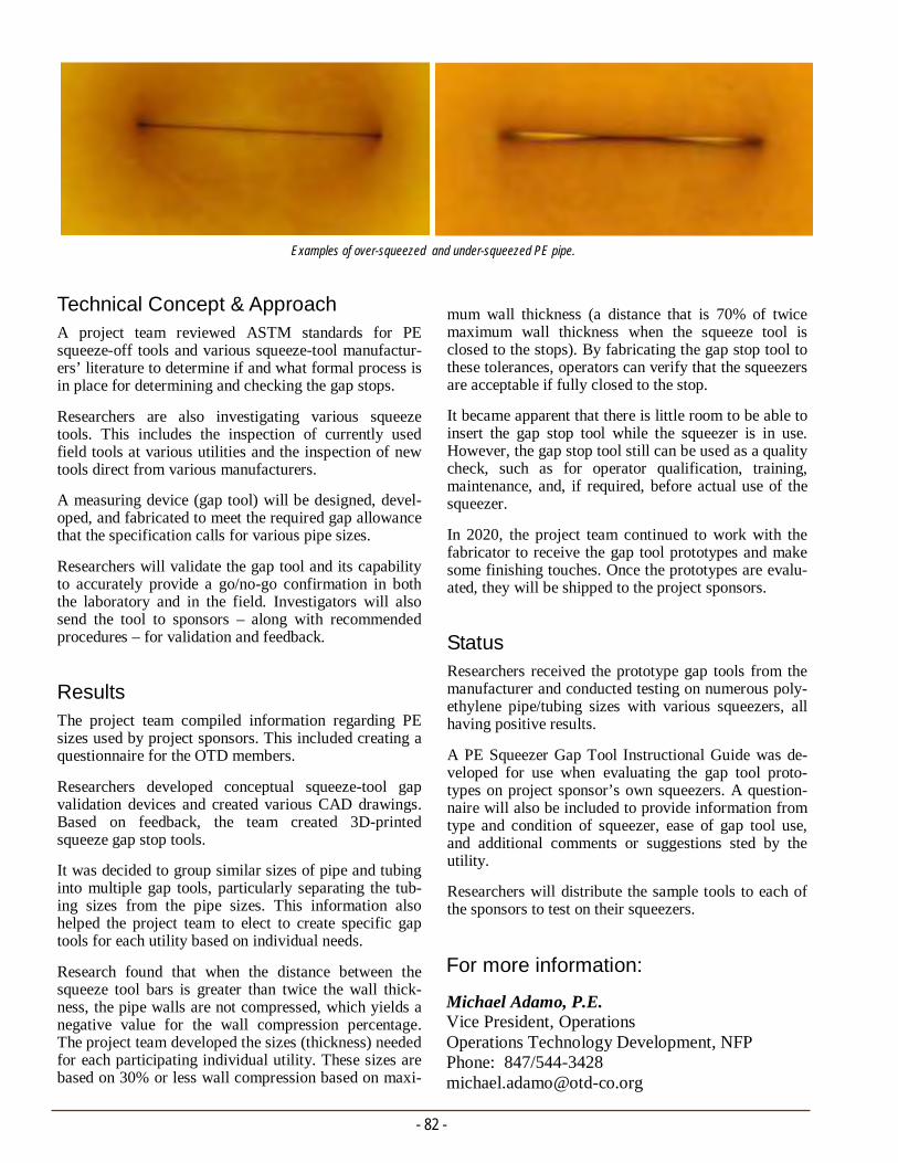
- 82 -
For more information:
Michael Adamo, P.E. Vice President, Operations Operations Technology Development, NFP Phone: 847/544-3428 [email protected]
mum wall thickness (a distance that is 70% of twice maximum wall thickness when the squeeze tool is closed to the stops). By fabricating the gap stop tool to these tolerances, operators can verify that the squeezers are acceptable if fully closed to the stop.
It became apparent that there is little room to be able to insert the gap stop tool while the squeezer is in use. However, the gap stop tool still can be used as a quality check, such as for operator qualification, training, maintenance, and, if required, before actual use of the squeezer.
In 2020, the project team continued to work with the fabricator to receive the gap tool prototypes and make some finishing touches. Once the prototypes are evalu-ated, they will be shipped to the project sponsors.
Status Researchers received the prototype gap tools from the manufacturer and conducted testing on numerous poly-ethylene pipe/tubing sizes with various squeezers, all having positive results.
A PE Squeezer Gap Tool Instructional Guide was de-veloped for use when evaluating the gap tool proto-types on project sponsor’s own squeezers. A question-naire will also be included to provide information from type and condition of squeezer, ease of gap tool use, and additional comments or suggestions sted by the utility.
Researchers will distribute the sample tools to each of the sponsors to test on their squeezers.
Technical Concept & Approach A project team reviewed ASTM standards for PE squeeze-off tools and various squeeze-tool manufactur-ers’ literature to determine if and what formal process is in place for determining and checking the gap stops.
Researchers are also investigating various squeeze tools. This includes the inspection of currently used field tools at various utilities and the inspection of new tools direct from various manufacturers.
A measuring device (gap tool) will be designed, devel-oped, and fabricated to meet the required gap allowance that the specification calls for various pipe sizes.
Researchers will validate the gap tool and its capability to accurately provide a go/no-go confirmation in both the laboratory and in the field. Investigators will also send the tool to sponsors – along with recommended procedures – for validation and feedback.
Results The project team compiled information regarding PE sizes used by project sponsors. This included creating a questionnaire for the OTD members.
Researchers developed conceptual squeeze-tool gap validation devices and created various CAD drawings. Based on feedback, the team created 3D-printed squeeze gap stop tools.
It was decided to group similar sizes of pipe and tubing into multiple gap tools, particularly separating the tub-ing sizes from the pipe sizes. This information also helped the project team to elect to create specific gap tools for each utility based on individual needs.
Research found that when the distance between the squeeze tool bars is greater than twice the wall thick-ness, the pipe walls are not compressed, which yields a negative value for the wall compression percentage. The project team developed the sizes (thickness) needed for each participating individual utility. These sizes are based on 30% or less wall compression based on maxi-
Examples of over-squeezed and under-squeezed PE pipe.
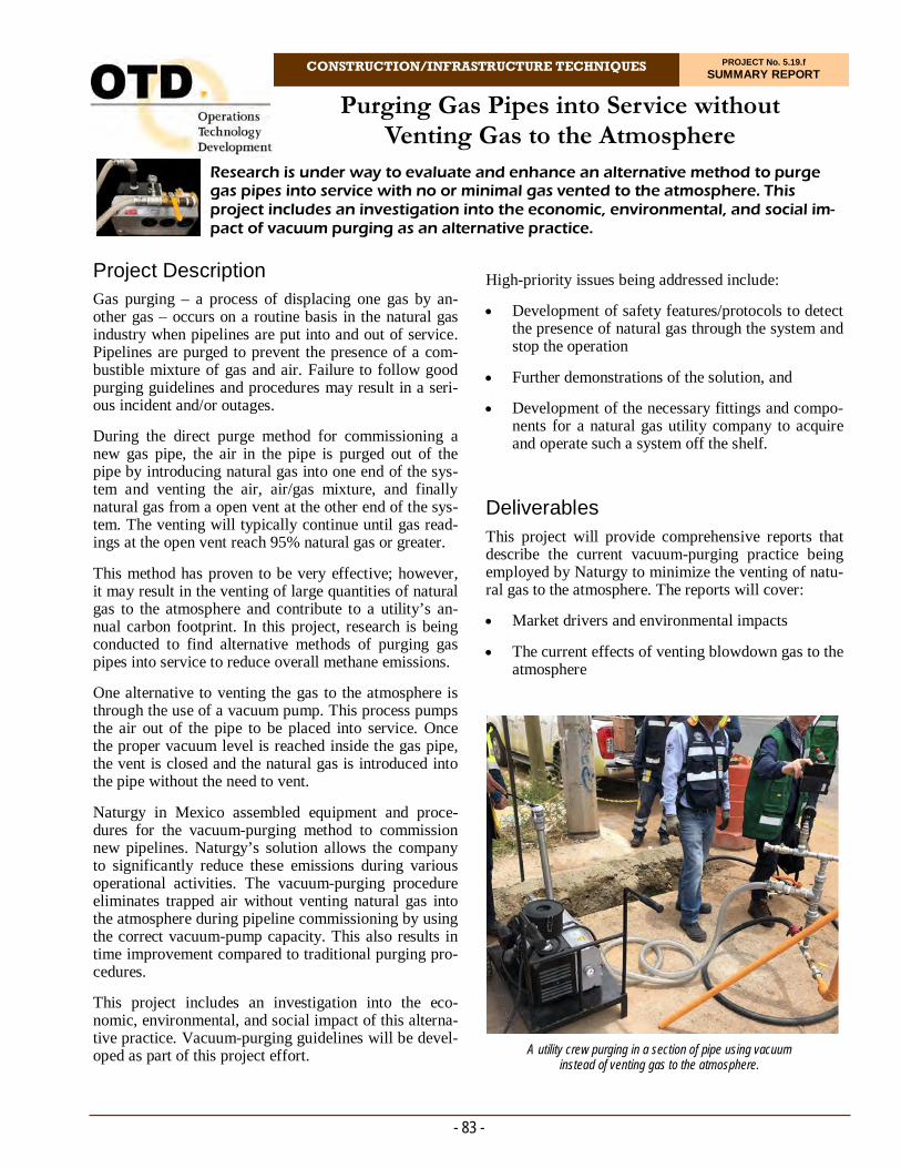
CONSTRUCTION/INFRASTRUCTURE TECHNIQUES PROJECT No. 5.19.f SUMMARY REPORT
Research is under way to evaluate and enhance an alternative method to purge gas pipes into service with no or minimal gas vented to the atmosphere. This project includes an investigation into the economic, environmental, and social im-pact of vacuum purging as an alternative practice.
Purging Gas Pipes into Service without Venting Gas to the Atmosphere
High-priority issues being addressed include:
Development of safety features/protocols to detect the presence of natural gas through the system and stop the operation
Further demonstrations of the solution, and
Development of the necessary fittings and compo-nents for a natural gas utility company to acquire and operate such a system off the shelf.
Deliverables
This project will provide comprehensive reports that describe the current vacuum-purging practice being employed by Naturgy to minimize the venting of natu-ral gas to the atmosphere. The reports will cover:
Market drivers and environmental impacts
The current effects of venting blowdown gas to the atmosphere
- 83 -
A utility crew purging in a section of pipe using vacuum instead of venting gas to the atmosphere.
Project Description Gas purging – a process of displacing one gas by an-other gas – occurs on a routine basis in the natural gas industry when pipelines are put into and out of service. Pipelines are purged to prevent the presence of a com-bustible mixture of gas and air. Failure to follow good purging guidelines and procedures may result in a seri-ous incident and/or outages.
During the direct purge method for commissioning a new gas pipe, the air in the pipe is purged out of the pipe by introducing natural gas into one end of the sys-tem and venting the air, air/gas mixture, and finally natural gas from a open vent at the other end of the sys-tem. The venting will typically continue until gas read-ings at the open vent reach 95% natural gas or greater.
This method has proven to be very effective; however, it may result in the venting of large quantities of natural gas to the atmosphere and contribute to a utility’s an-nual carbon footprint. In this project, research is being conducted to find alternative methods of purging gas pipes into service to reduce overall methane emissions.
One alternative to venting the gas to the atmosphere is through the use of a vacuum pump. This process pumps the air out of the pipe to be placed into service. Once the proper vacuum level is reached inside the gas pipe, the vent is closed and the natural gas is introduced into the pipe without the need to vent.
Naturgy in Mexico assembled equipment and proce-dures for the vacuum-purging method to commission new pipelines. Naturgy’s solution allows the company to significantly reduce these emissions during various operational activities. The vacuum-purging procedure eliminates trapped air without venting natural gas into the atmosphere during pipeline commissioning by using the correct vacuum-pump capacity. This also results in time improvement compared to traditional purging pro-cedures.
This project includes an investigation into the eco-nomic, environmental, and social impact of this alterna-tive practice. Vacuum-purging guidelines will be devel-oped as part of this project effort.

- 84 -
For more information:
Michael Adamo, P.E. Vice President, Operations Operations Technology Development, NFP Phone: 847/544-3428 [email protected]
Results During the Phase 1 effort, the project team obtained a replica vacuum system that is currently being used by Naturgy.
Researchers also constructed a test loop with pressure-sampling capabilities to observe the effects of vacuum conditions on a distribution network and various opera-tional parameters of the vacuum system. This allowed for a better understanding of the operation, perform-ance, and areas for possible improvement of the current system.
Numerous pump-downs on pipes were conducted to evaluate the efficacy of such a system on various pipe volumes. The system fully removed all measurable air molecules from the pipe samples tested (up to 800 feet of four-inch diameter polyethylene pipe), showing that 100% pure natural gas can be introduced to the system without the need to vent any gas to the atmosphere from a purge and that the vacuum purge is a viable concept for continued evaluation.
Through an online questionnaire and virtual interview process, a strong shared interest to lower methane emissions was identified. Furthermore, many gas utili-ties are concerned of the public perception of venting gas to atmosphere, especially in urban settings. Many gas utilities are involved in internal or industry recog-nized programs aimed at lowering emissions as well. These utilities are seeking new technologies and meth-ods that can help reduce all emissions metrics.
A Phase 1 Final Report was issued in November 2020. Details on the market and technology findings are de-tailed in the report.
Status Researchers initiated the Phase 2 effort which focuses on enhancing the identified vacuum purging technol-ogy to a commercial-ready state. In this phase, the team will identify remaining components needed to seamlessly and safely operate the vacuum pump and also continue to demonstrate the system at OTD mem-bers field locations to gain necessary feedback and ulti-mate acceptance.
A cost analysis of implementation of alternative methods that includes environmental impacts of these methods, and
Guidelines/equipment needed to implement the vacuum-purging system.
Benefits
Minimizing or eliminating the current practice of vent-ing natural gas to the atmosphere during purging can help reduce methane emissions.
Some of the additional benefits identified by Naturgy include: 1) enhanced safety by minimizing exposure to explosive mixtures; 2) reduced natural gas loss gener-ated during the purge process (unaccountable gas losses); 3) eliminated use of nitrogen as inerting agent; 4) improved company image by increasing confidence within communities by avoiding gas purges (no noise or gas odor), and 5) the cost-effective system eliminates the need for a nitrogen slug, reduces gas losses, and saves time.
Technical Concept & Approach Project sponsors were surveyed for their current meth-ods of pipe purging. The analysis also addressed the market drivers, environmental, and social impacts. In addition to evaluating the overall system and purging capability, system components were evaluated to deter-mine if there is any impact from the vacuum (mechan-ical coupling and other elastomeric seals, line valves, etc.). Areas of concern were identified.
The current system implemented by Naturgy is assem-bled from various commercially available components. For broader acceptance and implementation, a vacuum-purging packaged unit is needed that may include a vac-uum-pump system with integrated methane-detection alarms and safety shutoff; incorporated flame arresters in the exhaust outlet; and appropriate hoses, connectors, purge stacks, etc.
The final system will need to include sensing compo-nents that allow for the monitoring of the methane con-centration inadvertently pulled through the vacuum. This task will include identifying, acquiring, and testing these components to ensure that they perform as re-quired and operate safely with the vacuum system.
Once the field-ready version of the vacuum system is configured, researchers and project sponsors plan to conduct live demonstrations at utility-sponsored sites. These demonstrations are designed to identify opera-tional and component issues as well as introduce the technology to the project stakeholders. A user’s manual for the system’s safe operation and use will be devel-oped.
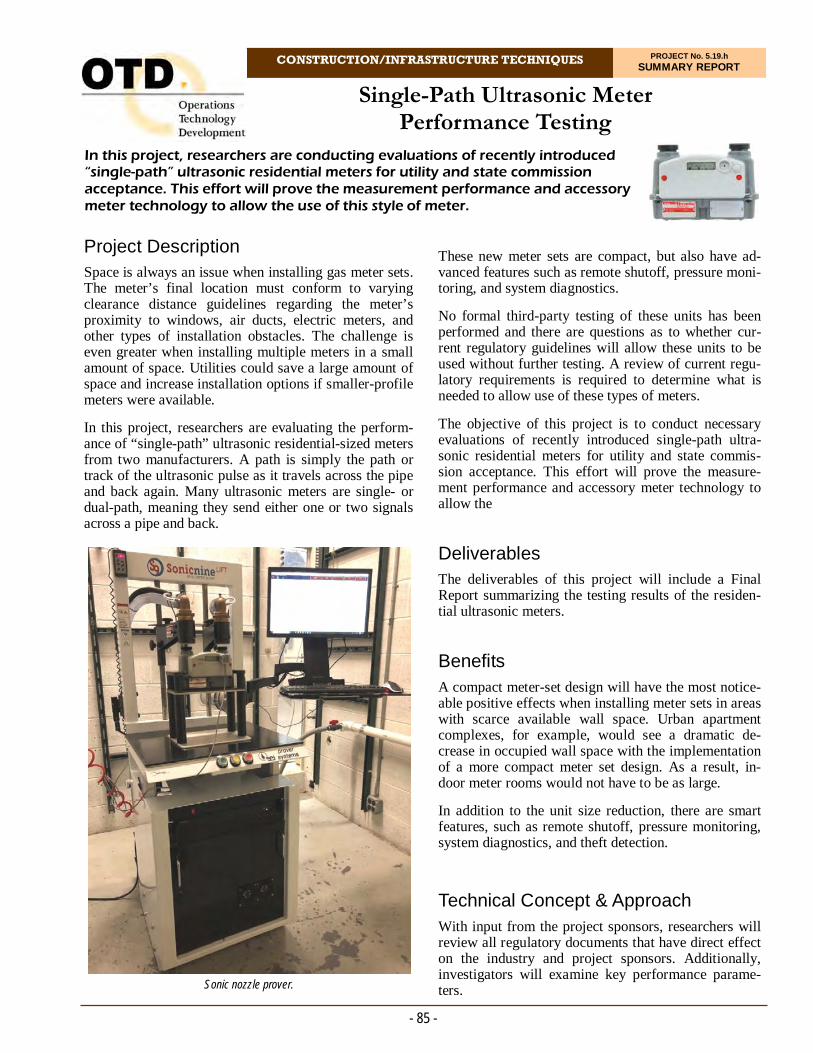
CONSTRUCTION/INFRASTRUCTURE TECHNIQUES PROJECT No. 5.19.h SUMMARY REPORT
Project Description Space is always an issue when installing gas meter sets. The meter’s final location must conform to varying clearance distance guidelines regarding the meter’s proximity to windows, air ducts, electric meters, and other types of installation obstacles. The challenge is even greater when installing multiple meters in a small amount of space. Utilities could save a large amount of space and increase installation options if smaller-profile meters were available.
In this project, researchers are evaluating the perform-ance of “single-path” ultrasonic residential-sized meters from two manufacturers. A path is simply the path or track of the ultrasonic pulse as it travels across the pipe and back again. Many ultrasonic meters are single- or dual-path, meaning they send either one or two signals across a pipe and back.
In this project, researchers are conducting evaluations of recently introduced “single-path” ultrasonic residential meters for utility and state commission acceptance. This effort will prove the measurement performance and accessory meter technology to allow the use of this style of meter.
Single-Path Ultrasonic Meter Performance Testing
These new meter sets are compact, but also have ad-vanced features such as remote shutoff, pressure moni-toring, and system diagnostics.
No formal third-party testing of these units has been performed and there are questions as to whether cur-rent regulatory guidelines will allow these units to be used without further testing. A review of current regu-latory requirements is required to determine what is needed to allow use of these types of meters.
The objective of this project is to conduct necessary evaluations of recently introduced single-path ultra-sonic residential meters for utility and state commis-sion acceptance. This effort will prove the measure-ment performance and accessory meter technology to allow the
Deliverables The deliverables of this project will include a Final Report summarizing the testing results of the residen-tial ultrasonic meters.
Benefits A compact meter-set design will have the most notice-able positive effects when installing meter sets in areas with scarce available wall space. Urban apartment complexes, for example, would see a dramatic de-crease in occupied wall space with the implementation of a more compact meter set design. As a result, in-door meter rooms would not have to be as large.
In addition to the unit size reduction, there are smart features, such as remote shutoff, pressure monitoring, system diagnostics, and theft detection.
Technical Concept & Approach With input from the project sponsors, researchers will review all regulatory documents that have direct effect on the industry and project sponsors. Additionally, investigators will examine key performance parame-ters.
- 85 -
Sonic nozzle prover.
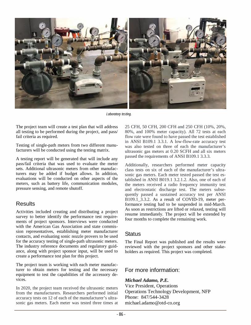
- 86 -
For more information:
Michael Adamo, P.E. Vice President, Operations Operations Technology Development, NFP Phone: 847/544-3428 [email protected]
25 CFH, 50 CFH, 200 CFH and 250 CFH (10%, 20%, 80%, and 100% meter capacity). All 72 tests at each flow rate were found to have passed the test established in ANSI B109.1 3.3.1. A low-flow-rate accuracy test was also tested on three of each the manufacturer’s ultrasonic gas meters at 0.20 SCFH and all six meters passed the requirements of ANSI B109.1 3.3.3.
Additionally, researchers performed meter capacity class tests on six of each of the manufacturer’s ultra-sonic gas meters. Each meter tested passed the test es-tablished in ANSI B019.1 3.2.1.2. Also, one of each of the meters received a radio frequency immunity test and electrostatic discharge test. The meters subse-quently passed a sustained accuracy test per ANSI B109.1_3.3.2. As a result of COVID-19, meter per-formance testing had to be suspended in mid-March. As soon as restrictions are lifted or relaxed, testing will resume immediately. The project will be extended by four months to complete the remaining work.
Status The Final Report was published and the results were reviewed with the project sponsors and other stake-holders as required. This project was completed.
The project team will create a test plan that will address all testing to be performed during the project, and pass/fail criteria as required.
Testing of single-path meters from two different manu-facturers will be conducted using the testing matrix.
A testing report will be generated that will include any pass/fail criteria that was used to evaluate the meter sets. Additional ultrasonic meters from other manufac-turers may be added if budget allows. In addition, evaluations will be conducted on other aspects of the meters, such as battery life, communication modules, pressure sensing, and remote shutoff.
Results Activities included creating and distributing a project survey to better identify the performance test require-ments of project sponsors. Interviews were conducted with the American Gas Association and state commis-sion representatives, establishing meter manufacturer contacts, and evaluating sonic nozzle provers to be used for the accuracy testing of single-path ultrasonic meters. The industry reference documents and regulatory guid-ance, along with project sponsor input, will be used to create a performance test plan for this project.
The project team is working with each meter manufac-turer to obtain meters for testing and the necessary equipment to test the capabilities of the accessory de-vices.
In 2020, the project team received the ultrasonic meters from the manufacturers. Researchers performed initial accuracy tests on 12 of each of the manufacturer’s ultra-sonic gas meters. Each meter was tested three times at
Laboratory testing.

CONSTRUCTION/INFRASTRUCTURE TECHNIQUES PROJECT No. 5.19.k SUMMARY REPORT
Project Description District governors regulating the pressure in natural gas distribution systems are manually adjusted on a sea-sonal basis two to four times per year. They are set to the maximum pressure that is anticipated to be needed to satisfy the highest gas-delivery demand for the re-quired period of time. The set-point pressure takes into account factors that will drive up gas usage, such as the time of day – typically, the early morning hours, a very cold peak heating day, etc.
Some systems have remotely monitored and controlled pressure regulation, but company personnel must oper-ate these systems 24 hours a day. Low-pressure sys-tems, where the pressure regulator can be a significant distance from the end of the distribution network, must also take into account the slower response time of the system to an increase in regulated pressure. Pressure adjustments may need to be made sooner and possibly at a higher set point to maintain the minimal operating pressure at the end of the system. This means that for the vast majority of the time, the set operating pressure is significantly higher than is needed. This leads to higher gas leakage and larger lost and unaccounted for gas than would be experienced if the pressure were autonomously adjusted remotely and automatically in real time as needed to meet changing gas demand, or by a system that could predict pressure requirements and make regulator adjustments before the need is detected.
There is also growing environmental concerns for the effects of greenhouse gases on the global environment. Gas companies are under growing pressure to decrease fugitive natural gas emissions through better control of the gas distribution system and the sources of natural gas leakage.
These issues could be addressed through the develop-ment and implementation of a system that would auto-matically regulate the pressure in gas distribution lines in real time. Increases in system pressure through auto-matic adjustment of a gas pressure regulator would only occur during times of increased gas demand, while maintaining lower pressure during periods of low de-mand. Such a system would also benefit from the use of computer self-learning algorithms to predict changes in usage demand and adjust system pressure.
In this project, researchers are conducting a technical review and evaluation of a smart regulator for medium- and low-pressure gas distribution systems. The system is designed to provide operators with visibility and pressure management as well as remote control of pressure-regulator output of their regulator stations.
Evaluation and Demonstrations of the Utonomy Smart Regulator
This project focuses on the Smart Regulator system, which was developed in the United Kingdom by Uton-omy, Ltd., in 2015. The Smart Regulator is an innova-tive active gas utility pressure-management system that uses a combination of hardware- and software-based self-learning algorithms and remote-controlled actuators to control system pressure in real time. The system allows operators to regulate system pressure to the lowest possible pressure while meeting system-delivery requirements, thus reducing gas leakage and unaccounted levels.
The objective of this project is to conduct a technical evaluation and North American field demonstrations of the Smart Regulator for medium- and low-pressure gas distribution systems.
- 87 -
Pressure regulator station with Utonomy Smart Regulator installed.
- 88 -
For more information:
Michael Adamo, P.E. Vice President, Operations Operations Technology Development, NFP Phone: 847/544-3428 [email protected]
cations platform and data-logging capability. The pro-ject team will test the system’s ability to retrieve in-structions from the platform and return data and status information. An evaluation will be conducted from a cybersecurity aspect.
The project team will coordinate field demonstrations of the Utonomy Smart Regulator. The field demonstra-tion will be conducted over a period of 12 months to allow evaluation of its operation and response to sea-sonal load variations.
Results
A technical review and evaluation of the Utonomy Smart Regulator was performed to better understand the capabilities, benefits, and possible transference to the U.S. natural gas industry. The team obtained de-tailed information on the Utonomy system and func-tionality. In addition, the team conducted a visit to Utonomy to examine the system and all the various components and user interface software.
The team also visited a large gas network operator to discuss its evaluation and pilot installation of the Uton-omy system. In addition, the team conducted a site visit at a district regulator station that was enhanced with the Utonomy system (actuator, controller, and communica-tion and power devices).
The Utonomy Smart Regulator is currently in opera-tional field trials at five locations in the southern U.K. All five locations use identical components and regula-tor stream configuration. The only variations are the make and model of the main regulator used and the size of the components. All five pressure regulator ki-osks are above ground prefabricated structures. A lar-ger field deployment was initiated in the U.K. that in-cludes below-ground regulator structures.
Status The Phase 1 Final Report was completed and a Phase 2 effort is now being planned. Phase 2 will demonstrate the operation and benefits of the Utonomy Smart Regu-lator through testing at Fisher's Flow Laboratory and in North American utility field trials.
Deliverables The deliverables of this project will include a report that 1) compares commercially available systems that re-motely and autonomously control gas pressure regulator operations 2) details the results of the Utonomy Smart Regulator laboratory testing in a simulated field envi-ronment 3) provides a case study detailing the results and experience with the Utonomy Smart Regulator, 4) describes site visits, installations, implementation, and operation of the Smart Regulator, and 5) the in an oper-ating field, and results of field demonstrations.
Benefits The Smart Regulator is designed to be retrofitted to ex-isting gas distribution regulators and pressure control systems so that it can be applied to a range of current gas pressure regulation systems.
Benefits include:
The ability to remotely or automatically adjust the pressure output of a pressure regulator station sev-eral times per day in response to changing gas de-mand through the day
Elimination of the need for gas company personnel to frequently visit each pressure regulator station to make these adjustments
A reduction in the loss of gas from the system
Remote visibility of the operation of regulator inlet and outlet pressures
A reduction in reports of gas odors in the controlled network
Improved pressure stability in the network, and
Easy installation.
Technical Concept & Approach This project includes a review of customer needs and development of a laboratory and field-testing approach.
Researchers will conduct a high-level study of similar technologies that may be available.
Fitness-For-Purpose testing will be conducted. This will include the design and construction of a small-scale gas distribution piping system that can be pressurized to different levels and flow rates. The Smart Regulator system will be installed on this laboratory piping system to evaluate its communication, analysis, and response to simulated changes in system gas delivery requirements. This will include establishing a cloud-based communi-

CONSTRUCTION/INFRASTRUCTURE TECHNIQUES PROJECT No. 5.19.n SUMMARY REPORT
Project Description Gas utilities are aware of the potential damage that an improper pipe squeeze-off operation can impart on polyethylene (PE) pipe. In this project, research is being conducted to determine the probability of imparting damage in pipes and fittings in close proximity to a squeezed-off point and provide data, recommendations, and best practices (e.g., use of clamps for protecting the squeezed-off location) for performing a squeeze-off operation.
This method being developed is based on the results of OTD project 2.13.d, Method for Developing an Initial Risk Profile for Aldyl-A Piping Systems. A specific task under the project evaluated the expected residual life-time of vintage Aldyl-A piping after squeeze-off with and without the use of a reinforcing clamp/fitting.
Several other projects were conducted also investigat-ing the performance and life expectancy of vintage PE pipe, including an investigation to forecast the remain-ing useful life and pressure-carrying capacity of vintage Aldyl-A pipes, taking into account the effects of:
Specific field temperatures and other conditions
Rock impingement
Soil loading and earth settlement
Pipe bending, and
Squeeze-off.
Deliverable
This project will provide information on the ability of various repair clamps/fittings to reduce stresses on vin-tage PE pipes after squeeze-off operations. Testing re-ports detailing the performance of the various clamps/sleeves will be provided in a Final Report.
Benefits Squeeze-off is a technique used to stop or reduce the flow of gas in PE pipe by compressing the pipe between parallel bars until the inside surfaces of the pipe make
Specific guidelines and best practices are being developed for performing squeeze-offs on vintage polyethylene pipes. Research is being conducted on the ability of various repair clamps/fittings to reduce stresses on vintage PE pipes after squeeze-off operations.
Best Practices for Squeeze-Off of Vintage Polyethylene Pipe
contact. This operation has been shown to inherently induce damage at the squeeze-off. A method to protect gas pipes at the squeeze point by using specific repair clamps/fittings that are currently available in the mar-ket could potentially enhance and extend the lifetime of a squeezed pipe.
Technical Concept & Approach The project team is building on research carried out in previous projects and further investigating and quanti-fying the stresses imparted on a PE pipe as a result of the squeeze-off procedure. In addition, researchers will evaluate the extent of imparted damage, and develop guidelines and best practices for maintaining the life of squeezed-off vintage PE pipes.
The approach is to employ Finite Element Method (FEM) analysis to determine the Stress Intensification Factors (SIFs) induced by the squeeze-off operation on various pipe sizes and materials. The SIFs will then be validated using 3D X-ray computed tomography (CT) scanning.
- 89 -

- 90 -
For more information:
Michael Adamo, P.E. Vice President, Operations Operations Technology Development, NFP Phone: 847/544-3428 [email protected]
Material Properties Testing
To support the FEM analysis, material properties testing will be performed via tensile testing and Dynamic Thermo-Mechanical Analysis. For each pipe material, three replicate specimens will be tested at three temperatures. Two pipe materials will be tested.
Short-Term Validation Testing
In this task, the squeezed-off pipe samples that were 3D scanned will be prepared and tested. A total of 36 specimens for each pipe size/material combination will be tested. The squeezed-off and clamped pipe specimens will be subjected to ele-vated temperature sustained hydrostatic pressure testing to validate a desired lifetime at end-use op-erating conditions.
Results
In 2020, initial project activities included project scop-ing and a survey to gather information from the spon-sors. The objective of the survey is to identify needs with regards to the size and type of repair clamps needed to protect the squeezed-off location of vintage polyethylene pipes.
Researchers obtained quotations for procurement of five selected clamps. The project team will perform an inventory of its Aldyl-A pipe samples and initiate the testing based on this material.
The research team followed up with project sponsors regarding the supply of pipe samples.
Status Sponsors are being contacted to provide the following pipe samples:
2″ IPS pre-1983 Aldyl-A
2″ IPS pre-1995 HDPE, and
2″ M7000/M8000
Specific tasks include:
Specimen Acquisition
Samples for testing include medium-density and high-density PE pipe samples and corresponding stainless-steel repair clamps, various electrofusion encirclement fittings, and butt-fusion repair sleeves.
Squeeze-off, CT Scanning, and FEM Analysis
Researchers will validate the kind of damage that is imparted in squeezed-off pipe. This will be accom-plished by performing pipe squeeze-offs at 0°C, 23°C, and 40°C (32°F, 73°F, and104°F) in accor-dance with ASTM F1041 and D2513 under typical operating pressures. For each pipe size, multiple specimens will be prepared at each temperature. One sample from each temperature will be sent for 3D CT scanning before squeeze-off. On completion of the squeeze-offs, all of the specimens will be CT scanned. The acquired 3D scans will be used to generate CAD models. The generated CAD models will then be used to simulate pipe internal pressuri-zation via FEM analysis to determine what the local SIFs are for various pipe sizes after they have been squeezed-off. This will generate absolute values of SIFs due to geometric deformation. The results will be compared to those of squeezed-off pipes in an historical database. This reference data will enable the team to provide lifetime prediction of squeezed-off pipe evaluated in this project.
The CAD models from before squeeze-off will also be used in full squeeze-off simulation and the de-formation results will be compared to the CT scanned deformation. This will help verify the simulation and provide insight about the damage induced by the squeeze-off process.
Various replacement clamps and fittings will be evaluated.
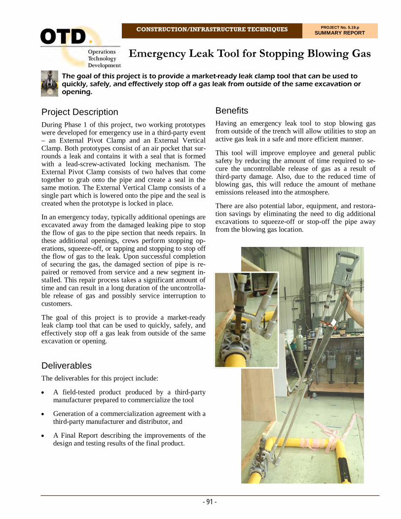
CONSTRUCTION/INFRASTRUCTURE TECHNIQUES PROJECT No. 5.19.p SUMMARY REPORT
Project Description During Phase 1 of this project, two working prototypes were developed for emergency use in a third-party event – an External Pivot Clamp and an External Vertical Clamp. Both prototypes consist of an air pocket that sur-rounds a leak and contains it with a seal that is formed with a lead-screw-activated locking mechanism. The External Pivot Clamp consists of two halves that come together to grab onto the pipe and create a seal in the same motion. The External Vertical Clamp consists of a single part which is lowered onto the pipe and the seal is created when the prototype is locked in place.
In an emergency today, typically additional openings are excavated away from the damaged leaking pipe to stop the flow of gas to the pipe section that needs repairs. In these additional openings, crews perform stopping op-erations, squeeze-off, or tapping and stopping to stop off the flow of gas to the leak. Upon successful completion of securing the gas, the damaged section of pipe is re-paired or removed from service and a new segment in-stalled. This repair process takes a significant amount of time and can result in a long duration of the uncontrolla-ble release of gas and possibly service interruption to customers.
The goal of this project is to provide a market-ready leak clamp tool that can be used to quickly, safely, and effectively stop off a gas leak from outside of the same excavation or opening.
Deliverables The deliverables for this project include:
A field-tested product produced by a third-party manufacturer prepared to commercialize the tool
Generation of a commercialization agreement with a third-party manufacturer and distributor, and
A Final Report describing the improvements of the design and testing results of the final product.
The goal of this project is to provide a market-ready leak clamp tool that can be used to quickly, safely, and effectively stop off a gas leak from outside of the same excavation or opening.
Emergency Leak Tool for Stopping Blowing Gas
Benefits Having an emergency leak tool to stop blowing gas from outside of the trench will allow utilities to stop an active gas leak in a safe and more efficient manner.
This tool will improve employee and general public safety by reducing the amount of time required to se-cure the uncontrollable release of gas as a result of third-party damage. Also, due to the reduced time of blowing gas, this will reduce the amount of methane emissions released into the atmosphere.
There are also potential labor, equipment, and restora-tion savings by eliminating the need to dig additional excavations to squeeze-off or stop-off the pipe away from the blowing gas location.
- 91 -

Technical Concept & Approach Specific tasks include:
Design Refinement of the Tool
This task includes interactions with manufacturers to refine the design of the external clamp prototypes such that it is stronger, more effective, and can be easily fabricated by the manufacturer. Currently, the leak clamp prototypes are designed to stop the flow of gas on polyethylene (PE) and steel pipe sizes of two inches in diameter through eight inches in di-ameter.
Fabrication of the Final Tool Design
This task will mostly be conducted by the manufac-turer to fabricate the final external clamp tool with oversight by the project team to ensure tool require-ments are met.
Laboratory and Field Testing of the Tool
This task includes laboratory testing and field test-ing the fabricated clamp tool by the manufacturer and testing it on damaged PE pipe and steel pipe. This testing will include multiple-size clamp tools and the different design enhancements made during the fabrication process.
Commercialization
This task includes efforts to bring this product to market, including, but not limited to, protecting in-tellectual property and seeking patents, obtaining a distributor, and securing licensing agreements.
Results
In 2020, the project team received prototypes for testing from two manufacturers.
The first tool utilized two hydraulic cylinders. Re-searchers tested the sealing capabilities on a PE pipe section in a laboratory setting. The gasket materials tested could not hold pressures higher than 30 psi. The project team and manufacturer are designing an alterna-tive sealing method.
- 92 -
For the second tool (which utilized a long-lever arm), the project team performed testing on various gasket materials, thicknesses, durometers, and shapes in order to determine the type of gasket that would provide the best seal given the design of the cavity. Researchers found that regardless of what gasket was used, changes are needed to be made on the long-arm clamping mechanism and the method of adhering and capturing the seal on the main body.
Refinements are being made to both of these prototypes. Laboratory and field testing will be conducted until both prototypes are able to successfully seal a 60psi leak for a significant period of time.
The project team and manufacturer of the lever-arm concept developed a new clamping method involving a lead screw on the lever arms, which will be created and tested early in 2021.
For the other prototype, the project team continued to refine the design of the hydraulically-activated leak clamp. The project team has gone through two major design revisions for this method. For the first redesign, the project team realized that the design proved to have too many components to be feasible since it required four hydraulic cylinders. Therefore, this design was abandoned. Researchers then developed a second redes-ign which uses a single hydraulic cylinder to lock the teeth around the pipe and then push the seal into the pipe and locked teeth at the same time. This design is still in the conceptual phase and will need some further refinement before being produced late in 2021.
Status The following activities are scheduled for execution:
Create the prototype lead-screw-activated lever arm system to test concept
Refine the design of the single hydraulic prototype
Perform laboratory testing on the new clamping mechanisms for both designs
Begin production of the final prototypes of both designs, and
Continue commercialization discussions with tool manufacturers, distributors, etc.
For more information:
Michael Adamo, P.E. Vice President, Operations Operations Technology Development, NFP Phone: 847/544-3428 [email protected]
- Rick Trieste Dept. Manager R&D Consolidated Edison Company of New York
“The development of an emergency tool to stop blowing gas from a damage to our natural gas infrastructure is a perfect example of a project life cycle that begins as a member problem. The problem reaches conceptual maturity and then grows to full prototype development in OTD.”
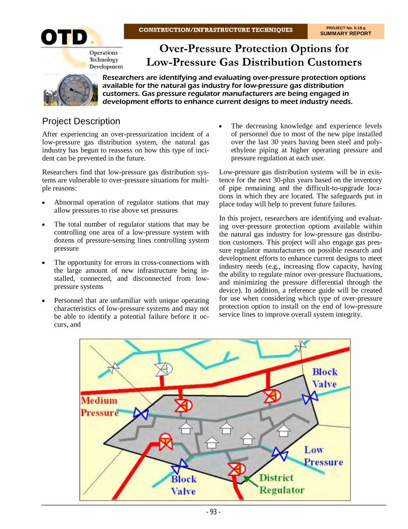
CONSTRUCTION/INFRASTRUCTURE TECHNIQUES PROJECT No. 5.19.q SUMMARY REPORT
Project Description After experiencing an over-pressurization incident of a low-pressure gas distribution system, the natural gas industry has begun to reassess on how this type of inci-dent can be prevented in the future.
Researchers find that low-pressure gas distribution sys-tems are vulnerable to over-pressure situations for multi-ple reasons:
Abnormal operation of regulator stations that may allow pressures to rise above set pressures
The total number of regulator stations that may be controlling one area of a low-pressure system with dozens of pressure-sensing lines controlling system pressure
The opportunity for errors in cross-connections with the large amount of new infrastructure being in-stalled, connected, and disconnected from low-pressure systems
Personnel that are unfamiliar with unique operating characteristics of low-pressure systems and may not be able to identify a potential failure before it oc-curs, and
Researchers are identifying and evaluating over-pressure protection options available for the natural gas industry for low-pressure gas distribution customers. Gas pressure regulator manufacturers are being engaged in development efforts to enhance current designs to meet industry needs.
Over-Pressure Protection Options for Low-Pressure Gas Distribution Customers
The decreasing knowledge and experience levels of personnel due to most of the new pipe installed over the last 30 years having been steel and poly-ethylene piping at higher operating pressure and pressure regulation at each user.
Low-pressure gas distribution systems will be in exis-tence for the next 30-plus years based on the inventory of pipe remaining and the difficult-to-upgrade loca-tions in which they are located. The safeguards put in place today will help to prevent future failures.
In this project, researchers are identifying and evaluat-ing over-pressure protection options available within the natural gas industry for low-pressure gas distribu-tion customers. This project will also engage gas pres-sure regulator manufacturers on possible research and development efforts to enhance current designs to meet industry needs (e.g., increasing flow capacity, having the ability to regulate minor over-pressure fluctuations, and minimizing the pressure differential through the device). In addition, a reference guide will be created for use when considering which type of over-pressure protection option to install on the end of low-pressure service lines to improve overall system integrity.
- 93 -

Deliverables The deliverables for this project will include:
A Final Report detailing the technical specifications for the different over-pressure protection options for low-pressure gas distribution service
Coordination and facilitation of webinars with manufacturers (including potential new products), and
A report that will include a reference guide compar-ing similar over-pressure protection options for each of the different manufacturers.
Benefits Installing an over-pressure protection device (OPPD) on low-pressure gas lines to serve customers reduces risk in the event of an unintended system over-pressure situation that may be the result of a mechanical failure or human error.
Installation of OPPDs will prevent widespread catastro-phic failures in the event of an over-pressurization of the system. If OPPDs are not installed and a system over-pressure event occurs, the cost of third-party claims related to emergency response, personal injury claims, property damage, temporary housing, and legal fees can exceed $1 billion.
Technical Concept & Approach Specific tasks include:
Identification and Evaluation of Over-Pressure Protection Devices for Low-Pressure Service
This task includes the identification and evaluation of current over-pressure protection options for low-pressure gas distribution service to customers. The evaluation includes the technical specifications of each device. A reference guide will be prepared with this information comparing similar devices and options. In addition, regulator manufacturers will be interviewed on the level of research and de-velopment efforts for OPPDs currently under way or expected in the near future.
- 94 -
Regulator and Device Manufacturer Webinars
This task includes the coordination and facilitation of webinars for each of the regulator and device manufacturers to present on their over-pressure pro-tection offerings for low-pressure gas distribution customers. One webinar will be conducted for each of the manufacturers. These webinars will be re-corded for those unable to participate and the manu-facturer presentations made available to project sponsors.
Results
The over-pressurization incidents investigated by the National Transportation Safety Board (NTSB) over the past 50 years demonstrate that low-pressure natural gas distribution systems that use only sensing lines and regulators as the means to detect and prevent over-pressurization are not optimal to prevent over-pressurization incidents. The NTSB recommended to “revise Title 49 Code of Federal Regulations Part 192 to require over-pressure protection for low-pressure natu-ral gas distribution systems that cannot be defeated by a single operator error or equipment failure.”
Activities for this project included identification of the project team, conducting a project kick-off call with sponsors, performing a search of existing products, and speaking with industry subject matter experts on avail-able products.
Status
This project is complete. A Final Report is pending.
For more information:
Michael Adamo, P.E. Vice President, Operations Operations Technology Development, NFP Phone: 847/544-3428 [email protected]
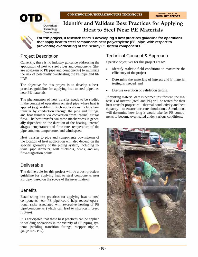
CONSTRUCTION/INFRASTRUCTURE TECHNIQUES PROJECT No. 5.19.s SUMMARY REPORT
Project Description Currently, there is no industry guidance addressing the application of heat to steel pipes and components (that are upstream of PE pipe and components) to minimize the risk of potentially overheating the PE pipe and fit-tings.
The objective for this project is to develop a best-practices guideline for applying heat to steel pipelines near PE materials.
The phenomenon of heat transfer needs to be studied in the context of operations on steel pipe where heat is applied (e.g. welding). Such applications include heat transfer by conduction through the pipe and fittings, and heat transfer via convection from internal air/gas flow. The heat transfer via these mechanisms is gener-ally dependent on the duration of the heating, internal air/gas temperature and flow rate, temperature of the pipe, ambient temperature, and wind speed.
Heat transfer to pipe and components downstream of the location of heat application will also depend on the specific geometry of the piping system, including in-ternal pipe diameter, wall thickness, bends, and any flow-stagnation points. Deliverable The deliverable for this project will be a best-practices guideline for applying heat to steel components near PE pipe, based on the scope of the investigation.
Benefits Establishing best practices for applying heat to steel components near PE pipe could help reduce opera-tional risks associated with excessive heating of PE pipe/components (which can lead to short-term creep rupture).
It is anticipated that these best practices can be applied to welding operations in the vicinity of PE piping sys-tems (welding transition fittings, stopper nipples, gauge tees, etc.).
For this project, a research team is developing a best-practices guideline for operations that apply heat to steel components near polyethylene (PE) pipe, with respect to preventing overheating of the nearby PE system components.
Identify and Validate Best Practices for Applying Heat to Steel Near PE Materials
Technical Concept & Approach Specific objectives for this project are to:
Identify realistic field conditions to maximize the efficiency of the project
Determine the materials of interest and if material testing is needed, and
Discuss execution of validation testing.
If existing material data is deemed insufficient, the ma-terials of interest (steel and PE) will be tested for their heat-transfer properties – thermal conductivity and heat capacity – to ensure accurate simulations. Simulations will determine how long it would take for PE compo-nents to become overheated under various conditions.
- 95 -
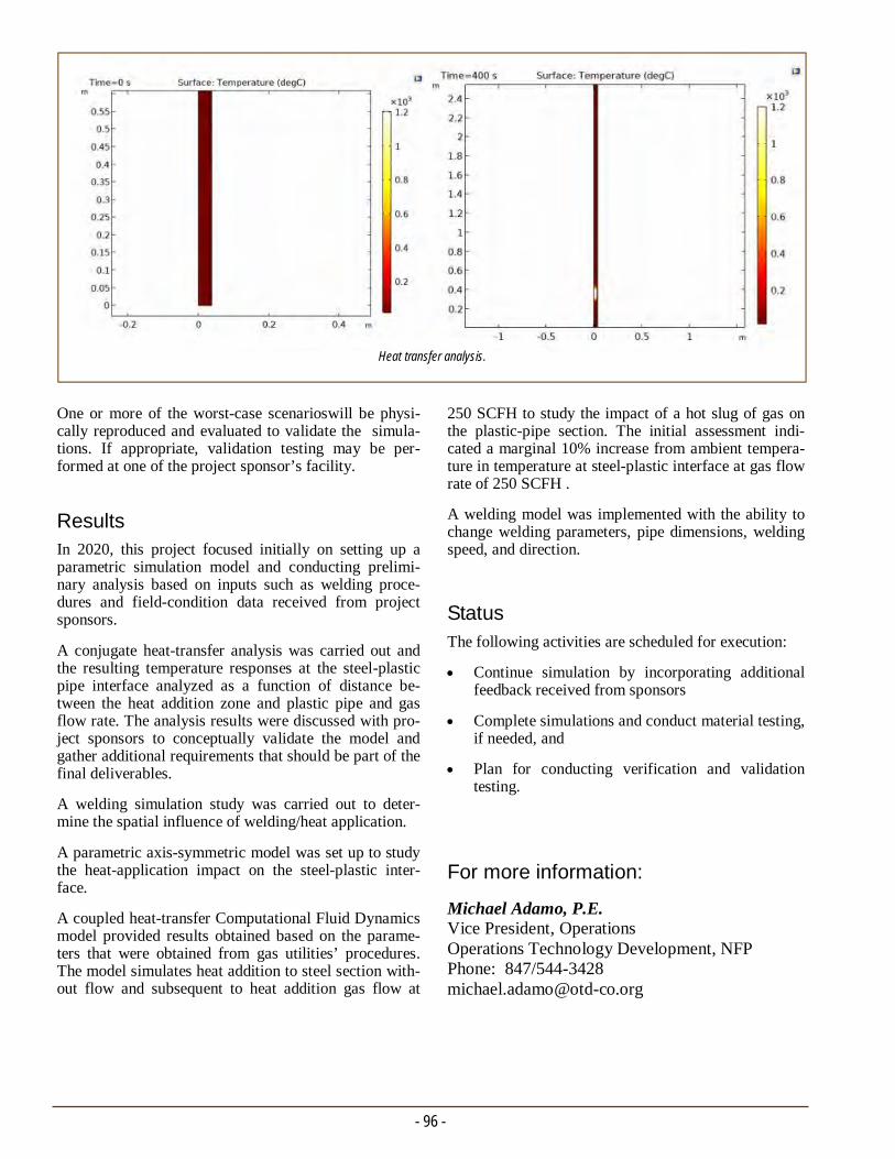
One or more of the worst-case scenarioswill be physi-cally reproduced and evaluated to validate the simula-tions. If appropriate, validation testing may be per-formed at one of the project sponsor’s facility.
Results In 2020, this project focused initially on setting up a parametric simulation model and conducting prelimi-nary analysis based on inputs such as welding proce-dures and field-condition data received from project sponsors.
A conjugate heat-transfer analysis was carried out and the resulting temperature responses at the steel-plastic pipe interface analyzed as a function of distance be-tween the heat addition zone and plastic pipe and gas flow rate. The analysis results were discussed with pro-ject sponsors to conceptually validate the model and gather additional requirements that should be part of the final deliverables.
A welding simulation study was carried out to deter-mine the spatial influence of welding/heat application.
A parametric axis-symmetric model was set up to study the heat-application impact on the steel-plastic inter-face.
A coupled heat-transfer Computational Fluid Dynamics model provided results obtained based on the parame-ters that were obtained from gas utilities’ procedures. The model simulates heat addition to steel section with-out flow and subsequent to heat addition gas flow at
- 96 -
250 SCFH to study the impact of a hot slug of gas on the plastic-pipe section. The initial assessment indi-cated a marginal 10% increase from ambient tempera-ture in temperature at steel-plastic interface at gas flow rate of 250 SCFH .
A welding model was implemented with the ability to change welding parameters, pipe dimensions, welding speed, and direction.
Status The following activities are scheduled for execution:
Continue simulation by incorporating additional feedback received from sponsors
Complete simulations and conduct material testing, if needed, and
Plan for conducting verification and validation testing.
For more information:
Michael Adamo, P.E. Vice President, Operations Operations Technology Development, NFP Phone: 847/544-3428 [email protected]
Heat transfer analysis.
CONSTRUCTION/INFRASTRUCTURE TECHNIQUES PROJECT No. 5.19.t SUMMARY REPORT
Project Description While there are several platforms for introducing de-velopments related to non-destructive evaluation (NDE) of polyethylene (PE) pipe joints, industry does not have a set of consensus guidelines on how to inter-pret the results of the NDE evaluations. There is also no clear understanding as to the difference between volumetric defects that are easily detectable and weak-fusion interfaces, that are difficult to detect.
Field failures mostly are due to the weak-fusion inter-faces, not the volumetric defects. The industry needs clear statements as to the failure risk associated with each kind of defect, together with probability-of-detection information.
The importance of proper pipe-preparation methods was comprehensively addressed in OTD project (5.16.r) Joint Industry PE Program. However, no re-search has been done on the efficacy of NDE methods as a quality control for surface cleanliness in assem-bled joints.
Gas Technology Institute (GTI) performed an exten-sive project on the impacts of heavy hydrocarbon con-tamination on the quality of butt-fusion joints in PE pipe. This project included an extensive evaluation of non-contaminated butt-fusion joints to develop base-line joint-quality data for reference. Follow-on projects included two efforts that focused on developing ultra-sonic methods for measuring contamination.
A project with Michigan State University (MSU) de-veloped a reliable method for producing butt-fusion joints with known levels of interface strength based on quantitative destructive testing. Joints of known qual-ity were sent to MSU in a blind study of the effective-ness of NDE methods in detecting weak-fusion inter-faces.
The methods evaluated by MSU included:
Micro-Computerized Tomography
Microwave Frequency Scanning
Co-axial Cable Probe
Split-Ring Resonator
For this project, a two-day workshop is being organized to present the results of research from Michigan State University and GRTgaz on non-destructive evaluation (NDE) methods for polyethylene piping systems.
Workshop on NDE Capabilities for Polyethylene Systems
Open-Ended Waveguide
Capacitive Sensors, and
Optical Transmission Scanning.
All test specimens evaluated by MSU were destruc-tively tested.
GRTGaz has extensive knowledge of NDE evaluations performed in Europe and has spent considerable time and effort in developing methods for evaluating elec-trofusion joints. The GRTGaz efforts include long-term hydrostatic testing of joints evaluated and catego-rization of the failures due to volumetric joints and weak interfaces, together with their probability of de-tection by the GRTGaz method.
For this project, a research team will organize a two-day workshop to present the results of R&D performed by GTI, MSU and GRTgaz on NDE methods for PE piping systems. Deliverables Deliverables include:
The Workshop
Workshop proceedings
- 97 -
Summary of consensus of implications of informa-tion presented, and
A roadmap for next steps in evaluating commer-cially available NDE technologies.
Benefits A clear, science-based understanding of the capabilities of existing NDE methods in detecting heat-fusion joint anomalies will be very useful in helping utilities de-velop approaches to mitigating historic joint-quality issues. The information provided will give utilities the necessary reference points for evaluating alternative approaches to assessing joint quality and ensuring joint quality in future operations.
Technical Concept & Approach Workshop topics include:
Overview of North American and European field failures in PE heat-fusion joints
The state of the art in NDE methods for PE piping systems
Discussion of what defects each evaluation method can detect and how these defects relate to field fail-ures
- 98 -
Demonstration of GRTgaz experience with Phased Array Ultrasonic Testing (PAUT) of electrofusion joints
Discussions on how to approach evaluation of ex-isting NDE technologies
Discussion of process-management approaches to ensuring joint integrity and where NDE ap-proaches are relevant
Discussion of how to process the information pro-vided and develop a unified strategy for addressing quality and integrity of historic joints and new joints.
Results / Status
The workshop is scheduled for June 1 and 2, 2021.
For more information:
Michael Adamo, P.E. Vice President, Operations Operations Technology Development, NFP Phone: 847/544-3428 [email protected]
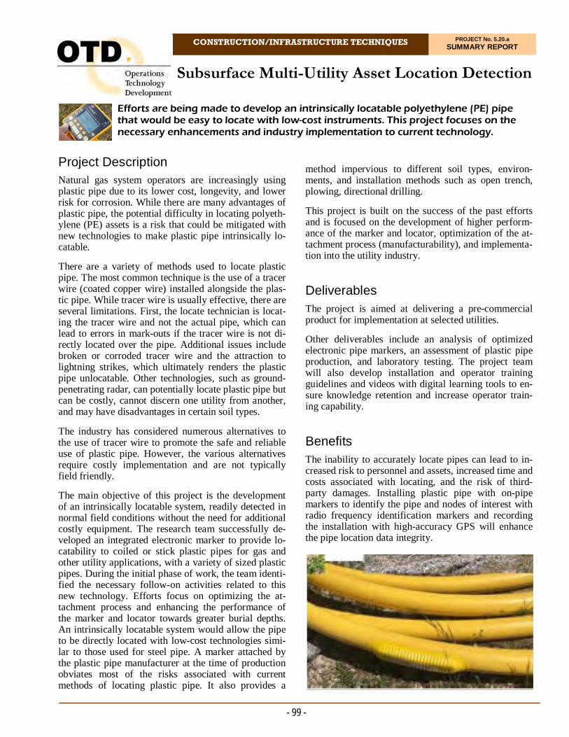
Subsurface Multi-Utility Asset Location Detection
CONSTRUCTION/INFRASTRUCTURE TECHNIQUES PROJECT No. 5.20.a SUMMARY REPORT
- 99 -
Project Description Natural gas system operators are increasingly using plastic pipe due to its lower cost, longevity, and lower risk for corrosion. While there are many advantages of plastic pipe, the potential difficulty in locating polyeth-ylene (PE) assets is a risk that could be mitigated with new technologies to make plastic pipe intrinsically lo-catable.
There are a variety of methods used to locate plastic pipe. The most common technique is the use of a tracer wire (coated copper wire) installed alongside the plas-tic pipe. While tracer wire is usually effective, there are several limitations. First, the locate technician is locat-ing the tracer wire and not the actual pipe, which can lead to errors in mark-outs if the tracer wire is not di-rectly located over the pipe. Additional issues include broken or corroded tracer wire and the attraction to lightning strikes, which ultimately renders the plastic pipe unlocatable. Other technologies, such as ground- penetrating radar, can potentially locate plastic pipe but can be costly, cannot discern one utility from another, and may have disadvantages in certain soil types.
The industry has considered numerous alternatives to the use of tracer wire to promote the safe and reliable use of plastic pipe. However, the various alternatives require costly implementation and are not typically field friendly.
The main objective of this project is the development of an intrinsically locatable system, readily detected in normal field conditions without the need for additional costly equipment. The research team successfully de-veloped an integrated electronic marker to provide lo-catability to coiled or stick plastic pipes for gas and other utility applications, with a variety of sized plastic pipes. During the initial phase of work, the team identi-fied the necessary follow-on activities related to this new technology. Efforts focus on optimizing the at-tachment process and enhancing the performance of the marker and locator towards greater burial depths. An intrinsically locatable system would allow the pipe to be directly located with low-cost technologies simi-lar to those used for steel pipe. A marker attached by the plastic pipe manufacturer at the time of production obviates most of the risks associated with current methods of locating plastic pipe. It also provides a
method impervious to different soil types, environ-ments, and installation methods such as open trench, plowing, directional drilling.
This project is built on the success of the past efforts and is focused on the development of higher perform-ance of the marker and locator, optimization of the at-tachment process (manufacturability), and implementa-tion into the utility industry.
Deliverables
The project is aimed at delivering a pre-commercial product for implementation at selected utilities.
Other deliverables include an analysis of optimized electronic pipe markers, an assessment of plastic pipe production, and laboratory testing. The project team will also develop installation and operator training guidelines and videos with digital learning tools to en-sure knowledge retention and increase operator train-ing capability.
Benefits The inability to accurately locate pipes can lead to in-creased risk to personnel and assets, increased time and costs associated with locating, and the risk of third-party damages. Installing plastic pipe with on-pipe markers to identify the pipe and nodes of interest with radio frequency identification markers and recording the installation with high-accuracy GPS will enhance the pipe location data integrity.
Efforts are being made to develop an intrinsically locatable polyethylene (PE) pipe that would be easy to locate with low-cost instruments. This project focuses on the necessary enhancements and industry implementation to current technology.
- 100 -
Testing of the markers and marker attachments may include but is not limited to the following:
Tag frequency and aging drift evaluations
Tag detection depth
Attachment adhesion/bonding strength
Creep analysis of the attached tag and the effects on the plastic pipe, and
Installation environment considerations.
The team and participating utilities will develop instal-lation and mapping guidelines and locator training guidance to support installations. In addition, the team will make efforts to install larger quantities of the in-trinsically locatable pipe.
Results During 2020, project sponsors stated that they want to receive locatable polyethylene pipe with tags pre-installed. The sponsors also indicated that there may be certain situations where it would be beneficial to be able to install tags on the pipe in the field – this in-cludes on existing pipe that is exposed and new instal-lations at offsets and changes in direction.
Marker and locator technology optimization was initi-ated. However, the COVID-19 virus outbreak delayed the ability for the pipe extruder to commit to working with the team on the manufacturability of applying tags during the extrusion process.
The project team and the manufacturer continued to engage the a polyethylene pipe extruder and a bonding company (from the auto industry) in order to identify the potential partners for the locatable pipe.
During the third quarter of 2020, a large PE pipe ex-truder agreed to partner with the project team on the project.
Status The project team now includes a pipe extrusion partner and together have developed a new project plan and deliverable end dates. The team is now taking the nec-essary steps to meet the goals of the project.
Advantages of an intrinsically locatable plastic pipe include:
Enhanced safety for natural gas distribution networks
Ability to locate the pipe is not affected if it is cut or damaged
The electronic markers are not subject to infer-ence from nearby utility lines
Saves steps during installation – eliminates tracer wire and related installation, splicing and access
Saves steps during location – eliminates trans-mitter connection
Unique frequency for various utility pipes and conduits
Eliminates susceptibility to lightning from a long conductor laying on the pipe, and
Long life expectancy of product designed to last the lifetime of the facility.
Technical Concept & Approach Initially, utilities and a newly formed Technical Advi-sory Panel were surveyed to better understand the needs regarding locatable plastic pipe and the implementation of this new technology. A testing matrix will be devel-oped to assess the manufacturing process. The range of climatic conditions and soil types along with mapping best practices will be scoped. The utilities will also be solicited for field installation sites and an understanding for mapping and training needs. The manufacturer will then optimize electronic pipe markers and an above-ground locator specific to the needs of the program.
In collaboration with the pipe manufacturer and various attachment manufacturer(s), the team will develop and test methods to attach the electronic markers to the pipe. The pipe manufacturer will review current plastic pipe extrusion methods to understand necessary upgrades to processes and equipment for the attachment of the elec-tronic markers to the pipe. Trial extrusion pipe runs will be conducted to validate the attachment method as well as any required process changes for the pipe coiling, loading, storage, and transportation. The output of this task will be a developed manufacturing guideline to produce the prototypes of the pipe and marker system for in ground testing and evaluations.
Various testing of both the marker and the attachment of the marker to the plastic pipe will be conducted. This testing will assist in developing a robust quality-assurance document and test procedures.
For more information:
Michael Adamo, P.E. Vice President, Operations Operations Technology Development, NFP Phone: 847/544-3428 [email protected]
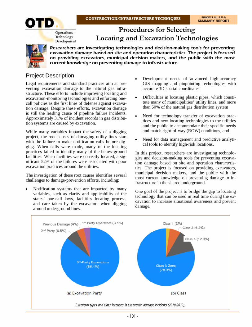
Procedures for Selecting Locating and Excavation Technologies
CONSTRUCTION/INFRASTRUCTURE TECHNIQUES PROJECT No. 5.20.b SUMMARY REPORT
- 101 -
Project Description Legal requirements and standard practices aim at pre-venting excavation damage to the natural gas infra-structure. These efforts include improving locating and excavation-monitoring technologies and enforcing one-call policies as the first lines of defense against excava-tion damage. Despite these efforts, excavation damage is still the leading cause of pipeline failure incidents. Approximately 31% of incident records in gas distribu-tion systems are caused by excavation.
While many variables impact the safety of a digging project, the root causes of damaging utility lines start with the failure to make notification calls before dig-ging. When calls were made, many of the locating practices failed to identify many of the below-ground facilities. When facilities were correctly located, a sig-nificant 52% of the failures were associated with poor excavation practices around the utilities.
The investigation of these root causes identifies several challenges to damage-prevention efforts, including:
Notification systems that are impacted by many variables, such as clarity and applicability of the states’ one-call laws, facilities locating process, and care taken by the excavators when digging around underground lines.
Development needs of advanced high-accuracy GIS mapping and pinpointing technologies with accurate 3D spatial coordinates
Difficulties in locating plastic pipes, which consti-tute many of municipalities’ utility lines, and more than 50% of the natural gas distribution system
Need for technology transfer of excavation prac-tices and new locating technologies to the utilities and the public to accommodate their specific needs and match right-of-way (ROW) conditions, and
Need for data management and predictive analyti-cal tools to identify high-risk locations.
In this project, researchers are investigating technolo-gies and decision-making tools for preventing excava-tion damage based on site and operation characteris-tics. The project is focused on providing excavators, municipal decision makers, and the public with the most current knowledge on preventing damage to in-frastructure in the shared underground.
One goal of the project is to bridge the gap to locating technology that can be used in real time during the ex-cavation to increase situational awareness and prevent damage.
Researchers are investigating technologies and decision-making tools for preventing excavation damage based on site and operation characteristics. The project is focused on providing excavators, municipal decision makers, and the public with the most current knowledge on preventing damage to infrastructure.
Excavator types and class locations in excavation damage incidents (2010-2019).

- 102 -
Performing predictive analysis to assist in identi-fying risk drivers and advancing the assessment of situational awareness of excavation damage.
Developing a web-based program and database of excavation-damage incidents and related causes.
Results / Status
During 2020, researchers performed a literature search of requirements, pertinent parameters, and incident characteristics. The project team also investigated ex-cavation-encroachment and notification systems.
A review of relevant federal and state requirements was completed. Incidents databases from the National Transportation Safety Board and the U.S. Department of Transportation's Pipelines and Hazardous Materials Safety Administration are complete. The development of the web-based program is still in progress.
Researchers initiated the analysis of the effect of site characteristics and excavation practices on the prob-ability of excavation damage. The distributions of the various incident parameters are obtained from the da-tabase results.
Deliverables Researchers will suggest a situational-awareness frame-work which provides relative information on under-ground utilities, site characteristics (such as location, depth, soil properties, and adjacent facilities types), and high-risk features of the excavation sites.
Such framework will provide knowledge of the activi-ties at the sites and how communications and actions impact immediate and near-future consequences.
Benefits This project benefits gas companies and their customers by providing up-to-date information on tools and tech-nologies used to locate utilities and methods and tech-niques used for safe excavation.
Technical Concept & Approach In this project, researchers are:
Identifying recent advances in locating, GIS, and excavation technologies that address damage pre-vention, right-of-way monitoring, and detection of difficult-to-locate systems.
Investigating relevant federal and state requirements and industry best practices.
Selecting locating and encroachment-notification equipment to match excavators’ specific site proper-ties and operation requirements. Recent close-to commercialization technologies include aerial- and ground-based equipment to patrol pipeline ROWs for security and encroachments.
For more information:
Michael Adamo, P.E. Vice President, Operations Operations Technology Development, NFP Phone: 847/544-3428 [email protected]
Website development.
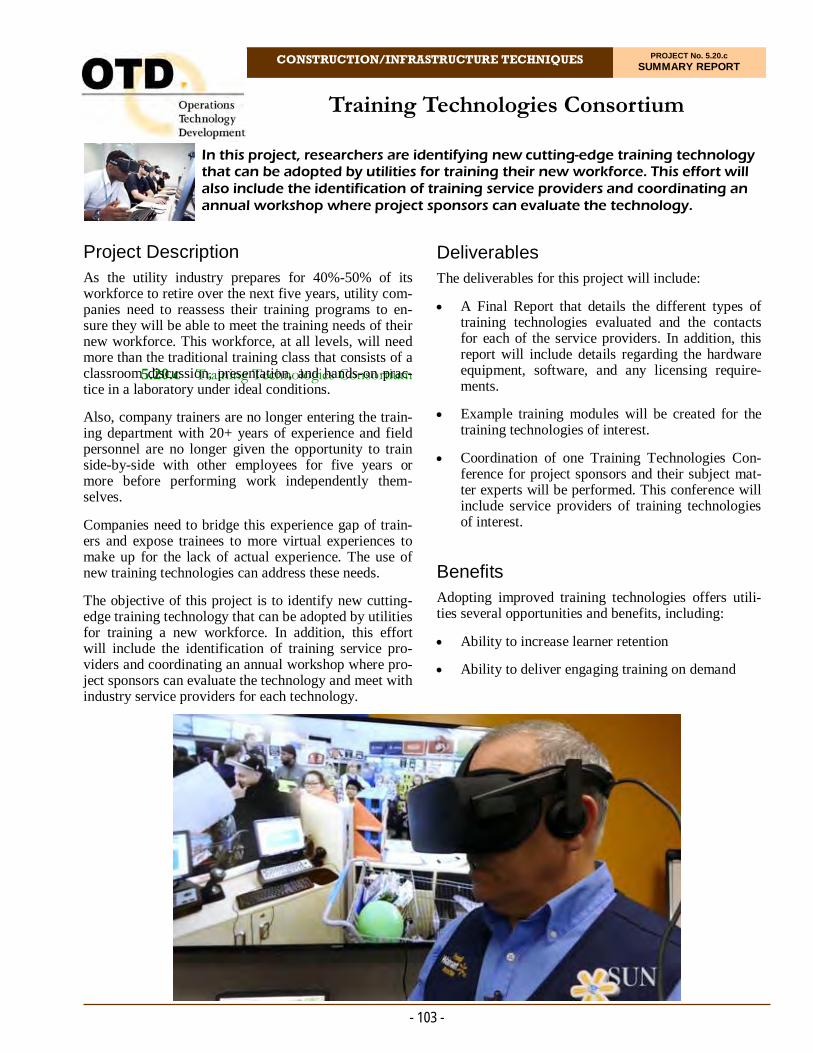
5.20.c Training Technologies Consortium
CONSTRUCTION/INFRASTRUCTURE TECHNIQUES PROJECT No. 5.20.c SUMMARY REPORT
Project Description As the utility industry prepares for 40%-50% of its workforce to retire over the next five years, utility com-panies need to reassess their training programs to en-sure they will be able to meet the training needs of their new workforce. This workforce, at all levels, will need more than the traditional training class that consists of a classroom discussion, presentation, and hands-on prac-tice in a laboratory under ideal conditions.
Also, company trainers are no longer entering the train-ing department with 20+ years of experience and field personnel are no longer given the opportunity to train side-by-side with other employees for five years or more before performing work independently them-selves.
Companies need to bridge this experience gap of train-ers and expose trainees to more virtual experiences to make up for the lack of actual experience. The use of new training technologies can address these needs.
The objective of this project is to identify new cutting-edge training technology that can be adopted by utilities for training a new workforce. In addition, this effort will include the identification of training service pro-viders and coordinating an annual workshop where pro-ject sponsors can evaluate the technology and meet with industry service providers for each technology.
In this project, researchers are identifying new cutting-edge training technology that can be adopted by utilities for training their new workforce. This effort will also include the identification of training service providers and coordinating an annual workshop where project sponsors can evaluate the technology.
Training Technologies Consortium
Deliverables The deliverables for this project will include:
A Final Report that details the different types of training technologies evaluated and the contacts for each of the service providers. In addition, this report will include details regarding the hardware equipment, software, and any licensing require-ments.
Example training modules will be created for the training technologies of interest.
Coordination of one Training Technologies Con-ference for project sponsors and their subject mat-ter experts will be performed. This conference will include service providers of training technologies of interest.
Benefits Adopting improved training technologies offers utili-ties several opportunities and benefits, including:
Ability to increase learner retention
Ability to deliver engaging training on demand
- 103 -
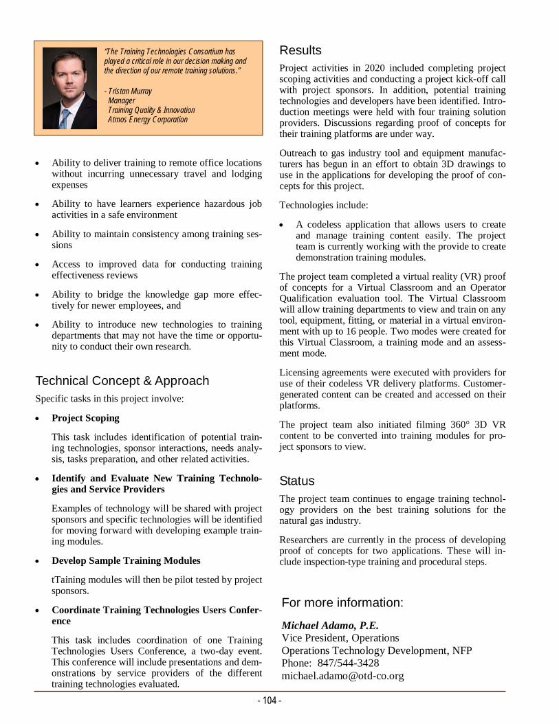
Ability to deliver training to remote office locations without incurring unnecessary travel and lodging expenses
Ability to have learners experience hazardous job activities in a safe environment
Ability to maintain consistency among training ses-sions
Access to improved data for conducting training effectiveness reviews
Ability to bridge the knowledge gap more effec-tively for newer employees, and
Ability to introduce new technologies to training departments that may not have the time or opportu-nity to conduct their own research.
Technical Concept & Approach Specific tasks in this project involve:
Project Scoping
This task includes identification of potential train-ing technologies, sponsor interactions, needs analy-sis, tasks preparation, and other related activities.
Identify and Evaluate New Training Technolo-gies and Service Providers
Examples of technology will be shared with project sponsors and specific technologies will be identified for moving forward with developing example train-ing modules.
Develop Sample Training Modules
tTaining modules will then be pilot tested by project sponsors.
Coordinate Training Technologies Users Confer-ence
This task includes coordination of one Training Technologies Users Conference, a two-day event. This conference will include presentations and dem-onstrations by service providers of the different training technologies evaluated.
- 104 -
Results Project activities in 2020 included completing project scoping activities and conducting a project kick-off call with project sponsors. In addition, potential training technologies and developers have been identified. Intro-duction meetings were held with four training solution providers. Discussions regarding proof of concepts for their training platforms are under way.
Outreach to gas industry tool and equipment manufac-turers has begun in an effort to obtain 3D drawings to use in the applications for developing the proof of con-cepts for this project.
Technologies include:
A codeless application that allows users to create and manage training content easily. The project team is currently working with the provide to create demonstration training modules.
The project team completed a virtual reality (VR) proof of concepts for a Virtual Classroom and an Operator Qualification evaluation tool. The Virtual Classroom will allow training departments to view and train on any tool, equipment, fitting, or material in a virtual environ-ment with up to 16 people. Two modes were created for this Virtual Classroom, a training mode and an assess-ment mode.
Licensing agreements were executed with providers for use of their codeless VR delivery platforms. Customer-generated content can be created and accessed on their platforms.
The project team also initiated filming 360° 3D VR content to be converted into training modules for pro-ject sponsors to view.
Status
The project team continues to engage training technol-ogy providers on the best training solutions for the natural gas industry.
Researchers are currently in the process of developing proof of concepts for two applications. These will in-clude inspection-type training and procedural steps.
For more information:
Michael Adamo, P.E. Vice President, Operations Operations Technology Development, NFP Phone: 847/544-3428 [email protected]
- Tristan Murray Manager Training Quality & Innovation Atmos Energy Corporation
“The Training Technologies Consortium has played a critical role in our decision making and the direction of our remote training solutions.”

Pipe Thread Conformance to Bi.20.1 Standard –Pipe Supplier Quality Assurance
CONSTRUCTION/INFRASTRUCTURE TECHNIQUES PROJECT No. 5.20.d SUMMARY REPORT
- 105 -
Project Description The natural gas industry expects that the materials the company uses conforms with established standards. When materials do not conform, the potential exists to create unease among customers and regulatory agen-cies. Also, at a time when methane emissions are a high-profile topic, any extra effort utilities can take to prevent unnecessary methane emissions will be impor-tant for continued support of natural gas being a safe and environmentally friendly energy solution.
OTD previously sponsored projects related to threaded joint make-up and leak prevention. During OTD pro-ject 5.18.w (Pipe Thread Sealant Performance), sev-eral pipe manufacturers were identified as providing material not in conformance with the B1.20.1 standard, even though marketing and technical documents refer-enced being in conformance with this thread standard.
In this project, researchers are investigating pipe thread conformance with the B1.20.1 standard for each major pipe supplier within the industry, creating an easy quality-control check, and working with pipe sup-pliers on improving their conformance to the B1.20.1 standard.
Deliverables The deliverables for this project will include a Final Report that details the conformance findings among the different threaded pipe and fitting manufacturers. In addition, the quality-control corrective actions dis-cussed with any of the pipe and fitting manufacturers will be detailed. Lastly, quality-control steps that can be performed by utility material receivers will be pre-sented.
Benefits Improved pipe and fitting thread conformance with industry standards may help reduce the total number of premature failures of gas tight joints. These premature threaded joint failures cost utilities a significant amount of their budget dollars annually to address these nonhazardous nuisance leaks.
Improved fitting conformance will help reduce the fol-lowing costs and conditions:
Travel time to leak location
Meter set disassembly
In this project, researchers are investigating pipe thread conformance with the B1.20.1 standard for each major pipe supplier within the industry. The project team will create an easy quality-control check and work with pipe suppliers on improving their conformance to the B1.20.1 standard.
- 106 -
Results During a previous OTD project, researchers found that pipe thread sealant performance from various suppliers provided threaded pipe could not be used for the pro-ject since the threading on the pipe did not conform to the B1.20.1 standard that is required for the transporta-tion of natural gas.
Researchers reviewed existing pipe thread data and a project team held a meeting to discuss a future testing plan.
Status The project team is currently:
Completing a test plan
Developing a list of threaded pipe suppliers
Ordering test samples or receiving samples from project sponsors, and
Initiating physical data collection.
Meter set reassembly
Appliance relighting
Decreased customer satisfaction
Increased employee muscle fatigue and injury, and
Wasted materials.
Technical Concept & Approach This project began in 2020 with the identification of known non-conformance issues, sponsor interactions, needs analysis, tasks preparation, and other related ac-tivities.
Researchers will identify and evaluate the quality-control checks that project sponsors currently perform on pipe and fittings received from suppliers and dis-tributors.
The project team will procure pipe and fittings from each of the identified suppliers and distributors. The pipe sizes will range from ½ inch diameter to four inches in diameter and will include stainless steel and black steel. B1.20.1 conformance inspections will be conducted on the pipe and fittings. The data from the conformance testing will be documented and included in the Final Report.
The project team will review the conformance testing results with the different pipe and fitting suppliers and distributors. This review will also include identifying deficiencies in their current quality-control processes along with proposing improvements for moving for-ward.
For more information:
Michael Adamo, P.E. Vice President, Operations Operations Technology Development, NFP Phone: 847/544-3428 [email protected]
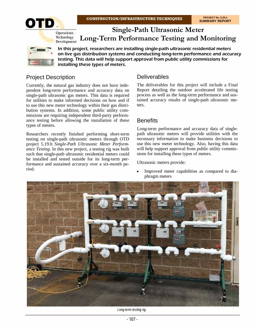
CONSTRUCTION/INFRASTRUCTURE TECHNIQUES PROJECT No. 5.20.e SUMMARY REPORT
Project Description Currently, the natural gas industry does not have inde-pendent long-term performance and accuracy data on single-path ultrasonic gas meters. This data is required for utilities to make informed decisions on how and if to use this new meter technology within their gas distri-bution systems. In addition, some public utility com-missions are requiring independent third-party perform-ance testing before allowing the installation of these types of meters.
Researchers recently finished performing short-term testing on single-path ultrasonic meters through OTD project 5.19.h Single-Path Ultrasonic Meter Perform-ance Testing. In this new project, a testing rig was built such that single-path ultrasonic residential meters could be installed and tested outside for its long-term per-formance and sustained accuracy over a six-month pe-riod.
In this project, researchers are installing single-path ultrasonic residential meters on live gas distribution systems and conducting long-term performance and accuracy testing. This data will help support approval from public utility commissions for installing these types of meters.
Single-Path Ultrasonic Meter Long-Term Performance Testing and Monitoring
Deliverables The deliverables for this project will include a Final Report detailing the outdoor accelerated life testing process as well as the long-term performance and sus-tained accuracy results of single-path ultrasonic me-ters.
Benefits Long-term performance and accuracy data of single-path ultrasonic meters will provide utilities with the necessary information to make business decisions to use this new meter technology. Also, having this data will help support approval from public utility commis-sions for installing these types of meters.
Ultrasonic meters provide:
Improved meter capabilities as compared to dia-phragm meters
- 107 -
Long-term testing rig.
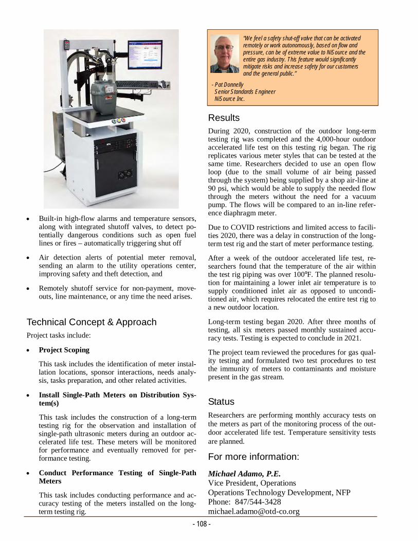
For more information:
Michael Adamo, P.E. Vice President, Operations Operations Technology Development, NFP Phone: 847/544-3428 [email protected]
Results During 2020, construction of the outdoor long-term testing rig was completed and the 4,000-hour outdoor accelerated life test on this testing rig began. The rig replicates various meter styles that can be tested at the same time. Researchers decided to use an open flow loop (due to the small volume of air being passed through the system) being supplied by a shop air-line at 90 psi, which would be able to supply the needed flow through the meters without the need for a vacuum pump. The flows will be compared to an in-line refer-ence diaphragm meter.
Due to COVID restrictions and limited access to facili-ties 2020, there was a delay in construction of the long-term test rig and the start of meter performance testing.
After a week of the outdoor accelerated life test, re-searchers found that the temperature of the air within the test rig piping was over 100ºF. The planned resolu-tion for maintaining a lower inlet air temperature is to supply conditioned inlet air as opposed to uncondi-tioned air, which requires relocated the entire test rig to a new outdoor location.
Long-term testing began 2020. After three months of testing, all six meters passed monthly sustained accu-racy tests. Testing is expected to conclude in 2021.
The project team reviewed the procedures for gas qual-ity testing and formulated two test procedures to test the immunity of meters to contaminants and moisture present in the gas stream.
Status
Researchers are performing monthly accuracy tests on the meters as part of the monitoring process of the out-door accelerated life test. Temperature sensitivity tests are planned.
Built-in high-flow alarms and temperature sensors, along with integrated shutoff valves, to detect po-tentially dangerous conditions such as open fuel lines or fires – automatically triggering shut off
Air detection alerts of potential meter removal, sending an alarm to the utility operations center, improving safety and theft detection, and
Remotely shutoff service for non-payment, move-outs, line maintenance, or any time the need arises.
Technical Concept & Approach Project tasks include:
Project Scoping
This task includes the identification of meter instal-lation locations, sponsor interactions, needs analy-sis, tasks preparation, and other related activities.
Install Single-Path Meters on Distribution Sys-tem(s)
This task includes the construction of a long-term testing rig for the observation and installation of single-path ultrasonic meters during an outdoor ac-celerated life test. These meters will be monitored for performance and eventually removed for per-formance testing.
Conduct Performance Testing of Single-Path Meters
This task includes conducting performance and ac-curacy testing of the meters installed on the long-term testing rig.
- Pat Donnelly Senior Standards Engineer NiSource Inc.
“We feel a safety shut-off valve that can be activated remotely or work autonomously, based on flow and pressure, can be of extreme value to NiSource and the entire gas industry. This feature would significantly mitigate risks and increase safety for our customers and the general public.”
- 108 -

Barholing and Worker Injuries
CONSTRUCTION/INFRASTRUCTURE TECHNIQUES PROJECT No. 5.20.f SUMMARY REPORT
- 109 -
Project Description When a gas leak is suspected, the utility sends a worker to the site to probe the ground, creating a series of up to 40 or 50 holes. This barholing enables effec-tive location and classification of gas leaks from distri-bution mains and services. However, barholing was identified by several gas utilities as a major cause of worker injuries.
The barholing technique is simple in that a mechanical tool operating in a pile-driving manner is operated by a single person to penetrate a small hole in the desired location, enabling gas samples to be taken at sub-surface levels.
Operators have noted a need for options – both prac-tices and tooling – for barholing related to leak investi-gations.
There are a variety of methods for making the barhole. One of the most common is through a plunger bar with a slap-hammer design (also called a bar driver). To use the plunger bar, workers must use a downward motion to force the bar into the ground. While the downward motion is awkward, the majority of problems occur when workers must remove the plunger bar from the ground. The motion required is similar to throwing an object straight up with arms slightly bent. The addition of the heavy handle to this motion can cause strains to the back and shoulders.
There are other methods of making the barhole, includ-ing using “needle bars” (that are pounded into the ground using a hammer) and using long drills. There are also several methods to remove the rod from the ground, including commercially available bar removers and some experimental or prototype bar removers.
There are also other pieces of equipment that can be used in barholing operations, including pneumatic drills to get through asphalt and concrete.
The objective for this project is to identify and review the industry’s best practices and barhole tooling op-tions.
Researchers will evaluate the various available and conceptual barhole tooling for the ability to reduce worker injuries.
Deliverables The deliverables for this project will include barholing guidelines and tooling recommendations based on the ability to reduce worker injury.
Benefits Barholing is a necessary process during leak investiga-tions. However, the barhole tools used are often man-ual mechanical devices which can lead to employee injuries. Utilities have a need for better barhole tooling and methods to minimize employee injuries.
Barholing best practices and improved tooling can help reduce worker injuries, reduce costs, and improve worker conditions.
Research is being conducted identify the industry’s best practices and barhole tooling options. Investigators are evaluating the various available and conceptual barhole tooling for the ability to reduce worker injuries.
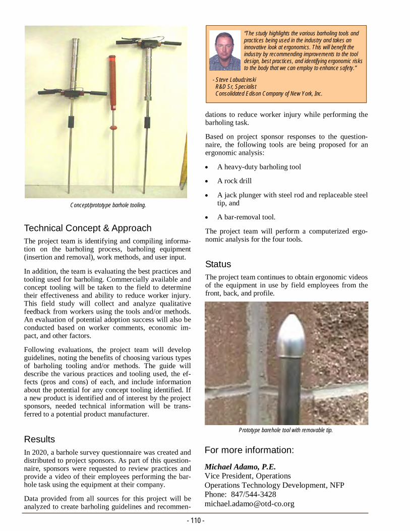
- 110 -
dations to reduce worker injury while performing the barholing task.
Based on project sponsor responses to the question-naire, the following tools are being proposed for an ergonomic analysis:
A heavy-duty barholing tool
A rock drill
A jack plunger with steel rod and replaceable steel tip, and
A bar-removal tool.
The project team will perform a computerized ergo-nomic analysis for the four tools.
Status The project team continues to obtain ergonomic videos of the equipment in use by field employees from the front, back, and profile.
Technical Concept & Approach The project team is identifying and compiling informa-tion on the barholing process, barholing equipment (insertion and removal), work methods, and user input.
In addition, the team is evaluating the best practices and tooling used for barholing. Commercially available and concept tooling will be taken to the field to determine their effectiveness and ability to reduce worker injury. This field study will collect and analyze qualitative feedback from workers using the tools and/or methods. An evaluation of potential adoption success will also be conducted based on worker comments, economic im-pact, and other factors.
Following evaluations, the project team will develop guidelines, noting the benefits of choosing various types of barholing tooling and/or methods. The guide will describe the various practices and tooling used, the ef-fects (pros and cons) of each, and include information about the potential for any concept tooling identified. If a new product is identified and of interest by the project sponsors, needed technical information will be trans-ferred to a potential product manufacturer.
Results
In 2020, a barhole survey questionnaire was created and distributed to project sponsors. As part of this question-naire, sponsors were requested to review practices and provide a video of their employees performing the bar-hole task using the equipment at their company.
Data provided from all sources for this project will be analyzed to create barholing guidelines and recommen-
For more information:
Michael Adamo, P.E. Vice President, Operations Operations Technology Development, NFP Phone: 847/544-3428 [email protected]
Concept/prototype barhole tooling.
Prototype barehole tool with removable tip.
- Steve Labudzinski R&D Sr, Specialist Consolidated Edison Company of New York, Inc.
“The study highlights the various barholing tools and practices being used in the industry and takes an innovative look at ergonomics. This will benefit the industry by recommending improvements to the tool design, best practices, and identifying ergonomic risks to the body that we can employ to enhance safety.”

Horizontal Directional Drilling Weak Links
CONSTRUCTION/INFRASTRUCTURE TECHNIQUES PROJECT No. 5.20.g SUMMARY REPORT
Investigators are reviewing the natural gas industry’s best practices and evaluating various commercially available weak leaks for trenchless installation of plastic pipe and tubing.
- 111 -
Project Description New federal regulations for the installation of plastic service lines by trenchless excavation requires that each section of plastic pipe and components that are pulled through the ground must use a “weak link” to ensure the pipeline will not be damaged by any exces-sive forces during the pulling process.
ASTM F1804-08 (Standard Practice for Determining Allowable Tensile Load for Polyethylene Gas Piping During Pull-In Installation) provides a means to deter-mine an allowable tensile load (ATL) value for a poly-ethylene (PE) gas pipe that is to be installed under-ground using methods that pull pipe into a trench (cut or plowed), bore hole, casing pipe, or the like. There-fore, weak links must be designed and chosen to fail before the ATL for the pipe being pulled is exceeded.
There are several options for weak links, including breakaway swivels where a color-coded pin(s) is used and designed to break in tension at a specific load.
The objective of this project is to review the industry’s best practices and evaluate various commercially avail-able weak leaks for trenchless installation of plastic pipe and tubing.
Deliverables The deliverables for this project will include weak-link guidelines and contributions to aid in producing a suc-cessful directional bore pullback.
Benefits The use of an appropriately-sized PE pipe as a weak link is key in a successful trenchless installation. The weak links are designed to yield before reaching the pipe’s standard safe pull strength to protect the pipe from overload – often at a force of approximately 20% less than normal tensile strength of PE pipe.
Providing utilities with accessible information on ac-ceptable types of weak links and best practices will ensure that they are utilizing the appropriate weak link based on the ATL for each standard size of plastic pipe or tubing.
Technical Concept & Approach In this project, researchers will review acceptable types of weak links available along with performance test results associated with each. In addition to devices, the

- 112 -
In addition to a listing of commercially available weak links, the guideline document may include:
Listing of “homemade” weak links used by the industry
Advantages and disadvantages of each weak link
Table of yield strengths for various PE types
Collection of member procedures and practices, and
Importance of good practices to minimize the ten-sile loads on the pipe being pulled in.
Results / Status
During 2020, researchers investigated and met with subject-matter experts on weak links and trenchless technology. Dr. Mark Knight, an Associate Professor in the University of Waterloo’s Department of Civil Engineering and Executive Director of the Center for the Advancement of Trenchless Technologies will be reviewing a questionnaire that will be electronically distributed to all the OTD project sponsors for devel-oping a Weak Link Breakaway Best Practice Guide as part of the deliverables for this project.
team will identify and review best practices used for protecting pipe during pull in. The team will reach out to OTD members to identify best practices, procedures, and devices used by each. This information will be used in the development of the guideline document.
The guidelines will help operators address the question of which weak link would be the best option to use. The guide will incorporate the ATL for standard sizes of PE pipe and tubing, break loads of mechanical swivels, and a selection table for using undersized pipe as a weak link.
For more information:
Michael Adamo, P.E. Vice President, Operations Operations Technology Development, NFP Phone: 847/544-3428 [email protected]
Breakaway swivel with color coded pins.

CONSTRUCTION/INFRASTRUCTURE TECHNIQUES PROJECT No. 5.20.h SUMMARY REPORT
Project Description Disposing wet spoil produced from directional drilling mud or hydro-excavation slurry is a costly endeavor for utilities and their contractors. Typically, the wet spoil must be removed from the site and dried at a specified area before disposal, or are disposed of by a third party at a significant cost. A solution is needed to lower the costs and increase efficiency regarding wet-spoil cleanup.
With high-volume replacement projects under way and constant tasks requiring daylighting, gas utilities are losing time and money as hydro-excavation trucks travel between job sites and high-cost treatment facili-ties. Deploying a modular slurry treatment process at a centralized location could remediate these issues.
The ability to “dry” or, separate, the water from the soil on site would allow for recycling of the conditioned soil or the immediate disposal at another site (i.e., landfill). Separated water could be re-used on hydro-vacuum trucks, greatly reducing cost and providing a positive economic impact. Most importantly, the hydro-excavating trucks will spend less time in transit and more time hydro-excavating.
Efforts are under way to characterize the potential advantages from deploying a centralized cleanup technology and to provide guidance on the appropriate scale for a gas utility company. The objective is to develop a roadmap to perform a pilot-scale demonstration with a suitable cleanup technology.
Wet Spoils Remediation
A project sponsored by Gas Technology Institute’s Sustaining Membership Program (SMP) evaluated technologies that separated or absorbed the water from slurry produced during hydro-excavation drilling ac-tivities. These processes ranged from chemical to me-chanical treatment of the slurry. This SMP project is still in progress; however, this intermediate OTD pro-ject will allow project sponsors the opportunity to learn more about the available technologies and plan for a pilot-scale demonstration in Phase 2 of this project.
The objective for this project is to characterize the po-tential advantages from deploying a centralized clean-up technology and provide guidance on the appropriate scale for a gas utility company. The focus of the pro-ject is to work with utility environmental subject mat-ter experts to put in place a full-scale demonstration.
Deliverables Key deliverables from Phase 1 of this project include a demonstration site and protocol to evaluate a preferred wet-spoil remediation technology.
- 113 -
Cost savings and efficiency gains deploying wet-spoil treatment strategy.
- 114 -
For more information:
Michael Adamo, P.E. Vice President, Operations Operations Technology Development, NFP Phone: 847/544-3428 [email protected]
Results In the second quarter of 2020, investigators called pro-ject sponsors and discussed various wet-spoil issues to learn more about the specific challenges each sponsor is facing with regards to wet-spoils remediation.
These interviews found:
1. Managing wet spoil is challenging because of the need to find facilities equipped to intake or process the substance
2. There are limits on the amount of wet spoil that can be processed by these entities, and
3. The cost to transport wet spoil between the excava-tion site, the cleanup site, and the landfill is overly burdensome.
There are some issues with contaminants, but the bulk of the issues were with drying and transporting. Over-all, the interviews validated the need for a solution that limits the costs associated with wet-spoils remediation.
Based on project sponsor guidance and conversations with potential technology providers, these cost savings could be accomplished with a drying process fit for slurry mixtures located near final export facilities or the excavation site.
Status The project team is seeking to identify a technology provider and a pilot demonstration site.
Benefits The costs regarding disposal and logistics of wet spoil from excavation sites can account for ~75% or more of the total project cost. These costs can vary depending on whether the excavated soil is treated before disposal. New technologies provide potential solutions, but a study is needed to evaluate the efficacy of the separa-tion technology and characterize all potential cost sav-ings from deploying this technology. A better under-standing of the efficiency gains from the proposed con-cept will aid in determining the most economical scale for a gas utility company to explore.
Technical Concept & Approach This project involves the following tasks:
Project Scoping
The project team held a webinar to review SMP results, review available technologies, and decide on the preferred choice of technology for the dem-onstrations site.
Determine Site Location
Researchers conducted phone interviews with pro-ject sponsors to seek a willing utility participant partner and an adequate location for the demonstra-tion. The participating partner may include the util-ity’s contractor partner.
Logistics Development
Site logistics regarding the optimal location for treatment and transportation of dried soils will be evaluated. Costs associated with the rental/lease of necessary equipment as well as human capital will be determined.
Site Visit
This task will involves a final site visit and walk-through with all personnel.

CONSTRUCTION/INFRASTRUCTURE TECHNIQUES PROJECT No. 5.20.i SUMMARY REPORT
Project Description Concern with water buildup accumulating in distribu-tion pipelines from unknown sources has become a more common issue in the natural gas industry. Under-standing supplemental in-line cleanup technologies could provide useful turnkey solutions to addressing new impurities as they are identified.
Due to system pressure drops, aging infrastructure, and new sources of renewable natural gas entering the sys-tem, water vapor has a variety of means to by-pass tra-ditional cleanup processes and condense in a distribu-tion asset. With increasing avenues for water infiltra-tion, supplemental cleanup with a modular process that does not require any energy input could provide a quick in-line resolution until further investigation and root-cause analysis can be performed. If left untreated, the accumulation of water in a distribution asset poses a dangerous problem concerning pipeline integrity, component operability, and customer outages. These problems can become even more severe when freezing conditions occur.
To address the accumulation of water condensation, a separation concept aims to remove water vapor from pipeline gas by developing a desiccating assembly with the necessary flexibility to handle water loading during typical distribution pipeline operation. The desiccating assembly would be comprised of desiccating beads that interact with the pipeline gas. Water molecules en-trained in the gas flow will adsorb to the surface of the desiccants while allowing the natural gas components to pass freely. This will result in dryer natural gas.
This desiccating system will be placed in line prior to distribution components where there is a high risk of encountering water condensation hazards such as freeze-ups, process disruptions, and component mal-function.
The goals of the project is to identify a desiccating sys-tem that could be applicable in natural gas distribution systems and to evaluate the water-extraction perform-ance of the system. Researchers will evaluate the effi-cacy of commercially available, off-the-shelf desic-cants to combat liquid water-vapor buildup in low-pressure delivery assets. Through this analysis and guidance from the project sponsors, the project team
The objective of this project is to design and fabricate an in-line desiccating system that can remove water vapor in natural gas distribution assets. At the conclusion of the project, an in-line desiccating assembly will be provided to project sponsors.
Removing Water-Vapor Impurities to Improve Gas Quality in a Distribution Pipeline
will determine whether these desiccants are a viable solution to adsorb and remove water vapor entrained in pipeline gas flow.
Deliverables At the conclusion of this project, an in-line desiccating assembly will be provided to the project sponsors. The development of a manual for in-house fabrication or identification of a commercializing partner can be ex-plored pending feedback from project sponsors.
Benefits By developing a better understanding of in-line cleanup concepts, recommendations can be provided to modify existing methods or develop new technolo-gies for use in natural gas distribution systems. Next-generation desiccating systems can be tailored to remediate new impurities as they are identified. These assemblies will prevent equipment damage and system inefficiencies that otherwise threaten safe and reliable operation.
- 115 -
In-line compressed air-drying filters.

- 116 -
For more information:
Michael Adamo, P.E. Vice President, Operations Operations Technology Development, NFP Phone: 847/544-3428 [email protected]
will pass through a humidifier that will bring the proc-ess gas up to 95% relative humidity. With the gas stream nearly saturated with water vapor, the initial relative humidity will be recorded. The flow will pass through the desiccant bed and the outlet relative hu-midity will be recorded. The change in humidity will be recorded over time and this data will detail the over-all adsorption capacity as well as the uptake rate. The back pressure can also be regulated for low-pressure applications up to 5 psig.
Prior to testing, odorant fade loss will be evaluated by measuring odorant concentration downstream of the desiccant bed. The team will be using a low-pressure drop mass flow controller for this low-pressure applica-tion. The flow controller provides a reading of the total volume of flow being passed through the system. With relative humidity and temperature data, corresponding water-vapor concentrations and mass flows can be de-termined. By studying the changes in water-vapor con-centration caused by exposure to the varying desic-cants, adsorption performance can be evaluated.
A number of desiccants are being evaluated during the testing campaign. Most importantly, the desiccants will be screened for resistance to odorant fade. Following this evaluation, adsorption capacity and uptake will be determined.
It is vital to be prepared with turnkey solutions so that gas utilities can continue the delivery of high-quality gas. This project will provide the foundation and feasi-bility for in-line removal concepts for future purity needs.
Technical Concept & Approach Researchers will initially identify and evaluate commer-cially available desiccants for water-vapor removal in natural gas distribution pipelines. This includes a re-view of desiccants for water-vapor removal and poten-tial in-line designs for deployment.
A discussion was held to determine the key technical parameters (e.g., pressure, flow rate, pipe material, pipe diameter, and water-vapor partial pressure). In addition, the project team discussed the current knowledge of this gas-quality issue and potential applications for the des-iccating assembly.
Once applicable desiccants are selected, a test rig will be used to evaluate desiccant performance. Technicians will subject the desiccants with known amounts of moisture to measure the efficacy of the candidates.
Results / Status
During 2020, general flows, pipe pressures, pipe diame-ters, and potential desiccant attachment locations near the meter set were addressed.
The need for a water-vapor removal system is primarily focused on residential customers. Feedback suggested that the lifetime of the system should be on the order of months. The sponsors indicated that the water-vapor removal system should require little to no maintenance, but were open to one or two “change-outs” throughout the winter months if downstream issues from water-vapor buildup were mitigated.
Researchers began investigating commercially available desiccants and designing a testing apparatus for desic-cant evaluation.
There are effectively five categories of desiccant mate-rials: molecular sieves, silica gels, clays, calcium oxide, and calcium sulfate. Each desiccant type offers variable performance properties that will be explored throughout testing. The three most important properties will be ad-sorption capacity, adsorption rate, and resistance to odorant fade. Through testing, these values will deter-mine the desiccant composition and sizing requirements of the desiccant housing system.
The testing apparatus was designed to evaluate the per-formance of the desiccants and can control flows up to and beyond 250 standard cubic feet per hour. The flow
Example of desiccating water beads.
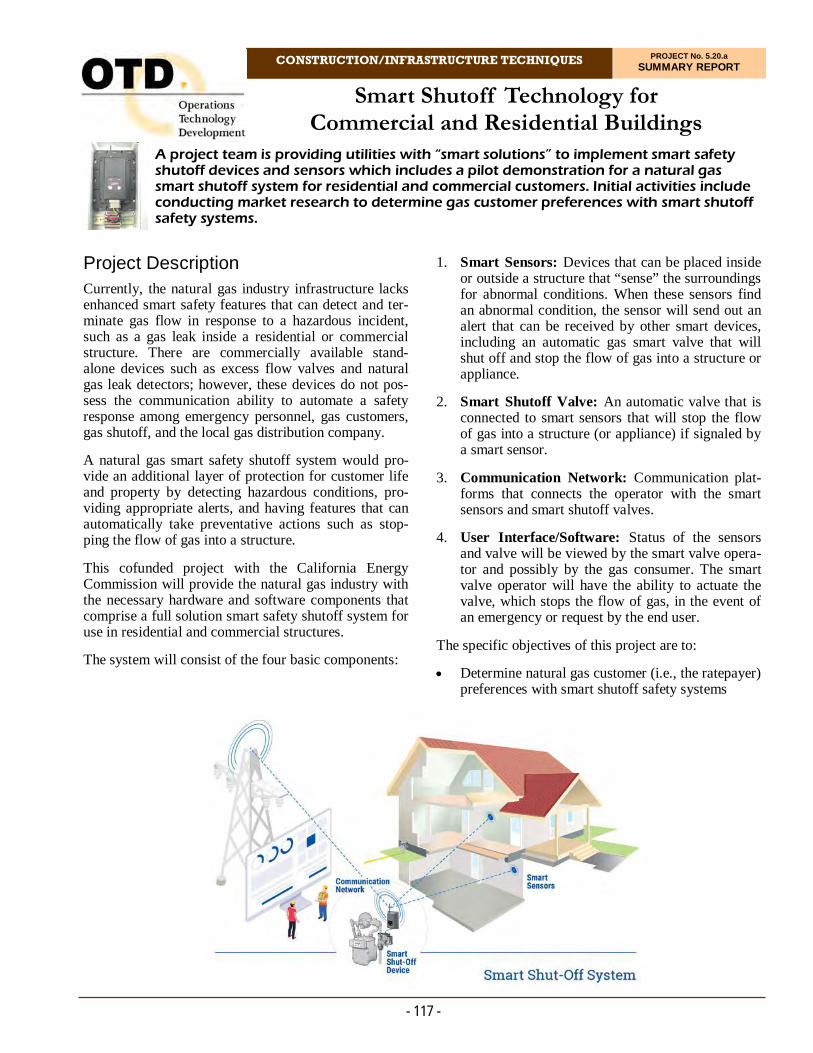
Smart Shutoff Technology for Commercial and Residential Buildings
CONSTRUCTION/INFRASTRUCTURE TECHNIQUES PROJECT No. 5.20.a SUMMARY REPORT
- 117 -
Project Description Currently, the natural gas industry infrastructure lacks enhanced smart safety features that can detect and ter-minate gas flow in response to a hazardous incident, such as a gas leak inside a residential or commercial structure. There are commercially available stand-alone devices such as excess flow valves and natural gas leak detectors; however, these devices do not pos-sess the communication ability to automate a safety response among emergency personnel, gas customers, gas shutoff, and the local gas distribution company.
A natural gas smart safety shutoff system would pro-vide an additional layer of protection for customer life and property by detecting hazardous conditions, pro-viding appropriate alerts, and having features that can automatically take preventative actions such as stop-ping the flow of gas into a structure.
This cofunded project with the California Energy Commission will provide the natural gas industry with the necessary hardware and software components that comprise a full solution smart safety shutoff system for use in residential and commercial structures.
The system will consist of the four basic components:
1. Smart Sensors: Devices that can be placed inside or outside a structure that “sense” the surroundings for abnormal conditions. When these sensors find an abnormal condition, the sensor will send out an alert that can be received by other smart devices, including an automatic gas smart valve that will shut off and stop the flow of gas into a structure or appliance.
2. Smart Shutoff Valve: An automatic valve that is connected to smart sensors that will stop the flow of gas into a structure (or appliance) if signaled by a smart sensor.
3. Communication Network: Communication plat-forms that connects the operator with the smart sensors and smart shutoff valves.
4. User Interface/Software: Status of the sensors and valve will be viewed by the smart valve opera-tor and possibly by the gas consumer. The smart valve operator will have the ability to actuate the valve, which stops the flow of gas, in the event of an emergency or request by the end user.
The specific objectives of this project are to:
Determine natural gas customer (i.e., the ratepayer) preferences with smart shutoff safety systems
A project team is providing utilities with “smart solutions” to implement smart safety shutoff devices and sensors which includes a pilot demonstration for a natural gas smart shutoff system for residential and commercial customers. Initial activities include conducting market research to determine gas customer preferences with smart shutoff safety systems.
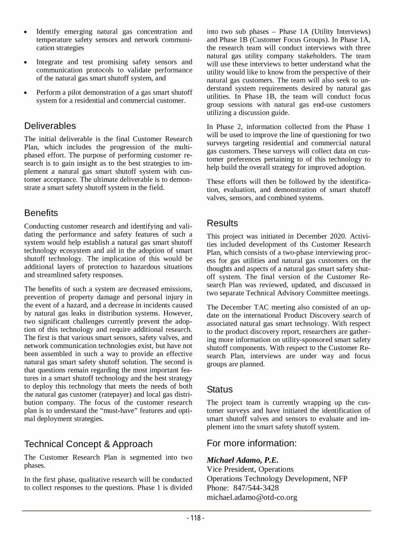
- 118 -
into two sub phases – Phase 1A (Utility Interviews) and Phase 1B (Customer Focus Groups). In Phase 1A, the research team will conduct interviews with three natural gas utility company stakeholders. The team will use these interviews to better understand what the utility would like to know from the perspective of their natural gas customers. The team will also seek to un-derstand system requirements desired by natural gas utilities. In Phase 1B, the team will conduct focus group sessions with natural gas end-use customers utilizing a discussion guide.
In Phase 2, information collected from the Phase 1 will be used to improve the line of questioning for two surveys targeting residential and commercial natural gas customers. These surveys will collect data on cus-tomer preferences pertaining to of this technology to help build the overall strategy for improved adoption.
These efforts will then be followed by the identifica-tion, evaluation, and demonstration of smart shutoff valves, sensors, and combined systems.
Results This project was initiated in December 2020. Activi-ties included development of ths Customer Research Plan, which consists of a two-phase interviewing proc-ess for gas utilities and natural gas customers on the thoughts and aspects of a natural gas smart safety shut-off system. The final version of the Customer Re-search Plan was reviewed, updated, and discussed in two separate Technical Advisory Committee meetings.
The December TAC meeting also consisted of an up-date on the international Product Discovery search of associated natural gas smart technology. With respect to the product discovery report, researchers are gather-ing more information on utility-sponsored smart safety shutoff components. With respect to the Customer Re-search Plan, interviews are under way and focus groups are planned.
Status The project team is currently wrapping up the cus-tomer surveys and have initiated the identification of smart shutoff valves and sensors to evaluate and im-plement into the smart safety shutoff system.
Identify emerging natural gas concentration and temperature safety sensors and network communi-cation strategies
Integrate and test promising safety sensors and communication protocols to validate performance of the natural gas smart shutoff system, and
Perform a pilot demonstration of a gas smart shutoff system for a residential and commercial customer.
Deliverables The initial deliverable is the final Customer Research Plan, which includes the progression of the multi-phased effort. The purpose of performing customer re-search is to gain insight as to the best strategies to im-plement a natural gas smart shutoff system with cus-tomer acceptance. The ultimate deliverable is to demon-strate a smart safety shutoff system in the field.
Benefits Conducting customer research and identifying and vali-dating the performance and safety features of such a system would help establish a natural gas smart shutoff technology ecosystem and aid in the adoption of smart shutoff technology. The implication of this would be additional layers of protection to hazardous situations and streamlined safety responses.
The benefits of such a system are decreased emissions, prevention of property damage and personal injury in the event of a hazard, and a decrease in incidents caused by natural gas leaks in distribution systems. However, two significant challenges currently prevent the adop-tion of this technology and require additional research. The first is that various smart sensors, safety valves, and network communication technologies exist, but have not been assembled in such a way to provide an effective natural gas smart safety shutoff solution. The second is that questions remain regarding the most important fea-tures in a smart shutoff technology and the best strategy to deploy this technology that meets the needs of both the natural gas customer (ratepayer) and local gas distri-bution company. The focus of the customer research plan is to understand the “must-have” features and opti-mal deployment strategies.
Technical Concept & Approach The Customer Research Plan is segmented into two phases.
In the first phase, qualitative research will be conducted to collect responses to the questions. Phase 1 is divided
For more information:
Michael Adamo, P.E. Vice President, Operations Operations Technology Development, NFP Phone: 847/544-3428 [email protected]
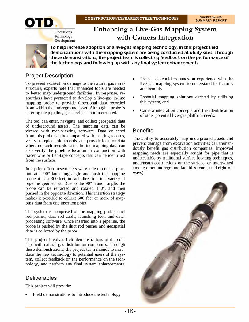
Enhancing a Live-Gas Mapping System with Camera Integration
CONSTRUCTION/INFRASTRUCTURE TECHNIQUES PROJECT No. 5.20.l SUMMARY REPORT
- 119 -
Project Description To prevent excavation damage to the natural gas infra-structure, experts note that enhanced tools are needed to better map underground facilities. In response, re-searchers have partnered to develop a live-gas in-line mapping probe to provide directional data recorded from within the underground asset. Although a probe is entering the pipeline, gas service is not interrupted.
The tool can enter, navigate, and collect geospatial data of underground assets. The mapping data can be viewed with map-viewing software. Data collected from this probe can be compared with existing records, verify or replace old records, and provide location data where no such records exist. In-line mapping data can also verify the pipeline location in conjunction with tracer wire or fish-tape concepts that can be identified from the surface.
In a prior effort, researchers were able to enter a pipe-line at a 90° launching angle and push the mapping probe at least 300 feet, in each direction, in a variety of pipeline geometries. Due to the 90° launch angle, the probe can be retracted and rotated 180°, and then pushed in the opposite direction. This insertion strategy makes it possible to collect 600 feet or more of map-ping data from one insertion point.
The system is comprised of the mapping probe, duct rod pusher, duct rod cable, launching tool, and data-processing software. Once inserted into a pipeline, the probe is pushed by the duct rod pusher and geospatial data is collected by the probe.
This project involves field demonstrations of the con-cept with natural gas distribution companies. Through these demonstrations, the project team intends to intro-duce the new technology to potential users of the sys-tem, collect feedback on the performance on the tech-nology, and perform any final system enhancements.
Deliverables
This project will provide:
Field demonstrations to introduce the technology
Project stakeholders hands-on experience with the live-gas mapping system to understand its features and benefits
Potential mapping solutions derived by utilizing this system, and
Camera integration concepts and the identification of other potential live-gas platform needs.
Benefits The ability to accurately map underground assets and prevent damage from excavation activities can tremen-dously benefit gas distribution companies. Improved mapping needs are especially sought for pipe that is undetectable by traditional surface locating techniques, underneath obstructions on the surface, or intertwined among other underground facilities (congested right-of-ways).
To help increase adoption of a live-gas mapping technology, in this project field demonstrations with the mapping system are being conducted at utility sites. Through these demonstrations, the project team is collecting feedback on the performance of the technology and following up with any final system enhancements.

- 120 -
directional travel. The integrated system achieved a total pushing length of 600 feet. During the length as-sessment, the probe travelled the entire length of pipe available for testing; therefore, the team is confident the probe can travel much further. Data collected from the mapping probe can be easily stored and viewed. This will assist Geographic Information Systems teams in updating databases with high-accuracy data or provide accurate mapping data prior to construction work.
The team successfully completed live demonstrations with four natural gas utilities.
In an effort to smooth the entry of the probe into the pipe, the team added an additional spring in the three-egg design. Additionally, the team optimized the space on the printed circuit board to remove some unused connections. This has shrunk the diameter of the egg approximately 3 mm.
Status The project team collected enough operational and end-use feedback to refine the overall design for a commercial product. The live gas mapping system will be commercially available in 2021 through PRISUM Technologies.
A technical report was issued in December 2020.
A mapping technology that can provide accurate data from inside the pipe would provide the advantage of verifying mapping data and creating a digital record of the existing gas system.
Enhanced mapping tools would also lower project costs by displaying underground elevation data and reducing the risk involved with excavations.
Technical Concept & Approach
During field demonstrations, the project team will col-lect and incorporate feedback to enhance the safety and operational efficiency of the mapping system.
Researchers will continue to refine software visualiza-tion tools to improve the ability to view 3D features col-lected by the mapping probe.
Feedback will be collected on camera integration needs and requirements during the field demonstration. With this feedback, the research team will identify potential integration partners and begin process design and con-ceptualization.
Results
Through this research effort, an externally driven map-ping probe was developed that can accurately map un-derground pipeline locations within a six-inch window of the centerline of the pipeline. The probe provides location data from inside the pipe, meaning that there is no reliance on acquiring location data from the surface to detail the coordinates of the pipe. It should be noted that the duct rod which propels the mapping probe was integrated with a tracer wire, so surface locates are pos-sible if needed.
The probe can enter two-inch and larger diameter pipe at an upright 90° angle which enables two-way bi-
For more information:
Michael Adamo, P.E. Vice President, Operations Operations Technology Development, NFP Phone: 847/544-3428 [email protected]
Simulated computer-generated design concepts for 90° pipeline entry in two-inch- (left) and four-inch- (right) diameter pipe.

Product Performance and Validation Program
CONSTRUCTION/INFRASTRUCTURE TECHNIQUES PROJECT No. 5.20.m SUMMARY REPORT
- 121 -
Project Description Requirements to validate product performances at the design level are well defined in various industry stan-dards. In the natural gas industry, the requirements out-line comprehensive testing protocols to evaluate prod-uct design or re-design, material, and production proc-esses.
In the commercial manufacturing environment, pro-duction processes (equipment, technology, etc.) throughout the lifecycle of a product are constantly changing. Industry standards – with some exception –have no requirements to address these types of changes.
There are a few examples in the natural gas industry of standards that require ongoing product testing. For ex-ample, ASTM D2513 requires semi-annual extrusion process qualification of a PE pipe, and CEN 1555-7 (European standard) requires ongoing process verifica-tion testing for electrofusion fittings to confirm that tests originally performed on products or joints/assemblies at the design level continue to be valid and the process continues to be capable of producing prod-ucts that conform to the requirements given in the rele-vant standards and customer specifications. However, based on the observations made during the last six years of quality auditing, the process of ongoing prod-uct validation has not been adopted and implemented by most manufacturers due to a lack of industry re-quirements and increased pressure to improve effi-ciency and reduce costs. Therefore, there is a need for an ongoing standardized product-testing program that will complement current quality auditing and material-supplier quality-assurance programs.
These validation-testing activities along with the qual-ity programs completes the product-quality assessment efforts necessary to allow for a robust control of sup-pliers and the products used by natural gas utilities.
This program will compare performances of similar products from various suppliers to help in making in-formed decisions for their continued usage. This pro-gram also has the ability to assist in the approval proc-ess for new product lines or components.
Deliverables The deliverables of the program will be individual re-ports for each set of tests by product type and an an-nual final summary report of the comparison of prod-uct performances
Benefits The goals of this program are to:
Create efficiencies and cost savings by consolidat-ing the validation and testing of products shared by the sponsors
Assess if products meet the requirements of the industry standards and customers
Provide information on product performance to make more informed choices
Provide information that can be used during an annual evaluation of suppliers
Provide information for the approval of a new sup-plier/product, and
For this project, researchers are creating a program to validate gas-industry product performances to confirm that manufacturers still produce high-quality material meeting customer and industry requirements. The program compares performances of similar products from various suppliers to help in making informed decisions for their continued usage.

- 122 -
Results The project team held a kick-off meeting in September 2020 to review the scope of work, schedule, and budget. It was discussed that a survey be developed and sent to the project sponsors to gather information regarding material, product type, and product configu-ration to be tested in the first year of the program.
Questions were raised concerning corrective actions in the event of product failures during testing and pro-curement of the samples. It was decided that samples will be purchased directly from distributors and that the project team would take the lead and follow up on corrective actions and their resolutions. The requests for corrective actions will be issued for methods re-quired by the industry standards.
GTI submitted a Microsoft Forms survey to the project sponsors in October. The survey asks a series of ques-tions that will narrow down the range of products for testing.
Status
The following activities are scheduled for execution:
1. Review the information provided by the sponsors in the survey
2. Create a matrix of product material, type configu-ration, and joint type and send the matrix to the sponsors to finalize the product selection
3. Create a final list of products for testing
4. Identify test methods and sampling plan
5. Establish technical working group members, and
6. Begin product procurement.
Allow sponsors to enhance their internal quality-management systems.
Technical Concept & Approach This program will create an ongoing testing-validation process for products and materials used in the natural gas distribution industry.
The product selection will be based on a decision tree that will help to identify the pertinent candidates.
The following categories for selection may be consid-ered:
Criticality
Product type
Suppliers’ site
Size
Product configuration
Sponsor’s infrastructure, and
Working conditions.
The test methods employed will be based on the re-quirements of relevant industry standards and sponsor requirements. Some testing efforts may be enhanced with additional test methods based on the experience and knowledge of subject matter experts in the field.
A centralized location (database) will be created to col-lect and maintain test data. Means and methods to pro-vide access to data will be considered.
Testing activities include sample collection/procure-ment, sample preparation, and testing. The number of samples to be prepared will be determined based on testing and evaluation needs discussed and finalized with project sponsors.
Testing will include four sets of tests of electrofusion fittings during the first year of the program, where one set is comprised of 30-36 samples of the same product size/manufacturer/product type/product material fused to the same pipe type to undergo a variety of tests, in-cluding:
Dimensional Analysis
Quick Burst
Sustained Pressure
Peel, and
Tensile or impact.
For more information:
Michael Adamo, P.E. Vice President, Operations Operations Technology Development, NFP Phone: 847/544-3428 [email protected]
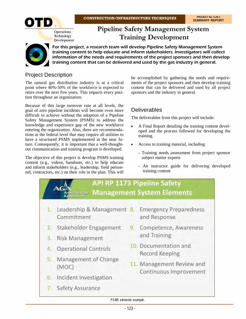
Pipeline Safety Management System Training Development
CONSTRUCTION/INFRASTRUCTURE TECHNIQUES PROJECT No. 5.20.n SUMMARY REPORT
- 123 -
Project Description The natural gas distribution industry is at a critical point where 40%-50% of the workforce is expected to retire over the next five years. This impacts every posi-tion throughout an organization.
Because of this large turnover rate at all levels, the goal of zero pipeline incidents will become even more difficult to achieve without the adoption of a Pipeline Safety Management System (PSMS) to address the knowledge and experience gap of the new workforce entering the organization. Also, there are recommenda-tions at the federal level that may require all utilities to have a structured PSMS implemented in the near fu-ture. Consequently, it is important that a well-thought-out communication and training program is developed.
The objective of this project is develop PSMS training content (e.g., videos, handouts, etc.) to help educate and inform stakeholders (e.g., leadership, field person-nel, contractors, etc.) on their role in the plan. This will
be accomplished by gathering the needs and require-ments of the project sponsors and then develop training content that can be delivered and used by all project sponsors and the industry in general.
Deliverables The deliverables from this project will include:
A Final Report detailing the training content devel-oped and the process followed for developing the training.
Access to training material, including
- Training needs assessment from project sponsor subject matter experts
- An instructor guide for delivering developed training content
For this project, a research team will develop Pipeline Safety Management System training content to help educate and inform stakeholders. Investigators will collect information of the needs and requirements of the project sponsors and then develop training content that can be delivered and used by the gas industry in general.
PSMS elements example.

- 124 -
portunity to complete and evaluate the training in ad-vance of an organizational-wide release. The pilot test feedback will then be used for making any updates to the training content and/or delivery method(s).
Results Initial project activities included participating in a PSMS webinar hosted by the American Petroleum In-stitute.
Status
The research team is:
Identifying subject matter experts from project sponsors to participate in the development of PSMS training content,
Completing project scoping activities, and
Identifying PSMS learning objectives to develop training content.
- Handouts for new training content
- Computer-based training modules, and
- Access to a delivery platform.
Benefits Development of common training content will provide:
Consistent training related to PSMS, which will help reduce additional scrutiny at the state commis-sion level for needing customized training
A more knowledgeable industry on the subject of PSMS as a whole, beyond those organizations with only dedicated PSMS staff
Reduced training-development expenses as a result of pooling funds, and
Improved training content as a result of identifying PSMS training needs and requirements.
Technical Concept & Approach
Eleven elements of a PSMS will be used as a starting point for identifying and organizing the training curricu-lum. In addition, the different stakeholder audiences (e.g., leadership, field staff, contractors, etc.) will be identified.
The project team will conduct a pilot test of the devel-oped PSMS training content with project sponsors. The stakeholders of each training module will have an op-
For more information:
Michael Adamo, P.E. Vice President, Operations Operations Technology Development, NFP Phone: 847/544-3428 [email protected]

CONSTRUCTION/INFRASTRUCTURE TECHNIQUES PROJECT No. 6.14.a SUMMARY REPORT
Project Description Distribution integrity management regulations encour-age utility companies to place a new focus on supplier and supply chain quality. Identifying threats and miti-gating risks starts with the manufacturing process.
Reducing supply-chain risk requires a comprehensive and well-coordinated supplier audit program to ensure that the integrity of the supply chain is controlled and that the supplier is following policies and procedures required by customers and regulators. Supplier audits identify non-conformances in manufacturing, shipping, engineering, and quality processes. Post audit, the sup-plier and auditors identify corrective actions which must be implemented by the supplier within an agreed-upon timeframe. Future audits ensure that these corrective actions have been successfully implemented.
While the need for enhanced quality audits and monitor-ing programs is increasing, the availability of resources to conduct these programs is decreasing due to a focus on operations and efficiencies.
This program was created to provide natural gas utility operators with a mechanism to collaboratively audit sup-pliers’ quality-management systems. The program con-ducts independent and unbiased assessments on behalf of participating operators to provide a reliable and stan-dardized approach for monitoring suppliers.
Deliverables The deliverables for the program will be reports for each audit and annual summary reports. Only program mem-bers are eligible to receive the audit findings reports.
Researchers will also track the performance of suppliers against metrics and will follow-up on identified defi-ciencies and corrective actions.
An annual workshop is conducted to summarize audit findings and prepare a preliminary list of potential can-didates for the following year’s audits.
This program provides gas utility operators with a mechanism to collaboratively audit suppliers’ quality-management systems. Experts conduct independent and unbiased assessments on behalf of participating operators to provide a reliable and standardized approach for monitoring suppliers.
Quality Audit Program for Natural Gas Utility Suppliers
Benefits Participation in a collaborative audit program provides value in the following ways:
Creates efficiencies and cost savings by consoli-dating audits into one program
Increases the number of audits performed
Creates leverage and increases influence with sup-pliers
Utilizes certified auditors with extensive experi-ence
Provides high-quality audits due to consistency and standardization of the audit methodology, and
Allows internal resources to focus on the core business rather than auditing.
Technical Concept & Approach The audits performed are based on the process ap-proach methodology of the ISO 9001:2015 Quality Management Systems per the requirements and inquir-ies from sponsors. Since 2015, the criteria/scope of the audits changed to focus more on industry standards and utility requirements.
- 125 -
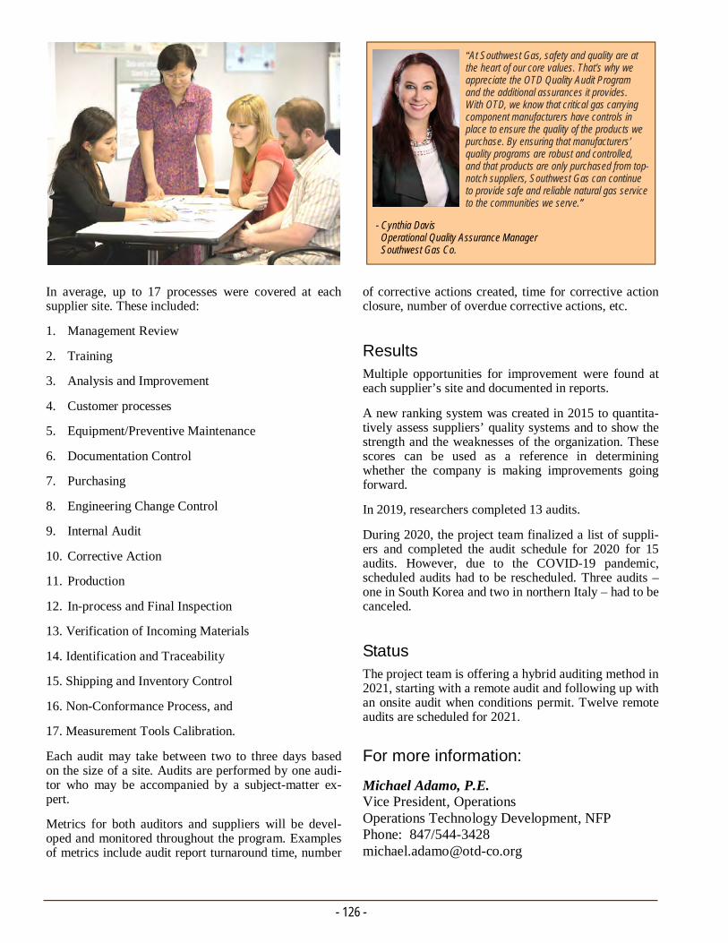
In average, up to 17 processes were covered at each supplier site. These included:
1. Management Review
2. Training
3. Analysis and Improvement
4. Customer processes
5. Equipment/Preventive Maintenance
6. Documentation Control
7. Purchasing
8. Engineering Change Control
9. Internal Audit
10. Corrective Action
11. Production
12. In-process and Final Inspection
13. Verification of Incoming Materials
14. Identification and Traceability
15. Shipping and Inventory Control
16. Non-Conformance Process, and
17. Measurement Tools Calibration.
Each audit may take between two to three days based on the size of a site. Audits are performed by one audi-tor who may be accompanied by a subject-matter ex-pert.
Metrics for both auditors and suppliers will be devel-oped and monitored throughout the program. Examples of metrics include audit report turnaround time, number
- 126 -
of corrective actions created, time for corrective action closure, number of overdue corrective actions, etc.
Results Multiple opportunities for improvement were found at each supplier’s site and documented in reports.
A new ranking system was created in 2015 to quantita-tively assess suppliers’ quality systems and to show the strength and the weaknesses of the organization. These scores can be used as a reference in determining whether the company is making improvements going forward.
In 2019, researchers completed 13 audits.
During 2020, the project team finalized a list of suppli-ers and completed the audit schedule for 2020 for 15 audits. However, due to the COVID-19 pandemic, scheduled audits had to be rescheduled. Three audits – one in South Korea and two in northern Italy – had to be canceled.
Status The project team is offering a hybrid auditing method in 2021, starting with a remote audit and following up with an onsite audit when conditions permit. Twelve remote audits are scheduled for 2021.
For more information:
Michael Adamo, P.E. Vice President, Operations Operations Technology Development, NFP Phone: 847/544-3428 [email protected]
- Cynthia Davis Operational Quality Assurance Manager Southwest Gas Co.
“At Southwest Gas, safety and quality are at the heart of our core values. That’s why we appreciate the OTD Quality Audit Program and the additional assurances it provides. With OTD, we know that critical gas carrying component manufacturers have controls in place to ensure the quality of the products we purchase. By ensuring that manufacturers’ quality programs are robust and controlled, and that products are only purchased from top-notch suppliers, Southwest Gas can continue to provide safe and reliable natural gas service to the communities we serve.”
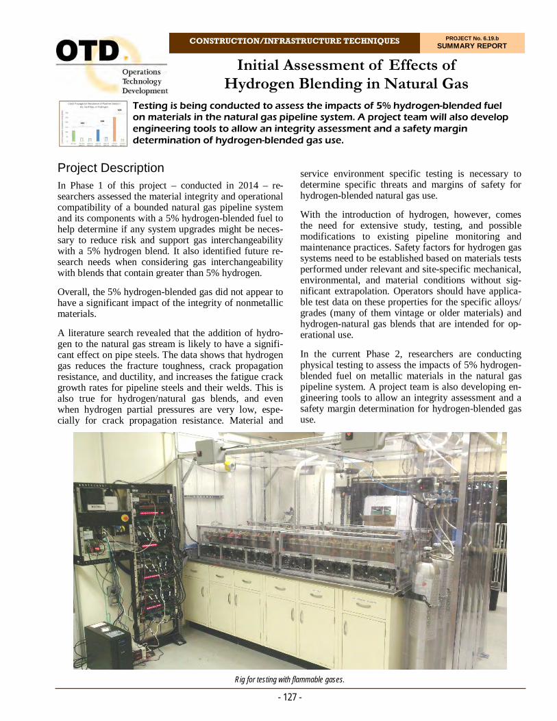
CONSTRUCTION/INFRASTRUCTURE TECHNIQUES PROJECT No. 6.19.b SUMMARY REPORT
Project Description In Phase 1 of this project – conducted in 2014 – re-searchers assessed the material integrity and operational compatibility of a bounded natural gas pipeline system and its components with a 5% hydrogen-blended fuel to help determine if any system upgrades might be neces-sary to reduce risk and support gas interchangeability with a 5% hydrogen blend. It also identified future re-search needs when considering gas interchangeability with blends that contain greater than 5% hydrogen.
Overall, the 5% hydrogen-blended gas did not appear to have a significant impact of the integrity of nonmetallic materials.
A literature search revealed that the addition of hydro-gen to the natural gas stream is likely to have a signifi-cant effect on pipe steels. The data shows that hydrogen gas reduces the fracture toughness, crack propagation resistance, and ductility, and increases the fatigue crack growth rates for pipeline steels and their welds. This is also true for hydrogen/natural gas blends, and even when hydrogen partial pressures are very low, espe-cially for crack propagation resistance. Material and
Testing is being conducted to assess the impacts of 5% hydrogen-blended fuel on materials in the natural gas pipeline system. A project team will also develop engineering tools to allow an integrity assessment and a safety margin determination of hydrogen-blended gas use.
Initial Assessment of Effects of Hydrogen Blending in Natural Gas
service environment specific testing is necessary to determine specific threats and margins of safety for hydrogen-blended natural gas use.
With the introduction of hydrogen, however, comes the need for extensive study, testing, and possible modifications to existing pipeline monitoring and maintenance practices. Safety factors for hydrogen gas systems need to be established based on materials tests performed under relevant and site-specific mechanical, environmental, and material conditions without sig-nificant extrapolation. Operators should have applica-ble test data on these properties for the specific alloys/grades (many of them vintage or older materials) and hydrogen-natural gas blends that are intended for op-erational use.
In the current Phase 2, researchers are conducting physical testing to assess the impacts of 5% hydrogen-blended fuel on metallic materials in the natural gas pipeline system. A project team is also developing en-gineering tools to allow an integrity assessment and a safety margin determination for hydrogen-blended gas use.
- 127 -
Rig for testing with flammable gases.

- 128 -
For more information:
Michael Adamo, P.E. Vice President, Operations Operations Technology Development, NFP Phone: 847/544-3428 [email protected]
A DoE approach to develop and ensure that the test-ing matrix covered all the right combinations and minimized the uncertainty and error, and
Calculated parameters/values needed to make engi-neering decisions.
In Phase 2, the investigators will establish the hydrogen-blend service and environmental conditions desired. Researchers will obtain vintage metallic pipeline mate-rials and new materials for physical testing.
The project team will develop a set of laboratory testing requirements. This will include a detailed review of the available standards and test methods in the literature.
Results
Preliminary test results were promising in that they do not indicate any degradation of the material properties with regard to the ductile failure mode.
In 2019, nearly 100 related hydrogen documents, re-ports, and references were collected for review, with the next step to establish the hydrogen-blend use cases with the sponsors. A use-case survey was distributed to the sponsors. The team also collected, organized, and pre-sented the project use cases.
In 2020, the team continued collecting and summarizing related hydrogen documents, reports, and references. The team collected more than 240 references, focusing on articles that contain experimental methods and re-sults.
The team began construction of the technical standards and testing matrix based on the literature search and review results.
Additional effort was conducted to coordinate this pro-ject with other national efforts to ensure no duplication with other projects and the most efficient use of re-sources, time, and samples between all stakeholders. Status The team continues to collect and summarize related hydrogen documents. Researchers are reviewing re-sponses to a sponsor survey to determine the system parameters for the most likely use cases.
Deliverables Sponsor-approved hydrogen-blend use case to
bound testing and engineering modeling require-ments
Set of vintage and new material testing samples
Physical testing and design plans
Final Report and webinar, and
Detailed plan for Phase 3 to execute testing, mod-eling, and development of reliability and engineer-ing tools.
Benefits As the natural gas industry moves towards reducing environmental impacts, exploring opportunities for renewable projects and de-carbonizing the pipeline are becoming more important. Companies are now evalu-ating renewable power-to-gas projects, including blending hydrogen into natural gas pipelines, which not only reduces greenhouse emissions, but also takes ad-vantage of an existing infrastructure for effective means of delivery to customers. This also presents new business opportunities for increased distribution reve-nues if pipelines are transporting new incremental sup-plies of renewable fuel and storage revenues for elec-tricity energy storage using hydrogen.
A study will provide the objective information neces-sary to: 1) support the pipeline industry’s transition to a future requiring increased flexibility, 2) assess the ma-terial integrity and operational compatibility of a natu-ral gas pipeline system with 5% hydrogen-blended fuel, 3) help to determine what, if any, system upgrades might be necessary, and 4) identify future research.
Technical Concept & Approach The Phase 2 project scope includes obtaining system-specific data and materials, formulating a Design of Experiment (DoE) approach, calculating parameters needed to make engineering decisions, and ultimately creating engineering tools to characterize the effect of hydrogen blending on a specific system.
Based on the literature review conducted in the Phase 1 effort, to avoid pipeline failure/rupture due to hydro-gen-blended gas effects, there is an essential set of in-formation needed for a specific steel pipeline system:
Engineering tools - calculations/plots
Measure material and physical parameters needed to make engineering decisions
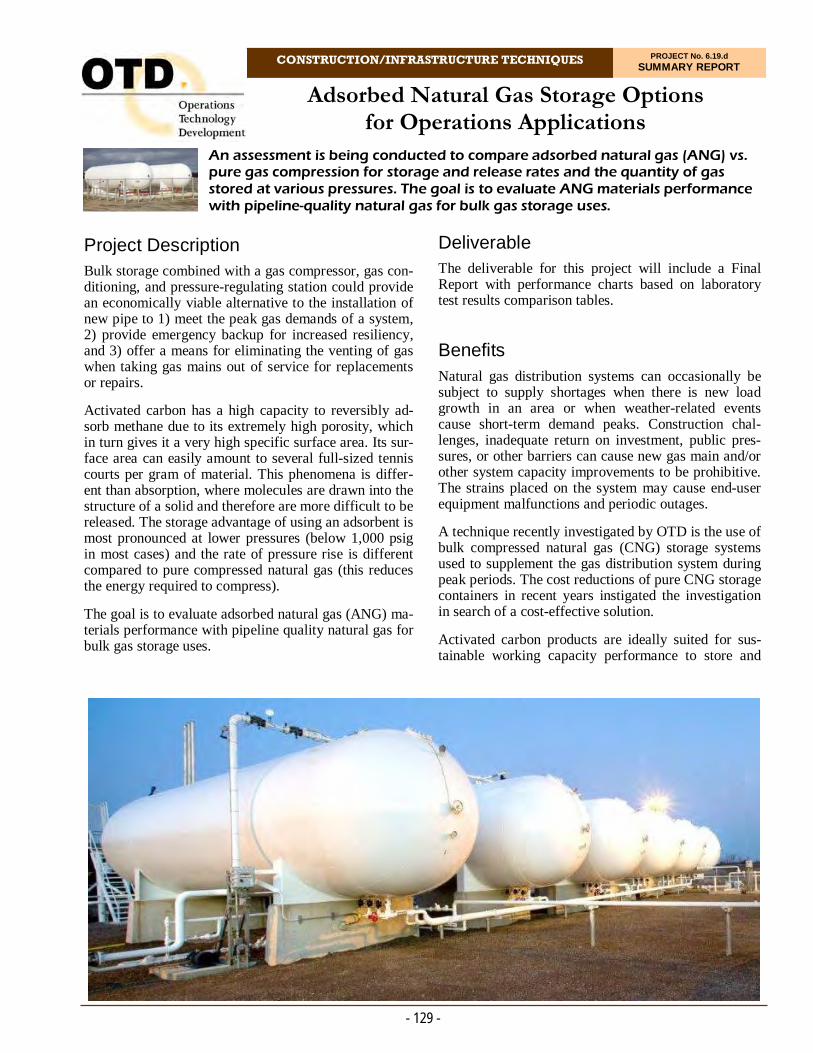
CONSTRUCTION/INFRASTRUCTURE TECHNIQUES PROJECT No. 6.19.d SUMMARY REPORT
Project Description Bulk storage combined with a gas compressor, gas con-ditioning, and pressure-regulating station could provide an economically viable alternative to the installation of new pipe to 1) meet the peak gas demands of a system, 2) provide emergency backup for increased resiliency, and 3) offer a means for eliminating the venting of gas when taking gas mains out of service for replacements or repairs.
Activated carbon has a high capacity to reversibly ad-sorb methane due to its extremely high porosity, which in turn gives it a very high specific surface area. Its sur-face area can easily amount to several full-sized tennis courts per gram of material. This phenomena is differ-ent than absorption, where molecules are drawn into the structure of a solid and therefore are more difficult to be released. The storage advantage of using an adsorbent is most pronounced at lower pressures (below 1,000 psig in most cases) and the rate of pressure rise is different compared to pure compressed natural gas (this reduces the energy required to compress).
The goal is to evaluate adsorbed natural gas (ANG) ma-terials performance with pipeline quality natural gas for bulk gas storage uses.
An assessment is being conducted to compare adsorbed natural gas (ANG) vs. pure gas compression for storage and release rates and the quantity of gas stored at various pressures. The goal is to evaluate ANG materials performance with pipeline-quality natural gas for bulk gas storage uses.
Adsorbed Natural Gas Storage Options for Operations Applications
Deliverable The deliverable for this project will include a Final Report with performance charts based on laboratory test results comparison tables.
Benefits Natural gas distribution systems can occasionally be subject to supply shortages when there is new load growth in an area or when weather-related events cause short-term demand peaks. Construction chal-lenges, inadequate return on investment, public pres-sures, or other barriers can cause new gas main and/or other system capacity improvements to be prohibitive. The strains placed on the system may cause end-user equipment malfunctions and periodic outages.
A technique recently investigated by OTD is the use of bulk compressed natural gas (CNG) storage systems used to supplement the gas distribution system during peak periods. The cost reductions of pure CNG storage containers in recent years instigated the investigation in search of a cost-effective solution.
Activated carbon products are ideally suited for sus-tainable working capacity performance to store and
- 129 -
- 130 -
For more information:
Michael Adamo, P.E. Vice President, Operations Operations Technology Development, NFP Phone: 847/544-3428 [email protected]
Results In 2019, results from previously conducted research on bulk storage solutions were reviewed to ascertain addi-tional use cases and define system supply require-ments. Attributes studied included required storage capacity, typical peak period durations, desired storage system recovery times, and desired discharge flow rates.
The research team surveyed project sponsors to better understand their needs, desired use cases, and system characteristics to ensure that the project approach will be based on real-world requirements.
In 2020, the project team linked with a chemical manufacturer to discuss scope, schedule, budget, roles, and responsibilities related to testing in a 48-inch-diameter CNG sphere.
Additionally, the project team analyzed new prelimi-nary testing results that indicate that scale up of ANG from benchscale testing is a significant barrier to devel-oping this technology.
Tests conducted by another company were especially large scale. The project team noted that the storage per-formance of the ANG for the scaled-up conditions was in both cases reduced compared to the benchscale trials conducted previously.
A cost estimate and a scope summary were prepared for bulk ANG testing.
Status
The project team will proceed with the design of an experimental apparatus, safety review, and equipment ordering.
release mixed hydrocarbon vapors such as gasoline and natural gas. By tailoring an activated carbon ad-sorbent sorbent from renewable raw materials, one company claims its product will hold up to three times the amount of methane as compressed gas at 230 psig.
The use of adsorbents particularly enhances the gas storage performance at lower pressures, which could improve the overall economics surrounding bulk gas storage investment and operating costs. As a result, sig-nificant cost savings potential exists from using much smaller tanks for the same volume of stored natural gas. Other potential applications for ANG include on-site emergency backup storage, low-pressure recovery, and reuse of flare gas, as well as low energy demand virtual pipeline.
Technical Concept & Approach Specific tasks for this project include:
Literature Search and Materials Specifications Gathering
Specifications were gathered to assess potential concerns with the ability to be impacted by odor-ants, higher hydrocarbons, moisture, and/or other factors.
Develop Test Plan and Prepare Laboratory and Data Acquisition
A specific test plan will be developed to guide re-searchers in obtaining the needed data to validate the claims by the manufacturer. In addition, the proper measurement and data-collection require-ments will be identified.
Laboratory Testing and Data Analysis
This task involves testing bulk-granular material to produce meaningful results at a scale adequate to model performance at larger gas utility application sizes. Data collection will take place at a variety of pressures and temperatures while varying the input and discharge flow rates.
There are several critical questions to be answered in order to fully assess the value of ANG for the scale, duty cycle, and applications. Namely, the cycle life degradation of the material when used with pipeline-quality natural gas is not fully understood. To date, most testing of ANG substrates has been conducted with pure methane in which the data shows an attrac-tive less than 5% loss over the life of the adsorbent; but the impact of heavier hydrocarbons being present is not known. Additionally, the effects of other constitu-ents in natural gas such as odorants, moisture, and natural gas liquids will need to be explored.
- Kevin Moen Business Development Manager Ingevity
““Ingevity has leveraged our 100 years of activated carbon expertise to enable adsorbed natural gas (ANG) vehicle technology for light-duty trucks. This technology is already being utilized on bi-fuel Ford F-150 trucks with utility providers across the U.S. We are currently focusing additional resources on ways ANG can be applied to other applications.”

METHANE EMISSIONS/DETECTION & GAS QUALITY
Significant initiatives in this area are addressing greenhouse-gas issues, methods for estimating pipeline leak emissions, and remote gas
sensing and monitoring. Research teams are also investigating gas-imaging techniques, biomethane monitoring, robots, drones,
and various sensors and methane-detection devices.
Results from these efforts help companies to reduce operations costs, minimize environmental impacts, and more cost effectively
comply with regulations. .


Residential Methane Detectors Program
METHANE EMISSION/DETECTION & GAS QUALITY PROJECT No. 1.14.g SUMMARY REPORT
This project developed a comprehensive residential methane detector (RMD) strategy that included market research, technical evaluation of current RMDs on the market, proposed changes to testing standards, and a nationwide pilot program.
Benefits The results of this research allow utility companies to add to their environmental and safety public-awareness programs by offering technically validated information regarding the reliability and enhanced safety that in-home methane detectors can provide.
Technical Concept & Approach Specific tasks include:
Consumer Behavior Study
Although RMDs are currently available, there is not widespread adoption and a general lack of awareness of these safety devices exists. This type of study complements existing market research on low customer adoption of gas detectors and cus-tomer responses in regards to leaks. The study looks at issues such as limitations in consumer
- 133 -
Project Description In this program, several discrete initiatives were con-ducted, with activities focused on 1) a consumer be-havior study to better understand how customers react to potential leaks and 2) the development of a “Fit-for-Purpose” standard for residential methane detectors.
This project also included a pilot program to evaluate commercially available detectors that performed well during laboratory evaluations. The pilot program in-vestigated the performance of the detectors in actual home settings, consumer responses to alarms, and so-licited feedback on what users felt about the detectors.
Deliverables
The deliverables for this program include: 1) A fit-for-purpose methane alarm threshold determination; 2) a revised standard testing protocol; 3) a consumer behav-ior study; and 4) pilot study and recommendations.
Environmental test chamber.

- 134 -
In 2016, the pilot program was initiated and a test plan developed. Three manufacturers were selected based on market share and performance in previous test phases. Approximately 1,000 detectors were installed in residential homes for up to a one-year period. Each participating utility was responsible for installation according to manufacturers’ instructions. During de-ployment, several alarms were reported with one a confirmed methane leak by the utility. The detectors were tested to determine how repeatable the original responses were. Two commercially available detectors had excellent performance. The biggest feedback com-plaint was the need for cords to power the RMDs, showing that development and commercialization of battery-powered devices is critical.
In 2018, the project team completed the “Fit for Pur-pose” recommended standard revisions to UL and completed testing the next tier of detectors. The final recommendation was an alarm threshold of 10% LEL methane in air. Researchers became involved in draft-ing a new National Fire Protection Agency (NFPA) standard for installation of fuel gases detection and warning equipment. This effort is still ongoing.
Phase 4 of the program involved the development of a rationale for recommendations on where to place com-mercially available residential methane detectors. The implication from literature sources is that placement of a detector should be in the vicinity to the leak source, and high on the wall in a residential space. For many residences, the largest potential leak source is a fur-nace, followed by a water heater, gas-fired dryer, and kitchen appliances. This encourages placement in base-ments, garages, and kitchens, which is counter to many manufacturer recommendations.
Phase 5 involved an evaluation of utility gas safety literature using the lessons learned in the consumer behavior survey. The goal was to make technical rec-ommendations on how to incorporate the use of resi-dential methane detectors into gas safety messaging. Data shows that utilities strongly promote a Learn message, which was a favorable result from the con-sumer behavior study.
Status
This project is complete. Final Reports were issued for all five phases of this project.
knowledge, consumer motivation, and decision making. These insights help utilities develop strate-gies to increase the effectiveness of RMD messag-ing.
Results from this study will be leveraged to develop a marketing and implementation strategy to im-prove customer adoption of residential methane detectors and to influence behavior so that custom-ers take action (report a leak) when a hazard is rec-ognized.
Development of Appropriate Detection Level and “Fit-for-Purpose” Standard
Commercially available RMDs currently alarm at 25% LEL, which is also the detection threshold that is specified in Underwriters Laboratories (UL) stan-dard 1484. However the Code of Federal Regula-tions 49 CFR 192 specifies a gas detection level of 20% LEL in confined spaces, while some states such as New York are even lower at 10% LEL. What is the appropriate alarm threshold to improve safety and that can be reasonably achieved?
Pilot Study
A pilot program investigated the performance of detectors in actual home settings, consumer re-sponses to alarms, and how effective the detection was. These factors influence how detectors are used and perceived.
Results
The first phase of this program determined whether commercially available residential methane gas detec-tors were susceptible to giving false-positive responses to an assortment of typical household chemicals. Re-search found that the two most commonly sold devices were the best performers.
In Phase 2, the project team conducted a more compre-hensive testing program on commercially available resi-dential methane detectors, expanding the testing pro-gram to international products. Laboratory testing was conducted to identify both strengths and deficiencies in these detectors.
Phase 3 was initiated in 2015 with a consumer behavior study. A survey of approximately 1,000 people was completed. This nationwide survey found that overall awareness and ownership of RMDs was almost non-existent. Subsequent interviews found that respondents were confusing RMDs with carbon monoxide detectors. The study made some suggestions for improvement in regards to natural gas safety education and awareness.
For more information:
Michael Adamo, P.E. Vice President, Operations Operations Technology Development, NFP Phone: 847/544-3428 [email protected]

ENVIRONMENT, RENEWABLES & GAS QUALILTY PROJECT No. 7.11.a SUMMARY REPORT
METHANE EMISSION/DETECTION & GAS QUALITY
Project Description Natural gas transmission pipeline and distribution companies are increasingly being asked to evaluate opportunities and accept new supply sources into their systems. This situation has created a marked shift from traditional gas-supply flow patterns – a trend that is expected to continue as these new supply sources (e.g., shale gas production and the introduction of renewable gas) are brought to market.
Along with this change in supply comes a change in the gas composition. Traditional supplies and gas com-positions that have been relatively stable and consis-tent for decades are now beginning to change, and stakeholders are looking to ensure that these composi-tional changes will not have an adverse effect on their gas-delivery infrastructure or their customers’ end-use applications.
For this project, a research team developed a prototype Gas Quality Resource Center (GQRC) that would pro-vide access to recent and historical information re-sources and provide expertise and guidance in this
An effort to develop a web-based Gas Quality Resource Center was conducted to provide information and expertise on issues surrounding gas quality, interchange-ability, and potential implications from the introduction of new supply sources into gas transmission and distribution systems.
Gas Quality Resource Center
technically complex area. The intent for the Center was to serve as a centralized clearinghouse for information related to gas quality, analysis of current flowing gas supplies in North America, identification of constituent trends across identified regions, analysis of current technical regulatory trends associated with pipeline tariff negotiations, and identification of research needed to help fill information gaps.
Deliverable The initial deliverable for this project was the creation of a dedicated Gas Quality Resource Center website and significant content.
Benefits The Gas Quality Resource Center was designed to help to allow for the safe introduction of new supply sources. The goal is to establish a common understand-ing and provide a sound technical basis upon which
- 135 -
A web-based resource center is under development to provide for information on gas quality and unconventional/renewable sources of gas.

gas industry stakeholders can make informed decisions regarding new supply options.
The GQRC helps to ensure continued system integrity and reliability, allow for an expanded use of clean-burning natural gas in growth sectors such as power generation and transportation, and help to reduce green-house gases through the addition/substitution of renew-able gas.
Technical Concept & Approach For this project, a research team and an industry advi-sory committee comprised of subject-matter experts developed a web-based Gas Quality Resource Center.
Researchers developed an online database on gas-quality-related information derived from publically published data as well as proprietary information gar-nered from various stakeholder groups.
Information focuses on renewable and unconventional gas. Within the renewable gas domain, the resource center contains information on resource assessments, conversion options, clean-up systems, gas-quality ex-pectations, and studies on potential concerns, implica-tions. and mitigating measures. Within the unconven-tional gas domain, the resource center contains informa-tion on historical and expected compositions from North American resource basins, gas-processing tech-nology, gas-processing facilities and capabilities, blend-ing capabilities, regional historic supply profiles, pub-licly available tariff requirements, and studies on known/potential implications to infrastructure and end uses as well as mitigating measures.
Results The first phase of the GQRC was initiated in 2012. A project advisory committee comprised of GQRC mem-bers and subject-matter experts met to develop the idea into a useable product. Project activities focused on set-ting up the framework for a relational database, inter-face with it through an advanced query function, and to begin populating it with relevant information.
During Phase 1, accomplishments included:
Web portal designed
Table structures were identified and modeled, and the relationships between them defined
Online resources for gas-quality information were identified
A complete search of U.S. and Canadian gas-quality tariffs was conducted and the information tabulated for eventual upload to the database, and
- 136 -
Pipeline tariff information was added.
The Technical Publication and Current Research librar-ies and their associated global search functionality were developed and partially populated. Clicking on the name would bring up a dialog box that would di-rectly link to the document if it is publicly available. If the document is not publicly available, the link would open to an online resource for document purchase.
Gas quality profile trending was established and graph-ing capabilities improved. Users can select a specific parameter, region, or pipeline. Data was limited as all gas-quality information needed to be manually entered. The ability to automatically transfer data from infor-mational postings was hampered by the unique data formatting of each pipeline.
The second phase of GQRC began in 2014 with the objective to continue development of the GQRC web-site and add categories identified by the advisory com-mittee. Categories identified were:
A refresh of gas quality data
Generation of a new administrator interface
Development of a discussion board portal
Update of existing data and population of missing categories, and
Development of an automatically generated email newsletter or feed for GQRC registrants.
In 2017, a new interface was developed because the existing protocol for updating data was manual. The ability to automate this process through a web applica-tion was deemed critical to the success of the GQRC.
With the major building blocks and the underlying da-tabase architecture completed (e.g., the design and im-plementation of basic functions and database schema), activities mainly involve populating various categories in the online data base.
Status A Phase 2 effort completed the GQRC site and func-tionality. A Final Report was issued in December 2020.
For more information:
Michael Adamo, P.E. Vice President, Operations Operations Technology Development, NFP Phone: 847/544-3428 [email protected]
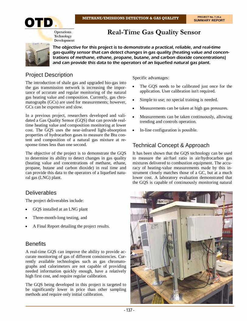
METHANE/EMISSIONS DETECTION & GAS QUALITY PROJECT No. 7.15.a SUMMARY REPORT
Project Description The introduction of shale gas and upgraded bio-gas into the gas transmission network is increasing the impor-tance of accurate and regular monitoring of the natural gas heating value and composition. Currently, gas chro-matographs (GCs) are used for measurements; however, GCs can be expensive and slow.
In a previous project, researchers developed and vali-dated a Gas Quality Sensor (GQS) that can provide real-time heating value and composition monitoring at lower cost. The GQS uses the near-infrared light-absorption properties of hydrocarbon gases to measure the Btu con-tent and composition of a natural gas mixture at re-sponse times less than one second.
The objective of the project is to demonstrate the GQS to determine its ability to detect changes in gas quality (heating value and concentrations of methane, ethane, propane, butane and carbon dioxide) in real time and can provide this data to the operators of a liquefied natu-ral gas (LNG) plant.
Deliverables The project deliverables include:
GQS installed at an LNG plant
Three-month-long testing, and
A Final Report detailing the project results. Benefits A real-time GQS can improve the ability to provide ac-curate monitoring of gas of different consistencies. Cur-rently available technologies such as gas chromato-graphs and calorimeters are not capable of providing needed information quickly enough, have a relatively high first cost, and require regular calibration.
The GQS being developed in this project is targeted to be significantly lower in price than other sampling methods and require only initial calibration.
The objective for this project is to demonstrate a practical, reliable, and real-time gas-quality sensor that can detect changes in gas quality (heating value and concen-trations of methane, ethane, propane, butane, and carbon dioxide concentrations) and can provide this data to the operators of an liquefied natural gas plant.
Real-Time Gas Quality Sensor
Specific advantages:
The GQS needs to be calibrated just once for the application. User calibration isn't required.
Simple to use; no special training is needed.
Measurements can be taken at high gas pressures.
Measurements can be taken continuously, allowing trending and controls operation.
In-line configuration is possible.
Technical Concept & Approach It has been shown that the GQS technology can be used to measure the air/fuel ratio in air/hydrocarbon gas mixtures delivered to combustion equipment. The accu-racy of heating-value measurements made by this in-strument closely matches those of a GC, but at a much lower cost. A laboratory evaluation demonstrated that the GQS is capable of continuously monitoring natural
- 137 -

gas heating value and composition with an accuracy of 0.5% and a response time of one second.
Specific tasks include:
Sensor Schematic and Procurement
During this task, researchers collaborate with utility representatives to develop a schematic of the GQS installation at the selected LNG plant or other facil-ity. One possible location for the GQS was identi-fied at an LNG plant.
Sensor Preparation and Calibration
During this task, the project team conduct the GQS modifications necessary to optimize the sensor for the natural gas operation. The sensor was originally configured for bio-gas. This modification includes a replacement of the spectrometer and a software up-grade. The sensor will be calibrated for the natural gas composition range typical for the gas supplied by the utility.
Sensor Installation and Testing
During this task, the project team will install the GQS at a selected location and set necessary soft-ware to enable remote control and monitoring of the GQS over the internet. The sensor capabilities of real-time monitoring of methane, propone, butane, and carbon dioxide concentrations in the natural gas as well the gas heating value will be demonstrated by conducting a three-month monitoring of the natu-ral gas received by the LNG plant. The GQS testing will be conducted concurrently with gas chromato-graph sampling at the same location.
Results This project began in 2015, with activity initially fo-cused on a design for the climate-controlled sensor en-closure. In 2016, the software was updated to enable collection of carbon dioxide data that is more accurate.
In 2017, the enclosure for the GQS installation was de-signed and fabrication of the full sensor inside the enclo-sure was initiated. The project team will use a mobile hot spot to collect and transmit data to during the dem-onstration period. Software integration was completed. A new spectrometer can read high wavelength data and, therefore, collect carbon dioxide data directly. Software was modified to collect and process this data.
The project team decided to add a duplicate sensor to the enclosure for the demonstration test. This provides the team with two sets of sensor data from a single demon-stration project. The sensors are both inside the enclo-sure and connected in series. Acquiring a dual set of data would be an significant advantage toward having the GQS reach the commercial market quickly.
- 138 -
The project team completed sensor assembly and cali-bration in 2018. The second sensor, this one based on an interferometer detector, was installed in parallel. Details of the dimensions, utility requirements, and other as-pects of the box (inlet and outlet ports, temperature range, etc.) to hold the GQS for demonstration testing were laid out. The heating and cooling unit is attached to the sensor enclosure. Data will be collected on a lap-top computer in a separate enclosure and sent via phone link for collection and processing.
Testing began in 2018, but had to be halted because gas system changes required the plant to be temporarily shut down. Plans were made to move the sensor to another LNG facility in North Carolina; however, this was not necessary because the first plant was brought back on line. Testing was carried out over a several week period. Data was collected and processed. All results will be provided in the project Final Report.
Status
A Final Report is being prepared.
For more information:
Michael Adamo, P.E. Vice President, Operations Operations Technology Development, NFP Phone: 847/544-3428 [email protected]

METHANE/EMISSIONS DETECTION & GAS QUALITY PROJECT No. 7.15.b SUMMARY REPORT
Project Description During natural gas emergency situations, first respond-ers need to quickly and efficiently assess the atmos-phere within a building or confined space. In this pro-ject, researchers are investigating the use of wireless sensors that can be strategically placed to inform first responders of methane concentration. The devices would provide critical information, allowing personnel to determine the concentration of methane inside build-ings, sewers, and other structures from a safe distance.
In Phase 1 of this project, researchers developed a local area network of methane sensors to assist leak investi-gators. The network employs off-the-shelf methane sen-sors, wireless technologies, and low-cost computing platforms. The communications is short range: from sensor node to sensor node and to investigators’ hand-held devices.
In Phase 2, hardware was modified to provide unat-tended methane monitoring. This monitor is placed in the vicinity of a suspected (or recently repaired) leak to provide up to five days of unattended monitoring.
Research is being conducted in an effort to develop a device to remotely monitor the level of gases during emergency situations and provide critical information to first responders and gas company personnel.
Remote Gas Sensing and Monitoring
The objective of Phase 3 was to develop a system to allow a leak investigator to remotely monitor methane levels at multiple points within a site under investiga-tion. The investigator uses a tablet or phone to see the gas values in real time. Phase 3 involved field tests of the prototype system.
The current Phase 4 focuses on the development of a pre-commercial-ready units that can be tested by spon-sors at actual leak sites. Deliverables Deliverables include the development of wireless sen-sor nodes that can detect methane. The project team also developed mesh networking for seven sensor nodes with 100m node-to-node spacing indoors with obstructions. Each sensor node serves a webpage via WiFi that contains the data from all of the sensor nodes. This project includes demonstrations of the pro-totype system and a report that captures the field-demonstration data, user feedback, and needed modifi-cations.
- 139 -
Outdoor test setup.

Benefits The safety of workers, first responders, and the general public will be enhanced by being able to monitor meth-ane concentrations remotely. In addition, continuous re-mote monitoring of various gas levels during known gas leak situations will allow for better and quicker analysis of the situation. The remote sensors can be placed and/or operated in the area of the known gas leak.
Technical Concept & Approach To improve the functionality of the device, researchers are developing a custom hardware/software solution comprised of a multiple-sensor system and a mobile monitoring device to improve the range and data con-nectivity of the wireless sensors.
The tangible objective is to produce a prototype of a sys-tem to be used by leak investigators and first responders. It will consist of multiple wireless sensor nodes that can be distributed over a site under investigation. The wire-less connectivity will be such that the investigator will be able to simultaneously see the data from all nodes using a smartphone or tablet as the interface device.
Demonstrations of the system were performed at test sites to determine if it is a good fit for normal leak-investigation practice.
Results During Phase 1, the project team developed a set of wireless methane sensors that communicate with one another via a wireless mesh network. Researchers dem-onstrated the system at several OTD meetings. Subse-quently, separate field tests were conducted in 2017.
The prototype system is able to measure methane con-centration, temperature, and humidity at multiple points within an area and provide this data to the investigator through a phone or tablet.
The unattended methane-monitoring system consists of multiple sensor nodes that communicate wirelessly with a base station. The sensor nodes were mechanically con-figured to be inserted into a barhole with minimal expo-sure above ground. The base station can capture data from nearby sensor nodes, store it, and forward it wire-lessly to a server. The data from the sensor nodes is ex-posed as a web page that can be viewed by any device with internet access. This allows one to check on the methane levels on a site remotely.
For the Phase 1 prototype, each node had access to data from the other active nodes in the mesh network. The mesh allows 100-meter maximum spacing between nodes and supports message relaying to maximize the area that can be monitored. For the Phase 2 prototype, a
long-range radio system was adopted that does not re-quire personnel to be present for reading, allowing unat-tended operation.
Three test sites were offered by the sponsors for field demonstrations in 2018. In all cases, the prototypes were demonstrated in a training facility.
In 2020, a subcontract with a sensor manufacturer was finalized and executed. The manufacturer surveyed utilities and captured the basic requirements for applica-tions.
Outdoor testing was initiated on candidate methane sen-sors to evaluate their stability.
Researchers are investigating:
An instrument that can measure natural gas concen-trations within a specified area, and wirelessly transmit readings to a remote, non-proprietary de-vice, such as a cell phone.
A device that is installed at work sites that can transmit methane readings to a remote device (e.g., a laptop) to monitor the efficacy of work completed.
Status A second round of surveys to further refine specifica-tions is planned. A key driver for the second round of surveys is the introduction of hydrogen injection into the discussion, and the necessity for these products to accommodate a gas mixture with hydrogen as a con-stituent.
For more information:
Michael Adamo, P.E. Vice President, Operations Operations Technology Development, NFP Phone: 847/544-3428 [email protected]
Antenna used in testing.
- 140 -
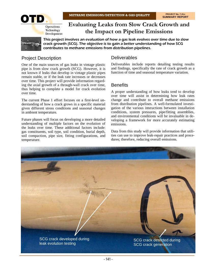
METHANE EMISSIONS/DETECTION & GAS QUALITY PROJECT No. 7.15.c SUMMARY REPORT
Project Description One of the main sources of gas leaks in vintage plastic pipe is from slow crack growth (SCG). However, it is not known if leaks that develop in vintage plastic pipes remain stable, or if the leak rate increases or decreases over time. This project will provide information regard-ing the axial growth of a through-wall crack over time, thus helping to complete a model for crack evolution over time.
The current Phase 1 effort focuses on a first-level un-derstanding of how a crack grows in a specific material given different stress conditions and seasonal changes in ambient temperature.
Future phases will focus on developing a more detailed understanding of multiple factors on the evolution of the leaks over time. These additional factors include: gas constituents, soil type, soil condition, burial depth, soil compaction, pipe size, fitting configurations, and temperature.
This project involves an evaluation of how a gas leak evolves over time due to slow crack growth (SCG). The objective is to gain a better understanding of how SCG contributes to methane emissions from distribution pipelines.
Evaluating Leaks from Slow Crack Growth and the Impact on Pipeline Emissions
Deliverables Deliverables include reports detailing testing results and findings, specifically the rate of crack growth as a function of time and seasonal temperature variation. Benefits A proper understanding of how leaks tend to develop over time will assist in determining how leak rates change and contribute to overall methane emissions from distribution pipelines. A well-formulated investi-gation of the various interactions between installation conditions, system pressures, pipe/fitting assemblies, and environmental conditions will be invaluable in de-veloping a framework for more accurately estimating emissions.
Data from this study will provide information that utili-ties can use to improve leak-repair practices and proce-dures; therefore, reducing overall emissions.
- 141 -
SCG crack developed during leak evolution testing
SCG crack detected during SCG crack generation

Technical Concept & Approach Pipes up to four inches in diameter and two different types of fittings (couplings and saddle tees) are being exposed to hydrostatic pressure testing. Testing is being performed at an elevated temperature (80°C or 90°C) and stress combination to ensure that slit failures are induced. A total of 18 specimens with SCG will be pre-pared. As soon as the specimens exhibit through-wall cracks, they will be removed from test.
A specially developed leak-flow-rate test rig is enclosed in an outdoor facility. The facility includes equipment and hardware to supply the continuous flow of air and to allow for continuous monitoring and acquisition of data. A by-pass system to allow for the flow of methane is incorporated for the periodic measurement of methane leak rates. Conducting the experiment in this manner eliminates the need for a complex compressor system and the associated safety measures needed for the con-tinuous circulation of methane.
Two stainless-steel chambers were built, each one large enough to house up to nine four-inch pipe/fitting assem-blies. Each chamber is arranged for the continuous flow of air through nine individual specimens. The specimens will be placed at the bottom of each chamber built and buried in two feet of soil. Air will continuously flow thorough the specimens at three different set pressures. The leak rate through each specimen will be continu-ously monitored and recorded by means of an instru-mented data-acquisition system for 10,000 hours. Leak rates through the soil will be determined by switching the source gas from air to compressed natural gas, ap-plying pressure to an individual specimen, and then us-ing a Hi-Flow Sampler™ to measure the leak rate.
Potential follow-on phases could include efforts to:
Expand the experimental data set to additional soil types and conditions
Conduct experiments at controlled temperature and pressure conditions to substantiate the time/temperature superposition principles needed to map experimental results to field conditions, and
Develop a probabilistic model to allow operators to infer the expected leak evolution rate for a leak loca-tion given current measurements and additional sys-tem knowledge related to the likely pipe, fittings, and burial conditions at the location.
Results The project team initially designed a leak-evolution test rig and software for the rig. The rig is used to generate pipe samples with small SCG leaks. The generation of pipe samples with SCG leaks began in 2017.
- 142 -
It was found from ongoing tests that the average leak rate of samples can vary between pressurization cycles, therefore, the project team develop data post-processing methods for extracting the leak rate of a sample over time and verification of the flow meter readings.
A proposal for Phase 2 of this project was presented to OTD to continue testing pipe samples generated in Phase 1.
In 2020, flow testing of two specimens showed high flow rates, indicating that the cracks had grown to ex-ceed a flow rate of 10 SCFH. Both pipes were tested for pressure containment, confirming the leaks were at the pipe specimen.
Low flow leak rate assessment, evaluating failed speci-mens, and continued testing of the remaining specimens was conducted.
Researchers received two rotameters that are being placed in a series to measure current flow rates from pipe samples. The rotameter setup will be used to in-form the measurement range of the samples and provide input for replacing the existing 0-10 SCFH meters with appropriate lower range meters.
Status Testing continues on the remaining specimens.
Specimen tub.
For more information:
Michael Adamo, P.E. Vice President, Operations Operations Technology Development, NFP Phone: 847/544-3428 [email protected]
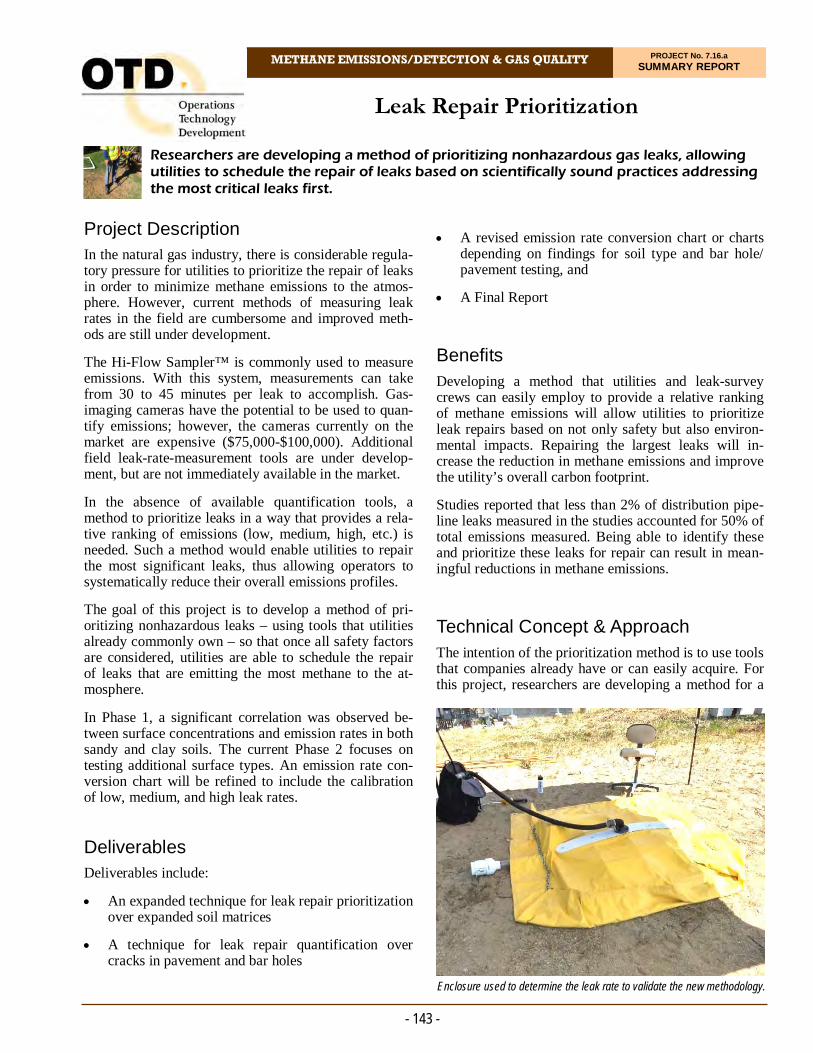
METHANE EMISSIONS/DETECTION & GAS QUALITY PROJECT No. 7.16.a SUMMARY REPORT
Project Description In the natural gas industry, there is considerable regula-tory pressure for utilities to prioritize the repair of leaks in order to minimize methane emissions to the atmos-phere. However, current methods of measuring leak rates in the field are cumbersome and improved meth-ods are still under development.
The Hi-Flow Sampler™ is commonly used to measure emissions. With this system, measurements can take from 30 to 45 minutes per leak to accomplish. Gas-imaging cameras have the potential to be used to quan-tify emissions; however, the cameras currently on the market are expensive ($75,000-$100,000). Additional field leak-rate-measurement tools are under develop-ment, but are not immediately available in the market.
In the absence of available quantification tools, a method to prioritize leaks in a way that provides a rela-tive ranking of emissions (low, medium, high, etc.) is needed. Such a method would enable utilities to repair the most significant leaks, thus allowing operators to systematically reduce their overall emissions profiles.
The goal of this project is to develop a method of pri-oritizing nonhazardous leaks – using tools that utilities already commonly own – so that once all safety factors are considered, utilities are able to schedule the repair of leaks that are emitting the most methane to the at-mosphere.
In Phase 1, a significant correlation was observed be-tween surface concentrations and emission rates in both sandy and clay soils. The current Phase 2 focuses on testing additional surface types. An emission rate con-version chart will be refined to include the calibration of low, medium, and high leak rates.
Deliverables Deliverables include:
An expanded technique for leak repair prioritization over expanded soil matrices
A technique for leak repair quantification over cracks in pavement and bar holes
Researchers are developing a method of prioritizing nonhazardous gas leaks, allowing utilities to schedule the repair of leaks based on scientifically sound practices addressing the most critical leaks first.
Leak Repair Prioritization
A revised emission rate conversion chart or charts depending on findings for soil type and bar hole/pavement testing, and
A Final Report
Benefits Developing a method that utilities and leak-survey crews can easily employ to provide a relative ranking of methane emissions will allow utilities to prioritize leak repairs based on not only safety but also environ-mental impacts. Repairing the largest leaks will in-crease the reduction in methane emissions and improve the utility’s overall carbon footprint.
Studies reported that less than 2% of distribution pipe-line leaks measured in the studies accounted for 50% of total emissions measured. Being able to identify these and prioritize these leaks for repair can result in mean-ingful reductions in methane emissions.
Technical Concept & Approach The intention of the prioritization method is to use tools that companies already have or can easily acquire. For this project, researchers are developing a method for a
- 143 -
Enclosure used to determine the leak rate to validate the new methodology.

field survey crew member to use to quickly analyze a leak site and gather a couple of data points (concentra-tion, wind speed, area, etc.) to make a coarse determina-tion of leak rate. This leak flow rate will be a rough esti-mate with the sole objective of categorizing or ranking the leaks. The method was tested with a variety of leak rates and environmental conditions. The leak flow rate using the conceptual method was compared to the leak rate measured using the Hi-Flow Sampler.
In Phase 2, soil testing at utilities will be obtained using the methodology created in Phase 1. The effectiveness of the method will be validated against traditional quan-tification methods. Barhole and pavement testing will also be conducted.
Results A conceptual procedure was designed for field crews to quickly analyze a leak site and make qualitative esti-mates of emission rates by simply collecting maximum concentration data over the leak area. For a more robust result, a separate procedure was developed that involves collecting a set of 13 surface concentration points in the vicinity of the maximum surface concentration indica-tion and calculating the average. Controlled field tests were performed to test this procedure. Tests consisted of simulating controlled underground leaks in both sand and clay soil types. Estimated emission rates derived from concentration data were compared to enclosure rates using a Hi-Flow Sampler. Subsurface simulated leaks were monitored using a Laminar Flow Element (LFE) manifold from which the pressure in the line and the pressure drop across the LFE was obtained. These data were then used to calculate the total leak rate from the buried pipe for quality control purposes.
Remarkably high relationships were observed between the averaged concentration of gas at the surface of the leak and the single enclosure rate in both sandy soils and clay soils.
The differences between using the maximum concentra-tion and using the average concentration to estimate leak flow rate is an important finding from this project. The differences indicate that using the mean concentration across an area to represent leak flow rate may act to standardize the proposed method across different soil types. By factoring in multiple measurements, the mean concentration effectively “smoothes out” high-indication concentrations that may only be high because of differ-ences in soil porosity, compaction, or permeability that limit the area over which the leak may be spreading.
A total of 35 samples were collected and recorded dur-ing a four-week field sampling in 2018. Each sample number consisted of 13 surface concentration readings.
For environmental testing, these results present relative high correlation values between surface concentration
and leak size, thus creating confidence that, at least in sand, the conceptual method could be used to qualita-tively state that one leak is larger or smaller than an-other leak by calculating the average of concentrations at the leak site.
Engineers also designed and built a movable grid to as-sist in the collection of concentrations across the leak spread area.
In 2020, the flow rate for each leak was set using the mass flow controller at the upstream manifold. Gas had to travel from the manifold through underground pipes to the leak location and permeate through the soil in order to be detected by methane instruments. To verify the amount of gas that eventually emerged from the ground surface, the surface expression was measured using a Hi-Flow sampler and a tarp enclosure. The measured flow rates were plotted against the setting flow rates in the chart below.
Results show that gas concentration at the center of the leak was higher than the surrounding area. It can be de-duced that when the soil was dry, gas was able to spread underground and emanated from the ground surface in a wider area compared to a small point source when the soil was moist. In support of this theory, studies have shown that moist soil conditions impede underground migration of gas from the leak source.
A two-week field test was completed in September 2020 with a host utility in California. A total of 38 pre-viously found underground pipeline leaks in residential areas were visited to determine if surface methane con-centration measurements could be used to estimate leak flow rates. Researchers found a correlation between surface methane concentration measurements (before a barhole is made) and leak flow rate. The correlation between surface methane concentration and leak flow rate was stronger on paved surfaces compared to un-paved surfaces. The field test shows that the 13-point method is feasible for estimating underground pipeline leak flow rates, but uncertainty remains significant. Re-searchers are considering improvisations to the method to reduce the uncertainty.
Status
Testing for Phase 1 was completed and a Phase 1 Final Report was issued in November 2020. Phase 2 is under way.
For more information:
Michael Adamo, P.E. Vice President, Operations Operations Technology Development, NFP Phone: 847/544-3428 [email protected]
- 144 -

METHANE EMISSIONS/DETECTION & GAS QUALITY PROJECT No. 7.16.b SUMMARY REPORT
Project Description With increased pressure to reduce methane emissions from the natural gas industry, measuring leak rates and quantifying emissions have become increasingly impor-tant to utilities. Various regulations at the federal and state level are requiring the reporting of greenhouse-gas emissions, and better tools are needed for measurement. While there have been several past OTD projects fo-cused on developing and evaluating methane-detection tools for leak-detection and leak-surveying applications, there has been limited focus on tools for the measure-ment and quantification of emissions.
Gas-imaging cameras allow for the quantification of leaks that may not be as easily accessible. These cam-eras also allow potentially dangerous leaks to be moni-tored from several meters away, which may be benefi-cial for safety reasons depending on the leak site.
Among the technologies being tested in this project are the forward-looking infrared (FLIR) camera (which can rapidly scan large areas and identify leaks in real time) and a video camera that monitors, quantifies, and dis-plays explosive/harmful gas leaks in real time.
The objective of this project is to evaluate these and other gas-imaging technologies for various applications in the natural gas industry. Specific applications will include the use of these tools for methane-emissions quantification and as a tool for first responders during leak investigation and grading.
Deliverables The following deliverables are anticipated from this project:
Quantitative measurements of methane leak rates using selected gas-imaging technologies.
A Final Report summarizing the data from the tech-nology evaluation and field demonstrations. This report will enable operators to determine if the use of gas-imaging cameras is a viable option for identi-fying gas leaks and quantifying methane emissions.
Recommendations for the manufacturers.
In this project, researchers are evaluating the use of gas-imaging technologies for various applications in the gas industry, including the use of these tools for methane- emissions quantification and as a tool for first responders during leak investigation and grading.
Evaluation of Gas-Imaging Technologies for Utility Applications
Benefits Gas-imaging technologies can have the ability to pro-vide for the detection and identification of leaks, as well as enable the quantification of leak flow rate. This results in increased safety for customers and utility em-ployees along with added environmental benefits asso-ciated with leak repair and/or pipe replacement pro-grams.
Gas-imaging cameras can reduce the time required to obtain a flow rate, enabling utility companies to collect emission rate data from every leak if so desired. Gas-imaging cameras can also help in the leak-investigation process as methane plumes can be visualized and used as an aid in investigating difficult-to-pinpoint leaks. The leak flow-rate information could then be used as a secondary factor (primary factor being safety) to de-velop leak-repair prioritization plans. As a result, emis-sions can be optimally reduced while maintaining a safe infrastructure.
- 145 -
Testing at the pipe farm.

Technical Concept & Approach In this project, controlled tests are performed comparing the performance of the gas-imaging cameras to tradi-tional leak-rate-measurement tools.
A testing matrix was developed to determine the pa-rameters and evaluation conditions for the gas-imaging cameras. These include: distance from the leak, leak rate, leak area, leak source (e.g., pipeline leak, meters), temperature, and other environmental conditions.
Controlled testing is performed in an outdoor pipe farm. The measurements from the gas-imaging cameras are validated using the Hi-Flow Sampler™ as the reference technique.
Pending the results of testing, two field demonstrations will be conducted with utilities on actual utility leaks. Demonstrations will help to determine the utility appli-cations appropriate for using gas-imaging tools. Tech-nologies will be tested on various types of leaks and leak sources.
Follow-on research could include evaluations of less expensive and more “field-ready” devices that manufac-turers are currently developing.
Results Testing focused on understanding the limits of gas-imaging technologies with regards to quantifying leaks under the following conditions: diffuse leaks in sand (i.e., spread over a large area), point-source leaks, diffuse leaks in clay soil, and diffuse leaks in silty soil.
Leaks were created and the performance of each unit compared/validated with other tools that have similar detection limitations.
In 2019, researchers provided a complete analysis and summary of two new cameras. Technologies were tested with a spoke test modified from the techniques used in the OTD laser point-and-shoot project and from scans of compressed natural gas fueling stations and natural gas customer meters.
- 146 -
One camera is used extensively in upstream leak detec-tion and repair programs as it can be used as an alterna-tive work practice specific to optical gas imaging for regulatory scans of equipment. The camera is robust and provides locating and visualization of larger leaks above ground.
The other technology is is a methane-specific uncooled camera. The uncooled nature means the camera starts up instantly; however, the uncooled detector is approxi-mately five times less sensitive.
Researchers found that both cameras performed well under specific use cases (which were larger pinhole leaks on above ground assets).
In 2020, researchers initiated testing on with a third de-vice. The project team identified three potential point sources at the pipe farm that can be used to test the third system. The site includes a simulated leak (pinhole at meter body) at a residential gas meter located in front of a mock shed; a compressor crank case vent at a com-pressed natural gas fueling station; and a controllable underground leak buried in sandy soil at roughly three feet. The meter set and underground leaks are connected to a natural gas supply line of 60 psig and their emission flow rates can be precisely controlled using a mass flow controller or laminar flow element.
Status
Researchers continue to monitor for possible equipment to test.
For more information:
Michael Adamo, P.E. Vice President, Operations Operations Technology Development, NFP Phone: 847/544-3428 [email protected]
Laboratory testing images.

METHANE EMISSIONS/DETECTION & GAS QUALITY PROJECT No. 7.16.d SUMMARY REPORT
Project Description In 2015, the Plastics Pipe Institute (PPI) published a revised technical note (TN-4/2015 Odorants in Plastic Fuel Gas Distribution Systems), recommending that odorant never be introduced into a plastic pipe system in a concentrated liquid state. The concern is that it will act in the same manner as liquid hydrocarbons (HC), with permeation resulting in weaker and softer material relative to non-permeated material.
Currently, no guidance exists to inform operators where to place an odorant injection point in relationship to a transition to plastic pipe or elastomers (valves, cou-plings, etc.). In general, the location must be far enough downstream to properly mix the odorant with the gas so that no liquid remains downstream of the injection point. In addition, the concept of odorant permeation into plastic pipe is disputed by some operators.
The PPI technical note states that: “Odorants should never be introduced into a plastic pipe system in a con-centrated liquid state.” Neither the 2000 AGA Odoriza-tion Manual nor the 2016 update mention plastic pipe or polymer locations, although the 2016 update does reference the PPI technical note.
The technical objectives in this project are to determine:
In this project, research focused on addressing several issues associated with odorant dispersion, including odorant permeation, odorant injection, and sampling points.
Implications of Odorant Dispersion in a Natural Gas Pipeline
How far downstream of an odorant injection point any transitions to polyethylene (PE) pipe or poly-mer materials should be located
The proper location for a sampling point for odor-ant concentration and odor monitoring, and
If and to what extent an odorant absorbs into a polymer matrix.
Deliverables Deliverables include: A table with recommended sam-pling points for various pipe diameters and flows; ab-sorption and desorption data to support the impact of odorant on the polymer materials; and a Final Report with summaries and recommendations.
Benefits Knowledge of where polymeric materials may be prop-erly located in a gas pipeline system and not be subject to liquid odorant permeation will improve the integrity and safety of the PE pipeline infrastructure. Integrating this information with sampling-point recommendations
- 147 -
Samples are dried (left) before dimensioning (right).

ommendations and knowledge of odorant-permeation rates would provide operators with data to make in-formed decisions regarding odorization-dispersion is-sues in specific systems.
Technical Concept & Approach The project team modeled vapor and mist dispersal within the pipeline using a fluid-flow simulation soft-ware package. This software contains the broad physical modeling capabilities needed to model flow, turbulence, heat transfer, and reactions for a variety of industrial applications.
A typical injector odorizer was simulated to model what happens to the vapor or mist as it is dispersed into the pipeline. Six distinct pipe diameters (two-inch to 24-inch), three standard flows, and two sampling points (center and edge) will be used, totaling 36 conditions for a given odorizer and odorant combination. Both t-butyl mercaptan (TBM) and tetrahydrothiophene (THT) will be considered.
To address the odorant-permeation issue, researchers tested the rates of absorption and desorption into and out of selected materials used in pipelines under ambient conditions. The materials were saturated and cut into four slices, which were each used to detect odorant con-centrations from a gas chromatography headspace analy-sis. A curve was generated to demonstrate absorption and desorption trends in the materials over time.
Headspace gas chromatography was selected as the tech-nique to detect odorant concentration. A sample is sealed in a closed container and heated to evolve the hydrocarbons present. The air volume in the container is pressurized to a known pressure and sampled through a heated transfer line to a gas chromatograph (GC).
Results Researchers performed steady-state Computational Fluid Dynamics (CFD) analysis to understand the effect of odorant blending and pipeline gas on mixing. Simula-tions showed that a maximum of 80 pipe diameters is sufficient for the different pipe diameters and pressures studied for smaller droplet diameters. As the droplet di-ameter is increased from 50 microns to 300 microns, a length of 83 pipe diameters is required. Droplets above 350 microns may take longer than 100 pipe diameters to vaporize and more thorough studies are required as the droplet sizes get larger than 350 microns to understand their behavior. In those cases, depending on natural gas flow rates, some odorant may pool at the bottom of the pipe until it vaporizes and becomes carried away by the gas flow.
- 148 -
Increasing the pressure did not show an effect on the droplet mixing for the cases studied, nor did changing the injection location from center to top. As a safety factor, a length of 100 pipe diameters is minimally rec-ommended for sample collection and transition into non-metallic components.
Polyethylene absorption and desorption of odorant was much slower, but it did occur.
The data continue to consistently show a bigger impact from THT over TBM in weight gain and headspace concentration. The THT desorption data appears to be on the same time scale as the absorption process.
In 2020, geometry creation and meshing of the different pipe sizes for simulation was conducted to determine the mixing length for the two odorants.
The conclusion of these studies finds that:
A minimum of 100 pipe diameters from an injection type odorization station is recommended before any transition to PE pipe or any gas sample is extracted for odorant monitoring.
Odorant does permeate into rubber materials used for pipe couplings. During exposure, the rubber gains weight (swells) and becomes softer.
Odorant permeates into PE at a slower rate than seen with rubber materials.
Status
This project is complete. A Final Report was issued in May 2020.
Material samples soak in TBM and THT.
For more information:
Michael Adamo, P.E. Vice President, Operations Operations Technology Development, NFP Phone: 847/544-3428 [email protected]

METHANE EMISSIONS/DETECTION & GAS QUALITY PROJECT No. 7.16.e SUMMARY REPORT
Project Description The introduction of fuel gases from a variety of differ-ent sources is becoming more prevalent as states be-come more aggressive towards incorporating renewable energy into their energy portfolios. Projects focusing on renewable energy also represent important steps to ad-dressing increasing climate challenges. For example, the California Air Resources Board is recommending methane emission mitigation strategies that include the conversion of agricultural and landfill waste into biogas or renewable natural gas. Food waste is also being pro-posed as a next-generation anaerobic digestion matrix.
Many of these gas sources have different trace chemical constituents from those found in natural gas. The need to understand the composition of these gases is increas-ing as the frequency of their introduction into the pipe-line system grows.
The focus of this project is on those constituents that are not routinely monitored by on-line instruments but are critical to gas quality. The emphasis is on systems with lower cost and shorter analysis times than current techniques.
For this project, research was conducted to determine if on-line monitoring systems can be used to ascertain key parameters in biomethane being blended into the gas distribution system. The focus was on those constituents that are not routinely monitored by on-line instruments but are critical to gas quality.
On-Line Biomethane Gas Quality Monitoring
In the current phase (Phase 2), manufacturer claims are being addresses through the preparation of four artifi-cial standards mimicking natural gas and natural gas with low, medium, and high concentrations of trace biomethane constituents. From the resulting chroma-tograms and/or spectra, the technologies will be evalu-ated for sensitivity, selectivity, and repeatability.
Deliverables Deliverables include:
A Task Summary Report to provide guidance on how to monitor the concentration of critical trace constituents in a renewable natural gas stream that are not already being routinely monitored, and
A Final Report that includes recommendations for any follow-on activities, including a cost estimate, schedule, technology development team, and pa-rameters for the design of an alternative analytical package if none are found available.
- 149 -
Setup to spike siloxane in methane gas.
Benefits Monitoring the concentration of critical constituents in the gas stream provides the industry with the capability of protecting valuable underground assets, delivering gas that meets end-usage requirements, and protecting human health.
On-line instrument packages are a benefit to both the gas company and the supplier. Results are instantly available instead of having to wait days or weeks for an off-site laboratory analysis. With on-line capabilities, response to conditions could be immediate.
Technical Concept & Approach In this project, researchers conducted a technology as-sessment of currently available and emerging technolo-gies for their ability to determine the constituents of in-terest. These included micro-gas chromatographs, opti-cal spectrometers, and mass spectrometers, but also in-cluded technologies that are currently being developed by private companies and universities. The focus was on low cost and quick data turnaround.
Technologies were assessed for their analytical charac-teristics (what components they could analyze and de-tection limits), their sampling characteristics (sampling pressure limits, scan time, and emissions), and their op-erational characteristics (availability, cost, consumables, maintenance, and packaging).
Results This project developed a survey to determine the bio-methane constituents with the highest risk and greatest need for on-line analysis. Five constituents were chosen based on survey feedback and expert knowledge:
BTEX (Benzene, Toluene, Ethylbenzene, and Xy-lenes)
n-Nitroso-di-n-propylamine (and other amines)
Siloxanes
Organic arsenic, and
Halogenated hydrocarbons (e.g., vinyl chloride ).
All of these constituents have been found in raw biogas samples from previous projects and the literature, and their presence should be avoided in biomethane.
A market survey and literature review was conducted to cover both commercialized and un-commercialized sen-sors for this application, looking at market-available analyzers and emerging sensors. Each technology’s po-tential was assessed by direct correspondence. The re-view identified technologies are available with features
- 150 -
such as on-line and automated sampling, low errors, and robustness to a natural gas medium are possible.
Phase 2 of the project began in 2018. Researchers se-lected the compositions of the four artificial standards for investigation. The standards gases contain 10 of the 13 components in the baseline standard, 10 of the 25 for the low standard, 16 of the 25 for the medium stan-dard, and 17 of the 25 for the high standard. The re-maining gaseous components will be spiked by gas blending using a gas blender or headspace injection.
The research team completed investigating the effects of the sampling cylinder temperature on siloxane sta-bility and completed experimenting with valve outlet pressures, which support a higher correlation.
In 2019, researchers secured a portable sensor to safely handle high levels of trimethylarsine (TMA) in the laboratory. The team also received a customized sam-pling cylinder regulator and started re-trialing the silox-ane stability study.
In 2020, a stability study of TMA in an inerted gas sampling cylinder was conducted. No significant loss was observed after 12 days at concentrations between 0.22-0.27 ppmv and standard errors between 0.07-0.12 ppmv. This confirms that the component is less prone to loss in an inerted cylinder than siloxanes, BTEX, and the selected halocarbons. The sample from this study is still contained and will be analyzed periodi-cally to determine a recommended holding time.
While activities were interrupted due to the COVID-19 pandemic, the project team prepared and shipped multi-ple artificial biomethane standards and returned analy-sis results from analyzer manufacturers were reviewed and discussed.
To remove ethylbenzene and not the stock cylinders with natural gas components meant ethylbenzene is no longer producible. This does not compromise the inves-tigation because all analyzers have already tested BTEX extensively with calculated sensitivity, selectiv-ity, and accuracy.
Status The last remaining returned results from the analyzer manufacturers are being analyzed and the project Final Report is being drafted.
For more information:
Michael Adamo, P.E. Vice President, Operations Operations Technology Development, NFP Phone: 847/544-3428 [email protected]

METHANE EMISSIONS/DETECTION & GAS QUALITY PROJECT No. 7.16.f SUMMARY REPORT
Project Description With the increased awareness and scrutiny of methane emissions, there has been a corresponding increase in methane sensing and alert technologies.
Sensing technologies investigated with OTD support have included laser-based sensors, optical imaging techniques, and MEMS (Micro-Electro-Mechanical Systems)-based methods.
The objective of this project was to investigate the cur-rent state of the art in “point” methane sensors and how they are used in the utility industry. A gap analysis was performed and sensors may be selected for further in-vestigation.
Deliverables A detailed set of use cases for methane sensors relative to leak investigations and other utility activities was developed. These include the business objectives and regulatory drivers for the activities. The technical re-
In this project, researchers investigated the current state of the art in “point” methane sensors and how they are used in the utility industry. A gap analysis was performed and sensors may be selected for further investigation.
Investigation of State-of-the-Art Methane Sensors
quirements for the methane sensors needed to carry out these activities were developed. The current equipment used, its costs, and the levels of sponsor satisfaction were also captured.
An analysis of the use cases and requirements was per-formed to determine if there are technology gaps that need to be addressed. The intent is to identify gaps in sensor technology, but others may be found. The project team will develop sample sensors, which will undergo independent verification testing.
Benefits The value of this research effort will be derived by corre-lating the current (and possible future) uses for methane sensing in the sensing in the utility industry with the various technology solutions and their associated costs. This will provide a roadmap to determine if there are applications where new or disruptive sensing technolo-gies can provide greater value than current practices.
- 151 - A variety of sensing technologies were investigated.
Technical Concept & Approach Specific project tasks included:
Requirements Analysis and System Design
An analysis of the requirements of use cases and documentation for business rules, system features, use cases, specifications, activity models, and do-main topics. The project team also developed a set of models and documents which express the sensing and data requirements for the utility use cases. As a part of this task, the current study of the state of the art in methane sensing, as applied to the utility use cases, was carried out.
Optional Evaluation of Sensor Technology
The project team evaluated a methane-sensing tech-nology that was brought to OTD for consideration. The decision to evaluate the technology will be based on how well it aligns with the use cases and/or technology gaps.
Results The project team prepared a thorough analysis of point sensors in 2016 followed by an update in 2019. After preparation of the original report, sponsors decided that researcher should directly collaborate with a specifi com-pany to further the development of a new point methane sensor that had the potential to be low cost and low power. Upon completion of the sensor development by the manufacturer, the project team was to thoroughly test the sensor. However, continual delays in producing a sensor ultimately led to the sponsors requesting that the project be cancelled and no sensor was ever delivered.
In 2017, the project team issued a preliminary analysis document that includes a review of current methods of methane detection/measurement, sensor technology, early-stage methane-detection technologies being devel-oped under the U.S. Department of Energy (DOE), tech-nology gaps, sponsor input on areas of interest, and ap-plications for new sensors/technologies.
There currently are numerous ways to measure methane concentrations in ambient air. However, important gaps in sensitivity and cost still exist and the development of an inexpensive methane sensor has a number of barriers. First, in order for a sensor manufacturer to realize a profit from wholesale production of a cheap sensor (less than a few dollars), there must be a significant number of
- 152 -
the sensor sold. Second, results from the sensor must be reproducible, otherwise the cost of making the sensor precise and accurate (e.g., through extensive calibra-tions) must be factored into the cost of the sensor. Pro-duction of an inexpensive sensor for which each indi-vidual unit produced must undergo significant calibra-tion and testing may negate the potential cost benefits. Third, production of the sensor is a very small piece of the puzzle and the required cost of obtaining and inter-preting the data (i.e., through complex detectors, cam-eras, and software) produced by the sensor should be built into the overall cost of the sensor.
Research found several new types of sensors currently under development, including nanotechnology-based chemical sensors (which are claimed to be able to offer high-sensitivity, low-power and low-cost capabilities); phage/colorimetric materials that react to a particular chemical species by changing color; and polymer ab-sorption sensors. The DOE’s Advanced Research Pro-jects Agency – Energy (ARPA-E) created a program called the Methane Observation Networks with Innova-tive Technology to Obtain Reductions (MONITOR) to develop new technologies. The ARPA-E MONITOR program recently funded a suite of projects to develop new sensors. The technologies are largely focused on the upstream on well-pad operations; however, it is pos-sible that these technologies may be useful downstream to distribution companies.
One manufacturer is still fine tuning the hardware as well as firmware. They have sent out the latest iteration of their design to the manufacturing supplier. The com-pany will follow up with the timelines for two different units (integrated detector vs. sensor module) with time-lines for testing.
Status This project is complete. A Final Report was issued in April 2020.
For more information:
Michael Adamo, P.E. Vice President, Operations Operations Technology Development, NFP Phone: 847/544-3428 [email protected]
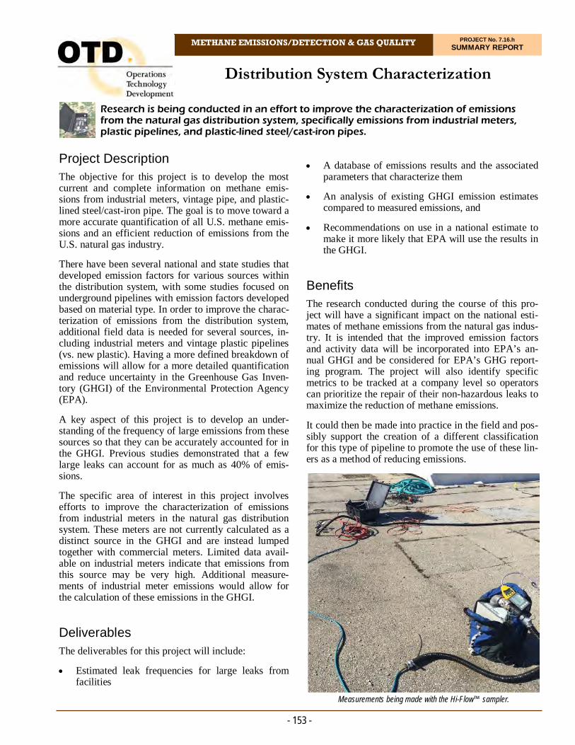
7.16.h Distribution System Characterization Distribution System Characterization
METHANE EMISSIONS/DETECTION & GAS QUALITY PROJECT No. 7.16.h SUMMARY REPORT
Research is being conducted in an effort to improve the characterization of emissions from the natural gas distribution system, specifically emissions from industrial meters, plastic pipelines, and plastic-lined steel/cast-iron pipes.
- 153 -
Project Description The objective for this project is to develop the most current and complete information on methane emis-sions from industrial meters, vintage pipe, and plastic-lined steel/cast-iron pipe. The goal is to move toward a more accurate quantification of all U.S. methane emis-sions and an efficient reduction of emissions from the U.S. natural gas industry.
There have been several national and state studies that developed emission factors for various sources within the distribution system, with some studies focused on underground pipelines with emission factors developed based on material type. In order to improve the charac-terization of emissions from the distribution system, additional field data is needed for several sources, in-cluding industrial meters and vintage plastic pipelines (vs. new plastic). Having a more defined breakdown of emissions will allow for a more detailed quantification and reduce uncertainty in the Greenhouse Gas Inven-tory (GHGI) of the Environmental Protection Agency (EPA).
A key aspect of this project is to develop an under-standing of the frequency of large emissions from these sources so that they can be accurately accounted for in the GHGI. Previous studies demonstrated that a few large leaks can account for as much as 40% of emis-sions.
The specific area of interest in this project involves efforts to improve the characterization of emissions from industrial meters in the natural gas distribution system. These meters are not currently calculated as a distinct source in the GHGI and are instead lumped together with commercial meters. Limited data avail-able on industrial meters indicate that emissions from this source may be very high. Additional measure-ments of industrial meter emissions would allow for the calculation of these emissions in the GHGI.
Deliverables
The deliverables for this project will include:
Estimated leak frequencies for large leaks from facilities
A database of emissions results and the associated parameters that characterize them
An analysis of existing GHGI emission estimates compared to measured emissions, and
Recommendations on use in a national estimate to make it more likely that EPA will use the results in the GHGI.
Benefits The research conducted during the course of this pro-ject will have a significant impact on the national esti-mates of methane emissions from the natural gas indus-try. It is intended that the improved emission factors and activity data will be incorporated into EPA’s an-nual GHGI and be considered for EPA’s GHG report-ing program. The project will also identify specific metrics to be tracked at a company level so operators can prioritize the repair of their non-hazardous leaks to maximize the reduction of methane emissions.
It could then be made into practice in the field and pos-sibly support the creation of a different classification for this type of pipeline to promote the use of these lin-ers as a method of reducing emissions.
Measurements being made with the Hi-Flow™ sampler.
- 154 -
Other primary efforts were focused in two areas: stan-dard operating procedures and sample site selection. The standard operating procedures for sampling indus-trial meters and pipelines (i.e., new vs. vintage plastic, lined steel and cast iron) were finalized and shared with study partners for evaluation.
In 2018, the project team completed evaluation of new vs. vintage plastic pipe and industrial meter samplings. For the project, researchers surveyed 18,934 compo-nents at 420 different meter sets, identifying 1,170 leaks with indications above 100 ppm and quantifying 351 individual leaks at 174 different meter sets. All 10 weeks of original measurements for industrial meters and two of the three campaigns for revisits of previous sites were completed.
In 2019, the project team submitted a report to the U.S. Department of Energy on the findings from this project. The report is now being used to revise emis-sion factors for commercial/industrial meters used in the annual EPA Greenhouse Gas Inventory.
Status From this research, investigators concluded that:
The initial blueprint provides for quantification of fugitive emissions in the commercial sector.
Small-scale field measurement lays the ground-work for validation of the methodology
Similar field collection and analytical methods can be applied to commercial sectors, and
Results from small-scale field measurements indi-cate that fugitive emissions from commercial buildings are higher than characterized in current inventories.
Ongoing activities involve additional statistical analy-sis of the industrial/commercial meter set data.
Technical Concept & Approach Specific project tasks include:
Sample Design and Initial Testing
Evaluation of Existing Leak Data
Development of a Field Testing Plan
A Field Measurement Campaign, and
Data Management and Statistical Analysis of Emis-sions Measurements.
The project team is seeking partners to provide access to distribution facilities for measurement activities.
Industry partners will provide:
Participation in the Technical Committee, providing guidance on the scope and progress of the project
Assistance in characterizing industrial meter types and locations and leaks on vintage plastic pipe and cast-iron and unprotected steel pipes with liners
Data about facilities for pre-planning of the field campaign
Access to facilities (if needed) for measurement
Data about operations during measurements, and
A review of results and input on use of data.
Results In 2017, the project team developed a new method (standard operating procedure) for data collection for underground pipelines and meters. Researchers discov-ered an important discrepancy between the definitions of commercial and industrial meters used by the Energy Information Association (EIA), which is subsequently used by the EPA, and the industry. The industry does not separate according to the EIA definitions. Typically, meters are installed based on usage and not a specific industrial/commercial classification. This difference in classification has made identification of sites more diffi-cult and raises the question about whether the EIA clas-sifications/definitions or the industry definitions are more appropriate for determining methane emissions.
For more information:
Michael Adamo, P.E. Vice President, Operations Operations Technology Development, NFP Phone: 847/544-3428 [email protected]
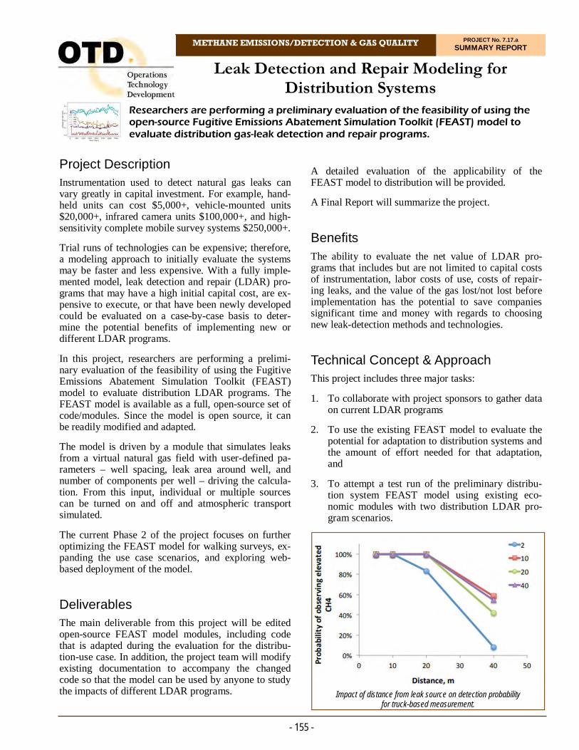
Leak Detection and Repair Modeling for Distribution Systems
METHANE EMISSIONS/DETECTION & GAS QUALITY PROJECT No. 7.17.a SUMMARY REPORT
Researchers are performing a preliminary evaluation of the feasibility of using the open-source Fugitive Emissions Abatement Simulation Toolkit (FEAST) model to evaluate distribution gas-leak detection and repair programs.
- 155 -
Project Description Instrumentation used to detect natural gas leaks can vary greatly in capital investment. For example, hand-held units can cost $5,000+, vehicle-mounted units $20,000+, infrared camera units $100,000+, and high-sensitivity complete mobile survey systems $250,000+.
Trial runs of technologies can be expensive; therefore, a modeling approach to initially evaluate the systems may be faster and less expensive. With a fully imple-mented model, leak detection and repair (LDAR) pro-grams that may have a high initial capital cost, are ex-pensive to execute, or that have been newly developed could be evaluated on a case-by-case basis to deter-mine the potential benefits of implementing new or different LDAR programs.
In this project, researchers are performing a prelimi-nary evaluation of the feasibility of using the Fugitive Emissions Abatement Simulation Toolkit (FEAST) model to evaluate distribution LDAR programs. The FEAST model is available as a full, open-source set of code/modules. Since the model is open source, it can be readily modified and adapted.
The model is driven by a module that simulates leaks from a virtual natural gas field with user-defined pa-rameters – well spacing, leak area around well, and number of components per well – driving the calcula-tion. From this input, individual or multiple sources can be turned on and off and atmospheric transport simulated.
The current Phase 2 of the project focuses on further optimizing the FEAST model for walking surveys, ex-panding the use case scenarios, and exploring web-based deployment of the model.
Deliverables The main deliverable from this project will be edited open-source FEAST model modules, including code that is adapted during the evaluation for the distribu-tion-use case. In addition, the project team will modify existing documentation to accompany the changed code so that the model can be used by anyone to study the impacts of different LDAR programs.
A detailed evaluation of the applicability of the FEAST model to distribution will be provided.
A Final Report will summarize the project.
Benefits The ability to evaluate the net value of LDAR pro-grams that includes but are not limited to capital costs of instrumentation, labor costs of use, costs of repair-ing leaks, and the value of the gas lost/not lost before implementation has the potential to save companies significant time and money with regards to choosing new leak-detection methods and technologies.
Technical Concept & Approach This project includes three major tasks:
1. To collaborate with project sponsors to gather data on current LDAR programs
2. To use the existing FEAST model to evaluate the potential for adaptation to distribution systems and the amount of effort needed for that adaptation, and
3. To attempt a test run of the preliminary distribu-tion system FEAST model using existing eco-nomic modules with two distribution LDAR pro-gram scenarios.
Impact of distance from leak source on detection probability for truck-based measurement.
- 156 -
enhanced the performance and ability of the model to represent a wider number of systems. The model was automated to a run all survey frequencies and produce graphics for quick analysis and comparison of differ-ent model run scenarios. In addition, an initial vehicle-based survey module was developed to begin explor-ing this methodology.
In 2020, researchers completed a literature survey across four major areas of research related to methane leaks from underground distribution systems: aerial emissions detection, conventional field measurements, truck-based leak detection, and the physical proper-ties affecting leakage.
In the summer of 2020, the project team organized a webinar to provide an overview of the FEAST-D model and the status of development efforts to date. Discussions focused on how the model may be used to compare various leak-detection platforms as well as how the model uses input data, such as pipeline mate-rial and age, to simulate a distribution network and generate randomness using the Markov model.
In late 2020, development, analysis, and detailed documentation of the FEAST-D model was com-pleted. Additionally, the software associated with the first version of the FEAST-D model, FEAST-D 1.0 beta, was finalized and ready for review by the com-plete project team prior to becoming publicly avail-able. Three major methods were considered and simu-lated for model evaluation, including EPA Method-21, truck-based, and drone-based leak-detection ap-proaches.
Status
Planned activities include:
A training webinar on how to run FEAST-D 1.0 beta, and
A project closeout webinar to review the project Final Report and identify model improvement op-portunities and functionality enhancements.
The information gathered on the leak field will be used to inform the numerical modeling of the leak-field sce-narios.
The feasibility of incorporating a number of scenarios/parameters for simulating leaks and atmospheric trans-port will be examined. These might include representing net value based on per mile of a particular type of pipe basis, a number of residences (i.e., number of meters), or the number of industrial facilities per square mile.
The form of the FEAST model that is currently available for download incorporates a particular model (i.e., set of equations) to simulate atmospheric transport away from a leak. Researchers expect that initially this model can be used to accurately simulate aboveground leaks in distribution. However, for belowground (more diffuse) leaks, the project team will conduct a preliminary inves-tigation into the feasibility of using a more advanced atmospheric transport model that may more precisely represent such leaks.
The performance of a modified FEAST model will be evaluated by attempting to run the model with existing distribution leak data anonymously provided by spon-sors, from the literature, and from existing data.
Phase 2 focuses on further optimizing the model and developing it for other use-case scenarios, such as mo-bile surveys. Extensive model-sensitivity tests will be conducted to determine the influence of different pa-rameters on model output and evaluate model perform-ance.
Results During Phase 1, the project team significantly modified modules to simulate a distribution pipeline network. Re-searchers adapted the model to represent a distribution network grid with leaks detected via a walking survey using a handheld tool. This established a base case for modeling the distribution of leaks generated, detected, and carried over from year to year.
Researchers created a different version of the model that attempts to simulate a gas distribution network on an areal basis (square kilometers or miles). The project team was able to successfully generate new leaks in ran-dom locations while simulating different survey inter-vals, with varying ability to locate leaks via walking surveys. Researchers also added an “accounting” of the leaks to track when they are generated and when they are found within a model run in order to track emissions.
The 2-D grid matrix layout was changed to a 1-D array layout, which means that the system can be represented by total miles of pipe instead of square area. This greatly
For more information:
Michael Adamo, P.E. Vice President, Operations Operations Technology Development, NFP Phone: 847/544-3428 [email protected]
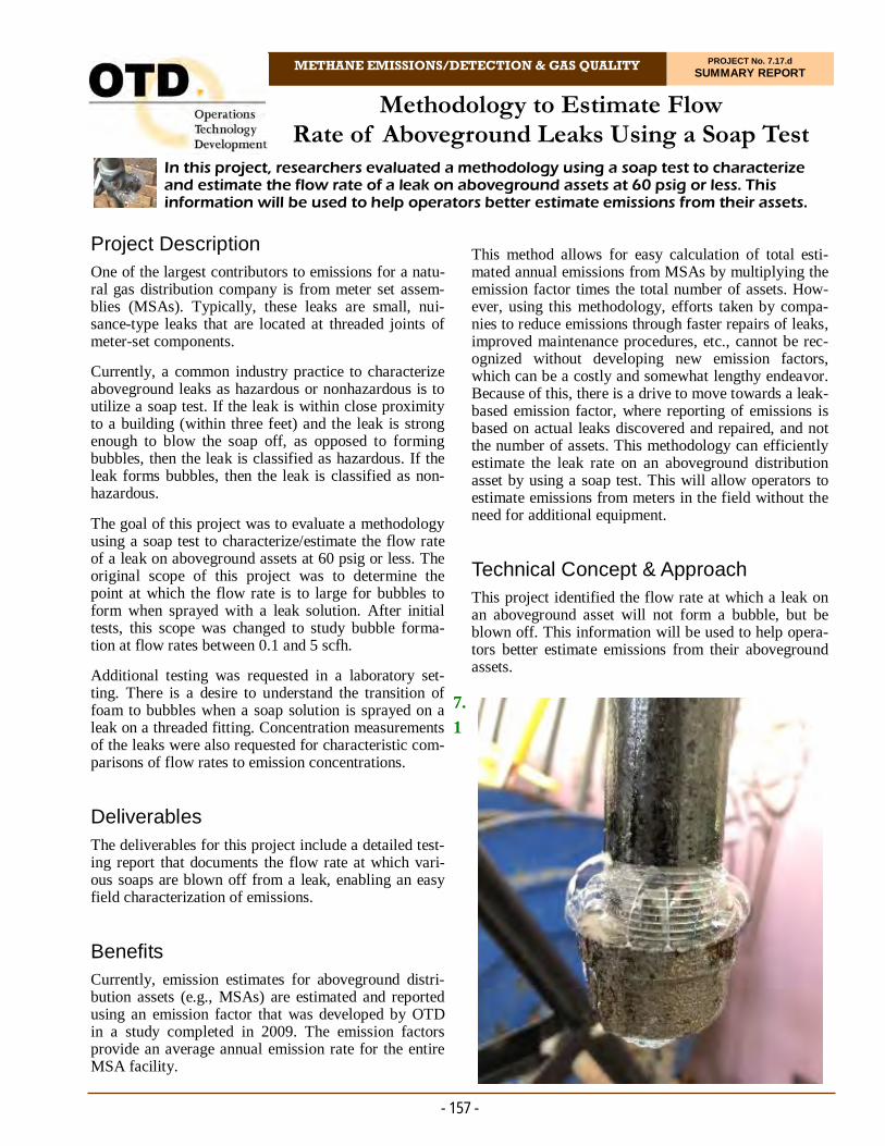
7.1
Methodology to Estimate Flow Rate of Aboveground Leaks Using a Soap Test
METHANE EMISSIONS/DETECTION & GAS QUALITY PROJECT No. 7.17.d SUMMARY REPORT
In this project, researchers evaluated a methodology using a soap test to characterize and estimate the flow rate of a leak on aboveground assets at 60 psig or less. This information will be used to help operators better estimate emissions from their assets.
- 157 -
Project Description One of the largest contributors to emissions for a natu-ral gas distribution company is from meter set assem-blies (MSAs). Typically, these leaks are small, nui-sance-type leaks that are located at threaded joints of meter-set components.
Currently, a common industry practice to characterize aboveground leaks as hazardous or nonhazardous is to utilize a soap test. If the leak is within close proximity to a building (within three feet) and the leak is strong enough to blow the soap off, as opposed to forming bubbles, then the leak is classified as hazardous. If the leak forms bubbles, then the leak is classified as non-hazardous.
The goal of this project was to evaluate a methodology using a soap test to characterize/estimate the flow rate of a leak on aboveground assets at 60 psig or less. The original scope of this project was to determine the point at which the flow rate is to large for bubbles to form when sprayed with a leak solution. After initial tests, this scope was changed to study bubble forma-tion at flow rates between 0.1 and 5 scfh.
Additional testing was requested in a laboratory set-ting. There is a desire to understand the transition of foam to bubbles when a soap solution is sprayed on a leak on a threaded fitting. Concentration measurements of the leaks were also requested for characteristic com-parisons of flow rates to emission concentrations.
Deliverables
The deliverables for this project include a detailed test-ing report that documents the flow rate at which vari-ous soaps are blown off from a leak, enabling an easy field characterization of emissions.
Benefits Currently, emission estimates for aboveground distri-bution assets (e.g., MSAs) are estimated and reported using an emission factor that was developed by OTD in a study completed in 2009. The emission factors provide an average annual emission rate for the entire MSA facility.
This method allows for easy calculation of total esti-mated annual emissions from MSAs by multiplying the emission factor times the total number of assets. How-ever, using this methodology, efforts taken by compa-nies to reduce emissions through faster repairs of leaks, improved maintenance procedures, etc., cannot be rec-ognized without developing new emission factors, which can be a costly and somewhat lengthy endeavor. Because of this, there is a drive to move towards a leak-based emission factor, where reporting of emissions is based on actual leaks discovered and repaired, and not the number of assets. This methodology can efficiently estimate the leak rate on an aboveground distribution asset by using a soap test. This will allow operators to estimate emissions from meters in the field without the need for additional equipment.
Technical Concept & Approach This project identified the flow rate at which a leak on an aboveground asset will not form a bubble, but be blown off. This information will be used to help opera-tors better estimate emissions from their aboveground assets.

- 158 -
based on available leak-rate data. Preliminary field trial data can be used to generate a new leak rate dis-tribution curve and refine the emission factors if com-pany-specific leak rate data is not available initially. Uncertainty observed when classifying leaks can be used to further update the emission factors using a probabilistic approach. The procedure provides a flexible approach for customizing the soap test for specific company needs and continuously improve the accuracy by incorporating new data.
A method based on existing soap tests for grading leaks was developed to perform leak-rate quantifica-tion on aboveground leaks at distribution pressure. The methodology is simple enough to be performed without requiring any special equipment or complex training.
The methodology allows the leak-rate estimate to be continuously improved. Field data can be used to gen-erate new emission factors if the initial population data was not specific to the company. As more field data is collected, the emission factor for each category can be adjusted continually to account for the uncer-tainty in the classification using a probabilistic ap-proach.
The findings show that there was a tendency to over-estimate leak rates using the soap bubble test method, which might be partially caused by the higher occur-rences of smaller leaks in the sample. More data will have to be collected to better understand the accuracy of the method on larger leaks.
The results of the field test are discussed in detail in the draft Final Report.
Status This project is complete. A Final Report was issued in August 2020.
Specific tasks in this project included:
Soap Solution Identification/Procedure Review
Soap that utility companies use to identify leaks can vary widely. Moreover, the concentration and mix-ing in the field by crews can vary as well. A survey of project sponsors for commonly used soaps, and procedures for mixing, was performed. Three soaps and concentrations will be included in the analysis.
Laboratory Testing of Leak Rates and Soap Bubbles
Researchers developed a test matrix to conduct leak testing on the various soaps selected. The matrix includes pressure variations and temperature varia-tions (of the soap and atmosphere). A test rig was constructed so that flow testing of a variety of dif-ferent leak configurations can be simulated. These leaks were primarily on threaded connections as that is the most common location for a leak in the field. The average leak rate will be determined from the testing performed.
Field Validation
Researchers validated leak flow rates in the field in comparison to those observed in the laboratory. Validation measurements can be made using a lami-nar flow element device (or similar instrument) as used in previous emissions studies.
Results Initially, laboratory tests were completed to study the effect of leak rates, leak type, and soap solution on bub-ble behavior during soap tests. The experiments demon-strated that there is a correlation between largest bubble size and leak rate which provided the basis of the esti-mation method. The tests also showed that leak rate is the most dominant factor affecting bubble behavior in comparison to soap solution and leak type (location of leak on fitting or joint).
A field test to assess the feasibility and accuracy of the soap bubble test for quantifying leak rate was completed at a sponsor site in California. Prior to the test, a set of bubble categories was developed to classify the soap test results, with each category having a representative leak rate. Over the course of three days, 47 previously found residential meter set leaks were visited and quantified with both the soap bubble test and Hi-Flow™ sampler.
The field trial demonstrated that the soap test method is viable for approximating leak size. Based on the field trial, a procedure to establish company/region-specific leak-classification criteria to facilitate the soap test quantification method was developed. The four-step ap-proach enables companies to develop unique criteria
For more information:
Michael Adamo, P.E. Vice President, Operations Operations Technology Development, NFP Phone: 847/544-3428 [email protected]

Evaluation of Methane-Detection Devices for Utility Operations
METHANE EMISSIONS/DETECTION & GAS QUALITY PROJECT No. 7.17.e SUMMARY REPORT
This project focused on the evaluation of new and advanced methane-detection devices for potential use in walking leak surveys, leak investigation, and stationary remote monitoring.
- 159 -
Project Description With the advancement of technologies – coupled with an industry focus on reducing methane emissions from natural gas operations – there has been an increase over the past several years in the number of products enter-ing the market for detecting methane. Consequently, there is a need to validate the technical specifications of these products and to evaluate the performance of these technologies for suitable applications for utility operations relative to tools currently used by the indus-try.
In this project, a testing program was conducted to evaluate these tools. The program is tailored for spe-cific-use case scenarios, including walking leak sur-veys, leak investigation, and stationary remote moni-toring.
Investigators reviewed a large body of research in the area of methane sensing. Sensing technologies in-cluded laser-based sensors, optical imaging techniques, biosensors, and other methods.
Deliverables The deliverables for this project include a report that summarizes the findings. The report will include rec-ommendations on the best applications/use-case sce-nario for each tool evaluated.
Benefits The adoption of new advanced methane-detection tech-nologies can improve the ability to identify and locate leaks, resulting in a more efficient leak detection and repair process.
These technologies also have the potential for remote monitoring of target assets that may require frequent, longer-term detection of methane.
Broadening the toolbox of methane-detection devices will allow for more tailored leak-detection methods, resulting in increased safety environmental benefits.
Technical Concept & Approach This project focused on evaluating technologies that are or near commercially available that can be used for walking leak surveys, leak investigation, and stationary remote monitoring.
Advancements in gas-sensor technologies have led to more sensitive devices that can detect methane at con-centrations at the parts per billion level, far below the atmospheric concentration of methane, which is ap-proximately two parts per million. These technologies, while extremely sensitive, typically have high capital costs, and often users have concerns with regard to false positives or identifying hits of methane that would not otherwise correspond to what a utility would define as a natural gas leak. On the other hand, these advanced technologies may allow for faster surveys and earlier detection of leaks, therefore preventing larger events from occurring.
Advancements have also been made that allow for the production of low-cost, lower-power methane sensors that can be deployed as a network of methane sensors to remotely monitor areas of interest.
Environmental test chamber.

- 160 -
LEL levels were larger than could be safely created. In the laboratory, the unit performed close to the manu-facturer specifications; however, one of the three units did not consistently alarm at 5% LEL concentration levels. The main limitation for the sensor as stationary remote monitor was the lack of extended battery power, providing only 8 to10 hours per charge (a limi-tation of many potential leave-behind monitors).
Other instruments were tested in the laboratory, in-cluding a cavity-based laser system that offers sub-ppb sensitivity to methane and a mid-infrared-laser-based system that operated at a different wavelength to eliminate the need for a cavity.
The project team investigated a system that was de-signed for leak investigations and walking surveys. The unit had a continuous methane sensor and logging capability with the additional capability of doing a determination of ethane concentrations. The ethane analysis required about five minutes to complete, thus was not in real time, but was used only to verify the presence of ethane once a potential leak was detected. The unit then responded with a report of “natural gas” or “swamp gas.” Outside testing was weather-limited, but the unit was evaluated in the laboratory and was found to perform quite well although less accurate than other sensors, especially below 10 ppmv.
Through the course of regular testing at the under-ground leak sites during this project, researchers also paired a high-accuracy GPS system with two of the analyzers to conduct a more detailed analysis of the high-speed, high-sensitivity methane analyzers. The results of this analysis agreed with current understand-ing of the importance of operating a high-sensitivity analyzer downwind of the types of relatively small underground leaks examined in this project. Future developments could be made in analytics for the high-sensitivity analyzers to be used more easily by field crews in real time.
Status
A Phase 1 Final Report was issued in April 2020.
Should the project period of performance be extended, researchers could perform more thorough testing on the sensors and testing on several new sensors that have become available since the end of the project.
The scope of the project includes a technical evaluation of these technologies. Information gathered on capital or operating and maintenance costs are included in the re-port, but will not be a part of the evaluation. The evalua-tion includes validation testing in the laboratory as well as controlled field evaluations of the technologies in simulations of target applications, such as a pipeline leak survey.
A candidate list of technologies was identified for evaluation in this project. The technologies range from laser-based systems requiring active sampling to micro-electromechanical systems requiring passive sampling.
A testing matrix was developed to validate the technical specifications of each technology. This includes detec-tion level, sensitivity, accuracy, precision, false posi-tives, repeatability, and reproducibility of results. Smaller devices that can fit into an environmental cham-ber were tested in a constant-volume-controlled atmos-phere. Backpack-carried devices that use a sampling wand will be tested using a smaller chamber where flowing gas can be introduced and sampled.
Controlled field testing was conducted to determine the performance of technologies against leak/methane-detection tools currently used by utilities. A simulated leak site was created for the field testing. Independent sensors were placed around a leak area to monitor the methane concentrations and to create a methane map profile. They will also serve as referee sensors for the point sensors to be evaluated for the target application of stationary remote monitoring. Measurements using the technology under investigation as well as the referee tool were conducted in parallel to ensure consistent en-vironmental and operating conditions.
Results The wide variety of potential use cases led the project team to develop a series of preliminary laboratory and field tests to evaluate the performance of four sensors and make recommendations for how they would per-form in real world deployment. These sensors were se-lected due to their potential applicability to the identified use cases and their availability.
One of the sensors was designed as a personal wearable device monitor for worker safety and researchers were interested in evaluating the performance of this unit as a potential stationary remote monitor. The sensor was relatively inexpensive, but the manufacturer specifica-tions stated detection limits are in the %LEL range (not ppm). The higher detection limit made this sensor a pos-sible candidate for deployment near company assets that may experience large leaks capable of increasing the ambient air methane levels into the %LEL range. The sensor was tested only in the laboratory as the leaks re-quired to raise the concentrations in ambient air to %
For more information:
Michael Adamo, P.E. Vice President, Operations Operations Technology Development, NFP Phone: 847/544-3428 [email protected]

METHANE EMISSIONS/DETECTION & GAS QUALITY PROJECT No. 7.18.b SUMMARY REPORT
Project Description Researchers are addressing a variety of issues related to biomethane injection in natural gas distribution and transmission pipelines. These include considerations regarding safety, reliability, interchangeability, continu-ity, and the requirements to keep gas flowing and avoid service interruption.
In this project, a research team developed a study on the quality, analysis, risk, and compositional variability of final end-use-grade biomethane.
The goal is to provide biomethane project developers, producers, and distributors with sound science and clear facts that can be used to reduce uncertainty about tech-nical issues related to biomethane utilization.
Deliverables The deliverables for the overall project include:
The most recent tabulation of gas quality data
A risk assessment of the constituents in biomethane
A simple risk calculator for pipeline component integrity, and
For this project, a research team developed a study on the quality, analysis, risk, and compositional variability of final end-use-grade biomethane to demonstrate the viability and safety of biomethane use in natural gas distribution and transmission systems.
Biomethane Justification Study for Improved/Accepted Gas Quality Standard
A biomethane acceptance justification document.
Benefits Demand for natural gas is increasing as utilities change electricity production from coal to natural gas and trucking fleets convert to compressed natural gas (CNG). Biomethane derived from landfills, wastewater treatment plants, dairy farms, food-waste processors, and other sources is poised to become an increasing part of the natural gas equation.
Biomethane qualifies as an advanced biofuel under the Renewable Fuel Standard, and as a cellulosic biofuel (since 2014) when used for CNG production. These qualifications are leading to wider acceptance and specification by regulators and customers. States and other entities are becoming more aggressive in want-ing to incorporate diverse sources of renewable energy into their energy portfolio.
Universally established gas quality acceptance stan-dards for biomethane will provide answers to intercon-nect project skeptics and detractors.
- 161 -
Biomethane is being introduced into natural gas pipelines from a variety of sources, including landfills, wastewater treatment plants, and livestock operations.
- 162 -
For more information:
Michael Adamo, P.E. Vice President, Operations Operations Technology Development, NFP Phone: 847/544-3428 [email protected]
the data-mining effort, and published information on the impact on infrastructure materials of construction.
An advisory committee (subset of sponsors) was formed to provide input and guidance.
Data collection from laboratory analyses, various re-search projects, and the literature survey was com-pleted and data curation completed.
The primary criteria for removal was the obvious pres-ence of a significant amount of air in a sample. The list of trace gas constituents and component materials was developed. Compatibility and chemical interaction re-ports were reviewed for some of the gas constituents. Directed acyclic graphs were drawn of the completed constituents to summarize the incompatibilities and illustrate the magnitude of risks.
Statistical data and estimated risks were added to the risk calculator.
Preliminary risks were determined based on reference materials and graphs.
In 2020, data tables were organized, statistics calcu-lated, and graphs made. The all-gas option was added along with a comparison to natural gas concentrations.
A draft report was issued in November 2020 that dem-onstrates that biomethane can be cleaned to specifica-tions meeting or better than typical pipeline specifica-tions. The report takes a dataset of biomethane con-stituent concentrations and compares it to both a natu-ral gas dataset and the AGA4A summary tariff data. This document shows that biomethane is an active bio-genic fuel of choice and an integral part of the renew-able energy solution.
Status
The risk calculator was developed, modified, and pro-vided to sponsors.
Technical Concept & Approach Data Collection and Mining
Data from previous gas quality analyses was thor-oughly vetted and tabulated for use in subsequent tasks. Data includes information from laboratory independent gas analyses that would be blinded as to actual source but would be grouped by region and type. Additional data from the literature was added to form a comprehensive catalog of informa-tion on biomethane quality.
Evaluation of Risk
Researchers updated existing risk assessments. Me-tallic pipe was added to the material matrix. Wher-ever possible, standard metal pipe corrosion data was used. Data from existing literature studies and laboratory experimentations was included.
Development of a Risk Calculator
A simple risk calculator for pipeline component integrity was developed.
Development of Justification Document
The framework of previous guidance documents and reports was used to develop a biomethane justi-fication document that will apply across the U.S. and Canada. This document 1) makes specific rec-ommendations of acceptance criteria for bio-methane based on assessments of the raw biogas feedstock, 2) discusses monitoring instrumentation and techniques, and 3) explains monitoring perio-dicity and why it is needed.
Results In 2018, considerable data mining was conducted and a literature search conducted.
The previous risk assessment utilized in a past U.S. De-partment of Transportation Pipeline and Hazardous Ma-terials Safety Administration project was reviewed.
A risk model based on a previous project was selected to be the starting point for the risk calculator. The revi-sion for biomethane justification includes user-selected inputs for gas source as analyzed constituents and their concentrations. The consequence is a prediction of im-pact based on the two prior inputs, data generated from

METHANE EMISSIONS/DETECTION & GAS QUALITY PROJECT No. 7.18.c SUMMARY REPORT
Project Description First responders are often in situations where they are investigating a leak in a potentially hazardous environ-ment. To determine the methane concentrations within buildings or structures, first responders use handheld methane-detection tools that require putting themselves in environments with potentially high concentrations of methane.
The overall objective for this project is to develop tools that allow operators to remotely assess leaks and meth-ane concentrations while limiting exposure to hazard-ous environments.
As a preliminary investigation, in Phase 1 of this pro-ject, a robot system prototype was used as a deployment platform for a remote-sensing technology already in development.
Deliverable The primary deliverable will be a laboratory-tested, ro-bot-based methane-detection device that can be certi-fied intrinsically safe in later phases.
Benefits Determining the methane concentrations within a build-ing can help to mitigate a potential leak event and al-lows for a more effective and efficient utility response. Having a remotely operated robot-based methane-detection system can provide a safer method for investi-gating a leak when the potential for high methane con-centrations exist inside of a structure.
Technical Concept & Approach Specific tasks for this project included:
Project Scoping and Evaluation of Current Proce-dures
Technology Evaluation of the Robotic Platform
Prototype Assembly, and
Laboratory Testing.
In this project, researchers evaluated a robotic device for use as a remotely operated methane-detection unit to reduce worker exposure to potentially hazardous situations.
Robot for Remote Methane Detection
Included with the robot is an attached PTZ (pan/tilt/zoom) camera, a battery, a remote controller, and a set of stabilizing bars, an extended manipulator arm for opening doors, and external equipment to display the robot’s audio/video output. The robot body has two rubber tracks for movement, along with four attached flippers with tracks. The front flippers can be moved up and down to position the robot while climbing stairs, moving objects, opening doors, etc. The body of the robot also contains a stationary camera on the front for navigation while driving as well as a flashlight and infrared camera for visibility in the dark.
Results In 2018, the project team procured a robot for testing. The test procedure included testing the capability of the robot to serve as an inspection tool in buildings. The testing also included evaluation of the robot’s ease of use and ability to traverse obstacle courses, climb stairs, and open doors.
- 163 -

- 164 -
For more information:
Michael Adamo, P.E. Vice President, Operations Operations Technology Development, NFP Phone: 847/544-3428 [email protected]
Continued evaluation of the robot in 2019 focused on the communications and navigation range of the robot with its controller, the robot’s ability to turn a valve, and the robot’s ability to navigate a residential prop-erty. Results of the testing were mixed. The robot proved to be adept at working specific valves that were in good working order, but had problems navigating steps with the manipulator arm attached, failing to climb residential carpeted interior stairs and wooden exterior stairs.
Another small test was completed to test the robot’s ability to operate valves. Two pipe nipples were at-tached on either side of a lever valve and the setup was placed in a vise. The robot was able to turn the lever valve with relative ease.
Status
Evaluation of the robot was completed in 2019. A Final Report was issued in May 2020.
Suggestions will be made to the continue the project to further evaluate the robot’s capability in aiding the util-ity industry. Future phases of this project could focus on the integration of methane detection devices directly with the robot. The evaluation could include devices that could be attached or imbedded within the robot without inhibiting necessary functionality such as arm and grip manipulation of doors and objects. Further work may also be done to modify the current robot de-sign to improve handling in the areas where it per-formed less effectively, particularly on stairs with the extended manipulator arm attached.
The robot proved to be capable of accomplishing many of the tasks; however, there were a few areas where testing revealed some limitations, especially when the extended arm attachment was added.
Subsequently, additional testing was conducted that included: 1) Operating the robot on stairs with different materials; 2) Trying many different door handles, and 3) Evaluating signal strength in different environments similar to both residential and commercial spaces.
After gaining familiarity with the robot’s controls and functions, a series of obstacle courses were assembled with four scenarios for testing the robot.
For the robot to be effective in patrolling buildings and homes, it needs to climb stairs consistently well and in a timely manner. Researchers developed a methodology to test the robot’s effectiveness in climbing industrial stairwells, wooden stairs, and carpeted stairs.
Another critical component of searching a building is opening doors. The project team tested doors with vary-ing handles to determine the robot’s consistent success or failure. These included round knobs, long handles, pull handles, and push handles.
A major factor in using a robot to inspect structures is signal strength. For initial tests, researchers tested the robot’s signal limitations within a building. It is impor-tant to note that the facility is made with metal materials with walls of painted cement and contain many metal cabinets and equipment. This is important because radio signals can be disrupted trying to penetrate these mate-rials. A test was performed to evaluate the signal strength when the robot was driven along an indirect path. As the operator remained stationary, the robot was driven through the hallways until the signal was lost and the operator could not control the robot. As demon-strated, the robot performs very well when navigating at short distances with few obstacles. The robot should perform well in a more residential environment where material construction would be less likely to block the signal’s path to the robot.
The project team evaluated the robot for possible use as a methane-detection tool. Researchers also took the op-portunity to test the robot in conjunction with a portable methane gas analyzer. This test was performed by at-taching the gas analyzer to the robot and navigating a planned path around a known leak.
Due to the sensor’s high sensitivity, sudden changes in movement and level can affect the accuracy of the data. The robot experienced trouble navigating the sand. This test also demonstrated the restrictions presented when attaching multiple devices to the robot. While the robot was only operated in an open-air space during this test, in a real application the attachments would hinder the robot’s ability to navigate stairs and doors as they re-stricted the robot’s movements and arm operation.
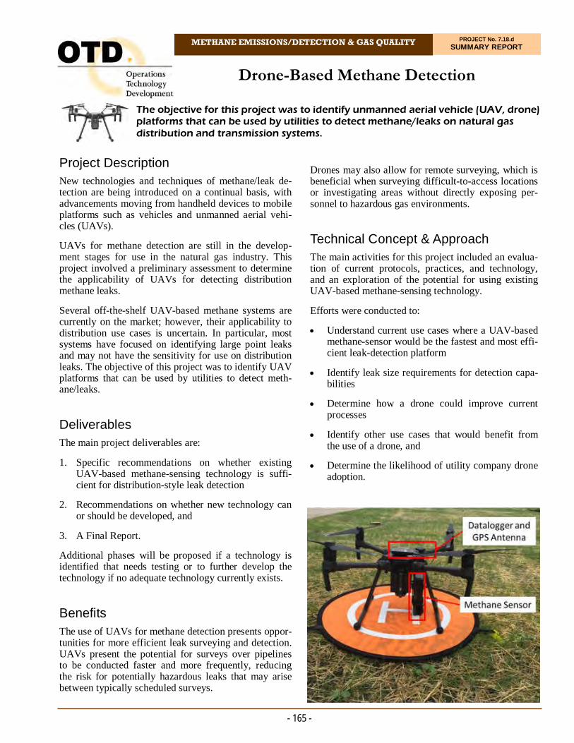
METHANE EMISSIONS/DETECTION & GAS QUALITY PROJECT No. 7.18.d SUMMARY REPORT
Project Description New technologies and techniques of methane/leak de-tection are being introduced on a continual basis, with advancements moving from handheld devices to mobile platforms such as vehicles and unmanned aerial vehi-cles (UAVs).
UAVs for methane detection are still in the develop-ment stages for use in the natural gas industry. This project involved a preliminary assessment to determine the applicability of UAVs for detecting distribution methane leaks.
Several off-the-shelf UAV-based methane systems are currently on the market; however, their applicability to distribution use cases is uncertain. In particular, most systems have focused on identifying large point leaks and may not have the sensitivity for use on distribution leaks. The objective of this project was to identify UAV platforms that can be used by utilities to detect meth-ane/leaks.
Deliverables The main project deliverables are:
1. Specific recommendations on whether existing UAV-based methane-sensing technology is suffi-cient for distribution-style leak detection
2. Recommendations on whether new technology can or should be developed, and
3. A Final Report.
Additional phases will be proposed if a technology is identified that needs testing or to further develop the technology if no adequate technology currently exists.
Benefits The use of UAVs for methane detection presents oppor-tunities for more efficient leak surveying and detection. UAVs present the potential for surveys over pipelines to be conducted faster and more frequently, reducing the risk for potentially hazardous leaks that may arise between typically scheduled surveys.
The objective for this project was to identify unmanned aerial vehicle (UAV, drone) platforms that can be used by utilities to detect methane/leaks on natural gas distribution and transmission systems.
Drone-Based Methane Detection
Drones may also allow for remote surveying, which is beneficial when surveying difficult-to-access locations or investigating areas without directly exposing per-sonnel to hazardous gas environments.
Technical Concept & Approach The main activities for this project included an evalua-tion of current protocols, practices, and technology, and an exploration of the potential for using existing UAV-based methane-sensing technology.
Efforts were conducted to:
Understand current use cases where a UAV-based methane-sensor would be the fastest and most effi-cient leak-detection platform
Identify leak size requirements for detection capa-bilities
Determine how a drone could improve current processes
Identify other use cases that would benefit from the use of a drone, and
Determine the likelihood of utility company drone adoption.
- 165 -
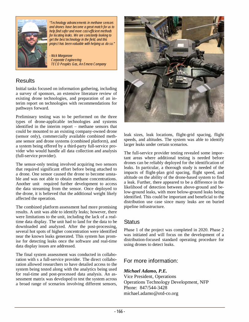
- 166 -
For more information:
Michael Adamo, P.E. Vice President, Operations Operations Technology Development, NFP Phone: 847/544-3428 [email protected]
leak sizes, leak locations, flight-grid spacing, flight speeds, and altitudes. The system was able to identify larger leaks under certain scenarios.
The full-service provider testing revealed some impor-tant areas where additional testing is needed before drones can be reliably deployed for the identification of leaks. In particular, a thorough study is needed of the impacts of flight-plan grid spacing, flight speed, and altitude on the ability of the drone-based system to find a leak. Further, there appeared to be a difference in the likelihood of detection between above-ground and be-low-ground leaks, with more below-ground leaks being identified. This could be important and beneficial to the distribution use case since many leaks are on buried pipeline infrastructure.
Status
Phase 1 of the project was completed in 2020. Phase 2 was initiated and will focus on the development of a distribution-focused standard operating procedure for using drones to detect leaks.
Results Initial tasks focused on information gathering, including a survey of sponsors, an extensive literature review of existing drone technologies, and preparation of an in-terim report on technologies with recommendations for pathways forward.
Preliminary testing was to be performed on the three types of drone-applicable technologies and systems identified in the interim report – methane sensors that could be mounted to an existing company-owned drone (sensor only), commercially available combined meth-ane sensor and drone systems (combined platform), and a system being offered by a third-party full-service pro-vider who would handle all data collection and analysis (full-service provider).
The sensor-only testing involved acquiring two sensors that required significant effort before being attached to a drone. One sensor caused the drone to become unsta-ble and was not able to obtain methane concentrations. Another unit required further development to access the data streaming from the sensor. Once deployed to the drone, it is believed that the additional weight likely affected the operation.
The combined platform assessment had more promising results. A unit was able to identify leaks; however, there were limitations to the unit, including the lack of a real-time data display. The unit had to land for the data to be downloaded and analyzed. After the post-processing, several hot spots of higher concentration were identified near the known leaks generated. This system has prom-ise for detecting leaks once the software and real-time data display issues are addressed.
The final system assessment was conducted in collabo-ration with s a full-service provider. The direct collabo-ration allowed researchers to have detailed access to the system being tested along with the analytics being used for real-time and post-processed data analysis. An as-sessment matrix was developed to test the system across a broad range of scenarios involving different sensors,
“Technology advancements in methane sensors and drones have become a great match for us to help find safer and more cost-efficient methods for locating leaks. We are constantly looking to get the best technology in the field, and this project has been valuable with helping us do so.”
- Nick Margarone Corporate Engineering TECO Peoples Gas, An Emera Company
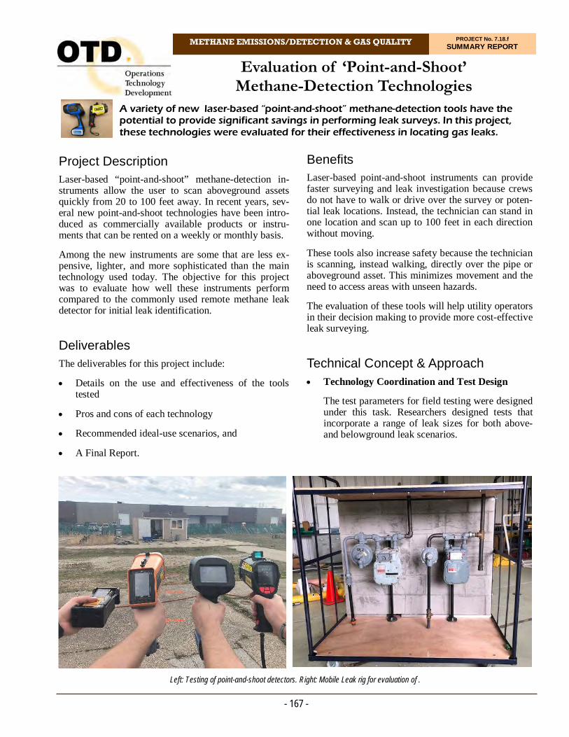
METHANE EMISSIONS/DETECTION & GAS QUALITY PROJECT No. 7.18.f SUMMARY REPORT
Project Description Laser-based “point-and-shoot” methane-detection in-struments allow the user to scan aboveground assets quickly from 20 to 100 feet away. In recent years, sev-eral new point-and-shoot technologies have been intro-duced as commercially available products or instru-ments that can be rented on a weekly or monthly basis.
Among the new instruments are some that are less ex-pensive, lighter, and more sophisticated than the main technology used today. The objective for this project was to evaluate how well these instruments perform compared to the commonly used remote methane leak detector for initial leak identification.
Deliverables The deliverables for this project include:
Details on the use and effectiveness of the tools tested
Pros and cons of each technology
Recommended ideal-use scenarios, and
A Final Report.
A variety of new laser-based “point-and-shoot” methane-detection tools have the potential to provide significant savings in performing leak surveys. In this project, these technologies were evaluated for their effectiveness in locating gas leaks.
Evaluation of ‘Point-and-Shoot’ Methane-Detection Technologies
Benefits Laser-based point-and-shoot instruments can provide faster surveying and leak investigation because crews do not have to walk or drive over the survey or poten-tial leak locations. Instead, the technician can stand in one location and scan up to 100 feet in each direction without moving.
These tools also increase safety because the technician is scanning, instead walking, directly over the pipe or aboveground asset. This minimizes movement and the need to access areas with unseen hazards.
The evaluation of these tools will help utility operators in their decision making to provide more cost-effective leak surveying.
Technical Concept & Approach Technology Coordination and Test Design
The test parameters for field testing were designed under this task. Researchers designed tests that incorporate a range of leak sizes for both above- and belowground leak scenarios.
- 167 -
Left: Testing of point-and-shoot detectors. Right: Mobile Leak rig for evaluation of .
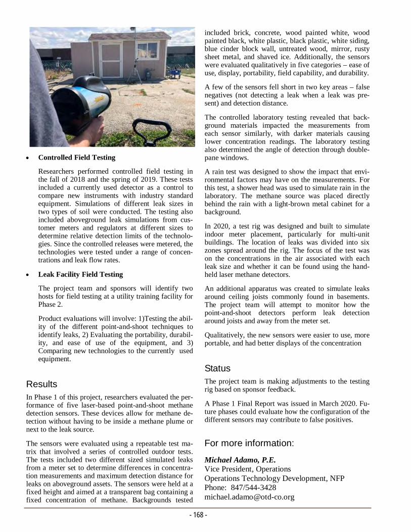
- 168 -
For more information:
Michael Adamo, P.E. Vice President, Operations Operations Technology Development, NFP Phone: 847/544-3428 [email protected]
included brick, concrete, wood painted white, wood painted black, white plastic, black plastic, white siding, blue cinder block wall, untreated wood, mirror, rusty sheet metal, and shaved ice. Additionally, the sensors were evaluated qualitatively in five categories – ease of use, display, portability, field capability, and durability.
A few of the sensors fell short in two key areas – false negatives (not detecting a leak when a leak was pre-sent) and detection distance.
The controlled laboratory testing revealed that back-ground materials impacted the measurements from each sensor similarly, with darker materials causing lower concentration readings. The laboratory testing also determined the angle of detection through double-pane windows.
A rain test was designed to show the impact that envi-ronmental factors may have on the measurements. For this test, a shower head was used to simulate rain in the laboratory. The methane source was placed directly behind the rain with a light-brown metal cabinet for a background.
In 2020, a test rig was designed and built to simulate indoor meter placement, particularly for multi-unit buildings. The location of leaks was divided into six zones spread around the rig. The focus of the test was on the concentrations in the air associated with each leak size and whether it can be found using the hand-held laser methane detectors.
An additional apparatus was created to simulate leaks around ceiling joists commonly found in basements. The project team will attempt to monitor how the point-and-shoot detectors perform leak detection around joists and away from the meter set.
Qualitatively, the new sensors were easier to use, more portable, and had better displays of the concentration
Status The project team is making adjustments to the testing rig based on sponsor feedback.
A Phase 1 Final Report was issued in March 2020. Fu-ture phases could evaluate how the configuration of the different sensors may contribute to false positives.
Controlled Field Testing
Researchers performed controlled field testing in the fall of 2018 and the spring of 2019. These tests included a currently used detector as a control to compare new instruments with industry standard equipment. Simulations of different leak sizes in two types of soil were conducted. The testing also included aboveground leak simulations from cus-tomer meters and regulators at different sizes to determine relative detection limits of the technolo-gies. Since the controlled releases were metered, the technologies were tested under a range of concen-trations and leak flow rates.
Leak Facility Field Testing
The project team and sponsors will identify two hosts for field testing at a utility training facility for Phase 2.
Product evaluations will involve: 1)Testing the abil-ity of the different point-and-shoot techniques to identify leaks, 2) Evaluating the portability, durabil-ity, and ease of use of the equipment, and 3)Comparing new technologies to the currently used equipment.
Results In Phase 1 of this project, researchers evaluated the per-formance of five laser-based point-and-shoot methane detection sensors. These devices allow for methane de-tection without having to be inside a methane plume or next to the leak source.
The sensors were evaluated using a repeatable test ma-trix that involved a series of controlled outdoor tests. The tests included two different sized simulated leaks from a meter set to determine differences in concentra-tion measurements and maximum detection distance for leaks on aboveground assets. The sensors were held at a fixed height and aimed at a transparent bag containing a fixed concentration of methane. Backgrounds tested
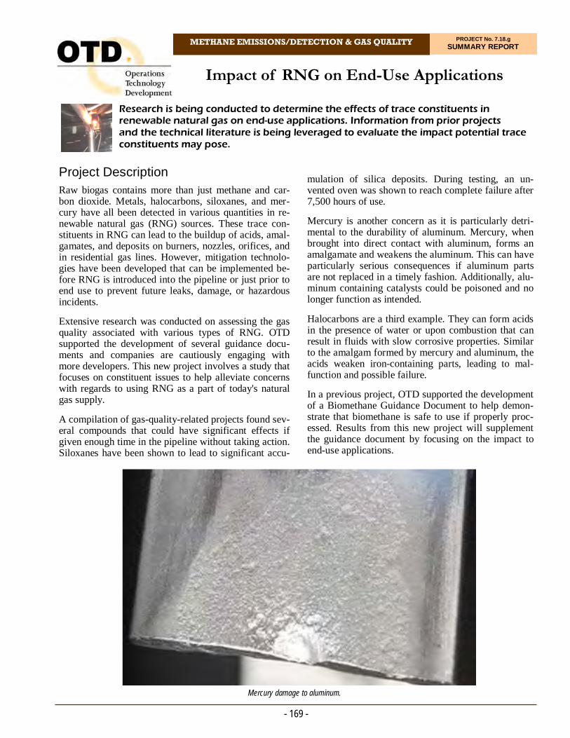
METHANE EMISSIONS/DETECTION & GAS QUALITY PROJECT No. 7.18.g SUMMARY REPORT
Project Description Raw biogas contains more than just methane and car-bon dioxide. Metals, halocarbons, siloxanes, and mer-cury have all been detected in various quantities in re-newable natural gas (RNG) sources. These trace con-stituents in RNG can lead to the buildup of acids, amal-gamates, and deposits on burners, nozzles, orifices, and in residential gas lines. However, mitigation technolo-gies have been developed that can be implemented be-fore RNG is introduced into the pipeline or just prior to end use to prevent future leaks, damage, or hazardous incidents.
Extensive research was conducted on assessing the gas quality associated with various types of RNG. OTD supported the development of several guidance docu-ments and companies are cautiously engaging with more developers. This new project involves a study that focuses on constituent issues to help alleviate concerns with regards to using RNG as a part of today's natural gas supply.
A compilation of gas-quality-related projects found sev-eral compounds that could have significant effects if given enough time in the pipeline without taking action. Siloxanes have been shown to lead to significant accu-
Research is being conducted to determine the effects of trace constituents in renewable natural gas on end-use applications. Information from prior projects and the technical literature is being leveraged to evaluate the impact potential trace constituents may pose.
Impact of RNG on End-Use Applications
mulation of silica deposits. During testing, an un-vented oven was shown to reach complete failure after 7,500 hours of use.
Mercury is another concern as it is particularly detri-mental to the durability of aluminum. Mercury, when brought into direct contact with aluminum, forms an amalgamate and weakens the aluminum. This can have particularly serious consequences if aluminum parts are not replaced in a timely fashion. Additionally, alu-minum containing catalysts could be poisoned and no longer function as intended.
Halocarbons are a third example. They can form acids in the presence of water or upon combustion that can result in fluids with slow corrosive properties. Similar to the amalgam formed by mercury and aluminum, the acids weaken iron-containing parts, leading to mal-function and possible failure.
In a previous project, OTD supported the development of a Biomethane Guidance Document to help demon-strate that biomethane is safe to use if properly proc-essed. Results from this new project will supplement the guidance document by focusing on the impact to end-use applications.
- 169 -
Mercury damage to aluminum.
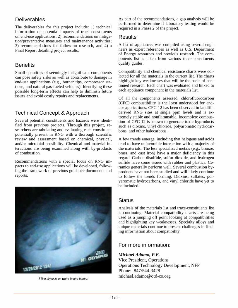
- 170 -
For more information:
Michael Adamo, P.E. Vice President, Operations Operations Technology Development, NFP Phone: 847/544-3428 [email protected]
As part of the recommendations, a gap analysis will be performed to determine if laboratory testing would be required in a Phase 2 of the project.
Results
A list of appliances was compiled using several engi-neers as expert references as well as U.S. Department of Energy resources and previous research. The com-ponents list is taken from various trace constituents quality guides.
Compatibility and chemical resistance charts were col-lected for all the materials in the current list. The charts highlight key weaknesses that will be the basis of con-tinued research. Each chart was evaluated and linked to each appliance component in the materials list.
Of all the components assessed, chlorofluorocarbon (CFC) combustibility is the least understood for end-use applications. CFC-12 has been observed in landfill-derived RNG sites at single ppm levels and is ex-tremely stable and nonflammable. Incomplete combus-tion of CFC-12 is known to generate toxic byproducts such as dioxins, vinyl chloride, polyaromatic hydrocar-bons, and other halocarbons.
A few trends emerge, including that halogens and acids tend to have unfavorable interaction with a majority of the materials. The less specialized metals (e.g., bronze, brass, and cast iron) have a major deficiency in this regard. Carbon disulfide, sulfur dioxide, and hydrogen sulfide have some issues with rubber and plastics. Ce-ramics generally perform well. Several combustion by-products have not been studied and will likely continue to follow the trends forming. Dioxins, sulfates, pol-yaromatic hydrocarbons, and vinyl chloride have yet to be included.
Status
Analysis of the materials list and trace-constituents list is continuing. Material compatibility charts are being used as a jumping off point looking at compatibilities and highlighting key weaknesses. Specialty alloys and unique materials continue to present challenges in find-ing information about compatibility.
Deliverables The deliverables for this project include: 1) technical information on potential impacts of trace constituents on end-use applications; 2) recommendations on mitiga-tion/preventative measures and maintenance activities; 3) recommendations for follow-on research, and 4) a Final Report detailing project results.
Benefits Small quantities of seemingly insignificant components can pose safety risks as well as contribute to damage in end-use applications (e.g., burner tips, compressor sta-tions, and natural gas-fueled vehicles). Identifying these possible long-term effects can help to diminish future issues and avoid costly repairs and replacements.
Technical Concept & Approach Several potential constituents and hazards were identi-fied from previous projects. Through this project, re-searchers are tabulating and evaluating each constituent potentially present in RNG with a thorough scientific review and assessment based on chemical, physical, and/or microbial possibility. Chemical and material in-teractions are being examined along with by-products of combustion.
Recommendations with a special focus on RNG im-pacts to end-use applications will be developed, follow-ing the framework of previous guidance documents and reports.
Silica deposits on water-heater burner.
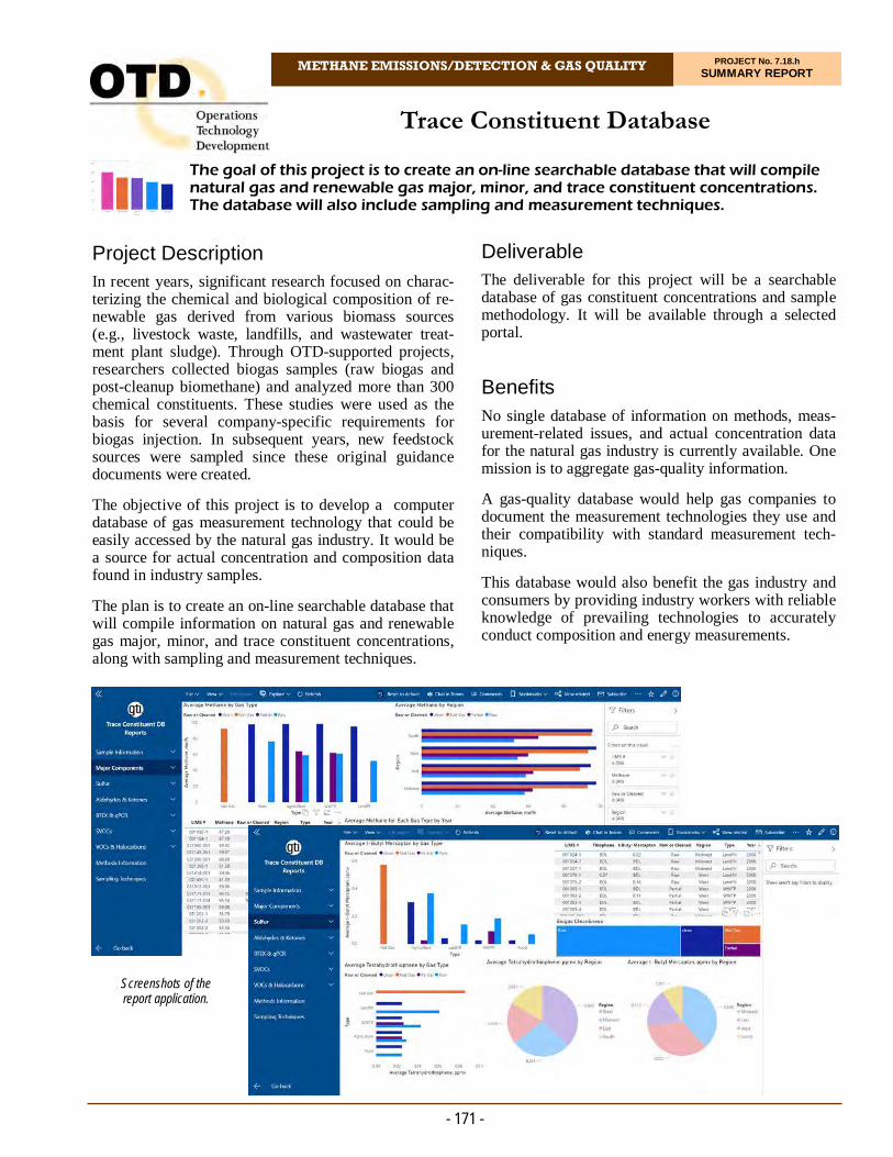
METHANE EMISSIONS/DETECTION & GAS QUALITY PROJECT No. 7.18.h SUMMARY REPORT
Project Description In recent years, significant research focused on charac-terizing the chemical and biological composition of re-newable gas derived from various biomass sources (e.g., livestock waste, landfills, and wastewater treat-ment plant sludge). Through OTD-supported projects, researchers collected biogas samples (raw biogas and post-cleanup biomethane) and analyzed more than 300 chemical constituents. These studies were used as the basis for several company-specific requirements for biogas injection. In subsequent years, new feedstock sources were sampled since these original guidance documents were created.
The objective of this project is to develop a computer database of gas measurement technology that could be easily accessed by the natural gas industry. It would be a source for actual concentration and composition data found in industry samples.
The plan is to create an on-line searchable database that will compile information on natural gas and renewable gas major, minor, and trace constituent concentrations, along with sampling and measurement techniques.
The goal of this project is to create an on-line searchable database that will compile natural gas and renewable gas major, minor, and trace constituent concentrations. The database will also include sampling and measurement techniques.
Trace Constituent Database
Deliverable The deliverable for this project will be a searchable database of gas constituent concentrations and sample methodology. It will be available through a selected portal.
Benefits No single database of information on methods, meas-urement-related issues, and actual concentration data for the natural gas industry is currently available. One mission is to aggregate gas-quality information.
A gas-quality database would help gas companies to document the measurement technologies they use and their compatibility with standard measurement tech-niques.
This database would also benefit the gas industry and consumers by providing industry workers with reliable knowledge of prevailing technologies to accurately conduct composition and energy measurements.
- 171 -
Screenshots of the report application.

- 172 -
For more information:
Michael Adamo, P.E. Vice President, Operations Operations Technology Development, NFP Phone: 847/544-3428 [email protected]
Results The data for this project was mined from the archives of Gas Technology Institute’s data files going back to the 1990s and through 2020. Analyses were curated and normalized onto master summary spreadsheets.
The database was created using Microsoft SQL Server and hosted using Microsoft’s Azure cloud storage plat-form. Microsoft Power BI was selected to visualize and report data. To date, eight reports were created covering a variety of target constituents and fuel-gas properties. The reports are currently linked on the pro-ject page of the OTD SharePoint site.
The application also has reports detailing sampling techniques and method information. The database and application are directly linked so the application is pulling raw data directly from the database in order to generate reports.
Status
The work on this phase of the project is complete. The Final Report was submitted and plans are under way for a second phase proposal to continue adding data and new gas-quality modules. Technical Concept & Approach
Existing data was organized into a master list of data for uploading into the selected database. Data will be blinded as to exact origin, but will be identified as to feedstock and completeness of upgrade from the raw biogas.
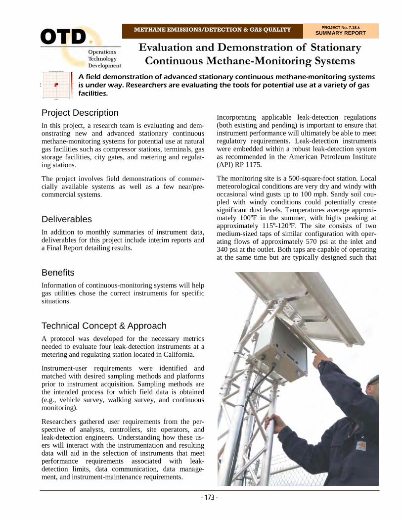
METHANE EMISSIONS/DETECTION & GAS QUALITY PROJECT No. 7.18.k SUMMARY REPORT
Project Description In this project, a research team is evaluating and dem-onstrating new and advanced stationary continuous methane-monitoring systems for potential use at natural gas facilities such as compressor stations, terminals, gas storage facilities, city gates, and metering and regulat-ing stations.
The project involves field demonstrations of commer-cially available systems as well as a few near/pre-commercial systems.
Deliverables In addition to monthly summaries of instrument data, deliverables for this project include interim reports and a Final Report detailing results.
Benefits Information of continuous-monitoring systems will help gas utilities chose the correct instruments for specific situations.
Technical Concept & Approach A protocol was developed for the necessary metrics needed to evaluate four leak-detection instruments at a metering and regulating station located in California.
Instrument-user requirements were identified and matched with desired sampling methods and platforms prior to instrument acquisition. Sampling methods are the intended process for which field data is obtained (e.g., vehicle survey, walking survey, and continuous monitoring).
Researchers gathered user requirements from the per-spective of analysts, controllers, site operators, and leak-detection engineers. Understanding how these us-ers will interact with the instrumentation and resulting data will aid in the selection of instruments that meet performance requirements associated with leak-detection limits, data communication, data manage-ment, and instrument-maintenance requirements.
A field demonstration of advanced stationary continuous methane-monitoring systems is under way. Researchers are evaluating the tools for potential use at a variety of gas facilities.
Evaluation and Demonstration of Stationary Continuous Methane-Monitoring Systems
Incorporating applicable leak-detection regulations (both existing and pending) is important to ensure that instrument performance will ultimately be able to meet regulatory requirements. Leak-detection instruments were embedded within a robust leak-detection system as recommended in the American Petroleum Institute (API) RP 1175.
The monitoring site is a 500-square-foot station. Local meteorological conditions are very dry and windy with occasional wind gusts up to 100 mph. Sandy soil cou-pled with windy conditions could potentially create significant dust levels. Temperatures average approxi-mately 100ºF in the summer, with highs peaking at approximately 115º-120ºF. The site consists of two medium-sized taps of similar configuration with oper-ating flows of approximately 570 psi at the inlet and 340 psi at the outlet. Both taps are capable of operating at the same time but are typically designed such that
- 173 -
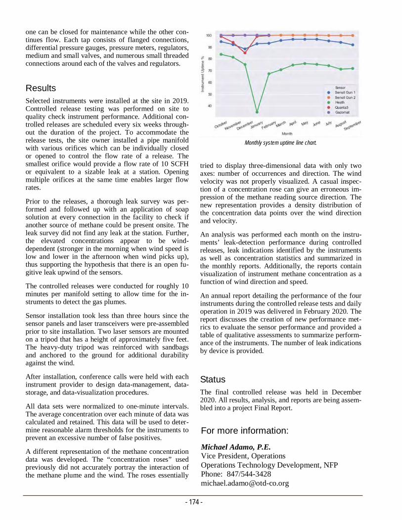
- 174 -
For more information:
Michael Adamo, P.E. Vice President, Operations Operations Technology Development, NFP Phone: 847/544-3428 [email protected]
tried to display three-dimensional data with only two axes: number of occurrences and direction. The wind velocity was not properly visualized. A casual inspec-tion of a concentration rose can give an erroneous im-pression of the methane reading source direction. The new representation provides a density distribution of the concentration data points over the wind direction and velocity.
An analysis was performed each month on the instru-ments’ leak-detection performance during controlled releases, leak indications identified by the instruments as well as concentration statistics and summarized in the monthly reports. Additionally, the reports contain visualization of instrument methane concentration as a function of wind direction and speed.
An annual report detailing the performance of the four instruments during the controlled release tests and daily operation in 2019 was delivered in February 2020. The report discusses the creation of new performance met-rics to evaluate the sensor performance and provided a table of qualitative assessments to summarize perform-ance of the instruments. The number of leak indications by device is provided. Status The final controlled release was held in December 2020. All results, analysis, and reports are being assem-bled into a project Final Report.
one can be closed for maintenance while the other con-tinues flow. Each tap consists of flanged connections, differential pressure gauges, pressure meters, regulators, medium and small valves, and numerous small threaded connections around each of the valves and regulators.
Results Selected instruments were installed at the site in 2019. Controlled release testing was performed on site to quality check instrument performance. Additional con-trolled releases are scheduled every six weeks through-out the duration of the project. To accommodate the release tests, the site owner installed a pipe manifold with various orifices which can be individually closed or opened to control the flow rate of a release. The smallest orifice would provide a flow rate of 10 SCFH or equivalent to a sizable leak at a station. Opening multiple orifices at the same time enables larger flow rates.
Prior to the releases, a thorough leak survey was per-formed and followed up with an application of soap solution at every connection in the facility to check if another source of methane could be present onsite. The leak survey did not find any leak at the station. Further, the elevated concentrations appear to be wind-dependent (stronger in the morning when wind speed is low and lower in the afternoon when wind picks up), thus supporting the hypothesis that there is an open fu-gitive leak upwind of the sensors.
The controlled releases were conducted for roughly 10 minutes per manifold setting to allow time for the in-struments to detect the gas plumes.
Sensor installation took less than three hours since the sensor panels and laser transceivers were pre-assembled prior to site installation. Two laser sensors are mounted on a tripod that has a height of approximately five feet. The heavy-duty tripod was reinforced with sandbags and anchored to the ground for additional durability against the wind.
After installation, conference calls were held with each instrument provider to design data-management, data-storage, and data-visualization procedures.
All data sets were normalized to one-minute intervals. The average concentration over each minute of data was calculated and retained. This data will be used to deter-mine reasonable alarm thresholds for the instruments to prevent an excessive number of false positives.
A different representation of the methane concentration data was developed. The “concentration roses” used previously did not accurately portray the interaction of the methane plume and the wind. The roses essentially
Monthly system uptime line chart.

METHANE EMISSIONS/DETECTION & GAS QUALITY PROJECT No. 7.19.a SUMMARY REPORT
Project Description Current procedures for classifying gas leaks are based on well-established methods and the equipment used for leak detection. However, there are an abundance of new methane-detection technologies entering the market that have the potential to improve leak detection and classi-fication efficiency.
Researchers identified at least one technology to use and test for this project. The instrument is currently a prototype instrument weighing less than three pounds that uses passive, open-path sampling (no pump). This system can be used to generate data to look for potential correlations between current instruments and techniques used for leak classification.
In this project, researchers are exploring the possibili-ties for new open-path methane detectors to be incorpo-rated into leak-classification/grading procedures.
A project team is compiling existing information on the performance of these sensors, create data comparing new methods to existing methods, evaluate any poten-tial safety risks of using aboveground measurement to grade leaks, and produce a recommended procedure for using the technology for leak classification/grading.
Deliverables
Key deliverables for this project include:
Existing data summary
New technique correlation data
Leak-classification procedure (if warranted), and
Quarterly and Final Reports
Benefits Two important issues are associated with identifying and classifying leaks – 1) labor costs required to per-form identification and classification, and 2) the accu-racy and repeatability of the measurement device. Both issues can impact the costs of finding and grading/
Researchers are exploring the possibilities for new open-path methane detectors to be incorporated into leak-classification/grading procedures. A project team is gathering existing information on the performance of these sensors, creating data comparing new methods to existing methods, evaluating any potential safety risks, and producing a recommended procedure.
Advanced Leak-Detection Technologies for Grading Leaks
classifying leaks through potential inefficiencies in equipment that may cause increased labor time to find the leaks or repeated visits needed to find missed leaks.
Some companies are restricted to specific types of technology and, therefore, cannot currently use a whole group of new methane-detection technologies known as open-path sensors for leak identification and classification. These sensors have the potential to more quickly examine large areas for leaks, reducing labor costs and increasing efficiency by covering large leak areas.
Technical Concept & Approach This project explores pathways for incorporating open-path methane detectors into company leak-classifica-tion procedures.
- 175 -
Measuring above-ground concentrations prior to barholing.

- 176 -
For more information:
Michael Adamo, P.E. Vice President, Operations Operations Technology Development, NFP Phone: 847/544-3428 [email protected]
concentrations and barhole concentrations of an under-ground leak when assessing the grade or severity of the leak. Two commercially available products were used to collect below-ground concentrations at barholes while another instrument was used to measure surface concentrations.
Subsequently, the instrument was re-engineered to have a higher upper detection limit of 500 ppm. In ad-dition, several alternative metrics (average concentra-tion, variance, area under curve) were introduced in this test and yielded much better correlation with leak flow rate compared to maximum concentration reading. The alternative metrics netted better correlation with the leak flow rate, especially when an outlier point is excluded. In addition, a simple leak-detection experi-ment demonstrated the instrument’s effectiveness as an open-path leak-survey instrument. The instrument was able to detect leaks from a distance away and above-ground level.
In 2020, release tests were conducted. Better correla-tion was observed between measurements and leak flow rates compared to previous rounds. In addition, a set of requirements was drafted for assessing new leak-grading equipment.
In September 2020, a total of 81 underground pipeline leaks at random residential sites were visited to evalu-ate the ability to grade leaks in comparison with a con-ventional pump-operated instrument.
Status Field testing continues. The next step is to conduct a field trial on actual leaks to verify the correlation and trends that have been observed during controlled re-lease tests.
A field test was designed that focuses on the ability of the technology to 1) quantify concentrations above-ground and 2) quantify concentrations above barholes.
The range of leak scenarios required to demonstrate the effectiveness of the new instruments/methods are lim-ited. Therefore, from the onset of the project, sponsors were asked to participate in real-world testing on real leaks where the new systems can be compared to exist-ing barholing techniques. Field testing will help to de-termine whether correlations exist between the initial surface-leak identification concentrations, the barhole concentrations, and the ultimate leak grade. Once the existing data and new data are compiled, the informa-tion and lessons learned will be combined into a written procedure on the best ways to utilize open-path methane sensors for leak classification.
Results
Recent advancements in laser optics and miniature tech-nologies paved the way for the development of a novel open-path methane sensor with potentially high sensi-tivity. Leak-detection devices also offer multiple pur-poses. They are used to not only detect and localize leak sources, but also to grade the severity of a leak. For a new sensor to be practical, it should ideally be capable of performing leak detection, localization, and grading to minimize leak surveys. However, potential con-straints exist with the use of open-path passive-sampling sensors as a means of measuring underground leaks. Specifically, the absence of a probe and pump means that the instrument must be placed on the ground surface to reliably read the concentration of any gas plume that emanates from the ground. Additionally, there exists challenges when using surface concentra-tion to estimate belowground conditions as there can be multiple atmospheric and/or subsurface conditions that complicate aboveground and below-ground correlation.
Researchers identified a new sensor that has the poten-tial to improve leak detection and classification effi-ciency. The instrument is currently a prototype origi-nally designed by the NASA Jet Propulsion Laboratory to find methane on Mars as a part of NASA’s Mars Rover program. The newer, miniature version is more lightweight and sensitive than traditional instruments of similar size and function. The system uses multiple mir-rors and a laser that are coupled to the appropriate analysis region for measuring concentrations of trace methane. The instrument is called “open path” because the laser is exposed to the atmosphere via a porous housing – even though the laser is technically contained within a structure.
In 2019 and 2020, several field tests were conducted at the leak field in the PG&E Safety Academy in Califor-nia to investigate if correlations exist between surface
- Francois Rongere R&D and Innovation Senior Manager - Gas Operations Pacific Gas and Electric Company
“PG&E works relentlessly to improve leak-detection methods and technologies. Leak grading is a key step of leak surveys since it prioritizes repairs based on safety. It is critical for us to ensure consistency of grading procedures before deploying new tools. This project provides the rigorous foundation needed for that.”
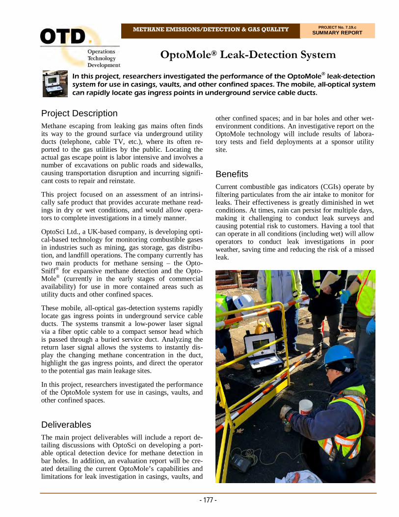
METHANE EMISSIONS/DETECTION & GAS QUALITY PROJECT No. 7.19.c SUMMARY REPORT
Project Description Methane escaping from leaking gas mains often finds its way to the ground surface via underground utility ducts (telephone, cable TV, etc.), where its often re-ported to the gas utilities by the public. Locating the actual gas escape point is labor intensive and involves a number of excavations on public roads and sidewalks, causing transportation disruption and incurring signifi-cant costs to repair and reinstate.
This project focused on an assessment of an intrinsi-cally safe product that provides accurate methane read-ings in dry or wet conditions, and would allow opera-tors to complete investigations in a timely manner.
OptoSci Ltd., a UK-based company, is developing opti-cal-based technology for monitoring combustible gases in industries such as mining, gas storage, gas distribu-tion, and landfill operations. The company currently has two main products for methane sensing – the Opto-Sniff® for expansive methane detection and the Opto-Mole® (currently in the early stages of commercial availability) for use in more contained areas such as utility ducts and other confined spaces.
These mobile, all-optical gas-detection systems rapidly locate gas ingress points in underground service cable ducts. The systems transmit a low-power laser signal via a fiber optic cable to a compact sensor head which is passed through a buried service duct. Analyzing the return laser signal allows the systems to instantly dis-play the changing methane concentration in the duct, highlight the gas ingress points, and direct the operator to the potential gas main leakage sites.
In this project, researchers investigated the performance of the OptoMole system for use in casings, vaults, and other confined spaces.
Deliverables The main project deliverables will include a report de-tailing discussions with OptoSci on developing a port-able optical detection device for methane detection in bar holes. In addition, an evaluation report will be cre-ated detailing the current OptoMole’s capabilities and limitations for leak investigation in casings, vaults, and
In this project, researchers investigated the performance of the OptoMole® leak-detection system for use in casings, vaults, and other confined spaces. The mobile, all-optical system can rapidly locate gas ingress points in underground service cable ducts.
OptoMole® Leak-Detection System
other confined spaces; and in bar holes and other wet-environment conditions. An investigative report on the OptoMole technology will include results of labora-tory tests and field deployments at a sponsor utility site.
Benefits Current combustible gas indicators (CGIs) operate by filtering particulates from the air intake to monitor for leaks. Their effectiveness is greatly diminished in wet conditions. At times, rain can persist for multiple days, making it challenging to conduct leak surveys and causing potential risk to customers. Having a tool that can operate in all conditions (including wet) will allow operators to conduct leak investigations in poor weather, saving time and reducing the risk of a missed leak.
- 177 -

- 178 -
For more information:
Michael Adamo, P.E. Vice President, Operations Operations Technology Development, NFP Phone: 847/544-3428 [email protected]
Results A field trial was successfully completed in Brooklyn, NY, in 2019. OptoMole was used for natural gas leak detection in an underground electric duct. There was insufficient time to conduct a full leak pinpointing, but the instrument allowed operators to deduce the direc-tion of the leak to narrow down the search area.
The main challenge encountered during the trial was presence of mud in the ducts, likely due to inclement weather the days prior, which blocked access. It is rec-ommended to find multiple access points to improve chances of probing the duct.
The demonstration showed that OptoMole has a valu-able application to improve leak localization in urban areas, which will help minimize unnecessary excava-tion.
Researchers tested the maneuverability of the detection probe and cable. For the initial test, the project team used PVC pipe sections measuring two, four, and six inches in diameter with three PVC tees measuring the same diameters, respectively. This was done to assess the ability of the probe to travel and turn into a 90-degree angle in a duct. While this may not be a normal function of the system, it was brought up as a possibil-ity, especially if the OptoMole could be used to investi-gate large residential building ducts.
In 2020, researchers completed laboratory tests of the system, including: exposure to water and response time, humidity testing, and low detection level tests.
Status The project team is preparing a Final Report.
Technical Concept & Approach The OptoMole evaluation focused on testing the:
Accuracy of the sensor in reading methane concen-trations
Functionality of the sensor in humid or wet condi-tions
Maneuverability of the sensor in congested conduits and in navigating bends
Safety of the sensor, and
Ease of deployment into electrical/shared utility conduits and for other applications such as survey-ing bar holes/casings.
Many of the available leak-detection devices are not able to operate in wet conditions. Their intake cannot handle large amounts of moisture for sampling pur-poses. Part of the OptoMole investigation included an assessment of the technology following complete sub-mersion in water that may or may not have high sedi-ment concentrations.
The overall approach of this project was to consult with OptoSci on its technology and its viability to produce accurate leak information in casings, vaults, other con-fined spaces, and in barhole type conditions while being redesigned into a more portable device. Inquiries will be made into the detection levels of methane following water submersion and if the technology can consistently perform in these conditions.
Deploying OptoMole for leak detection in a duct.
- Mattia Auriemma Manager Field Operations NYC National Grid
“This new tool for gas leak detection and investigation promises to provide a safe and reliable process for reducing methane emissions to the atmosphere and for reducing excavations, with minimal training required for use of tool.”
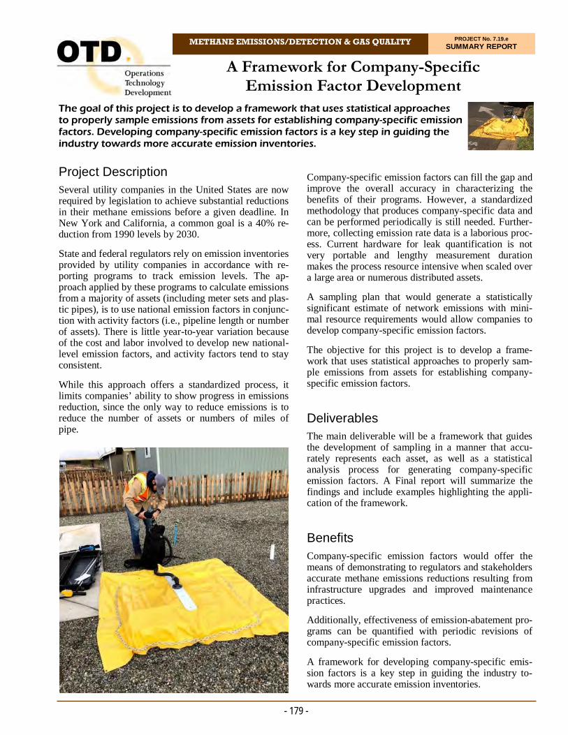
METHANE EMISSIONS/DETECTION & GAS QUALITY PROJECT No. 7.19.e SUMMARY REPORT
Project Description Several utility companies in the United States are now required by legislation to achieve substantial reductions in their methane emissions before a given deadline. In New York and California, a common goal is a 40% re-duction from 1990 levels by 2030.
State and federal regulators rely on emission inventories provided by utility companies in accordance with re-porting programs to track emission levels. The ap-proach applied by these programs to calculate emissions from a majority of assets (including meter sets and plas-tic pipes), is to use national emission factors in conjunc-tion with activity factors (i.e., pipeline length or number of assets). There is little year-to-year variation because of the cost and labor involved to develop new national-level emission factors, and activity factors tend to stay consistent.
While this approach offers a standardized process, it limits companies’ ability to show progress in emissions reduction, since the only way to reduce emissions is to reduce the number of assets or numbers of miles of pipe.
The goal of this project is to develop a framework that uses statistical approaches to properly sample emissions from assets for establishing company-specific emission factors. Developing company-specific emission factors is a key step in guiding the industry towards more accurate emission inventories.
A Framework for Company-Specific Emission Factor Development
Company-specific emission factors can fill the gap and improve the overall accuracy in characterizing the benefits of their programs. However, a standardized methodology that produces company-specific data and can be performed periodically is still needed. Further-more, collecting emission rate data is a laborious proc-ess. Current hardware for leak quantification is not very portable and lengthy measurement duration makes the process resource intensive when scaled over a large area or numerous distributed assets.
A sampling plan that would generate a statistically significant estimate of network emissions with mini-mal resource requirements would allow companies to develop company-specific emission factors.
The objective for this project is to develop a frame-work that uses statistical approaches to properly sam-ple emissions from assets for establishing company-specific emission factors.
Deliverables The main deliverable will be a framework that guides the development of sampling in a manner that accu-rately represents each asset, as well as a statistical analysis process for generating company-specific emission factors. A Final report will summarize the findings and include examples highlighting the appli-cation of the framework.
Benefits Company-specific emission factors would offer the means of demonstrating to regulators and stakeholders accurate methane emissions reductions resulting from infrastructure upgrades and improved maintenance practices.
Additionally, effectiveness of emission-abatement pro-grams can be quantified with periodic revisions of company-specific emission factors.
A framework for developing company-specific emis-sion factors is a key step in guiding the industry to-wards more accurate emission inventories.
- 179 -

- 180 -
For more information:
Michael Adamo, P.E. Vice President, Operations Operations Technology Development, NFP Phone: 847/544-3428 [email protected]
Method 2 began in 2020 and follows the original 12-month period of performance. Method 2 begins with a plan on how a utility would/could start with national data and findings, and then, over time, feed in their own survey data and validations to reinforce or wash-out the prior national data.
A sponsor report was completed in the first quarter of 2020. For this project, the next step is to remove data specific to the sponsor from the report and establish a standardized process for the project sponsors.
Underground and aboveground leaks will be treated using slightly different approaches in this project. The immediate focus is on underground leaks and will di-rectly leverage the report mentioned above.
In May 2020, an update presentation was provided to project sponsors outlining the methodology to develop company-specific emission factors using a statistical approach. Topics covered included:
How to establish random sample methodology and size
Statistical tests to check data quality
Pre-screening technologies
Method to develop decision tree to predict occur-rence of large leaks
Probabilistic analysis of errors
Establishing emission factors, and
Continuous refinement of emission factors.
Status The project team is preparing the narrative portion of the framework for company-specific emission-factor determination. This includes the belowground survey technique with direct and remote/stand-off measure-ment (pre-screening) methods, as well as aboveground leak emission-factor determination.
The majority of the research is now completed with only some adjustments to be made as the remote pre-screening methods and aboveground considerations are added to the framework.
Technical Concept & Approach Key aspects of this project include:
Sampling method selection
Measurement of sample representativeness
Probabilistic analysis of collected data, and
Generation of representative emission factors.
The main objective of the framework is to allow com-panies to have a standardized approach for planning, collecting, analyzing, and validating data to establish company-specific emission factors. This will allow companies to visualize an emission factor study as a series of manageable steps and focus on executing the tasks.
Determining factors that affect emission rates and cate-gorizing samples by these factors (e.g., pipe material and meter type) is important to recognize emission rate differences within an asset type. The project team will provide examples on how different assets can be strati-fied. Researchers will also review commercially avail-able sampling methods and their measurement uncer-tainties.
To allow for flexibility in experimental design, rather than prescribing a sample size, researchers will include statistical approaches for assessing the expected confi-dence level from a given sample size and how well a sample generalizes to the population. The selected ap-proach will produce a representative emission factor for each asset class as the output as well as confidence in-tervals to represent uncertainty in the result.
A framework is envisioned to be a set of sampling plans, sampling procedures, probabilistic analysis tools, and statistical tests intended for generating company-specific emission factors and can be used repeatedly. This framework will serve as a reference to select ap-propriate sampling methods, design a sampling plan, and calculate the emission factors.
Results
Research is this project consists of two methods: Method 1 - Walking Close Proximity Survey Frame-work (Point of Leak) and Method 2 – Mobile/Remote Survey Framework (Standoff from Leak).
Method 1 includes the sample method, sample plan, data analysis, and framework. The various forms of sampling plans are being explored (e.g., pure random, stratified random, and aggregate of multiple geographic samples). Additionally, researchers will add/address other statistical sample plans and dynamic sample plans for below and above ground assets.
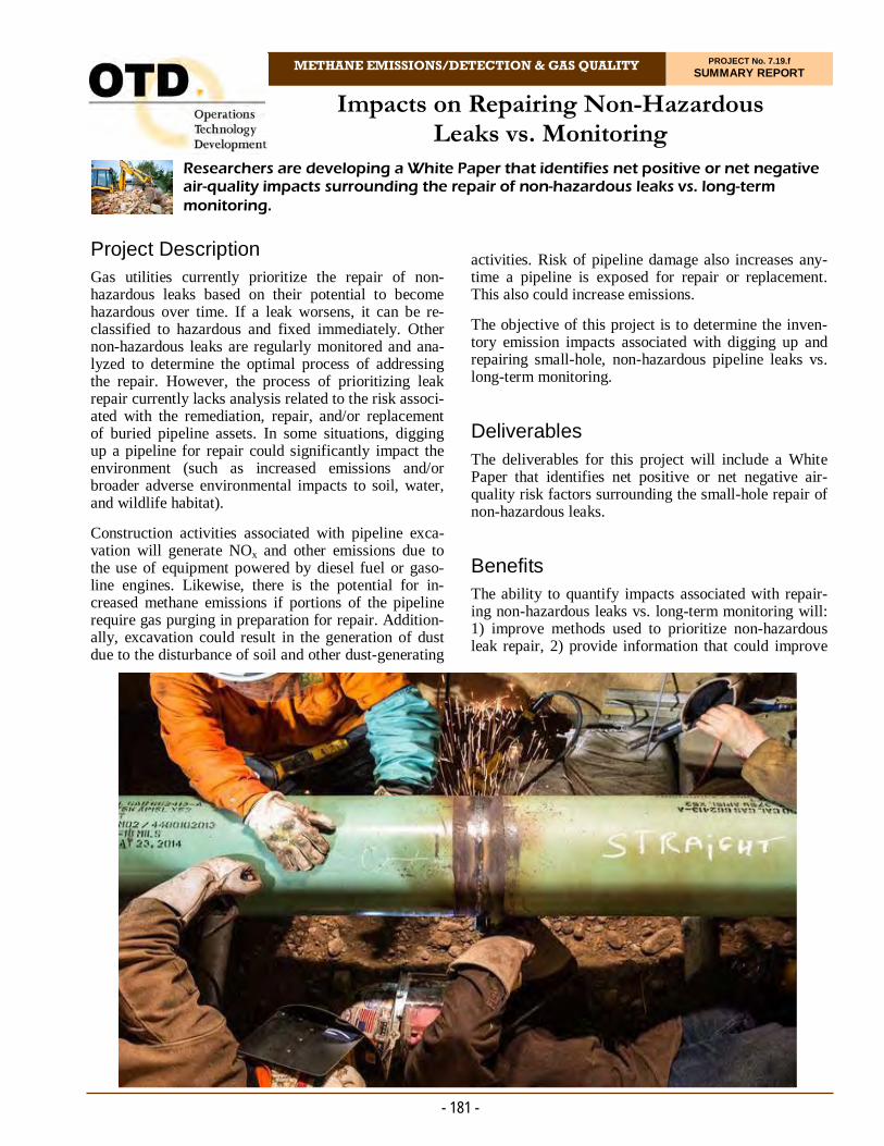
Impacts on Repairing Non-Hazardous Leaks vs. Monitoring
METHANE EMISSIONS/DETECTION & GAS QUALITY PROJECT No. 7.19.f SUMMARY REPORT
Researchers are developing a White Paper that identifies net positive or net negative air-quality impacts surrounding the repair of non-hazardous leaks vs. long-term monitoring.
- 181 -
Project Description Gas utilities currently prioritize the repair of non-hazardous leaks based on their potential to become hazardous over time. If a leak worsens, it can be re-classified to hazardous and fixed immediately. Other non-hazardous leaks are regularly monitored and ana-lyzed to determine the optimal process of addressing the repair. However, the process of prioritizing leak repair currently lacks analysis related to the risk associ-ated with the remediation, repair, and/or replacement of buried pipeline assets. In some situations, digging up a pipeline for repair could significantly impact the environment (such as increased emissions and/or broader adverse environmental impacts to soil, water, and wildlife habitat).
Construction activities associated with pipeline exca-vation will generate NOx and other emissions due to the use of equipment powered by diesel fuel or gaso-line engines. Likewise, there is the potential for in-creased methane emissions if portions of the pipeline require gas purging in preparation for repair. Addition-ally, excavation could result in the generation of dust due to the disturbance of soil and other dust-generating
activities. Risk of pipeline damage also increases any-time a pipeline is exposed for repair or replacement. This also could increase emissions.
The objective of this project is to determine the inven-tory emission impacts associated with digging up and repairing small-hole, non-hazardous pipeline leaks vs. long-term monitoring.
Deliverables
The deliverables for this project will include a White Paper that identifies net positive or net negative air-quality risk factors surrounding the small-hole repair of non-hazardous leaks.
Benefits The ability to quantify impacts associated with repair-ing non-hazardous leaks vs. long-term monitoring will: 1) improve methods used to prioritize non-hazardous leak repair, 2) provide information that could improve
- 182 -
Site Visits
Site characteristics for selected study areas will be defined and include: sites with small-hole repairs; sites with Grade 2 or 3 leaks; risk factors to be inventoried for each site, and types of equipment used during the repair will be verified.
Comparative Analysis and White Paper
The comparative analysis and White Paper will include the various risk aspects associated with the repair will be categorized by process type as well as totaled. Results will determine a net positive impact of repair or a net negative impact of repair. Data generated or gathered during the project will be used to determine leak-rate thresholds by which repairs of non-hazardous leaks could be prioritized in the future.
Results In 2020, a series of tasks were delineated in the busi-ness process of pipeline repair. The corresponding equipment used in each task was identified to generate the equipment and air-emission inventories.
The project team is developing equipment type, make, model, year, chemical type, hours in service for the repair for each process component.
Process components include:
Preparation (surveying, marking right of ways)
Excavation (surface demolition, spoil removal)
Pipe Repair (main isolation, blowdown, cleaning, coating, valve installation, welding/butt fusion)
Restoration (backfilling, repairs to other systems, tamping, repaving).
A preliminary survey was created to gather the equip-ment model and operation information, which will be used as inputs to compute the associated air emissions.
Status The project team is analyzing survey data. A second survey is being developed to collect information on leak repairs.
emissions management and environmental stewardship, and 3) result in leak-repair timing decisions that are de-fensible and understandable by regulators. Additionally, operators that have had recent engagements with their state public service commissions have greatly benefited from demonstrating the entire spectrum of risk – to in-clude risk associated with remediation, repair, and re-placement operations – as compared to the risk of leav-ing the leak in place. By demonstrating a more holistic risk-assessment approach, the understanding of risk was greatly improved.
Technical Concept & Approach Emission impacts associated with digging up and repair-ing small-hole, non-hazardous pipeline leaks vs. long-term monitoring will be inventoried and evaluated.
Specific tasks include:
Project Scoping
The project team will select and prioritize a list of sites to visit as well as select the type of data needed for quantifying environmental impact during pipe-line excavation and repair.
Data Collection
Data will be collected according to the following parameters:
Data will be delineated by process compo-nent, preparation, excavation (unpaved and/or paved), repair, handling and removal of solid waste, and repaving
Equipment inventory for repair jobs will be performed
Air Emission Inventory (AEI)-style data collection will be conducted
Both pipeline and non-pipeline sources will be included (such as off-road and on-road mobile sources) associated with excavation and repair, and
Compounds of interest will be assessed for inclusion in the inventory.
For more information:
Michael Adamo, P.E. Vice President, Operations Operations Technology Development, NFP Phone: 847/544-3428 [email protected]
- Rick Trieste Department Manager Research, Development and Demonstration Consolidated Edison Company of New York
“As operators, we are occasionally posed with questions or perspectives from interested parties that sometimes are not based on science. This project to examine the environmental aspect of repairing vs. monitoring natural gas leaks is one means of developing objective data of the impact of operations on the environment.”
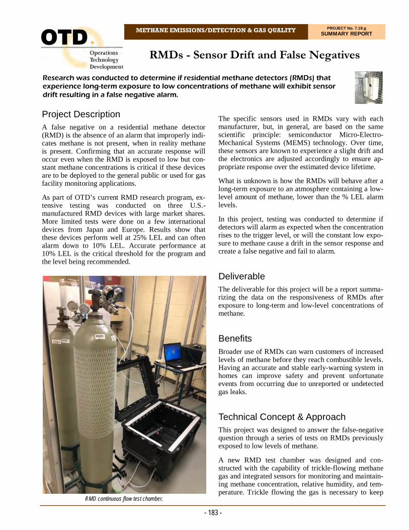
RMDs - Sensor Drift and False Negatives
METHANE EMISSIONS/DETECTION & GAS QUALITY PROJECT No. 7.19.g SUMMARY REPORT
- 183 -
Project Description A false negative on a residential methane detector (RMD) is the absence of an alarm that improperly indi-cates methane is not present, when in reality methane is present. Confirming that an accurate response will occur even when the RMD is exposed to low but con-stant methane concentrations is critical if these devices are to be deployed to the general public or used for gas facility monitoring applications.
As part of OTD’s current RMD research program, ex-tensive testing was conducted on three U.S.-manufactured RMD devices with large market shares. More limited tests were done on a few international devices from Japan and Europe. Results show that these devices perform well at 25% LEL and can often alarm down to 10% LEL. Accurate performance at 10% LEL is the critical threshold for the program and the level being recommended.
The specific sensors used in RMDs vary with each manufacturer, but, in general, are based on the same scientific principle: semiconductor Micro-Electro-Mechanical Systems (MEMS) technology. Over time, these sensors are known to experience a slight drift and the electronics are adjusted accordingly to ensure ap-propriate response over the estimated device lifetime.
What is unknown is how the RMDs will behave after a long-term exposure to an atmosphere containing a low-level amount of methane, lower than the % LEL alarm levels.
In this project, testing was conducted to determine if detectors will alarm as expected when the concentration rises to the trigger level, or will the constant low expo-sure to methane cause a drift in the sensor response and create a false negative and fail to alarm.
Deliverable The deliverable for this project will be a report summa-rizing the data on the responsiveness of RMDs after exposure to long-term and low-level concentrations of methane.
Benefits Broader use of RMDs can warn customers of increased levels of methane before they reach combustible levels. Having an accurate and stable early-warning system in homes can improve safety and prevent unfortunate events from occurring due to unreported or undetected gas leaks.
Technical Concept & Approach This project was designed to answer the false-negative question through a series of tests on RMDs previously exposed to low levels of methane.
A new RMD test chamber was designed and con-structed with the capability of trickle-flowing methane gas and integrated sensors for monitoring and maintain-ing methane concentration, relative humidity, and tem-perature. Trickle flowing the gas is necessary to keep
Research was conducted to determine if residential methane detectors (RMDs) that experience long-term exposure to low concentrations of methane will exhibit sensor drift resulting in a false negative alarm.
RMD continuous flow test chamber.

- 184 -
the methane concentration constant and avoid leaks over the test duration.
Safety shutoffs were added to cut off flowing gas if power and/or ventilation is lost. This test setup will be available for use on future sensor projects requiring flowing methane gas.
A minimum of three detectors for each test were tested from each manufacturer. At least three different manu-facturers were tested.
Researchers confirmed performance at 10% LEL meth-ane exposure of all devices used in study. Each subse-quent test required fresh devices (minimum of 12 de-vices per manufacturer).
Results In 2020, technicians completed construction of the test chamber.
A continuous gas analyzer was identified as a necessary component for confirming low methane levels and pur-chased to cover the range of methane concentrations outlined in scope of work (0-5000 ppmv).
All four RMD models underwent initial testing at 10% and 25% LEL methane in air. Exposure testing began for the one-week period with the highest condition point. Three detectors of each brand were exposed for seven days in the new chamber with the flowing gas being monitored by the new continuous analyzer. The detectors were tested at 250 ppmv, 500 ppmv, 1,000 ppmv, and 2,000 ppmv.
For more information:
Michael Adamo, P.E. Vice President, Operations Operations Technology Development, NFP Phone: 847/544-3428 [email protected]
No issues were seen with most devices. A single device did not alarm at 10% LEL, but did alarm at 25% LEL after exposure at 500 ppmv methane. All other expo-sures passed at both methane test levels. Several devices from one manufacturer falsely reported carbon monox-ide during the 500 ppmv, 1,000 ppmv, and 2,000 ppmv exposure tests. These alarms were seen after less than 16 hours of exposure, though the detectors were able to be reset in a neutral atmosphere. One detector reported an error after an overnight exposure during the ongoing 2,000 ppmv exposure tests and were not able to be reset.
Models from two manufacturers were removed from the exposure chamber after two days and tested. Two de-vices did not respond to 10% LEL. The remaining units responded to both 10% and 25% LEL.
Status
Initial testing was completed in 2020. A Final Report is being developed.
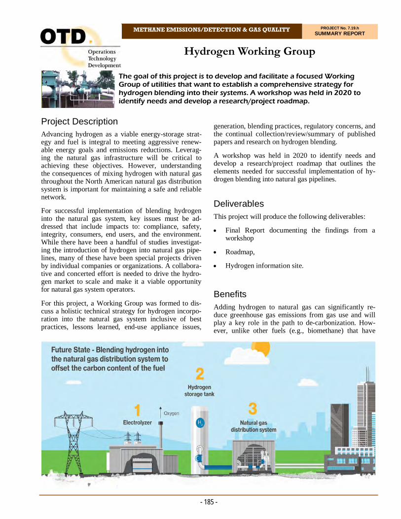
Hydrogen Working Group
METHANE EMISSIONS/DETECTION & GAS QUALITY PROJECT No. 7.19.h SUMMARY REPORT
- 185 -
Project Description Advancing hydrogen as a viable energy-storage strat-egy and fuel is integral to meeting aggressive renew-able energy goals and emissions reductions. Leverag-ing the natural gas infrastructure will be critical to achieving these objectives. However, understanding the consequences of mixing hydrogen with natural gas throughout the North American natural gas distribution system is important for maintaining a safe and reliable network.
For successful implementation of blending hydrogen into the natural gas system, key issues must be ad-dressed that include impacts to: compliance, safety, integrity, consumers, end users, and the environment. While there have been a handful of studies investigat-ing the introduction of hydrogen into natural gas pipe-lines, many of these have been special projects driven by individual companies or organizations. A collabora-tive and concerted effort is needed to drive the hydro-gen market to scale and make it a viable opportunity for natural gas system operators.
For this project, a Working Group was formed to dis-cuss a holistic technical strategy for hydrogen incorpo-ration into the natural gas system inclusive of best practices, lessons learned, end-use appliance issues,
generation, blending practices, regulatory concerns, and the continual collection/review/summary of published papers and research on hydrogen blending.
A workshop was held in 2020 to identify needs and develop a research/project roadmap that outlines the elements needed for successful implementation of hy-drogen blending into natural gas pipelines.
Deliverables
This project will produce the following deliverables:
Final Report documenting the findings from a workshop
Roadmap,
Hydrogen information site.
Benefits Adding hydrogen to natural gas can significantly re-duce greenhouse gas emissions from gas use and will play a key role in the path to de-carbonization. How-ever, unlike other fuels (e.g., biomethane) that have
The goal of this project is to develop and facilitate a focused Working Group of utilities that want to establish a comprehensive strategy for hydrogen blending into their systems. A workshop was held in 2020 to identify needs and develop a research/project roadmap.

- 186 -
Dynamic shock resistance (e.g., third-party dam-age)
Engineering Critical Assessment (ECA) consid-erations
Weld considerations, such as historic acetylene welds of lower quality
Cleanliness of the steel
Leak-vs.-rupture considerations
Short- vs. mid- and long-term integrity considera-tions
Operations and procedure adjustments, and
Cut points on when it makes more sense to replace pipe and use modern materials and modern stan-dards (e.g., ASME B31.12-2019 Hydrogen Pip-ing and Pipelines) to transport hydrogen blends.
Status The 2020 workshop helps to provide a roadmap for future research.
injected into natural gas pipelines, hydrogen can have potential impacts to infrastructure and end-use applica-tions. Limited research has been performed at scale to assess these impacts. A Working Group focused on hy-drogen allows operators to share experiences, current efforts, and streamline the process for identifying and addressing technical gaps and other barriers to imple-menting hydrogen.
Technical Concept & Approach Activities of the Working Group include an initial work-shop to memorialize challenges and goals, map a strate-gic plan at the utility level, and prioritize next steps for developments of research projects/programs, position papers, and other studies.
The project will leverage practical knowledge of the members. A goal will be to lay out a general strategy and define successful implementation of the integration of hydrogen as a storage strategy and fuel source.
The project team will also develop a web-based library of information through literature collection and a proac-tive interview process with industry-leading operators in hydrogen blending. This will provide a constantly re-freshed source of information on hydrogen and use in the natural gas network.
Results The workshop was held in July 2020 to help develop the research roadmap for enabling hydrogen injection into pipelines.
At the workshop, information was provided on a variety of current projects evaluating the impacts of hydrogen on the gas infrastructure and end-use applications.
This working group aims to be practical. The testing needs to provide results in the near term. Therefore, a handful of sponsors will need to provide actual systems they would consider for use for adding hydrogen blends. This will allow a set of practical-use cases to be devel-oped and analyzed.
The workshop provide information on vintage steels and welds. Key factors to consider include:
Cracking and fatigue susceptibility of low-toughness, older steels that have higher sulphur and phosphorous levels
For more information:
Michael Adamo, P.E. Vice President, Operations Operations Technology Development, NFP Phone: 847/544-3428 [email protected]
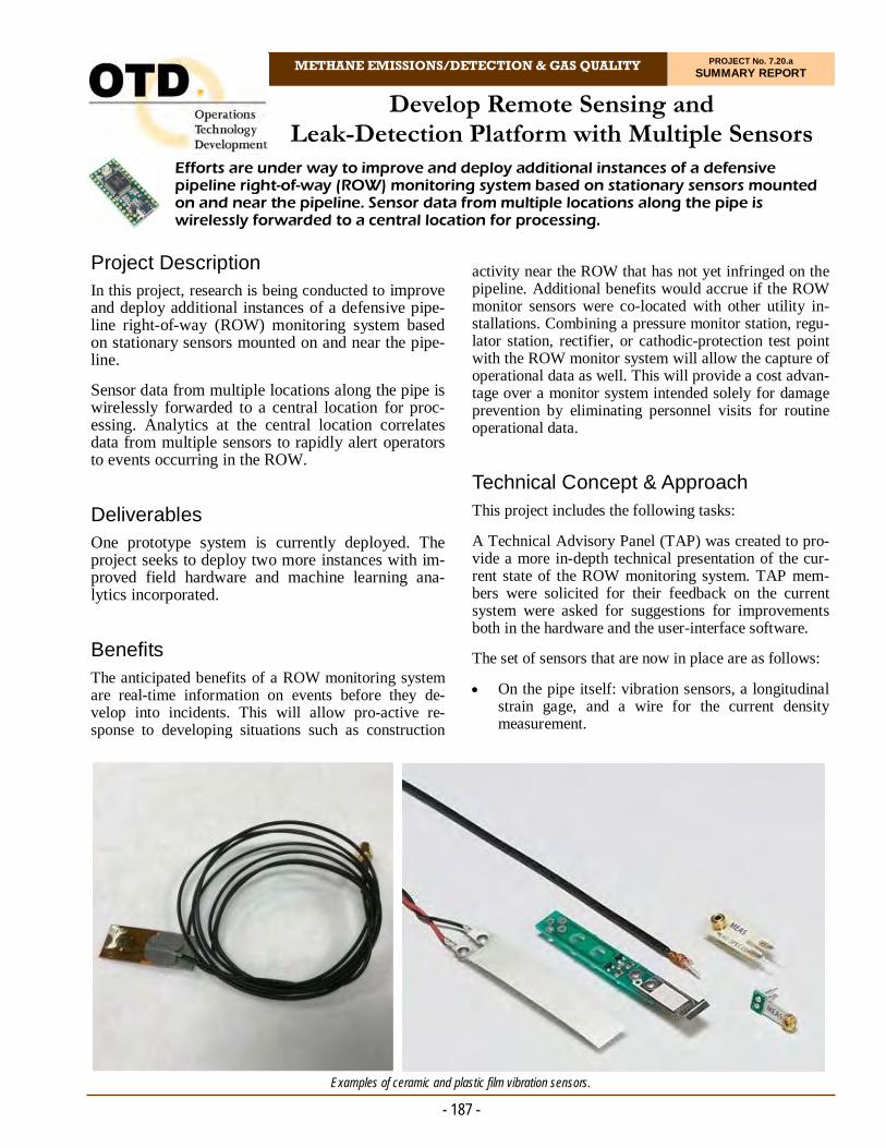
Develop Remote Sensing and Leak-Detection Platform with Multiple Sensors
METHANE EMISSIONS/DETECTION & GAS QUALITY PROJECT No. 7.20.a SUMMARY REPORT
- 187 -
Project Description In this project, research is being conducted to improve and deploy additional instances of a defensive pipe-line right-of-way (ROW) monitoring system based on stationary sensors mounted on and near the pipe-line.
Sensor data from multiple locations along the pipe is wirelessly forwarded to a central location for proc-essing. Analytics at the central location correlates data from multiple sensors to rapidly alert operators to events occurring in the ROW.
Deliverables One prototype system is currently deployed. The project seeks to deploy two more instances with im-proved field hardware and machine learning ana-lytics incorporated.
Benefits The anticipated benefits of a ROW monitoring system are real-time information on events before they de-velop into incidents. This will allow pro-active re-sponse to developing situations such as construction
activity near the ROW that has not yet infringed on the pipeline. Additional benefits would accrue if the ROW monitor sensors were co-located with other utility in-stallations. Combining a pressure monitor station, regu-lator station, rectifier, or cathodic-protection test point with the ROW monitor system will allow the capture of operational data as well. This will provide a cost advan-tage over a monitor system intended solely for damage prevention by eliminating personnel visits for routine operational data.
Technical Concept & Approach This project includes the following tasks:
A Technical Advisory Panel (TAP) was created to pro-vide a more in-depth technical presentation of the cur-rent state of the ROW monitoring system. TAP mem-bers were solicited for their feedback on the current system were asked for suggestions for improvements both in the hardware and the user-interface software.
The set of sensors that are now in place are as follows:
On the pipe itself: vibration sensors, a longitudinal strain gage, and a wire for the current density measurement.
Efforts are under way to improve and deploy additional instances of a defensive pipeline right-of-way (ROW) monitoring system based on stationary sensors mounted on and near the pipeline. Sensor data from multiple locations along the pipe is wirelessly forwarded to a central location for processing.
Examples of ceramic and plastic film vibration sensors.

- 188 -
Results In 2020, several avenues of investigation were pur-sued, based on feedback from TAP meetings. Two items specifically mentioned were a point methane sensor and having lightning protection/detection built into the stations. In addition to these sensors, research-ers investigated adding aboveground microphones to augment the belowground vibration sensors in the de-tection of activity on the ROW.
A list of current features of and proposed improve-ments to the ROW defense technology were presented to the TAP members.
A list of hardware requirement was completed. The installation will maintain compatibility with the belowground suite of sensors that were tested in a prior project. An additional set of aboveground sen-sors will also be added. In addition to the gas and lightning detection capabilities asked for by the TAP, acoustic microphones will be incorporated. The moti-vation for this is that sound may be a useful corollary in the identification of machinery operating in the ROW or in detecting thunder.
Researchers are cataloging and reviewing the stan-dards that exist for sensor data. These standards are being reviewed to develop a gap analysis between the standards for sensors and the devices and data being utilized in this project.
A lightning detection sensor was investigated to moni-tor lightning activity near the sensor station. This can aid in root-cause analysis of a failure; lightning dam-age often goes undetected or misdiagnosed. The sen-sor was interfaced with a development platform to monitor for lightning and test the reliability and accu-racy of the sensor.
Status
The team is soliciting for potential test sites from OTD companies and continue looking at alternative technol-ogy to address known issues.
In the soil nearby: a steel coupon that is connected to the pipe wire through a measurement shunt, a geophone to measure soil vibration, and a combined probe for soil moisture and temperature.
Researchers are making efforts improve the pipe-vibration sensors and their supporting electronics. The supporting electronics for the vibration sensors are now unreliable and must be replaced. One TAP recommenda-tion is to add a methane sensor at each listening post location. A point sensor could be added at a minimal cost in hardware or power consumption. The issue with point sensors is that they depend on the motion of the plume to contact the gas for detection. Given that the listening posts are intended to be thousands of feet apart, it would require a significant plume to be detected. The enclosure of the point sensor would need to encourage air flow by the sensor.
Another TAP recommendation was to secure the system against lightning damage. Most modern instrumentation has some form of lightning protection built in. The sys-tem could pro-actively perform some shutdown opera-tions to protect itself. The lightning occurrence data would also be useful in identifying nearby strikes that could damage cathodic protection systems and coatings.
Researchers also propose to add microphones to the aboveground portion of the listening post. These can provide corroborating data when vibrations are sensed on the pipe by listening for heavy equipment. Likewise, they can provide further evidence of lightning activity.
Other improvements that have been proposed are to re-fresh or upgrade the data-logging instruments and sup-porting radio equipment.
Investigators are examining pin brazing as a means of installing sensors requiring metallic contact. Pin brazing uses a material that can join a stud to the pipe surface at a much lower temperature. This technique is recognized by utilities and allowed as a procedure on their systems. The surface cleaning and preparation for brazing is less stringent than that required for adhesive bonding.
For more information:
Michael Adamo, P.E. Vice President, Operations Operations Technology Development, NFP Phone: 847/544-3428 [email protected]
Examples of pin-brazed studs and stud-mount vibration sensor.
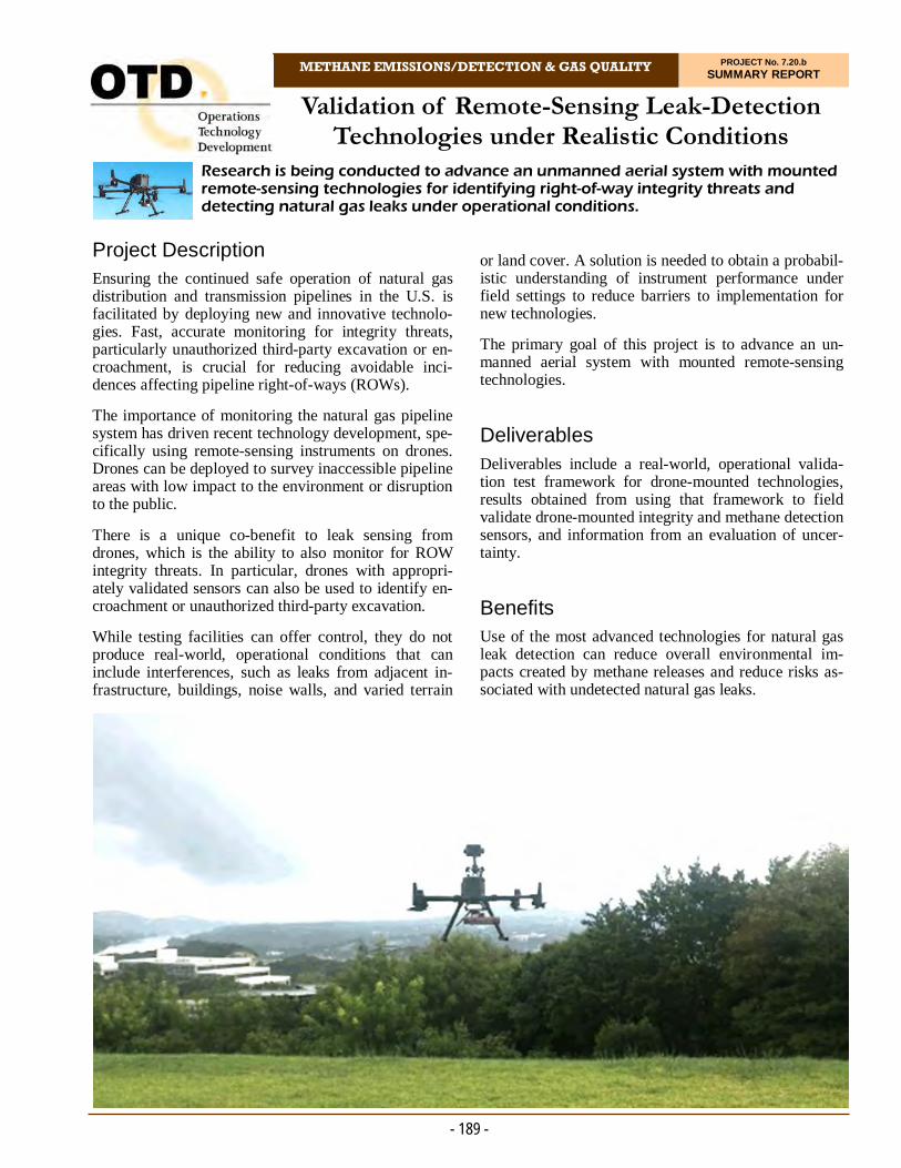
Validation of Remote-Sensing Leak-Detection Technologies under Realistic Conditions
METHANE EMISSIONS/DETECTION & GAS QUALITY PROJECT No. 7.20.b SUMMARY REPORT
- 189 -
Project Description Ensuring the continued safe operation of natural gas distribution and transmission pipelines in the U.S. is facilitated by deploying new and innovative technolo-gies. Fast, accurate monitoring for integrity threats, particularly unauthorized third-party excavation or en-croachment, is crucial for reducing avoidable inci-dences affecting pipeline right-of-ways (ROWs).
The importance of monitoring the natural gas pipeline system has driven recent technology development, spe-cifically using remote-sensing instruments on drones. Drones can be deployed to survey inaccessible pipeline areas with low impact to the environment or disruption to the public.
There is a unique co-benefit to leak sensing from drones, which is the ability to also monitor for ROW integrity threats. In particular, drones with appropri-ately validated sensors can also be used to identify en-croachment or unauthorized third-party excavation.
While testing facilities can offer control, they do not produce real-world, operational conditions that can include interferences, such as leaks from adjacent in-frastructure, buildings, noise walls, and varied terrain
or land cover. A solution is needed to obtain a probabil-istic understanding of instrument performance under field settings to reduce barriers to implementation for new technologies.
The primary goal of this project is to advance an un-manned aerial system with mounted remote-sensing technologies.
Deliverables
Deliverables include a real-world, operational valida-tion test framework for drone-mounted technologies, results obtained from using that framework to field validate drone-mounted integrity and methane detection sensors, and information from an evaluation of uncer-tainty.
Benefits Use of the most advanced technologies for natural gas leak detection can reduce overall environmental im-pacts created by methane releases and reduce risks as-sociated with undetected natural gas leaks.
Research is being conducted to advance an unmanned aerial system with mounted remote-sensing technologies for identifying right-of-way integrity threats and detecting natural gas leaks under operational conditions.
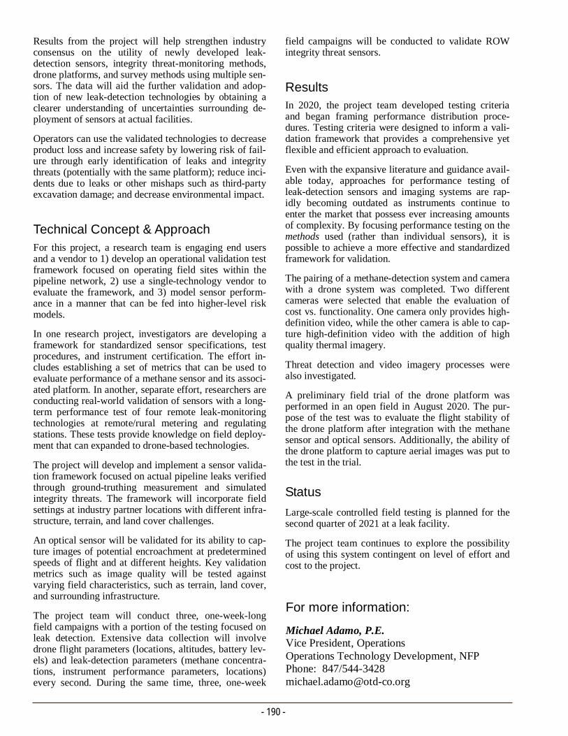
- 190 -
field campaigns will be conducted to validate ROW integrity threat sensors.
Results In 2020, the project team developed testing criteria and began framing performance distribution proce-dures. Testing criteria were designed to inform a vali-dation framework that provides a comprehensive yet flexible and efficient approach to evaluation.
Even with the expansive literature and guidance avail-able today, approaches for performance testing of leak-detection sensors and imaging systems are rap-idly becoming outdated as instruments continue to enter the market that possess ever increasing amounts of complexity. By focusing performance testing on the methods used (rather than individual sensors), it is possible to achieve a more effective and standardized framework for validation.
The pairing of a methane-detection system and camera with a drone system was completed. Two different cameras were selected that enable the evaluation of cost vs. functionality. One camera only provides high-definition video, while the other camera is able to cap-ture high-definition video with the addition of high quality thermal imagery.
Threat detection and video imagery processes were also investigated.
A preliminary field trial of the drone platform was performed in an open field in August 2020. The pur-pose of the test was to evaluate the flight stability of the drone platform after integration with the methane sensor and optical sensors. Additionally, the ability of the drone platform to capture aerial images was put to the test in the trial.
Status
Large-scale controlled field testing is planned for the second quarter of 2021 at a leak facility.
The project team continues to explore the possibility of using this system contingent on level of effort and cost to the project.
Results from the project will help strengthen industry consensus on the utility of newly developed leak-detection sensors, integrity threat-monitoring methods, drone platforms, and survey methods using multiple sen-sors. The data will aid the further validation and adop-tion of new leak-detection technologies by obtaining a clearer understanding of uncertainties surrounding de-ployment of sensors at actual facilities.
Operators can use the validated technologies to decrease product loss and increase safety by lowering risk of fail-ure through early identification of leaks and integrity threats (potentially with the same platform); reduce inci-dents due to leaks or other mishaps such as third-party excavation damage; and decrease environmental impact.
Technical Concept & Approach
For this project, a research team is engaging end users and a vendor to 1) develop an operational validation test framework focused on operating field sites within the pipeline network, 2) use a single-technology vendor to evaluate the framework, and 3) model sensor perform-ance in a manner that can be fed into higher-level risk models.
In one research project, investigators are developing a framework for standardized sensor specifications, test procedures, and instrument certification. The effort in-cludes establishing a set of metrics that can be used to evaluate performance of a methane sensor and its associ-ated platform. In another, separate effort, researchers are conducting real-world validation of sensors with a long-term performance test of four remote leak-monitoring technologies at remote/rural metering and regulating stations. These tests provide knowledge on field deploy-ment that can expanded to drone-based technologies.
The project will develop and implement a sensor valida-tion framework focused on actual pipeline leaks verified through ground-truthing measurement and simulated integrity threats. The framework will incorporate field settings at industry partner locations with different infra-structure, terrain, and land cover challenges.
An optical sensor will be validated for its ability to cap-ture images of potential encroachment at predetermined speeds of flight and at different heights. Key validation metrics such as image quality will be tested against varying field characteristics, such as terrain, land cover, and surrounding infrastructure.
The project team will conduct three, one-week-long field campaigns with a portion of the testing focused on leak detection. Extensive data collection will involve drone flight parameters (locations, altitudes, battery lev-els) and leak-detection parameters (methane concentra-tions, instrument performance parameters, locations) every second. During the same time, three, one-week
For more information:
Michael Adamo, P.E. Vice President, Operations Operations Technology Development, NFP Phone: 847/544-3428 [email protected]

METHANE EMISSIONS/DETECTION & GAS QUALITY PROJECT No. 7.20.e SUMMARY REPORT
Project Description A natural gas leak becomes of significant concern when the concentration of gas is within the range of 5% to 15% by volume in air. By law, a sulfur-based odorant is placed in natural gas to easily detect the gas.
Over the years, OTD sponsored numerous research pro-jects into odorization, leak-detection measurement, leak-capture technology, and residential methane detector (RMD) deployment.
In recent years, Fire & Risk Alliance (FRA) performed two natural gas modeling efforts for utility customers. The focus of these projects was on methane gas disper-sion in residential buildings. The first project was to provide guidance on the placement of RMDs using a small one-room test facility simulating a city kitchen. The review concluded that placement of an RMD should be in the vicinity of a leak source and located in a high position about a foot from the ceiling. According to the National Fire Protection Association (NFPA), the largest source of residential fires is from appliances in the kitchen, followed by HVAC equipment, then laun-dry. It follows that RMD placement in kitchens, base-ments, and garages where such equipment or functional-
The objective of this project is to develop a best practice on how to properly vent accumulated natural gas from a building through both physical testing using a built structure and computational fluid dynamics modeling.
Gas Dispersion Modeling for Venting Natural Gas from Structures
ity is located is recommended. After this initial study, FRA performed an additional placement study using a residential home custom built for the project.
The objective of this project is to work with FRA to develop a best practice on how to properly vent accu-mulated natural gas from a building through both physical testing using a built structure and computa-tional fluid dynamics modeling. Researchers will map the dispersion and ensuing ventilation of natural gas from within a residential structure for several different scenarios. This information will improve the ability of first responders or utility personnel to employ safe and proven techniques to carefully ventilate natural gas down to safe levels.
Deliverable The deliverables for this project will be:
A Best Practices manual for first responders and utility workers
Video and still images from computer modeling, and
A Final Report with conclusions.
Benefits According to U.S. Energy Information Administration, natural gas is used by almost half of American house-holds as their main heating and cooking fuel source, with more than 69 million natural gas customers na-tionally. In 2018, the residential sector consumed 4.97 trillion cubic feet of natural gas, which accounts for 17% of the national natural gas consumption.
While rare, natural gas leaks can be dangerous and may result in serious consequences if undetected. In 2018, 34 reported distribution line incidents resulted in six fatalities, 81 injuries, and hundreds of millions of dollars in total costs.
This project is focused on improving the safety of natural gas systems.
- 191 - FRA custom-built home for gas dispersion studies.

- 192 -
FRA will explore different ventilation approaches to determine the optimal ventilation strategies and will map the corresponding decrease in gas concentrations throughout the structure.
A modeling effort will be conducted to validate the measurements and to simulate the effect of ventilation on the accumulated concentration of natural gas within the test structure. The modeling will also expand on the experimental program to include scenarios that could not be fully tested.
A a Best Practices manual will be developed detailing how first responders can safely vent natural gas from a variety of residential leak scenarios.
Results Execution of the subcontract with the FRA and start of the experimental work has been delayed due to COVID-19 work restrictions. It is expected to require another six months to fully finish the project.
Status
Researchers will perform an extensive literature re-view to guide the ventilation study. Test-case scenar-ios will be selected.
Technical Concept & Approach Test-case scenarios will be requested from the project sponsors to determine the critical needs for onsite test-ing.
An extensive literature review will be performed to help guide the ventilation study. There has been work related to positive pressure ventilation (PPV) within the fire community and modeling studies for HVAC, air qual-ity, and other purposes. This information will be re-viewed and included in the Final Report.
Testing will be conducted at the FRA gas testing house in Damascus, MD. It is a test enclosure with external dimensions measuring nominally 20 feet by 40 feet by 20 feet that is constructed of dimensional lumber to simulate a large residential structure. The house con-tains standard insulation in the external walls and attic.
Experimental measurements will be recorded with a data-acquisition system using a custom graphic user interface developed to control and monitor the system during the experiment. Measurements will include methane concentration, relative humidity, and air ve-locities.
The two different types of methane sensors will be placed throughout the enclosure to monitor methane spread and concentration. Nominally, 60 separate com-bustible gas sensors will be used.
For more information:
Michael Adamo, P.E. Vice President, Operations Operations Technology Development, NFP Phone: 847/544-3428 [email protected]
Elevation view of simulated concentration.
Plan view of simulated concentration.
- Richard J. Trieste, Jr. Department Manager Research, Development, and Demonstration Consolidated Edison Company of New York
“The dispersion modeling and physical testing of this project will have immediate benefit to operators by combining good science with practical application to enhance of our emergency response procedures with the best process to vent natural gas from structures.”
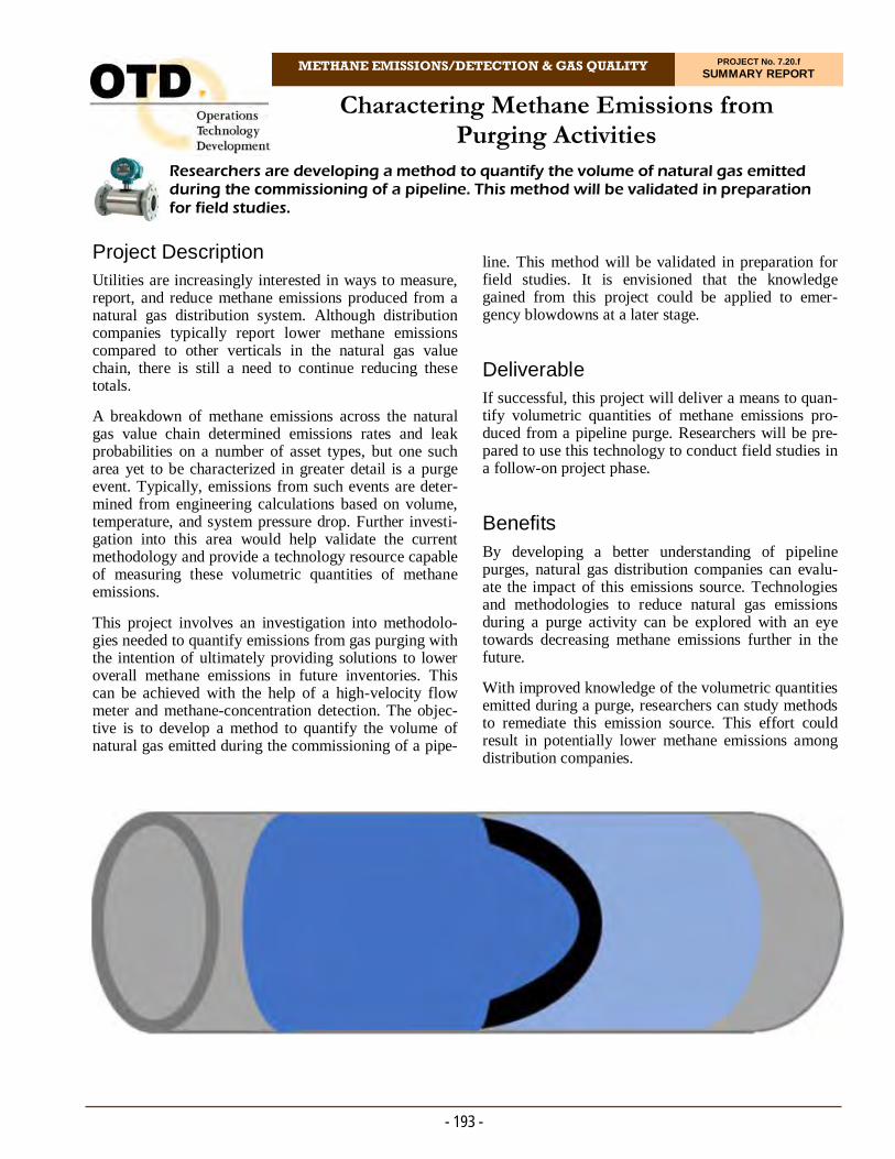
METHANE EMISSIONS/DETECTION & GAS QUALITY PROJECT No. 7.20.f SUMMARY REPORT
Project Description Utilities are increasingly interested in ways to measure, report, and reduce methane emissions produced from a natural gas distribution system. Although distribution companies typically report lower methane emissions compared to other verticals in the natural gas value chain, there is still a need to continue reducing these totals.
A breakdown of methane emissions across the natural gas value chain determined emissions rates and leak probabilities on a number of asset types, but one such area yet to be characterized in greater detail is a purge event. Typically, emissions from such events are deter-mined from engineering calculations based on volume, temperature, and system pressure drop. Further investi-gation into this area would help validate the current methodology and provide a technology resource capable of measuring these volumetric quantities of methane emissions.
This project involves an investigation into methodolo-gies needed to quantify emissions from gas purging with the intention of ultimately providing solutions to lower overall methane emissions in future inventories. This can be achieved with the help of a high-velocity flow meter and methane-concentration detection. The objec-tive is to develop a method to quantify the volume of natural gas emitted during the commissioning of a pipe-
Researchers are developing a method to quantify the volume of natural gas emitted during the commissioning of a pipeline. This method will be validated in preparation for field studies.
Charactering Methane Emissions from Purging Activities
line. This method will be validated in preparation for field studies. It is envisioned that the knowledge gained from this project could be applied to emer-gency blowdowns at a later stage.
Deliverable If successful, this project will deliver a means to quan-tify volumetric quantities of methane emissions pro-duced from a pipeline purge. Researchers will be pre-pared to use this technology to conduct field studies in a follow-on project phase.
Benefits By developing a better understanding of pipeline purges, natural gas distribution companies can evalu-ate the impact of this emissions source. Technologies and methodologies to reduce natural gas emissions during a purge activity can be explored with an eye towards decreasing methane emissions further in the future.
With improved knowledge of the volumetric quantities emitted during a purge, researchers can study methods to remediate this emission source. This effort could result in potentially lower methane emissions among distribution companies.
- 193 -
- 194 -
1. Indirect Hydrocarbon Measurement
This design will install both an in-line oxygen gas sensor and a thermal mass flow meter. The main gas flow will be sent through the sensor and flow meter so that a volumetric flow rate is recorded with respect to the changing oxygen concentra-tions. This is advantageous because the system will directly capture gas concentration data and flow data without modifying the flow stream. The team will assume a ratio of .21:.79 of oxygen to nitrogen in the flow, and the remaining flow will be assumed to be the hydrocarbons. This route is the simplest way to collect high-flow data and capture mixing of the gaseous species; however, the team acknowledges that this method indirectly measures the hydrocarbon content in the flow.
2. Direct Measurement of Hydrocarbons
To directly measure the hydrocarbon content of the flow, the team must divert a slipstream from the main gas line or regulate the pressure down at the purge end to decrease the flow for analysis to accommodate the lower gas-velocity requirements for hydrocarbon sensors. By lowering the velocity of the flow in this scheme, the team can collect representative samples of the hydrocarbon concen-tration in the main gas flow over time. The gas flow will be sent through a thermal mass flow me-ter so that a volumetric flow rate is recorded.
3. Low Flow Purges
The team is asking project sponsors about the fre-quency of such a purge. If this is found to be a more common method, the team can reevaluate the selection of the hydrocarbon sensor as it will more than likely be rated to handle lower flows. Then, mimicking the design in first option, the team could produce a system with direct hydrocar-bon measurement.
Status
The project team held a review meeting to finalize system requirements and has been acquiring system components to focus on designs two and three.
Technical Concept & Approach This project is divided into two efforts with a built-in Go/No-Go stage gate. The project team will review commercially available technologies and develop a fea-sible approach to measure volumetric quantities of natu-ral gas emitted during a purge. The team will then vali-date the proposed methodology via testing. If success-ful, a Phase 2 project would focus on executing project sponsor field trials of the methodology.
Project scoping includes efforts to understand which key technical needs (e.g., pressure, flow rate, pipe mate-rial, and pipe diameter) are most applicable.
The project team performed a search of technologies available.
Laboratory validations include simulating and measur-ing flows and gas mixtures that could be sustained dur-ing a purge.
Results In 2020, researchers evaluated gas-sensing and flow-metering technology that could withstand gas flows during a purge. There are several options to quantify this amount of gas emitted during a purge, but are de-signed under the pretense that the system must tolerate high flows from fully opened gas lines with operating pressures up to 60 psig. This is of note because the pro-ject team also had the opportunity to witness a live purge demonstration. During this demonstration, the flow was purposely constricted through a nearby valve. This observation led to some re-evaluations regarding system design.
There are three options in designing the purge flow me-ter. Due to the high flows experienced during a 20-60 psig purge, hydrocarbon gas-sensing options with high sampling frequencies are limited. However, the team identified an oxygen sensor that can withstand these flows and sample at a high enough frequency to capture changes in gas concentration from mixing during a purge. The team is also aware that some utilities may not be purging under full-flow conditions. If low flow purges are more common, more options for hydrocar-bon sensors become available to the team.
With this general framework, the team has three possi-ble paths to design the purge flow meter: For more information:
Michael Adamo, P.E. Vice President, Operations Operations Technology Development, NFP Phone: 847/544-3428 [email protected]
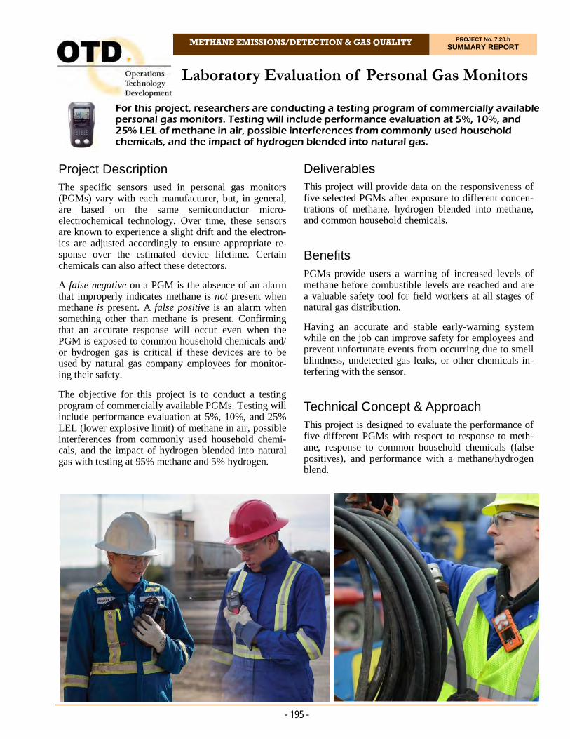
Laboratory Evaluation of Personal Gas Monitors
METHANE EMISSIONS/DETECTION & GAS QUALITY PROJECT No. 7.20.h SUMMARY REPORT
- 195 -
Project Description The specific sensors used in personal gas monitors (PGMs) vary with each manufacturer, but, in general, are based on the same semiconductor micro-electrochemical technology. Over time, these sensors are known to experience a slight drift and the electron-ics are adjusted accordingly to ensure appropriate re-sponse over the estimated device lifetime. Certain chemicals can also affect these detectors.
A false negative on a PGM is the absence of an alarm that improperly indicates methane is not present when methane is present. A false positive is an alarm when something other than methane is present. Confirming that an accurate response will occur even when the PGM is exposed to common household chemicals and/or hydrogen gas is critical if these devices are to be used by natural gas company employees for monitor-ing their safety.
The objective for this project is to conduct a testing program of commercially available PGMs. Testing will include performance evaluation at 5%, 10%, and 25% LEL (lower explosive limit) of methane in air, possible interferences from commonly used household chemi-cals, and the impact of hydrogen blended into natural gas with testing at 95% methane and 5% hydrogen.
Deliverables This project will provide data on the responsiveness of five selected PGMs after exposure to different concen-trations of methane, hydrogen blended into methane, and common household chemicals.
Benefits PGMs provide users a warning of increased levels of methane before combustible levels are reached and are a valuable safety tool for field workers at all stages of natural gas distribution.
Having an accurate and stable early-warning system while on the job can improve safety for employees and prevent unfortunate events from occurring due to smell blindness, undetected gas leaks, or other chemicals in-terfering with the sensor.
Technical Concept & Approach
This project is designed to evaluate the performance of five different PGMs with respect to response to meth-ane, response to common household chemicals (false positives), and performance with a methane/hydrogen blend.
For this project, researchers are conducting a testing program of commercially available personal gas monitors. Testing will include performance evaluation at 5%, 10%, and 25% LEL of methane in air, possible interferences from commonly used household chemicals, and the impact of hydrogen blended into natural gas.
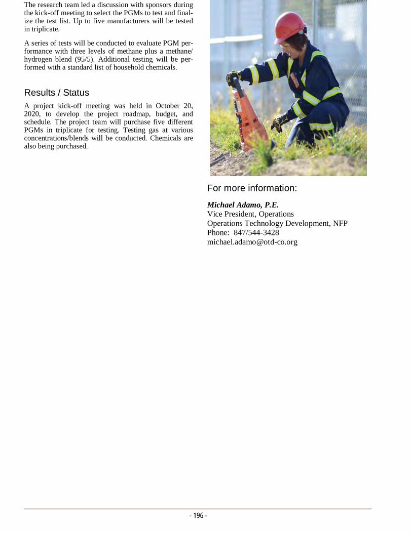
- 196 -
The research team led a discussion with sponsors during the kick-off meeting to select the PGMs to test and final-ize the test list. Up to five manufacturers will be tested in triplicate.
A series of tests will be conducted to evaluate PGM per-formance with three levels of methane plus a methane/hydrogen blend (95/5). Additional testing will be per-formed with a standard list of household chemicals.
Results / Status A project kick-off meeting was held in October 20, 2020, to develop the project roadmap, budget, and schedule. The project team will purchase five different PGMs in triplicate for testing. Testing gas at various concentrations/blends will be conducted. Chemicals are also being purchased.
For more information:
Michael Adamo, P.E. Vice President, Operations Operations Technology Development, NFP Phone: 847/544-3428 [email protected]

Methane Mitigation Using Linear Leak Recovery Motor Compressor
METHANE EMISSIONS/DETECTION & GAS QUALITY PROJECT No. 7.20.l SUMMARY REPORT
- 197 -
Project Description The U.S. Department of Energy is actively funding efforts aimed at reducing methane emissions from compressors and pneumatic controllers through the use of low-cost methods that can be used at newly installed locations or retrofit onto existing equipment. The linear motor leak recovery compressor will do just that by tapping into the methane vent lines installed on com-pressors, pneumatic controllers, and other common leak sources, and compressing the leaked methane back into the pipeline.
This simple solution enables 100% of these methane emissions to be captured and recovered without any impact on the performance or operation of the original equipment.
The linear motor leak recovery compressor’s low cost and nearly-zero maintenance allows for use across the high-pressure transmission and storage sector, as well as in upstream gathering and processing facilities.
The primary challenge preventing the capture and miti-gation of these leaks is the absence of a suitably engi-neered and priced solution. The linear motor compres-sor improves on the traditional reciprocating compres-sor by eliminating all but a single primary moving part, even when multiple stages of compression are required for high discharge pressures.
The design has multiple stages of compression directly powered by a reciprocating linear motor in place of the normal crank assembly. The precise motor controls allow the piston to rapidly move back and forth with-out striking the ends of the cylinders. The speed, fre-quency, and stroke length of linear motor compressor can all be controlled to fine tune the flow of the sys-tem. The directly powered linear motor can also start up and shut down instantly, enabling the unit to com-press to full discharge pressure from a dead stop. This capability also enables the flow to be infinitely ad-justed from zero to the full design flow.
Because of the unique flexibility of this technology, the compressor can also be used to recover emissions from planned events such as blowdowns that are re-quired as regular maintenance. These planned events are frequently the single largest source of emissions at
a site and can be avoided if the gas trapped in the equipment is compressed downstream rather than vented to the atmosphere.
To date, the project team has tested and refined the lin-ear motor compressor. This new project will validate the effectiveness of the technology in a variety of rele-vant environments to identify and quantify the wide-ranging applications for its use.
Furthermore, the leak recovery compressor will be de-signed such that it can be installed at a commercial scale across the natural gas sector in a manner that does not require new permits to be issued by the Environ-mental Protection Agency.
Deliverables In addition to the reports specified in the Federal Assis-tance Reporting Checklist, researchers will provide the
Research is under way to design, build, and test a novel, low-cost, leak recovery compressor to capture a wide variety of leaks across the natural gas value chain, including leaks from reciprocating compressors and pneumatic controllers that are among the largest methane emitters.
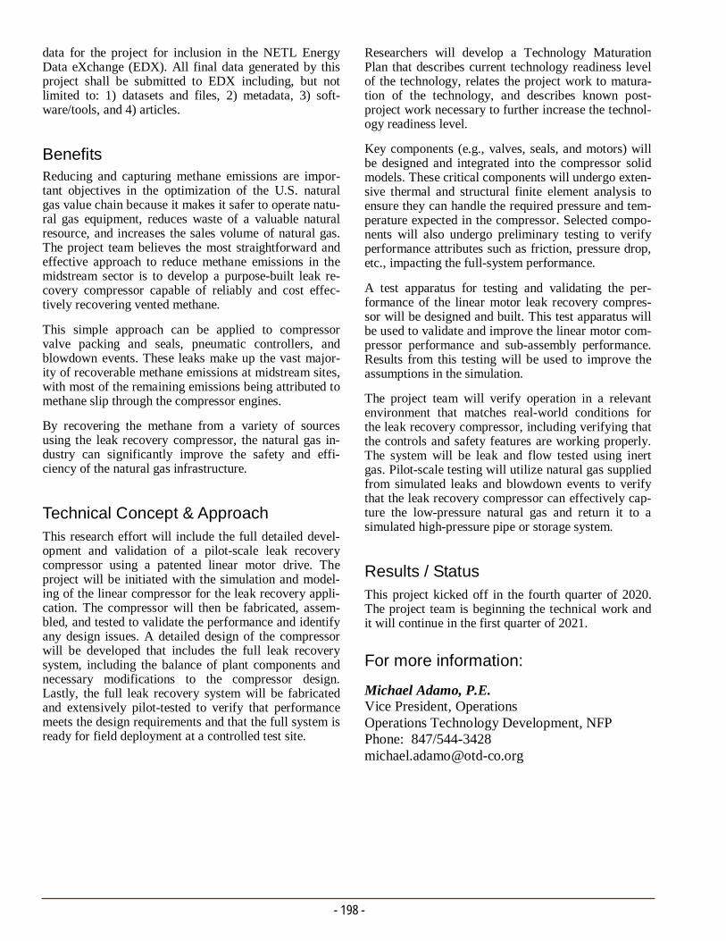
- 198 -
Researchers will develop a Technology Maturation Plan that describes current technology readiness level of the technology, relates the project work to matura-tion of the technology, and describes known post-project work necessary to further increase the technol-ogy readiness level.
Key components (e.g., valves, seals, and motors) will be designed and integrated into the compressor solid models. These critical components will undergo exten-sive thermal and structural finite element analysis to ensure they can handle the required pressure and tem-perature expected in the compressor. Selected compo-nents will also undergo preliminary testing to verify performance attributes such as friction, pressure drop, etc., impacting the full-system performance.
A test apparatus for testing and validating the per-formance of the linear motor leak recovery compres-sor will be designed and built. This test apparatus will be used to validate and improve the linear motor com-pressor performance and sub-assembly performance. Results from this testing will be used to improve the assumptions in the simulation.
The project team will verify operation in a relevant environment that matches real-world conditions for the leak recovery compressor, including verifying that the controls and safety features are working properly. The system will be leak and flow tested using inert gas. Pilot-scale testing will utilize natural gas supplied from simulated leaks and blowdown events to verify that the leak recovery compressor can effectively cap-ture the low-pressure natural gas and return it to a simulated high-pressure pipe or storage system.
Results / Status This project kicked off in the fourth quarter of 2020. The project team is beginning the technical work and it will continue in the first quarter of 2021.
data for the project for inclusion in the NETL Energy Data eXchange (EDX). All final data generated by this project shall be submitted to EDX including, but not limited to: 1) datasets and files, 2) metadata, 3) soft-ware/tools, and 4) articles.
Benefits Reducing and capturing methane emissions are impor-tant objectives in the optimization of the U.S. natural gas value chain because it makes it safer to operate natu-ral gas equipment, reduces waste of a valuable natural resource, and increases the sales volume of natural gas. The project team believes the most straightforward and effective approach to reduce methane emissions in the midstream sector is to develop a purpose-built leak re-covery compressor capable of reliably and cost effec-tively recovering vented methane.
This simple approach can be applied to compressor valve packing and seals, pneumatic controllers, and blowdown events. These leaks make up the vast major-ity of recoverable methane emissions at midstream sites, with most of the remaining emissions being attributed to methane slip through the compressor engines.
By recovering the methane from a variety of sources using the leak recovery compressor, the natural gas in-dustry can significantly improve the safety and effi-ciency of the natural gas infrastructure.
Technical Concept & Approach
This research effort will include the full detailed devel-opment and validation of a pilot-scale leak recovery compressor using a patented linear motor drive. The project will be initiated with the simulation and model-ing of the linear compressor for the leak recovery appli-cation. The compressor will then be fabricated, assem-bled, and tested to validate the performance and identify any design issues. A detailed design of the compressor will be developed that includes the full leak recovery system, including the balance of plant components and necessary modifications to the compressor design. Lastly, the full leak recovery system will be fabricated and extensively pilot-tested to verify that performance meets the design requirements and that the full system is ready for field deployment at a controlled test site.
For more information:
Michael Adamo, P.E. Vice President, Operations Operations Technology Development, NFP Phone: 847/544-3428 [email protected]

METHANE EMISSIONS/DETECTION & GAS QUALITY PROJECT No. 7.20.m SUMMARY REPORT
Project Description The blending of hydrogen into natural gas pipelines presents an opportunity for the gas industry to reduce greenhouse gas emissions from gas use and will play a key role in the path to de-carbonization.
As the gas composition of fuel sources changes, impact to the infrastructure as well as to the customer must be evaluated. This includes evaluations of devices used for residential methane detection.
In an OTD project 1.14.g, extensive testing was con-ducted on Residential Methane Detectors (RMDs). Ad-ditional tests were conducted on international devices from Japan and Europe. The specific sensors used in RMDs vary with each manufacturer but in general are based on the same scientific semiconductor technology. Over time, these sensors are known to experience a slight drift and the electronics are adjusted accordingly to ensure appropriate response over the estimated de-vice lifetime.
Using the protocols established in the earlier phases of the Residential Methane De-tector Program, RMDs will be tested at various methane/hydrogen blends in a con-trolled laboratory setting to determine how their effectiveness at detecting leaking gas may change and at what alarm levels.
Residential Methane Detectors (RMDs) – Test Response to Natural Gas/Hydrogen Blends
Currently, the impact of the presence of hydrogen on the alarm level and performance of an RMD is not known. Technical data sheets from some of the largest suppliers of sensors in RMDs indicate that hydrogen will induce a response along with methane. Other sen-sors exhibit similar responses.
Using protocols established in earlier phases of the RMD program, in this project RMDs will be tested at various methane/hydrogen blends in a controlled labo-ratory setting to determine how their effectiveness at detecting leaking gas may change and at what alarm levels.
Deliverables This project will provide data on the responsiveness of four selected RMDs after exposure to five different mixtures of hydrogen blended with methane. Re-searchers will determine the blend concentration at which the tested RMDs respond with an alarm.
- 199 -
RMDs will be tested at various methane/hydrogen blends in a controlled laboratory setting.
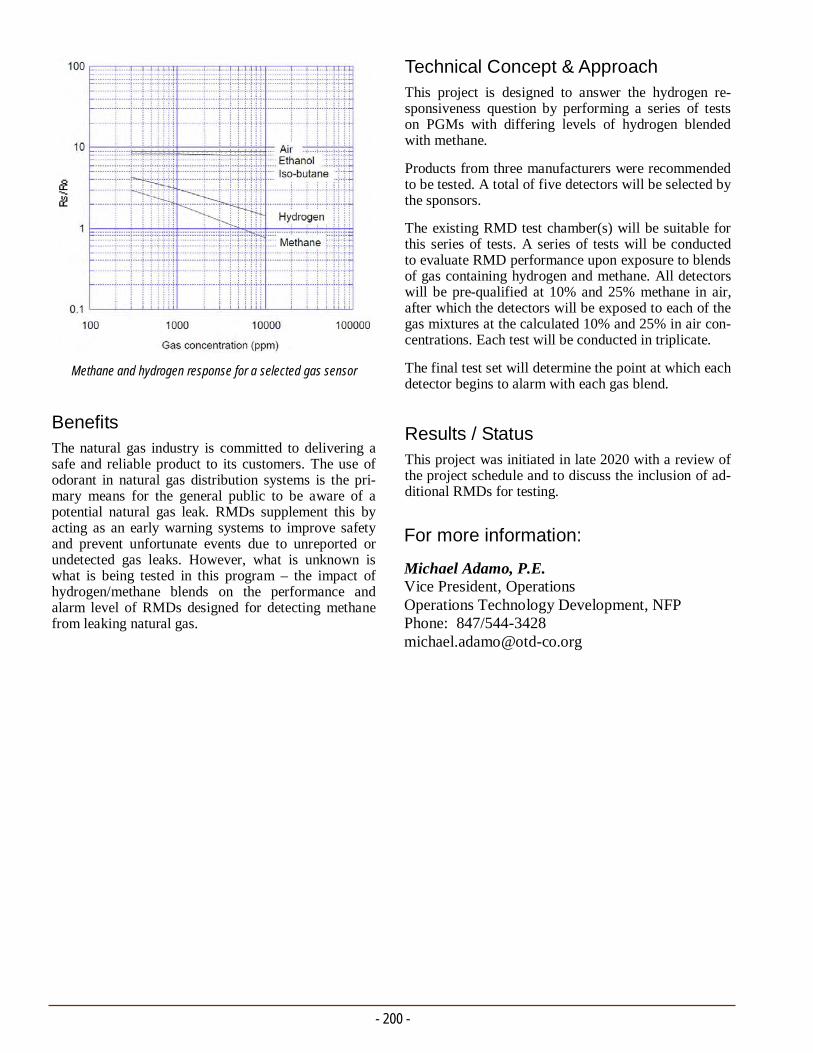
- 200 -
For more information:
Michael Adamo, P.E. Vice President, Operations Operations Technology Development, NFP Phone: 847/544-3428 [email protected]
Technical Concept & Approach This project is designed to answer the hydrogen re-sponsiveness question by performing a series of tests on PGMs with differing levels of hydrogen blended with methane.
Products from three manufacturers were recommended to be tested. A total of five detectors will be selected by the sponsors.
The existing RMD test chamber(s) will be suitable for this series of tests. A series of tests will be conducted to evaluate RMD performance upon exposure to blends of gas containing hydrogen and methane. All detectors will be pre-qualified at 10% and 25% methane in air, after which the detectors will be exposed to each of the gas mixtures at the calculated 10% and 25% in air con-centrations. Each test will be conducted in triplicate.
The final test set will determine the point at which each detector begins to alarm with each gas blend.
Results / Status This project was initiated in late 2020 with a review of the project schedule and to discuss the inclusion of ad-ditional RMDs for testing.
Benefits The natural gas industry is committed to delivering a safe and reliable product to its customers. The use of odorant in natural gas distribution systems is the pri-mary means for the general public to be aware of a potential natural gas leak. RMDs supplement this by acting as an early warning systems to improve safety and prevent unfortunate events due to unreported or undetected gas leaks. However, what is unknown is what is being tested in this program – the impact of hydrogen/methane blends on the performance and alarm level of RMDs designed for detecting methane from leaking natural gas.
Methane and hydrogen response for a selected gas sensor
INTELLIGENT UTILITIES Developments in this area include the use of advanced data-collection,
management, and information technologies to improve the safety, reliability, and efficiency of natural gas operations.
Efforts are being made to develop, commercialize, and implement
technologies to automate data collection, reduce manual data entry, enhance data quantity, and reduce data-entry backlogs.
The program is aimed at delivering software, hardware, standards,
and procedures to improve the accuracy, consistency, completeness, and relevancy of information and ensure regulatory compliance.
Current efforts include the development of a process visualization and reporting capability, smart phone tools, wearable computing
technology, and the development of industry-supported standards for transmission tracking and traceability.
.


INTELLIGENT UTILITIES PROJECT No. 8.16.b SUMMARY REPORT
Remote QA/QC Fusion: Inspection and Reporting
Project Description Investigations conducted by state public service com-missions and the National Transportation Safety Board are leading to recommendations of increased opera-tional scrutiny and reporting compliance in the natural gas industry. The goal of this project is to provide utili-ties with the capability to capture inspection-related data directly in the field as operational activities are being performed, and provide a real-time visual repre-sentation of the work for monitoring and remote-inspection purposes.
The underlying process and data-storage protocols were developed with the intention of system flexibility for integration with existing systems and the ability to add operational activities to the developed platform.
The initial case study in this project focused on plastic fusion inspections. Specifically, the project addressed new regulatory requirements in New York state for the visual-inspection reporting and data recording, as well as a requirement for a second visual inspection by someone other than the person performing the fusion.
Data required for recording are the location (GPS coor-dinates), identification of the fuser and inspector, and
This project focused on the development of a visualization and reporting process to perform inspections remotely and adhere to code regulations related to field-based plastic pipe fusions. Researchers addressed the capture of user identity, images, GPS location, and additional information required to support regulatory compliance.
the date the fusion was completed. Also required is in-spection record keeping of each fusion uncovered dur-ing routine operations. In addition, an auditable data-base containing this information must be kept.
Technology elements and processes developed under the OTD Intelligent Utility Program (e.g., mobile data collection, remote QA/QC, and excavation encroach-ment detection) were used and enhanced to develop a prototype system.
Deliverables A fusion inspection data requirements document
A mobile technology platform prototype
A web-based application
A three-month pilot project with one utility
A Final Report
A sponsor webinar, and
Documentation of the fusion inspection data-collection and monitoring process.
- 203 -
Training images.

Benefits Through this project, a mobile technology platform and process were developed to enable utilities to effectively comply with new regulations, with the goal of poten-tially performing real-time inspections from a central-ized location, eliminating the need for a second quali-fied inspector on site.
This system can be used in conjunction with a suitable field-based inspection sampling program. The platform and process are flexible enough to apply to other in-spection activities and data-management needs resulting from the expected integrity verification process being developed by the U.S. Department of Transportation’s Pipeline and Hazardous Materials and Safety Admini-stration.
While service-based companies are focused on provid-ing point-of-entry capability for capturing data and geo-spatially-tagged features for data storage, this effort focused on streamlining and centralizing the inspection process for compliance and operational efficiency.
Technical Concept & Approach In this project, the objective is to develop a fully func-tional prototype pipe fusion and reporting system for testing in a pilot project prior to commercialization.
Specific tasks include:
Survey/Regulation Data Requirements
Mobile Technology Development
Web-Based Monitoring and Reporting Application Development
Field Demonstration Project, and
Commercialization Strategy
Results The main concept and approach behind this project was to demonstrate the ability for a fusion inspector to per-form a code-based regulatory compliant inspection on a fusion from a remote location, capturing spatial data about the fusion, data about the fusion process, and photos documenting the in-field condition of the com-pleted fusion. By leveraging the most recent advance-ments with mobile devices, researchers were able to successfully define and develop a workflow system that allows for an inspector to, in real time, virtually inspect and review an activity completed by a gas utility work crew in the field from a back-office computer.
- 204 -
In order to achieve this, the project team developed a process that could fulfill the various visualization and reporting capabilities similar to the field-based inspec-tions by capturing all the fusion-related data required for inspection. This included capturing the identity of the fusion operator, photos of the various fusion activi-ties, and GPS location of the fusion, as well as any addi-tional data determined by the project sponsors required to support compliance to changing regulations.
Researchers were able to successfully showcase this process by partnering with a sponsor on a pilot project.
In 2017, the project team developed a web application that is used for collecting and processing data for this project. The web application is available on the Gas Technology Institute web server.
In 2018, the project team built and trained the artificial intelligence (AI) library for fusion-specific gas system components.
In early 2019, researchers initiated project planning and holding meetings to discuss the project timeline. The project team continued to enhance the capabilities of the AI platform to include image recognition and optical character recognition capabilities. This process included developing a database to hold all of the data collected from the AI process and store it in a way that is accessi-ble and related to the photo.
The research team also began developing requirements to build the web application to be utilized by the office-based personnel for reviewing fusions that have been installed/captured in the field.
Researchers collaborated with internal subject-matter experts to update the joint/fusion assessment survey.
Status This project was completed in 2020. Overall, the project was successful because researchers were able to demon-strate that through the use of technology, it is possible to remotely inspect work conducted out in the field in real time.
For more information:
Michael Adamo, P.E. Vice President, Operations Operations Technology Development, NFP Phone: 847/544-3428 [email protected]

Tracking and Traceability Marking Standard for Natural Gas Transmission Components
INTELLIGENT UTILITIES PROJECT No. 8.17.b SUMMARY REPORT
The goal of this project is to enable the capture of key information required for physically documenting and geospatially modeling new or repaired gas transmission systems to meet the regulatory requirements.
- 205 -
Project Description This project is focused on the development of a new marking standard for natural gas transmission compo-nents. By designing the marking standard specific to the various components encountered in a natural gas transmission system, and taking advantage of newer barcoding technologies, it is believed that the standard will provide value not only in the gas industry, but po-tentially to other utilities as well. The development of a new standard provides a comprehensive path to accom-modate the wide variety of components found in a natural gas transmission system.
The specific goal for this project is to enable the cap-ture of key information required for physically docu-menting and geospatially modeling new or repaired gas transmission systems to meet the latest regulatory re-quirements.
Three major developments are being pursued:
1. Development of a machine-readable marking stan-dard for all steel natural gas transmission system components
2. Construction of automated field-data-collection processes linking the required manufacturers’ in-spection and test documentation and supporting the automated definition of each field-installed compo-nent, and
3. Acquiring industry acceptance for publication of the standard under one or more standards organiza-tions.
Deliverables
Deliverables include:
A working protoype system capable of being trans-ported to industry conferences to demonstrate the new standard’s use in manufacturing, shipping, warehousing, and construction
A Final Report in the form of a purchasing docu-ment for invoking the use of the new marking stan-dard, and
An implementation roadmap and recommendations for the new transmission marking standard.
Benefits The development of field-data-collection processes to document the installed components and associate the proper inspection and test documentation is contingent on a properly designed electronic marking system that links the manufacturers’ inspection and test documen-tation and associated product data. Performing these processes manually requires significant labor, can re-sult in errors leading to construction delays, and may result in additional testing to prove component specifi-cation compliance.
The experiences of using intelligently marked plastic distribution components has shown to significantly reduce the time to document a new or repaired natural gas distribution system. With the establishment of the marking standard for natural gas transmission lines, utilities should be better equipped to construct their transmission facilities and implement controls over establishing the required documentation.
Piping with GS1 barcodes developed with industry marking standards.
- 206 -
In 2019, research continued on the final set of marking standards for the project. The standards are intelligent GS1-based functions contained in a 2D barcode and a standard set of attributes for each component class, pipe, valves, assemblies, fittings, and general utility components.
The project team completed the scope for the develop-ment of the first phase of software to run on iPhone and iPad for scanning direct part marks on transmis-sion components that comply with the standards from this project.
In 2020, the project team continued software develop-ment and initiated attribute-data development for two pilot programs. The marking guidelines were updated to permit multiple keys that point to inspection and test documentation concerning a specific instance of a component. Additional references are also now sup-ported as are product properties such as specifications, drawings, photographs, reports, and other multimedia information.
Sixteen barcodes were readied to test. Additional in-formation must be added to these barcodes to register the coating system documentation once completed.
Due to restrictions from the COVID-19 pandemic, the project team was unable to access the construction site or visit the component manufacturers or distributors coating facilities. The project, however, was still able to build a respectable set of documentation by having the engineering group from the first pilot scan each component barcode tag and its associated GS1 barcode tag to build a library of documents directly linked to each component. The project was mapped using stan-dard land survey techniques with the component loca-tions defined relative to the weld locations.
Researchers also developed preliminary models for tracking documentation associated with assembled fitting constructed from multiple subcomponents.
Status
The next pilots will proceed to build the field-data-collection applications. Execution of the pilots will be carefully matched to ensure maximum access and fewer restrictions than were encountered during the pandemic in 2020.
Technical Concept & Approach In addition to marking standards development, efforts are being made to:
Establish new application identifiers for fields (Utility Component Type and Heat Number) re-quired to support the new transmission marking standard developed in Phase 1.
Establish a voting membership at GS1. The GS1 voting members will be formed from the core indus-try group members who are currently in the Phase 1 project and new trading partners, utilities, distribu-tors, and manufacturers added in 2019 and 2020.
Continue the demonstration mobile software tech-nology to use in pilot systems for collecting key in-formation from marks on transmission components.
Conduct pilot programs to demonstrate the new standard’s ability to provide accurate track and traceability for components used in the construction of natural gas pipelines.
Develop processes, procedures, and protocols to stage and manage inspection and test documentation for components.
Results Initially, the project team reviewed manufacturing stan-dards and marking requirements for the many different transmission components and found that the marking standards primarily focused on identification of the product, almost exclusively, in a human-readable form. After reading a number of the manufacturing standards, researchers identified GS1 standards, the original mark-ing standard developed and put into use in 1974 for marking products in retail operations.
The GS1 standard’s architecture has been used by many key industries to achieve a high degree of tracking and traceability. GS1 standards are made available in the public domain and are not propriety to any specific in-dustry.
In 2018, researchers defined the individual properties that are to be included in the new mark for the transmis-sion components. The marking standard is being organ-ized by component class with specific rules developed for each class of components. The architecture sets three levels of information to be included in a utility mark, covering product definition, quality and security, and graphic/geospatial modeling properties. Researchers are developing a structured specification for each of the properties to be included in the marks for each class of component.
For more information:
Michael Adamo, P.E. Vice President, Operations Operations Technology Development, NFP Phone: 847/544-3428 [email protected]

GNSS Smart Applications for Field Data Collection
INTELLIGENT UTILITIES PROJECT No. 8.17.c SUMMARY REPORT
- 207 -
Project Description For several years, OTD has supported research into the evolving nature of Global Navigation Satellite System (GNSS) technologies for the natural gas industry via the GNSS Consortium project. Through the consor-tium, various GNSS receivers were investigated under real-world testing scenarios mimicking typical gas-industry workflows.
In Phase 1 of this project, a research team created a prototype hardware add-on which helps the field-data-collection personnel apply the correct operating proce-dures while handling the GNSS receiver. The system also increases safety by allowing data-collection steps to be broken down into two phases so that the user is only required to handle one device at a time. Ten pro-totypes were assembled, provisional patents were filed, and commercialization planning initiated.
Phase 2 included hardening the physical form-factor to better support durability in the field. Researchers will also offer to support field pilots of the second-generation prototype to allow customers to learn more about the product and to provide comments on its real-world application. Phase 3 involves modifications.
The goal is to develop sufficient documentation so any vendor could assemble the hardware and configure the software in an on-demand fashion for any customer.
Deliverables
This goal for this project is to produce a software and hardware technology that operates between the user’s existing GNSS receiver and existing field-data-collection smart devices.
Benefits Data quality is an important issue for any organization operating in today’s information technology environ-ment. High-quality data allows for detailed and reliable analysis that can support optimizations to business effi-ciency and improve input to risk assessments and man-agement.
This technology will help ensure consistency and ver-ify that quality thresholds are satisfied through auto-mated data collection. Additionally, the technology will reorganize the collection process so that the field-data collector is required to operate and handle fewer components during any given step.
Increasingly, it is necessary to pair field-collected data with high-quality geographic locations suitable for mapmaking and other geographic information system analysis functions. Research into GNSS devices shows that the best predictors of quality are first the capabili-ties of the hardware device itself and, a close second, the techniques and practices used by the field-data col-lector. Standardizing the collection process through smart automations can increase the accuracy of the GNSS position.
The hardware device being pursued in this project will provide access to accuracy-helping functions at a fi-nancially feasible price point.
Efforts are under way to increase the quality and consistency of location data collected by the natural gas industry through the use of Global Navigation Satellite System (GNSS) receivers. The approach is to automate certain steps of the data-collection process and reduce the burden on field-data-collection personnel.
Assembled units.
- 208 -
In 2019, Phase 2 was initiated. Researchers completed development of the new software components and the creation of a 3D printed case. A sturdy, field-ready case replaces the alpha prototype case use during Phase 1, which was a less-sturdy design made from off-the-shelf components. The system was demon-strated at the AGA Operations Conference.
The project team prepared two Phase 2 beta prototypes for systems testing. All system testing scripts were finalized and formatted for live field-based testing.
A three-phase approach was chosen for unit testing, integration testing, and systems testing.
In 2020, a demonstration was conducted and software modifications were made in support of anticipated hardware changes. The current Phase 3 further im-proves the system's existing features and provides ad-ditional features. Integrating the chip with the unit will eliminate the need for a separate GNSS device.
Status
Ongoing activities include:
Design of the printed circuit board to which all hardware components will connect and through which they will communicate
Refinement, testing, and debugging of the soft-ware, and
Implementation of new software features.
Technical Concept & Approach Test-case documentation is being created based on the requirements and design documentation. The test cases exercise each function, service, and design element. Re-searchers will execute each test case multiple times and record the actual results of the test. In cases where the actual results do not satisfy the expected results, the pro-ject team will re-work the prototype until the system passes all tests.
In Phase 2, a set of second-generation prototype units were built. The hardware subsystems and customer soft-ware modules will be updated to support Bluetooth con-nections to various mobile devices. Researchers will construct up to 20 duplicates of each prototype for each company who is interested in on-site field demonstra-tions, training, or pilot-project implementations.
Results In Phase 1, a total of 10 prototype units were assembled and field tested. Candidates for commercialization and additional development were identified and interviewed.
The project team completed an evaluation of existing technology, concluding that the objectives of this project are distinctly unique. As a pre-requisite step, researchers identified and documented product requirements and uses cases. This documentation defines the specific functions and value of the system.
Employing a model-driven approach, a common infor-mation technology practice, researchers identified a set of hardware and software components which could be used as a platform to realize the previously documented requirements specifications. A Single Board Computer (SBC) running an embedded Linux Operating System was selected, specifically the Raspberry Pi 3 (RPI3), as the primary computer environment. The RPI3 fell under the weight and size requirements, is available as a low-cost consumer product, and is supported by many open-source organizations.
Another key reason for choosing the RPI3 is the avail-ability of an all-in-one sensor system and LED display called the Sense HAT. The Sense HAT is designed for the RPI3, is programmable via Python, and contains the nine degrees of freedom sensors required to detect a per-pendicular orientation.
A set of custom software scripts were written which en-capsulate the required algorithms for automating the collection of high-quality point estimates from the GNSS device. The software scripts also include accept-ing user command via the Sense HAT’s joystick and displaying status indicators and messages.
For more information:
Michael Adamo, P.E. Vice President, Operations Operations Technology Development, NFP Phone: 847/544-3428 [email protected]
- Stephen Jeong Senior Gas Engineer Gas Operations R&D and Innovation Pacific Gas & Electric Company
“Capturing high-quality geospatial coordinates of our assets is a vital component of producing traceable, verifiable, and complete as-built records. The GNSS Smart Automation box will automate a major step in the data-collection process instead of relying on the field user to optimize the quality of the GNSS at the time it is recorded.”

Low-Cost RTK Base Station
INTELLIGENT UTILITIES PROJECT No. 8.17.d SUMMARY REPORT
The objective for this project is to promote the wide adoption of high-accuracy Global Navigation Satellite System (GNSS) technology by removing barriers to the implementation of real-time kinematic (RTK) technology. Research is focused on increasing access to data and creating an inventory of publicly available base stations.
- 209 -
Project Description The natural gas industry is motivated to place high-quality Global Navigation Satellite Systems (GNSS) technology in the hands of an increasing number of personnel. Consequently, gas utilities hold a special interest in lowering the per-user cost of systems so that achieving high-quality data is economically feasible.
As part of the GNSS Consortium, OTD supported a formalized receiver testing program conducted that in-dicated that real-time kinetic (RTK) GNSS systems are the most reliable and efficient methods for achieving high-accuracy position estimates. RTK receivers not only produce points that are both accurate and precise to a few centimeters, they also do a better job coping with the various problems associated with difficult real-world data-collection environments.
In recent years, researchers have been collaborating with several gas utilities in efforts to remove barriers to implementing these systems across individual utilities. In 2016, research was completed on a project spon-sored by Gas Technology Institute’s Sustaining Mem-bership Program (SMP) to investigate the possibility of creating low-cost RTK base stations as an alternative to fixed-base stations. The SMP project developed two versions of proof-of-concept portable base stations. The project proved that temporary portable base sta-tions, which run on batteries and register their own lo-cation at boot up, are feasible.
This project builds on the SMP project and focuses on increasing access to base-station data by creating an inventory of publicly available base stations, testing a publicly available base station at a long distance, and continuing the development of low-cost, portable, base-station technology.
In Phase 1, researchers tested the performance of low-cost RTK base stations in conjunction with low-cost RTK rover receivers. The current Phase 2 involves pi-lot projects to further evaluate the technology.
Deliverables Project deliverables include:
A catalog of publicly available base stations
A base station comparison report
Prototype hardware
Prototype software source and deployment
Requirements analysis documentation
Design documentation, and
Test cases and test-case results.
Follow-on steps include discussions with potential ven-dors, enhancements of the technology as needed, op-erator field tests, and pilot programs.
Low-cost RTK system training in Decatur, IL.

- 210 -
longer to acquire an RTK fix, lost RTK fix status more frequently, and in some cases could not acquire an RTK fix solution. In other words, the tradeoff for low-cost systems was shown to be in reliability and per-formance rather than in precision and accuracy.
In 2019, Phase 2 pilot projects were designed. A newer system was released that is based on a dual ra-dio band technology (the first version is based on a single radio band system), which was used in the pilot projects. On average, the system produced horizontal locations when achieving an RTK fix that was 1.7 cen-timeters from the actually known point with a preci-sion of 2.5 centimeters under real-world conditions. Additionally, the system produced vertical measure-ments averaging 0.7 centimeters below the know ele-vation with a 1.8 centimeters standard error.
The second-generation model has significant improve-ments, most notably the ability to receive satellite message broadcasts on multiple radio bands. Typi-cally, GNSS receivers with multi-band capabilities are faster, more efficient, and more accurate as compared to receivers with single-band capabilities. The unit can be used as a standalone RTK rover system or in a base-rover configuration, where one receiver acts a base, and another (or more) is used as a rover.
Overall, the new unit test results showed significant improvement in accuracy. The project team found that the new system offers many options for communica-tion and deployment. It is easily configurable through software integrated into the units and applications available for both Android and iOS mobile devices.
Researchers designed an on-site training program dedicated to educating gas utility staff on RTK GNSS technologies, including live hands-on operation.
In 2020, the project team delivered a demonstration for in Pensacola, Florida, for two OTD sponsors.
Status A Phase 2 Final Report was issued in April 2020.
Deployment testing proved the usability of the system both as a rover solution with other base sources (GNSS receivers and RTK networks) and as a base solution with other GNSS receivers.
Benefits Gas utilities share a common strategic goal to be safe, reliable, and compliant suppliers of natural gas. More and more, the business activities and processes neces-sary to achieve safety, reliability, and compliancy goals either produce and/or rely on high-quality data. Achiev-ing these goals at a lower cost would contribute to the efficiency of the organization.
Technical Concept & Approach Cataloging and Testing Publicly Available RTK
Base Stations
The project team researched and documented a full list of free base stations operating in the United States. One drawback to public base station data is that the effectiveness of the correction data degrades the further away the receiver unit is from the base. Researchers conducted a comparison test between the accuracy of a traditional, private, fixed-location base station and a public base station a distance away.
Portable Base Station Design and Development
Researchers detailed the requirements and design for a portable base station. All documentation will con-tain sufficient detail so that a third-party commercial vendor could reproduce the unit upon request.
Prototype Testing and Re-Work
This task included creating test-case documentation based on the requirements and design documenta-tion. The test cases exercise each function and de-sign element.
Pilot Projects
The system was evaluated in pilot projects with pro-gram sponsors.
Results
The project team completed an intensive search for free-to-use public base stations. Documentation cataloging these base stations and the lessons learned is included in a report issued in August 2018.
The results of testing were somewhat unexpected. The original hypothesis was that if a high-cost system may reliably produce one to two centimeters in accuracy and precision, a lower-cost alternative RTK system could be found which would produce about 30 centimeters or one foot. However, testing revealed that the lower-cost units produced similar accuracies and precision value to higher-cost systems when the unit was able to achieve an RTK fix solution; but the lower-cost units took
For more information:
Michael Adamo, P.E. Vice President, Operations Operations Technology Development, NFP Phone: 847/544-3428 [email protected]

INTELLIGENT UTILITIES PROJECT No. 8.18.a SUMMARY REPORT
Project Description There are a variety of data carriers used in marking sys-tems serving the sales and inventory management of construction components. However, these same data carriers (e.g., barcodes) fail to adequately perform when the components are placed in long-term storage or are delivered to the field for installation. Barcodes are often unreadable because environmental conditions or han-dling practices that damage, degrade, or misalign the mark, limiting its readability. Inks, transfer films, and toner-based labels all are perfectly adequate for indoor service, but are quickly compromised when outdoors in the weather.
The natural gas industry has a number of software ap-plications that automate the inventory management of valves, fittings, pipe, and other components for con-struction and is developing an ever-increasing number of tracking and traceability solutions by reading compo-
Research is being conducted to improve the durability and readability of data carriers (e.g., barcodes) suitable for use on construction materials. Researchers are investigating improvements in data carriers, 2D barcodes, RFID, intelligent coating systems, and embedded intelligent particles in the bodies’ components.
Component Marking and Laser Etching Development
nent attribute data from data carriers that are attached. Unfortunately, these advances can only be brought to full capability when the underpinning technology (the data carriers) is robust and reliable.
The objective of this project is to improve the durabil-ity and readability of data carriers suitable for use on construction materials. This project is researching im-provements in data carriers, including barcodes, radio frequency identification (RFID), intelligent coating systems, and embedded intelligent particles in the bod-ies of construction components.
In Phase 1 of the project, preliminary technology was built to directly mark on a carbon steel part not using an intermediary label or tag. The marking process uses a laser to engrave a 2D barcode directly on the surface of the component. The direct part marks can withstand the preheat conditions common to welded assemblies.
Phase 2 research focuses on data carriers that may be read by a machine during transportation, storage, and eventual incorporation into a network service delivery system or structure.
Deliverables Deliverables include:
A report of available data carriers that could im-prove the readability of an intelligent mark for steel components, and
Test results and a report analyzing the results of the laser etching research.
Benefits This research is designed to enable and increase proc-ess efficiency throughout a number of purchasing, transportation, warehousing, and construction activi-ties. This project will make possible the development of software systems improving fundamental business processes.
- 211 -
Salt-spray test of resins.
- 212 -
For more information:
Michael Adamo, P.E. Vice President, Operations Operations Technology Development, NFP Phone: 847/544-3428 [email protected]
Phase 1 trials to improve the corrosion resistance of the 2D barcodes.
In 2020, the production laser for Phase 2 was installed and software configuration completed. The first tests with the production laser were completed to improve etching speed with the more powerful laser, reducing the etch time from 40 minutes to less than nine minutes for a five-mil-deep 2D barcode. While the wattage of the new laser is five times the power of the research laser used in Phase 1, all of the processes from Phase 1 had to be repeated and modified to develop a quality etch at the faster rate. Researchers expect modifications will improve laser etch time while maintaining barcode quality.
The initial testing of the anti-corrosion coatings in Phase 1 showed that the adhesion properties of the first coating system trials were not optimal. It was decided to investigate the use of optically clear resins to bind the anti-corrosion components to improve its mechani-cal properties and its adhesion to freshly etched carbon steel. Fifteen resins were evaluated for optical proper-ties when transmitting laser light, adhesion, workabil-ity, and behavior under laser cleaning processes. Of the 15 resins tested, six exhibited characteristics that will make suitable candidates for the next phases of testing.
Additional testing was performed to optimize the appli-cation processes. Six different candidate resin-anti-corrosion combinations were tested for their adhesion properties based on different application methods. Overall, it appears that aerosol spraying provided the best overall performance.
Status
Researchers continue production testing of overlay res-ins for enhanced corrosion and abrasion testing. Accel-erated corrosion testing of new composite barcode sys-tem is also being conducted. Test results will be refined into a set of procedures and controls for establishing the specifications for the development of a commer-cially available production system.
The project team is testing top coating technology for optimal clarity, added corrosion resistance, abrasion protection, and, ultimately, scalability for commercial use.
Technical Concept & Approach Efforts are under way to optimize anti-corrosion formu-lations (aerosol and concentrated) developed in Phase 1 to extend the useful life of a 2D barcode and enhance the readability of 2D direct part marks. Preliminary suc-cess of Phase 1 anti-corrosion formulations has ex-tended the useful life of a 2D barcode to 17 salt-spray treatments. Coated 2D barcode samples were readable after 54 salt-spray cycles.
Research performed in Phase 1 used a manual 20-watt laser. In Phase 2, researchers will use a 100-watt pro-duction laser to develop processes to support production marking processes, speed to etch, resistance to damage, optimization of anticorrosion properties, compliance with data matrix barcode standards, optimized reflec-tance, and contrast properties.
Results In 2018, set up of the laser at laboratory facilities was completed. The test equipment was used to produce a number of samples to test the improved corrosion resis-tance of laser-etched marks and evaluate the metallurgi-cal effects of the laser-etching processes.
The project is testing different application methods of the corrosion-resistant materials applied to the barcode during the laser-etching process. Electro-spray and ink-based coatings applied through blotting processes were tested to gauge suitability for application purposes. Polymer-based and electro-spinning application proc-esses were tested in 2019.
The project team evaluated the impact of the thermal processes of laser etching the base material. The results of the evaluations did not show any adverse changes in the mechanical or chemical properties of the base metal. There was also no evidence of any changes in the granular structure of the base metal.
Untreated 2D barcode control samples were tested to be unreadable in less than an hour when exposed to simple high-humidity conditions. The treated test samples showed marked resistance to corrosion when exposed to an aggressive corrosion condition of a periodic bath of saline solution, approximately the same consistency as sea water. Treated 2D barcode samples were readable through 80 hours of testing.
The project team procured an 80-watt production-quality fiber laser. The laser was used to update the marking procedures and redefine the marking processes and variables (travel laser speed, power settings, fre-quency, focal settings) to reproduce the 2D barcode-quality parameters.
A salt-spray accelerated corrosion chamber was built for use in retesting and refining agents developed in the

INTELLIGENT UTILITIES PROJECT No. 8.18.e SUMMARY REPORT
Project Description The increasing necessity to detect, monitor, and miti-gate methane emissions drives the need to automate some tasks in this area. Routine activities such as pa-trolling construction sites or high-consequence areas now require visits by personnel. There are also facili-ties, such as gates or large regulator stations, that need periodic attention. Automated monitoring of these areas would allow personnel to be dispatched where most needed.
OTD has sponsored several efforts that involve measur-ing leak concentration or flow and delivering the data wirelessly. These projects produced prototype tools that address specific use cases, such as:
Investigative tools for first responders
Leak classification by flow rate, and
Unattended monitoring of known leaks.
The objective for this project is to integrate a suite of existing technologies into a prototype 24/7 leak-monitoring system. Researchers investigated state-of-the-art methane sensing, wireless connectivity, and web-hosting technologies.
Technology for 24/7 Leak Detection
The use cases that these past/ongoing efforts addressed have all been reactive: a leak call was made and miti-gation is in progress. They are monitors rather than detectors. A suite of base technologies was developed in these projects that can be redeployed or extended. The objective for this new project is to integrate a suite of existing technologies into a prototype 24/7 leak-monitoring system. The system will use state-of-the-art methane sensing, wireless connectivity, and web-hosting technology.
Deliverables The following deliverables are expected to result from this project:
A use case specification for an automated leak-detection system for temporary deployment
Description of the data that the sponsors require from a leak-detection system
- 213 -

- 214 -
For more information:
Michael Adamo, P.E. Vice President, Operations Operations Technology Development, NFP Phone: 847/544-3428 [email protected]
Results The path being followed is to develop common proces-sor and sensor modules, but several versions of the power supply and communication modules. This will allow the maximum amount of re-use but still allow some customization for different missions.
Sensors are being investigated that provide sensitivity to methane down to 0.1% gas by volume, low-power operation, and quick (30-45 seconds) warm-up time. Additional environmental sensors that provide tem-perature, humidity, barometric pressure, and the pres-ence of volatile organic compounds were also investi-gated. These sensors would complement the primary goal of gathering methane data.
In addition, the sensors have: long-term stability, built-in serial interface that simplifies support hardware, real-time auto-gas calibration and built-in environ-mental compensation, and no catalyst (therefore poi-son-resistant and intrinsically safe).
In 2020, researchers identified and investigated a soft-ware package used to evaluate the positioning of multi-ple sensors for optimum coverage. The project team found that there are multiple technologies in hand that can accomplish 24/7 monitoring. All approaches have the same basic modules that must be tailored to the specific use case. Versions of these basic modules were developed that can be combined to fit a given use case.
Status The project team is planning a webinar to revisit the use cases for stationary 24/7 methane monitoring to address the questions regarding the use of sensors, fre-quency of readings, number of sensing points, size of areas, available power, and other issues.
A reference design for the component modules re-quired to construct prototypes of the leak-detection systems
Construction and testing of prototypes, and
Deployment of the prototypes at utility test sites.
Benefits The deployment of an automated system for continual leak monitoring would provide benefit in terms of re-source allocation and scheduling. Personnel could be freed from some routine leak-patrol activities. Informa-tion provided by the monitor can be used to target per-sonnel activities where they are most required.
Technical Concept & Approach Specific activities include:
Project Scoping
The project team defined the requirements for a 24/7 detection system. There is a need to differenti-ate temporary and permanent use cases as these will have different requirements. The sensor types, ranges, and sensitivity and ranges were also deter-mined.
Preparation of a Reference Design
The design will be as modular as possible to sup-port the re-use of hardware between temporary and permanent installations. A modular power supply that can be battery- or mains-powered will be devel-oped.
Construction and Testing of Prototypes
In addition to electronics and power modules, the project team will fabricate housings specific to per-manent and temporary detector nodes.
Deployment of Prototypes
Test sites for the leak detector nodes will be solic-ited from the sponsors. The project team will pro-vide training with the detector prototypes and assist in deployment.
Data Analysis and reporting
Investigators will capture test deployment data traf-fic that will be maintained specifically for this pro-ject’s data. The research team will use the data to analyze the detector system performance. The data and findings will be provided to the sponsors on a regular basis.
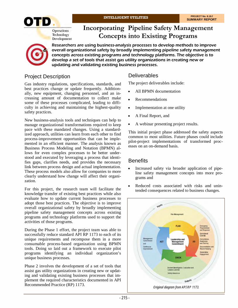
Project Description Gas industry regulations, specifications, standards, and best practices change or update frequently. Addition-ally, new equipment, changing personnel, and an in-creasing amount of documentation to collect make some of these processes complicated, leading to diffi-culty in achieving and maintaining the highest-quality safety practices.
New business-analysis tools and techniques can help to manage organizational transformations required to keep pace with these mandated changes. Using a standard-ized approach, utilities can learn from each other to find process-improvement opportunities that can be imple-mented in an efficient manner. The analysis known as Business Process Modeling and Notation (BPMN) al-lows for even complex processes to be better under-stood and executed by leveraging a process that identi-fies gaps, clarifies needs, and provides the necessary link between process design and actual implementation. These process models also allow for companies to more clearly understand how change will affect their organi-zation.
For this project, the research team will facilitate the knowledge transfer of existing best practices while also evaluate how to update current business processes to adopt those best practices. The objective is to improve overall organizational safety by broadly implementing pipeline safety management concepts across existing programs and technology platforms used to support the activities of those programs.
During the Phase 1 effort, the project team was able to successfully reduce standard API RP 1173 to each of its unique requirements and recompose them in a more consumable process-based organization using BPMN tools. Doing so laid out a framework to execute pilot programs identifying an individual organization’s unique business processes.
Phase 2 involves the development of a set of tools that assist gas utility organizations in creating new or updat-ing and validating existing business processes that im-plement the required characteristics documented in API Recommended Practice (RP) 1173.
Researchers are using business-analysis processes to develop methods to improve overall organizational safety by broadly implementing pipeline safety management concepts across existing programs and technology platforms. The objective is to develop a set of tools that assist gas utility organizations in creating new or updating and validating existing business processes.
Incorporating Pipeline Safety Management Concepts into Existing Programs
Deliverables The project deliverables include:
All BPMN documentation
Recommendations
Implementation at one utility
A Final Report, and
A webinar presenting project results.
This initial project phase addressed the safety aspects common to most utilities. Future phases could include pilot-project implementations of transformed proc-esses on an on-demand basis.
Benefits Increased safety via broader application of pipe-
line safety management concepts into more pro-grams and
Reduced costs associated with risks and unin-tended consequences related to business changes.
- 215 -
INTELLIGENT UTILITIES PROJECT No. 8.18.f SUMMARY REPORT
Original diagram from API RP 1173.

- 216 -
For more information:
Michael Adamo, P.E. Vice President, Operations Operations Technology Development, NFP Phone: 847/544-3428 [email protected]
Results In this project, researchers evaluated developing sim-plified ways for utility organizations to implement best practices. The project team initially researched stan-dard API RP 1173 into its core requirements and iden-tified each business process that supports those require-ments to expose gaps, coordinate communication, and introduce enterprise-level management of pipeline safety management systems (PSMS).
With major gas utilities, researchers tested the method-ology and identified areas for improvement. From there, the project team focused on two of the 10 essen-tial elements, finding that even in areas where proc-esses are firmly established, there are still areas for re-finement and gaps identified. As a result, we found that this approach is well-suited to support PSMS processes and enable enterprise systems to assist in better deci-sion-making capabilities.
The project team documented associated reference ma-terials using business analysis techniques. Researchers also interviewed subject-matter experts that have previ-ously gone through various forms of gap analysis re-lated to programs to better understand how the business analysis approach can help supplement these programs. Additionally, a survey was issued to discern the status of industry adoption of PSMS.
In 2020, investigators made considerable progress and completed the technical tasks.
Status A Phase 1 Final Report was issued in November 2020.
While much of the framework and design was estab-lished in Phase 1, additional phases are required to dis-till and optimize the approach and best practices for implementation.
Technical Concept & Approach The scope of this project includes applying business-analysis techniques and tools to gather requirements, record existing processes, identify gaps, and provide implementation recommendations including best prac-tices. The project team will research and identify the techniques that are best suited for managing business changes that incorporate pipeline safety management practices into existing programs.
Researchers will elicit requirements from stakeholders using standardized best practices. This will be com-prised of any or all of the following: interviewing sys-tem users, brainstorming, documenting observations, gathering survey information, and/or reviewing existing regulations and standards from regulating authorities.
Based on the requirements collected, the project team will provide analysis documentation. This may involve consulting additional subject-matter experts, incorporat-ing requirements and regulation materials, and consid-ering business goals. The conditions that will factor into the design will include elements to ensure that the plan will be generic enough for most utilities to implement the plan in an effective manner while minimizing or-ganizational change.
Researchers will leverage methodologies from past pro-jects to document business processes, requirements, data models, and other specifications based on informa-tion collected.
The project team will provide a recommended approach for implementing the best practices and transferring the knowledge compiled in previous tasks. Plans are to in-volve one utility in the implementation of these best practices.
- Zachary Lowe Director of Pipeline Safety Management Southern Company Gas
“Southern Company Gas is proud to continue our partnership with OTD to further understand the role of process mapping to support implementation of a Pipeline Safety Management System framework. Advancing pipeline safety is critical to ensuring access to clean, safe, reliable and affordable energy for our customers and communities.”

INTELLIGENT UTILITIES PROJECT No. 8.19.a SUMMARY REPORT
Project Description In this project, researchers evaluated and rigorously tested available Smart Phone applications which may serve as tools for increased safety or productivity for gas utility personnel. The focus was on applications which the user can download and deploy themselves, rather than on expensive enterprise applications which require expert deployments and ongoing maintenance. These include the types of applications employees may already be using without official recognition or accessi-bility from the company.
Examples which could be valuable to examine include decibel meter applications. It may be useful for an em-ployee to measure decibel sound levels while making the decision whether to use noise-attenuating personal-protective equipment.
Other examples of potential applications include:
Heads up windshield displays for drivers; the phone screen lays on the dashboard and projects informa-tion on the windshield.
For this project, a research team evaluated Smart Phone applications which may serve as tools for increased safety or productivity for gas utility personnel. Researchers tested the accuracy and reliability of these applications that a user can download and deploy themselves.
Smart Phone Tools
Situational awareness companions; for users in hazardous scenarios, the app communicates real-time position and status information for better safety support.
Infrared (IR) testers; digital cameras can detect a wider range of light, including IR. These can be used to verify the operation of equipment using IR communication.
Touchless gesture-control applications; allows the phone to read the user’s hand movements and con-vert them into commands, such as “take a picture.”
Measurement applications, such as measuring ob-jects in photos, virtual tape measures, arc tracing, virtual theodolite, bubble level, clinometer, etc.
Researchers evaluated the accuracy and reliability of these applications. The project also reports on mobile cybersecurity threats, how they manifest, and the steps that can be taken to reduce the likelihood that they can be deployed against a smartphone.
- 217 -
Left: Cellphones and sound meter mounted to a one-inch-diameter pole. Right: Light testing.
- 218 -
For more information:
Michael Adamo, P.E. Vice President, Operations Operations Technology Development, NFP Phone: 847/544-3428 [email protected]
In 2020, testing was conducted on four applications and the voice control/assist functionality in iOS and Android.
Survey Master is a free Smart Phone application that offers several tools that are normally part of profes-sional-grade survey software. The application has a very wide variety of features that can be helpful for a field data collector. A lot of these features are not usu-ally part of GIS data-collection mobile applications and resemble the expensive tools available to surveyors and the professional equipment that they use. The applica-tion, in general, is intuitive and easy to use.
The angle testing showed that CamScanner is most ef-fective at the approximate range of 0 to 45 degrees in-clination of the camera. The application started having difficulties auto-detecting the corners of the document at 40° inclination.
Smart Phone scanning technology is proving to be a significant alternative to traditional scanners and can be very useful, especially for people in the field. The qual-ity of the scanned image can be very impressive, as the application can ortho-rectify the image and remove the background. But the quality can also vary, depending on different factors, such as camera resolution, light, type of document, scan angle, etc.
For lower sound levels, below about 70 dB, both the Android and iOS applications performed adequately. However, at higher sound levels, especially at 85 dB and above, levels at which OSHA requires hearing pro-tection, the Android application measured consistently lower.
Results for the iOS application revealed a higher level of accuracy than for the Android application. The iOS application never read more than 2.5% below the actual noise level and only infrequently more than that above it.
Status
This project is complete. A Final Report was issued in August 2020.
Deliverables The project team compiled report containing the results of each test for each selected application and issued a Final Report.
Benefits Smart Phones are carried by nearly all utility personnel and provide a low-cost means to deploy additional pro-ductivity and safety tools throughout an organization.
In some cases, employees may be self-deploying solu-tions on their smart devices without official sanction from the company. Correct operation and use is critical to producing value. In fact, incorrect operation and us-age can produce undesirable results, including safety concerns and loss of efficiency.
Technical Concept & Approach Specific tasks included:
Select Applications and Design Tests
A set of evaluation criteria was identified and a test-ing plan created for each application.
Execute Testing Plan
The testing plan was executed and the results com-piled into reports.
Checklist for Cybersecurity Concerns
The project team conducted a survey of reports, documents, and studies produced by reputable au-thoritative bodies in the area of mobile cybersecu-rity. Researchers compiled a list of possible threats posed by mobile application usage and the common mechanisms by which threats manifest. A checklist was created which can be used to reduce the likeli-hood that those common security threat mecha-nisms can deployed against a Smart Phone. Because Android and iOS devices are fundamentally differ-ent, a separate checklist was created for each.
Results In 2019, researchers identified applications in several categories to evaluate in depth. Some of the applica-tions were excluded from further consideration due to quality or feasibility issues, and others were added to the list. Information from outside groups that evaluated some of the applications under consideration was also reviewed. Additionally, an initial review of resources on cybersecurity was conducted.
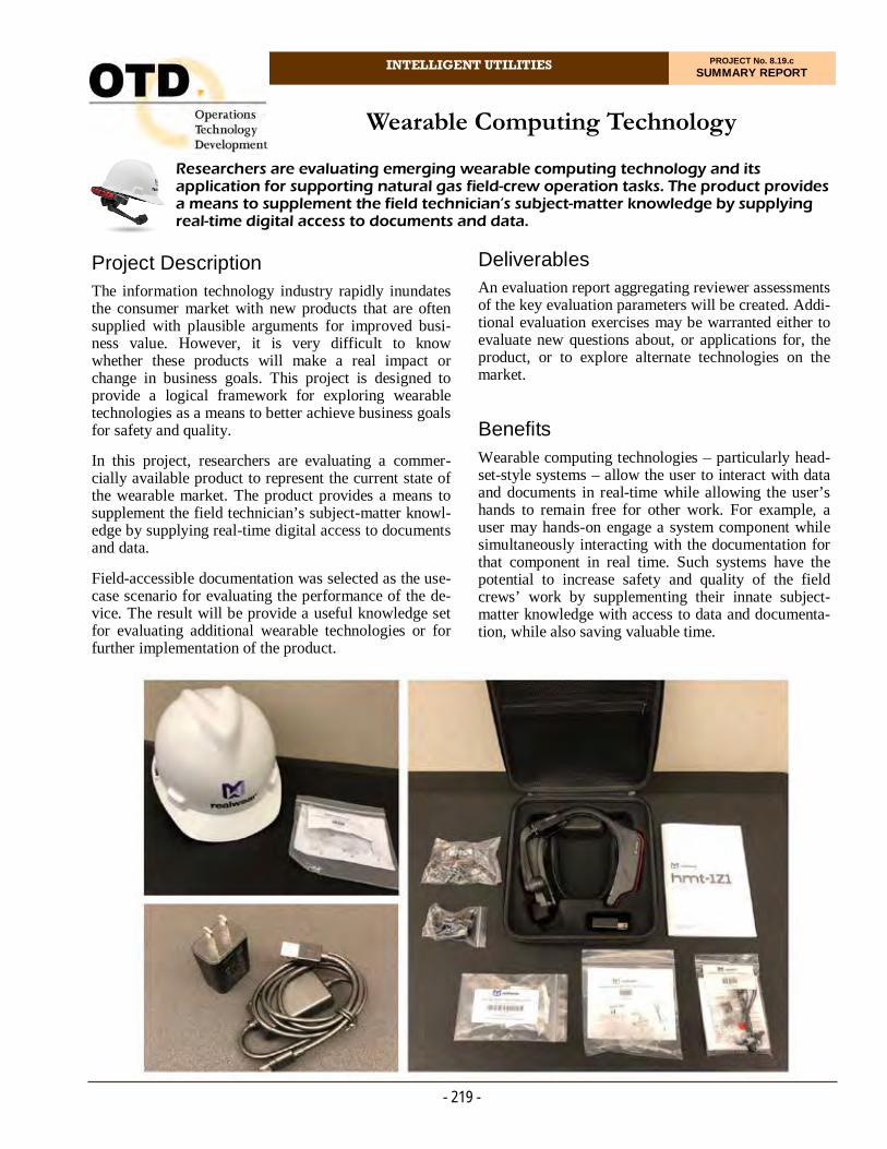
INTELLIGENT UTILITIES PROJECT No. 8.19.c SUMMARY REPORT
Project Description The information technology industry rapidly inundates the consumer market with new products that are often supplied with plausible arguments for improved busi-ness value. However, it is very difficult to know whether these products will make a real impact or change in business goals. This project is designed to provide a logical framework for exploring wearable technologies as a means to better achieve business goals for safety and quality.
In this project, researchers are evaluating a commer-cially available product to represent the current state of the wearable market. The product provides a means to supplement the field technician’s subject-matter knowl-edge by supplying real-time digital access to documents and data.
Field-accessible documentation was selected as the use-case scenario for evaluating the performance of the de-vice. The result will be provide a useful knowledge set for evaluating additional wearable technologies or for further implementation of the product.
Researchers are evaluating emerging wearable computing technology and its application for supporting natural gas field-crew operation tasks. The product provides a means to supplement the field technician’s subject-matter knowledge by supplying real-time digital access to documents and data.
Wearable Computing Technology
Deliverables An evaluation report aggregating reviewer assessments of the key evaluation parameters will be created. Addi-tional evaluation exercises may be warranted either to evaluate new questions about, or applications for, the product, or to explore alternate technologies on the market.
Benefits Wearable computing technologies – particularly head-set-style systems – allow the user to interact with data and documents in real-time while allowing the user’s hands to remain free for other work. For example, a user may hands-on engage a system component while simultaneously interacting with the documentation for that component in real time. Such systems have the potential to increase safety and quality of the field crews’ work by supplementing their innate subject-matter knowledge with access to data and documenta-tion, while also saving valuable time.
- 219 -
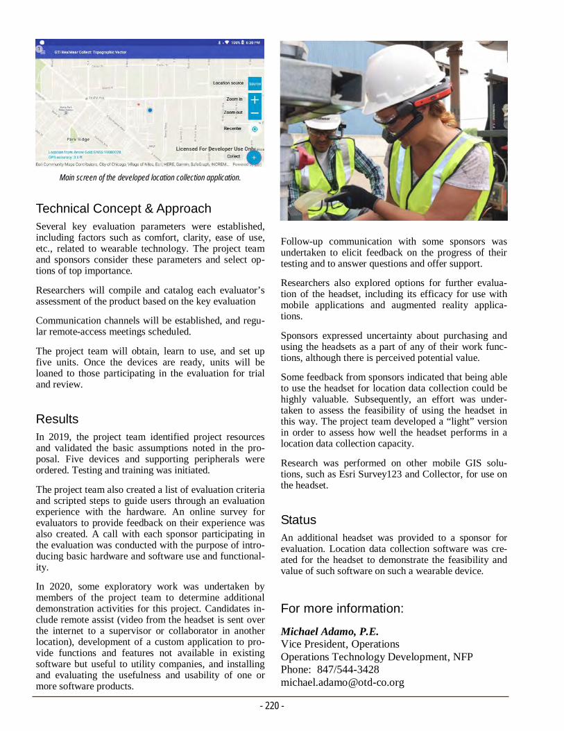
- 220 -
For more information:
Michael Adamo, P.E. Vice President, Operations Operations Technology Development, NFP Phone: 847/544-3428 [email protected]
Follow-up communication with some sponsors was undertaken to elicit feedback on the progress of their testing and to answer questions and offer support.
Researchers also explored options for further evalua-tion of the headset, including its efficacy for use with mobile applications and augmented reality applica-tions.
Sponsors expressed uncertainty about purchasing and using the headsets as a part of any of their work func-tions, although there is perceived potential value.
Some feedback from sponsors indicated that being able to use the headset for location data collection could be highly valuable. Subsequently, an effort was under-taken to assess the feasibility of using the headset in this way. The project team developed a “light” version in order to assess how well the headset performs in a location data collection capacity.
Research was performed on other mobile GIS solu-tions, such as Esri Survey123 and Collector, for use on the headset.
Status An additional headset was provided to a sponsor for evaluation. Location data collection software was cre-ated for the headset to demonstrate the feasibility and value of such software on such a wearable device.
Technical Concept & Approach Several key evaluation parameters were established, including factors such as comfort, clarity, ease of use, etc., related to wearable technology. The project team and sponsors consider these parameters and select op-tions of top importance.
Researchers will compile and catalog each evaluator’s assessment of the product based on the key evaluation
Communication channels will be established, and regu-lar remote-access meetings scheduled.
The project team will obtain, learn to use, and set up five units. Once the devices are ready, units will be loaned to those participating in the evaluation for trial and review.
Results In 2019, the project team identified project resources and validated the basic assumptions noted in the pro-posal. Five devices and supporting peripherals were ordered. Testing and training was initiated.
The project team also created a list of evaluation criteria and scripted steps to guide users through an evaluation experience with the hardware. An online survey for evaluators to provide feedback on their experience was also created. A call with each sponsor participating in the evaluation was conducted with the purpose of intro-ducing basic hardware and software use and functional-ity.
In 2020, some exploratory work was undertaken by members of the project team to determine additional demonstration activities for this project. Candidates in-clude remote assist (video from the headset is sent over the internet to a supervisor or collaborator in another location), development of a custom application to pro-vide functions and features not available in existing software but useful to utility companies, and installing and evaluating the usefulness and usability of one or more software products.
Main screen of the developed location collection application.

INTELLIGENT UTILITIES PROJECT No. 8.19.k SUMMARY REPORT
Project Description The objective of this project is to identify and evaluate AR software applications and hardware equipment (i.e., wearables and handheld) that can be used by field per-sonnel within the natural gas industry to assist with per-forming operations and maintenance (O&M) tasks.
The goal is to demonstrate the value of this technology and identify intuitive software applications and hard-ware equipment preferred by the natural gas industry.
Deliverables The deliverables for this project include a Final Report detailing the AR software applications and hardware equipment best suited for the natural gas industry. This report also highlights findings from a project sponsor pilot study.
Benefits Augmented Reality (AR) technology can help bridge this knowledge gap and also aid employees that do not perform the same type of work on a regular basis.
AR technology can help bridge knowledge gaps and can be used by field personnel within the natural gas industry to assist with performing O&M tasks. The goal of this project was to demonstrate the value of this technology and identify intuitive soft-ware applications and hardware equipment preferred by the natural gas industry.
Augmented Reality (AR) Technology for Performing O&M Tasks
AR technology has proven to improve the following:
Accuracy of work performed
Employee productivity
Safety of employees
Compliance documentation
Collaboration and communications, and
Customer service.
AR technology allows field personnel to access O&M procedures, checklists, troubleshooting tips, previous maintenance records, and training aids, and communi-cate with subject-matter experts in remote locations to assist and provide guidance on their activities, all hands-free. This technology also allows for video re-cording and photos of the work being performed or completed, leading to better documentation.
Technical Concept & Approach Specific tasks include:
- 221 -

- 222 -
For more information:
Michael Adamo, P.E. Vice President, Operations Operations Technology Development, NFP Phone: 847/544-3428 [email protected]
team about their needs, concerns, and observations. A schedule was created and provided to the volunteers outlining the weekly goals. Meetings were provided to troubleshoot any technical difficulties or to discuss the software and hardware. At the conclusion of this pilot, researchers aim to collect feedback on 1) the function-ality of readily deployable AR devices; 2) a compari-son of these options with competitive AR devices; 3) the field operator, subject-matter expert, and adminis-trative user experiences of using step-by-step guided procedures and remote mentor; and 4) a comparison of industry leading AR-enabled software tools that pro-vide step-by-step procedures and remote mentoring.
During the pilot program, training sessions were held with the project volunteers and virtual webinars hosted with software providers. Project volunteers provided feedback via surveys.
The project team and pilot volunteers arranged con-trolled demonstrations by deploying headsets with an uploaded AR software to test the efficacy of perform-ing procedures and remote assistance support in the hands-free environment.
Pilot volunteers completed an overview of the AR soft-ware solutions and evaluated them through surveys.
Sponsors provided feedback and survey results to de-termine which of the AR platforms most suited their needs. Two were chosen to continue with pilot pro-grams with participating OTD sponsors.
Status A Final Report is being developed.
Identification and Evaluation of AR Software Applications
The project team identified and evaluated potential software applications that may work well within the natural gas industry. Project sponsors selected the type of work activity (i.e., leak investigation, valve inspection, etc.) to use as part of the evalua-tion process.
Identification and Evaluation of AR Hardware Equipment
Researchers identified and evaluated potential AR hardware equipment that may work well within the natural gas industry. Sponsors were given the op-portunity to select which equipment to test.
Develop and Program Procedure Content into AR Application
This task included the project team members working directly with the AR software service pro-viders to develop and add the O&M procedures selected by the project sponsors to enter into the AR application. Types of documentation include work procedures, checklists, manufacturers instal-lation guides, training guides and videos, etc. Ad-ditional performance enhancements were made.
Pilot Study
A pilot study with project sponsors using the AR software application and hardware equipment was conducted.
Results
In 2019, a project sponsor survey was prepared to pro-vide a better understanding of how sponsors would like to use the AR technology and identify which types of procedures that they would like to see as part of the pilot project for evaluating the technology.
The project team identified potential AR software ap-plications and hardware equipment to evaluate.
In 2020, software was uploaded and evaluated on handheld tablets and wearables. User trials were initi-ated with software providers to better understand backend programming, data collection, and compati-bility with a wearable tablet.
Operating procedures were determined for evaluation and uploaded into the AR software workflow.
A pilot-project test plan was developed and discussed with pilot volunteers. This plan allows the sponsors to assess each step-by-step procedure/remote mentor soft-ware application and provide feedback to the project
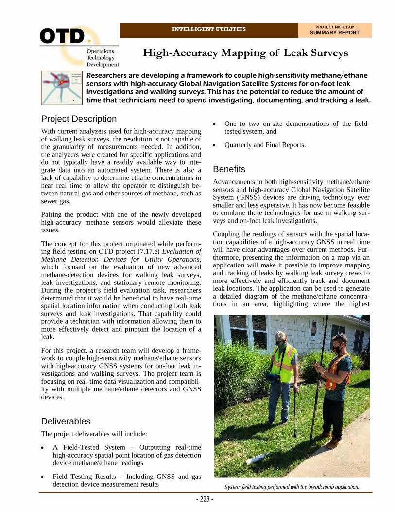
INTELLIGENT UTILITIES PROJECT No. 8.19.m SUMMARY REPORT
Project Description With current analyzers used for high-accuracy mapping of walking leak surveys, the resolution is not capable of the granularity of measurements needed. In addition, the analyzers were created for specific applications and do not typically have a readily available way to inte-grate data into an automated system. There is also a lack of capability to determine ethane concentrations in near real time to allow the operator to distinguish be-tween natural gas and other sources of methane, such as sewer gas.
Pairing the product with one of the newly developed high-accuracy methane sensors would alleviate these issues.
The concept for this project originated while perform-ing field testing on OTD project (7.17.e) Evaluation of Methane Detection Devices for Utility Operations, which focused on the evaluation of new advanced methane-detection devices for walking leak surveys, leak investigations, and stationary remote monitoring. During the project’s field evaluation task, researchers determined that it would be beneficial to have real-time spatial location information when conducting both leak surveys and leak investigations. That capability could provide a technician with information allowing them to more effectively detect and pinpoint the location of a leak.
For this project, a research team will develop a frame-work to couple high-sensitivity methane/ethane sensors with high-accuracy GNSS systems for on-foot leak in-vestigations and walking surveys. The project team is focusing on real-time data visualization and compatibil-ity with multiple methane/ethane detectors and GNSS devices.
Deliverables The project deliverables will include:
A Field-Tested System – Outputting real-time high-accuracy spatial point location of gas detection device methane/ethane readings
Field Testing Results – Including GNSS and gas detection device measurement results
Researchers are developing a framework to couple high-sensitivity methane/ethane sensors with high-accuracy Global Navigation Satellite Systems for on-foot leak investigations and walking surveys. This has the potential to reduce the amount of time that technicians need to spend investigating, documenting, and tracking a leak.
High-Accuracy Mapping of Leak Surveys
One to two on-site demonstrations of the field-tested system, and
Quarterly and Final Reports.
Benefits Advancements in both high-sensitivity methane/ethane sensors and high-accuracy Global Navigation Satellite System (GNSS) devices are driving technology ever smaller and less expensive. It has now become feasible to combine these technologies for use in walking sur-veys and on-foot leak investigations.
Coupling the readings of sensors with the spatial loca-tion capabilities of a high-accuracy GNSS in real time will have clear advantages over current methods. Fur-thermore, presenting the information on a map via an application will make it possible to improve mapping and tracking of leaks by walking leak survey crews to more effectively and efficiently track and document leak locations. The application can be used to generate a detailed diagram of the methane/ethane concentra-tions in an area, highlighting where the highest
- 223 -
System field testing performed with the breadcrumb application.

- 224 -
For more information:
Michael Adamo, P.E. Vice President, Operations Operations Technology Development, NFP Phone: 847/544-3428 [email protected]
The evaluation was conducted in a neighborhood where a replica of a gas system was designed to pro-vide a project area to conduct the testing. A GIS feature layer of this replica gas system was created.
The project team was successful in pairing both the high-accuracy GNSS receiver and methane sensor with the leak survey breadcrumb application on an Android device. Researchers were able to collect breadcrumb records around the entire project area using the bread-crumb application. Once completed, the manufacturer provided a spreadsheet containing the breadcrumb in-formation. Not only does the application collect both the methane-sensor readings and the GNSS spatial lo-cation data, it can capture vital information that can be used later for compliance and auditing purposes.
In addition to the breadcrumb application, the manu-facture also provides a vast catalog of customizable smart forms built into its platform. This will permit field crews to collect data for various types of gas-related activities while they are also performing a leak survey. Some examples of these forms are: Leak In-spection, Meter and Riser Inspections, Access Detail, Map Revisions, and Pipeline Marker Inspections. All the information collected from these forms links back directly to a utility’s GIS system, where it can help drive and manage business processes by providing real-time analytics.
Overall, the leak survey performed well during initial evaluation activities. The project team plans on finaliz-ing the testing matrix so a full-system evaluation can be conducted.
Status
Researchers are finalizing the draft of the walking leak survey requirements workflow document for project sponsors.
The project team is analyzing feedback on the test evaluation.
The COVID-19 pandemic has not directly affected the project. The project team continues to operate in a work-from-home scenario while making arrangements to conduct field testing on an as-needed basis. All planned work remains on schedule.
concentrations of methane are located, leading the technician to the leak location. The map and concen-trations can then be saved to generate forms used for tracking and repair crews to document that the leak has been fixed.
Additionally, the high-accuracy spatial location com-ponent can be used to address any issues arising from multiple callouts where crews are not able to pinpoint a leak. All the information collected during the leak surveys and investigations can be stored for later use and analysis by others, helping resolve any ambiguities with leak investigations.
Technical Concept & Approach
Activities include:
An evaluation of a system that can pair data from an approved gas detection device with a high-accuracy GNSS system
An evaluation of the ability to visualize the infor-mation in real time
Simulated leak testing of the developed system, and
Field testing of the developed system on simulated leaks.
Thorough testing of the existing product usability, data collection, accuracy, and output will be conducted.
The project has two research goals: The first goal is to balance the accuracy of GNSS/GPS options with costs, attempting to keep the ultimate product cost low while providing location accuracy within reason. The second goal is to ensure that the product operates with gas de-tectors currently in operation by our sponsors.
Results In 2020, the project team was successful in performing the initial evaluation of a walking leak survey solution. The goal was to become more familiar with the survey, laying the foundation for a more advanced and com-prehensive testing plan to be developed.
Researchers performed this preliminary assessment on a leak-survey “breadcrumb” application since the oper-ating-system version was still in development. To test the capabilities of the breadcrumb application (which combine the readings of a methane sensor with the high-accuracy data of a GNSS receiver), technicians simulated methane leaks in the field using a 99.99% methane gas cylinder canister. A methane sensor was used alongside a GNSS receiver to support the collec-tion of high-accuracy point location.

INTELLIGENT UTILITIES PROJECT No. 8.20.a SUMMARY REPORT
Project Description Personnel performance and skill competencies heavily impact a gas operator’s ability to maintain a safe and reliable system. Industry standards – such as ASME B31Q – specifically document which tasks should only be performed by or supervised by qualified personnel. Furthermore, B31Q documents the specific training and evaluation criteria for workers to become qualified for a task.
Gas industry personnel are interested in sharing the bur-den of creating training materials. Consequently, a pro-ject team formulated the current solution in alignment with the knowledge related to the training requirements within ASME B31Q and technical competencies related to cloud-based file sharing and web-based application development.
The objective of this project is to build and implement a prototype training documentation portal for OTD mem-ber companies to share training collateral such as vid-eos, documents, and presentations. This project will focus on the training materials associated with Pipeline Personnel Qualification Programs as described in the ASME B31Q standard.
In this project, researchers are implementing a prototype training documentation portal for companies to share training collateral such as videos, documents, and presentations. This project focuses on the training materials associated with Pipeline Personnel Qualification Programs as described in the ASME B31Q standard.
B31Q Training Documentation Portal
Deliverables A pilot web-based software application including file-sharing capability and a review and ranking tool will be deployed for use and review.
The project deliverables will include:
A prototype web-based system
Software requirements and design documents
System architecture deployment documents
Testing scripts and results documentation, and
Help documentation.
Benefits Creating materials in support of training programs for operator qualifications can become very time consum-ing and expensive. Each company can benefit by shar-ing the cost and burden of creating these training mate-rials for pipeline personnel qualifications documents for inclusion in training programs.
- 225 -

- 226 -
For more information:
Michael Adamo, P.E. Vice President, Operations Operations Technology Development, NFP Phone: 847/544-3428 [email protected]
of the test. In cases where the actual results do not satisfy the expected results, the project team will re-work the prototype until the system passes all tests.
Prototype Deployment and Support
The prototype system created during this project phase will be deployed to a cloud-based computer environment where companies may access the sys-tem with a companywide user profile. The cost of this task includes cloud services fees and basic sys-tem maintenance. Help documentation for the sys-tem will be created during this task.
Results In 2020, the project team finalized project resource commitments and drafted a work breakdown structure to identify tasks and tasks assignments. Typical project workflow best practices dictate that product require-ments be completed before beginning design and de-velopment. However, due to resource availability, soft-ware development was initiated before officially col-lecting requirements. The project workflow was re-aligned with industry best practices.
Software was investigated and appeared to supply the needed functionality to tag the final report documents semantically. The development environment for creat-ing the software was constructed and configured.
A final set of requirements were collected from project sponsors and merged into the existing set of require-ments.
Status Ongoing activities include:
Finalization of software development and software testing scripts
Investigation of content licensing issues regarding semantic web ontologies, and
Software testing and rework.
This project will increase access to expertise and knowledge through the development and implementa-tion of a web-based portal. A searchable repository of reports, documents, and other digital assets will be made available through the portal. Additionally, a community forum tailor-made for OTD member com-panies and their employees will be included in the ex-pertise portal. Knowledge assets will be related to a set of conceptual tags specific to gas industry language, making finding material and related documents easier. These tags will encourage the greater discovery of searched material as well as laterally and hierarchically associated documents.
Technical Concept & Approach Specific tasks include:
Requirements Analysis
The project team will create a specific list of fea-tures and characteristics the B31Q documentation portal system must possess. The requirements will include functionality, usability, reliability, per-formance, and supportability related to sharing files and allowing the community to rank and re-view the quality of the materials.
File Sharing Design and Development
Researchers will design and develop the central technology mechanism for uploading and downloading files. Additionally, data backup and a restoration process must be considered along with restricted user access and cybersecurity.
Review and Ranking Design and Development
The materials on the portal will be curated by the community. In this task, researchers will design and develop the technology components for allow-ing others to rank the quality of uploaded material, such as a five-star system, and write a description of the materials, such as a review system. These tools will be integrated into the same web applica-tion as the file-sharing system.
System Testing and Rework
This task includes creating test-case documenta-tion based on the requirements and design docu-mentation developed in earlier tasks. The test cases will exercise each function, service, and design element as a holistic system. The purpose is to en-sure that the system operates as intended after all components are assembled. The project team will execute each test case and record the actual results
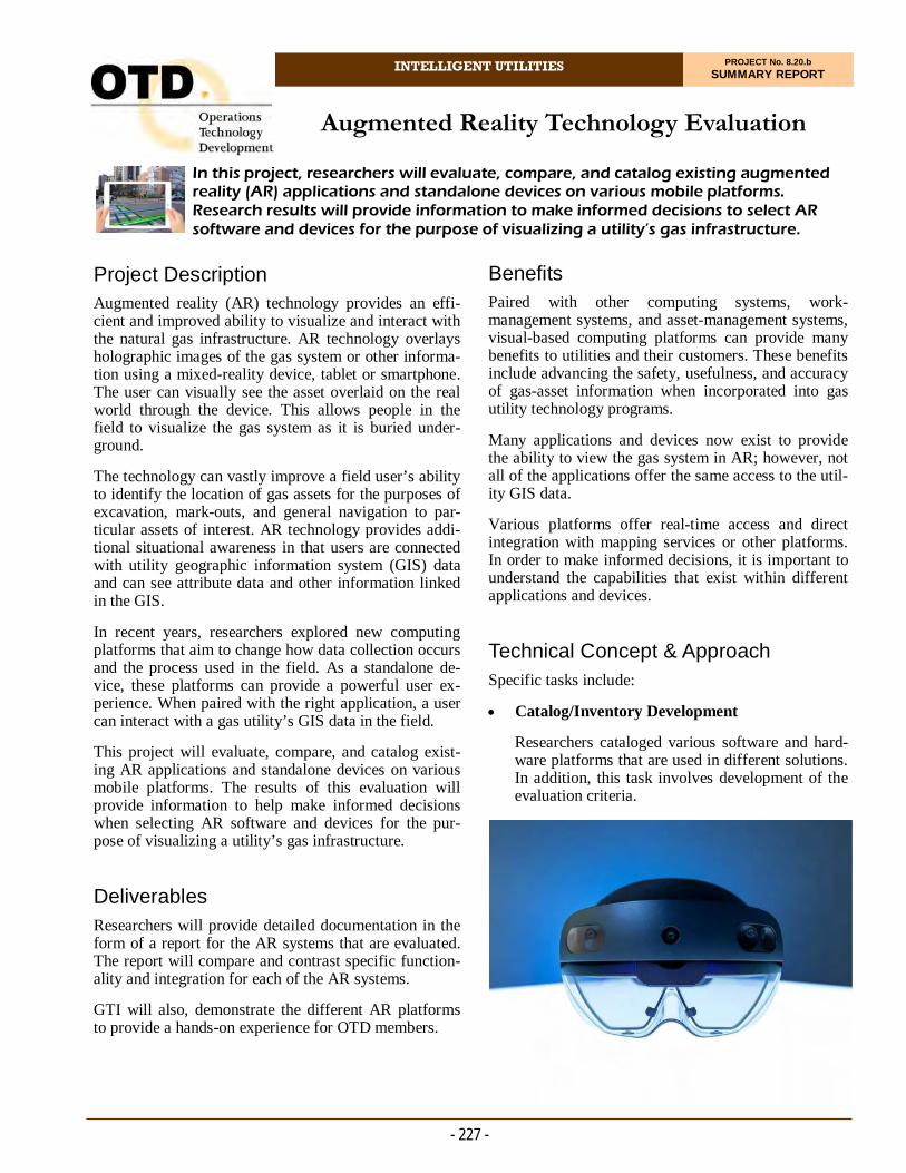
INTELLIGENT UTILITIES PROJECT No. 8.20.b SUMMARY REPORT
Project Description Augmented reality (AR) technology provides an effi-cient and improved ability to visualize and interact with the natural gas infrastructure. AR technology overlays holographic images of the gas system or other informa-tion using a mixed-reality device, tablet or smartphone. The user can visually see the asset overlaid on the real world through the device. This allows people in the field to visualize the gas system as it is buried under-ground.
The technology can vastly improve a field user’s ability to identify the location of gas assets for the purposes of excavation, mark-outs, and general navigation to par-ticular assets of interest. AR technology provides addi-tional situational awareness in that users are connected with utility geographic information system (GIS) data and can see attribute data and other information linked in the GIS.
In recent years, researchers explored new computing platforms that aim to change how data collection occurs and the process used in the field. As a standalone de-vice, these platforms can provide a powerful user ex-perience. When paired with the right application, a user can interact with a gas utility’s GIS data in the field.
This project will evaluate, compare, and catalog exist-ing AR applications and standalone devices on various mobile platforms. The results of this evaluation will provide information to help make informed decisions when selecting AR software and devices for the pur-pose of visualizing a utility’s gas infrastructure.
Deliverables Researchers will provide detailed documentation in the form of a report for the AR systems that are evaluated. The report will compare and contrast specific function-ality and integration for each of the AR systems.
GTI will also, demonstrate the different AR platforms to provide a hands-on experience for OTD members.
In this project, researchers will evaluate, compare, and catalog existing augmented reality (AR) applications and standalone devices on various mobile platforms. Research results will provide information to make informed decisions to select AR software and devices for the purpose of visualizing a utility’s gas infrastructure.
Augmented Reality Technology Evaluation
Benefits Paired with other computing systems, work-management systems, and asset-management systems, visual-based computing platforms can provide many benefits to utilities and their customers. These benefits include advancing the safety, usefulness, and accuracy of gas-asset information when incorporated into gas utility technology programs.
Many applications and devices now exist to provide the ability to view the gas system in AR; however, not all of the applications offer the same access to the util-ity GIS data.
Various platforms offer real-time access and direct integration with mapping services or other platforms. In order to make informed decisions, it is important to understand the capabilities that exist within different applications and devices.
Technical Concept & Approach Specific tasks include:
Catalog/Inventory Development
Researchers cataloged various software and hard-ware platforms that are used in different solutions. In addition, this task involves development of the evaluation criteria.
- 227 -

- 228 -
For more information:
Michael Adamo, P.E. Vice President, Operations Operations Technology Development, NFP Phone: 847/544-3428 [email protected]
used as a reference guide for project sponsors moving forward to assist them during their AR selection proc-ess. Listed in this document are some criteria identified through past AR projects as essential factors to con-sider when selecting an AR platform (both hardware and software).
The COVID-19 pandemic has not directly affected the project. As researchers continue the work remotely, they do not anticipate any project delays or issues as a result of the pandemic and stay-at-home orders.
Status Ongoing activities include evaluations of additional software and hardware. Videos of evaluations will be made to be used as demonstrations of the technologies for project sponsors.
Hardware/Software Capabilities
Researchers will categorize the capabilities of both the hardware and software components of the se-lected AR systems and identify functionality that can be tested and used in real-world conditions. The results of the testing will be used to develop recommendations for the use of different applica-tions and platforms.
The project team will compare and contrast the functionality of the AR systems with the ultimate goal of providing sufficient information that a sponsor can use to make decisions for acquiring an AR system for field operations.
GIS/System Integration
A core function of a computing system that is de-ployed in the field is its ability to consume and create data within a centralized data system or GIS. This task will evaluate the AR platform’s ability to use real-time GIS data and other system data within the AR platforms.
Demonstrations
The project team will demonstrate AR system ca-pabilities directly with up to two sponsors at their request. This will include hands-on time with the AR systems, training and support, and discussion of other system integrations that are available spe-cific to a sponsor’s needs.
Results In 2020, the research team identified software and hardware for evaluation. Researchers also discussed some of the criteria that would go into the inventory matrix catalog, which will be used to highlight the various capabilities of the software and hardware plat-forms at the end of the project.
Once the AR platforms were identified, a project team representative began reaching out to the AR vendors to purchase both hardware devices and software licenses, as well as to schedule training sessions.
The project team coordinated training sessions with two providers to begin the self-evaluation process of their AR platforms. Researchers laid pipe and gas fea-tures (stick-pipe couplings, end caps, tees, and reduc-ers) in a trench to create a replica gas system. This rep-lica gas system was then captured using a high-accuracy GNSS receiver, and converted into a GIS feature surface layer. The project team was able to run through several of the use cases.
Researchers also finalized a draft version of the inven-tory matrix catalog. This comparative matrix can be
GIS application on an iPad Pro.
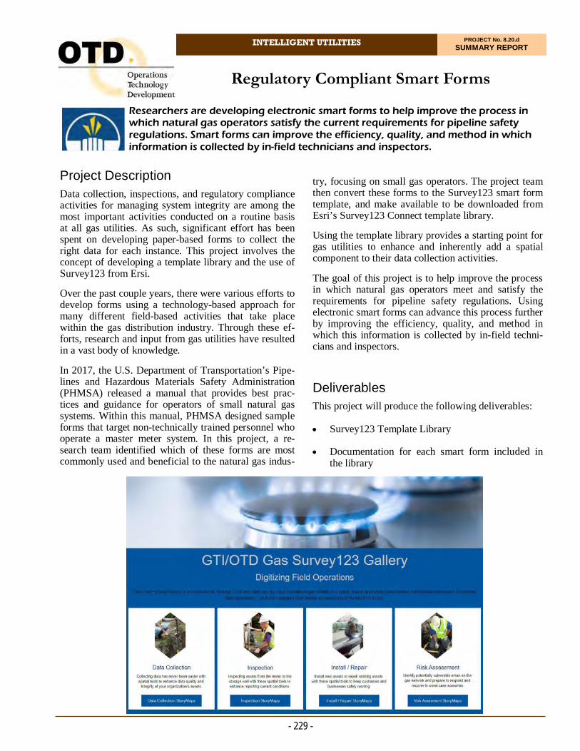
INTELLIGENT UTILITIES PROJECT No. 8.20.d SUMMARY REPORT
Project Description Data collection, inspections, and regulatory compliance activities for managing system integrity are among the most important activities conducted on a routine basis at all gas utilities. As such, significant effort has been spent on developing paper-based forms to collect the right data for each instance. This project involves the concept of developing a template library and the use of Survey123 from Ersi.
Over the past couple years, there were various efforts to develop forms using a technology-based approach for many different field-based activities that take place within the gas distribution industry. Through these ef-forts, research and input from gas utilities have resulted in a vast body of knowledge.
In 2017, the U.S. Department of Transportation’s Pipe-lines and Hazardous Materials Safety Administration (PHMSA) released a manual that provides best prac-tices and guidance for operators of small natural gas systems. Within this manual, PHMSA designed sample forms that target non-technically trained personnel who operate a master meter system. In this project, a re-search team identified which of these forms are most commonly used and beneficial to the natural gas indus-
Researchers are developing electronic smart forms to help improve the process in which natural gas operators satisfy the current requirements for pipeline safety regulations. Smart forms can improve the efficiency, quality, and method in which information is collected by in-field technicians and inspectors.
Regulatory Compliant Smart Forms
try, focusing on small gas operators. The project team then convert these forms to the Survey123 smart form template, and make available to be downloaded from Esri’s Survey123 Connect template library.
Using the template library provides a starting point for gas utilities to enhance and inherently add a spatial component to their data collection activities.
The goal of this project is to help improve the process in which natural gas operators meet and satisfy the requirements for pipeline safety regulations. Using electronic smart forms can advance this process further by improving the efficiency, quality, and method in which this information is collected by in-field techni-cians and inspectors.
Deliverables This project will produce the following deliverables:
Survey123 Template Library
Documentation for each smart form included in the library
- 229 -

- 230 -
For more information:
Michael Adamo, P.E. Vice President, Operations Operations Technology Development, NFP Phone: 847/544-3428 [email protected]
Researchers will provide a demonstration of the smart forms and detail the various components of the Sur-vey123 platform.
Results In 2020, the project team completed the task of con-verting the PHMSA designed sample forms, listed in PHMSA's Guidance Manual for Operators of Small Natural Gas Systems, to Survey123's XLSForm format.
The project team and Esri representatives met to deter-mine the best approach for building and designing the Gas Template Library. This library hosts an entire cata-log of gas-related smart forms so they can be easily accessed and utilized.
All of the forms are now available for download through Esri's Survey123 Connect application by typ-ing GTI, or the survey name, into the Search Menu un-der the Community Tab.
After conversations with Esri, Gas Technology Insti-tute decided to host the library through its web-based application Experience Builder. Using this platform would satisfy the need to highlight the entire catalog of gas templates while also providing gas utilities with a one-stop shop to learn more about every form in the catalog. Forms are grouped into four categories: Data Collection, Inspection, Installation/Repair, and Risk Assessment.
Status Researchers are completing development of the Sur-vey123 Gas Template Library and developing the web-based library.
Smart form demonstration as a recorded video/PowerPoint
Final Report, and
Webinar.
Benefits Developing standardized regulatory compliant smart form templates and aggregating them within a template library will allow gas utilities to save time, collect data in a standardized format, and establish parity across utilities for data collection. In addition, these smart-form templates will ensure that the current minimum requirements and standards for pipeline safety regula-tions and maintenance compliance are met. This will minimize risk by helping to ensure that the appropriate data is being collected, while also increasing produc-tivity by enabling gas utilities to quickly start elec-tronic data collection.
These benefits include: removing the reliance on paper forms, improving the overall process for completing the forms, organizing and structuring the submitted data into a backend database, enabling real-time data collection which can feed real-time system analytics and visualization, and collecting high-accuracy spatial location information (latitudinal and longitudinal coor-dinates).
The inherent capability of Survey123 to collect a spa-tial location of data collected in the field can also bene-fit utilities by improving accuracy of spatial informa-tion, and the ability to use the GIS for exposing pat-terns in results gathered from field data collection.
Technical Concept & Approach This project includes tasks that involve working di-rectly with Esri to continue building out the gas indus-try template library used for hosting the smart forms and providing access to gas utilities.
Note that Survey123 does not require the use of Esri products but is enabled to integrate directly with Esri or other GIS systems.
The project team is converting as many forms from the PHMSA small operators guide as possible. The se-lected forms are converted into Survey123’s digital data collection format. Additionally, where budget al-lows, the project team uses internal subject matter ex-pertise to validate these forms, making sure that they capture and incorporate the requirements necessary to satisfy the needs of the gas-related field activity they are addressing.
- Girish Ranade Manager, Operations System Support Washington Gas
“As we are moving away from a paper-based data-gathering environment, the timing of the Smart Forms has been perfect. We have seen several benefits already, including saving us time and providing a network where we can share more ideas and suggestions.”
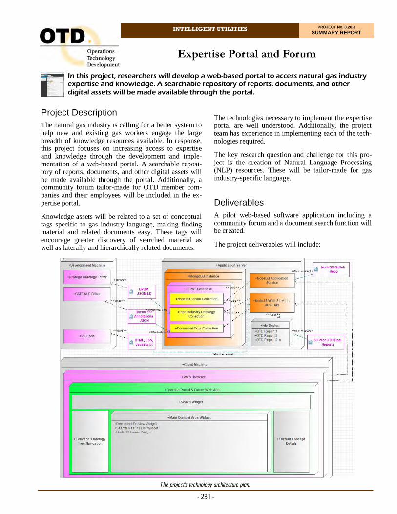
INTELLIGENT UTILITIES PROJECT No. 8.20.e SUMMARY REPORT
Project Description The natural gas industry is calling for a better system to help new and existing gas workers engage the large breadth of knowledge resources available. In response, this project focuses on increasing access to expertise and knowledge through the development and imple-mentation of a web-based portal. A searchable reposi-tory of reports, documents, and other digital assets will be made available through the portal. Additionally, a community forum tailor-made for OTD member com-panies and their employees will be included in the ex-pertise portal.
Knowledge assets will be related to a set of conceptual tags specific to gas industry language, making finding material and related documents easy. These tags will encourage greater discovery of searched material as well as laterally and hierarchically related documents.
In this project, researchers will develop a web-based portal to access natural gas industry expertise and knowledge. A searchable repository of reports, documents, and other digital assets will be made available through the portal.
Expertise Portal and Forum
The technologies necessary to implement the expertise portal are well understood. Additionally, the project team has experience in implementing each of the tech-nologies required.
The key research question and challenge for this pro-ject is the creation of Natural Language Processing (NLP) resources. These will be tailor-made for gas industry-specific language. Deliverables A pilot web-based software application including a community forum and a document search function will be created.
The project deliverables will include:
- 231 - The project’s technology architecture plan.

- 232 -
For more information:
Michael Adamo, P.E. Vice President, Operations Operations Technology Development, NFP Phone: 847/544-3428 [email protected]
The project team will create a specific list of features and characteristics the expertise portal system must possess. The requirements will include functionality, usability, reliability, performance, and supportability. The entire list of requirements will be subdivided into the three planned project phases. A reasonably func-tional prototype can be produced at the end of each phase, but also the level of effort will be scaled appro-priately for a successful project execution.
A system design will be created that describes a system capable of realizing the required features. The design models will include use cases that describe the user’s interaction within the system functions, a deployment model that describes each hardware and software com-ponent within their communication channels, and a set of screen mockups which provide a visual layout of the user interface.
System development activities include deploying data-bases, web services, and forum software services. Cus-tomer software code to manifest the web page and communications with the database will be created. As part of this project, quality-control measures, unit test-ing, and integration testing will be conducted.
Test cases will exercise each function, service, and de-sign element as a holistic system. The purpose is to make sure the system operates as intended after all components are assembled. The project team will exe-cute each test case and record the actual results of the test. In cases where the actual results do not satisfy the expected results, the project team will re-work the pro-totype until the system passes all tests.
Results / Status
In 2020, a final set of requirements was collected from project sponsors and merged into the existing set of requirements.
Significant progress was made in software design and development.
The project workflow will be re-aligned with industry best practices during late 2020.
A prototype web-based system
Software requirements and design documents
System architecture deployment documents
Custom gas industry semantic ontology
Custom gas industry NLP processing resources
Testing scripts and results documentation, and
Help documentation.
Benefits This project encompasses several sub-disciplines, in-cluding chemistry, physics, metallurgy, mechanical engineering, electrical engineering, information tech-nology and communications, business operations, safety engineering and control, construction, legal, regulation, and more.
A gas operations employee will benefit from easier access to a cache of industry knowledge and expertise by having a forum to interact with industry experts in a web-based environment. Examples of accessible re-ports and documentation may include those developed over the 15-year history of OTD projects.
Technical Concept & Approach The fully-featured web portal will be developed and implemented in a series of three project phases.
Phase 1 will identify a suitable information technology platform to support the online web portal. Addition-ally, a novel approach for automatically tagging digital documents will be created. The new tagging approach will involve creating new NLP token evaluation en-gines specifically tuned to capture gas industry lan-guage. Fifty OTD Final Reports will be processed and deployed on the knowledge portal as a pilot implemen-tation. A basic forum software solution will be inte-grated into the web-based portal.
Phase 2 will continue development of the NLP evalua-tion engines to include additional types of documents such as technical tables and Code of Federal Rule Structures and Standards documents. Additional docu-ments will be tagged through the NLP application and deployed to the web-based portal.
Phase 3 will finalize all development of the NLP evaluation engines and web-technology deployment. Plans for long-term maintenance and support of the system will be identified and implemented.
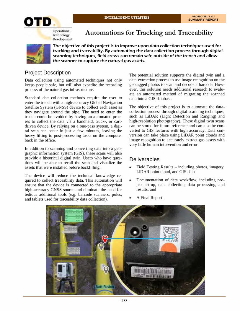
INTELLIGENT UTILITIES PROJECT No. 8.20.i SUMMARY REPORT
Project Description Data collection using automated techniques not only keeps people safe, but will also expedite the recording process of the natural gas infrastructure.
Standard data-collection methods require the user to enter the trench with a high-accuracy Global Navigation Satellite System (GNSS) device to collect each asset as they navigate around the pipe. The need to enter the trench could be avoided by having an automated proc-ess to collect the data via a handheld, truck-, or cart-driven device. By relying on a one-pass system, a digi-tal scan can occur in just a few minutes, leaving the heavy lifting to post-processing tasks on the computer back in the office.
In addition to scanning and converting data into a geo-graphic information system (GIS), these scans will also provide a historical digital twin. Users who have ques-tions will be able to recall the scan and visualize the assets that were installed before backfilling.
The device will reduce the technical knowledge re-quired to collect traceability data. This automation will ensure that the device is connected to the appropriate high-accuracy GNSS source and eliminate the need for tedious additional tools (e.g. barcode scanners, poles, and tablets used for traceability data collection).
The objective of this project is to improve upon data-collection techniques used for tracking and traceability. By automating the data-collection process through digital-scanning techniques, field crews can remain safe outside of the trench and allow the scanner to capture the natural gas assets.
Automations for Tracking and Traceability
The potential solution supports the digital twin and a data-extraction process to use image recognition on the geotagged photos to scan and decode a barcode. How-ever, this solution needs additional research to evalu-ate an automated method of migrating the scanned data into a GIS database.
The objective of this project is to automate the data-collection process through digital-scanning techniques, such as LiDAR (Light Detection and Ranging) and high-resolution photography). These digital twin scans can be stored for future reference and can also be con-verted to GIS features with high accuracy. Data con-version can take place using LiDAR point clouds and image recognition to accurately extract gas assets with very little human intervention and error. Deliverables Field Testing Results – including photos, imagery,
LiDAR point cloud, and GIS data
Documentation of data workflow, including pro-ject set-up, data collection, data processing, and results, and
A Final Report.
- 233 -

- 234 -
For more information:
Michael Adamo, P.E. Vice President, Operations Operations Technology Development, NFP Phone: 847/544-3428 [email protected]
Results In 2019, researchers initiated a review of different methodologies for capturing digital twin datasets from various LIDAR/photography-based scanners. For the project, an area was excavated to replicate an open trench setting.
In 2020, the project team also began research on mo-torized push carts that could allow for easier scanning in distribution-type use cases.
Researchers reviewed potential open-source software for object detection within images. The project team evaluated a scanning solution in July 2020, but due to COVID-19 had to postpone the scheduled field test.
The device of interest is attached to a metal arm that cantilevers off the side of a truck. The manufacturer also created an automated process for migrating digital scans into GIS data. The core of the company’s activi-ties have been on larger-diameter pipe so far, but smaller-sized pipe (i.e., two and four inches in diame-ter) is in-line with its current business model.
Status Current activities include: reviewing potential retrofits to a motorized push cart for handling the manufacturers newest scanner; configuring a backend data server for storing scanning results; and continuing to review ob-ject-detection software for use within this project.
Benefits The development of an appropriate data-collection de-vice will reduce the technical knowledge required to collect traceability data. This automation will ensure that the device is connected to the appropriate high-accuracy GNSS source and eliminate the need for ad-ditional tools.
Technical Concept & Approach In this project, researchers and a manufacturer are making efforts to enhance the company’s product by extracting and mapping a natural gas system for distri-bution-sized assets.
Specific activities include:
Technology Implementation
The project team will design the workflow of scan-ning, identifying, and mapping natural gas distri-bution-sized assets and review the most efficient data-collection processes.
A cloud-server environment will be created to han-dle the scanned data and post-processing.
The team will research and test an image-detection platform for identifying and decoding barcodes. In addition, an alternative method of collecting bar-code information during the field-scanning process will be investigated.
Technology Field Testing
The project team will establish a testing site and develop a testing matrix for evaluating data-collection quality.
The goal of this project is to provide a digital twin for utilities to revisit underground work after backfill; improve field crew safety by alleviating the extra effort to enter the trench to collect data, and eliminate potential data-entry errors.

INTELLIGENT UTILITIES PROJECT No. 8.20.j SUMMARY REPORT
Project Description Improved subsurface locating processes represent a technology gap that has no single solution.
White River Technologies has tools that have been proven in locating buried munitions that have unique “fingerprints,” distinguishing specific objects from other nearby metallic features. This same technology can be used to identify the cutter tool located within service tees through enhanced algorithms, identifying unique signatures to validate the structure, distinguish-ing it from other surrounding objects.
A preliminary demonstration was conducted to test the viability of this concept. The results that came back were very promising, and additional tasks to enhance the algorithms and unique fingerprints of these objects can take proof of concept into commercialization.
The above-ground three-dimensional electromagnetic (3DEM) technology that was proven in defense applica-tions of locating subsurface, metallic infrastructure. In
In this project, researchers are investigating an above-ground three-dimen-sional electromagnetic (3DEM) technology that has been proven in defense applications of locating subsurface, metallic infrastructure. The technology would be used to define distinct fingerprints of service tees to distinguish between other subsurface features.
Above-Ground Service Tee Identification and 3D Mapping
this project, the 3DEM technology would be used to define distinct fingerprints of service tees.
Deliverables Deliverables include:
A testing report
A field demonstration report, and
Final results and webinar.
Benefits Knowing exact locations of service tees – especially in three dimensions – has been a challenge for utilities. While many utilities have been continuously improv-ing their processes to capture high-accuracy locations of newly installed features, it doesn’t address the exist-ing pipe in the ground.
- 235 -

- 236 -
For more information:
Michael Adamo, P.E. Vice President, Operations Operations Technology Development, NFP Phone: 847/544-3428 [email protected]
Results In 2020, the contracting portion of this effort was com-pleted. Upon opening the project, researchers began project planning based on the proposed scope of work. A core group of team members was selected to manage the project and work closely with the subcontractor.
Status
The following activities are scheduled for execution:
Hold project kick-off call with project sponsors
Conduct biweekly project status meetings between
Finalize a work breakdown structure and detailed project schedule
Start technical planning and design with and facili-tate any resource requirements to begin develop-ment, and
Design and distribute a survey to sponsors, solicit-ing various project requirements and support infor-mation.
Plastic pipe is particularly challenging to locate. Ac-cording to the Common Ground Alliance 2015 DIRT report, improperly located or undetected subsurface utilities resulted in 1,906 injuries, 421 fatalities, and $1.7 billion in damages over the past 20 years. Most locating technology cannot accurately detect plastic pipe. Knowing precise locations of buried infrastructure can reduce injuries and damage, saving money and lives.
Technical Concept & Approach Specific project tasks include:
Signature Classification Enhancement
Researchers and utilities will identify the various types of service tees that are used in the field, pri-oritizing the most commonly used equipment, and enhancing the 3DEM tools and software to enable proper signature classification of those components.
Testing
In a controlled setting, tools will be tested to ensure consistent and repeatable results from various depths and orientations. The specific testing criteria will be identified with the project sponsors to best represent the field conditions and equipment that is actually used. A testing matrix will be created and delivered within the testing report.
Demonstration
Tools will be demonstrated in the field with at least one utility. The results will be documented, includ-ing any enhancements needed from the field dem-onstration.
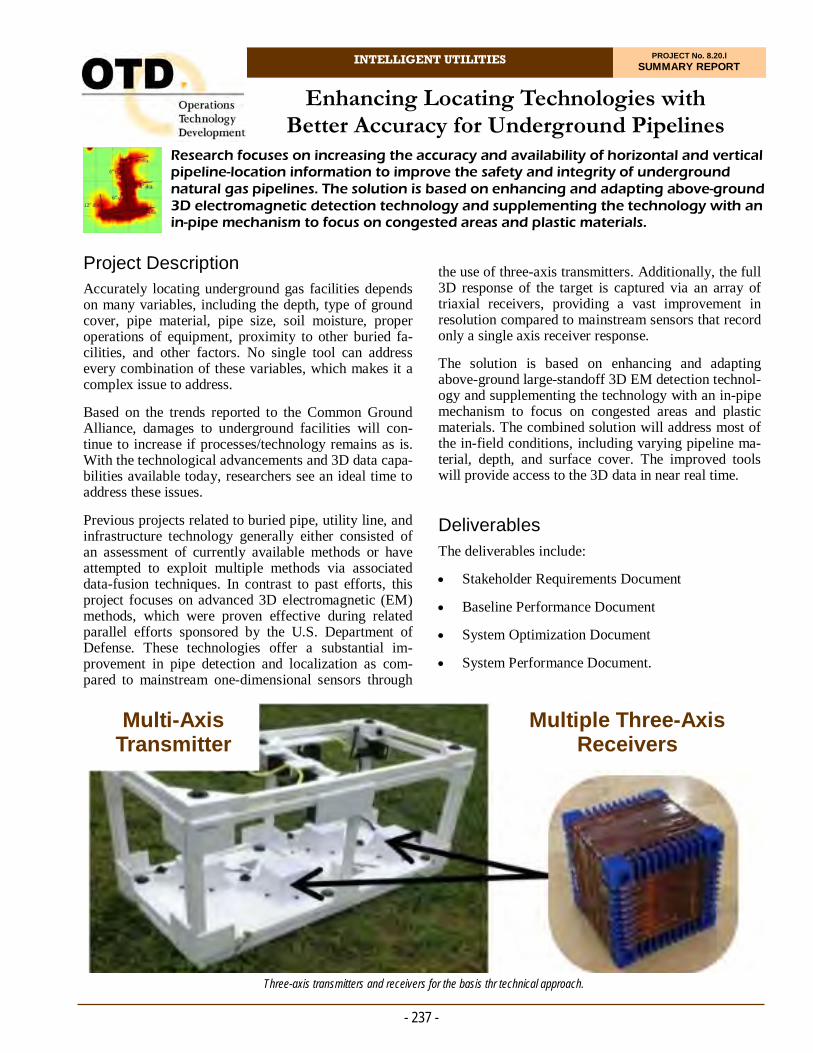
INTELLIGENT UTILITIES PROJECT No. 8.20.l SUMMARY REPORT
Project Description Accurately locating underground gas facilities depends on many variables, including the depth, type of ground cover, pipe material, pipe size, soil moisture, proper operations of equipment, proximity to other buried fa-cilities, and other factors. No single tool can address every combination of these variables, which makes it a complex issue to address.
Based on the trends reported to the Common Ground Alliance, damages to underground facilities will con-tinue to increase if processes/technology remains as is. With the technological advancements and 3D data capa-bilities available today, researchers see an ideal time to address these issues.
Previous projects related to buried pipe, utility line, and infrastructure technology generally either consisted of an assessment of currently available methods or have attempted to exploit multiple methods via associated data-fusion techniques. In contrast to past efforts, this project focuses on advanced 3D electromagnetic (EM) methods, which were proven effective during related parallel efforts sponsored by the U.S. Department of Defense. These technologies offer a substantial im-provement in pipe detection and localization as com-pared to mainstream one-dimensional sensors through
Research focuses on increasing the accuracy and availability of horizontal and vertical pipeline-location information to improve the safety and integrity of underground natural gas pipelines. The solution is based on enhancing and adapting above-ground 3D electromagnetic detection technology and supplementing the technology with an in-pipe mechanism to focus on congested areas and plastic materials.
Enhancing Locating Technologies with Better Accuracy for Underground Pipelines
the use of three-axis transmitters. Additionally, the full 3D response of the target is captured via an array of triaxial receivers, providing a vast improvement in resolution compared to mainstream sensors that record only a single axis receiver response.
The solution is based on enhancing and adapting above-ground large-standoff 3D EM detection technol-ogy and supplementing the technology with an in-pipe mechanism to focus on congested areas and plastic materials. The combined solution will address most of the in-field conditions, including varying pipeline ma-terial, depth, and surface cover. The improved tools will provide access to the 3D data in near real time.
Deliverables The deliverables include:
Stakeholder Requirements Document
Baseline Performance Document
System Optimization Document
System Performance Document.
- 237 -
Three-axis transmitters and receivers for the basis thr technical approach.
Multi-Axis Transmitter
Multiple Three-Axis Receivers
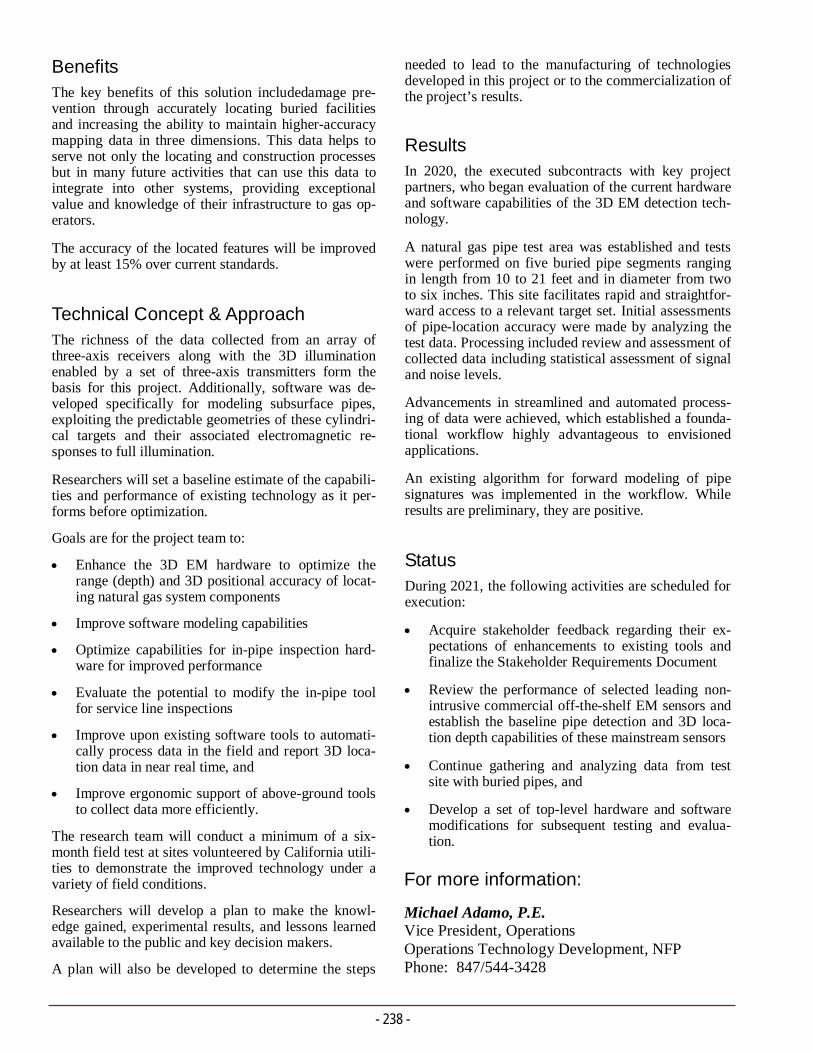
- 238 -
For more information:
Michael Adamo, P.E. Vice President, Operations Operations Technology Development, NFP Phone: 847/544-3428
needed to lead to the manufacturing of technologies developed in this project or to the commercialization of the project’s results.
Results In 2020, the executed subcontracts with key project partners, who began evaluation of the current hardware and software capabilities of the 3D EM detection tech-nology.
A natural gas pipe test area was established and tests were performed on five buried pipe segments ranging in length from 10 to 21 feet and in diameter from two to six inches. This site facilitates rapid and straightfor-ward access to a relevant target set. Initial assessments of pipe-location accuracy were made by analyzing the test data. Processing included review and assessment of collected data including statistical assessment of signal and noise levels.
Advancements in streamlined and automated process-ing of data were achieved, which established a founda-tional workflow highly advantageous to envisioned applications.
An existing algorithm for forward modeling of pipe signatures was implemented in the workflow. While results are preliminary, they are positive.
Status During 2021, the following activities are scheduled for execution:
Acquire stakeholder feedback regarding their ex-pectations of enhancements to existing tools and finalize the Stakeholder Requirements Document
Review the performance of selected leading non-intrusive commercial off-the-shelf EM sensors and establish the baseline pipe detection and 3D loca-tion depth capabilities of these mainstream sensors
Continue gathering and analyzing data from test site with buried pipes, and
Develop a set of top-level hardware and software modifications for subsequent testing and evalua-tion.
Benefits The key benefits of this solution includedamage pre-vention through accurately locating buried facilities and increasing the ability to maintain higher-accuracy mapping data in three dimensions. This data helps to serve not only the locating and construction processes but in many future activities that can use this data to integrate into other systems, providing exceptional value and knowledge of their infrastructure to gas op-erators.
The accuracy of the located features will be improved by at least 15% over current standards.
Technical Concept & Approach The richness of the data collected from an array of three-axis receivers along with the 3D illumination enabled by a set of three-axis transmitters form the basis for this project. Additionally, software was de-veloped specifically for modeling subsurface pipes, exploiting the predictable geometries of these cylindri-cal targets and their associated electromagnetic re-sponses to full illumination.
Researchers will set a baseline estimate of the capabili-ties and performance of existing technology as it per-forms before optimization.
Goals are for the project team to:
Enhance the 3D EM hardware to optimize the range (depth) and 3D positional accuracy of locat-ing natural gas system components
Improve software modeling capabilities
Optimize capabilities for in-pipe inspection hard-ware for improved performance
Evaluate the potential to modify the in-pipe tool for service line inspections
Improve upon existing software tools to automati-cally process data in the field and report 3D loca-tion data in near real time, and
Improve ergonomic support of above-ground tools to collect data more efficiently.
The research team will conduct a minimum of a six-month field test at sites volunteered by California utili-ties to demonstrate the improved technology under a variety of field conditions.
Researchers will develop a plan to make the knowl-edge gained, experimental results, and lessons learned available to the public and key decision makers.
A plan will also be developed to determine the steps
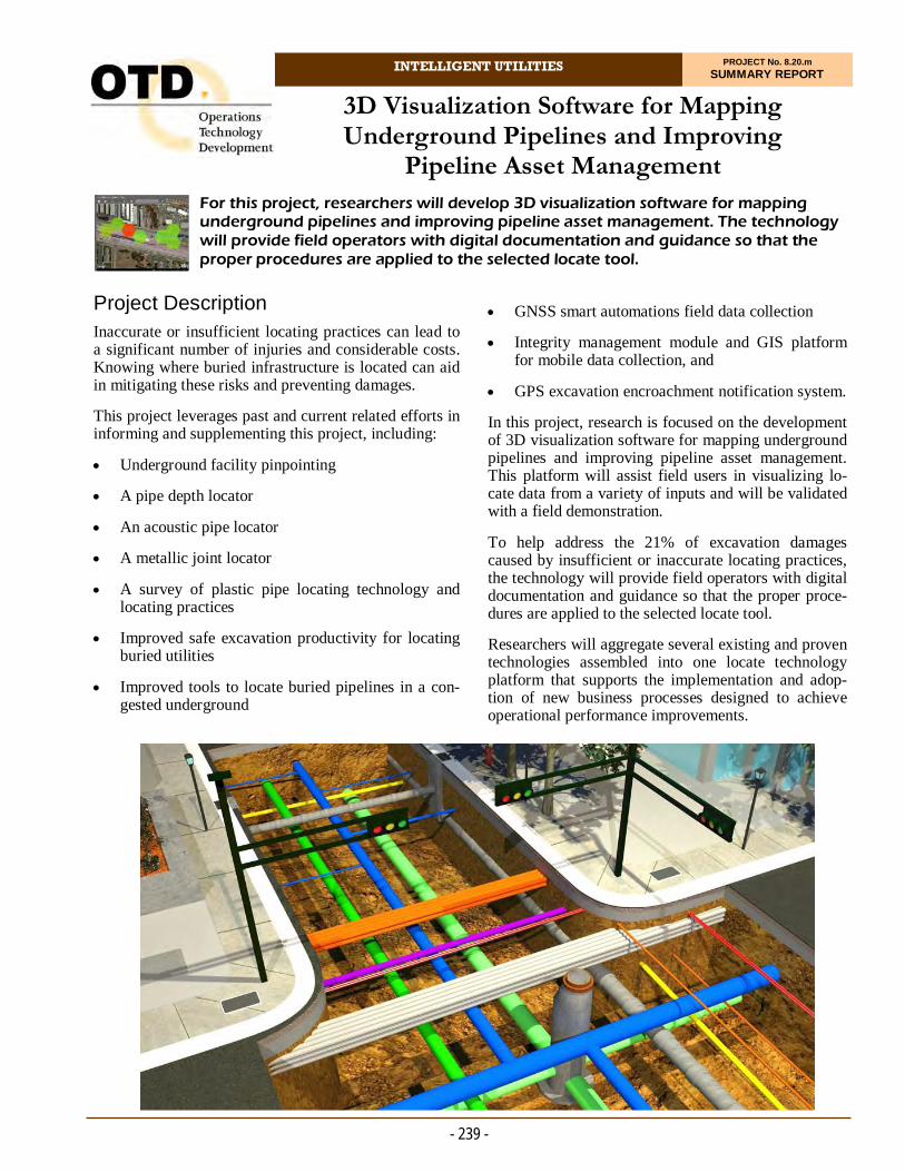
INTELLIGENT UTILITIES PROJECT No. 8.20.m SUMMARY REPORT
Project Description Inaccurate or insufficient locating practices can lead to a significant number of injuries and considerable costs. Knowing where buried infrastructure is located can aid in mitigating these risks and preventing damages.
This project leverages past and current related efforts in informing and supplementing this project, including:
Underground facility pinpointing
A pipe depth locator
An acoustic pipe locator
A metallic joint locator
A survey of plastic pipe locating technology and locating practices
Improved safe excavation productivity for locating buried utilities
Improved tools to locate buried pipelines in a con-gested underground
For this project, researchers will develop 3D visualization software for mapping underground pipelines and improving pipeline asset management. The technology will provide field operators with digital documentation and guidance so that the proper procedures are applied to the selected locate tool.
3D Visualization Software for Mapping Underground Pipelines and Improving
Pipeline Asset Management
GNSS smart automations field data collection
Integrity management module and GIS platform for mobile data collection, and
GPS excavation encroachment notification system.
In this project, research is focused on the development of 3D visualization software for mapping underground pipelines and improving pipeline asset management. This platform will assist field users in visualizing lo-cate data from a variety of inputs and will be validated with a field demonstration.
To help address the 21% of excavation damages caused by insufficient or inaccurate locating practices, the technology will provide field operators with digital documentation and guidance so that the proper proce-dures are applied to the selected locate tool.
Researchers will aggregate several existing and proven technologies assembled into one locate technology platform that supports the implementation and adop-tion of new business processes designed to achieve operational performance improvements.
- 239 -

- 240 -
For more information:
Michael Adamo, P.E. Vice President, Operations Operations Technology Development, NFP Phone: 847/544-3428 [email protected]
nect data sources in the field to a cloud repository to capture new data. It will also provide users (both in the field and office) with visualizations of the infrastructure location and metadata.
Perform System Testing
The project team will perform standard system testing, rework, and analysis. System testing will be conducted on sample above- and belowground pipe.
Pilot Demonstration and Analysis
The goal of this task is to conduct a minimum of a six-month field test at sites volunteered by Califor-nia utilities to demonstrate the improved technol-ogy under a variety of field conditions.
Evaluation of Project Benefits
The project team will complete project benefits questionnaires that provide all key assumptions used to estimate projected benefits, including tar-geted market sector (e.g., population and geo-graphic location), projected market penetration, baseline and projected energy use and cost, operat-ing conditions, and emission-reduction calcula-tions.
Technology/Knowledge
The project team will develop a plan to make the knowledge gained, experimental results, and les-sons learned available to the public and key deci-sion makers.
Production Readiness Plan
The goal of this task is to determine the steps that will lead to the commercialization of the project’s results.
Results / Status This project was initiated in late 2020. The research team is in the process of selecting equipment for re-view.
Deliverables Business requirements and analysis reports
Hardware/software interface requirements
All software and system documentation
Access to source-code repository
Testing documentation, and
Pilot Analysis.
Benefits Visualization software can improve the safety and in-tegrity of underground natural gas pipelines by increas-ing the accuracy and availability of horizontal and ver-tical pipeline location information. More accurate lo-cate results will help prevent future excavation inci-dents where the root cause is inaccurate locate mark-ings or insufficient locate practices.
A set of business process models will be created to de-scribe the necessary process improvements an organiza-tion must make in order to improve the geospatial accu-racy of existing GIS data in both the horizontal and ver-tical dimensions. Additionally, the analysis will provide an estimate of how much the accuracy of GIS data can be improved.
Technical Concept & Approach Specific project tasks include:
Analyze and Evaluate Participating Locate Data Sources
This task evaluates a variety of data sources that will aid in the utility-locating process. This task will determine how to integrate the select data sources and transmit real-time information from the utility-locate tool and GNSS (Global Navigation Satellite System).
System Requirements and Design
Researchers will develop the requirements of the project expectations and software for the system and use this documentation for auditing and testing.
Develop Cloud- and Field-Based Platform Com-ponents
Researchers will develop the cloud-based and field-based software that integrates the various data sources into one platform. The platform will con-
RISK & DECISION ANALYSIS MODELS
In this area, researchers are developing models, methodologies, implementation protocols, and case studies that will allow natural gas system operators to more effectively manage operations data
and improve the decision-making process.
Programs in this area employ a multi-disciplinary process that includes risk assessment, characterization, communication and management, and related research for decisions optimization.
The output of the program includes predictive models, calculators, and databases that describe the complex and interconnected
behavior of utility infrastructure systems and their risks.
Initiatives include the development of a risk model for locates and a risk-based methodology for remote-controlled valve
and automatic shut-off valve programs. .

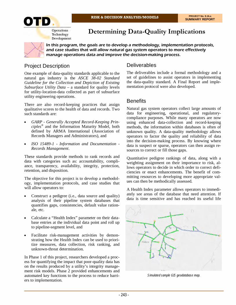
RISK & DECISION ANALYSIS/MODELS PROJECT No. 9.16.a SUMMARY REPORT
Project Description One example of data-quality standards applicable to the natural gas industry is the ASCE 38-02 Standard Guideline for the Collection and Depiction of Existing Subsurface Utility Data – a standard for quality levels for utility-location-data collected as part of subsurface utility engineering operations.
There are also record-keeping practices that assign qualitative scores to the health of data and records. Two such standards are:
GARP - Generally Accepted Record-Keeping Prin-ciples® and the Information Maturity Model, both defined by ARMA International (Association of Records Managers and Administrators), and
ISO 15489-1 - Information and Documentation - Records Management.
These standards provide methods to rank records and data with categories such as: accountability, compli-ance, transparency, availability, integrity, protection, retention, and disposition.
The objective for this project is to develop a methodol-ogy, implementation protocols, and case studies that will allow operators to:
Construct a pedigree (i.e., data source and quality) analysis of their pipeline system databases that quantifies gaps, consistencies, default value ration-ale, etc.
Calculate a “Health Index” parameter on their data-base entries at the individual data point and roll up to pipeline-segment level, and
Facilitate risk-management activities by demon-strating how the Health Index can be used to priori-tize measures, data collection, risk ranking, and unknown-threat determination.
In Phase 1 of this project, researchers developed a proc-ess for quantifying the impact that poor-quality data has on the results produced by a utility’s integrity manage-ment risk models. Phase 2 provided enhancements and automated key functions to the process to reduce barri-ers to implementation.
In this program, the goals are to develop a methodology, implementation protocols, and case studies that will allow natural gas system operators to more effectively manage operations data and improve the decision-making process.
Determining Data-Quality Implications
Deliverables The deliverables include a formal methodology and a set of guidelines to assist operators in implementing the data-quality standard. A Final Report and imple-mentation protocol were also developed.
Benefits Natural gas system operators collect large amounts of data for engineering, operational, and regulatory-compliance purposes. While many operators are now using enhanced data-collection and record-keeping methods, the information within databases is often of unknown quality. A data-quality methodology allows operators to factor the quality and reliability of data into the decision-making process. By knowing where data is suspect or sparse, operators can then assign re-sources to correct or fill those gaps.
Quantitative pedigree rankings of data, along with a weighting assignment on their importance to risk, al-lows operators to decide in which order to correct defi-ciencies or enact enhancements. The benefit of com-mitting resources to developing more appropriate val-ues can then be methodically assessed.
A Health Index parameter allows operators to immedi-ately see areas of the database that need attention. If data is time sensitive and has reached its useful life
- 243 -
Simulated sample GIS geodatabase map.

- 244 -
In Phase 2, the project team reviewed candidate sche-mas for the geographic information system (GIS) sample dataset. A cloud-based server and database were built. Information supplied along with member risk models, publicly available Energy Information Administration (EIA) data, and pilot data guidelines were used to populate the data model. A sample pilot data system was created with realistic GIS data matched to the data model.
The new dataset was forged from member risk models and EIA GIS data. In 2019, the dataset was greatly improved with a wide-ranging set of automated scripts to further enhance the quality and weight of the data. This pilot dataset was built to provide realis-tic results and information for users to identify data-quality gaps and risk-ranking insights for sponsor as-sessments.
The DQI tools analyze the model’s source data and provides the utility with an easy-to-understand and actionable set of data reports. The system produces two types of reports: data health reports and data com-pliance reports.
During 2020 refinements occurred in four major ar-eas, including importing risk model data from text files, specifying the GIS database connection, display-ing and configuring algorithms, and scoring of data on the table level. Major overhauling of the user interface was performed, resulting in improved ease of use and greater aesthetic appeal.
A template was defined for preparing integrity man-agement risk models for automated import into the DQI database. Prototype software was designed and developed for importing risk model details, most im-portantly risk model weights. The software also al-lows the user to specify the GIS database connection and credential information. Also, the software allows the user to batch assign data quality scores based on database tables.
Status This project is complete. A Final Report was issued in June 2020.
(e.g., survey data), it will automatically decrease the Health Index score. It will also provide a way to show continuous process improvement to leadership, com-missions, and the public by quantitatively demonstrat-ing an upward trend of the Health Index over time.
Technical Concept & Approach In this project, researchers identified potential data-quality standards and performed an assessment to deter-mine their applicability for the natural gas distribution and transmission industry.
A method to investigate and conduct a pedigree analysis of a pipeline or system database space was developed to quantify gaps, consistency, integrity, default value ra-tionale, and similar attributes of data.
A Health Index parameter was developed for database entries at the individual datum level, as well as a roll up calculation of health at the pipeline-segment level.
Business Process Model and Notation (BPMN) was used to map out the protocols and work processes. This ensures easier integration into the end users business processes and related software systems.
Results For this project, researchers successfully devised a sys-tematic process and supporting technology for quantify-ing the impact poor-quality data has on the results pro-duced by a utility’s integrity management risk models. Since it would be impractical to assess data quality by re-measuring the actual true value and compare it to the value recorded in the dataset, the Data Quality Implica-tion (DQI) tool determines quality by examining the practices, techniques, and tools used to collect and store the data.
The project team identified a set of existing standards and regulatory guidance which specify parameters for such practices, techniques, and tools, and created a scoring system which indicates the degree of confor-mity to these standards. The DQI tool analyzes the model’s source data and provides the utility with an easy-to-understand and actionable set of data quality reports.
The Phase 1 Final Report for this project – issued 2017 – includes an appendix that contains a matrix of the data elements, a sensitivity analysis, the DQI design require-ments, an implementation plan, and three synthetic util-ity case studies.
For more information:
Michael Adamo, P.E. Vice President, Operations Operations Technology Development, NFP Phone: 847/544-3428 [email protected]
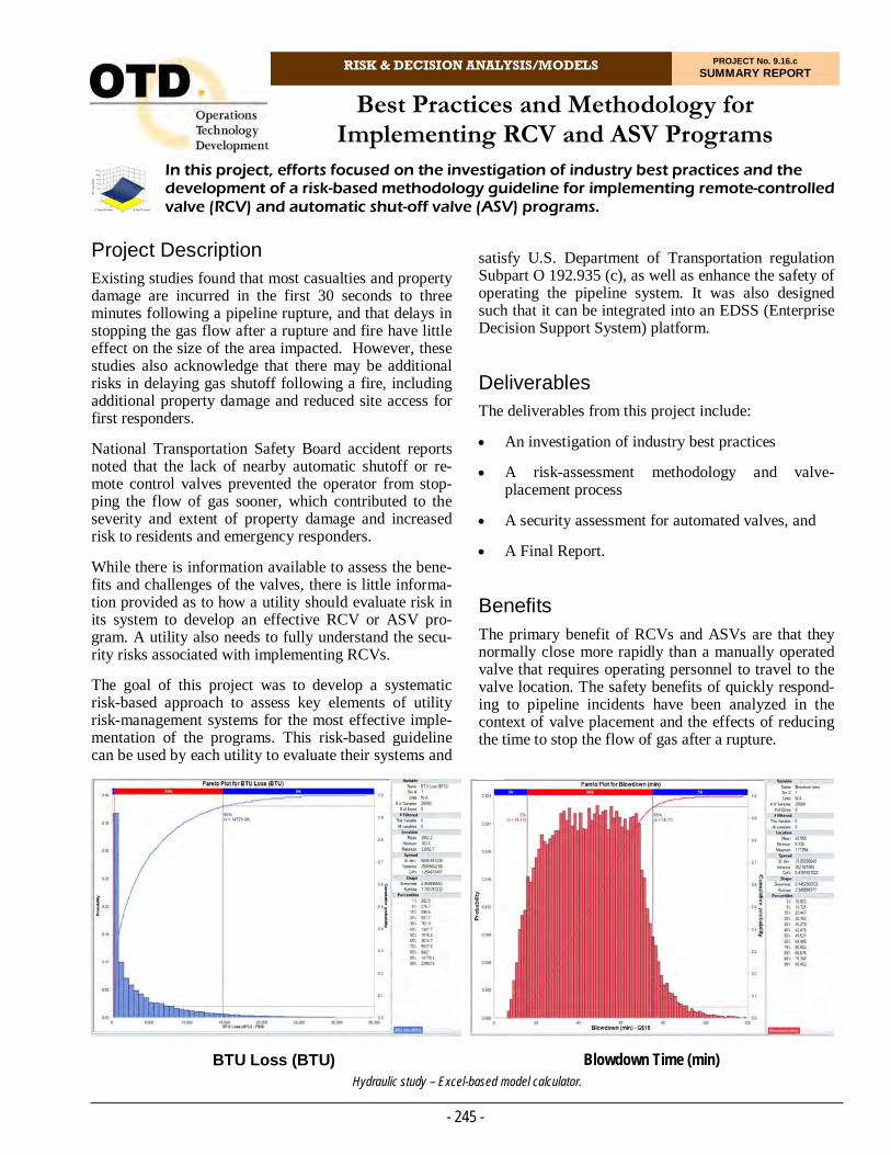
RISK & DECISION ANALYSIS/MODELS PROJECT No. 9.16.c SUMMARY REPORT
Project Description Existing studies found that most casualties and property damage are incurred in the first 30 seconds to three minutes following a pipeline rupture, and that delays in stopping the gas flow after a rupture and fire have little effect on the size of the area impacted. However, these studies also acknowledge that there may be additional risks in delaying gas shutoff following a fire, including additional property damage and reduced site access for first responders.
National Transportation Safety Board accident reports noted that the lack of nearby automatic shutoff or re-mote control valves prevented the operator from stop-ping the flow of gas sooner, which contributed to the severity and extent of property damage and increased risk to residents and emergency responders.
While there is information available to assess the bene-fits and challenges of the valves, there is little informa-tion provided as to how a utility should evaluate risk in its system to develop an effective RCV or ASV pro-gram. A utility also needs to fully understand the secu-rity risks associated with implementing RCVs.
The goal of this project was to develop a systematic risk-based approach to assess key elements of utility risk-management systems for the most effective imple-mentation of the programs. This risk-based guideline can be used by each utility to evaluate their systems and
In this project, efforts focused on the investigation of industry best practices and the development of a risk-based methodology guideline for implementing remote-controlled valve (RCV) and automatic shut-off valve (ASV) programs.
Best Practices and Methodology for Implementing RCV and ASV Programs
satisfy U.S. Department of Transportation regulation Subpart O 192.935 (c), as well as enhance the safety of operating the pipeline system. It was also designed such that it can be integrated into an EDSS (Enterprise Decision Support System) platform.
Deliverables The deliverables from this project include:
An investigation of industry best practices
A risk-assessment methodology and valve-placement process
A security assessment for automated valves, and
A Final Report.
Benefits The primary benefit of RCVs and ASVs are that they normally close more rapidly than a manually operated valve that requires operating personnel to travel to the valve location. The safety benefits of quickly respond-ing to pipeline incidents have been analyzed in the context of valve placement and the effects of reducing the time to stop the flow of gas after a rupture.
- 245 -
Hydraulic study – Excel-based model calculator. Blowdown Time (min) BTU Loss (BTU)
A security risk associated with implementation of re-mote-controlled valves is the potential for an outside entity to gain control of the valve and either exercise the valve and create outages, or perhaps prevent closure in the event of a rupture. A second component of this pro-ject was to assess and evaluate the current cybersecurity concerns and measures employed by the industry.
Technical Concept & Approach For the investigation of best practices, project represen-tatives engaged utilities that have well-established RCV and ASV programs to develop general guidelines spe-cific to valve location selection and implementation. Transmission companies, in particular, have been using RCVs and ASVs for decades. Although their systems and criteria may likely be different, there are lessons to be learned in terms of control methodology, hardware, software, cybersafety, etc. This task includes identify-ing relevant elements of utility risk-management plans in assessing whether installing RCVs and ASVs will increase the safety and reduce risk of operating the pipelines.
The project team developed a systematic approach to assess risk-management systems by utilizing event trees.
Hydraulic modeling runs provide determining factors that have the greatest influence on rupture energy re-lease and blowdown times. Various scenarios were modeled using randomly generated and selected rupture locations (based on risk and consequences of a pipeline rupture) of a select group of systems. Researchers then evaluated the effects of added valves and valve modifi-cations, taking into consideration various inputs such as valve types, closure times, pressures, ambient tempera-tures and gas loads, and high-consequence areas.
The deliverable is a process on optimized placement of automated valves. This approach will also lend itself to be implemented as a stand-alone process or eventually integrated into an EDSS.
Researchers engaged a cybersecurity expert to perform an analysis of communication security risks in operat-ing RCVs and ASVs.
Results
In 2017, the project team surveyed the SME Group to collect system loop details to be used, in part, to con-struct the project’s synthetic pipeline loops/systems needed for flow and pressure modeling.
- 246 -
A model was created to evaluate valve closure times on Btu release from a full line break. Researchers were successful in simulating several sequenced events to show differences in flow rates, total Btu loss, and blow-down time when valves are closed at different times after a line break. A transient case was also created that will be used to run various scenarios with manual, re-mote, and automated shutoff valves.
A cybersecurity survey was conducted and results pre-sented in a report to sponsors.
As part of ongoing cybersecurity analysis of core gas technologies in the operational environment, OTD sought to research the cybersecurity aspects of RCVs and ASVs. Particularly, OTD sought to identify poten-tial threat vectors and any relevant standards or best practices that can be used by the industry to understand and mitigate cyber security risks associated with imple-menting these devices. Status This project was completed with Final Report issued in March 2019.
The report then contains the following sections:
Summary of an SME survey and interview results of current (or lack of) automated valve programs
Organized summary of utility automated valve pro-gram/process reviews
Risk-based hydraulic modeling approach, execu-tion, results, conclusions, and recommendations for use, including the use of contour plots and a user-friendly Excel-based hydraulic model calculator, and
Cybersecurity utility survey results, industry stan-dards and research review, threat analysis, gap analysis, and conclusions/recommendations.
For more information:
Michael Adamo, P.E. Vice President, Operations Operations Technology Development, NFP Phone: 847/544-3428 [email protected]
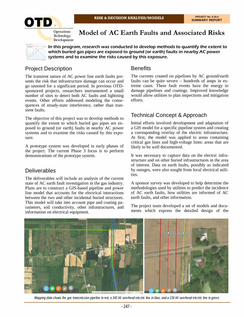
RISK & DECISION ANALYSIS/MODELS PROJECT No. 9.16.d SUMMARY REPORT
Project Description The transient nature of AC power line earth faults pre-sents the risk that infrastructure damage can occur and go unnoted for a significant period. In previous OTD-sponsored projects, researchers instrumented a small number of sites to detect both AC faults and lightning events. Other efforts addressed modeling the conse-quences of steady-state interference, rather than tran-sient faults.
The objective of this project was to develop methods to quantify the extent to which buried gas pipes are ex-posed to ground (or earth) faults in nearby AC power systems and to examine the risks caused by this expo-sure.
A prototype system was developed in early phases of the project. The current Phase 3 focus is to perform demonstrations of the prototype system.
Deliverables The deliverables will include an analysis of the current state of AC earth fault investigation in the gas industry. Plans are to construct a GIS-based pipeline and power line model that accounts for the electrical interactions between the two and other incidental buried structures. This model will take into account pipe and coating pa-rameters, soil conductivity, other infrastructures, and information on electrical equipment.
In this program, research was conducted to develop methods to quantify the extent to which buried gas pipes are exposed to ground (or earth) faults in nearby AC power systems and to examine the risks caused by this exposure.
Model of AC Earth Faults and Associated Risks
Benefits The currents created on pipelines by AC ground/earth faults can be quite severe – hundreds of amps in ex-treme cases. These fault events have the energy to damage pipelines and coatings. Improved knowledge would allow utilities to plan inspections and mitigation efforts.
Technical Concept & Approach Initial efforts involved development and adaptation of a GIS model for a specific pipeline system and creating a corresponding overlay of the electric infrastructure. At first, the model was applied to areas containing critical gas lines and high-voltage lines: areas that are likely to be well documented.
It was necessary to capture data on the electric infra-structure and on other buried infrastructures in the area of interest. Data on earth faults, possibly as indicated by outages, were also sought from local electrical utili-ties.
A sponsor survey was developed to help determine the methodologies used by utilities to predict the incidence of AC earth faults, how utilities are informed of AC earth faults, and other information.
The project team developed a set of models and docu-ments which express the detailed design of the
- 247 -
Mapping data shows the gas transmission pipeline in red, a 345 kV overhead electric line in blue, and a 230 kV overhead electric line in green.
- 248 -
A prototype of an AC fault risk model was con-structed that makes use of input data described in the BPMN diagram and data calculated from the physics model. From these, it generates the probability distri-bution of risks one would expect to find on the pipe-line.
In 2018, researchers became aware of the release of a commercial software package that substantially dupli-cates some the physics model. The product has a very well developed GIS/map type interface for entering the geometry of the pipes and conductors. The project team obtained a trial license and conducted an evalua-tion, finding positive results with respect to user inter-face and numerical agreement. Additionally, the com-pany indicated it is agreeable to providing the re-search team with additional features that are needed for the risk model. The project team concluded, given the significant efficiencies realized in the time and level of effort to upload pipeline and power-line sys-tems, collaboration efforts with the commercial soft-ware manufacturer should continue.
Researchers developed code to extract pipeline loca-tion data from the repository it is stored in into the physics model. This will allow future data received in this format to be readily imported into the model.
During 2019, researchers met via webinar to review and better understand the manufacturer’s application programming interface (API). Upon successful knowledge transfer and training, the project team lev-eraged the API to Monte Carlo simulate to populate the node probability table of the developed risk model.
In 2020, the project team acquired both pipeline and electric-line system parameters for a portion of the service territories where the two are co-located. Re-searchers used the supplied data to perform a case study, leveraging the online platform to analyze and verify the pipeline and power line systems risk pro-files. The project team experimented with several mitigation measures to investigate the best option to address risk for the specific systems.
Status A Final Report for this project is being developed.
system, such as geographic area(s) of interest, a GIS-based inventory of the major pipelines and power lines in the area, pipe and coating types, soil conductivity, and other data.
A beta prototype of a GIS-based system for the predic-tion of earth faults and their severity was constructed. The overlay of the electric power system onto the pipe-line GIS was constructed using existing utility records supplemented by geospatial imagery. Imagery is used to identify the locations of major power lines and associ-ated towers.
The likelihood of earth faults was estimated from the electrical equipment types and driving functions, such as weather and power loading. A basic electrical model was constructed to estimate the influence of an earth fault on a nearby pipeline. The primary inputs to this model are the relative geo-locations of the towers, asso-ciated metallic subsurface structures, and pipelines along with the soil conductivity in the area of interest. The combination of these elements provide an estimate of where the highest likelihood of earth fault conditions should occur, along with the degree of coupling be-tween these faults and the pipelines. This provides a “heat map” of areas that should be of concern.
The prototype of a GIS-based system for the prediction of earth faults was demonstrated for project sponsors. via a conference call/webinar format.
Results
Development focused on three major components of the predictive risk model:
1. A Business Process Modeling Notation (BPMN) model that captures the process steps for setting up and running the risk model
2. A physics model that predicts the current and volt-age levels on the pipeline over various parameter ranges, and
3. A risk model that uses inputs from the BPMN model and calculated values from the physics model to quantify the pipeline risk for a given set of inputs.
Prototype versions of these components were con-structed and tested using published data. Based on real-istic results, the researchers concluded both the physics and risk models appeared to be functioning correctly. The data used was drawn from open literature describ-ing pipe and power line interactions and factored in multiple variables, including soil resistivity, coating resistance, and separation distances. The basic assump-tions forming the prototype models were drawn from the experience of the investigators.
For more information:
Michael Adamo, P.E. Vice President, Operations Operations Technology Development, NFP Phone: 847/544-3428 [email protected]
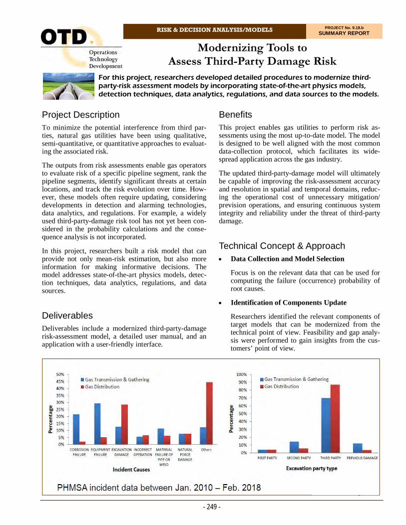
RISK & DECISION ANALYSIS/MODELS PROJECT No. 9.18.b SUMMARY REPORT
Project Description To minimize the potential interference from third par-ties, natural gas utilities have been using qualitative, semi-quantitative, or quantitative approaches to evaluat-ing the associated risk.
The outputs from risk assessments enable gas operators to evaluate risk of a specific pipeline segment, rank the pipeline segments, identify significant threats at certain locations, and track the risk evolution over time. How-ever, these models often require updating, considering developments in detection and alarming technologies, data analytics, and regulations. For example, a widely used third-party-damage risk tool has not yet been con-sidered in the probability calculations and the conse-quence analysis is not incorporated.
In this project, researchers built a risk model that can provide not only mean-risk estimation, but also more information for making informative decisions. The model addresses state-of-the-art physics models, detec-tion techniques, data analytics, regulations, and data sources.
Deliverables Deliverables include a modernized third-party-damage risk-assessment model, a detailed user manual, and an application with a user-friendly interface.
For this project, researchers developed detailed procedures to modernize third-party-risk assessment models by incorporating state-of-the-art physics models, detection techniques, data analytics, regulations, and data sources to the models.
Modernizing Tools to Assess Third-Party Damage Risk
Benefits This project enables gas utilities to perform risk as-sessments using the most up-to-date model. The model is designed to be well aligned with the most common data-collection protocol, which facilitates its wide-spread application across the gas industry.
The updated third-party-damage model will ultimately be capable of improving the risk-assessment accuracy and resolution in spatial and temporal domains, reduc-ing the operational cost of unnecessary mitigation/prevision operations, and ensuring continuous system integrity and reliability under the threat of third-party damage.
Technical Concept & Approach Data Collection and Model Selection
Focus is on the relevant data that can be used for computing the failure (occurrence) probability of root causes.
Identification of Components Update
Researchers identified the relevant components of target models that can be modernized from the technical point of view. Feasibility and gap analy-sis were performed to gain insights from the cus-tomers’ point of view.
- 249 -

- 250 -
For more information:
Michael Adamo, P.E. Vice President, Operations Operations Technology Development, NFP Phone: 847/544-3428 [email protected]
A Bayesian network approach was employed to ad-dress a variety of shortcomings experienced by users of existing models. For example, the Bayesian network is flexible – meaning that newly collected information for numerous contributing factors can be incorporated without redoing the entire model. This can be used for conducting “what-if” analyses by specifying different system attributes, such as material, size, system, exca-vation equipment, digging depth, etc. Additionally, the Bayesian approach is an ideal technique for modeling uncertainties and interactions between causal factors.
Researchers collected valuable datasets from both open sources as well as project sponsors via data calls and customer surveys. Rigorous data cleaning, processing, and visualization were performed to extract relevant information. For model modernization, only the data from the most recent years was included. This makes the quantified risk model more realistic as well as ap-plicable for future “what-if” analyses.
To make the model more user-friendly, the research team developed a web application encapsulating all functionalities of the modernized model. The applica-tion is accessible anywhere with an internet connec-tion. Moreover, the user-friendly interface allows field operators to specify all customizable inputs as well as conduct high-level risk analyses in the field.
Given the pipeline damages, the project team is explor-ing the possibility of estimating other unknown quanti-ties.
A final webinar was held to demonstrate the function-ality of the model.
Status Phase 1 of this project is complete. A Final Report was issued in February 2020.
Modernization of Risk Model and User Interface
Researchers developed Bayesian networks includ-ing the existing functionalities and the newly ex-tended capabilities. The probabilistic network has the advantage of modeling information flow in both the forward and backward directions, which is beneficial for performing root-cause diagnosis and failure-rate prognosis analysis. Considering the sponsors’ preference, the project team developed a user-friendly interface, which includes all the cus-tomizable inputs from users and shows the output as failure rates or probabilistic distributions.
Model Verification and Demonstration
Within the definition domain, the outputs for vari-ous input combinations were generated. For cases without actual validation data, the failure rate from the risk model should be consistent with historical databases and conceptual understanding.
Results
In this project, a comprehensive procedure was devel-oped to modernize a widely-used third-party excavation risk model. Extensive literature review and data collec-tion were performed throughout the project to support the risk model modernization process. As such, re-searchers identified and updated the following compo-nents from the original model:
The underlying architecture of the model was re-vised such that users have the flexibly to select dif-ferent system attributes, (for example material, pipe size, excavation equipment, excavation depth) when performing risk analysis.
The original fault-tree architecture was enhanced from “AND/OR” operations to reflect a more multi-variate and interconnected network such that com-plicated risk interactions can be considered.
The means by which root-cause analysis is proc-essed was enhanced by a Bayesian approach able to perform sensitivity analysis quantitatively as well as rank the significance of risk factors.
Individual model factors were updated to better align with current attributes collected by utilities and the Common Ground Alliance.
Outdated risk-modeling methodology, internal physics models, data, and interface applications were updated.
The user interface was developed to better facilitate model implementation by field operators.
- David Furdas Senior Engineer, Innovation & Technology Innovation & Technology Enbridge Gas Inc.
“This new model will better equip our risk-assessment group with completing accurate and realistic assessments of third-party damages. This in turn will have a positive impact on delivering natural gas in a safe and reliable manner.”

RISK & DECISION ANALYSIS/MODELS PROJECT No. 9.20.a SUMMARY REPORT
Project Description
In this project, researchers are exploring the application of various kinds of statistical and machine-learning techniques to identify the quality, reliability, and trace-ability of sensor data in assessing integrity risks.
The project goals are to:
Develop improved methods for estimating risk lev-els within a pipeline risk-management system
Develop methods to estimate the value of informa-tion provided by sensors of various types in differ-ent applications, and
Develop decision tools to support pipeline-integrity managers in selecting the most cost-effective addi-
In this project, the goal is to applying machine-learning, causal-modeling, Bayesian networks, and decision science methods to the challenge of data normalization, data analytics, and data synthesis. Efforts are under way to ensure that the methods support decision-making processes and situational awareness in the context of the natural gas infrastructure.
Data Collection, Normalization, and Integration Methods to Enhance Risk Assessment
Tools for Decision Making
tions to sensor networks in terms of reduction in expected risk within a given budget for risk man-agement.
A project team will evaluate a selection of the most widely used and most promising new sensor types ap-plied to a variety of types of transmission, distribution, and other gas facilities. The team will apply multiple machine-learning, causal-modeling, and Bayesian net-work techniques to the challenges of normalizing, inte-grating, and analyzing disparate data streams.
The focus is on identifying the issues, enhancements, and extensions needed, and to design and develop pro-totypes.
This project is co-funded by the U.S. Department of Transportation’s Pipelines and Hazardous Materials Safety Administration.
- 251 -
An influence diagram showing a general framework for risk management focusing on the decision to select controls to reduce or mitigate risks.

- 252 -
For more information:
Michael Adamo, P.E. Vice President, Operations Operations Technology Development, NFP Phone: 847/544-3428 [email protected]
and give more specifics if they wish. All respon-dents so far have agreed to these post-survey inter-views.
Results Several themes emerge from the initial survey re-sponses:
There is wide variation in current practices of risk assessment and management
A critical priority is to address processes or tools to better support data quality and data governance, and identifying types and sources of failure
A moderate or high priority was given for methods to define a consistent risk tolerance
A high priority was given for a risk-spend effi-ciency metric to select risk controls, and
A moderate or high priority was provided for proc-esses or tools to communicate risk inside or outside the organization.
Respondents also identified the following as challenges for their organizations and opportunities they would most like to see addressed by this research project:
Better probabilistic models that are easier to cus-tomize and with risk results that are easier to inter-pret
The need for computational capacity and faster models to handle large amounts of data
Better analytic methods, including trending
Greater clarity about risk tolerance, and
Improvements in the risk-management culture.
Status The project team is developing a second survey. Inter-views with utility subject matter experts are being con-ducted to determine the functionalities needed in a ho-listic distribution integrity management program framework to address current compliance needs and future risk modeling needs.
Deliverables Within this project, the main deliverable is the devel-opment of a decision-support tool. The tool will incor-porate the new methods and models for risk estimation developed by the team, and so make them accessible and useful to risk managers at gas utilities.
Benefits An improved decision-support tool will help to lower the costs of risk management and improve overall sys-tem safety and integrity.
Technical Concept & Approach In 2020, a primary task was to conduct a survey of risk managers at gas utilities to identify their current prac-tices and priorities for improvements. The project team will follow up with selected respondents and some new respondents to develop deeper insights.
The approach to discovering how gas utilities assess and manage infrastructure risks has three phases:
1. Initial meetings: Researchers arranged in-person and web-conference meetings with senior risk ex-ecutives and their teams at selected gas utilities. In these meetings, the project team asked for an over-view of current approaches used to assess and manage risks, to obtain key documents that de-scribe their current practices, and to nominate staff to respond to an online survey. Utilities on the Technical Advisory Group were also asked for access to data used for risk assessment (including data on assets, threats, incidents, and responses) for use in developing new types of analysis and tools for the research project.
2. Online survey: Researchers provided an online survey to obtain more detailed information in a standardized form on current practices and priori-ties for one or two respondents at selected utilities.
3. Post-survey interviews: The final survey question asked respondents if they are willing to provide a 30-minute follow-up telephone conversation to give them the opportunity to clarify their answers
- Aaron Rezendez Engineer, R&D and Innovation Pacific Gas and Electric Company
“The Bayesian Network research will allow us to derive new insights by connecting a broad number of pipeline and external attributes in mathematically meaningful ways to better understand how they interact and ultimately result in leaks and third-party damage.”


Operations Technology Development, NFP 1700 S Mount Prospect Rd Des Plaines, IL 60018
[email protected] 847-544-3400
www.otd-co.org 10/21