Research on Application of Mobile Diesel Equipments in ...
161
KR-97CC) -29 W^E###(KIGAIVI Research Report) MU *88# <4 Research on Application of Mobile Diesel Equipments in Underground Mines(W) e>m Korda Institui m n m iMining & Materials
-
Upload
khangminh22 -
Category
Documents
-
view
2 -
download
0
Transcript of Research on Application of Mobile Diesel Equipments in ...

KR-97CC) -29W^E###(KIGAIVI Research Report)
MU *88# <4
Research on Application of Mobile Diesel Equipments in Underground Mines(W)
e>m
Korda Instituim n m
iMining & Materials

DISCLAIMER
Portions of this document may be illegible electronic image products. Images are produced from the best available original document.

KR-97(C)-29#2u###(KIGAIVI Research Report)
P3«E6M#«E%(IV)
Research on Application of Mobile Diesel Equipments in Underground Mines(F)
: 4^^?^ y- # n
-y ^ ^
2, <$ 5L
m % mKorea Institute of Geology, Mining & Materials

tetfhl *mmm mm 4#
mmm w*(iv)
9)^
Research on Application of Mobile Diesel Equipments in Underground Mines(IV)
Kim Bok-youn, Kang Chang-hee, Jo Young-do, Lim Sang-taek
Abstract
This research commenced in 1994 for the purpose of providing safety
and environmental measures of underground mines where the mobile
diesel equipments are operating.
In this last research year, researches on filtering of diesel particulate
matter, design of underground layout and disaster prevention have been
carried out.
1) Through the research, it was known that water scrubber is only one
practical way to reduce DPM emission as of now. There are several
kinds of the sophisticated DPM filters, but it is not practical yet to be
used in underground equipments due to the many adverse effects of
the devices such as tremendous increase of SOx, NOx and back
-1-

pressure etc.
2) Layout of underground structure has to be designed based on rock
mechanical analysis and the concept of active support has to be
adopted considering the large openings are requested to accommodate
heavy duty diesel equipments in underground. Rock bolt and
shotcrete will be the most applicable method to support such a large
dimensional tunnels.
(1) Direction
The main haulage way of the mines where diesel equipments are
operating is ramp way system. For optimizing safety measures, and
minimizing maintenance cost of the tunnels, it is strongly recommended
that all the tunnels including ramp way, rooms and sublevels should be
designed in parallel to the direction of principal stress and perpendicular
to the direction of major discontinuity
(2) Inclination
Basically, the inclination of the ramp way depends on the specification
of the equipments, but 10 -15% is usual. The steep inclination needs less
initial investment but there will be an adverse effects such as higher
operating and maintenance costs.
(3) Profile(Cross section)
The maximum dimension of the equipments operating in local mines
appeared 12.8m long, 3.705m wide and 3.68m high. Considering the
dimension, the requested profile simply can be calculated to 4m x 4m,
— 2 —

but it should be decided according to the regulated minimum clearances
from the walls and roof. The minimum inner curvature radius of the
tunnels should be more than 5.2m, and in this case, the tunnel width of
the curved zone should be more than 5.5m.
(4) Sight distance and braking distance
For the safe operation of the equipments, the sight distance must be
longer, than braking distance, so that the driver can hold up the
equipment safely after finding the obstacles in front of him. The
maximum braking distance without heating of brake shoe is 60m.
(5) Support and maintenance
Due to the large dimensional tunnels where diesel equipments are
operating, the conventional supporting system is not applicable.
Therefore, the active support concept should be applied which utilizes
the surrounding rock mass as a support material by reinforcing them by
rock bolting and shotcreting.
3) There are three categories of possible disaster or hazard in workings
where diesel equipments are operating.
(1) Disasters by exhaust pollutants
a) The equipments specially designed for underground use are
strongly recommended.
b) Workings using diesel equipments should be properly ventilated
all the time to maintain the gas concentration bellow the
permissible level.
c) The fume diluter is recommended as the most practical after
-3-

treatment device in Korean mines.
(2) Underground fire
a) The main cause of diesel fire is over heated engine and spillage
of hydraulic liquid. Therefore, protecting the over heat of engine,
using fire resistive hydraulic liquid and high flash point fuel is
requested.
b) Fuel and the other oils are recommended to be stored at surface.
c) To protect the smoke return in case of underground fire, the
ventilation velocity must be kept more than 1.5m/sec. The fire
smoke starts to return on 1.5m/ sec and stops to return on
2.0m/sec.
d) The fire smoke flows through upper half of the tunnel and it's
temperature is 10 degrees higher than ventilation air flow.
e) For taking an immediate measure on fire, keeping the updated
simulation is essential matter.
-4-

* #
41# 4 -E- ............................................................................................................... 7
42# 4^4-44 "gf 4# .&#...........................................................................9
43# 4#3#### 44#4 43 g ### 10
3-1. Catalytic Trap Oxidizer..............................................................................11
3-2. Catalyzed Ceramic Trap.................................. 12
3-3. Coming Ceramic Trap with Fuel Additives......................................... 13
3- 4. Disposable Pleated-media Filter...............................................................17
44# >£4 ^ -fr44#...................................................................... 18
4- 1. ^44 71)^ .................................... -...........................................;18
4-2. 4^ ^34 21
4-2-1. 2:714# ..................................................................................................21
4-2-2. ##4 ## ............................................................................................24
4-3. #u>4 #7}3 ............................................................................... 25
4-3-1. ##4m(RQD) ...................................................................................... 26
4-3-2. #3rM##3(RMR)................................................... 29
4-3-3. Q-System................................................................................................ 40
4-3-4. RMR4- Q #4 #4 ............................................................................44
4-3-5. 4## 43 M 45
— 5 —

494-4. ^417}
4-4-1. 4 <2} ................................................................................... 49
4-4-2. £A} ................................................................................. 51
4- 5. *7]1 ^ *44*.......................................................................59
4-5-1. *^441- 3.4# 4)H #4 ........................................................... 62
4-5-2. 4#4 Sti0)! 4® 4&44 #4 ....................................................74
4-5-3. 7g3*4 7)#........................................................................................ 78
4- 5-4. 4^4 #4 ............................................................................................ 83
454 4^7# ^ b|1« 49..................................................................-112
5- 1. 444 ^<8 4 4# ..................................................................................112
5- 1-1. nil* _2.g#44 4% 44............................................................. ii2
5-1-2. 44 #4 .............................................................................................. 112
5-1-3. 7lEj- 44 .........................••...................................................................113
5-2. 44 #7H ......................................................................................................113
5-2-1. 7g4#44 4*4 44"..................................................................... 120
5-2-2. 4&44" ^4 °1*............................................................................123
5-2-3. 4# 7}dh .....................................................................................128
5-2-4. #7H44 ^ 37)44 7}*..............................................................130
71164 4 #........................................................................................................ 150
f If ^ ............................................................................................................. 155
- 6 -

*\ ■&
4 4¥# #^184 444 1 444 41 41 44444
44 ¥44 #7>4i 4# #4 1 4141# ¥444 44 8¥&
199445.4 1¥41 5-44 444-3. 444 4544- l 44544 4#
1-44 till# 31#11 ##4 11 414#, 4411 1 444# #5# 131¥# 3444 44 444 4#44 4# 144 341-4 4#
1 14#11 34 #4 ## 34 5.44454, 44 444 4#44
4-9-47} 4 444-41# 441 1# 34 4145 4 #4 33 441
4 7H1# 44 44# #14524-.
24454 9545## 1445# 451 5S&4 4# 444#4(Diesel
Particulate Matter ; DPM)4 44 7]5154 1## 14# 14, 513
#4 tifl# 44# 41#1 #141 4# 15# l7>4534 #334 41 444 13# 444431, 34 4#144 38## 4## #3
441 44 14 1114# 4441 4111 4M *## ¥ $1# 4 434, 4#14# 4-8-4# 3# 144 #14## simulation 41 41
4# 41484-
34451 1996451# ##71-34 Ill'll Fume diluterl 11#
# #141 41 1-8-14# #14334 44 114111 ##41
4#€ ¥ 4## 4#484-. 54 1441 4#7}34 314 1## 1
#4 ¥ 8# !#4 535## ^-4 133 71144334 11 #11
-7-

4# T 9Xn ##.04, 4^# # &xr M
#^4^1 MW ^ 4M3. ^4# #7l M simulation#
^4 7}«#<?] Ai^ju] ^-AVofl rflsflAi n aj-g- A^ ^-y^tq..
yyy- y^y i997Mlfe c|#^# #^###
MW^pPiM <3*1171#, ci#lM# cfl#^ *as.#
^ ^3171# ^ <W ^ M 4# 7i# ## <gf#4 4tiM
<gf# tWMM "ei #4 ci^^-tii" y# y-y^-si 7i#y:3i4* M
— 8 -

42#
1) 3344 #339
2) Ail Til 2771144 93 39 24 #43) 7}2 #4 7]7l 45. 4j7lt ^4(177D 44 44)
4) 4^4 #?h;e 4444 A>-§-44 34^4
5) 44444 yB*7>^ 42 44&4(93, 94499 44)
7) 4-4444 44 413719 4447} 9 444# 448) 44 444#4(Diesel Particulate Matter:DPM) 71234
9) 44 44444 dpm 4 #94 #4 4-4
10) dpm 44^s 93414(K) 4#
11) 5.41-4 4444 34
12) 4 s. 47>4 5:4-<39-
13) 44 444 94 44 49 39
14) 24 44 4-7144- 44 4Til
6) 44 4344 7}2 4£ 94^4(43, 449^9 44)
-9-

44 7>4 _$_<#i-l 44)444 sa^-4- ^.4 4444 ^4 #444
S. 44 7}444TL 44^ #4^ 44 &4 #4 ##4 4 $14. Fume
diluter4 4*1) 4 4 44#4 44# 4#*-4 445-44 444## 44
444 44 44# 4# 4^4-
Table. Comparative Merits and Drawbacks of Exhaust Treatment devices
2 8 9 9 9 8 # 89 8 9
WaterScrubber(59919
9*1)
1) 2989 9 #2#99 99989 ; 30 - 60 %N02 ; 20 %SO: : 80 %
2) #9*11#3) 52 99
1) 5#71- 32 2L7|f-9b|7|. £92) 89 999# 893) oH9# 8 2#o| y##94) 818 89 995 82 95 85
7|s *|o)9oH4) 99 ti9 95
7)5(3 8 9899)
Catalytic
Converter (5ro|| §SL
9*1)
1) 2989 99I2#CO ; 90 %Hydrocarbon ; 80 %
1) 59597) 019 8.2) 999 2889 57)3) S9 9595 #9o| 898.4) h||7| 82 9525 N02 #7)5) 9989(Mutagen) 57)
92#
ThermalReactor(89871)
1) 2889 9#2#CO 8 HC 9#
1) 600 - 700°C 28892) N02 57) 92#
FumeDll uter (oH9*l#
9*1)
1) 2889 9# 2#NOa 99 9#
2) 2889 #9 2#NOx 100 -> 17 %
3) 5299 ; 100 -> 18 %4) 897) 50192 898 885) 2889* §99258 8#
aH 8*19
1) 8*l# fll 918 7|sho)sic)2) NOx o|s>|o||5 8xfla:#?) 98
7)5
DieselParticulateFilter
(9998918)
1) 999895 8995 DPM8 299.
1) 5999 8 h||7|82952) 57|99 *H 9(regeneration)o|
129-3) 897) 9 8# 8.
?\l5
10-

#1422 144 4e 444 t))#! 42 1# 14-4#4# 244
2 4447)# 44# 4#l7}4#4 4E)(Diesel Particulate Filter:DPF)4
2 #4. °i ^i7> 4#i°> # 24# 4#4 i#4 44 4°i 4# 4
4#4-
- &##4 243:47)- 1444.
- 44 LHD4 #4244 4# #4 7144 444 4 4444 #.
- 434:4# &7ll 42. 4^-44 241-1 4## ^Mlf)# #l(Back
Pressure) #7}7> 4444-
- ill 144#4i- 14 4425. 4444 34# 4^944 4 14
44.
- 4442 444 12 #14 4444
3-1. Catalytic Trap Oxidizer
°l 444 radial flow, wire mesh 5? stainless steel ## l## 4 47)-
24 4444. °l Wire mesh# #444 44422 4 244 stainless
-g-7) #4 4#44 4444. 4 44# 4)7) 444 a# # 141 44
42 414 414 14# 4 14- 4144 21# 1414 141# #
44 wire mesh 244 414-7)- ##44 4#444- HI # 44 4
1 444 444 4 44# 41 14 21## 4444# 3:441 4
414 4414.
4##22 2444 14 41 #4 co4 44#2#4 4## 4244
#4 4# #S44. LHD4 4# 4444 144 7>#44 ^44 44
-11 —

84 445.4-7} 8#4 451484
CO 85%
44#5(hc)7> 82%
4-44-4 = 74%
no2 36%
#44 487} 90%
##4 487} 65%
44 4 44c SO4# 1,180%4 ^7\x\?}3L f84 ^4 4444. 44
444 LHD444 #8 #444 444 4 130mm Aqs. 4444 4
444 41#4 7M& 4414c 444 W #5# 420rs. #4444
44-
3-2. Catalyzed Ceramic Trap(^DHMIIB|-5jif:SSxl)
4 44 c 444^11# 4-S-44, coming glass# 5445. 44 8#48
4- 4 444 5848# 44451 54 4144#4 441 4# 487}#
44444 44 444. 4&c 48# #44 441 #44 4854,
stainless steel #4 444 84(Vergeer & Lawson 1984). 4# LHD #4
8 44444 #4# 54 4#4 4# S41 8c 48
CO 95%
es}#5(HC) 51%
NO 21%
87}4#4 92%
-12-

N025 #4 3 79%7} S045 1,500% 14 #7} 4^4-
#4 Corning^ 55 #4) 45 4 #45 #33 4444- 3# 4, ^
#4## 4157} 444-711 444 455 545 47} #84- 444 4
4) 7Hr4 4154 44434545 45 4|^# sfl 544 # 444- 4
5-4 #4##44 *114434445 44 lhd 4444 444 #44
*115 443. 4 445 4-9-3. 4444- Coming 444 5=4445 5#
454 25mm H20/hr5 4# 44 4444-
3-3. Corning Ceramic Trap with Fuel Additivessasxi2i as)
4 515 s4 444 315 415 3471133 4445 435. 4:4 45444 44 4144 444 544- 34 444533 #jl &4- 1 44 4534- 44711 44 444 414 17M1# 554- 434# #3 ^7M15 4# 1 444 Mn 80mg4- Cu 20mg44- #3 ^7M15 4144 1455# 4 150 °c 3 454. 44# #44 45 LHD444 14 7W5 71-54-711 4154-
4 415 44 7fl#4 #34 45 4444 45 #4435 ^%7}^il
44- ^44 43 37MI5 44 #44 4# 444 4545 4444-
4415, e»i 5^5 73Lp>t4 43## 4-44 47M1# 4 #44 ###
5 447> 44-444 #4- 4si# 445 44# 44# 443 45#4 35 544-47} ## 444- 51435, 5443 4144 147}
- 13 -

1## 44 ^7M]7> #44 #4 7) 1# 4 14
4 #4 1#44# 144- 444 41# M^)-7l 444# 444 44
7} #5 # 144-
4 11# 4# 7}5 cflSflA^ 7)4 5l47> §14. CO, 4##5
^ NOx^H 44 1554# tM $L}. o] tij-T^^. t}y %. y^M 90%
# 514# 3’47} 14- ala 45 17}*I14 DW°W ## ay #4 7}
414 514^4- Ames Mutagenic 4^ ^4^ y?}y #444#5##
if 1a] 14,248 revertant(# 4444)/m34 a] 2,946 revertant/m3S. 15a]
4# 155 4414- 44# 4# 114*1 79% 15AH4# 1#44-
4444 # 4s. 47Hi7> so24 so45 141# 4# &&4- 4 44
54 base metal(^^l)4 444 4444 44 so24 so454 14#
#444 4#4 44 &## 4 4 44- 45-4 44 #1 14 4 ay
/45.47M 44# 44 4444 41a}# 444#4 445.7} ## 4
444 1#4^4- 4s. 17M4 a}## 41 AM 44#1# 44?}7]
44 444 4# a1)a^ #444#4 4# 54444- 44 14 4#1
44 4154# 4144-7] 44 45# 4#4 #4 414154 5# 5
4 #14 ##155 #54 14# &4-
444 514414 (Catalytic Trap Oxidizer) 4 #41 a# 5114
(Catalyzed Coming Traps)# 41a}# 514a, #44441 H4##
4*114a., 7}5l### 4444#4 nfl# 3:4144- a.44 4 # 4#
## so24 so4# #7}a] 14. ay 511AM 1# ##14 no2#
-14-

44411 41 A} 3 #14441# 4 41414 41 Ml 4 4. °l 414411 41 41 111144 4H47}?44. M# o] tij-^ o. 7^ _$_<*jo)] cflsflA^ 7^ 71## ###1
114, 4 s. 17M1 43-4 -R-4^7} #4# 14 4-.44 #4 444#11 441 411 S3. 44 7>X| 414 7}##4
4 #11S3.1 447} 44 4444 #ss 1114 4s Ije, ^je, 44 #4 44 ^rt^s M444 44, 414 44 11 S& 4# 4)4(regeneration)a]^o) £}# s. 444 44 #S 1414 44
14, 44 4 44 Sl7} 417] 43-4 41411SS 44 4-§-#44 1
4-s 41 1444. 14 444 141 £3.1 1-#*H 4441 4s
4s &4# 12 &A4 44444 144-s 11 444 43- #
Earth
Power Harness Connection
Air Hose Connection
Exhaust Pipe STX Diesel Soot
Condense Trap
Fig. 1. Layout of STX System for DPM Filtering
-15-

if 4# 7M 444 4"4* 4^# 144- # is.
4# ti|7l 4444 4444S 3}JI^ 44ir EngelhardA>S]
STX Diesel Soot Filter^ Layout# S.1^ tf*3)"
44 41## 444-4 *4 4444 *1 37^^04
i^i 7gLfl#o„5.# 4#4#s ### # &* *4*4 4#4 44
t7f^cffe *s# 4* 4 $14- M, *447i* ##oj ^1# 444
44 44#4^s 4** #4 ** 444 #4 *^* 4^i $I#4 #
4 #4 4 444 #4 4#4 #444 s*4 44# #444(^4 2).
44 4tfl# 44 44# 4 4444# *7}*44* ##4^4- 444
7H4 44 4% 44444 #4 444 4444 444 4* € * &
* 44* 7T)W4# 4# #7fls.4# 44 4&44 444 dpm 44
44* Af-g-sRr 4* %44#s #7>#44# 1*44-
Fig. 2. DPM Filter manufactured by YUKONG
— 16 —

3-4. Disposable Pleated-media Filter(DPF, SlalS SEI)
Water Scrubber# ufly] ## yt# #JE°1]a1 =r $t&#
Jl#-# °] ##-sr Water trap, Over-pressure release valve t—S-
OTp.# 3). #o]# ## #e1#
JL zl ^7]§|-7l ## trap# £tb #£tb <8
## ##-#- ### ### 4## f $1^ #-##)£ Ihi# ##-#-$1#-.
a]### #7}#-## ^7)13L#^ 95% ##-#$#• a^o.5. A}-§-
# 41 Sltr A]#^ 104 #4 I7fl2l ^7Kr #= 45,000# #£##-.
n## ## nfl# AUS-^r filter# #7} 3.##
ZL#31 ## ## Aj^## £#-#6.3. S^§>7l7> #
El# M# #§}# A1 Water scrubber# ## -a]#o>## o}x$
A>#d|l A)}7l<5fl#:§Hr # ### \t#7f ## ###^ #
^##4-
Fig. 3. Concept of Disposable Diesel Exhaust Filter
-17-

44# 7gs.54 #4 ^ *471-*
4-1. £33il°l 7M
41147} ^ ^ 1## 4## ##, 45# ^6.5.
£°dH4 11 417} 4a# HI ##44, 441 #W 43 1#4
143 HI e #3 54# #41 # 1# ##44 44-4 H AMI
4 4# 1#4 #3 #4 4 #4
7^3# H(Rock Mass)<45}^ tgh# 4M1 ^o]7l 1#1
4 £-#33 H4 #44 4## 4-44.0 3. 3g7}#^ 7l#o] 5)
44 #4. 715)7] HI# 44 HH(Rock Mechanics)41 414 7] 4
4 4417} 44°} 44-. 4-444-44 4444 444 444 4441 44
4 #4 3-44 ### 1#4# 4-444. 4444 #4414 441## #
444 #4## #4 444 44# 4M 144-34 4# 44 #414
4-. 444 D4# 4#4 ## 4#4 14-
- 4# 4 4 4 (Elastic Displacement)
- 444 414 4 (Fracture)
- #44 44 4#4(Slip)
44-4 7gs #4# o]4^- ^.«yo)l 44 #34 ##•# 43## # 4
# 71)444 #4444 #4- tl44 411# 44 414-40.5. #-14
44, #41, H7] 4 51, 4# #4 2:4444 #3, 1# 44435. #
44- #4 314 43 1 4##1 #4 41 444 44-
### 4#4-71 4# #3 #4# 7L 4#4 44- 4#4- 14 37}4
— 18 —

4^5. 9%44.
1) 9 ^
^ Ml, 4^# eM, as^ #4 esM), #494 ^ #47g #o] am
#44 #% ^#4 ## 4# Ms]«>14 %AS ^JLSi-ji 444
7W4##%4-.
2) >8^73^
#% 3Si, 4###, ^7gs., 4###, #4 #5. #4 4 #4 4, #44
#4 44 ##4# #s#s# #444 7^444- #44 44% s#4
4 7fl444 M9# 4# 944 4#4 #4 4#45. #44-9.s ##.
3) 4##
#444 4#4 44 S#4# ### #%4 n S47> hjl #M%
44 4# 44 #e 4 #4 #4# *r#£. #44
4#* 4#4 444 447}4 4##4 44 4#% 4 7>4 ^94
7gs#& 3:4-4as. 9444 4#4 ##444 444# # 4% 4~§-
4 #4.
* 44 ###44 ### #s
6 ## 94 4## 4%7S£o] #4
6 4##-9-5- 4#49 #4% #5. #S
o 4 ^n# 9-44 ##% S#
-19-

-> Site characterisation ei S 5A[)£71*14, gj-g&£, gg, x|#f
-> Mine model formula!3EA^H#o| $|# Q!
on(e*ll S» 44)
##@7f
-> Design analysis(#^-M4)
yeeg, si *m layout gxii
-> Rock performance monitoring(45}7l#
4# sgcHl 4# eg §J yy @f| #g eg
<- Restropective analysis(e14 °j-y^ 7f §J 7-j##°i)
#@^4 gifsi-s Sx|4ti#e 44 Si ?HW-44 ;He
Fig. 4. Logic of rock mechanics programme
44 4iHr #7] 4144 4444# 3ttbi^l7l- 4^44
n 3)-^^- 44 #4. M- ;H#4 SM 7gs#4 ^
# 41 #4 #4#4 4fb 7l^ SA>sq- ^#47} e-4444
» 4^- 9-^14 4^
0 45 4 44
o #444
O 4 #4
o 44- (&4^, #)
o!4tb 7l& sa>7>s.oii 44 4OT44 #54 W4 45444 4
-20-

#44 4#oiH# 4#, 44 ##3A>, 4444 444 ###4 &4# #44 A5B7fl4Al %as# 4#44# 44 A34 4% #4
#71-# 41444 44 4-0-# # 1# 7HM44 4#-^#
4^4 #443 444 A34-4i- *1 # 13# #44 #4- 44 #5.
4 #4444 # #-## 4#4 #4.
6 #ia}# #4444 ##=#O oT-til-d} 4-4
0 #4444 3:4(4#4, #4^4, 44A# ##£, #4# #)O X|#^ 3:4
0 4-S- 4#4
O 444 ##
4-2. 2S£ @@0|| @SS % ££
4#4 ### 7W# 4 ##4 7>sfl4# W# 344#-4 44 44
4 44 A}4#33 ### 4 4^-4, #### 444 4#(rock mass
property) 4 4- 4## 34 #4 4# 4444.
4-2-1. 3:7] x] ^-(In-situ Stress)
44 441# 4#4 33 44& 44444 # A3# 344# 34 4
4#4 44-- 3714444 4&4 W44 44 43 #4 44 444
#44 44 444 47114 #4 414# ##4 H44- #-#33 #4^4-
4 3444-# 4#### 7fl41# 4 44 4#33 4#44 #3# 4
#471# #4 44- 4 3444# 44 # 7I-43 ##€ # 44. 4, #
-21-

#71)44 virgin stress# ## 7]] #4 44 -ft-5.4 induced stress©1
4- #4425. #37} ^4#^# 444 44##4 ## 4
3)-g-^(0v)^ #-*f### 4^4| #5)1##, #-§- Aj 0.5. &4# "r #4-
ov = T • h = 0.27 h................................................................................... (1)
4, Ov : ^4-8-4 (kg/cm3)
T : #44 45 44#4 (0.27kg/cm3)
h : #3(m)
zl44 #43# 44, 44^#, #443, #44 ##4 4# #44
44 #4 44) 3 -8-44 244 ##44 4#44 4444- #4 44
##4 4# 4#4# #2 ## ### 41# 44#44 24 4444-
44#4W# 44-8-44 4# #44 ##5:44 s)sfl ## 433 &4
44.
uOh =------------ov...................................................................................................... (2)
1 - u
#, u : #44 Poissonti]
4 ^4-8-4# ###44 Layout4 #5.4 2444# # #-#44. #,
#4##34 4^4#44 44 44# 4# #4424 #
## #4(Principal stress) ##4 #41 4414# 44 #3 #44
3711 51#4 44. #45. #3##4 T -8-4 ##4 43. 4m# 4# 73j£ #4 ##44 7># #444. 4 #711 #24 &44## 4 4#3
-22-

44-4147] 454 45 44 4# ##S45 444 %444 5#5
44 #44-5.5. 4545 44 7}# 44444. #44# 4444 45
4 44 #1#4 $14-
° 54441(Borehole deformation)
o #414!
o Flat Jack #
o ##441 (Hydraulic fracturing)
54141, 54141 4 Flat jack # #4 2.5 44 4544 15#
4 $15 4£7> 4^44 7] 454 44^s #4 445 #44 #/}##
4444, 544445 4&44 4# 55 #44 #4# 5 $15 #44
4 454 444B 45 44 #4445 #4# 5 $15 ###5. 45
4 #4 454# $14.
#4 55 44 ##44 #44 5454 #5 4# 44 4# #4 4
h#4 Plotting# 444- 44s. 4&4 4444 57>45 445 $141
>0.025H
Fig. 5. Vertical In-situ Stress with Depth
-23-

#4 &# 44 ##sl3 $1## 4 4 $14- 444 4# 44 44 44
#4# #41444 44444- 34 64 44 444 44 444 4#
plotting# &44. ^£7} #4 4444 44 444 444 44444
3.n 444-3. 445. #4# 44#44 44444 ^4 l: 14 454
3 444 4 4 $14.
0 6Hz 6v 1 2 3 4
500 -
HAST 119731SCANDINAVIA
I HERGET ii97t)I CANADA
WOROTNICKI [19781 AUSTRALIA
Fig. 6. Ratio of Horizontal Stress to Vertical Stress
4-2-2. 444 44! (Rock Mass Property)
44(Rock mass)44 44, 44, 44, 44, 444 44 4 S#4# #
444(in-situ medium)# 444 444 4444 44# 414-3 45 4
#44 414# 44(Rock)443 44- 444 44# #444(discon
tinuous), #544 (heter-geneous), 4 44 (anisotropic) 4 544 #4(Engi-
— 24 —

neering property)# 4"2 $14- 342 444 44 A] 40)] 4%
#43# #4# 4&# # %7i 4M 434 #4# #44# 4
#o) %A?M s|^4. 43 #44 ##4 ###4# 23 4#4 #4.
(1) 34(2# 34)4 ^(Modulus of deformation or Elasticity) ; drift,
entri, chamber, floor #4 #4
(2) 4# 4-E (Compressive strength) ; pillar #4
(3) 4342(Shear strength) ; A}3, y\^r 4#4# #4
(4) 4 ^#5, (Tension strength) ; 34
(5) ###(Friction angle) ; 444, yield zone, mine floor #4
(6) 4 *| (Bearing capacity) ; mine floor #4
44# ##4#2 4-#=# #44 #2# 4# ##4 3.44 2.4, 42
43, 454)4, #44 ^ 444 ## 4#44 4#4 44# 4443
444 Layout 444 34 44=4 444- #4422 #4 42#^#
444 444 #24# 244 44 ##4 ^4 5 #44 ## 44#
444, 427> 3444 27)4#4 4#4 44t)1 44-.
4-3. SM2I
44- ## 444 #4# 44=422 471-4-71 44 24# 195044#
4 ##4 444 44. 444 #44 43, 44 7>4 #44=4
4 #2, #44=44 7144, #4)#4 ##, 44# ## # S# 22##
4=44-4 ##422 471-*}# 44 #4 4]4$] 44. 4 44## 24= 4
444 4# 5 14- #4.
44 34 ## 4-4 #44 4AH 4141422 7>4 44 4#4 2 4#
-25-

44# RQD, RMR ^ Q system4 #4 tfl§>4 aH4 4##4 4#
4 #4.
4-3-1. Rock Quality Designation(RQD)
4 4H# Deere7} 196744 a)^ so}f ^ #4^
44 44# 44# 4# 444 44 ##444- RQD index# 4# 4
#3. &444- #/ 44 s»> 4 447> 10cm 44- 5)4 3 4* 444 A]
##44 44 4##& &44 4^-5. 47>7> 1004) 7>7>ir44 °M4
»v^t-o.5. 3|7l-44. W# 4 2m44 4444 444 4341
444 47> 44 #3. #4 4 #5) 3 $14.
looixiRQD ................ ...............................................................................................(3)
L
4, xi; 44 10cm 44 4# A 34-4 44
/M #^44 44# ^4# 4c 444^-S. 4f4 44 RQD #44
#44-71 4#4 44444 #4#44 -r(Jv)# 4#4-4 444^-5.
RQD# ^7}# # $1# 444(44)4 Barton(1974)4 44 444^4-
RQD = 115 - 3.3 Jv (4)
-26-

Table 1. Major Engineering Rock Mass Classifications Currently in Us
.Name of
ClassificationOriginator and Date
Country of
OrigineApplications
1. Rock load Terzaghi, 1946 USA Tunnels with steel support
2. Stand-up time Lauffer, 1958 Austria Tunneling
3. NATM Rabcewicz, Pacher Muller, 1964 Austria Tunneling
4. RQD index Deere et al., 1967 USA Core logging, Tunneling
5. RSR Concept Wickam et al., 1972 USA Tunneling
6. RMR system Bieniawski, 1973 - 1979 South Africa Tunnel, mines, slope, foundation
Extensions Weaver, 1975 South Africa Rippability
Laubscher, 1977 South Africa Mining
Chose and Raju, 1981 India Coal mining
Moreno Tallon, 1982 Spain Tunneling
Kendorski et al., 1983 USA Hard rock mining
Serafim and Pereira, 1983 Portugal Foundation
Gonzales de Vallejo, 1983 Spain Tunneling
Unal, 1983 USA Roof bolting/coal
Rooana, 1985 Spain Slope stability
Newman, 1985 USA Coal mining
Sandback, 1985 USA Boreability
Smith, 1986 USA Dredgabrlity
Venkateswarlu, 1986 India Coal Mining
Robertson, 1988 Canada Slope stability
7. Q system Barton et al., 1974 Norway Tunnels, chambers
Extensions Kirsten, 1982 South Africa Excavatability
Kirsten, 1983 South Africa Tunneling
8. Strength-Size Franklin, 1975 Canada Tunneling
9. Basic Geotechnical
description
ISRM, 1981 General communication
1976#4 Priests)- Hudson^ 344 44 #444 44 4
4-9-3. RQD# #4# 4 4# 444 Jf. 7>4 444- 444 4 44
4 m# 45- #4^44 4(X)-F 4-0-44 RQD* #4# 4" 4# 4-9.3.
44# f# f 44
RQD = 100e41x(0.1X + 1) (5)

17} 6 - 16/m 4f"4 ££ 7^^ ^4% RQD &
& 4# e $14.
RQD = -3.68X + 110.4................................................................................(6)
CL!#) 7-cr RQD X ubIjl 44 ^ 3144 ^44 431#
444 3H4-
approximation RQD .08A i 1UM
X ^ J()
li xpcritncnuil data points Vhinnot, Lower Chalk Rogerley, sandstone |
Rogerley, limestone Rogorley. mudstone!
Channel Tunnel. Lower Chalk
L Carboniferous' I limestone
theoretical curveRQD = 100e~o u (0.1X + 1)
6 8 10 12 14 16 18 20 22 24 26 28 30 32 34 36 38 40Average number of discontinuities per metre, X
Fig. 7. Relation between RQD and mean discontinuity frequancy
43l#4444(lSRM)o] #<S4f44 WM'gr 4#4 44-
-28-

#4#44
#4 ## #4 (Extremely close spacing)
^H### #4 (Very close spacing)
## #4 (Close spacing)
#4 (Moderate spacing)
Maxr #4 (Wide spacing)
#4 (Very wide spacing)
#4 al# #4 (Extremely wide spacing)
600-2,000
2,000-6,000
>6,000
<20
20- 60
60- 200
200- 600
4-3-2. Rock Mass Rating(RMR) System
4 RMR Tgfr 1972# 4 444# 44# 514-444 471144 44^7}
44# 4# 4 ###-4 4 <y-1>3|7>^c>14-. RMR# 4 4# 44 #
#4# 4# 67>4 A & (Parameter) # 4 ^1#44-.
a) 444 4#45L(Uniaxial compressive strength of rock material)
b) 4#4#(Rock quality designation : RQD)
c) #4#44 44(Spacing of discontinuities)
d) #4#44 5:4(Condition of discontinuities)
e) 44t 5:4 (Groundwater conditions)
f) #4^44 444 (Orientation of discontinuities)
o) RMR 44- 44471 444# 44# #4^44jl ##4444 4
s 444 ##447} #4#44 44 #4 4s is #44-41 4-4-4-#
44#s ##444 #4- 44# 444 #31# 4## ## 4#44- 4-
o}3 ^ shear zone#4 4«fl ##44-. 4^31 4^ iS #4# ###
4-#, 44 4## #### #i#44 #4-
-29-

44^44 ee# 44 5.24 #4.
£4 a)# JSJS 57)1 ^. 44 5444 3<F# #44^. 5ti-M -S-4:
1 #A&4 44 7>^47> #444 SSl-S-i: 4 f &4- # 44^7} &&#
# ## 4444.
& 24 a)4 57>4 7l^dh4 444§7>® #44 4#44 4
4&4^r 644 4, 44#44 #4, 344 44 3 7}# a 24 b)
4 444 47>44 4# it# #44 #4.
Table 2. Rock Mass Rating System
a. 47}4#
a z a ;) a 4=
13S3£
Point-load strengthindex (MPa) >10 4-10 2-4 1 - 2
04 04aH 43 0|alas a
e483as(MPa) >250 100-150 50-100 25-50 5-25 1 - 5 <1a a a t 15 12 7 4 2 1 0
2A|4ao| as RQD(%) 90-100 75-90 50-75 25-50 <25
a ?i a =r 20 17 13 8 3
3Sti^Sel a^ >2m 0.6-2m 200-600mm 60-200mm <60mm
a a a t 20 15 10 8 5
4sa^aa za
71SS0sa^as-maasass
saas#AH<immaae#
aaaaSMN<1mmaoisy
°|:nSSS*H5<5mm #4 1-5mmawa
^zse@4®>5mm#4>5mma as
a a a 4s 30 25 20 10 0
5 S#4=
gsiOnS t4DU/min)
as
0az
10
<0.1a#
10-25
0.1-0.2as
25-125
02-0.5sa®
>125
«i >0.5ass za So|45
a a a =r 15 10 7 4 0
b) 44^44 444 4# 33 #3
^ » 3 M 0|4F%& as S9 oHFsy35E 5! 0 -2 -5 -10 -12
S7|S=r= 7I 0 -2 -7 -10 -25
Al g 0 -5 -25 -50 -60
-30-

Rili
ng
c) ^7> #^4
s 7i- a ^ 100 - 81 80-61 60-41 40-21 <20
S 3 ti 3: 1 II III IV V
a a Very good rock Good rock Fair rock Poor rock Very poor rock
d) ^
3 3 ti £ 1 II III IV V« 3 #%|7|Z1 15m span ; 20ti 10m span ; 1ti 5m span ; 1#1J 2.5m span ; 104 Z) 1m span ; 30#-
SM2| S*HN (kPa)
>400 300-400 200-300 100-200 <100
Oj-gisl o'nhz|(=) >45 35-45 25-35 15-25 <15
4w4 4^/Ml Chart# o]-§-4^i 4 *H4* ^7)1 # 4 $%4-
Chart A Chart B
Unlselel Compresehf* Strength -
-31-

Chart C Chart D
*#Ung# lof Dlacontlnulty Spacing
Spacing of Discontinuities -
Chert lor Correlation between *00 end DleeenthvKy Spacing
LEGEND:COMBINED ROD AND SPAONORATMOS OF EACH REGIONAVE. CORRELATION LINE
Mean DteeontimHty Spacing • mm
Chart E. Guidelines for Classification of Discontinuity Conditions
a fh s a
Martial as<1m 1 - 3m 3 - 10m 10 - 20m >20m
6 4 2 1 0
fl-AH<0.1 mm 0.1 - 1.0mm 1 - 5mm >5mm
6 5 4 1 0
7|Sj7|oHf 74@@ 71## e-m a## ea#- DHSlt
6 5 3 1 0
SAflS
St# se a AH# #EB|# @A||@
6<5mm >5mm <5mm >5mm
4 2 2 0
SS|§E#s|s|x|&# etZJ- StH ESSE SSI- AjsMI SS| aas
6 5 3 1 0
44#4 6#4| 44# 4& 4 #44 -51# #4444 ^A}6\] tfl
4 44# 44/ 44, 44, ?]& # #444 #44 44 44-47] 4#
o]4. zle]ji 4 44# 4444 47>7> 44^ #41L #4# 44 #4
#44 47}44. #4444 4#,#44 44444 444^14 4444
#444# 4 7>44 7]## 5. 34 #4-(Wickham, 1972)
-32-

Table 3. Effect of Discontinuity Strike and Dip Orientation in Tunneling
as #zh yyoi %wm an as ^2h yyoisay m mi3A^t*toS # an a Ah a>aH ys° s. #3 # on
a Ah 45-90° a Ah 20-45° a Ah 45-90° a Ah 20-45° a Ah 20-45° a Ah 45-90° a Ah 0-20°#£|# y s. # E| y $ °H ° S£| y 2:
4# 5-4°] ^-4 525] ^o]
0-100^ ^44 441
°1^4 #o] ^-Xl-6] Layout0] 4 ^^|#7] ^SflA^ 444 °1
44 7H 544 >ffȣ 4444 ^444
4&444 44. 4 44 4^# ^44 5 44 54 % 5 $14.
Table 4. Rock Mass Rating systems and it’s Mining Application
Sf: 0-15
: 0-15
: 0-100
0.6-1.2
0-7-1.0
RMRxAbXAsXAf Max. 0.5

5. 24 d)*4M1* 4^44 <?M4 *** 4# A1 AS *4 4 A ^4.
QS., 4#**, #4 *414* 414AS <9-ti> *** ov^ ^yo)]
4 t>^oi s*4* 44444 44 -V171# *AS SA]^xq..p^ 8)
°14 #4, RMR System* ^ ## 735.0] ^5*^6]] tfl^ a]^
(guideline)* 4 *4 #4 °1^4 44#* *5(&7]z]*), 735 *4 ^
54 zie)A *4| 44 4*44 5. 5* RMR4 x]5^^]2] tfl
S4J 4M4
Hours Months 2 345 10
Years2 3 45 10 20
Minutes 1 10 30 Tii iiiii
■10m
GOOD ROCK
FAIR ROCK
POOR ROCK
1 hour
STAND-UP TIME - HOURS
Fig. 8. Relationship between the stand-up time and span for various rock
mass classes
O] S41 *A]£ x]S^#* g* xlsg#o]4 RMR *^AS 44*
5|7>4 has 735 x]s41 4*4* W* 4* 4AS 4 th# * 44
(Unal, 1983)
-34-

(7)P = [(100 - RMR) / 100]yB...................
4, P ; alJM 4-&3RT 4# : lb(kN)
Y ; 444 : lb/ft3(kg/m3)
B ; 4 : ft(m)
° 444 4 4 (Rock Mass Deformation)
7} ^(Foundation)4 ^-f- 444 4^)7]1 ^(Modulus of Deformation)°1]
4% 444 44 ^-S-44. ## RMR4 444 yx) 444^ #
^ 4444. 944 # nr 44 44 #4 444 44 444417} 4
444-
Table 5. The RMR System Guidelines for excavation and Support in Rock Tunnels
as# ; 10m, HSf; ol*|$, S7|x|g)-; 25MPa, : 83S4
Rock Mass Class ExcavationSupport
Rock bolt
(20,mmt fully grouted)Shotcrete Steel sets
1 Very good rock
RMR ; 81-100
Full face
3m advanceGenerally no support except for occasional spot bolting
II Good rock
RMR ; 61-80
Full face
1.0-1.5 m advance
Complete support 20 m from
face
Locally bolts in crown 3
m long, spaced 2.5 m
with occasional wire
mesh
50 mm in crown
where required
None
III Fair rock
RMR ; 41-60
Top heading and bench
1.5-3 m advance in top
heading. Commence support
after each blast. Complete
support 10 m from face
Systematics 4m long,
spaced 1.5-2 m in
crown and walls with
wire mesh in crown.
50-100 mm in
crown and 30
mm in sides.
None
IV Poor rock
RMR ; 21-40
Top heading and bench 1.0-1.5
m advance in top heading.
Install support concurrently with
excavation 10 m from face.
Systematic bolts 4-5 m
long, spaced M.5 m in
crown and walls with
wire mesh.
100-150 mm in
crown and 100
mm in sides
Light to medium
ribs spaced 1.5 m
where required.
V Verry poor rock
RMR; <20
Multiful drifts. 05-1.5 advance
in top heading. Install support
concurrently with excavation.
Shotcrete as soon as after
blasting
Systematic bolts 5-6m
long, spaced 1-1,5m in
crown and walls with
wire mesh. Bolt invert.
150-200 mm in
crown, 150 mm
in sides and 50
mm on face.
Medium to heavy
ribs spaced o.75 m
with steel lagging
and fore-poling if
required. Close invert.
-35-

•nd Banks (1#M)
» 2 R MR-100
0 20 40 60 80 100
Geomechanlcs Rock Mats Rating (RMR)
Fig. 9. Corelation between the In-situ modulus of Deformation and RMR
EM = 2 RMR - 100................................................................................... (8)
4, EM ; In-situ modulus of deformation (GPa)
RMR > 50
ZlSjal 198344 SerafimSf Pereira^- RMR 4°1 50 4 4#4 4
# #44# 4 #4^4-
EM = 10(RMR-10)/40................................................................................ (9)
W4 ^44 4#4 #44^ Chart D4
4. Romana(1985)tr RMR# 4% 444 44 °1#444-
o 45L(Rock Mass Strength)
-36-

Hoek4 Brown(1980)#r RMR &4 4# 4&4 #
4 444- u> 44. 4-##-:e4 tq-g- 44- #4 &444.
Oi 03 ,' O3---- = ------+ / m-------+ s......................................................................... (10)ac oc V oc
#, Oi ; 3l7] ^-§-#(Major principal stress)
03 ; 2:7] (Minor principal stress)
oc; #44 #####&
m, s ; #44 #44 4# 44"
##44 4## 4 4# #44# 4 44 4444 m* ##
"r 44. 44 s =15. #4- ##(Rock Mass) # 4^ m, s #:& 4
## 44 Hoek4 Brown 4 198844 4#4 ## # 7>4 ## 4# 4
#4-84.
- ^r44 4 ## ##(7l4#4"44 Smooth blasting)
m = mi exp[(RMR - 1000/28] ............................................................... (11)
s = exp[(RMR - 100)/9]
4, mi; 4## 4-4 4 #444 m %
- £4# ##(4-# 4 4 #44 44 £4-# ##)
m = ms exp [(RMR - 1000/14]............................................................... (12)
s = exp[(RMR - 100)/9]
-37-

<g-#4 5. 64| £4 4 4 $14-
RMR 4 £-55 4^ & 4# ^###55 197444
Bieniawski 7} 4o 4# 4## 4 $14-
Oi 03 a-----= A + B [—] •
Oc Oc
4, a ; 0.75
A ; 1 (Intact rock)
B ; Shale, Limestone = 2
Siltstone, Mudstone = 3
Sandstone, Quartzite = 4
Norite, Granite = 5
(13)
44 4ir 1983441 Yudhbir7> 5444 A M RMR ^4 #4"5 £4
444- (4 14)
A = 20m (0.0765 RMR - 7.65)...............................................................(14)
<444 RMR 4^4 *5454- 445 44141 #4 ol-g-4;n $)4- 5
44 °1 4-44 45, 4-44 54, #4*44 4445 44 44
4 444 4-44 i^^°l 5444 *45 44 457} 31445 ^
4 444 3.3L 4.4=3114 4) 4-444 #444^ #44 44-- 44# #
4# 5447l 4# 4-455 444 #44xr Q System°1 454 4$14-
— 38 —

Table 6. Approximate Relationship between Rock Mass Quality and
Material Constants
Disturbed rock mass m and
s valuesUndisturbed rock mass m and s values
EMPIRICAL FAILURE CRITERION
a, = o3 +V moc03 + sac2
a, = major principal effective stress03 = minor principal effective stress
oc = uniaxial compressive strength
of intact rockm & s are empirical constants
Carbonate
Rocks with well
developed
crystal cleavage
timeetaneManAle
Lithified
argillaceous
rocks
kudetoneSlltAtaneShaleState
Arenaceous
rocks with
strongcrystals
and poorly
Developed
crystal
cleavage
SandetaneQwvitiite
Fine grained
polyminerallic
igneous
crystalline rocks
dndeeiteDaleMteDialaAefflvfolite
Coarse grained
polyminerallicign
ecus &
metakorphic
crystalline rocks
imphtAaUteSatire gaeteeHwute
Quaatj-dLa'Ute
INTACT ROCK SAMPLES
Laboratory size specimens free from m 7.00 10.00 15.00 17.00 25.00
discontinuities s 1.00 1.00 1.00 1.00 1.00
RMR = 100 m 7.00 10.00 15.00 17.00 25.00
Q =500 s 1.00 1.00 1.00 1.00 1.00
VERY GOOD QUALITY ROCK MASS
Tightly interlocking undisturbed rock m 2.40 3.43 5.14 5.82 8.56
with unweathered joints at 1 to 3 m s 0.082 0.082 0.082 0.082 0.082
RMR = 85 m 4.10 5.85 8.78 9.95 - 14.63
O ii 8 s 0.189 0.189 0.189 0.189 0.189GOOD QUALITY ROCK MASS
Fresh to slightly weathered rock, m 0.575 0.821 1.231 1.395 2.052
slightly disturbed with joints at 1 to 3m s 0.00293 0.00293 0.00293 0.00293 0.00293
RMR = 65 m 2.006 2.865 4.298 4.871 7.163
O
s 0.189 0.0205 0.0205 0.0205 0.0205FAIR QUALITY ROCK MASS
Several sets of moderately weathered m 0.128 0.183 0.275 0.311 0.458
joints spaced at 0.3 to 1m s 0.00009 0.00009 0.00009 0.00009 0.00009
RMR = 44 m 0.947 1.353 2.030 2.301 3.383
Q = 1 s 0.00198 0.00198 0.00198 0.00198 0.00198POOR QUALITY ROCK MASSNumerous weathered joints-at 30- 500mm, m 0.029 0.041 0.061 0.069 0.102
some gouge. Clean compacted waste rock s 0.000003 0.000003 0.000003 0.000003 0.000003RMR = 23 m 0.447 0.639 0.959 1.087 1.598Q = 0.1 s 0.00019 0.00019 0.00019 0.00019 0.00198
VERY POOR QUALITY ROCK MASSNumerous heavily weathered joints spaced m 0.007 0.010 0.015 0.017 0.025<50mm with gouge, waste rock with fines s 0.0000001 0.0000001 0.0000001 0.0000001 0.0000001
RMR = 3 m 0.219 0.313 0.469 0.532 0.782Q = 0.01 s 0.00002 0.00002 0.00002 0.00002 0.00002
-39-

4-3-3. Q System
4 88# 19748 leg. eg] o] Norwegian Geotechnical Institute(NGl) 4
Barton et al.4] 431 *1188 8844- °1 88* 2127)] S) a>b)1 #
8 8848 7S£ 43. #7]]# 4]# #84 8844-
Q System^- 67]] 5] Ad:# ^?J44 (15)4 4 A] gfe 44- #o] 37]] S] H
#Ag ^4 ^7J8 4# 8448 3§7>S 4* 8844- Q System^ ^
7}4^r-* logarithmic rock mass quality scaled0]) 0.0014] A] 10004 3-g 5.
484.
RQD Jr JwQ = ------- x ---------x................................................................................ (15)
Jn Ja SRF
8/ RQD ; Rock quality Designation
Jn ; 4 4 5" (Joint set) 5] ^
Jr ; #8*84 7)^7]
Ja; 8a]]#4 gy
Jw ; **84
SRF ; -§-48^4*(Stress Reduction Factor)
4 *§7} g^#4 84 4*^ 5 741 4431 8^44 84-
4*4 * 7>4 ii 4, RQD 4 44#4 *(jn)* 444 44148 #
&# 4444 4*8*3.* 48 44 4448 a?]# 444a 84- 4
-g-4] 44 84 4#4(Jr)4 4AH# &8(Ja)* 844 844-44 88 8
s# 444 *a 84- 44*a8(Jw)* 44*4 84* 444a 8*
448, #^8*4*(SRF)* 0M& shear zone44 4S7> 8* 888
-40-

Table 7. Classification of Individual Parameters Used in the Q System8 7924 as a 3 u| 2
1. 9S*I3(RQD) (ROD)7h 0(3*6) 0-25 (1) RQD 7( 10 0199=90 23 102504. *3 25-50 (21 RQD 98* 5 095 9*04. as 50-75bk 75-90°K 0(39$ 90-100
2. SB|5 (Joint set number) (U (1) 82 298 =9A/5 3.0 x J„7h *ia, «bi 7isi as 0.5 - 1.0 9 A(94. 843 1 n 2 (2) 9S=*A/5 2.0 x J„ 9 A(*4. 843 171121 **8| $£( 34. 843 2 7H 401. 8BIS 271121 *S4 sal 6HI. 8BIS 3 7H 9A(. x/e|5 37*9 *S4 BBI 12o|. 479018 8B|S, *3*1, 8084, 404 8a| 15*1. =i#a. aya 20
3. 8E|S 7187|(Joint roughness number) Ur)a) 990 2*1 b) 10 cm SBIS 040 S'4
7|. *@48 "84 4 (1) 89* 4*02 9 @0*2 325 030. 7(87(0 *3*1, a$ 3 (2) 93 840001 3 m o|#A|5 ggo* 1.0cl. "95812 as 2 871821. 4B|5X9o| = (slickensided). as 1.5 (3) 044* *04001 7(S 990°1. TlSTfct *381, 1.5 0O|B(0 980 54*A(0|EHi. 095*12 as 1.0 844 J, = 0.5 a(S 7)*S.a(. A=B|5A10|H, 88 0.5
c) SEfotsim #4a so/soi. 84S2| a*ioi *7t8 099 gs axi 1.0XI. 84021 a*10| *718 094 a(9 8X9 1.0
4. S2|s| Xti (Joint alteration number) UJ (♦, approx.)a) 849 94
A. as, *338 8x9* 0.75 HB. 8EI0 08 08, 030 5028 1.0 (25 - 3(f)C. 8008, 88 8*8(h|8£8 ais)8x9 2.0 (25 - 30°)D. 858, Aia *a 4* 3.0 (25 - 30°)E. 08 ys 0(87*38 8£8 =14 4.0 (8-16?)b) SB1 to cm S 949 94
F. A188X1 a 90 4.0 (25 - 30na 883 h|218S 8£8 9*1044, 5mm o|*1) 6.0 (16 - 24°)H. 5-803 948 §£Se*(044, 5mm o|*|) 8.0 (12 - 16°)J. 948 8£8(@44, 5mm o|*1) 8£0xl a *332=1 8-12 (6-12°)
trial @41cl SEW 44 80/5 SB/S (6-24°)K. =14 9 0|8 c* 6-8
L M. 8£(A1.o1.xl 82) 8-12N. 8S.B, ais s 902| 8s 4 5.0 HO.P. 349 044 85 4 10-13 25 (6-24°)R. 13-20
5. SsiS (Joint water reduction factor) (jj Approx, water pressuretkpfcm‘1A. 02 L||x| Of0a| *4= (59/min o|*1) 1.0 < 1.0 (1) C.F. 5 79909.B. 5882 53, 7155 34* 38 0.66 1 - 1.5 438*17( 0* 45C. 3x9* 05 89o*A| c15 29 *3 0.5 2.5-10 J. 57)A|a 3 MSD. 2921 48*33 gx9* 38 88 0.33 2.5 -10 (2) as* 294x1 at*E. A|0O9 tt/BI 04:215 29 C10 *3 02 - 0.1 > 10F. 7*493 29 =15 *3 0.1 - 0.05 > 10
6. 3E 9 (Stress reduction factor) SRF (1)3047) 085 =1*14 324 H*)*(x|a) 0954 2440/ 0/547/ 49 33 St* =80 SRF* 25-50% 34*|g
A. 8£ 9 $188 8 921 @2ft9 83 93. =93 10090 3@ 9(82 07*05)
B. S£0 988899 049 17*4(82 <50ml 5C. ‘ " (82 >50m) 2.5D. 320 94=* 447*4 304 £*I(8£S 95). o|0g 389 7jE. 320 94«* 304 1 79± (82 <50m)F. * " (82 >50m) 5.0a 01042 943 8B|, 8084, 404 84 2.5b) 325 94=5, #90/ sxj/s 0S 5.0 (1) 80 o|83 47|*98 :
0c/0i o*/bi 5< O1/O3 <10 a =8 0e->0.80c =,->0.8=1H. x|X35 x/*9 >200 >13 2.5 01/03 >10 0=-X).60c Or>0.6diJ. 582 54 200 - 10 13 - 0.66 1.0 (21 x|so*A/ gs=$ryz7(x|s| ys7( 32K. *5 *9,320 32 10 - 5 0.66-0.33 0.5-2 4 018(9 =95 SRF 2.5=1 A/ 5.0 25L 939 94 =19 (rock burst) 5 -2.5 0.33-0.16 5-10 *7(AiaM. 80 rock burst 2.5 0.16 10-20
c) *9 *94«#s/ SfStsQuizingl ±S 99N. 939 squizing *9 5-100. 80 squizing 59 10-20
d) 998 94 : 3082=9 =1B| 89P. 909 98 99 5-10R. 80 98 99 10 - 15
-41-

4# 4#4 44 W4 3.71, 3el
3 4143# 44€ A4 4444# 44 £ #& ^7>§}fe
5AS- 4444 -8-^ sy* 544# 444- Barton-8: 444 yyy A
A# #, yy#4 #, 7ii7], y## sy #4 yells] si #
fit 4W 1143 44444-
3e]3 yyy# 44444 51-444 wy# yy#7i-44& 44
4% #44^4. 344 y^s# ym yi7i4 y^n# i-## 44
1 W44 41 ^71-7} 434s 4^4^43 # 4 14- Q 4# #44 #7>#4 (Equivalent Dimension)443 4# 434 #3344] 44
444 1444 4-8-34.
7S£ if!44 -8-34 44344 4# 4 #7} #4# 43 #44 #
4# #443-g-(Excavation Support Ratio : ESR) °14# #7}3 4#AS#
4# 4= $14- ESR# 4&4 54 € 44 44 #444# 73A# Af4
# 1134 333 4#44-
Table 9. Excavation Support Ratio suggested by Barton
Excavation Category ESR
A. Temporary mine openings 5-3
B. Vertical shafts
Circular section 2.5
rectangular/ square section 2.0
C. Permanent mine openings, water tunnels, for hydropower 1.6
(excluding high-pressure penstocks), pilot tunnels drifts,
headings for large excavation
D. Storage caverns, water treatment plants, minor highway and 1.3
railroad tunnels, surge chambers, access tunnels
E. Power stations, major highway or railroad tunnels, civil 1.0
defense chambers, portals, intersections
F. Underground nuclear power stations, factories 0.8
-42-

EXCEPTIONALLY POOP
EXTREMELYPOOR
REQUIREDfc 10
NO SUPPORT REQUIRED
£ 0.5
0.001 .05 .1 50 100
TUNNELLING QUALITY Q
Fig. 10. Tunnel support requirements in accordance with Q system
Q #4 73£S] Equivalent Dimensions] #44 44 ZL^ 104 ^
3871)5] rock bolts]- shotcrete ^7)] 7]#o] 4 4 4 $4- 755.7} 4 4 7S £
Q 54 447}, ESR 1.5*1) 3M ^7))7ie* '&SLT& 4
4- Zlf 100)1 ##ES] ZL444 44 ^54 S|EOj gol5 7
4^4 # 4^ 44 4A& 7)1444 44-
L = 2 + 0.15B/ESR.................................................................................. (16)
4, L ; 1-H 44H
B ; 755 4(m)
45- SH 44 7}^4 44 73e 4(Smax)4 44 4A5 7# 4 $14-
-43-

(17)Smax = 2(ESR)Q0'4 ................................................................
Q %4 *iy.<y-(Proof)# 4# 4-»3. #4 ^ $14.
P««f = (2.0/1,..............................................................(18)
44 4# 4444 ^7> 3 444 4# 4^-4 #o] S444-.
Proof = 2/3J,'/=JrW .:.......................................................(19)
4 Q system^ $S. tiJ"#4 #4#44 4417} ^t}jl $14
slate4 4471- 4444# 4444 #4^4# #444 ^4.
4-3-4. RMR4 Q4 441
RMR 444 Q System^! 47} 444 #44# 44 #7} 444 «y-4
& ^7} # 4# # 7M #4# 4 4444 44 44444. 444 4-
7>4 4*144 4& 44# 444 Bieniawski(1976)# 5(44
4f 4#4 4# #4 4# 444 4 $14. 4, 4^ 444 ^7}* 44
44 44 47>44 ^7}s ^4 # # $141 444-
RMR = 9 In Q + 44 ................................................................................ (20)
#4 Abad et.al.(1983)# ^444 1877(1 44# 5.4 &444# #44
44 7gs# 444 444 4#4 44 #4 4# 4144 4 $14.
-44-

RMR = 10.5 In Q + 42 (21)
4-3-5. ;*jj^Hr ^-(Mining Rock Mass Ratings : MRMR)
#4 #
^ $7} ^o]^o.L> o] -g-iH(Cavability)# ^7)-#
4 4^ ^^4 7)IS #7] 3|7> Mo]4. ^7)]
RMR4 ^ $)4- 3|7> RMR2] ^7>^S]- #o_^
*l*Hr4 M tM 7>n] 514- #,
O
a °J€^]^(RQD)
o ^5] M
o ^2]^4 sti ^ *14^ m
4*1 4^=4711 W4 |5]^4 #^4 25, 44-r 2£ 4# ^#4
4 3M4. 4 „s_2l 4^7]e4 a .104 #a_4, 42]4 4444 4444
24 % 4*HM1 44 #4 444 W 7]#^ n%! n, 5.114 44.
Table 10. Mining Rock Mass Classification
Parameter Range of Value
1ROD 100 - 97 96-84 83-71 70-56 55-44 43-31 30-17 16- 4 3-0
Rating
( = ROD x 15/100)15 14 12 10 8 6 4 2 0
2 UCStMPa) 185 184-165 164-145 144-125 124-105 104- 85 84- 65 64-45 44-25 24-5 4- 0
Rating 20 18 16 14 12 10 8 6 2 2 0
3Joint Spacing Refer Figure 11
Rating 25---------------------------------------------------------------------------------------------------------------------- 0
4
Joint Condition
Including GroundwaterRefer Table 11
Rating 40---------------------------------------------------------------------------------------------------------------------- 0
45-

RATINGS FOR MULTI-JOINT SYSTEMS MINIMUM SPACING (m)
"A£ —
0 ioOJMAXIMUM SPACING 1m)
EXAMPLE !tXXNT 3PAC1WB A »0.2* C»lXH»D*OAwRATINGS As IS, AB * 13 , ABO * 5
Fig. 11. MRMR Joint Spacing Rating(Redrawn after Laubscher, 1984)
4 MRMR* o]<4 ** 47>x] 2*4 &*3. 4444 044
1004443. o] 4-4*4 3g7>5Rr 4|** W*]
444 41* 44** 444*44:£ 14 444 4&7} * * $14.
2^ 12* 4444 4444 44 444* 44442. $14. 4
44 *444 4** 44444. *, 47)4 MRMR 314 **4 27]*
444* 44 4 4 (Hydraulic Radius)44 44* 42&4 *41 * 4*
44 *44 27] 4-4 *4 1 * $1* 4^44 ** 24* 44
4* 444- *444(Dh)* 4* 423. S444
Dh = 4A/U..................
4, Dh : *444(m)
- 46 -
(22)

Table 11. Adjustments for Joint Condition and Groundwater
Parameter Description Dry condition
Wet condition
Moist
Moderate
pressure
25-125 l/min.
Severe
pressure
A
Joint expression
(large scale
irregularities)
Wavy
Multi
directional100 100 95 90
Uni
directional
95
90
95
90
90
85
80
75
Curved8980
85
75
80
70
70
60
Straight79
70
74
6560 40
B
Joint expression
(small scale
irregularities or
roughness)
Very rough 100 100 95 90
Straight or rough99
85
99
8580 70
Smooth84
60
80
5560 50
Polished59
50
50
4030 20
C
Joint wall
alteration zone
Stronger than wall rock 100 100 100 100
No alteration 100 100 100 100
Weaker than wall rock 75 70 65 60
D
Joint filling
No fill - surface stain only 100 100 100 100
Non-softning
and
sheared
material (clay
or talc free)
Coarse
sheared95 90 70 50
Medium
sheared90 85 65 45
Fine sheared 85 80 60 40
Soft sheared
material
(eg.talc)
Coarse
sheared70 65 40 20
Medium
sheared65 60 35 15
Fine sheared 60 55 30 10
Gouge thickness
<amplitude of irregularity40 30 10
5
Flowing material
Gouge thickness
> amplitude of irregularity20 10
5
Flowing material
-47-

A : ^§-4 4€4(m2)
U : 9-^4
9-^4 9€ €€ 9f4 ^r4 49^ 9-^4 494 €^-4, 4
A>4^<y 4tr % €4 €44 #4. ZL 44 B9=€ 41^ 44 4^-& 41
€4€ 44-
#^r 4444 nflfe €944 44494 ^4 494 7}% =Lt\. 444
78b 4M 9-^4 9444 €944 94-49 € 4 7}9 #4
4b, 9-44 4€& «U4 # 4^ €944 94494 7>9 4444-
STABILITY GOODVERY POOR POOR
VERY GOOD GOOD ZERO
3 30
£ 20
MINING ROCK MASS RATING MRMR
Fig. 12. Relationship between Unsupported Excavation Size,
(Cavability and MRMR Values)
— 48 —

####4 7u^°M #44 s# 445 #4 #4 °H ## ^7H1
#4 4 #4- ^44 ##### 4544 #44 ##44 4## 5# 4
4 #4 a 444 4444 445-4 54 44- #4# 544# #44
H4H 4#44, 4 #44 ##4 7Sh4 54 s# #44# 45 4#
4 #47} #7] 454 #44 &4 # 47} 4#4 4A44- #44 #4
# 73 s4 ###4 # 4## 444 41 #4 73 s# ##=* s##AS4
4i=- #A ###* 41 jl 4 5£ #4-. #4 #4141 4# ### 43144
AS# 4--S-4 #5 #£7} 7}#44-
» 4# 4 ### #4(Roof wedge)4 5# 4 A## 5 #£# #41
o 7g^4 ### 5 #4#41 4 #44 #711 #.
o 7H# ##W, Room44 Pillar4 ##=, 4# ##, #4 4# ##
#44- 5 #4 ##4 4 #44 #4 #.
4-4-1. ##^#4 #4
#454(Discontinuity)4 4 #4 44 44#AS ### ####4 4
4 #444- ##44 44# &# 54#4 4# ## # #44 #45
#44- 4-4 -§-4# 4#4 #°1 5 7}4 5544-
° #4 (Joint)
5##As ^(Displacement)7} oj- 4H444 ##4 4# #4#
##4. #44 W4# #5 44 44 #4* ###(Joint set)## 4
4. 444 44 44 #454 4S #444 4# #444(Joint system)
4-4. W\
-49-

7} #7]7fl 44 C)TZ\ o>jz](Wedge)7> $#S)7fl 44- #4^
#4# t£ 45, 44# #5 454 45^ 17111-0] #5 44-
# e|# tifls. #5] (Bedding plane), 4 S] (Foliation), 4 7l| 4 (Cleavage) 1-3]- sg
^ #7)1 #4#^ 4^7} 5a#.
o y-^(Fault)
### 44-7]- 444# 4^#(Fracture zone)# ##4. ##4# 4#
# ## 4 #4 o]sH 71# 4#o] Dl)jiBl(Slickensided)# ^#7> 44- #
4 ### # mmol]# ## m# 4#5 4-M, 4 4455 44# 44
4% #4 #4# *1)4-# ^#7> #4.
44# #4#4# #44# 555# 4#4 ## 1071-4# # # $14.
1) ^^(Orientation) : #4444 ##, #4
2) 44(Spacing): #4444 44 #444 444 44
3) 44#(Persistence) : #4444 444 445. 4415. 431# 4#
55 54444 4# #4#44 444 #44-
4) 4#7](Roughness) : #444 $44 444 £# M4 #55 4
444 4# 4#4 571# 4#4# 55o]4.
5) 44 #-5(Wall strength) : #44 #54 #44 445 ## #oj]
4# 4=414 tr 4#7> 44.
6) #4#4(Aparture) : #44 #0]# #4# #44 o] #/]]# rfl^]5
#44 #4 44#4.
7) #7])#(Gouge/Filling) : #4* 4## ##5 5454 44# 5%
45, 44 #44.
- 50 "

8) ^(Seepage) : 445^ 4## 454 ^7) JEfe 44^
9) 44^4 ^(Number of sets) : X\S. #444#5 f^S)^
445-4 44# 7DWA]f]^ ^0)4.
10) 44 3.7](Block size) : *\3. m#4# i2]^l 4*1) ^-^44 44
4 544 44)44.
Fig. 13. Definition of Geological Terms
444 SA]f 44(dip)4 44
(Orientation or Strike) -4-4" id# 7)#5g_# #45^4- 5*1444
444 4^ #53. &444- 5% 44-4^5 3f-S)4 o]^ ^#4
3)444. 4#4 441# 3.4 134 44.
4-4-2. SA> 5g7> ig-^
#4444 43:4 795.44 441# ^54 44H# 4444 4# #
5# A^44. 444 #444 4a4 M4 #44#
(Spherical projection) 4 ^o] 0)^.5)37 o^cf. 3.4 144 #444 4- 44
-51-

^^(meridional net), ^44# Polar net)^5)- 44. he)
jl! 4544 #44^- (Equal area projection), 444
4^'i' #45. ^ (Equal angle projection) 4 Sj-H 44-
Fig. 14. Concept of the Meridional and the Polar net
(a) Equal area projection
Fig. 15. Relation between Equal
zenith
(b) Equal angle projection
and Equal Angle Projection
-52-

1) #@4 9SS (Equal area projection)
Lambert 5E9 Schmit 99444AS. 94, zl^J 154 (a)4 40)
4 A #9 944 144 ^44 1#19 91 AS #9 91AS 494
4 94449 9944.
2) §95. 99 9 (Equal angle projection)
°l 949 AEll 5)lAZZ.314 # 4 4(Stereographic projection) BE.9 9A94
4(Wulff projection) 4 4 AS 94 A^ 154 (b)4 #4 944 A 99 #
94 y^lAj^ji ZL 4194 #94 199 9 Ci 944 fj§ 9444-
49 =- 7>X] 999 41 ^^7}#^- §44 id&#A 419
49x}#§ §4S 9999 4A99 1#=4 Si4. §44 9449 9
4 499 5g7>«^l 44 994 A SI-AS 4449 7gS 4-944 #4
4-949 94s 9444 4 #-4 #99a4 #4
a% 164 14 444 5444 44 #444 94 94# 94-44-
4 4 444 944 449 4# (Great circle) 444-31 94 944
4 444 44As 4# 49# 4 944 9 944 44444 4 19
444 49(Pole)44 44- 4 494 44 944 994 94# X431
94- 499 49 944AS 999-7) 494 949 4 49# #A7>
SW144 9494 9499 944 4994 4931 449as 949#
44 494A $4.
A-l 174 (a)9 AE)15119^94 9444 4# 314(Great circle)4 49
(Pole)9 ZZ.49 949 9499 n.944 (b)9 94 14# 444 94
-53-

Vertical
Fig. 16. Great Circle and Pole which defines Inclination and Orientation
of a Inclined Plane
(a)
Great circle
Fig. 17. Streographic Projection of a Great Circle and Pole
-54-

4. 444 ^44 ##4 4 A}# ZL 3§4*| 4^4 ##■$ 5.
4 #^55 4^4# 444- %44|4 #44 5a}7}5## »1 ##55
plotting 44, =L #444 #4# 4^H4# 4 44# 4-8-
44-
3) ms 4£S
44 4# 1305 ^a}^£ 505.4 ^4# 7}1f 4 #4 4444 #4
4# 130/5055. 71^-447> 5# NE40, 50SEs}5 7]#44. 44 4^-4
44 SBU13)141- @5 4#1 Z144# ##44 4#4# 54^5 4
445544 44I4"#55 1305 44 44 €##-°)1 4* 45 NE404
#44# 544(^4 184 a). 4#4 #4# 4455 544441 44
4 4455 4444 13054 44 SE 44 4444 44. #, 1305 4
4 905 44 4444 44 4#4 4#. 4 4# 44455#e^ ne 4#
44 4##5 5054# 444 45 4i- 44 44# ^44.
Great circle
(4 (b) (c)
Fig. 18. Construction of Great Circle and Pole of a Plane
-55-

¥3* 4 345533 4a] 9057> 3^r 44 4 6_Tg 33(5^ 184
b). 5511333# 4444 44 44-34 44* #44 ¥5 ¥3 3=4-3
#44 4# 434 434 5434 4¥ 343(5# 183 c).
4) 9@o| 45gj
SMI4 3-5# 130/504 334 250/304 #43 54444 ¥ 444
44¥ 43 3433- ##* 44# 457} 44. 43 5#
44 4544 44 433& 44 44 44 2505 334 34 3¥4-
3 25053 34 205 3343 4 27053 44454 # 44 34 35
543 4455 305 3¥ 344 34* 535 4444 34 4455
905 33 34 ¥3* 4¥3(53 193 a). 3*4* ¥ 344 44 3#
ES 34 44435 35# 454 3 2154* 4 ¥43(53 193 b).
4 3-57} ¥ #43 5433 3*443- 4 54-33 ##* 43 3
34 ¥ 34 ¥33* 4345 #3 3543 ¥¥33 44435 #3
43 333 533* 4443 ¥4 #33#(Dip direction)-^ 20154*
4* ¥ 43(53 193 C).
(a) (b) (c)Fig. 19. Determination of the Line of Intersection of two Planes
-56-

5) SS- 2&AWSSI x-lBl as fr&l
#4-44 #4# 4444 4314# 44a## #4 as
544# 44 #444. 44=44 44# 44(Polar net)4 44 44 #
4 44 4#44(n# 20).
e °®
Fig. 20. Example of plots of numerous poles of geological planes
44 050/604 444-4 44 4-4 €#44 sos 444 4A>W 4#
o142). #4# 4# 44-44 ##as44 50S4 444# #, 230
4#as 60s 4# 44 44°1 44-. 441# s511444# 444# #a
7} &S4 s#4 ##4# 4M4 *94 44# # 44-.
zl# 20# 3517114 4a# 4 #4 444-. 544- 4-# 4# 44 4-#
#44 #4##44- 4, ##, #4 ## #4 444# #44 4s4 4
#4 4#### #4# 4 e s#4 44- 4# #4 4##4 4## 3.
44 4 4 7H4 4#44a 4-44 a 44 4414 #-44# 4# # #
-57-

Fig. 21. Counting Net for Polar Stereographic net
s SM 4144-3-9 21-8: Coyne-2]- Bellier4 94 499 194 9 7l] 4(Counting net)
44- 194 1007)1 a] 199 44^ 1007111- 449 444 9499#
44 41&44 5494 as] 9 144 94# a 449 414s
7H44 9# 4 m49 44# 594. ae|:n. #4 4#44 4 #49
3.444 a. a a>o]i 4 71144 499 1 9si 44- 4949 4 4-4
4 4 44 49 444 1# 4444 #4 71-944 4144. 4
7)49 499 iss. 444-7] 414 35044 4414 44# 94. as]
3 44 4 M 14 4514 94 49 14 49 4### 4994- 4949 #9 7>5 5S7> 99 #4 #94 414 *a 4944
94 9 944 59 4### #4-71-94 #499# zz.94 44 9444 a 9 224 9# #49 9 (Contour of Pole Concentrations) 1 194-
4949 9#44 49 45.94 SSZL^S 71)944 94
-58-

Total 351 poles
2t - 7 poles
gag 3% - 10 poles
m 4% - 14 poles
ES3 St - 17 poles
|B 61 - 22 poles
Fig. 22. Contours of Pole Concentrations Determined from Pole Plots
44 44- #4444 a# #4^ 4-44 444 a?]# 4## 4 #
44a 44 444 W4444- 7Sa 44444 4^4 44#
4s.7> 44.
4-5. w^ii w ftwm
4#4 ## W@4 s.4445. 4-§-4a ^4.
-59-

° #4^rS ##4 #4# # 4# M44#
Room and Pillar Mining
Sublevel Sloping
o 7]^7\ #3#
Shringkage Sloping
Cut and Fill Mining
Square-set Mining
0 #44 #5.7} 3.JL #44#^*1 7}## #444#Sublevel Caving
Block Caving
4 #4 4#^# 4 ##44 ##4 SW43 4# 4#^# Room
and Pillar ^ Sublevel Sloping 4 4 ##4 4 # #4 TSs.^- Ramp way#
444-3 44. 73^4 ### #44 #&4- 1#, 4## 4 ## #4 4
4 # -Sr473£ 4 7g^S] <£#4 2^7} 4ZL 7g^7> 7}# 431%
444 7i## 4= 4s.# 44444, 444 44 444 44 44 i?]
44 4 #4444 #s4 4444 4s4 4444 7}# # #5. # #
4# 444 4444 444.
# 44 4 s# Ramp way 435. 44 4s4 44 444 44=44
SI4 444 4-t-7> #4. 344 44444 4 Ramp way?} 444 #
#444 ##44 #44=44 #s# 3444 4s. 44444- ^4 4
44 Room44 Sublevel4 #7)1 S ## #45. 4^1444 #4- % #S
### 4 #4# # # #44 #44# ###4, 343 e #4#4
4 ^#=4# 444 441 #44# 44 #s4 44## #43 #4
-60-

4# 4 A# # # $1# 4444-
Ramp way4 #44 4#4| 3.7(1 ##44 10%(65.) 4(4
15%(83E)S $14. #4# #4X1 £6) <S#o)
&7( #47} #d># -r S1A4 443. #44 #44 #44 44 #44 #4 93 #4471- #4"44-
7$£ #44 4X1# 44 A 4#4- 4# 4-4 as #^44.#, 441s, 4s4 #44 5.#* 4#4 4# 44 7>x] #44 44
44.- #4:4#, #44 #414- #<9- #44, 4444, A# ^ 417l # 4# #4 ###s
- 4414 3714 444| 44 144tt 4#^44 ## #4# #44-71 44 7l# 4 #4 4 73^ #44- #44 s.
4 #4 #4444 4#4, 'gxls# 4 4444 4X14# 4# 73s#
7H37>4^ 44 444 #44 4444 3444 ^3# 444.
#413. 44# ### 4444 4^7>?
41413. #444 AA7> 44-4 #444?
443. #44 AA# 44, #4, 2-4, 44=4 ## 44-44 ##« #
4#7>? #44-.
44 4# 4-4# #44# 4# #4AS 4# #44 4# 44# 4
4# 444711 44. 344 e#4AS# 4# 711444- #, ### #4
444 444# ### #X1 44#4 aXI 44 4# 443 ### #
-61 -

*M7i 444# ##4 43144 citfls. s>y7> #^#4 4&#
4#44 4# 444.
n4 23# 442:44 441 4-44 4 444 4144 T-a^oq
W4 4# 4444 x\o)m. ^7)i x^ltb ^o]4.
STABLE WEDGE
UNSTABLE WEDGE
Fig. 23. Optimization of Stability by Changing Excavation Orientation
4-5-1. ^<3 #4* 314# 73£t^
43144 5.44# 3144 73:e# 4444 # #5.# # 4
£4 4444444. -Sr444 4^44 444 44# 4-4441 # # 91
S-4 431## 44 #45.4 4A44-
1) X4I#74B|^ 4UH
44 #444 73:e4 #4# M4# 444 4#44 3l#4^ 41
#4 7}#4S# 441444 44. 7>4 #4 M4a. 4# 44## #4
— 62 —

# #44 4# #44 444 4# #22 #*34# 444 24422
#^T## #4# 4# #4# 44# 7l^Sflo> ftc}.
444 #27} ^ 4# ##4 #424# 444 4### 4#
# 4 $U2# 42 447} #4 44444. 2.4 4444 44 4444
4# «^|hs 44# 4 4444 44 44 #24 4# #44 44
44- 4# 244^4 4# 4#4 #4 # 4## 4#4##4 (wheel
brake)4 4# 4^44 Si# 4## #44 444 44 zi#7] 4 #4 4
5. 44# wheel brake4 4# #44 #44 #4444#4-
7}##7] #4# # (Society of Automotive Engineers : SAE) 4## 4 4 4
# 7ie##4 #24# 4442 ## 444 444 #4# 42 4#4
4 4# #4* 7H#4S&4. SAE# 20mPh4 42.2. 42# #44 ##4
2 f# 22# eW 4# 7]#22 4#4 ## 7]#* 44444
Table 12. Maximum permissible brake stopping distance
Catagory Vehicle weight (pounds)
maximum stopping distance
(feet)1 <100,000 60
2 100,000 - 200,000 90
3 200,000 - 400,000 125
4 >400,000 175
2# 44# 44# 444 #44 444#24 44 544 2# 4# 44# 4# 4# 244444 4#4447) 4#4 4# 24444 4 #44# 4#4 ## #422 4# # #4
— 63 —

SD = [1/2 gt2-sin0 +VOt] + [(gt sin0 + VO)2 / 2g(umin - sin0)]...... (23)
4 SD : 4 *7) a) (ft)
g : (32.2 f/sec2)
t : *11* ^*4* *4 f *11*4 44* 4444 4 1 (sec)
0 : ^44-*(*)
VO : 41* #*^* *4* 44 ** (ft/sec)
umin : 344 4#4*
44 4 4 4 5* 44 14 4* 714* 4 *14 # 5:4"4*4l 14*
41(t)4 344 444 444 414*(Umin)4 3.7]} 4*4* t T ^ 4- 44 t*- 4***5 51 * 7>4 440.3. **44- * 44 5&I14
3. 414* #* f 44°1 4444 41*4 4 444 7)4* 44* ti4
4 43, 4*4* 377]3 44s. 44* 4* 4|7>4 44* 44* t24
44- SAE4 34 4* 144 444 h* 4*4 1*4, 14 t2* 3*
4* 1.533 5344-
Table 13. Brake action time
Vehicle weight Brake action time
(pounds) (seconds)<100,000 0.5
100,000 - 200,000 1.5
200,000 - 400,000 2.75
>400,000 4.5
*44 4444 4# 31** 4* 4*5 31*44.
- 64 -

(24)Umin = V2 / 2gS .................................. .
#, V : SAE5) 4i)93(29.33ft/sec)
g : 7^32(32.2 ft/sec2)
S : 494 #5)9 4#(ti x 29.33)
1 Aio)] o)t}| 7)11"# ^#5) 4# 4#4)99 0.30, 9.66 ft/sec
5. ##5)14. 4^4 t# umin #9 4944 (23) <44 4)9
t)5) 949 f# 9 $14. 3.5)14 o] ^A)4^ 497)5)5) H-4 4# 3
4°)3 41 94)7> 4144 #134 o] o)] 49 o]^. 44 4^44 4 9 s)) 4 4 H°1 114- 4 94)4 4)44 British Columbia Department
of Mines and Petroleum Resources^ 141 10003) 5) 49 x}44 4)1 4)
97)5) 119 944 200ft (60m)7)- 4114 419# 9 19 43)49
419 7)5)49 19414. ## #94 4449 =l 414 4)97)5)44
414 11# 443 114# ##99 1144 60m# 44) 49 7)5)
s. # 49 13414.
) <50 200 250 300 350 400 450 500
STOPPING DISTANCE, feet
200 250 300 350 400 450 500
STOPPING DISTANCE, feet
(a) less than 50t of GVW (b) 50t - lOOt of GVW
Fig. 24. Stopping distance characteristics of vehicles

44 #1 14 ^ ###44 44 zt# 244 #1 414 ###(Gross
Vehicle Weight)^ 4# 41144 444 44 € 1 444-
44 141-8: ## 2! 7im^ 4# 45-1- 41# 1# %2
4 42 144 41: 442245 114 #1 7}*l7} #1 444.
2) SS44 7W44
7M44(Sight distance)! 42# 1447} 44 #22 14# 4
44# #4#2 #1#tI1 44# 1 $1# 44 414 #2 444#
4# 44 4 #444. 4, 144214 444 24# 4##4 444
44! #4 4# 44 444 444 #4 ^-44 124 11# 44 7}
4 244 44 7}4447} 44=1 #4 44. 4# #4 ^.4 254 41
#4 41144 41M4 #24 7}#44# 41 14 4«M 4444
#44711 42 441 4##1 1# 44 4#41 #1# 1 M #2
2 4ji1 4# 1 SM 44- 2# l5! 41412 4#7>4 144 44
44. 441 7S2 1414# 7H447} 41144 4#4 42# 41 1
# #711444: #4
Required Stopping Oistonce
.Required Stopping Distance
Required Stopping Pittance
Sight OistonceLine of SiqhK__ [__
Verticoi Foce . or Obstruction
Required Stopping Distance
Trees Removed ond Slopes Laid Bock
Fig. 25. Sight distance diagrams for vertical and horizontal curves
— 66 -

3) 39s see
544 145 544 54414 1444 s# ?$s.<t}*\ 414
44444 4^444 43.4 s# 444 14- ^-44 444 454 4
5 55# 4 JI4444 44
7\) 4 cfl 5Bfl (Maximum sustained grades)
4#4 44) 4*1)5 44 Ml €4444- 3x45 454 4^444
5 31444 4414 5444 444- 4# #4 51544 15545
554 4# 43)s 44# 1144 £414 44 45 44, 443. 1
5 44 4)5 44 44 544 4# 5*144 45, 43.^4 #7} 5 5
44 57> 54 4M-7} 544 5s. 44-
ZZ-4 264 454 45314s(performance chart)0]4- 4UH4 44 45
4 4544 a# 3-455 3x4=4. 5 7>4 #5 45 44 5%4 4)4
10%4 4 544 447} 41 5 45 5s# S45s 44- 3x5444
I. FIND VEHICLE WEIGHT ON LOWER LEFT S. FROM INTERSECTION READ HORIZONTALLY TOHORIZONTAL SCALE. THE RIGHT TO INTERSECTION WITH
PERFORMANCE CURVE.2 READ UP TO SLANTED TOTAL
RESISTANCE. 4. READ DOWN FOR VEHICLE SPEED.
Fig. 26. Vehicle performance chart
-67-

# 9 $19 44 94 9-^7} 444 9*1 939 #49
9 $14- 3# 4 4194 9^S il^R>, ys. 53, 4414 =§49 94 9
9 494471 444 4-3# 44# 94 &3# 44444-
4) 94 94 (Vertical curve)
94449 44 4444 4# 443. 4#€ 4 9314 44449
4## 44. 949 449 1## 994 43# #jl 44 9344 9
94 7M49# 43# 9 $19 147} 444 #4 14953 9494
9 449 43714 444 444 44- 3 el 4 9444 9444 ^94
999 94 99935. #4 34 3# #4 314 449 94 494
3#443 #4- 44# 7>444 #3* 4# 999 449 494 99
9 7>4 453 9# 9 $14.
O S > L 14)
L = 2S - 200(Vhi + Vh2 )2 / 2.....................................................(25)
o S < L Icfi
L = AS2 / 100(Vhi + Vh2 f........................................................ (26)
4, L : 449 94
S : 45 41944
A : 9^H 494
hi: 994-9 9 94
h2: # 34 4 94
— 68 —

4) #S*j7il
#1144 4 A] oj.^4. ^rfls. qyLUfc 444-
144 #1144 #A4 #A4 3_ 43-4 #3: 1#44. ^Jl4
4## 1413- 44 444- 4#1#& nil 4%44- 144 44
4 44-4 1:e4 7))14# 444 44-4 #44 ^4431 i*i|>$4
44314 -444 ## 44-
4) 4 #4 # (Superelevation rate)
#4 #4#41# 444& 4444 4# 1# 44^ 4# 4-7)14
44 4 4# 44444 4444 44 4444 ^44 4144 444
4 44 4!4#4 1444. 44 444 444 44-
e + f = V2 / 15R.............................................................. ,..................... (27)
4, e : 4#4 4(ft/ft)
f : 141= 414#
V : 444£-(mph)
R : 4444 (ft)
444^-5. 4 #4 4)44 4144 444 #4144 114 14 1
4# 44444 04 44 44 W44 ## s43r 44 ^3-4 §14-
4#4#4# 411#3. 444 44 114 ^441# 444 #4^
4215)4 # 44- 44 JL^S.S.4 4 (American Association of State
Highway Officials)# #4«-444 4^4 44 44 14# #&4 4 4
4- #3-414 #3-## #l#s# 441 #44  3^7) 441
#4 1144 414## 414-
4* #4 90ft #3-414 4«44 20mPh 4^1 44 414]##
-69-

0.27*1# 31*1 50ft I5mph # 4^1 4#^14=
^ 0.325. ^#4. 444 #4# 4^-44 ## ^^)5.4fe 4^.4]
44 4^f M<>1 4# 44 ##44tr 4 4&44^ 4
^44.
Table 14. Recommended superelevation rates (ft/ft)
Radius of curve
(ft)Speed of vehicle (mph)
10 15 20 25 30 >3550 0.04 0.04
100 0.04 0.04 0.04150 0.04 0.04 0.04 0.05250 0.04 0.04 0.04 0.04 0.06300 0.04 0.04 0.04 0.04 0.05 0.06600 0.04 0.04 0.04 0.04 0.04 0.05
1,000 0.04 0.04 0.04 0.04 0.04 0.04
4) 4 ^(Superelevation Runout)
^44 &e 344 4444 444 44A5 444fe- 44
# 4^444 44 4W# # 44^ ^4 44 4 44444 2/3, -*- 4-¥-i 1/35. 44 4°1 44444- 44& 44 4=4-4444 ^444 44^ 4^-&4 44.
Table 15. Recommended rate of cross-slope change
Vehicle speed (mph) 10 15 20 25 30 >35Cross slope change 100
ft length of haulageway
(ft/ft)
0.08 0.08 0.08 0.07 0.06 0.05
-70-

44 m# 4^4# 4# #4 ce 35mPhs. E## me
4 o.04ft/fty hs. 44## ## 4 45ES. 444fe ^4 0.064 44
4# §1-711 54. 444 # 4^ 4"# #45# 0.06 + 0.04 = 0.100]
#m§Ml 44. m44 looft# 0.054 555# m#E& # e*J44#
200ft [(0.10 / 0.05) X 100 = 200]s. 4444. °1 444 1/34: 4444,
2/34 4444 EE# 444444
C=Z=(U>Fa+Fb)/2W=2(U+Fa + Fb+Z)+C
U=Track width of vehicle (center-to-center tires), feet Fa = Width of front overhang, feet Fb “Width of rear overhang,feet C=Total lateral clearance Z “Extra width allowance due to difficulty of
driving on curves, feet
Fig. 27. Haulageway width on curves
4) 545. 44 4 e# #4
4# E##E4 44 545. 44444 454 4#44 44# 4 91
e #5.44 #4 3# 274: 544-44 354# 5E 55 4##
3.444- 4444 455 544 93 #5 44# 4 E#445 44, 4
-71-

* 4^-4 *4 *4# *4 *4*5* #444.
(1) 5Li31444 44# 44 4# 444# 4444 &5L# 4
4=*4. #444 44# 4444 444 4*44 44 4 44 #44 # 4## 4#4 51444 44 44 44#* #444= 44.
(2) 4##«H4 #4* 44 4444 4 *#=#4 *44 *4 44# 4:4144 #* 4°1 $4- 44 44# 444#5. * 4=4 *57} 447} 4# 4444 4*44-
(3) #47} 414444 4444* #4 71457 <g#* *45
#4 41444.
(4) 544*4 ** *4 *4#°H h4^* 4444 %* 4
4 #4. m#&# 4 4*4 7V444* #5# 4= 451# 4= 4*4 444# 44 *4.
5) B B
*4 #444 5>*s]jl ^ 4 #4*4 4*4 4# *# 44# 5
a}* ti> 5. 164 #44. #44 44 #4* 12.8m, 44 *# 3.705m, 4
4 *4* 3.68m44 4*44 44# *44 4# 4## 4*44 4m x
4m 4*.# 7}#§M#4 514#4 *44* 444 #444 44, *#*
444 44444 4# 5# # #4 4444 *44 #4444 *4-.
& 1644 s.* 44- 44 4* 44*4* 4*4 5.2m, 4*4 10m 4
4-. 444 73h4 44 *4* #*# #4*4* 4*# 4# 4# 5.2m
4*4 444=44 4* 44*4*5. #4# 4* 4##* 5.5m7> #*
*4* 4*4 #4.
-72-

Table 16. Dimension of Diesel Equipments operating at Local Mine
S-HISflo|(mm) #(mm) &o|(mm) SIS y-S(mm)
#* MM
Atlas 2-boom, H282 10,625 1,900 2,250MIS 5,200SIS 3.000
Tamrock, 2-boom,Hs205d 11,380 1,960 2,400MIS 5,600 2IS3.100
L.H.D
Atlas st-8b,bucket 6.5m3 10,338 2,768 2,184 3,531
Tamrock,Toro 500cd bucket 5.25 m3 10,300 3,705 2,070 3,680
Mine truckAtlas MT349, 35ton 9,900 3,400 2,570
Ml 4,630 SI9.000
Tam toro35D,36ton 9,758 3,036 2,430Ml 4,897 218,945
S 155 7,475 2,495 2965
SMI 21.55 8,800 2,495 3,150 9,240
[H5155 7,685 2495 3,050 7,500
CH5 235 8,400 2,480 3,430 10,000
$SC|-
LX30bucket 4.3 m3 9,240 3,460 3,680 6,100
tta|. FR220,bucket 3.8m3 8,705 3,195 3,540 5,400
Ml-?- Mega-400 8,450 3,280 3,540 6,000
ANFOCHARGER
Anol 500 5,500 1,900 1,700Ml 3,150 215.100
Normet 650blc 8,300 2,100 2,000Ml 3,250 215,900
Rockbolter
Boltec h 320 11,200 2,200
Robolt h 395 9,350 1,900 2,400Ml 3,100 215,600
ShotcretingMachine
Spraymec, 605wpc 9,800 2,000 2,200Ml 3,600 216,900
ScalerBrokk 3000 7,000 1,900 2,500
tamrock scamec 2000 12,800 2,600 3,000
Maximum figure 12,800 3,705 3,680 10,000

4-5-2. 4# 41 £4^
1) 4 c!"cM(Massive rock mass)oj|Al°.| 295E.^4I
44 444-^-S 7>4 4*4 7@5 *7)144- 44 ^4-^.xl 7g£ *7)1*
^5.S|o>S> # ^ 7}%1 SL±7\ *4- ^#* *4 *9-4)4 7Ssi* #*4
JL7> f44* 4# 73H4 4M4 44 444 ^-*4 44* 4
*44, #4* 44444 *44 444 #4 44* 444* 44 4*
44^ 4£ *44 * 444 *444* 444 *4* 444.
444 *4* 7S5L 444 ^§4, #4 4*, 4&94 *4 <M4 4«M
#* 444 44-
si g#
Fig. 28. Logical Methodology for Mine Excavation Design in Massive Rock
-74-

785 #7)M <£434 jl$ 44# 7H 4^14 444^ 4454, ne| a #4 93 45 44 f^cf. y-y 43)4 44 # 4
4# #44^ 447} *4 $4 #4# # $1# 4& 4:44 54 454
-5-44# 5s} 4 4^ 4^ 444 45s]5# 4#- 444 4#55 44
44 444 4444 #444 7# 444 444 444 445 41*
#544--
4#4 444 43]* zi4 284 4* *45 47} 44 444 #4- zi
4414 oee* -8-4, Co* 444 4# ##45, T0* 444 4445.44.
414 *54 444 *# *44 -8-4 454 4144# 4 4 44 44
^Tfl-g-el (Boundary stress)4 444 4#45 4 4445* 45* 44
447} 454 4# 4 4 *# #4444 44# 4444. #71 4444
444 #44 rflsflA-]* 4-2 ^ 4-3444 44 444 44 44-
2) #e|*5°I 4^-(Stratified rock mass)oj|A#| ^41
*5 444414 #4 #47} 444 444 44 4444 444 44
4 #4# 0M, #444 444 4444* 44457} 044* 4444,
PREFERRED SHAPE
Fig. 29. An Excavation in a Stratified Rock Mass
-75-

#31# 543144 intact # ##54 €€ 44# 4€44-
444 44# ^ 44 <3 4 =-5-4 4€ss n 147} 44471 31#
4 €31 431 # 444 4 4= €4.
44# #4314 4 €5# 44s zt^ 294 #4 #444 =849431 4
€4# €#7} #A4 44 4€ $131 #S444 # AS# 4#4 €4.
(a) #4 43144 #44 #4 -§-44 444 444 zz-44- 4#31
4#7}
(b) 44 5.4(Immediate roof)4 444
(c) ## 444 444
44 AS## €4444 €31 €44 44 444 #44#7}# 44
4 # t£SL7} 44. 4# #4, 4< -8-4 #31# €4 #3| €€4# -8-4
4 4314 €44 €444#(spaiiing)o]#, 4444 431 #4 5.4As
4444- #4, 44 544 #€€#31# 4454 #€#4 4 44 4
4AS4-4 €-444 4444 #431 44 4€ ##31 4#AS 4-8-4
4 3141, #€# €-31# 44 #€4 €4 4 AS 4 4=4A #€4#31 #
44 44€ 31 #317} €44- 444 #31# ##€ ^gs# 3154s #
44 #44314 4 #317} 44 44 €4 444 #€31 44 ## #4
31 4# #-8-4 44 €45- 4444 31 #31 44 ## €4* €3144
4#4# 44 7>4 #€#4 #€444 44-
3) SB|7l ^#KJointed rock mass)01414 ^5€3I
€47} ##4 443144 €4# #314 4#4 4€44 #445#### 3154 31# #4431 44- €4 #4 #4 s#31 44, zl4s #
-76-

14 2.OH 4#- 44 #44 o>3]7> ^7l7ll S\JL o] 4-4 #o) 4^4) o)
41 1447)1 44- #4 #-#! 4 £#0.5. 2# 284 #! 4## 444
444 9# 4444 94 #41 44 44€ 444^4 §> 44)^44 4
44 49°14 44 44 #5##4 44 #4# #! 444# 4444
#4- 242 44tb #4^44 44 #494 441 ai 4#44 44^4
4 44- #5 #4 49444 44 4444 ###57} 044 4
#4 ##944 444 #4 4444! 44 -8-444 44-
444 444 #4#5! 14944 4#4# 44# 4" #!4 44
4# 4445.1- 149! 444 4444 44444 4#4 1, 1#
(Confined pressure)! 7}419! 444- 4, 444 444 44444 7S
5## #414 71S-7B4! #411 9441 4711455. 4444 444#
7H9! 444-. #4 44 44 44 #44 441-5. 9-444 44 4
44 44 2.44 114 4444 #54 4444 #44 5#4# 44
14 44 #441 54 3147}! 44 4### #4 #544-.
4 #4# 44! 444 #44 4 4! 54 315415 4 #9 4-8-44
944 444 #44 #5 9# 444 4## 42#! 444. #441
°1 244! #1 944 01#01 1 447} 42.44! #-#=4- 451 4
44! 444-. 44) 14 4#94 94# 4)<444. 4444 ##94
44! 24)5 944 4# 111 4414 4)144-
7}# #4# 415. #54 ###-#=4- #4 44 9#= 4 #W #944-
2# 30(a)414 5.! 14- #4 9 7l) #4 44 29 #4 !4M)5 45
4 111 44 #5 ##=(NE)4 ##14.
-77-

joint set 1
long axis of excavation
joint set II
(a) (b)Fig. 30. Joint sets striking parallel to the axis of tunnel
447} ti}3. 441 ^455 44# <r 44# 4* 444
4. 44 5?i4- #445& &44 ^o] 30(b)44. °14 4# 7}#s>
44 732^2] 4## 444 44°1 5)4 #444 #& ^44
#7^444 4#m4 44 -8-4# xM^5# 447]- 4f444 44
4-5-3. >§S. 447]#
44 ##2] 444 73b4 n 4 #54 444 #444 444 45.
4 45 44 44 4445& 44* *44 4 44- 4*5 454 zz.%
x] un^ 4^-455 ^lat 4444 *4444 4# 47)44# 5
7j-5fl^o> 4^uj], 44 ^o] 0143] o_a. 44^44 4444# 4
# ^(Support)45 44 444 45 7)144 44 7M)4 44444
#4431 H444 44 iiS7] 454 444 45# 4# 44445
— 78 —

(Active support) 71)994. #4 3#4 19 4919-97} 7giflofl
49994# 7S£S) 499 HJL #%l7)99 #7] 43-4 3-7114 #44#
# °1#4# 7fl44 4 #4139 (Passive support)35# 755. 47.]7} 7)
4 #7}#44/ 444 ##54 #35)5 # 444 #9(confined pres
sure)# 7}4#35*) 44-6- 394# ##4 1349 #4444 44.
x)5# 41 4 11 3(Temporary support) 4 4 #1 ^(Permanent support)
3. 4443.# 43# #4## #4 44# 43471 44 4
3# 44# 4431 4# 43# #4 4 ### <844 #4# 3-435.
444# 43# 444- 444 4443# <894371- 44€ 4# 1#
5# 4971- 144# 497} 44. 44 4 #4# l443(Primary
support)4 2443(Secondary support)4# #4# 4°1 ,4#4#4 14
43# 441 44 44434 7l#B 444 4 4471-4 44 43 44
#4 199 4444# 447} 94. #, 944] 444 99# 5949
4449 13#9# 94-49# 4## 44# 994. 444 24439
19 43oll 944 4*34# 971-493 3599 43# 14# 994-
3.9 314- 19 19 149135 4 734 999 9*343 943 7}
91 4 #4 44# -8-49 449 9-49 993 444 944 #9#
po9 994, 4 14 444 594 197} 4#943 99, 999 1*3
494 x-x 99# #4 # 4 x-x 99444 #4 99(Radial displace
ment) 4 139(Support pressure)# 4#4 1# 994-
-79-

Radialdisplacement
excavated
tunnel profile
support pressure px
support reaction
required support line /for tunnel roof u
required support line
radial displacement, 5j
Fig. 31. Hypothetical example of tunnel advance and support pressure-
radial displacement curve
-80-
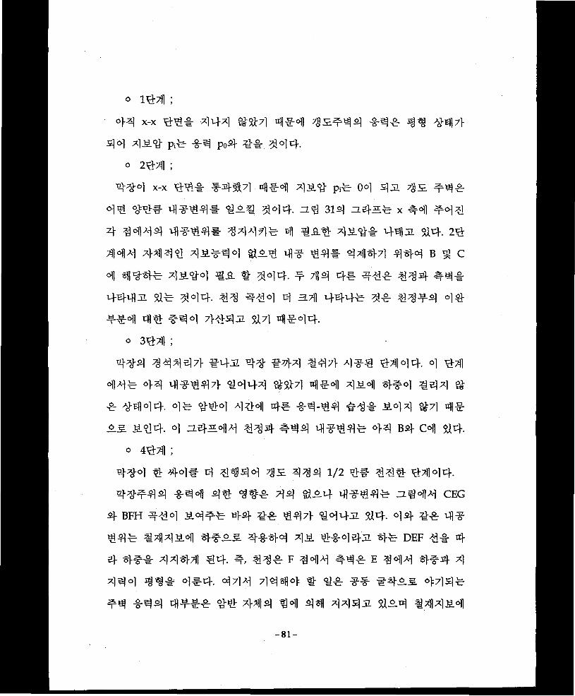
6 144;
41 x-x 44# 444 ##4 4 #4 ^5^14 -8-1# 4^ #47}
44 158 prer -8-4 po4 4-4- 444.
o 244 ;
44-4 x-x 44# I4I714&1 4s.4 Pi# 04 43. 45. ^4# 44 44# 4#44# 45# 444- 5l 3il zz.s}5^- x ^41 4- 4444 4#44# 4444# 4 #A4 158# 445 84- 24 444 4444 15#14 854 4# 44# 4444 444 B ^ c 4 444# 4S.4-4 €5 # 444- # 44 4# #4# 444 #4# 4445 8# 444. #4 #44 4 HTfi 444# 4# #44-4 44 ##4 44 #44 7>#45 81 %4I#44.
» 344 ;
444 44447} #45 44 #44 147} 4#4 4444. 4 44
44# 44 4#447} 4444 %87l 4#4 454 *Br4 #44 8
# 4-444- 4# #44 444 4# -8-4-44 #4# 544 §M 4#
55. 544- 4 54-5471 144 #44 4#44# 44 bs} C4 44.
0 444 ;
44-4 4 44# 4 4*344 15 414 1/2 4# 144 4444-
41#44 -8-44 4# 1## 44 854 4#44# 5^ 4^1 ceg
4- bfh #14 54## 44-8# 447} 1445 84- 44 8# 4#
44# 14154 ##55 l-g-44 15 l-g-445 4^ def 1* 4
4 4## 114-711 44- #/ H# F 14^1 #4# E 144 4#4 1
144 1^# 4#4. 411 1444 # 1# ## #155 411#
41 -8-14 4-t-## 44 144 44 44 1145 854 1x1154
— 81 —

#4# 4## #4 #444# 4# 4 44 44444^7} #444 ##44 44# 44as &44 FH4 EG4# 444
#5L# #4! 444 #, #4# G44 4S# 4#3i 444 4&4#
4dhs. 4 $47} 4-44 444471 44 #7}#4 444 #44 444-
=l% 31^71 # -r 4# 44 44 4S.7> 4"W 4" 4# 4244 4
44 #4^71 444# #44 44# 4#44 44 447} 44# 44
42# 44444# 7}## # # &4- zz.44 44441 ## 44# 4
#44 24 444 442# 7}?}#o] f7}^4. 44A1 444 42 4#
44# 44444 44- 4# 44 4#4^ &?M 4#4 44# 44
44 #43i 44# 4431, 4# #4 4#4# f4€ 7>a}^ 4#4 #2 4 #4 4*L44 #^-44 #4-
44 4# 444 424 #S. 44# 44# 4, #4 4444# 4#
4 4# 44# ##444 44.
(7}) 42# 7}#4 4 #£7} #44# #4 4#44 44-44 4^
# 4-
(4) 42# 7}#4 4 444 4247} 44 42# 4## 3}.
(4) 42# 4— 424 44 44# ### # 42^- 44444-
(4) #44 44 444 #44 44# 444 # 4# 45-7} 444
44. (4 ; ##4B)
(4) 4##71 oiBlul 42# 51414# 4# 44# 4444#s. #4
&4-
(4) 444 2444 #4444 444 ### 44 4# € # 4#
-82-

4^7} #4-
(4) 4# 444 5)4 ## 4517} #4
(4) #4* n $lr t 4-44 h#4 *44 ^s# 4*444
44-
4-5-4. 4&4 #4)
444 4*44 4*4 44 7>4 4444 #44 444 *44 4s
# 4as. 44 4473s4 *-*=, 444 a.7) 4 #0] *t))s)jl o]e)
4 *s# #S4 7]444 -B-447] 44 444 4S 444 4* 5) a
445)44 44- 7]£-4as, 44 444 44*^* s*^)*4 ^ 44
447} 4S 44* 4s# 44 *** 4S 4145) 44# 444 44.
44^s *44 444 *S #4* *4* ^(radial force)4 444
4** 4Sf)44 44*^(compressive strength)# 44 ##(confined
pressure)*-®))7)- 5)44 44*S7> #44 4— *S 44 4M* 47)1
5)44 44)7> &*as 444SS *4 444 #4* 7>44 44 441
4 44 4\E* 4 *4 *4444- 444 71)44 4S 44ss 7}*- 4
4 4#5)xr #4* 4*4 4*5)# 44 #* #*s# *as)m4a. #
* 44.
1) ##s(Rock bolt)
7» #*S4 42)
444 #44 #** 444* *4SS 1940 444 7))M 4 44*
4* 4* W5)4 444* 44 M4 44**44s S44SS 4
— 83 —

-§-5]71] 4 #4- #4 4544 7M a#5)#4 y-711 X]
54 444## 441 484. 44# ##5# 4444 €44 W44
444 ## 4 #44 449# 9#4 #### ### #4443. ## # 7}44 ### 9# 445 44 # ^ #4-
xflefl^j 7H#€44# 45 444 44 73#44 #449# 4-8-# 4
#44 45 494 7}^fAi|, #44- 44 4 #44 #44 44 7flM
44 45444 44 #444# 444 457]- 4447] 43-4 ##3=4 2.-S-44 4# ##471] 444- ##54 ##44 #
4# 443154 4#4- #4.
<##m4 44>
(1) 4S7> 44431 ##444 44444-
(2) ##7> 42. 444-2.5 ## 4 4#4 #444.
(3) 7gB#4# 44 4-4 #-2.5 ##444 444-
(4) #4##4 4# 4#4 44-
(5) 449-444 4# 4#4 5#494 7>#44-
(6) 44 7] 7i] #7]- 7>#44.
444 ##54 7]## #4 44 #4-2-5. 49##/M 44 454
4#4 4# 44 7]## 47>x] a# 4 7>x]4 7]## ##455. 4-8-
#t)1 44.
-84-

(a) Suspension effect (b) Beam forming effect
Fig. 32. Concepts of rock bolting effects
7i^>
(1) 7] ^(Suspension effect)
#^4^4 ^*1 n
7]^ir
(2) ^@#7)^ (Beam forming effect)
^sls. =1 <y^i- #4^
— 85 ”

32 #4 7} ### 454 4## #5# #1 a#l 1#4-
(3) 41# a# (Keying effect)
4 #4 #5 ##=4 4# 44 14##4 #7)j# 4, x#4 44
% #47} 1144# zi ##1# 44#4 144^. ##44 4444 4
1 4-f7> 44. 44# 2:444 4 ##4 7}#44- 1# 411 #1 1
4 (Key block)# ### 42.# ##4 5# 4 4 155# 44 444 4
#ir #4-11 a4# ###.
(4) ### #47]#(Arch forming effect)
#151 ##4 #4#3i #m# &4 ##4# 7}#4 #15 1# #
#41 #151 1155 ###1 1 4 #4 ¥1 ## 1 a4=4 4#
44 #444-. 4 #141 444-5.7} 5#4^#55 #44 4# 4#
54 4# 4 4444-. 44# #151 44# 4455 44?% 4l#4
44 44# 4114 45 ##44 #4-455 #4# #414 44# #
#14 ##44 44 44# 44# 4### zi *>47} #4-4 4545
4 #54 ##! #-4## 454 411 #41 44-. ##54 44# a
4-1- 4-## ## a4-4-5 #4 7}# #4 414# #154 7iio]#.
(zi# 32)
4) #154 1# ^ #4 4e
##5# 41/ 5# 4441/ 14 44- 44 7}X| ##5 1# 1 #
44-(l) 44414 4# 1#
a) ## 5# #(Point anchored bolt) :
154 #41 ##44 #1# 144 37##4jl ^#4 5## ##
— 86 —

4 ^4 ##^# 7l-#ss*1 #s4 ####4 $1# 444 ##
# 7}## #4SS 4#4 ## #41-4 $14.-Slot wedge type ; rod^ ##c>l ##44 $14 4^4 4^1#
#444 rod7> #4444 ^-^o]] 3i^£]£S. ^ #444-
## 44 b-E. #44# bearing plate# tfl ji nutS 3:4 4
47)1 44 44-
- Expansion shell type ; #4 31# 44 7} slot wedge type 5.4 S
n 7flf ^ 4—S. plug4 expansion shells. ##44 4—4 #
^4 444 # rod# 44444 plug7} expansion shell #SS
#47}44 shell# ##-44 #44 3.44 s# 4444
-Resin anchor type ; 44 # 7]-7] 444 S# 7]444 #S#
4 444 4 44# #444 4444 # 4 .44. 4, rod 4
44 #4# 447> Stm M.^ #4-711 (resin)# 7j-#44 #44-
##44# 4444-
b) ##31# 4 (Full length bolt) :
Rod4 ##-# #44 31# 4 4# 44SS cement mortar44 resin#
4-8-44 rod4 # 44# ##44 °M# ##44^ ##44 444#
4%4# 4#44 rod7} ## 4 #4 4s# 4# 4#4 # #7]-4
#44 $14-
- ##4(Grouted bolt) ; ##44# 4#4 ## 4 7># #44
$14-
• Resin bolt ; Polyester# ###(hardner)# ## 5£# S#-3i4
#714 S#"4 cartridge# ##4 #31 rod# #4444 4#
44# #714 cartridge7}. 444#4 tfl##4 44 4##
-87-

42)7} ^#4^ #44] #444 M44 rod4 #
4 AM# t^im.
• Cement grouted bolt ; resin #g_4" ## 7fl ^ 0)14 JL7]-S]
resin 4 4 <g7}4 cement mortar# A}##!}# 4 o] 42.4.
##44-o] #37 #;e4 mortar 44447]- ##44^ ##4
$124 4 #4^ 444 #4# 42# # $12# 31##
cembolteM 4 #4 44 4#4 4 4 $14- Cembolt# #^4
44 cement mortar# #4 tube4 5.## #25. A}#^- ufl
#4 4 4 A] 45 #4 44431 rod# #4# 2 $1S# 44
$14-
- 4%4 (Friction bolt) ; 41:4 4^ 4w4 # 7>4 ##7>
7fl# 544 3L $14.
• Split set bolt ; Ingersol Rand A}?} 7]] #4 4#44/ #454
44 # 444 4454 rod4 44 slot# 4#4 44 4#
25 =4#4 7>#4£# 4# 425 ##4 44& 4444
7lfl#4 444 44 radial force7> 4#44 #44 4#4#
#444 a.444# 4444.
• Swellex bolt; Atlas copco a}7} 7]|#4 4#—5. 13#; #44
tube# ##4 44431 31### #444 tube# 4444
#444 4#4# M44c #444.
c) #44 (Combined bolt) :
4 #4# ##37444 #437444 44# 2.4 #444 #425
4#4 ## #4 #4 $14.
- Anchored cement grout bolt
-88-

- Anchored resin bolt
- Hollow expansion bolt
- Wedgepipe bolt
d) yy|rB.(Special bolt) :
- Truss bolt
- Glass fiber bolt
- Urethane bolt
- Rope bolt
(2) si)lei] <9# M :
4^yy #y tint y#y ###y y&y #y.
- yy #s.(spot bolt or local bolt); y^ #s.y y y yyy y yyy yy 7>y ee# ^5. yy
y-7l(suspension) 7]^-y 4 y#%| 7]^# y-&# 4 Aj-g-yy.
-&yy -M-s(System bolt); yy 7iiy yy yyy 44
tifly A]^-f-o.s.y yyyo.3. #44 -g-yy# ^y-sRr 4^4
yyy y#7]^(beam forming effect) °14 444 ^47] y
(arch forming effect) ## 44# tifi A}-g-^cf.
• 4514 (Rectangular) ;
• tfl-r-y (Diagonal)
(3) yyyy w:
Rody yyy^- 7>y^7i-y yyy yy y^-y yy ^-yyy.
- yy*m(Pretension bolt); 4^y #my yyy^.s. yyy#
7>yy #y^y#y y#y ##yji yy* y-y-yys.
-89-

*#4 44*4# #444* OT °14, #* system bolting^
4 beam forming 4 4 arch forming 7]## *44# 41 *44
* M44-
- -r-'ti^'s-—(Untensioned bolt) ; #*4 *E. o|t]* 4#* suspe
nsion 4*# #.£.£. * 4* ##* **^# IIS *4 ^*
4.
4) ##m4 #4
444 44 7>4 #jl 9* 4* 4^ tfl* 44* 4444
4*43144^ 444 ^7>^44 7S5i4 44 4* 4444 #4# 4
443i 4*44# 444 44
(1) 4"’ll 4 4#—( spot or local bolting) 4 44
##?= 4 7]^^ 7>4 4*4 suspension effect^ keying effect# *44
7] 44 4*444. 444 44# * * &* ^44 44 n*4 49-4
441 4*444 444 4*4 4* 4444 44 4#* 4## * $1
4-a) *S4 *o] ^4
*4*44 4# #44 44# #44 431* *44 31444 41* 4
44 *°1 S.4 lm 44 441 *4°> *4 *,
L > D + 1.0..............................................................................................(28)
4, L ; #B4 4°l(m)
D; 444 ^°1H
a*, 4S4 #4 44414* 4*4 4* *44 4*431 44- 4,
*31* *** 4 ; L = 1/3 B
-90-

94=# 9#9 4 ; L = 1/2 B
4, B ; 4(m)
b) tlfi] 449#
W4 49# rod 499 999:e61| 441 4# 4^-5. t)]#44.
Tmax = OaA ........................................•......................... •...... ....................... (29)
T = Tmax/n =0.785d2oQ / n.................................................................... (30)
d = / nT/0.785 oa............. ...............................................................•...... (31)
9, Tmax ; Rods) 3)tfl 9 995. (kg)
T ; Rods) *)-§- 9^-8-9(kg)
n ; 9:9# (2-4)
oq ; 71)99 9995(kg/cm2)
A ; #54 999 (cm2)
d ; #54 9 9 (cm)
c) #54 9499
#54 94# #54 994 99# 93)7} 9#4 4^444 94 1
4 4-8-4 9# 9#44 #94494.
2S = ------ L .................................................................................................... (32)
3
2S = ------ W....................................................... (33)
9
RmaxLmax — ~ (34)
S2!
-91-

S : bolt4 ^r^(m)
L : bolts} z] o] (m)
W : 4(m)
Lmax : bolts] ^cfl z3o](m)
Rmax : rods] 2] 4 s|^^-£(ton)
T : ^S] 42(ton/m2)
* 4;, 4-3-4 5 a14] 4% 4 #" 4(pretension)4 rod #£.4 50% 44"
4 € 44# 4 4-9-5. 44-4 Its] #44= W-
(2) £44 #m(SYSTEM BOLTING) S] ^£4
Beam forming*]4v arch forming 7]#^*)] 4% 7]£^£4# 5}7] 444#
7]# ^#4 -§-4 l-y^S] #-4, 37]s]- #4 # 45]
7>7] £*l#4| 4# #4.4 44 #t]]440> w.
a) ^-4#- #m
4Lz #£ ^Jitb 44 44 ^#4 44# 4-4 4^14 -44# 444
44 44# zi^4- #*] 2-44 4#47> #444 4
4-4# 41>4 4:2-44 4#& 44 44-.
PRESSURE ZONE
■Theoretical boundary of pressure zone0.75 L L-
Fig. 32-1. Reduction of bolt length
-92-

zl spM 44 44## #**4 4*11 4 *#44 jl*444 ij.4.
44 *4^-4 ##* #4* r}# q 6.s 4*#* *4.
L = 1.40 + 0.184W................................................................................... (35)
4, L : bolts) #o](m)
W : ^SS) 4(m)
### **4 z)4# #0} 4 ^ $14. (ZL^ 32-1)
b) $] (Pretensioned bolt)
#4* 444* *44 ^44 $144 **$] $>44 S#4 44 4*
* Sfe -8-44 **4 #7>^444 4444 4#* 4 **4 *
7}** 4*7} &4. 44 4* **m4 44 444 444* 7}4I ##
5-4 4444 44- -8-4* 4444*4 beam44 arch# 4444 *4
44 4*7} $14.
444 ##s4 44 444* 7}*fl^# 4*4* 44#m4 #4. 4
4 #H 444 44* 4(35) 4 4(36)*& 4444.
Jorstad 4 : L - 1.6 + /l.O + 0.012W2............................... .................(36)
4/ 44** *444* 4 **4 *4* 2-* *444 *4. £* 4
4 **4 444 44 444* 44* 4* 447} $14- ^-44 4* 1
44 444 44 4 444 4* 2.0 4*4 444 4* 42.3. MM4
-93-

ll^l 33 %2l)
L/S > 2.0............................. ....................................................................... (37)
1, L : |IS] 14(m)
S : 1-E.cq H(m)
Nonecompression zone
Broadcompression zone
Narrowcompression zone
Fig. 33. Bolt span and compression zone
4144 111 141#1 Ill* 4*1 1111 %
11** *14 *141 1141- 11 4*4^ 1141 111 44
#4 ^7)44, HW, #4*14 sa> 7} #4 414 #4 4H
14 4 s &1.
HIHil 11** *44 *!!W 444, #*4 111*
1444 $1* 444 1444 Ills, zlIjl #1*4 *4 14 14
44 1*41. % *1* 14444 41 l£* 144- 11 11 #4
144 1411 114 1H£4- 1* 4 4441.
Ill, H4 Ills# &47l 414 111 llis 1*1*4
-94-

444 f7}Al?la
°1¥t11 444^7}- #7M 44^ 45441- 44. o]^
7)1 444 -g-^-4- #7^14^ 4^0-5. ##E0{| Aj-^ofl 444-§- 7>Sfl^
^ 4 (pretensioned bolting) »1 41-44. ZL^ 34^ pretensioned syste
matic bolting*)! 44 rock arch 4 ^t§Sj) ^j7 *)cf.
-FULLY GNOUTEO ROCK Rt*FO*C£ICNT WITH LENGTH, L, AMD SPACING, S
UNIFORM ZONE
OF COMPRESSION EFFECTIVEf ARCH THICKNESS, f4 ru*$
TENSION
REINFORCED NOCK ARCH WITH
Fig. 34. Rock arch by systematic rock bolting
Rock archil 44444 zz. 4^114 -fi-3. #-§-44 #4^44 41-4 ;££.
44 4^44.
ATa — Aoit ................................ ............................................................... (38)
4, ATA : 735. 44444 rock archS) 444
Api : Rock archS) -fl-S. -§-^
t: Rock archil ^41
* 444 rock arch4 t^I tfe #m444 444 44 44.
— 95 -

44, rock archS] 4* #7]-S]- bolt‘d S]sfl 7>Sfl4* ^g-* Ao3<>0 tfl
4 rock archS] *4 #7} Ad* 4* 4 3a 414#4
Ad = tan2(45°+$/2) A<j3 ..... ........................................................ .......... (39)
#, $ : 444 ^4 4#4
Ao3 : Rock boltofl S]Sfl 7}a0* **
44 *4 rock archil *4 *7}* #4*] xflJf 4# 370 4*^
* # * $14- 44 7M4* *44 3.71 Aa3* #as] «04 tij-^3}- 3.
704, 3el 31 7S£S1 y-yaj *°0 ^144 4*44 4*4 #4- 44 4H44
Ao3 = A0bAb/S2 ................................ ....................................................... (40)
4, ob : bolts) alrfl *4 Ab : 7gs. #44
S : Bolts! 4^
444 T^tt 4a. 4444 ^444 4 *4 3a 4*4 4* 444^44, rock bolts] ^44 44* 444* 4# 44 44-
ATa = [tan2(45° + $/2)][A0bAb/S2][L-S] .............................................. (41)
44 44 s]#4 4e] 7044 33 444* 44 44 *44 bolt 4
4 rfl 44s] -g-4* 44 4 * 434, 441 a 3* 44 pattern* 44
4 4*4 4*4* #* 4*4 bolt 4*4 *4, *4, 44 4*
44 ^ ^414 ** 3444 44444 44-
-96-

LBS TONS 60000-<
55000- -25
50000-
45000- —20
40000-
TORQUE-TENSION GRAPH
-------- With air torque wrench-------- With monkey wrench by hand
Fig. 35. Tensioning table
Rod41 7>4^ 9999 3.71 tt bolts] 39944 rods] 99- 7J-5.
9 4# 99 50% 447} 51 Ef #449-4. #913. 999* 7}#>r 9
9* nut-1- 1944 nut 2:9 torque# rod4] 7}sf|499
449 %^1# 9*49 pretension# 7}4e}. (39 35 #2)
5}) Rock bolt 2] 7J-5: a]-^
4 #9 rock bolt7} 999 "94 #9 #2 9*9 #9# #.9.7} $14. 9
4# 4 99 4923. # 92* 949- £149 rock bolt4l 444 4
9i- #2&4 4444 45.97119 494* 97}# #-6.7} $l?l 45-9
4. Rock bolts] 3.9 *9* 4*4 9# 22# 4 S]^ 4##4.
- 44s] 24
- 449 #44 9#
-1-4449 94
- Bolt9
-4# 94 -14 #9
-97-

- #3
31# #44 #4# 4#-d]|*| 6] #A] # (pulling test) 0)1 444 #444-
4# jack^.5. 4 #4 rock bolt# #4444 extensometerS. 4## 431,
4443 rock bolH ### 44# 4 #4- &7] 4^144# 4# 4 #4
1 444 4# 4 $47} bolt^] 43 #s #114 ^44444 4# 4 #
444 ^##3^.# bolt?} 444 #43i #44 4 #4 444 #4*
bolt 4 44 3i##444 44- 4444 444# 447} # 4# n 4
4# #444 44 4#44 4##### ?11#4# #34 444. Rock
bolt?} #44#h" ^44 #4# 4## #3. 4"n*4 4# #4#4 4
# # 44-
-##4 #4# : #4443 |e5} #44 44
- 44 Ji##4 44-8-4:44 3i##4 444 #444 31##-
4 #4
- 44 3i# 44 4 44 : 4144#4 44
- #44 4444 434 4?}: 444# 4 44
Fig. 36. Characteristics of Load/Extension relations
-98-

444 y#4 4### rock bolt44 4# 4## #4]S. 4 444, €
4] 3. 7StfloflA^ rock bolt4 4444 4*i] $15 #4#4 4## rock
bolt*)] 4444 #7]4 #14 444 444 #444 #7] 444 wire
mesh4 shotcrete#4 #9|] 4#45 4 #7} c)]##o]c]-. #, #4 (wedge)
3] a.7]7f rock bolt 44 A4 4i: nflo)]^ oj^y. 4# y##4
M 4 #4 4 &Ay 444-
2) ^aa|E(shotcrete)
7}) ShotcreteS] ye]
19114 4 #4 Carl E. Akeley*)] 444 "Cement gun"4 4# 44 AS.
4#?7]# 4#4 cement #4447} 7]] #4 $14 3# gunite £#
sprayed concrete f-AS #447} 45"*)] 44 shotcreteS. #44] 4$1A
4 £# 1 y# #44] 14 A#4ol $14.
7]# 445 ###7]4 mortar 3E# Concrete# Xif ##4
#444 4# 4# ay*]] 4# ^ss #444 zt #4as. #4445
M44. Shotcretes] 4141 #4# 4 #4 ##44 3454 S14- 4,
### batching plant4 4 ## (shuttering) *1 #A §ial concretes] #4]#
#A*i] 44 4444]s 4#4 y#4# # $1A4 #-# 44s. 44 4
#44 4# 4## 4 # 5 $14. 3s]a. #4 concrete*)] 444 4#
4A*)] 4# #4as. #4444 4#4 #444 44a a# 44a #
4- Shotcrete7> 44-s] ## 444 444 44# 4445 57]4s.*]
4## 45 mechanism# Ay 4#4 #"4-
(1) 444 ay# 44 14144 #44- 4444AS.4 ### y
444
-99-

(2) <8-'£K?-S] *4] (fracture)# 4 2] (joints) A}o] o)] concrete?} *44
4 a}* 4**4* mortar 41*4 4* ^#* 44 #*4 4
5* $>### *4*4-
(3) 4444* 444 4** *#s] 444 44as *# 444
4 #4.
(4) #4 #4-5-3. 444 ^4 **3. ^44SI4 44*7} 44
#4*7] 44 4*# 4-f* >*#4 3:47} $14.
(5) 444 shotcreteA}o]4 44^4 4*1]4 44^1* 4444 1
4^14* #4# 3V§444.
4, #* 4-414 Shotcrete 4^7} 444 44* 44 ** $4# 44
4 #%# 4^4431 4* 4#* 445. 4444 44 ^>414 44*4
* M41** 4** ##4 44- 4* 4** 44# 4444
7] 4 si] A] shotcrete7} 4*44# 444# *4* 4*4 44. 4,
(1) ###* 4**431 *# 4^0] 7}*6flo> #r}.
(2) 4-8 A] # 4* 4^44 45. 4#* # * $144 #4-
(3) #14] *4 a}*^5- 28A] a 4^7} if4 4 4*# *4# *
$1** 4)4 #4
Shotcrete6!]* 7]*43L5L *4(dry-mis shotcrete)4 44(wet-mix shotcrete)
O] $14. 44* cement* *# #41 # *#44 shotcrete 7]4]4 4* 4
* 3L** *44 3z#4]A] #A}A]*44 o]ufl *A]oj] 32#4]A] 31*4 #
-§- 7>44a1 *44* ##44- w4* cement, #41, # ## a}44| *#
44 pumpS. 3L—# *44 3z#4|A] *a]-4* ##44 4 4] nozzle 4|
a]* concretes] * ^44# #41 ?Ee]ss]7] #4#7]7} *a}**.
-100-

dry cement, sand and accelerator mix
water controlwater line
— air line
wear pad
wear plate
rotat1ng
compartment
tipwater ring
compressed
Fig. 37. Dry-mix shotcrete
air and acceleratorvacuum helps to restore pumping tube to normal shape
air pipe
rotating rollers
collecting * hopper
rotating bladessuction
‘pumping tube
Fig. 38. Wet-mix shotcrete
4 44 44 4w4 444*1 44

Table 17. Comparison of Dry and Wet System
Wet-mix shotcrete Dry-mix shotcrete<5f3> <§-§>
o y-ti#(rebound rate)o| W4 o otei^^-si zEfloii »§io sjci- 4='ai^Ko A|g@o| go| lc##S| 7|fe§£0t| o §-u| 7I-230I m|-;h afo| Mgsiol SiOH
SM g>*l SltrCLl. ?^0| solsich
O gAl 4=5ES h:##0| 51 a Sit 41 o g-b|7l ±@0|3. ZlEl#03
21^1. B£|*H=kO 7\n %±7l #0|#CK
O ^A|b|7l
<E1S> <eia>O §-H|7|- 32 71-2301 bl^Ch • O y-ysol -g-5! §H4o| %c|-
4) Shotcrete 4 44
ShotcreteS] 4^ 4.3 o_ 44^-3. 4# 444
444 44 #4 4-S-4 #444-
(1) 57)44 5.4 (Initial ground control) ^-4
o o)44 44(loosened rock mass)
o -g-444" 44(overstressed rock mass)
0 444 4 4(s welling rock mass)
0 #44 44(slaking rock mass)
» 7gtfl4^ -g-<y #4 (water bearing rock mass)
(2) 444 4M- #4
(3) j±4 ^ #4
ZLBjJL shotcrete# 444 444 44 44 rock bolt #4 INI 4 #4
— 102 —

fe- ^^-7> shotcrete
M01 ^4 a# riHsM 7}^#4.
(1) Shotcrete <&#o) #4?] 44 € f # 444
7} &3L 3 £l»H ^ ^°1 m.
(2) ^AS y^-y 44 4 €-8-4: ^4# # 4r SI
^ 5ti.
(3) 444 44 7> 4# 4 A]% #4 (slaking) 4# 44)7} %
t y-4.
Shotcret# -#31# 4 JL^l* A}4#4 shotcrete^ ?f-v)), 7^, #4, a]^-
a) 7) (timing) ^ 4 a)31#4 SsHD #o)4. €4|S. ?8xfl4 #& 4^
#€ °ll 4 314 shotcrete# ##4 rock bolt# ##
# 4% 4^(membrane) 4#4 °1# #44 €# 4 4
Table 18. Empirical design of shotcrete
Ground condition Shotcrete application1. 2)5.5) 2)5Kgood ground) 1. S§2| arch 3-ir-o|| 5 cm Al0
RQD : 75% 0|#oS cH^S. ?fl5)L[39^3 5)71 o||f£ttl §5E2| 2)5)
2. S.-§-2)5)(fair ground) 2. 993 arch ¥Soll 7-8cm A|g§)s| #
RQD : 50-70% §£3 u|Jn$| #a|7) 9)2) g^3-E-E §)7i| o)9.&oi ^9510121014 °)gsm
X|S7) I£& 9IK shotcrete
94e #e $a.3. ID 2)a)(poor ground) 3. 9S3o|| 8-10cm, 4^?o||^ 7-8cm
RQD : 25-50% 5£3. 4@0| ^ a|5. archS 3£ti o*& 44 u)421° 4 shotcrete @#o| #%|8)e 39 3377)9 A|5. @@ 9EH&H3 g#o|
#s|9 2705= A|g_ gs)o| »|f°S360£ a|5.
4. o)4P ##5) StaKvery poor ground) 4. 3S)s| 99 oil 2-3 cm 47HS.0|a)S 9alas x|M7) 21B)
* ?3s# 4-6m<3 3-r-g.
-103-

4 #4 ^ ^ ^4.
Shotcrete^) ^4 M# 3.7)1 4t4 M44 44 444 4# 44
44s 4# # 44- ^^44 Me 44 4?# #44 4#
4 #44 44 M3S 4 45. 197444 Heuer7> 444 M4 44-
44 44 44 44 44 M44 44 444 44## 4444 4
4 4444- #44#4 4#44 44 444 # ¥ 7>47> 5U4-
44 44444 4444 4W35 4#4# 44# 4444 44
44 435. 197044 Cecilo] 44 4 4# 34 4#4 44-. 4 44 #
5 model 44# #44 444 4444.(3fj 39 #5)
Fig. 39. Shotcrete for supporting loosened wedge
l/2a2T l/2a2Tt = ---------se t = .................................................................................. (42)
fa 2.8ft
4, t : Shotcrete #4 (cm)
-104-

a : (cm)
f a : ShotcreteS) ^ 3)-^ (kg/cm2)
f't : Shotcrete S) 9l^"^}5L(kg/m2)
T : S] i]£(kg/m2)
-8-^°] ^#5]^ WH shotcrete ^7)]# ^
7) 4^} 4]ic]"oVo1] Ai plastic zones) y3_a.fi l|) Jf<y-s)
(internal pressure)-8-
Pi = -c cot $ + P0 [ -c cot $ + (1-sin $)](r/R)2sm/1'sin
= Po (1-sin $)](r/R)2sin/1‘sin................................................................. (43)
^s) ifl^f <9-^^- ^^-44 S)tl W°1 &&7l 4^-4
Hopper, Lanf ^ Matthew 1972^ °1] rf-g-jf #-8- 5-^r^ <9# xf| 9:#
tI-S) 9-S. 7)1 ^=1 kD^-<g-^oi] 5)sfl shotcrete ^7]} 7} TUfl# ^ $14-
#, ^#-8-^°n ^^444 4##7] W shotcreteS) ^v\]±r t^g.
-9-5.
Pi x rr = -----------x Fs........................................................................................ (44)
fc
e, : ## -8-^
: %^#(2 - 3)
M, <9-^44 4-8-aRr ^<9^ (radial force)4 cfl^
#7) -9 %1 shotcrete ^7)]S) 7)1 fkg: ty-%- ^]_9-5 ^lt}# r S1)-
-105-

rPs x r
(45)x Fs.........................fc'
4, Fs : (radial force)
44- #4 4# 4% 444 shotcrete %%4 %%4 7}%44 4 #%3
% 44=% 4% M4 4^-44 44#%4 4# 4# 314% 4 4
# 44 4% #4]7> 3# %#& 4#%% 4% #% #44- 44%,
NATM ##4 44 #4 4#4 4#%% 4## #44 444 44*
4#4#% 34# 44 44 #4444. 41% #4 5cm o]^# 4# 4
3 %%# 5cm5. 4#4# 44 #444- 3 44% #^44441 4#4 #% crack44 3 44 4^}# 44471 4#44- 3#?l 4#4 %7|
44£ shotcrete4 #44% 4# 44 4% #4 44 433 43 ^4
44 4% #4# 4% 44 #444.
4) Shotcrete4 4#
Shotcrete 44# 3.4 444 7fl.iL 4 4#"4 #4 44 33. 4# 4= SX
4- 4&4#44# 4444 ^44% 4# 47} #34, #a> 4447^
%#4 4=4 7^5. 4# #44-
(l) %&4 %%4 443:4
Shotcrete4 #3% 7fl3% cement, #7fl, 1 3# 3 444 4#4 4 ^^
4 441% #44- 4 #4713 #%# 3 44 %% 44 70 - 90%% %
4# #444 3 144 4444, 4# 4 #4 #% 444 #4# 4#
44 4% %&4 4-
o #% :
4%7l% 4% 41-44 4# #71134% 44 #7fl7} #34 4%44
— 106 —

# 14 #44 #4. 114 44 #_*M
ZOOmesh °] 4" 4 D1 xr0] ^445. 2%#- &444 ^°]-0i: "S^-JL, 1"7}4 4
###144- -n-yyo] §^44 14- #4 shotcrete 7}7%<H A}<$
44 11 #4 44 4^44 hose line # #^H4 1/3 4
4# 11-$-£. 44 &# 19mm# 44 4# 4ji a4
U.S. standard sieve number
100 50 tO S 1 0,5 0.1 0.05 0.001
Grain size in millimetres
Fig. 40. Recommended gradation range for aggregate
### 44 4## 44 #s= 44 4:44 44 4^4 #4
7> 11 tili-5. ##44 44°> hose#°fl44 5Lw, nozzle44 #44 #
% 44 &444 #44 ^ 44#(rebound) # 44 7>4 4414 ##
14-1- 4# # 44. 4#44 n4 404 # #4 444 444 4# 417} 7>l 4 #4 4 4-
-107-

4 ##53. e #*}7} #54 1^7} *##J1 # cement 55#4
#4#4 ###4 W2. 5# #Ajjz] <*§*# ## crack# a^ ^}5#
4 ## is[7} Sit M>4 hoseMMHo] 311-4 4#44;il #a}a] u}#-#
*1 4**14 4*4 44- *41 4^Alt *11-611 9mm# w #*3. #4
All tA># 44 a] #44 4-4 19mm4*3. 44# *4*1* *##t
#4 4## 3}#. *4 *4)4 #44 ## 3p$MM #44 44 ###
4 44#*1 #5# #3L 4#4 3 - 8%# *445# #* *## 4
#4# 44
o Cement :
cementt 44 concrete #4 44 1# S£iH cement?} ?}# #4 a}
-§-431 454 444 4-f 4* #4 5*44 *144 #44 44 44
44 2# 54 5# cement# A}##* 5 *4- 4444 *### *}#*}
*1 #55 47] #4# #*1# 4 SI4 regulated cement?} ?H##4 44-
» * :
shotcrete-g- #* 44: concrete##- ## 5## #440} #*. % 44
#31 7l##, 1#, ####, *?1* #4 44# #4. 4MM53. *#5
3. *** #4# 44-
6 ##4 :
Shotcrete *14# 4## 4 4444 concrete ##453. #444:# 4:
#4 ## 4# MH #5* 57145# Ml#4:4. 4s]# #453. Alljg.un
#Al 47}#4 #41* MAile}3i #4 #41 # 44417} 44. 4#
concrete# *4414 3.# 44 4*44 shotcrete#*11 **# S.## #
44*1 *#4. Shotcrete#53. *## 415# *4414 4*#*, 44*
4* # #* **4**53. *#* 4*5 4# 454 5 #*
-108-

4* 4 5# 44 Mi 44 4=4. #11* 44 #44* 4*# 44
444 *7]7> *2 #44# 4 #244 -8-1444 4*4 ** 211
5» 4* 4# 4445. #4 21# 4=241 42. 4**4 *4* 4
#5 #4- 244 44*4 *14* 27]*2* *4** *1 4* 15
* *44* 41* *2 44.
(2) 15# 4#
414 15* 4 #4* *1* mixer* 4*4* 1*7} 4**44 1
1# 4*5 **4 ti]]#'&}4 cement7} #7]) 5.4* 414 coating 45
* #444. 244 mixer *1414 44#44 a 47} **44 4*
4 *1*25 454 44 mixer* #1*4 44 114 51144 #
4. Shotcretel 54 #511 «]]##* 4*4 14-
cement : 15 - 20%
2## : 30 - 40%
4*4 : 40 - 50%
*4 cement# 4* nozzle mani ## #* 214 1*4 51444
44 *445 1441* cement# 0.3 - 0.5tifl, #444* 0.4 - 0.6ti]]7}
*}*4- 11 «]]## 15* 145 24144 4*444 44 2*7]
## 1** *41*(prehydration)4 ## 1**4 *412 shotcret#
155 14 50%41 #414 11 4*4 11 ** * 41 7}1 *4
* **114. 414 41* ** SI# ** 4# *1# 147} 47]
4*4 141 1*4 4#- 14 #4# **4 3 - 8%# *145# #
11444 44.
-109-

(3) #4
Shotcrete4 2]# ^5.5) #2}- tifl^-of] 3711 3)~t"4 4 #■ nozzle man2] 7]
MS 3711 ##4- #4 #4^ 4# # 4#4 2^4 £-A} >|5l
^ 4s #41 3711 4## ##4. #4471 441 444 #44 #4# 4
443 #4* 444 414444 44 344 #4447} 444 31# #
44# 2:44 41# #-4 # 7>#4 4 4# 44 4°ti 4#4# #44
#4. $#4 4&# ##4# #44 #s#s, 444 #Tt 4 -g-^, hose4 44 g 44, nozzle4 44 # 44 7>4 a#4
441 4a44 44 3 - skg'cm2 #444, nozzle #444 #4 #s4
60 - SOnVsecS. #4 € 417} 7># 44444-
0. 76m5, nozzle to surface distance angle of nozzle to horizontal
(a) according to distance between (b) according to shotting anglenozzle and wall
Fig. 41. Change of Rebound rate
#44 7># #34 4# ui 4 AH a# 3# #35. ##4## 444.
3#4 #44 nozzle #4 # till## 33711 34# # &7l 4#44-
4## 1- till43 shotcrete #44 4444 ### 6-10k^cm2S. #
-110-

4 444:44, nozzle^ 4444 44, nozzle^ 4# #
4 44 shotcreteS] #c»14 4444 3.7\] #444- Nozzle^- 4444
44^ Im7> 7>^ o]^4o]4 Cj 7>^7l4 4444 444-4 ^44
#7}44- #4 4:Exr 444 444 44444 444 nozzles) o]^
^ 44 4^1 4-S-4 4&# 41444- 7M 4? 44c 44, #4 4
44W 44 44&4 4^-4-
Shotcrete7> 4^-4 f 4^4 4& 7444 #^-44 4 7144c
43:444 44 3:4# 44444- 444^-5, 4444c ■&, #
£7> 4444 4#4 444 44# -8-44 &c4-
-in-

4* *47} *<y£]xr 7gifl^ -f* 73£<>] ^Igo] 3.7] 4*4 45-*1H
44 o]n] ti}<2} *0] 3|7].4 ^4 Aj^AS ^^>3
* 4*444 # ^44, 4-3] 447> £]* 4** 44 44 #4W 44
7^4 ##44 #7M 44 4S 44^ ^44. 4444 444 4#
4X44 44^ 4 7>4s. **# 4 $L°4, zi 44* 4*4 #4-
5-1. XH5BI WS m M
5-1-1. 4# -$-4#*4 4# 44
1) 444 *44* *4* *4**as 444 44* 4*444
44-
2) 47] *4*4* #4 *4*4 tfl* Fume diluter 4 4*4 4
#444.
3) 444*4 *47} Jf-sm 4* 4-4 ^^4# *444 *
4.
4) 444*4 7}^*51* *5L44 4* 4*4 44*44 444
4*7>>2 *E4 5%44 44^^-S. 4*4 *7]*4 5%
*&* 4^4* *4
5-1-2. *4 44
l) 4**44 4* 44* 4*44 4# 4* *4 *4*^
-112-

444 4# ### ^ #£.4 444 44 f^5|i $14.
2) 444 444 4## #4 #2, %H4# #1-8-4 4444 4&4 4#4 44444 44.
3) 4^-4 7]4 -8-## 444 444# 44 #24, 444 44# it €2# 44444- ###44 #4.
4) 44#4 4#* ##444 44 4# 444 44 44 Simulation^.5. 4444 44444 #4.
5-1-3. 714 4#
2 4 «£-# 244 2^4 5.4 #444 4# 448# 447} #1
44 #-4 444# ##44 ##4# #14-2, ## ##4 444 s#
4 4# 41##4 44 #4 $124, 44# 44s.# #-44 #2444
6)1 A>ti-o] 7]^ A}J7, ti„5)14H S44 #44 aL#4 4# J&jfe, 24 #
#4 4# $StI #4 $14.444 44# 44# 4##7] 444# #24 4# ##4 #4#4
## 4 #4 #47} 4 #4 4 4 #4/ 244- ## 224 #4 £.#4-2,
#-44 #42#!- #44 #2, 4446)1 4# 44442. 14# 24 4
#, 4141-4 #4 24 #4 4#444 ##•
5-2. 2SLH mxH
#4# #44-4# 44 444# ### 2#4 ##4 44 ##4 # 4 #4 44 # 3# 4#4 4#7}# 4 44# 24 4# #4 44.
-113-

Table 19. History of underground mine fires in Korea
Date Name of mine LocationNumber offatalities
Nov. 6. 1969 Hwasun colliery Hwasun, Chonnam 8Nov. 16. 1977 Jangsong colliery Taebaek, Kangwon 12Oct. 27. 1979 Unsong colliery Munkyung, Kyungbuk 44Dec. 12. 1983 Bongmyung colliery Munkyung, Kyungbuk 9Sep. 2. 1989 Dongwon colliery Taebaek, Kangwon 5
Table 20. History of underground mine fires in USA
Date Name of mine LocationNumber offatalities
Dec. 6. 1909 Cherry mine(coat) Cherry, Illinois 259Jun. 8. 1917 Granite moutain shaft(copper) Butte, Montana 163Mar. 6. 1968 Belle Isle Mine(salt) Franklin, Louisiana 21May. 2. 1972 Sunshine Mine(silver) Kellog, Idaho 91Dec. 19.1984 Wilberg Mine(coal) Orangeville, Utah 27
444 3-4s 44^ 444. 444 ^4-s 1984^44 1994444 io
4 4014:S 11544 3MNH9 4^7} $1^4, 514 444 284, 444
30444 #44^4 444 44 47S4 #444 5. 20# 4
4. 4^-4 #7|a>3l^ -yo.^o.4 49#4 4jl# 3
444 a 21# 44.
Table 21. History of Underground mine fires in Japan
Date Name of mine LocationNumber offatalities
Oct. 6. 1954 Saporo, Hokaido 14
Jun. 20. 1952 aa* Fukuoka, Kyushu 10Mar. 9. 1961 ±M Fukuoka, Kyushu 71
Mar. 16. 1961 *>+ (i » 23
May. 12. 1968 51 "1 Saporo, Hokaido 13
Jul. 30. 1968 Saporo, Hokaido 31
Jan. 18. 1974 E?t6 Fukuoka, Kyushu 83
114-

## 44 #A))7}2## #4 A}2# 3}.^A>ZL^
#4 S# $1^ 441# #444# ^## 4 # $14. &23 4 #44 4
S^-4 #44## ?M #7)14^4 ^7}4# 444 AH»l7) 4#
41 7gtfl 4Afl3. 44 cfl^AflSfl 414# 3:7) 4# 25)2 4#7) 3§-y] t)j^
#4 <34 5)44 44-
7M44 #7))7} M 4 4)^ 7))45)4 $1# 7)44)44 #a))<2}^ 2
444 44 457) #l#4) 444 7M#zD4 #44 444 ^sf #3
7> $14 €4 #7))7}4# #4 734 #4A) #4 #4 #44# 3.4 ##
4 4-4
1) 444 # #7) 7)#4 ##s)4 4# 433. 4 7g&4 44-44.
2) 734# ##4 444 2## 44# 22)4 4447)7} 444.
3) 444 444 73s4 #444 447} #44 #4(0m) 3. 4444-
4) &## 44 4## 4444 #3.5)3. 43# #444 44444-
5) 44 44 44# 444 #444# 4444s 7}# #7)44 ##
4 444 44 44:44
6) 44 444# #4#, 44# #0) o}4 44 344 #4-
7) 344 #4s 44# 44 #4# CO 7}2: #5) o.sj7}a7} #3)5)
4 $14
444, 7S4 #7)14## 444# #7)) #4# 444 47)#7) 4# 3
4#4 44 4444# 37)4 47)4-2 3## # $1# 4#4 #344
3S4"7) 7) #5) 2## 44#44 7}#6)) simulation# #44 ti)4"A)s) tfl
44# #44 ## 44 4# #344.
-115-

44355 44 M45 W# 4444 454
7l5 5544- 5##7]]5 45444 7|£ ^ 444 444
# to 54 44 35 ^MMto ^45 3-f7> #4. W 5 454 45 #44 #4 54 44 55 ^xfl 7>^ a44#4 545455 &54 4544(444 4445)4 45^5 55 ^#-4 ^44 4<@37] 454 444 44 444 544 44&4 5435a5 4444(Spontaneous combustion)5}3. ##5 44- 5 #44 445 5-5
4545(4445)44 4445535a5 544to 44 4 to
n44 444 44444 44 354-7115 444 4445 a#4*fl5
4545 4 7} to 44444 4444454a. 3444 44 zt^4
44-
Reacting speed 10 (m/hr)
— i m&ik -
-2 10° 10z 104 10"
Heating
B# mm m#
Smouldering Combustion Deflagation Explosion Detonation
4 4
Fig. 42. Chemical Reaction of Combustion
44 nlMH 4445.(4 355 linear propagation speed)4 445
4444 45a 44445 444444 ^ 444 4313 ht!) 45.4
454 343 454 #4 4-44 445a 431471 #41 7]#4 44 4-
7S447)17} 7>44 #44 45a5 1, 47], 7)if 44# 5 44 °1
-116-

1#4 153. 1^4# 0}v|5}- a) 5. 44
44# #4 s>7] m 7H#453. 3i#44 444 #4-
1, 44, 7}5l 3## 44444 44 7>4 4444#- 414
*H#4.
44W4 44, 541 4:444 5145 4544. 14 #44 1#
#- 444 #4Ml 4444 14 444 M4 14- ;@5 44#- 1
514. a 14 #4 #441 #5#5# 4444 451 5514.
11# #4^1 1, 44-4 44 44 #57} #444.
7}4# 14^M 1, #-4, #-44, 544 #5, #7lj 14 #11 4
44 # 4 5£# 24 ##4 #4 #4 441 1 14.
1, 44, 7}5# 441 414 444 %M #4144 14=#: 444
14 44", 141, lls. 4 447## 71-4531, 44# 4444, 44
4#, 7}## ##, 14, #17## 7>4#4. 14 11 7#4.aB# 4#
4 557} #144 144 44 4#4 A##Ai|4 41 1444# 1#
441 111#: #444# #47} 4114 1#4- 5 441 447} 4-
4-5 44 #$1 4 44(Process)4 14=#- 114- 4# #1 154#-
44444 144# £11 #-47}5#41 #45 1#14. 44^1 ?<M
44 1#44# #-441 147} #545 5 ##41 5# 11 15.4
19-7} #544.
7}14 #1 511 4114# 44 41# #14, 444 1*344
(Process) 14. 1 41 44=115 4# 111 11 454# 44 # 5
# #4-14- 44511 411415 4# ##1141 1*1]# 11 #
41 14 111 Mil 7}# 154 7}5##44£ 44 44 4#4
- 117-

#444 &3 94.
444 4# <34 9#7}#### "494## 994 444 9# ##
##4 44# 7}# 44 9# 4"4 43 #943 #4 9# a 444 4
# #44 #4 49-7}## #4#43 9#4;e 5.##.. ns} 14 3A, $}
# 4 n 44444 44# 9#49 4 #944 494 9994# 4
&1 92.4# 44-44. #9 44 44 44# 7} a 4:44 ##9#-4 4 94-7} 994 a 44 #9# Jgtfl 4#4#4 #3# 4 4^5}31 44. #-
471 444 ## 47114# 4# 49# #4e}n 4^ #4 #4# 59
4# 7}#4 #44-71] 444##7} 7}4#7}4 ###/} #54 #44,
444# 9# 71943. 44-
44 44 4 44 #94 #44, 444# 94431 49 49 9% 444 9449# 94#7i 949## #4# < ##9 #-#7}9(44,
#4#, 99#, #4#) ## ### 494# 7}#(##, n#47ll, 4a# 4 44#9)4 9#a 94#### #4495. y}4# #99 #7fl#t}. 44- 4#7}9 949 7}4# #99 49 7S#i}# ### #94 449 4# 94# 4#9a 994 4447] #i}] 4#9#4 7}### #71194.
##4711# #444 4#7}^ 94 ##47111- #4##: 94.. 5###
4# 4447} /g## 9949 994- 4#444 ^g#4^11447}^# s.
9 44- 4#99 99# 49 47#999 ### 9#3 9# 4994-
444, 9 #44 4#4194 #4444 9 494
-118-

## 4444 7]^7m°l 4 #4 4 4 #4 2#7)#(High Tech.)43. #
# #44 #4# ## 4 44. 4# High Tech. 4## ### 3
7l?M4 a3442 £443. 434 #43# 3 7) #4 #437 #.4# 4
^4- 3 #4# 44# 444M4 34^4 44#44 $13# Software
#4 44447} #### 4# # #7> 44- a #4 444 7}## 24
4 4#44 ### High Tech. #44442 #3 4# 4## High
Tech. #4444 ##4 44444. #Afl ## 4444# 7S^4#44
System# a}##)*) #4#4 444 4444 ## # 4# 4# 43#
4 #44 4-3 44.
4 System# ##4 7>^-o_S 443 4# 7]#0)4..
4#44# 44 7>x]s. 44 $134 4#444 4# 44 44# 44
44# 3^4 ## ##4 47] 4 #4 435.# Expert System, #7] 4
## 24# Software 7fl#4 #34-7)1 44- 2 Hardware444# 7))s)]
a] 4 4jL#27} #2# #4#(Optical fiber)24 44 #3# 2# Loop #
## 22# #27> 44-
#44 242#4 a>#s]# 2##44# ## ##7> 44- #4^44
2 =L A}#4 444 %# #44 5)4 424 3# #44 ##4 #24
444M 3 #24 4# 2#44# a>#4# 3M #244. 4#4# #
All 3 4 #4 4- 2##4# 4# A) 9} 2 $14. 34 System# 244 4#
43 $14. 4442 #A|427> $13 244 $144# ### 427} #3
#4. "Ag4#-4"4 "7>4##"# #7>## 4443 47)71 #2 #4# #
# 814. 444 4# ##4# ##2 $134 #4444## #4 ##
## 444# 4##4. 4#4 ## 444 4#4## #42 44 #e
-119-

5-2-1. 734)44)4 7]14 >84
1) ymsm sg
73^4701 144 11 44^ 7>y#ol 41 4441
€4°li 444 444 alHsflAi 1 7}44 14 °1 Si4- 44
754, 1414 441(44)14 71-4#4 41455 #7H#37 zl 44
JE 444 1414 S-KJL $x°]*\ #47} 1144 1444 44444
4441 4^44 Si4- a #4 14#41 1 444- 14411 44
414 4-7117>i7]- *5.71 4#4 #4 441- H4 7>^7§o] 3.4. 7M
4 4444 e 7351441 4-7014 #444 4-70 7}54 1455. 4
#4 4444 54414 M44- 411-4 %84#4|7l- 4444 57l 5
44 14547} 1441471 4114 4t1 41 4144 114 44 7^5
11 11 4 73je 11-4431 41 4144 14141 HOT.
2) 73 m 4*114 33
734444 44 #1-4 441 11 551 4, 47], 7}^ 1 3##
7> OT-
411 7-15. 4-54-11 44 4704441 ^-4 434- 4-4 44 7>4
117} 4444 4144.
-120-

Fig. 43. Relationship between factors of Underground Fire
x\d\) =l o)^x\ 7$^^, ##44
4. a #7f| <14 44 4 y-Tfl ###41^ 4^44 2-44 45.449 4
444 ^4- 315flA^ ##94 lA}^## <9#### ti.7l] 5]37 -§-7141 4
4# 9## 44.
4&^-& 444 M4 491# T^#7fl A^S>J1 <99)9 4 7]## A>
447] 4^r9 #71)3.494 4494 2:71 ^h## 44 914 44- 7S41
#71)44^ 7|4o]l4 igE, Ml^l# #4 5# A}### 9 4^453. <971
#3. 73£4 4^. 7fl#4 ##4Hfe ^717} #944 94. a
#7)14 #4# # 9-44 f-71 9 #71)2:441 444^- #4 4415 47)
7> 4444 45 $1471 5### 4414 447} 5994-
& 7>44 M4 44, 951^# #594- 44 ^97}5 #414 4
-121-

3# 7}534 ##4#5 34 44 #*44 $14. 44# #7fl7}57} 73
44 ##44711 si4711 4# #3 444 #444# #5?l7l| 44- £
47H7H5# #443 3*43 447}5#»l 444 4# 3#35#44
#4711 #31 2#*-#34 34171- #444-
3) ^LH4xH°| H?i (Model)#
7MM4 #4 # n 3.144 444 44-4 A.F.Roberts4 44 4I-#
44 #*7} 4^444- 7315H 444 4444 4#43 4444 4
3.7} 444 31# 443 Roberts*11 4»N4 444 #41444 4441 ##
73 #54 4-
*Kas
Fig. 44. Concept of underground fire propagation (after A.F.Roberts)
01 H4*11 444 73,544 4-7113 73s. -oj 7>4#°11 444 #4##
53- 44431 #4#4 4-544* 54# 444 #547} 4443 7}
344 $1431 #4. 44 *3 #4443 #547} 334 *#431 473
-122-

7}5#57} 435. #4# 444c ## 4 ^ to,
3. SHIM* t'SS.^(Fuel-rich)°]4-5 ##4- 44 4414 447^ #
4 #57} 4# to#5 #5 444 to 7}4#4 44# 44to 4
7fl 44"# 4-44 45- 45, 4 4454# 4-454 (Oxygen - rich) 45
444- #4 444444c- to# 4# 44 44 €444c4, 444
4 57] 4444c 44544 44544 to 4#4 to4 3 44
#714 7}4#4 544 to4#4 ^-4 4-7fl5#55 4#445
44-
5-2-2. 45414 714 4#
1) totoi
7>4#4 44455 #44c #544 #4471)7} ##44 &7]4 4
44 to4# 4544 #44 #4455 457} 444# 4444. 3
4 45# #4)4-47} #4455 4445 4c #4# 5# #55 &##
#44.
4 #44#c 400°c4#-# 5#s) 4547} ##44- 3 ##4c 44
4, ##4c 45#4# #4-47} 4444- 7}4## 4-7)1 7]#5#-4 1
# 40M #4# #444. #7)) #^ #4 #57} 44 4c 73544 47H#4#c 454c ###to 44# ri f-7l##55 4#to 4
#4 ##444- 5 4 45444#c ###4 #54 4to# 544
5 4444#c 447}54 4#445 #4 7}57} 44 4##-55 #
7fl5#-4 ### 4###4 #7)4 444# #-#457} #445 ##-4
4.
-123-

94* 99 494 #*)]:§.717} ^«S£)JL 9*
9*4 # * 9* **4 4^9 eH 7} 4* 99 4# €4-
Fig. 45. Schematics of fire propagation in Underground
2) mms$ @4*5
73 4 M 944 49 712:4 ^99 2}5flA^ *3 5.9944 49 9
£7} 94. 51 45-4 99 0.38m X 0.38m, 99 40m4 2-9 7S 5
# 4-8-44 944-4 449* 2.444 #4, 9a, 94-94 4 29*
9994. ^9 46* *4 9*47} 94-4* 4-944 4#9 400°c4 *
*5 4-9* *44 494. 9 &71 #7) #3* lm/s, *7H 4*44 9
5-92* 25 kg/m3s. 494. 519 4644 94, ** *49 51*4 4*
47} 4442 44 994 *2.3. *4*2.3 9*^* 9 * 94-
9** 400x:49-44 4444 #4# *49- 4*7} 4 4 4 |A3 zl
*5 994 94* #7#(Fire Zone)95}51 f}t}. 4644 44
4* 495. 99 *23 *4*23 9*44 51 95 9**2# 94*
-124-

£(Fire speed rate) 43. #44. #447)14 44444 ^4# 3B)# #
-f =1 444^4 44144 43. #4 44### ##4 ^^7>
$14.
14- 16 16 20 2210 12
Fig. 46. Formation of fire zone(temperature contour)
3) ymsp;Ho| @4#A4
44, 444# &4A5# #44, 7}4#4 4 4 444 #-
JE #4 $14- 4 3 £4# 45, #444 Sic 44 442. 4# #4 4
4444 44# 44# 4 Sic #4#4 44#4 4 444# 444 4
44 #M4- 444 4]s44 444#4 44# #445.4 4#4 4
4. 4444 #-3# 34 %g4444 #4# 444# 444 Ad:43i 4
#4 44# 4444 4*1)4# 44444 4444 ##44. # 444
4 4445.5. 4# #44# #<#b#4 44#4# 444 tilH# 444
t)1 444#4 444 4444 # #44# 4444 #4s#4 44)^3
-125-

£-3. 44- 44^r #7]^
E7> #7}# 4^# #443- ydiWs. 5)fe 4# 4 4" $%4-
47-4 7L^ 48^r 36Kg/m34 #4 4^444 4#4 44
4^4 4444 44# f-7l^E4 4444 &4# 444-
- 2.0
- 1.5
300 360120 160 240a*, A a. *. fm/mln)
Fig. 47. Relationship between fire spread speed and airflow speed
e a •
120 180 240 300 360a. A 3*. $ (m/mim
Fig. 48. Relationship between length of fire zone and airflow speed
-126-

4 5x44 #44 4-§-3-
•##4.2. ZL ^sHrte f-7l^£0ll til^sflx-^ 7)4^ ## 4 f $14. a
##| 735L0fM # # $1# #a# #714^7} 2 - 5m/s#
#7)a#4)A) 7}# 2] 14 #41### 444)2 f-7] 4^27} 5m/s 4#2
a 44 -#7]4 ^#5:4-7} ^cflaiM #2^ 4a 4 #4 2 #7)
#27} 0.5m/s 4 #4 2^0)14XT 4##4 ### 447)1 4# #4 #4
4) #44 ##4#4. 4# #4 f-7l#s.fe 73^4^4 ##### 4tifl
4# #a# Aa4 444 4* 441# 4= $14.
#a## 7>4### 7314]44446,1 a <94* e4- #a 4#44# 7}4#4* 45.4a42 44# 20 - 40Kg/m34 #&4a44 7}#- 4#
4 4 a### 444# 4* 4 # $14. ###;&# 4 4a 4&4a^
30Kg/m34 44-7} 4# a#<4 ##444 4-45.4# 47Da
4# 7}^# 4 $14a 2344 # $14- 44 7}##4# 4##7)1 #4 4
sl£7} 10 Kg/m3# 4# a4#44 7}4#4 444 4a44#7)7}
444# #4 ##aa#4 44#4-
4) gA^£0| gu,M^
a}78^ ^a>4 73^44 #### 44^ #^#a41 4^4 444 4=
42 ## # $14. a#73a# 4-0-# 4#4] #44 #47} ##aa # a $liz 4 #4# #7) ^ 4sa#4 ##7Sa 4-f# #a#4 44
^£7} 1.5 - 2ti)ia #4)4-3., 4#aa #jl $1# #4^27} 4
444 #44# #44## 4444- a# #AMa#4 #4#4# 4^ ##4] a e 444# #4 ##aa 4# 4 4#7} 47)44. 44 4#
-127-

;|A#82i44 444 44] 4## ^#4 #4&44 #4*114 7gs #
71^-Efl 444 44 3J442 ^4# # &14- #4 4>W7l 4#4c 4
47} 7}4f4 22 4*3^22 24 %# #44 ##4 #47}
5-2-3. <92*5# 7>2
1) TjLH^xHA] 04^Ay^7^o| 2AH
#7)j A] 61] #4## 424#7}24 4#4 71 2## <324# 7}3#
4 #f-4 32234 44- 4^4- °1 4#4 4444 7>A-4 #4-^2
s 3444 3# $2 44 7]-4 2323. 44# 2.3 i* 4 #2 44
44 #4 44 7B444 444s.# 424 ###2 447} $1# 444
4. 4# 444 7]#4# 44 44 78444 44 7}3 %3 924# 7}
444 44444. 444 ## 4444 7}24 442## 784 424
4 44244 4 #4 44 442 #444- 444 3# 4-343342
4 44 442244 44 #4 #4# 424 7}2 244# 44# 5.
224 44. 4 Si4 444 44 44 4444 7}27} 7}42# # #4
# o2 244 44 3233, C04 =-4, CO, H2, CH4 #4 7}4# #4 7}24 ##4 44 24 44144.
Table 22. Gas emission range from fire on timbers
7 hi y# ysu voi.%)02 0-20C02 0-18
CO 0-12h2 0-5ch4 0-4C2H4 0 -1
-128 -

2) wxh 7^si
44 441 ##7}^4 ##4 4=# 45#a 5# 7}
4#4 ##4 5, 45 55 #41 4*114 454- M4 4*4 44 5
4 734# 55 441 4h4 i^£S M44 ##7># 4## COM
45 734-si)^ #54 5451144 5#, #4 4#417} 55
4# 5441# co441 hci, so2/ h2sz hcn# ##7># 545 4-§-#5
444(TLV : Threshold Limit Value)# 5444 444# 5*1 #4- 4
44 4LUSH 44 *14 4#47} 454# 5441# CO 45a# 4#
45 444# 455.# ##445 # # 54-
44414# 19814 6# 21444 5# 44 734 444# 4545a#
4# 5# #445# #47115# 454- 4-53. 44455. 45-541 4
5441 #4# # 4# ## ##7>a 4#*1 4441 44# 4-44##
5. 2341, #4 441 #4 7}#4 *1 4# #44 45 447>#4 4# tlv
# 5. 244) 44 44^4-
Table 23. Hazards of fire gases
##7l^ ¥ a §H 7| El # 5HHCN S 4 as, 91 a.NOx 511 a a#, a4, i5ijCl2 a 4 4¥. 91 aHF 44. @4SO2 4# a# 9i aH2S a a a4CO a aNH3 a 4 4¥HCI a#, a# 91 a
0|-H3B||oj 91a. 7|e a°4a# 7is eh as
-129-

Table 24. Threshold Limit Value of fire gases(ACGIH)
7f^4# 4 # & 5 ( T L V )ppm mg/rrV3
CO 50 55HCN 10 10HCI 5 7
oh3^a||°J 0.1 0.251 1.5
N02 3 6C02 5,000 9,000nh3 50 18h2s 10 14SOz 5 13
5-2-4. #4)44 ^ 3i7] 4)4 7l#
1) a- 4
#4455 44444 44# #44 W7} #^45 45
5 7}## # 4# 44 44 444# 4# #4 44- #5?}#. 7S4 4
4# 444# #34 #4445, #7l # 4s. # 444 ## 444 #
4# #44 45-445 $14. CO# 444 ## 7]44 #4444 zz.4
5. ##=# 457} 4H5144 44471 444 447} 7}#44 44- 44
#5# 45. #44 44444 444 4444 45-4 444 7}## #
4 44# 447} 4#4- 54 1 44 44# #5 4 44 #5#& 4 444 45-4 ## 445 4 #4# 1-8- 4444 #4# 45-7} %4- 3-44 # 4444# #7}7} 45 8-4447} 44# 444 #4- 7fl44
1 44444 4# &## 44 44# # #5# 44 #4. 5-# 5-5 4 444# 4#44 4455 444 4444 ##444 M# #8 44 t r #4-
-130-

#44#-# # 4 % #4, 7>i #44. & #4#x}3xi# xis]
#4 #3 3#7} #4# 44 4-## 4-4-.
7» #5, 4471
#£444# 444 #£### 4-443. #3# 4#44# 435. #
34 435.# #444- # ##-#,### 4 4#4 #3444, e#i
7##4 #-## -44 #o] ^4-. #441# #W 2## ¥##4 444:4
#3xH 4311 fb 444# #44-# 435 344 4 4 4-3 #£4- #
44 ### 44 #3 #£7} 44414 4444 #4-. 4# #£44- 4
4#4 (thermistor)# #£ 4#4 45.4 &# 47] 4447} ##4# 4
# 4 #4-3 #4-. #435# #£4- #44 ##=# 44 444-.
4 #4 #£#44# #434-7} 44 #4 ^# #£6fl £### 4#
4# 435 144 #4 43 4 ##4 £#44 444## 4#4 4
4 #3 4#43 44. 44# # 4##4 4# 244 ### #435
#44 435 471 #£7} #-#44 x}# 44 4#414 #7143# #4
(off) #3# 441 xl#4. 4#33# ##4# 4 4#, 444^7} 7}#4
4- ##33# 4#7l #4 44 4 #4 44# 44 ## 444-
x}## #£#xi7l# 444 ###£7} 44 #41 ¥# #£34-3 #
##4 #-#*}# 433 #3# 433# ti}oHi:444- #4## -o]
^4-.
#4### #714 1###- 4 #4 433 ###4 7H#-# 4-444#
#4# 4##-# 444-. 444 #37} ### 4# ## #33
-131-

4##7]7} #44 ffl}4L}_$.4 #?}7l nH-g-ofl °) #4#lH 441 444
#44 4-^# sflA-i 44# 45# ##4. ##y4 ^ tiJ-#, tij-4147> 7}##4- #44 4414 ###o] 44#7> #4# 4# ^#41
4*114 4444 ^4.
1^1 44^4-5 fb #5 44# #44441 y#44 #5
#44 7}#44-. 4% #144432 7}## 4^4 7^ 4 #4 7}#4)
°1 #4.
4) yy 44 yWH| 4*0^1 #### yyyy# y&&yy# 444 o.iumyy-y
#4 yytb 444- 4^7} y^#4 444 4^44 #57} #444- #
44 #14 44-444 444 444. y?i #44# y# y^ 44#* 44 46.5. 4 ##44 4444 2f^s ^ 44- 4#4444 444# #4 &7M #4## 444 44# 144# 45& 4dt 441-4 4414 4# 44-7} #5## 4# #-§-4 444. 4 147H1#
y# 44-1-4 4--n-^4 #y# # y# y#iy yji 144 44-4 14
44 %14. 4 44-441# M444 24lAm(444#24l)4 yji q44
ytflA} 4^-44 #7l# 4 #53. 444437 #7}tb 444 441
4 4#4#7} 444- 4 4 #44 4 45 AS4#4 #47}4 4# 4##
45 441-4 #444 41-4 4#4#7} 45##. 4 44- 4 #44 4
yy# 4-ew-. 4#4-4 yy 444# y 44i#4 #44 #444-
,9.5. yy# 4 45# ny.
4-44 44 444# 457} 54 44M4 #44# 444- 44 4h
-132 -

4 W7} #aS 2L7] 4# 444 cflsflA^ ^S# 4444-
^7] #41 4^7} $}a4 ^44 #5.1- # #7> $14. 44# 4^44 4
44 U4 4 4"7}47l 4 #4 4- o]4 445. 47141 tflsflA-ls 44
# 47} 44
4) 4444# 4471
44 Al4l# 014 ##4 44: #4 7}4:7} ##44 7}# 4471# 4
7}## 44 4asAl 44 #4# 4444- 4#as# 4444# # 4 a#4#, 4444# #4 4a 44^5.# 4 44 as 444 4^4 447} 44-44.
444 4414 7}^47-l# 444 4414 #44 444# 444X1 #
44 #a 44# 444## 44#as 44 444##- 44a 3.4 4
#4# 4414## #444. 4444 # 7}#4 44 444# 4441s
^ 444 #4 4444# 44#4 # 44. £ 4#4 #4#
g-4# #44 #4 4#44. #4# a 444 444 ON-OFF #444
44 44S3 4a# M4 4# 4as ##44. 444 44144 44
44a 444# XH44]4 7}4444 a444# #4 as #44 4#
44 aa 4a4 44as# 44 7}#4 #s, 1-44 4## 447} 4 4# 444.
4#4# %9iH4 4# 447} #444 44 444 «B##44 #41 4
^#4# 4##7i 444717} 44# #444. 44 4# #4144 a|)4
444 usbm# Afls.# 44# 7114471 a 444- Ws 44 4447}
# soots. 7}444 #44 4#4 444 4# 47}##4# #444
-133-

44 4*14# #4 ##M4 44 1# #244 414
7] 4 #4 4. 444 44# 4-W4 44 #1##4- 444# 111 5
# 444c 447> 7m4%4 4 444 525 #914 7}^# #s 4
54 5 44 chambers. #4#454 50%5 3_4S #4443. 4#
50% 5 chamber4 #4 7}7] 44 7}<m 44 44 444 t47> #2
1 44 4#!4# 44 431, 5 44 14 4-2% #4#4 114 #4
#4-5 142S 4 4 1## #2# 4:1-44 444.
zi 44 454 c ##4 #44 44 4-4 #4 41# 4445
4 71)14 $4-- H# 1714 #2-44-/ 4 #44, aucostic wave4 #4
14 44 44-4-4-. 4442s #27} H#7)# 4# #444 7}^?}
Q 2
Indicated distance
Gas temperature
40
30 u
LUcc3<
20 “j 0-
l-</)
10 o
0-100 0 100 200 300 400 500
TIME FROM FIRE IGNITION, s
Fig. 49. Time variation of gas temperature and indicated distance of
ultrasonic ranging system
— 134 —
#7}## #4# #7}#4- 444 ###7}#  #5# 55]t11 44-
### aucostic waves] 4a}44712) 5#7]5l# #7% 4ul 44A1 7] a]
7] 5] 7} #7}eMl @4- 44 4# # 7>4 54# 4-§-44  #5#
445 444 44 #44# #s# 4444 44)iH§ 44# 444#
444-
49# 5#4 #5 44445. 444 #44 444544 4t%#
444 455 #5 #7M1 4# 5#4 #54 444 45# # # 44-
2) 5 4
4 44-711 # ^4 #, 4711 #7] 7} o]a.ol^j7 yjl, 7>>1
4 44444 4444 454 4#4# M#7l 4#4 54444 4
4# 4 # 41 #4 #7HM 44144 53H 4= 444-444 4-7114#
ht% 454- #4 &7] 54# 4444 4-7117} 4444 44547} #7}#4t)1 44 44 54 #444# ^7% 44- 444 7S4 4-7)1471# &
7l 4:471- 4-r- #544-
## #4 54444- 44 444 73447% #44 444, &4444
4#4 4## 104 # 444 #44445 44-
&7l 444 4#4 4#471# 4#4 4# 7}^o] 444 $4- 4,
7» 47% 44# #44 # 4447] 44 7]40] 20 - 30#i%$l4. 4
4455 45 #57} #4 #5(#4# 78h)o%ai^ 3444 4-f
5 444-
4) 54 ##55 Cfl## 5444 ## 7}#444- 44544# #
0% 44 tgz}o] g^.444. 544# #4455 44# 54471
-135-

4 44# #4 e #4# 44 #4 5444.
4) 540.3.4 54-4 4 #4 ##4 44, 4440.5. ee#
#4.
4) 541- 44 4«H44 4# 4 4e44 # #^.7} $1^4 44 4
4 co #4a# 4-B-4 4f7} #4.
44 54 444 444 64 # 344 4444 #4 ##4 444 4
5#54 444 344 #44 #4 44^4-
44 4-4 ##444 54 #4 4^ 14 sa}- 44# 444 54 #4
4 4444 #44 4444 #44 ##4 0.3. #£ 5444 ##
400m, 44# 5.4m24 #4#5<4|4 # 43. #4|# ##44 444 4
ti.4 44 s. 541 4#a-i 4ej 71-4 4# 4 4a] 4 #4 444- #44-
(l) 54 #4
(a) 544
4# A, B, C 5441 54 544 S4°l #54 4711 4-AiMl 4441
4 44 44 #444 4# 547} #5 4514.
(b) #444
a>#44 sa>#4 #4 444 444 7S^4 444 4471- $144 #
4^4-
Table 25. Reaching distance of water jet
Water pressure (kg/cm2)
Reaching distance
(m)Remarks
1.5 10 -20mm straight nozzle
10% increase on 16mm nozzle
-effect of elevation is negligible
3.0 155.0 207.0 25
-136—

## 3001 444# 3# 16mm# 4#
### 4kg/cm2, 3#4 20 mm# 4# ## 1.5kg/cm#) #3## ##
# 4r ##4-
(2) # #3 #7H 344# 3414
(a) #44 ##tH>
4^ 34 4 4^1# #37)1341 4^7)1 ^ ##7}4
# 444- 75# #7)14143 ##4# #7i)#44 CO #5fe lO/OOOppm
4#44- 733#r#4 3.71, #44 -£-£., 444 JL7-) #4] <g% 4# 4
35 ^444 M### ##4 ^#44 4*)]## 44# 5. 264 44
Table 26. Relationship between airflow speed and return of smoke
Airflow speed Return speed of smoke
m/sec, (m/min) m/sec, (m/min)0.5 ( 30) 1.0 (60)1.0 ( 60) 0.04-0.3 (2.4-1.8)1.5 ( 90) negligible2.0 (120) No return
4, #4 #57> 1.5m/sec (90m/min) 4#7} 44 W944 4#44
4444/ 2nVsec (120m/min) 4 #4 44 4#44 - 3# JL #7l 4 27114 #35. #444 43 #oio] 1/2 ci-45# 4434 #44-
444 #5# 4# #534 4 lo°c .
(b) 4# #44 4#
4# #4 4## 444# #44 #5* 4## #4 #4* #4#
4# 7># #344- ###441 4441# 4#4 4# 4-4 #4 #4-
-137-

i) #4#
13444 4^1# 433. 4444 733 4441 #3##334 1
11 #?MM "@7]# 4^-Sr}^ ## 44. 3^4 7]$?} #444 4] 4 4
#317} #4-
ii) 4144
733 4411 #33. #4- #3 44 #31 #71-441 4#°1
4- 4# #4 #33. 144447^ <971-1 #4^1 4#44- 433. 4
41 3444 111 2.0m/sec3. 1444 #41& 41441 44#
#4# 1 44 44.
iii) #4=
#1! 4144# *3444 11# #71-441 £4-7} 44- 4144
444! 444 4^44- £4 3#4(nozzle man)fe 414714 #4 4
44 441 14# 1 44 414 44141 41# 447} &4- 14 1
1 #14 44 £4-3. #44 1441 44 # 1 44 414 l#4#
44^11 71-4 44# 4^44.
iv) 41 1444
41 14441 444 14# 3m ^ I8kgs. #43. 44=44 41
1 444 #41 4144 444 41 41 #3# 411 4444 4 4
44- 44 £41 #1 4133. #3 a #414414 #3 4443 !£
#4. #14 4144 7>4- 4#44. #7M 1414 1 #4# #4#
1 434 <93 #44 444 444 £47} 44^4.
v) 414714 #4
414711 733# i/2oi#5. 4 3 7M #14- 4 ##1 #144 8#
4 # 13 #4#4 4444 M4 444 4343 -*344! #1!
-138-

&&4- 443^94 lm ^44 CO 7}^^ 140ppm 43&3 ^7]#-
444 334 "o'7] #4# C07l9*| 443# &*_4 nBjv)- 3394 43 943 C07>^7> 0.5 - 1.0%(5,000 - 10,000ppm)o|^-o] 44 ^4 °]
334.
3) 7:1- B
73443 51-71)71- #3# 4^ 394# 34349 #£3, -ysfl 933 #44-4 #343 ml# 93 ifloi) 43*1 334 3334. 443
39# 9434 441 39 3#4 3*1 4 A±4 9334 34343
W44 9#3 ## 44# 4 3*-4 34& ^444^ 443 34434 #34 444 3-3 33-7} 43-1-44. 443 3-43# 4334 4 34 44 7>4 39-71 ## 444:94 3.9 434 USBM4 7)j#3 9 3# 971)33 4#4 714.
Borehole Inflatable flow restrictor
Fig. 50. Conceptual drawing of Inflatable Flow Restrictor

USBM414# 1996^^1 44 #4# 4-8-44 4 #4## 444
# 441 JL$>44 1#H4 #41 ###AS. #444 $14- ZL 7^#
e 4^111 #1 #41 ##44 ##44 #£1 444# #444-
4 #4# §Has.#4 #4 #44 #44 #447] 414 1a4 44
##44 ^#4 44 & 44 444 o]^ %4^ ^ $14- 4 444
1 78444 #4# # $11 #-44 78444 #4# 4 $11 #4 # 1
7>4 $14-
zl^ 501 4# #1 1# €# #4 ##4 4## 7lfx}M^]
(Iflatable Flow Restrictor)^ 7fl^]£ 0)4, n# 51# 7344# 4# 7] 4 4
4 ##1 # $11 7] 444 #444-
Fig. 51. Fully inflated IFR at site
44 ##441 4144 Sheets. 4#44 444 a#44 #4(44-
444544)# 734 #44# 4-8-414 ##44 4A1 444a. 44
4as. #4# -#4 4#*H 441- 4441 4#4 44 4## *W $1
—140 —

4- °] 44-ttMI- 400mA] f 73 f-7] 44&44 4414 s
A>4 14 ^4i- 4444 Jl44 ^#4^4- a 27414 S.
c 44 444m# #^£-&4 #7] ^^O] 73 - 86%4 4
4 il^-4 44 47] ^£7} 41- n 5.4^ 3.7)] 444^ 44& 4 4^44.
(a) Concept of parachute (b) Test scene
Fig. 52. Underground parachute
Table 27. Reducing effect of airflow velocity by parachute
# 4 (m/sec) 44ttM4^H # 4 (m/sec)
1 as 1.070.29
2 a# 1.930.34
3
o|dKH 2.90
43 0.42
4 44^m# o]-8-a||A] 400m lo]4 a] ^73 £03 a] #7]^£ 1, 2 4 3
m/s4 tflsflA-] 731]] 4-Afl4 ^#14& ^44^4. h 44ttE-4
-141-

#4#41 14115# *4 444 If# 44115 f-7l^£7> 1^2
m/s# 5l#A^ 11# ^4#4 # 71*57} 2m/s* 1* Sj-Tfltfl tH^M
* #* *57} *# 1*4 # **1 444# 300 - 2001# 45
44 #57} 4|###4.
n44 444 4-71441 44#4 #444 1145 #47)1## 4*5
s. 44-# 4, *, 7544 4^ #*4 444 #44 44441 4** 4
a. #* 4)44 7>4 4-71144. 4-71 44 Ai7} 444 #*#, ## 7l
5# 4-717> ##44 4— 44* 4444 4 444 *o) 41 update
44 444 #4-
4) #7|°t m 4g 0|#g^ simulation 7|#
7M4 444 #44 *#1 4*4 44* 444 44444 44 4
4# 444- 71514, 444 4## 14# 4444 734#^
711* ## 44 754 #7i# -B-am 3 44#* 44# * #* 444.
444 *41# 4444 444 4# 44* 44 Ais* #44 #4
Software# <TONGKIGESAN>4 4* 55.7L^* 44 7l#4%4- 4 5
S.7L#* ##El 4444 #4 #444- Al^H 7L5l#Al SH4JL
5144 5445 ##* # * #3 44 4# 4 4## 4*44 #
#4 44*5.44£ #4# * #4-
4 mtl#4 %*l* 4444 444 4*4 44# 44* 44# K
#444 ##Ai^#ff 14 5l47> #*#-65.4, #35 784#7] 4#
#14 #41# 14# #14711 4 #4. 7L f- 444 445-4, 444 5* 4* 44 45*44 #1 711415 37)1 #44 # * #711 4#4-
-142-

7» (Software) 7##
434 7Me #34* ##33 # 4* 437}- aa* #43 3 #3 4 # A $14. #37}- jia* ?i>i£r 7Ss., 3 4(3 4)4# 44, 3# 4, #4, rff£7°l $1A# *1# 434AA #A4 A#4- *13# #
£#*1 3a *34aa ##3*1 $1*4 *14# -f7l3-o|5f #3.
3*3# 3-*#3 ^r0>£ 433 #EX> (3-#f-7l#-)*!] 33 #A #A#37} *23# ##7}# A}-g-## 3 #3# #A# ## AATfl# A- #7]3 33# #3434 #A# i£r #4# t}}### #A#
7}}A3 #A# ##3 #3# #3# ##431 f-3 7}*4 x#3 #3 ## 333334 333-71 34^ #A# #*14.
*13 4*1 7333 333# 7H#3 #A4# #33#* M333# *1## 44AA# 33331 413# 3#*1 ###33 &A# #34. 3.
*13# #33 #4* 3# 4# AA 3, 7g^3 as, ##4, #4 *3 A3 A #4-5 783 #-43 #A5L 3 #*14 **}A A# A ##7l 3**1 4. 443, 32=l 3#333 #7l ##* #33 333-s. 4#33 33
3 33* 4*5 #A# 34* 4##3 333* #3# #3# 333#*1 4A44-
#33#* 53 #### #3 4# *A, 3*3 h3jl 4* a#43 tAA A3 3 3 $14. *14 4* AA#A A3 3 #33#* 433 *34 3* ###3 ##€ A#3 &4. 443, #33#4 33a 3#3 $13 3444# €A7> #4. 532. #34 #713 7}}# AS.* #7l# ^
-143-

#44 r}# ###- tfl#23. #424, #44 ##4 7jxfl^ 2#
M 44 W#^ 4## #114*11 4244. 44^1, W#4 #44#
4 #4# ### 4#42 4## 4 4 #3* ##44 $n*\$r 4 Til A]
4 *11 #4 #-8-44 4 44-7M #2 #2 #4 #4 *1#2 #24# 4
44-
44 ## #2# 4#47l 4*!H 44 2# #^-B| ##*} #44#
### 4141- # Si# 444 ;HM4^4. 4#44fe kirchhoff# 4#
4 4344844 7]2# Hardy-Cross iteration technique (#-#7)1 #4) 4 4
4 A}#5)2424 #44-0-3. Mesh ^#^22 #443.44. 344 °1
44# mesh # #44717} tJfl-r- 4#3 #43#4, mesh#4 44lir 4
#43 # #2 434 —33^4 44## 444- 342. #44 #2
4# 4## #4# 44 #714# 34# #3 4 4344 44°1 44#4## ###o>4 #4
44- ## 44# 3444 44 7}4 23## #7)1 44# # 424
#2 a}#4 444 444 ## 25.34# 4 199242# 7H#44 ##
#44- # 2334# Personal Computer# 42# #4 7]##42 #7)1
A}## # 424, #4# #2# 44# Parameter ## 4# # 43, 4
4#4# 4# #4# 4#4 Simulation2 7}#44 ##4 #4, ##7l
#4, #424 44##, 2##4 #711 #4# ###4# 4# 2# a>#
4 ### # 44.
## #7ilAl4 Sfl# 4 7}#44 44 S}4M #7l## ##4 Simulation
-144-

°1 7}#43 3# 4^7}5# <4## nr 34- 3.51 JI 3^7}54
611##4 13 5# 4 4313 #7l#5 #41 ##-#-71 41^-41 #434
611 #44 4 36fl 7} nfl*- 13 44.
4) #1#1
3 55^-13 #-g-^i- #343 ### ## ### #5.7} 33
5 41 #1 K## 13#1 sH##3 3 3441 36fl 7fl# ##- 434
3 #415. #4# 34 Simulation 344 #3 44455.4, 171#.# sfl
#4 Simulation*! #4#3°1 #3334-
33 13#1 &44# # M3#i- #-§-44 34441 33434-
334 #5# 7}5# 45# 34, 444 34, 44^5, ^5# 434
#, 343 4- 4#44 144413 3343354 3 .#415 #4171
111, 5# #1411 #3441 4343 43 #4 3#41 4# 3#3
#5434- #4 3## 13# 553#41 36: 3134# 433 #3#
51- 33# 1 6I14434.
3 14# #315. #1##1 143 #31 431 3#4 5341# 43
7} 3-#3# 33 4434- 341 34 33)45.3 4#4 #3154, ^■
4 4131 #7} 7}#e #334- #5 1334 3441 4# 7}5# #43
7}## 4, #34 3# 7I-5344 4#31## 3#4 143 4134-
444, 4# 331# 4M11- 513 53434 6114344 #447}
##€ 444 44 simulation 43 3# 134 5)14-5- 34434-
33 #7:4 134-33 343 3333 5 3143# 13# ###
-145-

#44(Update) # 447}! 4 l-S-l 7H44# 4 #7} 7)-^#44.
# 44 #4 4^# #7]M 444 4# #7M?M 4#4 44 54
7} 4^-4 447} ^o] 4^4 Simulation & ##4 44*1 #44 4^-
711 44. zislJL CL #4^r 44443. 444 44 44
% s
Fig. 53. Ventilation network of mine "K"
K444 #714 #4144 3^ 534 14 ^4#7l 75 HP 2## 44
■S}31 11- 735.011 x}4 ## 4444 44 71144011 cfl4 simulation#- 4
44 144 3Ll 544 14 4 # 4448- 690m3/mm°114 3,000m3/min5
^7>45!*-4 441 1-4 #71^=5 3711 #4 1 144
-146-

Fig. 54. Promoted Ventilation network of mine "K"
44 1# Simulation 144 44 #42 144 14 44S
1 147} a4s 444 #4- °14 14 14 #14 144a 444 4
a 44 a 4i4r ^x\ update 44 41 #4141- 444
44# 4= #71^1 #4 7111, 4, 1-7175^4 11 ^ 44, 1#7]
4 44= 90 1144 11#, 1-714 #44 #4 2.# li- 444as 4
4 # 4= 4t1144.
44 14 444 4444 447} M# 1-f #44 4#### 4
lls 44# 4= Sia_4, a4 1 4#14 #14 #1441 44# 4=
## #s# 1444 444# ea #4*

Dspjtout Cal_Rout OhJect_nk:4Del Bctd_uay_nk:6Del TPere Save Quit Plot
8.5 1.48 28 18 18.8 2.8 8 1888
Fig. 55. Simulation of fire propagation
44 9-2:7} #44:2 4444 4444 4 #4# 4444
sfl444 Zn4|ZL4 &4# # 9 4#
4# ea^}#4 44M# ;D44a 4 si) #4, 4^4^
4 444 4447) 4144 44- 4-fi-t} #444- #4 a] #?)4% 44
4 Simulation 4 7}#?}4 444 4# ^5. 4 44 rfl3|5. 444 7}#
#4 wm 4% 4442.# 44# 9 414. 242 444&4 4444
#4 2-4 4 S}4AJ"4 #7)#a 44 4442. Printer 4 Plotter# #4
#44 7}#44 4&4 4444 44444 44)7} 4-f #444.
a# #44 4 4 2a# 4 7Sa# #4 jl#4# 44 # #&24 #
4 a# 4# 75a 4)44a 44 7}a# #a444 44 4#444 44
-148-

4f #Ae}4. olBl^ ^-4# W#7l 44#4 96^^] 3^€ 7]
£S2^l 4 € 3M4-. ^ 56-c- ^44 ^
# 7>dh^£. #3E# simulationf!: ^2)-^| ft- <^j o] t}.
Length(m)
Fig. 56. Exemplary simulation of temperature and gas concentration
-149-

46# # #
* 999 949*94 #4"# * 9 984^ 498 995. 49 9* 9
948- 49 9* *99 4**;
84, 9# tifl7l *8# 9 19# #15. 144 984 484 4* 9 9 8* 988#14 41 44844 8## #7} <895. #71)88 7Ht
1 4 4188 #4 48 4*8 *18 888# 4h 1*898.#4, 4#%3* #4 8 98 71*8 488 8989 89# 9*388
8- *4 4# 84# 99#^#4 #8 4*8 8# *98# #44 8 88* 114 48 897} 9*3488 ziln 884 &14 8# 444
88, 88, ^1M *# 89888-
44, 4 #44 48 ^ 484 48 895.8 *8 44 844 48 8
9# 9*3888- 8 *81 8918# #488 8*8 18
D. cm m\&mm q%nmi
8#8*5.* water scrubber 48 ## 814 $8. 488 1888#
988 4#97}8#1 88(Diesel Particulate Filter '. DPF)#4 9444
a) 7i884 4*8 5-4 * 95. *8 84*4 8844 8948 #1
88# 5.43. 4*8, zt 995.97} 41* 944 8* 89 48, so2,
N02 7}^#4 #188 *7} 94 84 4*4 *8848 *9* 8*9,
*9 *988* 9888 *1 *148 8949 734 48844 a}9
1 9 89 849 1 84489 484 *7}##- #848 4*87}8#
-150-

4 1^7} 49l°> # 31# 4^1 1## 4# H 4# 44#4.
(1) 9# 4-4 343l#7} #44=#.
(2) 44 lhd# #431# 1# 14 444 -¥-44 1 4444 #.
(3) 1334# 94 43. 41-41 31## 4#* 97}# ## ##
(Back Pressure) 97>7} HH
(4) 34# l7}4-#4* 14 1435. 1444 14# 4441 9 1
114.
(5) 1443 144 si3 m 4<^C,>1.
2). W)ll W #XPI#
43 #44 141 41 fll 1#, 13 4 454- 44, #191 #4, 449 44, #94 ^ 414 1 4& sa> ^ 111 44 #44 31* 1443 zl 144# 4141 7M#44 *114-1# #4433#
434 #443 444 414# #1 9 13# 441 14.
(l) 4 3# 4
#3)3 4444# 4#4# 111 9 #1 431 Ramp way 133
11 434 11 141 1141 11 111 4#7> 14. H44 41
#H 1 Ramp way, Room 14 Sublevel# H# 1 9 1# 19#
4# 1149 4444, 3lJ! # #141# 9149 441 #4 #4
49 41 43# 144# 913 #4## #44 1 9 19 1114-
1# 1141 49 1414 444-4# 94 441 7>l a.4 444
43 #4 #1449 ### 1111 1414 44441 4 7>1 ##
-151-

45, *44 41#* 457} 4 4* *444 44444 7}# *444-
(2) f n
Ramp way* *ufl* #** A>o0to]| ht)1 4**4 10%(65.) *4 15%(8
5) 5. #711431 14- 44# #4711 *4# 45* 444 #444 57)
*47} 45* # 15*- #4)3. #4* #44 *#4 44 444 44
93 4447} *444.
(3) 4 4
44 4-444 4-0-43% 44 4 44#4 44 444 12.8m, 44 44
3.705m, 44 444 3.68m44. 4444 44 444 44 44* 444
4 4rn X 4rn #54 7}*4154 5*44 444* 444 #444 4
4, 44 #444 44444 4# 55 # #4 4444 *44 444
44 44-. 45* 44 #4# 454 4# 7)* 5.2m444 44444
45 *4*455 *44 4* 45 ## 5.5m7} #544-.
(4) 7MM44 41*44
7}444(Sight distance)* 454 *44-7} 4# #55 *4# 4 44
* *4431 4447)1 44* * 4* 44 444 *5 44444* 4
4 cfl #*o)*.. % 7M447} 4*44 444 45# 44 ## #44
44 44-447} 41 $4 41** * 4* 444-0- 41*7)4* 60m44-
-152-

(5) -fr 4
4*4* *4* 3. y-T^o] 37] t^^-oll 7|44 x)S. MA
A* n *47> e444- 444 *#4 4S4!* 4*4
4 44- **4 x)s.4* 7) £4 as., 44 7M]A] X]X]^^# A44*4
ZL 44 7>^]]7> xls. 44* 4s# 4* x):ti-41014.
444 4)44 4M. 44 as. 7>4 44 4*4* 44* #*m4 *h
4H4ui # * 44.
3).cmxmn oiiw si cHm
(1) hH# J2.4M4I 4#
7» 7N4 *44* 44* 7g44**s 444 44* 4*444
44.
4) *1)7) 4444* *4) 4444 44 Fume diluted A}-g-o) 44
444-
4) 44444 447> 4* 4s4 ^#7)# 44#4 44-
5}-) 31)4)444 7\£-*s* *ExMl 44 4*4 7)-4*7)a]) 444
yW>A *£4 5%44 3) 4^ as. 4141 AA *7) #4 5% 4
a4 4S.44 44-
(2) 7g4) 44)
g-As. 4*444 5.4°) 441** *4 4*1114 4 #7}# 44AS.
734 47)1 s. 44 4444 444 S7) 4# a^jl 444 #7) 4^ *
-153-

1 4^.44.
7\) l##!! 44 3i-7i)^ SHMH 4# 44 14 444
4# ## -8- 4 134 4#! 44 M4JI ^4.
4) 444 444 41# #443, 444 #1 #4 1444 1#
134 4#1 44444 44-
4) 13.4 44 #4# 444 t)#4^ 44 #31, 44)4 44#
1# 434 1444# ##411 44.
4) #7) #37} 1.5m/sec (90m/min) 147} 41 #4114^ 4 #4
4 4441, 2m/sec (120m/min) 444 41 4 #44 1#4-
4) l7)fe 271)4 #33 #444 7gs ^14 1/2 1b#3# 44#4
144. 144 #3# 4# #334 4 lot #4-
4) 44#4 41## 14444 #7i) 41 444 4# 44 Simula-
tion33 #444 44414 44
(3) 714 4141
zl 4 71)51)3.# 311 3134 #4 #4)171 4# #«S# 447} #4
7}7} 4-ti) 7)114# #141 1^5)# 147}J7, ## #44 ##4
I 4# #14#4 71)5)1 #0) &31, o)44 7M3# #44 7S34 7}
II 7}4-0] 44 7}JL, ti.5))lH 34-4 #44 3#1 44 &tE, 3#
##! 44 #1 %14.
444 144 7D1# 144-7) 44)4^ 7S34 44 #44 #444
44 4#4 #17} 1#141 41, 31# 4# 3137)) #4 3#43i,
#44 #43## 444 43i, #44! 14 4#4°)3i #44 h# #
4, 4441-4 44 h# #1 !#!4! 44-
-154-

References
1. Norbert Paas, 1979, "Relationship of Underground Diesel Engine
Maintenance to Emissions-part II", Southwest Research Institute of US
2. 44# 4, 1994, 4-0-4 4# 4444 4-0-4
^ 4#", 44444#^ KR-94(C)6-7
3. 44# 4, 1995, "4#44# 4#4# 44#4 4444 444 44
44 44", 4 #4 4444, 44444444 VoL 5 P48-56
4. 44-4 4, 1995, "#xfl4#44 4-0-# 44 #44# 44", 4444
#444- Vol.32 No.4
5. 44# 4, 1995, -%M 4444 4#4 4# ^444 4#4
4 44(H)", 44444## iLJI# KR-95(C)34
6. 44# 4, 1996, "44 #4151 4444 4#4 4# 444# 4#4
4 4#(IH)", 44444## #3.4 KR-96(Q37
7. 44# 4, 1996, "44 44M 344 4#4# 444# 44" 44
#444 44444##, Vol.6 No.3
8. Robert W. Waytulonis, 1992, "An Overview of the Effects of Diesel
Engine Maintenance on Emissions and Performances", IC9324, USBM
9. Robert W. Waytulonis, 1992, "The Effects of Maintenance and
Time-in-Service on Diesel Engine Exhaust Emissions", IC9324, USBM
10. C.F. Anderson, 1992, "US Bureau of Mines Diesel Emission Research
Laboratory", IC9324, USBM
11. T.R.Taubert, 1992, "Application of Urban Bus Diesel Particulate
-155-

Control System to Mining Vihicles", IC9324, USBM
12. Bryce K. Cantrell, 1992, "Measurement of Diesel Exhaust Aerosol in
Underground Coal Mines", IC9324, USBM
13. Jeffrey L. Ambs & B. Thompson McClure, 1993, "The Influence of
Oxidation Catalysts on N02 in Diesel Exhaust" SAE Technical paper
932494
14. E.D.Dainty & M.K.Gangal, 1992, "Mine Air Quality and Diesel
Machine Certification-An Overview" CANMET Report MRL 92-123(OP)
15. B.T. McClure, 1988, "Effectiveness of Catalytic Converters on Diesel
Engines used in Underground Mining" IC9197, USBM
16. Robert W. Waytulonis, 1992, "Diesel Exhaust Control" SME Mining
Engineering Handbook P 1040-1051,
17. &3M, 1992, "CM 44^4
18. 1993, "cm 4¥4 444-4 711^(11)", ^4^4
444
19. William Zeller, 1987, "Effects of Barium-Based Additive on Diesel
Exhaust Particulate", RI 9090, USBM
20. H.William Zeller, 1990, "Effectiveness of Iron-based Furel Additives
for Diesel Soot Control" RI 9438, USBM
21. US Government, 1995, Code of Fedral Regulation 30, Mineral
Resources, US Government Printing Office
22. T.R. Stacy, 1986. "Practical Handbook for Undrground Rock
Mechanics", Trans Tech Pulications
—156 —

23. /jvEiBiitw, 1985. bjs#
24. Z.T.Bieniawski, 1984, "Rock Mechanics Design in Mining and
Tunneling", A.A.Balkema
25. R.Schach, 1979. "Rock Bolting", Pergamon Press
26. 1986. %% %
27. E.T.Brown, 1981. "Rock Characterization Testing and Monitoring",
Pergamon Press
28. B.H.G.Nrady, 1985. "Rock Mechanics for Underground Mining",
George Allen & Unwin Ltd.
29. E.Hoke, 1980. "Underground Excavation in Rock", Institution of
Mining and Metallurgy
30. S.G.Britton, 1992. "SME Mining Engineering Handbook", Society for
Mining, Metallurgy, and Exploration, Inc.
31. W.W.Kaufman, 1977, "Design of Surface Mine Haulage Roads" USBM
IC 8758
32. 1990, ''T&ariSMe.G.ir, 44% 4 ^#4
33. a%4 %, 1992. "4^ #4 4 4
KR-92-6C-1
34. G.F.Friel, 1996. "Mine Fire Detection by Ultrasonic Ranging system",
RI9624, Pittsburgh Research Center
35. E.S. Weiss, 1996. "Inflatable Devices for Use in Combating Mine
Fires", RI9614, USBM
-157-

mmfe KR-97(C)-29
1997^ 12-i ^
1997ti 12-i ^ e*3
e«9 d: : 7M# 30
^eee e ^ ^ e e f ^eg a]: o| ^ &
e 4 : ^ 4