
Representation of functions and features in detail design
11
ELStVIER PlI: SOOlO-4485(96)00027-9 Computer-AidedDesIgn, Vol 26, No 12. pp. 961-971, 1996 Copyright 8, 1996 Elsewer Science Ltd Printed in Great Eirltaln All rights reserved 0010.4485/96/$15.00+0.00 Chang-Xue (Jack) Feng, Chun-Che Huang *, Andrew Kusiak*j- and Pei-Gen Lit Due to incomplete representation schemes of products and components at the detail design stage, most of the design tasks can only be performed by experienced designers. The problems associated with the representation schemes include the description of requirements, functions, tolerances, features, as well as relations among them. In this paper, classification of function and feature relations is proposed. Graph theory is used to represent the function feature relations as well as their inter-relations. The representation scheme proposed offers a foundation for further development and integration of the design system. Copyright CC:) 1996 Elsevier Science Ltd Keywords: detail design, graph theory, functions, feature, function-feature relations INTRODUCTION It is believed that most of the total life cycle cost of a product is determined at the design stage’.‘. However, traditionally, many product designers have been con- cerned with the performance of products and their functionality while rarely considering other criteria due to the lack of knowledge. Efforts have been made to develop new approaches to support the product development process. Specification of requirements and functions, representation of the interaction between requirements and functions, and optimization in the functional space were presented by Kusiak and Szczerbicki’. Welch and Dixon4 discussed the representation of design information for a class of conceptual design problems. A conceptual design problem was represented as a set of functional param- eters and dependencies among them. Ishii et al.’ used the design compatibility analysis (DCA) to evaluate a candidate design from multiple viewpoints. Kannapan and Marshek6 applied the algebraic and predicate logic approach for representation and reasoning in the design of machines. Hintz Manufacturing Technology Laboratory, Penn State University Berks Campus, PO Box 7009, Reading, PA 19610-6009. USA * Intelligent Systems Laboratory, Department of Industrial Engineer- ing, The University of Iowa, Iowa City, IA 52242-1527, USA t To whom correspondence should be addressed I: Intelligent Manufacturing Laboratory, School of Mechanical Engineering, Huazhong University of Science and Technology, Wuhan. Hubei 430074, China Pqwr rewiwl: 31 August 1995. Rrvised: 13 March 1996 The approaches discussed in the literature deal mainly with the conceptual design problems rather than detail design. The outcome of detail design is a complete geometry of a product and its components. The activities at the detail design stage of a component may include (see Figure I): 0 requirement-function transformation (transforma- tion from component requirements into feature related functions), 0 function-feature transformation, 0 feature selection, l feature compatibility analysis, l tolerance design 0 feature-process transformation, 0 process selection, . manufacturing cost analysis. The requirement-function transformation results in a set of feature related functions and the relationships among the functions. A feature related function is what a feature should perform. There are certain relationships among the feature related functions of a component, which in this paper are referred to as function relations. The function-feature transformation leads to the candidate features. This transformation should be based on the general function-feature relations. Other activities such as feature selection, feature compatibility analysis, and tolerance design are also required for ‘feature design’. The information on the feature relation- ship is important in feature design, in addition to the information of each individual feature. The manufactur- ability evaluation should be included in the framework of detail design. The upper level information is required for the downstream activities of manufacturability evaluation. Rosen7 proposed a common set concept to represent relationships among geometric entities, however, a detailed investigation has not been conducted. Hender- son and Taylor developed a framework and prototype system for meta modelling of products throughout the design stages of planning, conceptual design, embodi- ment design, and detail design. This paper focuses on the representation of relations among features and functions to facilitate detail design, which has not been addressed in the literature. The second section of this paper introduces the fundamentals of requirements, features, and functions. Feature related functions are also classified. The next section discusses the classification of function relations. 961
Transcript of Representation of functions and features in detail design

ELStVIER
PlI: SOOlO-4485(96)00027-9
Computer-AidedDesIgn, Vol 26, No 12. pp. 961-971, 1996 Copyright 8, 1996 Elsewer Science Ltd
Printed in Great Eirltaln All rights reserved 0010.4485/96/$15.00+0.00
Chang-Xue (Jack) Feng, Chun-Che Huang *, Andrew Kusiak*j- and Pei-Gen Lit
Due to incomplete representation schemes of products and components at the detail design stage, most of the design tasks can only be performed by experienced designers. The problems associated with the representation schemes include the description of requirements, functions, tolerances, features, as well as relations among them. In this paper, classification of
function and feature relations is proposed. Graph theory is used to represent the function feature relations as well as their inter-relations. The representation scheme proposed offers a foundation for further development and integration of the design system. Copyright CC:) 1996 Elsevier Science Ltd
Keywords: detail design, graph theory, functions, feature, function-feature relations
INTRODUCTION
It is believed that most of the total life cycle cost of a product is determined at the design stage’.‘. However, traditionally, many product designers have been con- cerned with the performance of products and their functionality while rarely considering other criteria due to the lack of knowledge.
Efforts have been made to develop new approaches to support the product development process. Specification of requirements and functions, representation of the interaction between requirements and functions, and optimization in the functional space were presented by Kusiak and Szczerbicki’. Welch and Dixon4 discussed the representation of design information for a class of conceptual design problems. A conceptual design problem was represented as a set of functional param- eters and dependencies among them. Ishii et al.’ used the design compatibility analysis (DCA) to evaluate a candidate design from multiple viewpoints. Kannapan and Marshek6 applied the algebraic and predicate logic approach for representation and reasoning in the design of machines.
Hintz Manufacturing Technology Laboratory, Penn State University Berks Campus, PO Box 7009, Reading, PA 19610-6009. USA * Intelligent Systems Laboratory, Department of Industrial Engineer- ing, The University of Iowa, Iowa City, IA 52242-1527, USA t To whom correspondence should be addressed I: Intelligent Manufacturing Laboratory, School of Mechanical Engineering, Huazhong University of Science and Technology, Wuhan. Hubei 430074, China Pqwr rewiwl: 31 August 1995. Rrvised: 13 March 1996
The approaches discussed in the literature deal mainly with the conceptual design problems rather than detail design. The outcome of detail design is a complete geometry of a product and its components.
The activities at the detail design stage of a component may include (see Figure I):
0 requirement-function transformation (transforma- tion from component requirements into feature related functions),
0 function-feature transformation, 0 feature selection, l feature compatibility analysis, l tolerance design 0 feature-process transformation, 0 process selection, . manufacturing cost analysis.
The requirement-function transformation results in a set of feature related functions and the relationships among the functions. A feature related function is what a feature should perform. There are certain relationships among the feature related functions of a component, which in this paper are referred to as function relations. The function-feature transformation leads to the candidate features. This transformation should be based on the general function-feature relations. Other activities such as feature selection, feature compatibility analysis, and tolerance design are also required for ‘feature design’. The information on the feature relation- ship is important in feature design, in addition to the information of each individual feature. The manufactur- ability evaluation should be included in the framework of detail design. The upper level information is required for the downstream activities of manufacturability evaluation.
Rosen7 proposed a common set concept to represent relationships among geometric entities, however, a detailed investigation has not been conducted. Hender- son and Taylor developed a framework and prototype system for meta modelling of products throughout the design stages of planning, conceptual design, embodi- ment design, and detail design. This paper focuses on the representation of relations among features and functions to facilitate detail design, which has not been addressed in the literature.
The second section of this paper introduces the fundamentals of requirements, features, and functions. Feature related functions are also classified. The next section discusses the classification of function relations.
961

Representation of functions and features: C-X Feng et al.
Selected teaturcs,
Feature rclattons
L‘ompatiblc features,
Feature relatmns
CilIldldil1C
processes
Selected prOCCSSCS
The representation of function relations with a hybrid graph is proposed. The graph and matrix representation of feature relations is presented in the fourth section. The fifth section presents the function-feature relation problem. A bipartite graph is used to represent the function-feature relations. Finally the sixth section concludes the paper.
FUNDAMENTALS OF REQUIREMENTS, FEATURES, AND FEATURE RELATED FUNCTIONS
Requirement space
Design requirements are ‘demands’ and ‘wishes’ that define the design task’. The design requirements are
li~rmed at various levels, such as product requirements. assembly requirements. and component requirements. The component requirements can be considered as the refined product and assembly requirements. In this paper, it is assumed that the component requirements are known before detail design of a component begins.
For mechanical design, it is difficult to provide an exhaustive list of all requirements and functions. With- out loss of generality, it is possible to consider a limited requirement space. For example, design of rotational parts can be further divided into design of a shaft. gear. and so on. This decomposition imposes limits on the requirement and function space.
The component requirements can be represented as a tree’. /$u~e 2 shows the requirement tree for a machine tool spindle. An arc connecting the branches of the requirement tree indicates a logical ‘AND’ relationship.
Spindle functional requirements
Lubricate Seal
Figure 2 Requirement tree of ;i machine tool spindle
962

Fundamentals of features
Features represent the engineering meaning of the geometry of a part or assembly. The engineering meaning may involve the formalization of the functions the feature serves, or how it can be produced, or how the feature behaves in various situations, and SO on”.
Features are classified into form features (nominal geometry), material features (material composition and condition), precision features (allowable deviations from nominal geometry), and technological features (information related to part performance and opera- tion)“.
A mechanical design can be viewed from different perspectives: design, manufacturing, and geometry. Xue and Dong” used three feature sets (design features, manufacturing ,features, and geometry features) for modelling from three distinctive perspectives.
Features are application specific, and they support multiple views, e.g. design, process planning, and assembly. Each application may have its own view of an object’“. Transformation can be achieved between certain application specific feature spaces14.
Features can also be divided into primary and secondary. The primary features do not inherit any instance parameters from other features. The secondary features depend on their parents and they are used to modify the shape of the part for the purpose of, for example, strengthening or smoothing the part”. One secondary feature may have multiple parents.
The feature concept used in this paper is in terms of geometry (form) and manufacturing.
Classification of feature related functions
Hundal and Langholtz’(’ developed function structures of engineering systems using c and X-TOOLKIT. Hodgson and Pitts” used a hierarchical structure to represent functions of a component. However, they did not fully consider the feature related functions.
A mechanical part includes a set of features. Each feature implements a specific function so as to satisfy the requirements. Although in most cases, features are designed to satisfy requirements of a product or an
Representation of functions and features: C-X Feng et al.
assembly, some features are used for other purposes. This paper defines three basic types of feature related functions (see also Figure 3~):
l Performance relatedfunctions: functions correspond- ing to the product performance requirements;
l Process related functions: functions corresponding to the manufacturing process requirements;
l Ergonomics related ,functions: functions concerned with the ergonomic requirements.
The performance related functions are obtained directly or indirectly from the functional requirements. The functional requirements of a mechanical product can be divided into mechanical, structural, thermal, fluid, and tribological requirements17. There are also corre- sponding mechanical, structural, thermal, ,Juid and tribological functions. The feature related functions are important in detail design of components. To study such functions, further classification of feature related func- tions is required. The approach presented in this paper suggests that the feature related functions regarding ‘mechanical’ functions be defined as mating, positioning, supporting, engaging, fastening, and _fkiction. Further decomposition is possible, for example, as shown in Figure 3b, the ‘mating’ functions can be divided into ‘cylinder-bore mating’, ‘key mating’, ‘slide mating’, and so on, while the ‘positioning’ can be divided into ‘centring’, ‘linear positioning’, and so on.
The functions of the second type are related to manufacturing processes. They are important in evalu- ating detail component designs due to requirements of the manufacturing process. Figure 3c shows functions corresponding to the machining process requirements. An example of the ‘supporting’ function is two centring holes supporting a long shaft during machining. ‘Tooling relief is a function that prevents a cutting tool from interference with a component. For example, a feature ‘groove’ may be required for cutter relief while turning the thread. ‘Positioning for process’ indicates a function to position or locate in the machining or inspecting process. Sometimes, a feature may have a function of ‘tool accessing’ for machining another feature, otherwise the cutter cannot reach the desired machining section. For instance, in machining a hole in a certain section
Figure 3 Classification of feature-related functions
1 Mechrical 1
(b)
963

Representation of functions and features: C-X Feng et al.
Spindle requirements
I Transfer force I I Transfer motion
I
Transfer
torque
\ Transfer
thrust
-II J
Figure 4 The requirement-function tree of a machine tool spindle
inside a box-type part, a ‘window’ of the box may be required for the cutter to reach.
The requirement-function mapping
A set of features describes a component design. The functions implemented by the features of a component should meet the component requirements. At the very beginning of detail design, a designer needs to transform the component requirements into a set of elementary functions. Such a transformation is called in this paper requirement-function mapping. Suitable features are then selected to implement the functions. Although automating the mapping for all possible mechanical designs seems to be not practical, it is possible to construct a mapping for a specific design domain (a specific group of components). The mapping can be achieved by using. for example, an expert system approach. Figure 4 shows a requirement-function tree for a machine tool spindle.
Relations
Figurr 5 shows the flow of information between the relations (function relations, feature relations, and function-feature relations) and the modules of ‘feature design’, ‘manufacturability evaluation’, as well as ‘process planning’.
The feature design process may include ‘feature selection’, ‘feature compatibility checking’. ‘tolerance design’, and some other modules (see Figurr 5~). The ‘feature selection’ requires the information from ‘requirement-function relations’ as a designer selects features that meet the functional requirements. The information on the features selected is the input of the ‘feature relations’ and ‘function-feature relations’ which are used in other applications such as ‘manufacturability evaluation’ and ‘process planning’. The information is exchanged between ‘feature relations’ and ‘feature compatibility checking’. The feature compatibility
Feature
related functions
checking module analyses various combinations of features. If the features of a part are ‘compatible’, the information is provided to ‘feature relations’. In addition to the ‘feature relations’, both the ‘function-feature relations’ and ‘function relations’ communicate with ‘tolerance design’, because the module ‘function rela- tions’ contains some geometric requirements.
Figures 5h and c demonstrate the application of function relations, feature relations, and function- feature relations in ‘manufacturability evaluation’ and ‘process planning’.
Details about these relations and their representation schemes are presented in the following sections.
FUNCTION RELATIONS
Problem statement
There are three reasons to study function relations:
. avoid omissions of certain f-unctions and features in the design,
l benefits to tolerance analysis, l benefits to downstream applications. e.g. process
planning.
It is not unusual that a feature with a certain function is not considered in a component design due to the lack of designer’s experience. Sotne functions. e.g. ‘bearing mating’ and ‘bearing preloading’, may appear together. A proper representation of function relations guarantees that all the functions relevant to a design are considered.
Quite often a strict geometric relation is required between two features in order to obtain a proper functionality. In other words, there may exist implicit geometric relations among the functions of features. In such cases, a proper functionality of features should be guaranteed by adding some geometric tolerances (especially the position tolerances such as perpendicu- larity, parallelism, concentricity, and so on) to the related
964

Representation of functions and features: C-X Feng et al.
Figure 5 Information flow between: (a) relations and ‘feature design’, (b) relations and ‘manufacturing evaluation’. (c) relations and ‘process planning’
(4 (b)
I kG Function
Manufacturability
evaluation
I Function-
Operation selection
Operation
sequence
Tool
selection
Machine c&%l&.t;n”
features. Some functions corresponding to those features must meet certain precision requirements. Frequently, the precision of two functions must be compatible. For example, a high accuracy of ‘bearing mating’ and low accuracy of ‘axial positioning’ may not be compatible. Furthermore, the precision of one function may be based on another function. For instance, the function ‘bearing mating’ might be the datum (reference) or ‘axial positioning’. The information of the function relations is useful for determining reference surfaces in tolerance design. Therefore, the description of function relations is beneficial in tolerance analysis.
The third advantage of function relations is their use in downstream applications, e.g. process planning. The data on functions and function relations are useful in process planning and evaluating manufactur- ability of the features. The information about the implicit geometry relations of functions, facilitates the selection of processes and determines the sequence of operations so as to ensure proper geometry relations and functionality.
Limited research has been done on the function relations in detail design. In this section, the classifica- tion and representation schemes for function relations are proposed.
Classification of function relations
The function relations are divided into explicit and implicit. The explicit relation depicts the dependency of functions or their common actions. while the implicit relation reveals the geometric relations and precision relations of the corresponding features. The implicit relation depends on the existence of the explicit relation. It is difficult to come up with the correct implicit function relationships just by the functions themselves. The classification tree of function relations is shown in Figure 6.
The explicit relations can be further divided into three types, i.e. dependency, interdependency, and designated dependency. The dependency relation indicates that a function exists only due to the presence of another function. For example, a cylinder and its keyway fulfil the functions ‘cylinder mating’ and ‘key mating’, respectively. The existence of the function ‘key mating’ depends on the function ‘cylinder mating’. In other words, if the function ‘cylinder mating’ does not exist, the function ‘key mating’ is meaningless. The inter- dependency relation between two functions illustrates that two functions depend on each other. For example, the functions ‘bearing mating’ and ‘axial bearing
965
Representation of functions and features: C-X Feng et a/.
Figure 6 The classihcation tree of function relations
positioning’ depend on each other as there is no proper functionality without either of the two functions. There are often cases in mechanical design that two functions may exist independently. however, they function depen- dently. Such a function relation is referred to as a &.sigtzutd ckptxlmc~~~ rclrrtion. For example. the func- tions ‘centring’ and ‘bearing mating’ correspond to two features. Their existence does not depend on each other, however. ‘centring’ cannot function well without proper ‘bearing mating’. In other words, they function dependently.
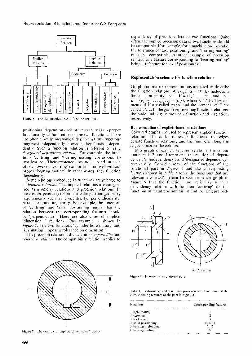
Some relations embedded in functions are referred to as imp/ici/ rchtions. The implicit relations are categor- ized as geometry relations and precision relations. In most cases, geometry relations are the position geometry requirements such as concentricity. perpendicularity. parallelism, and angularity. For example, the functions of ‘centring’ and ‘axial positioning’ imply that the relation between the corresponding features should be ‘perpendicular’. There are also cases of implicit ‘dimensional’ relations. One example is shown in Figure 7. The two functions ‘cylinder bore mating’ and ‘key mating’ impose a tolerance on dimension ~1.
The precision relation is divided into cwnputibilit~~ and wf&mcc~ relcrtion. The compatibility relation applies to
Figure 7 The example of implicit ‘dimensional’ relation
dependency of precision data of two functions. Quite often, the implied precision data of two functions should be compatible. For example, for a machine tool spindle, the tolerance of ‘tool positioning’ and ‘bearing mating’ must be compatible. Another example of precision relation is a feature corresponding to ‘bearing mating’ being a reference for ‘axial positioning’.
Representation scheme for function relations
Graph and matrix representations are used to describe the function relations. A gruph G = (V, E) includes a finite. non-empty set V = (1.2.. ~~7) and set E- {fJ,,P~.... .c,,,},c~ = (i> j), where i..j t V. The ele- ments of V are called rzo&s, and the elements of E are called r~(ges. In the graph representing function relations. the node and edge represent a function and a relation, respectively.
Representation of explicit function relations Coloured graphs are used to represent explicit function relations. The nodes represent functions, the edges denote function relations, and the numbers along the edges represent the colours.
In a graph of explicit function relations, the colou~ numbers I. 2, and 3 represents the relation of ‘depen- dency’. ‘interdependency’, and ‘designated dependency’, respectively. Consider some of the functions of the rotational part in Figurr 8 and the corresponding features shown in Tcrhk I (only the functions that are relevant are listed). It can be seen from the graph in Fiprr 9 that the function ‘tool relief’ @ is in a dependency relation with function ‘centring’ 0; the functions of ‘axial positioning’ @ and ‘bearing preload-
*I
A - A section
Figure 8 kcatures of a rotational part
fable 1 Performance and machining process related functions and the corresponding features of the part in Fi,quw H
Eunction Corresponding feature5
I tight miitlng 2
2 ccntrlng 1
.3 tool relief 3 1 i(xial positionmg 4. 6. I I 5 bearing preloadinp 6. II h bearing mating X

Representation of functions and features: C-X Feng et a/.
Figure 9 The graph of explicit function relation
ing’ @ are in the interdependency relation; the functions of ‘tight mating’ 0 and ‘bearing mating’ @ are in the designated dependency relation; and so on.
The graph for the explicit relations can be represented by matrix RE = [Y;] with k x k entries (k is the number of functions), where,
E Y;j =
1 dependency relation between functions
i and ,j
2 interdependency relation between
functions i and j
3 designated dependency relation between
functions i and j
0 otherwise
Representation of implicit function relations Geometry relations. Similar to the representation of explicit function relations, a graph of implicit geometry relations can be constructed. The only difference between the two graphs is in colour assignment. Here, five colours are assigned to the implicit relations, namely:
colour 1: concentric colour 2: perpendicular colour 3: parallel colour 4: angular colour 5: dimensional
Figure IO is the implicit relation graph of the part in Figure 8 and the functions in Table 1.
The functions @ and 0 (corresponding to feature 2 of the part in Figure 8) have the same relations with the remaining functions. If two functions connected by edge of colour 1 or 3 (relation ‘concentric’ or ‘parallel’) have the same relations with all the other functions, it is necessary to check whether these two functions could be implemented by one feature.
The matrix of implicit function relations RG = [ry] can
Figure IO The graph of implicit function relations
be constructed similar to RE, where
‘1
2
3 .G ‘ii = (
4
5
,O
if edge colour is 1 (concentric relation)
between functions i and j
ifedge colour is 2 (perpendicular relation)
between functions i and .j
if edge colour is 3 (parallel relation) between functions i and .j
if edge colour is 4 (angular relation) between functions i and .j
if edge colour is 5 (dimensional relation) between functions i and j
otherwise
Precision relation. To represent the implicit precision relations between two functions, the following three cases are specified:
l There exist both reference relations and compatibility relations.
l There exist compatibility relations, but no reference relations.
l Neither reference nor compatibility relations exist.
Furthermore, it is necessary to specify the degree of compatibility.
A reference relation of two functions can be represented as a directed edge. The reference relations and compatibility relations can be represented by a directed and an undirected graph, respectively.
For simplicity, in this paper, a hybrid graph consisting of both directed edges and undirected edges is used to represent the precision relations of a component.
The graph of precision relations has the following properties:
l For a reference relation, an edge is directed to a reference node. Usually, there also exists a compat- ibility relation between two functions with a reference relation.
l An undirected edge indicates that there is only compatibility relation.
l A weight IV (0 < u’ 5 1) is assigned to an edge. The more compatible the two functions, the closer to 1 is the weight W.
For the part in Figure 8, the function ‘centring’ is the reference of ‘bearing mating’, ‘axial positioning’, and ‘bearing preloading’. All the functions in Table I, except ‘tool relief, are in the compatibility relation.
The adjacency matrix RPB = [r:“] of the precision relation graph is defined as follows:
u’jj. if there is a directed edge from node i to node .j
Pa= . rii
1
-w ii, if there is an undirected edge between node i and node ,j
0, otherwise
The graph of precision relations for the example part in Figure 8 is shown in Figure 1 I. The matrix of precision relations has the following properties: l A zero entry (r;B = 0) does not necessarily imply that
there is no precision relation between functions i and
967

Representation of functions and features: C-X Feng et al.
Figure I1 The graph of precision relations
j. No precision relation exists between two functions i and .i only if rfl” = I’,, Pi3 = 0.
l If all the elements in the ith row and the ith column are zeros, then the ith row and ith column can be removed from the relation matrix.
l If Y;” = -II',,, then $= -n*,,. It means that all negative elements in R are symmetric.
REPRESENTATION OF FEATURE RELATIONS
Although substantial progress has been made in the research on representation of geometry relations of features, the computer representation of feature relations needs more attention”. This paper provides a graph and matrix representation of geometry relations.
Basic concepts
Chen et ~11.‘~ defined three types of relations between features, is-in, is-on, and adjacent-to. The is-in relation indicates a spatial relationship between a positive and a negative feature, i.e. the negative feature is within the positive one. The is-on relation may occur in the case of two positive or two negative features. It also implies a geometric or function dependency between two features. The adjacent-to relation simply indicates a geometric adjacency between two features.
Some overlap may exist between is-on and adjacent-to relations. Although a claim has been made that the two relations do not overlap”. an ambiguity exists. On the other hand. there are cases which are difficult to represent by either of the three relations. For instance, the relation between an inner fillet and a hole is difficult to represent using the above definitions.
Three feature types, i.e. positiw, nqptivr. and,fticcJ are defined in this paper. The positive and negative features have the same meaning as those used in Chen rt ~1.‘~. In this paper. the positive and negative features are called cntitv ,fkatuw.r since they represent certain geometric entities. Fuws indicate the boundary faces or the adjacent faces of two entity features no matter whether they are positive or negative. There are three reasons for introducing a face feature. First, one face may require a specific machining operation to form it. Second, a face is often used as a reference plane. Finally, it is easier to establish the geometry relation of a part using face features, as one entity feature may be adjoined to another entity feature through a face.
The representation schemes of geometry relations and
precision relations of features are discussed in the next section. Three types of geometry relations are defined, i.e. w~ion, suhtractior~, and sick-to, denoted by ‘U’, I-‘.
and ‘1’. respectively. Consider the relations for two features ,ji, and ,fh. The union feature ,f;, contains the elements of ,fi, and ,fh, while the subtraction feature ,/; contains only the elements remaining after taking ,fh away from ,f,i. The relation side-to indicates the relation between a face feature and an entity feature.
The precision relations of features are defined similarly to that of functions mentioned earlier, simply by replacing features with functions.
Graph representation of feature relations
Graph representation of geometry relations The symbols ‘@‘, ‘IQ’, and ‘0’ are used to denote the positive, negative. and face feature, respectively. They arc the nodes of a feature relation graph. The three feature relations union, subtraction, and side-to are represented by a double arrowhead, single arrowhead. and line segment of a graph, respectively. For subtrac- tion, the arrowhead points to the feature which should be taken away. e.g. ~11, + ‘f)! meaning if>, - ‘~1,.
The following properties hold for geometry relations:
Each operation type should be carefully designated when constructing a graph of geometry relations for a part. For a cylinder with a through hole, if the hole is considered as a negative feature, the operation between the cylinder and the hole is ‘U’ (union). If the hole is considered as a virtual cylinder, i.e. a positive feature. then the operation is .-’ (subtraction).
To reduce a graph complexity only the features that are of interest to a designer, should appear on the graph.
Fi&w 12 shows the example of geometry relation graph for the part in Figure 8. Some chamfers are not depicted in this graph.
When constructing a relation graph, one must consider that a negative feature should not only be in relation with a face, but also with a positive feature. Figuw 12 shows that feature 8 is in relation with the positive feature 2 in addition to the relation with face feature 1. However, the path between two adjacent
b’igure I2 The geometry relation graph for the part in b’;~~uw ,S
968

positive features (e.g. feature 2 and 5 in Figure 12) should cross their common face feature (here feature 4 in Figure 12). In other words, the union relation should not be applied to the two adjacent positive features.
The definition of primary and secondary feature is adopted from Chen et al.“. Based on the definitions of features and relations, the following properties are derived:
Property 1. A side-to relation can only exist between one face and one entity feature (either positive or negative).
Property 2. There exists at least one path connecting all the primary features of a part if no primary feature is deliberately omitted.
Based on the part geometry, a feature cannot be independent of other features. Correspondingly, a feature is reachable for any other features in a geometry relation graph of a part. The edges el , e2, , and e7 form a path connecting the primary features 2, 5, 7, and 8 as shown in Figure 12.
Property 3. If two primary features have side-to relations to the same face, then
(a) any two negative or two positive features (not virtual) are not directly connected;
(b) any positive and negative feature are in a union relation.
Two positive or two negative features with a common face are actually adjacent, and their relation is shown only as ‘side-to’ relation. However, for one positive and one negative feature with a common face, the negative one is actually contained in the positive one. The ‘union’ relation does apply in this case.
Property 4. For a part with a through hole or hollow cavity, there is at least one closed loop path connecting all the primary features.
Consider two end faces in ‘side-to’ relation with a through hole or hollow cavity. According to Property 2, there is a path connecting the two end faces without considering the hollow cavity. In addition, one can find another path through the hollow cavity. Therefore, these two paths form a closed loop.
Property 5. A face feature is always dependent on at least one entity feature, i.e. at least one edge of ‘side-to’ relation connects the face feature to an entity feature.
Face is not an entity feature and cannot exist independently.
Property 6. A secondary feature remains in the union or subtraction relation with at least one primary feature.
This property is quite obvious, as a secondary feature always depends on its parents based on the definition of the secondary feature.
The above properties are useful in checking the validity of the graph of geometry relations.
Graph representation of feature precision relations In a graph representing feature precision relations, the nodes represent features, while the edges represent precision relations, similar to the precision relations of functions. The graph of feature precision relations for the part in Figure 8 is presented in Figure 13.
Representation of functions and features: C-X Feng et al.
II 7 9
Figure 13 A graph of feature precision relations
Matrix representation of feature relations
Although a graph representation is explicit enough to describe the feature relations, it is not convenient for computer processing. The matrix representation is more appropriate for computer applications.
Matrix representation of geometry relations Assume that a part has m features and n relations. To represent the geometry relation graph of features, the incidence matrix C = [cii] with m x n entries is used, where
1 if edge j connects node i (relation j applies
cii =
i
to feature i)
0 otherwise
The incidence matrix of the graph of geometry relations in Figure 12 is presented below.
Each column of C has exactly two Is. The incidence matrix is not sufficient to completely represent all feature relations since the matrix does not reflect the relation type. Therefore, a weight vector W = [w,]~ is introduced, where:
1 if edge i is a union relation
u’; = - 1 if edge i is a subtraction relation
c=
\ 0 otherwise (side-to relation)
Relation No
1 2 3 4 5 6 7 8 9 10 11 12 13
000000001 10 0 0
1 1 0 0 0 0 0 0 0 1 0 0 0
0 I 1 0 0 0 0 0 0 0 0 0 0
0 0 1 1 0 0 0 0 0 0 0 0 0
0 0 0 1 1 0 0 0 0 0 0 0 0
000000000 0 11 0
000011000 0 0 11
100000111 0 0 0 0
000000000 0 0 0 1
000000010 0 0 0 0
000001100 0 0 0 0
- 1
2
3
4
5
6
7
8
9
10
11
Feature No
The weight vector for the graph in Figure 12 is
w = [l -100100100001]
Using both C and W, the geometry relations can be completely described.
The geometry relation of features can also be represented by a 3-edge coloured graph simply by
969
Representation of functions and features: C-X Feng et al.
assigning three different colours to the relations of union. subtraction. and side-to. The corresponding matrix can be easily constructed similar to that of explicit function relations.
REPRESENTATION OF FUNCTION- FEATURE RELATIONS
There are at least two scenarios where the function- feature relations are considered. First, one needs to select suitable features according to the functional require- ments. Second, it is required to check whether candidate features are necessary and sufficient to meet the functional requirements of the part. This leads to further checking of feature related functions. In such case, the manufacturability of features must bc evalu- ated.
In fact, the feature set and the function set of a part can be partitioned into two distinct groups. Although there exist relationships among the elements in the set of functions and features (see third and fourth sections), such a relationship is not considered here. The feature and function sets can be considered as two all inclusive but mutually exclusive subsets. This allows one to represent the function-feature relations with a bipartite graph.
A bipartite graph of function-feature relation for a component design is denoted by G = (6. B,,. E), where F, and Bpd are the ‘feature set of interest’ and ‘design function set of a part’. respectively. The_,/+/urr .sct (I/’ interrst F, is a collection of features of interest to a designer. The riesigr~ firnction set of’ (I port B,d is a collection of intended functions of the part. Each set of edges E indicates the relationship between features and functions.
A distinction should be made between the process related functions and performance related functions in certain applications. This implies incorporating the orientation to the edges of process related functions in a bipartite graph. i.e. directing an edge from a process related function to the corresponding feature. The relations between performance related functions and features are represented by undirected edges.
Figure I4 shows the bipartite graph of function-feature relation for the part in Figuw 8. Only the features of interest are shown in this graph.
The dttion mrrtri.y R = [r,,] with entries p x I is used to represent relations between /7 features and I functions, where
I -I
1 “j, =
0
relation between feature iand process
related function ,j
relation between feature i and performance related function ,j
no relation between feature iand function j
It should be emphasized that different features may have relations with the same function and one feature may have multiple functions. A feature, that is not of- interest. such as the primary feature 5 shown in Fijyw 8. can be deleted.
The function-feature mapping is a key issue in detail design. Further research should be conducted regarding metrics for functions, the effect of feature precision on functions, and so on.
Functwn XI Feature .\et
Figure 14 A bipartite graph of f’unctlon-feature relations
Once the functions, features, and function-feature relations have been represented, the link to a data file can be achieved with a <‘AD tool, e.g. Part Design Graph Language”.‘“. The transformation/mapping mechanism” may link the information (representation) of’ functions, features, and function-feature relations to the shared or neutral databases or use it in other application-specific features of new designs. The repre- sentation scheme presented can also be used in the function model” of a designed part to check for manufacturability and cost by a knowledge based system.
The representation approach discussed in this paper. forms a foundation for future research addressing topics. such as:
l the inheritance of information among design objects in a given model and their extensions to new designs:
l the integration of process models with product models:
l the extension of feature validation procedures to include the checking of functionality;
l the automation of the design process driven by form feature-based information:
l the application of representation libraries of design objects in design with defined inputs and outputs.
CONCLUSIONS
In this paper. representation schemes of function relations. feature relations, and function-feature inter- relations were discussed. These schemes are important in automated design of parts. especially at the detail design stage. A clear. complete, and simple representation of these relations is a prerequisite for feature selection, manufacturability evaluation, and process planning. To date limited research has been done in the representation area, especially for function relations and function- feature relations.
The classification of feature related functions was presented. This paper suggested that the functions be classified into performance related functions, process related functions, and ergonomics related functions. A detailed decomposition of feature related functions was also presented.
In detail design, it is necessary to investigate the function relations so as to provide a background for feature selection. It was proposed that the function relations be divided into explicit and implicit relations. Further classification of both explicit and implicit function relations was also provided. Coloured graphs
970

Representation of functions and features: C-X Feng et al.
were applied to represent explicit function relations and implicit geometry relations. The implicit precision relations facilitate design of tolerances and evaluation of candidate designs. These relations were represented by a weighted graph.
The feature relation problem is important in the selection of features and manufacturability evaluation at the detail design stage. Three relations: union, subtraction, and side-to, were proposed in the paper. Graphs and matrices were used to represent the feature relations. The precision relations of features were also considered. The representation scheme for feature relations proposed in this paper is complete and simple.
Besides feature and function relations, inter-relations between features and functions exist. It appears that such inter-relations are useful in feature selection. A bipartite graph was used to represent the inter-relations of functions and features.
The main advantage of the method presented in this paper is that it is appropriate for computer implementa- tion as it is matrix and graph based. The emphasis of the paper is on the representation of functions, features, and their inter-relations, rather than defining a unified set of features. The representation scheme discussed applies to any feature classification or representation schemes.
REFERENCES
I
2
3
4
5
6
7
x
9
10
II
I2
I3
I4
I5
Jo, H H, Parsaei, R and Sullivan, W G ‘Principles of concurrent engineering’ in Parsaei, H and Sullivan, W (Eds) Concurrent
Enginerring: Contemporury Issues and Modern Design Tools Chapman & Hall, London (1993) pp l-23 Shunk. D Integrated Process Design and Development Irwin, Homewood, IL (1992) Kusiak. A and Szczerbicki, E ‘A formal approach to specifications in conceptual design’ ASME J. Mech. Des. Vol I14 No 4 (1992) pp 659%666 Welch, R V and Dixon, J R ‘Representing function. behavior and structure during conceptual design’ in Taylor, D L and Stauffer, L A (Eds) ASME Proc. Design Theory and Mrthodolog~ DE- Vol 42, ASME (1992) pp II-18 Ishii. K, Adler, R and Barkan. P ‘Application of design compat- ibility analysis to simultaneous engineering’ AI EDAM Vol 2 No 1 (I 988) pp 53-65 Kannpan, S M and Marshek, R M ‘An algebraic and predicate logic approach to representation and reasoning in machine design’ Mechan. Much. Theory Vol25 No 3 (1990) pp 335-353
Rosen. D W ‘Feature-based design: four hypothesis for future CAI) systems’ Res. Engng Des. Vol 5 Nos 3 -4 ( 1993) pp 125-139 Henderson, M R and Taylor, L E ‘A meta-model for mechanical products based upon the mechanical design process’ Res. Engng
Des. Vol 5 No 3-4 (1993) pp 140- 160 Pahl, G and Beitz. W Engineering Design Springer-Verlag. New York ( 1988) Shah, J J ‘Features in design and manufacturing’ in Kusiak, A (Ed.) Intelligent Design and Murmfacturing John Wiley, New York (1992) pp 39-72 Shah, J J and Rogers, M T ‘Functional requirements and concep- tual design of the feature-based modeling system’ Comput. Aided
Engng J Vol5 No I (1988) pp 9-14 Xue. D and Dong, Z ‘Automated concurrent design based on combined feature, tolerance, production process and cost models’ in ASME Proc. Advances in Design Automation Vol 2, ASME, New York (1993) pp 199%210 Bronsvoort, W F and Jansen, F W ‘Feature modeling and conver- sion- key concepts to concurrent engineering’ Comput. Indust. Vol 21 No I (1993) pp 61-86 Shah. J J ‘Feature transformation between application specific feature spaces’ Comput. Aided Engng J. Vol 5 No 6 (1989) pp 241-255 Chen, Y M, Miller, R A and Vemuri, K R ‘A framework for fea- ture based part modeling’ in Computers in Engineering Vol 1, ASME, New York (1991) pp 3577365
I6
17
IX
I9
20
Hundal, M S and Langholtz, L D ‘Developing function structures of engineering systems using C and X-TOOLKIT intrinsics’ in
ASME Proc. Computer in Engineering Vol I, ASME, New York (1991) pp 155-159 Hodgson, B A and Pitts, G ‘Designing for CNC manufacture’ in
Corbett, J, Dooner, M, Meleka, J and Pym. C (Eds) Design for Munufhcture Addison-Wesley, Wokingham, England (1991) pp 56-68 Krause, F L, Kramer, S and Rieger, E ‘PDGL: A language for efficient feature-based production gestaltung’ Ann. ClRP Vol 40 No I (1991) pp 135-137 Krause, F L, Kramer, S and Rieger, E ‘Featurebasierte Produk- tentwicklung’ ZwF Vol87 No 5 (1992) pp 247- I5 1 Schiebeler, R and Ehrlenspiel, K ‘REKK: A knowledge-based system as an integrated design-assistant‘ in Design j& Munu-
jbcturahilitv DE-Vol 52, ASME. New York (1993) pp 69-74
Andrew Kusiak is u prqfessor in the
Department qf Industriul Engineering ut the University o/‘Iouu, low City, low.
He is interested in engineering design,
manufacturing, process rrengineering,
artificiul intelligmc’e. and optimization. Dr Kusiuk is the Editor-in-Chiyf o/’ the
Journal of Intelligent Manufacturing.
Chun-Che Hurmng is u PhD student in the
Department qf’lndustrial Engineering at the University of Io+vu. IoM.~ City, Iowa.
He holds an MS degree in Operations Research from Columbia University. He
is interested in concurrent engineering, modular system design, and scheduling.
Pei-Gen Li received his Muster’s degree
in Mechanical Engineering at Huazhong University oJ’ Science & Techno1og.t
(HUST), China. in 1981, and PhD degree ,fiom University of’ Wisconsin-
Madison in 1987. He is currentIF (I
prof&sor und the Deun of’ the School of Mechanicul Science cmd Engineering ut
HUST
Since 1987, his wearch interests huve been,focusing on CALKA.M. ct.w, FZIS. He has authored and co-authored over S0puper.s.
Dr Li served several times as a trchnicul e.upert for CALICAM. und
Workshop Automation in the National CIM program in Chincl.
C Jack Feng is an assistant pro)ssor in
The School of Engineering Technology and Commonweulth Engineering
(SETCE) ut The Penn State Universit,v Berks Campus, Rending. PA, (/..‘$.A. He holds o BS degree in mrchanicul engi- neering. MS degrees in mechaniccrl cmd industrial engineering, and n PhD degree in industrial engineering. His reseurch interests are in design,jor mangfbcturing,
just-in-time/lean/agile manyfbcturing and qualit? engineering.
1 97


![Ornament ist kein Detail [Ornament is no Detail] (2012)](https://static.fdokumen.com/doc/165x107/6345424d38eecfb33a067963/ornament-ist-kein-detail-ornament-is-no-detail-2012.jpg)