
REPORT OF - ICAO
428
REPORT OF TWENTY THIRD MEETING OF THE COMMUNICATIONS/NAVIGATION AND SURVEILLANCE SUB-GROUP (CNS SG/23) OF APANPIRG (Bangkok, Thailand, 2 – 6 September 2019) INTERNATIONAL CIVIL AVIATION ORGANIZATION ASIA AND PACIFIC OFFICE The views expressed in this Report should be taken as those of the Sub-group and not of the Organization. This Report will be submitted to the APANPIRG/30 Meeting and any formal action taken will be published in due course as a Supplement to the Report of the APANPIRG Meeting.
-
Upload
khangminh22 -
Category
Documents
-
view
6 -
download
0
Transcript of REPORT OF - ICAO

REPORT OF
TWENTY THIRD MEETING OF THE COMMUNICATIONS/NAVIGATION AND SURVEILLANCE SUB-GROUP
(CNS SG/23) OF APANPIRG
(Bangkok, Thailand, 2 – 6 September 2019)
INTERNATIONAL CIVIL AVIATION ORGANIZATION
ASIA AND PACIFIC OFFICE
The views expressed in this Report should be taken as those of the Sub-group and not of the Organization. This Report will be submitted to the APANPIRG/30 Meeting and any formal action taken will be published in due course as a Supplement to the Report of the APANPIRG Meeting.

Table of Contents i-2 History of the Meeting Page 1. Introduction .............................................................................................................................. i-5 2. Attendance ............................................................................................................................... i-5 3. Opening of the Meeting ........................................................................................................... i-5 4. Officers and Secretariat ............................................................................................................ i-5 5. Organization, Working arrangement, Language and Documentation ..................................... i-5 6. Conclusions and Decisions – Definition .................................................................................. i-5 7.
Report on Agenda Items Agenda Item 1: Adoption of agenda .......................................................................................... 1 Agenda Item 2: Review outcomes of APANPIRG/RASG Chairpersons review, ..................... 1 APANPIRG/29 meeting, DGCA/55 and DGCA/56 meetings, ANC/13 meeting,
ATM Sub-group, and other major meetings relevant to CNS Sub-group Agenda Item 3: Aeronautical Fixed Service (AFS) ................................................................... 3
3.1 Review Report of the Sixth Meeting of the Aeronautical Communication Services Implementation Coordination Group (ACSICG/6) including outcomes of the Fifth and Sixth Meetings of Common aeRonautical VPN Operations Group (CRV OG/5 and CRV OG/6);
3.2 Review Report of Fifth Meeting of the Asia Pacific AIDC Task Force
(APA TF/5); 3.3 Review outcomes of the Third Meeting of System Wide Information
Management Task Force (SWIM TF/3); and 3.4 Other AFS related issues
Agenda Item 4: Aeronautical Mobile Communications Service and Aeronautical
electromagnetic spectrum utilization .............................................................. 16 4.1 Update on status of datalink applications and VHF capability sharing
by States; 4.2 Review outcome of the Regional Preparatory Group (RPG) Meeting
for ITU World Radiocommunication Conference 2019 (WRC-19); and 4.3 Other issues related to aeronautical communications service and
aeronautical radio spectrum management
Agenda Item 5: Navigation ...................................................................................................... 19
5.1 Review report of the Sixth Meeting of Performance based Navigation Implementation Coordination Group (PBNICG/6);
5.2 Updates on national PBN implementation plan and PBN
implementation issues;
5.3 Updates on global development on Ground-based Augmentaion System (GBAS);

i-3 Table of Contents
5.4 Review outcomes of the GBAS/SBAS Implementation Workshop; and 5.5 Other navigation related issues
Agenda Item 6: Surveillance ................................................................................................... 29
6.1 Review Reports of Fourth Meeting of the Surveillance Implementation Coordination Group (SURICG/4) including: - Review outcomes of the Fourteenth Meeting of the South East Asia
and Bay of Bengal Sub-regional ADS-B Implementation Working Group (SEA/BOB ADS-B WG/14); and
- Review outcomes of the Seminar & Second Meeting of Mode S Downlinked Aircraft Parameters Working Group (Mode S DAPs WG/2)
6.2 Review outcomes of the ICAO APAC Aeronautical Surveillance
Workshop; 6.3 Review outcomes of the APAC Regional ATM Automation Systems
Symposium; and 6.4 Other surveillance related issues
Agenda Item 7: Review and updates ....................................................................................... 38 7.1 Review outcomes of the ICAO ASBU Workshop; 7.2 Seamless ATM Reporting Process including the ASBU regional
performance dashboard/implementation plan; and 7.3 Discuss the draft guidance for certification, procurement and
implementation procedures of CNS/ATM Systems Agenda Item 8: Review status of CNS deficiencies (APANPIRG Deficiency List) .............. 41 Agenda Item 9: Human Factors and Air Traffic Safety Electronics Personnel (ATSEPs) related
training ........................................................................................................... 42 Agenda Item 10: Cybersecurity of CNS/ATM systems ............................................................ 44 10.1 Review outcomes of ICAO Blockchain Aviation Summit and
Exhibition Agenda Item 11: Discuss and share experience and application of new technologies, including
big data analysis, artificial intelligence, Digital-Tower ................................ 46 Agenda Item 12: Dates of next meeting and any other business ............................................... 47
Table of Contents i-4 List of Appendices Appendix A: ATN/AMHS and AIDC implementation status ............................................. A-1 Appendix B: AFTN/AMHS based Interface Control Document for ATFM ....................... B-1 Appendix C: Revised Terms of Reference of CRV OG ...................................................... C-1 Appendix D: Updated CRV Implementation Plan v.2 ......................................................... D-1 Appendix E: CRV Implementation Status .......................................................................... E-1 Appendix F: Chart of AIDC Implementation Status ............................................................ F-1 Appendix G: The Philosophy for APAC SWIM Implementation and the Proposed SWIM implementation roadmap ..................................................................... G-1 Appendix H: Asia/Pacific FIXM version 4.1 Extension ...................................................... H-1 Appendix I: APAC Regional Transition Plan .......................................................................I-1 Appendix J: Asia/Pacific Ground-Based Augmentation System (GBAS)/Satellite-Based
Augmentation System (SBAS) Implementation Task Force (APAC GBAS/SBAS ITF) with the Terms of Reference ............................................. J-1
Appendix K: Mode S DAPs Implementation and Operation Guidance Document .............. K-1 Appendix L: ATM Automation System Task Force (ATMAS/TF) with TOR .................... L-1 Appendix M: Revised Surveillance Strategy for the APAC Region .................................... M-1 Appendix N: Revised ADS-B Implementation and Operations Guidance Document (AIGD) .......................................................................................... N-1 Appendix O: Guidance for Procurement and Certification of CNS/ATM Services and Systems ........................................................................................................... O-1 Appendix P: Updated list of CNS related deficiencies ......................................................... P-1 List of Attachments: Attachment 1: List of participants ........................................................................................... 1-1 Attachment 2: List of working/information papers/flimsies .................................................... 2-1
_ _ _ _ _ _ _ _ _ _ _ _ _ _

i-5 History of the Meeting 1. Introduction 1.1 The Twenty Third Meeting of the Communications, Navigation and Surveillance Sub-group (CNS SG/23) of Asia/Pacific Air Navigation Planning and Implementation Regional Group (APANPIRG), was held at the ICAO Regional Office, Bangkok, Thailand, from 2 to 6 September 2019. 2. Attendance 2.1 The meeting was attended by 102 participants from 24 States/Administrations (Australia, Bangladesh, Bhutan, Cambodia, China, Hong Kong China, Macao China, Fiji, India, Indonesia, Japan, Lao PDR, Malaysia, Mongolia, Nepal, New Zealand, Philippines, Republic of Korea, Singapore, Sri Lanka, Thailand, Tonga, USA, Viet Nam, and 4 International Organizations namely CANSO, IATA, IFALPA and IFATSEA. The list of participants is placed at Attachment 1 to this Report. 3. Opening of the Meeting 3.1 Mr. Arun Mishra, ICAO Regional Director opened the meeting. In his opening remarks, he extended his warm welcome to all participants in particular the former chairs of the Sub-group and chairpersons of contributory bodies to the sub-group and highlighted the recent important developments relevant to CNS in the APAC Region. Mr. Richard Wu, Chairman of the CNS Sub-group of APANIRG reviewed the achievements and tasks of the Sub-group since its last meeting. Mr. Wu highlighted that strong growth in air traffic required further collaboration among all States/Administrations in the region to cope with the challenge. The CNS Sub-group played an important role in facilitating States in provision of seamless air navigation service with the deployment of advanced technologies in a harmonized manner. Mr. Wu also expressed his appreciation to the job well done by States/Administrations in supporting the CNS Sub-group’s work through the contributory task forces and working groups. With concerted efforts, Mr. Wu further encouraged the CNS Sub-group to continue to steer the way forward on the latest CNS development and new technologies for APAC Region. 4. Officers and Secretariat 4.1 The meeting was alternately chaired by Mr. Richard Wu, and Mr. Amit Kumar Banerjee, the Chair and Vice Chair of the CNS Sub-group respectively. The Secretariat support was collectively provided by Messrs. Li Peng, Luo Yi, Regional Officers CNS of APAC-RO and Mr. Ha Huho, Regional Officer of APAC-RSO. The meeting was also supported by Regional Officers, ATM and AVSEC-FAL. 5. Organization, Working Arrangement, Language and Documentation 5.1 The working language was English inclusive of all documentation and this Report. The Sub-group met as a single body to deal with all the agenda items. 5.2 A list of Working Papers, Information Papers, Presentations (24 working papers and 41 information papers, and 3 flimsies) considered by the Meeting is provided in Attachment 2 to this Report.
6. Conclusions and Decisions - Definition 6.1 The Sub-groups of APANPIRG record their actions in the form of Draft Conclusions, Draft Decisions, Conclusions and Decisions with the following significance:
1) Draft Conclusions deal with matters, which, in accordance with the Sub-Group’s Terms of Reference, require the attention of States or actions by ICAO in accordance with established procedures;
2) Draft Decisions relate solely to matters dealing with the internal working
arrangements of APANPIRG and its contributory bodies;

History of the Meeting i-6
3) Conclusions: Those Conclusions adopted by the Sub-group on behalf of
APANPIRG on technical matters; and 4) Decisions relate solely to matters dealing with internal working arrangement
of the Sub-group only. Note: in accordance with APANPIRG Procedural Handbook, Sub Groups are
empowered to adopt Conclusions and Decisions on technical matters (especially those concerning guidance to States in the implementation of ICAO SARPs, GANP, RANP, and Seamless ANS Plan).
_ _ _ _ _ _ _ _ _ _ _ _
List of Conclusions, Draft Conclusions and Decisions i-7
Reference Subject Page Conclusion CNS SG/23/1 (ACSICG/6/1) - AFTN/AMHS-Based Interface Control Document
for ATFM 4
Decision CNS SG/23/2 (ACSICG/6/2 - CRV OG/5/1)
- Revised Terms of Reference of CRV OG 4
Conclusion CNS SG/23/3 (ACSICG/6/3-CRV OG/5/2)
- CRV Implementation Plan amendment (Version 2)
5
Conclusion CNS SG/23/4 (SWIMTF/3/1) - The philosophy and roadmap for APAC SWIM implementation
11
Conclusion CNS SG/23/5 (SWIMTF/3/3) - Interoperable Registry Model for SWIM Registry
in APAC Region 12
Draft Conclusion CNS SG/23/6 (SWIM TF/3/4)
- Asia/Pacific Regional FIXM Extension for ATFM 13
Draft Conclusion CNS SG/23/7 (ACSICG/6/4)
- Direct Controller-Pilot Communication SATVOICE Trials
18
Draft Conclusion CNS SG/23/8 (PBNICG/6/1)
- Asia/Pacific Regional Transition Plan for RNP APCH Chart Identification from RNAV to RNP
20
Decision CNS SG/ 23/9 - Establishment of the Asia/Pacific Ground-based
Augmentation System (GBAS)/Satellite-based Augmentation System (SBAS) Implementation Task Force (APAC GBAS/SBAS ITF)
26
Conclusion CNS SG/23/10 (SURICG/4/1) - ADS-B and Flow Management 30 Conclusion CNS SG/23/11 (SURICG/4/2) - UAS Cooperative Surveillance Equipage 31 Conclusion CNS SG23/12 (SURICG/4/3) - Adoption of Mode S DAPs Implementation and
Operations Guidance Document 32
Decision CNS SG/23/13 (SURICG/4/5) - Establishment of the Asia/Pacific ATM
Automation System Task Force (ATMAS/TF) 34
Draft Conclusion CNS SG/23/14 (SURICG/4/6)
- Revised Surveillance Strategy for the APAC Region
35
Conclusion CNS SG/23/15 (SURICG/4/7)
- Revised ADS-B Implementation and Operations Guidance Document (AIGD)
35
Draft Conclusion CNS SG/23/16 - Initial ATS Surveillance and DCPC VHF
Coverage Charts for inclusion in Version 3.0 of the Asia Pacific Seamless Air Navigation Service Plan
37

List of Conclusions, Draft Conclusions and Decisions i-8
Reference Subject Page Conclusion CNS SG/23/17 - Adoption of Guidance for Procurement and
Certification of CNS/ATM Services and Systems 41
Decision CNS SG/23/18 - Need for Study Human Factor Issues of Air Traffic Safety Electronics Personnel (ATSEP)
43
_ _ _ _ _ _ _ _ _ _ _ _
Report of Agenda Items 1 Agenda Item 1: Adoption of the meeting agenda 1.1 The tentative agenda proposed in WP/01 was adopted by the meeting. Agenda Item 2: Review outcomes of APANPIRG/RASG Chairpersons review, APANPIRG/29 meeting, DGCA/55 and DGCA/56 meetings, ANC/13 meeting, ATM Sub-group, and other major meetings relevant to CNS Sub-group Outcomes of APANPIRG/29 Meetings on CNS Matters (WP/04) 2. 1 The meeting carried out a review of the actions taken by APANPIRG/29 on the seven Conclusions formulated by the Twenty-second Meeting of the CNS Sub-group (CNS SG/22). In accordance with APANPIRG Decision 26/65, Sub Groups were empowered to adopt Conclusions and Decisions on technical and operational matters. The meeting also noted the follow-up actions taken on the 8 Conclusions and 1 Decision adopted by CNS SG/22 meeting. The meeting noted the satisfactory actions taken and the progress achieved by States and the Secretariat. The status of the follow-up actions to the Conclusions/Decisions is provided in Attachment A and the outstanding Conclusions is provided in the Attachment B to WP/04. DGCA Conf/55 Outcomes (WP/02) 2.2 The 55th Conference of Directors General of Civil Aviation (DGCAs), Asia and Pacific Regions was held in Nadi, Fiji from 22 to 26 October 2018. The Theme Topic of DGCA Conf/55 was: “Collaboration and Harmonization for Safe, Secure and Sustainable Aviation in the Asia Pacific Region” 2.2.1 The Conference developed 47 Action Items, among which 14 of them were identified relevant to the implementation of CNS facilities and services i.e.: 55/1; 55/3; 55/5; 55/6; 55/10; 55/13; 55/18; 55/19; 55/20; 55/21; 55/37; 55/40; 55/41 and 55/43. 2.2.2 In particular, the DGCA Conf/55 urged States/Administrations:
i) to collaborate, harmonize, support and participate in the development and implementation of cross-border ATFM and A-CDM;
ii) to collaborate and share ADS-B data; iii) to implement AIDC; iv) to support the ICAO Asia/Pacific SWIM Task Force and related demonstrations; v) to adopt a holistic approach to UAS integration and regulation; vi) to adopt harmonized approach for planning, implementation and transition to
Digital Tower and Remote Tower; v) to consider application of AeroMACS according to specific needs; and vi) to encourage States to join FPP APAC and fulfil the commitments made in the
Beijing Declaration. DGCA Conf/56 Outcome (WP/23) 2.3 The DGCA Conf/56 was hosted by Nepal in Kathmandu from 19 to 23 August 2019. The Theme Topic of the DGCA Conf/56 was “Harmonizing Efforts to Meet the Capacity Constraints”. 2.3.1 The Conference developed 36 Action Items, among which 11 of them were identified relevant to the implementation of CNS facilities and services i.e.: 56/2; 56/5; 56/6; 56/9; 56/11; 56/13; 56/14; 56/15; 56/20; 56/32 and 56/33.

2 Report on Agenda Items 2.3.2 In particular, the DGCA Conf/56 urged States/Administrations:
i) to accelerate progress on ANS related elements under the Beijing Declaration; ii) to support the GANP by the development and maintenance of a national air
navigation plan and its supporting documents; iii) to encourage sharing of ADS-B data with neighboring States to take full benefits
of ADS-B; iv) to promote the development of a cyber-security culture across the aviation sector
and encourage States/industry to develop programs to build an aviation cyber security workforce; and
v) to pay close attention to the outcome of the 40th Assembly and its impact on the aviation safety and air navigation services.
2.4 The DGCA Conf/57 will be hosted by Bangladesh from 22 – 26 November 2020. The Theme Topic for the DGCA Conf/57 is “Promoting ICAO Gender Equality Programme in conjunction with Next Generation of Aviation Professionals (NGAP) initiative”. Accordingly, emphasis should be given to the theme topic in formulating discussion and information papers for the DGCA Conf/57. 2.4.1 The Chair encouraged member States actively to take follow-up actions on CNS related actions items resulted from the DGCA Conferences. Sixth meeting of APANPIRG and RASG-APAC Coordination Meeting (IP/18) 2.5 The Sixth meeting of APANPIRG and RASG-APAC coordination meeting was held on 6 August 2019 at ICAO APAC office. The meeting noted the progress made on the follow-up actions taken on the outcomes of APANPIRG/29 and RASG-APAC/8 meeting. The meeting reviewed key challenges faced in the APAC Region including:
- Rapid growth in air operators and aircraft fleet; - Airspace and airport capacity constraint; - Insufficient resources to improve compliance with ICAO provisions; - Slow progress in implementation of CNS-ATM infrastructures and airport
expansion; - Insufficient number of qualified safety inspectors and insufficient training
capacity; and - Strengthening of political will and awareness of aviation’s benefits.
2.5.1 A number of key issues were reviewed including flying PBN procedures; RNP Approach Chart Identification changes; ATFM & A-CDM; modern ground/ground aeronautical COM network; enhanced ANS surveillance capability; sustainable funding to assist States in implementation of SARPs; concrete action plan focused on resolution of identified deficiencies, etc.
2.5.2 The meeting identified that both Flight Safety and ATM (RASG/APANPIRG) may be responsible for addressing RPAS issues. 2.5.3 The meeting noted that the revised Terms of Reference of the PIRGs and RASGs will be considered at 40th Assembly – Paper A40-WP/53 refers: https://www.icao.int/Meetings/a40/Pages/documentation-reference-documents.aspx ATM/SG/7 Outcomes (WP/13) 2.6 The meeting noted CNS-related outcomes from ATM/SG/7 meeting held from 5 to 9 August 2019. The meeting also noted major outcomes of FIT-Asia/9 meeting held from 1 to 5 July 2019 in Makassar, Indonesia and RASMAG/24 meeting held from 9 to 12 July 2019 in Bangkok. The meeting developed 18 Draft Conclusions, Conclusions and Draft Decision. The main relevant points to CNS are listed below:
Report on Agenda Items 3
- 45 problem reports (PRs) were analyzed by FIT-Asia Central Reporting Agency for
period between 7/2018 to 6/2019 including aircraft receiving and UM175 resulting in downlink error;
- As informed by IATA, more PBCS capable aircraft will be certified within 1 to 1.5 year;
- General satisfactory Performance Reports on RCP240/RSP 180 status of ADS-C CPDLC;
- Still lack of reporting from some Administrations, RASMAG adopted Conclusion 24/2 urging States to monitor, and analyze PBCS reports;
- LHDs in 2017 reduced in South Asian/Indian Ocean partially due to AIDC implementation;
- AIDC would help to reduce ATC workload and human errors in addition to reducing LHDs;
- Digital Tower Technology developed in New Zealand based on Eurocae Doc. ED240A;
- Safety and operational benefits of harmonized regional ADS-B airspace identified by Singapore;
- Suggestion on ADS-B data sharing between Indonesia and the Philippines; and - ATM/SG adopted a regional Guidance for the regulation and safe Operation of UAS
within national Airspace through Conclusion ATM/SG/7-9 and also propose to disband APUAS/TF.
Outcomes of AN Conf/13 (IP/07) 2.7 The meeting noted the relevant outcomes of AN Conf/13 held in October 2018 in particular the Recommendations 2.2/1 – long-term evolution of communications, navigation and surveillance systems and frequency spectrum access; 2.2/2 on GNSS evolution, and 3.1/1 on SWIM as provided in Attachment B to the paper. Agenda Item 3: Aeronautical Fixed Service (AFS) 3.1 Under this agenda, the meeting reviewed meeting reports of a number of contributory bodies on the AFS matters. Outcomes of ACSICG/6 including the outcomes of CRV OG/5 and CRV OG/6 (WP/05) 3.2 The Chairman of the Aeronautical Communication Services (ACS) Implementation Co-ordination Group presented the report of the ACSICG/6 meeting which was hosted by AEROTHAI in Bangkok from 13 to 15 May 2019. The meeting reviewed the outcomes of the meeting including those from the 5th and 6th meetings of CRV Operations Group and the actions taken.
3.3 The meeting noted the updated ATN/AMHS and AIDC implementation status in the APAC Region provided in Appendix A to this Report. 3.4 The meeting noted that a COM Coordination Meeting among China, Japan, Mongolia and Russian Federation was held on 6 May 2019. As proposed by APAC States in APAC Region, Russian Federation agreed to consider to connect CRV at Moscow, Irkutsk and Khabarovsk to support AMHS connections and possible ATS direct speech circuits between ACCs in APAC States and Russian Federation. The States concerned agreed to develop a target date for joining CRV and meeting again for the concrete testing procedures in early 2020.
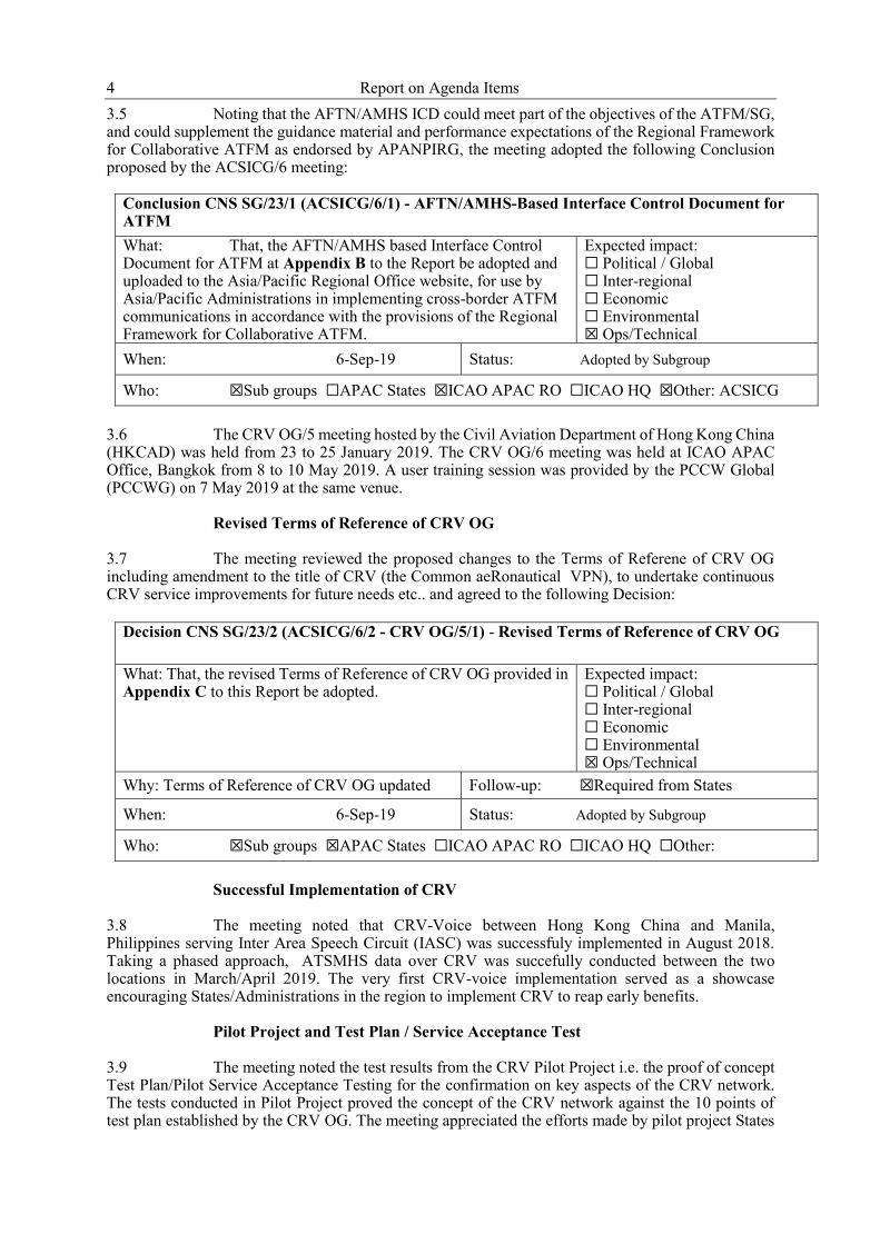
4 Report on Agenda Items 3.5 Noting that the AFTN/AMHS ICD could meet part of the objectives of the ATFM/SG, and could supplement the guidance material and performance expectations of the Regional Framework for Collaborative ATFM as endorsed by APANPIRG, the meeting adopted the following Conclusion proposed by the ACSICG/6 meeting:
Conclusion CNS SG/23/1 (ACSICG/6/1) - AFTN/AMHS-Based Interface Control Document for ATFM What: That, the AFTN/AMHS based Interface Control Document for ATFM at Appendix B to the Report be adopted and uploaded to the Asia/Pacific Regional Office website, for use by Asia/Pacific Administrations in implementing cross-border ATFM communications in accordance with the provisions of the Regional Framework for Collaborative ATFM.
Expected impact: ☐ Political / Global ☐ Inter-regional ☐ Economic ☐ Environmental ☒ Ops/Technical
When: 6-Sep-19 Status: Adopted by Subgroup
Who: ☒Sub groups ☐APAC States ☒ICAO APAC RO ☐ICAO HQ ☒Other: ACSICG 3.6 The CRV OG/5 meeting hosted by the Civil Aviation Department of Hong Kong China (HKCAD) was held from 23 to 25 January 2019. The CRV OG/6 meeting was held at ICAO APAC Office, Bangkok from 8 to 10 May 2019. A user training session was provided by the PCCW Global (PCCWG) on 7 May 2019 at the same venue. Revised Terms of Reference of CRV OG 3.7 The meeting reviewed the proposed changes to the Terms of Referene of CRV OG including amendment to the title of CRV (the Common aeRonautical VPN), to undertake continuous CRV service improvements for future needs etc.. and agreed to the following Decision:
Decision CNS SG/23/2 (ACSICG/6/2 - CRV OG/5/1) - Revised Terms of Reference of CRV OG What: That, the revised Terms of Reference of CRV OG provided in Appendix C to this Report be adopted.
Expected impact: ☐ Political / Global ☐ Inter-regional ☐ Economic ☐ Environmental ☒ Ops/Technical
Why: Terms of Reference of CRV OG updated Follow-up: ☒Required from States
When: 6-Sep-19 Status: Adopted by Subgroup
Who: ☒Sub groups ☒APAC States ☐ICAO APAC RO ☐ICAO HQ ☐Other: Successful Implementation of CRV 3.8 The meeting noted that CRV-Voice between Hong Kong China and Manila, Philippines serving Inter Area Speech Circuit (IASC) was successfuly implemented in August 2018. Taking a phased approach, ATSMHS data over CRV was succefully conducted between the two locations in March/April 2019. The very first CRV-voice implementation served as a showcase encouraging States/Administrations in the region to implement CRV to reap early benefits.
Pilot Project and Test Plan / Service Acceptance Test 3.9 The meeting noted the test results from the CRV Pilot Project i.e. the proof of concept Test Plan/Pilot Service Acceptance Testing for the confirmation on key aspects of the CRV network. The tests conducted in Pilot Project proved the concept of the CRV network against the 10 points of test plan established by the CRV OG. The meeting appreciated the efforts made by pilot project States

Report on Agenda Items 5
for the successful testing conducted. The meeting considered no necessary for other States to spend efforts on duplicating similar test, in order to speed up the CRV implementation. A State Letter, with reference T 8/2.10- AP025/19 (CNS), dated 6 March 2019 was sent to notify States/Administration about the test result and encourage them to initiate service order with PCCWG for CRV implementation as early as possible, with no later than end of 2020.
Packet Overhead in CRV Network
3.10 During the CRV pilot acceptance testing, it was observed during the throughput test that the available bandwidth could be less than the subscribed bandwidth. It was clarified that the available bandwidth was discounted because of the processing of GRE tunnel overhead. As such, States/Administrations were urged to ensure that they subscribe appropriate amount of bandwidth for the required service and applications over CRV.
Route Restriction
3.11 The meeting noted the proposal from New Zealand to amend paragraph 2.4.4 of the CRV Implementation Plan to include:
(ii) When peering with the CRV Contractors network, it is permissible to use the CRV User’s own Public IP addressing and ASN, and the CRV Contractor will use a Public AS.
3.12 In conjunction with this amendment proposal to the CRV Implementation Plan, the meeting considered the proposal from CRV OG/6 meeting regarding the need to separate Appendix A – CRV Implementation Status Table from the CRV Implementation Plan in order to reflect the progress of CRV implementation in a timely manner. In view of the foregoing considerations, the meeting adopted the following combined Conclusion:
Conclusion CNS SG/22/3 - (ACSICG/6/3 - CRV OG/5/2) - CRV Implementation Plan amendment (Version 2) What: That, the CRV Implementation Plan be amended to remove Appendix A - the implementation status table from the plan and to include the following new text in paragraph 2.4.4 – Routing Restriction:
i. Route advertisements will be restricted so that each CRV User which interacts with the CRV routing protocol can only advertise subnets which are allowed in the CRV IP Address Plan.
ii. When peering with the CRV Contractors network, it is permissible to use the CRV User’s own Public IP addressing and ASN, and the CRV Contractor will use a Public AS.
Expected impact: ☐ Political / Global ☐ Inter-regional ☐ Economic ☐ Environmental ☒ Ops/Technical
Why: In order to update the progress of CRV implementation in a timely manner and to provide the option for those States that follow the ITEF and APNIC guidelines for peering between private networks.
Follow-up: ☒Required from States
When: 6-Sep-19 Status: Adopted by Subgroup
Who: ☒Sub groups ☒APAC States ☐ICAO APAC RO ☐ICAO HQ ☐Other: XXXX Note: The updated CRV Implementation Plan v.2 is provided in Appendix D to this Report.

6 Report on Agenda Items
CRV Implementation Status
3.13 The PCCWG informed the meeting that around 60 ANSPs of ICAO member States in APAC and MID Regions are expected to join the CRV. The meeting was reminded that 2020 is the target year for all ANSPs to implement the project. There are seven States/Administrations that already have signed service order with PCCWG with several more States to join CRV in either 2019 or 2020. The CRV Implementation Status updated by CRV OG/6 is provided in Appendix E to this Report. 3.14 The meeting discussed the concern on cybersecurity issues in implementation of CRV. It is understood that cybersecurity is a broad topic much wider than CRV. GRE tunnel, encryption and firewall are viable solutions to improve cybersecurity on CRV, while States/Administrations have to make comprehensive consideration of cost, impact on operational performance and acceptable level before the CRV implementation. Doc 9855 Guidelines on the Use of the Public Internet for Aeronautical Applications remains the main provision from ICAO. The meeting discussed the feasibility to establish inter-regional connection between CRV and other regional network (e.g. REDDIG). Role of AFTN/ATSMHS Routing Directory during Transition 3.15 The meeting noted the function and role of AFTN and ATSMHS routing directory (28th Edition) during the transition period from point to point connection to AFTN/ATSMHS over CRV environment. The meeting discussed that if direct routing was allowed in the hybrid environment with CRV and point to point connection by end of 2020, i.e. direct routings are only implemented for those States/Administrations who have joined CRV while for those States/Administrations not joining CRV yet are still required to follow the current routing directory. As result of discussions, the meeting agreed to fully follow the AFTN/ATSMHS routing directory during the transition period by end of 2020. For inter-regional traffic, it is required to follow the existing entry/exit points and procedure.
Inter-Regional Communication Connection
3.16 Kuwait presented the serviceability reports on the performance of Inter-regional communication circuits. The paper also highlighted an issue of missing flight plans. India, Pakistan, Singapore and Oman, Bahrain, Kuwait are the designated entry/exit countries between the APAC and the MID Regions. The performance of the four interregional circuits between two regions were analyzed. Among the reported cases, one reason was due to a communication failure, unavailability of alternative routes, and delay in AFTN failure detection. The meeting recommended to initiate further action including alternative communication link, to encourage entry/exit points at the APAC and MID Region to join the CRV project and to migrate the Inter-Regional connection to AMHS with enhanced connection reliability and availability. The CRV OG/5 meeting encouraged Kuwait, Bahrain, Oman in the MID Region and India and Pakistan in APAC Region to join CRV to improve the circuit performance.
AMHS via secure VPN over the internet 3.17 States joined CRV may consider some alternate means of exchanging messages in the event of a local or regional CRV failure. In late November 2018, Airservices Australia experienced a network outage in their international service provider’s network which caused delay in the exchange of data between the USA, Indonesia, Singapore and South Africa. Australia proposed to consdier using Business to Business (B2B) Virtual Private Networks (VPN) which has been implemented with FAA and Airways New Zealand. The States/Administrations were encouraged to consider the role of bi-lateral B2B VPNs to ensure the continuity of AMHS services in the event of a local or regional CRV failure. This issue was further discussed at CRV OG/6 meeting as recorded in the following paragraphs.
Report on Agenda Items 7
CRV Regional Diversity Planning
3.18 There are some locations where the infrastructure or the traffic do not justify additional Points of Presence (POPs) that, in theory, would prevent single points of failure. ATSMHS require AMHS to have dynamic alternative routing. The concern expressed about single points of failure in the Pacific region with one POP is presented. B2B VPNs over the Internet could be a viable solution as they are low in cost and readily implemented. In order to pursue B2B VPNs as backup to the CRV for AMHS, the following issues need to be addressed:
a) Procedures to determine what failures would activate the use of B2B VPNs by users;
b) Security of B2B VPNs for AMHS (internal issue); and c) Procedures to activate B2B VPNs for AMHS at affected Communication Centers.
3.19 CRV member states were also reminded of the guidelines given in ICAO Doc 9855 AN/459 on the Use of the Public Internet for Aeronautical Applications.
Connecting of Service Providers to the CRV 3.20 The CRV OG/6 meeting acknowledged that by allowing connection from Service Providers (such as PCCWG, Aireon, SITA, etc.) and Service Consumers (such as Airlines, Airports, MET Organisations, etc) to the CRV, potential telecommunications cost reduction could be achieved with added value to the use of the CRV. The process for connecting Service Providers and Service Consumers to the CRV was adopted by the CRV OG/6 meeting through Decison CRV OG/6/2 which is attached to the CRV OG/6 meeting report as Appendix C. It will be incoporated into the CRV Operations Manual. 3.21 The CRV OG is not responsible for the accreditation/certification/validation of a Service Providers, but taking all reasonable steps in assessing the Service Providers to ensure they have sufficient systems and process in place to provide their service over the CRV. In this connection, the CRV OG/6 meeting encouraged States to use CRV for the exchange of ADS-B data and agreed that there is a potential to reduce the costs of Space based ADS-B service delivery over CRV.
CRV Pioneer State Contribution to the ICAO Managed Service Agreement (MSA)
3.22 As a task of CRV OG, consideration on the use of residual MSA funds to conduct independent safety assessment of the CRV was conducted through a questionnaire. The Democratic People’s Republic of Korea and Hong Kong China would have their contributions returned according to an APANPIRG Conclusion. 3.23 Based on the feedback derived from the questionnaire, Australia proposed a way forward for balancing the funds under ICAO Managed Service Agreement (MSA). The meeting noted that a Decision on the way forward was made by the CRV OG/6 meeting (Decision CRVOG/6/3). The working group would be led by Co-Chair of CRV OG (Asia) and PCCWG was invited to join the development of the Scope of Work (SOW).
ICAO No Country Left Behind Initiative applied to CRV 3.24 France DSNA presented 2 concrete cost comparison cases, one for French Polynesia and one for New-Caledonia. Through these examples, it was indicated that additional financial efforts by small States were required which have little needs and incentive to make connection to CRV. 3.25 PCCWG answered that Package D is the lowest reasonable offer they can make and that it doesn't want to weaken the network performance by offering a cheaper solution that may introduce risks. From PCCWG perspective, amongst the solutions proposed by France, the only one that could solve the problem is to have a cost sharing scheme between small Island States and the

8 Report on Agenda Items peering bigger States to acquire mutual benefits. PCCWG was encouraged to further explore more cost effective solutions for any countries facing challenges in procuring CRV services with financial constraints. PCCWG would also study how CRV could interface with PASNET, and revert the solution/proposal to CRV OG/7 for consideration. CRV Security Encryption Solution 3.26 France informed CRV OG/6 meeting that security risk assessment on CRV was performed according to the French law deriving from the EU NIS Directive and encryption has to be set up for the New-Caledonia/Fiji and French Polynesia/New-Zealand connections.
3.27 French DSNA proposed to test and implement trials on IPSec encryption, given that it was a proven, standardized, easy to configure multi-vendor solution at a lower price. The CRV OG/6 meeting suggested DSNA to conduct the test by coordination with counterpart and request support from PCCWG when available. The meeting encouraged States/Administrations to share their best practices regarding cybersecurity resolution by engagement of local resources with papers or high level guidance materials. Supporting the Implementation of IWXXM 3.28 The Guidelines developed and endorsed by the ICAO Meteorology Panel (METP) is available on the METP Secure website: https://portal.icao.int/METP/Pages/default.aspx and on the public website https://www.icao.int/airnavigation/METP/Pages/default.aspx. Noting that the Guidelines document indicates that AMHS provides a mechanism for the exchange of IWXXM information, the Secretariat highlighted the previous APANPIRG Conclusions (27/50 and 28/16), which urged States/Administrations to progress the planning and implementation of AMHS networks and infrastructure to support the regional implementation of IWXXM.
IWXXM Distribution over AMHS
3.29 The AMHS File Transfer Body Part (FTBP) enhanced feature can support distribution of eXtensible Markup Language (XML) based IWXXM data as a message “attachment”. In order to support IWXXM over AMHS, and ensure delivery of the data to intended destinations, the following steps were recommended by USA for consideration:
a) Implementation of FTBP capability to AMHS systems; b) Additional bandwidth of CRV may be required for IWXXM traffic; and c) Implementation of Meteorology Systems/Services, such as NOAA NextGen
IT/WebService and FAA CSS Wx, to provide and consume IWXXM data.
AFTN and AMHS Routing Table in AMC 3.30 Thailand updated the meeting on the routing matrix of the Routing Directory Menu in the AMC website including the AFTN Routing table, CIDIN Routing table and AMHS Routing Table. The Global Routing introduced in AMC is to ensure consistency of the AFTN/AMHS Routing worldwide. States/Administrations were invited to review and decide how to manage their Routing Tables in AMC. States/Administrations may prefer to manage either directly by themselves or through the Asia/Pacific focal point – AEROTHAI on behalf of COM Centres in the APAC Region. Such decision should be coordinated with AMC Team to make the necessary follow-up actions. 3.31 It was further clarified that in case States wish to manage the directory information by themselves, the information updates in the AMC should be made within first seven days of each AIRAC cycle.
Report on Agenda Items 9
CAAP-FAA AMHS/AIDC Planned Implementation 3.32 The Philippines and USA proposed to implement Air Traffic Services (ATS) Message Handling System (AMHS) and ATS Inter-Facility Data Communications (AIDC) between Manila Area Control Center (ACC) and Oakland Center. The bi-lateral agreement to establish the CRV connection between USA and Philippines was agreed in March 2019. The voice service between Manila ACC and Oakland Center will be migrated to CRV network from the existing T1/E1 circuit. USA updated the meeting that the AMHS and AIDC connection over CRV is expected to be completed by June 2020. The Fifth Meeting of the Asia/Pacific AIDC Task Force (WP/06) 3.33 The Co-chair of Asia/Pacific AIDC Task Force presented the outcome of the APA TF/5 meeting held in Bangkok from 23 to 25 April 2019. The papers and report of the meeting is provided at the following website: https://www.icao.int/APAC/Meetings/Pages/2019-APA-TF5.aspx 3.34 The outcomes and main achievements of the APA TF/5 meeting as highlighted below:
- The meeting considered that CRV could be used to resolve latency issue of AFTN communication circuit used for AIDC application;
- The meeting considered necessary to present the AIDC implementation status
shown on graphical map for quick and easy understanding by APANPIRG and decisions makers of States. Singapore and India offered to take the task for the development. The Task Force co-chair presented the chart of AIDC implementation status chart as shown in Appendix F to this Report; and
- AIDC Implementation Issues consolidated by Indonesia were reviewed and
updated. Total 84 issues among which additional 11 issues were identified. 31 issues were closed including some caused by link latency.
Updates to the AIDC (ATSU) pairs identified by APANPIRG 3.35 The meeting further reviewed the hot-spot identified by RASMAG/23 and APANPIRG/29 meetings. The meeting noted that the hot-spot identified by RASMAG/23 and APANPIRG/29 meetings were updated the Task Force. The progress and target date of implementation are highlighted below:
Jakarta and Chennai - 4Q 2020 Jakarta and Ujung Pandang – 4Q 2020 Jakarta /Melbourne FIRs - 4Q 2020; Chennai and Kuala Lumpur was implemented on 15 May 2017 with a limited set of
messages and LOA to be signed in 4Q 2019 (SOP was signed 26 April in 2017); Manila and Fukuoka – coordination in progress; Manila and Taipei – operational trial in May, 2019. LOA to be signed 3Q 2019; Manila and Hong Kong – 2Q 2019; Manila and Ho Chi Minh – technical test in June 2019, and implementation 4Q
2019; Manila and Singapore: 2Q 2019; Manila and Kota Kinabalu: - technical test in May 2019, and implementation 4Q
2020; Manila and Ujung Pandang: - technical test in May 2019, and implementation 4Q
2019; Urumqi/Lahore: New IDD service provider selected by Pakistan and
communication being improved and LHD reduced; Beijing/Ulaanbaatar: coordination is underway for testing and implementation; Hong Kong/Guangzhou AIDC operational trial was conducted since 2Q 2018; and

10 Report on Agenda Items Mumbai/Karachi and Muscat – coordination is underway for implementation and
Mumbai side is ready (added by RASMAG/22) Achievements and Terms of Reference of the APA Task Force and Action items 3.36 The meeting noted the achievements of APA Task Force summarized by its co-chair:
- Completed Regional AIDC Implementation Guidance Material - Created greater awareness of the benefit of AIDC, especially to address LHD issues; - Promoted implementation/trials by States: - Identified LHD hotspots implemented or implementing AIDC by 2020; and - Co-operation amongst States through sharing of implementation issues which led
to resolution of some identified issues; 3.37 Noting the achievements made by the APA TF in completion of tasks specified in the TOR which focusing Southeast Asia and Bay of Bengal sub-regions, the meeting invited the AIDC Task Force to discuss a dissolved date of the Task Force at its next meeting.
3.38 Nepal proposed to further share the experience gained by States/Administration that already implemented AIDC. The meeting recalled that the requirements for AIDC implementation is specified in the AIDC Planning Table in the Regional Air Navigation Plan and it is also listed as a priority in the APAC seamless ANS plan. The focal points for AIDC implementation available from the ICAO APAC website can be used for facilitating implementation. The regional AIDC implementation guidance material and the consolidated issues collected by the APA TF with some recommended solutions can facilitate AIDC implementation between States. 3.39 Upon a query regarding on whether the implementation status chart can be included into the updated seamless ANS plan, the co-chair of APA TF stated that the chart in the current form is not completed as it is based on reported implementation status in the APA TF only and further updates including verification and confirmation would be required.
Third Meeting of System Wide Information Management Task Force (WP/10) 3.40 The meeting reviewed the report of SWIMTF/3 meeting held in Bangkok from 7 to 10 May 2019 and noted the following main outcomes:
- APAC SWIM Implementation Materials to be completed by SWIMTF/4 meeting;
- SWIMTF/3 formuated a draft Conclusion for adoption of the philosophy and
roadmap for APAC SWIM implementation (core information is provided in Flimsy 3 to SWIMTF/3 meeting);
- Guidance for SWIM Service Identifiers (SSID) and SWIM Service Versioning was
kept in the SWIM Respository of APAC SWIM Portal for refernce and furture consideration for endorsement;
- Interoperable Registry Model, wich consists of independent registries that
exchange registration data with each other is recommended for adoption as APAC SWIM Registry in the APAC Region;
- SWIMTF/3 endorsed a Draft Conclusion regarding adoption of Asia/Pacific FIXM
version 4.1 Extension;
- A test platform for SWIM based services and applications validation associated with Task 2-1-3 was carried out and led by Japan, China, and Republic of Korea in collaboration with technical supporters from Japan Electronic Navigation Research Institute (ENRI), China Air Traffic Management Bureau (ATMB), Korea Airports Corporation;

Report on Agenda Items 11
- The SWIM ASEAN Demonstration will be conducted in November 2019 in
Singapore and Thailand (one day in Bangkok and one day in Singapore); - Seventeen (17) States/Administrations provided responses to the APAC SWIM
Survey conducted during December 2018 to March 2019. Several recommendations and conclusions derived from the survey were reviewed and noted by the meeting;
- Through a launch ceremony of CRV for APAC Region, the meeting re-confirmed
a conclusion of CRV OG/5 meeting that CRV will be used to support SWIM Implementation in APAC Region;
- Reconfirmed that “the concern on CRV bandwidth was not a technical issue but a
decision of the CRV subscriber to opt for CRV bandwidth requirements to meet its operational needs”;
- SWIMTF/3 recommended that initial tests for SWIM applications over CRV could
be conducted between those participating States of ASEAN SWIM Demonstration. Similar trials may also be conducted by States for validating the test bed (China, Japan and Republic of Korea);
- For Action Item 2-14 arose from SWIMTF/2 meeting, SWIMTF/3 endorsed the
SWIM Education Video and Education Brochure for publication and distribution. ACSICG/6 meeting also appreciated the SWIM Education Video. Further SWIM training package and training programme were developed by the SWIMTF in coordination with Global Aviation Training (GAT);
- SWIMTF/4 meeting is scheduled for 18 to 21 May 2020 in conjunction with METP
WG-MIE/7 meeting tentatively scheduled for 11-15 May 2020 in Thailand.
3.41 The meeting noted one decision made by the Task Force and took actions on the three Draft Conclusions formulated by the SWIM Task Force.
SWIM Implementation Philosophy for development of SWIM Roadmap
3.42 The SWIM implementation philosophy endorsed by the SWIM Task Force provides the overarching philosophy for the development of the Asia-Pacific SWIM implementation roadmap. It would be difficult to harmonize methodology for governance and registration at a later stage if no due consideration was given to the principles and policies for governance and registration at the beginning. Therefore, the meeting adopted the following Conclusion.
Conclusion CNS SG/23/4 (SWIMTF/3/1) – The philosophy and roadmap for APAC SWIM implementation What: The philosophy for APAC SWIM implementation and the proposed SWIM implementation roadmap provided in Appendix G to the report be adopted for SWIM implementation in the APAC Region.
Expected impact: ☐ Political / Global ☐ Inter-regional ☐ Economic ☐ Environmental ☒ Ops/Technical
Why: The philosophy provides the rational for how the roadmap is developed. The SWIM implementation roadmap is a series of tasks and milestones that needs to be achieved before an Asia-Pacific SWIM becomes a reality.
Follow-up: ☒Required from States

12 Report on Agenda Items
When: 6-Sep-19 Status: Adopted by Subgroup
Who: ☒Sub groups ☒APAC States ☐ICAO APAC RO ☒ICAO HQ ☐Other
SWIM Service Identifiers and Versioning SWIM Services 3.43 The meeting noted that the SWIMTF made a Decision (SWIMTF/3/2) to keep the Guidance for creating SWIM Service Identifiers and versioning SWIM Services in the SWIM Repository of APAC SWIM Portal for future consideration and endorsement. APAC SWIM Registry Approach 3.44 The meeting noted that the SWIM TF endorsed an interoperable registry model for APAC Region which consists of independent registries that exchange data with each other. The meeting also agreed to use the ICAO Information Management Panel (IMP) Controlled Vocabulary as a starting point for the APAC Controlled Vocabulary. Accordingly, the meeting adopted the following Conclusion. Conclusion CNS SG/23/5 (SWIMTF/3/3) - Interoperable Registry Model for SWIM Registry in APAC Region What: The Interoperable Registry Model, which consists of independent registries that exchange registration data with each other, is adopted for APAC SWIM Registry.
Expected impact: ☐ Political / Global ☐ Inter-regional ☐ Economic ☐ Environmental ☒ Ops/Technical
Why: The registration is required for SWIM implementation. The interoperable Registry Model is considered as a preferred model for use in APAC Region
Follow-up: ☒Required from States
When: 6-Sep-19 Status: Adopted by Subgroup
Who: ☒Sub groups ☒APAC States ☐ICAO APAC RO ☐ICAO HQ ☐Other
3.45 The service description document needs to provide detail information to consume a service and it should be directly provided, or link or attachment can be provided at a SWIM registry. Contents of the service description document have to offer minimum information set. An APAC SWIM registry needs to provide the basic functionalities, which are defined by the IMP, such as A) service registration, B) search, C) filtering, D) notification. In addition, an APAC SWIM registry also needs to support other functionalities like E) access control that allows a user to find information with an approved manner and F) information exchange (i.e., interoperability) that enables to share information between registries. 3.46 APAC SWIM registry should use a common Uniform Resource Identifier (URI) (i.e., http://registry.swim."civil aviation authority".aero) to easily identify each SWIM registry and improve the discoverability of a SWIM registry. It was clarified that the URI for civil aviation authority would be different and up to decision made by individual State for the concrete name to be used.
FIXM Model Extension to support ATFM Operations and ATFM/A-CDM Integration
3.47 FIXM Extension was developed to support the ATFM information exchange for cross-border ATFM operations and ATFM/A-CDM integration in the Asia/Pacific Region. With the finding that the Calculated Take-Off Time (CTOT) and Calculated Landing Time (CLDT) fields considered necessary to support the cross-border ATFM operations were not included in the FIXM version 4.0 Core, the FIXM version 4.0 Extension including CTOT and CLDT was therefore developed. A system-

Report on Agenda Items 13
to-system interconnection test between Singapore and Thailand to validate the exchange of developed FIXM version 4.0 Extension was successfully conducted in August 2017 using the CTOT Distribution and CTOT Cancellation cases designed based on the Web Services (HTTP) messaging protocol. These required ATFM data attributes were still not found in FIXM Version 4.1 in December 2017. In the end of April 2018, the validation of developed FIXM version 4.1 Extension was completed. 3.48 Based on the operational scenarios developed for the SWIM in ASEAN Demonstration, additional data attributes required to be exchanged among stakeholders involving in A-CDM (Airport-Collaborative Decision Making) operation and to support the integration between ATFM and A-CDM were also identified. Considering that these data attributes are flight-specific, FIXM would be the appropriate information exchange model to support the aforementioned operations. Consequently, the FIXM version 4.1 Extension was further enhanced to include these data attributes. In view of the foregoing, the meeting endorsed the following Draft Conclusion: Draft Conclusion CNS SG/23/6 (SWIM TF/3/4) - Asia/Pacific Regional FIXM Extension for ATFM What: That, noting:
1. the need for interoperable system-to-system information exchange to support the implementation and automation of cross-border ATFM in the Asia/Pacific Region; and
2. 2. the data attributes included in the Asia/Pacific FIXM version 4.1 Extension were endorsed by ATFM/SG.
3. The Asia/Pacific FIXM version 4.1 Extension described and provided in Appendix H (xsd format not attached) be adopted and uploaded to the ICAO APAC Regional Office website for immediate use by Asia/Pacific Administrations, where the capability to do so exists, for cross-border ATFM information exchange.
Expected impact: ☐ Political / Global ☒ Inter-regional ☐ Economic ☐ Environmental ☒ Ops/Technical
Why: To provide the information exchange model necessary to support cross-border ATFM in the Asia/Pacific Region, in order to support the implementation of the performance objectives of the Asia/Pacific Regional Framework for Collaborative ATFM.
Follow-up: ☒Required from States
When: 6-Nov-19 Status: Draft to be adopted by PIRG
Who: ☒Sub groups ☐APAC States ☒ICAO APAC RO ☐ICAO HQ ☐Other 3.49 The meeting also noted that the FIXM Extension had been forwarded to the FIXM Change Control Board (CCB) for publication on the FIXM official website for use by other stakeholders. Member of CCB from Australia with support from USA facilitated the process for publication of the FIXM Extension. Test platform related Activities 3.50 In order to support the implementation of FF-ICE/R1, the required services, applications and operational processes need to be validated through SWIM environment. A test platform is constructed for SWIM based services and applications validation. The task is carried out and led by Japan, China, and Republic of Korea in collaboration with technical supporters from Electronic Navigation Research Institute (ENRI), Air Traffic Management Bureau (ATMB), Korea Airports Corporation. SWIM in ASEAN Demonstration 3.51 The meeting noted that the SWIM in ASEAN demonstration will be in November 2019 in both Singapore and Thailand (one day in Bangkok and one day in Singapore). The relevant

14 Report on Agenda Items documents on the technical readiness including the provisional scenario arrangement and intermediate milestones can be found at http://tinyurl.com/aseanSWIM-TIM2-5. The SWIM Project Team of EUR/NAT Region 3.52 The meeting noted that a SWIM Project Team (SWIM PT) was established to deal with SWIM implementation in the ICAO European Region. The first meeting of the SWIM PT was held in September 2018. APAC SWIM TF would keep close liaison and communication with other regional SWIM-related working groups in order to share experience gained and lessons learnt on SWIM implementation. The Result of APAC SWIM Survey 3.53 The meeting noted a summary of results from the APAC Regional SWIM Survey conducted based on Conclusion CNS SG/22/6 during December 2018 to March 2019. Seventeen (17) States/Administrations had provided responses to the SWIM survey, including Australia, Bhutan, China, Fiji, Hong Kong China, Indonesia, Japan, Lao PDR, Macao China, Mongolia, Nepal, New Zealand, Republic of Korea, Republic of the Philippines, Singapore, Thailand and United States. Many of them provided more than one responses from different group of stakeholder. The recommendations resulted from the survey were reviewed and considered by the SWIMTF/3 meeting. 3.54 Considering the SWIM survey result, the SWIMTF/3 meeting agreed that higher priority should be given to the SWIM implementation for cross-border ATFM and A-CDM operations and the associated required information services. Launch ceremony of CRV for Asia and Pacific Regions 3.55 Ms. Jeri Groce, Chairperson of SWIM Task Force introduced the work programme of SWIMTF and Mr. Terence Palmer, co-chair of CRV OG introduced the work programme of CRV Operation Group to the joint meeting. The meeting recalled a conclusion of CRV OG/5 meeting regarding the need to support SWIM by CRV and that the CRV will be used to support SWIM implementation in the APAC Region.
SWIM-enabled MET Information Services and related Issues
3.56 The meeting noted that the Hong Kong Observatory (HKO) of Hong Kong China SWIM-enabled MET system supports MET information exchange services to filter, transform and distribute MET information for use in user's SWIM systems. One of two possible issues identified relevant to MET information in SWIM is the required bandwidth of CRV whether large enough to support SWIM enabled information services involving exchange of large volume data such as gridded data, image data and other binary MET data. Most of the APAC States plans to implement CRV with 10MB or below at the moment. Further coordination between IMP and MET/P may be required to define the bandwidth requirement of the SWIM network and work out the recommended solution. In this connection, the meeting recalled the outcome of discussions at CRV OG/5 meeting regarding the required bandwidth “the concern on bandwidth was not a technical issue but a decision of the CRV subscriber to opt for the CRV bandwidth requirements to meet its operational needs” APAC SWIM Education Materials 3.57 In following up an Action Item of the SWIM TF, SWIM education video and SWIM Brochure had been developed by ICAO APAC Office in cooperation with member States and industry. The SWIMTF/3 meeting endorsed the video for distribution. The brochure had been forwarded to ICAO Headquarters for further review and action. It was informed that the education video was also presented to the DGCA Conf/56. Per request by the SWIMTF, the video has been posted on the ICAO APAC Webpage: https://www.icao.int/APAC/Pages/swim.aspx .
Report on Agenda Items 15
Transition to SWIM – Common Benefit to APAC Region (IP/19) 3.58 It is important for each State and/or region to decide what aim for by introducing SWIM. Japan presented following ideas on common value and benefits to promote transition to SWIM in APAC Region.
- One idea is to increase productivity with digital information such as digitalizing the flight plan for sharing with stakeholders related to ATFM and A-CDM using FIXM format; digitalizing NOTAM service using AIXM format and digitalizing weather information using IWXXM format; and
- Another idea to restructure ANS system by less dependency on legacy function which would make it possible to gradually abolish old communication functions while integrating AFTN / AMHS services into SWIM.
IWXXM Distribution over AMHS Coordination (IP/25) 3.59 USA stated that the Common AeRonautical Virtual Private Network (CRV), an underlying Internet Protocol (IP) based network does have enough bandwidth required by IWXXM traffic although IWXXM traffic load is expected to be ten folds over legacy Traditional Alphanumeric Code (TAC) format with compression applied. The respective MET authorities are expected to implement IWXXM version 3.0 prior to November 2020 and implement Extensible Markup Language (XML) gateway or equivalent.
3.60 A quick survey indicated that some MET facilities do not have capability to exchange XML format with other ANSPs over AMHS. In order to have a smooth transition, MET facilities need to implement the following: a) XML exchange capability with respective AMHS or its XML gateway; b) allow bi-directional exchange of IWXXM (publication/consuming); c) underlying network to support the XML exchange; d) XML schema validation capability; e) mapping WMO ID to AFTN/AMHS address for transmission of IWXXM; and f) compression capability 3.61 The IWXXM data currently includes MET data: METAR, SIGMET, TAF, and SPECI. The AMHS infrastructure can support this requirement. However, if the MET data in IWXXM format be expanded in the future to include Volcanic Ash Advisory, Tropical Cyclone Advisory, Space Wx, SIGWX, then further coordination between MET and COM would be required to avoid overloading the AFS network that may cause delay in distributing critical service such Air Traffic Inter-Facility Data Communication (AIDC). It was further clarified that versions of IWXXM should have no much impact on its exchange over AMHS. It should be transparent to AMHS as version 3 and version 2 should have no difference for their exchange over AMHS. However, it should be single attachment of FTBP with agreed max. size of the file. It was noted, the MET Workshop on IWXXM in June 2019 generally agreed that the single file size of FTBP should be less than 4 Mbytes. Local VPN Planning for Air Navigation Services in Mongolia (IP/29) 3.62 Through the paper, Mongolia introduced their local IP based integrated VPN network planning for implementation in 2020-2021 to support the air navigation services. The VPN will carry AFTN/AMHS data, Voice over IP, weather and surveillance data using optical as main and satellite as backup. The VPN will also integrate with CRV network in the APAC Region. Mongolia sought advice and support from other States for their domestic VPN implementation. A number of States informed that some delays experienced in using IP based network to support RCAG communication and/or for voice over IP traffic. Safety resilience in associated with cybersecurity should also be considered when IP network is used. With respect to a query whether spectrum C bands currently used by VSAT to be transferred for use by mobile operators, it was informed that there had been no such change till ITU

16 Report on Agenda Items WRC-15. States concerned were invited to monitor whether such bands allocation would be changed for use by IMT at WRC-19. Agenda Item 4: Aeronautical Mobile Communications Service and Aeronautical electromagnetic spectrum utilization
4.1 Under this agenda item, the meeting discussed several papers and the relevant information from the ACSICG/6 Report related to the aeronautical mobile communication. Update of AeroMACS Application and Specification in China (WP/03) 4.2 China updated the meeting on the development of the Aeronautical Mobile Airport Communications System (AeroMACS), which provides broadband wireless communications capability for safety critical communications on the airport surface. The system is able to provide connectivity to aircraft and ground vehicles as well as connections between other critical airport fixed assets. China has implemented AeroMACS and its applications at 23 airports since 2014, which further enhanced safety of aerodrome surface operation. The AeroMACS development progressed from basic system performance to DTA (D-TAXI based on AeroMACS) application for aircraft and ground vehicles in Beijing Capital Airport. Civil Aviation Administration of China (CAAC) published the standard and recommendations for AeroMACS in 2019. As the harmonized approach with common standards and guidance materials for the wireless mobile communication at airport including AeroMACS service is required, ICAO was invited to expedite further development of such standards and guidance materials. It was informed that in addition to the SARPs provided in Chapter 7 of Annex 10 Vol. III, ICAO recently in 2019 issued Doc.10044 on AeroMACS. The meeting supported its development in this area and considered that still a lot of work need to be done to harmonize on the standard of avionics, link technology and applications at global level. It is required to closely keep in view of the latest guidance and direction under development in the GANP. Initial 4D Flight Trial Evaluation (WP/15) 4.3 China informed the meeting of the successful Initial Four-dimensional (I4D) flight trial took place on 20 March 2019 along the route from Tianjin Binhai International Airport (ZBTJ) to Guangzhou Baiyun International Airport (ZGGG). The flight trial has successfully tested I4D concept, with Aeronautical Telecommunication Network (ATN) enabled CPDLC, ADS-C and RTA functions, and demonstrated the I4D benefits in improving the operational safety and efficiency. It is noted that the ATN/IPS and ATN/OSI study and a Trajectory based Operation/4D A330 are on-going, the meeting was invited to consider to develop implementation roadmap for ATN/IPS network in APAC region. A regional strategy for air-ground data link may also be updated to provide further guidance to member States. Internet Protocol Suite (IPS) Progress (IP/37) 4.4 USA provided an update from AEEC IPS Sub- committee on the progress of IPS development including the evolution of Air-Ground data link. The ATN/IPS are currently under development by three different Standards Development Organizations (SDOs): (1) ICAO Communications Panel (CP) Working Group I, (2) RTCA SC223/EUROCAE WG 108, and (3) AEEC IPS. ICAO CP WG-I was tasked to develop Edition 3 of Doc 9896, and planned to incorporate the output of the IPS Mobility Sub-Group and the IPS Security Sub-Group. The Airlines Electronic Engineering Committee (AEEC) has initiated a subcommittee on the Internet Protocol Suite (IPS) for Aeronautical Safety Services (AEEC IPS). The meeting was informed about the benefits of moving to Internet Protocol Suite (IPS), and noted that IPS standardization, technology research and development, and validation had progressed considerably over the past several years, and continue to be mature. Some new services using baseline 2 (B2) include 4-Dimensional Trajectory Data Link (4DTRAD) and Data Link Taxi (D-TAXI) etc. The presentation raised an issue whether the Region needs to go directly for implementation of ATN/IPS as specified in ICAO Doc9896 or to follow the path of ATN/OSI as specified in ICAO Doc9705/Doc9880.
Report on Agenda Items 17
4.5 After the discussions presented in WP/15 and IP/37, the meeting considered necessary to review and update the regional AMS strategy adopted by APANPIRG in 2013 and the Datalink strategy adopted by APANPIRG in 2005. China offered to take a lead with support from USA, Australia and Japan to jointly develop a draft of revised regional AMS Strategy including datalink for review by the next meeting of ACSICG scheduled for May 2020. ACTION ITEM The Regional Preparatory Activities for WRC-2019 (WP/12) 4.6 The meeting noted the regional preparatory activities for WRC2019 including the outcome of Fourth and Fifth meeting of APT Regional Preparatory Group meeting for ITU WRC-19 (APG19-4 and APG19-5), which was held respectively in Busan, Republic of Korea, from 7 to 12 January 2019, and in Tokyo, Japan from 31 July 2019 to 6 August 2019. 4.7 In the APG19-4, ICAO representatives submitted information Document APG19-4/INF-04 and APG19-4/INF-05 on the ICAO Position updates and ICAO special concerns for WRC-19 AI 1.7. The outcome of the APT APG19-4 was generally in line with the ICAO Position and its updates including those on WRC-19 AI1.10 and 1.7 were fully in line with the ICAO Position. Under AI.10, Singapore made a proposal for a new AI for WRC-2023 regarding space based VHF communication (AMS(R)S) in 118-137 MHz bands currently allocated to AM(R)S. The space-based VHF communication is intended to be a complimentary technology to space based ADS-B in support of a seamless ATM system. The proposal was supported by APANPIRG through Conclusion APANPIRG29/18. 4.8 In the APG19-5, one information paper APG19-5/INF-02 was submitted by ICAO, containing the updated ICAO Position as approved by Council in June 2019, which is provided in Appendix A to WP12 for easy reference. APG19-5 was the final APAC regional preparatory meeting of APT to finalize the Preliminary APT Common Proposals (PACPs) for the various agenda items of WRC-19 which had developed and agreed through general consensus. The agreed PACPs on WRC-19 Agenda Items related to aviation such as 1.10 (GADSS) and 9.1.4 (Sub-orbital Vehicles) were fully in line with the ICAO Position. The APG19-5 also agreed to a PACP, calling for studies on a potential aeronautical mobile satellite (route) service allocation in the 117.975-137MHz AM(R)S band. The PACP specifies that it needs to be ensured that the new allocation does not cause any harmful interference or introduce any additional constraints to the incumbent services in the same and adjacent bands. This is also fully in line with ICAO Position. 4.9 The meeting reviewed and updated the focal points designated by States for WRC-19 which is provided in Appendix X to this Report. The meeting urged States/Administration to provide support to the ICAO Position at WRC-19 and arranging the designated focal points to participate in the Conference to be held at Sharm el-Sheikh, Egypt, from 28 October to 22 November 2019. ACTION ITEM Handbook on Radio Frequency Spectrum Requirements (Doc 9718, Vol. II) (IP/10) 4.10 The Secretariat presented the latest updates on the revision of the Handbook on Radio Frequency Spectrum Requirement for Civil Aviation (DOC9718), Volume II, Frequency assignment planning criteria for aeronautical radio communication and navigation systems. The ICAO secretariat initiated the revision and drafting of the Handbook in 2018, to incorporate the application of the Recommendation ITU-R P-528.4 (2019) on Aeronautical Propagation Curves and to cover the planning criteria for aeronautical navigation systems. The overall achievements included the revision of Chapter 1, drafting of Chapter 3 - ILS, Chapter 4 - VOR, Chapter 5 - DME and Chapter 6 - GBAS/VDB. It also moves the guidance material on frequency assignment planning for NAV systems currently in Annex 10, Volume I, Attachments C (ILS, VOR, DME) and D (GBAS/VDB) into the Handbook. The outcome was reviewed by the Navigation Systems Panel (NSP) and circulated to CNS experts in the regions. The updated frequency assignment planning criteria presented in this paper would update and replace the criteria currently in use in the APAC Region, which was specified by Recommendation 12/2 - Amended ASIA/PAC plan of radio navigation aids from the third Asia/Pacific Regional Air

18 Report on Agenda Items Navigation Meeting held in 1993. The material in this paper is being used for updating the ICAO program Frequency Finder to include the module for NAV systems frequency assignment planning, which including ILS Localizer and Glide Path, VOR, DME and GBAS/VDB. The member States at the meeting were invited to provide offline comments and inform ICAO APAC Office in case of any findings. Update on Space-based VHF Communications (IP/36) 4.11 Singapore presented updates on the developments of space-based VHF including the Preliminary APT Common Proposal (PACP) for ITU WRC-19 and the technical studies conducted on space-based VHF. The meeting noted the revised coverage of the proposed constellation that would benefit a large number of States/Administrations and the aviation community. States were invited to support the PACP for space-based VHF communications WRC-19 Agenda Item 10 with Addendum Number A24-A6, currently in circulation by APT for endorsement by its member States. The clarifications were provided on the concerns of intended coverage and potential interference. Considering the ATM benefits, enhancement to airspace efficiency, capacity and safety from using such services when available, the meeting supported the on-going studies and supported ICAO’s position on this matter. Adoption of Direct Controller-Pilot Communication (DCPC) SATVOICE (WP/05) 4.12 Singapore presented to ACSICG/6 meeting on the potential performance of new generation satellite voice communications (SATVOICE) that could achieve better Required Communication Performance (RCP) standards than the current RCP 400/Vro, and highlighted ICAO Communications Panel’s (CP) approach to support direct controller-pilot communication (DCPC) SATVOICE. 4.13 With faster and more secured private ground networks available today, ANSPs and airlines can achieve much faster call establishments by having preset identifications (IDs) with automatic authentication process (bypass the need for a manual 2nd authentication stage) through the use of private networks (e.g. IPVPN, VoIP, etc.) between a Communications Service Provider (CSP) and ANSPs/airlines. Singapore commenced DCPC SATVOICE trials in March 2019, by having preset aircraft IDs through the use of private networks. It is anticipated that this trial can achieve much faster RCP standards when compared to existing RCP for SATVOICE and HF voice (RCP 400/V) and/or CPDLC (typically RCP 240/D). The interim results suggest that the 99 percentile call establishment times were 25.96s (Ground-to-Air) and 18.75s (Air-to-Ground) which could potentially support RCP60. 4.14 Considering the on-going ICAO CP’s work and Singapore trials on DCPC SATVOICE along with the encouraging trial results thus far, the meeting supported the ATM benefits, enhancement to airspace efficiency, capacity and safety from using DCPC SATVOICE, and endorsed the push for SATVOICE as a DCPC mean. Accordingly, the meeting agreed to the following draft Conclusion:
Draft Conclusion CNS SG/23/7 (ACSICG/6/4) - Direct controller-pilot communication SATVOICE Trials What: That, States who are interested in direct controller-pilot communication (DCPC) SATVOICE services are encouraged to conduct DCPC SATVOICE trials to verify its performance.
Expected impact: ☒Political / Global ☒ Inter-regional ☐ Economic ☐ Environmental ☒ Ops/Technical
Why: SATVOICE is a potential DCPC over remote/oceanic airspace. Follow-up: ☐Required from States
When: 6-Nov-19 Status: Draft to be adopted by PIRG
Who: ☒Sub groups ☒APAC States ☒ICAO APAC RO ☒ICAO HQ ☐Other: XXXX

Report on Agenda Items 19
Potential Interference from LED Products (WP/17)
4.15 India shared an incidence of LED lighting device causing harmful interference to the air-ground aeronautical communications in the VHF band 118-137MHz. The installation of a LED Light [Bulb] at Bellary VHF RCAG Site was identified as the reason of unacceptable background noise on the operational frequency. Electrical Department was requested not to install LED lights at VHF site, and internal guidelines have been issued not to install LED lights at VHF sites to avoid potential VHF interference issues. With a view to exercise caution on the issue, awareness among CNS community has been already made in India. Frequency Spectrum Management Panel (FSMP) has discussed such instances of LED lighting devices causing harmful interference to aviation systems particularly to the vital air-ground VHF communications in its previous meetings. As LED devices are increasingly being used as power saving devices and are replacing conventional lighting systems, States were invited to note the Indian experience and to aware the potential harmful EMI that might be caused by LED lighting. ACTION ITEM Termination of AMS(R)S Service by MTSAT (IP/33) 4.16 Japan informed the meeting of the “Termination of AMS(R)S Service by MTSAT” which had been informed at ICAO Communications Panel PT-Sat/6 as IP01. JCAB launched the MTSAT in 2007 to provide the AMS(R)S in Asia/Pacific Region. The MTSAT has to be retired at its end of service life-cycle, and no replacement satellite for AMS(R)S is planned. Accordingly, the service providing by MTSAT will be terminated. JCAB will stop transmission of P channel on January 31, 2020. During and after this event, the continued AMS(R)S operation within Asia/Pacific Region will be ensured by existing service providers. Agenda Item 5: Navigation Review Report of PBNICG/6 meeting (WP/11) 5.1. The meeting reviewed the outcomes of the Sixth Meeting of the Performance Based Navigation Implementation Coordination Group (PBNICG/6), which was held in Bali, Indonesia, from 24 to 26 April 2019. The meeting was also informed that two events, PBN Workshop for Indonesia and PBN Safety Assessment Practice Session were held before the PBNICG/6 meeting at the same venue on 22 April 2019 and 23 April 2019 respectively. 5.2. The Secretariat introduced regional PBN implementation status comparing with global PBN implementation status and ICAO Panel/Study Group activities related to PBN. The Secretariat mentioned that PBN approach procedure implementation process was slower than the average global progress but PBN SID/STAR implementation process was faster than the global one. Regarding PBN activities by the ICAO, the amendment of PBN Manual expected to be published by the first quarter of 2020, criteria for Visually Prescribed Track (VPT) RNAV (RNAV Visual), PBN to xLS with RF legs, RNP AR operations, etc. were introduced.
5.3. The meeting was informed of the result of a survey on the three PBN implementation challenges conducted by the ICAO Asia/Pacific Regional Sub-Office (RSO), i.e. RAIM Prediction Service, PBN Operational Approval and PBN Safety Assessment. The results showed that most of the responded States (12) had their own regulations, published their requirements and applied them to their operations. However, the meeting recognized that around two thirds of the States in the region didn’t responded to the survey.
5.4. The Secretariat introduced the PBN implementation challenges received during the PBNICG/6 meeting. The main challenges that the States were experiencing were:
PBN operational approval; format of the Flight Plan which cannot accept new PBN navigation specifications,
i.e. RNP2, RNP 0.3, A-RNP;

20 Report on Agenda Items PBN Safety assessment; PBN training for ATC especially on the mix of traffic (PBN and non PBN); validation of instrument flight procedure; flight validation; charting; obstacle survey; high temperature for Baro VNAV; and a procedure in controlled airspace has to be fully contained in controlled
airspace.
5.5. The meeting was informed of the progress of the regional transition plan development for RNP APCH chart identification from RNAV to RNP. The draft plan was reviewed by the PBNICG/6 meeting and accepted by the PBN Programme Office. The accepted APAC Regional Transition Plan is attached in the Appendix I of the Report. 5.6. The meeting was also informed that PBNICG/6 meeting had agreed with the proposed regional transition plan in Appendix I and encouraged States to begin transition based on the proposed plan. However, any State who cannot follow the plan because of the number of procedures and internal publication process may implement chart transition in accordance with States own plan, which need to be in line with regional plan as practicable as possible.
5.7. Considering the Draft Conclusion proposed by the PBNICG/6 had been reviewed and endorsed by the ATM SG/7, and the implementation of the APAC Regional Transition Plan would interact with other ICAO regions and ICAO Headquarters, the Secretariat proposed to submit the Draft Conclusion to the APANPIRG/30 planned in November 2019. The meeting agreed to the following draft Conclusion:
Draft Conclusion CNS SG/23/8 (PBNICG/6/1) - Asia/Pacific Regional Transition Plan for RNP APCH Chart Identification from RNAV to RNP What: Considering ICAO provided a guidance and template on transition planning for RNP approach chart identification, That,
a) The Asia/Pacific Regional Transition Plan for RNP APCH Chart Identification from RNAV to RNP in Appendix I to the Report be adopted as a draft regional plan for RNP APCH chart identification transition;
b) ICAO Regional Office coordinate with ICAO PBN Programme Office for the inclusion of the plan in the Global Dashboard for the progress monitoring;
c) ICAO PBN Program Office to confirm that a global contingency plan has been developed and coordinated with all Regional Offices and with the major data houses;
d) ICAO PBN Programme Office to provide an updated version of the Asia/Pacific Regional Transition Plan for RNP APCH Chart Identification from RNAV to RNP to ICAO Regional Office;
e) ICAO Regional Office to publish the plan on the ICAO Regional Office website; and
f) States develop their transition plan and implement the chart identification transition according to their designated slots.
Expected impact: ☒ Political / Global ☒ Inter-regional ☐ Economic ☐ Environmental ☒ Ops/Technical
Why: To minimize the exposure to the mixed operational environment of RNAV and RNP chart identification, and to reduce confusion between them by air traffic controllers and pilots, the regional transition of RNP APCH chart identification should be progressed in orderly
Follow-up: ☒Required from States

Report on Agenda Items 21
manner based on Asia/Pacific Regional Transition Plan. When: 6-Nov-19 Status: Draft to be adopted by PIRG Who: ☒Sub groups ☒APAC States ☒ICAO APAC RO ☒ICAO HQ ☐Other: ICAO APAC RSO 5.8. The meeting was informed that 8 out of 45 elements of APAC ATM Reporting that were selected based on ASBU elements and regional requirements are related to PBN. However, Key Performance Indicators (KPIs) in the ASBU portal are not practicable for the application to APAC Seamless ATM Monitoring unless it is automatically interfaced with the system of data providers, such as airports, ATS facility and airlines. In addition, current indicators do not show actual PBN implementation Status as they are not aligned with ICAO resolution A37-11 and do not reflect proposed update of ASBU elements, which will be published this year. 5.9. In this regard, the Secretariat proposed to the meeting to review and amend performance indicators to show real PBN implementation status of the region (see Table X). Major changes proposed were the introduction of priority to each objective, inclusion of ASBU Block 0 elements in the proposed new edition of GANP, and change of performance indicators that would be easy to report through on-line reporting system. In terms of RNP route implementation, it was proposed to consider incorporating RNP routes into PBN airspace requiring specific navigation performance as it would provide more benefits for the PBN capable aircraft.
Reference Priority
Objective New ASBU
Module Performance Indicator
90 1
Continuous Descent Operations (CDO)
B0-CDO APTA-B0/4
% of international aerodromes/TMA where CDO is implemented
90 2
Continuous Descent Operations (CDO)
B0-CDO APTA-B0/4
% of international aerodromes/TMA where CDO is implemented
100 1
Continuous Climb Operations (CCO)
B0-CCO APTA-B0/5
% of international aerodromes where CCO is implemented
100 2
Continuous Climb Operations (CCO)
B0-CCO APTA-B0/5
% of international aerodromes where CCO is implemented
110 1
PBN Approaches (with basic capabilities)
B0-APTA APTA-B0/1
% of high density aerodromes instruments runway ends with precision approaches or RNP Approaches (APV or LNAV (High density aerodrome is defined by Asia-Pacific Seamless ATM Plan as aerodromes with
scheduled operations in excess of 100,000/year)
3 GBAS/SBAS CAT I precision approach procedures
APTA-B0/3 % of instrument runway ends with GLS and SBAS CAT
I procedures
120 1
SIDs/ STARs PBN SID and STAR procedures (with basic capabilities)
B0-CCO/ B0-CDO
APTA-B0/2
% of international aerodromes/TMAs with PBN SID and STAR implemented
1 Helicopter PBN Point in Space (PinS) Operations
APTA-B0/6 % of heliports or other landing locations where PBN instrument arrivals and departures are implemented
140 1
PBN Routes RNP routes
B0-FRTO FRTO-B1/2
% of ATS routes designated as PBN RNP routes (accepted RNAV routes in Category S) in accordance
with Seamless ATM Phase 1

22 Report on Agenda Items
Table X - Proposed indicator changes for Seamless ATM monitoring
5.10. ICAO Regional Office proposed to improve the current reporting and monitoring system by developing a completely electronic, internet-based reporting system with enhanced user-friendly features, with the consideration that the current monitoring methodology has some deficiencies such as the limited scope in monitoring areas, self-assessment, too many data required, etc.. The meeting was asked to discuss how to progress APAC PBN implementation in accordance with ASBU development and how to improve PBN implementation reporting and monitoring under the APAC Seamless ATM monitoring scheme to take advantage on the amendment of APAC Seamless ANS Plan and reporting system, and to reflect the changes of ASBU elements in the GANP. 5.11. Regarding performance indicators for CDO/CCO and PBN approaches, the USA expressed a need to strike a balance between assigning appropriate priorities on international and domestic aerodromes considering the large number of aerodromes in the USA. The Secretariat mentioned there would be more economical and operational benefits if PBN approaches were established at both international and domestic airports, which is in line with ICAO Assembly Resolution A37-11 requirements. After deliberation, the meeting agreed to separate the application of CDO/CDO for international aerodromes from domestic aerodromes and to assign different priorities considering the feasibility of CDO/CCO implementation. Accordingly, the Table X was amended reflecting the discussion by the meeting.
Proposed contingency measure for the Regional Transition Plan for RNP APCH Chart identification (WP/24)
5.12. The Secretariat presented the development of regional transition plan for RNP APCH chart identification from RNAV to RNP and proposes the establishment of its contingency measure to prevent the demand on States’ chart information change from overflowing flight information service provider’s actual capacity, which may cause the published flight information by the States not being loaded into aircraft navigation data base in time. 5.13. The meeting was informed that regional transition plans of Asia and Pacific (APAC), Europe (EUR) and Middle East (MID) regions were approved by the ICAO PBN Programme Office and would share their transition period from the second quarters of 2019 to the fourth quarters of 2020. Considering the number of charts of three regions, i.e. APAC - 1,730 charts, EUR - 1481 charts, MID - more than 50 charts, and the expected demand of the regions, which was equally distributed based on the AIRAC cycles required within the State’s slot, it would be vulnerable for aeronautical navigation data providers to exceed its capacity of each AIRAC cycle estimated as 180 charts based on one major data house, which might cause detrimental effects to aircraft operations (see Table Y).
150 1
PBN Airspace Regional
Are all your Category R and S upper controlled airspace and Category T airspace supporting high
density aerodromes designated as non-exclusive or exclusive PBN airspace as appropriate?
(1 – yes, 0 – no)
250 ATM systems
enabling optimal PBN/ATC operations
B0-APTA % of ATC units with ATM systems enabling optimal
PBN operations
290 UPR and DARP B0-FRTO % of FIRs using UPR and DARP within R airspace
Priority 1 - Critical upgrade assignment based on whether the implementation of an element could bring most benefit to the region or regional upgrade by States and is essential to achieve the service level required globally Priority 2 - Recommended upgrade for those elements which would bring benefits to the region and generally to be implemented from 2022, but States are encouraged to implement earlier if beneficial Priority 3 - Assigned to those elements which may not be required for regional implementation, so may not be universally implemented) in the Asia/Pacific Region

Report on Agenda Items 23
AIRAC Cycle
Number of Charts AIRAC Cycle
Number of Charts APAC EUR Total APAC EUR Total
Jul 18 99 104 203 Mar 26 116 33 149 Aug 15 121 67 188 Apr 23 116 13 129 Sep 12 79 131 210 May 21 104 102 206 Oct 10 80 89 169 Jun 18 114 42 156 Nov 07 66 130 196 Jul 16 92 38 130 Dec 05 65 19 84 Aug 13 92 6 98 Jan 02 101 112 213 Sep 10 91 35 126 Jan 30 95 72 167 Oct 08 82 29 111 Feb27 116 77 193 Nov 05 82 28 110
Table Y – the number of charts planned to change in APAC and EUR
5.14. In addition, when considering the number of charts to be amended in each AIRAC cycle, it needs to be considered that each State may publish charts containing essential information on safety before or after the assigned slot of the State. States in the other regions may also publish charts containing either essential safety information or chart identification changes. In this reason, the number of charts that are to be changed in each AIRAC cycle should be more than that of the planned in the Table X and the green shaded areas also need to be monitored carefully for the excess of demand. 5.15. Based on these, the Secretariat proposed following contingency measures:
5.15.1. Airlines should ensure that the recent AIP information is reflected to their navigation data base and inform pilots of the changes including ATC phraseology. In addition, airlines should ensure their pilots would make reference to the updated AIP during the chart transition period. 5.15.2. State and data houses should put the charts containing safety related information on the higher priority to the chart identification changes.
5.15.3. To support planning of chart publication, it is proposed the following publication practices:
i. States should publish a plan for the chart changes in the Aeronautical Information
Circular (AIC) well in advance, proposed by at least 84 days (3 AIRAC Cycles) before the effective date;
ii. Data houses confirm their capacity and inform States of their acceptance by at least
70 days before the effective date; and
iii. States will publish charts in accordance with the Annex 15 AIRAC Cycles, preferably by 56 days (2 AIRAC cycles) before the effective date
5.15.4. Each State should develop a national RNP APCH chart transition plan in accordance with the regional transition plan in the Appendix I. The State transition plan should consider contingency measures mentioned above as well as recommendation in the ICAO Circular 353. 5.15.5. The PBN Programme Office should
i. develop a global contingency plan for RNP APCH chart identification transition
and provide it as a global guidance for the States. The global contingency plan should include coordination process between data houses and States; and
ii. monitor the global demand of the chart changes and coordinate with data houses if
there is an indication that the demand exceeds the capacity of data houses.

24 Report on Agenda Items 5.15.6. General aviation users should be aware of the changes of the RNP APCH chart identification as they have to update their navigation data by themselves. They have to aware that the affected changes are only the procedures compliant with the criteria in the ICAO Doc. 8168.
Transition planning for change to instrument flight procedure approach chart identification from RNAV to RNP (IP/38)
5.16. Australia presented issues regarding the transition planning for RNP APCH chart identification. The required transition period for approximately 680 charts would be 2 years 9 months considering 80 chart changes with 3 update cycles per year. Australia informed that they would provide suitable explanatory information to industry through an AIC, which includes explanation of chart changes, planned duration and State transition schedule. 5.17. In addition, Australia proposed contingency arrangement to be considered in the State transition plan as follows:
5.17.1. State should consider commercial charting provider capacity and high workload cycles, production delays, and notification arrangements to ICAO Regional Office in the event the State transition plan cannot meet the assigned slot and /or needs amendment. 5.17.2. Contingency arrangement at a regional and global level may consider management of transition slots including slot swaps between States, coordination procedures between States and commercial providers to deal with exceeding demand and safety related chart changes, and postponement of chart identification changes.
5.18. The Secretariat pointed out that the proposed contingency measures only considered the capacity of one major data house while more data houses, i.e. NavBlue, Airbus, etc. have been providing services to aircraft operators. In this regard, the Secretariat proposed to consider ways to enhance global coordination between data houses and States, and what needs to be provided to States. RPAS-based flight inspection in China (IP/16) 5.19. China presented information on the latest development of Remotely Piloted Aircraft Systems (RPAS)-based flight inspection system (FIS) which is potentially an alternative or complementary solution for flight inspection, with higher cost-effectiveness and agility. The meeting was informed that a RPAS-based multitask FIS prototype had been developed by a joint research team since 2017 and accomplished a complete trial flight at a civil airport in China in 2019. The successful flight trial validated the technical feasibility and provided meaningful reference for the Unmanned Aircraft System (UAS) operation in civil airdrome. China informed that for the trial flight, the Specific Operations Risk Assessment (SORA) methodology in the Advisory Circular for UAS safety administration published by CAAC was applied for approval. 5.20. Australia asked China where they could bring this topic to the Navigation Systems Panel (NSP) which has been discussing this topic. China accepted the invitation and responded that they had presented this topic in other events and would include the amendment of ICAO Doc 8071, Manual on Testing of Radio Navigation Aids.
ICAO Seminar on Flight Inspection and Procedure Validation 24-27 September 2019, Bangkok (IP/04)
5.21. The Secretariat introduced the Seminar on Flight Inspection and Procedure Validation which would be held in Bangkok, Thailand from 24 to 27 September 2019. The seminar would provide participants with a unique opportunity to learn about current and future solutions on flight inspection and flight procedure validation, and how these solutions could contribute to improvements in the safety and efficiency of aircraft operations. In addition, the seminar would also provide an overview of the latest developments in standards, technical provisions, safety oversight requirements and guidance
Report on Agenda Items 25
materials directly related to the topics from a variety of perspectives. Detailed information on the seminar can be found at: https://www.icao.int/APAC/Meetings/Pages/2019-FIPV-Seminar.aspx. Global development of Ground-Based Augmentation System (GBAS) (IP/28) 5.22. Hong Kong China provided a summary of current status of GBAS deployments worldwide and a list of ICAO documents related to GBAS implementation. The meeting was also informed of the latest development of GAST-D system, Multi-Constellation/Multi-Frequency (MC/MF) GBAS development, and activities of the International GBAS Working Group (IGWG). Outcomes of the GBAS/SBAS Implementation Workshop (IP/06) 5.23. The Secretariat provided information on the outcomes of the GBAS/SBAS Implementation Workshop held in Seoul, Republic of Korea on 3-5 June 2019. The workshop discussed various topics including system development, safety assessment and implementation status of SBAS systems, GBAS/SBAS readiness of major aircraft manufacturers, GBAS/SBAS system certification and operations, flight procedure development and validation, implementation challenges and State’s perspectives and implementation experiences of GBAS/SBAS. The meeting was informed that participants of the workshop recognized what should be identified for the system development by States and Industry, roles of the regulator and ANSP, differences between GLS/LPV procedures and APV Baro VNAV procedures, fleet readiness and future plan of Airbus and Boeing, and implementation plan of States in the region and implementation challenges.
Feasibility assessment for implementing Ground Based Augmentation System (GBAS) (WP/21)
5.24. Hong Kong China presented its strategy and experience in building a database for GNSS and scintillation in order to facilitate an ionospheric analysis prior to GBAS implementation recognizing the need to capture the characterization of ionosphere in the APAC Region and assess the potential impacts on GBAS due to ionospheric storm and scintillation around the airport. Hong Kong, China also shared the result of the GBAS trial at the Hong Kong International Airport (HKIA) which was conducted to assess the feasibility and identify potential impacts arising from local ionospheric effects and constraints induced by terrains/structures around HKIA. 5.25. Recognizing ongoing and planned GBAS implementation in the region under ICAO ASBU Block 1 initiatives, Hong Kong China proposed to establish a working group to assist APAC States for GBAS implementation. The working group would address major issues during GBAS implementation, monitor the global development, share trials and implementation experience, and develop relevant guidance materials with reference to international/regional best practices, especially in the aspect of certification of GBAS and GLS operations. To include these tasks, Hong Kong, China presented a proposed Terms of Reference (TOR) for establishment of the GBAS Working Group.
5.26. Australia, China, India, Japan, New Zealand and Singapore supported the proposal for the establishment of GBAS working Group. In addition, Singapore proposed to expand the scope of the working group to SBAS considering the implementation of both systems has many common tasks and procedures. New Zealand supported Singapore’s proposal. Australia expressed their support and willing to share GBAS implementation experience and information but may not be able to attend face-to-face meeting because of budgetary issue.
5.27. IATA supported GBAS and SBAS trials and the establishment of working group. However, IATA expressed that States should not either mandate GBAS/SBAS operations or limit the operations for aircraft not capable GBAS/SBAS operations prematurely. In addition, States should consider cost issues of airlines as the retrofit of aircraft would be expensive. The Chairman remarked that cost-benefit analysis and equity issues should be considered for implementation of any ASBU initiatives in accordance with the principles laid down in GANP, where GBAS/SBAS was of no exception.

26 Report on Agenda Items 5.28. The Chairman proposed the establishment of the Asia/Pacific GBAS/SBAS Implementation Task Force (GSITF) with a defined working period specified in the Terms of Reference instead of a GBAS/SBAS Working Group in accordance with the project management principle stated in the APANPIRG Procedural Handbook. The Task Force may convene face-to-face meeting per year, to be supplemented by web/teleconference as appropriate to encourage more States to join the task force. Bhutan, China, Hong Kong China, India, Japan, New Zealand, Republic of Korea, Singapore and Thailand expressed their intention to join the APAC GSITF. Australia agreed to support the work of the Task Force through teleconferences.
5.29. In view of the foregoing, the meeting adopted the following Decision:
Decision CNS SG/23/9 (WP/21) - ESTABLISHMENT OF THE APAC GBAS/SBAS ITF What: Recognizing the recent development and implementation of Ground-Based Augmentation System (GBAS) and Satellite-Based Augmentation System (SBAS) in the Asia and Pacific Region, That, the Asia/Pacific Ground-Based Augmentation System (GBAS)/Satellite-Based Augmentation System (SBAS) Implementation Task Force (APAC GBAS/SBAS ITF) with the Terms of Reference in Appendix J to this Report be established under the CNS Sub Group of APANPIRG.
Expected impact: ☐ Political / Global ☐ Inter-regional ☐ Economic ☐ Environmental ☒ Ops/Technical
Why: Recognizing benefits including safety enhancement of GBAS/SBAS implementation, the need for a regional supporting body has been raised in the region. The task force will support States who want to implement GBAS/SBAS but have difficulty in proceeding projects because of lack of expertise and resources. The scope of work includes, but not limited to, addressing major issues, monitoring the global development, sharing trials and implementation experience, and developing relevant guidance materials with reference to international/regional best practices for GBAS/SBAS deployment in the APAC Region.
Follow-up: ☒Required from States
When: 6-Sep-19 Status: Adopted by Subgroup
Who:☒Sub groups ☒APAC States ☒ICAO APAC RO ☐ICAO HQ ☒Other: ICAO APAC RSO The Operation Test of GBAS Station at Tianjin Binhai International Airport (IP/13) 5.30. China provided information on the result of on-site operational test of GBAS ground equipment conducted from May 2018 to January 2019. The operational reliability and positioning reliability of the operational performance indicators met the requirements in the case of the worst data collected, and sigma alarm events did not occur. In the aspect of continuity indicators, the positioning accuracy of the system did not exceed the threshold, and there was no dangerous misleading information (HMI) causing the aircraft's position error exceeding the protection level alarm threshold, and there was no unplanned outage. The continuity of VDB message and the packet loss rate met the requirements during the operational period. In addition, the integrity of GNSS during equipment operation was monitored and analyzed, and it was suggested to pay full attention to the impact of interference and other events before operation. Outcomes of the PBN Workshop for Air Traffic Controllers (IP/26) 5.31. The Secretariat provided information on the third PBN Workshop for Air Traffic Controllers conducted under the ICAO Special Implementation Project (SIP) in Bangkok, Thailand from 13 to 16 August 2019. The workshop was comprised of theoretical parts reflecting amendments of ICAO documents and 3 exercises to enhance understanding of the PBN application to terminal and

Report on Agenda Items 27
en-route airspace. Most of the participants complimented the comprehensive materials and exercises. The meeting was informed of the active participation of the IFATCA, which was a good example on how International Organizations could interact with ICAO activities for the interest of their members. In addition, considering the workshop materials are mature through the three workshops, the RSO would provide them for other ICAO regions who need training the trainers on this subject.
Engineering Test of GBAS Ionospheric Model at Low Latitude Area in Guangzhou Baiyun International Airport (IP/14)
5.32. China presented the application test results of GBAS ionospheric model for airports in low latitudes. The ionospheric monitoring receiver data installed at Guangzhou Baiyun International Airport were used to calculate the variation trend of ionospheric gradient with time, the distribution of ionospheric gradient and the variation trend of ionospheric gradient variance in one day. Through simulation, it was concluded that in extreme cases of the ionosphere threat model in the low-latitude regions of Asia-Pacific, positioning errors may exceed the standard requirements and need a local position monitoring equipment within 3 km form the runway entry point. 5.33. The Chairperson of the meeting asked whether the Beidou Satellite Navigation System has a plan to support the DFMC operation. China answered that the Beidou system would support the DFMC. To deal with the extreme cases of ionospheric threat model in the low latitude region of APAC region, Japan recommended to refer to the APAC GBAS ionospheric threat model developed by the APAC Ionospheric Studies Task Force (ISTF).
Update on the GBAS ionosphere threat model improvement in Japan (IP/31) 5.34. Japan provided the updated information on the result of ionospheric delay gradient in the transition region from low to mid-latitude region based on the data obtained from 2014 to 2017. The result showed the steep gradients at the geographical latitude lower than 30⁰N (about 25⁰N in magnetic latitude). In addition, the analysis showed the velocity and orientation were distributed around 100m/sec in the eastward direction, which may result in miss-direction of gradients by both the GBAS ground station and the aircraft. Japan added that more data analysis would be necessary as the data obtained period was in the declining phase of the solar activity and these results would be useful to add more information to the APAC GBAS ionospheric threat model. 5.35. The Chairperson of the meeting complimented the progress of GBAS ionospheric characteristics study and sharing information with the meeting, and asked whether Japan would continue sharing the result of the study. Japan answered that they would share the updated common GBAS ionospheric threat model with other States as the current model was developed under the conservative assumptions and needed to be improved continuously.
GBAS status update in Japan (IP/20) 5.36. Japan provided information on the GBAS implementation status in Haneda airport. The installation of GBAS system would be implemented by the end of 2019 and the CAT I operation would begin by the end of March 2021 after the adjustment work and operational evaluation on GPS data and GBAS signals to assess their compliance with the GBAS system’s safety requirements. 5.37. The meeting compared Japan’s approach with Hong Kong China’s approach explained in the WP21, and discussed which approach would be better for a State who wants to implement GBAS from the beginning. The meeting understood that GBAS system design would be the same among States, which could reduce the time for the implementation but specific site evaluation would be necessary. However, the certification of the system would be different from each State. The meeting informed that the proposed APAC GBAS/SBAS Implementation Task Force would support States by sharing their experiences and expertise.

28 Report on Agenda Items Australian SBAS Programme (IP/39) 5.38. Australia provided the updated information on the development of SBAS, which would have capability of L1 SBAS, Dual Frequency Multi Constellation (DFMC) SBAS and Precise Point Positioning (PPP). The meeting was informed that the project report - the ‘SBAS Test-bed Demonstrator Trial Economics Benefits Report’ had been produced and available at https://frontiersi.com.au/wp-content/uploads/2018/08/SBAS-Economic-Benefits-Report.pdf. The meeting was also informed that Australian Government and New Zealand Government had been allocated the budget to acquire a SBAS capability, inclusive of aviation certification. 5.39. The meeting was also informed that two Requests For Information had been issued through the Australian Government’s procurement information system, AUSTENDER, to assess the market’s capability to deliver a SBAS that meets high-level requirements to provide L1 SBAS, DFMC SBAS, and PPP, and the Request For Tender for acquisition of a SBAS capability would be planned for Q1 2020. Parties wanting more information on Geoscience Australia’s positioning program were encouraged to establish contact with the agency through [email protected].
5.40. New Zealand mentioned that it should be good for small States to join other States’ SBAS implementation project even though many differences would exist. This kind of cooperation would improve the feasibility of SBAS implementation for them.
Progresses of BDS Development and Standardization Work in ICAO (IP/15) 5.41. China presented information on the development progress of BeiDou Navigation Satellite System (BDS) and the BDS standardization work progress in ICAO. China informed that the BDS had been providing global services since 27 December 2018 and three more BDS satellites had been launched in 2019. The BDS would provide effective support for the operations of Performance Based Navigation (PBN) and Automatic Dependent Surveillance-Broadcast (ADS-B). 5.42. The meeting was informed that the first validation stage of the BDS open service (B1I, B1C and B2a) performance requirements in SARPs Section 3.7 had been passed, and 17 of all the 24 performance requirements in Section 3.7 had been validated in the fourth meeting of the NSP Joint Working Groups held in April 2019. In addition, the validation work of SARPs Appendix B was halfway done. The validation work of SARPs Attachment D would start after the validation of SARPs Section 3.7 had been completed.
SBAS status update in Japan (IP/21) 5.43. Japan provided the updated information of MSAS and future plan. MTSAT-2 would be decommissioned in 2020 and Quasi-Zenith Satellite System (QZSS) providing services from 1 November 2018 would replace MTSAT-2. The MSAS had been providing GPS augmentation information for RNAV from en-route to NPA (RNP 0.3) and full scale LPV service would be implemented in 2023, which would have LPV approach procedures for all IFR runway ends of 85 airports. For this end, MSAS LPV 250 trial approach would gradually be introduced from 2020. 5.44. In addition, the meeting was informed that L5 augmentation signal with PRN196 for DFMC validation became available on 23 September 2017 and additional L5 augmentation signals were available with PRN197 and PRN200. The Japan Civil Aviation Bureau (JCAB) would start a process to change current L5 PRNs to SBAS PRN at a suitable moment. In addition to the L1 SBAS signal, all QZSS satellites except QZS-1 would have the capability of broadcasting DFMC SBAS messages through the L5S signal.
Anomalous propagation of VOR/ILS LOC by sporadic E layer (IP/32) 5.45. Japan presented the results of statistical analysis of the anomalous propagation of VHF aeronautical navigation signals by the sporadic E (Es) layer. Analysis showed the change of signal

Report on Agenda Items 29
power of the channel during a specific time of the day and specific season. Japan informed that the possibility of anomalous propagation of the VOR and ILS LOC signal and the impact on the operational equipment could be evaluated through the analysis. The meeting was informed that the observation network had been expanded to six stations over Japan and the real-time data would be available through the website of UEC (http://gwave.cei.uec.ac.jp/cgi-bin/vor/vhf.cgi). 5.46. The meeting thanked Japan in sharing their findings and enquired Japan whether ILS GP component would be affected by the Es layer and the possible mitigation measures against signal interferences. Japan responded that ILS GP signal would not be affected by the Es layer because GP is operating at a higher frequency band. For interference to ILS LOC, change of frequency assignment for the affected beam direction would be a possible solution. However, the impact on the airborne equipment by the Es layer is still under the study as only a few cases have been identified.
Agenda Item 6: Surveillance 4th Meeting of the Surveillance Implementation Coordination Group (WP/07) 6.1 The meeting reviewed the report of the Fourth Meeting of the Surveillance Implementation Coordination Group (SURICG/4), which the action taken on the outcome of SEA/BOB ADS-B WG/14 and Mode S DAPS WG/2. The SURICG/4 was held in, Nanjing, China from 9 to 12 April 2019. The meeting report and other relevant documents are available at webpage: https://www.icao.int/APAC/Meetings/Pages/2019-SURICG4.aspx. 6.2 The Fourteenth Meeting of the South-East Asia/Bay of Bengal Sub-Regional ADS-B Implementation Working Group (SEA/BOB ADS-B WG/14) was held in November 2018 in Bangkok, Thailand. The meeting report and papers are available on the following webpage: https://www.icao.int/APAC/Meetings/Pages/2018-SEA-BOB_ADSB-WG14.aspx 6.3 The Second Meeting of the Mode S Downlink Aircraft Parameters working group (Mode S DAPs WG/2) was held in Singapore from 12 to 14 March 2019. The Meeting Report and papers are available at the webpage: https://www.icao.int/APAC/Meetings/Pages/2019-Mode-S-DAPs-WG2.aspx Election of Co-chair of SURICG 6.4 Due to resignation of Mr. Alex Milns from the Co-chair role after the third meeting, there is a need to elect a new Co-chair to take up the role. Nominated by China and seconded by New Zealand and Hong Kong China, Mr. Yeo Cheng Nam, Director (Aeronautical Telecommunications & Engineering) of the Civil Aviation Authority of Singapore was unanimously elected as the new Co-chair of the SURICG. Slow Progress in Achieving Full ADS-B Equipage after Mandate 6.5 Hong Kong China presented its observation on becoming slow in achieving full ADS-B equipage in its airspace after the issuance of ADS-B avionics equipage mandate for entire Hong Kong FIR since December 2016. The ADS-B avionics equipage was kept at a more or less constant level at about 98%. Such a stop for further progress had hindered use of standalone ADS-B surveillance for air traffic control operation in complex airspace such as approach/departure and terminal airspace. Without full ADS-B equipage, a safety assessment to rely solely on ADS-B to provide a full picture of air traffic situation in such airspace could not be passed. Since ADS-B could not serve as a standalone surveillance means in complex airspace due to incomplete aircraft equipage, the replacement program

30 Report on Agenda Items of SSR needed to take into account such constraints. The effort to make the final residual portion of aircraft equip was a hard work and need cooperation with operators.
Potential Issues associated with RPAS Operating Exclusively at Low Altitudes (less than 500 feet above Ground Level)
6.6 The Chair of ICAO Surveillance Panel introduced draft guidance material that has been proposed by the Panel for further action and coordination by the Air Navigation Bureau. Some potential issues associated with large numbers of Remotely Piloted Aircraft System (RPAS) at low altitudes attempting to make use of current Mode S surveillance avionics were highlighted. Particular focus has been on the topics of 24-bit aircraft address availability for RPAS and potential 1090 MHz congestion from RPAS. It was informed that draft guidance on this had been proposed by the ICAO Surveillance Panel to be distributed to States. The meeting further discussed a Draft Conclusion to invite State/Administrations to carefully monitor potential congestion on 1090 MHz and 24-bit aircraft address limitation due to operation of RPAS or other emerging aircraft types. As result of discussion, the proposed Draft Conclusion was integrated into another Draft Conclusion associated with the discussion on the outcome of the SEA/BOB WG/14 meeting. ICCAIA updates on Space based ADS-B in operations 6.7 ICCAIA updated that Aireon has commissioned space based ADS-B. UK NATS and Navcanada are using Space based ADS-B to separate traffic in the north Atlantic using agreed “ASEPS” standards. The ICAO SASP has agreed to develop the separation standards for Space based surveillance and RCP 240 communication. These procedures are expected to be published in Doc 4444 in the future. Space based ADS-B allows ANSPs to provide complete surveillance over their FIR and surveillance in the boundary area of adjacent FIRs. It also has the potential to change concepts in the extended flow management beyond FIR boundaries.
Outcome of the SEA/BOB ADS-B WG/14 meeting Space Based ADS-B and Flow Management
6.8 ICCAIA presented an update in SEA/BOB ADS-B WG/14 on the development status of space based ADS-B which could be used to support long range flow management, traffic load calculation and ATC planning and airspace safety. The Aireon system, organization, procedures and capabilities will be examined by the European Safety Agency (EASA) and certified as an ATC surveillance service provider. 6.9 It will be possible for Aireon to provide its registered ANSP users with surveillance for ADS-B equipped aircraft from Departure locations to Destination locations worldwide. An alternate possibility for data sharing is that the adjacent States use space based ADS-B. Aireon registered ANSP users typically are offered with 50 to 100 NM coverage into the adjacent FIR to support FIR boundary safety. Considering that the proposed application of space-based ADS-B could be used to enhance the accuracy of estimated boundary and runway arrival time, to improve predictability and certainty of Air Traffic Operations in a seamless way especially in South East Asia or Bay of Bengal sub-regions, the meeting adopted the following Conclusion:
Conclusion CNS SG/23/10 (SURICG/4/1) - ADS-B and Flow Management What: That, given the need to ensure greater awareness of aircraft progress before FIR and ATC sector boundaries to improve position estimates, States are encouraged to consider the application of new surveillance technologies and/or data sharing which can provide surveillance from “departure to destination”.
Expected impact: ☐ Political / Global ☐Inter-regional ☐ Economic ☐ Environmental ☒ Ops/Technical
Why: To assist states considering how to improve arrival estimates and to counter the lack of DEP messages received in APAC ATC systems
Follow-up: ☐Required from States
Report on Agenda Items 31
When: 6-Sep-19 Status: Adopted by Subgroup
Who: ☒Sub groups ☒APAC States ☒ ICAO APAC RO ☐ICAO HQ ☐Other: XXXX 24-bit Aircraft Address and Spectrum Issues for small UAS
6.10 USA highlighted issues of 24-bit aircraft address and 1090 MHz spectrum associated with consideration for small UAS. The paper had been discussed at the ICAO Surveillance Panel’s Aeronautical Surveillance Working Group meeting in September 2018. 6.11 Projections of small UAS growth in the U.S. indicate that it is likely that there will be over a million such vehicles by 2025. Therefore, the number of available ICAO aircraft addresses would be insufficient for all of the envisioned small UAS in the U.S.. Currently FAA does not issue ICAO aircraft addresses to small UAS registered under Part 107 of the U.S. Code of Federal Regulations, section 14. Also, the FAA does not issue ICAO aircraft addresses to “hobbyist” small air vehicles registered in the U.S. Only aircraft/vehicles registered via the FAA’s Civil Aircraft Registry are issued an ICAO aircraft address. Spectrum issues associated with small UAS 6.12 An earlier study and analysis conducted by MITRE (CAASD) in 2016 explored the impact of very high densities of small UAS (sUAS) transmitting ADS-B using the Universal Access Transceiver (UAT). A broader range of operating scenarios characterized by various sUAS traffic densities and transmission power levels was examined. RF experts within the FAA believe that avionics manufacturers cannot accurately control RF transmit power below 1W, nor can FAA/FCC effectively regulate RF transmit power levels below 1W. Therefore, FAA focuses on the 1W results in the AIAA paper, which shows that even the minimum analysed density of 0.5 sUAS per square kilometre / 1.75 sUAS per square mile (1400 sUAS operating within 800 square miles) causes FAA ground stations to become blinded from seeing manned aircraft ADS-B reports. 6.13 The 1090 MHz frequency is currently more congested than the 978 MHz frequency, since 1090 MHz is also used by ATCRBS and Mode S systems (TCAS, SSRs and multilateration systems). Therefore, any impacts on 1090 MHz from sUAS ADS-B transmissions on this frequency are expected to be significantly worse than those calculated for UAT on 978 MHz. In view of the foregoing, it can be concluded that even at RF transmit power levels that are equivalent to cell phones (1 Watt), sUAS operating in a typical large urban area at airspace densities of one sUAS per two square kilometres and equipped with a 1090ES-capable Mode S transponder would be expected to cripple any ICAO standard surveillance system. 6.14 The meeting noted the outcome of discussions on these issues at SURICG/4 meeting and adopted the following Conclusion:
Conclusion CNS SG/23/11 (SURICG/4/2) – UAS Cooperative Surveillance Equipage
What: That, States are invited to be aware that widespread 1090ES-capable Mode S transponder equipage by large population of UAS may not be feasible in some States due to limited 24-bit aircraft address allocation and congested spectrum concerns. States should monitor potential congestion on 1090 MHz and availability of 24-bit aircraft address due to operation of UAS, or other emerging aircraft types.
Expected impact: ☐ Political / Global ☐ Inter-regional ☐ Economic ☐ Environmental ☒ Ops/Technical
Why: To assist States considering appropriate management and procedural limitations for UAS operations in their airspace that are not receiving
Follow-up: ☒Required from States
32 Report on Agenda Items air traffic service as defined in ICAO Doc 4444 (PANS-ATM). When: 6-Sep-19 Status: Adopted by Subgroup
Who: ☒Sub groups ☒APAC States ☐ICAO APAC RO ☐ICAO HQ ☐Other: Aireon ALERT and Globalbeacon 6.15 Aireon ALERT is the first free, global, real-time emergency aircraft location service. Air Navigation Service Providers (ANSPs), aircraft operators, regulators and search and rescue organizations in need of crucial aircraft location data, can rely on Aireon ALERT to help provide an ADS-B OUT 1090MHz equipped aircraft’s most recently known position. Aireon ALERT is a one-time, per event aircraft location service. Aireon ALERT will only be able to provide data in emergency situations to pre-registered stakeholders. Registration and 24/7/365 service is operated by the Irish Aviation Authority (IAA). Registration can be made at the webpage: https://aireonalert.com/ on which, additional information is available. 6.16 GlobalBeacon is jointly created by Aireon and FlightAware to provide a way to compliance with ICAO’s Global Aeronautical Distress Safety System (GADSS) Standards and Recommended Practices (SARPS) for flight tracking. By combining FlightAware’s web interface and worldwide airline flight tracking information with Aireon’s space-based ADS-B data, GlobalBeacon will provide airlines with a real-time aircraft tracking dashboard that features configurable alerts, providing immediate notification of abnormal events. Should an aircraft deviate from its intended flight path, the airline operations center will be notified. The GlobalBeacon became operational on Monday 5 November 2018. Further details of GlobalBeacon can be obtained from FlightAware. Report of DAPs WG/2 Meeting 6.17 The meeting noted the information on implementation and planning status of DAPs application, as well as technical issues addressed by States and ICAO SP Panel. The meeting encouraged the DAPs WG to further progress the research on Interrogator Identifier (II) Code coordination and interrogation strategy, and invite avionics manufacturers and avionics users to share their knowledge and experiences at the WG meetings.
DAPs Implementation and Operation Guidance Document
6.18 The meeting reviewed the draft Mode S DAPs Implementation and Operation Guidance Document developed by the DAPs WG. The meeting appreciated the efforts made by the working group for the development of the guidance material and adopted the following Conclusion: Conclusion CNS SG23/12 (SURICG/4/3) - Adoption of Mode S DAPs Implementation and Operation Guidance Document What: That, the Mode S DAPs Implementation and Operation Guidance Document provided in Appendix K to the Report be adopted as Edition 1.0 .
Expected impact: ☐ Political / Global ☐ Inter-regional ☐ Economic ☐ Environmental ☒ Ops/Technical
Why: To provide guidance on implementation and operation of Mode S DAPs to States in the APAC Region
Follow-up: ☒ Required from States
When: 6-Sep-19 Status: Adopted by Subgroup
Who: ☒Sub groups ☐APAC States ☐ICAO APAC RO ☐ICAO HQ ☐Other:
Report on Agenda Items 33
ATM Automation System Development Issues
6.19 A paper from China to the SURICG/4 meeting highlighted a gap between the capabilities of the automation system and the user expectations. A description of emerging requirements was also provided with suggestion to consider the relevant planning and transition plans for the ATM automation system in the APAC region. The implementation of service and performance based ATM automation system should be in compliant to ASBU framework and GANP roadmap, and meet the operational requirements and future development. China proposed to consider subsequent establishment of a regional task force to conduct research on ATM automation systems, which need to be defined more precisely.
Open Architecture for Air Traffic Management System
6.20 Singapore illustrated the limitations of current ATM systems in which typical key functional modules are packaged into a single system which is highly customized by the original equipment manufacturers (OEMs). There is no established standard for the functions and interfaces of individual functional modules. The disadvantages and limitations of ATMS packaged in this way were discussed and considered as challenges under rapid technology advancement and increased cybersecurity threats. A number of new ATM functionalities is expected to be integrated with the ATM automation system. It is unlikely that a legacy ATM automation system could meet such expectations. 6.21 An open architecture based on Service Oriented Architecture (SOA) concept was proposed for the Air Traffic Management (ATM) automation system. It could be broken down into several modularized services using set of standardized interfaces to communicate across all services. The advantages of this architecture was deliberated as the possibility for ANSP to select the best individual module for their purpose from different OEM, upgrade modules independently, integrate new functionalities into system module by module. Regarding the ambition to implement this architecture, standardization is one of the key challenges. The topics discussed in the paper maybe tasked to the new regional Task Force on ATM automation systems, when established.
Exploration and Application of ATC Handover Technology Between ATC Automation Systems Based on Flight Data Interaction
6.22 China introduced a method of electronic handover between ATC center and regional small airports through CAAC Standard MH/T4029.3 Category C data. Category C data handover replaced the coordination process of AIDC with the synchronization of flight plan. The handover using Category C data made it unnecessary to define a specific waypoint in the process. It has good applicability in handover between ATC center and regional airports with small and lower airspace of responsibility. After the implementation of Category C data handover, the SSR code and release time application process can be simplified for outbound flights of regional airports, and the telephone handover action can be directly replaced by data interaction between systems.
ICAO Asia Pacific Regional ATM Automation System Symposium
6.23 Under this agenda, the meeting reviewed and discussed the outcome of the ICAO APAC Regional ATM Automation System Symposium (APAC RATMS) held in Nanjing, China, from 22 to 23 November 2018. The symposium was organized in response to Action Item 54/13 of the 54th DGCA Conference on ATM automation system and the requirement resulted from discussions at CNS SG/21 meeting. It was deemed important to establish a dedicated Task Force in order to study the operational and technical experience, and shape the future development roadmap and performance-based guidance for the ATM automation system. 6.24 The meeting noted that a briefing on the above proposal was also provided to ATM SG/7 meeting. A number of States/Administration expressed their willingness to support the work of the Task Force including: China, Hong Kong China, India, Indonesia, Nepal, Singapore, Thailand and USA. In view of the foregoing, the meeting adopted the following Decision.

34 Report on Agenda Items Decision CNS SG/23/13 (SURICG/4/5) - Establishment of ATM Automation System Task Force (ATMAS/TF) What: That, the ATM Automation System Task Force (ATMAS/TF) with TOR provided in Appendix L to the Report be established.
Expected impact: ☐ Political / Global ☐ Inter-regional ☐ Economic ☐ Environmental ☒ Ops/Technical
Why: To take forward all matters arising the ATM Automaton System Symposium and to address the regional needs, such as developing regional guidance to facilitate the implementation, enhancements, operation and maintenance of ATM automation systems and services in the Region
Follow-up: ☒ Required from States
When: 6-Sep-19 Status: Adopted by Subgroup Who: ☒Sub groups ☐APAC States ☐ICAO APAC RO ☐ICAO HQ ☐ Other:
Suggestions on the Development of ATM Automation System (WP/16) 6.25 In this connection, the meeting also considered WP/16 from China further support the establishment of the ATM Automation System Task Force. The paper highlighted the need to develop service-based and performance-based ATM automation system. China also shared with the meeting about its practice in ATM automation system management covering the entire life cycle of the system. Some issues and difficulties encountered for ATM automation system development were highlighted such as core support for safe operation, insufficient system standard and specifications, explosive growth of functional requirements and ATS operations' growing dependence on ATM automation systems. It was clarified that ADS-B IN is one of the items under research and study for inclusion into the future ATM system. China suggested to consider to adopt expandable architecture with backup system for the challenging upgrade with typical life of automation system for about 15 years. Outcome of the APAC Regional ATM Automation System Symposium 6.26 The meeting noted the relevant information resulted from the APAC Regional ATM Automation System Symposium (APAC RATMS) symposium provided in IP/03. The report with a summary of presentations, programme, and the presentations are provided on the following APAC webpage: https://www.icao.int/APAC/Meetings/Pages/2018-ATM-ASS.aspx APAC Regional Surveillance Strategy 6.27 The meeting noted that the SURICG/6 meeting had reviewed the APAC regional Surveillance Strategy adopted by APANPIRG/27 meeting in 2016 and proposed some changes based on the outcome of AN Conf/13 and latest developments. The meeting endorsed the proposed changes and agreed to the following Draft Conclusion for consideration by the APANPIRG/30 meeting:

Report on Agenda Items 35
Draft Conclusion CNS SG/23/14 (SURICG/4/6) - Revised Surveillance Strategy for the APAC Region What: That, the Revised Surveillance Strategy for the APAC Region provided in Appendix M to the Report be adopted.
Expected impact: ☐ Political / Global ☒ Inter-regional ☒ Economic ☐ Environmental ☒ Ops/Technical
Why: To reflect the outcome of ANC13 and the latest development of surveillance technology. Follow-up: ☒Required from States
When: 6-Nov-19 Status: Draft to be adopted by PIRG Who: ☒Sub groups ☒APAC States ☒ICAO APAC RO ☐ICAO HQ ☐ Other:
ADS-B Implementation and Operations Guidance Document (AIGD)
6.28 The meeting noted that SURICG/6 meeting had updated AIGD based on the contributions from States and developments on ADS-B in the APAC Region. The proposed changes to AIGD are summarized as below:
Added procedures on handling GPS time and week counters rollover (Section 9.13)
Added two new problem types and updated the status of known ADS-B avionics problems to Attachment A of Appendix 2 “List of known ADS-B avionics problems”,
6.29 The meeting noted the proposed changes and adopted the following Conclusion.
Conclusion CNS SG/23/15 (SURICG/4/7) - Revised ADS-B Implementation and Operations Guidance Document (AIGD) What: That, the revised ADS-B Implementation and Operations Guidance Document (AIGD) provided in Appendix N to the Report, which consolidated all change proposals during SURICG/4, be adopted as Version 12.
Expected impact: ☐ Political / Global ☐ Inter-regional ☐ Economic ☐ Environmental ☒ Ops/Technical
Why: Editorial correction and updates Follow-up: ☐Required from States
When: 6 Sep 2019 Status: Adopted by Subgroup
Who: ☒CNS Sub group ☐APAC States ☒ICAO APAC RO ☐ICAO HQ 6.29.1 Nepal highlighted the difficulties faced on the retrofit of national old aircraft. It was understood that the regulator and ANSPs should promote the operational benefits that airlines would have received such as priority for preferred flight level and airspace, less separation criteria could be applied for those equipped aircraft. 6.29.2 CANSO made reference to an action item of DGCA Conf/56 resulted from a DP presented by India on data sharing between India and Myanmar (CNS SG/23 - WP/23 refers). CANSO encouraged States/Administrations and ANSPs to put more efforts for ADS-B implementation and ADS-B data sharing between States to achieve more flight safety and efficiency benefits.
Dealing with the Impact of Unmanned Aerial Systems (UAS) 6.30 New Zealand provided updates to SURICG/4 meeting on UAS issues. In the period March 2018 to March 2019 there have been 126 reported incidents from the public, Crew of airborne aircraft, other UAS operators and ATC related to the unauthorized UAS operating in controlled

36 Report on Agenda Items airspace, usually in close proximity to aircraft or airports, a 100% increase over the previous 12-month. In most cases there is no clear evidence that the object was a UAS. The UAV portal Airshare has proved useful, however, it required advanced notification of the operation and created additional workload for ATC. Airshare could be enhanced to increase participation from cooperative UAS, identify non-cooperative UAS, provide mobile app for UAS users. The potential to use tracking data with Airshare was also discussed to support automatic approvals. New types of surveillance systems need to be identified, and tested on target with the size 0.01m2 radar cross section, while understanding the limitation. Outcome of the Workshop on Aeronautical Surveillance Systems (IP/02) 6.31 APAC Aeronautical Surveillance Workshop held from 5-6 November 2018 covered a number of agenda on the latest developments focusing ADS-B Improvement, ACAS system and the current and future surveillance systems. The agreed outcomes and Conclusions of the workshop had been further reviewed and considered by SURICG/4, and made reference during the revision of regional surveillance strategy. The presentations made at the workshop are available on the following webpage: https://www.icao.int/APAC/Meetings/Pages/2018-WASS.aspx
Challenges Faced in Effectively Implementing MSAW in Nepal (WP/20) 6.32 Nepal presented the efforts on the implementation of the ground-based safety nets to support the ANS safety. Due to the extensive mountainous terrain that have contributed to past several CFIT accidents, challenges are also encountered in effectively implementation MSAW in Nepal’s airspace. The meeting was informed about the studies by Nepal on the ICAO provisions and worldwide regional/national guidance materials on MSAW, the commissioning and certification status of the MSAW function of the new surveillance system remains unclear. Australia, China, Hong Kong China, Japan and Singapore informed the meeting that they have implemented MSAW element of the safety net in their ATM systems. India, Australia and China shared their experiences for the MSAW implementation. Secretariat also advised that this issue should be brought attention to related ICAO panel for which contact point could be given. The meeting was of the view that this element of MSAW and other safety net alerts should be forwarded to the established ATM Automation System Task Force (ATMAS TF) for consideration and study. 6.32.1 India clarified that there was a distinct difference between MSAW and APM, each of which had different terrain and obstacle data requirements. 6.32.2 The Secretariat informed the meeting that many Asia/Pacific States were making poor progress in collecting and using terrain and obstacle data. Many States were also challenged by the lack of appropriate legislation and regulation ensuring the provision of terrain and obstacle data that met the quality requirements of ICAO Doc 10066 Procedures for Air Navigation Services – Aeronautical Information Management (PANS-AIM). Australia informed the meeting that some States may have used NASA Shuttle Radar Topography Mission (STRM) data to develop their terrain and obstacle databases. 6.32.3 The Secretariat encouraged State to consider submitting a working paper to the appropriate ICAO technical panel. The meeting was also informed that MSAW was included in the Safety Nets (SNET) thread of the new Global Air Navigation Plan/Aviation System Block Upgrades (GANP/AGBU), but little guidance had been provided. Draft Conclusion ATM/SG/7-2 – ICAO HQ Support for Regional ANS Implementation, to be presented to APANPIRG/30, requested ICAO HQ to provide more guidance for ASBUs in the GANP/ASBU portal. 6.32.4 China informed that meeting that their terrain and obstacle information sourced from legacy information sources, rather than Electronic Terrain and Obstacle Databases (ETOD) had been used for MSAW in China, but there were challenges in entering the data into ATM automation systems. It was also noted that there were significant differences of system design and data requirements between MSAW and Ground Proximity Warning Systems (GPWS).

Report on Agenda Items 37
ATS Surveillance and DCPC VHF Coverage Charts for APAC Region (WP/22)
6.33 According to the Conclusion APANPIRG/29/22, a mechanism to produce charts with regular updates in a sustainable manner was put in place to show the latest situation of ATS surveillance and DCPC VHF coverage in the Asia Pacific Seamless ANS Plan for the region. The need to enhance the surveillance and Direct Controller and Pilot Communication (DCPC) VHF coverage where gaps exist in APAC Region along some of the busy air traffic routes at boundaries between FIRs has been identified during APANPIRG/29 in 2018. 6.34 The ICAO APAC Regional Office issued the State Letter AP012/19 (CNS) on 6 February 2019 with a target date by 8 March 2019 for States/Administrations to respond to the survey. WP/09 on “Progress in Response to the Survey on ATS Surveillance and DCPC VHF Coverage” was presented to SURICG/4 in April 2019 to update the progress and urge States/Administrations to respond the survey. After receiving response from 15 States in accordance with the format of the survey while 2 States provided descriptive / pictorial coverage without details of coordinates, the initial ATS Surveillance DCPC VHF Charts were produced for review by the meeting. The meeting appreciated the joint efforts made by Hong Kong China and Thailand in producing the initial charts with support by various States/Administrations. ATM SG/7 meeting was also informed of the latest developments. The meeting reviewed and considered the initial charts were in good shape for being published in the latest version of Seamless Air Navigation Service Plan. Accordingly, the meeting endorsed the following Draft Conclusion: Draft Conclusion CNS SG/23/16 – Initial ATS Surveillance and DCPC VHF Coverage Charts for inclusion in Version 3.0 of the Asia Pacific Seamless Air Navigation Service Plan What: That, the initial version of the charts as the outcome of the survey on Surveillance and Direct Control and Pilot Communication (DCPC) VHF Coverage be endorsed and incorporated into the Version 3.0 of the Asia Pacific Seamless Air Navigation Service Plan.
Expected impact: ☐ Political / Global ☐ Inter-regional ☒ Economic ☐ Environmental ☒ Ops/Technical
Why: To analyse the gaps of surveillance and DCPC VHF coverage for remedial action plans to be taken by States/Administrations to provide seamless air navigation service in APAC Region
Follow-up: ☒Required from States
When: 6-Nov-19 Status:Draft to be adopted by PIRG
Who:☐Sub groups ☒APAC States ☒ICAO APAC RO ☐ICAO HQ ☐Other: XXXX 6.35 Australia asked that the chart be labelled with coverage depicted at FL290. Australia will coordinate with the study authors to depict ADS-B and VHF communication coverage over continental Australia. The meeting was invited to note that surveillance and CPDLC is provided in oceanic area using FANS 1/A technology and this satisfied the required PBCS for DCPC for separation standards being applied. The meeting encouraged States/Administrations to work with appropriate parties and/or other States/Administrations to derive plans in addressing the coverage gaps identified in the charts, and reminded States/Administrations (Group 2 in Appendix 1 to WP/22) which had not yet responded to the survey to contribute relevant information to complete the coverage charts. Japan’s effort to A-SMGCS: Data-Driven and Simulation-Based
Research Activities on Airport Surface Traffic Flow (IP/22) 6.36 Japan presented data-driven and simulation-based research activities on airport surface traffic flow to handle issues including surface traffic congestion, uncertain taxiing times in busy hub airports. The Research carried by ENRI covered analysis of airport surface traffic data (e.g. MLAT tracks, gate assignment records, ATC process records), development of surface traffic simulator which is verifiable by actual traffic data, and simulation studies on novel surface traffic management policies,
38 Report on Agenda Items traffic situation prediction for given taxiway layout and given flight schedules, etc. Results of simulation revealed the reduction and stabilization of queuing time for departure, and other benefits in optimizing airport design and operations under temporary restrictions due to reconstruction. Indonesia Surveillance Update (IP/34) 6.37 Through the paper, Indonesia outlined a complete picture on its current status of surveillance implementation, including surveillance radars, ATM automation systems, A-SMGCS, ADS-B ground stations, ADS-B mandate, ADS-B data sharing. Mandate for ADS-B equipage for airspace above FL290 was issued in May 2017. The meeting congratulated Indonesia for the encouraging achievements made by Indonesia. 6.38 The meeting noted the ADS-B Implementation Status in the APAC Region updated by SURICG/4 provided in Appendix A to WP/7 which would be brought attention of APANPIRG/30 meeting. Agenda Item 7: Review and updates
Outcomes of the ICAO ASBU Workshop (WP/14 and its Attachment D)
7.1 An ICAO-FAA ASBU Workshop was conducted from 29 – 31 January 2019 in Bangkok for participants from ASEAN States where 54 participants attended the workshop. ICAO HQ briefed participants on the changes in 6th edition of GANP, the GANP Portal and new ASBU Framework. The Sixth Edition of GANP would be a ‘living’ document whereby States could propose changes, and if approved, the GANP would be amended without waiting for an ICAO Assembly year. 7.2 In 2019, the new ASBU framework will introduce new Threads and Elements. More information on the new ASBU framework in draft form until confirmed by HQ can be found at https://www4.icao.int/ganpportal/ASBU. During the workshop, all APANPIRG groups were encouraged to review the ASBU Framework and provide amendments according to their implementation experience. A summary of Workshop outcomes including discussions on CNS matters is provided in Attachment D to WP14. Seamless ATM Reporting Process, dashboard and implementation Plan (WP/14) 7.3 The meeting noted the reported status of the Asia/Pacific Seamless ANS Plan, reporting, and implementation progress of air navigation improvements in the APAC Region. It was informed that the information was presented as WP/06 at ATM SG/7 meeting. 7.4 The meeting noted the seamless ATM reporting status including the status on identified elements presented in the paper. Based on available reports collected and consolidated in ISTARS tool, the meeting noted the status of implementation against the ten regional priority targets planned for Phase I (November 2015-Novemer 2019) which had not yet been achieved. 7.5 The meeting noted noted that the ATMSG/7 meeting formulated a Draft Conclusion for consideration by APANPIRG/30 in Novemer for adoption of new version (3.0) of the Asia/Pacific Seamless ANS Plan as shown in Appendix F to WP/14 (draft Version 2.6). The changes were resulted from the need to match the updated ASBU scheme in the 6th Edtion of GANP approved by the ICAO Council and to be endorsed by A40 and the outcome of discussions from ICAO-FAA ASBU Workshop held in end of Janauary 2019. The initial analysis of the ASBU elements was discussed in the working paper. 7.6 The meeting also noted that States are urged to utilize the Asia/Pacific Seamless ANS Plan to develop a National Air Navigation Plan (NANP) after considering the NANP Template being developed. The meeting was informed that through cconsultation, amendment to the PfA to RANP Vol. II to include requirement for States to have a NANP had been made. A copy of the amended PfA is provided in Attachment B and a template for NANP based on the consultation feedback is provided

Report on Agenda Items 39
in Attachment C to WP/14. The intention is to replace the State Seamless ATM Plan Template being posted on the ICAO APAC website.
Monitoring and Reporting 7.7 A significant effort has been made to increase updates of reporting by States /Administrations. The contributory bodies under APANPIRG and their participants should ensure that the data reported through the reporting system are consistently accurate. While the ratio of reporting States/Administrations had increased to 67%, the remaining States are urged to join the initiative in 2019 for their own benefit, since the solving of difficulties faced with regional implementation can only stem from a comprehensive detection and understanding of the gaps by regional bodies, and thus the need for reporting. 7.8 Given that the overall implementation progress of Seamless ATM elements had been poor, greater visibility using web-based portals was necessary not just for the Seamless ANS Plan’s elements but also the drilled-down safety-critical AIM, SAR, ATM Contingency and ATFM elements. At the same time, ICAO was very aware of the need to ensure that the reporting process was easy to use and did not require significant State resources, while providing a globally-available output that other ICAO regions might use as well. In this connection, the meeting noted the Draft Conclusion ATM/SG/7-2 bullet (3) to invite ICAO HQ ensure an urgent upgrade of the electronic regional ANS Monitoring and Reporting Scheme to allow States to electronically submit data related to the Seamless ANS Plan and its subsidiary plans and ensure the ICAO Regional Office can amend online elements, metrics and priorities, consistent with APANPIRG endorsements. 7.9 The meeting noted two Draft Conclusions formulated by ATM SG/7 meeting for consideration by APANPIRG regarding adoption of the revised seamless ANS plan and monitoring and reporting including a PfA on the requirement for a national air navigation plan being included into the RANP Vol. II. The meeting expressed concerns about the criteria that may be used for assessment of the completeness of the NANP and how the assessment would be conducted as it would be resulted in an air navigation deficiency should States concerned could not meet 90% completion. The meeting agreed that this matter would be further deliberated in the APANPIRG/30 meeting with more detailed explanation from ICAO Regional Office ACTION ITEM. There was also a need to upgrade the priorities discussed and agreed by the CNS SG to separate PBN related requirement for international aerodromes from national aerodromes. Long-term Vision for CARATS (IP/23) 7.10 Japan updated the meeting on the status of the long-term vision for the future air traffic systems of Japan, namely “CARATS: Collaborative Actions for Renovation of Air Traffic Systems. In last fiscal year, based on recent ICAO activities and social situation, JCAB made decisions to implement following measures under the collaborative framework with industry, academia and government. Operational Improvements (OIs):
- Improved information services for aircraft operators / Provided effective information to operators
- Accurate and flexible procedures for departures, arrivals and approaches / RNP to ILS
- RNP operations with high accuracy including the "time" element / RNP2 Enablers (ENs):
- Information management infrastructure / Digital NOTAM - Information sharing infrastructure / SWIM(SOA) - Utilization of aircraft derived data / DAPS for WAM - Downlink of weather observation data from aircraft / DAPS for WAM

40 Report on Agenda Items 7.10.1 SWIM and digital NOTAM, are integral part of CNS/ATM digitization for realizing TBO. These measures are enhanced to collaborate decision with a variety of stake holders not only ANSP but also operators for suitable trajectory based flight plan in a timely manner for utilizing predicted air space condition such as bad weather, congestion, etc.
Global Air Navigation Plan (GANP) Study Group (IP/09) 7.11 Through the paper, the Secretariat provided updates on the GANP and the establishment of the GANP Study Group (GSG). The GANP Portal is a web portal where all aviation stakeholders will be able to find the most relevant information related to the GANP, it is at: https://www4.icao.int/ganpportal/ 7.11.1 On 14 August 2019, ICAO State Letter with Subject: Establishment of the Global Air Navigation Plan (GANP) Study Group (GSG), Ref.: AN 13/54.3 – IND/19/6 was issued. The Study Group will serve as a coordination point for all GANP development activities by subsuming pre-existing teams working on the GANP. The invited States were encouraged to actively participate in the work of the Study Group. ANNEX 10 VOL.V and new Vol. VI on RPAS C2 Link (IP/30) 7.12 This IP presented the proposals to amend Annex 10, Volume V and to add a new Volume VI to Annex 10 to include a dedicated to the SARPs on the “C2 Link Procedures” and the “C2 Link Systems”. On 23 August 2019, a State Letter with Ref.: AN 7/67.1.1-19/52 and Subject: Proposals for the amendment of Annex 10, Volume V, new first edition of Volume VI and consequential amendments to Annexes 1 and 2 arising from the thirteenth meeting of the Remotely Piloted Aircraft Systems Panel (RPASP/13) was issued for a 6-month consultation. 7.13 The proposed Volume VI, “Communication Systems and Procedures relating to Remotely Piloted Aircraft Systems C2 Link”, is constituted in two parts: Part I, dealing with procedural SARPs, organized similarly to Annex 10 Volume 2; and part II on Systems organized similarly to Annex 10 Volume 3. The State Letter, appended the IP/30 introduces generic and technology-neutral C2 Link SARPs, the first of the two planned C2 Link deliverables. It provides stakeholders, including regulators, manufacturers and operators, with a framework enabling them to plan for the introduction of the C2 Link.
Guidance for Procurement and Certification of CNS/ATM Services and Systems(Flimsy1)
7.14 Singapore presented the draft Guidance for Procurement and Certification of CNS/ATM Services and Systems to the meeting. This Guidance was developed based on the outcomes of a workshop held in July 2017 on Procurement and Certification of CNS/ATM services and systems, in response to the concerns raised during the period 2015 to 2016 by States at various Asia/Pacific conferences and meetings, as well as APANPIRG/27 Conclusion. The regional guidance had been developed with contributions from Mr. Frederic Lecat, a former ICAO APAC Regional Officer (CNS), Mr. Jorge Carlos Woods and Mr. St John Morris of the Civil Aviation Safety Authority of Australia (CASA) and Mr. Lo Weng Kee of CAA Singapore who also consolidated the contributions. The meeting reviewed the draft Guidance and agreed to incorporate one new paragraph 1.4 as recommended by Hong Kong China on the need of consultation with airlines. The meeting appreciated the efforts made by the drafting team for completion of the guidance material and adopted the following Conclusion:

Report on Agenda Items 41
Conclusion CNS SG/23/17 - Adoption of Guidance for Procurement and Certification of CNS/ATM Services and Systems What: That, the Guidance for Procurement and Certification of CNS/ATM Services and Systems provided in Appendix O to the Report be adopted as Edition 1.0 .
Expected impact: ☐ Political / Global ☐ Inter-regional ☐ Economic ☐ Environmental ☒ Ops/Technical
Why: To provide guidance on, Procurement and Certification of CNS/ATM Services and Systems in the APAC Region
Follow-up: ☐Required from States
When: 6-Sep-19 Status: Adopted by Subgroup
Who: ☒Sub groups ☒APAC States ☒ICAO APAC RO ☐ICAO HQ ☐Other:
Agenda Item 8: Review status of CNS deficiencies (APANPIRG Deficiency List) Updated status of CNS deficiencies (WP/08) 8.1 Under this agenda, the meeting reviewed Conclusion APANPIRG/29/27 urging States concerned to establish action plan with defined target dates for resolution of deficicies, update the status on the action taken and update contact details of a focal point to coordinate actions to resolve the deficiencies. In this connection, the meeting reviewed the outcomes of a COM coordiatnion meeting Afghanistan, China and Pakistan) held in July 2019 in addressing the long standing the existing deficiencies in the CNS fields. Poor ground/ground communication between Afghanistan and Pakistan (Updated in July 2019)
8.2 The AFS communication status was updated by Afghanistan and reviewed by the COM coordination meeting. Afghanistan and Pakistan prefer to join CRV to resolve the existing COM deficiencies between two States, the COM coordination meeting developed the following Action Item:
ACTION ITEM/3 - Afghanistan and Pakistan agreed to as first step to recover the VSAT communication connection by upgrading the VSAT terminals and equipment in Lahore and Karachi. ACAA will provide Point of Contact (POC) of the service provider for assistance and Network Control Centre (NCC) settings. The two sides also agreed to implement CRV as soon as practical.
8.3 Afghanistan and Pakistan are urged to work out a concrete remedial solution with updated CAP and a target date of implementation. ATS direct speech circuit between Pakistan and China (Updated in July 2019)
8.4 The meeting noted that some improvements on the poor communications had been made by China and Pakistan. Based on the LHD data collected by China RMA in 2018, the area Urumqi FIR interface with Lahore FIR is no longer hot spot area. China RMA will continue to track the LHDs concerning the area in 2019, and report to RASMAG/25 to remove the hot spot in APAC Region. Recognizing the further efforts for the improvements required to be made, the COM coordination meeting agreed to the following action items:

42 Report on Agenda Items ACTION ITEM/1 - China and Pakistan agreed to terminate the project which is “Solutions for Communications between China and Pakistan” by previous COM coordination meeting held in Beijing in 2015.
ACTION ITEM/2 - China and Pakistan agreed to optimize the ground-ground communications through CRV. After the CRV implementation completed, the schedule for implementation of AMHS, AIDC, ADS-B and ATS direct speech circuit between the two States will be established.
8.5 The meeting noted that China had established a VHF station with 2 channels at Taxkorgan in 2015 and an ADS-B station at Shache airport in 2017. Now the communication and surveillance coverage for PURPA has been much enhanced. The VHF signal coverage of VHF and ADS-B can reach around 20 kilometers west of PURPA. 8.6 The meeting also noted that progress had been made by Pakistan regarding the RCAG VHF station being established at GARELTH-HUNZA. PCAA is currently procuring VHF equipment and expect to finalize installation in the first half of 2020. However, the surveillance coverage gap over the crossing point of PURPA still exists even if RCAG VHF is operational. States concerned were urged to consider sharing surveillance data. 8.7 China and Pakistan are urged to work out a concrete remedial solution with updated CAP and a target date of implementation 8.8 The meeting did not identify any additional deficiencies in the CNS fields. The updated list of CNS related deficiencies is provided in Appendix P to this Report. Agenda Item 9: Human Factors and Air Traffic Safety Electronics Personnel (ATSEPs) related training 9.1 The CNS SG fully recognized the importance of Human Factors and ATSEP training in support of ANS operations, and encouraged States/Administrations to share relevant information at its annual sub-group and any other appropriate meetings. Factors Adding Stress and Fatigue to ATSEP and the Need for a Study to Address the Human Factor Issues of ATSEP (WP/19) 9.2 The International Federation of Air Traffic Safety Electronics Association (IFATSEA) emphasized the importance to study the human factor issues of ATSEPs on their working environment, abilities, limitations and on other characteristics for evaluating their job and safety performance. The stressful working environment that can lead to errors, lapses, latent or error-causing conditions that brings the invisible windows of opportunity for unsafe acts, or even fatal accidents. Given the unique nature of the job performance with zero tolerance for error and with the requirements of high levels of technical skills, there is a need for defining uniform standards on the roles, responsibilities, training requirements, duty time limitations and adequate human resources with regards to ATSEPs who are playing vital role in the safety chain. A study on human factor issues of ATSEPs was suggested. The paper further elaborated the factors that cause the human factor issues to the ATSEP and the possible impacts on safety and efficiency in airports operations and air navigation service if such issue are not addressed. After deliberation, the IFATSEA would collaborate with ANSPs and draw references from international best practice in conducting the study on human factor issues, including stress and fatigue, of ATSEP and recommending to revisit the outcome of the studies in the CNS/SG/24 for further discussion. The meeting considered that establishment of a small working group would be necessary to support such study. Australia, China, Hong Kong China, India, Nepal, the Philippines, Singapore and IFATSEA volunteered to be members of the study working group. In consideration of the significance of this subject, the meeting agreed to take it forward and adopt the following Decision:

Report on Agenda Items 43
Decision CNS SG/23/18 – Need for Study Human Factor Issues of Air Traffic Safety Electronics Personnel (ATSEP) What: That, considering the human factor issues of ATSEP, if not addressed, could lead to high risks in safe and efficient air navigation service, a small working group with members listed in paragraph 9.2 of the CNS SG/23 meeting report be formed to study the human factor issues of ATSEP collaboratively and report the outcomes of the study to CNS SG/24 meeting.
Expected impact: ☐ Political / Global ☐ Inter-regional ☐ Economic ☐ Environmental ☒ Ops/Technical
Why: To understand the stress and fatigue levels of ATSEP and for resolving potential risks to ANS
Follow-up: ☒Required from States
When: 6-Sep-19 Status:Adopted by Subgroup
Who:☒Sub groups ☒APAC States ☐ICAO APAC RO ☐ICAO HQ ☐Other: XXX 9.3 CANSO also shared its publication on the CANSO Standard of Excellence in Human Performance which looked at Human Performance holistically at an ANSP’s organizational level. This approach therefore addressed human performance issues affecting not just controllers but maintenance staff as well. It identified a number of key human performance elements usually addressed by different departments within an organization and stressed that all areas that contribute to human performance should be managed in an integrated manner. The CANSO publication can be downloaded from the following webpage: https://www.canso.org/canso-standard-excellence-human-performance-management 9.4 USA informed the meeting that FAA had studied fatigue training related issued for a number of years. The information on result of study can be found from the following public link: https://www.faa.gov/about/initiatives/maintenance_hf/fatigue/ Additional information is available from USA for interested States. 9.5 At the invitation of the CNS SG Chairperson, both CANSO and USA would prepare paper and/or presentation specific to technical CNS personnel risk management programs which include stress and fatigue for the next CNS meeting or seminar as appropriate.
ATSEP Training and Licensing in Fiji (IP/17)
9.6 Fiji presented the meeting about its ATSEP training and licensing methods. The Civil Aviation Authority of Fiji has included the issuance licenses to ATSEPs since 1999. The theory classroom training is conducted at the ANSP’s Aviation Academy and the on-the-job-training is conducted at the ANSP. The ICAO Doc .7192 is adopted as a training guidance, and it’s recommended to transition to the Competency Based Training and Assessment using the PANS-TRG and ICAO Doc.10057. Each person who is responsible for certifying aeronautical facilities as fit for operational service or withdrawing / releasing it from service for maintenance, shall be a holder of an Aeronautical Facility Technician's Licence (AFTL) and a rating specific to the facility type and for that location. The training programme is in accordance with the Doc.7192 and is divided into 4 phases. Factors known to cause stress and fatigue of ATSEP may raise safety concerns and need to be well managed.
Introduction of Training for ATSEP in Japan (IP/24)
9.7 In following up the directive of CNS/SG/22 meeting to further promote to share information on the national training frameworks, Japan made a presentation on introduction of the circumstances of ATSEP in Japan; adopted competency-based training and their training for ATSEP. The ATSEP in Japan provide management, operation and reliability management service of ATC facilities, Navaids and ATC information processing systems. The basic training (2 years) is provided at Aeronautical Safety College and specialized course (2-7 weeks) is provided at Iwanuma Training Centre. ICAO Doc. 10057 is adopted as guidance for ATSEP CBT and assessment.

44 Report on Agenda Items ATSEP Training for Maintenance Providers for Navigation Safety Facilities (IP/35) 9.8 This paper presented ROK’s mandatory training and certification system for navigation safety facility engineers and introduces various education and training programs aiming for improving the capacity of engineers. The main training courses include initial training to educate the basic theory of CNS, on-the-job(OJT) training and recurrent training as described in Doc 10057. Those who passed the tests after initial training and OJT are given the certificate for maintenance.
Figure 2.1 Current education and training system
9.9 The paper also introduced the development of online initial education system by KAC and Improvement of education and training system and the professional training laboratory by IIAC. Competency Assessment: ATSEP Licensing (IP/41)
9.10 CAA Philippines implemented a Competency-Based Training and Assessment (CBTA) program for Air Traffic Safety Electronics Personnel (ATSEP) to ensure that enough qualified and competent aviation professionals are available to install, operate, and maintain the air navigation systems and equipment within Manila FIR. The training part of the CAAP’s CBTA was adapted from Doc 7192 Part E2 (ATSEP Training Manual), Doc 10057 (Manual on ATSEP Competency-based Training and Assessment), and Doc 9868 (Procedures for Air Navigation Services – Training). The assessment part (Licensing) adapts the Philippine’s regulation in the issuance of License for aviation professionals. To acquire legal basis for its implementation the articles regarding ATSEP License and Rating, with reference to ICAO Doc 9868 2nd Edition, 2015 - PANS Training, the ANSP (CNS) of CAAP made the amendment of the Philippine Civil Aviation Regulation (PCAR), which took-effect on January 2017, to include ATSEP among other aviation professionals, to be assessed and issued a license before performing an aviation related activity. Agenda Item 10: Cybersecurity of CNS/ATM systems Cybersecurity Requirements for Air Navigation Service Providers (WP/09)
10.1 The secretariat presented information on Air Navigation Service Providers (ANSP) and Air Traffic Management Security Requirements and additional information relating to the establishment of cyber security guidance material and resources. The paper reiterated the importance in compliance with the International and National requirements for ATS Providers and ATM Security, encouraged the use of relevant guidance and resources as well as experience sharing. It also addressed the Future working structure for cybersecurity at ICAO, Cybersecurity awareness and training, and new ICAO Cybersecurity Strategy which is to be considered by the 40th Session of the ICAO Assembly. 10.2 CANSO supports to upgrade the ICAO Secretariat Study Group on Cybersecurity (SSGC) to an ICAO Panel as it would help improve governance and accelerate the process for the introduction of guidance material and SARPs if necessary. As such, CANSO would be submitting a WP with this recommendation at the coming ICAO Assembly and looked forward to the support of States. CANSO

Report on Agenda Items 45
would be publishing a CANSO Standard of Excellence in Cybersecurity with the aim of helping ANSPs assess, develop and improve their cybersecurity. It would also be updating the CANSO Cybersecurity and Risk Assessment Guide to provide ANSPs with an overview of cyber threats and risks as well as the considerations for assessing and managing cyber risks. And lastly, CANSO Emergency Response Guide would be updated to include cybersecurity incidents. All three documents when published would made be available in the CANSO website: www.canso.org. Information Security Implementation for CNS/ATM Systems in India (IP/11)
10.3 Increased use of information technology in CNS/ATM infrastructure means greater exposure to cyber-attack. ANSPs need to develop and execute security strategies and plans to ensure continuation of operations despite this threat. As per relevant ICAO provisions and with reference to industry experience, Airports Authority of India (AAI) implemented the Information Security Management System (ISMS) policy as its cyber-security framework for securing its CNS/ATM infrastructure, which will adequately direct, support and guide the various departments of ANS to establish information security in line with the business/legal/regulatory needs. ISMS serves as a central policy document with which all employees and contractors working on CNS/ATM system must follow. AAI also works in collaboration with National agency NCIIPC (National Critical Information Infrastructure Protection Center) to further strengthen the security environment. Upon additional request for advice from India, ICAO responded that external audit and/or advice, similar to the concept of Universal Security Oversight Audit Programme (USOAP) would be useful and applicable as the core ATM system has many sub-systems connected. In some cases, regulatory requirements also are in place for such external audit. Hong Kong China also shared with the meeting their experience in engaging independent consultants as well as soliciting assistance from the experts in the cyber security unit of the Hong Kong Police to scrutinize the cyber security aspects of ATM system and its associated network connections. Relevant Information on CRV Cyber Security (IP/05)
10.4 From the very beginning, cyber security was considered as a relevant issue to the Common aeRonautical VPN (CRV) project and was addressed from time to time in CRV meetings. The secretariat collected some background information related to the implementation of CRV, including CRV Procurement Requirement on cyber security for tenderer and the actual implementation of Security Management Plan by PCCW Global, Independent Assessment on the Safety and Security of the CRV as a task of CRV OG/4 undertaken by the CRV OG co-chair (Asia) and & pioneer CRV member States, and updates on ICAO Provisions and Practical Consideration. Outcome of ICAO Blockchain Aviation Summit and Exhibition (IP/08) 10.5 The secretariat presented the meeting the main outcome of the ICAO Blockchain Aviation Summit & Exhibition (BC2019) held at Abu Dhabi, United Arab Emirates (UAE) in April 2019. The meeting noted the Objectives of the event and the widely growing interest in blockchain potential. The application of blockchain technology can be envisioned for almost all areas of the aviation system, States are invited to further a common understanding of application of blockchain technology, with awareness of the risk, and support new ICAO blockchain related initiatives to address ICAO Strategic Objectives and UN Sustainable Development Goals. Planned Cybersecurity and Cyber Safety/Resilience related Activities 10.6 A workshop on cyber safety and resilience and cyber tabletop exercise is scheduled for 19 to 21 November 2019 at the ICAO APAC Office in Bangkok. The letter of invitation is being issued. The objective of the Cyber Safety and Resilience seminar is to empower the CAA and ANSPs with measures to mitigate the exploitation of critical information systems, develop awareness on cyber issues affecting aviation, and foster a cyber-safety culture that promotes a resilient and secure cyberspace. States and ANSPs were encouraged to participate in the workshop.

46 Report on Agenda Items 10.7 The meeting was also informed that a 5-day cyber-security and cyber safety training course jointly organized by ICAO (GAT) and Embry-Riddle Aeronautical University (ERAU) is planned for March 2020 at ICAO APAC Regional Office. 10.8 In order to address common concerns, a joint ad hoc working group among CRV OG, ACSICG and SWIMTF focusing cybersecurity, cyber safety and resilience is also planned for 21 -23 April in USA. The detailed agenda and programme for the meeting will be worked out at CRV OG/7 meeting in the end of January 2020. Agenda Item 11: Discuss and share experience and application of new technologies, including big data analysis, artificial intelligence, Digital-Tower
Cyclone Preparedness and Response Guidance for Operation and Maintenance Management of CNS/ATM Automation and Ancillary Systems (WP/18)
11.1 India presented the meeting about its experience gained in the process to cope with natural disasters, mainly in the form of cyclones occurring quite frequently in the coastal areas in the recent past. The paper enumerated elements/steps of cyclone contingency plans including pre-cyclone contingency plan/measures and post-cyclone response, which covered practical detailed checklist for preparedness review on building/structures to house CNS/ATM automation and ancillary facilities, Satellite Communication, ILS, DVOR/DME, Radar, Airport Security Systems and Satellite Phone, as well as operational procedure for preventive switching off of facilities, with focus on minimised damages during Cyclone and early resumption of operation from disaster. The meeting thanked India for the guidelines presented in the paper, which is considered helpful for emergency planning for different natural disasters, and member States are invited to share this kind of experience and best practices in future events. 11.1.1 Bhutan and Nepal discussed about assoicated lightning protection issues. Nepal considered that it should be included in contract with the supplier within warranty policy. China mentioned that CAAC has published a standard on this can be made refernce to (MH/T 4020). India suggested to seek assistance or service from professional compnay who can provide preventive solution. Japan made reference to IP14 preesented to CNS SG/19 meeting on related informaiton. The Sub-group Chair supplemented that methodologies could be deployed during the planning & design, implemntation, as well as operations and maintenance work. The methodologies including provision of meshed ground network, ground resistance, active/passive ligthning system, etc are available to enhance lightning protection to CNS/ATM systems.
Transition Plan of CNS/ATM Facilities with System Architecture Supporting Redundancy at New ATC Tower and ACC at IGIA New Delhi (IP/12)
11.2 In order to enhance the operational efficiency and capacity of Indira Gandhi International Airport (IGIA), New Delhi-India, new CNS/ATM Automation systems coupled with planned construction of a fourth RWY, a new ATS Complex consisting of ATC Tower (101.9 meters high, top one in India) and ACC complex was required. India presented the configuration details of the state of the art CNS/ATM and ancillary systems installed at New ATS Complex, as well as the details of ATM Automation System architecture supporting failure redundancy with main, standby and disaster recovery. After extensive testing and parallel operations, the system has been operationalized on the 2nd August 2019 satisfactorily. Trial on Digital Tower Technologies at the Hong Kong Int’l Airport (IP/27) 11.3 Digital Tower (DT) and Remote Tower (RT) technology is ready to serve as a provision of the visual surveillance system in the context of ATS. Validation trials and implementation for DT and RT have been intensively carried out worldwide to fit individual operational needs. In the light of technology for digitisation of tower operation being ready for deployment with a view to enhancing ATS safety, service levels and efficiencies, this paper highlights a paper submitted by China and Hong
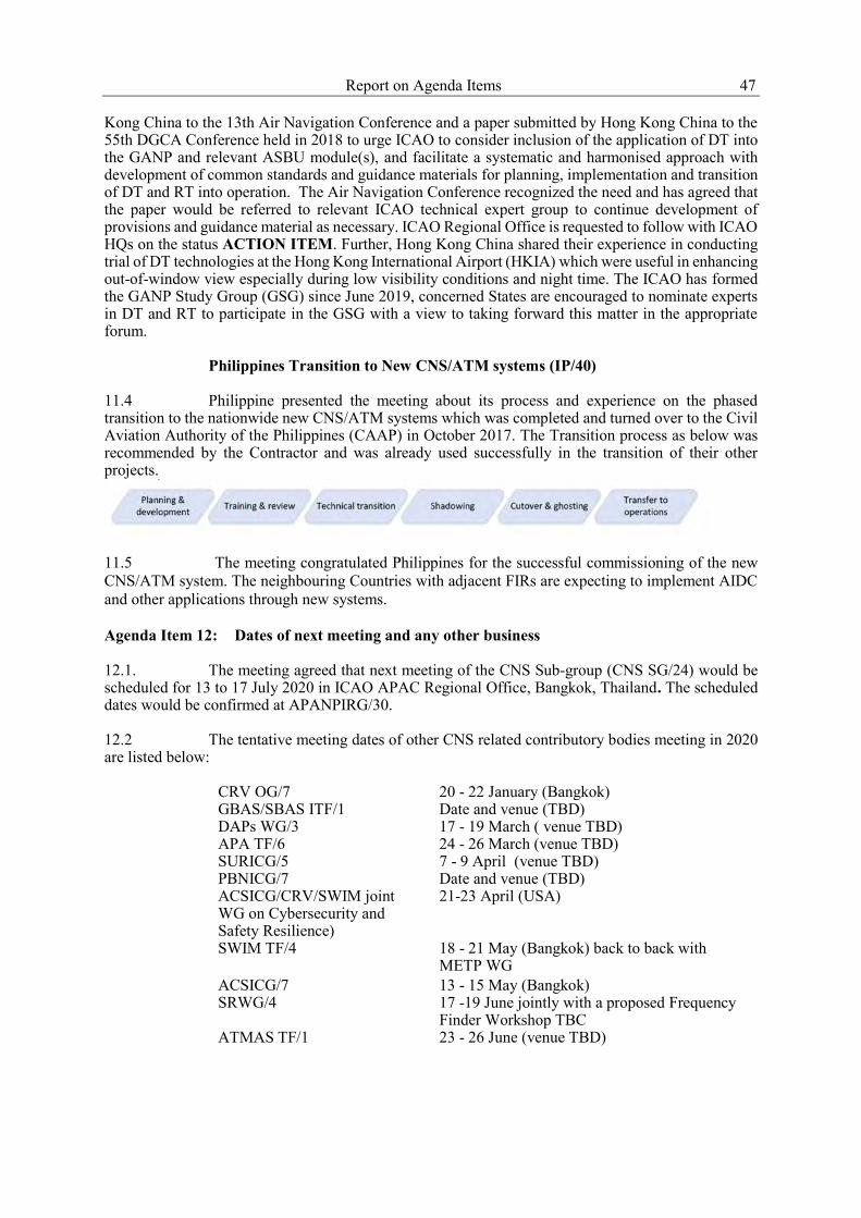
Report on Agenda Items 47
Kong China to the 13th Air Navigation Conference and a paper submitted by Hong Kong China to the 55th DGCA Conference held in 2018 to urge ICAO to consider inclusion of the application of DT into the GANP and relevant ASBU module(s), and facilitate a systematic and harmonised approach with development of common standards and guidance materials for planning, implementation and transition of DT and RT into operation. The Air Navigation Conference recognized the need and has agreed that the paper would be referred to relevant ICAO technical expert group to continue development of provisions and guidance material as necessary. ICAO Regional Office is requested to follow with ICAO HQs on the status ACTION ITEM. Further, Hong Kong China shared their experience in conducting trial of DT technologies at the Hong Kong International Airport (HKIA) which were useful in enhancing out-of-window view especially during low visibility conditions and night time. The ICAO has formed the GANP Study Group (GSG) since June 2019, concerned States are encouraged to nominate experts in DT and RT to participate in the GSG with a view to taking forward this matter in the appropriate forum.
Philippines Transition to New CNS/ATM systems (IP/40)
11.4 Philippine presented the meeting about its process and experience on the phased transition to the nationwide new CNS/ATM systems which was completed and turned over to the Civil Aviation Authority of the Philippines (CAAP) in October 2017. The Transition process as below was recommended by the Contractor and was already used successfully in the transition of their other projects.
11.5 The meeting congratulated Philippines for the successful commissioning of the new CNS/ATM system. The neighbouring Countries with adjacent FIRs are expecting to implement AIDC and other applications through new systems. Agenda Item 12: Dates of next meeting and any other business 12.1. The meeting agreed that next meeting of the CNS Sub-group (CNS SG/24) would be scheduled for 13 to 17 July 2020 in ICAO APAC Regional Office, Bangkok, Thailand. The scheduled dates would be confirmed at APANPIRG/30. 12.2 The tentative meeting dates of other CNS related contributory bodies meeting in 2020 are listed below:
CRV OG/7 20 - 22 January (Bangkok) GBAS/SBAS ITF/1 Date and venue (TBD) DAPs WG/3 17 - 19 March ( venue TBD) APA TF/6 24 - 26 March (venue TBD) SURICG/5 7 - 9 April (venue TBD) PBNICG/7 Date and venue (TBD) ACSICG/CRV/SWIM joint WG on Cybersecurity and Safety Resilience)
21-23 April (USA)
SWIM TF/4 18 - 21 May (Bangkok) back to back with METP WG
ACSICG/7 13 - 15 May (Bangkok) SRWG/4 17 -19 June jointly with a proposed Frequency
Finder Workshop TBC ATMAS TF/1 23 - 26 June (venue TBD)

48 Report on Agenda Items 12.3 The meeting noted the information presented by the CETC Northwest Group International regarding their capabilities and solutions provided to the aviation including GBAS and ADS-B. Note of appreciation 12.4 On behalf of the Group, Mr. Richard Wu, Chairperson of CNS Sub-group expressed thankfulness to ICAO Secretariats for their excellent support in ensuring smooth running of the CNS SG/23 meeting, the CETC Northwest Group for their kind sponsorship for the lunch, the Vice Chair Mr Amit Kumar Banerjee for chairing the meeting, all participants from member States/Administrations, ICAO APAC Regional Office, IATA, CANSO, IFALPA, IFATSEA etc., for their significant contributions in making the meeting a successful and fruitful one.
_ _ _ _ _ _ _ _ _ _ _ _ _ _
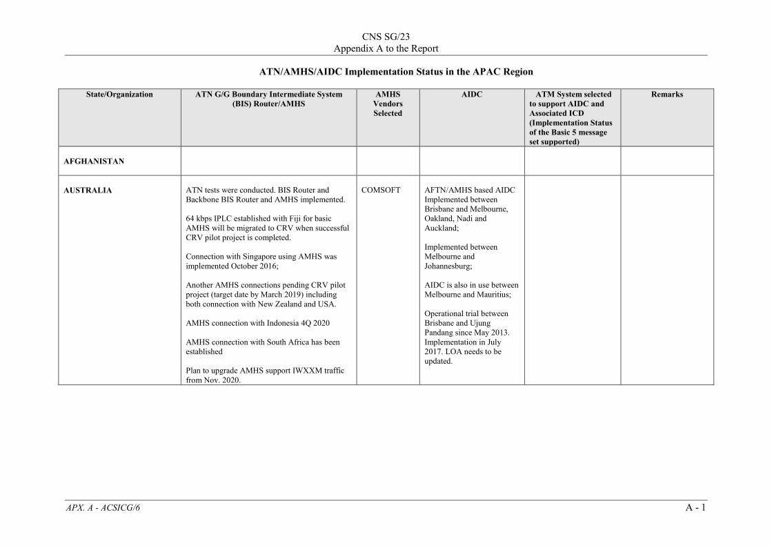
CNS SG/23
Appendix A to the Report
APX. A - ACSICG/6 A - 1
ATN/AMHS/AIDC Implementation Status in the APAC Region
State/Organization ATN G/G Boundary Intermediate System (BIS) Router/AMHS
AMHS Vendors Selected
AIDC ATM System selected to support AIDC and Associated ICD (Implementation Status of the Basic 5 message set supported)
Remarks
AFGHANISTAN
AUSTRALIA
ATN tests were conducted. BIS Router and Backbone BIS Router and AMHS implemented. 64 kbps IPLC established with Fiji for basic AMHS will be migrated to CRV when successful CRV pilot project is completed. Connection with Singapore using AMHS was implemented October 2016; Another AMHS connections pending CRV pilot project (target date by March 2019) including both connection with New Zealand and USA. AMHS connection with Indonesia 4Q 2020 AMHS connection with South Africa has been established Plan to upgrade AMHS support IWXXM traffic from Nov. 2020.
COMSOFT
AFTN/AMHS based AIDC Implemented between Brisbane and Melbourne, Oakland, Nadi and Auckland; Implemented between Melbourne and Johannesburg; AIDC is also in use between Melbourne and Mauritius; Operational trial between Brisbane and Ujung Pandang since May 2013. Implementation in July 2017. LOA needs to be updated.

CNS SG/23
Appendix A to the Report
APX. A - ACSICG/6 A - 2
State/Organization ATN G/G Boundary Intermediate System (BIS) Router/AMHS
AMHS Vendors Selected
AIDC ATM System selected to support AIDC and Associated ICD (Implementation Status of the Basic 5 message set supported)
Remarks
BANGLADESH
In Q1/2013, Bangladesh installed ATN/AMHS and BIS Router at Dhaka (VGHS) with User Agents at Chittagong (VGEG) and Sylhet (VGSY).
COMSOFT
Tentative date of implementation of AIDC is Q4 of 2018 with Kolkata and Myanmar.
The Bangladesh ATM Upgrade Project (BATMUP) under Public Private Partnership (PPP) in Dhaka is expected to be completed by 2018. As soon as the ATM up- gradation is completed hopefully Bangladesh will be able to implement AIDC with Kolkata and Myanmar by the end of 2018.
BHUTAN
ATN/AMHS circuits, using IP over VPN, with Thailand (Bangkok) and India (Mumbai) commissioned in June and July 2017 respectively. IOT and POT with Mumbai completed on 27th June 2017. IOT and POT with Thailand completed on 2nd May 2017.
AEROTHAI’S AMHS System
Currently not applicable. If required in the future, will be decided after CRV implementation (scheduled for mid-2019).

CNS SG/23
Appendix A to the Report
APX. A – ACSICG/6 A - 3
State/Organization ATN G/G Boundary Intermediate System (BIS) Router/AMHS
AMHS Vendors Selected
AIDC ATM System selected to support AIDC and Associated ICD (Implementation Status of the Basic 5 message set supported)
Remarks
TMC signing with both countries at final stage.
BRUNEI DARUSSALAM
ATN BIS Router planned for 2015 and AMHS planned for 2015
CAMBODIA
BIS Router and AMHS installed. Cambodia (CATS) AMHS connected with Bangkok via VSAT IP link since 10 December 2013
AVITECH
AIDC function and capability made available. Ready for testing with neighbors ATS Facilities starting from 2017 and target date of implementation with Bangkok in 4Q2019
THALES which supports AIDC ICD Version 1.
CHINA
ATN Router and AMHS including NCC deployed in 2008 which is being upgraded to support ATN/IPS with target date of completion in December 2013. The Beijing-Hong Kong AMHS link was put into operation in 2018; With Thailand is completed POT, after sign the TMC circuit and was put into operation in Q3 2019. AMHS/ATN technical tests with Macau completed in 2009. Plan for ATN/AMHS implementation with Macao China in 2019.
IN-HOUSE (Aero-Info Technologies Co., Ltd)
AIDC between some of ACCs within China has been implemented. AIDC between several other ACCs are being implemented. AIDC between Sanya and Hong Kong put in to operational use since 8 Feb 2007. AIDC between Dalian and Incheon implemented in Nov. 2016;

CNS SG/23
Appendix A to the Report
APX. A - ACSICG/6 A - 4
State/Organization ATN G/G Boundary Intermediate System (BIS) Router/AMHS
AMHS Vendors Selected
AIDC ATM System selected to support AIDC and Associated ICD (Implementation Status of the Basic 5 message set supported)
Remarks
ATN/AMHS circuit with ROK has been put into operation since June 2011. ATN/AMHS tests with India has been put into operation since 2016. ATN and AMHS IOT with Mongolia is completed in May 2018. Plan for commissioning after POT completion in 2019. Connection tests with Nepal is TBD.
Guangzhou with Nanning/Zhanjiang/Zhuhai implemented; Nanning and Kunming/Guiyang/Zhanjiang implemented in 2011; Zhanjiang/Haikou; Chengdu and Chongqing/Guiyang implemented in 2011; Guiyang and Chongqing/Kunming implemented in 2011; For Beijing/Ulaanbaatar, planned date of testing in 2019.
HONG KONG, CHINA
Manila / Philippines CRV/AMHS circuit was put into operation in May 2019. Beijing / China ATN/AMHS circuit was put into operation in 2018. Plan to migrate to CRV in 2019. Bangkok / Thailand ATN/AMHS circuit was put into operation use in 2014. Plan to migrate to CRV in 2019.
COMSOFT
AFTN-based AIDC with Sanya put into operational use in Feb 2007. AIDC technical trial with Taibei conducted in 2010 and completed in 2012 and put into operational use in Nov. 2012 AIDC technical and interoperability tests with Guangzhou were conducted successfully in April and
Raytheon ATM system Support AIDC ICD Version 3 commissioned in November 2016.
Already support exchange of IWXXM messages based on FTBP.

CNS SG/23
Appendix A to the Report
APX. A – ACSICG/6 A - 5
State/Organization ATN G/G Boundary Intermediate System (BIS) Router/AMHS
AMHS Vendors Selected
AIDC ATM System selected to support AIDC and Associated ICD (Implementation Status of the Basic 5 message set supported)
Remarks
Fukuoka / Japan Currently on AFTN. Plan to cut over to CRV/AMHS in Q1 2020. HoChiMinh / Vietnam Currently on AFTN. Plan to test ATN/AMHS in 2019. Taibei Currently on AFTN. Plan to test CRV/AMHS in 2019 .
June 2017 respectively and put into operational use in May 2018. AIDC technical and interoperability tests with Manila were conducted successfully in May 2018 with no observations on exchanging core set messages (EST, ACP, TOC, AOC, LAM, LRM). AIDC operational trial with Manila was commenced in March 2019. .
MACAO, CHINA
ATN/AMHS interoperability test with Beijing commenced in March 2009. ATN/AMHS circuit with Hong Kong put into operational use in end Dec. 2009. ATN/AMHS implementation with mainland China planned for 2019.
COMSOFT
(Not applicable for using AIDC, looking into the possible application (some way) between TWR and ACC/APP).
COOK ISLANDS
DEMOCRATIC PEOPLE’S REPUBLIC OF KOREA
The ATN BIS Router and AMHS planned for in 2011.
With neighboring ACCs to be implemented

CNS SG/23
Appendix A to the Report
APX. A - ACSICG/6 A - 6
State/Organization ATN G/G Boundary Intermediate System (BIS) Router/AMHS
AMHS Vendors Selected
AIDC ATM System selected to support AIDC and Associated ICD (Implementation Status of the Basic 5 message set supported)
Remarks
FIJI ISLANDS
ATN BBIS IPS router and AMHS implemented over CRV for connection to USA in April, 2019 with Australia planned for June, 2019. . For connections with sub-regional centers: For New Caledonia using AMHS since 2017; For connection with Kiribati using UA/AMHS implemented in 2015.
COMSOFT
AFTN based AIDC implemented between Nadi/ Brisbane, Auckland and Oakland.
- Support and implemented AIDC messaging: ABI, EST, CPL, CDN, ACP, TOC, AOC with all three centers - AIDC ICD version 2.0 implemented with Auckland and Oakland. - AIDC ICD Version 1.0 implemented with Brisbane
FRANCE (French Polynesia Tahiti)
Planned for implementation of AMHS in 2020. Using IP with New Zealand since 2017.
Implementation of AIDC (based on Version 3) with adjacent centers (Oakland and Auckland) since 2009.
THALES EUROCAT for AIDC
Alternate routing for backup between Tahiti and Christchurch via Tahiti/New Caledonia IP link
INDIA
Dual stack ATN/IP router and AMHS implemented at Mumbai in 2011. Operational AMHS connections with Bangkok, Dhaka, Singapore, Kathmandu, Karachi implemented. With Beijing implemented in 2016; With Colombo implemented in May2017; With Bhutan implemented in July 2017; and Planned for Muscat and Nairobi for 2019.
COMSOFT
-15-May-2017, AIDC implemented between Chennai and Kuala Lumpur with ABI and EST messages. CDN is done with voice confirmation. TOC/AOC to be implemented; -Chennai-Colombo in testing phase; - Chennai-Male test trials in progress; LOA signed. - Mumbai-Karachi test trials in progress;
1) Raytheon at New Delhi, Mumbai and Chennai 2) Selex at Hyderabad and Bengaluru. 3) INDRA at 39 locations
1) Major Indian airports and ATC centers have integrated ATS Automation Systems having AIDC capability. Successful AIDC trials have been carried out amongst major ATSUs within India. 2) AIDC implemented between Chennai and Mumbai. 3) AMHS implemented and working between

CNS SG/23
Appendix A to the Report
APX. A – ACSICG/6 A - 7
State/Organization ATN G/G Boundary Intermediate System (BIS) Router/AMHS
AMHS Vendors Selected
AIDC ATM System selected to support AIDC and Associated ICD (Implementation Status of the Basic 5 message set supported)
Remarks
- Chennai-Yangon is in testing phase; -Mumbai-Male test trials in progress; LOA signed. -Trivandrum-Male test trials in progress. LOA signed. - Mumbai- Muscat planned for 2019.
A. BBIS: Mumbai-Singapore, Bangkok B: BIS: Mumbai, Kathmandu, Dhaka
INDONESIA
ATN BIS Router and AMHS with Singapore implemented Since February 2018; AMHS Trial (IOT) with Brisbane planned 4Q2020 over VPN;
IDS
ELSA
Implementation Jakarta (new ATM system in 4Q2020) The target date of AIDC implementation will commence testing in 4Q2020 including following pairs: Jakarta-Singapore; Jakarta-Chennai; Jakarta-Ujung Pandang; Jakarta-Melbourne; Jakarta – Kuala Lumpur Ujung Pandang –Brisbane: implemented in July 2017. Ujung Pandang – Manila - Successful testing conducted; Target date of implementation 4Q2019
Thales in Makassar able to support ICD Version 3 since December 2015
Between PNG – Ujung Pandang, the implementation are waiting for PNG’s ATM system upgraded. For CRV, contract in 3Q2019 and implementation in 4Q2019

CNS SG/23
Appendix A to the Report
APX. A - ACSICG/6 A - 8
State/Organization ATN G/G Boundary Intermediate System (BIS) Router/AMHS
AMHS Vendors Selected
AIDC ATM System selected to support AIDC and Associated ICD (Implementation Status of the Basic 5 message set supported)
Remarks
Ujung Pandang - Kota Kinabalu - Implementation date TBC -Ujung Pandang – Oakland, test conducted, and target date for implementation in 3Q2019.
JAPAN
ATN BBIS router and AMHS installed at 2000. Connection tests with USA 2000 - 2004 and put into operational use in 2005. ATN BBIS router (to apply to Dual Stack) and AMHS (to upgrade in 2015. The connection test with each country which is not currently connecting is started after update. Upgrading connection with Hong Kong using VPN will be implemented in 2019 after implementation of CRV; Coordinating for all other circuits upgrading.
NEC
AIDC implemented between Fukuoka ATMC and Oakland ARTCC in 1998. AIDC implemented between Fukuoka ATMC and Anchorage ARTCC in 2005. AIDC implemented between Tokyo ACC/Fukuoka ACC and Incheon ACC in 2010. Implemented between Fukuoka and Incheon since June 2009.
AIDC implemented between Fukuoka ACC/Naha ACC and Taibei ACC implemented. AIDC between Fukuoka ACC and Shanghai ACC under negotiation.
Japan and USA conducting testing AIDC over AMHS and cutover date is 5 May 2017.

CNS SG/23
Appendix A to the Report
APX. A – ACSICG/6 A - 9
State/Organization ATN G/G Boundary Intermediate System (BIS) Router/AMHS
AMHS Vendors Selected
AIDC ATM System selected to support AIDC and Associated ICD (Implementation Status of the Basic 5 message set supported)
Remarks
KIRIBATI
Connection with Nadi using UA/AMHS implemented in 2015.
LAO PDR
ATN BIS Router and AMHS completed, planned for operation with Bangkok since 4Q 2016.
THALES
AIDC testing with Bangkok in 2017 and target for implementation in 4Q2019. Testing with Hanoi on-going since 2017; with Cambodia operational test again in June 2018, and implementation 2Q 2019. Testing with Kunming and Yangon ongoing.
THALES which is able to support ICD Version 2.
MALAYSIA
ATN BIS Router completed 2007. AMHS implementation planned for Q42017; Malaysia – Singapore for AMHS implementation in 2019 Malaysia – Thailand for AMHS implementation in 2019.
FREQUENTIS
AIDC testing with Bangkok ACC conducted since 2016. Operational trial will commence in August 2019. AIDC Between Kuala Lumpur/ Chennai implemented in phases from May 2017 implementation for ABI, EST and MAC along with response messages LAM, LRM and ACP. Review on the CDN message implementation conducted in Aug. 2017. SOP signed 26 April, 2017. AIDC testing with Singapore on going since
SELEX which is able to support ICD Version 3.

CNS SG/23
Appendix A to the Report
APX. A - ACSICG/6 A - 10
State/Organization ATN G/G Boundary Intermediate System (BIS) Router/AMHS
AMHS Vendors Selected
AIDC ATM System selected to support AIDC and Associated ICD (Implementation Status of the Basic 5 message set supported)
Remarks
2016. Target date for operational trial from 3Q2018, and Implementation 2Q2019. Planned testing with Ho Chi Minh ACC – 3Q2019; AIDC between KK ACC and Manila ACC in 4Q2020 and technical testing 2Q 2019. KK ACC with Ujung Pandang TBC; AIDC between Kuching ACC and Singapore planned for 2Q2020; AIDC technical test between Kota Kinabalu ACC and Singapore planned for 3Q2019; AIDC between Kuala Lumpur and Jakarta testing planned for 4Q2020.
MALDIVES
In the process of replacing the existing operational AFTN system by AMHS. It is expected to complete the installation before the end of 2019. With the new AMHS, it is planned to establish a new IP connection between an additional
Connection established with all the adjacent ATSUs. Interoperability tests successfully completed in 2017.
SELEX which is able to support ICD Version 3.

CNS SG/23
Appendix A to the Report
APX. A – ACSICG/6 A - 11
State/Organization ATN G/G Boundary Intermediate System (BIS) Router/AMHS
AMHS Vendors Selected
AIDC ATM System selected to support AIDC and Associated ICD (Implementation Status of the Basic 5 message set supported)
Remarks
neighboring ATSU as the current link is an X.25 connection between Colombo. Also will look for the possibility of implementing the CRV network to use with AMHS and AIDC during the same phase.
LOA signed for operational trials between Mumbai, Chennai, and Trivandrum. Operational trials were also successful with these ATSUs, while several issues were resolved from both ends. Ready to sign LOA with Melbourne and is expected during the 2nd quarter of 2019. Trials with Colombo had few issues, which Colombo is working to resolve it on their end with the automation system supplier. Connections between all 5 ATSUs are turned ON in the ATS automation system to conduct pre-notified operational trials.
MARSHALL ISLANDS
MICRONESIA (EDERATED STATES OF)

CNS SG/23
Appendix A to the Report
APX. A - ACSICG/6 A - 12
State/Organization ATN G/G Boundary Intermediate System (BIS) Router/AMHS
AMHS Vendors Selected
AIDC ATM System selected to support AIDC and Associated ICD (Implementation Status of the Basic 5 message set supported)
Remarks
Chuuk
Kosrae
Pohnpei
Yap
MONGOLIA
AMHS/AFTN gateway implemented 2012. ATNBIS router implemented in 2014. ATN and AMHS IOT with China was completed in May 2018. Plan for commissioning after POT completion in 2019.
COMSOFT
ATM automation system supports both AIDC and OLDI. Coordinating with Russia on OLDI connection in target date 2016. Coordinating with China on AIDC connection between Beijing/Ulaanbaatar technical trials in progress. Planned date of testing in 2019.
INDRA Aircon 2100 supporting AIDC ICD Version 2.
MYANMAR
AMHS including ATFN/AMHS gateway implemented in Nov. 2011; Connection with Thailand implemented in 4Q2016; Planned for AMHS connection with Beijing. Target date TBC.
THALES
AIDC connection pre-operation test with Thailand conducted in 4Q2017 and Target date of implementation 4Q2019; AIDC testing with Kunming and Chennai conducted in 2017.
THALES Automation system upgraded to Thales Topsky ATC system in January 2017 which supports AIDC Ver. 2 and AMHS connections
NAURU

CNS SG/23
Appendix A to the Report
APX. A – ACSICG/6 A - 13
State/Organization ATN G/G Boundary Intermediate System (BIS) Router/AMHS
AMHS Vendors Selected
AIDC ATM System selected to support AIDC and Associated ICD (Implementation Status of the Basic 5 message set supported)
Remarks
NEPAL
BIS Router and AMHS commissioned with Kathmandu Mumbai circuit on 2 June 2014.
COMSOFT
AIDC between Kathmandu and Beijing and planned testing between KTM-BBN and KTM-CCU for 3Q2018
NEW CALEDONIA
New router and AMHS commissioned December 2016
COMSOFT
NEW ZEALAND
AMHS connection with the USA over CRV was implemented in April 2019. AMHS connection to Australia over CRV is scheduled for June 2019.
COMSOFT
AIDC implemented between New Zealand, Australia, Fiji, Tahiti, Chile and USA.
Supported the Basic 5 message set. ATM systems are LEIDOS and ADACEL
PAKISTAN
ATN/AMHS connections with Mumbai since 2015. Planning for AMHS connection with Beijing and Kuwait after upgrading existing facilities between the Countries. Target dates for implementation TBC.
COMSOFT
Implemented between Karachi and Lahore ACCs Further testing to be conducted between Delhi/Karachi & Delhi/Lahore after system upgradation at Indian end; Mumbai/Karachi &AHM/Karachi on trial operation. For testing with Muscat planned for 4Q2019. Coordination for testing with Tehran is in progress.
ATM system from Intra AIRCON 2100
Existing Radar system being upgraded.
PAPUA NEW GUINEA
Plans to create a newly duplicated digital communications line connecting with existing and new sites and AMHS system implemented in 4Q2014
COMSOFT
Plan to implement with all neighboring FIRs in 3Q 2018. Negotiation with Indonesia for AIDC with Ujung Pandang in May 2018.
COMSOFT which is able to support ICD Version 3

CNS SG/23
Appendix A to the Report
APX. A - ACSICG/6 A - 14
State/Organization ATN G/G Boundary Intermediate System (BIS) Router/AMHS
AMHS Vendors Selected
AIDC ATM System selected to support AIDC and Associated ICD (Implementation Status of the Basic 5 message set supported)
Remarks
PHILIPPINES
New ATN/AMHS was installed at the New CNS/ATM Center in Manila. Site Acceptance was successfully done on October 2015. The new AMHS commissioned and operational in March 2018. The international connection still using AFTN except Hong Kong. The AMHS Implemented over CRV with Hong Kong 1Q2019 and with Singapore is planned over CRV by end of 4Q2019. AMHS implementation with Oakland USA via CRV is planned for 4Q2019.
COMSOFT
On-going test with Singapore, Ujung Pandang and Taipei ACCs; Planned technical trial over new ATM system with other ACCs from 4Q2017 to 3Q2019: Coordination is underway for using AIDC function of the new ATM system with adjacent ACCs. Planned implementation: 2Q2019 – Singapore ACC; 4Q2019 – Ujung Pandang ACC; 3Q2019 – Taipei ACC; 2Q2019- Hong Kong ACC;
THALES which is able to support ICD Version 2.
REPUBLIC OF KOREA
ATN/AMHS circuit with China put into operational use in June 2011. AMHS implementation with China over CRV in 4Q2019. AMHS implementation with Japan over CRV in 4Q2020.
SAMSUNG
AIDC implemented between ACC and Fukuoka ATMC in 2010 AIDC between Incheon and Dalian implemented in Nov. 2016.
Rockheed Martin System

CNS SG/23
Appendix A to the Report
APX. A – ACSICG/6 A - 15
State/Organization ATN G/G Boundary Intermediate System (BIS) Router/AMHS
AMHS Vendors Selected
AIDC ATM System selected to support AIDC and Associated ICD (Implementation Status of the Basic 5 message set supported)
Remarks
SINGAPORE
AMHS implemented. ATN/AMHS circuit with India put into operational use in March 2011. ATN/AMHS circuit with UK put into operational use in March 2012. ATN/AMHS circuit with Thailand put into operational use in December 2014. ATN/AMHS circuit with Australia put into operational use in October 2016. ATN/AMHS circuit with Indonesia put into operational use in February 2018. Inter-Operability Test (IOT) with Japan, Malaysia, Philippines, Sri Lanka and Vietnam targeted in 2019. IOT with Bahrain and Brunei targeted in 2020.
FREQUENTIS COMSOFT
Operational with Ho Chi Minh implemented July 2014 Kuala Lumpur operational trial started since September 2018 and is on-going, implementation planned for June2019. Manila operational trial started in February 2019. Implementation planned for June 2019. Technical trials with Jakarta ACC will be initiated once the Jakarta ACC ATMS renewal is completed.
THALES supports ICD Version 3 since December 2018
SRI LANKA
ATN BIS Router Planned for 2013. IP based AMHS implemented by Oct. 2017.
- Mumbai tested May 2017 operational planned for Q4 2017;
- Singapore testing in Q4 2017 operational for 2018;
- Male testing and operational date TBD.
IDS
Trials with Male planned for in 3Q2019. Trial with Chennai on-going. Plan for implementation in 2018 and with Melbourne plan for 1Q2018.
INTELCAN which is able to support ICD Version 3.
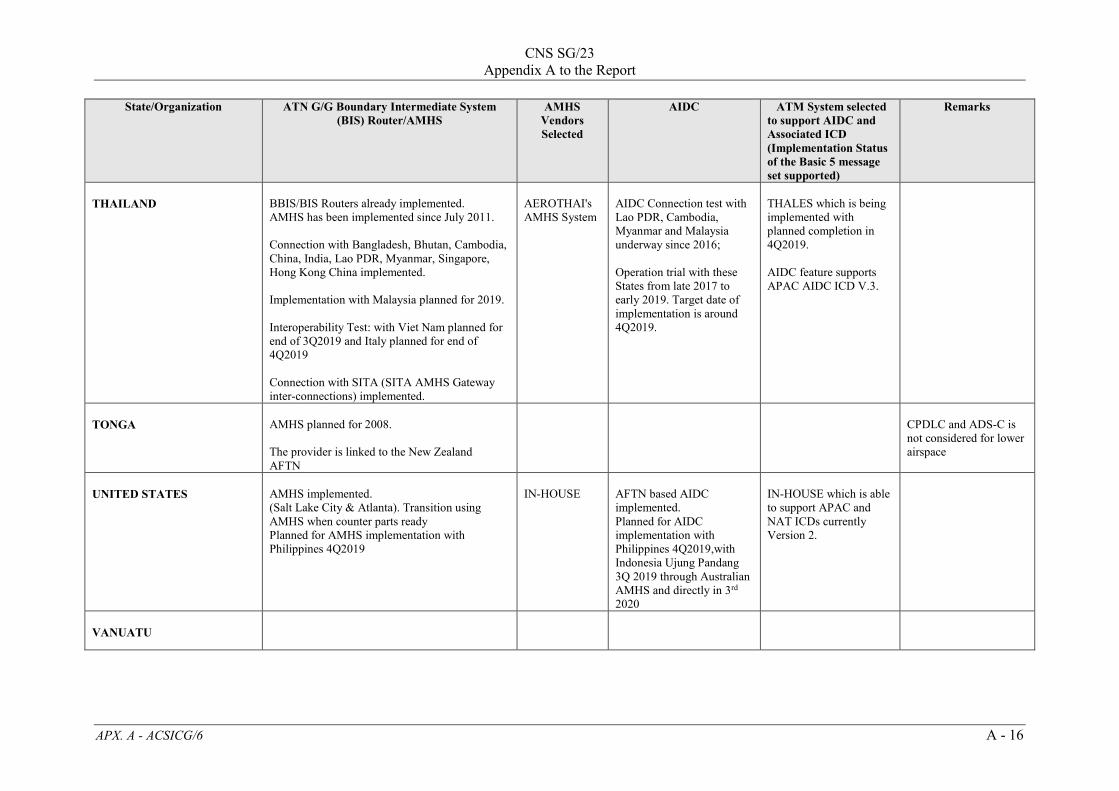
CNS SG/23
Appendix A to the Report
APX. A - ACSICG/6 A - 16
State/Organization ATN G/G Boundary Intermediate System (BIS) Router/AMHS
AMHS Vendors Selected
AIDC ATM System selected to support AIDC and Associated ICD (Implementation Status of the Basic 5 message set supported)
Remarks
THAILAND
BBIS/BIS Routers already implemented. AMHS has been implemented since July 2011. Connection with Bangladesh, Bhutan, Cambodia, China, India, Lao PDR, Myanmar, Singapore, Hong Kong China implemented. Implementation with Malaysia planned for 2019. Interoperability Test: with Viet Nam planned for end of 3Q2019 and Italy planned for end of 4Q2019 Connection with SITA (SITA AMHS Gateway inter-connections) implemented.
AEROTHAI's AMHS System
AIDC Connection test with Lao PDR, Cambodia, Myanmar and Malaysia underway since 2016; Operation trial with these States from late 2017 to early 2019. Target date of implementation is around 4Q2019.
THALES which is being implemented with planned completion in 4Q2019. AIDC feature supports APAC AIDC ICD V.3.
TONGA
AMHS planned for 2008. The provider is linked to the New Zealand AFTN
CPDLC and ADS-C is not considered for lower airspace
UNITED STATES
AMHS implemented. (Salt Lake City & Atlanta). Transition using AMHS when counter parts ready Planned for AMHS implementation with Philippines 4Q2019
IN-HOUSE
AFTN based AIDC implemented. Planned for AIDC implementation with Philippines 4Q2019,with Indonesia Ujung Pandang 3Q 2019 through Australian AMHS and directly in 3rd 2020
IN-HOUSE which is able to support APAC and NAT ICDs currently Version 2.
VANUATU
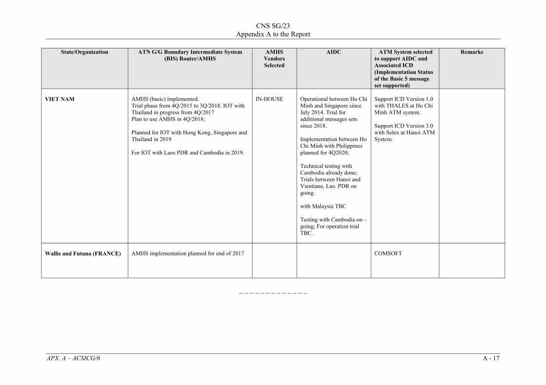
CNS SG/23
Appendix A to the Report
APX. A – ACSICG/6 A - 17
State/Organization ATN G/G Boundary Intermediate System (BIS) Router/AMHS
AMHS Vendors Selected
AIDC ATM System selected to support AIDC and Associated ICD (Implementation Status of the Basic 5 message set supported)
Remarks
VIET NAM
AMHS (basic) implemented. Trial phase from 4Q/2015 to 3Q/2018. IOT with Thailand in progress from 4Q/2017 Plan to use AMHS in 4Q/2018; Planned for IOT with Hong Kong, Singapore and Thailand in 2019 For IOT with Laos PDR and Cambodia in 2019.
IN-HOUSE
Operational between Ho Chi Minh and Singapore since July 2014. Trial for additional messages sets since 2018. Implementation between Ho Chi Minh with Philippines planned for 4Q2020; Technical testing with Cambodia already done; Trials between Hanoi and Vientiane, Lao. PDR on going. with Malaysia TBC Testing with Cambodia on – going; For operation trial TBC.
Support ICD Version 1.0 with THALES at Ho Chi Minh ATM system. Support ICD Version 3.0 with Selex at Hanoi ATM System.
Wallis and Futuna (FRANCE)
AMHS implementation planned for end of 2017
COMSOFT
_ _ _ _ _ _ _ _ _ _ _ _ _

Distributed Multi-Nodal
Air Traffic Flow Management
AFTN/AMHS Based Interface Control
Document
06 September 2019
Version: 1.0
CNS SG/23 Appendix B to the Report

AFTN/AMHS-Based ATFM ICD Distributed Multi-Nodal ATFM
APX. B - ii
Revision Record
Revision Description Date Authored By
Approved By
[Grab your reader’s attention with a great quote from the document or use this space to emphasize a key point. To place this text box anywhere on the page, just drag it.]

AFTN/AMHS-Based ATFM ICD Distributed Multi-Nodal ATFM
APX. B - iii
Table of Contents
Revision Record .................................................................................................................... ii List of Figures ........................................................................................................................v
List of Tables ........................................................................................................................ vi List of Acronyms ................................................................................................................. vii
1 ICD Scope...........................................................................................................................1
1.1 Introduction .................................................................................................................1
1.2 Scope ...........................................................................................................................1
1.3 Subsystem Responsibility List ....................................................................................1
1.4 Operational Requirement ............................................................................................1
2 Applicable Documents .......................................................................................................2
3 Interface Characteristics .....................................................................................................2
3.1 General Characteristics ...............................................................................................2
3.1.1 Data Format ..........................................................................................................3
3.1.2 Messages defined by ADEXP ...............................................................................4
3.1.3 Message Construction ...........................................................................................1
3.1.3.1 IA-5 Message Field 1: Start of Message ......................................................5
3.1.3.2 IA-5 Message Field 2: Transmission Identification .....................................5
3.1.3.3 IA-5 Message Field 3: Additional Service Indication ..................................5
3.1.3.4 IA-5 Message Field 4: Priority Indicator ......................................................5
3.1.3.5 IA-5 Message Field 5: Addressee of the Message .......................................6
3.1.3.6 IA-5 Message Field 6: Day / Time of the Message ......................................6
3.1.3.7 IA-5 Message Field 7: Originator of the Message .......................................6
3.1.3.8 IA-5 Message Field 8: Optional Heading Information .................................6
3.1.3.9 IA-5 Message Field 9: ATS Message Payload .............................................7
3.1.3.10 IA-5 Message Field 10: End of Message ......................................................7
3.1.4 Message Body (ATS Message Payload) ...............................................................7
3.1.4.1 Messages defined by ADEXP ......................................................................7
3.2 Functional Design Characteristics ...............................................................................8
3.2.1 ADEXP ATS Message Payload –Message Fields ..............................................10
3.2.1.1 TITLE Field ................................................................................................11
3.2.1.2 ADDR Field ................................................................................................11
3.2.1.3 ARCID Field...............................................................................................11
3.2.1.4 IFPLID Field...............................................................................................11
3.2.1.5 ADEP Field.................................................................................................12
3.2.1.6 ADES Field.................................................................................................12

AFTN/AMHS-Based ATFM ICD Distributed Multi-Nodal ATFM
APX. B - iv
3.2.1.7 EOBD Field ................................................................................................12
3.2.1.8 EOBT Field.................................................................................................12
3.2.1.9 IOBD Field .................................................................................................12
3.2.1.10 IOBT Field ..................................................................................................12
3.2.1.11 CTOT Field.................................................................................................12
3.2.1.12 NEWCTOT Field .......................................................................................13
3.2.1.13 REGUL Field ..............................................................................................13
3.2.1.14 TAXITIME Field ........................................................................................13
3.2.1.15 REGCAUSE Field ......................................................................................13
3.2.1.16 REASON Field ...........................................................................................14
3.2.1.17 RVR Field ...................................................................................................14
3.2.1.18 COMMENT Field.......................................................................................14
3.2.1.19 REFDATA field .........................................................................................14
3.2.1.20 MSGREF field ............................................................................................15
3.2.2 ADEXP ATS Message Payload Types ...............................................................15
3.2.2.1 SAM Message Composition .......................................................................15
3.2.2.2 SRM Message Composition .......................................................................16
3.2.2.3 SLC Message Composition ........................................................................16
3.2.3 Message Summary Table ....................................................................................17
3.2.4 Protocol Implementation .....................................................................................17
3.2.5 Security ...............................................................................................................17
3.3 Physical Design Characteristics ................................................................................17
3.3.1 Electrical Power and Electronic Characteristics .................................................17
3.3.1.1 Connectors ..................................................................................................17
3.3.1.2 Wire/Cable ..................................................................................................17
3.3.1.3 Electrical Power/Grounding .......................................................................17
3.3.1.4 Fasteners .....................................................................................................18
3.3.1.5 Electromagnetic Compatibility ...................................................................18

AFTN/AMHS-Based ATFM ICD Distributed Multi-Nodal ATFM
APX. B - v
List of Figures
Figure 1. Logical Architecture Showing Interface Demarcation between the Local ATFM system and AFTN/AMHS .............................................................................3
Figure 2. IA-5 Illustration of ICAO Message ............................................................................5
Figure 3. IA-5 Illustration of ADEXP Message ........................................................................5
Figure 4. Overall structure of AFTN (ADEXP) message ..........................................................7
Figure 5. SAM message using ADEXP structure ......................................................................7

AFTN/AMHS-Based ATFM ICD Distributed Multi-Nodal ATFM
APX. B - vi
List of Tables
Table 1. Summary of IA-5 Fields used in messages sent via AFTN/AMHS ............................4
Table 2. Fields and corresponding flight information contained in each ICAO 4444 message type..............................................................................................................9
Table 3. Fields and corresponding flight information contained in each ADEXP message type ..........................................................................................................................10
Table 4. Flight data attributes associated with ADEXP message fields ..................................11
Table 5. Message Summary .....................................................................................................17
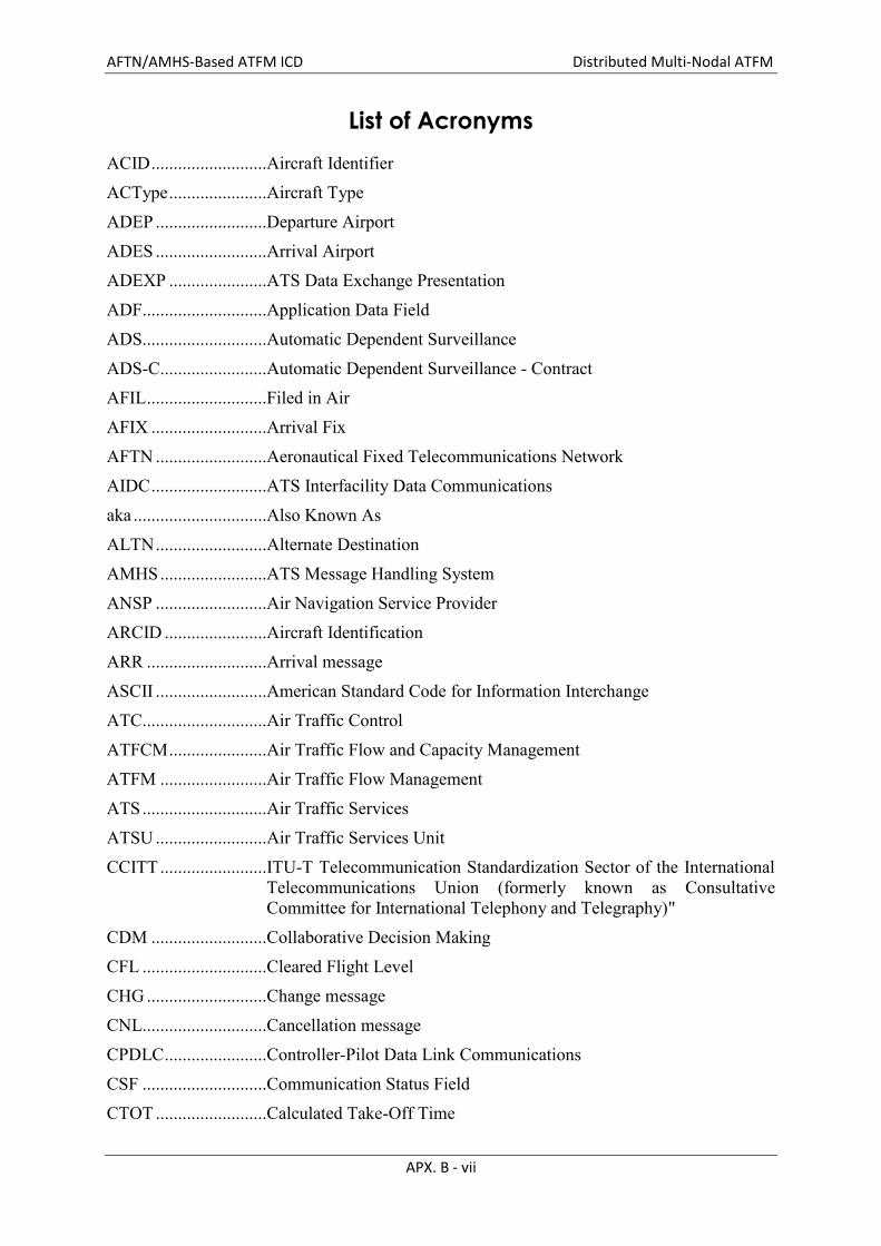
AFTN/AMHS-Based ATFM ICD Distributed Multi-Nodal ATFM
APX. B - vii
List of Acronyms
ACID ..........................Aircraft Identifier ACType ......................Aircraft Type ADEP .........................Departure Airport ADES .........................Arrival Airport ADEXP ......................ATS Data Exchange Presentation ADF............................Application Data Field ADS............................Automatic Dependent Surveillance ADS-C........................Automatic Dependent Surveillance - Contract AFIL ...........................Filed in Air AFIX ..........................Arrival Fix AFTN .........................Aeronautical Fixed Telecommunications Network AIDC ..........................ATS Interfacility Data Communications aka ..............................Also Known As ALTN .........................Alternate Destination AMHS ........................ATS Message Handling System ANSP .........................Air Navigation Service Provider ARCID .......................Aircraft Identification ARR ...........................Arrival message ASCII .........................American Standard Code for Information Interchange ATC............................Air Traffic Control ATFCM ......................Air Traffic Flow and Capacity Management ATFM ........................Air Traffic Flow Management ATS ............................Air Traffic Services ATSU .........................Air Traffic Services Unit CCITT ........................ITU-T Telecommunication Standardization Sector of the International
Telecommunications Union (formerly known as Consultative Committee for International Telephony and Telegraphy)"
CDM ..........................Collaborative Decision Making CFL ............................Cleared Flight Level CHG ...........................Change message CNL............................Cancellation message CPDLC .......................Controller-Pilot Data Link Communications CSF ............................Communication Status Field CTOT .........................Calculated Take-Off Time

AFTN/AMHS-Based ATFM ICD Distributed Multi-Nodal ATFM
APX. B - viii
DCT............................Direct Routing DEP ............................Departure message DEP ............................Departure Airport DEST..........................Destination Airport DFIX ..........................Departure Fix DLA ...........................Delay message DOF............................Date of Flight Departure EET ............................Estimated Elapsed Time EOBD .........................Estimated Off-Block Date EOBT .........................Estimated Off-Block Time ETFMS .......................Enhanced Tactical Flow Management System FAN............................FANS Application Notification FANS ........................Future Air Navigation System FCN ............................FANS Completion Notification FMH ...........................Facilities Notification Message Header FMP............................Flow Management Position FPL .............................Flight Plan message FPO ............................Facilities Notification Current Position HDG ...........................Heading IA5 .............................International Alphabet Number 5 IATA ..........................International Air Transport Association IBT .............................In-Block Time ICAO ..........................International Civil Aviation Organization ICD .............................Interface Control Document IFPLD ........................Individual Flight Plan IFPLID .......................Individual Flight Plan Identifier IFPS............................Integrated Initial Flight Plan Processing System IOBD ..........................Initial Off-Block Date IOBT ..........................Initial Off-Block Time IP ................................Internet Protocol K .................................Kilometer LDT ............................Landing/Touch Down Time M ................................Mach N .................................Knot NM .............................Network Manager
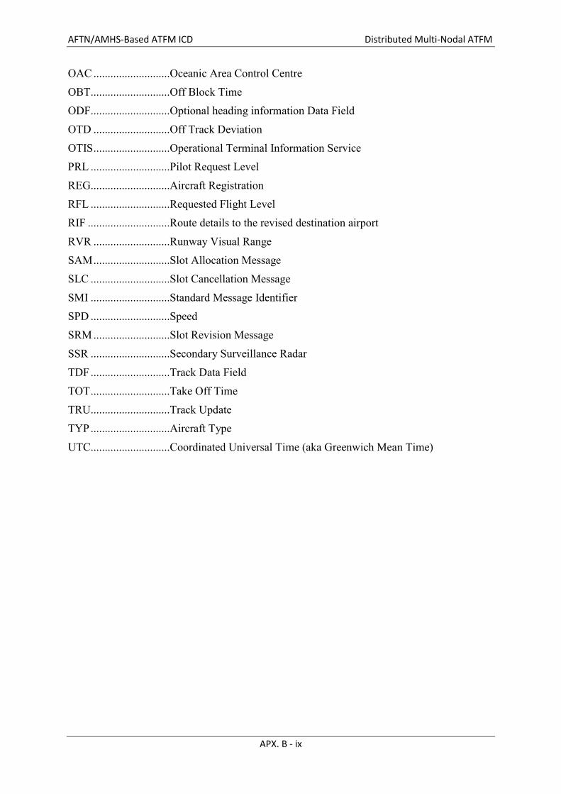
AFTN/AMHS-Based ATFM ICD Distributed Multi-Nodal ATFM
APX. B - ix
OAC ...........................Oceanic Area Control Centre OBT............................Off Block Time ODF............................Optional heading information Data Field OTD ...........................Off Track Deviation OTIS ...........................Operational Terminal Information Service PRL ............................Pilot Request Level REG............................Aircraft Registration RFL ............................Requested Flight Level RIF .............................Route details to the revised destination airport RVR ...........................Runway Visual Range SAM ...........................Slot Allocation Message SLC ............................Slot Cancellation Message SMI ............................Standard Message Identifier SPD ............................Speed SRM ...........................Slot Revision Message SSR ............................Secondary Surveillance Radar TDF ............................Track Data Field TOT ............................Take Off Time TRU............................Track Update TYP ............................Aircraft Type UTC............................Coordinated Universal Time (aka Greenwich Mean Time)
AFTN/AMHS-Based ATFM ICD Distributed Multi-Nodal ATFM
APX. B - 1
1 ICD Scope
This section identifies the scope, purpose, and organization of this Interface Control Document (ICD) and identifies the subsystem responsibility list.
1.1 Introduction Distributed Multi-Nodal Air Traffic Flow Management (ATFM) Network concept is based on a network of Air Navigation Service Providers (ANSPs) leading independent ATFM operation within their area of responsibility and connecting to each other through information sharing framework. Unlike regional-centralized ATFM where there is an overarching authority responsible for ATFM operation for the entire region, each ANSP together with associated Airspace Users (AUs) and Airport Operators (AOs) within their respective FIR (Flight Information Region), participating in cross-border ATFM following this Distributed Multi-Nodal ATFM Network concept, form ATFM Node where ANSP as Node Leader is responsible for engagement with various Node stakeholders and ensuring that the Node as a whole is ready and able to participate in the regional cross-border ATFM process. By establishing common ATFM operating procedures and utilizing fully-interconnected information sharing mechanism among ATFM Nodes, ATFM programs based on Collaborative Decision Making (CDM) process, involving both domestic and intra-regional international flights, can be effectively implemented in the region.
To achieve the efficient information dissemination required for such ATFM operation, the baseline standard for information exchange among related stakeholders is needed. This Interface Control Document (ICD) specifies the interface requirements which ATFM support system of each Node Leader must meet in order to be able to communicate with systems of other ATFM Nodes participating in the cross-border ATFM and to ensure the compatibility between them.
1.2 Scope This ICD details the interface between nodes of the distributed Multi-Nodal ATFM. This ICD:
Establishes data exchange, functional, and performance requirements
Assigns responsibilities for interface implementation and maintenance
1.3 Subsystem Responsibility List The node leader of each FIR develops and maintains their own ATFM software in accordance to this ICD.
1.4 Operational Requirement Distributed Multi-Nodal ATFM Network comprises ATFM Nodes, each of which led by ANSP responsible for ATFM operation within their respective FIR. With various ATFM support systems which have been developed or procured independently by different ANSPs and lack of information linkage between them, a major airline with a number of flights originating from many places is required to access different systems to obtain ATFM information on all their flights, consequently creating a possible roadblock to scaling the ATFM Network due to the high workload in accessing their related information. This calls for the need of a so-called single-point information access able to be achieved by establishing the interconnection between ATFM support systems aiming at enabling the seamless information sharing among

AFTN/AMHS-Based ATFM ICD Distributed Multi-Nodal ATFM
APX. B - 2
stakeholders. However, to maintain the flexibility to accommodate new users and additional customized functions of ATFM support systems developed or procured separately as previously mentioned and to minimize the impact of changes between them, loose system coupling is still required. Furthermore, to attain cost-effective communication among stakeholders and to gain the network-wide scalability, common standards for information exchange are needed to be considered. On the other hand, with the nature of decentralized ATFM operational approach where ATFM support system of each ATFM Node locating geographically dispersed, security across systems is of paramount importance. Technical requirements to address the operational need for information sharing between ATFM support systems stated above can be summarized as follows.
1) Loose system coupling 2) Common standards for information exchange 3) System-wide security
To facilitate the aforementioned requirements, this document describes an interface connection that is designed using the currently deployed AFTN networking (or AMHS).
In particular, considering variation in interactions between stakeholders required at different phases of ATFM operation and keeping in mind the objective of having systems loosely coupled, a data exchange architecture based on existing messaging to exchange ATFM information. This solution is intended to eventually be deprecated and replaced by a SWIM based solution that uses FIXM data models. However, considering the timeline for deployment of all nodes of the multi-nodal network, it is considered a necessary first step to initially deploy ATFM using data exchange with AFTN/AMHS.
2 Applicable Documents
List of all applicable documents:
ICAO DOC 4444
ICAO DOC 9971
FIXM 4.1.0 core
FIXM XXX APAC extension for MN
SWIM Version of the Multi-Nodal ICD
MN COP
3 Interface Characteristics
This section provides the general, functional, and physical characteristics for each AFTN node and the AFTN/AMHS interface.
3.1 General Characteristics This section identifies the interfacing subsystem(s); the point(s) of interface including associated cable terminations, functions, and services provided by the interface; and each layer implemented within the interfacing subsystem(s) necessary to achieve connectivity.

AFTN/AMHS-Based ATFM ICD Distributed Multi-Nodal ATFM
APX. B - 3
Figure 1 identifies the interface described within this ICD and depicts how the systems fit into the logical architecture context of the implementation.
Figure 1. Logical Architecture Showing Interface Demarcation
between the Local ATFM system and AFTN/AMHS
3.1.1 Data Format
In general, data that is sent to the local ATFM System across the interface will use text-based messages, as defined by the ICAO Doc 4444 standard for exchange of flight information messages. Specifically, the communication described in this ICD is based on the message transfer requirements necessary to exchange character-based International Alphabet Number 5 (IA-5) AFTN message data1 between two ATM systems. IA-5 is a modified subset of American
1 This ICD includes a collection of information from several standards that are applicable to the interface. This is because the Multi-Nodal concept only needs a subset of all of the messages available from the relevant standards. Universally, when discussing the general characteristics of the data format of the messages: the message
Remote Infrastructure
Local AFTN System Local AFTN System Boundary
Local ATFM System
Local ATFM System Boundary
AFTN MessagingAFTN System
AMHS Messaging
AFTN/AMHS Gateway
AFTN Messaging
AFTN/AMHS Gateway
Remote ATFM System

AFTN/AMHS-Based ATFM ICD Distributed Multi-Nodal ATFM
APX. B - 4
Standard Code for Information Interchange (ASCII) characters that can only be supported by AFTN and AFTN/AMHS Gateway. The information in this document pertaining to the message transmission is based on the CCITT 1984 X.25 standard2.
There are messages not defined by ICAO Doc 4444. These are defined by AIDC and ADEXP. For simplicity, aside from some helpful contrasting information between ICAO Doc 4444 and AIDC messaging, only messages related to multi-nodal operations are included in this ICD.
3.1.2 Messages defined by ADEXP
For the Slot Allocation Message (SAM) and the Slot Revision Message (SRM), the Slot Cancellation Message (SLC), the standard that is applied is referenced using the EUROCONTROL document: ATFCM User’s Manual Edition 21, dated 03 May 2018. The SAM, SRM, and SLC follow the same form as required by ICAO Doc 4444 and as reiterated in this ICD (see section 3.1.4).
3.1.3 Message Construction
Each AFTN message, regardless of the data format, contains a specific structure that is compliant with IA-5 and defined in ICAO Annex 10. This structure is summarized in Table 1.
Table 1. Summary of IA-5 Fields used in messages sent via AFTN/AMHS
Field # Description Format Example
1 Start of Message/ Start of heading 4 letters ZCZC
2 Transmission Identification 3 letters + 3 numbers HAR001
3 Additional Service Indication Optional <11 characters 123456
4 Priority Indicator 2 letters FF
5 Addressee of the message 8 letters EGLLZRZX
6 Day / time of the message DDHHMM (UTC) 041345
7 Originator of the message 8 letters OPSTZQZX
8 Optional Heading Information ODF – See AIDC See AIDC
9 ATS Message Payload … …
10 End of Message 4 letters NNNN
composition is defined as IA-5 as described in ICAO Annex 10, Volume I, paragraph 4.11.1; message format is as specified in Volume II, section 4.4.16; and message text shall be as specified in Volume II, section 4.4.16.3. 2 https://icao.int/APAC/Documents/edocs/cns/ICD_X25Protocol.pdf
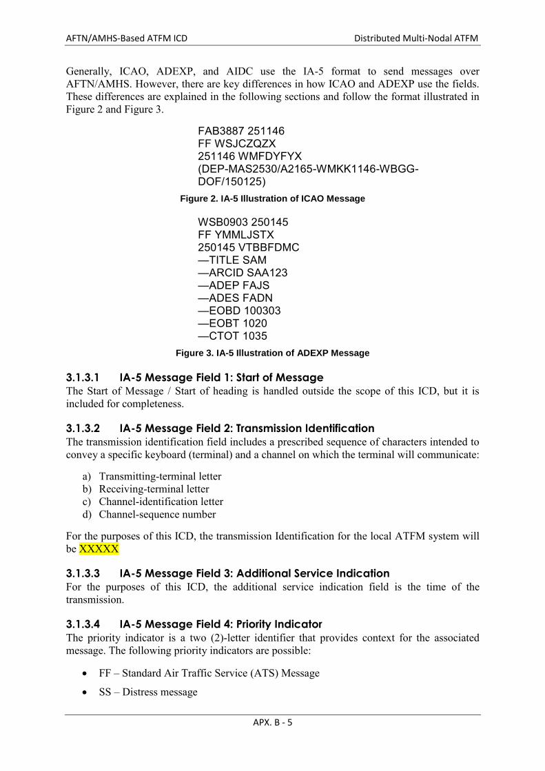
AFTN/AMHS-Based ATFM ICD Distributed Multi-Nodal ATFM
APX. B - 5
Generally, ICAO, ADEXP, and AIDC use the IA-5 format to send messages over AFTN/AMHS. However, there are key differences in how ICAO and ADEXP use the fields. These differences are explained in the following sections and follow the format illustrated in Figure 2 and Figure 3.
FAB3887 251146 FF WSJCZQZX 251146 WMFDYFYX (DEP-MAS2530/A2165-WMKK1146-WBGG-DOF/150125)
Figure 2. IA-5 Illustration of ICAO Message
WSB0903 250145 FF YMMLJSTX 250145 VTBBFDMC —TITLE SAM —ARCID SAA123 —ADEP FAJS —ADES FADN —EOBD 100303 —EOBT 1020 —CTOT 1035
Figure 3. IA-5 Illustration of ADEXP Message
3.1.3.1 IA-5 Message Field 1: Start of Message
The Start of Message / Start of heading is handled outside the scope of this ICD, but it is included for completeness.
3.1.3.2 IA-5 Message Field 2: Transmission Identification
The transmission identification field includes a prescribed sequence of characters intended to convey a specific keyboard (terminal) and a channel on which the terminal will communicate:
a) Transmitting-terminal letter b) Receiving-terminal letter c) Channel-identification letter d) Channel-sequence number
For the purposes of this ICD, the transmission Identification for the local ATFM system will be XXXXX
3.1.3.3 IA-5 Message Field 3: Additional Service Indication
For the purposes of this ICD, the additional service indication field is the time of the transmission.
3.1.3.4 IA-5 Message Field 4: Priority Indicator
The priority indicator is a two (2)-letter identifier that provides context for the associated message. The following priority indicators are possible:
FF – Standard Air Traffic Service (ATS) Message
SS – Distress message

AFTN/AMHS-Based ATFM ICD Distributed Multi-Nodal ATFM
APX. B - 6
DD – Urgent message
GG – One of the following: o Meteorological message o Flight Regularity Message o Aeronautical Information Services message
KK – Aeronautical Administrative message. For the purposes of this ICD, the ATFM messaging will only send FF messages.
3.1.3.5 IA-5 Message Field 5: Addressee of the Message
The addressee of the message is an eight-character code that is interpreted by the network to determine the routing location that the message will be sent.
When the number of addressees required is more than the operational system parameters allow, two or more transmissions of the message must be made. The eight (8)-letter combination addressee indicators are composed as follows:
The four (4)-letter ICAO location indicator, as defined by ICAO DOC 7910 (Location Indicators).
A three (3)-letter designator for the facility type/office, or if no designator has been assigned, ZZZX for aircraft in flight, or YYYX for all other cases. The source of the facility designator is ICAO DOC 8585, Designators for Aircraft Operating Agencies, Aeronautical Authorities and Services.
The eighth character of the address indicates the end system application and is determined by the Air Traffic Services Unit (ATSU).
3.1.3.6 IA-5 Message Field 6: Day / Time of the Message
The day/time field is the time the message is sent by a local ATFM System or filed for sending (for incoming messages). The field is a six (6)-digit date/time group that follows the format, DDHHMM in Coordinated Universal Time (UTC).
3.1.3.7 IA-5 Message Field 7: Originator of the Message
The originator of the message is an eight-character code of the ANSP, organization, and application which is sending the message. Similar to IA-5 Message Field 5, the originator address is constructed in three parts:
The four (4)-letter ICAO location indicator, as defined by ICAO DOC 7910 (Location Indicators).
A three (3)-letter designator for the facility type/office, as defined by ICAO DOC 8585, Designators for Aircraft Operating Agencies, Aeronautical Authorities and Services.
The eighth character of the address indicates the end system application and is determined by the ATSU.
3.1.3.8 IA-5 Message Field 8: Optional Heading Information
The optional heading information field is used for AIDC messages. It is rarely used for ICAO or ADEXP messages; therefore, it is not included in this ICD.

AFTN/AMHS-Based ATFM ICD Distributed Multi-Nodal ATFM
APX. B - 7
3.1.3.9 IA-5 Message Field 9: ATS Message Payload
See section 3.1.4 and section 3.2.
3.1.3.10 IA-5 Message Field 10: End of Message
The end of message field is a specific character sequence that is indicative of the end of the AFTN message. Similar to IA-5 message field 1, this is handled by the AFTN/AMHS gateway; therefore, it is not within the scope of this ICD.
3.1.4 Message Body (ATS Message Payload)
The message body—message type and data—follows the message header. The message body contains the message type and information used to identify the flight attributes as well as maintain an updated flight state. The message body may be different depending on whether it is defined by ICAO or ADEXP. The context of this ICD Is focused on multi-nodal operations, and therefore only ADEXP related messaging is included.
3.1.4.1 Messages defined by ADEXP
In contrast with messages defined by AIDC and ICAO, the message body for ADEXP messages does not begin with an open parenthesis. Instead, they begin with the hyphen “—“, followed by a keyword (TITLE), and then the three (3)-letter indicator of the message type. Although there are several complexities related to simple and compound fields in ADEXP messages, for this ICD, the focus is limited to only simple fields.
Each field is delimited a by hyphen “–“, and the data elements within each field are separated by ‘/’ or spaces. The example shown in Figure 4 has been presented in a manner which makes it easy to read. This has been achieved through the use of carriage returns, line feeds, indents, etc. Such a layout does not form part of the ADEXP format rules; therefore, presentation of a message is at the discretion of the receiving system.
− 𝑇𝐼𝑇𝐿𝐸 [𝑀𝑒𝑠𝑠𝑎𝑔𝑒𝑇𝑦𝑝𝑒] − [𝐹𝐼𝐸𝐿𝐷1][𝐸𝑙𝑒𝑚𝑒𝑛𝑡] − [𝐹𝐼𝐸𝐿𝐷2][𝐸𝑙𝑒𝑚𝑒𝑛𝑡] − [𝐹𝐼𝐸𝐿𝐷3][𝐸𝑙𝑒𝑚𝑒𝑛𝑡]
…
Figure 4. Overall structure of AFTN (ADEXP) message
Figure 5 is an example of a SAM message that follows the ADEXP structure:
—TITLE SAM —ARCID SAA123 —ADEP FAJS —ADES FADN —EOBD 100303 —EOBT 1020 —CTOT 1035 —REGUL FAJS —TAXITIME 0015 —REGCAUSE WA 84
Figure 5. SAM message using ADEXP structure

AFTN/AMHS-Based ATFM ICD Distributed Multi-Nodal ATFM
APX. B - 8
3.2 Functional Design Characteristics This subsection describes the functional design characteristics of this interface and focuses on the AFTN messages that contain the information necessary to manage flight data for multi-nodal operations, or are related to the communication between a local ATFM system and AFTN. These messages are independent of the messaging system—AFTN or AMHS.
Every ATFN message contains a combination of identifying fields for uniqueness and specific flight data attributes for the flight. Table 2 shows the information contained in each field and which fields are sent with each message type from ICAO Doc 4444 ATM/501 and includes all AFTN messages. Table 3 shows a similar table for those messages defined in ADEXP3.
3 Table 3 indicates the messages, as defined by the ADEXP; however, the source of the table is actually the Air Traffic Flow & Capacity Management Operations ATFCM Users Manual, edition 22.1, dated 14 November 2018.
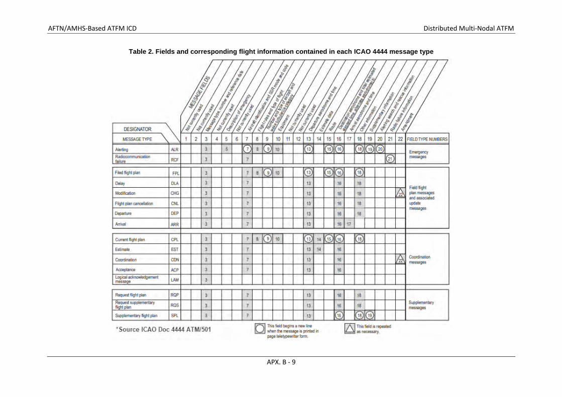
AFTN/AMHS-Based ATFM ICD Distributed Multi-Nodal ATFM
APX. B - 9
Table 2. Fields and corresponding flight information contained in each ICAO 4444 message type

AFTN/AMHS-Based ATFM ICD Distributed Multi-Nodal ATFM
APX. B - 10
Table 3. Fields and corresponding flight information contained in each ADEXP message type
The messages needed to perform the slot management functionality are the SAM, SRM and SLC. Each message sent by the Local ATFM system to AFTN/AMHS or received by the local ATFM System from AFTN/AMHS is compliant with ADEXP. The table 3 above is for reference only, please refer to the table 4 below for the exact ADEXP fields to be sent in the respective SAM, SRM and SLC messages.
3.2.1 ADEXP ATS Message Payload –Message Fields
Table 4 provides an overview of the data that is contained in each field for the ADEXP messages defined in this document. The complete structure and the format of the information in each field can be found in the EUROCONTROL Specification for ATS Data Exchange Presentation (ADEXP), version 3.2.
Each ATFM message comprises a number of fields, some of which are mandatory and some of which are optional. This may vary from message to message. Specific requirements are given in this document according to the principles of the ADEXP Standard document already mentioned. All ATFM messages shall begin with the TITLE field. The order of other fields is optional.
The field IFPLID, the unique identifier assigned to a flight by EUROCONTROL’s Integrated Initial Flight Plan Processing System (IFPS) (two (2) alphabetic characters followed by eight (8) digits, e.g. —IFPLID AA12345678), will be in all ADEXP messages issued by the Network Manager (NM). EUROCONTROL’s Enhanced Tactical Flow Management System (ETFMS) will accept the IFPLID when provided in an incoming message in ADEXP format. Therefore, messages sent to NM may include the Individual Flight Plan (IFPLD). The field is optional and it is not used in any other system worldwide so the value can be anything such as AA00000000.
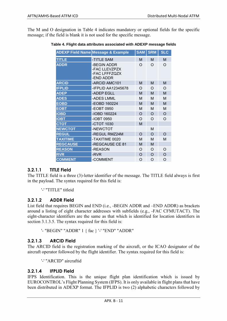
AFTN/AMHS-Based ATFM ICD Distributed Multi-Nodal ATFM
APX. B - 11
The M and O designation in Table 4 indicates mandatory or optional fields for the specific message; if the field is blank it is not used for the specific message.
Table 4. Flight data attributes associated with ADEXP message fields
ADEXP Field Name Message & Example SAM SRM SLC
TITLE -TITLE SAM M M M ADDR -BEGIN ADDR
-FAC LLEVZPZX -FAC LFFFZQZX -END ADDR
O O O
ARCID -ARCID AMC101 M M M IFPLID -IFPLID AA12345678 O O O ADEP -ADEP EGLL M M M ADES -ADES LMML M M M EOBD -EOBD 160224 M M M EOBT -EOBT 0950 M M M IOBD -IOBD 160224 O O O IOBT -IOBT 0950 O O O CTOT -CTOT 1030 M NEWCTOT -NEWCTOT M REGUL -REGUL RMZ24M O O O TAXITIME -TAXITIME 0020 M M M REGCAUSE -REGCAUSE CE 81 M M REASON -REASON O O O RVR -RVR O O O COMMENT -COMMENT O O O
3.2.1.1 TITLE Field
The TITLE field is a three (3)-letter identifier of the message. The TITLE field always is first in the payload. The syntax required for this field is:
'-' "TITLE" titleid
3.2.1.2 ADDR Field
List field that requires BEGIN and END (i.e., -BEGIN ADDR and –END ADDR) as brackets around a listing of eight character addresses with subfields (e.g., -FAC CFMUTACT). The eight-character identifiers are the same as that which is identified for location identifiers in section 3.1.3.5. The syntax required for this field is:
'- "BEGIN" "ADDR" 1 { fac } '-' "END" "ADDR"
3.2.1.3 ARCID Field
The ARCID field is the registration marking of the aircraft, or the ICAO designator of the aircraft operator followed by the flight identifier. The syntax required for this field is:
'-' "ARCID" aircraftid
3.2.1.4 IFPLID Field
IFPS Identification. This is the unique flight plan identification which is issued by EUROCONTROL’s Flight Planning System (IFPS). It is only available in flight plans that have been distributed in ADEXP format. The IFPLID is two (2) alphabetic characters followed by
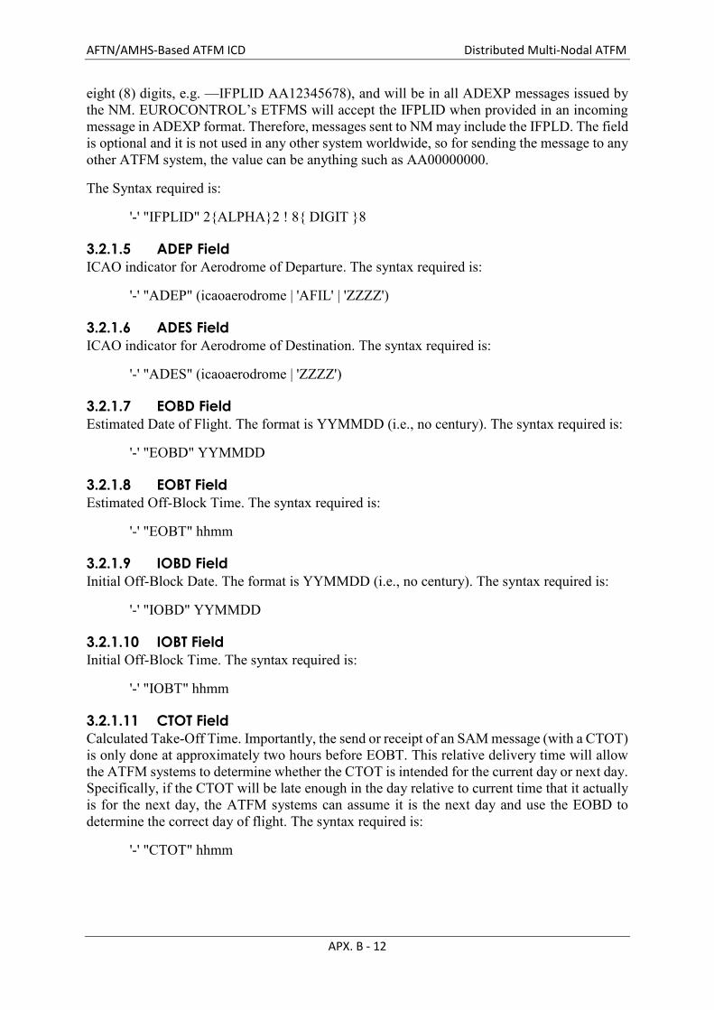
AFTN/AMHS-Based ATFM ICD Distributed Multi-Nodal ATFM
APX. B - 12
eight (8) digits, e.g. —IFPLID AA12345678), and will be in all ADEXP messages issued by the NM. EUROCONTROL’s ETFMS will accept the IFPLID when provided in an incoming message in ADEXP format. Therefore, messages sent to NM may include the IFPLD. The field is optional and it is not used in any other system worldwide, so for sending the message to any other ATFM system, the value can be anything such as AA00000000.
The Syntax required is:
'-' "IFPLID" 2{ALPHA}2 ! 8{ DIGIT }8
3.2.1.5 ADEP Field
ICAO indicator for Aerodrome of Departure. The syntax required is:
'-' "ADEP" (icaoaerodrome | 'AFIL' | 'ZZZZ')
3.2.1.6 ADES Field
ICAO indicator for Aerodrome of Destination. The syntax required is:
'-' "ADES" (icaoaerodrome | 'ZZZZ')
3.2.1.7 EOBD Field
Estimated Date of Flight. The format is YYMMDD (i.e., no century). The syntax required is:
'-' "EOBD" YYMMDD
3.2.1.8 EOBT Field
Estimated Off-Block Time. The syntax required is:
'-' "EOBT" hhmm
3.2.1.9 IOBD Field
Initial Off-Block Date. The format is YYMMDD (i.e., no century). The syntax required is:
'-' "IOBD" YYMMDD
3.2.1.10 IOBT Field
Initial Off-Block Time. The syntax required is:
'-' "IOBT" hhmm
3.2.1.11 CTOT Field
Calculated Take-Off Time. Importantly, the send or receipt of an SAM message (with a CTOT) is only done at approximately two hours before EOBT. This relative delivery time will allow the ATFM systems to determine whether the CTOT is intended for the current day or next day. Specifically, if the CTOT will be late enough in the day relative to current time that it actually is for the next day, the ATFM systems can assume it is the next day and use the EOBD to determine the correct day of flight. The syntax required is:
'-' "CTOT" hhmm
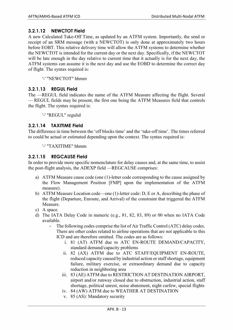
AFTN/AMHS-Based ATFM ICD Distributed Multi-Nodal ATFM
APX. B - 13
3.2.1.12 NEWCTOT Field
A new Calculated Take-Off Time, as updated by an ATFM system. Importantly, the send or receipt of an SRM message (with a NEWCTOT) is only done at approximately two hours before EOBT. This relative delivery time will allow the ATFM systems to determine whether the NEWCTOT is intended for the current day or the next day. Specifically, if the NEWCTOT will be late enough in the day relative to current time that it actually is for the next day, the ATFM systems can assume it is the next day and use the EOBD to determine the correct day of flight. The syntax required is:
'-' "NEWCTOT" hhmm
3.2.1.13 REGUL Field
The —REGUL field indicates the name of the ATFM Measure affecting the flight. Several — REGUL fields may be present, the first one being the ATFM Measures field that controls the flight. The syntax required is:
'-' "REGUL" regulid
3.2.1.14 TAXITIME Field
The difference in time between the ‘off blocks time’ and the ‘take-off time’. The times referred to could be actual or estimated depending upon the context. The syntax required is:
'-' "TAXITIME" hhmm
3.2.1.15 REGCAUSE Field
In order to provide more specific nomenclature for delay causes and, at the same time, to assist the post-flight analysis, the ADEXP field —REGCAUSE comprises:
a) ATFM Measure cause code (one (1)-letter code corresponding to the cause assigned by the Flow Management Position [FMP] upon the implementation of the ATFM measure).
b) ATFM Measure Location code—one (1)-letter code: D, E or A, describing the phase of the flight (Departure, Enroute, and Arrival) of the constraint that triggered the ATFM Measure.
c) A space. d) The IATA Delay Code in numeric (e.g., 81, 82, 83, 89) or 00 when no IATA Code
available. - The following codes comprise the list of Air Traffic Control (ATC) delay codes.
There are other codes related to airline operations that are not applicable to this ICD and are therefore omitted. The codes are as follows:
i. 81 (AT) ATFM due to ATC EN-ROUTE DEMAND/CAPACITY, standard demand/capacity problems
ii. 82 (AX) ATFM due to ATC STAFF/EQUIPMENT EN-ROUTE, reduced capacity caused by industrial action or staff shortage, equipment failure, military exercise, or extraordinary demand due to capacity reduction in neighboring area
iii. 83 (AE) ATFM due to RESTRICTION AT DESTINATION AIRPORT, airport and/or runway closed due to obstruction, industrial action, staff shortage, political unrest, noise abatement, night curfew, special flights
iv. 84 (AW) ATFM due to WEATHER AT DESTINATION v. 85 (AS): Mandatory security

AFTN/AMHS-Based ATFM ICD Distributed Multi-Nodal ATFM
APX. B - 14
vi. 86 (AG): Immigration, Customs, Health vii. 87 (AF): Airport Facilities, parking stands, ramp congestion, buildings,
gate limitations viii. 88 (AD): Restrictions at airport of destination, airport/runway closed
due obstruction, industrial action, staff shortage, political unrest, noise abatement, night curfew, special flights
ix. 89 (AM): Restrictions at airport of departure, airport/runway closed due obstruction, industrial action, staff shortage, political unrest, noise abatement, night curfew, special flights, start-up and pushback, ...
The —REGCAUSE appears in the SAM and SRM messages, and is associated only with the controlling ATFM Measure. The code appearing in the message is the code valid at the time the delay was given to the flight.
The syntax required is:
'-' "REGCAUSE" regulationreasoncode locationccode ” “ IATAdelaycode
3.2.1.16 REASON Field
Reason to explain an action by the FMP (e.g. rejection, cancellation, etc.). The syntax required is:
'-' "REASON" 4{ALPHA}12
3.2.1.17 RVR Field
Runway Visual Range. The syntax required is:
'-' "RVR" 1{ DIGIT }3
3.2.1.18 COMMENT Field
This field provides additional information. The syntax required is:
'-' "COMMENT" 1 { LIM_CHAR }
3.2.1.19 REFDATA field
This is reference data for the message being transmitted that collectively defines the unique message number. This field has three subfields, namely the sender subfield, the receiver (recvr) subfield, and the sequence number (seqnum) subfield. The sender subfield indicates the eight (8)-letter facility address of the sending facility; the receiver subfield indicates the eight (8)-letter facility address to which the message is being sent; and the sequence number subfield indicates the three (3)-digit serial number of the message being sent.
The message sequence number progresses sequentially from 001 to 000 (representing 1000), thence repeats from 001, for all messages sent to the same addressee, regardless of the type of message.
The three (3)-digit sequence number, the sender and receiver address, creates a unique combination used as the reference data. This is the equivalent of Field type 3, element (b) called ‘message number’ in ICAO Doc 4444.
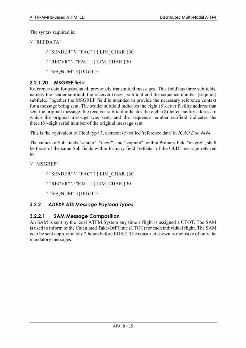
AFTN/AMHS-Based ATFM ICD Distributed Multi-Nodal ATFM
APX. B - 15
The syntax required is:
'-' "REFDATA"
'-' "SENDER" '-' "FAC" 1{ LIM_CHAR }30
'-' "RECVR" '-' "FAC" 1{ LIM_CHAR }30
'-' "SEQNUM" 3{DIGIT}3
3.2.1.20 MSGREF field
Reference data for associated, previously transmitted messages. This field has three subfields, namely the sender subfield, the receiver (recvr) subfield and the sequence number (seqnum) subfield. Together the MSGREF field is intended to provide the necessary reference context for a message being sent. The sender subfield indicates the eight (8)-letter facility address that sent the original message; the receiver subfield indicates the eight (8)-letter facility address to which the original message was sent; and the sequence number subfield indicates the three (3)-digit serial number of the original message sent.
This is the equivalent of Field type 3, element (c) called 'reference data' in ICAO Doc 4444.
The values of Sub-fields "sender", "recvr", and "seqnum", within Primary field "msgref", shall be those of the same Sub-fields within Primary field "refdata" of the OLDI message referred to
'-' "MSGREF"
'-' "SENDER" '-' "FAC" 1{ LIM_CHAR }30
'-' "RECVR" '-' "FAC" 1{ LIM_CHAR }30
'-' "SEQNUM" 3{DIGIT}3
3.2.2 ADEXP ATS Message Payload Types
3.2.2.1 SAM Message Composition
An SAM is sent by the local ATFM System any time a flight is assigned a CTOT. The SAM is used to inform of the Calculated Take-Off Time (CTOT) for each individual flight. The SAM is to be sent approximately 2 hours before EOBT. The construct shown is inclusive of only the mandatory messages.

AFTN/AMHS-Based ATFM ICD Distributed Multi-Nodal ATFM
APX. B - 16
3.2.2.2 SRM Message Composition
An SRM is sent by an ATFM system any time a flight that has already received an SAM message, is assigned a revised CTOT. The SRM is used to inform of the new Calculated Take-Off Time (CTOT) for each individual flight. Since the goal is to send the original CTOT (via SAM) approximately 2 hours before EOBT, the SRM should not be sent until after the SAM has been acknowledged, + a short interval of time (e.g., 5 minutes). That way, the SAM will always be the first message sent with a CTOT, and SRM messages are suppressed until the CTOT is sent. All revisions to the CTOT should be sent via SRM. The construct shown is inclusive of only the mandatory messages.
3.2.2.3 SLC Message Composition
An SLC is sent by an ATFM system any time a flight is no longer assigned a CTOT. The SLC is used to inform that the previously assigned Calculated Take-Off Time (CTOT) no longer applies for an individual flight. The construct shown is inclusive of only the mandatory messages.
TITLE
ARCID – –
–
IFPLID
ADEP ADES –
–
–
EOBD
EOBT CTOT –
–
–
TAXITIME
REGCAUSE –
SAM
Aircraft ID
Departure Airport
Arrival Airport
Estimated Off Block Time Calculated Take-Off Time
Estimated Taxi Time
TITLE
ARCID – –
–
IFPLID
ADEP ADES –
–
–
EOBD
EOBT NEWCTOT –
–
–
TAXITIME
REGCAUSE –
SRM
Aircraft ID
Departure Airport
Arrival Airport
Estimated Off Block Time New Calc Take-Off Time
Estimated Taxi Time
TBD value
TBD value
Estimated Off Block Day
ATFM Measure Cause Code
Estimated Off Block Day
ATFM Measure Cause Code

AFTN/AMHS-Based ATFM ICD Distributed Multi-Nodal ATFM
APX. B - 17
3.2.3 Message Summary Table
Table 5 provides a summary of the message including the ID, message title, whether it is required, and the message flow direction.
Table 5. Message Summary
ID Message Title Message Direction
SAM Slot Allocation Message Local AFTN System AFTN
SRM Slot Revision Message Local AFTN System AFTN
SLC Slot Cancellation Message Local AFTN System AFTN
3.2.4 Protocol Implementation
TBD – dependent on specific site implementation
3.2.5 Security
This is a direct connection between AFTN / AMHS and the local ATFM system through a cable connection and after the data is ingested into local ATFM System, the interface is controlled explicitly via firewall rules and precise protocols.
3.3 Physical Design Characteristics TBD – dependent on specific site implementation
3.3.1 Electrical Power and Electronic Characteristics
3.3.1.1 Connectors
TBD – dependent on specific site implementation
3.3.1.2 Wire/Cable
TBD – dependent on specific site implementation
3.3.1.3 Electrical Power/Grounding
TBD – dependent on specific site implementation
TITLE
ARCID – –
–
IFPLID
ADEP ADES –
–
–
EOBD
EOBT
TAXITIME – –
SLC
Aircraft ID
Departure Airport
Arrival Airport
TBD value
Estimated Off Block Time Estimated Taxi Time
Estimated Off Block Day

AFTN/AMHS-Based ATFM ICD Distributed Multi-Nodal ATFM
APX. B - 18
3.3.1.4 Fasteners
TBD – dependent on specific site implementation
3.3.1.5 Electromagnetic Compatibility
Not applicable.
CNS SG/23 Appendix C to the Report
APX. C – ACSICG/6 C - 1
Common Regional Virtual Private Network (VPN) Operations Group (OG) of Asia/Pacific Air Navigation Planning and
Implementation Regional Group (APANPIRG) (APANPIRG CRV OG)
TERMS OF REFERENCE
1. Background
The establishment of APANPIRG CRV OG was proposed during the deliberations of the CRV Task Force (TF) as a dedicated group to provide oversight of the CRV operations and the performance of the CRV Service Provider. The APANPIRG CRV OG is formally established by APANPIRG Decision 27/33.
2. Terms of Reference
The Common aeRonautical Virtual Private Network (VPN) Operations Group (OG) will provide oversight of the function and performance of the CRV and the performance of the Service Provider. The following are the activities to be performed:
a) Oversee the implementation of the CRV post Contract Award;
b) Manage issues arising from the transition with CRV TF, if any;
c) Co-ordinate and standardize the establishment or upgrade of CRV services as required;
d) Co-ordinate activities with other ICAO CRV OGs, if any, to make sure that decision making and communication with CRV Service Provider is consistent and timely;
e) Oversee the performance of the CRV Service Provider, including customer service;
f) Oversee the performance of the CRV network;
g) Oversee the escalation and solving by the CRV Service Provider of issues associated with the provision of the CRV, including safety and security related issues;
h) Assist with the resolution of issues associated with the provision of the CRV among
the CRV Users as required, including safety and security related issues;
i) Assist with the migration of Aeronautical Fixed Services (AFS) onto the CRV, in line with the GANP and seamless ATM plan;
j) Maintain CRV OG documentation associated with the function, performance and
management of the CRV, including the CRV OG Operations Manual, a list of CRV users and a record of variations to the common tender package;
k) Accept deliverables from the CRV Service Provider on behalf of the CRV Users as
required;
l) Promote the use of CRV;

CNS SG/23 Appendix C to the Report
APX. C – ACSICG/6 C - 2
m) Undertake continuous service improvements review to ensure CRV meets future needs; and
n) Perform any other activity as required by CRV operations.
3. Reporting
The CRV OG will report to Asia/Pacific Air Navigation Planning and Implementation Regional Group (APANPIRG) through ACSICG and CNS SG.
4. Participation The CRV OG will include all APAC Member States/Administrations, and any other organization as needed. Member States and/or inter-regional entry/exit Administrations in other ICAO regions may also be invited or request to participate in the activities of CRV OG.
5. Conduct of the work
It is anticipated that the CRV OG will conduct its work primarily by Web Conferences, teleconferences and other electronic means of communications. Face to Face meetings of CRV OG may be required on an annual basis. The ICAO APAC Regional Office will provide secretariat support for the CRV OG.
6. Rapporteur
There will be two Co-Chairpersons of the CRV OG, one primarily responsible for Asia coordination and the other for Pacific coordination.
_ _ _ _ _ _ _ _ _ _ _ _

CNS SG/23 Appendix D to the Report
INTERNATIONAL CIVIL AVIATION ORGANIZATION
COMMON AERONAUTICAL VPN (CRV) IMPLEMENTATION PLAN
Version 2.0
15 May 2019
ssomsri
Typewritten Text
ssomsri
Typewritten Text
ssomsri
Typewritten Text
APX. D - ACSICG/6
ssomsri
Typewritten Text
ssomsri
Typewritten Text
ssomsri
Typewritten Text
ssomsri
Typewritten Text

COMMON AERONAUTICAL VPN (CRV) IMPLEMENTATION PLAN – v2.0
Page 2 of 63
Table of Contents ABBREVIATIONS ............................................................................................................................... 4
1.0 INTRODUCTION ...................................................................................................................... 6
1.1 Purpose .................................................................................................................................... 6 1.2 Overview of the CRV .............................................................................................................. 6
2.0 IMPLEMENTATION OVERVIEW AND PROCESSES .......................................................... 7
2.1 General Description of Implementation .................................................................................. 7
2.2 Implementation Schedule/ Roadmap ...................................................................................... 7
2.2.1 Work Processes ................................................................................................................ 7
2.2.2 Roadmap for CRV ........................................................................................................... 8
2.3 Application Transition Schemes ............................................................................................. 8
2.3.1 AMHS .............................................................................................................................. 8
2.3.2 AFTN ............................................................................................................................... 8
2.3.3 ADS-B.............................................................................................................................. 9
2.3.4 Voice ................................................................................................................................ 9
2.4 Technical Specifications of CRV (for applications reference) ............................................... 9
2.4.1 Service Level Agreement & Quality of Service ............................................................ 10
2.4.2 IP Addressing ................................................................................................................. 10
2.4.3 Interface ......................................................................................................................... 10
2.4.4 Routing Restrictions....................................................................................................... 11
2.4.5 Packet Loss Rate ............................................................................................................ 11
2.4.6 For VoIP Transport (ED-137) ........................................................................................ 11
2.4.7 Standards used ............................................................................................................... 11
2.5 Use Cases .............................................................................................................................. 11
3.0 IMPLEMENTATION SUPPORT ............................................................................................ 13
3.1 Introduction ........................................................................................................................... 14 3.2 Implementation Team ........................................................................................................... 15
3.2.1 CRV-OG ........................................................................................................................ 15
3.2.2 National CRV Points of Contact .................................................................................... 15
3.2.3 Local CRV Points of Contact ........................................................................................ 28
3.2.4 CRV Contractor ............................................................................................................. 42
4.0 BASIC SITE IMPLEMENTATION REQUIREMENTS ......................................................... 43
4.1 Site/ Facilities Requirements ................................................................................................. 43
4.1.1 CRV User Responsibility ............................................................................................... 43
4.1.2 Contractor Responsibility .............................................................................................. 43
4.2 Hardware and Software Requirements .................................................................................. 45
4.2.1 General Topics ............................................................................................................... 45
4.2.2 Hardware Requirements................................................................................................. 46
4.2.3 Software Requirements .................................................................................................. 46
5.0 TESTING AND EVALUATION. ............................................................................................ 46
6.0 CONTINGENCY PLAN/ BACK-OFF PLAN ......................................................................... 48
6.1 Purpose .................................................................................................................................. 48 6.2 Harmonized Contingency Plan.............................................................................................. 48
7.0 MIXED OPERATING ENVIRONMENT ............................................................................... 48
7.1 Routing of AFTN/ AMHS messages to non-CRV States/ Administrations ......................... 48

COMMON AERONAUTICAL VPN (CRV) IMPLEMENTATION PLAN – v2.0
Page 3 of 63
7.2 Inter-Region common network connectivity......................................................................... 48
Appendix A .......................................................................................... Error! Bookmark not defined. Appendix B .......................................................................................................................................... 63

COMMON AERONAUTICAL VPN (CRV) IMPLEMENTATION PLAN – v2.0
Page 4 of 63
ABBREVIATIONS ABBREVIATION DESCRIPTION AFTN Aeronautical Fixed Telecommunication Network AIDC ATS Inter-facility Data Exchange AMHS Air Traffic Service Message Handling System ANSP Air Navigation Service Provider APANPIRG Asia/Pacific Air Navigation Planning and Implementation Regional Group APAC Asia/Pacific ATC Air Traffic Control ATM Air Traffic Management ATN Aeronautical Telecommunication Network ATS Air Traffic Services BBIS Backbone Boundary Intermediate System BIS Boundary Intermediate System CAA Civil Aviation Authority CAR Caribbean Region CBA Cost Benefit Analysis CNS Communications, Navigation and Surveillance ConOps Concept of Operations CRV Common aeRonautical Virtual Private Network DSCP Differentiated Services Code Point EUR European Region FIXM Flight Information Exchange Model FPL Flight Plan ICAO International Civil Aviation Organization IP Internet Protocol IPS Internet Protocol Suite IWXXM ICAO Weather Information Exchange Model MET Meteorological MPLS Multi-Protocol Label Switching NAT Network Address Translation NID Network Interface Device OH Operational Hazard OG Operation Group OSI Open Systems Interconnections PoC Point of Contact QoS Quality of Service RFI Request for Information RFP Request for Proposal SARP Standards and Recommended Practices SAT Site Acceptance Test SIP Session Initiation Protocol SME Subject Matter Expert SOP Standard Operating Procedures ST Sealed Tender

COMMON AERONAUTICAL VPN (CRV) IMPLEMENTATION PLAN – v2.0
Page 5 of 63
ABBREVIATION DESCRIPTION SWIM System-Wide Information Management TF Task Force WXXM Weather Information Exchange Model (based on XML) UC Use Case VoIP Voice Over Internet Protocol VPN Virtual Private Network XML Extensible Markup Language

COMMON AERONAUTICAL VPN (CRV) IMPLEMENTATION PLAN – v2.0
Page 6 of 63
1.0 INTRODUCTION 1.1 Purpose The purpose of this Implementation Plan is to provide guidance for all States/ Administrations on the operation requirements for the upcoming Common aeRonautical Virtual Private Network (CRV) used in Asia/ Pacific (APAC) Region and the roadmap for implementation. The details includes in Table 1, Table 2 and Appendix A, a list of all States/ Administrations concerned, and for each State/ Administration it includes the:
i. National Points of Contact and Local Points of Contact; and
ii. expected deployment date. The information contained in this document was first adopted by the 1st Meeting of CRV Operations Group (CRV OG/1). It is intended that this Implementation Plan shall be used as the means to:
i. identify all actions required to implement CRV;
ii. ensure a harmonized approach for the APAC Region;
iii. monitor and report on progress; and
iv. identify any issues, risks or problems which may arise.
1.2 Overview of the CRV Currently, aeronautical ground-ground communications in the ICAO Asia/Pacific Region, and in particular Aeronautical Fixed Telecommunication Network (AFTN) and AMHS services, operate over point-to-point international leased circuits. However, this network configuration exhibits a number of limitations such as the inability to switch to new protocols like Voice over IP (VoIP) or System Wide Information Management (SWIM) efficiently, high cost for every connection and limited flexibility for increase in bandwidth. A CRV Task Force (TF) was formally established in accordance with APANPIRG Decision (24/32), (Bangkok, Thailand, 24-26 June 2013). The concept of CRV was taken from other common network that has already implemented in other regions such as Pan-European Network Services (PENS) and FAA Telecommunication Infrastructure (FTI). The CRV is a dedicated multiprotocol label switching (MPLS) Internet Protocol (IP) based Virtual Private Network (VPN) communication network provided by a common network service provider and support all Aeronautical Fixed Service (AFS) in the APAC region. Telecommunication costs are reduced as States/ Administrations will only require minimal connections to a far reaching network instead of individual connections to each neighboring State/ Administration. The CRV service provider provides the service to allow CRV members to exchange voice and data information with each other. Each CRV member should determine the amount of bandwidth require for each Quality of Service (QoS) sub queue. In addition, each CRV member should also determine the total access bandwidth that they need to subscribe.
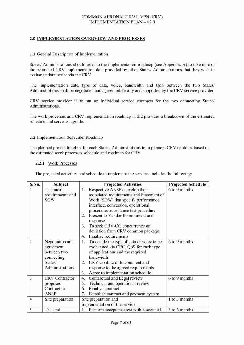
COMMON AERONAUTICAL VPN (CRV) IMPLEMENTATION PLAN – v2.0
Page 7 of 63
2.0 IMPLEMENTATION OVERVIEW AND PROCESSES 2.1 General Description of Implementation States/ Administrations should refer to the implementation roadmap (see Appendix A) to take note of the estimated CRV implementation date provided by other States/ Administrations that they wish to exchange data/ voice via the CRV. The implementation date, type of data, voice, bandwidth and QoS between the two States/ Administrations shall be negotiated and agreed bilaterally and supported by the CRV service provider. CRV service provider is to put up individual service contracts for the two connecting States/ Administrations. The work processes and CRV implementation roadmap in 2.2 provides a breakdown of the estimated schedule and serve as a guide. 2.2 Implementation Schedule/ Roadmap The planned project timeline for each States/ Administrations to implement CRV could be based on the estimated work processes schedule and roadmap for CRV.
2.2.1 Work Processes
The projected activities and schedule to implement the services includes the following: S/No. Subject Projected Activities Projected Schedule 1 Technical
requirements and SOW
1. Respective ANSPs develop their associated requirements and Statement of Work (SOW) that specify performance, interface, conversion, operational procedure, acceptance test procedure
2. Present to Vendor for comment and response
3. To seek CRV-OG concurrence on deviation from CRV common package
4. Finalize requirements
6 to 9 months
2 Negotiation and agreement between two connecting States/ Administrations
1. To decide the type of data or voice to be exchanged via CRC, QoS for each type of applications and the required bandwidth
2. CRV Contractor to comment and response to the agreed requirements
3. Agree to implementation schedule
6 to 9 months
3 CRV Contractor proposes Contract to ANSP
4. Contractual and Legal review 5. Technical and operational review 6. Finalize contract 7. Establish contract and payment system
6 to 9 months
4 Site preparation Site preparation and implementation of the service
1 to 3 months
5 Test and 1. Perform acceptance test with associated 3 to 6 months

COMMON AERONAUTICAL VPN (CRV) IMPLEMENTATION PLAN – v2.0
Page 8 of 63
S/No. Subject Projected Activities Projected Schedule evaluation applications
2. Perform acceptance test with respective ANSPs
6 Service acceptance
Service acceptance 1 week
2.2.2 Roadmap for CRV
The roadmap for CRV implementation in the APAC Region is appended in Appendix A.
2.3 Application Transition Schemes This paragraph provides States/ Administrations the recommended transition scheme for each application (e.g. AMHS, ATFM, ADS-B, Voice, etc.) targeted to be implemented or migrated from the existing communication link/ network.
2.3.1 AMHS
Being IP, it should be possible to reroute the existing connection at the IP layer either by an address translation or by pointing the LA at a new IP address in the AMHS system. However the recommended approach will be to setup a parallel connection using the CRV that can be thoroughly tested to the satisfaction of both ANPS’s. Once the stability of the CRV has been verified, the cutover would be conducted by the respective com-centers at the AMHS system level. The actual approach taken will require a negotiation between each pair of ANSP’s.
2.3.2 AFTN
Depending on the existing AFTN connection there are a number of migration strategies available.
Option 1. Migration to AMHS
Setting up a new AMHS link over the CRV as per ICAO grand master plan xyz.123 would be the preferred option for migration of AFTN. It would allow the new connection to be setup and tested independently.
Option 2. Migrate from native X.25 to XoT
Where the existing connection is a native X.25 connection end to end, and migration to AMHS is not possible, then XoT is the next preferred option. It is recommended that a new LA be setup that uses the XoT over CRV path. Once the XoT connection has been verified and tested by each ANSP then actual migration of AFTN would be performed by the respective com centers similar to AMHS in 2.3.1 above. If PCCW are not able to provide serial interfaces on their CE routers then it would be incumbent on the ANSP to deliver the AFTN traffic as a XoT connection.
Option 3. Migrate from XoT to XoT
Where the AFTN connection between two ANSP’s is already using XoT, and if the trust in the performance of the CRV is high, then the cutover from the legacy link to the CRV could be as simple as an X25 route change on each ANSP’s respective XoT routers. Alternatively, a new LA could be setup and tested before being cutover at the system level by the respective ANSP’s com-centers.

COMMON AERONAUTICAL VPN (CRV) IMPLEMENTATION PLAN – v2.0
Page 9 of 63
2.3.3 ADS-B
To deliver their stream to the PCCW gateway, likewise at the other end it would be up to the partner ANSP to ensure that that there is a multicast path available from the CRV egress to their flight data management system. Being multicast it is possible for the same information to traverse the same two endpoints via multiple network paths simultaneously, however some ANSPs may decide to setup new multicast groups via the CRV so that the performance of the CRV can be measured against the legacy link. Alternatively, ANSPs may decide to replace the multicast stream with unicast data flows that operate via an ADS-B filter.
PCCW could implement Generic Routing Encapsulation (GRE) tunnel solution (NID to NID) between States/ Administrations who are agreeable to have direct connection for routing control over the any to any MPLS layer 3 backbone.
2.3.4 Voice
The specific strategy used to migrate the voice services will vary depending on the existing setup, the proposed voice interface between the ANSP and PCCW (E&M / ISDN / VoIP), how the partner ANSP is setup and their intended connection to PCCW. Despite this there are two main options.
Option 1 – New buttons on the operator consoles - Preferred
This option involves setting up new buttons on the operator consoles at each end. The new buttons are configured from the outset to route via the CRV. This strategy allows the new service to be configured and tested with minimal disruption to operators and also allows for an almost seamless cutover (pressing a different button). Another great advantage of this strategy is to ability to do a practical test of the voice quality by allowing the same pair of controllers test both paths within a few seconds of each other.
Option 2 – Reconfigure existing connections to use the CRV
Where Option 1 is not possible, the only other alternative is to reconfigure the existing connection. This will involve increased coordination between the two ANSP’s and PCCW as well as potentially multiple technical groups within an ANSP as it is likely that multiple systems will need to be reconfigured at the same time. E.g. Voice switches, networking devices etc. This option would also involve a lengthy outage and interruption to operational staff.
2.4 Technical Specifications of CRV (for applications reference) CRV envisaged in the ICAO CNS/ ATM concept via through two backbones (one Multiprotocol Label Switching (MPLS), based on a terrestrial, satellite, or both networks, and one based on a secured Virtual Private Network over the public internet.
i. It will be a homogeneous and generalized application of the IP protocol in the transport network for voice and data aeronautical communications;
ii. It will establish an appropriate Quality of Service (QoS) quality requirements;
iii. It will have a centralized and common network management;
iv. It will have a homogeneous and standardized interface, consisting Network Interface Device(s) (NID(s)) linked to the existing local switches, satellite and/or terrestrial links based

COMMON AERONAUTICAL VPN (CRV) IMPLEMENTATION PLAN – v2.0
Page 10 of 63
on the Multiprotocol Label Switching (MPLS) technology, as well as ground services, based on a Virtual Private Network (VPN) over the public internet;
v. It will have voice and data gateway service by the Service Provider; and
vi. For IT security, individual ANSPs may implement an authentication service based on a cooperative public key infrastructure (PKI) including IPSec for IPv4 and IPv6 and digital certificates management for public IP links between ANSPs.
Figure 1: High level system overview of CRV
2.4.1 Service Level Agreement & Quality of Service
i. QoS are implemented using guidance from IETF RFC 4594 Configuration Guidelines for Different Service Classes. The routing protocol, voice, voice signaling, real-time interactive and standard data types shall all be given separate QoS bandwidth;
ii. Differentiated Services Code Point (DSCP) QoS markings to traffic will be used before it enters the network; and
iii. SLAs are based on States/ Administrations’ requirements (i.e. Packages A, B, B+, C, C+ and D offered by CRV contractor).
2.4.2 IP Addressing
i. CRV supports IPv4 and IPv6 addressing. The overall IP addressing plan will be centrally managed by the CRV contractor and will be known as the CRV IP address plan;
ii. An IPv4 plan, appended as Appendix B, was agreed in the APAC region and was concluded through Conclusion 21/22 - Asia/Pacific ATN Interim Addressing Plan; and
iii. The Middle East Regional (MID) region IPv4 plan is appended as Appendix C of this document.
2.4.3 Interface
i. The interface type provided by the NID to the CRV User is the Ethernet IEEE 802.3ab (1000
Base-T).
COMMON AERONAUTICAL VPN (CRV) IMPLEMENTATION PLAN – v2.0
Page 11 of 63
2.4.4 Routing Restrictions
i. Route advertisements will be restricted so that each CRV User which interacts with the CRV routing protocol can only advertise subnets which are allowed in the CRV IP Address Plan.
ii. When peering with the CRV Contractors network, it is permissible to use the CRV User’s own Public IP addressing and ASN, and the CRV Contractor will use a Public AS.
2.4.5 Packet Loss Rate:
i. Packet loss rate of less than 0.1% for all the SLA-Voice; and
ii. Packet loss rate of less than 0.5% for all the SLA-Data.
2.4.6 For VoIP Transport (ED-137)
i. The VoIP Transport shall provide a maximum jitter of 40ms;
ii. The VoIP Transport shall provide a maximum packet loss of 0.1%;
iii. The VoIP Transport shall provide an availability greater than 99.9%; and
iv. The CRV shall use the high priority tags in the VPN packet headers to ensure that VoIP traffic is given high priority and minimal delay. An appropriate level of priority will be given to ED-137 SIP signaling.
2.4.7 Standards used
i. SNMP and MIB-II management protocols, implemented in accordance with RFC 1157 and
RFC 1213;
ii. Implementation of the RTP/RTCP and RTP “header compression” protocols, in accordance with RFC 2508;
iii. The multiservice IP network permit the creation of VPNs using MPLS, in accordance with RFC 2547 and RFC 3031, and QoS configuration over MPLS/VPN, in accordance with RFC 3270 and RFC 2983;
iv. QoS is implemented using guidance from IETF RFC 4594. (Covered under QoS); and
v. The CRV provide transport for the ED-137 VoIP. *Note: If at the time of the publication of this document the specific rules and standards mentioned in any of the other Sections have been revoked, superseded or updated, the new rules or standards shall be deemed as applicable. 2.5 Use Cases Use Case 1 – ANSPs Interconnect AMHS Summary of Situation

COMMON AERONAUTICAL VPN (CRV) IMPLEMENTATION PLAN – v2.0
Page 12 of 63
ANSP ‘A’ and ANSP ‘B’ wish to have a direct connection between their AMHS. Both ANSPs decide that the AMHS application shall be built upon the Aeronautical Telecommunication Network (ATN). The ATN will in turn use the CRV. User Response Each ANSP already has a connection to the CRV. Each ANSP: 1. Notifies the CRV-OG Coordinator of their intention to establish the new facility. 2. Determines if their existing access speed is sufficient. If it is not the ANSP will arrange with the CRV Service Provider to increase their bandwidth. 3. Negotiates bi-laterally with the other ANSP to determine what IT security arrangements are required. In this User Case they decide to implement an IPSec VPN. 4. Negotiates bi-laterally with the other ANSP to determine what testing, acceptance and commissioning procedures are required. 5. Notify CRV-OG on completion of the implementation to update records. Operational Needs UC1.1 The CRV link must meet the reliability and availability needs of AMHS. UC1.2 The CRV link must provide IP version 4 transport for the ATN. UC1.3 The CRV link must provide IP version 6 transport for the ATN. UC1.4 The CRV link must allow the ANSPs to implement IPSec VPN tunnels. UC1.5 The CRV link must allow for bandwidth changes. Use Case 2 – ANSPs Implement ATC Voice over Internet Protocol Circuits Summary of Situation ANSPs ‘A’ and ‘B’ wish to build upon the success of their AMHS implementation and have identified four Voice over Internet Protocol (VoIP) voice circuits which should be moved to the CRV. User Response Each ANSP already has a connection to the CRV. Each ANSP: 1. Notifies the CRV-OG Coordinator of their intention to establish the new facility. 2. Determines if their existing access bandwidth is sufficient. If it is not, the ANSP will arrange with the Service Provider to increase their bandwidth. 3. Negotiates bi-laterally with the other ANSP to determine what IT security arrangements are required. In this Case they decide to implement an IPSec VPN to provide secure end-to-end transport between ANSPs. 4. Negotiates bi-laterally with the other ANSP to determine what testing, acceptance and commissioning procedures are required. 5. Tags the VPN traffic containing the Voice over Internet Protocol (VoIP) Real-time Transport Protocol (RTP) and Session Initiation Protocol (SIP) data with appropriate priority markings to allow the CRV Service Provider to identify the voice traffic. Operational Needs UC2.1 The CRV link must meet the reliability and availability needs of ATC voice. UC2.2 The CRV link must provide an IP version 4 VPN tunnel to transport IP version 4 VoIP and SIP signaling. UC2.3 The CRV link must provide an IP version 6 VPN tunnel to transport IP version 6 VoIP and SIP signaling. UC2.4 The CRV link will use the high priority tags in the VPN packet headers to ensure that VoIP traffic is given high priority and minimal delay. Use Case 3 – ANSPs Implement Automatic Ring-down Circuits Summary of Situation

COMMON AERONAUTICAL VPN (CRV) IMPLEMENTATION PLAN – v2.0
Page 13 of 63
ANSPs ‘A’ and ‘B’ wish to build upon the success of their AMHS implementation and have identified an Automatic Ring-down (ARD) analog voice circuit which should be moved to the CRV. User Response Each ANSP already has a connection to the CRV. Each ANSP: 1. Notifies the CRV-OG Coordinator of their intention to establish the new facility. 2. Determines if their existing access bandwidth is sufficient. If it is not, the ANSP will arrange with the Service Provider to increase their bandwidth. 3. Negotiates bi-laterally with the other ANSP to determine what voice quality Mean Opinion Score (MOS) is required. Perceptual Evaluation of Speech Quality (PESQ) ITU-T Rec. P.862 may be used to measure the effects of distortions (e.g. errors, packet loss, delay, etc.) to provide the MOS score. 4. Negotiates bi-laterally with the other ANSP to determine what testing, acceptance and commissioning procedures are required. UC3.1 The CRV link must meet the reliability and availability needs of ATC voice. UC3.2 The CRV link must provide conversion from analog voice to VoIP. UC3.3 The CRV link must provide appropriate SIP signaling to support the ARD functionality. UC3.4 The CRV link must provide IP version 4 transport for the VoIP. UC3.5 The CRV link must provide IP version 6 transport for the VoIP. UC3.6 The CRV link will use the high priority tags in the packet headers to ensure that VoIP traffic is given high priority and minimal delay. The CRV must give an appropriate level of priority to SIP. UC3.7 The CRV link must deliver voice so that it is clearly understood with minimal delay. Use Case 4 – ANSPs Implement Analog Voice Circuits Summary of Situation ANSPs ‘A’ and ‘B’ wish to build upon the success of their AMHS implementation and have identified four analog voice circuits which should be moved to the CRV. User Response Each ANSP already has a connection to the CRV. Each ANSP: 1. Notifies the CRV-OG Coordinator of their intention to establish the new facility. 2. Determines if their existing access bandwidth is sufficient. If it is not, the ANSP will arrange with the Service Provider to increase their bandwidth. 3. Negotiates bi-laterally with the other ANSP to determine what voice quality Mean Opinion Score (MOS) is required. In this Case they decide a MOS of 4.0 is required so they select a CRV service level that provides the required voice quality. 4. Negotiates bi-laterally with the other ANSP to determine what testing, acceptance and commissioning procedures are required. Operational Needs UC4.1 The CRV link must meet the reliability and availability needs of ATC voice. UC4.2 The CRV link must provide conversion from analog voice to VoIP. UC4.3 The CRV link must detect analog signaling and provide appropriate SIP signaling and vice versa. UC4.4 The CRV link must provide IP version 4 transport for the VoIP. UC4.5 The CRV link must provide IP version 6 transport for the VoIP. UC4.6 The CRV link will use the high priority tags in the packet headers to ensure that VoIP traffic is given high priority and minimal delay. The CRV must give an appropriate level of priority to SIP. UC4.7 The CRV link must deliver voice so that it is clearly understood with minimal delay. 3.0 IMPLEMENTATION SUPPORT

COMMON AERONAUTICAL VPN (CRV) IMPLEMENTATION PLAN – v2.0
Page 14 of 63
3.1 Introduction The aim of the transition is to be interruption less. But as the services must migrate from the current network infrastructure to the CRV, an interruption time due to disconnection and reconnection, is mandatory and the team involved (CRV-OG, CRV Members and Contractor) will be of utmost importance to the overall process. This chapter comprises the basic teams involved in the implementation of the CRV infrastructure, the roles of each professional and the main coordination steps and stakeholders including the CRV-OG. These responsibilities come in addition to those stated in the Terms and Conditions and Terms of Reference. Figure 3 describes the relevant entities for the CRV implementation.
Figure 3: Relevant Entities to this Project. (Source: CRV Tender doc - Att II - Terms of Reference_v3)
COMMON AERONAUTICAL VPN (CRV) IMPLEMENTATION PLAN – v2.0
Page 15 of 63
3.2 Implementation Team The implementation team will be composed of the CRV-OG representatives, the National Points of Contact (NPOC), Local Points of Contact (LPOC) and the CRV Contractor Team, as described in the following sections.
3.2.1 CRV-OG The CRV Operations Group (OG) will provide oversight of the function and performance of the network after the CRV is completely installed. Besides, it will be involved in the oversight of the implementation of the CRV post Contract Award. The main activities and roles applied to the CRV-OG during the implementation of the CRV infrastructure are:
i. Develop close coordination with the National CRV POC and Contractor for the complete implementation of the CRV node;
ii. Provide the CRV IP Addressing Scheme (Plan) to the Contractor, in close coordination with the National CRV POC; and
iii. Provide the classification and marking scheme for the prioritization of traffic for the QoS to be used by the aeronautical applications in the CRV network.
Note: When applying QoS, the end-to-end configuration needs to be observed (LAN- layer 2 switches and WAN- Layer 3 routers devices). So, this activity will involve close coordination with the National CRV POC and Contractor, taking into consideration the tender document Att II - Annex b - Matrix of Flows for CRV services_v2), SLA, and the tender document Att II - Annex c - Mapping of services for quality management_v2.
3.2.2 National CRV Points of Contact Table 1 contains the National CRV Points of Contact that will be in charge of the whole process in each CRV Member, independently if the State involved has more than one node. The main activities and roles of the National CRV Points of Contact are:

COMMON AERONAUTICAL VPN (CRV) IMPLEMENTATION PLAN – v2.0
Page 16 of 63
i. Develop close coordination with the CRV-OG representatives, Contractor and Local CRV POC for the complete implementation of the CRV node;
ii. Receive the requests for site surveys from the Contractor, coordinating the actions with the Local CRV POC;
iii. Participate and/or Coordinate the participation of the Local CRV POC and Local Staff in the implementation meetings with the Contractor;
iv. Participate and/or Coordinate the participation of the Local CRV POC and Local Staff in the training package (on line, on site, initial and refresh) as defined in the Section 3.12 (Training) of the Terms of Reference (TOR) document;
v. Coordinate the actions and instruct the Local CRV Points of Contact regarding all activities involved in the implementation phase;
vi. Review and approve the System Design Document (SDD), System Engineering plan (SEP) and other documents, part of the tender package, prepared by the Contractor upon the contract award and signature;
vii. Review and approve the Validation Plan, including the Site Acceptance Test (SAT), prepared by the Contractor;
viii. Oversee if the Contractor is following the national laws and procedures concerning the assignment of frequencies with the radio regulator authorities in each country (case of microwave and satellite equipment);
ix. Update the ICAO CNS Regional Officer (ICAO Asia and Pacific Regional Office) with regard to the timeframe, situation, difficulties and other topics deemed necessary for the implementation of the CRV node(s);
x. Provide the local CRV IP Addressing Scheme - Plan to the Contractor in close coordination with the CRV-OG representatives.
xi. Provide the current numbering plan for the ATS Switched Voice Circuits to the Contractor;
xii. Provide the current direct hotline Voice Circuits configuration to the Contractor;
xiii. Provide the classification and marking scheme for the prioritization of traffic for the QoS to be used by the aeronautical applications in the CRV network (See note in the paragraph 3.2.1.3);
xiv. Receive the requests for site surveys from the Contractor and coordinate the activities with the Local CRV POC; and
xv. Approve the implementation planning.

COMMON AERONAUTICAL VPN (CRV) IMPLEMENTATION PLAN – V2.0
Page 17 of 63
Table 1: National CRV Points of Contact Asia Pacific Region:
State/ Administratio
n
ANSP/ CAA
National CRV Point of Contact
(POC) Job Title E-mail Telephone/FAX Address
Afghanistan
Director of Technical Services
Afghanistan Civil Aviation
Authority (ACAA)
Eng. Mohammad Shaker Popal
Director of CNS
Office Tele: +93 (0)20 2311962
Mobile : +93 (0)799 601095 Kabul international airport
Australia Airservices Australia
Mr. Terence Palmer
Team Leader Networks
om
Tel:+61 (2) 6268 4960
Airservice Australia 25 Constitution Avenue
Canberra 2600, ACT Australia
Bangladesh
Dhaka Hazrat Shahjalal
Mr. S M A Gaffar Fakir
Communication Officer (ATM) Civil Aviation Authority of Bangladesh
Tel +880 171 506 7502 Fax +880 (2) 890 1411
Headquarters, Kurmitola Dhaka 1229
BANGLADESH

COMMON AERONAUTICAL VPN (CRV) IMPLEMENTATION PLAN – V2.0
Page 18 of 63
State/ Administratio
n
ANSP/ CAA
National CRV Point of Contact
(POC) Job Title E-mail Telephone/FAX Address
Bhutan Civil Aviation Authority
Mr. Karma Wangchuk
Dy. Executive ANS
Engineer
+975 8 271347 (Ext.:107), Fax.: +975 8 271944 Paro Airport
Brunei Darussalam
Cambodia Mr. Neang To
Chief of CNS State Secretariat
of Civil Aviation
Tel +855 (23) 224 258 Fax +855 (23) 224 259
State Secretariat of Civil Aviation
#44 Phnom Penh International Airport
Russian Federation Blvd. Phnom Penh CAMBODIA
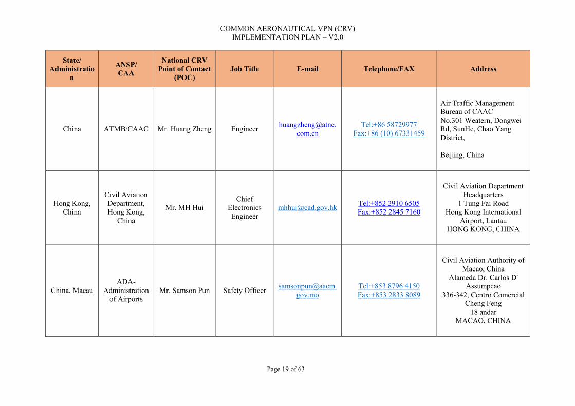
COMMON AERONAUTICAL VPN (CRV) IMPLEMENTATION PLAN – V2.0
Page 19 of 63
State/ Administratio
n
ANSP/ CAA
National CRV Point of Contact
(POC) Job Title E-mail Telephone/FAX Address
China ATMB/CAAC Mr. Huang Zheng Engineer [email protected]
Tel:+86 58729977 Fax:+86 (10) 67331459
Air Traffic Management Bureau of CAAC No.301 Weatern, Dongwei Rd, SunHe, Chao Yang District, Beijing, China
Hong Kong, China
Civil Aviation Department, Hong Kong,
China
Mr. MH Hui Chief
Electronics Engineer
Tel:+852 2910 6505 Fax:+852 2845 7160
Civil Aviation Department Headquarters
1 Tung Fai Road Hong Kong International
Airport, Lantau HONG KONG, CHINA
China, Macau ADA-
Administration of Airports
Mr. Samson Pun Safety Officer [email protected]
Tel:+853 8796 4150 Fax:+853 2833 8089
Civil Aviation Authority of Macao, China
Alameda Dr. Carlos D' Assumpcao
336-342, Centro Comercial Cheng Feng
18 andar MACAO, CHINA

COMMON AERONAUTICAL VPN (CRV) IMPLEMENTATION PLAN – V2.0
Page 20 of 63
State/ Administratio
n
ANSP/ CAA
National CRV Point of Contact
(POC) Job Title E-mail Telephone/FAX Address
Democratic People's
Republic of Korea
General Administration
of Civil Aviation
Mr. Ri Sung II
Vice Chief, Communication Section ATM Department
Tel:+850 (2) 181111 Ext. 8108
Fax:+850 (2) 381 4410
General Administration of Civil Aviation
Pyongyang International Airport
Sunan District, Pyongyang DEMOCRATIC PEOPLE'S
REPUBLIC OF KOREA
Fiji Airports Fiji Limited
Mr. Kelepi Dainaki
Manager Air Navigation Engineering
Services
Tel:+679 673 1623 Mobile:+679 990 6110
Fax:+679 673 1123
Airports Fiji Limited Private Mail Bag
Nadi Airport FIJI ISLANDS
France (territories of
French Polynesia,
New Caledonia and
Wallis and Futuna)
DSNA (France) Mr. Jean-Marc Valentin ATM Expert
Tel:+687 352443 Fax:+687 265 206
Direction Aviation Civile BP H1, 98800
NEW CALEDONIA
India Airports
Authority of India
Mr. Anurag Sharma
General Manager (COM) [email protected]
Tel:+91 (11) 2461 0537 Fax:+91 (11) 2463 2930
Airports Authority of India Rajiv Gandhi Bhawan
Saddurjung Airport New Delhi 110003
INDIA
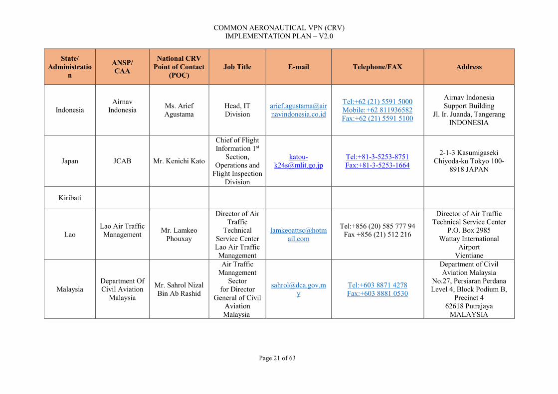
COMMON AERONAUTICAL VPN (CRV) IMPLEMENTATION PLAN – V2.0
Page 21 of 63
State/ Administratio
n
ANSP/ CAA
National CRV Point of Contact
(POC) Job Title E-mail Telephone/FAX Address
Indonesia Airnav
Indonesia
Ms. Arief Agustama
Head, IT Division
Tel:+62 (21) 5591 5000 Mobile: +62 811936582 Fax:+62 (21) 5591 5100
Airnav Indonesia Support Building
Jl. Ir. Juanda, Tangerang INDONESIA
Japan JCAB Mr. Kenichi Kato
Chief of Flight Information 1st
Section, Operations and
Flight Inspection Division
Tel:+81-3-5253-8751 Fax:+81-3-5253-1664
2-1-3 Kasumigaseki Chiyoda-ku Tokyo 100-
8918 JAPAN
Kiribati
Lao Lao Air Traffic Management
Mr. Lamkeo Phouxay
Director of Air Traffic
Technical Service Center Lao Air Traffic Management
Tel:+856 (20) 585 777 94 Fax +856 (21) 512 216
Director of Air Traffic Technical Service Center
P.O. Box 2985 Wattay International
Airport Vientiane
Malaysia Department Of Civil Aviation
Malaysia
Mr. Sahrol Nizal Bin Ab Rashid
Air Traffic Management
Sector for Director
General of Civil Aviation Malaysia
Tel:+603 8871 4278 Fax:+603 8881 0530
Department of Civil Aviation Malaysia
No.27, Persiaran Perdana Level 4, Block Podium B,
Precinct 4 62618 Putrajaya
MALAYSIA
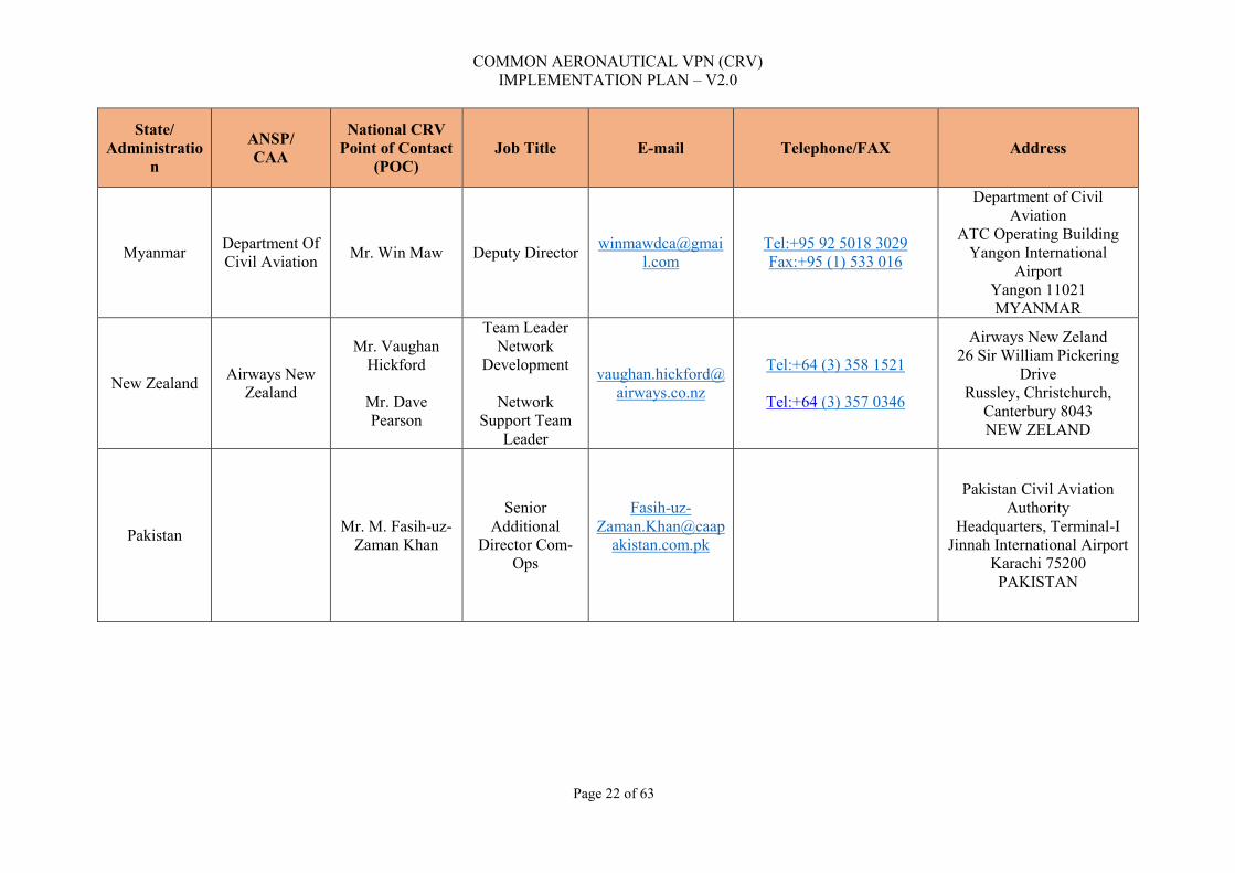
COMMON AERONAUTICAL VPN (CRV) IMPLEMENTATION PLAN – V2.0
Page 22 of 63
State/ Administratio
n
ANSP/ CAA
National CRV Point of Contact
(POC) Job Title E-mail Telephone/FAX Address
Myanmar Department Of Civil Aviation Mr. Win Maw Deputy Director winmawdca@gmai
l.com
Tel:+95 92 5018 3029 Fax:+95 (1) 533 016
Department of Civil Aviation
ATC Operating Building Yangon International
Airport Yangon 11021 MYANMAR
New Zealand Airways New Zealand
Mr. Vaughan Hickford
Mr. Dave Pearson
Team Leader Network
Development
Network Support Team
Leader
Tel:+64 (3) 358 1521
Tel:+64 (3) 357 0346
Airways New Zeland 26 Sir William Pickering
Drive Russley, Christchurch,
Canterbury 8043 NEW ZELAND
Pakistan Mr. M. Fasih-uz-Zaman Khan
Senior Additional
Director Com-Ops
Fasih-uz-Zaman.Khan@caap
akistan.com.pk
Pakistan Civil Aviation Authority
Headquarters, Terminal-I Jinnah International Airport
Karachi 75200 PAKISTAN

COMMON AERONAUTICAL VPN (CRV) IMPLEMENTATION PLAN – V2.0
Page 23 of 63
State/ Administratio
n
ANSP/ CAA
National CRV Point of Contact
(POC) Job Title E-mail Telephone/FAX Address
Philippines Civil Aviation
of the Philippines
Mr. Elmer E. Gomez Division Chief elm_gomez@yaho
o.com
Tel:+63 (2) 944 2192 Fax:+63 (2) 879 9244
Civil Aviation Authority of the Philippines
Air Navigation Service ANS Technical Center
Building Old Mia Road, Pasay City
1300 Metro Manila, PHILIPPINES
Republic of Korea
Ministry of Land,
Infrastructure and Transport
Mr. Kyung Joon, Jang
Assistant Director [email protected]
Tel:+82 (44) 201 4362 Fax:+82 (44) 201 5637
Ministry of Land, Infrastructure and Transport
11, Doum-ro 6 Sejong Special self-
governing City REPUBLIC OF KOREA
Singapore Singapore Air Traffic Control
Centre
Mr. Augustine Lau
Engineer (Communication
s/ Navaids Systems)
Tel:+65 6422 7071 Fax:+65 6542 2447
Civil Aviation Authority of Singapore
Singapore Changi Airport P.O. Box 1
SINGAPORE 918141
Sri Lanka
Airport & Aviation
Services (Sri Lanka) Ltd.
Mr. Wipula Wimanshanthi
Head of Electronics and
Air Nav Engineering
Mobile:+94 77 304 7653 Fax:94 (11) 263 3488
Airport & Aviation Services (Sri Lanka) Ltd. Colombo Airport Ratmalana 10370
SRI LANKA
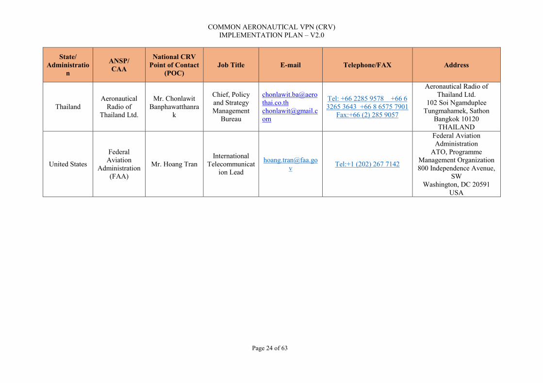
COMMON AERONAUTICAL VPN (CRV) IMPLEMENTATION PLAN – V2.0
Page 24 of 63
State/ Administratio
n
ANSP/ CAA
National CRV Point of Contact
(POC) Job Title E-mail Telephone/FAX Address
Thailand Aeronautical
Radio of Thailand Ltd.
Mr. Chonlawit Banphawatthanra
k
Chief, Policy and Strategy Management
Bureau
[email protected] [email protected]
Tel: +66 2285 9578 +66 6 3265 3643 +66 8 6575 7901
Fax:+66 (2) 285 9057
Aeronautical Radio of Thailand Ltd.
102 Soi Ngamduplee Tungmahamek, Sathon
Bangkok 10120 THAILAND
United States
Federal Aviation
Administration (FAA)
Mr. Hoang Tran International
Telecommunication Lead
Tel:+1 (202) 267 7142
Federal Aviation Administration
ATO, Programme Management Organization 800 Independence Avenue,
SW Washington, DC 20591
USA
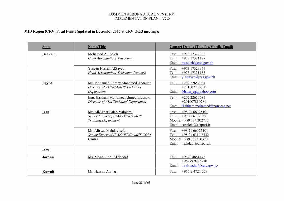
COMMON AERONAUTICAL VPN (CRV) IMPLEMENTATION PLAN – V2.0
Page 25 of 63
MID Region (CRV) Focal Points (updated in December 2017 at CRV OG/3 meeting):
State Name/Title Contact Details (Tel./Fax/Mobile/Email)
Bahrain Mohamed Ali Saleh Chief Aeronautical Telecomm
Fax: +973 17329966 Tel: +973 17321187 Email: [email protected]
Yaseen Hassan AlSayed Head Aeronautical Telecomm Network
Fax: +973 17329966 Tel: +973 17321183 Email: [email protected]
Egypt Mr. Mohamed Ramzy Mohamed Abdallah Director of AFTN/AMHS Technical Department
Tel: +202 22657981 +201007736780 Email: [email protected]
Eng. Haitham Mohamed Ahmed Eldosoki Director of AIM Technical Department
Tel: +202 22650781 +201007810781 Email: [email protected]
Iran Mr. AliAkbar SalehiValojerdi Senior Expert of IRANAFTN/AMHS Training Department
Fax: +98 21 66025101 Tel: +98 21 6102337 Mobile: +989 124 202775 Email: [email protected]
Mr. Alireza Mahdavisefat Senior Expert of IRANAFTN/AMHS COM Centre
Fax: +98 21 66025101 Tel: +98 21 6314 6432 Mobile: +989 333510320 Email: [email protected]
Iraq
Jordan Ms. Mona Ribhi AlNaddaf Tel: +9626 4881473 +96279 9876710 Email: [email protected]
Kuwait Mr. Hassan Alattar Fax: +965-2 4721 279

COMMON AERONAUTICAL VPN (CRV) IMPLEMENTATION PLAN – V2.0
Page 26 of 63
State Name/Title Contact Details (Tel./Fax/Mobile/Email)
Communication Engineer
Tel: +965-2 4732 530 Mobile: +965 99449454 Email: [email protected]
Lebanon Mr. Mohamad Abdallah Saad Head of Telecommunication Equipment
Fax: +961 1 629 031 Tel: +961 1 628 151 Mobile: +961 3 280 299 Email: [email protected]
Libya
Oman Mr. Nasser Salim Al-Suleimani Chief ATM Systems Mr. Ibrahim Said Al-Hajri ATM Systems Engineer
Email: [email protected] [email protected]
Qatar
Saudi Arabia
Ibrahim bash Senior Systems Engineer Automation Engineering Branch
Fax: +966 12 671 9041 Tel: +966 12 671 7717 Ext 1119 Mobile: +966 50 567 1231 Email: [email protected]
Sudan Eng. Yasir Eltayeb Sidahmed Fax: +249 183 770001 Tel: +249 183 782701 Email: [email protected]
Syria
UAE Greg Kurten A/Director CNS Communication, Navigation and Surveillance
Fax: +971 2 599 6872 Tel: +971 2 599 6860 Email: [email protected]
Shahzad Chaudhary Senior CNS Engineer Communication, Navigation and Surveillance
Fax: +971 2 599 6872 Tel: +971 2 599 6865 Email: [email protected]

COMMON AERONAUTICAL VPN (CRV) IMPLEMENTATION PLAN – V2.0
Page 27 of 63
State Name/Title Contact Details (Tel./Fax/Mobile/Email)
Yemen

COMMON AERONAUTICAL VPN (CRV) IMPLEMENTATION PLAN – V2.0
Page 28 of 63
3.2.3 Local CRV Points of Contact Table 2 contains the Local Points of Contact. In fact, the professionals nominated and listed in the referred tables will really take part in the installation, on behalf of the States, and will be in charge of the oversight of the Contractor´s team in each site. They will report directly to the National Points of Contact of each CRV Member. The main activities and roles for the Local CRV Points of Contact are:
i. Instruct and coordinate the actions with all the local staff involved in the CRV implementation;
ii. Develop close coordination with the National CRV POC and the Contractor´s site staff for the complete implementation of the CRV node;
iii. Coordinate the actions for the site surveys with the National CRV POC;
iv. Participate in the implementation meetings with the Contractor (if decided by the National Point of Contact);
v. Participate to the elaboration of the implementation planning;
vi. Participate in the Training Package and nominate, to the National CRV POC, the Local staff there will participate in the referred events;
vii. Report, give feedback and update the National CRV POC regarding all aspects concerning the implementation of the CRV node;
viii. Assist the National POC in the revision and approval of the SDD, SEP and other implementation documents, prepared by the Contractor;
ix. Assist the National POC in the revision and approval of the Validation Plan including the SAT, prepared by the Contractor;
x. Oversee the installation in order to ensure that the Contractor team is keeping the working area clean and free from fire hazards and if after installation, all excess material is duly removed;
xi. Make sure that the local safety rules are observed by the Contractor in terms of intervention on operational systems;
xii. Oversee the installation in order to ensure that the Contractor is following what is described in the TOR, item 3.3.2.9, concerning the Electromagnetic compatibility/ grounding;
xiii. Oversee if the QoS configuration is duly performed by the Contractor, as defined by the CRV-OG representatives and the National CRV POC;
xiv. Oversee if the CRV IP Addressing Scheme (Plan) is duly performed by the Contractor, as defined by the CRV-OG representatives and the National CRV POC;
xv. Oversee if the configuration of current numbering plan for the ATS Switched Voice is duly performed by the Contractor, as defined by the CRV-OG representatives and the National CRV POC;

COMMON AERONAUTICAL VPN (CRV) IMPLEMENTATION PLAN – V2.0
Page 29 of 63
xvi. Oversee if the configuration of the current Direct Circuits (DIR) is duly performed by the Contractor, as defined by the CRV-OG representatives and the National CRV POC;
xvii. Coordinate the actions for the site surveys and assist the Contractor´s personnel during the visits; and
xviii. Hold meetings with the Contractor as deemed necessary and report to National POC.

COMMON AERONAUTICAL VPN (CRV) IMPLEMENTATION PLAN – V2.0
Page 30 of 63
Local CRV Points of Contact (installation and oversight of the Contractor´s team on each site)
State State/ANSP Site Local CRV Points of Contact
Email Telephone / Fax Service installation
Afghanistan Afghanistan Civil Aviation Authority (ACAA)
Kabul Eng. Mohd.Shaker Popal [email protected] Kabul International Airport
American Samoa
Pago Pago Tel.: Fax :
Pago Pago International Airport
Australia Airservices Australia
Brisbane Mr. Michael Earnes [email protected]
+61 2 6268 5042 +61 409 357 965
Australia Airservices Australia Brisbane Air Traffic Services Centre Airport Drive, Eagle Farm, Queensland 4009 Australia
Australia Airservices Australia
Melbourne Bibhuti Panda +61 2 6268 5169 +61 451 060 674
Australia Airservices Australia Melbourne Air Traffic Services Centre Tower Road, Tullamarine, Victoria Australia
Bangladesh Dhaka Tel 088-02-8920852, 088-02-8901465 email [email protected]
Hazrat Shahjalal International Airport - Dhaka COM Center

COMMON AERONAUTICAL VPN (CRV) IMPLEMENTATION PLAN – V2.0
Page 31 of 63
State State/ANSP Site Local CRV Points of Contact
Email Telephone / Fax Service installation
Bhutan Department of Air Transport, ANSP-Division, CNS Section
Paro Mr. Sangay Dy. Chief Comm. Officer
[email protected] Tel: +975 8 271407 Fax.: +975 8 271944
Paro
Brunei Darussalam
Brunei Tel.: Fax :
Brunei International Airport
Cambodia Phnom Penh Mr. Norngsao 85-16771136, Mr. Sivaluk 66-2502-6742 (Thailand number)
Tel.: 855-23-890194, 855-23-890262, Mr. Norngsao 85-16771136, Mr. Sivaluk 66-2502-6742 (Thailand number) Fax :
Phnom Penh International Airport - Phnom Pehn COM center
China ATMB - Air Traffic Management Bureau,CAAC
Beijing Mr. Huang Zheng [email protected]
Tel.:+86(10)58729977 Fax :+86(10)67331459
Beijing Network Control Center No.301 Weatem, Dongwei Rd. Sunhe, Chao Yang District, Beijing ,China
China ATMB - Air Traffic Management Bureau,CAAC
Guangzhou Tel.:+86-020-86122850 Fax :+86-020-86636200
Guangzhou COM Network Center No.3 Nanyun East Street, Airport Road, Baiyun District Guangzhou, China

COMMON AERONAUTICAL VPN (CRV) IMPLEMENTATION PLAN – V2.0
Page 32 of 63
State State/ANSP Site Local CRV Points of Contact
Email Telephone / Fax Service installation
China, Hong Kong
Hong Kong Mr. Gene Kwok [email protected] Tel: +852 2910 6523 Fax: +852 2845 7160
Civil Aviation Department Headquarters, 1 Tung Fai Road, Hong Kong International Airport, Lantau, Hong Kong
China, Macau
ADA- Administraiton of Airports
Macau Tel.: (+853)28861111 Fax: (+853)28862222 Email: [email protected]
Macau International Airport PAC on Talpa Macao, China
Cook Islands
Rarotonga Tel.: Fax :
Rarotonga International Airport
Democratic People's Republic of Korea
ATC, Pyongyang International Airport, SUNAN District, DPR Korea
Pyongyang Tel.: 850-2-381 5910 Fax : 850-2-831 4410
Pyongyang City
Fiji Airports Fiji Limited
Nadi Mr. Jioji Kinisi [email protected] Tel: +679 6731603 Fax:+679 6731123
ATMC Equipment Room, ATMC Building Ottawa Road, Nadi Airport, Fiji Islands
French Polynesia
Service d'Etat de l'Aviation Civile / Faa'a International Airport
Papeete Mr. Marc Deginther [email protected]
Tel: (689) 40 86 10 32 Mobile: (689) 89 29 84 74 Fax: (689) 40 86 10 39
Service d'Etat de l'Aviation Civile BP 6011 - 98702 Faa'a International Airport

COMMON AERONAUTICAL VPN (CRV) IMPLEMENTATION PLAN – V2.0
Page 33 of 63
State State/ANSP Site Local CRV Points of Contact
Email Telephone / Fax Service installation
India Airports Authority of India
Mumbai Mr. Hemant Ramchandani Joint General Manager (CNS) CSI Airport Mumbai India
[email protected] +91 (22) 2682 8123 Mobile: +91 92 2331 4272
India Airports Authority of India
New Delhi Mr. K. S. Kathayat AGM (COM) IGI Airport New Delhi 110037 India
Indonesia Jakarta ATS Centre
Jakarta Tel.: Fax :
Soekarno-Hatta International Airport Jakarta, Tangerang, Banten 19120 Indonesia
Indonesia Makassar ATS Centre
Makassar Tel.: Fax :
Sultan Hasanuddin International Airport Jalan Raya Airport No. 1 Makassar Sulawesi 90552, Indonesia
Japan Tokyo Air Traffic Control Centre
Tokyo TBD Tel.: Fax :
1-2, Namiki, Tokorozawa city, Saitama pref. 359-0042 Japan

COMMON AERONAUTICAL VPN (CRV) IMPLEMENTATION PLAN – V2.0
Page 34 of 63
State State/ANSP Site Local CRV Points of Contact
Email Telephone / Fax Service installation
Japan Air Traffic Management Center (ATMC)
Fukuoka TBD Tel.: Fax :
1302-17 Nata Higashi-ku Fukuoka-city Fukuoka-Pref 811-0204 Japan
Kiribati Mr CARLIER Yann of DGAC/DAC-New Caledonia
Tarawa Tel.: Fax :
Bonriki International Airport
Lao People's Democratic Republic
Vientiane Tel.: 856-21-520157, 856-21-512090, Ms. Pen 66-802969631 (Thailand number). Mr. Somboon 856-20-5560-1638
Wattay International Airport
Malaysia Kota Kinabalu Air Traffic Control Centre
Kota Kinabalu Mr. Mohd. Dahri Bin Munik
Tel:+6 088 224911 Mobile: +6 019 8815780 Fax: +6 088 219170
ATCC Building, Jalan Kepayan 88618 Kota Kinabalu, Sabah.
Malaysia Kuala Lumpur Air Traffic Control Centre (KL ATCC)
Selangor Mr. Mohd. Hamli Bin Alias
Tel: +6 03 7846 5233 Mobile: +6 012 629 5405 Fax: +6 03 7845 6590
Kuala Lumpur Air Traffic Control Centre, Level 1, Block A, Complex of Air Traffic Control Centre, 47200 Subang, Selangor.

COMMON AERONAUTICAL VPN (CRV) IMPLEMENTATION PLAN – V2.0
Page 35 of 63
State State/ANSP Site Local CRV Points of Contact
Email Telephone / Fax Service installation
Malaysia Kuching Sub-Centre Kuching Air Traffic Control Centre
Kuching Mr. Suzaiman bin Zaini [email protected]
Tel: +6 082 616532 Mobile: +6 016 8881971 Fax: +6 082 454523
Kuching Air Traffic Control Centre, Kuching International Airport, 93728 Kuching,Sarawak.
Maldives Maldives Airports Company Limited
Male Tel.: 960-322071 Fax: 960-317202 atcc @ airport.com.mv
Malé International Airport Ibrahim Nasir International Airport Hulhule 22000, Republic of Maldives
Marshall Islands
Majuro Tel.: Fax :
Marshall Islands International Airport
Micronesia (Federated States of)
Chuuk/Kosrae/Ponapei/Yap
Tel.: Fax :
Pohnpei International Airport
Mongolia Communication Navigation Surveillance section, Civil Aviation Authority of Mongolia
Ulaanbaatar Tel.: +976 11 281603 Fax : +976 1170049785
Khan-Uul district, 10th khoroo, Buyant-Ukhaa, Ulaanbaatar, Mongolia
Myanmar Department Of Civil Aviation
Yangon Mr. Kyaw Zay Ya [email protected]
Tel:95-1-533030, Ext:453 Mobile:95-9-974684449 Fax:95-1-533016
ATC Tower Building, Yangon Int’l Airport, Airport Road, 11021, Mingaladon Township, Yangon, Myanmar.
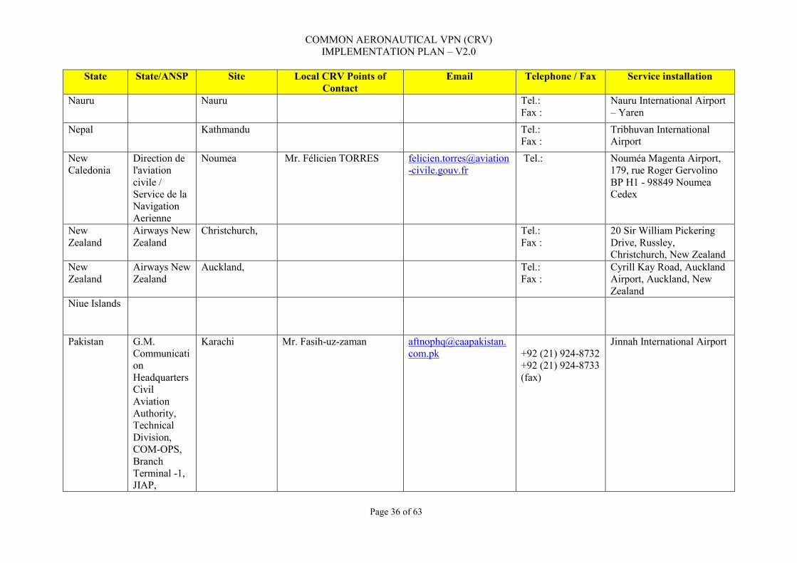
COMMON AERONAUTICAL VPN (CRV) IMPLEMENTATION PLAN – V2.0
Page 36 of 63
State State/ANSP Site Local CRV Points of Contact
Email Telephone / Fax Service installation
Nauru Nauru Tel.: Fax :
Nauru International Airport – Yaren
Nepal Kathmandu Tel.: Fax :
Tribhuvan International Airport
New Caledonia
Direction de l'aviation civile / Service de la Navigation Aerienne
Noumea Mr. Félicien TORRES
Tel.:
Nouméa Magenta Airport, 179, rue Roger Gervolino BP H1 - 98849 Noumea Cedex
New Zealand
Airways New Zealand
Christchurch, Tel.: Fax :
20 Sir William Pickering Drive, Russley, Christchurch, New Zealand
New Zealand
Airways New Zealand
Auckland, Tel.: Fax :
Cyrill Kay Road, Auckland Airport, Auckland, New Zealand
Niue Islands
Pakistan G.M. Communication Headquarters Civil Aviation Authority, Technical Division, COM-OPS, Branch Terminal -1, JIAP,
Karachi Mr. Fasih-uz-zaman [email protected]
+92 (21) 924-8732 +92 (21) 924-8733 (fax)
Jinnah International Airport

COMMON AERONAUTICAL VPN (CRV) IMPLEMENTATION PLAN – V2.0
Page 37 of 63
State State/ANSP Site Local CRV Points of Contact
Email Telephone / Fax Service installation
Karachi, Pakistan
Palau Koror Tel.: Fax :
Roman Tmetuchl International Airport
Papua New Guinea
Port Moresby Tel.: Fax :
Jacksons International Airport Morea-Tobo Rd Port Moresby 121 Papua New Guinea
Philippines Civil Aviation of the Philippines
Pasay City Mr. Gilmar D. Tiro [email protected] Tel.: +63 (2) 944-2242, +63 (2) 6727729, +63 (2) 6727728 Fax :
Philippine Air Traffic Management Center CAAp Compound, Old Mia Road, Pasay City, 1300 Metro Manila, PHILIPPINES
Republic of Korea
AFTN Center Seoul Tel.: + 823 28800335 Fax :
62, Haneul-Gil Gangseo-Gu Seoul, 157-711, Korea
Samoa Faleolo Tel.: Fax :
Faleolo International Airport
Singapore Singapore Air Traffic Control Centre
Singapore Tel.: 6214 8050/65 Fax : 6545 9370
LORADS II Building, 60, Biggin Hill Road, Singapore Postal Code 509950
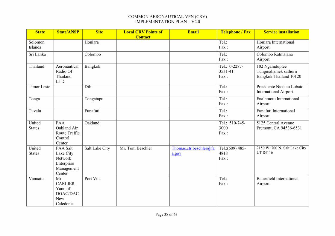
COMMON AERONAUTICAL VPN (CRV) IMPLEMENTATION PLAN – V2.0
Page 38 of 63
State State/ANSP Site Local CRV Points of Contact
Email Telephone / Fax Service installation
Solomon Islands
Honiara Tel.: Fax :
Honiara International Airport
Sri Lanka Colombo Tel.: Fax :
Colombo Ratmalana Airport
Thailand Aeronautical Radio Of Thailand LTD
Bangkok Tel.: 0-2287-3531-41 Fax :
102 Ngamduplee Tungmahamek sathorn Bangkok Thailand 10120
Timor Leste Dili Tel.: Fax :
Presidente Nicolau Lobato International Airport
Tonga Tongatapu Tel.: Fax :
Fuaʻamotu International Airport
Tuvalu Funafuti Tel.: Fax :
Funafuti International Airport
United States
FAA Oakland Air Route Traffic Control Center
Oakland Tel.: 510-745-3000 Fax :
5125 Central Avenue Fremont, CA 94536-6531
United States
FAA Salt Lake City Network Enterprise Management Center
Salt Lake City Mr. Tom Beschler [email protected]
Tel.:(609) 485-4818 Fax :
2150 W. 700 N. Salt Lake City UT 84116
Vanuatu Mr CARLIER Yann of DGAC/DAC-New Caledonia
Port Vila Tel.: Fax :
Bauerfield International Airport

COMMON AERONAUTICAL VPN (CRV) IMPLEMENTATION PLAN – V2.0
Page 39 of 63
State State/ANSP Site Local CRV Points of Contact
Email Telephone / Fax Service installation
Viet Nam Ho Chin Minh/Hanoi
Tel.: Fax :
Tan Son Nhat International Airport Noi Bai International Airport
Wallis and Futuna
Aviation Civile
Wallis Mr. Bernard Le Guillou [email protected]
+00-681-72-12-02 Fax: 00-681-72-29-54 email: [email protected]
Hihifo Airport Aviation Civile BP1 Mata-Utu 98600 WALLIS
ICAO MID Region
Bahrain Bahrain Civil Affairs
Manama
Egypt NANSC Cairo Iran Civil
Aviation Organization
Tehran
Iraq CAA Baghdad Jordan CARC Amman Kuwait Directorate
General of CA
Kuwait
Lebanon CAA Beirut Libya CAA Tripoli Oman Public
Authority for CA
Muscat
Qatar CAA Doha

COMMON AERONAUTICAL VPN (CRV) IMPLEMENTATION PLAN – V2.0
Page 40 of 63
State State/ANSP Site Local CRV Points of Contact
Email Telephone / Fax Service installation
Saudi Arabia
General Authoroity of CA
Jeddah and Riyadh
Sudan CAA Khartoum Syria CAA Damascus UAE General CA
Authoroity AbuDhabi
Yemen CA and Met Authrority
Sanaa
Interregional connectivity
Russia Interregional connection for AFTN between Beijing China and Far East Air Navigation” 680031, Matveevskoye Shosse, 28a Khabarovsk Russia
Khabarovsk China: Mr. Huang Zhang Tel:0086-010-67318494 ,0086-010-58729977 FAX:0086-010-67331459 E-mail:[email protected] POC Ms. Tatyana Ivanovna Khvan Tel: 007(4212)418-591 Email: [email protected]
China: Mr. Huang Zhang Tel:0086-010-67318494 ,0086-010-58729977 FAX:0086-010-67331459 E-mail:[email protected] POC Ms. Tatyana Ivanovna Khvan Tel: 007(4212)418-591 Email: [email protected]
China: Address:No. 301 ,Qian Wei Gou Cun,Sun He Xiang, Chaoyang District Beijing 100122 Russia Address: Branch “Far East Air Navigation” 680031, Matveevskoye Shosse, 28a Khabarovsk Russia

COMMON AERONAUTICAL VPN (CRV) IMPLEMENTATION PLAN – V2.0
Page 41 of 63
State State/ANSP Site Local CRV Points of Contact
Email Telephone / Fax Service installation
UK Interconnection with Singapore
Fareham Name: Stuart Dingle [email protected]
Name: Stuart Dingle Email: [email protected] D: 01489 612259 M: 07786 211975
Physical Address: 4000 Parkway, Whiteley, Fareham, Hants PO15 7FL
South Africa Interconnection with India
Johannesburg
Italy Interconnection with Thailand
Rome

COMMON AERONAUTICAL VPN (CRV) IMPLEMENTATION PLAN – V2.0
Page 42 of 63
3.2.4 CRV Contractor The Contractor shall nominate all the staff involved in the implementation of the CRV node, mainly the Program Manager for the CRV program. The Contractor will follow all the steps described in the tender documentation, specially the TOR and Instructions to Tenderers, for the implementation of the CRV node. The main activities to be carried out by the Contractor during the implementation are:
i. Submit the updated SDD and the SEP to the CRV-OG, to the CNS Officer for the Asia/Pacific Regional Office and to the National CRV POC;
ii. Submit the requests for site surveys to the National CRV POC following the procedures described in the paragraph 4.1.2.2;
iii. Update and submit the Installation Transition Plan to the CRV-OG, to the CNS Officer for the Asia/Pacific Regional Office and to the National CRV POC;
iv. Be responsible for the supply, transport, installation, start-up and operation of all CRV equipment especially designed for a given CRV node;
v. Be dealing with customs and transport company about shipping and introducing the equipment in the Country;
vi. The interconnection (to be provided by CRV users) of the Network Interface Device (NID) to the Local Area Network (LAN) switches and other local equipment, including Voice Communication System (VCS), will be confirmed during the site survey;
vii. Demonstrate before the final validation of the SDD and through a test bed that the main characteristics of the intended design of the network will meet the performance requirements, SLA, safety, security and contingency requirements;
viii. Implement the CRV IP Addressing Scheme (Plan), following the information provided by the CRV-OG and/or the National CRV POC;
ix. Implement the classification and marking scheme for the prioritization of the traffic and Quality of Services (QoS), as described in the document Att II - Annex c - Mapping of services for quality management_v2 and in coordination with the CRV-OG and the National and Local CRV POCs (See note in the paragraph 3.2.1.3);
x. The Contractor shall measure the established parameters during circuit implementation (in accordance with ITU-T), and shall also monitor them for 24 hours to show compliance with the established specifications;
xi. Implement the configuration of current numbering plan for the ATS Switched Voice, as defined by the CRV-OG representatives and the National CRV POC, and taking into account the tender document Att II - Annex b - Matrix of Flows for CRV services_v2;
xii. Implement the configuration of the current Direct Circuits (DIR), as defined by the CRV-OG representatives and the National CRV POC and taking into account the tender document Att II - Annex b - Matrix of Flows for CRV services_v2;

COMMON AERONAUTICAL VPN (CRV) IMPLEMENTATION PLAN – V2.0
Page 43 of 63
xiii. Submit, in details, the escalation process to be followed for the implementation in each CRV
node;
xiv. Submit, to the CRV National POC, the documentation for the training of the CRV technicians;
xv. Contractor Representative shall record the minutes of the meeting and distribute the minutes within three (3) Business Days of the meeting date;
xvi. The Contractor shall propose a planning chart that includes all the actions, steps, milestones, meetings, after negotiations with CRV Local and National POC and respect it once approved by the CRV User Representative or amend it in coordination with CRV User representatives; and
xvii. The Contractor shall help the CRV User in the uptake of responsibility before commissioning the equipment by accompanying the CRV User technicians in charge of the equipment.
4.0 BASIC SITE IMPLEMENTATION REQUIREMENTS Chapter 4 describes the site and facilities requirements envisaged in the implementation phased for the CRV infrastructure, divided into CRV User´s and Contractor´s responsibilities, and also the main hardware and software for the proof of concept and implementation of the WAN links, LAN protocols, applications and main equipment. These responsibilities come in addition to those stated in the Terms and Conditions and Terms of Reference. 4.1 Site/ Facilities Requirements
4.1.1 CRV User Responsibility
i. The CRV User shall provide the physical space for the installation of cabinets and equipment;
ii. The CRV User shall deliver to the premises the electric power required to feed the equipment to be provided by the Contractor;
iii. The CRV User shall provide access to the equipment to be connected to the CRV NID and to analog/ digital voice gateway;
iv. The CRV User shall accompany and assist the Contractor during the whole operation;
v. The CRV User shall provide room for storing the equipment, received before its installation; and
vi. The CRV User shall inform the Contractor about the local safety rules and procedures and produce suited documents as deemed necessary.
4.1.2 Contractor Responsibility
i. The Project Manager, on behalf of the Contractor, shall nominate and introduce all the staff involved in the site surveys and in the implementation of a CRV node. The list with the staff
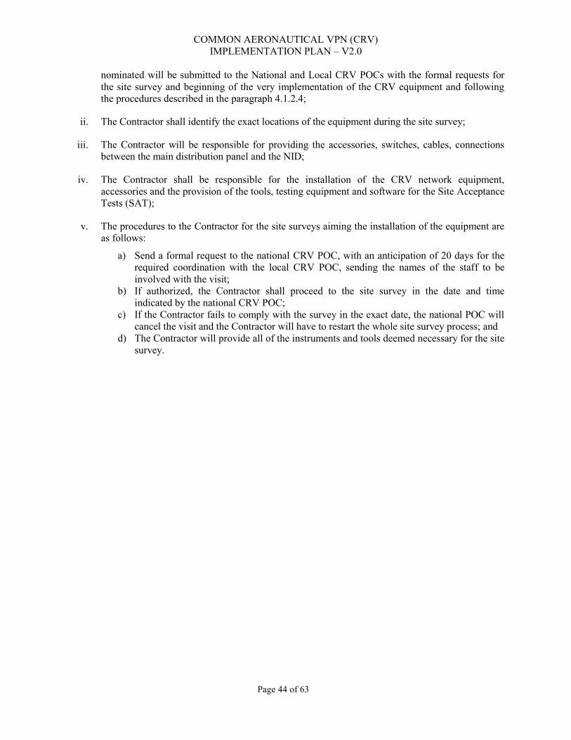
COMMON AERONAUTICAL VPN (CRV) IMPLEMENTATION PLAN – V2.0
Page 44 of 63
nominated will be submitted to the National and Local CRV POCs with the formal requests for the site survey and beginning of the very implementation of the CRV equipment and following the procedures described in the paragraph 4.1.2.4;
ii. The Contractor shall identify the exact locations of the equipment during the site survey;
iii. The Contractor will be responsible for providing the accessories, switches, cables, connections between the main distribution panel and the NID;
iv. The Contractor shall be responsible for the installation of the CRV network equipment, accessories and the provision of the tools, testing equipment and software for the Site Acceptance Tests (SAT);
v. The procedures to the Contractor for the site surveys aiming the installation of the equipment are as follows:
a) Send a formal request to the national CRV POC, with an anticipation of 20 days for the required coordination with the local CRV POC, sending the names of the staff to be involved with the visit;
b) If authorized, the Contractor shall proceed to the site survey in the date and time indicated by the national CRV POC;
c) If the Contractor fails to comply with the survey in the exact date, the national POC will cancel the visit and the Contractor will have to restart the whole site survey process; and
d) The Contractor will provide all of the instruments and tools deemed necessary for the site survey.
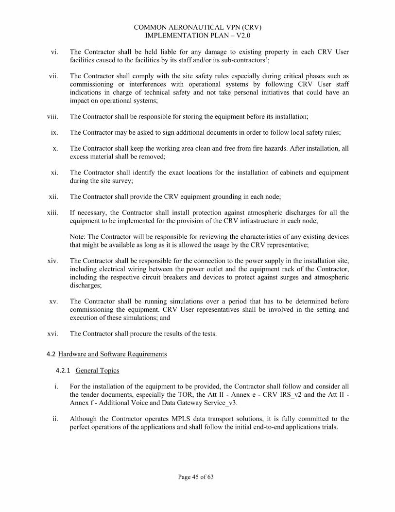
COMMON AERONAUTICAL VPN (CRV) IMPLEMENTATION PLAN – V2.0
Page 45 of 63
vi. The Contractor shall be held liable for any damage to existing property in each CRV User facilities caused to the facilities by its staff and/or its sub-contractors’;
vii. The Contractor shall comply with the site safety rules especially during critical phases such as commissioning or interferences with operational systems by following CRV User staff indications in charge of technical safety and not take personal initiatives that could have an impact on operational systems;
viii. The Contractor shall be responsible for storing the equipment before its installation;
ix. The Contractor may be asked to sign additional documents in order to follow local safety rules;
x. The Contractor shall keep the working area clean and free from fire hazards. After installation, all excess material shall be removed;
xi. The Contractor shall identify the exact locations for the installation of cabinets and equipment during the site survey;
xii. The Contractor shall provide the CRV equipment grounding in each node;
xiii. If necessary, the Contractor shall install protection against atmospheric discharges for all the equipment to be implemented for the provision of the CRV infrastructure in each node;
Note: The Contractor will be responsible for reviewing the characteristics of any existing devices that might be available as long as it is allowed the usage by the CRV representative;
xiv. The Contractor shall be responsible for the connection to the power supply in the installation site, including electrical wiring between the power outlet and the equipment rack of the Contractor, including the respective circuit breakers and devices to protect against surges and atmospheric discharges;
xv. The Contractor shall be running simulations over a period that has to be determined before commissioning the equipment. CRV User representatives shall be involved in the setting and execution of these simulations; and
xvi. The Contractor shall procure the results of the tests.
4.2 Hardware and Software Requirements
4.2.1 General Topics
i. For the installation of the equipment to be provided, the Contractor shall follow and consider all the tender documents, especially the TOR, the Att II - Annex e - CRV IRS_v2 and the Att II - Annex f - Additional Voice and Data Gateway Service_v3.
ii. Although the Contractor operates MPLS data transport solutions, it is fully committed to the perfect operations of the applications and shall follow the initial end-to-end applications trials.

COMMON AERONAUTICAL VPN (CRV) IMPLEMENTATION PLAN – V2.0
Page 46 of 63
4.2.2 Hardware Requirements
i. For the satellite equipment, the Contractor shall install the indoor and outdoor units.
ii. Where Applicable, the basic satellite equipment to be provided and checked is: Block Up Converters (BUC), Low Noise Block (LNB) down converters and Satellite Modems and VSAT Network management sub-system.
iii. Where Applicable, the basic ground/terrestrial equipment to be provided will comprise: routing system of the IP VPN Internet (with the needed interfaces), the basic ground voice and data gateway (with the needed interfaces), the NID (with the needed interfaces), switches (with the needed interfaces), A/B baseband switch (with the needed interfaces), Multiprotocol Label Switching (MPLS) for the Wide Area Network (WAN) (optical and/or microwave) links equipment.
iv. Before connecting the NID and the analog/digital, if needed, the contractor´s team shall install the new racks and prepare the transition cables, such as junction coaxial cables, junction sub-d cables or RJ based cables.
v. All the test and measurement tools shall be provided by the Contractor. No testing and measurement equipment will be provided by the CRV User representatives.
vi. All the needed equipment must be shipped and acknowledge by the CRV-User before the installation phase with sufficient delay. The Provider have to take the customs procedure delay into account.
vii. All the received items must be inventoried and tested before the beginning of installation in order to avoid dispute.
4.2.3 Software Requirements
Where applicable, the basic software to be provided and/or used in each site is: Network Management Systems (NMS) software, if the SDD indicates that one or more CRV nodes will be selected to manage the CRV network in parallel with the Contractor´s Network Operations Center (NOC), software for BUC, Satellite Modems, NID, Voice/Data Gateway and switches.
4.2.4 Documentation Requirements
The needed documentation for the uptake of the equipment shall be provided to CRV User on its demand as deemed necessary.
5.0 TESTING AND EVALUATION. The tests for the acceptance of the implemented equipment in each CRV node will be performed using simulations of the applications and, eventually, the real application tests that will follow the operational requirements as described in the tender documents, mainly, but not restricted to:

COMMON AERONAUTICAL VPN (CRV) IMPLEMENTATION PLAN – V2.0
Page 47 of 63
i. Att II - Annex a - CRV CONOPS_v2;
ii. Att II - Annex b - Matrix of Flows for CRV services_v2;
iii. CRV Implementation plan (Chapter 5); and
iv. Validation Plan including the Site Acceptance Test (SAT) protocols (prepared by the Contractor). The main testing and measurement equipment and tools that shall be used by the Contractor are:
i. Spectrum Analyzer;
ii. cable analyzer;
iii. audio analyzer/generator;
iv. Multi-meters;
v. LAN/Network protocol analyzer; and
vi. Telephones.
Note: This paragraph doesn´t exhaust all the testing and measurement equipment to be used during the implementation phase, and the Contractor shall describe all of them in the documentation to be provided after the contract signature. The Contractor shall test its backbone (end-to-end) and the connection to its Network Operating Center (NOC). The links will be tested using computers for asynchronous and IP flows for example, and analogical phones. An example of asynchronous test is opening a HyperTerminal session and send characters and a Bit Error Rate Test using a software such as WinSSD. The requirements for the test procedures will be reflected in the Chapter 5 (Testing and Evaluation). Notwithstanding this fact, the tests procedures will need some software for the applications as reflected in the following paragraphs. Note: The following paragraphs don´t exhaust all the software and the Contractor shall describe all of them in the documentation to be provided after the contract signature. For AFTN simulation: The simulation will consist of connecting a PC to the AFTN port at the back of the rack (with the right rate described in the document Att II - Annex b - Matrix of Flows for CRV services_v2) and close the serial interface at the other end of the circuit (loop). With the PC launch the winssd program (or other similar) and start the Bit Error Rate (BER) test. Run the test for 5 minutes and check that there are only a few errors. For AMHS simulation: AMHS service is over IP (see the document Att II - Annex b - Matrix of Flows for CRV services_v2. To simulate it:
i. ping any remote equipment in the network according to the following cross matrix; and

COMMON AERONAUTICAL VPN (CRV) IMPLEMENTATION PLAN – V2.0
Page 48 of 63
ii. Verify that the end user is exchanging information correctly.
IP based RADAR and Asterix: The simulation will consist in selecting two sites, configuring sufficient bandwidth and multicast an IP flow.
ATS/DS Circuits: All ATS/DS calls are auto-dialed. The communication is established after the user picks up the phone. The simulation will consist of connecting a telephone on the desired line at the back of the rack, pick-up the phone make the call to the other end of the circuit. For E1 based circuits, to be connected to a VCS, this cannot be simulated.
ATS Switched Circuits: ATS switched calls are dialed. The communication is established after the user picks up the phone and dials the remote dial number. The simulation will consist of connecting a telephone on the desired line at the back of the rack, pick-up the phone and dial a remote number in order to call the other end of the circuit. For E1 based circuits, connected to a VCS, this cannot simulated.
6.0 CONTINGENCY PLAN/ BACK-OFF PLAN 6.1 Purpose States/ Administrations are to establish contingency plan, with the CRV contractor, in case of the following scenario:
i. CRV total failure;
ii. CRV partial failure (e.g. voice channel failure);
iii. Provider Edge (PE) to Customer Edge (CE) link failure (e.g. ANSP1 lose connectivity to CRV); and
iv. PE to PE failure (e.g. ANSP1 and ANSP2 unable to exchange data/ or voice). 6.2 Harmonized Contingency Plan States/ Administrations could also bilaterally/ multilaterally setup additional IPLC(s) as a contingency. This contingency plan could be harmonized in the APAC region to reduce costs. 7.0 MIXED OPERATING ENVIRONMENT 7.1 Routing of AFTN/ AMHS messages to non-CRV States/ Administrations During the initial phase of the CRV implementation, States/ Administrations who have joined CRV are to ensure the routing of AFTN/ AMHS messages to States/ Administrations who have not joined CRV. 7.2 Inter-Region common network connectivity It is envisaged for common networks (e.g. PEN, FTI and CRV) in different Regions to be inter-connected.

Appendix A – APAC IPv4 Address Plan
Page 49 of 63
Appendix A
1 Introduction
1.1 Objective
This document is meant to describe the addressing plan for IPv4 addresses throughout the Asia/Pacific Region. This document defines the recommended address format for IPv4 addresses. The IPv4 network is to be used within region.
1.2 References [1] ICAO Doc 9705-
AN/956 Manual of Technical Provisions for the ATN
[2] ICAO Doc 9896 Manual for the ATN using IPS Standards and Protocols
[3] ICAO Doc 7910 ICAO Location Indicators [4] RFC 1518 An Architecture for IP Address Allocation with
CIDR [5] RFC 1918 Address Allocation for Private Internets [6] RFC 2050 BGP-4 Internet Registry IP Allocation Guidelines [7] RFC 3330 Special-Use IPv4 Addresses [8] RFC 4271 BGP-4 Specification
1.3 Terms Used
Administrative Domain – An administrative entity in the ATN/IPS. An
Administrative Domain can be an individual State, a group of States, an Aeronautical Industry Organization (e.g., an Air-Ground Service Provider), or an Air Navigation Service Provider (ANSP) that manages ATN/IPS network resources and services. From a routing perspective, an Administrative Domain includes one or more Autonomous Systems.
Autonomous System – A connected group of one or more IP prefixes, run by one or more network operators, which has a single, clearly defined routing policy.

Page 50 of 63
Intra-domain (interior gateway) routing protocol
– Protocols for exchanging routing information between routers within an AS.
Inter-domain (exterior gateway) routing protocol
– Protocols for exchanging routing information between Autonomous Systems. They may in some cases be used between routers within an AS, but they primarily deal with exchanging information between Autonomous Systems.
Local Internet Registry – A Local Internet Registry (LIR) is an IR that primarily assigns address space to users of the network services it provides. LIRs are generally ISPs, whose customers are primarily end users and possibly other ISPs. [LACNIC]
1.4 Acronyms
AMHS – ATN Message Handling System ARP – Address Resolution Protocol ATN – Aeronautical Telecommunications Network BGP – Border Gateway Protocol DNS – Domain Name Service IANA – Internet Assigned Numbers Authority ICS – ATN Internet Communication Service IP – Internet Protocol IPv4 – Internet Protocol Version 4 IPv6 – Internet Protocol Version 6 IPS – Internet Protocol suite LACNIC – Latin American and Caribbean Internet Address Registry LIR – Local Internet Registry OSPF – Open Shortest Path First RIR – Regional Internet Registry

Page 51 of 63
1.5 Overview of Addressing Issues
The following subsections present issues that affect the completion of the addressing plan for operating the IPS-based AMHS network.
1.5.1 Public or Private Address An important decision for the region is whether to use private or public addresses. Private addresses can be used if coordinated by all participating States and Organization; however, it is possible that existing networks already use addresses in the private block ranges. Public addresses must be obtained from a Regional Internet Registry (RIR). The Internet Assigned Numbers Authority (IANA) has delegated responsibility for administration of Internet numbering to the Latin American and Caribbean Internet Address Registry (LACNIC).
1.5.2 Address of Systems in External Regions
Systems in external regions could be assigned an address from the APAC address space rather than use an address in their regional address block. Note however that this must be coordinated with private addresses so as to avoid collisions.
2 IPv4 Addressing Overview and Fundamentals In the Internet Protocol a distinction is made between names, addresses, and routes. A name indicates what we seek. An address indicates where it is. A route indicates how to get there. The Internet protocol deals primarily with addresses. Its main task is to forward data to a particular destination address. It is the task of higher-level protocols to make the mapping from names to addresses, for example using a domain name service (DNS). The Internet protocol forwards packet data units (PDU) to a destination address using routing tables maintained by a routing protocol. The routing tables contain the address of the next hop along the route to the destination. There are in general two classes of routing protocols: inter-domain or exterior routing protocols such as the Border Gateway Protocol (BGP) and intra-domain or interior routing protocols such as the Open Shortest Path First (OSPF) protocol. In order to forward PDUs to the next hop address, there must be a mapping from this address to the link level address, for example, an Ethernet address. This mapping is maintained by an address discovery protocol such as the Address Resolution Protocol (ARP).
An IPv4 address consists of four bytes (32 bits). These bytes are also known as octets. For readability purposes, humans typically work with IP addresses in a notation called dotted decimal. This notation places periods between each of the four numbers (octets) that comprise an IP address. For example, an IP address that a computer sees as
00001010 00000000 00000000 00000001
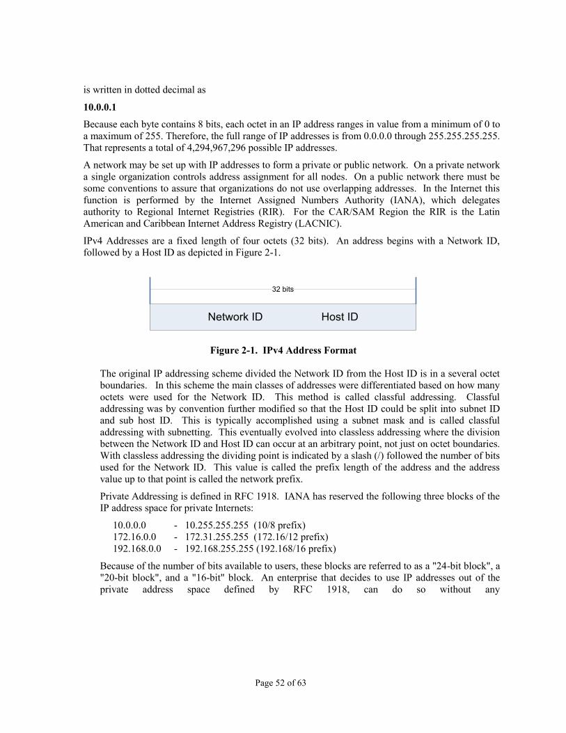
Page 52 of 63
is written in dotted decimal as
10.0.0.1
Because each byte contains 8 bits, each octet in an IP address ranges in value from a minimum of 0 to a maximum of 255. Therefore, the full range of IP addresses is from 0.0.0.0 through 255.255.255.255. That represents a total of 4,294,967,296 possible IP addresses.
A network may be set up with IP addresses to form a private or public network. On a private network a single organization controls address assignment for all nodes. On a public network there must be some conventions to assure that organizations do not use overlapping addresses. In the Internet this function is performed by the Internet Assigned Numbers Authority (IANA), which delegates authority to Regional Internet Registries (RIR). For the CAR/SAM Region the RIR is the Latin American and Caribbean Internet Address Registry (LACNIC).
IPv4 Addresses are a fixed length of four octets (32 bits). An address begins with a Network ID, followed by a Host ID as depicted in Figure 2-1.
Figure 2-1. IPv4 Address Format
The original IP addressing scheme divided the Network ID from the Host ID is in a several octet boundaries. In this scheme the main classes of addresses were differentiated based on how many octets were used for the Network ID. This method is called classful addressing. Classful addressing was by convention further modified so that the Host ID could be split into subnet ID and sub host ID. This is typically accomplished using a subnet mask and is called classful addressing with subnetting. This eventually evolved into classless addressing where the division between the Network ID and Host ID can occur at an arbitrary point, not just on octet boundaries. With classless addressing the dividing point is indicated by a slash (/) followed the number of bits used for the Network ID. This value is called the prefix length of the address and the address value up to that point is called the network prefix.
Private Addressing is defined in RFC 1918. IANA has reserved the following three blocks of the IP address space for private Internets:
10.0.0.0 - 10.255.255.255 (10/8 prefix) 172.16.0.0 - 172.31.255.255 (172.16/12 prefix) 192.168.0.0 - 192.168.255.255 (192.168/16 prefix)
Because of the number of bits available to users, these blocks are referred to as a "24-bit block", a "20-bit block", and a "16-bit" block. An enterprise that decides to use IP addresses out of the private address space defined by RFC 1918, can do so without any
Network ID Host ID
32 bits

Page 53 of 63
coordination with IANA or an Internet registry. Addresses within this private address space will only be unique within an enterprise or a group of enterprises (e.g., an ICAO region), which chose to cooperate over this space so they may communicate with each other in their own private Internet.
3 IPv4 Addressing
3.1 Overview CAR/SAM
3.1.1 During the fourth meeting of ATN/TF4 (Santo Domingo, Dominican Republic, 27 to
28 June 2008) the group analyzed different alternatives for the implementation of the TCP/IP in the CAR/SAM Regions identifying the available options that would facilitate this implementation in the AMHS Service and future applications. This was reviewed in accordance with Document 9880 Part IIB of the ICAO. In this respect the Meeting decided two viable options for the implantation the TCP/IP:
a) AMHS using the RFC1006 on Guiders TCP/IP (IPv4) to allow AMHS to directly interface with IPv4 Guiders for the intra-regional connections.
b) Configurating AMHS, as specified in a) with capacity for IPv4 conversion to IPv6 through the implementation of a function of IP router as gateway for the interregional connections.
3.1.2 The Sixth Meeting of Committee ATM/CNS (ATM/CNS/6) (Santo Domingo,
Dominican Republic, 30 June to the 04 July 2008) analyzed this Plan of IP Addressing for CAR/SAM Regions and considered that such a plan would be sent to the ICAO for revision.
3.1.3 During the ACP/WG/I/8 (Montreal, Canada, 25 to 29 August 2008) it was
concluded that it is possible to consider a regional scheme of IPv4 addressing. Taking into consideration that the private sector would be using the propose addressing scheme in other applications, the Meeting considered nonviable to apply the IP addressing scheme at a global level.
3.1.4 The Third Meeting of the Group of Regional Implementation SAM/IG/3 (Lima,
Peru, 20 to 24 April 2009) considered that, taking into account specified in Table CNS 1Bb from the FASID, the AMHS system to be installed in the SAM Region will use IP protocol and will initially use the IPv4 version. The block of used IPv4 addresses will follow the format established during the ATM/CNS/SG/6 Meeting.
3.2 IP Addressing Plan
When we began to work on the plan of IP addressing, we once again reviewed the scheme that was originally proposed, analyzed the amount of States/Territories by

Page 54 of 63
Region, the amount of addressing that each State/Territory could use and the amount of addressing reserved for the interconnection between States/Territories. The result of this study concluded that:
3.2.1 1 bit would be reduced to State/Territory level. This means the transfer of 256 States to 128 States by region. In the EUR/NAT Region, which is most numerous, has 53 States/Territories, means that there are many vacant numbers.
3.2.2 1 bit at Host's level would be added. This would allow the transfer from 4096 to 8190 hosts per State/Territory. This was considered due to the amount of future applications that would be implemented, mainly in the more developed States, and could cause the amount of directions not to be sufficient. The structure is shown below:
3.2.3 It should be noted the networks assigned to each State are private networks (RFC 1918). The first Bytes that integrate the assigned address will always maintain a decimal value of 10. Whereas the other three Bytes are used to distribute, in hierarchic form, the blocks of directions corresponding to each State.
3.2.4 The first four bits of the second Byte (4 bits) will be used to identify the regions in around which the States/Territories of the world are grouped:
o 0000 => SAM: South American Office. o 0001 =>. NACC: North American, American Power station and Caribbean
Office. o 0010 => APAC: Asia and Pacific Office. o 0011 => MID: Middle East Office. o 0100 => WACAF: Western and Central African Office. o 0101 => ESAF: Eastern and Southern African Office. o 0110 => EUR/NAT: European and North Atlantic Office.
3.2.5 On the other hand, the last four bits of the second Byte, and the first three bits of the
third Byte (7 bits) will be used to identify the States/Territories of each region.
3.2.6 Whereas the last five bits of the third Byte and the eight bits that compose the fourth
Byte (13 bits) will be used by each one of the States/Territories to assign addressing to their terminals/servers
3.2.7 The IPv4 address allocation scheme will be able to cover:
o 16 Regions.

Page 55 of 63
o 128 States/Territories by each Region. o 8190 Host' s for each State/Territory
3.2.8 The IPv4 addressing plan would allow each State/Territory to be able to make use of the block of directions assigned as needed.
a) Each State has been assigned 8190 usable Network addresses, which seem to be sufficient to cover existing needs.
b) In the development of the mentioned scheme, a flexible margin has been designated so that it will allow the future growth or change in the network in the future. For example, if a region were subdivided in two or more regions, or the emerging of a new State/Territory.
c) Argentina has already implemented its ATN network with a scheme of addresses different from the proposed one, prior to the publication of this document, has placed a border devise with the intention that this devise will make the address translation between the outer directions.
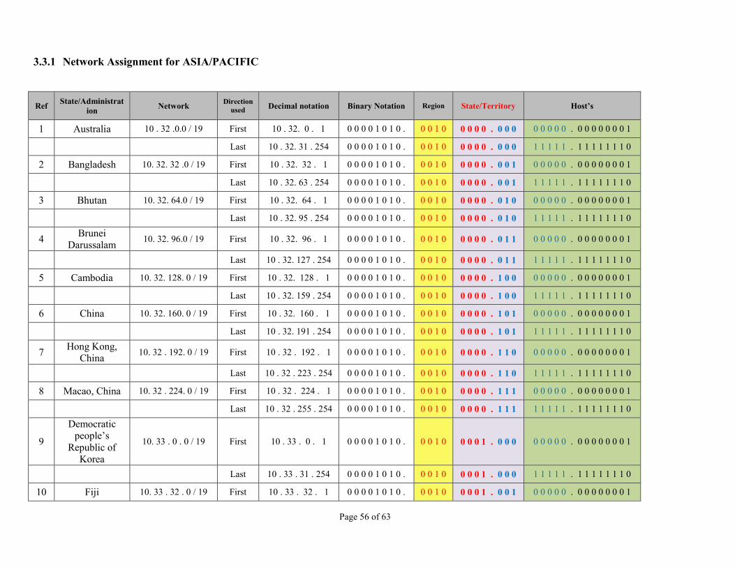
Page 56 of 63
3.3.1 Network Assignment for ASIA/PACIFIC
Ref State/Administration Network Direction
used Decimal notation Binary Notation Region State/Territory Host’s
1 Australia 10 . 32 .0.0 / 19 First 10 . 32. 0 . 1 0 0 0 0 1 0 1 0 . 0 0 1 0 0 0 0 0 . 0 0 0 0 0 0 0 0 . 0 0 0 0 0 0 0 1
Last 10 . 32. 31 . 254 0 0 0 0 1 0 1 0 . 0 0 1 0 0 0 0 0 . 0 0 0 1 1 1 1 1 . 1 1 1 1 1 1 1 0
2 Bangladesh 10. 32. 32 .0 / 19 First 10 . 32. 32 . 1 0 0 0 0 1 0 1 0 . 0 0 1 0 0 0 0 0 . 0 0 1 0 0 0 0 0 . 0 0 0 0 0 0 0 1
Last 10 . 32. 63 . 254 0 0 0 0 1 0 1 0 . 0 0 1 0 0 0 0 0 . 0 0 1 1 1 1 1 1 . 1 1 1 1 1 1 1 0
3 Bhutan 10. 32. 64.0 / 19 First 10 . 32. 64 . 1 0 0 0 0 1 0 1 0 . 0 0 1 0 0 0 0 0 . 0 1 0 0 0 0 0 0 . 0 0 0 0 0 0 0 1
Last 10 . 32. 95 . 254 0 0 0 0 1 0 1 0 . 0 0 1 0 0 0 0 0 . 0 1 0 1 1 1 1 1 . 1 1 1 1 1 1 1 0
4 Brunei Darussalam 10. 32. 96.0 / 19 First 10 . 32. 96 . 1 0 0 0 0 1 0 1 0 . 0 0 1 0 0 0 0 0 . 0 1 1 0 0 0 0 0 . 0 0 0 0 0 0 0 1
Last 10 . 32. 127 . 254 0 0 0 0 1 0 1 0 . 0 0 1 0 0 0 0 0 . 0 1 1 1 1 1 1 1 . 1 1 1 1 1 1 1 0
5 Cambodia 10. 32. 128. 0 / 19 First 10 . 32. 128 . 1 0 0 0 0 1 0 1 0 . 0 0 1 0 0 0 0 0 . 1 0 0 0 0 0 0 0 . 0 0 0 0 0 0 0 1
Last 10 . 32. 159 . 254 0 0 0 0 1 0 1 0 . 0 0 1 0 0 0 0 0 . 1 0 0 1 1 1 1 1 . 1 1 1 1 1 1 1 0
6 China 10. 32. 160. 0 / 19 First 10 . 32. 160 . 1 0 0 0 0 1 0 1 0 . 0 0 1 0 0 0 0 0 . 1 0 1 0 0 0 0 0 . 0 0 0 0 0 0 0 1
Last 10 . 32. 191 . 254 0 0 0 0 1 0 1 0 . 0 0 1 0 0 0 0 0 . 1 0 1 1 1 1 1 1 . 1 1 1 1 1 1 1 0
7 Hong Kong, China 10. 32 . 192. 0 / 19 First 10 . 32 . 192 . 1 0 0 0 0 1 0 1 0 . 0 0 1 0 0 0 0 0 . 1 1 0 0 0 0 0 0 . 0 0 0 0 0 0 0 1
Last 10 . 32 . 223 . 254 0 0 0 0 1 0 1 0 . 0 0 1 0 0 0 0 0 . 1 1 0 1 1 1 1 1 . 1 1 1 1 1 1 1 0
8 Macao, China 10. 32 . 224. 0 / 19 First 10 . 32 . 224 . 1 0 0 0 0 1 0 1 0 . 0 0 1 0 0 0 0 0 . 1 1 1 0 0 0 0 0 . 0 0 0 0 0 0 0 1
Last 10 . 32 . 255 . 254 0 0 0 0 1 0 1 0 . 0 0 1 0 0 0 0 0 . 1 1 1 1 1 1 1 1 . 1 1 1 1 1 1 1 0
9
Democratic people’s
Republic of Korea
10. 33 . 0 . 0 / 19 First 10 . 33 . 0 . 1 0 0 0 0 1 0 1 0 . 0 0 1 0 0 0 0 1 . 0 0 0 0 0 0 0 0 . 0 0 0 0 0 0 0 1
Last 10 . 33 . 31 . 254 0 0 0 0 1 0 1 0 . 0 0 1 0 0 0 0 1 . 0 0 0 1 1 1 1 1 . 1 1 1 1 1 1 1 0
10 Fiji 10. 33 . 32 . 0 / 19 First 10 . 33 . 32 . 1 0 0 0 0 1 0 1 0 . 0 0 1 0 0 0 0 1 . 0 0 1 0 0 0 0 0 . 0 0 0 0 0 0 0 1

Page 57 of 63
Ref State/Administration Network Direction
used Decimal notation Binary Notation Region State/Territory Host’s
Last 10 . 33 . 63 . 254 0 0 0 0 1 0 1 0 . 0 0 1 0 0 0 0 1 . 0 0 1 1 1 1 1 1 . 1 1 1 1 1 1 1 0
11 India 10. 33 . 64 . 0 / 19 First 10 . 33 . 64 . 1 0 0 0 0 1 0 1 0 . 0 0 1 0 0 0 0 1 . 0 1 0 0 0 0 0 0 . 0 0 0 0 0 0 0 1
Last 10 . 33 . 95 . 254 0 0 0 0 1 0 1 0 . 0 0 1 0 0 0 0 1 . 0 1 0 1 1 1 1 1 . 1 1 1 1 1 1 1 0
12 Indonesia 10. 33 . 96 . 0 / 19 First 10 . 33 . 96 . 1 0 0 0 0 1 0 1 0 . 0 0 1 0 0 0 0 1 . 0 1 1 0 0 0 0 0 . 0 0 0 0 0 0 0 1
Last 10 . 33 . 96 . 254 0 0 0 0 1 0 1 0 . 0 0 1 0 0 0 0 1 . 0 1 1 1 1 1 1 1 . 1 1 1 1 1 1 1 0
13 Japan 10. 33 . 128 . 0 / 19 First 10 . 33 . 128 . 1 0 0 0 0 1 0 1 0 . 0 0 1 0 0 0 0 1 . 1 0 0 0 0 0 0 0 . 0 0 0 0 0 0 0 1
Last 10 . 33 . 159 . 254 0 0 0 0 1 0 1 0 . 0 0 1 0 0 0 0 1 . 1 0 0 1 1 1 1 1 . 1 1 1 1 1 1 1 0
14 Kiribati 10. 33 . 160 . 0 / 19 First 10 . 33 . 160 . 1 0 0 0 0 1 0 1 0 . 0 0 1 0 0 0 0 1 . 1 0 1 0 0 0 0 0 . 0 0 0 0 0 0 0 1
Last 10 . 33 . 191 . 254 0 0 0 0 1 0 1 0 . 0 0 1 0 0 0 0 1 . 1 0 1 1 1 1 1 1 . 1 1 1 1 1 1 1 0
15 Lao People’s Democratic
Republic 10. 33 . 192 . 0 / 19 First 10 . 33 . 192 . 1 0 0 0 0 1 0 1 0 . 0 0 1 0 0 0 0 1 . 1 1 0 0 0 0 0 0 . 0 0 0 0 0 0 0 1
Last 10 . 33 . 223 . 254 0 0 0 0 1 0 1 0 . 0 0 1 0 0 0 0 1 . 1 1 0 1 1 1 1 1 . 1 1 1 1 1 1 1 0
16 Malaysia 10. 33 . 224 . 0 / 19 First 10 . 33 . 224 . 1 0 0 0 0 1 0 1 0 . 0 0 1 0 0 0 0 1 . 1 1 1 0 0 0 0 0 . 0 0 0 0 0 0 0 1
Last 10 . 33 . 255 . 254 0 0 0 0 1 0 1 0 . 0 0 1 0 0 0 0 1 . 1 1 1 1 1 1 1 1 . 1 1 1 1 1 1 1 0
17 Maldives 10. 34 . 0 . 0 / 19 First 10 . 34 . 00 . 1 0 0 0 0 1 0 1 0 . 0 0 1 0 0 0 1 0 . 0 0 0 0 0 0 0 0 . 0 0 0 0 0 0 0 1
Last 10 . 34 . 31 . 254 0 0 0 0 1 0 1 0 . 0 0 1 0 0 0 1 0 . 0 0 0 1 1 1 1 1 . 1 1 1 1 1 1 1 0
18 Marshall Islands 10. 34 . 32 . 0 / 19 First 10 . 34 . 32 . 1 0 0 0 0 1 0 1 0 . 0 0 1 0 0 0 1 0 . 0 0 1 0 0 0 0 0 . 0 0 0 0 0 0 0 1
Last 10 . 34 . 63 . 254 0 0 0 0 1 0 1 0 . 0 0 1 0 0 0 1 0 . 0 0 1 1 1 1 1 1 . 1 1 1 1 1 1 1 0
19 Micronesia 10. 34 . 64 . 0 / 19 First 10 . 34 . 64 . 1 0 0 0 0 1 0 1 0 . 0 0 1 0 0 0 1 0 . 0 1 0 0 0 0 0 0 . 0 0 0 0 0 0 0 1
Last 10 . 34 . 95 . 254 0 0 0 0 1 0 1 0 . 0 0 1 0 0 0 1 0 . 0 1 0 1 1 1 1 1 . 1 1 1 1 1 1 1 0
20 Mongolia 10. 34 . 96 . 0 / 19 First 10 . 34 . 96 . 1 0 0 0 0 1 0 1 0 . 0 0 1 0 0 0 1 0 . 0 1 1 0 0 0 0 0 . 0 0 0 0 0 0 0 1
Last 10 . 34 . 127 . 254 0 0 0 0 1 0 1 0 . 0 0 1 0 0 0 1 0 . 0 1 1 1 1 1 1 1 . 1 1 1 1 1 1 1 0
21 Myanmar 10. 34 . 128 . 0 / 19 First 10 . 34 . 128 . 1 0 0 0 0 1 0 1 0 . 0 0 1 0 0 0 1 0 . 1 0 0 0 0 0 0 0 . 0 0 0 0 0 0 0 1
Last 10 . 34 . 159 . 254 0 0 0 0 1 0 1 0 . 0 0 1 0 0 0 1 0 . 1 0 0 1 1 1 1 1 . 1 1 1 1 1 1 1 0

Page 58 of 63
Ref State/Administration Network Direction
used Decimal notation Binary Notation Region State/Territory Host’s
22 Nauru 10. 34 . 160 . 0 / 19 First 10 . 34 . 160 . 1 0 0 0 0 1 0 1 0 . 0 0 1 0 0 0 1 0 . 1 0 1 0 0 0 0 0 . 0 0 0 0 0 0 0 1
Last 10 . 34 . 191 . 254 0 0 0 0 1 0 1 0 . 0 0 1 0 0 0 1 0 . 1 0 1 1 1 1 1 1 . 1 1 1 1 1 1 1 0
23 Nepal 10. 34 . 192 . 0 / 19 First 10 . 34 . 192 . 1 0 0 0 0 1 0 1 0 . 0 0 1 0 0 0 1 0 . 1 1 0 0 0 0 0 0 . 0 0 0 0 0 0 0 1
Last 10 . 34 . 223 . 254 0 0 0 0 1 0 1 0 . 0 0 1 0 0 0 1 0 . 1 1 0 1 1 1 1 1 . 1 1 1 1 1 1 1 0
24 New Zealand 10. 34 . 224 . 0 / 19 First 10 . 34 . 224 . 1 0 0 0 0 1 0 1 0 . 0 0 1 0 0 0 1 0 . 1 1 1 0 0 0 0 0 . 0 0 0 0 0 0 0 1
Last 10 . 34 . 255. 254 0 0 0 0 1 0 1 0 . 0 0 1 0 0 0 1 0 . 1 1 1 1 1 1 1 1 . 1 1 1 1 1 1 1 0
25 Pakistan 10. 35 . 0 . 0 / 19 First 10 . 35 . 0 . 1 0 0 0 0 1 0 1 0 . 0 0 1 0 0 0 1 1 . 0 0 0 0 0 0 0 0 . 0 0 0 0 0 0 0 1
Last 10 . 35 . 31 . 254 0 0 0 0 1 0 1 0 . 0 0 1 0 0 0 1 1 . 0 0 0 1 1 1 1 1 . 1 1 1 1 1 1 1 0
26 Papua New Guinea 10. 35 . 32 . 0 / 19 First 10 . 35 . 32 . 1 0 0 0 0 1 0 1 0 . 0 0 1 0 0 0 1 1 . 0 0 1 0 0 0 0 0 . 0 0 0 0 0 0 0 1
Last 10 . 35 . 63 . 254 0 0 0 0 1 0 1 0 . 0 0 1 0 0 0 1 1 . 0 0 1 1 1 1 1 1 . 1 1 1 1 1 1 1 0
27 Philippines 10. 35 . 64 . 0 / 19 First 10 . 35 . 64 . 1 0 0 0 0 1 0 1 0 . 0 0 1 0 0 0 1 1 . 0 1 0 0 0 0 0 0 . 0 0 0 0 0 0 0 1
Last 10 . 35 . 95 . 254 0 0 0 0 1 0 1 0 . 0 0 1 0 0 0 1 1 . 0 1 0 1 1 1 1 1 . 1 1 1 1 1 1 1 0
28 Republic of Korea 10. 35 . 96 . 0 / 19 First 10 . 35 . 96 . 1 0 0 0 0 1 0 1 0 . 0 0 1 0 0 0 1 1 . 0 1 1 0 0 0 0 0 . 0 0 0 0 0 0 0 1
Last 10 . 35 . 127 . 254 0 0 0 0 1 0 1 0 . 0 0 1 0 0 0 1 1 . 0 1 1 1 1 1 1 1 . 1 1 1 1 1 1 1 0
29 Samoa 10. 35 . 128 . 0 / 19 First 10 . 35 . 128 . 1 0 0 0 0 1 0 1 0 . 0 0 1 0 0 0 1 1 . 1 0 0 0 0 0 0 0 . 0 0 0 0 0 0 0 1
Last 10 . 35 . 159 . 254 0 0 0 0 1 0 1 0 . 0 0 1 0 0 0 1 1 . 1 0 0 1 1 1 1 1 . 1 1 1 1 1 1 1 0
30 Singapore 10. 35 . 160 . 0 / 19 First 10 . 35 . 160 . 1 0 0 0 0 1 0 1 0 . 0 0 1 0 0 0 1 1 . 1 0 1 0 0 0 0 0 . 0 0 0 0 0 0 0 1
Last 10 . 35 . 191 . 254 0 0 0 0 1 0 1 0 . 0 0 1 0 0 0 1 1 . 1 0 1 1 1 1 1 1 . 1 1 1 1 1 1 1 0
31 Solomon Islands 10. 35 . 192 . 0 / 19 First 10 . 35 . 192 . 1 0 0 0 0 1 0 1 0 . 0 0 1 0 0 0 1 1 . 1 1 0 0 0 0 0 0 . 0 0 0 0 0 0 0 1
Last 10 . 35 . 223 . 254 0 0 0 0 1 0 1 0 . 0 0 1 0 0 0 1 1 . 1 1 0 1 1 1 1 1 . 1 1 1 1 1 1 1 0
32 Sri Lanka 10. 35. 224 . 0 / 19 First 10 . 35 . 224 . 1 0 0 0 0 1 0 1 0 . 0 0 1 0 0 0 1 1 . 1 1 1 0 0 0 0 0 . 0 0 0 0 0 0 0 1
Last 10 . 35 . 255 . 254 0 0 0 0 1 0 1 0 . 0 0 1 0 0 0 1 1 . 1 1 1 1 1 1 1 1 . 1 1 1 1 1 1 1 0
33 Thailand 10. 36 . 0 . 0 / 19 First 10 . 36 . 00 . 1 0 0 0 0 1 0 1 0 . 0 0 1 0 0 1 0 0 . 0 0 0 0 0 0 0 0 . 0 0 0 0 0 0 0 1

Page 59 of 63
Ref State/Administration Network Direction
used Decimal notation Binary Notation Region State/Territory Host’s
Last 10 . 36 . 31 . 254 0 0 0 0 1 0 1 0 . 0 0 1 0 0 1 0 0 . 0 0 0 1 1 1 1 1 . 1 1 1 1 1 1 1 0
34 Timor Leste 10. 36. 32 . 0 / 19 First 10 . 36. 32 . 1 0 0 0 0 1 0 1 0 . 0 0 1 0 0 1 0 0 . 0 0 1 0 0 0 0 0 . 0 0 0 0 0 0 0 1
Last 10 . 36. 63 . 254 0 0 0 0 1 0 1 0 . 0 0 1 0 0 1 0 0 . 0 0 1 1 1 1 1 1 . 1 1 1 1 1 1 1 0
35 Tonga 10. 36 . 64 . 0 / 19 First 10 . 36 . 64 . 1 0 0 0 0 1 0 1 0 . 0 0 1 0 0 1 0 0 . 1 1 0 0 0 0 0 0 . 0 0 0 0 0 0 0 1
Last 10 . 36 . 95 . 254 0 0 0 0 1 0 1 0 . 0 0 1 0 0 1 0 0 . 1 1 0 1 1 1 1 1 . 1 1 1 1 1 1 1 0
36 Vanuatu 10. 36 . 96 . 0 / 19 First 10 . 36 . 96 . 1 0 0 0 0 1 0 1 0 . 0 0 1 0 0 1 0 0 . 0 1 1 0 0 0 0 0 . 0 0 0 0 0 0 0 1
Last 10 . 36 . 127 . 254 0 0 0 0 1 0 1 0 . 0 0 1 0 0 1 0 0 . 0 1 1 1 1 1 1 1 . 1 1 1 1 1 1 1 0
37 Vietnam 10. 36 . 128 . 0 / 19 First 10 . 36 . 128 . 1 0 0 0 0 1 0 1 0 . 0 0 1 0 0 1 0 0 . 1 0 0 0 0 0 0 0 . 0 0 0 0 0 0 0 1
Last 10 . 36 . 159 . 254 0 0 0 0 1 0 1 0 . 0 0 1 0 0 1 0 0 . 1 0 0 1 1 1 1 1 . 1 1 1 1 1 1 1 0
38 Afghanistan 10. 36 . 160 . 0 / 19 First 10 . 36 . 160 . 1 0 0 0 0 1 0 1 0 . 0 0 1 0 0 1 0 0 . 1 0 1 0 0 0 0 0 . 0 0 0 0 0 0 0 1
Last 10 . 36 . 191 . 254 0 0 0 0 1 0 1 0 . 0 0 1 0 0 1 0 0 . 1 0 1 1 1 1 1 1 . 1 1 1 1 1 1 1 0
39 French
Polynesia, France
10. 36 . 192 . 0 / 19 First 10 . 36 . 192 . 1 0 0 0 0 1 0 1 0 . 0 0 1 0 0 1 0 0 . 1 1 0 0 0 0 0 0 . 0 0 0 0 0 0 0 1
Last 10 . 36 . 223 . 254 0 0 0 0 1 0 1 0 . 0 0 1 0 0 1 0 0 . 1 1 0 1 1 1 1 1 . 1 1 1 1 1 1 1 0
40 New
Caledonia, France
10. 36 . 224 . 0 / 19 First 10 . 36 . 224 . 1 0 0 0 0 1 0 1 0 . 0 0 1 0 0 1 0 0 . 1 1 1 0 0 0 0 0 . 0 0 0 0 0 0 0 1
Last 10 . 36 . 255 . 254 0 0 0 0 1 0 1 0 . 0 0 1 0 0 1 0 0 . 1 1 1 1 1 1 1 1 . 1 1 1 1 1 1 1 0
41 Wallis &
Futuna Islands, France
10. 37 . 0 . 0 / 19 First 10 . 37 . 0 . 1 0 0 0 0 1 0 1 0 . 0 0 1 0 0 1 0 1 . 0 0 0 0 0 0 0 0 . 0 0 0 0 0 0 0 1
Last 10 . 37 . 31 . 254 0 0 0 0 1 0 1 0 . 0 0 1 0 0 1 0 1 . 0 0 0 1 1 1 1 1 . 1 1 1 1 1 1 1 0
42 Niue Islands, New Zealand 10. 37 . 32 . 0 / 19 First 10 . 37 . 32 . 1 0 0 0 0 1 0 1 0 . 0 0 1 0 0 1 0 1 . 0 0 1 0 0 0 0 0 . 0 0 0 0 0 0 0 1
Last 10 . 37 . 63 . 254 0 0 0 0 1 0 1 0 . 0 0 1 0 0 1 0 1 . 0 0 1 1 1 1 1 1 . 1 1 1 1 1 1 1 0
43 Pecan Island,
United Kingdom
10. 37 . 64 . 0 / 19 First 10 . 37 . 64 . 1 0 0 0 0 1 0 1 0 . 0 0 1 0 0 1 0 1 . 0 1 0 0 0 0 0 0 . 0 0 0 0 0 0 0 1

Page 60 of 63
Ref State/Administration Network Direction
used Decimal notation Binary Notation Region State/Territory Host’s
Last 10 . 37. 95 . 254 0 0 0 0 1 0 1 0 . 0 0 1 0 0 1 0 1 . 0 1 0 1 1 1 1 1 . 1 1 1 1 1 1 1 0
44 American
Samoa , United States
10. 37 . 96 . 0 / 19 First 10 . 37. 96 . 1 0 0 0 0 1 0 1 0 . 0 0 1 0 0 1 0 1 . 0 1 1 0 0 0 0 0 . 0 0 0 0 0 0 0 1
Last 10 . 37. 127 . 254 0 0 0 0 1 0 1 0 . 0 0 1 0 0 1 0 1 . 0 1 1 1 1 1 1 1 . 1 1 1 1 1 1 1 0
45 Guam, United States 10. 37 . 128 . 0 / 19 First 10 . 37. 128 . 1 0 0 0 0 1 0 1 0 . 0 0 1 0 0 1 0 1 . 1 0 0 0 0 0 0 0 . 0 0 0 0 0 0 0 1
Last 10 . 37. 159 . 254 0 0 0 0 1 0 1 0 . 0 0 1 0 0 1 0 1 . 1 0 0 1 1 1 1 1 . 1 1 1 1 1 1 1 0
46 Johnson Island Kingman Reef, United States
10. 37 . 160 . 0 / 19 First 10 . 37. 160 . 1 0 0 0 0 1 0 1 0 . 0 0 1 0 0 1 0 1 . 1 0 1 0 0 0 0 0 . 0 0 0 0 0 0 0 1
Last 10 . 37. 191 . 254 0 0 0 0 1 0 1 0 . 0 0 1 0 0 1 0 1 . 1 0 1 1 1 1 1 1 . 1 1 1 1 1 1 1 0
47 Midway, United States 10. 37 . 192 . 0 / 19 First 10 . 37. 192 . 1 0 0 0 0 1 0 1 0 . 0 0 1 0 0 1 0 1 . 1 1 0 0 0 0 0 0 . 0 0 0 0 0 0 0 1
Last 10 . 37. 223 . 254 0 0 0 0 1 0 1 0 . 0 0 1 0 0 1 0 1 . 1 1 0 1 1 1 1 1 . 1 1 1 1 1 1 1 0
48
Northern Mariana
Islands, United States
10 . 37 .224. 0 / 19 First 10 . 37 . 224 . 1 0 0 0 0 1 0 1 0 . 0 0 1 0 0 1 0 1 . 1 1 1 0 0 0 0 0 . 0 0 0 0 0 0 0 1
Last 10 . 37 . 255 . 254 0 0 0 0 1 0 1 0 . 0 0 1 0 0 1 0 1 . 1 1 1 1 1 1 1 1 . 1 1 1 1 1 1 1 0
49 Palmyra, United States 10 . 38 . 0 . 0 / 19 First 10 . 38 . 0 . 1 0 0 0 0 1 0 1 0 . 0 0 1 0 0 1 1 0 . 0 0 0 0 0 0 0 0 . 0 0 0 0 0 0 0 1
Last 10 . 38 . 31 . 254 0 0 0 0 1 0 1 0 . 0 0 1 0 0 1 1 0 . 0 0 0 1 1 1 1 1 . 1 1 1 1 1 1 1 0
50 Wake Islands, United States 10. 38. 32 . 0 / 19 First 10 . 38 . 32 . 1 0 0 0 0 1 0 1 0 . 0 0 1 0 0 1 1 0 . 0 0 1 0 0 0 0 0 . 0 0 0 0 0 0 0 1
Last 10 . 38 . 63 . 254 0 0 0 0 1 0 1 0 . 0 0 1 0 0 1 1 0 . 0 0 1 1 1 1 1 1 . 1 1 1 1 1 1 1 0
51 Cook Islands 10.38. 64 .0 / 19 First 10 . 38 . 64 . 1 0 0 0 0 1 0 1 0 . 0 0 1 0 0 1 1 0 . 0 1 0 0 0 0 0 0 . 0 0 0 0 0 0 0 1
Last 10 . 38 . 95 . 254 0 0 0 0 1 0 1 0 . 0 0 1 0 0 1 1 0 . 0 1 0 1 1 1 1 1 . 1 1 1 1 1 1 1 0
52 Palau 10. 38 . 96 . 0 / 19 First 10 . 38. 96 . 1 0 0 0 0 1 0 1 0 . 0 0 1 0 0 1 1 0 . 0 1 1 0 0 0 0 0 . 0 0 0 0 0 0 0 1
Last 10 . 38. 127 . 254 0 0 0 0 1 0 1 0 . 0 0 1 0 0 1 1 0 . 0 1 1 1 1 1 1 1 . 1 1 1 1 1 1 1 0
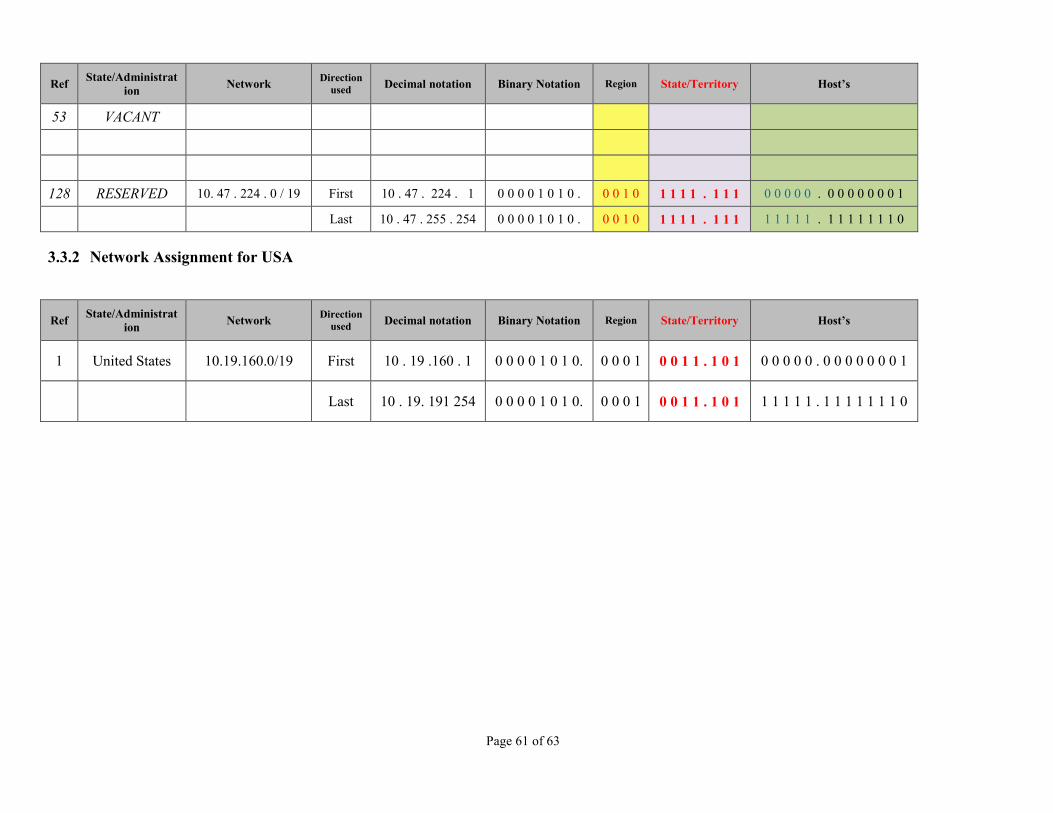
Page 61 of 63
Ref State/Administration Network Direction
used Decimal notation Binary Notation Region State/Territory Host’s
53 VACANT
128 RESERVED 10. 47 . 224 . 0 / 19 First 10 . 47 . 224 . 1 0 0 0 0 1 0 1 0 . 0 0 1 0 1 1 1 1 . 1 1 1 0 0 0 0 0 . 0 0 0 0 0 0 0 1
Last 10 . 47 . 255 . 254 0 0 0 0 1 0 1 0 . 0 0 1 0 1 1 1 1 . 1 1 1 1 1 1 1 1 . 1 1 1 1 1 1 1 0
3.3.2 Network Assignment for USA
Ref State/Administration Network Direction
used Decimal notation Binary Notation Region State/Territory Host’s
1 United States 10.19.160.0/19 First 10 . 19 .160 . 1 0 0 0 0 1 0 1 0. 0 0 0 1 0 0 1 1 . 1 0 1 0 0 0 0 0 . 0 0 0 0 0 0 0 1
Last 10 . 19. 191 254 0 0 0 0 1 0 1 0. 0 0 0 1 0 0 1 1 . 1 0 1 1 1 1 1 1 . 1 1 1 1 1 1 1 0

Page 62 of 63
3.4 Using IPv4-Compatible Address Formats
In many instances, you can represent a 32-bit IPv4 address as a 128-bit IPv6 address. The transition mechanism defines the following two formats. IPv4-compatible address
000 ... 000 IPv4 Address IPv4-mapped address
000 ... 000 0xffff IPv4 Address The mapped address format is used to represent an IPv4 node. The only currently defined use of this address format is part of the socket API. An application can have a common address format for both IPv6 addresses and IPv4 addresses. The common address format can represent an IPv4 address as a 128-bit mapped address. However, IPv4-to-IPv6 protocol translators also allow these addresses to be used.

Appendix B– MID IPv4 Address Plan
Page 63 of 63
Appendix B
No. State Network IP Address
Hosts IP addresses Decimal Notation Binary Notation
1st Byte Region State Hosts 1 Bahrain 10.48.0.0/19 First 10.48.0.1 00001010. 0011 0000.000 00000.00000001
Last 10.48.31.254 00001010. 0011 0000.000 11111.11111110 2 Egypt 10.48.32.0/19 First 10.48.32.1 00001010. 0011 0000.001 00000.00000001
Last 10.48.63.254 00001010. 0011 0000.001 11111.11111110 3 Iran 10.48.64.0/19 First 10.48.64.1 00001010. 0011 0000.010 00000.00000001
Last 10.48.95.254 00001010. 0011 0000.010 11111.11111110 4 Iraq 10.48.96.0/19 First 10.48.96.1 00001010. 0011 0000.011 00000.00000001
Last 10.48.127.254 00001010. 0011 0000.011 11111.11111110 5 Jordan 10.48.0.0/19 First 10.48.128.1 00001010. 0011 0000.100 00000.00000001
Last 10.48.159.254 00001010. 0011 0000.100 11111.11111110 6 Kuwait 10.48.0.0/19 First 10.48.160.1 00001010. 0011 0000.101 00000.00000001
Last 10.48.195.254 00001010. 0011 0000.101 11111.11111110 7 Lebanon 10.48.0.0/19 First 10.48.196.1 00001010. 0011 0000.110 00000.00000001
Last 10.48.223.254 00001010. 0011 0000.110 11111.11111110 8 Libya 10.48.0.0/19 First 10.48.224.1 00001010. 0011 0000.111 00000.00000001
Last 10.48.255.254 00001010. 0011 0000.111 11111.11111110 9 Oman 10.48.0.0/19 First 10.49.0.1 00001010. 0011 0001.000 00000.00000001
Last 10.49.31.254 00001010. 0011 0001.000 11111.11111110 10 Qatar 10.48.0.0/19 First 10.49.32.1 00001010. 0011 0001.001 00000.00000001
Last 10.49.63.254 00001010. 0011 0001.001 11111.11111110 11 Saudi
Arabia 10.48.0.0/19 First 10.49.64.1 00001010. 0011 0001.010 00000.00000001
Last 10.49.95.254 00001010. 0011 0001.010 11111.11111110 12 Sudan 10.48.0.0/19 First 10.49.96.1 00001010. 0011 0001.011 00000.00000001
Last 10.49.127.254 00001010. 0011 0001.011 11111.11111110 13 Syria 10.48.0.0/19 First 10.49.128.1 00001010. 0011 0001.100 00000.00000001
Last 10.49.159.254 00001010. 0011 0001.100 11111.11111110 14 UAE 10.48.0.0/19 First 10.49.160.1 00001010. 0011 0001.101 00000.00000001
Last 10.49.127.254 00001010. 0011 0001.101 11111.11111110 15 Yemen 10.48.0.0/19 First 10.49.128.1 00001010. 0011 0001.110 00000.00000001
Last 10.49.223.254 00001010. 0011 0001.110 11111.11111110

CNS SG/23 Appendix E to the Report
APX. E – ACSICG/6 E - 1
CRV IMPLEMENTATION TABLE
State/ Administration
Intended date for CRV cut-over
Applications targeted
Migration scheme
Prerequisites/ dependencies
Australia Contract in May2018 and service readiness in 3Q 2018
AFTN, ADS-B, AMHS, Voice With: Australia February,2019(AMHS/AIDC), March,2019(Voice) Fiji March,2019 (AMHS June 2019/AIDC, Voice completed April) New Zealand, February, 2019 (AMHS June 2019, AFTN May 2019/AIDC), March, 2019 (Voice April 2019 completed) Indonesia 4Q2019 (TBC) (AMHS/AIDC, Voice, ADS-B); PNG 4Q2019(TBC), (AMHS/AIDC, Voice) Singapore 2Q2019 TBC (AMHS/AIDC, Voice); South Africa TBC
3Q2019 TBC,(AMHS/AIDC, Voice); Japan would be end of 2019.
staged approach
Termination of current COM contract
Bhutan Contract in 3Q2019, service readiness in 4Q2019
Data(AMHS, AFTN) and voice Administrative approval from the management for the direct contract and approval from BCAA Cambodia As early as convenient,
dependent on neighboring countries
Internal decision making

CNS SG/23 Appendix E to the Report
APX. E – ACSICG/6 E - 2
State/ Administration
Intended date for CRV cut-over
Applications targeted
Migration scheme
Prerequisites/ dependencies
China Contract in 3Q2019, service readiness in 4Q2019
Data(AMHS) With: Hong Kong 4Q2019; Japan 2Q2020; Thailand 4Q2019; India 4Q2019. Republic of Korea a.s.a.p ATFM traffic test May 2020 over CRV
staged approach
DemocraticPeople's Republic of Korea
Contract in 3Q2018 and service readiness in 4Q2018
AFTN and VoIP
Hong Kong, China Contract signed on 6 April 2018. Connection was installed successfully in June 2018. CRV-Voice with Manila was put into operation on 14 August 2018.
DATA (AMHS) With: Beijing 4Q2019; Manila operational May 2019 Japan 1Q2020; Thailand 3Q2019;
staged approach
Need to coordinate with relevant CAAs/ANSPs in joining CRV in a harmonized manner, etc.
Macao, China To be confirmed CBA migration fromX25toIP
Fiji Contract in May 2018 and service readiness in 3Q 2018
Data (AMHS) and VoIP With: Australia ATS voice April 2019 completed, AMHS planned June 2019, NZ ATS voice c. 2019 and USA ATS voice March 2019 completed. AMHS April 2019.
Staged approach CBA, safety case
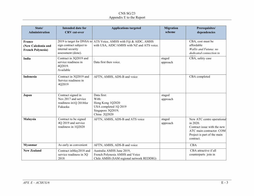
CNS SG/23 Appendix E to the Report
APX. E – ACSICG/6 E - 3
State/ Administration
Intended date for CRV cut-over
Applications targeted
Migration scheme
Prerequisites/ dependencies
France (New Caledonia and French Polynesia)
2019 is target for DNSA to sign contract subject to internal security assessment (done).
ATS Voice, AMHS with Fiji & AIDC, AMHS with USA, AIDC/AMHS with NZ and ATS voice.
CBA, cost must be affordable Wallis and Futuna: no dedicated connection to CRV India Contract in 3Q2019 and
service readiness in 4Q2019. Available
. Data first then voice.
staged approach
CBA, safety case
Indonesia Contract in 3Q2019 and Service readiness in 4Q2019
AFTN, AMHS, ADS-B and voice CBA completed
Japan Contract signed in Nov.2017 and service readiness in1Q 2018for Fukuoka
Data first: With: Hong Kong 1Q2020 USA completed 1Q 2019 Singapore 3Q2019; China 2Q2020
staged approach
Malaysia Contract to be signed 4Q 2019 and service readiness in 1Q2020
AFTN, AMHS, ADS-B and ATS voice staged approach
New ATC centre operational in 2020. Contract issue with the new ATC main contractor. COM Project is part of the main contract.
Myanmar As early as convenient AFTN, AMHS, ADS-B and voice CBA
New Zealand Contract inMay2018 and service readiness in 3Q 2018
Australia AMHS June 2019, French Polynesia AMHS and Voice Chile AMHS (SAM regional network REDDIG) AFTN, AMHS and voice
CBA attractive if all counterparts join in
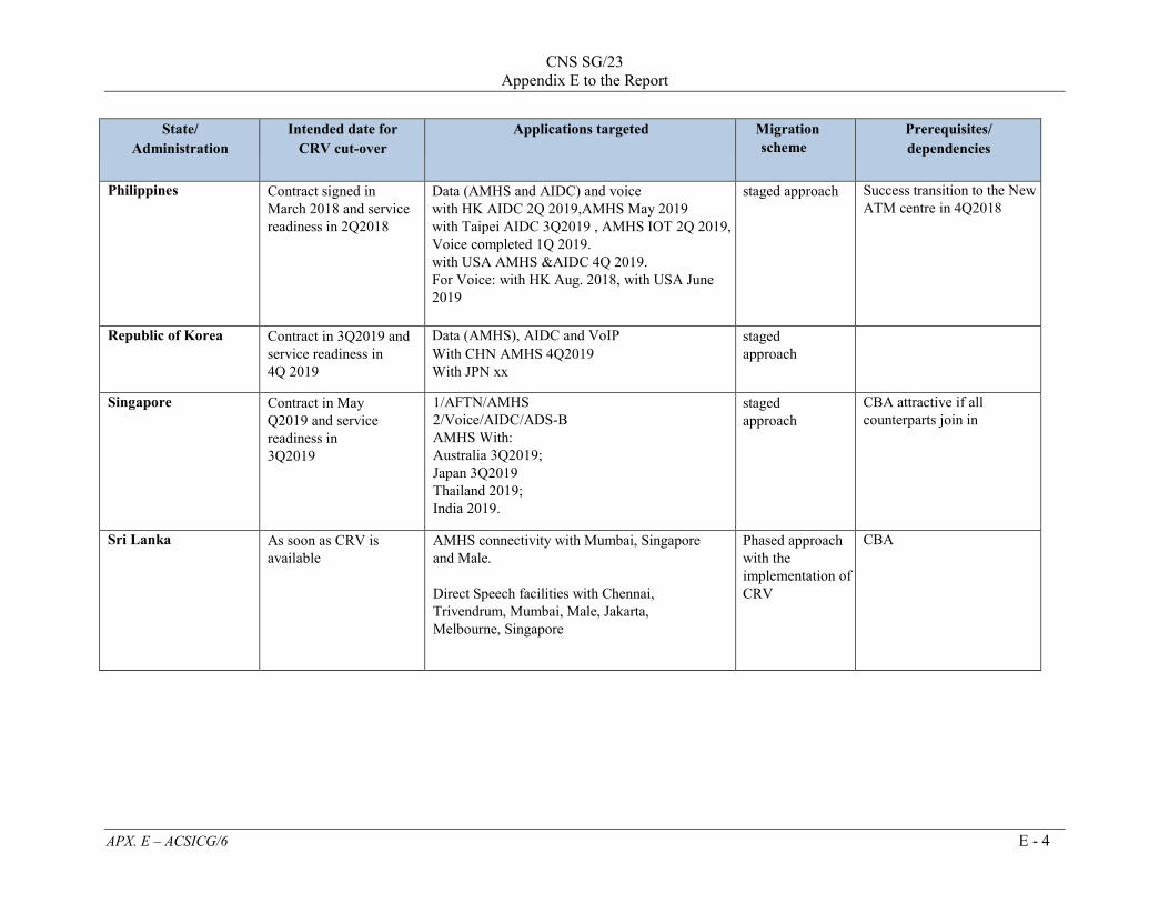
CNS SG/23 Appendix E to the Report
APX. E – ACSICG/6 E - 4
State/ Administration
Intended date for CRV cut-over
Applications targeted
Migration scheme
Prerequisites/ dependencies
Philippines Contract signed in March 2018 and service readiness in 2Q2018
Data (AMHS and AIDC) and voice with HK AIDC 2Q 2019,AMHS May 2019 with Taipei AIDC 3Q2019 , AMHS IOT 2Q 2019, Voice completed 1Q 2019. with USA AMHS &AIDC 4Q 2019. For Voice: with HK Aug. 2018, with USA June 2019
staged approach Success transition to the New ATM centre in 4Q2018
Republic of Korea Contract in 3Q2019 and service readiness in 4Q 2019
Data (AMHS), AIDC and VoIP With CHN AMHS 4Q2019 With JPN xx
staged approach
Singapore Contract in May Q2019 and service readiness in 3Q2019
1/AFTN/AMHS 2/Voice/AIDC/ADS-B AMHS With: Australia 3Q2019; Japan 3Q2019 Thailand 2019; India 2019.
staged approach
CBA attractive if all counterparts join in
Sri Lanka As soon as CRV is available
AMHS connectivity with Mumbai, Singapore and Male. Direct Speech facilities with Chennai, Trivendrum, Mumbai, Male, Jakarta, Melbourne, Singapore
Phased approach with the implementation of CRV
CBA

CNS SG/23 Appendix E to the Report
APX. E – ACSICG/6 E - 5
State/ Administration
Intended date for CRV cut-over
Applications targeted
Migration scheme
Prerequisites/ dependencies
Thailand
Contract in 3Q 2019 and service readiness in 4Q2019
Data first Then voice, subject to safety case: China 4Q2019 Hong Kong 4Q2019; Singapore 4Q2019; India 2019.
Staged approach
United States Contract in May 2018 and service readiness in 3Q 2018
1) with Australia AFTN to AMHS over IP: Feb 2019 Voice: March, 2019 2) With Fiji AMHS/AIDC Feb 2019 Voice March, 2019 3) With New Zealand AMHS/AIDC, Voice March 2019 4) With Japan AMHS/AIDC Feb 2019 VOICE: TBC 5) With Philippines AMHS/AIDC 3Q2019 VOICE April, 2019 6) other FIRs as opportune (French Polynesia, Samoa, Indonesia, PNG etc.) 7) ATFM, AMHS with Attachment 8) BBIS with Fiji, Australia and Japan 3Q2018 (for only AMHS)
Staged approach

CNS SG/23 Appendix E to the Report
APX. E – ACSICG/6 E - 6
State/ Administration
Intended date for CRV cut-over
Applications targeted
Migration scheme
Prerequisites/ dependencies
Viet Nam To be confirmed later (After discussed with PCCW Global)
_ _ _ _ _ _ _ _ _ _ _ _ _
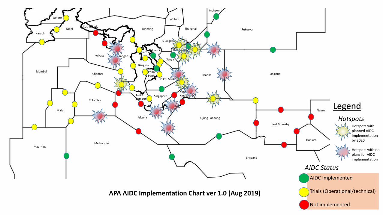
PhnomPenh
Bangkok
VientianeHanoi
Ho Chi Minh
Sanya
Hong Kong
GuangzhouTaibei
Manila
Yangon
KualaLumpur
Singapore
KotaKinabalu
Ujung PandangJakarta
Chennai
Kolkata
Colombo
Male
Mumbai
MelbourneMauritius
Brisbane
Fukuoka
Oakland
Shanghai
Incheon
Wuhan
Delhi Kunming
Dhaka
Kathmandu
Karachi
Lahore
Port Moresby
Honiara
Nauru
AIDC Implemented
Trials (Operational/technical)
Not implemented
APA AIDC Implementation Chart ver 1.0 (Aug 2019)
Hotspots
Legend
Hotspots with planned AIDCImplementationby 2020
Hotspots with noplans for AIDCimplementation
AIDC Status
ssomsri
Typewritten Text
CNS SG/23 Appendix F to the Report
ssomsri
Typewritten Text
ssomsri
Typewritten Text
ssomsri
Typewritten Text

CNS SG/23 Appendix G to the Report
APX. C – SWIM TF/3 G - 1
THE SWIM IMPLEMENTATION PHILOSOPHY AND ROADMAP
1. ASIA-PACIFIC SWIM IMPLEMENTATION PHILOSOPHY 1.1 As proposed in SWIM TF/2/WP-07 and SWIM TF/3/WP-19, the proposed SWIM implementation philosophy for Asia-Pacific is a bottom-up, agile like approach. 1.2 Starting by identifying and selecting one particular operation expected to benefit from SWIM implementation, the information services and infrastructure services required to support this operation can then be identified and implemented. SWIM governances that are considered necessary for the implementation and usage of such services to support the specified operation can be built. At this stage, it is considered that the governance rules to be implemented are the only ones deemed necessary for these set of services to be used operationally. 1.3 This bottom-up principle will help provide the clear justifications to implement the SWIM infrastructure needed to better and more efficiently support the operations. Once the services are implemented and utilized to support this first operation, reflecting the advantages of using SWIM, the same process can be continuously applied to other operations considered important and requiring more effective information exchange for the region. This repetitive process adopts agile development principles in that it strives for a Minimally Viable Product (MVP), i.e. a set of working, tested and operationally ready services built on the necessary Asia-Pacific SWIM infrastructure to support the identified operations. 2. ASIA-PACIFIC SWIM IMPLEMENTATION ROADMAP 2.1 Based on the implementation philosophy as outlined above, the implementation roadmap can be derived as follows :
a) Identify the operations that can be better supported by SWIM; b) Identify and design the information services required to support the operations
specified; c) Identify and design the SWIM infrastructure services required to support the
information services determined; d) Implement the SWIM infrastructure services; e) Implement the information services; f) Perform message exchange test; g) Perform operational trials using the information services implemented; h) Carry out performance and reliability test; i) Develop governance rules around the information services supporting the operations;
and j) Repeat for the next operations identified.
A diagrammatic representation of the roadmap is given in the bottom of this Appendix. 2.2 A preliminary registry can be built to provide initial service discover capability. Once there is demand for the use of the implemented services outside of their original intent, a registry or registries with full capability can be then established to aid in the discovery of these services.

CNS SG/23 Appendix G to the Report
APX. C – SWIM TF/3 G - 2
2.3 When the
registry(s) is being implemented, governance surrounding the use and access of the registry(s) will need to be considered together with any interoperability issues between registries if necessary.
2.4 SWIM TF/3/WP19 further details how each step of the roadmap may be implemented.
Phase 0: Identification of a Concept of Operations
• Identify operation that can be better supported by SWIM;
• Understanding the shortfall
• Stakeholders Consultation
• Stakeholders agreement
• Develop Scenarios • Develop Use Cases • Identify
Information
Phase 1: Implementation of SWIM Infrastructure Services • Services Software
Development • Functional Testing • Functional
Validation
Phase 2: Implementation of SWIM Information Services
• Register* the service
• On Ramp the service
• Services Software Development
• Functional Testing • Functional
Validation • Performance
Phase 3: Transition to SWIM Environment • Operational
Deployment • Operational Test
and Validation • User Acceptance
Testing
*When a registry has been developed

CNS SG/23 Appendix H to the Report
APX. E – SWIM TF/3 H - 1
1.0 Based on the operational scenarios developed for the SWIM in ASEAN Demonstration, additional data attributes required to be exchanged among stakeholders involving in A-CDM (Airport-Collaborative Decision Making) operation and to support the integration between ATFM and A-CDM were identified. Considering that these data attributes are flight-specific, FIXM would be the appropriate information exchange model to support the aforementioned operations. Consequently, the FIXM version 4.1 Extension was further developed to include these data attributes. Table 1 shows the list of data attributes currently included in the FIXM version 4.1 Extension developed.
Estimated Calculated Target Actual TOBT AOBT TSAT CTOT TTOT
ETO CTO ATO ELDT CLDT
Other Trajectory Aircraft Track
ETO CTO ATO Flight level or Altitude Waypoint
Ground speed Bearing Flight level or Altitude Position (Designator or Latitude/Longitude or
Relative Point) Time over position
Table 1: FIXM version 4.1 Extension Data Attributes
1.1 A system-to-system interconnection test between Singapore and Thailand to validate the exchange of developed FIXM version 4.1 Extension was successfully conducted in March/April 2019 using the Flight Information Update use case, involving the distribution of ATFM and A-CDM related data attributes, designed based on the AMQP (Advanced Message Queuing Protocol) messaging protocol.
1.2 The FIXM version 4.1 Extension aforementioned was presented at and endorsed by the Ninth Meeting of the Asia/Pacific Air Traffic Flow Management Steering Group (ATFM/SG/9) in April 2019. Although the options for identifying and including the data attributes in addition to the ones shown in Table 1 were discussed at length during ATFM/SG/9, it was agreed by the meeting that, to avoid any further delay in approval and publication of the developed FIXM version 4.1 Extension for the operational use in the Asia/Pacific Region, any additional data attributes such as the ones for A-CDM purposes should be included in the second version of extension to be developed at a later date.
1.3 The FIXM version 4.1 Extension developed is detailed in Appendix below. Noting the near-term need for system-to-system ATFM information exchange between enabled ATFM Nodes, it is proposed that this FIXM Extension be adopted as the Asia/Pacific FIXM version 4.1 Extension and be made available for immediate use by Asia/Pacific Administrations. It is further proposed that this FIXM Extension be presented to the FIXM Change Control Board (CCB) for validation and publication on the FIXM official website.
Based on the anticipation that the future ATFM information services will be highly composite, pulling data from across domains to support ATFM functions from planning, monitoring, and managing through post-event analysis, adapting or combining the existing information exchange models to provide comprehensive ATFM information exchange has scope and structural limitations. Particularly, ATFM information is not flight-specific, related to a single flight, as is FIXM and may contain or use description of volumes with attributes not currently required for AIXM, while there is no overlap between ATFM functions and IWXXM. Besides, considering that adding new data elements to existing information

CNS SG/23 Appendix H to the Report
APX. E – SWIM TF/3 H - 2
exchange models would be a lengthy process due to the required coordination and attaining acceptance from the existing information exchange model governing community, the scalability and interoperability of ATFM-related information exchange will be certainly affected. With the analysis on both technical and non-technical factors such as schedule, potential risks, and potential benefits, it was concluded that developing the new and standalone information exchange model for ATFM-related information exchange is the best option.
1.4 Similarly, the assessment on the possibility to utilize the existing information exchange models for the exchange of ATFM Daily Plan (ADP) being currently distributed among ATFM units and related stakeholders in the Asia/Pacific region revealed that developing the new information exchange model is likely the best alternative as the information contained in ADP covers more than one information domains. With this common view, the collaboration between Singapore, Thailand, and USA on the development of ATFM-specific information exchange model has been discussed. Initially, it is agreed that, to not reinvent the wheel, the scope of ATFM information to be included in this new information exchange model being discussed must be clearly identified. For example, the data elements considered flight-specific, e.g. CTOT, CLDT, CTO, etc., should remain under FIXM, while the data elements included in ADP which are applied to a number of flights will be included in the new model.
APAC Flow XSD Description
Namespace Description
ApacFlow FIXM Extension containing data attributes to support Air Traffic Flow Management operations in accordance with Distributed Multi-Nodal Air Traffic Flow Management Network concept and Airport-Collaborative Decision Making operations in Asia/Pacific region.
Class Definition Reference/Remark
ApacDepartureType Class containing ATFM data related to departure aerodrome
This class is to be included in extension field under DepartureType class.
Data Attribute Definition Reference/Remark
actualOffBlockTime A time the aircraft is pushed back / vacates parking position (equivalent to airline/handlers ATD – Actual Time of Departure and ACARS=OUT)
ICAO Doc 9971 Manual on Collaborative ATFM, 3rd Edition, 2018
calculatedTakeOffTime A time calculated and issued by an ATFM unit, as a result of tactical slot allocation, at which a flight is expected to become airborne
ICAO Doc 9971 Manual on Collaborative ATFM, 3rd Edition, 2018
targetOffBlockTime A time that an Aircraft Operator or Ground handler estimates that an aircraft will be ready to startup/be pushed back
ICAO Asia/Pacific Framework for Collaborative ATFM, Version 3, August 2017
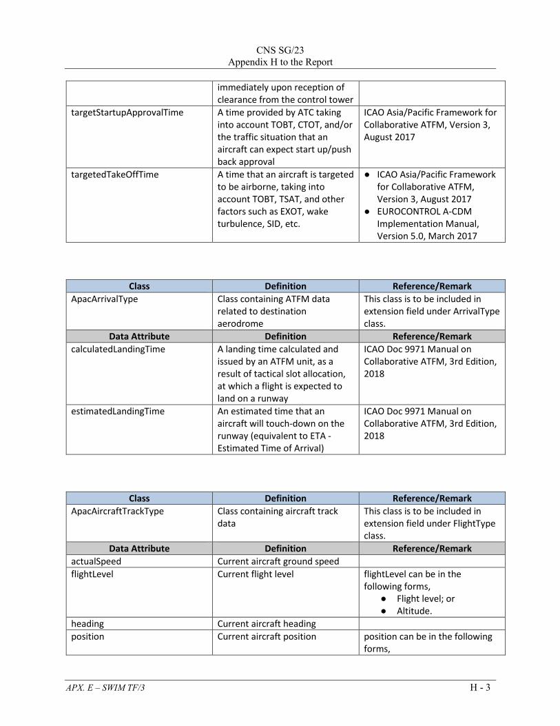
CNS SG/23
Appendix H to the Report
APX. E – SWIM TF/3 H - 3
immediately upon reception of clearance from the control tower
targetStartupApprovalTime A time provided by ATC taking into account TOBT, CTOT, and/or the traffic situation that an aircraft can expect start up/push back approval
ICAO Asia/Pacific Framework for Collaborative ATFM, Version 3, August 2017
targetedTakeOffTime A time that an aircraft is targeted to be airborne, taking into account TOBT, TSAT, and other factors such as EXOT, wake turbulence, SID, etc.
● ICAO Asia/Pacific Framework for Collaborative ATFM, Version 3, August 2017
● EUROCONTROL A-CDM Implementation Manual, Version 5.0, March 2017
Class Definition Reference/Remark
ApacArrivalType Class containing ATFM data related to destination aerodrome
This class is to be included in extension field under ArrivalType class.
Data Attribute Definition Reference/Remark
calculatedLandingTime A landing time calculated and issued by an ATFM unit, as a result of tactical slot allocation, at which a flight is expected to land on a runway
ICAO Doc 9971 Manual on Collaborative ATFM, 3rd Edition, 2018
estimatedLandingTime An estimated time that an aircraft will touch-down on the runway (equivalent to ETA - Estimated Time of Arrival)
ICAO Doc 9971 Manual on Collaborative ATFM, 3rd Edition, 2018
Class Definition Reference/Remark
ApacAircraftTrackType Class containing aircraft track data
This class is to be included in extension field under FlightType class.
Data Attribute Definition Reference/Remark
actualSpeed Current aircraft ground speed
flightLevel Current flight level flightLevel can be in the following forms,
● Flight level; or ● Altitude.
heading Current aircraft heading
position Current aircraft position position can be in the following forms,

CNS SG/23 Appendix H to the Report
APX. E – SWIM TF/3 H - 4
● Designator; ● Latitude/Longitude; or ● Relative point.
positionTime Time when all data in this class is reported
Class Definition Reference/Remark
ApacTrajectoryType Class containing all trajectory elements of a flight
This class is to be included in extension field under FlightType class.
Data Attribute Definition Reference/Remark
element A list of trajectory elements
Class Definition Reference/Remark
ApacTrajectoryElementType Class containing composition of each trajectory element(s) specified in ApacTrajectoryType
Data Attribute Definition Reference/Remark
level An estimated flight level of the aircraft at this trajectory element
level can be in the following forms,
● Flight level; or ● Altitude.
routePoint A specified position of this trajectory element
routePoint can be in the following forms,
● Designator; ● Latitude/Longitude; or ● Relative point.
actualTimeOver An actual time of the aircraft over routePoint
calculatedTimeOver A time calculated and issued by an ATFM unit, as a result of tactical slot allocation, at which a flight is expected to be over routePoint, i.e. a fix, waypoint, or particular location. The implementation of this constraint may be carried out through tactical ATC intervention, such as speed control or route extension, or by having the aircraft meet the constrained time through the use of its Flight
ICAO Doc 9971 Manual on Collaborative ATFM, 3rd Edition, 2018
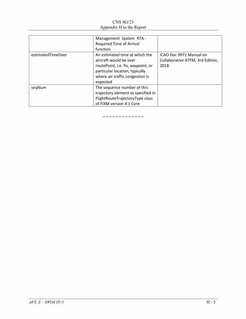
CNS SG/23
Appendix H to the Report
APX. E – SWIM TF/3 H - 5
Management System RTA - Required Time of Arrival function
estimatedTimeOver An estimated time at which the aircraft would be over routePoint, i.e. fix, waypoint, or particular location, typically where air traffic congestion is expected
ICAO Doc 9971 Manual on Collaborative ATFM, 3rd Edition, 2018
seqNum The sequence number of this trajectory element as specified in FlightRouteTrajectoryType class of FIXM version 4.1 Core
_ _ _ _ _ _ _ _ _ _ _ _ _

CNS SG/23 Appendix H to the Report
APX. E – SWIM TF/3 H - 6
<?xml version="1.0" encoding="UTF-8"?>
<schema
attributeFormDefault="unqualified"
elementFormDefault="qualified"
targetNamespace="http://www.aerothai.aero/apac/1.0"
version="1.00"
xmlns="http://www.w3.org/2001/XMLSchema"
xmlns:apac="http://www.aerothai.aero/apac/1.0"
xmlns:fb="http://www.fixm.aero/base/4.1"
xmlns:xs="http://www.w3.org/2001/XMLSchema">
<xs:annotation>
<xs:documentation>
Copyright (c) 2018 Aeronautical Radio of Thailand Limited
===========================================
All rights reserved.
Redistribution and use in source and binary forms, with or
without modification,
are permitted
provided that the following conditions are met:
* Redistributions of source code must retain the above
copyright notice, this list
of conditions and
the disclaimer.
* Redistributions in binary form must reproduce the above
copyright notice, this
list of conditions
and the disclaimer in the documentation and/or other
materials provided with the
distribution.
* Neither the name of Aeronautical Radio of Thailand Limited
nor the names of their contributors may
be used to endorse or
promote products derived from this specification without
specific prior written permission.
DISCLAIMER
THIS SPECIFICATION IS PROVIDED BY THE COPYRIGHT HOLDERS AND
CONTRIBUTORS "AS IS"
AND ANY EXPRESS OR IMPLIED WARRANTIES, INCLUDING, BUT NOT
LIMITED TO, THE IMPLIED
WARRANTIES OF MERCHANTABILITY AND FITNESS FOR A PARTICULAR
PURPOSE ARE
DISCLAIMED. IN NO EVENT SHALL THE COPYRIGHT OWNER OR
CONTRIBUTORS BE LIABLE FOR

CNS SG/23
Appendix H to the Report
APX. E – SWIM TF/3 H - 7
ANY DIRECT, INDIRECT, INCIDENTAL, SPECIAL, EXEMPLARY, OR
CONSEQUENTIAL DAMAGES
(INCLUDING, BUT NOT LIMITED TO, PROCUREMENT OF SUBSTITUTE
GOODS OR SERVICES; LOSS
OF USE, DATA, OR PROFITS; OR BUSINESS INTERRUPTION) HOWEVER
CAUSED AND ON ANY
THEORY OF LIABILITY, WHETHER IN CONTRACT, STRICT LIABILITY,
OR TORT (INCLUDING
NEGLIGENCE OR OTHERWISE) ARISING IN ANY WAY OUT OF THE USE OF
THIS SOFTWARE, EVEN
IF ADVISED OF THE POSSIBILITY OF SUCH DAMAGE.
Editorial note: this license is an instance of the BSD
license template as provided
by the Open
Source Initiative:
http://www.opensource.org/licenses/bsd-license.php
The authoritative reference for FIXM is www.FIXM.aero.
Details on Aeronautical Radio of Thailand Limited:
http://www.aerothai.co.th/
</xs:documentation>
</xs:annotation>
<xs:import namespace="http://www.fixm.aero/base/4.1"
schemaLocation="./../../core/base/Base.xsd"/>
<xs:import namespace="http://www.fixm.aero/flight/4.1"
schemaLocation="./../../../core/flight/Flight.xsd"/>
<xs:import namespace="http://www.fixm.aero/messaging/4.1"
schemaLocation="./../../../core/messaging/Messaging.xsd"/>
<xs:annotation>
<xs:documentation>
The ApacFlow contains information related to Air Traffic Flow
Management and Airport-Collaborative Decision Making operations.
</xs:documentation>
</xs:annotation>
<xs:complexType name="ApacAircraftTrackType">
<xs:annotation>
<xs:documentation>
Class containing aircraft track data. This class is to be
included in extension field
under FlightType class.
</xs:documentation>
</xs:annotation>
<xs:complexContent>
<xs:extension base="fb:ExtensionType">

CNS SG/23 Appendix H to the Report
APX. E – SWIM TF/3 H - 8
<xs:sequence>
<xs:element name="actualSpeed"
type="fb:GroundSpeedType" minOccurs="0" maxOccurs="1" >
<xs:annotation>
<xs:documentation>
Current aircraft ground speed.
</xs:documentation>
</xs:annotation>
</xs:element>
<xs:element name="flightLevel"
type="fb:FlightLevelOrAltitudeType" minOccurs="0" maxOccurs="1" >
<xs:annotation>
<xs:documentation>
Current flight level
</xs:documentation>
</xs:annotation>
</xs:element>
<xs:element name="heading" type="fb:BearingType"
minOccurs="0" maxOccurs="1" >
<xs:annotation>
<xs:documentation>
Current aircraft heading
</xs:documentation>
</xs:annotation>
</xs:element>
<xs:element name="position"
type="fb:SignificantPointType" minOccurs="0" maxOccurs="1" >
<xs:annotation>
<xs:documentation>
Current aircraft position
</xs:documentation>
</xs:annotation>
</xs:element>
</xs:sequence>
<xs:attribute name="positionTime" type="fb:TimeType"
use="optional" >
<xs:annotation>
<xs:documentation>
Time when all data in this class is reported
</xs:documentation>
</xs:annotation>
</xs:attribute>
</xs:extension>
</xs:complexContent>
</xs:complexType>
<xs:element name="ApacAircraftTrack"
type="apac:ApacAircraftTrackType" substitutionGroup="fb:Extension" />
<xs:complexType name="ApacArrivalType">
<xs:annotation>
<xs:documentation>

CNS SG/23
Appendix H to the Report
APX. E – SWIM TF/3 H - 9
Class containing ATFM data related to destination
aerodrome. This class is to be
included in extension field under ArrivalType class.
</xs:documentation>
</xs:annotation>
<xs:complexContent>
<xs:extension base="fb:ExtensionType">
<xs:attribute name="calculatedLandingTime"
type="fb:TimeType" use="optional" >
<xs:annotation>
<xs:documentation>
A landing time calculated and issued by an ATFM
unit, as a result of tactical slot
allocation at which a flight is expected to land
on a runway. [ICAO DOC 9971 Manual
on Collaborative ATFM, 3rd Edition, 2018]
</xs:documentation>
</xs:annotation>
</xs:attribute>
<xs:attribute name="estimatedLandingTime"
type="fb:TimeType" use="optional" >
<xs:annotation>
<xs:documentation>
The estimated time that an aircraft will touch-
down on the runway (equivalent to
ETA) [ICAO Doc 9971 Manual Collaborative ATFM,
3rd Edition, 2018]
</xs:documentation>
</xs:annotation>
</xs:attribute>
</xs:extension>
</xs:complexContent>
</xs:complexType>
<xs:element name="ApacArrival" type="apac:ApacArrivalType"
substitutionGroup="fb:Extension" />
<xs:complexType name="ApacDepartureType">
<xs:annotation>
<xs:documentation>
Class containing ATFM data related to departure aerodrome.
This class is to be included
in extension field under DepartureType class.
</xs:documentation>
</xs:annotation>
<xs:complexContent>
<xs:extension base="fb:ExtensionType">
<xs:attribute name="actualOffBlockTime" type="fb:TimeType"
use="optional" >
<xs:annotation>
<xs:documentation>

CNS SG/23 Appendix H to the Report
APX. E – SWIM TF/3 H - 10
The time the aircraft pushes back / vacates
parking position (equivalent to airline/handler
ATD - Actual Time of Departure and ACARS=OUT).
[ICAO Doc 9971 Manual on Colloborative
ATFM, 3rd Edition, 2018]
</xs:documentation>
</xs:annotation>
</xs:attribute>
<xs:attribute name="calculatedTakeOffTime"
type="fb:TimeType" use="optional" >
<xs:annotation>
<xs:documentation>
A time calculated and issued by an ATFM unit, as
a result of tactical slot allocation,
at which a flight is expected to become airborne.
[ICAO Doc 9971 Manual Collaborative
ATFM, 3rd Edition, 2018]
</xs:documentation>
</xs:annotation>
</xs:attribute>
<xs:attribute name="targetOffBlockTime" type="fb:TimeType"
use="optional" >
<xs:annotation>
<xs:documentation>
A time that an Aircraft Operator or Ground
handler estimates that an aircraft will
be ready to startup/be push back immediately upon
reception of clearance from the
control tower. [ICAO Asia/Pacific Framework for
Collaborative ATFM, Version 3, August
2017]
</xs:documentation>
</xs:annotation>
</xs:attribute>
<xs:attribute name="targetStartupApprovalTime"
type="fb:TimeType" use="optional" >
<xs:annotation>
<xs:documentation>
A time provided by ATC taking into account TOBT,
CTOT (Calculated Take-Off Time)
and/or the traffic situation that an aircraft can
expect start up/push back approval.
[ICAO Asia/Pacific Framework for Collaborative
ATFM, Version 3, August 2017]
</xs:documentation>
</xs:annotation>
</xs:attribute>
<xs:attribute name="targetedTakeOffTime"
type="fb:TimeType" use="optional" >
<xs:annotation>
<xs:documentation>

CNS SG/23
Appendix H to the Report
APX. E – SWIM TF/3 H - 11
A time that an aircraft is targeted to be
airborne, taking into account TOBT, TSAT,
and other factors such as EXOT, wake turbulence,
SID, etc. [ICAO Asia/Pacific Framework
for Collaborative ATFM, Version 3, August 2017]
[EUROCONTROL A-CDM Implementation
Manual, Version 5.0, March 2017]
</xs:documentation>
</xs:annotation>
</xs:attribute>
</xs:extension>
</xs:complexContent>
</xs:complexType>
<xs:element name="ApacDeparture" type="apac:ApacDepartureType"
substitutionGroup="fb:Extension" />
<xs:complexType name="ApacTrajectoryType">
<xs:annotation>
<xs:documentation>
Class containing composition of each trajectory element(s)
specified in ApacTrajectoryType
</xs:documentation>
</xs:annotation>
<xs:complexContent>
<xs:extension base="fb:ExtensionType">
<xs:sequence>
<xs:element name="element"
type="apac:ApacTrajectoryElementType" minOccurs="0" maxOccurs="2000" >
<xs:annotation>
<xs:documentation>
A list of trajectory element.
</xs:documentation>
</xs:annotation>
</xs:element>
</xs:sequence>
</xs:extension>
</xs:complexContent>
</xs:complexType>
<xs:element name="ApacTrajectory" type="apac:ApacTrajectoryType"
substitutionGroup="fb:Extension" />
<xs:complexType name="ApacTrajectoryElementType">
<xs:annotation>
<xs:documentation>
Class containing composition of each trajectory element(s)
specified in ApacTrajectoryType.
</xs:documentation>
</xs:annotation>

CNS SG/23 Appendix H to the Report
APX. E – SWIM TF/3 H - 12
<xs:sequence>
<xs:element name="level"
type="fb:FlightLevelOrAltitudeChoiceType" minOccurs="0" maxOccurs="1"
>
<xs:annotation>
<xs:documentation>
An estimated flight level of the aircraft at the
trajectory element.
</xs:documentation>
</xs:annotation>
</xs:element>
<xs:element name="routePoint" type="fb:SignificantPointType"
minOccurs="1" maxOccurs="1" >
<xs:annotation>
<xs:documentation>
A specified position of this trajectory element
[routePoint can be in the following
forms, fix; waypoint; or particular location]
</xs:documentation>
</xs:annotation>
</xs:element>
</xs:sequence>
<xs:attribute name="actualTimeOver" type="fb:TimeType"
use="optional" >
<xs:annotation>
<xs:documentation>
The actual time of aircraft over routePoint
</xs:documentation>
</xs:annotation>
</xs:attribute>
<xs:attribute name="calculatedTimeOver" type="fb:TimeType"
use="optional" >
<xs:annotation>
<xs:documentation>
A time calculated and issued by an ATFM unit, as a
result of tactical slot allocation,
at which a flight is expected to be over routePoint,
i.e. a fix, waypoint, or particular
location. The implementation of this constraint may be
carried out through tactical
ATC intervention, such as speed control or route
extension, or by having the aircraft
meet the constrained time through the use of its Flight
Management System RTA - Required
Time of Arrival function. [ICAO Doc 9971 Manual on
Collaborative ATFM, 3rd Edition,
2018]
</xs:documentation>
</xs:annotation>
</xs:attribute>

CNS SG/23
Appendix H to the Report
APX. E – SWIM TF/3 H - 13
<xs:attribute name="estimatedTimeOver" type="fb:TimeType"
use="optional" >
<xs:annotation>
<xs:documentation>
A estimated time at which an aircraft would be over
routePoint, i.e. fix, waypoint
or particular location, typically where air traffic
congestion is expected. [ICAO
Doc 9971 Manual on Collaborative ATFM, 3rd Edition,
2018]
</xs:documentation>
</xs:annotation>
</xs:attribute>
<xs:attribute name="seqNum" type="xs:int" use="required" >
<xs:annotation>
<xs:documentation>
The sequence number of this trajectory element as
specified in FlightRouteTrajectoryType
class of FIXM version 4.1 Core
</xs:documentation>
</xs:annotation>
</xs:attribute>
</xs:complexType>
<xs:element name="ApacTrajectoryElement"
type="apac:ApacTrajectoryElementType" />
</schema>

RNAV to RNP Chart Identification Change
Regional Transition Plan 1730
180
Region: APAC To be used in conjunction with Circular 353 only 120
9.61111
Use the following data to develop a proposed regional slot for transition. Actual slot will be coordinated and allocated by the ICAO PBN Programme Office 14.4167
Jun 2019
AIRAC cycle dates: https://www.nm.eurocontrol.int/RAD/common/airac_dates.html
Figures below are filled automatically - do not change Enter values here: 2019 2020
Start Date
Sequence
based on
ready
date No. of Charts
Required
number of Airac
Cycles
Allocated AIRAC
Cycle
Earliest Proposed
Start Date
Latest Proposed
Start Date
No. of
AIRAC
Cycle Jul 18 Aug 15 Sep 12 Oct 10 Nov 07 Dec 05 Jan 02 Jan 30 Feb 27 Mar 26 Apr 23 May 21 Jun 18 Jul 16 Aug 13 Sep 10 Oct 08 Nov 05 Sum State's comment
Afghanistan Thursday, October 10, 2019 27 6 1 18-Jul-19 18-Jun-20 1 6 6
Australia Thursday, August 15, 2019 32 653 18 18 months 18 37 37 37 37 37 36 36 36 36 36 36 36 36 36 36 36 36 36 653 possibly begin on 15 Aug 2019
Bangladesh Thursday, October 10, 2019 27 1 1 1 1 1 5 RNP, 1 RNAV(GNSS)
Bhutan Thursday, October 10, 2019 27 3 1 1 3 3
Brunei Darussalam Thursday, June 18, 2020 1 2 1 1 2 2
Cambodia Thursday, February 27, 2020 16 5 1 1 5 5
China Thursday, July 18, 2019 36 317 18 Published RNP 151 11 Oct 2018 31 Dec 2020 18 18 18 18 18 18 18 18 18 18 18 18 17 17 17 17 17 17 17 317 151 RNP, 317 RNAV(GNSS)
Hong Kong, China Thursday, January 02, 2020 20 8 6 6 8 8
Macao, China Thursday, January 02, 2020 20 4 6 6 4 4
Taipei FIR Thursday, January 30, 2020 19 22 4 4 6 6 5 5 22
Cook Islands Thursday, March 26, 2020 10 15 3 3 5 5 5 15
Democratic Peoples Republic of Korea Thursday, August 15, 2019 32 4 1 1 4 4
Fiji Thursday, July 18, 2019 36 8 1 1 8 8
India Thursday, October 10, 2019 27 4 1 1 4 4
Indonesia Thursday, June 18, 2020 1 76 6 6 13 13 13 13 12 12 76
Japan Thursday, January 02, 2020 20 93 12 Published 25 GPS App 12 7 7 7 8 8 8 8 8 8 8 8 8 93
Kiribati Thursday, March 26, 2020 10 4 1 1 4 4
Lao Peoples' Democratic Republic Thursday, February 27, 2020 16 5 1 1 5 5
Malaysia Thursday, January 02, 2020 20 50 6 6 5 5 10 9 10 11 50
Maldives Thursday, July 18, 2019 36 16 1 1 16 16 effective on Jan 2 2019
Marshall Islands Thursday, March 26, 2020 10 6 1 1 6 6
Micronesia Thursday, June 18, 2020 1 10 1 1 10 10
Mongolia Thursday, August 15, 2019 32 3 1 1 3 3
Myanmar NA #VALUE! 0 0 Implemented 0 0
Nauru Thursday, March 26, 2020 10 0 0 0 0 0
Nepal Thursday, July 18, 2019 36 4 2 2 2 2 4
New Zealand Thursday, July 18, 2019 36 126 18 progressive implementation 18 7 7 7 7 7 7 7 7 7 7 7 7 7 7 7 7 7 7 126
Pakistan Thursday, October 10, 2019 27 43 12 12 4 4 4 4 4 4 4 3 3 3 3 3 43
Palau Thursday, June 18, 2020 1 2 1 1 2 2
Papua New Guinea Thursday, June 18, 2020 1 2 1 Published 15 GPS App 1 2 2
Philippines Thursday, January 02, 2020 20 31 12 12 3 3 3 3 3 3 3 2 2 2 2 2 31
Republic of Korea Thursday, August 15, 2019 32 32 1 1 32 32
Samoa Thursday, March 26, 2020 10 5 1 1 5 5
Singapore Thursday, January 02, 2020 20 6 2 implement anytime 2 3 3 6
Solomon Islands Thursday, March 26, 2020 10 0 0 Published 24 GPS App 0 0 0
Sri Lanka NA #VALUE! 0 0 Implemented 0 0
Thailand Thursday, January 02, 2020 20 62 10 10 6 6 6 6 6 6 6 6 6 8 62
Timor Leste Thursday, June 18, 2020 1 5 1 1 5 5
Tonga Thursday, April 23, 2020 8 8 1 1 8 8
Tuvalu Thursday, May 21, 2020 7 2 1 1 2 2
Vanuatu Thursday, April 23, 2020 8 13 2 2 7 6 13
Vietnam Thursday, February 27, 2020 16 9 1 1 9 9
New Caledonia Thursday, July 18, 2019 36 9 1 1 9 9
French Polynesia Thursday, August 15, 2019 32 35 2 2 18 17 35
Wallis and Futuna Is. Thursday, July 18, 2019 37 2 1 1 2 2
United States of America NA #VALUE! 19 0 0 0
1730 99 121 79 80 66 65 101 95 116 116 116 104 114 92 92 91 82 82 1711
* China : Published PBN procedures are in domestic AIP and will not affect regional transition.
* USA : These is no intention to change chart title. US will include PBN requirement box in the chart.
* Austalia proposed to follow the triennial procedure validation cycle. If resources available, transition will be made in 18 months. Chart will be published quartly
Regional Transition Plan no later than
# of charts changed
Constraints
Capacity Chart Service Provider
Capacity Chart Service Provider adjusted
Required AIRAC Cycle:
Required AIRAC Cycle adjusted:
I - 1
ssomsri
Typewritten Text
ssomsri
Typewritten Text
ssomsri
Typewritten Text
ssomsri
Typewritten Text
ssomsri
Typewritten Text
ssomsri
Typewritten Text
ssomsri
Typewritten Text
ssomsri
Typewritten Text
ssomsri
Typewritten Text
ssomsri
Typewritten Text
ssomsri
Typewritten Text
ssomsri
Typewritten Text
ssomsri
Typewritten Text
ssomsri
Typewritten Text
ssomsri
Typewritten Text
ssomsri
Typewritten Text
ssomsri
Typewritten Text
ssomsri
Typewritten Text
ssomsri
Typewritten Text
ssomsri
Typewritten Text
ssomsri
Typewritten Text
ssomsri
Typewritten Text
CNS SG/23 Appendix I to the Report
ssomsri
Typewritten Text
ssomsri
Typewritten Text
ssomsri
Typewritten Text

CNS SG/23 Appendix J to the Report
J - 1
TERMS OF REFERENCE OF ASIA AND PACIFIC
GROUND-BASED AUGMENTATION SYSTEM (GBAS) / SATELLITE-BASED AUGMENTATION SYSTEM (SBAS)
IMPLEMENTATION TASK FORCE (APAC GBAS/SBAS ITF)
Consists of objectives and deliverables as follows: The Objectives of the APAC GBAS/SBAS ITF are to: 1) Keep abreast of the latest global developments in GBAS/SBAS and associated
technologies to cope with forthcoming development and implementation of ICAO SARPs, the Global Air Navigation Plan (GANP), the Global Aviation Safety Plan (GASP) and Asia/Pacific Seamless Air Navigation Service Plan (APSAP);
2) Facilitate the implementation, enhancements, operation and maintenance of GBAS/SBAS and services identified in the Aviation System Block Upgrades (ASBU) modules and APSAP elements using the project management principles where appropriate;
3) Ensure continuous and coherent development of the GBAS/SBAS that is maintaining synergy and harmonization with other regions to enhance systems robustness, resilience and interoperability; and
4) Review, identify and address major issues in technical, operational, safety and
regulatory aspects to facilitate the implementation or provision of safe, efficient and orderly Air Navigation Service (ANS) in relation to GBAS/SBAS.
Deliverables to meet the Objectives: 1) To submit progress report to the ICAO CNS Sub-group while keeping ATM Sub-group
informed of addressing the APAC GBAS/SBAS ITF deliverables (listed in 2 to 6 below);
2) To support the ICAO in making specific recommendations and developing guidance materials, such as minimum functional/performance requirements and optional/local requirements, which aims at facilitating the implementation or provision of robust, safe, efficient and orderly ANS by the use of existing and/or new procedures, facilities and technologies in relation to GBAS/SBAS;
3) To review outcomes of the Navigation Systems Panel, AN-Conf, DGCA Conference, APANPIRG, CNS Sub-group, ATM Sub-group, RASMAG, PBNICG and other international conferences related to GBAS/SBAS, revise and update a tasks list and action items for the APAC GBAS/SBAS ITF;
4) To study and identify applicable applications, share experience, and recommend the best industry practices in the Asia and Pacific Regions considering:
- Systems planning and design - ICAO roadmap in the GANP/ASBU

CNS SG/23 Appendix J to the Report
J - 2
- Systems interoperability - Operation and maintenance practice - Ionospheric effects and scintillation - Avionics - GBAS Landing System (GLS) and SBAS procedure development and validation - Siting criteria and safeguarding - Safety assessment - Training - Acceptance and certification - Transition
5) To encourage research and development, trials and demonstrations of applications and
technologies, and, as necessary, steer for the sharing of this information and expertise among States/Administrations through organizing educational seminars and symposia to educate States/Administrations and airspace users; and
6) To formulate draft Conclusions and Decisions relating to matters in the field of GBAS/SBAS that come within the scope of the APANPIRG, CNS Sub-group, ATM Sub-group, and RASMAG work plan.
Timeframe for Deliverables: For deliverable item 2 on guidance materials, it is anticipated that a first draft could be made available in 3 years after establishment of the Task Force for seeking endorsement by CNS Sub-group, after which the guidance materials would be updated/enhanced on an on-going basis. For other deliverable items 3-6, they will be made available as appropriate subject to review by the Task Force. The life time of the Task Force would be subject to review after endorsement of the first edition of the guidance materials. Meeting: The APAC GBAS/SBAS ITF shall convene annually with at least one face-to-face meeting per year, which is supplemented by teleconference meetings (e.g. WebEx) as appropriate. Membership: All APAC member States/Administrations providing ANS in the Asia and Pacific Regions. APAC members should nominate Subject Matter Experts from Civil Aviation Authorities, ANSPs, and other organizations with strong background in engineering and ATC/flight operations in relation to GBAS/SBAS to participate in the Task Force. The Task Force would also invite representatives of International Organizations recognized by the ICAO Council as representing important civil aviation interests to participate in its work in a consultative capacity.
– – – – – – – – – – – –

Mode S Downlink Aircraft Parameters Implementation and Operations Guidance Document
APX. G – SURICG/4 Edition 1.0 - March 2019 K - 1
CNS SG/23 Appendix K to the Report
MODE S DOWNLINK AIRCRAFT PARAMETERS IMPLEMENTATION AND OPERATIONS GUIDANCE DOCUMENT
Edition 1.0 - March 2019
INTERNATIONAL CIVIL AVIATION ORGANIZATION ASIA AND PACIFIC OFFICE

Mode S Downlink Aircraft Parameters Implementation and Operations Guidance Document
APX. G – SURICG/4 Edition 1.0 - March 2019 K - 2
Intentionally left blank
Mode S Downlink Aircraft Parameters Implementation and Operations Guidance Document
APX. G – SURICG/4 Edition 1.0 - March 2019 K - 3
TABLE OF CONTENTS
1. INTRODUCTION ............................................................................................................................................. 5
1.1 PURPOSE ..................................................................................................................................................... 5
1.2 BACKGROUND ............................................................................................................................................ 5
1.2.1 Mode S and DAPs ................................................................................................................................... 5
1.2.2 Benefit of Mode S and Use of DAPs ....................................................................................................... 6
1.3 ARRANGEMENT OF DAPS IGD .................................................................................................................. 6
1.4 DOCUMENT HISTORY AND MANAGEMENT ................................................................................................ 6
1.5 COPIES ........................................................................................................................................................ 6
1.6 CHANGES TO DAPS IGD ............................................................................................................................ 6
1.7 EDITING CONVENTIONS ............................................................................................................................. 7
1.8 DAPS IGD REQUEST FOR CHANGE FORM ................................................................................................ 8
1.9 AMENDMENT RECORD ............................................................................................................................... 9
2. ACRONYMS LIST ......................................................................................................................................... 10
3. REFERENCE DOCUMENTS ....................................................................................................................... 12
4. DESCRIPTION OF MODE S DAPS DATA ................................................................................................. 14
4.1 MODE S ELS ............................................................................................................................................ 14
4.2 MODE S EHS ............................................................................................................................................ 15
4.3 DAPS DATA EXCHANGE PROTOCOL BETWEEN SURVEILLANCE AND ATM AUTOMATION SYSTEM ..... 16
5. IMPLEMENTATION PRINCIPLES AND PHASES .................................................................................. 17
5.1 IMPLEMENTATION PRINCIPLES ................................................................................................................ 17
5.1.1 Stakeholders Coordination ................................................................................................................... 17
5.1.2 System Compatibility ............................................................................................................................ 17
5.1.3 DAPs Data Integrity ............................................................................................................................. 18
5.1.4 System Integration ................................................................................................................................ 18
5.2 IMPLEMENTATION CHECKLIST ............................................................................................................ 19
5.2.1 Activity Sequence .................................................................................................................................. 19
5.2.2 Concept Phase ...................................................................................................................................... 19
5.2.3 Design Phase ........................................................................................................................................ 20
5.2.4 Implementation Phase .......................................................................................................................... 21
6. SYSTEM INTEGRITY AND MONITORING ............................................................................................. 22
6.1 INTRODUCTION ......................................................................................................................................... 22
6.2 PERSONNEL LICENSING AND TRAINING ................................................................................................... 22
6.3 ATS SYSTEM VALIDATION ....................................................................................................................... 22
6.3.1 Safety Assessment Guidelines ............................................................................................................... 22
6.3.2 System Safety Assessment ..................................................................................................................... 22
6.3.3 Integration Test ..................................................................................................................................... 23
6.3.4 ATS Operation Manuals ....................................................................................................................... 23
6.4 SYSTEM MONITORING ............................................................................................................................. 23
6.4.1 Consideration for System Monitoring ................................................................................................... 23
Mode S Downlink Aircraft Parameters Implementation and Operations Guidance Document
APX. G – SURICG/4 Edition 1.0 - March 2019 K - 4
6.4.2 Mode S DAPs Problem Reports ............................................................................................................ 24
6.4.3 Example of Mode S DAPs Problem ...................................................................................................... 25
6.5 APPLICATION ANALYSIS ........................................................................................................................... 25
6.5.1 Data Recording ..................................................................................................................................... 26
6.5.2 Local Data Collection ........................................................................................................................... 26
6.5.3 Avionics Problem Identification and Correction ................................................................................... 26
6.6 IDENTIFIED ISSUES ................................................................................................................................... 26
7. REGULATIONS AND PROCEDURES ........................................................................................................ 27
7.1 MANDATING MODE S DAPS .................................................................................................................... 27
7.2 AVIONICS .................................................................................................................................................. 28
7.2.1 Mode S Transponder Capabilities ........................................................................................................ 28
7.2.2 Transition Guidelines ............................................................................................................................ 29
7.2.3 Interrogation of Transponders on Ground ............................................................................................ 29
7.3 MODE S INTERROGATOR ......................................................................................................................... 30
7.3.1 Working Principles ............................................................................................................................... 30
7.3.2 Interrogator Codes ............................................................................................................................... 30
7.3.3 Interrogation Methods .......................................................................................................................... 31
7.3.4 Interrogate Comm-B Data .................................................................................................................... 31
7.4 ATM AUTOMATION SYSTEM .................................................................................................................... 33
7.4.1 Elementary Surveillance ....................................................................................................................... 33
7.4.2 Enhanced Surveillance ......................................................................................................................... 33
7.5 FLIGHT PLANNING ................................................................................................................................... 34
7.5.1 ICAO Flight Plan Item 7 - Aircraft Identification ................................................................................. 34
7.5.2 Equipment (Surveillance Equipment /SSR Equipment) ......................................................................... 35
7.5.3 Inconsistency between Mode S Flight Planning and Surveillance Capability ...................................... 36
7.5.4 Setting Flight ID in Cockpits ................................................................................................................ 36
7.6 CONTINGENCY PLAN ................................................................................................................................ 37
8. TRAININNG AND COMPETENCE ............................................................................................................. 38
8.1 INTRODUCTION ......................................................................................................................................... 38
8.2 TRAINING OF AN AIR TRAFFIC CONTROLLER (ATC) IN DAPS .............................................................. 38
8.3 TRAINING OF AN ATSEP IN DAPS ........................................................................................................... 38
8.4 COMPETENCY ASSESSMENT OF AN ATSEP IN DAPS............................................................................... 39
9. SPECIFIC EXAMPLES ON MODE S DAPS APPLICATION .................................................................. 40
9.1 USE OF SELECTED ALTITUDE ................................................................................................................... 40
APPENDIX 1: MODE S DAPS ANALYSIS .......................................................................................................... 41
APPENDIX 2: LIST OF IDENTIFIED ISSUES ................................................................................................... 44
APPENDIX 3: LIST OF PARTICIPANTS ............................................................................................................ 48
Mode S Downlink Aircraft Parameters Implementation and Operations Guidance Document
APX. G – SURICG/4 Edition 1.0 - March 2019 K - 5
1. INTRODUCTION
1.1 Purpose
This Mode S Downlink Aircraft Parameters Implementation and Operations Guidance Document (DAPs IGD) provides guidance for the planning, implementation and operational application of Mode S DAPs technology in the Asia and Pacific Regions.
The procedures and requirements for Mode S DAPs operations are detailed in the relevant States’ AIP. This IGD is intended to provide key information on Mode S DAPs performance, integration, principles, procedures and collaboration mechanisms.
The content is based upon the work to date of the Mode S DAPs Working Group and various ANC Panels for the operational use of Mode S DAPs.
1.2 Background
1.2.1 Mode S and DAPs
Mode S (Select) is an extension of conventional SSR which permits selective addressing of individual aircraft equipped with MODE S transponders. Additional data known as Downlink Aircraft Parameters (DAPs) may also be extracted from the aircraft, including aircraft identification which should correspond to the ACID entered in the flight plan.
Mode S operates on the same radio frequencies (1030 and 1090 MHz) as conventional SSR systems allowing for interrogation of older Mode A/C transponders and well as more modern Mode S transponders.
Each Mode S equipped aircraft is assigned a unique ICAO 24-bit aircraft address. Using the selective interrogation capability of the Mode S SSR, Mode S Sensors are able to first acquire and then to selectively interrogate a specific aircraft via its unique ICAO 24-bit aircraft address. This significantly improves the radar’s detection and tracking performance, and therefore improving the ability of ATC to monitor and direct the aircraft, as well as the others around it.
The innovation of Mode S resides in the use of selective addressing of aircraft which offers technical advantages over conventional SSR, such as reducing FRUIT and garble, providing higher integrity radar tracks.
Mode S technology has the following characteristics:
a) selective interrogation,
b) individual aircraft address and
c) datalink capability.
The Mode S Application includes Mode S radar system, datalink Systems, MLAT Systems, etc. Mode S DAPs is an application of the Mode S Datalink System. The downlink standard length transaction interface shall deliver DAPs to the transponder which then makes data available to the ground surveillance systems. Each DAP shall be packed into the Comm-B format (‘MB’ field) and can be extracted using either the ground-initiated Comm-B (GICB) protocol, or using MSP downlink channel 3 via the dataflash application.
Mode S Downlink Aircraft Parameters Implementation and Operations Guidance Document
APX. G – SURICG/4 Edition 1.0 - March 2019 K - 6
1.2.2 Benefit of Mode S and Use of DAPs
The Mode S Application reduces the weakness of Mode A/C, because of the selective interrogation reducing synchronous garble and asynchronous interference. The parity check technique improves reliability and integrity of surveillance data. The availability of almost 17 million unique aircraft addresses, in conjunction with the automatic reporting of flight identity, alleviates Mode 3/A code shortages and enables unambiguous aircraft identification, if the correct aircraft address and/or Aircraft Identification are entered in both the flight plan and aircraft systems. The datalink technique assists the acquisition of downlink aircraft parameters, and the additional track label information improves the air situational awareness. The controller and pilot are presented with improved situation awareness, which reduce the R/T workload.
1.3 Arrangement of DAPs IGD
The Mode S DAPs Implementation and Operations Guidance Document consists of the following parts:
Section 1 Introduction Section 2 Acronym Lists Section 3 Reference Documents Section 4 Description of Mode S DAPs Data Section 5 Implementation Principles and Phase Section 6 System Integrity and Monitoring Section 7 Regulations and Procedures Section 8 Training and Competence Section 9 Specific Examples on Mode S DAPs Applications
1.4 Document History and Management
The framework of this document was introduced in the first Working Group Meeting of Mode S Downlink Aircraft Parameters in March 2018. The Meeting agreed to further develop based on the proposed framework to a complete document for approval as regional guidance document. A working team, consisting of volunteers from China, Hong Kong-China, Japan, Malaysia, Singapore, Thailand and New Zealand was established by the Meeting to contribute to the content of the document. In July 2018, the completed draft of this document was ready for circulation among States for review and comment.
The aim of this document to supplement SARPs, PANS and relevant provisions contained in ICAO documentation and it will be regularly updated to reflect evolving provisions.
1.5 Copies
Paper copies of this DAPs IGD are not distributed. Controlled and endorsed copies can be found at the following web site: http://www.icao.int/APAC/Pages/edocs.aspx and may be freely downloaded from the web site, or by emailing APANPIRG through the ICAO Asia and Pacific Regional Office who will send a copy by return email.
1.6 Changes to DAPs IGD
Whenever a user identifies a need for a change to this document, a Request for Change (RFC) Form (see Section 1.8 below) should be completed and submitted to the ICAO Asia and Pacific Regional Office. The Regional Office will collate RFCs for consideration by the Surveillance Implementation Coordination Group.

Mode S Downlink Aircraft Parameters Implementation and Operations Guidance Document
APX. G – SURICG/4 Edition 1.0 - March 2019 K - 7
When an amendment has been agreed by a meeting of the Surveillance Implementation Coordination Group then a new version of the DAPs IGD will be prepared, with the changes marked by an “|” in the margin, and an endnote indicating the relevant RFC, so a reader can see the origin of the change. If the change is in a table cell, the outside edges of the table will be highlighted; e.g.:
Final approval for publication of an amendment to the DAPs IGD will be the responsibility of APANPIRG.
1.7 Editing Conventions
(Intentionally blank)

Mode S Downlink Aircraft Parameters Implementation and Operations Guidance Document
APX. G – SURICG/4 Edition 1.0 - March 2019 K - 8
1.8 DAPs IGD Request for Change Form
RFC Nr:
Please use this form when requesting a change to any part of this DAPs IGD. This form may be photocopied as required, emailed, faxed or e-mailed to ICAO Asia and Pacific Regional Office +66 (2) 537-8199 or [email protected]
1. SUBJECT: 2. REASON FOR CHANGE: 3. DESCRIPTION OF PROPOSAL: [expand / attach additional pages if necessary] 4. REFERENCE(S): 5. PERSON INITIATING: DATE: ORGANISATION: TEL/FAX/E-MAIL: 6. CONSULTATION RESPONSE DUE BY DATE: Organization Name Agree/Disagree Date 7. ACTION REQUIRED : 8. DAPs IGD EDITOR DATE REC’D : 9. FEEDBACK PASSED DATE :

Mode S Downlink Aircraft Parameters Implementation and Operations Guidance Document
APX. G – SURICG/4 Edition 1.0 - March 2019 K - 9
1.9 Amendment Record
Amendment Number
Date Amended by Comments
0.1 20 March 2018 China Hong Kong, China
Initial draft for consideration by Mode S DAPs WG/1
0.2 1 August 2018 China Hong Kong, China Japan Singapore Malaysia
First completed draft based on the agreed document framework in Mode S DAPs WG/1 for review and comment by States
0.3 23 August 2018 China Based on Version 0.2 draft, China hold a meeting to discuss problems respecting the first completed draft. This is a revised document according to content of this meeting.
0.3.1 26 September 2018 China Hong Kong, China Singapore New Zealand
Based on Version 0.3 draft, States make a full comment on the content of IGD. This is a revised document according to those comments.
0.3.2 6 November 2018 China New Zealand Hong Kong, China Singapore Malaysia
Based on Version 0.3.1 draft, States discussed all comments of IGD in the Mode S DAPs WG 1st Web Conference. This is revised by the meeting decisions.
0.4 27 December 2018 China New Zealand Singapore Australia
Based on Version 0.3.2, States review and comment on the IGD. This is a revised document according to those comments.
1.0 14 March 2019 China Japan Singapore Malaysia
Consideration by Mode S DAPs WG/2

Mode S Downlink Aircraft Parameters Implementation and Operations Guidance Document
APX. G – SURICG/4 Edition 1.0 - March 2019 K - 10
2. ACRONYMS LIST
AA Aircraft Address AC Altitude Code ACID Aircraft Identification ADS-B Automatic Dependent Surveillance-Broadcast AIP Aeronautical Information Publication ANC Air Navigation Conference ANSP Air Navigation Service Provider APAC Asia Pacific ATC Air Traffic Control ATM Air Traffic Management ATN Aeronautical Telecommunications Network ATS Air Traffic Service ATSEP Air Traffic Safety Electronic Personnel BDS Comm-B Data Selector CA Capability CDTI Cockpit Display Traffic Information CFL Cleared Flight Level CLAM Cleared Level Adherence Monitoring CNS Communications, Navigation and Surveillance DAPs Downlink Aircraft Parameters DF Downlink Format EASA European Aviation Safety Agency EHS Mode S Enhanced Surveillance ELM Extended Length Message ELS Mode S Elementary Surveillance ES Extended Squitter EUROCAE European Organization for Civil Aviation Equipment EUROCONTORL European Organisation for the Safety of Air Navigation FIR Flight Information Region FLTID Flight Identification (transmitted by aircraft) FMS Flight Management System FS Flight Status FRUIT False Relies Unsynchronized In Time GICB Ground-Initiated Comm-B HMI Human Machine Interface IC Interrogator Code ICAO International Civil Aviation Organization ID Identity IFR Instrument Flight Rules II Interrogator Identifier IRF Interrogation Repetition Frequency MHz Megahertz MIP Mode Interlace Patterns MIT Massachusetts Institute of Technology MLAT Multilateration MSAW Minimum Safe Altitude Warning MSP Mode S Specific Protocol SARPs (ICAO) Standards and Recommended Practices SFL Selected Flight Level SI Surveillance Identifier SSR Secondary Surveillance Radar

Mode S Downlink Aircraft Parameters Implementation and Operations Guidance Document
APX. G – SURICG/4 Edition 1.0 - March 2019 K - 11
STCA Short-Term Conflict Alert UTC Universal Time Coordinated WAM Wide Area Multilateration WG Working Group
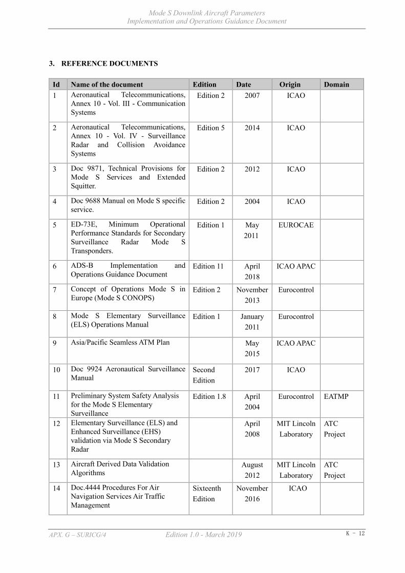
Mode S Downlink Aircraft Parameters Implementation and Operations Guidance Document
APX. G – SURICG/4 Edition 1.0 - March 2019 K - 12
3. REFERENCE DOCUMENTS
Id Name of the document Edition Date Origin Domain 1 Aeronautical Telecommunications,
Annex 10 - Vol. III - Communication Systems
Edition 2 2007 ICAO
2 Aeronautical Telecommunications, Annex 10 - Vol. IV - Surveillance Radar and Collision Avoidance Systems
Edition 5 2014 ICAO
3 Doc 9871, Technical Provisions for Mode S Services and Extended Squitter.
Edition 2 2012 ICAO
4 Doc 9688 Manual on Mode S specific service.
Edition 2 2004 ICAO
5 ED-73E, Minimum Operational Performance Standards for Secondary Surveillance Radar Mode S Transponders.
Edition 1 May 2011
EUROCAE
6 ADS-B Implementation and Operations Guidance Document
Edition 11 April 2018
ICAO APAC
7 Concept of Operations Mode S in Europe (Mode S CONOPS)
Edition 2 November 2013
Eurocontrol
8 Mode S Elementary Surveillance (ELS) Operations Manual
Edition 1 January 2011
Eurocontrol
9 Asia/Pacific Seamless ATM Plan May 2015
ICAO APAC
10 Doc 9924 Aeronautical Surveillance Manual
Second Edition
2017 ICAO
11 Preliminary System Safety Analysis for the Mode S Elementary Surveillance
Edition 1.8 April 2004
Eurocontrol EATMP
12 Elementary Surveillance (ELS) and Enhanced Surveillance (EHS) validation via Mode S Secondary Radar
April 2008
MIT Lincoln Laboratory
ATC Project
13 Aircraft Derived Data Validation Algorithms
August 2012
MIT Lincoln Laboratory
ATC Project
14 Doc.4444 Procedures For Air Navigation Services Air Traffic Management
Sixteenth Edition
November 2016
ICAO

Mode S Downlink Aircraft Parameters Implementation and Operations Guidance Document
APX. G – SURICG/4 Edition 1.0 - March 2019 K - 13
15 Clarification Mode S Transponder in an Airport/A-SMGCS Environment
Edition 1.1 3 May 2005
Eurocontrol

Mode S Downlink Aircraft Parameters Implementation and Operations Guidance Document
APX. G – SURICG/4 Edition 1.0 - March 2019 K - 14
4. DESCRIPTION OF MODE S DAPs DATA
Inside the aircraft transponder, DAPs are stored in different BDS Registers for responding to DAPs interrogation requests by a Mode S ground system. Aircraft parameters are periodically delivered from aircraft sensors, flight management system, etc., to these registers via the downlink standard length transaction interface. BDS Registers, which have not been updated within the specified maximum update interval, are cleared or indicated as invalid and such aircraft parameters would be unavailable for ground interrogations. When a Mode S SSR sends an interrogation requesting the downlink of registers, DAPs are packed into Comm-B format (known as “MB” field) and are extracted using either the GICB protocol or Mode S specific protocols (MSPs) channel 3.
BDS Registers are identified by two-digit hex number. For example, BDS Register for selected vertical intention, which is identified by hex number 4016, is commonly written as BDS code 4, 0 in publications. Depending on the stage of Mode S implementation, i.e. Mode S ELS and Mode S EHS, the scope of Mode S DAPs data involved would be different as illustrated in the following subsections.
Detailed data format and maximum update interval of each BDS register are given in “ICAO Doc 9871 - Technical Provisions for Mode S Services and Extended Squitter”.
4.1 Mode S ELS
In Mode S ELS implementation, aircraft and ground Mode S system should be compliant of providing the following functionalities over traditional Mode A/C systems:
a) Selective interrogation;
b) Use of ICAO Aircraft Address;
c) Automatic reporting of ACID;
d) Report of transponder capability;
e) Altitude reporting with resolution of 25ft (subject to aircraft capability);
f) Provision of flight status to indicate airborne or on-the-ground (subject to aircraft capability);
g) Report of SI Code capability; and
h) ACAS active resolution advisory report (when equipped with TCAS)
DAPs associated with Mode S ELS are stored in BDS code 1,0, BDS code 1,7, BDS code 2,0 and BDS code 3,0 registers of aircraft’s transponder.
Table 4-1 DAPs in Mode S ELS
Register Name Usage
BDS code 1,0 Datalink Capability Report
To report the data link capability of the Mode S transponder/data link installation.
BDS code 1,7 Common Usage GICB Capability Report
To indicate common usage GICB services currently supported.
BDS code 2,0 Aircraft Identification To report aircraft identification to the ground.
BDS code 3,0 ACAS Resolution Advisory Report To report ACAS active resolution advisory

Mode S Downlink Aircraft Parameters Implementation and Operations Guidance Document
APX. G – SURICG/4 Edition 1.0 - March 2019 K - 15
With the above functionalities properly configured, Mode S ELS could bring the following benefits to ATC operations:
a) Provide unambiguous aircraft identification through the use of the unique aircraft address and aircraft identification;
b) Help solving Mode 3/A code shortage in congested airspace, through the use of the Mode S conspicuity code (A1000) instead of discrete Mode 3/A codes;
c) Improve surveillance data integrity by;
1) reducing synchronous garble*, 2) lessening over-interrogations, and 3) simplifying aircraft identification in case of false targets;
d) Improve the accuracy of multi-surveillance tracking and safety nets with more accurate target detection from Mode S radars and high resolution in altitude reporting; and
e) Able to process more aircraft tracks than conventional Mode A/C radars.
*Note, while Mode S will help to reduce data garble it will not totally resolve the issue. Issues around multi-path and different transponder types in close proximity (e.g. Mode A/C near a Mode S transponder) mean that the return received by the radar may not be correct. In the case of a Mode A/C transponder close to a Mode S transponder, instances have been recorded where the Mode S address has been transposed into the reply from the Mode A transponder.
4.2 Mode S EHS
Mode S EHS implementation includes all the features of Mode S ELS with the addition of DAPs stored in BDS code 4,0, BDS code 5,0 and BDS code 6,0 registers of aircraft’s transponder. The following table summarizes the details of DAPs of these three registers:
Table 4-2 DAPs in Mode S EHS
Register Name/Downlink Aircraft Parameters Usage
BDS code 4,0 Selected Vertical Intention
MCP/FCU Selected Altitude
To provide information about the aircraft’s current vertical intentions
FMS Selected Altitude Barometric Pressure Setting
MCP/FCU Mode Target Altitude Source
BDS code 5,0
Track and
Turn Report
Roll Angle
To provide track and turn data to the ground systems.
True Track Angle Ground Speed
Track Angle Rate True Air Speed
BDS code 6,0
Heading and
Speed Report
Magnetic Heading
To provide heading and speed data to ground systems.
Indicated Air Speed Mach Number
Barometric Altitude Rate Inertial Vertical Velocity

Mode S Downlink Aircraft Parameters Implementation and Operations Guidance Document
APX. G – SURICG/4 Edition 1.0 - March 2019 K - 16
In addition to those improvements contributed by Mode S ELS in Section 4.1, Mode S EHS implementation provides the following benefits to ATC operation:
a) Further improve multi-surveillance tracking accuracy and performance through the use of DAPs on track, turn, speed and heading of the aircraft in the track calculation;
b) Further improve the accuracy of safety nets, e.g. Short-Term Conflict Alert (STCA), through the provision of more accurate aircraft tracks;
c) Allow the implementation of new safety nets in ATM automation system for cross-checking selected aircraft vertical intention (i.e. Selected Altitude) with ATC controllers’ instruction as well as verifying the barometric pressure setting applied in the aircraft; and
d) Improve situational awareness of ATC controllers by enabling the direct access of aircraft parameters in ATM automation system, e.g. Indicated Air Speed, Selected Altitude, etc.;
e) Progressive reduction of R/T workload per aircraft.
4.3 DAPs Data Exchange Protocol Between Surveillance and ATM Automation System
The decoding of DAPs data from downlink messages is handled by ground surveillance equipment such as radars, ADS-B, MLAT and WAM ground stations. The Surveillance Data Processor (SDP) within the ATM automation system can combine multiple downlink messages into single target report for display to controllers. All Purpose Structured EUROCONTROL Surveillance Information Exchange (ASTERIX) formats are commonly used as the protocol for target report transmission from surveillance systems to the ATM automation system.
ASTERIX formats are categorized based on the types of surveillance data involved. ASTERIX Category 20, ASTERIX Category 21 and ASTERIX Category 48 are responsible for the DAPs data transmission from MLAT systems, ADS-B systems and radars respectively. For each ASTERIX category, the protocol format is further divided into different editions with variations on the supported DAPs data. ANSP’s should carry out appropriate studies on the available protocol editions during the design stage to ensure the chosen format can cater for the scope of DAPs proposed to be implemented and that the Surveillance and ATM automation systems can correctly process the protocol selected.
For details, previous and current versions of ASTERIX Category 20, Category 21 and Category 48 specification documents can be downloaded from the following link of EUROCONTROL web sites:
https://www.eurocontrol.int/publications/cat020-multilateration-mlt-messages-part-14
https://www.eurocontrol.int/publications/cat021-automatic-dependent-surveillance-broadcast-ads-b-messages-part-12
https://www.eurocontrol.int/publications/cat048-monoradar-target-reports-part-4-next-version-cat-001

Mode S Downlink Aircraft Parameters Implementation and Operations Guidance Document
APX. G – SURICG/4 Edition 1.0 - March 2019 K - 17
5. IMPLEMENTATION PRINCIPLES AND PHASES
Implementation guidance is developed to progress the DAPs implementation from concept to operational use in ICAO APAC region. In this chapter, section one addresses the implementation principles, which describes the issues of international coordination, system compatibility, data integrity and system integration, while section two addresses the implementation phase, to assist States with the management of DAPs implementation activities.
5.1 Implementation Principles
5.1.1 Stakeholders Coordination
DAPs provide useful information from aircraft which can benefit ANSP and airspace users. Improvements in efficiency and safety can be achieved, however the resultant changes in operational procedures to provide the improvements, will affect ANSPs, Regulators, Airlines, and other related airspace users. Before implementation by any States, a coordination team should be formed to study, coordinate, support and consult the implementation plans and related activities. The coordination team should include field experts on avionics, data link, surveillance infrastructures and end users.
Changes in the ATM operational procedures as the result of the use of DAPs requires coordination among ATS providers, Regulators, Airlines, and where applicable, coordination among neighboring States to maximize the benefits. All States are encouraged to share their operational experiences, and to report anomalies through Mode S DAPs WG and the Surveillance Implementation Coordination Group.
Not all Surveillance and ATM automation systems are capable of processing and using DAPs, therefore investment in all related fields needs to be considered by all States. The coordination team should be consulted for the future investment plans and related activities considering the technical and operational aspects. Consideration needs to be given to achieve a balance between investment and benefits.
5.1.2 System Compatibility
a) Technical:
DAPs can be obtained by different surveillance technologies such as Mode S Radar, ADS-B, MLAT and WAM, however not all the transponders can support DAPs. Different surveillance technologies in ICAO APAC States mean that system compatibility should be considered.
Potential interference between different surveillance technologies should be fully considered before implementation, otherwise the efficiency and safety of the system cannot be ensured. Harmonization between different technologies should be considered and optimized to reduce the RF congestion on 1030MHz and 1090MHz.
Since not all aircraft are equipped with Mode S transponders, and not all the Mode S transponder have the ability to support DAPs, compatibility and efficiency should always be considered before implementation.
When DAPs are implemented, the data rate will increase compared to the conventional radar data, and the related BDS information extraction strategies should be considered. To reduce load on the 1090MHz spectrum, only those registers intended for operational use should be interrogated/extracted.
b) Operational:
Different processing systems can support DAPs in different levels, hence the quality and information of target may be different after the processed DAPs has been added. For example, some radar tracking

Mode S Downlink Aircraft Parameters Implementation and Operations Guidance Document
APX. G – SURICG/4 Edition 1.0 - March 2019 K - 18
algorithms will consider DAPs as an input to the tracking, so the quality and information of the target will be a little bit different, therefore there should be compatibility considerations between different systems before use of the target data.
There are different air traffic management and operation strategies used by neighboring States. So the operational procedures should always consider the operational compatibilities. For example, Mode A/C transponders and Mode S transponders may be working in the same area.
5.1.3 DAPs Data Integrity
DAPs data integrity should always be the first consideration when putting DAPs data into use. Since the data integrity from the source are not delivered by any related BDS register now, States are encouraged to find a reliable methodology to ensure the data integrity prior to the use of the data. Additionally, ongoing means of determining data integrity should be implemented, along with an ability to exclude invalid DAPs data from ATM automation systems.
States which already have experience on data integrity are encouraged to share this information with other States. The coordination team could support and harmonize this activity, and provide a standard method to evaluate the data integrity, and share the method to all the States.
5.1.4 System Integration
By introducing DAPs, the target characteristic from the source to the end user may be different compared to pre-DAPs implementation. In different phases of the processing flow of target data, DAPs can be used by different systems to improve tracking performance. Some key points in the data flow are as follows:
a) Airborne Avionics Systems
As DAPs data comes from different kinds of sensors and avionics systems on the aircraft, the reliability of the data should be ensured before the data is used operationally. Research has shown that some BDS data is missing or not updated correctly. The reasons for this needs to be established as it can mean that use of some DAPs data is not suitable for implementation. Examples of issues include:
1) Older Flight Management Systems which do not provide all the DAPs data, and 2) Incorrect installation (e.g. onboard equipment wired to wrong registers)
b) Ground Sensor Systems
Ground sensors may use the DAPs to improve their target tracking performance, having an impact on the tracking function; the target data produced by this kind of sensors will show different characteristics to the pre-DAPs implemented tracking function, such as the turning rate, the kinematic movement and so on. Data users need to be aware of this performance improvement.
c) Ground Automation Systems
Ground automation systems can use DAPs information for a wide variety of uses, such as for tracking, safety net processing, situational awareness, en-route meteorological information sharing and so on. Ensuring DAPs information is processed and used in an appropriate way should be considered during implementation.
d) Other Surveillance Systems

Mode S Downlink Aircraft Parameters Implementation and Operations Guidance Document
APX. G – SURICG/4 Edition 1.0 - March 2019 K - 19
Any DAPs data should be capable of being integrated with other surveillance systems data, and any potential difference and impact should be considered before use. Some of the information can be cross checked by different surveillance technologies.
e) Other Related Systems
5.2 Implementation CHECKLIST
The purpose of this implementation checklist is to document the range of activities that needs to be completed to bring a DAPs application from an initial concept to operational use. Some activities of this checklist may be specific to individual stakeholders.
5.2.1 Activity Sequence
The activities are listed in an approximate sequential order. However, each activity does not have to be completed prior to starting the next activity. In many cases, a parallel and iterative process should be used to feed data and experience from one activity to another. It should be noted that not all activities will be required for all applications.
5.2.2 Concept Phase
a) Construct operational concept:
1) Purpose; 2) Operational environment; 3) ATM functions; and 4) Infrastructure;
b) Identify benefits:
1) Safety enhancements; 2) Efficiency; 3) Capacity; 4) Environmental; 5) Cost reductions; 6) Accessibility; and 7) Other metrics (e.g. predictability, flexibility, usefulness);
c) Identify constraints:
1) Air-Ground interoperability; 2) Compatibility with non-equipped aircraft; 3) Need for exclusive airspace; 4) Required ground infrastructure; 5) RF spectrum; 6) Integration with existing technology; 7) Technology availability; and 8) Actuality of existing infrastructure;

Mode S Downlink Aircraft Parameters Implementation and Operations Guidance Document
APX. G – SURICG/4 Edition 1.0 - March 2019 K - 20
d) Prepare business case:
1) Cost benefit analysis; and 2) Demand and justification.
5.2.3 Design Phase
a) Identify operational requirements:
1) Security; and 2) Systems interoperability;
b) Identify human factors issues:
1) Human-machine interfaces; 2) Training development and validation; 3) Workload demands; 4) Role of automation vs. role of human; 5) Crew coordination/pilot decision-making interactions; and 6) ATM collaborative decision-making.
c) Identify technical requirements:
1) Standards development; 2) Prevailing avionics standards; 3) Data required; 4) Functional processing; 5) Functional performance; 6) Required certification levels; and 7) Identify the infrastructure that needs upgrade.
d) Equipment development, test, and evaluation:
1) Prototype systems built to existing or draft standards/specifications; 2) Upgrade and test scheme for the existing infrastructure; 3) Developmental bench and flight tests; 4) Acceptance test parameters; Acceptance test should be performed to ensure all the key
indicators are met; and 5) Select and procure technology.
e) Develop procedures:
1) Pilot and controller actions and responsibilities; 2) Standardize the interaction and phraseologies; 3) Controller’s responsibility to maintain a monitoring function, if appropriate; 4) System certification procedure should be made. 5) Standard Operating Procedure should be made if the human machine interface of the
system is changed.

Mode S Downlink Aircraft Parameters Implementation and Operations Guidance Document
APX. G – SURICG/4 Edition 1.0 - March 2019 K - 21
6) Contingency procedures; For example duplicate Mode S address is detected; 7) Emergency procedures, for example ACAS message is received; 8) General procedures for unforeseen issues should be made; and 9) Develop AIP and Information documentation.
f) Prepare design phase safety case:
1) Safety rationale; 2) Safety budget and allocation; and 3) Functional hazard assessment.
5.2.4 Implementation Phase
a) Prepare implementation phase safety case;
b) Conduct operational test and evaluation:
1) Flight deck and ATC validation simulations; and 2) Flight tests and operational trials;
c) Obtain systems certification:
1) Aircraft equipment; and 2) Ground systems;
d) Obtain regulatory approvals:
1) Air traffic certification of use;
e) Impact Assessment
An impact assessment should be conducted to gauge the effect in terms of security, efficiency, operating regulations, human factors, infrastructure, environment, and so on.
f) Implementation transition:
1) Promulgate procedures; The regulatory authority shall promulgate general regulations to the participants. Each participant shall formulate corresponding detailed regulations.
2) Deliver training; Training should be conducted to ensure the personnel are familiar with standard, regulation, and technology of the Mode S DAPs implementation and operation. Licensing process could be executed if needed.
3) Continue data collection and analysis; 4) Resolve any unforeseen issues; and 5) Continue feedback into standards development processes;
g) Performance monitoring to ensure that the agreed performance is maintained.
Mode S Downlink Aircraft Parameters Implementation and Operations Guidance Document
APX. G – SURICG/4 Edition 1.0 - March 2019 K - 22
6. SYSTEM INTEGRITY AND MONITORING
6.1 Introduction
CNS and ATM environment is an integrated system including physical systems (hardware, software, and communication networks), human elements (pilots, controllers and engineers), and the operational procedures for its applications. The integration of Mode S DAPs with other surveillance technologies enables more information from an aircraft to be used to provide a safer service.
Because of the integrated nature of such system and the degree of interaction among its components, comprehensive system monitoring is recommended. The procedures described in this section aim to ensure system integrity by validation, identification, reporting and tracking of possible problems revealed during system monitoring with appropriate follow-up actions.
6.2 Personnel Licensing and Training
Prior to operating any element of the Mode S DAPs system, operational and technical personnel shall undertake appropriate training as determined by the ANSP or State Regulatory Authority, including compliance with the Convention on International Civil Aviation where applicable. With these the personnel will be familiar with regulation, standard and requirement of the Mode S DAPs implementation and operation.
6.3 ATS System Validation
6.3.1 Safety Assessment Guidelines
To meet system integrity requirements, ANSPs or States should conduct a validation process that confirms the integrity of their equipment and procedures. Such processes shall include:
a) A system safety assessment for new implementations is the basis for definitions of system performance requirements. Where existing systems are being modified to utilize additional services, the assessment demonstrates that the ATS Provider’s system will meet safety objectives.
b) Integration test results confirming interoperability for operational use of airborne and ground systems; and
c) Confirmation that the ATS operation procedure are compatible with those of adjacent providers where the system is used across a common boundary.
6.3.2 System Safety Assessment
The objective of the system safety assessment is to ensure that implementation and operation of Mode S DAPs is safe. The safety assessment should be conducted for implementation as well as any future enhancements and should include:
a) Identifying failure or error conditions;
b) Assigning levels of criticality;
c) Determining risks/probabilities for occurrence;
d) Identifying mitigating measures;

Mode S Downlink Aircraft Parameters Implementation and Operations Guidance Document
APX. G – SURICG/4 Edition 1.0 - March 2019 K - 23
e) Categorizing the degree of acceptability of risks; and
f) Operational hazard ID process.
Following the safety assessment, States should institute measures to offset any identified failure or error conditions that are not already categorized as acceptable. This should be done to reduce the probability of their occurrence to an acceptable level. This could be accomplished through automation of procedures.
6.3.3 Integration Test
States should conduct trials with suitably equipped aircraft to ensure the DAPs data meets the operational and technical requirements to provide ATS. The introduction of the Mode S DAPs will give more information about the aircraft, and should not affect the performance of the existing system. States should be satisfied by test results and analysis carried out by the ANSP.
6.3.4 ATS Operation Manuals
States may coordinate with adjacent States to confirm that their ATS operation manuals contain standard operating procedures to ensure harmonization of procedures that impact across common boundaries.
6.4 System Monitoring
During the implementation and operation of the Mode S DAPs technology, routine collection of data is necessary in order to ensure that the system continues to meet or exceed its performance, safety and interoperability requirements, and that operational service delivery and procedures are working as intended.
6.4.1 Consideration for System Monitoring
Mode S transponders may have been installed a long time ago to support mandatory ACAS functionality. The Mode A/C function has been permanently used by ATC, but the Mode S functions may not have been used. Any failure impacting Mode A/C would have been detected by ATC during normal operation and corrective action would have been undertaken. Before implementing Mode S for surveillance, system checks are usually made to ensure the correct operation of the Mode S transponders (e.g. continue to correctly process Mode A/C and Mode S replies), but possibly no system checks were made to ensure that the DAPs data was correct, so a number of undetected failures may have existed over the years of operation.
A number of Mode S transponder from different OEMs have been observed to be non-compliant with Annex 10 Volume IV requirements (e.g. no SI code capability, no reply to aircraft register extraction, incorrectly configured aircraft address, incorrect content of BDS registers), even though the transponder is certified to level 2. Although actions have been taken in some areas (mainly where Mode S has been implemented) to address these problems, some aircraft with MODE S which are not working correctly still operate (mostly in areas where Mode S has not yet been implemented).
During the initial deployment of European Mode S, it was discovered that avionics upgrade performed on some aircraft had resulted in erroneous transponder operations so that, in some cases, the aircraft could not even be detected by the ground radar. It is therefore recommended that before commencing Mode S surveillance operations in a given airspace, system monitoring be put in place for the purpose of timely detection and rectification of hidden transponder problems. This will enable the ANSP and aircraft operators to remedy identified issues prior to using Mode S operationally.

Mode S Downlink Aircraft Parameters Implementation and Operations Guidance Document
APX. G – SURICG/4 Edition 1.0 - March 2019 K - 24
The communication lines for transferring surveillance information in a Mode S radar require much higher data throughput as there is more information per aircraft. For example, compared to a Mode A/C radar, Mode S DAPs require up to three times more data throughput.
Mode S DAPs bring safety benefits even when only a portion of the traffic is properly equipped. Some aircraft can be configured to provide additional data items but their use should be considered with caution since some airborne installations may not have been certified, hence data may be erroneous, System monitoring to validate the transmitted information is considered desirable for DAPs operation.
6.4.2 Mode S DAPs Problem Reports
During the application of the Mode S DAPs, some problem may be found during the observation of one or more specific events. Faulty Mode S DAPs data should be recorded and analyzed. Problems may be found during the routine analysis of application data. Any problem should be documented and reported to the DAPs WG.
After a problem has been found, the finder can attempt to resolve it with the appropriate party and also report the solution to the DAPs WG. The problem and solution will be distributed to the DAPs WG members. If the problem has not been resolved, the problem should be reported to the DAPs WG, and members will be encouraged to resolve the problem. In many cases, a Mode S DAPs problem will be systematic across a particular aircraft or avionics configuration. Engagement with, and correction by the manufacturer may be required.
The mode S DAPs problem should be reported with the form as shown in Table 6-1.
Table 6-1 Mode S DAPs Problem Report Form
PRS# Start Time/Date UTC End Time/Date UTC Registration Aircraft ID Flight ID ICAO Aircraft Address Aircraft Type Flight Sector/ Location ATS Unit Description / additional information Originator Originator Reference number Organization
PRS#: A unique identification number assigned by the PRS Administrator to this problem report. Organizations writing problem reports are encouraged to maintain their own internal list of these problems for tracking purposes. Once the problems have been reported to the PRS and incorporated in the database, a number will be assigned by the PRS and used for tracking by the SURICG.
Start Time/Date UTC: UTC time/date when the event occurred. End Time/Date UTC: UTC time/date when the event ended. Registration: Registration number (tail number) of the aircraft involved. Aircraft ID : Coded equivalent of call sign as entered in FPL Item 7. Flight ID: The Flight ID/Flight Number downlinked from the aircraft.

Mode S Downlink Aircraft Parameters Implementation and Operations Guidance Document
APX. G – SURICG/4 Edition 1.0 - March 2019 K - 25
ICAO Aircraft Address: Unique aircraft address expressed in Hexadecimal form. Aircraft Type: The aircraft model involved. Flight Sector/Location: The departure airport and destination airport for the sector being flown
by the aircraft involved in the event. These should be the ICAO. Identifiers of those airports. Or if more descriptive, give the location of the aircraft during the event.
ATS Unit: ICAO identifier of the ATC center or tower controlling the aircraft at the time of the event.
Originator: Point of contact at the originating organization for this report (usually the author).
Organization: The name of the organization (airline, ATS provider or communications service provider) that created the report.
Description: This should provide as complete a description of the situation leading up to the problem as is possible. Where the organization reporting the problem is not able to provide all the information (e.g. the controller may not know everything that happens on the aircraft), it would be helpful if they would coordinate with the other parties to obtain the necessary information. The description should include:
a) A complete description of the problem that is being reported b) The route contained in the FMS and flight plan c) Any flight deck indications d) Any indications provided to the controller when the problem
occurred e) Any additional information that the originator of the problem
report considers might be helpful but is not included on the list above
If necessary, to contain all the information, additional pages may be added. if the originator considers it might be helpful, diagrams and other additional information (such as printouts of message logs) may be appended to the report.
6.4.3 Example of Mode S DAPs Problem
Through monitoring, it has been reported that erroneous DAPs data have been observed due to failure or improper setting/installation of Mode S equipment. A Working Paper of the ICAO Surveillance Panel Working Group (WP ASP12-20) has indicated that a lot of incorrect, outdated and even erroneous data and parameters are present for DAPs data. The errors and/or miss-matches can be frequent, including:
a) The ACID is not always correct (erroneous)
b) The Selected Altitude is not correct or is not updated (For example Selected Altitude data should be provided the MCP/FCU not by the FMS as the FMS data is usually incorrect).
c) Mode S DAPs data does not correspond to the content of the requested register.
6.5 Application Analysis

Mode S Downlink Aircraft Parameters Implementation and Operations Guidance Document
APX. G – SURICG/4 Edition 1.0 - March 2019 K - 26
During the Operation of Mode S DAPs, the application analysis is necessary in order to ensure that the system continues to meet or exceed its performance, safety and interoperability requirements. To analyze the Mode S DAPs applications, routine data should be recorded.
6.5.1 Data Recording
It is recommended that ATS providers and communication service providers retain the records defined below for at least 30 days to allow for accident/incident investigation processes. These records should be made available on request to the relevant State safety authority. Where data is sought from an adjacent State, the usual State to State channels should be used.
Where possible these recordings shall be in a form that permits a replay of the situation and identification of the messages that were received by the ATS system. Data exchange across borders may not be possible due to different Radar or ATM message formats or to State regulatory issues.
Not only the data from ground equipment, but also the data from aircraft equipment should be recorded. By analyzing the recorded data, the exact reason of the failures can be found.
6.5.2 Local Data Collection
ATS providers and communications service providers should identify and record Mode S DAPs system component failures that have the potential to negatively impact the safety of controlled flights or compromise service continuity.
6.5.3 Avionics Problem Identification and Correction
ATS providers should develop systems or procedures to:
a) detect Mode S DAPs avionics anomalies and faults
b) advise the regulators and where appropriate the aircraft operators on the detected Mode S DAPs avionics anomalies and faults
c) devise mechanisms and procedures to address identified faults
Regulators should ensure that appropriate corrective actions are taken to address identified faults.
An example of Mode S DAPs analysis is taken in Appendix 1.
6.6 Identified Issues
Several identified issues had already been recognized during the implementation of the Mode S DAPs data application in ATM automation system. Some of them even disrupted the operation of ATC services. Thus, it is necessary to ensure the reliability of DAPs for utilization for ATC operation. This section will present some issues for helping to figure them out.
Based on the experience gained from States, the common Mode S DAPs problems are summarized under different categories in Appendix 2. It is noted that many cases of wrong DAPs found in Mode S implementation were because of the aircraft avionics capability. There are also some issues that resulted of human factors. Experiences showed that it was important to keep close coordination with airlines to promote the DAPs application. Airlines should be informed of the issues in time and to check their aircraft Mode S transponders in a timely manner. At the same time, airlines need improve their working procedures including ensuring they file flight plans correctly.

Mode S Downlink Aircraft Parameters Implementation and Operations Guidance Document
APX. G – SURICG/4 Edition 1.0 - March 2019 K - 27
7. REGULATIONS AND PROCEDURES
Mode S DAPs involves the transmission of specific data from aircraft. These data messages can be interrogated by the ground equipment called Mode S interrogator. ATC use the data to show the more precise and integrated situation of the surveillance aircraft. The following procedures relate to the use of Mode S DAPs data in ATS ground surveillance applications.
The implementation of the Mode S DAPs system will support the provision of high performance surveillance, enhancing flight safety, improving the controller efficiency and reducing the workload of both the controller and pilot.
7.1 Mandating Mode S DAPs
a) Depending on the type of operations that States are going to conduct, States will have to consider whether there is a need to publish mandates. Some operations will require all aircraft within an airspace to be suitably equipped while others can still work well on a ‘best equipped best served’ basis.
b) Use of Multilateration on airport surface is an example of an operation where it is recommended for all aircraft to be equipped with Mode S transponders. Another example is the conspicuity code environment, where Flight Identification may be used as the prime means to couple flight plans, allowing ANSPs to overcome the shortage of Mode A codes. Equipage mandates would be necessary for such operations.
c) With appropriate software, ATM automation systems are able to use Mode S DAPs to provide additional information to controllers, enabling a reduction in controller workload and the enhancement of Safety Net systems. Equipage mandates are not necessary, but consideration to the nature of the services required and/or a cost-benefit study, may warrant such mandates.
d) As at May 2018, examples of States which use Mode S DAPs without publishing mandates are Australia1, New Zealand and Singapore. Examples of States with published mandates for Mode S DAPs are France, Germany and the United Kingdom.
e) In publishing mandate/regulations, States should:
1) Define the standards applicable to the State. i. E.g. Joint Aviation Authorities (JAA) Temporary Guidance Leaflets (TGL) 13
Revision 1 for Elementary Surveillance; or ii. E.g. European Aviation Safety Agency (EASA) Acceptable Means of Compliance
(AMC) 20-13 for Enhanced Surveillance; or iii. E.g. Mode S level 2 if the requirement is simply for Airport Surface Multilateration.
2) Define the airspace affected by the regulations i. E.g. Within the [FIR Authority] Flight Information Region above Flight Level XXX
3) Define the category of aircraft that the regulation applies to
i. E.g. Aircraft with a maximum certified take-off mass exceeding 5,700 kg or having a maximum cruising true airspeed capability greater than 250 kt; or
ii. E.g. All IFR aircraft
1 Australia has a mandate for Mode S transponders at selected airports utilising Multilateration for surface surveillance, but no widespread mandates for airborne DAPs usage

Mode S Downlink Aircraft Parameters Implementation and Operations Guidance Document
APX. G – SURICG/4 Edition 1.0 - March 2019 K - 28
4) Define the timing of the regulations allowing sufficient time for operators to equip.
i. E.g. With effect from 1 Jan 2020.
7.2 Avionics
7.2.1 Mode S Transponder Capabilities
a) The various levels of capabilities for Mode S Transponders are described in subsequent paragraphs. State should select the capability as required by its operations.
b) According to ICAO Annex 10, Vol. 4, Mode S transponders shall conform to one of five levels of capability as follows:
1) Level 1 is the basic transponder. Level 1 permits surveillance based on Mode A/C as well as on Mode S. With a Mode S aircraft address, it comprises the minimum features for compatible operation with Mode S interrogators. It has no datalink capability and will not be used by international air traffic.
2) Level 2 has the same capabilities as Level 1 and permits standard length datalink communication from ground to air and air to ground. It includes automatic aircraft identification reporting. This is the minimum level permitted for international flights. Data parity with overlay control (ICAO Annex 10, Vol. 4, 3.1.2.6.11.2.5) for equipment certified on or after 1 January 2020.
3) Level 3 has the capabilities as level 2 and also those prescribed for ground-to-air ELM communications.
4) Level 4 has the capabilities as level 3 and also those prescribed for air-to-ground ELM communications.
5) Level 5 has the capabilities as level 4 and also those prescribed for enhanced Comm-B and ELM communications.
c) Other than the various levels, transponders also can have the following features:
1) Extended squitter - transponders that shall have the capabilities of level 2, 3, 4 or 5 and also those prescribed for extended squitter operation.
2) SI Capability - Transponders with the ability to process SI codes shall have the capabilities of level 2, 3, 4 or 5 and also those prescribed for SI code operation.
3) Data flash Application – transponders that implement the data flash mode. 4) Hijack Mode Capability – transponders that support the Hijack Mode and have the
capabilities of level 2, 3, 4 or 5. 5) ACAS Compatibility –transponders compatible with ACAS. 6) Antenna Diversity – in aircraft with transponder using two antennas, receivers and
transmitting channels. 7) According to ED-73E, Elementary Surveillance – elementary surveillance transponders
will require at least level 2 transponder and have the following capabilities:
i. Flight status reporting; ii. Barometric pressure altitude reporting iii. Transponder capability (CA) iv. II and SI code capable v. Declaration of capability (BDS code 1,0)

Mode S Downlink Aircraft Parameters Implementation and Operations Guidance Document
APX. G – SURICG/4 Edition 1.0 - March 2019 K - 29
vi. Common usage GICB capability report (BDS code 1,7) vii. Mode S specific services capability (BDS code 1,8 to BDS code 1,C) viii. Flight identification (BDS code 2,0) ix. ACAS Active Resolution Advisory (BDS code 3,0) if equipped with ACAS II x. Aircraft register (BDS code 2,1) – optional
8) According to ED-73E, Enhanced Surveillance – enhanced surveillance transponders have the capabilities of elementary surveillance transponders, plus the capability to provide the following DAPs:
i. Magnetic Heading (BDS code 6,0) ii. Indicated Airspeed and/or Mach No. (BDS code 6,0) iii. Vertical Rate (climb/descend) (BDS code 6,0) iv. True Airspeed (provided if Track Angle Rate is not available) (BDS code 6,0) v. MCP/FCU Selected Altitude (BDS code 4,0) vi. Ground Speed (BDS code 5,0) vii. Roll Angle (BDS code 5,0) viii. Track Angle Rate (if available) (BDS code 5,0) ix. True Track Angle (BDS code 5,0) x. Barometric Pressure Setting (BDS code 4,0)
7.2.2 Transition Guidelines
a) Equipage of aircraft will be achieved over a period of time. Not all aircraft will be equipped with the necessary capability. A transition plan is required to accommodate varying degrees of aircraft equipment compliance.
b) As part of the formulation for a transition plan, States should assess the impact of having aircraft that are not suitably equipped within the affected airspace, to enable the implementation of suitable mitigating measures. States should also collect statistics on the readiness of the aircraft within the affected airspace.
c) For different operations, the mitigation measures in the transition plan could be different. For example, if the operation is just to use the Mode S DAPs to provide useful information to the controllers, the impact of having unequipped aircraft is minor. Mitigating measures could be as simple as making the controllers aware that not all aircraft are able to provide the information. On the other hand, where mode S is mandated for airport surface Multilateration, mitigating measures for having unequipped aircraft may include having special procedures for non-equipped aircraft or the deployment of a surface movement radar.
7.2.3 Interrogation of Transponders on Ground
Table 7-1 summarizes the requirements to inhibit or not inhibit replies from aircraft on the ground.
Table 7-1 The Requirements of Interrogation of Transponders on Ground
Type of interrogations Transponder reply Mode A/C Should be inhibited Mode A/C/S All Call Shall always be inhibited Mode S only All Call (UF =11) Shall always be inhibited Mode S (Roll call UF=0,4,5,16,20,21,24) Shall not be inhibited

Mode S Downlink Aircraft Parameters Implementation and Operations Guidance Document
APX. G – SURICG/4 Edition 1.0 - March 2019 K - 30
Acquisition Squitter (Short Squitter) Shall be inhibited if surface type of extended squitter is transmitted
Extended Squitter (Long Squitter) Shall not be inhibited
[Information obtained from Eurocontrol’s Clarification Mode S Transponder in an Airport/A-SMGCS Environment Ed 1.1 dated 3 May 2005]
a) Replies to Mode A/C/S all call and Mode S only all call interrogations shall always be inhibited when the aircraft declares the on the ground state. It shall not be possible to inhibit replies to discretely addressed Mode S interrogations regardless of whether the aircraft is airborne or on the ground.
b) Mode A/C replies should be inhibited (i.e. Mode A/C transponder set to standby) when the aircraft is on the ground to prevent interference when in close proximity to an interrogator or other aircraft. Mode S discretely addressed interrogations do not give rise to such interference. An exception on the recommendation to inhibit Mode A/C replies will be at airports having Multilateration systems working with Mode A/C.
c) Mode S transponders shall be set to the correct mode according to its flight status (i.e. airborne mode when it’s in the air and ground mode when on the ground). When an aircraft is in ground mode, replies to all call are inhibited. It is recommended that aircraft provide means to determine the on-the-ground state automatically and provide that information to the transponder.
7.3 Mode S Interrogator
7.3.1 Working Principles
The Mode S interrogators transmit interrogation to elicit replies for detection of Mode S transponders and more information from the aircraft. Use of a unique ICAO 24-bit aircraft address and provision of all the required aircraft data in one reply will reduces interrogation rates.
Each aircraft can be interrogated selectively, needing only one or two ‘hits’ per aircraft per scan and minimizing interference problems associated with SSR Mode A/C.
The operation of a Mode S interrogator will not interfere with the SSR performance of any aircraft equipped with a Mode A/C transponder.
A Mode S interrogator is capable of performing the conventional surveillance function with Mode A/C transponders.
7.3.2 Interrogator Codes
The Mode S system requires each interrogator to have an IC, which can be carried within the uplink and downlink transmissions. The 4-bit IC uplink field in UF11 shall contain either 4-bit II code or the lower 4 bits of the 6-bit SI codes. It is recommended that whenever possible an interrogator should operate using a single interrogator code.
The II codes shall be assigned to interrogators in the range from 0 to 15. The II code value of 0 shall only be used for supplementary acquisition. The SI codes shall be assigned to interrogators in the range from 1 to 63. The SI code value of 0 shall not be used.
The assignment of interrogator II or SI codes, where necessary in areas of overlapping coverage, across international boundaries of flight information regions, shall be the subject of regional air navigation
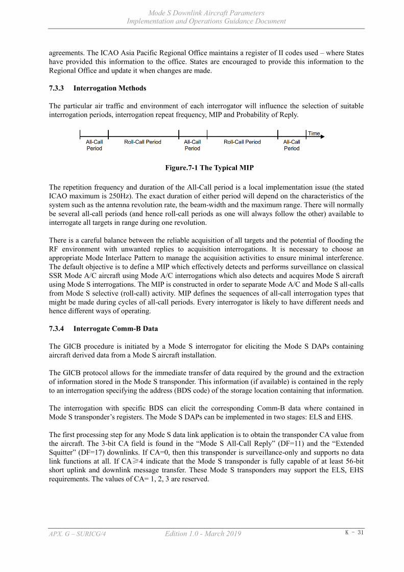
Mode S Downlink Aircraft Parameters Implementation and Operations Guidance Document
APX. G – SURICG/4 Edition 1.0 - March 2019 K - 31
agreements. The ICAO Asia Pacific Regional Office maintains a register of II codes used – where States have provided this information to the office. States are encouraged to provide this information to the Regional Office and update it when changes are made.
7.3.3 Interrogation Methods
The particular air traffic and environment of each interrogator will influence the selection of suitable interrogation periods, interrogation repeat frequency, MIP and Probability of Reply.
Figure.7-1 The Typical MIP
The repetition frequency and duration of the All-Call period is a local implementation issue (the stated ICAO maximum is 250Hz). The exact duration of either period will depend on the characteristics of the system such as the antenna revolution rate, the beam-width and the maximum range. There will normally be several all-call periods (and hence roll-call periods as one will always follow the other) available to interrogate all targets in range during one revolution.
There is a careful balance between the reliable acquisition of all targets and the potential of flooding the RF environment with unwanted replies to acquisition interrogations. It is necessary to choose an appropriate Mode Interlace Pattern to manage the acquisition activities to ensure minimal interference. The default objective is to define a MIP which effectively detects and performs surveillance on classical SSR Mode A/C aircraft using Mode A/C interrogations which also detects and acquires Mode S aircraft using Mode S interrogations. The MIP is constructed in order to separate Mode A/C and Mode S all-calls from Mode S selective (roll-call) activity. MIP defines the sequences of all-call interrogation types that might be made during cycles of all-call periods. Every interrogator is likely to have different needs and hence different ways of operating.
7.3.4 Interrogate Comm-B Data
The GICB procedure is initiated by a Mode S interrogator for eliciting the Mode S DAPs containing aircraft derived data from a Mode S aircraft installation.
The GICB protocol allows for the immediate transfer of data required by the ground and the extraction of information stored in the Mode S transponder. This information (if available) is contained in the reply to an interrogation specifying the address (BDS code) of the storage location containing that information.
The interrogation with specific BDS can elicit the corresponding Comm-B data where contained in Mode S transponder’s registers. The Mode S DAPs can be implemented in two stages: ELS and EHS.
The first processing step for any Mode S data link application is to obtain the transponder CA value from the aircraft. The 3-bit CA field is found in the “Mode S All-Call Reply” (DF=11) and the “Extended Squitter” (DF=17) downlinks. If CA=0, then this transponder is surveillance-only and supports no data link functions at all. If CA≥4 indicate that the Mode S transponder is fully capable of at least 56-bit short uplink and downlink message transfer. These Mode S transponders may support the ELS, EHS requirements. The values of CA= 1, 2, 3 are reserved.

Mode S Downlink Aircraft Parameters Implementation and Operations Guidance Document
APX. G – SURICG/4 Edition 1.0 - March 2019 K - 32
CA Field Check
Mode S aircraftAcquisition
BDS 1,0 Request
BDS 1,7 Request BDS 3,0 RequestBDS 2,0 Request
CA≥4
CA=0
YES
NO
BDS 4,0/5,0/6,0Request
Within Coverage?
NO
YES
Initial PhaseEvery Scan
BDS40/50/60
Capable?
Surveillance
Only
Stop Request
Surveillance
Only
NO
YES
Able to Extract BDS40/50/60?
Figure.7-2 The Typical Procedure of DAPs Extraction
Given that the Mode S transponder’s CA value is 4 or greater, the second processing step for any Mode S data link application is to extract the transponder’s Mode S data link capability report register BDS code 1,0. Bits in this register indicate the support of such Mode S data link functions as aircraft identification (register BDS code 2,0), ACAS (register BDS code 3,0), common-usage capability (register BDS code 1,7) etc. The Mode S-Specific services capability bit in register BDS code 1,0 indicates whether the avionics installation supports further data link functions. If this bit is set, the Mode S data link application would next extract the common-usage capability register BDS code 1,7. All of the registers involved with the ELS, EHS application have bit flags assigned in this register BDS code 1,7. If the bit flag is set, it indicates that the corresponding register has been updated in a timely manner and contains valid data which can be extracted by the interrogator. The processing protocol is sufficient initialization for basic data link applications such as ELS, EHS since all their status and configuration information is available from register BDS code 1,0 and register BDS code 1,7.
So the Mode S interrogator should transmit the selectively interrogation to elicit the Mode S transponder reply with the specific formats and Comm-B data contained in the corresponding registers.
Normally, the more Comm-B data requested by the Mode S interrogator, the more information can be extracted from the aircraft transponder registers. It will also help the ATC controller get the aircraft's flight status and flight intention. However, there should be some necessary limitations for the Comm-B data request to avoid the phenomenon of Comm-B data discontinuity because of the limited Roll-Call interrogation duration.

Mode S Downlink Aircraft Parameters Implementation and Operations Guidance Document
APX. G – SURICG/4 Edition 1.0 - March 2019 K - 33
It is suggested that the number, periodicity and priority of BDS data extraction rule be reasonably and effectively implemented according to the requirements and the number of aircraft in the airspace. The scientific strategy can ensure the ATC controller get Comm-B data timely and effectively.
7.4 ATM Automation System
7.4.1 Elementary Surveillance
For the Elementary Surveillance, the following parameters of aircraft can be beneficial to the ATM automation system:
a) ICAO 24-bit Aircraft Address/Aircraft Identification
1) The ATM automation system should collect the real aircraft address/aircraft identification from the received message, and the aircraft address/aircraft identification can be shown on the control HMI to identify the aircraft.
2) The ATM automation system can use the aircraft address/aircraft identification to correlate an aircraft’s track with the flight plan, so the use of aircraft address/aircraft identity can alleviate the shortage of Mode 3/A code.
3) The ATM automation system can also utilize the aircraft address/aircraft identification to improve the tracking function.
b) Transponder Capability Report
The ATM automation system can collect datalink capability of transponder from the receive message and show the information to the controller. The controller can estimate whether the aircraft with this transponder meets the requirement in the airspace
c) Altitude reporting in 25ft interval
The ATM automation system can collect aircraft altitude reporting in 25ft increments and provides valuable improvements to the quality of safety nets. The improvements should reduce the number of nuisance alerts and enhance the integrity of separation assurance.
d) Flight status (airborne/on the ground)
The ATM automation system can collect the flight status of the aircraft. Whether the aircraft is airborne or on the ground can be shown in the system to improve situational awareness of the controller. Also, the flight status can be used to filter the aircraft on the ground in the system if necessary.
e) ACAS Resolution Advisory Report
The ATM automation system can collect the ACAS Resolution Advisory Report and the information can be shown in the system to improve situational awareness of the controller.
7.4.2 Enhanced Surveillance
For the Enhanced Surveillance, the following parameters of aircraft can be beneficial to the ATM automation system:
a) Selected Altitude
1) The ATM automation system can collect the selected altitude of the aircraft and show the information to the controller to improve the situational awareness of the controller.

Mode S Downlink Aircraft Parameters Implementation and Operations Guidance Document
APX. G – SURICG/4 Edition 1.0 - March 2019 K - 34
2) The ATM automation system can generate an optimized CLAM alert when the SFL chosen by the crew does not match the cleared altitude given by the controller, alerting the controller to take appropriate action to remedy the issue.
3) The ATM automation system can also utilize the SFL to improve the accuracy of safety net.
b) Barometric data
The ATM automation system can collect the barometric data of the aircraft and show the information to the controller. The system can provide a warning when the barometric data transmitted by the aircraft does not match the parameter of the area where the aircraft is operating.
c) Roll Angle, Track Angle Rate, True Track Angle, Ground Speed, Magnetic Heading, True Airspeed
1) The ATM automation system can collect these parameters and may allow the display of some of the information to the controller to improve the situational awareness of the controller. Display of some parameters, provides a clearer picture to the controllers generating a reduction in radio calls with the pilot, so the R/T usage between controller and individual aircraft under service are reduced.
2) The system can utilize the kinematics information of the aircraft to perform a more precise tracking function and improve the accuracy of safety net.
3) The system may use True track angle, Magnetic Heading, True Airspeed and Ground Speed to calculate a wind direction and speed of a specific area, which will enable the updating of forecast winds and improve trajectory modeling in the system. The system may also show the wind information to the controller to improve situational awareness of the controller.
d) Vertical Rate
The ATM automation system can collect the vertical rate data of the aircraft to improve the precision of the compute altitude and the accuracy of the related alert. The system can make use of the data to realize an optimized CFL protection in STCA and MSAW analysis function.
e) Indicated Air Speed/Mach Number
The ATM automation system can acquire indicated air speed/Mach number of the aircraft, allow ATC to monitor the aircrew compliance with the controller’s instructions, and if required provide a warning to the controller when there is a mismatch.
7.5 Flight Planning
7.5.1 ICAO Flight Plan Item 7 - Aircraft Identification
ACID must be accurately record in item 7 of the ICAO Flight Plan form as per the following instructions:
Aircraft Identification, not exceeding 7 alphanumeric characters and without hyphens or symbols is to be entered both in item 7 of the flight plan and replicated exactly when set in the aircraft (for transmission as Flight ID) as follows:
Either,

Mode S Downlink Aircraft Parameters Implementation and Operations Guidance Document
APX. G – SURICG/4 Edition 1.0 - March 2019 K - 35
a) The ICAO designator for the aircraft operating agency followed by the flight identification (e.g. KLM511, NGA213, JTR25), when in radiotelephony the call sign to be used by the aircraft will consists of the ICAO telephony designator for the operating agency followed by the flight identification (e.g. KLM 511, NIGERIA213, JESTER25).
Or,
b) The nationality or common mark registration marking of the aircraft (e.g. EIAKO, 4XBCD, N2567GA), when:
1) in radiotelephony the callsign used by the aircraft will consists of this identification alone (e.g. CGAJS), or preceded by the ICAO telephony designator for the operating agency (e.g. BLIZZARD CGAJS),
2) the aircraft is not equipped with radio.
Note 1: No zeros, hyphens, dashes or spaces are to be added when the Aircraft Identification consists of less than 7 characters.
Note 2: Appendix 2 to ICAO DOC4444 (PANS-ATM 16th edition, 2016) refers.
Note 3: Standards for nationality, common and registration marks to be used are contained in Annex 7, section 3.
Note 4: Provisions for the use of radiotelephony call signs are contained in Annex 10, Volume II, Chapter 5. ICAO designators and telephony designators for aircraft operating agencies are contained in Doc 8585 — Designators for Aircraft Operating Agencies, Aeronautical Authorities and Services.
7.5.2 Equipment (Surveillance Equipment /SSR Equipment)
a) ICAO Flight Plan Item 10 – Surveillance Equipment and Capabilities
When an aircraft is equipped with a Mode S Transponder, appropriate Mode S designator shall be entered in item 10 of the flight plan to indicate that the flight is capable of transmitting Mode S DAPs messages.
These are defined in ICAO DOC 4444 as follows:
‘N’ No surveillance equipment for the route to be flown is carried, or the equipment is unserviceable
SSR Mode A and C
‘A’ Mode A transponder
‘C’ Mode A and Mode C transponder
SSR Mode S
‘E’ Mode S transponder, including aircraft identification, pressure-altitude and extended squitter (ADS-B) capability
‘H’ Mode S transponder, including aircraft identification, pressure-altitude and enhanced surveillance capability
‘I’ Mode S transponder, including aircraft identification, but no pressure-altitude capability
‘L’ Mode S transponder, including aircraft identification, pressure-altitude, extended squitter (ADS-B) and enhanced surveillance capability
Mode S Downlink Aircraft Parameters Implementation and Operations Guidance Document
APX. G – SURICG/4 Edition 1.0 - March 2019 K - 36
‘P’ Mode S transponder, including pressure-altitude, but no aircraft identification capability
‘S’ Mode S transponder, including both pressure altitude and aircraft identification capability
‘X’ Mode S transponder with neither aircraft identification nor pressure-altitude capability
Note: Enhanced surveillance capability is the ability of the aircraft to down-link aircraft derived data via a Mode S transponder.
b) ICAO Flight Plan Item 18 – Other Information
Where required by the appropriate authority the ICAO AA (24 Bit Code) may be recorded in Item 18 of the ICAO flight plan, in hexadecimal format as per the following example:
CODE/7C432B
Members or states should note that use of hexadecimal code may be prone to human error and is less flexible in regard to airframe changes for a notified flight.
7.5.3 Inconsistency between Mode S Flight Planning and Surveillance Capability
Inconsistency between flight planning of Mode S and surveillance capability of an aircraft can impact on ATC planning and situational awareness. States are encouraged to monitor for consistency between flight plan indicators and actual surveillance capability. Where discrepancies are identified aircraft operators should be contacted and instructed to correct flight plans, or general advice (as appropriate to the operational environment and type of flight planning problems) should be issued to aircraft operators.
Advice to Operators:
Concerning inconsistency between Mode S Flight Planning and Surveillance Capability:
a) ICAO AA (24 Bit Code) not submitted, or submitted incorrectly.
b) Mode S and surveillance capabilities indicators incorrectly.
The flight planning requirements for aircraft are described in local document reference or ICAO DOC 4444 Appendix 2. The capability of the aircraft transponder and ADS-B capability will typically be available in the transponder manual or in the aircraft flight manual for the aircraft. If in doubt, consult the transponder manual, aircraft flight manual or the Licensed Aircraft Maintenance Engineer.
7.5.4 Setting Flight ID in Cockpits
a) Flight ID Principles
The Flight ID is the equivalent of the aircraft callsign and is used in both Mode S SSR and ADS-B technology. Up to seven characters long, it is usually set in airline aircraft by the flight crew via a cockpit interface. It enables air traffic controllers to identify an aircraft on a display and to correlate a radar or ADS-B track with the filed flight plan ACID. Flight ID is critical, so it must be entered carefully. Punching in the wrong characters can lead to ATC confusing one aircraft with another.
It is important that the Flight ID entered in the transponder exactly matches ACID entered in the flight plan.

Mode S Downlink Aircraft Parameters Implementation and Operations Guidance Document
APX. G – SURICG/4 Edition 1.0 - March 2019 K - 37
Intuitive correlation between an aircraft’s flight identification and radio callsign enhances situational awareness and communication. Airlines typically use a three letter ICAO airline code in flight plans, NOT the two letter IATA codes.
b) Setting Flight ID
The callsign dictates the applicable option below for setting Mode S or ADS-B Flight ID:
1) The flight number using the ICAO three-letter designator for the aircraft operator if a flight number callsign is being used (e.g. QFA1 for Qantas 1, THA54 for Thai 54).
2) The nationality and registration mark (without hyphen) of the aircraft if the callsign is the full version of the registration (e.g. VHABC for international operations).
3) The registration mark alone of the aircraft if the callsign is the abbreviated version of the registration (e.g. ABC for domestic operations).
4) The designator corresponding to a particular callsign approved by the ANSP or regulator (e.g. SPTR13 for firespotter 13).
5) The designator corresponding to a particular callsign in accordance with the operations manual of the relevant recreational aircraft administrative organization (e.g. G123 for Gyroplane 123).
7.6 Contingency Plan
ANSPs should prepare appropriate contingency plans in the event of a system failure that prevents use of Mode S DAPs.

Mode S Downlink Aircraft Parameters Implementation and Operations Guidance Document
APX. G – SURICG/4 Edition 1.0 - March 2019 K - 38
8. TRAINING AND COMPETENCE
8.1 Introduction
Training and development play an important role in the effectiveness of organizations and to the experiences of people in work. Training on DAPs has implications in improving productivity, aviation safety and personal development. The primary goal of the training is to develop and maintain an appropriate level of trust in DAPs related module, i.e. to make ATC and ATSEP aware of the likely situations where DAPs will be effective and, more importantly, situations in which DAPs will not be so effective (e.g. sudden, unexpected maneuvers).
8.2 Training of an Air Traffic Controller (ATC) in DAPs
With the inclusion of DAPs into surveillance and ATM automation system, an ATC training plan should adopt a modular approach. This approach progressively introduces various features, functionality of the new system on one hand and allows for integration with the ATC operational procedures. Additional benefits include shorter, logical self-contained units, clear attainable goals, better evaluation of training effectiveness and simplified self-assessment.
The ANSP should develop familiarization and rating focused training to ATC prior to adoption of DAPs in Surveillance and ATM automation systems.
The ANSP should ensure that all ATC concerned are assessed as competent for the use of the relevant DAPs module.
8.3 Training of an ATSEP in DAPs
a) The ANSP should develop an ATSEP training programme that is acceptable to the ANS Regulator prior to its implementation.
b) As a minimum, the training programme should comprise three levels as described below:
1) Level 1 (Basic training). This should comprise training on the basic Surveillance and ATM automation systems operating in the State and their impacts on the safety of aircraft operations. The ANSP should ensure every ATSEP undergoes the basic training.
2) Level 2 (Qualification training). This should comprise training to develop knowledge and skills on Surveillance and ATM automation systems. The ANSP should ensure each ATSEP is trained in one or more domains depending on their job scope.
3) Level 3 (Specialized training). This should comprise training on specific Surveillance and ATM automation systems installed in the State, followed by on-the-job training.
c) The ANSP should conduct a yearly review of the training plan for each ATSEP at the beginning of the year to identify any gaps in competency or changes in training requirements and priorities the type of training required for the coming year in regards of DAPs development.
d) The ANSP should keep records of individual ATSEP training, competency assessment and approval history, where applicable, and associated documents. The records should be kept at least until the Surveillance and ATM automation system of which the ATSEP was trained on is no longer in use with the ANSP.
e) The individual training records for each of ATSEP should include a training plan detailing the courses completed as well as the time-frame for attending future courses as required under
Mode S Downlink Aircraft Parameters Implementation and Operations Guidance Document
APX. G – SURICG/4 Edition 1.0 - March 2019 K - 39
his/her training plan.
8.4 Competency Assessment of an ATSEP in DAPs
a) The ANSP should develop an assessment methodology to determine the competency of an ATSEP in accordance with the competency framework developed in PANS-Training and which should be adapted to suit the local context.
b) The ANSP may select a person to be a competency assessor only if the person –
1) is an ATSEP approved in accordance with paragraph 8.3 for the particular Surveillance and ATM automation system; and
2) has received adequate training in the conduct of competency assessment, practical checks and oral questionings.
c) A competency assessor should not conduct a competency assessment on an ATSEP who is under the direct supervision of the competency assessor, unless the assessment is done in the presence of a second independent assessor.
d) The assessment methodology should include a process for on-going competency checking and refresher training to ensure retention of competence.
Mode S Downlink Aircraft Parameters Implementation and Operations Guidance Document
APX. G – SURICG/4 Edition 1.0 - March 2019 K - 40
9. SPECIFIC EXAMPLES ON MODE S DAPs APPLICATION
9.1 Use of Selected Altitude
Since August 2013, Mode S data processing functions have been implemented in Chengdu ATM automation system. The system uses the select altitude data extracted from the Mode S DAPs to provide an optimized CLAM alert for controllers. The system will generate the alert when the SFL chosen by the crew does not match the cleared altitude recorded in the ATM automation system. And a time delay parameter is predefined for the response time of the flight after controllers input to the ATM automation system (typically at the time of instruction given to the pilot).
Thanks to this new kind of alert, controllers have a better awareness of the intention of the airplanes and may discover the crew’s mis-operation much earlier than the traditional CLAM, and then take actions timely to avoid the potential conflict.
In April 2017, an A320 aircraft was maintaining level flight at 27600 feet with another flight flying nearby at 26600 feet. Suddenly, the crew set an error altitude 22600 feet. The ATM automation system triggered the alert immediately even before the aircraft began to descend. The controller quickly noticed the alert and informed the crew in time. The aircraft successfully stopped descend at 27400 feet.
_ _ _ _ _ _ _ _ _ _ _ _ _ _ _

Mode S Downlink Aircraft Parameters Implementation and Operations Guidance Document
APX. G – SURICG/4 Edition 1.0 - March 2019 K - 41
APPENDIX 1: Mode S DAPs Analysis
a) Data Recording Configuration
Figure 1 represents an example of a configuration for data recording. The Mode S sensor sends interrogations to an individual aircraft using a unique ICAO 24-bit aircraft address. The Mode S transponder has 255 BDS Registers. Each register stores aircraft parameters data derived from FMS or other sensors. An interrogation uses GICB protocol to request a specific BDS Register data. In response to the interrogation, Mode S transponder sends a reply which contains the BDS register data.
GICBcontroller
Radar datamonitor Data Storage
…
FMS
altimeter
weather sensor
interrogation
reply
Aircraft
BDS registersMode S Transponder
BDS01BDS02
…BDSff
Mode S Sensor
GICBcontroller
Radar datamonitor Data Storage
…
FMS
altimeter
weather sensor
interrogation
reply
Aircraft
BDS registersMode S Transponder
BDS01BDS02
…BDSff
Mode S Sensor
…
FMS
altimeter
weather sensor
…
FMS
altimeter
weather sensor
interrogation
reply
Aircraft
BDS registersMode S Transponder
BDS01BDS02
…BDSff
BDS registersMode S Transponder
BDS01BDS02
…BDSff
Mode S Sensor
Figure1 - Example of Data Recording Configuration
b) Data Analysis
As described above section, erroneous DAPs data have been observed due to failure or improper setting/installation of Mode S avionics equipment. Bad data hinders the use of DAPs by the ATC service. To employ DAPs for ATC services, the reliability of DAPs is important. Therefore, it is necessary to analyze the recorded data to ensure reliability of the DAPs data.
If a controller finds some problem during the application of the Mode S DAPs, the ATS providers can analyze the recorded data to find the exact reason which caused the problem. If the ATS equipment has a fault which caused the problem, the ATS provider should implement a solution as soon as possible. If the ATS provider proves that the problem is caused by an avionics fault, then the problem should be reported to the appropriate party to solve the problem. The ATS providers need to devise mechanisms and procedures to address identified faults.
ATS providers should develop systems to analyze the routine recorded data. From the analyses, ATS providers can provide more information of the transponder’s performance such as SI capability, datalink capability etc. The information can be used to improve the capability of the operation of Mode S DAPs equipment. By analyzing the recorded data, advice on avionics anomalies and faults, which have been detected, can be passed onto the regulators and the aircraft operators.
c) DAPs Data Validation
In order to ensure that Mode S DAPs are operating in conformance with the ICAO requirements, validating DAPs data is highly recommended. It has been noted that there are some drawbacks in the traditional methodology of executing tests for aircraft on the ground as follows:

Mode S Downlink Aircraft Parameters Implementation and Operations Guidance Document
APX. G – SURICG/4 Edition 1.0 - March 2019 K - 42
1) Avionics for DAPs consist of a number of devices and functional blocks. They are interconnected and the configuration is complicated.
2) Avionics and configuration differ depending on each aircraft. 3) It is difficult to cover the possible test patterns completely. 4) Ground test methodology would not detect failures or anomalies that occur after the
testing.
Responding to these drawbacks, MIT Lincoln Laboratory developed and proposed a DAPs validation methodology, which monitors DAPs data received from actual flying aircraft to detect erroneous data. The MIT validation methodology is mainly categorized by two groups, static value tests and dynamic value tests.
Static value tests are executed to detect erroneous values of the bits and fields in BDS registers which do not change during a flight. Those bits and fields represent the avionics system’s configuration, capability, and status information. These tests verify that those bits and fields are proper values in compliance with the ICAO regulations for DAPs applications. Table 1 shows an example of static value tests. As can be seen by the table, failed data were detected in each BDS register test. For BDS Register 2016, failed data with wrong character coding were caused not due to equipment problem, but to faulty data input.
Table 1 Example of Static Value Tests
BDS Register
Test Item Total Count Aircraft
Executed Failed Executed Failed BDS code
1,0 Aircraft identification capability flag = ‘1’ 544,980 7,183 3,615 146
BDS code 2,0
Each character conforms to ICAO 6-bit character coding
737,993 1,516 3,596 144
BDS code 4,0
Unavailable data fields are set at zero 54,248,802 1,755 3,614 4
Dynamic value tests validate the values which dynamically change according to aircraft motion, such as aircraft speed and track angle. The tests compare the DAPs values with equivalent data like radar-measured positions. If the difference between DAPs values and radar-derived parameters exceeds the acceptability threshold, the DAPs value is accounted as an error. Figure 2 represents an example of dynamic value tests. This figure indicates that ground speed differences between DAPs data and radar-derived data fall inside the threshold range.

Mode S Downlink Aircraft Parameters Implementation and Operations Guidance Document
APX. G – SURICG/4 Edition 1.0 - March 2019 K - 43
Figure 2 - Example of Dynamic Value Tests

Mode S Downlink Aircraft Parameters Implementation and Operations Guidance Document
APX. G – SURICG/4 Edition 1.0 - March 2019 K - 44
APPENDIX 2: LIST OF IDENTIFIED ISSUES
Ref. Issue Cause Safety Implications to ATC
(Yes / No) Recommendations
1.
Wrong ground bits in DAPs led to the track decoupling
from the flight plan
Through joint investigation with the airlines, it found that parts of the aircraft A were exchanged with another aircraft B for test. The malfunction part was discovered when the wrong ground bits data was found coming from the aircraft B.
Yes The wrong ground bits in DAPs could make
ATM automation system display track decoupled with flight plan
2. Wrong aircraft identification
Many cases of wrong aircraft identification were found at the beginning of mode S operation. All related data collected and sent to the relevant airlines by the management department. Through joint investigation with the airlines, it was found that the issue is normally due to pilot’s error.
Yes Wrong aircraft identification could lead to
wrong flight plan coupling.
Through the joint efforts of ATMB and the airlines, the aircraft identification data
became more and more accurate.
3. Wrong Barometric
Pressure
Barometric Pressure, such as BARO or QNH, is available in Mode S BDS code 4,0. Initial testing found that data above the transition level for some aircraft types would not be useful due to a mismatch between what the crew set in the cockpit, and what the aircraft Downlinked.
Yes There will display a wrong Barometric
Pressure with aircraft in ATM automation system.
EASA Safety Information Bulletin SIB-2016-05R2
(“Incorrect Downlink Barometric Pressure Settings”)
covers this issue.
4.
Different processing between
Mode A/C and Mode S Altitude
Currently, the altitude accuracy of Mode A/C radar is 100ft, while that of Mode S radar is 25ft. The altitude tracking and display mechanism of ATM automation systems could be received both precisions altitude data.
Yes In Mode S radar and Mode A/C radar overlapped area, the ATM automation
systems might display an altitude jumping.
The altitude tracking and display mechanism of ATM
automation systems need to be optimized to avoid altitude
jumping.

Mode S Downlink Aircraft Parameters Implementation and Operations Guidance Document
APX. G – SURICG/4 Edition 1.0 - March 2019 K - 45
5.
Mode S interrogators
request the aircraft transponder registers too
frequently in busy airspace
If Mode S interrogators request the aircraft transponder registers too frequently in busy airspace, it may appear that the transponder registers information cannot complete the whole transmission process. The BDS parameters requesting rule needs to be set by the Mode S interrogator reasonably.
Yes ATM automation system would display
track delay or intermittent interruption of radar data.
The data transmission rate of Mode S radar to feed ATM
automation system needs to be selected reasonably to meet the
requirements of ATC operations in busy airspace to
prevent track delay or intermittent interruption of
radar data.
6.
Mode S DAPs data does not
correspond to the content of the
requested register
It has been noted that from time to time Mode S DAPs data does not correspond to the content of the requested register. For example, the content of BDS code 5,0 is received when extracting BDS code 4,0. This phenomenon is called “BDS swap”.
Table 1 represents an example data of BDS swap. The table shows the data of BDS code 0,5/4,0/5,0 data downlink from an aircraft in three sequential scans. As can be seen by the table, BDS swap occurred at 08:05:45.
Yes Wrong information could display to controller.
Different options can be implemented to decrease the impact of such as: 1. limit the number of radar extracting aircraft registers 2. implement specific filters in radar or in the surveillance data processing to discard the erroneous data (e.g. when two different registers are received with the same content they are both discarded)
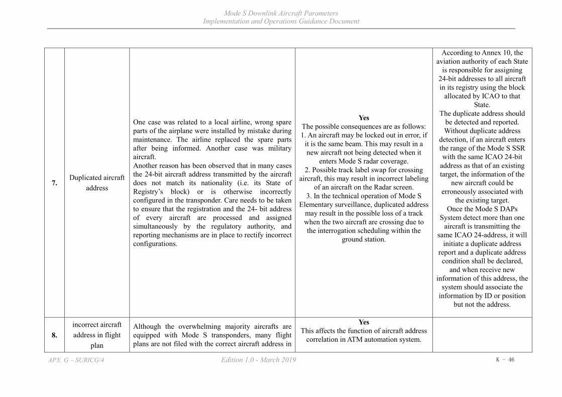
Mode S Downlink Aircraft Parameters Implementation and Operations Guidance Document
APX. G – SURICG/4 Edition 1.0 - March 2019 K - 46
7. Duplicated aircraft
address
One case was related to a local airline, wrong spare parts of the airplane were installed by mistake during maintenance. The airline replaced the spare parts after being informed. Another case was military aircraft. Another reason has been observed that in many cases the 24-bit aircraft address transmitted by the aircraft does not match its nationality (i.e. its State of Registry’s block) or is otherwise incorrectly configured in the transponder. Care needs to be taken to ensure that the registration and the 24- bit address of every aircraft are processed and assigned simultaneously by the regulatory authority, and reporting mechanisms are in place to rectify incorrect configurations.
Yes The possible consequences are as follows: 1. An aircraft may be locked out in error, if
it is the same beam. This may result in a new aircraft not being detected when it
enters Mode S radar coverage. 2. Possible track label swap for crossing
aircraft, this may result in incorrect labeling of an aircraft on the Radar screen.
3. In the technical operation of Mode S Elementary surveillance, duplicated address
may result in the possible loss of a track when the two aircraft are crossing due to the interrogation scheduling within the
ground station.
According to Annex 10, the aviation authority of each State
is responsible for assigning 24-bit addresses to all aircraft in its registry using the block
allocated by ICAO to that State.
The duplicate address should be detected and reported. Without duplicate address
detection, if an aircraft enters the range of the Mode S SSR with the same ICAO 24-bit
address as that of an existing target, the information of the
new aircraft could be erroneously associated with
the existing target. Once the Mode S DAPs
System detect more than one aircraft is transmitting the
same ICAO 24-address, it will initiate a duplicate address
report and a duplicate address condition shall be declared,
and when receive new information of this address, the
system should associate the information by ID or position
but not the address.
8. incorrect aircraft address in flight
plan
Although the overwhelming majority aircrafts are equipped with Mode S transponders, many flight plans are not filed with the correct aircraft address in
Yes This affects the function of aircraft address
correlation in ATM automation system.

Mode S Downlink Aircraft Parameters Implementation and Operations Guidance Document
APX. G – SURICG/4 Edition 1.0 - March 2019 K - 47
item 18.
9. incorrect wind
speed and direction
Aircrew round the system output figures from Spot Wind data was the main reason for variations by crew response. e.g. Recorded wind 283/42kts, crew response 280/40kts.
No
Table 1 Example Data of BDS Swap
BDS Register
Time of Scan 08:05:35 08:05:45
(BDS swap occurred) 08:05:55
BDS code 0,5 605f80c056966f a3280030a40000 605f845303ce8d BDS code 4,0 a3280030a40000 a3280030a40000 a3280030a40000 BDS code 5,0 fff8cf1f800489 a3280030a40000 ffb8cf1f80048a

Mode S Downlink Aircraft Parameters Implementation and Operations Guidance Document
APX. G – SURICG/4 Edition 1.0 - March 2019 K - 48
APPENDIX 3: LIST OF PARTICIPANTS
Name States/Administration Name States/Administration
Luo Yi ICAO Xie Yulan China
Cao Susu China Guo Jianhua China
Jin Lijie China Duan Bo China
Zhang Kai China Wang Xiaowei China
Chen Yang China Wang Yu China
Zhou Shuiping China Tang Weisheng China
Yao Yuan China Michael MH Chu Hong Kong, China
Charles Leung Charn Wai Hong Kong, China Hiromi Miyazaki Japan
Yasuhiro Otani Japan Ho Wee Sin Singapore
Mei Chin NG Singapore Chin Lin KWEK Singapore
Meng Soon KHOO Singapore Khairul Nazmi Bin Zainol Ariffin Malaysia
Mohd Shahrul Azree Bin Remly Malaysia Shairyzal B. Mohammad C. Azizan Malaysia
Alford Andy New Zealand Milns Alex Australia
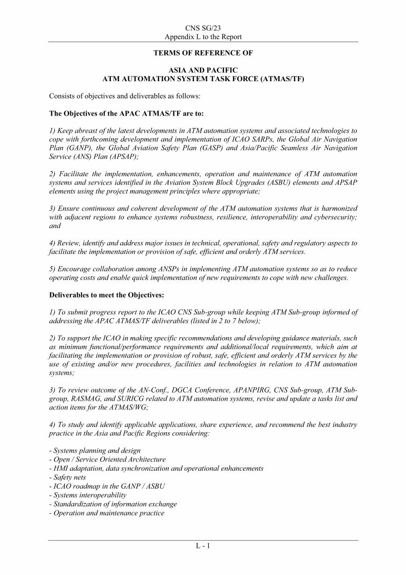
CNS SG/23 Appendix L to the Report
L - 1
TERMS OF REFERENCE OF
ASIA AND PACIFIC ATM AUTOMATION SYSTEM TASK FORCE (ATMAS/TF)
Consists of objectives and deliverables as follows: The Objectives of the APAC ATMAS/TF are to: 1) Keep abreast of the latest developments in ATM automation systems and associated technologies to cope with forthcoming development and implementation of ICAO SARPs, the Global Air Navigation Plan (GANP), the Global Aviation Safety Plan (GASP) and Asia/Pacific Seamless Air Navigation Service (ANS) Plan (APSAP); 2) Facilitate the implementation, enhancements, operation and maintenance of ATM automation systems and services identified in the Aviation System Block Upgrades (ASBU) elements and APSAP elements using the project management principles where appropriate; 3) Ensure continuous and coherent development of the ATM automation systems that is harmonized with adjacent regions to enhance systems robustness, resilience, interoperability and cybersecurity; and 4) Review, identify and address major issues in technical, operational, safety and regulatory aspects to facilitate the implementation or provision of safe, efficient and orderly ATM services. 5) Encourage collaboration among ANSPs in implementing ATM automation systems so as to reduce operating costs and enable quick implementation of new requirements to cope with new challenges. Deliverables to meet the Objectives: 1) To submit progress report to the ICAO CNS Sub-group while keeping ATM Sub-group informed of addressing the APAC ATMAS/TF deliverables (listed in 2 to 7 below); 2) To support the ICAO in making specific recommendations and developing guidance materials, such as minimum functional/performance requirements and additional/local requirements, which aim at facilitating the implementation or provision of robust, safe, efficient and orderly ATM services by the use of existing and/or new procedures, facilities and technologies in relation to ATM automation systems; 3) To review outcome of the AN-Conf., DGCA Conference, APANPIRG, CNS Sub-group, ATM Sub-group, RASMAG, and SURICG related to ATM automation systems, revise and update a tasks list and action items for the ATMAS/WG; 4) To study and identify applicable applications, share experience, and recommend the best industry practice in the Asia and Pacific Regions considering: - Systems planning and design - Open / Service Oriented Architecture - HMI adaptation, data synchronization and operational enhancements - Safety nets - ICAO roadmap in the GANP / ASBU - Systems interoperability - Standardization of information exchange - Operation and maintenance practice

CNS SG/23 Appendix L to the Report
L - 2
- Acceptance and certification - Flight inspection - Cybersecurity - Safety assessment - Training - Transition 5) To encourage research and development, trials and demonstrations of applications and technologies, and, as necessary, steer for the sharing of this information and expertise between States/Administrations through organizing educational seminars and symposia to educate States/Administrations and airspace users; 6) To formulate draft Conclusions and Decisions relating to matters in the field of ATM automation systems that come within the scope of the APANPIRG, CNS Sub-group, ATM Sub-group, and RASMAG work plan; and 7) To collaborate with relevant international organization (such as EuroControl) for harmonisation of ATM system requirements. Timeframe for Deliverables: For deliverable item 2 on guidance materials, it is anticipated that a first draft could be made available in 3 years after establishment of the Task Force for seeking endorsement by CNS Sub-group, after which the guidance materials would be updated/enhanced on an on-going basis. For other deliverable items 3-7, they will be made available as appropriate subject to review by the Task Force. The life time of the Task Force would be subject to review after endorsement of the first edition of the guidance materials. Meeting: The APAC ATMAS/TF shall convene annually with at least one face-to-face meeting per year, which is supplemented by teleconference meetings (e.g. WebEx) as appropriate. Membership: All APAC member States/Administrations providing air navigation services in the Asia and Pacific Regions. APAC members should nominate Subject Matter Experts from Civil Aviation Authorities, ANSPs, and other organizations with strong background in engineering and operation in relation to ATM automation systems to participate into the Task Force. The Task Force would also invite representatives of International Organizations recognized by the ICAO Council as representing important civil aviation interests to participate in its work in a consultative capacity.
– – – – – – – – – – – –
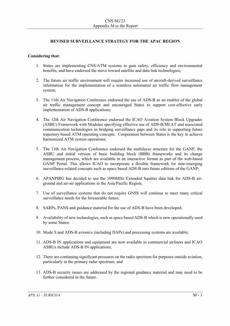
CNS SG/23
Appendix M to the Report
APX. G – SURICG/4 M - 1
REVISED SURVEILLANCE STRATEGY FOR THE APAC REGION
Considering that:
1. States are implementing CNS/ATM systems to gain safety, efficiency and environmental benefits, and have endorsed the move toward satellite and data link technologies;
2. The future air traffic environment will require increased use of aircraft-derived surveillance
information for the implementation of a seamless automated air traffic flow management system;
3. The 11th Air Navigation Conference endorsed the use of ADS-B as an enabler of the global
air traffic management concept and encouraged States to support cost-effective early implementation of ADS-B applications;
4. The 12th Air Navigation Conference endorsed the ICAO Aviation System Block Upgrades
(ASBU) Framework with Modules specifying effective use of ADS-B/MLAT and associated communication technologies in bridging surveillance gaps and its role in supporting future trajectory-based ATM operating concepts. Cooperation between States is the key to achieve harmonized ATM system operations;
5. The 13th Air Navigation Conference endorsed the multilayer structure for the GANP, the ASBU and initial version of basic building block (BBB) frameworks and its change management process, which are available in an interactive format as part of the web-based GANP Portal. This allows ICAO to incorporate a flexible framework for new/emerging surveillance-related concepts such as space based ADS-B into future editions of the GANP;
6. APANPIRG has decided to use the 1090MHz Extended Squitter data link for ADS-B air-
ground and air-air applications in the Asia/Pacific Region;
7. Use of surveillance systems that do not require GNSS will continue to meet many critical surveillance needs for the foreseeable future;
8. SARPs, PANS and guidance material for the use of ADS-B have been developed;
9. Availability of new technologies, such as space based ADS-B which is now operationally used
by some States;
10. Mode S and ADS-B avionics (including DAPs) and processing systems are available;
11. ADS-B IN applications and equipment are now available in commercial airliners and ICAO ASBUs include ADS-B IN applications;
12. There are continuing significant pressures on the radio spectrum for purposes outside aviation,
particularly in the primary radar spectrum; and
13. ADS-B security issues are addressed by the regional guidance material and may need to be further considered in the future.
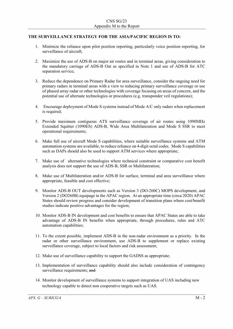
CNS SG/23
Appendix M to the Report
APX. G – SURICG/4 M - 2
THE SURVEILLANCE STRATEGY FOR THE ASIA/PACIFIC REGION IS TO:
1. Minimize the reliance upon pilot position reporting, particularly voice position reporting, for surveillance of aircraft;
2. Maximize the use of ADS-B on major air routes and in terminal areas, giving consideration to the mandatory carriage of ADS-B Out as specified in Note 1 and use of ADS-B for ATC separation service;
3. Reduce the dependence on Primary Radar for area surveillance, consider the ongoing need for
primary radars in terminal areas with a view to reducing primary surveillance coverage or use of phased array radar or other technologies with coverage focusing on areas of concern, and the potential use of alternate technologies or procedures (e.g. transponder veil regulations);
4. Encourage deployment of Mode S systems instead of Mode A/C only radars when replacement is required;
5. Provide maximum contiguous ATS surveillance coverage of air routes using 1090MHz
Extended Squitter (1090ES) ADS-B, Wide Area Multilateration and Mode S SSR to meet operational requirements;
6. Make full use of aircraft Mode S capabilities, where suitable surveillance systems and ATM
automation systems are available, to reduce reliance on 4-digit octal codes. Mode S capabilities such as DAPs should also be used to support ATM services where appropriate;
7. Make use of alternative technologies where technical constraint or comparative cost benefit
analysis does not support the use of ADS-B, SSR or Multilateration; 8. Make use of Multilateration and/or ADS-B for surface, terminal and area surveillance where
appropriate, feasible and cost effective; 9. Monitor ADS-B OUT developments such as Version 3 (DO-260C) MOPS development, and
Version 2 (DO260B) equipage in the APAC region. At an appropriate time (circa 2020) APAC States should review progress and consider development of transition plans where cost/benefit studies indicate positive advantages for the region;
10. Monitor ADS-B IN development and cost benefits to ensure that APAC States are able to take
advantage of ADS-B IN benefits when appropriate, through procedures, rules and ATC automation capabilities;
11. To the extent possible, implement ADS-B in the non-radar environment as a priority. In the
radar or other surveillance environment, use ADS-B to supplement or replace existing surveillance coverage, subject to local factors and risk assessment;
12. Make use of surveillance capability to support the GADSS as appropriate;
13. Implementation of surveillance capability should also include consideration of contingency surveillance requirements; and
14. Monitor development of surveillance systems to support integration of UAS including new
technology capable to detect non cooperative targets such as UAS.

CNS SG/23
Appendix M to the Report
APX. G – SURICG/4 M - 3
15. Encourage sharing of surveillance data to improve safety and efficiency in air traffic management; and
16. Monitor potential congestion on 1090 MHz and availability of 24-bit aircraft address due to
operation of UAS, or other emerging aircraft types.
Note 1:
a) Version 0 ES as specified in Annex 10, Volume IV, Chapter 3, Paragraph3.1.2.8.6 (up to and including Amendment 82 to Annex 10) and Chapter 2 of Technical Provisions for Mode S Services and Extended Squitter (ICAO Doc 9871) (Equivalent to DO260) to be used till at least 2020.
b) Version 1 ES as specified in Chapter 3 of Technical Provisions for Mode S Services and Extended Squitter (ICAO Doc 9871) (Equivalent to DO260A);
c) Version 2 ES as specified in Chapter 4 of Technical Provisions for Mode S Services and Extended Squitter (ICAO Doc 9871) (Equivalent to DO260B).
d) States/Administrations in APAC region are strongly encouraged to mandate aircraft with a maximum take-off mass exceeding 5 700 kg or having a maximum cruising true airspeed capability greater than 250 knots, to be equipped with ADS-B OUT avionics compliant with Version 2 ES (DO-260B) or later version with date of manufacture on or after 1 January 2020.
_ _ _ _ _ _ _ _ _ _ _ _

ADS-B IMPLEMENTATION AND OPERATIONS GUIDANCE DOCUMENT
Edition 12.0 - April 2019
INTERNATIONAL CIVIL AVIATION ORGANIZATION ASIA AND PACIFIC OFFICE
CNS SG/23 Appendix N to the Report

ADS-B Implementation and Operations Guidance Document
APX. B – SURICG/4 Edition 12.0 - April 2019 N - 2
Intentionally left blank
ADS-B Implementation and Operations Guidance Document
APX. B – SURICG/4 Edition 12.0 - April 2019 N - 3
TABLE OF CONTENTS
1. INTRODUCTION ............................................................................................................ 7 1.1 Arrangement of the AIGD .................................................................................................. 7 1.2 Document History and Management .................................................................................. 7 1.3 Copies ................................................................................................................................. 8 1.4 Changes to the AIGD .......................................................................................................... 8 1.5 Editing conventions ............................................................................................................ 8 1.6 AIGD Request for Change Form ........................................................................................ 9 1.7 Amendment Record .......................................................................................................... 10 2. ACRONYM LIST & GLOSSARY OF TERMS............................................................ 15 2.1 Acronym List .................................................................................................................... 15 2.2 Glossary of Terms ............................................................................................................. 16 3. REFERENCE DOCUMENTS………………………………………………………... 17 4. ADS-B DATA .................................................................................................................. 19 5. ADS-B IMPLEMENTATION ....................................................................................... 20 5.1 Introduction ....................................................................................................................... 20 5.1.1 Planning ................................................................................................................... 20 5.1.2 Implementation team to ensure international coordination ..................................... 20 5.1.3 System compatibility ............................................................................................... 20 5.1.4 Integration ................................................................................................................ 21 5.1.5 Coverage Predictions ............................................................................................... 24 5.2 Implementation checklist .................................................................................................. 24 5.2.1 Introduction .............................................................................................................. 24 5.2.2 Activity Sequence .................................................................................................... 24 5.2.3 Concept Phase .......................................................................................................... 25 5.2.4 Design Phase ............................................................................................................ 25 5.2.5 Implementation Phase .............................................................................................. 26 6. HARMONIZATION FRAMEWORK FOR ADS-B IMPLEMENTATION ....................................................................................... 28 6.1 Background ...................................................................................................................... 28 6.2 Template of Harmonization Framework for ADS-B Implementation .............................. 29 7. SYSTEM INTEGRITY AND MONITORING ............................................................ 32 7.1 Introduction ....................................................................................................................... 32 7.2 Personnel Licensing and Training .................................................................................... 32 7.3 System Performance Criteria for an ATC separation service ........................................... 32 7.4 ATC system validation ..................................................................................................... 33
ADS-B Implementation and Operations Guidance Document
APX. B – SURICG/4 Edition 12.0 - April 2019 N - 4
7.4.1 Safety Assessment Guidelines ............................................................................. 33 7.4.2 System safety assessment .................................................................................... 33 7.4.3 Integration test ..................................................................................................... 34 7.4.4 ATS Operation Manuals ...................................................................................... 34 7.4.5 ATS System Integrity .......................................................................................... 34 7.5 System Monitoring ........................................................................................................... 35 7.5.1 Problem Reporting System (PRS) ....................................................................... 35 7.5.2 The monitoring process ....................................................................................... 35 7.5.3 Distribution of confidential information ............................................................. 36 7.5.4 ADS-B problem reports ....................................................................................... 36 7.5.5 ADS-B periodic status report............................................................................... 36 7.5.6 Processing of Reports .......................................................................................... 37 7.6 APANPIRG ....................................................................................................................... 37 7.7 Local Data Recording and Analysis ................................................................................. 37 7.7.1 Data recording ..................................................................................................... 37 7.7.2 Local data collection ............................................................................................ 38 7.7.3 Avionics problem identification and correction .................................................. 38 7.8 ADS-B Problem Report .................................................................................................... 39 7.8.1 Report Form ......................................................................................................... 39 7.8.2 Description of Fields ........................................................................................... 40 7.9 ADS-B Performance Report Form .................................................................................... 41 8. RELIABILITY & AVAILABILITY CONSIDERATIONS ....................................... 42 8.1 Reliability ......................................................................................................................... 42 8.2 Availability ....................................................................................................................... 42 8.3 Recommendations for high reliability/availability ADS-B systems ................................. 43 A: System design ......................................................................................................... 43 B: Logistics strategy ................................................................................................... 44 C: Configuration Management .................................................................................... 45 D: Training & Competency plans ................................................................................ 46 E: Data collection & Review ....................................................................................... 46 9. ADS-B REGULATIONS AND PROCEDURES .......................................................... 47 9.1 Introduction ....................................................................................................................... 47 9.2 ADS-B Regulations .......................................................................................................... 47 9.3 Factors to be considered when using ADS-B ................................................................... 48 9.3.1 Use of ADS-B Level data..................................................................................... 48 9.3.2 Position Reporting Performance .......................................................................... 48 9.3.3 GNSS Integrity Prediction Service ...................................................................... 49 9.3.4 Sharing of ADS-B Data........................................................................................ 49 9.3.5 Synergy between GNSS and ADS-B ................................................................... 50

ADS-B Implementation and Operations Guidance Document
APX. B – SURICG/4 Edition 12.0 - April 2019 N - 5
9.4 Reporting Rates ................................................................................................................ 51 9.4.1 General ................................................................................................................ 51 9.5 Separation ......................................................................................................................... 51 9.5.1 General ................................................................................................................. 51 9.5.2 Identification Methods ......................................................................................... 51 9.5.3 ADS-B Separation ................................................................................................ 52 9.5.4 Vertical Separation ............................................................................................... 52 9.6 Air Traffic Control Clearance Monitoring ....................................................................... 53 9.6.1 General ................................................................................................................. 53 9.6.2 Deviation from ATC clearances .......................................................................... 53 9.7 Alerting service ................................................................................................................. 53 9.8 Position Reporting ............................................................................................................ 53 9.8.1 Pilot position reporting requirements in ADS-B coverage .................................. 53 9.8.2 Meteorological reporting requirement in ADS-B airspace .................................. 53 9.9 Phraseology ....................................................................................................................... 53 9.9.1 Phraseology standard ........................................................................................... 53 9.9.2 Operations of Mode S Transponder and ADS-B ................................................. 54 9.10 Flight Planning .................................................................................................................. 55 9.10.1 ADS-B Flight Planning Requirement – Flight Identity ....................................... 55 9.10.2 ADS-B Flight Planning Requirements ................................................................. 56 9.10.3 Setting Flight Identification (Flight ID) in Cockpits ........................................... 57 9.11 Procedures to Handle Non-compliant ADS-B Aircraft or Mis-leading ADS-B Transmissions .................................................................................. 58 9.12 Emergency Procedures .................................................................................................... 61 9.13 Procedures to Handle GPS Time and Week Counter Rollover ........................................ 62 10. Security Issues Associated with ADS-B ........................................................................ 63 10.1 Introduction ....................................................................................................................... 63 10.2 Considerations .................................................................................................................. 63 Appendix 1 – An Example of Commissioning Checklist Appendix 2 – Guidance Materials on Monitoring and Analysis of ADS-B Avionics
Performance Appendix 3 – A Template for ADS-B Mandate/Regulations for Aircraft Avionics

ADS-B Implementation and Operations Guidance Document
APX. B – SURICG/4 Edition 12.0 - April 2019 N - 6
Appendix 4 – An Example of Advice to Operators Concerning Inconsistency between ADS-B Flight Planning and Surveillance Capability
Appendix 5 – Checklist of Common Items or Parameters for the Monitoring of ADS-B
System Appendix 6 – Baseline ADS-B Service Performance Parameters Appendix 7 – Guidance Material on Generation, Processing and Sharing of ASTERIX
Category 21 ADS-B Messages
ADS-B Implementation and Operations Guidance Document
APX. B – SURICG/4 Edition 12.0 - April 2019 N - 7
1. INTRODUCTION The Eleventh ICAO Air Navigation Conference held in 2003 recommended that States recognize ADS-B as an enabler of the global ATM concept bringing substantial safety and capacity benefits; support the cost-effective early implementation of it; and ensuring it is harmonized, compatible and interoperable with operational procedures, data linking and ATM applications. The Twelve ICAO Air Navigation Conference held in 2012 endorsed the Aviation System Block Upgrades (ASBU) to provide a framework for global harmonization and interoperability of seamless ATM systems. Among the Block Upgrades, the Block 0 module “Initial Capability for Ground Surveillance” recommends States to implement ADS-B which provides an economical alternative to acquire surveillance capabilities especially for areas where it is technically infeasible or commercially unviable to install radars. This ADS-B Implementation and Operations Guidance Document (AIGD) provides guidance material for the planning, implementation and operational application of ADS-B technology in the Asia and Pacific Regions. The procedures and requirements for ADS-B operations are detailed in the relevant States’ AIP. The AIGD is intended to provide key information on ADS-B performance, integration, principles, procedures and collaboration mechanisms. The content is based upon the work to date of the APANPIRG ADS-B Study and Implementation Task Force (SITF), the Surveillance Implementation Coordination Group (SURICG) and various ANC Panels developing provisions for the operational use of ADS-B. Amendment to the guidance material will be required as new/revised SARPs and PANS are published. 1.1 ARRANGEMENT OF THE AIGD The AIGD consists of the following Parts:
Section 1 Introduction Section 2 Acronyms and Glossary of Terms Section 3 Reference Documents Section 4 ADS-B Data Section 5 ADS-B Implementation Section 6 Template of Harmonization Framework for ADS-B
Implementation Section 7 System Integrity and Monitoring Section 8 Reliability and Availability Considerations Section 9 ADS-B Regulations and Procedures Section 10 Security Issues Associated with ADS-B
1.2 DOCUMENT HISTORY AND MANAGEMENT This document is managed by the APANPIRG. It was introduced as draft to the first Working Group meeting of the ADS-B SITF in Singapore in October 2004, at which it was agreed to develop the draft to an approved working document that provides implementation guidance for States. The first edition was presented to APANPIRG for adoption in August 2005. It is intended to supplement SARPs, PANS and relevant provisions contained in ICAO documentation and it will be regularly updated to reflect evolving provisions.

ADS-B Implementation and Operations Guidance Document
APX. B – SURICG/4 Edition 12.0 - April 2019 N - 8
1.3 COPIES Paper copies of this AIGD are not distributed. Controlled and endorsed copies can be found at the following web site: http://www.icao.int/APAC/Pages/edocs.aspx Copy may be freely downloaded from the web site, or by emailing APANPIRG through the ICAO Asia and Pacific Regional Office who will send a copy by return email. 1.4 CHANGES TO THE AIGD Whenever a user identifies a need for a change to this document, a Request for Change (RFC) Form (see Section 1.6 below) should be completed and submitted to the ICAO Asia and Pacific Regional Office. The Regional Office will collate RFCs for consideration by the Surveillance Implementation Coordination Group. When an amendment has been agreed by a meeting of the Surveillance Implementation Coordination Group then a new version of the AIGD will be prepared, with the changes marked by an “|” in the margin, and an endnote indicating the relevant RFC, so a reader can see the origin of the change. If the change is in a table cell, the outside edges of the table will be highlighted; e.g.:
Final approval for publication of an amendment to the AIGD will be the responsibility of APANPIRG. 1.5 EDITING CONVENTIONS (Intentionally blank)
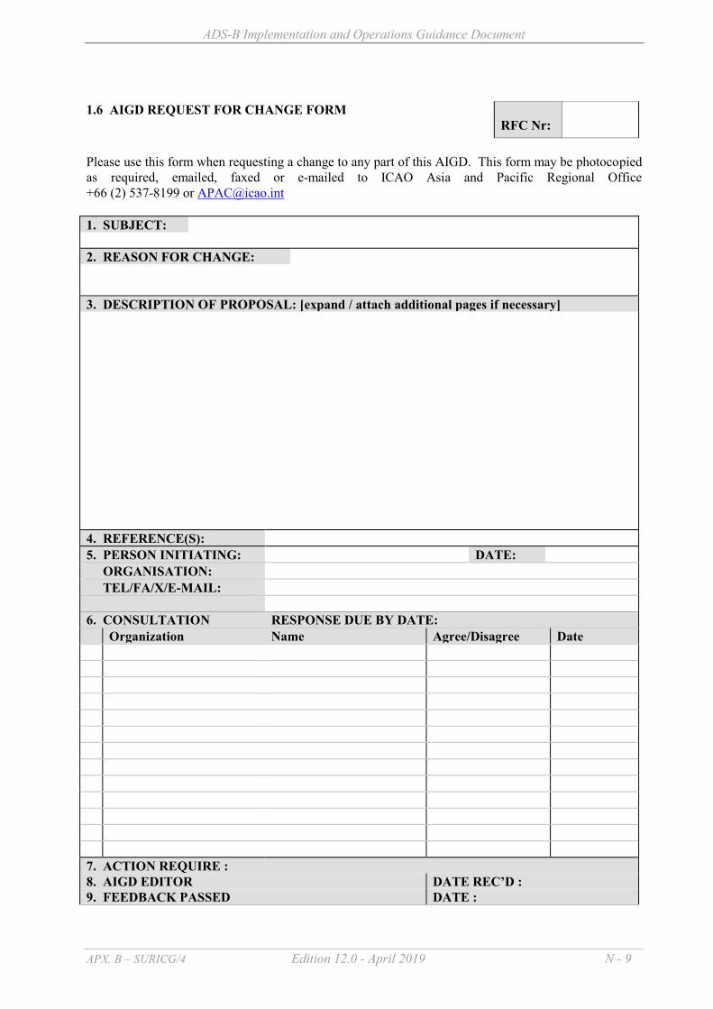
ADS-B Implementation and Operations Guidance Document
APX. B – SURICG/4 Edition 12.0 - April 2019 N - 9
1.6 AIGD REQUEST FOR CHANGE FORM
RFC Nr:
Please use this form when requesting a change to any part of this AIGD. This form may be photocopied as required, emailed, faxed or e-mailed to ICAO Asia and Pacific Regional Office +66 (2) 537-8199 or [email protected] 1. SUBJECT: 2. REASON FOR CHANGE: 3. DESCRIPTION OF PROPOSAL: [expand / attach additional pages if necessary] 4. REFERENCE(S): 5. PERSON INITIATING: DATE: ORGANISATION: TEL/FA/X/E-MAIL: 6. CONSULTATION RESPONSE DUE BY DATE: Organization Name Agree/Disagree Date 7. ACTION REQUIRE : 8. AIGD EDITOR DATE REC’D : 9. FEEDBACK PASSED DATE :

ADS-B Implementation and Operations Guidance Document
APX. B – SURICG/4 Edition 12.0 - April 2019 N - 10
1.7 AMENDMENT RECORD
Amendment Number
Date Amended by Comments
0.1 24 December 2004 W. Blythe H. Anderson
Modified draft following contributions from ADS-B SITF Working Group members. Incorporated to TF/3 Working Paper #3.
0.2 (1.0) 24 March 2005 H. Anderson Final draft prepared at ADS-B SITF WG/3
0.3 (1.1) 03 June 2005 Nick King Amendments following SASP WG/WHL meeting of May 2005
0.4 15 July 2005 CNS/MET SG/9 Editorial changes made
1.0 26 August 2005 APANPIRG/16 Adopted as the first Edition
2.0 25 August 2006 Proposed by ADS-B SITF/5 and adopted by APANPIRG/17
Adopted as the second Edition
3.0 7 September 2007
Proposed by ADS-B SITF/6 and adopted by APANPIRG/18
Adopted as the second amendment (3rd edition)
4.0 5 September 2011 Proposed by ADS-B SITF/10 and adopted by APANPIRG/22
Adopted amendment on consequential change to the Flight Plan and additional material on the reliability and availability for ADS-B ground system
5.0 14 September 2012 Proposed by ADS-B SITF/11 and adopted by APANPIRG/23
Included sample template on harmonization framework
6.0 June 2013 Proposed by ADS-B SITF/12 and adopted by APANPIRG/24
Revamped to include the latest ADS-B developments and references to guidance materials on ADS-B implementation
7.0 September 2014 Proposed by ADS-B SITF/13 and adopted by APANPIRG/25
(i) Included guidance materials on monitoring and analysis of ADS-B equipped aircraft
(ii) Included guidance materials on synergy between GNSS and ADS-B
(iii) Revised ATC Phraseology (iv) Included clarification on
Flight Planning 8.0 September 2015 Proposed by ADS-B SITF/14
and adopted by APANPIRG/26
(i) Updated the guidance materials on monitoring and analysis of ADS-B equipped aircraft
(ii) Updated the categories of reported ADS-B avionics problems
(iii) Updated the guidance materials on ADS-B flight

ADS-B Implementation and Operations Guidance Document
APX. B – SURICG/4 Edition 12.0 - April 2019 N - 11
plan (iv) Updated the guidance
materials on disabling ADS-B transmissions
(v) Remove reference to operational approval for use of ADS-B Out by ATC
9.0 September 2016 Proposed by ADS-B SITF/15
and adopted by APANPIRG/27
(i) Included a list of additional functional requirements for ADS-B integration
(ii) Addition of a checklist of common items or parameters for monitoring of ADS-B System
(iii) Amendment to emphasize the issue on potential incorrect processing of DO-260B downlinks by ADS-B ground stations during upgrade
(iv) Updated the list of known ADS-B avionics problems
(v) Included a general recommendation of technical solution on acquisition of Mode 3/A code information via Mode S downlink for DO-260 aircraft in ADS-B implementation with Mode A/C SSR environment
10.0 June 2017 Proposed by SURICG/2 (i) Updated “B787 position error
with good NUC” in the list of known ADS-B avionics problems.
(ii) Included new problem type “Incorrect Ground Bit Setting in ADS-B Avionics Downlink Data” and “A350 ADS-B on-ground performance” in the list of known ADS-B avionics problems.
(iii) Amendment to the template for ADS-B Mandate / Regulations for Aircraft Avionics.
(iv) Included a general recommendation to use ADS-B in overcoming the limitations of Mode A/C radar technology.
(v) Included a general recommendation on carrying
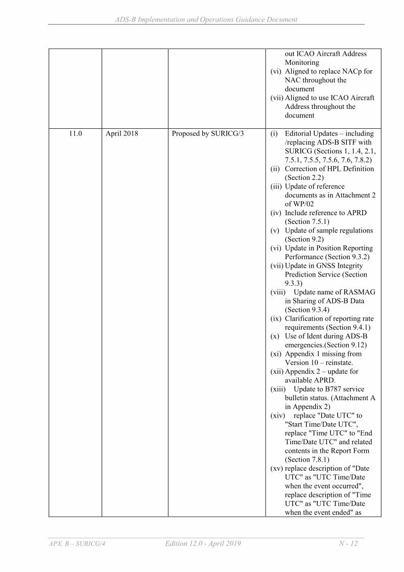
ADS-B Implementation and Operations Guidance Document
APX. B – SURICG/4 Edition 12.0 - April 2019 N - 12
out ICAO Aircraft Address Monitoring
(vi) Aligned to replace NACp for NAC throughout the document
(vii) Aligned to use ICAO Aircraft Address throughout the document
11.0 April 2018 Proposed by SURICG/3 (i) Editorial Updates – including
/replacing ADS-B SITF with SURICG (Sections 1, 1.4, 2.1, 7.5.1, 7.5.5, 7.5.6, 7.6, 7.8.2)
(ii) Correction of HPL Definition (Section 2.2)
(iii) Update of reference documents as in Attachment 2 of WP/02
(iv) Include reference to APRD (Section 7.5.1)
(v) Update of sample regulations (Section 9.2)
(vi) Update in Position Reporting Performance (Section 9.3.2)
(vii) Update in GNSS Integrity Prediction Service (Section 9.3.3)
(viii) Update name of RASMAG in Sharing of ADS-B Data (Section 9.3.4)
(ix) Clarification of reporting rate requirements (Section 9.4.1)
(x) Use of Ident during ADS-B emergencies.(Section 9.12)
(xi) Appendix 1 missing from Version 10 – reinstate.
(xii) Appendix 2 – update for available APRD.
(xiii) Update to B787 service bulletin status. (Attachment A in Appendix 2)
(xiv) replace "Date UTC" to "Start Time/Date UTC", replace "Time UTC" to "End Time/Date UTC" and related contents in the Report Form (Section 7.8.1)
(xv) replace description of "Date UTC" as "UTC Time/Date when the event occurred", replace description of "Time UTC" as "UTC Time/Date when the event ended" as

ADS-B Implementation and Operations Guidance Document
APX. B – SURICG/4 Edition 12.0 - April 2019 N - 13
sometimes the problem will lasts across mid-night. (Section 7.8.2)
(xvi) In Remote Control & Monitoring (RCMS) part, suggest to replace "ASTERIX Output Load" to "ASTERIX Output Load and Link Status" (Appendix 5)
(xvii) Update on DO260A EMG issue (Section 9.12)
(xviii) Update the link to the Guidance Material on generation, processing and sharing of ASTERIX (Section 4)
(xix) Reference to Space based ADS-B and ATC automation as in WP12 is added under 5.1.4.4.6
(xx) Updated Section 4Managing the Problem in Appendix 2 to incorporate the General mechanism and procedure for blacklisting aircraft
(xxi) Updated the Attachment A to Appendix 2 – List of known ADS-B avionics problems
(xxii) Added Appendix 6 – Baseline ADS-B Service Performance Parameters
(xxiii) Added Appendix 7 – Guidance Material on Generation, Processing and Sharing of ASTERIX Category 21 ADS-B Messages
12.0 April 2019 Proposed by SURICG/4 (i) Added procedures on handling GPS time and week counters rollover (Section 9.13)
(ii) Added two new problem types
to Attachment A of Appendix 2 “List of known ADS-B avionics problems”, including:
o Rockwell TSS-4100
Geometric Altitude Reporting as Pressure Altitude
o Improper NACv reporting (iii) Updated the status of known
ADS-B avionics problems in Attachment A of Appendix 2

ADS-B Implementation and Operations Guidance Document
APX. B – SURICG/4 Edition 12.0 - April 2019 N - 14
“List of known ADS-B avionics problems”, including:
o B787 position error with
good NIC o Rockwell TSS-4100 track
extrapolation issue o Embraer 170 track jumping
issue o Airbus Single Aisle
production wiring issue o Boeing 777-300ER
production wiring issue

ADS-B Implementation and Operations Guidance Document
APX. B – SURICG/4 Edition 12.0 - April 2019 N - 15
2. ACRONYM LIST & GLOSSARY OF TERMS 2.1 ACRONYM LIST ACID Aircraft Identification ADS-C Automatic Dependent Surveillance - Contract ADS-B Automatic Dependent Surveillance - Broadcast AIGD ADS-B Implementation and Operations Guidance Document AIP Aeronautical Information Publication AIT ADS-B Implementation Team AMSL Above Mean Sea Level APANPIRG Asia/Pacific Air Navigation Planning and Implementation Regional Group APRD ADS-B Avionics Problem Reporting Database ARINC Aeronautical Radio Incorporate ATC Air Traffic Control (or Air Traffic Controller) ATM Air Traffic Management ATS Air Traffic Services ATSP ATS Provider ATSU ATS unit CNS Communications, Navigation, Surveillance CRC Cyclic Redundancy Check CDTI Cockpit Display Traffic Information DAIW Danger Area Infringement Warning FIR Flight Information Region FLTID Flight Identification FMS Flight Management System FOM Figure of Merit used in ASTERIX messaging GPS Global Positioning System (USA) HPL Horizontal Protection Level ICAO International Civil Aviation Organization MSAW Minimum Safe Altitude Warning MTBF Mean Time Between Failures MTCA Medium Term Conflict Alert MTTR Mean Time To Restore NACp Navigation Accuracy Category NIC Navigation Integrity Category PRS Problem Reporting System RAI Restricted Area Intrusion RAM Route Adherence Monitoring RAIM Receiver Autonomous Integrity Monitoring RFC Request for Change RNP Required Navigation Performance SIL Source Integrity Level SITF Study and Implementation Task Force STCA Short Term Conflict Alert SURICG Surveillance Implementation Coordination Group
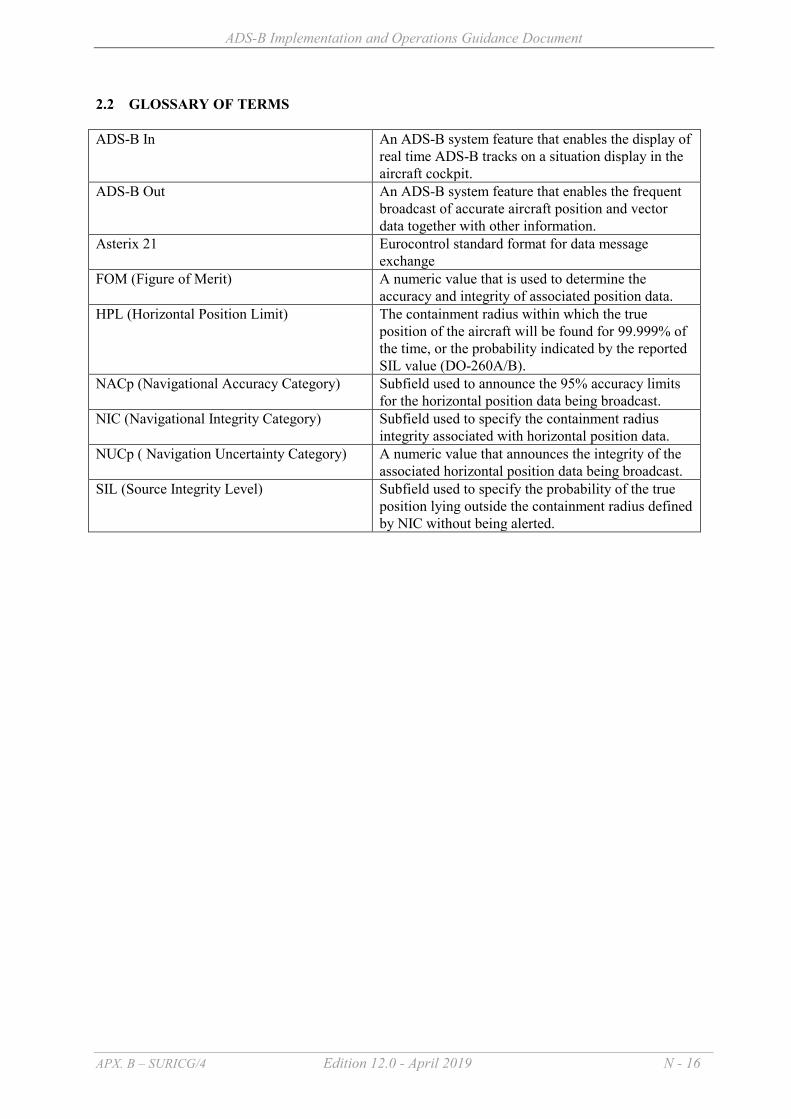
ADS-B Implementation and Operations Guidance Document
APX. B – SURICG/4 Edition 12.0 - April 2019 N - 16
2.2 GLOSSARY OF TERMS ADS-B In
An ADS-B system feature that enables the display of real time ADS-B tracks on a situation display in the aircraft cockpit.
ADS-B Out
An ADS-B system feature that enables the frequent broadcast of accurate aircraft position and vector data together with other information.
Asterix 21
Eurocontrol standard format for data message exchange
FOM (Figure of Merit) A numeric value that is used to determine the accuracy and integrity of associated position data.
HPL (Horizontal Position Limit)
The containment radius within which the true position of the aircraft will be found for 99.999% of the time, or the probability indicated by the reported SIL value (DO-260A/B).
NACp (Navigational Accuracy Category) Subfield used to announce the 95% accuracy limits for the horizontal position data being broadcast.
NIC (Navigational Integrity Category) Subfield used to specify the containment radius integrity associated with horizontal position data.
NUCp ( Navigation Uncertainty Category) A numeric value that announces the integrity of the associated horizontal position data being broadcast.
SIL (Source Integrity Level) Subfield used to specify the probability of the true position lying outside the containment radius defined by NIC without being alerted.

ADS-B Implementation and Operations Guidance Document
APX. B – SURICG/4 Edition 12.0 - April 2019 N - 17
3. REFERENCE DOCUMENTS
Id Name of the document Reference Date Origin Domain 1 Annex 2: Rules of the Air Tenth Edition
Including Amendment 43 dated 10/11/16
July 2005 ICAO
2 Annex 4: Aeronautical Chart Eleventh Edition including Amendment 59 dated 10/11/16
July 2009 ICAO
3 Annex 10: Aeronautical Telecommunications, Vol. IV – Surveillance Radar and Collision Avoidance Systems
Fifth Edition
July 2014 ICAO
4 Annex 11: Air Traffic Services Fourteenth Edition
July 2016 ICAO
5 Annex 15: Aeronautical Information Services
Fifteenth Edition July 2016 ICAO
6 PAN-ATM (Doc 4444/ATM501) Sixteenth Edition November 2016
ICAO
7 Air Traffic Services Planning Manual (Doc 9426/AN924)
First Edition including Amendment 4 30/12/92
1984 ICAO
8 Manual on Airspace Planning Methodology for the Determination of Separation Minima (Doc 9689/AN953)
First Edition including Amendment 1 dated 30/8/02
1998 ICAO
9 Doc 9859 Safety Management Manual (SMM)
Third Edition 2013 ICAO
10 Technical Provisions for Mode S Services and Extended Squitter (Doc 9871/AN460)
Second Edition including Amendment 1 dated 09/01/17
2012 ICAO
11 Aeronautical Surveillance Manual (Doc 9924)
Second Edition 2017 ICAO
12 ICAO Circular 326 AN/188 “Assessment of ADS-B and Multilateration Surveillance to Support Air Traffic Services and Guidelines for Implementation”.
First Edition 2012 ICAO
13 Regional Supplementary Procedures (Doc 7030)
Fifth Edition including Amendment 9 dated 25/04/14
2008 ICAO
14 Minimum Operational Performance Standards (MOPS) for 1090 MHz Automatic Dependent Surveillance – Broadcast (ADS-B) – including Change 1
RTCA DO-260 September 13, 2000 Change 1 to
2000
2006
RTCA
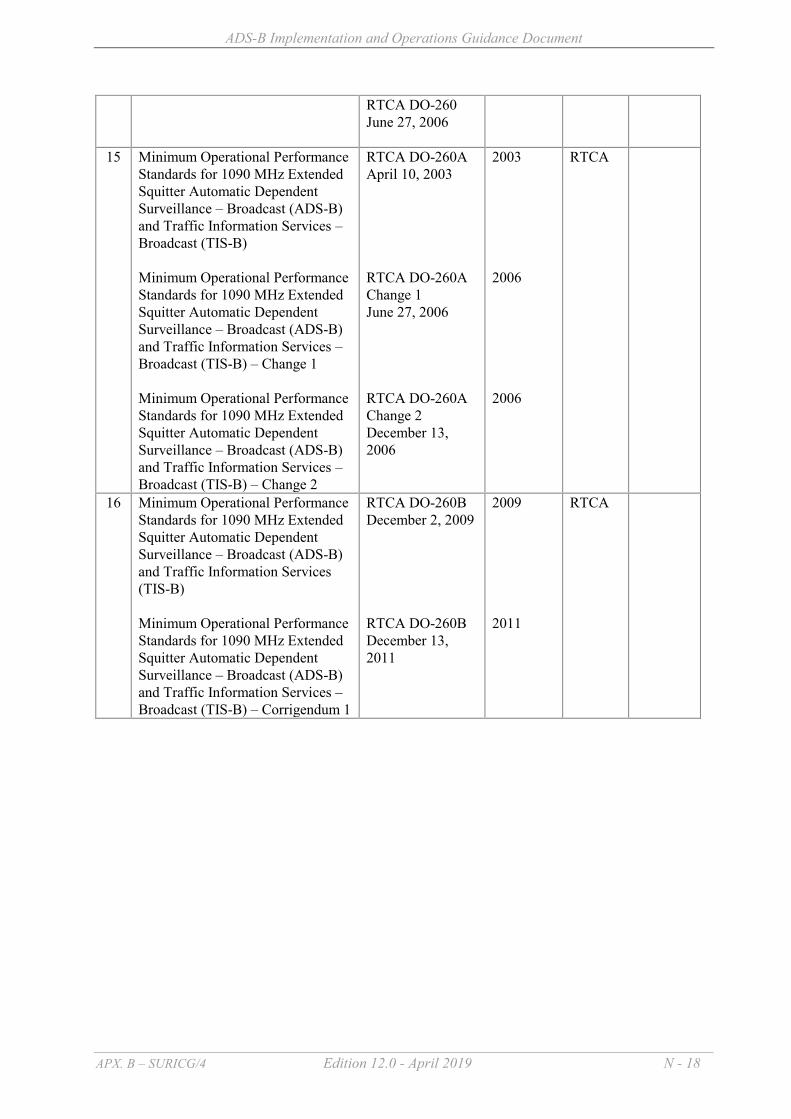
ADS-B Implementation and Operations Guidance Document
APX. B – SURICG/4 Edition 12.0 - April 2019 N - 18
RTCA DO-260 June 27, 2006
15 Minimum Operational Performance Standards for 1090 MHz Extended Squitter Automatic Dependent Surveillance – Broadcast (ADS-B) and Traffic Information Services – Broadcast (TIS-B) Minimum Operational Performance Standards for 1090 MHz Extended Squitter Automatic Dependent Surveillance – Broadcast (ADS-B) and Traffic Information Services – Broadcast (TIS-B) – Change 1 Minimum Operational Performance Standards for 1090 MHz Extended Squitter Automatic Dependent Surveillance – Broadcast (ADS-B) and Traffic Information Services – Broadcast (TIS-B) – Change 2
RTCA DO-260A April 10, 2003 RTCA DO-260A Change 1 June 27, 2006 RTCA DO-260A Change 2 December 13, 2006
2003 2006 2006
RTCA
16 Minimum Operational Performance Standards for 1090 MHz Extended Squitter Automatic Dependent Surveillance – Broadcast (ADS-B) and Traffic Information Services (TIS-B) Minimum Operational Performance Standards for 1090 MHz Extended Squitter Automatic Dependent Surveillance – Broadcast (ADS-B) and Traffic Information Services – Broadcast (TIS-B) – Corrigendum 1
RTCA DO-260B December 2, 2009 RTCA DO-260B December 13, 2011
2009 2011
RTCA

ADS-B Implementation and Operations Guidance Document
APX. B – SURICG/4 Edition 12.0 - April 2019 N - 19
4. ADS-B DATA APANPIRG has decided to use 1090MHz Extended Squitter data link for ADS-B data exchange in the Asia and Pacific Regions. In the longer term an additional link type may be required. To ensure interoperability of ADS-B ground stations in the Asia Pacific (ASIA/PAC) Regions, during the 16th APANPIRG Meeting held in August 2005, the ASTERIX Category 21 version 0.23 (V0.23) which had incorporated DO260 standard was adopted as the baselined ADS-B data format for deployment of ADS-B ground stations and sharing of ADS-B data in the ASIA/PAC Regions. At this time, DO260A and DO260B standards were not defined. This baselined version provides adequate information so that useful ATC operational services, including aircraft separation, can be provided. V0.23 can be used with DO260, DO260A and DO260B ADS-B avionics/ground stations to provide basic ATC operational services. However, V0.23 cannot fully support the more advanced capabilities offered by DO260A and DO260B. As the avionics standards changed through the different versions of DO260, the ADS-B ground station processing also needed to change, so that downlinks received from aircraft would be correctly interpreted in construction of the ASTERIX Category 21 messages. It is important that States with “older generation” ADS-B ground stations designed to support DO260 or DO260A, take action to upgrade to support the latest ADS-B avionics standard as well as the older standards. DO260B avionics will become more common in the Asia Pacific region as the FAA and European ADS-B mandates for 2020 require this version. States intending to implement ADS-B surveillance and share ADS-B data with others might consider to adopt a more updated version of ASTERIX in order to make use of the advanced capabilities offered by DO260A and DO260B compliant avionics. A guidance material on generation, processing and sharing of ASTERIX Cat. 21 ADS-B messages is provided at Appendix 7 for reference by States. In this guidance material, the ADS-B data contained inside ASTERIX Cat 21 are classified as Group 1 (mandatory), Group 2 (Desirable) and Group 3 (Optional). It is required to transmit all data that are operationally desirable (Group 2), when such data are received from the aircraft, in addition to the data that are mandatory (Group 1) in ASTERIX messages. Whether Group 3 optional data will need to be transmitted or not should be configurable on item-by-item basis within the ADS-B ground station depending on specific operational needs. It is considered necessary that all data that are mandatory in ASTERIX messages (i.e. Group 1 data items) and operationally desirable (i.e. Group 2 data items) when such data are received from aircraft, should be included in data sharing. In the event that the data have to be filtered, the list of optional data items (i.e. Group 3 data items) needs to be shared will be subject to mutual agreement between the two data sharing parties concerned.
ADS-B Implementation and Operations Guidance Document
APX. B – SURICG/4 Edition 12.0 - April 2019 N - 20
5. ADS-B IMPLEMENTATION 5.1 INTRODUCTION 5.1.1 Planning There are a range of activities needed to progress ADS-B implementation from initial concept
level to operational use. This section addresses the issues of collaborative decision making, system compatibility and integration, while the second section of this chapter provides a checklist to assist States with the management of ADS-B implementation activities.
5.1.2 Implementation team to ensure international coordination
5.1.2.1 Any decision to implement ADS-B by a State should include consultation with the wider ATM community. Moreover, where ADS-B procedures or requirements will affect traffic transiting between states, the implementation should also be coordinated between States and Regions, in order to achieve maximum benefits for airspace users and service providers.
5.1.2.2 An effective means of coordinating the various demands of the affected organizations is
to establish an implementation team. Team composition may vary by State or Region, but the core group responsible for ADS-B implementation planning should include members with multidiscipline operational expertise from affected aviation disciplines, with access to other specialists where required.
5.1.2.3 Ideally, such a team should comprise representatives from the ATS providers, regulators
and airspace users, as well as other stakeholders likely to be influenced by the introduction of ADS-B, such as manufacturers and military authorities. All identified stakeholders should participate as early as possible in this process so that their requirements can be identified prior to the making of schedules or contracts.
5.1.2.4 The role of the implementation team is to consult widely with stakeholders, identify
operational needs, resolve conflicting demands and make recommendations to the various stakeholders managing the implementation. To this end, the implementation team should have appropriate access to the decision-makers.
5.1.3 System compatibility
5.1.3.1 ADS-B has potential use in almost all environments and operations and is likely to become a mainstay of the future ATM system. In addition to traditional radar-like services, it is likely that ADS-B will also be used for niche application where radar surveillance is not available or possible. The isolated use of ADS-B has the potential to foster a variety of standards and practices that, once expanded to a wider environment, may prove to be incompatible with neighbouring areas.
5.1.3.2 Given the international nature of aviation, special efforts should be taken to ensure
harmonization though compliance with ICAO Standards and Recommended Practices (SARPs). The choice of systems to support ADS-B should consider not only the required performance of individual components, but also their compatibility with other CNS systems and prevailing avionics standards.
ADS-B Implementation and Operations Guidance Document
APX. B – SURICG/4 Edition 12.0 - April 2019 N - 21
5.1.3.3 The future concept of ATM encompasses the advantages of interoperable and seamless transition across flight information region (FIR) boundaries and, where necessary, ADS-B implementation teams should conduct simulations, trials and cost/benefit analysis to support these objectives.
5.1.4 Integration
5.1.4.1 ADS-B implementation plans should include the development of both business and safety cases. The adoption of any new CNS system has major implications for service providers, regulators and airspace users and special planning should be considered for the integration of ADS-B into the existing and foreseen CNS/ATM system. The following briefly discusses each element.
5.1.4.2 Communication system 5.1.4.2.1 The communication system is an essential element within CNS. An air
traffic controller can now monitor an aircraft position in real time using ADS-B where previously only voice position reports were available. However, a communication system that will support the new services that result from the improved surveillance may be necessary. Consequently, there is an impact of the ongoing ADS-B related work on the communication infrastructure developments.
5.1.4.3 Navigation system infrastructure 5.1.4.3.1 ADS-B is dependent upon the data obtained from a navigation system
(typically GNSS), in order to enable its functions and performance. Therefore, the navigation infrastructure should fulfill the corresponding requirements of the ADS-B application, in terms of:
a) Data items; and b) Performance (e.g. accuracy, integrity, availability etc.).
5.1.4.3.2 This has an obvious impact on the navigation system development, which evolves in parallel with the development of the surveillance system. 5.1.4.4 Other surveillance infrastructure 5.1.4.4.1 ADS-B may be used to supplement existing surveillance systems or as the
principal source of surveillance data. Ideally, surveillance systems will incorporate data from ADS-B and other sources to provide a coherent picture that improves both the amount and utility of surveillance data to the user. The choice of the optimal mix of data sources will be defined on the basis of operational demands, available technology, safety and cost-benefit considerations.
5.1.4.4.2 ADS-B is one of the cost-effective means in complementing and
overcoming limitations of Mode A/C radars, including false targets, aircraft positions temporarily not displayed and split tracks, which could cause aircraft display issues on radar screens for ATC irrespective of brands of Air Traffic Management System being used. Within busy airspace, aircraft

ADS-B Implementation and Operations Guidance Document
APX. B – SURICG/4 Edition 12.0 - April 2019 N - 22
could be managed at close lateral distance while vertically separated. In such situation, Mode A/C radars sometimes provide garbled detection, in the form of false targets due to overlapping replies from two or more aircraft. In the case of ADS-B, ADS-B data are broadcast in an omni-directional, random and periodic intervals without suffering from the same issue. In addition, automatic data validation is usually done at ADS-B receivers to ensure integrity of ADS-B information received from the aircraft.
5.1.4.4.3 A guidance material on issues to be considered in ATC multi-sensor fusion
processing including integration of ADS-B data is provided on the ICAO website http://www.icao.int/APAC/Pages/edocs.aspx for reference by States.
5.1.4.4.4 Acquisition of Mode 3/A code for DO-260 aircraft through Mode S
downlink There is a potential problem for some of the air traffic management systems
(ATMS) for fusion of ADS-B targets with Mode A/C SSR targets, because a common identifier to the aircraft, Mode 3/A code, is not available through ADS-B. Then ATMS can only rely on proximity analysis of aircraft position and Mode C altitude to determine whether detections from two distinct types of surveillance sources belong to the same aircraft. This matching technique might introduce ambiguity in associating ADS-B with Mode A/C SSR targets for fused display.
States may consider enhancing their ADS-B ground stations to listen to
Downlink Format 5 and 21 (DF 5 and 21) of Mode S interrogation replies which carry the Mode 3/A code of the same aircraft. As a result, ADS-B target reports of the same DO-260 aircraft can be filled with Mode 3/A code acquired from Mode S downlink to facilitate matching with Mode A/C SSR targets before transmitting to the ATMS.
The transmission of DF 5 and DF 21 messages from a Mode S aircraft
requires to be triggered by ground-based Mode S interrogators, either through active or passive interrogation. For active interrogation, Mode S interrogators can be installed alongside with ADS-B ground stations for actively triggering DF 5 and DF 21 messages transmission from the aircraft. The interrogators shall follow ICAO standard to perform periodic all-call and roll-call to the aircraft in range. For passive interrogation, the ADS-B ground stations will only passively listen to the DF messages from the aircraft for acquiring the Mode 3/A code. It is required to ensure that Mode S interrogations are performed by external systems, such as A-SMGCS, MLAT system or Mode S radar under their coverage.
The above provides an interim solution during transition from Mode A/C
SSR to Mode S SSR. After upgrading to Mode S SSR, ATMS can have an alternative means to make use of Flight ID or ICAO Aircraft Address to perform association between ADS-B and Mode S radar targets without ambiguity.

ADS-B Implementation and Operations Guidance Document
APX. B – SURICG/4 Edition 12.0 - April 2019 N - 23
5.1.4.4.5 A guidance material on processing and displaying of ADS-B data at air traffic controller positions is provided on the ICAO website “http://www.icao.int/APAC/Pages/edocs.aspx” for reference by States.
5.1.4.4.6 Most of the ATC automation systems that support terrestrial ADS-B will
also support space-based ADS-B without modifications. For more guidance, reference can be made to WP/12 on "ATC Automation Requirement and Space-based ADS-B" delivered during 3rd meeting of the SURICG.
5.1.4.5 Additional Functional Requirements for ADS-B Integration
5.1.4.5.1 The following list of functions could be considered by each individual States to see whether they are suitable for their own operational needs or applicable to local environment from ADS-B integration point of view:
The priority of ADS-B sensor position data vs radar data could be
adaptable; For ADS-B aircraft, receipt of the Mode S conspicuity code could
trigger use of the Flight ID / ICAO Aircraft Address for flight plan correlation;
If, due to sensor or aircraft capability limitation, no SSR code is
received for an aircraft, the system could use Flight ID/ ICAO Aircraft Address for track correlation;
For correlation based on Flight ID, the received ID could exactly match
the ACID of the flight plan; For correlation based on ICAO Aircraft Address, the received address
could match the address entered in the flight plan item 18 CODE/ keyword;
The system could generate an alert for a correlated flight for which the
Flight ID from the track does not match the flight plan ACID and/or the ICAO Aircraft Address from the track does not match the code given in the flight plan Item 18 CODE/ keyword;
The system could allow the setting of ADS-B above or below the radar
sources within the Surveillance Data Processor Tile Set on a per-tile basis;
Priority could only apply to data received at or above the adapted NUCp,
NACp, NIC, and/or SIL thresholds; The system could be configurable to either discard ADS-B data or
display the track with an indication of ADS-B degradation if the received NUCp, NACp, NIC, or SIL is below an adapted threshold;
If the system is configured to display the degraded track, the degraded
position and status could only be displayed if there are no other surveillance sources available;

ADS-B Implementation and Operations Guidance Document
APX. B – SURICG/4 Edition 12.0 - April 2019 N - 24
The system could allow the adaptation of ADS-B emergency codes to
map to special Mnemonics; The system could include an adaptable Downlinked Aircraft Parameters
(DAP) field that invokes a popup with the following information from Mode-S and ADS-B aircraft:
- Magnetic Heading - True Track Angle - Indicated Airspeed/Mach Number - Groundspeed - Track Angle Rate - True Airspeed - Roll Angle - Selected Altitude - Vertical Rate
The system could generate a conformance alert if the Selected Altitude
and the Cleared Flight Level do not match. The system could monitor1 the ICAO Aircraft Address of individual
aircraft and generate alert for the following cases: - ICAO Aircraft Address does not match with that specified in
flight plan - ICAO Aircraft Address is all 0 or F (expressed in hexadecimal) - ICAO Aircraft Address is not defined in ICAO’s allocation - Duplicated ICAO Aircraft Addresses exist within surveillance
coverage - ICAO Aircraft Address changes during the flight
5.1.5 Coverage Predictions
5.1.5.1 Reliable and robust analysis and planning of ADS-B coverage to support seamless ATM initiative requires accurate and reliable coverage modelling. States should ensure that surveillance engineering/technical teams are provided with modelling tools to provide accurate and reliable coverage predictions for ATM planning and analysis.
5.2 IMPLEMENTATION CHECKLIST 5.2.1 Introduction The purpose of this implementation checklist is to document the range of activities that needs to be completed to bring an ADS-B application from an initial concept to operational use. This checklist may form the basis of the terms of reference for an ADS-B implementation team, although some activities may be specific to individual stakeholders. An example of the checklist used by AirServices Australia is given at Appendix 1. 5.2.2 Activity Sequence
1 Monitoring could be done by ATM system or other systems of the States/Administration

ADS-B Implementation and Operations Guidance Document
APX. B – SURICG/4 Edition 12.0 - April 2019 N - 25
The activities are listed in an approximate sequential order. However, each activity does not have to be completed prior to starting the next activity. In many cases, a parallel and iterative process should be used to feed data and experience from one activity to another. It should be noted that not all activities will be required for all applications. 5.2.3 Concept Phase a) construct operational concept:
1) purpose; 2) operational environment; 3) ATM functions; and 4) infrastructure;
b) identify benefits:
1) safety enhancements; 2) efficiency; 3) capacity; 4) environmental; 5) cost reductions; 6) access; and 7) other metrics (e.g. predictability, flexibility, usefulness);
c) identify constraints:
1) pair-wise equipage; 2) compatibility with non-equipped aircraft; 3) need for exclusive airspace; 4) required ground infrastructure; 5) RF spectrum; 6) integration with existing technology; and 7) technology availability;
d) prepare business case:
1) cost benefit analysis; and 2) demand and justification.
5.2.4 Design Phase a) identify operational requirements:
1) security; and 2) systems interoperability;
b) identify human factors issues:
1) human-machine interfaces; 2) training development and validation; 3) workload demands; 4) role of automation vs. role of human; 5) crew coordination/pilot decision-making interactions; and

ADS-B Implementation and Operations Guidance Document
APX. B – SURICG/4 Edition 12.0 - April 2019 N - 26
6) ATM collaborative decision-making; c) identify technical requirements:
1) standards development; 2) prevailing avionics standards; 3) data required; 4) functional processing; 5) functional performance; and 6) required certification levels;
d) equipment development, test, and evaluation:
1) prototype systems built to existing or draft standards/specifications; 2) developmental bench and flight tests; and 3) acceptance test parameters; and 4) select and procure technology;
e) develop procedures:
1) pilot and controller actions and responsibilities; 2) phraseologies; 3) separation/spacing criteria and requirements; 4) controller’s responsibility to maintain a monitoring function, if appropriate; 5) contingency procedures; 6) emergency procedures; and 7) develop AIP and Information documentation
f) prepare design phase safety case: 1) safety rationale; 2) safety budget and allocation; and 3) functional hazard assessment.
5.2.5 Implementation phase a) prepare implementation phase safety case; b) conduct operational test and evaluation:
1) flight deck and ATC validation simulations; and 2) flight tests and operational trials;
c) obtain systems certification:
1) aircraft equipment; and 2) ground systems;
d) obtain regulatory approvals:
1) air traffic certification of use; e) implementation transition:

ADS-B Implementation and Operations Guidance Document
APX. B – SURICG/4 Edition 12.0 - April 2019 N - 27
1) Promulgate procedures and deliver training 2) continue data collection and analysis; 3) resolve any unforeseen issues; and 4) continue feedback into standards development processes;
f) performance monitoring to ensure that the agreed performance is maintained. 5.2.5.1 Once the implementation project is complete, ongoing maintenance and upgrading of both ADS-B operations and infrastructure should continue to be monitored, through the appropriate forums.

ADS-B Implementation and Operations Guidance Document
APX. B – SURICG/4 Edition 12.0 - April 2019 N - 28
6. HARMONIZATION FRAMEWORK FOR ADS-B IMPLEMENTATION 6.1 BACKGROUND 6.1.1 It is obvious that full benefits of ADS-B will only be achieved by its harmonized
implementation and seamless operations. During the 6th meeting of ADS-B SEA/WG in February 2011, Hong Kong, China initiated to strengthen collaboration among concerned States/Administrations for harmonized ADS-B implementation and seamless operations along two ATS routes L642 and M771 with major traffic flow (MTF). An ad-hoc workgroup comprising concerned CAAs/ANSPs from Hong Kong, China, Mainland China, Vietnam and Singapore was subsequently formed to elaborate and agree on a framework regarding implementation timelines, avionics standards, optimal flight levels, and ATC and engineering handling procedures. As a coherent effort, ADS-B implementation along ATS routes L642 and M771 has been harmonized while Hong Kong, China and Singapore have published respective Aeronautical Information Circulars and Airworthiness Notices on ADS-B mandates for these two routes with effect on 12 December 2013.
6.1.2 It is considered that the above implementation framework for ATS routes L642/M771
would serve as a useful template for extension to other high density routes to harmonize ADS-B implementation. Paragraph 6.2 shows the detailed framework.

ADS-B Implementation and Operations Guidance Document
APX. B – SURICG/4 Edition 12.0 - April 2019 N - 29
6.2 TEMPLATE OF HARMONIZATION FRAMEWORK FOR ADS-B IMPLEMENTATION
Harmonization Framework for ADS-B Implementation along ATS Routes L642 and M771
No. What to harmonize What was agreed Issue / what needs to be further
discussed
1 Mandate Effective Singapore (SG), Hong Kong (HK), China (Sanya) :
12 Dec 2013
Vietnam (VN) : to be confirmed
2 ATC Operating Procedures No need to harmonize Refer to SEACG for consideration of the
impact of expanding ADS-B surveillance
on ATC Operating Procedures including
Large Scale Weather procedures.
3 Mandate Publish Date No need to harmonize To publish equipment requirements as
early as possible.

ADS-B Implementation and Operations Guidance Document
APX. B – SURICG/4 Edition 12.0 - April 2019 N - 30
4 Flight Level SG, HK, CN : - At or Above FL290 (ADS-B airspace) - Below FL290 (Non-ADS-B airspace) VN to be confirmed
5 Avionics Standard (CASA/AMC2024) SG - CASA or AMC2024 or FAA AC No. 20-165 HK - CASA or AMC2024 or FAA AC No. 20-165 VN - CASA or AMC2024 or FAA AC No. 20-165 CN - CASA or AMC2024 or FAA AC No. 20-165
ADS-B Task Force agreed that DO260B will be accepted as well. SG, HK, and CN agreed their ADS-B GS will accept DO260, DO260A and DO260B by 1 July 2014 (Note 1)
6 Flight Planning Before 15 Nov 2012, as per AIGD On or after 15 Nov 2012, as per new flight plan format
7 Aircraft Equippage 7a) Procedures if Aircraft Not Equipped or
Aircraft without a Serviceable ADS-B Transmitting Equipment before Flight
SG, HK, CN : FL280 and Below VN to be confirmed

ADS-B Implementation and Operations Guidance Document
APX. B – SURICG/4 Edition 12.0 - April 2019 N - 31
7b) Aircraft Equipped but Transmitting Bad
Data (Blacklisted Aircraft)
For known aircraft, treat as non ADS-B aircraft.
Share blacklisted aircraft among
concerned States/Administration
8 Contingency Plan
8a) Systemic Failure such as Ground System
/ GPS Failure
Revert back to current procedure.
8b) Avionics Failure or Equipped Aircraft
Transmitting Bad Data in Flight
Provide other form of separation, subject to bilateral
agreement.
From radar/ADS-B environment to ADS-B only
environment, ATC coordination may be able to
provide early notification of ADS-B failure.
Address the procedure for aircraft
transiting from radar to ADS-B airspace
and from ADS-B to ADS-B airspace.
9 Commonly Agreed Route Spacing SEACG Need for commonly agreed minimal in-
trail spacing throughout.
Note 1: Also included two ADS-B GS supplied by Indonesia at Matak and Natuna
_ _ _ _ _ _ _ _ _ _ _ _ _ _

ADS-B Implementation and Operations Guidance Document
APX. B – SURICG/4 Edition 12.0 - April 2019 N - 32
7. SYSTEM INTEGRITY AND MONITORING 7.1 INTRODUCTION The Communications, Navigation, Surveillance and Air Traffic Management (CNS/ATM) environment is an integrated system including physical systems (hardware, software, and communication networks), human elements (pilots, controllers and engineers), and the operational procedures for its applications. ADS-B is a surveillance system that may be integrated with other surveillance technologies or may also operate as an independent source for surveillance monitoring within the CNS/ATM system. Because of the integrated nature of such system and the degree of interaction among its components, comprehensive system monitoring is recommended. The procedures described in this section aim to ensure system integrity by validation, identification, reporting and tracking of possible problems revealed during system monitoring with appropriate follow-up actions. These procedures do not replace the ATS incident reporting procedures and requirements, as specified in PANS-ATM (Doc 4444), Appendix 4; ICAO’s Air Traffic Services Planning Manual (Doc 9426), Chapter 3; or applicable State regulations, affecting the reporting responsibilities of parties directly involved in a potential ATS incident. 7.2 PERSONNEL LICENSING AND TRAINING Prior to operating any element of the ADS-B system, operational and technical personnel shall undertake appropriate training as determined by the States, including compliance with the Convention on International Civil Aviation where applicable. Notwithstanding the above requirement and for the purposes of undertaking limited trials of the ADS-B system, special arrangements may be agreed between the operator and an Air Traffic Services Unit (ATSU). 7.3 SYSTEM PERFORMANCE CRITERIA FOR AN ATC SEPARATION SERVICE A number of States have introduced ADS-B for the provision of Air Traffic Services, including for surveillance separation. The ICAO Separation and Airspace Safety Panel (SASP) has completed assessment on the suitability of ADS-B for various applications including provision of aircraft separation based on comparison of technical characteristics between ADS-B and monopulse secondary surveillance radar. It is concluded that that ADS-B surveillance is better or at least no worse than the referenced radar, and can be used to provide separation minima as described in PANS-ATM (Doc 4444) whether ADS-B is used as a sole means of ATC surveillance or used together with radar, subject to certain conditions to be met. The assessment result is detailed in the ICAO Circular 326 AN/188 “Assessment of ADS-B and Multilateration Surveillance to Support Air Traffic Services and Guidelines for Implementation”. Regarding the use of ADS-B in complex airspace (as discussed in ICAO Circular 326), complex airspace may be considered to be airspace with the following characteristics:
- Higher aircraft density - Higher route crossing point density - A higher mixture of different aircraft performance levels - A higher rate of aircraft manoeuvring (as distinct from straight and level flight).

ADS-B Implementation and Operations Guidance Document
APX. B – SURICG/4 Edition 12.0 - April 2019 N - 33
The following recommendations need to be considered:
1. Whether complex or not, States are urged to consider whether the current or required surveillance system performance is better, equivalent or worse than the SASP reference. 2. If the current or required surveillance system used by a State is lower or equivalent in performance than the reference MSSR used in Circular 326 Appendix A, then that State may use the Appendix C performance criteria. 3. If the current or required surveillance system used by a State is higher performance than the reference MSSR used in Circular 326 Appendix A, then the State must ensure that the ADS-B system achieves the more demanding performance. 4. State should undertake, in all cases, a safety assessment that ensures that any additional risks and safety requirements already identified for the airspace where ADSB or MLAT is to be implemented, or any newly identified risks, are effectively controlled and risk is reduced to an acceptable level.
States intending to introduce ADS-B separation minima shall comply with provisions of PANS-ATM, Regional Supplementary Procedures (Doc 7030) and Annex 11 paragraph 3.4.1. States should adopt the guidelines contained in this document unless conformance with PANS-ATM specifications requires change. 7.4 ATC SYSTEM VALIDATION 7.4.1 Safety Assessment Guidelines To meet system integrity requirements, States should conduct a validation process that confirms
the integrity of their equipment and procedures. Such processes shall include:
a) A system safety assessment for new implementations is the basis for definitions of system performance requirements. Where existing systems are being modified to utilize additional services, the assessment demonstrates that the ATS Provider’s system will meet safety objectives;
b) Integration test results confirming interoperability for operational use of airborne and
ground systems; and c) Confirmation that the ATS Operation Manuals are compatible with those of adjacent
providers where the system is used across a common boundary. 7.4.2 System safety assessment
The objective of the system safety assessment is to ensure the State that introduction and operation of ADS-B is safe. This can be achieved through application of the provisions of Annex 11 paragraph 2.27 and PANS-ATM Chapter 2. The safety assessment should be conducted for initial implementation as well as any future enhancements and should include:
a) Identifying failure conditions; b) Assigning levels of criticality; c) Determining risks/ probabilities for occurrence;

ADS-B Implementation and Operations Guidance Document
APX. B – SURICG/4 Edition 12.0 - April 2019 N - 34
d) Identifying mitigating measures and fallback arrangements; e) Categorising the degree of acceptability of risks; and f) Operational hazard ID process.
Following the safety assessment, States should institute measures to offset any identified failure conditions that are not already categorized as acceptable. This should be done to reduce the probability of their occurrence to a level as low as reasonably practicable. This could be accomplished through system automation or manual procedures. Guidance material on building a safety case for delivery of an ADS-B separation service is provided on the ICAO APAC website “http://www.icao.int/APAC/Pages/edocs.aspx” for reference by States.
7.4.3 Integration test
States should conduct trials with suitably equipped aircraft to ensure they meet the operational and technical requirements to provide an ATS. Alternatively, they may be satisfied by test results and analysis conducted by another State or organization deemed competent to provide such service. Where this process is followed, the tests conducted by another State or organization should be comparable (i.e. using similar equipment under similar conditions). Refer also to the Manual on Airspace Planning Methodology for the Determination of Separation Minima (Doc9689).
7.4.4 ATS Operation Manuals
States should coordinate with adjacent States to confirm that their ATS Operation Manuals contain standard operating procedures to ensure harmonization of procedures that impact across common boundaries.
7.4.5 ATS System Integrity
With automated ATM systems, data changes, software upgrades, and system failures can affect adjacent units. States shall ensure that:
a) A conservative approach is taken to manage any changes to the system; b) Aircrew, aircraft operating companies and adjacent ATSU(s) are notified of any planned
system changes in advance, where that system is used across a common boundary; c) ATSUs have verification procedures in place to ensure that following any system
changes, displayed data is both correct and accurate; d) In cases of system failures or where upgrades (or downgrades) or other changes may
impact surrounding ATS units, ATSUs should have a procedure in place for timely notification to adjacent units. Such notification procedures will normally be detailed in Letters of Agreement between adjacent units; and
e) ADS-B surveillance data is provided with equal to or better level of protection and
security than existing surveillance radar data.
ADS-B Implementation and Operations Guidance Document
APX. B – SURICG/4 Edition 12.0 - April 2019 N - 35
7.5 SYSTEM MONITORING During the initial period of implementation of ADS-B technology, routine collection of data is necessary in order to ensure that the system continues to meet or exceed its performance, safety and interoperability requirements, and that operational service delivery and procedures are working as intended. The monitoring program is a two-fold process. Firstly, summarised statistical data should be produced periodically showing the performance of the system. This is accomplished through ADS-B Periodic Status Reports. Secondly, as problems or abnormalities arise, they should be identified, tracked, analyzed and corrected and information disseminated as required, utilizing the ADS-B Problem Report. Guidance materials on monitoring and analysis of ADS-B Avionics Performance are given at Appendix 2. Checklist of common items or parameters that could be considered for monitoring is summarized at Appendix 5 for reference. 7.5.1 Problem Reporting System (PRS)
The Problem Reporting System is tasked with the collection, storage and regular dissemination of data based on reports received from SURICG members. The PRS tracks problem reports and publish information from those reports to SURICG members. Problem resolution is the responsibility of the appropriate SURICG members.
The PRS Administrator shall: a) prepare consolidated problem report summaries for each SURICG meeting; b) collect and consolidate ADS-B Problem Reports; and c) maintain a functional website (with controlled access) to manage the problem reporting
function. The PRS is managed through the Asia Pacific ADS-B Avionics Problem Reporting Database (APRD) which is accessible to authorized users via https://applications.icao.int/ADSB-APRD/login.aspx.
7.5.2 The monitoring process
When problems or abnormalities are discovered, the initial analysis should be performed by the organization(s) identifying the problem. In addition, a copy of the problem report should be entered in to the PRS which will assign a tracking number. As some problems or abnormalities may involve more than one organization, the originator should be responsible for follow-up action to rectify the problem and forward the information to the PRS. It is essential that all information relating to the problem is documented and recorded and resolved in a timely manner.
The following groups should be involved in the monitoring process and problem tracking to ensure a comprehensive review and analysis of the collected data: a) ATS Providers;

ADS-B Implementation and Operations Guidance Document
APX. B – SURICG/4 Edition 12.0 - April 2019 N - 36
b) Organizations responsible for ATS system maintenance (where different from the ATS provider);
c) Relevant State regulatory authorities; d) Communication Service Providers being used; e) Aircraft operators; and f) Aircraft and avionics manufacturers.
7.5.3 Distribution of confidential information
It is important that information that may have an operational impact on other parties be distributed by the authorised investigator to all authorised groups that are likely to be affected, as soon as possible. In this way, each party is made aware of problems already encountered by others, and may be able to contribute further information to aid in the solution of these problems. The default position is that all states agree to provide the data which will be de-identified for reporting and record keeping purposes.
7.5.4 ADS-B problem reports
Problem reports may originate from many sources, but most will fall within two categories; reports based on observation of one or more specific events, or reports generated from the routine analysis of data. The user would document the problem, resolve it with the appropriate party and forward a copy of the report to the PRS for tracking and distribution. While one occurrence may appear to be an isolated case, the receipt of numerous similar reports by the PRS could indicate that an area needs more detailed analysis.
To effectively resolve problems and track progress, the problem reports should be sent to the nominated point of contact at the appropriate organization and the PRS. The resolution of the identified problems may require:
a) Re-training of system operators, or revision of training procedures to ensure compliance
with existing procedures; b) Change to operating procedures;
c) Change to system requirements, including performance and interoperability; or
d) Change to system design.
7.5.5 ADS-B periodic status report
The ATS Providers should complete the ADS-B Periodic Status Report annually and deliver the report to the regional meeting of the SURICG. The Periodic Status Report should give an indication of system performance and identify any trend in system deficiencies, the resultant operational implications, and the proposed resolution, if applicable.
Communications Service Providers, if used, are also expected to submit Periodic Status Reports on the performance of the networks carrying ADS-B data at the annual regional meeting of the SURICG. These reports could also contain the details of planned or current upgrades to the network.

ADS-B Implementation and Operations Guidance Document
APX. B – SURICG/4 Edition 12.0 - April 2019 N - 37
7.5.6 Processing of Reports
Each group in the monitoring process should nominate a single point of contact for receipt of problem reports and coordination with the other parties. This list will be distributed by the PRS Administrator to all parties to the monitoring process. Each State should establish mechanisms within its ATS Provider and regulatory authority to:
a) Assess problem reports and refer them to the appropriate technical or operational
expertise for investigation and resolution; b) Coordinate with aircraft operators; c) Develop interim operational procedures to mitigate the effects of problems until such
time as the problem is resolved; d) Monitor the progress of problem resolution; e) Prepare a report on problems encountered and their operational implications and
forward these to the PRS; f) Prepare the ADS-B periodic status report at pre-determined times and forward these to
the Secretary of the annual meeting of the SURICG; and g) Coordinate with any Communication Service Providers used.
7.6 APANPIRG APANPIRG, with the assistance of its contributory bodies, shall oversee the monitoring process to ensure the ADS-B system continues to meet its performance and safety requirements, and that operational procedures are working as intended. The APANPIRG’S objectives are to:
a) review Periodic Status Reports and any significant Problem Reports; b) highlight successful problem resolutions to SURICG members; c) monitor the progress of outstanding problem resolutions; d) prepare summaries of problems encountered and their operational implications; and e) assess system performance based on information in the PRS and Periodic Status Reports.
7.7 LOCAL DATA RECORDING AND ANALYSIS 7.7.1 Data recording
It is recommended that ATS Providers and Communication Service Providers retain the records defined below for at least 30 days to allow for accident/incident investigation processes. These records should be made available on request to the relevant State safety authority. Where data is sought from an adjacent State, the usual State to State channels should be used.

ADS-B Implementation and Operations Guidance Document
APX. B – SURICG/4 Edition 12.0 - April 2019 N - 38
These recordings shall be in a form that permits a replay of the situation and identification of the messages that were received by the ATS system.
7.7.2 Local data collection
ATS providers and communications service providers should identify and record ADS-B system component failures that have the potential to negatively impact the safety of controlled flights or compromise service continuity.
7.7.3 Avionics problem identification and correction
ATS providers need to develop systems to: a) detect ADS-B avionics anomalies and faults b) advise the regulators and where appropriate the aircraft operators on the detected ADS-B avionics anomalies and faults c) devise mechanisms and procedures to address identified faults Regulators need to develop and maintain systems to ensure that appropriate corrective actions are taken to address identified faults.

ADS-B Implementation and Operations Guidance Document
APX. B – SURICG/4 Edition 12.0 - April 2019 N - 39
7.8 ADS-B PROBLEM REPORT 7.8.1 Report Form
PRS # Start Time/Date UTC End Time/Date UTC Registration
Aircraft ID
Flight ID ICAO Aircraft Address
Aircraft Type Flight Sector/ Location
ATS Unit Description / additional information
Originator Originator Reference number
Organization
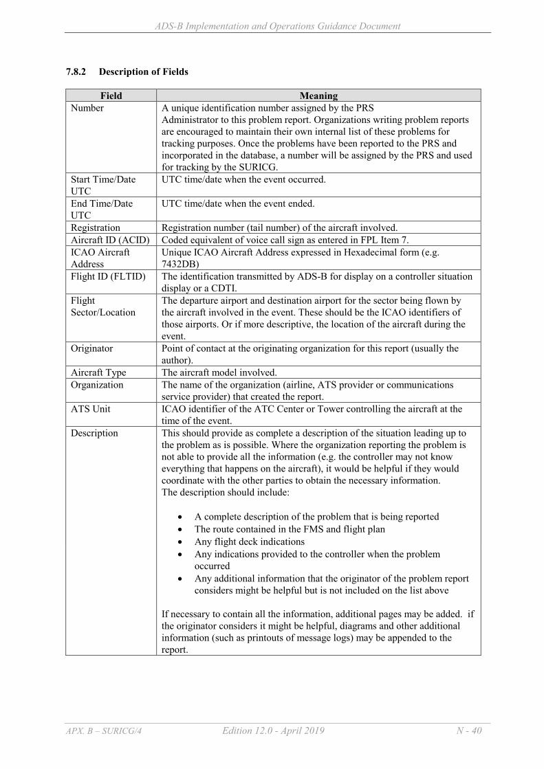
ADS-B Implementation and Operations Guidance Document
APX. B – SURICG/4 Edition 12.0 - April 2019 N - 40
7.8.2 Description of Fields
Field Meaning Number A unique identification number assigned by the PRS
Administrator to this problem report. Organizations writing problem reports are encouraged to maintain their own internal list of these problems for tracking purposes. Once the problems have been reported to the PRS and incorporated in the database, a number will be assigned by the PRS and used for tracking by the SURICG.
Start Time/Date UTC
UTC time/date when the event occurred.
End Time/Date UTC
UTC time/date when the event ended.
Registration Registration number (tail number) of the aircraft involved. Aircraft ID (ACID) Coded equivalent of voice call sign as entered in FPL Item 7. ICAO Aircraft Address
Unique ICAO Aircraft Address expressed in Hexadecimal form (e.g. 7432DB)
Flight ID (FLTID) The identification transmitted by ADS-B for display on a controller situation display or a CDTI.
Flight Sector/Location
The departure airport and destination airport for the sector being flown by the aircraft involved in the event. These should be the ICAO identifiers of those airports. Or if more descriptive, the location of the aircraft during the event.
Originator Point of contact at the originating organization for this report (usually the author).
Aircraft Type The aircraft model involved. Organization The name of the organization (airline, ATS provider or communications
service provider) that created the report. ATS Unit ICAO identifier of the ATC Center or Tower controlling the aircraft at the
time of the event. Description This should provide as complete a description of the situation leading up to
the problem as is possible. Where the organization reporting the problem is not able to provide all the information (e.g. the controller may not know everything that happens on the aircraft), it would be helpful if they would coordinate with the other parties to obtain the necessary information. The description should include:
A complete description of the problem that is being reported The route contained in the FMS and flight plan Any flight deck indications
Any indications provided to the controller when the problem occurred
Any additional information that the originator of the problem report considers might be helpful but is not included on the list above
If necessary to contain all the information, additional pages may be added. if the originator considers it might be helpful, diagrams and other additional information (such as printouts of message logs) may be appended to the report.

ADS-B Implementation and Operations Guidance Document
APX. B – SURICG/4 Edition 12.0 - April 2019 N - 41
7.9 ADS-B PERFORMANCE REPORT FORM Originating Organization Date of submission Originator Report Period TECHNICAL ISSUES OPERATIONAL ISSUES GENERAL COMMENTS

ADS-B Implementation and Operations Guidance Document
APX. B – SURICG/4 Edition 12.0 - April 2019 N - 42
8. RELIABILITY & AVAILABILITY CONSIDERATIONS Reliability and Availability of ADS-B systems should normally be equivalent or better than the reliability and availability of radar systems. Guidance material on Reliability and Availability standards for ADS-B systems and supporting voice communications systems are included in the document “Baseline ADS-B Service Performance Parameters” at Appendix 6.
The “Baseline ADS-B Performance Parameters” document contains three Tiers of service performance parameters with different reliability and availability standards for each Tier. The appropriate Tier should be selected for the type of ADS-B service intended:
(a) Tier 1 standards are for a high performance traffic separation service;
(b) Tier 2 standards are for a traffic situational awareness service with procedural separation; and
(c) Tier 3 standards are for a traffic advisory service (flight information service)
To achieve high operational availability of ADS-B systems to support aircraft separation services, it is necessary to operate with duplicated/redundant systems. If one system fails, the service continues using an unduplicated system. This is acceptable for a short period, whilst the faulty system is being repaired, because the probability of a second failure during the short time window of repairing is low. However, it is necessary to ensure that the repair does not take too long. A long repair time increases the risk of an unexpected failure (loss of service continuity); which in turn, introduces potential loss of service (low availability) and loss of aircraft operational efficiency and/or safety impacts.
Checklist of common items or parameters that could be considered for monitoring is summarized at Appendix 5 for reference. 8.1 Reliability
8.1.1 Reliability is a measure of how often a system fails and is usually measured as Mean
Time Between Failure (MTBF) expressed in hours. Continuity is a measure equivalent to reliability, but expressed as the probability of system failure over a defined period. In the context of this document, failure means inability to deliver ADS-B data to the ATC centre. Ie: Failure of the ADS-B system rather than an equipment or component failure.
8.1.2 Poor system MTBF has a safety impact because typically it causes unexpected transition from one operating mode to another. For example, aircraft within surveillance coverage that are safely separated by a surveillance standard distance (say, 5 NM) are unexpectedly no longer separated by a procedural standard distance (say 15 mins), due to an unplanned surveillance outage.
8.1.3 In general, reliability is determined by design (see para 8.3 B below)
8.2 Availability
8.2.1 Availability is a measure of how often the system is available for operational use. It is
usually expressed as a percentage of the time that the system is available.
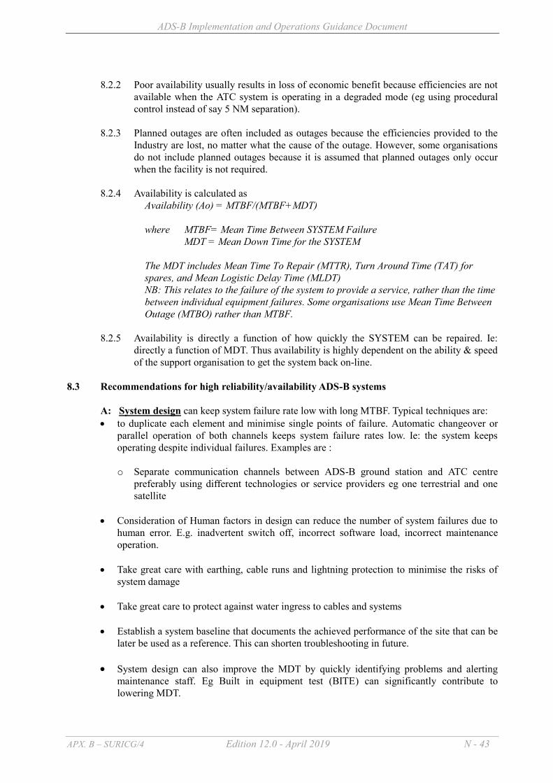
ADS-B Implementation and Operations Guidance Document
APX. B – SURICG/4 Edition 12.0 - April 2019 N - 43
8.2.2 Poor availability usually results in loss of economic benefit because efficiencies are not
available when the ATC system is operating in a degraded mode (eg using procedural control instead of say 5 NM separation).
8.2.3 Planned outages are often included as outages because the efficiencies provided to the
Industry are lost, no matter what the cause of the outage. However, some organisations do not include planned outages because it is assumed that planned outages only occur when the facility is not required.
8.2.4 Availability is calculated as
Availability (Ao) = MTBF/(MTBF+MDT) where MTBF= Mean Time Between SYSTEM Failure MDT = Mean Down Time for the SYSTEM The MDT includes Mean Time To Repair (MTTR), Turn Around Time (TAT) for spares, and Mean Logistic Delay Time (MLDT) NB: This relates to the failure of the system to provide a service, rather than the time between individual equipment failures. Some organisations use Mean Time Between Outage (MTBO) rather than MTBF.
8.2.5 Availability is directly a function of how quickly the SYSTEM can be repaired. Ie: directly a function of MDT. Thus availability is highly dependent on the ability & speed of the support organisation to get the system back on-line.
8.3 Recommendations for high reliability/availability ADS-B systems
A: System design can keep system failure rate low with long MTBF. Typical techniques are: to duplicate each element and minimise single points of failure. Automatic changeover or
parallel operation of both channels keeps system failure rates low. Ie: the system keeps operating despite individual failures. Examples are : o Separate communication channels between ADS-B ground station and ATC centre
preferably using different technologies or service providers eg one terrestrial and one satellite
Consideration of Human factors in design can reduce the number of system failures due to human error. E.g. inadvertent switch off, incorrect software load, incorrect maintenance operation.
Take great care with earthing, cable runs and lightning protection to minimise the risks of system damage
Take great care to protect against water ingress to cables and systems Establish a system baseline that documents the achieved performance of the site that can be
later be used as a reference. This can shorten troubleshooting in future. System design can also improve the MDT by quickly identifying problems and alerting
maintenance staff. Eg Built in equipment test (BITE) can significantly contribute to lowering MDT.

ADS-B Implementation and Operations Guidance Document
APX. B – SURICG/4 Edition 12.0 - April 2019 N - 44
B: Logistics strategy aims to keep MDT very low. Low MDT depends on logistic support providing short repair times. To achieve short repair times, ANSPs usually provide a range of logistics, including the following, to ensure that the outage is less than a few days:
ensure the procured system is designed to allow for quick replacement of faulty modules to
restore operations provide remote monitoring to allow maintainers to identify the faulty modules for transport
to site provide support tools to allow technicians to repair faulty modules or to configure/setup
replacement modules provide technicians training to identify & repair the faulty modules provide local maintenance depots to reduce the time it takes to access to the site provide documentation and procedures to “standardise” the process use an in-country spares pool to ensure that replacement modules are available within
reasonable times use a maintenance contract to repair faulty modules within a specified turnaround time.
I.e.: to replenish the spares pool quickly.
Whilst technical training and remote monitoring are usually considered by ANSPs, sometimes there is less focus on spares support.
Difficulties can be experienced if States : a) Fail to establish a spares pool – because procurement of spares at the time of failure can
bring extensive delays due to : b) obtaining funds c) obtaining approval to purchase overseas d) obtaining approval to purchase from a “sole source” e) difficulties and delays in obtaining a quotation f) delays in delivery because the purchase was unexpected by the supplier g) Fail to establish a module repair contract resulting in :
- long repair times - unplanned expenditure - inability for a supplier to repair modules because the supplier did not have adequate
certainty of funding of the work
Spares pool
ANSPs can establish, preferably as part of their acquisition purchase, adequate spares buffer stock to support the required repair times. The prime objective is to reduce the time period that the system operates un-duplicated. It allows decoupling of the restoration time from the module repair time.
Module repair contract
ANSPs can also enter into a maintenance repair contract, preferably as part of their acquisition purchase, to require the supplier to repair or replace and deliver failed modules within a specified time – preferably with contractual incentives/penalties for compliance. Such support contracts are best negotiated as part of the acquisition contract when competition between vendors is at play to keep costs down. Sometimes it is appropriate to demand that the support contractor also keep a certain level of buffer stock of spares “in country”.

ADS-B Implementation and Operations Guidance Document
APX. B – SURICG/4 Edition 12.0 - April 2019 N - 45
It is strongly recommended that maintenance support is purchased under the same contract as the acquisition contract. The advantages of a module repair contract are:
- The price can be determined whilst in the competitive phase of acquisition – hence avoids excessive costs
- The contract can include the supplier bearing all shipping costs - Can be funded by a define amount per year, which support the budget
processes. If the costs are fixed, the supplier is encouraged to develop a reliable system minimising module repairs.
- It avoids delays and funding issues at the time of the module failure Other typical strategies are: Establish availability and reliability objectives that are agreed organization wide. In
particular agree System response times (SRT) for faults and system failure to ensure that MDT is achieved. An agreed SRT can help organizations to decide on the required logistics strategy including number, location and skills of staff to support the system.
Establish baseline preventative maintenance regimes including procedures and performance inspections in conjunction with manufacturer recommendations for all subsystems
Use remote control & monitoring systems to identify faulty modules before travel to site. This can avoid multiple trips to site and reduce the repair time
Have handbooks, procedures, tools available at the site or a nearby depot so that travel time
does not adversely affect down time Have adequate spares and test equipment ready at a maintenance depot near the site or at the
site itself. Vendors can be required to perform analysis of the number of spares required to achieve low probability of spare “stock out”
Have appropriate plans to cope with system and component obsolescence. It is possible to contractually require suppliers to regularly report on the ability to support the system and supply components.
Have ongoing training programs and competency testing to ensure that staff are able to perform the required role
The detailed set of operational and technical arrangements in place and actions required to maintain a system through the lifecycle are often documented in a Integrated Logistics Support Plan. C: Configuration Management aims to ensure that the configuration of the ground stations is maintained with integrity. Erroneous configuration can cause unnecessary outages. Normally configuration management is achieved by : Having clear organizational & individual responsibilities and accountabilities for system
configuration.
Having clear procedures in place which define who has authority to change configuration and records of the changes made including, inter alia

ADS-B Implementation and Operations Guidance Document
APX. B – SURICG/4 Edition 12.0 - April 2019 N - 46
o The nature of the change including the reason o Impact of the change & safety assessment o An appropriate transition or cutover plan o Who approved the change o When the change was authorized and when the change was implemented
Having appropriate test and analysis capabilities to confirm that new configurations are
acceptable before operational deployment.
Having appropriate methods to deploy the approved configuration (Logistics of configuration distribution). Suggested methods;
o Approved configuration published on intranet web pages o Approved configuration distributed on approved media
D: Training & Competency plans aim to ensure that staff has the skills to safety repairs Normally this is achieved by: Conduct of appropriate Training Needs Analysis (TNA) to identify the gap between trainee
skill/knowledge and the required skill/knowledge.
Development and delivery of appropriate training to maintainers Competency based testing of trainees Ongoing refresher training to ensure that skills are maintained even when fault rates are low E: Data collection & Review :
Regular and scheduled review should be undertaken to determine whether reliability/availability objectives are being met. These reviews need to consider : Reports of actual achieved availability & reliability
Data regarding system failures including “down time” needs to be captured and analysed so
the ANSP actually knows what is being (or not being) achieved. Any failure trends that need to be assessed. This requires data capture of the root cause of
failures Any environmental impacts on system performance, such coverage obstructions such as
trees, planned building developments, corrosion, RFI etc. Changes in infrastructure may also be relevant including air conditioning (temperature/humidity etc.) and power system changes.
System problem reports especially those that relate to software deficiencies (design) System and component obsolescence Staff skills and need for refresher training

ADS-B Implementation and Operations Guidance Document
APX. B – SURICG/4 Edition 12.0 - April 2019 N - 47
9. ADS-B REGULATIONS AND PROCEDURES 9.1 INTRODUCTION ADS-B involves the transmission of specific data messages from aircraft and vehicle systems. These data messages are broadcast at approximately 0.5 second intervals and received at compatible ground stations that relay these messages to ATSU(s) for presentation on ATS situation displays. The following procedures relate to the use of ADS-B data in ATS ground surveillance applications. The implementation of the ADS-B system will support the provision of high performance surveillance, enhancing flight safety, facilitating the reduction of separation minima and supporting user demands such as user-preferred trajectories. 9.2 ADS-B REGULATIONS As agreed at APANPRIG 22/8, States intending to implement ADS-B based surveillance services may designate portions of airspace within their area of responsibility by: (a) mandating the carriage and use of ADS-B equipment; or (b) providing priority for access to such airspace for aircraft with operative ADS-B equipment over those aircraft not operating ADS-B equipment. In publishing ADS-B mandate/regulations, States should consider to :
define the ADS-B standards applicable to the State. For interoperability and harmonization,
such regulations need to define both the standards applicable for the aircraft ADS-B position source and the ADS-B transmitter.
define the airspace affected by the regulations and the category of aircraft that the regulation
applies to.
define the timing of the regulations allowing sufficient time for operators to equip. Experience in Asia Pacific Regions is that major international carriers are having high equippage rates of ADS-B avionics. However the equippage rates of ADS-B avionics for some regional fleets, business jets and general aviation are currently low and more time will be required to achieve high equippage rates.
establish the technical and operational standards for the ground stations and air traffic management procedures used for ADS-B separation services, including the associated voice communications services.
States may refer to Appendix 3 on the template for ADS-B mandate/regulations for aircraft avionics. Some States listed below have published their ADS-B mandate/regulations on their web sites that could also be used for reference. (a) Civil Aviation Safety Authority (CASA) of Australia Civil Aviation Order 20.18 Compilation No. 4) 2014, Civil Aviation Order 82.1 (Compilation No. 13) , Civil Aviation Order 82.3 (No. 18), Civil Aviation Order 82.5 (No. 19) https://www.legislation.gov.au/Details/F2017C01115/Download” (b) Civil Aviation Department (CAD) of Hong Kong, China Aeronautical Information Publication Supplement No. A01/16 dated 1 February 2016

ADS-B Implementation and Operations Guidance Document
APX. B – SURICG/4 Edition 12.0 - April 2019 N - 48
“https://www.ais.gov.hk/HK_AIP/supp/A01-16.pdf” (c) Civil Aviation Authority of Singapore (CAAS) Aeronautical Information Publication (eAIP) Part 2 ENR 1.8 – Regional Supplementary Procedures – Section 7 – Automatic Dependent Surveillance Broadcast (ADS-B) Out exclusive airspace within parts of the Singapore FIR “https://fpl-1.caasaim.gov.sg/aip/2018-03-14/final/2018-03-14/html/index-en-GB.html” (d) Federal Aviation Administration (FAA) ADS–B Out Performance Requirements To Support Air Traffic Control (ATC) Service, Final Rule http://www.gpo.gov/fdsys/pkg/FR-2010-05-28/pdf/2010-12645.pdf States are encouraged to mandate forward fit for newly manufactured aircraft on and after 1 January 2020, having a maximum certified takeoff weight of 5700kg or greater, or having a maximum cruising true airspeed capability of greater than 250 knots, with ADS-B avionics compliant to Version 2 ES (equivalent to RTCA DO-260B) or later version 2. 9.3 FACTORS TO BE CONSIDERED WHEN USING ADS-B 9.3.1 Use of ADS-B Level data
The accuracy and integrity of pressure altitude derived level information provided by ADS-B are equivalent to Mode C level data provided through an SSR sensor and subject to the same operational procedures as those used in an SSR environment. Where the ATM system converts ADS-B level data to display barometric equivalent level data, the displayed data should not be used to determine vertical separation until the data is verified by comparison with a pilot reported barometric level.
9.3.2 Position Reporting Performance
The ADS-B data from the aircraft will include a NUCp/NIC/SIL/NACp categorization of the integrity and accuracy of the horizontal position data. This figure is determined from NIC/ NACp/ SIL values for DO260A/B compliant avionics and NUC values for DO260/ED102 compliant avionics.
In general, for 5NM separation, if the HPL value used to generate ADS-B quality indicators (NUC or NIC) is greater than 2 nautical miles the data is unlikely to be of comparable quality to that provided by a single monopulse SSR. ADS-B data should not be used for separation unless a suitable means of determining data integrity is used. The key minimum performance requirements for an ADS-B system to enable the use of a 3 NM or 5 NM separation minimum in the provision of air traffic control is provided in the ICAO Circular 326 (especially Appendix C).
ADS-B reports with low integrity may be presented on situation displays, provided the controller is alerted (e.g. by a change in symbology and/or visual alert) to the change and the implications for the provision of separation. An ANS Provider may elect not to display ADS-B tracks that fail to meet a given position reporting performance criterion.
9.3.3 GNSS Integrity Prediction Service
2 Subject to endorsement by CNS/SG/22 in July 2018

ADS-B Implementation and Operations Guidance Document
APX. B – SURICG/4 Edition 12.0 - April 2019 N - 49
ADS-B uses GNSS for position determination. As such, availability of GNSS data has a direct influence on the provision of a surveillance service.
ATS Providers may elect to use a GNSS integrity prediction service to assist in determining the future availability of useable ADS-B data. The integrity prediction service alerts users to potential future loss or degradation of the ADS-B service in defined areas. When these alerts are displayed, the system is indicating to its users that at some time in the future the ADS-B positional data may be inadequate to support the application of ADS-B separation. It is recommended that the prediction service is made available to each ATSU that is employing ADS-B to provide a separation service, to ensure that air traffic controllers are alerted in advance of any predicted degradation of the GNSS service and the associated reduction in their ability to provide ADS-B separation to flights that are within the affected area. This is similar to having advance warning of a planned radar outage for maintenance. ADS-B should not be used to provide separation between aircraft that will be affected by an expected period of inadequate position reporting integrity.
If an unpredicted loss of integrity occurs (including a RAIM warning report from aircrew) then; (a) ADS-B separation should not be applied by ATC to the particular aircraft reporting
until the integrity has been assured; and (b) The controller should check with other aircraft in the vicinity of the aircraft reporting
the RAIM warning, to determine if they have also been affected and establish alternative forms of separation if necessary.
9.3.4 Sharing of ADS-B Data
ADS-B Data-sharing for ATC Operations Member States should consider the benefits of sharing ADS-B data received from aircraft operating in the proximity of their international airspace boundaries with adjacent States that have compatible technology in an effort to maximize the service benefits and promote operational safety. Data sharing may involve the use of the data to provide separation services if all the requirements for delivery of separation services are satisfied. In some cases, States may choose to use a lower standard that supports surveillance safety nets and situational awareness whilst operations are conducted using procedural separation standards. Any agreement on the sharing of surveillance data should be incorporated in Letters of Agreement between the States concerned. Such agreements may also include the sharing of VHF communication facilities. A template for ADS-B data-sharing agreement is provided on the ICAO APAC website “http://www.icao.int/APAC/Pages/edocs.aspx” for reference by States. ADS-B Data-sharing for Safety Monitoring With endorsement of the methodology by both the ICAO Separation and Airspace Safety Panel (SASP) and the Regional Airspace Safety Monitoring Advisory Group (RASMAG), ADS-B data can be used for calculating the altimetry system error (ASE) which is a measure of the

ADS-B Implementation and Operations Guidance Document
APX. B – SURICG/4 Edition 12.0 - April 2019 N - 50
height-keeping performance of an aircraft. It is an ICAO requirement that aircraft operating in RVSM airspace must undergo periodic monitoring on height-keeping performance. The existing methods to estimate aircraft ASE include use of a portable device, the Enhanced GPS Monitoring Unit, and ground-based systems called Height Monitoring Unit/Aircraft Geometric Height Measurement Element. The use of ADS-B data for height-keeping performance monitoring, on top of providing enhanced and alternative means of surveillance, will provide a cost-effective option for aircraft operators. States are encouraged to share ADS-B data to support the height-keeping performance monitoring of airframe. Civil/Military ADS-B Data-sharing Civil/military data sharing arrangements, including aircraft surveillance, were a key part of civil/military cooperation in terms of tactical operational responses and increasing trust between civil and military units. Aircraft operating ADS-B technology transmit their position, altitude and identity to all listeners, conveying information from co-operative aircraft that have chosen to equip and publicly broadcast ADS-B messages. Thus there should be no defence or national security issues with the use and sharing of such data. Some military transponders may support ADS-B using encrypted DF19 messages, but these data are normally not decoded or used at all by civil systems. In most cases today, tactical military aircraft are not ADS-B equipped or could choose to disable transmissions. In future, increasing numbers of military aircraft will be ADS-B capable, with the ability to disable these transmissions. ADS-B data sharing should not influence the decision by military authorities to equip or not equip with ADS-B. Moreover, it is possible for States to install ADS-B filters that prevent data from sensitive flights being shared. These filters can be based on a number of criteria and typically use geographical parameters to only provide ADS-B data to an external party if aircraft are near the boundary. A guidance material on advice to military authorities regarding ADS-B data sharing is provided on the ICAO APAC website “http://www.icao.int/APAC/Pages/edocs.aspx” for reference by States.
9.3.5 Synergy of ADS-B and GNSS States intending to implement GNSS/PBN or ADS-B should consider the efficiency of
implementing the other technology at the same time due to the inherent efficiencies in doing so. GNSS systems provide navigation solutions to IFR aircraft for the conduct of enroute, terminal and non-precision approaches. The use of GNSS/PBN can provide higher performance and higher safety. Transition to GNSS can avoid significant ground infrastructure costs.
ADS-B systems provide surveillance based upon GNSS position source. ADS-B provides high performance and high update surveillance for both air-air and ATC surveillance. Transition to ADS-B can avoid the costs associated with ground based radar infrastructure. ADS-B system installations rely on acceptable GNSS equipment being installed in the aircraft to provide the position source and integrity.
If the fleet is equipped with ADS-B, they will already have most of the requirements to use
GNSS for navigation satisfied. Similarly, if aircraft have suitable GNSS on board, they will have a position source to support ADS-B. It is noted however, that some care is needed to ensure that the requirements of GNSS/PBN and surveillance are both satisfied.

ADS-B Implementation and Operations Guidance Document
APX. B – SURICG/4 Edition 12.0 - April 2019 N - 51
There is significantly less cost for these systems to be installed in an aircraft at the same time. A single installation of GNSS & ADS-B will involve : a single design activity instead of two a single downtime instead of two installation of the connection between GPS and ADS-B transponder a single test, certification and aircraft flight test
For the affected aviation community (ANSP, regulator and operator), the lessons learnt and issues faced in both GNSS and ADS-B have significant commonality. This can lead to efficiencies in Industry education and training.
9.4 Reporting Rates 9.4.1 General
The ADS-B system shall maintain a reporting rate that ensures at least an equivalent degree of accuracy, integrity and availability as specified by the performance requirements of a radar system that is used to provide a similar ATC service. The standard reporting rate is approximately 0.5 second from the aircraft, but the rate of update provided to the ATM system (for the situation display) may be less frequent (e.g. 5 seconds), provided performance requirements for the service are achieved. Reporting rate requirements are included in the document “Baseline ADS-B Service Performance Parameters” which is available at Appendix 6.
9.5 SEPARATION 9.5.1 General
ADS-B data may be used in combination with data obtained by other means of surveillance (such as radar, flight plan track, ADS-C) for the application of separation provided appropriate minima as determined by the State are applied. It should be noted that the quality of communications will have a bearing on the determination of appropriate minima.
All safety net features (MSAW, STCA, MTCA, RAM and DAIW/ RAI etc) should possess the same responsiveness as equivalent radar safety net features.
9.5.2 Identification Methods
Some of the methods approved by ICAO for establishing identification with radar, may be employed with ADS-B (see PANS-ATM chapter 8). One or more of the following identification procedures are suggested:
a) direct recognition of the aircraft identification in an ADS-B label on a situation display; b) transfer of ADS-B identification; c) observation of compliance with an instruction to TRANSMIT ADS-B IDENT. Note: In automated systems, the “IDENT” feature may be presented in different ways, e.g. as a flashing of all or part of the position indication and associated label.
9.5.3 ADS-B Separation

ADS-B Implementation and Operations Guidance Document
APX. B – SURICG/4 Edition 12.0 - April 2019 N - 52
ADS-B Separation minima has been incorporated by ICAO in PANS-ATM (Doc 4444), and in Regional Supplementary Procedures (Doc 7030). In a mixed surveillance environment, States should use the larger separation standard applicable between aircraft in the conflict pair being considered.
9.5.4 Vertical separation 9.5.4.1 Introduction
The ADS-B level data presented on the controllers situation display shall normally be derived from barometric pressure altitude. In the event that barometric altitude is absent, geometric altitude shall not be displayed on displays used for provision of air traffic services. Geometric altitude may be used in ATM systems for other purposes.
9.5.4.2 Vertical tolerance standard
The vertical tolerances for ADS-B level information should be consistent with those applied to Mode C level information.
9.5.4.3 Verification of ADS-B level information
The verification procedures for ADS-B level information shall be the same as those employed for the verification of Mode C level data in a radar environment.

ADS-B Implementation and Operations Guidance Document
APX. B – SURICG/4 Edition 12.0 - April 2019 N - 53
9.6 AIR TRAFFIC CONTROL CLEARANCE MONITORING 9.6.1 General ADS-B track data can be used to monitor flight path conformance with air traffic control
clearances. 9.6.2 Deviations from ATC clearances
The ATC requirements relating to monitoring of ADS-B traffic on the situation display should be similar to those contained in PANS-ATM Ch.8.
9.7 ALERTING SERVICE For ADS-B equipped aircraft, the provision of an alerting service should be based on the same criteria as applied within a radar environment. 9.8 POSITION REPORTING 9.8.1 Pilot position reporting requirements in ADS-B coverage States should establish voice and/or CPDLC position reporting procedures consistent with those
applicable with radar for aircraft that have been identified by ATC. 9.8.2 Meteorological reporting requirements in ADS-B airspace ATSUs may promulgate in the AIP meteorological reporting requirements that apply within the
nominated FIR. The meteorological reporting data required and the transmission methods to be used by aircrew shall be specified in AIP.
9.9 PHRASEOLOGY 9.9.1 Phraseology Standard
States should use common phraseology for both ADS-B and radar where possible, and should note the requirement for ADS-B specific phraseology in some instances. States shall refer to PANS ATM Chapter 12 for ADS-B phraseology: ADS-B EQUIPMENT DEGRADATION ADS-B OUT OF SERVICE (appropriate information as necessary). TO REQUEST THE CAPABILITY OF THE ADS-B EQUIPMENT a) ADVISE ADS-B CAPABILITY; *b) ADS-B TRANSMITTER (data link); *c) ADS-B RECEIVER (data link); *d) NEGATIVE ADS-B. * Denotes pilot transmission. Note: For (b) and (c) – the options are not available for aircraft that are not equipped. TO REQUEST RESELECTION OF AIRCRAFT IDENTIFICATION REENTER FLIGHT IDENTIFICATION.

ADS-B Implementation and Operations Guidance Document
APX. B – SURICG/4 Edition 12.0 - April 2019 N - 54
Note: For some aircraft, this option is not available in-flight TERMINATION OF RADAR AND/OR ADS-B SERVICE IDENTIFICATION LOST [reasons] (instructions). TO REQUEST THE OPERATION OF THE MODE S OR ADS-B IDENT FEATURE SQUAWK IDENT. Note: For some standalone ADS-B equipage affecting General Aviation, the option of “TRANSMIT ADS-B IDENT” may be available TO REQUEST AIRCRAFT SWITCHING TO OTHER TRANSPONDER OR TERMINATION OF ADS-B TRANSMITTER OPERATION a) SWITCH TO OTHER TRANSPONDER b) STOP ADS-B TRANSMISSION. SQUAWK (code) ONLY. Note: a) In many cases the ADS-B transmitter cannot be operated independently of the SSR transponder and switching off the ADS-B transmission would also switch off the SSR transponder operation b) “STOP ADS-B TRANSMISSION” applies only to aircraft that have the facility to switch off the ADS-B transmission, while maintaining SSR operation.
9.9.2 Operations of Mode S Transponder and ADS-B It should be noted that independent operations of Mode S transponder and ADS-B will not be possible in many aircraft (e.g. where ADS-B is solely provided by 1090 MHz extended squitter emitted from the transponder). Additionally, some desirable but optional features of ADS-B transmitters may not be fitted in some aircraft. Controller training on this issue, as it relates to the following examples of radio telephony and/or CPDLC phraseology is recommended. 9.9.2.1 STOP ADSB TRANSMISSION or STOP SQUAWK Issue: In most commercial aircraft, a common “transponder control head” is used for SSR transponder, ACAS and ADS-B functionality. In this case, a pilot who complies with the instruction to stop operation of one system will also need to stop operation of the other systems – resulting in a loss of surveillance not intended or expected by the controller. ATC need to be aware that an instruction to “Stop ADS-B Transmission” may require the pilot to switch off their transponder that will then stop all other functions associated with the transponder operations (such as ACARs etc). Pilots need to be aware of their aircraft’s equipment limitations, the consequences of complying with this ATC instruction, and be aware of their company policy in regard to this. As with any ATC instruction issued, the pilot should advise ATC if they are unable to comply.
Recommendation: It is recommended that the concatenated phrases STOP ADSB TRANSMISSION, SQUAWK (code) ONLY or STOP SQUAWK, TRANSMIT ADSB ONLY are used. It is recommended that controller training highlights the possible consequences of issuing these instructions and that pilot training highlights the consequences of complying with this instruction. It is also recommended that aircraft operators have a clearly stated policy on procedures for this situation. Should a pilot respond with UNABLE then the controller should consider alternative solutions to the problem that do not remove the safety defences of the other surveillance technologies. This might include manual changes to flight data, coordination with other controllers and/or change of assigned codes or callsigns.

ADS-B Implementation and Operations Guidance Document
APX. B – SURICG/4 Edition 12.0 - April 2019 N - 55
Very few aircraft provide the capability to turn off ADS-B without turning off TCAS. It is not recommended to switch off ATC transponders (& remove TCAS protection). The only action for most pilots of aircraft transmitting misleading ADS-B data in response to ATC requests is to recycle the transponder, or switch to the alternate transponder as appropriate. Besides, aircraft that do not support ADS-B OFF should have the details included in the flight manual including the undesirability of disabling TCAS.
9.9.2.2 STOP ADSB ALTITUDE TRANSMISSION [WRONG INDICATION or reason] and TRANSMIT ADSB ALTITUDE Issue: Most aircraft will not have separate control of ADSB altitude transmission. In such cases compliance with the instruction may require the pilot to stop transmission of all ADSB data and/or Mode C altitude – resulting in a loss of surveillance not intended or expected by the controller. Recommendation: It is recommended that, should the pilot respond with UNABLE, the controller should consider alternative solutions to the problem that do not remove the safety defences of other surveillance data. This might include a procedure that continues the display of incorrect level information but uses pilot reported levels with manual changes to flight data and coordination with other controllers. 9.9.2.3 TRANSMIT ADS-B IDENT Issue: Some aircraft may not be capable or the ADSB SPI IDENT control may be shared with the SSR SPI IDENT function. Recommendation: It is recommended that controllers are made aware that some pilots are unable to comply with this instruction. An alternative means of identification that does not rely on the ADSB SPI IDENT function should be used. 9.10 FLIGHT PLANNING 9.10.1 ADS-B Flight Planning Requirement – Flight Identity
The aircraft identification (ACID) must be accurately recorded in section 7 of the ICAO Flight Plan form as per the following instructions: Aircraft Identification, not exceeding 7 characters is to be entered both in item 7 of the flight plan and replicated exactly when set in the aircraft (for transmission as Flight ID) as follows: Either,
a) The ICAO three-letter designator for the aircraft operating agency followed by the
flight identification (e.g. KLM511, BAW213, JTR25), when:
in radiotelephony the callsign used consists of the ICAO telephony designator for the operating agency followed by the flight identification (e.g. KLM 511, SPEEDBIRD 213, HERBIE 25).
Or,
b) The registration marking of the aircraft (e.g. EIAKO, 4XBCD, OOTEK), when:

ADS-B Implementation and Operations Guidance Document
APX. B – SURICG/4 Edition 12.0 - April 2019 N - 56
1) in radiotelephony the callsign used consists of the registration marking alone (e.g. EIAKO), or preceded by the ICAO telephony designator for the operating agency (e.g. SVENAIR EIAKO),
2) the aircraft is not equipped with radio.
Note 1: No zeros, hyphens, dashes or spaces are to be added when the Aircraft Identification consists of less than 7 characters.
Note 2: Appendix 2 to PANS-ATM refers. ICAO designators and telephony designators for aircraft operating agencies are contained in ICAO Doc 8585.
9.10.2 ADS-B Flight Planning Requirements 9.10.2.1 ICAO Flight Plan Item 10 – Surveillance Equipment and Capabilities
An appropriate ADS-B designator shall be entered in item 10 of the flight plan to indicate that the flight is capable of transmitting ADS-B messages. These are defined in ICAO DOC 4444 as follows:
B1 ADS-B with dedicated 1090 MHz ADS-B “out” capability B2 ADS-B with dedicated 1090 MHz ADS-B “out” and “in” capability U1 ADS-B “out” capability using UAT U2 ADS-B “out” and “in” capability using UAT V1 ADS-B “out” capability using VDL Mode 4 V2 ADS-B “out” and “in” capability using VDL Mode 4
During the ADS-B SITF/13 meeting held in April 2014, clarification of the B1 and B2 descriptors was recommended as follows. This will be progressed for change to ICAO DOC 4444, but may take some time for formal adoption:
B1 ADS-B “out” capability using 1090 MHz extended squitter B2 ADS-B “out” and “in” capability using 1090 MHz extended squitter
States should consider use of the revised descriptors in AIP.
9.10.2.2 ICAO Flight Plan Item 18 – Other Information
Where required by the appropriate authority the ICAO Aircraft Address (24 Bit Code) may be recorded in Item 18 of the ICAO flight plan, in hexadecimal format as per the following example: CODE/7C432B States should note that use of hexadecimal code may be prone to human error and is less flexible in regard to airframe changes for a notified flight.
9.10.2.3 Transponder Capabilities
When an aircraft is equipped with a mode S transponder, that transmits ADS-B messages, according to ICAO Doc 4444, an appropriate Mode S designator should also be entered in item 10; i.e.: either s

ADS-B Implementation and Operations Guidance Document
APX. B – SURICG/4 Edition 12.0 - April 2019 N - 57
o E Transponder — Mode S, including aircraft identification, pressure-altitude and extended
squitter (ADS-B) capability, or o L Transponder — Mode S, including aircraft identification, pressure-altitude, extended squitter
(ADS-B) and enhanced surveillance capability.
During the ADS-B SITF/13 meeting held in April 2014, clarification of the E and L descriptors was recommended as follows. This will be progressed for change to ICAO DOC 4444, but may take some time for formal adoption:
o E Transponder — Mode S, including aircraft identification, pressure-altitude and ADS-B
capability, or o L Transponder — Mode S, including aircraft identification, pressure-altitude, ADS-B and
enhanced surveillance capability. States should consider use of the revised descriptors in AIP. 9.10.2.4 Inconsistency between ADS-B Flight Planning and Surveillance Capability
Inconsistency between flight planning of ADS-B and surveillance capability of an aircraft can impact on ATC planning and situational awareness. States are encouraged to monitor for consistency between flight plan indicators and actual surveillance capability. Where discrepancies are identified, aircraft operators should be contacted and instructed to correct flight plans, or general advice (as appropriate to the operational environment and type of flight planning problems) should be issued to aircraft operators. An example of such advice is provided at Appendix 4.
9.10.3 Setting Aircraft Identification (Flight ID) in Cockpits (a) Flight ID Principles
The aircraft identification (sometimes called the flight identification or FLTID) is the equivalent of the aircraft callsign and is used in both ADS-B and Mode S SSR technology. Up to seven characters long, it is usually set in airline aircraft by the flight crew via a cockpit interface. It enables air traffic controllers to identify and aircraft on a display and to correlate a radar or ADS-B track with the flight plan date. Aircraft identification is critical, so it must be entered carefully. Punching in the wrong characters can lead to ATC confusing once aircraft with another.
It is important that the identification exactly matches the aircraft identification (ACID) entered in the flight notification. Intuitive correlation between an aircraft’s identification and radio callsign enhances situational awareness and communication. Airline aircraft typically use a three letter ICAO airline code used in flight plans, NOT the two letter IATA codes. (b) Setting Flight ID The callsign dictates the applicable option below for setting ADS-B or Mode S Flight ID:
(i) the flight number using the ICAO three-letter designator for the aircraft operator if a
flight number callsign is being used (e.g. QFA1 for Qantas 1, THA54 for Thai 54).
(ii) the nationality and registration mark (without hyphen) of the aircraft if the callsign is the full version of the registration (e.g .VHABC for international operations).
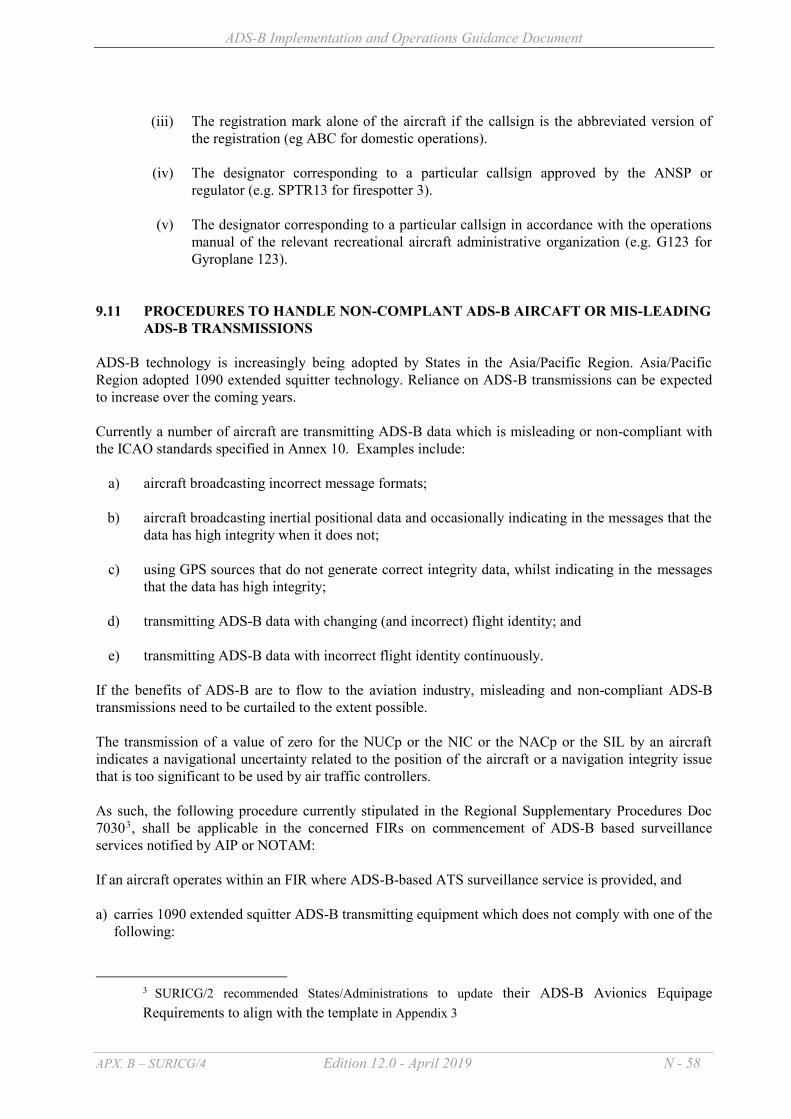
ADS-B Implementation and Operations Guidance Document
APX. B – SURICG/4 Edition 12.0 - April 2019 N - 58
(iii) The registration mark alone of the aircraft if the callsign is the abbreviated version of
the registration (eg ABC for domestic operations).
(iv) The designator corresponding to a particular callsign approved by the ANSP or regulator (e.g. SPTR13 for firespotter 3).
(v) The designator corresponding to a particular callsign in accordance with the operations
manual of the relevant recreational aircraft administrative organization (e.g. G123 for Gyroplane 123).
9.11 PROCEDURES TO HANDLE NON-COMPLANT ADS-B AIRCAFT OR MIS-LEADING ADS-B TRANSMISSIONS
ADS-B technology is increasingly being adopted by States in the Asia/Pacific Region. Asia/Pacific Region adopted 1090 extended squitter technology. Reliance on ADS-B transmissions can be expected to increase over the coming years. Currently a number of aircraft are transmitting ADS-B data which is misleading or non-compliant with the ICAO standards specified in Annex 10. Examples include:
a) aircraft broadcasting incorrect message formats;
b) aircraft broadcasting inertial positional data and occasionally indicating in the messages that the data has high integrity when it does not;
c) using GPS sources that do not generate correct integrity data, whilst indicating in the messages
that the data has high integrity;
d) transmitting ADS-B data with changing (and incorrect) flight identity; and
e) transmitting ADS-B data with incorrect flight identity continuously. If the benefits of ADS-B are to flow to the aviation industry, misleading and non-compliant ADS-B transmissions need to be curtailed to the extent possible. The transmission of a value of zero for the NUCp or the NIC or the NACp or the SIL by an aircraft indicates a navigational uncertainty related to the position of the aircraft or a navigation integrity issue that is too significant to be used by air traffic controllers. As such, the following procedure currently stipulated in the Regional Supplementary Procedures Doc 70303, shall be applicable in the concerned FIRs on commencement of ADS-B based surveillance services notified by AIP or NOTAM: If an aircraft operates within an FIR where ADS-B-based ATS surveillance service is provided, and a) carries 1090 extended squitter ADS-B transmitting equipment which does not comply with one of the
following:
3 SURICG/2 recommended States/Administrations to update their ADS-B Avionics Equipage Requirements to align with the template in Appendix 3

ADS-B Implementation and Operations Guidance Document
APX. B – SURICG/4 Edition 12.0 - April 2019 N - 59
1) EASA AMC 20-24; or 2) the equipment configuration standards in Appendix XI of Civil Aviation Order 20.18 of the
Civil Aviation Safety Authority of Australia; or 3) installation in accordance with the FAA AC No. 20-165 – Airworthiness Approval of ADS-B;
or b) the aircraft ADS-B transmitting equipment becomes unserviceable resulting in the aircraft
transmitting misleading information; then: a) except when specifically authorized by the appropriate ATS authority, the aircraft shall not fly unless
the equipment is: 1) deactivated; or 2) transmits only a value of zero for the NUCp or NIC or NACp or SIL States may elect to implement a scheme to blacklist those non-compliant aircraft or aircraft consistently transmitting mis-leading ADS-B information, so as to refrain the aircraft from being displayed to ATC. Please refer Appendix 2 for guidance in implementing the blacklist scheme. A sample template is given below for reference by States to publish the procedures to handle non-compliant ADS-B aircraft or misleading ADS-B transmissions in their ADS-B mandate/regulations: After <insert earliest date that ADS-B may be used for any relevant operational purpose> if an aircraft carries ADS-B transmitting equipment which does not comply with :
(a) European Aviation Safety Agency - Certification Considerations for the Enhanced ATS in Non-Radar Areas using ADS-B Surveillance (ADS-B-NRA) Application via 1090 MHZ Extended Squitter (AMC 20-24), or
(b) European Aviation Safety Agency - Certification Specifications and Acceptable Means of Compliance for Airborne Communications, Navigation and Surveillance Subpart D — Surveillance (SUR) (CS-ACNS.D.ADS-B), or
(c) Federal Aviation Administration – Advisory Circular No: 20-165A (or later versions) Airworthiness Approval of Automatic Dependent Surveillance – Broadcast (ADS-B) Out Systems, or
(d) the equipment configuration standards in Appendix XI of Civil Aviation Order 20.18 of the Civil Aviation Safety Authority of Australia.
or the aircraft ADS-B transmitting equipment becomes unserviceable resulting in the aircraft transmitting misleading information; the aircraft must not fly unless equipment is: (a) deactivated; or (b) set to transmit only a value of zero for the NUCp or NIC or NACp or SIL. Note: 1. It is considered equivalent to deactivation if NUCp or NIC or NACp or SIL is set to continually transmit only a value of zero.

ADS-B Implementation and Operations Guidance Document
APX. B – SURICG/4 Edition 12.0 - April 2019 N - 60
2. Regulators should take appropriate action to ensure that such regulations are complied with. 3. ATC systems should discard ADS-B data when NUC or NIC or NACp or SIL =0.

ADS-B Implementation and Operations Guidance Document
APX. B – SURICG/4 Edition 12.0 - April 2019 N - 61
9.12 EMERGENCY PROCEDURES ATC surveillance systems should provide for the display of safety-related alerts and warnings, including conflict alert, minimum safe altitude warning, conflict prediction and unintentionally duplicated SSR codes and aircraft identifications. The ADS-B avionics may transmit emergency status messages to any ADS-B ground station within coverage. The controller receiving these messages should determine the nature of the emergency, acknowledge receipt if appropriate, and initiate any assistance required. An aircraft equipped with ADS-B might operate the emergency and/or urgency mode as follows:
a) emergency; b) no communications; c) unlawful interference; d) minimum fuel; and/or e) medical.
Selection of an emergency transponder code (e.g. 7600) automatically generates an emergency indication in the ADS-B message. However, some ADS-B transponders may only generate a generic emergency indication. That means, the specific type of emergency, e.g., communication failure, is not always conveyed to the controller in an ADS-B environment. The controller may only receive a generic emergency indication irrespective of the emergency codes being selected by the pilot. In some early ADS-B avionics configurations, when a generic emergency indication is being transmitted, a request to “Transmit ADS-B Ident” or “Squawk Ident” may not result in the Ident indication being displayed in the ATC System. This is because the emergency and ident flags share the same data elements in the ADS-B downlink message. Due to limitations of some ADS-B transponders, procedures should be developed for ATC to confirm the types of emergency with pilots based on operational needs of States. In contrast to DO260 avionics, for DO-260A avionics, the transmission of an Emergency/Priority status message in the ADS-B message set will also include the original MODE A code allocated by ATC. When the aircraft resets the MODE A code to the original allocated code the ground station can retain the Emergency/Priority status in the Asterix message, for up to 100 seconds, even though the aircraft is no longer squawking an emergency code. This situation can generate confusion as to the actual status of the aircraft. Executive control responsibility The responsibility for control of the flight rests with the ATSU within whose airspace the aircraft is operating. However, if the pilot takes action contrary to a clearance that has already been coordinated with another sector or ATSU and further coordination is not possible in the time available, the responsibility for this action would rest with the pilot in command, and performed under the pilot’s emergency authority. Emergency procedures The various circumstances surrounding each emergency situation preclude the establishment of exact detailed procedures to be followed. The procedures outlined in PANS-ATM Chapter 15 provide a general guide to air traffic services personnel and where necessary, should be adapted for the use of ADS-B.

ADS-B Implementation and Operations Guidance Document
APX. B – SURICG/4 Edition 12.0 - April 2019 N - 62
9.13 PROCEDURES TO HANDLE GPS TIME AND WEEK COUNTER ROLLOVER The GPS system is often used in the ATC environment, including:
- to time stamp surveillance data with the “time of applicability” of the data. This allows positional data to be “extrapolated” to the time of display and allows old data to be discarded.
- to time synchronise ATC systems to the correct time, so that when it uses surveillance data, it can determine the “age” of the data.
- to time stamp recorded data and maintenance data
Thus accurate time is important to minimise incorrect positional data being presented to ATC and to ensure that valid data is not discarded – amongst other important technical roles in synchronising various computer servers in a network. 9.13.1 GPS TIME – COUNTERS AND LEAP SECONDS The GPS navigation message contains information about the current date and time in the form of a sequential week counter (representing the number of weeks elapsed since the last time this counter was reset to zero). This counter is 10 bits long and this resets to zero every 1024 weeks (19.6 years). GPS week zero started at 00:00:00 UTC on January 6, 1980, and the week number became zero again on August 21, 1999. A rollover event occurred on 6 April 2019. ATC systems use UTC. The difference between GPS time and UTC changes whenever a “leap second” is inserted in UTC. Wikipedia says that “one-second adjustment that is occasionally applied to civil time Coordinated Universal Time (UTC) to keep it close to the mean solar time at Greenwich, in spite of the Earth's rotation slowdown and irregularities”. This is done in coordination with the international community. The GPS messages sent by the satellites includes the difference between GPS time and UTC, thus allowing the GPS receivers to calculate UTC. 9.13.2 GPS RECEIVER ISSUES Each GPS receiver has firmware/software that computes UTC from the GPS time counters and from the known offset. In the past some GPS receivers have not coped well with these changes. The triggers occur very infrequently and in some cases they have not been adequately tested. This can cause incorrect UTC time to be output following some events such as:
- Software deficiencies highlighted by the week number rollover. The rollover occurs each 19.6 years
- Deficiencies at leap second introductions (at intervals greater than 1 year)
- Loss of GPS-UTC time offset (sometimes at power off in devices not using non-volatile
storage). Typically this can result in up to 15 minutes of incorrect time data until the offset is restored from the satellite messages.
Other problems such as receiver lock up (service failure) can occur when the GPS receiver is exposed to rare real world events or stimuli.

ADS-B Implementation and Operations Guidance Document
APX. B – SURICG/4 Edition 12.0 - April 2019 N - 63
9.13.3 ATC SYSTEM RISKS AND MITIGATION ANSPs and regulators need to be aware of the potential issues that may arise from GPS receivers that inadequately process events and stimuli. Possible mitigations that could be considered include:
- Testing GPS receivers with a GPS test tool that simulates possible events/ stimuli
- Co-ordination with GPS receiver manufacturers
- Disconnect GPS receivers just before expected events – and check the output before reconnecting the GPS receiver. (in this case the ANSP would be relying on the ability of the ATC or surveillance system to operate for a period without the GPS synchronisation).
10. SECURITY ISSUES ASSOCIATED WITH ADS-B 10.1 INTRODUCTION ADS-B technologies are currently “open systems” and the openness is an essential component of successful use of ADS-B. It was also noted that ADS-B transmission from commercial aircraft is a “fact of life” today. Many commercial aircraft are already equipped with ADS-B and have been transmitting data for some time. It was noted that there has been considerable alarmist publicity regarding ADS-B security. To a large extent, this publicity has not considered the nature and complexity of ATC. Careful assessment of security policies in use today for ADS-B and other technologies can provide a more balanced view. 10.2 CONSIDERATIONS A list of ADS-B vulnerabilities categorised into threats to Confidentiality, Integrity and Availability has been reviewed and documented into the guidance material on security issues associated with ADS-B provided on the ICAO APAC website “http://www.icao.int/APAC/Pages/edocs.aspx” under “Restricted Site” for reference by States. States could contact ICAO Regional Office to get access to the guidance material. The following recommendations are made to States :
(a) While ADS-B is recognized as a key enabling technology for aviation with potential safety benefits, it is recommended that States made aware of possible ADS-B security specific issues;
(b) It is recommended that States note that much of the discussion of ADS-B issues in the Press has not considered the complete picture regarding the ATC use of surveillance data;
(c) For current ADS-B technology implementation, security risk assessment studies should be made in coordination with appropriate national organisations and ANSPs to address appropriate mitigation applicable in each operational environment, in accordance with ATM interoperability requirements; and
(d) Future development of ADS-B technology, as planned in the SESAR master plan for example, should address security issues. Studies should be made to identify potential encryption and authentication techniques, taking into consideration the operational need of

ADS-B Implementation and Operations Guidance Document
APX. B – SURICG/4 Edition 12.0 - April 2019 N - 64
air to ground and air to air surveillance applications. Distribution of encryption keys to a large number of ADS-B receivers is likely to be problematic and solutions in the near and medium term are not considered likely to be deployed worldwide. Internet based encryption strategies are not deployable when ground stations are pass receivers.
_ _ _ _ _ _ _ _ _ _ _ _ _ _ _

ADS-B Implementation and Operations Guidance Document
APX. B – SURICG/4 Edition 12.0 - April 2019 Appendix 1 - 1
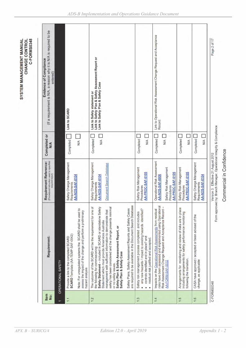
ADS-B Implementation and Operations Guidance Document
APX. B – SURICG/4 Edition 12.0 - April 2019 Appendix 1 - 2

ADS-B Implementation and Operations Guidance Document
APX. B – SURICG/4 Edition 12.0 - April 2019 Appendix 1 - 3

ADS-B Implementation and Operations Guidance Document
APX. B – SURICG/4 Edition 12.0 - April 2019 Appendix 1 - 4
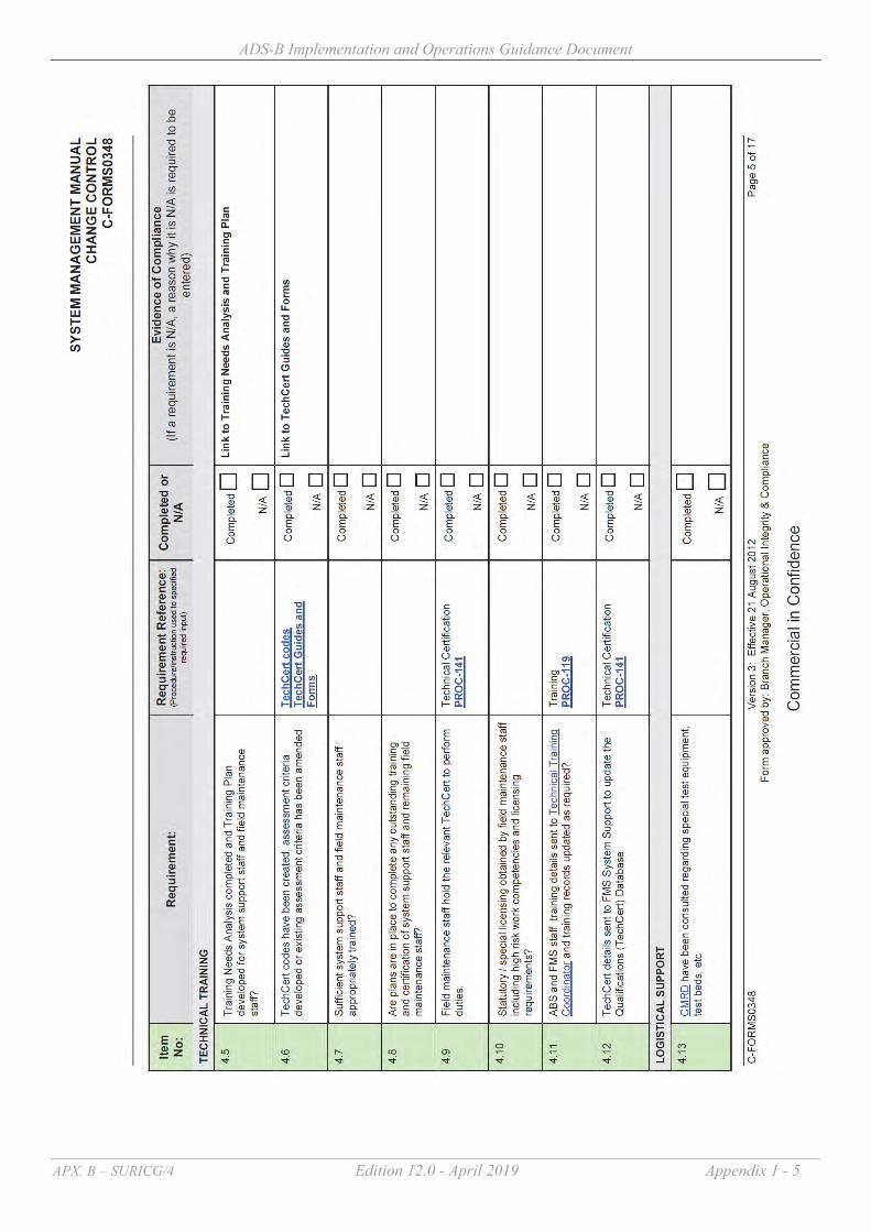
ADS-B Implementation and Operations Guidance Document
APX. B – SURICG/4 Edition 12.0 - April 2019 Appendix 1 - 5

ADS-B Implementation and Operations Guidance Document
APX. B – SURICG/4 Edition 12.0 - April 2019 Appendix 1 - 6

ADS-B Implementation and Operations Guidance Document
APX. B – SURICG/4 Edition 12.0 - April 2019 Appendix 1 - 7

ADS-B Implementation and Operations Guidance Document
APX. B – SURICG/4 Edition 12.0 - April 2019 Appendix 1 - 8
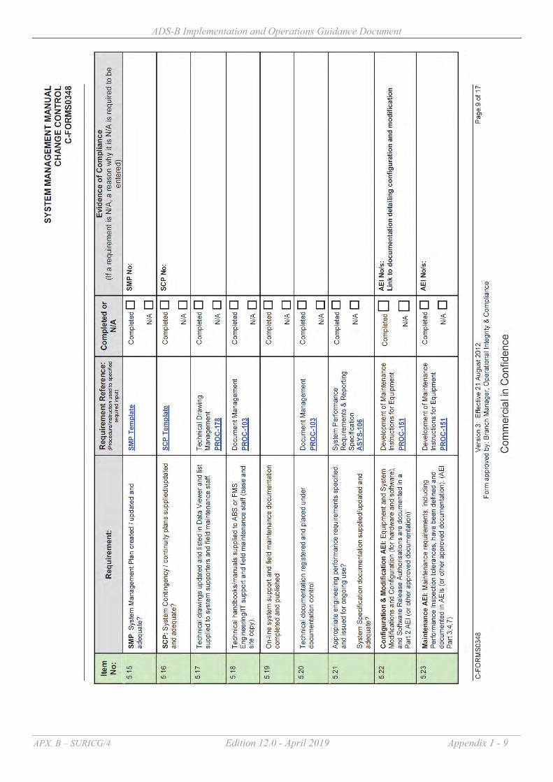
ADS-B Implementation and Operations Guidance Document
APX. B – SURICG/4 Edition 12.0 - April 2019 Appendix 1 - 9

ADS-B Implementation and Operations Guidance Document
APX. B – SURICG/4 Edition 12.0 - April 2019 Appendix 1 - 10

ADS-B Implementation and Operations Guidance Document
APX. B – SURICG/4 Edition 12.0 - April 2019 Appendix 1 - 11

ADS-B Implementation and Operations Guidance Document
APX. B – SURICG/4 Edition 12.0 - April 2019 Appendix 1 - 12
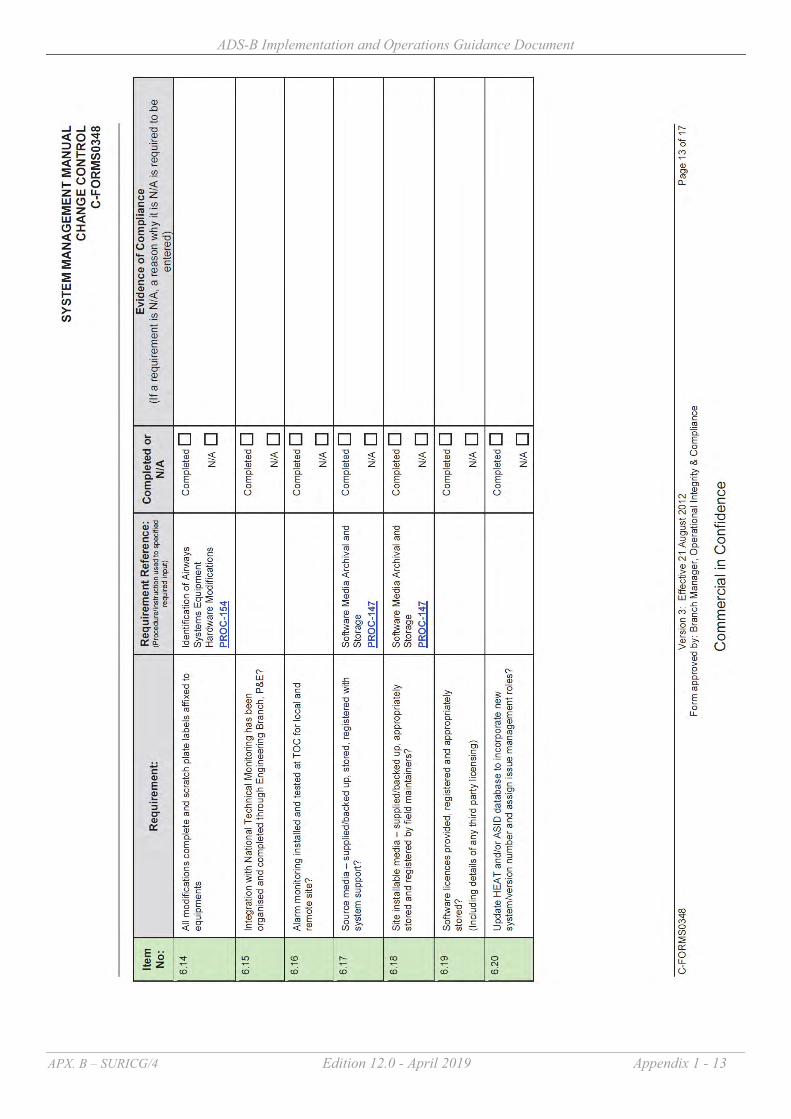
ADS-B Implementation and Operations Guidance Document
APX. B – SURICG/4 Edition 12.0 - April 2019 Appendix 1 - 13

ADS-B Implementation and Operations Guidance Document
APX. B – SURICG/4 Edition 12.0 - April 2019 Appendix 1 - 14

ADS-B Implementation and Operations Guidance Document
APX. B – SURICG/4 Edition 12.0 - April 2019 Appendix 1 - 15
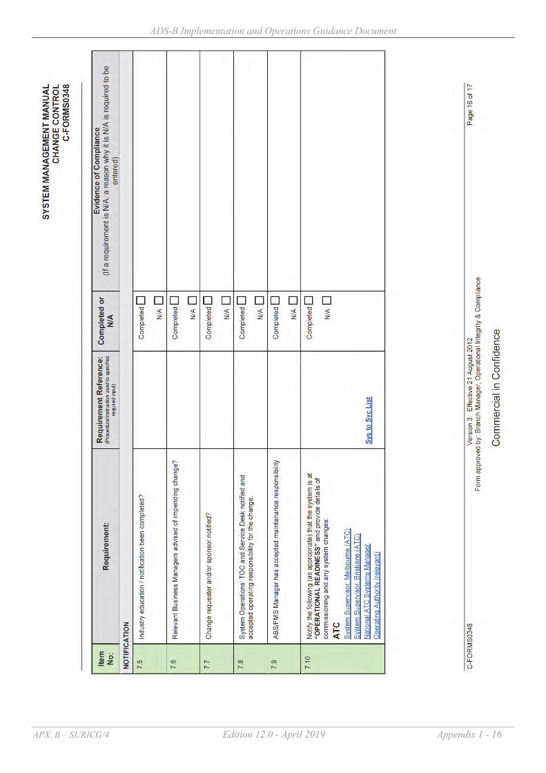
ADS-B Implementation and Operations Guidance Document
APX. B – SURICG/4 Edition 12.0 - April 2019 Appendix 1 - 16
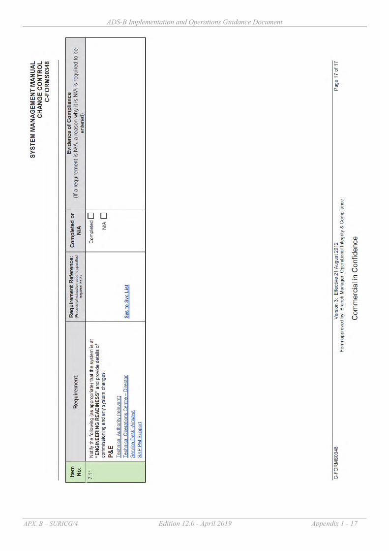
ADS-B Implementation and Operations Guidance Document
APX. B – SURICG/4 Edition 12.0 - April 2019 Appendix 1 - 17

ADS-B Implementation and Operations Guidance Document
APX. B – SURICG/4 Edition 12.0 - April 2019 Appendix 1 - 18
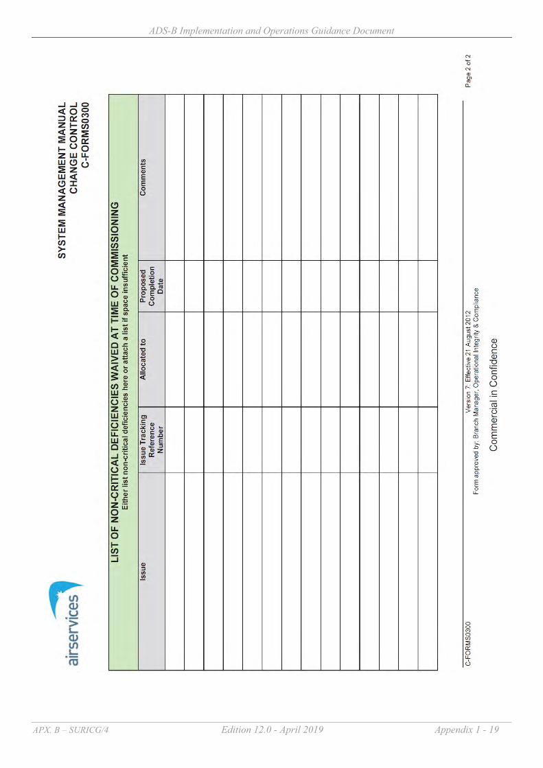
ADS-B Implementation and Operations Guidance Document
APX. B – SURICG/4 Edition 12.0 - April 2019 Appendix 1 - 19

ADS-B Implementation and Operations Guidance Document
Edition 12.0 April 2019 Appendix 2 - 1
Guidance Materials on Monitoring and Analysis of ADS-B Avionics Performance
1 Introduction
1.1 The APANPIRG has endorsed the following Conclusion during its 24th Meeting to encourage States/Administration to exchange their ADS-B performance monitoring results and experience gained from the process : Conclusion 24/45 - Exchange ADS-B Performance Monitoring Result “That, States be encouraged to exchange findings/result of their ADS-B performance monitoring including experience gained in conducting the required performance monitoring.”
1.2 Since the ADS-B mandate for some airspace in the Region became effective in
December 2013, monitoring and analysis on avionics performance of ADS-B equipped aircraft has become an increasingly important task for concerned States. The fully functional ADS-B Avionics Problem Reporting Database (APRD) was launched on the 21 July 2017. The database is placed at ICAO APAC website in the restricted area with name: APAC ADS-B Avionics Problem Reporting Database accessible via https://applications.icao.int/ADSB-APRD/login.aspx. States are encouraged to make full use of the APRD for reporting ADS-B avionics problems and sharing experience as well as follow-up actions through the APRD web-page.
1.3 This document serves to provide guidance materials on monitoring and analysis of avionics performance of ADS-B equipped aircraft, which is based on the experience gained by States.
2 Problem Reporting and Feedback 2.1 For ADS-B avionics problems, it is critical that an appropriate reporting and feedback
mechanism be established. It is highly desirable that those discovering the problems should report them to the appropriate parties to take action, such as study and analyse the problems, identify the root causes, and rectify them. Those action parties include :-
(a) Air Navigation Service Providers (ANSPs) – upon detection of any unacceptable
ADS-B reports from an aircraft, report the observed problem to the performance monitoring agent(s), if any, and the Aircraft Operators for investigation. In addition, ANSPs should take all actions to avoid using the ADS-B reports from the aircraft until the problem is rectified (e.g. black listing the aircraft), if usage of such reports could compromise safety.
(b) Regulators – to initiate any appropriate regulatory action or enforcement.
Appendix 2

ADS-B Implementation and Operations Guidance Document
Edition 12.0 April 2019 Appendix 2 - 2
(c) Aircraft Operators – to allow avionics specialists to examine the causes and as customers of the avionics manufacturers ensure that corrective action will take place.
(d) Avionics Manufacturers and Aircraft Manufacturers – to provide technical evidence and knowledge about the problem and problem rectification
2.2 Incentives should be received by those parties acting on the problems including :- (a) Regulations that require deficiencies to be rectified (b) Regulatory enforcement (c) Consequences if conduct of operations with problematic equipment (e.g. no access
to the airspace requiring healthy equipment)
2.3 When an ADS-B avionics problem is reported, it should come along with adequate details about the problem nature to the action parties. In addition, the problem should be properly categorised, so that appropriate parties could diagnose and rectify them systematically.
3 Problem Categorisation
3.1 Regarding ADS-B avionics, their problems are quite diversified in the Region but can
be categorized to ensure they will be examined and tackled systematically.
3.2 Based on the experience gained from States, the common ADS-B avionics problems in the Region are summarized under different categories in Attachment A. It is noted that only a relatively minor portion of the aircraft population exhibits these problems. It must be emphasized that aircraft transmitting incorrect positional data with NUC = 0 or NIC = 0 should not be considered a safety problem. The data transmitted have no integrity and shall not be used by ATC. This situation exists for many aircraft when their GNSS receivers are not connected to the transponders.
4 Managing the Problem 4.1 There are two major approaches to manage the problems :-
(a) Regulatory approach Regulations which require non-approved avionics to disable ADS-B transmission (or transmit “no integrity”), and the concerned operators to file flight plans to indicate no ADS-B equipage. APANPIRG has endorsed this approach which is reflected in the Regional Supplementary Procedures (Doc 7030).
(b) Blacklist approach Filtering out (“black listing”) any airframes that do not comply with the regulations or transmitting bad data, and advising the regulator of the non-
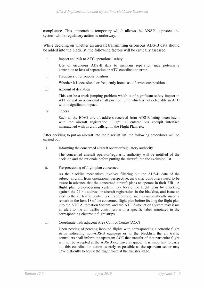
ADS-B Implementation and Operations Guidance Document
Edition 12.0 April 2019 Appendix 2 - 3
compliance. This approach is temporary which allows the ANSP to protect the system whilst regulatory action is underway. While deciding on whether an aircraft transmitting erroneous ADS-B data should be added into the blacklist, the following factors will be critically assessed:
i. Impact and risk to ATC operational safety
Use of erroneous ADS-B data to maintain separation may potentially contribute to loss of separation or ATC coordination error.
ii. Frequency of erroneous position
Whether it is occasional or frequently broadcast of erroneous position.
iii. Amount of deviation
This can be a track jumping problem which is of significant safety impact to ATC or just an occasional small position jump which is not detectable in ATC with insignificant impact.
iv. Others
Such as the ICAO aircraft address received from ADS-B being inconsistent with the aircraft registration, Flight ID entered via cockpit interface mismatched with aircraft callsign in the Flight Plan, etc.
After deciding to put an aircraft into the blacklist list, the following procedures will be carried out:
i. Informing the concerned aircraft operator/regulatory authority
The concerned aircraft operator/regularity authority will be notified of the decision and the rationale before putting the aircraft into the exclusion list.
ii. Pre-processing of flight plan concerned
As the blacklist mechanism involves filtering out the ADS-B data of the subject aircraft, from operational perspective, air traffic controllers need to be aware in advance that the concerned aircraft plans to operate in their FIR. A flight plan pre-processing system may locate the flight plan by checking against the 24-bit address or aircraft registration in the blacklist, and issue an alert to the air traffic controllers if appropriate, such as automatically insert a remark in the Item 18 of the concerned flight plan before feeding the flight plan into the ATC Automation System, and the ATC Automation System may issue an alert to the air traffic controllers with a specific label annotated in the corresponding electronic flight strips.
iii. Coordinate with adjacent Area Control Centre (ACC)
Upon posting of pending inbound flights with corresponding electronic flight strips indicating non-ADS-B equipage or in the blacklist, the air traffic controllers shall inform the upstream ACC that transfer of that particular flight will not be accepted at the ADS-B exclusive airspace. It is important to carry out this coordination action as early as possible as the upstream sector may have difficulty to adjust the flight route at the transfer stage.

ADS-B Implementation and Operations Guidance Document
Edition 12.0 April 2019 Appendix 2 - 4
iv. Handling of an aircraft for removal from the blacklist once rectification action had taken place
Once notification from the aircraft operators/regulatory authorities is received that the problem has been rectified, performance of the aircraft will be closely monitored when it flies to the concerned FIR. If the aircraft shows the observed problem has been resolved, the aircraft will be removed from the blacklist. The aircraft operator/regulatory authority will also be notified accordingly.
5 Systematic Monitoring and Analysis of the Problem
States using ADS-B should have in place systematic ways to identify and manage ADS-B deficiencies similar to that described below :-
5.1 Reporting Deficiencies
States using ADS-B should have in place systematic ways to identify ADS-B deficiencies including :- (a) Systematic capture of ATC reported events and engineering detected events into a
database; and (b) Manual or automatic detection of anomalous avionics behavior independent from
controller reports
5.1.1 ATC Reported Deficiencies ATC procedures should exist that allow services to continue to be provided safety, as
well as to capture relevant information for later analysis. This should include :-
(a) ATC request for the pilot to select the alternate transponder; and (b) ATC to adequately record the circumstances including Flight ID, ICAO Aircraft
Address (if readily available) accurate time, Flight plan, and pilot provided information.
5.1.2 Non ATC reported deficiencies
5.1.2.1 Where capability is available, States should also identify non ATC reported
deficiencies.
5.1.2.2 Without overlapping radar coverage: ADS-B data may be examined for the following :- (a) NUCp of each ADS-B reported position is smaller than required for service
delivery for more than 5% of total number of ADS-B updates; (b) NIC, NACp, SIL are smaller than required for service delivery for more than 5%
of total number of ADS-B updates;

ADS-B Implementation and Operations Guidance Document
Edition 12.0 April 2019 Appendix 2 - 5
(c) ICAO Aircraft Address (i.e. I021/080) is inconsistent with the flight planned registration (REG) based on each state’s ICAO Aircraft Address allocation methodology;
(d) Flight ID entered via cockpit interface and downlinked in ADS-B data (i.e. I021/170 in Asterix CAT 21) is a mismatch1 with aircraft callsign in the ATS Flight Plan;
(e) Inconsistent vertical rate compared to flight level change; and (f) Inconsistency of position reports and presence of "jumps.
5.1.2.3 Overlapping radar coverage: For States that have overlapping radar coverage, a systematic means to monitor and analyze ADS-B could be considered in addition to relying on ATC to report the problem, or utilising the evaluation criteria in 5.1.2.2 above. This can be achieved by comparing radar information with ADS-B reported position, velocity, flight level and vertical rate change data as well as examining the ADS-B quality indicators and Flight Identification (FLTID) contained in the ADS-B reports. For each ADS-B flight, its ADS-B data could be compared with its corresponding radar information. For example, this would allow analysis to determine if the following pre-defined criteria are met :- (a) Deviation between ADS-B reported position and independent referenced radar
position is greater than 1NM2, with the indication of good positional quality in the quality indicators for more than 5% of total number ADS-B updates. A sample screen shot of a system performing the analysis automatically is given at Attachment B for reference.
5.2 Managing and Processing Deficiencies
Whether detected by ATC or not, all deficiencies should trigger:
(a) Systematic recording of the details of each occurrence such as date/time of occurrence, ICAO aircraft address and flight plan information should be obtained. Graphical representations such as screen capture of radar and ADS-B history
1 A missing Flight ID, or a Flight ID with only “spaces” should not be considered a mismatch. 2 For example, the deviation between ADS-B and radar tracks could be set to 1NM in accordance with ICAO Circular 326 defining position integrity (0.5NM < HPL < 1NM) for 3NM aircraft separation use, on assumption that radar targets are close to actual aircraft position. The values of ADS-B quality indicators (NUCp, NACp, SIL, NIC) could be chosen based on the definition in ICAO Circular 326 on Position Accuracy and Position Integrity for 3NM aircraft separation minimum. A threshold of 5% is initially set to exclude aircraft only exhibiting occasional problems during their flight journey. The

ADS-B Implementation and Operations Guidance Document
Edition 12.0 April 2019 Appendix 2 - 6
tracks, graphs of NUCp/NIC value changes versus time and deviation between radar and ADS-B tracks along the flight journey would be desirable. Examples of typical graphical representations are shown below :-
`
(b) Systematic technical analysis of each detected issue using ADS-B recorded data, to ensure that all detected issues are examined and addressed. Typically this will need: systems to record ADS-B data, replay ADS-B data and analyze ADS-B data staff and procedures to analyze each report A database system to manage the status of each event and to store the results of
each analysis
above criteria should be made configurable to allow fine-turning in future. Evaluation of ADS-B vs radar may alternatively expose radar calibration issues requiring further investigation.

ADS-B Implementation and Operations Guidance Document
Edition 12.0 April 2019 Appendix 2 - 7
(c) Procedures to support engagement with operators (domestic & foreign), regulators, other ANSPs, Airframe OEMs and avionics vendors to ensure that each issue is investigated adequately and maximize the probability that the root cause of the event is determined. The procedures could include :- Data collection procedures; Telephone & email contact details; and Mechanisms for reporting, as appropriate, to the Asia Pacific ADS-B Avionics
Problem Reporting Database (APRD)
* * * * * * * *
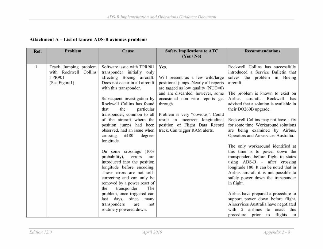
ADS-B Implementation and Operations Guidance Document
Edition 12.0 April 2019 Appendix 2 - 8
Attachment A – List of known ADS-B avionics problems
Ref. Problem Cause Safety Implications to ATC
(Yes / No)
Recommendations
1. Track Jumping problem with Rockwell Collins TPR901 (See Figure1)
Software issue with TPR901 transponder initially only affecting Boeing aircraft. Does not occur in all aircraft with this transponder. Subsequent investigation by Rockwell Collins has found that the particular transponder, common to all of the aircraft where the position jumps had been observed, had an issue when crossing ±180 degrees longitude. On some crossings (10% probability), errors are introduced into the position longitude before encoding. These errors are not self-correcting and can only be removed by a power reset of the transponder. The problem, once triggered can last days, since many transponders are not routinely powered down.
Yes. Will present as a few wild/large positional jumps. Nearly all reports are tagged as low quality (NUC=0) and are discarded, however, some occasional non zero reports get through. Problem is very “obvious”. Could result in incorrect longitudinal position of Flight Data Record track. Can trigger RAM alerts.
Rockwell Collins has successfully introduced a Service Bulletin that solves the problem in Boeing aircraft. The problem is known to exist on Airbus aircraft. Rockwell has advised that a solution is available in their DO260B upgrade. Rockwell Collins may not have a fix for some time. Workaround solutions are being examined by Airbus, Operators and Airservices Australia. The only workaround identified at this time is to power down the transponders before flight to states using ADS-B – after crossing longitude 180. It can be noted that in Airbus aircraft it is not possible to safely power down the transponder in flight. Airbus have prepared a procedure to support power down before flight. Airservices Australia have negotiated with 2 airlines to enact this procedure prior to flights to

ADS-B Implementation and Operations Guidance Document
Edition 12.0 April 2019 Appendix 2 - 9
Ref. Problem Cause Safety Implications to ATC (Yes / No)
Recommendations
Australia. An additional partial workaround is : to ensure that procedures exist for ATC to ask the pilot to changeover transponders if the problem is observed. Since there is a 10% chance of the problem occurring on each crossing of ±180 degrees longitude, the chance that both transponders being affected is 1%. There is no complete workaround available for flights that operate across 180 degrees longitude directly to destination without replacing the transponder. Airbus advised that a new TPR901 transponder compliant with DO260B is available from December 2015. This new transponder does not have such problem.
2. Rockwell Collins TDR94 Old version. The pattern of erroneous positional data is very distinctive of the problem. (See Figure 2)
Old software typically before version -108. The design was completed before the ADS-B standards were established and the message definitions are different to the current DO260. Rockwell has recommended
Yes. Will present as a few wild positional jumps. Nearly all reports are tagged as low quality (NUC=0) and are discarded, however, some occasional non zero reports get through. Also causes incorrect altitude reports.
Problem well known. Particularly affects Gulfstream aircraft which unfortunately leave the factory with ADS-B enabled from this transponder model. Rockwell has issued a service bulletin recommending that ADS-B be disabled for aircraft with this

ADS-B Implementation and Operations Guidance Document
Edition 12.0 April 2019 Appendix 2 - 10
Ref. Problem Cause Safety Implications to ATC (Yes / No)
Recommendations
that ADS-B be disabled on these models.
Problem is very “obvious”.
transponder software. See Service Information Letter 1-05 July 19, 2005. It is easy to disable the transmission. If a new case is discovered, an entry needs to be made to the black list until rectification has been effected.
3. Litton GPS with proper RAIM processing
Litton GNSSU (GPS) Mark 1 design problem. (Does not apply to Litton Mark II). GPS does not output correct messages to transponder.
No. Perceived GPS integrity changes seemingly randomly. With the GPS satellite constellation working properly, the position data is good. However the reported integrity is inconsistent and hence the data is sometimes/often discarded by the ATC system. The effected is perceived extremely poor “coverage”. The data is not properly “protected” against erroneous satellite ranging signals – although this cannot be “seen” by ATC unless there is a rare satellite problem.
This GPS is installed in some older, typically Airbus, fleets. Data appears “Correct” but integrity value can vary. Performance under “bad” satellite conditions is a problem. Correction involves replacing the GNSSU (GPS) which is expensive. If a new case is discovered, an entry needs to be made to the black list until rectification has been effected.
4. SIL programming error for DO260A avionics
Installers of ADS-B avionics using the newer DO260A standard mis program “SIL”. a) This problem appears for
No. First report of detection appears good (and is good), all subsequent reports not displayed because the
Would NOT be included in a “black list”. Aircraft with “Dynon avionics” exhibit this behavior. They do not

ADS-B Implementation and Operations Guidance Document
Edition 12.0 April 2019 Appendix 2 - 11
Ref. Problem Cause Safety Implications to ATC (Yes / No)
Recommendations
DO260A transponders, with SIL incorrectly set to 0 or 1 (instead of 2 or 3) b) As the aircraft enters coverage, the ADS-B ground station correctly assumes DO260 until it receives the version number. c) The transmitted NIC (DO260A) is interpreted as a good NUC (DO260) value, because no SIL message has yet been received. The data is presented to ATC.
data quality is perceived as “bad” by the ATC system. Operational effect is effectively no ADS-B data. Hence no risk.
have a certified GPS and hence always set SIL = 0. This is actually correct but hence they do not get treated as ADS-B equipped.
5. Garmin “N” Flight ID problem (See Figure 3)
Installers of Garmin transponder incorrectly set “Callsign”/Flight ID. This is caused by poor human factors and design that assumes that GA aircraft are US registered.
Yes. Flight ID appears as “N”. Inhibits proper coupling.
Can be corrected by installer manipulation of front panel. Does not warrant “black list” activity.
6. Flight ID corruption issue 1 – trailing “U” Flight ID’s received : GT615, T615U ,NEB033, NEB033U, QF7550, QF7550U, QF7583, QF7583U, QF7585,
TPR901 software problem interfacing with Flight ID source. Results in constantly changing Flight ID with some reports having an extra “U” character.
Yes. Flight ID changes during flight inhibits proper coupling or causes decoupling.
Affects mainly B747 aircraft. Boeing SB is available for Rockwell transponders and B744 aircraft. Rockwell Collins have SB 503 which upgrades faulty -003 transponder to -005 standard.

ADS-B Implementation and Operations Guidance Document
Edition 12.0 April 2019 Appendix 2 - 12
Ref. Problem Cause Safety Implications to ATC (Yes / No)
Recommendations
QF7585, QF7585U, QF7594, QFA7521, QFA7531, QFA7531, QFA7531U, QFA7532, QFA7532U, QFA7532W, QFA7550, QFA7552, QFA7581
If a new case is discovered, an entry needs to be made to the black list until rectification has been effected.
7. Flight ID corruption issue 2
ACSS software problem results in constantly changing Flight ID. Applies to ACSS XS950 transponder Pn 7517800- 110006 and Honeywell FMC (pn 4052508 952). ACSS fix was available in Sept 2007.
Yes. Flight ID changes during flight inhibits proper coupling or causes decoupling.
Software upgrade available. If a new case is discovered, an entry needs to be made to the black list until rectification has been effected.
8. No Flight ID transmitted Various causes No. Flight ID not available. Inhibits proper coupling.
Aircraft could “fail to couple with Flight Data Record”. Not strictly misleading – but could cause controller distraction.
9. ACSS Transponder 10005/6 without Mod A reports NUC based on HFOM.
Yes. Appears good in all respects until there is a satellite constellation problem (not normally detectable by ground systems).
Not approved and hence not compliant with CASA regulations. If known could be added to black list. Configuration is not permitted by regulation.
10. Occasional small position jump backwards (See Figure 4)
For some older Airbus aircraft, an occasional report may exhibit a small “jump
No. Not detectable in ATC due to
ATC ground system processing can eliminate these.

ADS-B Implementation and Operations Guidance Document
Edition 12.0 April 2019 Appendix 2 - 13
Ref. Problem Cause Safety Implications to ATC (Yes / No)
Recommendations
back” of less than 0.1 nm Root cause not known
extrapolation, use of latest data and screen ranges used.
11. Older ACSS transponders report integrity too conservatively
Design error reports integrity one value worse than reality
No. In poor GPS geometry cases the ATC system could discard the data when the data is in fact useable. Will be perceived as loss of ADS-B data.
Can be treated in the same manner as a loss of transponder capability.
12. Intermittent wiring GPS transponder
ADS-B transmissions switch intermittently between INS position and GPS position.
Yes. Normally the integrity data goes to zero when INS is broadcast, but sometimes during transition between INS and GPS, an INS position or two can be broadcast with “good” NUC value. Disturbing small positional jump.
If a new case is discovered, an entry needs to be made to the black list until rectification has been effected.
13. Wrong ICAO Aircraft Address
Installation error No. No direct ATC impact unless a rare duplicate is detected.
This is not a direct ADS-B problem, but relates to a Mode S transponder issue that can put TCAS at risk. Cannot be fixed by black list entry. Needs to be passed to regulator for resolution.
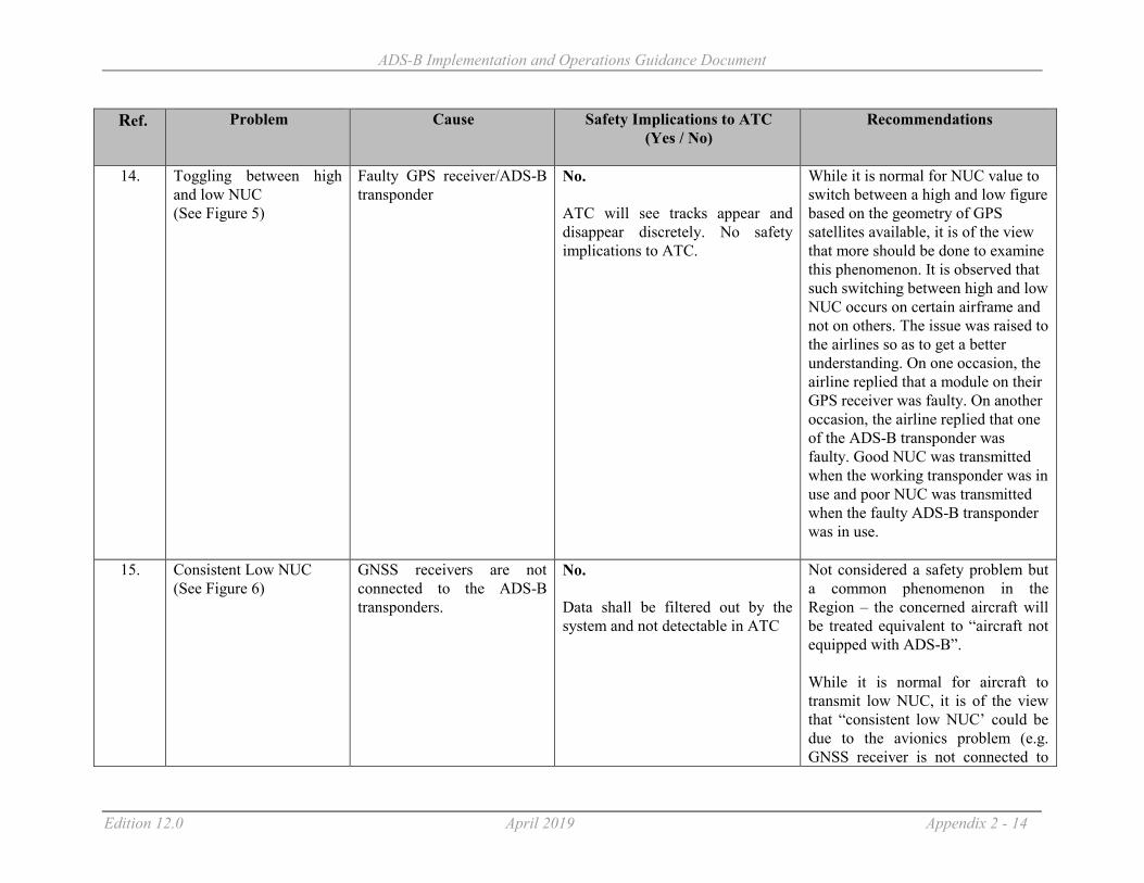
ADS-B Implementation and Operations Guidance Document
Edition 12.0 April 2019 Appendix 2 - 14
Ref. Problem Cause Safety Implications to ATC (Yes / No)
Recommendations
14. Toggling between high and low NUC (See Figure 5)
Faulty GPS receiver/ADS-B transponder
No. ATC will see tracks appear and disappear discretely. No safety implications to ATC.
While it is normal for NUC value to switch between a high and low figure based on the geometry of GPS satellites available, it is of the view that more should be done to examine this phenomenon. It is observed that such switching between high and low NUC occurs on certain airframe and not on others. The issue was raised to the airlines so as to get a better understanding. On one occasion, the airline replied that a module on their GPS receiver was faulty. On another occasion, the airline replied that one of the ADS-B transponder was faulty. Good NUC was transmitted when the working transponder was in use and poor NUC was transmitted when the faulty ADS-B transponder was in use.
15. Consistent Low NUC (See Figure 6)
GNSS receivers are not connected to the ADS-B transponders.
No. Data shall be filtered out by the system and not detectable in ATC
Not considered a safety problem but a common phenomenon in the Region – the concerned aircraft will be treated equivalent to “aircraft not equipped with ADS-B”. While it is normal for aircraft to transmit low NUC, it is of the view that “consistent low NUC’ could be due to the avionics problem (e.g. GNSS receiver is not connected to
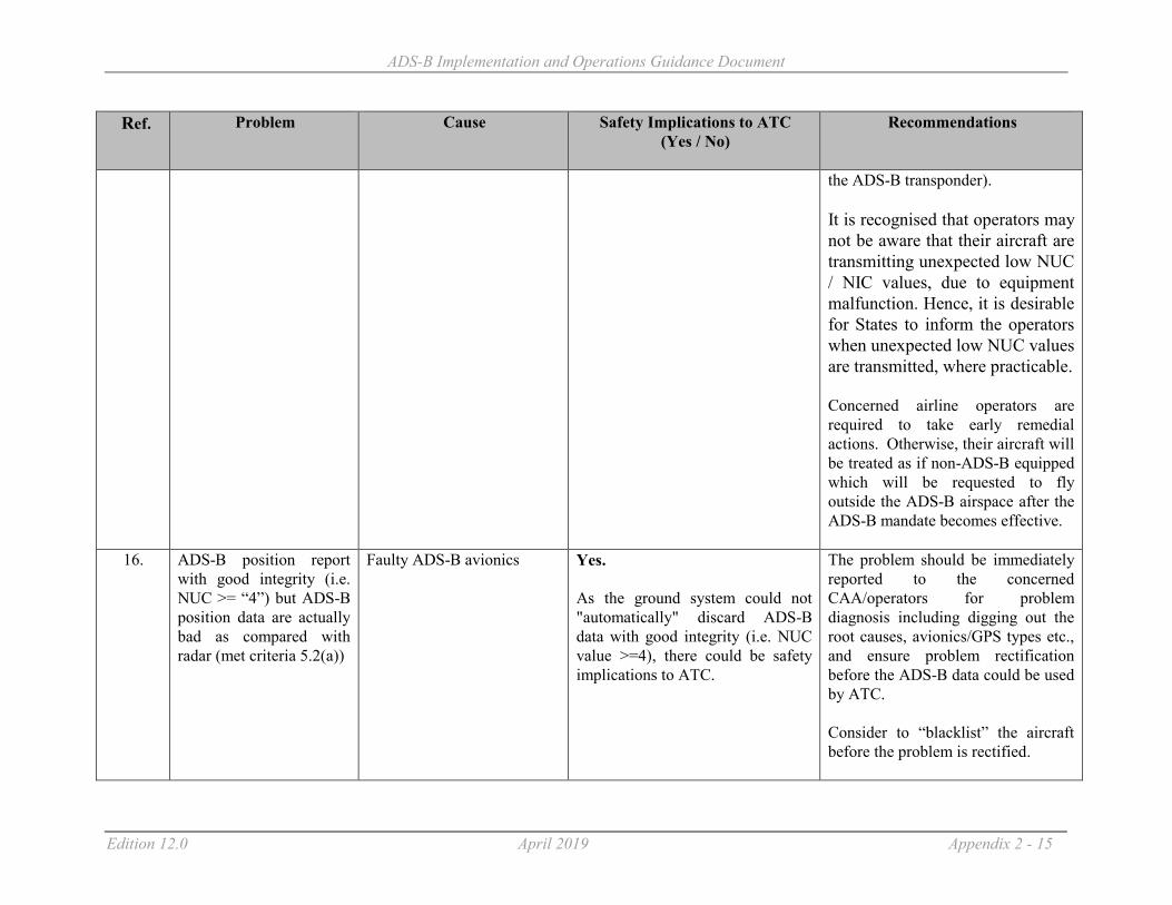
ADS-B Implementation and Operations Guidance Document
Edition 12.0 April 2019 Appendix 2 - 15
Ref. Problem Cause Safety Implications to ATC (Yes / No)
Recommendations
the ADS-B transponder). It is recognised that operators may not be aware that their aircraft are transmitting unexpected low NUC / NIC values, due to equipment malfunction. Hence, it is desirable for States to inform the operators when unexpected low NUC values are transmitted, where practicable. Concerned airline operators are required to take early remedial actions. Otherwise, their aircraft will be treated as if non-ADS-B equipped which will be requested to fly outside the ADS-B airspace after the ADS-B mandate becomes effective.
16. ADS-B position report with good integrity (i.e. NUC >= “4”) but ADS-B position data are actually bad as compared with radar (met criteria 5.2(a))
Faulty ADS-B avionics Yes. As the ground system could not "automatically" discard ADS-B data with good integrity (i.e. NUC value >=4), there could be safety implications to ATC.
The problem should be immediately reported to the concerned CAA/operators for problem diagnosis including digging out the root causes, avionics/GPS types etc., and ensure problem rectification before the ADS-B data could be used by ATC. Consider to “blacklist” the aircraft before the problem is rectified.

ADS-B Implementation and Operations Guidance Document
Edition 12.0 April 2019 Appendix 2 - 16
Ref. Problem Cause Safety Implications to ATC (Yes / No)
Recommendations
17. FLTID transmitted by ADS-B aircraft does not match with callsign in flight plan (see Figures 7a – 7d)
Human errors Yes. Could lead to screen clutter - two target labels with different IDs (one for radar and another for ADS-B) being displayed, causing potential confusion and safety implications to ATC.
Issue regulations/letters to concerned operators urging them to set FLTID exactly match with callsign in flight plan.
18 B787 position error with good NIC
Issue 1: Software issue - surveillance system inappropriately “coasts” the position when data received by the transponder is split across multiple messages. System seems to self correct after some time. Can be corrected by surveillance system power off. Issue 2: Data packets were not being distributed to the transponder when the internal timing between different elements of the Integrated Surveillance System became synchronized.
Yes. Misleading position presentation which is typically detected by ATC observing aircraft “off track” when in fact it is “on-track”.
Boeing performed a change to the B787 Type Certificate for incorporation of the upgraded ISS software in March of 2017. All B787 aircraft delivered after Line number 541 have the upgraded ISS software which corrects this issue. Boeing released Service Bulletin B787-81205-SB340036-00 on 30 June 2017. Note that this Service Bulletin is available at no cost to the operator, and includes the concurrent requirement to implement Boeing Service Bulletin B787-81205-SB340005-00. On 5 Nov 2018, FAA issued Airworthiness Directive 2017-NM-118-AD, effective 10 Dec 2018, which requires application of Boeing

ADS-B Implementation and Operations Guidance Document
Edition 12.0 April 2019 Appendix 2 - 17
Ref. Problem Cause Safety Implications to ATC (Yes / No)
Recommendations
SB B787-81205-SB340036-00 by 10 Dec 2019. EASA has invoked this AD for States under its jurisdiction. States and Operators are urged to implement the service bulletin immediately and report to FAA or ICAO APAC Office.
19 A number of airlines have reported or experienced ADS-B outages for complete flight sectors in A330 aircraft. Appears as low reliability ADS-B and has afflicted both A & B side at same time.
Being actively investigated. One airline has implemented on-board recording which confirms that the MMRs are not providing HIL/HPL to the transponder whilst continuing to provide HFOM, GPS alt etc
No. Equivalent to a failed transponder.
Aircraft must be managed procedurally if outside radar coverage.
20 A380 flight ID lost after landing
For the A380 fleet, it has been confirmed that for some seconds after landing, the flight ID is set as invalid by FMS to AESS. Consequently, the current AESS design uses, as per design, the Aircraft Registration Number as a back-up source for A/C flight identification field in ADS-B broadcast messages.
No.
The correction to this logic is planned for next AESS standard release; planned for 2017.” Only a problem for arriving aircraft on surface surveillance systems.
21 A350 ADS-B On-ground Performance
On departure, A350 aircraft will initially use INS derived position for ADS-B reports
Yes. where ADS-B is used for surface movement display
Airbus is in discussion with FAA and EUROCONTROL about this issue.
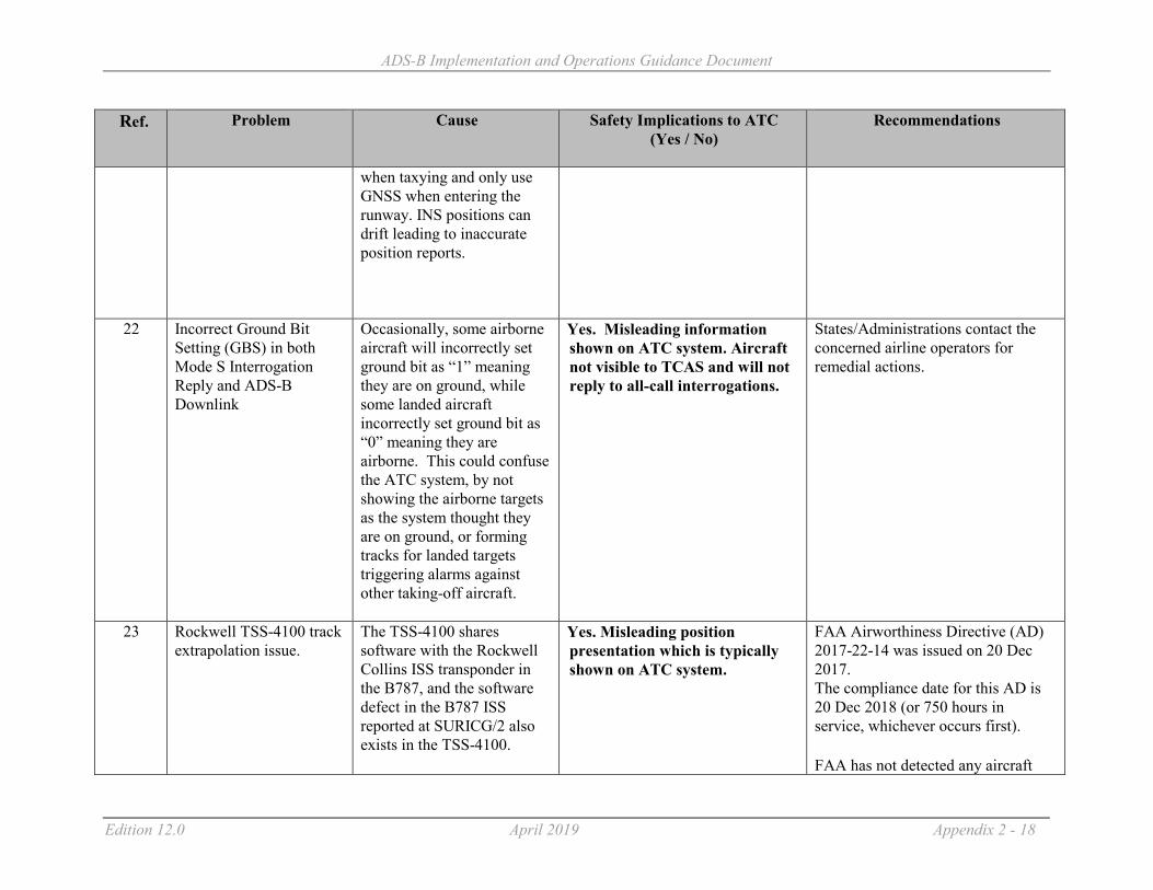
ADS-B Implementation and Operations Guidance Document
Edition 12.0 April 2019 Appendix 2 - 18
Ref. Problem Cause Safety Implications to ATC (Yes / No)
Recommendations
when taxying and only use GNSS when entering the runway. INS positions can drift leading to inaccurate position reports.
22
Incorrect Ground Bit Setting (GBS) in both Mode S Interrogation Reply and ADS-B Downlink
Occasionally, some airborne aircraft will incorrectly set ground bit as “1” meaning they are on ground, while some landed aircraft incorrectly set ground bit as “0” meaning they are airborne. This could confuse the ATC system, by not showing the airborne targets as the system thought they are on ground, or forming tracks for landed targets triggering alarms against other taking-off aircraft.
Yes. Misleading information shown on ATC system. Aircraft not visible to TCAS and will not reply to all-call interrogations.
States/Administrations contact the concerned airline operators for remedial actions.
23 Rockwell TSS-4100 track extrapolation issue.
The TSS-4100 shares software with the Rockwell Collins ISS transponder in the B787, and the software defect in the B787 ISS reported at SURICG/2 also exists in the TSS-4100.
Yes. Misleading position presentation which is typically shown on ATC system.
FAA Airworthiness Directive (AD) 2017-22-14 was issued on 20 Dec 2017. The compliance date for this AD is 20 Dec 2018 (or 750 hours in service, whichever occurs first). FAA has not detected any aircraft
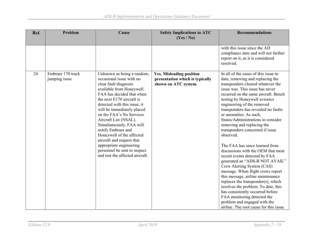
ADS-B Implementation and Operations Guidance Document
Edition 12.0 April 2019 Appendix 2 - 19
Ref. Problem Cause Safety Implications to ATC (Yes / No)
Recommendations
with this issue since the AD compliance date and will not further report on it, as it is considered resolved.
24 Embraer 170 track jumping issue
Unknown as being a random, occasional issue with no clear fault diagnosis available from Honeywell. FAA has decided that when the next E170 aircraft is detected with this issue, it will be immediately placed on the FAA’s No Services Aircraft List (NSAL). Simultaneously, FAA will notify Embraer and Honeywell of the affected aircraft and request that appropriate engineering personnel be sent to inspect and test the affected aircraft.
Yes. Misleading position presentation which is typically shown on ATC system.
In all of the cases of this issue to date, removing and replacing the transponders cleared whatever the issue was. This issue has never recurred on the same aircraft. Bench testing by Honeywell avionics engineering of the removed transponders has revealed no faults or anomalies. As such, States/Administrations to consider removing and replacing the transponders concerned if issue observed. The FAA has since learned from discussions with the OEM that most recent events detected by FAA generated an “ADS-B NOT AVAIL” Crew Alerting System (CAS) message. When flight crews report this message, airline maintenance replaces the transponder(s), which resolves the problem. To date, this has consistently occurred before FAA monitoring detected the problem and engaged with the airline. The root cause for this issue

ADS-B Implementation and Operations Guidance Document
Edition 12.0 April 2019 Appendix 2 - 20
Ref. Problem Cause Safety Implications to ATC (Yes / No)
Recommendations
remains unknown.
25 Airbus Single Aisle production wiring issue
FAA has observed 17 Airbus Single Aisle aircraft from two airlines with missing Length-Width Codes (LWC is a message element in DO-260B/ED-102A that is required by both the US and European mandates). FAA believes that this was a production line wiring issue.
No. Airbus released three Service Bulletins to correct this issue, which existed in 128 Airbus Single Aisle aircraft. As of 1-Dec-2018, all of the aircraft which operate at US airports with ADS-B surface surveillance were corrected. The FAA will not further report on this issue.
26 Boeing 777-300ER production wiring issue
FAA has observed at least 10 Boeing B777-300ER aircraft with missing or improper NACv/SDA/eCat/LWC message elements (these are message elements in DO-260B/ED-102A that are required by both the US and European mandates (eCat is FAA shorthand for Emitter Category). After notification, Boeing reported to FAA that this was a production line parity pin wiring issue.
No. On 7 July 2017, Boeing released Service Bulletin SB 777-34-0281 to correct this issue. Boeing has informed FAA that all affected B777 operators have been notified. The FAA will not further report on this issue.
27 Rockwell TSS-4100 Geometric Altitude Reporting as Pressure Altitude
This issue exists in any TSS-4100 installed with TSSA-4100 software RCPN 810-0052-100, RCPN 810-0052-
Yes. At present, the FAA regulator has determined that this issue occurs too rarely to warrant issuing an Airworthiness Directive or a Special
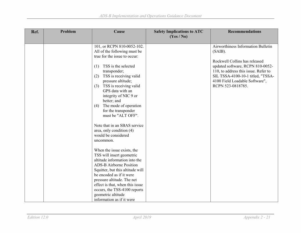
ADS-B Implementation and Operations Guidance Document
Edition 12.0 April 2019 Appendix 2 - 21
Ref. Problem Cause Safety Implications to ATC (Yes / No)
Recommendations
101, or RCPN 810-0052-102. All of the following must be true for the issue to occur: (1) TSS is the selected
transponder; (2) TSS is receiving valid
pressure altitude; (3) TSS is receiving valid
GPS data with an integrity of NIC 9 or better; and
(4) The mode of operation for the transponder must be "ALT OFF".
Note that in an SBAS service area, only condition (4) would be considered uncommon. When the issue exists, the TSS will insert geometric altitude information into the ADS-B Airborne Position Squitter, but this altitude will be encoded as if it were pressure altitude. The net effect is that, when this issue occurs, the TSS-4100 reports geometric altitude information as if it were
Airworthiness Information Bulletin (SAIB). Rockwell Collins has released updated software, RCPN 810-0052-110, to address this issue. Refer to SIL TSSA-4100-10-1 titled, "TSSA-4100 Field Loadable Software", RCPN 523-0818785.

ADS-B Implementation and Operations Guidance Document
Edition 12.0 April 2019 Appendix 2 - 22
Ref. Problem Cause Safety Implications to ATC (Yes / No)
Recommendations
pressure altitude. In many cases, this will be incorrect altitude information.
28 NACv reporting greater than 2
The FAA has detected a number of aircraft which consistently report NACv = 3 and NACv = 4. Per FAA AC 20-165B section 3.3.3.7.3, “A NACv = 3 or NACv = 4 should not be set based on GNSS velocity accuracy unless you can demonstrate to the FAA that the velocity accuracy actually meets the requirement.” EASA CS-ACNS states that “There is currently no established guidance on establishing a NACv performance of ‘three’ or better.” Therefore, it appears that there are improperly configured ADS-B installations operating in the U.S.
No. While there is no known urgent issue with these findings, as no known ATC or airborne application requires NACv values exceeding two, FAA does have long-term intentions of deploying surveillance tracking and alerting prediction algorithms in ATC automation which will use real-time NACv values. ICAO States planning to make similar improvements should be aware of this situation.

ADS-B Implementation and Operations Guidance Document
Edition 12.0 April 2019 Appendix 2 - 23
Figure 1 - Track Jumping problem with TPR901 Figure 3 - Garmin “N” Flight ID problem
Figure 2 - Rockwell Collins TDR94 Old version. The pattern of Figure 4 - Occasional small position jump backwards

ADS-B Implementation and Operations Guidance Document
Edition 12.0 April 2019 Appendix 2 - 24
erroneous positional data is very distinctive of the problem
Figure 5 - NUC value toggling Figure 6 – Consistent low NUC
NUC always 0

ADS-B Implementation and Operations Guidance Document
Edition 12.0 April 2019 Appendix 2 - 25
Figure 7a - Additional zero inserted Figure 7b - ICAO Airline Designator Code dropped
Figure 7c - Wrong numerical codes entered Figure 7d - IATA Airline Designator Code used
ADS-B
Radar
ADS-B
Radar
Radar
ADS-B ADS-B
Radar
NUC always 0

ADS-B Implementation and Operations Guidance Document
Edition 12.0 April 2019 Appendix 2 - 26
Attachment B - Sample screen shot of a system to monitor and analyse performance of ADS-B avionics

ADS-B Implementation and Operations Guidance Document
Edition 12.0 April 2019 Appendix 3 - 1
Appendix 3
A Template for ADS-B Mandate/Regulations for Aircraft Avionics
(1) On and after dd/mm/yyyy, if an aircraft carries 1090MHz extended squitter (1090ES) ADS-B transmitting equipment for operational use in xxxxxxxx territory, the equipment must have been certificated as meeting :1
(a) European Aviation Safety Agency - Certification Considerations for the Enhanced ATS in
Non-Radar Areas using ADS-B Surveillance (ADS-B-NRA) Application via 1090 MHZ Extended Squitter (AMC 20-24), or
(b) European Aviation Safety Agency - Certification Specifications and Acceptable Means of Compliance for Airborne Communications, Navigation and Surveillance Subpart D — Surveillance (SUR) (CS-ACNS.D.ADS-B), or
(c) Federal Aviation Administration – Advisory Circular No: 20-165A (or later versions) Airworthiness Approval of Automatic Dependent Surveillance – Broadcast (ADS-B) Out Systems, or
(d) the equipment configuration standards in Appendix XI of Civil Aviation Order 20.18 of the Civil Aviation Safety Authority of Australia.
(2) On and after dd/mm/yyyy, if an aircraft operates on airways (insert routes)…………at or above
FLXXX………(or in defined airspace boundaries ……………. at or above FLXXX):2
The aircraft must carry serviceable 1090MHz extended squitter (1090ES) ADS-B transmitting equipment that has been certificated as meeting :-
(a) European Aviation Safety Agency - Certification Considerations for the Enhanced ATS in
Non-Radar Areas using ADS-B Surveillance (ADS-B-NRA) Application via 1090 MHZ Extended Squitter (AMC 20-24), or
(b) European Aviation Safety Agency - Certification Specifications and Acceptable Means of Compliance for Airborne Communications, Navigation and Surveillance Subpart D — Surveillance (SUR) (CS-ACNS.D.ADS-B), or
(c) Federal Aviation Administration – Advisory Circular No: 20-165A (or later versions) Airworthiness Approval of Automatic Dependent Surveillance – Broadcast (ADS-B) Out Systems, or
(d) the equipment configuration standards in Appendix XI of Civil Aviation Order 20.18 of the Civil Aviation Safety Authority of Australia.
(3) An aircraft carrying 1 090 MHz extended squitter (1090ES) ADS-B equipment shall disable
ADS-B transmission unless:
(a) the aircraft emits position information of an accuracy and integrity consistent with the transmitted value of the position quality indicator; or
1 This paragraph ensures all aircraft operating in the airspace, if equipped with ADS-B, are compliant
to standards.
2 This paragraph provides mandate requirements within certain parts of the airspace

ADS-B Implementation and Operations Guidance Document
Edition 12.0 April 2019 Appendix 3 - 2
(b) the aircraft always transmits a value of 0 (zero) for one or more of the position quality indicators (NUCp, NIC, NACp or SIL); or
(c) the operator has received an exemption granted by the appropriate ATS authority. Note: States are urged to include at least the standards stated in the template. States may include other standards allowed by the State’s regulations.

ADS-B Implementation and Operations Guidance Document
Edition 12.0 April 2019 Appendix 4 - 1
Appendix 4
An Example of Advice to Operators Concerning Inconsistency Between ADS-B Flight Planning and Surveillance Capability
1 Background Newer technologies for aircraft surveillance are now available – such as Mode S and ADS-B – which in many aircraft are installed as replacements for older Mode A/C transponders. Air Traffic Control makes use of these new capabilities, and uses the Flight Plan information as a decision support tool – to allow the Air Traffic Controller to predict the surveillance capability of a particular aircraft before it enters radar or ADS-B coverage. Requirements for ADS-B and Mode S (insert local reference document if applicable) may mean that if flight planning does not accurately reflect the aircraft capability, services may be withheld (for example if ADS-B is mandatory, but not indicated on the flight plan – this section to be modified for local requirements).
2 Flight Planning Requirements for Transponder and ADS-B
The flight planning requirements for aircraft are described in (local document reference or ICAO DOC 4444 Appendix 2) and repeated below. Surveillance Equipment N if no surveillance equipment for the route to be flown is carried, or the equipment is unserviceable
OR
INSERT one or more of the following descriptors, to a maximum of 20 characters, to describe the serviceable surveillance equipment and/or capabilities on board:
SSR Modes A and C
A Transponder — Mode A (4 digits — 4 096 codes)
C Transponder — Mode A (4 digits — 4 096 codes) and Mode C
SSR Mode S
E Transponder — Mode S, including aircraft identification, pressure-altitude and extended squitter (ADS-B) capability
H Transponder — Mode S, including aircraft identification, pressure-altitude and enhanced surveillance capability

ADS-B Implementation and Operations Guidance Document
Edition 12.0 April 2019 Appendix 4 - 2
I Transponder — Mode S, including aircraft identification, but no pressure-altitude capability
L Transponder — Mode S, including aircraft identification, pressure-altitude, extended squitter (ADS-B) and enhanced surveillance capability
P Transponder — Mode S, including pressure-altitude, but no aircraft identification capability
S Transponder — Mode S, including both pressure altitude and aircraft identification capability
X Transponder — Mode S with neither aircraft identification nor pressure-altitude capability
Note : Enhanced surveillance capability is the ability of the aircraft to down-link aircraft derived data via a Mode S transponder.
ADS-B
B1 ADS-B with dedicated 1 090 MHz ADS-B “out” capability1
B2 ADS-B with dedicated 1 090 MHz ADS-B “out” and “in” capability1
U1 ADS-B “out” capability using UAT
U2 ADS-B “out” and “in” capability using UAT
V1 ADS-B “out” capability using VDL Mode 4
V2 ADS-B “out” and “in” capability using VDL Mode 4
3 Additional information The capability of your aircraft transponder, and ADS-B capability, will typically be available in the transponder manual, or in the aircraft flight manual for the aircraft. For General Aviation aircraft, the most common configurations for filing in the flight plan item10b will be (listed in order of capability). EB1 – An ADS-B equipped aircraft would typically file this to indicate the Mode S transponder capability with ADS-B out. S – The majority of Mode S transponders (without ADS-B) will support pressure altitude information and Flight ID transmission. C – For aircraft with an older Mode A/C transponder – most of which provide pressure altitude capability. Less common configurations in General Aviation will include:
1 Based on current version of ICAO Doc 4444

ADS-B Implementation and Operations Guidance Document
Edition 12.0 April 2019 Appendix 4 - 3
H, LB1 or LB2 – Enhanced surveillance capability is more usually associated with higher end aircraft. ADS-B IN (B2) is relatively rare at this time, but may be available for some aircraft. I, P or X – Most Mode S transponders will support Flight ID and pressure altitude, so these configurations are not common. A – some low end GA aircraft may not provide pressure altitude information. U1 or U2 – these ADS-B technologies are only authorized in a limited number of countries in the Asia Pacific Region. Planning designations not to be used in Asia Pacific: V1 or V2 – these ADS-B technologies are not authorised for use in Asia Pacific Region. Remember: Always flight plan the correct surveillance capability for your aircraft. If in doubt, consult the transponder manual, aircraft flight manual, or your Licenced Aircraft Maintenance Engineer.

ADS-B Implementation and Operations Guidance Document
Edition 11.0 July 2018 Appendix 5 - 0
Appendix 5
Checklist of Common Items or Parameters for the Monitoring of ADS-B System
1 ADS-B Ground Station Site Monitoring
Receiver Sensitivity Antenna Cable GPS Health Coverage Check Probability of Detection Station Service Availability Receiver Status
Remote Control & Monitoring (RCMS)
CPU Process Operation Temperature ASTERIX Output Load and Link Status Time Synchronization GPS Status Power Status Site Monitor Status Memory Usage Software Version (Operating System and RCMS Application)
Logistic Support Monitoring
Record all failures, service outage and repair/return to service times
2 ADS-B Equipage Monitoring
Update and maintain list of ADS-B equipped airframe details database Identify aircraft non-compliant to regional mandate
3 ADS-B Avionics Monitoring
Track Consistency Valid Flight ID Presence of NACp/NIC/NUC Values Presence of Geometric Altitude

ADS-B Implementation and Operations Guidance Document
Edition 11.0 July 2018 Appendix 5 - 1
Correctness of ICAO Aircraft Address Avionics Configuration and Connections Update and maintain list of aircraft with faulty avionics
4 ADS-B Performance Monitoring
Percentage of aircraft with good integrity reports Accuracy of ADS-B Horizontal Position (Based on a reference sensor) Deviation between Geometric and Barometric Height Monitor the number of position jumps Message interval rate
5 ADS-B Display on ATC Display
Split Track – ADS-B reported position might be off Coupling Failure – Wrong aircraft ID Duplicated ICAO Aircraft Address Display of data block

ADS-B Implementation and Operations Guidance Document
Edition 12.0 April 2019 Appendix 6 - 1
Appendix 6 BASELINE ADS-B SERVICE PERFORMANCE PARAMETERS
The following table provides guidelines for various performance requirements of ADS-B Category (Tier) 1, 2 or 3 services that States may consider when acquisition of an ADS-B managed service agreement with a service provider: Service Parameter Guidance Category 1 (Tier 1)
5Nm separation capable commensurate with Radars (separation/vectoring/high performance with reliability, integrity & latency)
Category 2 (Tier 2) Situational awareness similar to ADS-C (safety-net alerts, SAR, supports procedural separation without voice, not 5nm separation)
Category 3 (Tier 3) Position Reporting with Enhanced Flight Operation
Aircraft Updates
Recommended 0.5 second < Interval < 5 seconds as Operationally required
0.5 second < Interval < 20 seconds as Operationally required
0.5 second < Interval < 60 seconds as Operationally required
Maximum 0.5 second < Interval < 10 seconds as Operationally required
Network Latency
Recommended
95%: < 2 seconds of receiver-station output
95%: < 15 seconds of receiver-station output
95%: < 60 seconds of receiver-station output
Reliability 1 Recommended
2 autonomous receiver-stations including antenna, each providing data, no common point of failure
1 unduplicated receiver-station including antenna
1 unduplicated receiver-station including antenna
Reliability 2 - MTBF
Recommended
Each receiver-station including antenna to have MTBF >10,000 hrs
Each receiver-station including antenna to have MTBF >10,000 hrs
Each receiver-station including antenna to have MTBF >10,000 hrs
Reliability – Communications Infrastructure
Recommended
Completely duplicated, no common point of failure
Unduplicated, MTBF > 400 hrs Unduplicated, MTBF> 200 hrs
Reliability – Total ADS-B Service
Recommended
Total Service MTBF >50,000 hrs Total Service MTBF > 400hrs Total Service MTBF> 200 hrs

ADS-B Implementation and Operations Guidance Document
Edition 12.0 April 2019 Appendix 6 - 2
Service Parameter Guidance Category 1 (Tier 1) 5Nm separation capable commensurate with Radars (separation/vectoring/high performance with reliability, integrity & latency)
Category 2 (Tier 2) Situational awareness similar to ADS-C (safety-net alerts, SAR, supports procedural separation without voice, not 5nm separation)
Category 3 (Tier 3) Position Reporting with Enhanced Flight Operation
Availability – Total ADS-B Service
Recommended
Total Service Availability > .999 Total Service Availability >.95 Total Service Availability >.90
Integrity – Ground Station
Recommended Site monitor System Monitoring
Site monitor System Monitoring
System Monitoring
Minimum System Monitoring Not required Not required Integrity – Data Communications & Processing
Recommended
All systems up to ATM system, errors < 1 x 10E-6
All systems up to ATM system, errors < 1 x 10E-6
All systems up to ATM system, errors < 1 x 10E-6
The choice of category (tier) could be based upon a number of factors including the following, a) The desired service b) The available budget c) The available ATC automation system & its capabilities and/or interim display systems d) ATC training and ratings e) Availability of appropriately tailored ATC procedures States could initially choose one level and transition to another at a later time. For example, Category (Tier) 2 could be used to add additional safety nets/situational awareness and gain operational experience during the initial stage, moving later to a full separation service using Category (Tier) 1. Note: The Performance Based Surveillance Sub Group of the ICAO Surveillance Panel is reviewing performance standards for surveillance systems generally. A future update to the requirements in the above table may be based on the outcomes of that panel.
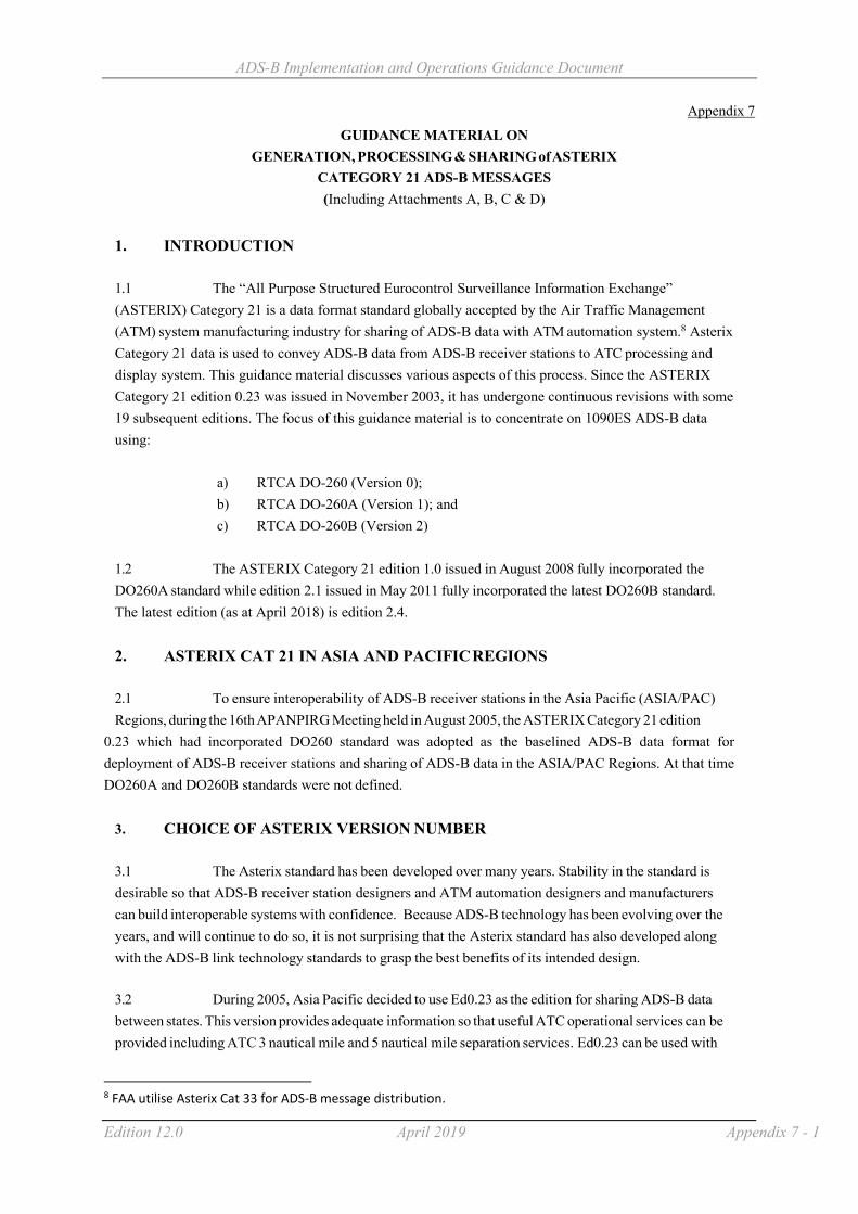
ADS-B Implementation and Operations Guidance Document
Edition 12.0 April 2019 Appendix 7 - 1
Appendix 7
GUIDANCE MATERIAL ON GENERATION, PROCESSING & SHARING of ASTERIX
CATEGORY 21 ADS-B MESSAGES (Including Attachments A, B, C & D)
1. INTRODUCTION
1.1 The “All Purpose Structured Eurocontrol Surveillance Information Exchange” (ASTERIX) Category 21 is a data format standard globally accepted by the Air Traffic Management (ATM) system manufacturing industry for sharing of ADS-B data with ATM automation system.8 Asterix Category 21 data is used to convey ADS-B data from ADS-B receiver stations to ATC processing and display system. This guidance material discusses various aspects of this process. Since the ASTERIX Category 21 edition 0.23 was issued in November 2003, it has undergone continuous revisions with some 19 subsequent editions. The focus of this guidance material is to concentrate on 1090ES ADS-B data using:
a) RTCA DO-260 (Version 0); b) RTCA DO-260A (Version 1); and c) RTCA DO-260B (Version 2)
1.2 The ASTERIX Category 21 edition 1.0 issued in August 2008 fully incorporated the DO260A standard while edition 2.1 issued in May 2011 fully incorporated the latest DO260B standard. The latest edition (as at April 2018) is edition 2.4.
2. ASTERIX CAT 21 IN ASIA AND PACIFIC REGIONS
2.1 To ensure interoperability of ADS-B receiver stations in the Asia Pacific (ASIA/PAC) Regions, during the 16th APANPIRG Meeting held in August 2005, the ASTERIX Category 21 edition
0.23 which had incorporated DO260 standard was adopted as the baselined ADS-B data format for deployment of ADS-B receiver stations and sharing of ADS-B data in the ASIA/PAC Regions. At that time DO260A and DO260B standards were not defined.
3. CHOICE OF ASTERIX VERSION NUMBER
3.1 The Asterix standard has been developed over many years. Stability in the standard is desirable so that ADS-B receiver station designers and ATM automation designers and manufacturers can build interoperable systems with confidence. Because ADS-B technology has been evolving over the years, and will continue to do so, it is not surprising that the Asterix standard has also developed along with the ADS-B link technology standards to grasp the best benefits of its intended design.
3.2 During 2005, Asia Pacific decided to use Ed0.23 as the edition for sharing ADS-B data between states. This version provides adequate information so that useful ATC operational services can be provided including ATC 3 nautical mile and 5 nautical mile separation services. Ed0.23 can be used with
8 FAA utilise Asterix Cat 33 for ADS-B message distribution.

ADS-B Implementation and Operations Guidance Document
Edition 12.0 April 2019 Appendix 7 - 2
DO260, DO260A and DO260B ADS-B avionics/receiver stations to provide basic ATC operational services. However, Ed0.23 cannot fully support all the capabilities offered by DO260A and DO260B.
3.3 Nearly all Ed0.23 data items can be “re-constructed” from a received Ed2.1 data stream. However, most of the special DO260A/B data items cannot be “re-constructed” from an Ed0.23 data stream. In terms of domestic use and data sharing with other ANSPs concerning ADS-B data, several options exist for ANSPs as follows:
Option Domestic use Data sharing
1 Ed0.23 Ed0.23. This is the default and basic standard.
2 Ed2.1 Ed0.23. This will require some conversions to occur, probably through an ADS-B format conversion and filter system (see Paragraph 11), between a domestic system and a foreign system.
Difficulties may exist if the domestic ATM system requires special DO260A/B data items, since they cannot all be re-constructed from the external foreign Ed0.23 data stream.
3 Ed2.1 Ed2.1. Must negotiate bilaterally with data sharing partner regarding exact version to be used to achieve the intended functions.
Note: In this table, Ed2.1, a later DO260B compliant Asterix Cat 21 edition, is chosen as a representation of an Asterix Cat 21 edition after Ed0.23. There exists other Asterix CAT 21 editions (e.g. 0.26, 1.3, 2.4 etc.) after Ed0.23 that could be used by ANSPs for domestic and data sharing use.
4. SPECIFICATION OF ASTERIX MESSAGE PROCESSING
4.1 Care is needed to understand the difference in specifications :
4.2 Asterix Cat 21: Defines the characteristics of the data ON the interface including fields that are mandatory on the interface.
4.3 ADS-B receiver station specifications: To define the Asterix standard, the ANSP must also define which optional Asterix data items are required to be delivered on the Asterix interface, when the appropriate data is received from the aircraft. It is desirable that suppliers be required to:
a) indicate how the receiver station processes and outputs every received DO260, DO260A and DO260B data element into an Asterix data element/field; and
b) indicate which and how each Asterix data element and field presented at the output are
populated. 4.4 ATM automation system specifications: Defines which received Asterix data element and fields are processed and how they are processed. Also defines which Asterix optional data fields are required by the ATM automation systems (if any). ANSPs that specify ADS-B receiver stations and ATM automation systems need to consider carefully and clearly about what they desire to achieve. Specifications which simply require compliance with a particular Asterix edition will be inadequate in most circumstances. In particular ANSPs, together with their suppliers should :

ADS-B Implementation and Operations Guidance Document
Edition 12.0 April 2019 Appendix 7 - 3
a) Specify the Asterix standard edition to be used. This defines the message formats that are
placed on the link between ADS-B receiver station and downstream systems like ATM automation, recording & analysis systems, bypass ATC systems and foreign ANSPs. The edition will define which messages elements are mandatory in each message (very few fields) and a large number of optional fields. The optional fields can only be filled if relevant data is received from the aircraft. The optional fields will only be filled if the receiver station specification requires them to be filled.
b) Specify the ADS-B receiver station behaviour so that when data is received from the
aircraft, the receiver station is required to fill appropriate optional Asterix data fields.
c) Specify the ATM automation system behaviour including appropriate semantic and
syntax checks applied to the Asterix data, including any triggers for the system to discard data. The processing applied to each received Asterix data field should be specified. The ATC system should discard any messages with unexpected Asterix categories without discarding messages with known and defined Asterix categories.
5. MANDATORY FIELDS : ASTERIX AND 1090ES ADS-B
5.1 Asterix Cat 21 has been designed to support multiple datalinks. It has been defined to support data fields which are not available in the 1090ES standards. Therefore some data items and fields are not relevant when 1090ES is used.
5.2 The standard itself defines various items as optional or mandatory. This is defining what is ON the interface. It does NOT specify the behaviour of the transmitting receiver station nor the behaviour of the receiving ATM automation system.
5.3 When a single link technology has been chosen it may be sensible to diverge from the formal Ed0.23 standard to reduce the required Asterix datalink bandwidth. E.g.: in an environment with only 1090ES, it is unnecessary to transmit “Link Technology Indicator”. Asterix Cat 21 Ed 2.1 allows this selection.

ADS-B Implementation and Operations Guidance Document
Edition 12.0 April 2019 Appendix 7 - 4
Data Items
Description Mandatory (M) or Optional (O) items as per ASTERIX Category 21 Version 0.23 Specification
Version 2.1 Specification
I021/010 Data Source Identification M M I021/030 Time of Day M N/A I021/071 or I021/073
Time of Applicability of Position or Time of Message reception for position
N/A One of these is must be transmitted
I021/040 Target Report Descriptor M M
I021/080 Target Address M M I021/210 Link Technology Indicator/
MOPS version M O
6. GENERATION OF ASTERIX AT AN ADS-B RECEIVER STATION
6.1 The following general principles should be adopted:
6.2 Commensurate with link bandwidth availability, transmit all mandatory Asterix data items and also transmit those Asterix data items that are operationally desirable. That is, when the appropriate aircraft transmission is received by the ADS-B receiver station, the data should be transmitted to the ATC system for operational use or for technical recording and analysis use. If no aircraft transmission data is received to fill an Asterix data item during any update cycle, the data item should not be included in the Asterix data stream to reduce bandwidth requirements.
6.3 Group 1 (Mandatory Data Items): An Asterix Cat21 message should not be transmitted unless the mandatory data items defined in Appendix A are all present.
6.4 Group 2 (Desirable Data Items) : The data items defined in Appendix B are operationally desirable which should always be transmitted in the Asterix Cat 21 messages whenever the data are received by the 1090ES receiver station from aircraft (if allowed by the relevant Asterix standard chosen).
6.5 Group 3 (Optional Data Items) : The data items defined in Appendix C are considered optional and may or may not need to be transmitted depending on availability of such data from aircraft and/or other specific operational needs.
6.6. Group 4 (Future Data Items): The following data are defined in the DO260A and DO260B standards but are not yet defined in the Asterix standard. This group is provided for information only. It illustrates the need for system designers to provide for future adaptability when possible and when cost effective to do so. Not only will the Asterix standard continue to evolve, but changes to DO260 can also be anticipated within the decade.
a) Target heading: Information from DO260A/B Target state and status messages

ADS-B Implementation and Operations Guidance Document
Edition 12.0 April 2019 Appendix 7 - 5
(On condition messages). These could be used for detection of pilot errors in selection of heading/altitude; and
b) GPS Offset: Could be used to more accurately display aircraft position on an
airport surface, or better detect that an aircraft has passed an airport hold point.
6.7 When developing a specification for an ADS-B receiver station, it is considered necessary that the specification requires the transmission of all data items that are operationally desirable (Group 2), when such data are received from the aircraft, in addition to the data items that are mandatory (Group 1) in Asterix messages. Whether Group 3 optional data items will need to be transmitted or not should be configurable on item-by-item basis within the ADS-B receiver station depending on specific operational needs.
7. PROCESSING OF ASTERIX ADS-B DATA AT THE ATC SYSTEM
7.1 An Asterix Cat21 message should not be accepted by the ATC system for processing unless it includes at least all the Group 1 data items.
7.2 The ATC system should process all received Asterix Cat21 message data items that bring operational benefits (i.e. Group 2 data items). An ATM automation specification should require that the system appropriately process those Group 2 data items depending on specific operational need. Whether the ATC system will process Group 3 optional data items will depend on specific operational needs.
8. DATA SHARING OF ASTERIX ADS-B DATA
8.1 In principle, all data receiving from the shared ADS-B receiver station should be delivered to the receiving party as far as practicable without filtering, unless owing to technical reasons such as the need to convert the data from one ASTERIX format to another, or it is requested by the receiving party of the data.
8.2 It is considered necessary that all data items that are mandatory in Asterix messages (i.e. Group 1 data items) and operationally desirable (i.e. Group 2 data items) when such data are received from aircraft, should be included in data sharing. In the event that the data have to be filtered, the list of optional data items (i.e. Group 3 data items) needs to be shared will be subject to mutual agreement between the two data sharing parties concerned.
9. ISSUE RELATED TO DO260A
9.1 Support of DO260A using Asterix Cat 21 Ed0.23
a) DO260A was developed after Ed0.23 of Asterix was defined. Therefore, Ed0.23
does not directly support DO260A. However, receiver station software can generate useful Ed0.23 Asterix data from DO260A reports through use of the following techniques;

ADS-B Implementation and Operations Guidance Document
Edition 12.0 April 2019 Appendix 7 - 6
b) A useful I021/090 Figure of Merit can be generated from DO260A messages. Some implementations have a table, which defines the FOM/PA to be generated for each combination of SIL, NIC and NAC. The contents of the table can be offline defined to generate the appropriate FOM/PA values. The downstream ATC system can then process DO260A reports as if they were DO260 reports; and
c) If there is a particular need for the ATC system to have access to the NIC/NAC
or SIL or other data item that exist in DO260A (but not in DO260), then users may need to consider a more recent version of Cat 21.
9.2 Support of DO260A using Asterix Cat 21 Ed 1.0 or Ed2.1 (or later versions)
a) When DO260A is used, then the ANSP could decide to use Asterix Cat 21
Ed1.0 (or later versions) or Ed2.1 (or later versions); and
b) Readers are invited to carefully examine the DO260A fields (see Appendix D) to
determine if the benefits of additional DO260A fields are large enough to warrant adoption of Asterix Cat 21 Ed1.0 (or later versions) or Ed2.1 (or later versions).
10. ISSUE RELATED TO DO260B
10.1 Support of DO260B using Asterix Cat 21 Ed0.23
a) DO260B was developed some years after DO260A. Therefore, Asterix Cat 21,
Ed0.23 does not directly support DO260B;
b) The same techniques used for processing DO260A can be used for processing DO260B, however, the table used must account for NIC supplement B & NIC supplement C, and may also wish to account for SDA; and
c) If there is a particular need for the ATC system to have access to the new data
items offered by DO260B, then users may need to consider a more recent version of Cat 21 (e.g. Ed2.1 or later versions).
10.2 Support of DO260B using Asterix Cat 21 Ed2.1 or later versions
a) If DO260B is used, then the ANSP could decide to use Asterix Cat 21 Ed2.1 or
later; and
b) Readers are invited to carefully examine the DO260B data items (see Appendix
D) to determine if the benefits of additional DO260B data items are large enough to warrant adoption of Asterix Cat 21 Version 2.1 or later.

ADS-B Implementation and Operations Guidance Document
Edition 12.0 April 2019 Appendix 7 - 7
11. ADS-B FORMAT CONVERSION AND FILTER SYSTEM
11.1 It is clear that the evolution of 1090ES ADS-B transmission will continue. Avionics software will be upgraded to provide additional or changed functionality. As a result Asterix standards will also continue to evolve, and ATC systems will need to be adaptable to be able to cope with new functionality requirements and new message standards.
11.2 The use of an ADS-B format conversion & filter (ADS-B FC&F) system between domestic ADS-B systems and data shared with other states is a cost-effective way to provide the necessary protection and flexibility in this evolution. Such a system provides ADS-B format conversion between domestic and foreign ADS-B systems. While decoupling one ADS-B Asterix environment from another, the system allows information that meets specific sharing criteria to be passed through for data sharing. By doing so, loading on the ATM automation systems to process ADS-B data and bandwidth requires to transmit the ADS-B data could then be reduced. The system also allows independent domestic format changes without disruption to the foreign environment. A typical structure could be as shown below:

ADS-B Implementation and Operations Guidance Document
Edition 12.0 April 2019 Appendix 7 - 8
7 Attachment A - Group 1 (Mandatory Data Items)
Data Items Description Ed
0.23
Ed
2.1
Remarks
I021/010 Data Source Identification X X Identifies source of data. Important if validity checks are performed as an anti spoofing capability. Validation that the data is received from an approved ADS-B receiverstation. Data received from a receiver station should not be processed if the position of the reported aircraft is an unreasonable distance away from the known location of the ADS-B receiver
station. Where space based ADS-B is used and a nominal station location is defined, such range processing limits will need to account for the coverage supplied.
I021/030 Time of Day X Necessary to extrapolate the ADS-B data to time of display. Data received with a Time of Day too far in the past should be discarded. This data is too old.
I021/071 or I021/073
Time of Applicability of Position or
Time of Message reception for position
X Necessary to extrapolate the ADS-B data to time of display. Data received with a Time of Day too far in the past should be discarded. This data is too old.
I021/040 Target Report Descriptor X X Indicates if report is a duplicate, on the receiver, is a simulated target, is a test target. This needs to be checked by ATC system prior to processing. If the data indicates that the report is a test target or a simulated target, it is normally processed differently to “real” targets.
I021/080 Target Address X X Included in all 1090ES downlink messages, so always available. Used for report/report linkage in ATC tracking.
I021/090 Figure of Merit/Quality Indicators
X X Position cannot be used without quality indicator. If the quality of the positional data does not meet the requirements the data should be discarded.
I021/130 Position in WGS-84 co-ordinates
X X Report cannot be used without position
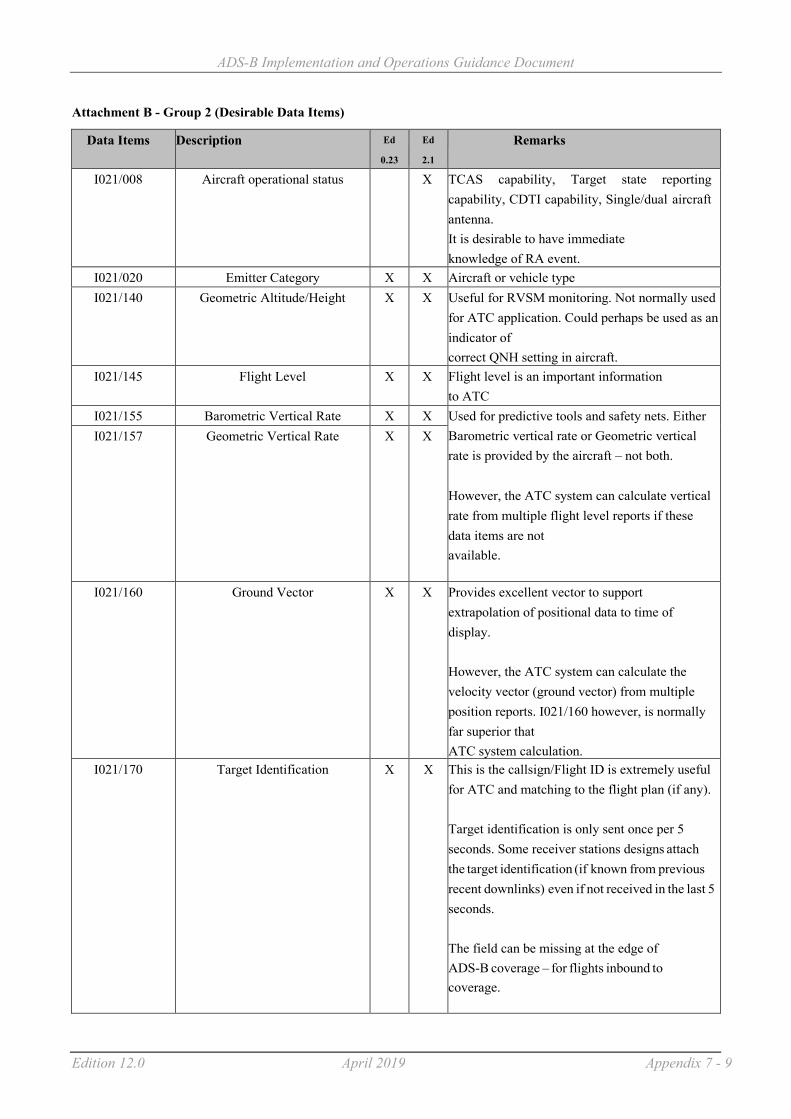
ADS-B Implementation and Operations Guidance Document
Edition 12.0 April 2019 Appendix 7 - 9
Attachment B - Group 2 (Desirable Data Items)
Data Items Description Ed
0.23
Ed
2.1
Remarks
I021/008 Aircraft operational status X TCAS capability, Target state reporting capability, CDTI capability, Single/dual aircraft antenna. It is desirable to have immediate knowledge of RA event.
I021/020 Emitter Category X X Aircraft or vehicle type I021/140 Geometric Altitude/Height X X Useful for RVSM monitoring. Not normally used
for ATC application. Could perhaps be used as an indicator of correct QNH setting in aircraft.
I021/145 Flight Level X X Flight level is an important information to ATC
I021/155 Barometric Vertical Rate X X Used for predictive tools and safety nets. Either Barometric vertical rate or Geometric vertical rate is provided by the aircraft – not both.
However, the ATC system can calculate vertical rate from multiple flight level reports if these data items are not available.
I021/157 Geometric Vertical Rate X X
I021/160 Ground Vector X X Provides excellent vector to support extrapolation of positional data to time of display.
However, the ATC system can calculate the velocity vector (ground vector) from multiple position reports. I021/160 however, is normally far superior that ATC system calculation.
I021/170 Target Identification X X This is the callsign/Flight ID is extremely useful for ATC and matching to the flight plan (if any).
Target identification is only sent once per 5 seconds. Some receiver stations designs attach the target identification (if known from previous recent downlinks) even if not received in the last 5 seconds.
The field can be missing at the edge of ADS-B coverage – for flights inbound to coverage.

ADS-B Implementation and Operations Guidance Document
Edition 12.0 April 2019 Appendix 7 - 10
I021/200 Target Status X X This is the emergency type and is highly desirable.

ADS-B Implementation and Operations Guidance Document
Edition 12.0 April 2019 Appendix 7 - 11
Attachment C - Group 3 (Optional Data Items)
Data Items Description Ed
0.23
Ed
2.1
Remarks
I021/077 Time of report transmission X Time of applicability is relevant for ATC system processing. Time of transmission is less relevant.
I021/032 Time of Day Accuracy X Maximum error in Time of day. Normally the maximum value is known by the ANSP because of station design.
I021/095 Velocity Accuracy X If using GPS, velocity accuracy will be adequate if the Position quality is accurate.
I021/072 Time of applicability of velocity
X Can be managed by a velocity data time out in receiver station.
I021/075 Time of message reception of velocity
X Normally velocity is in the same Asterix message as position. Velocity data time out in receiver station.
I021/161 Track number X Tracking can be performed by ATC system. Also the 24 bit code (aircraft address) could be used as a pseudo track number.
I021/110 Trajectory Intent X X Defined in DO260 but not transmitted by any known product. Not defined in DO260A or DO260B
I021/146 (Intermediate) Selected Altitude
X X Target altitude : Information from DO260A/B Target state and status messages (On condition messages). These could be used for detection of pilot errors in selection of heading/altitude.
I021/148 Final State Selected Altitude X X
I021/015 Service identification X Type of Service (VDL4, Ext Squitter, UAT, TIS-B VDL4, TIS-B Ext Squitter, TIS-B UAT, FIS-B VDL4, GRAS VDL4, MLT). Not useful to most ATC systems.
I021/016 Service management X Update rate or whether data driven output from GS. Normally known by receiver.

ADS-B Implementation and Operations Guidance Document
Edition 12.0 April 2019 Appendix 7 - 12
Data Items Description Ed
0.23
Ed
2.1
Remarks
I021/074 Time of message reception of position – high resolution
X High resolution is designed to support MLAT system processing by receiver. Not required for pure ADS-B.
I021/076 Time of message reception of velocity – high resolution
X High resolution is designed to support MLAT system processing by receiver. Not required for pure ADS-B.
I021/210 MOPS version/ Link Technology Indicator
X X Maybe useful for statistics about equipage. Not operationally relevant
I021/070 Mode 3/A code X Could be used for legacy ATC system that do not use Flight ID
I021/165 Rate of Turn/Track Angle rate X X Not transmitted in DO260, DO260A or DO260B messages
I021/271 Surface capabilities and characteristics
X
I021/132 Message amplitude X Useful for technical analysis. Not operationally relevant
I021/250 Mode S MB data X
I021/260 ACAS resolution advisory report
X
I021/400 Receiver ID X
I021/295 Data ages X
I021/150 Air Speed X X Defined in standards but only sent in absence Ground vector information. Can’t be used for extrapolation unless wind speed known.
I021/151 True Air Speed X X
I021/152 Magnetic Heading X X Defined in standards but only sent in absence Ground vector information.
I021/220 Met Report X X Not transmitted in DO260, DO260A or DO260B messages
I021/230 Roll Angle X X Not transmitted in DO260, DO260A or DO260B messages
I021/131 Position in WGS-84 coordinates, high resolution
X

ADS-B Implementation and Operations Guidance Document
Edition 12.0 April 2019 Appendix 7 - 13
Attachment D - Differences among DO260, DO260A, DO260B
DO-260 DO-260A DO-260B Availability of data in Asterix CAT 21
Potential uses of additional information
Introduction of Navigation Integrity Category (NIC) to replace Navigation Uncertainty Category (NUCP)
NUCP is used. NIC is used to replace NUCP.
More levels of NIC available. Vertical component removed.
NIC is shown in Ed1.0 and above. More levels of NIC (shown as PIC) are available in v2.1.
The additional quantum levels of NIC would allow the ANSP more flexibility in deciding whether the NIC is considered as ‘good’ (if required)
However, for 3 NM & 5 NM separation with HPL 1Nm and 2 Nm respectively, this additional quantum is not useful.
Quality Indicator for Velocity (NUCR and NACV)
NUCR is used. Replaced with NACV. Definition remains the same.
Vertical component removed.
Available in Ed0.23 and above.
Vertical component is not available for DO260B.
Surveillance Integrity Level and Source Integrity Level (SIL)
Not available. Surveillance Integrity Level is used.
Renamed as Source Integrity Level. Definition is changed to exclude avionics fault.
Available in Ed1.0 and above.
The SIL will allow the user to further assess the integrity of the reported position (if required).
NB: An implied SIL exists for DO260 aircraft if they always use GPS. However DO260 aircraft do not provide SIL.
System Design Assurance (SDA)
Not available. Not available. To address probability of avionics fault.
Available in Ed2.1. The SDA will indicate the robustness of the system. ANSPs may decide on a minimum SDA for ADS-B services. If this action is taken then DO260 and DO260A aircraft will be unable to meet the criteria.

ADS-B Implementation and Operations Guidance Document
Edition 12.0 April 2019 Appendix 7 - 15
DO-260 DO-260A DO-260B Availability of data in
Asterix CAT 21 Potential uses of additional information
Navigation Accuracy Category (NACP)
Not available. Derived from HFOM and VFOM.
Relies only on HFOM.
Available in Ed1.0 and above.
A reported accuracy is not provided by DO260. However, an estimated accuracy can be derived from NUC – assuming that NUC is HPL based.
Geometric Vertical Accuracy (GVA)
Not available. Not available. Derived from VFOM.
Available in Ed2.1. Geometric altitude accuracy is not normally required for operational purposes.
Barometric Altitude Integrity Code (NICBARO)
Not available. To indicate integrity of barometric altitude.
Same as DO-260A
Available in Ed1.0 and above.
The NICBARO indicates the integrity of the barometric height.
ANSPs could indicate to the controller that Barometric data has not been verified, however, aircraft without dual barometric systems/air data computers may be unable to provide a non zero NICBARO as data could be unnecessarily discarded.
Length / Width of Aircraft
Not available. Provide an indication of aircraft size.
Same as DO-260A
Available in Ed1.0 and above.
The width / length indicate the size of the aircraft. This information may be used as an input for generating alerts on airport surface movement control.
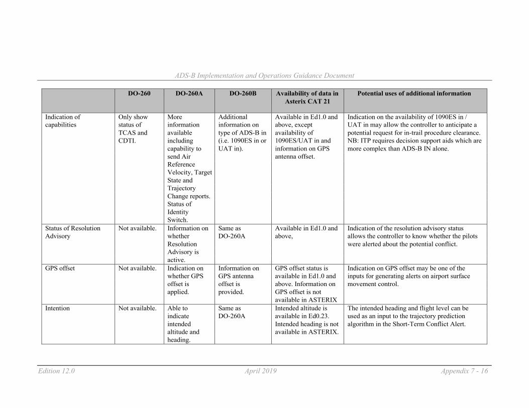
ADS-B Implementation and Operations Guidance Document
Edition 12.0 April 2019 Appendix 7 - 16
DO-260 DO-260A DO-260B Availability of data in
Asterix CAT 21 Potential uses of additional information
Indication of Only show More Additional Available in Ed1.0 and Indication on the availability of 1090ES in / capabilities status of information information on above, except UAT in may allow the controller to anticipate a
TCAS and available type of ADS-B in availability of potential request for in-trail procedure clearance. CDTI. including (i.e. 1090ES in or 1090ES/UAT in and NB: ITP requires decision support aids which are capability to UAT in). information on GPS more complex than ADS-B IN alone. send Air antenna offset. Reference Velocity, Target State and Trajectory Change reports. Status of Identity Switch.
Status of Resolution Not available. Information on Same as Available in Ed1.0 and Indication of the resolution advisory status Advisory whether DO-260A above, allows the controller to know whether the pilots
Resolution were alerted about the potential conflict. Advisory is active.
GPS offset Not available. Indication on Information on GPS offset status is Indication on GPS offset may be one of the whether GPS GPS antenna available in Ed1.0 and inputs for generating alerts on airport surface offset is offset is above. Information on movement control. applied. provided. GPS offset is not available in ASTERIX
Intention Not available. Able to Same as Intended altitude is The intended heading and flight level can be indicate DO-260A available in Ed0.23. used as an input to the trajectory prediction intended Intended heading is not algorithm in the Short-Term Conflict Alert. altitude and available in ASTERIX. heading.
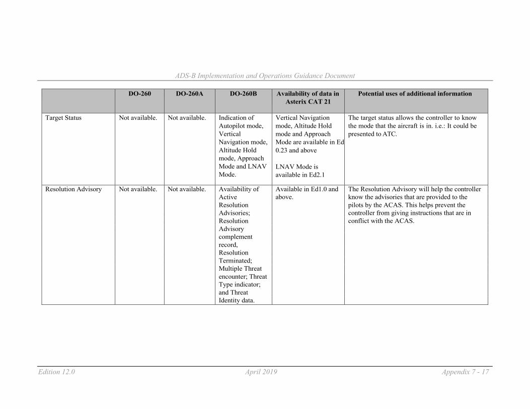
ADS-B Implementation and Operations Guidance Document
Edition 12.0 April 2019 Appendix 7 - 17
DO-260 DO-260A DO-260B Availability of data in
Asterix CAT 21 Potential uses of additional information
Target Status Not available. Not available. Indication of Autopilot mode, Vertical Navigation mode, Altitude Hold mode, Approach Mode and LNAV Mode.
Vertical Navigation mode, Altitude Hold mode and Approach Mode are available in Ed 0.23 and above
LNAV Mode is available in Ed2.1
The target status allows the controller to know the mode that the aircraft is in. i.e.: It could be presented to ATC.
Resolution Advisory Not available. Not available. Availability of Available in Ed1.0 and The Resolution Advisory will help the controller Active above. know the advisories that are provided to the Resolution pilots by the ACAS. This helps prevent the Advisories; controller from giving instructions that are in Resolution conflict with the ACAS. Advisory complement record, Resolution Terminated; Multiple Threat encounter; Threat Type indicator; and Threat Identity data.

ADS-B Implementation and Operations Guidance Document
Edition 12.0 April 2019 Appendix 7 - 18
DO-260 DO-260A DO-260B Availability of data in
Asterix CAT 21 Potential uses of additional information
Mode A DO260 Broadcasted Broadcasted Available in Ed0.26 and The Mode A allows flight plans to be coupled change 1, using test worldwide as a above. with the ADS-B tracks (supports legacy ATM allows this message in regular message. automation system). using test USA only.
message in USA only. This was not implemented in actual products.
_ _ _ _ _ _ _ _ _ _ _ _ _

CNS SG/23 Appendix O to the Report
.
Guidance for Procurement and Certification
of
CNS/ATM Services and Systems
Edition 1.0
September 2019
INTERNATIONAL CIVIL AVIATION ORGANIZATION ASIA AND PACIFIC OFFICE

Guidance for Procurement and certification of CNS/ATM Services and Systems
Intentionally left blank

ICAO APAC - Procurement and certification of CNS/ATM services and systems
O - 3 | P a g e
Table of Contents 1. Introduction .......................................................................................................................................... 4
1.1. Background: the need for more guidance regarding the procurement and certification of
CNS/ATM services and systems .................................................................................................... 4
1.2. Scope and objectives of the document ........................................................................................ 4
1.3. Structure of the document ........................................................................................................ 5
1.4 Consultation with airlines …………………………………………………………………………………………………….. 5
1.5 Other documents of interest ……………………………………………………………………………………………………5
2. Complying with national regulations and procedures .......................................................................... 8
2.1. Responsibility for acceptance, certification and surveillance ....................................................... 8
2.2 Acceptance process (factory and onsite, initial and upgrades) and safety assessment of changes
………………………………………………………………………………………………………………………………………………..8
2.3 Certification and surveillance processes, including safety assessment of changes ………………….9
2.4. Particular case of a gift or donation between Member States ................................................... 11
3. Procurement strategy and contract execution ................................................................................... 13
3.1. E-Procurement ............................................................................................................................ 13
3.2. Benchmarking ............................................................................................................................. 13
3.3. Different procurement strategies .............................................................................................. 16
3.4. Best value for money (weighted evaluation) and lifecycle cost considerations ......................... 17
3.5. Establishing the requirements…………… ………………………………………………………………………………. 17
3.6. Respect of the initial contractual terms and conditions ............................................................. 27
3.7. Best practices can help States to guide their exporting industry ............................................... 27
3.8. Assistance with procurement ..................................................................................................... 27
3.9. Assistance with certification/surveillance .................................................................................. 29
4. Liability and Intellectual Property Rights ............................................................................................ 30
4.1. Liability ........................................................................................................................................ 30
4.2. Intellectual Property Rights ........................................................................................................ 30

ICAO APAC - Procurement and certification of CNS/ATM services and systems
O - 4 | P a g e
1. Introduction
1.1. Background: the need for more guidance regarding the
procurement and certification of CNS/ATM services and systems
During the period 2015 to 2016, several States presented papers at various Asia/Pacific
conferences and meetings about their following difficulties encountered as buyers and sellers of
CNS/ATM systems:-
(A) Buyers of CNS/ATM systems
Lack of expertise to certify that new CNS/ATM systems comply with ICAO SARPs in
current background of Safety Management System (SMS), Safety Oversight Audit (SOA)
and Continuous Monitoring Approach (CMA); and
Lack of information about how innovative ways of procurement could help to overcome
some of the constraints faced by ANSP in buying and commissioning new CNS/ATM
systems, complying with ICAO standards.
(B) Sellers of CNS/ATM systems
Lack of internationally recognized certification and development guidance and
procedures for CNS/ATM systems. Availability of such guidance and procedures could
lead to international acceptance, resulting in time and cost savings.
APANPIRG/27 meeting in September 2017 had a Conclusion to have a Workshop to share experience
and best practices as well as formulate guidance on development and certification procedures for
CNS/ATM systems. As a result, a Workshop was held on morning of 17 July 2017 at the ICAO APAC
Regional Office before start of the CNS/21/SG meeting.
1.2. Scope and objectives of the document
This document deals with the procurement and certification of CNS/ATM systems and aims to
provide guidance to States regarding:-
(a) Procurement and commissioning of new CNS/ATM systems, complying with ICAO standards;
and
(b) Certification and development guidance and procedures for CNS/ATM systems.
ICAO APAC - Procurement and certification of CNS/ATM services and systems
O - 5 | P a g e
1.3. Structure of the document
Further to the background and objectives exposed in the chapter 1Chapter 2 introduces how
national regulations and procedures constitute the framework for any procurement or certification
activities, and how to re-use evidences, when available, of acceptance, certification or effective
surveillance in the regulatory context of the procuring/recipient State. It also addresses the specific case
of a gift or donation between Member States.
Chapter 3 addresses the major elements of a procurement strategy, including e-procurement,
benchmarking, and as required, the need for assistance with procurement or certification activities, and
on how to best execute the contract once signed off.
Chapter 4 further elaborates on liability and intellectual property rights.
To go deeper
In some of the paragraphs of this document, the mention “To go deeper” proposes further guidance for
subject matter experts. These guidelines can be skipped if one is not a technical expert in the area and
consults this guidance from the perspective of procurement or certification processes only.
1.4 Consultation with airlines
According to the ICAO’s policies on charges for airports and air navigation facilities and services
(ICAO Doc 9082), its Section III Paragraph 10 states that “providers for air navigation services for
international use may require all users to pay their share of the cost of providing them such services
regardless of whether or not the utilization takes place over the territory of the provider State.” The
procurement of CNS/ATM of systems for supporting air navigation services would incur both capital and
recurrent expenditure. For those Civil Aviation Authorities (CAAs) or Air Navigation Service Providers
(ANSPs) who adopt the user-pay principle of recovering cost arising from procurement of the CNS/ATM
systems from the users, it is required to consult the users (i.e. airlines) prior to making any procurement
decisions in accordance with the ICAO’s key charging principles of non-discrimination, cost-relatedness,
transparency and consultant with users as stated in ICAO Doc 9082.
1.5 Other documents of interest
In 2008, a guidance material was developed under an initiative of the Regional Airspace Safety
Monitoring Advisory Group (RASMAG) of the Asia Pacific Air Navigation Planning and Implementation
Regional Group (APANPIRG) to assist air navigation service providers (ANSP) with the implementation of

ICAO APAC - Procurement and certification of CNS/ATM services and systems
O - 6 | P a g e
data link-based air traffic management (ATM) systems. The material was adopted as Asia/Pacific regional
guidance material by APANPIRG/18 (3-7 September 2007) under the provisions of Conclusion 18/5. The
RASMAG retains editorial responsibility for the document.
The document can be found at
https://www.icao.int/APAC/Documents/edocs/ads_cpdlc_didc_ver2.pdf
Of particular interest are the chapters 2 – Procurement and 3 – Implementation as both chapters
address procurement and implementation processes of ATM systems in a fashion that is not specific to
the datalink services. These chapters are therefore relevant for those States/ANSP willing to procure
systems or services in general.
Another useful document relating to the implementation of the APAC Seamless ATM objectives
is the ICAO Asia/Pacific Seamless ATM Implementation Guidance Material which can be found here:
https://www.icao.int/APAC/Documents/edocs/Seamless%20ATM%20Implementation%20Guidance%20
v5-0.pdf
In particular, the table 2 Implementation Matrix details the different stages of a sound
implementation process as follows:
Procurement activities, as detailed further in the present document, should be seen as a particular process
in the broader picture of the implementation, throughout the stage 1. Project planning.
Certification/surveillance of CNS/ATM systems activities relate to the Action D of the stage 3. Safety.

ICAO APAC - Procurement and certification of CNS/ATM services and systems
O - 7 | P a g e
Another useful reference document is from CANSO which develops a CANSO Acquisition
Excellence Manual that provides 11 Case Studies about the various different approaches of acquisition
of ATM systems and services. This Manual can be accessed via the following link: -
https://www.canso.org

ICAO APAC - Procurement and certification of CNS/ATM services and systems
O - 8 | P a g e
2. Complying with national regulations and procedures
2.1. Responsibility for acceptance, certification and surveillance
While different processes for acceptance, certification and surveillance exist across the Asia-
Pacific Region, their common goal is to ensure that applicable requirements, as transposed from the
ICAO provisions and other relevant standards, are continuously complied with.
In any case, the responsibility for acceptance, certification and surveillance shall rest with the
State authority or the organization authorized by the State (ANSP) following established procedures.
2.1.1. CNS/ATM systems
Some States have adopted a regime of acceptance testing for their CNS/ATM systems, and some
others a regime of certification. Other States combine these two approaches, relying on acceptance
testing to grant the initial certificate.
Beyond the regime itself, what matters is that the demonstration that national rules, regulations
and standards are complied with relies on scientific evidences. While the scope and depth of tests
required can vary from one regulatory system to another, such evidences can only be obtained through
an engineering approach relying on proper requirements and testing.
To go deeper
In a general manner, testing of CNS/ATM systems can be approached in a functional manner.
The ICAO Document 8071 (Manual on Testing of Radio Navigation Aids) volumes II and III address
respectively the testing of radio-navigation aids and testing of surveillance radar systems and constitute
a helpful guidance which can be analyzed and transposed by the State Authority into national guidance.
For ADS-B systems, the ADS-B Implementation and Operations Guidance Document (AIGD) (current
version is Edition 10.0, June 2017) contains helpful guidance to approach testing of ADS-B function.
For AIDC, the AIDC Implementation and Operations Guidance Document (current version is Edition 1.0 -
July 2017) contains helpful guidance to approach testing of AIDC function.
ICAO APAC - Procurement and certification of CNS/ATM services and systems
O - 9 | P a g e
2.1.2. Particular case of the flight inspections
The ICAO Document 8071 volume II states in its paragraph 1.7 AUTHORITY FOR STATUS
DETERMINATION that “the responsibility for determining procedure and facility status rests with the
appropriate State authority or the organization authorized by the State.”
This explicitly means that even though flight inspections could be procured from a service
provider, the appropriate State authority (usually the Civil Aviation Authority) has to issue the guidance
(referencing the applicable rules and regulations, procedure, periodicity, etc) to the service provider,
usually as part of the contract, to ensure that the service provider conducts flight inspections in
compliance with the applicable rules and regulations.
To go deeper
Before award, a detailed assessment of the bids should be conducted as part of the procurement to
ensure that the selected service provider will comply with the applicable rules and regulations of the
recipient State, including in terms of process, quality assurance and validity.
It is also the State responsibility to make sure that inspections are conducted in such a way that there is
no validity gap between inspections. If however, due to unforeseen circumstances or lack of planning, an
inspection could not be conducted before the end of the validity period, an exemption could be granted,
but based only on a safety assessment, evaluating that the risk to do so remains tolerable.
2.2. Acceptance process (factory and onsite, initial and upgrades) and
safety assessment of changes
Most States use the acceptance process, relying on tests that cover the set of requirements.
Among the best practices, such tests are performed while the system/service is in factory, and
then on site. For a COTS (Commercial off-the-shelf), it is usually a minimum to test the system as a black-
box (testing the interfaces), for which the specific knowledge of the system internal structure is not
required.
However, it is recommended that the level of testing be proportioned to the criticallity of the
system, and includes grey-box or white-box testing as deemed necessary.
A simple way to do that can consist in requiring “free tests” during factory and on-site testing
stages, in addition to the test cases pre-established with the manufacturer. The advantage of such

ICAO APAC - Procurement and certification of CNS/ATM services and systems
O - 10 | P a g e
approach is that these “free tests” may reveal non-compliances or defects that otherwise would have
been overlooked. A drawback is however such an approach is unstructured.
To go deeper
In the same spirit, different levels of care can be applied to the processes of procurement, requirement,
testing and maintenance:
Care in terms of traceability (between System and Software requirements, between Software
requirements and Software Architectural Design, between Software Architectural Design and Detailed
Design, and between Software Detailed Design and Executable Code);
- Care in terms of coverage of testing; and
- Care in terms of independence of testing.
In Europe for example, the level of care throughout the overall lifecycle of a software that forms part of
an ANS system directly derives from the safety assessment and is determined by the SWAL (Software
Assurance Level). The higher the criticality, the stronger the care. Standards like EUROCAE ED-153
Guidelines for ANS Software Safety Assurance (ED-109/DO-278 Software Integrity Assurance
Considerations for Communication Navigation, Surveillance and Air Traffic Management (CNS/ATM)
Systems) are based on the principles retained by ED-12B/DO-178 B for avionics.
2.3. Certification and surveillance processes, including safety
assessment of changes
Some States have adopted this regime. For example, Republic of Korea has proposed some best
practices in a paper to APANPIRG/27 (APANPIRG/27 - WP/21).
In particular, it is advised that processes to system certification & development include:
Safety inspection of equipment
Inspection of related matters such as requirement
Inspection of the suitability for test procedure, and test results
Inspection of software development and design assurance system
Inspection of hardware development and design assurance system
Inspection of user manual
Inspection of education, training and data

ICAO APAC - Procurement and certification of CNS/ATM services and systems
O - 11 | P a g e
To go deeper
Detailed guidance can be found in the Attachment A to the paper.
2.3.1. Re-use of existing compliance evidences
In the case of import/export of CNS/ATM systems, or donation of systems as developed in 2.4, it
may be efficient to envisage reusing the evidences of compliance as initially established in the State of
manufacture, when available.
However, since the effective implementation of ICAO provisions into national requirements
varies from country to country as well as compliance processes, this should be done with great care.
It is recommended that such re-use be subject to a Memorandum of Understanding between
States, after a careful comparison of national requirements and compliance processes.
Once the gap analysis has been conducted, the basis of compliance should be carefully
complemented to comply with the national regulatory framework of the recipient State.
2.3.2. Some suppliers have a basis ready (product policy) – could be reused but must
be carefully evaluated and complemented in the local operational context
As part of their product policy, some suppliers have a basis of compliance evidences ready. For
example, it may comprise a catalogue of tests with results documented, a system (or “product”) safety
assessment, etc.
However it is usually not free of charge and should be taken care of in the initial procurement.
The existing basis should also be carefully evaluated and complemented in the local operational
context and against the national requirements, which will also have a cost.
2.4. Particular case of a gift or donation between Member States
In the case where a Member State A receives a gift from a Member State B, State B should
undertake all efforts to ensure that State A is in the position to safely commission and maintain the

ICAO APAC - Procurement and certification of CNS/ATM services and systems
O - 12 | P a g e
system. In particular, and before the gift occurs, a complete review of the implementation and post
implementation processes, including maintenance activities, should be performed by States A and B
against State A’s capabilities.
To go deeper
The potential gaps are:
Lack of documentation (design, interfaces, operator handbook, etc), or documentation not
available in the proper language;
No or insufficient training delivered to State A;
No or insufficient evidence of compliance with the national regulations and procedures of State
A;
No or insufficient support from State B for State A to perform its safety assessment;
No or insufficient support from State B for State A to commission the system;
No maintenance solution proposed or offered to State A.
After the review and gap analysis, it is recommended that States A and B sign an agreement ruling the
donation, with the objective to close the detected gaps within agreed timelines.
When a third party is involved, such as a manufacturer, service provider, training center, or other
stakeholders, it is recommended that their roles and responsibilities be identified in the agreement, along
with the terms and conditions ruling their interventions.

ICAO APAC - Procurement and certification of CNS/ATM services and systems
O - 13 | P a g e
3. Procurement strategy and contract execution
3.1. E-Procurement
E-procurement, including electronic tendering, electronic quotations, and sourcing, proves to be
efficient in terms of cost and time reduction in tendering and should be encouraged.
Traceability through a sound record management system can also contribute to reduce
corruption in public procurement practices.
3.2. Benchmarking
3.2.1. Market survey: features of systems/services available versus own needs, total
cost of ownership
Benchmarking --i.e. comparison-- is a critical activity supporting the Project Planning stage –right
from the identification of the problem and improvement required, through intermediate activities and
down to planning the tendering and maintenance contract process.1 A brief revisit of the ICAO Global Air
Traffic Management Operational Concept (GATMOC)2, and supporting documents clarifies the role and
criticality of benchmarking in the widest relevant context. The GATMOC points out that
i. achieving an expected performance (at the level of the 11 Key Performance Areas3) requires services, which in turn need assets4; and that
ii. managing the delivery of ATM services –ie ATM Service Delivery Management (ATM SDM)5 — is about managing the Performance, Services and Assets package (PSAP) as a
1 Actions A to F of Stage 1 in Table 2 of the ‘APAC Seamless ATM Implementation Guidance Material’ referred in the earlier
section 0. 2 ICAO Air Traffic Management Service Delivery Management (ATM SDM) Circular (Cir 335 AN/194), p.(iii). 3 The combined performance of what GATMOC Appendix D calls ‘Expectations’ (alphabetically: Access and equity; Capacity; Cost-effectiveness; Efficiency; Environment; Flexibility; Global Interoperability; Participation by the ATM Community; Predictability; Safety; and Security) and subsequent documents call Key Performance Areas (e.g. ICAO Global Air Navigation Plan 2016-2030, p.31). 4 Assets can be of the following types: people, technology, information, procedures, and/or a combination of them. Assets include, for example, aerodromes, airspace, radars, etc. The word ‘system’ as used in this document is a combination of assets of types technology, information and procedures as supplied by the vendor. 5 ICAO Air Traffic Management Service Delivery Management (ATM SDM) Circular (Cir 335 AN/194), p.(vii): “ATM SDM means analyzing and deciding what assets need to be deployed to deliver what required services, to obtain what expected performance [across the 11 Key Performance Areas], and to do so while thinking:
a) across and within global concept components — [i.e.] airspace organization, aerodrome operations, user operations, etc.; b) across and within time horizons — from long-term planning through to tactical decisions; and c) end to end — whether seen as gate to gate or en route to en route.”

ICAO APAC - Procurement and certification of CNS/ATM services and systems
O - 14 | P a g e
whole, getting the balance right, and demonstrating so by way of a system-wide performance case.6
Thus, in GATMOC terms, benchmarking is about understanding:
iv. the current air traffic demand and PSAP;
v. the forecasted air traffic demand and PSAP;
vi. what assets are available in the market and the extent to which these could improve any
gaps in the PSAP (current or forecasted) through the provision of related services.
In plain language, benchmarking is simply taking stock of
a. how well the demand is being satisfied now, and by what services and assets;
b. how well the demand would be satisfied in the future if nothing is done; and
c. what assets are available in the market that could close any gaps in satisfaction now and
in the future.
The basic examples below illustrate how to develop more complex ones, and why:
Suppose that one of the performance objectives of the procurement is “Objective 1: increase
the en-route throughput which can be handled during typical busy hour.”7
o Then, performance indicators and corresponding metrics (units of measurement)
would have to be chosen to describe the performance baseline (currently being
delivered) and the performance targets expected to be satisfied by the procurement.
o For example, Throughput Demand (performance indicator) could be chosen and
measured as number of IFR movements per hour (metric); Throughput Capacity as
number of IFR movements per hour; and Number of Sectors as number of sectors that
are open in an airspace volume during a typical busy hour.
o Actual measurements will establish the performance baseline (e.g. 40; 30; 10;
respectively) and analysis of demand-forecasts and expectations will define the
performance targets to be satisfied by the procurement (e.g. 50; 60; 5; respectively).
Simultaneously with the above, another performance objective could be “Objective 2:
increase the number of aircraft that can be simultaneously accommodated in en-route
airspace.”8 Peak Instantaneous Aircraft Count (PIAC) Demand and PIAC Capacity could be the
performance indicators measured as number of IFR flights simultaneously present in the
6 ICAO Air Traffic Management Service Delivery Management (ATM SDM) Circular (Cir 335 AN/194): p.1-2, §1.2 7 Example adapted from the ICAO Manual on Global Performance of the Air Navigation System (Doc 9883) (Part I, pp.15-16). 8 Example adapted from the ICAO Manual on Global Performance of the Air Navigation System (Doc 9883) (Part I, pp.15-16).
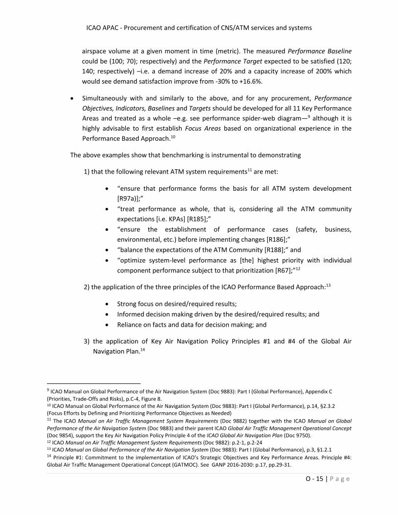
ICAO APAC - Procurement and certification of CNS/ATM services and systems
O - 15 | P a g e
airspace volume at a given moment in time (metric). The measured Performance Baseline
could be (100; 70); respectively) and the Performance Target expected to be satisfied (120;
140; respectively) –i.e. a demand increase of 20% and a capacity increase of 200% which
would see demand satisfaction improve from -30% to +16.6%.
Simultaneously with and similarly to the above, and for any procurement, Performance
Objectives, Indicators, Baselines and Targets should be developed for all 11 Key Performance
Areas and treated as a whole –e.g. see performance spider-web diagram—9 although it is
highly advisable to first establish Focus Areas based on organizational experience in the
Performance Based Approach.10
The above examples show that benchmarking is instrumental to demonstrating
1) that the following relevant ATM system requirements11 are met:
“ensure that performance forms the basis for all ATM system development
[R97a)];”
“treat performance as whole, that is, considering all the ATM community
expectations [i.e. KPAs] [R185];”
“ensure the establishment of performance cases (safety, business,
environmental, etc.) before implementing changes [R186];”
“balance the expectations of the ATM Community [R188];” and
“optimize system-level performance as [the] highest priority with individual
component performance subject to that prioritization [R67];”12
2) the application of the three principles of the ICAO Performance Based Approach:13
Strong focus on desired/required results;
Informed decision making driven by the desired/required results; and
Reliance on facts and data for decision making; and
3) the application of Key Air Navigation Policy Principles #1 and #4 of the Global Air
Navigation Plan.14
9 ICAO Manual on Global Performance of the Air Navigation System (Doc 9883): Part I (Global Performance), Appendix C
(Priorities, Trade-Offs and Risks), p.C-4, Figure 8. 10 ICAO Manual on Global Performance of the Air Navigation System (Doc 9883): Part I (Global Performance), p.14, §2.3.2 (Focus Efforts by Defining and Prioritizing Performance Objectives as Needed) 11 The ICAO Manual on Air Traffic Management System Requirements (Doc 9882) together with the ICAO Manual on Global
Performance of the Air Navigation System (Doc 9883) and their parent ICAO Global Air Traffic Management Operational Concept (Doc 9854), support the Key Air Navigation Policy Principle 4 of the ICAO Global Air Navigation Plan (Doc 9750). 12 ICAO Manual on Air Traffic Management System Requirements (Doc 9882): p.2-1, p.2-24 13 ICAO Manual on Global Performance of the Air Navigation System (Doc 9883): Part I (Global Performance), p.3, §1.2.1 14 Principle #1: Commitment to the implementation of ICAO’s Strategic Objectives and Key Performance Areas. Principle #4: Global Air Traffic Management Operational Concept (GATMOC). See GANP 2016-2030: p.17, pp.29-31.
ICAO APAC - Procurement and certification of CNS/ATM services and systems
O - 16 | P a g e
For further guidance, see: ICAO Air Traffic Management Service Delivery Management (ATM SDM)
Circular (Cir 335 AN/194); ICAO Manual on Global Performance of the Air Navigation System (Doc
9883); ICAO Manual on Air Traffic Management System Requirements (Doc 9882); and ICAO
Global Air Navigation Plan [GANP] 2016-2030 (Doc 9750).
3.2.2. Other ANSP: lessons learnt from acceptance, transition and operations
Projects are always challenging. Organizations should minimize risk by incorporating in
their current project plans the lessons learnt by other ANSPs in previous, similar situations.
For example, organizations can compare their current project plans with previous ones
by other ANSPs and with the difficulties the latter found during acceptance, transition and operations, to
analyze differences, potential impacts and possible risk mitigations.
3.3. Different procurement strategies
3.3.1. Grouped procurement with other ANSP
One option that ANSPs could consider while planning for procurement of CNS/ATM
system will be group procurement. This means a group of like-minded ANSPs with more or less
similar requirements could band together to procure CNS/ATM systems. With such an approach,
ANSP could benefit from economies of scale in term of cost of procurement as well as after-sale
support. Examples of such group procurement are COOPANS15, iTEC and Co-Flight.
3.3.2. Collaboration with suppliers for joint development & production
For complex procurement such as for ATM systems and when ANSPs may want to be
involved in development of the ATM system, ANSP may want to consider collaboration with potential
system suppliers for joint development and production of the system. From involvement in its
development process, ANSP will have better knowledge of the ATM system. Such development
experience gained will be useful in subsequent maintenance and upgrading of the ATM system.
----------------------------------------------------------------------------------------------------------------------------------------------------------------------------------------------------
15 COOPANS is a partnership between air navigation service providers of Austria, Croatia, Denmark, Ireland and
Sweden which had chosen Thales to be their industry partner to implement an unified air traffic control system
among the 5 States
ICAO APAC - Procurement and certification of CNS/ATM services and systems
O - 17 | P a g e
3.3.3 Proof-of-concept method, prior to award of procurement
For some new CNS/ATM features that have to be developed/customised and not
available in the market, ANSPs may want to consider using the proof-of-concept method, prior to
commitment of award of procurement. In this particular case, contractors will have to demonstrate
successfully their understanding and capabilities of developing the new features, prior to award of
procurement. This method will allow the ANSP to have better confidence of getting the new features
that it wants, although the cost and time of procurement could be affected as a result.
3.3.4 Competitive process
3.3.4.1 Turn-Key
For a situation when ANSP does not have the expertise nor resources, it may want to
consider the turn-key approach where the successful tenderer will undertake to design, supply,
implement, test, train and certify the CNS/ATM system that it provides, even transition into operations.
3.3.4.2 Service Subscription
In circumstances when an ANSP wants to focus only on the availability of service,
without being bogged down by maintenance and repair of asset or high capital expenditure, ANSP may
consider the service subscription approach for procurement of CNS/ATM service. In this instance, ANSP
will incur operational expenditure but not capital expenditure. Such an approach is useful when there is
fluctuating demand for service.
3.3.5 Pre-qualification of suppliers using transparent criteria and careful evaluation
As discussed and exemplified earlier (3.2), benchmarking allows organizations to
understand more accurately and objectively the overall problem (including the improvement required)
and the market possibilities.
This understanding can be formalized in a broad set of explicit, transparent, and objective
criteria (e.g. principles, indicators, metrics, ranges, etc.) against which potential suppliers can be carefully
evaluated and a small subset formally pre-qualified as suitable to enter a subsequent tendering process.
3.4. Best value for money (weighted evaluation) and lifecycle cost
considerations
In order to evaluate thoroughly so that all costs are accounted for, it is essential to carry
out a total lifecycle cost evaluation in order to recommend a best-value-for-money proposal. So all the

ICAO APAC - Procurement and certification of CNS/ATM services and systems
O - 18 | P a g e
costs involve in procurement and operation of the system/facility from birth to cradle, including mid-life
upgrade, should be accounted for. To carry out the evaluation fairly and in a transparent manner, State
should carefully consider its requirements and evaluation criteria to be used during assessment of
tender proposals. For transparency reasons, evaluation criteria would have to be decided and approved
before any assessment of tender proposals is carried out. As such requirements and evaluation criteria
may be of different importance, they may be graded in percentage terms, etc to reflect their relative
importance. To assist the resulting complex detailed evaluation, tool such as Analytical Hierarchy
Process may be used
To facilitate overall evaluation of reasonableness of tender proposals received, State will
have to carry out its own self-assessment. This can be done, for example, by comparing the tender
proposals received or by carrying out a market survey of systems/services that may likely meet its
requirements, taking into account real value of money over time. For evaluation of costs of software
development, this can be done by breaking the works into estimated manhours required multiplied by
manhour rates.
3.5. Establishing the requirements
Establishing the requirements for the CNS/ATM system or service is an essential part of
the compliance process, since the bargaining power is with the buyer until the award of the contract.
This includes selecting applicable and relevant standards, assessing the future
compliance during the bidding process, and obtaining from the vendor/manufacturer all the evidences
that will serve the safety, training and V&V processes during the execution of the contract.
3.5.1. Include applicable standards for the system/services purchased
In selecting the applicable and relevant standards, some States usually face a number of
difficulties:
How to select relevant standards from the mass of existing standards? (background)
Should one select ICAO standards? national standards? How deep? (background)
How to handle non or partial compliances reported by the industry?
How to handle in the contract the evolution of those standards, and new standards
(foreground)
3.5.2 Selection of relevant standards and initial compliance (background)
ICAO APAC - Procurement and certification of CNS/ATM services and systems
O - 19 | P a g e
To select relevant standards, one should take care to select ICAO SARPS and their latest
amendments, as well as guidance material (manuals etc). ICAO-NET is a useful resource
(https://portal.icao.int/ICAO-NET/Pages/default.aspx). In most of the States, the technical librarian
and/or ICAO point of contact has an access to ICAO resources.
The overarching documents will include at least the following, in their latest version:
ICAO Annex 10 Volume I Radio Navigation Aids
ICAO Annex 10 Volume III Communications Systems
ICAO Annex 10 Volume VI Surveillance Radar and Collision Avoidance Systems
ICAO Annex 11 Air Traffic Services
ICAO Document 4444 PANS Air Traffic Management
ICAO Document 8071 (Manual on Testing of Radio Navigation Aids)
To go deeper
It is a good practice to mention specifically the relevant provisions within ICAO annexes, but to avoid
taking inadvertently some out, one should use “including”.
Example: inclusion of ADS-C capability into an ATM system for oceanic airspace:
Refer to ICAO DOC 4444, including chapter 4.11.5 Contents of ADS-C reports
The ICAO Asia/Pacific Seamless ATM Implementation Guidance Material
(https://www.icao.int/APAC/Documents/edocs/Seamless%20ATM%20Implementation%20Guidance
%20v5-0.pdf ) includes in its Table 3: Implementation Actions and Guidance of ICAO Asia/Pacific
Seamless ATM Implementation Guidance Material the list of ICAO provisions and other standards
that may be of interest.
Following on our example, the table 3 page 29 points out to Seamless item 280 ADS-C, CPDLC (B0-
TBO) and mentions in the left column other documents that should be analyzed and referred to.
National requirements and standards with their latest amendments should also be
included. It is also advisable to reference the differences of national provisions against the ICAO
provisions in the procurement if they are of interest. However, one should assume that implementing
these differences as part of a system or service will have a cost from industry perspective, since they will
be seen as a deviation to standards.

ICAO APAC - Procurement and certification of CNS/ATM services and systems
O - 20 | P a g e
3.5.3 Require the detailed evidences of initial compliance of the design in the
technical offer
Usually, selection criteria consist in formal, technical and financial in nature. .
The initial compliance to standards should form a major component of the technical
subset.
For this to be efficient, the instructions to tenderers should require a response
sufficiently justified from bidders to allow for evaluation of their initial compliance.
The instructions to tenderers should also require from the bidders to indicate how and
when non- or partial compliances reported will be covered during the execution of the contract. This can
have financial ramifications that should be accounted for in the financial criteria. Doing so ensures a fair
treatment of all bidders, as their actual level of compliance against national standards will be different
at the time of bidding.
3.5.4 Evolution of standards (foreground)
Usually a contract is signed off for several years. Over the lifespan of the contract,
standards will unavoidably evolve.
As a result, the contract signed should be clear at the time of signing off, and include a
mechanism, such as an impact analysis, to promptly maintain the compliance against applicable
standards. Depending on the product policy of the vendor, this may or may not be free of charge.
To go deeper
For systems, the impact analysis of the evolution could determine the size of the impact on the system:
sub-system(s) or function(s), interface(s), and its nature: hardware, software and/or dataset.
It is noticeable that some software upgrades, whether stemming from evaluation of standards or not,
will entail a hardware upgrade. There should be provisions in the initial procurement to cover this case as
well.
To determine the corresponding cost, it is recommended to use a system of metrics as developed in 0,
since the impact determination a priori (at the time of the initial procurement) may not be possible.
For services, while the contract should require that the provision of services shall comply with applicable
standards, the costs of evolution of standards will probably be borne by the provider. Provisions should

ICAO APAC - Procurement and certification of CNS/ATM services and systems
O - 21 | P a g e
be in the contract to obligate the provider to notify with sufficient lead time a change to the interface(s),
so that the customer can analyze the impact and, as required, conduct the preparation work.
It should also be noted that as Air Traffic Management evolves towards SWIM, the frequency of changes
to models, formats or interfaces (such as AIXM, FIXM or IWXXM) may increase, which calls for sound
version management practices in procurement and compliance processes.
3.5.5 User requirements
Requirements should be gathered from users such as ATCOs to facilitate their buy-in as
well as from maintenance contractors to learn from problems encountered during existing operations.
It is good also to scout the market to see what is new and available and consult with users about their
suitability and adaptation for future local use. This will then form as future new requirements. Besides
these, the need for interfacing of new systems/services to existing systems/services would also have to
be catered for, so that appropriate costs and time for development of Interface Control Documents, etc
would be factored in tenderers’ proposals.
In determining availability, reliability and spares level of the new facility/service, States
should consider the following:
Review whether alternate means of provision of service are readily available;
Review air traffic and its distribution;
Discuss with ATC about expected level of service to be provided;
Review conditions of the site and surrounding terrain such as accessibility;
Review weather trends at the system site;
Review expected turn-around time for repair of faulty items by OEM;
Review philosophy or degree of repair of cards/modules to be carried out
3.5.5.1 Evolution of user requirements
It is a good practice not to change the user requirements after the bidding process. This
would bring confusion on the baseline, including timelines and costs incurred.
As user requirements evolve, the State/ANSP should maintain a wish list. When the
new requirements have matured, they can be shared with the vendor/manufacturer for impact analysis,
as described in 0. If a procurement strategy was chosen as described in 3.3, then this list of
requirements could be shared with partners.

ICAO APAC - Procurement and certification of CNS/ATM services and systems
O - 22 | P a g e
3.5.5.2. Contribution of the vendor to the safety assessment process
During clarification with contractors who had bidded for tender of CNS systems, States
could ask about common modes and conditions of failure of the CNS systems. Such information can then
form the basis of a hazard list for the selected system should the contractor be successfully awarded the
tender.
Agree on the responsibilities of ANSP (integrator) and supplier
The tender should clarify what the responsibilities of the ANSP and those of the supplier
are. To perform the safety assessment as required by the Safety Management System established at the
national level for safe transition of the new system/service, the ANSP will need to get tenderers to
submit information such as the following during its tender bid:
allocate information to be gathered from equipment supplier such as design philosophy and
reliability considerations of the system such as assumptions made and procedures of design,
levels of redundancies, testing), etc
collect evidences regarding actual performance of the system such as Mean Time Between
Failure (MTBF), Mean Time To Repair (MTTR), etc.
To go deeper
To explore further the processes for system assessment and certification, one can take a look at
Attachment A of Working Paper 21 as presented by the Republic of Korea at APANPIRG/27 meeting in
September 2016. The link to this Attachment A is as follows:-
http://www.icao.int/APAC/Meetings
Then select Year 2016, select APANPIRG/27, then WP 21
3.5.6 Contributions of the vendor to the training process

ICAO APAC - Procurement and certification of CNS/ATM services and systems
O - 23 | P a g e
Technology platforms available in the market are supplied with a baseline of technical
and operational manuals (including related procedures, data, etc.) and corresponding training courses
that are applicable to all customers. However, these always need adaptation to the customer needs,
processes and location.
In particular, to training, the customer needs to keep in mind the following:
The supplier’s terminology needs to be mapped to that of customer to ensure clarity.
The supplier’s training process needs to be adapted or complemented by the customer’s own to
ensure that customer staff is trained to competency standards. It is not advisable to assume that
supplier’s training is competency based, or that the supplier’s syllabi include all considerations
needed by the customer.
Given that the technology platform is new, there will be a need for new operating procedures and
it is advisable that these be designed and tested in advance by a ‘pioneer team’.
3.5.7 Contributions of the vendor to Validation & Verification (V & V) process
Verification and Validation activities are critical, require significant effort and need to be
planned and understood by the customer from the very beginning of a project. The customer needs to
develop a thorough idea of the V&V activities that it expects to be undertaken –e.g. depth, breadth,
timing, applicable standards, evidences produced by, success criteria, recommended independence,
amount auditing to be conducted, etc. —and which activities will be undertaken by the supplier and which
by the customer.
There is a raft of different types of V&V activities/techniques suited to the various types
and phases of projects and to the types of assets. There is plenty of suitable literature and the matter will
not be discussed here any further beyond making the following points.
First, since the terminology can vary across a variety of industry standards, some
jurisdictions provide adaptable guidance in the form of high-level common principles that are present in
most.15
Second, it is important to emphasize an often forgotten aspect. The point is not simply to
be confident that the assets behave as expected or specified. It is also to be confident that these do not
behave in unexpected ways –confidence which is more difficult and nuanced to obtain since the ‘absence
of evidence’ is not ‘evidence of absence.’ In this regard, for example, due attention should be paid to
15 E.g. Advisory Circular ‘Software and its use in Aeronautical Telecommunication and Radio Navigation Services’ (Civil Aviation Safety Authority. AC 171-04(0. https://www.casa.gov.au/files/171c04pdf)

ICAO APAC - Procurement and certification of CNS/ATM services and systems
O - 24 | P a g e
negative testing, stress testing, free tests, subjecting a technical platform to a realistic input environment
for a set period of time, etc.
Factory & Site Acceptance Tests, live trials , etc must have traceability to users’
requirements.
3.5.8 Transition and on-site support
3.5.8.1 Readiness of operational and maintenance staff
As part of the Safety Management System process to introduce a new system/facility
into service, both the operational and maintenance staff must be trained and be ascertained as being
familiar and comfortable with the use of the new system/facility. This is important as it involves buy-in
by the users of the system/facility. If they are not properly trained to either use or maintain the new
system/facility confidently, they will not use/maintain the new facility/system safely and efficiently.
Training can be done through various means or through different stages such as computer-based
training, class-room lecture, hand-on training, shadow operations, etc. Following such training,
attendees will have to be assessed to ascertain the level of competency attained which will be important
in deciding whether to be able to go ahead with transition to the new system/facility. Aside from such
initial training, continuous refresher training to ensure that attendees retain their skills in maintaining
the new system/facility is essential.
3.5.8.2 Contingency planning during phasing in of new system/service
As with introduction of any new system/facility, there must be contingency planning in
case things do not work out as what we have planned. This will minimize any impact to existing
operations should the transition not turn out well. Also, as part of the contingency planning, the timing
and date of the transition will also have to be carefully considered so as to minimize any impact to
existing operations. Notifications of other stakeholders, curtailment of certain activities or operations
would also have to be considered as part of contingency planning for transition/operationalisation of a
new system/service.
3.5.8.3 Big bang approach or incremental phasing in of new system/service
As part of planning of transition to new system/facility, there is this dilemma of a Big Bang
approach or an incremental phasing of new system/services. A Big Bang approach is cleaner in
transition but carries high risk that the transition may not go as planned due to unforeseen or omitted
considerations. It would involve a major change which affected parties may find it difficult to accept and
react. On the other hand, incremental phasing in will take longer time for transition but as the changes

ICAO APAC - Procurement and certification of CNS/ATM services and systems
O - 25 | P a g e
are in small bites, affected parties could be less affected and therefore find them easier to buy in and
accept. Also, incremental phasing in carries lower risk since only certain parts/services are changed and
not everything, in case problems are encountered during the transition. For complex system/service
such as transition to a new ATM system, one effective way of transition is to have shadow operations
whereby a part of the new system/service shadows the current system/service. This helps to ensure that
affected parties get familiarized with the new system/service and this new system/service is working
well. This helps to build up confidence of the affected parties in using the new system/service and
facilitate their buy-in. With confidence, the scale of the shadow operations could increase and it could
also run for longer period of time.
3.5.9 Supplier’s on-site support during and after transition
Aviation is an unforgiving environment and things can go wrong even when the best
project plans are well executed – example even if all V&V activities are successful, even if all staff is trained
on time, etc.
Therefore, depending on the complexity of the assets and operations, and the fallback
alternatives in place, the customer may still consider worthwhile availing itself of the supplier’s on-site
support during and after the critical transition-to-commissioning phase in order to respond effectively
should any residual risk materialize.
3.5.10 Requirements regarding maintenance
Inspection of faults and escalation process
As part of the procurement, it is a good practice to lay down the requirements about how
faults in the system or the services will be inspected and solved. In the particular case of COTS, even
though the testing process is based on black-box principles, the inspection and resolution of faults
should be done at the white box level, and reports should state what caused the fault(s) and what was
done to avoid any further occurrence.
To go deeper
Timelines to diagnose and solve the faults should be established in the procurement.
In the same spirit, the escalation process should take into account the potential and actual impacts of
the fault on the safety of operations, and these impacts should be agreed on by the State/ANSP.

ICAO APAC - Procurement and certification of CNS/ATM services and systems
O - 26 | P a g e
Whenever the fault cannot be resolved within a timeline that is compatible with the potential or actual
impact of the fault on the safety of operations, a workaround should be proposed by the vendor and its
implementation agreed on by the State/ANSP after a minimal safety assessment.
Corrections/changes management – configuration management
Configuration management by the manufacturer, vendor and State/ANSP is an essential
part of safety assurance.
Regarding services, the contract should require from the vendor that an impact
assessment is made for any planned configuration change. The impact assessment shall address the
safety impact and the change be coordinated with all the parties involved.
Regarding systems, the contract should require that the manufacturer implements a
change management process of system configurations.
These requirements will in turn enable the State/ANSP to manage the configuration of
its operational systems.
To go deeper
Contract wise and to better control the costs of evolution throughout the lifecycle, it is recommended to
use metrics based on impact analysis of the change. For example, for a system, the metric could consist
of the number of function(s)/interface(s) impacted, the depth of the impact (light, moderate, heavy) itself
characterized in terms of manpower, and the level of care, as proposed in 2.2. A price could be
negotiated during the initial procurement with the vendor/manufacturer for each component of the
metric.
Example to follow-up on ADS-C, paragraph 3.5.1: inclusion of ADS-C capability into an ATM system for
oceanic airspace:
Number of function(s)/interface(s) impacted:
4 functions (HMI, Flight Data Processing System, Datalink Server, Dataset Management),
Depth of the impact (light, moderate, heavy): HMI (light), Flight Data Processing System (moderate),
Datalink Server (heavy), Dataset Management (light)
Level of care: equivalent to Software Assurance Level (SWAL) 3
This would allow to pick up the corresponding manpower or cost as initially negotiated.
ICAO APAC - Procurement and certification of CNS/ATM services and systems
O - 27 | P a g e
3.6. Respect of the initial contractual terms and conditions
3.6.1 During execution of the contract, it is important that all parties should respect the
contractual terms and conditions as well as spirit of the contract – namely to commission/operationalise
the new system/service on prior agreed timeline and costs. Any deviation on one side may lead to
disputes. But as with any procurement of goods/services, there are bound to be changes along the way,
due to new requirements, changing circumstances, etc. What is important is that both parties should be
open and transparent when problems/disputes arise, so as to seek out amicable solutions. For dispute
settlement, it would be good to revert to what the contract has in place such as mediation, arbitration,
with litigation as the last resort
3.7. Best practices can help States to guide their exporting industry
3.7.1 By adopting a systemic approach as recommended in this guidance,
vendors/manufacturers are in a better position to export as they will have already complied with robust
worldwide requirements
3.8. Assistance with procurement
3.8.1. Civil Aviation Purchasing Service by ICAO Technical Cooperation Bureau
As part of the procurement strategy, a need to be assisted in procuring the new system
or services or certifying it may be identified.
The Civil Aviation Purchasing Service (CAPS) was established by ICAO in mid-1974 to
assist countries in the procurement of aviation equipment. The assistance is provided in both the
administrative aspects of a procurement and, when necessary, the technical aspects.
Any Government/Administration/Government Agency/Private Entity might become a
Member of CAPS by completing the registration form and the Memorandum of Understanding.
CAPS is essentially a type of Trust Fund arrangement. The method of assessing
administrative charges, however, departs from the traditional (across-the-board flat rate percentage),
utilizing instead a progressively reducing scale of charges, according to the value of the purchase
involved.

ICAO APAC - Procurement and certification of CNS/ATM services and systems
O - 28 | P a g e
A feature of CAPS is the flexibility to offer a CAPS Member the options of either a
complete procurement service (from specification of the equipment through to its commissioning) or
participation in specific stages of the procurement process, e.g.
(i) preparation of specification;
(ii) invitation of tenders, evaluation of tenders and preparation of recommendations;
(iii) negotiations and award of contract;
(iv) supervision of contract awarded by ICAO or awarded directly by a CAPS Member, up to
final acceptance.
In such case, the cost for each stage is developed and quoted to the CAPS Member once
the tasks required of ICAO are clearly identified.
The nature of purchases already undertaken under CAPS is varied and has included the
procurement of flight and ATC radar simulation equipment, aircraft, navigation aids, air traffic control
radar equipment and complex, large-scale activities associated with complete airport development.
To go deeper
Technical services include:
preparation of detailed technical specifications;
preparation of technical tender documentation;
technical evaluation of tenders;
technical contract negotiations;
drafting of technical component of purchase order/contract document;
review of system design document;
site and equipment inspections;
acceptance and commissioning activities, etc..
Note.— It should be noted that in performing the services described herein, ICAO acts solely for
and/or on behalf of the Government/Administration/Government Agency/Private Entity
3.8.2. Industry

ICAO APAC - Procurement and certification of CNS/ATM services and systems
O - 29 | P a g e
Different companies can also provide valuable assistance in the different steps of the
process up to the award of contract. Usually, their knowledge of the market allows for a solid
benchmarking and establishment of robust requirements.
If such an option is retained, it is recommended to ensure in the assistance procurement
that the same company will not contribute to the later stages of implementation, to avoid any conflict of
interest.
3.9. Assistance with certification/surveillance
The ICAO Technical Cooperation Bureau, as well as industry, can assist with the
certification and surveillance processes. In the case of TCB, OPAS may assist for short-term or long-term
missions (OPS, AIR, PEL, ANS, AGA).
In the scope of this document, these experts will assist with the
certification/surveillance of CNS/ATM systems or services.

ICAO APAC - Procurement and certification of CNS/ATM services and systems
O - 30 | P a g e
4. Liability and Intellectual Property Rights
4.1. Liability
Contracts usually include liability clauses to protect the customer from losses due to the supplier
breaching the contract provisions. Since such protection comes at a cost, the customer should tailor
such clauses to reflect risks that are as realistic. Otherwise additional costs would be incurred without
any corresponding real benefit.
4.2. Intellectual Property Rights (IPR)
The scope of ICAO does not extend over intellectual property rights (IPR), which falls under the
purview of other international conventions and agreements.
Assets are subject to IPR generally (e.g. design of hardware or software, etc.), and their
continued use and upgrade during the entire lifecycle is a common concern since the original suppliers
may cease to be in business or may discontinue support for a particular product or line.
This concern is magnified for assets that are difficult to replace with equivalent ones
readily available in the market, that have a long lifecycle with plenty of life left and that are bound to
need remedial fixes and/or upgrades – as is usually the case with assets that are heavily dependent
on software and/or information.
In such cases, the customer should consider reducing the risk through contractual
arrangements allowing the transfer of IPR and necessary material to the customer under specific
conditions. This can be done through a software escrow (sometimes also referred as technology
escrow) which is a service that helps protect all parties involved in a software license by having a
neutral 3rd party escrow agent holds source code, data, and documentation until a mutually-agreed-
upon event occurs.
_ _ _ _ _ _ _ _ _ _ _ _ _

CNS SG/23 Appendix P to the Report
(Updated July 2019)
P - 1
REPORTING FORM ON AIR NAVIGATION DEFICIENCIES IN THE CNS FIELDS IN THE ASIA/PACIFIC REGION
Identification Deficiencies Corrective Action
Requirement States/facilities Description Date first reported
Remarks Description Executing body
Target date for completion
Priority for action
Reliable ground to ground communication as specified in the regional Air Navigation Plan (Doc.9673) Tables CNS II-1; CNS II-2 & CNS II-3
Afghanistan and
Pakistan
Unreliability of AFS communication between Afghanistan and Pakistan was brought to the notice of APANPIRG/21. Lack of reliability in the AFS including data communication between Kabul and Karachi and ATS voice communication between Lahore and Kabul was identified.
September 2010
A follow-up COM coordination meeting was held in July 2019 to discuss way forward
1. Site visits in Pakistan by expert from the VSAT service provider were made in February and March 2016. Remedial recommendations were provided to CAA. Pakistan. 2. Both Afghanistan and Pakistan agreed to as first step to recover the VSAT connection by upgrading terminals in Lahore and Karachi. Afghanistan will provide assistance and does the Network Configuration settings; 3. Both States also agreed to implement CRV as soon as practical to resolve the existing COM deficiencies.
CAA. Afghanistan and CAA. Pakistan
June 2019
A

(Updated July 2019) CNS SG/23
Appendix P to the Report
P - 2
Identification Deficiencies Corrective Action Requirement States/facilities Description Date first
reported Remarks Description Executing
body Target date for
completion Priority for
action Regional Air Navigation Plan – Vol. II – Tables CNS II-2; CNS II-3 & CNS II-APAC-1
Pakistan & China
Improvement of ATS Direct Speech circuit performance and A/G communication and surveillance coverage between China and Pakistan
May 2014 RASMAG/19 Updated in July 2019
In early 2017, a hotline connection changing to a new service provider at Pakistan side was made. Some improvement has been achieved.
While the performance of the ground/ground ATS speech communication between Lahore and Urumqi and the air/ground communication and surveillance coverage over PURPA crossing point having been much improved both China and Pakistan agreed to optimize the ground-ground communications through CRV. After the CRV implementation completed, the schedule for implementation of AMHS, AIDC, ADS-B data sharing and ATS direct speech circuit between the two States will be established.
ATMB. China and CAA. Pakistan
June 2019
A

1 - 1
TWENTY-THIRD MEETING OF THE COMMUNICATIONS/NAVIGATION
AND SURVEILLANCE SUB-GROUP (CNS SG/23) OF APANPIRG
(Bangkok, Thailand 2 – 6 September 2019)
Attachment 1 to the Report
LIST OF PARTICIPANTS
STATE/ORGANIZATION/ NAME
DESIGNATION/ADDRESS TEL/FAX/-EMAIL
AUSTRALIA (1) Mr. Jeffrey R. Bollard Service and Asset Performance Advisor
Airservices Australia 25 Constitution Avenue Canberra ACT 2601 AUSTRALIA
Tel: +61 (2) 6268 4949 Mobile: +61 423 390 757 Fax: E-mail: [email protected]
BANGLADESH (4) Mr. Mohammad Hamidul Haque Director (Communication)
Civil Aviation Authority of Bangladesh Headquarters, Kurmitola Dhaka – 1229 BANGLADESH
Tel: +880 (2) 890 1404 Fax: +880 (2) 890 1411 E-mail: [email protected]
Mr. Akm Manzur Ahmed Deputy Director (Planning) Civil Aviation Authority of Bangladesh Planning & Training Division Headquarters, Kurmitola Dhaka – 1229 BANGLADESH
Tel: +880 (2) 890 1062 Fax: +880 (2) 890 1400 E-mail: [email protected] [email protected]
Mr. Mohammad Abdullah Kaiser Senior Communication Engineer Civil Aviation Authority of Bangladesh D-3/5, CAAB/RA, Kawla Biman Bandar Than Kurmitola, Dhaka – 1229 BANGLADESH
Tel: +880 (2) 890 1406 Mobile: +880 192 266 6666 +880 198 411 1222 Fax: +880 (2) 890 1411 E-mail: [email protected] [email protected]
Mr. Md. Mahbub Alom Assistant Communication Engineer Civil Aviation Authority of Bangladesh Headquarters, Kurmitola Dhaka – 1229 BANGLADESH
Tel: Fax: E-mail: [email protected]
BHUTAN (2) Mr. Sangay Deputy Chief CNS Officer
Department of Air Transport Paro International Airport, Paro BHUTAN
Tel: +975 (8) 272 511 Fax: +975 (8) 271 407 E-mail: [email protected]
102 Participants from 24 States/Administrations and 4 International Organizations

1 - 2
STATE/ORGANIZATION/ NAME
DESIGNATION/ADDRESS TEL/FAX/-EMAIL
Mr. Karma Gayley CNS Officer
Bhutan Civil Aviation Authority (BCAA) 2nd Floor, ANS Section BCAA Building, Paro International Airport BHUTAN
Tel: +975 08 271 347 Fax: E-mail: [email protected]
CAMBOIDA (2) Mr. Neang To Chief of CNS Office
State Secretariat of Civil Aviation #44 Phnom Penh International Airport Russian Federation Blvd. Sangkat Kakab, Khan Posenchey Phnom Penh CAMBODIA
Tel: +855 (23) 890 198 Fax: +855 (23) 890 102, 890 108 E-mail: [email protected] [email protected]
Mr. Heng Mengkong
Deputy Chief of CNS Office State Secretariat of Civil Aviation #44 Phnom Penh International Airport Russian Federation Blvd. Sangkat Kakab, Khan Posenchey Phnom Penh CAMBODIA
Tel: +855 (23) 890 198 Fax: +855 (23) 890 102, 890 108 E-mail: [email protected] [email protected]
CHINA (8) Ms. Guo Jing Director, CNS Division of ATRO
Civil Aviation Administration of China (CAAC) No.155 Dongsixidajie Beijing CHINA (PEOPLE’S REPUBLIC OF)
Tel: +86 135 0101 4162 Fax: +86 (10) 6409 2577 E-mail: [email protected]
Mr. Zhang De Associate Consultant, CNS Division of ATRO Civil Aviation Administration of China (CAAC) No.155 Dongsixidajie Beijing CHINA (PEOPLE’S REPUBLIC OF)
Tel: + 86 186 1025 6306 Fax: +86 (10) 6409 2677 E-mail: [email protected]
Ms. Cai Jing Assistant, CNS Division of Air Traffic Management Bureau (ATMB) Civil Aviation Administration of China (CAAC) No.12, Dongsanhuanzhonglu Chaoyang District Beijing CHINA (PEOPLE’S REPUBLIC OF)
Tel: +86 151 0103 9859 Fax : +86 (10) 8778 6915 E-mail:
Mr. Li Guang Director Engineer, Technical Center of Air Traffic Management Bureau Civil Aviation Administration of China (CAAC) No.301 Dongwei Road Chaoyang District Beijing CHINA (PEOPLE’S REPUBLIC OF)
Tel: +86 186 0001 0181 Fax: E-mail: [email protected]
1 - 3
STATE/ORGANIZATION/ NAME
DESIGNATION/ADDRESS TEL/FAX/-EMAIL
Mr. Wang Yu Assistant, CNS Division of Central and Southern
ATMB Civil Aviation Administration of China (CAAC) No. 163 Yunxiao Road Baiyun District, Guangzhou Guangdong Province CHINA (PEOPLE’S REPUBLIC OF)
Tel: +86 139 2891 2321 Fax: E-mail: [email protected]
Mr. Zhu Yanbo Deputy General Manager Aviation Data Communication Corporation No. 238 Beisihuanzhong Road Haidian District Beijing CHINA (PEOPLE’S REPUBLIC OF)
Tel: +86 139 0118 0510 Fax: E-mail: [email protected]
Mr. Geng Yongchao Vice-General Manager CETC Northwest Group Co., Ltd. Xi’an Branch No.1 Baisha Road, Xi’an Shaanxi Province CHINA (PEOPLE’S REPUBLIC OF)
Tel: +86 (29) 8878 8599 Fax: +86 (29) 8827 9713 E-mail: [email protected]
Mr. Fang Kun
Postdoctoral Researcher Beihang University No. 37 Xueyuan Road Haidian District Beijing PEOPLE’S REPUBLIC OF CHINA
Tel: +86 135 8176 9000 Fax: +86 (10) 8233 8300 E-mail: [email protected]
HONG KONG, CHINA (5) Mr. Richard Wu Assistant Director-General of Civil Aviation
Civil Aviation Department of Hong Kong China Civil Aviation Department 1 Tung Fai Road Hong Kong International Airport HONG KONG, CHINA
Tel: +852 2910 6501 Fax: +852 2795 8469 E-mail: [email protected]
Mr. MH Hui Chief Electronics Engineer Civil Aviation Department of Hong Kong China Air Traffic Engineering Services Division Civil Aviation Department 1 Tung Fai Road Hong Kong International Airport HONG KONG, CHINA
Tel: +852 2910 6505 Fax: +852 2845 7160 E-mail: [email protected]
Ms. Shirley Sit Aeronautical Communications Supervisor Civil Aviation Department of Hong Kong China Civil Aviation Department 1 Tung Fai Road Hong Kong International Airport HONG KONG, CHINA
Tel: +852 2910 6202 Fax: +852 2910 1160 E-mail: [email protected]
1 - 4
STATE/ORGANIZATION/ NAME
DESIGNATION/ADDRESS TEL/FAX/-EMAIL
Ms. Agnes Ka Aeronautical Communications Supervisor
Civil Aviation Department of Hong Kong China Civil Aviation Department 1 Tung Fai Road Hong Kong International Airport HONG KONG, CHINA
Tel: +852 2910 6222 Fax: +852 2910 1160 E-mail: [email protected]
Mr. Alan Li Electronics Engineer Civil Aviation Department of Hong Kong China Civil Aviation Department Air Traffic Engineering Services Division 1 Tung Fai Road Hong Kong International Airport HONG KONG, CHINA
Tel: +852 2910 6559 Fax: +852 2845 7160 E-mail: [email protected]
MACAU, CHINA (5) Mr. Sun Shabo Consultant
Civil Aviation Authority of Macao, China Alameda Dr. Carlos D’Assumpção 336-342, Centro Comercial Cheng Feng 18º andar MACAU, CHINA
Tel: +853 8796 4131 Fax: +853 2833 8089 E-mail: [email protected]
Mr. Lo Veng Tong, Freeman
Senior Safety Officer Civil Aviation Authority of Macao, China Alameda Dr. Carlos D’Assumpção 336-342, Centro Comercial Cheng Feng 18º andar MACAU, CHINA
Tel: +853 8796 4132 Fax: +853 2833 8089 E-mail: [email protected]
Mr. Chan Iat Seng, Sammy Director of Engineering & Maintenance Branch CAM Macau International Airport Co., Ltd. E & M Building Taipa MACAU, CHINA
Tel: +853 8898 2399 Fax: +853 8898 2387 E-mail: [email protected]
Ms. Wong Pui Man, Cecil Head of IT, Technical Support Communication, Navaids & Surveillance Division CAM Macau International Airport Co., Ltd. E & M Building Taipa MACAU, CHINA
Tel: +853 8898 2395 Fax: +853 8898 2387 E-mail: [email protected]
Mr. Chou Hei Wo, Orlando Deputy Safety Manager CAM Macau International Airport Co., Ltd. E & M Building Taipa MACAU, CHINA
Tel: +853 8898 2509 Fax: +853 8898 2506 E-mail: [email protected]
FIJI (1) Mrs. Sereima Bolanavatu ANS Inspector (CNS)
Civil Aviation Authority of Fiji (CAAF) Private Mail Bag NAP 0354 Nadi Airport FIJI
Tel: +679 892 3155 Fax: +679 672 0261 E-mail: [email protected]

1 - 5
STATE/ORGANIZATION/ NAME
DESIGNATION/ADDRESS TEL/FAX/-EMAIL
INDIA (6) Mr. Amit Kumar Banerjee Executive Director (CNS-P) – I
Airports Authority of India B-Block, Room No. 155 Rajiv Gandhai Bhawan Safdarjung Airport New Delhi 110003 INDIA
Tel: +91 (11) 2461 8279 Mobile: +91 943 304 6461 Fax: +91 (11) 2461 1134 E-mail: [email protected]
Mr. Jai Bhagwan Singh Joint General Manger (CNS) Airports Authority of India Rajiv Gandhi Bhawan Safdarjung Airport New Delhi 110003 INDIA
Tel: +91 (11) 2465 1030 Fax: +91 (11) 2461 9159 E-mail: [email protected]
Mr. Ajay Gupta Joint General Manager (CNS) Office of Executive Director (CNS-OM) Rajiv Gandhi Bhawan Safdarjung Airport New Delhi 110003 INDIA
Tel: +91 965 091 5222 Fax: +91 (11) 2461 9159 E-mail: [email protected]
Mr. Ravi Rattan Bassi General Manager Airports Authority of India Rajiv Gandhi Bhawan Safdarjung Airport New Delhi 110003 INDIA
Tel: +91 (11) 2469 2913 Fax: E-mail: [email protected]
Mr. Saragadam E.V.R. Naidu General Manager (CNS-P) Airports Authority of India Rajiv Gandhi Bhawan Safdarjung Airport New Delhi 110003 INDIA
Tel: +91 (11) 2465 4969 Mobile: +97 11 663 978 Fax: E-mail: [email protected]
Mr. V. Muruganandam Joint General Manager (CNS) Airports Authority of India ATS Block, Chennai Airport Meenambakkam Chennai 600 027 INDIA
Tel: +91 94 4490 8490 Fax: E-mail: [email protected]
INDONESIA (5) Mr. Taruna Jaya Chief of Navigation Aids, Surveillance and
Automation Facilities DGCA Indonesia Sainath Tower, Kemayoran Jakartapusat INDONESIA
Tel: +62 81 2850 6726 Fax: E-mail: [email protected]
Mr. Budi Fathoni Air Navigation Inspector DGCA Indonesia Sainath Tower, Kemayoran Jakartapusat INDONESIA
Tel: +62 (21) 350 5006 Fax: E-mail: [email protected]
1 - 6
STATE/ORGANIZATION/ NAME
DESIGNATION/ADDRESS TEL/FAX/-EMAIL
Mrs. Henna Hurdiansari Air Navigation Inspector
DGCA Indonesia Sainath Tower, Kemayoran Jakartapusat INDONESIA
Tel: +62 821 1107 7001 Fax: E-mail: [email protected]
Mr. Cecep Hendriana Precision Landing & Navigation Aid Facilities Readiness Manager AirNav Indonesia Headquarter Jl. Juanda No. 1, Tangerang, Banten INDONESIA
Tel: +62 (21) 5591 5000 Fax: +62 (21) 5591 5100 E-mail: [email protected] [email protected]
Mr. Suryadi Joko Wiratmo ATS Systems Planning Manager AirNav Indonesia Headquarter Jl. Juanda No. 1, Tangerang, Banten INDONESIA
Tel: +62 (21) 5591 5000 Fax: +62 (21) 5591 5100 E-mail: [email protected] [email protected]
JAPAN (3) Mr. Tetsuya Jo Special Assistant to the Director
Japan Civil Aviation Bureau 2-1-3, Kasumigaseki Chiyoda-ku Tokyo 100-8918 JAPAN
Tel: +81 (3) 5253 8742 Fax: +81 (3) 5253 1663 E-mail: [email protected]
Mr. Kenji Sekitani Special Assistant to the Director Japan Civil Aviation Bureau 2-1-3, Kasumigaseki Chiyoda-ku Tokyo 100-8918 JAPAN
Tel: +81 (3) 5253 8751 Fax: +81 (3) 5253 1664 E-mail: [email protected]
Mr. Susumu Saito Principal Researcher ENRI National Institute of Maritime Port and Aviation Technology 7-42-23 Jindaiji-Higashi Chofu, Tokyo 182-0012 JAPAN
Tel: +81 422 41 3191 Fax: +81 422 41 3199 E-mail: [email protected] [email protected]
LAO PDR (2) Mr. Xaysavanh Kittanouvong Deputy Director of Aeronautical Radio Division
Lao Air Navigation Services P.O. Box 2985 Wattay International Airport Souphanouvong Road, Vientiane LAO PDR
Tel: +856 (21) 512 090 Fax: +856 (21) 512 216 E-mail: [email protected]
Mr. Moukphamay Thammavongsa
Air Navigation Systems Engineer Lao Air Navigation Services P.O. Box 2985 Wattay International Airport Souphanouvong Road, Vientiane LAO PDR
Tel: +856 (20) 9977 5884 Fax: +856 (21) 512 216 E-mail: [email protected]
MALAYSIA (6)

1 - 7
STATE/ORGANIZATION/ NAME
DESIGNATION/ADDRESS TEL/FAX/-EMAIL
Mr. Noor Izhar Baharin Deputy Director
Civil Aviation Authority of Malaysia No. 27, Persiaran Perdana Precinct 4, Level 4 Block Podium B, 62618 Putrajaya MALAYSIA
Tel: +60 (3) 8871 4229 Fax: +60 (3) 8881 0573 E-mail: [email protected]
Mr. Sahrol Nizal Ab Rashid Senior Assistant Director Civil Aviation Authority of Malaysia No. 27, Persiaran Perdana Precinct 4, Level 4 Block Podium B, 62618 Putrajaya MALAYSIA
Tel: +60 (3) 8871 4278 Fax: +60 (3) 8881 0573 E-mail: [email protected]
Mr. Almalik Faizal Bin Samali Senior Manager Civil Aviation Authority of Malaysia No. 27, Persiaran Perdana ARAS 1-4, Block Podium B 62618 Putrajaya MALAYSIA
Tel: +60 13 395 8181 Fax: E-mail: [email protected]
Mr. Izad Redza Bin Jamaludin CNS-ATM OPS & Maintenance Manager Civil Aviation Authority of Malaysia No. 8 & 10, Jalan Pengacara U1/48 Temaeya Industrial Park 40150 Shah Alam, Selangor MALAYSIA
Tel: +60 (3) 5569 1515 Fax: +60 (3) 5569 2525 E-mail: [email protected]
Mr. Nor Azman Azit Technical Advisor No. 27, Persiaran Perdana Precinct 4, Level 4 Block Podium B, 62618 Putrajaya MALAYSIA
Tel: +60 13 336 6949 Fax: E-mail:
Mr. Mohd Fahmi Bin Abd Aziz Civil Aviation Authority of Malaysia No. 27, Persiaran Perdana ARAS 1-4, Block Podium B 62618 Putrajaya MALAYSIA
Tel: +60 19 476 5287 Fax: E-mail: [email protected]
MONGOLIA (2) Mr. Urantugs Badambazar ATM Officer
Civil Aviation Authority of Mongolia Khan-Uul District, 10th Horoo Ulaanbaatar MONGOLIA
Tel: +976 (11) 282 108 Fax: +976 (11) 282 109 E-mail: [email protected]
Mr. Erdenesukh Magsarjav CNS Officer Civil Aviation Authority of Mongolia Khan-Uul District, 10th Horoo Ulaanbaatar MONGOLIA
Tel: +976 (11) 282 040 Fax: +976 (11) 282 109 E-mail: [email protected]
NEPAL (2)

1 - 8
STATE/ORGANIZATION/ NAME
DESIGNATION/ADDRESS TEL/FAX/-EMAIL
Mr. Mukul Mishra Deputy Director
Civil Aviation Authority of Nepal (CAAN) CAAN Head Office Babar Mahal, Kathmandu NEPAL
Tel: +977 (1) 426 2387 Fax: +977 (1) 426 2516 E-mail: [email protected]
Mr. Sanjeev Singh Kathayat Deputy Director Civil Aviation Authority of Nepal (CAAN) CAAN Head Office Babar Mahal, Kathmandu NEPAL
Tel: +977 (1) 426 2387 Mobile: +977 98 4127 7496 Fax: +977 (1) 426 2516 E-mail: [email protected]
NEW ZEALAND (2) Mr. Dave Cooper Manager Technology Policy & Standards
New Zealand Airways Corporation P.O. Box 14131 Christchurch 8544 NEW ZEALAND
Tel: +64 (3) 358 1670 Fax: E-mail: [email protected]
Mr. David Wills Aeronautical Services Officer (Telecommunications) Civil Aviation Authority of New Zealand 55 Featherston Street, Wellington 6017 NEW ZEALAND
Tel: +64 (27) 202 3094 Fax: E-mail: [email protected]
PHILIPPINES (3) Mr. Mario T. Mendoza Department Manager III
Civil Aviation Authority of the Philippines ANS-CAAP, NAIA Road 1300 Pasay City PHILIPPINES
Tel: +63 918 628 5107 Fax: E-mail: [email protected]
Mr. Noel S. Gumayagay Acting Chief ANS-FIC, ATMC/ANS Field Office Chief, NCR Civil Aviation Authority of the Philippines ANS Technical Center Building Mia Road cornor Ninoy Aquino Avenue Pasay City PHILIPPINES
Tel: +63 (2) 944 2193 Fax: E-mail: [email protected]
Mr. Nepthali G. Velasco Chief, CNS Safety Inspectorate Division Aerodrome & CNS Safety Oversight Office Civil Aviation Authority of the Philippines Ground Floor, Main Building NAIA Road, cornor Sucat Road Pasay City, Metro Manila PHILIPPINES
Tel: +63 (2) 0917 391 8987 Fax: E-mail: [email protected]
REPUBLIC OF KOREA (5) Ms. Jeong Mi Jin Assistance Manager
Ministry of Land Infrastructure and Transport #11, Doum-ro 6, Sejong Special Self-governing City, 30103 REPUBLIC OF KOREA
Tel: +82 (44) 201 4364 Fax: +82 (44) 201 5637 E-mail: [email protected]

1 - 9
STATE/ORGANIZATION/ NAME
DESIGNATION/ADDRESS TEL/FAX/-EMAIL
Mr. Kwon Yong Hee Assistance Manager
Ministry of Land Infrastructure and Transport #11, Doum-ro 6, Sejong Special Self-governing City, 30103 REPUBLIC OF KOREA
Tel: +82 (44) 201 4361 Fax: +82 (44) 201 5637 E-mail: [email protected]
Mr. Kim Hyeon Jeong Assistance Manager Ministry of Land Infrastructure and Transport 47 Gonghang-ro 424 beon-gil Jung-ru, Incheon REPUBLIC OF KOREA
Tel: +82 (32) 740 2204 Fax: +82 (32) 740 2189 E-mail: [email protected]
Mr. Lee Tae Yeon Manager Korea Airport Corporation 78 Haneul-gil, Gangseo-gu Seoul 07505 REPUBLIC OF KOREA
Tel: +82 (2) 2660 2866 Fax: +82 (2) 2660 2870 E-mail: [email protected]
Mr. Kim Jin Kook Manager Incheon Airport 424-47, Gong hang-gil, Jung-gu Incheon 22382 REPUBLIC OF KOREA
Tel: +82 (32) 740 6829 Fax: +82 (32) 741 2739 E-mail: [email protected]
SINGAPORE (8) Mr. Lo Weng Kee Deputy Director (Engineering Operations)
Civil Aviation Authority of Singapore P.O. Box 1, Singapore Changi Airport SINGAPORE 918141
Tel: +65 6541 2445 Fax: +65 6542 2447 E-mail: [email protected]
Mr. Chua Kim Hee Deputy Director (Projects) Civil Aviation Authority of Singapore P.O. Box 1, Singapore Changi Airport SINGAPORE 918141
Tel: +65 6541 3439 Fax: +65 6542 2447 E-mail: [email protected]
Mr. Kwek Chin Lin Chief ATC Specialist (Systems Development) Civil Aviation Authority of Singapore P.O. Box 1, Singapore Changi Airport SINGAPORE 918141
Tel: +65 6541 2664 Fax: +65 6545 6516 E-mail: [email protected]
Mr. Joe Chua Chief (Systems Planning) Civil Aviation Authority of Singapore P.O. Box 1, Singapore Changi Airport SINGAPORE 918141
Tel: +65 6595 6762 Fax: +65 6441 0221 E-mail: [email protected]
Mr. Puah Kok Pin Principal Engineer (Surveillance Projects) Civil Aviation Authority of Singapore P.O. Box 1, Singapore Changi Airport SINGAPORE 918141
Tel: +65 6422 7682 Fax: +65 6542 2447 E-mail: [email protected]
Mr. Victor Lee Hoong Kwan Senior Manager (CNS Regulation) Civil Aviation Authority of Singapore Singapore Changi Airport P.O. Box 1, AAR Division SINGAPORE
Tel: +65 6541 2476 Fax: +65 6542 3869 E-mail: [email protected]
1 - 10
STATE/ORGANIZATION/ NAME
DESIGNATION/ADDRESS TEL/FAX/-EMAIL
Mr. Yeoh Yi Wei Senior Manager (CNS Regulation)
Civil Aviation Authority of Singapore Changi Airport, 3rd Storey T2 Room 038-039 SINGAPORE
Tel: +65 6422 7087 Fax: +65 6542 3869 E-mail: [email protected]
Mr. Naresh Kumar Dhalamal Tarani
Principal Manager (ATS Regulation) Civil Aviation Authority of Singapore Singapore Changi Airport P.O. Box 1, AAR Division SINGAPORE
Tel: +65 6541 3032 Fax: E-mail: [email protected]
SRI LANKA (1) Mr. A.D. Chackrewarthy
Manager, Aeronautical Communication Airport & Aviation Service Sri Lanka (PVT) Ltd. Aeronautical Communication Centre, NSC Bandaranayake International Airport Katunayake SRI LANKA
Tel: +94 (11) 226 4231 Fax: +94 (11) 225 2328 E-mail: [email protected]
THAILAND (10) Mr. Sarawoot Rungruengwajiake ANS Officer
The Civil Aviation Authority of Thailand 333/105 Lak Si Plaza, Khamphaeng Phet 6 Road Talat Bangkhen, Lak Si Bangkok 10210 THAILAND
Tel: +66 (2) 568 8800 Ext. 2510 Fax: +66 (2) 568 8847 E-mail: [email protected]
Mr. Krisanapon Paisal CNS Officer The Civil Aviation Authority of Thailand 333/105 Lak Si Plaza, Khamphaeng Phet 6 Road Talat Bangkhen, Lak Si Bangkok 10210 THAILAND
Tel: +66 (2) 568 8800 Ext. 2510 Fax: +66 (2) 568 8847 E-mail: [email protected]
Mr. Pichet Huayhongtong CNS Officer The Civil Aviation Authority of Thailand 333/105 Lak Si Plaza, Khamphaeng Phet 6 Road Talat Bangkhen, Lak Si Bangkok 10210 THAILAND
Tel: +66 (2) 568 8800 Ext. 2510 Fax: +66 (2) 568 8847 E-mail: [email protected]
Mr. Wittaya Chunvattananon Senior Director, Air Traffic Services Engineering Support Bureau Aeronautical Radio of Thailand Ltd. 102 Ngamduplee, Tungmahamek Bangkok 10120 THAILAND
Tel: +66 (2) 285 9061 Fax: E-mail: [email protected]
Mr. Chanyoot Janprasong Director, Air Traffic Surveillance Systems Engineering Department Aeronautical Radio of Thailand Ltd. 102 Ngamduplee Bangkok 10120 THAILAND
Tel: +66 (2) 287 8636 Fax: E-mail: [email protected]

1 - 11
STATE/ORGANIZATION/ NAME
DESIGNATION/ADDRESS TEL/FAX/-EMAIL
Mr. Chanyut Phrukkumwong Acting Director, Air Traffic Services Engineering
Research and Development Department Aeronautical Radio of Thailand Ltd. 102 Ngamduplee Bangkok 10120 THAILAND
Tel: +66 (2) 287 8591 Fax: E-mail: [email protected]
Mr. Pattharasit Phankrawee Air Traffic Engineering Manager Aeronautical Radio of Thailand Ltd. 102 Ngamduplee Bangkok 10120 THAILAND
Tel: +66 (2) 287 8270 Fax: E-mail: [email protected]
Ms. Amornrat Jirattigalachote Strategic Planning Assistant Manager (Engineering) Aeronautical Radio of Thailand Ltd. 102 Ngamduplee Bangkok 10120 THAILAND
Tel: +66 (2) 287 8262 Fax: E-mail: [email protected]
Mr. Nattapong Siansawasdi Executive Air Traffic Systems Engineering Aeronautical Radio of Thailand Ltd. 102 Ngamduplee Bangkok 10120 THAILAND
Tel: Fax: E-mail: [email protected]
Ms. Theesuda Sotpiparpnukul Flight Operations Engineer Thai Airways International Public Co., Ltd. 89 Vibhavadi Rangsit Chompon, Jatuchak Bangkok 10900 THAILAND
Tel: +66 (2) 545 2883 Fax: E-mail: [email protected]
TONGA (1) Mr. Sione Feiloakitau Tarapautolo
Chief, Technical and Support Officer Tong Airports Limited P.O. Box 876 Nukualofa TONGA
Tel: +676 849 6712 Fax: +676 35211 E-mail: [email protected]
USA (3) Mr. Michael Watkins Senior Air Traffic Representative, Asia Pacific
Federal Aviation Administration Air Traffic Organizations, System Operations American Embassy, Singapore 27 Napier Road SINGAPORE INTL 258508
Tel: +65 6476 9462 Fax: E-mail: [email protected]
Mr. Hoang Tran International Telecommunication Lead Federal Aviation Administration ATO, Programme Management Organization 800 Independence Avenue, SW Washington, DC 20591 USA
Tel: +1 (202) 267 7142 Fax: E-mail: [email protected]

1 - 12
STATE/ORGANIZATION/ NAME
DESIGNATION/ADDRESS TEL/FAX/-EMAIL
Mr. Ahmad Usmani Air Traffic Organization, International Asia-
Pacific Manager Federal Aviation Administration Air Traffic Organization, International Office 600 Independence Avenue, SW Washington, DC 20597 USA
Tel: +1 (202) 267 0913 Fax: E-mail: [email protected]
VIET NAM (9) Mr. Ho Sy Tung Deputy General Director
Vietnam Air Traffic Management Corporation 6/200 Nguyen Son Street Long Bien District Hanoi 10000 VIET NAM
Tel: +84 24 3873 3207 Fax: E-mail: [email protected]
Mr. Pham Hung Son Deputy Director - CNS Department Vietnam Air Traffic Management Corporation 6/200 Nguyen Son Street Long Bien District Hanoi 10000 VIET NAM
Tel: +84 (24) 3827 1368 Fax: E-mail: [email protected]
Mr. Vu Ngoc Tuan CNS Officials Air Navigation Department Civil Aviation Authority of Viet Nam 119 Nguyen Son Street Long Bien District Hanoi 10000 VIET NAM
Tel: +84 (24) 3872 0199 Fax: E-mail: [email protected]
Mr. Nguyen Viet Cuong Surveillance Specialist CNS Department Vietnam Air Traffic Management Corporation 6/200 Nguyen Son Street Long Bien District Hanoi 10000 VIET NAM
Tel: Fax: E-mail: [email protected]
Mr. Nguyen Minh Thang Chief of Technical – Quality Division Air Traffic Technical Co., Ltd. Vietnam Air Traffic Management Corporation 6/200 Nguyen Son Street Long Bien District Hanoi 10000 VIET NAM
Tel: Fax: E-mail: [email protected]
Mr. Pham Anh Tuan Deputy Director of Technical, Technology, Environment Department Airports Corporation of Viet Nam (ACV) Phường 2, Tan Binh Ho Chi Minh City VIET NAM
Tel: Fax: E-mail:

1 - 13
STATE/ORGANIZATION/ NAME
DESIGNATION/ADDRESS TEL/FAX/-EMAIL
Mr. Le Hoai Nam Chief of Technical, Technology, Environment
Division Danang International Airport Airports Corporation of Viet Nam (ACV) Phường 2, Tan Binh Ho Chi Minh City VIET NAM
Tel: Fax: E-mail: [email protected]
Mr. Nguyen Hai Viet Deputy Director of Noi Bai Training Centre Nai Bai International Airport Airports Corporation of Viet Nam (ACV) Phường 2, Tan Binh Ho Chi Minh City VIET NAM
Tel: Fax: E-mail: [email protected]
Mr. Trinh Le Son Engineer Tan Son Nhat Airfield Operation Centre Tan Son Nhat International Airport Airports Corporation of Viet Nam (ACV) Phường 2, Tan Binh Ho Chi Minh City VIET NAM
Tel: Fax: E-mail:
CANSO (1) Mr. Hai Eng Chiang Director Asia and Pacific Affairs
CANSO c/o Singapore Changi Airport P.O. Box 1, Singapore 918141 SINGAPORE
Tel: +65 6541 2007 Fax: +65 6543 4995 E-mail: [email protected]
IATA (2) Mr. Julian Fung International Operations Manager
International Air Transport Association (IATA) Cathay Pacific Airways 9th Floor, South Tower, Cathay City Hong Kong International Airport CHINA (PEOPLE’S REPUBLIC OF)
Tel: +852 2747 3818 Fax: +852 2141 3818 E-mail: [email protected]
Mr. Nobumichi Akagi Director International Air Transport Association (IATA) Japan Airlines 3-3-2 Haneda Airport, Ota-ku Tokyo 144-0041 JAPAN
Tel: +81 (3) 5756 3133 Fax: +81 (3) 5256 3527 E-mail: [email protected]
IFALPA (2) Capt. Amornvaj Mansumitchai Deputy President
The International Federation of Air Line Pilot’s Associations (IFALPA) 484 Ratchadaniwet Soi 12, Huai Khwang District Bangkok THAILAND
Tel: +66 88 858 8825 Fax: E-mail: [email protected]
Mr. Sivanit Ratanadib IFALPA Director 28 Soi Pridi Banomyon 14 Wattana Bangkok 10110 THAILAND
Tel: +66 91 564 1455 Fax: E-mail: [email protected]

1 - 14
STATE/ORGANIZATION/ NAME
DESIGNATION/ADDRESS TEL/FAX/-EMAIL
IFATSEA (1) Mr. Senthilvel Balasubramanian Regional Director Asia Pacific
International Federation of Air Traffic Safety Electronics Associations (IFATSEA) Hugo-Eckener-Ring 1 D-60549 Frankfurt a.M. GERMANY
Tel: +918 762 193 082 Fax: +49 (425) 1672 0525 E-mail: [email protected]
ICAO (5) Mr. Ha Huho Regional Officer, ATM (AOM-PBN)
ICAO Asia and Pacific Regional Sub-Office China Service Mansion Section C 1F No.9, Erwei Road, Shunyi District Beijing 100621 CHINA
Tel: +86 (10) 6455 7174 Fax: +86 (10) 6455 7122 E-mail: [email protected]
Mr. Li Peng
Regional Officer, CNS International Civil Aviation Organization Asia and Pacific Office 252/1, Vibhavadee Road Ladyao, Chatuchak Bangkok 10900 THAILAND
Tel: +66 (2) 537 8189 Ext.158 Fax: +66 (2) 537 8199 E-mail: [email protected]
Mr. Luo Yi Regional Officer, CNS International Civil Aviation Organization Asia and Pacific Office 252/1, Vibhavadee Road Ladyao, Chatuchak Bangkok 10900 THAILAND
Tel: +66 (2) 537 8189 Ext.155 Fax: +66 (2) 537 8199 E-mail: [email protected]
Mr. Shane Sumner Regional Officer, ATM International Civil Aviation Organization Asia and Pacific Office 252/1, Vibhavadee Road Ladyao, Chatuchak Bangkok 10900 THAILAND
Tel: +66 (2) 537 8189 Ext.152 Fax: +66 (2) 537 8199 E-mail: [email protected]
Mr. Chew Han Chee
Air Traffic Management Officer International Civil Aviation Organization Asia and Pacific Office 252/1, Vibhavadee Road Ladyao, Chatuchak Bangkok 10900 THAILAND
Tel: +66 (2) 537 8189 Fax: +66 (2) 537 8199 E-mail: [email protected]
_ _ _ _ _ _ _ _ _ _ _ _ _

Attachment 2 to the Report
LIST OF WORKING/INFORMATION PAPERS
WP/IP/No.
Agenda Subject Presented by
WORKING PAPERS
WP/1 - Provisional Agenda Secretariat
WP/2 2 Relevant Action Items of 55th Conference of Directors
General of Civil Aviation Secretariat
WP/3 4.1 Update of Aeromacs Application and Specification in
China China
WP/4 2 Review of APANPIRG/29 Action Plan on CNS Related
Conclusions Secretariat
WP/5 3.1 Review Report of the Sixth Meeting of the Aeronautical
Communication Services Implementation Coordination Group (ACSICG/6)
Chairman of ACSICG
WP/6 3.2 Review the Report of the Fifth Meeting of AIDC
Implementation Task Force Co-chair of the APA TF
WP/7 6.1 Review Report of the Fourth Meeting of the Surveillance
Implementation Coordination Group (SURICG/4) Secretariat
WP/8 8 Review Status of CNS Deficiencies Secretariat
WP/9 10 Cybersecurity Requirements for Air Navigation Service
Providers Secretariat
WP/10 3.3 Review Report of the Third Meeting of the Asia-Pacific
SWIM Task Force (SWIMTF/3) Secretariat
WP/11 5.1 Review Report of PBNICG/6 Meeting Secretariat
WP/12 4.2 Review the Regional Preparatory Activities for WRC-2019 Secretariat
WP/13 2 ATM/SG/7 Outcomes Secretariat
WP/14 7.1 & 7.2 Seamless ATM Plan Update Secretariat
International Civil Aviation Organization
Twenty-third Meeting of the Communications/ Navigation and Surveillance Sub-group (CNS SG/23) of APANPIRG Bangkok, Thailand, 2 - 6 September 2019

Attachment 2 to the Report 2 - 2
WP/IP/No.
Agenda Subject Presented by
WP/15 4.1 China Initial 4D Flight Trial Evaluation China
WP/16 6.3 Suggestions on the Development of ATM Automation
System China
WP/17 4.3 Potential Interference to Aeronautical Spectrum from LED
Products India
WP/18 11 Cyclone Preparedness and Response Guidance for
Operation and Maintenance Management of CNS/ATM Automation and Ancillary Systems
India
WP/19 9 Factors Adding Stress and Fatigue to ATSEP and the Need
for a Study to Address the Human Factor Issues of ATSEP IFATSEA
WP/20 6.4 Challenges Faced in Effectively Implementing MSAW in
Nepal’s Airspace Nepal
WP/21 5.5 Feasibility Assessment for Implementing Ground-Based
Augmentation System (GBAS) Hong Kong, China
WP/22 6.4 ATS Surveillance and Direct Controller and Pilot
Communication VHF Coverage Charts for APAC Region Hong Kong, China and Thailand
WP/23 2 Relevant Action Items of 56th Conference of Directors
General of Civil Aviation Secretariat
WP/24 5.1 Proposed Contingency Measure for the Regional Transition
Plan for RNP APACH Chart Identification Secretariat
INFORMATION PAPERS
IP/1 - Meeting Bulletin Secretariat
IP/2 6.2 Review Outcome of the Workshop on Aeronautical
Surveillance Systems Secretariat
IP/3 6.3 Review Outcome of the ICAO Asia Pacific Regional ATM
Automation System Symposium Secretariat
IP/4 5.5 ICAO Seminar on Flight Inspection and Procedure
Validation 24 - 27 September 2019, Bangkok Secretariat
IP/5 10 Relevant Information to the Implementation of Common
Aeronautical VPN (CRV) on Cyber Security Secretariat
IP/6 5.4 Outcome of the GBAS/SBAS Implementation Workshop Secretariat
IP/7 2 Outcome of ANC/13 Secretariat

WP/IP/No.
Agenda Subject Presented by
IP/8 10.1 Outcome of ICAO Blockchain Aviation Summit and
Exhibition Secretariat
IP/9 7 Global Air Navigation Plan (GANP) Study Group Secretariat
IP/10 4.3 Handbook on Radio Frequency Spectrum Requirements for
Civil Aviation (Doc 9718, Volume II) Secretariat
IP/11 10.1 Information Security Implementation for CNS/ATM
Systems in India India
IP/12 11 Transition Plan of CNS/ATM Facilities with System
Architecture Supporting Redundancy at New ATC Tower and ACC at IGIA New Delhi
India
IP/13 5.3 The Operation Test of GBAS Station at Tianjin Binhai
International Airport China
IP/14 5.3 Engineering Test of GBAS Ionospheric Model at Low
Latitude Area in Guangzhou Baiyun International Airport China
IP/15 5.5 Progresses of BDS Development and Standardization
Work in ICAO China
IP/16 5.5 RPAS - based Flight Inspection in China China
IP/17 9 ATSEP Training and Licensing in Fiji Fiji
IP/18 2 Outcome of Sixth Coordination Meeting of APANPIRG
and RASG-APAC Secretariat
IP/19 3.3 Transition to SWIM - Common Benefit to APAC Region Japan
IP/20 5.1 GBAS Status Update in Japan Japan
IP/21 5.5 SBAS Status Update in Japan Japan
IP/22 6.4 Japan’s Effort to A-SMGCS: Data-driven and Simulation-
based Research Activities on Airport Surface Traffic Flow Japan
IP/23 7.2 The Long-term Vision for the Future Air Traffic Systems of
Japan (CARATS) Japan
IP/24 9 Introduction of Training for ATSEP in Japan Japan
IP/25 3.4 IWXXM Distribution over AMHS Coordination USA
IP/26 5.2 Outcomes of the PBN Workshop for Air Traffic Controllers Secretariat
IP/27 11 Trial on Digital Tower Technologies at the Hong Kong
International Airport Hong Kong, China

Attachment 2 to the Report 2 - 4
WP/IP/No.
Agenda Subject Presented by
IP/28 5.2 Global Development of Ground-Based Augmentation
System (GBAS) Hong Kong, China
IP/29 3.4 Local VPN Network Implementation Planning for Air
Navigation Services in Mongolia Mongolia
IP/30 7 Annex 10 Volume V and VI on RPAS C2 Link Secretariat
IP/31 5.5 Update on the GBAS Ionosphere Threat Model
Improvement in Japan Japan
IP/32 5.5 Anomalous Propagation of VOR/ILS LOC by Sporadic E
Layer Japan
IP/33 4.3 Termination of AMS(R)S Service by MTSAT Japan
IP/34 6 Indonesia Surveillance Update Indonesia
IP/35 9 ATSEP Training for Maintenance Providers for Navigation
Safety Facilities Republic of Korea
IP/36 4.3 Update on Space-based VHF Communications Singapore
IP/37 4 Internet Protocol Suite (IPS) Progress USA
IP/38 5 Transition Planning for Change to Instrument Flight
Procedure Approach Chart Identification from RNAV to RNP
Australia
IP/39 5.5 Australian SBAS Programme Australia
IP/40 11 Philippines Transition to New CNS/ATM Systems Philippines
IP/41 9 Competency Assessment: ATSEP Licensing Philippines
FLIMSY
1 7.3 Draft Guidance for Certification, Procurement and Implementation Procedures of CNS/ATM Systems
Singapore
2 5.1 Terms of Reference (ToR) for Asia and Pacific Ground-
based Augmentation system (GBAS)/Satellite-based Augmentation System (SBAS) Implementation task force (APAC GBAS/SBAS ITF)
Secretariat
3 6 Terms of Reference (ToR) for ATM Automation System
Task Force Working Group (ATMAS WGTF) Secretariat
_ _ _ _ _ _ _ _ _ _ _ _