Repairing method of fixed partial prostheses in dentistry: laser welding
Upload
khangminh22Category
view
1download
0
Repairing and Recovering Structural Performance of Earthen WallsUsed in Japanese Dozo-Style Structures After Seismic Damage
Paper:
Repairing and Recovering Structural Performance ofEarthen Walls Used in Japanese Dozo-Style Structures
After Seismic Damage
Hajime Yokouchi∗,† and Yoshimitsu Ohashi∗∗
∗Kokushikan University4-28-1 Setagaya, Setagaya-ku, Tokyo 154-8515, Japan
†Corresponding author, E-mail: [email protected]∗∗Tokyo City University, Tokyo, Japan
[Received May 14, 2018; accepted August 21, 2018]
Several traditional building group districts exist inJapan as a system for preserving the remaining his-torical villages and townscapes of the country, alongwith their surrounding environment. In the north-ern Kanto region of Japan, there remain examplesof many dozo-style structures called “Dozo-dukuri,”forming a distinctive historical townscape. In the 2011Tohoku Region Pacific Offshore Earthquake, the tra-ditional townscapes and dozo-style structures of theKanto region were seriously damaged. When restor-ing the walls of damaged dozo-style structures to asound condition, demolishing and reconstructing allthe mud requires considerable labor; moreover, fewmodern artisans can construct mud walls. However,if there was a method that could recover the struc-tural performance of the walls immediately via par-tial repair, the restoration of the walls could again be-come economical. Therefore, in this study, we firstsurveyed the specifications of mud walls in the north-ern Kanto region. Then, we performed horizontalloading tests on full-scale walls produced according tothe survey results to determine the structural perfor-mance of walls under a horizontal force, e.g., an earth-quake. Further, a test specimen damaged by a hor-izontal force was repaired, and a horizontal loadingtest was performed again. The results elucidated thestructural performance recoverability obtained by theproposed repair method.
Keywords: Japanese traditional buildings, cultural her-itage disaster prevention, post-earthquake damage evalu-ation, restoration technique, seismic performance
1. Introduction
Several traditional building group districts (also re-ferred to as preservation districts) exist in Japan as a sys-tem for preserving the remaining historical villages andtownscapes of the country, along with their surroundingenvironment. Three such preservation districts exist in the
Tochigi, Ibaraki, and Gunma prefectures of the northernKanto region – Kauemoncho in Tochigi City, Makabe inSakuragawa City, and Kiryu Shinmachi in Kiryu City –and there are similar historical areas in surrounding dis-tricts.
As shown in Fig. 1, examples of dozo-style struc-tures include misegura (dozo-style townhouses intendedto be multiuse shops or dwellings) and storehouses calleddozo. These preservation districts and their surroundingsform a distinctive historical townscape, as the traditionalJapanese buildings – built from the end of the Edo Periodto the early Showa Period (approximately 70–180 yearsago) – were constructed in rows and clusters.
Dozo-style structures have earthen “mud walls” that are200–300 mm thick at their outer circumference for fireprotection. Although originally used as warehouses, thesestructures came to be used as stores, parlors, and otherkinds of buildings in modern times.
In the 2011 Tohoku Region Pacific Offshore Earth-quake, the traditional townscapes and dozo-style struc-tures of the Kanto region were seriously damaged [1, 2].The Kumamoto and Tottori Earthquakes that occurred in2016 also caused great damage to the shear walls of dozo-style structures; their restoration is still underway. Dam-age to historical structures not only creates a safety haz-ard for people in and around them but also is a blow to thevitality of a community. Therefore, rapid recovery fromseismic damage is desired.
When returning the walls of damaged dozo-style struc-tures to a sound condition, demolishing and reconstruct-ing all the mud requires considerable labor; moreover,few modern artisans can construct mud walls. However,if there was a method that could recover the structuralperformance of the walls immediately via partial repair,the restoration of the walls could again become econom-ical. To our knowledge, no research on the repair ofearthquake-damaged dozo walls and the reestablishmentof their structural performance using such a method hasbeen reported.
Therefore, this study aims to clarify the following as-pects of dozo-style structures. First, we clarify the origi-nal structural performance of mud walls. Second, we de-
Journal of Disaster Research Vol.13 No.7, 2018 1333
https://doi.org/10.20965/jdr.2018.p1333
© Fuji Technology Press Ltd. Creative Commons CC BY-ND: This is an Open Access article distributed under the terms of the Creative Commons Attribution-NoDerivatives 4.0 International License (http://creativecommons.org/licenses/by-nd/4.0/).
Yokouchi, H. and Ohashi, Y.
Misegura DozoMisegura
Tochigi city Sakuragawa city Kiryu city
Dozo
Fig. 1. Historical towns located in the northern Kanto region.
(1) Stucco 5 mm(2) Undercoating 11 mm(3) Intermediate coating (ICM) 13 mm (4) Retouch (ICM) 15 mm(5) Barrel roll and Rope hiding (RWM) 15 mm(6) Longitudinal rope and Rope hiding (RWM) 15 mm(7) Rough wall (RWM) 100-110 mm
120
120
40-5
0
300
Unit : mm
(1)(2)
(3)(4)
(5)(6)
(7)(8)
(9)(10)(11)
Barrel roll rope
Longitudinalrope
Outer horizontalbamboo
Inner horizontal bamboo(Furring of bamboo)
Vertical bamboo
RWM: Rough wall mud ICM: Intermediate coating mud
(8) Backing (RWM) 20-30 mm(9) Rammed earth 30-50 mm (10) Undercoating 10 mm(11) Stucco 5 mm
Fig. 2. Details of the interior of the dugout wall.
scribe a repair method for mud walls damaged by earth-quakes and analyze the effectiveness of this method forrestoring the structural performance of the walls, giventhat the mud wall, which is the main seismic element ofa dozo-style structure, differs in construction method andstructure depending on its region and that the strength ofthe mud used for the walls also varies greatly dependingon the production area.
Therefore, in this study, we first survey the specifica-tions of mud walls in the northern Kanto region. Then,we perform out horizontal loading tests on full-scale wallsproduced according to the survey results to determine thestructural performance of the walls under a horizontalforce, e.g., an earthquake. Further, a test specimen dam-aged by a horizontal force is repaired, and a horizontalloading test is performed again. The results elucidate thestructural performance recoverability obtained by the pro-posed repair method.
Methods of mixing soil with organic fibers, such asstraw, and fixing the soil on a substrate knitted with bam-boo or wood – similar to Japanese dozo-style construc-tion – have been used for construction worldwide, includ-ing in China, India, Bhutan, Africa, Western Europe, and
Unit : mm
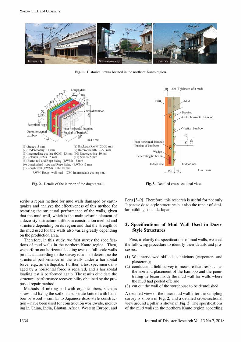
40 200
150 90
9030
120
(Thickness of a mud)
Outdoor side
Mud
BracketOuter horizontal bamboo
Vertical bamboo
Pillar
Wedge
Indoor side
Penetrating tie beam
Inner horizontal bamboo(Furring of bamboo)
Fig. 3. Detailed cross-sectional view.
Peru [3–9]. Therefore, this research is useful for not onlyJapanese dozo-style structures but also the repair of simi-lar buildings outside Japan.
2. Specifications of Mud Wall Used in Dozo-Style Structures
First, to clarify the specifications of mud walls, we usedthe following procedure to identify their details and pro-cesses.
(1) We interviewed skilled technicians (carpenters andplasterers);
(2) conducted a field survey to measure features such asthe size and placement of the bamboo and the pene-trating tie beam inside the mud wall for walls wherethe mud had peeled off; and
(3) cut out the wall of the storehouse to be demolished.
A detailed view of the inner mud wall after the samplingsurvey is shown in Fig. 2, and a detailed cross-sectionalview around a pillar is shown in Fig. 3. The specificationsof the mud walls in the northern Kanto region according
1334 Journal of Disaster Research Vol.13 No.7, 2018

Repairing and Recovering Structural Performance of Earthen WallsUsed in Japanese Dozo-Style Structures After Seismic Damage
Table 1. Specifications of mud walls around the northern Kanto region.
Materials Specifications
Penetrating tie beamSize Thickness: 30 mm Height: 120 mm
Pitch 909 mm
Inner horizontal bamboo (Furring of bamboo)Outer horizontal bamboo
Vertical bamboo
Size Diameter: about 25–30 mm
Shape Round bamboo
PitchInner horizontal bamboo: 2 (Between the upper and lower penetrating tie beams)Outer horizontal bamboo: about 100 mmVertical bamboo: about 120 mm
Mud Thickness about 150–250 mm(The wall thickness changes according to the needs of the owner)
(a) Type A (b) Type B and Type C
Fig. 4. Schematics of the specimens.
to the surveys are shown in Table 1.Two types of mud – rough wall mud and intermedi-
ate coating mud – are used for mud walls. The roughwall mud is clay mixed with straw that is approximately50 mm long and kneaded with water. The intermediatecoating mud is clay mixed with sand and fibrous strawthat is approximately 20–30 mm long and kneaded withwater.
Traditional Japanese wooden structures feature wallsconstructed with exposed timber pillars, but in dozo-stylestructures, the thick mud walls are used as a covering forthe outside pillars. For this reason, the base layer bamboois not split; round bamboo is used. First, the inner hori-zontal bamboo is hung between the pillars on both sidesin a frame. On the outside, vertical bamboo is installed;the outer horizontal bamboo is placed into a sawblade-shaped bracket cut out of the pillar, so that the weight ofthe mud is transferred from the outer horizontal bambooto the pillars. The intersections of bamboo are tightly tiedwith straw rope to produce a solid substrate.
In constructing parts of a wall where the cross sectionbecomes smaller owing to the frame, the rough wall, lon-gitudinal rope, barrel roll, and straw rope are densely ar-ranged, to maintain the integrity of the mud. Furthermore,when increasing the wall thickness, a rough wall mud isused, with intermediate coating mud thinly plastered toreinforce the fixing of the rough wall mud and to smooththe wall surface. Subsequently, retouching is performed,and the finishing materials are plastered.
3. Experiment Specifications
3.1. Overview of the SpecimensThis research included the construction and load test-
ing of three types of specimens, as described in Fig. 4.The Type A specimen comprised the framework only, forconfirming the effect of the penetrating tie beams. TheType B specimen was used to clarify the strength, de-formation performance, and damage state of the originalmud wall of a dozo-style structure. The Type C specimenhad the same specifications as Type B and was the testspecimen used to clarify the effect of repairing walls dam-aged by earthquakes. Specifically, we performed a load-ing test up to the restoration limit state and confirmed thedifference in the structural performance compared with aspecimen with the same specifications. Then, we repairedthe specimen damaged in the loading test, performed theloading test again, and clarified the repair effects. Here,for reducing costs and shortening the construction period– aiming for quick recovery from earthquake damage –the limit state at which the structural performance can berecovered to the original performance by partial repair isdefined as the restoration limit state. According to theflow shown in Fig. 5, Types B and C were constructedaccording to the specifications clarified in the above sur-vey, such as including the fitting of bamboo in the wall,the production process, and the preparation of wall mudplaster (rough wall mud and intermediate coating mud).
The shape and dimensions of the specimens and the
Journal of Disaster Research Vol.13 No.7, 2018 1335

Yokouchi, H. and Ohashi, Y.
(40weeks)
(12weeks)
(7weeks)
Bamboo knitting
(1) Rough strike
(2) Backing
(3) Undercoating and Longitudinal rope
Carpentering
(7) Regulating the unevenness
(3weeks) (7weeks)Plastering
Indoor sideOutdoor side
(9) Intermediate coating
(8) Surface protection of penetrating tie beam
and Retouch
(40weeks)
(4weeks)(4) Undercoating and
Rope hiding(4weeks)
(5) Undercoating and Barrel roll
(8weeks)(6) Intermediate
coating
Loading tests
Kneading
Clay screeningRetting(1weeks)
Kneading of the mud
Intermediate coating mudRough wall mud
Rough wall mud
Intermediate coating mud
Fig. 5. Production of mud walls.
materials used were basically the same: their width wastwo 910-mm spans, with a height of 2,730 mm. The jointbetween the pillar and the horizontal frame was shapedso that the end of the pillar did not touch the horizontalframe, even in the case of significant deformation. Thus,we ignored the resistance caused by the pillar sinking intothe horizontal frame, so that we could observe only theperformance of the wall panel. The shapes and dimen-sions of Types B and C are shown in Fig. 6, the materialsand specifications used are shown in Table 2, and Table 3shows the wall thickness and weight of each specimen af-ter drying.
The structural performance of wooden shear walls inJapan is generally evaluated via a loading test for a one-span specimen. However, if the specimens of this researchwere set to one span, the damage to the outdoor wallwould differ from that to the original pillars because thepillars on both sides would become corner pillars. For thisreason, we designed two-span specimens with a centerpillar, so that the damage around the original pillar couldbe roughly reproduced. Regarding the proof strength, wesupposed that even if the number of spans is different,the proof strength of a building can be roughly evaluatedby standardizing the proof strength obtained from the ex-periment as the proof stress per unit length or unit cross-sectional area.
The rough wall mud and the intermediate coating mudused for the test specimens are described in Table 4,the compression strength test results are shown in Ta-ble 5, and the stress–strain curves (average of six sam-ples) are shown in Fig. 7. The compression strength testswere performed according to the method developed by theJapanese Housing and Wood Technology Center [10].
3.2. Load-Measuring MethodMeasurement and loading were performed using the
method shown in Fig. 8. Positive and negative alternat-ing loading via displacement control was performed. Theloading schedule of gradually increasing the shear defor-mation angle to 1/600, 1/450, 1/300, 1/200, 1/150, 1/100,1/75, 1/60, 1/50, 1/40, and 1/30 rad in three cycles wasfollowed by one cycle of 1/20-rad loading. Finally, we ap-plied loading (with a deformation angle of approximately1/7 rad) to pull up to the allowable jack stroke (approxi-mately 400 mm).
The measurement items common to all specimens wereas follows: the horizontal load, the horizontal displace-ment of the beam and foundation, the lifting displacementof pillar bases, and the axial strain of the pillar top/basefixing bolts. In addition, for Types B and C, we examinedthe occurrence of cracks and the main crack width wheneach controlled deformation was reached. For Types Band C, the loading tests were performed under the super-vision of two skilled plasterers, who were responsible forrepairing the damaged building; the restoration limit state(the limit to which the structural performance can be re-stored to its original performance via partial repair) wasjudged according to the experience of the plasterers.
4. Structural Performance Test Results
This chapter shows the static horizontal loading test re-sults for all specimens and clarifies the structural perfor-mance of dozo-style structures.
1336 Journal of Disaster Research Vol.13 No.7, 2018

Repairing and Recovering Structural Performance of Earthen WallsUsed in Japanese Dozo-Style Structures After Seismic Damage
Unit: mm 9015020
40 200
9030
120
Bracket
Pillar130x130-150 Inner horizontal bamboo
(Furring of bamboo) 20-30
Vertical bamboo 20-30
910 910150 21
0
120 79
0
120 79
0
120 45
021
0
6527
3065
910
910
Penetrating tie beam30x120
Beam 150x210
Foundation150x150
Outer horizontal bamboo 20-30
(1) Rough strike (RWM)(2) Backing (RWM)
(3) Undercoating and Longitudinal rope (RWM)
(7) Regulating the unevenness (ICM)
(9) Intermediate coating (ICM)(8) Retouch (ICM)
(4) Undercoating and Rope hiding (RWM)
(5) Undercoating and Barrel roll (RWM)
(6) Intermediate coating(ICM)
PillarPenetrating tie beam
RWM: Rough wall mudICM: Intermediate coating mud
Fig. 6. Shapes and dimensions of Types B and C.
Table 2. Outline of the elements and specifications.
Element Specifications
Type AType BType C
PillarMaterial Japanese cedar
Size Width 130 mm × Depth 130–150 mm (Bracket 20 mm)
FoundationMaterial White cedar
Size 150 mm × 150 mm
BeamMaterial White cedar
Size Width 150 mm × Depth 210 mm
Penetrating tie beam Material Japanese cedarSize Width 30 mm × Depth 120 mm
Wedge Material White cedar
Type BType C
Surface protection of penetrating tie beam Material Rush (Ryukyu) L= 250 mm
BambooMaterial Long-jointed bamboo (Madake)
Size Diameter: 20–30 mm
Table 3. Wall thickness and weight of each specimen after drying.
Type B Type C Average
Wall thickness [mm]
Rough wall mud 169 172 171Intermediate coating mud 35 32 33
Total 204 204 204
Weight of a specimen[kN] 13.5 13.0 13.2([N/m]) (7408) (7119) (7263)
Table 4. Types and preparation details of the mud.
Rough wall mud About 60–70 kg of straw per cubic meter of clayIntermediate coating mud Cray: 10 kg, Sand: 15 kg, Fibrous straw: 300 g, Water: 7–8 l
Table 5. Compression strength test results of the mud.
SampleThickness
[mm]Number of
samplesAge[day]
Maximum compression strength[N/mm2] Density
[g/cm3]Min. Max. Average
Rough wall mud 70 6 43 0.371 0.391 0.378 1.30Intermediate coating mud 70 6 41 0.700 0.801 0.758 1.62
Journal of Disaster Research Vol.13 No.7, 2018 1337

Yokouchi, H. and Ohashi, Y.
0
0.2
0.4
0.6
0.8
0 0.02 0.04 0.06 0.08 0.1
Com
pres
sive
stre
ss
(N/m
m2 )
Strain
Intermediate coating mud
Rough wall mud
Fig. 7. Stress–strain curves (average of 6 samples).
4.1. Relationship Between Damage and Deforma-tion (Types B and C)
We confirmed that the major damage processes in theexperiment tended to be approximately the same for theType B and Type C specimens. Table 6 shows the crackstates when the target deformation peak was reached inthe first cycle of positive and negative loading, the ratioof the proof strength to the maximum proof strength, andthe residual deformation for each deformation angle.
First, fine cracks occurred at the corners at deformationangles of 1/600–1/450 rad. Then, cracks along the pen-etrating tie beams on the indoor side emerged at 1/450–1/300 rad.
At 1/100–1/75 rad, the corners of the indoor side beganto undergo compressive fracture; peeling of the outdoorside legs in the out-of-plane direction was confirmed atalmost the same deformation level.
When a load of 1/75 rad was applied, shear cracksoccurred near the central pillar of the outdoor side, andcracks appeared on the outdoor side along the uppermosttransverse penetrating tie beam at 1/60–1/50 rad. At thistime, cracks along the penetrating tie beams on the indoorside were connected over the length of the inner width ofthe pillar. The crack width also progressed; thus, 1/50 radwas judged to be the restoration limit state.
Applying further loading increased the damage to thewall and reduced the proof strength, such that large shearcracks occurred near the central pillar of the outdoor sideof the wall when −1/30 rad was applied, causing themud of the outer wall to flake off, whereas from 1/30 to1/20 rad, multiple cracks along the transverse penetratingtie beam of the outermost top row joined into one crack.
For the Type B specimen, we applied a load at 1/7.1 rad.The outdoor side did not collapse on a large scale until theend of the experiment, because of the adhesion of the mudto the straw rope.
As previously described, we examined the damage ateach deformation level, obtaining useful knowledge forestimating the residual seismic performance of dozo-stylestructures damaged by earthquakes.
4.2. Properties of Strength and Deformation
The relationship between the horizontal load and theshear deformation angle for the Types A, B, and C speci-mens (as obtained from loading tests) is shown in Figs. 9and 10, including skeleton curves for positive loading.
The strength of the Type A wall was significantly lowerthan that of the other two types. However, as the deforma-tion increased, because the resistance caused by the pen-etrating tie beams sinking into the pillars increased, theproof strength, which continued to increase in proportionto the deformation, was confirmed even if the deformationreached 1/7 rad or more.
The maximum proof strength of Type B was 37.1 kN,and the deformation angle at that time was 1/30 rad. Afterthe maximum proof strength was reached, the resistanceforce of the mud wall decreased, but – as with Type A, de-scribed above – the resistance force of the penetrating tiebeams increased with the horizontal deformation. Thesewalls maintained a proof strength of 84% or more of themaximum up to the final deformation by balancing themud wall resistance and the penetrating tie beam resis-tance, confirming their toughness.
For the Type C specimen, we applied loading up toa deformation angle of 1/50 rad, which was judged tobe the restoration limit. The proof strength at each de-formation up to the one for Type B was approximately94% on the positive-load side and approximately 92% onthe negative-load side, so that the structural performanceof the specimen constructed with the same specificationswas found to vary little overall, even if there were slightdifferences in the physical properties and construction ac-curacy of the natural materials.
4.3. Energy Absorption Performance
The hysteresis energy consumption per loop for eachdeformation is shown in Fig. 11. Fig. 12 shows the re-lationship between the equivalent viscous damping factorof the first loop and the shear deformation angle in eachdeformation. The hysteresis energy consumption was cal-culated via extraction of the hysteresis curves (the rela-tionship between the horizontal load and shear deforma-tion angle) one loop at a time and numerical integration,whereas the equivalent viscous damping factor was evalu-ated using Eq. (1) according to the hysteresis energy con-sumption [11]. Here, ΔW is the energy consumption ofone cycle of the historical loop, and We is the potentialenergy.
heq =1
4π
(ΔWWe
). . . . . . . . . . . (1)
The equivalent viscous damping factor up to 1/50 radshowed a good match between the Types B and C speci-mens (approximately 10%). It increased with increasingdeformation, reaching nearly 14% at the time of final de-formation. For each specimen, the amount of energy ab-sorption in the second loop was approximately 70% ofthat in the first loop, regardless of the deformation level,
1338 Journal of Disaster Research Vol.13 No.7, 2018

Repairing and Recovering Structural Performance of Earthen WallsUsed in Japanese Dozo-Style Structures After Seismic Damage
H=2
730m
m
Disp. gauge
Disp. gauge
Disp. gauge
Disp. gauge
Anti-swing device Anti-swing device
Actuator Actuator
Disp. gauge
Disp. gauge
Disp. gauge
Bolt
Bolt Bolt
+- + -
1820mm
(a) Outdoor side (b) Indoor side
Fig. 8. Methods of measurement and loading.
Table 6. Damage to the Type B specimen.
1/600 1/450 1/200 1/75 1/50 1/40 1/30 1/20
Outdoorside
Indoorside
21 27 48 80 88 96 100 98
0.4 0.4 1.2 3.7 6.7 9.4 14.8 25.2Residual deformation
[x10-3rad]-
Deformation angle [rad] Final
Type B
Damage state
Blue Positive+Red Negative-
Ratio of the proofstrength to the maximum
proof strength [%]85
Loadingdirection
Loadingdirection
Maximumstrength
-40-30-20-10
010203040
-75 -25 25 75 125
Hor
izon
tal l
oad
[kN
]
Shear deformation angle [x10-3rad]
Type B-40-30-20-10
010203040
-75 -25 25 75 125
Hor
izon
tal l
oad
[kN
]
Shear deformation angle [x10-3rad]
Type C-40-30-20-10
010203040
-75 -25 25 75 125
Hor
izon
tal l
oad
[kN
]
Shear deformation angle [x10-3rad]
Type A
Fig. 9. Relationship between the horizontal load and the shear deformation angle.
0
5
10
15
20
0
10
20
30
40
0 25 50 75 100 125 150
Horizontal load
per unit length [kN/m
]Hor
izon
tal
load
[kN
]
Shear deformation angle [x10-3rad]
Type A
Type B
Type C
1/75 1/50 1/30
Fig. 10. Skeleton curve comparison during positive loading.
Journal of Disaster Research Vol.13 No.7, 2018 1339

Yokouchi, H. and Ohashi, Y.
0
400
800
1200
1600
2000
0 10 20 30 40 50 60Shear deformation angle [x10-3rad]
Type B Type C 1st loop 2nd loop 3rd loop
1/75rad
Hyste
resis
ene
rgy
cons
umpt
ion
[kN
rad]
1/50rad1/30rad
Fig. 11. Hysteresis energy consumption per loop for each deformation.
02468
101214161820
0 10 20 30 40 50 60Shear deformation angle [x10-3rad]
Type BType C
1/75rad
Equi
vale
ntvi
scou
sda
mpi
ngfa
ctor
[%]
1/50rad1/30rad
Fig. 12. Relationship between the equivalent viscous damping factors of the first loop.
Fig. 13. Damage state before repair.
and in the third loop, it decreased to approximately 90%of that in the second loop.
5. Repair and Structural Performance Recov-ery of Mud Walls Damaged by Earthquakes
To clarify the applicability of the repair method fordamaged walls, we repaired the Type C specimen, whichwas damaged by applying force up to the restoration limitstate (story drift angle of 1/50 rad) and then performed
Loading test of Type C
Check the current status
Chipping
Mud coating repair (1st time)
Mud coating repair (2nd time)
Mud coating repair (3rd time)
Mud coating repair (4th time)
Loading test of Type C-RE
10 days
4 days
7 days
4 days
8 months
Fig. 14. Repair process.
a horizontal loading test on the repaired specimen (TypeC-RE).
5.1. Repair MethodFigure 13 shows the damage to the Type C specimen
before repair. In the specimen, cracks along the penetrat-ing tie beams on the indoor side became linked through-out the width of the pillar, and the damage grew to in-clude other cracks. This specimen was repaired via theprocedure shown in Fig. 14 under the judgment and guid-
1340 Journal of Disaster Research Vol.13 No.7, 2018

Repairing and Recovering Structural Performance of Earthen WallsUsed in Japanese Dozo-Style Structures After Seismic Damage
Existing wall
Blue line: Aqueous foundation strengthening agentDashed line: Glass fiber net
Nails (L=50 mm, V-shape)
Mud coating (1st time)
Finished surface
Mud coating (2nd time)Mud coating (3rd time)
Mud coating (Last time)
About 45
Fig. 15. Method of chipping and repair.
Outdoor side Indoor side
Gray line: Damage state of the restoration limit
1-3 4-10 11-20 21-35 36-60 61-90Depth from the Finished surface to the broken one (mm)
Fig. 16. Removal of the wall mud.
ance of a skilled plasterer engaged in the repair of seismic-damaged structures.
First, after confirming the current damage, we beganchipping. In this process, while setting up terrace-likesteps around the damaged area, as shown in Fig. 15, wechanged the depth by chipping away at the damaged part.We decided to leave the penetrating tie beams and bambooand the wedges in the wall in their existing state. Then, themud surrounding the penetrating tie beams on the indoorside was removed until the penetrating tie beam surfacewas exposed, and the exposed surface protection materi-als (a type of rush called ryukyu) of the penetrating tiebeams were removed. As the straw ropes on the outdoorside were healthy, we were careful not to damage themwhile removing the mud. Finally, to adjust the wall thick-ness after repair to the same wall thickness before repair,we scraped off approximately 2–3 mm from both sides ofthe existing wall surface to prevent the partial repair frombeing evident.
In Fig. 16, the removal of the wall mud is shown, withthe colors representing the removed depths.
Next, we performed out the step of gradually daub-ing the mud wall with an aqueous reinforcement agentfor the face applied to the wall surface. The wall wasdaubed multiple times in sequential order, beginning withthe deepest scraped areas. To enhance the fixing, glassfiber nets (hereinafter simply called nets) were placed ineach layer, as shown in Fig. 17. Peeling from the exist-ing wall was prevented by fastening a net to the existing
Fig. 17. Adding the glass fiber net.
wall at an interval of approximately 450 mm from a posi-tion approximately 50 mm away from the end of the net,with 50-mm-long V-shaped nails. This work was done ineach layer, and the surface of the last mud coating wassmoothed. For the penetrating tie beams around the in-door side, approximately 2 mm of formulated plaster (alsocalled stucco) was daubed on the penetrating tie beam sur-face, and then the net (mesh width: 5 mm) was laid downand stapled using industrial staples. This process was thenrepeated.
The specimen before repair (Type C) was produced us-ing clay collected from the countryside in the area, butall the mud used for repair was intermediate coating mudcontaining commercially available clay (production area:Fukaya City, Saitama Prefecture).
5.2. Verification of Structural Performance Recov-ery
For the repaired specimen (Type C-RE), we performedpositive and negative alternating repetitive loading viadisplacement control, as we did for the original specimens(Types B and C). In this section, we detail the experimen-tal results of the repaired specimen and verify the effect ofthe repairs on the structural performance compared withthe results for the original specimens in sound condition.
The crack states when the target deformation peak wasreached in the first cycle of positive and negative loadingare shown in Table 7 and are compared with those forTypes B and C. When the deformation angle was 1/600–
Journal of Disaster Research Vol.13 No.7, 2018 1341

Yokouchi, H. and Ohashi, Y.
Table 7. Cracking states of the outdoor and indoor sides under a typical deformation.
1/450 1/100Indoor side Outdoor side Outdoor side Indoor side Outdoor side Indoor side
Type B
Originalspecimen
Type C
Originalspecimen
Type C-RE
Repairedspecimen
Elevation surface
Damage state
BluePositive+
RedNegative-
Loadingdirection
Deformation angle [rad] 1/50 (Restoration limit) 1/30 (Maximum strength)
(Indoor side)
(Outdoor side)
-45
-30
-15
0
15
30
45
-75 -50 -25 0 25 50 75 100 125 150
Horiz
onta
l lo
ad [k
N]
Shear deformation angle [x10-3rad]
Fig. 18. Hysteresis loop of Type C-RE.
1/450 rad, cracks occurred along the penetrating tie beamson the indoor side. As the force increased, shear crackingoccurred near the center pillar on the outdoor surface at1/100 rad for the repaired specimen. In contrast, the orig-inal specimen exhibited a shear crack at 1/75 rad. Thiscomparison revealed that the damage in the repaired spec-imen progressed faster than that in the original specimen.Compared with the original specimen, the damage to therepaired specimen at 1/50 rad (the restoration limit state)was dispersed around the repaired spots. At the maxi-mum proof strength, the expansion of the shear cracks onthe outdoor side of the wall surface and the penetration ofthe cracks along the uppermost penetrating tie beam wereconfirmed in both Types B and C-RE. They reduced theproof strength of the specimen. The nets and mud of therepaired sections did not peel away from the existing wallsuntil end of the loading test, confirming that adhesion tothe existing wall was maintained.
-25-20-15-10-50510152025
-45
-30
-15
0
15
30
45
-75 -50 -25 0 25 50 75 100 125 150
Horizontal loadper unit length [kN
/m]Ho
rizon
tal
load
[kN
]
Shear deformation angle [x10-3rad]
Type BType CType C-RE
1/100rad1/50rad (Restoration limit)
1/30rad(Maximum strength)
Fig. 19. Comparison of the skeleton curves among the spec-imens.
The relationship between the horizontal load and theshear deformation angle of the repaired specimen (TypeC-RE) is shown in Fig. 18. The skeleton curves of the re-paired and original specimens are shown in Fig. 19. Here,the initial stiffness and yield strength were evaluated ac-cording to the structural performance evaluation methodof the Japanese Housing and Wood Technology Centerfor shear walls, as shown in Fig. 20 [12].
As shown in Table 8, the initial stiffness and yieldstrength of the repaired specimen were approximately90% of those of Type B, with no major differences fromthe pre-repair state. The maximum proof strength at thetime of negative loading was 1.2 times that of the originalspecimen, and we confirmed a tendency for the two typesto exhibit equal specifications or for the repaired specimento perform better. The deformation at the maximum proofstrength was the same for the Type C-RE and Type B
1342 Journal of Disaster Research Vol.13 No.7, 2018

Repairing and Recovering Structural Performance of Earthen WallsUsed in Japanese Dozo-Style Structures After Seismic Damage
Shear deformation angle [x10-3rad]
Horizontal load [kN]
Maximum strength (Pmax)0.9Pmax
0.1Pmax
0.4PmaxInitial stiffness
Yield strength
Fig. 20. Evaluation of the initial stiffness and yield strength.
Table 8. Comparison of the results for Type B and Type C-RE.
Initial stiffness[×103kN/rad]
Yield strength[kN] ([kN/m])
Maximum strength [kN] ([kN/m])
Positive direction Positive direction Positive direction Negative direction1© Type C-RE 2.45 20.2 (11.1) 38.4 (21.1) 40.7 (22.4)
2© Type B 2.81 22.5 (12.3) 37.1 (20.4) 34.5 (18.9)1© / 2© 0.87 0.90 1.04 1.18
specimens (approximately 1/30 rad). From the time ofthe maximum proof strength until the final deformation,the proof strength was maintained at 84% or more of themaximum proof strength, and, as with Type B, we con-firmed the toughness of this specimen. We also confirmedthat the maximum proof strength of the repaired speci-men tended to be higher than that of the original, possiblybecause the stress concentration was reinforced in placeswhere intermediate coating mud, which is stronger thanrough wall mud, was used for the repair. One of the fac-tors preventing brittle cracking and peeling was embed-ding nets in multiple layers and enhancing the fixabilityof the walls.
6. Conclusion
We surveyed the specifications of dozo-style structuresacross the northern Kanto region of Japan and conductedhorizontal loading tests on specimens produced accordingto our findings. From the loading test results, we clarifiedthe structural performance of the walls and the damage atseveral deformation levels, thus obtaining useful knowl-edge for estimating the residual seismic performance ofand damage to dozo-style structures damaged by earth-quakes.
When cracks along the penetrating tie beams on the in-door side connected over the length of the inner width ofthe pillar and the crack width also progressed, the mudwall was judged to be at a restoration limit state. The de-formation angle at this state was 1/50 rad.
In the repair method described in this paper, the ini-
tial stiffness and proof strength/deformation properties ofthe repaired wall recovered to nearly the original condi-tion or better. The major damage process of the repairedspecimen tended to be very similar to that of the originalspecimen, and the repaired section was integrated with theexisting wall to provide effective resistance with no pos-sibility of localized destruction. These results confirmedthe effectiveness of our repair method.
AcknowledgementsWe thank Mr. Naoki Kokubun and Mr. Yoshiaki Nomura for con-ducting the experiment together. This study was performed asa Development of Comprehensive Disaster Mitigation Project of“Preservation Districts for Groups of Traditional Buildings” un-der the JST Strategic Basic Research Programs for RISTEX. Thispaper includes research and development project results.
References:[1] H. Yokouchi and Y. Ohashi, “Earthquake resistance evaluations
and seismic damage assessment of Japanese traditional building inTochigi,” Proc. of the 15th World Conf. on Earthquake Engineering,No.1272, 2012.
[2] Joint Editorial Committee for the Report on the Great East JapanEarthquake Disaster, “Report on the Great East Japan EarthquakeDisaster, Building Series Vol.4, Structural Damage to Timber Build-ings / Damage of Historic Buildings,” Architectural Institute ofJapan, 2015 (in Japanese).
[3] C. Kawashima, “Design of private houses, Overseas version,”Suiyosha Publishing Inc., pp. 67-96, 2016 (in Japanese).
[4] K. Ohta, “Wooden building in Eastern Europe,” Sagami-Syobo,pp. 39-48, 1988 (in Japanese).
[5] E. Fodde, “Traditional Earthen Building Techniques in CentralAsia,” Int. J. of Architectural Heritage, Vol.3, No.2, pp. 145-168,2009.
[6] N. Quinn, D. D’Ayala, and T. Descamps, “Structural Characteriza-tion and Numerical Modeling of Historic Quincha Walls,” Int. J. ofArchitectural Heritage, Vol.10, No.2-3, pp. 300-331, 2016.
Journal of Disaster Research Vol.13 No.7, 2018 1343

Yokouchi, H. and Ohashi, Y.
[7] M. Blondet, J. Vargas-Neumann, N. Tarque, J. Soto, C. Sosa, and J.Sarmiento, “Seismic protection of earthen vernacular and historicalconstructions,” Proc. of the 10th Int. Conf. on Structural Analysisof Historical Constructions, pp. 3-14, 2016.
[8] M. R. Maheri, A. Maheri, S. Pourfallah, R. Azarm, and A. Had-jipour, “Improving the Durability of Straw-Reinforced Clay PlasterCladding for Earthen Buildings,” Int. J. of Architectural Heritage,Vol.5, No.3, pp. 349-366, 2011.
[9] Q. Ali, N. Ahmad, M. Ashraf, M. Rashid, and T. Schacher, “ShakeTable Tests on Single-Story Dhajji Dewari Traditional Buildings,”Int. J. of Architectural Heritage, Vol.11, No.7, pp. 1046-1059, 2017.
[10] National Institute for Land and Infrastructure Management, “Tech-nical manual on the shear wall factor of mud wall, surface latticewall and inserted wooden siding wall,” Japanese Housing and WoodTechnology Center, pp. 144-147, 2004 (in Japanese).
[11] A. Shibata, “Dynamic Analysis of Earthquake Resistant Struc-tures,” Tohoku University Press, 2010.
[12] National Institute for Land and Infrastructure Management, Build-ing Research Institute, “Allowable Stress Design for House withTimber Frame Construction (2017 Edition),” Japanese Housing andWood Technology Center, pp. 300-301, 2017 (in Japanese).
Name:Hajime Yokouchi
Affiliation:Associate Professor, Department of Architec-ture, Kokushikan University
Address:4-28-1 Setagaya, Setagaya-ku, Tokyo 154-8515, JapanBrief Career:2001 Joined Aoki Corporation2004 Asunaro Aoki Construction Co., Ltd.2009-2018 National Institute of Technology, Oyama College2018- Associate Professor, Kokushikan UniversitySelected Publications:• “Structural Characterization of The Existing Historic Buildings in TheUrban Areas of Northern Kanto Region,” AIJ J. of Technology andDesign, Vol.23, No.55, pp. 881-884, 2017.• “Proposal and Practice of Comprehensive Disaster Mitigation Dependingon Communities in Preservation Districts for Traditional Buildings,” J.Disaster Res., Vol.10, No.5, pp. 857-873, 2015.Academic Societies & Scientific Organizations:• Architectural Institute of Japan (AIJ)• Institute of Social Safety Science (ISSS)• JAPAN ICOMOS National Committee (JPICOMOS)
Name:Yoshimitsu Ohashi
Affiliation:Professor, Department of Architecture, TokyoCity University
Address:1-28-1 Tamazutsumi, Setagaya-ku, Tokyo 158-8557, JapanBrief Career:2000-2005 Associate Professor, Prefectural University of Kumamoto2005-2009 Professor, Musashi Institute of Technology2009- Professor, Tokyo City UniversitySelected Publications:• “Study on The Relationship Between The Damage and The ResidualStrength of Wooden House According to Old Standard,” J. of Structuraland Construction Engineering, Vol.80, No.712, pp. 895-904, 2015• “Exercise Book of Structural Design for Timber House.” The BuildingCenter of Japan, 2012• “Study on Seismic Performance of Traditional Timber Houses subjectedto Full-scale Shaking Table Tests,” Research J. of AIJ, 2010.Academic Societies & Scientific Organizations:• Architectural Institute of Japan (AIJ)• Japan Wood Research Society (JWRS)
1344 Journal of Disaster Research Vol.13 No.7, 2018
Powered by TCPDF (www.tcpdf.org)
Copyright © 2022 FDOKUMEN