Relay Attack Resistant Passive Keyless Entry - KTH
90
IN DEGREE PROJECT MECHANICAL ENGINEERING, FIRST CYCLE, 15 CREDITS , STOCKHOLM SWEDEN 2020 Relay Attack Resistant Passive Keyless Entry Securing PKE Systems with Immobility Detection ABEL VALKO KTH ROYAL INSTITUTE OF TECHNOLOGY SCHOOL OF INDUSTRIAL ENGINEERING AND MANAGEMENT
-
Upload
khangminh22 -
Category
Documents
-
view
4 -
download
0
Transcript of Relay Attack Resistant Passive Keyless Entry - KTH

IN DEGREE PROJECT MECHANICAL ENGINEERING,FIRST CYCLE, 15 CREDITS
, STOCKHOLM SWEDEN 2020
Relay Attack Resistant Passive Keyless EntrySecuring PKE Systems with Immobility Detection
ABEL VALKO
KTH ROYAL INSTITUTE OF TECHNOLOGYSCHOOL OF INDUSTRIAL ENGINEERING AND MANAGEMENT


Relay Attack Resistant Passive Keyless Entry
ABEL VALKO
Bachelor’s Thesis at ITMSupervisor and Examiner: Nihad Subasic
TRITA-ITM-EX 2020:48

AbstractA significant security risk of modern vehicles is their vulner-ability to relay attacks. Challenge-response methods, suchas those employed in Passive Keyless Entry (PKE) used bymost commercial vehicles, are inherently exposed to thisclass of attacks, where communication between a vehicleand it’s key can be transmitted by an attacker over longrange - thereby bypassing any encryption and unlockingthe vehicle without requiring direct access to the key.
While a multitude of defenses have been proposed in re-cent years, many lack either robustness or practicality. Anyviable security system must satisfy a number of criteria.Such a strategy will likely have to rely on an environmentalparameter which is not only immutable but also sufficientlyspace variant as to allow it to discern two positions whichmay be merely meters apart. Moreover, the system hasto be: cost effective; easily implementable; and take usercomfort, such as the key’s battery time, into account.
The main purpose of this thesis is the implementationand evaluation of a PKE system resistant to relay attacks,it also analyses a multitude of proposed strategies for feasi-bility, as well as suggests a novel method: Approach CurveMatching. It is concluded that the most promising ap-proaches include: Immobility Detection, Distance Bound-ing Protocols, Approach Curve Matching, and analysingthe Jackard index of Wi-Fi access points - the first of whichis chosen to be implemented in the prototype PKE system.
The project first develops a PKE system utilizing twoRaspberry Pis acting as the vehicle’s on-board computerand key fobs microcomputer and implements the commu-nication protocol using Bluetooth, as opposed to the con-ventional RFID. Immobility Detection, using an accelerom-eter, is then implemented. The final system is then testedand evaluated. It is concluded that while Immobility De-tection is not comprehensively effective, it is easily imple-mentable, cost-effective, and can greatly increase the se-curity of PKE systems. Furthermore, the project observedthat Bluetooth’s Received Signal Strength Indicator (RSSI)measurements are subject to exceeding fluctuation and aregenerally environment dependent; it is surmised that whileother implementations of indirect distance measurementwith Bluetooth may be more accurate, RSSI is not optimalfor PKE applications. Finally, it is proposed that Immo-bility Detection should be employed promptly by manufac-turers while investigating potentially more effective, albeituncertain, strategies.
Keywords: Passive Keyless Entry, Relay Attack, MafiaFraud, Access Control, Mechatronics
ReferatTitle in Swedish
En betydande sakerhetsbrist av moderna fordon ar derassarbarhet mot sa kallade ’relay attacker’. Dessa typer avattacker, dar signaler mellan bilen och nyckeln vidarebe-fordras, kringgar all kryptering och laser upp bilen utan attha direkt tillgang till nyckeln. En stor del av kommersiellafordon tillampar ’Passive Keyless Entry’ (PKE) som byg-ger pa ’challenge-response’ metoder som visats vara sarkiltutsatta for dessa attacker.
En mangd olika skyddssystem har foreslagits pa se-nare ar, men manga saknar erforderlig robusthet eller ge-nomorbarhet. Ett lampligt system bor uppfylla en rad olikakriterier. Strategin maste grundas pa en omgivningspara-meter som ar bade oforanderlig och tillrackligt rymdbero-ende att tva nara positoner kan skiljas at. Dessutom skasystemet vara kostnadseffektivt, implementerbart, och tahansyn till anvandarkomfort sasom batteritid.
Projektets huvudsyfte ar konstrktionen och analysenav ett ’relay attack’ resistent PKE system. I detta projektingar ocksa en analys av ett antal foreslagna forsvar ochforeslar en ny metod: ’Approach Curve Matching’. Slutsat-sen dras att de mest lovande taktikerna ar: analys av Jac-kard indexet av Wi-Fi hotspots, ’Distance Bounding Pro-tocols’, ’Approach Curve Matching’ och ’Immobility Detec-tion’ som ocksa implementeras i prototyp PKE systemet.
Projektet utvecklar forst ett PKE system med tva Rasp-berry Pis som agerar som bilens och nyckelns mikrodatoreroch implementerar kommunikationsprotokollet med hjalpav Bluetooth. ’Immobility Detection’ ar sedan implemen-terad genom en inbyggd accelerometer i nyckeln. Slutligentestas och utvarderas systemet. Det konkluderas att trotsatt ’Immobility Detection’s effektivitet inte ar helt omfat-tande ar den latt att implementera, kostnadseffektiv, ochkan bidra till en betydlig okning av sakerheten hos PKEsystem. Vidare observerade projektet att Bluetooths ’Re-ceived Signal Strength Indicator’ (RSSI) matningar ar ut-satta for avsevard ostadighet och ar allmant omgivningsbe-roende. Darfor anses Bluetooth RSSI inte lamplig for PKEtillampningar aven om andra metoder for avstansmatningmed Bluetooth kan ha hogre prestanda. Det foreslas att’Immobility Detection’ tillampas av tillvarkare omgaendemedans andra potentiellt mer effektiva strategier utreds.
Keywords: Nyckellosa System, Atkomstkontroll, RelayAttack, IT-sakerhet, Mekatronik

Acknowledgements
I would like to thank my supervisor Nihad Subasic for providing guidance during thewhole project. Thanks are also due to the team of course assistants who have helpedduring the course of this project and my peers for their opposition and discussionon the thesis. Finally, I would also like to express my thanks to Andras Valko,Balazs Valko, and Janos Valko for fruitful discussions and brainstorming, and forproviding invaluable support throughout the thesis.
Abel ValkoMay 2020
Contents
1 Introduction 11.1 Purpose . . . . . . . . . . . . . . . . . . . . . . . . . . . . . . . . . . 21.2 Scope . . . . . . . . . . . . . . . . . . . . . . . . . . . . . . . . . . . 21.3 Method . . . . . . . . . . . . . . . . . . . . . . . . . . . . . . . . . . 3
2 Background 52.1 Passive Keyless Entry . . . . . . . . . . . . . . . . . . . . . . . . . . 5
2.1.1 Overview . . . . . . . . . . . . . . . . . . . . . . . . . . . . . 52.1.2 Encryption . . . . . . . . . . . . . . . . . . . . . . . . . . . . 7
2.2 Relay Attack . . . . . . . . . . . . . . . . . . . . . . . . . . . . . . . 82.2.1 Overview . . . . . . . . . . . . . . . . . . . . . . . . . . . . . 82.2.2 Limitations . . . . . . . . . . . . . . . . . . . . . . . . . . . . 92.2.3 Threat . . . . . . . . . . . . . . . . . . . . . . . . . . . . . . . 10
2.3 Key Fob Design . . . . . . . . . . . . . . . . . . . . . . . . . . . . . . 102.3.1 Battery . . . . . . . . . . . . . . . . . . . . . . . . . . . . . . 102.3.2 Wireless Technology . . . . . . . . . . . . . . . . . . . . . . . 10
3 Proposed Defenses 133.1 Received Signal Strength Indicator . . . . . . . . . . . . . . . . . . . 133.2 Coordinate Tracing . . . . . . . . . . . . . . . . . . . . . . . . . . . . 133.3 GPS . . . . . . . . . . . . . . . . . . . . . . . . . . . . . . . . . . . . 143.4 Jaccard Similarity of Wi-Fi Access Points . . . . . . . . . . . . . . . 153.5 Distance Bounding . . . . . . . . . . . . . . . . . . . . . . . . . . . . 163.6 Immobility Detection . . . . . . . . . . . . . . . . . . . . . . . . . . . 173.7 Approach Curve Matching . . . . . . . . . . . . . . . . . . . . . . . . 17
4 Implementation 214.1 Hardware . . . . . . . . . . . . . . . . . . . . . . . . . . . . . . . . . 21
4.1.1 Microcomputer . . . . . . . . . . . . . . . . . . . . . . . . . . 214.1.2 Bluetooth Module . . . . . . . . . . . . . . . . . . . . . . . . 214.1.3 Accelerometer . . . . . . . . . . . . . . . . . . . . . . . . . . . 224.1.4 Locking and Servo Motor . . . . . . . . . . . . . . . . . . . . 22
4.2 Software . . . . . . . . . . . . . . . . . . . . . . . . . . . . . . . . . . 23
4.2.1 Logic . . . . . . . . . . . . . . . . . . . . . . . . . . . . . . . 244.2.2 Authentication Protocol . . . . . . . . . . . . . . . . . . . . . 244.2.3 Software Architecture . . . . . . . . . . . . . . . . . . . . . . 254.2.4 Encryption . . . . . . . . . . . . . . . . . . . . . . . . . . . . 26
4.3 Results . . . . . . . . . . . . . . . . . . . . . . . . . . . . . . . . . . . 26
5 Discussion 29
6 Conclusion 31
Bibliography 33
Appendices 37A ZOE-M8B GPS Module Data-sheet (excerpt) . . . . . . . . . . . . . 37B Power Consumption Measurements for WF(M)200 Wi-Fi Module
(excerpt) . . . . . . . . . . . . . . . . . . . . . . . . . . . . . . . . . . 45C AIS2DW12 Accelerometer Data-sheet (excerpt) . . . . . . . . . . . . 50D Python Code for the Designed PKE System - Key . . . . . . . . . . 53E Python Code for the Designed PKE System - Vehicle . . . . . . . . . 65F Test Cases . . . . . . . . . . . . . . . . . . . . . . . . . . . . . . . . . 74
List of Figures
2.1 Protocol diagram of typical PKE system. . . . . . . . . . . . . . . . . . 62.2 Inner and outer RFID zones. . . . . . . . . . . . . . . . . . . . . . . . . 72.3 Agent entering between the car and key fob communication. . . . . . . . 82.4 Protocol diagram of relay attack on PKE System. . . . . . . . . . . . . 92.5 RFID beacons placed around the car interior and exterior. . . . . . . . . 11
4.1 Connection diagram for the MPU6050 accelerometer to Raspberry Pi Zero. 224.2 Activity diagram of the unlocking process for the improved PKE system
with Immobility Detection. . . . . . . . . . . . . . . . . . . . . . . . . . 234.3 Sequence diagram of a successful unlocking sequence. . . . . . . . . . . . 254.4 Prototype setup of the implemented PKE system with the key fob and
accelerometer (left) and on-board computer and lock (right). . . . . . . 26

List of Abbreviations
BLE Bluetooth Low Energy
DTW Dynamic Time Warping
GPIO General Purpose Input/OutputGPS Global Positioning System
LF Low Frequency
PKE Passive Keyless EntryPKES Passive Keyless Entry and StartPWM Pulse Width Modulation
RF Radio FrequencyRFID Radio-Frequency IdentificationRKS Remote Keyless SystemRSSI Received Signal Strength Indicator
SARA Signal Amplification Relay AttackSMBus System Management Bus
UHF Ultra High Frequency

Chapter 1
Introduction
Notes: Even number of pages. Holes. Position figuresIn Sweden alone there are near 5 million registered, in use, personal vehicles [1].
Approximately one for every 2 individuals [2]. The rapidly increasing connectivityof these vehicles and the shift from mechanical to electronic and wireless systemsgives rise to new security vulnerabilities. Modern methods of car theft are a primeexample of newly digitalized exploits owing to the spread of digital lock systems.The Remote Keyless System (RKS) has all but replaced the previous mechanicallock mechanism in cars with its Passive Keyless Entry (PKE) variant becomingstandard in most high-end brands instead of its active counterpart. The traditionalactive RKS is a unidirectional system where the user unlocks the vehicle with aremote control, a.k.a. ’key fob’. The PKE System, explained in detail in Chapter2.1, unlocks the car automatically as the user approaches the vehicle with the keyfob - without the need for any interaction with the user interface. It employsbidirectional communication where the car sends a wake-up signal to the key whenit is within range (commonly under 1 meter) and the driver takes hold of the handle,proceeded by a challenge response from the key which, if correct, will unlock thevehicle. A similar check may be performed in order to start the vehicle [3, 4].
This system increases user comfort due to the eliminated interaction and withthe encryption algorithm and challenge-response technique that is employed in mostrecent implementations, explained in 2.1, assures high resistance to many methods ofattacks. However, it is not secure against relay attacks - also known as Mafia Fraud- and Signal Amplification Relay Attack (SARA) which are attacks that do notrequire decryption and are not affected by the encryption algorithm’s complexity,nor can they be eliminated using alternative protocols [4, 5]. A review by Gulsever ofUpstream’s, a cyber security company’s, repository consisting of security incidentsrelating to the automotive industry show 187 exploits related to connected carswith 25 unique attack vectors (paths that allow an attacker to gain access to asystem) identified [6]. RKS vulnerabilities accounted for the largest number ofthem as well as having the largest ratio of ’black hat’ (malicious as opposed to’white hat’ - research) attacks. Various suggested security features exist that could
1
CHAPTER 1. INTRODUCTION
protect a PKE System from relay attacks. These include context based systemsusing relative position of car and key fob, comparison of Wi-Fi access point lists,Global Positioning System (GPS) coordinates etc [3, 4, 7, 8]. This thesis analysesthese proposed defences as well as suggests a novel way of protection, constructs aprototype system with the chosen method - Immobility Detection - and evaluatessaid system.
1.1 PurposeThis project, within the scope of a Bachelor’s Thesis in Mechatronics at KTH RoyalInstitute of Technology, aims to construct a prototype PKE System as a proof ofconcept for relay attack resistance by way of Immobility Detection. It aims toanalyze and evaluate the effectiveness and feasibility of an added ’sleep-mode’ toexisting PKE Systems in relation to existing and other proposed security features.This is summarised in the following research questions:
• How effective is Immobility Detection as a method of protection against relayattacks?
• How feasible is the implementation of Immobility Detection in PKE systems?
• How does Immobility Detection compare to other potential methods of protec-tion against relay attacks? Can it be supported by other methods for increasedprotection?
• Is Bluetooth Low Energy (BLE) a viable alternative to Radio-Frequency Iden-tification (RFID) in PKE systems?
1.2 ScopeThis paper aims to present a proof of concept implementation of relay attack resis-tance using an accelerometer in a PKE System’s key fob. As such it is constrainedto the implementation of the base functionality of a PKE System. However, it doesnot include some of the more robust features deemed irrelevant for this thesis. Theimplementation of encryption used in modern systems, such as KeeLoq [8], optimi-sation of power consumption, as well as physical robustness are considered outsidethe scope of this study. It is assumed for the purposes of this thesis that the encryp-tion protocol is reliable and has the required complexity to be undecipherable, thusno consideration is given to it. A simple mechanical system is also demonstratedwhich serves merely as a visual representation of the door lock. Power consump-tion, especially of the key fob, is an important aspect to consider with any proposedsolution. This project considers the effects of added features and sensors on batterylife but does not take this into consideration in the physical prototype. Based onthe project’s needs as well as economic and time constraints the hardware chosenis as presented in Chapter 4.1.
2
1.3. METHOD
Additionally, this paper presents several alternative methods of protection foundin the literature. These are summarized and briefly evaluated for effectiveness andfeasibility and subsequently compared to the solution presented and developed inthis thesis.
1.3 MethodThis study has been conducted in the following six phases; initial problem formu-lation, preliminary solution brainstorming, research, problem and solution speci-fication, construction and, finally, evaluation. Once the problem was identified,various possible solutions were brainstormed and evaluated. Several of these werelater found to be methods suggested by other papers or supported by the industry.In the subsequent research phase all methods were rigorously assessed. The sug-gested solution was then concretized. A Raspberry Pi Zero W was chosen as themicrocomputer for its price, simplicity, as well as wireless capabilities. The commu-nication protocol was implemented using Bluetooth as opposed to the conventionalRFID. The setup was constructed with all necessary dimensions for functioning asa suitable demonstration of the concept, omitting certain irrelevant features. Theimplemented solution was then evaluated and compared to other proposed solutions.
3

Chapter 2
Background
The following chapter outlines all the required information for complete analysesof the proposed defenses. Understanding current PKE implementation - into whichany defense must be integrated - both in terms of limitations and potential is crucialfor assessing viability of any system. In order to judge the effectiveness of proposedstrategies the chapter also presents a high level overview of relay attacks.
2.1 Passive Keyless Entry
2.1.1 Overview
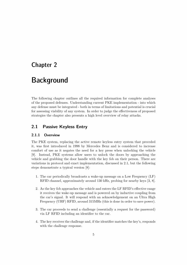
The PKE system, replacing the active remote keyless entry system that precededit, was first introduced in 1998 by Mercedes Benz and is considered to increasecomfort of use as it negates the need for a key press when unlocking the vehicle[9]. Instead, PKE systems allow users to unlock the doors by approaching thevehicle and grabbing the door handle with the key fob on their person. There arevariations in protocol and exact implementation, discussed in 2.1, but the followingsteps demonstrate a typical version [8]:
1. The car periodically broadcasts a wake-up message on a Low Frequency (LF)RFID channel, approximately around 130 kHz, probing for nearby keys [3, 8].
2. As the key fob approaches the vehicle and enters the LF RFID’s effective rangeit receives the wake-up message and is powered on by inductive coupling fromthe car’s signal. It will respond with an acknowledgement on an Ultra HighFrequency (UHF) RFID, around 315MHz (this is done in order to save power).
3. The car proceeds to send a challenge (essentially a request for the password)via LF RFID including an identifier to the car.
4. The key receives the challenge and, if the identifier matches the key’s, respondswith the challenge response.
5
CHAPTER 2. BACKGROUND
5. The car then unlocks - assuming that the challenge response is accepted.
While variations on this system exist, such as omitting the wake-up or requiringdouble verification, the core functionality is the same across manufacturers [3, 8].
Figure 2.1. Protocol diagram of typical PKE system. (Figure made with draw.io)
The same process as described above is presented in Figure 2.1. A variation onthis system is the Passive Keyless Entry and Start (PKES) system which has anadditional sequence similar to the one detailed in Figure 2.1 when the user entersthe vehicle, allowing engine start with the push of a button on the dashboard.
6
2.1. PASSIVE KEYLESS ENTRY
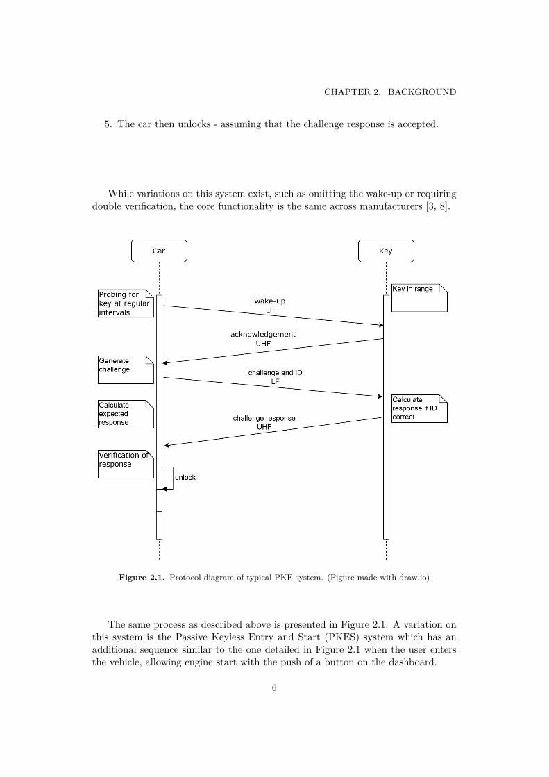
Figure 2.2. Inner and outer RFID zones. [8]
For this, two RFID zones are required, as depicted in Figure 2.2, with onereaching outside of the car (generally in a range no more then one meter from thedoors) for unlocking and one exclusively on the inside of the vehicle for starting theengine. Note that while the LF zones are strictly in a few meter radius around thecar the range of the UHF transmitter can be significantly larger [3, 4, 7, 8].
2.1.2 EncryptionWhile this paper does not focus on the encryption algorithms used in PKE systemsit is briefly summarized as follows: Both the vehicle and the key fob share a secrethardware key unique to a manufactured vehicle. When the key fob has acknowledgedthat it is in range the car generates a pseudo-random code to be transmitted as thechallenge. The key receives the challenge and uses it to generate a response using acipher such as KeeLoq or DST [8]. During this time the car will also generate theresponse and compare it to the received response from the key. In theory, this isa one-way operation which can neither be predicted, reverse engineered, or brute-forced. While the cryptography method used in PKE can itself be attacked [10], thisgoes beyond the scope of this paper: which assumes that the encryption methodcan be fully relied upon.
7
CHAPTER 2. BACKGROUND
2.2 Relay Attack
2.2.1 Overview
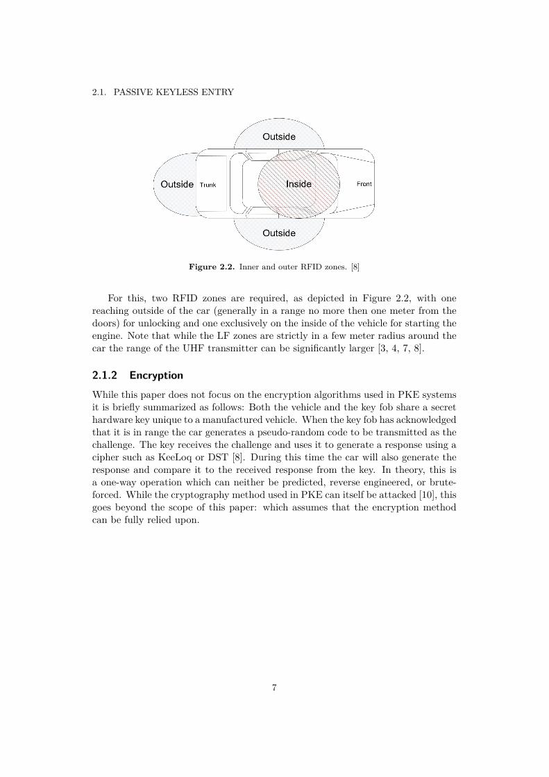
Relay attacks, also known as Mafia Fraud, have multiple forms, though all relyon the same fundamental principles. It is a man-in-the-middle attack, a methodby which an agent (in this case a relay) steps between two (or more) devices andforwards (a.k.a. relays) signals between them, see Figure 2.3 This allows the agentto essentially pose as a trusted device without having to know any details of thesecure communication. This type of attack is commonly employed with parked carswith the key in a relatively close range, such as inside a house or in the pocket ofthe driver at a store, cafe, or similar [3].
Figure 2.3. Agent entering between the car and key fob communication. (Figuremade with draw.io)
As mentioned previously, while the LF RFID needed to establish connectionbetween the key and car has a range limited to approximately a meter from thevehicle, the range of the UHF response sent by the key can have a much greaterrange: analogous to actively unlocking the car with the button. This leads tocertain systems being vulnerable to amplification attacks where a signal, in thiscase the challenge from the car, is amplified to the key. Since the car broadcasts thechallenge periodically, without prior verification that the key is in range, this canbe picked up by a relay device and amplified. The key receives the signal, verifiesthat it has the correct ID associated with the key, and responds to the challengeaccordingly. If the car and key are within range of the UHF signal, such as in thedriveway and inside a house, the car is immediately unlocked. (An extra wake-upverification cycle may also be executed.)
8
2.2. RELAY ATTACK
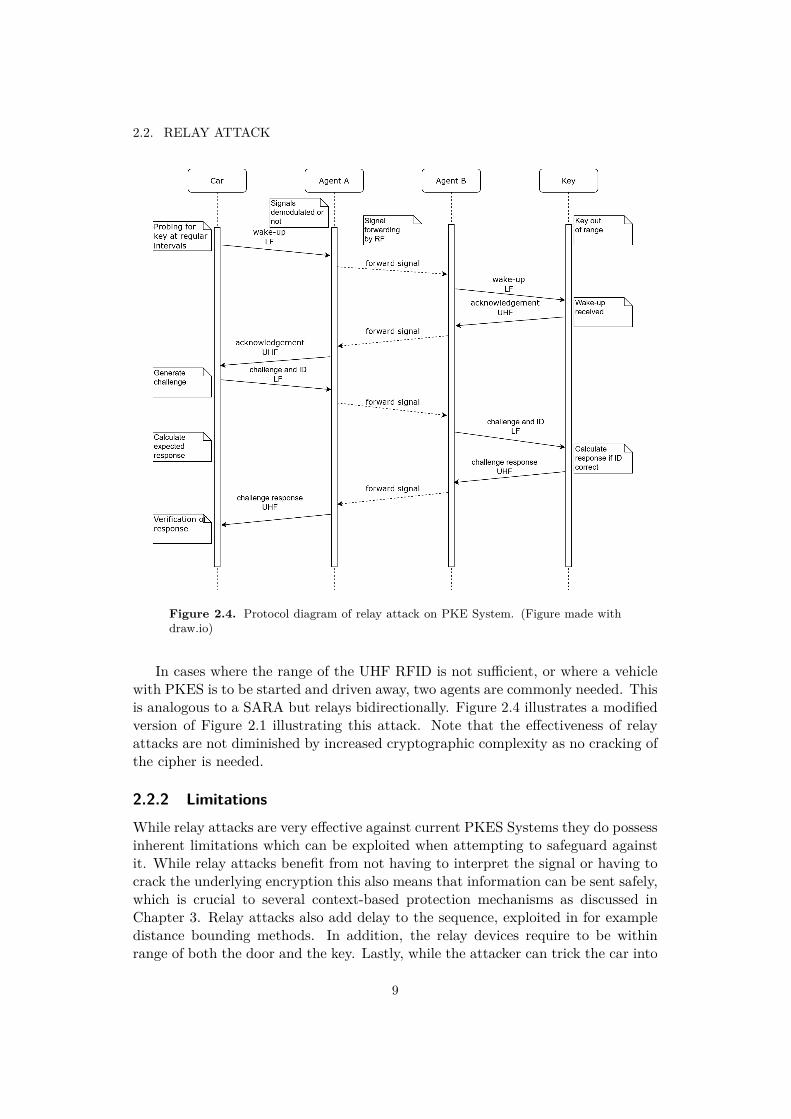
Figure 2.4. Protocol diagram of relay attack on PKE System. (Figure made withdraw.io)
In cases where the range of the UHF RFID is not sufficient, or where a vehiclewith PKES is to be started and driven away, two agents are commonly needed. Thisis analogous to a SARA but relays bidirectionally. Figure 2.4 illustrates a modifiedversion of Figure 2.1 illustrating this attack. Note that the effectiveness of relayattacks are not diminished by increased cryptographic complexity as no cracking ofthe cipher is needed.
2.2.2 LimitationsWhile relay attacks are very effective against current PKES Systems they do possessinherent limitations which can be exploited when attempting to safeguard againstit. While relay attacks benefit from not having to interpret the signal or having tocrack the underlying encryption this also means that information can be sent safely,which is crucial to several context-based protection mechanisms as discussed inChapter 3. Relay attacks also add delay to the sequence, exploited in for exampledistance bounding methods. In addition, the relay devices require to be withinrange of both the door and the key. Lastly, while the attacker can trick the car into
9
CHAPTER 2. BACKGROUND
believing that it is the key, the key fob itself can not actually be manipulated. Itsposition, environmental characteristics, sent message, etc. are not affected by theattack; a fact that can be utilized to design an effective defence.
2.2.3 Threat
Given the above, what threat do relay attacks actually pose? While reliable statis-tics on the occurrence of relay attacks are impossible to find, they have been demon-strated in countless studies, reported on in news outlets, and caught on securityfootage [11, 12]. While specific implementations vary even within a single manufac-turer’s different car models, decreasing the effectiveness of a single setup, multiplepapers have found that vulnerability in modern vehicles is widespread with most, ifnot all, vehicles with PKE being susceptible. Furthermore, while hardware availabil-ity and price was previously a mitigating factor, a Chinese security research teamsucceeded in demonstrating a relay attack on a PKE System from a maximum of320 meters using 20 Euro equipment in 2017 [3, 13].
2.3 Key Fob Design
2.3.1 Battery
When suggesting potential defenses against relay attacks it is crucial to put theseinto the context of existing systems and technical limitations. Battery limitationsof the key fob are often ignored in otherwise rigorous studies, such as the paperpublished by J.Wang et al. which suggests a combination of various defenses despitetheir unfeasability in real-world applications, see Chapter 3 [7]. The main advantageof PKES systems over previous ones is comfort and simplicity which is negated ifconstant battery replacement becomes an issue.
While it is outside the scope of this paper to provide a detailed analysis of powerconsumption of key fobs it is necessary to have a basic estimate in order to verifythe feasibility of the suggested defences. The 2018 Lexus NX300h is taken as anaverage vehicle with PKES; it uses a CR2032 button cell battery of 3 V and acapacity of 220 mAh [14]. According to the vehicle’s user manual the batteries aregenerally expected to last one to two years [15]. As a very rough estimate for generalcomparisons it can be said to have a consumption of 220/(365 ∗ 1.5) = 0.4 mAhper day. This estimate can be used for evaluating the added power consumption ofproposed solutions.
2.3.2 Wireless Technology
While specific frequencies differ due to regulations, the technology used for commu-nication between the key fob and the on-board computer in the vehicle is generallythe same for all manufacturers. An LF channel is used for wake-up while authenti-
10
2.3. KEY FOB DESIGN
cation is processed using a UHF channel. This allows for low power usage while idle,inductive coupling for wake-up, as well as a generally simple but robust interface.
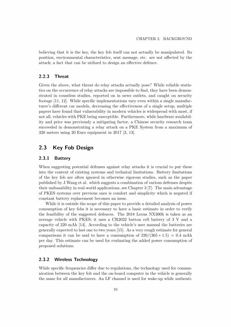
A separate set of RFID transceivers may be present inside and outside of thecar so that it can be determined if the key fob is within or without the vehicle, asseen in Figure 2.5. An alternative may be to simply create different zones in andaround the car which can easily be distinguished between.
Figure 2.5. RFID beacons placed around the car interior and exterior. [16]
While most current manufacturers use RFID technology for their PKES systems,BLE is an emerging technology for secure access control and indoor positioningsolutions. Unfortunately, distance measurements using Received Signal StrengthIndicator (RSSI) or Rx power (received signal power, measured in dBm) have beenconsistently shown to be inaccurate. Mesh networks and trilateration techniquesmay increase accuracy, but these are not viable solutions for PKE systems. Onestudy in a static indoor environment showed that due to the multipath interferencecaused by metallic surfaces distance measurements using BLE RSSI resulted in amean absolute position error of ∼ 1.2 m. While this may be sufficiently accuratefor some applications it is not viable for a premium consumer product which isexpected to be substantially more consistent.
However, in late 2018 Imec demonstrated a system using BLE that has excellentaccuracy of distance measurement and claims to be immune to sophisticated dis-tance manipulation that other defense measures are still susceptible to [17]. Withits low power consumption and potential for high accuracy BLE could come to re-place RFID based PKES systems. Furthermore, it can enable novel access controlsystems such as those needed for unlocking carpooling vehicles with mobile phones,or other access sharing applications.
11


Chapter 3
Proposed Defenses
The following defenses are potential solutions to the vulnerabilities of PKES sys-tems as proposed by this study and supported by previous research. Many effectivedefenses employ context-based verification where there is an independent verifica-tion of an environmental parameter by the key fob and vehicle followed by a mutualauthentication. If this parameter is chosen right it is sufficiently complex and spacevariant that there exists a clear difference in its value near the car and some metersaway. Ideally, the environmental parameter is also resistant to spoofing. Whilemany of the following approaches are effective methods of protection on paper,the implementation of these are often not considered by other studies. After theanalyses below, prototyping, and evaluation, this paper discusses the ideal defensestrategies in Chapter 5.
3.1 Received Signal Strength Indicator
Received Signal Strength Indicator (RSSI) is a measure of the approximate powerlevel of a received signal. There exist suggestions to use this to verify proximity tothe car [18], however this is essentially already what is implemented by the LF RFIDwake-up. The key only replies when it detects a signal with enough power. This ishowever easily duped using a relay attack or signal amplification relay attack.
3.2 Coordinate Tracing
This is a method proposed amongst others by S. Rizvi et al. where either the LFsignal’s RSSI or a different communication channel such as Bluetooth is used totriangulate the position of the key and compare it to that of the vehicle’s [4]. Thereare a multitude of difficulties with this.
The first problem arises already with the implementation on the vehicle side. SRizvi et al. proposes using the GPS already included in most cars’ entertainmentsystems. This, if possible at all due to regulations, would require a large overhaul
13
CHAPTER 3. PROPOSED DEFENSES
of how access is managed to the vehicle’s features while locked. A highly costly andunpractical operation.
A further issue is that of accuracy. RSSI can be used for relative positioning butdue to its inaccuracy and susceptibility to physical interference it is not suitable forexact positional measurements. Even assuming that the accuracy is sufficient, thesolving of simultaneous equations needed for triangulation are extremely demandingand would require a more expensive chip in the key fob and cause greatly increasedpower consumption.
This method, while theoretically sound, is practically impossible to implement.It is far too complex, computationally intensive, and even inaccurate.
3.3 GPS
One suggested defense against relay attacks is location verification using GPS [7].This proposes using the often already included GPS in the vehicle’s on-board com-puter as well as an added GPS in the key fob for independent location measure-ments. The measured coordinates of the key can then be transmitted together withthe wake-up acknowledgement or challenge response and compared by the vehiclewith its known position. This would in theory allow verification of the distancebetween the devices.
This solution however has several major flaws. Firstly, the accuracy of GPSmeasurements may not be suitable precisely for this type of close range applica-tion. GPS is intended to provide specific location measurement with a guaranteedaccuracy in the United States of under 7.8 meters with 95% certainty [19]. Whilethe reported accuracy is greater than this, hardware quality, interference, weatherconditions, and other factors can greatly influence the effective accuracy. This is farfrom accurate enough for definitive protection against relay attacks where distancesof a few meters can be crucial. GPS can furthermore be susceptible to spoofingattacks [7].
A further problem with implementing a context-based verification grounded onGPS technology is the power consumption of the GPS module and accompanyingcalculations. As an example, the ZOE-M8B [20], see Appendix A, released in 2019,marketed as a compact low power chip, has a typical power requirement of tensof mAs while active. A consumption far from negligible. Furthermore, it has along ”Time-To-First-Fix” (the time taken to calculate a position after startup) witharound 30 seconds ”cold-start” (without previously saved GPS data, used unlessprevious position is similar). Moreover, this module is rather expensive, costingabove 10 Euros. While it claims to possess spoofing detection, a feature enabling itto detect if the GPS signal is manipulated externally such as an attacker might doto bypass the verification system, it does warn that this may not detect all spoofingattempts. Furthermore, the accuracy of this specific module is likely not sufficient,claiming accuracy to around 3 meters. [20]
Other manufacturers may have more accurate or faster GPS modules, though
14
3.4. JACCARD SIMILARITY OF WI-FI ACCESS POINTS
it is likely that they would have even greater power consumption and cost, makingthem unviable for this application. While verification with GPS may become viablein the future with more efficient, accurate, and cheaper components it can be con-cluded from the above analysis that it is as of now not a solution suited for PKESSystems.
3.4 Jaccard Similarity of Wi-Fi Access Points
One potential countermeasure against relay attacks, also proposed by researchers atQueen’s University, Kingston, Ontario, is using the Jaccard index of Wi-Fi accesspoints detected by the key and car to ensure spatial proximity. This is the intersectof the available Wi-Fi access points for the two devices divided by the union of theseand measures the similarity of the Wi-Fi access point lists. An inbuilt Wi-Fi modulein the key would scan for hotspots and return the list with eventual accompanyingdata, such as RSSI, to the vehicle for verification, which would compare it to itsown list. The vehicle would only be unlocked if the Jaccard index is sufficientlyhigh.
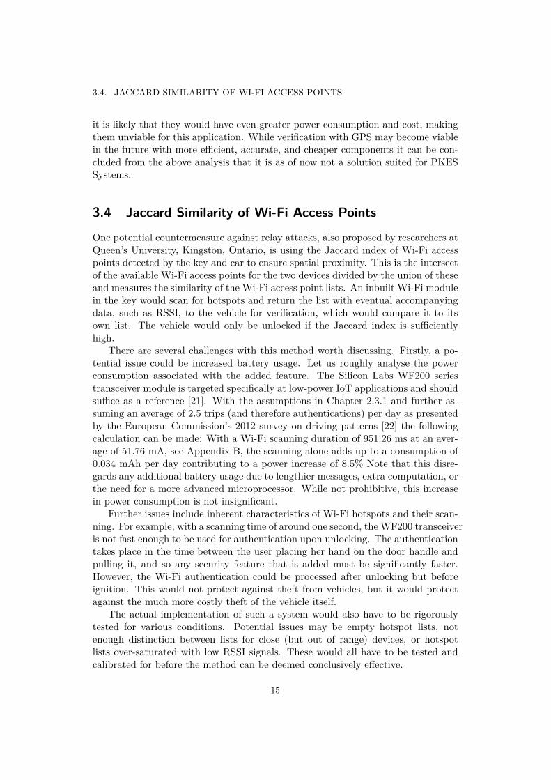
There are several challenges with this method worth discussing. Firstly, a po-tential issue could be increased battery usage. Let us roughly analyse the powerconsumption associated with the added feature. The Silicon Labs WF200 seriestransceiver module is targeted specifically at low-power IoT applications and shouldsuffice as a reference [21]. With the assumptions in Chapter 2.3.1 and further as-suming an average of 2.5 trips (and therefore authentications) per day as presentedby the European Commission’s 2012 survey on driving patterns [22] the followingcalculation can be made: With a Wi-Fi scanning duration of 951.26 ms at an aver-age of 51.76 mA, see Appendix B, the scanning alone adds up to a consumption of0.034 mAh per day contributing to a power increase of 8.5% Note that this disre-gards any additional battery usage due to lengthier messages, extra computation, orthe need for a more advanced microprocessor. While not prohibitive, this increasein power consumption is not insignificant.
Further issues include inherent characteristics of Wi-Fi hotspots and their scan-ning. For example, with a scanning time of around one second, the WF200 transceiveris not fast enough to be used for authentication upon unlocking. The authenticationtakes place in the time between the user placing her hand on the door handle andpulling it, and so any security feature that is added must be significantly faster.However, the Wi-Fi authentication could be processed after unlocking but beforeignition. This would not protect against theft from vehicles, but it would protectagainst the much more costly theft of the vehicle itself.
The actual implementation of such a system would also have to be rigorouslytested for various conditions. Potential issues may be empty hotspot lists, notenough distinction between lists for close (but out of range) devices, or hotspotlists over-saturated with low RSSI signals. These would all have to be tested andcalibrated for before the method can be deemed conclusively effective.
15
CHAPTER 3. PROPOSED DEFENSES
The main appeal of using Wi-Fi hotspots for relative localisation is also a largedrawback, namely the universality of the technology. While Wi-Fi hotspots existalmost everywhere in populated areas, it is also a technology that can be cheaply andeasily spoofed. An attacker could, with readily available equipment, merely createa few high strength hotspots beside both the key and vehicle thereby drowning out’real’ hotspots. Such tampering could potentially be detected and defended against,for example by filtering suddenly appearing hotspots or hotspots with suspiciousRSSI fluctuations. This however adds a great level of complexity to the solution,increasing power consumption, lowering effectivity and time efficiency, as well asgreatly increasing development costs and time.
3.5 Distance Bounding
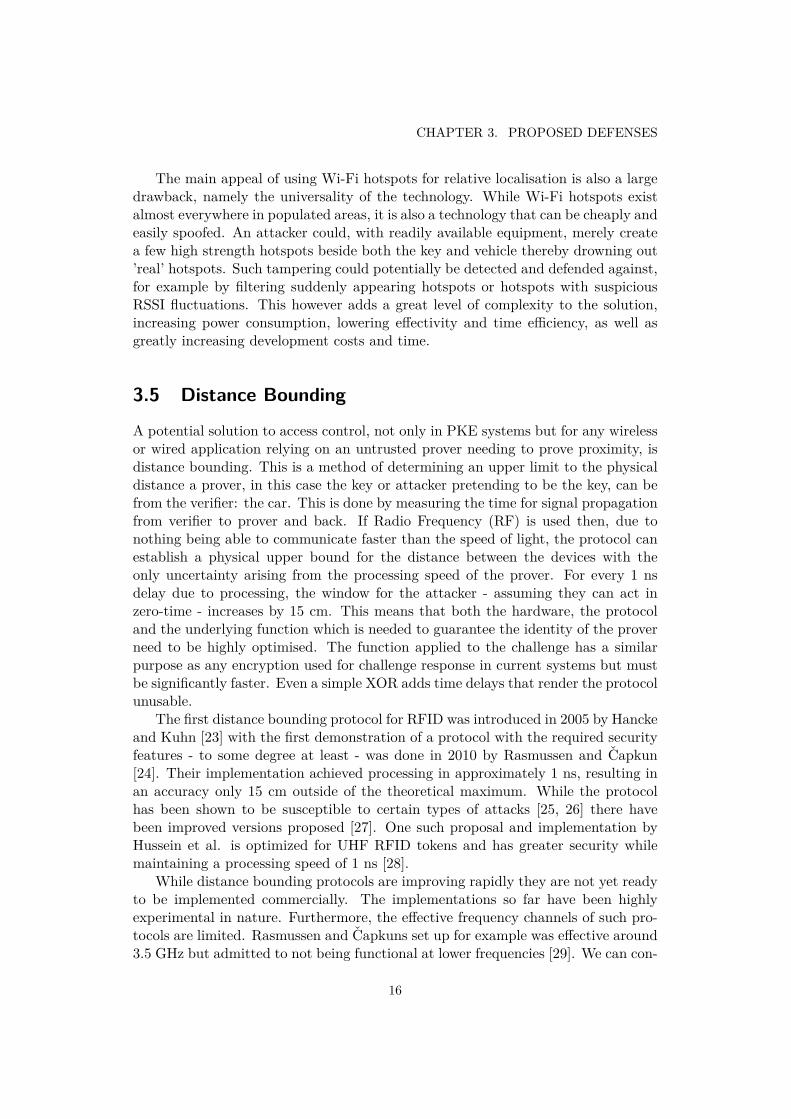
A potential solution to access control, not only in PKE systems but for any wirelessor wired application relying on an untrusted prover needing to prove proximity, isdistance bounding. This is a method of determining an upper limit to the physicaldistance a prover, in this case the key or attacker pretending to be the key, can befrom the verifier: the car. This is done by measuring the time for signal propagationfrom verifier to prover and back. If Radio Frequency (RF) is used then, due tonothing being able to communicate faster than the speed of light, the protocol canestablish a physical upper bound for the distance between the devices with theonly uncertainty arising from the processing speed of the prover. For every 1 nsdelay due to processing, the window for the attacker - assuming they can act inzero-time - increases by 15 cm. This means that both the hardware, the protocoland the underlying function which is needed to guarantee the identity of the proverneed to be highly optimised. The function applied to the challenge has a similarpurpose as any encryption used for challenge response in current systems but mustbe significantly faster. Even a simple XOR adds time delays that render the protocolunusable.
The first distance bounding protocol for RFID was introduced in 2005 by Hanckeand Kuhn [23] with the first demonstration of a protocol with the required securityfeatures - to some degree at least - was done in 2010 by Rasmussen and Capkun[24]. Their implementation achieved processing in approximately 1 ns, resulting inan accuracy only 15 cm outside of the theoretical maximum. While the protocolhas been shown to be susceptible to certain types of attacks [25, 26] there havebeen improved versions proposed [27]. One such proposal and implementation byHussein et al. is optimized for UHF RFID tokens and has greater security whilemaintaining a processing speed of 1 ns [28].
While distance bounding protocols are improving rapidly they are not yet readyto be implemented commercially. The implementations so far have been highlyexperimental in nature. Furthermore, the effective frequency channels of such pro-tocols are limited. Rasmussen and Capkuns set up for example was effective around3.5 GHz but admitted to not being functional at lower frequencies [29]. We can con-
16
3.6. IMMOBILITY DETECTION
clude that distance bounding as a protection against relay attacks has substantialpotential in both PKE systems and other applications such as smart card readersbut may not be a viable solution in the near future.
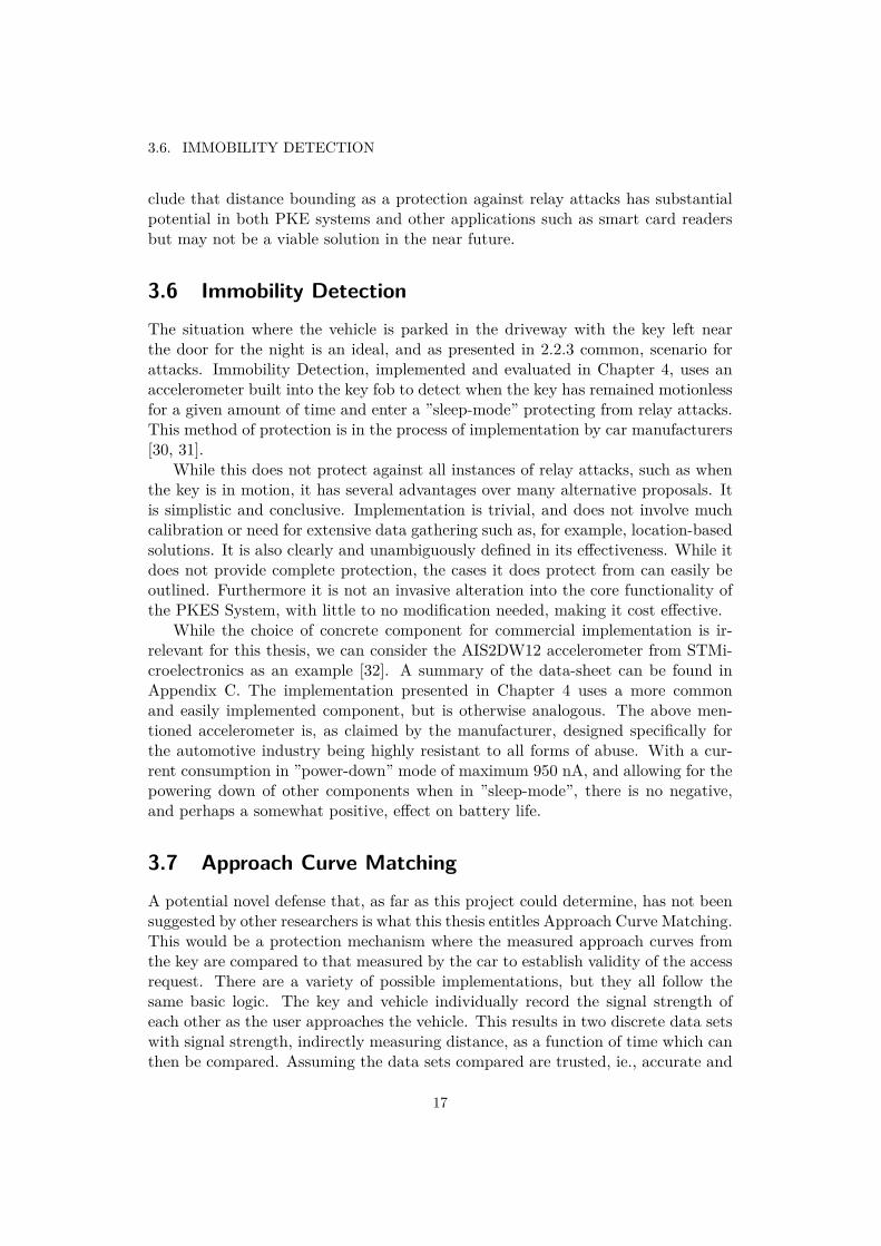
3.6 Immobility DetectionThe situation where the vehicle is parked in the driveway with the key left nearthe door for the night is an ideal, and as presented in 2.2.3 common, scenario forattacks. Immobility Detection, implemented and evaluated in Chapter 4, uses anaccelerometer built into the key fob to detect when the key has remained motionlessfor a given amount of time and enter a ”sleep-mode” protecting from relay attacks.This method of protection is in the process of implementation by car manufacturers[30, 31].
While this does not protect against all instances of relay attacks, such as whenthe key is in motion, it has several advantages over many alternative proposals. Itis simplistic and conclusive. Implementation is trivial, and does not involve muchcalibration or need for extensive data gathering such as, for example, location-basedsolutions. It is also clearly and unambiguously defined in its effectiveness. While itdoes not provide complete protection, the cases it does protect from can easily beoutlined. Furthermore it is not an invasive alteration into the core functionality ofthe PKES System, with little to no modification needed, making it cost effective.
While the choice of concrete component for commercial implementation is ir-relevant for this thesis, we can consider the AIS2DW12 accelerometer from STMi-croelectronics as an example [32]. A summary of the data-sheet can be found inAppendix C. The implementation presented in Chapter 4 uses a more commonand easily implemented component, but is otherwise analogous. The above men-tioned accelerometer is, as claimed by the manufacturer, designed specifically forthe automotive industry being highly resistant to all forms of abuse. With a cur-rent consumption in ”power-down” mode of maximum 950 nA, and allowing for thepowering down of other components when in ”sleep-mode”, there is no negative,and perhaps a somewhat positive, effect on battery life.
3.7 Approach Curve MatchingA potential novel defense that, as far as this project could determine, has not beensuggested by other researchers is what this thesis entitles Approach Curve Matching.This would be a protection mechanism where the measured approach curves fromthe key are compared to that measured by the car to establish validity of the accessrequest. There are a variety of possible implementations, but they all follow thesame basic logic. The key and vehicle individually record the signal strength ofeach other as the user approaches the vehicle. This results in two discrete data setswith signal strength, indirectly measuring distance, as a function of time which canthen be compared. Assuming the data sets compared are trusted, ie., accurate and
17
CHAPTER 3. PROPOSED DEFENSES
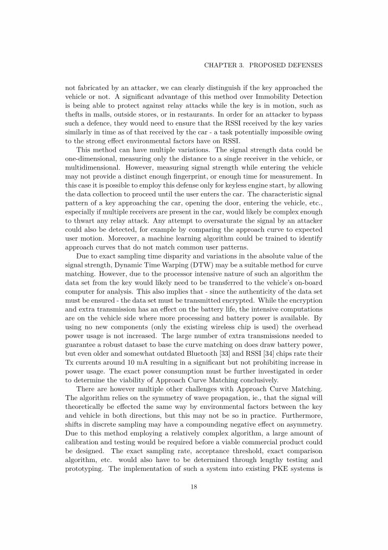
not fabricated by an attacker, we can clearly distinguish if the key approached thevehicle or not. A significant advantage of this method over Immobility Detectionis being able to protect against relay attacks while the key is in motion, such asthefts in malls, outside stores, or in restaurants. In order for an attacker to bypasssuch a defence, they would need to ensure that the RSSI received by the key variessimilarly in time as of that received by the car - a task potentially impossible owingto the strong effect environmental factors have on RSSI.
This method can have multiple variations. The signal strength data could beone-dimensional, measuring only the distance to a single receiver in the vehicle, ormultidimensional. However, measuring signal strength while entering the vehiclemay not provide a distinct enough fingerprint, or enough time for measurement. Inthis case it is possible to employ this defense only for keyless engine start, by allowingthe data collection to proceed until the user enters the car. The characteristic signalpattern of a key approaching the car, opening the door, entering the vehicle, etc.,especially if multiple receivers are present in the car, would likely be complex enoughto thwart any relay attack. Any attempt to oversaturate the signal by an attackercould also be detected, for example by comparing the approach curve to expecteduser motion. Moreover, a machine learning algorithm could be trained to identifyapproach curves that do not match common user patterns.
Due to exact sampling time disparity and variations in the absolute value of thesignal strength, Dynamic Time Warping (DTW) may be a suitable method for curvematching. However, due to the processor intensive nature of such an algorithm thedata set from the key would likely need to be transferred to the vehicle’s on-boardcomputer for analysis. This also implies that - since the authenticity of the data setmust be ensured - the data set must be transmitted encrypted. While the encryptionand extra transmission has an effect on the battery life, the intensive computationsare on the vehicle side where more processing and battery power is available. Byusing no new components (only the existing wireless chip is used) the overheadpower usage is not increased. The large number of extra transmissions needed toguarantee a robust dataset to base the curve matching on does draw battery power,but even older and somewhat outdated Bluetooth [33] and RSSI [34] chips rate theirTx currents around 10 mA resulting in a significant but not prohibiting increase inpower usage. The exact power consumption must be further investigated in orderto determine the viability of Approach Curve Matching conclusively.
There are however multiple other challenges with Approach Curve Matching.The algorithm relies on the symmetry of wave propagation, ie., that the signal willtheoretically be effected the same way by environmental factors between the keyand vehicle in both directions, but this may not be so in practice. Furthermore,shifts in discrete sampling may have a compounding negative effect on asymmetry.Due to this method employing a relatively complex algorithm, a large amount ofcalibration and testing would be required before a viable commercial product couldbe designed. The exact sampling rate, acceptance threshold, exact comparisonalgorithm, etc. would also have to be determined through lengthy testing andprototyping. The implementation of such a system into existing PKE systems is
18

3.7. APPROACH CURVE MATCHING
not as trivial as Immobility Detection. Therefore, while this thesis highlights theviability and encourages further study of this method it does not investigate it indepth.
19

Chapter 4
Implementation
The following chapter presents the implementation of the PKE system. It detailsand motivates chosen hardware, software architecture, software logic and, finally,presents the results obtained.
4.1 HardwareThe following sections describe the hardware setup for the implementation of anImmobility Detection enhanced PKE system. While the exact setup is not identicalto most commercial systems, it is equivalent in all aspects that could affect thedefense systems effectiveness and implementability. Decisions regarding hardwareselection were based primarily on suitability for the project, economic viability, andease of use.
4.1.1 MicrocomputerThe microcomputer used was the Raspberry Pi Zero W: a low-cost single-boardcomputer with inbuilt wireless (Wi-Fi and Bluetooth) capabilities. The computa-tional power required for the authentication protocol and Bluetooth communicationis very low with essentially only the encryption being a processor heavy operation.The actual chips used commercially in key fobs and on-board computers are natu-rally highly optimised for cost and performance but the Raspberry Pi is suitable fora proof of concept due to its ease of use. Furthermore it has an abundance of GeneralPurpose Input/Output (GPIO) pins which make it preferable for prototyping.
4.1.2 Bluetooth ModuleThe Raspberry Pi Zero W has an inbuilt Cypress CYW43438 chip for wirelesscommunication using Wi-Fi and Bluetooth, which was used. The project did not usethe low-energy capability of Bluetooth 4.1 as power consumption was not consideredfor the physical prototype, but the implementation would not differ significantlywith BLE. RSSI was used for distance measurements.
21
CHAPTER 4. IMPLEMENTATION
4.1.3 Accelerometer
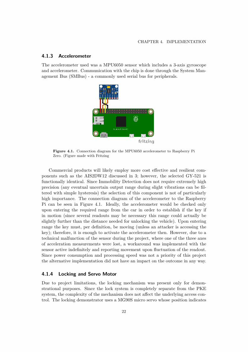
The accelerometer used was a MPU6050 sensor which includes a 3-axis gyroscopeand accelerometer. Communication with the chip is done through the System Man-agement Bus (SMBus) - a commonly used serial bus for peripherals.
Figure 4.1. Connection diagram for the MPU6050 accelerometer to Raspberry PiZero. (Figure made with Fritzing
Commercial products will likely employ more cost effective and resilient com-ponents such as the AIS2DW12 discussed in 3; however, the selected GY-521 isfunctionally identical. Since Immobility Detection does not require extremely highprecision (any eventual uncertain output range during slight vibrations can be fil-tered with simple hysteresis) the selection of this component is not of particularlyhigh importance. The connection diagram of the accelerometer to the RaspberryPi can be seen in Figure 4.1. Ideally, the accelerometer would be checked onlyupon entering the required range from the car in order to establish if the key ifin motion (since several readouts may be necessary this range could actually beslightly further than the distance needed for unlocking the vehicle). Upon enteringrange the key must, per definition, be moving (unless an attacker is accessing thekey); therefore, it is enough to activate the accelerometer then. However, due to atechnical malfunction of the sensor during the project, where one of the three axesof acceleration measurements were lost, a workaround was implemented with thesensor active indefinitely and reporting movement upon fluctuation of the readout.Since power consumption and processing speed was not a priority of this projectthe alternative implementation did not have an impact on the outcome in any way.
4.1.4 Locking and Servo Motor
Due to project limitations, the locking mechanism was present only for demon-strational purposes. Since the lock system is completely separate from the PKEsystem, the complexity of the mechanism does not affect the underlying access con-trol. The locking demonstrator uses a MG90S micro servo whose position indicates
22

4.2. SOFTWARE
the locked/unlocked state of the vehicle. The servo control is achieved throughPulse Width Modulation (PWM) on the Raspberry Pi’s GPIO pins. A duty cycleof 2% at 50Hz is used for setting the servo at 0°and 13% for rotating to 180°.
4.2 Software
The following sections describe the software setup for the implementation of anImmobility Detection enhanced PKE system. The implementation was done inthree releases. One for the base functionality consisting of the software needed fora PKE system without Immobility Detection, one with implemented ImmobilityDetection, and finally implementing the demonstational locking mechanism. Whilecertain features were omitted or greatly simplified, such as the encryption algorithmor excluding the initial button press before authentication begins often included incommercial systems, care was taken in order to ensure that the general softwarearchitecture and authentication protocol allowed for the implementation of suchfeatures. These include support for multiple keys and active RKS. The source codewas written in Python and can be found in Appendices D and E.
Figure 4.2. Activity diagram of the unlocking process for the improved PKE systemwith Immobility Detection. (Figure made with draw.io)
23
CHAPTER 4. IMPLEMENTATION
4.2.1 Logic
The logic underlying the PKE system is based on existing commercial systems toa large degree. The Immobility Detection is a defence system easily implementeddistinct from the base functionality which is, with the exception of some omittedfeatures, identical to those described in 2.1. Figure 4.2 depicts an activity diagramfor unlocking the vehicle. The addition of Immobility Detection inserts an extracontrol after checking for proximity of the vehicle - using RSSI - where depending onthe accelerometer readout either the authentication proceeds or the user is alertedto a potential attack. The alert can take any form, in this project it was sufficient touse a command-line message, but commercial systems would likely use an audiblealert from the key fob.
4.2.2 Authentication Protocol
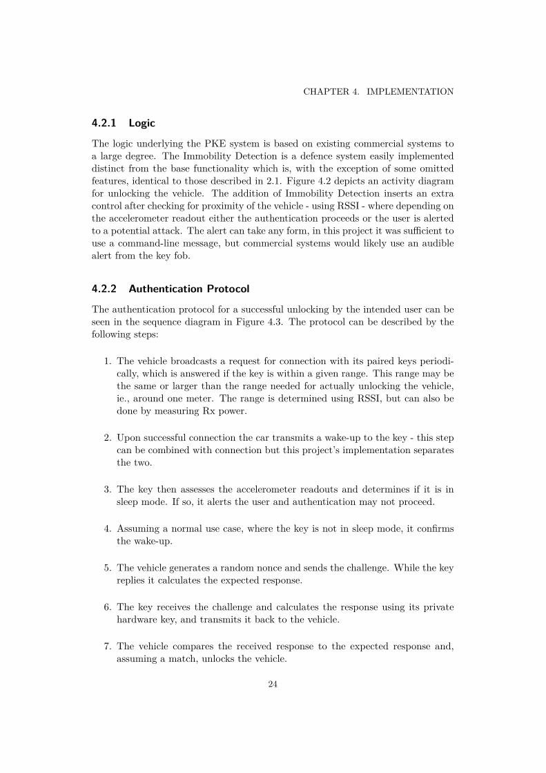
The authentication protocol for a successful unlocking by the intended user can beseen in the sequence diagram in Figure 4.3. The protocol can be described by thefollowing steps:
1. The vehicle broadcasts a request for connection with its paired keys periodi-cally, which is answered if the key is within a given range. This range may bethe same or larger than the range needed for actually unlocking the vehicle,ie., around one meter. The range is determined using RSSI, but can also bedone by measuring Rx power.
2. Upon successful connection the car transmits a wake-up to the key - this stepcan be combined with connection but this project’s implementation separatesthe two.
3. The key then assesses the accelerometer readouts and determines if it is insleep mode. If so, it alerts the user and authentication may not proceed.
4. Assuming a normal use case, where the key is not in sleep mode, it confirmsthe wake-up.
5. The vehicle generates a random nonce and sends the challenge. While the keyreplies it calculates the expected response.
6. The key receives the challenge and calculates the response using its privatehardware key, and transmits it back to the vehicle.
7. The vehicle compares the received response to the expected response and,assuming a match, unlocks the vehicle.
24
4.2. SOFTWARE
Figure 4.3. Sequence diagram of a successful unlocking sequence. (Figure madewith draw.io)
4.2.3 Software Architecture
The software for the PKE system is build up by the software in the vehicle’s on-board computer and that of the key fob. Python modules used worth mentioningare: PyBluez for interfacing with the Pi’s Bluetooth resources and smbus for SMBusaccess through I2C for the accelerometer. The software was highly modularized -primarily for easy integration of new features - as well as for ease of development.Multi-threading was used for RSSI and accelerometer monitoring with periodic call-backs to the main Bluetooth and sleep-mode control modules to update the stateof the key fob.
The key fob’s software, see Appendix D, consisted of a main control module
25
CHAPTER 4. IMPLEMENTATION
implementing the protocol logic with more specific functions delegated to othermodules. The Bluetooth module implemented all necessary functions for commu-nication such as: establishing connection, cleaning up Bluetooth sockets, and send-ing/receiving messages. The sleep-mode module similarly implemented all necessaryfunctionality for monitoring the accelerometer and determining sleep-mode.
The software of the vehicle’s on-board computer is much simpler. It is a twostate machine with a series of events as transition criteria from one state to theother (the authentication protocol). The functions for the protocol are trivial, seeFigure 4.3 and Appendix E.
4.2.4 Encryption
For the purposes of this project no secure encryption algorithm was implemented.As encryption does not influence the Immobility Detection system and the under-lying logic it was deemed unnecessary. However, due to the protocol implementinga mock challenge-response, an unencrypted and non-random placeholder for a po-tential real challenge-response, the addition of such a feature would not alter thearchitecture of the software as a whole. Similarly, other desired features can easilybe added to the system due to its modularity and regard for compatibility withomitted features.
4.3 Results
After developing the software and constructing the setup, as seen in Figure 4.4, theeffectiveness of the implemented PKE system was assessed using a set of test casesfor common use cases, found in Appendix F.
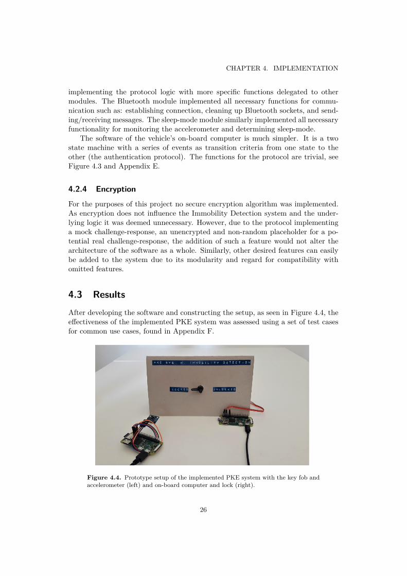
Figure 4.4. Prototype setup of the implemented PKE system with the key fob andaccelerometer (left) and on-board computer and lock (right).
26
4.3. RESULTS
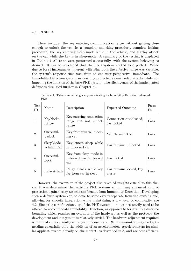
These include: the key entering communication range without getting closeenough to unlock the vehicle, a complete unlocking procedure, complete lockingprocedure, the key entering sleep mode while in the vehicle, and a relay attackon the car while the key is in sleep-mode. A summary of the testing is displayedin Table 4.1 All tests were performed successfully, with the system behaving asdesired. It can be concluded that the PKE system worked as expected. Whiledue to RSSI inaccuracies inherent with Bluetooth the effective range was variable,the system’s response time was, from an end user perspective, immediate. TheImmobility Detection system successfully protected against relay attacks while notimpeding the function of the base PKE system. The effectiveness of the implementeddefense is discussed further in Chapter 5.
Table 4.1. Table summarising acceptance testing for Immobility Detection enhancedPKE
TestID Name Description Expected Outcome Pass/
Fail
1 KeyNotIn-Range
Key entering connectionrange but not unlockrange
Connection established,car locked Pass
2 Succesful-Unlock
Key from rest to unlock-ing car Vehicle unlocked Pass
3 SleepMode-WhileInCar
Key enters sleep whilein unlocked car Car remains unlocked Pass
4 Succesful-Lock
Key from sleep-mode inunlocked car to lockedcar
Car locked Pass
5 RelayAttack Relay attack while keyfar from car in sleep
Car remains locked, keyalerts Pass
However, the execution of the project also revealed insights crucial to this the-sis. It was determined that existing PKE systems without any advanced form ofprotection against relay attacks can benefit from Immobility Detection. Developingsuch a defense system can be done to some extent separate from the existing one,allowing for smooth integration while maintaining a low level of complexity, see4.2. Since the core functionality of the PKE system does not necessarily need to bealtered to accommodate Immobility Detection, as opposed to for example distancebounding which requires an overhaul of the hardware as well as the protocol, thedevelopment and integration is relatively trivial. The hardware adjustment requiredis minimal - the currently employed processor and RFID transmitter may be kept -needing essentially only the addition of an accelerometer. Accelerometers for simi-lar applications are already on the market, as described in 3, and are cost efficient.
27
CHAPTER 4. IMPLEMENTATION
Furthermore, the addition of such as system was deemed to be insignificant or evenpositive - depending on exact implementation - on battery life, an important aspectin commercial applications.
The level of effectiveness of Bluetooth in the place of RFID based communicationdid not have a notable affect on this project. However, some interesting trendscould be observed. The project used RSSI for measuring proximity to the vehicle,a critical feature for both security and user comfort. There were however majorflaws detected with this. RSSI in general is not intended for absolute distancemeasurements. While for the purposes of this project the test environment couldbe limited for accurate calibration of the RSSI range, environmental factors ina commercial application would affect the readout significantly. This effect wasobserved to be so strong that the system designed - in itss current form - could notfunction effectively in a varying environment. Objects in the path of the key fob,surrounding metallic objects, any covering material such as clothes, a bag, or evena person’s hand all have a significant impact on the RSSI value. While Bluetooth,or rather BLE, as a technology for PKE systems may yet be ideal, see 2.3.2, thisproject observed that using RSSI is not viable.
28
Chapter 5
Discussion
Evaluation of Immobility Detection This project has designed and developeda proof of concept implementation of a PKE system with Immobility Detection asa form of protection against relay attacks. It was observed that even a relativelysimple Immobility Detection system is extremely effective against relay attacks onstationary key fobs. Even low cost accelerometers provide sensor data satisfactoryfor ensuring sleep-mode is entered when desirable. However, this system does notprotect against all instances of relay attacks as mobile keys are still equally vulner-able. With recent affordable and high range relay devices these thefts may becomemore common, posing a risk even for Immobility Detection enhanced PKE systems.Nevertheless, the clearly defined effective range of this system is an advantage inand of itself, allowing for manufacturers to clearly outline what the system achieves.
It was shown that the development of Immobility Detection is simple and can beeasily integrated into existing PKE systems without requiring substantial changesto existing hardware or software. It was further found that such a system can beachieved in a cost effective manner with existing low cost components. If powerusage optimization is desired then implementations exist where this system mayincrease battery life.
While some parameters, such as the timer for entering sleep mode and exactvibration thresholds, must be calibrated with regard for end use, the commercialdevelopment time of such a system is significantly shorter than many other proposedsolutions and has little to no associated risks. Therefore, manufacturers could beginmanufacturing newer car models with Immobility Detection in a short time-frame,while investigating other, more long-term, solutions.
Alternative Defenses Multiple proposed defenses have been described and an-alyzed. Many lack consideration for implementability, commercial viability, or costwhile others fall short in terms of security. It is deemed that two other methodspromise potential. While distance bounding may be far from a commercial ap-plication, requiring further study not only on the protocol but also on hardware,integration into a printed circuit board, and reliability, recent advances in all of the
29
CHAPTER 5. DISCUSSION
above aspects are promising. Such a solution would be a large improvement on cur-rent access control. The second method proposed by this thesis - Approach CurveMatching - may also provide considerable increase in security for PKE systems.This defence system however requires substantial research before its feasibility canbe determined.
Viability of Bluetooth LE for PKE While this thesis concluded that BluetoothRSSI measurements - at least using the setup in this project - are not reliable enoughfor PKE applications, Bluetooth as a technology may yet be viable. The powerusage of BLE is very low, having been developed for similar applications, whichlends itself to access control. Albeit RSSI may not be ideal for PKE, there arenovel ways of distance measurement being developed, some even specifically for theautomotive industry as discussed in 2.3.2. The added advantage of enabling accesssharing using mobile phones greatly increases the attractiveness of this technology.
Additional Security Features There are a variety of added precautionary fea-tures that can contribute to an overall safer PKE system. Theft detection, such asthat implemented in this project, whereby an attempted threat is not only foiledbut alerted against, can increase the risk for attackers and thereby limit attempts.Moreover, access control restrictions upon failed unlock attempts can reduce theopportunity for an attacker to retry an attempted theft, use a different method, oreven gather data on the protocol to be used to fine tune the attack. Since all locksystems contain a parallel active keyless entry, in the case of an erroneous attemptby the intended user that can still used to unlock the car. Merely the addition of anaudible signal from the key fob, as is already present on the vehicle side, may providesome protection against theft. Meanwhile, generally stricter timing constraints forthe authentication protocol protect against attacks with more rudimentary equip-ment or those over long range where potentially time intensive demodulation andmodulation of the signal is often needed. Furthermore, for legal proof of theft - inan insurance claim for example - it may be advisable for the key and vehicle to storea log of recent unlocking procedures.
30
Chapter 6
Conclusion
This thesis investigated, implemented, and assessed an Immobility Detection en-hanced PKE system for relay attack resistance as well as various other proposeddefence mechanisms. It can be concluded that, albeit limited to the case of astationary key, Immobility Detection is a highly effective method of protection. Ad-ditionally, the implementation of such a system, as opposed to other proposals, inexisting PKE systems is found to be cost efficient, trivial in nature, and not timeconsuming. In combination with the introduction of other defensive measures, Im-mobility Detection can greatly increase the security of PKE systems. While thisthesis focuses specifically on PKE systems for vehicles, similar technology can usedfor other access control applications. The conclusions of this thesis can be used tomotivate further research as well as direct action by vehicle manufacturers.
31

Bibliography
[1] Statistics Sweden. (2020, Jan) Registered vehicles January 2006–December2019. [Online]. Available: https://www.scb.se/en/finding-statistics/statistics-by-subject-area/transport-and-communications/road-traffic/registered-vehicles/pong/tables-and-graphs/registered-vehicles/ [Accessed: 2020-02-02].
[2] ——, “Preliminary population statistics 2019,” https://www.scb.se/en/finding-statistics/statistics-by-subject-area/population/population-composition/population-statistics/pong/tables-and-graphs/monthly-statistics--the-whole-country/preliminary-population-statistics-2019/, Statis-tics Sweden, Tech. Rep., Jan 2020, [Online; accessed 2020-02-16].
[3] L. Huang, Q. Yang, Q. Gu, W. Zhang, H. Shan, J. Li, and Y. Zeng, In-side Radio: An Attack and Defense Guide. Springer Nature and PublishingHouse of Electronics Industry, Beijing, Mar 2018. ISBN 978-981-10-8446-1. doi:10.1007/978-981-10-8447-8
[4] S. Rizvi, J. Imler, L. Ritchey, and M. Tokar, “Securing PKES against RelayAttacks using Coordinate Tracing and Multi-Factor Authentication,” in 201953rd Annual Conference on Information Sciences and Systems (CISS), Mar2019. doi: 10.1109/CISS.2019.8692790. ISSN null pp. 1–6.
[5] A. I. Alrabady and S. M. Mahmud, “Analysis of attacks against the security ofkeyless-entry systems for vehicles and suggestions for improved designs,” IEEETransactions on Vehicular Technology, vol. 54, no. 1, pp. 41–50, Jan 2005. doi:10.1109/TVT.2004.838829
[6] M. Gulsever, “A Study on Vulnerabilities in Connected Cars,” B.Sc. Thesis,KTH, School of Electrical Engineering and Computer Science (EECS), Jun2019.
[7] J. Wang, K. Lounis, and M. Zulkernine, “CSKES: A Context-Based SecureKeyless Entry System,” in 2019 IEEE 43rd Annual Computer Software andApplications Conference (COMPSAC), vol. 1, Jul 2019. doi: 10.1109/COMP-SAC.2019.00120. ISSN 0730-3157 pp. 817–822.
33
BIBLIOGRAPHY
[8] A. Francillon, B. Danev, and S. Capkun, “Relay Attacks on Passive KeylessEntry and Start Systems in Modern Cars.” IACR Cryptology ePrint Archive,vol. 2010, p. 332, Jan 2010. doi: 10.1109/FSKD.2012.6234155
[9] W. Choi, M. Seo, and D. Hoon Lee, “Sound-Proximity: 2-FactorAuthentication against Relay Attack on Passive Keyless Entry andStart System,” Journal of Advanced Transportation, Jan 2018. doi:https://doi.org/10.1155/2018/1935974
[10] K. Leuven. (2018, Sep) Fast, Furious and Insecure: PassiveKeyless Entry and Start in Modern Supercars. [Online]. Avail-able: https://www.esat.kuleuven.be/cosic/fast-furious-and-insecure-passive-keyless-entry-and-start-in-modern-supercars/ [Accessed: 2020-02-16].
[11] T. Gerber. (2019, Mar) SAPD: Car thieves using technology to hack key fobs,steal vehicles. [Online]. Available: https://www.ksat.com/news/2019/03/12/sapd-car-thieves-using-technology-to-hack-key-fobs-steal-vehicles/ [Accessed:2020-03-16].
[12] The Japan Times. (2019, 01) Osaka police say thefts of vehicles using ’relayattack’ technique on rise in area. [Online]. Available: https://www.japantimes.co.jp/news/2019/01/05/national/crime-legal/osaka-prefecture-police-say-car-thefts-using-relay-attack-technique-rise-area/#.XrWpskBuKP [Accessed:2020-03-16].
[13] Y. Z. Y. Li. (2017, 10) Car keyless entry system attack. [Online]. Available:https://conference.hitb.org/hitbsecconf2017ams/materials/ [Accessed: 2020-02-02].
[14] Lexus. What sized battery is used in Lexus remote keys? [On-line]. Available: https://lexus2.custhelp.com/app/answers/detail/a id/8347/∼/what-size-battery-is-used-in-lexus-remote-keys%3F [Accessed: 2020-02-21].
[15] ——. Lexus 2018 NX300H Owner’s Manual (OM78212U). [Online].Available: https://drivers.lexus.com/t3Portal/document/om-s/OM78212U/pdf/OM78212U.pdf [Accessed: 2020-02-21].
[16] J. Rodriguez. (2016, Oct) Long-range RFID emitter an-tennas for passive keyless entry systems. [Online]. Avail-able: https://www.eenewsautomotive.com/news/long-range-rfid-emitter-antennas-passive-keyless-entry-systems [Accessed: 2020-03-16].
[17] Imec. (2018, Nov) Imec demonstrates first secure passive keyless entrysolution for automotive using Bluetooth Low Energy. [Online]. Avail-able: https://www.imec-int.com/en/articles/imec-demonstrates-first-secure-passive-keyless-entry-solution-for-automotive-using-bluetooth-low-energy [Ac-cessed: 2020-04-21].
34
https://www.eenewsautomotive.com/news/long-range-rfid-emitter-antennas-passive-keyless-entry-systems
BIBLIOGRAPHY
[18] S. K. J. K. Gyu-Ho Kim, Kwan-Hyung Lee, “Vehicle Relay Attack AvoidanceMethods Using RF Signal Strength,” Communications and Network, Apr 2013.doi: 10.4236/cn.2013.53B2103
[19] National Coordination Office for Space-Based Positioning, Navigation, andTiming. (2017) GPS accuracy. [Online]. Available: https://www.gps.gov/systems/gps/performance/accuracy/ [Accessed: 2020-02-16].
[20] U-blox AG. (2019) ZOE-M8B, Ultra-small, super low power u-box M8GNSS SiP module. [Online]. Available: https://www.u-blox.com/en/docs/UBX-17035164 [Accessed: 2020-02-19].
[21] S. Labs, WF200 Data Sheet: Wi-Fi©Network Co-Processor, Jan 2020.[Online]. Available: https://www.silabs.com/support/resources.p-wireless wi-fi wf200-series-2-wi-fi-transceiver-socs
[22] P. K. G. F. D. M. A. S. G. A. A. Z. A. T. Christian, “Driving and parking pat-terns of European car drivers - a mobility survey.” Dec 2012. doi: 10.2790/70746
[23] G. P. Hancke and M. G. Kuhn, “An RFID Distance Bounding Protocol,” inFirst International Conference on Security and Privacy for Emerging Areas inCommunications Networks (SECURECOMM’05), Sep. 2005. doi: 10.1109/SE-CURECOMM.2005.56 pp. 67–73.
[24] K. B. Rasmussen and S. Capkun, “Realization of RF Distance Bounding,” inProceedings of the 19th USENIX Conference on Security, ser. USENIX Secu-rity’10. USA: USENIX Association, Aug 2010. doi: 10.5555/1929820.1929854.ISBN 8887666655554 p. 25.
[25] A. Mitrokotsa, C. Onete, and S. Vaudenay, “Mafia fraud attack againstthe RC Distance-Bounding Protocol,” in 2012 IEEE International Confer-ence on RFID-Technologies and Applications (RFID-TA), Nov 2012. doi:10.1109/RFID-TA.2012.6404571 pp. 74–79.
[26] D. Singelee and B. Preneel, “Security Analysis of the Rasmussen-Capkun CRCSDistance Bounding Protocol,” Jan 2010, p. 13.
[27] T. Yang, L. Kong, W. Xin, J. Hu, and Z. Chen, “Resisting relay attacks onvehicular Passive Keyless Entry and start systems,” in 2012 9th InternationalConference on Fuzzy Systems and Knowledge Discovery, 2012. doi: 10.1109/F-SKD.2012.6234155 pp. 2232–2236.
[28] M. J. Hussain, L. Lu, and H. Zhu, “TIGHT: A Cross-Layer RF DistanceBounding Realization for Passive Wireless Devices,” IEEE Transactions onWireless Communications, vol. 14, no. 6, pp. 3076–3085, Feb 2015. doi:10.1109/TWC.2015.2400440
35
BIBLIOGRAPHY
[29] K. B. Rasmussen. (2010, Aug) Realisation of RF Distance Bounding. [Online].Available: https://www.usenix.org/conference/usenixsecurity10/realization-rf-distance-bounding Accessed: 2020-02-23.
[30] Ford Motor Company. Motion Sensing Key Fob. [Online].Available: https://www.ford.co.uk/owner/resources-and-support/ask-ford/technical-and-maintenance/car-features/motion-sensing-key-fob [Accessed:2020-05-09].
[31] J. Edgren, “Den smarta nyckeln stoppar biltjuvarna [in Swedish],” Ny Teknik,11 2017. [Online]. Available: https://www.nyteknik.se/fordon/den-smarta-nyckeln-stoppar-biltjuvarna-6883404 [Accessed: 2020-05-09].
[32] STMicroelectronics. (2019, Jun) AIS2DW12, MEMS digital output motionsensor: ultra-low-power 3-axis accelerometer for automotive applications .[Online]. Available: https://www.st.com/en/mems-and-sensors/ais2dw12.html[Accessed: 2020-02-15].
[33] Argenox Technologies. (2018, Jan) A Guide to Selecting a Bluetooth Chipset.[Online]. Available: https://www.argenox.com/library/bluetooth-low-energy/a-guide-to-selecting-a-bluetooth-chipset/ [Accessed: 2020-07-05].
[34] Texas Instruments Incorporated. (2006) CC1050 Single Chip Very Low PowerRF Transmitter. [Online]. Available: https://www.ti.com/product/CC1050/technicaldocuments [Accessed: 2020-07-05].
36
Appendices
A ZOE-M8B GPS Module Data-sheet (excerpt)
37
ZOE-M8B Ultra-small, super low power u-blox M8 GNSS SiP module Data Sheet
Abstract
Technical data sheet describing the ZOE-M8B ultra-small and ultra-low power GNSS SiP modules with Super-E mode. Power consumption is as low as 12 mW with Super-E mode. The modules provide a fully integrated, complete solution, reducing design and test efforts. They are ideal for passive antennas, due to built-in SAW and LNA and have high accuracy thanks to concurrent reception of up to 3 GNSS.
www.u-blox.com
UBX-17035164 - R04
ZOE-M8B - Data Sheet
UBX-17035164 - R04 Document Information Page 2 of 31 Production Information
Document Information Title ZOE-M8B
Subtitle Ultra-small, super low power u-blox M8 GNSS SiP module
Document type Data Sheet
Document number UBX-17035164
Revision and date R04 13-Aug-2019
Document status Production Information
Product status Corresponding content status
In Development / Prototype
Objective Specification Target values. Revised and supplementary data will be published later.
Engineering Sample Advance Information Data based on early testing. Revised and supplementary data will be published later.
Initial Production Early Production Information Data from product verification. Revised and supplementary data may be published later.
Mass Production / End of Life
Production Information Document contains the final product specification.
This document applies to the following products:
Product name Type number ROM/FLASH version PCN reference
ZOE-M8B ZOE-M8B-0-10 ROM SPG 3.51 N/A
u-blox or third parties may hold intellectual property rights in the products, names, logos and designs included in this document. Copying, reproduction, modification or disclosure to third parties of this document or any part thereof is only permitted with the express written permission of u-blox. The information contained herein is provided “as is” and u-blox assumes no liability for its use. No warranty, either express or implied, is given, including but not limited to, with respect to the accuracy, correctness, reliability and fitness for a particular purpose of the information. This document may be revised by u-blox at any time without notice. For the most recent documents, visit www.u-blox.com.
Copyright © u-blox AG.
ZOE-M8B - Data Sheet
UBX-17035164 - R04 Functional description Page 6 of 31 Production Information
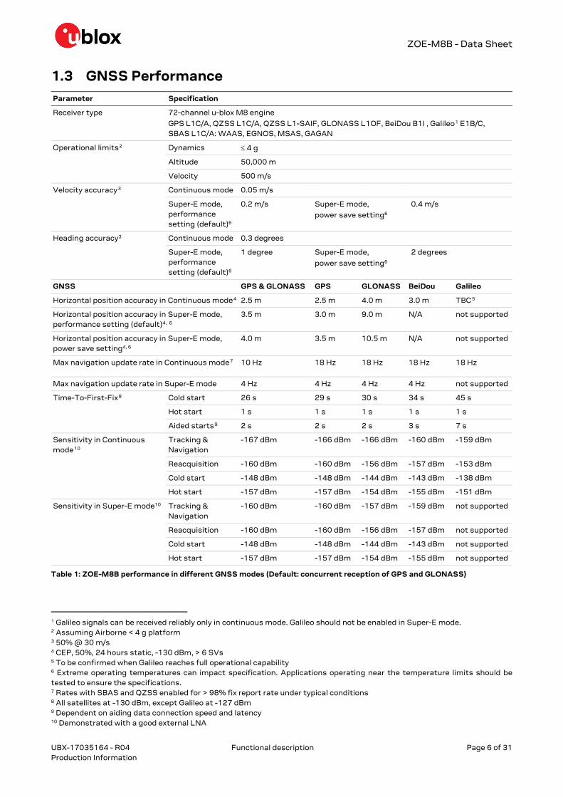
1.3 GNSS Performance Parameter Specification
Receiver type 72-channel u-blox M8 engine
GPS L1C/A, QZSS L1C/A, QZSS L1-SAIF, GLONASS L1OF, BeiDou B1I , Galileo1 E1B/C, SBAS L1C/A: WAAS, EGNOS, MSAS, GAGAN
Operational limits2 Dynamics ≤ 4 g
Altitude 50,000 m
Velocity 500 m/s
Velocity accuracy3 Continuous mode 0.05 m/s
Super-E mode, performance setting (default)6
0.2 m/s Super-E mode,
power save setting6
0.4 m/s
Heading accuracy3 Continuous mode 0.3 degrees
Super-E mode, performance setting (default)6
1 degree Super-E mode,
power save setting6
2 degrees
GNSS GPS & GLONASS GPS GLONASS BeiDou Galileo
Horizontal position accuracy in Continuous mode4 2.5 m 2.5 m 4.0 m 3.0 m TBC5
Horizontal position accuracy in Super-E mode, performance setting (default)4, 6
3.5 m 3.0 m 9.0 m N/A not supported
Horizontal position accuracy in Super-E mode, power save setting4, 6
4.0 m 3.5 m 10.5 m N/A not supported
Max navigation update rate in Continuous mode7 10 Hz 18 Hz 18 Hz 18 Hz 18 Hz
Max navigation update rate in Super-E mode 4 Hz 4 Hz 4 Hz 4 Hz not supported
Time-To-First-Fix8 Cold start 26 s 29 s 30 s 34 s 45 s
Hot start 1 s 1 s 1 s 1 s 1 s
Aided starts9 2 s 2 s 2 s 3 s 7 s
Sensitivity in Continuous mode10
Tracking & Navigation
-167 dBm -166 dBm -166 dBm -160 dBm -159 dBm
Reacquisition -160 dBm -160 dBm -156 dBm -157 dBm -153 dBm
Cold start -148 dBm -148 dBm -144 dBm -143 dBm -138 dBm
Hot start -157 dBm -157 dBm -154 dBm -155 dBm -151 dBm
Sensitivity in Super-E mode10 Tracking & Navigation
-160 dBm -160 dBm -157 dBm -159 dBm not supported
Reacquisition -160 dBm -160 dBm -156 dBm -157 dBm not supported
Cold start -148 dBm -148 dBm -144 dBm -143 dBm not supported
Hot start -157 dBm -157 dBm -154 dBm -155 dBm not supported
Table 1: ZOE-M8B performance in different GNSS modes (Default: concurrent reception of GPS and GLONASS)
1 Galileo signals can be received reliably only in continuous mode. Galileo should not be enabled in Super-E mode. 2 Assuming Airborne < 4 g platform 3 50% @ 30 m/s 4 CEP, 50%, 24 hours static, -130 dBm, > 6 SVs 5 To be confirmed when Galileo reaches full operational capability 6 Extreme operating temperatures can impact specification. Applications operating near the temperature limits should be tested to ensure the specifications. 7 Rates with SBAS and QZSS enabled for > 98% fix report rate under typical conditions 8 All satellites at -130 dBm, except Galileo at -127 dBm 9 Dependent on aiding data connection speed and latency 10 Demonstrated with a good external LNA
ZOE-M8B - Data Sheet
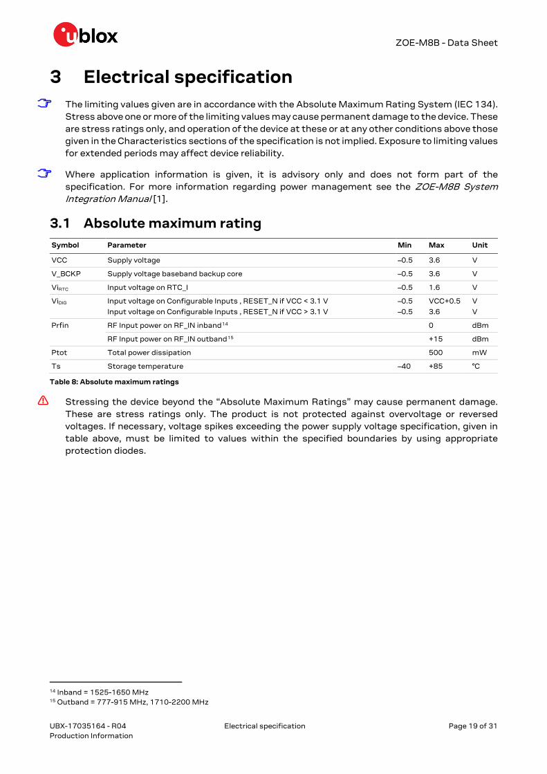
UBX-17035164 - R04 Electrical specification Page 19 of 31 Production Information
3 Electrical specification The limiting values given are in accordance with the Absolute Maximum Rating System (IEC 134).
Stress above one or more of the limiting values may cause permanent damage to the device. These are stress ratings only, and operation of the device at these or at any other conditions above those given in the Characteristics sections of the specification is not implied. Exposure to limiting values for extended periods may affect device reliability.
Where application information is given, it is advisory only and does not form part of the specification. For more information regarding power management see the ZOE-M8B System Integration Manual [1].
3.1 Absolute maximum rating Symbol Parameter Min Max Unit
VCC Supply voltage –0.5 3.6 V
V_BCKP Supply voltage baseband backup core –0.5 3.6 V
ViRTC Input voltage on RTC_I –0.5 1.6 V
ViDIG Input voltage on Configurable Inputs , RESET_N if VCC < 3.1 V
Input voltage on Configurable Inputs , RESET_N if VCC > 3.1 V
–0.5
–0.5
VCC+0.5
3.6
V
V
Prfin RF Input power on RF_IN inband14 0 dBm
RF Input power on RF_IN outband15 +15 dBm
Ptot Total power dissipation 500 mW
Ts Storage temperature –40 +85 °C
Table 8: Absolute maximum ratings
Stressing the device beyond the “Absolute Maximum Ratings” may cause permanent damage. These are stress ratings only. The product is not protected against overvoltage or reversed voltages. If necessary, voltage spikes exceeding the power supply voltage specification, given in table above, must be limited to values within the specified boundaries by using appropriate protection diodes.
14 Inband = 1525-1650 MHz 15 Outband = 777-915 MHz, 1710-2200 MHz
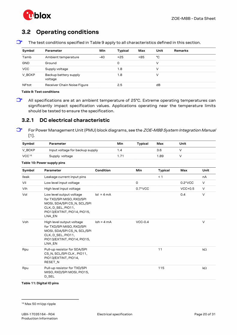
ZOE-M8B - Data Sheet
UBX-17035164 - R04 Electrical specification Page 20 of 31 Production Information
3.2 Operating conditions
The test conditions specified in Table 9 apply to all characteristics defined in this section.
Symbol Parameter Min Typical Max Unit Remarks
Tamb Ambient temperature -40 +25 +85 °C
GND Ground 0 V
VCC Supply voltage 1.8 V
V_BCKP Backup battery supply voltage
1.8 V
NFtot Receiver Chain Noise Figure 2.5 dB
Table 9: Test conditions
All specifications are at an ambient temperature of 25°C. Extreme operating temperatures can significantly impact specification values. Applications operating near the temperature limits should be tested to ensure the specification.
3.2.1 DC electrical characteristic
For Power Management Unit (PMU) block diagrams, see the ZOE-M8B System Integration Manual [1].
Symbol Parameter Min Typical Max Unit
V_BCKP Input voltage for backup supply 1.4 3.6 V
VCC16 Supply voltage 1.71 1.89 V
Table 10: Power supply pins
Symbol Parameter Condition Min Typical Max Unit
Ileak Leakage current input pins < 1 nA
Vil Low level input voltage 0 0.2*VCC V
Vih High level input voltage 0.7*VCC VCC+0.5 V
Vol Low level output voltage
for TXD/SPI MISO, RXD/SPI MOSI, SDA/SPI CS_N, SCL/SPI CLK, D_SEL, PIO11, PIO13/EXTINT, PIO14, PIO15, LNA_EN
Iol = 4 mA 0.4 V
Voh High level output voltage
for TXD/SPI MISO, RXD/SPI MOSI, SDA/SPI CS_N, SCL/SPI CLK, D_SEL, PIO11, PIO13/EXTINT, PIO14, PIO15, LNA_EN
Ioh = 4 mA VCC-0.4 V
Rpu Pull-up resistor for SDA/SPI CS_N, SCL/SPI CLK , PIO11, PIO13/EXTINT, PIO14, RESET_N
11 kΩ
Rpu Pull-up resistor for TXD/SPI MISO, RXD/SPI MOSI, PIO15, D_SEL
115 kΩ
Table 11: Digital IO pins
16 Max 50 mVpp ripple
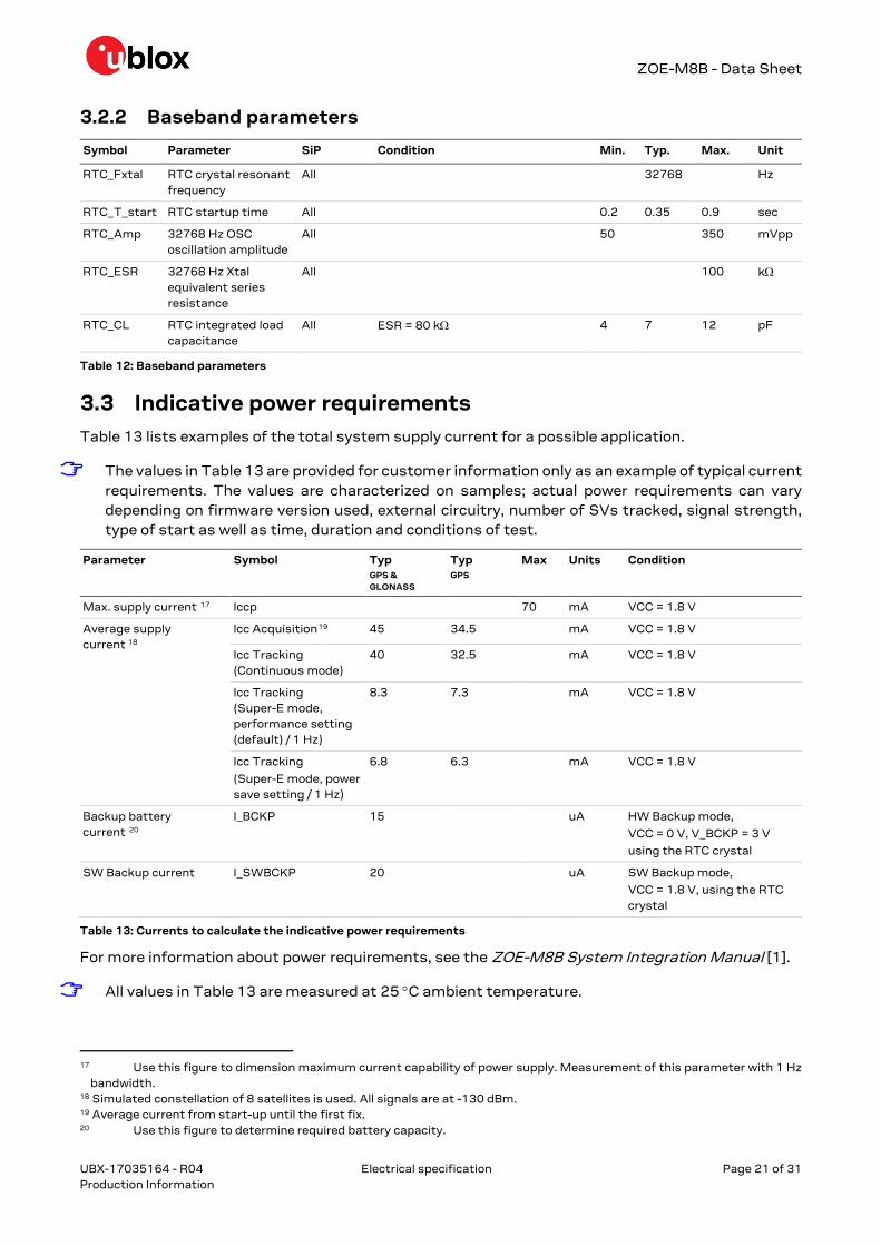
ZOE-M8B - Data Sheet
UBX-17035164 - R04 Electrical specification Page 21 of 31 Production Information
3.2.2 Baseband parameters
Symbol Parameter SiP Condition Min. Typ. Max. Unit
RTC_Fxtal RTC crystal resonant frequency
All 32768 Hz
RTC_T_start RTC startup time All 0.2 0.35 0.9 sec
RTC_Amp 32768 Hz OSC oscillation amplitude
All 50 350 mVpp
RTC_ESR 32768 Hz Xtal equivalent series resistance
All 100 kΩ
RTC_CL RTC integrated load capacitance
All ESR = 80 kΩ 4 7 12 pF
Table 12: Baseband parameters
3.3 Indicative power requirements Table 13 lists examples of the total system supply current for a possible application.
The values in Table 13 are provided for customer information only as an example of typical current requirements. The values are characterized on samples; actual power requirements can vary depending on firmware version used, external circuitry, number of SVs tracked, signal strength, type of start as well as time, duration and conditions of test.
Parameter Symbol Typ GPS & GLONASS
Typ GPS
Max Units Condition
Max. supply current 17 Iccp 70 mA VCC = 1.8 V
Average supply current 18
Icc Acquisition19 45 34.5 mA VCC = 1.8 V
Icc Tracking (Continuous mode)
40 32.5 mA VCC = 1.8 V
Icc Tracking (Super-E mode, performance setting (default) / 1 Hz)
8.3 7.3 mA VCC = 1.8 V
Icc Tracking
(Super-E mode, power save setting / 1 Hz)
6.8 6.3 mA VCC = 1.8 V
Backup battery current 20
I_BCKP
15 uA HW Backup mode,
VCC = 0 V, V_BCKP = 3 V
using the RTC crystal
SW Backup current I_SWBCKP
20 uA SW Backup mode,
VCC = 1.8 V, using the RTC crystal
Table 13: Currents to calculate the indicative power requirements
For more information about power requirements, see the ZOE-M8B System Integration Manual [1].
All values in Table 13 are measured at 25 °C ambient temperature.
17 Use this figure to dimension maximum current capability of power supply. Measurement of this parameter with 1 Hz
bandwidth. 18 Simulated constellation of 8 satellites is used. All signals are at -130 dBm. 19 Average current from start-up until the first fix. 20 Use this figure to determine required battery capacity.

ZOE-M8B - Data Sheet
UBX-17035164 - R04 Electrical specification Page 22 of 31 Production Information
3.4 SPI timing diagrams In order to avoid incorrect operation of the SPI, the user needs to comply with certain timing conditions. The following signals need to be considered for timing constraints:
Symbol Description
SPI CS_N (SS_N) Slave select signal
SPI CLK (SCK) Slave clock signal
Table 14: Symbol description
Figure 3: SPI timing diagram
3.4.1 Timing recommendations
The recommendations below are based on a firmware running from SQI flash memory.
Parameter Description Recommendation
tINIT Minimum Initialization Time 10 us
tDES Deselect Time 1 ms.
tbit Minimum bit time 1 us (1 MHz max bit frequency)
tbyte Minimum byte period 8 µs (125 kHz max byte frequency)
Table 15: SPI timing recommendations
The values in the above table result from the requirement of an error-free transmission. By allowing just a few errors and disabling the glitch filter, the bit rate can be increased considerably.
3.5 DDC timing diagrams The DDC interface is I2C Fast Mode compliant. For timing parameters consult the I2C standard.
The maximum bit rate is 100 kbit/s. The interface stretches the clock when slowed down while serving interrupts, so real bit rates may be slightly lower.

B. POWER CONSUMPTION MEASUREMENTS FOR WF(M)200 WI-FI MODULE(EXCERPT)
B Power Consumption Measurements for WF(M)200Wi-Fi Module (excerpt)
45

AN1219: Power ConsumptionMeasurement Setup and Results onWF(M)200
WF(M)200 is a Wi-Fi network co-processor optimized for low-energy consumption. This application note describes how toperform current consumption measurements and get the lowestcurrent consumption with WF(M)200.Additionally, this document shows how to achieve accurate measurements usingBDR8022 or BRD8023 and provides measurement examples for different use cases.This document applies to both WF200 and WFM200. For simplicity, both devices arereferred to as WF(M)200.
KEY POINTS
• WF200 and WFM200 are optimized for lowconsumption
• Improving WF(M)200 usage for low-currentconsumption
• Performing accurate currentmeasurements with BRD8022/BRD8023
• Measurement examples
silabs.com | Building a more connected world. Rev. 1.0

1.3 Power Profiles Definitions
The current consumption on WF(M)200 is highly dynamic and varies significantly depending on the following factors.• Wi-Fi data traffic activity depends on the application. The more transmit and receive data, the higher the consumption.• Wi-Fi Power-save enabled depends on the application. It saves power consumption if the data throughput is low or if the host uses
short period of high throughput and no data traffic between them.
Table 1.2. Power States Description
Modes State Definitions
Traffic modes
(STA and Soft-AP)
WF(M)200 is associated with an Access Point, handling some traffic in transmitting or inreceiving data frames traffic or in listen state
TX Transmitting Wi-Fi frames
RX Receiving Wi-Fi frames.
Listen Listening to the channel to receive framesor between RX and TX. This is also the de-fault mode if power save is not enabled.
Additional modes when power save is ena-bled
(STA only)
WF(M)200 is associated with an Access Point and set in power save.
TX, RX and listen states listed above are still valid.
States below are observed between beacons reception, provided that WUP pin is Low.
These states also occur if there is no activity with the host before association.
Sleep This state is using LP_CLK and switchingoff the XTAL.
Snooze Occurs when there is no LP_CLK providedto WF(M)200.
Sleep with XO This state is using LP_CLK but maintainsXTAL oscillator active and switching off theXTAL.
Idle modes
(STA and Soft-AP)
WF(M)200 is shut down. Resuming operation requires a complete start-up sequencetriggered by a rising edge on RESETn pin.
Shut-down mode Occurs when the host has sent the HIFmessage requesting the WF(M)200 toswitch in Shutdown mode. Achieved onlywhen WUP pin is Low.
Reset mode Occurs when RESETn pin is set low.
1.4 Host Interface (SPI/SDIO)
WF(M)200 can be controlled by an MCU or SoC using either SPI or SDIO (upon SDIO_DAT2/HIF_SEL pin state during the rising edgeof RESETn) through the host interface.
The SPI/SDIO clock frequency has an impact on consumption during sleep. As a result, during this state, when possible, the lowestconsumption is achieved when the clock is stopped. Moreover, when the wake-up is set to high to exchange message between the hostand the WF(M)200, use the highest possible serial clock to reduce this duration.
Note: With Linux driver on Raspberry Pi, it is not possible to get the lowest current consumption in sleep state with SDIO interfacebecause the serial clock is not stopped. As a result, the measurements presented in 3. Measurement Setup use the SPI interface.
1.5 RESETn
WF(M)200 RESETn pin has an internal pull-up (43 Kohm typical).
This pin should be kept high when in Shutdown mode to achieve the lowest current consumption.
AN1219: Power Consumption Measurement Setup and Results on WF(M)200WF200 and WFM200 Overview
silabs.com | Building a more connected world. Rev. 1.0 | 5

2. Measurement Summary
Static use cases for current consumption are mentioned in the table below.
These current consumptions are detailed in the data sheet.
Dynamic use cases:• Power save mode when associated under DTIM provides the WF(M)200 average current consumption when there is no TX/RX of
data (only receiving Beacons with the DTIM interval and using the sleep state). The current consumption for DTIM1, DTIM3, andDTIM10 is described in the data sheet.
• Time and consumption during boot and firmware download• Time and consumption during scan: An active scan is performed on channels 1 up to 11 and a passive scan on channel 12 up to 14• Time and consumption during Association to an Access Point: The current consumption to get the association with a selected Ac-
cess Point• Consumption during data traffic: Low bit rate and short burst of high bit rate, ping current consumption
All current consumption figures provide a better understanding for the global consumption of the WF(M)200 according to the targetedapplication.
The table below includes a summary of measurements detailed in the following sections:
Static power states:
Table 2.1. Current Consumption Summary for Static States
Use Case Typical current consumption at 3.3 V Comments
TX burst 154.4 mA Depends on the constellation and code rateused in TX and depending of the maximum
power allowed
RX burst 41.8 mA
Listen 45.4 mA
Sleep 24.33 µA Depends on the WF(M)200 parts used(some variations are possible)
Sleep with XO ON 438.4 µA
Snooze (No LP_CLK) 1.48 mA
Shutdown ~513 nA WUP low and RESETn stay high
Reset ~75.5µA When RESETn is low. Depends on the in-ternal pull-up resistor in the WF(M)200 part.
Dynamic use cases:
Table 2.2. Current Consumption Summary for Dynamic States
Use Case Measurement Duration Averaged current consump-tionat 3.3 V
Comments
Wi-Fi Power save DTIM1 1.02 s ~927 μA Can depend on the AccessPoint and Wi-Fi context.
Wi-Fi Power save DTIM3 2.45 s ~327 μA Can depend on the AccessPoint and Wi-Fi context.
Wi-Fi Power save DTIM10 4.1 s ~115 μA Can depend on the AccessPoint and Wi-Fi context.
Firmware download 264.16 ms ~16.38 mA Depends on the SPI/SDIO clockand firmware size.
AN1219: Power Consumption Measurement Setup and Results on WF(M)200Measurement Summary
silabs.com | Building a more connected world. Rev. 1.0 | 7
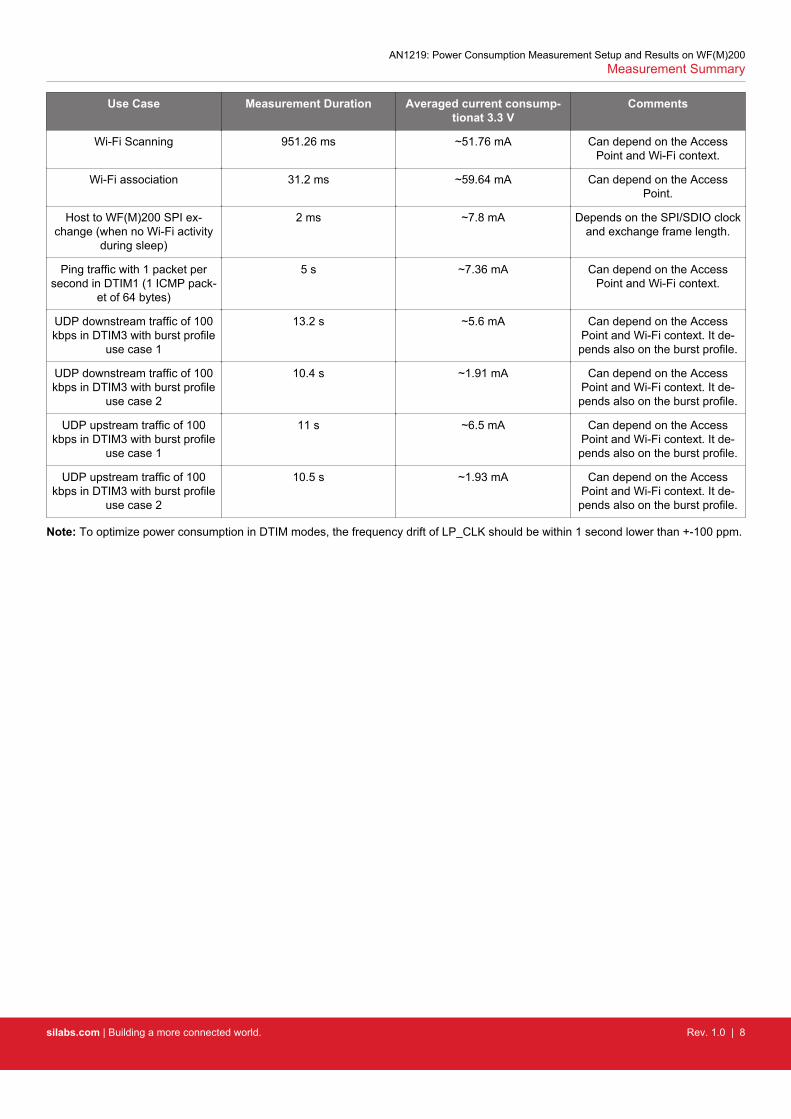
Use Case Measurement Duration Averaged current consump-tionat 3.3 V
Comments
Wi-Fi Scanning 951.26 ms ~51.76 mA Can depend on the AccessPoint and Wi-Fi context.
Wi-Fi association 31.2 ms ~59.64 mA Can depend on the AccessPoint.
Host to WF(M)200 SPI ex-change (when no Wi-Fi activity
during sleep)
2 ms ~7.8 mA Depends on the SPI/SDIO clockand exchange frame length.
Ping traffic with 1 packet persecond in DTIM1 (1 ICMP pack-
et of 64 bytes)
5 s ~7.36 mA Can depend on the AccessPoint and Wi-Fi context.
UDP downstream traffic of 100kbps in DTIM3 with burst profile
use case 1
13.2 s ~5.6 mA Can depend on the AccessPoint and Wi-Fi context. It de-pends also on the burst profile.
UDP downstream traffic of 100kbps in DTIM3 with burst profile
use case 2
10.4 s ~1.91 mA Can depend on the AccessPoint and Wi-Fi context. It de-pends also on the burst profile.
UDP upstream traffic of 100kbps in DTIM3 with burst profile
use case 1
11 s ~6.5 mA Can depend on the AccessPoint and Wi-Fi context. It de-pends also on the burst profile.
UDP upstream traffic of 100kbps in DTIM3 with burst profile
use case 2
10.5 s ~1.93 mA Can depend on the AccessPoint and Wi-Fi context. It de-pends also on the burst profile.
Note: To optimize power consumption in DTIM modes, the frequency drift of LP_CLK should be within 1 second lower than +-100 ppm.
AN1219: Power Consumption Measurement Setup and Results on WF(M)200Measurement Summary
silabs.com | Building a more connected world. Rev. 1.0 | 8

APPENDICES
C AIS2DW12 Accelerometer Data-sheet (excerpt)
50

This is information on a product in full production.
June 2019 DocID031240 Rev 4 1/60
AIS2DW12
MEMS digital output motion sensor: ultra-low-power 3-axis accelerometer for automotive applications
Datasheet - production data
Features AEC-Q100 qualified Supply voltage, 1.62 V to 3.6 V Independent IO supply and supply voltage
compatible Ultra-low-power mode consumption down to
380 nA @1.6 Hz ±2g/±4g dynamically selectable full scales High-speed I²C/SPI digital output interface 2 independent programmable interrupts Single data conversion on demand 16-bit data output Embedded temperature sensor Self-test 32-level embedded FIFO 10000 g high shock survivability ECOPACK, RoHS and “Green” compliant
Applications Car key applications Inclination / orientation detection Motion-activated functions Gesture recognition Free-fall detection Smart power saving
DescriptionThe AIS2DW12 is an ultra-low-power three-axis linear accelerometer which leverages on the robust and mature manufacturing processes already used for the production of micromachined accelerometers and designed to address non-safety automotive applications.
The AIS2DW12 has four different ultra-low-power modes, two user-selectable full scales (2g/4g) and is capable of measuring accelerations with output data rates from 1.6 Hz to 100 Hz.
The AIS2DW12 has an integrated 32-level first-in, first-out (FIFO) buffer allowing the user to store data in order to limit intervention by the host processor.
The embedded self-test capability allows the user to check the functioning of the sensor in the final application.
The AIS2DW12 has a dedicated internal engine to process motion and acceleration detection including free-fall, motion and no-motion, wakeup, activity/inactivity and 6D/4D orientation.
The AIS2DW12 is available in a small thin plastic land grid array package (LGA) and it is guaranteed to operate over an extended temperature range from -40 °C to +85 °C.
LGA-12 (2x2x0.93 mm³)
Table 1. Device summary
Order codes Temp. range [°C] Package Packaging
AIS2DW12 -40 to +85 LGA-12 Tray
AIS2DW12TR -40 to +85 LGA-12 Tape and reel
www.st.com

Mechanical and electrical specifications AIS2DW12
12/60 DocID031240 Rev 4
2.2 Electrical characteristics
Table 5. Electrical characteristics @ Vdd = 3.0 V, T = -40°C to +85°C unless otherwise noted (1) Symbol Parameter Test conditions Min. Typ.(2) Max. Unit
Vdd Supply voltage 1.62 3.6 V
Vdd_IO I/O pins supply voltage(3) 1.62 Vdd+0.1 V
IddLP Current consumption in Power Mode 1
ODR 100 Hz@ Vdd = 1.8 V(4) 5
μA
ODR 50 Hz@ Vdd = 1.8 V(4) 3
ODR 12.5 Hz@ Vdd = 1.8 V(4) 1
ODR 1.6 Hz@Vdd = 1.8 V(4) 0.38
ODR 100 Hz@ Vdd = 3 V
6.5 12.0
ODR 50 Hz@ Vdd = 3 V(4) 3.7 6.4
ODR 12.5 Hz@ Vdd = 3 V(4) 1.3 2.9
ODR 1.6 Hz@ Vdd = 3 V(4) 0.67 1.9
Idd_PDCurrent consumption in power-down
@ Vdd = 1.8 V(4) 50nA
@ Vdd = 3 V 100 950
VIH Digital high-level input voltage 0.8*Vdd_IO V
VIL Digital low-level input voltage 0.2*Vdd_IO V
VOH Digital high-level output voltage IOH = 4 mA(5) VDD_IO - 0.2 V
VOL Digital low-level output voltage IOL = 4 mA(5) 0.2 V
1. The product is factory calibrated at 3.0 V. The operational power supply range is from 1.62 V to 3.6 V.
2. Typical specifications are not guaranteed.
3. It is possible to remove Vdd maintaining Vdd_IO without blocking the communication busses. In this condition the measurement chain is powered off.
4. Verified at characterization level in Power Mode 1 configuration.
5. 4 mA is the maximum driving capability, ie. the maximum DC current that can be sourced/sunk by the digital pad in order to guarantee the correct digital output voltage levels VOH and VOL.

D. PYTHON CODE FOR THE DESIGNED PKE SYSTEM - KEY
D Python Code for the Designed PKE System - Key
D.1 main.py
1 import bluetooth2 import time34 import b t c o n f i g5 import bt6 import b t r s s i7 import acc89 def main ( ) :
10 bt . s e t u p b l u e t o o t h ( ) #Make suret h a t b l u e t o o t h c t l s e r v i c e i s running and power i s on
11 i d l e = False12 print ( ” Socket setup complete ” )13 sleep mod = acc . s l eep mode contro l module ( )14 sleep mod . s t a r t a c c m o n i t o r ( )15 while True :16 attack warn ing = False17 bt module = bt . Bt module server ( ) #A l l o c a t e
re source s and i n i t i a l i z e b t module18 i f bt module . connect ( ) :19 bt module . s t a r t r s s i m o n i t o r t h r e a d ( ) #S t a r t r s s i
monitor20 while True :21 #Do not p r i n t l o g i f in i d l e22 i f i d l e == True :23 rece ived , e r r o r = bt module . l i s t e n ( timeout =1,
p r i n t i n g=False )24 else :25 rece ived , e r r o r = bt module . l i s t e n ( )26 #Legacy?27 i f r e c e i v e d == None :28 i d l e = False29 i f e r r o r <= 0 :30 break31 else :32 time . s l e e p ( 0 . 1 )3334 e l i f r e c e i v e d == bytearray ( ” k e e p a l i v e ” , b t c o n f i g .
ENCODING) :35 l i f e s i g n = ” a l i v e ”36 #Only respond to keep−a l i v e i f in r s s i range37 i f bt module . i n range :38 i f bt module . send ( l i f e s i g n , Fa l se ) :39 i f i d l e == False :40 i d l e = True41 print ( ” Veh ic l e unlocked . Enter ing i d l e .
Responding to keep−a l i v ep e r i o d i c a l l y ” )
42 continue
53

APPENDICES
43 else :44 i d l e = False45 break46 e l i f r e c e i v e d == bytearray ( ”Wake up ! ” , b t c o n f i g .
ENCODING) :47 #Only r e p l y to wake−up i f in r s s i range48 i f bt module . i n range :49 print ( ”Key in range ” )50 i f s leep mod . s l e e p :51 i f attack warn ing == False :52 attack warn ing == True53 print ( ”WARNING! ACCESS REQUESTED WHILE
SLEEPING” )54 else :55 attack warn ing = False56 print ( ” Sending wake−up con f i rmat ion . . . ” )57 wakeup confirm = ” confirm wakeup ”58 i d l e = False59 i f bt module . send ( wakeup confirm ) :60 continue61 else :62 break63 e l i f r e c e i v e d [ 0 : 9 ] == bytearray ( ” c h a l l e n g e ” , b t c o n f i g .
ENCODING) :64 print ( ” Ca l cu l a t ing c h a l l e n g e response ” )65 response = ” response ”66 print ( ” Sending c h a l l e n g e response ” )67 i d l e = False68 i f bt module . send ( re sponse ) :69 continue70 else :71 break72 else :73 i d l e = False74 print ( ” I n v a l i d message r e c e i v e d . Ignor ing and
proceed ing ” )7576 i f name == ” ma in ” :77 main ( )
54

D. PYTHON CODE FOR THE DESIGNED PKE SYSTEM - KEY
D.2 bt.py
1 import os2 import bluetooth3 import time4 import thread ing56 import b t c o n f i g7 import b t r s s i89
10 class Bt module server :11 ””” Class f o r c o n t r o l l i n g the b l u e t o o t h module , Key i s Server , Car
i s Cient12 ”””1314 def i n i t ( s e l f ) :15 s e l f . sock = bluetooth . BluetoothSocket ( b luetooth .RFCOMM) #
a l l o c a t e resource16 s e l f . sock . bind ( ( ”” ,0 ) ) #bind any adapter and any
por t17 s e l f . c l i e n t s o c k = None18 s e l f . v e h i c l e a d d r e s s = None19 s e l f . r s s i t h r e a d = None20 s e l f . s t o p r s s i t h r e a d = False #f l a g to s top r s s i thread
upon d i sconnec t or r e s e t21 s e l f . r s s i = None #r o l l i n g average r s s i
readout22 s e l f . r s s i q u e u e = [ ] #recen t r s s i readouts f o r
averag ing23 s e l f . i n range = False #in r s s i range f l a g2425 def s t a r t r s s i m o n i t o r t h r e a d ( s e l f ) :26 ””” S t a r t s a thread f o r monitoring r s s i va lue o f v e h i c l e a d d r e s s
.27 Thread i s k i l l e d upon d i sconnec t or error .28 C a l l s r s s i c a l l b a c k to update r s s i on thread29 ”””30 s e l f . s t o p r s s i t h r e a d = False31 s e l f . r s s i t h r e a d = thread ing . Thread (32 t a r g e t=b t r s s i . m o n i t o r r s s i ,33 args=(lambda : s e l f . s t o p r s s i t h r e a d , ) ,34 kwargs=35 ’ addr ’ : s e l f . v e h i c l e a d d r e s s [ 0 ] ,36 ’ parent ’ : s e l f ,37 ’ s l e e p ’ : b t c o n f i g . RSSI SLEEP ,38 ’ debug ’ : Fa l se39 40 )41 s e l f . r s s i t h r e a d . daemon = True #dameonize42 s e l f . r s s i t h r e a d . s t a r t ( )4344 def r s s i c a l l b a c k ( s e l f , r s s i ) :45 ””” Passed RSSI readouts from thread and updates r s s i va lue .
55

APPENDICES
46 ”””47 #Only average f u l l queue48 i f r s s i == None :49 s e l f . r s s i = None50 s e l f . i n range = False51 return52 else :53 #c a l c u l a t e and update r s s i54 i f len ( s e l f . r s s i q u e u e ) >= b t c o n f i g .RSSI AVERAGE LENGTH:55 s e l f . r s s i q u e u e . append ( r s s i )56 s e l f . r s s i q u e u e = s e l f . r s s i q u e u e [ 1 : ]57 avg = 058 for i in s e l f . r s s i q u e u e :59 avg += i60 s e l f . r s s i = avg/ b t c o n f i g .RSSI AVERAGE LENGTH61 else :62 s e l f . r s s i q u e u e . append ( r s s i )63 #update s e l f . in range based on curren t r s s i va lue64 i f s e l f . r s s i == None :65 s e l f . i n range = False66 e l i f s e l f . r s s i >= b t c o n f i g .RSSI THRESHOLD [ 1 ] :67 s e l f . i n range = True68 e l i f s e l f . r s s i <= b t c o n f i g .RSSI THRESHOLD [ 0 ] :69 s e l f . i n range = False7071 def c l o s e s o c k e t s ( s e l f ) :72 #g r a c e f u l e x i t73 try :74 s e l f . c l i e n t s o c k . c l o s e ( )75 s e l f . sock . c l o s e ( )76 except bluetooth . BluetoothError as e :77 print ( ” Error whi l e c l o s i n g socket : ” )78 print ( e )79 s e l f . s t o p r s s i t h r e a d = True #make sure thread i s s topped80 i f s e l f . r s s i t h r e a d != None :81 s e l f . r s s i t h r e a d . j o i n ( ) #wait f o r thread to d i e8283 def connect ( s e l f ) :84 ””” Connects to s e l f . v e h i c l e a d d r e s s on s o c k e t85 ”””86 print ( ” Waiting f o r connect ion . . . ” )87 s e l f . sock . l i s t e n (1 ) #Ready to accep t 1 connect ion88 s e l f . sock . s e t t imeout ( b t c o n f i g .CONNECT TIMEOUT) #Socket t imeout89 c u r r e n t e r r o r = None90 while True : #Ends only i f connect ion i s e s t a b l i s h e d
. Key has no o ther job in the meantime . Could be threaded .91 try : #Try to connect92 s e l f . c l i e n t s o c k , s e l f . v e h i c l e a d d r e s s = s e l f . sock .
accept ( )93 break94 except bluetooth . btcommon . BluetoothError as e :95 #Errors excepted , connect ion r e t r i e d96 errno = e . args [ 0 ]97 i f errno != c u r r e n t e r r o r :
56

D. PYTHON CODE FOR THE DESIGNED PKE SYSTEM - KEY
98 print ( e )99 c u r r e n t e r r o r = errno
100 print ( ” Waiting f o r connect ion . . . ” )101 print ( ” Connection e s t a b l i s h e d from ” + str ( s e l f . c l i e n t s o c k .
getpeername ( ) ) + ” at ” + str ( s e l f . v e h i c l e a d d r e s s [ 0 ] ) )102103 #Only a l l ow connect ion from the pa i red v e h i c l e104 i f s e l f . v e h i c l e a d d r e s s [ 0 ] != b t c o n f i g .CAR ADDR:105 print ( ” Address does not match v e h i c l e . Blocking address ” )106 command = ” echo ’ b lock ’ ” + str ( s e l f . v e h i c l e a d d r e s s [ 0 ] ) +
” ’\ nquit ’ | b l u e t o o t h c t l ”107 os . system (command) #Block any unexpected d e v i c e s t h a t t r y
to connect . Use B l u e t o o t h c t l .108 time . s l e e p ( 0 . 1 ) #Sync109 return False #Reloads s o c k e t and t r i e s connect ion
again110 return True111112 def l i s t e n ( s e l f , t imeout=b t c o n f i g .LISTEN TIMEOUT, p r i n t i n g=True ) :113 ””” Unfortunate l e g a c y name . . . l i s t e n i n g f o r message114 ”””115 p r i n t i n g = False116 i f p r i n t i n g == True :117 print ( ” L i s t e n i n g on c l i e n t socke t . . . ” )118 s e l f . c l i e n t s o c k . s e t t imeout ( timeout )119 try :120 data = s e l f . c l i e n t s o c k . recv (1024)121 i f p r i n t i n g == True :122 print ( ” Received : ” + str ( data ) )123 return data , 0124 #timed out shou ld be handled d i f f e r e n t to r e a l e r ro r s125 except bluetooth . BluetoothError as e :126 i f e . args [ 0 ] == ” timed out ” :127 return None , 1128 print ( e )129 print ( ” Fa i l ed . Rese t t ing socket and re tu rn ing to main frame
” )130 s e l f . c l o s e s o c k e t s ( ) #cleanup131 return None , −1132133 def send ( s e l f , data , p r i n t i n g=True ) :134 ””” Send message on s o c k e t ”””135 to send = bytearray ( data , b t c o n f i g .ENCODING)136 try :137 s e l f . c l i e n t s o c k . send ( to send )138 #Retry sending once , sync error may occur . E lse c leanup and
re turn139 except bluetooth . BluetoothError as e :140 i f p r i n t i n g == True :141 print ( e )142 print ( ” Retrying to send . . . ” )143 try :144 s e l f . c l i e n t s o c k . send ( to send )145 except bluetooth . BluetoothError as e :
57

APPENDICES
146 i f p r i n t i n g == True :147 print ( e )148 print ( ” Sending f a i l e d . Rese t t ing socket and
re tu rn ing to main frame ” )149 s e l f . c l o s e s o c k e t s ( )150 return False151 i f p r i n t i n g == True :152 print ( ” Message sent ” )153 return True154155 def s e t u p b l u e t o o t h ( ) :156 #B l u e t o o t h c t l setup , make sure e v e r y t h i n g i s on and primed157 print ( ” Rese t t ing b l u e t o o t h c t l ” )158 os . system ( ” sudo sys t emct l stop b luetooth ” )159 os . system ( ” sudo sys t emct l s t a r t b luetooth ” )160 os . system ( ” echo ’ power on\nquit ’ | b l u e t o o t h c t l ” )161 time . s l e e p ( 0 . 1 )
58
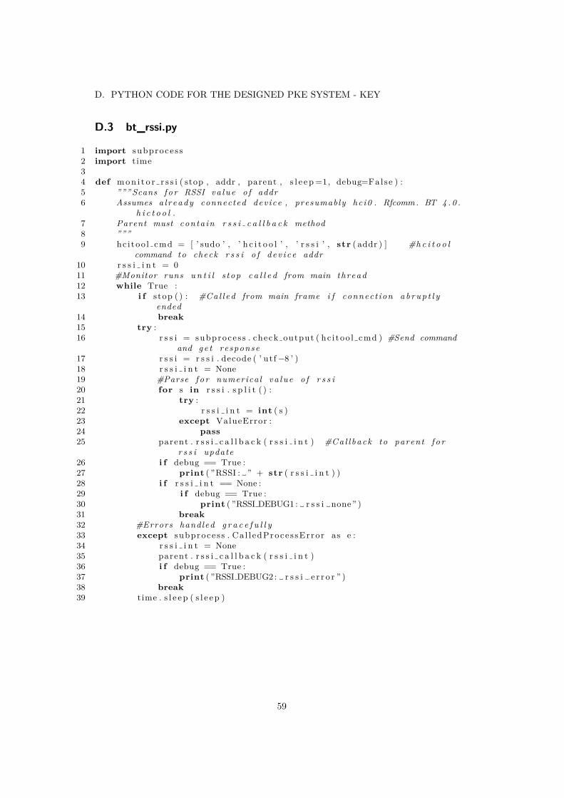
D. PYTHON CODE FOR THE DESIGNED PKE SYSTEM - KEY
D.3 bt_rssi.py
1 import subproces s2 import time34 def m o n i t o r r s s i ( stop , addr , parent , s l e e p =1, debug=False ) :5 ””” Scans f o r RSSI va lue o f addr6 Assumes a l r eady connected dev ice , presumably hc i0 . Rfcomm . BT 4 . 0 .
h i c t o o l .7 Parent must conta in r s s i c a l l b a c k method8 ”””9 hc i too l cmd = [ ’ sudo ’ , ’ h c i t o o l ’ , ’ r s s i ’ , str ( addr ) ] #h c i t o o l
command to check r s s i o f d ev i c e addr10 r s s i i n t = 011 #Monitor runs u n t i l s top c a l l e d from main thread12 while True :13 i f stop ( ) : #Cal l ed from main frame i f connect ion a b r u p t l y
ended14 break15 try :16 r s s i = subproces s . check output ( hc i too l cmd ) #Send command
and g e t response17 r s s i = r s s i . decode ( ’ ut f−8 ’ )18 r s s i i n t = None19 #Parse f o r numerical va lue o f r s s i20 for s in r s s i . s p l i t ( ) :21 try :22 r s s i i n t = int ( s )23 except ValueError :24 pass25 parent . r s s i c a l l b a c k ( r s s i i n t ) #Cal l back to parent f o r
r s s i update26 i f debug == True :27 print ( ”RSSI : ” + str ( r s s i i n t ) )28 i f r s s i i n t == None :29 i f debug == True :30 print ( ”RSSI DEBUG1 : r s s i none” )31 break32 #Errors handled g r a c e f u l l y33 except subproces s . Ca l l edProces sError as e :34 r s s i i n t = None35 parent . r s s i c a l l b a c k ( r s s i i n t )36 i f debug == True :37 print ( ”RSSI DEBUG2 : r s s i e r r o r ” )38 break39 time . s l e e p ( s l e e p )
59

APPENDICES
D.4 btconfig.py
1 CAR ADDR = ”B8 : 2 7 :EB: 9 9 : F8 : 8A” #address o f car2 DEFAULT PORT = 1 #d e f a u l t por t ( l e g a c y )3 TIMEOUT = 10 #timeout f o r b l u e t o o t h . B lue too thSocke t .
recv ( )4 ENCODING = ” utf−8” #encoding f o r messages5 RSSI THRESHOLD = (−2 ,0) #h y s t e r e s i s f o r r s s i6 DEBUG = True7 RSSI SLEEP = 0.05 #r s s i thread s l e e p time , due to h c i t o o l
i n t e r f a c i n g t h i s has l i t t l e e f f e c t , the command t a k e s too muchtime
8 RSSI AVERAGE LENGTH = 3 #RSSI queue l e n g t h9 CONNECT TIMEOUT = 1 #Defau l t t imeout f o r e s t a b l i s h i n g
connect ion10 LISTEN TIMEOUT = 0.5 #Defau l t t imeout f o r recv
60

D. PYTHON CODE FOR THE DESIGNED PKE SYSTEM - KEY
D.5 acc.py
1 import smbus2 import thread ing3 import time4 from math import s q r t56 import a c c c o n f i g78 class s l e ep mode contro l module :9 def i n i t ( s e l f ) :
10 s e l f . bus =smbus . SMBus(1 ) #i n i t i 2c bus11 s e l f . s l e e p = False #Sleep mode , True i f no
motion d e t e c t e d f o r g i ven time12 s e l f . acc queue = [ ] #Queue o f p rev ious acc
readouts13 s e l f . a c c va lue = None #Current average acc va lue14 s e l f . s l e e p t i m e r s t a r t = None #S t a r t o f most recen t s l e e p
t imer15 s e l f . s l e e p t i m e r a c t i v e = Fal se16 s e l f . mpu init ( )1718 def s t a r t a c c m o n i t o r ( s e l f ) :19 #c r ea t e thread and s t a r t i t20 thread = thread ing . Thread (21 t a r g e t = monitor acc ,22 args = ( ) ,23 kwargs = 24 ’ bus ’ : s e l f . bus ,25 ’ parent ’ : s e l f ,26 ’ s l e e p ’ : 0 . 1 ,27 ’ debug ’ : Fa l se28 )29 thread . daemon = True30 thread . s t a r t ( )3132 def a c c c a l l b a c k ( s e l f , acc ) :33 acc abs = s q r t ( ( acc [0 ]−1) ∗∗2 + ( acc [1 ]−1) ∗∗2 + ( acc [2 ]−1) ∗∗2) #
Get abs a c c e l e r a t i o n34 s e l f . acc queue . append ( acc abs )3536 i f len ( s e l f . acc queue ) > a c c c o n f i g .ACC QUEUE LEN:37 s e l f . acc queue = s e l f . acc queue [ 1 : ]3839 i f s e l f . a c c va lue != None :40 #I f acc too d i f f e r e n t from prev ious s l e e p f a l s e41 i f abs ( ( s e l f . acc va lue−acc abs ) / s e l f . a c c va lue ) > a c c c o n f i g
.ACC TOLERANCE:42 i f s e l f . s l e e p == True :43 print ( ” S leep mode o f f ” )44 s e l f . s l e e p = False45 s e l f . s l e e p t i m e r a c t i v e = Fal se46 else :47 #I f s l e ep , cont inue s l e e p i n g
61

APPENDICES
48 i f s e l f . s l e e p :49 pass50 else :51 #I f not s l e e p i n g but s l e e p t imer a l r eady on , check
i f t imer done and s l e e p i f so52 i f s e l f . s l e e p t i m e r a c t i v e :53 i f ( time . time ( ) − s e l f . s l e e p t i m e r s t a r t ) >
a c c c o n f i g .SLEEP TIMEOUT:54 s e l f . s l e e p = True55 print ( ” S leep mode a c t i v e ” )56 #Else s t a r t t imer57 else :58 s e l f . s l e e p t i m e r s t a r t = time . time ( )59 s e l f . s l e e p t i m e r a c t i v e = True60 avg = 061 for value in s e l f . acc queue :62 avg += value63 s e l f . a c c va lue = avg/ a c c c o n f i g .ACC QUEUE LEN #w i l l produce s low
s t a r t u p u n t i l queue i s f u l l , shou ld j u s t take a second ortwo
6465 def mpu init ( s e l f ) :66 #Vodoo magic f o r mpu i n i t67 s e l f . bus . w r i t e b y t e d a t a ( a c c c o n f i g .DEVICE ADDRESS, a c c c o n f i g .
SMPLRT DIV, 7)68 s e l f . bus . w r i t e b y t e d a t a ( a c c c o n f i g .DEVICE ADDRESS, a c c c o n f i g .
PWR MGMT 1, 1)69 s e l f . bus . w r i t e b y t e d a t a ( a c c c o n f i g .DEVICE ADDRESS, a c c c o n f i g .
CONFIG, 0)70 s e l f . bus . w r i t e b y t e d a t a ( a c c c o n f i g .DEVICE ADDRESS, a c c c o n f i g .
GYRO CONFIG, 24)71 s e l f . bus . w r i t e b y t e d a t a ( a c c c o n f i g .DEVICE ADDRESS, a c c c o n f i g .
INT ENABLE, 1)7273 def monitor acc ( bus , parent , s l e e p =0.1 , debug=False ) :74 #c a l l threaded , monitors acce lerometer , e x p e c t s parent wi th
a c c c a l l b a c k method75 while True :76 acc x = read raw data ( bus , a c c c o n f i g .ACCEL XOUT H) /1638477 acc y = read raw data ( bus , a c c c o n f i g .ACCEL YOUT H) /1638478 acc z = read raw data ( bus , a c c c o n f i g .ACCEL ZOUT H) /1638479 i f debug :80 print ( ” Acce lerometer readout : X =” , str ( acc x ) , ”Y =” , str (
acc y ) , ”Z = ” , str ( a c c z ) )81 parent . a c c c a l l b a c k ( ( acc x , acc y , a c c z ) )82 time . s l e e p ( s l e e p )8384 def read raw data ( bus , addr ) :85 #read data from addr on the i2c bus86 high = bus . r ead byte data ( a c c c o n f i g .DEVICE ADDRESS, addr )87 low = bus . r ead byte data ( a c c c o n f i g .DEVICE ADDRESS, addr+1)88 #combine readouts89 value = ( ( high << 8) | low )90 #g e t n e g a t i v e s
62

D. PYTHON CODE FOR THE DESIGNED PKE SYSTEM - KEY
91 i f value > 32768 :92 value = value − 6553693 return value
63

APPENDICES
D.6 accconfig.py
1 #I2C addresses , d ev i c e address to sensor , acc module s p e c i f i c c o n f i g2 PWR MGMT 1 = 0x6B3 SMPLRT DIV = 0x194 CONFIG = 0x1A5 GYRO CONFIG = 0x1B6 INT ENABLE = 0x387 ACCEL XOUT H = 0x3B8 ACCEL YOUT H = 0x3D9 ACCEL ZOUT H = 0x3F
10 GYRO XOUT H = 0x4311 GYRO YOUT H = 0x4512 GYRO ZOUT H = 0x471314 DEVICE ADDRESS = 0x681516 ACC QUEUE LEN = 1017 ACC TOLERANCE = 0.0518 SLEEP TIMEOUT = 10
64

E. PYTHON CODE FOR THE DESIGNED PKE SYSTEM - VEHICLE
E Python Code for the Designed PKE System - Vehicle
E.1 main.py
1 import fsm2 import bt34 def main ( ) :5 bt . s e t u p b l u e t o o t h ( )6 print ( ” Se t t i ng up v e h i c l e ” )7 v e h i c l e = fsm . v e h i c l e f s m ( )8 print ( ” Veh ic l e setup complete ” )9 v e h i c l e . run ( )
1011 i f name == ” ma in ” :12 main ( )
65

APPENDICES
E.2 fsm.py
1 import bt2 import l o ck34 #i s t h i s the b e s t s t r u c t u r e ? Should t he r e be an a c t i v e method?5 #a b s t r a c t c l a s s f o r v e h i c l e s t a t e s6 class v e h i c l e :7 def i n i t ( s e l f ) :8 unlocked = None9 #method f o r moving to next s t a t e , b l o c k s u n t i l r eq s f o r next s t a t e
f u l f i l l e d10 def t r a n s i t i o n ( s e l f , bt module ) :11 pass12 #method f o r e n t e r i n g s t a t e , b a s i c se tup13 def ente r ( s e l f ) :14 pass1516 #add but ton pre s s and then out o f range l o c k i n g17 class v e h i c l e u n l o c k e d ( v e h i c l e ) :18 def ente r ( s e l f ) :19 s e l f . unlocked = True20 lock . unlock ( )21 print ( ” Veh ic l e unlocked ” )22 def t r a n s i t i o n ( s e l f , bt module ) :23 print ( ” Waiting f o r l o c k i n g procedure . V e r i f y in g key in range
p e r i o d i c a l l y . ” )24 bt . w a i t f o r l o c k i n g p r o c e d u r e ( bt module )25 print ( ” Locking procedure complete ” )26 n e x t s t a t e = v e h i c l e l o c k e d ( )27 return next s ta t e , None2829 class v e h i c l e l o c k e d ( v e h i c l e ) :30 def ente r ( s e l f ) :31 s e l f . unlocked = False32 lock . l o ck ( )33 print ( ” Veh ic l e locked ” )34 def t r a n s i t i o n ( s e l f , bt module=None ) :35 print ( ” Waiting f o r unlock a u t h e n t i c a t i o n . . . ” )36 #u n l o c k a u t h e n t i c a t i o n b l o c k s u n t i l a u t h e n t i c a t i o n complete and
then re turns bt module wi th curren t s o c k e t fo com37 bt module = bt . u n l o c k a u t h e n t i c a t i o n ( )38 print ( ” Authenticaton complete ” )39 n e x t s t a t e = v e h i c l e u n l o c k e d ( )40 return next s ta t e , bt module4142 def v e h i c l e s e t u p ( ) :43 s t a t e = v e h i c l e l o c k e d ( )44 return s t a t e4546 #f i n i t e s t a t e machine f o r v e h i c l e47 class v e h i c l e f s m :48 def i n i t ( s e l f ) :49 s e l f . s t a t e = v e h i c l e s e t u p ( )
66

E. PYTHON CODE FOR THE DESIGNED PKE SYSTEM - VEHICLE
50 s e l f . bt module = bt . b t s o c k e t ( )5152 def run ( s e l f ) :53 while True :54 #cleanup f o r b t on e x i t ?55 next s ta t e , s e l f . bt module = s e l f . s t a t e . t r a n s i t i o n ( s e l f .
bt module )56 s e l f . s t a t e = n e x t s t a t e57 s e l f . s t a t e . ente r ( )
67
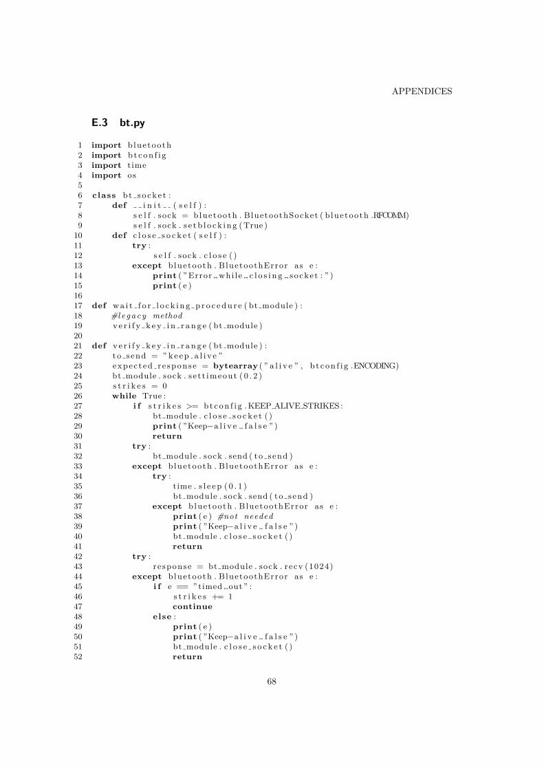
APPENDICES
E.3 bt.py
1 import bluetooth2 import b t c o n f i g3 import time4 import os56 class b t s o c k e t :7 def i n i t ( s e l f ) :8 s e l f . sock = bluetooth . BluetoothSocket ( b luetooth .RFCOMM)9 s e l f . sock . s e t b l o c k i n g ( True )
10 def c l o s e s o c k e t ( s e l f ) :11 try :12 s e l f . sock . c l o s e ( )13 except bluetooth . BluetoothError as e :14 print ( ” Error whi l e c l o s i n g socket : ” )15 print ( e )1617 def w a i t f o r l o c k i n g p r o c e d u r e ( bt module ) :18 #l e g a c y method19 v e r i f y k e y i n r a n g e ( bt module )2021 def v e r i f y k e y i n r a n g e ( bt module ) :22 to send = ” k e e p a l i v e ”23 expec ted re sponse = bytearray ( ” a l i v e ” , b t c o n f i g .ENCODING)24 bt module . sock . s e t t imeout ( 0 . 2 )25 s t r i k e s = 026 while True :27 i f s t r i k e s >= b t c o n f i g . KEEP ALIVE STRIKES :28 bt module . c l o s e s o c k e t ( )29 print ( ”Keep−a l i v e f a l s e ” )30 return31 try :32 bt module . sock . send ( to send )33 except bluetooth . BluetoothError as e :34 try :35 time . s l e e p ( 0 . 1 )36 bt module . sock . send ( to send )37 except bluetooth . BluetoothError as e :38 print ( e ) #not needed39 print ( ”Keep−a l i v e f a l s e ” )40 bt module . c l o s e s o c k e t ( )41 return42 try :43 response = bt module . sock . recv (1024)44 except bluetooth . BluetoothError as e :45 i f e == ” timed out ” :46 s t r i k e s += 147 continue48 else :49 print ( e )50 print ( ”Keep−a l i v e f a l s e ” )51 bt module . c l o s e s o c k e t ( )52 return
68
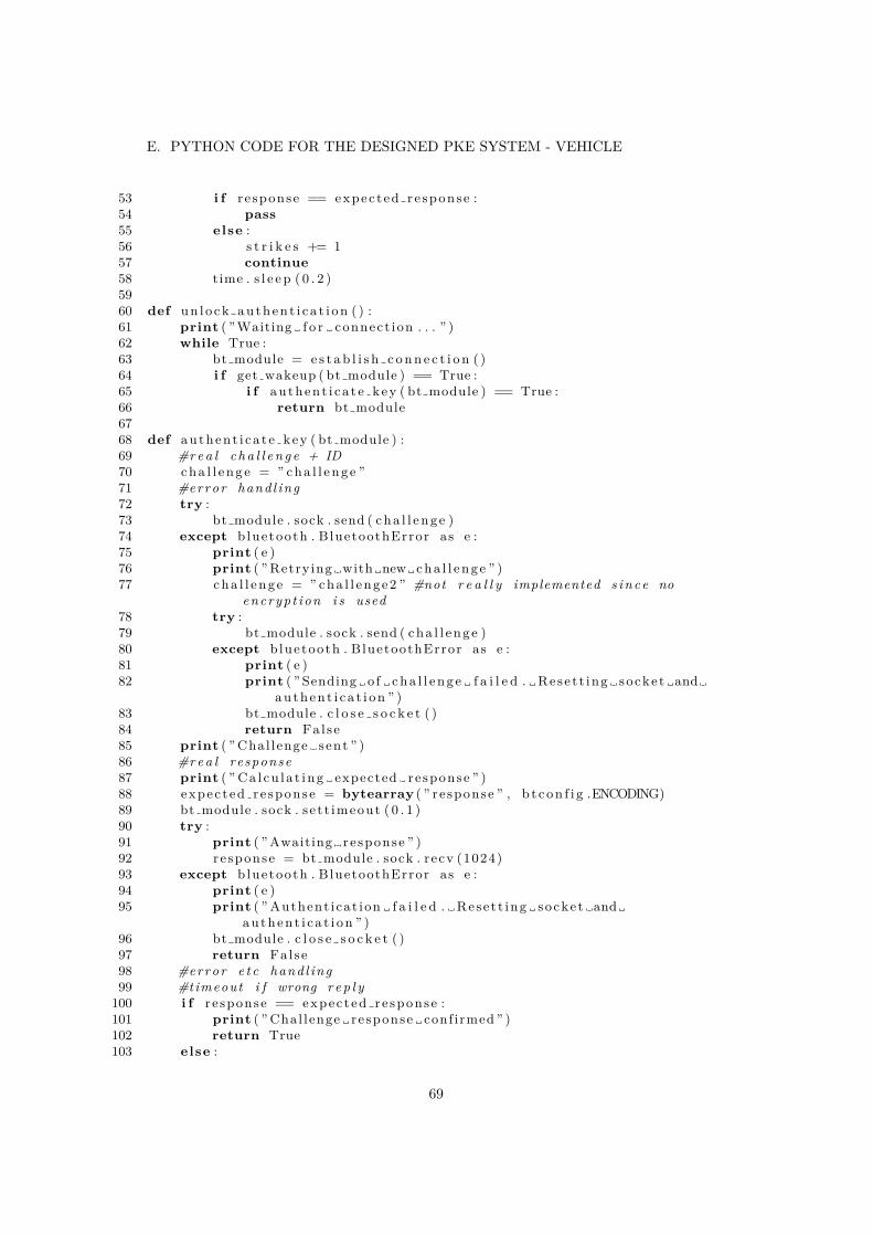
E. PYTHON CODE FOR THE DESIGNED PKE SYSTEM - VEHICLE
53 i f re sponse == expec ted re sponse :54 pass55 else :56 s t r i k e s += 157 continue58 time . s l e e p ( 0 . 2 )5960 def u n l o c k a u t h e n t i c a t i o n ( ) :61 print ( ” Waiting f o r connect ion . . . ” )62 while True :63 bt module = e s t a b l i s h c o n n e c t i o n ( )64 i f get wakeup ( bt module ) == True :65 i f authent i ca t e key ( bt module ) == True :66 return bt module6768 def authent i ca t e key ( bt module ) :69 #r e a l c h a l l e n g e + ID70 c h a l l e n g e = ” c h a l l e n g e ”71 #error hand l ing72 try :73 bt module . sock . send ( c h a l l e n g e )74 except bluetooth . BluetoothError as e :75 print ( e )76 print ( ” Retrying with new c h a l l e n g e ” )77 c h a l l e n g e = ” cha l l enge2 ” #not r e a l l y implemented s ince no
encryp t ion i s used78 try :79 bt module . sock . send ( c h a l l e n g e )80 except bluetooth . BluetoothError as e :81 print ( e )82 print ( ” Sending o f c h a l l e n g e f a i l e d . Rese t t ing socket and
a u t h e n t i c a t i o n ” )83 bt module . c l o s e s o c k e t ( )84 return False85 print ( ” Chal lenge sent ” )86 #r e a l response87 print ( ” Ca l cu l a t ing expected response ” )88 expec ted re sponse = bytearray ( ” re sponse ” , b t c o n f i g .ENCODING)89 bt module . sock . s e t t imeout ( 0 . 1 )90 try :91 print ( ” Awaiting response ” )92 response = bt module . sock . recv (1024)93 except bluetooth . BluetoothError as e :94 print ( e )95 print ( ” Authent icat ion f a i l e d . Rese t t ing socket and
a u t h e n t i c a t i o n ” )96 bt module . c l o s e s o c k e t ( )97 return False98 #error e t c hand l ing99 #timeout i f wrong r e p l y
100 i f re sponse == expec ted re sponse :101 print ( ” Chal lenge response conf irmed ” )102 return True103 else :
69
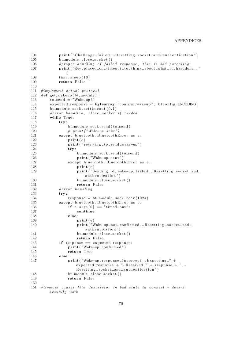
APPENDICES
104 print ( ” Chal lenge f a i l e d . Rese t t ing socket and a u t h e n t i c a t i o n ” )105 bt module . c l o s e s o c k e t ( )106 #proper hand l ing o f f a i l e d response , t h i s i s bad paren t ing107 print ( ”Key placed on timeout to th ink about what i t has done . . ”
)108 time . s l e e p (10)109 return False110111 #implement a c t u a l p r o t o c o l112 def get wakeup ( bt module ) :113 to send = ”Wake up ! ”114 expec ted re sponse = bytearray ( ” confirm wakeup ” , b t c o n f i g .ENCODING)115 bt module . sock . s e t t imeout ( 0 . 1 )116 #error handl ing , c l o s e s o c k e t i f needed117 while True :118 try :119 bt module . sock . send ( to send )120 # p r i n t (”Wake−up sen t ”)121 except bluetooth . BluetoothError as e :122 print ( e )123 print ( ” r e t r y i n g to send wake−up” )124 try :125 bt module . sock . send ( to send )126 print ( ”Wake−up sent ” )127 except bluetooth . BluetoothError as e :128 print ( e )129 print ( ” Sending o f wake−up f a i l e d . Rese t t ing socket and
a u t h e n t i c a t i o n ” )130 bt module . c l o s e s o c k e t ( )131 return False132 #error hand l ing133 try :134 response = bt module . sock . recv (1024)135 except bluetooth . BluetoothError as e :136 i f e . args [ 0 ] == ” timed out ” :137 continue138 else :139 print ( e )140 print ( ”Wake−up not conf irmed . Rese t t ing socket and
a u t h e n t i c a t i o n ” )141 bt module . c l o s e s o c k e t ( )142 return False143 i f re sponse == expec ted re sponse :144 print ( ”Wake−up conf irmed ” )145 return True146 else :147 print ( ”Wake−up response i n c o r r e c t . Expecting ” +
expec ted re sponse + ” Received ” + response + ” .Rese t t ing socket and a u t h e n t i c a t i o n ” )
148 bt module . c l o s e s o c k e t ( )149 return False150151 #timeout causes f i l e d e s c r i p t o r in bad s t a t e in connect + doesnt
a c t u a l l y work
70

E. PYTHON CODE FOR THE DESIGNED PKE SYSTEM - VEHICLE
152 def e s t a b l i s h c o n n e c t i o n ( ) :153 c u r r e n t e r r o r = None154 print ( ” Trying to connect . . . ” )155 while True :156 bt module = b t s o c k e t ( )157 try :158 bt module . sock . connect ( ( b t c o n f i g .KEY ADDR, b t c o n f i g .PORT) )159 print ( ” Connection with key e s t a b l i s h e d ” )160 return bt module161 except bluetooth . btcommon . BluetoothError as e :162 errno = e . args [ 0 ]163 i f errno != c u r r e n t e r r o r :164 i f errno == 112 :165 print ( str ( e ) + ” − Key i s out o f range or down” )166 e l i f errno == 111 :167 print ( str ( e ) + ” − Key detec ted but i s not ready to
r e c e i v e connect ion , program may not be s t a r t e d” )
168 e l i f errno == 113 :169 print ( str ( e ) + ” − Blue too thc t l power may be o f f ” )170 print ( ” Attempting to turn on power” )171 os . system ( ” echo ’ power on\nquit ’ | b l u e t o o t h c t l ” )172 e l i f errno == 77 :173 print ( str ( e ) + ” − Unexpected socket f a i l i u r e ,
v e r i f y s e t t i n g s and socket−p r o t o c o l sync ” )174 else :175 print ( e )176 c u r r e n t e r r o r = errno177 print ( ” Trying to connect . . . ” )178 pass179 #already connected exep t i on hand l ing ( might not be needed )180 def s e t u p b l u e t o o t h ( ) :181 print ( ” Rese t t ing b l u e t o o t h c t l ” )182 os . system ( ” sudo sys t emct l stop b luetooth ” )183 os . system ( ” sudo sys t emct l s t a r t b luetooth ” )184 os . system ( ” echo ’ power on\nquit ’ | b l u e t o o t h c t l ” )185 time . s l e e p ( 0 . 1 )
71

APPENDICES
E.4 btconfig.py
1 KEY ADDR = ”B8 : 2 7 :EB: 3 5 : 4C:35 ” #address o f key fob2 PORT = 1 #d e f a u l t por t3 TIMEOUT = 10 #timeout f o r b l u e t o o t h . B lue too thSocke t . recv ( ) in s4 ENCODING = ” utf−8”5 KEEP ALIVE STRIKES = 3
72
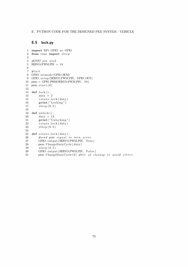
E. PYTHON CODE FOR THE DESIGNED PKE SYSTEM - VEHICLE
E.5 lock.py
1 import RPi .GPIO as GPIO2 from time import s l e e p34 #GPIO pin used5 SERVO PWM PIN = 1867 #i n i t8 GPIO. setmode (GPIO.BCM)9 GPIO. setup (SERVO PWM PIN, GPIO.OUT)
10 pwm = GPIO.PWM(SERVO PWM PIN, 50)11 pwm. s t a r t (0 )1213 def l o ck ( ) :14 duty = 215 r o t a t e l o c k ( duty )16 print ( ” Locking ” )17 s l e e p ( 0 . 5 )1819 def unlock ( ) :20 duty = 1321 print ( ” Unlocking ” )22 r o t a t e l o c k ( duty )23 s l e e p ( 0 . 5 )2425 def r o t a t e l o c k ( duty ) :26 #send pwm s i g n a l to turn servo27 GPIO. output (SERVO PWM PIN, True )28 pwm. ChangeDutyCycle ( duty )29 s l e e p ( 0 . 5 )30 GPIO. output (SERVO PWM PIN, Fa l se )31 pwm. ChangeDutyCycle (0 ) #b i t o f c leanup to avoid j i t t e r
73

APPENDICES
F Test Cases
Test Case 1 KeyNotInRange
Actors: Key, Vehicle
Preconditions: Key outside of connection range. Vehicle locked.
Success Scenario:
1. The Key approaches the vehicle.
2. The Vehicle establishes connection with the Key.
3. The Key does not enter unlocking range (around 1 meter).
4. The Vehicle sends a wake-up to the Key.
5. The Key is not in range, it does not confirm the wake-up.
Postconditions: Vehicle still locked. (Connection established betweenKey and Vehicle.)
Test Case 2 SuccesfulUnlock
Actors: Key, Vehicle
Preconditions: Key outside of connection range. Vehicle locked. Keyin sleep mode.
Success Scenario:
1. The Key approaches the vehicle.
2. The Vehicle establishes connection with the Key.
3. The Key enters the unlocking range (around 1 meter).
4. The Vehicle unlocks. (wake-up and challenge completed)
Postconditions: Vehicle is unlocked.
74

F. TEST CASES
Test Case 3 SleepModeWhileInCar
Actors: Key, Vehicle
Preconditions: Key within unlocking range. Live connection betweenVehicle and Key. Vehicle unlocked. Key not in sleep-mode.
Success Scenario:
1. The Key sits still for given amount of time and enters sleep mode.
Postconditions: Vehicle remains unlocked. (Connection alive betweenKey and Vehicle.)
Test Case 4 SuccesfulLock
Actors: Key, Vehicle
Preconditions: Key within unlocking range. Live connection betweenVehicle and Key. Vehicle unlocked. Key in sleep-mode.
Success Scenario:
1. The Key leaves the unlocking range of the Vehicle but stays in connectionrange.
2. The Vehicle is locked.
Postconditions: Vehicle is locked. Key not in sleep-mode. (Connec-tion alive between Key and Vehicle.)
75

APPENDICES
Test Case 5 RelayAttack
Actors: Key, Vehicle, (Attacker)
Preconditions: Key outside of connection range. Vehicle locked. Keyin sleep-mode.
Success Scenario:
1. Attacker relays connection request from Vehicle to Key. (Simulated bybringing the Vehicle in range of the Key)
2. The Key connects.
3. Vehicle sends wake-up.
4. Key does not confirm wake-up. Key alerts user to potential attack.
Postconditions: Vehicle remains locked. Key remains in sleep mode.Key sends attack alert. (Connection alive betweenKey and Vehicle.)
76


TRITA TRITA-ITM-EX 2020:48
www.kth.se