REFRACTURING: WHY, WHEN AND WHEN NOT TO
39
REFRACTURING: WHY, WHEN AND WHEN NOT TO GEORGE E. KING, P.E. APACHE CORPORATION 13 NOVEMBER 2014 SPE LUNCHEON HOUSTON, TX
-
Upload
khangminh22 -
Category
Documents
-
view
0 -
download
0
Transcript of REFRACTURING: WHY, WHEN AND WHEN NOT TO

REFRACTURING: WHY, WHEN AND WHEN NOT TO GEORGE E. KING, P.E.
APACHE CORPORATION
13 NOVEMBER 2014
SPE LUNCHEON
HOUSTON, TX

Response of Refracturing
Good and Better Targets
Warning Flags
What Appears to Work at this Point
Timing
Proppant
Diverting
Missed “pay” in those tight source rocks.
PARTS OF THE PRESENTATION
2

EAGLE FORD RE-FRACTURING – EXAMPLE FROM BP
• Dry gas well, underperforming well compared to offsets / neighbors
• Original stim used low vol X-linked fracs (4,600 bbl/stg). Refrac’ed with high volume slickwater fracs (9,500 bbl/stg).
Lateral length (perf to perf) = 4,850’
Stage spacing: 305’, Cluster spacing: 61’
5 Clusters/ stage, 4 shots per cluster, 90 degree phasing
Refrac
No perforations added for refrac
15 stages separated by slugs of biodegradable polymer diversion agent
Ref
rac
Op
erat
ion
s
post refrac - choke = 16/64
Slide Courtesy of Sam French at BP, presented at UrTec, 2014

SOUTHERN ALBERTA SHALLOW GAS WELL REFRACS REFRACS NOT JUST FOR SHALES
4
Refracturing restored many wells to initial production – Is production really declining or is the flow capacity of the frac?


Enlarged frac geometry, reservoir contact, add contact points
Improved pay coverage – increased frac height in vertical wells
Increased frac conductivity or restoring frac conductivity
Propping or re-propping previously unpropped fractures
Fit-for-purpose fracture fluids
Re-energizing / re-inflating natural fissures
Frac Reorientation - field stress altered – new rock contacted
Over-flushed frac jobs – repair by straddle frac & quality prop.
FACTORS IN SUCCESSFUL REFRACS
6
Suggestion: A non-shale specific criteria was advanced by Reeves, et.al., 1999 to separate poor completions from poor geology before progressing towards a restimulation.

Low pressured, depleted wells, limited reserves.
Wells in which diagnostics indicate effective fractures & drainage to boundaries.
Questionable mechanical integrity
Access to better parts of formation prevented.
Off-set wells recovered >> their “share” of reserves.
FACTORS IN FAILED REFRACS
7

COMPARISON OF MAX MONTH PRODUCTION OF WELLS ACROSS FOUR YEARS
8
One field shows a steady decline in max month production with time – result of regional fractures?

Good Candidate? Not so Good Candidate?
Poor initial frac
Bypassed shows
Frac spacing >300 ft
Less than 1000 lb/ft of prop over lateral
Where sH ~ sh & natural fracs present
Some frac hit wells
No natural fractures
No gas/oil shows during drilling
High stress sv < sH & sH >> sh
Poorly performing in-fill wells in UCR
Poor Integrity
WHAT MAKES A GOOD REFRAC CANDIDATE? AND WHAT DOESN’T?
9 Guidelines? – Yes, Absolutes? – No.

GO BACK TO FRACTURING BASICS
Total proppant amounts can be very large & linked to well productivity – fluid volumes less important.
10

1) Cement squeeze & reperf
2) Liner patch to seal old perfs and refrac
3) Refrac old perfs (no new perfs) – w/ & w/o diverting
4) Restore proppant in near-wellbore w/ mini refrac
5) Add new perfs and refrac well with no diverters
6) Add new perfs and refrac well with diverters
7) Set plugs and refrac in stages down work string
8) Refrac specific intervals with coiled tubing
REFRAC APPROACHES – WHAT HAS BEEN DONE? AT LEAST 8 BASIC APPROACHES
11
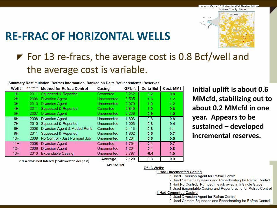
RE-FRAC OF HORIZONTAL WELLS
For 13 re-fracs, the average cost is 0.8 Bcf/well and the average cost is variable.
Initial uplift is about 0.6 MMcfd, stabilizing out to about 0.2 MMcfd in one year. Appears to be sustained – developed incremental reserves.

TIMING
Controls:
How old is the well?
What’s the current production rate?
Are GOR increasing and liquids decreasing?
How good was the initial completion?
What is the oil or gas price projection?
What is the cost of refracs? (~25% to 40% of a new well??)

BAKKEN OIL RE-FRAC
Liquids much more difficult to flow through narrow fracs than gas – is increasing GOR and decreasing Oil a sign of unpropped fracture closure?

BAKKEN OIL RE-FRAC
Liquids much more difficult to flow through narrow fracs than gas – is increasing GOR and decreasing Oil a sign of unpropped fracture closure?

BAKKEN OIL RE-FRAC
Liquids much more difficult to flow through narrow fracs than gas – is increasing GOR and decreasing Oil a sign of unpropped fracture closure?
Opposing trend movement of GOR and Oil suggest gas can move through flow passages more easily than can oil. Refracturing opens passages - briefly

DO ALL PERF CLUSTERS OR FRACS PRODUCE?
A common finding by production logs or tracers in Horizontal Multi-Fractured Wells. - 30 to 50% of the fractures are producing 80% of the production. Are these underperforming fracture stimulations a refrac opportunity or a waste of money?
• Check for over-flushed fractures • Ask yourself why are you continuing to fracture in unproductive areas & wasting $.

OIL & GAS SHOWS ALONG THE LATERAL

OIL & GAS SHOWS ALONG THE LATERAL
Estimated or Measured Matrix Hydrocarbon Contribution

OIL & GAS SHOWS ALONG THE LATERAL

OIL & GAS SHOWS ALONG THE LATERAL

OIL & GAS SHOWS ALONG THE LATERAL
Adapted from: Berkat, et al.: “Identification and Characterization of Producing Fractures in Naturally Fractured Reservoirs Using PIWD,” SPE 120687 PIWD = productivity index while drilling

LOOK AT THE COMPONENTS OF THE GAS SHOWS
•Gas Show •Quantity •Ratio of gasses •Corresponding GR
•Other logs (CNL, Density) to help assess TOC •Density for Brittleness •Resistivity for water saturation and salinity •ROP (rate of penetration) •Is it a hot shale or a natural fracture?
The objective is to align the perf clusters with natural fractures.

Refracturing depends on:
Target
Timing
Method
CONCLUSIONS
24

SOME OBSERVATIONS
Refracs often have a lower fracture gradients than found in the initial fracs. The uniaxial strain equation implies that high production that produces low pore pressure should also reduce the fracture gradient.

Produced water following hydraulic fracture stimulation frequently contains unique messages (data) from the stimulated formations.
Changes in chemistry of water reflect the architecture of the producing stimulated network.
Processes of water mixing; solid dissolution ion diffusion from matrix water to fracture water and the effect of area-to-volume ratio in leaching of ions from walls of the fracture to the injected water describe where the frac water went.
MESSAGE IN A BOTTLE (SPE 168892)
26 Bearinger, D.: “Message in a Bottle,” (Nexen) SPE Workshop Hydraulic Fracturing Flowback, 6-7 November 2013, San Antonio, TX. & SPE 168892
Is rapid flow easier from a planar fracture than a complex fracture?

27
What is this telling us? If we get the highest gas recovery with lowest water recovery, should we be trying to get less early water recovery? It may help with fracture type estimation & early is a key.
Ezulike, O.: “Flowback Analysis for Determining Load Recovery and Its Effects on Early-Time Hydrocarbon Production Rate,” (U Alberta) SPE Workshop Hydraulic Fracturing Flowback, 6-7 November 2013, San Antonio, TX. & SPE 168892

Time of sampling is the control
Induced fracture water recovered first, then salinity increases as water recovered from complex (natural fractures).
Water reaches a plateau – characteristic of stable water flow from early production.
Salinity declines after frac flowback is exhausted, connate water decreases and condensed water increases with gas production increase.
VARIANCE IN PRODUCED WATER TDS
28
Bearinger, Doug: “Message in a Bottle,” (Nexen) SPE Workshop Hydraulic Fracturing Flowback, 6-7 November 2013, San Antonio, TX.

FLOWBACK VOL. VS. GAS PRODUCTION
29 Ezulike, O.: “Flowback Analysis for Determining Load Recovery and Its Effects on Early-Time Hydrocarbon Production Rate,” (U Alberta) SPE Workshop Hydraulic Fracturing Flowback, 6-7 November 2013, San Antonio, TX. & SPE 168892

• Sodium (Na) & potassium (K) ions appeared to move faster by diffusion than Ca & Mg ions. (ion transfer & ratio judgment)
• Formation clay & permeability may affect cation ratios.
• Slope of TDS rise related to connate water salinity and contact area of fractures & formation.
• Ion concentration & ion ratios impacted by area-to-volume ratio of fracs. Lower AVR in planar fracs & higher AVR in complex fracs.
• Waters in producing wells diluted by condensation from gas, but dilution has no effect on ion ratio.
• As load fluid recovered, salinity dropped radically as formation water production decreased & condensed water increased.
ION RATIOS IN THE PRODUCED WATER
30 Bearinger, D.: “Message in a Bottle,” SPE Workshop Hydraulic Fracturing Flowback, 6-7 November 2013, San Antonio, TX. & SPE 168892

COST & TIME BREAKDOWN OF REFRAC Refracs – How Successful?
Best are older wells w/ x-link or foam initial frac
Must have the reserves in place to be economic.
Recent, horizontal multi-frac with many stages do not appear to be that good of a candidate?

REFRAC POPULARITY?
Refracs small portion of fracturing activity
Refracs are about 2 to 3% of fracs per year.
Most refracs made w/o sufficient candidate analysis.
Unconventionals appear to have the highest refrac success rate – particularly in early years of shale frac modernization (i.e., 2000 to 2008)
Barnett refracs returned initial rate & EUR gained 0.6 bcf to 3 bcf.
Sources: Wolhart, 2002, Vincent

REORIENTATION EFFECTS

NOT EVERY WELL IS A GOOD CANDIDATE
34

FRAC HITS
A Frac “Hit” is a pressure or fluid incoming response from a frac treatment in an adjacent (?) well.

FRAC HITS
Planar Fractures Most likely hit distance => less than
1500 ft.
Skips wells? => sometimes
Longer hits => 4000 ft.
Mechanical damage potential => high
Likely production effect in “hit” well => reduced production 5% to 15%.
Prevention => pressure up w/field gas, auto shut in.
Design change => increase well spacing, stagger perf flusters out of frac’s way.
Complex Most likely hit distance => about
500 ft.
Skips wells? => frequently
Longer hits => rare over 1000 ft.
Mechanical damage potential => low – water loading is main issue
Likely production effect in “hit” well => increased 10% to 50%
Prevention => most operators don’t bother, some load well.
Design change => stagger perf clusters if less than 500 ft.

REFRACTURING TO MITIGATE FRAC HITS
Adding rate & reserves is the main goal of refracturing.
Some reports indicate older wells with “new” (re)fracture before new, adjacent wells were fractured, were at least partly protected.
Wells shut in and/or loaded or pressurized also appeared to be protected.

Craig, M., Wendte, S., Buchwalter, J.: “”Barnett Shale Horizontal Restimulations: A Case Study of 13 Wells,” SPE 154669, SPE Americas Unconventional Resources Conference, Pittsburgh, PA, USA, 5-7 June 2012.
Fredd, C.N., McConnell, S.B., Boney, C.L., England, K.W.: “Experimental Study of Fracture Conductivity for Water-Fracturing and Conventional Fracturing Applications,” SPE 74138, SPE Journal, Vol. 6, No. 03, pp 288-298.
French, S., Rodgerson, J., Feik, C.: Re-Fracturing Horizontal Shale Wells: Case History of a Woodford Shale Pilot Project,” SPE 168607, SPE Hydraulic Fracturing Conference, 4-6 February 2014, The Woodlands, TX, USA.
Lanz, T., Greene, D., Eberhard, M., Pershall, R.: “Refracture Treatments Proving Successful in Horizontal Bakken Wells: Richland County, Montana,” SPE Rocky Mountain Oil & Gas Technical Symposium, Denver, CO, USA, 16-18 April 2007.
Reeves, S.R., Hill, D.G., Hopkins, C.W., Conway, M.W., Tiner, R.L., Mohaghegh, S.: “Restimulation Technology for Tight Gas Sand Wells,” SPE 56482, SPE Annual Technical Conference and Exhibition, Houston, TX, USA, 3-6 October 1999.
Siebrits, E., J.L. Elbel, R.S. Hoover, I.R. Diyashev, L.G. Griffin, S.L. Demetrius, C.A. Wright, B.M. Davidson, N.P. Steinsberger, D.G. Hill: “Refracture Reorientation Enhances Gas Production in Barnett Shale Tight Gas Wells,” SPE 63030, SPE Annual Technical Conference and Exhibition, Dallas, TX, USA, 1-4 October 2000.
Vincent, M.C.: “Refracs – Why Do They Work, And Why Do They Fail in 100 Published Field Studies,” SPE 134330, SPE Annual Technical Conference and Exhibition, Florence, Italy, 19-22 September 2010.
Vincent, M.C.: Examining Our Assumptions – Have Oversimplifications Jeopardized Out Ability to Design Optimal Fracture Treatments,” SPE 119143, SPE Hydraulic Fracturing Conference, The Woodlands, TX, USA, 19-21 January 2009.
Wolhart, S., “Hydraulic Fracturing Restimulation,” SPE Distinguished Lecturer Series. 2002.
REFERENCES
38

END OF SLIDE SUPPORT PACKAGE
39