![Patch Antenna[1]](https://static.fdokumen.com/doc/165x107/63158e4cc32ab5e46f0d5c89/patch-antenna1.jpg)
Recent Antenna System Technologies for Next-generation ...
10
14 NTT Technical Review 1. Introduction Wireless access technologies have advanced rapid- ly [1] and broadband wireless communication sys- tems have become popular in our daily lives. An antenna is a very important component of a wireless system because it acts as the input and output inter- face for wireless equipment, as shown in Fig. 1. How- ever, system performance is determined by the total performance of each component, such as the antenna and the radio-frequency (RF), intermediate-frequen- cy (IF), and baseband (BB) units. For recent high-per- formance wireless systems, overall system design has been essential. Accordingly, the antenna must not Koichi Tsunekawa † Abstract This paper describes the requirements of the antennas or antenna systems in recent high-speed and high-capacity wireless communication systems and the key technologies for satisfying them. It also explains the antennas and antenna systems being researched and developed for next-generation wireless communication systems. The antenna in such a system requires high gain, high-efficiency antenna ele- ments and a multi-antenna design. This paper introduces a high-efficiency antenna created by integrat- ing it with a monolithic microwave integrated circuit (MMIC) in a millimeter-wave frequency-band sys- tem, a multi-antenna system for the multiple-input multiple-output (MIMO) technique that enables mul- tiple data transmission for land mobile communication systems, and a beam-scanning antenna for satel- lite communication systems. It also explains the general research and development trend of antenna sys- tems and technical problems in each wireless system as an introduction to the other selected papers in this issue. Recent Antenna System Technologies for Next-generation Wireless Communications Antenna element Propagation Circuit Signal processing unit Total wireless system Antenna system Ant. Ant. Air BB IF/RF BB IF/RF Fig. 1. Wireless and antenna system. Selected Papers: Advanced Antenna System Technology † NTT Network Innovation Laboratories Yokosuka-shi, 239-0847 Japan E-mail: [email protected]
-
Upload
khangminh22 -
Category
Documents
-
view
4 -
download
0
Transcript of Recent Antenna System Technologies for Next-generation ...

14 NTT Technical Review
1. Introduction
Wireless access technologies have advanced rapid-ly [1] and broadband wireless communication sys-tems have become popular in our daily lives. Anantenna is a very important component of a wirelesssystem because it acts as the input and output inter-
face for wireless equipment, as shown in Fig. 1. How-ever, system performance is determined by the totalperformance of each component, such as the antennaand the radio-frequency (RF), intermediate-frequen-cy (IF), and baseband (BB) units. For recent high-per-formance wireless systems, overall system design hasbeen essential. Accordingly, the antenna must not
Koichi Tsunekawa†
AbstractThis paper describes the requirements of the antennas or antenna systems in recent high-speed and
high-capacity wireless communication systems and the key technologies for satisfying them. It alsoexplains the antennas and antenna systems being researched and developed for next-generation wirelesscommunication systems. The antenna in such a system requires high gain, high-efficiency antenna ele-ments and a multi-antenna design. This paper introduces a high-efficiency antenna created by integrat-ing it with a monolithic microwave integrated circuit (MMIC) in a millimeter-wave frequency-band sys-tem, a multi-antenna system for the multiple-input multiple-output (MIMO) technique that enables mul-tiple data transmission for land mobile communication systems, and a beam-scanning antenna for satel-lite communication systems. It also explains the general research and development trend of antenna sys-tems and technical problems in each wireless system as an introduction to the other selected papers inthis issue.
Recent Antenna System Technologies forNext-generation Wireless Communications
Antennaelement
PropagationCircuitSignalprocessing unit
Total wireless system
Antenna system
Ant. Ant.Air
BBIF/RFBB IF/RF
Fig. 1. Wireless and antenna system.
Selected Papers: Advanced Antenna System Technology
† NTT Network Innovation LaboratoriesYokosuka-shi, 239-0847 JapanE-mail: [email protected]

Vol. 3 No. 9 Sep. 2005 15
only have antenna elements with high-performancecharacteristics, but must also perform effectively asan antenna system in conjunction with the RF, IF, andBB units. New functions can be added through anten-na system design: for example, appropriate radiationpattern control provides a large system capacity byusing baseband signal processing and an antenna ele-ment with an integrated RF circuit provides high gainwithout feeder loss.
The selected papers in this issue describe the latestantenna and antenna system technologies for achiev-ing high performance. Two of the papers presentbeam-scanning antenna systems in satellite broad-band communication. Beam scanning is carried outusing by two methods: one [2] uses a variable activedevice or tunable reactance device incorporated intothe antenna element, which has high-speed electron-ic control while the other [3] uses mechanically con-trolled antenna movement, which has a very precisedirection control function. Another paper [4] intro-duces an active integrated antenna system with an RFcircuit, which provides high gain and high efficiency,for a high-capacity millimeter-wave transmissionsystem. And two papers describe a multiple-input
multiple-output (MIMO) antenna system for obtain-ing high-speed transmission and high system capaci-ty in the land mobile communication system from theviewpoints of beamforming techniques [5] andimplementation methods [6].
As an introduction to these advanced antenna tech-niques, this paper provides a general explanation ofthe requirements of antennas and antenna systems inrecent high-speed and high-capacity wireless com-munication systems and the key technologies for sat-isfying these requirements. It also describes currentantenna systems and NTT’s antenna research resultsfor typical wireless systems.
2. Antenna requirements in recent wirelesscommunication systems
The trend of wireless systems is shown in Fig. 2.This indicates the typical system transmission speedand number of antennas needed to achieve a particu-lar system performance for each operating frequency.Wireless communication systems are moving towardshigh transmission speeds and high capacity by usinghigher system frequencies to enable a wide frequency
FWA
Bluetooth
RF-ID
Transmission speed
Fre
quen
cy
Multi-antenna (multiplexing)technique
1 kbit/s 10 kbit/s 100 kbit/s 1 Mbit/s 10 Mbit/s 100 Mbit/s 1 Gbit/s100 MHz
1 GHz
10 GHz
100 GHz
PDC
IMT-2000 HSDPA
4G802.11g
802.11a802.11n
PHS
802.11b
UWB
High-gaintechnique
High-efficiencytechnique
60-GHz system
RF-ID: radio-frequency identificationPDC: personal digital cellularPHS: personal handy-phone systemIMT-2000: international mobile
telecommunications 2000
HSDPA: high-speed download packetaccess
802.11x: family of IEEE standardsUWB: ultrawidebandFWA: fixed wireless access4G: fourth generation
: ubiquitous system
: land mobile system
: short-range system
: WLAN system
: fixed wireless system
System name
System name
currently in service
future service
Fig. 2. Advances of terrestrial wireless communication systems and their relationship to antenna technologies.
for Next Wireless Communications

Selected Papers
16 NTT Technical Review
band and using advanced system technology toachieve high quality and signal multiplexing. Theantenna requirements for these system properties are:
• High-gain and high-efficiency technology• Multi-antenna technologyIncreases in the gain and efficiency of an antenna
are offset by higher propagation loss at high frequen-cies, so the received signal level needs to be higher.High gain is an age-old problem in antenna researchand development. Multi-antenna technologyimproves the receiving signal quality and providesmultiplexed signal transmission by using an antennasystem that includes RF circuits, BB units, and anten-na elements.
2.1 High-gain and high-efficiency antennaTheoretical and experimental antenna gain and effi-
ciency characteristics are shown in Fig. 3. The depen-dences of gain and beamwidth on horn dimensionL(λ) in a relatively large antenna are explained in Fig.3(a) [7]. When L is more than 0.5 times the wave-length, the antenna’s efficiency is about 100%; a larg-er antenna provides higher gain. However, the high-gain radiation pattern leads to a narrow beamwidth.Therefore, a mobile terminal needs to use beam-scan-ning or beam-tracking techniques to follow the trans-mitter while the terminal moves. On the other hand,the efficiency decreases if the antenna size is less than0.5 wavelengths. The bandwidth of a linear dipoleantenna versus its efficiency for various antenna sizes(D: diameter) is shown in Fig. 3(b). This graph wasestimated from theoretical limits [8] and many exper-
imental results. The antenna efficiency becomesapproximately –5 dB when antenna bandwidth of10% is provided using a linear dipole antenna with alength of 0.3 wavelengths. This figure shows that theefficiency and bandwidth have a tradeoff relationshipand that the efficiency drops greatly as the antennasize decreases. Therefore, some clever ideas for theantenna element structure are needed to overcomethese weak points.
2.2 Multi-antenna systemA multi-antenna system has several antenna ele-
ments, but it does not merely work as an ordinaryarray antenna. The performance requirements are sat-isfied because the antenna system includes RF cir-cuits, BB units, and antenna elements. The antennaelement technologies and the multi-antenna systemare shown in Fig. 4. In the antenna element, a highgain can be achieved by improvements to the antennaelement structure, for example, by using a new mate-rial, adding a parasitic element, or integrating an RFcircuit (Figs. 4(a)–(c)). The antenna shown in Fig.4(c) is called an integrated antenna. It can control theradiation pattern as well as provide high gain by elim-inating feeder loss. In a multi-antenna system (Fig.4(d)), the radiation pattern is controlled by basebandsignal processing, so the pattern of each wirelesschannel can be controlled by each baseband channel.Furthermore, it is possible to get multiplexed signaltransmission in the space domain by baseband signalprocessing. Multi-antenna systems are generallycalled smart antennas or active antennas [9].
01 10
L (λ)
(a) Aperture antenna gain characteristics
100 0–15
–10
–5
0
5 10 15 20
10
20
30
40
Bea
mw
idth
(de
g)
Gai
n (d
Bi)
Effi
cien
cy (
dB)
50
60
70
80
0
10
20
30
40
50
60
70
80
D = 0.1λ
D = 0.2λ
D = 0.3λ
D = 0.4λ
Bandwidth (%) (voltage standing wave ratio (VSWR)<2)
(b) Dipole antenna efficiency characteristics
Beamwidth L × L
Square horn
Linear antenna
D
Fig. 3. Antenna gain and efficiency characteristics.

Selected Papers
Vol. 3 No. 9 Sep. 2005 17
An example of a mobilecommunication systemusing a smart antenna inthe base station is shown inFig. 5. Independent infor-mation can be sent to theterminals, which are spa-tially separated, using thesame frequency at the sametime because each beam isgenerated for a specific ter-minal by using the spacedivision multiple access(SDMA) technique. Fur-thermore, N multiplexedtransmissions can be sentto a terminal with N anten-nas by utilizing the slightdifference in antenna loca-tions in the terminal. MIMO is representative of thiskind of technology. The latest smart antenna systemscan increase the antenna gain even in a mobile systemand expand the service area. The designed systemcapacity can be increased by using multiplexing tech-niques based on baseband signal processing. Multi-
antenna systems can achieve very high performancewith high-level functions corresponding to the wire-less system requirements.
2.3 Key antenna technologies The key technologies for achieving a high-gain,
(a) Novelantenna element
Innovative materials
Radiation pattern
Input impedance characteristics
Frequency
Parasitic element
Variable capacitor
(b) Complex antenna element
(c) Integrated antenna element
(d) Multi-antenna system
Ch 1
BB (signal processing)
Ch 2
RF RF1
IF1
RF2
IF2
Ret
urn
loss
High-gain and high-efficiency antenna
Ch 1
Ch 2
Fig. 4. Antenna elements and system.
Interferencesuppression
MIMO
ch 1
ch 2
ch 2
SDMA
Fig. 5. Smart antenna system (land mobile telecommunication).

Selected Papers
18 NTT Technical Review
high-efficiency, multi-antenna system are shown inTable 1. Antennas for the latest wireless communica-tion systems are required to achieve high gain andhigh efficiency. The multi-antenna systems aredesigned to make maximum use of system resources,especially space.
3. Wireless systems and suitable antennasystems
The kinds of wireless systems that we can expect to
find around us in the near future are illustrated in Fig.6. RF-ID (radio-frequency identification) tags will beattached to various kinds of objects in a ubiquitousnetwork and a large quantity of information will begathered to provide useful knowledge to each person.High-speed data transmission ranging from a fewmegabits per second to 1 Gbit/s will be possible inmobile satellite systems, land mobile systems, andwireless local area network (WLAN) systems. Inhome networks, individual items of electronic equip-ment will be connected to each other at very high
SDMA
MIMO
PC
Home
DVDVCR Office
Hot spot
Internet
Public broadbandIP networks
Public land mobilecommunications
networks
Land mobilesystem
Containers
Short-rangelink system
Ubiquitousnetworksystem
WLAN system
Mobile satellitesystem
Ubiquitous BS
RF tagBS: base station
Fig. 6. Wireless communication systems.
Key technologiesRequirements
2) Multi-antennatechniques
1) High gain andhigh efficiency
a. Beam scanning antennab. Sector antenna (fixed narrow multi-beam system)c. Diversity antennad. SDMA antennae. MIMO antenna
a. Innovative materials (meta-material, high magnetic material, …)b. Element design (parasitic element, fractal element, …)c. Integrated antenna (antenna with RF circuit or RF device, …)d. Active antenna (antenna within variable reactance or switch, ….)
Table 1. Key technologies to meet antenna requirements.

Selected Papers
Vol. 3 No. 9 Sep. 2005 19
speed (several gigabits per second) wirelessly insteadof by cables. In these wireless systems, highly func-tional and high-performance antennas will be essen-tial. Table 2 explains the main features and technicaltrend of the systems and also shows NTT’s approach-es to antennas and antenna systems for each high-per-formance wireless system. The technologies in Table1 that are used are indicated in parentheses. Eachantenna system must satisfy severe specifications andalso provide high functionality, as shown in Figs. 4(c)and (d). The antennas discussed in the selected papersin this issue are shown in blue in Table 2. The presentstatus of each antenna system and research anddevelopment in NTT are explained below.
3.1 Ubiquitous network antenna systemTag antenna elements have the same problems as
pagers or portable telephone systems that use the LF,UHF, and VHF bands. The antenna element must beas small as possible and have high efficiency in asmall volume and in the neighborhood of variousobjects. Most antennas for passive tags using the LFband (13 MHz) are spiral, helical, N-turn loop, ormeander line antennas [10] for achieving an electro-magnetic induction area and their gains are consid-ered to be very low. Bent and spiral monopole ordipole antennas are used in personal computer cardwireless communication systems or in small squarefilm tags using UHF-band systems [11]. Theapproach is to design the antenna and RF-IC as onesystem; in other words, the connection impedancebetween the antenna and RF-IC is designed as afreely selectable value instead of being restricted to50 Ω. The same kind of technique is currently being
investigated in NTT in a study of active integratedantennas [12]. On the other hand, the base stationantenna can be designed by applying techniquesdeveloped for pagers or land mobile antennasbecause it has high-gain and beam-tilting characteris-tics.
3.2 Millimeter-wave frequency bandcommunication antenna system
A high-speed wireless communication system isachieved by using wideband technology, so millime-ter-wave frequencies, which provide a very widebandwidth, are attracting attention. The use of highfrequencies also requires high output power to com-pensate for the huge propagation loss and passive cir-cuit losses, so high-gain and high-efficiency antennasare very important in system design [13]. Millimeter-wave systems mainly use horn, reflector [14], or lensantennas [15]. Horn or reflector antennas are used inrelatively long-range communication where the rangeis several hundred meters. A lens type antenna, whichis integrated with monolithic microwave integratedcircuits (MMICs) to achieve high efficiency withouta feeding line, is mainly used for short-range trans-mission, e.g., for a home link system. Active inte-grated antenna technology in which an amplifier fortransmitting and receiving is mounted without usinga connector or cables is suitable for a high-frequency-band system [16]. Typical antenna types for millime-ter-wave frequency systems are shown in Table 3.Horn or reflector antennas provide very high gain butcannot be integrated with MMICs. The lens antennaprovides high gain and can be made into an integrat-ed antenna but requires adjustment to correct its
Mobile satellite
Short-rangecommunication
System featuresMain technical trends(example system, standard, or equipment)
NTT’s antenna approaches(using technologies in Table 1)
S/Ku band high-speed mobile comm. (N-Star/ETS-VIII)Broadband (Internet) (WINS)Millimeter wave/optical comm. (MILSTAR,GeoLITE)
High frequency band (millimeter-wave system)Ultrawideband (UWB)Infrared rays (IrDA)
Multi-beam antennaLarge deployable antennaBeam-tracking antenna system
(1c, 1d, 2a, 2e)
Active integrated antenna system (millimeter wave)
(1b, 1c, 2a, 2b)
UbiquitousRF-ID
Active tagsSensor networkMesh network (802.15.5)
Compact high-efficiency tag antennaHigh-gain beam tilting base station antenna
(1a, 1b, 1c)
Land mobileand WLAN
MIMO-OFDM (802.11n,802.16a/e)MC-CDMA (4G, Beyond 3G)HSDPA (3.5G,1xEV-DO/V)
MIMO-OFDM antenna systemCompact mobile terminal antenna system
(1b, 1d, 2b, 2c, 2d, 2e)
(discussed in papers in this issue)
Very long rangeMedium to highspeedVarious mobilestations
Short rangeUltrahigh speedLink transmission
Multiple accessLow rate
Medium rangeHigh speed/capacityMany subscribers
Table 2. Wireless systems and NTT’s antenna system approaches.

Selected Papers
20 NTT Technical Review
mounting error. The patch antenna is a good elementfor integration with MMICs because it can be madeon the same material substrates, so it does not needantenna adjustment. We have developed an activeintegrated antenna designed for broadband mobilewireless access systems using the 25-GHz band, asshown in Fig. 7 [12]. It exhibited output power of14.6 dBm and a noise figure of less than 5 dB. Theonly weakness of this integrated antenna is that highgains cannot be provided with one patch antenna. Thethird selected paper in this issue describes a high-gainintegrated active antenna and high-efficiency RF cir-cuit for the millimeter-wave frequency band for amillimeter-wave communication system [4]. A high-gain integrated patch antenna is investigated as a par-asitic element to obtain a wide antenna aperture. Themillimeter-wave frequency-band link system wasfirst proposed for application to the transmission ofuncompressed HDTV (high-definition television)signals in the home or in a studio.
3.3 Land mobile and WLAN antenna systemsThe number of subscribers to land mobile systems,
especially cellular systems, has increased rapidly, andusers are now demanding high-speed transmission
for broadband Internet access. To meets thesedemands, many improvements to the land mobile sys-tem have been proposed such as wideband code divi-sion multiple access (W-CDMA), adaptive modula-tion, and ad hoc transmission. Recently, the utiliza-tion of space has become as desirable as frequencyand time utilization [17]. Space utilization is achievedusing a multi-antenna system with a radiation controlmechanism, which is accomplished by a smart anten-na system. 3.3.1 Typical multi-antenna techniques for
mobile systemsThe application areas of multi-antenna techniques
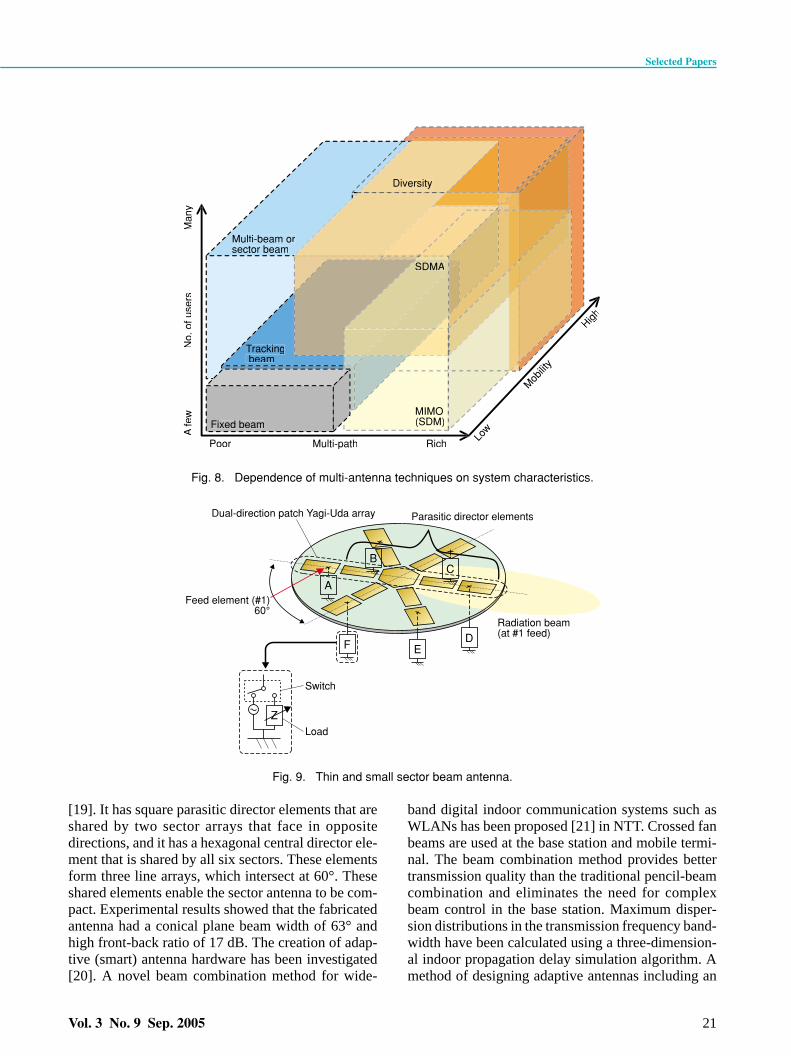
depend qualitatively on the system characteristics, asshown in Fig. 8. A fixed high-gain beam antenna doesnot always need antenna elements, but the other tech-niques are achieved through various combinations ofantenna elements, so they are provided by adaptive orintegrated multi-antenna systems, as shown in Figs.4(c) and (d). A narrow-beam or high-gain antenna isused in the line-of-sight situation (where there are noobstacles between the transmitting and receivingantennas and there are few paths in the multipathtransmission), so a beam-scanning mechanism isneeded when a terminal moves fast, and multiplebeams or sector beams are required when there aremany terminals in the service area. The diversityantenna technique can provide a stable signal level ina multipath mobile environment. Beam scanning(with a sector beam or multiple beams) and diversityantenna techniques have been used fairly extensivelyfrom the early days of mobile communication servicebecause they use only simple signal processing. How-ever, with the rapid progress of signal processingtechnology, a desired signal can now be distinguishedfrom a mixture of many signals in a multipath envi-ronment. The SDMA technique distributes signalsamong the terminals communicating in the servicearea. MIMO techniques enable very-high-data-ratecommunication with multiplexed transmission ineach antenna of the multi-antenna system of the basestation or mobile terminal. These techniques requiremore calculation as the movement speed of themobile terminal increases. In these wireless systems,signal processing ability and superior algorithms aremore important than the performance of antenna ele-ments.3.3.2 Research results and developed antenna
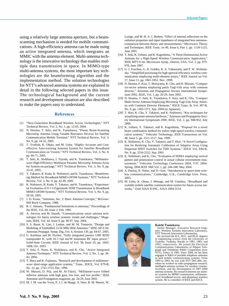
systems A very small and thin planar six-sector antenna
using a patch Yagi-Uda array with common directorsfor mobile terminals has been proposed (Fig. 9) [18],
Antenna side RF circuit side
75 m
m
69 mm
6 × 6 antenna array Front-end circuits RF sub-circuit#1
RF sub-circuit#2
Sub-array #2Sub-array #1 Patch antenna
Fig. 7. Active integrated antenna for 25-GHz system.
GainIntegrationwith MMIC
Mountingadjustment
Antenna
Very high(over 20 dBi)
No (Feeder)Horn orreflector
High(10 to 20 dBi)
Yes NeededLens
Low(2 dBi)
Yes NoSingle patch
High(10 dBi)
Yes NoParasitic
element patch
Table 3. Antenna types for millimeter-wave systems.
Selected Papers
Vol. 3 No. 9 Sep. 2005 21
[19]. It has square parasitic director elements that areshared by two sector arrays that face in oppositedirections, and it has a hexagonal central director ele-ment that is shared by all six sectors. These elementsform three line arrays, which intersect at 60°. Theseshared elements enable the sector antenna to be com-pact. Experimental results showed that the fabricatedantenna had a conical plane beam width of 63° andhigh front-back ratio of 17 dB. The creation of adap-tive (smart) antenna hardware has been investigated[20]. A novel beam combination method for wide-
band digital indoor communication systems such asWLANs has been proposed [21] in NTT. Crossed fanbeams are used at the base station and mobile termi-nal. The beam combination method provides bettertransmission quality than the traditional pencil-beamcombination and eliminates the need for complexbeam control in the base station. Maximum disper-sion distributions in the transmission frequency band-width have been calculated using a three-dimension-al indoor propagation delay simulation algorithm. Amethod of designing adaptive antennas including an
Diversity
SDMA
MIMO(SDM)
Tracking beam
Multi-beam orsector beam
Poor Multi-path Rich
A fe
wN
o. o
f use
rsM
any
Low
Mob
ility
High
Fixed beam
Fig. 8. Dependence of multi-antenna techniques on system characteristics.
EF
A
CB
D
Dual-direction patch Yagi-Uda array Parasitic director elements
Feed element (#1)60°
Switch
Radiation beam(at #1 feed)
ZLoad
Fig. 9. Thin and small sector beam antenna.

antenna configuration that is suitable for streetmicrocells, considering the propagation environ-ment, has been described. An automatic calibra-tion method at the transmitters and receiversusing the transmitting signal (ACT), whichenables realtime calibration, has been presented[22]. An SDMA technique using polarization hasalso been studied [23]. The transmission qualityof an SDMA scheme that uses vertical patternand polarization control was investigated in anactual cellular environment. For a sector cell sys-tem, this configuration was shown to be effectivebased on an evaluation of the spatial correlationcharacteristics. We also found that the output car-rier-to-interference-plus-noise power ratio (CINR) ofthe proposed configuration was from 10 to 17 dBhigher than that of the conventional SDMA configu-ration when the number of users was greater thanfour. The proposed configuration can reduce theantenna size compared with conventional SDMA.Moreover, MIMO techniques enable very-high-data-rate transmission using a limited frequency band. Wehave studied technologies based on the eigenmode-space division multiplexing (E-SDM) [24] schemebecause it provides the theoretically maximum chan-nel capacity and reduces the terminal’s calculationload. The selected papers in this issue introduce boththeoretical and practical technologies. The fourthpaper describes new MIMO methods with beam-forming to overcome problems of calculation com-plexity and low MIMO effect in the line-of-sight sce-nario [5]. The fifth paper describes the configurationof an 8 × 4 MIMO-OFDM transceiver and presentsexperimental results for the propagation characteris-tics, bit error rate (BER), and frequency utilization[6].
3.4 Satellite broadband communication systemIf we want to create a seamless and flexible wire-
less network system, then a satellite communicationsystem is very important because it provides a wideservice area. However, it has the inherent problemthat the distance between the transmitter and receiveris long, so the terminal needs a larger antenna thanones in the land mobile system to provide high-speedtransmission. The effective solution is to make thesatellite dish larger to provide high gain and multi-beam transmission. We have studied multibeam com-munication satellite technology and onboard largedeployable antennas for creating a broadband mobilesatellite communication system [25]. An MMIC-based beamforming network equipment for a multi-
beam feeder whose weight is only 1/3 that of the con-ventional type was developed. We are also develop-ing a large, highly precise deployable antenna with adiameter in the over-10-m range. The mobile terminalacting as an earth station is also an important compo-nent of a broadband mobile satellite communicationsystem. Typical existing antennas in earth stations areshown in Table 4. Various mobile terminals areaccommodated in the satellite communication systemby different transmission rates, and these terminalsuse various antenna methods and locations. A com-paratively large terminal antenna is required to han-dle high data transmission rates in a satellite systemto mitigate the huge propagation loss. The high gainand narrow beam of a large antenna make a beam-scanning mechanism necessary to enable the antennato follow the satellite direction as the terminal moves.The sixth selected paper describes a highly accurateand cost-effective auto-tracking antenna system forearth stations onboard vessels, using a novel incli-nometer that is highly accurate in acceleration distur-bance environments and a new systematic stabiliza-tion controller design process based on H∞ control[3].
4. Conclusion
This paper gave an overview of the requirements ofantennas and antenna systems in recent high-speedand high-capacity wireless communication systemsand the key technologies for satisfying these require-ments to create next-generation wireless communica-tions. It also described current antenna systems andNTT’s antenna research results for typical wirelesssystems.
Antennas for next-generation wireless communica-tions require high gain, high efficiency, and a multi-antenna design. A high-gain antenna can be made
Selected Papers
22 NTT Technical Review
Satellitecategory
LEO: low earth orbitMEO: medium earth orbitGEO: geostationary earth orbit
LEO
MEOGEO
Typical satellitesystem
IridiumGlobalstar
ICON-STARINMARSAT
Current typical earth station antenna(size or length, gain)
Helical (0.1 m, 2 dBi)Linear whip (0.1 m, 0 dBi)Patch (0.1 m2, 3 dBi)
Parabola (0.6 – 0.9 m, 18 – 21 dBi)Phased patch array (0.5 m2, 14 dBi)Helical (0.3 m, 2 dBi)Patch array (0.3 m2, 12 dBi)Patch (0.1 m2, 3 dBi)
Table 4. Typical antennas in earth stations.
Selected Papers
Vol. 3 No. 9 Sep. 2005 23
using a relatively large antenna aperture, but a beam-scanning mechanism is needed for mobile communi-cations. A high-efficiency antenna can be made usingan active integrated antenna, which integrates anMMIC with the antenna element. Multi-antenna tech-nology is the innovative technology that enables mul-tiple data transmission in space. In MIMO-typemulti-antenna systems, the most important key tech-nologies are the beamforming algorithm and theimplementation method. The solution technologiesfor NTT’s advanced antenna systems are explained indetail in the following selected papers in this issue.The technological background and the currentresearch and development situation are also describedto make the papers easy to understand.
References
[1] “Next-Generation Broadband Wireless Access Technologies,” NTTTechnical Review, Vol. 2, No. 1, pp. 12-63, 2004.
[2] N. Honma, T. Seki, and K. Tsunekawa, “Planar Beam-ScanningMicrostrip Antenna Using Tunable Reactance Devices for SatelliteCommunication Mobile Terminal,” NTT Technical Review, Vol. 3,No. 9, pp. 24-32, 2005.
[3] T. Yoshida, K. Ohata, and M. Ueba, “Highly Accurate and Cost-effective Auto-tracking Antenna System for Satellite BroadbandCommunication on Vessels,” NTT Technical Review, Vol. 3, No. 9,pp. 60-71, 2005.
[4] T. Seki, K. Nishikawa, I. Toyoda, and K. Tsunekawa, “Millimeter-wave High-Efficiency Multilayer Parasitic Microstrip Antenna Arrayfor System-on-package,” NTT Technical Review, Vol. 3, No. 9, pp.33-41, 2005.
[5] Y. Takatori, R. Kudo, K. Nishimori, and K. Tsunekawa, “Beamform-ing Method for Broadband MIMO-OFDM Systems,” NTT TechnicalReview, Vol. 3, No. 9, pp. 42-49, 2005.
[6] K. Nishimori, R. Kudo, Y. Takatori, and K. Tsunekawa, “Experimen-tal Evaluation of 8 × 4 Eigenmode SDM Transmission in BroadbandMIMO-OFDM Systems,” NTT Technical Review, Vol. 3, No. 9, pp.50-59, 2005.
[7] J. D. Kraus, “Antennas, Sec. 2: Basic Antenna Concepts,” McGraw-Hill Book Company, 1988.
[8] R. C. Hansen, “Fundamental limitations in antennas,” Proceedings ofthe IEEE, Vol. 69, Issue 2, Feb. 1981.
[9] A. Alexiou and M. Haardt, “Communications smart antenna tech-nologies for future wireless systems: trends and challenges,” Maga-zine, IEEE, Vol. 42, Issue 9, pp. 90-97, Sep. 2004.
[10] S. S. Basat, K. Lim, J. Laskar, and M. M. Tentzeris, “Design andModeling of Embedded 13.56 MHz Rfid Antennas,” IEEE AP-S Int.Antennas Propagat. Symp. Dig.,Vol. 4, Session 130, pp. 64-67, 2005.
[11] U. Karthaus and M. Fischer, “Fully integrated passive UHF RFIDtransponder IC with 16.7-/spl mu/W minimum RF input power,”Solid-State Circuits, IEEE Journal of Vol. 38, Issue 10, pp. 1602-1608, Oct. 2003.
[12] T. Seki, F. Nuno, K. Nishikawa, and K. Cho, “Active IntegratedAntenna Technique,” NTT Technical Review, Vol. 2, No. 1, pp. 36-43, 2004.
[13] T. Ihara and K. Fujimura, “Research and development of millimeter-wave short-range application systems,” Trans., IEICE, Vol. E79-B,No. 12, pp. 1741-1753, Dec. 1996.
[14] W. Menzel, D. Pilz, and M. Al-Tikriti, “Millimeter-wave foldedreflector antennas with high gain, low loss, and low profile,” IEEEAntennas and Propagation magazine, pp. 24-29, June 2002.
[15] M. J. M. van der Vorst, P. J. I. de Maagt, A. Neto, R. M. Heeres, W.
Luinge, and M. H. A. J. Herben, “Effect of internal reflections on theradiation properties and input impedance of integrated lens antennas-comparison between theory and measurements,” Microwave Theoryand Techniques, IEEE Trans. on 49, Issue 6, Part 1, pp. 1118-1125,June 2001.
[16] T. Seki, K. Uehara, and K. Kagoshima, “A Three-Dimensional ActiveAntenna for a High-Speed Wireless Communication Application,”IEEE MTT-S Int. Microwave Symp., Denver, USA, Vol. 2, pp. 975-978, June 1997.
[17] G. J. Foschini, G. D. Golden, R. A. Valenzuela, and P. W. Wolnian-sky, “Simplified processing for high spectral efficiency wireless com-munication employing multi-element arrays,” IEEE Journal on Vol.17, Issue 11, pp. 1841-1852, Nov. 1999.
[18] N. Honma, F. Kira, T. Maruyama, K. Cho, and H. Mizuno, “Compactsix-sector antenna employing patch Yagi-Uda array with commondirector,” Antennas and Propagation Society International Sympo-sium 2002, IEEE, Vol. 1, pp. 26-29, June 2002.
[19] N. Honma, T. Seki, K. Tsunekawa, F. Kira, and K. Cho, “CompactMulti-Sector Antenna Employing Microstrip Yagi-Uda Array Anten-na with Common Director Elements,” IEICE Trans. B, Vol. J87-B,No. 9, pp. 1363-1371, Sep. 2004 (in Japanese).
[20] T. Hori, K. Cho, Y. Takatori, and K. Nishimori, “Key techniques foractualizing smart antenna hardware,” Antennas and Propagation Soci-ety International Symposium 2000, IEEE, Vol. 2, pp. 948-952, July2000.
[21] K. Uehara, Y. Takatori, and K. Kagoshima, “Proposal for a novelbeam combination method for indoor high-speed wireless communi-cation systems,” Vehicular Technology, IEEE Transactions on Vol.48, Issue 5, pp. 1511-1517, Sep. 1999.
[22] K. Nishimori, K. Cho, Y. Takatori, and T. Hori, “A Novel Configura-tion for Realizing Automatic Calibration of Adaptive Array UsingDispersed SPDT Switches for TDD Systems,” IEICE Vol. E84-B,No. 9, pp. 2516-2522, Sep. 2001.
[23] K. Nishimori, and K. Cho, “Evaluation of SDMA employing verticalpattern and polarization control in actual cellular environment mea-surement,” Vehicular Technology Conference 2004, VTC 2004-Spring, 2004 IEEE 59th Vol. 1, pp. 244-248, May 2004.
[24] A. Paulraj, R. Nabar, and D. Gore, “Introduction to space-time wire-less communications,” Cambridge, U.K., Cambridge Univ. Press,2003.
[25] M. Ueba, K. Ohata, J. Mitsugi, and M. Umehira, “Broadband andscalable mobile satellite communication system for future access net-works,” 22nd AIAA ICSSC, AIAA 2004-3154.
Koichi TsunekawaSenior Manager, Executive Research Engi-
neer, Wireless Systems Innovation Laboratory,NTT Network Innovation Laboratories.
He received the B.S., M.S., and Ph.D. degreesin engineering science from the University ofTsukuba, Tsukuba, Ibaraki in 1981, 1983, and1992, respectively. He joined the ElectricalCommunications Laboratories of Nippon Tele-graph and Telephone Public Corporation (nowNTT), Tokyo in 1983. Since 1984, he has beenengaged in R&D of portable telephone antennasin land mobile communication systems. From1993 to 2003, he was with NTT DoCoMo, Inc.where he worked on radio propagation research,intelligent antenna systems for wireless commu-nications, and the development of IMT-2000antenna systems. His research interests are anten-na systems for MIMO transmission, millimeter-wave broadband access, and ubiquitous wirelesssystem. He is a member of IEEE and IEICE.