
NETIMPRESS next
163
NETIMPRESS Network Compatible in-circuit Flash Micom Programmer for Embedded Smart Systems NETIMPRESS next FLASH PROGRAMMER Instruction Manual DTS INSIGHT CORPORATION
-
Upload
khangminh22 -
Category
Documents
-
view
5 -
download
0
Transcript of NETIMPRESS next
NETIMPRESS Network Compatible in-circuit Flash Micom Programmer for Embedded Smart Systems
NETIMPRESS next
FLASH PROGRAMMER Instruction Manual
DTS INSIGHT CORPORATION

NETIMPRESS Network Compatible in-circuit Flash Micom Programmer for Embedded Smart Systems
i
Instruction Manual
No. M2383AM-05
Publication History
Edition Date of Issue Description
First edition 4-February-2013 Initial publication
Second edition 9-April-2013 Errata are corrected.
Third edition 9-July-2015 Errata are corrected.
Fourth edition 28-June-2016 Addition of AZ403.
Fifth edition 1-April-2017 Bar-code reader Process mode change. Unusable letter addition.
(1) No part of this manual may be reproduced or transmitted in any form or by any means, electronic or mechanical, without the written permission of DTS INSIGHT CORPORATION.
(2) The contents of this manual are subject to change without prior notice due to improvement of the functionality.
(3) If any question about the contents of this manual arises, contact DTS INSIGHT CORPORATION.
(4) DTS INSIGHT CORPORATION shall not be held responsible for direct or indirect adverse effects resulting from operation of this system irrespective of the above item (3).
Product and company names mentioned in this manual are the trademarks of their respective owners.
© 2013 DTS INSIGHT CORPORATION. All rights reserved
Printed in Japan

NETIMPRESS Network Compatible in-circuit Flash Micom Programmer for Embedded Smart Systems
ii

NETIMPRESS Network Compatible in-circuit Flash Micom Programmer for Embedded Smart Systems
iii
Compatibility with
MegaNETIMPRESS/C”arNETIMPRESS NETIMPRESS next is compatible with MegaNETIMPRESS/C”arNETIMPRESS series.
You can use the control module for MegaNETIMPRESS/C”arNETIMPRESS series without any changes.
* Programming voltage output control signal is adapted by NEIMPRESS next even though TVpp output is supported by MegaNETIMPRESS/C”arNETIMPRESS.
NETIMPRESS Network Compatible in-circuit Flash Micom Programmer for Embedded Smart Systems
iv
Contents
1 Overview and Features ................................................................................. 1
2 General Precautions ..................................................................................... 2
3 Part Names and Functions ........................................................................... 3
4 System Configuration of NETIMPRESS next .............................................. 8
4.1 Connecting with Peripheral devices ........................................................................... 8 4.2 About Each Configuration ........................................................................................ 10
4.2.1 Ethernet environment ............................................................................................... 10
4.2.2 Target system .......................................................................................................... 10
4.2.3 Bar-code environment .............................................................................................. 15
4.2.4 Digital I/O Connection/Example ............................................................................... 29 4.3 Other New Functions of NETIMPRESS next ........................................................... 33
4.3.1 Keylock Function ...................................................................................................... 33
4.3.2 Log Function ............................................................................................................ 34
4.3.3 Clock Function (RTC)............................................................................................... 36
5 Commands .................................................................................................. 37
5.1 Commands and their functions ................................................................................ 37 5.2 File Operations ......................................................................................................... 39
5.2.1 File Load .................................................................................................................. 39
5.2.2 File Save .................................................................................................................. 40
5.2.3 File Purge ................................................................................................................. 41
5.2.4 Display Current File (Function F4) ........................................................................... 42
5.2.5 Set Transfer Address (Function F5) ......................................................................... 44
5.2.6 Delete All Files (Function F7) ................................................................................... 46
5.2.7 Quick Format (Function FA) ..................................................................................... 47
5.2.8 Regular Format (Function FC) ................................................................................. 48 5.3 Editing Buffer Memory.............................................................................................. 50
5.3.1 Edit (Modify Buffer Memory Data) ............................................................................ 50
5.3.2 Block Store (Modify Buffer Memory Data) ................................................................ 51
5.3.3 Clear Buffer (Initialize Buffer Memory) ..................................................................... 53
5.3.4 Modified Bit Search (Search Modified Data) ............................................................ 54
5.3.5 Display Sum Value (Function 93) ............................................................................. 55
5.3.6 YSM File Check (Function 98) ................................................................................. 56 5.4 Parameter Settings .................................................................................................. 57
5.4.1 Setting Execution Address (Function 0) ................................................................... 57
5.4.2 Communication Channel Setting (Function D1) ....................................................... 59
5.4.3 UART Baud Rate Setting (Function D2) .................................................................. 60

NETIMPRESS Network Compatible in-circuit Flash Micom Programmer for Embedded Smart Systems
v
5.4.4 Set CSI Baud Rate (Function D9) ............................................................................ 61
5.4.5 Set TVcc Threshold (Function D3) ........................................................................... 62
5.4.6 Set MCU Mode (Function D4) .................................................................................. 63
5.4.7 Set Watchdog Timer (Function D5) .......................................................................... 64
5.4.8 Display Flash Memory Area (Function D6) .............................................................. 65
5.4.9 Set Communication Channel (Function D7) ............................................................. 66
5.4.10 Change Displayed Model Name (Function D8) ........................................................ 67
5.4.11 Set Data Format (Function 5) ................................................................................... 68
5.4.12 Set MCU Operating Frequency (Function DF) ......................................................... 70
5.4.13 View Version Info (Function 94) ............................................................................... 71
5.4.14 Verify Mode Switching (Function 99) ....................................................................... 72
5.4.15 Set Buffer Memory Initial Mode ................................................................................ 73
5.4.16 View License (Function 9B) ..................................................................................... 74
5.4.17 SUM Value Mode Switching (Function 9C) .............................................................. 75
5.4.18 ADDRESS WARNING On/Off for File Loading (Function 9E) ................................. 76
5.4.19 ADDRESS WARNING On/Off for Startup (Function 9F) .......................................... 77
5.4.20 View Serial No. (Function AE) .................................................................................. 78
5.4.21 Add License (Function AF) ....................................................................................... 79 5.5 Overview/Operation of the Control Module .............................................................. 80
5.5.1 Select YIM Folder (Function B0) .............................................................................. 81
5.5.2 Create YIM Folder (Function B1) ............................................................................. 82
5.5.3 Delete YIM Folder (Function B2) .............................................................................. 83
5.5.4 Copy YIM Folder (Function B3) ................................................................................ 84
5.5.5 Protect Current YIM Folder (Function B4) ................................................................ 85
5.5.6 Retain Current YIM Folder (Function B5) ................................................................. 86
5.5.7 View Current YIM Folder (Function B6) ................................................................... 87
5.5.8 Set Current YMN File (Function BC) ........................................................................ 88
5.5.9 Execute Current YMN File (Function BD) ................................................................ 89 5.6 Ethernet Settings...................................................................................................... 90
5.6.1 IP Address/Port Setting (Function E2) ..................................................................... 90
5.6.2 Gateway Address Setting (Function E3) .................................................................. 92
5.6.3 Subnet Mask Setting (Function E4) ......................................................................... 93
5.6.4 Communication Speed/Communication Mode Setting (Function E8) ................... 94 5.7 Device Functions...................................................................................................... 95
5.7.1 Copy ......................................................................................................................... 96
5.7.2 Blank Check ............................................................................................................. 97
5.7.3 Erase ........................................................................................................................ 98
5.7.4 Program ................................................................................................................... 99
5.7.5 Read Check ........................................................................................................... 100
5.7.6 E.P.R. ..................................................................................................................... 101 5.8 Log Operation ........................................................................................................ 103
5.8.1 Set Log Mode (Function CA0)................................................................................ 103
NETIMPRESS Network Compatible in-circuit Flash Micom Programmer for Embedded Smart Systems
vi
5.8.2 Delete the Log (Function CA5)............................................................................... 104
5.8.3 Delete the All Log (Function CA0) .......................................................................... 105
5.8.4 Set Log Deletion (Function CA8) ........................................................................... 106 5.9 I/F Setting ............................................................................................................... 107
5.9.1 Set Cable Selection (Function CD0) ...................................................................... 107
5.9.2 Set the Input Filter Value of Digital Input (Function CD1) ...................................... 107 5.10 Restrictions ............................................................................................................ 108
6 Command Sequence Function ................................................................ 109
6.1 EXE Key ................................................................................................................. 109
6.1.1 Function Overview ................................................................................................. 109
6.1.2 EXE Key Setting .................................................................................................... 110 6.2 YMN File ................................................................................................................ 112
6.2.1 Function Overview ................................................................................................. 112
6.2.2 Format of Command Sequence File (*.YMN ) ....................................................... 113 6.3 Definitions of Device Command ............................................................................. 114
7 Sum Check Function ................................................................................ 115
7.1 Sum Check Overview ............................................................................................. 115 7.2 Sum Check Function Settings ................................................................................ 115
7.2.1 YSM Files (*.YSM) ................................................................................................. 115
7.2.2 YSM File Format .................................................................................................... 116
8 Specifications ............................................................................................ 117
8.1 Operating Conditions ............................................................................................. 117 8.2 Ethernet Interface .................................................................................................. 117
8.2.1 Connector (Ethernet).............................................................................................. 117
8.2.2 Signal Table ........................................................................................................... 117 8.3 Compact Flash Interface ........................................................................................ 118
8.3.1 Connector (Control Module) ................................................................................... 118
8.3.2 Signal Table ........................................................................................................... 118 8.4 Digital I/O Interface ................................................................................................ 119
8.4.1 Connector (DIO PROBE) ....................................................................................... 119
8.4.2 Signal Table ........................................................................................................... 120
8.4.3 Timing Specifications ............................................................................................. 122
8.4.4 Electrical Characteristics ........................................................................................ 123
8.4.5 Digital I/O PROBE ( AZ401) ................................................................................... 124
8.4.6 Digital I/O PROBE ( AZ403) ................................................................................... 125 8.5 Bar-code reader Interface ...................................................................................... 126
8.5.1 Connector (BCR PROBE) ...................................................................................... 126
8.5.2 Signal Table ........................................................................................................... 126
8.5.3 Electrical Characteristics ........................................................................................ 126
8.5.4 BCR PROBE (AZ402) ............................................................................................ 127

NETIMPRESS Network Compatible in-circuit Flash Micom Programmer for Embedded Smart Systems
vii
8.6 Target Interface ...................................................................................................... 128
8.6.1 Connector (TARGET PROBE 1) ............................................................................ 128
8.6.2 Signal Table ........................................................................................................... 129
8.6.3 Interface Circuit Type ............................................................................................. 130
8.6.4 DC Characteristics ................................................................................................. 134
8.6.5 Interface Cable (AZ410) ......................................................................................... 135
8.6.6 Interface Cable (AZ411, AZ413) ............................................................................ 136
8.6.7 Interface Cable (AZ412) ......................................................................................... 137 8.7 CAN Interface ........................................................................................................ 138
8.7.1 Connector (TARGET PROBE 2) ............................................................................ 138
8.7.2 Signal Table ........................................................................................................... 139
8.7.3 Interface Circuit Type ............................................................................................. 140
8.7.4 CAN Interface Cable (AZ414) ................................................................................ 145
8.7.5 CAN Interface Cable (AZ415) ................................................................................ 146
8.7.6 CAN Interface Cable (AZ416) ................................................................................ 147
APPENDIX List of Error Codes ......................................................................... 148

NETIMPRESS Network Compatible in-circuit Flash Micom Programmer for Embedded Smart Systems
viii
Ensuring Safety Use of Flash Programmer
In order to ensure the proper and safety use of Flash Programmer, please be sure to follow the safety caution mentioned below as operating Flash Programmer. DTS INSIGHT CORPORATION has no responsibility nor guarantee for any injuries which occur as a result of the violation of these safety caution and warnings.
Following safety-related symbols are used on Flash Programmer and its instruction manual for a safety use.
It indicates not only that there is a danger to humans as well as to the equipment, but also that it is necessary to refer to the instruction manual.
It indicates a safety ground terminal. As this terminal is on the main unit, please be sure to connect this terminal to the ground before operating.
WARNING In order to avoid the risk of death or serious injury which may occur as a result of an incorrect use.
CAUTION In order to avoid the risk of minor injury or material damage which may occur as a result of an incorrect use.
To avoid the risk of death or serious injury to users, such as electrocution or any other accidents, as well as the risk of damage to Flash Programmer, please follow the warnings mentioned below.
WARNING Use in Chemical Gases
Do not use Flash Programmer in an environment where are combustible or explosive gases or steam. Using Flash Programmer in such environment is extremely dangerous.
Flash Programmer is designed for indoor use
Do not use Flash Programmer in an outdoor.
Power Supply
As Flash Programmer is designed to prevent the electrocution or any other accidents, be sure to use the power supply pack (AC adapter) specified by DTS INSIGHT CORPORATION ONLY.
Confirm that the supply-side voltage matches to the rated power supply voltage for a power supply pack. Also ensure that the power supply switch (on the back panel) of Flash Programmer is switched "OFF" before connecting to the power cord.
The provided power cable complies with the electrical power system of the country where the product is originally sold.
When using the product outside the country of sale, check in advance the supply voltage and the plug type in the country where you use, and prepare a suitable power cable.
Be sure to connect the FG terminal of the power cable to the ground.
Always connect the Flash Programmer system, user’s system, and host computer to the same AC power outlet.
Removing the Case
Only qualified service engineers should remove the case of Flash Programmer because of the high voltage.

NETIMPRESS Network Compatible in-circuit Flash Micom Programmer for Embedded Smart Systems
ix
Making the Most of Flash Programmer
The Flash Programmer is an electronic device which consists of high-precision electronic components. Please be sure to understand and follow the caution listed below in order to avoid any accidents and as well as to make the most of your Flash Programmer.
1. Switch ON / Switch OFF Sequence
CAUTION Refer to the Switch ON / Switch OFF sequence below regarding Switch ON and OFF of
the host computer, Flash Programmer, and a target system.
The Switch ON / Switch OFF sequence should be followed in order to avoid major damages to a target system and Flash Programmer itself. (Especially between Flash Programmer and a target system.)
<Power Up Sequence>
(1) Host computer
(2) Flash Programmer
(3) Target system
<Power Down Sequence>
(1) Target system
(2) Flash Programmer
(3) Host computer
2. Connecting the Probe and Connector
CAUTION Switch OFF the power supply of Flash Programmer and a target system before plugging in
or unplugging any probes or cables.
All probes and cables are designed to prevent an incorrect connection. Never force them to plug in nor unplug. Confirm the position and direction.
3. Disassembling Flash Programmer
CAUTION Since Flash Programmer contains printed circuit boards with minute patterns, never
remove screws or disassemble Flash Programmer.

NETIMPRESS Network Compatible in-circuit Flash Micom Programmer for Embedded Smart Systems
x
IMPORTANT
Thank you for your purchasing this Flash Programmer “NETIMPRESS next”.
To make the most of Flash Programmer, please read and understand NETIMPRESS next Flash Programmer Instruction Manual before use. After reading the instruction manual, please keep it for the further reference whenever required. Please ensure that Flash Programmer should be used only by persons who have read and understood the instruction manual. We strongly recommend that the first-time users receive a proper instruction from those who have a good knowledge of Flash Programmer.
What is Flash Programmer?
The Flash Programmer refers to the Flash Programmer main unit, control modules, and other related products manufactured by DTS INSIGHT CORPORATION. A target system and the host computer are strictly excluded.
Flash Programmer is an electronic device which consists of the high-precision electronic components. In order to make the most of Flash Programmer and also to prevent any accidents, please follow the caution listed below.
A certain repair fee is required regarding the equipment damages resulted from an incorrect use or connection, etc. Please aware that it may require a few months for repairs.
Regarding software products and manuals, DTS INSIGHT CORPORATION guarantees only if there are any damages of media provided by DTS INSIGHT CORPORATION, manual defects or trouble executing the program installation.
If proved that there are bugs or that there are problems apart from those listed above, the action will be taken based on the maintenance agreement.
WARNING
Be sure to Switch OFF the power supply of Flash Programmer and a target system before plugging in or unplugging any cables between Flash Programmer and a target system. Be aware that plugging in or unplugging any cables while the power supply is ON, may result in an explosion or ignition of Flash Programmer or a target system.
Before Switching ON the power supply, be sure to confirm whether the direction of Pin 1 in the probe tip matches to Pin 1 Socket in a target system. An incorrect connection may result in an explosion or ignition of Flash Programmer or a target system.
CAUTION As particular parts of electronic circuits in the probe tip are exposed, Flash Programmer should be used only in environments where are protected from a static electricity. Using Flash Programmer in such environment as without static electric protection may result in destroying Flash Programmer or a target system.
The Switch ON / OFF sequence should be followed. Flash Programmer should be switched ON prior to a target system and remained ON while Switch ON / OFF of a target system power supply. An incorrect Switch ON / OFF sequence may result in a serious damage to Flash Programmer or a target system circuits.
NETIMPRESS Network Compatible in-circuit Flash Micom Programmer for Embedded Smart Systems
1
1 Overview and Features
NETIMPRESS series is the universal flash microcomputer programmer for programming flash microcomputers soldered on a user’s system.
By using the microcomputer-specific control module, NETIMPRESS series supports programming flash microcomputers of various types.
The speed of writing is increased for NETIMPRESS next. Also the external control functions by bar-code reader and digital I/O are improved.
NETIMPRESS next of /CAN option can program flash microcomputer via the CAN interface in addition to the serial interface functions and features.
Features
(1) NETIMPRESS next supports programming microcomputers of various types using the microcomputer-specific control module.
(2) Connect NETIMPRESS next to a user system using the microcomputer-specific target probe (optional). A target microcomputer can be programmed while it is being soldered on a user system.
(3) NETIMPRESS next can be used as a standalone. Programming information can be saved as a file on the Compact Flash.
(4) NETIMPRESS next can be controlled remotely from a host computer with Ethernet interface. This enables file transfer and programming parameter changes (optional AZ490 software is required).
(5) As NETIMPRESS next can be connected via Ethernet, it can be connected to a network and used to build a system. It can be easily controlled remotely with your application software created at a customers' sites using the remote control package AZ491 (optional software), enabling you to build an automatic programming system.
(6) High speed flash memory programming.
(7) High speed search for modified data.
(8) Modified information can be saved on the Compact Flash as a modified file of an original programming information file.
(9) Item numbers can be changed by using a bar-code reader.
(10) Sequential operation can be available by using the digital I/O.
(11) Log can be saved.
NETIMPRESS Network Compatible in-circuit Flash Micom Programmer for Embedded Smart Systems
2
2 General Precautions
(1) Be sure to use the AC adapter specified by DTS INSIGHT CORPORATION. When you connect the DC jack to NETIMPRESS next, make sure that the AC plug is unplugged and the Power Switch is turned off.
(2) Do not use NETIMPRESS next in dusty areas, where there is direct sunlight or corrosive gas is generated.
(3) Use NETIMPRESS next in environments with temperature between 5 and 40C and humidity between 20% and 80%.
(4) In case there is noise in the AC current line, use a noise filter to eliminate the noise.
(5) To insert or remove the control module, be sure to turn off the power of NETIMPRESS next.
(6) To turn the power on, turn on the power of NETIMPRESS next first and then a user system. To turn off the power, follow the reverse order.
(7) NETIMPRESS next operates with the control module set into the Compact Flash connector. NETIMPRESS next does not operate with the Compact Flash being removed.
Visit our Web site for information about how to use NETIMPRESS next and related products and for the latest information.
https://www.dts-insight.co.jp/en/support/support_netimpress/top/index.php?m=Search

NETIMPRESS Network Compatible in-circuit Flash Micom Programmer for Embedded Smart Systems
3
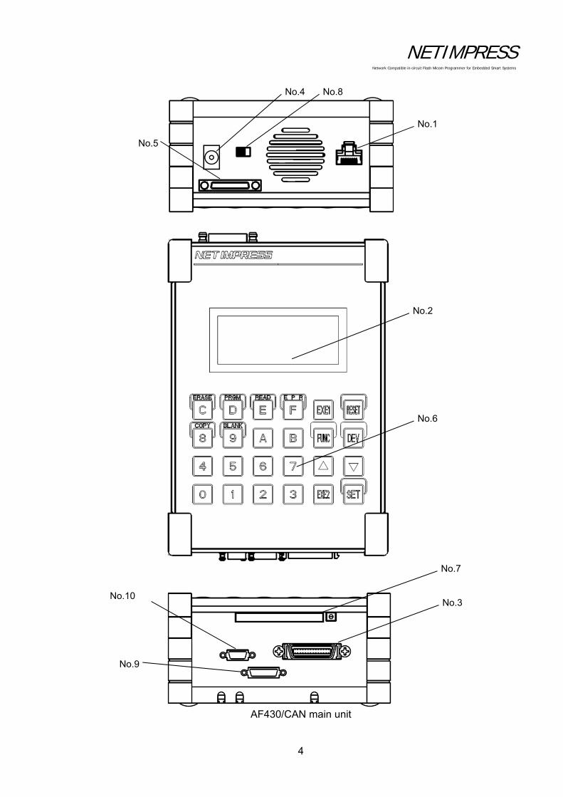
3 Part Names and Functions
The figure below illustrates the parts and components names of NETIMPRESS next main unit.
AF430 main unit
No.1
No.2
No.4 No.8 No.5
No.6
No.3
No.7
No.10
NETIMPRESS Network Compatible in-circuit Flash Micom Programmer for Embedded Smart Systems
4
AF430/CAN main unit
No.1
No.2
No.3
No.4
No.5
No.8
No.6
No.7
No.10
No.9

NETIMPRESS Network Compatible in-circuit Flash Micom Programmer for Embedded Smart Systems
5
No.1 ETHERNET
This is the connector to connect with Ethernet (10/100Base-T).
No.2 LCD
Displays various information.
Programming power application display
This shows that high voltage power for programming is being applied. This display can be cleared by pressing the RESET key.
Control module model name
Displays the model name of the control modules in the Compact Flash. You can customize this display part using the steps described in Chapter 5.
Device function display
Displays the device function being executed.
Function display/Modify bit display
Displays the function currently being executed or that the data in the buffer memory is modified data.
When "F" is displayed, it indicates the function, which is currently being executed.
When "D" is displayed, it indicates the device function, which is currently being executed.
When "M" is displayed, it indicates the data modified by the key entry or buffer transfer.
F / 1 0 0 0 / A A /
/ H V B L A N K /
F H 8 1 9

NETIMPRESS Network Compatible in-circuit Flash Micom Programmer for Embedded Smart Systems
6
Address display
Displays the flash memory address, data key entry and various messages. This only displays the lowest eight address digits and does not display the higher address digits.
Buffer
Displays buffer memory data and error codes.
ROM data/sum check
Displays the flash ROM data and a sum value of buffer memory data.
No.3 TARGET PROBE 1
This is the connector to connect the probe that connects with a target system.
No.4 DC12V
This jack is to connect the AC adapter for NETIMPRESS next.
No.5 DIO PROBE
This is the connector to control by digital I/O.
No.6 KEYBOARD
[0 to F]
Use the hexadecimal data keys to enter the numeric values. 8, 9, C, D, E and F are used as the keys to specify each device function combining with the DEV key.
[RESET]
Use this key to abort operations or delete the error messages. Pressing this RESET key disconnects remote connection too.
[FUNC, DEV]
Use these command keys to make various operation settings combining with the hexadecimal data keys.
[ ]
These are the keys to increment and decrement the address values. The buffer memory and the ROM data for the addresses are displayed simultaneously. This is also used as a parameter delimiter for FUNC.
[SET]
Use this key to set the functions and device functions. You can also use this SET key to modify the data in buffer memory.
[EXE1, EXE2]
You can assign various commands to these two keys. For further information, see Chapter 6 “Command Sequence Function”.
No.7 CONTROL MODULE
This is the slot to insert the control module. NETIMPRESS next only operates with its specific Compact Flash.

NETIMPRESS Network Compatible in-circuit Flash Micom Programmer for Embedded Smart Systems
7
No.8 POWER
Power Switch I: Power ON O: Power OFF
No.9 TARGET PROBE2 (AF430/CAN only)
This connector is used to connect a probe to connect NETIMPRESS next and a target system through the CAN interface.
No.10 BCR PROBE
This is the connector to connect the probe that connects with a bar-code reader.

NETIMPRESS Network Compatible in-circuit Flash Micom Programmer for Embedded Smart Systems
8
4 System Configuration of NETIMPRESS next
4.1 Connecting with Peripheral devices
The following figure shows a connection example of NETIMPRESS next and peripheral devices.
PASS ERR RUN
DI0 DI1 DI2
DO0 DO1 DO2
PC
LAN cable
HUB
User system(Target)
Control Module(Compact Flash)
Target probe
ACADAPTERAC plug
DI/O unit
Ethernet environment
Digital I/Oenvironment
Bar-code reader
Bar-code environment
NETIMPRESS next
RS-232C
NETIMPRESS Network Compatible in-circuit Flash Micom Programmer for Embedded Smart Systems
9
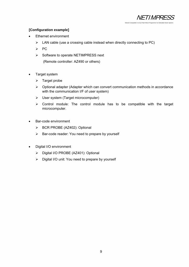
[Configuration example]
Ethernet environment
LAN cable (use a crossing cable instead when directly connecting to PC)
PC
Software to operate NETIMPRESS next
(Remote controller: AZ490 or others)
Target system
Target probe
Optional adapter (Adapter which can convert communication methods in accordance with the communication I/F of user system)
User system (Target microcomputer)
Control module: The control module has to be compatible with the target microcomputer.
Bar-code environment
BCR PROBE (AZ402): Optional
Bar-code reader: You need to prepare by yourself
Digital I/O environment
Digital I/O PROBE (AZ401): Optional
Digital I/O unit: You need to prepare by yourself

NETIMPRESS Network Compatible in-circuit Flash Micom Programmer for Embedded Smart Systems
10
4.2 About Each Configuration
4.2.1 Ethernet environment
To connect NETIMPRESS next to PC, you need to set the Ethernet.
Follow the steps below to set up the Ethernet.
a. Create YCM file in advance by using the AZ482 (F/DF sheet generator).
b. Copy the YCM file into the root directory of the control module. Only one .YCM file can exist in the root directory. Also, if the .YCM file is copied into a place other than the root directory, the file is not recognized correctly.
c. Insert the control module into NETIMPRESS next main unit and turn ON the power.
d. As the message, “YCM DATA SET?”, appears on the LCD, press [EXE1] or [EXE2] key. Then, IP address, Port, Sub-net mask, and Gateway mask specified in the .YCM file are set up for Ethernet connection. If you do not want to make this setting, press [RESET] key.
e. The IP address you have set up are shown on the LCD, and then NETIMPRESS next is started up. Ethernet setting is now completed.
* Ethernet can be also set up by a standalone operation (Function E2 to E4). For details, see Section 5.6 “Ethernet Settings”.
After you completed the Ethernet setting, you can establish the communication with the remote controller (AZ490), which is software for controlling the programmer.
4.2.2 Target system
[Pin assignment]
The information on target interface of NETIMPRESS next (information on pin assignments and circuits) is described in Chapter 8 “Specifications”.
For input signals to a user system, it is recommended to attach pull-up resister (about 10 K) considering possible malfunction when NETIMPRESS next is not connected.
The definitions for specific signal lines vary for each the control module. For details, see the manual for your control module.
[Programming on a stand-alone basis]
Basic instructions for programming on a stand-alone basis are described below.
For more details, refer to the table listing the commands and their functions in Chapter 5 “Commands”.

NETIMPRESS Network Compatible in-circuit Flash Micom Programmer for Embedded Smart Systems
11
1. Initializing the Buffer Memory*1
Initialize*2 the buffer memory of an area which corresponds to the flash ROM area of the microcomputer (MCU).
Key Operations LCD Display (Whole)
Buffer memory initialization function Set
*1 Buffer memory
This is the place where the program data for the Flash ROM is stored. By loading an object file on to the buffer memory, it is converted into binary data and stored. Data can be modified using the Edit function (See Section 5.3 “Editing Buffer Memory”). Even if the power of NETIMPRESS next is turned off, the buffer memory data is preserved because the buffer memory is on the Compact Flash.
*2 Initialization
The buffer memory data when initialized varies depending on the control module and it will be "00" or "FF". (For information about the data contents, see your control module manual.)
FUNC 2
SET FUNC SET
F 2 / B U F F E R A E L CR
/ x x x x /
F x n n n
NETIMPRESS Network Compatible in-circuit Flash Micom Programmer for Embedded Smart Systems
12
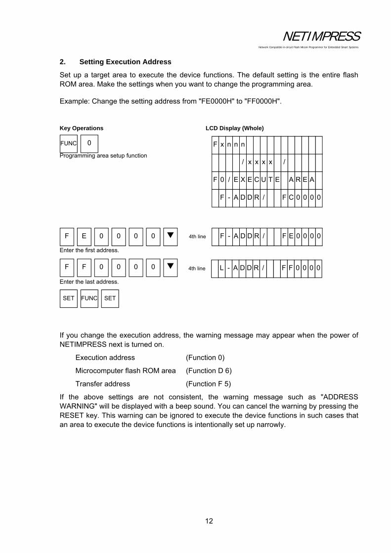
2. Setting Execution Address
Set up a target area to execute the device functions. The default setting is the entire flash ROM area. Make the settings when you want to change the programming area.
Example: Change the setting address from "FE0000H" to "FF0000H".
Key Operations LCD Display (Whole)
Programming area setup function Enter the first address. Enter the last address.
If you change the execution address, the warning message may appear when the power of NETIMPRESS next is turned on.
Execution address (Function 0)
Microcomputer flash ROM area (Function D 6)
Transfer address (Function F 5)
If the above settings are not consistent, the warning message such as "ADDRESS WARNING" will be displayed with a beep sound. You can cancel the warning by pressing the RESET key. This warning can be ignored to execute the device functions in such cases that an area to execute the device functions is intentionally set up narrowly.
FUNC 0
F E 0 0 0 0
F F 0 0 0 0
SET FUNC SET
F - A D D R / 0 0 0 0 E F 4th line
F - A D D R / 0 0 0 0 C F
F 0 / E X E C U A E R A E T
/ x x x x /
F x n n n
L - A D D R / 0 0 0 0 F F 4th line

NETIMPRESS Network Compatible in-circuit Flash Micom Programmer for Embedded Smart Systems
13
3. Loading the Object File
Load a user’s object file on the Compact Flash into buffer memory of NETIMPRESS next. For example, load the "DAT128K.BIN" file.
Key Operations LCD Display (Whole)
File load function
Select "DAT128K.BIN".
FUNC F 1
SET FUNC SET
D A T 1 2 N I B . 8 4th line
D O W N L O A D N I B . . . 3rd line
T E S X E H . 1 T
F F 1 / F I L E D A O L
/ x x x x /
F x n n n
NETIMPRESS Network Compatible in-circuit Flash Micom Programmer for Embedded Smart Systems
14
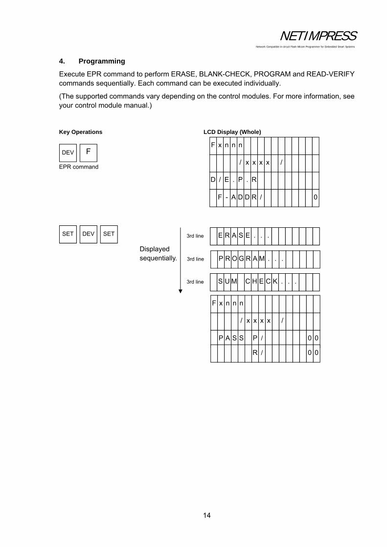
4. Programming
Execute EPR command to perform ERASE, BLANK-CHECK, PROGRAM and READ-VERIFY commands sequentially. Each command can be executed individually.
(The supported commands vary depending on the control modules. For more information, see your control module manual.)
Key Operations LCD Display (Whole)
EPR command
Displayed sequentially.
F DEV
SET DEV SET E R A S E . . . 3rd line
P R O G R A M . . . 3rd line
S U M C H E C . . . K 3rd line
F - A D D R / 0
D / E . P . R
/ x x x x /
F x n n n
P A S S P / 0 0
R / 0 0
/ x x x x /
F x n n n

NETIMPRESS Network Compatible in-circuit Flash Micom Programmer for Embedded Smart Systems
15
4.2.3 Bar-code environment
[Overview]
Bar-code reader, whose connection type is RS232C, can be connectable.
You need to prepare the followings if you use a bar-code reader for NETIMPRESS next.
BCR PROBE (AZ402)
Bar-code reader main unit (RS-232C connection type)
Bar-code
YBO file
The process mode is written in a dedicated option file (extension: YBO).
<NOTES>
Bar-code reader can be used with the standalone environment only. (cannot be used with the Ethernet communication).
YBO file:
You can create and edit the file by software (AZ486).
(AZ486 can be downloaded from our home page.)
For further information, see the AZ486 manual.
Make sure to place the YBO file into the root directory of Compact Flash which is inserted to the programmer.
If it is in a place other than the root directory, the bar-code process becomes invalid. (The bar-code cannot be received.)
Process mode:
(1) Mode which executes a script file conformed with the bar-code (SCRIPT mode)
(2) Mode which executes a bar-code whose format is provided by DTS INSIGHT CORPORATION (ORIGINAL mode)
(3) Mode which selects a YIM folder conformed with the barcode, and then executes the access to the target (EPR) (SELECT mode)

NETIMPRESS Network Compatible in-circuit Flash Micom Programmer for Embedded Smart Systems
16
[General flowchart]
XXXXXX.YBO Option file
SCRIPTFILE.SCP
RS232C
Bar-code reader
Mode set-up
A mode which searches the script file and
executes it
SAMPLE001.YIM
SAMPLE002.YIM
A mode which selects YIM folder
(executes EPR)
A mode which reads and executes a bar-code created in regulation
format
The following process varies depending on the mode
NETIMPRESS next

NETIMPRESS Network Compatible in-circuit Flash Micom Programmer for Embedded Smart Systems
17
[Set up the Bar-code reader]
To read the bar-code by NETIMPRESS next, set the bar-code reader as follows.
Communication setting of the bar-code reader
Data format
Prefix (header) No
Suffix (footer)* CR(0x0d)
Scan data transfer format <data><suffix>
* For suffix information, information in the YBO file has priority in case it is specified by YBO file.
Baud rate 9600bps
Parity No
Stop bit 1-stop bit
Data length 8-bit

NETIMPRESS Network Compatible in-circuit Flash Micom Programmer for Embedded Smart Systems
18
[YBO file]
Only one YBO file can exist in the root directory of the Compact Flash.
Bar-code process becomes invalid if there is no file in the root directory or if there are more than one files in the root directory.
Bar-code can be read by the bar-code reader in case the file format has no problem.
YBO file is configured by some options and a mode which switches programmer control.
YBO file name:
XXXXX.YBO
*1. You can name xxxx parts as you like.
*2. The extension must be YBO.
YBO file configuration:
/ / X X X X X . Y B O
/ / 2 0 x x . x x . x x
[ M O D E ]
S C R I P T
[ S E T T I N G ]
S T A R T = 0 0 0 2
E N D = 0 0 1 2
S U F F I X = 0 x 0 D
[ E N D ]
Format
1. The lines before [MODE] are treated as comments. It is ignored.
2. Programming order is [MODE] – [SETTING].
3. In case there is no setting in [SETTING], it is operated as START=0, END=delimiter, SUFFIX=0x0D.
4. Make sure to place [END] at the end of the file. If there is no [END], it will become a format error.
Header
Header
NETIMPRESS Network Compatible in-circuit Flash Micom Programmer for Embedded Smart Systems
19
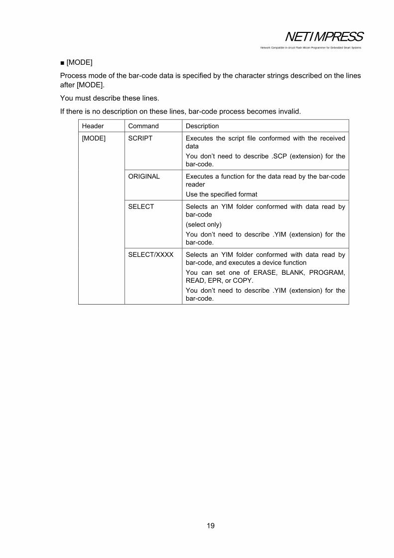
[MODE]
Process mode of the bar-code data is specified by the character strings described on the lines after [MODE].
You must describe these lines.
If there is no description on these lines, bar-code process becomes invalid.
Header Command Description
[MODE]
SCRIPT Executes the script file conformed with the received data
You don’t need to describe .SCP (extension) for the bar-code.
ORIGINAL Executes a function for the data read by the bar-code reader
Use the specified format
SELECT Selects an YIM folder conformed with data read by bar-code
(select only)
You don’t need to describe .YIM (extension) for the bar-code.
SELECT/XXXX
Selects an YIM folder conformed with data read by bar-code, and executes a device function
You can set one of ERASE, BLANK, PROGRAM, READ, EPR, or COPY.
You don’t need to describe .YIM (extension) for the bar-code.

NETIMPRESS Network Compatible in-circuit Flash Micom Programmer for Embedded Smart Systems
20
[SETTING]
Effective range and end code of received bar-code are set by the character strings described on the lines after [SETTING].
You can omit these settings.
Header Argument Description
[SETTING]
START= Where to start the sampling:
Set the starting point of the data sample
Settable range: 1 to 2047 (decimal)
0x1 to 0x7FF (hexadecimal)
* Enable with other than ORIGINAL mode
END= Where to stop the sampling:
Set the end point of the data sample
Settable range: 1 to 2047 (decimal)
0x1 to 0x7FF (hexadecimal)
* Enable with other than ORIGINAL mode
SUFFIX= End code option:
Set the end code of the bar-code data
If there is no description, 0x0D (CR) will be the end code as default.
Settable byte: 1-byte
Settable character: ASCII code
0 to 127 (decimal)
0x0 to 0x7F (hexadecimal)
* Enable with other than ORIGINAL mode
NETIMPRESS Network Compatible in-circuit Flash Micom Programmer for Embedded Smart Systems
21
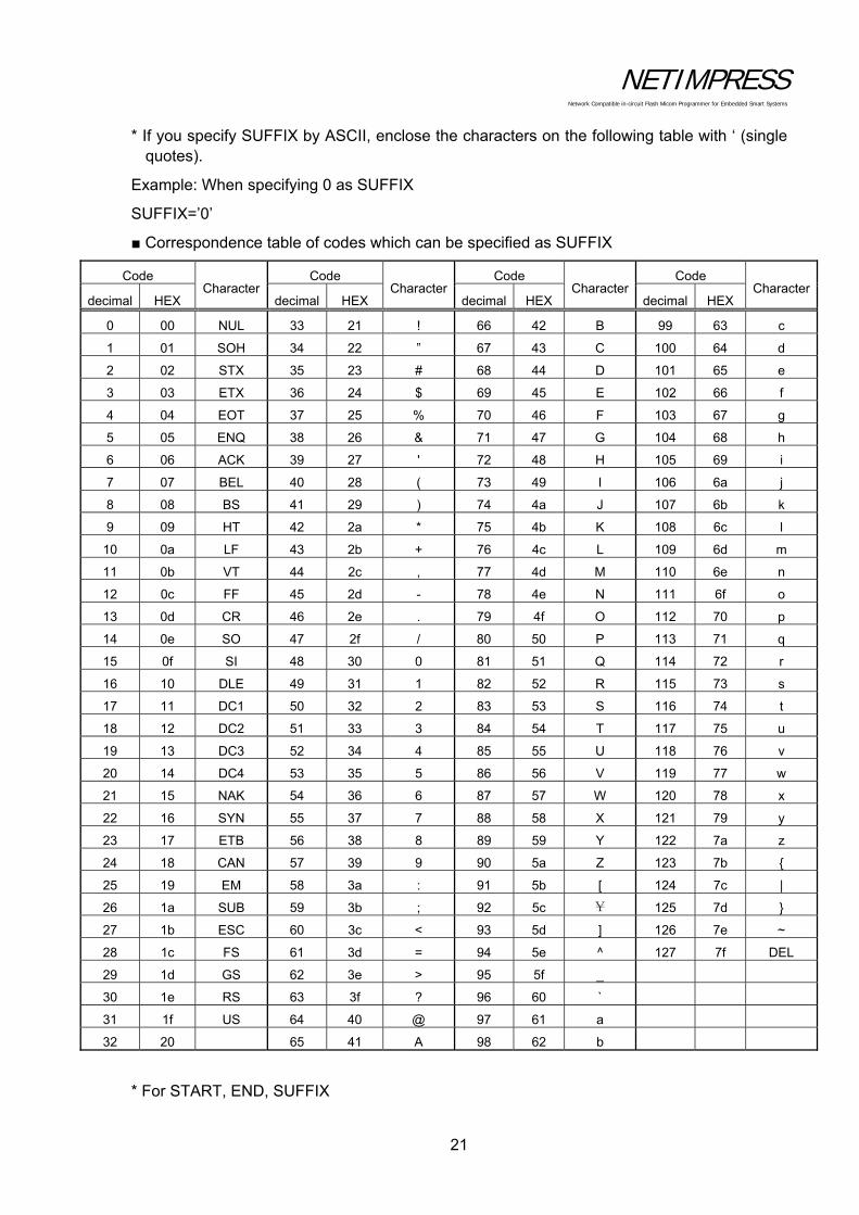
* If you specify SUFFIX by ASCII, enclose the characters on the following table with ‘ (single quotes).
Example: When specifying 0 as SUFFIX
SUFFIX=’0’
Correspondence table of codes which can be specified as SUFFIX
Code Character
Code Character
Code Character
Code Character
decimal HEX decimal HEX decimal HEX decimal HEX
0 00 NUL 33 21 ! 66 42 B 99 63 c
1 01 SOH 34 22 ” 67 43 C 100 64 d
2 02 STX 35 23 # 68 44 D 101 65 e
3 03 ETX 36 24 $ 69 45 E 102 66 f
4 04 EOT 37 25 % 70 46 F 103 67 g
5 05 ENQ 38 26 & 71 47 G 104 68 h
6 06 ACK 39 27 ' 72 48 H 105 69 i
7 07 BEL 40 28 ( 73 49 I 106 6a j
8 08 BS 41 29 ) 74 4a J 107 6b k
9 09 HT 42 2a * 75 4b K 108 6c l
10 0a LF 43 2b + 76 4c L 109 6d m
11 0b VT 44 2c , 77 4d M 110 6e n
12 0c FF 45 2d - 78 4e N 111 6f o
13 0d CR 46 2e . 79 4f O 112 70 p
14 0e SO 47 2f / 80 50 P 113 71 q
15 0f SI 48 30 0 81 51 Q 114 72 r
16 10 DLE 49 31 1 82 52 R 115 73 s
17 11 DC1 50 32 2 83 53 S 116 74 t
18 12 DC2 51 33 3 84 54 T 117 75 u
19 13 DC3 52 34 4 85 55 U 118 76 v
20 14 DC4 53 35 5 86 56 V 119 77 w
21 15 NAK 54 36 6 87 57 W 120 78 x
22 16 SYN 55 37 7 88 58 X 121 79 y
23 17 ETB 56 38 8 89 59 Y 122 7a z
24 18 CAN 57 39 9 90 5a Z 123 7b
25 19 EM 58 3a : 91 5b [ 124 7c |
26 1a SUB 59 3b ; 92 5c ¥ 125 7d
27 1b ESC 60 3c < 93 5d ] 126 7e ~
28 1c FS 61 3d = 94 5e ^ 127 7f DEL
29 1d GS 62 3e > 95 5f _
30 1e RS 63 3f ? 96 60 `
31 1f US 64 40 @ 97 61 a
32 20 65 41 A 98 62 b
* For START, END, SUFFIX
NETIMPRESS Network Compatible in-circuit Flash Micom Programmer for Embedded Smart Systems
22
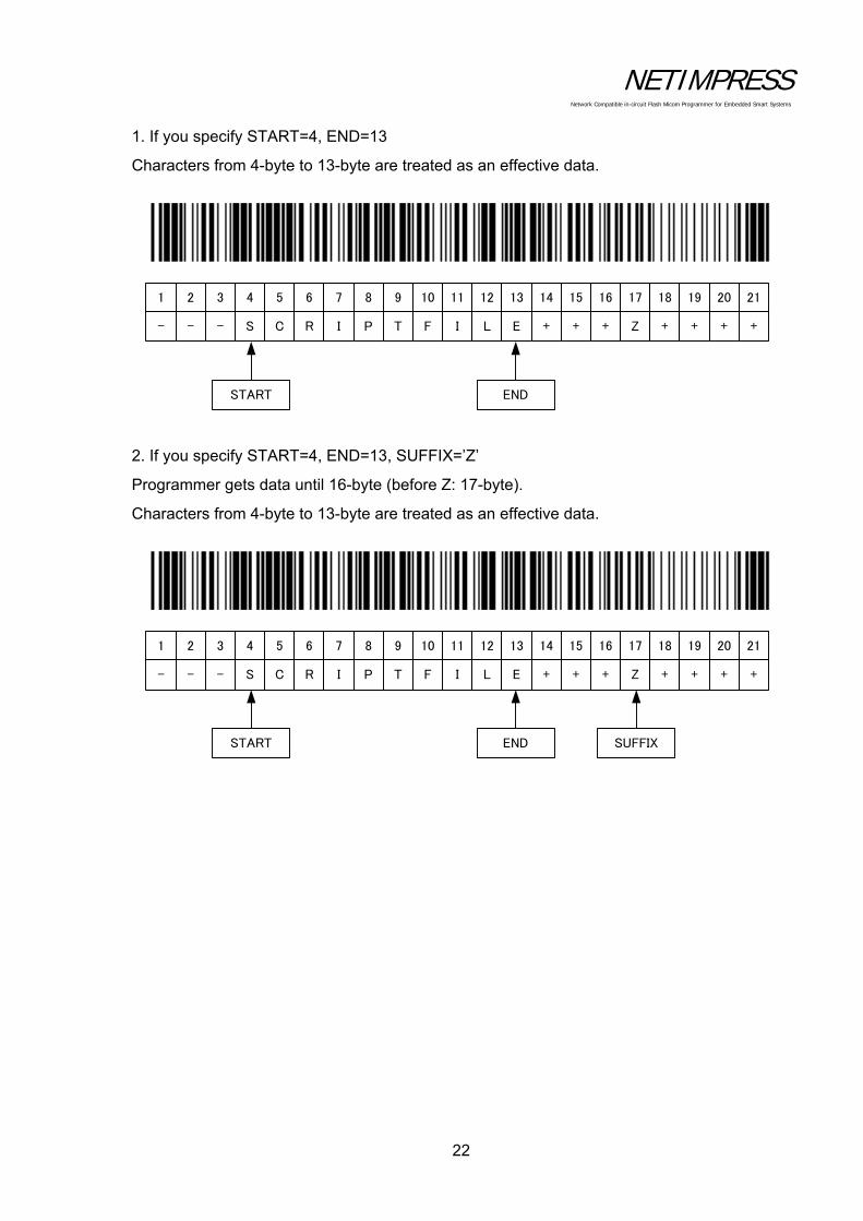
1. If you specify START=4, END=13
Characters from 4-byte to 13-byte are treated as an effective data.
2. If you specify START=4, END=13, SUFFIX=’Z’
Programmer gets data until 16-byte (before Z: 17-byte).
Characters from 4-byte to 13-byte are treated as an effective data.
1 2 3 4 5 6 7 8 9 10 11 12 13 14 15 16 17 18 19 20 21
- - - S C R I P T F I L E + + + Z + + + +
START END
1 2 3 4 5 6 7 8 9 10 11 12 13 14 15 16 17 18 19 20 21
- - - S C R I P T F I L E + + + Z + + + +
START END SUFFIX
NETIMPRESS Network Compatible in-circuit Flash Micom Programmer for Embedded Smart Systems
23
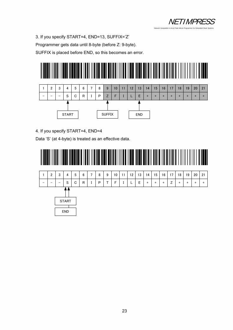
3. If you specify START=4, END=13, SUFFIX=’Z’
Programmer gets data until 8-byte (before Z: 9-byte).
SUFFIX is placed before END, so this becomes an error.
4. If you specify START=4, END=4
Data ‘S’ (at 4-byte) is treated as an effective data.
1 2 3 4 5 6 7 8 9 10 11 12 13 14 15 16 17 18 19 20 21
- - - S C R I P Z F I L E + + + + + + + +
START ENDSUFFIX
1 2 3 4 5 6 7 8 9 10 11 12 13 14 15 16 17 18 19 20 21
- - - S C R I P T F I L E + + + Z + + + +
START
END

NETIMPRESS Network Compatible in-circuit Flash Micom Programmer for Embedded Smart Systems
24
5. If you specify START=4 only
Data from 4-byte to 21-byte are treated as an effective data.
6. If you specify END=13 only
Data from 1-byte to 13-byte are treated as an effective data.
1 2 3 4 5 6 7 8 9 10 11 12 13 14 15 16 17 18 19 20 21
- - - S C R I P T F I L E + + + Z + + + +
START
1 2 3 4 5 6 7 8 9 10 11 12 13 14 15 16 17 18 19 20 21
- - - S C R I P T F I L E + + + Z + + + +
END

NETIMPRESS Network Compatible in-circuit Flash Micom Programmer for Embedded Smart Systems
25
[Execution mode]
(1) SCRIPT mode
Overview
It compares a script file (extension: SCP) placed in the root directory of the Compact Flash to bar-code information, and executes the matched script file.
You need to create/prepare the script file by yourself.
The bar-code information to be compared is a file name only. It does not include the extension.
Example of YBO file creation by using SCRIPT mode
[ M O D E ]
S C R I P T
[ S E T T I N G ]
S T A R T = 0 0 0 4
E N D = 0 0 1 3
[ E N D ]
Example for when YBO file is specified as below:
If you read the following bar-code, it searches a file whose name is a character string of column 4 to 13 with extension “SCR” in the root directory, and executes the script file if it is found.
1 2 3 4 5 6 7 8 9 10 11 12 13 14 15 16 17 18 19
- - - S C R I P T F I L E + + + + + +
SCRIPTFILE.SCP
TEST0001.SCP
TEST0002.SCP
Compares the bar-code data to a file name
whose extension is SCP.
NETIMPRESS Network Compatible in-circuit Flash Micom Programmer for Embedded Smart Systems
26
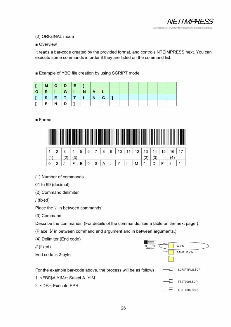
(2) ORIGINAL mode
Overview
It reads a bar-code created by the provided format, and controls NTEIMPRESS next. You can execute some commands in order if they are listed on the command list.
Example of YBO file creation by using SCRIPT mode
Format
1 2 3 4 5 6 7 8 9 10 11 12 13 14 15 16 17
(1) (2) (3) (2) (3) (4)
0 2 / F B 0 $ A . Y I M / D F / /
(1) Number of commands
01 to 99 (decimal)
(2) Command delimiter
/ (fixed)
Place the ‘/’ in between commands.
(3) Command
Describe the commands. (For details of the commands, see a table on the next page.)
(Place ‘$’ in between command and argument and in between arguments.)
(4) Delimiter (End code)
// (fixed)
End code is 2-byte
For the example bar-code above, the process will be as follows.
1. <FB0$A.YIM>: Select A. YIM
2. <DF>: Execute EPR
[ M O D E ]
O R I G I N A L
[ S E T T I N G ]
[ E N D ]
SCRIPTFILE.SCP
TEST0001.SCP
TEST0002.SCP
A.YIM
SAMPLE.YIM
NETIMPRESS Network Compatible in-circuit Flash Micom Programmer for Embedded Smart Systems
27
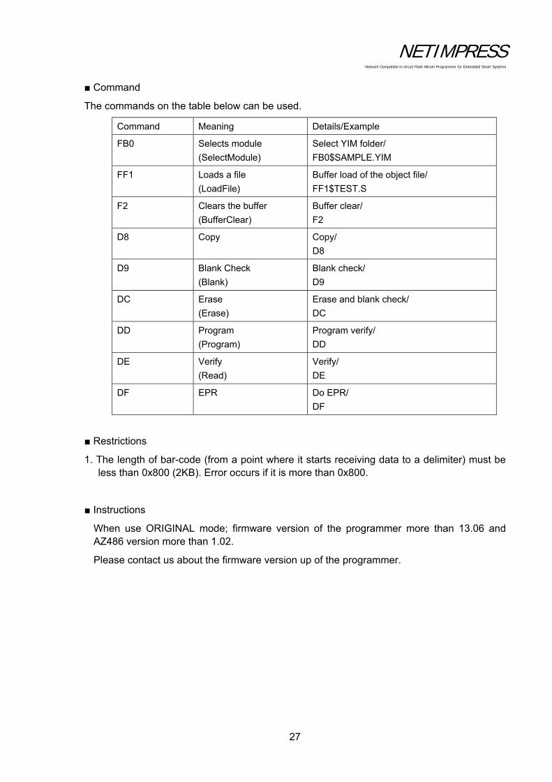
Command
The commands on the table below can be used.
Command Meaning Details/Example
FB0 Selects module
(SelectModule)
Select YIM folder/
FB0$SAMPLE.YIM
FF1 Loads a file
(LoadFile)
Buffer load of the object file/
FF1$TEST.S
F2 Clears the buffer
(BufferClear)
Buffer clear/
F2
D8 Copy Copy/
D8
D9 Blank Check
(Blank)
Blank check/
D9
DC Erase
(Erase)
Erase and blank check/
DC
DD Program
(Program)
Program verify/
DD
DE Verify
(Read)
Verify/
DE
DF EPR
Do EPR/
DF
Restrictions
1. The length of bar-code (from a point where it starts receiving data to a delimiter) must be less than 0x800 (2KB). Error occurs if it is more than 0x800.
Instructions
When use ORIGINAL mode; firmware version of the programmer more than 13.06 and AZ486 version more than 1.02.
Please contact us about the firmware version up of the programmer.

NETIMPRESS Network Compatible in-circuit Flash Micom Programmer for Embedded Smart Systems
28
(3) SELECT mode
Overview
It compares a YIM folder (extension: YIM) placed in the root directory of the Compact Flash to the bar-code information, and selects the matched YIM folder.
After selecting, it continuously executes a device function specified by /XXX.
Example of YBO file creation by using SCRIPT mode
[ M O D E ]
S E L E C T / E P R
[ S E T T I N G ]
S T A R T = 0 0 0 6
E N D = 0 0 1 2
[ E N D ]
Example for when YBO file is specified as above:
If you read the following bar-code, it searches a file whose name is a character string of column 6 to 12 with extension “YIM” in the root directory, and selects the YIM folder if it is found.
After selecting the folder, executes EPR.
1 2 3 4 5 6 7 8 9 10 11 12 13 14 15 16 17 18 19
- - - - - T E S T 0 0 2 + + + + + + +
Compares the bar-code data to a folder
name whose extension is YIM.
SCRIPTFILE.SCP
TEST0001.SCP
TEST0002.SCP
TEST001.YIM
TEST002.YIM
TEST003.YIM

NETIMPRESS Network Compatible in-circuit Flash Micom Programmer for Embedded Smart Systems
29
4.2.4 Digital I/O Connection/Example
[Overview]
You can do the followings by digital I/O input.
Receive a notice of execution state of programmer (RUN signal)
Receive a notice of state of programming to flash memory (PASS and ERR signal)
Receive a notice of state of script execution (PASS and ERR signal)
Select and execute the script file
[Signals used for script execution]
*1: For all signal information of digital I/O, see Section 8.4 “Digital I/O Interface”.
*2: OUT0 to OUT4 and IN0 to IN4 are command names of digital input/output specified by the script file. On this table, signal names for each signal are listed.
*3: Bit 0 to bit 4 signals for script file selection. On this table, it is corresponding to the signal name. For details of the correspondence of bit 0 to bit 4 signal selection and script file name, see [Script Execution] on the following page.
Signal Name definition Script *2 I/ODigital I/O ST0 Script selection signal 0 (Digital I/O input) Script selection: bit 0 *3 IDigital I/O ST1 Script selection signal 1 (Digital I/O input) Script selection: bit 1 *3 IDigital I/O ST2 Script selection signal 2 (Digital I/O input) Script selection: bit 2 *3 IDigital I/O ST3 Script selection signal 3 (Digital I/O input) Script selection: bit 3 *3 IDigital I/O ST4 Script selection signal 4 (Digital I/O input) Script selection: bit 4 *3 IDigital I/O IN0 Digital I/O input signal0 IN0 IDigital I/O IN1 Digital I/O input signal1 IN1 IDigital I/O IN2 Digital I/O input signal2 IN2 IDigital I/O IN3 Digital I/O input signal 3 IN3 IDigital I/O IN4 Digital I/O input signal 4 IN4 I
Digital I/O OUT0 Digital I/O output signal 0 OUT0 ODigital I/O OUT1 Digital I/O output signal 1 OUT1 ODigital I/O OUT2 Digital I/O output signal 2 OUT2 ODigital I/O OUT3 Digital I/O output signal 3 OUT3 ODigital I/O OUT4 Digital I/O output signal 4 OUT4 O

NETIMPRESS Network Compatible in-circuit Flash Micom Programmer for Embedded Smart Systems
30
[Script file]
Script file is an execution file which enables to control digital I/O, execute the flash programming, and select the programming type sequentially.
Create the script file by using software (AZ488) for creating the script file.
Command which can be executed by script file:
Buffer memory clear
File Load
Digital I/O output OUT 0 to OUT 4
Digital I/O input IN 0 to IN 4
Wait designation
Device function BLANK
Device function ERASE
Device function PROGRAM
Device function READ
Device function EPR

NETIMPRESS Network Compatible in-circuit Flash Micom Programmer for Embedded Smart Systems
31
[Script Execution]
Script execution by script signal selection is as a following figure.
a. Select the script file to be executed by using a script selection signal, digital I/O ST 0 to ST 4.
b. The selected script file is executed by a START signal input. (If you input the STEP signal, the commands described on the script file are executed in order.)
Set Digital I/O ST 0 to ST 4
START or STEP ?
Execute the SCRIPT
Execute the SCRIPT(Execute one command)
STEP
START

NETIMPRESS Network Compatible in-circuit Flash Micom Programmer for Embedded Smart Systems
32
[Script file name]
For details of the digital I/O ST 0 to ST 4 and the corresponding script files, see the table below.
The script file names are fixed.
Script file can be executed if it is placed in the root directory of the Compact Flash.
XXScript.scp
*1: For xx, you can designate 00 to 31. (It must be a biliteral.)
*2: You can name the file by either uppercase or lowercase characters. (not case-sensitive)
Corresponding script file for each digital I/O ST 0 to ST 4
ST4 ST3 ST2 ST1 ST0 Script file name
0 0 0 0 0 00Script.scp
0 0 0 0 1 01Script.scp
0 0 0 1 0 02Script.scp
0 0 0 1 1 03Script.scp
0 0 1 0 0 04Script.scp
• • • • • •
• • • • • •
1 1 1 1 1 31Script.scp
00Script.SCP
01Script.SCP
02Script.SCP
TEST001.YIM
TEST002.YIM
TEST003.YIM

NETIMPRESS Network Compatible in-circuit Flash Micom Programmer for Embedded Smart Systems
33
4.3 Other New Functions of NETIMPRESS next
4.3.1 Keylock Function
This is a function to lock the key operation of NETIMPRESS next.
[How to lock the key operation]
Press the RESET key for more than 3 seconds.
There are 2 selectable modes for keylock. One is FULL KEY MODE which can use all key operation (no key lock), and the other is SINGLY KEY MODE, which means only some key operations (RESET, EXE1, EXE2) are available, and the other keys are locked.
The mode is switched in the order of FULL KEY MODE→SINGLE KEY MODE repeatedly.
NETIMPRESS Network Compatible in-circuit Flash Micom Programmer for Embedded Smart Systems
34
4.3.2 Log Function
This is a function to save execution histories of programmer into the Compact Flash.
The execution histories are saved as log file (csv).
[How to save the log]
Function: Select ON/OFF of log output by FUNC-CA0.
There are 2 selectable modes for log output. One is a brief log mode, and the other is a full log mode. See below for the details of both modes. Select either one mode by FUNC-CA0.
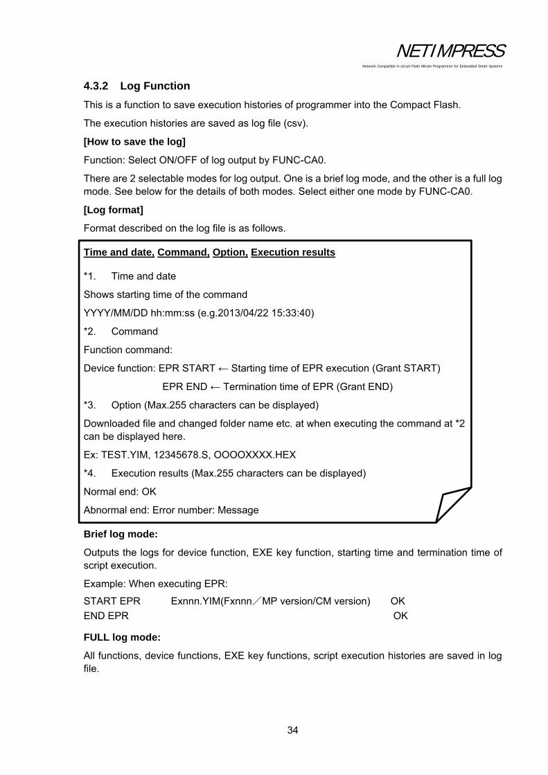
[Log format]
Format described on the log file is as follows. Time and date, Command, Option, Execution results *1. Time and date
Shows starting time of the command
YYYY/MM/DD hh:mm:ss (e.g.2013/04/22 15:33:40)
*2. Command
Function command:
Device function: EPR START ← Starting time of EPR execution (Grant START)
EPR END ← Termination time of EPR (Grant END)
*3. Option (Max.255 characters can be displayed)
Downloaded file and changed folder name etc. at when executing the command at *2 can be displayed here.
Ex: TEST.YIM, 12345678.S, OOOOXXXX.HEX
*4. Execution results (Max.255 characters can be displayed)
Normal end: OK
Abnormal end: Error number: Message Brief log mode:
Outputs the logs for device function, EXE key function, starting time and termination time of script execution.
Example: When executing EPR:
START EPR Exnnn.YIM(Fxnnn/MP version/CM version) OK
END EPR OK FULL log mode:
All functions, device functions, EXE key functions, script execution histories are saved in log file.

NETIMPRESS Network Compatible in-circuit Flash Micom Programmer for Embedded Smart Systems
35
[Save]
LOG is saved in the “LOG” folder in the Compact Flash (the extension is csv).
You can find the LOG folder right under the root of Compact Flash.
File name of LOG is defined as below.
File name: <LOG_yyyymmddxxx.csv>
Example: LOG_20130101000.csv
*1: xxx means a file number.
One LOG file can hold 256 Kbytes data.
If the data exceeds 256 Kbytes in one day, a new LOG file will be created by incrementing the file number.
LOG_20130101000.csv
LOG_20130101001.csv
*2: Upper limit of xxx is 999.
*3: Log for 1500 to 2000 execution of device function EPR can be saved in one log file.
LOG_20130101000.csv
LOG_20130102000.csv
LOG_20130102001.csv
LOG
Create a new file to keep a
log if the previous file
exceeds 256 Kbytes.

NETIMPRESS Network Compatible in-circuit Flash Micom Programmer for Embedded Smart Systems
36
[Delete]
Old log files are automatically deleted.
(If you select NOT DELETE in Section 5.8.4 “Set Log Deletion (Function CA8)”, it is not deleted.)
You can set the duration of retention of log file (keep the log file for how many months from now). For details see Section 5.8.4 “Set Log Deletion (Function CA8)”.
4.3.3 Clock Function (RTC)
NETIMPRESS next has a built-in RTC to output the execution time of log file. The default setting is Japan time.
If you need to change it, use a remote controller AZ490. You can change it within the range of ± 1 day from the default setting.
NETIMPRESS Network Compatible in-circuit Flash Micom Programmer for Embedded Smart Systems
37
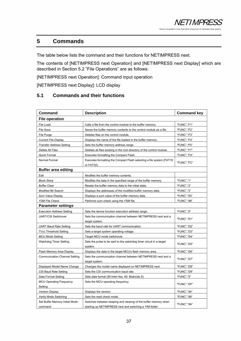
5 Commands
The table below lists the command and their functions for NETIMPRESS next.
The contents of [NETIMPRESS next Operation] and [NETIMPRESS next Display] which are described in Section 5.2 “File Operations” are as follows:
[NETIMPRESS next Operation]: Command input operation
[NETIMPRESS next Display]: LCD display
5.1 Commands and their functions
Command Description Command key
File operation
File Load Calls a file from the control module to the buffer memory. “FUNC”,“F1”
File Save Saves the buffer memory contents to the control module as a file. “FUNC”,“F2”
File Purge Deletes files on the control module. “FUNC”,“F3”
Current File Display Displays the name of the file loaded in the buffer memory. “FUNC”,“F4”
Transfer Address Setting Sets the buffer memory address range. “FUNC”,“F5”
Delete All Files Deletes all files existing in the root directory of the control module. “FUNC”,”F7”
Quick Format Executes formatting the Compact Flash. “FUNC”,”FA”
Normal Format Executes formatting the Compact Flash selecting a file system (FAT16
or FAT32). “FUNC”,”FC”
Buffer area editing
Edit Modifies the buffer memory contents.
Block Store Modifies the data in the specified range of the buffer memory. “FUNC”,“1”
Buffer Clear Resets the buffer memory data to the initial state. “FUNC”,“2”
Modified Bit Search Displays the addresses of the modified buffer memory data. “FUNC”,“3”
Sum Value Display Displays a sum value of the buffer memory data. “FUNC”,“93”
YSM File Check Performs sum check using the YSM file. “FUNC”,“98”
Parameter settings
Execution Address Setting Sets the device function execution address range. “FUNC”,“0”
UART/CSI Switchover Sets the communication channel between NETIMPRESS next and a
target system. “FUNC”,“D1”
UART Baud Rate Setting Sets the baud rate for UART communication. “FUNC”,“D2”
TVcc Threshold Setting Sets a target system operating voltage. “FUNC”,“D3”
MCU Mode Setting Target MCU mode switchover. “FUNC”,“D4”
Watchdog Timer Setting Sets the pulse to be sent to the watchdog timer circuit in a target
system. “FUNC”,“D5”
Flash Memory Area Display Displays the data in the target MCU's flash memory area. “FUNC”,“D6”
Communication Channel Setting Sets the communication channel between NETIMPRESS next and a
target system. “FUNC”,“D7”
Displayed Model Name Change Changes the model name displayed on NETIMPRESS next. “FUNC”,“D8”
CSI Baud Rate Setting Sets the CSI communication baud rate. “FUNC”,“D9”
Data Format Setting Sets data format (50:Intel Hex, 60: Motorola S) “FUNC”,“5”
MCU Operating Frequency
Setting
Sets the MCU operating frequency. “FUNC”,“DF”
Version Display Displays the version. “FUNC”,“94”
Verify Mode Switching Sets the read check mode. “FUNC”,“99”
Set Buffer Memory Initial Mode
command
Switches between keeping and clearing of the buffer memory when
starting up NETIMPRESS next and switching a YIM folder. “FUNC”,”9A”
NETIMPRESS Network Compatible in-circuit Flash Micom Programmer for Embedded Smart Systems
38
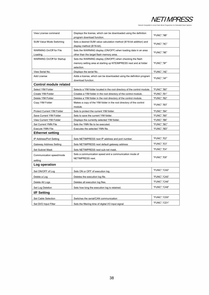
View License command Displays the license, which can be downloaded using the definition
program download function. “FUNC”,”9B”
SUM Value Mode Switching Sets a desired SUM value calculation method (8/16-bit addition) and
display method (8/16-bit). “FUNC”,”9C”
WARNING On/Off for File
Loading
Sets the WARNING display (ON/OFF) when loading data in an area
other than the target flash memory area. “FUNC”,”9E”
WARNING On/Off for Startup Sets the WARNING display (ON/OFF) when checking the flash
memory setting area at starting up NTEIMPRESS next and at folder
selection.
“FUNC”,”9F”
View Serial No. Displays the serial No. “FUNC”,”AE”
Add License Adds a license, which can be downloaded using the definition program
download function. “FUNC”,”AF”
Control module related
Select YIM Folder Selects a YIM folder located in the root directory of the control module. “FUNC”,“B0”
Create YIM Folder Creates a YIM folder in the root directory of the control module. “FUNC”,“B1”
Delete YIM Folder Deletes a YIM folder in the root directory of the control module. “FUNC”,“B2”
Copy YIM Folder Makes a copy of the YIM folder in the root directory of the control
module. “FUNC”,“B3”
Protect Current YIM Folder Sets to protect the current YIM folder. “FUNC”,“B4”
Save Current YIM Folder Sets to save the current YIM folder. “FUNC”,“B5”
View Current YIM Folder Displays the currently selected YIM folder. “FUNC”,“B6”
Set Current YMN File Sets the YMN file to be executed. “FUNC”,“BC”
Execute YMN File Executes the selected YMN file. “FUNC”,“BD”
Ethernet setting
IP Address/Port Setting Sets NETIMPRESS next IP address and port number. “FUNC”,“E2”
Gateway Address Setting Sets NETIMPRESS next default gateway address “FUNC”,“E3”
Set Subnet Mask Sets NETIMPRESS next sub-net mask. “FUNC”,“E4”
Communication speed/mode
setting
Sets a communication speed and a communication mode of
NETIMPRESS next. “FUNC”,“E8”
Log operation
Set ON/OFF of Log Sets ON or OFF of execution log. “FUNC”,“CA0”
Delete a Log Deletes the execution log file. “FUNC”,“CA5”
Delete All Logs Deletes all execution log files. “FUNC”,“CA6”
Set Log Deletion Sets how long the execution log is retained. “FUNC”,“CA8”
I/F Setting
Set Cable Selection Switches the serial/CAN communication “FUNC”,“CD0”
Set DI/O Input Filter Sets the filtering time of digital I/O input signal “FUNC”,“CD1”

NETIMPRESS Network Compatible in-circuit Flash Micom Programmer for Embedded Smart Systems
39
5.2 File Operations
5.2.1 File Load
Calls the specified object file from the control module.
[NETIMPRESS next Operation]
... File Load command
... Select the name of a file to load.
... Execute loading an object file onto the buffer memory.
Operation Example:
Load the "DAT128K.BIN" file from the control module.
[NETIMPRESS next Operation] [NETIMPRESS next Display]
Key Operations LCD Display (Whole)
File Load command Select "DAT128K.BIN". Execute loading an object file.
FUNC SET SET
FUNC F 1
FUNC SET SET
FUNC F 1
/ D A T 1 2 8 K . B I N
(Select the file name when it is displayed.)
4th line
(Displayed during loading, and then disappearswhen the loading completes.)
D O W N L O A D NI B . . . 3rd line
T E S T 1 X E H .
F F 1 / F I L E D A O L
/ x x x x /
F x n n n
NETIMPRESS Network Compatible in-circuit Flash Micom Programmer for Embedded Smart Systems
40
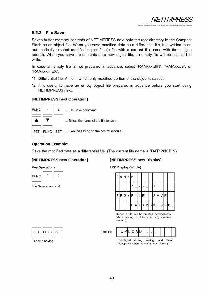
5.2.2 File Save
Saves buffer memory contents of NETIMPRESS next onto the root directory in the Compact Flash as an object file. When you save modified data as a differential file, it is written to an automatically created modified object file (a file with a current file name with three digits added). When you save the contents as a new object file, an empty file will be selected to write.
In case an empty file is not prepared in advance, select “RAMxxx.BIN”, “RAMxxx.S”, or “RAMxxx.HEX”.
*1 Differential file: A file in which only modified portion of the object is saved.
*2 It is useful to have an empty object file prepared in advance before you start using NETIMPRESS next.
[NETIMPRESS next Operation]
... File Save command
... Select the name of the file to save.
... Execute saving on the control module.
Operation Example:
Save the modified data as a differential file. (The current file name is "DAT128K.BIN)
[NETIMPRESS next Operation] [NETIMPRESS next Display]
Key Operations LCD Display (Whole)
File Save command Execute saving.
FUNC SET SET
FUNC F 2
FUNC SET SET
FUNC F 2
(Displayed during saving, and thendisappears when the saving completes.)
U P L O A D . . . 3rd line
(Since a file will be created automatically when saving a differential file, execute saving.)
D A T 1 2 0 0 0 . K 8
F F 2 / F I L E E V A S
/ x x x x /
F x n n n

NETIMPRESS Network Compatible in-circuit Flash Micom Programmer for Embedded Smart Systems
41
5.2.3 File Purge
Deletes the object files in the control module.
[NETIMPRESS next Operation]
... File Purge (delete) command
... Select the file to purge.
... Execute purging the file.
... To delete, press SET key. To cancel deletion, press RESET key.
Operation Example:
Delete the "DAT128K.BIN" file from the control module.
[NETIMPRESS next Operation] [NETIMPRESS next Display]
Key Operations LCD Display (Whole)
File Purge command Select the "DAT128K.BIN" file. Execute Purge command. Execute deletion.
FUNC SET SET
FUNC F 3
SET RESETor
FUNC SET SET
FUNC F 3
SET
D A T 1 2 N I B . K 8 4th line
F I L E D E L E ? K O E T 3rd line
T E S T 1 X E H .
F F 3 / F I L E E T E L E D
/ x x x x /
F x n n n
NETIMPRESS Network Compatible in-circuit Flash Micom Programmer for Embedded Smart Systems
42
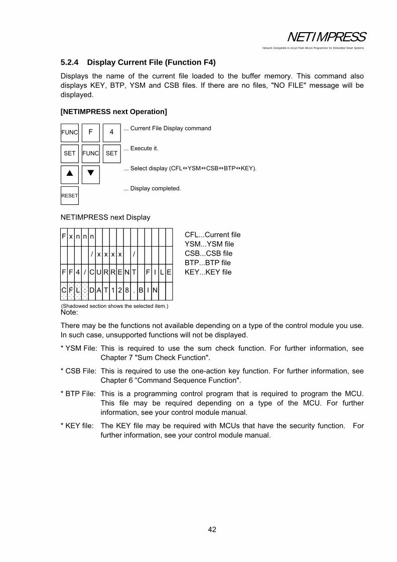
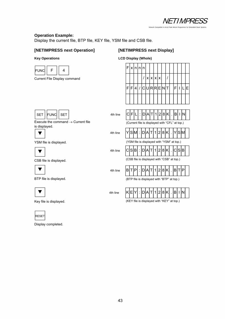
5.2.4 Display Current File (Function F4)
Displays the name of the current file loaded to the buffer memory. This command also displays KEY, BTP, YSM and CSB files. If there are no files, "NO FILE" message will be displayed.
[NETIMPRESS next Operation]
... Current File Display command
... Execute it.
... Select display (CFLYSMCSBBTPKEY).
... Display completed.
NETIMPRESS next Display
CFL...Current file YSM...YSM file CSB...CSB file BTP...BTP file KEY...KEY file
Note:
There may be the functions not available depending on a type of the control module you use. In such case, unsupported functions will not be displayed.
* YSM File: This is required to use the sum check function. For further information, see Chapter 7 "Sum Check Function".
* CSB File: This is required to use the one-action key function. For further information, see Chapter 6 “Command Sequence Function".
* BTP File: This is a programming control program that is required to program the MCU. This file may be required depending on a type of the MCU. For further information, see your control module manual.
* KEY file: The KEY file may be required with MCUs that have the security function. For further information, see your control module manual.
FUNC SET SET
FUNC F 4
RESET
(Shadowed section shows the selected item.)
C F L : D A T 1 2 N I B . 8
F F E4 / C U R R L I F T N E
/ x x x x /
F x n n n
NETIMPRESS Network Compatible in-circuit Flash Micom Programmer for Embedded Smart Systems
43
Operation Example: Display the current file, BTP file, KEY file, YSM file and CSB file.
[NETIMPRESS next Operation] [NETIMPRESS next Display]
Key Operations LCD Display (Whole)
Current File Display command
Execute the command Current file is displayed.
YSM file is displayed. CSB file is displayed. BTP file is displayed. Key file is displayed. Display completed.
FUNC SET SET
FUNC F 4
RESET
(YSM file is displayed with “YSM” at top.)
Y S M : D A T 1 2 M S Y . K 8 4th line
(Current file is displayed with “CFL” at top.)
C F L : D A T 1 2 N I B . K 8 4th line
(CSB file is displayed with “CSB” at top.)
C S B : D A T 1 2 B S C . K 8 4th line
(BTP file is displayed with “BTP” at top.)
B T P : D A T 1 2 P T B . K 8 4th line
(KEY file is displayed with “KEY” at top.)
K E Y : D A T 1 2 N I B . K 8 4th line
F F E4 / C U R R L I F T N E
/ x x x x /
F x n n n
NETIMPRESS Network Compatible in-circuit Flash Micom Programmer for Embedded Smart Systems
44
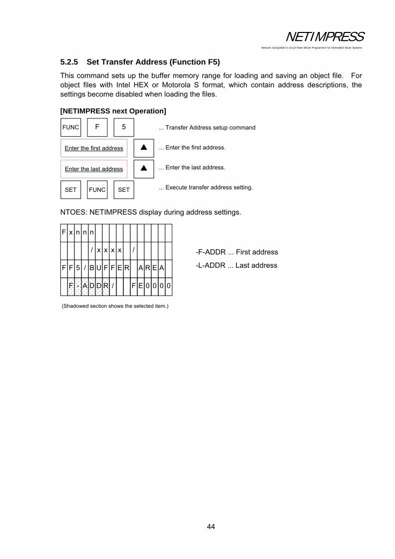
5.2.5 Set Transfer Address (Function F5)
This command sets up the buffer memory range for loading and saving an object file. For object files with Intel HEX or Motorola S format, which contain address descriptions, the settings become disabled when loading the files.
[NETIMPRESS next Operation]
... Transfer Address setup command
... Enter the first address.
... Enter the last address.
... Execute transfer address setting.
NTOES: NETIMPRESS display during address settings.
-F-ADDR ... First address
-L-ADDR ... Last address
FUNC F
Enter the first address
Enter the last address
SET FUNC SET
5
(Shadowed section shows the selected item.)
F - A D D R / 000 0 E F
F F 5 / B U F F AE R A R E
/ x x x x /
F x n n n
NETIMPRESS Network Compatible in-circuit Flash Micom Programmer for Embedded Smart Systems
45
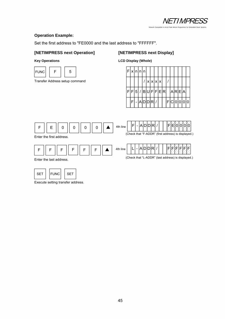
Operation Example:
Set the first address to "FE0000 and the last address to "FFFFFF".
[NETIMPRESS next Operation] [NETIMPRESS next Display]
Key Operations LCD Display (Whole)
Transfer Address setup command
Enter the first address. Enter the last address. Execute setting transfer address.
SET FUNC SET
F E 0 0 0 0
F F F FF F
FUNC F 5
(Check that “F-ADDR” (first address) is displayed.)
4th line F - A D D R / 000 0 E F
(Check that “L-ADDR” (last address) is displayed.)
4th line L - A D D R / FF F F F F
F - A D D R / 00 0 0 C F
F F 5 / B U F F A E R A R E
/ x x x x /
F x n n n
NETIMPRESS Network Compatible in-circuit Flash Micom Programmer for Embedded Smart Systems
46
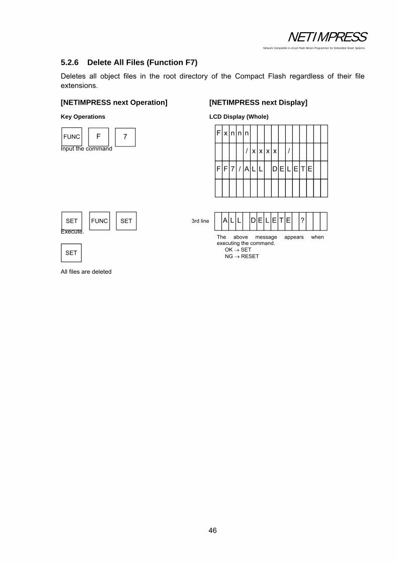
5.2.6 Delete All Files (Function F7)
Deletes all object files in the root directory of the Compact Flash regardless of their file extensions.
[NETIMPRESS next Operation] [NETIMPRESS next Display]
Key Operations LCD Display (Whole)
Input the command
Execute.
All files are deleted
FUNC F 7
SET FUNC SET
SET
A L L D E L ? E T E3rd line
The above message appears whenexecuting the command.
OK SET NG RESET
F F 7 / A L L E T E L E D
/ x x x x /
F x n n n

NETIMPRESS Network Compatible in-circuit Flash Micom Programmer for Embedded Smart Systems
47
5.2.7 Quick Format (Function FA)
Executes formatting the Compact Flash.
When formatting with this command, a file system is same as the one before formatting.
[NETIMPRESS next Operation] [NETIMPRESS next Display]
Key Operations LCD Display (Whole)
Quick format command
Set. The Compact Flash is formatted.
FUNC F A
SET FUNC SET
SET
Q U I C K F ? T A M R O3rd line
The above message appears whenexecuting the command.
OK SET NG RESET
F F T A / Q U I C A M R O F K
/ x x x x /
F x n n n

NETIMPRESS Network Compatible in-circuit Flash Micom Programmer for Embedded Smart Systems
48
5.2.8 Regular Format (Function FC)
Selects a file system and executes formatting the Compact Flash.
A file system that can be selected is either FAT16 or FAT32.
Also, you can check a currently formatted file system by executing this command. For details, see the operation example below.
: Regular format command
: Selects a file system to format (FAT16 or FAT32)
: Executes the regular format.
: Press the SET key to format, or press the RESET key to cancel formatting.
FUNC SET SET
FUNC F C
SET RESET or

NETIMPRESS Network Compatible in-circuit Flash Micom Programmer for Embedded Smart Systems
49
Operation Example:
The following is an operation example to format the Compact Flash changing its current file system FA16 to FA32.
[NETIMPRESS next Operation] [NETIMPRESS next Display]
Key Operations LCD Display (Whole)
Regular format command or Select a file system to format.
Set Executes the formatting.
FUNC F C
F A T 1 6 F O R T A M
F F C / C F _ F T A M R O
/ x x x x /
F x n n n
A file system currently formatted is
displayed. If it is formatted with FAT32,it is displayed as “FAT32 FORMAT”.
SET FUNC SET
SET
F A T 3 2 F ? T A M R O3rd line
A file system selected with the keys is displayed.
Switches FAT16→FAT32→FAT16
using the keys.
F A T 3 2 F O R T A M 4th line

NETIMPRESS Network Compatible in-circuit Flash Micom Programmer for Embedded Smart Systems
50
5.3 Editing Buffer Memory
5.3.1 Edit (Modify Buffer Memory Data)
Searches for data of the specified buffer memory address to edit them.
[NETIMPRESS next Operation]
... Enter the address.
... Modify buffer memory.
Operation Example:
Modify the data of the buffer address "FE0000" to "00".
[NETIMPRESS next Key Operations] [NETIMPRESS next Display]
Enter the address "FE0000". Modify buffer memory to "00".
* Buffer memory
This is a place to store the data to program the MCU.
By loading an object file on to the buffer memory, it is converted into binary data and stored. Even if the power of NETIMPRESS next is turned off, the buffer memory data is preserved because the buffer memory is on the Compact Flash.
Enter the address
Enter the modified data
SET
SET
F E 0
0 0 SET
SET0 0 0
(When changed, it moves to next address.)
/ F E 0 0 / 0 0 / 0 0 3rd line
/ F E 0 0 / F F / 0 0
/ x x x x /
F x n n n

NETIMPRESS Network Compatible in-circuit Flash Micom Programmer for Embedded Smart Systems
51
5.3.2 Block Store (Modify Buffer Memory Data)
Fills the specified range of the buffer memory with the same specified data.
[NETIMPRESS next Operation]
... Block Store command
... Enter the first address.
... Enter the last address.
... Enter the new data.
... Execute modifying buffer memory.
NETIMPRESS next display during address and data entries.
-F-ADDR ... First address
-L-ADDR ... Last address
-DATA ... New data
Enter the first address
Enter the last address
Enter the modified data
1
FUNC SET SET
FUNC
(Shadowed section shows the selected item.)
F - A D D R / 000 0 E F
F 1 / B L O C K E R O T S
/ x x x x /
F x n n n
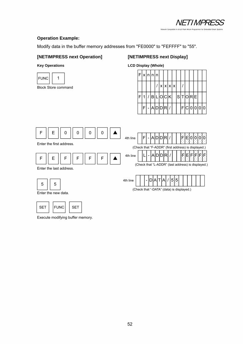
NETIMPRESS Network Compatible in-circuit Flash Micom Programmer for Embedded Smart Systems
52
Operation Example:
Modify data in the buffer memory addresses from "FE0000" to "FEFFFF" to "55".
[NETIMPRESS next Operation] [NETIMPRESS next Display]
Key Operations LCD Display (Whole)
Block Store command
Enter the first address. Enter the last address. Enter the new data. Execute modifying buffer memory.
SET FUNC SET
F E 0 0 0 0
F E F FF F
5 5
FUNC 1
4th line
(Check that “F-ADDR” (first address) is displayed.)
F - A D D R / 000 0 E F
(Check that “L-ADDR” (last address) is displayed.)
4th line L - A D D R / FFF F E F
(Check that “-DATA” (data) is displayed.)
4th line - D A T A / 5 5
F - A D D R / 000 0 C F
F 1 / B L O C K E R O T S
/ x x x x /
F x n n n

NETIMPRESS Network Compatible in-circuit Flash Micom Programmer for Embedded Smart Systems
53
5.3.3 Clear Buffer (Initialize Buffer Memory)
Initializes the buffer memory which corresponds to the flash memory area (displayed by [FUNC D6]).
[NETIMPRESS next Operation]
... Clear Buffer command
... Execute clearing buffer.
* Initialization
The buffer memory data when initialized varies depending on the control module and it will be "00" or "FF". ((For information about the data contents, see your control module manual.)
2 FUNC
FUNC SET SET
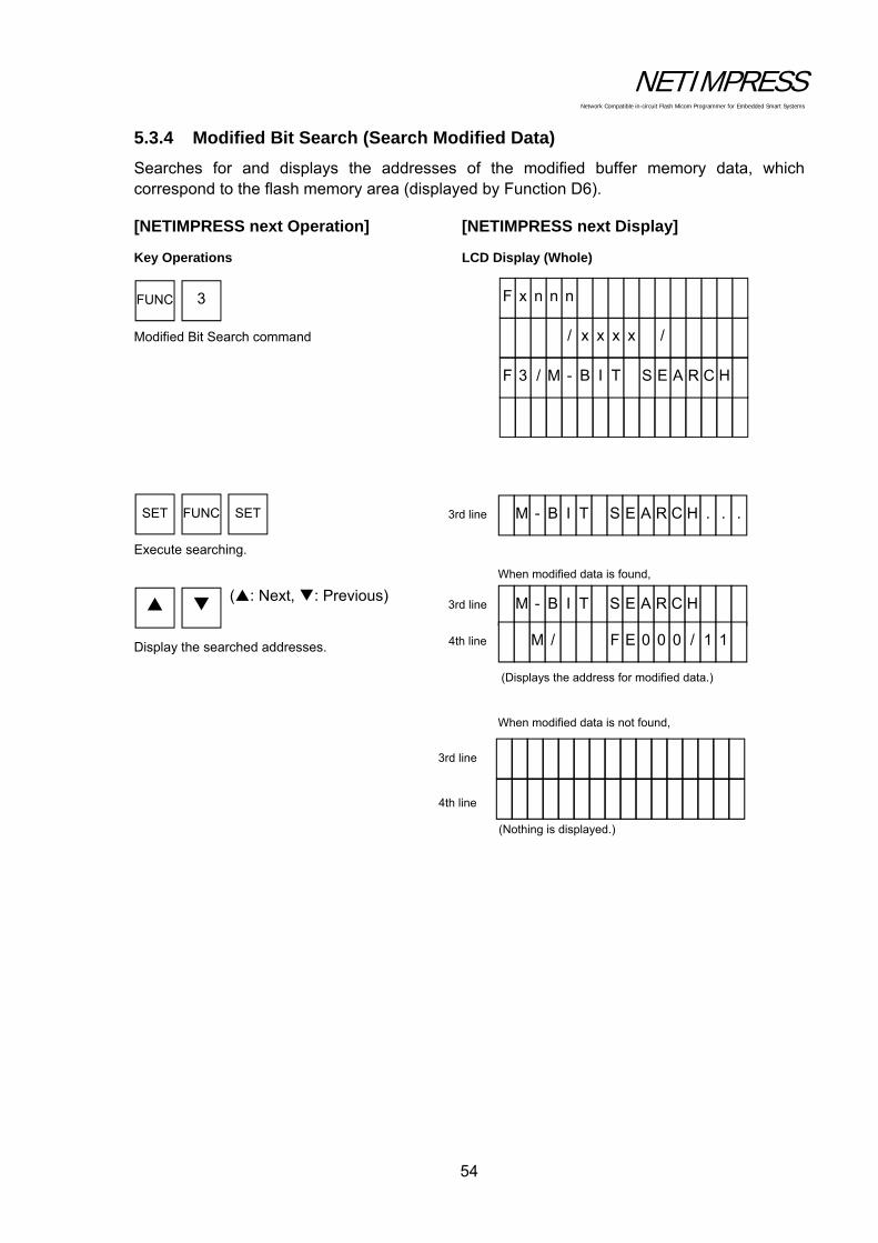
NETIMPRESS Network Compatible in-circuit Flash Micom Programmer for Embedded Smart Systems
54
5.3.4 Modified Bit Search (Search Modified Data)
Searches for and displays the addresses of the modified buffer memory data, which correspond to the flash memory area (displayed by Function D6).
[NETIMPRESS next Operation] [NETIMPRESS next Display]
Key Operations LCD Display (Whole)
Modified Bit Search command Execute searching.
Display the searched addresses.
(: Next, : Previous)
3 FUNC
FUNC SET SET
M .- B I T S . . H C R A E 3rd line
(Displays the address for modified data.)
When modified data is found,
M - B I T S H C R A E 3rd line
M / F 11 / 0 0 0 E 4th line
4th line
When modified data is not found,
(Nothing is displayed.)
3rd line
F 3 / M - B I T HC R A E S
/ x x x x /
F x n n n
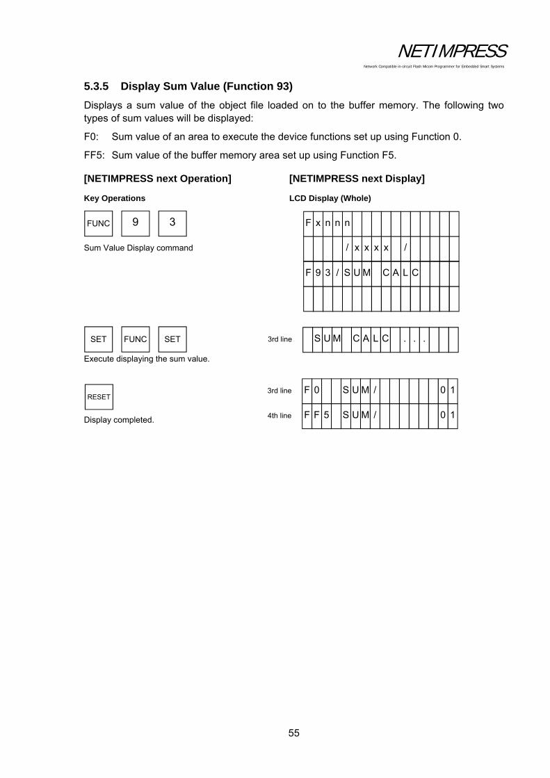
NETIMPRESS Network Compatible in-circuit Flash Micom Programmer for Embedded Smart Systems
55
5.3.5 Display Sum Value (Function 93)
Displays a sum value of the object file loaded on to the buffer memory. The following two types of sum values will be displayed:
F0: Sum value of an area to execute the device functions set up using Function 0.
FF5: Sum value of the buffer memory area set up using Function F5.
[NETIMPRESS next Operation] [NETIMPRESS next Display]
Key Operations LCD Display (Whole)
Sum Value Display command Execute displaying the sum value.
Display completed.
FUNC 9 3
SET FUNC SET
RESET
S U M C A L . . . C 3rd line
F 0 1S U M / 0 3rd line
F F 15 S U M / 0 4th line
F 9 3 / S U M C L A C
/ x x x x /
F x n n n

NETIMPRESS Network Compatible in-circuit Flash Micom Programmer for Embedded Smart Systems
56
5.3.6 YSM File Check (Function 98)
Compares the YSM file contents and the buffer memory contents. For more information, see Chapter 7 "Sum Check Function".
[NETIMPRESS next Operation] [NETIMPRESS next Display]
Key Operations LCD Display (Whole)
Display Sum Value command
Execute displaying sum value. Display completed.
Error Display
YSM NOT FOUND
Cause: Displayed when the YSM file is not found.
Action: Copy the YSM file on to the YIM folder.
YSM FILE FORMAT ERROR
Cause: The YSM file has the wrong description or the file is corrupted.
Action: Check contents of the YSM file and describe in the correct format.
YSM CHECK ERROR YSM/XX RAM/YY
Displayed during a check when sum values are different.
XX shows the sum value described in the YSM file, while YY shows the sum value for the buffer memory.
YSM CHECK ERROR ADDRESS:ZZZZZZZ
Displayed during a check when the data described in the YSM file and the buffer memory data are different. ZZZZZZZ shows the address that has different data.
FUNC 9 8
SET FUNC SET
RESET
3rd line
Displayed when sum check is passed. If anerror occurs, the error location will bedisplayed.
3rd line
F 9 8 / Y S M K C E H C
/ x x x x /
F x n n n

NETIMPRESS Network Compatible in-circuit Flash Micom Programmer for Embedded Smart Systems
57
5.4 Parameter Settings
5.4.1 Setting Execution Address (Function 0)
Sets the target area to execute the device functions.
[NETIMPRESS next Operation]
... Execution Address setup command
... Enter the buffer memory first address.
... Enter the buffer memory last address.
... Execute setting the address.
NETIMPRESS display during address entry
F-ADDR ... First address
L-ADDR ... Last address
FUNC 0
SET FUNC SET
Enter the first address
Enter the last address
(Shadowed section shows the selected item.)
F - A D D R / 000 0 E F
F 0 / E X E C U AE R A E T
/ x x x x /
F x n n n

NETIMPRESS Network Compatible in-circuit Flash Micom Programmer for Embedded Smart Systems
58
Operation Example:
Set the first address to "FE0000" and the last address to "FFFFFF".
[NETIMPRESS next Operation] [NETIMPRESS next Display]
Key Operations LCD Display (Whole)
Execution Address setup command
Enter the first address. Enter the last address. Execute setting address to execute the device functions.
SET FUNC SET
F E 0 0x0 0
F F F FF F
FUNC 0
4th line
(Check that “F-ADDR” (first address) is displayed.)
F - A D D R / 00 0 0 E F
(Check that “L-ADDR” (last address) is displayed.)
4th line L - A D D R / FF F F F F
F - A D D R / 00 0 0 C F
F 0 / E X E C U A E R A E T
/ x x x x /
F x n n n
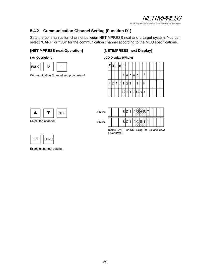
NETIMPRESS Network Compatible in-circuit Flash Micom Programmer for Embedded Smart Systems
59
5.4.2 Communication Channel Setting (Function D1)
Sets the communication channel between NETIMPRESS next and a target system. You can select "UART" or "CSI" for the communication channel according to the MCU specifications.
[NETIMPRESS next Operation] [NETIMPRESS next Display]
Key Operations LCD Display (Whole)
Communication Channel setup command
Select the channel. Execute channel setting.
FUNC D 1
SET FUNC
SET
(Select UART or CSI using the up and downarrow keys.)
S C I / U T R A
S C I / C I S
4th line
4th line
S C I / C I S
F D 1 / T G T F T I
/ x x x x /
F x n n n

NETIMPRESS Network Compatible in-circuit Flash Micom Programmer for Embedded Smart Systems
60
5.4.3 UART Baud Rate Setting (Function D2)
Sets the UART baud rate when the communication channel between NETIMPRESS next and a target system is UART. You can select "2400" to "2M” for the communication baud rate according to the MCU specifications.
[NETIMPRESS next Operation] [NETIMPRESS next Display]
Key Operations LCD Display (Whole)
UART Baud Rate setup command Select the baud rate. (Select UART baud rate using the up and down arrow keys.)
Execute setting UART baud rate
FUNC D 2
SET FUNC SET
x x x s p b x 4th line
2 4 0 s p b 0
F D 2 / U A R T D U A B
/ x x x x /
F x n n n

NETIMPRESS Network Compatible in-circuit Flash Micom Programmer for Embedded Smart Systems
61
5.4.4 Set CSI Baud Rate (Function D9)
Sets the CSI baud rate when the communication channel between NETIMPRESS next and a target system is CSI. You can select "62.5K" to "10M” for the communication baud rate according to the MCU specifications.
[NETIMPRESS next Operation] [NETIMPRESS next Display]
Key Operations LCD Display (Whole)
CSI Baud Rate setup command
Select the baud rate. Execute setting CSI baud rate.
FUNC D 9
SET FUNC SET
6 2 . 5 s p b K
F D 9 / C S I D U A B
/ x x x x /
F x n n n
(Select the baud rate using the up and downarrow keys.)
x x x x s p b K 4th line

NETIMPRESS Network Compatible in-circuit Flash Micom Programmer for Embedded Smart Systems
62
5.4.5 Set TVcc Threshold (Function D3)
Sets the minimum operating voltage for a target system. This setting is a must because the minimum voltage setting will be used to detect power-off of a target system.
[NETIMPRESS next Operation]
... TVcc Threshold setup command
... Select the TVcc threshold value.
... Execute TVcc threshold setting.
Operation Example:
Set the TVcc threshold value to "4.5V".
[NETIMPRESS next Operation] [NETIMPRESS next Display]
Key Operations LCD Display (Whole)
TVcc Threshold setup command
Select (or enter) "4.5". Execute TVcc threshold setting.
* The TVcc detecting accuracy of NETIMPRESS next is the set value 0.1V.
FUNC D 3
SET FUNC SET
Numeric
key
FUNC D 3
SET FUNC SET
(Select the TVcc threshold value using the upand down arrow keys.) (Or, enter a TVcc threshold value directlyusing a numeric key.)
4th line V 5 . 4
V 0 . 3
F D 3 / T V C C H S E R H T
/ x x x x /
F x n n n
or Numeric
key

NETIMPRESS Network Compatible in-circuit Flash Micom Programmer for Embedded Smart Systems
63
5.4.6 Set MCU Mode (Function D4)
Sets up the MCU mode. This MCU mode setting command may not be supported depending on a type of MCUs. For further information, see your control module manual.
[NETIMPRESS next Operation] [NETIMPRESS next Display]
Key Operations LCD Display (Whole)
MCU Mode setup command
Select the mode. Execute MCU mode setting.
Note: Display contents may differ depending on a type of MCU.
FUNC D 4
SET FUNC SET
(Select the MCU mode using the up anddown arrow keys.)
4th line
F D 4 / T G T E D O M
/ x x x x /
F x n n n
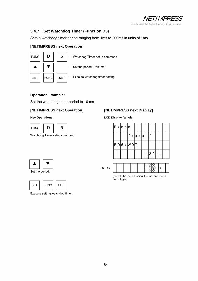
NETIMPRESS Network Compatible in-circuit Flash Micom Programmer for Embedded Smart Systems
64
5.4.7 Set Watchdog Timer (Function D5)
Sets a watchdog timer period ranging from 1ms to 200ms in units of 1ms.
[NETIMPRESS next Operation]
... Watchdog Timer setup command
... Set the period (Unit: ms).
... Execute watchdog timer setting.
Operation Example:
Set the watchdog timer period to 10 ms.
[NETIMPRESS next Operation] [NETIMPRESS next Display]
Key Operations LCD Display (Whole)
Watchdog Timer setup command Set the period.
Execute setting watchdog timer.
FUNC D 5
SET FUNC SET
FUNC D 5
SET FUNC SET
(Select the period using the up and downarrow keys.)
s m 0 1 4th line
s m 0 2
F D 5 / W D T
/ x x x x /
F x n n n

NETIMPRESS Network Compatible in-circuit Flash Micom Programmer for Embedded Smart Systems
65
5.4.8 Display Flash Memory Area (Function D6)
Displays the flash memory area of a target MCU.
Display:
F-ADDR: Shows the first address of the flash memory area.
L-ADDR: Shows the last address of the flash memory area.
[NETIMPRESS next Operation] [NETIMPRESS next Display]
Key Operations LCD Display (Whole)
Flash Memory Area Display command Execute.
Select the display item. Display completed.
FUNC D 6
SET FUNC SET
RESET
(Displays the first address.)
F 0 - A D D R / 0 0 0 0 0 0 04th line
(Displays the last address.)
L F - A D D R / F F 7 0 0 0 04th line
F D 6 / F L A S R D D A H
/ x x x x /
F x n n n
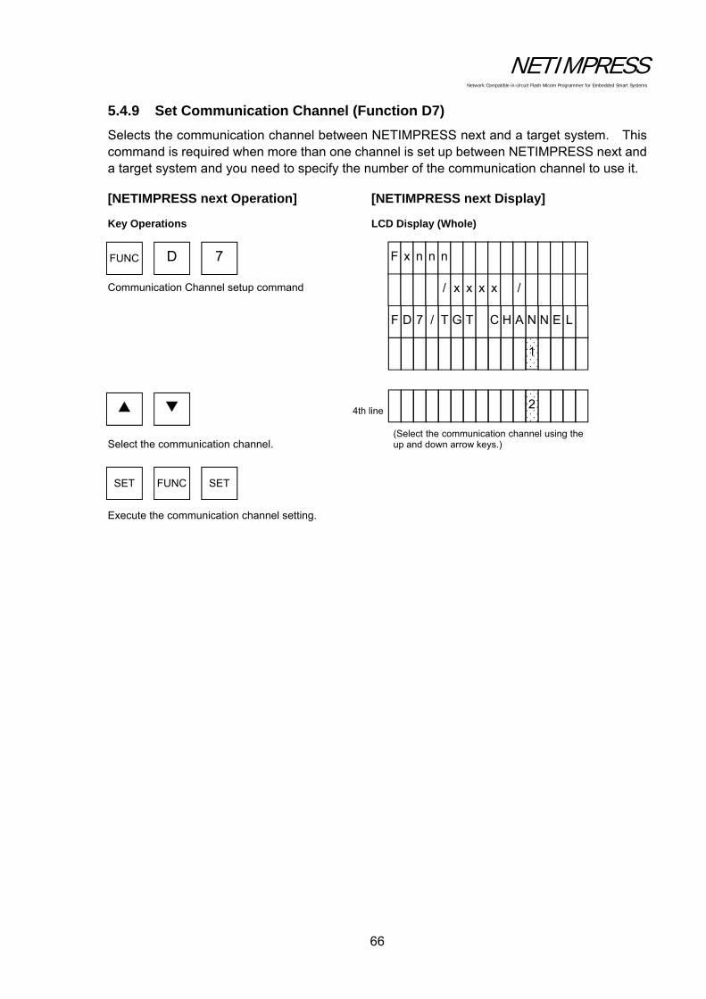
NETIMPRESS Network Compatible in-circuit Flash Micom Programmer for Embedded Smart Systems
66
5.4.9 Set Communication Channel (Function D7)
Selects the communication channel between NETIMPRESS next and a target system. This command is required when more than one channel is set up between NETIMPRESS next and a target system and you need to specify the number of the communication channel to use it.
[NETIMPRESS next Operation] [NETIMPRESS next Display]
Key Operations LCD Display (Whole)
Communication Channel setup command Select the communication channel. Execute the communication channel setting.
FUNC D 7
SET FUNC SET
(Select the communication channel using theup and down arrow keys.)
4th line 2
1
F D 7 / T G T L E N N A H C
/ x x x x /
F x n n n

NETIMPRESS Network Compatible in-circuit Flash Micom Programmer for Embedded Smart Systems
67
5.4.10 Change Displayed Model Name (Function D8)
Changes a model name shown in the NETIMPRESS next display.
Up to 16 characters can be entered as a model name.
Note:
When entering on NETIMPRESS next, characters only from "0" to "9" and from "A" to "F" can be entered. By connecting with a PC and using the software that runs on a PC, you can enter any alpha-numeric characters.
[NETIMPRESS next Operation] [NETIMPRESS next Display]
Key Operations LCD Display (Whole)
Displayed Model Name Change command Move the cursor with the and keys.
Execute changing the displayed model name.
FUNC D 8
SET FUNC SET
Enter Model Name
(Pressing either the up or down key movesthe cursor.)
4th line A B C 1 2 3 4
F H 8 1 9
F D 8 / M C U E P Y T
/ x x x x /
F x n n n
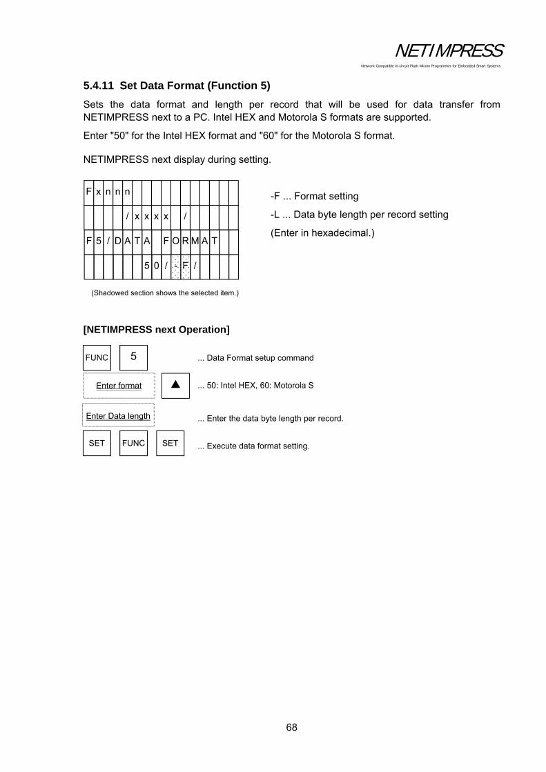
NETIMPRESS Network Compatible in-circuit Flash Micom Programmer for Embedded Smart Systems
68
5.4.11 Set Data Format (Function 5)
Sets the data format and length per record that will be used for data transfer from NETIMPRESS next to a PC. Intel HEX and Motorola S formats are supported.
Enter "50" for the Intel HEX format and "60" for the Motorola S format.
NETIMPRESS next display during setting.
-F ... Format setting
-L ... Data byte length per record setting
(Enter in hexadecimal.)
[NETIMPRESS next Operation]
... Data Format setup command
... 50: Intel HEX, 60: Motorola S
... Enter the data byte length per record.
... Execute data format setting.
(Shadowed section shows the selected item.)
5 0 / / F -
F 5 / D A T A T A M R O F
/ x x x x /
F x n n n
FUNC 5
SET FUNC SET
Enter format
Enter Data length

NETIMPRESS Network Compatible in-circuit Flash Micom Programmer for Embedded Smart Systems
69
Operation Example:
Set the record length to 16-byte and the format to Motorola S format.
[NETIMPRESS next Operation] [NETIMPRESS next Display]
Key Operations LCD Display (Whole)
Data Format setup command Select the Motorola S format. Enter the record byte length (16-byte) in hexadecimal.
Execute data format setting.
FUNC 5
SET FUNC SET
6 0
1 0
(Check that “-F” (first address) is displayed.)
4th line 6 0 / / F -
(Check that “-L” (last address) is displayed.)
4th line 1 0 / / L -
5 0 / / F -
F 5 / D A T A T A M R O F
/ x x x x /
F x n n n
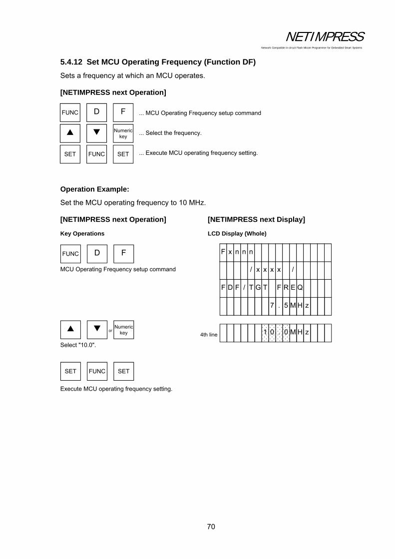
NETIMPRESS Network Compatible in-circuit Flash Micom Programmer for Embedded Smart Systems
70
5.4.12 Set MCU Operating Frequency (Function DF)
Sets a frequency at which an MCU operates.
[NETIMPRESS next Operation]
... MCU Operating Frequency setup command
... Select the frequency.
... Execute MCU operating frequency setting.
Operation Example:
Set the MCU operating frequency to 10 MHz.
[NETIMPRESS next Operation] [NETIMPRESS next Display]
Key Operations LCD Display (Whole)
MCU Operating Frequency setup command
Select "10.0".
Execute MCU operating frequency setting.
FUNC D F
SET FUNC SET
Numeric key
FUNC D F
SET FUNC SET
4th line 1 0 . z H M 0
7 . z H M 5
F D F / T G T Q E R F
/ x x x x /
F x n n n
or Numeric key
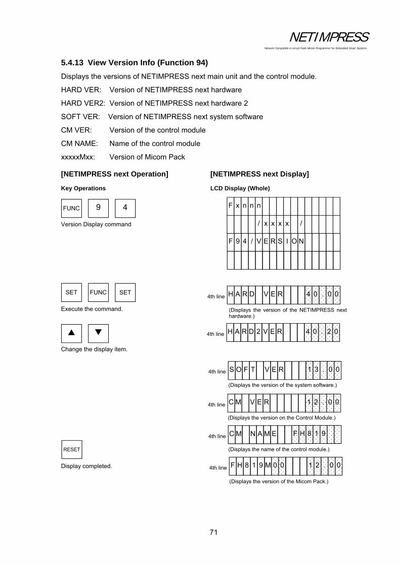
NETIMPRESS Network Compatible in-circuit Flash Micom Programmer for Embedded Smart Systems
71
5.4.13 View Version Info (Function 94)
Displays the versions of NETIMPRESS next main unit and the control module.
HARD VER: Version of NETIMPRESS next hardware
HARD VER2: Version of NETIMPRESS next hardware 2
SOFT VER: Version of NETIMPRESS next system software
CM VER: Version of the control module
CM NAME: Name of the control module
xxxxxMxx: Version of Micom Pack
[NETIMPRESS next Operation] [NETIMPRESS next Display]
Key Operations LCD Display (Whole)
Version Display command
Execute the command. Change the display item.
Display completed.
FUNC 9 4
SET FUNC SET
RESET
(Displays the version of the NETIMPRESS nexthardware.)
4th line H A R D V E R 00. 0 4
4th line
(Displays the version of the system software.)
S O F T V E R 00. 3 1
(Displays the version on the Control Module.)
4th line C M V E R 00. 2 1
(Displays the name of the control module.)
4th line C M N A M E 9 1 8 H F
(Displays the version of the Micom Pack.)
4th line F H 8 1 9 M 0 0 00. 2 1
F 9 4 / V E R S N O I
/ x x x x /
F x n n n
4th line H A R D 2 V E R 02. 0 4
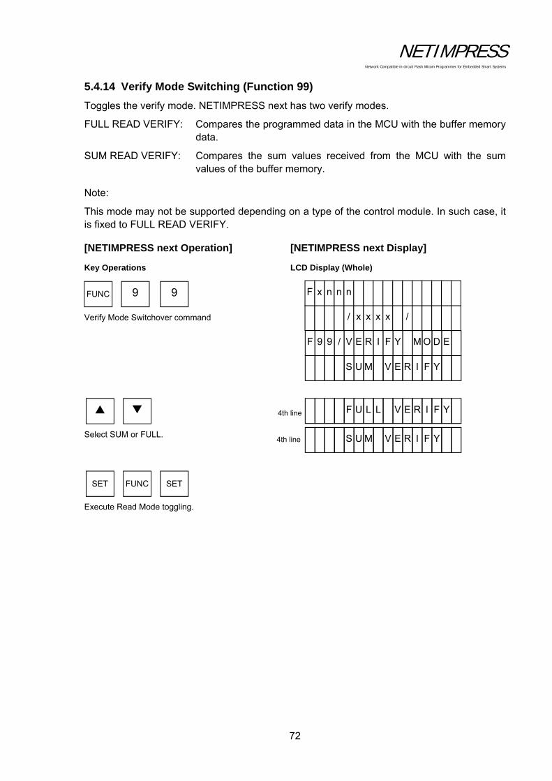
NETIMPRESS Network Compatible in-circuit Flash Micom Programmer for Embedded Smart Systems
72
5.4.14 Verify Mode Switching (Function 99)
Toggles the verify mode. NETIMPRESS next has two verify modes.
FULL READ VERIFY: Compares the programmed data in the MCU with the buffer memory data.
SUM READ VERIFY: Compares the sum values received from the MCU with the sum values of the buffer memory.
Note:
This mode may not be supported depending on a type of the control module. In such case, it is fixed to FULL READ VERIFY.
[NETIMPRESS next Operation] [NETIMPRESS next Display]
Key Operations LCD Display (Whole)
Verify Mode Switchover command
Select SUM or FULL.
Execute Read Mode toggling.
FUNC 9 9
SET FUNC SET
4th line F U L L Y F I R E V
S U M V Y F I R E 4th line
S U M V Y F I R E
F 9 9 / V E R I E D O M Y F
/ x x x x /
F x n n n

NETIMPRESS Network Compatible in-circuit Flash Micom Programmer for Embedded Smart Systems
73
5.4.15 Set Buffer Memory Initial Mode
Switches between keeping and clearing of contents of the buffer memory when starting up NETIMPRESS next.
[NETIMPRESS next Operation] [NETIMPRESS next Display]
Key Operations LCD Display (Whole)
Set Buffer Memory Initial Mode command Select KEEP or CLEAR. Execute.
FUNC 9 A
SET FUNC SET
4th line B U F F E R R A RA E L C M
4th line B U F F E R R A P E E K M
B U F F E R R A P E E K M
F 9 A / B U F F T I N I R E
/ x x x x /
F x n n n

NETIMPRESS Network Compatible in-circuit Flash Micom Programmer for Embedded Smart Systems
74
5.4.16 View License (Function 9B)
Displays the license that can be downloaded using the definition program download function of the control module.
[NETIMPRESS next Operation] [NETIMPRESS next Display]
Key Operations LCD Display (Whole)
(Example: Control module has two licenses, “FH817” and “FH819”.)
View License command
Execute. Change the display contents. Display completed.
FUNC 9 B
SET FUNC SET
RESET
4th line L 0 1 / 0 2 9 1 8 H F
4th line L 0 2 / 0 2 7 1 8 H F
F 9 B / L I C E E C N
/ x x x x /
F x n n n
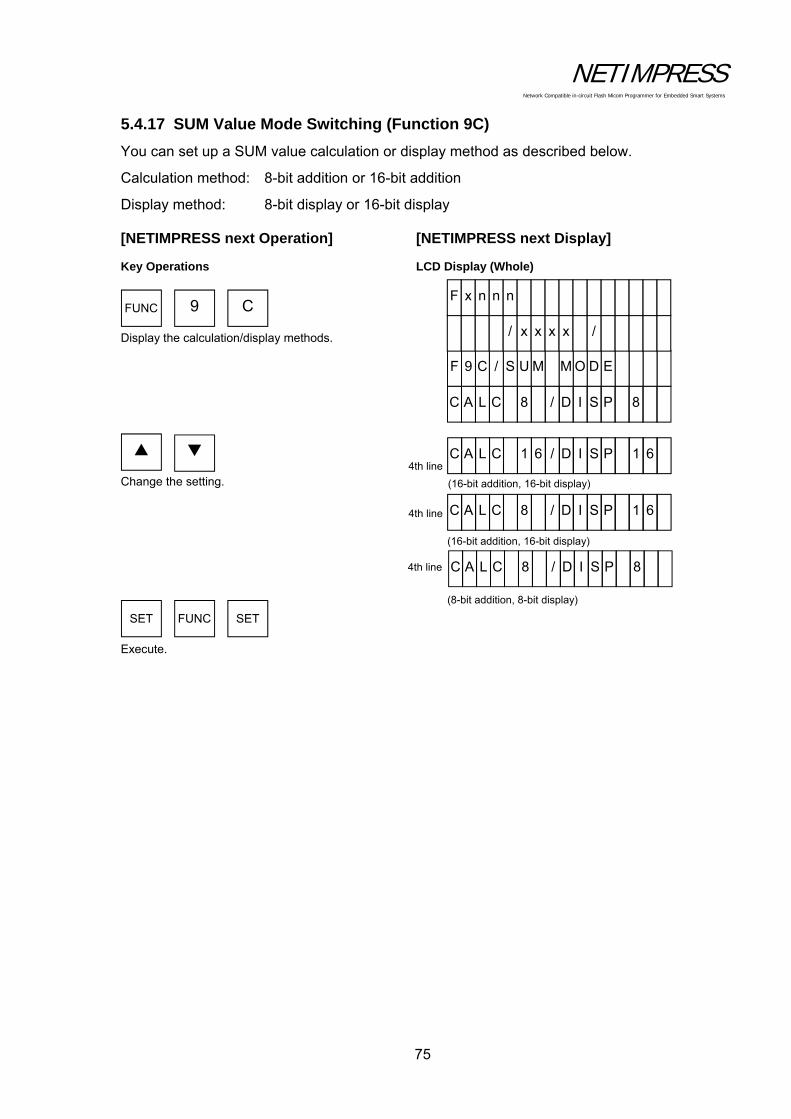
NETIMPRESS Network Compatible in-circuit Flash Micom Programmer for Embedded Smart Systems
75
5.4.17 SUM Value Mode Switching (Function 9C)
You can set up a SUM value calculation or display method as described below.
Calculation method: 8-bit addition or 16-bit addition
Display method: 8-bit display or 16-bit display
[NETIMPRESS next Operation] [NETIMPRESS next Display]
Key Operations LCD Display (Whole)
Display the calculation/display methods. Change the setting.
Execute.
FUNC 9 C
SET FUNC SET
4th line
C A L C 1 6 / D 61 P S I
(16-bit addition, 16-bit display)
4th line C A L C 8 / D 61 P S I
(16-bit addition, 16-bit display)
C A L C 8 / D 8 P S I 4th line
(8-bit addition, 8-bit display)
C A L C 8 / D 8 P S I
F 9 C / S U M E D O M
/ x x x x /
F x n n n

NETIMPRESS Network Compatible in-circuit Flash Micom Programmer for Embedded Smart Systems
76
5.4.18 ADDRESS WARNING On/Off for File Loading (Function 9E)
If data having address data other than the flash memory area of the target microcomputer is loaded when loading a file into the buffer memory of the control module, the error message, "ADDRESS WARNING", is displayed.
By using this command, you can select whether to do the address check. “ADDRESS WARNING” message will be displayed when the address check is failed.
ADDRESS WARNING ON Address is checked.
ADDRESS WARNING OFF Address is not checked.
[NETIMPRESS next Operation] [NETIMPRESS next Display]
Key Operations LCD Display (Whole)
ADDRESS WARNING display Change the setting. Execute.
FUNC 9 E
4th line
(Address is not checked.)
A D D R W A R N F F O G I
4th line
(Address is checked.)
A D D R W A R N N O G I
SET FUNC SET
A D D R W A R N N O G I
F 9 GE / A D D R N I N R A W
/ x x x x /
F x n n n

NETIMPRESS Network Compatible in-circuit Flash Micom Programmer for Embedded Smart Systems
77
5.4.19 ADDRESS WARNING On/Off for Startup (Function 9F)
When NETIMPRESS next is started up or when the YIM folder is selected., it checks the data in the Compact Flash. At this time, if the address range set up with [FUNC 0] or [FUNC F 5] is different from the flash memory area of the target microcomputer set up with [FUNC D 6], the error message, "ADDRESS WARNING", is displayed. And, you can set up either to display "ADDRESS WARNING" or not to display.
By using this command, you can select whether to do the address check. “ADDRESS WARNING” message will be displayed when the address check is failed.
ADDRESS WARNING ON Address is checked.
ADDRESS WARNING OFF Address is not checked.
[NETIMPRESS next Operation] [NETIMPRESS next Display]
Key Operations LCD Display (Whole)
ADDRESS WARNING display Change the setting. Execute.
FUNC 9 F
4th line A D D R W A R N F F O G I
4th line
(Address is not checked.)
(Address is checked.)
A D D R W A R N N O G I
SET FUNC SET
A D D R W A R N N O G I
F 9 GF / A D D R N I N R A W
/ x x x x /
F x n n n
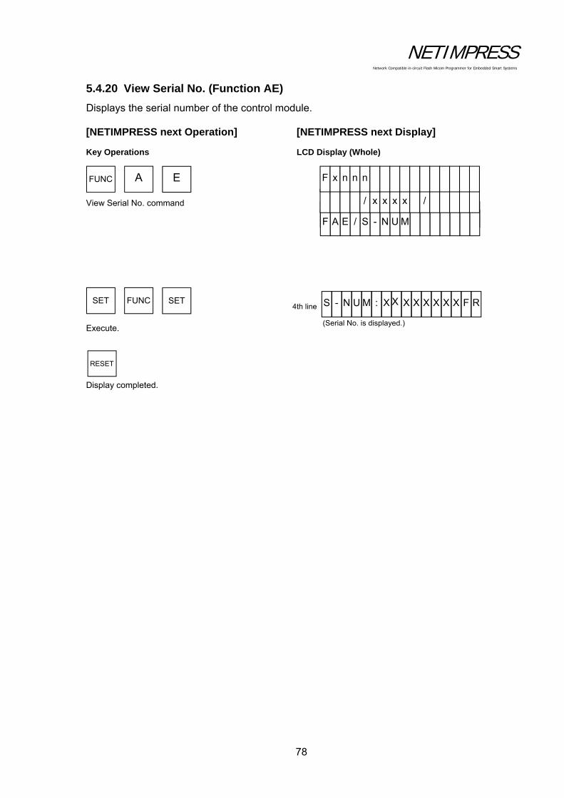
NETIMPRESS Network Compatible in-circuit Flash Micom Programmer for Embedded Smart Systems
78
5.4.20 View Serial No. (Function AE)
Displays the serial number of the control module.
[NETIMPRESS next Operation] [NETIMPRESS next Display]
Key Operations LCD Display (Whole)
View Serial No. command Execute. Display completed.
FUNC A E
SET FUNC SET
RESET
(Serial No. is displayed.)
4th line
F A E / S - N U M
/ x x x x /
F x n n n
S - N U M : X X X RFX X X X X
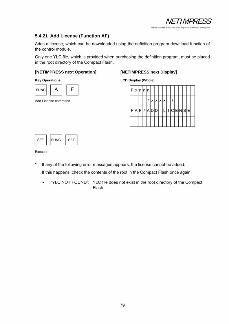
NETIMPRESS Network Compatible in-circuit Flash Micom Programmer for Embedded Smart Systems
79
5.4.21 Add License (Function AF)
Adds a license, which can be downloaded using the definition program download function of the control module.
Only one YLC file, which is provided when purchasing the definition program, must be placed in the root directory of the Compact Flash.
[NETIMPRESS next Operation] [NETIMPRESS next Display]
Key Operations LCD Display (Whole)
Add License command Execute.
* If any of the following error messages appears, the license cannot be added.
If this happens, check the contents of the root in the Compact Flash once again.
“YLC NOT FOUND”: YLC file does not exist in the root directory of the Compact Flash.
FUNC A F
SET FUNC SET
F A F / A D D ES N E C I L
/ x x x x /
F x n n n

NETIMPRESS Network Compatible in-circuit Flash Micom Programmer for Embedded Smart Systems
80
5.5 Overview/Operation of the Control Module
The following schematic diagram describes the overview of the control module.
Folder, into which the definition program (file), buffer memory (file), and modify bit memory (file) are stored.* System folder is created when the YIM folder is created.
Only one CSB exists in the root.If there are more than one CSB, it results in an error.
YMN file (YdcManagement)For further information on YMN function, see Chapter 6.
Compact flash
System folder A (Read-only)
Definition program
file
Buffer file
YIM folder(A.YIM)
YIM folder(B.YIM)
CSB
YMN
BTPUserOBJ
* . *
Only one BTP exists in the root of the YIM folder.
Select a YIM folder suitable for the target microcomputer system with the function operation.
* YIM folder selected is called “current YIM folder”.
<<Major functions of YIM folder>> Extension of the YIM folder is .YIM. The YIM folder is switched between A and B with a function to achieve smooth setup
and changes so as to fit a target microcomputer system. To prevent incorrect operation, the YIM folder has the protect function.
With this protect function, the YIM folder is made to read-only, disabling various downloading and parameter change functions.
* Note for YIM folder: Only one BTP file exists in the YIM folder.
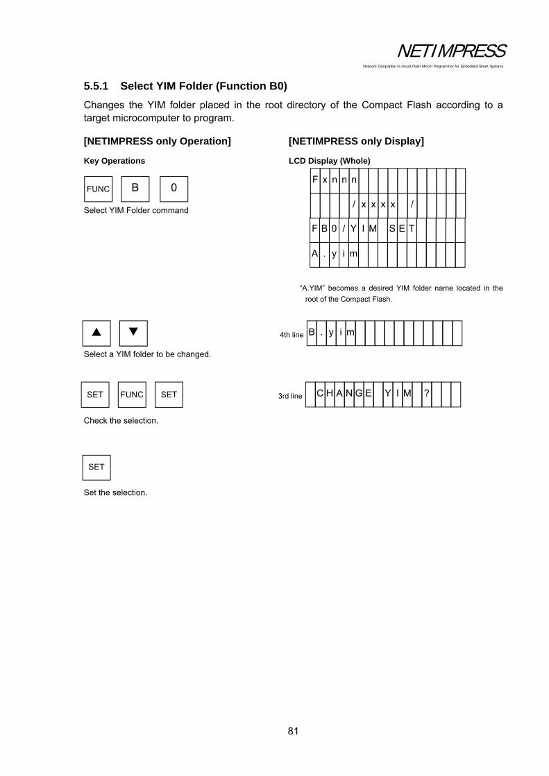
NETIMPRESS Network Compatible in-circuit Flash Micom Programmer for Embedded Smart Systems
81
5.5.1 Select YIM Folder (Function B0)
Changes the YIM folder placed in the root directory of the Compact Flash according to a target microcomputer to program.
[NETIMPRESS only Operation] [NETIMPRESS only Display]
Key Operations LCD Display (Whole)
Select YIM Folder command
“A.YIM” becomes a desired YIM folder name located in the
root of the Compact Flash.
Select a YIM folder to be changed. Check the selection.
Set the selection.
FUNC B 0
SET FUNC SET
SET
4th line B . y i m
3rd line C H A N G E Y ? M I
A . y i m
F B 0 / Y I M T E S
/ x x x x /
F x n n n
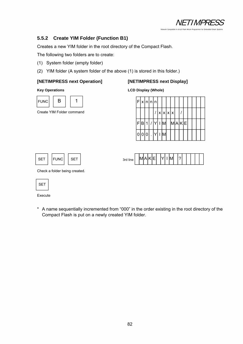
NETIMPRESS Network Compatible in-circuit Flash Micom Programmer for Embedded Smart Systems
82
5.5.2 Create YIM Folder (Function B1)
Creates a new YIM folder in the root directory of the Compact Flash.
The following two folders are to create:
(1) System folder (empty folder)
(2) YIM folder (A system folder of the above (1) is stored in this folder.)
[NETIMPRESS next Operation] [NETIMPRESS next Display]
Key Operations LCD Display (Whole)
Create YIM Folder command Check a folder being created. Execute
* A name sequentially incremented from “000” in the order existing in the root directory of the Compact Flash is put on a newly created YIM folder.
FUNC B 1
SET FUNC SET
SET
3rd line M A K E Y I M ?
0 0 0 . Y I M
F B 1 / Y I M E K A M
/ x x x x /
F x n n n
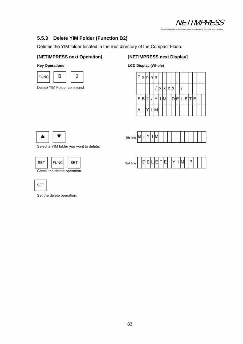
NETIMPRESS Network Compatible in-circuit Flash Micom Programmer for Embedded Smart Systems
83
5.5.3 Delete YIM Folder (Function B2)
Deletes the YIM folder located in the root directory of the Compact Flash.
[NETIMPRESS next Operation] [NETIMPRESS next Display]
Key Operations LCD Display (Whole)
Delete YIM Folder command Select a YIM folder you want to delete. Check the delete operation. Set the delete operation.
FUNC B 2
SET FUNC SET
SET
3rd line D E L E T E Y ? M I
A . Y I M
F B 2 / Y I M E T E L E D
/ x x x x /
F x n n n
4th line B . Y I M
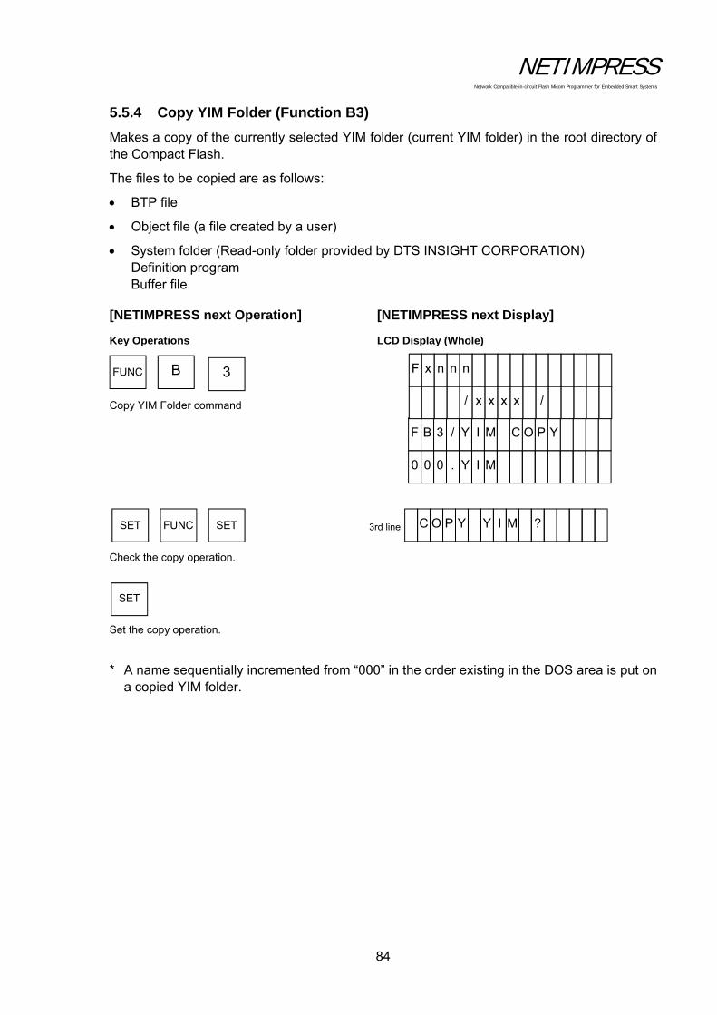
NETIMPRESS Network Compatible in-circuit Flash Micom Programmer for Embedded Smart Systems
84
5.5.4 Copy YIM Folder (Function B3)
Makes a copy of the currently selected YIM folder (current YIM folder) in the root directory of the Compact Flash.
The files to be copied are as follows:
BTP file
Object file (a file created by a user)
System folder (Read-only folder provided by DTS INSIGHT CORPORATION) Definition program Buffer file
[NETIMPRESS next Operation] [NETIMPRESS next Display]
Key Operations LCD Display (Whole)
Copy YIM Folder command
Check the copy operation. Set the copy operation.
* A name sequentially incremented from “000” in the order existing in the DOS area is put on a copied YIM folder.
FUNC B 3
SET FUNC SET
SET
3rd line C O P Y Y I M ?
0 0 0 . Y I M
F B 3 / Y I M Y P O C
/ x x x x /
F x n n n

NETIMPRESS Network Compatible in-circuit Flash Micom Programmer for Embedded Smart Systems
85
5.5.5 Protect Current YIM Folder (Function B4)
To avoid improper operation, the currently selected YIM folder (current YIM folder) is protected to prevent any file from being downloaded or parameters from being changed.
[NETIMPRESS next Operation] [NETIMPRESS next Display]
Key Operations LCD Display (Whole)
Protect Current YIM Folder command
Set the protect. Check the setting.
Set the protect.
PROTECT: Sets the protect.
UNPROTECT: Cancels the protect.
FUNC B 4
SET FUNC SET
SET
3rd line P R O T E C T ? M I Y
U N P R O T C E T
F B 4 / Y I M TC E T O R P
/ x x x x /
F x n n n
4th line P R O T E T C
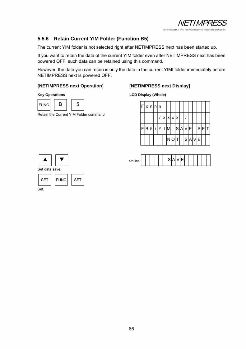
NETIMPRESS Network Compatible in-circuit Flash Micom Programmer for Embedded Smart Systems
86
5.5.6 Retain Current YIM Folder (Function B5)
The current YIM folder is not selected right after NETIMPRESS next has been started up.
If you want to retain the data of the current YIM folder even after NETIMPRESS next has been powered OFF, such data can be retained using this command.
However, the data you can retain is only the data in the current YIMI folder immediately before NETIMPRESS next is powered OFF.
[NETIMPRESS next Operation] [NETIMPRESS next Display]
Key Operations LCD Display (Whole)
Retain the Current YIM Folder command Set data save. Set.
N O T E V A S
FUNC B 5
SET FUNC SET
F B T5 / Y I M ES E V A S
/ x x x x /
F x n n n
4th line S A V E

NETIMPRESS Network Compatible in-circuit Flash Micom Programmer for Embedded Smart Systems
87
5.5.7 View Current YIM Folder (Function B6)
Displays the currently selected YIM folder (current YIM folder).
[NETIMPRESS next Operation] [NETIMPRESS next Display]
Key Operations LCD Display (Whole)
View Current YIM Folder command
Display the current YIM folder name. Display completed.
FUNC B 6
F B 6 / C U R R MI Y T N E
/ x x x x /
F x n n n
4th line A . Y I M SET FUNC SET
RESET

NETIMPRESS Network Compatible in-circuit Flash Micom Programmer for Embedded Smart Systems
88
5.5.8 Set Current YMN File (Function BC)
Sets a YMN file you want to execute.
[NETIMPRESS next Operation] [NETIMPRESS next Display]
Key Operations LCD Display (Whole)
Set Current YMN File command * A desired YMN file name can be used.
Select a YMN file you want to execute. * A desired YMN file name can be used. Set.
* For further information on YMN file, see Chapter 6 “Command Sequence Function” .
FUNC B C
SET FUNC SET
T E S T . Y M N
F B C / Y M N T E S
/ x x x x /
F x n n n
4th line T E S T 2 . Y M N

NETIMPRESS Network Compatible in-circuit Flash Micom Programmer for Embedded Smart Systems
89
5.5.9 Execute Current YMN File (Function BD)
Executes the YMN file you have selected in Section 5.5.8 “Set Current YMN File (Function BC)”.
[NETIMPRESS next Operation] [NETIMPRESS next Display]
Key Operations LCD Display (Whole)
Execute YMN File command Execute.
* For further information on YMN file, see Chapter 6 “Command Sequence Function”.
FUNC B D
SET FUNC SET
F B D / Y M N ET U C E X E
/ x x x x /
F x n n n

NETIMPRESS Network Compatible in-circuit Flash Micom Programmer for Embedded Smart Systems
90
5.6 Ethernet Settings
5.6.1 IP Address/Port Setting (Function E2)
Sets the IP address and port number for NETIMPRESS next.
[NETIMPRESS next Operation]
... IP Address/Port setup command
... Sets the IP address and port number.
... Execute IP address/port setting.
FUNC E 2
SET FUNC SET

NETIMPRESS Network Compatible in-circuit Flash Micom Programmer for Embedded Smart Systems
91
Operation Example:
Set the IP address to "192.0.0.1" and port number to "1100".
[NETIMPRESS next Operation] [NETIMPRESS next Display]
Key Operations LCD Display (Whole)
IP Address/Port setup command Set "192" (IP address). Set "0" (IP address). Set "0" (IP address). Set "1" (IP address). Set "1100" (port number).
Execute IP address/port setting.
SET FUNC SET
1 9 2
0 0 0
FUNC E 2
0 0 0
1 0 0
0 0 1 1
4th line 1 9 2 . 1 6 8 . 0 . 0
4th line 1 9 2 . 0 . 0 . 0
4th line 1 9 2 . 0 . 0 . 0
4th line 1 9 2 . 0 . 1 . 0
1 9 2 . 1 6 8 . 0 . 0
F E 2 / I P A S S E R DD
/ x x x x /
F x n n n
h 0 0 1 1
F E 2 / P O R T
/ x x x x /
F x n n n

NETIMPRESS Network Compatible in-circuit Flash Micom Programmer for Embedded Smart Systems
92
5.6.2 Gateway Address Setting (Function E3)
Sets the default gateway address of NETIMPRESS next.
Set the gateway address when you want to access NETIMPRESS next from different network or from the same network using routers. If NETIMPRESS next and a PC are on the same network, set up the gateway address to "0.0.0.0".
[NETIMPRESS next Operation]
... Gateway Address setup command
... Set up the gateway address.
... Execute gateway address setting.
Operation Example:
Set up the gateway address to “192.0.0.254”.
[NETIMPRESS next Operation] [NETIMPRESS next Display]
Key Operations LCD Display (Whole)
Gateway Address setup command
Set "192" (gateway address). Set "0" (gateway address).
Set "0" (gateway address). Set "254" (gateway address). Execute gateway address setting.
FUNC E 3
SET FUNC SET
SET FUNC SET
1 9 2
0 0 0
FUNC E 3
0 0 0
4 5 2
4th line 1 9 2 . 0 . 0 . 0
4th line 1 9 2 . 0 . 0 . 0
4th line 1 9 2 . 0 . 0 . 0
4th line 1 9 2 . 0 . 4 5 2 . 0
0 . 0 . 0 . 0
F E 3 / G A T E Y A W
/ x x x x /
F x n n n

NETIMPRESS Network Compatible in-circuit Flash Micom Programmer for Embedded Smart Systems
93
5.6.3 Subnet Mask Setting (Function E4)
Sets up the subnet mask of NETIMPRESS next.
[NETIMPRESS next Operation]
... Set Subnet Mask command
... Set the subnet mask.
... Execute the subnet mask setting command.
Operation Example:
Change the subnet mask to "255.255.255.0".
[NETIMPRESS next Operation] [NETIMPRESS next Display]
Key Operations LCD Display (Whole)
Set Subnet Mask command
Set "255" (subnet mask). Set "255" (subnet mask). Set "255" (subnet mask).
Set "0" (subnet mask). Execute the subnet mask setting command.
FUNC E 4
SET FUNC SET
SET FUNC SET
2 5 5
5 5 2
FUNC E 4
2 5 5
0 0 0
4th line 2 5 5 . 0 . 0 . 0
4th line 2 5 5 . 2 5 5 . 0 . 0
4th line 2 5 5 . 2 5 5 . 0 . 5 5 2
4th line 2 5 5 . 2 5 5 . 0 . 5 5 2
0 . 0 . 0 . 0
F E 4 / S U B N K S A M TE
/ x x x x /
F x n n n
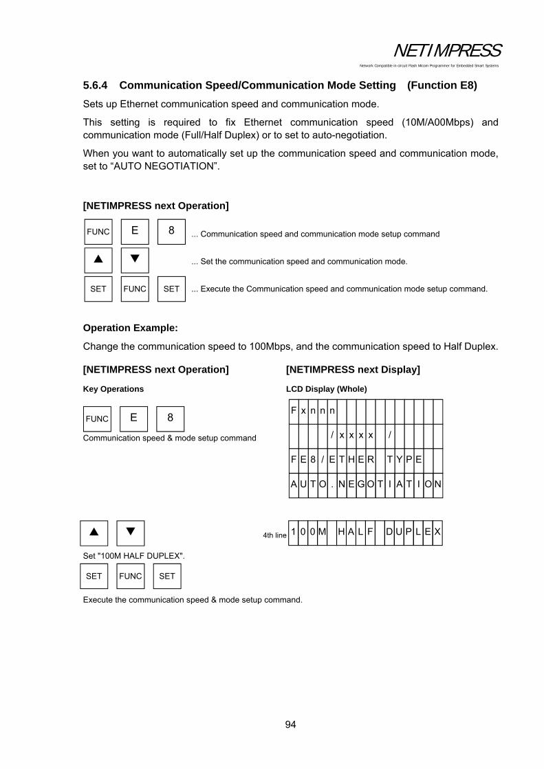
NETIMPRESS Network Compatible in-circuit Flash Micom Programmer for Embedded Smart Systems
94
5.6.4 Communication Speed/Communication Mode Setting (Function E8)
Sets up Ethernet communication speed and communication mode.
This setting is required to fix Ethernet communication speed (10M/A00Mbps) and communication mode (Full/Half Duplex) or to set to auto-negotiation.
When you want to automatically set up the communication speed and communication mode, set to “AUTO NEGOTIATION”.
[NETIMPRESS next Operation]
... Communication speed and communication mode setup command
... Set the communication speed and communication mode.
... Execute the Communication speed and communication mode setup command.
Operation Example:
Change the communication speed to 100Mbps, and the communication speed to Half Duplex.
[NETIMPRESS next Operation] [NETIMPRESS next Display]
Key Operations LCD Display (Whole)
Communication speed & mode setup command
Set "100M HALF DUPLEX". Execute the communication speed & mode setup command.
FUNC E 8
SET FUNC SET
FUNC E 8
A U T O . N E G O N O I T A I T
F E 8 / E T H E E P Y T R
/ x x x x /
F x n n n
SET FUNC SET
4th line
1 0 0 M H A L F X E L P U D

NETIMPRESS Network Compatible in-circuit Flash Micom Programmer for Embedded Smart Systems
95
5.7 Device Functions
This section explains about the device functions.
The table below lists the device functions available with NETIMPRESS next.
Command Command contents Command key
Copy Reads data from the flash memory to the buffer memory and performs read check.
"DEV", "8"
Blank Check Checks if the flash memory is erased before programming. "DEV", "9"
Erase Erases the flash memory and performs blank check. "DEV", "C"
Program Programs the flash memory and performs read check. "DEV", "D"
Read Check Compares the flash memory and the buffer memory. "DEV", "E"
E.P.R. Executes the Erase, Blank Check, Program, and Read Check commands sequentially.
"DEV", "F"
* Not all features of the device functions may be supported depending on a type of MCUs. Check with your control module manual.
CAUTION:
HV" is displayed in the upper left corner of NETIMPRESS next display while executing the device functions. This indicates that the programming voltage is being applied to a target system through the probe. To power off a user system and attach or remove the probe, press the RESET key on NETIMPRESS next and make sure that "HV" is no longer displayed first.

NETIMPRESS Network Compatible in-circuit Flash Micom Programmer for Embedded Smart Systems
96
5.7.1 Copy
Copies the contents of flash memory area inside the MCU to buffer memory of NETIMPRESS next. After copying, this command compares the imported contents of the buffer memory with the flash memory contents. Note that the current file is deleted when executing the Copy command.
If the contents are copied successfully and they are found matching, "PASS" will be displayed. If not, the error addresses will be displayed. The copy command is executed within the range where the device functions are executed (FUNC 0).
[NETIMPRESS next Operation] [NETIMPRESS next Display]
Key Operations LCD Display (Whole)
Copy command
Execute the command.
8 DEV
SET DEV SET 3rd line C O P Y . . .
(Copy is being executed.)
(COPY command is completed.) nnnnnnnn: Sum calculation value of buffer
memory data
mmmmmmmm: Sum calculation result value of read
data
F - A D D R /
D / C O P Y
/ x x x x /
F x n n n
R / m m m m m m m m
P n A S S P / n n n n n n n
/ x x x x /
F x n n n

NETIMPRESS Network Compatible in-circuit Flash Micom Programmer for Embedded Smart Systems
97
5.7.2 Blank Check
Checks that the flash memory area of the MCU has been erased. If the flash memory contents have been erased, "PASS" will be displayed. If not, the address of the bits that have not been erased or the top address of the erased block including that address will be displayed. The Blank Check command is executed within the range where the device functions are executed (FUNC 0).
[NETIMPRESS next Operation] [NETIMPRESS next Display]
Key Operations LCD Display (Whole)
Blank Check command
Execute the command.
9 DEV
SET DEV SET 3rd line B L A N K . . .
(Blank check is being executed.)
F - A D D R /
D / B L A N K
/ x x x x /
F x n n n
R / m mm m m m m m
P n A S S P / n n n n n n n
(BLANK command is completed.)
nnnnnnnn: Sum calculation value of buffer memory data
mmmmmmmm: Sum calculation result value of read data
/ x x x x /
F x n n n

NETIMPRESS Network Compatible in-circuit Flash Micom Programmer for Embedded Smart Systems
98
5.7.3 Erase
Erases the contents of the flash memory inside the MCU. After erasing, this command performs a blank check and verifies erasing has been successful. If erasing has been successful, then "PASS" will be displayed. If not, the error address will be displayed. The Erase command is executed within the range where the device functions are executed (FUNC 0).
[NETIMPRESS next Operation] [NETIMPRESS next Display]
Key Operations LCD Display (Whole)
Erase command
Execute the command.
C DEV
SET DEV SET 3rd line E R A S E . . .
(Erase is being executed.)
F - A D D R /
D / E R A S E
/ x x x x /
F x n n n
R / m mm m m m m m
P n A S S P / n n n n n n n
(ERASE command is completed.)
nnnnnnnn: Sum calculation value of buffer memory data
mmmmmmmm: Sum calculation result value of read data
/ x x x x /
F x n n n
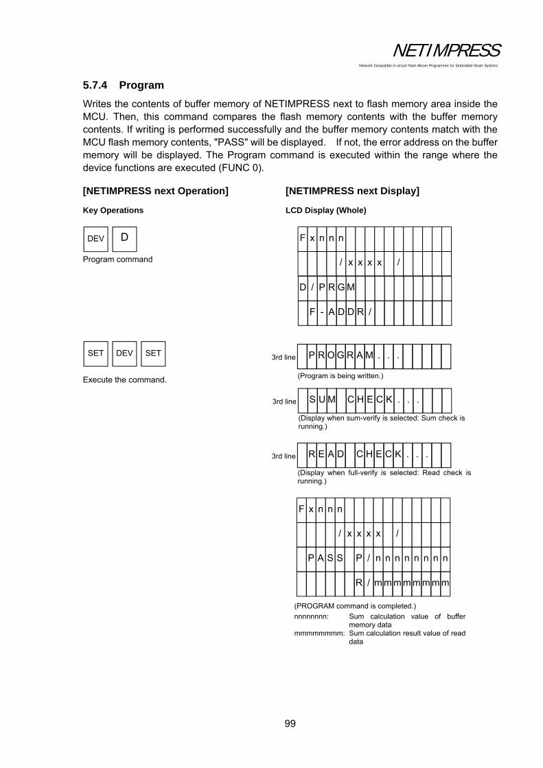
NETIMPRESS Network Compatible in-circuit Flash Micom Programmer for Embedded Smart Systems
99
5.7.4 Program
Writes the contents of buffer memory of NETIMPRESS next to flash memory area inside the MCU. Then, this command compares the flash memory contents with the buffer memory contents. If writing is performed successfully and the buffer memory contents match with the MCU flash memory contents, "PASS" will be displayed. If not, the error address on the buffer memory will be displayed. The Program command is executed within the range where the device functions are executed (FUNC 0).
[NETIMPRESS next Operation] [NETIMPRESS next Display]
Key Operations LCD Display (Whole)
Program command Execute the command.
D DEV
SET DEV SET
3rd line S U M C H E C . . . K
(Display when sum-verify is selected: Sum check isrunning.)
3rd line P R O G R A M . . .
(Program is being written.)
F - A D D R /
D / P R G M
/ x x x x /
F x n n n
3rd line R E A D C H E . . . K C
(Display when full-verify is selected: Read check isrunning.)
R / m mm m m m m m
P n A S S P / n n n n n n n
(PROGRAM command is completed.)
nnnnnnnn: Sum calculation value of buffermemory data
mmmmmmmm: Sum calculation result value of readdata
/ x x x x /
F x n n n
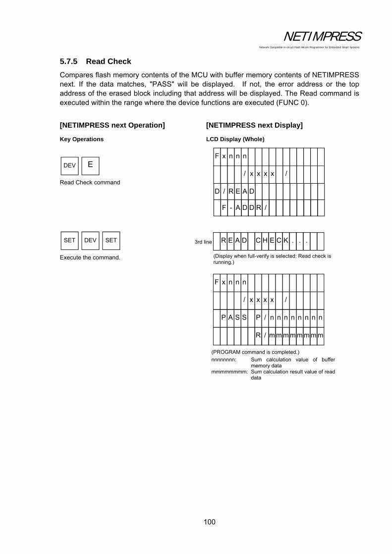
NETIMPRESS Network Compatible in-circuit Flash Micom Programmer for Embedded Smart Systems
100
5.7.5 Read Check
Compares flash memory contents of the MCU with buffer memory contents of NETIMPRESS next. If the data matches, "PASS" will be displayed. If not, the error address or the top address of the erased block including that address will be displayed. The Read command is executed within the range where the device functions are executed (FUNC 0).
[NETIMPRESS next Operation] [NETIMPRESS next Display]
Key Operations LCD Display (Whole)
Read Check command
Execute the command.
E DEV
SET DEV SET 3rd line R E A D C H E . . . K C
(Display when full-verify is selected: Read check isrunning.)
F - A D D R /
D / R E A D
/ x x x x /
F x n n n
R / m m m m m m m m
P n A S S P / n n n n n n n
(PROGRAM command is completed.)
nnnnnnnn: Sum calculation value of buffermemory data
mmmmmmmm: Sum calculation result value of readdata
/ x x x x /
F x n n n
NETIMPRESS Network Compatible in-circuit Flash Micom Programmer for Embedded Smart Systems
101
5.7.6 E.P.R.
Writes to the internal flash memory area inside the MCU. This command executes the Erase, Blank Check, Program, and Read Verify commands sequentially. If the E.P.R. command is completed successfully, "PASS" will be displayed. If not, the error message will be displayed. The E.P.R. command is executed within the range where the device functions are executed (FUNC 0).
You can set the verify mode by FUNC99.
Note:
There may be the commands not available depending on a type of the control modules. For further information, see your control module manual.

NETIMPRESS Network Compatible in-circuit Flash Micom Programmer for Embedded Smart Systems
102
[NETIMPRESS next Operation] [NETIMPRESS next Display]
Key Operations LCD Display (Whole)
E.P.R. command Execute the command.
(E.P.R. command is completed.)
nnnnnnnn: Sum calculation value of buffer memory data
mmmmmmmm: Sum calculation result value of read data
F DEV
SET DEV SET
3rd line S U M C H E C . . . K
(Display when sum-verify is selected: Sum check isrunning.)
3rd line E R A S E . . .
(Erase is being executed.)
3rd line P R O G R A M . . .
(Program is being written.)
F - A D D R /
D / P R G M
/ x x x x /
F x n n n
3rd line R E A D C H E . . . K C
(Display when full-verify is selected: Read check isrunning.)
R / m m m m m m m m
P n A S S P / n n n n n n n
/ x x x x /
F x n n n

NETIMPRESS Network Compatible in-circuit Flash Micom Programmer for Embedded Smart Systems
103
5.8 Log Operation
5.8.1 Set Log Mode (Function CA0)
Sets the mode to get the execution log of NETIMPRESS next.
There are the following 3 modes:
Not get the log (LOG OFF)
Brief log mode (LOG ON (DEV))
FULL log mode (LOG ON (ALL))
[NETIMPRESS next Operation] [NETIMPRESS next Display]
Key Operations LCD Display (Whole)
Input the command
Select
Execute the command.
FUNC C A
SET FUNC SET
4th line
4th line
0
4th line

NETIMPRESS Network Compatible in-circuit Flash Micom Programmer for Embedded Smart Systems
104
5.8.2 Delete the Log (Function CA5)
Deletes the selected log file.
[NETIMPRESS next Operation] [NETIMPRESS next Display]
Key Operations LCD Display (Whole)
Input the command
Select
Execute the command.
FUNC C A
SET FUNC SET
4th line
5 F x n n n
/ x x x x /
F C A 5 / L O G D E L E T E
L O G _ X X X X X X X X
L O G _ X X X X X X X X
L O G _ X X X X X X X X
L O G _ X X X X X X X X
4th line
4th line
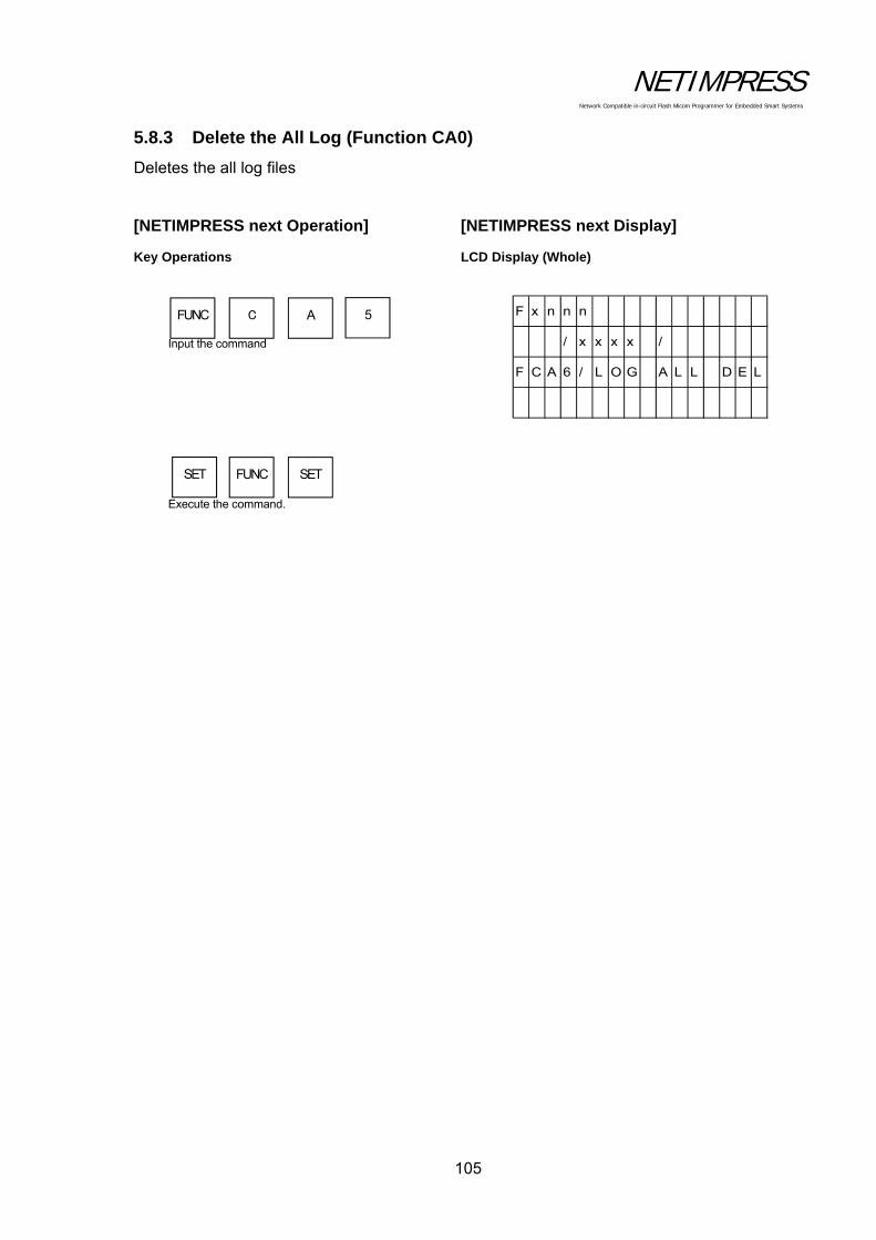
NETIMPRESS Network Compatible in-circuit Flash Micom Programmer for Embedded Smart Systems
105
5.8.3 Delete the All Log (Function CA0)
Deletes the all log files
[NETIMPRESS next Operation] [NETIMPRESS next Display]
Key Operations LCD Display (Whole)
Input the command
Execute the command.
FUNC C A
SET FUNC SET
5 F x n n n
/ x x x x /
F C A 6 / L O G A L L D E L
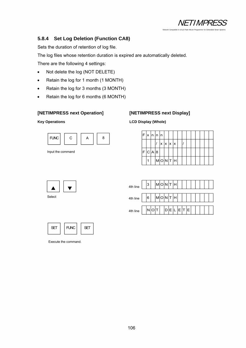
NETIMPRESS Network Compatible in-circuit Flash Micom Programmer for Embedded Smart Systems
106
5.8.4 Set Log Deletion (Function CA8)
Sets the duration of retention of log file.
The log files whose retention duration is expired are automatically deleted.
There are the following 4 settings:
Not delete the log (NOT DELETE)
Retain the log for 1 month (1 MONTH)
Retain the log for 3 months (3 MONTH)
Retain the log for 6 months (6 MONTH)
[NETIMPRESS next Operation] [NETIMPRESS next Display]
Key Operations LCD Display (Whole)
Input the command
Select
Execute the command.
FUNC C A
SET FUNC SET
4th line
4th line
4th line
8 F x n n n
/ x x x x /
F C A 8
1 M O N T H
3 M O N T H
6 M O N T H
N O T D E L E T E

NETIMPRESS Network Compatible in-circuit Flash Micom Programmer for Embedded Smart Systems
107
5.9 I/F Setting
5.9.1 Set Cable Selection (Function CD0)
Selects the serial/CAN I/F of NETIMPRESS next.
There are the following 3 settings:
Auto selection (CABLE SELECT)
Priority: Serial (TARGET PROBE 1)
Priority: CAN (TARGET PROBE 2)
Auto selection (CABLE SELECT) is set as a default.
5.9.2 Set the Input Filter Value of Digital Input (Function CD1)
Sets the filtering time of digital I/O input.
Settable range: 1 to 256 (ms)
10 [ms] is set as a default.

NETIMPRESS Network Compatible in-circuit Flash Micom Programmer for Embedded Smart Systems
108
5.10 Restrictions
This section describes the restrictions on files and folders inside the Compact Flash.
(1) Length of a file and folder name
The maximum length of a file and folder name is 128 characters.
(2) Characters not allowed for a file and folder name
The characters listed in the table below cannot be used in a file and folder name.
% ¥ / : * (space)
? < > | “
(3) Number of files and YIM folder in the Compact Flash
The figure below illustrates the structure of YIM folder and files.
The table below lists the maximum number of files and YIM folders you can have in the Compact Flash.
YIM Folder Current YIM File Root File
FAT16 ( 1 to 8 characters)
(9 to 13 characters)
(14 to 26 characters)
(27 to 39 characters)
511
255
169
127
511
255
169
127
511
255
169
127
FAT32
2048 2048 2048
Notes:
The maximum number of files and folders you can have in the Compact Flash varies according to a file system (FAT16/FAT32).
With FAT16, the maximum number of files and folders you can have in the Compact Flash varies according to the number of characters including extension.
・・・・
・・・・
・・・・
YIM folder
Root file
Current YIM file ( File underneath YIM folder )

NETIMPRESS Network Compatible in-circuit Flash Micom Programmer for Embedded Smart Systems
109
6 Command Sequence Function
6.1 EXE Key
6.1.1 Function Overview
The control modules that support the EXE key function can execute the device functions with one touch key entry. The two keys shown in the figure below, [EXE1] and [EXE2], can be assigned for one touch entry.
The usual key operation to execute the device functions:
will not be necessary and [EXE1] and [EXE2] can be used to execute the device functions in one touch entry.
DEV SET DEV SET
EXE1
EXE2
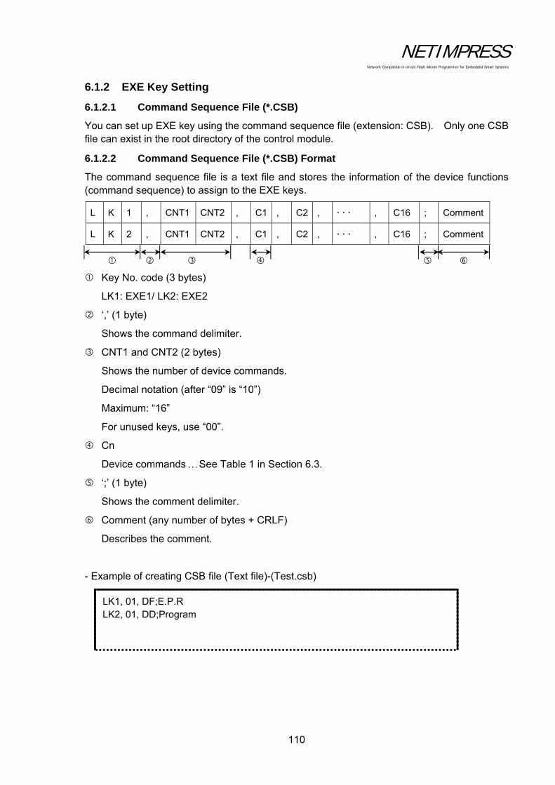
NETIMPRESS Network Compatible in-circuit Flash Micom Programmer for Embedded Smart Systems
110
6.1.2 EXE Key Setting
6.1.2.1 Command Sequence File (*.CSB)
You can set up EXE key using the command sequence file (extension: CSB). Only one CSB file can exist in the root directory of the control module.
6.1.2.2 Command Sequence File (*.CSB) Format
The command sequence file is a text file and stores the information of the device functions (command sequence) to assign to the EXE keys.
L K 1 , CNT1 CNT2 , C1 , C2 , , C16 ; Comment
L K 2 , CNT1 CNT2 , C1 , C2 , , C16 ; Comment
Key No. code (3 bytes)
LK1: EXE1/ LK2: EXE2
‘,’ (1 byte)
Shows the command delimiter.
CNT1 and CNT2 (2 bytes)
Shows the number of device commands.
Decimal notation (after “09” is “10”)
Maximum: “16”
For unused keys, use “00”.
Cn
Device commands See Table 1 in Section 6.3.
‘;’ (1 byte)
Shows the comment delimiter.
Comment (any number of bytes + CRLF)
Describes the comment.
- Example of creating CSB file (Text file)-(Test.csb)
LK1, 01, DF;E.P.R LK2, 01, DD;Program

NETIMPRESS Network Compatible in-circuit Flash Micom Programmer for Embedded Smart Systems
111
6.1.2.3 Error Messages
Messages, causes and actions are as shown below:
(1) CSB NOT FOUND
Cause: This error will occur when a command sequence file is not found in the root directory, or multiple command sequence files are found in the directory, or the command sequence file has the wrong format.
Action: Check that there is only one command sequence file in the root directory and that it has the proper format.
(2) OAK1 ASSIGN ERR/ OAK2 ASSIGN ERR
Cause: This error will occur when the settings information in the command sequence file has any inconsistencies (undefined device commands, unmatched number of device commands, or others).
Action: Correct the setting information in the command sequence file.

NETIMPRESS Network Compatible in-circuit Flash Micom Programmer for Embedded Smart Systems
112
6.2 YMN File
6.2.1 Function Overview
This YMN file is a file to register the command sequence.
With the following function operations, you can execute the commands set up in the YMN file.
Select a YMN file you want to execute. (For further information, see Section 5.5.8 “Set Current YMN File (Function BC)”.)
Execute the YMN file you have selected with [FUNC BC]. (For further information, see Section 5.5.9 “Execute Current YMN File (Function BD)”.)
* Differences compared to CSB file
(1) Starting operation
CSB: Operation is started with the EXE key.
YMN: Operation is started with [FUNC BD].
(2) Selecting a file
CSB: Only one CSB file existing in the root of the Compact Flash is executed.
YMN: YMN file you have selected with [FUNC D8] is executed.
(Multiple YMN files can exist in the root of the Compact Flash.)
(3) Maximum number of commands
CSB: 16 commands
YMN: 100 commands
(4) File format
CSB: See Section 6.1.2.2 “Command Sequence File (*.CSB) Format”.
YMN: See Section 6.2.2 “Format of Command Sequence File (*.YMN )”.
FUNC B C
FUNC B D
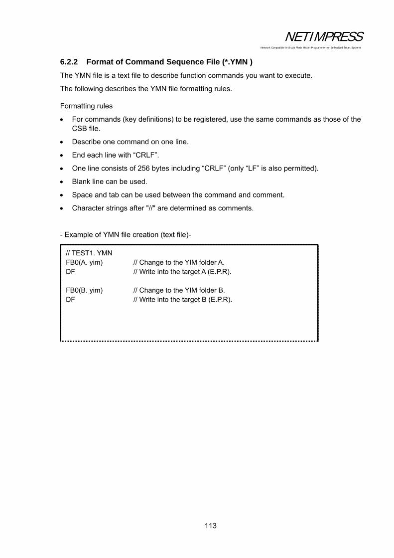
NETIMPRESS Network Compatible in-circuit Flash Micom Programmer for Embedded Smart Systems
113
6.2.2 Format of Command Sequence File (*.YMN )
The YMN file is a text file to describe function commands you want to execute.
The following describes the YMN file formatting rules.
Formatting rules
For commands (key definitions) to be registered, use the same commands as those of the CSB file.
Describe one command on one line.
End each line with “CRLF”.
One line consists of 256 bytes including “CRLF” (only “LF” is also permitted).
Blank line can be used.
Space and tab can be used between the command and comment.
Character strings after "//" are determined as comments.
- Example of YMN file creation (text file)-
// TEST1. YMN FB0(A. yim) // Change to the YIM folder A. DF // Write into the target A (E.P.R). FB0(B. yim) // Change to the YIM folder B. DF // Write into the target B (E.P.R).

NETIMPRESS Network Compatible in-circuit Flash Micom Programmer for Embedded Smart Systems
114
6.3 Definitions of Device Command
The table below lists the command definitions when creating CSB file and YMN file.
Table 1. Key definitions
Cn Description
F0(XXXXXXXX YYYYYYYY) Device function area setting
(XXXXXXXX: First address, YYYYYYYY: Last address) *1
F1(XXXXXXXX YYYYYYYY ZZ) Block store
(XXXXXXXX: First address, YYYYYYYY: Last address, ZZ: Data) *2
F2 Buffer memory clear
FF1(XXXXXXXX. XXX) File load
(XXXXXXXX. XXX: Load file name) *3
FF5(XXXXXXXX YYYYYYYY) Transfer address setting
(XXXXXXXX: First address, YYYYYYYY: Last address) *1
D9 Blank (Device function)
DC Erase (Device function)
DD Program (Device function)
DE Read (Device function)
DF E. P. R (Device function)
FB0(XXXXXXXX. YIM) Changing of current YIM folder (xxx.YIM)
(XXXXXXXX. YIM: YIM folder name) *4
FBD(XXXXXXXX. YMN) Execution of current YMN file
(XXXXXXXX. YMN: YMN file name to be executed.) *5
*1 These settings can be omitted. When omitted, the address becomes the entire flash ROM area.
*2 These settings can be omitted. When omitted, the address becomes the entire flash ROM area and the data becomes “00”.
*3 This setting cannot be omitted.
*4 This setting can be omitted. When omitted, YIM folder in the Compact Flash is searched for.
*5 This setting can be omitted. When omitted, the YMN file, which is selected with [FUNC] [B] [C], is executed.

NETIMPRESS Network Compatible in-circuit Flash Micom Programmer for Embedded Smart Systems
115
7 Sum Check Function
7.1 Sum Check Overview
This function is used to check the sum values and data at specified addresses at each execution of the device functions. As this check is performed for each execution of the device functions, it is possible to prevent incorrect object data from being written.
7.2 Sum Check Function Settings
7.2.1 YSM Files (*.YSM)
The YSM file (extension: YSM) is used to set up the sum check function.
If the YSM file (example: abc.YSM) having the same file name as that of the current file (example: abc.S) exists in the current YIM folder of the control module, the sum check function is executed.
Before executing the device functions, the YSM file data is compared with the buffer memory data. If it passes the check, then the device functions are executed. After the Read device function is executed, a sum value of YSM file and a sum value when the Read device function is executed are compared.

NETIMPRESS Network Compatible in-circuit Flash Micom Programmer for Embedded Smart Systems
116
7.2.2 YSM File Format
The YSM file is in the Motorola S format. Use the AZ281 to create this file.
Line 1 SUM Data Set a sum value for the object data. Address: 00000000, Size: 1, Type: HEX Data: Sum value of the object data Line 2 SUM Data Check Flag Set whether Line 1 will be checked or not. Address: 00000000, Size: 1, Type: HEX Data: Check (1), Not check (0) Line 3 Data check (Data1): Direct comparison with the object data Set the top address, size and data to compare. Address: Data top address Size: Data size Type: HEX or ASCII Data: Data Line 4 Data1 Check Flag Set whether Line 3 will be checked or not. Address: 00000000, Size: 1, Type: HEX Data: Check (1), Not check (0) These file generated in the above example will be as follows. (Motorola S format file) 1 S30600000000D623 SUM Data 2 S3060000000001F8 SUM Data Check Flag 3 S30B00000100010203040506DE Data1 4 S3060000000001F8 Data1 Check Flag 5 S70500000000FA
From line 3, you can add as many check data and check flag in a pair as you want up to 10 items.
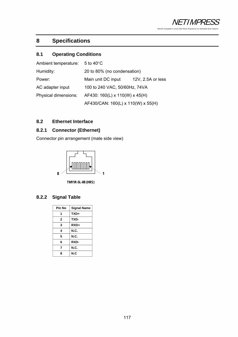
NETIMPRESS Network Compatible in-circuit Flash Micom Programmer for Embedded Smart Systems
117
8 Specifications
8.1 Operating Conditions
Ambient temperature: 5 to 40C
Humidity: 20 to 80% (no condensation)
Power: Main unit DC input 12V, 2.5A or less
AC adapter input 100 to 240 VAC, 50/60Hz, 74VA
Physical dimensions: AF430: 160(L) x 110(W) x 45(H)
AF430/CAN: 160(L) x 110(W) x 55(H)
8.2 Ethernet Interface
8.2.1 Connector (Ethernet)
Connector pin arrangement (mate side view)
8.2.2 Signal Table
TXD+
N.C
N.C.
RXD-
N.C.
N.C.
RXD+
TXD-
Signal NamePin No
1
6
4
3
7
2
5
8
18
TM11R-5L-88 (HRS)
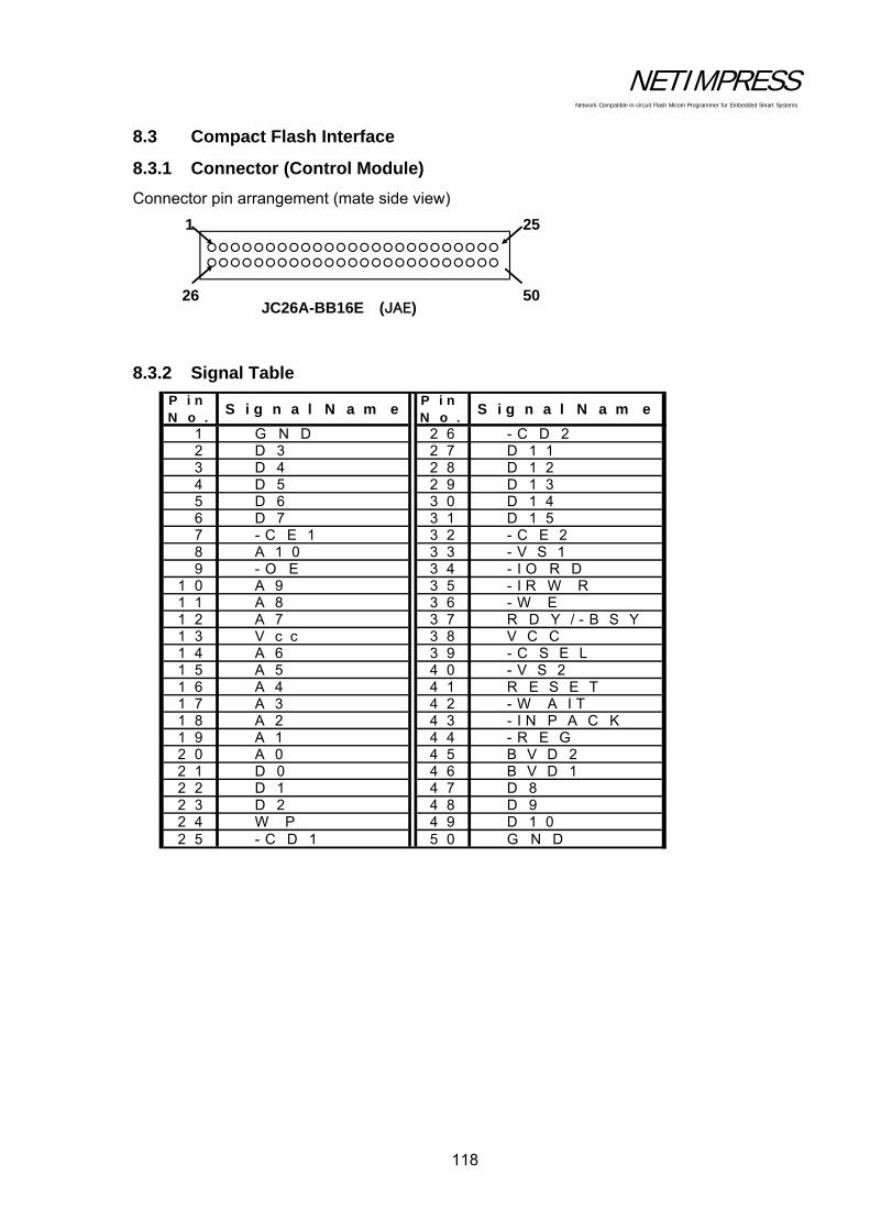
NETIMPRESS Network Compatible in-circuit Flash Micom Programmer for Embedded Smart Systems
118
8.3 Compact Flash Interface
8.3.1 Connector (Control Module)
Connector pin arrangement (mate side view)
8.3.2 Signal Table
P i nN o .
S i g n a l N a m eP i nN o .
S i g n a l N a m e
1 G N D 2 6 - C D 22 D 3 2 7 D 1 13 D 4 2 8 D 1 24 D 5 2 9 D 1 35 D 6 3 0 D 1 46 D 7 3 1 D 1 57 - C E 1 3 2 - C E 28 A 1 0 3 3 - V S 19 - O E 3 4 - I O R D
1 0 A 9 3 5 - I R W R1 1 A 8 3 6 - W E1 2 A 7 3 7 R D Y / - B S Y1 3 V c c 3 8 V C C1 4 A 6 3 9 - C S E L1 5 A 5 4 0 - V S 21 6 A 4 4 1 R E S E T1 7 A 3 4 2 - W A I T1 8 A 2 4 3 - I N P A C K1 9 A 1 4 4 - R E G2 0 A 0 4 5 B V D 22 1 D 0 4 6 B V D 12 2 D 1 4 7 D 82 3 D 2 4 8 D 92 4 W P 4 9 D 1 02 5 - C D 1 5 0 G N D
JC26A-BB16E (JAE)
251
26 50
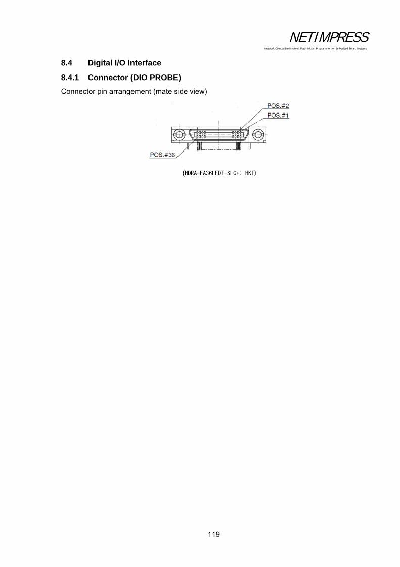
NETIMPRESS Network Compatible in-circuit Flash Micom Programmer for Embedded Smart Systems
119
8.4 Digital I/O Interface
8.4.1 Connector (DIO PROBE)
Connector pin arrangement (mate side view)
(HDRA-EA36LFDT-SLC+: HKT)

NETIMPRESS Network Compatible in-circuit Flash Micom Programmer for Embedded Smart Systems
120
8.4.2 Signal Table
PINNo Signal Name definition I/O
Type(*3)
1 DOCOM Isolation ground for Digital I/O OUT0 to 4, Pass, Error, and Run - -2 DOVCC Power supply of overcurrent protection circuit - -
3 PassPASS status output signal Low: Normal end Hiz: Other than above O A
4 ErrorERROR status output signal Low: Abnormal end Hiz: Other than above O A
5 Run
Operation condition output signal Low: Writing or function execution is currently beingexecuted Hiz: Other than above O A
6 Digital I/O OUT0 Digital I/O output signal0 O A7 Reserved - -8 Reserved - -9 Reserved - -10 Digital I/O ST2 Script selection signal 2 (Digital I/O input) I B11 Digital I/O ST3 Script selection signal 3 (Digital I/O input) I B12 Digital I/O ST4 Script selection signal 4 (Digital I/O input) I B13 Digital I/O IN0 Digital I/O input signal 0 I B14 Digital I/O IN1 Digital I/O input signal 1 I B15 Digital I/O IN2 Digital I/O input signal 2 I B16 Digital I/O IN3 Digital I/O input signal 3 I B17 Reserved - -18 DIVCC Isolation power switch for input - -19 DOCOM Isolation ground for Digital I/O OUT0 to 4, Pass, Error, and Run - -20 DOVCC Power supply of overcurrent protection circuit - -21 Digital I/O OUT1 Digital I/O output signal 1 O A22 Digital I/O OUT2 Digital I/O output signal 2 O A23 Digital I/O OUT3 Digital I/O output signal 3 O A24 Digital I/O OUT4 Digital I/O output signal 4 O A25 Reserved - -26 Reserved - -27 DIVCC Isolation power switch for input I B28 Digital I/O IN4 Digital I/O input signal 4 I B29 EXE1 EXE1 KEY Pin I B30 EXE2 EXE2 KEY Pin I B31 CLR RESET KEY Pin/ User clear signal I B32 STEP Step execution input signal I B33 START Script signal loading trigger input signal I B34 Digital I/O ST0 Script selection signal 0 (Digital I/O input) I B35 Digital I/O ST1 Script selection signal 1 (Digital I/O input) I B36 DIVCC Isolation power switch for input - -
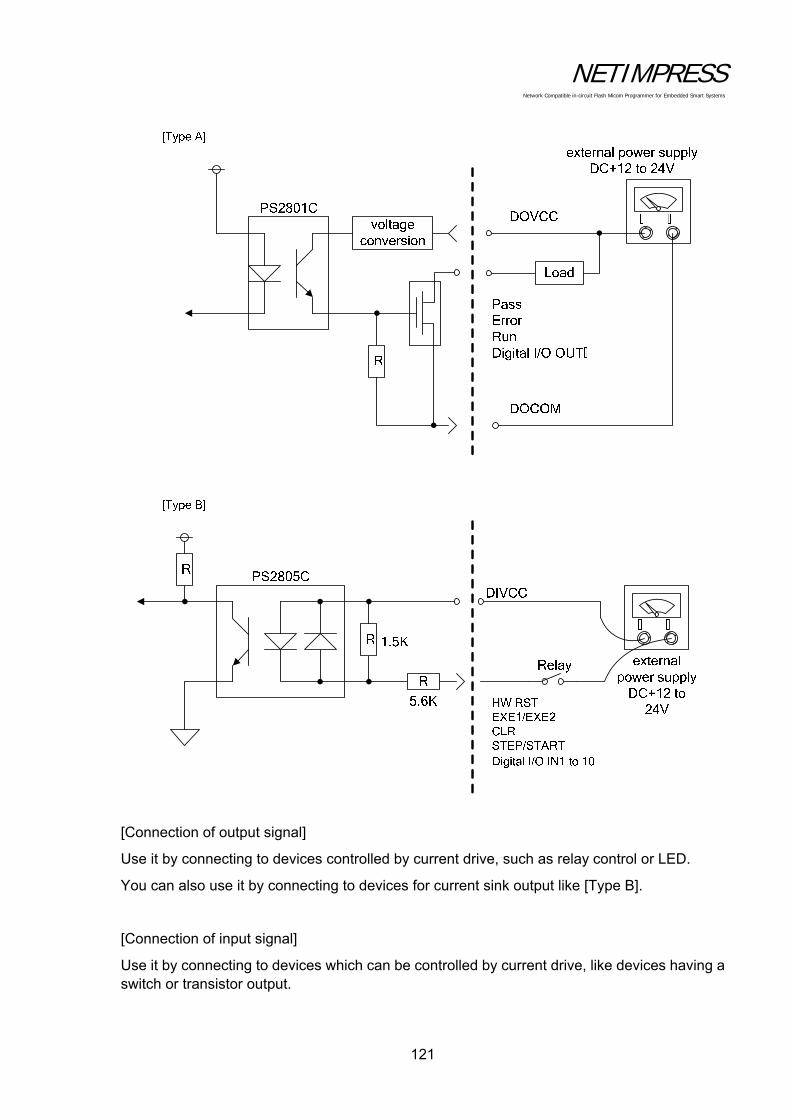
NETIMPRESS Network Compatible in-circuit Flash Micom Programmer for Embedded Smart Systems
121
[Connection of output signal]
Use it by connecting to devices controlled by current drive, such as relay control or LED.
You can also use it by connecting to devices for current sink output like [Type B].
[Connection of input signal]
Use it by connecting to devices which can be controlled by current drive, like devices having a switch or transistor output.

NETIMPRESS Network Compatible in-circuit Flash Micom Programmer for Embedded Smart Systems
122
8.4.3 Timing Specifications
Minimum Maximum
T PWL 30ms 200ms
T INT 30ms
[Digital I/O Inx, Digital I/O STx, STEP, START]
(*1) Changeable by a filter setting
T PWL T INT
T PWL
Key entry 1
Key entry 2
TDIL
TDINT 1ms to 256ms(*1)
1ms to 256ms(*1)
Minimum
∞
∞
Maximum
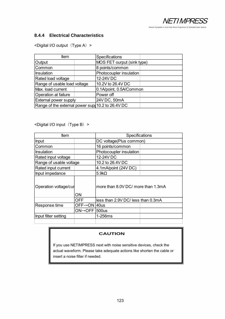
NETIMPRESS Network Compatible in-circuit Flash Micom Programmer for Embedded Smart Systems
123
8.4.4 Electrical Characteristics
<Digital I/O output(Type A)>
SpecificationsOutput MOS FET ourput (sink type)Common 8 points/commonInsulation Photocoupler insulationRated load voltage 12-24V DCRange of usable load voltage 10.2V to 26.4V DCMax. load current 0.1A/point, 0.5A/CommonOperation at failure Power offExternal power supply 24V DC, 50mARange of the external power supp10.2 to 26.4V DC
Item
<Digital I/O input(Type B)>
Input DC voltage(Plus common)Common 16 points/commonInsulation Photocoupler insulationRated input voltage 12-24V DCRange of usable voltage 10.2 to 26.4V DCRated input current 4.1mA/point (24V DC)Input impedance 5.9kΩ
Operation voltage/cur
ON
more than 8.0V DC/ more than 1.3mA
OFF less than 2.9V DC/ less than 0.3mAResponse time OFF→ON 40us
ON→OFF 500usInput filter setting 1-256ms
Item Specifications
CAUTION
If you use NETIMPRESS next with noise sensitive devices, check the
actual waveform. Please take adequate actions like shorten the cable or
insert a noise filter if needed.

NETIMPRESS Network Compatible in-circuit Flash Micom Programmer for Embedded Smart Systems
124
8.4.5 Digital I/O PROBE ( AZ401)
You can customize the connector and wiring as you want.
Target-side Wiring Specification
Insulatorcolor
Dot Mark
1 Red 1 dot DOCOM2 Black 1 dot DOVCC3 Red 1 dot Pass4 Black 1 dot Error5 Red 1 dot RUN6 Black 1 dot Digital I/O OUT07 Red 1 dot Rsv8 Black 1 dot Rsv9 Red 1 dot Rsv
10 Black 1 dot Digital I/O ST211 Red 2 dots Digital I/O ST312 Black 2 dots Digital I/O ST413 Red 2 dots Digital I/O IN014 Black 2 dots Digital I/O IN115 Red 2 dots Digital I/O IN216 Black 2 dots Digital I/O IN317 Red 2 dots RSV18 Black 2 dots DIVCC19 Red 2 dots DOCOM20 Black 2 dots DOVCC21 Red 3 dots Digital I/O OUT122 Black 3 dots Digital I/O OUT223 Red 3 dots Digital I/O OUT324 Black 3 dots Digital I/O OUT425 Red 3 dots Rsv26 Black 3 dots Rsv27 Red 3 dots DIVCC28 Black 3 dots Digital I/O IN429 Red 3 dots EXE130 Black 3 dots EXE231 Red 4 dots CLR32 Black 4 dots STEP33 Red 4 dots START34 Black 4 dots Digital I/O ST035 Red 4 dots Digital I/O ST136 Black 4 dots DIVCC
Pin No. Signal NamePin No.
Orange
Orange
Grey
White
Yellow
Grey
White
Yellow
Pink
White
White
Yellow
Pink
Orange
Pink
Orange
Grey
Grey

NETIMPRESS Network Compatible in-circuit Flash Micom Programmer for Embedded Smart Systems
125
8.4.6 Digital I/O PROBE ( AZ403)
When you implement MIL standard conformity connector on the Digital I/O environment, you can use this probe.
NETIMPRESS-side Digital I/O System-side
1 DOCOM2 DOVCC3 Pass4 Error5 RUN6 Digital I/O OUT07 Rsv8 Rsv9 Rsv10 Digital I/O ST211 Digital I/O ST312 Digital I/O ST413 Digital I/O IN014 Digital I/O IN115 Digital I/O IN216 Digital I/O IN317 RSV18 DIVCC19 DOCOM20 DOVCC21 Digital I/O OUT122 Digital I/O OUT223 Digital I/O OUT324 Digital I/O OUT425 Rsv26 Rsv27 DIVCC28 Digital I/O IN429 EXE130 EXE231 CLR32 STEP33 START34 Digital I/O ST035 Digital I/O ST136 DIVCC
Pin No. Signal Name
A1 DOCOMA2 DOVCCA3 PassA4 ErrorA5 RUNA6 Digital I/O OUT0A7 RsvA8 RsvA9 RsvA10 Digital I/O ST2A11 Digital I/O ST3A12 Digital I/O ST4A13 Digital I/O IN0A14 Digital I/O IN1A15 Digital I/O IN2A16 Digital I/O IN3A17 RSVA18 DIVCCA19 DOCOMA20 DOVCCB1 Digital I/O OUT1B2 Digital I/O OUT2B3 Digital I/O OUT3B4 Digital I/O OUT4B5 RsvB6 RsvB7 DIVCCB8 Digital I/O IN4B9 EXE1B10 EXE2B11 CLRB12 STEPB13 STARTB14 Digital I/O ST0B15 Digital I/O ST1B16 DIVCCB17 n.cB18 n.cB19 n.cB20 n.c
Pin No. Signal Name

NETIMPRESS Network Compatible in-circuit Flash Micom Programmer for Embedded Smart Systems
126
8.5 Bar-code reader Interface
8.5.1 Connector (BCR PROBE)
8.5.2 Signal Table
8.5.3 Electrical Characteristics
Signal type DC Characteristics AC Characteristics
OUT
VOHmin:5V
VOLmax:-5V slew rate: 30V/μsec or less
IN VIHmin:+3V VILmax:-3V

NETIMPRESS Network Compatible in-circuit Flash Micom Programmer for Embedded Smart Systems
127
8.5.4 BCR PROBE (AZ402)
L
NETIMPRESS-side BCR-side
CN1
HDR-E14MAG1+
(Honda Tsushin Kogyo)
51
96
DEB-9P(05)
(Hirose Electric)
CN2
L=300mm

NETIMPRESS Network Compatible in-circuit Flash Micom Programmer for Embedded Smart Systems
128
8.6 Target Interface
8.6.1 Connector (TARGET PROBE 1)
Connector pin arrangement (mate side view)
14 1
28 15DX10-28S (Hirose Electric)

NETIMPRESS Network Compatible in-circuit Flash Micom Programmer for Embedded Smart Systems
129
8.6.2 Signal Table
The table below shows the signals of the target interface connector. PinNo.
Signal Name Definition Circuit Type
1 GND Ground - 2 TVccd User system power input
(or driver power for I/F when an optional adapter is installed) 1
3 Vcc 5 V output (max. 100 mA) 7 4 TRES Positive logic reset output 3 5 /TRES Negative logic reset output (Open collector output) 2 6 TCK Clock output for synchronous communication 8 7 NC Not connected - 8 NC Reserved - 9 TAUX2 Output pin (Definition may vary depending the type of the
Control Module) 3
10 /TICS 3 11 /TOE Output pin (Definition may vary depending the type of the
Control Module) 3
12 TMODE Output pin (Definition may vary depending the type of the Control Module)
3
13 TTXD Send output for communication (send and receive for two-way communication)
9
14 GND Ground - 15 GND Ground - 16 /TVpp1 EN Voltage output control pin for the negative logic program 5 17 /TVpp2 EN Voltage output control pin for the negative logic program 5 18 WDT Watchdog timer output (Open collector output) 2 19 TAUX3 Input/output pin
(Definition may vary depending the type of the Control Module) 4
20 TAUX4 Input/output pin (Definition may vary depending the type of the Control Module)
4
21 NC Reserved - 22 PROBE SELECT Terminal for selecting the TARGET PROBE 1 or TARGET
PROBE 2. -
23 TAUX Input/output pin (Definition may vary depending the type of the Control Module)
4
24 TBUSY Busy input signal for synchronous communication 6 25
TIO Input/output pin (Definition may vary depending the type of the Control Module)
6
26 TVccs
Not used (or user power monitor input when an optional adapter is installed)
1
27 TRXD Receive data input pin 10 28 GND Ground -
NOTES:
(1) For input signals to a user system, it is recommended to attach pull-up resisters (about 10 K)
considering possible malfunction when NETIMPRESS next is not connected.
(2) The definitions for the specific signal lines vary depending on the control modules. For more
information, see the manual for your control module.
(3) When you use /TICS, use pull-up resisters (about 10 K).
(4) A current limiter is provided.
The current limiter functions if a current over 200 mA flows for 1.6 ms or longer.
If a capacitor is connected to the Vpp line, use a capacitor satisfying the conditions above.

NETIMPRESS Network Compatible in-circuit Flash Micom Programmer for Embedded Smart Systems
130
8.6.3 Interface Circuit Type
Type 1
TVccd
NET IMPRESS side
+XV(To VHC125 VCC)
To voltage monitor circuit
LM358
10K
1M
User Target side
+5V(Internal power)
TVccs
+5V(Internal power)
1K
10K
LM358
AQY221RS
AQY221RS
AQY221RS
AQY221RS

NETIMPRESS Network Compatible in-circuit Flash Micom Programmer for Embedded Smart Systems
131
Type 2
Type 3
Type 4
220
1MLS07
NET IMPRESS side User Target side+5V(Internal power)
+XV
220
1MVHC125
NET IMPRESS side User Target side
+XV
220
1MVHC125
1K
NET IMPRESS side User Target side
LVC244
+3.3V(Internal power)

NETIMPRESS Network Compatible in-circuit Flash Micom Programmer for Embedded Smart Systems
132
Type 5
Type 6
Type 7
1M
D1FS4AQY212GS
10
0.22uF
NET IMPRESS side User Target side
1K
1MLVC244
NET IMPRESS side User Target side+3.3V(Internal power)
1 (FUSE)
NET IMPRESS side User Target side
+5V(Internal power)

NETIMPRESS Network Compatible in-circuit Flash Micom Programmer for Embedded Smart Systems
133
Type 8
Type 9
Type 10
+XV
22
1MVHC125
NET IMPRESS side User Target side
+XV
22
1MVHC125
22
NET IMPRESS side User Target side
LVC244
+3.3V(Internal power)
22
1MLVC244
+3.3V(Internal power)
NET IMPRESS side User Target side
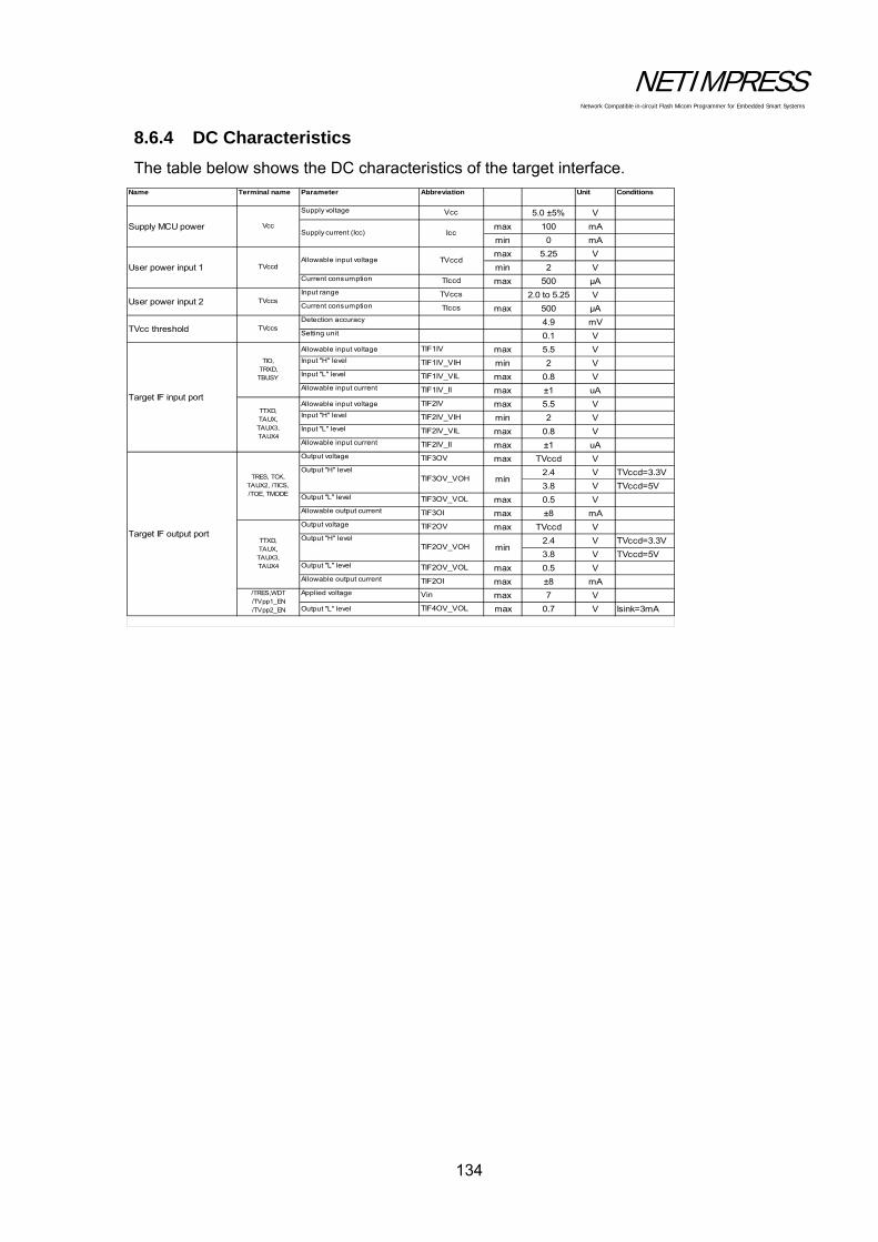
NETIMPRESS Network Compatible in-circuit Flash Micom Programmer for Embedded Smart Systems
134
8.6.4 DC Characteristics
The table below shows the DC characteristics of the target interface.
Name Terminal name Parameter Abbreviation Unit Conditions
Supply voltage Vcc 5.0 ±5% V
max 100 mA
min 0 mA
max 5.25 V
min 2 VCurrent consumption TIccd max 500 μAInput range TVccs 2.0 to 5.25 VCurrent consumption TIccs max 500 μADetection accuracy 4.9 mVSetting unit 0.1 V
Allowable input voltage TIF1IV max 5.5 VInput "H" level TIF1IV_VIH min 2 VInput "L" level TIF1IV_VIL max 0.8 VAllowable input current TIF1IV_II max ±1 uA
Allowable input voltage TIF2IV max 5.5 VInput "H" level TIF2IV_VIH min 2 VInput "L" level TIF2IV_VIL max 0.8 VAllowable input current TIF2IV_II max ±1 uAOutput voltage TIF3OV max TVccd V
2.4 V TVccd=3.3V
3.8 V TVccd=5VOutput "L" level TIF3OV_VOL max 0.5 VAllowable output current TIF3OI max ±8 mAOutput voltage TIF2OV max TVccd V
2.4 V TVccd=3.3V
3.8 V TVccd=5VOutput "L" level TIF2OV_VOL max 0.5 VAllowable output current TIF2OI max ±8 mAApplied voltage Vin max 7 V
Output "L" level TIF4OV_VOL max 0.7 V Isink=3mA
Target IF output port
TVccd
TIO,TRXD,TBUSY
Target IF input port
Allowable input voltage
User power input 2
TTXD,TAUX,TAUX3,TAUX4
TVccs
TVccd
TRES, TCK,TAUX2, /TICS,/TOE, TMODE
TTXD,TAUX,TAUX3,TAUX4
IccSupply MCU power Vcc
User power input 1
Supply current (Icc)
TVcc threshold
/TRES,WDT/TVpp1_EN/TVpp2_EN
TVccs
min
minOutput "H" level
Output "H" level
TIF3OV_VOH
TIF2OV_VOH
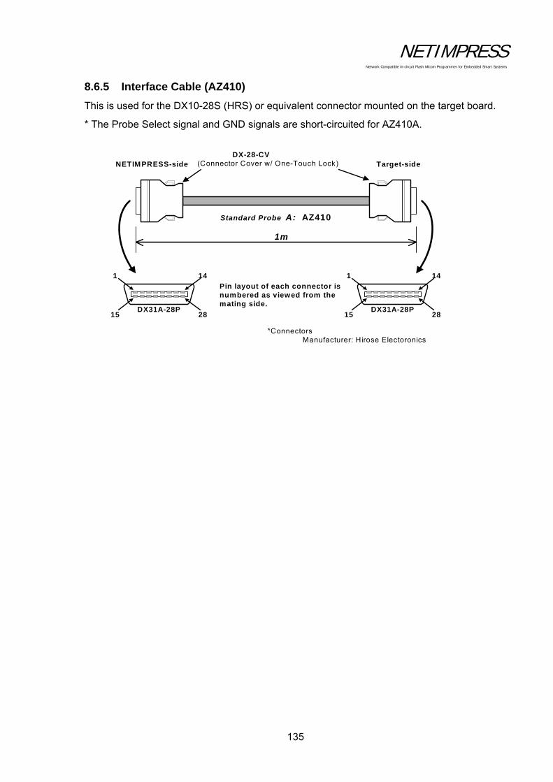
NETIMPRESS Network Compatible in-circuit Flash Micom Programmer for Embedded Smart Systems
135
8.6.5 Interface Cable (AZ410)
This is used for the DX10-28S (HRS) or equivalent connector mounted on the target board.
* The Probe Select signal and GND signals are short-circuited for AZ410A.
Standard Probe A: AZ410
1m
DX-28-CV(Connector Cover w/ One-Touch Lock)
1 14
15 28DX31A-28P
Pin layout of each connector isnumbered as viewed from themating side.
*ConnectorsManufacturer: Hirose Electoronics
1 14
15 28DX31A-28P
NETIMPRESS-side Target-side

NETIMPRESS Network Compatible in-circuit Flash Micom Programmer for Embedded Smart Systems
136
8.6.6 Interface Cable (AZ411, AZ413)
Use this cable to connect to test pins or others.
The AZ413 does not have any IC test clip and its tip is not treated.
Standard Probe B: AZ411
Signal x 20GND x 1
1m
Pin layouts of each connector is numbered as viewed from the mating side.
0.25m
...
Test Clips:
Enlarged View
1 14
15 28DX31A-28P
NETIMPRESS-side
Target-side
(Hirose Electronics)
2
1 19
20
PS-20PE-D4LT1-B1
(JAE)
NETIMPRESS-side Standard Signal Pin Assign
Pin No.NETIMPRESS
Standard Signal Name123456789
1011121314151617181920
TRXD
TTXD
TI0
TMODE
TVccs (TI1)
TAUX5 (/TOE)
TBUSY
/TICS
TAUX
TAUX2 (TR/W)
TAUX4 (TVpp2C)
TCK
TAUX3 (TVpp1C)
/TRES
WDT
TRES
TVpp2
Vcc
TVpp1
TVccd
2122232425262728
GND
ReservedGND
GNDGND
GNDProbe select
GND
GND (Black) : Directry Soldered to PWB.
Target-side Test Clips Signal Pin Assign
Pin No. Lead ColorNETIMPRESSSignal Name
123456789
1011121314151617181920
Brown
Light-Blue
RedOrangeYellowGreenBlueVioletGrey
WhiteWhite & BlackWhite & BrownWhite & Red
White & OrangeWhite & YellowWhite & GreenWhite & BlueWhite & VioletWhite & Grey
Yellow & Green
TRXDTTXD
TI0TMODETVccs (TI1)
TAUX5 (/TOE)TBUSY/TICSTAUXTAUX2 (TR/W)TAUX4 (TVpp2C)TCKTAUX3 (TVpp1C)/TRESWDTTRESTVpp2VccTVpp1TVccd
I/O
IOIOIOIOOOOOOOOOOOOI
※ The lead color of pin No.19 has been changed from “Light-Green” to “Yellow & Green” to distinguish it from “Green”.
The pin No.19 which you have may be “Light-Green”.
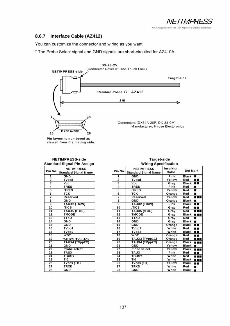
NETIMPRESS Network Compatible in-circuit Flash Micom Programmer for Embedded Smart Systems
137
8.6.7 Interface Cable (AZ412)
You can customize the connector and wiring as you want.
* The Probe Select signal and GND signals are short-circuited for AZ410A.
Standard Probe C: AZ412
1m
DX-28-CV(Connector Cover w/ One-Touch Lock)
1 14
15 28DX31A-28P
Pin layout is numbered asviewed from the mating side.
*Connectors (DX31A-28P, DX-28-CV)Manufacturer: Hirose Electoronics
NETIMPRESS-side
Target-side
NETIMPRESS-side Standard Signal Pin Assign
Pin No.NETIMPRESS
Standard Signal Name123456789
1011121314151617181920
TRXD
TTXD
TI0
TMODE
TVccs (TI1)
TAUX5 (/TOE)
TBUSY
/TICS
TAUX
TAUX2 (TR/W)
TAUX4 (TVpp2C)
TCK
TAUX3 (TVpp1C)
/TRES
WDT
TRES
TVpp2
Vcc
TVpp1
TVccd
2122232425262728
GND
ReservedGND
GNDGND
GNDProbe select
GND
Pin No.NETIMPRESS
Standard Signal Name123456789
1011121314151617181920
TRXD
TTXD
TI0
TMODE
TVccs (TI1)
TAUX5 (/TOE)
TBUSY
/TICS
TAUX
TAUX2 (TR/W)
TAUX4 (TVpp2C)
TCK
TAUX3 (TVpp1C)
/TRES
WDT
TRES
TVpp2
Vcc
TVpp1
TVccd
2122232425262728
GND
ReservedGND
GNDGND
GNDPlobe select
GND
Insulator Color
PinkYellowGrayPink
YellowOrangeYellowOrange
PinkGrayGrayGrayGrayGray
OrangeWhiteWhite
OrangeOrangeOrangeYellowYellowPink
WhiteWhiteYellowWhiteWhite
Dot Mark
RedBlackRedRedRedRedBlackBlackRedRedBlackRedBlackBlackRedBlackRedRedBlackBlackBlackRedRedBlackBlackRedBlack
Target-side Wiring Specification
Black

NETIMPRESS Network Compatible in-circuit Flash Micom Programmer for Embedded Smart Systems
138
8.7 CAN Interface
NETIMPRESS next with /CAN option supports the CAN interface.
Note:
The CAN interface is disabled when an interface cable (AZ410, AZ411, AZ412 or AZ413) is connected to the target interface (TARGET PROBE1) if “CABLE SELECT” is set for the Set Cable Selection (Function CD0).
If you want to enable CAN interface, please disconnect the interface cable from target interface (TARGET PROBE1) or select “CAN (TARGET PROBE2)” for the Set Cable Selection (Function CD0)
8.7.1 Connector (TARGET PROBE 2)
Connector pin arrangement (mate side view)
13 1
26 14
HDR-EA 26 LFYPG 1 +(Honda Tsushin Kogyo )

NETIMPRESS Network Compatible in-circuit Flash Micom Programmer for Embedded Smart Systems
139
8.7.2 Signal Table
The table below lists the input and output signals at the target side. PIN No.
Signal Name Definition I/O Type(*3)
1 GND GND - - 2 /TRES Negative logic reset output (Open collector output) O H 3 reserved Reserved signal line. Do not connect this line. - -
4 TTxD Send output for communication (send and receive (input and output) for two-way communication)
I/O D
5 TRxD Receive input for communication I F 6 reserved Reserved signal line. Do not connect this line. - - 7 reserved Reserved signal line. Do not connect this line. - -
8 TAUX Output terminal (The definition of this terminal may vary depending on the control module.)
O C
9 TAUX3(TVpp1C) Output terminal (The definition of this terminal may vary depending on the control module.)
O C
10 /TICS For control of target power O C 11 CANH_High (*2)(*4) CAN_High for CAN communication (High Speed CAN) I/O J 12 CANH_Low (*2) CAN_High for CAN communication (Low Speed CAN) I/O K 13 Reserved Reserved signal line. Do not connect this line. - - 14 TCK Clock output for clock synchronized communication O E 15 TRES Positive logic reset output O B 16 TVccs (*1) User power input (For monitoring of user power) I A 17 Reserved Reserved signal line. Do not connect this line. - - 18 Reserved Reserved signal line. Do not connect this line. - - 19 WDT Watchdog timer output O H 20 TBUSY BUSY input for clock synchronized communication I G
21 TAUX2(TRW) Output terminal (The definition of this terminal may vary depending on the control module.)
O C
22 TAUX4(TVpp2C) Output terminal (The definition of this terminal may vary depending on the control module.)
O C
23 TMODE Output terminal (The definition of this terminal may vary depending on the control module.)
O I
24 CANL_High (*2) (*4) CAN_Low for CAN communication (High Speed CAN) I/O J 25 CANL_Low (*2) CAN_Low for CAN communication (Low Speed CAN) I/O K 26 GND GND - -
(*1) This signal is used only when the target power is monitored inside the programmer. Maximum lead-in current, Icc (max) = 500uA (*2) Input/output voltage range: CAN communication voltage level (*3) This shows the input/output circuit type of the signal line. For further information, see
the following pages. (*4) The default value of the terminating resistor is “open”. The terminating resistor
can be changed to “open”, “60”, or “120” using the control module. For further information, see the manual for control module.
For further information on signal definitions for each control module, see the manual for the relevant control module.
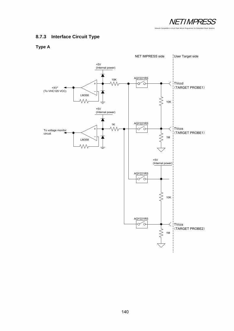
NETIMPRESS Network Compatible in-circuit Flash Micom Programmer for Embedded Smart Systems
140
8.7.3 Interface Circuit Type
Type A
NET IMPRESS side
+XV*(To VHC125 VCC)
To voltage monitor circuit
LM358
10K
1M
User Target side
+5V(Internal power)
+5V(Internal power)
1K
10K
LM358
10K
1M
+5V(Internal power)
TVccd(TARGET PROBE1)
TVccs(TARGET PROBE1)
TVccs(TARGET PROBE2)
AQY221RS
AQY221RS
AQY221RS
AQY221RS

NETIMPRESS Network Compatible in-circuit Flash Micom Programmer for Embedded Smart Systems
141
Type B
Type C
Type D
+XV*
220
1MVHC125
NET IMPRESS side User Target side
+5V(Internal power)
HCT244
+5V(Internal power)
220
1MVHC244
NET IMPRESS side User Target side
+XV*
22
1MVHC125
22
NET IMPRESS side User Target side
LVC244
+3.3V(Internal power)
+5V(Internal power)
HCT244
TC7SB66FU

NETIMPRESS Network Compatible in-circuit Flash Micom Programmer for Embedded Smart Systems
142
Type E
Type F
Type G
+XV*
22
1MVHC125
NET IMPRESS side User Target side
+5V(Internal power)
HCT244
TC7SB66FU
22
1MLVC244
+3.3V(Internal power)
NET IMPRESS side User Target side
+5V(Internal power)
HCT244
TC7SB66FU
1K
1MLVC244
+3.3V(Internal power)
NET IMPRESS side User Target side
+5V(Internal power)
HCT244
TC7SB66FU
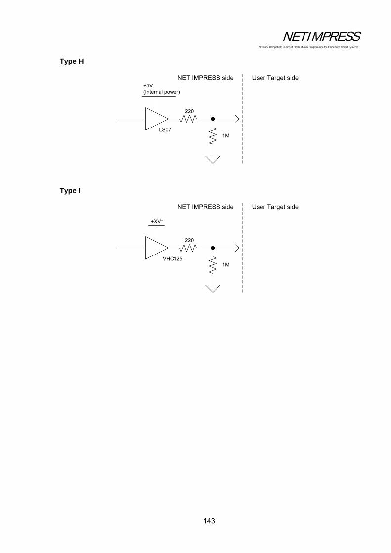
NETIMPRESS Network Compatible in-circuit Flash Micom Programmer for Embedded Smart Systems
143
Type H
Type I
220
1MLS07
NET IMPRESS side User Target side+5V(Internal power)
+XV*
220
1MVHC125
NET IMPRESS side User Target side

NETIMPRESS Network Compatible in-circuit Flash Micom Programmer for Embedded Smart Systems
144
Type J
Type K
120 120
G6K-2F(Relay)
G6K-2F(Relay)
CANH
CANL
PCA82C250
The initial status of Relay “OFF”, in other words, an OPEN status without a terminator.
Terminator setting circuit
CANH(+)
CANL(-)
NET IMPRESS side User Target side
2.2K
CANH
CANL
TJA1054
CANH(+)
CANL(-)
NET IMPRESS side User Target side
RTH
RTL
2.2K
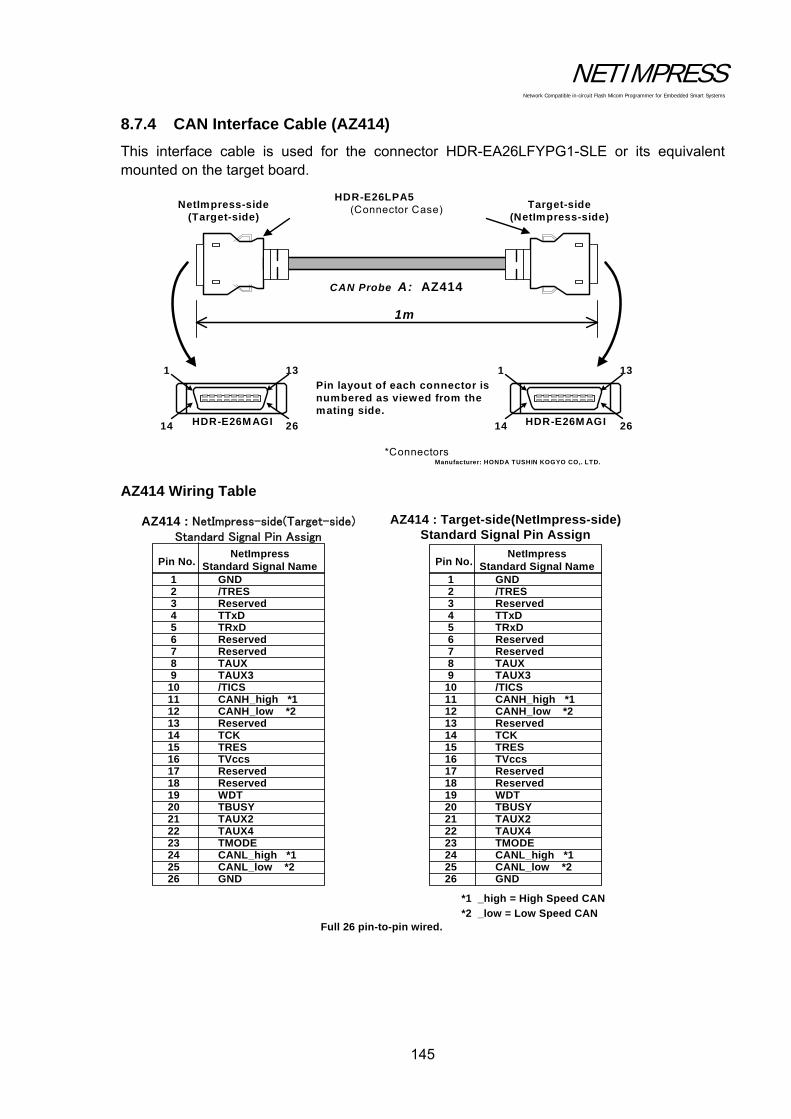
NETIMPRESS Network Compatible in-circuit Flash Micom Programmer for Embedded Smart Systems
145
8.7.4 CAN Interface Cable (AZ414)
This interface cable is used for the connector HDR-EA26LFYPG1-SLE or its equivalent mounted on the target board.
AZ414 Wiring Table
CAN Probe A: AZ414
1m
HDR-E26LPA5(Connector Case)
1 13
14 26HDR-E26MAGI
Pin layout of each connector isnumbered as viewed from themating side.
*ConnectorsManufacturer: HONDA TUSHIN KOGYO CO,. LTD.
1 13
14 26HDR-E26MAGI
NetImpress-side(Target-side)
Target-side(NetImpress-side)
AZ414 : NetImpress-side(Target-side) Standard Signal Pin Assign
Pin No.NetImpress
Standard Signal Name123456789
1011121314151617181920
Reserved
CANL_low *2
CANH_low *2
GND
CANH_high *1
CANL_high *1
/TICS
TMODE
TAUX3
TBUSY
Reserved
WDT
TRxD
Reserved
TTxD
Reserved
Reserved
TVccs
/TRES
212223242526
GND
ReservedTAUX
TCKTRES
TAUX2TAUX4
AZ414 : Target-side(NetImpress-side)Standard Signal Pin Assign
Pin No.NetImpress
Standard Signal Name123456789
1011121314151617181920
Reserved
CANL_low *2
CANH_low *2
GND
CANH_high *1
CANL_high *1
/TICS
TMODE
TAUX3
TBUSY
Reserved
WDT
TRxD
Reserved
TTxD
Reserved
Reserved
TVccs
/TRES
212223242526
GND
ReservedTAUX
TCKTRES
TAUX2TAUX4
Full 26 pin-to-pin wired.
*1 _high = High Speed CAN
*2 _low = Low Speed CAN
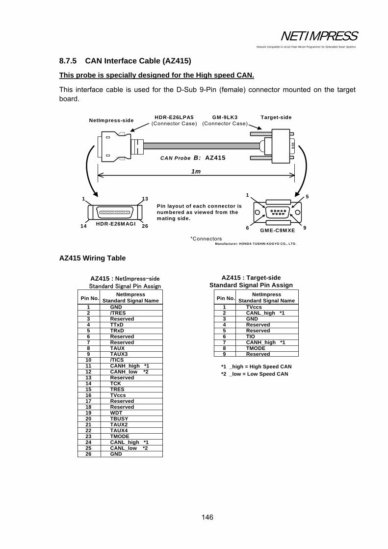
NETIMPRESS Network Compatible in-circuit Flash Micom Programmer for Embedded Smart Systems
146
8.7.5 CAN Interface Cable (AZ415)
This probe is specially designed for the High speed CAN.
This interface cable is used for the D-Sub 9-Pin (female) connector mounted on the target board.
AZ415 Wiring Table
CAN Probe B: AZ415
1m
HDR-E26LPA5(Connector Case)
1 13
14 26HDR-E26MAGI
Pin layout of each connector isnumbered as viewed from themating side.
*ConnectorsManufacturer: HONDA TUSHIN KOGYO CO,. LTD.
1 5
6 9
NetImpress-sideTarget-side
GME-C9MXE
GM-9LK3(Connector Case)
AZ415 : NetImpress-side Standard Signal Pin Assign
Pin No.NetImpress
Standard Signal Name123456789
1011121314151617181920
Reserved
CANL_low *2
CANH_low *2
GND
CANH_high *1
CANL_high *1
/TICS
TMODE
TAUX3
TBUSY
Reserved
WDT
TRxD
Reserved
TTxD
Reserved
Reserved
TVccs
/TRES
212223242526
GND
ReservedTAUX
TCKTRES
TAUX2TAUX4
AZ415 : Target-sideStandard Signal Pin Assign
Pin No.NetImpress
Standard Signal Name123456789 Reserved
TIOReservedReservedGNDCANL_high *1TVccs
CANH_high *1TMODE
*1 _high = High Speed CAN
*2 _low = Low Speed CAN

NETIMPRESS Network Compatible in-circuit Flash Micom Programmer for Embedded Smart Systems
147
8.7.6 CAN Interface Cable (AZ416)
This probe is specially designed for the Low speed CAN.
This interface cable is used for the D-Sub 9-Pin (female) connector mounted on the target board.
AZ416 Wiring Table
CAN Probe C: AZ416
1m
HDR-E26LPA5(Connector Case)
1 13
14 26HDR-E26MAGI
Pin layout of each connector isnumbered as viewed from themating side.
*ConnectorsManufacturer: HONDA TUSHIN KOGYO CO,. LTD.
1 5
6 9
NetImpress-sideTarget-side
GME-C9MXE
GM-9LK3(Connector Case)
AZ416 : NetImpress-side Standard Signal Pin Assign
Pin No.NetImpress
Standard Signal Name123456789
1011121314151617181920
Reserved
CANL_low *2
CANH_low *2
GND
CANH_high *1
CANL_high *1
/TICS
TMODE
TAUX3
TBUSY
Reserved
WDT
TRxD
Reserved
TTxD
Reserved
Reserved
TVccs
/TRES
212223242526
GND
ReservedTAUX
TCKTRES
TAUX2TAUX4
AZ416 : Target-sideStandard Signal Pin Assign
Pin No.NetImpress
Standard Signal Name123456789 Reserved
TIOReservedReservedGNDCANL_low *2TVccs
CANH_low *2TMODE
*1 _high = High Speed CAN
*2 _low = Low Speed CAN
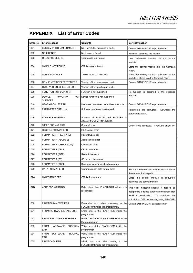
NETIMPRESS Network Compatible in-circuit Flash Micom Programmer for Embedded Smart Systems
148
APPENDIX List of Error Codes
Error No. Error message Contents Corrective action
1001 SYSTEM PROGRAM ROM ERR NETIMPRESS main unit is faulty. Contact DTS INSIGHT support center.
1002 NO LICENSE No license is found. You must purchase the license.
1003 GROUP CODE ERR Group code is different. Use parameters suitable for the control
module.
1004 CM FILE NOT FOUND CM file does not exist. Store the control module into the Compact
Flash.
1005 MORE 2 CM FILES Two or more CM files exist. Make the setting so that only one control
module is stored into the Compact Flash.
1006 COM ID VER UNEXPECTED ERR Version of the common part is old. Contact DTS INSIGHT support center.
1007 CM ID VER UNEXPECTED ERR Version of the specific part is old.
1008 FUNCTION NOT SUPPORT Function is not supported. No function is assigned to the specified
function. 1009 DEVICE FUNCTION NOT
SUPPORT
Device function is not supported.
1010 HPARAM CONST ERR Hardware parameter cannot be constructed. Contact DTS INSIGHT support center.
1015 PARAMETER ERR xxxx Software parameter is corrupted. Parameters are corrupted. Download the
parameters again.
1016 ADDRESS WARNING Address of FUNC-0 and FUNC-F5 is
different from that of FUNC-D6.
1020 S FILE FORMAT ERR S format error Object file is corrupted. Check the object file.
1021 HEX FILE FORMAT ERR HEX format error
1022 FORMAT ERR (REC TYPE) Record type error
1023 FORMAT ERR (ADDRESS) Address field error
1024 FORMAT ERR (CHECK SUM) Checksum error
1025 FORMAT ERR (CRLF) CRLF code error
1026 FORMAT ERR (SIZE) Record size error
1027 FORMAT ERR (S5) S5 record check error
1028 FORMAT ERR (ASCII) Binary conversion disabled data error
1029 DATA FORMAT ERR Communication data format error Since the communication error occurs, check
the communication path.
102A CM FORMAT ERR CM file format error Since the control module is corrupted,
download the control module.
102B ADDRESS WARNING Data other than FLASH-ROM address is
recognized. This error message appears if data to be
assigned to a device other than the target flash
ROM is downloaded. To shut-down this
output, turn OFF this warning using FUNC-9E.
1030 FROM PARAMETER ERR Parameter error when accessing to the
FLASH-ROM inside the programmer. Contact DTS INSIGHT support center.
1031 FROM HARDWARE ERASE ERR Erase error of the FLASH-ROM inside the
programmer
1032 FROM SOFTWARE ERASE ERR Blank check error of the FLASH-ROM inside
the programmer
1033 FROM HARDWARE PROGRAM
ERR
Write error of the FLASH-ROM inside the
programmer
1034 FROM SOFTWARE PROGRAM
ERR
Verify error of the FLASH-ROM inside the
programmer
1035 FROM DATA ERR Initial data error when writing to the
FLASH-ROM inside the programmer

NETIMPRESS Network Compatible in-circuit Flash Micom Programmer for Embedded Smart Systems
149
Error No. Error message Contents Corrective action
1041 PCIC WRITE CMD TIMEOUT CF write error The Compact Flash may be defective.
Contact DTS INSIGHT support center. 1042 PCIC WRITE STAT TIMEOUT
1043 PCIC WRITE BAD ERR
1044 PCIC WRITE SECTOR ERR
1045 PCIC WRITE ERR
1046 PCIC WRITE ECC ERR
1047 PCIC CMD ABORT
1048 PCIC WRITE NORMAL ERR
1049 PCIC WRITE UNKNOWN ERR
104A PCIC READ CMD TIMEOUT CF read error
104B PCIC READ STAT TIMEOUT
104C PCIC READ BAD ERR
104D PCIC READ SECTOR ERR
104E PCIC READ ECC ERR
104F PCIC READ CMD ERR
1050 PCIC READ NORMAL ERR
1051 PCIC READ UNKNOWN ERR
1060 FILE SYSTEM ERR (MBR) File system error of Compact Flash Since the Compact Flash is not formatted in
the FAT format, the card cannot be
recognized.
Format the Compact Flash in the FAT format.
1061 FILE SYSTEM ERR (PREG)
1062 FILE SYSTEM ERR (PBR)
1063 ILLEGAL FILE SYSTEM
1064 FILE SYSTEM ERR (FAT CNT)
1065 UNC ERR It is prohibited to use the network path.
1066 FULL PATH ERR Shorten the file and folder names.
1067 PATH LENGTH ERR
1068 SHORT NAME ERR Short file name cannot be created any further.
1069 CF DISK FULL (DIR) Free area of the root is insufficient.
Delete the file or folder in the root.
106A CF DISK FULL (DAT) Free data area of the Compact Flash is
insufficient. Delete the file or folder.
106D DOS FILE SIZE ERR File system of the Compact Flash may be
corrupted. Format the Compact Flash in the
FAT format. 106E FILE SYSTEM ERR (FAT)
1070 FILE READ ONLY ERR Write-access is made to the read-only file. Since the specified file is a read-only file, this
error is output.
Change the file destination or change the file
attribute of the specified file.
1072 FILE NOT EXIST File is not found. Since the specified file is not found, this error
is output.
Change the file destination or store the
specified file.
1073 FILE EXIST File already exists. Since the specified file already exists, the error
is output.
Change the file designation or delete the
specified file.
1074 FOLDER NOT EXIST Folder is not found. Since the specified folder is not found, the
error is output. Change the folder destination
or store the specified folder.
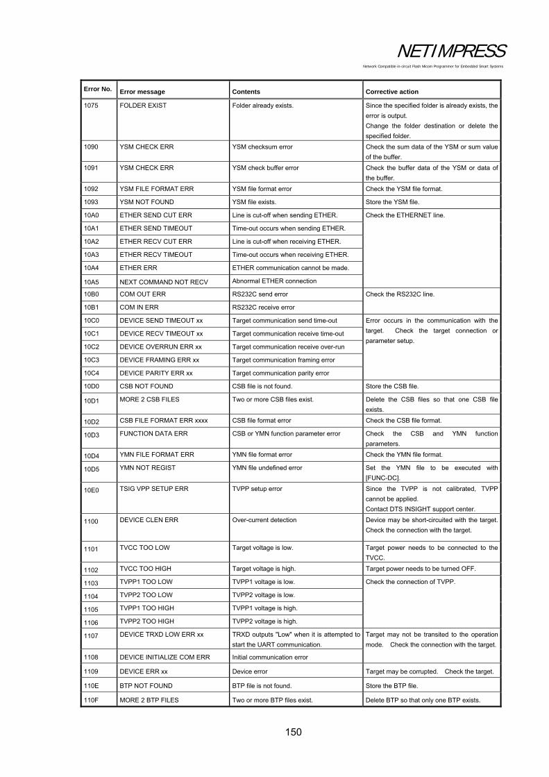
NETIMPRESS Network Compatible in-circuit Flash Micom Programmer for Embedded Smart Systems
150
Error No. Error message Contents Corrective action
1075 FOLDER EXIST Folder already exists. Since the specified folder is already exists, the
error is output.
Change the folder destination or delete the
specified folder.
1090 YSM CHECK ERR YSM checksum error Check the sum data of the YSM or sum value
of the buffer.
1091 YSM CHECK ERR YSM check buffer error Check the buffer data of the YSM or data of
the buffer.
1092 YSM FILE FORMAT ERR YSM file format error Check the YSM file format.
1093 YSM NOT FOUND YSM file exists. Store the YSM file.
10A0 ETHER SEND CUT ERR Line is cut-off when sending ETHER. Check the ETHERNET line.
10A1 ETHER SEND TIMEOUT Time-out occurs when sending ETHER.
10A2 ETHER RECV CUT ERR Line is cut-off when receiving ETHER.
10A3 ETHER RECV TIMEOUT Time-out occurs when receiving ETHER.
10A4 ETHER ERR ETHER communication cannot be made.
10A5 NEXT COMMAND NOT RECV Abnormal ETHER connection
10B0 COM OUT ERR RS232C send error Check the RS232C line.
10B1 COM IN ERR RS232C receive error
10C0 DEVICE SEND TIMEOUT xx Target communication send time-out Error occurs in the communication with the
target. Check the target connection or
parameter setup. 10C1 DEVICE RECV TIMEOUT xx Target communication receive time-out
10C2 DEVICE OVERRUN ERR xx Target communication receive over-run
10C3 DEVICE FRAMING ERR xx Target communication framing error
10C4 DEVICE PARITY ERR xx Target communication parity error
10D0 CSB NOT FOUND CSB file is not found. Store the CSB file.
10D1 MORE 2 CSB FILES Two or more CSB files exist. Delete the CSB files so that one CSB file
exists.
10D2 CSB FILE FORMAT ERR xxxx CSB file format error Check the CSB file format.
10D3 FUNCTION DATA ERR CSB or YMN function parameter error Check the CSB and YMN function
parameters.
10D4 YMN FILE FORMAT ERR YMN file format error Check the YMN file format.
10D5 YMN NOT REGIST YMN file undefined error Set the YMN file to be executed with
[FUNC-DC].
10E0 TSIG VPP SETUP ERR TVPP setup error Since the TVPP is not calibrated, TVPP
cannot be applied.
Contact DTS INSIGHT support center.
1100 DEVICE CLEN ERR Over-current detection Device may be short-circuited with the target.
Check the connection with the target.
1101 TVCC TOO LOW Target voltage is low. Target power needs to be connected to the
TVCC.
1102 TVCC TOO HIGH Target voltage is high. Target power needs to be turned OFF.
1103 TVPP1 TOO LOW TVPP1 voltage is low. Check the connection of TVPP.
1104 TVPP2 TOO LOW TVPP2 voltage is low.
1105 TVPP1 TOO HIGH TVPP1 voltage is high.
1106 TVPP2 TOO HIGH TVPP2 voltage is high.
1107 DEVICE TRXD LOW ERR xx TRXD outputs "Low" when it is attempted to
start the UART communication.
Target may not be transited to the operation
mode. Check the connection with the target.
1108 DEVICE INITIALIZE COM ERR Initial communication error
1109 DEVICE ERR xx Device error Target may be corrupted. Check the target.
110E BTP NOT FOUND BTP file is not found. Store the BTP file.
110F MORE 2 BTP FILES Two or more BTP files exist. Delete BTP so that only one BTP exists.

NETIMPRESS Network Compatible in-circuit Flash Micom Programmer for Embedded Smart Systems
151
Error No. Error message Contents Corrective action
1110 BTP FORMAT ERR BTP file format error Check the BTP file format.
1111 KEY NOT FOUND KEY file is not found. Store the KEY file.
1112 MORE 2 KEY FILES Two or more KEY files exist. Delete KEY so that only one KEY exists.
1113 KEY FORMAT ERR KEY file format error Check the KEY file format.
1114 KEY ERR KEY check err
1120-113F xxxxx Error occurs in the definition of the specific
part.
See the manual for control module.
1150 YIM MAX YIM folder is not created any further.
1151 YIM PROTECTED YIM folder is protected.
1160 YLC NOT FOUND YLC file is not found. Contact DTS INSIGHT support center.
1161 MORE 2 YLC FILES Two or more YLC files exist.
1162 YLC FORMAT ERR YLC file format error
Check the YCM file.
Set the YIM folder.
1170 YCM FORMAT ERR YCM file format error
1180 YIM NOT REGIST YIM undefined error
1181 CM NOT REGIST Control module undefined error Download the control module.
1182 BUF NOT REGIST Buffer memory undefined error Keep a sufficient free area size of the DOS
area and start up the programmer.

NETIMPRESS Network Compatible in-circuit Flash Micom Programmer for Embedded Smart Systems
152
New Error Codes for NETIMPRESS next
Error No. Error message Contents Corrective action
1A00 SCRIPT FILE NOT (START) Script file check error:
No (START) line on the executing script file Check the script file
1A01 SCRIPT FILE ERR LINE XXXX
Script file check error:
There are unspecified descriptions on the line No.
xxx of the executing script file.
Check the script file
1A02 SCRIPT FILE FORMAT ERR Script file check error:
No (END) line on the executing script file. Check the script file
1A03 SCRIPT EMPTY
Script file check error:
No commands to execute on the (START) to (END)
of the executing script file
Check the script file
1A04 SCRIPT DI TIMEOUT
Error while executing the script file:
Cannot detect the on/off of input signal which is
specified during time-out time on the INPUT line of
the script.
Check the line of the error script file, and your
environments.
1A05 SCRIPT FILE NOT FOUND
Error for the script file search:
Cannot find the script file specified by bar-code or
digital input.
Make sure that the information specified by the
bar-code or digital input conforms to a target
script file.
1A06 DIO CLEN ERR Overcurrent is detected when outputting digital I/OCheck the wire connection of digital I/O of
programmer and your DI/O unit.
1A10 RTC DATA FORMAT ERR Abnormal setting value is detected in the setting of
NETIMPRESS next internal RTC
Check that the set value is within the
specification time.
1A20 BCR RECV TIMEOUT Time-out occurs when receiving the bar-code
Check the SUFFIX setting of the bar-code
reader.
If SUFFIX is specified by YBO file, check the
characters specified for SUFFIX, and your
bar-code data.
1A21 BCR DATA FORMAT ERR Format of the bar-code data is not correct
Check the created bar-code data.
Check that the designation of bar-code option
file (YBO) is correct.
1A23 BCR
YBOFILE_FORMAT_ERR Format error of the bar-code option file (YBO) Check the YBO file.
1A24 MORE 2 YBO FILES More than one bar-code option files (YBO) are
existed.
Make sure to place only one YBO file in the root
directory of the Compact Flash.
1A25 BCR RECV OVER Over-incoming data buffer of bar-code data Designate 2048 byte or less for the bar-code
data
1A26 MORE 1 YBO FILE Loaded another YBO file, even though there is a
YBO file already
Make sure to place only one YBO file in the root
directory of the Compact Flash.
1A27 BCR CLEN ERR Overcurrent occurs when connecting the bar-codeCheck the condition of devices connected to
AZ402
1A29-1A2C BCR ILLEGAL DATA(XXXX) Analysis error of the received bar-code
Check the created bar-code data.
Check that the designation of bar-code option
file (YBO) is correct.