2 Presentation. Next Generation Technology-Enhanced Learning
Upload
nist-odishaCategory
view
0download
0
The next-generation BLASTPol experiment
Bradley J. Dober∗a, Peter A. R. Adeb, Peter Ashtonc, Francesco E. Angilea, James A. Bealld,Dan Beckerd, Kristi J. Bradforde, George Chee, Hsiao-Mei Chod, Mark J. Devlina, Laura M.
Fisselc, Yasuo Fukuif, Nicholas Galitzkia, Jiansong Gaod, Christopher E. Groppie, SethHillbrandg, Gene C. Hiltond, Johannes Hubmayrd, Kent D. Irwinh, Jeffrey Kleina, Jeff VanLanend, Dale Lid, Zhi-Yun Lii, Nathan P. Louriea, Hamdi Manie, Peter G. Martinj, Philip
Mauskopfe, Fumitaka Nakamurak, Giles Novakc, David P. Pappasd, Enzo Pascaleb, Fabio P.Santosc, Giorgio Savinil, Douglas Scottm, Sara Stanchfielda, Joel N. Ullomd, Matthew
Underhille, Michael R. Vissersd, Derek Ward-Thompsonn
aDepartment of Physics and Astronomy University of Pennsylvania, 209 South 33rd Street,Philadelphia, PA 19104;
bDepartment of Physics & Astronomy, Cardiff University, 5 The Parade, Cardiff CF24 3A A,UK;
cDepartment of Physics & Astronomy, Northwestern University, 2145 Sheridan Road,Evanston, IL 60208;
dQuantum Electronics and Photonics Division, National Institute of Standards andTechnology, 325 Broadway Street, Boulder, CO 80305;
eDepartment of Physics, Arizona State University, P.O. Box 871504, Tempe, AZ 85287;fDepartment of Physics and Astrophysics, Nagoya University, Chikusa-ku Nagoya 464-8602,
Japan;gDepartment of Physics and Astronomy, California State University, Sacramento, 6000 J
Street, Sacramento, CA 95819;hDepartment of Physics, Stanford University, 382 Via Pueblo Mall, Stanford, CA 94305;iDepartment of Astronomy, University of Virginia, P. O. Box 400325, Charlottesville, VA
22904;jDepartment of Astronomy & Astrophysics, University of Toronto, 50 St. George Street,
Toronto, ON M5S 3H4, Canada;kNational Astronomical Observatory, Mitaka, Tokyo 181-8588, Japan;
lDepartment of Physics and Astronomy, University College London, Gower Street, London,WC1E 6BT, UK;
mDepartment of Physics and Astronomy, 6224 Agricultural Road, University of BritishColumbia, Vancouver, BC, V6T 1Z1 Canada;
nJeremiah Horrocks Institute of Maths, Physics and Astronomy, University of CentralLancashire, Preston, PR1 2HE, UK;
ABSTRACT
The Balloon-borne Large Aperture Submillimeter Telescope for Polarimetry (BLASTPol) is a suborbital map-ping experiment designed to study the role magnetic fields play in star formation. BLASTPol has had twoscience flights from McMurdo Station, Antarctica in 2010 and 2012. These flights have produced thousands of
∗Corresponding Author. E-mail: [email protected], Telephone: 215-746-3792Copyright 2014 Society of Photo-Optical Instrumentation Engineers. One print or electronic copy may be made forpersonal use only. Systematic reproduction and distribution, duplication of any material in this paper for a fee or forcommercial purposes, or modification of the content of the paper are prohibited.
arX
iv:1
407.
3756
v1 [
astr
o-ph
.IM
] 1
4 Ju
l 201
4

polarization vectors at 250, 350 and 500 microns in several molecular cloud targets. We present the design,specifications, and progress towards the next-generation BLASTPol experiment (BLAST-TNG). BLAST-TNGwill fly a 40% larger diameter primary mirror, with almost 8 times the number of polarization-sensitive detec-tors resulting in a factor of 16 increase in mapping speed. With a spatial resolution of 22′′ and four times thefield of view (340 arcmin2) of BLASTPol, BLAST-TNG will bridge the angular scales between Planck’s all-skymaps with 5′ resolution and ALMA’s ultra-high resolution narrow (∼ 20′′) fields. The new receiver has a largercryogenics volume, allowing for a 28 day hold time. BLAST-TNG employs three arrays of Microwave KineticInductance Detectors (MKIDs) with 30% fractional bandwidth at 250, 350 and 500 microns. In this paper, wewill present the new BLAST-TNG instrument and science objectives.
Keywords: BLAST, MKID, Submillimeter, Star Formation, Polarimetry, Instrumentation, Molecular Cloud,Balloon Payload
1. INTRODUCTION
The BLASTPol experiment was a stratospheric 1.8 m telescope which observed the sky with bolometric detectorsoperating in three 30% wide bands at 250, 350 and 500 µm. Polarization sensitivity was achieved via the insertionof polarized grids in front of the detector arrays. Polarization modulation was achieved via a stepped achromatichalf-wave plate (HWP). BLASTPol had two Long Duration Balloon (LDB) flights from McMurdo, Antarcticain 2010 and 2012. Some results from these flights are documented elsewhere.1–3
The next generation BLASTPol experiment will improve upon the previous BLASTPol measurements. Witha larger 2.5 m primary mirror and almost 8 times more detectors, it will have an increased resolution (22′′ at250 µm), four times the field of view (340 arcmin2), and up to 16 times the mapping speed of BLASTPol. Thisperformance enhancement will enable us to perform the most detailed study of the role of magnetic fields in theregulation of star formation than ever achieved before.
2. SCIENTIFIC MOTIVATION
After decades of research, the physical processes regulating star formation remain poorly understood. Large-scaleobservations of star forming regions provide counts of the number of dense clouds, each of which will eventuallyevolve into many thousands of stars. However, when simple models of gravitational collapse are applied to theclouds they yield a Galactic star formation rate (SFR) that is many times larger than what is actually observed.Some process or combination of processes must be slowing the collapse of the clouds. The two prevailing theoriesinvolve turbulence, which prevents the effective dissipation of energy, and Galactic magnetic fields, which arecaptured and squeezed by the collapsing cloud providing a mechanism for mechanical support.
In many numerical simulations, magnetic fields dramatically affect both the star formation efficiency andlifetime of molecular clouds.4–6 However observationally, the strength and morphology of magnetic fields inmolecular clouds remain poorly constrained. A useful tracer of magnetic fields in star forming regions is polar-ization. By mapping polarization from dust grains aligned with respect to their local magnetic field, the fieldorientation (projected on the sky) can be traced. Molecular clouds typically have temperatures of several tens ofKelvin with emission peaking in the submillimeter. Most previous submillimeter polarimetry observations havegenerally been restricted to bright targets (> 1 Jy) and small map sizes (< 0.05 deg2).7,8
One of BLAST-TNG’s main goals is to map the magnetic field morphology of a large sample of molecularclouds in order to account for projection effects and obtain robust statistics on magnetic field morphology. Alarge sample of molecular clouds will allow us to constrain star formation models. BLAST-TNG can providevaluable data that will aid in two major areas of star formation models: how ordered are the magnetic fields inthe molecular cloud, and how does that field direction correlate with the filamentary structure within the clouds?Numerical simulations have shown that molecular clouds with strong magnetic fields show less polarization angledispersion than clouds with weak fields.9–12 Recently, polarization maps have been used to characterize themagnetized turbulence power spectrum within molecular clouds.13,14 These analyses are based on a polarizationangle dispersion function and can be used to characterize the relative strength of the ordered and turbulentmagnetic field components. The same analysis can be applied to all the BLAST-TNG polarization maps, resulting

Figure 1. BLAST-TNG provides the critical link between Planck’s all-sky polarimetry at 850 µm with 5′ resolution andALMA’s 0.01′′ resolution polarimetry at the same wavelength. The upper left is a Galactic-scale Planck image followedby the BLAST observation of Vela18 and the magnetic field map for the IRAS 4A protobinary in Perseus acquired usingthe Submillimeter Array (a precursor to ALMA).19 BLAST-TNG will map polarization using a 22′′ FWHM beam at250 µm. This beam nearly matches the ALMA 850 µm field-of-view and is more than 200 times smaller (in area) thanPlanck’s 850 µm beam.
in a more complete and accurate picture. Also, faint, low column density 12CO filaments observed in Taurus15,16
seem to closely follow magnetic field lines traced by optical polarimetry, which could indicate streaming ofmolecular gas along field lines. BLAST-TNG will be able to investigate the alignment between the magneticfields and intermediate and high density filaments seen in Herschel maps.17 With an increase in knowledge ofthe role of magnetic fields in molecular clouds, we will come one step closer to understanding how stars form.
BLAST-TNG, and its predecessor, BLASTPol, are the first instruments to combine the sensitivity andmapping speed necessary to trace magnetic fields across entire clouds with the resolution to trace fields downinto dense substructures, including cores and filaments. BLAST-TNG provides the critical link between thePlanck all-sky polarization maps with 5′ resolution and ALMA’s ultra-high resolution, narrow (20′′) field ofview.20,21 BLAST-TNG will use Planck ’s all-sky data to refine its target selection. ALMA will then be able toutilize BLASTPol maps to zero in on areas of particular interest. Together, these three instruments will be ableto probe the inner workings of star formation with previously unreachable resolution, sensitivity and scope.
BLAST was originally designed as an unpolarized instrument to study high redshift dusty infrared galaxies.The conversion to BLASTPol was intended as a proof of concept to see if the technique is viable. While BLASTPolwas able to make ground-breaking initial measurements, its utility was limited. In order to make technologicalprogress and fully exploit the targets made available by Planck, a next generation instrument powered by largearrays of state-of-the-art detectors must be built. In previous BLASTPol flights, ∼5 deg2 was mapped in total,while nearby star forming complexes such as Vela or Lupus are 10-100 deg2. With BLASTPol we could onlymap a small fraction of a complex, but with this new instrument, the ability to map the entire complex is readilyachievable.
3. INSTRUMENT
This section will focus primarily on components that differ from the previous incarnation of BLASTPol. Thedesign and specifications of this instrument are driven by science goals, availability of existing instrumentation,and the practical limitations of ballooning.
3.1 Optical Design
BLAST-TNG will utilize a 2.5 m carbon fiber reinforced polymer (CFRP) parabolic primary mirror (Figure 2,Right). It will be constructed by Vanguard Space Technologies in San Diego, CA. The carbon fiber primarymirror will be constructed by applying layers of CFRP to a precision-ground positive granite mold. This layer will

Figure 2. Left: The BLAST-TNG gondola design with the inner and outer sun shields removed. Right: The CFRP mirrordesign concept by Vanguard Space Technologies. The CFRP optics bench supports and constrains both the primary andsecondary mirrors at all pointing elevations.
‘sandwich’ an aluminum honeycomb support structure. This CFRP / aluminum honeycomb / CFRP sandwichwill be attached to a carbon fiber optics bench to maintain its shape at all elevation angles. A 50 cm diametersecondary mirror will be machined out of aluminum and is mounted to the optics bench via three CFRP struts.The secondary mirror will possess an in-flight focusing method via three ∼400 g stepper motors. These opticsprovide diffraction-limited performance over a 22′ diameter FOV at the Cassegrain focus at λ = 250 µm. Theestimated antenna efficiency is ≥ 95%. A complete discussion of the previous BLASTPol optics for the 2005Sweden flight can be found in previous papers.22
The cold reimaging optics (Figure 3) are kept at 4 K and consist of an Offner-relay configuration with twoconcave spherical mirrors and a third cold spherical mirror at the position of an image of the primary mirror.This third spherical mirror acts as a Lyot stop, provides a location for a calibration source, and allows foradditional side-lobe rejection. The off-axis angle of the final reimaging mirror allows us to place two dichroicbeam splitters in front of the focal plane, making possible simultaneous measurements by all three arrays atdifferent wavelengths.
3.2 Cryostat Design
BLAST-TNG’s cryostat design is based on the previous BLAST and BLASTPol cryostat.23,24 Instead of separateLN and LHe reservoirs, the new design calls for a single 250 L LHe tank which forces the boiled-off He gas throughtwo heat exchangers that cool two vapor-cooled shields (VCS), which operate at 66 K and 190 K. We baselinean efficiency of 80% for the heat exchangers, which corresponds to a 28 day hold time, based on testing of aprototype design. We expect to achieve better performance for the fully optimized devices that will be used inthe cryostat.
Due to the larger cryogenic volume and proportionally larger optics, the BLAST-TNG cryostat will be 3.33times larger in volume than the previous BLAST cryostat. This corresponds to a cryostat diameter of 40 inchesand a height of 60 inches. The detectors will be kept at ∼280 mK by a closed cycle 3He sorption fridge which isbacked by a 1 K pumped 4He fridge. The self-contained, recycling refrigerator can maintain a base temperatureof 280 mK with 30 µW of cooling power for 4 days. The refrigerator can be recycled in under 2 hours and will be

Figure 3. A cutaway view of the BLAST-TNG optics box. Light enters from the lower left and is re-imaged onto the threedetector arrays (500 µm array shown at top left). Two dichroic filters split the beam to the 250 and 350 µm arrays whichare mounted on the opposite side of the optics bench. A cold Lyot stop is placed at the image of the primary mirror whichallows for greater sidelobe rejection and the introduction of a calibration source. A modulating cold half-wave plate isplaced inside the optics box. The motorized mechanism for rotating the waveplate is mounted at 300 K on the inside ofthe vacuum shell.
cycled every ∼40 hours. The pumped pot maintains 1 K with 20 mW of cooling power with outside atmosphericpressure of 15 Torr or less.
3.3 Gondola Design
The BLAST-TNG gondola provides a pointed platform for the telescope and attaches to the balloon flight train.The gondola consists of two parts: an outer aluminum frame, which can be pointed in azimuth; and an inneraluminum frame which points in elevation. While the BLAST-TNG outer frame remains the same from BLASTand BLASTPol, the gondola inner frame has been completely redesigned to accommodate a ∼3.4 times largercryostat and 40% larger diameter primary mirror (see Figure 2). The pyramids that support the inner framehave been replaced with a step ladder style trusses which are similar to those employed by EBEX.25
To avoid large thermal changes in the optics both the inner and outer frames have attached sunshield struc-tures, which is shown in Figure 4. In order to accommodate the larger inner frame sunshield and maintain ourBLASTPol’s maximum pointing elevation of 55 degrees, we also adopt a spreader bar design that is based onone from the EBEX gondola.25
BLAST-TNG uses the same azimuth control as BLASTPol, which was controlled by a brushless, direct driveservo motor attached to a high moment of inertia reaction wheel, and an active pivot motor which connectedthe cable suspended gondola to the balloon flight train. The reaction wheel consists of a 1.5 m disk made of7.6 cm thick aluminum honeycomb, with 48 0.9 kg brass disks mounted around the perimeter. The reactionwheel is mounted below the center of mass of the telescope, directly beneath the active pivot. By spinningthe reaction wheel, angular momentum can be transferred to and from the gondola, allowing precise controlover the azimuthal velocity of the telescope with minimal latency. The active pivot motor provides additionalazimuthal torque by twisting against the flight train, and can also be used over long time scales to transferangular momentum to the balloon.
BLAST-TNG uses the same suite of sensors (GPS, pinhole sun sensors, magnetometers, gryoscopes, starcameras,26 and inclinometers) that have been used in previous BLAST and BLASTPol flights. A complete

Figure 4. The BLAST-TNG sunshield design. The inner baffle allows BLAST-TNG to observe targets between 22-55
elevation and as close as 35 to the sun, while the outer baffle shields the cryostat and electronics from overheating. Left:Right: The rear view of the gondola shows where the readout electronics (teal), power generation (purple) and breakout(blue) hardware enclosures will be mounted on the inner and outer frames.
discussion of our hierarchal attitude determination methods and full suite of pointing sensors can be foundelsewhere.27
The elevation of the inner frame is controlled by a Kollmorgon DC brushless servo motor mounted on oneside of the inner frame at the attachment point to the outer frame. A free bearing provides the connection pointbetween the inner and outer frames, on the other side. To maintain the dynamic balance of the BLASTPol innerframe, fluid was pumped from a low part of the inner frame to a high part to compensate for the mass lost fromcryogen boil-off during flight. However, with the increase in cryogens in BLAST-TNG, the ballast tank systembecame a higher liability during the flight. Therefore, the servo motor has been fitted with a Harmonic Drivehigh torque 80:1 gearhead. The Harmonic Drive∗ has zero backlash and supplies more than enough torque torotate the inner frame once the cryostat becomes unbalanced after cryogen boil-off. Since the servo motor is nowgeared, an absolute optical encoder is being used. The RESOLUTE absolute rotary encoder on RESA rings†
provides resolution to 0.00075 arc-second, which is much more precise than required by BLAST-TNG.
3.4 Detectors
BLAST-TNG will drive the development of polarization-sensitive TiN microwave kinetic inductance detectors(MKIDs) for submillimeter wavelengths. The MKIDs will be divided into three arrays of 627, 324, and 201 feedsat 250, 350, and 500 µm, respectively (See Table 1). Each feedhorn has two orthogonal polarization-sensitivedetectors, allowing for simultaneous observations of both polarizations in the same spatial pixel. This designproduces just over 2300 detectors in BLAST-TNG, ∼8.2 times that of BLASTPol. These new MKID arraysincrease the net mapping speed of BLAST-TNG by a factor of 16 over BLASTPol.
The detectors for BLAST-TNG are based on microwave kinetic inductance detectors (MKIDs), a leadingdetector candidate for future FIR/sub-mm satellite missions. In MKIDs, photons incident on a superconductingfilm with energy above the gap create a change in quasi-particle density that can be determined by measuring thecomplex impedance of the film.28 Benefits of MKIDs include built-in frequency domain multiplexing capabilities,the potential for simplified fabrication and the decreased complexity of low temperature cabling and focal planeinter-connects. Thousands of MKIDs, fabricated on a single layer, can be coupled to one RF line and amplifiedby a low power (<5 mW), wide-bandwidth, cryogenic silicon germanium (SiGe) amplifier.
∗Harmonic Drive LLC. http://harmonicdrive.net/products/gearheads/csg-unit/†Renishaw PLC. http://www.renishaw.com/en/resolute-rotary-angle-absolute-encoder-options–10939
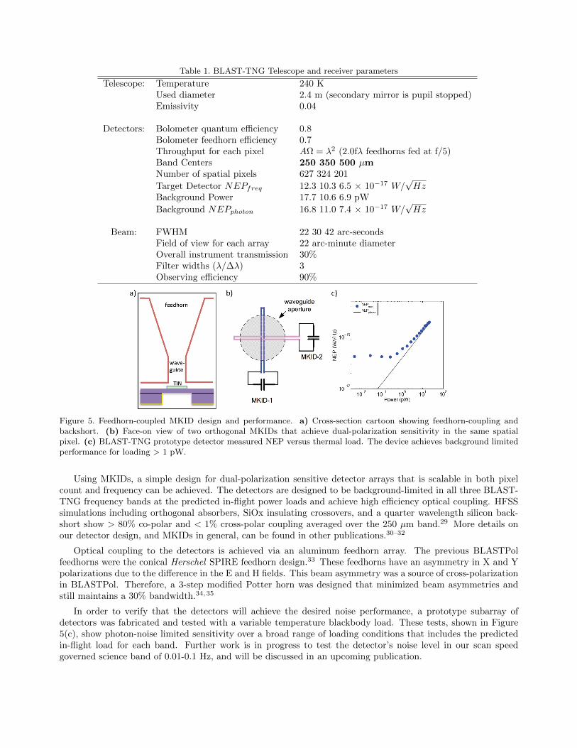
Table 1. BLAST-TNG Telescope and receiver parameters
Telescope: Temperature 240 KUsed diameter 2.4 m (secondary mirror is pupil stopped)Emissivity 0.04
Detectors: Bolometer quantum efficiency 0.8Bolometer feedhorn efficiency 0.7Throughput for each pixel AΩ = λ2 (2.0fλ feedhorns fed at f/5)Band Centers 250 350 500 µmNumber of spatial pixels 627 324 201
Target Detector NEPfreq 12.3 10.3 6.5 × 10⁻¹⁷ W/√Hz
Background Power 17.7 10.6 6.9 pW
Background NEPphoton 16.8 11.0 7.4 × 10⁻¹⁷ W/√Hz
Beam: FWHM 22 30 42 arc-secondsField of view for each array 22 arc-minute diameterOverall instrument transmission 30%Filter widths (λ/∆λ) 3Observing efficiency 90%
Figure 5. Feedhorn-coupled MKID design and performance. a) Cross-section cartoon showing feedhorn-coupling andbackshort. (b) Face-on view of two orthogonal MKIDs that achieve dual-polarization sensitivity in the same spatialpixel. (c) BLAST-TNG prototype detector measured NEP versus thermal load. The device achieves background limitedperformance for loading > 1 pW.
Using MKIDs, a simple design for dual-polarization sensitive detector arrays that is scalable in both pixelcount and frequency can be achieved. The detectors are designed to be background-limited in all three BLAST-TNG frequency bands at the predicted in-flight power loads and achieve high efficiency optical coupling. HFSSsimulations including orthogonal absorbers, SiOx insulating crossovers, and a quarter wavelength silicon back-short show > 80% co-polar and < 1% cross-polar coupling averaged over the 250 µm band.29 More details onour detector design, and MKIDs in general, can be found in other publications.30–32
Optical coupling to the detectors is achieved via an aluminum feedhorn array. The previous BLASTPolfeedhorns were the conical Herschel SPIRE feedhorn design.33 These feedhorns have an asymmetry in X and Ypolarizations due to the difference in the E and H fields. This beam asymmetry was a source of cross-polarizationin BLASTPol. Therefore, a 3-step modified Potter horn was designed that minimized beam asymmetries andstill maintains a 30% bandwidth.34,35
In order to verify that the detectors will achieve the desired noise performance, a prototype subarray ofdetectors was fabricated and tested with a variable temperature blackbody load. These tests, shown in Figure5(c), show photon-noise limited sensitivity over a broad range of loading conditions that includes the predictedin-flight load for each band. Further work is in progress to test the detector’s noise level in our scan speedgoverned science band of 0.01-0.1 Hz, and will be discussed in an upcoming publication.

Figure 6. Focal Plane Array (FPA) design and assembly. Left: A rendering of the FPA in its two-stage CFRP thermalstandoff. The top ring sits at 1 K and provides a mount point for the directional coupler while the FPA sits at 280 mK.Right: A cross-sectional exploded view of the FPA. The detector wafer (green) is mounted directly below a squarewaveguide interface wafer (blue). Both of these elements are fixed in X/Y via a pin (orange) and slot method, and fixedin Z via several beryllium copper spring tabs. The feedhorns (teal) are mounted on top, as well as a bandpass filter.
The detectors are housed in a focal plane array housing (FPA) which is an 8-sided polygon and is shown inFigure 6. The backplate possesses a rim for mounting the thermal standoff, SMA connectors, and heat strapto the 300 mK absorption fridge. The detector and square waveguide interface wafers are mounted inside thebackplate via a pin-and-slot method to constrain the detectors in X/Y. To fix the Z dimension, both wafersare held down to the backplate via beryllium copper spring tabs. The detector wafer is oversized compared tothe square interface wafer to allow for wirebonds to both the microstrip multiplexing lines. Additionally, goldwirebonds are made to increase the thermal conductivity and keep the detectors cooled to 280 mK. Finally, thefeedhorn plate attaches to the outer rim of the backplate and is constrained via two close-fit pins. A bandpassfilter is attached to the front of the feedhorn plate.
The thermal standoff consists of two interlocking sets of thin-walled CFRP rods. The first set of rods are2 inches long and isolate the 4 K optics box to a ring at 1 K. One set of SMA cables is heat sunk to the 1 Kstage via a directional coupler. Next, a set of one inch long rods isolate the 1 K stage from the FPA which iscooled to 280 mK. Thermal conductivity calculations show that the load to the 280 mK and 1 K stages will be∼14 µW and ∼ 120 µW, respectively, for all three arrays. Finite element analysis on the carbon fiber supportstructure shows < 5 µm of deflection during normal operation. This amount of thermal loading and deflectionis well within our tolerances.
3.5 Polarization Modulation
The primary modulation scheme for BLAST-TNG will be based on the successful implementation of a broad-bandhalf-wave plate (HWP) used in BLASTPol shown in Figure 3. The low-emissivity HWP consists of five 500 µmsapphire layers glued together with 6 µm layers of polyethylene. The HWP has a metal mesh anti-reflectivecoating36 with a measured in band transmission of 86-95%. Located inside the cryogenic optics box, the HWPis far from the Cassegrain focus (∼30 cm) while allowing it to dissipate heat to the 4 K stage. Raster maps withareas ranging from 0.25 to tens of square degrees are made by scanning the gondola in azimuth and elevation.The HWP orientation is changed at the end of each raster scan (∼10 min). A typical 5 hour integration thereforeconsists of ∼30 HWP moves. The integration is spread over the flight to maximize the sky rotation while takingfull advantage of the polarization modulation.
BLAST-TNG has two orthogonally polarized detectors per pixel with the vectors rotated by 45deg from pixelto pixel along the scan direction. As the telescope scans at a typical speed of 0.1/s, this configuration providesnear simultaneous measurements of both Q and U while eliminating most of the common-mode 1/f noise. Italso provides a “fail safe” backup should the HWP rotation mechanism somehow fail. The BLAST-TNG coldoptics are larger, similar versions of what was used for BLASTPol (Figure 3), which has a measured instrumentalpolarization of < 0.5%. The symmetry of our on-axis telescope provides low inherent instrumental polarization.Operation in the submillimeter carries the risk of diffraction and scattering off of the secondary mirror and its

supports. However, there was no evidence of this with BLASTPol. The signals from the dust polarization aremuch larger in the submillimeter than they are in the CMB bands. Therefore, BLAST-TNG does not requirethe extreme control of systematic effects that are needed to measure CMB polarization directly.
ACKNOWLEDGMENTS
The BLAST collaboration acknowledges the support of NASA through grant numbers NNX13AE50G S04 andNNX09AB98G, the Leverhulme Trust through the Research Project Grant F/00 407/BN, Canada’s NaturalSciences and Engineering Research Council (NSERC), and the National Science Foundation Office of PolarPrograms. Frederick Poidevin thanks the Spanish Ministry of Economy and Competitiveness (MINECO) underthe Consolider-Ingenio project CSD2010-00064 (EPI: Exploring the Physics of Inflation). Bradley Dober issupported through a NASA Earth and Space Science Fellowship. Peter Ashton is supported through Reach forthe Stars, a GK-12 program supported by the National Science Foundation under grant DGE-0948017. However,any opinions, findings, conclusions, and/or recommendations are those of the investigators and do not necessarilyreflect the views of the Foundation. We would also like to thank the Columbia Scientific Balloon Facility (CSBF)staff for their continued outstanding work.
REFERENCES
[1] Matthews, T., Ade, P., Angile, F., Benton, S., Chapman, N., Devlin, M., Dober, B., Fissel, L., Fukui, Y.,Gandilo, N., et al., “2010 blastpol observations of the magnetic field of the filamentary galactic cloud ’lupusi’,” in [American Astronomical Society Meeting Abstracts ], 222 (2013).
[2] Poidevin, F., Ade, P., Angile, F., Benton, S., Chapin, E., Devlin, M., Fissel, L., Fukui, Y., Gandilo, N.,Gundersen, J., et al., “Comparison of prestellar core elongations and large-scale molecular cloud structuresin the lupus i region,” arXiv preprint arXiv:1405.0331 (2014).
[3] Galitzki, N., Ade, P. A. R., Angile, F. E., Benton, S. J., Devlin, M. J., Dober, B., Fissel, L. M., Fukui,Y., Gandilo, N. N., Klein, J., Korotkov, A. L., Matthews, T. G., Moncelsi, L., Netterfield, C. B., Novak,G., Nutter, D., Pascale, E., Poidevin, F., Savini, G., Scott, D., Shariff, J. A., Soler, J. D., Tucker, C. E.,Tucker, G. S., and Ward-Thompson, D., “The Balloon-borne Large Aperture Submillimeter Telescope forPolarimetry-BLASTPol: Performance and results from the 2012 Antarctic flight,” in [Ground-based andAirborne Telescopes V ], Presented at the Society of Photo-Optical Instrumentation Engineers (SPIE) Con-ference 9145 (June 2014).
[4] Hennebelle, P., Commercon, B., Joos, M., Klessen, R. S., Krumholz, M., Tan, J. C., and Teyssier, R.,“Collapse, outflows and fragmentation of massive, turbulent and magnetized prestellar barotropic cores,”A&A 528, A72 (Apr. 2011).
[5] Li, Z.-Y. and Nakamura, F., “Magnetically regulated star formation in turbulent clouds,” The AstrophysicalJournal Letters 609(2), L83 (2004).
[6] Li, Z.-Y., Wang, P., Abel, T., and Nakamura, F., “Lowering the characteristic mass of cluster stars bymagnetic fields and outflow feedback,” The Astrophysical Journal Letters 720(1), L26 (2010).
[7] Dotson, J. L., Vaillancourt, J. E., Kirby, L., Dowell, C. D., Hildebrand, R. H., and Davidson, J. A.,“350 µm polarimetry from the caltech submillimeter observatory,” The Astrophysical Journal SupplementSeries 186(2), 406 (2010).
[8] Matthews, B. C., McPhee, C. A., Fissel, L. M., and Curran, R. L., “The legacy of scupol: 850 µm imagingpolarimetry from 1997 to 2005,” The Astrophysical Journal Supplement Series 182(1), 143 (2009).
[9] Ostriker, E. C., Stone, J. M., and Gammie, C. F., “Density, velocity, and magnetic field structure inturbulent molecular cloud models,” The Astrophysical Journal 546(2), 980 (2001).
[10] Heitsch, F., Zweibel, E. G., Mac Low, M.-M., Li, P., and Norman, M. L., “Magnetic Field DiagnosticsBased on Far-Infrared Polarimetry: Tests Using Numerical Simulations,” ApJ 561, 800–814 (Nov. 2001).
[11] Falceta-Goncalves, D., Lazarian, A., and Kowal, G., “Studies of Regular and Random Magnetic Fields inthe ISM: Statistics of Polarization Vectors and the Chandrasekhar-Fermi Technique,” ApJ 679, 537–551(May 2008).

[12] Soler, J. D., Hennebelle, P., Martin, P. G., Miville-Deschenes, M.-A., Netterfield, C. B., and Fissel,L. M., “An Imprint of Molecular Cloud Magnetization in the Morphology of the Dust Polarized Emission,”ApJ 774, 128 (Sept. 2013).
[13] Hildebrand, R. H., Kirby, L., Dotson, J. L., Houde, M., and Vaillancourt, J. E., “Dispersion of magneticfields in molecular clouds. i,” The Astrophysical Journal 696(1), 567 (2009).
[14] Houde, M., Rao, R., Vaillancourt, J. E., and Hildebrand, R. H., “Dispersion of magnetic fields in molecularclouds. iii.,” The Astrophysical Journal 733(2), 109 (2011).
[15] Goldsmith, P. F., Heyer, M., Narayanan, G., Snell, R., Li, D., and Brunt, C., “Large-scale structure of themolecular gas in taurus revealed by high linear dynamic range spectral line mapping,” The AstrophysicalJournal 680(1), 428 (2008).
[16] Heyer, M., Gong, H., Ostriker, E., and Brunt, C., “Magnetically aligned velocity anisotropy in the taurusmolecular cloud,” The Astrophysical Journal 680(1), 420 (2008).
[17] Hill, T., Motte, F., Didelon, P., Bontemps, S., Minier, V., Hennemann, M., Schneider, N., Andre, P.,Men’shchikov, A., Anderson, L. D., Arzoumanian, D., Bernard, J.-P., di Francesco, J., Elia, D., Giannini,T., Griffin, M. J., Konyves, V., Kirk, J., Marston, A. P., Martin, P. G., Molinari, S., Nguyen Luong, Q.,Peretto, N., Pezzuto, S., Roussel, H., Sauvage, M., Sousbie, T., Testi, L., Ward-Thompson, D., White, G. J.,Wilson, C. D., and Zavagno, A., “Filaments and ridges in Vela C revealed by Herschel: from low-mass tohigh-mass star-forming sites,” A&A 533, A94 (Sept. 2011).
[18] Netterfield, C. B., Ade, P. A., Bock, J. J., Chapin, E. L., Devlin, M. J., Griffin, M., Gundersen, J. O.,Halpern, M., Hargrave, P. C., Hughes, D. H., et al., “Blast: The mass function, lifetimes, and propertiesof intermediate mass cores from a 50 deg2 submillimeter galactic survey in vela ( 265),” The AstrophysicalJournal 707(2), 1824 (2009).
[19] Girart, J. M., Rao, R., and Marrone, D. P., “Magnetic fields in the formation of sun-like stars,” Sci-ence 313(5788), 812–814 (2006).
[20] Planck Collaboration, Ade, P. A. R., Aghanim, N., Alves, M. I. R., Aniano, G., Armitage-Caplan, C.,Arnaud, M., Arzoumanian, D., Ashdown, M., Atrio-Barandela, F., Aumont, J., Baccigalupi, C., Banday,A. J., Barreiro, R. B., Battaner, E., Benabed, K., Benoit-Levy, A., Bernard, J.-P., Bersanelli, M., Bielewicz,P., Bond, J. R., Borrill, J., Bouchet, F. R., Boulanger, F., Bracco, A., Burigana, C., Cardoso, J.-F.,Catalano, A., Chamballu, A., Chiang, H. C., Christensen, P. R., Colombi, S., Colombo, L. P. L., Combet,C., Couchot, F., Coulais, A., Crill, B. P., Curto, A., Cuttaia, F., Danese, L., Davies, R. D., Davis, R. J.,de Bernardis, P., de Rosa, A., de Zotti, G., Delabrouille, J., Dickinson, C., Diego, J. M., Donzelli, S., Dore,O., Douspis, M., Dupac, X., Enßlin, T. A., Eriksen, H. K., Falgarone, E., Fanciullo, L., Ferriere, K., Finelli,F., Forni, O., Frailis, M., Fraisse, A. A., Franceschi, E., Galeotta, S., Ganga, K., Ghosh, T., Giard, M.,Giraud-Heraud, Y., Gonzalez-Nuevo, J., Gorski, K. M., Gregorio, A., Gruppuso, A., Guillet, V., Hansen,F. K., Harrison, D. L., Helou, G., Hernandez-Monteagudo, C., Hildebrandt, S. R., Hivon, E., Hobson, M.,Holmes, W. A., Hornstrup, A., Huffenberger, K. M., Jaffe, A. H., Jaffe, T. R., Jones, W. C., Juvela, M.,Keihanen, E., Keskitalo, R., Kisner, T. S., Kneissl, R., Knoche, J., Kunz, M., Kurki-Suonio, H., Lagache,G., Lamarre, J.-M., Lasenby, A., Lawrence, C. R., Leonardi, R., Levrier, F., Liguori, M., Lilje, P. B.,Linden-Vørnle, M., Lopez-Caniego, M., Lubin, P. M., Macıas-Perez, J. F., Maino, D., Mandolesi, N., Maris,M., Marshall, D. J., Martin, P. G., Martınez-Gonzalez, E., Masi, S., Matarrese, S., Mazzotta, P., Melchiorri,A., Mendes, L., Mennella, A., Migliaccio, M., Miville-Deschenes, M.-A., Moneti, A., Montier, L., Morgante,G., Mortlock, D., Munshi, D., Murphy, J. A., Naselsky, P., Nati, F., Natoli, P., Netterfield, C. B., Noviello,F., Novikov, D., Novikov, I., Oxborrow, C. A., Pagano, L., Pajot, F., Paoletti, D., Pasian, F., Pelkonen,V.-M., Perdereau, O., Perotto, L., Perrotta, F., Piacentini, F., Piat, M., Pietrobon, D., Plaszczynski, S.,Pointecouteau, E., Polenta, G., Popa, L., Pratt, G. W., Prunet, S., Puget, J.-L., Rachen, J. P., Reinecke,M., Remazeilles, M., Renault, C., Ricciardi, S., Riller, T., Ristorcelli, I., Rocha, G., Rosset, C., Roudier, G.,Rusholme, B., Sandri, M., Scott, D., Soler, J. D., Spencer, L. D., Stolyarov, V., Stompor, R., Sudiwala, R.,Sutton, D., Suur-Uski, A.-S., Sygnet, J.-F., Tauber, J. A., Terenzi, L., Toffolatti, L., Tomasi, M., Tristram,M., Tucci, M., Umana, G., Valenziano, L., Valiviita, J., Van Tent, B., Vielva, P., Villa, F., Wade, L. A.,Wandelt, B. D., and Zonca, A., “Planck intermediate results. XIX. An overview of the polarized thermalemission from Galactic dust,” ArXiv e-prints (May 2014).

[21] Planck Collaboration, Ade, P. A. R., Aghanim, N., Alves, M. I. R., Aniano, G., Armitage-Caplan, C.,Arnaud, M., Arzoumanian, D., Ashdown, M., Atrio-Barandela, F., Aumont, J., Baccigalupi, C., Banday,A. J., Barreiro, R. B., Battaner, E., Benabed, K., Benoit-Levy, A., Bernard, J.-P., Bersanelli, M., Bielewicz,P., Bond, J. R., Borrill, J., Bouchet, F. R., Boulanger, F., Bracco, A., Burigana, C., Cardoso, J.-F.,Catalano, A., Chamballu, A., Chiang, H. C., Christensen, P. R., Colombi, S., Colombo, L. P. L., Combet,C., Couchot, F., Coulais, A., Crill, B. P., Curto, A., Cuttaia, F., Danese, L., Davies, R. D., Davis, R. J.,de Bernardis, P., de Rosa, A., de Zotti, G., Delabrouille, J., Dickinson, C., Diego, J. M., Donzelli, S., Dore,O., Douspis, M., Dupac, X., Enßlin, T. A., Eriksen, H. K., Falgarone, E., Fanciullo, L., Ferriere, K., Finelli,F., Forni, O., Frailis, M., Fraisse, A. A., Franceschi, E., Galeotta, S., Ganga, K., Ghosh, T., Giard, M.,Giraud-Heraud, Y., Gonzalez-Nuevo, J., Gorski, K. M., Gregorio, A., Gruppuso, A., Guillet, V., Hansen,F. K., Harrison, D. L., Helou, G., Hernandez-Monteagudo, C., Hildebrandt, S. R., Hivon, E., Hobson, M.,Holmes, W. A., Hornstrup, A., Huffenberger, K. M., Jaffe, A. H., Jaffe, T. R., Jones, W. C., Juvela, M.,Keihanen, E., Keskitalo, R., Kisner, T. S., Kneissl, R., Knoche, J., Kunz, M., Kurki-Suonio, H., Lagache,G., Lamarre, J.-M., Lasenby, A., Lawrence, C. R., Leonardi, R., Levrier, F., Liguori, M., Lilje, P. B.,Linden-Vørnle, M., Lopez-Caniego, M., Lubin, P. M., Macıas-Perez, J. F., Maino, D., Mandolesi, N., Maris,M., Marshall, D. J., Martin, P. G., Martınez-Gonzalez, E., Masi, S., Matarrese, S., Mazzotta, P., Melchiorri,A., Mendes, L., Mennella, A., Migliaccio, M., Miville-Deschenes, M.-A., Moneti, A., Montier, L., Morgante,G., Mortlock, D., Munshi, D., Murphy, J. A., Naselsky, P., Nati, F., Natoli, P., Netterfield, C. B., Noviello,F., Novikov, D., Novikov, I., Oxborrow, C. A., Pagano, L., Pajot, F., Paoletti, D., Pasian, F., Pelkonen,V.-M., Perdereau, O., Perotto, L., Perrotta, F., Piacentini, F., Piat, M., Pietrobon, D., Plaszczynski, S.,Pointecouteau, E., Polenta, G., Popa, L., Pratt, G. W., Prunet, S., Puget, J.-L., Rachen, J. P., Reinecke,M., Remazeilles, M., Renault, C., Ricciardi, S., Riller, T., Ristorcelli, I., Rocha, G., Rosset, C., Roudier, G.,Rusholme, B., Sandri, M., Scott, D., Soler, J. D., Spencer, L. D., Stolyarov, V., Stompor, R., Sudiwala, R.,Sutton, D., Suur-Uski, A.-S., Sygnet, J.-F., Tauber, J. A., Terenzi, L., Toffolatti, L., Tomasi, M., Tristram,M., Tucci, M., Umana, G., Valenziano, L., Valiviita, J., Van Tent, B., Vielva, P., Villa, F., Wade, L. A.,Wandelt, B. D., and Zonca, A., “Planck intermediate results. XX. Comparison of polarized thermal emissionfrom Galactic dust with simulations of MHD turbulence,” ArXiv e-prints (May 2014).
[22] Olmi, L., “Optical designs for submillimeter-wave spherical-primary(sub) orbital telescopes and novel opti-mization techniques,” in [Proceedings of SPIE ], 4849, 245–256 (2002).
[23] Fissel, L. M., Ade, P. A. R., Angile, F. E., Benton, S. J., Chapin, E. L., Devlin, M. J., Gandilo, N. N.,Gundersen, J. O., Hargrave, P. C., Hughes, D. H., Klein, J., Korotkov, A. L., Marsden, G., Matthews, T. G.,Moncelsi, L., Mroczkowski, T. K., Netterfield, C. B., Novak, G., Olmi, L., Pascale, E., Savini, G., Scott, D.,Shariff, J. A., Soler, J. D., Thomas, N. E., Truch, M. D. P., Tucker, C. E., Tucker, G. S., Ward-Thompson, D.,and Wiebe, D. V., “The balloon-borne large-aperture submillimeter telescope for polarimetry: BLAST-Pol,”in [Society of Photo-Optical Instrumentation Engineers (SPIE) Conference Series ], Society of Photo-OpticalInstrumentation Engineers (SPIE) Conference Series 7741 (July 2010).
[24] Marsden, G., Ade, P. A. R., Benton, S., Bock, J. J., Chapin, E. L., Chung, J., Devlin, M. J., Dicker, S.,Fissel, L., Griffin, M., Gundersen, J. O., Halpern, M., Hargrave, P. C., Hughes, D. H., Klein, J., Korotkov,A., MacTavish, C. J., Martin, P. G., Martin, T. G., Matthews, T. G., Mauskopf, P., Moncelsi, L., Netterfield,C. B., Novak, G., Pascale, E., Olmi, L., Patanchon, G., Rex, M., Savini, G., Scott, D., Semisch, C., Thomas,N., Truch, M. D. P., Tucker, C., Tucker, G. S., Viero, M. P., Ward-Thompson, D., and Wiebe, D. V., “TheBalloon-borne Large-Aperture Submillimeter Telescope for polarization: BLAST-pol,” in [Society of Photo-Optical Instrumentation Engineers (SPIE) Conference Series ], Society of Photo-Optical InstrumentationEngineers (SPIE) Conference Series 7020 (Aug. 2008).
[25] Reichborn-Kjennerud, B., Aboobaker, A. M., Ade, P., Aubin, F., Baccigalupi, C., Bao, C., Borrill, J.,Cantalupo, C., Chapman, D., Didier, J., et al., “Ebex: a balloon-borne cmb polarization experiment,” in[SPIE Astronomical Telescopes+ Instrumentation ], 77411C–77411C, International Society for Optics andPhotonics (2010).
[26] Rex, M., Chapin, E., Devlin, M. J., Gundersen, J., Klein, J., Pascale, E., and Wiebe, D., “Blast autonomousdaytime star cameras,” in [Astronomical Telescopes and Instrumentation ], 62693H–62693H, InternationalSociety for Optics and Photonics (2006).

[27] Gandilo, N. N., Ade, P. A. R., Amiri, M., Angile, F. E., Benton, S. J., Bock, J. J., Bond, J. R., Bonetti, J. A.,Bryan, S. A., Chiang, H. C., Contaldi, C. R., Crill, B. P., Devlin, M. J., Dober, B., Dore, O. P., Farhang,M., Filippini, J. P., Fissel, L. M., Fraisse, A. A., Fukui, Y., Galitzki, N., Gambrel, A. E., Gudmundsson,J. E., Halpern, M., Hasselfield, M., Hilton, G. C., Holmes, W. A., Hristov, V. V., Irwin, K. D., Jones, W. C.,Kermish, Z. D., Klein, J., Korotkov, A. L., MacTavish, C. J., Mason, P. V., Matthews, T. G., Megerian,K. G., Moncelsi, L., Montroy, T. E., Morford, T. A., Mroczkowski, T. K., Nagy, J. M., Netterfield, C. B.,Novak, G., Nutter, D., Pascale, E., Poidevin, F., Rahlin, A. S., Reintsema, C. D., Ruhl, J. E., Runyan, M. C.,Savini, G., Scott, D., Shariff, J. A., Soler, J. D., Thomas, N. E., Trangsrud, A., Truch, M. D., Tucker, C. E.,Tucker, G. S., Tucker, R. S., Turner, A. D., Ward-Thompson, D., Weber, A. C., Wiebe, D. V., and Young,E. Y., “Attitude determination for balloon-borne experiments,” in [Ground-based and Airborne TelescopesV ], Presented at the Society of Photo-Optical Instrumentation Engineers (SPIE) Conference 9145-101(June 2014).
[28] Day, P. K., LeDuc, H. G., Mazin, B. A., Vayonakis, A., and Zmuidzinas, J., “A broadband superconductingdetector suitable for use in large arrays,” Nature 425(6960), 817–821 (2003).
[29] Hubmayr, J., Beall, J., Becker, D., Cho, H., Dober, B., Devlin, M., Fox, A., Gao, J., Hilton, G., Irwin, K.,et al., “Dual-polarization sensitive mkids for far infrared astrophysics,” Applied Superconductivity, IEEETransactions on 23(3), 2400304–2400304 (2013).
[30] Hubmayr, J., Beall, J., Becker, D., Brevik, J., Cho, H., Che, G., Devlin, M., Dober, B., Gao, J., Gal-itzki, N., et al., “Dual-polarization-sensitive kinetic inductance detectors for balloon-borne sub-millimeterpolarimetry,” Journal of Low Temperature Physics , 1–7 (2014).
[31] Vissers, M. R., Gao, J., Sandberg, M., Duff, S. M., Wisbey, D. S., Irwin, K. D., and Pappas, D. P.,“Proximity-coupled ti/tin multilayers for use in kinetic inductance detectors,” Applied Physics Let-ters 102(23), 232603 (2013).
[32] Doyle, S., Mauskopf, P., Naylon, J., Porch, A., and Duncombe, C., “Lumped element kinetic inductancedetectors,” Journal of Low Temperature Physics 151(1-2), 530–536 (2008).
[33] Chattopadhyay, G., Glenn, J., Bock, J. J., Rownd, B. K., Caldwell, M., and Griffin, M. J., “Feed horn cou-pled bolometer arrays for spire-design, simulations, and measurements,” Microwave Theory and Techniques,IEEE Transactions on 51(10), 2139–2146 (2003).
[34] Potter, P., [A new horn antenna with suppressed sidelobes and equal bandwidths ], Jet Propulsion Laboratory,California Institute of Technology (1963).
[35] Zeng, L., Bennett, C. L., Chuss, D. T., and Wollack, E. J., “A low cross-polarization smooth-walled hornwith improved bandwidth,” Antennas and Propagation, IEEE Transactions on 58(4), 1383–1387 (2010).
[36] Zhang, J., Ade, P., Mauskopf, P., Moncelsi, L., Savini, G., and Whitehouse, N., “New artificial dielectricmetamaterial and its application as a terahertz antireflection coating,” Applied optics 48(35), 6635–6642(2009).
Copyright © 2022 FDOKUMEN