Recent Advances in Numerical Modelling of CPT - ISC6 ...
10
Recent Advances in Numerical Modelling of CPT Helmut F. Schweiger Graz University of Technology, Graz, Austria, [email protected] Marcos Arroyo Universitat Politècnica de Catalunya, Barcelona, Spain, [email protected] Laurin Hauser Graz University of Technology, Graz, Austria, [email protected] ABSTRACT: The numerical simulation of cone penetration tests (CPT) involves large deformations and large displace- ments leading to severe mesh distortion and therefore standard displacement based finite element formulations are not suitable for solving this type of problems. In this work the Particle Finite Element Method code G-PFEM, which employs an updated Lagrangian description, is utilized. The use of linear elements in combination with a stabilized mixed formu- lation and frequent remeshing of critical regions ensures computational efficiency. The well-known Clay and Sand Model (CASM), which is a model based on critical state soil mechanics principles, has been implemented in G-PFEM and extended to account for effects of bonding and destructuration. In this contribution two aspects are addressed, firstly the influence of bonding on cone resistance and the correlation with the undrained shear strength. Secondly the influence of the constitutive model on cone resistance and undrained shear strength by changing the shape of the yield surface of the Clay and Sand Model. Keywords: cone penetration testing, clay and sand model, bonding, Particle Finite Element Method 1. Introduction In-situ soil investigation methods provide essential information on the characteristics of geomaterials in geo- technical engineering. The relevant mechanical parameters are generally derived using correlations based on various measured quantities. In cone penetration testing (CPTu), the tip resistance qc, the sleeve friction fs and the pore water pressure (usually at position u2) are continuously recorded while the probe is pushed into the soil at a constant rate of 2 cm/s. The probe has a conical tip with a base area of 10 or 15 cm². A number of well-established correlations is available for the determination of the required soil properties. Most of them are based on either drained or undrained behavior during cone penetration as usually expected for sands or clays respectively. However, these correlations are not always directly applicable for parameter determination for advanced constitutive models used in numerical analyses. A step forward in that direction could be to model CPT by means of numerical methods employing advanced constitutive models which are capable of representing specific aspects of soil behaviour, for example bonding and destructuration. This approach is illustrated here presenting fully coupled hydro- mechanical simulations CPTu based on the Particle Finite Element Method [1] using a structure-enhanced version of the Clay and Sand Model [2]. First a short summary of G-PFEM and CASM is given, followed by results of numerical simulations of CPT in undrained conditions highlighting the effects of the constitutive model employed and the influence of bonding and destructuration on calculated tip resistance and pore water pressures. First, it is investigated to what extent bonding and destructuration influences the calculated tip resistance and secondly whether the increase of undrained shear strength due to bonding (or similarily due to overconsolidation) can be determined by a constant Nkt-value for different degrees of bonding. The latter aspect is evaluated by comparing the undrained shear strength obtained by correlation with the undrained shear strength obtained from numerically simulated undrianed triaxial compression tests with the same model parameters as used for the CPT simulation. 2. Numerical model The simulation of cone penetration is a challenging task from a numerical point of view because large deformations, non-linear material behavior and frictional contact need to be considered as an ideally rigid cone penetrates a fully saturated soil body (partially saturated conditions are not considered at this stage). Cone penetration has been successfully modelled by means of different numerical methods, like the Arbitrary Eulerian- Lagrangian Method [3], the Material Point Method [4], [5] or the PFEM [1], which forms the basis for the application G-PFEM which is used in this work [6], [7], [8]. It has been developed within the Kratos framework [9] at the Polytechnic University of Catalonia (UPC) and the Center for Numerical Methods in Engineering (CIMNE). 2.1. G-PFEM In G-PFEM, which can be considered as an extension of PFEM to deal with geotechnical problems, the quasi- static linear momentum and mass balance equations are formulated for a solid and fluid phase adopting an updated Lagrangian description, whereas a frequent remeshing of regions with high deformation gardients is performed. At the beginning of a time step, the domain is treated as a cloud of particles/nodes that carry all the relevant information. Then, nodes may be added or removed depending on the nodal density, boundaries of
-
Upload
khangminh22 -
Category
Documents
-
view
0 -
download
0
Transcript of Recent Advances in Numerical Modelling of CPT - ISC6 ...

Recent Advances in Numerical Modelling of CPT Helmut F. Schweiger
Graz University of Technology, Graz, Austria, [email protected]
Marcos Arroyo Universitat Politècnica de Catalunya, Barcelona, Spain, [email protected]
Laurin Hauser Graz University of Technology, Graz, Austria, [email protected]
ABSTRACT: The numerical simulation of cone penetration tests (CPT) involves large deformations and large displace-ments leading to severe mesh distortion and therefore standard displacement based finite element formulations are not suitable for solving this type of problems. In this work the Particle Finite Element Method code G-PFEM, which employs an updated Lagrangian description, is utilized. The use of linear elements in combination with a stabilized mixed formu-lation and frequent remeshing of critical regions ensures computational efficiency. The well-known Clay and Sand Model (CASM), which is a model based on critical state soil mechanics principles, has been implemented in G-PFEM and extended to account for effects of bonding and destructuration. In this contribution two aspects are addressed, firstly the influence of bonding on cone resistance and the correlation with the undrained shear strength. Secondly the influence of the constitutive model on cone resistance and undrained shear strength by changing the shape of the yield surface of the Clay and Sand Model.
Keywords: cone penetration testing, clay and sand model, bonding, Particle Finite Element Method
1. Introduction In-situ soil investigation methods provide essential
information on the characteristics of geomaterials in geo-technical engineering. The relevant mechanical parameters are generally derived using correlations based on various measured quantities. In cone penetration testing (CPTu), the tip resistance qc, the sleeve friction fs and the pore water pressure (usually at position u2) are continuously recorded while the probe is pushed into the soil at a constant rate of 2 cm/s. The probe has a conical tip with a base area of 10 or 15 cm².
A number of well-established correlations is available for the determination of the required soil properties. Most of them are based on either drained or undrained behavior during cone penetration as usually expected for sands or clays respectively. However, these correlations are not always directly applicable for parameter determination for advanced constitutive models used in numerical analyses. A step forward in that direction could be to model CPT by means of numerical methods employing advanced constitutive models which are capable of representing specific aspects of soil behaviour, for example bonding and destructuration. This approach is illustrated here presenting fully coupled hydro-mechanical simulations CPTu based on the Particle Finite Element Method [1] using a structure-enhanced version of the Clay and Sand Model [2].
First a short summary of G-PFEM and CASM is given, followed by results of numerical simulations of CPT in undrained conditions highlighting the effects of the constitutive model employed and the influence of bonding and destructuration on calculated tip resistance and pore water pressures. First, it is investigated to what extent bonding and destructuration influences the calculated tip resistance and secondly whether the increase of undrained shear strength due to bonding (or
similarily due to overconsolidation) can be determined by a constant Nkt-value for different degrees of bonding. The latter aspect is evaluated by comparing the undrained shear strength obtained by correlation with the undrained shear strength obtained from numerically simulated undrianed triaxial compression tests with the same model parameters as used for the CPT simulation.
2. Numerical model The simulation of cone penetration is a challenging
task from a numerical point of view because large deformations, non-linear material behavior and frictional contact need to be considered as an ideally rigid cone penetrates a fully saturated soil body (partially saturated conditions are not considered at this stage). Cone penetration has been successfully modelled by means of different numerical methods, like the Arbitrary Eulerian-Lagrangian Method [3], the Material Point Method [4], [5] or the PFEM [1], which forms the basis for the application G-PFEM which is used in this work [6], [7], [8]. It has been developed within the Kratos framework [9] at the Polytechnic University of Catalonia (UPC) and the Center for Numerical Methods in Engineering (CIMNE).
2.1. G-PFEM In G-PFEM, which can be considered as an extension
of PFEM to deal with geotechnical problems, the quasi-static linear momentum and mass balance equations are formulated for a solid and fluid phase adopting an updated Lagrangian description, whereas a frequent remeshing of regions with high deformation gardients is performed. At the beginning of a time step, the domain is treated as a cloud of particles/nodes that carry all the relevant information. Then, nodes may be added or removed depending on the nodal density, boundaries of
the domain are defined, a new mesh is created and eventually the calculation step is solved using the Finite Element Method (FEM). These computational steps are illustrated in Fig. 1. Consequently, an updated cloud of nodes is generated [1]. This strategy results in an increased computational cost and therefore low order elements in combination with a mixed, stabilized formulation of the problem are used. In this way, the computation time can be reduced, and the issue of locking associated with low order approximations is addressed. In [8] different mixed formulations have been implemented and tested, where an additional degree of freedom – the determinant J of the deformation gradient or the mean pressure p – is introduced on top of the displacement and water pressure fields u and pw, respectively. It was found that the mixed u-J-pw formulation performs well and therefore this approach is adopted here to solve the coupled hydro-mechanical problem. Furthermore, the problem is stabilized using the Polynomial Pressure Projection. For a more detailed outline of the PFEM the interested reader is referred to [6] and [8].
2.2. Clay and Sand Model
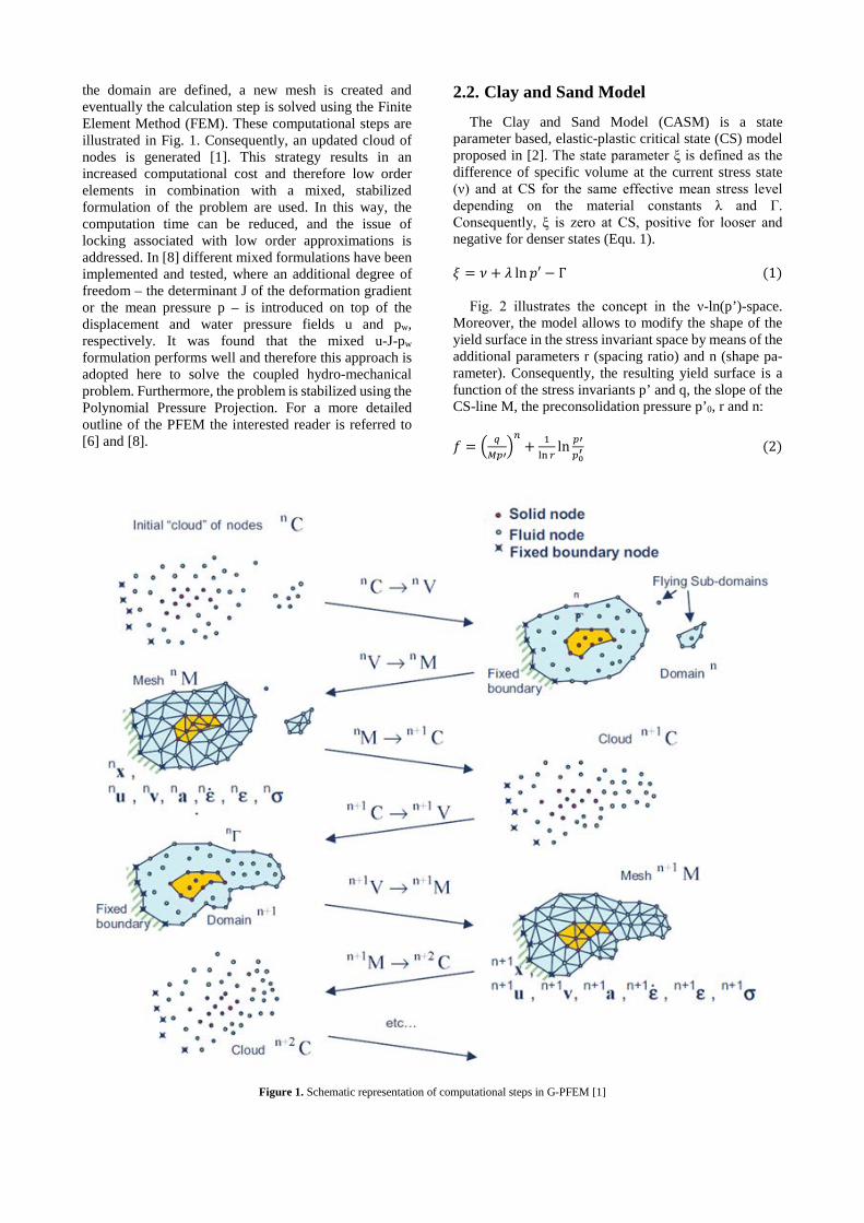
The Clay and Sand Model (CASM) is a state parameter based, elastic-plastic critical state (CS) model proposed in [2]. The state parameter ξ is defined as the difference of specific volume at the current stress state (ν) and at CS for the same effective mean stress level depending on the material constants λ and Γ. Consequently, ξ is zero at CS, positive for looser and negative for denser states (Equ. 1).
𝜉𝜉 = 𝜈𝜈 + 𝜆𝜆 ln𝑝𝑝′ − Γ (1)
Fig. 2 illustrates the concept in the ν-ln(p’)-space.
Moreover, the model allows to modify the shape of the yield surface in the stress invariant space by means of the additional parameters r (spacing ratio) and n (shape pa-rameter). Consequently, the resulting yield surface is a function of the stress invariants p’ and q, the slope of the CS-line M, the preconsolidation pressure p’0, r and n:
𝑓𝑓 = � 𝑞𝑞
𝑀𝑀𝑀𝑀′�𝑛𝑛
+ 1ln 𝑟𝑟
ln 𝑀𝑀′𝑀𝑀0′ (2)
Figure 1. Schematic representation of computational steps in G-PFEM [1]
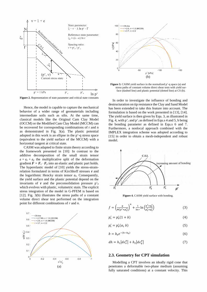
Figure 2. Representation of state parameter and critical state constants
Hence, the model is capable to capture the mechanical
behavior of a wider range of geomaterials including intermediate soils such as silts. At the same time, classical models like the Original Cam Clay Model (OCCM) or the Modified Cam Clay Model (MCCM) can be recovered for corresponding combinations of r and n as demonstrated in Fig. 3(a). The plastic potential adopted in this work is an ellipse in the p’-q stress space (equivalent to the yield surface of the MCCM) with a horizontal tangent at critical state.
CASM was adapted to finite strain theory according to the framework presented in [10]: In contrast to the additive decomposition of the small strain tensor ε = εe + εp the multiplicative split of the deformation gradient F = Fe · Fp into an elastic and plastic part holds. The hyperelastic model of [10] yields the stress-strain-relation formulated in terms of Kirchhoff stresses τ and the logarithmic Hencky strain tensor εh. Consequently, the yield surface and the plastic potential depend on the invariants of τ and the preconsolidation pressure p’0 which evolves with plastic, volumetric stain. The explicit stress integration of the model in G-PFEM is based on [12]. Fig. 3(b) illustrates the stress paths of a constant volume direct shear test performed on the integration point for different combinations of r and n.
(a)
(b)
Figure 3. CASM yield surface in the normalized p’-q space (a) and
stress paths of constant volume direct shear tests with yield sur-face (dashed line) and plastic potential (dotted line) at CS (b).
In order to investigate the influence of bonding and
destructuration on tip resistance the Clay and Sand Model has been extended to take this feature into account. The formulation is based on the work presented in [13], [14]. The yield surface is then given by Equ. 3, as illustrated in Fig. 4, with p’c and p’t as defined in Equ.s 4 and 5, b being the bonding parameter as defined in Equ.s 6 and 7. Furthermore, a nonlocal approach combined with the IMPLEX integration scheme was adopted according to [15] in order to obtain a mesh-independent and robust model.
Figure 4. CASM yield surface with bonding.
𝑓𝑓 = � 𝑞𝑞𝑀𝑀�𝑀𝑀′+𝑀𝑀t
′��𝑛𝑛
+ 1ln 𝑟𝑟
ln �𝑀𝑀′+𝑀𝑀t
′
𝑀𝑀c′+𝑀𝑀t′� (3)
𝑝𝑝c′ = 𝑝𝑝0′ (1 + 𝑏𝑏) (4)
𝑝𝑝t′ = 𝑝𝑝0′ (𝛼𝛼𝑡𝑡 𝑏𝑏) (5)
𝑏𝑏 = 𝑏𝑏0𝑒𝑒−(ℎ−ℎ0) (6)
𝑑𝑑ℎ = ℎ1�𝑑𝑑𝜖𝜖𝑣𝑣
𝑀𝑀� + ℎ2�𝑑𝑑𝜖𝜖𝑞𝑞𝑀𝑀� (7)
2.3. Geometry for CPT simulation Modelling a CPT involves an ideally rigid cone that
penetrates a deformable two-phase medium (assuming fully saturated conditions) at a constant velocity. This

leads to an axisymmetric model consisting of a rectangular box with a height of 1.1 m and a width of 0.5 m. The cone radius R measures 1.78 cm with a tip angle of 60° corresponding to the standard geometry (base area of 10 cm²). The penetration starts from an initial position where the cone is located at a depth of 10 cm. The lateral and lower boundaries are fixed in normal direction while an overburden pressure can be applied at the top of the domain. Moreover, free drainage is allowed at the boundaries except along the symmetry axis. Fig. 5 shows the basic model.
From a mathematical point of view, the contact between cone and soil body is described by a set of constraints and a penalty method is considered for resolution. The contact algorithm is explained in detail in [6]. It should be noted at this stage that all analyses presented in this paper assume a smooth cone. Rough interfaces are available in the code [7] but they are not employed here since the aim in this work is not to model a particular CPT test, but rather to explore the effects of different modelling assumptions such as bonding or the shape of the yield surface.
Figure 5. Axisymmetric model and refined mesh during penetration
process.
3. Influence of yield surface shape In this section, as a first step, the influence of the shape
of the yield surface, which is governed by input parameters r and n as explained in the previous section, on calculated cone resistance is evaluated. The stiffness and strength parameters are based on [16] representing a layer of clayey silt (locally known as ‘Salzburger Seeton’) at a depth of around 12 to 13 m resulting in an initial isotropic effective stress of 130 kPa and an initial water pressure of 100 kPa. At this point, the simulations consider weightless soil and no friction along the cone interface. The basic input parameters are summarized in Table 1.
Two parameter sets for r and n are investigated: The combination r = 2 and n = 1.5 approximates the MCC yield surface resulting in associated behaviour for the adopted plastic potential. Alternatively, non-associativity is obtained for r = 3.7 and n = 2.2. The latter combination
was calibrated for a silty sand from Porto ([17]). Fig. 6 shows the resulting penetration curves for the tip resistance qc and the pore pressures u2 obtained for different r-n pairs and a soil permeability of 2*10-8 m/s, corresponding to undrained conditions. It follows from Fig. 6 that the calculated tip resistance is sensitive to the shape of the yield surface and is notably higher for the parameter combination of r = 2 and n = 1.5, resembling the Modified Cam Clay Model. This results emphasizes that care must be taken when parameters for constitutive models are derived from cone penetration testing. It is interesting to see that the excess pore water pressure shows little influence of the yield surface shape. This basic study is extended in a later section when the undrained shear strength is determined from tip resistance for different geometries of the yield surface.
Table 1. Input parameter for ‘Salzburger Seeton’.
γ [kN/m³] λ* [-] κ* [-] φ’ [°] 0 0.015 0.005 22.5
G0 [kPa] α [-] p'0 [kPa] OCR [-] 2900 0 130 1
Figure 6. Calculated CPTu values over normalized depth z/R includ-
ing the tip resistance qc and the water pressure u2 for different yield surface geometries (r = 2/n = 1.5 and r = 3.7/n = 2.2).
4. Influence of bonding and destructuration In this section the influence of initial bonding and
destructuration occurring during the penetration process is evaluated. The parameters for this investigation are taken again for a clayey silt, in this case from a site in the south of Austria (St. Kanzian), listed in Tab. 2. The constitutive model described in section 2.2 is employed for this study. The coefficient of lateral earth pressure at rest K0 ist taken as 0.5, the effective vertical stress is 160 kPa and the initial water pressure u0 is 50 kPa. Shape parameters for the yield surface are r = 2 and n = 1.5 respectively.
Table 2. Input parameter for clayey silt “St. Kanzian”.
γ [kN/m³] λ* [-] κ* [-] φ’ [°] 0 0.019 0.0042 29.4
G0 [kPa] α [-] p'0 [kPa] OCR [-] 28570 0 153.4 1
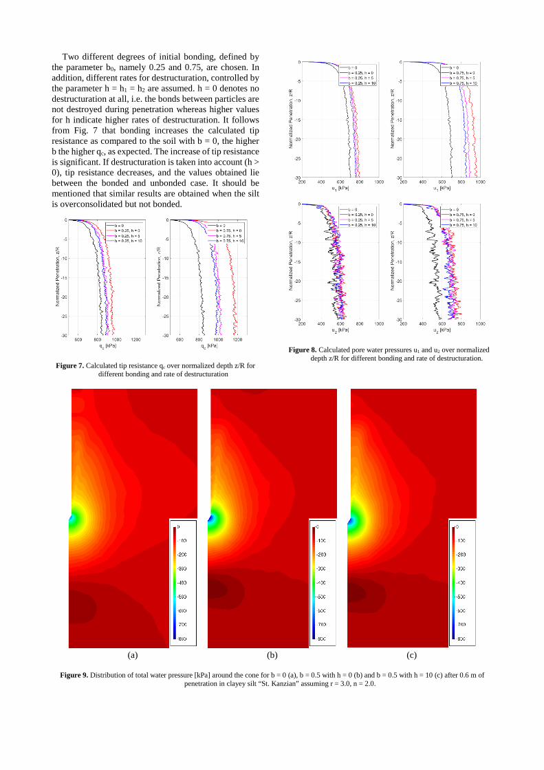
Two different degrees of initial bonding, defined by the parameter b0, namely 0.25 and 0.75, are chosen. In addition, different rates for destructuration, controlled by the parameter h = h1 = h2 are assumed. h = 0 denotes no destructuration at all, i.e. the bonds between particles are not destroyed during penetration whereas higher values for h indicate higher rates of destructuration. It follows from Fig. 7 that bonding increases the calculated tip resistance as compared to the soil with b = 0, the higher b the higher qc, as expected. The increase of tip resistance is significant. If destructuration is taken into account (h > 0), tip resistance decreases, and the values obtained lie between the bonded and unbonded case. It should be mentioned that similar results are obtained when the silt is overconsolidated but not bonded.
Figure 7. Calculated tip resistance qc over normalized depth z/R for different bonding and rate of destructuration
Figure 8. Calculated pore water pressures u1 and u2 over normalized depth z/R for different bonding and rate of destructuration.
(a) (b) (c)
Figure 9. Distribution of total water pressure [kPa] around the cone for b = 0 (a), b = 0.5 with h = 0 (b) and b = 0.5 with h = 10 (c) after 0.6 m of penetration in clayey silt “St. Kanzian” assuming r = 3.0, n = 2.0.
(a) (b)
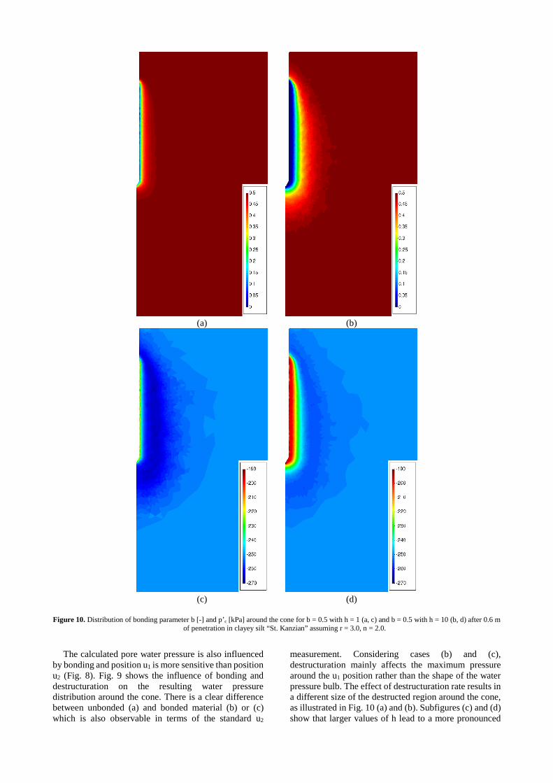
(c) (d) Figure 10. Distribution of bonding parameter b [-] and p’c [kPa] around the cone for b = 0.5 with h = 1 (a, c) and b = 0.5 with h = 10 (b, d) after 0.6 m
of penetration in clayey silt “St. Kanzian” assuming r = 3.0, n = 2.0.
The calculated pore water pressure is also influenced
by bonding and position u1 is more sensitive than position u2 (Fig. 8). Fig. 9 shows the influence of bonding and destructuration on the resulting water pressure distribution around the cone. There is a clear difference between unbonded (a) and bonded material (b) or (c) which is also observable in terms of the standard u2
measurement. Considering cases (b) and (c), destructuration mainly affects the maximum pressure around the u1 position rather than the shape of the water pressure bulb. The effect of destructuration rate results in a different size of the destructed region around the cone, as illustrated in Fig. 10 (a) and (b). Subfigures (c) and (d) show that larger values of h lead to a more pronounced
softening behaviour as p‘c (desribing the resulting size of the yield surface) reduces significantly near the cone.
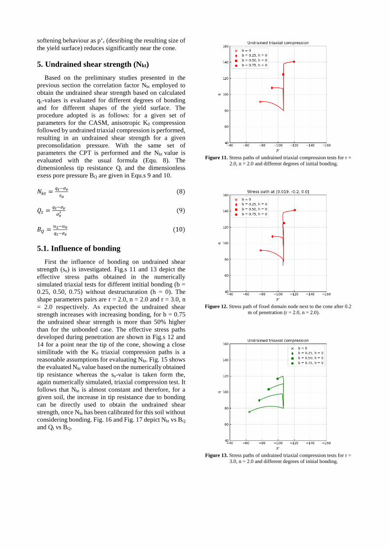
5. Undrained shear strength (Nkt) Based on the preliminary studies presented in the
previous section the correlation factor Nkt employed to obtain the undrained shear strength based on calculated qc-values is evaluated for different degrees of bonding and for different shapes of the yield surface. The procedure adopted is as follows: for a given set of parameters for the CASM, anisotropic K0 compression followed by undrained triaxial compression is performed, resulting in an undrained shear strength for a given preconsolidation pressure. With the same set of parameters the CPT is performed and the Nkt value is evaluated with the usual formula (Equ. 8). The dimensionless tip resistance Qt and the dimensionless exess pore pressure BQ are given in Equ.s 9 and 10.
𝑁𝑁𝑘𝑘𝑡𝑡 = 𝑞𝑞𝑡𝑡−𝜎𝜎𝑣𝑣
𝑠𝑠𝑢𝑢 (8)
𝑄𝑄𝑡𝑡 = 𝑞𝑞𝑡𝑡−𝜎𝜎𝑣𝑣
𝜎𝜎𝑣𝑣′ (9)
𝐵𝐵𝑄𝑄 = 𝑢𝑢2−𝑢𝑢0
𝑞𝑞𝑡𝑡−𝜎𝜎𝑣𝑣 (10)
5.1. Influence of bonding First the influence of bonding on undrained shear
strength (su) is investigated. Fig.s 11 and 13 depict the effective stress paths obtained in the numerically simulated triaxial tests for different intitial bonding (b = 0.25, 0.50, 0.75) without destructuration (h = 0). The shape parameters pairs are r = 2.0, n = 2.0 and r = 3.0, n = 2.0 respectively. As expected the undrained shear strength increases with increasing bonding, for b = 0.75 the undrained shear strength is more than 50% higher than for the unbonded case. The effective stress paths developed during penetration are shown in Fig.s 12 and 14 for a point near the tip of the cone, showing a close similitude with the K0 triaxial compression paths is a reasonable assumptions for evaluating Nkt. Fig. 15 shows the evaluated Nkt value based on the numerically obtained tip resistance whereas the su-value is taken form the, again numerically simulated, triaxial compression test. It follows that Nkt is almost constant and therefore, for a given soil, the increase in tip resistance due to bonding can be directly used to obtain the undrained shear strength, once Nkt has been calibrated for this soil without considering bonding. Fig. 16 and Fig. 17 depict Nkt vs BQ and Qt vs BQ.
Figure 11. Stress paths of undrained triaxial compression tests for r =
2.0, n = 2.0 and different degrees of initial bonding.
Figure 12. Stress path of fixed domain node next to the cone after 0.2
m of penetration (r = 2.0, n = 2.0).
Figure 13. Stress paths of undrained triaxial compression tests for r =
3.0, n = 2.0 and different degrees of initial bonding.
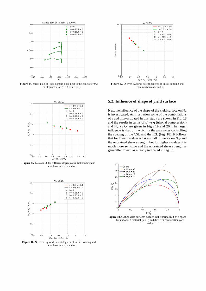
Figure 14. Stress path of fixed domain node next to the cone after 0.2
m of penetration (r = 3.0, n = 2.0).
Figure 15. Nkt over Qt for different degrees of initial bonding and
combinations of r and n.
Figure 16. Nkt over BQ for different degrees of initial bonding and
combinations of r and n.
Figure 17. Qt over BQ for different degrees of initial bonding and
combinations of r and n.
5.2. Influence of shape of yield surface
Next the influence of the shape of the yield surface on Nkt is investigated. As illustration some of the combinations of r and n investigated in this study are shown in Fig. 18 and the results in terms of p’ vs q (triaxial compression) and Nkt vs Qt are given in Fig.s 19 and 20. The larger influence is that of r which is the parameter controlling the spacing of the CSL and the ICL (Fig. 18). It follows that for lower r-values n has a small influence on Nkt (and the undrained shear strength) but for higher r-values it is much more sensitive and the undrained shear strength is generaller lower, as already indicated in Fig.3b.
Figure 18. CASM yield surfaces surface in the normalized p’-q space
for unbonded material (b = 0) and different combinations of r and n.
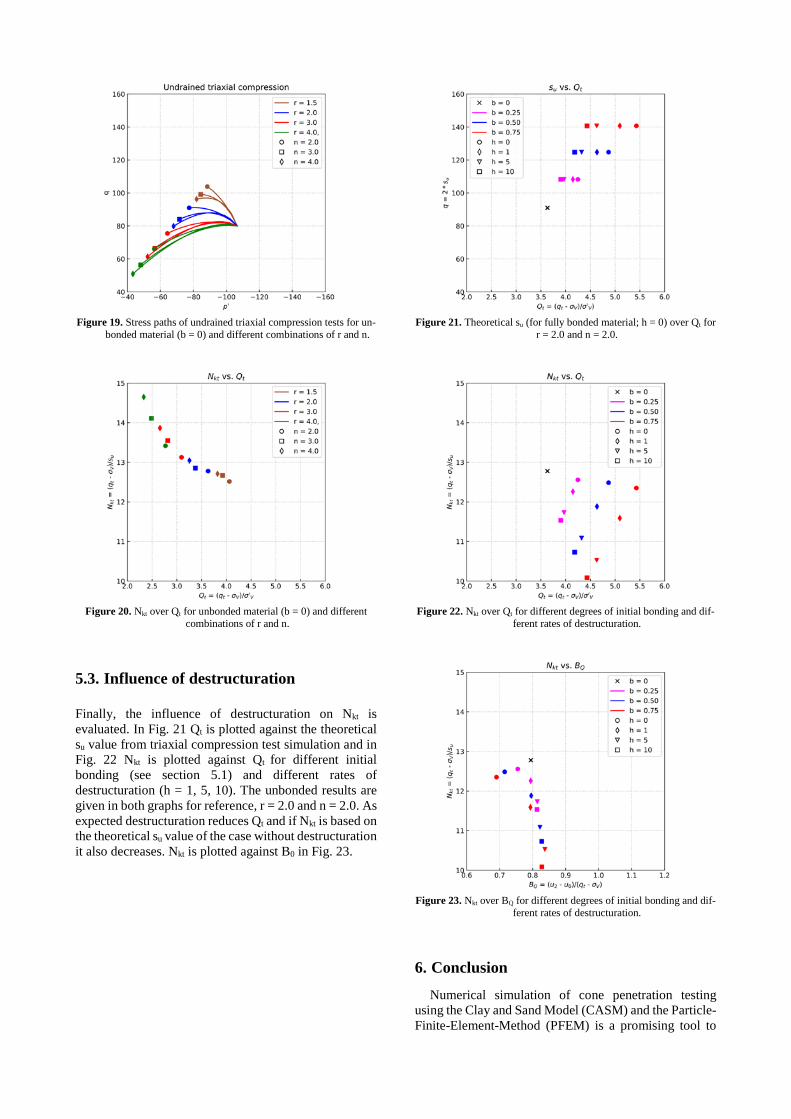
Figure 19. Stress paths of undrained triaxial compression tests for un-
bonded material (b = 0) and different combinations of r and n.
Figure 20. Nkt over Qt for unbonded material (b = 0) and different
combinations of r and n.
5.3. Influence of destructuration
Finally, the influence of destructuration on Nkt is evaluated. In Fig. 21 Qt is plotted against the theoretical su value from triaxial compression test simulation and in Fig. 22 Nkt is plotted against Qt for different initial bonding (see section 5.1) and different rates of destructuration (h = 1, 5, 10). The unbonded results are given in both graphs for reference, r = 2.0 and n = 2.0. As expected destructuration reduces Qt and if Nkt is based on the theoretical su value of the case without destructuration it also decreases. Nkt is plotted against B0 in Fig. 23.
Figure 21. Theoretical su (for fully bonded material; h = 0) over Qt for
r = 2.0 and n = 2.0.
Figure 22. Nkt over Qt for different degrees of initial bonding and dif-
ferent rates of destructuration.
Figure 23. Nkt over BQ for different degrees of initial bonding and dif-
ferent rates of destructuration.
6. Conclusion
Numerical simulation of cone penetration testing using the Clay and Sand Model (CASM) and the Particle-Finite-Element-Method (PFEM) is a promising tool to
better understand the influence of various soil features on cone resistance and pore water pressures. In this paper the influence of the shape of the yield surface, which can be adjusted in the CASM to account for different soil behavior has been analyzed and it could be shown that both pore water pressures and cone resistance are influenced by the shape of the yield surface adopted. This is important when parameters for constitutive models are derived from CPT.
In a second study bonding and destructuration have been investigated and again it could be shown that they affect calculated values. Higher bonding leads to higher tip resistance compared to unbonded soils as expected. High rates of destructuration reduce tip resistance and values are between bonded and unbonded soils.
With respect to undrained shear strength Nkt values have been evaluated based on numerically simulated triaxial compression test. It could be shown that Nkt values are not influenced by bonding, but by destructuration and are also sensitive to the shape of the adopted yield surface.
References [1] Oñate, E., Idelsohn, S.R., Celigueta, M.A., Rossi, R., Marti, J.,
Carbonell, J.M., Ryzakov, R., Suárez, B. “Advances in the Particle Finite Element Method (PFEM) for Solving Coupled Problems in Engineering”, In: Oñate E., Owen D.R.J. (eds.) Particle-Based Methods. Computational Methods in Applied Sciences, vol 25. Springer, Dordrecht, The Netherlands, 2011, pp. 1-49. https://doi.org/10.1007/978-94-007-0735-1_1
[2] Yu, H.S. “CASM: a unified state parameter model for clay and sand”, International Journal for Numerical and Analytical Meth-ods in Geomechanics 22, pp. 621-653, 1998. https://doi.org/10.1002/(SICI)10969853(199808)22:8<621::AID-NAG937>3.0.CO;2-8
[3] Sheng, D., Kelly, R., Pineda, J., Lachlan, B. “Numerical study of rate effects in cone penetration test”, In: 3rd International Sympo-sium on Cone Penetration Testing, Las Vegas, Nevada, USA, 2014, pp. 419-428.
[4] Ceccato, F., Simonini, P. “Numerical study of partially drained penetration and pore pressure dissipation in piezocone test”, Acta Geotechnica, 12(1), pp. 195-209, 2017. https://doi.org/10.1007/s11440-016-0448-6
[5] Beuth, L. “Formulation and Application of a Quasi-Static Material Point Method”. PhD Thesis, Universität Stuttgart, 2012.
[6] Monforte, L., Arroyo, M., Carbonell, J.M., Gens, A. “Numerical simulation of undrained insertion problems in geotechnical engi-neering with the Particle Finite Element Method (PFEM)”, Com-puters and Geotechnics 82, pp. 144-156, 2017a. https://doi.org/10.1016/j.compgeo.2016.08.013
[7] Monforte, L., Arroyo, M., Carbonell, J.M., Gens, A. “Coupled ef-fective stress analysis of insertion problems in geotechnics with the Particle Finite Element Method”, Computers and Geotechnics 101, pp. 114-129, 2018. https://doi.org/10.1016/j.compgeo.2018.04.002
[8] Monforte, L., Carbonell, J.M., Arroyo, M., Gens, A. “Performance of mixed formulations for the particle finite element method in soil mechanics problems”, Computational Particle Mechanics 4(3), pp. 269-284, 2017b. https://doi.org/10.1007/s40571-016-0145-0
[9] Dadvand, P., Rossi, R., Oñate, E. “An Object-oriented Environ-ment for Developing Finite Element Codes for Multi-disciplinary Applications”, Arch Comput Methods Eng 17(3), 253-297, 2010.
[10] Monforte, L., Arroyo, M., Gens, A., Carbonell, J.M. “Integration of elasto-plastic constitutive models in finite deformation: An ex-plicit approach”, In Oñate E., Owen D.R.J., Peric, D., Chiumenti, M. (eds.) Proceedings of the XIII International Conference on Computational Plasticity, Barcelona, Spain, 2015, pp. 398-406.
[11] Houlsby, G.T. “The use of a variable shear modulus in elastic-plastic models for clays”, Computers and Geotechnics 1(1), pp. 3-13, 1985. https://doi.org/10.1016/0266-352X(85)90012-6
[12] Sloan, S.W., Abbo, A.J., Sheng, D. “Refined explicit integration of elastoplastic models with automatic error control”, Engineering Computations 18, pp. 121-154, 2001. https://doi.org/10.1108/02644400110365842
[13] Gens, A., Nova, R. “Conceptual base for a constitutive model for bonded soils and weak rocks”, Proceeding of the International Symposium on Geotechnical Engineering of Hard Soils-Soft Rocks, Athens, Vol. 1, 485-494. 1993.
[14] González, N. A., Arroyo, M., Gens, A. “Identification of bonded clay parameters in SBPM tests: a numerical study”, Soils and foundations, 49(3), 329-340, 2009. https://doi.org/10.3208/sandf.49.329
[15] Monforte, L., Ciantia, M. O., Carbonell, J. M., Arroyo, M., Gens, A. “A stable mesh-independent approach for numerical modelling of structured soils at large strains”, Computers and Geotechnics, 116, 103215, 2019. https://doi.org/10.1016/j.compgeo.2019.103215
[16] Sachsenhofer, M. “Comparison of correlations from CPTu, SDT, DP”, Master’s Thesis, Graz University of Technology, 2012.
[17] Rios, S., Cianta, M., Gonzalez, N., Arroyo, M., da Fonseca, A.V. “Simplifying calibration of bonded elasto-plastic models”, Com-puters and Geotechnics 73, pp. 100-108, 2016. https://doi.org/10.1016/j.compgeo.2015.11.019