Real-time 3D video conference on generic hardware
11
Real-Time 3D Video Conference on Generic Hardware X. Desurmont 1 , J.L. Bruyelle 1 , D. Ruiz 2 , J. Meessen 1 , B. Macq 2 1 Multitel ASBL, Parc Initialis – Rue Pierre et Marie Curie 2, B-7000, Mons, Belgium. 2 Communications and Remote Sensing Laboratory, UCL, Louvain-la-neuve, Belgium. ABSTRACT Nowadays, video-conference tends to be more and more advantageous because of the economical and ecological cost of transport. Several platforms exist. The goal of the TIFANIS immersive platform is to let users interact as if they were physically together. Unlike previous teleimmersion systems, TIFANIS uses generic hardware to achieve an economically realistic implementation. The basic functions of the system are to capture the scene, transmit it through digital networks to other partners, and then render it according to each partner’s viewing characteristics. The image processing part should run in real-time. We propose to analyze the whole system. it can be split into different services like central processing unit (CPU), graphical rendering, direct memory access (DMA), and communications trough the network. Most of the processing is done by CPU resource. It is composed of the 3D reconstruction and the detection and tracking of faces from the video stream. However, the processing needs to be parallelized in several threads that have as little dependencies as possible. In this paper, we present these issues, and the way we deal with them. Keywords: real-time, 3D, video conference, dual core 1. INTRODUCTION Video-conference use is growing. Nevertheless, people are reluctant to video conference because the quality of the meeting is still degraded due to bad immersive perception (e.g. it does not really allow eye contact, it suffers from high latency and poor robustness precluding the illusion of being physically together). Moreover, it is difficult to share common document objects like presentations (i.e. PowerPoint), or 3D objects like building designs or chemical molecules. In the recent years, some initiatives [1] have tried to cope with this problem and, as a result, some tele-immersion systems were built, but these were using specific clusters of high-power computers. The goal of the TIFANIS [2] teleimmersive platform is to let users interact as if they were physically together, but using generic hardware in order to allow widespread use. The basic functions of the system are to capture the scene, transmit it through digital networks to other partners, and then render it according to each partner’s viewing characteristics. The image processing part should run in real-time, 20 frames per second (FPS), with low delay (100 ms) to offer the realistic feeling of presence involved by the very concept of teleimmersion. The basic functions are the acquisition, the 3D reconstruction, the detection and tracking of the face, the transmission of all this data to a remote place, and finally the display of the data. We propose to analyze the requirements of the whole system by taking into account all the needed resources. We see that they can be split in different services, like CPU, graphical rendering, DMA, and communications through the network. Most of the processing is done by CPU resource. It is composed of the
-
Upload
independent -
Category
Documents
-
view
1 -
download
0
Transcript of Real-time 3D video conference on generic hardware
Real-Time 3D Video Conference on Generic Hardware X. Desurmont1, J.L. Bruyelle1, D. Ruiz2, J. Meessen1, B. Macq2
1 Multitel ASBL, Parc Initialis – Rue Pierre et Marie Curie 2, B-7000, Mons, Belgium. 2 Communications and Remote Sensing Laboratory, UCL, Louvain-la-neuve, Belgium.
ABSTRACT Nowadays, video-conference tends to be more and more advantageous because of the economical and ecological cost of transport. Several platforms exist. The goal of the TIFANIS immersive platform is to let users interact as if they were physically together. Unlike previous teleimmersion systems, TIFANIS uses generic hardware to achieve an economically realistic implementation. The basic functions of the system are to capture the scene, transmit it through digital networks to other partners, and then render it according to each partner’s viewing characteristics. The image processing part should run in real-time. We propose to analyze the whole system. it can be split into different services like central processing unit (CPU), graphical rendering, direct memory access (DMA), and communications trough the network. Most of the processing is done by CPU resource. It is composed of the 3D reconstruction and the detection and tracking of faces from the video stream. However, the processing needs to be parallelized in several threads that have as little dependencies as possible. In this paper, we present these issues, and the way we deal with them. Keywords: real-time, 3D, video conference, dual core
1. INTRODUCTION Video-conference use is growing. Nevertheless, people are reluctant to video conference because the quality of the meeting is still degraded due to bad immersive perception (e.g. it does not really allow eye contact, it suffers from high latency and poor robustness precluding the illusion of being physically together). Moreover, it is difficult to share common document objects like presentations (i.e. PowerPoint), or 3D objects like building designs or chemical molecules. In the recent years, some initiatives [1] have tried to cope with this problem and, as a result, some tele-immersion systems were built, but these were using specific clusters of high-power computers. The goal of the TIFANIS [2] teleimmersive platform is to let users interact as if they were physically together, but using generic hardware in order to allow widespread use. The basic functions of the system are to capture the scene, transmit it through digital networks to other partners, and then render it according to each partner’s viewing characteristics. The image processing part should run in real-time, 20 frames per second (FPS), with low delay (100 ms) to offer the realistic feeling of presence involved by the very concept of teleimmersion. The basic functions are the acquisition, the 3D reconstruction, the detection and tracking of the face, the transmission of all this data to a remote place, and finally the display of the data. We propose to analyze the requirements of the whole system by taking into account all the needed resources. We see that they can be split in different services, like CPU, graphical rendering, DMA, and communications through the network. Most of the processing is done by CPU resource. It is composed of the
3D reconstruction and the detection and tracking faces from the video stream. The needs are higher than what a good dual core PC can offer. We conclude that we need to use several PCs to handle the whole image processing. However, the processing needs to be parallelized in several threads that have least as little dependencies as possible.
Thus, we use a methodology to achieve the “adequation” of the algorithm to the given architecture of the two dual core PCs. The bottleneck of the system appears to be the communication between the threads. It is not a problem in a single unit, as the memory between threads is shared, but it becomes problematic for the communications between two machines. Thus, for the hardware layer, we propose to use Gigabit Ethernet. For the application layer, we chose to use SOAP, because it is becoming an established standard and can handle all the communication as a web service. Then we show the results of the practical implementation we have developed from the specifications we have proposed. We use LINUX with priority handling for lower latency. The whole code is in C++. We consider that we have achieved a good implementation, regarding the practical use of all the resources (and specifically the CPU resource).
2. FUNCTIONAL ALGORITHMS
The functional algorithms for the capture system are divided into two main functions: 3D image reconstruction, and face positioning. Theses two functions are decomposed in sub-algorithms described below. More information is in [3]. Other issues concern the communication and the display. 2.1. Calibration
The SVS1 library, provided with the camera, performs calibration using Tsai’s method [4] to determine both intrinsic (focal length, distortion) and extrinsic (relative position and orientation) parameters of the cameras. This calibration should be executed only one time per camera when the system is installed, thus real-time consideration are not needed in the process.
2.2. Depth map computation
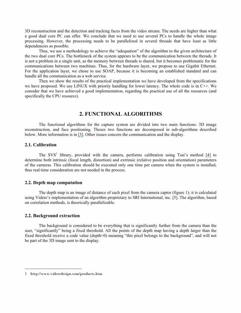
The depth map is an image of distance of each pixel from the camera captor (figure 1); it is calculated using Videre’s implementation of an algorithm proprietary to SRI International, inc. [5]. The algorithm, based on correlation methods, is theorically parallelizable.
2.2. Background extraction
The background is considered to be everything that is significantly further from the camera than the user, “significantly” being a fixed threshold. All the points of the depth map having a depth larger than the fixed threshold receive a code value (depth=0) meaning “this pixel belongs to the background”, and will not be part of the 3D image sent to the display.
1 http://www.videredesign.com/products.htm
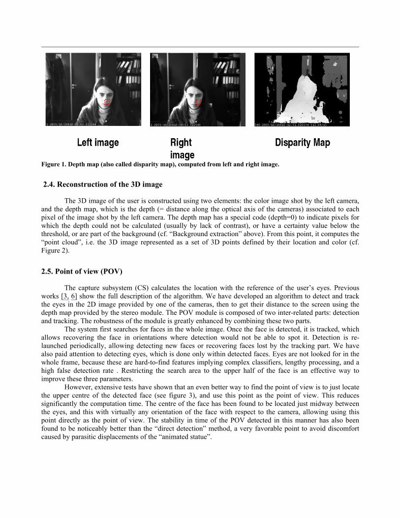
Figure 1. Depth map (also called disparity map), computed from left and right image.
2.4. Reconstruction of the 3D image
The 3D image of the user is constructed using two elements: the color image shot by the left camera, and the depth map, which is the depth (= distance along the optical axis of the cameras) associated to each pixel of the image shot by the left camera. The depth map has a special code (depth=0) to indicate pixels for which the depth could not be calculated (usually by lack of contrast), or have a certainty value below the threshold, or are part of the background (cf. “Background extraction” above). From this point, it computes the “point cloud”, i.e. the 3D image represented as a set of 3D points defined by their location and color (cf. Figure 2).
2.5. Point of view (POV)
The capture subsystem (CS) calculates the location with the reference of the user’s eyes. Previous works [3, 6] show the full description of the algorithm. We have developed an algorithm to detect and track the eyes in the 2D image provided by one of the cameras, then to get their distance to the screen using the depth map provided by the stereo module. The POV module is composed of two inter-related parts: detection and tracking. The robustness of the module is greatly enhanced by combining these two parts.
The system first searches for faces in the whole image. Once the face is detected, it is tracked, which allows recovering the face in orientations where detection would not be able to spot it. Detection is re-launched periodically, allowing detecting new faces or recovering faces lost by the tracking part. We have also paid attention to detecting eyes, which is done only within detected faces. Eyes are not looked for in the whole frame, because these are hard-to-find features implying complex classifiers, lengthy processing, and a high false detection rate . Restricting the search area to the upper half of the face is an effective way to improve these three parameters.
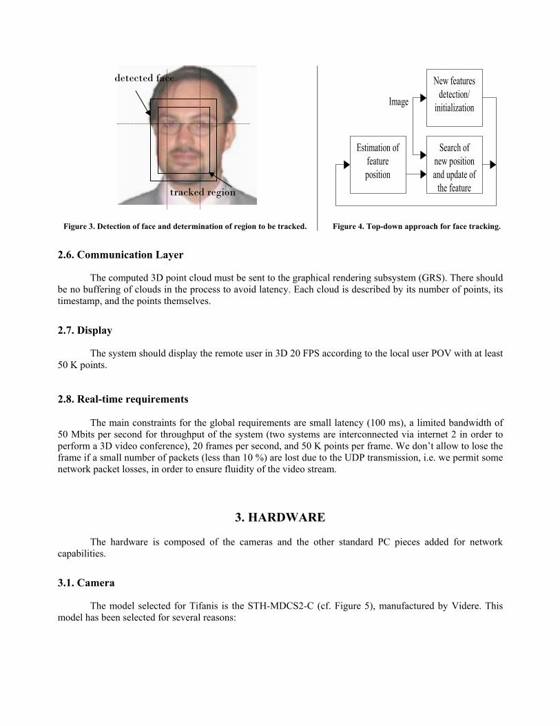
However, extensive tests have shown that an even better way to find the point of view is to just locate the upper centre of the detected face (see figure 3), and use this point as the point of view. This reduces significantly the computation time. The centre of the face has been found to be located just midway between the eyes, and this with virtually any orientation of the face with respect to the camera, allowing using this point directly as the point of view. The stability in time of the POV detected in this manner has also been found to be noticeably better than the “direct detection” method, a very favorable point to avoid discomfort caused by parasitic displacements of the “animated statue”.
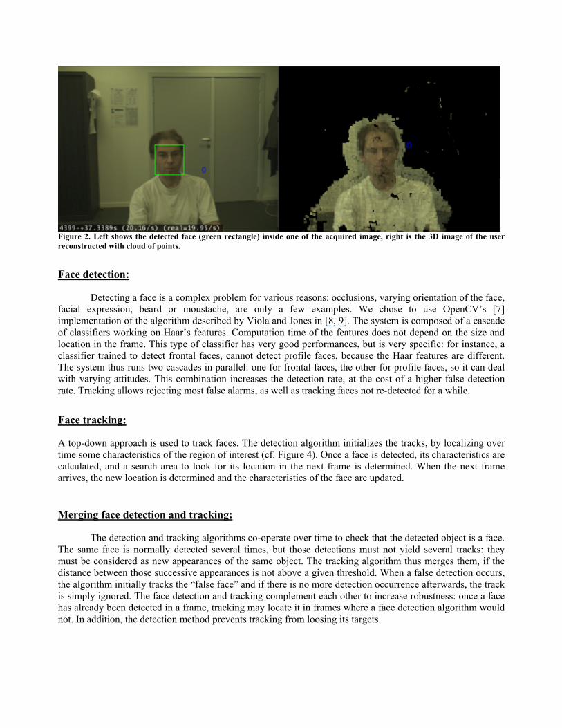
Figure 2. Left shows the detected face (green rectangle) inside one of the acquired image, right is the 3D image of the user reconstructed with cloud of points.
Face detection:
Detecting a face is a complex problem for various reasons: occlusions, varying orientation of the face, facial expression, beard or moustache, are only a few examples. We chose to use OpenCV’s [7] implementation of the algorithm described by Viola and Jones in [8, 9]. The system is composed of a cascade of classifiers working on Haar’s features. Computation time of the features does not depend on the size and location in the frame. This type of classifier has very good performances, but is very specific: for instance, a classifier trained to detect frontal faces, cannot detect profile faces, because the Haar features are different. The system thus runs two cascades in parallel: one for frontal faces, the other for profile faces, so it can deal with varying attitudes. This combination increases the detection rate, at the cost of a higher false detection rate. Tracking allows rejecting most false alarms, as well as tracking faces not re-detected for a while.
Face tracking:
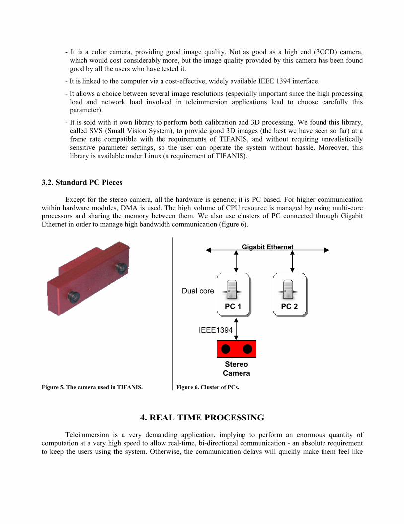
A top-down approach is used to track faces. The detection algorithm initializes the tracks, by localizing over time some characteristics of the region of interest (cf. Figure 4). Once a face is detected, its characteristics are calculated, and a search area to look for its location in the next frame is determined. When the next frame arrives, the new location is determined and the characteristics of the face are updated.
Merging face detection and tracking:
The detection and tracking algorithms co-operate over time to check that the detected object is a face. The same face is normally detected several times, but those detections must not yield several tracks: they must be considered as new appearances of the same object. The tracking algorithm thus merges them, if the distance between those successive appearances is not above a given threshold. When a false detection occurs, the algorithm initially tracks the “false face” and if there is no more detection occurrence afterwards, the track is simply ignored. The face detection and tracking complement each other to increase robustness: once a face has already been detected in a frame, tracking may locate it in frames where a face detection algorithm would not. In addition, the detection method prevents tracking from loosing its targets.
New features detection/
initialization
Estimation offeatureposition
Search of new positionand update of
the feature
Image
Figure 3. Detection of face and determination of region to be tracked. Figure 4. Top-down approach for face tracking.
2.6. Communication Layer
The computed 3D point cloud must be sent to the graphical rendering subsystem (GRS). There should be no buffering of clouds in the process to avoid latency. Each cloud is described by its number of points, its timestamp, and the points themselves.
2.7. Display
The system should display the remote user in 3D 20 FPS according to the local user POV with at least 50 K points. 2.8. Real-time requirements
The main constraints for the global requirements are small latency (100 ms), a limited bandwidth of 50 Mbits per second for throughput of the system (two systems are interconnected via internet 2 in order to perform a 3D video conference), 20 frames per second, and 50 K points per frame. We don’t allow to lose the frame if a small number of packets (less than 10 %) are lost due to the UDP transmission, i.e. we permit some network packet losses, in order to ensure fluidity of the video stream.
3. HARDWARE
The hardware is composed of the cameras and the other standard PC pieces added for network capabilities.
3.1. Camera
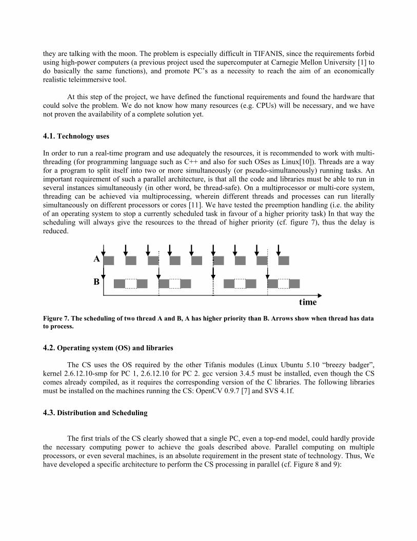
The model selected for Tifanis is the STH-MDCS2-C (cf. Figure 5), manufactured by Videre. This model has been selected for several reasons:
detected face
tracked region
- It is a color camera, providing good image quality. Not as good as a high end (3CCD) camera, which would cost considerably more, but the image quality provided by this camera has been found good by all the users who have tested it.
- It is linked to the computer via a cost-effective, widely available IEEE 1394 interface.
- It allows a choice between several image resolutions (especially important since the high processing load and network load involved in teleimmersion applications lead to choose carefully this parameter).
- It is sold with it own library to perform both calibration and 3D processing. We found this library, called SVS (Small Vision System), to provide good 3D images (the best we have seen so far) at a frame rate compatible with the requirements of TIFANIS, and without requiring unrealistically sensitive parameter settings, so the user can operate the system without hassle. Moreover, this library is available under Linux (a requirement of TIFANIS).
3.2. Standard PC Pieces
Except for the stereo camera, all the hardware is generic; it is PC based. For higher communication within hardware modules, DMA is used. The high volume of CPU resource is managed by using multi-core processors and sharing the memory between them. We also use clusters of PC connected through Gigabit Ethernet in order to manage high bandwidth communication (figure 6).
VAC PC 2 PC 1
Gigabit Ethernet
IEEE1394
Stereo Camera
Dual core
Figure 5. The camera used in TIFANIS. Figure 6. Cluster of PCs.
4. REAL TIME PROCESSING
Teleimmersion is a very demanding application, implying to perform an enormous quantity of computation at a very high speed to allow real-time, bi-directional communication - an absolute requirement to keep the users using the system. Otherwise, the communication delays will quickly make them feel like
they are talking with the moon. The problem is especially difficult in TIFANIS, since the requirements forbid using high-power computers (a previous project used the supercomputer at Carnegie Mellon University [1] to do basically the same functions), and promote PC’s as a necessity to reach the aim of an economically realistic teleimmersive tool.
At this step of the project, we have defined the functional requirements and found the hardware that
could solve the problem. We do not know how many resources (e.g. CPUs) will be necessary, and we have not proven the availability of a complete solution yet.
4.1. Technology uses
In order to run a real-time program and use adequately the resources, it is recommended to work with multi-threading (for programming language such as C++ and also for such OSes as Linux[10]). Threads are a way for a program to split itself into two or more simultaneously (or pseudo-simultaneously) running tasks. An important requirement of such a parallel architecture, is that all the code and libraries must be able to run in several instances simultaneously (in other word, be thread-safe). On a multiprocessor or multi-core system, threading can be achieved via multiprocessing, wherein different threads and processes can run literally simultaneously on different processors or cores [11]. We have tested the preemption handling (i.e. the ability of an operating system to stop a currently scheduled task in favour of a higher priority task) In that way the scheduling will always give the resources to the thread of higher priority (cf. figure 7), thus the delay is reduced.
A
B
time
Figure 7. The scheduling of two thread A and B, A has higher priority than B. Arrows show when thread has data to process.
4.2. Operating system (OS) and libraries
The CS uses the OS required by the other Tifanis modules (Linux Ubuntu 5.10 “breezy badger”, kernel 2.6.12.10-smp for PC 1, 2.6.12.10 for PC 2. gcc version 3.4.5 must be installed, even though the CS comes already compiled, as it requires the corresponding version of the C libraries. The following libraries must be installed on the machines running the CS: OpenCV 0.9.7 [7] and SVS 4.1f.
4.3. Distribution and Scheduling
The first trials of the CS clearly showed that a single PC, even a top-end model, could hardly provide the necessary computing power to achieve the goals described above. Parallel computing on multiple processors, or even several machines, is an absolute requirement in the present state of technology. Thus, We have developed a specific architecture to perform the CS processing in parallel (cf. Figure 8 and 9):
Reconstruction of the 3D image:
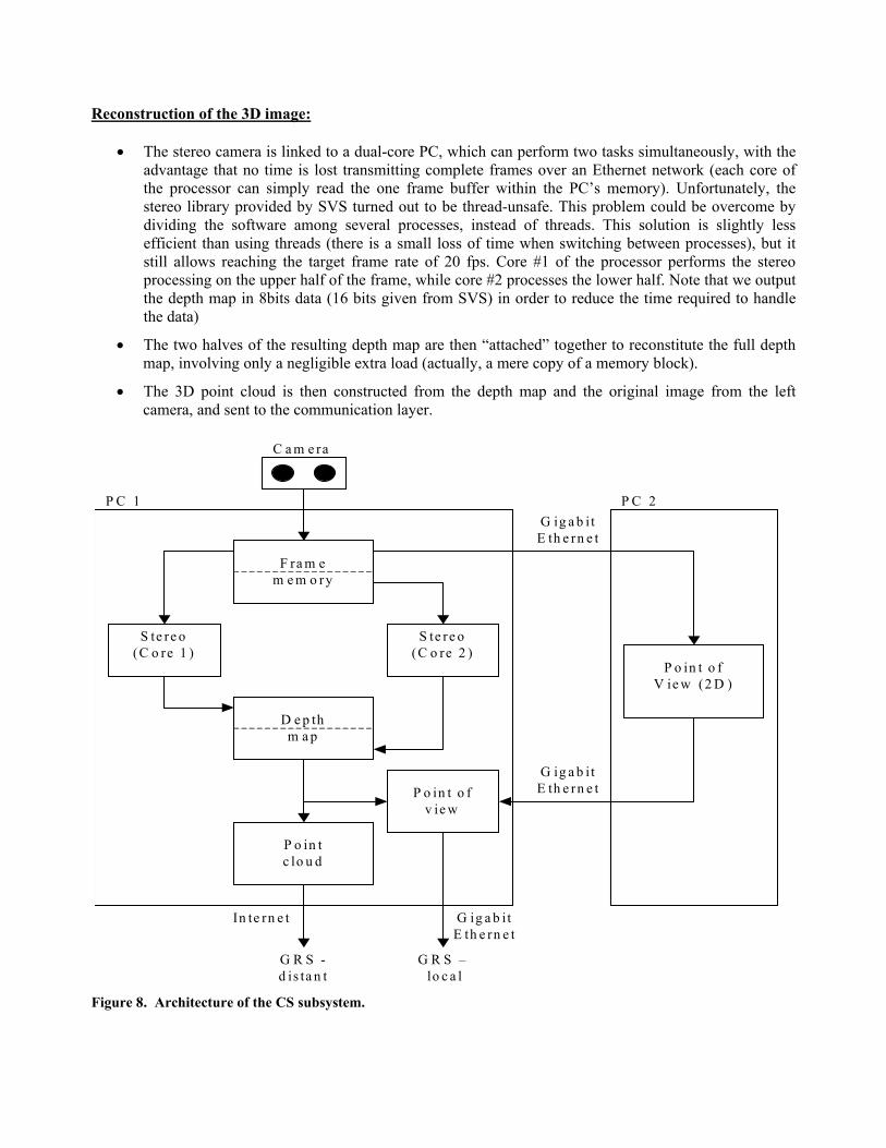
• The stereo camera is linked to a dual-core PC, which can perform two tasks simultaneously, with the advantage that no time is lost transmitting complete frames over an Ethernet network (each core of the processor can simply read the one frame buffer within the PC’s memory). Unfortunately, the stereo library provided by SVS turned out to be thread-unsafe. This problem could be overcome by dividing the software among several processes, instead of threads. This solution is slightly less efficient than using threads (there is a small loss of time when switching between processes), but it still allows reaching the target frame rate of 20 fps. Core #1 of the processor performs the stereo processing on the upper half of the frame, while core #2 processes the lower half. Note that we output the depth map in 8bits data (16 bits given from SVS) in order to reduce the time required to handle the data)
• The two halves of the resulting depth map are then “attached” together to reconstitute the full depth map, involving only a negligible extra load (actually, a mere copy of a memory block).
• The 3D point cloud is then constructed from the depth map and the original image from the left camera, and sent to the communication layer.
C a m e ra
F ra m e m e m o ry
S te re o (C o re 1 )
S te re o (C o re 2 )
D e p th m a p
P o in t c lo u d
P C 1 P C 2
P o in t o f V ie w (2 D )
G R S -d is ta n t
G R S – lo c a l
G ig a b it E th e rn e t
G ig a b it E th e rn e t P o in t o f
v ie w
In te rn e t G ig a b it E th e rn e t
� Figure 8. Architecture of the CS subsystem.
Communication Layer:
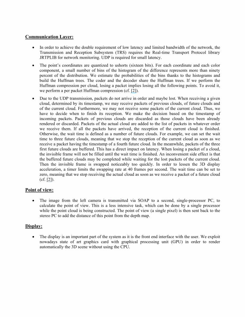
• In order to achieve the double requirement of low latency and limited bandwidth of the network, the Transmission and Reception Subsystem (TRS) requires the Real-time Transport Protocol library JRTPLIB for network monitoring. UDP is required for small latency.
• The point’s coordinates are quantized to ushorts (sixteen bits). For each coordinate and each color component, a small number of bins of the histogram of the difference represents more than ninety percent of the distribution. We estimate the probabilities of the bins thanks to the histograms and build the Huffman trees. The coder and the decoder share the Huffman trees. If we perform the Huffman compression per cloud, losing a packet implies losing all the following points. To avoid it, we perform a per packet Huffman compression (cf. [2]).
• Due to the UDP transmission, packets do not arrive in order and maybe lost. When receiving a given cloud, determined by its timestamp, we may receive packets of previous clouds, of future clouds and of the current cloud. Furthermore, we may not receive some packets of the current cloud. Thus, we have to decide when to finish its reception. We make the decision based on the timestamp of incoming packets. Packets of previous clouds are discarded as those clouds have been already rendered or discarded. Packets of the actual cloud are added to the list of packets in whatever order we receive them. If all the packets have arrived, the reception of the current cloud is finished. Otherwise, the wait time is defined as a number of future clouds. For example, we can set the wait time to three future clouds, meaning that we stop the reception of the current cloud as soon as we receive a packet having the timestamp of a fourth future cloud. In the meanwhile, packets of the three first future clouds are buffered. This has a direct impact on latency. When losing a packet of a cloud, the invisible frame will not be filled until the wait time is finished. An inconvenient side effect is that the buffered future clouds may be completed while waiting for the lost packets of the current cloud. Then the invisible frame is swapped noticeably too quickly. In order to lessen the 3D display acceleration, a timer limits the swapping rate at 40 frames per second. The wait time can be set to zero, meaning that we stop receiving the actual cloud as soon as we receive a packet of a future cloud (cf. [2]).
Point of view:
• The image from the left camera is transmitted via SOAP to a second, single-processor PC, to calculate the point of view. This is a less intensive task, which can be done by a single processor while the point cloud is being constructed. The point of view (a single pixel) is then sent back to the stereo PC to add the distance of this point from the depth map.
Display:
• The display is an important part of the system as it is the front end interface with the user. We exploit nowadays state of art graphics card with graphical processing unit (GPU) in order to render automatically the 3D scene without using the CPU.
Tasks
VIDERE CAMERA Images Acquisition
IEEE 1394 DMA
Half Disparity 1PC 1 CPU 1
Half Disparity 2PC1 CPU 2
PC1 CPU 1 Disparity Merging
PC1 DMA PCI ETH Transfert to Gigabit Ethernet Card
Transfert to Program Memory
PC2 DMA PCI ETH Transfert from Ethernet Card
PC2 CPU 1 Face Detection & Tracking
Resources
PC2 -> PC1 Transfert to Gigabit Ethernet Card
PC1 CPU 1 FOV Computation
PC1 DMA PCI ETH
Thread pauses until CPU ready
PC2 DMA PCI ETH Transfert from Gigabit Ethernet
PC2 CPU 1 3D points compression
Transfert to Gigabit Ethernet Card
PC2 DMA PCI ETH Internet transfert to remote user
PC1 DMA PCI ETH Internet reception from remote user
PC1 CPU1
Update of rendered viewPC1 DMA GPU
Decompression
Previous frame compression
Previous frame
Previous frame
Time in milliseconds
Next frame
Next frame
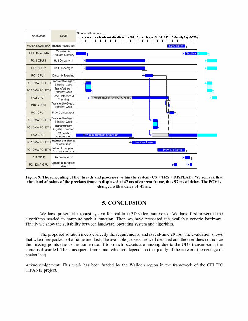
Figure 9. The scheduling of the threads and processes within the system (CS + TRS + DISPLAY). We remark that the cloud of points of the previous frame is displayed at 47 ms of current frame, thus 97 ms of delay. The POV is
changed with a delay of 41 ms.
5. CONCLUSION
We have presented a robust system for real-time 3D video conference. We have first presented the algorithms needed to compute such a function. Then we have presented the available generic hardware. Finally we show the suitability between hardware, operating system and algorithm.
The proposed solution meets correctly the requirements, and is real-time 20 fps. The evaluation shows
that when few packets of a frame are lost , the available packets are well decoded and the user does not notice the missing points due to the frame rate. If too much packets are missing due to the UDP transmission, the cloud is discarded. The consequent frame rate reduction depends on the quality of the network (percentage of packet lost) Acknowledgement: This work has been funded by the Walloon region in the framework of the CELTIC TIFANIS project.

REFERENCES [1] NTII (National Tele-immersion Initiative), http://www.advanced.org/tele-immersion/news.html. [2] D. Ruiz, J. Bruyelle, X. Desurmont, and B. Macq, ”A point-based tele-immersion system: from acquisition to stereoscopic display”, Proceedings of SPIE Vol. #6490 Stereoscopic Displays and Virtual Reality Systems XIV, Electronic Imaging, January 2007, San Jose, California, USA. [3] X. Desurmont, I. Ponte, J. Meessen, J. Delaigle, "Nonintrusive viewpoint tracking for 3D for perception in smart video conference", Three-Dimensional Image Capture and Applications VI, part of the IS&T/SPIE Symposium on Electronic Imaging 2006, 16-19 January 2006 in San Jose, CA USA. [4] R.Y. Tsai, "An Efficient and Accurate Camera Calibration Technique for 3D Machine Vision", Proceedings of IEEE Conference on Computer Vision and Pattern Recognition, Miami Beach, FL, 1986, pages 364-374. [5] Http://www.ai.sri.com/~konolige/svs/svs.htm. [6] I. Martinez-Ponte, X. Desurmont, J. Meessen and J.-F. Delaigle, "Robust human face hiding ensuring privacy", 6th International Workshop on Image Analysis for Multimedia Interactive Services, April 13-15, 2005, Montreux, Switzerland. [7] Open Computer Vision Library http:/sourceforge.net/projects/opencvlibrary [8] P. Viola and M. Jones, “Rapid Object Detection using a Boosted Cascade of Simple Features”, Proc. of the 2001 IEEE Computer Society Conference on Computer Vision and Pattern Recognition, vol. 1, pp. 511-518, 2001. [9] R. Lienhart and J. Maydt, “An Extended Set of Haar-like Features for Rapid Object Detection”, IEEE ICIP 2002, vol. 1, pp. 900-903, September 2002. [10] B. Nichols, D. Buttlar and J. Proulx Farell: Pthreads Programming, O'Reilly & Associates, ISBN 1-56592-115-1. [11] www.wikipedia.org