Rapid Replacement of Bridge Deck Expansion Joints – Phase II
136
Rapid Replacement of Bridge Deck Expansion Joints – Phase II Final Report May 2017 Sponsored by Federal Highway Administration Iowa Department of Transportation (InTrans Project 13-451)
-
Upload
khangminh22 -
Category
Documents
-
view
3 -
download
0
Transcript of Rapid Replacement of Bridge Deck Expansion Joints – Phase II

Rapid Replacement of Bridge Deck Expansion Joints – Phase II
Final ReportMay 2017
Sponsored byFederal Highway AdministrationIowa Department of Transportation(InTrans Project 13-451)

About the Construction Management and Technology programThe mission of the Construction Management and Technology (CMAT) program is to improve the efficiency and cost-effectiveness of planning, designing, constructing, and operating transportation facilities through innovative construction processes and technologies.
About the Bridge Engineering CenterThe mission of the Bridge Engineering Center (BEC) is to conduct research on bridge technologies to help bridge designers/owners design, build, and maintain long-lasting bridges.
About the Institute for TransportationThe mission of the Institute for Transportation (InTrans) at Iowa State University is to develop and implement innovative methods, materials, and technologies for improving transportation efficiency, safety, reliability, and sustainability while improving the learning environment of students, faculty, and staff in transportation-related fields.
Iowa State University Nondiscrimination Statement Iowa State University does not discriminate on the basis of race, color, age, ethnicity, religion, national origin, pregnancy, sexual orientation, gender identity, genetic information, sex, marital status, disability, or status as a US veteran. Inquiries regarding nondiscrimination policies may be directed to the Office of Equal Opportunity, 3410 Beardshear Hall, 515 Morrill Road, Ames, Iowa 50011, telephone: 515–294–7612, hotline: 515–294–1222, email: [email protected].
Disclaimer NoticeThe contents of this document reflect the views of the authors, who are responsible for the facts and the accuracy of the information presented herein. The opinions, findings and conclusions expressed in this publication are those of the authors and not necessarily those of the sponsors.
The sponsors assume no liability for the contents or use of the information contained in this document. This report does not constitute a standard, specification, or regulation.
The sponsors do not endorse products or manufacturers. Any trademarks or manufacturers’ names appear only because they are considered essential to the objective of the document.
Quality Assurance StatementThe Federal Highway Administration (FHWA) provides high-quality information to serve Government, industry, and the public in a manner that promotes public understanding. Standards and policies are used to ensure and maximize the quality, objectivity, utility, and integrity of its information. The FHWA periodically reviews quality issues and adjusts its programs and processes to ensure continuous quality improvement.
Iowa DOT Statements Federal and state laws prohibit employment and/or public accommodation discrimination on the basis of age, color, creed, disability, gender identity, national origin, pregnancy, race, religion, sex, sexual orientation or veteran’s status. If you believe you have been discriminated against, please contact the Iowa Civil Rights Commission at 800-457-4416 or the Iowa Department of Transportation affirmative action officer. If you need accommodations because of a disability to access the Iowa Department of Transportation’s services, contact the agency’s affirmative action officer at 800-262-0003.
The preparation of this report was financed in part through funds provided by the Iowa Department of Transportation through its “Second Revised Agreement for the Management of Research Conducted by Iowa State University for the Iowa Department of Transportation” and its amendments.
The opinions, findings, and conclusions expressed in this publication are those of the authors and not necessarily those of the Iowa Department of Transportation or the U.S. Department of Transportation Federal Highway Administration.

Technical Report Documentation Page
1. Report No. 2. Government Accession No. 3. Recipient’s Catalog No.
InTrans Project 13-451
4. Title and Subtitle 5. Report Date
Rapid Replacement of Bridge Deck Expansion Joints – Phase II May 2017
6. Performing Organization Code
InTrans Project 13-451
7. Author(s) 8. Performing Organization Report No.
Adam M. Miller and Charles T. Jahren
9. Performing Organization Name and Address 10. Work Unit No. (TRAIS)
Institute for Transportation
Iowa State University
2711 South Loop Drive, Suite 4700
Ames, IA 50010-8664
11. Contract or Grant No.
12. Sponsoring Organization Name and Address 13. Type of Report and Period Covered
Iowa Department of Transportation
800 Lincoln Way
Ames, IA 50010
Federal Highway Administration
U.S. Department of Transportation
1200 New Jersey Avenue SE
Washington, DC 20590
Final Report
14. Sponsoring Agency Code
SPR RB33-013
15. Supplementary Notes
Visit www.intrans.iastate.edu for color pdfs of this and other research reports.
16. Abstract
Bridge deck expansion joints are used to allow for movement of the bridge deck due to thermal expansion, dynamic loading, and
other factors. More recently, expansion joints have also been sealed to prevent winter de-icing chemicals and other corrosives
applied to bridge decks from penetrating and damaging the bridge substructure components. Expansion joints are often one of the
first components of a bridge deck to fail and repairing or replacing expansion joints are essential to extending the life of the
bridge.
In the Phase I study, the research team focused on the current means and methods of repairing and replacing bridge deck
expansion joints. Research team members visited with Iowa Department of Transportation (DOT) bridge maintenance crew
leaders to document methods of maintaining and repairing bridge deck expansion joints. Active joint replacement projects in
Iowa were observed to document the means of replacing expansion joints that were beyond repair, as well as to identify
bottlenecks in the construction process that could be modified to decrease the length of expansion joint replacement projects.
After maintenance and replacement strategies had been identified, a workshop was held at the Iowa State Institute for
Transportation to develop ideas to better maintain and replace expansion joints. Maintenance strategies were included in the
discussion as a way to extend the useful life of expansion joints to decrease the number of joints replaced in a year and also
reduce traffic disruptions.
Through a cooperative effort with the Iowa DOT Office of Bridges and Structures, Office of Construction and Materials, District
bridge maintenance crews, and contractors, the researchers on this project not only investigated and documented bridge deck
expansion joint maintenance and replacement strategies, but also gathered, developed, and documented a number of ideas (from
the group as well as from other state DOTs) for improvement.
17. Key Words 18. Distribution Statement
bridge deck—bridge joint repair—bridge maintenance—design details—
expansion joint design—expansion joint replacement
No restrictions.
19. Security Classification (of this
report)
20. Security Classification (of this
page)
21. No. of Pages 22. Price
Unclassified. Unclassified. 132 NA
Form DOT F 1700.7 (8-72) Reproduction of completed page authorized


RAPID REPLACEMENT OF BRIDGE DECK
EXPANSION JOINTS – PHASE II
Final Report
May 2017
Principal Investigator
Charles T. Jahren, Professor
Construction Management and Technology
Institute for Transportation, Iowa State University
Research Assistant
Adam M. Miller
Authors
Adam M. Miller and Charles T. Jahren
Sponsored by
the Iowa Department of Transportation and
the Federal Highway Administration
(InTrans Project 13-451)
Preparation of this report was financed in part
through funds provided by the Iowa Department of Transportation
through its Research Management Agreement with the
Institute for Transportation
A report from
Institute for Transportation
Iowa State University
2711 South Loop Drive, Suite 4700
Ames, IA 50010-8664
Phone: 515-294-8103 / Fax: 515-294-0467
www.intrans.iastate.edu


v
TABLE OF CONTENTS
ACKNOWLEDGMENTS ............................................................................................................. ix
EXECUTIVE SUMMARY ........................................................................................................... xi
CHAPTER 1. INTRODUCTION ....................................................................................................1
1.1 Background and Problem Statement ..............................................................................1 1.2 Objectives ......................................................................................................................1 1.3 Scope ..............................................................................................................................1
1.4 Report Organization .......................................................................................................2
CHAPTER 2. LITERATURE REVIEW .........................................................................................3
2.1 Expansion Joints ............................................................................................................3
2.2 Expansion Joint Elimination ........................................................................................12 2.3 Joint Lifecycle ..............................................................................................................18
CHAPTER 3. DETERIORATION PATTERNS AND MAINTENANCE EFFORTS .................20
3.1 Chapter Overview ........................................................................................................20
3.2 Introduction ..................................................................................................................20 3.3 Research Methodology ................................................................................................20
3.4 Sliding Plate Expansion Joints .....................................................................................20 3.5 Strip Seal and Compression Seal Joints .......................................................................26 3.6 Finger Joints and Modular Expansion Joints ...............................................................35
3.7 Integral Abutment Joints ..............................................................................................41
CHAPTER 4. CURRENT JOINT REPLACEMENT PRACTICES .............................................43
4.1 Chapter Overview ........................................................................................................43 4.2 Introduction ..................................................................................................................43
4.3 Northbound I-380 Joint A Replacement ......................................................................43 4.4 US 18 over the Wapsipinicon River ............................................................................54
CHAPTER 5. EXPANSION JOINT IMPROVEMENT WORKSHOP ........................................59
5.1 Introduction ..................................................................................................................59 5.2 Summary of Previous Research Tasks .........................................................................59 5.3 Pertinent Iowa DOT Design Standards and Design Considerations ............................62 5.4 Breakout Groups, Idea Discussion, and Ranking ........................................................63 5.5 Workshop Results ........................................................................................................64
CHAPTER 6. RAPID REPLACEMENT OF EXPANSION JOINTS WORKSHOP ...................67
6.1 Introduction ..................................................................................................................67
6.2 Student Proposals .........................................................................................................67 6.3 Breakout Discussions ...................................................................................................70 6.4 Further Investigation on Deck Extensions ...................................................................79 6.5 Conclusion ...................................................................................................................83

vi
CHAPTER 7. EXPANSION JOINT HEADER MATERIALS AND EVALUATION ................84
7.1 Introduction ..................................................................................................................84
7.2 Elastomeric Concrete ...................................................................................................84 7.3 Portland Cement Concrete ...........................................................................................88 7.4 Magnesium Phosphate Cement ....................................................................................92 7.5 Calcium Aluminate Cements .......................................................................................95
CHAPTER 8. CONCLUSIONS AND SUGGESTIONS FOR FUTURE RESEARCH ...............97
8.1 Conclusions ..................................................................................................................97 8.2 Suggestions for Future Research .................................................................................99
REFERENCES ............................................................................................................................101
APPENDIX A. WORKSHOP PARTICIPANTS, OVERVIEW, AND RESULTS ....................105
APPENDIX B. WORKSHOP GROUP DISCUSSION NOTES .................................................109
Bridge Deck Expansion Joint (BDEJ) Group 1 Discussion Notes ..................................109 BDEJ Group 2 Discussion Notes .....................................................................................112
BDEJ Group 3 Discussion Notes .....................................................................................113
APPENDIX C. STUDENT JOINT REPLACEMENT PROPOSALS ........................................117
APPENDIX D. MICHIGAN DOT INDEPENDENT BACKWALL WITH SLIDING
SLAB ...............................................................................................................................119

vii
LIST OF FIGURES
Figure 2.1. Sliding plate joint ..........................................................................................................3
Figure 2.2. Strip seal expansion joint at full expansion ...................................................................4 Figure 2.3. Strip seal end detail .......................................................................................................6 Figure 2.4. Finger joint with trough .................................................................................................6 Figure 2.5. Compression seal joint, with (right) or without (left) edge armoring ...........................8 Figure 2.6. Modular bridge expansion joint.....................................................................................9
Figure 2.7. Asphalt plug joint ........................................................................................................10 Figure 2.8. Cushion (or plank) seal expansion joint ......................................................................11 Figure 2.9. Poured silicone (polymer) sealant joint .......................................................................12 Figure 2.10. Integral abutment cross section .................................................................................13 Figure 2.11. New York semi-integral abutment ............................................................................16
Figure 2.12. Debonded link slab system ........................................................................................17 Figure 3.1. Large sections of a plate broken loose on northbound I-380 Exit 19A in Cedar
Rapids, Iowa ......................................................................................................................22 Figure 3.2. Gap forming between top of abutment and approach panel on the I-80 over I-
35 west abutment in Iowa ..................................................................................................23 Figure 3.3. Rusted top plate beneath a raise plate showing relatively good condition on
westbound US 20 over Catfish Creek in Cedar Rapids, Iowa ...........................................24
Figure 3.4. Extreme case of sliding plate joint maintenance .........................................................25 Figure 3.5. Strip seal joint ..............................................................................................................26
Figure 3.6. Compression seal joint ................................................................................................27 Figure 3.7. Badly weathered, but still functioning, strip seal joint showing debris building
up in the seal ......................................................................................................................28
Figure 3.8. Modular expansion joint with loose seal due to rust buildup in extrusion insert ........29
Figure 3.9. Strip seal joint with missing extrusion section ............................................................32 Figure 3.10. Compression seal joint with failed section of armoring ............................................34 Figure 3.11. Silicoflex expansion joint ..........................................................................................35
Figure 3.12. Modular expansion joint ............................................................................................36 Figure 3.13. Neoprene trough below finger expansion joint .........................................................37
Figure 3.14. Exposed piling from slope erosion ............................................................................38
Figure 3.15. Debris collection in modular expansion joint preventing full closure of the
joint ....................................................................................................................................39 Figure 3.16. New Iowa DOT standard detail for integral abutment wing wall armoring ..............42 Figure 4.1. Northbound I-380 project location through Cedar Rapids, Iowa ................................44 Figure 4.2. Approximate locations of expansion joints along Exit 19A on Northbound I-
380 project through Cedar Rapids, Iowa ...........................................................................45 Figure 4.3 Northbound I-380 project concrete removal cross section ...........................................46
Figure 4.4 Aqua Cutter hydrodemolition machine ........................................................................49 Figure 4.5. Joint A after hydrodemolition .....................................................................................50 Figure 4.6 Concrete remaining after hydrodemolition ..................................................................51 Figure 4.7. Flexible shaft vibratory compactor ..............................................................................53 Figure 4.8. US 18 over Wapsipinicon River project location ........................................................54
Figure 4.9. US 18 over Wapsipinicon River project removal cross section ..................................55 Figure 4.10. Replacement paving notch plan for US 18 over Wapsipinicon River project ..........56 Figure 4.11. US 18 over Wapsipinicon River project possible detour route .................................58

viii
Figure 6.1. Adhesive bonded gland concept ..................................................................................68
Figure 6.2. Stacked strip seals concept ..........................................................................................68
Figure 6.3. Strip seal gland installation tool ..................................................................................69 Figure 6.4. Sliding plate concept ...................................................................................................69 Figure 6.5. Typical expansion joint replacement cross section .....................................................70 Figure 6.6. Tied precast approach slab concept .............................................................................72 Figure 6.7. Slotted dowel concept..................................................................................................74
Figure 6.8. Sliding plate joint anchorage during removal .............................................................75 Figure 6.9. Sliding plate joint cross section ...................................................................................75 Figure 6.10. Skewed bridge deck reinforcing (left) and non-skewed deck reinforcing
(right) .................................................................................................................................76 Figure 6.11. Suggested demolition limits for partial-depth joint replacement concept .................77
Figure 6.12. Iowa DOT strip seal anchorage .................................................................................78
Figure 6.13. NYSDOT deck extension detail ................................................................................80 Figure 6.14. MDOT deck extension detail .....................................................................................81
Figure 7.1. Reflective cracking in elastomeric concrete header ....................................................87
Figure 7.2. Elastomeric concrete joint header with severe material loss .......................................88
LIST OF TABLES
Table 2.1. Joint lifespan, Purdue University study ........................................................................19
Table 2.2. Joint lifespan, Arizona DOT study ...............................................................................19
Table 4.1. Construction task length by hour ..................................................................................48 Table 4.2. Total construction task lengths .....................................................................................49 Table 7.1. Michigan HES engineered cementitious composite proportions for bridge and
highway repair ...................................................................................................................92 Table 7.2. Composition of ordinary Portland cement (OPC) and calcium aluminate
cement (CAC) ....................................................................................................................95

ix
ACKNOWLEDGMENTS
The authors would like to thank the Iowa Department of Transportation (DOT) for sponsoring
this research as well as the Federal Highway Administration for state planning and research
(SPR) funds used for this project.
The authors would like to thank the technical advisory committee for this project including Dean
Bierwagen, Mark Carter, Dan Cramer, Matt Johnson, Linda Narigon, James Nelson, Steve
Sandquist, Justin Sencer, and Wayne Sunday. A multitude of Iowa DOT personnel, too
numerous to list, were engaged on this project and the authors would like to thank each of them
for their individual contributions.
Finally, the authors would like to thank Roger Anderson, Steve Kunz, Stan Stallsmith, and Andy
Stone for their contributions to this research.
Notes: Previous versions of parts of this report content were published in the Phase I interim
report, written by the same authors, Adam M. Miller and Charles T. Jahren: Rapid Replacement
of Bridge Deck Expansion Joints Study – Phase I. 2014. Institute for Transportation, Iowa State
University, Ames, IA.
The content of this Phase II final report supercedes the Phase I content. For reuse of any of the
content, please use this final report rather than the Phase I interim report in source attributions
and References.


xi
EXECUTIVE SUMMARY
Bridge deck expansion joints are used to allow movement of the bridge deck due to thermal
expansion, dynamic loading, and other factors. More recently, expansion joints have also been
sealed to prevent winter de-icing chemicals and other corrosives applied to bridge decks from
penetrating and damaging the bridge substructure components.
Expansion joints are often one of the first components of a bridge deck to fail and repairing or
replacing expansion joints is essential to extending the life of the bridge.
In the Phase I study, the research team focused on documenting the current means and methods
of bridge expansion joint deterioration, maintenance, and replacement and on identifying
improvements through all of the input gathered.
Research team members visited with Iowa Department of Transportation (DOT) bridge
maintenance crew leaders to document methods of maintaining and repairing bridge deck
expansion joints. They observed active joint replacement projects in Iowa to document the means
of replacing expansion joints that were beyond repair, as well as to identify bottlenecks in the
construction process that could be modified to decrease the length of expansion joint
replacement projects.
After maintenance and replacement strategies were identified, a workshop was held at the Iowa
State University Institute for Transportation to develop ideas to better maintain and replace
expansion joints. Maintenance strategies were included in the discussion as a way to extend the
useful life of a joint to decrease the number of joints replaced in a year and reduce traffic
disruptions.
The results of this second phase of the research provide details about the types of failure
experienced with expansion joints in Iowa, measures taken to repair and prevent these types of
failures, current construction methods undertaken by contractors in Iowa, and hypothesized ways
to improve methods of expansion joint repair and maintenance.
In this phase of the project, the team completed a review of published literature. Topics included
types of joints used or tested in other states, common and reported modes of failures in other
states, integral abutments and the differences in their use between states, other methods of
eliminating deck joints from existing bridges, and surveys of the average life span of particular
types of expansion joints.
A second workshop was held with the emphasis solely on the replacement of expansion joints.
Discussion topics included alternate methods of replacing joints, the possibility of using partial-
depth deck removals for replacements, the removal of existing reinforcing steel from the end of
the deck, and an alternative construction design that would eliminate the joint at the abutment
and move it to a less problematic location.

xii
Further investigations were performed into the prior use and research of the alternative design
commonly called a deck extension.
Finally, an overview was completed of several different broad categories of materials that could
be used as a high-early-strength pavement to reduce the cure time required for joint
replacements, because early investigations found cure times were one of the longest single tasks
required in the replacement of expansion joints.
In summary, through a cooperative effort with the Iowa DOT Office of Bridges and Structures,
Office of Construction and Materials, District bridge maintenance crews, and contractors, the
researchers on this project not only investigated and documented bridge deck expansion joint
maintenance and replacement strategies, but also gathered, developed, and documented a number
of ideas (from the group as well as from other state DOTs) for improvement. Some results are
likely to be commissioned as future projects for more detailed evaluation and development.

1
CHAPTER 1. INTRODUCTION
1.1 Background and Problem Statement
Bridge deck expansion joints are the components of a bridge that allow for movement of the
bridge deck due to thermal expansion, dynamic loading, and several other factors. More recently,
expansion joints have had a secondary function of preventing the passage of water. This water
often contains de-icing salts and other corrosive chemicals that are harmful to the substructure of
the bridge.
Expansion joints are often one of the first components of a bridge to fail. Failure can be due to
increased traffic loading, component fatigue, low-quality work, or several other factors. Joint
failure can lead to increased damage to bridge substructures including rust formation on metal
bearings as well as increased spalling on precast beam ends, concrete abutments, and concrete
piers. To prevent further bridge damage, joints are often repaired or replaced.
Joint replacements are particularly problematic construction projects, often requiring traffic
closures to allow completion of the work. Traffic closures are undesirable and often require
staged jobs and difficult working conditions.
Completing work during low-traffic periods, nights, and weekends can help alleviate traffic
concerns. However, it is challenging to complete a repair in a very short period or at night while
still maintaining the necessary joint quality. Improved methods to rapidly repair and replace
bridge deck expansion joints are desirable.
1.2 Objectives
The objectives of this research were two-fold: examine both current means and methods as well
as develop new methods of replacing expansion joints.
1.3 Scope
This research provides the Iowa Department of Transportation (DOT) with detailed information
about the types of failure experienced by expansion joints, measures taken by the Iowa DOT to
repair and prevent these types of failures, current construction methods undertaken by
contractors in Iowa, and hypothesized ways to improve methods of expansion joint repair and
maintenance.
A significant portion of this research focused on the current state of expansion joints and on
developing novel ideas to rapidly repair expansion joints, so some results may be contracted as
future projects for more detailed evaluation.

2
1.4 Report Organization
This report is organized as follows. Chapter 1 contains a brief introduction. Chapter 2 contains a
literature review of published literature related to bridge deck expansion joints, their lifecycles,
durability, problems, and alternative designs. Chapter 3 contains field-gathered information on
the rate and types of expansion joint deterioration in Iowa as well as the methods undertaken by
the Iowa DOT to repair these joints. Chapter 4 contains detailed observations of current
construction methods practiced by contractors on several different expansion joint replacement
projects in Iowa. Chapter 5 contains the summary and results of a workshop held with the
research team, the Iowa DOT, local contractors, and design-consultants to develop methods to
improve bridge deck expansion joints currently being used in Iowa. Chapter 6 contains the
summary and follow-up investigation of a second workshop again held with the research team,
the Iowa DOT, local contractors, and design-consultants with the focus on improving expansion
joint replacement methods. Chapter 7 contains a review of published literature and information
involving possible high-early-strength concretes that could be used during bridge deck expansion
joint replacements to reduce the duration of cure time. Chapter 8 includes conclusions
suggestions for future research.
The report content concludes with References for works cited in it and four appendices.

3
CHAPTER 2. LITERATURE REVIEW
2.1 Expansion Joints
Bridge deck expansion joints serve a number of important purposes. Most importantly, they
prevent the buildup of stresses in bridge decks by allowing for movement due to thermal
expansion, live loads, settlement, and prestressing camber.
In more recent decades, joints have also been required to protect the end of the bridge deck and
prevent the passage of water and corrosive de-icing chemicals through the bridge deck, while
providing a quality riding surface that produces a minimum amount of noise.
The two broad categories of bridge deck expansion joints are closed joints and open joints.
Closed joints are specifically designed to be watertight, preventing the passage of water and de-
icing chemicals through the expansion joint, while open joints are not designed to be watertight.
Of these joints, the most commonly used bridge deck joints are sliding plate joints, compression
seal joints, and strip seal joints, for shorter expansion lengths, while finger joints and modular
joints are used for longer expansion distances (Chang and Lee 2002). Integral abutments, which
can eliminate expansion joints, while serving many of the same purposes, are also commonly
installed and are addressed in the following sections of this chapter.
2.1.1 Sliding Plate Joints
At one time, sliding plate joints, like the one depicted in Figure 2.1, were the predominant joint
used on bridges by state highway agencies.
Caicedo et al. 2011
Figure 2.1. Sliding plate joint
Sliding plate joints use a pair of steel plates with one that slides over the top of the other to
provide continuity over the gap at the end of the bridge deck. This joint addressed many of the
important functions of allowing the necessary movements, while still providing a quality riding

4
surface. However, with the increasing use of de-icing chemicals, sliding plate joints fell out of
favor due to their lack of waterproofness. While the sliding plates would prevent the passage of
most debris, there was nothing to stop water and dissolved chemicals from passing through the
joint and damaging bridge substructures.
Over time, these joints develop issues because the sliding steel plates fatigue and come loose
under traffic loading. Large pieces of loose plate can cause hazards to passing traffic. They also
suffered from debris buildup, particularly in the gutter regions where runoff is typically
concentrated.
Many failures could also be attributed to inadequate consolidation of the concrete around the
anchorages, which is a problem that still occurs today with other types of expansion joints
(Purvis 2003). Some states have suggested improving sliding plate joints by installing a trough
beneath the joints to prevent runoff, which is a detail commonly used by Russian transportation
agencies (Palle et al. 2011).
2.1.2 Strip Seal Joints
Strip seal expansion joints are increasingly popular with state highway agencies. As shown in
Figure 2.2, a strip seal is an elastomeric, often neoprene, membrane held in place by a metal
extrusion embedded in the concrete bridge deck.
Bolluyt et al. 2001, Iowa State University
Figure 2.2. Strip seal expansion joint at full expansion
In a survey of state highway agencies completed with the National Cooperative Highway
Research Program (NCHRP) Synthesis 319, strip seals were the joint that received the most
positive appraisals. It was thought that strip seals had a lifespan longer than other closed joints.
However, strip seals were not without their problems.
When strip seals do finally need to be replaced, the task is challenging requiring the removal of a
considerable amount of concrete. It was also mentioned that splices in the neoprene membrane
should be avoided (Purvis 2003).
A 2001 Iowa State University (ISU) study of strip seal expansion joints in Iowa determined that
almost 17 percent of strip seal expansion joints over abutments were considered to have failed

5
(Bolluyt et al. 2001). Improper installation and debris accumulation appear to be the major
culprits for failure of strip seal extrusions.
Neoprene glands in Iowa are typically field installed after the metal extrusion has been
embedded in the concrete bridge deck. If concrete or other debris is lodged inside the extrusion
during gland installation, it can be difficult to properly insert the gland in the extrusions to create
a watertight seal. It can also prevent the extrusion from properly anchoring the gland, allowing it
to easily pull free if the gland is stretched to near the designed expansion distance.
Debris accumulation in a gland is another problem. When debris accumulates in glands, wheel
loading from passing traffic can cause a prying action that pulls seals loose. If the gland already
suffers from incorrect installation, this combination of problems can quickly lead to early
failures.
Despite the indications of early failures and causes of strip seal failures, published literature does
not effectively describe what portion of the expansion joint has failed.
The same ISU study (Bolluyt et al. 2001) found that that most failures of strip seals were failures
of the neoprene gland, not the entire strip seal assembly. In fact, manufacturers stated the
expected service life of the gland is only 15 to 20 years. The foregoing does not indicate that
damage to the embedded extrusions never occurs, only that it occurs much less frequently
(Chang and Lee 2002, Bolluyt et al. 2001).
One common suggestion to improve the lifespan of strip seals is to prevent debris buildup in the
seals. One way in which this could be accomplished is by having a regular joint cleaning
schedule where maintenance workers use compressed air and/or water to wash debris out of the
joint. However, this is uncommon in practice with only five of 39 states responding to the
previous ISU study stating they had a regular maintenance program.
Most state highway agency maintenance for bridge joints was reactive, not proactive, with
maintenance being addressed after damage has occurred. In particular, the Massachusetts DOT
(MassDOT) stated that it had a premature failure rate, which was designated as being less than 5
years in that study, but nearly a 0 percent failure rate of strip seals if joints were cleaned on a
regular basis (Bolluyt et al. 2001). Numbers declined if joints were not regularly cleaned.
Additionally. all five states with maintenance programs provided rates of premature failure at 0
to 5 percent, the lowest category available for that survey.
Another suggested way of reducing debris buildup in strip seals is to set the joint at a sufficient
slope that the force of the draining water washes the debris down the seal, through the curb, and
off of the bridge deck. Currently in Iowa, the strip seal end detail, shown in Figure 2.3, includes
an upturned end at the curb to prevent runoff from leaving the bridge deck.

6
Bolluyt et al. 2001, Iowa State University
Figure 2.3. Strip seal end detail
This detail effectively traps the debris on the deck in the gutter line keeping it trapped in the seal.
The detail has been used by the Iowa DOT since 2000 and is also used by the Minnesota and
Wisconsin DOTs (MnDOT and WisDOT), while several states surrounding Iowa have used
details that allow water to drain through the curb of the bridge into some sort of collection
system. Among these states are Kansas, Missouri, and South Dakota.
In the past, Kansas has extended strip seals past the outside face of the curb a minimum of 6
inches, while Missouri still extends strip seals a minimum of 3 inches past the edge of the slab
(Chang and Lee 2002, Bolluyt et al. 2001).
2.1.3 Finger (Tooth) Joints
Finger joints are similar to sliding plate joints, and they are a type of joint that uses a set of
interlocking plates to allow joint movement rather than using the plates that pass one on top of
the other. These joints, which appear similar to the detail shown in Figure 2.4, are still often used
for expansion distances greater than what can be achieved with a strip seal joint.
Caicedo et al. 2011
Figure 2.4. Finger joint with trough

7
Like sliding plate joints, finger joints are generally well liked and thought to be very durable.
They were preferred among many engineers because of their durability and lack of required
maintenance. Most problems with finger joints were directly attributed to poor initial
construction practices, such as vertical and horizontal misalignment.
Since finger joints are designed to provide a continuously level surface across the gap, they
provide a smooth riding surface, and snowplow damage is rare. The main problems are that the
joint is not designed to be watertight and that the joint requires a drainage trough underneath it to
prevent damage to the bridge substructure.
Very few problems with finger joints are documented in the literature and the problems that were
documented were not common occurrences. Among the reported damage were deterioration of
the concrete around the joint anchorage and occasional problems with the joint anchorage.
Otherwise, the most commonly reported damage was usually bent fingers with the occasional
broken finger.
Since these joints are essentially a series of small cantilevered steel beams, it is essential that the
design be sufficiently robust. It is also important that weld details be designed correctly for
fatigue, as these joints are especially susceptible to fatigue damage if not designed correctly
(Purvis 2003, Guthrie et al. 2005).
2.1.4 Drainage Troughs
With the growing use of de-icing chemicals on bridges, most finger joints are used in
conjunction with a drainage trough. These troughs, typically either neoprene or steel, hang below
the joint and catch and divert (from critical bridge components) any water, chemicals, and debris
that leak through the joint.
Particularly with finger joints, most reported problems were related to these drainage troughs and
not the joint itself. The buildup of debris in the drainage trough is the most commonly reported
problem. If the buildup becomes too severe, troughs can become clogged and water can overflow
onto the very components that the trough was installed to protect. Additionally, the added weight
of the debris, water, and, in the winter, ice buildup, can cause the trough to rip at the anchorages
and fail entirely.
The solution for many of the trough problems is to prevent debris buildup either with regular
cleaning or by providing a steep enough slope that debris is carried away. In one report, the
Arkansas State Highway and Transportation Department (AHTD) stated “When a finger joint had
a trough sloping at eight percent, there was no debris accumulation six years after placement; but,
when the trough had a slope of one percent, it was filled with debris in six months.”
While regular cleaning is also suggested, many of the troughs are not easily accessible from below
the bridge, while the finger joints themselves prevent easy access from the top of the bridge deck
(Purvis 2003, Guthrie et al. 2005).

8
2.1.5 Compression Seals
Compression seal joints are another type of commonly used expansion joint. These joints use a
pre-formed elastomeric seal to allow for the necessary bridge movements while providing a
watertight seal of the joint. Although these joints are normally installed with an adhesive
between the bridge deck and seal, the seal must be kept in compression to keep it watertight.
Compression seals are often used with or without steel armoring at the edge of the bridge deck,
as shown in Figure 2.5.
Purvis 2003, National Cooperative Highway Research Program
Figure 2.5. Compression seal joint, with (right) or without (left) edge armoring
Good for shorter expansion distances of about 0.25 to 2.5 inches, compression seals have
received mixed reviews from the state highway agencies that have used them. Among their
reported problems are a lack of consistent performance, early leaking of the joint, and seals that
eventually harden and lose their compressive qualities (Purvis 2003).
Other reported problems with compression seal joints is spalled and cracked concrete in the deck
surrounding the expansion joint. If spalling becomes serious and enough concrete is lost, the
elastomeric seal can eventually come loose (Chang and Lee 2002).
In situations where steel angle is used to protect the end of the concrete bridge deck from
damage, inadequate consolidation beneath the angle can be a problem. Voids beneath the angle
can cause additional stresses to develop from traffic loading, eventually causing fatigue failure of
sections of the armor angle (Issa et al. 1996).
2.1.6 Modular Joints
Modular bridge expansion joints (MBEJs) are, in essence, a series of strip seal expansion joints
supported through an expansion gap by a support beam (see Figure 2.6).

9
Adam Miller, Institute for Transportation; adapted from D.S. Brown Company
(dsbrown.com/Resources/Bridges/Steelflex/Joints/D320-PV-S.pdf)
Figure 2.6. Modular bridge expansion joint
Modular joints have, within reasonable limits, a nearly unlimited expansion distance.
In past decades, MBEJs have acquired a bad reputation as being unreliable and they have a high
initial cost. The number of early failures led to NCHRP Report 402: Fatigue Design of Modular
Bridge Expansion Joints (Dexter et al. 1997).
The research determined that the early problems could be attributed to three main causes: poor
installation, wear of elastomeric parts, and, most often, fatigue cracking of the steel components.
Poor installation included poor consolidation of concrete under the support boxes and reflective
cracking in the top of the deck above the support boxes. Elastomeric components of MBEJs
include the neoprene glands, the elastomeric bearings, and spacing springs. Over time, these
components wear out and require replacement.
The advantage of MBEJs is that, unlike many other joint types, individual components can be
replaced instead of an entire joint (Dexter et al. 1997).
A prominent problem, fatigue cracking, was found to have a number of causes. First, MBEJs
were designed using a finite fatigue-life design. However, due to the uncertainty of the number
of stress cycles that can accumulate, an MBEJ can easily exceed 10 million stress cycles during
the life of a bridge deck. At such a high number of cycles, infinite life design is justified to
prevent early failure. Additionally, the cost difference between a finite-life design and an
infinite-life design was so small that the infinite-life design procedure should be used, if for no
other reason, to provide a better product.
Another contributing factor to the fatigue cracking was the use of field-welded details that did
not provide sufficient fatigue resistance. In particular, due to the difficulty of producing full-
penetration welds, partial-depth fillet welds used to be used for the center beam to support the
reinforcing steel bar connection. NCHRP Report 402 determined that, for roughly equal-sized
full-penetration and fillet welds, the fillet weld had a fatigue strength of 25 percent or less than
that of the full-penetration weld (Dexter et al. 1997). Thus, the current specifications for modular
expansion joints no longer allow fillet-welded details.

10
The specifications also give more guidance on the appropriate American Association of State
Highway and Transportation Officials (AASHTO) fatigue categories, as well as test procedures
to determine the proper constant-amplitude fatigue limit (CAFL) and fatigue category for new
modular joint designs that may be developed after this specification is adopted (Dexter et al.
1997).
2.1.7 Other Joint Types
While the joints discussed previously tend to be the most prevalent types of joints, many other
types of expansion joints have been tested over the years with varying results. These alternative
joints include plug seals, inflatable neoprene seals, cushion seals, and field-molded sealers.
2.1.7.1 Plug Seals
Plug seals are essentially a section of polymer-modified asphalt placed in in the bridge deck as
shown in Figure 2.7.
Purvis 2003, National Cooperative Highway Research Program
Figure 2.7. Asphalt plug joint
For small expansion distances, the lower stiffness of the asphalt plug joint allows it to be
compressed to accommodate necessary movement. This joint has the advantages of being easy to
install and repair, is not typically subject to damage from snowplows, and has few problems with
debris becoming trapped in the joint. However, the joint is not effective at providing a watertight
seal at upturns, for long bridge decks, or along skewed bridges. There have also been concerns
about rutting of the asphalt plug during warm weather and cracking in cold weather (Malla et al.
2006).
2.1.7.2 Inflatable Neoprene Seals
Inflatable neoprene seals appear to be much like compressions seals. These seals are inflated
after they are installed in the joint for a period of up to 24 hours. This compresses the seal against
the edges of the joint opening, ensuring a watertight seal while a bonding agent sets. Traffic can
pass over the joint while it is inflated, making this a rapid repair. Because of the inflatable
quality, these seals can also accommodate some irregularity in the joint edge.

11
A disadvantage of this joint is that, after 24 hours, it is deflated and the watertight bond relies
solely on the bonding agent. Any damage to the adhesive of the joint header will render this joint
ineffective. Transportation agencies have responded to investigators with mixed views on the
durability of this joint (Purvis 2003).
2.1.7.3 Cushion Seals
Cushion seals, also known as plank seals, use a steel-reinforced neoprene pad to provide the
necessary bridge movement while maintaining a smooth deck. Figure 2.8 shows an example.
Purvis 2003, National Cooperative Highway Research Program
Figure 2.8. Cushion (or plank) seal expansion joint
Cushion seals are not considered to be a very durable joint by most transportation agencies. In
snowy climates, in particular, cushion seals were found to be very susceptible to snow plow
damage with entire sections being destroyed in a single pass. Snow plow blades would cut into
the material causing large rips along entire lanes.
Since repairs involved replacing the entire joint, damage to one section meant a lengthy
replacement process for the entire section (Malla et al. 2006).
2.1.7.4 Field-Molded Sealers
Poured silicone sealant is a joint material that has often been used for repairs of very small
movement joints. These joints consist of a section of silicone, poured as a liquid into the
expansion gap, that then sets and waterproofs the joint (see Figure 2.9).

12
Purvis 2003, National Cooperative Highway Research Program
Figure 2.9. Poured silicone (polymer) sealant joint
A backer rod is typically used to prevent the sealant from leaking through the joint while it is still
in a liquid state during construction. This joint is typically only useful for gaps smaller than 1
inch.
There are a few advantages to this system. Since the sealant material is field-molded, the header
walls do not need to be perfectly straight or parallel, repairs can be completed easily and rapidly,
and only damaged sections need to be removed instead of the entire silicone joint.
However, the materials used for these joints are generally not robust and are easily susceptible to
damage from passing traffic and debris. Seals also may harden or loosen from the header,
particularly if put into tension, so that the entire seal can be pulled from the joint in one long
strip. This results in considerably shorter lifespans in comparison to other joint types, while this
may be balanced by the ease and speed of installation (Purvis 2003).
2.2 Expansion Joint Elimination
2.2.1 Integral Abutments
Few bridge decks are short enough to ignore expansion requirements altogether, although most
bridge engineers would likely consider no expansion joint to be ideal. Thus, integral abutment
bridges are becoming increasingly popular, because they accommodate expansion by allowing
the bridge abutment to move with respect to the driven piles that support it and eliminate the
need for a bridge deck expansion joint. This is accomplished by embedding the ends of the
bridge girders in the abutment backwall and allowing the flexibility of the pile foundations to
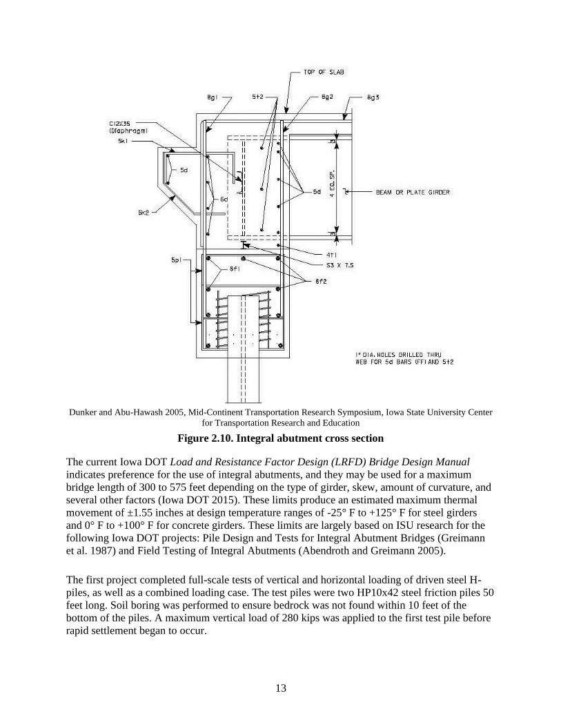
accommodate the necessary movement. Figure 2.10 shows a typical cross section.
13
Dunker and Abu-Hawash 2005, Mid-Continent Transportation Research Symposium, Iowa State University Center
for Transportation Research and Education
Figure 2.10. Integral abutment cross section
The current Iowa DOT Load and Resistance Factor Design (LRFD) Bridge Design Manual
indicates preference for the use of integral abutments, and they may be used for a maximum
bridge length of 300 to 575 feet depending on the type of girder, skew, amount of curvature, and
several other factors (Iowa DOT 2015). These limits produce an estimated maximum thermal
movement of ±1.55 inches at design temperature ranges of -25° F to +125° F for steel girders
and 0° F to +100° F for concrete girders. These limits are largely based on ISU research for the
following Iowa DOT projects: Pile Design and Tests for Integral Abutment Bridges (Greimann
et al. 1987) and Field Testing of Integral Abutments (Abendroth and Greimann 2005).
The first project completed full-scale tests of vertical and horizontal loading of driven steel H-
piles, as well as a combined loading case. The test piles were two HP10x42 steel friction piles 50
feet long. Soil boring was performed to ensure bedrock was not found within 10 feet of the
bottom of the piles. A maximum vertical load of 280 kips was applied to the first test pile before
rapid settlement began to occur.

14
Interestingly, the same vertical maximum load was achieved during the combined loading test
after the pile head had displaced 2 inches horizontally. It was determined that, within reasonable
limits, the maximum vertical pile load is seemingly independent of the horizontal displacement.
Among the design suggestions was the use of a pre-bored hole to help reduce pile stresses when
horizontal displacement occurs (Greimann et al. 1997).
Along with the Iowa DOT, the Tennessee DOT (TDOT) is a leading agency in the use of integral
abutments. Tennessee has one of the longest known integral abutment bridges, the Happy
Hollow Bridge, which carries State Route 50 over Happy Hollow Creek. The Happy Hollow
Bridge is curved and superelevated and is 1,175 feet long. This is longer than the typical
maximum length for integral abutments.
In general, TDOT limits the movement at each abutment to about 2 inches, but unlike the Iowa
DOT, TDOT does not have a specific limit on length or skew. TDOT treats every bridge as a
separate case, which is possible because the agency completes 95 percent of its bridge designs
in-house (Holloway 2012).
Iowa DOT and TDOT design methodologies have several other differences between them. The
Iowa DOT’s pre-bored holes around integral abutment piles have a minimum of 10 feet. These
holes are filled with bentonite slurry that is intended to provide no structural resistance to the top
section of the pile. This introduces a great deal of flexibility into the piles that, combined with
the allowance for plastic hinging, accommodates greater expansion distances. However, this lack
of constraint of the top of the piles also introduces an increased concern for local-buckling that
reduces pile capacity. TDOT, on the other hand, does not pre-bore piles, keeping the constraint
around the top of the piles and largely preventing local-buckling concerns.
Another difference between Iowa and Tennessee are the orientation of the piles. The Iowa DOT
orients piles for weak axis bending to prevent interaction between flange-local buckling and
either web-local buckling or lateral-torsional buckling. In this situation, only flange-local
buckling has the possibility to affect the flexural-bending strength. The skew of bridges in Iowa
reduces the maximum allowed expansion length because of the increased possibility of biaxial
bending in the piles of skewed bridges. This, again, increases the concern of interaction between
various types of local buckling.
TDOT, on the other hand, orients the piles with the strong axis perpendicular to the longitudinal
axis of the integral abutment bridge (IAB), regardless of skew. TDOT does this to reduce
maximum stresses in the piles at an equivalent thermal displacement. Since TDOT does not pre-
bore holes, the surrounding soil is still present along the top several feet of the pile to provide
confinement. This alleviates some of the concern for local-buckling.
Strong-axis orientation may also reduce the likelihood of localized crushing of the concrete at the
pile/abutment interface. However, TDOT, much like the Iowa DOT, expects a significant amount
of plastic hinging in the piles to achieve the necessary displacement (Abendroth and Greimann
2005, Holloway 2012).

15
Most states are satisfied with the performance of integral abutment bridges. In 2004, Maruri and
Petro (2005) surveyed transportation agencies in the US on their use of integral abutment
bridges: 39 agencies, of 53, responded, corresponding to a 79 percent response rate. Survey
responses showed that the estimated number of in-service integral abutment bridges increased by
almost 200 percent from an estimated 4,000 integral abutment bridges in 1995 to an estimated
13,000+ integral abutment bridges in 2004.
Integral abutments are much more common in the northern states, where de-icing chemicals and
snowplows are widely used, and less common in the south, where corrosive chemicals are not
common. Integral abutment usage is sure to continue with 77 percent of the states that responded
to the survey stating they will continue to use some form of integral abutment whenever possible.
There were some negative comments regarding integral abutments. Arizona and Vermont no
longer use integral abutments because of problems with the approach slabs and scour issues,
respectively. Washington, as well, preferred the use of semi-integral abutment designs for
reasons related to seismic performance.
2.2.1 Semi-Integral Abutments
Semi-integral abutments are an alternative to integral abutments that function in much the same
way. As seen in Figure 2.11, the girder ends are embedded in the backwall, but the entire
backwall and girder system is situated on bearings that allow the backwall and girder system to
slide over a fixed foundation.

16
Yannotti et al. 2005, Integral Abutment and Jointless Bridges 2005 FHWA Conference. Constructed Facilities
Center, College of Engineering and Mineral Resources
Figure 2.11. New York semi-integral abutment
In Iowa, this detail is commonly used as a joint retrofit in situations where an integral abutment
is not compatible with the existing bridge design.
Semi-integral abutments have received much less attention than full integral abutments bridges.
According to the Maruri and Petro survey (2005), semi-integral abutments can be utilized on
bridge lengths up to 3,280 feet, which is almost three times the length of the longest existing
integral abutment bridge.
State agencies have also stated that semi-integral abutments were largely used in unique
situations where integral abutments don’t work well, such as bridges with large skew angles or
high backwalls, or those built on difficult soil conditions (Yanotti et al. 2005). One soil condition
in particular that was mentioned was a situation where the bedrock is close to the surface and
piles cannot develop sufficient horizontal resistance to provide fixity for the footing.
2.2.2 Link Slabs
Link slabs are a method being increasingly tested for use in replacing expansion joints located
over intermediate bridge piers. Link slabs are, in essence, a continuation of the bridge deck
above the location that two girders meet over a pier as shown in Figure 2.12.
LIKELY LOCATION OF SEALER

17
Lam et al. 2008, Ministry of Transportation of Ontario
Figure 2.12. Debonded link slab system
The stiffness of the continued deck is so small in comparison to that of the girders that continuity
is not provided. Thus, the bridge will continue to act as a series of simply supported members.
The link slab will then act as a beam with a moment caused by the rotation at the end of the
girders. The rotation of this section of the bridge slab will allow the necessary rotations that are
normally confined to an expansion joint, while still providing an unbroken riding surface over
the pier. To provide the necessary flexibility of the link slab, a portion of the deck is debonded at
the end of the girders (Aktan et al. 2008).
The basic design concepts still used are those developed by Caner and Zia (1998). First, they
designed the bridge spans as simply supported. Second, they specified that the link slab be
debonded from the end of the girder a length equal to 5 percent of the span length to provide the
link slab flexibility that was suggested by El-Safty (1994). Third, they determined the end
rotations of the girders located on either end of the link slab using service loads. Finally, they
applied these end rotations to the link slab using this relationship:
Ma =2EI
Ld× 𝜃
With known end moments, the slab can then be designed as a beam to resist the applied
moments. Ideally, cracking should be prevented. However, this is not always possible, and, if
cracking cannot be prevented, the appropriate AASHTO code procedures should be considered
to control crack width. Given this is a relatively new idea, there is not a great deal of existing
knowledge on the performance of link slabs.
In 1998, North Carolina built, instrumented, monitored, and tested a pilot link slab. The link slab
was designed for beam end rotations of 0.02 radians. The link slab was also designed to have
some fine cracking at the surface of the deck under normal service loading. The maximum width
of these fine cracks was designed to be about 0.013 inches.

18
After a year of monitoring, including a planned test when the link slab was specifically
overloaded, a few conclusions were developed. At no point did the rotations equal or exceed the
design amount of 0.02 radians. This included the time during the planned test. However, a crack
at the middle of the link slab had a width of approximately 0.063 inches. This crack existed
before the live load tests were conducted and did not increase in size during the tests. It was
ultimately believed that this crack was larger than designed due to localized debonding of the
reinforcement (Wing and Kowalsky 2005).
In the early 2000s, as part of several deck rehabilitation projects, link slabs were installed on a
number of Michigan bridges. Inspections of these bridges in 2006, showed observations similar
to those by Wing and Kowalsky (2005). In every link slab inspected, a full-depth crack was
found approximately at the centerline of the pier, regardless of whether or not a sawcut had been
provided at that location. However, other than the transverse cracking at the pier centerlines,
little other cracking or damage was reported at the link slab locations (Aktan et al. 2008).
Aktan et al. (2008) completed a detailed finite-element analysis to help predict how certain
parameters affect the performance of link slabs for use in Michigan. The analysis resulted in
several conclusions. First, the top and bottom layer of steel should be continuous throughout the
link slab. Second, the researchers determined there should be additional moment and axial loads
applied to the link slab during design to account for thermal gradients. Finally, sawcuts should be
provided in the link slab at the centerline of the pier and at each end of the link slab. These
sawcuts serve to concentrate cracking to those areas. This will promote larger cracking at these
locations, but if cracking can be confined to expected locations, it should not hamper the
performance of the link slab.
2.3 Joint Lifecycle
An important aspect of any joint discussion regarding bridge deck expansion joints is the lifespan
of the joint. Statistical data concerning the lifespan of a joint can be difficult to come by as
records of joint repairs and replacements have often not been well-kept, as well as some
considerable uncertainty as to what actually constitutes a joint failure.
In many cases, the failure of only the neoprene gland in strip seals and compression seals is
considered failure. However, we would consider that regular maintenance should be planned
(much like changing the oil in a car) and that full failure should not be considered to have
occurred until the entire joint needs replaced, including the surrounding concrete, steel
extrusions, and anchorages.
Two surveys have been completed to determine the lifecycle of joints. Both of these surveys
used the best estimate from the engineers who completed the surveys, not actual statistical data.
The first survey, compiled by Purdue University (Table 2.1), surveyed engineers and
maintenance personnel in Illinois, Indiana, Kentucky, Michigan, and Ohio.

19
Table 2.1. Joint lifespan, Purdue University study
Joint
Strip
Seal
Compression
Seal
Integral
Abutment
(1)
Integral
Abutment
(2)
Polymer
Modified
Asphalt
Poured
Silicone
Joint
Weighted
Average 10.92 10.3 9.79 7.33 5.74 5.56
Range 1.5-25 2-20 1.5-20 1.5-15 0-20 0-20
Standard
Deviation 5.34 4.86 6.24 4.07 6.9 6.41
(1) Integral abutment with a poured sealant (poured silicone, tar, etc.)
(2) Integral abutment with a preformed neoprene seal
Source: Chang and Lee 2001
The second survey, compiled by Baker Engineering for the Arizona DOT (ADOT) (Table 2.2),
was returned by transportation agencies in 25 US states and 2 Canadian provinces.
Table 2.2. Joint lifespan, Arizona DOT study
Joint
Strip
Seal
Compression
Seal
Integral
Abutment Finger/Plate Modular Pourable
Average 18.01 12.65 50.94 28.1 19.21 11.5
Minimum 8 5 15 10 10 4
Maximum 30 25 100 75 25 30
Source: Baker Engineering 2006
The difference in the average lifespan values between the two studies vary considerably. In fact,
only the lifespan for compression seal joints bear much similarity between the two studies with a
two- year difference in estimated lifespan.
Of particular interest is the difference in the projected integral abutment lifespans with a
difference of nearly 40 years. However, there may be some difference in what is assumed to
constitute failure between the two reports.
In the Purdue University study (Chang and Lee 2001), integral abutments are separated as to the
type of joint sealer used between the abutment and the approach slab. The main purpose of the
sealer between the abutment and the approach slab is not to prevent water from flowing through
the joint and a lack of waterproofing at the edge of the approach slab would allow water to runoff
anyway; however, sealing is important to prevent debris buildup that may restrict necessary
movement during deck elongation. So, while there is some required maintenance activity to keep
these sealant joints in good condition, it would be difficult to argue that the entire integral
abutment, comprising the piles, abutment, backwall, girders, and bridge deck has failed.

20
CHAPTER 3. DETERIORATION PATTERNS AND MAINTENANCE EFFORTS
3.1 Chapter Overview
This chapter details the results of interviews with Iowa DOT bridge maintenance crew leaders
regarding their field experience with joint deterioration and the maintenance efforts they pursue
to extend the life of the bridge deck expansion joints in their specific districts.
This chapter is organized by type of expansion joint. Each joint section discusses identified
patterns of deterioration, maintenance methods utilized in extending the life of the expansion
joints, and the indications that the maintenance crew leaders use to determine when maintenance
or replacement may soon be needed.
3.2 Introduction
The Iowa DOT doesn’t have published guidelines that specifically state the maintenance to
complete on expansion joints. Most actions are determined and completed at the discretion of the
District engineer and the bridge maintenance crew leader. As such, the actions taken often
remain largely unknown to the design engineers who will eventually be designing joint
replacements.
3.3 Research Methodology
Deterioration patterns and repair efforts were documented primarily by a field visit to Mark
Carter, Iowa DOT District 6 bridge maintenance crew leader.
Four main groups of expansion joints were identified as being widely utilized by the Iowa DOT:
sliding plate joints, strip seal and compression seal joints, modular and finger joints, and integral
abutment joints.
Sliding plate joints are a legacy type of joint still installed on a number of Iowa bridges. Strip
seal and compression seal joints are used for small to medium expansion distances. For large
expansion distances, modular or finger-type expansion joints are used. While the Iowa DOT has
occasionally utilized other joint types, use was uncommon, largely untested, and not addressed
during this study.
3.4 Sliding Plate Expansion Joints
A sliding plate expansion joint is a system with steel plates embedded in both the abutment side
and deck side of an expansion joint that are then allowed to freely “slide” over one another to
provide a smooth ride for traffic and allow for the required movement of the bridge deck.

21
The Iowa DOT no longer utilizes sliding plate expansion joints for new construction. However,
of the 1,000 bridges on the primary system that contain expansion joints, about a third still
contain at least one existing sliding plate joint (Jim Nelson, personal communication
December 4, 2013). Thus, the maintenance and rehabilitation of these joints are still of major
concern for the immediate future.
3.4.1 Joint Deterioration
At the advanced age of most of the sliding plate joints, several problems are generally occurring.
Since most of the sliding plate joints are already experiencing these types of deterioration, the
age at which these problems occur was not discussed. Among the most common observed by the
Iowa DOT maintenance personnel is a lack of movement in the joints.
After many years of sliding against one another, the two plates that form the joint start building
up rust between the plates. Eventually, the rust between the plates builds up to such a degree that
the plates are fused together, and the joint becomes immobile.
These now fixed joints prevent the bridge deck from expanding or contracting as necessary and
cause additional stresses to build up in both the abutment and the bridge deck. When stresses in
the concrete become high enough, the joint eventually pulls free from the surrounding concrete.
Carter reported, when the joints pull free, they generally pull free from the abutment side of the
joint. The damage can be anywhere from simply a steel plate pulling loose and needing removed
from the joint to the extreme case where the abutment fails at its base where it connects the
footing.
The severity of the damage is usually somewhere between these two cases with the steel plate
and a large section of concrete, but not the entire abutment, pulling free. The opposite case,
where the joint pulls free from the deck side, is considerably less common but still occurs.
A second major point of failure with sliding plate joints is fatiguing of the steel plate. This
damage is especially likely to occur in areas with considerably heavy truck traffic, especially if
that traffic has increased from when the joint was originally installed.
The combination of the plate losing structural section strength due to rust formation and the
cyclical loads of heavy traffic eventually cause fatigue damage to the steel plate, and large
sections of the plate may break loose as seen in Figure 3.1.

22
Adam Miller, Institute for Transportation
Figure 3.1. Large sections of a plate broken loose on northbound I-380 Exit 19A in Cedar
Rapids, Iowa
The joint shown, now replaced, was present on Exit 19A, Northbound I-380 in Cedar Rapids. A
processing plant was noted a few blocks from the exit and the Iowa DOT inspector had observed
a considerable amount of heavy truck traffic on that exit. Most of the joints along that exit
showed similar fatigue damage including one joint where nearly the entire top plate was missing.
3.4.2 Signs of Joint Failure
There are a few signs of an immobile joint that is pulling free from the abutment. The first sign is
a gap gradually forming between the top of the abutment and the approach slab as shown in
Figure 3.2.

23
Trevor Otto, Institute for Transportation
Figure 3.2. Gap forming between top of abutment and approach panel on the I-80 over I-35
west abutment in Iowa
Notice there is a gap (which is also filled with debris) forming between the approach panel and
the top of the abutment. When initially constructed, these two slabs should be flush with only a
small bond breaker between the panels.
Noise produced when driving over the joint can be another sign of joint failure. A sliding plate
joint that is in good condition should make little noise when traffic passes over it. However, if
the joint has pulled loose from the abutment, the sound described by Carter is “like a cannon
being fired.” The louder the noise, the more movement is occurring in the joint.
Signs of fatigue damage are typical for many steel structures that are subjected to repetitive
loads. Cracks along an expansion joint are important indications of incipient plate failure.
Vertical movement of the top plate of the expansion joint can also be observed during the
passage of traffic. There can be some difficulties, however, in observing fatigue cracks in the
plate.
In past decades, joints were not always replaced as a part of a typical bridge overlay job. To
match the new grade of the bridge deck to the grade of the expansion joint, a second steel plate,
known as a raise plate, was welded to the top plate of the existing joint. While this solved the
elevation problem, it did not add any structural capability to the steel plate.
Years later, the original top plates are now beginning to fatigue, but the damage is hidden under
a raise plate that usually appears to be in relatively good condition. This can be seen in Figure
3.3 (before replacement), where a badly rusted top plate can be viewed beneath a top plate
showing relatively good conditions.
Gap between approach
panel and abutment

24
Adam Miller, Institute for Transportation
Figure 3.3. Rusted top plate beneath a raise plate showing relatively good condition on
westbound US 20 over Catfish Creek in Cedar Rapids, Iowa
The portion shown is along the shoulder section of the highway. The top plate had come loose
previously and been removed across the entire two lanes of traffic of the joint.
3.4.3 Joint Maintenance Efforts
There are several aspects to consider when maintaining sliding plate expansion joints. These
joints are not and never were designed to be watertight. Thus, maintenance measures never
considered the need to make the joint watertight. Improving the joint beyond the original
condition was considered to be out of scope of maintenance efforts. Secondly, the main purpose
is to allow the expansion and contraction of a bridge deck to prevent structural damage. Thus, the
main goals in repairs of sliding plate expansion joints is to allow movement of the bridge deck
and passage of traffic while disregarding whether the joint prevents passage of water.
Damage where the joint has pulled loose from the abutment or, less commonly, the bridge deck,
is problematic. Such damage generally involves the removal of a substantial amount of concrete
requiring a period of traffic closure to complete the repairs.
These traffic closures are sudden and generally occur at a less than ideal time, requiring the
roadway to be opened again in a rather short amount of time. To do this, the loose concrete and
joint sections are removed in their entirety. The missing concrete and joint are then replaced by
creating a flat open joint in the roadway. Essentially, the concrete is removed and new concrete
is placed with a gap between the abutment and bridge deck allowing for bridge movement.
Figure 3.4 shows an extreme case where both sides of the joint have broken loose.
Extremely rusted top plate
Raise plate, weathered,
but still in fair condition
Spalled concrete: a problem
unrelated to the raise plate
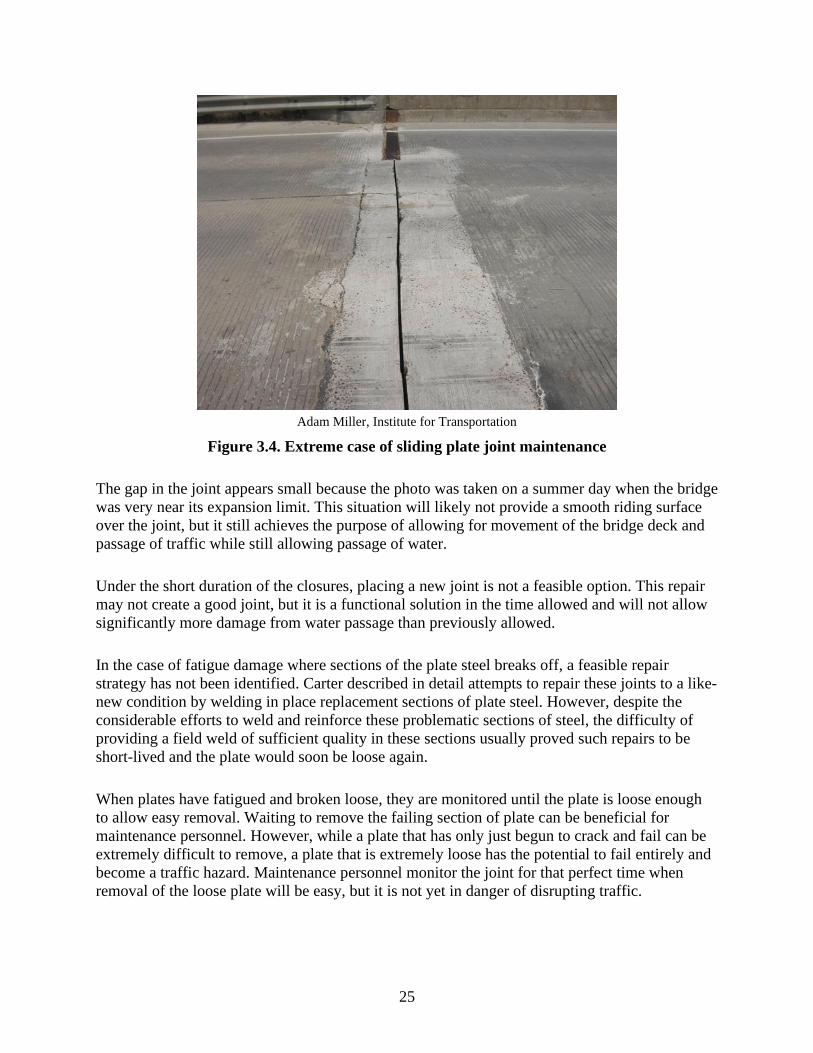
25
Adam Miller, Institute for Transportation
Figure 3.4. Extreme case of sliding plate joint maintenance
The gap in the joint appears small because the photo was taken on a summer day when the bridge
was very near its expansion limit. This situation will likely not provide a smooth riding surface
over the joint, but it still achieves the purpose of allowing for movement of the bridge deck and
passage of traffic while still allowing passage of water.
Under the short duration of the closures, placing a new joint is not a feasible option. This repair
may not create a good joint, but it is a functional solution in the time allowed and will not allow
significantly more damage from water passage than previously allowed.
In the case of fatigue damage where sections of the plate steel breaks off, a feasible repair
strategy has not been identified. Carter described in detail attempts to repair these joints to a like-
new condition by welding in place replacement sections of plate steel. However, despite the
considerable efforts to weld and reinforce these problematic sections of steel, the difficulty of
providing a field weld of sufficient quality in these sections usually proved such repairs to be
short-lived and the plate would soon be loose again.
When plates have fatigued and broken loose, they are monitored until the plate is loose enough
to allow easy removal. Waiting to remove the failing section of plate can be beneficial for
maintenance personnel. However, while a plate that has only just begun to crack and fail can be
extremely difficult to remove, a plate that is extremely loose has the potential to fail entirely and
become a traffic hazard. Maintenance personnel monitor the joint for that perfect time when
removal of the loose plate will be easy, but it is not yet in danger of disrupting traffic.

26
The repair shown previously in Figure 3.1 would be typical of what remains of a plate joint. The
joint will no longer provide a smooth ride for traffic but will still complete the main functions of
allowing the movement of the bridge deck and the passage of traffic.
3.5 Strip Seal and Compression Seal Joints
Strip seal and compression seal expansion joints are separate styles of joints that utilize a gland
to prevent the passage of water through the expansion joint. In particular, a strip seal joint
includes a gland, generally neoprene, that is mechanically locked in place through the use of
steel extrusions embedded in the concrete header on either side of the expansion joint. Figure 3.5
shows an example of a strip seal joint.
Not to scale
Adam Miller, Institute for Transportation; adapted from D.S. Brown Company (dsbrown.com)
Figure 3.5. Strip seal joint
A compression seal is forced into place and uses the compressive force from the bridge deck to
remain in place as shown in Figure 3.6.

27
Not to scale
Adam Miller, Institute for Transportation; adapted from Watson Bowman Acme Corp. (wbacorp.com)
Figure 3.6. Compression seal joint
Although the Iowa DOT is phasing out the use of compression seals, they are still installed
occasionally, and a considerable number are currently in use.
Both strip seals and compression seals have similar deterioration patterns and are addressed
together in the next section.
3.5.1 Joint Deterioration
The most common problem with strip seal and compression seal joints is the failure of the
neoprene glands that are placed in the joints. In Iowa, this typically occurs after about 15 years of
service for a strip seal joint and 10 years of service for a compression seal joint.
A failed seal is not a failure of the structural integrity of the joint, as the seal is not a structural
component. The seal is simply in place for waterproofing purposes. Thus, failure of the seal
allows the joint to still function, movement of the bridge deck will still occur, and traffic is not
hindered, but the joint will now allow the passage of salt and de-icing chemicals that may
damage the substructure.
Both strip seal and compression seal joints have problems with debris building up in the seals, as
seen in Figure 3.7.

28
Adam Miller, Institute for Transportation
Figure 3.7. Badly weathered, but still functioning, strip seal joint showing debris building
up in the seal
The buildup of debris causes a number of problems. The abrasive nature of the collected
materials causes additional wear to the neoprene seals. Additionally, this buildup may prevent
the expansion joint from closing properly during warm summer months. The material essentially
decreases the allowable expansion distance. This can cause additional stresses to build up in the
end of the bridge deck during warm summer months.
Strip seals and compression seals also suffer from spalling of the concrete immediately on either
side of the expansion joint. Spalls by themselves are often not severe enough to cause joint
failure. They do lead to other problems, though. Spalls allow water and corrosive chemicals to
penetrate more easily to the reinforcing steel bars at the end of the bridge deck. This may
eventually lead to larger spalls and weakened concrete holding the joint in place. Water may also
begin to penetrate the interface between the concrete and the joint. Eventually, the back of the
joint can begin to rust as can be seen in the previous Figure 3.7.
Expansive force due to the formation of packed rust can force the joint forward. Additional
stresses are then placed on the joint anchorages, which, when coupled with normal traffic
loading, can then separate from the extrusion. Mark Carter with the Iowa DOT District 6 bridge
maintenance crew had on hand several examples of joints where the extrusion pulled free from
the extrusion anchor at the weld that connects the two. However, it was mentioned that it was not
common for anchorages to pull free from the concrete.
This tipping forward of the joints also makes them more susceptible to snowplow damage by
creating a small ledge that can be caught by the blade. Failure of extrusion sections in Iowa by
snowplow damage, traffic loading, or otherwise early in the lifespan of the joints is not common
and is usually considered to be a result of faulty installation.
Rust is commonly only a problem in the interface between the joint and the concrete. However,
on a rare occasion and with an extremely old steel extrusion, rust may form inside the extrusion

29
preventing the neoprene seal from being inserted. Rust inside the extrusion occurs nearly always
in a seal that has served its useful life and already requires a replacement. This problem is
essentially the same in modular joints (as shown in Figure 3.8).
Adam Miller, Institute for Transportation
Figure 3.8. Modular expansion joint with loose seal due to rust buildup in extrusion insert
Unique to compression seals, sections of the steel armoring may fracture under traffic loading.
Failure of the steel armoring is particularly common in the wheel path. After the loose armoring
is removed, the concrete below is often revealed to have been inadequately consolidated.
The inadequate consolidation results in a series of voids beneath the steel armor causing a
considerable increase in stress that the steel armoring is not intended to resist. After enough
loading cycles, sections of armoring eventually fail, fracture, and come loose.
Loss of the steel armoring is generally not a major point of joint failure by itself and can be
repaired easily. However, the failure of the steel armor is, in general, a sign that the joint is
rapidly approaching the end of its useful life and will likely need a major repair or replacement
in the next few years.
3.5.2 Signs of Joint Failure
Failure of a strip seal joint and a compression seal joint is less apparent than it is with a sliding
plate joint. The easiest way to tell if a gland has failed is by visually inspecting the gland for
tears and punctures. However, failure of the neoprene glands can be difficult to observe visually
if the failure is still small. Debris collected in the joint will exacerbate the difficulty of seeing the
failure visually.

30
Joint leakage can also be determined from the effects on the underside of the bridge. Rusted
substructure components, debris buildup, and visible moisture, particularly after rain, on the
underside of the bridge deck are all signs that the seal may have failed. However, these are
general signs of a leaking joint and could very well be other problems besides a failed gland.
In the case of rust, it can be difficult to see the extent of the damage visually until it has reached
a severe level. It can be particularly difficult to tell if a joint has become misaligned due to rust
buildup between the joint and the bridge deck.
Rust tends to force the top of the joint forward. When strip seal extrusions are initially
constructed, they are set with the top surface parallel on both extrusions. Ideally, the top surface
is also parallel to the bridge deck. The same applies to compression seal armoring. Thus, the
amount of movement can be roughly estimated from the misalignment of the joint. However, it
can be difficult to observe the extent of the joint movement.
One trick that Mark Carter uses is to place any flat straight object (an engineer’s scale was used
during the investigation) perpendicular to the joint extrusions and sight down the joint. It is then
much easier to determine to what extent the joint has moved relative to the bridge deck and to the
opposite extrusion. This trick provides a simple, although not perfect, method of estimating the
extent of the damage from the joint alignment visually.
Signs of concrete spalls are more difficult to observe before damage becomes visible. Hammer
tapping, such as that described in the American Society for Testing and Materials (ASTM)
ASTM D 4580, remains one of the best methods for determining the state of concrete
delamination. However, Mark Carter noted that the Iowa DOT Office of Maintenance generally
ignores concrete spalls in the joint header until the damage is visible.
Diagrams of joint components can be found previously in Figure 3.5 and Figure 3.6. Note that
generally ignoring concrete spalls in the joint header until the damage is visible only applies to
Iowa DOT maintenance of joint headers and does not include deck repairs or contracted work.
Spalls of small areas such as concrete headers are generally not considered to be economical to
test regularly until the damage is visible.
Signs of fatigue for steel expansion joint parts are typical of those for any steel member. Cracks
and unintended movement of the steel armoring are the most noticeable signs of fatigue failure.
3.5.3 Joint Maintenance Efforts
A variety of maintenance efforts can be undertaken to correct the previously discussed
deterioration. The simplest problem to solve would appear to be the collection of debris in the
seal. One solution is to apply compressed air or pressurized water at regular maintenance
intervals and remove the debris from the joints.

31
Bridge maintenance crew leaders estimate that joints ideally require cleaning twice during the
spring and summer months. However, the Iowa DOT does not perform joint cleaning
universally.
Cleaning is not necessary during the winter as the joints are generally in a more open position
and, therefore, less likely to have issues with debris blocking expansion movement as the bridges
contract. However, it is during winter that a considerable amount of debris, particularly from
sand and salts applied to the road during winter weather, accumulates.
In District 6, specifically, debris is only removed when other work is being completed on or
nearby a joint. The given reason for this shortfall in maintenance is a lack of labor, because the
maintenance offices do not have enough labor to spare man hours for cleaning debris out of
expansion joints.
A lot of discussion was present during our investigation on the problem of debris collecting in
expansion joints. The literature reviewed during the literature review also commonly discussed
this problem. Mark Carter’s suggested solution for this problem was to contract out joint
cleaning on a yearly basis. The cleaning of the joints could be hard bid similar to bridge painting
or other contracted maintenance repairs. This could address the problem without diverting Iowa
DOT maintenance staff from other projects.
A second suggestion, from Chang and Lee (2002), is to allow water and debris to drain from the
end of the joint. If the joint is then placed with a great enough cross slope, debris should be
washed out of the joint during rainstorms. This would eliminate the need for labor, contracted or
in-house, to clean out the joint. However, Carter pointed out that a strong wind could blow this
contaminated water onto the substructure of the bridge, potentially causing the same damage the
joint is intended to prevent. So, while this idea has merit, it is not nearly as simple as suggested
and would require some form of drainage system to work properly and protect the substructure.
Broken and failed seals are also rather straightforward to fix. In most cases, a failed seal can
simply be removed, the extrusions cleaned, and a new seal installed. The Iowa DOT allows
simply removing the failed portion of the neoprene seal and splicing in a new section. However,
in the Iowa DOT’s experience, the repairs last longer if an entirely new seal is installed across
the entire joint.
Field splices in the neoprene strip seal are difficult to properly construct and are prone to early
failure between the old and new sections. Thus, it is suggested that field splices should be used
on the neoprene joints only when absolutely required to replace the seal. Typically, in Iowa,
neoprene seal replacements are contracted out and not completed by the Iowa DOT.
Spalls are most commonly repaired by removing the loose concrete and patching the spalls with
new concrete or asphalt. These repairs can generally be performed quickly with little traffic
disruption.

32
Cure time for a concrete patch tends to be the longest part of these jobs. Traffic disruptions for
these repairs could be made even shorter using a faster curing, yet still durable concrete mix, for
patching. In addition, it was stated that spalls should be repaired as soon as possible after they
appear, to prevent further damage of the reinforcement and steel joint components from chloride
penetration.
Despite the best efforts to prevent damage to strip seal extrusions, it is common for them to see
severe damage toward the end of their lifespans. Despite the use of corrosion-resistant steel,
joints typically have considerable rust buildup toward the end of their useful life. As the rust
buildup is often between the steel extrusion and concrete header, it appears little can be done in
terms of maintenance to address this issue. It is likely that a section of the steel extrusion will
eventually be torn loose from the remainder of the joint.
Loose sections of extrusion are fully repaired only if the damage is done in the early stages of the
joint lifecycle. If the joint is old, it will likely be programmed for replacement and little more
action taken. If the failure is early, repairs will be necessary to avoid further damage to the
bridge substructure.
Several different repairs for extrusions were examined during this investigation. Figure 3.9
shows a strip seal joint with a missing section of the extrusion.
Adam Miller, Institute for Transportation
Figure 3.9. Strip seal joint with missing extrusion section
The considerable rust between the joint and header concrete leads to the conclusion that this
section of extrusion was probably pulled free from the anchors. The forward movement of the
joint likely allowed a snowplow blade to catch the extrusion and pull it free. If the joint was still

33
fairly new, concrete may be removed to allow a new section of the extrusion to be embedded and
field welded to the existing sections.
Maintenance personnel cautioned that if only a new section of the extrusion, and not an entire
new extrusion across the bridge deck, is to be installed, the section should extend from the failed
section to the edge of the bridge. In other words, there should only be one point of contact
between the old and new sections of joints.
It was their experience that a new section of extrusion placed between two existing sections
tended to buckle during hot weather. The buckling, combined with normal traffic loading, often
fatigued the field welds quickly on either end, and the welds would soon fail.
While the extrusion should still be embedded into the concrete, the broken welds allow water to
flow through the joint rendering the repair ineffective. As well, the splice weld should avoid the
wheel path of the bridge, even if doing so requires removing a larger section of the broken
extrusion than otherwise be necessary.
However, in Figure 3.9, it is apparent that no new section of extrusion has been installed. It was
judged that this joint was old enough that replacing the missing section was not economical. That
being true, the joint, while extremely worn and showing several signs of coming failure, was not
in bad enough condition to warrant a full replacement of the entire joint yet. Instead, District 6
maintenance staff created their own temporary fix.
The loose section of extrusion was removed but the neoprene seal was left intact. Two bolts were
doweled and epoxied into the deck to provide a mechanical attachment for the seal. An adhesive
was then used to both hold the neoprene seal against the concrete and to again create a watertight
seal where the extrusion was now missing. This repair had been in place for several years and,
with occasional maintenance, this repair was performing at an acceptable level.
Broken sections of compression seal armoring are fixed much in the same way that sliding plate
joints are fixed, by replacing the broken armoring and replacing any loose concrete with new
concrete to provide a flat, smooth riding surface. Figure 3.10 shows this type of repair.

34
Adam Miller, Institute for Transportation
Figure 3.10. Compression seal joint with failed section of armoring
In this situation, compression seals have the advantage of still maintaining a well-functioning
seal provided that the concrete header is still largely in good condition and the neoprene gland
isn’t damaged. The steel armoring is merely present to protect the concrete edge and increase the
durability of the joint. The armoring does not actually contribute to the ability of a joint to be
watertight or accommodate expansion and contraction.
These repairs tend to be completed in several hours as there is no major removal of concrete
involved. The longest schedule element is the required cure time for the new concrete.
Recently, the Iowa DOT has been experimenting with the use of a Silicoflex joint sealing system
from R.J. Watson, Inc. as a repair measure for damaged expansion joints. A Silicoflex seal is
essentially an inverted strip seal held in place by an adhesive instead of an extrusion. The use of
an adhesive makes Silicoflex ideal for joint repairs involving damaged strip seal extrusion
sections. Figure 3.11 shows an example of a repair done with a Silicoflex joint.

35
Adam Miller, Institute for Transportation; adapted from R.J. Watson, Inc.
(www.rjwatson.com/wp-content/uploads/silicoflex-brochure-may.pdf)
Figure 3.11. Silicoflex expansion joint
The seal can be attached to any flat vertical face of the joint. This eliminates the need for
concrete demolition, and to remove any existing steel sections of the joint. The new seal can be
attached directly with the adhesive below the existing sections of extrusion. Major concrete
damage to the vertical face will still require repair to allow a bonding surface for the Silicoflex
joint.
The lack of any major removal, lack of concrete construction, little to no cure time, and ease of
installation make this a very quick and inexpensive joint to install. The manufacturer brochure
estimates less than 30 minutes for installation per lane, assuming that the only construction task
is the joint installation, with the possibility of the bridge opening about an hour after the end of
the installation (R.J. Watson).
To date, this approach has been used on at least two repair projects in Iowa, one of which had
experienced a major early loss of a large section of the existing strip seal extrusion. As of the
initial writing of this report, the first annual inspection of this joint had not been completed on
either of these projects. However, publication of this report was delayed and the following
information from Jim Nelson with the Iowa DOT (personal communication May 9, 2017) is now
available.
Project 1
NE 56th Street over Relocated US 65
Letting: 5/17/2011
Last inspection: 11/3/2015
Joint condition: There is no mention of deterioration or any concerns in the inspection report.
There is one photo of the joint and the seal appears to be functioning appropriately.

36
Project 2
IA 59 over Mill Creek
Letting: 1/18/2012
Last Inspection: 11/8/2016
Joint Condition: There is no mention of deterioration or any concerns in the inspection report.
There is one photo of the joint and the seal is covered with sand/debris and cannot be seen.
3.6 Finger Joints and Modular Expansion Joints
Finger joints and modular expansion joints are styles used by the Iowa DOT for large expansion
distances, typically greater than 5 inches. Finger joints, as the name suggests, are designed as a
series of interlocking steel fingers used to transfer traffic across the joint. Modular expansion
joints are essentially a series of strip seal joints supported by reinforcing steel support bars
placed parallel to traffic as shown in Figure 3.12.
Adam Miller, Institute for Transportation; adapted from D.S. Brown Company
(dsbrown.com/Resources/Bridges/Steelflex/Joints/D320-PV-S.pdf)
Figure 3.12. Modular expansion joint
Currently, the Iowa DOT tends to favor finger joints for large expansion distances. However,
several modular joints are still in use on bridges in Iowa.
3.6.1 Joint Deterioration
There was much less discussion with Carter about finger and modular joints than about the other
joint styles. This is not surprising given only 58 bridges in Iowa with finger joints installed
compared to almost 400 bridges still utilizing sliding plate joints and more than 500 bridges
utilizing strip seal joints. With fewer finger and modular joints in use, it follows that less mean
time is spent maintaining those joints and, in general, fewer problems existed with finger joints
to begin with.
Since finger joints are not watertight, debris tends to pass through the joint without causing
trouble to the joint. In addition, the nearly continuous riding surface prevents most damage from
snowplows catching raised edges of the joint. In fact, the only real problems that were given for
finger joints included spalling of the header concrete, which is a problem that is typical of almost

37
all joint styles, and the rare failure of one of the joint fingers. The structural failure of a finger of
the joint can generally be traced to heavy traffic loads, especially if average daily traffic has
increased since the initial design and installation of the joint.
The one major disadvantage of finger joints is that they are not watertight and, thus, typically
require that neoprene troughs be installed below the joint to catch the water and debris that flow
through the joint and divert the water and debris from the structural members. Problems with
finger joints can usually stem from the neoprene trough.
The first problem with these troughs is associated with the neoprene tearing near the trough
anchors to the bridge deck, which allows the trough to fall loose. This was said to be particularly
prevalent near the end of the winter months due to ice building up in the troughs. Snow and ice
on top of the roadway melts during the day and re-freezes at night. In the shaded parts beneath
the bridge deck, the ice may not melt, forming heavier and heavier loads that can eventually tear
the trough loose.
Another problem relating to these troughs is the flow of water. Where strip seals, compression
seals, and modular joints prevent water from passing through the joint entirely, finger joints
merely divert the water after it flows through the joint. Some troughs divert water away from the
center of the abutment, while a neoprene trough below a finger expansion joint, as shown in
Figure 3.13, diverts water to a catch basin at the center of the footing.
Adam Miller, Institute for Transportation
Figure 3.13. Neoprene trough below finger expansion joint
The water should then flow harmlessly into the stream below without damaging the steel
components of the substructure. However, many older Iowa bridges have no form of slope
protection beneath the bridge. During periods of heavy rain, this continued water flow may

38
eventually erode away the slope exposing the steel piling as seen in Figure 3.14. At least two
pilings were exposed when the image in Figure 3.14 was captured.
Adam Miller, Institute for Transportation
Figure 3.14. Exposed piling from slope erosion
Modular expansion joints show many of the same problems that strip seal joints show. Neoprene
glands again begin to fail at about year 15 and, as shown in Figure 3.15, incompressible debris
collects in the joint.

39
Adam Miller, Institute for Transportation
Figure 3.15. Debris collection in modular expansion joint preventing full closure of the
joint
Figure 3.15 shows the problem of debris preventing full closure of the joint particularly well, as
it was taken on an extremely warm summer day. Most joints had already been or were nearly
completely closed.
Concrete spalls are also quite common in modular joints. Iowa DOT personnel found that in
almost every case, spalls occur over the location of the support boxes, which are steel boxes that
create openings in the bridge deck for the support beams to rest, at between 9 and 11 years of
age. This is very exact in comparison to most other joint styles that tend to spall at random points
along the length of the joint from about 10 years until the joint is replaced.
Figure 3.15 also shows the problem of rust formation inside the steel extrusion, as was first
mentioned with strip seal joints in section 3.5.1.The left seal is not inserted into the center beam
in this case and is thus allowing a small amount of water to flow through the joint. This was
explained to not be a common occurrence and that it only occurs on extremely old expansion
joints. This particular joint was more than 30 years old and the neoprene seals had been replaced
twice. It was found during the last neoprene seal replacement that there was just too much rust in
that section of the center beam to fit the neoprene seal in place.
Given that the neoprene is held in place by the compressive action of the steel extrusion, the
neoprene seals can already be difficult to install. If that compressive area is reduced even more, it
can become impossible to install. Since the joint is already quite old, no major maintenance
measures were taken. At this age, the joint needs to be replaced, because any maintenance efforts
would be ineffective and cause unnecessary traffic interruptions.

40
Finger joints show few visual indications of deterioration. Tearing of the neoprene trough is
extremely difficult to see, as the troughs are often anchored to the bridge deck. Soil erosion
problems may be detected by watching for places where the soil has washed away.
3.6.2 Joint Maintenance Efforts
Maintenance efforts for finger joints are rather straightforward. When neoprene troughs break,
they are replaced with new troughs. Splices are allowed, but, like neoprene glands, splices are
not suggested unless absolutely required.
Erosion is addressed by replacing the eroded soil and compacting the new soil as well as
possible. Erosion fabric may be placed but is not done universally. Ideally, rip-rap is placed on
the eroding slope to help prevent further damage, but this is rarely done due to the expense and
time required.
Fractured fingers in finger joints are generally ignored if it’s an isolated case on the joint. In the
past, it may have been attempted to weld the damaged section back to the existing joint, but, like
sliding plate joints, the welds tended to just fail again.
All in all, finger joints tend to require little actual maintenance between installation and
replacement. However, finger joints also tend to be more expensive for initial installation and
replacement due to the large amount of steel used in the joint.
Modular joints are disliked by many engineers and are not commonly utilized by the Iowa DOT.
The first modular joints installed had a tendency for abrupt early failure. The substantial number
of modular joint failures eventually led to the commissioning of NCHRP Report 402: Fatigue
Design of Modular Bridge Expansion Joints.
This study determined the major causes of failure and then outlined solutions, and notably that
welds were often undersized and that fatigue damage was often not considered during design.
Since the publication of this report, modular joints have improved considerably and are no longer
prone to early failures. In fact, Carter stated that modular joints were his preferred style, as the
many components of the joint allowed pieces of the joint to be replaced instead of the entire
joint.
Specifically in the maintenance of modular joints, like strip seal joints, torn neoprene glands are
replaced. Although splices are allowed, they are still not suggested. Also, spacer springs beneath
the joints are replaced regularly. These springs are used to ensure that the separate center beams
are spaced evenly during bridge expansion and contraction. Their failure can be seen easily by
bulging in the spring or the failure to return to their relaxed condition during the appropriate
expansion or contraction.
Support beams are also painted occasionally to help prevent corrosion. It was cautioned that
painters need to be extremely careful to keep paint off the sliding surface in the support box, as

41
this may prevent proper movement of the support beams. Other damages to modular joints are
addressed in the same fashion as those to strip seal joints.
3.7 Integral Abutment Joints
Integral abutment joints were examined only briefly in this investigation. Bridge maintenance
crew leaders stated that integral abutment joints were their preferred style of expansion joint
because they are largely maintenance free. This preference in Iowa largely mirrored a survey of
several other states conducted by Chang and Lee (2001) that reached a similar conclusion in the
states surveyed.
There were only two main maintenance issues pointed out with regard to integral abutment
joints. The first was the occasional patching of the tire buffing and silicon sealant (CF) joint used
in Iowa to accommodate the movement between the abutment and the approach slab. The second
problem dealt with erosion from the runoff at the end of the bridge.
The CF joint repairs are already quite rapid and very straightforward repairs. As expected with
any crumb rubber and silicon joint, materials often break loose from the joint leaving voids for
water to penetrate. To repair this joint, the loose and missing tire buffings are replaced and new
silicon poured into the joint to provide a watertight seal. This is already a rapid and easy repair.
Erosion comes from the water runoff at the end of the bridge. During rainstorms, water flows
over the joint, off the sides of the approach slab, and down around the abutment. Over time, this
water can wash away soil surrounding the abutment and eventually expose the pilings, similar to
the situation described above pertaining to finger joints. This erosion problem is known to the
Iowa DOT, which was working on implementing a new detail for wing armoring on bridges.
The detail for new bridges includes a bed of erosion stone atop a layer of engineering fabric atop
the compacted subgrade and following the slope of the subgrade. This layer of stone should act
as a drain allowing the runoff to quickly flow around the abutment and footing without eroding
the supporting soils. Figure 3.16 shows a profile view of this new detail.

42
Iowa DOT
Figure 3.16. New Iowa DOT standard detail for integral abutment wing wall armoring
Erosion is repaired in the same fashion as it is for finger joints. Eroded soil is replaced,
compacted, and monitored for any future problems.

43
CHAPTER 4. CURRENT JOINT REPLACEMENT PRACTICES
4.1 Chapter Overview
This chapter explains the details involved in two bridge deck expansion joint replacement
projects that were observed during the first phase of the project. This chapter is organized by
project. Each section provides an overview of information specific to each job and then provides
pertinent observations that were made throughout the course of each project.
4.2 Introduction
In construction, challenges exist in communication and understanding between the design
engineers and the workers completing the physical repairs in the field. Design changes can help
expedite field work, but existing processes to replace expansion joints must be understood before
changes can be made. Conversely, many jobsite supervisors may also have ideas that can
facilitate more rapid completion of the repairs but lack the engineering knowledge required to
ensure that a design meets required standards for safety and durability. Thus, an objective of this
chapter is to help engineers become more knowledgeable about the specific means and methods
currently used during joint replacement projects.
4.3 Northbound I-380 Joint A Replacement
The Northbound I-380 joint replacement research targeted activities that occurred during the
second year of a two-year project involving the complete removal and replacement of several
expansion joints along I-380 through Cedar Rapids, Iowa. The joint replacement specifically
observed, designated as Joint A, was immediately before Exit 19A on Northbound I-380 (see
Figure 4.1).

44
© Google 2014
Figure 4.1. Northbound I-380 project location through Cedar Rapids, Iowa
Also along Exit 19A were joints D and E (see Figure 4.2).

45
© Google 2014
Figure 4.2. Approximate locations of expansion joints along Exit 19A on Northbound I-380
project through Cedar Rapids, Iowa
In total, five expansion joints were to be replaced as part of this project over three consecutive
weekends. The researchers observed the project during the first weekend. Detailed records were
kept only for Joint A. However, some comparisons were also made involving Joint D throughout
the project.
The initial staging during the first weekend of work entailed replacing both joints on the exit
ramp, Joints D and E, as well as half of Joint A. The remaining half of Joint A, as well as Joint B
and C, were replaced in sections over the next two weekends. With this staging plan, only the
exit ramp would be entirely closed to traffic, and only for a single weekend. This closure could
not be avoided due to the width of the ramp. For the remaining two weekends, at least one lane
would always remain open.
Joint A
Joint D
Joint E
Joint B
Joint C

46
4.3.1 Joint Condition and Replacement Plan
Joint A was an old sliding plate joint still in use long past its service life. Overall, the joint did
not appear to be in extremely bad condition, because only an approximately one-foot section of
plate had broken loose. However, when the top steel plate was removed, that revealed a
considerable amount of rust buildup.
There was enough rust between the plates of the expansion joint that both the Iowa DOT
inspector and researchers on this project doubted that the joint had been properly functioning in
years. Not surprisingly, this rust buildup conforms to the joint deterioration patterns discussed
previously in section 3.4.1. Other joints in this project, and Joint E in particular, exhibited much
more severe failures that ultimately prompted the replacement.
The old sliding plate joint was to be replaced with a new strip seal expansion joint. Concrete
removal would consist of the top of the backwall from the existing riding surface to the top of the
paving notch and the end two feet of roadway concrete (see Figure 4.3).
Iowa DOT
Figure 4.3 Northbound I-380 project concrete removal cross section
Unlike other joint replacements, this job did not require the removal or replacement of the
approach slabs, paving notch, or the entirety of the backwall. Embedded reinforcing steel bar
was to remain for the reconstruction of the joint. Any bars not embedded in the concrete were to
be removed and replaced with epoxy-coated bars, which largely included the existing hoops and
longitudinal bars.
The new expansion joint and reinforcing steel (rebar) would be formed and constructed using a
high-early-strength concrete mix. Previous tests on the concrete mix had resulted in the

47
development of a maturity curve that indicated the required compressive strength of the concrete
of 4,000 psi to be reached in 9 to 12 hours.
One of the main focuses for observing the replacement of Joint A was to find the length of time
required to complete specific construction tasks, knowing the typical length of a construction
task greatly facilitates efforts to reduce the overall time of a joint replacement project. The longer
the task, the more potential that task has for reducing the overall time of the project. If the task
only takes a few hours, reducing that time is unlikely to shorten the entire project considerably.
4.3.2 Joint A Replacement and Methods
Traffic closures were allowed from 7 p.m. Friday evening until 6 a.m. Monday morning. Thus,
traffic control measures started precisely at 7 p.m. Friday evening. Traffic control initially
consisted of signage that directed traffic to change lanes, as well as traffic cones to designate
closed lanes. The initial use of traffic cones allowed equipment mobilization to proceed as soon
as possible after the 7 p.m. project start time.
On projects where a considerable amount of work is done in a short amount of time, like this
one, it is best to complete tasks concurrently with other tasks as often as possible. After traffic
had been completely redirected out of the work zone, traffic cones were replaced with jersey
barriers to increase the safety of the jobsite. As seen in Table 4.1 and Table 4.2, traffic control
took about four hours of the project time to complete.
However, since traffic control worked concurrently with equipment mobilization and demolition,
it had little impact on the overall project time. Thus, the overall project time would not be
reduced by reducing the time to install traffic control.

48
Table 4.1. Construction task length by hour
Date 7/19 7/20 7/21
Activity Hour 7 8 9 10
11
12 1 2 3 4 5 6 7 8 9
10
11
12 1 2 3 4 5 6 7 8 9
10
11
12 1 2 3 4 5 6 7 8 9
10
11
12 1 2 3 4 5 6 7 8 9
10
11
12
Traffic control
Equipment mobilization
Hydrodemoliti on of Joint A
Demolition with 15-lb chipping hammers
Formwork and rebar placement
Concrete placement and cure time

49
Table 4.2. Total construction task lengths
Activity
Total
Hours
Traffic Control 4
Equipment Mobilization 2
Hydrodemolition of Joint A 14
Demolition with 15lb Chipping
Hammers 6
Total Demolition Time 20
Formwork and Rebar Placement 13
Concrete Placement and Cure Time 11
4.3.2.1 Joint A Concrete Removal
Equipment mobilization began shortly after traffic was completely rerouted, which was about an
hour into the project. This job was unique in that the contractor utilized hydrodemolition for the
majority of the concrete removal on Joint A. The contractor utilized an Aqua Cutter from
Aquajet Systems AB, similar to the one shown in Figure 4.4.
Iowa DOT
Figure 4.4 Aqua Cutter hydrodemolition machine
This system requires not only the aqua cutter but also a water storage truck and several trailer-
mounted pumps to provide the necessary water pressure. The contractor also mobilized several
towable air compressors and several 15-pound chipping hammers.

50
The aqua jet equipment took several hours to set up and properly align with the limits of
demolition before the contractor could begin cutting. While this happened, the steel plates that
formed the existing expansion joint were removed with an oxy-acetylene torch.
The supervisor explained that the aqua cutter would not be able to remove any concrete below
the steel. Thus, the more concrete that could be exposed, the less concrete that would need to be
removed by hand.
A moveable cage, which was essentially a few aluminum fence posts with several layers of
orange snow fence, was placed around the aqua cutter on three sides. The supervisor explained
that during demolition, small particles or broken concrete may be thrown into the air. The
particles would be small, ejected with little force, and of no danger to the workers or observers.
However, these small particles could potentially cause superficial damage to passing vehicles
and that damage to passing vehicles needed to be prevented.
Demolition with the aqua cutter started promptly at 10:30 p.m., but was stopped after a short
time. It was discovered that, upon removing the bottom layer of concrete, the water jet was
digging a trench in the ground beneath the bridge. This had been anticipated by the contractor as
a potential problem and the delay was short while sections of scrap steel plate were placed
beneath the sections that were to be removed. The demolition process then continued.
The aqua cutter had a demolition width of about 5 feet. After completing the removal between
the required limits, the machine was moved to the side, realigned with the previous sections of
demolition, and restarted. Hydrodemolition of Joint A took place for about 14 hours (see Figure
4.5).
Adam Miller, Institute for Transportation
Figure 4.5. Joint A after hydrodemolition
The aqua cutter was capable of removing most, but not all, of the concrete necessary to replace
the joint. In particular, the aqua cutter could not remove the concrete within about 8 inches of the

51
curb, as well as the curb itself. While not of concern to this project, this area near the curb may
be larger if the joint is at a skew to the curb. A small section of concrete beneath the existing
joint could not be removed with the aqua cutter (see Figure 4.6).
Iowa DOT
Figure 4.6 Concrete remaining after hydrodemolition
The remaining concrete was removed with 15-pound chipping hammers. This was much slower
than the removal by hydrodemolition, but also consisted of concrete often in confined areas and
corners. Removal with chipping hammers was about a 6-hour task, bringing the total time for
demolition to 20 hours.
Removal of Joint D had been done with 15-pound chipping hammers until the water jet had
finished on Joint A. At this point, about a third of Joint D had been removed with 15-pound
chipping hammers. The water jet was then moved to Joint D to finish removal of that section,
while the 15-pound chipping hammers were moved to Joint A to remove the remaining concrete.
4.3.2.2 Joint A Formwork and Reinforcing Placement
The formwork installation started when about half of the existing joint had been entirely
removed. Formwork was not complicated for this project and consisted of plywood supported by
2 by 4 lumber. Some of the sections had been precut and preassembled to expedite the process of
installing the formwork. The concrete profile was identical to the section to be removed (shown
previously in Figure 4.3), although the reinforcing steel (rebar) layout had changed slightly for
the new joint.

52
This rectangular layout was ideal, as it avoided the need to build formwork with any angles other
than 90 degrees. Other shapes, such as the angled profile of many paving notches, are more time-
consuming to construct than simple rectangular sections. Formwork was all placed by hand as
the sections were not large enough to require any additional equipment.
The installation of the new reinforcing bar proceeded shortly after the bottom sections of
formwork had been placed and supported. Waiting until the forms are in place allows the
reinforcing steel to be supported by the forms at the proper elevation, by the use of rebar chairs,
and ensures that proper cover requirements are met the first time the reinforcing steel bar is
installed.
On this particular job, the contractor had to install, then remove and reinstall the rebar several
times before the layout was correct. Overall, the additional effort involved in installing the
reinforcing steel probably added several hours to the project length. The Iowa DOT inspector
commented that the workers appeared inexperienced with rebar placement.
The reinforcing steel (rebar) was placed and tied together by hand with epoxy-coated rebar tie
wire. The expansion joint extrusion was set in place with the reinforcing bar. The joint extrusions
were separated by a piece of three-quarter inch foam insulation and then clamped together. The
foam insulation would maintain the proper spacing while the concrete was poured and was both
compressive and easily removed in pieces if the deck was to undergo expansion before the
insulation was removed.
While the reinforcing steel was being placed, the end sections of formwork and bulkheads, again
constructed out of plywood and dimensioned lumber, were installed. Formwork and reinforcing
steel installation finished in the early hours of the morning and no additional work was
completed on Joint A until later in the morning when the concrete batch plant opened to provide
concrete. At this point, Joint A would easily be finished before the set deadline as long as the
concrete was delivered to the site at a reasonable time.
4.3.2.3 Joint A Concrete Placement and Finishing
Concrete placing and finishing was an easy task on this project. Concrete arrived at the site
promptly at 10 a.m. A high-range water-reducing admixture, as well as other chemicals, were
added to the concrete on-site immediately before the concrete was placed. The engineer that
designed the concrete mix stated that the concrete would begin to set initially about 25 minutes
after the chemicals were added, with previous tests showing required strengths being achieved in
about 9 hours.
The concrete pour was much more organized than the rest of the project and the construction
laborers appeared to be very experienced with concrete pours. Immediately before concrete was
placed, a thin layer of grout was placed by hand on all existing concrete faces that would adjoin
the new concrete. Concrete was then placed directly from the truck into the formwork and
vibrated with a flexible shaft vibratory compactor as shown in Figure 4.7.

53
Jacob Shaw, Institute for Transportation
Figure 4.7. Flexible shaft vibratory compactor
Once the concrete was placed and vibrated, the clamps holding the joint extrusions in place were
removed. Even though the concrete had not yet set, pressure of the concrete behind the extrusion
would hold the joint against the insulation separator.
The concrete was then finished by hand, first with wooden floats and then with magnesium
finishing trowels, to provide a nice smooth riding surface. The workers sprayed curing
compound on the surface of the concrete, and left the joint to cure.
4.3.2.4 Conclusions and Discussions
The research team, the Iowa DOT inspector, and the jobsite supervisor came to some conclusions
from their observations of this jobsite during downtime discussions between them.
• Demolition was the single longest construction task with concrete cure time taking the
second most amount of time
• There was no clearly obvious way to precast an expansion joint
• General formwork shapes could be prebuilt, but complete prebuilding of formwork is
extremely difficult
The prebuilding of formwork was a particularly prevalent topic. The same contractor had
completed an identical job on the southbound lanes of I-380 the summer before and had not pre-

54
manufactured any formwork. To save time during the observed job, general formwork shapes
had been pre-constructed before the job began.
The discussion focused on the possible use of a pre-manufactured steel form that could be
erected much more quickly. However, this idea was discarded as nearly impossible because,
even though the Iowa DOT provides standard profiles for bridge members, the final dimensions
often vary slightly. It would take a substantial number of different forms to have a form that
would work for almost every bridge. Thus, it was just easier, less-expensive, and not necessarily
slower to use plywood formwork to construct a portion of it during the job.
4.4 US 18 over the Wapsipinicon River
The US 18 over the Wapsipinicon River project (see Figure 4.8) was a typical joint replacement
job for the Iowa DOT.
© Google 2014
Figure 4.8. US 18 over Wapsipinicon River project location
The project consisted of the removal and replacement of an existing sliding plate expansion joint
with a new strip seal expansion joint at either end of the bridge. The replacement of the paving
notch was also included in the construction and is a typical repair often included with expansion
joint repairs. Detailed records of construction task lengths were not kept for this project, as the
project took several months.
4.4.1 Joint Condition and Replacement Plan
When the researchers conducted their site visit to the US 18 project, the existing sliding plate
joints had already been removed from the bridge deck and abutment. However, the removed

55
sliding plate joint sections were still present at the jobsite. The joint sections were badly rusted
and had a significant number of broken plate sections. The bridge was originally built, including
the old sliding plate joint, in 1978, making the existing joint almost 35 years old. There was not
likely any particular circumstance that caused the joint to rust and fail. It was, quite frankly, just
old.
This joint was set up as a typical replacement of a sliding plate joint with a new strip seal joint.
Also included in the project were the removal and replacement of the paving notch, a portion of
the abutment, and the doubly reinforced approach slab on both ends of the bridge.
Concrete removal was to consist of a 1- by 1-foot square section of concrete on the deck side of
the joint along with the removal of the backwall to 1 foot 9 inches below the bottom of the
existing paving notch (see Figure 4.9).
Iowa DOT
Figure 4.9. US 18 over Wapsipinicon River project removal cross section
On the deck side, any embedded longitudinal reinforcing steel bars were to be left in place for
lap splices. On the abutment side, any embedded vertical bars were to remain. An additional row
of reinforcing bar doweled and epoxied into the remaining abutment would provide extra support
(see Figure 4.10).

56
Iowa DOT
Figure 4.10. Replacement paving notch plan for US 18 over Wapsipinicon River project
The US 18 job was given a contract length of 75 workdays for completion. The job was
constructed in three stages to provide one open lane of traffic at all times during the project.
Stage 1 consisted of the closure of the westbound lane and the construction of a paved asphalt
shoulder on the westbound lane of the approaches. This paved shoulder effectively widened the
westbound lane and allowed traffic to be routed partially onto the shoulder of the bridge,
allowing a wider construction zone in the eastbound lane.
Stage 2 consisted of the reconstruction of the eastbound lane expansion joints, approaches, and
the paving of the shoulder. During Stage 2, one lane of traffic was maintained on the westbound
lane.
Stage 3 consisted of the reconstruction of the expansion joints and approaches on the westbound
lane.
4.4.2 US 18 Observations
The researchers visited the US 18 over the Wapsipinicon River project during the final stage of
joint demolition. As is common, the bridge was staged so that one lane of traffic would remain
open at all times. Thus, at this point, the entirety of the joint at the west abutment had been
replaced and half of the joint at the eastern abutment had been replaced. The second half of the
eastern abutment was in the process of being demolished.

57
The team had noted during the I-380 observations that demolition seems to be the driving factor
in how long a project takes. Thus, they focused on observing the US 18 project during the
demolition phase. The inspector noted that on the previous three sections, demolition had taken
about three total days. After demolition, half of a day was usually required to straighten the
vertical reinforcing bars that would remain embedded.
The team observed that the existing horizontal bars on the deck side of the joint took little
damage and could be efficiently removed with 15-pound chipping hammers on this job. The
backwall and paving notch had mass removal completed with a skid loader mounted hydraulic
breaker and 15-pound chipping hammers were utilized to remove the final sections of the
backwall to provide a relatively straight, smooth edge for reconstruction. The detailed removal
was not possible with a hydraulic breaker because it caused some small damage to the embedded
reinforcing bar. However, this damage, mainly the bending of bars, was small and could easily
be corrected after demolition.
The biggest hindrance to faster demolition is the requirement that the existing vertical
reinforcing bars in the backwall typically must remain in place to develop lap splices.
Demolition would proceed faster with larger demolition equipment. However, larger hydraulic
breakers would cause an unacceptable level of damage to the embedded reinforcing bar. If these
reinforcing bars could be removed, the rate of demolition could be increased.
The alternative to maintaining the embedded bars is to drill holes and epoxy new reinforcing bars
into the existing footing. On some projects, this would be an additional construction task and
more equipment. However, on this and many other projects, the new abutment design require the
addition of a third row of vertical reinforcing between the two existing rows.
These bars can be seen in Figure 4.10 labeled as 5b2. In similar designs, there would be no
additional step in the construction process, merely a step that would be lengthened while another
is made shorter.
One observation that the research team found key was the use of a staged project instead of a
detour to complete the US 18 job. As seen in Figure 4.11, the bridge of interest was only a few
hundred feet beyond the intersection of US 18 and County Road V-14 (Exeter Avenue). This
would be about a 2.5-mile detour to County Road B-57 that would meet US 18 in New Hampton,
Iowa.
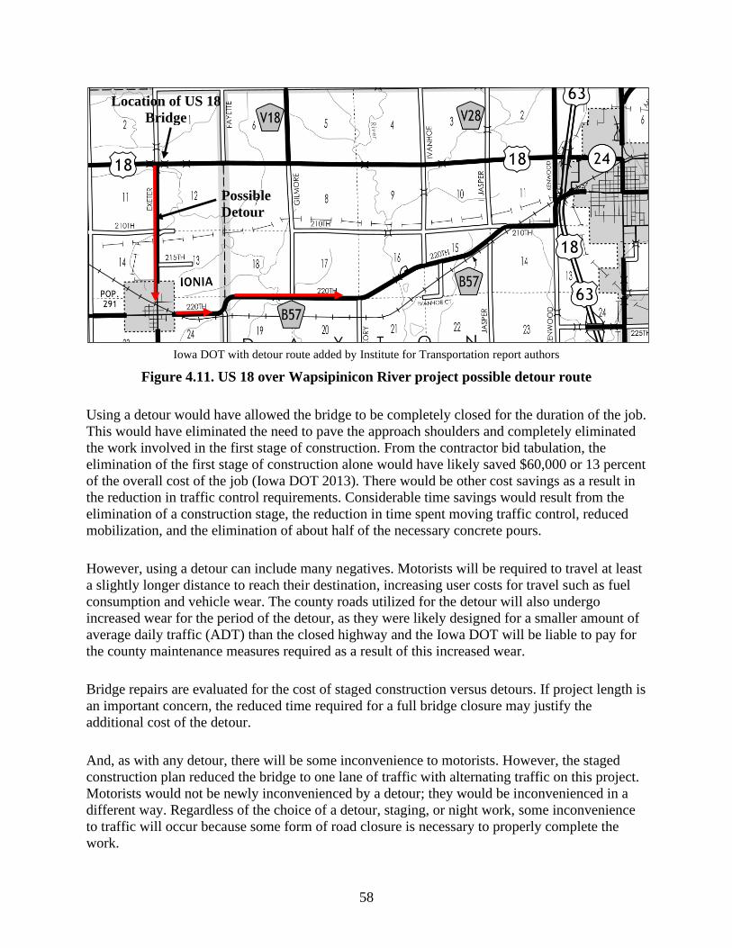
58
Iowa DOT with detour route added by Institute for Transportation report authors
Figure 4.11. US 18 over Wapsipinicon River project possible detour route
Using a detour would have allowed the bridge to be completely closed for the duration of the job.
This would have eliminated the need to pave the approach shoulders and completely eliminated
the work involved in the first stage of construction. From the contractor bid tabulation, the
elimination of the first stage of construction alone would have likely saved $60,000 or 13 percent
of the overall cost of the job (Iowa DOT 2013). There would be other cost savings as a result in
the reduction in traffic control requirements. Considerable time savings would result from the
elimination of a construction stage, the reduction in time spent moving traffic control, reduced
mobilization, and the elimination of about half of the necessary concrete pours.
However, using a detour can include many negatives. Motorists will be required to travel at least
a slightly longer distance to reach their destination, increasing user costs for travel such as fuel
consumption and vehicle wear. The county roads utilized for the detour will also undergo
increased wear for the period of the detour, as they were likely designed for a smaller amount of
average daily traffic (ADT) than the closed highway and the Iowa DOT will be liable to pay for
the county maintenance measures required as a result of this increased wear.
Bridge repairs are evaluated for the cost of staged construction versus detours. If project length is
an important concern, the reduced time required for a full bridge closure may justify the
additional cost of the detour.
And, as with any detour, there will be some inconvenience to motorists. However, the staged
construction plan reduced the bridge to one lane of traffic with alternating traffic on this project.
Motorists would not be newly inconvenienced by a detour; they would be inconvenienced in a
different way. Regardless of the choice of a detour, staging, or night work, some inconvenience
to traffic will occur because some form of road closure is necessary to properly complete the
work.
Location of US 18
Bridge
Possible
Detour

59
CHAPTER 5. EXPANSION JOINT IMPROVEMENT WORKSHOP
5.1 Introduction
One important aspect to the replacement of expansion joints is the collaboration between the
designers, constructors, and maintenance personnel working on each joint. Without the input of
all involved parties, what may seem like a beneficial idea to one party may adversely affect
another party. To meet this end, a workshop was held December 4, 2013 at the ISU Institute for
Transportation (InTrans).
Workshop participants included representatives of three Midwest design consultants, three local
Iowa contractors, the Iowa DOT Office of Bridges and Structures, the Iowa DOT bridge
maintenance teams, the Iowa DOT Office of Construction, and the research team. Appendix A
includes a list of the participants.
The workshop began with an introduction from Jim Nelson of the Iowa DOT Office of Bridges
and Structures. Adam Miller (a Master’s candidate at ISU) then followed with a brief overview
of the research to that point.
5.2 Summary of Previous Research Tasks
5.2.1 Task 1 – Literature Review
Miller’s presentation began with a short overview of the first research task, which was a
thorough review of the existing literature. The literature review showed that, while there was a
considerable amount of literature that addresses expansion joints, and particularly their
durability, there was little information regarding their replacement.
Regarding other expansion joint literature, the review found that integral abutment joints are the
preferred joint for new bridges (Chang and Lee 2001). For expansion distances greater than those
allowed by integral abutment joints, strip seal expansion joints are being used increasingly
throughout the US. In particular, many states are also replacing sliding plate joints and
compression seal joints with strip seal joints. However, one research project discovered that a
broad range of service lives were estimated by various states for strip seal joints. The service life
of a strip seal expansion joint was estimated to be anywhere from 10 to 30 years (Guthrie et al.
2005). This information correlated with a University of Purdue study of expansion joints in
Indiana that found strip seal joints were prone to early failure due to incorrect installation of the
joint (Chang and Lee 2002).
5.2.2 Task 2 – Deterioration Patterns and Temporary Maintenance
The second research task involved the development of a visual record to document joint
deterioration patterns as well as an explanation of the temporary maintenance activities that are

60
conducted on expansion joints. The following information is the result of a one-day field
investigation with Mark Carter, the Iowa DOT District 6 bridge maintenance crew leader.
(Further field investigations will be conducted in the future as weather conditions and
maintenance workloads allow.)
Sliding plate joints were the first addressed. The Iowa DOT no longer installs new sliding plate
joints, but many are still in use in Iowa. It was found that rust was the most prominent problem
with sliding plate joints. The water tightness of sliding plate joints was ignored because these
joints were never designed to be watertight. Rusted joints have two primary undesirable
consequences.
First, many existing sliding plate joints have had additional “raise plates” attached to match the
driving surface of the joint to deck overlay surface. However, the existing joints were often in
less than satisfactory condition. Often the “raise plates” were welded to a severely rusted existing
plate. After enough rounds of traffic loading, the existing plate finally fatigues and fails. As a
result, the new top plate comes loose from the bridge deck or back wall. Often, the lower plate of
the joint is still intact, providing a riding surface for traffic. Thus, the joint still allows the
passage of traffic and is effectively still functioning. This kind of joint failure only results in a
low spot on the driving surface equal to the plate thickness, but the ride will not be smooth. The
loose plate is usually removed and no further repairs are undertaken.
The second failure from rust occurs when the sliding plates rust and bond together. Eventually,
this rust pack may cause the joints to become completely immobile. During periods of bridge
deck contraction, these now immobile plates may pull free from the abutment back wall or. less
commonly, the bridge deck itself.
Carter reported that, at times, he found large sections of the abutment had pulled free. Sliding
plate joints that have pulled free require considerable effort to repair. The loose joint and any
loose concrete must be removed. In older abutments, additional rebar may be added. This is
however, often dependent on the age and design of the abutment and is done on a case-by-case
basis if necessary. Due to time constraints, new joints are usually not installed; instead, a flat butt
joint is constructed to allow for the expansion movement. This allows the deck to expand and
contract as required, but does not create a smooth ride for traffic or prevent the passage of water.
Lastly, on a much less common basis is the simple fatigue failure of sliding plate expansion
joints. While this failure is still a concern, the cause is often simply an undersized and under
designed joint. The maintenance measures are similar to loose raise plates in that little is done.
Carter explained that, early in his career, they would attempt to reattach sections of fractured
plates, but welds used to attach the repair plates rarely proved to be durable and the practice was
finally discontinued.
Compression seal and strip seal joints share many of the same deterioration concerns. The
biggest problem for both joints is a buildup of incompressible material in the joint. Sand, salts,
and other debris collect in the seal during the winter months. During summer bridge expansions,
this material may prevent full joint movements and cause additional stresses at the joint

61
anchorages. While the maintenance solution to this problem is simple, flush the joints clear of
debris at the end of every winter, this is not uniformly or regularly done. Joints are usually only
cleaned when other work is being done on or near the joint making clearing the joint convenient.
Another common problem with both compression and strip seal joints is the spalling of edges of
the concrete. If the spalls become severe enough, it may allow deterioration of the reinforcement
in the end of the deck, and, thus, weakening of the joint. These spalls may also cause rust to
build up behind the joint. This pack rust forces the joints forward and allows compression-seal
armoring and strip-seal extrusions to be more easily caught by snowplows and more susceptive
to damage from repeated traffic loadings. Spalls are repaired by typical concrete patching
methods. Pack rust is a problem that cannot be easily dealt with and is often ignored until the
steel components finally break free.
Unique to compression seals, sections of the steel armoring may break off under traffic loading.
The quality of the concrete beneath the armoring often reveals inadequate consolidation of the
concrete as the cause of these failures. The maintenance measure for this type of damage is to
replace the failed section of steel armoring with concrete that matches the profile of the steel
armoring. The armoring is in place to increase joint durability and does not actually aid in the
expansion or waterproofing functions of these joints. Thus, while failing armoring is a sign of
deterioration for the joint, it can still operate quite well with the temporary field repairs.
5.2.3 Task 3 – Jobsite Observations
The third research task consisted of observing current expansion joint replacement projects in an
attempt to determine factors that affect the duration of a joint replacement. Several factors were
noticed during these observations.
It was found that the single longest task in joint replacements was often the demolition of the
existing concrete to be replaced. Among the demolition work, the largest driving factor was the
existing rebar, particularly on jobs that required the replacement of the abutment and paving
notch as well as the joint. The Iowa DOT generally requires existing rebar to remain intact to
provide continuity between the existing footing and the new abutment and joint that will be
placed (Jim Nelson, personal communication December 4, 2013). To remove the concrete from
the existing rebar without causing significant damage, smaller demolition tools must be utilized,
and often hand-held jackhammers. This greatly slows the demolition time.
The second main observation dealt with worker experience. There was a great deal of difference
in the pace of a job whether the workers were experienced in joint replacements or
inexperienced. This particularly related to the erection of formwork and placing of new rebar. In
the researchers’ prior experience, this is especially true in staged jobs. When formwork is erected
and rebar placed in nearly the same fashion four times, the fourth time is always completed in
less time than the first.

62
One unique jobsite observation was the use of hydrodemolition for the removal of an expansion
joint. This particular job required only the removal of enough concrete to remove the joint and
place new rebar. Little to no concrete was removed from the abutment and the paving notch was
left intact. There were several observed advantages and disadvantages to hydrodemolition. These
pros and cons are listed below:
Pros:
• Hydrodemolition is fast and easy. After initial setup and preparations, little effort is required
from the laborers.
• Existing reinforcing steel is left almost perfectly intact.
Cons:
• New equipment is costly to purchase.
• A significant amount of water is required with an equally significant amount of runoff
containing small particles of removed concrete.
• While reinforcing is left intact, coatings will most certainly be removed from the bars.
• Jackhammer work will still be required to remove the joint entirely, although the amount of
work is substantially reduced.
The last major jobsite observation consisted more of several discussions with the supervisors on
the jobsites. One point that was made was that staging a project is expensive. The extra cost of
traffic control and the extended length of time to complete the project are significant costs. As
well, when joints are replaced in halves, the physical replacement takes longer than if it is
replaced in one continuous section. One supervisor roughly estimated that, if a job was not
staged, he could probably reduce his costs and job lengths each by approximately a third.
However, complete closures of a bridge may create traffic problems in areas where detours are
not readily available.
5.3 Pertinent Iowa DOT Design Standards and Design Considerations
Following Miller’s overview, Nelson gave an overview of the pertinent design standards and an
overview of the current practices of the Iowa DOT for the replacement of expansion joints. The
presentation started with an overview of the types of expansion joints currently utilized by the
Iowa DOT for newly constructed bridges.
The Iowa DOT currently utilizes integral abutments with up to 3 inches of CF joint at the paving
notch. For expansion of 4 to 5 inches, a strip seal expansion joint is currently the preferred
choice. Finger joints are utilized for expansion distances of up to 10 inches, while modular
expansion joints are recommended for movement up to 15 inches. However, modular expansion
joints are not commonly used by the Iowa DOT.
Integral abutments are the current method of choice for the Iowa DOT where bridge expansion is
sufficiently small to be utilized. The Iowa DOT LRFD Bridge Design Manual limits
pretensioned, prestressed, or precast prestrssed concrete beam (PPCB) bridges to a length of

63
approximately 575 feet for bridges without a skew and 425 feet at a 45-degree skew (Iowa DOT
2015). Continuous welded plate girder (CWPG) bridges are limited to an approximate length of
400 feet and 300 feet at a zero-degree skew and 45-degree skew, respectively.
Of particular interest in Nelson’s presentation was a numerical breakdown of the expansion
joints currently in use in Iowa. Currently, there are 1,065 bridges in the state utilizing some type
of expansion joint. Just over half of these bridges are using existing strip seal expansion joints.
Sliding plate joints are the next most commonly used joints on just fewer than 400 bridges. Since
most of these sliding plate joints are near the end of, or past, their functional life, they are the
most commonly replaced joint. With more than a third of Iowa’s bridges still utilizing sliding
plate joints, the replacement of these joints is a problem that will likely continue for several
decades. Thus, efforts to improve the means and methods of replacing expansion joints will still
be pertinent for the foreseeable future.
The presentation ended with an overview of several design concerns that must be taken into
consideration when planning the replacement of an expansion joint. Narrow bridges are a
significant difficulty. Lack of a good route detour causes many of these bridges to be candidates
for a staged construction project. However, these narrow lanes can cause difficulties when
staging a project. Lane widths less than 14 feet 6 inches require narrow width signing. As lane
widths become narrower, it becomes an engineering judgment decision regarding the acceptable
minimum lane width, as there is a predetermined standard. Temporary barrier rails separating
moving traffic from construction crews exacerbate this problem. These barriers measure 1 foot
10.5 inches for precast concrete and 1 foot 1 5/8 inches for steel barrier rails.
A second design consideration is the splicing of existing reinforcing bars to new reinforcing bars.
Lap splices are preferred, as it is easier to meet concrete cover requirements using them.
However, with lap splices, the existing rebar must be left intact in largely good condition to be
effective. Mechanical splices, on the other hand, require little more than a few inches of bar
protruding from the existing concrete. Mechanical splices tend to be bulkier and require more
concrete to meet cover requirements. Meeting these requirements can be difficult in a 7.5 in.
thick bridge deck (Jim Nelson, personal communication December 4, 2013).
5.4 Breakout Groups, Idea Discussion, and Ranking
For the next part of the workshop, the participants divided into three separate groups with each
specific discipline of design, construction, and maintenance evenly distributed among each
group. This ensured that, during the discussions, every group would have design, construction,
and maintenance represented. The groups were instructed to develop ideas relating to the overall
improvement of expansion joints.
While the main focus of the meeting and research was on expediting the construction process,
any and all ideas to improve expansion joints in general were considered. An idea to improve the
lifespan may not directly help joints to be replaced more rapidly, for example, but replacing
joints less often will still help alleviate future problems associated with bridge closures. Thus,
any idea related to the improvement of expansion joints was considered.

64
A summary of the three separate group’s discussions is included in Appendix B.
The underlying principal behind the discussion group results were as follows: if three separate
groups of experts in their own fields came up with the same or similar solutions, those solutions
are likely to be the most feasible solutions. At the very least, such a method gives the research
team a way to determine which ideas are the most important to be investigated further within the
course of this research study, and in future research projects.
After about 90 minutes, the groups were brought together as a large group for a working lunch to
discuss as a large group what each smaller group had discussed. As previously suggested, several
similar ideas had been discussed separately by each of the three groups. Similar ideas were then
combined into common ideas, and these common ideas were all listed to be ranked by a voting
process.
For the voting process, each member present was given 10 separate tags to be placed next to the
ideas they believed were the most pertinent to undergo further actions. Twenty-seven total ideas
were considered during the voting process. The complete list as well as a tally of the votes is
included at the end of Appendix A. The top 10 ideas (by number of votes) are expanded upon in
the next subsection.
5.5 Workshop Results
5.5.1 Assess Existing Joint Behavior
Existing expansion joints are selected largely based on the expansion distance required by a
bridge. Tests should be conducted to measure the actual joint expansion distance, which can be
compared to the theoretical joint expansion distance. This should be particularly noted with
respect to the age of a bridge. The pertinent question to ask is if the required expansion for the
bridge reduces with age so that, when joints need to be replaced, they may be replaced with a
more easily maintained joint that allows less movement (e.g., a finger joint to a strip seal or a
strip seal to a semi-integral abutment).
5.5.2 Develop Standard Detail for Precast Joint, Paving Notch, and Approach
Discussions with the contractors present during the workshop revealed that concrete cure time
may consume as much if not more time than concrete removal and that this time spent waiting
for concrete to cure could be reduced with the use of precast members. Time savings could be
increased by an even larger amount if existing rebar in the concrete that is to be removed is not
required to be maintained as protruding rebar to facilitate lap splicing.

65
5.5.3 Increase Use of Semi-Integral Abutments
During discussions with the contractor representatives who were present, it was stated that
integral abutment and semi-integral abutment expansion joints are the favored joints among
contractors. These are the easiest and quickest joints to erect, as the sections are more or less just
rectangles with a paving notch. The standardization of details makes these joints faster and easier
to construct than stub-type abutments.
5.5.4 Eliminate Strip Seal Upturn at Gutter and Develop Drainage System
The main cause of deterioration in strip seal expansion joints is from the accumulation of debris
in the neoprene seal. Currently in Iowa, strip seal joints are designed to prevent the flow of water
through the joint. Sand, de-icing salts, and other debris are collected in the joint during the winter
months. This debris can cause splits under traffic loading, or prevent full expansion during
summer months.
The workshop participants concluded an alternate system should be developed that reroutes
water through a drainage system depositing contaminated water away from important structural
members while still maintaining a watertight membrane at the joint. The flow of water would
also prevent debris accumulation by flushing debris from the joints.
5.5.5 Develop a Proactive Maintenance Program
Currently, joint components are replaced when they fail. Most commonly, this means failure of
neoprene glands in strip seals and compression seal glands. The wait time between the discovery
of these failures, programming, bidding, and finally replacement can mean a significant amount
of time that a joint is functioning but not watertight.
Carter suggested that, in his experience, most strip seal glands fail at about 15 to 20 years while
compression seal glands fail most commonly after 10 years. Thus, glands should be replaced
proactively to prevent failure instead of waiting until failure has already occurred.
5.5.6 Evaluate the Use of Dowel Bars and Fast-Curing Concrete
Demolition and cure times are two of the longest tasks during a joint replacement. In general, the
Iowa DOT prefers to maintain the existing vertical bars in stub abutments to allow the usage of
lap splices. This requires that the concrete be removed from the bars while the bars remain in
largely good condition. Smaller demolition tools must then be utilized to remove the concrete,
slowing the overall pace of the job. Allowing the complete removal of the vertical bars will
allow removal times to be significantly shorter, or about one workday in the researcher’s prior
experience, instead of the several days that it now currently takes. The use of new reinforcing
steel doweled and grouted into the old footing will add additional rebar placement time, but this
added time should be a fraction of the time saved in removal.

66
5.5.7 Develop a Mechanical Attachment for Future Joint Replacements
Current expansion joints are generally cast integrally with the concrete bridge deck. When joint
replacements are necessary, this requires that concrete be demolished, new rebar placed,
formwork erected, and new concrete placed. A retrofitted mechanical attachment would alleviate
future problems. Similar to replaceable parts in a mechanical system (car, machinery, etc.), these
joints would be designed to be easily replaced.
5.5.8 Evaluate Concrete Mixes and Better Specify Proper Use of High-Early-Strength Concrete
During the workshop discussions, the contractor representatives noted that concrete cure time
may extend joint replacement schedules almost as much as concrete removal time. Concrete
mixes that reach usable concrete strengths in as little as 24 hours or less are currently available.
However, in rural areas where such mixes are not used as regularly, necessary maturity data may
not be available. In addition, guidelines should be developed to better specify when certain mixes
are truly beneficial. An 8-hour concrete mix would be beneficial on an overnight project, but
would have no benefit over a 24-hour concrete mix on an extended closure.
5.5.9 Determine Allowed Movement for Different Concrete Mixes
Concrete mixes of cement, aggregate, and polymer have been used previously to serve the same
functions as an expansion joint gland to accommodate small movements in bridge decks. Other
mixes of asphalt binder and aggregates are available that have been proven useful in
accommodating expansion. However, the Iowa DOT has not done an in-depth study on the
amount of expansion that could be allowed for the many different concrete mixes that currently
exist. Some polymer and asphalt concretes may allow sufficient elastic movement for short
bridges to allow the elimination of expansion joints altogether. In particular, the Michigan DOT
has been experimenting with the use of engineered cementitious composite link slabs in bridge
deck rehab as opposed to traditional expansion joints.
5.5.10 Develop Emergency Procedures for Evaluating Necessary Quality of Repair
During prior research tasks, trips, and discussions with Carter, it was discussed that, at a handful
of times during the year, emergency repairs were necessary on expansion joints. The repairs
often included the removal of significant portions of the existing back wall and large sections, if
not the entirety, of the expansion joint. Repairs were often completed in as little as eight hours to
restore use of the bridge to traffic.
Both the Iowa DOT maintenance personnel and the contractors at the workshop noted that the
concrete removal during these repairs already constituted about half of the work required in a
normal joint replacement. Both also seemed to agree that, with a longer closure time (possibly as
little as 2 to 3 days) and a few other changes, these temporary repair efforts could easily be
expanded into complete joint replacement projects.

67
CHAPTER 6. RAPID REPLACEMENT OF EXPANSION JOINTS WORKSHOP
6.1 Introduction
During the previous workshop, December 4, 2013, the possibility of developing a standard detail
for a precast or mechanically attached replacement joint was discussed. It was determined that
the best approach to doing such would be to hold another meeting with interested parties to
develop a replacement joint detail. After this detail was developed the research team would
identify areas of the detail that needed additional investigation and begin some preliminary
investigation into these areas. This meeting occurred February 18, 2015 at the ISU Institute for
Transportation (InTrans). Attendants included the following:
• Jim Nelson, PE, Iowa DOT Office of Bridges and Structures
• Curtis Carter, PE, Iowa DOT Office of Bridges and Structures
• Wayne Sunday, PE, Iowa DOT Office of Construction and Materials
• Adam Miller, EIT, Construction Management and Technology Program, Institute for
Transportation at ISU
• Charles Jahren, PhD, PE, Professor, Construction Management and Technology Program,
Institute for Transportation at ISU
• An Chen, PhD, PE, Civil, Construction and Environmental Engineering, ISU
• Brent Phares, PhD, PE, Bridge Engineering Center, Institute for Transportation at ISU
• Dan Cramer, Cramer & Associates Inc.
• Josh Opheim, PE, WHKS & Co.
The workshop began with a brief introduction from Jim Nelson and a short explanation of why
the Iowa DOT was pursuing research on rapidly replacing bridge deck expansion joints. This
introduction contained the same information as outlined in section 5.3. Following Nelson’s
introduction, Adam Miller gave a presentation reviewing the previous workshop from
December 4, 2013.
6.2 Student Proposals
Leading up to this workshop, it was proposed that several undergraduate students should be
invited to the workshop as part of an effort to add creativity to the problem-solving process. The
expectation was that engineering students would not be as greatly constrained in their thinking
by prior training or experience in comparison to experienced engineers. However, their
inexperience might give them less notion of what is or is not actually feasible. Thus, the
professionals attending would be present to lend the experience necessary to actually design a
feasible proposal.
Ultimately, class schedules conflicted with the workshop and the students were instead gathered
as a group without the professionals to develop their own ideas before the workshop took place.
A full list of the student proposals is included in Appendix C. Highlighted ideas that were
presented to the professionals at the workshop are explained in more detail below.

68
The first concept developed by the student group was to eliminate the metal extrusion holding
the strip seal gland in place. If the gland could be bonded directly to the concrete header, as
shown in Figure 6.1, a considerable amount of time could be saved by not replacing the metal
extrusions.
Adam Miller, Institute for Transportation; adapted from R.J. Watson, Inc.
(www.rjwatson.com/wp-content/uploads/silicoflex-brochure-may.pdf)
Figure 6.1. Adhesive bonded gland concept
Removing broken extrusions, leveling, spacing, and pouring the concrete to support new
extrusions are tasks that require considerable time. Not requiring the work of placing the
extrusion would substantially decrease the time required for joint replacements. In fact, if the
header material was still in good condition and only the metal joint components had failed, there
would be no need for concrete removal at all. This idea is conceptually similar to the R.J. Watson
Silicoflex joint mentioned previously.
Pros and cons of this joint were discussed previously. During the workshop, Dan Cramer
questioned the durability of these joints. His company had previously installed similar
membranes and Cramer explained that if field conditions were not ideal, it could be difficult to
perfect the initial adhesive bond between the gland and the header.
The second student-proposed concept involved stacking two strip seals on top of each other as
shown in Figure 6.2.
Figure 6.2. Stacked strip seals concept
The concept was simply to install a second strip seal joint directly below a typical strip seal joint.
In doing so, when the first strip seal gland inevitably failed, the second would already be in place
to maintain the watertight joint in the bridge deck. The generalized idea would be to provide
redundancy; when one joint, fails another seal is already in place to maintain proper function.

69
During the professional workshop, Cramer mentioned that field installation of the lower strip
seal gland into the metal extrusion would be incredibly difficult, if not impossible. Currently,
when glands are installed in the field, they are forced into place by prying against the opposing
section of metal extrusion with the tool shown in Figure 6.3.
Figure 6.3. Strip seal gland installation tool
One alternative to providing redundancy, in particular, is to use drainage troughs, which are
typically placed under finger joints, under other types of expansion joints. Palle et al. (2011)
observed during an observation trip to Russia that their bridges typically utilize troughs under
sliding plate expansion joints. The plate functioned to allow a smooth riding surface and
prevented the passage of most debris, while the trough carried away water and de-icing salts.
This effectively prevented most of the problems with debris clogging drainage troughs and
causing them to fail. Purvis (2003) suggested installing drainage troughs under closed joints,
such as strip seals, to prevent any minor leakages over the joint life from damaging the bridge
substructure. The same idea was put forth during the December 4, 2013 workshop as a rapid,
inexpensive, and effective way to repair a joint that is leaking, but does not yet warrant a full
replacement.
The third proposal was put forth by a student who had previously built skywalks between
buildings. In a building, a steel plate is placed over the joints and allowed to slide to prevent
damage to the exterior façade and waterproofing from the pedestrians passing over it. Modified
for bridge construction, this idea became a sliding plate or finger joint placed over a strip seal
joint as shown below in Figure 6.4.
Figure 6.4. Sliding plate concept
Sliding plate joints have typically proven to be robust joints with a lack of water tightness being
the major drawback. They have also proven to be problematic on occasion because large pieces
of steel plates can fatigue and come loose in traffic. However, a system that would allow the

70
sliding plate to be removed and replaced before the end of its fatigue life would ensure that a
plate would always be in good condition, protecting the strip seal joint from traffic and
snowplow damage.
The student concept involved placing a sliding plate raised over the joint with bolts protruding.
This could be modified to recess the anchor bolt heads level with the plate and the bridge deck to
prevent snowplow damage.
6.3 Breakout Discussions
After the presentation of the student proposals, the workshop participants were separated into
two groups to independently develop a detail for rapidly replacing the expansion joints. For time
reference, the length of the joint replacement on I-380 was used as a baseline of about 50 hours,
which can be accomplished in a single weekend. For a proposed detail to be worthwhile, it would
either need to have a shorter schedule than this baseline, or provide other substantial benefits,
such as decreased cost or increased longevity.
The participants were provided with a demolition plan similar to the one shown in Figure 6.5.
Iowa DOT
Figure 6.5. Typical expansion joint replacement cross section
Although exact limits of demolition may differ slightly, particularly with respect to steel or
concrete girders, this could be considered a typical removal cross section for a joint replacement
in Iowa.

71
6.3.1 Group A Joint Concept
The concept in Group A began by discussing what expansion distance was actually required for
the typical joint replacement in Iowa. While no actual statistical information was available, Jim
Nelson estimated that the majority of the bridges currently requiring joint replacements required
rather small expansion distances. In fact, most of these bridges would meet the requirements for
integral abutments if they were constructed today.
A later analysis of Iowa DOT bridge data found that, of the 379 steel girder bridges in Iowa with
existing sliding plate joints, 193 bridges were less than the 300 foot maximum length for an
integral abutment on a 45-degree-skewed bridge. For a maximum bridge length of 400 feet,
which must have a zero-degree skew for an integral abutment, 299 of the 379 bridges met this
requirement. (The length and skew requirements are from the 2015 Iowa DOT LRFD Bridge
Design Manual). This larger number (299) includes some bridges that still may have been
disqualified from using an integral abutment due to skew and length requirements as well as end
span requirements.
While many of these bridges, if constructed today, would be designed with integral abutments,
note that existing foundations do not allow for integral abutments, and the time required to
convert these bridges to semi-integral abutments makes this option unappealing if time is a
constraint.
A joint is required, but these bridges are far from requiring the full 5+ inches of expansion
distance that strip seals are capable of providing. So, what if the joint at the abutment was
eliminated entirely? A working idea based on the question eventually evolved into the concept
shown in Figure 6.6.

72
Figure 6.6. Tied precast approach slab concept
Since the initial thought behind the workshop involved precast components, it was thought that a
new precast approach slab could be utilized to span the existing abutment backwall and that the
expansion joint could be pushed out past the bridge substructure onto the approach panel, where
leakage is no longer a concern for deterioration.
A precast panel approach would also accommodate staged jobs where traffic must be maintained.
The precast panels could be constructed in approximate lane widths allowing one lane to be
replaced at a time.
By spanning over the backwall, this design would also eliminate the worry of finding a failed
paving notch during the joint replacement process. In fact, it would entirely eliminate the need
for a paving notch to support the approach slab as the approach slab would now bear directly on
the bridge girders.
There were a few immediately noted disadvantages involving this detail. First, one end of the
integral approach slab would bear on the bridge substructure. The other end would require a
sleeper slab, which would need to be constructed to support the dead load of the slab and live
load of the traffic.
The second concern was that the end of the bridge would likely need to be strengthened in order
to support the additional live load of traffic across the additional span. However, it was predicted
that this future strengthening could probably be accomplished beneath the bridge without
disrupting traffic.
73
The last immediate concern was that if the sleeper slab were to settle, the slab that was simply
supported above the existing backwall could now come into contact with the backwall. This
could eventually result in the backwall or slab failing from an additional applied load that they
were not designed to carry.
When all of the workshop participants were together, the feasibility of this idea was discussed at
length. The addition of a new approach slab would require the removal of the existing slab. It
was thought that this extra amount of demolition would not add a considerable amount of time to
the project duration.
In fact, on a previous rapid construction project, to quickly remove the existing approach slab, it
was saw-cut into manageable sections during the evening prior to the project when traffic was
light. Traffic was allowed to travel over these approach slab sections for the next day causing no
disruption to traffic. When the project finally began, an excavator with a claw attachment was
utilized to pick up individual saw-cut approach sections and the approach slab removal was
completed with little to no hindrance to the project schedule.
The connection between the existing deck and new approach slab could be difficult to construct.
Nelson and Carter thought that it should be easy to design that connection to the required
structural capacities. However, if a precast slab is used, the existing longitudinal bars in the deck
would need to be removed. It would be difficult to accurately determine where the existing bars
are located to correctly construct the precast slab. Thus, the dowel bars would need to be located
in the precast slab and grouted in the existing deck to achieve the required development lengths
and connection between the approach slab and the deck.
The workshop participants realized that there was a new problem of aligning the bars properly
without damage. The bars would need to be located approximately at the mid-depth of the span
to avoid spalling of the bridge deck. If holes were drilled horizontally into the bridge deck, the
approach slab would need to be tilted or slid into place to insert the dowel bars into the holes to
be grouted. Grout tubes would then also be required to fill the holes and develop the proper
connection strength. Getting the slab lined up this way would be incredibly difficult. Sliding the
slab into place risks damaging the reinforcing bars, slab, and bridge substructure, while lifting
the slab into place requires the slab to be picked up and placed at an angle, which would be
difficult.
Instead of drilling holes, slotted dowels could be used. Slots could be cut into the bridge deck,
the slab and dowel bars set in place horizontally, and the slots then filled with high-strength
grout to develop the connection between the new reinforcing and existing deck. However,
cutting these slots may require cutting one or more of the transverse reinforcing bars as shown in
Figure 6.7.

74
Figure 6.7. Slotted dowel concept
If the slots were required over a diaphragm, cutting one transverse bar is not a concern.
However, if these slots are required further back into the bridge deck, it is unknown how the
bridge deck will react. Iowa DOT bridge decks are often overdesigned for constructability
reasons, but it is unknown if the spacing of the bars would be problematic. This detail will
require further investigation.
There were other potential issues with this joint. Placing two slabs together in this fashion will
create a cold joint in the deck. While Nelson and Carter were confident that the connection
between the existing slab and new slab could be designed to have the necessary structural
capacity, how would this connection act under service conditions?
The point of this new slab is to move the potential leaks away from the bridge deck where any
future leaks would not be a serious concern. Further investigation will be required to determine if
this cold joint will remain closed tightly enough to prevent leakage at this cold joint. If the cold
joint will not be watertight, then instead of moving the potential problem away from the bridge,
the problem would have only been moved to another part of the bridge.
6.3.2 Group B Joint Concept
The concept from Group B can be best described as less is more. Since concrete demolition is the
most time-consuming activity, less concrete removal means less time. From prior experience in
Kansas, Cramer had constructed many joints that only required removing a 4- to 5-inch depth of
bridge deck as opposed to a full-depth deck removal. Any reinforcing or anchorages that were
encountered during concrete removal were simply cut out and removed.
Existing joint anchorages take a great deal of work to remove. Sliding plate joint anchorages, in
particular, are bolted to the top flange of the girder and require the removal of a considerable
amount of concrete. The size and depth of these anchorages are shown in Figure 6.8 and Figure
6.9.

75
Adam Miller, Institute for Transportation
Figure 6.8. Sliding plate joint anchorage during removal
Figure 6.9. Sliding plate joint cross section
Removing this anchorage entirely yields no structural advantage. The strip seal anchorages used
by the Iowa DOT are not required to be bolted to the top flange of the girder. Thus, if nothing
will be bolted to the top flange, there is little reason to remove the anchorage from the top flange.
In Cramer’s experience, it took significantly less time to simply cut out any sections of the old
anchorage that are in the way of the new joint and leave the remainder embedded in the deck
where it is already out of the way.
More so, if a joint replacement were combined with a deck overlay, only a few inches of deck
may need to be removed. If the removal is sufficiently shallow, it may be possible to avoid the
issue of removing concrete from around the longitudinal bars.

76
The removal of deck reinforcing steel bar may also greatly speed the pace of demolition. Cramer
estimated that if there is no requirement to maintain existing deck rebar, demolition time could
be halved. Rebar is particularly tricky to maintain on skewed bridges. On a non-skewed bridge,
transverse bars are easily removed and replaced during construction, as the surrounding concrete
will be entirely removed (see Figure 6.10).
Figure 6.10. Skewed bridge deck reinforcing (left) and non-skewed deck reinforcing (right)
On a skewed bridge, also shown in Figure 6.10, transverse bars must be preserved in good
condition as well as the longitudinal bars. Not only does this require twice as much reinforcing to
be preserved without damage, but it is also twice as much reinforcing steel bar to work around to
remove concrete and the existing joint anchorages.
For a typical joint replacement project, holes could be drilled horizontally into the bridge deck
and the bars could be replaced by dowels, saving considerable time in the demolition phase.
However, if a partial-depth removal is used and the rebar does not need to be replaced, there
would be no additional time spent replacing these reinforcing bars anyway. According to
Cramer, drilling holes for rebar is rapid and efficient for horizontal bars up to 1 foot deep and for
vertical bars up to 1.5 feet deep.
A debate between actually using a precast section and a cast-in-place section also occurred in
Group B. In particular, the Group B discussion involved how the joint extrusion was actually set
in place and aligned. Given that metal joint extrusions typically have a specified clearance from
the top of the bridge deck, they do not actually bear on the bridge deck at any point and cannot
be attached directly to the deck for alignment. Typically, metal joint extrusions are aligned and
held in place by hanging the joint from a series of angle iron supports that span over the area of
the replacement joint. These hangers must then be removed after the concrete header has been
poured but before the concrete has set.
Limit of
removal
Limit of
removal
Embedded
transverse
bars

77
If a precast section were used, set screws could be used to adjust the elevation of the joint. The
set screws would be a more straight forward method of aligning the joint, but would still require
some grout to both cover the set screws and seal the gap between the new and existing sections.
Thus, despite using a precast section, there would still be some cast-in-place cementitious
material required to seal the construction joint. However, a precast section would allow higher
strength concretes to be used as a joint header, potentially increasing joint durability. Cast-in-
place concretes can also attain high strengths in a short time period, but these materials may not
be readily available in rural areas.
The cross-sectional view of the general concept developed by Group B is shown in Figure 6.11.
Figure 6.11. Suggested demolition limits for partial-depth joint replacement concept
A concise explanation is that this concept requires doing less work. The first change that reduces
work is to simply remove less concrete. Remove only the concrete and existing anchorage
sections necessary to anchor a new joint. The remainder of the existing anchorage can just be left
embedded in the bridge deck. The suggested removal limits in Figure 6.11 result in almost a 60
percent reduction in the amount of concrete that must be removed. Since demolition is usually
the longest task in a joint replacement, this alone should expedite the rate of joint replacements.
Allowing the removal of the reinforcing that protrudes into the demolition areas would also
speed up construction. A few issues need to be investigated before these bars are removed. First,
are 1 foot or less of the end sections of the longitudinal bars (transverse bars are easily replaced)
actually necessary to meet the structural requirements of the bridge deck? Will the end of the
deck perform as intended without these sections? Second, can the new concrete header bond
sufficiently to the exiting concrete so that these bars do not need to connect the new and existing
sections?
If anchors are required, would it be possible to remove the existing rebar, and quickly add
anchors to provide composite action for the concrete? The Iowa DOT uses several types of
anchors, including drilled and chemically bonded (polymer-grouted), regularly. The California
Typical removal limits
Suggested removal limits

78
Department of Transportation (Caltrans) suggests avoiding mechanical expansion anchors
(MEAs) to resist tensile forces or dynamic loads, both of which are concerns near an expansion
joint (Caltrans 2012).
When using chemically bonded anchors, a high degree of quality control must be ensured. These
same anchors may also require holes greater than 10 inches deep in order to develop their full
tensile strength. A hole this deep should not be problematic, as the extrusions will typically be
installed at the top of a diaphragm on one side of the joint and at the top of the abutment on the
other.
The last necessary item to address in the detail from Figure 6.11is the joint anchorage. The
standard joint anchorage detail utilized by the Iowa DOT, shown in Figure 6.12, is quite large.
Figure 6.12. Iowa DOT strip seal anchorage
The total height of the joint and anchorage is almost about 6.5 inches tall and nearly 13 inches
long. This anchorage currently requires more concrete removal than the suggested limits.
However, this type of anchorage has been found to be properly functioning with failures of the
metal extrusion usually occurring at the weld between the extrusion and the anchorage as
discussed with Mark Carter during the investigation of deterioration patterns and maintenance
efforts. Thus, a new concept would require a design that is at least as robust as that using the
existing anchorage, but with a smaller profile.
We suggest redesigning the anchorage to allow it to be attached to drilled and chemically bonded
anchors installed at the end of the bridge deck. These anchors, as discussed above, could also
serve the dual purpose of providing a bond between the new and existing concrete allowing for
the removal of the existing reinforcing by cutting it off at the removal limits for the concrete.

79
6.4 Further Investigation on Deck Extensions
After the workshop, it was determined that further investigation should be performed on the
Group A joint replacement proposal. This idea of having a continuous deck that floats over the
backwall to eliminate the expansion joint is more commonly known in the literature as a deck
sliding over a backwall or a deck extension. For the remainder of this report, the Group A
proposal is referred to as a deck extension.
According to a 2004 survey, there were approximately 3,900 bridges with deck extensions
currently in use in the US. This type of bridge is stated to be particularly prominent in the
Northeast region of the country as opposed to the Midwest and Northern regions where full
integral abutment designs are more common (Maruri and Petro 2005).
New York, in particular, has been building bridges with deck extensions since the 1980s or
earlier. From a 1998 study by Alampalli and Yannotti, 105 deck extensions were inspected by
engineers in New York in 1996, with 72 having concrete superstructures and 33 having steel
ones. These bridges were found to be performing as anticipated with minor deck cracking as the
only notable problem. Several main conclusions were identified in regards to deck extensions.
Specifically regarding these inspected bridges, it was determined that steel structures were
usually less prone to deck cracking then prestressed-concrete superstructures, and that
performance typically worsened with increased skew or span length.
In a further effort involving field inspections, a comparison between jointless bridges and
conventional armored joints, mainly those with compression seals, was completed using New
York bridge inspection and inventory data. Sample sizes of 515 jointless bridge spans and 733
jointed bridge spans were analyzed. The authors found that all components of the jointless
bridges performed better, despite having an average age of 10.5 years as compared to the average
jointed age of 6 years (Alampalli and Yannotti 1998). The typical deck extension construction
details were those shown in Figure 6.13.

80
Source: Alampalli and Yannotti 1998
Figure 6.13. NYSDOT deck extension detail
According to Alampalli and Yannotti, the deck and approach slab were previously included in a
single placement, and the formed joint is merely a saw-cut to promote full-depth cracking at the
correct location. The authors wrote that the current practice was to place the approach slab and
deck in separate pours, eliminating the need for a saw-cut. This joint is provided to allow
superstructure rotation with the bottom layer of the longitudinal deck steel continuous through
the joint to keep the deck and approach slab from separating.
In recent years, the Michigan DOT (MDOT) has invested considerable effort into developing
jointless bridge decks to eliminate premature deterioration due to joint leakage. They have
worked to develop a durable deck extension detail. This detail, shown in Figure 6.14, differs
from the New York State DOT (NYSDOT) detail in the locations of the construction joint and
the continuous longitudinal reinforcing.

81
Source: Aktan et al. 2008
Figure 6.14. MDOT deck extension detail
While New York places the construction joint in line with the center of the backwall, the MDOT
detail places the construction joint in line with the inside edge of the backwall. In addition, the
NYSDOT detail has a continuous bottom layer of longitudinal deck reinforcing whereas the
MDOT detail utilizes a continuous top layer of longitudinal reinforcing. Continuing the top layer
of reinforcing through the joint should allow negative moment transfer across the construction
joint as opposed to allowing the joint to act as a hinge.
The MDOT detail also differs slightly from the proposal developed by Group A. While the Iowa
DOT uses 20-foot approach slabs, MDOT only uses a 20-foot approach slab for full integral and
semi-integral bridges. For deck extension details, MDOT extends the approach slab only 5 feet
from the near edge of the backwall to rest on a sleeper slab. This sleeper slab has an inverted T
shape with the approach slab resting on one side and the standard pavement resting on the other.
This sleeper slab would help to eliminate the problem of differential settlement between a section
of existing pavement and new sleeper slab supporting a new approach slab.
Additionally, a series of finite element models were developed by Western Michigan University
(WMU) for MDOT to analyze certain details to aid in the design of deck extensions. In
particular, the difference in nominal moment between a deck extension that continued the top
layer of deck reinforcing versus the bottom layer of deck reinforcing was determined.
As expected, continuing the top layer of reinforcing, as the original MDOT detail showed,
caused the construction joint to transfer negative moment causing tensile stresses at the top of the
slab/approach connection around the construction joint. Continuing the bottom layer of
longitudinal reinforcing caused the joint to act as a hinge eliminating the stresses at the

82
construction joint but increased the nominal positive moment at the midpoint of the approach
slab.
Given the latter situation, the bottom layer of continuity steel, was considered to be preferred
(Aktan et al. 2008). This conclusion seems agreeable as cracking can be allowed on the bottom
side of the slab, making design for the additional mid-span moment more achievable than
designing for negative moment capacity at the top of the deck, where cracking should be
prevented. A waterstop could be included in the construction joint to prevent the passage of
water and mitigate additional cracking.
6.4.1 Michigan DOT Deck Extension Experience
The research team decided that more direct and recent information about other state’s
experiences with deck extensions would be beneficial. To this effort, attempts were made to
contact both the NYSDOT and MDOT.
A response was received from Bradley Wagner, bridge design supervising engineer with MDOT.
A back and forth email discussion was held and the researchers learned several things from
Wagner.
First, it was stated that there are numerous bridges in Michigan that had been constructed with
this exact (Figure 6.14), or similar details. The Iowa DOT intended to use this, or a similar detail,
to move the passage of water, de-icing salts, and other corrosive agents away from the abutment
to a point over aggregate backfill that would not be adversely affected if the joint component
eventually failed. Simply put, instead of providing a gap in the deck at the abutment over many
critical components, the gap would be provided over the approach slab backfill. Wagner stated
that, to the best of their knowledge, the MDOT design had achieved that goal.
Regarding the choice of continuing the top or bottom layer of longitudinal through the
construction joint, a future release of the MDOT detail (see Appendix D) will show the top layer
as not being continued throughout the joint, largely for the reason of preventing tensile stress in
the top of the bridge deck; the bottom layer is shown as continuous in the future issue. The
current detail shows the top layer continuing through the construction joint. Additionally, to try
to prevent any transfer of stress, MDOT will require the approach slab to be placed after the deck
end to provide a designed cold joint at the abutment.
Common problems and maintenance concerns were of particular interest to the Iowa DOT.
Wagner confirmed the concerns about settlement of the sleeper slab, calling settlement the most
common problem with the deck sliding over the backwall design. Structural problems were not
reported from the settlement, only the formation of a bump at the transition from the approach to
the highway.
The previous MDOT standard had a small layer of aggregate over structural backfill, compacted-
in-place (CIP) to 95 percent of unit weight. Since the thin aggregate layer did little to prevent

83
settlement and the structural backfill was only compacted to 95 percent, settlement would occur.
This was changed in the most recently issued detail, found in Appendix D, to include a thicker
aggregate layer compacted to 98 percent.
Settlement of the backfill was not the only cause of a bump at the end of the road, however.
Since the original detail showed only a 5-foot approach slab, tolerances were tight to maintain a
smooth ride. Wagner stated that MDOT preferred the use of a longer approach slab whenever
possible and future issues of this detail will include the 5-foot approach slab length as a
minimum distance (Bradley Wagner, personal communication June 2015).
6.5 Conclusion
The two proposed concepts differ in the mindset behind them. Group A, deck sliding over
backwall, has suggested an approach that is not likely to accelerate the project, but will hopefully
result in a better end product. Group B, replace less, would hopefully accelerate the project but
the same styles of joints will be going in the same places. Both ideas may be appropriate in
certain situations.
The suggestions proposed by Group B will take less time, and cost less than Group A, but should
also be expected to last no longer than a standard strip seal expansion joint would last. The
Group A concept is intended to improve the bridge beyond its initial design, but by taking longer
with an inevitably more expensive design. The deck sliding over the backwall design is intended
to last, with proper maintenance, until the bridge is eventually replaced. Both concepts have their
place in meeting the challenges of managing the bridge infrastructure at different points of their
lifecycle.

84
CHAPTER 7. EXPANSION JOINT HEADER MATERIALS AND EVALUATION
7.1 Introduction
The end of the bridge deck, or the header, is an integral component of any bridge deck expansion
joint. Headers are utilized to anchor the joint structurally, provide for the smooth passage of
traffic, and maintain a waterproof seal between the expansion joint and the bridge deck. A failed
joint header could render an otherwise completely functional expansion joint useless.
It was also found during field investigations that a considerable amount of time during a joint
replacement project is spent waiting for concrete to cure. Thus, joint replacements would benefit
from the inclusion of a header material that can reach the required strength in as little as several
hours, as well as provide the durability necessary to ensure the required lifespan of the joint. This
chapter reviews a number of the possible joint header materials, but is in no way intended to be a
comprehensive list of every possible pavement product.
One problem that emerged during this part of the investigation was the lack of specific
manufacturer information about many of the materials marketed as high-early-strength (HES)
repair materials. There are a number of commercial cementitious binders and concrete mixes pre-
approved by the Iowa DOT for structural concrete repairs. Of these, the research team tried to
identify the cement binder that formed the basis of the product, but found that this information
was often difficult to obtain. Even when the base material could be identified, many of these
products were proprietary blends of more than one cementitious component and the exact
proportions are, justifiably, not provided.
Although the following section contains information about material properties for certain types
of pavement products, the only way to accurately predict the durability of any given material is
to run a full range of shrinkage, freeze-thaw, and strength tests on that specific material.
7.2 Elastomeric Concrete
Elastomeric concretes (ECs) are a type of polymer concrete usually consisting of a modified
polyurethane binder, and a presorted aggregate. Typically, these proprietary materials are
supplied in three parts: a liquid resin, a liquid activator, and a manufacturer-supplied aggregate.
These aggregates range from finely graded sands to fiberglass fibers.
Elastomeric concrete typically has a very fast cure time, often less than 4 hours. EC is also
believed to be a more resilient material than portland cement concrete (PCC) better able to
absorb the impact portion of a wheel load at expansion joint locations (R.J. Watson, Inc. and
Watson Bowman Acme Corporation). EC, as opposed to PCC, is also more resistant to freeze-
thaw due to its higher ductility, and is purported to have a better resistance to de-icing chemicals
in comparison to standard materials (Gergely et al. 2009).

85
7.2.1 Advantages
The main advantage of using ECs is the decrease in the road closure time required to replace an
expansion joint. Time is saved not only in the cure time, but also in demolition and joint
replacement phases as well. Having determined that concrete cure times make up a considerable
amount of the required joint replacement time, the rapid cure times of ECs allow bridges to be
opened to traffic several hours earlier in comparison to using PCC.
Elastomeric concrete is also designed to bond well to existing concrete. Thus, ECs do not require
embedded steel reinforcing to provide a bond between the existing and new concrete. It also does
not require reinforcing to prevent structural failure as required with standard concrete. Since the
longitudinal reinforcing steel bar no longer needs to be maintained for structural purposes, these
bars can be removed during demolition, expediting the pace at which demolition proceeds. Since
no concern is required for internal reinforcing or development lengths, smaller volumes of
concrete are necessary to be removed.
In a recent study regarding elastomeric headers, it was determined that the depth of the new
header material has a considerable impact on the capacity, with the capacity decreasing as the
thickness increased. Thus, shallower demolition areas would be structurally beneficial for EC
headers, in addition to reducing removal times (Carroll and Juneau 2014).
There will also be a small benefit of time savings in cases where the installation of new
reinforcing steel has been eliminated. This benefit will be much smaller than the time savings
that accrues during demolition and curing; however, for such rapid projects, small considerable
improvements in time can often be helpful.
In addition, EC has the advantage of being supplied in prepackaged buckets that can easily be
stored by state DOT maintenance units and used for emergency repairs without requiring long
lead times to ensure that the strength and curing rates of the material meet the needs of the
project.
7.2.2 Previous Agency Experience
Many transportation agencies have either laboratory tested or installed EC headers for use with
expansion joints. Usage, lifespan, and experiences with this material has varied widely. In a 2009
report for the North Carolina DOT (NCDOT), laboratory tests and field installations were
completed to determine the suitability of ECs for use in North Carolina. In all, 11 different
products were tested. The results of the laboratory tests found compressive and tensile strengths
were on average all lower than the reported results of the manufacturer.
Only 4 of the 11 materials met the current NCDOT compressive strength requirements, 2,800
psi, while 9 of the materials met the binder-only tensile strength requirement, 800 psi. A separate
tensile test was completed for the binder alone, and for the fully mixed elastomeric concrete. The

86
EC tensile strength, while lower than reported strength, was still typically higher than the
modulus of rupture for typical PCC.
Lastly, a laboratory test for shrinkage was halted after a period of 2 months due to a measured
average shrinkage of less than one half of a percent.
With regard to field testing, field personnel reported a few common concerns. In particular, the
elastomeric concretes often cured more slowly in colder temperatures making finishing more
difficult. Colder temperatures would not be a problem in Iowa in the summer months when much
of the infrastructure work is completed. However, it would pose problems or require the
application of heating elements during any emergency repairs that would be necessary during the
winter or during the early spring and late fall seasons.
One of the difficulties that were documented included ensuring proper consolidation beneath
armored joints, much the same as with PCC. Field personnel agreed that joints were definitely
easier to install when using EC, but the reviews on their durability and longevity were mixed
(Gergely et al. 2009).
Kansas has a considerable amount of experience with the use of ECs for expansion joint headers.
In 2005, the Kansas DOT (KDOT) completed a 10-year field test of Watson Bowman
Wabocrete, D.S. Brown Delcrete, and standard PCC joint headers. Final results showed that the
EC joint headers performed as well as if not better than the standard PCC joint headers.
Inspections found that after 10 years only 2 of 14 EC joint headers had degraded to a fair
condition. After 14 years, 6 of 16 PCC joints had degraded to a fair condition. At equivalent
times, EC showed about the same level of distress in comparison to PCC joints. As well, the
pavement near the joints was found to be in better condition for EC joint headers. KDOT did
observe some small, but acceptable, amounts of rutting for the EC joint headers (Distlehorst and
Wajakowski 2005).
However, in a 2007 report for the Pennsylvania DOT (PennDOT), it was indicated that KDOT
was no longer utilizing EC for joint headers. KDOT had reported that early failures of EC
headers was the reason for this change. However, the mode of failure was not specified. It was
stated that there was an observed reduction in damage from water infiltration between the
replacement joint header and existing concrete deck interface (Urbanec et al. 2007).
The same report detailed widely varying estimates of the lifespan of EC joints. The Michigan
DOT (MDOT) stated that failure typically occurred in 2 to 5 years. The NYSDOT estimated EC
joint lifespans at 7 to 10 years. The Ohio DOT (ODOT) stated that one joint repaired using EC
lasted for 21 years before again needing replaced, a lifespan that for repairs on older bridges
could easily carry the life of joints past the useful life of the bridge. Further details regarding the
use of EC in Ohio could not be obtained.

87
The typical reason for choosing EC was the rapid cure times as well as its resilience. The
agencies commonly stated that proper initial installation of the EC header and the quality of the
PCC that would be bonded to were critical to a successful joint. In particular, proper mixing was
considered so crucial that ODOT requires a manufacturer representative to mix the EC during
installation to ensure that the material is properly mixed. The contractor typically completes
demolition, surface preparation, placement, and finishing (Urbanec et al. 2007).
7.2.3 The Kansas Experience
To resolve the opposing reports regarding the experience of KDOT with EC, the researchers
contacted Paul Kulseth of the KDOT Bureau of Structures and Geotechnical Services. Kulseth
explained that both reports were accurate when they were published.
Prior to the report published in 2005, EC worked well as a header material for anchoring strip
seal joints. These joints performed for a lifespan of more than 10 years; however, KDOT
preferred a lifespan 15 years or longer for joints with these types of material and had numerous
failures requiring repair or replacement in the last 7 to 8 years. The problem experienced by
KDOT involved the joint developing cracking over the anchorages matching the shape of the
anchorage; this can be observed in Figure 7.1.
Kansas DOT
Figure 7.1. Reflective cracking in elastomeric concrete header

88
Eventually, the cracking became severe enough that the header material was lost as shown in
Figure 7.2.
Kansas DOT
Figure 7.2. Elastomeric concrete joint header with severe material loss
When enough of the header material was lost, the joint began to loosen and had to be removed in
order to ensure traffic safety.
There were also several reported failures due to failed welds between sinusoidal anchorages and
the strip seal extrusions. Only a very small number of these failures could be attributed to
improper design movements, and Kulseth said that all of the joints that had been utilized by
KDOT that were anchored in an EC header were of the strip seal type. While Kulseth thought EC
could be used successfully as a header for other joint types, KDOT had not yet elected to use it
as such (Paul Kulseth, personal communication January 29, 2015.).
7.3 Portland Cement Concrete
Portland cement is one of several types of hydraulic cements that can be used as a binder in
concrete. The main components of PCC are portland cement, coarse aggregate, fine aggregate,
and water. There are several advantages to using portland cement in HES concrete.
Acceptable materials for PCC can typically be acquired from local sources avoiding costly
transportation costs required for alternative concrete materials that may not be as widely
available. As well, PCC has the advantage of having a long detailed history of usage; whereas,

89
the use of alternative binders have been much more limited. Lastly, portland cement is typically
a less expensive concrete binder as opposed to alternative materials (Juneger et al. 2011).
Portland cement is available in several different types. Two of them, Type I (often Type I/II) and
Type III, can be utilized to create effective HES concrete. Combined, Type I and Type III
cement account for more than 95 percent of cement production in the US.
Type I is considered general-purpose cement to be used when there are no special circumstances
surrounding the material to be used (FHWA). Type III is developed specifically for HES
concrete and has a nearly identical chemical composition to that of Type I cement. However,
Type III cement is ground much more finely in comparison to Type I cement.
This smaller particle size serves to increase the surface area of the cement that will be in contact
with water during mixing. This increased surface area results in faster hydration of the concrete
and ultimately results in higher early strengths in comparison to an identical mix using Type I
cement (Li et al. 2006).
Several techniques promote rapid strength gain in PCC. Among the techniques that promote
early strength gain are the use of Type III cement, low water-to-cement (w/c) ratio, high cement
contents, higher cure temperatures, and the use of admixtures. However, many of these same
techniques may affect specific qualities of the final concrete. In particular, concrete shrinkage,
and the development of an air void system, can be affected in HES PCC. In Iowa where freeze-
thaw is a major concern, these effects on durability need to be well understood by the engineer
specifying the concrete mix.
Some concerns with the durability of HES PCC used for structural repairs have been some
documented. In the 1990s, a series of full-depth patches were constructed in Michigan with a
concrete designed to be opened to traffic within 8 hours of placement. Many of these patches
required replacement in as little as 3 years. It was ultimately believed that the premature
deterioration resulted from the occurrence of restrained shrinkage stresses in these slabs
(Soroushian and Ravanbakhsh 1999).
In a separate study of HES concretes that were used in a series of full-depth repairs in Ohio and
Georgia, freeze-thaw laboratory tests found several of the HES concretes that utilized Type III
PCC to be unacceptable. Interestingly, the same test run on the same concrete mixes in the other
state achieved acceptable results. No exact cause could be determined by analysis of test results,
but microcracking of the concrete as well as having a w/c ratio that was near the manufacturer-
recommended upper limit were eventually suggested to be the possible causes (Whiting and Nagi
1994).
More recent research has endeavored to explain these earlier failures and durability concerns
regarding HES PCC. It is becoming increasingly clear that both shrinkage of HES PCC and
freeze-thaw durability are important properties for such materials.

90
Plastic shrinkage of HES PCC can be exaggerated due to the combined effects of a low w/c ratio,
high cure temperatures, and a lack of adequate cure time. Plastic shrinkage is caused by water on
the surface of the finished concrete evaporating at a rate higher than that at which it can be
replaced. If this condition becomes severe, the surface layers of concrete can dry prematurely
and cause surface cracking that can eventually lead to severe full-depth cracking.
HES PCC is typically cured at a higher temperature, either by design to promote early strength
gain or as a result of the same early strength gain. Higher temperatures increase the rate of
evaporation from the surface of the concrete. This problem is exacerbated by the use of water-
reducing admixtures, which lower the required w/c ratio in order to have a workable concrete
mix. The reduced quantity of water results in less available free water to bleed to the concrete
surface.
These problems can all be reduced by proper curing methods including the immediate use of
concrete cure compound on the surface to reduce evaporation, as well as methods to
continuously wet the surface of the concrete. However, if concrete sections are intended to be
opened, providing continued curing after opening can be problematic. Methods to keep the
surface of the concrete damp are difficult to maintain for extended lengths of time under traffic
(Van Dam et al. 2005a).
Autogenous shrinkage, a type of shrinkage that is often not a concern for ordinary 28-day PCC,
can increase to a problematic level for HES PCC. Autogenous shrinkage is the result of water in
the pore structure of concrete being absorbed for chemical hydration in a process known as self-
desiccation. Since the product of hydration is smaller in volume than the original components
(unreacted Portland cement and water), it is understandable that the concrete will shrink.
In ordinary PCC, there is an excess of water present in the concrete structure to be used for
hydration and the amount of autogenous shrinkage is small. In HES PCC, the combination of
higher cement contents and lower w/c ratios decrease the water content to the point that there is
no longer an excess of water; this in turn increases the amount of autogenous shrinkage.
Ironically, the same high cement contents and lower w/c ratios that decrease the amount of free
water may also decrease the amount of evaporation from the concrete, in turn reducing the
effects of drying shrinkage (ACI Committee 231 2010).
Under NCHRP Project 18-04B, a number of tests on concrete mixes were completed in two
categories: mixes designed to open to traffic in 6 to 8 hours and mixes design to open to traffic in
20 to 24 hours (Van Dam et al. 2005b). One of the completed tests was a restrained drying ring
test (AASHTO PP 34-99). Several interesting conclusions were developed.
As part of the analysis of the results, it was found that there was a statistically significant
difference between the 6- to 8-hour mixes and the 20- to 24-hour mixes with regard to the
amount of time that passed until first evidence of cracking was observed. However, the same
could not be found regarding the total number of cracks that occurred, leading to the conclusion
that higher strength materials may not necessarily crack more often, even though it appears that
they crack more quickly.

91
It was also found that specimens that were cured at higher temperatures cracked less often. It was
not possible to determine the effect that heating had on either the concrete properties or the test
itself. Thus, the actual cause of the reduced amount of cracking at higher temperatures could not
be determined (Van Dam et al. 2005b).
The investigators of the same project undertook the task of determining the freeze-thaw
durability of HES PCC as well. Freeze-thaw durability is largely dependent on the quantity and
distribution of air voids in hardened concrete. Upon mixing, both 6- to8-hour and 20- to 24-hour
mixes were tested per AASHTO T152 for the total air content of the freshly mixed concrete.
The desired air content was 6.0 ± 1.5 percent. All of the 20- to 24-mixes fell within this range.
The 6- to8-hour mixes showed significantly more variability with several mixes falling below the
4.5 percent air content minimum and one specimen having air content that exceeded 7.5 percent.
In particular, 3 of the 8 mixes made with Type III cement and also a Type F HRWR admixture
did not meet the necessary standards (Van Dam et al. 2005b). These findings concur with the
findings of previous research performed by Whiting and Nagi (1998), which suggested that more
finely ground cements as well as Type F HRWR both can contribute negatively to the control for
the air content of concrete.
Also to test freeze-thaw resistance, hardened specimens were subjected to AASHTO T 161. The
change in length of the specimens, also known as the dilation, was the recorded value. Much like
the air content, the 6- to 8-hour specimens showed significantly more variability in the tests with
about 20 percent of the tests exceeding a value of 0.01 mm/mm (1 percent) elongation. On the
other hand, all of the 20- to 24-hour concrete mixes were found to be below the 0.01 mm/mm
limit.
It was noted in the report that of the 20 percent of 6- to 8-hour specimens with unacceptable
dilation, most contained both Type III cement and Type F HRWR admixture, the same
combination that negatively affected the total amount of entrained air in the freshly mixed
concrete (Van Dam et al. 2005b).
Previous research has suggested that achieving high concrete strengths in 6 to 8 hours is entirely
possible and is not particularly difficult to achieve. However, in terms of durability, using a
longer but still rapid cure time such as 20 to 24 hours may provide some long-term benefits.
Typical material contents for 20- to 24-hour concrete included the use of 650 to 890 pounds per
cubic yard of Type I cement with a w/c ratio of 0.40 to 0.48. Higher cement contents resulted in
earlier strength gain. With regard to 6- to 8-hour mixes, the typical cement content was
approximately 740 to 900 pounds per cubic yard for Type I cement and 600 to 825 pounds per
cubic yard for Type III cement.
The w/c ratios varied greatly with a range of maximum values from 0.33 to 0.49 with Type III
cement requiring more water than an equivalent weight of Type I cement (Van Dam et al.

92
2005a). This finding matches previous findings that Type III cement requires higher w/c ratios in
comparison to Type I cement (ACI committee 325 2001).
Michigan, in particular, is experimenting with the use of a special type of fiber-reinforced
concrete in order to combat the durability problems that are commonly experienced with the use
of HES PCC. Their initial goal was a set time of approximately 15 minutes with 2,500 psi
compressive strength at 4 hours, and 3,000 psi at 6 hours. The concrete mixes included poly-
vinyl-alcohol fibers designed not to disallow cracking, but to prevent the crack sizes from
growing large enough to allow the passage of deleterious chemicals.
Ideally, when cracking occurs, it will occur as a series of small cracks, as opposed to one large
damaging crack. The Michigan HES mix also includes the addition of polystyrene beads that are
intended to create artificial flaws in order to aid in the forming of the desired series of small
cracks. In addition, the mix contains no coarse aggregate, replacing that volume with an
increased amount of sand and cement.
This large amount of additional cement and admixtures will increase the cost of the mix
considerably, but when compared to other high performance concretes, such as ultra-high-
performance concrete (UHCP), which can cost $1,500 to $3,000 per cubic yard, it is still
expected to be a cost-effective repair material. Ideal mix proportions determined for the material
are listed in Table 7.1.
Table 7.1. Michigan HES engineered cementitious composite proportions for bridge and
highway repair
Materials
Proportion
(of cement)
Amount
(lb/yd3)
Cement (Type III) 1 1547.37
Sand 1 1547.37
Water 0.33 507.54
PVA Fibers (% by volume) 0.02 44.01
Polystyrene Beads 0.064 99.09
High Range Water Reducer 0.0075 11.61
Accelerator 0.04 61.83
Hydration Stabilizer 0.0046 7.02
Source: Li et al. 2006
A list of material suppliers can be found in Li et al. 2006.
7.4 Magnesium Phosphate Cement
Magnesium phosphate cement (MPC) is a cementitious binder that achieves its strength from an
acid-based reaction between a solid magnesium powder and an aqueous phosphate solution

93
(Ding and Li 2005). Similar to portland cement in many ways, MPC is a possible substitute for
portland cement as `a concrete binder.
As opposed to portland cement that is often sold by ASTM type and ordered as a ready-mixed
concrete from a central batch plant, MPC is usually included in a proprietary product under a
specific brand name and provided as a binder that must be mixed with aggregate if desired. Some
of the available MPC products are Speedpave MP by Metalcrete Industries Inc., Euco-Speed MP
by The Euclid Chemical Co., and MasterEmaco T 545 (formerly known as Set 45) by Master
Builders, Inc.
Compared to portland cement, MPC has had limited use and, as such, the amount of research
into the material is more limited. The concerns that have limited the usage of MPC are the cost,
about two to three times more than portland cement, relatively poor water resistance, and a set
time that is almost too short for proper placement, consolidation, and finishing. (Li and Chen
2013).
7.4.1 Advantages
MPC has seen increased use in recent years due to its very rapid set, high early-strength, good
bonding capabilities with PCC, and durability. Laboratory and field tests have been executed in
an attempt to more properly evaluate the use of MPC specifically as a bridge and pavement
repair material. The most appealing aspect of MPC is its ability to achieve very high compressive
strengths in a very short time period. Laboratory tests have achieved 1-hour strengths of nearly
5.2 ksi (Yang et al. 2000) and 3-hour strengths of nearly 7,000 ksi (Li and Chen 2013).
MasterEmaco T 545, a proprietary MPC, advertises a 3-hour compressive strength of 5 ksi when
cured at 72° F (BASF 2015).
As with PCC that is used as a repair material, long-term durability is of considerable interest
with MPC. Shrinkage is an important aspect of durability with any repair material, as shrinkage
can degrade the bond between new and old concretes as well as cause premature cracking in the
repair material.
Tested shrinkage values for MPC have appeared to be far below that of PCC. MPC has been
recorded having total shrinkage values of between 25 and 35 microstrain. Ordinary PCC, in
comparison, can have total shrinkage values of between 200 and 1,000 microstrain, depending on
the exact mix design and curing conditions (Li et al. 2014, Li and Chen 2013).
There has been some disagreement regarding the total shrinkage value for MPC. However, the
alternatively proposed value, approximately 40 percent of the value for PCCor about 280
microstrain in that particular test, is still considerably lower than that for ordinary PCC (Qiao et
al. 2010). The low shrinkage value of MPC is vastly superior to that of PCCand thus there is
little concern about restrained shrinkage cracking in MPC that is used for structural repairs.
94
MPC also provides a superior bond to existing concrete in comparison to the bond between new
PCC and existing concrete. While very small cracks do not greatly accelerate the passage of
water and chloride ingress, an uncracked deck is still a superior situation for durability. If the
bond between the new concrete and old concrete is weak, a crack could form in spite of the joint
being tied by reinforcing and functioning structurally. Preferably, a crack between new repair
material and existing concrete should be prevented.
Flexural bond strengths were tested by breaking beams that had been cast as half PCC and then
had the other half cast as either PCC or MPC. The resulting bond strengths of MPC differed
depending on the ratio of magnesium to phosphate in the mix but was on average 77 to 120
percent higher than the bond for PCC to PCC. Specifically, after a single day, PCC had
developed a bond strength of about 230 psi while MPC had a bond strength of nearly 330 psi.
The 28-day bond strengths increased to about 330 psi for PCC and 580 to 725 psi for MPC (Qiao
et al. 2010).
7.4.2 Concerns
There are some concerns with regard to the use of MPC. Coupled with its ability to achieve very
high early-strength, is it has an unusually fast set time. For unaltered MPC, set times can be as
short as 9 minutes from the start of mixing (Ding and Li 2005). In fact, the technical data guide
for MasterEmaco T 545 very clearly instructs users that “MasterEmaco T 545 must be mixed,
placed, and finished within 10 minutes in normal temperatures (71° F or 21° C)” (BASF 2015).
This more or less requires that either the entire amount of MPC required for a repair be mixed
and placed at once, or that cold joints be allowed at regular intervals along a repair. For
reference, replacements of an existing sliding plate joint with a strip seal expansion joint can
easily utilize 2 to 6 cubic yards of concrete in a single placement depending on how many lanes
of traffic are involved.
It is possible to slightly increase the set time. Using borax or boric acid as a retarder can increase
set times to a range of 15 to 20 minutes (Yang et al. 2013). Additionally, increasing the w/c ratio
can increase working times for MPC. A study found that a w/c ratio of .20 could provide a
setting time upwards of 25 minutes. It was also thought that substituting a high quantity of Class
C fly ash could increase set time. However, increasing the w/c ratio and fly ash content was also
seen to reduce the desired early strength gain (Li and Chen 2013).
A second issue that may prevent some engineers from using MPC is noticeable strength
reduction in the presence of water. MPC samples, when submerged in water for a period after
curing, have been found to lose strength. For example, MPC samples that were stored in water
for a period of 30 and 90 days after 7 days of curing lost approximately 20 percent of their initial
compressive strength. Samples stored in a weak sodium chloride solution, chosen to mimic the
effects of de-icing chemicals, produced similar results.
However, MPC is still capable of achieving 3-day compressive strengths of 7,000 psi or higher.
Thus, even after a 20 percent strength loss, an MPC repair material should still have sufficient
strength as long as the repairs were designed using that lower strength value (Yang et al. 2000).

95
7.5 Calcium Aluminate Cements
Another material that can be used as a concrete binder is calcium aluminate cement (CAC),
which is also known as high-aluminate cement. Calcium aluminate cement is not widely utilized
and products and suppliers are limited to a very few, such as Ciment Fondu by Kerneos
Aluminate Technologies (formerly Lafarge Aluminates). CAC is a cementitious binder
containing small amounts of silica and a large amount of alumina. For typical portland cement,
the opposite is typically true. A typical chemical composition of CAC can be seen in Table 7.2.
Table 7.2. Composition of ordinary Portland cement (OPC) and calcium aluminate cement
(CAC)
Phase
OPC
(%)
CAC
(%)
C3S 50-70 0
C2S 15-30 <10
C3A 5-10 0
C4AF 5-15 10-40
CA 0 40-50
Source: Barborak 2010
The main advantage of CAC for the use as a concrete binder for structural repairs is its high
early-strength gain. This strength gain can be as high as 3,500 psi at 3 hours and higher than
6,000 psi at 6 hours (Barborak 2010). CAC can be expected to achieve nearly 80 percent of its
strength within 24 hours (Kurtis and Monteiro 1999).
While CAC has existed for over a century, it has not been widely used or researched due to a
series of structural failures that occurred during the early years of its use. The main cause of
these failures was related to a temperature dependent property of CAC termed as conversion. At
lower cure temperatures, the hydrates formed are unstable and will, over time, convert to a
denser and more stable hydrate. As the metastable hydrates convert to the denser and more stable
hydrates, porosity is increased and in turn, strength is decreased. However, when the hydrates are
completely converted the strength will plateau at a final value that would still be sufficient for
most structural applications. This process is largely temperature dependent and can occur slowly
over a long period of time or almost immediately during the curing process if temperatures are
sufficiently high. Many of these earlier failures were due to the use of a higher unconverted
(unstable hydrate) design strength as opposed to a lower converted strength value (Ideker 2008).
7.5.1 Concerns
Aside from an overarching lack of a body of knowledge, CAC can also be very unforgiving with
regard to the w/c ratio. Short-term strength, much like that for Portland cement, decreases

96
slightly as the w/c ratio is increased; however, the long-term converted strength can drop
considerably as the w/c ratio is increased.
Currently, French regulations for CAC require a minimum cement content of 675 pounds per
cubic yard and a maximum w/c ratio of 0.40 (Kurtis and Monteiro 1999). More recent guidelines
from the Texas Department of Transportation (TxDOT) require the same minimum cement
content of 675 pounds per cubic yard but a maximum w/c ratio of 0.35 (TxDOT 2009). Because
this material would be intended for use in accelerated repairs and accelerated repairs often occur
at night, it would be essential that quality control is sufficient to ensure that CAC production and
use meets the necessary guidelines, especially during these adverse construction conditions.
As for the durability of CAC, it was originally intended to be a sulfate-resistant cement, and in
the unconverted stage is highly resistant to sulfate attack and chloride ingress. However,
conversion creates a more porous material, and also creates a hydrate that is reactive with
sulfates. The product of this reaction is expansive, both filling necessary voids for freeze-thaw
durability and, in severe cases, causing tension cracking in the concrete.
However, CACs do have superior resistance to alkali-silica reactivity (ASR). ASR takes place at
very high pore solution pH levels: 13.5 to 13.9. The pH of a CAC pore solution is typically much
less and in the range from 11.4 to 12.5. Thus, there is much less danger of damage due to
reactive aggregates. However, this benefit is not applicable if unreactive aggregates are used.
Other concerns with CAC durability involve the corrosion of internal reinforcing. As CAC is
inherently more porous than PCC, it can be expected that chloride ingress will be more severe
for CACs. As well, the less alkaline pore solution of CACs will do less to neutralize the effects
of chloride ingress. There is no history of severe damage due to chloride penetration, but that
may be true in part due to the sparse usage of CAC. Corrosion from chloride penetration is
particularly a concern on bridge decks where chlorides are regularly applied as de-icing
chemicals during winter months (Kurtis and Monteiro 1999).
Concerning shrinkage, another major aspect of durability, little prior research exists. Of the little
that does, CAC is expected to have approximately the same amount of drying shrinkage as PCC.
However, because the curing process occurs more quickly with CAC, drying shrinkage is
expected to occur much more quickly with approximately half of drying shrinkage occurring
within the first 24 hours. PCC, on the other hand, can be expected to have approximately half of
the drying shrinkage occurring within the first 7 days. Since shrinkage occurs at such an early
time with CAC, it can be difficult to measure. Most PCC shrinkage tests typically begin taking
measurements 24 hours after mixing. However, for CAC the 6-hour mark may be a more
reasonable time. The main conclusion that can be drawn regarding shrinkage for CAC is that
shrinkage properties are still largely unknown; the same is true for early cracking tendencies
(Ideker 2008).

97
CHAPTER 8. CONCLUSIONS AND SUGGESTIONS FOR FUTURE RESEARCH
8.1 Conclusions
The research yielded the following conclusions:
• Demolition and concrete cure times are the activities that require the most time for existing
expansion joint replacement projects. The largest percentage of time would be saved by
reducing these steps. However, all concrete units tend to be tied together with embedded
reinforcing steel, which largely controls the length of time required for demolition.
Requirements to maintain reinforcing steel bar in good condition necessitates the use of
smaller handheld demolition equipment as opposed to larger tractor-mounted breakers that
damage the embedded reinforcing steel bars.
Contractors on the technical advisory committee and at the workshops think that removal of
existing rebar and installation of dowel bars would be faster than maintaining the existing
rebar. Allowing the removal of the reinforcing that protrudes into the demolition areas
would speed up construction. However, this introduces concerns with spalling of the bridge
deck if cover concrete is not of sufficient depth to accommodate drilling and doweling into a
header joint in the bridge deck.
If the expansion joint has no skew, only the longitudinal reinforcing bars must have their
embedment maintained. If the expansion joint is set at a skew, both transverse and
longitudinal reinforcing bars must have their embedment maintained. Maintaining
embedment of both transverse and longitudinal reinforcing bars considerably complicates
demolition efforts and this should be considered as plans are made.
• During one construction observation session, hydrodemolition was used in lieu of handheld
pneumatic breakers for demolition of the existing concrete. With experience, it appeared
that the use of hydrodemolition could be a more rapid process in comparison to the use of
pneumatic breakers. However, data to confirm this could not be gathered as part of this
investigation.
Several challenges were observed with regard to hydrodemolition, including the need for a
considerable quantity of water and the need to control a considerable amount of runoff with
suspended small particles, as well as the need for some pneumatic breaker removal of
concrete in inaccessible regions. It also required the use of relatively expensive equipment
that is unfamiliar for this purpose to most contractors in Iowa.
• Expansion joint repair is accomplished as needed, but preventive maintenance is largely
ignored. Cleaning of sealed expansion joints to remove collected debris may only be
performed if other repairs are being completed on the same bridge. Additionally, bridge
maintenance crews have observed that neoprene glands perform well up to 15 years and 10
years for strip seal and compression seal joints, respectively. The performance of the

98
neoprene seals beyond that age can be unpredictable and often seal replacements occur after
failure.
After failure and before replacement, the joint is left open, allowing possible damage to be
inflicted on substructure components by leaking water with dissolved de-icing chemicals.
An alternative to repairing expansion joints only as needed would be to replace seals on a
preventive maintenance cycle of 15 years for strip seal joints and 10 years for compression
seal joints, before they fail.
• With joints performing such a critical waterproofing function to prevent substructure
damage from corrosives such as de-icing chemicals mixed with water, providing
redundancy in waterproofing could prevent damage to the substructure in cases where the
joint has undergone damage but is not yet slated for replacement.
• Emergency repairs of legacy-type joints, which are often sliding plate joints, by Iowa DOT
bridge maintenance crews typically consist of doing whatever is necessary to allow the
movement of the bridge deck and the passage of traffic. Restraints on time, manpower, and
materials prevent repairs from improving the joint to a better working condition. Joints are
left leaking with rough riding surfaces.
Several types of joints exist that require very little installation time including adhesive
bonded joints and expandable foam compression joints (e.g., an EMseal joint). These joints
could be used to provide temporary waterproofing until a full joint replacement can be
completed. However, doing so requires these joint materials to be stockpiled so that they are
readily available when unexpected emergency repairs are required.
• Angle iron armoring for compression seal joints is susceptible to fatigue failure under traffic
loading due to inadequate consolidation of concrete beneath the steel sections. Much like
sliding plate joints, attempts to replace broken plate sections have usually proved inadequate
with welds quickly fatiguing and failing.
In most cases, loose steel sections are removed by maintenance workers and replaced with
concrete in a manner that can still provide an acceptable watertight seal if the neoprene
gland is still in working condition.
• Full removal of old sliding plate joint anchorages is unnecessary during joint replacements.
The old anchorages were typically bolted to the top flange of the steel girder and require a
considerable amount of concrete removal, time, and effort to remove.
Alternatively, the concrete can be removed to the depth required for the new strip seal
anchorage and the exposed sections of the sliding plate joint anchorage can be removed with
a cutting torch. The remainder can be left embedded in the existing concrete. However, it
must be ensured that structural capacity for the strip seal anchorage is still met.

99
• Some of the alternative materials for reducing cure times, such as elastomeric (polymer)
concretes had been used previously by state highway agencies with varying results.
Materials such as portland cement concrete and magnesium phosphate cement had been
tested previously and found to have very high early-strength. However, in achieving that
high-early-strength gain, concrete properties may be undesirably altered without the proper
precautions.
8.2 Suggestions for Future Research
Given that a considerable portion of this research focused on the current state of expansion joints
and on developing novel ideas to rapidly repair expansion joints, some results are likely to be
commissioned as future projects for more detailed evaluation and development. Suggestions
follow.
• Look into providing redundancy in waterproofing. Such redundancy could be provided by a
flexible waterproof trough located under the expansion joint. As damage occurs, such as
damage to neoprene glands where the watertight seal has been broken, the expansion joint
will prevent the passage of most debris while the trough will still prevent water and
dissolved corrosives from damaging substructure components.
This combination might be useful, because a problem with some trough installations is that
they become filled with debris and clog. Retaining most debris at the surface of the bridge
deck by the original damaged gland will possibly prevent clogging.
• Develop a suitable high-early-strength concrete mix to be used in repair applications.
Alternatively analyze existing commercial products developed for this purpose to achieve a
successful mix. Both pre-bagged mixes that could be stockpiled and stored for emergency
repairs on short notice as well as large batched mixes ordered from concrete batch plants
should be considered.
Prior research has found that concrete strength requirements can easily be met in as little as
4 hours, but that these mixes often suffer from increased amounts of shrinkage, which can
cause premature deterioration in repair projects.
Alternatively, other types of concretes could be considered including polymer concretes and
magnesium phosphate-based concretes, each capable of achieving high early-strengths.
Concrete that meets strength requirements in 24 hours is relatively easy to obtain and has
few problems with shrinkage.
• Redesign strip seal anchorages for a smaller profile. Current anchorages used in Iowa are
nearly 6 inches in depth and therefore usually require, at minimum, the removal of the full-
depth of the bridge deck to install a new joint. A smaller profile could reduce the amount of
concrete required to be removed, particularly if coupled with a bridge overlay, which could
reduce the amount of reinforcing that needs exposed.
100
We suggest redesigning the anchorage to allow it to be attached to drilled and chemically
bonded anchors installed at the end of the bridge deck. These anchors could also serve the
dual purpose of providing a bond between the new and existing concrete allowing for the
removal of the existing reinforcing by cutting it off at the removal limits for the concrete. A
new concept would require a design that is at least as robust and durable as the current
design, given that joint damage due to anchorage pullout rarely occurs.
• Design, construct, instrument, and observe a “deck sliding over backwall design” as a pilot
project. Discussions during the two workshops completed as part of this project indicated
that it would be a superior design from the point of view of the workshop participants to
move the expansion joint away from the bridge deck and instead accommodate bridge
expansion in the approach slabs.
It was also thought that such a repair could also be completed in a single weekend; this
would not reduce the amount of time required for joint replacements, but would create a
more effective joint in the same amount of time. Experiences with a similar type of repair in
Michigan were indicated to be positive.

101
REFERENCES
Abendroth, R. E., and Greimann, L. F. 2005. Field Testing of Integral Abutments. Center for
Transportation Research and Education, Iowa State University, Ames, IA.
ACI Committee 231. 2010. Report on Early-Age Cracking: Causes, Measurement, and
Mitigation (ACI 231R-10). American Concrete Institute, Farmington Hills, MI, 46 pp.
ACI Committee 325. 2001. Accelerated Techniques for Concrete Paving (ACI 325.11R-01).
American Concrete Institute, Farmington Hills, MI, 18 pp.
Aktan, H., Attanayake, U., and Ulku, E. 2008. Combining Link Slab, Deck Sliding over
Backwall, and Revising Bearings. Western Michigan University, Department of Civil and
Construction Engineering, College of Engineering and Applied Sciences, Lansing, MI.
Alampalli, S., and Yannotti, A. P. 1998. In-Service Performance of Integral Bridges and Jointless
Decks. Transportation Research Record: Journal of the Transportation Research Board,
No. 1624, pp. 1–7.
Baker Engineering. 2006. Evaluation of Various Types of Bridge Deck Joints. For the Arizona
Department of Transportation. Phoenix, AZ.
Barborak, R. 2010. Calcium Aluminate Cement Concrete (Class CAC Concrete) TxDOT Special
Specification SS-4491 Tip Sheet. Construction and Bridge Divisions, Texas Department
of Transportation.
BASF. 2015. MasterEmaco T 545 and T 545HT Technical Data Guide. Retrieved from
www.master-builders-solutions.basf.us/en-
us/products/masteremaco/1639?Product=MasterEmacoT545andT545HT.
Bolluyt, J. E., Kau, V. B., and Greimann, L. F. 2001. Performance of Strip Seals in Iowa Bridges
Pilot Study. College of Engineering, Iowa State University, Ames, IA.
Caicedo, J. M., Wieger, G., Ziehl, P., and Rizos, D. 2011. Simplifying Bridge Expansion Joint
Design and Maintenance. Department of Civil and Environmental Engineering,
University of South Carolina. Columbia, SC.
Caltrans. 2012. 5-81 Anchorage to Concrete. Bridge Design Aids.
www.dot.ca.gov/hq/esc/techpubs/manual/bridgemanuals/bridge-design-
aids/page/bda_5_81.pdf.
Caner, A. and Zia, P. 1998. Behavior and Design of Link Slab for Jointless Bridge Decks. PCI
Journal. May–June 1998, pp.68–80.
Carroll, C., and Juneau, A. 2014. Repair of Concrete Bridge Deck Expansion Joints Using
Elastomeric Concrete. Practice Periodical on Structural Design and Construction.
Chang, L.-M., and Y.-J. Lee. 2001. Evaluation and Policy for Bridge Deck Expansion Joints.
FHWA Joint Transportation Research Program and Indiana Department of
Transportation. Purdue University, West Lafayette, IN.
Chang, L.-M., and Y.-J. Lee. 2002. Evaluation of Performance of Bridge Deck Expansion Joints.
Journal of Performance of Constructed Facilities. 16(1), pp. 3–9.
Dexter, R. J., Connor, R. J., and Kaczinski, M. R. 1997. NCHRP Report 402: Fatigue Design of
Modular Bridge Joint Systems. Transportation Research Board, National Research
Council, Washington, DC.
Ding, Z., and Li, Z. 2005. High-Early-Strength Magnesium Phosphate Cement with Fly Ash.
ACI Materials Journal. 102(6), pp. 375–381.

102
Distlehorst, J., and Wojakowski, J. 2005. Evaluation of Elastomeric Concrete in Bridge
Expansion Joint Header Applications. Kansas Department of Transportation, Topeka,
KS.
D.S. Brown Company. 2006. Steelflex Modular Expansion Joint System – D240-PV-S. Retrieved
from www.dsbrown.com/Bridges/ExpansionJointSystems/Modular.aspx.
D.S. Brown Company. 2012. Steelflex Strip Seal Expansion Joint – SSE2M. Retrieved from
www.dsbrown.com/Bridges/ExpansionJointSystems/Steelflex.aspx.
Dunker, K. F., and Abu-Hawash, A. 2005. Expanding the Use of Integral Abutments in Iowa.
Proceedings of the 2005 Mid-Continent Transportation Research Symposium, August
18–19, 2005. Iowa State University Center for Transportation Research and Education,
Ames, IA.
El-Safty, A. K. 1994. Analysis of Jointless Bridge Decks with Partially Debonded Simple Span
Beams. PhD Dissertation, North Carolina State University, Raleigh, NC.
FHWA. Portland Cement. Retrieved from
www.fhwa.dot.gov/infrastructure/materialsgrp/cement.html.
Gergely, J., Ogunro, V., and Manus, M. 2009. Material Property and Quality Control
Specifications for Elastomeric Concrete Used at Bridge Deck Joints. University of North
Carolina, Charlotte, NC.
Greimann, L. F., Abendroth, R. E., Johnson, D. E., and Ebner, P. B. 1987. Pile Design and Tests
for Integral Abutments Bridges. College of Civil Engineering, Iowa State University,
Ames, IA.
Guthrie, W. S., Yuen, L. H., and Ross, L. A. 2005. Performance of Concrete Bridge Deck Joints.
Brigham Young University for Utah Department of Transportation Salt Lake City, UT.
Holloway, K. P. 2012. Illinois Integral Abutment Bridges: Behavior under Extreme Thermal
Loading and Design Recommendations. MS Thesis. University of Illinois at Urbana-
Champaign, Urbana IL.
Ideker, J. H. 2008. Early-Age Behavior of Calcium Aluminate Cement Systems. PhD
Dissertation. University of Texas, Austin, TX.
Iowa DOT. 2013. April 16, 2013 Bid Tabulations. Iowa Department of Transportation. Retrieved
from www.iowadot.gov/contracts/lettings/130416_BidTabs.pdf
Iowa DOT. 2015. LRFD Bridge Design Manual. Iowa Department of Transportation. Office of
Bridges and Structures, Ames, IA. www.iowadot.gov/bridge/manuallrfd.htm.
Issa, M., Robinson, B., and Shahawy, M. 1996. On Site Evaluation of Bridge Deck Expansion
Joints. Florida Department of Transportation, Structures Research Center, Tallahassee,
FL.
Juenger, M. C. G., Winnefeld, F., Provis, J. L., and Ideker, J. H. 2011. Advances in alternative
cementitious binders. Cement and Concrete Research. 41, pp. 1,232–1,243.
Kurtis, K., and Monteiro, P. 1999. Analysis of Durability of Advanced Cementitious Materials
for Rigid Pavement Construction in California. Pavement Research Center, Institute of
Transportation Studies, University of California, Berkeley, CA.
Lam, C., Lai, D., Au, J., Lim, L., Young, W., and Tharmabala, B. 2008. Development of
Concrete Link Slabs to Eliminate Bridge Expansion Joints over Piers. 2008 Annual
Conference of the Transportation Association of Canada, Toronto, Ontario, September
21–24, 2008.

103
Li, J., Zhang, W., and Cao, Y. 2014. Laboratory Evaluation of Magnesium Phosphate Cement
Paste and Mortar for Rapid Repair of Cement Concrete Pavement. Construction and
Building Materials. 58, pp. 122–128.
Li, V. C., Li, M., and Lepech, M. 2006. High Performance Material for Rapid Durable Repair of
Bridges and Structures. The Advanced Civil Engineering Materials Research Laboratory,
University of Michigan, Ann Arbor, MI.
Li, Y., and Chen, B. 2013. Factors that Affect the Properties of Magnesium Phosphate Cement.
Construction and Building Materials. 47, pp. 977–983.
Malla, R. B., Shaw, M. T., Shreshta, M. R., and Boob, S. 2006. Sealing of Small Movement
Bridge Expansion Joints. University of Connecticut for New England Transportation
Consortium, Storrs, CT.
Maruri, R., and Petro, S. 2005. Integral Abutment and Jointless Bridges (IAJB) 2004 Service
Summary. Proceedings of the IAJB 2005, 12-29. March 16-18, 2005, Baltimore, MD.
Palle, S., Hopwood, T., and Meade, B. 2011. Improved Bridge Expansion Joints. Kentucky
Transportation Center. University of Kentucky, Lexington, KY.
Purvis, R. 2003. NCHRP Synthesis 319: Bridge Deck Joint Performance. Transportation
Research Board, National Research Council, Washington, DC.
Qiao, F., Chau, C. K., and Li, Z. 2010. Property Evaluation of Magnesium Phosphate Cement
Mortar as Patch Repair Material. Construction and Building Materials. 24, pp. 695-700.
R.J. Watson, Inc. Poly-Tron Elastomeric Concrete Data Sheet. Retrieved from
www.rjwatson.com/expansion-joints/poly-tron-elastomeric-concrete/.
R.J. Watson, Inc. Silicoflex Joint Sealing System. Retrieved from www.rjwatson.com/wp-
content/uploads/silicoflex-brochure-may.pdf.
Soroushian, P., and Ravanbakhsh, S. 1999. High-Early-Strength-Concrete: Mixture
Proportioning with Processed Cellulose Fibers for Durability. ACI Materials Journal.
96(5), pp. 593–600.
TxDOT. 2009. Type CAC Concrete Special Specification 4491. Construction and Bridge
Divisions, Texas Department of Transportation.
Urbanec, K., Shettima, M., and Scott, M. 2007. Elastomeric Concrete for Bridge Deck
Expansion Dam Headers. Jeff Zell Consultants, Inc. for Pennsylvania Department of
Transportation, Coraopolis, PA.
Van Dam, T. J., Peterson, K. R., Sutter, L. L., Panguluri, A., Sytsma, J., Buch, N., Kowli, R., and
Desaraju, P. 2005a. NCHRP Report 540: Guidelines for Early-Opening-to-Traffic
Portland Cement Concrete for Pavement Rehabilitation. Transportation Research Board,
National Research Council, Washington, DC.
Van Dam, T. J., Peterson, K. R., Sutter, L. L., Panguluri, A., Sytsma, J., Buch, N., Kowli, R., and
Desaraju, P. 2005b. Final Report for Early-Opening-to-Traffic Portland Cement
Concrete for Pavement Rehabilitation. Transportation Research Board, National
Research Council, Washington, DC. Retrieved from
www.trb.org/news/blurb_detail.asp?id=5203.
Watson Bowman Acme Corporation. 2010. Wabo Compression Seal – WA-500. Retrieved from
wbacorp.com/products/bridge-highway/joint-seals/wabo-compressionseal-bridge-series/.
Watson Bowman Acme Corporation. WaboCrete II Elastomeric Concrete Data Sheet. Retrieved
from wbacorp.com/products/bridge-highway/joint-headers-spall-repair/wabo-crete-ii.
Whiting, D., and Nagi, M. 1994. Strength and Durability of Rapid Highway Repair Concretes.
Concrete International. 16(9), pp. 36–41.

104
Whiting, D., and Nagi, M. 1998. Manual on Control of Air Content in Concrete. Portland
Cement Association, Skokie, IL.
Wing, K. M., and Kowalsky, M. J. 2005. Behavior, Analysis, and Design of an Instrumented
Link Slab Bridge. Journal of Bridge Engineering, 10(3), pp. 331–334.
Yang, N., Shi, C., Yang, J., and Chang, Y. 2013. Research Progresses in Magnesium Phosphate
Cement-Based Materials. Journal of Materials in Civil Engineering. 26(10).
Yang, Q., Zhu, B., and Wu, X. 2000. Characteristics and Durability Test of Magnesium
Phosphate Cement-Based Material for Rapid Repair of Concrete. Materials and
Structures, 33, pp. 229–234.
Yannotti, A. P., Alampalli, S., and White, H. L. 2005. New York State Department of
Transportation’s Experience with Integral Abutment Bridges. Proceedings of the Integral
Abutment and Jointless Bridges 2005 FHWA Conference. March 16–18, 2005,
Constructed Facilities Center, College of Engineering and Mineral Resources, West
Virginia, University. Baltimore, MD.

105
APPENDIX A. WORKSHOP PARTICIPANTS, OVERVIEW, AND RESULTS
Workshop Participants
Note: The participants were split into three roughly equal groups
each containing, to the best of our abilities, an equal number of
specialized participants in each group.
Group 1
1 Wayne Sunday Iowa DOT Construction
2 Matt Johnson TranSystems Consultant Design
3 Andy Stone United Contractors Contractor
4 Jim Nelson Iowa DOT Design
5 Mark Harle Iowa DOT Design
6 Mark Carter Iowa DOT Maintenance
7 Linda Narigon Iowa DOT Research
Administration
8 Adam Miller InTans CMAT Research Team
Group 2
1 Scott Nixon Iowa DOT Construction
2 Stan Stallsmith WHKS Consultant Design
3 Dan Cramer Cramer and
Associates
Contractor
4 Dean Bierwagen Iowa DOT Design
5 Ahmad Abu-
Hawash
Iowa DOT Design
6 Justin Sencer Iowa DOT Maintenance
7 Justin Dahlberg InTans BEC Research Team
Group 3
1 Steve Kunz Shuck-Britson Consultant Design
2 Roger Anderson Cunningham-Reis Contractor
3 Gary Novey Iowa DOT Design
4 George Kotlers Iowa DOT Design
5 Gordy Port Iowa DOT Maintenance
6 Greg Mize Iowa DOT Maintenance
7 Chuck Jahren InTans CMAT Research Team

106
Rapid Bridge Deck Joint Repair Investigation Workshop Agenda
Iowa State Institute of Transportation
12/4/2013
Welcome and Introduction. Jim Nelson (15 minutes)
Research Overview. Adam Miller and Chuck Jahren
Lit Review Brief (5 to 10 minutes)
Joint types and deterioration patterns (30 minutes)
Temporary joint maintenance measures (10 minutes)
Joint replacement construction observation (30 minutes)
Joint design practices and details. Jim Nelson (20 minutes)
Break out session tasks and goals. Chuck Jahren (10 minutes)
3 Pre-assigned breakout groups (45 minutes)
Lunch. 3 Group leaders report on the discussion and ideas (45 minutes. 1 hour)
Group discussion of the ideas, voting, and ranking. Jim Nelson (30 minutes)
Conclusion and wrap up, what’s next. Chuck Jahren (10 minutes)

107
Workshop Results Breakdown
Future Projects
Assess Existing Joint Behavior. Proposed
1. Eliminate Strip Seal Upturn at Gutter and Develop Drainage System – Proposal requested
from InTrans
Further Investigations under this Project
1. Develop Standard Detail for Precast Joint, Paving Notch, and Approach
2. Evaluate the Removal of Embedded Rebar And Use of Dowel Bars
3. Develop a Mechanical Attachment for Future Joint Replacements
4. Evaluate Concrete mixes and Specify Proper use of High-Early-Strength Concrete
5. Determine Allowed Movement for Different Concrete Mixes
6. Develop Emergency Procedures for Evaluating Necessary Quality of Repair
Refer to DOT
Increase use of Semi-Integral Abutments
On Hold for Future Consideration
Develop a Proactive Maintenance Program

108
Workshop Final Ideas Listed by Final Tally
Rank
Idea
#
Final
Tally Explanation
1 1 28
Assess joint behavior, monitor/test expansion, measure actual joint expansion distance vs. theoretical expansion distance, possibly
eliminate joint or move to longer length for integral or semi-integral abutments
2 8 27 Create standard detail for a precast/prefab joint as well as approach and paving notch
3 13 24 Increase use of semi-integral abutments.
4 19 23 Stop strip seal at gutter and develop and alternate drainage system/alternate joint configuration.
5 5 21
Schedule routine maintenance and gland replacements. Mark Carter suggests automatically replacing strip seal glands at 15-20 years
and compression seal glands at 10 years.
6 4 18
Evaluate using a full-depth sawcut and complete removal of the joint. Combine with evaluating use of fast curing concrete and use
of dowel bars
7 11 16 Create a mechanical attachment for current joint replacements to accommodate future joint replacements.
8 16 15 Evaluate different concrete mixes and determine when it would be proper to use faster curing mixes.
9 9 13
Determine allowed movement for various concrete mixes. For example polymer concretes allow some small movements without an
expansion joint
10 27 13 Emergency repair procedures for evaluating if a more permanent repair is warranted over a temporary repair.
11 7 12
Include user costs in construction estimate. Increase incentive dollars for accelerated projects. Also create realistic evaluation of how
fast joints need to be replaced.
12 18 10 More carefully consider the required number of concrete pours.
13 25 10 Prequalify rapid replacement contractors.
14 26 9 Design steel plate bridges to allow temporary traffic usage over joint construction areas during peak traffic hours.
15 3 7 Ensure proper installation of expansion joints, ensure proper joint spacing vs. ambient temperature, solve extrusion fabrication issues
16 10 7
Evaluate emerging new technologies for use in expansion joints replacements. E.g. FRP dowel bars, UHPC, impregnanted foam
glands, bonded glands, shape memory Mat'l.
17 17 6 Study removal tools, productivity rates, and quality consequences.
18 21 6 Provide more 3D views of complicated concrete areas.
19 2 5 Contract regular cleaning of expansion joints
20 6 3 Widen bridges to accommodate traffic on new lanes while replacing joint on old lanes
21 22 3 Use empirical deck design at expansion joints
22 15 2 Increase use of hydrodemolition.
23 20 2 Improve design and durability of neoprene troughs.
24 24 2 Cantilever finger joint to dump water away from piers.
25 12 1 Allow contractors more freedom in choosing the type of replacement expansion joint.
26 14 1 Design replacement joint for partial deck embedment. This allows for more shallow removal and less demolition.
27 23 1 Double stack strip seal to prevent leakage if one seal fails.

109
APPENDIX B. WORKSHOP GROUP DISCUSSION NOTES
Bridge Deck Expansion Joint (BDEJ) Group 1 Discussion Notes
Design
• Tied approach, sleeper slab. Move joint off bridge
o If joints leak into subgrade layer it is a significantly smaller concern than de-icing
chemicals leaking onto beam ends.
• Configuration of Strip Seal at edge of deck. Run joint straight through the curb allowing
water and salts to drain out end of joint.
o MnDOT may already use such a detail.
• Orientation of the Strip Seal gland
o Invert the glad (looking like an inverted V) to help push debris out of gland during
summer expansion times.
• For repairs welding a section of extrusion in between two existing sections of extrusion does
not work well. However, extending a repair section from the damaged area to the edge of
deck does work.
o The welded section tends to expand differently than the original sections causing the
welded repair section to buckle. If the section extends to the edge of deck one end is
not confined.
• If extrusion durability is a problem use alternative materials to steel (e.g. carbon fiber) for
extrusions.
• Curb plate recess is not deep enough. With existing construction tolerances snow plows are
catching the edge of the plate.
• Expand the use of jointless bridges.
o Contractors prefer integral abutments because the entire end section is more or less
just a large rectangle.
o Tennessee currently uses the Kingsport? Bridge that is almost 3,000 ft long. The only
existing expansion joints are modular joints on either end.
• Design joints for replacement.
o Make initial construction details with provisions for when the joint will need
replaced.

110
o Doweled reinforcing bars vs. bonded bars.
• Use special materials e.g. Epoxy concrete with quick cure times or UHPC.
• Use troughs under sliding plates
o The only serious problem with sliding plate joints stems from joint leakage.
• Use an empirical deck design at joints to eliminate some reinforcing.
o Less reinforcing allows for easier and faster demolition.
• Use a double stacked strip seal.
• Modular joints vs. Finger joints
o Finger joints are preferred in urban areas due to noise.
o Modular joint more durable than finger joints if properly maintained.
o Maintenance on Modular Joints is lacking in training.
• Neoprene trough details not robust enough.
• Cantilever finger joint if you can dump water.
Construction
• Integral abutments are the preferred design
o Smoothest joint and easiest to construct
• Fabrication issues
o Welds at joint anchorages are failing
o Manufacturing of rubber for seals is slipping. Glands are arriving with splits and
showing early failure compared to older seals.
• Construction of concrete around turn ups problematic for strip seals.
• Materials
o Quick curing concrete mixes are common and have significant maturity data in large
urban areas. Quick curing mixes can be more difficult to come by in less populated
areas.
• Field segments of extrusions. Some splices are occurring under traffic wheel paths.

111
o Revise standard notes on where splices are permitted in joints.
• Prequalify rapid joint replacement contractors
o The experience required for a three month job and a three day job differ significantly.
• Steel plating over joint work to allow traffic to use all lanes during peak traffic hours.
• More scrutiny of duration of closures and staging
o Is staging really necessary or is a detour possible.
▪ Detours tend to allow better quality work to be done sooner at a lower cost.
▪ Motorists may be inconvenienced.
o Shut downs for 2-3 days instead of 8-10 hours may produce a better quality more
durable joint.
Maintenance
• Use rapid set deck patch mix for repairs
o 12-15 min. working time with rapid cure times.
• Strip seal patch is a tool that has its place but is not a cure-all.
• Train staff to properly maintain modular joints
• Replace modular joints components as they fail.
o With proper maintenance modular joints may outlast most other joints.
• Prefab replacement details
• Full depth saw cut and dowel
o A significant amount of demolition time is spent removing concrete while keeping
bars straight.
• Automatically replace strip seal glands at 15-20 years
o Begin a proactive maintenance program instead of waiting for glands to fail.
• Replace compression seals at 10 yrs.
o Existing stop bars may not accommodate newer compression seals.

112
• Regularly clean glands
o Again have a proactive maintenance program.
• Extension of strip seal through curb to drain seals
o Wind issues – where does the liquid go from there?
• Extend closures of partial emergency repairs
o Extend closures 2-3 days from 8 hours and install strip seal extrusions.
o Result will be a new watertight joint instead of a makeshift repair that may slowly
cause other problems until a proper replacement is done.
BDEJ Group 2 Discussion Notes
• Assess Joint Behavior – Monitor/test to determine if joint could be eliminated.
• Contract cleaning of expansion joints
• Ensure proper installation of expansion joints
• Full depth sawcut and complete removal of embedded rebar
o Effect on decks using dowel bars?
• Routine Schedule maintenance
• Widening bridges to accommodate joints replacement
o In areas where bridge widening is already expected to occur
• Include user costs in estimate/increase incentive $ for accelerated jobs
• Precast/Prefab joint
o Create a standard detail for this
• Different concrete mixes allow a different amount of movement
• Evaluate/establish use of emerging technologies
• Mechanical attachment of expansion joints
o Accommodate future replacement of joints
• Joint Selection/Contractor Option

113
• Increase use of Semi-Integral Abutments
• Design replacement joint for partial deck embedment
• Require hydrodemolition?
BDEJ Group 3 Discussion Notes
• Encourage detours whenever possible
• Consider using maintenance concrete mix that will set up faster
o Use maturity method to determine concrete strength. Get ready mix plants and
suppliers to help.
• Precast elements together
• Hydrodemolition
o Mobilization is expensive
o Will work better without staging
o Solve water collection/supply issues
• Solve concerns of removal of concrete from prestressed beams
• Utilize dowel bars more so rebar can be cut
o Solve concern about dowling into a 7.5” deck
o More stable for dowling if working over a diaphragm
o Maintaining rebar is a bigger problem at the backwall than the horizontal bars on the
deck side.
• Document productivity of concrete chipping removal with various removal methods.
• Determine how close constructed joint expansion/contraction distance is to the theoretical
designed difference.
o Adjustment can be made at backwall.
o Glands can tear in the winter
• Determine how quickly bridges react to temperature changes. Where does the temperature
apply.

114
• Number of pours and cure time may be more important than demo time.
• Can several pours be combined into a single pour
o Backwall, Deck, Curb, Barrier rail, approach panel etc.
• Stop Strip Seal at gutter line and collect the water e.g. with drainage pipe.
• Address problems of maintaining “diapers” They tear at attachment eyelets. E.g. Vets bridge
in Sioux City
• Turn up @ curbline is problematic
• Contract gland replacement
o Resolve responsibility for sealing if the extrusion is in bad condition.
o Revise water test spec requirements
• Consider providing 3d isometric views of how to form complicated pieces of concrete
o Particularly where a skew is involved
• Can glands be inserted into bridge rail and curb areas without special formwork to make
working room?
• Complete gland replacements in cold weather when joints are open
• Use light torch to get “glue” out
• Reformulate lubricant adhesive for quicker cleanup during removal of gland
• Wash bridges and joints at regular intervals.
• Mitigate traffic control
• Precasting – how can it be done?
o How would you precast decks?
o Precast paving notch might be easier
o Joint setup time is significant?
o Precast approach, top of backwall and extrusion together
o More projects are just top of backwall to paving notch
o Contractor could precast at site

115
• Consider hotter mixes on closure joints, back into the approach panel.
o Dowel with FRP bars?
• Ensure durability of new concrete mixes
• 24 hour cure concrete mix would be very helpful. However, in most cases there would not be
much benefit to a cure time less than 24 hours.
• Pour curb and Rail at same time.


117
APPENDIX C. STUDENT JOINT REPLACEMENT PROPOSALS
• Provide extrusion with gland preinstalled
• Leave void beneath deck for insertable joint – slide in from side
• Replace less concrete
• Use standard joint that does not have to be custom fit to each repair project
• Save the steel extrusions and reuse during repairs
• Keep surrounding concrete from failing
• Avoid having to expose rebar to reuse it
• Have neoprene bond directly to concrete with adhesive
• Have water run off end of joint (eliminate turn up at curb)
• Use finger joints more often
• Sliding plate to protect neoprene seals underneath
• Look at expansion joints from buildings and stadiums
• More layers to block water (multiple strips seals/redundancy)
• Let it leak, direct water away from important areas
• Embed new bars, set precast on top, fill holes with grout


119
APPENDIX D. MICHIGAN DOT INDEPENDENT BACKWALL WITH SLIDING SLAB
This appendix includes the newest detail for an independent backwall with sliding slab (version
6.20.03A issued October 19, 2015) from the MDOT Bureau of Highway Development.
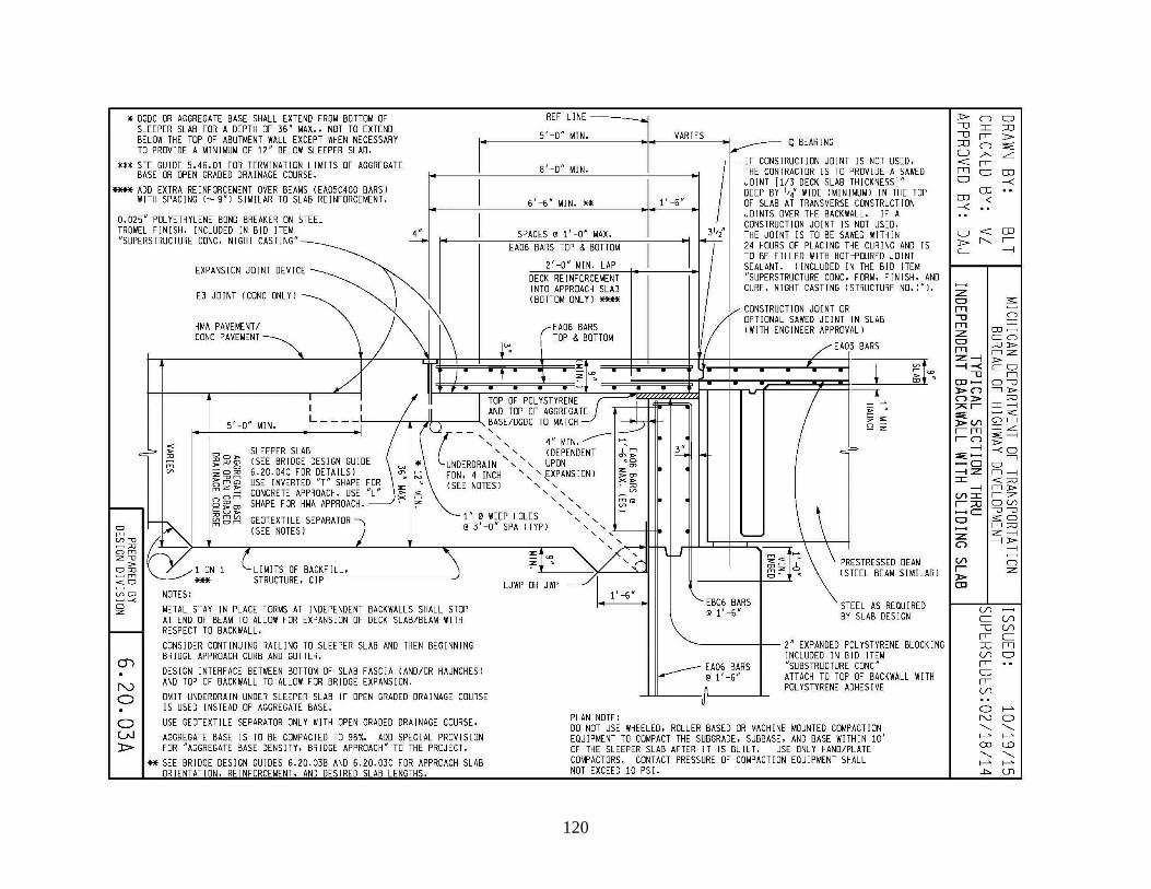
120


THE INSTITUTE FOR TRANSPORTATION IS THE FOCAL POINT FOR TRANSPORTATION AT IOWA STATE UNIVERSITY.
InTrans centers and programs perform transportation research and provide technology transfer services for government agencies and private companies;
InTrans contributes to Iowa State University and the College of Engineering’s educational programs for transportation students and provides K–12 outreach; and
InTrans conducts local, regional, and national transportation services and continuing education programs.
Visit InTrans.iastate.edu for color pdfs of this and other research reports.