Rail Accident Report - GOV.UK
73
Report 09/2016 May 2016 Rail Accident Report Runaway and collision at Bryn station, Wigan 27 November 2014
-
Upload
khangminh22 -
Category
Documents
-
view
0 -
download
0
Transcript of Rail Accident Report - GOV.UK

Report 09/2016May 2016
Rail Accident Report
Runaway and collision at Bryn station, Wigan 27 November 2014

This investigation was carried out in accordance with:
l the Railway Safety Directive 2004/49/EC;l the Railways and Transport Safety Act 2003; and l the Railways (Accident Investigation and Reporting) Regulations 2005.
© Crown copyright 2016 You may re-use this document/publication (not including departmental or agency logos) free of charge in any format or medium. You must re-use it accurately and not in a misleading context. The material must be acknowledged as Crown copyright and you must give the title of the source publication. Where we have identified any third party copyright material you will need to obtain permission from the copyright holders concerned. This document/publication is also available at www.raib.gov.uk.
Any enquiries about this publication should be sent to:
RAIB Email: [email protected] Wharf Telephone: 01332 253300Stores Road Fax: 01332 253301 Derby UK Website: www.gov.uk/raibDE21 4BA
This report is published by the Rail Accident Investigation Branch, Department for Transport.
Report 09/2016Bryn
May 2016
Preface
The purpose of a Rail Accident Investigation Branch (RAIB) investigation is to improve railway safety by preventing future railway accidents or by mitigating their consequences. It is not the purpose of such an investigation to establish blame or liability. Accordingly, it is inappropriate that RAIB reports should be used to assign fault or blame, or determine liability, since neither the investigation nor the reporting process has been undertaken for that purpose.
The RAIB’s findings are based on its own evaluation of the evidence that was available at the time of the investigation and are intended to explain what happened, and why, in a fair and unbiased manner.
Where the RAIB has described a factor as being linked to cause and the term is unqualified, this means that the RAIB has satisfied itself that the evidence supports both the presence of the factor and its direct relevance to the causation of the accident. However, where the RAIB is less confident about the existence of a factor, or its role in the causation of the accident, the RAIB will qualify its findings by use of the words ‘probable’ or ‘possible’, as appropriate. Where there is more than one potential explanation the RAIB may describe one factor as being ‘more’ or ‘less’ likely than the other.
In some cases factors are described as ‘underlying’. Such factors are also relevant to the causation of the accident but are associated with the underlying management arrangements or organisational issues (such as working culture). Where necessary, the words ‘probable’ or ‘possible’ can also be used to qualify ‘underlying factor’.
Use of the word ‘probable’ means that, although it is considered highly likely that the factor applied, some small element of uncertainty remains. Use of the word ‘possible’ means that, although there is some evidence that supports this factor, there remains a more significant degree of uncertainty.
An ‘observation’ is a safety issue discovered as part of the investigation that is not considered to be causal or underlying to the event being investigated, but does deserve scrutiny because of a perceived potential for safety learning.
The above terms are intended to assist readers’ interpretation of the report, and to provide suitable explanations where uncertainty remains. The report should therefore be interpreted as the view of the RAIB, expressed with the sole purpose of improving railway safety.
The RAIB’s investigation (including its scope, methods, conclusions and recommendations) is independent of any inquest or fatal accident inquiry, and all other investigations, including those carried out by the safety authority, police or railway industry.

Report 09/2016Bryn
4 May 2016
This page is intentionally left blank
Report 09/2016Bryn
May 2016

Report 09/2016Bryn
5 May 2016
Runaway and collision at Bryn station, Wigan 27 November 2014
Contents
Preface 3Summary 7Introduction 8
Key definitions 8The accident 9
Summary of the accident 9Context 9
The sequence of events 17Key facts and analysis 20
Background information 20Identification of the immediate cause 38Identification of causal factors 41Identification of underlying factors 50Previous occurrences of a similar nature 51
Summary of conclusions 52Immediate cause 52Causal factors 52Underlying factors 53Observations 53
Actions reported as already taken or in progress relevant to this report 54Learning points 56Recommendations 57Appendices 60
Appendix A - Glossary of abbreviations and acronyms 60Appendix B - Glossary of terms 61Appendix C - Investigation details 67Appendix D - DTS operator’s manual (extract) 68Appendix E - Balfour Beatty setup instruction for the wiring train 69Appendix F - DTS working mode controls - wiring modifications 71

Report 09/2016Bryn
6 May 2016
This page is intentionally left blank

Report 09/2016Bryn
7 May 2016
Summary
At 00:11 hrs on 27 November 2014 two engineering vehicles (that were part of a new overhead line wiring train) ran away on a gradient close to Bryn station, near Wigan. They collided with two mobile elevating work platforms in the station; seven members of staff who were on and around the work platforms narrowly escaped injury.The two coupled vehicles were a haulage vehicle, an existing item of track maintenance plant, and a specially-adapted wagon, on which the overhead wiring team were located.The driver of the haulage vehicle did not correctly operate the controls to change from a travelling mode to a working mode before he left the cab. This caused the brakes to release and, because it also caused the brake controls on the wagon to become disabled, the wiring team were unable to reapply them. No design, change management, approval or risk assessment work had identified the need for a safety measure to prevent or mitigate the consequences of the error. The RAIB identified two underlying factors that help explain why the parties involved had not realised the significance of changes that were proposed to the use of the haulage vehicle. In summary, when developing the new train, they followed a philosophy of minimising technical change and they did not adopt a systematic and integrated approach to the identification and management of requirements and interfaces (a system-based design approach).The RAIB has made five recommendations:l Three directed to Balfour Beatty Rail, the operator of the vehicles, concerned with:ensuring improved hazard identification when introducing and operating railborne
plant;properly assessing and managing the risk implications of making changes to the
design and use of its equipment; and improving the quality of the alterations it makes to electrical systems on its
equipment.l One directed to RSSB concerned with clarifying its guidance to the rail industry
concerning the management of changes relating to the design, operation and maintenance of vehicles and plant operating in engineering possessions.
l One directed to Network Rail to ensure the risks associated with the introduction of new and modified railborne plant are properly managed before such plant is allowed to operate on its infrastructure.
Sum
mar
y

Report 09/2016Bryn
8 May 2016
Introduction
Key definitions1 Metric units are used in this report, except when it is normal railway practice to
give speeds and locations in imperial units. Where appropriate the equivalent metric value is also given.
2 All mileages in the report are measured from a datum at Huyton Junction, 6 miles (9.6 km) east of Liverpool Lime Street station on the line to Manchester Victoria.
3 The report contains abbreviations and technical terms (shown in italics the first time they appear in the report). These are explained in appendices A and B. Sources of evidence used in the investigation are listed in appendix C.
Introduction

Report 09/2016Bryn
9 May 2016
The accident
Summary of the accident 4 At 00:11 hrs on Thursday 27 November 2014, an on-track machine, which was
being set up to carry out work within an engineering possession, ran uncontrolled downhill and collided with two stationary road-rail vehicles (RRVs), in Bryn station, near Wigan (figures 1 and 2).
5 The on-track machine, referred to as an access unit for the purposes of the report, was made up of two vehicles from an overhead line wiring train (wiring train): a dynamic track stabiliser (DTS) hauling a wagon carrying an elevating work platform and basket (access wagon). Both RRVs were mobile elevating work platforms (MEWPs).
6 The wiring train had been travelling on the Up St Helens line and had stopped outside Bryn station so the access unit could be uncoupled from the rest of the wiring train. Staff on the access wagon were trying to transfer the active driving controls from the DTS to the access wagon when it started to run away. It travelled for around 110 metres before colliding with the MEWPs at 12 mph (19 km/h).
7 The MEWPs and their work baskets suffered major damage, and three of the staff on the access wagon reported minor upper body injuries. However, the consequences of the accident could have been much more serious:l Four staff who had been in the MEWP work baskets just managed to get out
before the collision. Three others, nearby on the track and on the station platform, also just managed to move clear.
l The telescopic boom of one of the MEWPs swang across the station platform during the collision, only narrowly missing the seven staff who had been on and nearby to the MEWPs.
l The energy absorbed in the collision by the MEWPs is likely to have significantly reduced the deceleration that the staff still on the access unit were subjected to.
l The collision prevented the access unit continuing, reaching higher speeds and presenting a greater danger to those on board and to other trains.
ContextLocation8 Bryn station is on the Huyton and St Helens line that branches off the mainline
between Liverpool Lime Street and Manchester Victoria stations at Huyton Junction (figure 3). The line runs approximately north-east, via St Helens Central (5 miles and 16 chains), to Springs Branch Junction, 1.25 miles (two kilometres) south east of Wigan North Western station on the West Coast Main Line. It comprises two tracks: the Up St Helens and the Down St Helens.
The
acci
dent

Report 09/2016Bryn
10 May 2016
© Crown Copyright. All rights reserved. Department for Transport 100039241. RAIB 2015
Location of accident
MEWP work baskets
MEWPs Access unit
Figure 1: Extract from Ordnance Survey map showing location of the accident
Figure 2: The access unit and the two MEWPs after the collision at Bryn station
The accident

Report 09/2016Bryn
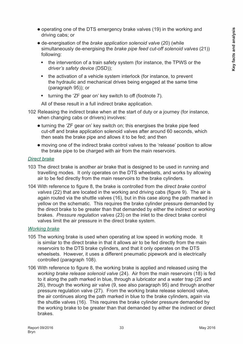
11 May 2016
West Coast Main Line - to Preston and Glasgow
Huyton Junction
Springs Branch JunctionGarswood
9 miles 00 chains
St Helens Central5 miles 16 chains
Bryn10 miles 22 chains
Wigan North Western
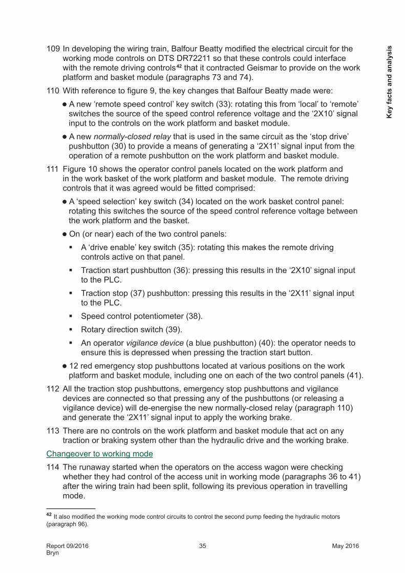
Newton-le-Willows
Tuebrook sidings
To Manchester Victoria via
Ordsall Lane Junction
Liverpool Lime Street
West Coast Main Line - to Crewe and LondonTo Crewe and London
Notes:Not to scaleSome lines and stations omitted for clarity
9 The mainline to Manchester from Huyton Junction crosses the West Coast Main Line at Newton-le-Willows and approaches Manchester Victoria station via Ordsall Lane Junction.
10 Bryn station is located at 10 miles 22 chains. It is on a section of line that runs downhill almost continuously from 10 miles 0 chains, through Bryn station, to Springs Branch Junction at 12 miles 54 chains. In places the gradient is as steep as 1 in 86. The gradient is 1 in 116 where the access unit was uncoupled.
11 A programme of phased infrastructure improvement work is currently underway in north-west England to enable more rail services to be operated by electric trains. Known as the North West Electrification programme, Phase 1 involved the overhead electrification of the Liverpool to Manchester mainline between Newton-le-Willows and Manchester. This was completed in December 2013. Phase 2 1 of the programme included the electrification of the remaining section between Newton-le-Willows and Liverpool.
12 Phase 2 also included the electrification of the Huyton and St Helens line between Huyton Junction and Springs Branch Junction. The work to be undertaken on the night of the accident was for this project.
Figure 3: Diagram of the railway between Liverpool Lime Street station and the West Coast Main Line between Wigan and Newton-le-Willows
1 Later phases include electrification of lines between Preston and Blackpool (Phase 3), Manchester and Preston (Phase 4), and Manchester and Stalybridge (Phase 5). Further information on the North West Electrification programme and its progress can be found at www.networkrail.co.uk.
The
acci
dent

Report 09/2016Bryn
12 May 2016
Organisations involved13 Network Rail owns, operates and maintains the railway infrastructure where the
accident occurred as part of its London North Western (North) Route. It also assessed the suitability of the wiring train for operation on its infrastructure and issued a certificate permitting this2.
14 Balfour Beatty Rail (Balfour Beatty) was contracted by Network Rail to carry out the Phase 2 North West Electrification work. Two divisions within the company were involved:l its project division, which was responsible for designing and installing the
overhead line equipment (OLE), between Liverpool and Newton-le-Willows, and between Huyton and Springs Branch Junctions, and which had planned and was managing the work on the night; and
l its plant division, which had supplied the wiring train and employed the driver and fitter who brought it to site; the plant division had also specified, modified, procured and leased the vehicles and equipment from which the wiring train was constructed; it also carried out ongoing maintenance work.
15 Geismar designed, manufactured and supplied specialist equipment used on the wiring train, including the work platform and basket on the access wagon.
16 VTG leased Balfour Beatty the two KFA container flat wagons that were used on the wiring train. One carried the Geismar-supplied work platform and basket.
17 Interfleet Technology (Interfleet) was appointed by Geismar to assess and certify the compliance of its equipment with relevant railway industry standards.
18 Plasser and Theurer (Plasser) originally designed and manufactured the DTS vehicles that Balfour Beatty owned and modified for use on the wiring train.
19 Network Rail, Balfour Beatty, VTG, Geismar, Interfleet and Plasser freely co-operated with the investigation.
The wiring train and its operation20 In early 2012, Balfour Beatty reviewed its strategy for installing OLE catenary
systems in the UK. With a number of major electrification projects planned, a desire to reduce costs and improve productivity, and foreseen engineering possession constraints, it identified the need for a higher output method of installation. It looked at a number of alternatives, including solutions that the company had used elsewhere in Europe, and sought advice from equipment suppliers. It decided to invest in a new railborne plant system, and later in 2012 started the project to design and develop the wiring train.
2 The certificate was issued to enable trials (paragraph 85).
The accident

Report 09/2016Bryn
13 May 2016
Dropper SupportCatenary wire
Pantograph headPantograph
Contact wire
21 The catenary system used on conventional OLE systems comprises an upper catenary wire, regularly supported from lineside masts (or other structures), to which are connected a series of short vertical wires (droppers) that support the contact wire (figure 4). Traditionally these wires have been installed and tensioned separately, requiring a number of engineering possessions to complete a single length of tensioned catenary. Balfour Beatty designed the wiring train to be able to pay out and tension both wires simultaneously so that a tensioned length of catenary could be installed in one engineering possession. It was also designed to give a number of other advantages: l the ability for engineering possessions to be taken and given up around the
train, allowing the movements to, and from, site to be made in normal traffic and, therefore, making the best use of the time when the line is blocked;
l the potential to work adjacent to other lines that could remain open to normal traffic; and
l the need for fewer staff to be on the track during the engineering possession.
Figure 4: Diagram of a typical catenary system used on a conventional OLE systemTh
e ac
cide
nt

Report 09/2016Bryn
14 May 2016
Tensioner module Work platform and basket module
Working cab Driving cab
Tensioner wagon
Tensioner unit Access unit
DTS DR72213
KFA wagon VTG 95385
KFA wagon VTG 95382
DTS DR77211Access wagon
Tensioner unit Access unit
22 Figure 5 shows an overview of the vehicles and equipment systems comprising the two parts of the wiring train3: l the access unit, which was made up of a DTS (number DR72211) and the
access wagon, comprising the KFA wagon (number VTG 95382) carrying the work platform and basket; and
l the tensioner unit, the part of the train that remained outside Bryn station, which was made up of another DTS (number DR72213) and special wagon, the tensioner wagon. The tensioner wagon comprised the other KFA wagon (number VTG 95385) and carried the specialist equipment (also supplied by Geismar) for running out and tensioning the catenary and contact wires from on-board cable drums.
Geismar supplied the specialist equipment as two modules: the work platform and basket module and the tensioner module. The specialist equipment was fitted to subframes that were secured to the KFA wagons using standard ISO container twist-lock fixings.
Figure 5: The wiring train
3 The RAIB found a variety of terminology in use for describing the vehicles and equipment comprising the wiring train. By reference to figure 5, the following terms have been adopted in the report for purposes of consistency: wiring train, access unit, access wagon, work platform and basket module, tensioner unit, tensioner wagon and tensioner module.
The accident

Report 09/2016Bryn
15 May 2016
23 In common with other railborne plant, the wiring train can be considered to operate in three modes4: working mode, travelling mode and running mode.
24 The wiring train is used to perform its designed task of catenary system installation in working mode. In this mode the wiring train is split and the tensioner and access units are driven separately, at low speed (Balfour Beatty stated a maximum speed of 5 mph (8 km/h) for the access wagon), from remote controls on the tensioner and work platform and basket modules. The tensioner unit leads, paying out and tensioning the wires; the access unit follows closely behind carrying the staff who install the droppers, and clip and secure the contact wire.
25 Running mode applies when the train is operating outside an engineering possession in normal traffic. In this mode, the tensioner and access wagon are coupled together and driven from the leading DTS cab. Work equipment (such as the work platform and basket) needs to be stowed away, and all on-board train safety systems (such as the train protection and warning system (TPWS)) need to be active. In running mode the wiring train can travel at up to the maximum line speed, or the maximum permitted vehicle speed (50 mph (80 km/h)) if this is less.
26 Travelling mode is used for transiting within an engineering possession. It is similar to running mode except that on-board safety systems do not need to be active (since the train is not required to interact with the signalling system) and that movements (and speed) are under the control of the person in charge of the possession.
27 Balfour Beatty acquired the DTS vehicles in 1996. They were built for British Rail in the late 1980s and were originally designed for track maintenance purposes5. However, Balfour Beatty identified that they had a continuously-variable, low speed hydraulic drive system that it felt was ideally suited to the new use of hauling the tensioner and access units in working mode; testing showed the DTSs could provide sufficient tractive effort to haul the other vehicles. Balfour Beatty had underutilised DTSs available, a further advantage.
28 DTSs have two cabs; they are referred to in this report as the working cab and the driving cab. Both cabs are provided with the traction and brake controls for: l the mechanical drive, which drives two of the wheelsets on the DTS
(paragraphs 90 to 92);l the direct brake, an air brake that acts on all four of the wheelsets on the DTS
(paragraphs 103 to 104); and l the indirect brake, a continuous and automatic air brake that, via the train
brake pipe, operates on all wheelsets on the DTS and vehicles coupled to it (paragraphs 97 to 102).
These are the traction and braking systems used in running and travelling modes.
4 These terms are used for consistency with current railway industry standards (paragraph 63): GM/RT2400 issue 5 and RIS-1702-PLT.5 DTSs are used to stabilise track so that trains can run without the need for an initial speed restriction following track work.
The
acci
dent

Report 09/2016Bryn
16 May 2016
29 The working cab also has controls for the traction and braking systems used in working mode6: the hydraulic drive (paragraphs 93 to 96) and the working brake (paragraphs 105 to 107). Balfour Beatty made a number of changes to the DTS vehicles so they could operate the wiring train. This work included modifying the working mode traction and braking systems so that, on the wiring train, they could be controlled remotely from the tensioner and work platform and basket modules (paragraph 24). The wiring train was configured so the working cabs were adjacent to the access and tensioner wagons (figure 5).
30 The wiring train first entered service in May 2014, but was withdrawn following an accident that involved a wire breaking and striking a member of staff (paragraph 82). It re-entered service on 10 November 2014 after investigation and modification. As a result, at the time of the runway accident on 27 November 2014, Balfour Beatty was using the train to install only one wire at a time.
External circumstances31 Weather in the region at the time of the accident was overcast; no precipitation
had been recorded for over 15 hours. The air temperature was 7ºC. The RAIB found no evidence that the weather had played a part in the accident.
6 The working cab has additional controls for operating the equipment used for track stabilisation (footnote 5). On the wiring train, this equipment was secured out of use.
The accident

Report 09/2016Bryn
17 May 2016
The sequence of events
Events preceding the accident32 On the night of 26-27 November 2014, Balfour Beatty planned to complete the
installation of the catenary system on an 1860 metre long section between Bryn and Garswood stations (figure 3). The catenary wire had been installed the night before and work was now needed to install, clip and secure the contact wire.
33 The wiring train had been stabled during Wednesday 26 November at Tuebrook sidings (in Liverpool), and the fitter arrived around 20:00 hrs to check and prepare it for the shift that night. He reported finding nothing untoward. The driver arrived at Tuebrook about an hour later, completed the running brake test in the sidings, and the train departed shortly after 22:00 hrs. There were five staff on board including the driver and the fitter. DTS DR72211 (hauling the access unit) was leading.
34 The train was routed to St Helens Central station, arriving at 22:24 hrs. Here additional staff (mainly linesmen, labourers and operators) who would be working on board started to load equipment and tools and make preparations for the work. The person in charge of the possession was granted an engineering possession around the train and, at 23:14 hrs, the train departed (in travelling mode) for where the wiring run was to start, just outside Bryn station; DTS DR72211 remained leading. There were now 17 staff on board. The train stopped off on the way to drop off equipment and make adjustments to catenary components that had already been installed.
35 Meanwhile the two MEWPs, which were to follow the wiring train to check and make adjustments to the installed catenary, made their way into Bryn station from the direction of St Helens Central after on-tracking at Arch Lane vehicle access point 0.7 kilometres south-west of Garswood station. Station closed circuit television (CCTV) shows them arriving at midnight. There were seven staff with them.
Events during the accident36 The DTS on-train data recorder (OTDR) shows that the driver used the indirect
brake to bring the train to a stand outside Bryn station at 00:00:35 hrs and, at 00:00:42 hrs, he de-activated the driving cab controls (by turning the so-called ‘ZF gear on’ key switch off (paragraph 92)). Witness evidence indicates that he then left the driving cab and went to meet the fitter to agree how they were going to separate the tensioner and access units and set them up to operate in working mode. The RAIB has concluded from witness and test evidence that the driver left the indirect brake control valve handle (paragraph 100) in the ‘release’ position7.
37 The driver and fitter met at the coupling between the two units. The fitter disconnected the brake pipe and control cables, and then mechanically uncoupled. They then agreed that the fitter would set up DTS DR72213 on the tensioner unit, and the driver would set up DTS DR72211 on the access unit.
7 The indirect brake would have remained applied because the ‘ZF gear on’ switch operation would have vented the train brake pipe.
The
sequ
ence
of e
vent
s
Report 09/2016Bryn
18 May 2016
38 There was a crew of seven on the work platform and basket module, including the work platform operator and the work basket operator.
39 Witness evidence suggests that a few minutes after uncoupling, the driver returned to DTS DR72211 and entered the working cab knowing that, after disconnecting the control cables (during uncoupling), the engine needed restarting. There was another person in the working cab, but he was there specifically to observe and record the work being done8 and was not familiar with the DTS controls. The driver silenced an audible warning9, re-set the computer (used to control the DTSs when they work in tandem) and started the engine. The OTDR showed that, at 00:11:06 hrs, he also turned on the controls for the working mode traction and braking system (paragraph 108).
40 The driver left the cab and walked back along the track to the access wagon where, according to witness evidence, he asked one of the operators on the work platform and basket module to see if he now had control of the DTS. Then, at 00:11:32 hrs, the access unit started to move downhill into Bryn station.
41 At first the driver thought that the operator on the work platform and basket module was controlling the movement, and he started to walk on to the tensioner wagon as he wanted to show the fitter how to operate it. However, the staff on the work platform and basket module soon became aware that the access unit was running away. Concerned about the MEWPs and staff in the station, they started shouting and sounding the horn.
42 There were two staff in each MEWP work basket, a member of staff on the track between the MEWPs and two more staff nearby on the station platform. They all heard the warning. The access unit collided with the MEWPs at 00:12:05 hrs. The station CCTV showed that the staff had managed to move clear a few seconds before. It also showed how the telescopic boom of one of the MEWPs swung across the station platform during the collision, narrowly missing the staff who had moved out of the way (figure 6).
43 The collision with the two MEWPs caused the access unit to decelerate at around 0.4 m/s2 (equivalent to a moderate train brake application), bringing it to a stand within the station. This prevented it running further and faster on the downhill gradient, and possibly out of the possession at Springs Branch Junction (on the West Coast Main Line) (paragraph 10). A number of staff on board disembarked as it was slowing down, the others when it had come to rest.
Events following the accident44 Balfour Beatty completed an immediate headcount of those on site, notified both
Network Rail and its own operations control offices and collected first accounts from witnesses.
8 So that Balfour Beatty could compare the wiring process being used with that of other established methods.9 That had resulted from the separation of the control cables.
The sequence of events

Report 09/2016Bryn
19 May 2016
-14.0 seconds
+1.0 second
+2.0 seconds
- 4.0 seconds
+1.5 seconds
+2.5 seconds
Note: time shown relative to collision
Figure 6: CCTV images of the evacuation of MEWPs at Bryn station and the collision consequences (images courtesy Northern Rail)
45 Several staff who were by the wiring train when the runaway started, including the driver, made their way into the station. There was concern that the DTS engine was still running, so the driver operated one of the external engine stop pushbuttons. He also went into both cabs and collected personal effects. There is CCTV evidence that a number of other people also entered the cabs on the DTS immediately after the collision. The OTDR on DTS DR72211 stopped recording at 00:20:25 hrs, indicating that the battery isolation switch was operated at this time.
46 The railway remained closed for investigation and recovery work until 17:20 hrs on 27 November 2014.
The
sequ
ence
of e
vent
s

Report 09/2016Bryn
20 May 2016
Key facts and analysis
Background informationManagement of change47 The common safety method for risk evaluation and assessment (CSM RA) is
a regulation of the European Union that describes a common mandatory risk management process for the European rail industry.
48 The CSM RA specifically applies when a technical, operational or organisational change is being proposed to the railway. In summary, it requires the proposer of the change (for instance the operator of a vehicle) to:l consider if the proposed change has an impact on safety and, if it does, use
criteria in the CSM RA to decide if the change is significant; and, if the change is significantl apply the risk management process described in the CSM RA to confirm that
associated risks are acceptable. If the change is not significant, the proposer needs to record how it arrived at this decision.
49 The risk management process involves the systematic consideration of the proposed changes and associated hazards. It essentially consists of the following steps: l System definition – the definition of the parts of the system (technical,
operational or organisational) that are to be considered in the risk assessment. Essentially these are the parts that are to be changed or are likely to be affected by the change(s). The definition needs to cover a variety of issues including the intended purpose of the system, its functions and elements, and the system boundaries and interfaces.
l Hazard identification – the systematic identification of all reasonably foreseeable hazards using a broad-based team of experts.
l Risk acceptability – the application of one or more of the following three principles to determine the acceptability of the risks associated with each hazard10 and where further safety measures need to be considered:application of suitable codes of practice11, such as relevant and recognised
technical standards;comparison with a reference system12 that is proven in-use to have an
acceptable safety level; or
10 Hazards associated with risks that are considered to be ‘broadly acceptable’ do not need to be analysed further.11 The CSM RA defines a number of requirements that a code of practice needs to satisfy. 12 The CSM RA requires the reference system to have similar functions and interfaces, and to be used under similar operational and environmental conditions.
Key facts and analysis
Report 09/2016Bryn
21 May 2016
by explicit risk estimation, using qualitative and quantitative methods, and evaluating the acceptability of the estimated risks using criteria in European legislation or national rules.
If the risk for a particular hazard is shown to be acceptable by application of one of the above principles (for instance because the hazard is controlled by the application of a suitable code of practice or the residual risk is acceptably low), no further action is required (apart from the need to record this). If the associated risks cannot be shown to be acceptable, then additional safety measures need to be considered.
l Demonstration of compliance with safety requirements – the various responsible parties demonstrating that the safety requirements have been complied with. This work is supervised by the proposer and independently assessed by an assessment body.
The risk assessment process is iterative and considered to be complete when all safety requirements have been fulfilled and the risk associated with reasonably foreseeable hazards is acceptably low.
50 The Office of Rail and Road (ORR) publishes guidance13 to help proposers follow the requirements of the CSM RA when managing change. It includes, for instance, a methodology for determining whether or not a change should be considered to be significant, helping to determine whether the above risk management steps need to be followed.
51 However, the ORR guidance also clarifies that CSM RA only applies to the mainline railway14. Importantly, paragraph 2.22 of the ORR guidance states that the CSM RA does not apply to vehicles (such as railborne plant) when they are operating within an engineering possession; and that, in these circumstances, risks can be managed through other measures, such as the Management of Health and Safety at Work Regulations 1999.
52 RSSB15 also publishes guidance on the use of the CSM RA. This includes a set of Rail Industry Guidance Notes16 (guidance notes) describing how to follow the CSM RA risk management process, and also some worked examples. In the guidance notes, RSSB recognises the CSM RA risk management process as ‘sound’ and suggests that it could be used (either fully or in part) more generally, for instance in cases where it did not strictly need to be applied because risks were not identified as being significant. However, the RAIB found nothing in the guidance notes explicitly stating that the risk management method could be used (or should be considered) when the CSM RA does not apply, for instance when vehicles are operating in engineering possessions.
13 ORR’s guidance, ’Common Safety Method for risk evaluation and assessment: Guidance on the application of Commission Regulation (EU) 402/2013’, March 2015, is available on its website: www.orr.gov.uk.14 It does not apply, for instance, to metros, light rail and heritage railways.15 A not-for-profit company owned and funded by major stakeholders in the railway industry, and which provides support and facilitation for a wide range of cross-industry initiatives. The company is registered as ‘Rail Safety and Standards Board’ but trades as ‘RSSB’.16 These documents are available on RSSB’s website: www.rssb.co.uk.
Key
fact
s an
d an
alys
is
Report 09/2016Bryn
22 May 2016
53 The Management of Health and Safety at Work Regulations 1999 defines the general duty for employers to make a ‘suitable and sufficient’ assessment of risks in order to identify measures needed to comply with statutory safety responsibilities. They further require a risk assessment to be reviewed when there is significant change. The Health and Safety Executive published an Approved Code of Practice that gave advice on compliance with these regulations, but the ORR has advised that this has now been withdrawn17. The RAIB notes that the ORR has issued a policy statement stating its view that compliance with CSM RA produces a risk assessment that is ‘suitable and sufficient’ and that the CSM RA is, therefore, not in conflict with the Regulations.
54 Balfour Beatty has defined its requirements for the management of change in its Health and Safety Management System procedures. In summary, these require that changes, such as the use of new and modified plant, are formally assessed and validated in order to comply with legislation. The procedures neither describe how this work is to be undertaken, nor do they give any supporting guidance.
Approval of railborne plant and requirements for braking55 The approvals regime that is used when introducing railborne plant on to the
national network involves the following key steps:l assessment of compliance with the statutory requirements of the Machinery
Directive18 published by the European Union19;l assessment of compliance with relevant rail industry standards; andl review and acceptance by the infrastructure manager, in this case following the
processes governed by the Network Rail Acceptance Panel (NRAP).These steps, and the braking requirements that they prescribe for working mode operation, are discussed in the paragraphs that follow.
Machinery Directive56 The Machinery Directive requires manufacturers to ensure products comply
with defined essential health and safety requirements before they are placed on the market and (or) put into service. Generally, compliance checks can be undertaken by the manufacturers themselves. However, for certain types of equipment, notably (in the case of the wiring train) work access platforms20, additional arrangements may apply; for instance, the need to use a notified body. The manufacturer needs to keep a technical file that demonstrates how the product complies, produce a certificate declaring conformity and affix a CE mark.
17 The RAIB notes that the guidance on risk assessment was of a general nature, and did not specifically cover change management.18 This is enacted by the ‘Supply of Machines (Safety) Regulations’ in Great Britain.19 In running mode, railborne plant also needs to comply with the Railway Interoperability Directive.20 Referred to as ‘Devices for the lifting of persons or of persons and goods involving a hazard of falling from a vertical height of more than three metres’.
Key facts and analysis

Report 09/2016Bryn
23 May 2016
57 The Machinery Directive requires the use of an iterative process of risk assessment to determine the essential health and safety requirements that apply. However, it also allows manufacturers to declare conformity by demonstrating compliance with a harmonised standard 21 relevant to the equipment type. The RAIB established that the following harmonised standards were relevant to the access unit: l EN 14033-3:2009, ‘Railway applications – track – railbound construction
and maintenance machines, Part 3: General safety requirements’, regarding requirements for rail vehicle design; and
l EN 280:201322, ‘Mobile elevating work platforms – design calculations – stability criteria – construction – safety – examination and test’, regarding the design of work access platform and basket equipment.
58 Brake system requirements are defined in clause 5.25 of EN 14033-3. This clause directly references:l Clause 9 of EN 14033-1:2011, ‘Railway applications – track – railbound
construction and maintenance machines, Part 1: Technical requirements for running’; which, for operation in running mode, defines a wide ranging and detailed set of requirements including:the brake equipment that is mandated for each type of machine;the characteristics of each brake system that is fitted (eg automatic air brake,
direct brake and emergency brake), including performance and design integrity; and
certain equipment-specific design features.l Clause 5.12 of EN 14033-2:2008, ‘Railway applications – track – railbound
construction and maintenance machines, Part 2: Technical requirements for working’; which, for operation in working (and travelling) mode, essentially defines only two requirements:that there is a brake fitted that is capable of providing a specified low speed
stopping performance23; the characteristics and design integrity of this brake are not otherwise specified; and
that a separate parking brake is fitted that is capable of holding the machine on a specified gradient.
59 A brake system used to fulfil a running mode brake requirement can also be used in working mode. However, RSSB has confirmed that if an individual brake system is only used in working (or travelling) mode, that system would only need to comply with the less onerous requirements of EN 14033-2.
21 The reference list of harmonised standards is published in the Official Journal of the European Union.22 The issue from 2009 was relevant at the time of the contract and was used by Geismar when self-certifying conformity with the Machinery Directive.23 Pedestrian staff may be in the vicinity of railborne plant when it is operating in working mode. The RAIB understands the specified low speed stopping performance has been defined with this in mind.
Key
fact
s an
d an
alys
is
Report 09/2016Bryn
24 May 2016
Rail industry standards60 RSSB publishes a suite of technical standards (eg Railway Group standards
and Rail Industry Standards) that continue to be used to assess the suitability of railborne plant for operation on the national network. RSSB also defines the process that is used to confirm and certify compliance. At the time the wiring train was being developed, this process was known as Engineering Acceptance, and was defined in Railway Group standard, GM/RT2000, ‘Engineering acceptance of rail vehicles’ 24. Two types of conformance body were involved: the Conformance Certification Body (CCB), the accredited body authorised to certify compliance in individual areas (eg design and construction), and the Vehicle Acceptance Body (VAB), the accredited body authorised to certify overall compliance.
61 Railway Group standard, GM/RT2400 issue 4, ‘Engineering design of on-track machines’ defined the key design requirements for railborne plant at the time Balfour Beatty awarded the contract for the work platform and basket and tensioner modules (paragraph 71). The braking requirements are specified in clause 3.5. With regards to operation in working mode (termed ‘operating mode’ in GM/RT2400 issue 4), a low speed stopping performance similar to that in EN 14033-2 is prescribed. The running mode brake system can be used to achieve this stopping performance, but if it is not, an alternative brake system needs to be employed. The requirements for this are specified in clause 3.5.3.3. As well as meeting the defined low speed stopping performance requirement, this separate working mode brake system needs to:l be fail safe, so that a loss of operating energy results in the brakes being
applied (this is how an automatic air brake works); andl inhibit or interrupt traction power in the event of an emergency brake
application.62 Clause 3.5.3.4 of GM/RT2400 issue 4 also requires that, in working mode,
operators have a nearby means of making an emergency brake application. 63 GM/RT2400 issue 4 applies to all modes of operation. RSSB has recently
replaced it with two new standards25 that apply separately to the running and working (and travelling) modes of operation: l GM/RT2400 issue 5, ‘Engineering design of on-track machines in running mode’
(which then makes reference to EN 14033-1); andl Rail Industry Standard RIS-1702-PLT, ‘Rail industry standard for the design
of on-track machines in working and travelling modes’ (which then makes reference to EN 14033-2).
24 GM/RT2000 is due to be withdrawn. Following a request from industry to retain an approvals scheme for railborne plant, RSSB is introducing a new conformance process, RIS-1710-PLT, ‘Rail industry standard for engineering certification of railborne plant’, and a new conformance body known as a Plant Acceptance Body (PAB).25 These standards did not need to be applied as part of Engineering Acceptance since they became applicable after Balfour Beatty awarded the contract to Geismar.
Key facts and analysis

Report 09/2016Bryn
25 May 2016
64 Clause 2.4 of RIS-1702-PLT defines the requirement for the working mode brake. This specifically references the low speed stopping requirement in EN 14033-2 (paragraph 58), but additionally requires that the brake applies in a fail safe way (or that an additional independent braking means is available). Clause 2.4 further requires that the complete brake system, including consideration of correct use by an operator, meets a minimum level of safety performance26. RSSB advised that it had drafted RIS-1702-PLT to enhance the minimum requirements specified by EN 14033-2.
Network Rail Acceptance Panel65 The Network Rail Acceptance Panel (NRAP) is responsible for a number
of company processes that help Network Rail comply with its statutory responsibilities and its Health and Safety Management System. It includes Network Rail’s product acceptance process that is used to assess the suitability of products, such as the wiring train.
66 The product acceptance process, which is defined in Network Rail company standard NR/L2/RSE/100/05, ‘Product introduction and change’, provides Network Rail with an opportunity to assess safety issues and risks before issuing certification (a Certificate of Acceptance) that allows a product to operate or be used on its infrastructure.
67 Two key parties in Network Rail are involved:l the product acceptance team, who administer the process; and l the relevant professional head (in the case of the wiring train, the professional
head for plant and traction and rolling stock) and supporting specialist engineers, who determine the acceptance requirements and the level of assessment (for instance if an independent safety assessor is required).
68 The professional head (or representative) or a specially-constituted system review panel (SRP) review the evidence that shows how the acceptance requirements have been met. The product acceptance team issue the Certificate of Acceptance based on what the reviewers recommend.
69 Network Rail has a template (requirements template) that the reviewers normally use to help set the acceptance requirements. It has space, for instance, to list applicable Railway Group and other standards, but it does not prescribe any product or system-specific design requirements.
Wiring train development, approval and introduction70 Balfour Beatty developed the wiring train as three separate subsystems:
l the work platform and basket module and the tensioner module that it procured from Geismar (paragraph 22);
l the two KFA container flat wagons that it leased from VTG to carry the work platform and basket module and the tensioner module (paragraphs 16 and 22), thereby forming the access and tensioner wagons; and
l the DTSs that it modified so they could haul the train and work together with the access and tensioner wagons (paragraphs 27 and 29).
26 Specified according to EN 13849-1, ‘Safety of machinery – Safety-related parts of control systems – Part 1: General principles for design’.
Key
fact
s an
d an
alys
is

Report 09/2016Bryn
26 May 2016
71 Balfour Beatty’s plant and project divisions worked together to develop the train concept and a specification for the work platform and basket and tensioner modules. On 11 January 2013, the plant division agreed a contract with Geismar to supply the modules against this specification. The specification included the need for Geismar to obtain ‘plant approval’ (and appoint a conformance body for this purpose). The specification also included a clause that required provision be made to remotely control (drive) the ‘haulage units’ from both the work platform and basket module and the tensioner module (paragraph 148).
72 Geismar appointed Interfleet to act as both VAB and CCB in accordance with GM/RT2000 (paragraphs 17 and 60). This involved Interfleet identifying the requirements in Railway Group standards for the work platform and basket and tensioner modules, and carrying out scrutiny work so that it could issue an Engineering Acceptance Certificate (and the certificates supporting it) 27.
73 The contract specification did not fully detail how the electrical controls, which Geismar were to make provision for (paragraph 71) on the work platform and basket module (and the tensioner module), needed to work in order to remotely operate the controls on the ‘haulage units’. Balfour Beatty started to develop the schematic design for the control interface when it later selected DTSs to be the ‘haulage units’ (paragraph 27). The interface required modification of the DTS working mode controls (paragraph 108), but Balfour Beatty limited this to electrical wiring alterations. Because these alterations were considered relatively simple, it did not believe it necessary to consult with Plasser, the original equipment manufacturer (OEM) (paragraph 18). Balfour Beatty explained further that, since the DTSs were over 25 years old and that others had made modifications in the meantime, Plasser’s understanding of the vehicles may not necessarily be up to date.
74 Balfour Beatty sent the first schematic description of the control interface to Geismar on 27 February 201328. Geismar made some suggestions and documented the later revisions of the design for Balfour Beatty to review and approve. On 8 May 2013, Balfour Beatty accepted a written contract variation prepared by Geismar. This was limited to Geismar supplying and fitting the electrical wiring and components on the work platform and basket and tensioner modules that were needed to provide the remote driving control interface with the DTS working mode controls.
75 Other required changes to the DTSs were:l the provision of the computer system needed so that the two DTSs could be
driven in tandem (paragraph 39);l alterations to the hydraulic drive system on DTS DR72211 to increase vehicle
speed in working mode; and
27 The certificates that Interfleet issued for Engineering Acceptance related to the access and tensioner wagons as complete vehicles; that is the work platform and basket module plus the KFA wagon carrying it and the tensioner module plus the KFA wagon carrying it. By necessity, this involved Interfleet collecting certain information about the wagon (for instance, its wheel loads and parking brake performance). It also involved Interfleet collecting information relating to the DTS hauling the wagons. This included a demonstration that, when each of the wagons were coupled to a DTS operating in working mode, the required low speed stopping performance (paragraph 61) could be achieved. Balfour Beatty helped provide this information.28 This schematic related only to the electrical control circuits. Geismar stated that this electrical information was incomplete, and that it was not provided with any information relating to either the pneumatic or the mechanical aspects of the traction and braking systems on the DTS. The RAIB found no evidence to suggest otherwise.
Key facts and analysis

Report 09/2016Bryn
27 May 2016
l the addition of a dummy pantograph head to assist in checking and testing the installed catenary.
Balfour Beatty carried out all the DTS modifications at its works in Ashford, documenting them using its in-house change control process. Balfour Beatty considered all the changes made to the DTSs to be minor in nature and, for this reason and that it had asked Geismar to obtain approval (Engineering Acceptance) for the work platform and basket and tensioner modules, it did not identify a need to carry out plant approval work itself.
76 Balfour Beatty’s plant division selected the KFA wagons following an inspection of wagons that VTG had available in its fleet. Balfour Beatty did not modify them and VTG remained responsible for their maintenance. The wagons had valid Engineering Acceptance Certificates. As a result, Interfleet focused its scrutiny work (paragraph 72) on how the addition of the work platform and basket and tensioner modules altered the already approved wagon design and performance. It assessed the new plant-related aspects of the wagons against requirements in Railway Group standards that it found to be relevant (such as GM/RT2400 issue 4).
77 On 15 March 2013, around two months after awarding the contract to Geismar, Balfour Beatty convened a risk assessment workshop (a hazard and operability study (HAZOP)) chaired by a manager from its Safety, Health, Environment and Quality organisation. This involved a multidisciplinary team (with engineering and operations expertise) from its plant and project divisions and Geismar representatives. The HAZOP considered the wiring train as a whole. It comprised an initial hazard identification exercise, followed by a review of the measures needed to mitigate each associated risk.
78 Geismar also carried out its own risk assessment of the equipment it supplied for mounting on the access and tensioner wagons using the principles in EN 14121- 1 29, ‘Safety of machinery. Risk assessment. Principles’. It produced two reports recording the work, one for each wagon. While these reports make reference to the complete wagons, Geismar has stated that the risk assessments related only to equipment it had supplied, and not, for instance, to associated braking systems. The work was undertaken, in conjunction with other assessment work to show that the work platform and basket equipment conformed to EN 280 (paragraph 57), to support Geismar self-certifying, on 2 December 2013, that the equipment complied with the Machinery Directive (paragraph 56).
79 On 4 February 2014, Interfleet judged that it had completed sufficient scrutiny work to issue a trial Engineering Acceptance Certificate for the wagons so that Balfour Beatty could start operator training.
29 This has now been replaced by EN 12100, ‘Safety of machinery. General principles for design. Risk assessment and risk reduction’. For the Machinery Directive, EN 12100 is classed a so-called ‘A-type’ harmonised standard that specifies basic concepts and principles that are applicable to all categories of machinery.
Key
fact
s an
d an
alys
is
Report 09/2016Bryn
28 May 2016
80 On 6 February 2014, Balfour Beatty, now seeking a Certificate of Acceptance from Network Rail (paragraph 66), submitted acceptance requirement information using Network Rail’s requirements template (paragraph 69). The information included conformance certificates, a list of applicable Railway Group standards and output from its HAZOP workshop 30. On 7 March 2014, a Network Rail plant engineer (in the professional head’s team) examined the wiring train and provided Balfour Beatty with a list of ten issues that needed addressing on the access unit.
81 Network Rail decided to convene an SRP to review compliance (paragraph 68). This met on 21 March 2014. Balfour Beatty presented an overview of the wiring train and the status of work done to resolve the issues that the plant engineer had identified. The SRP decided to recommend issuing a trial Certificate of Acceptance so that Balfour Beatty could gain experience of operating the new train. The trial certificate was issued on 2 May 2014 and was valid for three months. In that time, Balfour Beatty was to close out outstanding issues and invite Network Rail’s plant engineer to a follow up HAZOP where service experience could be reviewed.
82 The wiring train entered service on 10 May 2014. However, at around 05:30 hrs on 11 May 2014, an accident occurred when a wire broke on the tensioner wagon and recoiled and struck a member of staff, rendering him unconscious and causing facial injury.
83 The train was withdrawn from service and Balfour Beatty led a formal industry investigation. This concluded that the immediate cause of the accident was that, due to poor sighting 31, the operator allowed the manipulator arms, which are used to deploy the catenary and contact wires, to get too close to each other, and, as a result, one of the wires came into contact with a sharp edge when it was under tension. It reported a number of ‘underlying causes’ including concerns with the adequacy of engineering controls, operating procedures and guidance, and the training and supervision of staff 32.
84 The train remained out of service 33 while additional training and testing was carried out. A number of engineering modifications were also made, some of which were at the request of the ORR 34. During this period, Balfour Beatty undertook a number of reviews of its HAZOP work, some of which involved arranging new workshops 35.
85 On 3 November 2014, Network Rail prepared a second trial Certificate of Acceptance and, on 7 November 2014, Balfour Beatty held a joint safety review with both Giesmar and Network Rail (paragraph 191).
86 The wiring train re-entered service on 10 November 2014.
30 The version sent included some minor modifications made at a review on 9 December 2013.31 The investigation concluded that lighting was poor (night time to dawn), there was heavy rain and that the operator was further away than the 20 metre optimum distance that was recommended.32 The investigation concluded that the operator had no formal training and was not being supervised.33 The train ran for one shift in the meantime, but with one of the two manipulator arms disabled.34 The modifications included fitting new guards around the tensioning equipment, improved regulation of the wire tension and a means of guarding against the manipulator arms being incorrectly operated.35 These involved representatives from Balfour Beatty’s plant and project divisions, its sub-contractors and Geismar.
Key facts and analysis

Report 09/2016Bryn
29 May 2016
Working cab Driving cab1
2
3
7
7 8
1 - Diesel engine2 - Torque converter and gearbox3 - Final drive gearbox
7 - Hydraulic motor8 - Hydraulic motor
Traction and braking system overview87 The access unit 36 has two traction systems, the mechanical drive and the
hydraulic drive, and three pneumatic brake systems that operate from a common set of compressed air equipment:l the indirect brake, l the direct brake; andl the working brake.
88 All the equipment, with the exception of the remote driving controls on the work platform and basket module and some distributed parts of the indirect brake, is located on the DTS. Figure 7 shows the arrangement of the traction system equipment; Figure 8 shows the brake system air schematic.
Figure 7: DTS traction system (simplified)
89 Figure 9 shows the layout of the relevant controls in the DTS working and driving cabs.
Mechanical drive90 The mechanical drive is the traction system used in running and travelling modes
(paragraphs 25 and 26).91 With reference to figure 7, the system comprises a diesel engine (1) coupled to a
torque converter and gearbox (2). This drives two final drive gearboxes (3), one on each of the two wheelsets at the driving cab end of the DTS.
92 With reference to figure 9, the mechanical drive system is made active when the ‘ZF gear on’ key switch (4) is turned on (see also paragraph 36). The driver changes gear using the gear selector (5), and adjusts the engine speed using the throttle (6).
36 This overview focusses on the access unit. The traction and braking arrangements on the tensioner unit are principally the same. However, the remote driving controls are arranged differently and the hydraulic drive circuit is supplied by only one pump.
Key
fact
s an
d an
alys
is

Report 09/2016Bryn
30 May 2016
Air
to h
ydra
ulic
dr
ive
clut
ches
Con
nect
ion
to b
rake
pi
pe o
n ac
cess
pl
atfo
rm w
agon
Air
supp
ly
Wor
king
cab
Driv
ing
cab
1113
2325
269
27
18
1717
12
23
1919
2222
15
14
15
1616
2121
2420
9 -
Wor
king
air
valv
e11
- B
rake
dis
tribu
tor v
alve
12 -
Aux
iliar
y ai
r res
ervo
ir13
- B
rake
pip
e14
- Fl
exib
le h
ose
15 -
Bra
ke c
ylin
der
16 -
Shu
ttle
valv
e17
- In
dire
ct b
rake
con
trol v
alve
18 -
Mai
n ai
r res
ervo
ir19
- E
mer
genc
y br
ake
valv
e20
- B
rake
app
licat
ion
sole
noid
val
ve21
- B
rake
pip
e fe
ed c
ut-o
ff va
lve
22 -
Dire
ct b
rake
con
trol v
alve
23 -
Pre
ssur
e re
gula
tion
valv
e24
- W
orki
ng b
rake
rele
ase
sole
noid
val
ve25
- Lu
bric
ator
26 -
Wat
er tr
ap27
- P
ress
ure
regu
latio
n va
lve
Indi
rect
bra
keD
irect
bra
keW
orki
ng b
rake
Figu
re 8
: DTS
bra
ke s
yste
m a
ir sc
hem
atic
(sim
plifi
ed)
Key facts and analysis

Report 09/2016Bryn
31 May 2016
Driving cab
Direct brake control valve
Indirect brake control valve
4
56
Working cabDirect brake control valve
Indirect brake control valve (Handle removed)
9
1028293033
31
4 56
32
4 - ‘ZF gear on’ key switch5 - Gear selector6 - Throttle9 - Working air valve10 - Hydraulic drive LED indicator28 - ‘Work mode on’ switch
29 - ‘Start drive’ pushbutton30 - ‘Stop drive’ pushbutton31 - ‘Speed select’ potentiometer32 - Direction switch33 - ‘Remote speed control’ key switch
Figure 9: DTS working and driving cab controls (Note: the DTS is equipped with a single removable handle for the indirect brake control valve. The above photographs show it located in the control valve in the driving cab. See also footnote 47.)
Key
fact
s an
d an
alys
is
Report 09/2016Bryn
32 May 2016
Hydraulic drive93 The hydraulic drive is the continuously-variable, low speed traction system that is
used in working mode (paragraphs 24 and 27). The system drives all four of the wheelsets on the DTS.
94 With reference to figure 7, the system comprises: l two hydraulic motors (7) that each drive one of the two wheelsets at the working
cab end of the DTS, andl a single larger hydraulic motor (8) that drives both wheelsets at the driving cab
end. 95 With reference to figures 8 and 9, the hydraulic drive engages when a set of
pneumatically-controlled clutches operate after the lever of the working air valve (9) is lowered. A set of light-emitting diodes in the working cab (10) indicate this. An interlock prevents the mechanical drive and the hydraulic drive from being engaged at the same time.
96 As originally designed, all three hydraulic motors were fed from a single hydraulic pump. However, Balfour Beatty modified the hydraulic circuit on DTS DR72211 so the motors are additionally fed from the otherwise unused vibration drive pump 37 (paragraph 75).
Indirect brake97 The indirect brake is a conventional continuous and automatic air brake system
that is used in running and travelling modes (paragraph 28). It operates on all wheelsets on the DTS and the access wagon.
98 With reference to figure 8, the system comprises a brake distributor valve (11) and auxiliary air reservoirs (12) on the DTS and also on the access wagon 38. These are connected by a single brake pipe (13) that runs the length of the unit. Flexible hoses (14) are provided between the DTS and the access wagon.
99 The indirect brakes apply when the distributor valves are able to feed air from the auxiliary air reservoirs to the brake cylinders on the DTS (15) and access wagon. On the DTS, the air is routed, via shuttle valves (16), along the path marked in green. This requires the brake cylinder pressure demanded by the indirect brake to be greater than that demanded by either the direct or working brakes.
100 The indirect brake is normally controlled from the indirect brake control valves (17) that are located in the working and driving cabs (figure 9). These valves are used to vary the pressure in the brake pipe, by either venting the pipe or feeding it with air from the main reservoirs (18). The brake distributor valve (11) varies the pressure to the brake cylinders depending on the pressure of the air in the brake pipe. The indirect brake is released when the brake pipe is fully charged (at nominally 5 bar (500 kPa)), and fully applied when the brake pipe is vented to a pressure of 3.3 bar (330 kPa) and below.
101 The brake pipe can be vented by a number of other means, for instance:l the accidental separation of an inter-vehicle hose (paragraph 98);
37 The vibration pump originally fed the track dynamic stabilising equipment (footnote 6). 38 The brake equipment on the access wagon is not shown on figure 8.
Key facts and analysis
Report 09/2016Bryn
33 May 2016
l operating one of the DTS emergency brake valves (19) in the working and driving cabs; or
l de-energisation of the brake application solenoid valve (20) (while simultaneously de-energising the brake pipe feed cut-off solenoid valves (21)) following:the intervention of a train safety system (for instance, the TPWS or the
driver’s safety device (DSD));the activation of a vehicle system interlock (for instance, to prevent
the hydraulic and mechanical drives being engaged at the same time (paragraph 95)); or
turning the ‘ZF gear on’ key switch to off (footnote 7).All of these result in a full indirect brake application.
102 Releasing the indirect brake when at the start of duty or a journey (for instance, when changing cabs or drivers) involves:l turning the ‘ZF gear on’ key switch on; this energises the brake pipe feed
cut-off and brake application solenoid valves after around 60 seconds, which then seals the brake pipe and allows it to be fed; and then
l moving one of the indirect brake control valves to the ‘release’ position to allow the brake pipe to be charged with air from the main reservoirs.
Direct brake103 The direct brake is another air brake that is designed to be used in running and
travelling modes. It only operates on the DTS wheelsets, and works by allowing air to be fed directly from the main reservoirs to the brake cylinders.
104 With reference to figure 8, the brake is controlled from the direct brake control valves (22) that are located in the working and driving cabs (figure 9). The air is again routed via the shuttle valves (16), but in this case along the path marked in yellow on the schematic. This requires the brake cylinder pressure demanded by the direct brake to be greater than that demanded by either the indirect or working brakes. Pressure regulation valves (23) on the inlet to the direct brake control valves limit the air pressure in the direct brake system.
Working brake105 The working brake is used when operating at low speed in working mode. It
is similar to the direct brake in that it allows air to be fed directly from the main reservoirs to the DTS brake cylinders, and that it only operates on the DTS wheelsets. However, it uses a different pneumatic pipework and is electrically controlled (paragraph 108).
106 With reference to figure 8, the working brake is applied and released using the working brake release solenoid valve (24). Air from the main reservoirs (18) is fed to it along the path marked in blue, through a lubricator and a water trap (25 and 26), through the working air valve (9, see also paragraph 95) and through another pressure regulation valve (27). From the working brake release solenoid valve, the air continues along the path marked in blue to the brake cylinders, again via the shuttle valves (16). This requires the brake cylinder pressure demanded by the working brake to be greater than that demanded by either the indirect or direct brakes.
Key
fact
s an
d an
alys
is

Report 09/2016Bryn
34 May 2016
107 For the working brake to be functional there has to be no blockage between the main reservoirs (18) and the solenoid valve (24). With reference to figure 9, this means that the working air valve in the working cab has to be open, with the lever down 39 (9). Furthermore, since the valve cannot be left open when in running and travelling modes, because the hydraulic drive clutches would otherwise be engaged (paragraph 95), it has to be opened each time there is a changeover to working mode. Changeover to working mode does not prevent a driver being able to apply the indirect or direct brake using the controls in the cab.
Traction and brake control in working mode108 The DTS was built with an integrated set of electrical controls (working mode
controls) for operating the hydraulic drive and working brake from the working cab 40. With reference to figure 9, these comprise:l The ‘work mode on’ rotary switch (28): turning this to either the ‘norm’ or
‘settlement override’ positions makes the electrical circuit for the working mode controls live by connecting it to a 24 volt supply. It also connects a 24 volt supply to a solenoid that semi-permanently energises the brake pipe feed cut- off and brake application solenoid valves (sealing the brake pipe and allowing it to be charged) and prevents the train safety systems (including the TPWS and the DSD) being able to intervene and de-energise them (paragraph 101). The switch is informally referred to as the ‘24 volt’ switch.
l The ‘start drive’ (29) and the ‘stop drive’ (30) pushbuttons: pressing these provides separate signal inputs, ‘2X10’ and ‘2X11’ respectively, to a programmable logic controller (PLC). A logic subroutine in the PLC determines whether the DTS can move. In summary, if the ‘2X10’ input is present (‘start drive’ pressed) and the ‘2X11’ input lacking (‘stop drive’ not pressed), the PLC provides the following electrical outputs 41:‘Q4A’, which, via a relay, energises the working brake release solenoid valve
(paragraph 106); this cuts off the air supply on one side of the valve and vents the other side (thereby releasing air in the brake cylinders that was supplied by the working brake); and
‘Q10’, which energises a relay (drive disable relay) connecting the speed reference voltage (see below) to the electronic controller for the pump (paragraph 96) that then feeds and operates the hydraulic drive motors.
The PLC logic is designed so that the working brake will not be commanded to release if these input conditions are not met (for instance, as soon as the ‘stop drive’ push button is pressed).
l The ‘speed select’ potentiometer (31): rotating this varies the speed reference voltage used by the pump electronic controller to adjust the pump output and, therefore, the DTS speed.
l The rotary direction switch (32): rotating this changes the polarity of the speed reference voltage used by the pump electronic controller and, as a result, the direction of travel.
39 Lever of the working air valve is in the raised position in figure 9.40 The working mode controls can also be operated from an external control panel on the DTS.41 A number of other input conditions also have to be satisfied, for instance that the dynamic track stabilising equipment (footnote 37) is detected to be in a safe condition.
Key facts and analysis
Report 09/2016Bryn
35 May 2016
109 In developing the wiring train, Balfour Beatty modified the electrical circuit for the working mode controls on DTS DR72211 so that these controls could interface with the remote driving controls 42 that it contracted Geismar to provide on the work platform and basket module (paragraphs 73 and 74).
110 With reference to figure 9, the key changes that Balfour Beatty made were:l A new ‘remote speed control’ key switch (33): rotating this from ‘local’ to ‘remote’
switches the source of the speed control reference voltage and the ‘2X10’ signal input to the controls on the work platform and basket module.
l A new normally-closed relay that is used in the same circuit as the ‘stop drive’ pushbutton (30) to provide a means of generating a ‘2X11’ signal input from the operation of a remote pushbutton on the work platform and basket module.
111 Figure 10 shows the operator control panels located on the work platform and in the work basket of the work platform and basket module. The remote driving controls that it was agreed would be fitted comprised:l A ‘speed selection’ key switch (34) located on the work basket control panel:
rotating this switches the source of the speed control reference voltage between the work platform and the basket.
l On (or near) each of the two control panels:A ‘drive enable’ key switch (35): rotating this makes the remote driving
controls active on that panel.Traction start pushbutton (36): pressing this results in the ‘2X10’ signal input
to the PLC.Traction stop (37) pushbutton: pressing this results in the ‘2X11’ signal input
to the PLC.Speed control potentiometer (38).Rotary direction switch (39).An operator vigilance device (a blue pushbutton) (40): the operator needs to
ensure this is depressed when pressing the traction start button.l 12 red emergency stop pushbuttons located at various positions on the work
platform and basket module, including one on each of the two control panels (41). 112 All the traction stop pushbuttons, emergency stop pushbuttons and vigilance
devices are connected so that pressing any of the pushbuttons (or releasing a vigilance device) will de-energise the new normally-closed relay (paragraph 110) and generate the ‘2X11’ signal input to apply the working brake.
113 There are no controls on the work platform and basket module that act on any traction or braking system other than the hydraulic drive and the working brake.
Changeover to working mode114 The runaway started when the operators on the access wagon were checking
whether they had control of the access unit in working mode (paragraphs 36 to 41) after the wiring train had been split, following its previous operation in travelling mode.
42 It also modified the working mode control circuits to control the second pump feeding the hydraulic motors (paragraph 96).
Key
fact
s an
d an
alys
is

Report 09/2016Bryn
36 May 2016
35
35
40 41
37
37
38
38
41
40
3436
36
39
39
34 - ‘Speed selection’ key switch35 - ‘Drive enable’ key switch36 - Traction start pushbutton37 - Traction stop pushbutton
38 - Speed control potentiometer39 - Direction switch40 - Vigilance pushbutton41 - Emergency stop pushbutton
Work platform controls
Work basket controls
Figure 10: Control panels on the work platform and basket module
Key facts and analysis

Report 09/2016Bryn
37 May 2016
115 The RAIB found evidence of two documented procedures describing the changeover to working mode:l the instruction in Plasser’s operator’s manual for setting up a DTS of this type to
do track maintenance work, appendix D; and l an instruction written by Balfour Beatty on how to set up the DTS when
operating as part of the wiring train, appendix E.116 Although written for different purposes, both refer to the following key steps in the
changeover sequence:l lowering the lever on the working air valve (paragraph 106) - to engage the
hydraulic drive (paragraph 95) and allow air into the working brake pneumatic pipework (paragraph 107); then
l turning on the ‘work mode on’ rotary switch (paragraph 108) – to make the working mode controls active; then
l releasing any indirect or direct brake force that was being used to hold the vehicle(s) in the meantime 43.
117 Although the driver had not been given a copy of Balfour Beatty’s written instructions, one of the wiring train designers had taken him through the steps involved. The driver was an experienced operator, familiar with this type of machine, and was involved in training other staff. Balfour Beatty advised that it had placed laminated copies of the instructions in the DTS cabs.
Testing and examination118 The following outlines the key testing jointly undertaken by industry parties 44 and
the RAIB in support of the investigation.119 Initial functional testing was carried out using the DTS hauling the tensioner
wagon (DTS DR72213) and following the changeover instruction in the Plasser operator’s manual 45 (appendix D). This found nothing untoward with either the operation of the working brake, or the engagement of the hydraulic drive clutches. However, tests investigating deviations from this instruction showed that, depending on the position of the indirect and direct brake levers, if the lever for the working air valve is not lowered, it is possible for there to be zero pressure in the DTS brake cylinders when the hydraulic drive is not engaged. This would result in an unbraked condition.
120 Movement tests using the access unit showed that, on a track gradient of 1 in 120 (similar to that where the access unit was uncoupled (paragraph 10)), engagement of the hydraulic drive alone would hold the vehicles. With the ‘speed select’ potentiometer (paragraph 108) set at maximum, other test results and analysis indicated that the travel speed would not significantly exceed 5.1 km/h, even taking into account the effect of the downhill gradient at Bryn station.
43 The parking brake could also be used to hold the vehicle(s).44 The industry parties involved were Balfour Beatty, Plasser, Geismar and Network Rail.45 Adapted to reflect the DTS’s use as a haulage vehicle for the wiring train.
Key
fact
s an
d an
alys
is

Report 09/2016Bryn
38 May 2016
121 Similar tests showed that, with the hydraulic drive disengaged, a brake cylinder pressure of 0.4 bar was sufficient to hold the vehicles on the same gradient. Other tests showed that the brake cylinder pressure was around 3.8 bar (380 kPa) when the working brake was applied on its own.
122 Functional testing of the air equipment on the access unit found no evidence:l of a blockage in the pipework between the DTS main reservoirs and the working
brake release solenoid valve (paragraph 106); l that the flow of air would have been significantly restricted to the working brake
release solenoid valve, the brake cylinders or the hydraulic drive clutches, if the working air valve lever had only been partly down;
l of malfunction of the shuttle valves in the brake pipework (that route air according to the brake cylinder pressure demanded by the indirect, direct and working brakes); or
l of a fault, for instance with the wagon or DTS brake distributor valves, which was falsely charging the brake pipe (paragraph 100) and that might have led to the premature release of an indirect brake application.
123 Correlation checks found some significant differences when comparing the installed wiring for the modified DTS working mode controls with design drawings. These particularly concerned the modifications made to the DTS working mode controls. The RAIB also observed that the quality of the wiring used to modify the working mode controls was substandard compared to that installed when the DTS was built (appendix F). However, electrical testing did not identify that either the correlation differences or the quality of the wiring had compromised the intended circuit function. In particular, there was no evidence:l of a false electrical feed to the working brake release solenoid; orl that operation of the ‘start drive’ and ‘stop drive’ pushbuttons in the DTS
cab (paragraph 108), or the traction start, traction stop and emergency stop pushbuttons on the work platform and basket module (paragraph 111), resulted in incorrect inputs to the PLC.
Identification of the immediate cause 124 The indirect brakes on the access unit (the DTS and the coupled access
wagon) released when the operators on the work platform and basket module did not have any control over a functioning traction or brake system.
125 Tests showed that while the staff on the work platform and basket module 46 only had access to controls that acted on the hydraulic drive and working brake (paragraph 113), both these systems were capable of providing sufficient brake force to hold the vehicles on the track gradient at Bryn station (paragraphs 120 and 121).
46 Balfour Beatty’s working instructions did not permit staff to travel on the work platform and basket module unless the ‘working drive is enabled’. However, it is unclear whether this rule also applied during the changeover to working mode when the vehicles were stationary. The RAIB found no evidence that the fact that staff were on the work platform and basket module contributed to the cause of the accident; in fact, the outcome may have been worse if they had not been present as they were able to warn the team working in Bryn station (paragraphs 41 and 42).
Key facts and analysis

Report 09/2016Bryn
39 May 2016
126 However, the RAIB found evidence that the changeover to working mode was almost certainly incomplete when the driver left the cab. As a result, neither the hydraulic drive nor the working brake were functioning and the indirect brake application, which had been holding the vehicles, gradually released.
127 The OTDR shows that the ‘work mode on’ rotary switch had been operated at the time of the runaway (paragraph 39), but there was evidence (paragraphs 128 to 130) to indicate that the key step of lowering the lever of the working air valve (paragraph 116) had almost certainly not been carried out. Since it was not lowered, the valve would have remained closed and there would have been no air to operate the working brake (paragraph 107) or engage the hydraulic drive (paragraph 95).
128 An accredited agent working on behalf of the RAIB attended the accident site and took a photograph of the working cab controls at 02:54 hrs. While this showed the lever of the working air valve in the open (ie lowered) position (figure 11), the RAIB has concluded that it was almost certainly closed (ie raised) when the access unit started to runaway.
Key
fact
s an
d an
alys
is
Figure 11: Photograph of the working cab taken at 02:54 hrs by the RAIB’s accredited agent
‘Work mode on’ switch
Working air valve

Report 09/2016Bryn
40 May 2016
129 The OTDR does not record the operation of the working air valve. However other recorded information, notably the response of the brake cylinder and brake pipe pressures to the operation of the ‘work mode on’ and ‘ZF gear on’ switches, indicates the position in which the lever was almost certain to have been. With reference to the OTDR recording (figure 12):l Shortly after coming to a stop outside Bryn station, the driver turned off the
‘ZF gear on’ key switch (a) to de-activate the driving cab (paragraph 36). As intended, this resulted in the brake pipe venting (b) and, in response, the indirect brake fully applying (c) (paragraph 101).
l When the driver later turned on the ‘work mode on’ key switch (d), the working mode controls responded by semi-permanently energising the brake pipe feed cut-off and brake application solenoid valves and sealing the brake pipe (paragraph 108). Since the driver had left the indirect brake control valve handle in the release position in the driving cab 47 (paragraph 36), the now-sealed brake pipe immediately started to charge as designed (e).
l The brake pipe pressure continued to rise and eventually the brake cylinder pressure started to fall (f), indicating that air in the brake cylinders had been supplied by the indirect brake (via the brake distributor valves and along the green path on figure 8). The brake cylinder pressure continued to fall to a level that meant the brakes could no longer hold the access unit and it started to run away (g).
Figure 12: OTDR recording of brake pressures, speed 48, and operation of the ‘ZF gear on’ and ‘work mode on’ switches.
47 The indirect brake control valve handle is removable. DTSs operate with only one handle for both cabs. Witness evidence indicates that the handle was left in the driving cab. Figure 11 supports this. 48 Testing showed that the irregularities on the speed signal were due to electrical interference from the electric warning horn on the DTS.
Key facts and analysis
f
eg
‘Working mode on’ switch
Brake cylinder pressure
Brake pipe pressure
Speed‘ZF gear on’ switch
b
c
ad
Report 09/2016Bryn
41 May 2016
130 From functional tests (paragraph 122) and analysis of the brake system design, the RAIB has concluded that the brake cylinder pressure would not have reduced if air from the working brake had been available to supply the brake cylinders (along the blue path of figure 8). The lack of evidence of a pipework blockage or a technical issue with the working air or shuttle valves, means that the closed working air valve was almost certainly the reason why air did not flow along the blue path.
131 In summary, operation of the ‘work mode on’ switch without having opened the working air valve would fully explain why:l the indirect brake that had previously been holding the access unit fully released
(due to the brake pipe feed cut-off and brake application solenoid valves energising, sealing the brake pipe and allowing it to be charged);
l the working brake did not function (because no air was supplied to the working brake release solenoid valve); and
l there was no resistance (braking force) from the hydraulic drive (because there was no air to engage the clutches).
132 Had a trained person been present in either of the DTS cabs they could have operated the direct or indirect brake controls to stop the runaway (paragraph 107). However, the only person present (the person who was there to observe and record the work being done that night (paragraph 39)) was unfamiliar with the vehicle design and its operation.
133 The RAIB was not able to establish why the lever of the working air valve was in the lowered position when its accredited agent photographed the working cab controls. However, it is aware that a number of people had entered the working and driving cabs immediately after the accident (paragraph 45).
Identification of causal factors 134 The access unit started to run away because neither the working brake
nor the hydraulic drive were functioning when the indirect brake released (paragraph 126). This was almost certainly because of a single unprotected, but foreseeable, human error (ie the driver turned on the ‘working mode on’ switch and left the cab, without first opening the working air valve).
135 This human error was a causal factor. It could have been mitigated by a variety of means, including:l the provision of an engineered safeguard to prevent the indirect brake fully
releasing before the working air valve and the ‘work mode on’ switch had been both correctly operated; or, alternatively, to apply the indirect brake in the event of a lack (or loss) of air to the hydraulic drive clutches and working brake when the working mode electrical controls were live;
l providing the staff on the work platform and basket module with an additional means of braking that was independent of the hydraulic drive or the working brake (paragraph 113); or
l an operational control or rule, for instance for the driver to have been required to remain in one of the DTS cabs where he would have been able to apply the indirect or direct brake (paragraph 107).
Key
fact
s an
d an
alys
is

Report 09/2016Bryn
42 May 2016
136 The additional causal factors relate to why the need for suitable mitigation was not identified as a result of:l change management controls;l approvals activities; or l other risk assessment work (independent of change management controls).
137 Each of the causal factors is now considered in turn.Human error138 The driver almost certainly left the working cab after turning on the ‘work
mode on’ switch, but without opening the working air valve. This released the indirect brake without the hydraulic drive being able to engage or the working air brake being able to apply.
139 The task of changing over the DTS controls in the working cab to working mode is a manual process requiring the driver to complete a number of individual actions. The key steps are independent of whether the DTS is working alone or with the access (or tensioner) wagon (paragraph 116). Therefore, the same steps would have been used since the DTS was built in the 1980s (paragraph 27).
140 The driver was experienced in operating this type of plant and had also trained others to do so. He was familiar with the established method of operation. However, the RAIB has concluded that it would be easy to make an error when applying this process by omitting a key step, such as the lowering of the working air valve lever.
141 The RAIB found evidence on OTDR recordings of previous examples where it is likely that the working air valve had not been opened when the ‘work mode on’ switch had been operated, leaving the DTS in a potentially unbraked condition. Balfour Beatty also reported that, while a wider awareness had only come to light as a result of investigations after the accident, its OTDR analysts had previously observed that this unbraked condition can occur with railborne plant of this type.
142 However, Balfour Beatty advised that it had no previous experience of runaways involving DTSs or similar plant. The RAIB has concluded that the probable reason is that the driver would almost always have been in the cab and, therefore, able to take recovery action in the event of such an irregularity by using one of the other available brake systems (paragraph 107).
143 The RAIB found no evidence that Balfour Beatty had required the driver (or anyone else) to remain in the working cab, for instance in its setup instructions (appendix E). Neither had this requirement been identified as a control measure in its HAZOP activities (paragraphs 80, 81 and 84).
Key facts and analysis

Report 09/2016Bryn
43 May 2016
Change management controls144 The change management controls applied to the introduction of the wiring
train did not identify the need to mitigate the risk associated with the unprotected human error.
145 The CSM RA defines the risk management process that needs to be applied when making any significant change that affects the safety of the main line railway (paragraphs 47 to 51). While ORR guidance states that the CSM RA does not apply to vehicles working within an engineering possession, it is evident that the risk management process is considered to be a systematic and sound means of assessing and managing the safety implications of technical and operational changes (paragraph 52), such as the change of use proposed for the DTS (paragraphs 27 and 29). The ORR has further concluded that compliance with the CSM RA results in a risk assessment that is ‘suitable and sufficient’, and is thereby compatible with legally-mandated risk assessments that apply to vehicles operating within engineering possessions (paragraphs 51 and 53).
146 Balfour Beatty determined that the operational and technical changes associated with using the DTS with the wiring train were not significant and the RAIB found no evidence that a structured risk management process, such as that required by the CSM RA, was applied to consider and manage their effects. If it had been, the systematic approach could have helped to explicitly recognise the key issue of the DTS cabs being unmanned, and therefore for the associated risks to be understood and mitigated.
147 In developing the wiring train Balfour Beatty adopted a philosophy of minimising design changes to the DTS. This was particularly evident in the way the remote driving controls on the work platform and basket module were intended to interface with the DTS.
148 In its specification for the equipment modules that it contracted Geismar to supply (paragraph 71), Balfour Beatty stated that:
‘The Customer’s haulage unit (the DTS) is controlled by a simple on/off switch (the ‘start drive’ and the ‘stop drive’ (paragraph 108)) and provision shall be made to control this from the access platforms…’, and that ‘Emergency stop buttons … shall be placed at the four corners of each module to stop the traction (which will automatically apply the brakes).’
149 The RAIB understands that this set the overall design objective for the remote driving controls in that they would only operate on the DTS working mode controls. Balfour Beatty concluded that the changes it was proposing to make to the working mode controls were minor in nature (paragraph 73), and it intentionally avoided making modifications to complex systems, such as the PLC.
Key
fact
s an
d an
alys
is

Report 09/2016Bryn
44 May 2016
150 The RAIB found no evidence of any challenge to Balfour Beatty’s design objective of the electrical remote driving controls being, in effect, a duplicated extension of the working mode controls and, therefore, operating on the same traction and brake equipment (the hydraulic drive and the working brake). During the design development, additional functionality and enhancements were added to the electrical controls. These included the speed controls (paragraph 111), extra emergency stop buttons (paragraphs 111 and 148) and also the normally-closed relay (paragraph 110) that Balfour Beatty installed on the DTS following Geismar’s suggestion that the traction stop circuits on the Geismar supplied modules should be configured with normally-closed electrical contacts. However, none of the development work resulted in any formal concerns being raised about a potential loss of operational functionality on the access wagon due to the way in which the remote driving controls were configured.
151 The RAIB also observed that:l Balfour Beatty did not adopt a systems-based design approach to the
development of the wiring train. This would have involved it defining and documenting the design concept and functional requirements for the wiring train as a complete entity, and then methodically cascading requirements to individual sub-systems, like the work platform and basket and tensioner modules, and defining the associated interfaces.
l Plasser, the OEM for the DTSs, was not consulted (paragraph 73). As well as considering that the design changes were minor, Balfour Beatty explained that it felt confident that its knowledge of the machine was the most up to date because it had owned, operated and maintained the DTSs (and similar vehicles) for a number of years.
152 Adopting a minimum design change philosophy (paragraph 192), not following a systems-based design approach (paragraph 194) and the lack of involvement of Plasser (or an equivalent design authority) are all likely to have limited the designers’ detailed understanding of the DTS and the operational significance of the changes that were proposed.
153 Balfour Beatty advised that, although it found no supporting record, its engineers had consulted with its professional head of engineering on the proposed DTS design changes (paragraphs 73 and 75) at the time and had reasoned that they were all simple in nature and had no impact on operational safety. For the working mode controls, it had concluded that, as two means of retardation were available (the hydraulic drive and the working brake), there was a degree of redundancy in the system design. Although Balfour Beatty documented the design changes, the RAIB found no record of how it had arrived at its decisions on the significance of them (for instance, by using the criteria in the CSM RA (paragraph 48)) or of any other changes.
Key facts and analysis

Report 09/2016Bryn
45 May 2016
Approvals activities154 Work undertaken as part of the approvals regime, to demonstrate
compliance of the working brake system and the remote driving controls with technical standards, did not identify the need to mitigate the risk associated with the unprotected human error.
155 The RAIB identified two reasons why a consideration of requirements in technical standards was an additional opportunity to identify the need for mitigation. Such a consideration would probably have highlighted:l the lack of integrity in the working mode control system because, for instance,
there was no engineered safeguard to prevent the working brake (and the hydraulic drive) being left in an unsafe condition; or
l the need for the operators on the work platform and basket module to have had an additional independent means of braking.
156 The working mode controls act on a brake system that is only used in working mode: the working brake. Two requirements in published standards were relevant at the time:l relating to the Machinery Directive: clause 5.12 of EN 14033-2, ‘Railway
applications –track – railbound construction and maintenance machines, Part 2: Technical requirements for working’ (paragraph 58); and
l relating to rail industry standards: clause 3.5.3.3 of GM/RT2400 issue 4, ‘Engineering design of on track machines’ (paragraph 61).
157 While clause 5.12 of EN 14033-2 only required that the working brake met a specified low speed stopping performance (paragraph 58), clause 3.5.3.3 of GM/RT2400 issue 4 also included requirements for design integrity: specifically, that the brake system was ‘fail safe’ (so the loss of operating energy results in a brake application) and inhibited or interrupted traction power (paragraph 61). RIS- 1702- PLT, ‘Rail industry standard for the design of on-track machines in running and travelling modes’, that has now replaced GM/RT2400 issue 4, similarly requires that such a brake is ‘fail safe’ (or that an additional independent brake is available), while additionally stating that the complete brake control system needs to meet a minimum level of safety performance (paragraph 64).
158 Clause 3.5.3.4 of GM/RT2400 issue 4 was relevant to the controls on the work platform and basket module. It specifically required the staff to have a nearby means of making an emergency brake application (paragraph 62).
159 The reasons why none of the approvals activities relating to engineering acceptance (paragraph 60) or Network Rail’s process for product acceptance (paragraph 66) identified the need for mitigation of the risks associated with the unprotected human error are considered below.
Key
fact
s an
d an
alys
is
Report 09/2016Bryn
46 May 2016
Engineering acceptance - DTS160 There was no assessment of compliance of the DTS, or its modifications,
with current rail industry standards because it was considered to be of an established design and because the modifications that had been made to it were of a minor nature.
161 In developing the wiring train, Balfour Beatty was careful to minimise modification (paragraph 147). This was particularly the case for the working mode controls, where it had the specific design objective of only making relatively simple wiring alterations (paragraph 73 and 109) so that they could be operated remotely from the work platform and basket (and tensioner) module.
162 The DTS vehicles that Balfour Beatty used to haul the access and tensioner wagons were originally purchased by British Rail in 1988, pre-dating the introduction of Railway Group standards. On this basis, and that it considered that changes to them were minor, Balfour Beatty reasoned that the vehicles had so-called ‘grandfather rights’ and were therefore able to operate on the national network without the need to review compliance with current rail industry standards 49.
163 Clause 8.2 of GM/RT2000, ‘Engineering acceptance of rail vehicles’ (paragraph 60), requires that any change that is made to a vehicle that was registered to operate on British Rail infrastructure before 1 March 1994 needs to be assessed if it affects compliance with mandatory requirements. However, while also bearing in mind that alternative processes for demonstrating compliance with such requirements are now permitted, the RAIB found no evidence to indicate that Balfour Beatty considered the changes it had made to the DTS warranted the need to carry out such an assessment (paragraph 75).
164 RSSB has advised the RAIB that the party seeking engineering acceptance is left to use engineering judgement in deciding if a change to an existing vehicle affects the need to consider compliance with current technical standards. There is no published guidance or criteria.
Engineering acceptance – access wagon165 The assessment of compliance of the access wagon with current rail
industry standards did not consider the need for the working brake controls to be fail safe, and there was no requirement for the emergency stop pushbuttons to act on a brake that was fail safe, or independent of the hydraulic drive or working brake.
166 Although Balfour Beatty did not identify the need to assess compliance of the DTS vehicles with current standards, it asked Geismar to obtain approval for the new equipment it was supplying. Geismar contracted Interfleet to act as both VAB and CCB (paragraph 72).
49 RIS-1530-PLT, ‘Rail Industry Standard for Engineering Plant and On-Track Plant and Equipment’ requires that vehicles that only operate in possessions are periodically recertified against latest requirements. However, Network Rail confirmed that there is no equivalent requirement for railborne plant that can also operate outside of engineering possessions.
Key facts and analysis
Report 09/2016Bryn
47 May 2016
167 The conformance work focused on the work platform and basket and tensioner modules plus the wagons carrying them. Interfleet took into account certificates that the KFA wagons already had and, for requirements that were relevant, treated the work platform and basket and tensioner modules as passive wagon payloads 50 (paragraph 76). The work included consideration of the requirements of GM/ RT2400 issue 4, and Geismar submitted information and evidence for Interfleet to scrutinise.
168 It was determined that the requirement in clause 3.5.3.3, which would have related to the remote operation of the working brake (paragraph157), was not a requirement that was applicable to either the access wagon or the tensioner wagon. The RAIB understands that the reasons were two-fold:l that, because the remote driving controls were acting on brake equipment that
was not located on the access wagon, this equipment (even when operated) should not be considered to be part of the access or tensioner wagons; and
l that it was considered that the DTS working mode controls, which the remote driving controls were interfacing with, was equipment that was already in service and had not been modified (in a significant way).
169 Although it was decided clause 3.5.3.3 was not applicable, Interfleet did assess compliance with the requirement in clause 3.5.3.4 for staff to have controls to be able to make an emergency brake application (paragraph 62). However, RSSB advised the RAIB that clause 3.5.3.4 did not require that these controls needed to act on a brake with a defined level of design integrity (for instance, that is fail safe) or that is independent of the brake used to achieve the low speed stopping performance required in clause 3.5.3.3 (paragraph 61).
170 Interfleet’s records show that it confirmed compliance with clause 3.5.3.4 by checking that emergency stop pushbuttons (paragraph 111) were fitted on the work platform and basket module when it carried out an examination of the access wagon’s construction. These emergency stop pushbuttons act to generate the ‘2X11’ signal input to apply the working brake (paragraph 112).
171 The RAIB found no evidence that Balfour Beatty had raised any concerns with approvals work that Geismar and Interfleet undertook in support of engineering acceptance.
Network Rail’s product acceptance process 172 A review of compliance of the remote driving controls with EN 13849-1 was
limited to an inspection of the electrical circuits and did not result in an assessment of the overall integrity of the brake control system.
173 RIS-1702-PLT, which has now replaced GM/RT2400 issue 4, includes the need to show that the complete braking control system meets a minimum level of safety performance: level ‘d’, as defined by EN13849-1, ‘Safety of machinery – Safety related parts of control systems – Part 1: General principles for design’ (paragraph 64).
50 RSSB has advised the RAIB that, although this approach was acceptable at the time, it is currently reviewing changes to its standards so that such modules are assessed as an integral part of the vehicle design.
Key
fact
s an
d an
alys
is
Report 09/2016Bryn
48 May 2016
174 Network Rail’s plant engineer identified that the remote driving controls were safety critical when he examined the wiring train on 7 March 2014 (paragraph 80) and asked Balfour Beatty to demonstrate that they complied with EN13849- 1. Balfour Beatty commissioned a consultant, who examined the train and recommended the implementation of a number of modifications.
175 Reports on the work carried out by the consultant indicate that it was restricted to the remote driving control circuit wiring and did not extend to a wider consideration of the brake control system. If it had, and if an assessment of the integrity of the overall brake system had been carried out that included the effects of operator use (as RIS-1702-PLT requires), further brake system improvement might have been identified.
176 Balfour Beatty advised that it forwarded the consultant’s reports to Network Rail, but it received no comment on them.
Other risk assessment work177 No risk assessment work undertaken in support of the development of
the wiring train identified the need to mitigate the risk associated with the unprotected human error.
178 Although unconnected with a change management control, both Balfour Beatty and Geismar carried out risk assessment work during the development of the wiring train: l Balfour Beatty in support of its internal development processes; andl Geismar in support of it self-certifying conformity of the equipment it had
supplied on the access and tensioner wagons in accordance with the Machinery Directive.
179 Geismar explained that the risk assessment it had developed to support its Machinery Directive certification was focused on the work platform and basket module equipment it had supplied for mounting on the FTA wagon (paragraph 78). The assessment report specifically stated that the identified risks were ‘…for the use of only this machine’ and that if (the machine) ‘…is used in association with another machine (for example a TRAMM – lightweight auxiliary machine) it is the responsibility of the owner or developer to carry out an additional risk assessment if necessary’. As a consequence, the work did not set out to consider the risks associated with the equipment’s use with a haulage vehicle (such as a DTS), and therefore would not have identified any concerns that may have led to a relevant design or operational enhancement.
180 The risk assessment that Balfour Beatty carried out considered the operation of the wiring train as a whole, and as such was an additional opportunity to identify concerns with the unprotected human error leading to a vehicle runaway (paragraphs 181 to 186). The RAIB found no evidence that Network Rail challenged the assessment work undertaken before issuing a Certificate of Acceptance that allowed the train to operate on its infrastructure (paragraphs 187 to 191).
Key facts and analysis

Report 09/2016Bryn
49 May 2016
Balfour Beatty181 The risk assessment that considered the wiring train as a whole did not
identify an unbraked vehicle runaway as a significant hazard. 182 Balfour Beatty arranged a multidisciplinary HAZOP workshop early in the
development of the wiring train to identify hazards and review risk control measures (paragraph 77). The report from the workshop indicates that hazards were identified by consideration of the tasks involved in operating the train as a whole: train preparation (loading materials and equipment etc.), movement to and on site, setting up the train to carry out work, working, finishing work and re-configuring the train and travelling back from site.
183 The workshop report includes reference to a number of potentially related hazards, but it is evident, with one exception, that the risk of runaway was not considered. Typical of these were:l ‘train movements’, when entering an engineering possession, and ‘uncontrolled
movement’, within an engineering possession: however, the proposed control measure of staff competency and supervision by the person in charge of the possession and the engineering supervisor suggests a concern with the authorisation and control of driven vehicle movements; and
l ‘uncontrolled movement of the access basket’ when staff are in the work basket: however, it is evident that the concern was with the smoothness of the traction system used in working mode.
184 One hazard, referred to as ‘train is not split correctly,’ did imply a possible concern that the consequence could be that the braking system would not function. However, a runaway outcome was not identified and the overall risk was assessed as being relatively low. The control measure proposed was that the task should only be carried out using competent staff.
185 Balfour Beatty reviewed this risk assessment work on at least seven occasions before the train was re-introduced into service on 10 November 2014, sometimes involving Geismar representatives and sometimes only in-house. Most of these re-assessments were carried out after the wire breaking accident on 11 May 2014 and, for the most part, focused on the use of the specialist wire-handling equipment on the tensioner unit.
186 Although the RAIB found no evidence that any new runaway-related hazards were identified, it observed that one of the reviews (dated 7 August 2014) gave fresh consideration to the above hazard concerning train splitting, and specifically added ‘vehicle runaway’ as an outcome. However, this did not change the level of risk or propose additional control measures, and did not identify the need for any enhancement to the vehicle design or operation.
Key
fact
s an
d an
alys
is

Report 09/2016Bryn
50 May 2016
Network Rail187 Network Rail’s product acceptance process did not challenge or report
concerns with any risk assessment before it issued a Certificate of Acceptance that allowed the access unit to operate.
188 Balfour Beatty included the most up–to-date version of its HAZOP report (together with other supporting documents) on the requirements template it sent to Network Rail (paragraph 80). However, Network Rail could find no records 51 that explained if, or how, the information on the template had formed part of the SRP review (paragraph 81). While the template would normally be used to set requirements for acceptance (paragraph 69), Network Rail suggested that it may not have been in this case. It further explained that reviewers are under no obligation to use the template. Therefore, the SRP may have based its recommendation to issue a Certificate of Acceptance on other criteria.
189 Other evidence suggests that this was probably what happened, and that the SRP concerned itself more with standards conformity and the issues that the plant engineer had identified (paragraph 80). Network Rail explained that, while the SRP made 23 other challenges in its consideration of the wiring train, it did not challenge Balfour Beatty’s HAZOP because this document was not tabled at the meeting on 21 March 2014 (paragraph 81); the SRP minutes and notes on the Certificate of Acceptance are consistent with this.
190 Balfour Beatty had planned to invite Network Rail to a follow-up HAZOP eight weeks after the SRP where service experience was to be reviewed (paragraph 81). However, this was cancelled following the wire break accident.
191 A Network Rail representative did attend the joint safety review that Balfour Beatty organised on 7 November 2014 (paragraph 85). However, while no formal minutes were taken, there is general consensus that this focused on hazards associated with the wire-handling equipment on the tensioner unit, such as another wire break52. Network Rail advised that the scope of the second trial Certificate of Acceptance dated 3 November 2014 (paragraph 85) was also limited to a consideration of these hazards. Network Rail concluded that this certificate was probably actually signed after the joint safety review; it did not consider there had been a need to arrange another SRP.
Identification of underlying factors 192 Balfour Beatty focused on a philosophy of using an existing vehicle
with minimum design change. This led to it not considering the wider implications of the new use that the DTS was being put to.
193 The RAIB found evidence that the philosophy of minimum design change probably influenced decisions regarding specification and design of the train and the designers’ appreciation of the full significance of the DTS change of operation. As a result, the full scope of the proposed changes was not defined and systematically considered using a robust risk management process, such as that required by the CSM RA (paragraph 146).
51 Some of the key staff that had been involved were not available to ask.52 Informal email correspondence reporting on the meeting outcome further supports this.
Key facts and analysis
Report 09/2016Bryn
51 May 2016
194 Balfour Beatty did not follow a system-based design approach when developing the wiring train. This limited its understanding of the new use that the DTS was being put to.
195 The RAIB has concluded that following a system-based design approach would have led the designers to systematically analyse and determine the requirements for each sub-system on the train (paragraph 151). As such, it might have helped them to recognise the implications of operating the access unit with the DTS cab unmanned, and, as a result, the need for design or operational enhancements.
Previous occurrences of a similar nature196 While the RAIB has not previously investigated a runaway on the mainline
involving railborne plant that is able to operate outside an engineering possession as well as within, it is aware that runway accidents in engineering possessions represent a major hazard and have previously resulted in multiple fatalities and injuries. This includes the four deaths and five injuries that occurred on 15 February 2004 when a work trailer ran downhill unbraked for over five kilometres into a track gang who were working on the West Coast Main Line near Tebay in Cumbria. It also includes the accident that occurred on the Metropolitan Line of London Underground on 16 May 1990 when four track workers assisting with tamping work near Chorleywood station were struck and killed by a runaway flat wagon that had earlier been uncoupled from the tamping machine, and then left inadequately secured.
197 Most of the RAIB’s investigations of runaways within mainline engineering possessions have concerned RRVs. Typical of these were the runaway incidents in 2007 at Brentwood (Essex) and Birmingham Snow Hill that involved mobile elevating work platforms (RAIB report 11/2009). Both of these incidents occurred because the work platforms entered a transitional unbraked state when changing between road and rail modes of operation. No engineered safeguards had been fitted to prevent this.
198 A number of other RRV runaways were reported around this time, and although an industry initiative was endeavouring to address safety concerns, the RAIB decided to conduct a class investigation (RAIB report 27/2009). This made a number of wide-ranging recommendations including the need for a systems- based approach for managing the design, operation and maintenance of RRVs. It also recommended a structured assessment of the operational safety of existing RRVs (and trailers).
199 The RAIB has more recently investigated RRV runaway accidents near Raigmore, Inverness (RAIB report 10/2011), at Bradford Interchange station (RAIB report 09/2013) and Glasgow Queen Street station (RAIB report 15/2014). All of these also occurred when changing between road and rail modes of operation. However, while engineering safeguards had been fitted in all three cases, none prevented an unbraked condition occurring. The RAIB made a number of recommendations as a result; these included the need for Network Rail to review the safety requirements it specifies for RRVs, and for it to improve its processes for auditing the engineering management systems of rail plant suppliers, manufacturers and converters.
Key
fact
s an
d an
alys
is
Report 09/2016Bryn
52 May 2016
Summary of conclusions
Immediate cause 200 The indirect brakes on the access unit (the DTS and the coupled access wagon)
released when the operators on the work platform and basket module did not have any control over a functioning traction or brake system (paragraph 124).
Causal factors 201 The causal factors were:
a. The driver almost certainly left the working cab after turning on the ‘work mode on’ switch, but without opening the working air valve. This released the indirect brake without the hydraulic drive being able to engage or the working air brake being able to apply (paragraph 138).
The RAIB has decided not to make a recommendation relating to this causal factor. It has concluded that the error was unprotected and foreseeable, and it has not identified any evidence concerning a lack of experience or understanding of the actions that needed to be taken.
b. The change management controls applied to the introduction of the wiring train did not identify the need to mitigate the risk associated with the unprotected human error (paragraph 144, Recommendations 2 and 3).
c. Work undertaken as part of the approvals regime, to demonstrate compliance of the working brake system and the remote driving controls with technical standards, did not identify the need to mitigate the risk associated with the unprotected human error (paragraph 154). This causal factor arose due to a combination of the following:
i. There was no assessment of compliance of the DTS, or its modifications, with current rail industry standards because it was considered to be of an established design and that the modifications that had been made to it were of a minor nature (paragraph 160, Recommendations 1, 2 and 3).
ii. The assessment of compliance of the access wagon with current rail industry standards excluded consideration of the need for the working brake controls to be fail safe, and there was no requirement for the emergency stop pushbuttons to act on a brake that was fail safe or independent of the hydraulic drive or working brake (paragraph 165, Recommendations 2 and 3).
iii. A review of compliance of the remote driving controls with EN13849-1 was limited to an inspection of the electrical circuits and did not result in an assessment of the overall integrity of the brake control system (paragraph 172, Recommendation 4).
Summ
ary of conclusions

Report 09/2016Bryn
53 May 2016
d. No risk assessment work undertaken in support of the development of the wiring train identified the need to mitigate the risk associated with the unprotected human error (paragraph 177). This causal factor arose due to a combination of the following:
i. The risk assessment that considered the wiring train as a whole did not identify an unbraked vehicle runaway as a significant hazard (paragraph 181, Recommendation 1).
ii. Network Rail’s product acceptance process did not challenge or report concerns with any risk assessment before it issued a Certificate of Acceptance that allowed the access unit to operate (paragraph 187, Recommendations 3 and 4).
Underlying factors 202 The underlying factors were:
a. Balfour Beatty focused on a philosophy of using an existing vehicle with minimum design change. This led to it not considering the wider implications of the new use that the DTS was being put to (paragraph 192, Recommendations 2 and 3).
b. Balfour Beatty did not follow a system-based design approach when developing the wiring train. This limited its understanding of the new use that the DTS was being put to (paragraph 194, Recommendation 2).
Observations 203 The RAIB observed that there were significant differences between design
drawings and the installed wiring for the modified DTS working mode control circuits. Similarly, the quality of the wiring used to modify the DTS circuits was substandard compared to the wiring that was installed when the vehicle was built (paragraph 123, Recommendation 5).
204 The RAIB observes that the ORR’s guidance on the CSM RA does not make it clear that the risk management process described in the regulation is also considered suitable for carrying out risk assessments for vehicles operating in possessions (paragraph 145). The RAIB has decided not to make a recommendation relating to this observation because of the action that the ORR is taking to clarify its guidance (paragraph 212).
205 The RAIB also observes that staff were travelling on the work platform and basket module when the wiring train departed from St Helens Central station (paragraph 34). This was in contravention with Balfour Beatty’s working instructions that stated: ‘Staff may only travel in the scissor platform when working drive is enabled this ensures at all times in the event of needing to stop the vehicle control is available to those staff on the platform’ (Learning point 2).
Sum
mar
y of
con
clus
ions
Report 09/2016Bryn
54 May 2016
Actions reported as already taken or in progress relevant to this report Balfour Beatty206 Balfour Beatty withdrew the wiring train from service following the accident. It has
advised that it has carried out its own internal investigation and has supported a formal joint industry investigation. It has further advised that it has implemented the recommendations that it identified as relevant.
207 On 23 December 2014, following the initial functional testing carried out on DTS DR72213 (paragraph 119), Balfour Beatty issued a national incident report (NIR) informing the rail industry of the risk of an unbraked condition with this type of railborne plant. It also issued a safety alert to its staff.
208 Balfour Beatty explained that it organised a programme of work to re-assess the risks associated with the wiring train and its operation. This involved a series of workshops, attended by representatives from a variety of functions (engineering, operations, safety management etc), to first identify the hazards and then the control measures required. As well as improvements to staff training and competence, Balfour Beatty has reported that this work has identified a number of engineering enhancements. Those relevant to the accident include:l a safeguard to ensure continued integrity of the DTS braking system when
changing to and from working mode; andl providing the staff on the work platform and basket module with a means of
applying the indirect brake and an indication of the status of the hydraulic drive. Balfour Beatty has engaged an external consultant to oversee the modifications
involved.209 It has also explained that it has conducted a review of health and safety
legislation and has re-written the process its plant division uses for engineering change approval. It has advised that its new process incorporates the requirements of the CSM RA.
Network Rail210 Network Rail has advised that it has made a number of changes to the product
acceptance processes that the NRAP is responsible for. This has included the creation of a new check-list of generic acceptance requirements that incorporates guidance on the type of evidence that applicants are expected to provide so that Network Rail can assess compliance. The check-list applicable to railborne plant operating within engineering possessions includes the need to provide safety-related information, relevant certificates and assessments that have been undertaken using the CSM RA. The RAIB observes that the Network Rail company standard NR/L2/RSE/100/05 (paragraph 66) has been revised and makes reference to the new generic acceptance requirements.
211 Network Rail has also explained that it is now:l making changes to better define the scope of approval that relates to a
Certificate of Acceptance; andl insisting that products similar to the wiring train are subject to an independent
safety assessment.
Actions reported as already taken or in progress relevant to this report

Report 09/2016Bryn
55 May 2016
ORR212 The ORR has advised that it will be clarifying its guidance on the use of the CSM
RA by adding a sentence at the end of paragraph 2.22 (of the guidance) stating: ‘In circumstances where the CSM RA is not a formal legal requirement the risk management process it describes is suitable to be used for the management of change.’
Act
ions
repo
rted
as
alre
ady
take
n or
in p
rogr
ess
rele
vant
to th
is re
port
Report 09/2016Bryn
56 May 2016
Learning points
213 The RAIB has identified the following key learning points 53:
1 In accordance with the requirements of the Railways (Accident Investigation and Reporting) Regulations 2005 54, organisations involved in a railway accident (including the owners of railway property, railway industry bodies, manufacturers and suppliers of equipment, components and services) are reminded of the requirement to preserve all relevant evidence over which they have control. This accident has highlighted that this requirement is particularly relevant to the state and position of controls and indications in driving cabs and other operating locations on rail vehicles, plant and related equipment 55 (paragraph 128).
2 It is important that staff do not travel on railborne plant and vehicles in engineering possessions when they are not permitted to do so (paragraph 205).
53 ‘Learning points’ are intended to disseminate safety learning that is not covered by a recommendation. They are included in a report when the RAIB wishes to reinforce the importance of compliance with existing safety arrangements (where the RAIB has not identified management issues that justify a recommendation) and the consequences of failing to do so. They also record good practice and actions already taken by industry bodies that may have a wider application.54 The Railways (Accident Investigation and Reporting) Regulations 2005 and supporting guidance can be found on the RAIB’s website www.gov.uk/raib.55 If it is necessary to change the state of controls for safety or other essential reasons, then such changes need to be formally recorded.
Learning point
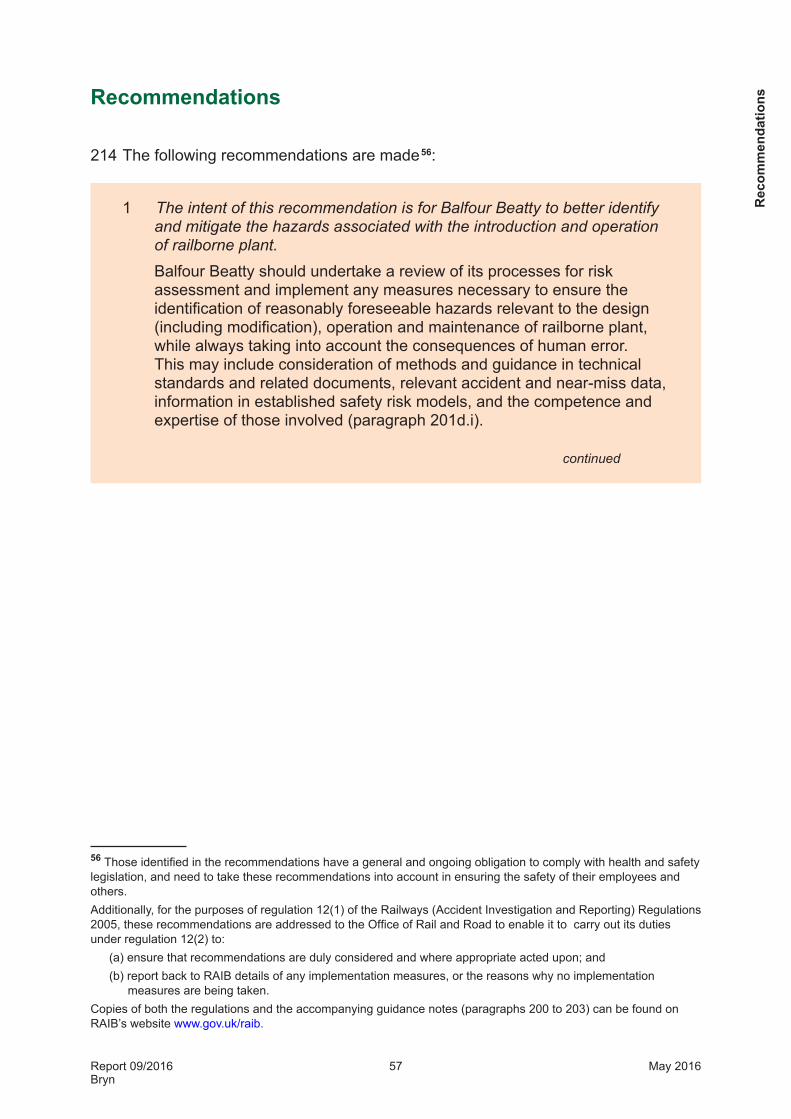
Report 09/2016Bryn
57 May 2016
Recommendations
214 The following recommendations are made 56:
1 The intent of this recommendation is for Balfour Beatty to better identify and mitigate the hazards associated with the introduction and operation of railborne plant.
Balfour Beatty should undertake a review of its processes for risk assessment and implement any measures necessary to ensure the identification of reasonably foreseeable hazards relevant to the design (including modification), operation and maintenance of railborne plant, while always taking into account the consequences of human error. This may include consideration of methods and guidance in technical standards and related documents, relevant accident and near-miss data, information in established safety risk models, and the competence and expertise of those involved (paragraph 201d.i).
continued
56 Those identified in the recommendations have a general and ongoing obligation to comply with health and safety legislation, and need to take these recommendations into account in ensuring the safety of their employees and others. Additionally, for the purposes of regulation 12(1) of the Railways (Accident Investigation and Reporting) Regulations 2005, these recommendations are addressed to the Office of Rail and Road to enable it to carry out its duties under regulation 12(2) to:
(a) ensure that recommendations are duly considered and where appropriate acted upon; and (b) report back to RAIB details of any implementation measures, or the reasons why no implementation
measures are being taken.Copies of both the regulations and the accompanying guidance notes (paragraphs 200 to 203) can be found on RAIB’s website www.gov.uk/raib.
Rec
omm
enda
tions
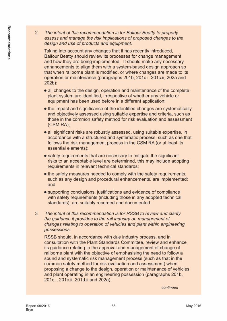
Report 09/2016Bryn
58 May 2016
2 The intent of this recommendation is for Balfour Beatty to properly assess and manage the risk implications of proposed changes to the design and use of products and equipment.
Taking into account any changes that it has recently introduced, Balfour Beatty should review its processes for change management and how they are being implemented. It should make any necessary enhancements to align them with a system-based design approach so that when railborne plant is modified, or where changes are made to its operation or maintenance (paragraphs 201b, 201c.i, 201c.ii, 202a and 202b):l all changes to the design, operation and maintenance of the complete
plant system are identified, irrespective of whether any vehicle or equipment has been used before in a different application;
l the impact and significance of the identified changes are systematically and objectively assessed using suitable expertise and criteria, such as those in the common safety method for risk evaluation and assessment (CSM RA);
l all significant risks are robustly assessed, using suitable expertise, in accordance with a structured and systematic process, such as one that follows the risk management process in the CSM RA (or at least its essential elements);
l safety requirements that are necessary to mitigate the significant risks to an acceptable level are determined, this may include adopting requirements in relevant technical standards;
l the safety measures needed to comply with the safety requirements, such as any design and procedural enhancements, are implemented; and
l supporting conclusions, justifications and evidence of compliance with safety requirements (including those in any adopted technical standards), are suitably recorded and documented.
3 The intent of this recommendation is for RSSB to review and clarify the guidance it provides to the rail industry on management of changes relating to operation of vehicles and plant within engineering possessions.
RSSB should, in accordance with due industry process, and in consultation with the Plant Standards Committee, review and enhance its guidance relating to the approval and management of change of railborne plant with the objective of emphasising the need to follow a sound and systematic risk management process (such as that in the common safety method for risk evaluation and assessment) when proposing a change to the design, operation or maintenance of vehicles and plant operating in an engineering possession (paragraphs 201b, 201c.i, 201c.ii, 201d.ii and 202a).
continued
Recom
mendations

Report 09/2016Bryn
59 May 2016
4 The intent of this recommendation is for the risks associated with new or modified railborne plant to be properly managed before such plant is allowed to operate on the national network.
Taking into account any changes that it has recently introduced, Network Rail should review its processes for product acceptance of new and modified plant, and how they are being implemented, and make any necessary enhancements so that they consistently confirm that (paragraphs 201c.iii and 201d.ii):l associated risks have been robustly assessed using a structured and
systematic process, such as one that follows the risk management process of the common safety method on risk evaluation and assessment (or at least its essential elements);
l the safety requirements necessary to mitigate risks to an acceptable level have been determined, this includes those in adopted technical standards;
l there is evidence that all identified safety requirements have been complied with and that safety measures are in place; and
l that supporting conclusions and justifications have been suitably recorded.
5 The intent of this recommendation is for Balfour Beatty to improve the quality of alterations made to the electrical systems of its equipment.
Balfour Beatty should undertake a review of its procedures for the modification of electrical equipment of railborne plant, and their implementation, and make any changes necessary in order to ensure that work is correctly documented and is carried out in accordance with recognised good practice (paragraph 203).
Rec
omm
enda
tions

Report 09/2016Bryn
60 May 2016
Appendices
Appendix A - Glossary of abbreviations and acronymsCCB Conformance Certification Body
CCTV Closed circuit television
CSM RA Common safety method for risk evaluation and assessment
DSD Driver’s safety device
DTS Dynamic track stabiliser
HAZOP Hazard and operability study
MEWP Mobile elevating work platform
NIR National incident report
NRAP Network Rail Acceptance Panel
OEM Original equipment manufacturer
OLE Overhead line equipment
ORR Office of Rail and Road
OTDR On-train data recorder
PAB Plant acceptance body
PLC Programmable logic controller
RRV Road-rail vehicle
SRP System review panel
TPWS Train protection and warning system
VAB Vehicle Acceptance BodyA
ppendices

Report 09/2016Bryn
61 May 2016
Appendix B - Glossary of termsAll definitions marked with an asterisk, thus (*), have been taken from Ellis’s British Railway Engineering Encyclopaedia © Iain Ellis. www.iainellis.com.
Access unit The part of the wiring train that is used to provide moving and elevated access for catenary installation work. It comprises a Balfour Beatty-owned haulage vehicle (a DTS) and a wagon leased from VTG carrying specialist work access equipment supplied by Geismar. See also figure 5.
Access wagon Container flat wagon leased from VBK carrying specialist work access equipment supplied by Geismar comprising an elevating work platform and basket. See also figure 5.
Accredited agent A member of railway staff trained and appointed by the RAIB to preserve, record and gather perishable evidence pending the arrival of RAIB inspectors.
Assessment body A body appointed by the proposer of a change affecting the railway to carry out an independent assessment of how the risk management process in the CSM RA has been applied, and the results that have been obtained.
Auxiliary air reservoirs
An air tank on each vehicle of a train with a continuous and automatic air brake that stores the compressed air used to apply the brakes on that vehicle.
Brake application solenoid valve
An electrically-operated valve on the DTS that is used to close or vent the brake pipe.
Brake cylinder A pneumatic actuator that is used to convert a supplied air pressure into the force used to apply the friction brakes on a rail vehicle.
Brake distributor valve
The pneumatic component on each vehicle of a train (having a continuous and automatic air brake) that responds to changes in the brake pipe pressure and supplies compressed air to the brake cylinders.
Brake pipe A pressurised air pipe running the length of a train (having a continuous and automatic air brake) that is used to control the brake distributor valves.
Brake pipe feed cut-off solenoid valves
Electrically-operated valves on the DTS that are used to allow or prevent air being fed into the brake pipe.
Catenary system A description given to the complete assembly of tensioned wires that make up the overhead line electrification system.* See also figure 4.
Catenary wire The uppermost wire of the catenary system. See also figure 4.
App
endi
ces

Report 09/2016Bryn
62 May 2016
CE mark A mark showing the manufacturer’s declaration that a product complies with the essential requirements of European health and safety directives.
Common safety method for risk evaluation and assessment
A European regulation intended to regularise risk evaluation and assessment for mainline railways in Europe.
Conformance body A body authorised to review and certificate compliance with technical standards.
Conformance Certification Body
A body that is authorised to issue Certificates of Conformance that declare that, within a specific area of certification (ie by design, as constructed or as planned to be maintained) a rail vehicle complies with relevant mandatory requirements in Railway Group standards.
Contact wire The wire on a catenary system that the pantograph on an electric train contacts in order to collect electrical current. See also figure 4.
Continuous and automatic air brake
A compressed air brake system that operates throughout a train, and which automatically applies the brakes in the event that vehicles unintentionally separate.
Direct brake control valve
A manually-operated pneumatic valve in the DTS cab that the driver can use to directly feed the brake cylinders with compressed air from the main reservoirs.
Down In the direction of Liverpool (on this railway).
Driver’s safety device
A system used to stop the train or locomotive if the driver ceases to respond. Previously commonly referred to as a ‘dead man’s handle’, most examples are pedals that have to be help pressed, and may also incorporate a vigilance monitoring system that requires the pedal to be released and re-pressed in response to an audible warning.
Dynamic track stabiliser
A railborne machine that is used to accelerate the consolidation of recently maintained or re-ballasted track by a combination of vertical load and vibration.*
Engineering Acceptance Certificate
A certificate issued by a Vehicle Acceptance Body that certifies that a vehicle complies with all relevant mandatory requirements in Railway Group standards.
Engineering possession
A section of line (delimited by possession limit boards and detonators) that is blocked for the normal running of trains to allow engineering work to be carried out.
Appendices
Report 09/2016Bryn
63 May 2016
Engineering supervisor
The person nominated to manage the safe execution of work taking place in an engineering worksite within an engineering possession. This includes arranging marker boards (used to indicate the limits of the engineering worksite) and authorising the movements of trains into and within the worksite.
Essential health and safety requirements
Broad objectives for health and safety that are specified in each product safety Directive published by the European Union.
Grandfather rights The waiving of the requirement to comply with the latest technical standard on the grounds that the equipment was in service prior to the introduction of the standard, was compliant with the requirements relevant at the time and/or has demonstrated safe operation over a suitable period of time.
Harmonised standard
A technical standard recognised by the European Union as providing a means of conforming with essential health and safety requirements.
Hazard and operability study
A structured and systematic examination of a planned or existing process or operation, in order to identify and evaluate problems that present risks to personnel or equipment, or prevent efficient operation.
Health and Safety Executive
An enforcing authority responsible for health and safety in Great Britain.
Health and Safety Management System
A formal system or framework to assist in managing health and safety responsibilities.
Indirect brake control valves
A manually-operated pneumatic valve in the DTS cab that the driver uses to control the brake pipe pressure and thereby the pressure of the air fed to the brake cylinders by the brake distributor valves on the DTS and the access and tensioner wagons.
ISO container twist-lock fixings
A rotating connector that is used to secure freight containers on road trailers, rail wagons, ships and other modes of transport. The fixings interface with the special metal castings that are located at each corner of a standard multi-modal freight container.
Light-emitting diodes
A semi-conductor light source.
Linesman A person who installs and maintains overhead electrical power cables and wires.
Machinery Directive
A directive of the European Union that requires that new machinery (of defined type and scope) is designed and constructed to comply with common minimum European safety requirements.
App
endi
ces

Report 09/2016Bryn
64 May 2016
Mandatory requirements
The requirements for rail vehicles that are mandated in the most current Railway Group standards.
Mobile elevating work platform
The generic name given for any wheeled machine designed to provide a safe working platform for one or more operatives and capable of adjusting this height under the control of the operator.*
National incident report
A report following an incident that is circulated to the railway industry giving technical or operating advice.
Network Rail Acceptance Panel
A panel that governs a number of processes that help Network Rail comply with its statutory responsibilities and health and safety management system concerning changes to its infrastructure and the introduction of new and modified vehicles and products.
Normally-closed relay
An electrically-operated switch that prevents the conduction of electricity when it is energised.
Notified body An independent organisation appointed and accredited to assess a product’s conformance with European safety requirements.
On-track machine A piece of specialist railway plant that moves only on the rails and is normally self-propelled.
On-tracking The operation by which an RRV transfers from its road wheels to its rail wheels.
On-train data recorder
Equipment fitted on a rail vehicle that records train speed and the status of various controls and systems relating to its operation.
Overhead line equipment
Wires and associated equipment, located above and adjacent to the railway, for supplying electricity to electric trains.
Overhead line wiring train
A formation of on-track machines that are used to install and tension the wires and fit other components that comprise the catenary system.
Pantograph head The part of the roof-mounted current collection equipment on an electric train that contacts the contact wire of the catenary system. See also figure 4.
Person in charge of the possession
An individual who is certificated as competent to take charge of arrangements associated with an engineering possession.
Plant Acceptance Body
A body with the authority to certificate the conformance of railborne plant and associated equipment in accordance with RIS-1710-PLT, ‘Rail Industry Standard for Engineering Conformance of Railborne Plant’.
Appendices

Report 09/2016Bryn
65 May 2016
Pressure regulation valve
A valve used to limit the air pressure in a pneumatic system.
Programmable logic controller
A digital computer used to control electromechanical systems.
Road-rail vehicle A road vehicle that has been adapted to make it capable of running on railway track as well as on the road.
Running brake test A test where the brakes are applied on a train, shortly after starting out, to check that they retard the train as expected.
Safety requirement A characteristic of a system or its operation that is necessary in order to deliver acceptable risk.
Shuttle valves Type of pneumatic valve that allows air to flow through it from one of two sources.
System review panel
A specialist body delegated by the Network Rail Acceptance Panel to consider specific system and safety compatibility issues.
Systems-based design
A systematic and integrated approach to the identification and management of requirements and interfaces when developing engineering products. The approach recognises products as systems comprising an assembly or collection of individual elements or parts (sub-systems) that need to function in an integrated manner in order to perform a required task. The processes involved include the definition of the system requirements, the structured decomposition of the system into sub-systems, the cascading of the system requirements to the individual sub-systems, the specification of the interfaces between the sub-systems, the development of the individual sub-system technical solutions and the subsequent integration of these to produce the completed system. The processes also include the verification and validation tasks used at each stage to evaluate sub-system and system requirement compliance.
Tamping The operation of lifting the track and simultaneously packing the ballast beneath the sleepers in order to improve the track geometry.
Tamping Machine An engineering vehicle that is used for tamping the track.
Tandem The use of two locomotives (or other haulage vehicles) operating together to haul a train.
Technical file Set of technical documents that demonstrate that an item of machinery complies with the requirements of the Machinery Directive.
Telescopic boom An extendable beam that is used to support the work basket on certain types of mobile elevating work platform.
App
endi
ces

Report 09/2016Bryn
66 May 2016
Tensioner module Specialist cable handling and tensioning equipment supplied by Geismar on a sub-frame with ISO-compatible container fixing points. See also figure 5.
Tensioner unit The part of the wiring train that is used to carry, pay out and tension the catenary and contact wires. It comprises a Balfour Beatty-owned haulage vehicle (a DTS) and a wagon leased from VTG carrying specialist cable handling and tensioning equipment supplied by Geismar. See also figure 5.
Tensioner wagon Container flat wagon leased from VBK carrying specialist cable handling and tensioning equipment supplied by Geismar. See also figure 5.
Tractive effort The force generated by a locomotive (or other haulage vehicle) in order to accelerate.
Train protection and warning system
A system fitted to certain signals which will automatically apply a train’s brakes if it approaches the signal at too high a speed, or fails to stop at it, when it is set at danger. It will also automatically apply a train’s brakes if it is travelling too fast on the approach to certain speed restrictions and buffer stops.
Up In the direction of Wigan (on this railway).
Vehicle Acceptance Body
A body given authority by RSSB to undertake engineering acceptance for rail vehicles.
Vigilance device A separate safety device (pushbutton) that staff additionally need to operate in order to remotely drive the access unit from the access wagon.
Work platform and basket module
Specialist work access equipment supplied by Geismar, comprising an elevating work platform and basket on a sub- frame with ISO-compatible container fixing points. See also figure 5.
West Coast Main Line
The railway route that runs from London Euston to Glasgow, including the lines to Birmingham, Liverpool and Manchester.
Working air valve A pneumatic valve in the DTS working cab that allows air to be supplied to the working brake and the hydraulic drive clutches.
Working brake release solenoid valve
An electrically-operated valve on the DTS that is used to apply and release the working brake.
Appendices

Report 09/2016Bryn
67 May 2016
Appendix C - Investigation detailsThe RAIB used the following sources of evidence in this investigation: l information provided by witnesses;l information from the OTDR on the wiring train;l CCTV recordings from Bryn station;l site photographs and measurements;l results of testing carried out on the vehicles from the wiring train;l information and documents provided by Network Rail, Balfour Beatty, Geismar,
Plasser, Interfleet and the ORR;l technical standards published by the British Standards Institution and RSSB; l documents relating to the Machinery Directive published by the European Union;
andl documents relating to the CSM RA published by the European Union, the ORR and
RSSB.
App
endi
ces

Report 09/2016Bryn
68 May 2016
Appendix D - DTS operator’s manual (extract)
Appendices

Report 09/2016Bryn
69 May 2016
Appendix E - Balfour Beatty setup instruction for the wiring train
App
endi
ces

Report 09/2016Bryn
70 May 2016
Appendices
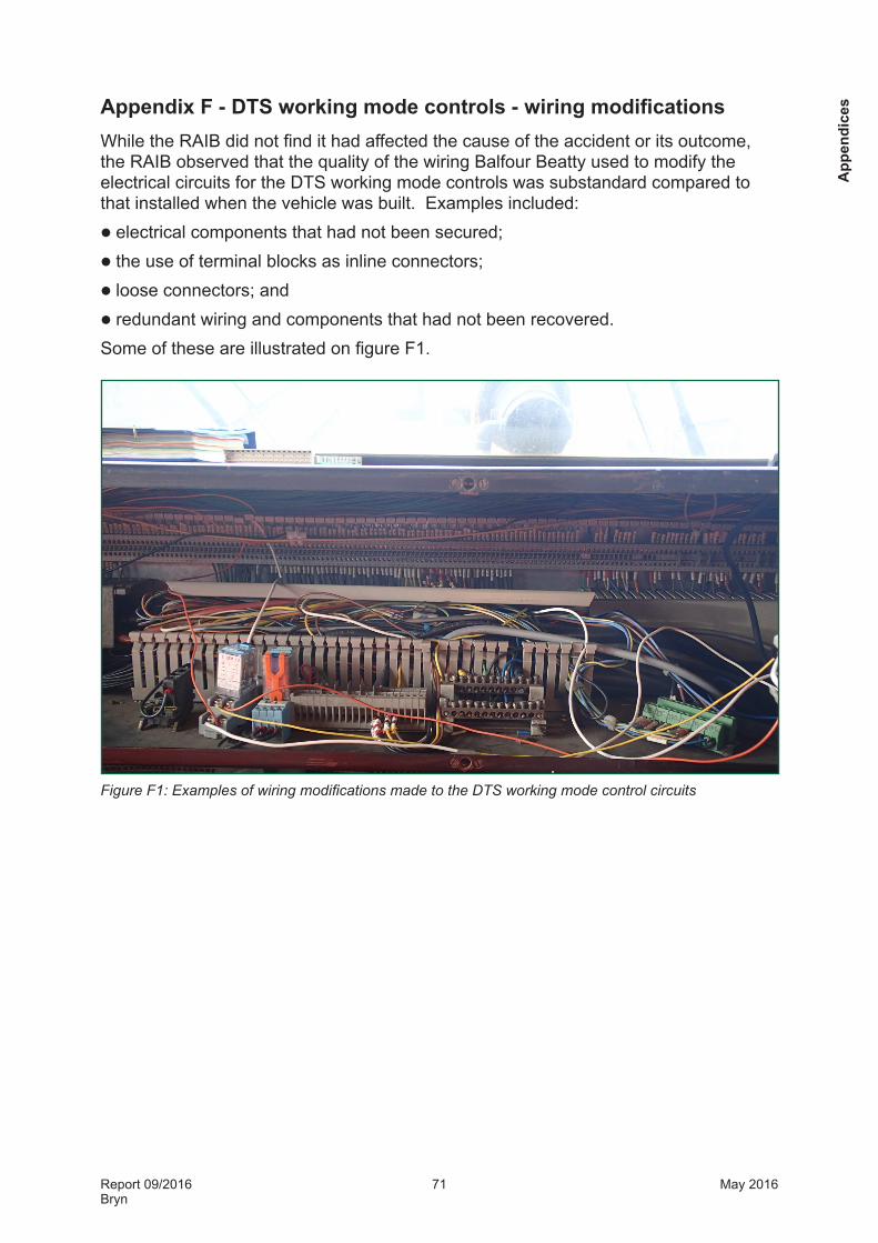
Report 09/2016Bryn
71 May 2016
Appendix F - DTS working mode controls - wiring modifications While the RAIB did not find it had affected the cause of the accident or its outcome, the RAIB observed that the quality of the wiring Balfour Beatty used to modify the electrical circuits for the DTS working mode controls was substandard compared to that installed when the vehicle was built. Examples included:l electrical components that had not been secured;l the use of terminal blocks as inline connectors;l loose connectors; andl redundant wiring and components that had not been recovered. Some of these are illustrated on figure F1.
Figure F1: Examples of wiring modifications made to the DTS working mode control circuits
App
endi
ces

Report 09/2016Bryn
72 May 2016
This page is intentionally left blank

This report is published by the Rail Accident Investigation Branch, Department for Transport.
© Crown copyright 2016
Any enquiries about this publication should be sent to:
RAIB Telephone: 01332 253300The Wharf Fax: 01332 253301Stores Road Email: [email protected] UK Website: www.gov.uk/raibDE21 4BA