R3-1100 Ovation Algorithms Reference Manual - Powergenics
498
10/02 1 R3-1100 (Rev 3) Ovation Algorithms Reference Manual Section Title Page Emerson Process Management Proprietary Class 2C Summary of Changes Section 1. Introduction 1-1. Overview. . . . . . . . . . . . . . . . . . . . . . . . . . . . . . . . . . . . . . . . . . . . . . . . . . . . . . . . . . 1-1 1-2. Contents of this Document . . . . . . . . . . . . . . . . . . . . . . . . . . . . . . . . . . . . . . . . . . . . 1-2 1-3. Additional Reference Documents . . . . . . . . . . . . . . . . . . . . . . . . . . . . . . . . . . . . . . . 1-3 Section 2. General User Information 2-1. Section Overview . . . . . . . . . . . . . . . . . . . . . . . . . . . . . . . . . . . . . . . . . . . . . . . . . . . 2-1 2-2. Hardware Addressing for Algorithms. . . . . . . . . . . . . . . . . . . . . . . . . . . . . . . . . . . . 2-2 2-3. Propagation of Algorithm Point Quality/Track Ramp Rate . . . . . . . . . . . . . . . . . . . 2-3 2-4. Default Algorithm Naming Convention . . . . . . . . . . . . . . . . . . . . . . . . . . . . . . . . . . 2-4 2-5. Tracking Signals for Algorithms . . . . . . . . . . . . . . . . . . . . . . . . . . . . . . . . . . . . . . . 2-6 2-5.1. Purpose of Tracking . . . . . . . . . . . . . . . . . . . . . . . . . . . . . . . . . . . . . . . . . . . 2-6 2-5.2. Tracking Algorithm Summary . . . . . . . . . . . . . . . . . . . . . . . . . . . . . . . . . . . 2-7 2-5.3. Tracking Issues . . . . . . . . . . . . . . . . . . . . . . . . . . . . . . . . . . . . . . . . . . . . . . 2-8 2-5.4. Tracking Approach . . . . . . . . . . . . . . . . . . . . . . . . . . . . . . . . . . . . . . . . . . . 2-9 2-5.5. Tracking Examples . . . . . . . . . . . . . . . . . . . . . . . . . . . . . . . . . . . . . . . . . . 2-10 2-5.6. Blocking Tracking . . . . . . . . . . . . . . . . . . . . . . . . . . . . . . . . . . . . . . . . . . . 2-11 2-6. Setting Tracking Signals for Algorithms . . . . . . . . . . . . . . . . . . . . . . . . . . . . . . . . 2-12 2-7. Setting Algorithm Status and Mode . . . . . . . . . . . . . . . . . . . . . . . . . . . . . . . . . . . . 2-15 2-8. Algorithm Binary to Hexadecimal Conversion . . . . . . . . . . . . . . . . . . . . . . . . . . . 2-16 2-9. Status Checking . . . . . . . . . . . . . . . . . . . . . . . . . . . . . . . . . . . . . . . . . . . . . . . . . . . 2-17 2-9.1. Invalid Number Checking and Quality Checking for Algorithms . . . . . . . 2-17 2-9.2. Error Information Generated by Algorithms . . . . . . . . . . . . . . . . . . . . . . . 2-18 2-10. Algorithm Functions . . . . . . . . . . . . . . . . . . . . . . . . . . . . . . . . . . . . . . . . . . . . . . . . 2-19 Section 3. Algorithms 3-1. Section Overview . . . . . . . . . . . . . . . . . . . . . . . . . . . . . . . . . . . . . . . . . . . . . . . . . . . 3-1 3-2. Algorithm Reference Page Format . . . . . . . . . . . . . . . . . . . . . . . . . . . . . . . . . . . . . . 3-2 3-3. AAFLIPFLOP . . . . . . . . . . . . . . . . . . . . . . . . . . . . . . . . . . . . . . . . . . . . . . . . . . . . . . 3-4 3-4. ABSVALUE . . . . . . . . . . . . . . . . . . . . . . . . . . . . . . . . . . . . . . . . . . . . . . . . . . . . . . . 3-6 3-5. ALARMMON. . . . . . . . . . . . . . . . . . . . . . . . . . . . . . . . . . . . . . . . . . . . . . . . . . . . . . 3-7 3-6. ANALOG DEVICE . . . . . . . . . . . . . . . . . . . . . . . . . . . . . . . . . . . . . . . . . . . . . . . . . 3-9 3-7. ANALOGDRUM . . . . . . . . . . . . . . . . . . . . . . . . . . . . . . . . . . . . . . . . . . . . . . . . . . 3-13 3-8. AND . . . . . . . . . . . . . . . . . . . . . . . . . . . . . . . . . . . . . . . . . . . . . . . . . . . . . . . . . . . . 3-17 3-9. ANNUNCIATOR . . . . . . . . . . . . . . . . . . . . . . . . . . . . . . . . . . . . . . . . . . . . . . . . . . 3-19 3-10. ANTILOG. . . . . . . . . . . . . . . . . . . . . . . . . . . . . . . . . . . . . . . . . . . . . . . . . . . . . . . . 3-21
-
Upload
khangminh22 -
Category
Documents
-
view
0 -
download
0
Transcript of R3-1100 Ovation Algorithms Reference Manual - Powergenics

Ovation Algorithms Reference Manual
Section Title Page
Summary of Changes
Section 1. Introduction
1-1. Overview. . . . . . . . . . . . . . . . . . . . . . . . . . . . . . . . . . . . . . . . . . . . . . . . . . . . . . . . . . 1-11-2. Contents of this Document . . . . . . . . . . . . . . . . . . . . . . . . . . . . . . . . . . . . . . . . . . . . 1-21-3. Additional Reference Documents . . . . . . . . . . . . . . . . . . . . . . . . . . . . . . . . . . . . . . . 1-3
Section 2. General User Information
2-1. Section Overview . . . . . . . . . . . . . . . . . . . . . . . . . . . . . . . . . . . . . . . . . . . . . . . . . . . 2-12-2. Hardware Addressing for Algorithms. . . . . . . . . . . . . . . . . . . . . . . . . . . . . . . . . . . . 2-22-3. Propagation of Algorithm Point Quality/Track Ramp Rate . . . . . . . . . . . . . . . . . . . 2-32-4. Default Algorithm Naming Convention . . . . . . . . . . . . . . . . . . . . . . . . . . . . . . . . . . 2-42-5. Tracking Signals for Algorithms . . . . . . . . . . . . . . . . . . . . . . . . . . . . . . . . . . . . . . . 2-6
2-5.1. Purpose of Tracking. . . . . . . . . . . . . . . . . . . . . . . . . . . . . . . . . . . . . . . . . . . 2-62-5.2. Tracking Algorithm Summary. . . . . . . . . . . . . . . . . . . . . . . . . . . . . . . . . . . 2-72-5.3. Tracking Issues . . . . . . . . . . . . . . . . . . . . . . . . . . . . . . . . . . . . . . . . . . . . . . 2-82-5.4. Tracking Approach . . . . . . . . . . . . . . . . . . . . . . . . . . . . . . . . . . . . . . . . . . . 2-92-5.5. Tracking Examples . . . . . . . . . . . . . . . . . . . . . . . . . . . . . . . . . . . . . . . . . . 2-102-5.6. Blocking Tracking . . . . . . . . . . . . . . . . . . . . . . . . . . . . . . . . . . . . . . . . . . . 2-11
2-6. Setting Tracking Signals for Algorithms . . . . . . . . . . . . . . . . . . . . . . . . . . . . . . . . 2-122-7. Setting Algorithm Status and Mode . . . . . . . . . . . . . . . . . . . . . . . . . . . . . . . . . . . . 2-152-8. Algorithm Binary to Hexadecimal Conversion . . . . . . . . . . . . . . . . . . . . . . . . . . . 2-162-9. Status Checking . . . . . . . . . . . . . . . . . . . . . . . . . . . . . . . . . . . . . . . . . . . . . . . . . . . 2-17
2-9.1. Invalid Number Checking and Quality Checking for Algorithms. . . . . . . 2-172-9.2. Error Information Generated by Algorithms . . . . . . . . . . . . . . . . . . . . . . . 2-18
2-10. Algorithm Functions . . . . . . . . . . . . . . . . . . . . . . . . . . . . . . . . . . . . . . . . . . . . . . . . 2-19
Section 3. Algorithms
3-1. Section Overview . . . . . . . . . . . . . . . . . . . . . . . . . . . . . . . . . . . . . . . . . . . . . . . . . . . 3-13-2. Algorithm Reference Page Format . . . . . . . . . . . . . . . . . . . . . . . . . . . . . . . . . . . . . . 3-23-3. AAFLIPFLOP. . . . . . . . . . . . . . . . . . . . . . . . . . . . . . . . . . . . . . . . . . . . . . . . . . . . . . 3-43-4. ABSVALUE . . . . . . . . . . . . . . . . . . . . . . . . . . . . . . . . . . . . . . . . . . . . . . . . . . . . . . . 3-63-5. ALARMMON. . . . . . . . . . . . . . . . . . . . . . . . . . . . . . . . . . . . . . . . . . . . . . . . . . . . . . 3-73-6. ANALOG DEVICE . . . . . . . . . . . . . . . . . . . . . . . . . . . . . . . . . . . . . . . . . . . . . . . . . 3-93-7. ANALOGDRUM . . . . . . . . . . . . . . . . . . . . . . . . . . . . . . . . . . . . . . . . . . . . . . . . . . 3-133-8. AND . . . . . . . . . . . . . . . . . . . . . . . . . . . . . . . . . . . . . . . . . . . . . . . . . . . . . . . . . . . . 3-173-9. ANNUNCIATOR . . . . . . . . . . . . . . . . . . . . . . . . . . . . . . . . . . . . . . . . . . . . . . . . . . 3-193-10. ANTILOG. . . . . . . . . . . . . . . . . . . . . . . . . . . . . . . . . . . . . . . . . . . . . . . . . . . . . . . . 3-21
10/02 1 R3-1100 (Rev 3)Emerson Process Management Proprietary Class 2C

Table of Contents, Cont’d
Section Title Page
Section 3. Algorithms (Cont’d)
3-11. ARCCOSINE . . . . . . . . . . . . . . . . . . . . . . . . . . . . . . . . . . . . . . . . . . . . . . . . . . . . . 3-233-12. ARCSINE . . . . . . . . . . . . . . . . . . . . . . . . . . . . . . . . . . . . . . . . . . . . . . . . . . . . . . . . 3-243-13. ARCTANGENT . . . . . . . . . . . . . . . . . . . . . . . . . . . . . . . . . . . . . . . . . . . . . . . . . . . 3-253-14. ASSIGN . . . . . . . . . . . . . . . . . . . . . . . . . . . . . . . . . . . . . . . . . . . . . . . . . . . . . . . . . 3-263-15. ATREND . . . . . . . . . . . . . . . . . . . . . . . . . . . . . . . . . . . . . . . . . . . . . . . . . . . . . . . . 3-273-16. AVALGEN . . . . . . . . . . . . . . . . . . . . . . . . . . . . . . . . . . . . . . . . . . . . . . . . . . . . . . . 3-293-17. BALANCER. . . . . . . . . . . . . . . . . . . . . . . . . . . . . . . . . . . . . . . . . . . . . . . . . . . . . . 3-303-18. BCDNIN . . . . . . . . . . . . . . . . . . . . . . . . . . . . . . . . . . . . . . . . . . . . . . . . . . . . . . . . . 3-363-19. BCDNOUT . . . . . . . . . . . . . . . . . . . . . . . . . . . . . . . . . . . . . . . . . . . . . . . . . . . . . . . 3-393-20. BILLFLOW . . . . . . . . . . . . . . . . . . . . . . . . . . . . . . . . . . . . . . . . . . . . . . . . . . . . . . 3-423-21. CALCBLOCK . . . . . . . . . . . . . . . . . . . . . . . . . . . . . . . . . . . . . . . . . . . . . . . . . . . . 3-443-22. CALCBLOCKD . . . . . . . . . . . . . . . . . . . . . . . . . . . . . . . . . . . . . . . . . . . . . . . . . . . 3-543-23. COMPARE . . . . . . . . . . . . . . . . . . . . . . . . . . . . . . . . . . . . . . . . . . . . . . . . . . . . . . . 3-613-24. COSINE . . . . . . . . . . . . . . . . . . . . . . . . . . . . . . . . . . . . . . . . . . . . . . . . . . . . . . . . . 3-633-25. COUNTER . . . . . . . . . . . . . . . . . . . . . . . . . . . . . . . . . . . . . . . . . . . . . . . . . . . . . . . 3-643-26. DBEQUALS . . . . . . . . . . . . . . . . . . . . . . . . . . . . . . . . . . . . . . . . . . . . . . . . . . . . . . 3-673-27. DEVICESEQ . . . . . . . . . . . . . . . . . . . . . . . . . . . . . . . . . . . . . . . . . . . . . . . . . . . . . 3-693-28. DEVICEX. . . . . . . . . . . . . . . . . . . . . . . . . . . . . . . . . . . . . . . . . . . . . . . . . . . . . . . . 3-74
3-28.1. Signal Combinations . . . . . . . . . . . . . . . . . . . . . . . . . . . . . . . . . . . . . . . . . 3-743-28.2. Control Operation . . . . . . . . . . . . . . . . . . . . . . . . . . . . . . . . . . . . . . . . . . . 3-793-28.3. Control Modes . . . . . . . . . . . . . . . . . . . . . . . . . . . . . . . . . . . . . . . . . . . . . . 3-803-28.4. Mode Independent Commands . . . . . . . . . . . . . . . . . . . . . . . . . . . . . . . . . 3-843-28.5. Alarming . . . . . . . . . . . . . . . . . . . . . . . . . . . . . . . . . . . . . . . . . . . . . . . . . . 3-873-28.6. Device Status Reporting . . . . . . . . . . . . . . . . . . . . . . . . . . . . . . . . . . . . . . 3-903-28.7. Setting Device Parameters . . . . . . . . . . . . . . . . . . . . . . . . . . . . . . . . . . . . . 3-92
3-29. DIGCOUNT . . . . . . . . . . . . . . . . . . . . . . . . . . . . . . . . . . . . . . . . . . . . . . . . . . . . . . 3-983-30. DIGDRUM . . . . . . . . . . . . . . . . . . . . . . . . . . . . . . . . . . . . . . . . . . . . . . . . . . . . . . 3-1003-31. DIGITAL DEVICE. . . . . . . . . . . . . . . . . . . . . . . . . . . . . . . . . . . . . . . . . . . . . . . . 3-106
3-31.1. SAMPLER (Controlled Sampler) . . . . . . . . . . . . . . . . . . . . . . . . . . . . . . 3-1083-31.2. VALVE NC (Non-Controlled Valve) . . . . . . . . . . . . . . . . . . . . . . . . . . . 3-1103-31.3. MOTOR NC (Non-Controlled Motor). . . . . . . . . . . . . . . . . . . . . . . . . . . 3-1113-31.4. MOTOR (Simple Controlled Motor) . . . . . . . . . . . . . . . . . . . . . . . . . . . . 3-1133-31.5. MOTOR 2-SPD (Two-Speed or Bi-Directional Controlled Motor) . . . . 3-1163-31.6. MOTOR 4-SPD (Two-Speed and Bi-Directional Controlled Motor) . . . 3-1203-31.7. VALVE (Controlled Valve). . . . . . . . . . . . . . . . . . . . . . . . . . . . . . . . . . . 3-125
3-32. DIVIDE. . . . . . . . . . . . . . . . . . . . . . . . . . . . . . . . . . . . . . . . . . . . . . . . . . . . . . . . . 3-1283-33. DROPSTATUS. . . . . . . . . . . . . . . . . . . . . . . . . . . . . . . . . . . . . . . . . . . . . . . . . . . 3-1323-34. DRPI . . . . . . . . . . . . . . . . . . . . . . . . . . . . . . . . . . . . . . . . . . . . . . . . . . . . . . . . . . . 3-1343-35. DVALGEN . . . . . . . . . . . . . . . . . . . . . . . . . . . . . . . . . . . . . . . . . . . . . . . . . . . . . . 3-1363-36. FIELD . . . . . . . . . . . . . . . . . . . . . . . . . . . . . . . . . . . . . . . . . . . . . . . . . . . . . . . . . . 3-1373-37. FIFO . . . . . . . . . . . . . . . . . . . . . . . . . . . . . . . . . . . . . . . . . . . . . . . . . . . . . . . . . . . 3-139
R3-1100 (Rev 3) 2 10/02Emerson Process Management Proprietary Class 2C

Table of Contents, Cont’d
Section Title Page
Section 3. Algorithms (Cont’d)
3-38. FLIPFLOP . . . . . . . . . . . . . . . . . . . . . . . . . . . . . . . . . . . . . . . . . . . . . . . . . . . . . . 3-1423-39. FUNCTION . . . . . . . . . . . . . . . . . . . . . . . . . . . . . . . . . . . . . . . . . . . . . . . . . . . . . 3-1443-40. GAINBIAS . . . . . . . . . . . . . . . . . . . . . . . . . . . . . . . . . . . . . . . . . . . . . . . . . . . . . . 3-1493-41. GASFLOW . . . . . . . . . . . . . . . . . . . . . . . . . . . . . . . . . . . . . . . . . . . . . . . . . . . . . . 3-1533-42. HIGHLOWMON . . . . . . . . . . . . . . . . . . . . . . . . . . . . . . . . . . . . . . . . . . . . . . . . . 3-1593-43. HIGHMON . . . . . . . . . . . . . . . . . . . . . . . . . . . . . . . . . . . . . . . . . . . . . . . . . . . . . . 3-1613-44. HISELECT . . . . . . . . . . . . . . . . . . . . . . . . . . . . . . . . . . . . . . . . . . . . . . . . . . . . . . 3-1623-45. HSCLTP . . . . . . . . . . . . . . . . . . . . . . . . . . . . . . . . . . . . . . . . . . . . . . . . . . . . . . . . 3-1673-46. HSLT. . . . . . . . . . . . . . . . . . . . . . . . . . . . . . . . . . . . . . . . . . . . . . . . . . . . . . . . . . . 3-1683-47. HSTVSVP. . . . . . . . . . . . . . . . . . . . . . . . . . . . . . . . . . . . . . . . . . . . . . . . . . . . . . . 3-1693-48. HSVSSTP . . . . . . . . . . . . . . . . . . . . . . . . . . . . . . . . . . . . . . . . . . . . . . . . . . . . . . . 3-1703-49. INTERP. . . . . . . . . . . . . . . . . . . . . . . . . . . . . . . . . . . . . . . . . . . . . . . . . . . . . . . . . 3-1713-50. KEYBOARD . . . . . . . . . . . . . . . . . . . . . . . . . . . . . . . . . . . . . . . . . . . . . . . . . . . . 3-1753-51. LATCHQUAL . . . . . . . . . . . . . . . . . . . . . . . . . . . . . . . . . . . . . . . . . . . . . . . . . . . 3-1783-52. LEADLAG . . . . . . . . . . . . . . . . . . . . . . . . . . . . . . . . . . . . . . . . . . . . . . . . . . . . . . 3-1803-53. LEVELCOMP. . . . . . . . . . . . . . . . . . . . . . . . . . . . . . . . . . . . . . . . . . . . . . . . . . . . 3-1843-54. LOG . . . . . . . . . . . . . . . . . . . . . . . . . . . . . . . . . . . . . . . . . . . . . . . . . . . . . . . . . . . 3-1883-55. LOSELECT. . . . . . . . . . . . . . . . . . . . . . . . . . . . . . . . . . . . . . . . . . . . . . . . . . . . . . 3-1903-56. LOWMON . . . . . . . . . . . . . . . . . . . . . . . . . . . . . . . . . . . . . . . . . . . . . . . . . . . . . . 3-1953-57. MAMODE . . . . . . . . . . . . . . . . . . . . . . . . . . . . . . . . . . . . . . . . . . . . . . . . . . . . . . 3-1963-58. MASTATION. . . . . . . . . . . . . . . . . . . . . . . . . . . . . . . . . . . . . . . . . . . . . . . . . . . . 3-1983-59. MASTERSEQ. . . . . . . . . . . . . . . . . . . . . . . . . . . . . . . . . . . . . . . . . . . . . . . . . . . . 3-2083-60. MEDIANSEL . . . . . . . . . . . . . . . . . . . . . . . . . . . . . . . . . . . . . . . . . . . . . . . . . . . . 3-2193-61. MULTIPLY . . . . . . . . . . . . . . . . . . . . . . . . . . . . . . . . . . . . . . . . . . . . . . . . . . . . . 3-2273-62. NLOG . . . . . . . . . . . . . . . . . . . . . . . . . . . . . . . . . . . . . . . . . . . . . . . . . . . . . . . . . . 3-2313-63. NOT . . . . . . . . . . . . . . . . . . . . . . . . . . . . . . . . . . . . . . . . . . . . . . . . . . . . . . . . . . . 3-2333-64. OFFDELAY . . . . . . . . . . . . . . . . . . . . . . . . . . . . . . . . . . . . . . . . . . . . . . . . . . . . . 3-2343-65. ONDELAY . . . . . . . . . . . . . . . . . . . . . . . . . . . . . . . . . . . . . . . . . . . . . . . . . . . . . . 3-2373-66. ONESHOT . . . . . . . . . . . . . . . . . . . . . . . . . . . . . . . . . . . . . . . . . . . . . . . . . . . . . . 3-2403-67. OR. . . . . . . . . . . . . . . . . . . . . . . . . . . . . . . . . . . . . . . . . . . . . . . . . . . . . . . . . . . . . 3-2433-68. PACK16 . . . . . . . . . . . . . . . . . . . . . . . . . . . . . . . . . . . . . . . . . . . . . . . . . . . . . . . . 3-2453-69. PID . . . . . . . . . . . . . . . . . . . . . . . . . . . . . . . . . . . . . . . . . . . . . . . . . . . . . . . . . . . . 3-2473-70. PIDFF . . . . . . . . . . . . . . . . . . . . . . . . . . . . . . . . . . . . . . . . . . . . . . . . . . . . . . . . . . 3-2573-71. PNTSTATUS . . . . . . . . . . . . . . . . . . . . . . . . . . . . . . . . . . . . . . . . . . . . . . . . . . . . 3-2693-72. POLYNOMIAL . . . . . . . . . . . . . . . . . . . . . . . . . . . . . . . . . . . . . . . . . . . . . . . . . . 3-2713-73. PREDICTOR . . . . . . . . . . . . . . . . . . . . . . . . . . . . . . . . . . . . . . . . . . . . . . . . . . . . 3-2733-74. PSLT . . . . . . . . . . . . . . . . . . . . . . . . . . . . . . . . . . . . . . . . . . . . . . . . . . . . . . . . . . . 3-2783-75. PSVS. . . . . . . . . . . . . . . . . . . . . . . . . . . . . . . . . . . . . . . . . . . . . . . . . . . . . . . . . . . 3-2793-76. PULSECNT . . . . . . . . . . . . . . . . . . . . . . . . . . . . . . . . . . . . . . . . . . . . . . . . . . . . . 3-2803-77. QAVERAGE. . . . . . . . . . . . . . . . . . . . . . . . . . . . . . . . . . . . . . . . . . . . . . . . . . . . . 3-2813-78. QUALITYMON . . . . . . . . . . . . . . . . . . . . . . . . . . . . . . . . . . . . . . . . . . . . . . . . . . 3-283
10/02 3 R3-1100 (Rev 3)Emerson Process Management Proprietary Class 2C

Table of Contents, Cont’d
Section Title Page
Section 3. Algorithms (Cont’d)
3-79. RATECHANGE . . . . . . . . . . . . . . . . . . . . . . . . . . . . . . . . . . . . . . . . . . . . . . . . . . 3-2853-80. RATELIMIT. . . . . . . . . . . . . . . . . . . . . . . . . . . . . . . . . . . . . . . . . . . . . . . . . . . . . 3-2873-81. RATEMON. . . . . . . . . . . . . . . . . . . . . . . . . . . . . . . . . . . . . . . . . . . . . . . . . . . . . . 3-2893-82. RESETSUM . . . . . . . . . . . . . . . . . . . . . . . . . . . . . . . . . . . . . . . . . . . . . . . . . . . . . 3-2913-83. RPACNT. . . . . . . . . . . . . . . . . . . . . . . . . . . . . . . . . . . . . . . . . . . . . . . . . . . . . . . . 3-2943-84. RPAWIDTH . . . . . . . . . . . . . . . . . . . . . . . . . . . . . . . . . . . . . . . . . . . . . . . . . . . . . 3-2963-85. RUNAVERAGE. . . . . . . . . . . . . . . . . . . . . . . . . . . . . . . . . . . . . . . . . . . . . . . . . . 3-2973-86. RVPSTATUS . . . . . . . . . . . . . . . . . . . . . . . . . . . . . . . . . . . . . . . . . . . . . . . . . . . . 3-2993-87. SATOSP . . . . . . . . . . . . . . . . . . . . . . . . . . . . . . . . . . . . . . . . . . . . . . . . . . . . . . . . 3-3033-88. SELECTOR . . . . . . . . . . . . . . . . . . . . . . . . . . . . . . . . . . . . . . . . . . . . . . . . . . . . . 3-3043-89. SETPOINT . . . . . . . . . . . . . . . . . . . . . . . . . . . . . . . . . . . . . . . . . . . . . . . . . . . . . . 3-3063-90. SINE . . . . . . . . . . . . . . . . . . . . . . . . . . . . . . . . . . . . . . . . . . . . . . . . . . . . . . . . . . . 3-3103-91. SLCAIN . . . . . . . . . . . . . . . . . . . . . . . . . . . . . . . . . . . . . . . . . . . . . . . . . . . . . . . . 3-3113-92. SLCAOUT . . . . . . . . . . . . . . . . . . . . . . . . . . . . . . . . . . . . . . . . . . . . . . . . . . . . . . 3-3153-93. SLCDIN . . . . . . . . . . . . . . . . . . . . . . . . . . . . . . . . . . . . . . . . . . . . . . . . . . . . . . . . 3-3193-94. SLCDOUT . . . . . . . . . . . . . . . . . . . . . . . . . . . . . . . . . . . . . . . . . . . . . . . . . . . . . . 3-3233-95. SLCPIN. . . . . . . . . . . . . . . . . . . . . . . . . . . . . . . . . . . . . . . . . . . . . . . . . . . . . . . . . 3-3273-96. SLCPOUT. . . . . . . . . . . . . . . . . . . . . . . . . . . . . . . . . . . . . . . . . . . . . . . . . . . . . . . 3-3303-97. SLCSTATUS . . . . . . . . . . . . . . . . . . . . . . . . . . . . . . . . . . . . . . . . . . . . . . . . . . . . 3-3343-98. SMOOTH . . . . . . . . . . . . . . . . . . . . . . . . . . . . . . . . . . . . . . . . . . . . . . . . . . . . . . . 3-3393-99. SPTOSA . . . . . . . . . . . . . . . . . . . . . . . . . . . . . . . . . . . . . . . . . . . . . . . . . . . . . . . . 3-3413-100. SQUAREROOT . . . . . . . . . . . . . . . . . . . . . . . . . . . . . . . . . . . . . . . . . . . . . . . . . . 3-3423-101. SSLT . . . . . . . . . . . . . . . . . . . . . . . . . . . . . . . . . . . . . . . . . . . . . . . . . . . . . . . . . . . 3-3453-102. STEAMFLOW . . . . . . . . . . . . . . . . . . . . . . . . . . . . . . . . . . . . . . . . . . . . . . . . . . . 3-3463-103. STEAMTABLE . . . . . . . . . . . . . . . . . . . . . . . . . . . . . . . . . . . . . . . . . . . . . . . . . . 3-3483-104. STEPTIME . . . . . . . . . . . . . . . . . . . . . . . . . . . . . . . . . . . . . . . . . . . . . . . . . . . . . . 3-3523-105. SUM . . . . . . . . . . . . . . . . . . . . . . . . . . . . . . . . . . . . . . . . . . . . . . . . . . . . . . . . . . . 3-3583-106. SYSTEMTIME. . . . . . . . . . . . . . . . . . . . . . . . . . . . . . . . . . . . . . . . . . . . . . . . . . . 3-3623-107. TANGENT . . . . . . . . . . . . . . . . . . . . . . . . . . . . . . . . . . . . . . . . . . . . . . . . . . . . . . 3-3643-108. TIMECHANGE . . . . . . . . . . . . . . . . . . . . . . . . . . . . . . . . . . . . . . . . . . . . . . . . . . 3-3663-109. TIMEDETECT . . . . . . . . . . . . . . . . . . . . . . . . . . . . . . . . . . . . . . . . . . . . . . . . . . . 3-3673-110. TIMEMON . . . . . . . . . . . . . . . . . . . . . . . . . . . . . . . . . . . . . . . . . . . . . . . . . . . . . . 3-3693-111. TRANSFER . . . . . . . . . . . . . . . . . . . . . . . . . . . . . . . . . . . . . . . . . . . . . . . . . . . . . 3-3723-112. TRANSLATOR . . . . . . . . . . . . . . . . . . . . . . . . . . . . . . . . . . . . . . . . . . . . . . . . . . 3-3763-113. TRANSPORT . . . . . . . . . . . . . . . . . . . . . . . . . . . . . . . . . . . . . . . . . . . . . . . . . . . . 3-3813-114. TRNSFNDX . . . . . . . . . . . . . . . . . . . . . . . . . . . . . . . . . . . . . . . . . . . . . . . . . . . . . 3-3833-115. TSLH. . . . . . . . . . . . . . . . . . . . . . . . . . . . . . . . . . . . . . . . . . . . . . . . . . . . . . . . . . . 3-3863-116. TSLP . . . . . . . . . . . . . . . . . . . . . . . . . . . . . . . . . . . . . . . . . . . . . . . . . . . . . . . . . . . 3-3873-117. UNPACK16 . . . . . . . . . . . . . . . . . . . . . . . . . . . . . . . . . . . . . . . . . . . . . . . . . . . . . 3-3883-118. VCLTP . . . . . . . . . . . . . . . . . . . . . . . . . . . . . . . . . . . . . . . . . . . . . . . . . . . . . . . . . 3-3903-119. VSLT. . . . . . . . . . . . . . . . . . . . . . . . . . . . . . . . . . . . . . . . . . . . . . . . . . . . . . . . . . . 3-391
R3-1100 (Rev 3) 4 10/02Emerson Process Management Proprietary Class 2C

Table of Contents, Cont’d
Section Title Page
Section 3. Algorithms (Cont’d)
3-120. XOR . . . . . . . . . . . . . . . . . . . . . . . . . . . . . . . . . . . . . . . . . . . . . . . . . . . . . . . . . . . 3-3923-121. X3STEP . . . . . . . . . . . . . . . . . . . . . . . . . . . . . . . . . . . . . . . . . . . . . . . . . . . . . . . . 3-3933-122. 2XSELECT. . . . . . . . . . . . . . . . . . . . . . . . . . . . . . . . . . . . . . . . . . . . . . . . . . . . . . 3-402
Section 4. Q-Line Algorithms
4-1. Section Overview . . . . . . . . . . . . . . . . . . . . . . . . . . . . . . . . . . . . . . . . . . . . . . . . . . . 4-14-2. Reference Pages . . . . . . . . . . . . . . . . . . . . . . . . . . . . . . . . . . . . . . . . . . . . . . . . . . . . 4-14-3. QPACMD . . . . . . . . . . . . . . . . . . . . . . . . . . . . . . . . . . . . . . . . . . . . . . . . . . . . . . . . . 4-24-4. QPACMPAR . . . . . . . . . . . . . . . . . . . . . . . . . . . . . . . . . . . . . . . . . . . . . . . . . . . . . . 4-94-5. QPASTAT. . . . . . . . . . . . . . . . . . . . . . . . . . . . . . . . . . . . . . . . . . . . . . . . . . . . . . . . 4-114-6. QSDDEMAND. . . . . . . . . . . . . . . . . . . . . . . . . . . . . . . . . . . . . . . . . . . . . . . . . . . . 4-124-7. QSDMODE. . . . . . . . . . . . . . . . . . . . . . . . . . . . . . . . . . . . . . . . . . . . . . . . . . . . . . . 4-144-8. QSRMA . . . . . . . . . . . . . . . . . . . . . . . . . . . . . . . . . . . . . . . . . . . . . . . . . . . . . . . . . 4-154-9. QVP. . . . . . . . . . . . . . . . . . . . . . . . . . . . . . . . . . . . . . . . . . . . . . . . . . . . . . . . . . . . . 4-224-10. XMA2 . . . . . . . . . . . . . . . . . . . . . . . . . . . . . . . . . . . . . . . . . . . . . . . . . . . . . . . . . . . 4-254-11. XML2 . . . . . . . . . . . . . . . . . . . . . . . . . . . . . . . . . . . . . . . . . . . . . . . . . . . . . . . . . . . 4-37
Appendix A. Migrated Special Functions
A-1. Section Overview . . . . . . . . . . . . . . . . . . . . . . . . . . . . . . . . . . . . . . . . . . . . . . . . . . A-1A-2. WPDF Special Functions to Ovation Algorithms. . . . . . . . . . . . . . . . . . . . . . . . . . A-2
Glossary
Index
10/02 5 R3-1100 (Rev 3)Emerson Process Management Proprietary Class 2C


10/02 Changes-1 R3-1100 (Rev 3)Emerson Process Management Proprietary Class 2C
Summary of Changes
This revision of “Ovation Algorithms Reference Manual” (R3-1100) has beenreformatted and updated. The following new algorithm was added:
• DEVICEX (see Section 3).
All sections include additional miscellaneous corrections and clarifications.


Section 1. Introduction
1-1. Overview
Algorithms are sets of rules, procedures, or mathematical formulas that define a
desired control or calculation strategy. They are typically provided with a
Controller, and then specified algorithms are applied during the system scan.
The Ovation®
algorithms are used to implement a wide range of functionality on a
Controller, from simple mathematical operations, to quality checking, to complex
control algorithms.
10/02 1-1 R3-1100 (Rev 3)Emerson Process Management Proprietary Class 2C

1-2. Contents of this Document
1-2. Contents of this Document
This document is organized into the following sections:
• Section 1. Introduction describes the contents of the document.
• Section 2. General User Information describes the background and the
routines used to implement both tracking and non-tracking algorithms.
• Section 3. Algorithms describes tracking algorithms and includes reference
pages with details on each algorithm.
• Section 4. Q-Line Algorithms describes algorithms which are to be used to
interface with Q-line I/O and includes reference pages with details on each
algorithm.
• Appendix A. Migrated Special Functions is applicable for systems that have
migrated control and databases from a WDPF system to an Ovation system. It
provides an overview of the Special Functions names and parameter interface.
R3-1100 (Rev 3) 1-2 10/02Emerson Process Management Proprietary Class 2C

1-3. Additional Reference Documents
1-3. Additional Reference Documents
Additional reference documents that will be helpful to the algorithm user are listed
in Table 1-1.
Table 1-1. Reference Documents
DocumentNumber Title Description
M0-0053 Q-Line Installation Manual Provides information on QPA card
applications.
NT-0020 Ovation Operator Station User
Guide (for use with NT systems)
Describes the use of the Ovation Operator
Station drop.
NT-0060 Ovation Developer Studio User
Guide (for use with NT systems)
Provides information on drop
configuration, system hierarchy, creating
points, and security.
NT-0080 Ovation Control Builder User
Guide (for use with NT systems)
Provides information on the Control
Builder which is used to create the logic
that runs in the Ovation Controller.
R3-1150 Ovation I/O Reference Manual Describes the Ovation cards and their
installation.
R3-1140 Ovation Record Types User
Guide
Lists all point record types and includes
details on the Algorithms record types:
LC.
R3-1105 Using the Ovation Init and
Admin Tools
Describes configuring the Ovation
(Solaris) System.
U0-0106 Standard Control Algorithms
User Guide
Provides information on the WDPF
algorithms which are used to implement a
wide range of functionality on a DPU.
U0-1100 QLC User Guide Provides information on QLC switch
settings.
U0-1125 QVP Servo Controller User
Guide
Describes the use of the QVP card and
algorithm.
U3-1021 Ovation Link Controller User
Guide
Provides information on Link Controller
Configuration settings.
U3-1031 Ovation Operator Station User
Guide (for use with Solaris
systems)
Describes the use of the Ovation Operator
Station drop.
10/02 1-3 R3-1100 (Rev 3)Emerson Process Management Proprietary Class 2C

1-3. Additional Reference Documents
U3-1040 Ovation Control Builder User
Guide (for use with Solaris
systems)
Describes using Control Builder to
perform the various up-load and down-
load procedures for implementing
algorithms.
WIN20 Ovation Operator Station User
Guide (for use with Windows
2000 systems)
Describes the use of the Ovation Operator
Station drop.
WIN60 Ovation Developer Studio User
Guide (for use with Windows
2000 systems)
Provides information on drop
configuration, system hierarchy, creating
points, and security.
WIN80 Ovation Control Builder User
Guide (for use with Windows
2000 systems)
Provides information on the Control
Builder which is used to create the logic
that runs in the Ovation Controller.
Table 1-1. Reference Documents (Cont’d)
DocumentNumber Title Description
R3-1100 (Rev 3) 1-4 10/02Emerson Process Management Proprietary Class 2C

Section 2. General User Information
2-1. Section Overview
This section describes the basic use of algorithms:
• Hardware Addressing for Algorithms (Section 2-2).
• Results of various algorithm operations on point quality and setting track ramp
rate (Section 2-3).
• Interpreting the names of algorithms that have been automatically generated
(Section 2-4).
• Purpose, rules, and directions for tracking signals for algorithms (Section 2-5).
• Setting and using digital tracking signals for algorithms (Section 2-6).
• Digital signals and the actions involved in setting algorithm status (Section 2-7).
• Converting algorithm binary values to hexadecimal (Section 2-8).
• How algorithms check for invalid numbers and status (Section 2-9).
• Possible algorithm names and functions (Section 2-10).
Note
For information on Ladders, see “Ovation Control
Builder User Guide” (NT-0080), (U3-1040), or
(WIN80).
10/02 2-1 R3-1100 (Rev 3)Emerson Process Management Proprietary Class 2C

2-2. Hardware Addressing for Algorithms
2-2. Hardware Addressing for Algorithms
Addressing initialized in the algorithms is either for Ovation cards or
Q-line cards.
For a point that is read from or written to an I/O card, the hardware address
parameter indicates the offset from where the pertinent I/O register resides.
• For Q-line, the hardware address is equal to the address directly jumpered on
the card plus the offset into the proper channel number (no doubling required).
• For Ovation, the I/O Builder determines the hardware address for the modules.
Some algorithms require that a hardware address be entered into the hardware
address field. For example, for a MASTATION algorithm, use the following
method to determine the hardware address:
1. Access the Point Information window to view the module record.
2. Select the Hardware tab.
3. Note the hex representation of the hardware address for the module in the
“HD” field.
4. The algorithm requires the base address, so take the “D” in the base address
and convert it to a zero.
5. Enter that value into the algorithm’s hardware address field.
For example, if a Loop Interface module record’s HD field is “0x9D,” then
“0x90” is entered in the MASTATION’S hardware address field.
R3-1100 (Rev 3) 2-2 10/02Emerson Process Management Proprietary Class 2C

2-3. Propagation of Algorithm Point Quality/Track Ramp Rate
2-3. Propagation of Algorithm Point Quality/TrackRamp Rate
Propagation of Point Quality
Process points may have one of the following quality values, assigned by the user
or the system:
• GOOD = Point is functioning properly.
• FAIR = Typically an entered value.
• POOR = Generated from certain algorithms if some inputs were BAD and some
were GOOD.
• BAD = Point is not functioning properly, typically caused by sensor failure.
In general, the worst quality of the algorithm’s input points is passed on to the
output point for each standard algorithm. For example, an input sensor failure
causes BAD quality to propagate through all standard algorithms that directly or
indirectly use the input point. This BAD quality may be used to reject certain
algorithms to Manual mode. (Refer to the individual algorithm descriptions for
complete information).
Note
Algorithms propagate GOOD quality when in
Manual mode.
Track Ramp Rate
The Track Ramp Rate (TRAT) referred to in the algorithm descriptions is used by
the algorithm when tracking action is terminated and normal control begins. It is the
time in units per second for the output to decay or ramp to the value dictated by the
inputs under normal (non-tracking) operation. The default Track Ramp Rate value
is 2.5 units per second.
10/02 2-3 R3-1100 (Rev 3)Emerson Process Management Proprietary Class 2C

2-4. Default Algorithm Naming Convention
2-4. Default Algorithm Naming Convention
Each algorithm has one output point. The output point is automatically named and
defined unless the user connects the algorithm to an output box located at the
bottom of the screen. This allows the user to define the pointname.
In addition to the output point, the Control Builder automatically creates
intermediate process points for tracking, and displaying algorithm set points and
deviations, if necessary.
The naming scheme for the automatically created output points in the Solaris-based
system is shown below.
Figure 2-1. Naming Convention for Automatically Created Points — Solaris-based System
Algorithm pin name
Always a (-)
Number (01 through 99999) Algorithmnumber assigned by the Control Builder
Always a (-)
Drop Number (001 through 254)
0 2 5 - 6 7 2 0 0 - OUT
R3-1100 (Rev 3) 2-4 10/02Emerson Process Management Proprietary Class 2C
2-4. Default Algorithm Naming Convention
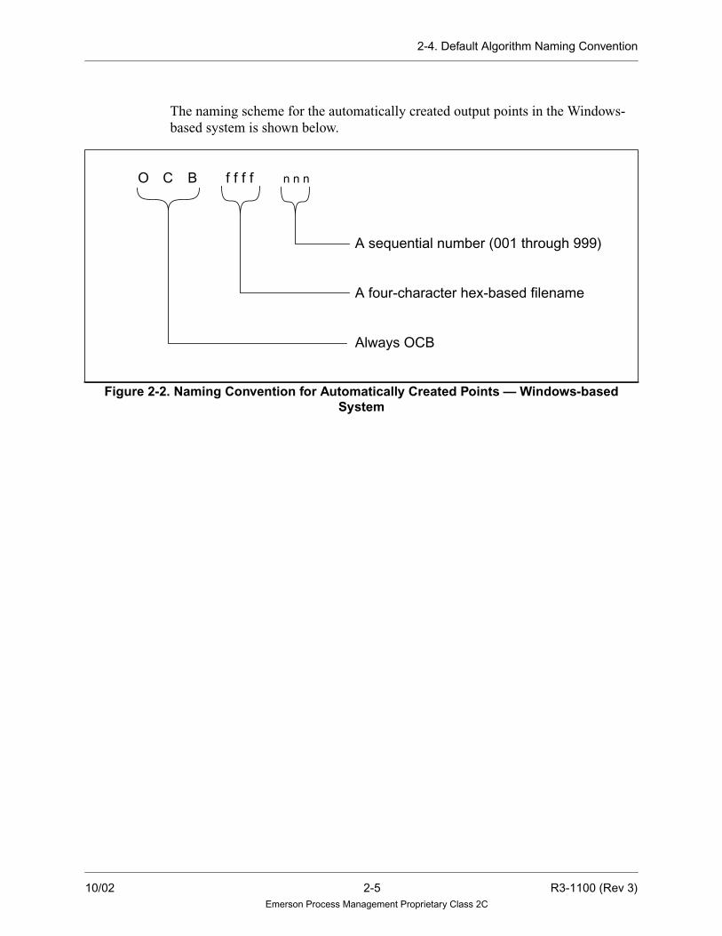
The naming scheme for the automatically created output points in the Windows-
based system is shown below.
Figure 2-2. Naming Convention for Automatically Created Points — Windows-basedSystem
A sequential number (001 through 999)
A four-character hex-based filename
Always OCB
O C B f f f f n n n
10/02 2-5 R3-1100 (Rev 3)Emerson Process Management Proprietary Class 2C

2-5. Tracking Signals for Algorithms
2-5. Tracking Signals for Algorithms
Typically, multiple control strategies (or “modes”) are defined to control a process.
For example, both manual and automatic control modes may be available. Multiple
types of automatic control may be available, such as flow control, level control,
element control, and cascade control modes.
When transferring between control strategies (for instance, from manual to
automatic control modes), information is required by the newly selected control
strategy to ensure a smooth transition. These required values are obtained from the
active control strategy and are provided to the other available strategies. This
exchange of information between control strategies is referred to as tracking.
2-5.1. Purpose of Tracking
Changes in the mode of a process have the potential to disrupt the process. For
example, consider a situation where a control element is manually set to a low level,
even though the automatic control scheme is calculating a high level. If the control
mode is changed to automatic, a “bump” will occur as this control element’s setting
goes from low to high. If the change is extreme, equipment damage could result.
Methods used to avoid this type of rapid adjustment are referred to as “bumplesstransfer.”
Another obstacle which must be avoided is “reset windup.” Many control schemes
base the output value on a sum of multiple components. For example, a PID control
scheme sums a Proportional component and an Integral component. In certain
situations, the value of the output may reach its limit (100%) while one of the
components is still increasing. Although the output cannot be driven past 100%, it
will take time for the component value to return to the appropriate range. During
this time, if it is necessary to lower the output, the artificially high component value
can cause a delay. In order to keep the control scheme components within the
appropriate range, an approach called “anti-reset windup limiting” is used.
To ensure bumpless transfer (during the transition from one control mode to
another) and to avoid reset windup, tracking is needed. For example, consider an
output which can be controlled using either flow control or level control. While the
flow control scheme is controlling the output, the level control scheme operates in
a tracking mode, which causes the output of the level control scheme to equal the
output of the flow control scheme. When the level control scheme takes control, all
of its component values will be in the appropriate range, and the output will not
change dramatically (that is, will not cause a bump).
R3-1100 (Rev 3) 2-6 10/02Emerson Process Management Proprietary Class 2C

2-5. Tracking Signals for Algorithms
-
tg
2-5.2. Tracking Algorithm Summary
Only these algorithms support tracking via dual-purpose analog inputs and outputs
(that is, track value in AV field, mode status bits in 3W field):
Table 2-1. Tracking Algorithm Summary
AlgorithmTRAT
Ramping
TOUTto
IN1
TRK1to
IN1
TRK2to
IN2
TRK3to
IN3
TRK4to
IN4AcceptsTRIN
CascadeTrack
Optimize
Switch-able
Slewing
Switchable
OutpuTrackin
ANALOG
DEVICE
x x
BALANCER x x TRK01-TRK16
DIVIDE x x x
FIELD x
FUNCTION x x x
GAINBIAS x x x
GASFLOW x x
HISELECT x x x x x x
LEADLAG x x x
LOSELECT x x x x x x
MASTATION x x x
MULTIPLY x x x
PID x x1 x x
PIDFF x x1 x x
SETPOINT x2 x
SQUAREROOT x x x
SUM x x x
TRANSFER x3 x x x x x
1 Through S (setpoint) pin2 Information Only3 Ramps supported on both TRR1 and TRR2 pins
10/02 2-7 R3-1100 (Rev 3)Emerson Process Management Proprietary Class 2C

2-5. Tracking Signals for Algorithms
2-5.3. Tracking Issues
The following issues are defined for tracking:
• If downstream tracking can come from more than one source, then the initial
building order determines the source unless manually changed. The exception
to this is the BALANCER, which can accept tracking from up to 16 downstream
algorithms.
• Tracking may be broken after the signal wires are drawn. On the Solaris
platform, this may be done by clearing the TRIN entry in the algorithm’s EDIT
window. On the Windows platform, this may be done with the Clear Tracking
icon.
• If non-tracking algorithms are inserted between tracking algorithms, then the
designer is responsible for tracking across the “gaps.” Typically, the
TRANSFER algorithm is used above the gap to insert the user-computed
tracking.
• Reset Windup limiting is performed by tracking algorithms if:
1. They are properly configured for tracking.
2. The scale limits (TPSC and BTSC) are set to reflect the accepted signal
range.
— In addition, the PID and PIDFF algorithms provide for enhanced windup
limiting in the cascade configuration.
• Cross sheet tracking is implemented by passing a tracking point “upstream”
through the same page connectors which pass control signals downstream. On
the Solaris platform, this is done by filling in the optional tracking point name
in the cross page connector’s EDIT window. On the Windows platform, this is
done by using the Set Tracking icon with the signal wires.
R3-1100 (Rev 3) 2-8 10/02Emerson Process Management Proprietary Class 2C

2-5. Tracking Signals for Algorithms
2-5.4. Tracking Approach
To implement tracking in the Ovation system, tracking signals are sent between
algorithms. These signals tell the upstream algorithm whether or not to be in the
tracking mode and what value is required by the downstream algorithm to achieve
the present output.
Tracking signals are automatically generated by the Control Builder. The Control
Builder assigns points to carry the tracking mode and value information. The
insertion of tracking logic is transparent to the user (requires no user input to
implement). The user has the option of turning tracking off.
One output point that is used for tracking is created for each algorithm that has a
IN1 input. The output is listed in the algorithm definitions as TOUT. TOUT contains
the track output value, mode and status output signals for the cascade IN1 variable.
Some algorithms have two to four additional tracking outputs for the Input 2, Input
3, and Input 4 as well. These are TRK2, TRK3, and TRK4.
The tracking output is input by the upstream algorithm as TRIN (Tracking Input
Point) according to the tracking rules outlined in the following sections. TRIN
contains the tracking analog input value and the tracking and limiting mode input
signals.
Tracking values are generated by a reverse calculation of the normal algorithm
function. That is, when the algorithm is actively controlling the process, it uses one
or more inputs to calculate an output. When in the tracking mode, the algorithm is
provided with the output value, and must calculate the input value required to obtain
that output. This value is sent to the upstream algorithm which is generating the
algorithm’s input. When there is more than one input, the value is sent to the IN1
input.
Not all algorithms initiate tracking (refer to Table 2-1 for a list of tracking
algorithms). All algorithms do not process the signals the same way. Refer to the
individual algorithm descriptions to determine how the signals are processed for a
particular algorithm.
10/02 2-9 R3-1100 (Rev 3)Emerson Process Management Proprietary Class 2C

2-5. Tracking Signals for Algorithms
2-5.5. Tracking Examples
Mode Transition
One of the most common uses of tracking is during the transition between manual
mode and auto mode. In this case, the control algorithm upstream of the
MASTATION algorithm must be tracked to the current output of the MASTATION
algorithm. The input to the MASTATION station will be the same as the output
from the MASTATION station at the moment of the mode change, and bumping
will be prevented.
SUM Algorithm
Another common use of tracking is for one input into a SUM algorithm. A
two-input SUM algorithm normally adds two inputs, A and B, to produce an output,
C. That is, A + B = C. When the algorithm is in tracking mode, C is dictated by
downstream tracking requirements and one of the inputs which may be continually
varying as process conditions change. Therefore, a value for the other input must be
calculated by the algorithm such that the sum of the inputs is equal to the required
output. Simple algebraic manipulation of the SUM equation reveals that the
dependent input must be tracked to the difference between required C and
independent B. That is, A = C - B.
PID Algorithm
Still another common tracking use involves one of the inputs to a PID algorithm’s
error calculation. As in the SUM example, the output of the PID is dictated by
downstream tracking requirements and the process variable acts as an independent
variable. However, because integral action is involved in this control algorithm, the
concept for tracking changes. Here, the appropriate technique is to cause a zero
error to be presented to the PID during tracking periods to provide no error-related
movement of the PID output when tracking is initially released.
Therefore, the dependent input to the PID error function, the set point, should be
tracked to the value of the process variable input so that a zero-error condition is
produced. Also, the PID output must be tracked when the associated portion of the
system is not in control so that integral action will not cause process upsets by
following set point errors. As described previously, this condition is called reset
windup.
R3-1100 (Rev 3) 2-10 10/02Emerson Process Management Proprietary Class 2C
2-5. Tracking Signals for Algorithms
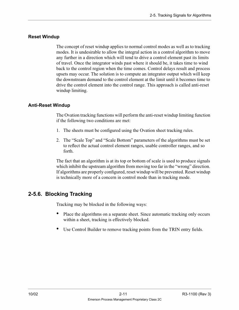
Reset Windup
The concept of reset windup applies to normal control modes as well as to tracking
modes. It is undesirable to allow the integral action in a control algorithm to move
any further in a direction which will tend to drive a control element past its limits
of travel. Once the integrator winds past where it should be, it takes time to wind
back to the control region when the time comes. Control delays result and process
upsets may occur. The solution is to compute an integrator output which will keep
the downstream demand to the control element at the limit until it becomes time to
drive the control element into the control range. This approach is called anti-reset
windup limiting.
Anti-Reset Windup
The Ovation tracking functions will perform the anti-reset windup limiting function
if the following two conditions are met:
1. The sheets must be configured using the Ovation sheet tracking rules.
2. The “Scale Top” and “Scale Bottom” parameters of the algorithms must be set
to reflect the actual control element ranges, usable controller ranges, and so
forth.
The fact that an algorithm is at its top or bottom of scale is used to produce signals
which inhibit the upstream algorithm from moving too far in the “wrong” direction.
If algorithms are properly configured, reset windup will be prevented. Reset windup
is technically more of a concern in control mode than in tracking mode.
2-5.6. Blocking Tracking
Tracking may be blocked in the following ways:
• Place the algorithms on a separate sheet. Since automatic tracking only occurs
within a sheet, tracking is effectively blocked.
• Use Control Builder to remove tracking points from the TRIN entry fields.
10/02 2-11 R3-1100 (Rev 3)Emerson Process Management Proprietary Class 2C

2-6. Setting Tracking Signals for Algorithms
2-6. Setting Tracking Signals for Algorithms
The digital tracking signals are set and used as described in the following table.
Signal Action of the Algorithm Initiating the TrackingImplementation by the Algorithm
Being Told to Track
Track PID and PIDFF set the Track output signal TRUE. The output value is set equal to the
Track input value. An internal track
buffer is set up to provide a bumpless
transfer when the Track input signal
is removed.
TRANSFER sets the Track output signal TRUE for
the value that is not selected.
MASTATION set the Track output signal TRUE for
one loop after it reads the hardware value on the first
pass. MASTATION sets the Track output signal
TRUE when the algorithm is not in Auto mode.
All algorithms set the Track output signal TRUE
when the Track input signal is TRUE.
Track-if-
Lower
HISELECT sets the Track-if-Lower output signal
TRUE for the value that is not selected only when
there are no Track, Track-if-Higher, or Tack-if-
Lower input signals and the gain on the input value is
positive.
If the output value of the PID, or
PIDFF is less than the Track input
value, then a negative error causes the
Controller to take action from the
previous output value, and a positive
error causes the Controller to take
action from the Track input value.LOSELECT sets the Track if Lower output signal
TRUE for the value that is not selected only when
there are not Track, Track-if-Higher, or Track-if-
Lower input signals and the gain on the input value is
negative.
All algorithms set the Track-if-Lower output signal
TRUE when there is no Track input signal and either:
• The Track-if-Lower signal is TRUE and the
gain on the input value is positive, or
• The Track-if-Higher input signal is TRUE and
the gain on the input value is negative.
R3-1100 (Rev 3) 2-12 10/02Emerson Process Management Proprietary Class 2C

2-6. Setting Tracking Signals for Algorithms
Track-if-Higher
LOSELECT sets the Track-if-Higher output signal
TRUE for the value that is not selected only when
there are no Track, Track-if-Higher, or Track-if-
Lower input signals and the gain on the input value is
positive.
If the output value of PID, or PIDFF
is greater than the Track input value,
then a positive error causes the
Controller to take action from the
previous output value, and a negative
error causes the Controller to take
action from the Track input value.HISELECT sets the Track-if-Higher output signal
TRUE for the value that is not selected only when
there are no Track, Track-if-Higher, or Track-if-
Lower input signals and the gain on the input value is
negative.
All algorithms set the Track-if-Higher output signal
TRUE when there is no Track input signal and:
• The Track-if-Higher input signal is TRUE and
the gain on the input value is positive, or
• The Track-if-Lower input signal is TRUE and
the gain on the input value is negative.
Lower
Inhibit
PID and PIDFF set the Lower Inhibit output signal
TRUE when the algorithm is in Cascade mode, no
Track input signal exists, and:
• The Track-if-Lower input signal is TRUE and
either the gain on the set point is positive with
INDIRECT action on the error or the gain on
the set point is negative with DIRECT action on
the error, or
• The Track-if-Higher input signal is TRUE and
either the gain on the set point is negative with
INDIRECT action on the error, or the gain on
the set point is positive with DIRECT action on
the error.
The output is prevented from
decreasing its value, but it is
permitted to increase.
All algorithms set the Lower Inhibit output signal
TRUE when there is no Track input signal and:
• The output value is at the low limit specified
and the gain on the output value is positive, or
• The output value is at the high limit specified
and the gain on the input value is negative, or
• The Lower Inhibit input signal is TRUE and the
gain on the input value is positive, or
• The Raise Inhibit input signal is TRUE and the
gain on the input value is negative.
Signal Action of the Algorithm Initiating the TrackingImplementation by the Algorithm
Being Told to Track
10/02 2-13 R3-1100 (Rev 3)Emerson Process Management Proprietary Class 2C
2-6. Setting Tracking Signals for Algorithms
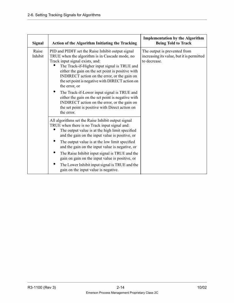
Raise
Inhibit
PID and PIDFF set the Raise Inhibit output signal
TRUE when the algorithm is in Cascade mode, no
Track input signal exists, and:
• The Track-if-Higher input signal is TRUE and
either the gain on the set point is positive with
INDIRECT action on the error, or the gain on
the set point is negative with DIRECT action on
the error, or
• The Track-if-Lower input signal is TRUE and
either the gain on the set point is negative with
INDIRECT action on the error, or the gain on
the set point is positive with Direct action on
the error.
The output is prevented from
increasing its value, but it is permitted
to decrease.
All algorithms set the Raise Inhibit output signal
TRUE when there is no Track input signal and:
• The output value is at the high limit specified
and the gain on the input value is positive, or
• The output value is at the low limit specified
and the gain on the input value is negative, or
• The Raise Inhibit input signal is TRUE and the
gain on gain on the input value is positive, or
• The Lower Inhibit input signal is TRUE and the
gain on the input value is negative.
Signal Action of the Algorithm Initiating the TrackingImplementation by the Algorithm
Being Told to Track
R3-1100 (Rev 3) 2-14 10/02Emerson Process Management Proprietary Class 2C

2-7. Setting Algorithm Status and Mode
2-7. Setting Algorithm Status and Mode
The mode and status digital signals are set as follows:
Signal Action
Auto Mode MASTATION sets the output Auto Mode signal TRUE when the algorithm is in
Auto mode.
High Limit Reached All algorithms set the High Limit Reached output signal TRUE when the output
is at the high limit specified and the High Limit Reached output signal is not scan
removed.
Local Manual Mode MASTATION sets the Local Manual Mode output signal TRUE when the
algorithm is in Local Manual mode.
Low Limit Reached All algorithms set the Low Limit Reached output signal TRUE when the output
is at the low limit specified and the Low Limit Reached output signal is not scan
removed.
Manual Mode MASTATION sets the output Manual mode signal TRUE when the algorithm is
in Manual mode.
10/02 2-15 R3-1100 (Rev 3)Emerson Process Management Proprietary Class 2C

2-8. Algorithm Binary to Hexadecimal Conversion
2-8. Algorithm Binary to Hexadecimal Conversion
The following binary to hexadecimal conversion table is included to assist the user
in using algorithms that require binary to hexadecimal conversion (for example,
DIGDRUM).
Byte = 8 bits, Integer = 16 bits
In DIGDRUM, the above binary number represents the states of the 16 outputs in a
given step. The right-most bit represents Output 001, and the left-most bit
represents Output 016. For example, if the user wants Step 5 to have the outputs in
these states, I05 would be initialized to 0x53C6.
Table 2-2. Binary to Hexadecimal Conversion
Binary to Hexadecimal Conversion Table
Binary Hexadecimal Decimal
0000 0 0
0001 1 1
0010 2 2
0011 3 3
0100 4 4
0101 5 5
0110 6 6
0111 7 7
1000 8 8
1001 9 9
1010 A 10
1011 B 11
1100 C 12
1101 D 13
1110 E 14
1111 F 15
Binary: 0101 0011 1100 0110 0101001111000110B
Hexadecimal: 5 3 C 6 0x53C6
R3-1100 (Rev 3) 2-16 10/02Emerson Process Management Proprietary Class 2C

2-9. Status Checking
2-9. Status Checking
This section describes the status checking that an algorithm performs.
2-9.1. Invalid Number Checking and Quality Checking for Algorithms
Most algorithms perform invalid number checking on analog input points. These
points include tracking inputs. If an invalid number is detected, the drop goes into
alarm and the problem is identified by Fault Code 66, Fault ID 3.
For algorithms, Fault Parameter 3 contains the number of the algorithm sheet
detecting an invalid number. These numbers are reported as hexadecimal values.
Refer to“ Error Codes and Messages” (R3-1145) for more information on Fault
Code 66.
An invalid number is generated under exceptional conditions. An example of such
conditions is taking the square root of a negative number. The Function section in
the individual algorithm reference sheets, identifies those algorithms which provide
additional checking to avoid specific exceptional conditions.
When an invalid number is input to an algorithm, generally the output of the
algorithm will also be invalid and will be marked with BAD quality. In the
following algorithm reference sheets, each algorithm that performs invalid number
checking discusses how the invalid number is treated and the results that occur from
the invalid number.
There are three types of invalid numbers: indefinite, NAN, and denormal.
• An indefinite invalid number is generated from a mathematical operation for
which there is no reasonable result.
• A NAN (not-a-number) invalid number is an unrecognizable real number
format and should never occur.
• A denormal invalid number is generated when the result of a mathematical
operation is too small to be represented in the 32-bit real number format used in
the system. If an analog input is a denormal invalid number, the drop is placed
into alarm identified by Fault Code 66, Fault ID 3.
However, certain algorithms store the denormal value into a temporary variable,
convert it to zero, and use that value (0) in the algorithm calculation. Consequently,
these algorithms calculate a valid output value with GOOD quality and the drop
goes into alarm.
10/02 2-17 R3-1100 (Rev 3)Emerson Process Management Proprietary Class 2C

2-9. Status Checking
If the output of the algorithm is a denormal invalid number, then the value of the
output is set to zero and the drop is not placed into alarm. These denormal invalid
numbers are displayed throughout the system as zero.
If an invalid number is generated, the cause of the problem should be immediately
investigated and corrected since it could cause a control problem in the system.
In addition to invalid number checking, many algorithms generate a quality setting
on the output. In most cases, the quality of the output equals the quality of the input.
This is commonly called propagated quality. For example, the quality of the input
is propagated to the output. However, this simple propagation is not true for all
algorithms. Consult the algorithm reference sheet for each algorithm for specific
quality propagation information.
2-9.2. Error Information Generated by Algorithms
The second status word in an analog or digital process point may contain error
information generated by an algorithm that processed the value of that point.
For analog and digital points, the 2W record field contains the second status word.
If a bit is TRUE, then the error indicated by that bit has been detected. If a bit is
FALSE, then the error has not been detected.
Each algorithm reference sheet lists the second status word of a point record.
R3-1100 (Rev 3) 2-18 10/02Emerson Process Management Proprietary Class 2C

2-10. Algorithm Functions
2-10. Algorithm Functions
Each algorithm may be assigned one or more of the following functional categories:
• Arithmetic — Performs a mathematical function.
• Artificial I/O — Assigns a value to a point.
• Boolean — Performs a Boolean (logic) function using digital point(s)
• CRT I/O — Interfaces to the Operator’s Keyboard and CRT.
• Digital — Primarily uses digital points.
• Field I/O — Interfaces to the I/O cards.
• High-Level Controller — Combines several related control functions into one
algorithm.
• Limiter — Limits the value of an analog point.
• Low-Level Controller — Performs one basic control function.
• Monitor — Monitors one or more points and outputs a digital point when a
condition has been reached.
• Quality — Deals with the quality of the point(s).
• Selector — Selects an analog value based on certain conditions.
• Sequencer — Implements sequential control.
10/02 2-19 R3-1100 (Rev 3)Emerson Process Management Proprietary Class 2C

2-10. Algorithm Functions
Refer to Table 2-3 to identify the name and function(s) of a particular algorithm.
Section 3 and Section 4 provide reference pages that give detailed information on
each algorithm.
Table 2-3. Algorithm Functions
Algorithm Name Function
AAFLIPFLOP — Alternate Action Flip-Flop with Reset Boolean, Digital
ABSVALUE — Absolute Value of an Input Arithmetic
ALARMMON — Monitors up to 16 Analog or Digital Points for Alarm
States
Monitor
ANALOG DEVICE — Interfaces to local analog loop Controllers. Low-Level Controller
ANALOGDRUM — Drum Controller with Two Analog Outputs
or with One Analog Output
Sequencer
AND — Logical AND Gate up to Eight Inputs Boolean, Digital
ANNUNCIATOR — Calculate Alarm State Monitor
ANTILOG — Antilog of Scaled Input, Base 10 or Natural Base Arithmetic
ARCCOSINE — Arc cosine of an input (in radians) Arithmetic
ARCSINE — Arcsine of an input (in radians) Arithmetic
ARCTANGENT — Arc tangent of an input (in radians) Arithmetic
ASSIGN — Transfer the value and quality of one process point to
another process point of the same type.
Artificial I/O
ATREND — Trend an Analog or Digital Point Field I/O
AVALGEN — Analog Value Generator Artificial I/O
BALANCER — Controls up to 16 Downstream Algorithms Arithmetic, Low-Level
Controller
BCDNIN — Inputs N BCD Digits to the Functional Processor from the
DIOB
Field I/O
BCDNOUT — Outputs N BCD Digits from the Functional Processor to
the I/O Bus
Field I/O
BILLFLOW — Calculates Gas Flow Monitor
CALCBLOCK — Allows the user to define a mathematical calculation
using a list of operators.
Arithmetic
CALCBLOCKD — Allows the user to define a mathematical
calculation using a list of operators.
Arithmetic
COMPARE — Floating Point Compare Arithmetic
COSINE — Cosine of an input (in radians) Arithmetic
COUNTER — Interface Up/Down counter Digital
DBEQUALS — Deviation Monitor Between two Variable Inputs Monitor
DEVICESEQ — Sequencer using MASTER/DEVICE arrangement. High-Level, Digital
R3-1100 (Rev 3) 2-20 10/02Emerson Process Management Proprietary Class 2C

2-10. Algorithm Functions
DEVICEX — Combines the commands to open/close or start/stop a
piece of equipment with feedback signals indicating the command was
accomplished.
Digital
DIGCOUNT — Digital Counter with Flag Digital
DIGDRUM — Drum Controller with 16 Digital Outputs Sequencer
DIGITAL DEVICE — Provides a digital alarm bit to be set for seven
types of devices. They are: SAMPLER, VALVE NC, MOTOR NC,
MOTOR, MOTOR 2-SPD, MOTOR 4-SPD, and VALVE.
Digital
DIVIDE — Divides Two Gained and Biased Inputs Arithmetic
DROPSTATUS — Drop Status Record Monitor Monitor
DRPI — Digital Rod Position Indicator Monitor
DVALGEN — Digital Value Generator Artificial I/O, Digital
FIELD — Write value to I/O point. Field I/O
FIFO — Transaction Queue: First In - First Out High Level, Digital
FLIPFLOP — S-R Type Flip-Flop Memory with Reset Override Artificial I/O, CRT I/O
FUNCTION — Two-Segment Function Generator Arithmetic
GAINBIAS — Limits a Gained and Biased Input Limiter
GASFLOW — Calculates a Pressure and Temperature Compensated
Mass or Volumetric Flow
Arithmetic
HIGHLOWMON — High and Low Signal Monitor with Reset
Deadband and Fixed/Variable Limits
Monitor
HIGHMON — High Signal Monitor with Reset Deadband and a Fixed/
Variable Limit
Monitor
HISELECT — Selects the Greater of Two Gained and Biased Inputs Selector
INTERP — Provides a linear table-lookup and interpolation function. High-Level Controller
KEYBOARD — Programmable/Function Key Interface - P1 through
P10 to control Key Interface
CRT I/O
LATCHQUAL — Latch point quality Quality
LEADLAG — Lead/Lag Compensator Low-Level Controller
LEVELCOMP — Calculates the density compensated water level in a
pressurized steam drum.
High-Level Controller
LOG — Base 10 Logarithm and Bias Arithmetic
LOSELECT — Selects the Smaller of Four Gained and Biased Inputs Selector
LOWMON — Low Signal Monitor with Reset Deadband and a Fixed/
Variable Limit
Monitor
MAMODE — Logic Interface to MASTATION Digital
Table 2-3. Algorithm Functions (Cont’d)
Algorithm Name Function
10/02 2-21 R3-1100 (Rev 3)Emerson Process Management Proprietary Class 2C

2-10. Algorithm Functions
MASTATION — Interface Between a soft Manual/Auto station and the
functional processor
CRT I/O, Digital
MASTERSEQ — Sequencer using MASTER/DEVICE arrangement. High-Level, Digital
MEDIANSEL — Monitors analog transmitter inputs for quality and
deviation from each other.
Quality, Selector
MULTIPLY — Multiplies Two Gained and Biased Inputs Arithmetic
NLOG — Natural Logarithm with Bias Arithmetic
NOT — Logical NOT Gate Boolean, Digital
OFFDELAY — Pulse Stretcher Digital
ONDELAY — Pulse Timer Digital
ONESHOT — Digital One-Shot Pulse Digital
OR — Logical OR Gate up to 8 Inputs Boolean, Digital
PACK16 — Packs up to 16 Digital Point Values into a Packed Digital
Record
Artificial I/O, Digital
PID — Proportional Plus Integral Plus Derivative Controller CRT I/O, High Level
Controller
PIDFF — Proportional Plus Integral Plus Derivative Controller with
Feed Forward.
High Level Controller
PNTSTATUS — Point Status Digital
POLYNOMIAL — Fifth Order Polynomial Equation Arithmetic
PREDICTOR — Compensate for pure Time-Delay High Level Controller
PULSECNT — Pulse Count Digital
QAVERAGE — Average N Analog Points; Exclude Points with BAD
Quality; N < 9
Arithmetic, Quality
QPACMD — Writes a command byte to a QPA card. Field I/O
QPACMPAR — Writes a comparator value to a QPA card. Field I/O
QPASTAT — Outputs the digital status from a QPA card. Field I/O
QSDDEMAND — Writes demand and mode to QSD card. Field I/O
QSDMODE — Indicates QSD mode. Field I/O
QSRMA — Interface manual/auto station to a QSR card. Field I/O
QUALITYMON — Quality Check one Input Quality
QVP — Interface to QVP card. Field I/O
RATECHANGE — Rate of Change Transform Arithmetic
RATELIMIT — Rate Limiter with Fixed Rate Limit and Flag when
Rate Limit is Exceeded
Limiter
Table 2-3. Algorithm Functions (Cont’d)
Algorithm Name Function
R3-1100 (Rev 3) 2-22 10/02Emerson Process Management Proprietary Class 2C

2-10. Algorithm Functions
RATEMON — Rate of Change Monitor with Reset Deadband and
Fixed/Variable Rate Limit
Monitor
RESETSUM — Summer with Reset Arithmetic
RPACNT — Counts pulses from the Pulse Accumulator (PA) card Field I/O
RPAWIDTH — Pulse Width from the Pulse Accumulator Card Field I/O
RUNAVERAGE — Running Average Transform Arithmetic
RVPSTATUS — Reads the Valve Positioner Card Status & Info. Field I/O
SATOSP — Transfers Analog Values to a Packed Digital Record Artificial I/O, Digital
SELECTOR — Transfer between N Analog Inputs, where N < 8 Selector
SETPOINT — Soft and/or Hard Manual Loader Station with an
Interface to the RLI Card Set Point
CRT I/O, Field I/O
SINE — Sine of an input (in radians) Arithmetic
SLCAIN — Reads Analog Input (s) from QLC/LC Field I/O
SLCAOUT — Writes Analog Output(s) to QLC/LC Field I/O
SLCDIN — Reads Digital Input (s) from QLC/LC Field I/O
SLCDOUT — Writes Digital Outputs to QLC/LC Field I/O
SLCPIN — Reads packed digital input(s) from QLC/LC Field I/O
SLCPOUT — Writes packed digital outputs to QLC/LC Field I/O
SLCSTATUS — Status Value of QLC/LC Field I/O
SMOOTH — Smoothed Value Transform Arithmetic
SPTOSA — Transfers Packed Digital Value to an Analog record Artificial I/O, Digital
SQUAREROOT — Square Root of a Gained and Biased Input Arithmetic
STEAMFLOW — Flow Compensation High Level
STEAMTABLE — Calculates Thermodynamic properties of water and
steam. This includes the following algorithms: HSCLTP, VCLTP,
HSLT, SSLT, VSLT, PSLT, TSLP, TSLH, PSVS, HSTVSVP,
HSVSSTP.
High Level
STEPTIME — Automatic Step Timer Sequencer
SUM — Adds Four Gained and Biased Inputs Arithmetic
SYSTEMTIME — Stores system Date and Time in analog points. Monitor
TANGENT — Tangent of an input (in radians) Arithmetic
TIMECHANGE — Time Change Monitor
TIMEDETECT — Time Detector Monitor
TIMEMON — Pulse Digital Points Based on the system time Monitor
TRANSFER — Selects a Gained and Biased Input Based on a Flag Selector
TRANSLATOR — Translator Selector, Sequencer
Table 2-3. Algorithm Functions (Cont’d)
Algorithm Name Function
10/02 2-23 R3-1100 (Rev 3)Emerson Process Management Proprietary Class 2C

2-10. Algorithm Functions
TRANSPORT — Transport Time Delay Sequencer
TRNSFNDX — Will select output analog value from up to sixty-four
outputs which hold the input.
Selector
UNPACK16 — Unpacks up to 16 Digital Point Values from a Packed
Digital Record
Artificial I/O, Digital
XMA2 — Interface between a soft manual/auto station and a QAM,
QAA, QLI card and the functional processor.
CRT I/O, Digital
XML2 — Soft and/or hard manual loader station with an Interface to the
QAM, QLI, card setpoint.
CRT I/O, Digital
XOR — Exclusive OR of Two Inputs Boolean, Digital
X3STEP — Controls devices which must be kept within a certain
tolerance.
Field I/O
2XSELECT — Selects and Monitors Two Transmitter Signals Monitor, Quality, Selector
Table 2-3. Algorithm Functions (Cont’d)
Algorithm Name Function
R3-1100 (Rev 3) 2-24 10/02Emerson Process Management Proprietary Class 2C

Section 3. Algorithms
3-1. Section Overview
This section provides a description of each standard algorithm. The following topics
are included:
• Algorithm reference page format (Section 3-2).
• Algorithm reference pages (Section 3-3 through Section 3-122).
10/02 3-1 R3-1100 (Rev 3)Emerson Process Management Proprietary Class 2C

3-2. Algorithm Reference Page Format
3-2. Algorithm Reference Page Format
Each algorithm reference page contains the following sections (where applicable):
• Description — Describes the algorithm’s operation.
• Invalid Real Numbers and Quality — Describes how quality is set.
• Functional Symbol — Illustrates (in pictorial form) the algorithm’s operation.
Note
1. = Required Analog input or output
(solid line and arrowhead)
2. = Required Digital or Packed Digital
input or output (solid line, hollow arrowhead)
3. = Optional or Selectable Analog input or
output (dashed line, solid arrowhead)
4. = Optional or Selectable Digital or Packed Digital
input or output (dashed line, hollow arrowhead)
• Algorithm Record Type (if required) — Defines the type and size of the
record generated for storing parameters and other information necessary to the
algorithm. Refer to “Record Types User’s Guide” (R3-1140) for a complete
description of the structures of algorithm records.
Note
A complete list of algorithms is found in
Table 2-3.
• Algorithm Definitions — Provides the following information on the algorithm:
— Names of the parameters used.
— Algorithm record field used by each tuning constant or data initialization
parameter; also, the type of entry required in this field (integer, byte, or real).
R3-1100 (Rev 3) 3-2 10/02Emerson Process Management Proprietary Class 2C

3-2. Algorithm Reference Page Format
— Parameter types such as those described below:
• Variable = Input or output signal to the block (that is, analog or digital).
• Tuning Constant = Fixed parameter that remains constant unless it is
changed by the user at the Operator’s Station or Control Builder.
• Data Initialization Parameter = Fixed constant that cannot be changed
by the user at the Operator’s Station but can be changed by the Control
Builder.
• Selectable = can be either a Tuning constant in an algorithm record field
or a point record.
— Definition of whether the parameter is required or optional.
If the parameter is optional and not initialized by the user, it defaults to zero.
If there are input points to the algorithm that are optional and not initialized
by the user, they will have a value of zero for analog points and FALSE for
digital inputs.
— Default value (if applicable).
— Brief description of the parameter.
— Minimum point record required by each variable.
Each algorithm defines the minimum size point record that can be used for
each algorithm input or output.
The quality of the points is set BAD when a detectable hardware failure is
encountered. This information can be used in control strategies or for
alarming purposes by detecting BAD quality using the QUALITYMON
series of algorithms.
• Function — Explains the algorithm’s operation in terms of a mathematical
equation.
• Application Example — Provides an example to demonstrate the use of the
algorithm.
• Miscellaneous Sections — applicable to a specific algorithm only.
10/02 3-3 R3-1100 (Rev 3)Emerson Process Management Proprietary Class 2C

3-3. AAFLIPFLOP
3-3. AAFLIPFLOP
Description
The AAFLIPFLOP algorithm simulates a memory device whose output state is
inverted by each momentary TRUE signal on SRST (that is, the output state OUT
is inverted when there is a transition in the input SRST from a FALSE to a TRUE
signal). OUT is set to FALSE anytime the reset digital input signal RSET is TRUE.
Functional Symbol
Algorithm Record Type = LC
Algorithm Definitions
Name
LC Alg.RecordField Type
Required/Optional
DefaultValue Description
Min.Point
Record
INIT — Variable Optional — Initial Value LD, LP
SRST — Variable Required — Input (digital) LD, LP
RSET — Variable Required — Reset Input (digital) LD, LP
OUT — Variable Required — Output (digital) LD, LP
SRST
RSETOUT
INIT
AAFLIPFLOP
R3-1100 (Rev 3) 3-4 10/02Emerson Process Management Proprietary Class 2C

3-3. AAFLIPFLOP
Function
where:
X = Value can be 0 or 1.
S = Output remains in the same or previous state.
T = Output toggles from the previous state.
OLD SRST = Value of the SRST input on the previous loop executed by the
functional processor.
On the first pass, OUT is set to FALSE if RSET is TRUE. Otherwise, OUT is
set as follows:
— If the optional INIT input is initialized by the user, OUT will be set to the
value of INIT.
— If INIT is not initialized or has BAD quality on the first pass, OUT remains
in the same state. OUT is set to FALSE on power up/reset unless it is
initialized to TRUE by the user in the program.
RSET OLD SRST SRST OUT
0 0 0 S
0 0 1 T
0 1 0 S
0 1 1 S
1 X X 0
10/02 3-5 R3-1100 (Rev 3)Emerson Process Management Proprietary Class 2C

3-4. ABSVALUE
3-4. ABSVALUE
Description
The output for the ABSVALUE algorithm is the absolute value of input IN1.
The value of IN1 is checked for invalid real numbers. If IN1 is valid, the quality of
IN1 is propagated to the quality of OUT and the real number value of OUT is
written to the point record.
Invalid Numbers and Quality
If the value of IN1 is invalid or if the calculated value of OUT written to the point
record is invalid, the quality and the reason are set to BAD.
Functional Symbol
Algorithm Record Type = None
Algorithm Definitions
Function
OUT = ABS(IN1)
Name
Alg.RecordField Type
Required/Optional
DefaultValue Description
Min.Point
Record
IN1 — Variable Required — Input (analog) LA
OUT — Variable Required — Output (analog) LA
ABSVALUE
IN1
OUT
OUT
ABSVALUEIN1
OR
R3-1100 (Rev 3) 3-6 10/02Emerson Process Management Proprietary Class 2C

3-5. ALARMMON
3-5. ALARMMON
Description
The ALARMMON algorithm sets OUT equal to TRUE if any of the inputs are in
alarm (alarm status is TRUE). OUT is set to TRUE if unacknowledged and alarm
bits are set in the first status word of the point or alarm bit is TRUE and
unacknowledged is FALSE.
The inputs are optional, numbering from 1 through 16, and may be analog or digital
types. The ALRM flag determines the type of alarm check that the algorithm will
perform.
If the ALRM flag is 0 (X1=0), the optional output (FOUT) is set FALSE if no inputs
went into alarm since the last loop. FOUT is set TRUE for one loop when inputs go
into alarm.
If the ALRM flag is 1 (X1=1), the digital output (FOUT) is set TRUE if one or more
inputs have their unacknowledged alarm bit set to TRUE.
If the ALRM flag is 2 (X1=2), the OUT point is set to a 1 when any of the Inputs
are in alarm. The FOUT point is set to a 1 (for 1 loop) if any of the inputs go into
alarm and they were not in Alarm in the previous loop.
If the ALRM flag is 3 (X1=3), the OUT point is set to TRUE when any of the input
points are in ALARM. The FOUT point is set to a TRUE whenever any of the input
points have both their ‘ALARM’ and ‘unacknowledged’ bits set TRUE.
Functional Symbol
ALARM
IN1
IN16
•
•
•
FOUT
OUT
MON
10/02 3-7 R3-1100 (Rev 3)Emerson Process Management Proprietary Class 2C

3-5. ALARMMON
Algorithm Record Type = LC
Algorithm Definitions
Name
LC Alg.RecordField Type
Required/Optional
DefaultValue Description
Min.Point
Record
DIAG LU-Integer Data Init. Required 16 Tuning Diagram Number —
ALRM X1 -Byte Data Init. Optional 0 Type of alarm check: —
IN1
•
•
•
IN16
— Variable Optional — Input (analog or digital) LA, LD
OUT — Variable Required — Output (digital) LD, LP
FOUT — Variable Optional — Alarm Check
Output (digital)
LD, LP
State change digital points should not be used since the alarm status will be set TRUE for each state change.
This would be an improper use of this algorithm.
Value Description
0 New Alarm
1 Unacknowledged
alarm
2 New alarm/Any
alarm
3 Unacknowledged
alarm/Any alarm
R3-1100 (Rev 3) 3-8 10/02Emerson Process Management Proprietary Class 2C

3-6. ANALOG DEVICE
3-6. ANALOG DEVICE
Description
The Analog Output Device algorithm is used to interface to local analog loop
Controllers. Under normal operation, the analog device algorithm attempts to
control the device.
When the Analog Device algorithm is in AUTO, the error is calculated by taking
the feedback minus the demand times a sensitivity factor. The default sensitivity
factor is one. If the error is less than the inner deadband, the analog output is set to
zero. If the error is greater than the outer deadband, the analog output is set equal to
this error. If the error is between the two deadbands, the error is scaled between zero
and one. The closer the error is to the outer deadband, the closer the scale factor to
one. The closer the error is to the inner deadband, the closer the scale factor is to
zero. The output is simply the error multiplied by the scale factor. The output is
clamped to the clamping limits (MAX). The quality of OUT is set to the worst
quality of the two inputs when not in tracking mode.
The shed relay is a copy of the digital input. If the digital input is reset or the tracking
input indicates that there is tracking, the tracking output will be equal to the tracking
input. When tracking, quality is set to the quality of the track input variable.
10/02 3-9 R3-1100 (Rev 3)Emerson Process Management Proprietary Class 2C

3-6. ANALOG DEVICE
Tracking Signals
Tracking is performed through signals passed in the upper 16 bits of the third status
word of the analog tracking point. This algorithm takes the following action in
response to the information found in the digital input signal TRIN:
Functional Symbol
BIT DESCRIPTION ACTION TOUT SIGNAL
16 Track Implemented Passed Through
17 Track if Lower No Action Not Used
18 Track if Higher No Action Not Used
19 Lower Inhibit No Action Not Used
20 Raise Inhibit No Action Not Used
21 Conditional Track Implemented Passed Through
22 Not Used No Action Not Used
23 Deviation Alarm No Action Not Used
24 Local Manual Mode No Action Not Used
25 Manual Mode No Action Not Used
26 Auto Mode No Action Not Used
27 Not Used No Action Not Used
28 Not Used No Action Not Used
29 Not Used No Action Not Used
30 Low Limit Reached Implemented Passed Through
31 High Limit Reached Implemented Passed Through
ANALOGSHED
DIGINDEVICE
OUTU OUT OUTD
OUT5
IN1 IN2
TOUT
TRIN
R3-1100 (Rev 3) 3-10 10/02Emerson Process Management Proprietary Class 2C
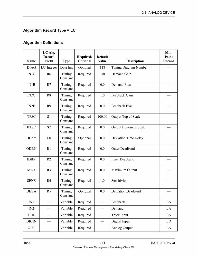
3-6. ANALOG DEVICE
Algorithm Record Type = LC
Algorithm Definitions
Name
LC Alg.RecordField Type
Required/Optional
DefaultValue Description
Min.Point
Record
DIAG LU-Integer Data Init Optional 118 Tuning Diagram Number —
IN1G R6 Tuning
Constant
Required 1.01 Demand Gain —
IN1B R7 Tuning
Constant
Required 0.0 Demand Bias —
IN2G R8 Tuning
Constant
Required 1.0 Feedback Gain —
IN2B R9 Tuning
Constant
Required 0.0 Feedback Bias —
TPSC S1 Tuning
Constant
Required 100.00 Output Top of Scale —
BTSC S2 Tuning
Constant
Required 0.0 Output Bottom of Scale —
DLAY C0 Tuning
Constant
Optional 0.0 Deviation Time Delay —
ODBN R1 Tuning
Constant
Required 0.0 Outer Deadband —
IDBN R2 Tuning
Constant
Required 0.0 Inner Deadband —
MAX R3 Tuning
Constant
Required 0.0 Maximum Output —
SENS R4 Tuning
Constant
Required 1.0 Sensitivity —
DEVA R5 Tuning
Constant
Optional 0.0 Deviation Deadband —
IN1 — Variable Required — Feedback LA
IN2 — Variable Required — Demand LA
TRIN — Variable Required — Track Input LA
DIGIN — Variable Required — Digital Input LD
OUT — Variable Required — Analog Output LA
10/02 3-11 R3-1100 (Rev 3)Emerson Process Management Proprietary Class 2C

3-6. ANALOG DEVICE
TOUT — Variable Required — Tracking Output LA
SHED — Variable Required — Shed Relay LD
OUTU — Variable Optional — Up Analog LA
OUTD — Variable Optional — Down Analog LA
OUT5 — Variable Required — Deviation Alarm LD
Name
LC Alg.RecordField Type
Required/Optional
DefaultValue Description
Min.Point
Record
R3-1100 (Rev 3) 3-12 10/02Emerson Process Management Proprietary Class 2C

3-7. ANALOGDRUM
3-7. ANALOGDRUM
Description
The ANALOGDRUM algorithm is a software drum controller with one analog
output value and up to 30 steps OR a software drum controller with two analog
output values and up to 15 steps. The output selected is based on the current step
number and a list of up to 30 /15 initialized real values. The current step number
may be tracked to a selected step (TRIN) when in tracking mode (TMOD = TRUE),
increased (INC), or decreased (DEC). The current step number is only increased or
decreased on a FALSE to TRUE transition of INC and DEC. The maximum number
of steps must be initialized. When the step number becomes greater than the
maximum number of steps, the current step number is reset to one.
The track input value (TRIN) and output value (OUT) are checked for invalid real
numbers. If a tracking request is received and TRIN is an invalid number, then the
tracking request is ignored. However, the current step can be increased (using INC)
or decreased (using DEC) even when TRIN is an invalid number.
If the algorithm calculates an invalid real number output, the value is invalid and
the quality is set to BAD.
Functional Symbol
Algorithm Record Type = LC
ANALOG
INCDEC
TMOD
TRIN
OUT
STEP
DRUM
OUT2
10/02 3-13 R3-1100 (Rev 3)Emerson Process Management Proprietary Class 2C
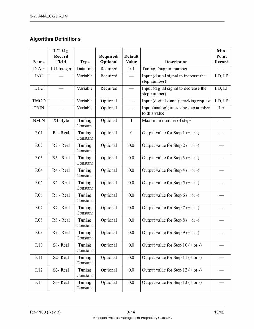
3-7. ANALOGDRUM
Algorithm Definitions
Name
LC Alg.RecordField Type
Required/Optional
DefaultValue Description
Min.Point
Record
DIAG LU-Integer Data Init Required 101 Tuning Diagram number —
INC — Variable Required — Input (digital signal to increase the
step number)
LD, LP
DEC — Variable Required — Input (digital signal to decrease the
step number)
LD, LP
TMOD — Variable Optional — Input (digital signal); tracking request LD, LP
TRIN — Variable Optional — Input (analog); tracks the step number
to this value
LA
NMIN X1-Byte Tuning
Constant
Optional 1 Maximum number of steps —
R01 R1- Real Tuning
Constant
Optional 0 Output value for Step 1 (+ or -) —
R02 R2 - Real Tuning
Constant
Optional 0.0 Output value for Step 2 (+ or -) —
R03 R3 - Real Tuning
Constant
Optional 0.0 Output value for Step 3 (+ or -) —
R04 R4 - Real Tuning
Constant
Optional 0.0 Output value for Step 4 (+ or -) —
R05 R5 - Real Tuning
Constant
Optional 0.0 Output value for Step 5 (+ or -) —
R06 R6 - Real Tuning
Constant
Optional 0.0 Output value for Step 6 (+ or -) —
R07 R7 - Real Tuning
Constant
Optional 0.0 Output value for Step 7 (+ or -) —
R08 R8 - Real Tuning
Constant
Optional 0.0 Output value for Step 8 (+ or -) —
R09 R9 - Real Tuning
Constant
Optional 0.0 Output value for Step 9 (+ or -) —
R10 S1- Real Tuning
Constant
Optional 0.0 Output value for Step 10 (+ or -) —
R11 S2- Real Tuning
Constant
Optional 0.0 Output value for Step 11 (+ or -) —
R12 S3- Real Tuning
Constant
Optional 0.0 Output value for Step 12 (+ or -) —
R13 S4- Real Tuning
Constant
Optional 0.0 Output value for Step 13 (+ or -) —
R3-1100 (Rev 3) 3-14 10/02Emerson Process Management Proprietary Class 2C

3-7. ANALOGDRUM
R14 S5- Real Tuning
Constant
Optional 0.0 Output value for Step 14 (+ or -) —
R15 S6- Real Tuning
Constant
Optional 0.0 Output value for Step 15 (+ or -) —
R16 S7- Real Tuning
Constant
Optional 0.0 Output value for Step 16 (+ or -)
or Output value 2 for Step 1
—
R17 S8- Real Tuning
Constant
Optional 0.0 Output value for Step 17 (+ or -)
or Output value 2 for Step 2
—
R18 S9- Real Tuning
Constant
Optional 0.0 Output value for Step 18 (+ or -)
or Output value 2 for Step 3
—
R19 T1- Real Tuning
Constant
Optional 0.0 Output value for Step 19 (+ or -)
or Output value 2 for Step 4
—
R20 T2- Real Tuning
Constant
Optional 0.0 Output value for Step 20 (+ or -)
or Output value 2 for Step 5
—
R21 T3- Real Tuning
Constant
Optional 0.0 Output value for Step 21 (+ or -)
or Output value 2 for Step 6
—
R22 T4- Real Tuning
Constant
Optional 0.0 Output value for Step 22 (+ or -)
or Output value 2 for Step 7
—
R23 T5- Real Tuning
Constant
Optional 0.0 Output value for Step 23 (+ or -)
or Output value 2 for Step 8
—
R24 T6- Real Tuning
Constant
Optional 0.0 Output value for Step 24 (+ or -)
or Output value 2 for Step 9
—
R25 T7- Real Tuning
Constant
Optional 0.0 Output value for Step 25 (+ or -)
or Output value 2 for Step 10
—
R26 T8- Real Tuning
Constant
Optional 0.0 Output value for Step 26 (+ or -)
or Output value 2 for Step 11
—
R27 T9- Real Tuning
Constant
Optional 0.0 Output value for Step 27 (+ or -)
or Output value 2 for Step 12
—
R28 U1-Real Tuning
Constant
Optional 0.0 Output value for Step 28 (+ or -)
or Output value 2 for Step 13
—
R29 U2-Real Tuning
Constant
Optional 0.0 Output value for Step 29 (+ or -)
or Output value 2 for Step 14
—
R30 U3-Real Tuning
Constant
Optional 0.0 Output value for Step 30(+ or -)
or Output value 2 for Step 15
—
STEP — Variable Required — Output (analog); first selected by the
current step number
LA
Name
LC Alg.RecordField Type
Required/Optional
DefaultValue Description
Min.Point
Record
10/02 3-15 R3-1100 (Rev 3)Emerson Process Management Proprietary Class 2C

3-7. ANALOGDRUM
OUT — Variable Required — Output (analog); selected by the
current step number
LA
OUT2 — Variable Optional — Output (analog); second selected by
the current step number
LA
Name
LC Alg.RecordField Type
Required/Optional
DefaultValue Description
Min.Point
Record
R3-1100 (Rev 3) 3-16 10/02Emerson Process Management Proprietary Class 2C

3-8. AND
3-8. AND
Description
The AND algorithm is a logical AND gate that can implement up to eight inputs.
For the AND algorithm, the output equals the logical AND of two to eight inputs
(that is, all inputs must be TRUE for the output to be TRUE). AND requires at least
two inputs and up to eight digital inputs.
Functional Symbol
Algorithm Record Type = None
Algorithm Definitions
Name
Alg.RecordField Type
Required/Optional
DefaultValue Description
Min.Point
Record
IN1 — Variable Required — Input (digital) LD, LP
IN2 — Variable Required — Input (digital) LD, LP
IN3 — Variable Optional — Input (digital) LD, LP
IN4 — Variable Optional — Input (digital) LD, LP
IN5 — Variable Optional — Input (digital) LD, LP
IN6 — Variable Optional — Input (digital) LD, LP
IN7 — Variable Optional — Input (digital) LD, LP
IN8 — Variable Optional — Input (digital) LD, LP
OUT — Variable Req’d./Opt. — Output (digital) LD, LP
IN2IN3IN4
IN1IN2IN3IN4
IN1
IN5IN6IN7IN8
IN5IN6IN7IN8
OUTOUT
OR
10/02 3-17 R3-1100 (Rev 3)Emerson Process Management Proprietary Class 2C

3-8. AND
Note
Output is required if connected to anything
other than another OR or AND
Function
OUT = IN1 AND IN2 AND IN3 AND IN4 AND IN5 AND IN6 AND IN7 AND
IN8
R3-1100 (Rev 3) 3-18 10/02Emerson Process Management Proprietary Class 2C

3-9. ANNUNCIATOR
3-9. ANNUNCIATOR
Description
The ANNUNCIATOR algorithm calculates one alarm window state of a lamp box,
based on the result of annunciator logic (IN1), the previous window state (OUT)
and the inputs from the operator push-button interface (ACK, RSET, TEST). The
algorithm will also determine the state of a horn (HORN) and the chime (CHIM)
based on the inputs (PHRN and PCHM), the new window alarm state (OUT) and
the light state (FAST, SLOW, MDFY, STAT (on or off).
The input (IN1) can be either an analog or a digital. If it is an analog, then it is the
number of points that are in the alarm and define the window. If IN1 is worse than
OUT, the modified flash is used. Slow is set when IN1 returns to normal and OUT
has been acknowledged and is ready for RSET. STAT is on any time that OUT
remains in alarm.
Invalid Numbers and Quality
If the value of IN1 is valid or if the calculated value of OUT written to the point
record is invalid, the quality and reason of OUT is set to BAD.
Functional Symbol
OUTFASTSLOWMDFYSTATHORNCHIM
IN1ACKRSETTESTPHRNPCHM
ANNUNCIATOR
10/02 3-19 R3-1100 (Rev 3)Emerson Process Management Proprietary Class 2C

3-9. ANNUNCIATOR
Algorithm Record Type = None
Algorithm Definitions
Name
Alg.RecordField Type
Required/Optional
DefaultValue Description
Min.Point
Record
IN1 — Variable Required — Input LA, LD,
LP
ACK — Variable Required — Acknowledge Input (digital) LD, LP
RSET — Variable Required — Reset Input (digital) LD, LP
TEST — Variable Required — Test Input (digital) LD, LP
PHRN — Variable Required — Previous Horn Input (digital) LD, LP
PCHM — Variable Required — Previous Chime Input (digital) LD, LP
OUT — Variable Required — Output (analog) LA
FAST — Variable Required — Fast Flash Output (digital) LD, LP
SLOW — Variable Required — Slow Flash Output (digital) LD, LP
MDFY — Variable Required — Modified Flash Output (digital) LD, LP
STAT — Variable Required — Window State (on/off) Output
(digital)
LD, LP
HORN — Variable Required — Current Horn Output (digital) LD, LP
CHIM — Variable Required — Current Chime Output (digital) LD, LP
R3-1100 (Rev 3) 3-20 10/02Emerson Process Management Proprietary Class 2C

3-10. ANTILOG
3-10. ANTILOG
Description
The ANTILOG algorithm scales an input value and outputs the antilog of the scaled
value.
If the scaled input is outside the range for which the antilog can be stored as a real
number, an optional “out-of-range” digital is set, and the output value is set to the
corresponding limiting value.
Two algorithm tuning parameters are used: one for the scaling factor, and one to
select the base to be used for the calculation (base 10 or the natural base e, where
the natural base e is the default).
Invalid Numbers and Quality
The value of IN1 is checked for invalid real numbers. If IN1 is invalid, the value of
OUT equals the invalid value of IN1, and OUT’s quality is set to BAD and
conditional calculated reason is set. The quality of flag FOUT also is set to BAD. If
IN1 is valid, the quality and reasons of IN1 are propagated to OUT.
NoteOther logarithmic algorithms are LOG and NLOG.
Functional SymbolIN1
OUT
FOUTANTILOG
10/02 3-21 R3-1100 (Rev 3)Emerson Process Management Proprietary Class 2C

3-10. ANTILOG
Algorithm Record Type = LC
Algorithm Definitions
Function
OUT = e (IN1 x SCAL) if BASE = 0
OR
OUT = 10(IN1 x SCAL) if BASE = 1
Note
For range-checking purposes, the upper and
lower limits of x such that ex can be
represented as a real number are:
HIGH = 88.72 (HIGH is less than
IN * (3.4E + 38) = 88.722)
LOW = -87.31 (LOW is greater than
IN * (4.4E - 38) = -87.316)
Name
LC Alg.RecordField Type
Required/Optional
DefaultValue Description
Min.Point
Record
DIAG LU-Integer Data Init. Required 64 Tuning Diagram Number —
BASE X1 - Byte Data Init. Optional 0 Base selection: —
SCAL R1 - Real Tuning
Constant
Optional 0.0 Scaling factor —
IN1 — Variable Required — Input (analog) LA
OUT — Variable Required — Output (analog); antilog of the
input value
LA
FOUT — Variable Optional — Output (digital); out-of-range
alarm
LD, LP
Value Description
0 Natural base e
1 Base 10
NoteAny positive integer will
select Base 10 operation.
R3-1100 (Rev 3) 3-22 10/02Emerson Process Management Proprietary Class 2C

3-11. ARCCOSINE
3-11. ARCCOSINE
Description
The ARCCOSINE algorithm performs the mathematical arc cosine function.
ARCCOSINE has one input and one output analog point. Each time the algorithm is
executed, if the output is on scan, it is set to the ARCCOSINE of the input. The output
of this algorithm is in radians. If an output in degrees is desired, multiply it by 57.29579
to convert to degrees. If the input to this algorithm is outside the range of
-1.0 to +1.0, the output is an invalid number and the drop is placed into alarm.
Invalid Real Numbers and Quality
Analog input values are checked for invalid real numbers. If the input value is invalid,
the value of the output is invalid and its quality is set to BAD. If the input is valid, the
quality of the input is propagated to the output.
Functional Symbol
Algorithm Record Type = None
Algorithm Definitions
Function
OUT=ARCCOSINE (IN1)
NameAlg. Record
Field TypeRequired/Optional
DefaultValue Description
Min. PointRecord
IN1 — Variable Required — Input (analog) LA
OUT — Variable Required — Output (analog) LA
IN1 OUTARCCOSINE
10/02 3-23 R3-1100 (Rev 3)Emerson Process Management Proprietary Class 2C

3-12. ARCSINE
3-12. ARCSINE
Description
The ARCSINE algorithm performs the mathematical arc sine function. ARCSINE has
one input and one output analog point. Each time the algorithm is executed, if the
output is on scan, it is set to the ARCSINE of the input. The output of this algorithm
is in radians. If an output in degrees is desired, multiply it by 57.29579 to convert to
degrees. If the input to this algorithm is outside the range of -1.0 to +1.0, the output is
an invalid number and the drop is placed into alarm.
Invalid Real Numbers and Quality
Analog input values are checked for invalid real numbers. If the input value is invalid,
the value of the output is invalid and its quality is set to BAD. If the input is valid, the
quality of the input is propagated to the output.
Functional Symbol
Algorithm Record Type = None
Algorithm Definitions
Function
OUT=ARCSINE (IN1)
NameAlg. Record
Field TypeRequired/Optional
DefaultValue Description
Min. PointRecord
IN1 — Variable Required — Input (analog) LA
OUT — Variable Required — Output (analog) LA
ARCSINEIN1 OUT
R3-1100 (Rev 3) 3-24 10/02Emerson Process Management Proprietary Class 2C

3-13. ARCTANGENT
3-13. ARCTANGENT
Description
The ARCTANGENT algorithm performs the mathematical arc tangent function.
ARCTANGENT has one input and one output analog point. Each time the algorithm is
executed, if the output is on scan, it is set to the ARCTANGENT of the input. The output
of this algorithm is in radians. If an output in degrees is desired, multiply it by 57.29579
to convert to degrees.
Invalid Real Numbers and Quality
Analog input values are checked for invalid real numbers. If the input value is invalid,
the value of the output is invalid and its quality is set to BAD. If the input is valid, the
quality of the input is propagated to the output.
Functional Symbol
Algorithm Record Type = None
Algorithm Definitions
Function
OUT=ARCTANGENT(IN1)
NameAlg. Record
Field TypeRequired/Optional
DefaultValue Description
Min. PointRecord
IN1 — Variable Required — Input (analog) LA
OUT — Variable Required — Output (analog) LA
ARCTANGENTIN1 OUT
10/02 3-25 R3-1100 (Rev 3)Emerson Process Management Proprietary Class 2C

3-14. ASSIGN
3-14. ASSIGN
Description
The ASSIGN algorithm transfers point value and the quality of one point to another
point of the same record type. The algorithm will allow value and quality to be
passed from one analog to another analog point, or from a digital to another digital
point or from one packed to another packed point. The user must specify an output
point name — default points may not be used.
Invalid Real Numbers and Quality
If the input point is an analog point, the value is checked for an invalid real number. If
the input value is invalid, the value of the output is invalid and its quality is set to BAD.
Functional Symbol
Algorithm Record Type = None
Algorithm Definitions
Name
Alg.RecordField Type
Required/Optional
DefaultValue Description
Min. PointRecord
IN1 — Variable Required — Input LA, LD, LP
OUT — Variable Required — Output LA, LD, LP
IN1 ASSIGN OUT
R3-1100 (Rev 3) 3-26 10/02Emerson Process Management Proprietary Class 2C

3-15. ATREND
3-15. ATREND
Description
The ATREND algorithm outputs a user-specified point to a strip chart recorder for
trending. By tuning the algorithm, the operator may change the point being trended
to any point in the system that is on the Data Highway. Any point with a system
identification (that is, LA/LD record size or larger) can be trended, regardless of the
Controller in which the point is located or used. The output to the recorder is set to
zero percent for five seconds and then to 100 percent for 10 seconds to indicate that
the point being trended or its scaling has been changed. A Tuning diagram allows
the point name to be entered to change the point being trended.
Top of scale and bottom of scale values may also be specified on-line and are used
to convert an analog point’s current value to a percentage of full scale. A digital
point’s current value is output as either 25 percent (FALSE) or 75 percent (TRUE).
This converted value is then normalized to be output to a specified analog output
point card. To time tag each hour during a trend, the output to the recorder may be
set to zero percent for five seconds at the start of each hour when this is initialized
in the X3 field of algorithm record. If the user is not trending a point, a value of zero
is output to the I/O card. The output (TRND) is set TRUE when a point is being
trended. If no point is being trended, TRND is set FALSE.
Functional Symbol
ATREND CARD
R2 =R3 =
X3 =G0 =
TRND
10/02 3-27 R3-1100 (Rev 3)Emerson Process Management Proprietary Class 2C

3-15. ATREND
Algorithm Record Type = LC
Algorithm Definitions
Name
LC Alg.RecordField Type
Required/Optional
DefaultValue Description
Min.Point
Record
DIAG LU - Integer Data
Init.
Required 18 Tuning Diagram Number —
TYPE X3 - Byte Data
Init.
Optional 0 Recorder card type
0 =1 to 5 V or 4 to 20 mA Q-Line
1 =0 to 10 V Q-Line
2 =1 to 5 V or 4 to 20 mA Q-Line with
hourly marks
3 =0 to 10 V Q-Line with hourly
marks
—
TRND — Variable Required — Output (digital) LD, LP
CARD — Variable Required — Point with Recorder hardware
address (analog).
LA
Notes
The following fields in the algorithm record are used to trend a particular point. The Tuning
diagram associated with the tuning of this algorithm enables the user to initialize and tune
these fields.
LC Alg.Rec. Field Type Description
R2 - Real Tuning Constant Top of scale value
R3 - Real Tuning Constant Bottom of scale value
G0 - Integer Tuning Constant System identification of the point being trended. Thepoint name entered on the tuning diagram isautomatically converted to the system identification tobe stored in this field.
R3-1100 (Rev 3) 3-28 10/02Emerson Process Management Proprietary Class 2C

3-16. AVALGEN
3-16. AVALGEN
Description
The AVALGEN algorithm initializes an analog point. For the AVALGEN algorithm,
the output is the analog value stored in the tuning constant (VALUE). This value is
a set point or bias to other algorithms. If VALUE is entered incorrectly or if the data
is corrupted, then the algorithm generates an invalid number, the value of OUT is
invalid, and its quality is set to BAD.
Functional Symbol
Algorithm Record Type = LC
Algorithm Definitions
Function
OUT = VALU
Name
LC Alg.RecordField Type
Required/Optional
DefaultValue Description
Min. PointRecord
DIAG LU-Integer Data Init. Required 65 Tuning Diagram Number —
VALU R1 - Real Tuning
Constant
Required 0 Analog value (+ or -) of output —
OUT — Variable Required — Output (analog) LA
A
OUT
10/02 3-29 R3-1100 (Rev 3)Emerson Process Management Proprietary Class 2C

3-17. BALANCER
3-17. BALANCER
Description
The BALANCER algorithm monitors the modes of up to 16 downstream
algorithms and performs a user-defined type of tracking when all of the downstream
algorithms are requesting the upstream algorithm to track. A special configuration
of the BALANCER algorithm enables it to be used to balance the outputs of several
downstream Manual/Auto (M/A) station algorithms.
The actual number of downstream algorithms is initialized by the user. The user
connects the output of this algorithm to the IN1 input of any downstream algorithm
or to the IN2 input of a downstream selector type algorithm. When configuring the
BALANCER algorithm, the user specifies which algorithms (in other sheets and/or
drops) use the output signal of the BALANCER algorithm. The BALANCER
algorithm checks the feedback signals to see how many of the downstream
algorithms are requesting the upstream algorithm to track (how many are in Manual
mode). It then uses this information, along with the type of control initialized, to
calculate the analog output value which is being sent to the inputs of these
downstream algorithms.
Note
The first time BALANCER is executed, or in a
RESET/POWER UP occurrence, the algorithm will
not use the track input values passed back by the
downstream algorithms until the track inputs have
been calculated by the downstream algorithms.
R3-1100 (Rev 3) 3-30 10/02Emerson Process Management Proprietary Class 2C

3-17. BALANCER
Functional Symbol
Control Modes
There are two types of control: NORMAL and MA BALANCER. The user must
select a type of tracking (highest, lowest or average) to be used for both types of
control.
NORMAL
If all of the downstream algorithms are requesting the upstream algorithm to track,
then the output of the BALANCER algorithm is either the highest, the lowest or the
average of the analog track signals passed back from the downstream algorithms.
The quality of the output is then the worst quality of the analog track signals passed
back.
If any of the downstream algorithms are not requesting the upstream algorithm to
track, then the output of the BALANCER algorithm is the gained and biased analog
input value. The quality of the output is the quality of the input value.
The downstream algorithms may be any of the standard algorithms. Internal
tracking within the BALANCER algorithm is implemented when switching from
the highest, lowest, or average of the analog track signals to the gained and biased
analog input value.
MA BALANCER
If all of the downstream MA algorithms are requesting the upstream algorithm to
track, then the output of the BALANCER algorithm is either the highest, the lowest
or the average of the analog track signals passed back from the downstream
algorithms.
If any of the downstream algorithms are not requesting the upstream algorithm to
track, then the output of the BALANCER algorithm is a value which causes the
average of all the downstream algorithm outputs to be equal to the gained and biased
input value.
BALANCER
IN1
OUT
TRK01TRK02TRK03
TRK16
.
.
.
TOUT
10/02 3-31 R3-1100 (Rev 3)Emerson Process Management Proprietary Class 2C

3-17. BALANCER
The quality of the output is the worst quality of the analog track signals passed back.
The downstream algorithms must be MASTATION and the gains and biases of these
algorithms must all be equal to 1.0 and 0.0, respectively, for this type of control to be
implemented properly. Internal tracking within the BALANCER algorithm is
implemented when switching from the highest, lowest, or average of the analog track
signals to the value which balances the downstream algorithm outputs.
The analog track signals are used regardless of their quality.
Invalid Real Numbers and Quality
If the algorithm generates an invalid output value, the last valid value is used for the
output, and the quality of OUTPUT point is set to BAD. In addition, if the algorithm
receives an invalid value as an input, or calculates an invalid value as the output, the
drop is placed into alarm.
Initializing the Algorithm
Caution
The feedback tracking signals from thedownstream algorithms must be initializedbefore downloading the BALANCERalgorithm. If the feedback tracking signalinformation is missing, errors will result.
The Control Builder allows the user to type in or connect signal lines for TOUT
point from the downstream algorithms. The tracking point is fed back as a analog
track input to the BALANCER algorithm to be used to calculate the correct analog
output value.
R3-1100 (Rev 3) 3-32 10/02Emerson Process Management Proprietary Class 2C

3-17. BALANCER
Tracking Signals
This algorithm takes the following action in response to the information found in
the analog track signals (in the third status field), which are passed back from the
downstream algorithms:
The output is limited by high and low limits specified by the user. The high and low
limit flags and the tracking signal from the algorithm are output in the third status
field of the TOUT, to be used for display and by an upstream algorithm.
Bit Description Action TRK Signal
16 Track Implemented Passed through*
17 Track if lower No action Passed through**
18 Track if higher No action Passed through**
19 Lower inhibit No action Passed through***
20 Raise inhibit No action Passed through***
21 Conditional Track No action Not used
22 Not used No action Not used
23 Deviation Alarm No action Not used
24 Local Manual mode No action Not used
25 Manual mode No action Not used
26 Auto mode No action Not used
27 Not Used No action Not used
28 Not Used No action Not used
29 Not Used No action Not used
30 Low limit reached No action Low limit reached
31 High limit reached No action High limit reached
* Only when all of the track signals from the downstream algorithms are requesting the
upstream algorithm to track.
** Only when none of the track signals from the downstream algorithm are requesting the
upstream algorithm to track and when all of the downstream signals are requesting this
signal.
*** Only when none of the track signals from the downstream algorithms are requesting the
upstream algorithm to track and when all of the downstream signals are requesting this
signal. The signals are set according to the definitions given in setting tracking signals.
10/02 3-33 R3-1100 (Rev 3)Emerson Process Management Proprietary Class 2C

3-17. BALANCER
Notes
• If the algorithm generates an invalid track output
value, the IN1 input is used as the track output
value, unless it is invalid. The track output value
is not updated if both the calculated track output
and IN1 input values are invalid.
• See guidelines in MASTATION algorithm
description for setting MASTATION CNFG
parameter.
Algorithm Record Type= LC
Algorithm Definitions
Name
LC Alg.RecordField Type
Required/Optional
DefaultValue Description
Min.Point
Record
DIAG LU-Integer Data Init Required 79 Tuning Diagram Number —
NMIN X1- Byte Data Init. Required 1 Number of downstream
algorithms (up to 16)
—
CNTL G3-Integer
Bit 0
Data Init. Required NORMAL Type of control to be
implemented:
NORMAL:Normal control mode
BALANCER:MA Balancer
control mode
—
TRK G3-Integer
Bits 1 and
2
Data Init. Required HIGHEST Type of tracking to be
implemented:
HIGHEST: Highest value
LOWEST: Lowest value
AVERAGE: Average value
—
GAIN R1 - Real Tuning
Constant
Required 1.0 Gain on input variable. The gain
on the input should never be
initialized to zero; if it is, the drop
is placed into alarm.
—
BIAS R2 - Real Tuning
Constant
Optional 0.0 Bias on input variable —
TPSC R3 - Real Tuning
Constant
Required 100.0 Maximum value of the output
point
—
R3-1100 (Rev 3) 3-34 10/02Emerson Process Management Proprietary Class 2C

3-17. BALANCER
BTSC R4 - Real Tuning
Constant
Required 0.0 Minimum value of the output
point
—
TRAT R5 - Real Tuning
Constant
Required 2.5 Track ramp rate (units per
second)
—
IN1 — Variable Required — Analog input variable LA
TOUT — Variable Required — Upstream input track value, mode
and status of the algorithm
LA
OUT — Variable Required — Analog output variable LA
TRK01 — Variable Required — One feedback tracking signal
from a downstream algorithm
which consists of tracking value
and tracking signals (in the third
status field of analog track point)
LA
TRK02 — Variable Required — One feedback tracking signal
from a downstream algorithm
which consists of tracking value
and tracking signals (in the third
status field of analog track point)
LA
TRK03 — Variable Optional — One feedback tracking signals
from a downstream algorithm
which consists of tracking value
and tracking signals (in the third
status field of analog track point)
LA
•
•
•
TRK16
Name
LC Alg.RecordField Type
Required/Optional
DefaultValue Description
Min.Point
Record
10/02 3-35 R3-1100 (Rev 3)Emerson Process Management Proprietary Class 2C

3-18. BCDNIN
3-18. BCDNIN
Description
The BCDNIN algorithm reads a packed point (IN) in Binary Coded Decimal
(BCD), converts it to a real number, and stores it in the AV field of the output record
(OUT). The user must indicate the type of action to be taken on the input value.
Direct action will cause the input value to be read directly. Inverse action will cause
the input value to be read and inverted (one’s complement) before it is used. The
user must specify the number of BCD digits to read and the bit position where the
reading is to begin.
Functional Symbol
Algorithm Record Type = LC
BCDNIN OUT
OUT
BCDNINOR
IN
IN
R3-1100 (Rev 3) 3-36 10/02Emerson Process Management Proprietary Class 2C

3-18. BCDNIN
Algorithm Definition
Name
LC Alg.RecordField Type
Required/Optional
DefaultValue Description
Min.Point
Record
DIAG LU - Integer Data Init. Required 94 Tuning Diagram Number —
BITP X2 - Byte Tuning
Constant
Required — Bit position of the first digit —
NDIG X1- Byte Data Init. Required 1 Number of digits to read: 1, 2, 3, or 4 —
CNTL X3 - Byte Tuning
Constant
Optional Direct Control Action Indicator:
Value Description
0 Direct Action - Card value is
read from the I/O Bus and
used. This is for a BCD
display where low is TRUE.
1 Inverse Action - Card
value is read from the
I/O Bus, inverted and then
used. This is for a BCD
display where high is
TRUE.
—
IN — Variable Required — Input (packed) LP
OUT — Variable Required — Output (analog) LA
10/02 3-37 R3-1100 (Rev 3)Emerson Process Management Proprietary Class 2C

3-18. BCDNIN
Example1
To read four BCD digits starting at Bit Position 0:
BITP = 0
NDIG = 4
Then, the current value of OUT is 6281.0.
Example 2
To read two BCD digits starting at Bit Position 4:
BITP = 4
NDIG = 2
Then, the current value of OUT is 28.
0110
6 2 8 1
0010 1000 0001Card value for low TRUEdisplay (CNTL = 0)
1001 1101 0111 1110 Card value for high TRUEdisplay (CNTL = 1)
Bit 15 Bit 0
BCD Display
BCD Display
XXXX
2 8
0010 1000 XXXXCard value for low TRUEdisplay (CNTL = 0)
XXXX 1101 0111 XXXX Card value for high TRUEdisplay (CNTL = 1)
Bit 15 Bit 0
X = Unaffected bits that may be used for other BCD display or digital inputs.
R3-1100 (Rev 3) 3-38 10/02Emerson Process Management Proprietary Class 2C

3-19. BCDNOUT
3-19. BCDNOUT
Description
The BCDNOUT algorithm reads a real value from input IN, converts it to
binary-coded-decimal (BCD), and outputs a number of digits to a packed output
point. The user must indicate the type of action to take on the output value. Direct
action will cause the output value to be written directly. Inverse action will cause
the value to be inverted (one’s complement) before it is written to the output point.
The user must specify the number of BCD digits to write, and the bit position where
the writing is to begin.
Invalid Numbers
The analog input (IN) is checked for invalid real numbers. If an invalid real number
is entered as IN, it is not written to the output point.
Functional Symbol
Algorithm Record Type = LC
IN
IN
BCDNOUTOR
OUT
OUTBCDNOUT
10/02 3-39 R3-1100 (Rev 3)Emerson Process Management Proprietary Class 2C

3-19. BCDNOUT
Algorithm Definitions
Name
LC Alg.RecordField Type
Required/Optional
DefaultValue Description
Min.Point
Record
DIAG LU-Integer Data Init. Required 95 Tuning Diagram Number —
BITP X2 - Byte Tuning
Constant
Required 0 Bit position of the first digit —
NDIG X1 - Byte Data Init. Required 1 Number of digits to read: 1, 2, 3, or 4 —
CNTL X3 - Byte Tuning
Constant
Optional Direct Control Action Indicator:
Value Description
0 Direct Action - Card value is
read from the hardware and
used. This is for a BCD
display where low is TRUE.
1 Inverse Action - Card
value is read from the
hardware, inverted and
then used. This is for a
BCD display where high
is TRUE.
—
IN — Variable Required — Input (analog) LA
OUT — Variable Required — Output (packed) LP
R3-1100 (Rev 3) 3-40 10/02Emerson Process Management Proprietary Class 2C

3-19. BCDNOUT
Example 1
To write four BCD digits, starting at Bit Position 0, where the current value of IN is
6281.0:
BITP = 0
NDIG = 4.
Example 2
To write two BCD digits, starting at Bit Position 4, where the current value of IN is
28.0:
BITP = 4
NDIG = 2
0110
6 2 8 1
0010 1000 0001 Card value for low TRUEdisplay (CNTL = 0.0)
1001 1101 0111 1110 Card value for high TRUEdisplay (CNTL = 1.0)
Bit 15 Bit 0
BCD Display
XXXX
2 8
0010 1000 XXXX Card value for low TRUEdisplay (CNTL = 0.0)
XXXX 1101 0111 XXXX Card value for high TRUEdisplay (CNTL = 1.0)
Bit 15 Bit 0
BCD Display
10/02 3-41 R3-1100 (Rev 3)Emerson Process Management Proprietary Class 2C
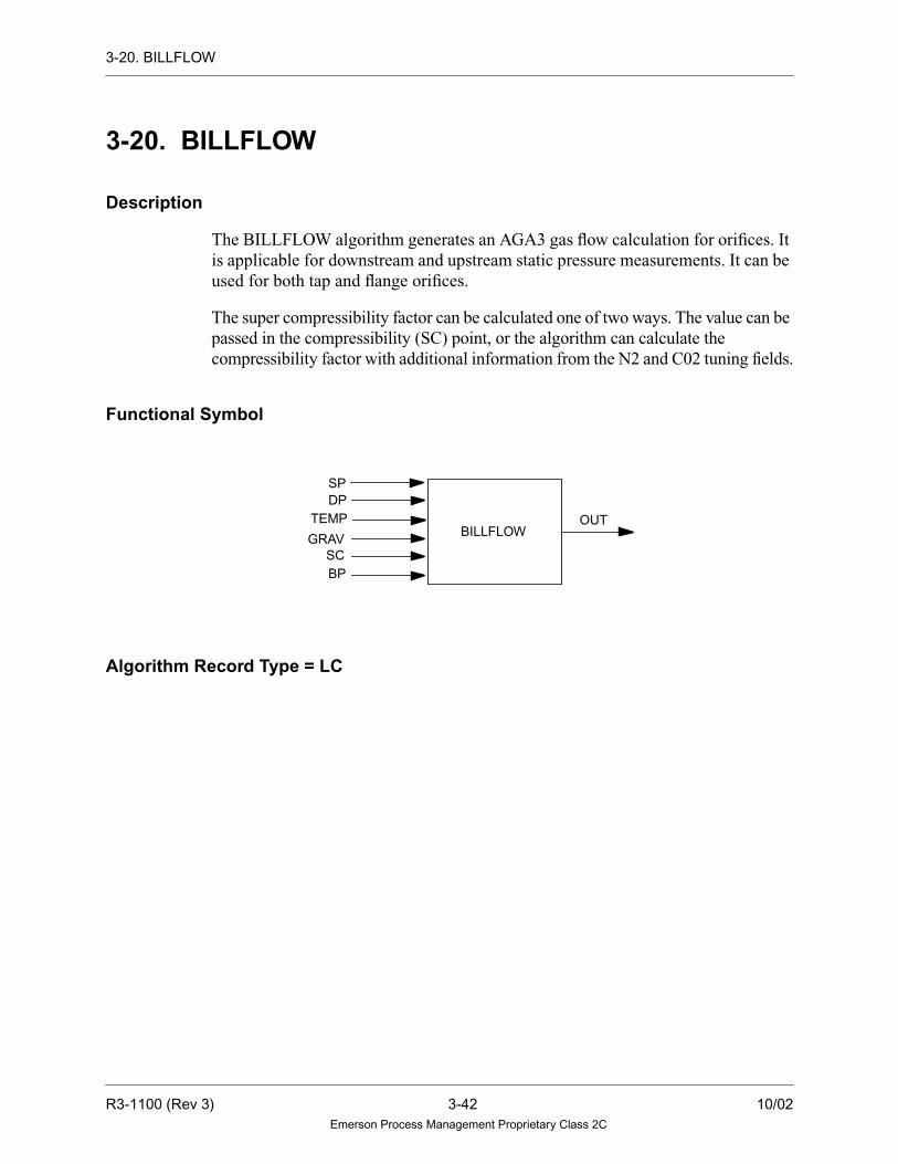
3-20. BILLFLOW
3-20. BILLFLOW
Description
The BILLFLOW algorithm generates an AGA3 gas flow calculation for orifices. It
is applicable for downstream and upstream static pressure measurements. It can be
used for both tap and flange orifices.
The super compressibility factor can be calculated one of two ways. The value can be
passed in the compressibility (SC) point, or the algorithm can calculate the
compressibility factor with additional information from the N2 and C02 tuning fields.
Functional Symbol
Algorithm Record Type = LC
BILLFLOW
SPDP
TEMP
GRAVSCBP
OUT
R3-1100 (Rev 3) 3-42 10/02Emerson Process Management Proprietary Class 2C

3-20. BILLFLOW
Algorithm Definitions
Name
LC Alg.RecordField Type
Required/Optional
DefaultValue Description
Min.Point
Record
DIAG LU-Integer Data Init. Required 115 Tuning Diagram Number —
FLOW X2-Byte Data Init. Required Down-
stream
Flow Element Type (Downstream or
Upstream)
—
XDO R1-Real Tuning
Constant
Required 0.0 Orifice ID —
DI R2-Real Tuning
Constant
Required 0.0 Pipe ID —
PB R3-Real Tuning
Constant
Required 14.73 Pressure Base —
TB R4-Real Tuning
Constant
Required 60.0 Temperature Base —
TAP X1-Byte Data Init. Required Pipe Tap Location (Flange or Pipe) —
CU R6-Real Tuning
Constant
Required .001 Cutoff —
C02 R7-Real Tuning
Constant
Required 0.75 Mole % C02 —
N2 R8-Real Tuning
Constant
Required 0.48 Mole % N2 —
SP — Variable Required — Static Flowing Pressure (PSIG) LA
DP — Variable Required — Orifice Differential Pressure (IN WC) LA
TEMP — Variable Required — Temperature of Gas (Deg. F) LA
GRAV — Variable Required — Specific Gravity LA
SC — Variable Optional — Super compressibility LA
BP — Variable Required — Barometric Pressure (PSIA) LA
OUT — Variable Required — Gas Flow Output (KCF/HR) LA
10/02 3-43 R3-1100 (Rev 3)Emerson Process Management Proprietary Class 2C

3-21. CALCBLOCK
3-21. CALCBLOCK
Description
The CALCBLOCK algorithm is designed to allow the user to solve complex
mathematical equations within a control sheet. The CALCBLOCK algorithm
supports any operation from the following list. For more complex equations,
CALCBLOCK algorithms can be cascaded together. Logical operations are
supported by the CALCBLOCKD algorithm (see Section 3-22).
Keypad Standard Scientific
Add (a + b) *Square Root *Cosine (Cos (a))
Subtract (a - b) *Reciprocal (l/a) *Sine (Sin (a))
Multiply (a * b) Max (max (a,b)) *Tangent (Tan (a))
Divide (a / b) Min (min (a,b)) *Arccos (arccos (a))
*Negate (-a) *Arcsin (arcsin (a))
Remain (rem (a,b)) *Arctan (arctan (a))
*Round (round a) *Natural Log (1n (a))
*Truncate (trunc a) *Log base 10 (log (a))
*Absolute value (abs a) *Antilog (alog (a))
Power (ab)
*Exp (ea)
*Square (a2)
*Cube (a3)
(*) = Unary Operator (Takes only one argument.)
a
R3-1100 (Rev 3) 3-44 10/02Emerson Process Management Proprietary Class 2C

3-21. CALCBLOCK
Each CALCBLOCK algorithm can support up to 18 inputs and 10 floating point
constants.
Each CALCBLOCK algorithm can support up to 15 of the above operations (in any
combination). Each operator will have two arguments.
The intermediate result of each operation will be stored in the Real Fields (1-15) of
the algorithm record. These intermediate results will be displayed in the tuning
window of the monitor graphic and can be used by the user to debug a calculation.
The result of the defined calculation is stored in the OUT point. If an invalid number
(for example, divide by zero, 1n (negative number), infinity, and so forth), occurs,
the VALID output will be set to logical FALSE. If the calculation does not result in
an invalid number, the VALID output will be set to logical TRUE.
The QBAD parameter is initialized by the user to indicate whether the OUT point
should be set to bad quality if an invalid number is calculated. The default value is
“YES” which will set the output to bad quality if an invalid number is encountered.
The real constant fields are the only tunable fields in the algorithm. All editing must
be performed via the Control Builder. See “Ovation Control Builder User Guide”
(NT-0080), (U3-1040), or (WIN80) for more information on the Control Builder.
The optional ENBL input allows the algorithm to be conditionally executed. If the
input is connected, the calculation will be carried out only if the ENBL input is
TRUE. If the ENBL input is FALSE, the calculation will not be performed, and the
output will be set to the previous value.
If the ENBL input is not connected, then there is no conditional execution, and the
calculation is performed each execution loop.
10/02 3-45 R3-1100 (Rev 3)Emerson Process Management Proprietary Class 2C

3-21. CALCBLOCK
Functional Symbol
Algorithm Record Type = LC
Algorithm Definitions
Name
LC Alg.RecordField Type
Required/Optional
DefaultValue Description
Min.Point
Record.
DIAG LU-Byte Data Init. Optional 46 Tuning Diagram Number —
QBAD Y5-Byte Data Init Optional YES Bad Quality on Invalid Number
YES = Set output to bad quality
NO = Do not set output to bad quality
—
OPR1 X0-Byte Variable Required — Operand #1 —
OPR2 X1-Byte Variable Optional — Operand #2 —
OPR3 X2-Byte Variable Optional — Operand #3 —
OPR4 X3-Byte Variable Optional — Operand #4 —
OPR5 X4-Byte Variable Optional — Operand #5 —
OPR6 X5-Byte Variable Optional — Operand #6 —
IN1IN2IN3
IN4IN5IN6IN7IN8IN9IN10IN11IN12
CALCBLOCK
VALI
OUT
IN16
IN17
IN15
IN14
IN13
IN18
ENBL
R3-1100 (Rev 3) 3-46 10/02Emerson Process Management Proprietary Class 2C

3-21. CALCBLOCK
OPR7 X6-Byte Variable Optional — Operand #7 —
OPR8 X7-Byte Variable Optional — Operand #8 —
OPR9 X8-Byte Variable Optional — Operand #9 —
OP10 X9-Byte Variable Optional — Operand #10 —
OP11 Y0-Byte Variable Optional — Operand #11 —
OP12 Y1-Byte Variable Optional — Operand #12 —
OP13 Y2-Byte Variable Optional — Operand #13 —
OP14 Y3-Byte Variable Optional — Operand #14 —
OP15 Y4-Byte Variable Optional — Operand #15 —
ARG1 G0-Integer Variable Required — Argument #1 —
ARG2 G1-Integer Variable Optional — Argument #2 —
ARG3 G2-Integer Variable Optional — Argument #3 —
ARG4 G3-Integer Variable Optional — Argument #4 —
ARG5 G4-Integer Variable Optional — Argument #5 —
ARG6 G5-Integer Variable Optional — Argument #6 —
ARG7 G6-Integer Variable Optional — Argument #7 —
ARG8 G7-Integer Variable Optional — Argument #8 —
ARG9 G8-Integer Variable Optional — Argument #9 —
AR10 G9-Integer Variable Optional — Argument #10 —
AR11 B0-Integer Variable Optional — Argument #11 —
AR12 B1-Integer Variable Optional — Argument #12 —
AR13 B2-Integer Variable Optional — Argument #13 —
AR14 YU-Integer Variable Optional — Argument #14 —
AR15 B4-Integer Variable Optional — Argument #15 —
AR16 B5-Integer Variable Optional — Argument #16 —
AR17 B6-Integer Variable Optional — Argument #17 —
AR18 B7-Integer Variable Optional — Argument #18 —
Name
LC Alg.RecordField Type
Required/Optional
DefaultValue Description
Min.Point
Record.
10/02 3-47 R3-1100 (Rev 3)Emerson Process Management Proprietary Class 2C

3-21. CALCBLOCK
AR19 B8-Integer Variable Optional — Argument #19 —
AR20 B9-Integer Variable Optional — Argument #20 —
AR21 C0-Integer Variable Optional — Argument #21 —
AR22 C1-Integer Variable Optional — Argument #22 —
AR23 C2-Integer Variable Optional — Argument #23 —
AR24 C3-Integer Variable Optional — Argument #24 —
AR25 C4-Integer Variable Optional — Argument #25 —
AR26 C5-Integer Variable Optional — Argument #26 —
AR27 C6-Integer Variable Optional — Argument #27 —
AR28 C7-Integer Variable Optional — Argument #28 —
AR29 C8-Integer Variable Optional — Argument #29 —
AR30 YT-Integer Variable Optional — Argument #30 —
RES1 R1-Real Variable — — Result of operation #1 —
RES2 R2-Real Variable — — Result of operation #2 —
RES3 R3-Real Variable — — Result of operation #3 —
RES4 R4-Real Variable — — Result of operation #4 —
RES5 R5-Real Variable — — Result of operation #5 —
RES6 R6-Real Variable — — Result of operation #6 —
RES7 R7-Real Variable — — Result of operation #7 —
RES8 R8-Real Variable — — Result of operation #8 —
RES9 R9-Real Variable — — Result of operation #9 —
RE10 S1-Real Variable — — Result of operation #10 —
RE11 S2-Real Variable — — Result of operation #11 —
RE12 S3-Real Variable — — Result of operation #12 —
RE13 S4-Real Variable — — Result of operation #13 —
RE14 S5-Real Variable — — Result of operation #14 —
RE15 S6-Real Variable — — Result of operation #15 —
Name
LC Alg.RecordField Type
Required/Optional
DefaultValue Description
Min.Point
Record.
R3-1100 (Rev 3) 3-48 10/02Emerson Process Management Proprietary Class 2C

3-21. CALCBLOCK
CON1 S7-Real Tuning
Constant
Optional — Constant 1 —
CON2 S8-Real Tuning
Constant
Optional — Constant 2 —
CON3 S9-Real Tuning
Constant
Optional — Constant 3 —
CON4 T1-Real Tuning
Constant
Optional — Constant 4 —
CON5 T2-Real Tuning
Constant
Optional — Constant 5 —
CON6 T3-Real Tuning
Constant
Optional — Constant 6 —
CON7 T4-Real Tuning
Constant
Optional — Constant 7 —
CON8 T5-Real Tuning
Constant
Optional — Constant 8 —
CON9 T6-Real Tuning
Constant
Optional — Constant 9 —
CO10 T7-Real Tuning
Constant
Optional — Constant 10 —
ENBL — Variable Optional — Enable Calculations LD
IN1 — Variable Optional — Input 1 LA
IN2 — Variable Optional — Input 2 LA
IN3 — Variable Optional — Input 3 LA
IN4 — Variable Optional — Input 4 LA
IN5 — Variable Optional — Input 5 LA
IN6 — Variable Optional — Input 6 LA
IN7 — Variable Optional — Input 7 LA
IN8 — Variable Optional — Input 8 LA
IN9 — Variable Optional — Input 9 LA
IN10 — Variable Optional — Input 10 LA
Name
LC Alg.RecordField Type
Required/Optional
DefaultValue Description
Min.Point
Record.
10/02 3-49 R3-1100 (Rev 3)Emerson Process Management Proprietary Class 2C

3-21. CALCBLOCK
Example 1
The following example illustrates a single calculation.
IN11 — Variable Optional — Input 11 LA
IN12 — Variable Optional — Input 12 LA
IN13 — Variable Optional — Input 13 LA
IN14 — Variable Optional — Input 14 LA
IN15 — Variable Optional — Input 15 LA
IN16 — Variable Optional — Input 16 LA
IN17 — Variable Optional — Input 17 LA
IN18 — Variable Optional — Input 18 LA
OUT — Variable Required — Calculation result value LA
VALI — Variable Optional — Valid output flag LD
Name
LC Alg.RecordField Type
Required/Optional
DefaultValue Description
Min.Point
Record.
T + 459.67Y =
1164.83
ENBL
IN1
CALCBLOCK
VALI
OUT
DVALGENSIG1
TY
R3-1100 (Rev 3) 3-50 10/02Emerson Process Management Proprietary Class 2C

3-21. CALCBLOCK
Example 2
The following example illustrates a multiple calculation.
This calculation is divided into two parts using two CALCBLOCK algorithms as
follows:
Algorithm Parameter Value Step Solution
IN1 T Not applicable
ENBL SIG1 Not applicable
CON1 459.67 Not applicable
CON2 1164.83 Not applicable
OPR1 + RES1 = IN1 + CON1
OPR2 / RES2 = RES1 / CON2
OUT Y Y = RES2
VALI SIG2 Not applicable
2.62068 x 10=0.000672
-5
(6.2354116Y3 - 14.042987Y4 + 7.3749399Y5
)-2.0296177 + 0.33158207Y + 1.7158422Y2 +
expµ
ENBL
IN1
CALCBLOCK
VALI
OUT
DVALGENSIG1
Y
CALCBLOCK
VALI
OUT
IN1
ENBL
µ
CALCBLOCK #1 CALCBLOCK #2
10/02 3-51 R3-1100 (Rev 3)Emerson Process Management Proprietary Class 2C

3-21. CALCBLOCK
CALCBLOCK #1 solves equation:
(-2.0296177 + 0.33158207Y + 1.7158422Y2 + 6.2354116Y3 - 14.042987Y4 + 7.3749399Y5)
AlgorithmParameter Value Intermediate Step Step Solution
IN1 Y Not applicable Not applicable
ENBL SIG1 Not applicable Not applicable
CON1 2.0296177 Not applicable Not applicable
CON2 0.33158207 Not applicable Not applicable
CON3 1.7158422 Not applicable Not applicable
CON4 6.2354116 Not applicable Not applicable
CON5 14.042987 Not applicable Not applicable
CON6 7.3749377 Not applicable Not applicable
CON7 4 Not applicable Not applicable
CON8 5 Not applicable Not applicable
OPR1 power RES1 = power (IN1, CON8) Y^5
OPR2 power RES2 = power (IN1, CON7) Y^4
OPR3 cube RES3 = cube (IN1) Y^3
OPR4 square RES4 = square (IN1) Y^2
OPR5 * RES5 = CON6 * RES1 7.374 * (Y^5)
OPR6 * RES6 = CON5 * RES2 14.042 * (Y^4)
OPR7 * RES7 = CON4 * RES3 6.235 * (Y^3)
OPR8 * RES8 = CON3 * RES4 1.715 * (Y^2)
OPR9 * RES9 = CON9 * IN1 0.331 * Y
OP10 negative RE10 = neg (CON1) -2.029
OP11 + RE11 = RE10 + RES9 (-2.029 + (0.331 * Y))
OP12 + RE12 = RE11 + RES8 ((-2.029 + (0.331 * Y)) + (1.715 * (Y^2)))
OP13 + RE13 = RE12 + RES7 ((-2.029 + (0.331 * Y)) + (1.715 * (Y^2))
+ (6.235 * (Y^3)))
OP14 — RE14 = RE13 - RES6 (((-2.029 + (0.331 * Y)) + (1.715 * (Y^2))
+ (6.235 * (Y^3)) - (14.042 * (Y^4)))
R3-1100 (Rev 3) 3-52 10/02Emerson Process Management Proprietary Class 2C

3-21. CALCBLOCK
CALCBLOCK #2 solves equation:
(2.62068 x 10⁻⁵ / 0.000672) exp(OUT1)
OP15 + RE15 = RE14 + RES5 ((((-2.029 + (0.331 * Y)) + (1.715 * (Y^2))
+ (6.235 * (Y^3)) - (14.042 * (Y^4))) +
(7.374 * (Y^5)))
OUT OUT OUT = RE15 Not applicable
VALI VALI Not applicable Not applicable
AlgorithmParameter Value Intermediate Step Step Solution
IN1 OUT Not applicable Not applicable
ENBL VALI Not applicable VALI signal from CALCBLOCK #1
CON1 0.0389982143 Not applicable (2.62068 x 10⁻⁵ / 0.000672)
OPR1 exp RES1 = exp (IN1) (exp IN1)
OPR2 * RES2 = CON1 * RES1 (0.0389982143 * (exp IN1))
OUT OUT OUT = RES2 Not applicable
VALI VALI Not applicable Not applicable
AlgorithmParameter Value Intermediate Step Step Solution
10/02 3-53 R3-1100 (Rev 3)Emerson Process Management Proprietary Class 2C

3-22. CALCBLOCKD
3-22. CALCBLOCKD
Description
The CALCBLOCKD algorithm is the digital version of the CALCBLOCK
algorithm (see Section 3-21). CALCBLOCKD can perform logical functions only.
The list of functions is outlined in the table below. For more complex calculations,
CALCBLOCKD algorithms can be cascaded together.
Each CALCBLOCKD algorithm can support up to 18 inputs and 10 floating point
constants.
Each CALCBLOCKD algorithm can support up to 15 of the above operations (in
any combination). Each operator will have two arguments.
The intermediate result of each operation will be stored in the Real Fields (1-15) of
the algorithm record. These intermediate results will be displayed in the tuning
window of the monitor graphic and can be used by the user to debug a calculation.
The result of the defined calculation is stored in the OUT point. If an invalid
calculation occurs, the VALID output will be set to logical FALSE. If the
calculation does not result in an invalid number, the VALID output will be set to
logical TRUE.
The QBAD parameter is initialized by the user to indicate whether the OUT point
should be set to bad quality if an invalid number is calculated. The default value is
“YES” which will set the output to bad quality if an invalid number is encountered.
Logical
And (a && b)
Nand (a ^& b)
Or (a || b)
Nor (a ^| b)
Xor (a xor b)
Not (not a)
R3-1100 (Rev 3) 3-54 10/02Emerson Process Management Proprietary Class 2C

3-22. CALCBLOCKD
The real constant fields are the only tunable fields in the algorithm. All editing must
be performed via the Control Builder. See “Ovation Control Builder User Guide”
(NT-0080), (U3-1040), or (WIN80) for more information on the Control Builder.
The optional ENBL input allows the algorithm to be conditionally executed. If the
input is connected, the calculation will be carried out only if the ENBL input is
TRUE. If the ENBL input is FALSE, the calculation will not be performed, and the
output will be set to the previous value.
If the ENBL input is not connected, then there is no conditional execution, and the
calculation is performed each execution loop.
Functional Symbol
Algorithm Record Type = LC
IN1IN2IN3
IN4IN5IN6IN7IN8IN9IN10IN11IN12
VALI
OUT
IN16
IN17
IN15
IN14
IN13
IN18
ENBL
DIGCALCBLOCK
10/02 3-55 R3-1100 (Rev 3)Emerson Process Management Proprietary Class 2C

3-22. CALCBLOCKD
Algorithm Definitions
Name
LC Alg.RecordField Type
Required/Optional
DefaultValue Description
Min.Point
Record.
DIAG LU-Byte Data Init. Optional 46 Tuning Diagram Number —
OPR1 X0-Byte Variable Required — Operand #1 —
OPR2 X1-Byte Variable Optional — Operand #2 —
OPR3 X2-Byte Variable Optional — Operand #3 —
OPR4 X3-Byte Variable Optional — Operand #4 —
OPR5 X4-Byte Variable Optional — Operand #5 —
OPR6 X5-Byte Variable Optional — Operand #6 —
OPR7 X6-Byte Variable Optional — Operand #7 —
OPR8 X7-Byte Variable Optional — Operand #8 —
OPR9 X8-Byte Variable Optional — Operand #9 —
OP10 X9-Byte Variable Optional — Operand #10 —
OP11 Y0-Byte Variable Optional — Operand #11 —
OP12 Y1-Byte Variable Optional — Operand #12 —
OP13 Y2-Byte Variable Optional — Operand #13 —
OP14 Y3-Byte Variable Optional — Operand #14 —
OP15 Y4-Byte Variable Optional — Operand #15 —
ARG1 G0-Integer Variable Required — Argument #1 —
ARG2 G1-Integer Variable Optional — Argument #2 —
ARG3 G2-Integer Variable Optional — Argument #3 —
ARG4 G3-Integer Variable Optional — Argument #4 —
ARG5 G4-Integer Variable Optional — Argument #5 —
ARG6 G5-Integer Variable Optional — Argument #6 —
ARG7 G6-Integer Variable Optional — Argument #7 —
ARG8 G7-Integer Variable Optional — Argument #8 —
ARG9 G8-Integer Variable Optional — Argument #9 —
AR10 G9-Integer Variable Optional — Argument #10 —
R3-1100 (Rev 3) 3-56 10/02Emerson Process Management Proprietary Class 2C

3-22. CALCBLOCKD
AR11 B0-Integer Variable Optional — Argument #11 —
AR12 B1-Integer Variable Optional — Argument #12 —
AR13 B2-Integer Variable Optional — Argument #13 —
AR14 YU-Integer Variable Optional — Argument #14 —
AR15 B4-Integer Variable Optional — Argument #15 —
AR16 B5-Integer Variable Optional — Argument #16 —
AR17 B6-Integer Variable Optional — Argument #17 —
AR18 B7-Integer Variable Optional — Argument #18 —
AR19 B8-Integer Variable Optional — Argument #19 —
AR20 B9-Integer Variable Optional — Argument #20 —
AR21 C0-Integer Variable Optional — Argument #21 —
AR22 C1-Integer Variable Optional — Argument #22 —
AR23 C2-Integer Variable Optional — Argument #23 —
AR24 C3-Integer Variable Optional — Argument #24 —
AR25 C4-Integer Variable Optional — Argument #25 —
AR26 C5-Integer Variable Optional — Argument #26 —
AR27 C6-Integer Variable Optional — Argument #27 —
AR28 C7-Integer Variable Optional — Argument #28 —
AR29 C8-Integer Variable Optional — Argument #29 —
AR30 YT-Integer Variable Optional — Argument #30 —
RES1 R1-Real Variable — — Result of operation #1 —
RES2 R2-Real Variable — — Result of operation #2 —
RES3 R3-Real Variable — — Result of operation #3 —
RES4 R4-Real Variable — — Result of operation #4 —
RES5 R5-Real Variable — — Result of operation #5 —
RES6 R6-Real Variable — — Result of operation #6 —
RES7 R7-Real Variable — — Result of operation #7 —
Name
LC Alg.RecordField Type
Required/Optional
DefaultValue Description
Min.Point
Record.
10/02 3-57 R3-1100 (Rev 3)Emerson Process Management Proprietary Class 2C

3-22. CALCBLOCKD
RES8 R8-Real Variable — — Result of operation #8 —
RES9 R9-Real Variable — — Result of operation #9 —
RE10 S1-Real Variable — — Result of operation #10 —
RE11 S2-Real Variable — — Result of operation #11 —
RE12 S3-Real Variable — — Result of operation #12 —
RE13 S4-Real Variable — — Result of operation #13 —
RE14 S5-Real Variable — — Result of operation #14 —
RE15 S6-Real Variable — — Result of operation #15 —
CON1 S7-Real Tuning
Constant
Optional — Constant 1 —
CON2 S8-Real Tuning
Constant
Optional — Constant 2 —
CON3 S9-Real Tuning
Constant
Optional — Constant 3 —
CON4 T1-Real Tuning
Constant
Optional — Constant 4 —
CON5 T2-Real Tuning
Constant
Optional — Constant 5 —
CON6 T3-Real Tuning
Constant
Optional — Constant 6 —
CON7 T4-Real Tuning
Constant
Optional — Constant 7 —
CON8 T5-Real Tuning
Constant
Optional — Constant 8 —
CON9 T6-Real Tuning
Constant
Optional — Constant 9 —
CO10 T7-Real Tuning
Constant
Optional — Constant 10 —
ENBL — Variable Optional — Enable Calculations LD
IN1 — Variable Required — Input 1 LP
IN2 — Variable Optional — Input 2 LP
Name
LC Alg.RecordField Type
Required/Optional
DefaultValue Description
Min.Point
Record.
R3-1100 (Rev 3) 3-58 10/02Emerson Process Management Proprietary Class 2C

3-22. CALCBLOCKD
IN3 — Variable Optional — Input 3 LP
IN4 — Variable Optional — Input 4 LP
IN5 — Variable Optional — Input 5 LP
IN6 — Variable Optional — Input 6 LP
IN7 — Variable Optional — Input 7 LP
IN8 — Variable Optional — Input 8 LP
IN9 — Variable Optional — Input 9 LP
IN10 — Variable Optional — Input 10 LP
IN11 — Variable Optional — Input 11 LP
IN12 — Variable Optional — Input 12 LP
IN13 — Variable Optional — Input 13 LP
IN14 — Variable Optional — Input 14 LP
IN15 — Variable Optional — Input 15 LP
IN16 — Variable Optional — Input 16 LP
IN17 — Variable Optional — Input 17 LP
IN18 — Variable Optional — Input 18 LP
OUT — Variable Required — Calculation result value LP
VALI — Variable Optional — Valid output flag LD
Name
LC Alg.RecordField Type
Required/Optional
DefaultValue Description
Min.Point
Record.
10/02 3-59 R3-1100 (Rev 3)Emerson Process Management Proprietary Class 2C

3-22. CALCBLOCKD
Example
The following example illustrates a single calculation:
A = NOT(IN1) && (IN2 XOR IN3)
Algorithm Parameter Value Step Solution
IN1 I1 Not applicable
IN2 I2 Not applicable
IN3 I3 Not applicable
ENBL SIG1 Not applicable
OPR1 NOT RES1 = not(IN1)
OPR2 XOR RES2 = xor(IN2, IN3)
OPR3 AND RES3 = and(RES1, RES2)
OUT A A = RES3
VALI SIG2 Not applicable
ENBL
IN1
DVALGENSIG1
I1
CALCBLOCK
VALI
OUT
IN1I2
IN1I3
A
DIG
R3-1100 (Rev 3) 3-60 10/02Emerson Process Management Proprietary Class 2C
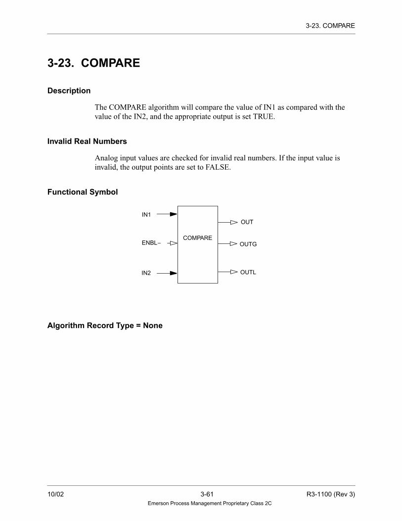
3-23. COMPARE
3-23. COMPARE
Description
The COMPARE algorithm will compare the value of IN1 as compared with the
value of the IN2, and the appropriate output is set TRUE.
Invalid Real Numbers
Analog input values are checked for invalid real numbers. If the input value is
invalid, the output points are set to FALSE.
Functional Symbol
Algorithm Record Type = None
OUT
COMPAREOUTG
OUTLIN2
IN1
ENBL
10/02 3-61 R3-1100 (Rev 3)Emerson Process Management Proprietary Class 2C

3-23. COMPARE
Algorithm Definitions
NameAlg. Record
Field TypeRequired/Optional
DefaultValue Description
Min. PointRecord
IN1 — Variable Required — Input 1 (analog) LA
IN2 — Variable Required — Input 2 (analog) LA
OUT — Variable Required — IN1 equals IN2 (digital) LD
OUTG — Variable Required — IN1 Greater than IN2 (digital) LD
OUTL — Variable Required — IN1 Less than IN2 (digital) LD
ENBL — Input Optional — When this input is true, IN1 is
compared to IN2, and the
appropriate output is set
TRUE.
LD
R3-1100 (Rev 3) 3-62 10/02Emerson Process Management Proprietary Class 2C

3-24. COSINE
3-24. COSINE
Description
The COSINE algorithm performs the mathematical cosine function. COSINE has one
input and one output analog point. Each time the algorithm is executed, if the output
is on scan, it is set to the COSINE of the input. The input to this algorithm is in
radians. If an input is only available in degrees, multiply it by 0.01745329 to convert
to radians.
Invalid Real Numbers and Quality
Analog input values are checked for invalid real numbers. If the input value is
invalid, the value of the output is invalid and its quality is set to BAD. If the input
is valid, the quality of the input is propagated to the output.
Functional Symbol
Algorithm Record Type = None
Algorithm Definitions
Function
OUT=COSINE(IN1)
NameAlg. Record
Field TypeRequired/Optional
DefaultValue Description
Min. PointRecord
IN1 — Variable Required — Input (analog) LA
OUT — Variable Required — Output (analog) LA
COSINEIN1 OUT
10/02 3-63 R3-1100 (Rev 3)Emerson Process Management Proprietary Class 2C
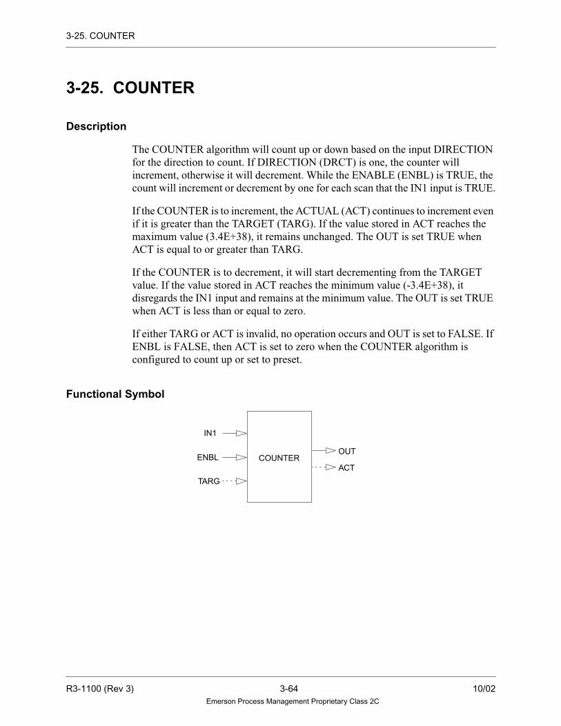
3-25. COUNTER
3-25. COUNTER
Description
The COUNTER algorithm will count up or down based on the input DIRECTION
for the direction to count. If DIRECTION (DRCT) is one, the counter will
increment, otherwise it will decrement. While the ENABLE (ENBL) is TRUE, the
count will increment or decrement by one for each scan that the IN1 input is TRUE.
If the COUNTER is to increment, the ACTUAL (ACT) continues to increment even
if it is greater than the TARGET (TARG). If the value stored in ACT reaches the
maximum value (3.4E+38), it remains unchanged. The OUT is set TRUE when
ACT is equal to or greater than TARG.
If the COUNTER is to decrement, it will start decrementing from the TARGET
value. If the value stored in ACT reaches the minimum value (-3.4E+38), it
disregards the IN1 input and remains at the minimum value. The OUT is set TRUE
when ACT is less than or equal to zero.
If either TARG or ACT is invalid, no operation occurs and OUT is set to FALSE. If
ENBL is FALSE, then ACT is set to zero when the COUNTER algorithm is
configured to count up or set to preset.
Functional Symbol
COUNTER
IN1
OUTENBL
TARG
ACT
R3-1100 (Rev 3) 3-64 10/02Emerson Process Management Proprietary Class 2C

3-25. COUNTER
Algorithm Record Type = LC
Algorithm Definitions
Name
LC Alg.RecordField Type
Required/Optional
DefaultValue Description
Min. PointRecord
DIAG LU-Integer Data
Init
Required 1 Tuning Diagram Number —
IN1 — Variable Required — Start Input Digital LD, LP
ENBL — Variable Required — Enable Input Digital LD, LP
DRCT X1-Byte Data
Init
Required 0 Count Direction: —
TARG R1-Real Selectable Required 0.0 Count Target Number LA
ACT R2-Real Selectable Required 0.0 Actual Count Output LA
OUT — Variable Required — Count Complete Output LD, LP
Value Description
0 Decrement
1 Increment
10/02 3-65 R3-1100 (Rev 3)Emerson Process Management Proprietary Class 2C

3-25. COUNTER
Example
Function
IF DRCT = INCREMENT ( ↑ ) AND TARG = X
THEN OUT = TRUE IF ACT ≥ X
ELSE
OUT = FALSE
ACT = ACT + 1
IF DRCT = DECREMENT ( ↓ ) AND TARG = X
THEN OUT = TRUE IF ACT ≤ 0
ELSE
OUT = FALSE
ACT = ACT -1
ACT
TARGET = 50
If counter decrements to zero fromIf counter increments to TARGET (50)then OUT = TRUE when ACT = 50 TARGET (50) then OUT = TRUE when
0
TARGET = 50
0
50 50
ACT
-3.4E+38 (minimum value)
3.4E+38 (maximum value)
and ACT continues to count ACT = 0 and ACT continues to count
R3-1100 (Rev 3) 3-66 10/02Emerson Process Management Proprietary Class 2C

3-26. DBEQUALS
3-26. DBEQUALS
Description
The DBEQUALS high/low comparator algorithm monitors two analog input
values. If the absolute value of the difference between the signals exceeds the
deadband value, the digital output is set TRUE. If the absolute value of the
difference between the signals is less than the absolute value of the difference
between DBAN and RTRN, then the output is set FALSE.
Invalid Real Numbers and Quality
Both analog input values are checked for invalid real numbers. If one of the input
values is invalid, the value of the output is invalid and its quality is set to BAD. If
all the inputs are valid, the worse quality among the inputs is propagated to the
output.
Functional Symbol
Algorithm Record Type = LC
HLIN1 OUT
IN2
IN2IN1
HL
OUT
OR
10/02 3-67 R3-1100 (Rev 3)Emerson Process Management Proprietary Class 2C

3-26. DBEQUALS
Algorithm Definitions
Function
TEMP = IN1 - IN2
IF ABS(TEMP) > DBAN
THEN OUT = TRUE
IF OUT = TRUE
THEN IF ABS(TEMP) <ABS(DBN-RTRN)
THEN OUT = FALSE
where:
Name
LC Alg.RecordField Type
Required/Optional
DefaultValue Description
Min. PointRecord
DIAG LU-Integer Data Init. Required 23 Tuning Diagram Number —
DBND R1 - Real Tuning
Constant
Required 0 Deadband —
RTRN R2 - Real Tuning
Constant
Optional 0 Deadband return delta
parameter
—
IN1 — Variable Required — Input (analog) LA
IN2 — Variable Required — Input (analog) LA
OUT — Variable Required — Output (digital) LD, LP
TEMP = local, temporary, real variable
R3-1100 (Rev 3) 3-68 10/02Emerson Process Management Proprietary Class 2C

3-27. DEVICESEQ
3-27. DEVICESEQ
Description
The DEVICESEQ algorithm provides an interface between control logic function
and a MASTERSEQ algorithm. In the most common application configuration, the
logic control is utilized to control a particular device. In this configuration, the
MASERSEQ algorithm typically provides a supervisory control function of
multiple devices. Refer to the MASTERSEQ reference pages for details on the
operation of the MASTERSEQ algorithm.
The DEVICESEQ algorithm communicates with the associated MASTERSEQ
algorithm via a packed group point status point. The DEVICESEQ algorithm’s
interface to the control logic via individual inputs and outputs. Refer to the template
definition table for details on the algorithm inputs, output and configuration
parameters.
Functional Symbol
Details of Operation
The DEVICESEQ algorithm provides the MASTERSEQ with the status
information of the associated device. This status information is outlined in the
following status information section. The DEVICESEQ algorithm also transfers the
value of the GO bit in the status point to the STRT output. As long as the GO bit in
the status point is TRUE, the associated device is considered to be running.
The algorithm can also be configured to utilize an internal failure timer. This timer
will monitor the amount of time that elapses while the device is running. The timer
stops accumulating time when either the PASS or FAIL input becomes TRUE. The
elapsed time is compared to the value of the TARG parameter each execution cycle
of the algorithm.The internal timer expires when the accumulated time becomes
greater than or equal to the value of TARG parameter and is greater than zero. If the
failure timer is enabled anytime, the value of the TARG parameter is greater than
zero. If the failure timer is enabled, the accumulated time is always stored in the R3
field of the algorithm. In addition, the accumulated time is also stored in the
optional ACT output point.
MSTRFAIL
PASSTARGRDY
DEVICESEQ
STRT
ACTTIME
(from MASTERSEQ)
10/02 3-69 R3-1100 (Rev 3)Emerson Process Management Proprietary Class 2C

3-27. DEVICESEQ
The algorithm also incorporates an additional internal timer that stores the time that
has elapsed while the device was running. This timer value is stored in both the
optional TIME output and the R4 field of the algorithm record. This value is
dependent of the internal failure timer and is always updated whether the internal
failure timer is utilized or not. The accumulated time in both timers is calculated
based on loop time.
During the first pass mode of the controller and when the RESET bit in the status
point (MSTR) is TRUE, the DEVICESEQ algorithm sets the elapsed time for both
the step timer and the internal failure timer to zero
Status Information
The DEVICESEQ algorithm provides the attached MASTERSEQ algorithm with
the following status information:
• It provides an indication that the associated device is ready for a remote start.
The device is ready for remote start when the RDY input is TRUE. The value of
the RDY input is then transferred to the READY bit of the status point during
each execution cycle of the algorithm.
• It provides an indication that the associated device has failed. The device is failed
when the FAIL input is TRUE. The value of the FAIL input is transferred to the
FAILED bit in the status point during each execution cycle of the algorithm.
• It provides an indication that the associated device has completed when the
PASS input is TRUE. The value of the PASS input is transferred to the
SUCCESS bit during each execution cycle of the algorithm.
R3-1100 (Rev 3) 3-70 10/02Emerson Process Management Proprietary Class 2C
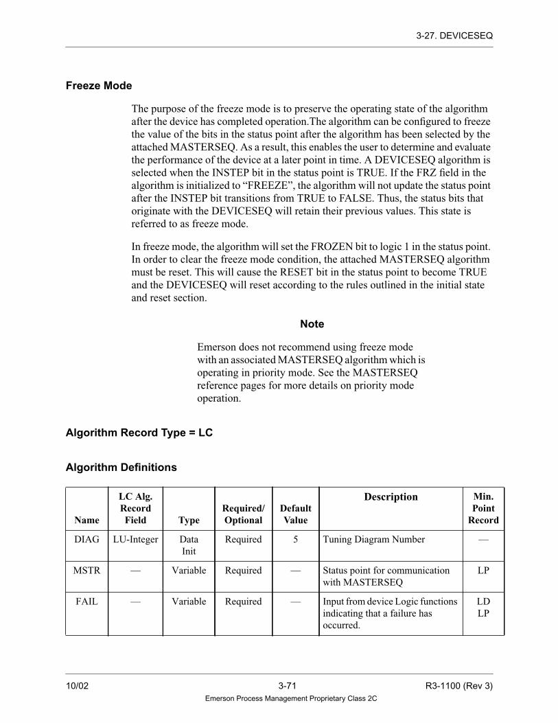
3-27. DEVICESEQ
Freeze Mode
The purpose of the freeze mode is to preserve the operating state of the algorithm
after the device has completed operation.The algorithm can be configured to freeze
the value of the bits in the status point after the algorithm has been selected by the
attached MASTERSEQ. As a result, this enables the user to determine and evaluate
the performance of the device at a later point in time. A DEVICESEQ algorithm is
selected when the INSTEP bit in the status point is TRUE. If the FRZ field in the
algorithm is initialized to “FREEZE”, the algorithm will not update the status point
after the INSTEP bit transitions from TRUE to FALSE. Thus, the status bits that
originate with the DEVICESEQ will retain their previous values. This state is
referred to as freeze mode.
In freeze mode, the algorithm will set the FROZEN bit to logic 1 in the status point.
In order to clear the freeze mode condition, the attached MASTERSEQ algorithm
must be reset. This will cause the RESET bit in the status point to become TRUE
and the DEVICESEQ will reset according to the rules outlined in the initial state
and reset section.
Note
Emerson does not recommend using freeze mode
with an associated MASTERSEQ algorithm which is
operating in priority mode. See the MASTERSEQ
reference pages for more details on priority mode
operation.
Algorithm Record Type = LC
Algorithm Definitions
Name
LC Alg.RecordField Type
Required/Optional
DefaultValue
Description Min.Point
Record
DIAG LU-Integer Data
Init
Required 5 Tuning Diagram Number —
MSTR — Variable Required — Status point for communication
with MASTERSEQ
LP
FAIL — Variable Required — Input from device Logic functions
indicating that a failure has
occurred.
LD
LP
10/02 3-71 R3-1100 (Rev 3)Emerson Process Management Proprietary Class 2C

3-27. DEVICESEQ
PASS — Variable Required — Input from device Logic functions
indicating that the execution of
the device has completed
successfully.
LD
LP
RDY — Variable Required — Input from device Logic functions
indicating that the associated
device is ready for a start
command.
LD
LP
BASE R1-Real Data
Init
Required 1.0 Time Base in Seconds.
Defines the units that the internal
failure time accumulated time will
be displayed in. (Typical values
are 1.0 or 0.1 sec.)
—
TARG R2-Real Selectable Required 0.0 Delay Time.
Defines the amount of time that
can elapse, while the device is
running, before the DEVICESEQ
algorithm will set the failure bit in
the status point to Logic Delay
Time 1. If the value of the
parameters is 0.0 the internal
failure timer will be disabled.
LA
FRZ X1-Byte Data
Init
Required NO
FREEZE
Update Freeze Flag.
Enables and disables freeze mode.
—
STRT — Variable Required — Start Device LD
LP
ACT — Variable Optional — Output value of internal failure
timer.
LA
TIME — Variable Optional — Output value of step timer.
Represents the amount of time the
device has been running
LA
Name
LC Alg.RecordField Type
Required/Optional
DefaultValue
Description Min.Point
Record
R3-1100 (Rev 3) 3-72 10/02Emerson Process Management Proprietary Class 2C

3-27. DEVICESEQ
Status Bit Definitions
Bit Number Originator Signal Name Description
0 MASTERSEQ GO Signal to Device to Begin
Step.
1 DEVICESEQ FAILED Signal to MASTERSEQ that
Current Step Encountered a
Failure.
2 DEVICESEQ SUCCESS Signal to MASTERSEQ that
Current Step Completed
Successfully.
3 DEVICESEQ READY Signal to MASTERSEQ that
the low-level Logic is Ready
to Receive a Remote Start
Command.
4 MASTERSEQ INSTEP Signal from MASTERSEQ
that the Step is Currently
Being Executed.
5 MASTERSEQ OVERRIDE When TRUE indicates that
the OVRD input was used to
Increment the step.
6 MASTERSEQ RESET MASTERSEQ sets this bit
logic 1 when reset input is
TRUE.
7 DEVICESEQ FROZEN This bit is TRUE when
DEVICESEQ has Frozen
updates to the status point.
See DEVICESEQ section for
data.
8 - 15 Reserved for future use — —
10/02 3-73 R3-1100 (Rev 3)Emerson Process Management Proprietary Class 2C

3-28. DEVICEX
3-28. DEVICEX
Description
The DEVICEX algorithm combines the commands to open and close or start and
stop a piece of equipment with feedback signals indicating the command was
accomplished. Devices allow controlled access of the equipment they own and
simplify the operation of the equipment. This algorithm provides digital outputs
that reflect how the I/O outputs of the device are being maintained and the different
status/mode conditions of the device.
The DEVICEX algorithm responds to the following signal combinations:
• One digital output and no feedback
• One digital output and one digital feedback
• Two digital outputs and two digital feedback signals
• Two digital outputs and one feedback
• Three digital outputs and two feedbacks
3-28.1. Signal Combinations
One Digital Output and No Feedback
With one output and no feedback, the DEVICEX algorithm sets the device to a
defined state (on, off, start, stop, open, close) when commanded (see Figure 3-1).
Figure 3-1. One Digital Output and No Feedback
INPUT OUTPUTDEVICE = STATE
INPUT OUTPUT
ONSTARTOPENOFFSTOPCLOSE
111000
R3-1100 (Rev 3) 3-74 10/02Emerson Process Management Proprietary Class 2C

3-28. DEVICEX
One Digital Output and One Digital Feedback
With one output and one feedback (see Figure 3-2), the DEVICEX algorithm can
set the output to a defined state, set the “In Transition” bit (A2 field of bit 1 of the
device record), and then monitor the input. If the input's state does not match the
output state within a user specified amount of time, the device indicates a failed
operation has occurred. If the feedback indicates the desired state is reached within
the user specified time, the device sets its current state field to the appropriate value.
In either case, the In Transition bit will reset at the end of the operation.
Figure 3-2. One Digital Output and One Digital Feedback
INPUT OUTPUTDEVICE = STATE
FEEDBACK
INPUT OUTPUT
ONSTARTOPENOFFSTOPCLOSE
111000
FEEDBACK
111000
Note:
INPUT ≠ OUTPUT in N time --> Failure & Reset “IN TRANSITION”
INPUT ≠ OUTPUT in N time --> Set State & Reset “IN TRANSITION”
10/02 3-75 R3-1100 (Rev 3)Emerson Process Management Proprietary Class 2C

3-28. DEVICEX
Two Digital Outputs and Two Digital Feedbacks
With two digital outputs and two digital feedbacks (see Figure 3-3), the DEVICEX
algorithm can set the appropriate output to “1” or ON and wait for the appropriate
feedback to be true. When the appropriate feedback indicates true, the device sets
its current state field to the appropriate state. If the feedback does not indicate the
appropriate state is reached within the user specified time, the device status display
indicates a failed operation.
Figure 3-3. Two Digital Outputs and Two Digital Feedback Signals
INPUT OUTPUT1DEVICE = STATE
FEEDBACK2
INPUT OUTPUT1
ONSTARTOPENOFFSTOPCLOSE
111000
FEEDBACK2
000111
OUTPUT2
FEEDBACK1
111000
OUTPUT2
000111
FEEDBACK1
R3-1100 (Rev 3) 3-76 10/02Emerson Process Management Proprietary Class 2C

3-28. DEVICEX
Two Digital Outputs and One Digital Feedback
With two digital outputs and one feedback (see Figure 3-4), the DEVICEX
algorithm can set the appropriate output to “1” or ON and wait for the feedback to
go to the desired state. When the feedback indicates the new state, the device sets
its current state field to the appropriate state. If the feedback does not indicate the
appropriate state was reached within the user specified time, the device indicates a
failed operation.
Figure 3-4. Two Digital Outputs and One Digital Feedback
INPUT OUTPUT1DEVICE = STATE
INPUT OUTPUT1
ONSTARTOPENOFFSTOPCLOSE
111000
OUTPUT2
FEEDBACK
111000
OUTPUT2
000111
FEEDBACK
10/02 3-77 R3-1100 (Rev 3)Emerson Process Management Proprietary Class 2C

3-28. DEVICEX
Three Digital Outputs and Two Digital Feedbacks
With three outputs and two feedbacks (see Figure 3-5), the algorithm can set the
appropriate output to “1” according to the OPEN/CLOSE, START/STOP, or STOP
TRAVEL command requested. If the request is an Open or Close command, the
feedbacks are monitored to see if the new state is reached. When the feedbacks
indicate the new state, the device’s current state bit is updated to the appropriate
state. If the feedbacks do not indicate the appropriate state within the user specified
time, the device indicates a failed operation. If the command is a Stop Operation
request, the algorithm will write a “1” to the Stop Travel output and indicate that the
device is stopped.
Figure 3-5. Three Digital Outputs and Two Digital Feedbacks
INPUT OUTPUT1
DEVICE = STATE
FEEDBACK2
OUTPUT2
FEEDBACK1
OUTPUT3
INPUT OUTPUT1
ONSTARTOPENOFFSTOPCLOSE
111000
FEEDBACK2
000111
FEEDBACK1
111000
OUTPUT3
000000
OUTPUT2
000111
STOP OPERATION - - 0 0 1
R3-1100 (Rev 3) 3-78 10/02Emerson Process Management Proprietary Class 2C

3-28. DEVICEX
3-28.2. Control Operation
If the state of the I/O is indeterminate (that is, when both input status bits are equal
to 1, or both are equal to zero and the device is not being commanded to another
state), the Sensor Failure bit (bit 2 and 3 of the 1W field of the DVCE point) in the
device record is set and the quality is set to bad. Note, that once a device is
commanded to another state, the “In Transition” status is set to true as soon as the
algorithm starts driving the device to the commanded state. The “In Transition”
status is reset when the device feedback indicates the new state, and the operation
is successful. If the operation fails, and the device indicates it is neither open nor
closed (both bits of the feedbacks are zero or one), the “In Transition” status will
remain set and the Input Sensor Failure bit will not be set. However, the Operation
Failed bit (bit 2 of the A2 field of the DVCE point) will be set.
The device with two feedbacks may also be configured to display a “Failure to
Respond” status. If the user configures the device to have a response time, the
failure will occur if both feedbacks are not at a zero (clear) state within the defined
response time. If a “Failure to Respond” occurs, there will be no “Operation
Failure” since the algorithm will wait for a new command to process following the
response failure. However, if the device is Stopped and the feedbacks indicate a zero
condition, the Sensor Failure bit will not be set.
The digital inputs and outputs used by the DEVICEX algorithm can either be
signals read from or written to I/O cards, other digital process points contained in
the system, or a combination of the two.
Whenever a device experiences a failed operation (or response failure), it may
ignore additional requests for state changes or it may continue servicing such
requests. This depends on how the device is configured (bit 4 of the C4 field of the
algorithm record). The user may want a DEVICEX algorithm to ignore further
requests after a piece of equipment has failed in order to prevent further damage to
the equipment. Regardless of how a device is configured, it will service at least one
request subsequent to each change of operating mode (for example, Auto Mode to
Manual Mode). If the device is configured to ignore requests after a failure, it will
display the status “LOCKOUT” when a failed operation (or response failure)
occurs.
10/02 3-79 R3-1100 (Rev 3)Emerson Process Management Proprietary Class 2C
3-28. DEVICEX
3-28.3. Control Modes
A device is put into one of three modes by the operator by pressing the appropriate
control key (located on the Control Panel or Membrane Keyboard) or specified
function key (located on a standard keyboard). Note that the device must be
configured to operate in that mode. Therefore, the DEVICEX has three modes of
operation that can be adjusted during monitoring. These modes are as follows:
• AUTO
• MANUAL
• LOCAL
Note
For information on the Control Panel or
Membrane Keyboard, see “Ovation Operator
Station User Guide” (U3-1031), (NT-0020),
or (WIN20).
Auto Mode
Auto Mode allows the Controller application program to control the device through
user programmed logic. The device cannot go into Auto mode unless it is
configured to operate in that mode.
Once it is configured for Auto mode, the device can enter Auto mode if one of the
following occurs:
• The operator presses the Auto mode control key.
• The status of the device is a return from Tag Out and its default mode is Auto.
• The Reject to Auto (ARE) input becomes true and both Manual (MRE) and
Local (LRE) rejects are false.
• The default mode of the device is Auto, and the DEVICEX algorithm is in its
first pass.
• Upon a failed operation if the device is configured.
R3-1100 (Rev 3) 3-80 10/02Emerson Process Management Proprietary Class 2C

3-28. DEVICEX
The device will exit Auto mode whenever one of the following happens:
• The operator presses the Manual Mode control key.
• The operator presses the Local Mode control key.
• The operator Tags Out the device.
• The Reject to Local (LRE) input goes true.
• The Reject to Manual (MRE) input goes true.
• A Failed Operation occurs and the device is configured to go to Manual mode
when the operation fails.
The device may be configured (bit 6 of the C4 field) to go to Manual mode when a
change of state command is entered. If this is the case, pressing the following
control keys will cause the device to go to Manual mode:
• Start/Open
• Stop/Close
• Stop Travel (discontinue operation in progress)
When in Auto Mode, the DEVICEX algorithm will accept commands from the
digital process points that are linked to the device through the DEVICEX algorithm.
Possible commands are:
• Stop/Close
• Start/Open
• Stop Travel (discontinue operation in progress)
• Emergency OPEN/START Override
• Emergency CLOSE/STOP Override
The device will not process any Manual or Local commands while in Auto mode.
10/02 3-81 R3-1100 (Rev 3)Emerson Process Management Proprietary Class 2C

3-28. DEVICEX
Manual Mode
Manual Mode allows the operator to control the device with the control keys. The
device cannot go into Manual Mode unless it is configured for that mode. Once the
device is configured, it can enter Manual Mode when one of the following occurs:
• The operator requests Manual mode by pressing the Manual Mode request key.
• The status of the device is a return from Tag Out and its default mode is Manual.
• The Reject to Manual (MRE) input goes true.
• Upon start-up of the Controller, the default mode of the device is Manual.
• There is an occurrence of an Emergency Override and the default mode of the
device is Manual.
• Upon a failed operation, if the device is configured.
The device may be configured to go to Manual mode when a change of state
command is entered. If this is the case, pressing the following control keys will
cause the device to go to Manual mode:
• Start/Open
• Stop/Close
• Stop Travel (discontinue operation in progress)
The device exits Manual Mode whenever one of the following happens:
• The operator requests Local mode with a control key.
• The operator requests Auto mode with a control key.
• The Reject to Local (LRE) or Reject to Auto (ARE) input becomes true and
Manual Reject (MRE) is false.
• The operator requests the device to be Tagged-Out with the appropriate control
key.
When in Manual Mode, the DEVICEX algorithm will accept commands from the
following possible commands:
• Start/Open
• Stop/Close
• Stop
R3-1100 (Rev 3) 3-82 10/02Emerson Process Management Proprietary Class 2C

3-28. DEVICEX
When in Manual Mode, the DEVICEX algorithm will allow the Emergency
Override to the device only if the device is configured (see bit 0 in C4 field) such
that the overrides have precedence over the operator’s commands.
In addition, when in Manual Mode, the DEVICEX algorithm will not process any
Auto and Local commands to Close, Open, or Stop the devices.
Local ModeLocal Mode is the lowest level mode of operation for the device. A device can enter
this mode only if the following two conditions are met:
• The Reject to Local (LRE) input goes true.
• The operator requests Local mode with a control key.
The device exits Local mode whenever one of the following happens:
• The operator Tags Out the device.
• The Reject to Manual (MRE) input goes true.
• A Failed Operation occurs and the device is configured to go to Manual mode
when operation fails.
When in Local Mode, the DEVICEX algorithm will accept commands. Commands
are digital process points that are linked to the device through the DEVICEX
algorithm. Possible commands are:
• Stop/Close
• Start/Open
• Stop Travel (discontinue operation in progress)
• Emergency OPEN/START Override
• Emergency CLOSE/STOP Override
As long as the device is in the Local mode, the DEVICEX algorithm will not
execute any commands from the Auto and Manual modes. However, the Emergency
Overrides will be honored when the device is in Local mode.
10/02 3-83 R3-1100 (Rev 3)Emerson Process Management Proprietary Class 2C

3-28. DEVICEX
3-28.4. Mode Independent Commands
There are several commands that are requested with keys and are executed if the
device is in Auto, Manual or Local mode. These commands are:
• Tag Out the Device
• Acknowledge Trip
• Auto mode request
• Manual mode request
• Local mode request
These commands will not be accepted, however, if the device is tagged-out.
Tag Out
When in Tag Out Mode, the device ignores all commands except “Remove Tag
Out”. The device will go to its default mode when the Tag Out is removed.
Lock OutA subset of the Tag Out mode is the device “LOCK OUT” mode. Lock out occurs
if the device is configured (see bit 4 C4 field) to ignore subsequent commands to
change state after an operation fails. In other words, the device has only one
opportunity to change state in a particular mode. If the operation fails, the
DEVICEX algorithm will not accept another Open/Start or Close/Stop command
while locked out.
A device may be removed from a Lock Out condition by any of the following
actions:
• Pressing the Auto, Manual or Local mode control keys.
• Tagging out the device.
R3-1100 (Rev 3) 3-84 10/02Emerson Process Management Proprietary Class 2C

3-28. DEVICEX
Emergency Overrides
In addition to the change of state commands, in each of the operating modes there
are two other commands: Emergency Start/Open/Trip and Emergency Stop/Close/
Reset.
These two commands are generated by external logic in the Controller and can act
as emergency overrides over all other commands, including Stop Travel.
Whenever either the Emergency Open, or Emergency Close input becomes true, the
DEVICEX algorithm forces the device to its default state and attempts to get the
device to the commanded state. (If the DEVICEX algorithm is not configured to
ignore failures, the emergency command executes only once.) If both emergency
overrides are set at the same time, the device remains on its present course of action.
As long as either Emergency input is set, the DEVICEX algorithm ignores all Auto
and Local commands to drive the device. The device may also be configured to have
the Emergency inputs override the Manual commands or the Manual commands to
override the Emergency inputs. Upon removal of the emergency override, the
device will return to its default mode.
Note
Emergency overrides, like all other
commands, will be ignored when the device
is tagged out or in Local Mode.
Change of State
In general, when a change of state command is in progress, it is continued until the
device reaches the new state or until a time out occurs. The following conditions
will cause an operation in progress to be discontinued:
• The device is Tagged Out, resulting in inputs being read and outputs not set to
true. They are left as they were at the time of Lock Out.
• A Stop (discontinue operation) command is requested by the current control
mode and an Emergency Override is not in progress. However, if the device is
in Manual mode, and it is configured such that the Emergency Overrides do not
have priority over Manual commands, a Manual Stop request will override the
Emergency command.
10/02 3-85 R3-1100 (Rev 3)Emerson Process Management Proprietary Class 2C

3-28. DEVICEX
In order for a change of state command to be executed, its proper permissive bit
must be true. For example a Manual Close/Stop command will only be executed if
the Close/Stop permissive bit of the device is true. The Emergency Override and
Stop (discontinue operation) commands do not require any permissives to be true in
order to be executed.
The permissives of a device are set to true on start-up and remain true unless the
DEVICEX algorithm is used to update them.
The amount of time that a device allows for the equipment to change state following
a command can be set by the user. The user must specify the units of time for
transition (tenths of a second, seconds, or minutes), and the maximum number of
time units to get to the set and reset states. The user can also specify a time period
(in loops) for the equipment to respond to a command.
For devices with feedback, the amount of time that the DEVICEX algorithm sets
the appropriate output to “ON” can also be configured by the user. The following
modes are supported:
• Set output “ON” for a user configured time period (less than the transition time),
or until the new state is reached, which ever occurs first. (Indicate this mode by
setting bit 1 of C4 field.)
• Set output “ON” for a user configured time period (equal to the transition time)
or until the new state is reached, which ever occurs first. (Indicate this mode by
setting bit 2 of the C4 field.)
• Maintain output “ON” continuously, until a new command is given. This mode
also has a time-out associated with it, but the pulsing continues after the time-
out occurs. If the operation should fail (device does not reach the commanded
state) the operation will be flagged as a failure, and the pulsing will discontinue
until a new command is given. (Indicate this mode by setting bit 3 of the C4
field.)
For the case where the device has only one output (no feedbacks), the output will
be set to “ON” (or “OFF”) continuously depending on whichever command is
requested. There are no time-outs for this case.
A device will always write to its output(s) when a new change of state command
occurs regardless of the state of its input(s). If the device command is from other
application logic, care should be taken to ensure that the command is maintained or
pulsed as needed.
R3-1100 (Rev 3) 3-86 10/02Emerson Process Management Proprietary Class 2C
3-28. DEVICEX
The device continuously checks for change of state commands when it is not in the
process of executing one. The device will execute a change of state command when
it is first set to “ON.” If the command stays “ON,” the device will treat it as a new
command when it finishes executing the last command. Since the device writes to
its output(s) when a new command occurs, its output(s) will cycle continuously
“ON” and “OFF” if the following are true:
• A change of state command is “ON” and it matches the state of the device's
input(s).
• The device is configured to set its output(s) “ON” for a certain amount of time,
then “OFF”.
3-28.5. Alarming
The DEVICE algorithm supports seven types of alarms. All of these alarms, except
Trips, require operator acknowledgment. The device conditions which can produce
alarms are:
• Failed Operations
• Failures to Respond
• Trips
• Alarm State
• Sensor Failures
• Emergency Overrides
• Attention (Trouble)
Failed Operations
If the Failed Operations alarm is configured, the DEVICEX algorithm puts the
device in alarm whenever the equipment does not complete a change-of-state
command (for example, if a valve is commanded to open and it does not do so
within the user specified time). A Failed Operation Alarm will clear upon the next
Open, Close, or Stop command to the device.
10/02 3-87 R3-1100 (Rev 3)Emerson Process Management Proprietary Class 2C

3-28. DEVICEX
Failure to Respond
If the Failure to Respond alarm is configured, the DEVICEX algorithm puts the
device into alarm if the feedbacks do not reflect an “In Transition” state within a
user specified number of loops. The “In Transition” state must be that both
feedbacks have a value of 0.
Trips
If Trip alarms are configured, the DEVICEX algorithm puts the device into alarm
whenever the equipment unexpectedly changes state (for example, when a breaker
trips open). A Trip Alarm will clear when the user acknowledges the Trip by
commanding the device to the Tripped state. Trip Alarm returns do not require
acknowledgment by the user via the Alarm window since they will be cleared by
commanding the device.
Alarm State
The device can be configured to go into alarm based on a user-defined state. The
alarm will clear only when the device returns to the non-alarmed state. These alarms
must be acknowledged by the user.
Sensor Failures
A Sensor Failure alarm will be caused by either or both of the following conditions:
• The device feedbacks are indeterminate (that is, both show a 00 or 11 status) and
the device is not in transition. This is an input sensor alarm.
• The outputs do not reflect the value written to them (output sensor alarm).
Emergency Override
The Emergency Override alarm is generated any time an override occurs and the
device is not at the override state. For example, the occurrence of an Emergency
Open would generate an alarm if the device is Closed. If both override inputs
happen to become true at the same time, an alarm is generated regardless of the state
of the device.
R3-1100 (Rev 3) 3-88 10/02Emerson Process Management Proprietary Class 2C

3-28. DEVICEX
Attention (Trouble)
The Attention (Trouble) alarm is caused by the following conditions:
• The device is in Auto mode and an Auto Open/Start command is present while
the device Open/Start permissive is OFF or and Emergency Close/Stop override
is ON.
• The device is in Auto mode and an Auto Close/Stop command is present while
the device Close/Stop permissive if OFF or and Emergency Open/Start override
is ON.
• The device is not in Auto mode and an Auto Open/Start command is present
while the device is not Open or Running.
• The device is not in Auto mode and an Auto Close/Stop command is present
while the device is not Closed or OFF.
If the device is configured to go into alarm based on a combination of conditions,
the point will be put into alarm when either one or more of the alarm conditions
exist.
The following alarming options are available:
• No Alarming
• Failed Operations, Sensor Failures, Trips, Response Failures, Attention
conditions, and Emergency Overrides
• Failed Operations, Sensor Failures, Trips, Response Failures, Attention
conditions, Emergency Overrides, and Alarm State
Clearing Alarms
Upon Tagging Out, Scan Removing, or putting a device into Local mode, the
following alarms will be cleared:
• Failed Operation
• Failure to Respond
• Sensor Failures
• Trips
• Attention
10/02 3-89 R3-1100 (Rev 3)Emerson Process Management Proprietary Class 2C

3-28. DEVICEX
A State Alarm, however will not be cleared by any of the conditions mentioned above.
It must be cleared by commanding the device.
Tagging out or going to Local mode clears any Emergency Override present.
3-28.6. Device Status Reporting
The device record maintains information corresponding to the current status of a
device. Depending on the state of a device, its displayed status includes a
combination of the following conditions:
• Current State
• In Transition
• Operation Failed
• Tripped
• Stopped
• Emergency Close
• Emergency Open
• Current Mode
• Override Failure
• Scan Removed
• Alarm Checking Off
• Tagged Out
• Locked Out
• Quality
• Permissives
• Rejects
The status information mentioned above comes from various flags (bits) in certain
fields in the packed point and algorithm record.
R3-1100 (Rev 3) 3-90 10/02Emerson Process Management Proprietary Class 2C

3-28. DEVICEX
The A2 field of the Packed point (DVCE) has the following information:
Table 3-1. A2 Field Bit Information
Bit Description
Bit 0 Current State. This bit indicates the current state of the feedback signals. In case feedback
signals give conflicting data, the last known state will be reported. When scanned removed
the last command state will be reported.
Bit 1 In Transition. This bit indicates the device algorithm is currently in the process of trying
to change the state of it’s equipment. The bit will be set true when the device starts to
execute a command. It will be reset when the feedback signals indicate the operation is
complete or the operation has failed.
Bit 2 Operation Failed. This bit is set following any unsuccessful attempt to change the state of
the equipment. It will remain set until the next attempt is made to change the state of the
equipment. Failed operation are not indicated if the device is scanned off.
Bit 3 Tripped. This bit is set any time the equipment changes stage on its own not by the
algorithm. It will remain set until the Trip Acknowledge command. If it is not acknowledge
no other change of state operations, in any mode will be processed. The tripped bit is not
set when the device is Tagged Out or Scanned Removed.
Bit 4 Stopped. This bit is set whenever the device is commanded to stopped. The bit will remain
set until the next attempt is made by the device to change the state of the equipment.
Bit 5 Emergency Close. This bit reflects the status of the override inputs to the device.
Bit 6 Emergency Open. This bit reflects the status of the override inputs to the device.
Bit 7 Last Commanded State. This bit reflects the last known state of the device.
Bit 8 Local Mode. This bit indicates that the device is in local mode.
Bit 9 Manual Mode. This bit indicates that the device is in manual mode.
Bit 10 Auto Mode. This bit indicates that the device is in auto mode.
Bit 11 Reserved.
Bit 12 Attention. This bit indicates certain error conditions are present.
Bit 13 Failed to Respond. This bit indicates that the device did not respond to a command.
Bit 14 Locked Out. This bit indicates that the state of the device is locked out.
Bit 15 Tagged Out. This bit indicates that the state of the device is tagged out.
10/02 3-91 R3-1100 (Rev 3)Emerson Process Management Proprietary Class 2C
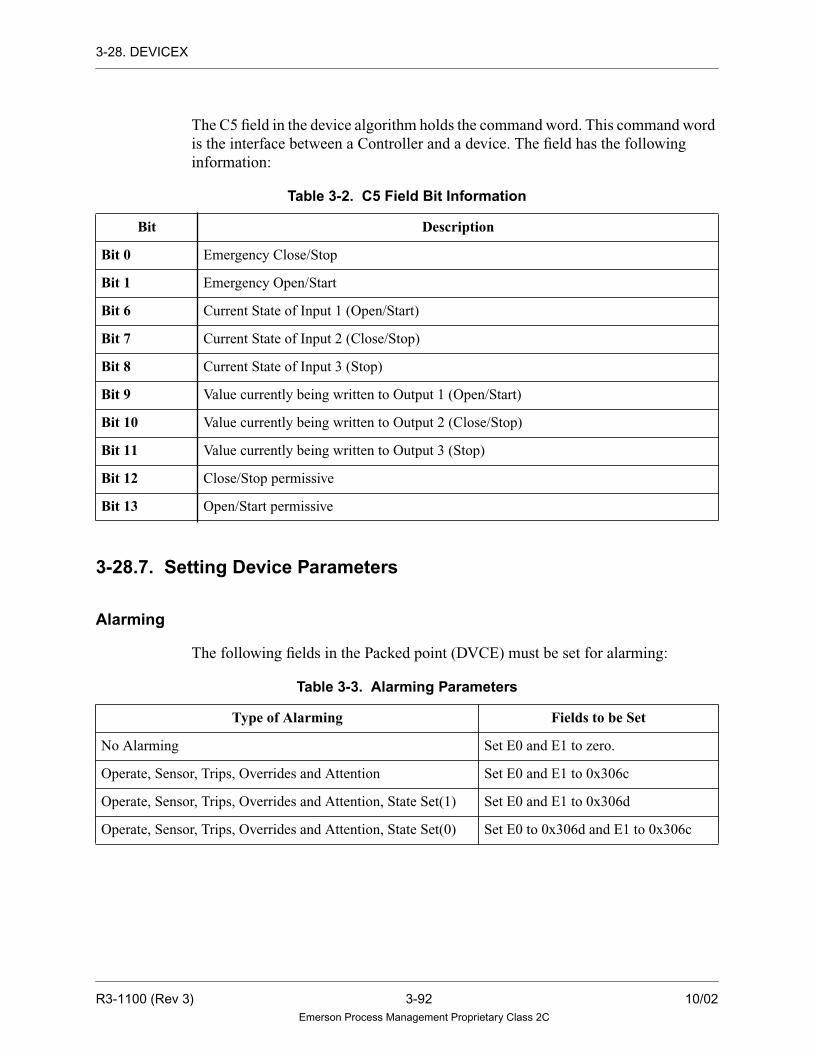
3-28. DEVICEX
The C5 field in the device algorithm holds the command word. This command word
is the interface between a Controller and a device. The field has the following
information:
3-28.7. Setting Device Parameters
Alarming
The following fields in the Packed point (DVCE) must be set for alarming:
Table 3-2. C5 Field Bit Information
Bit Description
Bit 0 Emergency Close/Stop
Bit 1 Emergency Open/Start
Bit 6 Current State of Input 1 (Open/Start)
Bit 7 Current State of Input 2 (Close/Stop)
Bit 8 Current State of Input 3 (Stop)
Bit 9 Value currently being written to Output 1 (Open/Start)
Bit 10 Value currently being written to Output 2 (Close/Stop)
Bit 11 Value currently being written to Output 3 (Stop)
Bit 12 Close/Stop permissive
Bit 13 Open/Start permissive
Table 3-3. Alarming Parameters
Type of Alarming Fields to be Set
No Alarming Set E0 and E1 to zero.
Operate, Sensor, Trips, Overrides and Attention Set E0 and E1 to 0x306c
Operate, Sensor, Trips, Overrides and Attention, State Set(1) Set E0 and E1 to 0x306d
Operate, Sensor, Trips, Overrides and Attention, State Set(0) Set E0 to 0x306d and E1 to 0x306c
R3-1100 (Rev 3) 3-92 10/02Emerson Process Management Proprietary Class 2C
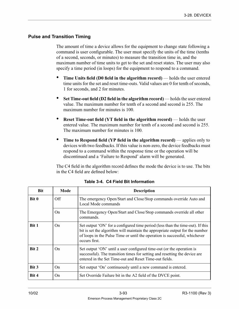
3-28. DEVICEX
Pulse and Transition Timing
The amount of time a device allows for the equipment to change state following a
command is user configurable. The user must specify the units of the time (tenths
of a second, seconds, or minutes) to measure the transition time in, and the
maximum number of time units to get to the set and reset states. The user may also
specify a time period (in loops) for the equipment to respond to a command.
• Time Units field (D0 field in the algorithm record) — holds the user entered
time units for the set and reset time-outs. Valid values are 0 for tenth of seconds,
1 for seconds, and 2 for minutes.
• Set Time-out field (D2 field in the algorithm record) — holds the user entered
value. The maximum number for tenth of a second and second is 255. The
maximum number for minutes is 100.
• Reset Time-out field (YT field in the algorithm record) — holds the user
entered value. The maximum number for tenth of a second and second is 255.
The maximum number for minutes is 100.
• Time to Respond field (YP field in the algorithm record) — applies only to
devices with two feedbacks. If this value is non-zero, the device feedbacks must
respond to a command within the response time or the operation will be
discontinued and a ‘Failure to Respond’ alarm will be generated.
The C4 field in the algorithm record defines the mode the device is to use. The bits
in the C4 field are defined below:
Table 3-4. C4 Field Bit Information
Bit Mode Description
Bit 0 Off The emergency Open/Start and Close/Stop commands override Auto and
Local Mode commands
On The Emergency Open/Start and Close/Stop commands override all other
commands.
Bit 1 On Set output ‘ON’ for a configured time period (less than the time-out). If this
bit is set the algorithm will maintain the appropriate output for the number
of loops in the Pulse Time or until the operation is successful, whichever
occurs first.
Bit 2 On Set output ‘ON’ until a user configured time-out (or the operation is
successful). The transition times for setting and resetting the device are
entered in the Set Time-out and Reset Time-out fields.
Bit 3 On Set output ‘On’ continuously until a new command is entered.
Bit 4 On Set Override Failure bit in the A2 field of the DVCE point.
10/02 3-93 R3-1100 (Rev 3)Emerson Process Management Proprietary Class 2C
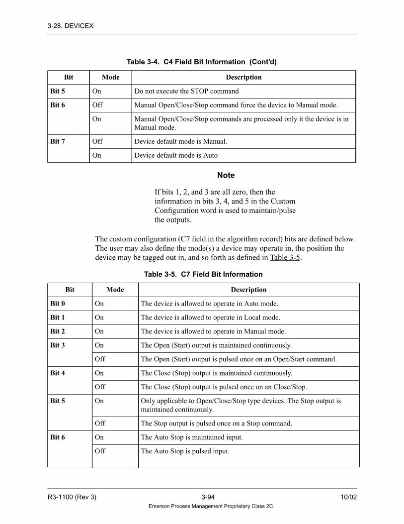
3-28. DEVICEX
Note
If bits 1, 2, and 3 are all zero, then the
information in bits 3, 4, and 5 in the Custom
Configuration word is used to maintain/pulse
the outputs.
The custom configuration (C7 field in the algorithm record) bits are defined below.
The user may also define the mode(s) a device may operate in, the position the
device may be tagged out in, and so forth as defined in Table 3-5.
Bit 5 On Do not execute the STOP command
Bit 6 Off Manual Open/Close/Stop command force the device to Manual mode.
On Manual Open/Close/Stop commands are processed only it the device is in
Manual mode.
Bit 7 Off Device default mode is Manual.
On Device default mode is Auto
Table 3-5. C7 Field Bit Information
Bit Mode Description
Bit 0 On The device is allowed to operate in Auto mode.
Bit 1 On The device is allowed to operate in Local mode.
Bit 2 On The device is allowed to operate in Manual mode.
Bit 3 On The Open (Start) output is maintained continuously.
Off The Open (Start) output is pulsed once on an Open/Start command.
Bit 4 On The Close (Stop) output is maintained continuously.
Off The Close (Stop) output is pulsed once on an Close/Stop.
Bit 5 On Only applicable to Open/Close/Stop type devices. The Stop output is
maintained continuously.
Off The Stop output is pulsed once on a Stop command.
Bit 6 On The Auto Stop is maintained input.
Off The Auto Stop is pulsed input.
Table 3-4. C4 Field Bit Information (Cont’d)
Bit Mode Description
R3-1100 (Rev 3) 3-94 10/02Emerson Process Management Proprietary Class 2C

3-28. DEVICEX
Functional Symbol
Bit 7 On The Auto Start is maintained input.
Off The Auto Start is pulsed input.
Bit 8 On The Local Stop is maintained input.
Off The Local Stop is pulsed input.
Bit 9 On The Local Start is maintained input.
Off The Local Start is pulsed input.
Bit 10 On The Close/Stop permissive is internally generated.
Bit 11 On The Open/Start permissive is internally generated.
Bit 12 On The Travel (Transition) Timer Enabled is internally generated.
Bit 13 On The equipment may be Tagged-out in the open position.
Bit 14 On If Bit 14 is set, equipment may be Tagged-out in the closed position.
For Start/Stop devices only, equipment may be tagged out in the Off/Stop
position.
Bit 15 On The device will be forced to Manual mode when a failed operation occurs.
Table 3-5. C7 Field Bit Information (Cont’d)
Bit Mode Description
DEVICEX
OUT1
IN2
IN3
CPRM
OPRM
ARE
MRE
LOPL
LRE
ACLL
LSTL
AOPL
LCLL
ASTL
TMEN
EMOP
EMCL
OUT2
OUT3
OUT4
LOC
MAN
AUTO
OPFL
TRIP
STAT
DEST
DVCEIN1
10/02 3-95 R3-1100 (Rev 3)Emerson Process Management Proprietary Class 2C

3-28. DEVICEX
Algorithm Record Type = LC
Algorithm Definitions
Name
LCAlgorithmRec. Field Type
Req’d orOpt.
DefaultValues Description
Min.PointRec.
DIAG LU-Byte Data Init. Req’d 47 Tuning Diagram Number. -
SET D2-Integer Data Init. Req’d 20 Set time-out (Max of 255 if units are 1/
10 seconds or seconds. Max. of 100 if
units are minutes.)
–
RSET YT-Integer Data Init. Req’d 20 Reset time-out (Max of 255 if units are
1/10 seconds or seconds. Max. of 100 if
units are minutes.)
–
EM C4 -Integer Data Init. Req’d 9 Emergency override commands -
PT D4 - Integer Data Init. Req’d 0 Pulse Time -
TR YP - Integer Data Init. Req’d 0 Number of Loops to Respond -
CZ C7 - Integer Data Init. Req’d 0 Configuration -
TU D0 - Integer Data Init. Req’d 1 Units time-out
Value Time Units
0 - Tenths of Seconds
1 - Seconds
2 - Minutes
-
TYPE C8 - Integer Data Init. Req’d Open Device Type: Open/close or Start/Stop -
DTIM D5 - Integer Data Init. Req’d 0 Delay Time in Seconds -
DVCE - Variable Req. - Device Record LP
IN1 - Variable Opt. - Device Input 1 - Feedback LD,LP
IN2 - Variable Opt. - Device Input 2 - Feedback LD,LP
IN3 - Variable Opt. - Device Input 3 - Feedback LD,LP
CPRM - Variable Opt - Close Permissive LD,LP
OPRM - Variable Opt - Open Permissive LD,LP
ARE - Variable Opt - Auto Reject LD,LP
LRE - Variable Opt - Local Reject LD,LP
MRE - Variable Opt - Manual Reject LD,LP
LOPL - Variable Opt - Local Open Logic LD,LP
LCLL - Variable Opt - Local Close Logic LD,LP
LSTL - Variable Opt - Local Stop Logic LD,LP
AOPL - Variable Opt - Auto Open Logic LD,LP
ACLL - Variable Opt - Auto Close Logic LD,LP
R3-1100 (Rev 3) 3-96 10/02Emerson Process Management Proprietary Class 2C

3-28. DEVICEX
ASTL - Variable Opt - Auto Stop Logic LD,LP
TMEN - Variable Opt - Transition Timer Enable LD,LP
EMCL - Variable Opt - Emergency Close/Stop LD,LP
EMOP - Variable Opt - Emergency Open/Start LD,LP
OUT1 - Variable Opt - Output 1 LD,LP
OUT2 - Variable Opt - Output 2 LD,LP
OUT3 - Variable Opt - Output 3 LD,LP
OUT4 - Variable Opt - Output 4 LD,LP
LOC - Variable Opt - Local Mode LD,LP
MAN - Variable Opt - Manual Mode LD,LP
AUTO - Variable Opt - Auto Mode LD,LP
OPFL - Variable Opt - Failure-to-Respond LD,LP
TRIP - Variable Opt - Report Trip LD,LP
STAT - Variable Opt - State of the device LD,LP
DEST - Variable Opt - Delay Output LD,LP
Name
LCAlgorithmRec. Field Type
Req’d orOpt.
DefaultValues Description
Min.PointRec.
10/02 3-97 R3-1100 (Rev 3)Emerson Process Management Proprietary Class 2C

3-29. DIGCOUNT
3-29. DIGCOUNT
Description
The DIGCOUNT algorithm sets the output digital FLAG TRUE if M inputs or more
of the N digital inputs are TRUE (where N ≤ 12, and M and N are constants). The
output analog record is set equal to the number of TRUE digital inputs.
Functional Symbol
Algorithm Record Type = LC
IN1IN2IN3IN4IN5IN6IN7IN8IN9IN10IN11IN12
DIGCOUNT
FLAG
OUT
R3-1100 (Rev 3) 3-98 10/02Emerson Process Management Proprietary Class 2C

3-29. DIGCOUNT
Algorithm Definitions
Name
LC Alg.RecordField Type
Required/Optional
DefaultValue Description
Min.Point
Record.
DIAG LU-Integer Data Init. Required 85 Tuning Diagram number —
NMIN G4-Integer Data Init. Required 0 Total digital inputs (N) —
MTRU X1 - Byte Tuning
Constant
Required 0 Maximum TRUE digital inputs
(M)
—
IN1 — Variable Required — Input (digital) LD, LP
IN2
•
•
•
IN12
— Variable Optional — Input (digital) LD, LP
OUT — Variable Required — Output (analog) LA
FLAG — Variable Required — Output (digital flag) LD, LP
10/02 3-99 R3-1100 (Rev 3)Emerson Process Management Proprietary Class 2C

3-30. DIGDRUM
3-30. DIGDRUM
Description
The DIGDRUM algorithm is a software drum controller with up to 32 digital output
values and up to 50 steps. The outputs selected to be TRUE are based on the current
step number and a list of up to 50 initialized integer values. These integers contain 32
bits of data, which are then mapped onto the 32 digital outputs. Thus, for each step,
the user can initialize any combination of TRUE and FALSE states for any or all of
the 32 outputs by converting a string of up to 32 bits into a hexadecimal number.
Functional Symbol
These 50 integers should be input as hexadecimal numbers (for example, 0x1234).
Refer to the Binary to Hexadecimal Conversion Table in Section 2-8 for information
on how to create a hexadecimal number from 16 bits.
DRUM
INC
DEC
TMOD
TRIN
G0=G1=G2=G3=G4=
STEP
O01
O32
G5=G6=G7=G8=G9=
B0=B1=B2=YU=B4=B5=B6=B7=B8=B9=
C0=C1=C2=C3=C4=C5=C6=C7=C8=YT=
D0=YQ=D2=YP=D4=D5=D6=YN=D8=D9=
YM=YL=E2=E3=E4=YC=Y9=E7=E8=Y8=
DIG•••
R3-1100 (Rev 3) 3-100 10/02Emerson Process Management Proprietary Class 2C

3-30. DIGDRUM
The current step number may be tracked to a selected step (TRIN) when in tracking
mode (TMOD = TRUE), increased (INC), or decreased (DEC). The current step
number is only increased or decreased on a FALSE to TRUE transition of INC and
DEC. The maximum number of steps must be initialized. When the current step
number becomes greater than the number of steps, the current step number is reset
to one. If TRIN is a non-integer value, the algorithm rounds the value to the nearest
integer. Any value for TRIN not in the range of one to NMIN is converted to a one
by the algorithm.
The track input value (TRIN) and output value (OUT) are checked for invalid real
numbers. If a tracking request is received and TRIN is an invalid number, then the
tracking request is ignored. However, the current step can be increased (using INC)
or decreased (using DEC) even when TRIN is an invalid number.
If the algorithm calculates an invalid real number output, the value is invalid and the
quality is set to BAD.
Algorithm Record Type = LC
Algorithm Definitions
Name
LC Alg.RecordField Type
Required/Optional
DefaultValue Description
Min. PointRecord
DIAG LU-Integer Data Init. Required 102 Tuning Diagram Number –
INC — Variable Required 0 Input (digital signal to increase
the step number)
LD, LP
DEC — Variable Required 0 Input (digital signal to decrease
the step number)
LD, LP
TMOD — Variable Required 0 Input (digital signal); tracking
request
LD, LP
TRIN — Variable Required 0 Input (analog); tracks the step
number to this value
LA
NMIN X1 - Byte Tuning
Constant
Required 0 Maximum number of steps —
10/02 3-101 R3-1100 (Rev 3)Emerson Process Management Proprietary Class 2C

3-30. DIGDRUM
TYPE X2 - Byte Data Init Optional Long Steps are Long or Short.
Long = Step 1 to Step 50
defines up to 32 outputs.
Short = Double number of
steps to 100 since parameter
“I/01” contains Step 1 value in
the lower 16 bits, and Step 2
value in the higher 16 bits.
Therefore, only up to 16
outputs are used.
—
I01 G0 - Integer Tuning
Constant
Optional 0 Output values for Step 1 —
I02 G1 - Integer Tuning
Constant
Optional 0 Output values for Step 2 —
I03 G2 - Integer Tuning
Constant
Optional 0 Output values for Step 3 —
I04 G3 - Integer Tuning
Constant
Optional 0 Output values for Step 4 —
I05 G4 - Integer Tuning
Constant
Optional 0 Output values for Step 5 —
I06 G5 - Integer Tuning
Constant
Optional 0 Output values for Step 6 —
I07 G6 - Integer Tuning
Constant
Optional 0 Output values for Step 7 —
I08 G7 - Integer Tuning
Constant
Optional 0 Output values for Step 8 —
I09 G8 - Integer Tuning
Constant
Optional 0 Output values for Step 9 —
I10 G9 - Integer Tuning
Constant
Optional 0 Output values for Step 10 —
I11 B0 - Integer Tuning
Constant
Optional 0 Output values for Step 11 —
I12 B1 - Integer Tuning
Constant
Optional 0 Output values for Step 12 —
I13 B2 - Integer Tuning
Constant
Optional 0 Output values for Step 13 —
I14 YU - Integer Tuning
Constant
Optional 0 Output values for Step 14 —
Name
LC Alg.RecordField Type
Required/Optional
DefaultValue Description
Min. PointRecord
R3-1100 (Rev 3) 3-102 10/02Emerson Process Management Proprietary Class 2C

3-30. DIGDRUM
I15 B4 - Integer Tuning
Constant
Optional 0 Output values for Step 15 —
I16 B5 - Integer Tuning
Constant
Optional 0 Output values for Step 16 —
I17 B6 - Integer Tuning
Constant
Optional 0 Output values for Step 17 —
I18 B7 - Integer Tuning
Constant
Optional 0 Output values for Step 18 —
I19 B8 - Integer Tuning
Constant
Optional 0 Output values for Step 19 —
I20 B9 - Integer Tuning
Constant
Optional 0 Output values for Step 20 —
I21 C0 - Integer Tuning
Constant
Optional 0 Output values for Step 21 —
I22 C1 - Integer Tuning
Constant
Optional 0 Output values for Step 22 —
I23 C2 - Integer Tuning
Constant
Optional 0 Output values for Step 23 —
I24 C3 - Integer Tuning
Constant
Optional 0 Output values for Step 24 —
I25 C4 - Integer Tuning
Constant
Optional 0 Output values for Step 25 —
I26 C5 - Integer Tuning
Constant
Optional 0 Output values for Step 26 —
I27 C6 - Integer Tuning
Constant
Optional 0 Output values for Step 27 —
I28 C7 - Integer Tuning
Constant
Optional 0 Output values for Step 28 —
I29 C8 - Integer Tuning
Constant
Optional 0 Output values for Step 29 —
I30 YT - Integer Tuning
Constant
Optional 0 Output values for Step 30 —
I31 D0 - Integer Tuning
Constant
Optional 0 Output values for Step 31 —
I32 YQ - Integer Tuning
Constant
Optional 0 Output values for Step 32 —
I33 D2 - Integer Tuning
Constant
Optional 0 Output values for Step 33 —
Name
LC Alg.RecordField Type
Required/Optional
DefaultValue Description
Min. PointRecord
10/02 3-103 R3-1100 (Rev 3)Emerson Process Management Proprietary Class 2C

3-30. DIGDRUM
I34 YP - Integer Tuning
Constant
Optional 0 Output values for Step 34 —
I35 D4 - Integer Tuning
Constant
Optional 0 Output values for Step 35 —
I36 D5 - Integer Tuning
Constant
Optional 0 Output values for Step 36 —
I37 D6 - Integer Tuning
Constant
Optional 0 Output values for Step 37 —
I38 YN - Integer Tuning
Constant
Optional 0 Output values for Step 38 —
I39 D8 - Integer Tuning
Constant
Optional 0 Output values for Step 39 —
I40 D9 - Integer Tuning
Constant
Optional 0 Output values for Step 40 —
I41 YM -
Integer
Tuning
Constant
Optional 0 Output values for Step 41 —
I42 YL - Integer Tuning
Constant
Optional 0 Output values for Step 42 —
I43 E2 - Integer Tuning
Constant
Optional 0 Output values for Step 43 —
I44 E3 - Integer Tuning
Constant
Optional 0 Output values for Step 44 —
I45 E4 - Integer Tuning
Constant
Optional 0 Output values for Step 45 —
I46 YC - Integer Tuning
Constant
Optional 0 Output values for Step 46 —
I47 Y9 - Integer Tuning
Constant
Optional 0 Output values for Step 47 —
I48 E7 - Integer Tuning
Constant
Optional 0 Output values for Step 48 —
I49 E8 - Integer Tuning
Constant
Optional 0 Output values for Step 49 —
I50 Y8 - Integer Tuning
Constant
Optional 0 Output values for Step 50 —
STEP — Variable Required — Output (analog); current step
number
LA
Name
LC Alg.RecordField Type
Required/Optional
DefaultValue Description
Min. PointRecord
R3-1100 (Rev 3) 3-104 10/02Emerson Process Management Proprietary Class 2C

3-30. DIGDRUM
O01 — Variable Optional — Output (digital signal);
least-significant bit; set or reset
according to the bits in the
integer selected by the current
step number
LD, LP
O02
.
.
.
O31
— Variable Optional — Output (digital signal); set or
reset according to the bits in the
integer selected by the current
step number
LD, LP
O32 — Variable Optional — Output (digital signal); most
significant bit set or reset
according to the bits in the
integer selected by the current
step number
LD, LP
Name
LC Alg.RecordField Type
Required/Optional
DefaultValue Description
Min. PointRecord
10/02 3-105 R3-1100 (Rev 3)Emerson Process Management Proprietary Class 2C

3-31. DIGITAL DEVICE
3-31. DIGITAL DEVICE
Description
The Digital Device algorithm provides logic to control the following seven types of
devices:
• SAMPLER (Controlled Sampler) (Section 3-31.1).
• VALVE NC (Non-Controlled Valve) (Section 3-31.2).
• MOTOR NC (Non-Controlled Motor) (Section 3-31.3).
• MOTOR (Simple Controlled Motor) (Section 3-31.4).
• MOTOR 2-SPD (Two-Speed or Bi-directional Controlled Motor)
(Section 3-31.5).
• MOTOR 4-SPD (Two-Speed and Bi-directional Controlled Motor)
(Section 3-31.6).
• VALVE (Controlled Valve) (Section 3-31.7).
The Digital Device algorithm provides a digital alarm bit to be set for applicable
devices. The algorithm provides time delays for each device as needed, which will
keep the device from failing while the device is processing a command. The time
delay for each device can be independently tuned in the Control Builder (see
“Ovation Control Builder User Guide” (NT-0080), (U3-1040), or (WIN80) for
more information).
Where applicable, there are three modes: AUTO, MANUAL, and OFF. When the
device is in OFF mode, the algorithm only tracks the inputs and will not respond to
any control logic or operator commands. When in AUTO mode, the device only
responds to control logic, and in MANUAL mode, the device only responds to the
Program Keys on the Operator Keyboard (refer to the “Interface Keys on the
Operator Keyboard” table).
In order for a device to respond to a command, the device must be available — not
failed — and in either MANUAL or AUTO mode. Where applicable, the algorithm
can be reset by either a remote reset device point, or by the Operator Keyboard.
When the device is reset, the alarm output point is always reset, along with the
packed status alarm bits. When a device is in either the Failed or Unavailable
condition, the device will remain in the OFF mode until the problem is resolved and
the device is reset. The device will always be put in the MANUAL mode when the
reset is set and the device is READY. The algorithm will respond for both the
Remote Reset and the Operator Reset in any mode.
R3-1100 (Rev 3) 3-106 10/02Emerson Process Management Proprietary Class 2C

3-31. DIGITAL DEVICE
A run counter is maintained for the motor and the sampler devices and can be reset
by the Operator Keyboard. The algorithm will keep the count in local memory as
either hours, minutes, or seconds, and then saves it as an analog output.
Interface Keys on the Operator Keyboard
Program Key Description
P1 Close/Stop
P2 Open/Start/Fast Forward Start/Forward Start/Fast Start
P3 Slow Forward Start/Reverse Start/Slow Start
P4 Fast Reverse Start
P5 Slow Reverse Start
P6 Reset Total Run Time
P7 Reset Device Algorithm
10/02 3-107 R3-1100 (Rev 3)Emerson Process Management Proprietary Class 2C

3-31. DIGITAL DEVICE
3-31.1. SAMPLER (Controlled Sampler)
Description
The Controlled Sampler device has the option of having the Operator Keyboard on
or off. The priority is set in the Control Builder and can only be changed in the
Control Builder (see “Ovation Control Builder User Guide” (NT-0080), (U3-1040),
or (WIN80)). The list of inputs and outputs are found in the Algorithm Definitions
table.
If the Operator Keyboard is off, the keyboard keys are disabled, and the output
(OUT1) of the device follows the input (IN1). When the Operator Keyboard is on,
the output follows the input until the output is changed manually by the operator
with either the STOP or START keys. The output will follow the input again once
there is a change in the input.
The runtime counts when the output is set. The operator has the ability to reset the
runtime when either priority is set. There are no modes, time delays, or alarms
associated with the Controlled Sampler.
Functional Symbol
Algorithm Record Type = LC
SAMPLEROUT1
RUNIN1
R3-1100 (Rev 3) 3-108 10/02Emerson Process Management Proprietary Class 2C
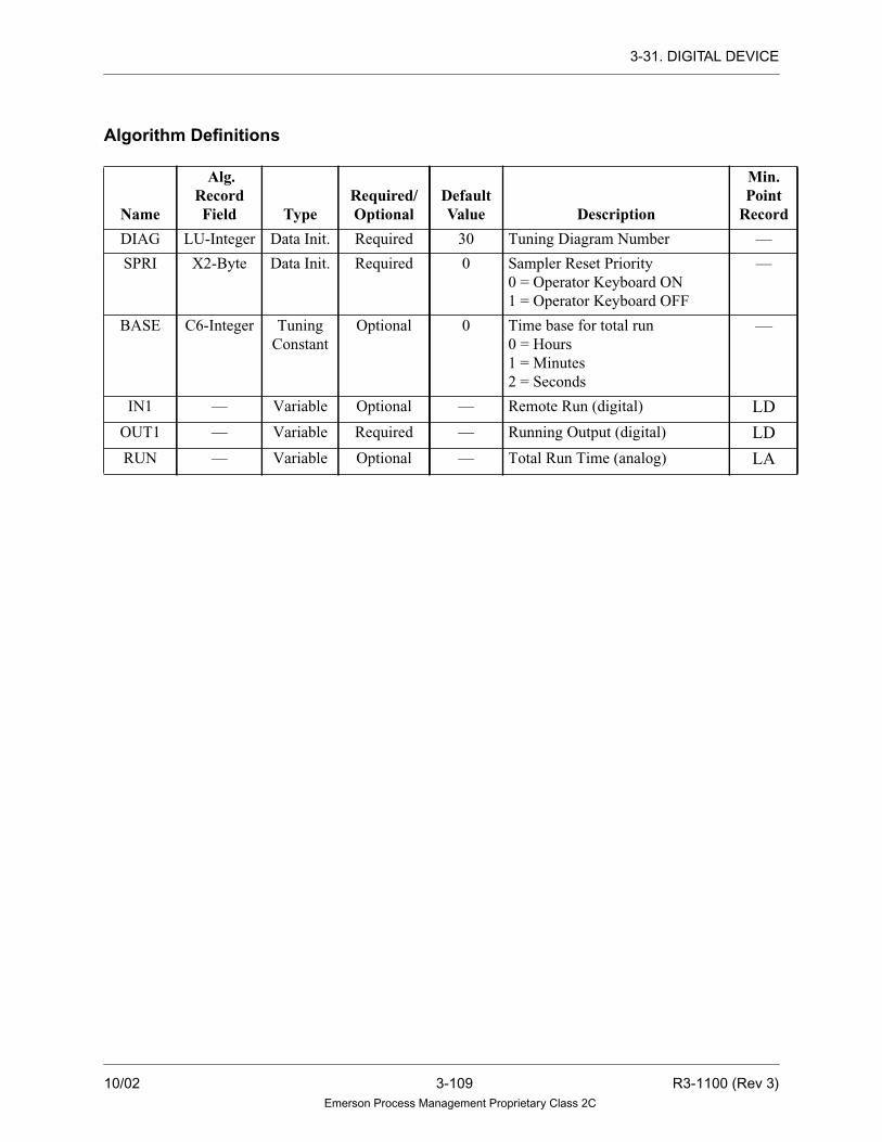
3-31. DIGITAL DEVICE
Algorithm Definitions
Name
Alg.RecordField Type
Required/Optional
DefaultValue Description
Min.Point
Record
DIAG LU-Integer Data Init. Required 30 Tuning Diagram Number —
SPRI X2-Byte Data Init. Required 0 Sampler Reset Priority
0 = Operator Keyboard ON
1 = Operator Keyboard OFF
—
BASE C6-Integer Tuning
Constant
Optional 0 Time base for total run
0 = Hours
1 = Minutes
2 = Seconds
—
IN1 — Variable Optional — Remote Run (digital) LD
OUT1 — Variable Required — Running Output (digital) LD
RUN — Variable Optional — Total Run Time (analog) LA
10/02 3-109 R3-1100 (Rev 3)Emerson Process Management Proprietary Class 2C

3-31. DIGITAL DEVICE
3-31.2. VALVE NC (Non-Controlled Valve)
Description
The Non-Controlled Valve does not accept control information from either the
control logic or the operator (see the Algorithm Definitions table for a list of inputs
and outputs). The algorithm activates the digital alarm bit when in the failed state
(see the Truth table for states of the valve). There are no modes, time delay, or run
time associated with this device.
Functional Symbol
Algorithm Record Type = LC
Algorithm Definitions
Truth Table
Name
Alg.RecordField Type
Required/Optional
DefaultValue Description
Min.Point
Record
DIAG LU-Integer Data Init. Required 30 Tuning Diagram Number —
IN1 — Variable Required — Open Contact (digital) LD
IN2 — Variable Required — Close Contact (digital) LD
IN3 — Variable Optional — Remote Reset (digital) LD
ALRM — Variable Optional — Device Alarm (digital) LD
OPEN Status CLOSED Status Valve State
Set Set Moving
Set Reset Open
Reset Set Closed
Reset Reset Failed
VALVEALRM
IN1
NCIN2
IN3
R3-1100 (Rev 3) 3-110 10/02Emerson Process Management Proprietary Class 2C

3-31. DIGITAL DEVICE
3-31.3. MOTOR NC (Non-Controlled Motor)
Description
The Non-Controlled Motor does not accept control information from either the
control logic or the operator (refer to the Algorithm Definitions table for the list of
inputs and outputs). The digital alarm bit is set when the motor is either in the failed
state or Unavailable state (refer to the Truth table for the states of the motor). The
Non-Controlled Motor has an analog run time output that may be reset by the
operator. There are no modes or time delays associated with this device.
Functional Symbol
Algorithm Record Type = LC
Algorithm Definitions
Name
Alg.RecordField Type
Required/Optional
DefaultValue Description
Min.Point
Record
DIAG LU-Integer Data Init. Required 30 Tuning Diagram Number —
BASE C6-Integer Tuning
Constant
Optional 0 Time base for total run.
0 = Hours
1 = Minutes
2 = Seconds
—
IN1 — Variable Required — Ready Contact (digital) LD
IN2 — Variable Required — Running Contact (digital) LD
IN3 — Variable Optional — Remote Device Reset (digital) LD
ALRM — Variable Optional — Device Alarm (digital) LD
RUN — Variable Optional — Total Run Time (analog) LA
MOTOR ALRMIN1
NCIN2
IN3RUN
10/02 3-111 R3-1100 (Rev 3)Emerson Process Management Proprietary Class 2C

3-31. DIGITAL DEVICE
Truth Table
READY Status RUNNING Status Motor State
Set Set Running
Set Reset Ready
Reset Set Failed
Reset Reset Unavailable
R3-1100 (Rev 3) 3-112 10/02Emerson Process Management Proprietary Class 2C

3-31. DIGITAL DEVICE
3-31.4. MOTOR (Simple Controlled Motor)
Description
The Simple Controlled Motor runs at one speed and in one direction when in
operation. This motor has the option of accepting start or stop commands from
either the control logic or the operator.
When the device is in AUTO mode, the algorithm accepts control commands from
the Remote Start (IN3) and Remote Stop (IN4) inputs. When the device is in
MANUAL mode, the algorithm accepts the control commands Stop and Start from
the Operator Keyboard. Whenever a command is processed in either AUTO or
MANUAL mode, the outputs (OUT1 and OUT2) are set accordingly for the
duration of the time delay previously set in the Control Builder (see “Ovation
Control Builder User Guide” (NT-0080), (U3-1040), or (WIN80) for more
information).
The Stop Permissive (IN8) must be set to allow the motor to be stopped. The Stop
Permissive is automatically set when no input is connect to IN8. Refer to the
Algorithm Definitions table for the list of inputs and outputs.
The digital alarm bit is set when:
• The device is in the Failed state.
• The device is in the Unavailable state.
• The device changes running states without being commanded to do so.
• The device fails to start or stop.
When the device fails to start or stop, the alarm will trigger, but the device will stay
in the current mode and continue looking for the proper combination of Running
and Ready. When this combination is detected, the alarm will be reset and the
device will continue operating in a normal condition. All other alarms will put the
device in OFF mode. Refer to the Truth table for the states of the motor.
The Simple Controlled Motor also has a status packed point that displays which
alarm has been set, the last command, and which mode it is currently in. Refer to
the Output Status Bits table for the list of the status bits.
10/02 3-113 R3-1100 (Rev 3)Emerson Process Management Proprietary Class 2C

3-31. DIGITAL DEVICE
Functional Symbol
Algorithm Record Type = LC
Algorithm Definitions
Name
Alg.RecordField Type
Required/Optional
DefaultValue Description
Min.Point
Record
DIAG LU-Integer Data Init. Required 30 Tuning Diagram Number —
DLY1 C0-Integer Tuning
Constant
Required 0 Time for Ready after Stop —
DLY2 C1-Integer Tuning
Constant
Required 1 Time for Stop —
DLY3 C2-Integer Tuning
Constant
Required 1 Time for Start —
BASE C6-Integer Tuning
Constant
Optional 0 Time for base for total run.
0 = Hours
1 = Minutes
2 = Seconds
—
IN1 — Variable Required — Ready Contact (digital) LD
IN2 — Variable Required — Running Contact (digital) LD
IN3 — Variable Optional — Remote Start (digital) LD
IN4 — Variable Optional — Remote Stop (digital) LD
IN5 — Variable Optional — Remote Auto (digital) LD
IN6 — Variable Optional — Remote Manual (digital) LD
IN7 — Variable Optional — Remote Device Reset (digital) LD
IN8 — Variable Optional — Stop Permissive (digital) LD
OUT1 — Variable Required — Start Output (digital) LD
OUT2 — Variable Required — Stop Output (digital) LD
ALRM — Variable Optional — Device Alarm (digital) LD
MOTOR
OUT1IN1
IN2
IN3
IN4
IN5
IN6
IN7
IN8
ALRM
STAT
RUN
OUT2
R3-1100 (Rev 3) 3-114 10/02Emerson Process Management Proprietary Class 2C

3-31. DIGITAL DEVICE
Truth Table
Output Status Bits
STAT — Variable Optional — Alarm and Mode Status (packed) LP
RUN — Variable Optional — Total Run Time (analog) LA
READY Status RUNNING Status Motor State
Set Set Running
Set Reset Ready
Reset Set Failed
Reset Reset Unavailable
Bit Description
0 Failed to Stop
1 Failed to Start
2 Not Applicable
3 Not Applicable
4 Not Applicable
5 Device Unavailable
6 Device Deviation
7 Device Failed
8 Last Command Stop
9 Last Command Start
10 Not Applicable
11 Not Applicable
12 Not Applicable
13 Device Off
14 Device in Manual
15 Device in Auto
Name
Alg.RecordField Type
Required/Optional
DefaultValue Description
Min.Point
Record
10/02 3-115 R3-1100 (Rev 3)Emerson Process Management Proprietary Class 2C

3-31. DIGITAL DEVICE
3-31.5. MOTOR 2-SPD (Two-Speed or Bi-Directional Controlled Motor)
Description
The Two-Speed or Bi-Directional Controlled Motor has the option of either running
fast or slow, or running forward or backward when in operation. This motor has the
option of accepting start or stop commands from either the control logic or the
operator.
When the device is in AUTO mode, the algorithm accepts control commands from
the Remote Fast/Forward Start (IN4), Remote Slow/Reverse Start (IN5), and
Remote Stop (IN6) inputs. When the device is in MANUAL mode, the algorithm
accepts the control commands Stop, Fast/Forward Start, and Slow/Reverse Start
from the Operator Keyboard. Whenever a command is processed in either AUTO or
MANUAL mode, the outputs (OUT1, OUT2, and OUT3) are set accordingly for the
duration of the time delay previously set in the Control Builder (see “Ovation
Control Builder User Guide” (NT-0080), (U3-1040), or (WIN80) for more
information).
The Stop Permissive (IN10) must be set to allow the motor to be stopped. The Stop
Permissive is automatically set when no input is connected to IN10. This motor may
be commanded to change direction or speed without first being stopped. Refer to
the Algorithm Definitions table for the list of inputs and outputs.
The digital alarm bit is set when one of the following occurs:
• The device is in the Failed state.
• The device is in the Unavailable state.
• The device changes running states without being commanded to do so.
• The device fails to start or stop.
When the device fails to start or stop, the alarm will trigger, but the device will stay
in the current mode and continue looking for the combination of Running and
Ready. When this combination has been detected, the alarm will be reset and the
device will continue operating in a normal condition. All other alarms will put the
device in OFF mode. See the Truth table for the states of the motor.
The Two Speed or Bi-Directional Controlled Motor also has a status packed point
that displays which alarm has been set, the last command, and which mode it is
currently in. See Output Status Bits for the list of status bits.
R3-1100 (Rev 3) 3-116 10/02Emerson Process Management Proprietary Class 2C

3-31. DIGITAL DEVICE
Functional Symbol
Algorithm Record Type = LC
Algorithm Definitions
Name
Alg.RecordField Type
Required/Optional
DefaultValue Description
Min.Point
Record
DIAG LU-Integer Data Init. Required 30 Tuning Diagram Number —
DLY1 C0-Integer Tuning
Constant
Required 0 Time for Ready after Stop —
DLY2 C1-Integer Tuning
Constant
Required 1 Time for Stop —
DLY3 C2-Integer Tuning
Constant
Required 1 Time for Start Fast/Forward —
DLY4 C3-Integer Tuning
Constant
Required 1 Time for Start Slow/Reverse —
BASE C6-Integer Tuning
Constant
Optional 0 Time base for total run:
0 = Hours
1 = Minutes
2 = Seconds
—
IN1 — Variable Required — Ready Contact (digital) LD
IN2 — Variable Required — Fast/Forward Running Contact
(digital)
LD
IN3 — Variable Required — Slow/Reverse Running Contact
(digital)
LD
IN4 — Variable Optional — Remote Fast/Forward Start
(digital)
LD
IN5 — Variable Optional — Remote Slow/Reverse Start
(digital)
LD
MOTOR
OUT1
IN1
IN2
IN3
IN4
IN5
IN6
IN7
IN8
ALRM
STAT
RUN
OUT2
IN9
IN10
2-SPD
OUT3
10/02 3-117 R3-1100 (Rev 3)Emerson Process Management Proprietary Class 2C

3-31. DIGITAL DEVICE
Truth Table
IN6 — Variable Optional — Remote Stop (digital) LD
IN7 — Variable Optional — Remote Auto (digital) LD
IN8 — Variable Optional — Remote Manual (digital) LD
IN9 — Variable Optional — Remote Device Reset (digital) LD
IN10 — Variable Optional — Stop Permissive (digital) LD
OUT1 — Variable Required — Fast/Forward Start Output
(digital)
LD
OUT2 — Variable Required — Slow/Reverse Start Output
(digital)
LD
OUT3 — Variable Required — Stop Output (digital) LD
ALRM — Variable Optional — Device Alarm (digital) LD
STAT — Variable Optional — Alarm and Mode Status (packed) LP
RUN — Variable Optional — Total Run Time (analog) LA
READY StatusFAST/FORWARDRUNNING Status
SLOW/REVERSERUNNING Status Motor State
Set Set Set Not Applicable
Set Set Reset Running Fast or Forward
Set Reset Set Running Slow or Reverse
Set Reset Reset Ready
Reset Set Set Failed
Reset Set Reset Failed
Reset Reset Set Failed
Reset Reset Reset Unavailable
Name
Alg.RecordField Type
Required/Optional
DefaultValue Description
Min.Point
Record
R3-1100 (Rev 3) 3-118 10/02Emerson Process Management Proprietary Class 2C

3-31. DIGITAL DEVICE
Output Status Bits
Bit Description
0 Failed to Stop
1 Failed to Start Fast/Forward
2 Failed to Start Slow/Reverse
3 Not Applicable
4 Not Applicable
5 Device Unavailable
6 Device Deviation
7 Device Failed
8 Last Command Stop
9 Last Command Start Fast/Forward
10 Last Command Start Slow/Reverse
11 Not Applicable
12 Not Applicable
13 Device Off
14 Device in Manual
15 Device in Auto
10/02 3-119 R3-1100 (Rev 3)Emerson Process Management Proprietary Class 2C

3-31. DIGITAL DEVICE
3-31.6. MOTOR 4-SPD (Two-Speed and Bi-Directional Controlled Motor)
Description
The Two-Speed and Bi-Directional Controlled Motor has the option of accepting
start or stop commands from either the control logic or the operator. This motor has
the option of running in any one of the following four states:
• Fast and forward
• Fast and reverse
• Slow and forward
• Slow and reverse
When the device is in AUTO mode, the algorithm accepts control commands from
the Remote Fast Forward Start (IN6), Remote Slow Forward Start (IN7), Remote
Fast Reverse Start (IN8), Remote Slow Reverse Start (IN9), and Remote Stop
(IN10) inputs.
When the device is in MANUAL mode, the algorithm accepts the control
commands Stop, Fast Forward Start, Slow Forward Start, Fast Reverse Start, and
Slow Reverse Start from the Operator Keyboard. Whenever a command is
processed in either AUTO or MANUAL mode, the outputs (OUT1, OUT2, OUT3,
OUT4, and OUT5) are set accordingly for the duration of the time delay previously
set in the Control Builder (see “Ovation Control Builder User Guide” (NT-0080),
(U3-1040), or (WIN80) for more information).
The Stop Permissive (IN14) must be set to allow the motor to be stopped. The Stop
Permissive is automatically set when no input is connected to IN14. This motor may
be commanded to change direction or speed without first being stopped. See the
Algorithm Definitions table for the list of inputs and outputs.
The digital alarm bit is set when one of the following occurs:
• The device is in the Failed state.
• The device is in the Unavailable state.
• The device changes running states without being commanded to do so.
• The device fails to start or stop.
R3-1100 (Rev 3) 3-120 10/02Emerson Process Management Proprietary Class 2C

3-31. DIGITAL DEVICE
When the device fails to start or stop, the alarm will trigger, but the device will stay
in the current mode and continue looking for the proper combination of Running
and Ready. When this combination is found, the alarm will be reset and the device
will continue operating in a normal condition. All other alarms will put the device
in OFF mode. See the Truth table for the states of the motor.
The Two-Speed and Bi-Directional Controlled Motor also has a status packed point
that displays which alarm has been set, the last command, and which mode it is
currently in. See the Output Status Bits table for the list of status bits.
Functional Symbol
Algorithm Record Type = LC
Algorithm Definitions
Name
Alg.RecordField Type
Required/Optional
DefaultValue Description
Min.Point
Record
DIAG LU-Integer Data Init. Required 30 Tuning Diagram Number —
DLY1 C0-Integer Tuning
Constant
Required 0 Time for Ready after Stop —
DLY2 C1-Integer Tuning
Constant
Required 1 Time for Stop —
DLY3 C2-Integer Tuning
Constant
Required 1 Time for Fast Forward Start —
DLY4 C3-Integer Tuning
Constant
Required 1 Time for Slow Forward Start —
MOTOR
OUT1
IN1IN2IN3IN4IN5IN6IN7IN8
ALRM
STAT
RUN
OUT2
IN9IN10
4-SPD
OUT3
IN11IN12IN13IN14
OUT4
OUT5
10/02 3-121 R3-1100 (Rev 3)Emerson Process Management Proprietary Class 2C

3-31. DIGITAL DEVICE
DLY5 C4-Integer Tuning
Constant
Required 1 Time for Fast Reverse Start —
DLY6 C5-Integer Tuning
Constant
Required 1 Time for Slow Reverse Start —
BASE C6-Integer Tuning
Constant
Optional 0 Time base for total run.
0 = Hours
1 = Minutes
2 = Seconds
—
IN1 — Variable Required — Ready Contact (digital) LD
IN2 — Variable Required — Fast Forward Running Contact
(digital)
LD
IN3 — Variable Required — Slow Forward Running Contact
(digital)
LD
IN4 — Variable Required — Fast Reverse Running Contact
(digital)
LD
IN5 — Variable Required — Slow Reverse Running Contact
(digital)
LD
IN6 — Variable Optional — Remote Fast Forward Start
(digital)
LD
IN7 — Variable Optional — Remote Slow Forward Start
(digital)
LD
IN8 — Variable Optional — Remote Fast Reverse Start
(digital)
LD
IN9 — Variable Optional — Remote Slow Reverse (digital) LD
IN10 — Variable Optional — Remote Stop (digital) LD
IN11 — Variable Optional — Remote Auto (digital) LD
IN12 — Variable Optional — Remote Manual (digital) LD
IN13 — Variable Optional — Remote Device Reset (digital) LD
IN14 — Variable Optional — Stop Permissive (digital) LD
OUT1 — Variable Required — Fast Forward Start Output
(digital)
LD
OUT2 — Variable Required — Slow Forward Start Output
(digital)
LD
OUT3 — Variable Required — Fast Reverse Start Output (digital) LD
OUT4 — Variable Required — Slow Reverse Start Output
(digital)
LD
OUT5 — Variable Required — Stop Output (digital) LD
Name
Alg.RecordField Type
Required/Optional
DefaultValue Description
Min.Point
Record
R3-1100 (Rev 3) 3-122 10/02Emerson Process Management Proprietary Class 2C

3-31. DIGITAL DEVICE
Truth Table
ALRM — Variable Optional — Device Alarm (digital) LD
STAT — Variable Optional — Alarm and Mode Status (packed) LP
RUN — Variable Optional — Total Run Time (analog) LA
READYStatus
FASTFORWARDRUNNING
Status
SLOWFORWARDRUNNING
Status
FASTREVERSERUNNING
Status
SLOWREVERSERUNNING
Status Motor State
Set Set Set Set Set Not Applicable
Set Set Set Set Reset Not Applicable
Set Set Set Reset Set Not Applicable
Set Set Set Reset Reset Not Applicable
Set Set Reset Set Set Not Applicable
Set Set Reset Set Reset Not Applicable
Set Set Reset Reset Set Not Applicable
Set Set Reset Reset Reset Running Fast
Forward
Set Reset Set Set Set Not Applicable
Set Reset Set Set Reset Not Applicable
Set Reset Set Reset Set Not Applicable
Set Reset Set Reset Reset Running Slow
Forward
Set Reset Reset Set Set Not Applicable
Set Reset Reset Set Reset Running Fast
Reverse
Set Reset Reset Reset Set Running Slow
Reverse
Set Reset Reset Reset Reset Ready
Reset Set Set/Reset Set/Reset Set/Reset Failed
Reset Set/Reset Set Set/Reset Set/Reset Failed
Reset Set/Reset Set/Reset Set Set/Reset Failed
Reset Set/Reset Set/Reset Set/Reset Set Failed
Reset Reset Reset Reset Reset Unavailable
Name
Alg.RecordField Type
Required/Optional
DefaultValue Description
Min.Point
Record
10/02 3-123 R3-1100 (Rev 3)Emerson Process Management Proprietary Class 2C

3-31. DIGITAL DEVICE
Output Status Bits
Bit Description
0 Failed to Stop
1 Failed to Start Fast Forward
2 Failed to Start Slow Forward
3 Failed to Start Fast Reverse
4 Failed to Start Slow Reverse
5 Device Unavailable
6 Device Deviation
7 Device Failed
8 Last Command Stop
9 Last Command Start Fast Forward
10 Last Command Start Slow Forward
11 Last Command Start Fast Reverse
12 Last Command Start Slow Reverse
13 Device Off
14 Device in Manual
15 Device in Auto
R3-1100 (Rev 3) 3-124 10/02Emerson Process Management Proprietary Class 2C

3-31. DIGITAL DEVICE
3-31.7. VALVE (Controlled Valve)
Description
The Controlled Valve has the option of accepting commands from either the control
logic or the operator.
When the device is in AUTO mode, the algorithm accepts control commands from
the Remote Open (IN3) and Remote Close (IN4) inputs. When the device is in
MANUAL mode, the algorithm accepts the control commands Close and Open
from the Operator Keyboard. Whenever a command is processed in either AUTO or
MANUAL mode, the outputs (OUT1 and OUT2) are set accordingly for the
duration of the time delay previously set in the Control Builder (see “Ovation
Control Builder User Guide” (NT-0080), (U3-1040), or (WIN80) for more
information).
The Open and Close Permissives (IN8 and IN9) must be set to allow the valve to be
opened or closed. The Open and Close Permissives are automatically set when no
input is connected to IN8 or IN9. See the Algorithm Definitions table for the list of
inputs and outputs.
The digital alarm bit is set when one of the following occurs:
• The device is in the Failed state.
• The device opens or closes without being commanded to do so.
• The device fails to open or close.
When the device fails to open or close, the alarm will trigger, but the device will stay
in the current mode and continue looking for the proper Open and Close input
combination. When this combination is found, the alarm will be reset, and the
device will continue operating in a normal condition. All other alarms will put the
device in OFF mode. See the Truth table for the states of the valve.
The Controlled Valve also has a status packed point that displays which alarm has
been set, the last command, and which mode it is currently in. See the Output Status
Bits table for the list of the status bits.
10/02 3-125 R3-1100 (Rev 3)Emerson Process Management Proprietary Class 2C

3-31. DIGITAL DEVICE
Functional Symbol
Algorithm Record Type = LC
Algorithm Definitions
Name
Alg.RecordField Type
Required/Optional
DefaultValue Description
Min.Point
Record
DIAG LU-Integer Data Init. Required 30 Tuning Diagram Number —
DLY1 C0-Integer Tuning
Constant
Required 1 Time for Close
(should be greater than loop time)
—
DLY2 C1-Integer Tuning
Constant
Required 1 Time for Open
(should be greater than loop time)
—
BASE C6-Integer Tuning
Constant
Optional 0 Time base for total run
0 = Hours
1 = Minutes
2 = Seconds
—
IN1 — Variable Required — Open Contact (digital) LD
IN2 — Variable Required — Close Contact (digital) LD
IN3 — Variable Optional — Remote Open (digital) LD
IN4 — Variable Optional — Remote Close (digital) LD
IN5 — Variable Optional — Remote Auto (digital) LD
IN6 — Variable Optional — Remote Manual (digital) LD
IN7 — Variable Optional — Remote Device Reset (digital) LD
IN8 — Variable Optional — Open Permissive (digital) LD
IN9 — Variable Optional — Close Permissive (digital) LD
OUT1 — Variable Required — Open Output (digital) LD
OUT2 — Variable Required — Close Output (digital) LD
VALVE
OUT1
IN1
IN2
IN3
IN4
IN5
IN6
IN7
IN8
ALRM
STAT
OUT2
IN9
R3-1100 (Rev 3) 3-126 10/02Emerson Process Management Proprietary Class 2C

3-31. DIGITAL DEVICE
Truth Table
Output Status Bits
ALRM — Variable Optional — Device Alarm (digital) LD
STAT — Variable Optional — Alarm and Mode Status (packed) LP
OPEN Status CLOSED Status Valve State
Set Set Moving
Set Reset Open
Reset Set Closed
Reset Reset Failed
Bit Description
0 Failed to Close
1 Failed to Open
2 Not Applicable
3 Not Applicable
4 Not Applicable
5 Not Applicable
6 Device Deviation
7 Device Failed
8 Last Command Close
9 Last Command Open
10 Not Applicable
11 Not Applicable
12 Not Applicable
13 Device Off
14 Device in Manual
15 Device in Auto
Name
Alg.RecordField Type
Required/Optional
DefaultValue Description
Min.Point
Record
10/02 3-127 R3-1100 (Rev 3)Emerson Process Management Proprietary Class 2C

3-32. DIVIDE
3-32. DIVIDE
Description
The DIVIDE algorithm divides two gained and biased inputs. The output of the
DIVIDE algorithm is the result of the gained and biased IN1 divided by the gained
and biased IN2. If the gained and biased IN2 is zero, or an invalid real number, then
the output is either the high or low limit according to the sign of the IN1.
Note
If the algorithm receives an invalid value as the input,
or if it calculates an invalid value as the output, the
drop is placed into alarm.
Functional Symbol
Tracking Signals
Tracking and limiting are done through signals passed in the third status field of an
analog point to the algorithm. This algorithm takes the following action in response
to the information found in the input signal TRIN:
Bit Description Action TOUT Signal
16 Track Implemented Passed through
17 Track if lower No action Passed through*
18 Track if higher No action Passed through*
19 Lower inhibit No action Passed through**
20 Raise inhibit No action Passed through**
21 Conditional Track Implemented Passed through***
22 Not used No action Not used
IN1 IN2
OUT
.
.
TOUT
TRIN
R3-1100 (Rev 3) 3-128 10/02Emerson Process Management Proprietary Class 2C

3-32. DIVIDE
The high and low limit flags and the tracking signals from the algorithms are outputs
to TOUT, to be used for display and by an upstream algorithm. If the output value
is invalid, the quality of OUT is set BAD otherwise, the quality of OUT is set to the
worst quality of the two inputs when not in tracking mode. When tracking, the
quality is set to the quality of the track input variable.
Note
If the algorithm generates an inverted track output,
the IN1 value is used as the track output, unless it is
invalid, The track output value is not updated if both
the calculated track output and INI input values are
inverted.
23 Deviation Alarm No action Not used
24 Local Manual mode No action Not used
25 Manual mode No action Not used
26 Auto mode No action Not used
27 Not Used No action Not used
28 Not Used No action Not used
29 Not Used No action Not used
30 Low limit reached No action Low limit reached
31 High limit reached No action High limit reached
* Only when the Track signal is not present.
** Only when the Track signal is not present; the signals are set according to the definitions given
in Setting Tracking Signals.
*** If the algorithm is being told to track, then the Conditional track bit is ignored. Otherwise, the
value of the conditional track bit is transferred to all output track points. If the Conditional Track
bit is set in the track input point, the analog value of all output track points is calculated based
on the analog value of the track input point.
Bit Description Action TOUT Signal
10/02 3-129 R3-1100 (Rev 3)Emerson Process Management Proprietary Class 2C

3-32. DIVIDE
Algorithm Record Type = LC
Algorithm Definitions
Name
LC Alg.RecordField Type
Required/Optional
DefaultValue Description
Min.Point
Record
DIAG LU-Integer Data Init. Required 81 Tuning Diagram Number —
IN1G R1 - Real Tuning
Constant
Required 1.0 Gain (+ or -) on input 1 —
IN1B R2 - Real Tuning
Constant
Optional 0.0 Bias (+ or -) on input 2 —
IN2G R3-Real Tuning
Constant
Required 1.0 Gain on input 2 —
IN2B R4-Real Tuning
Constant
Optional 0.0 Bias on input 2 —
TPSC R5-Real Tuning
Constant
Required 100.0 Maximum value of the output point —
BTSC R6-Real Tuning
Constant
Required -100.0 Minimum value of the output point —
TRAT R7-Real Tuning
Constant
Required 2.5 Track ramp rate (units per second) —
IN1 — Variable Required — Input (analog) LA
TOUT — Variable Required — Track output value, mode & status
for input variable
LA
IN2 — Variable Required — Input (analog) LA
OUT — Variable Required — Output (analog) LA
TRIN — Variable Optional — Tracking analog value, tracking and
limiting mode signals input variance
LA
R3-1100 (Rev 3) 3-130 10/02Emerson Process Management Proprietary Class 2C

3-32. DIVIDE
Function
IN2GB = (IN2 x IN2 GAIN) + IN2 BIAS
IN1GB = (IN1 x IN1 GAIN) + IN1BIAS
IF IN2GB ≠ 0 THEN
OUT = IN1GB / IN2GB
ELSE
IF IN1GB ≥ 0 THEN
OUT = TPSC
ELSE
OUT = BTSC
IF OUT ≥ TPSC
OUT = TPSC
ELSE
IF OUT ≤ BTSC THEN
OUT = BTSC
10/02 3-131 R3-1100 (Rev 3)Emerson Process Management Proprietary Class 2C

3-33. DROPSTATUS
3-33. DROPSTATUS
Description
The DROPSTATUS algorithm accesses and outputs the contents of any record field
in the Drop Status Record (DU) for a particular Controller. To access the contents
of a record field, the field number must be specified. If an invalid field number is
entered, zero is written to the AOUT and POUT output points.
The data in the DU record field is output as a packed point. If specified, the contents
of the record field can also be output as an analog value. Refer to “Ovation Record
Types User’s Guide” (R3-1140) for a description of the DU record fields.
Functional Symbol
Field Numbers
Field Number Field Name
1 FA
2 FB
3 FC
4 FK
5 FS
6 FO
7 HC
8 TA
9 CT
10 RT
11 LN
12 E5
13 E6
14 GD
15 GL
16 GI
DROPSTATUSAOUTPOUT
R3-1100 (Rev 3) 3-132 10/02Emerson Process Management Proprietary Class 2C

3-33. DROPSTATUS
Algorithm Record Type = LC
Algorithm Definitions
17 GG
18 GH
19 NC
20 FF
21 JU
22 UU
23 U5
24 U6
25 U7
Name
LC Alg.RecordField Type
Required/Optional
DefaultValue Description
Min.Point
Record
RECD G0 -
Integer
Data Init. Required 0 The field number in the drop
record.
—
AOUT — Variable Optional — Output (analog); contents of the
DU record field.
LA
POUT — Variable Required — Output (packed); contents of the
DU record field.
LP
Field Number Field Name
10/02 3-133 R3-1100 (Rev 3)Emerson Process Management Proprietary Class 2C

3-34. DRPI
3-34. DRPI
Description
The DRPI algorithm converts the gray codes (IN1) to actual rod positions. On the
first pass, the rod position is always a zero value with BAD quality. For control rods,
the calculation for converting gray codes into steps is converting the gray code to a
decimal number and adding the two gray codes together and multiplying the sum
by STEP. If there is an error reading either gray code, or if the gray code is above
the maximum range, only the good code is used in the calculation and the resultant
quality is set to FAIR. If gray code A is BAD, then the rod position is equal to:
((converted gray code B times 2 times STEP) + (1/2 times STEP)). If the gray code
B is BAD, then the rod position is equal to: ((converted gray code A times 2 times
STEP) - (1/2 times STEP)). If both gray codes are BAD or above the limits, then the
rod position is set to zero with BAD quality.
If the rod is a shutdown rod and the converted gray codes added together equal
BOTS, then the rod position is equal to GAP and POOR quality. If the converted
gray codes added together is greater than BOTS, then the rod position is equal to
TOPG plus the calculated position.
If bit 12 of IN1 is set, then the algorithm sets a two second timer. When the timer
expires, the algorithm saves the current rod being scanned. During the first scan of
any rod after the two second timer has expired, a rod value of zero is allowed. At all
other times a zero is not valid. If a zero is not allowed, then any zero reading will be
ignored by setting the rod number (RODZ) to zero.
Functional Symbol
IN1RODSHUTTRIP
OUT
RODZDRPI
R3-1100 (Rev 3) 3-134 10/02Emerson Process Management Proprietary Class 2C

3-34. DRPI
Algorithm Record Type = LC
Algorithm Definitions
Name
LC Alg.RecordField Type
Required/Optional
DefaultValue Description
Min.Point
Record
DIAG LU-Integer Data Init Required 93 Tuning Diagram Number —
MNIN R1-Real Tuning
Constant
Required 0.0 Maximum number of steps per rod —
GAP R2-Real Tuning
Constant
Required 0.0 Shutdown Rod Gap —
TOPG R3-Real Tuning
Constant
Required 0.0 Shutdown Top Gap —
FUEL R4-Real Tuning
Constant
Required 0.0 Maximum Steps for Rapid Refuel —
BOTS G0-Integer Tuning
Constant
Required 4 Number of Bottom Coils for
Shutdown Rod
—
MAXS G1-Integer Tuning
Constant
Required 6 Maximum Coils in Shutdown Rod —
STEP G2-Integer Tuning
Constant
Required 6 Number of Steps Between Coils —
IN1 — Variable Required 0 Input (packed)
Bits 0 - 4 - Gray
Bit 5 - Gray Code A Error Bit
Bits 6 - 10 - Gray Code B
Bit 11 - Gray Code B Error Bit
Bit 12 - CD24 Monitor.
Indicator that zero value can be
accepted.
Bit 13 - Rapid Refuel in
progress
LP
ROD — Variable Required — Rod Number
Input (analog)
LA
SHUT — Variable Required — Shutdown Control Rod
Input (digital)
LD, LP
TRIP — Variable Required — Unit Trip
Input (digital)
LD, LP
OUT — Variable Required — Rod Position
Output (analog)
LA
RODZ — Variable Required — Rod Number or zero
Output (analog)
LA
10/02 3-135 R3-1100 (Rev 3)Emerson Process Management Proprietary Class 2C

3-35. DVALGEN
3-35. DVALGEN
Description
The DVALGEN algorithm initializes a digital point. For the DVALGEN algorithm,
the output is the digital value stored in the tuning constant (VALU). This value can
be used to force any digital input to any algorithm to either a TRUE or FALSE
statement that will remain fixed unless changed by a tuning function.
Functional Symbol
Algorithm Record Type = None
Algorithm Definitions
Function
OUT = VALUE
Name
Alg.RecordField Type
Required/Optional
DefaultValue Description
Min.Point
Record
DIAG LU-Integer Data Init. Required 69 Tuning Diagram Number —
VALU R1 - Real Tuning
Constant
Required 1.0 Real value (0.0 = FALSE; 1.0 or
any other non-zero, real number =
TRUE)
—
OUT — Variable Required — Output (digital) LD, LP
DVALGEN OUTDVALGEN
OUT
OR
R3-1100 (Rev 3) 3-136 10/02Emerson Process Management Proprietary Class 2C

3-36. FIELD
3-36. FIELD
Description
The FIELD algorithm is used only with the hardware analog output variable points.
This algorithm will check the value against the IO card limits and set the appropriate
bits in the track output point. It should be used instead of “output analog hardware”
I/O connectors in applications involving interfaces to control elements (for
example, valves and dampers).
The output digital point (FAIL) will be TRUE when the algorithm detects a
hardware error on the I/O card.
This algorithm is designed to read the value from the point record and output value
TOUT on the first pass.
Functional Symbol
Algorithm Record Type = LC
Algorithm Definitions
Name
LC Alg.RecordField Type
Required/Optional
DefaultValue Description
Min.Point
Record
IN1 — Variable Required — Input (analog) LA
TOUT — Variable Required — Track Output Value Mode and Status
For Input Variable (analog)
LA
HWPT — Variable Optional — Hardware Output (analog) LA
FAIL — Variable Optional — Hardware Error Point (digital) LD, LP
IN1
TOUT
FAIL
10/02 3-137 R3-1100 (Rev 3)Emerson Process Management Proprietary Class 2C

3-36. FIELD
Tracking Signals
The high and low limits flags and tracking signals from the algorithm are output to
TOUT, to be used for display and by an upstream algorithm.
The following information is output by this algorithm in the TOUT signal.
Bit Description Action TOUT Signal
16 Track Implemented TRUE when output value is at
low limit of the card
17 Track if lower No action Passed through
18 Track if higher No action Passed through
19 Lower inhibit Implemented TRUE when output value is at
the low limit of the card
20 Raise inhibit Implemented TRUE when output value is at
high limit of the card
21 Conditional Track No action Not used
22 Not used No action Not used
23 Deviation Alarm No action Not used
24 Local Manual mode No action Not used
25 Manual mode No action Not used
26 Auto mode No action Not used
27 Supervisory mode No action Not used
28 Cascade mode No action Not used
29 DDC mode No action Not used
30 Low limit reached Implemented Low limit reached
31 High limit reached Implemented High limit reached
* Only when the Track signal is not present.
** Only when the Track signal is not present; the signals are set according to the definitions given
in Setting Tracking Signals.
R3-1100 (Rev 3) 3-138 10/02Emerson Process Management Proprietary Class 2C

3-37. FIFO
3-37. FIFO
Description
The FIFO algorithm provides a basic First In - First Out operation. The order in
which any of the 16 digital inputs transition from FALSE to TRUE is preserved. The
order is stored using the input number of the associated input (that is, 1 for IN1, 2
for IN2, 3 for IN3, and so forth).
Initially, the value of the output is zero. If the FIFO is empty, the output is also zero.
For each successive FALSE to TRUE Transition of the rotate (RTAT) input, the
oldest input number stored in the FIFO will be removed from internal storage and
that numerical value will be written to the output (OUT). Note that the output is
considered separate from the actual FIFO.
The point will retain the value until either the rotate (RTAT) or the clear (CLR) input
transitions from FALSE to TRUE. A FALSE to TRUE transition on the (RTAT)
input will cause the oldest entry in the FIFO to be removed from the FIFO and
placed in the output (OUT). At this point, the value in the (OUT) variable is no
longer included in the queue.
If multiple inputs transition from FALSE to TRUE on the same execution cycle of
the Controller, then they will be ordered according to their numerical number. For
example, IN1 will be placed in the FIFO first and thus will be rotated out first.
A FALSE to TRUE transition on the clear (CLR) input will cause the output and all
the internal FIFO entries to be set to zero. As long as the clear (CLR) input remains
TRUE, the algorithm will ignore all the inputs and thus will not operate.
The FIFO will be considered full when all 16 inputs have made a transition from
FALSE to TRUE without any subsequent FALSE to TRUE transition on the rotate
(RTAT) input. When this full condition exists, any further FALSE to TRUE
transitions of any of the inputs will be ignored until at least one of the stored values
is rotated out of the FIFO.
The FLAG output is set TRUE when the FIFO is NOT empty.
Note
The FIFO values are stored in the algorithm
record fields G0-G9, B0-B5.
10/02 3-139 R3-1100 (Rev 3)Emerson Process Management Proprietary Class 2C

3-37. FIFO
Functional Symbol
Algorithm Record Type= LC
Algorithm Definitions
Name
LC Alg.RecordField Type
Required/Optional
DefaultValue Description
Min.Point
Record
IN1 — Variable Required — Digital Input LD
IN2 — Variable Optional — Digital Input LD
IN3 — Variable Optional — Digital Input LD
IN4 — Variable Optional — Digital Input LD
IN5 — Variable Optional — Digital Input LD
IN6 — Variable Optional — Digital Input LD
IN7 — Variable Optional — Digital Input LD
IN8 — Variable Optional — Digital Input LD
IN9 — Variable Optional — Digital Input LD
IN10 — Variable Optional — Digital Input LD
IN11 — Variable Optional — Digital Input LD
IN12 — Variable Optional — Digital Input LD
IN1IN2IN3IN4IN5IN6IN7IN8IN9IN10IN11IN12
OUT
FIFO
IN13IN14IN15IN16
RTATCLR
FLAG
R3-1100 (Rev 3) 3-140 10/02Emerson Process Management Proprietary Class 2C

3-37. FIFO
IN13 — Variable Optional — Digital Input LD
IN14 — Variable Optional — Digital Input LD
IN15 — Variable Optional — Digital Input LD
IN16 — Variable Optional — Digital Input LD
RTAT — Variable Required — Digital Rotate FIFO Input LD
CLR — Variable Required — Digital Clear FIFO Input LD
OUT — Variable Required — Analog output variable LA
FLAG — Variable Optional — Digital output variable LD
Name
LC Alg.RecordField Type
Required/Optional
DefaultValue Description
Min.Point
Record
10/02 3-141 R3-1100 (Rev 3)Emerson Process Management Proprietary Class 2C

3-38. FLIPFLOP
3-38. FLIPFLOP
Description
The FLIPFLOP algorithm is a memory device. Its output states are defined in the
truth tables shown under “Function for Reset Override” and “Function for Set
Override.”
Functional Symbol
Algorithm Record Type = LC
Algorithm Definitions
Name
LC Alg.RecordField Type
Required/Optional
DefaultValue Description
Min.Point
Record
TYPE X1-Byte Data
Init.
Required 0 Type of flip-flop:
1 - Flip-flop with set override
0 - Flip-flop with reset override
—
SET — Variable Required — Input (digital); set LD, LP
RSET — Variable Required — Input (digital); reset LD, LP
OUT — Variable Required — Output (digital) LD, LP
SET
RSET
S
R
OUT1
0
R3-1100 (Rev 3) 3-142 10/02Emerson Process Management Proprietary Class 2C

3-38. FLIPFLOP
Function for Reset Override
where:
S = Output remains in the same or previous state.
On power up/reset of the Controller, OUT is set according to
the truth table, unless SET and RSET are both FALSE.
Function for Set Override
where:
S = Output remains in the same or previous state.
On power up/reset of the Controller, OUT is set according to
the truth table, unless SET is set FALSE.
SET RSET OUT
0 0 S
0 1 0
1 0 1
1 1 0
SET RSET OUT
0 0 S
0 1 0
1 0 1
1 1 1
10/02 3-143 R3-1100 (Rev 3)Emerson Process Management Proprietary Class 2C

3-39. FUNCTION
3-39. FUNCTION
Description
The FUNCTION algorithm generates a piecewise-linear function that is determined
by elements of a 12-element X-Y breakpoint array. Each Y-array element
(dependent variable) has a respective X-array element (independent variable),
thereby portraying the desired function. The number of breakpoints specifies the
size of the array.
If the input value is invalid or less than the smallest element in the X-array, the
output assumes the value of the corresponding Y-array element. Also, if the input
value is greater than the largest X-array element, the output assumes the value of the
corresponding Y-array element. If there is more than one output value (Y-array) for
a particular input value (X-array), the output will be the first element of the Y-array
encountered.
The TPSC and BTSC algorithm definitions must match the highest and lowest
Y-array values of the function defined in order for tracking to be properly
implemented. If the limits are different, the algorithm tracks to the value. But upon
releasing, it bumps back to the calculated output value.
Note
If the algorithm receives an invalid value as an input,
or calculates an invalid value for the output, the drop
is placed into alarm.
Functional Symbol
F (X)
IN1
OUT
TOUT
TRIN
R3-1100 (Rev 3) 3-144 10/02Emerson Process Management Proprietary Class 2C

3-39. FUNCTION
Tracking Signals
Tracking and limiting are done through signals passed in the upper 16 bits of the
third status word of the analog point. This algorithm takes the following action in
response to the information found in the input signal TRIN:
Bit Description Action TOUT Signal
16 Track Implemented Passed through
17 Track if lower No action Passed through*
18 Track if higher No action Passed through*
19 Lower inhibit No action Passed through**
20 Raise inhibit No action Passed through**
21 Conditional Track Implemented Passed through***
22 Not used No action Not used
23 Deviation Alarm No action Not used
24 Local Manual mode No action Not used
25 Manual mode No action Not used
26 Auto mode No action Not used
27 Not Used No action Not used
28 Not Used No action Not used
29 Not Used No action Not used
30 Low limit reached No action Low limit reached
31 High limit reached No action High limit reached
* Only when the Track signal is not present.
** Only when the Track signal is not present; the signals are set according to the definitions given
in Setting Tracking Signals (Section 2-6).
*** If the algorithm is being told to track, then the Conditional track bit is ignored. Otherwise, the
value of the conditional track bit is transferred to all output track points. If the Conditional Track
bit is set in the track input point, the analog value of all output track points is calculated based
on the analog value of the track input point.
10/02 3-145 R3-1100 (Rev 3)Emerson Process Management Proprietary Class 2C

3-39. FUNCTION
The high and low limit flags and the tracking signals from the algorithm are output
to TOUT, to be used for display and by an upstream algorithm. If the output value
is invalid, the quality of OUT is set to BAD. Otherwise, the quality of OUT is set to
the quality of the input when not in tracking mode. When tracking, the quality is set
to the quality of the track input variable.
When the FUNCTION algorithm is tracking, it forces the upstream algorithm to
track to the X-array value associated with the Y-array value to which the
FUNCTION is told to track. However, if there is more than one X-array value
associated with the specified Y-array value, the FUNCTION algorithm forces the
upstream algorithm to track to the first X-array value encountered.
Note
If the algorithm generates an invalid track output
value, the input value is used as the track output,
unless it is invalid. The track output value is not
updated if both the calculated track output and input
values are invalid.
Algorithm Record Type = LC
Algorithm Definitions
Name
LC Alg.RecordField Type
Required/Optional
DefaultValue Description
Min.Point
Record
DIAG LU-Integer Data Init Required 105 Tuning Diagram Number —
GAIN T7 - Real Tuning
Constant
Required 1.0 Gain on the input. The gain on the
input should never be initialized to
zero; if it is, the drop is placed into
alarm
—
BIAS T8- Real Tuning
Constant
Required 0.0 Bias on the input —
TPSC T9- Real Tuning
Constant
Required 100.0 Maximum value of the output point —
BTSC U1 - Real Tuning
Constant
Required 0.0 Minimum value of the output point —
TRAT U2 - Real Tuning
Constant
Required 2.5 Track ramp rate (units per second). —
R3-1100 (Rev 3) 3-146 10/02Emerson Process Management Proprietary Class 2C

3-39. FUNCTION
BPTS X1 - Byte Tuning
Constant
Required 2.0 Number of break points (number of (x,
y) coordinate pairs)
—
X- 1 R1 - Real Tuning
Constant
Required - 100.0 X-coordinate 1 —
Y- 1 S4 - Real Tuning
Constant
Required - 100.0 Y-coordinate 1 —
X- 2 R2 - Real Tuning
Constant
Required 100.0 X-coordinate 2 —
Y- 2 S5- Real Tuning
Constant
Required 100.0 Y-coordinate 2 —
X- 3 R3 - Real Tuning
Constant
Optional 0.0 X-coordinate 3 —
Y- 3 S6 - Real Tuning
Constant
Optional 0.0 Y-coordinate 3 —
X- 4 R4 - Real Tuning
Constant
Optional 0.0 X-coordinate 4 —
Y- 4 S7 - Real Tuning
Constant
Optional 0.0 Y-coordinate 4 —
X- 5 R5 - Real Tuning
Constant
Optional 0.0 X-coordinate 5 —
Y- 5 S8 - Real Tuning
Constant
Optional 0.0 Y-coordinate 5 —
X- 6 R6 - Real Tuning
Constant
Optional 0.0 X-coordinate 6 —
Y- 6 S9 - Real Tuning
Constant
Optional 0.0 Y-coordinate 6 —
X- 7 R7 - Real Tuning
Constant
Optional 0.0 X-coordinate 7 —
Y- 7 T1 - Real Tuning
Constant
Optional 0.0 Y-coordinate 7 —
X- 8 R8 - Real Tuning
Constant
Optional 0.0 X-coordinate 8 —
Y- 9 T2 - Real Tuning
Constant
Optional 0.0 Y-coordinate 8 —
X- 9 R9 - Real Tuning
Constant
Optional 0.0 X-coordinate 9 —
Name
LC Alg.RecordField Type
Required/Optional
DefaultValue Description
Min.Point
Record
10/02 3-147 R3-1100 (Rev 3)Emerson Process Management Proprietary Class 2C

3-39. FUNCTION
Y- 9 T3 - Real Tuning
Constant
Optional 0.0 Y-coordinate 9 —
X -10 S1 - Real Tuning
Constant
Optional 0.0 X-coordinate 10 —
Y -10 T4 - Real Tuning
Constant
Optional 0.0 Y-coordinate 10 —
X -11 S2 - Real Tuning
Constant
Optional 0.0 X-coordinate 11 —
Y -11 T5 - Real Tuning
Constant
Optional 0.0 Y-coordinate 11 —
X -12 S3 - Real Tuning
Constant
Optional 0.0 X-coordinate 12 —
Y -12 T6 - Real Tuning
Constant
Optional 0.0 Y-coordinate 12 —
IN1 — Variable Required — IN1 variable analog input LA
TOUT — Variable Required — Track output value, mode and status
signals for input variable
LA
OUT — Variable Required — Analog output variable LA
TRIN — Variable Optional — Tracking analog value, tracking and
limiting mode signals input variance
LA
Name
LC Alg.RecordField Type
Required/Optional
DefaultValue Description
Min.Point
Record
R3-1100 (Rev 3) 3-148 10/02Emerson Process Management Proprietary Class 2C

3-40. GAINBIAS
3-40. GAINBIAS
Description
The GAINBIAS algorithm multiplies the analog input with an internal gain, adds a
bias and then limits the output value.
To scale the output proportionally to the input, calculate the required Gain and Bias
as follows. See figure below.
Note
If the algorithm receives an invalid value as
an input, or calculates an invalid value as the
output, the drop is placed into alarm.
OUT - OUTGain = MAX MIN
IN - INMAX MIN
Bias = OUTMIN INMINGain *-
OUTMAX
OUTMIN INMAX
INMIN
10/02 3-149 R3-1100 (Rev 3)Emerson Process Management Proprietary Class 2C

3-40. GAINBIAS
Functional Symbol
Tracking Signals
Tracking and limiting are done through signals passed in the upper 16 bits of the
third status of the analog point. This algorithm takes the following action in
response to the information found in the input signal TRIN:
Bit Description Action TOUT Signal
16 Track Implemented Passed through
17 Track if lower No action Passed through*
18 Track if higher No action Passed through*
19 Lower inhibit No action Passed through**
20 Raise inhibit No action Passed through**
21 Conditional Track Implemented Passed through***
22 Not used No action Not used
23 Deviation Alarm No action Not used
24 Local Manual mode No action Not used
25 Manual mode No action Not used
26 Auto mode No action Not used
27 Not Used No action Not used
28 Not Used No action Not used
29 Not Used No action Not used
30 Low limit reached No action Low limit reached
K
IN1
OUT
TOUT
TRIN
R3-1100 (Rev 3) 3-150 10/02Emerson Process Management Proprietary Class 2C

3-40. GAINBIAS
The high and low limit flags and the tracking signals from the algorithm are output
to TOUT, to be used for display and by an upstream algorithm. If the OUT value is
invalid, the quality of OUT is set to BAD. Otherwise, if the quality propagation
(PROQ) option is ON, the quality of OUT is set to the quality of the input when not
in tracking mode. When tracking, the quality is set to the quality of the track input
variable. If the PROQ option is OFF, the quality of OUT is set to GOOD.
Note
If the algorithm generates an invalid track output
value, the input value is used as the track output,
unless it is invalid. The track output value is not
updated if both the calculated track output and input
values are invalid.
31 High limit reached No action High limit reached
* Only when the Track signal is not present.
** Only when the Track signal is not present; the signals are set according to the definitions given
in Setting Tracking Signals (Section 2-6).
*** If the algorithm is being told to track, then the Conditional track bit is ignored. Otherwise, the
value of the conditional track bit is transferred to all output track points. If the Conditional Track
bit is set in the track input point, the analog value of all output track points is calculated based
on the analog value of the track input point.
Bit Description Action TOUT Signal
10/02 3-151 R3-1100 (Rev 3)Emerson Process Management Proprietary Class 2C

3-40. GAINBIAS
Algorithm Record Type= LC
Algorithm Definitions
Function
OUT = (IN1 x GAIN) + BIAS
IF OUT ≥ TPSC THEN
OUT = TPSC
ELSE
IF OUT ≤ BTSC THEN
OUT = BTSC
Name
LC Alg.RecordField Type
Required/Optional
DefaultValue Description
Min.Point
Record
DIAG LU-Integer Data Init Required 76 Tuning Diagram Number —
GAIN R1 - Real Tuning
Constant
Required 1.0 Gain on input. The gain on the input
should never be initialized to zero; if
it is, the drop is placed into alarm.
—
BIAS R2 - Real Tuning
Constant
Optional 0.1 Bias on input —
TPSC R3 - Real Tuning
Constant
Required 100.0 Maximum value of the output point —
BTSC R4 - Real Tuning
Constant
Required - 100.0 Minimum value of the output point —
TRAT R5 - Real Tuning
Constant
Required 2.5 Track ramp rate (units per second) —
PROQ X1 - Byte
Bit 1
Data Init. Required ON Quality Propagation option:
ON=Normal quality selection
OFF=Quality of the output is always
GOOD, except when OUTPUT is not
a valid real number.
—
IN1 — Variable Required — Input analog LA
TOUT — Variable Required — Track output value, mode and status
signals for input variable
LA
OUT — Variable Required — Analog output variable LA
TRIN — Variable Optional — Tracking analog value, tracking and
limiting mode signals input variable
LA
R3-1100 (Rev 3) 3-152 10/02Emerson Process Management Proprietary Class 2C

3-41. GASFLOW
3-41. GASFLOW
Description
The GASFLOW algorithm calculates a pressure-and-temperature-compensated
mass or volumetric flow for ideal gases.
The mass flow is calculated as shown below:
The volumetric flow is calculated as shown below:
It is possible to disable pressure compensation or temperature compensation. For no
pressure compensation, the user must specify a negative pressure reference (PRES)
value. For no temperature compensation, the user must specify a negative
temperature reference (TEMP) value.
The TPSC and BTSC parameters are used to limit the output value of the algorithm.
Functional Symbol
OUT GAIN PDIFPACT ABSPRES+PREF ABSPRES+-------------------------------------------------
TREF ABSTEMP+TACT ABSTEMP+--------------------------------------------------×××=
OUT GAIN PDIFPREF ABSPRES+
PACT ABSSPRES+----------------------------------------------------
TACT ABSTEMP+TREF ABSTEMP+--------------------------------------------------×××=
GASFLOW
IN1 PACT TACT
OUT
TOUT
TRIN
10/02 3-153 R3-1100 (Rev 3)Emerson Process Management Proprietary Class 2C

3-41. GASFLOW
Tracking Signals
Tracking and limiting are done through signals passed in the upper 16 bits of the
analog tracking point’s third status word. This algorithm takes the following action
in response to the information found in the input signal TRIN:
The high and low limit flags are output to TOUT to be used for display.
The output will have the worst quality of the analog inputs specified assigned to the
quality of the output.
Bit Description Action TOUT Signal
16 Track Ignored Not used
17 Track if lower Ignored Not used
18 Track if higher Ignored Not used
19 Lower inhibit Ignored Not used
20 Raise inhibit Ignored Not used
21 Conditional Track No action Not used
22 Not used No action Not used
23 Deviation Alarm No action Not used
24 Local Manual mode No action Not used
25 Manual mode No action Not used
26 Auto mode No action Not used
27 Not Used No action Not used
28 Not Used No action Not used
29 Not Used No action Not used
30 Low limit reached No action Low limit reached
31 High limit reached No action High limit reached
R3-1100 (Rev 3) 3-154 10/02Emerson Process Management Proprietary Class 2C
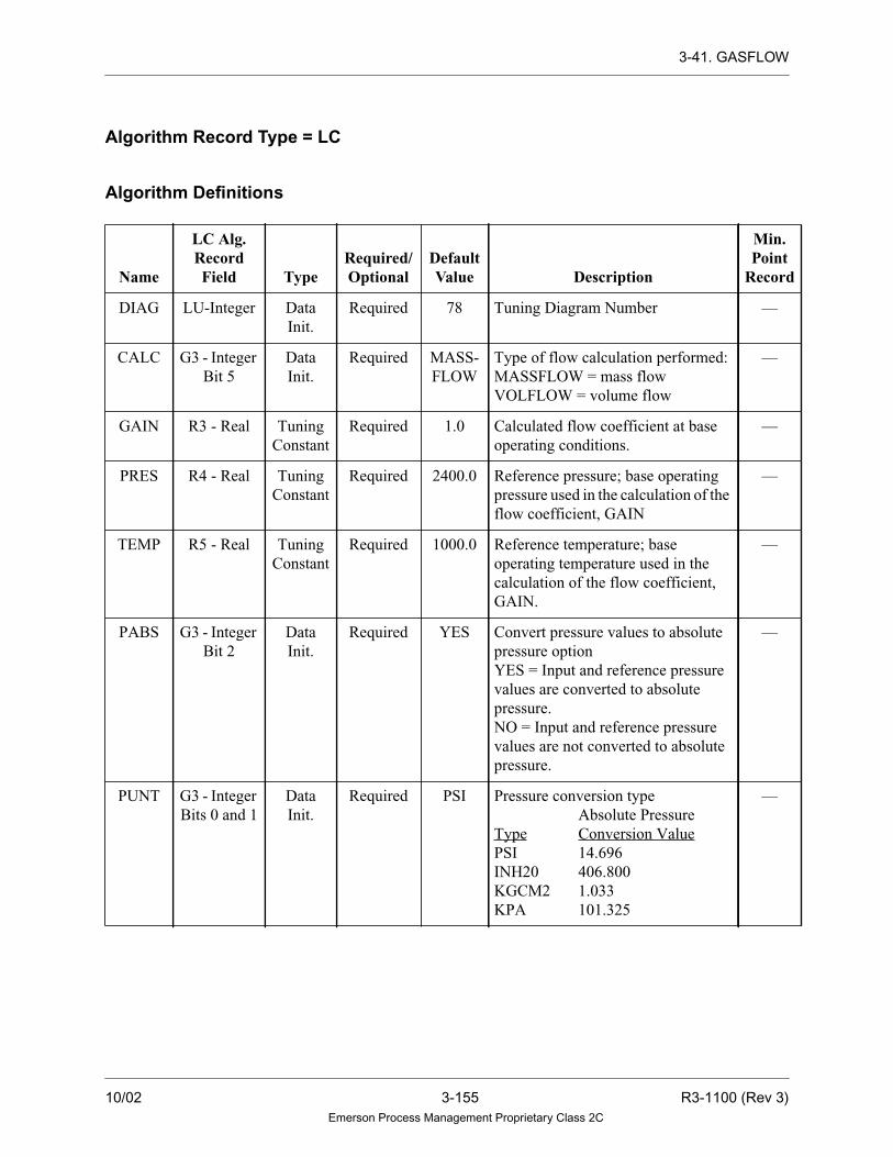
3-41. GASFLOW
Algorithm Record Type = LC
Algorithm Definitions
Name
LC Alg.RecordField Type
Required/Optional
DefaultValue Description
Min.Point
Record
DIAG LU-Integer Data
Init.
Required 78 Tuning Diagram Number —
CALC G3 - Integer
Bit 5
Data
Init.
Required MASS-
FLOW
Type of flow calculation performed:
MASSFLOW = mass flow
VOLFLOW = volume flow
—
GAIN R3 - Real Tuning
Constant
Required 1.0 Calculated flow coefficient at base
operating conditions.
—
PRES R4 - Real Tuning
Constant
Required 2400.0 Reference pressure; base operating
pressure used in the calculation of the
flow coefficient, GAIN
—
TEMP R5 - Real Tuning
Constant
Required 1000.0 Reference temperature; base
operating temperature used in the
calculation of the flow coefficient,
GAIN.
—
PABS G3 - Integer
Bit 2
Data
Init.
Required YES Convert pressure values to absolute
pressure option
YES = Input and reference pressure
values are converted to absolute
pressure.
NO = Input and reference pressure
values are not converted to absolute
pressure.
—
PUNT G3 - Integer
Bits 0 and 1
Data
Init.
Required PSI Pressure conversion type
Absolute Pressure
Type Conversion Value
PSI 14.696
INH20 406.800
KGCM2 1.033
KPA 101.325
—
10/02 3-155 R3-1100 (Rev 3)Emerson Process Management Proprietary Class 2C

3-41. GASFLOW
TABS G3 - Integer
Bit 4
Data
Init.
Required YES Convert temperature values to
absolute temperature option.
YES = Input and reference temperature
values are converted to absolute
temperature.
NO = Input and reference temperature
values are not converted to absolute
temperature.
—
TUNT G3 - Integer
Bit 3
Data
Init.
Required FAHR Temperature conversion type
Absolute
Temperature
Type Conversion Value
FAHR 459.67
CENT 273.15
—
TPSC R1 - Real Tuning
Constant
Required 100.0 Maximum value of the output —
BTSC R2 - Real Tuning
Constant
Required 0.0 Minimum value of the output —
PNEG G3 - Integer
Bit 6
Data
Init.
Required NO-
CHECK
Check for use of negative pressure
and temperature reference values
—
NOCHECK = No check is performed
to see if the PACT(C) and TACT(C)
inputs were specified. A negative
PRES REF or TEMP REF value will
cause the associated term to be
omitted from the equation.
—
CHECK = Check whether the
PACT(C) and TACT(C) inputs were
specified. If an input is not specified,
the associated term will be omitted
from the equation. When the inputs
are specified, the PRES REF and
TEMP REF values will be used
regardless of their sign.
—
Name
LC Alg.RecordField Type
Required/Optional
DefaultValue Description
Min.Point
Record
R3-1100 (Rev 3) 3-156 10/02Emerson Process Management Proprietary Class 2C

3-41. GASFLOW
PSEL G3 - Integer
Bit 7
Data
Init.
Required STAN-
DARD
Select pressure conversion type —
STANDARD = Use the pressure
conversion value defined by PRES
UNIT.
—
USER = Use the pressure conversion
value defined by USER PRES.
—
PUSR R6 - Real Tuning
Constant
Required 0.0000 Value for user-specified pressure
conversion
—
TYPE X1 - Byte Data
Init.
Required DEL-
TAP
Flow Differential or DELTAP
Default: DELTAP
—
IN1 — Variable Required — Differential pressure analog input LA
TOUT — Variable Required — Track output value and status output
signals
LA
PACT — Variable Optional — Actual pressure analog input LA
TACT — Variable Optional — Actual temperature analog input LA
OUT — Variable Required — Analog output variable LA
TRIN — Variable Optional — Track value, tracking and limit
modes. Analog input
LA
Name
LC Alg.RecordField Type
Required/Optional
DefaultValue Description
Min.Point
Record
10/02 3-157 R3-1100 (Rev 3)Emerson Process Management Proprietary Class 2C
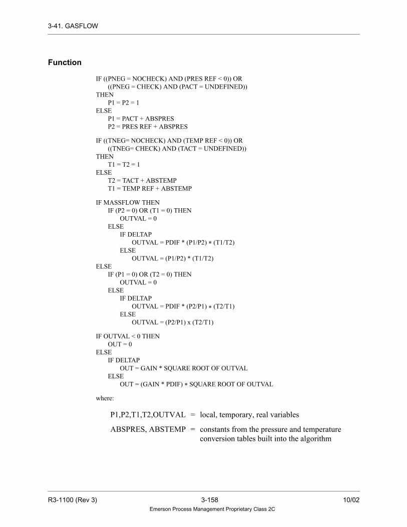
3-41. GASFLOW
Function
IF ((PNEG = NOCHECK) AND (PRES REF < 0)) OR
((PNEG = CHECK) AND (PACT = UNDEFINED))
THEN
P1 = P2 = 1
ELSE
P1 = PACT + ABSPRES
P2 = PRES REF + ABSPRES
IF ((TNEG= NOCHECK) AND (TEMP REF < 0)) OR
((TNEG= CHECK) AND (TACT = UNDEFINED))
THEN
T1 = T2 = 1
ELSE
T2 = TACT + ABSTEMP
T1 = TEMP REF + ABSTEMP
IF MASSFLOW THEN
IF (P2 = 0) OR (T1 = 0) THEN
OUTVAL = 0
ELSE
IF DELTAP
OUTVAL = PDIF * (P1/P2) * (T1/T2)
ELSE
OUTVAL = (P1/P2) * (T1/T2)
ELSE
IF (P1 = 0) OR (T2 = 0) THEN
OUTVAL = 0
ELSE
IF DELTAP
OUTVAL = PDIF * (P2/P1) * (T2/T1)
ELSE
OUTVAL = (P2/P1) x (T2/T1)
IF OUTVAL < 0 THEN
OUT = 0
ELSE
IF DELTAP
OUT = GAIN * SQUARE ROOT OF OUTVAL
ELSE
OUT = (GAIN * PDIF) * SQUARE ROOT OF OUTVAL
where:
P1,P2,T1,T2,OUTVAL = local, temporary, real variables
ABSPRES, ABSTEMP = constants from the pressure and temperature
conversion tables built into the algorithm
R3-1100 (Rev 3) 3-158 10/02Emerson Process Management Proprietary Class 2C

3-42. HIGHLOWMON
3-42. HIGHLOWMON
Description
The HIGHLOWMON algorithm is a high and low signal monitor with reset deadband
and fixed/variable limits. For the HIGHLOWMON algorithm, if the input value (IN1)
is greater than the high set point or less than the low set point, the digital output flag
is set TRUE. To reset the flag, the input must be less than the high set point minus the
deadband on the high set point, and greater than the low set point plus the deadband
on the low set point.
Functional Symbol
Algorithm Record Type = LC
Algorithm Definitions
Name
LC Alg.RecordField Type
Required/Optional
DefaultValue Description
Min.Point
Record
DIAG LU-Integer Data Init. Required 74 Tuning Diagram Number —
HISP R1 - Real Selectable Required 0.0 High set point LA
HIDB R2 - Real Tuning
Constant
Optional 0.0 Deadband on high set point —
LOSP R3 - Real Selectable Required 0.0 Low set point LA
LODB R4 - Real Tuning
Constant
Optional 0.0 Deadband on low set point —
IN1 — Variable Required — Input (analog) LA
OUT — Variable Required 0.0 Output (digital) LD
IN1 OUTH
L
HISP
LOSP
10/02 3-159 R3-1100 (Rev 3)Emerson Process Management Proprietary Class 2C

3-42. HIGHLOWMON
Function
IF IN1 > HISP OR IN1 < LOSP
THEN OUT = TRUE
ELSE
IF IN1 < (HISP - HIDB) AND IN1 > (LOSP + LODB)
THEN OUT = FALSE
R3-1100 (Rev 3) 3-160 10/02Emerson Process Management Proprietary Class 2C
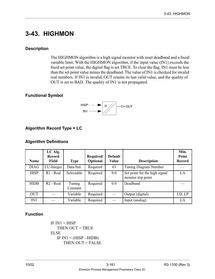
3-43. HIGHMON
3-43. HIGHMON
Description
The HIGHMON algorithm is a high signal monitor with reset deadband and a fixed/
variable limit. With the HIGHMON algorithm, if the input value (IN1) exceeds the
fixed set point value, the digital flag is set TRUE. To clear the flag, IN1 must be less
than the set point value minus the deadband. The value of IN1 is checked for invalid
real numbers. If IN1 is invalid, OUT retains its last valid value, and the quality of
OUT is set to BAD. The quality of IN1 is not propagated.
Functional Symbol
Algorithm Record Type = LC
Algorithm Definitions
Function
IF IN1 > HISP
THEN OUT = TRUE
ELSE
IF IN1 < (HISP - HIDB)
THEN OUT = FALSE
Name
LC Alg.RecordField Type
Required/Optional
DefaultValue Description
Min.Point
Record
DIAG LU-Integer Data Init. Required 63 Tuning Diagram Number —
HISP R1 - Real Selectable Required 0.0 Set point for the high signal
monitor trip point
LA
HIDB R2 - Real Tuning
Constant
Required 0.0 Deadband —
OUT — Variable Required — Output (digital) LD, LP
IN1 — Variable Required — Input (analog) LA
H OUT
IN1
HISP
10/02 3-161 R3-1100 (Rev 3)Emerson Process Management Proprietary Class 2C

3-44. HISELECT
3-44. HISELECT
Description
The HISELECT algorithm performs a gain and bias on the four inputs. The output
is equal to the greater of the four values, according to the quality (QUAL)
parameter.
The quality (QUAL) parameter contains two options that enable the user to select
the value and type of quality that the output point receives. The WORSE option
selects the greater value for an output point, independent of the qualities of the two
input points. The output point is assigned the worst quality of the four input points.
The SELECTED option also selects the greater value, independent of the qualities
of the four input points. The output point is assigned the value and quality of the
selected input point. However, if any of the four gained and biased values are equal,
the better quality is assigned to the output point.
Notes
1. If the algorithm calculates an invalid output value
by using one of the gained and biased inputs, the
value of the other three points is used for the
output. In addition, for the NOTBAD option, if
the quality of four input points is BAD, and only
one of the inputs is a valid value, the algorithm
will select the valid gained and biased input for
the output, and set the quality of the output point
to BAD.
2. If the calculated track output is invalid, then the
IN2 output is equal to the IN1 input, and the
cascade track output is equal to the IN1 input, if
the inputs are valid. If the calculated track output
and the input values are invalid, then the IN1 and
IN1 track outputs are not updated.
3. If the algorithm receives an invalid value as an
input, or if it calculates an invalid value as an
output, the drop is placed into alarm.
R3-1100 (Rev 3) 3-162 10/02Emerson Process Management Proprietary Class 2C

3-44. HISELECT
Functional Symbol
Tracking Signals
Tracking and limiting are done through signals passed in the upper 16 bits of the
third status word of the analog tracking point. This algorithm takes the following
action in response to the information found in the analog input signal TRIN:
Description Action TRK1 Signal
16 Track Implemented and passed through.
Passed through or set TRUE when
IN1 input is not selected and IN1
gain is >0*
Implemented and passed
through.Passed through or set TRUE
when IN2 input is not selected and
IN2 gain is >0*
17 Track if lower
18 Track if higher Passed through or set TRUE when
IN1 input is not selected and IN1
gain is >0*
Passed through or set TRUE when IN2
input < is not selected and IN2 gain is
>0*
19 Lower inhibit Passed through** Passed through**
20 Raise inhibit Passed through** Passed through**
21 Conditional Track Implemented Passed through***
22 Not used Not used Not used
23 Deviation Alarm Not used Not used
24 Local Manual mode Not used Not used
25 Manual mode Not used Not used
26 Auto mode Not used Not used
27 Not Used Not used Not used
28 Not Used Not used Not used
29 Not Used Not used Not used
30 Low limit reached Low limit reached Not used
IN1 IN2 IN3 IN4
OUT
TRK4 TRK3 TRK2 TRK1
TRIN
10/02 3-163 R3-1100 (Rev 3)Emerson Process Management Proprietary Class 2C

3-44. HISELECT
The high and low limit flags, and the tracking signals from the algorithm are output
to TRK3 and TRK4, to be used for display and by upstream algorithms. If the output
value is invalid, the quality of OUT is set to BAD. Otherwise, the quality of OUT is
set according to the quality (QUAL) parameter. When tracking, the quality is set to
the quality of the track input variable.
Algorithm Record Type= LC
Algorithm Definitions
31 High limit reached High limit reached Not used
* Only when the Track signal is not present.
** Only when the Track signal is not present; the signals are set according to the definitions given in
Setting Tracking Signals (Section 2-6).
*** If the algorithm is being told to track, then the Conditional track bit is ignored. Otherwise, the value
of the conditional track bit is transferred to all output track points. If the Conditional Track bit is
set in the track input point, the analog value of all output track points is calculated based on the
analog value of the track input point.
Name
LC Alg.RecordField Type
Required/Optional
DefaultValue Description
Min.Point
Record
DIAG LU-Integer Data Init Required 83 Tuning Diagram Number —
IN1G R1 - Real Tuning
Constant
Required 1.0 Gain on input 1. The gain on the input1
should never be initialized to zero; if it
is, the drop is placed into alarm.
—
IN1B R2 - Real Tuning
Constant
Optional 0.0 Bias on input 1 —
IN2G R3 - Real Tuning
Constant
Required 1.0 Gain on input 2. The gain on the input
2 should never be initialized to zero; if
it is, the drop is placed into alarm.
—
IN2B R4 - Real Tuning
Constant
Optional 0.0 Bias on input 2 —
IN3G R8-Real Tuning
Constant
Optional 1.0 Gain on input 3. The gain on the input
3 should never be initialized to zero; if
it is, the drop is placed into alarm
—
IN3B R9-Real Tuning
Constant
Optional 0.0 Bias on input 3 —
IN4G S1-Real Tuning
Constant
Optional 1.0 Gain on input 4, the gain on the input 4
should never be initialized to zero; if it
is the drop is placed into alarm
—
Description Action TRK1 Signal
R3-1100 (Rev 3) 3-164 10/02Emerson Process Management Proprietary Class 2C

3-44. HISELECT
IN4B S2-Real Tuning
Constant
Optional 0.0 Bias on input 4 —
TPSC R5 - Real Tuning
Constant
Required 100.0 Maximum value of the output point —
BTSC R6 - Real Tuning
Constant
Required 0.0 Minimum value of the output point —
TRAT R7 - Real Tuning
Constant
Required 2.5 Track ramp rate (units per second) —
QUAL X1 - Byte
Bits 0 and 1
Data Init. Required WORSE Output quality type.
Quality Definition
WORSE Worst quality of the four
inputs is selected.
SELECTED Output point is assigned the
quality of the selected input
point. If thevaluesoftheinput
points are equal, the best
quality is selected.
—
IN1 — Variable Required — Analog input 1 LA
TRK1 — Variable Required — Track output value mode and status
signals for Input 1 variable
LA
IN2 — Variable Required — Analog input 2 LA
TRK2 — Variable Required — Track output value mode status signals
for Input 2 variable
LA
IN3 — Variable Optional — Analog input 3 LA
TRK3 — Variable Optional — Track output value mode signal for
Input 3
LA
IN4 — Variable Optional — Analog input 4 LA
TRK4 — Variable Optional — Track output value mode signal for
Input 4
LA
OUT — Variable Required — Analog output variable LA
TRIN — Variable Optional — Tracking and signals analog input
variable
LA
Name
LC Alg.RecordField Type
Required/Optional
DefaultValue Description
Min.Point
Record
10/02 3-165 R3-1100 (Rev 3)Emerson Process Management Proprietary Class 2C
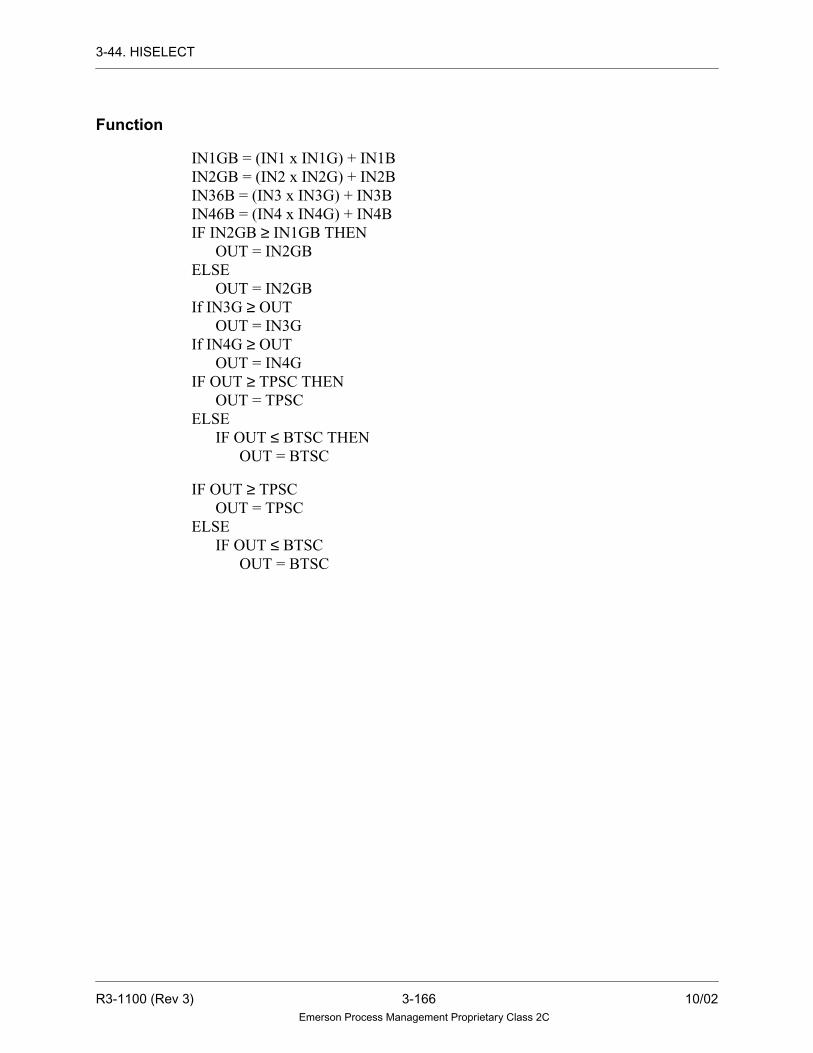
3-44. HISELECT
Function
IN1GB = (IN1 x IN1G) + IN1B
IN2GB = (IN2 x IN2G) + IN2B
IN36B = (IN3 x IN3G) + IN3B
IN46B = (IN4 x IN4G) + IN4B
IF IN2GB ≥ IN1GB THEN
OUT = IN2GB
ELSE
OUT = IN2GB
If IN3G ≥ OUT
OUT = IN3G
If IN4G ≥ OUT
OUT = IN4G
IF OUT ≥ TPSC THEN
OUT = TPSC
ELSE
IF OUT ≤ BTSC THEN
OUT = BTSC
IF OUT ≥ TPSC
OUT = TPSC
ELSE
IF OUT ≤ BTSC
OUT = BTSC
R3-1100 (Rev 3) 3-166 10/02Emerson Process Management Proprietary Class 2C

3-45. HSCLTP
3-45. HSCLTP
Description
HSCLTP calculates Enthalpy (H) and Entropy (S) of Compressed Liquid given its
Temperature and Pressure. It is one of the functions of the STEAMTABLE algorithm.
See Section 3-103 for more information.
Functional Symbol
ENTROPY
FLAGSTM-TBL
TEMP PRESATM
CL
PRES
ENTHALPY
10/02 3-167 R3-1100 (Rev 3)Emerson Process Management Proprietary Class 2C

3-46. HSLT
3-46. HSLT
Description
HSLT calculates Enthalpy (H) of Saturated Liquid given its Temperature. It is one of
the functions of the STEAMTABLE algorithm. See Section 3-103 for more
information.
Functional Symbol
ENTHALPY
FLAGSTM-TBL
TEMP
SL
R3-1100 (Rev 3) 3-168 10/02Emerson Process Management Proprietary Class 2C

3-47. HSTVSVP
3-47. HSTVSVP
Description
HSTVSVP calculates Enthalpy (H), Entropy (S), Temperature, and Specific
Volume of Saturated Vapor given its Pressure. It is one of the functions of the
STEAMTABLE algorithm. See Section 3-103 for more information.
Functional Symbol
ENTHALPY
FLAGSTM-TBL
PRESATM
SV
PRES
ENTROPYSPECIFICTEMPVOLUME
10/02 3-169 R3-1100 (Rev 3)Emerson Process Management Proprietary Class 2C

3-48. HSVSSTP
3-48. HSVSSTP
Description
HSVSSTP calculates Enthalpy (H), Entropy (S), and Specific Volume of
Superheated Steam given its Temperature and Pressure. It is one of the functions of
the STEAMTABLE algorithm. See Section 3-103 for more information.
Functional Symbol
ENTROPY
FLAGSTM-TBL
TEMP PRESATM
SS
PRES
SPECIFICVOLUME
ENTHALPY
R3-1100 (Rev 3) 3-170 10/02Emerson Process Management Proprietary Class 2C

3-49. INTERP
3-49. INTERP
Description
The INTERP algorithm provides a linear table-lookup and interpolation function.
The algorithm provides a lookup table for the value of a dependent variable (Y)
based on the value of an independent variable (X). The actual value X (XIN) is input
to the algorithm along with up to ten reference Y values (Y1...Y10) and their
corresponding X values (X1...X10).
If the value of the XIN is not identically equal to any of the X1...X10 inputs, then
resulting value of YOUT is calculated by linear interpolation between the closest
two values that the input XIN falls between (that is, Xn + Xn+1). The formula to
calculate YOUT is given as follows:
YOUT = (Yn + (Yn+1 - Yn) * ((XIN - Xn) / (Xn+1 - Xn))
The value of YOUT is limited by the user defined high and low limit values. Refer
to the accompanying figure that illustrates the interpolation procedure.
Functional Symbol
Quality
The algorithm will propagate the worst quality between the XIN input and the
associated Y inputs used to determine the value of YOUT. If the output is an exact
Y input, then the YOUT quality will be the worst quality of the XIN input and that
particular Y input.
Y1
Y2
Y3
Y5
Y6
Y7
Y8
Y9
Y10
Y4
XIN
INTERP VALID
YOU
T
10/02 3-171 R3-1100 (Rev 3)Emerson Process Management Proprietary Class 2C

3-49. INTERP
User Configuration
The values of X1...X10 MUST be monotonically increasing (that is, Xn+1 > Xn). If
the value of the XIN is found to fall between X1...X10, then the VALID output is
set to logic one. If the monotonicity of the X1 - X10 is not monotonically
increasing, then the algorithm may yield unpredictable results. If the algorithm can
determine that the table is not monotonically increasing, then YOUT will be set
equal to Y10 and the VALID output will be set to logic 0.
If the value of XIN > X10, then YOUT is set equal to Y10. If XIN < X1, then YOUT
is set equal to Y1. In both of these cases, the VALID output is set to logic zero. If
the algorithm calculates an invalid number, then YOUT will be set to the last
GOOD value and the quality will be set to BAD.
If the YOUT is calculated by interpolating between Yn and Yn+1, then the quality
of YOUT will be the worst quality of the XIN, Yn and Yn+1 inputs.
Interpolation Illustration
% change in X= | XIN - Xn |
- Assumption is that a K% change in X yields a K% change in Y.
Thus, in terms of Percent of full range, ∆X = ∆Y.
∆Y = |YOUT - Yn |
}∆Y
}
∆Y = YOUTYn =∆Y = YOUT −Yn
∆X
Yn+1
YOUT
Yn
Xn
XIN
Xn+1
R3-1100 (Rev 3) 3-172 10/02Emerson Process Management Proprietary Class 2C

3-49. INTERP
Algorithm Record Type = LC
Algorithm Definitions
Name
LC Alg.RecordField Type
Required/Optional
DefaultValue Description
Min.Point
Record
DIAG LU-Integer Data Init Required 113 Tuning Diagram Number —
TYPE X2-Byte Data Init Required Linear Interpolation Type. Currently only
linear is supported.
—
NUMR X1 - Byte Data Init Required 0 Number of X values. —
X1 R1- Real Tuning
Constant
Required 0.0 X value corresponding to Y1. —
X2 R2- Real Tuning
Constant
Required 0.0 X value corresponding to Y2. —
X3 R3- Real Tuning
Constant
Required 0.0 X value corresponding to Y3. —
X4 R4- Real Tuning
Constant
Required 0.0 X value corresponding to Y4. —
X5 R5- Real Tuning
Constant
Required 0.0 X value corresponding to Y5. —
X6 R6- Real Tuning
Constant
Required 0.0 X value corresponding to Y6. —
X7 R7- Real Tuning
Constant
Required 0.0 X value corresponding to Y7. —
X8 R8- Real Tuning
Constant
Required 0.0 X value corresponding to Y8. —
X9 R9- Real Tuning
Constant
Required 0.0 X value corresponding to Y9. —
X10 S1- Real Tuning
Constant
Required 0.0 X value corresponding to Y10. —
TPSC S2- Real Tuning
Constant
Required 100.0 Output top of scale. —
BTSC S3- Real Tuning
Constant
Required 0.0 Output bottom of scale. —
XIN — Variable Required — Actual value of X variable (analog) LA
Y1 — Variable Optional — Output Value 1(analog) LA
Y2 — Variable Optional — Output Value 2 (analog) LA
Y3 — Variable Optional — Output Value 3 (analog) LA
Y4 — Variable Optional — Output Value 4 (analog) LA
10/02 3-173 R3-1100 (Rev 3)Emerson Process Management Proprietary Class 2C

3-49. INTERP
Y5 — Variable Optional — Output Value 5 (analog) LA
Y6 — Variable Optional — Output Value 6 (analog) LA
Y7 — Variable Optional — Output Value 7 (analog) LA
Y8 — Variable Optional — Output Value 8 (analog) LA
Y9 — Variable Optional — Output Value 9 (analog) LA
Y10 — Variable Optional — Output Value 10 (analog) LA
YOUT — Variable Required — Output Y value (analog) LA
VALID — Variable Optional — Equals Logic 1 when the XIN value
is found to fall between two X
values in the table (digital).
LD
Name
LC Alg.RecordField Type
Required/Optional
DefaultValue Description
Min.Point
Record
R3-1100 (Rev 3) 3-174 10/02Emerson Process Management Proprietary Class 2C

3-50. KEYBOARD
3-50. KEYBOARD
Description
The KEYBOARD (Key Interface) algorithm interfaces the ten control keys
(start/open, stop/close, auto, man, ↑, ↓, ∆, ∇) to the Controller in the most basic
form. The output of each key is available for use once the algorithm is activated via
a control select command.
The KEYBOARD algorithm interfaces the Operator Station programmable keys
(P1 through P10) to the Controller in the most basic form. The output of each
programmable key is available for use once the algorithm is activated via a control
select key. When using this algorithm, none of the ten Control keys may be used for
the activated control select number.
For the ∆ and ∇, ↑ and ↓ keys, the output will maintain a TRUE signal for as long
as the key is pressed. For all other keys, the output of this algorithm is a pulse
(TRUE signal) of variable length. The pulse length is determined by the LENGTH
(LENG) parameter, which specifies the pulse length in loops. If LENGTH is equal
to 0 or 1, the pulse will be 1 loop long. The LENGTH parameter may specify a pulse
length up to 255 loops.
Note
P9 and P10 keys are the same as Open and
Close keys.
10/02 3-175 R3-1100 (Rev 3)Emerson Process Management Proprietary Class 2C

3-50. KEYBOARD
Functional Symbol
Algorithm Record Type = LC
Algorithm Definitions
Name
LC Alg.RecordField Type
Required/Optional
DefaultValue Description
Min.Point
Record
DIAG LU-Integer Data Init. Required 128 Tuning Diagram Number —
LENG X2 - Byte Data Init. Optional 1 Length of output pulse in loops. —
PK1 — Variable Optional — Output (digital); passed on from
Function Key F1 or Programmable
Key P1.
LD, LP
PK2 — Variable Optional — Output (digital); passed on from
Function Key F2 or Programmable
Key P2.
LD, LP
PK3 — Variable Optional — Output (digital); passed on from
Function Key F3 or Programmable
Key P3.
LD, LP
PK4 — Variable Optional — Output (digital); passed on from
Function Key F4 or Programmable
Key P4.
LD, LP
KEYBOARD
PK1
PK2
PK3
PK4
PK5
PK6
PK7
PK8OPEN (PK9)CLOS (PK10)
SPUPSPDNAUTOMANINCDEC
R3-1100 (Rev 3) 3-176 10/02Emerson Process Management Proprietary Class 2C

3-50. KEYBOARD
PK5 — Variable Optional — Output (digital); passed on from
Function Key F5 or Programmable
Key P5.
LD, LP
PK6 — Variable Optional — Output (digital); passed on from
Function Key F6 or Programmable
Key P6.
LD, LP
PK7 — Variable Optional — Output (digital); passed on from
Function Key F7 or Programmable
Key P7.
LD, LP
PK8 — Variable Optional — Output (digital); passed on from
Function Key F8 or Programmable
Key P8.
LD, LP
OPEN — Variable Optional — Output (digital); Passed on from
KEYBOARD START/OPEN
LD, LP
CLOS — Variable Optional — Output (digital): Passed on from
KEYBOARD STOP/CLOSE
LD, LP
SPUP — Variable Optional — Output (digital): Passed on from
KEYBOARD set point
INCREASE (↑ )
LD, LP
SPDN — Variable Optional — Output (digital); Passed on from
KEYBOARD set point Decrease
(↓)
LD, LP
AUTO — Variable Optional — Output (digital); Passed on from
KEYBOARD AUTO
LD, LP
MAN — Variable Optional — Output (digital); Passed on from
KEYBOARD MANUAL
LD, LP
INC — Variable Optional — Output (digital); Passed on from
KEYBOARD Output Increase (∆)
LD, LP
DEC — Variable Optional — Output (digital); Passed on from
KEYBOARD Output Decrease (∇ )
LD, LP
Name
LC Alg.RecordField Type
Required/Optional
DefaultValue Description
Min.Point
Record
10/02 3-177 R3-1100 (Rev 3)Emerson Process Management Proprietary Class 2C

3-51. LATCHQUAL
3-51. LATCHQUAL
Description
The LATCHQUAL algorithm latches and unlatches the quality of an input analog
or digital point. The algorithm writes a command to the ZY field of IN1 to set or
clear its “Latched Quality” bit depending on SET and RSET. Bit 14 of the
2W(second status word) of the analog point or bit 11 of the 2W (second status word)
of the digital point is the “Latched Quality” bit for the point.
Functional Symbol
If RSET is TRUE and the latched quality bit of IN1 is set, then a command is written
to the ZY field of IN1 to Unlatch Quality.
If RSET is FALSE and SET is TRUE, then depending on the value of QUAL, a
command is written to the ZY field of IN1 to set its Latched Quality bit and quality
as follows:
• If QUAL = 0 and Latched Quality of IN1 is not set, then Latched quality bit is
set at its current state.
• If QUAL = 1 and Latched Quality of IN1 is not set or the Quality of IN1 is not
GOOD, then the Quality is set (latched) to GOOD.
• If QUAL = 2 and Latched Quality of IN1 is not set or the Quality of IN1 is not
FAIR, then the Quality is set (latched) to FAIR.
• If QUAL = 3 and Latched Quality of IN1 is not set or the Quality of IN1 is not
POOR, then the Quality is set (latched) to POOR.
• If QUAL ≥ 4 and Latched Quality of IN1 is not set or the Quality of IN1 is not
BAD, then the Quality is set (latched) to BAD.
RSET overrides SET. If both are TRUE, then the Latched Quality bit of IN1 will be
cleared.
LATCHQUAL
IN1SET
QUALRSET
R3-1100 (Rev 3) 3-178 10/02Emerson Process Management Proprietary Class 2C

3-51. LATCHQUAL
Note
IN1 can be a digital or analog point, with the
minimum point record being LD or LA. If a smaller
point record is used, then no action will be taken.
Algorithm Record Type = None
Algorithm Definitions
Name
LC Alg.RecordField Type
Required/Optional
DefaultValue Description
Min.Point
Record
SET — Variable Required — Digital input. Set Latched Quality bit
flag.
LD, LP
IN1 — Variable Required — Analog/Digital input LD, LA
QUAL — Variable Required — Packed input. Indicates the quality to
which IN1 is to be set.
LP
RSET — Variable Required — Digital input. Clear Latched Quality
bit flag.
LD, LP
10/02 3-179 R3-1100 (Rev 3)Emerson Process Management Proprietary Class 2C

3-52. LEADLAG
3-52. LEADLAG
Description
LEADLAG is a nonlinear lead/lag function. The output value is a function of the
old output, old input, new input, gain, lead and lag time constants. In steady state,
OUT = IN1 x GAIN (except when limited). The output will achieve 98 percent of
the expected steady-state output value in five time constants.
Note
If the algorithm receives an invalid value as an input,
or calculates an invalid value as the output, the drop
is placed into alarm.
Functional Symbol
Tracking Signals
Tracking and limiting are done through signals passed in the upper 16 bits of the
third status word of the analog track point. This algorithm takes the following action
in response to the information found in the analog input signal TRIN:
Bit Description Action TOUT Signal
16 Track Implemented Passed through
17 Track if lower No action Passed through*
18 Track if higher No action Passed through*
19 Lower inhibit Implemented Passed through**
20 Raise inhibit Implemented Passed through**
21 Conditional Track No action Not used
LEADLAG
IN1
OUT
TOUT
TRIN
R3-1100 (Rev 3) 3-180 10/02Emerson Process Management Proprietary Class 2C

3-52. LEADLAG
The high and low limit flags and the tracking signals from the algorithm are output
to TOUT, to be used for display and by an upstream algorithm. If the output value
is invalid, the quality of OUT is set to BAD. Otherwise, the quality of OUT is set to
the quality of the input when not in tracking mode. When tracking, the quality is set
to the quality of the track input variable.
Note
If the algorithm generates an invalid track output
value, the IN1 input value is used as the track output,
unless it is invalid. The track output value is not
updated if both the calculated track output and IN1
input values are invalid.
22 Not used No action Not used
23 Deviation Alarm No action Not used
24 Local Manual mode No action Not used
25 Manual mode No action Not used
26 Auto mode No action Not used
27 Not Used No action Not used
28 Not Used No action Not used
29 Not Used No action Not used
30 Low limit reached No action Low limit reached
31 High limit reached No action High limit reached
* Only when the Track signal is not present.
** Only when the Track signal is not present; the signals are set according to the definition given in
Setting Tracking Signals (Section 2-6).
Bit Description Action TOUT Signal
10/02 3-181 R3-1100 (Rev 3)Emerson Process Management Proprietary Class 2C

3-52. LEADLAG
Algorithm Record Type= LC
Algorithm Definitions
Name
LC Alg.RecordField Type
Required/Optional
DefaultValue Description
Min.Point
Record
DIAG LU-Integer Data Init Required 33 Tuning Diagram Number —
IN1G R3 - Real Tuning
Constant
Required 1.0 Gain on input. The gain on the input
should never be initialized to zero; if it
is, the drop is placed into alarm
—
TPSC R1 - Real Tuning
Constant
Required 100.0 Maximum value of the output point —
BTSC R2 - Real Tuning
Constant
Required 0.0 Minimum value of the output point —
LEAD R4 - Real Tuning
Constant
Required 0.0 Lead time constant (second) —
LAG R5 - Real Tuning
Constant
Required 30.0 Lag time constant (second)
Note: This is approximately 1/5 of the
total time to settle. For example, for a
1 minute total, set LAG to 12 seconds.
—
TRAT R6 - Real Tuning
Constant
Required 2.5 Track ramp rate (units per second). —
IN1 — Variable Required — Analog input variable LA
TOUT — Variable Required — Track output value, for mode & status
signals for Input 1 variable
LA
OUT — Variable Required — Analog output variable LA
TRIN — Variable Optional — Tracking & Limiting mode signals and
tracking value; analog input variable
LA
R3-1100 (Rev 3) 3-182 10/02Emerson Process Management Proprietary Class 2C

3-52. LEADLAG
Function
OUT = (K1 x IN1) + (K2 x OLDIN1) + (K3 x OLDOUT)
where:
OLDOUT = Previous output
IN1 = Current input
OLDIN1 = Previous input
K1 = GAIN x (H + 2x LEAD)/(H + 2x LAG)
K2 = GAIN x (H - 2x LEAD)/(H + 2x LAG)
K3 = (2x LAG - H)/(2x LAG + H)
H = Sampling time (loop time)
10/02 3-183 R3-1100 (Rev 3)Emerson Process Management Proprietary Class 2C

3-53. LEVELCOMP
3-53. LEVELCOMP
Description
The LEVELCOMP algorithm calculates the density compensated water level in a
pressurized steam drum. This compensation assumes a differential pressure
transmitter is inputting the raw level signal. One leg of the transmitter is connected
to a condensate reservoir which establishes the transmitter’s maximum water level.
The other side of the transmitter is connected to the point which defines the
minimum transmitter water level. The distance between these taps is the transmitter
range “D”. See the following figure for details of the assumed piping configuration.
D
LT
Level
Transmitter
Reference LevelReservoir
υ
υ
υτ
s
w
R3-1100 (Rev 3) 3-184 10/02Emerson Process Management Proprietary Class 2C

3-53. LEVELCOMP
P
The steam and water inside the drum are at saturation conditions. The water in the
condensated reservoir is pressurized water. The LEVELCOMP algorithm uses the
specific volume of the steam in the drum (υs), the specific volume of the water in
the drum (υw) and the specific volume of the water in the reference leg(υr), and the
specific volume of the water at calibration conditions (υcal) to compute the
compensated level. The LEVELCOMP algorithm does the steamtable calculations
to obtain values for υs, υw, and υr based on input points pressure and temperature.
The derivation of υr requires an estimation of the average temperature in the
condensate reference column. The temperature can be a variable point or entered as
a tuning constant. The calibration fluid specific volume (υcal) is an estimated value
entered as a tuning constant.
K
K
PT
DrumPressure
DrumLevel
-
LT
Specific Volume ofCompressed Water
Specific Volume ofSaturated Water
Specific Volume ofSaturated Steam
OUT
L
L
(0 to “D”)
Estimated temperature ofwater in the reference leg
Lin
L =
- D (1 -vcal +
vcal )v r v
S
( vw)
vcal
vcal
vs
(0 to “D”)
in
+ “MIN”
LEVELCOM
Vr VW VS
“MIN”
10/02 3-185 R3-1100 (Rev 3)Emerson Process Management Proprietary Class 2C
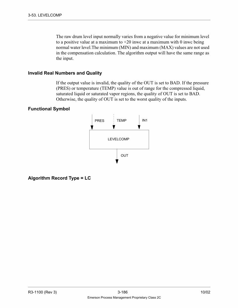
3-53. LEVELCOMP
The raw drum level input normally varies from a negative value for minimum level
to a positive value at a maximum to +20 inwc at a maximum with 0 inwc being
normal water level.The minimum (MIN) and maximum (MAX) values are not used
in the compensation calculation. The algorithm output will have the same range as
the input.
Invalid Real Numbers and Quality
If the output value is invalid, the quality of the OUT is set to BAD. If the pressure
(PRES) or temperature (TEMP) value is out of range for the compressed liquid,
saturated liquid or saturated vapor regions, the quality of OUT is set to BAD.
Otherwise, the quality of OUT is set to the worst quality of the inputs.
Functional Symbol
Algorithm Record Type = LC
PRES TEMP IN1
OUT
LEVELCOMP
R3-1100 (Rev 3) 3-186 10/02Emerson Process Management Proprietary Class 2C

3-53. LEVELCOMP
Algorithm Definitions
Function
Name
LC Alg.RecordField Type
Required/Optional
DefaultValue Description
Min.Point
Record
DIAG LU-Integer Data Init Required 112 Tuning diagram number —
VCAL R1 - Real Tuning
Constant
Required 0.016049 Specific Volume of Calibration
fluid (lbs per ft3)
—
MAX R2 - Real Tuning
Constant
Required 1.0 Maximum Level Range —
MIN R3- Real Tuning
Constant
Required 0.0 Minimum Level Range —
TEMP R4 - Real Selectable Required — Temperature of water in reference
leg (F)
LA
PRES — Variable Required — Drum Pressure (analog) (PSI) LA
IN1 — Variable Required — Drum Level Transmitter (analog) LA
OUT — Variable Required — Output variable (analog) LA
OUT =
LIN - D ( VCAL+
VCAL)VR VS
VCAL VCAL
VW VS-( )
Where as D = Maximum range level -
+ Min
Minimum range level
LIN = IN1 + Min
1-
10/02 3-187 R3-1100 (Rev 3)Emerson Process Management Proprietary Class 2C

3-54. LOG
3-54. LOG
Description
The LOG algorithm performs the mathematical logarithmic function. For the LOG
algorithm, the output equals the base 10 logarithm of the input value plus a bias. If
the input value is less than or equal to zero, the output is set to a large negative
number (-3.4 x 1038). The value of IN1 is checked for invalid real numbers. If IN1
is valid, the quality of IN1 is propagated to the quality of OUT and the real number
value of OUT is written to the point record. If the value of IN1 is invalid or if the
calculated value of OUT written to the point record is invalid, the quality of OUT
is set to BAD.
Note
Other logarithmic algorithms are ANTILOG and NLOG.
Functional Symbol
Algorithm Record Type = LC
LOG
OUT
OUT
IN1
LOGIN1
OR
R3-1100 (Rev 3) 3-188 10/02Emerson Process Management Proprietary Class 2C

3-54. LOG
Algorithm Definitions
Function
OUT = LOG10 (IN1) + BIAS
Name
LC Alg.RecordField Type
Required/Optional
DefaultValue Description
Min.Point
Record
DIAG LU-Integer Data Init. Required 68 Tuning Diagram Number —
BIAS R1 - Real Tuning
Constant
Optional 0.0 Bias Factor(+ or -) —
IN1 — Variable Required — Input (analog) LA
OUT — Variable Required — Output (analog) LA
10/02 3-189 R3-1100 (Rev 3)Emerson Process Management Proprietary Class 2C

3-55. LOSELECT
3-55. LOSELECT
Description
The LOSELECT algorithm performs a gain and bias on the four inputs. The output
is equal to the smallest of the four values, according to the quality (QUAL)
parameter.
The quality (QUAL) parameter contains two options that enable the user to select
the value and type of quality that the output point receives. The WORSE option
selects the lower value for an output point, independent of the qualities of the two
input points. The output point is assigned the worst quality of the four input points.
The SELECTED option also selects the lowest value, independent of the qualities
of the four input points. The output point is assigned the value and quality of the
selected input point. However, if any of the four gained and biased values are equal,
the best quality is assigned to the output point.
Notes
1. If the algorithm calculates an invalid output value
by using one of the gained and biased inputs, the
value of the other point is used for the output.
2. If the calculated track output is invalid, then the
IN2 track output is equal to the IN2 input, and the
IN1 track output is equal to the IN1 input, if the
inputs are valid. If the calculated track outputs
and the input values are invalid, then the IN2 and
IN1 track outputs are not updated.
3. If the algorithm receives an invalid value as an
input, or if it calculates an invalid value as an
output, the drop is placed into alarm.
R3-1100 (Rev 3) 3-190 10/02Emerson Process Management Proprietary Class 2C

3-55. LOSELECT
Functional Symbol
Tracking Signals
Tracking and limiting are done through signals passed in the upper 16 bits of the
third status of the analog tracking point. This algorithm takes the following action
in response to the information found in the analog input signal TRIN:
Bit Description Action TRK1 Signal
16 Track Implemented and passed
through. Passed through or set
TRUE when IN1 input is not
selected and IN1 gain is >0*
Implemented and passed
through.Passed through or set TRUE
when IN2 input is not selected and
IN2 gain is >0*
17 Track if lower
18 Track if higher Passed through or set TRUE
when IN1 input is not selected
and IN1 gain is >0*
Passed through or set TRUE when
IN2 input is not selected and IN2 gain
is >0*
19 Lower inhibit Passed through** Passed through**
20 Raise inhibit Passed through** Passed through**
21 Conditional Track Implemented Passed through***
22 Not used Not used Not used
23 Deviation Alarm Not used Not used
24 Local Manual mode Not used Not used
25 Manual mode Not used Not used
26 Auto mode Not used Not used
27 Not Used Not used Not used
28 Not Used Not used Not used
29 Not Used Not used Not used
IN1 IIN4
OUT
IN2 IN3
TRK4 TRK3 TRK2 TRK1
TRIN
10/02 3-191 R3-1100 (Rev 3)Emerson Process Management Proprietary Class 2C

3-55. LOSELECT
The high and low limit flags, and the tracking signals from the algorithm are output
to TRK2, TRK3, and TRK4, to be used for display and by upstream algorithms. If
the output value is invalid, the quality of OUT is set to BAD. Otherwise, the quality
of OUT is set according to the QUALITY (QUAL) parameter. When tracking, the
quality is set to the quality of the track input variable.
Algorithm Record Type= LC
Algorithm Definitions
30 Low limit reached Low limit reached Not used
31 High limit reached High limit reached Not used
* Only when the Track signal is not present.
** Only when the Track signal is not present; the signals are set according to the definitions given
in Setting Tracking Signals (Section 2-6).
*** If the algorithm is being told to track, then the Conditional track bit is ignored. Otherwise, the
value of the conditional track bit is transferred to all output track points. If the Conditional Track
bit is set in the track input point, the analog value of all output track points is calculated based on
the analog value of the track input point.
Name
LC Alg.RecordField Type
Required/Optional
DefaultValue Description
Min.Point
Record
DIAG LU-Integer Data Init. Required 80 Tuning Diagram Number —
IN1G R1 - Real Tuning
Constant
Required 1.0 Gain on Input 1. The gain on the input
should never be initialized to zero; if it
is, the drop is placed into alarm.
—
IN1B R2 - Real Tuning
Constant
Optional 0.0 Bias on Input 1. —
IN2G R3 - Real Tuning
Constant
Required 1.0 Gain on input 2. The gain on the input
should never be initialized to zero; if it
is, the drop is placed into alarm.
—
IN2B R4 - Real Tuning
Constant
Optional 0.0 Bias on input 2. —
IN3G R8 - Real Tuning
Constant
Optional 1.0 Gain on Input 3. The gain on the input
should never be initialized to zero.
—
IN3B R9 - Real Tuning
Constant
Optional 0.0 Bias on Input 3. —
Bit Description Action TRK1 Signal
R3-1100 (Rev 3) 3-192 10/02Emerson Process Management Proprietary Class 2C

3-55. LOSELECT
IN4G S1 - Real Tuning
Constant
Optional 1.0 Gain on Input 4. The gain on the input
should never be initialized to zero.
—
IN4B S2 - Real Tuning
Constant
Optional 0.0 Bias on Input 4. —
TPSC R5 - Real Tuning
Constant
Required 100.0 Maximum value of the output point. —
BTSC R6 - Real Tuning
Constant
Required 0.0 Minimum value of the output point. —
TRAT R7 - Real Tuning
Constant
Required 2.5 Track ramp rate (units per second). —
QUAL X1 - Byte
Bits 0
Data Init. Required WORSE Output quality type.
Quality Definition
WORSE Worst quality of the four
inputs is selected.
SELECTED Output point is assigned the
quality of the selected input
point. If the values of the
inputpointsareequal,thebest
quality is selected.
—
IN1 — Variable Required — Input 1 (analog) LA
TRK1 — Variable Required — Track output value mode & status
signals for Input 1
LA
IN2 — Variable Required — Input 2 (analog) LA
TRK2 — Variable Required — Track output value mode & status
signals for input 2 variable
LA
IN3 — Variable Optional — Input 3 (analog) LA
TRK 3 — Variable Optional — Track output value mode & status
signals for input 3.
LA
IN4 — Variable Optional — Input 4 (analog) LA
TRK 4 — Variable Optional — Track output value mode & status
signals for input 4.
LA
OUT — Variable Required — Analog output variable LA
TRIN — Variable Optional — Tracking & Limiting mode signals
and tracking value analog input
variable
LA
Name
LC Alg.RecordField Type
Required/Optional
DefaultValue Description
Min.Point
Record
10/02 3-193 R3-1100 (Rev 3)Emerson Process Management Proprietary Class 2C

3-55. LOSELECT
Function
IN1GB = (IN1 x IN1 GAIN) + IN1BIAS
IN2GB = (IN2 x IN2 GAIN) + IN2 BIAS
IN3GB = (IN3 x IN3 GAIN) + IN3BAS
IN4GB = (IN4 x IN4 GAIN) + IN4BAS
IF IN2GB ≤ IN1GB THEN
OUT = IN2GB
ELSE
OUT = IN1GB
If IN3G ≤ OUTPUT
OUT = IN3G
If IN4G ≤ OUTPUT
OUT = IN4G
IF OUT ≥ TPSC THEN
OUT = TPSC
ELSE
IF OUT ≤ BTSC THEN
OUT = BTSC
R3-1100 (Rev 3) 3-194 10/02Emerson Process Management Proprietary Class 2C

3-56. LOWMON
3-56. LOWMON
Description
The LOWMON algorithm is a low signal monitor with reset deadband and a fixed
variable limit. For the LOWMON (Low signal monitor, reset deadband) algorithm,
if the input value (IN1) goes below the fixed set point value (LOSP), the digital
output is set TRUE. To clear the output, IN1 must be greater than the set point value
plus the deadband. The value of IN1 is checked for invalid real numbers. If IN1 is
invalid, OUT retains its last valid value, and the quality of OUT is set to BAD. The
quality of IN1 is not propagated.
Functional Symbol
Algorithm Record Type = LC
Algorithm Definitions
Function
IF IN1 < LOSP
THEN OUT = TRUE
ELSE
IF IN1 > (LOSP + LODB)
THEN OUT = FALSE
NameLC Alg.
Record Field TypeRequired/Optional
DefaultValue Description
Min. PointRecord
DIAG LU-Integer Data Init. Required 60 Tuning Diagram Number —
IN1 — Variable Required — Input (analog) LA
LOSP R1 - Real Selectable Required 0.0 Set point for the low signal
monitor trip point
LA
LODB R2 - Real Tuning
Constant
Required 0.0 Deadband —
OUT — Variable Required — Output (digital) LD, LP
OUTIN1
LLOSP
10/02 3-195 R3-1100 (Rev 3)Emerson Process Management Proprietary Class 2C

3-57. MAMODE
3-57. MAMODE
Description
The MAMODE is used in conjunction with a MASTATION algorithm. This
algorithm is used to send the priorities (raise/lower), inhibits (raise/lower), reject
(manual/auto), track bit and Slew Bias commands to the MASTATION. If Bias is
TRUE, then MASTATION can raise/lower the Bias value. If Bias is FALSE, the Bias
value is slewed to zero and the Bias value is not allowed to be raised or lowered.
The output TRK, AUTO, MAN and LOC points are set TRUE based on the
MASTATION’s track point connected to the algorithm.
Raise/Lower Inhibit and Priorities work as follows:
• When Raise Inhibit and Lower Inhibit occur at the same time, the MASTATION
will ignore the commands.
• When Priority Lower and Priority Raise occur at the same time, the
MASTATION will ignore the commands.
• When Raise Inhibit and Priority Raise occur at the same time, the output of the
MASTATION will be locked.
• When Lower Inhibit and Priority Lower occur at the same time, the output of
the MASTATION will be locked.
Functional Symbol
Bits In Mode:
Bit 0 Priority Lower
Bit 1 Priority Raise
Bit 2 Low Inhibit
Bit 3 High Inhibit
MAMODE
PLWPRALWIRAIMREAREBACT
AUTO
MAN
LOC
MODE (to MASTATION)STRK
TRK
R3-1100 (Rev 3) 3-196 10/02Emerson Process Management Proprietary Class 2C

3-57. MAMODE
Algorithm Record Type = None
Algorithm Definitions
Bit 4 Manual Reject
Bit 5 Auto Reject
Bit 6 Bias Active
Bit 7 Set Tracking Bit
Bit 8 Indicate Low Inhibit
Bit 9 Indicate High Inhibit
Bit 10 Local Mode
Bit 11 MASTATION is in manual mode
Bit 12 MASTATON is in auto
Bit 13 MASTATON is told to track
Bit 14 RLI priority lower
Bit 15 RLI priority raise
Name
Alg.RecordField Type
Required/Optional
DefaultValue Description
Min.Point
Record
PLW — Variable Optional — Priority Lower input LD, LP
PRA — Variable Optional — Priority Raise input LD, LP
LWI — Variable Optional — Lower Inhibit input LD, LP
RAI — Variable Optional — Raise Inhibit input LD, LP
MRE — Variable Optional — Manual Reject input LD, LP
ARE — Variable Optional — Auto Reject input LD, LP
BACT — Variable Optional — Bias Active input LD, LP
STRK — Variable Optional — Set MASTATION track bit LD, LP
TRK — Variable Optional — MASTATION is based on TRIN
point
LD, LP
AUTO — Variable Optional — Auto Mode output LD, LP
MAN — Variable Optional — Manual Mode output LD, LP
LOC — Variable Optional — Local Mode output LD, LP
MODE — Variable Optional — Output to MASTATION LP
10/02 3-197 R3-1100 (Rev 3)Emerson Process Management Proprietary Class 2C

3-58. MASTATION
3-58. MASTATION
Description
MASTATION algorithm interfaces a CRT-based soft manual/auto station and an
optional Ovation Loop Interface module card with the functional processor.
The following modes are available: Auto, Manual, and Local.
The user selects one of the following interfaces with the TYPE Algorithm Field:
• SOFT - Soft manual/auto station only
• RLI - Ovation Loop Interface module
• RVP - Ovation Valve Position module
Functional Symbol
If an Ovation Loop Interface Module is set in TYPE and the Controller is reset,
powered-up or fails, the output is read from the Ovation Loop Interface module card
and used initially in the OUT field of the algorithm. This reports the status of the
field device before any action is taken by either the algorithm or the operator.
Note
The TPSC and BTSC parameters are used to limit the
output value of the algorithm. These values mustalways be 100% and 0%, respectively when a SLIM
interfaces to an Ovation Loop Interface module card.
.
.
I A T A I
BIAS
OUTTRIN
MODE TOUTIN1
BTSC TPSC
R3-1100 (Rev 3) 3-198 10/02Emerson Process Management Proprietary Class 2C

3-58. MASTATION
Auto Mode
The output equals the gained and biased input plus the bias bar value
(OUT = (IN1 x IN1 GAIN) + IN1 BIAS + BIAS BAR) except:
• When the algorithm is told to track, the output will equal the track input when
the tracking signal is present. The output will ramp from the track input back to
the gained and biased input when the tracking signal is removed.
• When a raise inhibit or lower inhibit signal is present, it may prevent the output
from following the input.
The bias bar value is output as an analog value and may be raised or lowered by the
Increase/Decrease set point keys (arrow up/arrow down) on the Operator’s
Keyboard. This value is only added to the output value in Auto mode; it has no
effect on the output (but still may be raised or lowered) in Manual or Local mode.
If an Ovation Loop Interface module is selected, the output value is written to the card.
The Increase/Decrease Output keys on the Operator’s Keyboard have no effect in
this mode.
Manual Mode
The output is raised or lowered by using the Increase/Decrease Output requests. The
raise inhibit and lower inhibit signals override the Operator’s Keyboard Increase/
Decrease Output requests. The tracking signal will cause the output to equal the
track input, regardless of the raise/lower inhibit signals and the Increase/Decrease
Output key requests. The bias bar value has no effect on the output, but still may be
raised and lowered.
If an LI interface is selected, the output value is written to the card. The output value
may also be raised or lowered from the Loop Interface Module (SLIM) in this mode.
Local Mode
This mode is only available if an LI Module, type interface has been selected. The
Increase/Decrease commands from the SLIM directly control the LI card, which is
in Local mode. The algorithm either reads the demand counter on the LI, and causes
its output to track the card’s value. In this tracking mode, all directional commands
inside the functional processor (for example, Variable Input, Raise Inhibit and
Lower Inhibit) and directional commands from the Operator’s/Alarm Console (for
example, Increase, Decrease) have no effect on the algorithm.
10/02 3-199 R3-1100 (Rev 3)Emerson Process Management Proprietary Class 2C

3-58. MASTATION
Mode Transfers
The algorithm transfers between the Auto, Manual, and Local modes as follows:
• The digital reject signal from the MAMODE Algorithm will reject the
algorithm from Auto to Manual mode or from Auto to Local mode (when the
Manual Inhibit feature is ON).
• The Auto Request and Manual Request signals from the AUTO and MAN mode
request keys on the Operator’s Keyboard will switch the algorithm to the desired
mode if it is not in Local mode.
• If the LI is selected, the SLIM can switch the algorithm between Auto, Manual,
and Local modes.
• If the LI is selected, and if there are hardware errors, the algorithm will reject to
Local mode. If the card determines that there is a SLIM communications error
while it is in Local mode, it will reject the card to Manual mode. The algorithm
will also go to Manual mode.
• If the Quality Reject (REJQ) feature is OFF, then the quality check is not
performed on the input when in Auto mode. If the algorithm is in Auto mode
and the quality of the input goes BAD or not GOOD depending on the Quality
Reject flag, then the algorithm rejects to Manual mode as long as the Manual
inhibit feature is OFF. If the Manual inhibit feature is on, the algorithm rejects
to Local mode.
• Regardless of the REJQ parameter, the input value (IN1) will be checked for an
invalid value when the algorithm is in Auto mode. If the algorithm is in Auto
mode and the value of the input becomes invalid, the algorithm rejects to
Manual mode, providing the Manual Inhibit feature is OFF. If the Manual
Inhibit feature is ON, the algorithm rejects to Local mode if the RLI interface is
selected. If the algorithm is not in Auto mode and the operator tries to select
Auto mode when the input value is invalid, the algorithm remains in the same
mode and does not reject to Manual mode.
• The track input value will also be checked for invalid real numbers when the
algorithm is being told to track. While in Auto mode, if the algorithm is told to
track and the track input value is invalid, the algorithm rejects to Manual mode,
providing the Manual Inhibit feature is OFF. In all modes, the track request is
ignored when the track input value is invalid.
• On reset/power-up, the algorithm is in Local mode if a LI interface is selected.
If a soft interface is selected, then the algorithm goes to the mode initialized by
the First pass mode (FP) parameter unless that mode is blocked by the Manual
Inhibit feature.
R3-1100 (Rev 3) 3-200 10/02Emerson Process Management Proprietary Class 2C

3-58. MASTATION
• On reset/power-up of the LI card, if LI interface is selected and RLI priority
(PRLI) is YES, then the algorithm is set to local mode and the output value is
zero. If the LI interface is selected and RLI priority (PRLI) is NO, then the
algorithm changes the RLI card mode from local to the last mode before the
card is powered down. The LI analog output value will be initialized to the last
output value before the card was powered off.
Note
The Manual Inhibit feature prevents the algorithm
from entering Manual mode when it is on, thus causing
the algorithm to act as a rejector of the input value.
The interface keys of the Operator’s Keyboard are:
Key Use
AUTO Function Key Auto mode request
MAN Function Key Manual mode request
Set Point Increase Function Key Raise the bias bar (↑ )
Set Point Decrease Function Key Lower the bias bar (↓ )
Output Increase Function Key Raise the output (∆)
Output Decrease Function Key Lower the output (∇ )
10/02 3-201 R3-1100 (Rev 3)Emerson Process Management Proprietary Class 2C

3-58. MASTATION
Operational Symbol
The following symbol illustrates the operation of MASTATION via a SAMA
representation.
.
.
I A T A I
BIAS
OUTTRIN
MODETOUT IN1
BTSCTPSC
∑
R3-1100 (Rev 3) 3-202 10/02Emerson Process Management Proprietary Class 2C

3-58. MASTATION
Tracking Signals
Tracking and limiting are done through signals passed in the upper 16 bits of the
third status word of the analog track point. This algorithm takes the action shown in
the following table in response to the information found in the analog input signal
TRIN.
Bit Description Action TOUT Signal
16 Track Implemented Passed through, set TRUE on first pass to read the
hardware, or set TRUE when not in Auto mode.
17 Track if lower No action Passed through*
18 Track if higher No action Passed through*
19 Lower inhibit Implemented* Passed through*
20 Raise inhibit Implemented Passed through***
21 Conditional Track Implemented Passed through***
22 Not used No action Not used
23 Deviation Alarm No action Not used
24 Local Manual mode No action Local mode
25 Manual mode No action Manual mode
26 Auto mode No action Auto mode
27 Not Used No action Not used
28 Not Used No action Not used
29 Not Used No action Not used
30 Low limit reached No action Low limit reached
31 High limit reached No action High limit reached
* Only when the Track signal is not present.
** Only when the Track signal is not present; the signals are set according to the definitions given in
Setting Tracking Signals (Section 2-6).
*** If the algorithm is being told to track, then the Conditional track bit is ignored. Otherwise, the
value of the conditional track bit is transferred to all output track points. If the Conditional Track
bit is set in the track input point, the analog value of all output track points is calculated based on
the analog value of the track input point.
10/02 3-203 R3-1100 (Rev 3)Emerson Process Management Proprietary Class 2C

3-58. MASTATION
The high and low limit flags, the mode and the tracking signals from the algorithm
are output to TOUT, to be used for display and by an upstream algorithm. The
configuration of the use of this algorithm must be specified by the user for correct
implementation of the tracking features. If the upstream algorithm is BALANCER,
then the configuration must indicate that this algorithm is being used with the
BALANCER algorithm. Otherwise, the configuration is specified as NORMAL.
If a BAD hardware status error caused the algorithm to reject to Local, the quality
will remain BAD on the output and the algorithm will remain in Local mode until
the error is cleared. If a write error caused the algorithm to reject to Local, the
quality will become GOOD on the output and the algorithm will remain in Local
mode until Local mode is exited via the SLIM.
If there are no hardware errors, the quality of OUT is set to the quality of the track
input variable when tracking. Otherwise, the quality of OUT is GOOD when in
Manual mode or set to the quality of the input when in Auto mode.
If the algorithm calculates an invalid real number for the output in Auto mode, the
quality of OUT is set to BAD and the drop is placed into alarm.
Note
If the algorithm generates an invalid track output
value, the IN1 input value is used as the track output,
unless it is invalid. The track output value is not
updated if both the calculated track output and IN1
input values are invalid.
The TPSC and BTSC parameters are used to limit the output value of the algorithm.
These values must always be 100% and 0%, respectively, when interfacing to an LI
card which is connected to a SLIM.
Any output raise or lower request, from the Operator Station is sent directly to the
LI configured as an electric drive card type when it is in Failed Local mode. The LI
outputs any SLIM raise or lower requests for the output, then outputs any controller
raise or lower requests for the output to the digital raise or lower outputs.
When the position feedback signal of an LI configured as an electric drive card type
fails, the LI goes to Failed Local mode and the value of output point is the feedback
signal from the drive. The output bar SLIM display will flash between 0 and 100%
to indicate the Failed Local mode.
The options to have runbacks and/or interface to an electric drive on the LI card
must be configured through the I/O Builder (described in “Ovation I/O Builder
User’s Guide” (U3-1044) or “Ovation Developer Studio User Guide” (NT-0060) or
(WIN60)).
R3-1100 (Rev 3) 3-204 10/02Emerson Process Management Proprietary Class 2C

3-58. MASTATION
Caution
When using the MASTATION algorithm with aBALANCER algorithm, follow these guidelines:
1. If MASTATION precedes BALANCER, setthe MASTATION CNFG parameter toNORMAL.
2. For all MASTATIONS that immediatelyfollow BALANCER, set MASTATIONSCNFG parameter to BALANCER.
3. For MASTATIONS that followMASTATIONS in guideline 2, set CNFGparameter to NORMAL.
Algorithm Record Type = LC
Algorithm Definitions
Name
LC Alg.RecordField Type
Required/Optional
DefaultValue Description
Min.Point
Record
DIAG LU-Integer Data Init Required 10 Tuning Diagram Number —
IN1G R5 - Real Tuning
Constant
Required 1.0 Gain on input. The cascade gain should
never be initialized to zero; if it is, the
drop is placed into alarm.
—
IN1B R6 - Real Tuning
Constant
Optional 0.0 Bias on input —
TPSC R7 - Real Selectable Required 100.0 Maximum value of the output point LA
BTSC R8 - Real Selectable Required 0.0 Minimum value of the output point LA
TPBS R2 - Real Tuning
Constant
Required 0.0 Maximum value of the bias bar —
BTBS R3 - Real Tuning
Constant
Required 0.0 Minimum value of the bias bar —
PCNT X1 - Byte Tuning
Constant
Required 4 Percent change in first four seconds —
TIME X2 - Byte Tuning
Constant
Required 25 Number of seconds remaining for ramp
to full scale
—
10/02 3-205 R3-1100 (Rev 3)Emerson Process Management Proprietary Class 2C

3-58. MASTATION
FP G0-Integer
Bit 8
Data Init. Required MANUAL First pass mode. Algorithm goes to this
mode on reset/power-up:
MANUAL: Manual mode
AUTO: Auto mode
—
TYPE G0-Integer
Bits 0 and
1
Data Init. Optional SOFT Interface Card type:
SOFT: Soft M/A only
RLI:LI card
RVP:VP Card
—
DRVE G0-Integer
Bit 9
Data Init Optional NO Electric Drive:
NO
YES
—
CARD X5-Byte Data Init Optional 0 PCI Card Number (1, 2) —
HWAD B2 -Integer Data Init. Optional 0 Card address for any hardware
interface (in decimal bytes)
Refer to Section 2-2.
—
RDNT X3-Byte
Bit 0
Data Init Required NO Redundant RVP cards:
NO
YES
—
HWA2 Y0-Integer Data Init Required 0 Redundant RVP hardware address —
PRLI G0-Integer
Bit 2
Data Init Required YES RLI Priority:
YES
NO
—
PRAR S1-Real Tuning
Constant
Optional 2.5 Priority Raise Rate —
PRAT S2-Real Tuning
Constant
Optional 100.0 Priority Raise Target —
PLWR S3-Real Tuning
Constant
Optional 2.5 Priority Lower Rate —
PLWT S4-Real Tuning
Constant
Optional 0.0 Priority Lower Target —
Name
LC Alg.RecordField Type
Required/Optional
DefaultValue Description
Min.Point
Record
R3-1100 (Rev 3) 3-206 10/02Emerson Process Management Proprietary Class 2C

3-58. MASTATION
REJQ G0-Integer
Bits 6 and
7
Data Init. Required BAD Quality reject type (only has meaning
if Manual Inhibit is OFF):
BAD:Algorithm rejects to Manual mode
whenthequalityof theIN1inputgoesBAD
and the algorithm is in Auto mode.
NOTGOOD:Algorithm rejects to Manual
mode when the quality of the IN1 input is
NOT GOOD and the algorithm is in Auto
mode.
OFF:The quality of the IN1 input is not
checked or used to reject the algorithm
to Manual mode when the algorithm is
in Auto mode.
—
CNFG G0-Integer
Bit 5
Data Init. Required NORMAL Configuration type:
NORMAL:Upstream algorithm is not
BALANCER
BALANCER:Upstream algorithm is
BALANCER
—
TRAT R1 - Real Tuning
Constant
Required 2.5 Track ramp rate —
IN1 — Variable Required — Input 1 variable analog input LA
TOUT — Variable Required — Track output value mode & status
signals for Input 1 variable
LA
MODE — Variable Optional — Output point from the MAMODE
algorithm
LP
OUT — Variable Required — Analog output variable LA
TRIN — Variable Optional — Tracking & Limiting mode signals &
tracking value; analog Input variable
LA
BIAS — Variable Optional — Analog bias bar variable output LA
Name
LC Alg.RecordField Type
Required/Optional
DefaultValue Description
Min.Point
Record
10/02 3-207 R3-1100 (Rev 3)Emerson Process Management Proprietary Class 2C

3-59. MASTERSEQ
3-59. MASTERSEQ
Description
The MASTERSEQ (SEQUENCER, MASTER) algorithm provides a supervisory
algorithm to control sequential execution of control functions. The algorithm utilizes
individual DEVICESEQ algorithms to provide an interface to the logic functions
being executed in each step of the sequence. Each MASTERSEQ algorithm can have
a maximum of 30 DEVICESEQ algorithms attached. Each of the individual
DEVICESEQ algorithms is referred to as a device. If more than 30 devices are
required, then multiple MASTERSEQ algorithms can be cascaded together.
The algorithm monitors the device that corresponds to each step via a packed group
point. This packed group point is termed the status point. There is a unique status
point for each device. The status point serves as both input and output for the
MASTERSEQ and DEVICESEQ algorithms according to the bit definitions in the
accompanying table. A device is considered “on” or “running” when bit zero, in its
associated packed group status point, is equal to logic 1. Likewise a device is
considered “off” or “stopped” when bit zero is equal to logic zero.
Functional Symbol
MASTER
DV02
DV03
DV04
DV05
DV06
DV07
DV08DV09
FAILHOLDDONE
SEQ DV10
ENBLOVRDPRCDRSETTKINTMOD
STEP
DV01
DV30
•••
To
DEVICESEQ
R3-1100 (Rev 3) 3-208 10/02Emerson Process Management Proprietary Class 2C

3-59. MASTERSEQ
User Configuration
The attached devices are numbered sequentially from 1-30 and the associated
default status points are named DV01-DV30 respectively. These 30 devices can be
sequenced in any user-defined order. The 30 integer fields in the algorithm template
(ST01-ST30) correspond to the 30 possible steps. The steps are numbered
sequentially. In order to associate a particular device with a step number, the device
number is included in the integer field that corresponds to that step number. A
particular device can be included in multiple steps in the sequence. The current step
number being considered by the MASTERSEQ is stored in the STEP output.
In the following sections, a step is considered complete when the DEVICESEQ
algorithm assigned to that step indicates a success or failure or the user overrides
the step via the OVRD input. If a step references a device that does not exist or a
zero is specified as the device number for a particular step, then, that step is skipped
and the algorithm increments the step.
The MASTERSEQ algorithm can operate in two modes. These are normal mode
and priority mode. In normal mode, the step numbers increase sequentially and the
corresponding devices are executed accordingly. In priority mode, the step number
that corresponds to the device to be executed is input to the algorithm via the TKIN
input. That step will be executed when the TMOD input is TRUE. The order of the
steps does not need to be sequential. This allows the sequence to be dynamically
adaptive based on the requirements of a particular application.
The algorithm will be reset to the initial state when the RSET input is TRUE
regardless of the mode of operation. Any time the RSET input is TRUE, it will
cause the algorithm to clear all bits in the status point, stop any device that is
currently running, and set the current step to zero. Refer to the reset flow chart for
a visual depiction of the actions performed when the RSET input is TRUE.
Initial State
The initial step of the algorithm, on power-up, is zero. At step zero, no devices are
active. In normal mode, if the ENBL input is equal to logic one, the algorithm will
sequence to the first available step. If the ENBL input is equal to logic 0, then all
devices will be ignored and will remain in their previous state and the algorithm will
be inactive. A step is considered to be available if its associated device number
corresponds to a DEVICESEQ algorithm that is connected to the MASTERSEQ
algorithm. If the device number is valid, the device will be considered for execution
according to the rules outlined in the following sections. If the ENBL input is
FALSE the algorithm will be inactive regardless of the mode of operation.
10/02 3-209 R3-1100 (Rev 3)Emerson Process Management Proprietary Class 2C

3-59. MASTERSEQ
Normal Mode Step Execution and Control
In the normal mode of operation, the sequential execution of the connected devices
is controlled via the PRCD and OVRD inputs on the algorithm. The PRCD input
acts as a “start” button. If the PRCD input is TRUE, the algorithm will read the
value of the READY and FAILED bits from the associated status point. Refer to the
description of the DEVICESEQ algorithm for details on how the READY and
FAILED bits in the status point are initialized. If the associated device is READY
and not FAILED, the algorithm will set bit one to zero, in the status point that
corresponds to that device, to logic 1.
If the READY bit in the status point is FALSE, the algorithm will set the HOLD
output to logic 1. If the FAILED bit is TRUE, the algorithm will set HOLD output
to logic 1. In both of these conditions, the algorithm will remain at the current step.
If while a device is running, the SUCCESS bit becomes TRUE in the corresponding
status point, the algorithm will set bit zero in the status point to logic 1 (thus
stopping the device) and the step will be incremented to the next step sequential
number. The next device will not be started unless the PRCD input is TRUE.
If while a device is running, the FAILED bit becomes TRUE in the status point, the
step number will not be incremented and both the HOLD and FAIL outputs will be
set to logic 1. Once this condition is reached, one of the following actions must
occur in order for the step to increment:
a.) The FAIL condition must be cleared which will cause the FAIL output to be set
to logic zero and the step will be incremented to the next sequential number.
b.) The OVRD input must be set to logic 1, which will cause the step to increment
to the next sequential number.
If at any time during execution, the OVRD input becomes equal to logic 1, the
algorithm will increment the current step. If the OVRD input is equal to logic 1
while a particular step is being executed, the algorithm will turn the corresponding
device off and the step number will be incremented to the next available step. Any
tine the step is incremented as a result of the OVRD input, the OVERRIDE bit will
be set to 1 at the status point. This will provide a history feature for each step to
indicate how the step number was advanced. If the PRCD and OVRD inputs are
equal to logic 1 simultaneously, the OVRD will take precedence.
When the last step in the sequence has completed, the algorithm sets the DONE
output logic to 1. At this point, the algorithm must be reset to begin operation again.
Refer to the normal mode flow chart for a visual depiction of the operation of the
algorithm when operating in normal mode.
R3-1100 (Rev 3) 3-210 10/02Emerson Process Management Proprietary Class 2C

3-59. MASTERSEQ
Priority Mode Step Execution and Control
In priority mode, the step number to be executed is determined by the analog value
of the TKIN input. Any fractional value to the right of the decimal point, in the
TKIN input value, will be truncated. This gives the user the ability to dynamically
steer the algorithm to any desired step in the sequence. The value of the TKIN input
will be used as the step number only if the TMOD input is TRUE. Thus the
algorithm is considered to be in priority mode when the step number is determined
from the TKIN input. As in normal mode, the PRCD input must be TRUE in order
for the execution of the step to begin.
If the value of TKIN is equal to a step that corresponds to a valid device, the TMOD
input is TRUE and PRCD input is FALSE, the algorithm will set the current step to
the TKIN value. However, the step will not be executed until the PRCD input
becomes TRUE. When operating in Priority Mode, the algorithm will ignore the
OVRD input. If the value of the TKIN refers to a device that does not exist, the
algorithm will remain at the previous step. If a device is running, the TKIN and
TMOD inputs are ignored until the step completes.
If the READY bit, in the status point, is TRUE and the FAILED bit is FALSE, the
algorithm will issue a start to the associated device. This is accomplished by setting
bit zero in the status point to logic 1.
If the READY bit in the status point is FALSE, the algorithm will set the HOLD
output logic to 1. If the FAILED bit is TRUE, the algorithm will set both the HOLD
and FAIL output to logic 1. In both of these conditions, the algorithm will remain
at the current step.
If while a device is running, the SUCCESS bit becomes TRUE in the corresponding
status point, the algorithm will set bit zero in the status point logic 0 (thus stopping
the device). The step will be set to the value of the TKIN input if it is a valid step.
The next device will not be started unless the PRCD input is TRUE.
If while a device is running, the FAILED bit becomes TRUE in the status point, both
the HOLD and FAIL outputs will be set to logic 1. When this condition is reached,
the current step can be changed via the TKIN and TMOD inputs.
Refer to the priority mode flow chart for a visual depiction of the operation of the
algorithm when operating in priority mode.
If any time during the priority mode operation the TMOD input becomes FALSE,
the algorithm will revert to normal mode operation. The hybrid mode section
outlines the operation of the algorithm using a combination of normal mode and
priority mode.
10/02 3-211 R3-1100 (Rev 3)Emerson Process Management Proprietary Class 2C

3-59. MASTERSEQ
Hybrid Mode Operation
It is possible to operate the algorithm in a hybrid mode where some steps are
performed in normal mode and others in Priority Mode. The mode switch is
controlled by the digital value of the TMOD input and thus can be done dynamically.
When operating in normal mode, the normal mode rules outlined above apply and
when operating in priority mode, the priority mode rules above apply.
Algorithm Record Type = LC
Algorithm Definitions
Name
LC Alg.RecordField Type
Required/Optional
DefaultValue Description
Min.Point
Record
DIAG LU-Integer Data Init Required 3 Tuning Diagram Number —
NMIN X1-Byte Tuning
Constant
Required 0 Number of Steps —
ST01 G0- Integer Tuning
Constant
Required 0 Device Number for Step 1 —
ST02 G1- Integer Tuning
Constant
Optional 0 Device Number for Step 2 —
ST03 G2- Integer Tuning
Constant
Optional 0 Device Number for Step 3 —
ST04 G3- Integer Tuning
Constant
Optional 0 Device Number for Step 4 —
ST05 G4- Integer Tuning
Constant
Optional 0 Device Number for Step 5 —
ST06 G5- Integer Tuning
Constant
Optional 0 Device Number for Step 6 —
ST07 G6- Integer Tuning
Constant
Optional 0 Device Number for Step 7 —
ST08 G7- Integer Tuning
Constant
Optional 0 Device Number for Step 8 —
ST09 G8- Integer Tuning
Constant
Optional 0 Device Number for Step 9 —
ST10 G9- Integer Tuning
Constant
Optional 0 Device Number for Step 10 —
ST11 B0- Integer Tuning
Constant
Optional 0 Device Number for Step 11 —
R3-1100 (Rev 3) 3-212 10/02Emerson Process Management Proprietary Class 2C

3-59. MASTERSEQ
ST12 B1- Integer Tuning
Constant
Optional 0 Device Number for Step 12 —
ST13 B2- Integer Tuning
Constant
Optional 0 Device Number for Step 13 —
ST14 YU- Integer Tuning
Constant
Optional 0 Device Number for Step 14 —
ST15 B4- Integer Tuning
Constant
Optional 0 Device Number for Step 15 —
ST16 B5- Integer Tuning
Constant
Optional 0 Device Number for Step 16 —
ST17 B6- Integer Tuning
Constant
Optional 0 Device Number for Step 17 —
ST18 B7- Integer Tuning
Constant
Optional 0 Device Number for Step 18 —
ST19 B8- Integer Tuning
Constant
Optional 0 Device Number for Step 19 —
ST20 B9- Integer Tuning
Constant
Optional 0 Device Number for Step 20 —
ST21 C0- Integer Tuning
Constant
Optional 0 Device Number for Step 21 —
ST22 C1- Integer Tuning
Constant
Optional 0 Device Number for Step 22 —
ST23 C2- Integer Tuning
Constant
Optional 0 Device Number for Step 23 —
ST24 C3- Integer Tuning
Constant
Optional 0 Device Number for Step 24 —
ST25 C4- Integer Tuning
Constant
Optional 0 Device Number for Step 25 —
ST26 C5- Integer Tuning
Constant
Optional 0 Device Number for Step 26 —
ST27 C6- Integer Tuning
Constant
Optional 0 Device Number for Step 27 —
ST28 C7- Integer Tuning
Constant
Optional 0 Device Number for Step 28 —
ST29 C8- Integer Tuning
Constant
Optional 0 Device Number for Step 29 —
ST30 YT- Integer Tuning
Constant
Optional 0 Device Number for Step 30 —
Name
LC Alg.RecordField Type
Required/Optional
DefaultValue Description
Min.Point
Record
10/02 3-213 R3-1100 (Rev 3)Emerson Process Management Proprietary Class 2C

3-59. MASTERSEQ
ENBL — Variable Required — MASTERSEQ is Inoperative
anytime this signal is FALSE.
LD, LP
OVRD — Variable Required — Proceed to Next Step ignoring any
status of the current Step.
LD, LP
PRCD — Variable Required — Execute the current step. LD, LP
RSET — Variable Required — Re-Initializes algorithm to step zero. LD, LP
TKIN — Variable Optional — Dynamic step value. LA
TMOD — Variable Optional — Activate Priority mode. LD, LP
FAIL — Variable Required — TRUE When a DEVICESEQ
Algorithm Reports a Failure.
LD, LP
HOLD — Variable Required — TRUE when algorithm is waiting to
execute current step.
LD, LP
DONE — Variable Required — TRUE When Master Completes last
Defined Step. (Can be used to daisy
chain multiple MASTERSEQ).
LD, LP
STEP — Variable Required — Number of Current Step (1-30) LA
DV01 — Variable Required — Communication with Device
Algorithm 1 (See Bit Definitions)
LP
DV02 — Variable Optional — Communication with Device
Algorithm 2 (See Bit Definitions).
LP
DV03 — Variable Optional — Communication with Device
Algorithm 3 (See Bit Definitions).
LP
DV04 — Variable Optional — Communication with Device
Algorithm 4 (See Bit Definitions).
LP
DV05 — Variable Optional — Communication with Device
Algorithm 5 (See Bit Definitions).
LP
DV06 — Variable Optional — Communication with Device
Algorithm 6 (See Bit Definitions).
LP
DV07 — Variable Optional — Communication with Device
Algorithm 7 (See Bit Definitions).
LP
DV08 — Variable Optional — Communication with Device
Algorithm 8 (See Bit Definitions).
LP
DV09 — Variable Optional — Communication with Device
Algorithm 9 (See Bit Definitions).
LP
DV10 — Variable Optional — Communication with Device
Algorithm 10 (See Bit Definitions).
LP
DV11 — Variable Optional — Communication with Device
Algorithm 11 (See Bit Definitions).
LP
Name
LC Alg.RecordField Type
Required/Optional
DefaultValue Description
Min.Point
Record
R3-1100 (Rev 3) 3-214 10/02Emerson Process Management Proprietary Class 2C

3-59. MASTERSEQ
DV12 — Variable Optional — Communication with Device
Algorithm 12 (See Bit Definitions).
LP
DV13 — Variable Optional — Communication with Device
Algorithm 13 (See Bit Definitions).
LP
DV14 — Variable Optional — Communication with Device
Algorithm 14 (See Bit Definitions).
LP
DV15 — Variable Optional — Communication with Device
Algorithm 15 (See Bit Definitions).
LP
DV16 — Variable Optional — Communication with Device
Algorithm 16 (See Bit Definitions).
LP
DV17 — Variable Optional — Communication with Device
Algorithm 17 (See Bit Definitions).
LP
DV18 — Variable Optional — Communication with Device
Algorithm 18 (See Bit Definitions).
LP
DV19 — Variable Optional — Communication with Device
Algorithm 19 (See Bit Definitions).
LP
DV20 — Variable Optional — Communication with Device
Algorithm 20 (See Bit Definitions).
LP
DV21 — Variable Optional — Communication with Device
Algorithm 21 (See Bit Definitions).
LP
DV22 — Variable Optional — Communication with Device
Algorithm 22 (See Bit Definitions).
LP
DV23 — Variable Optional — Communication with Device
Algorithm 23 (See Bit Definitions).
LP
DV24 — Variable Optional — Communication with Device
Algorithm 24 (See Bit Definitions).
LP
DV25 — Variable Optional — Communication with Device
Algorithm 25 (See Bit Definitions).
LP
DV26 — Variable Optional — Communication with Device
Algorithm 26 (See Bit Definitions).
LP
DV27 — Variable Optional — Communication with Device
Algorithm 27 (See Bit Definitions).
LP
DV28 — Variable Optional — Communication with Device
Algorithm 28 (See Bit Definitions).
LP
DV29 — Variable Optional — Communication with Device
Algorithm 29 (See Bit Definitions).
LP
DV30 — Variable Optional — Communication with Device
Algorithm 30 (See Bit Definitions).
LP
Name
LC Alg.RecordField Type
Required/Optional
DefaultValue Description
Min.Point
Record
10/02 3-215 R3-1100 (Rev 3)Emerson Process Management Proprietary Class 2C

3-59. MASTERSEQ
Status Bit Definitions
Bit Number Originator Signal Name Description
0 MASTERSEQ GO Signal to Device to Begin Step.
1 DEVICESEQ FAILED Signal to MASTERSEQ that Current
Step Encountered a Failure.
2 DEVICESEQ READY Signal to MASTERSEQ that the low-
level Logic is Ready to Receive a
Remote Start Command.
3 DEVICESEQ SUCCESS Signal to MASTERSEQ that current
Step Completed Successfully.
4 MASTERSEQ INSTEP Signal from Master that the step is
currently being Executed.
5 MASTERSEQ OVERRIDE When TRUE indicates that the OVRD
input was used to Increment the step.
6 MASTERSEQ RESET MASTERSEQ sets this bit logic 1
when reset input is TRUE.
7 DEVICESEQ FROZEN This bit is TRUE when DEVICESEQ
has Frozen updates to the status point
(see DEVICESEQ section for data)
8 - 15 Reserved for future
use.
— —
R3-1100 (Rev 3) 3-216 10/02Emerson Process Management Proprietary Class 2C

3-59. MASTERSEQ
Step = 0
Clear selected bitin status word for step
step = step+1
Isstepvalid
?
Setdone tologic 1
Set selected bitto logic 1 for device
Set overridebit in status point to
logic 2
output tologic 1
Set failoutput to
logic 1
OVRDinput
TRUE
?
Isdevicefailed
?
Isdevice
ready
?
Issue a start to device
Set hold output
= logic 0
Hasdevice
finishedsuccessfully
?
Isdevicerunning
?
Isproceed
inputTRUE
?
Isstep
maxstep
?
NormalMode
y
y
y y
y
N
N
N
N
N
N
N
N
y
>
Set hold
Is
10/02 3-217 R3-1100 (Rev 3)Emerson Process Management Proprietary Class 2C

3-59. MASTERSEQ
Step = 0
Is
?
STEP = TKIN
Set holdSet fail
output to
logic 1
Isdevicefailed
?
Is
device
ready
?
Issue a start
to logic 0
Hasdevice
finishedsuccessfully
?
devicerunning
?
Isproceed
inputTRUE
?
IsTKIN
= a validstep
?
PriorityMode
y
y
y
N
N
N
N
N
y
Setselectedbit tologic 1for device
Issue
a stop to
device
to device
output
to logic 1
Set holdoutput
to logic 1
Clearselected
fordevice
N
y
N
y
bit
TMODinputTRUE
Set hold output
Is
R3-1100 (Rev 3) 3-218 10/02Emerson Process Management Proprietary Class 2C

3-60. MEDIANSEL
3-60. MEDIANSEL
Description
The MEDIANSEL (Median value selector, quality and deviation checks) algorithm
monitors analog transmitter inputs for quality and deviation from each other. The
output (OUT) of the algorithm is the median of the three analog inputs as long as there
are no Quality or Deviation Alarms. Otherwise, the algorithm determines the best or
most probably correct input or average of inputs for the output value. In addition to
the output signal (OUT), there is a High Alarm analog output (HI), a Low Alarm
analog output (LO) and 12 digital signals, indicating the states of the inputs, which
may be output as individual digital points or as a packed digital record.
Functional Symbol
The type of quality on the input that sets the Quality Alarm for that point is
initialized in the Control Indicator Word. The Control Deviation Alarm digital
output signal between two points is set TRUE when the difference of the two points
is greater than the user-initialized Control Deviation Deadband (CNDB) and the
two points are not in Quality Alarm. Also, the Alarm Deviation Alarm digital output
signal between two points is set TRUE when the difference of the two points is
greater than the user-initialized Alarm Deviation Deadband (ALDB) and the two
points are not in Quality Alarm. The Alarm Deviation Deadband should be less than
the Control Deviation Deadband for the algorithm to function properly.
If all three transmitters are in Quality Alarm, the output value remains the last
GOOD value. In addition, if all three transmitters are in quality alarm or if the
output (OUT) value is invalid, the quality of the output is set to BAD.
MEDIANSEL
ABDA
ABDC
ACDA
ACDC
BCDA
BCDC
XABQ
XBBQ
XCBQ
XBQ
PBPT
XALM
MREOUT HI LO
XA XB XC
R1=R2=
10/02 3-219 R3-1100 (Rev 3)Emerson Process Management Proprietary Class 2C

3-60. MEDIANSEL
If two transmitters are in Quality Alarm, the output value is the value of the
transmitter that is not in Quality Alarm.
If one transmitter is in Quality Alarm and there is no Control Deviation Alarmbetween the two transmitters not in Quality Alarm, the output value is the
average of the two transmitters not in Quality Alarm.
If one transmitter is in Quality Alarm and there is a Control Deviation alarmbetween the two transmitters not in Quality Alarm, the output value is:
1. The higher value of the two transmitters not in Quality Alarm if the higher value
is greater than the High Alarm Monitor value (HMTR) and the lower value is
not less than the Low Alarm Monitor value (LMTR).
OR
2. The lower value of the two transmitters not in Quality Alarm if the lower value
is less than the Low Alarm Monitor value and the higher value is not greater
than the High Alarm Monitor value.
OR
3. Either the higher or lower value of the two transmitters not in Quality Alarm,
depending on the High/Low Output parameter initialized in the Control
Indicator Word.
If none of the transmitters are in Quality Alarm but all three transmitters arein Control Deviation with each other, the output value is:
1. The highest value of the transmitters if the highest value is greater than the High
Alarm Monitor value (HMTR) and the lowest (LMTR).
OR
2. The lowest value of the transmitters if the lowest value is less than the Low
Alarm Monitor value and the highest value is not greater than the High Alarm
Monitor value.
OR
3. Either the highest or lowest value of the transmitters, depending on the High/
Low Output parameter initialized in the Control Indicator Word.
R3-1100 (Rev 3) 3-220 10/02Emerson Process Management Proprietary Class 2C
3-60. MEDIANSEL
If none of the transmitters are in Quality Alarm but one transmitter is inControl Deviation with both of the other two transmitters and there is noControl Deviation alarm between the other two transmitters, the output value
is the average of the two transmitters not in Control Deviation Alarm with each
other. If none of the transmitters are in Quality Alarm and two transmitters are in
Control Deviation Alarm with each other but not with the third transmitter, the
output value is the value of the third (median) transmitter.
If none of the transmitters are in Quality or Control Deviation Alarm andeither all or none of the three transmitters are in Alarm Deviation with eachother, the output is the median value of the transmitters.
If none of the transmitters are in Quality or Control Deviation Alarm but onetransmitter is in Alarm Deviation with both of the other two transmitters andthere is no Alarm Deviation between the other two transmitters, the output
value is the average of the two transmitters not in Alarm Deviation with each other.
If none of the transmitters are in Quality or Control Deviation Alarm and twotransmitters are in Alarm Deviation with each other but not with the thirdtransmitter, the output value is the value of the third (median) transmitter.
If none of the transmitters are in Control Deviation Alarm with each other, the
high alarm output and low alarm output values are set equal to the output value.
Otherwise, the high alarm output value is set equal to the highest transmitter value
not in Quality Alarm, and the low alarm output value is set equal to the lowest
transmitter value not in Quality Alarm.
The Transmitter Quality Alarm digital output (XBQ) is set TRUE when all three
transmitters are in Quality Alarm. The Transmitter A Quality Alarm digital output
(XABQ) is set TRUE when Transmitter A is in Quality Alarm. The Transmitter B
Quality Alarm digital output (XBBQ) is set TRUE when Transmitter B is in Quality
Alarm. The Transmitter C Quality Alarm digital output (XCBQ) is set TRUE when
Transmitter C is in Quality Alarm.
The Transmitter A – Transmitter B Control Deviation Alarm digital output (ABDC)
is set TRUE when the deviation between Transmitter A and Transmitter B is greater
than the Control Deviation Deadband. The Transmitter A – Transmitter C Control
Deviation Alarm digital output (ACDC) is set TRUE when the deviation between
Transmitter A and Transmitter C is greater than the Control Deviation Deadband.
The Transmitter B – Transmitter C Control Deviation Alarm digital output (BCDC)
is set TRUE when the deviation between Transmitter B and Transmitter C is greater
than the Control Deviation Deadband.
10/02 3-221 R3-1100 (Rev 3)Emerson Process Management Proprietary Class 2C

3-60. MEDIANSEL
The Transmitter A – Transmitter B Alarm Deviation Alarm digital output (ABDA)
is set TRUE when the deviation between Transmitter A and Transmitter B is greater
than the Alarm Deviation Deadband. The Transmitter A – Transmitter C Alarm
Deviation Alarm digital output (ACDA) is set TRUE when the deviation between
Transmitter A and Transmitter C is greater than the Alarm Deviation deadband. The
Transmitter B – Transmitter C Alarm Deviation Alarm digital output (BCDA) is set
TRUE when the deviation between Transmitter B and Transmitter C is greater than
the Alarm Deviation Deadband.
The Transmitter Malfunction Alarm digital output (XALM) is set TRUE when there
is a Quality Alarm on any of the three signals or when the deviation between any
two transmitter values is greater than either the Control Deviation Deadband or the
Alarm Deviation Deadband.
The Manual Reject digital output (MRE) is set TRUE:
1. When all three transmitters are in Quality Alarm.
OR
2. When there is one point in Quality Alarm and there is a Control Deviation
Alarm between the two points not in Quality Alarm.
OR
3. When all three transmitters are in Control Deviation with each other.
The Manual Reject digital output is either a one-shot signal or a maintained output,
depending on the MRE output type that is initialized in the Control Indicator Word
(CNTL).
The Packed output signal (PBPT) contains the Manual Reject output, the
Transmitter Malfunction Alarm, the Quality Alarms, the Control Deviation Alarms,
and the Alarm Deviation Alarms for all three transmitters.
R3-1100 (Rev 3) 3-222 10/02Emerson Process Management Proprietary Class 2C

3-60. MEDIANSEL
The Interface keys on the Operators Keyboard are:
Note
If the transmitter selected goes to BAD quality, then
the algorithm will change mode to median.
Invalid Numbers and Quality
The transmitter’s input values to the algorithms are checked for invalid real
numbers. If an input value contains an invalid real number, it is not used in
generating the output of the algorithm. However, the Transmitter Quality Alarm
digital output for the point is set to TRUE if the input value is invalid.
If the algorithm calculates an invalid real number for the output, the quality of the
output is set to BAD and the output value is invalid.
Function Key Use
P1 Median Mode Requested
P2 Transmitter A Mode requested
P3 Transmitter B Mode requested
P4 Transmitter C Mode requested
P5 Toggle the inhibiting of the control deviation alarm
check on the manual reject (MRE) output
10/02 3-223 R3-1100 (Rev 3)Emerson Process Management Proprietary Class 2C

3-60. MEDIANSEL
Algorithm Record Type = LC
Algorithm Definitions
Name
LC Alg.RecordField Type
Required/Optional
DefaultValue Description
Min.Point
Record
DIAG LU-Integer Data Init. Required 62 Tuning Diagram Number —
CNTL X1- Byte Data Init. Optional 0 Control Indicator Word
Bit Description
0 MRE Output Type
0 = One-shot signal
1 = Maintained signal
1 High/Low Output
0 = Selected high GOOD
quality output
1 = Select low GOOD
quality output
2 Quality Alarm Type
0 = BAD Quality Alarm
1 = Not GOOD Quality
Alarm
—
ALDB R1 - Real Tuning
Constant
Required 0.0 Alarm Deviation Deadband —
CNDB R2 - Real Tuning
Constant
Required 0.0 Control Deviation Deadband —
HMTR R3 - Real Tuning
Constant
Required 0.0 High Alarm monitor value —
LMTR R4 - Real Tuning
Constant
Required 0.0 Low Alarm monitor value —
XA — Variable Required — Input (analog); Transmitter A LA
XB — Variable Required — Input (analog); Transmitter B LA
XC — Variable Required — Input (analog); Transmitter C LA
OUT — Variable Required — Output (analog); median value LA
HI — Variable Optional — Output (analog); High Alarm
monitoring value
LA
LO — Variable Optional — Output (analog); Low Alarm
monitoring value
LA
R3-1100 (Rev 3) 3-224 10/02Emerson Process Management Proprietary Class 2C
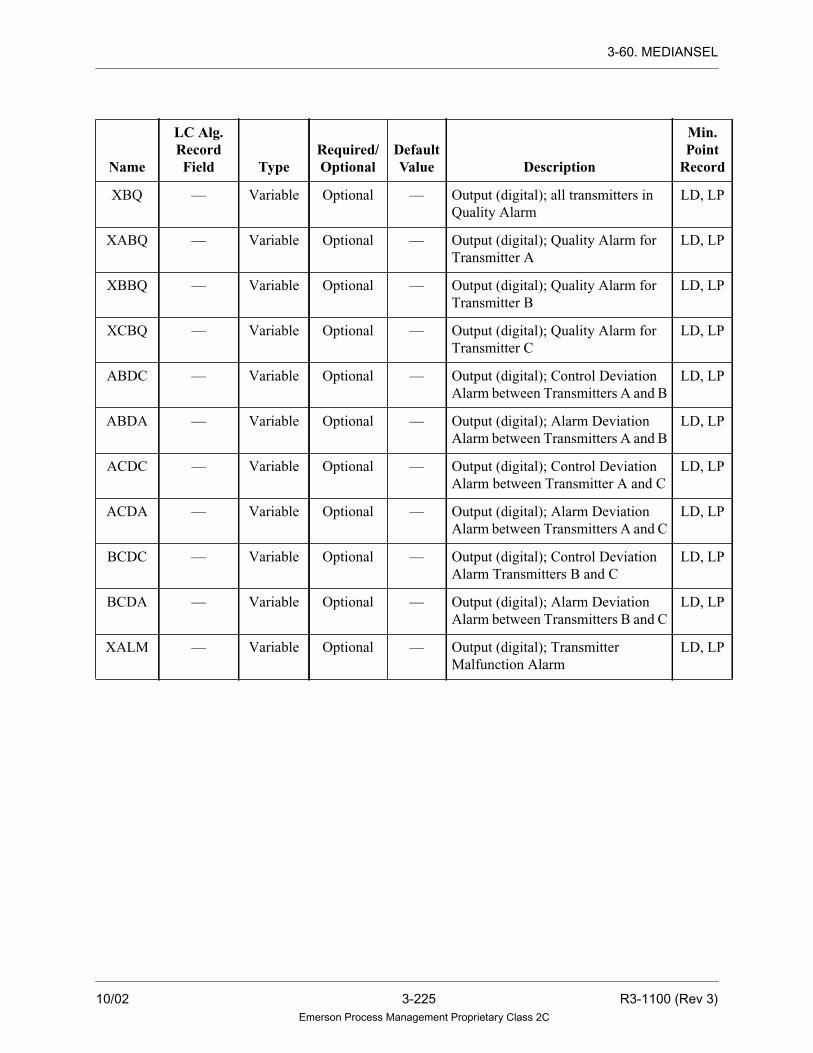
3-60. MEDIANSEL
XBQ — Variable Optional — Output (digital); all transmitters in
Quality Alarm
LD, LP
XABQ — Variable Optional — Output (digital); Quality Alarm for
Transmitter A
LD, LP
XBBQ — Variable Optional — Output (digital); Quality Alarm for
Transmitter B
LD, LP
XCBQ — Variable Optional — Output (digital); Quality Alarm for
Transmitter C
LD, LP
ABDC — Variable Optional — Output (digital); Control Deviation
Alarm between Transmitters A and B
LD, LP
ABDA — Variable Optional — Output (digital); Alarm Deviation
Alarm between Transmitters A and B
LD, LP
ACDC — Variable Optional — Output (digital); Control Deviation
Alarm between Transmitter A and C
LD, LP
ACDA — Variable Optional — Output (digital); Alarm Deviation
Alarm between Transmitters A and C
LD, LP
BCDC — Variable Optional — Output (digital); Control Deviation
Alarm Transmitters B and C
LD, LP
BCDA — Variable Optional — Output (digital); Alarm Deviation
Alarm between Transmitters B and C
LD, LP
XALM — Variable Optional — Output (digital); Transmitter
Malfunction Alarm
LD, LP
Name
LC Alg.RecordField Type
Required/Optional
DefaultValue Description
Min.Point
Record
10/02 3-225 R3-1100 (Rev 3)Emerson Process Management Proprietary Class 2C

3-60. MEDIANSEL
MRE — Variable Optional — Output (digital); manual reject LD, LP
PBPT — Variable Optional — Output (packed digital)
Bit Description
0 Manual reject
1 Transmitter malfunction
2 All transmitters in Quality
Alarm
3 Quality Alarm for
Transmitter A
4 Quality Alarm for
Transmitter B
5 Quality Alarm for
Transmitter C
6 Alarm deviation between
Transmitters A and B
7 Alarm deviation between
Transmitters A and C
8 Alarm deviation between
Transmitters B and C
9 Control deviation between
Transmitters A and B
10 Control deviation between
Transmitters A and C
11 Control deviation between
Transmitters B and C
12 Inhibit Control Deviation
Check for MRE Output
13 Transmitter A mode
14 Transmitter B mode
15 Transmitter C mode
LP
Name
LC Alg.RecordField Type
Required/Optional
DefaultValue Description
Min.Point
Record
R3-1100 (Rev 3) 3-226 10/02Emerson Process Management Proprietary Class 2C

3-61. MULTIPLY
3-61. MULTIPLY
Description
The MULTIPLY algorithm multiplies two gained and biased inputs. The output of
the MULTIPLY algorithm is the product of the two individually gained and biased
inputs.
Note
If the algorithm receives an invalid value as
an input, or if it calculates an invalid value as
the output, the drop is placed into alarm.
Functional Symbol
Tracking Signals
Tracking and limiting are done through signals passed in the upper 16 bits of the
third status word of the analog point. This algorithm takes the following action in
response to the information found in the analog input signal TRIN:
Bit Description Action TOUT Signal
16 Track Implemented Passed through
17 Track if lower No action Passed through*
18 Track if higher No action Passed through*
19 Lower inhibit No action Passed through**
20 Raise inhibit No action Passed through**
21 Conditional Track Implemented Passed through***
22 Not used No action Not used
23 Deviation Alarm No action Not used
X
IN1 IN2
OUT
TOUT
TRIN
10/02 3-227 R3-1100 (Rev 3)Emerson Process Management Proprietary Class 2C
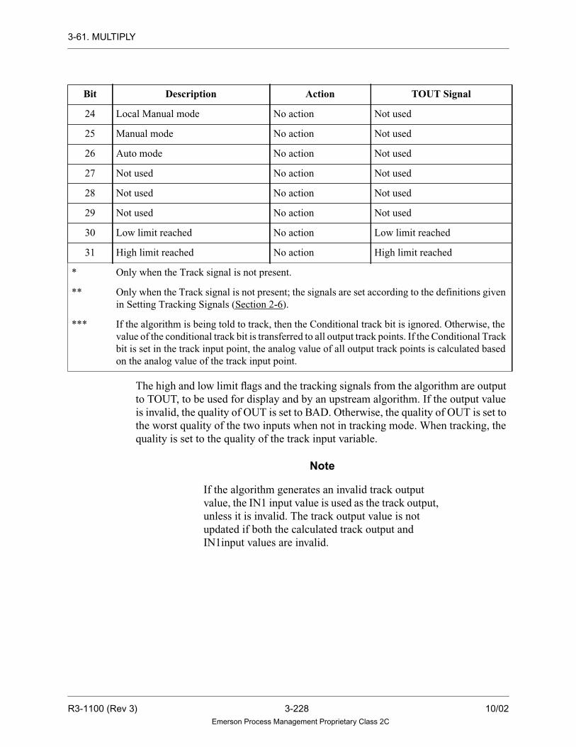
3-61. MULTIPLY
The high and low limit flags and the tracking signals from the algorithm are output
to TOUT, to be used for display and by an upstream algorithm. If the output value
is invalid, the quality of OUT is set to BAD. Otherwise, the quality of OUT is set to
the worst quality of the two inputs when not in tracking mode. When tracking, the
quality is set to the quality of the track input variable.
Note
If the algorithm generates an invalid track output
value, the IN1 input value is used as the track output,
unless it is invalid. The track output value is not
updated if both the calculated track output and
IN1input values are invalid.
24 Local Manual mode No action Not used
25 Manual mode No action Not used
26 Auto mode No action Not used
27 Not used No action Not used
28 Not used No action Not used
29 Not used No action Not used
30 Low limit reached No action Low limit reached
31 High limit reached No action High limit reached
* Only when the Track signal is not present.
** Only when the Track signal is not present; the signals are set according to the definitions given
in Setting Tracking Signals (Section 2-6).
*** If the algorithm is being told to track, then the Conditional track bit is ignored. Otherwise, the
value of the conditional track bit is transferred to all output track points. If the Conditional Track
bit is set in the track input point, the analog value of all output track points is calculated based
on the analog value of the track input point.
Bit Description Action TOUT Signal
R3-1100 (Rev 3) 3-228 10/02Emerson Process Management Proprietary Class 2C

3-61. MULTIPLY
Algorithm Record Type= LC
Algorithm Definitions
Name
LC Alg.RecordField Type
Required/Optional
DefaultValue Description
Min.Point
Record
DIAG LU-Integer Data Init. Required 82 Tuning Diagram Number —
IN1G R1 - Real Tuning
Constant
Required 1.0 Gain on input 1. The gain on input 1
should never be initialized to zero; if
it is, the drop is placed into alarm.
—
IN1B R2 - Real Tuning
Constant
Optional 0.0 Bias on input 1 —
IN2G R3 - Real Tuning
Constant
Required 1.0 Gain on input 2 —
IN2B R4 - Real Tuning
Constant
Optional 0.0 Bias on input 2 —
TPSC R5 - Real Tuning
Constant
Required 100.0 Maximum value of the output point —
BTSC R6 - Real Tuning
Constant
Required 0.0 Minimum value of the output point —
TRAT R7 - Real Tuning
Constant
Required 2.5 Track ramp rate (units per second) —
IN1 — Variable Required — Analog input 1 LA
TOUT — Variable Required — Track output value mode & status
signals for input 1 variable
LA
IN2 — Variable Required — Analog input 2 LA
OUT — Variable Required — Analog output variable LA
TRIN — Variable Optional — Tracking & limiting mode signals
and tracking value; analog input
variable
LA
10/02 3-229 R3-1100 (Rev 3)Emerson Process Management Proprietary Class 2C

3-61. MULTIPLY
Function
IN1GB= (IN1 x IN1G) + IN1B
IN2GB = (IN2 x IN2G) + IN2B
OUT = IN2GB x IN1GB
IF OUT ≥ TPSC THEN
OUT = TPSC
ELSE
IF OUT ≤ BTSC THEN
OUT = BTSC
R3-1100 (Rev 3) 3-230 10/02Emerson Process Management Proprietary Class 2C

3-62. NLOG
3-62. NLOG
Description
The NLOG algorithm performs the mathematical natural logarithmic function. For
the NLOG algorithm, the output equals the natural logarithm of the input value plus
a bias. If the input value is less than or equal to zero, the output is set to a large
negative number (-3.4 x 1038).
Note
Other logarithmic algorithms are ANTILOG and LOG.
Invalid Numbers and Quality
The quality of the input is propagated to the output. However, if the algorithm
calculates an invalid value for the output, the quality of the output is set to BAD,
and the output value is invalid.
Functional Symbol
NLOG
IN1
OUT
10/02 3-231 R3-1100 (Rev 3)Emerson Process Management Proprietary Class 2C

3-62. NLOG
Algorithm Record Type = LC
Algorithm Definitions
Function
OUT = NATURAL LOG OF IN1 + BIAS
Name
LC Alg.RecordField Type
Required/Optional
DefaultValue Description
Min.Point
Record
DIAG LU-Integer Data Init. Required 70 Tuning Diagram Number —
BIAS R1 - Real Tuning
Constant
Optional 0.0 Bias —
IN1 — Variable Required — Input (analog) LA
OUT — Variable Required — Output (analog) LA
R3-1100 (Rev 3) 3-232 10/02Emerson Process Management Proprietary Class 2C
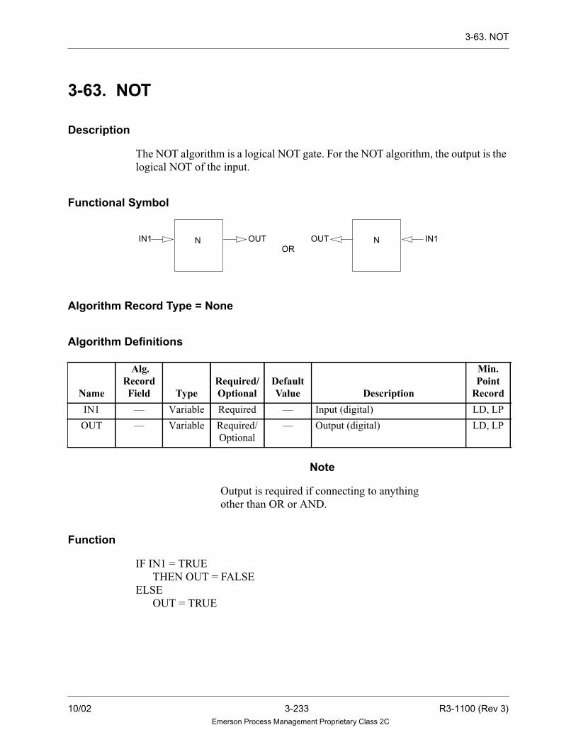
3-63. NOT
3-63. NOT
Description
The NOT algorithm is a logical NOT gate. For the NOT algorithm, the output is the
logical NOT of the input.
Functional Symbol
Algorithm Record Type = None
Algorithm Definitions
Note
Output is required if connecting to anything
other than OR or AND.
Function
IF IN1 = TRUE
THEN OUT = FALSE
ELSE
OUT = TRUE
Name
Alg.RecordField Type
Required/Optional
DefaultValue Description
Min.Point
Record
IN1 — Variable Required — Input (digital) LD, LP
OUT — Variable Required/
Optional
— Output (digital) LD, LP
NOR
OUTIN1 IN1OUT N
10/02 3-233 R3-1100 (Rev 3)Emerson Process Management Proprietary Class 2C

3-64. OFFDELAY
3-64. OFFDELAY
Description
The OFFDELAY algorithm extends the time that the output is TRUE. On a FALSE-
to-TRUE state level change of the IN1 (Pulse Stretcher), the Timer ACTUAL
(ACT) is set to zero and the OUT output is TRUE.
On a subsequent TRUE-to-FALSE state level change of the IN1, the ACTUAL
(ACT) begins accumulating time. When ACTUAL (ACT) is equal to the TARGET
(TARG), accumulation stops, the OUT output is set to FALSE, and ACTUAL
(ACT) retains data until it is reset by another FALSE-to-TRUE state level change
of the IN1 input.
If the TARGET (TARG) value specifies a time which is less than the sheet scan
time, it is permissible for the OUT output to be set FALSE on the same scan that the
IN1 input changed from TRUE to FALSE.
The timers are re-triggerable (that is, the ACTUAL (ACT) can be reset before it
reaches the TARGET (TARG) value).
The OUT output is de-energized if (ACT >= TARG).
If the TARGET (TARG) or ACTUAL (ACT) operands contain a negative or invalid
number, OUT is set to FALSE but no other operation takes place.
When a Controller resets, if IN1 is FALSE, ACTUAL (ACT) remains unchanged
and the OUT output is TRUE according to the comparison between the ACTUAL
(ACT) and the TARGET (TARG). However, if the ACTUAL (ACT) has an initial
value, then the ACTUAL’S (ACT’s) initial value is compared to TARG. If IN1 is
TRUE, ACTUAL (ACT) is set to zero and OUT is TRUE.
In redundant Controllers, during Fail over, if IN1 is FALSE, ACTAUL (ACT)
remains unchanged and both outputs are TRUE according to the comparison
between the ACTUAL (ACT) and TARGET (TARG). If IN1 is TRUE, ACT is set
to zero and OUT is TRUE.
An optional time base (minimum of 0.1 second) can be entered in the R1 field of
the algorithm record. The default time base is 1 second.
R3-1100 (Rev 3) 3-234 10/02Emerson Process Management Proprietary Class 2C

3-64. OFFDELAY
Functional Symbol
Algorithm Record Type = LC
Algorithm Definitions
Name
LC Alg.RecordField Type
Required/Optional
DefaultValue Description
Min.Point
Record
DIAG LU-Integer Data Init Required 97 Tuning Diagram number —
BASE R1 - Real Data Init Optional 1.0 Time Base in seconds (minimum
0.1 second, default 1.0 seconds)
—
IN1 — Variable Required — Input (digital) LD, LP
TARG R2 - Real Selectable Required 0.0 Delay Time number (analog) LA
ACT R3 - Real Selectable Required 0.0 Output (analog) LA
OUT — Variable Required — Output (digital) LD, LP
OUT
ACT
IN1
TARGOFFTD
10/02 3-235 R3-1100 (Rev 3)Emerson Process Management Proprietary Class 2C
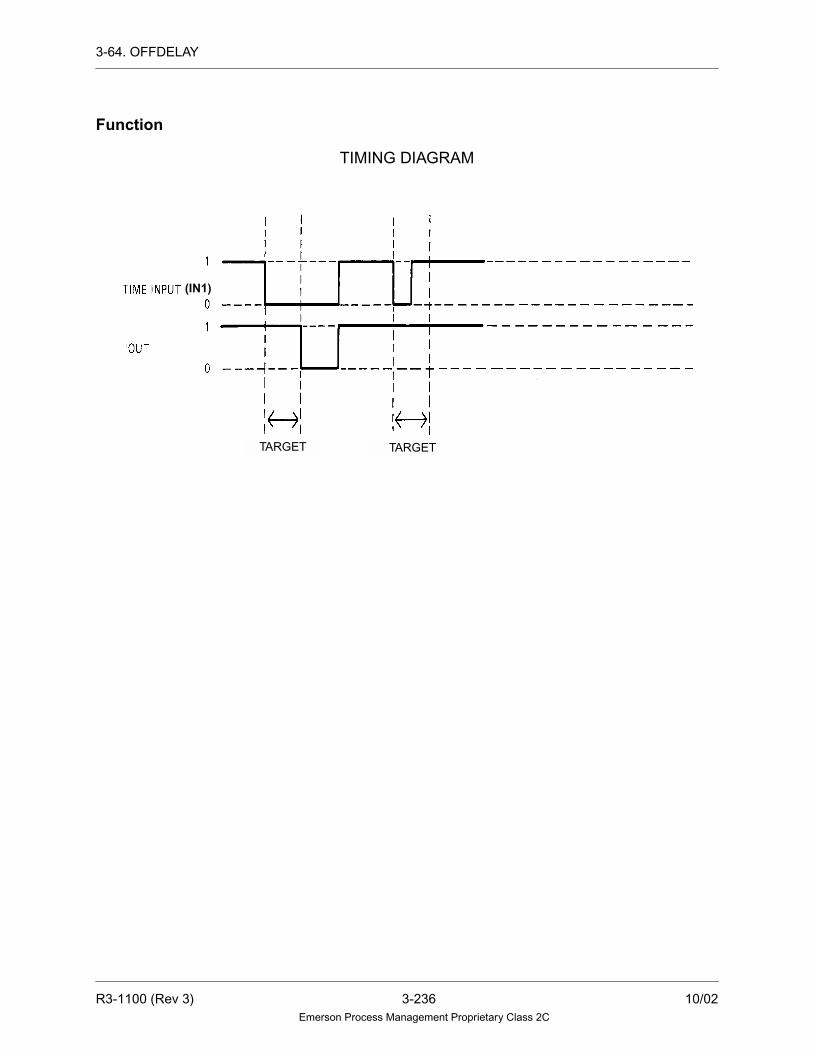
3-64. OFFDELAY
Function
TIMING DIAGRAM
(IN1)
TARGET TARGET
R3-1100 (Rev 3) 3-236 10/02Emerson Process Management Proprietary Class 2C

3-65. ONDELAY
3-65. ONDELAY
Description
The ONDELAY algorithm delays the time that the output will be set to TRUE.
When the ONDELAY algorithm is enabled with the IN1 input TRUE, the Timer
ACTUAL (ACT) accumulates time per the specified Time BASE (BASE) until it
equals the Timer TARGET (TARG). At this point, it stops accumulating and
remains at the TARGET (TARG) value and OUT goes to TRUE.
If the IN1 input changes from TRUE to FALSE while the Timer is enabled, the
ACTUAL (ACT) retains the current value. When the IN1 input changes back to the
TRUE state, the ACTUAL (ACT) resumes accumulating time.
The user can reset ACTUAL (ACT) to zero at any time by making the ENBL input
FALSE: This causes OUT to go FALSE. Typically, however, the IN1 and ENBL
inputs are tied together so that ONDELAY acts as a “classical” timer.
If the ACTUAL (ACT) value is equal to or greater than the TARGET (TARG) value,
transitions of the IN1 input have no effect.
Of special consideration is the case when the Timer TARGET (TARG) equals zero.
In this instance, the OUT output follows the IN1 input as long as the Timer is
enabled.
If the TARGET (TARG) specifies a time which is less than the sheet scan time, it is
permissible for the OUT output to be TRUE on the first scan that the IN1 and ENBL
inputs are TRUE.
If the TARGET (TARG) or ACTUAL (ACT) operands contain a negative or invalid
number, OUT is set to FALSE but no other operation takes place.
When a Controller resets, if ENBL is TRUE, ACTUAL (ACT) remains unchanged
and the OUT output is energized according to the comparison between ACTUAL
(ACT) and TARGET (TARG). However, if ACTUAL (ACT) has an initial value,
then ACT’s initial value is compared to TARGET (TARG). If ENBL is FALSE,
ACTUAL (ACT) is set to zero and OUT is FALSE.
In redundant Controllers, during Failover, if ENBL is energized, ACTUAL (ACT)
remains unchanged and both outputs are energized according to the comparison
between ACTUAL (ACT) and TARGET (TARG). If ENBL is FALSE, ACTUAL
(ACT) is set to zero and OUT is FALSE.
An optional time base (minimum of 0.1 second) can be entered in the R1 field of
the algorithm record. The default time base is 1 second.
10/02 3-237 R3-1100 (Rev 3)Emerson Process Management Proprietary Class 2C

3-65. ONDELAY
Functional Symbol
Algorithm Record Type = LC
Algorithm Definitions
Name
LC Alg.RecordField Type
Required/Optional
DefaultValue Description
Min.Point
Record
DIAG LU-Integer Data Init Required 96 Tuning Diagram number —
BASE R1 - Real Data Init Optional 1.0 Time Base seconds (minimum 0.1
second, default 1.0 seconds)
—
IN1 — Variable Required — Input (digital) LD, LP
ENBL — Variable Required — Input (digital) LD, LP
TARG R2 - Real Selectable Required 0.0 Delay Time number (analog) LA
ACT R3 - Real Selectable Required 0.0 Output (analog) LA
OUT — Variable Required — Output (digital) LD, LP
OUT
ACT
IN1
ENBL
TARG
ONTD
R3-1100 (Rev 3) 3-238 10/02Emerson Process Management Proprietary Class 2C

3-65. ONDELAY
Function
TIMING DIAGRAM
TARGET TARGET TARGET
10/02 3-239 R3-1100 (Rev 3)Emerson Process Management Proprietary Class 2C

3-66. ONESHOT
3-66. ONESHOT
Description
The ONESHOT algorithm sets the output TRUE on a transition for a specified
period of time. On a FALSE-to-TRUE transition of the IN1 input, the OUT output
energizes. The ACTUAL (ACT) is reset to zero and immediately begins
accumulating time, and continues to accumulate until it equals the TARGET
(TARG) or until another FALSE-to-TRUE transition of the IN1 input has occurred.
When ACTUAL (ACT) equals TARGET (TARG), the OUT output de-energizes
and the ACTUAL (ACT) retains its value until a FALSE-to-TRUE transition of the
IN1 input has occurred.
The function is retriggerable (that is, if the ACTUAL (ACT) is accumulating time and
the IN1 input makes a FALSE-to-TRUE transition before it reaches the TARGET
(TARG) value, the function is reset and begins accumulating from time zero).
If the ACTUAL (ACT) is greater than the TARGET (TARG), it is inhibited from
accumulating time and the OUT output will be de-energized.
If TARGET (TARG) equals zero, the OUT output never energizes.
If the TARGET (TARG) or ACTUAL (ACT) operands contain a negative or invalid
number, OUT is de-energized but no other operation takes place.
When a Controller resets, regardless of the IN1 state, ACTUAL (ACT) remains
unchanged and OUT output is energized according to the comparison between
ACTUAL (ACT) and TARGET (TARG). However, if ACTUAL (ACT) has an initial
value, then ACTUAL’s (ACT) initial value is compared to TARGET (TARG).
In redundant Controllers, during Failover, regardless of the IN1 state, ACTUAL
(ACT) remains unchanged and the OUT output is energized according to the
comparison between ACTUAL (ACT) and TARGET (TARG).
An optional time base (minimum of 0.1 second) can be entered in the R1 field of
the algorithm record. If a value is not entered into BASE (R1), the default time base
is assumed to be 1 second.
R3-1100 (Rev 3) 3-240 10/02Emerson Process Management Proprietary Class 2C

3-66. ONESHOT
Functional Symbol
Algorithm Record Type = LC
Algorithm Definitions
Name
LC Alg.RecordField Type
Required/Optional
DefaultValue Description
Min.Point
Record
DIAG LU-Integer Data Init Required 98 Tuning Diagram number —
BASE R1 - Real Data Init Optional 1.0 Time Base in seconds (minimum 0.1
second, default 1.0 seconds); (0
implies 1.0 second)
—
IN1 — Variable Required — Input (digital signal) LD, LP
TARG R2 - Real Selectable Required 0.0 Pulse Time number (analog signal) LA
ACT R3 - Real Selectable Required 0.0 Output (analog signal) LA
OUT — Variable Required — Output (digital signal) LD, LP
IN1
TARG
OUT
ACT
10/02 3-241 R3-1100 (Rev 3)Emerson Process Management Proprietary Class 2C

3-66. ONESHOT
Function
TIMING DIAGRAM
(IN1)
TARGET TARGET TARGET
R3-1100 (Rev 3) 3-242 10/02Emerson Process Management Proprietary Class 2C

3-67. OR
3-67. OR
Description
The OR (Logical OR gate up to 8 inputs) algorithm changes the Boolean of the
output based on the input.The output equals the logical OR of two to eight inputs
(that is, at least one input must be TRUE for the output to be TRUE).
Functional Symbol
Algorithm Record Type = None
Algorithm Definitions
NameAlg. Record
Field TypeRequired/Optional
DefaultValue Description
Min.PointRecord
IN1 — Variable Required — Input (digital) LD, LP
IN2 — Variable Required — Input (digital) LD, LP
IN3 — Variable Optional — Input (digital) LD, LP
IN4 — Variable Optional — Input (digital) LD, LP
IN5 — Variable Optional — Input (digital) LD, LP
IN6 — Variable Optional — Input (digital) LD, LP
IN7 — Variable Optional — Input (digital) LD, LP
IN8 — Variable Optional — Input (digital) LD, LP
OUT — Variable Required/
Optional
— Output (digital) LD, LP
OR
IN1IN2IN3IN4
IN1IN2IN3IN4IN5IN6IN7IN8
IN5IN6IN7IN8
OROUT OUT
OR
10/02 3-243 R3-1100 (Rev 3)Emerson Process Management Proprietary Class 2C

3-67. OR
NoteOutput is required if connecting to anything other
than OR or AND.
Function
OUT = IN1 OR IN2 OR IN3 OR IN4 OR IN5 OR IN6 OR IN7 OR IN8
R3-1100 (Rev 3) 3-244 10/02Emerson Process Management Proprietary Class 2C
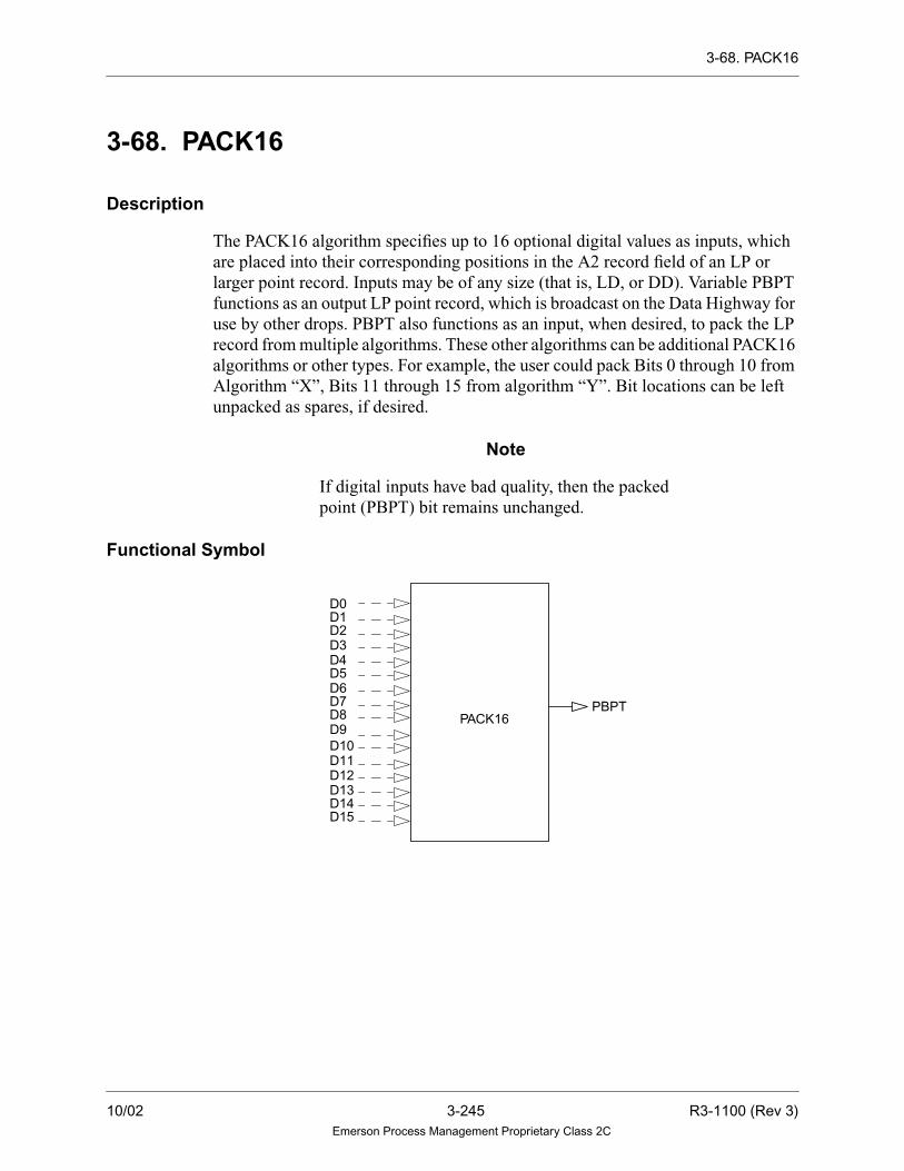
3-68. PACK16
3-68. PACK16
Description
The PACK16 algorithm specifies up to 16 optional digital values as inputs, which
are placed into their corresponding positions in the A2 record field of an LP or
larger point record. Inputs may be of any size (that is, LD, or DD). Variable PBPT
functions as an output LP point record, which is broadcast on the Data Highway for
use by other drops. PBPT also functions as an input, when desired, to pack the LP
record from multiple algorithms. These other algorithms can be additional PACK16
algorithms or other types. For example, the user could pack Bits 0 through 10 from
Algorithm “X”, Bits 11 through 15 from algorithm “Y”. Bit locations can be left
unpacked as spares, if desired.
Note
If digital inputs have bad quality, then the packed
point (PBPT) bit remains unchanged.
Functional Symbol
PACK16
D0D1D2D3D4D5D6D7D8D9D10D11
D15D14D13D12
PBPT
10/02 3-245 R3-1100 (Rev 3)Emerson Process Management Proprietary Class 2C

3-68. PACK16
Algorithm Record Type = None
Algorithm Definitions
Name
Alg.RecordField Type
Required/Optional
DefaultValue Description
Min.Point
Record
D0 — Variable Optional — Input (digital) for Bit 0 LD
D1 — Variable Optional — Input (digital) for Bit 1 LD
D2 — Variable Optional — Input (digital) for Bit 2 LD
D3 — Variable Optional — Input (digital) for Bit 3 LD
D4 — Variable Optional — Input (digital) for Bit 4 LD
D5 — Variable Optional — Input (digital) for Bit 5 LD
D6 — Variable Optional — Input (digital) for Bit 6 LD
D7 — Variable Optional — Input (digital) for Bit 7 LD
D8 — Variable Optional — Input (digital) for Bit 8 LD
D9 — Variable Optional — Input (digital) for Bit 9 LD
D10 — Variable Optional — Input.(digital) for Bit 10 LD
D11 — Variable Optional — Input (digital) for Bit 11 LD
D12 — Variable Optional — Input (digital) for Bit 12 LD
D13 — Variable Optional — Input (digital) for Bit 13 LD
D14 — Variable Optional — Input (digital) for Bit 14 LD
D15 — Variable Optional — Input (digital) for Bit 15 LD
PBPT — Variable Required — Output (packed point) LP
R3-1100 (Rev 3) 3-246 10/02Emerson Process Management Proprietary Class 2C

3-69. PID
3-69. PID
Description
The PID algorithm provides a proportional, integral, derivative controller function.
The algorithm is a parallel PID implementation that utilizes integral tracking signals
for bumpless transfer. The output value is limited via user defined limits and anti-
reset windup is handled internally.
Functional Symbol
Guidelines
Note
PV = Process Variable
STPT = Set Point
1. PV GAIN and PV BIAS must be used to normalize the process variable inputs
to a 0 to 100 percent value.
(PV x PV GAIN) + PV BIAS = PV percent. Thus:
∫κ
∆
OUT
ST
ardFF
ddt
PV
PGAININTGDGAINDRAT
TOUT
TRIN
PT
DEVA
Gpv =PV - PV top bot
100 -G pv PV botBpv =
10/02 3-247 R3-1100 (Rev 3)Emerson Process Management Proprietary Class 2C

3-69. PID
2. STPT GAIN and STPT BIAS must be used to normalize the set point to a 0 to
100 percent value. If setpoint input units are not 0 to 100 percent, then:
(STPT x STPT GAIN) + STPT BIAS = set point percent. Thus:
3. Determine set point high and low limits with these equations:
set point high limit = (100 - STPT BIAS)/STPT GAIN
set point low limit = (0 -STPT BIAS)/STPT GAIN
Output Calculation
The output (which is in either engineering units or percent and limited by the high
and low limits specified) equals the result of the PID equation except:
• When the algorithm is told to track, the output will equal the track input when
the tracking signal is present. The output will ramp at the user specified track
rate, from the track input back to the controlled value when the tracking signal
is removed.
• When a raise inhibit or lower inhibit signal is present, it may prevent the PID
controller from controlling.
• If the algorithm calculates an invalid real number for the output, the quality of
the output is set to BAD. Consequently, if an invalid value is entered as an input
to the algorithm, or if the algorithm generates an invalid value for the output, the
drop is placed into alarm. In all cases, the output is set to the last GOOD value.
• If the algorithm generates an invalid track output value, the set point input value
is used as the track output, unless it is invalid. The track output value is not
updated if both the calculated track output and the set point input values are
invalid.
G sp =SP - SPtop bot
100 - G sp SPbotBsp =
R3-1100 (Rev 3) 3-248 10/02Emerson Process Management Proprietary Class 2C

3-69. PID
Error Deadband and Deadband Gain
The algorithm can be configured to utilize a Deadband region in the Controller error
signal. This Deadband region is used to modify the error signal that is presented to
the PID equation.
The Controller error signal is calculated as the difference between the normalized
process variable and normalized set point and is passed as the input to the PID
equation. If the algorithm is configured to utilize an error Deadband, the error that
is presented to the PID equation is Error = Error × Error Deadband Gain.
PID error Deadband is configured by initializing the DBND field to a non-zero
value. This value represents the normalized Controller error signal to be used as the
Deadband region. Deadband is applied bilaterally with respect to zero. For example,
if the DBND field is equal to 5, then the deadband region will be between -5% and
+5%. If the controller error signal is within the deadband, then the actual error that
is presented to the PID equation is the product of the error signal and the error
deadband gain. The ERRD field contains the value of the error deadband gain. The
valid values for this field are any real numbers between zero and one [0-1].
As an example, consider the following: DBND is 5 and ERRD is 0.5. For a
normalized Controller error signal of 2%, the actual error signal that is applied to
the PID equation is 2% x 0.5 = 1%. In general, for these example values of DBND
and ERRD, any normalized error signal between -5% and +5% will be reduced by
50% before being applied to the PID equation. Derivative action is disabled when
the algorithm is operating within the deadband region.
When the algorithm is configured as a deadband controller, transitions into and out
of the deadband region are smoothed internally by utilizing a hold and track
operation. During this transition cycle, the Controller output is set to its previous
value and the integral term is re-calculated to account for the different Controller
dynamics of the new region. This effectively eliminates the abrupt change in the
proportional term due to the deadband transition. Derivative action is disabled when
the algorithm is operating within the deadband region.
10/02 3-249 R3-1100 (Rev 3)Emerson Process Management Proprietary Class 2C

3-69. PID
Tracking Signals
External tracking and limiting are done through signals passed in the upper 16 bits
of the third status word of the analog track points. This algorithm takes the
following action in response to information found in the third status word of the
analog input signal TRIN:
The High and Low limit flags, the mode, and the tracking signals from the algorithm
are output to TOUT to be used for display and by upstream algorithms.
Bit Description Action TOUT Signal
16 Track Implemented Passed through or set TRUE when not
in Cascade mode.
17 Track if lower Implemented when not in
Manual mode*
Not used
18 Track if higher Implemented when not in
Manual mode*
Not used
19 Lower inhibit Implemented* Passed through**
20 Raise inhibit Implemented* Passed through**
21 Conditional Track See description of cascaded
mode.
Passed through if in the cascaded mode.
22 Not used No action Not used
23 Deviation Alarm No action Not used
24 Local Manual mode No action Not used
25 Manual mode No action Manual mode
26 Auto mode No action Auto mode
27 Not Used No action Not used
28 Not Used No action Not used
29 Not Used No action Not used
30 Low limit reached No action Low limit reached
31 High limit reached No action High limit reached
* Only when the Track signal is not present.
** Only when the Track signal is not present; the signals are set according to the definitions given in
Setting Tracking Signals in Section 2-6.
R3-1100 (Rev 3) 3-250 10/02Emerson Process Management Proprietary Class 2C

3-69. PID
Algorithm Record Type = LC
Algorithm Definitions
Name
LC Alg.RecordField Type
Required/Optional
DefaultValue Description
Min.Point
Record
DIAG LU-Integer Data Init Required 38 Tuning Diagram Number —
SPTG R3 - Real Tuning
Constant
Required 1.0 Gain on set point. The gain on
the set point should never be
initialized to zero.
—
SPTB R4 - Real Tuning
Constant
Optional 0.0 Bias on set point —
PVG R1 - Real Tuning
Constant
Required 1.0 Gain on process variable input.
The gain on the set point
should never be initialized to
zero.
—
PVB R2 - Real Tuning
Constant
Optional 0.0 Bias on process variable input —
TPSC R5 - Real Tuning
Constant
Required 100.0 Maximum value of the output
point
—
BTSC R6 - Real Tuning
Constant
Required 0.0 Minimum value of the output
point
—
TYPE X5 - Byte
Bits 1 and
0
Data Init. Required NORMAL Type of PID controller:
NORMAL: Regular PID
control
ESG: PID control with error
squared on the proportional
gain term
ESI: PID control with error
squared on the integral term
—
ACTN X5 - Byte
Bit 2
Data Init. Required INDIRECT Direction Flag:
INDIRECT: Error = Set point -
process variable
DIRECT: Error = Process
variable - set point
—
10/02 3-251 R3-1100 (Rev 3)Emerson Process Management Proprietary Class 2C

3-69. PID
CASC X5 - Byte
Bit 3
Data Init Required NORMAL Controller is downstream in a
cascaded configuration.
NORMAL: Normal PID
action.
CASCADED: See description
of cascaded mode and
conditional tracking.
—
DACT X5 - Byte
Bit 4
Data Init Required Normal Type of Derivative action
Normal — Derivative applied
to change in error.
Set point — Derivative applied
to change in set point.
Process — Derivative applied
to change in process variable.
—
DBND S3 - Real Tuning
Constant
Required 0.0 PID error deadband —
ERRD S4 - Real Tuning
Constant
Required 0.0 PID error deadband gain —
PGAIN R8 - Real Selectable Required 1.0 PID proportional gain. If the
proportional gain equals zero,
the proportional part will not
be included in the output.
LA
INTG R9 - Real Selectable Required 10.0 PID integral time in seconds
per repeat. If the integral time
equals zero, the integral part
will not be included in the
output.
LA
DGAIN S1 - Real Selectable Required 0.0 PID derivative gain. If the
derivative gain equals zero, the
derivative part will not be
included in the output.
LA
DRAT S2 - Real Selectable Required 0.0 PID derivative rate decay
constant in seconds
LA
TRAT R7 - Real Tuning
Constant
Required 2.5 Track ramp rate (units per
second)
—
Name
LC Alg.RecordField Type
Required/Optional
DefaultValue Description
Min.Point
Record
R3-1100 (Rev 3) 3-252 10/02Emerson Process Management Proprietary Class 2C

3-69. PID
PV — Variable Required — Process variable analog input. LA
STPT — Variable Required — Set point analog input LA
TOUT — Variable Required — Track output value. LA
OUT — Variable Required — Analog output variable LA
TRIN — Variable Optional — Tracking analog input variable LA
DEVA — Variable Required — Error between process variable
and set point for PID. This is
calculated using the
normalized set point PVAR.
LA
Name
LC Alg.RecordField Type
Required/Optional
DefaultValue Description
Min.Point
Record
10/02 3-253 R3-1100 (Rev 3)Emerson Process Management Proprietary Class 2C
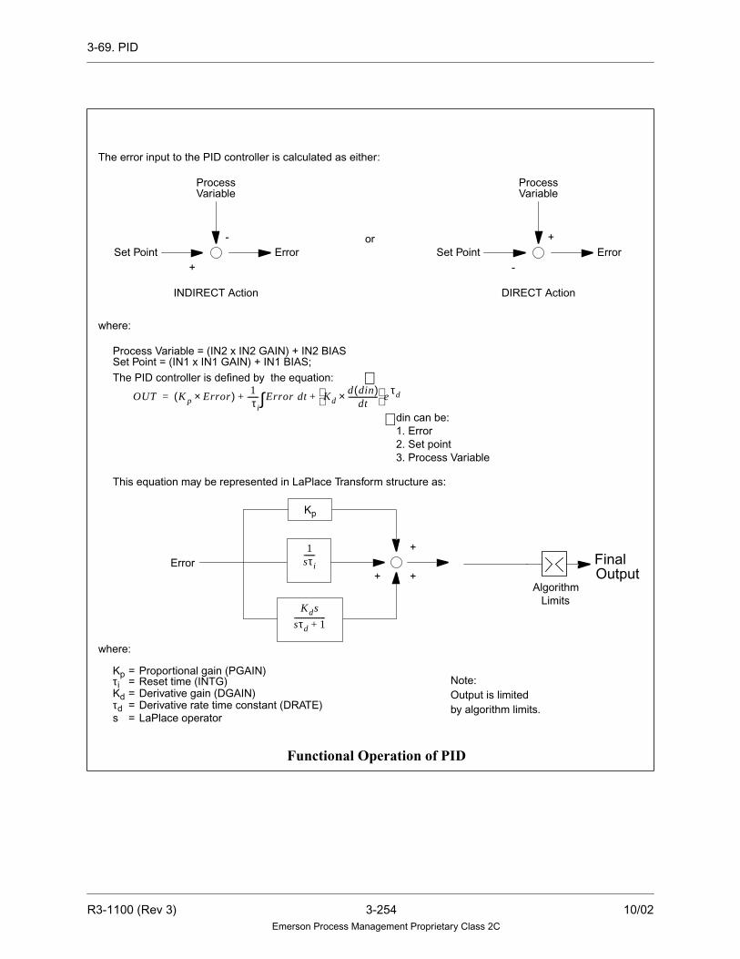
3-69. PID
The error input to the PID controller is calculated as either:
ProcessVariable
DIRECT ActionINDIRECT Action
Set Point Error-
+
ProcessVariable
Set Point Error+
-
where:
Process Variable = (IN2 x IN2 GAIN) + IN2 BIASSet Point = (IN1 x IN1 GAIN) + IN1 BIAS;The PID controller is defined by the equation:
This equation may be represented in LaPlace Transform structure as:
OUT K p Error×( ) 1sτ i------ Error dt∫ Kd
d din( )dt
----------------× e
τd+ +=
where:
Kp
Kdτds
=
===
Proportional gain (PGAIN)
Derivative gain (DGAIN)Derivative rate time constant (DRATE)LaPlace operator
Error
or
Kp
1sτ i------
Kds
sτd 1+-----------------
τi = Reset time (INTG)
+
++
din can be:1. Error2. Set point3. Process Variable
∗
∗
AlgorithmLimits
FinalOutput
Functional Operation of PID
Note:Output is limitedby algorithm limits.
R3-1100 (Rev 3) 3-254 10/02Emerson Process Management Proprietary Class 2C

3-69. PID
Cascaded Mode and Conditional Tracking:
Conditional tracking is a scheme which allows tighter control of the process
variable when the control strategy is implemented using cascaded Controllers.
Essentially, the conditional tracking scheme allows the upstream Controller to have
immediate influence on the final output when the error between the process variable
and the set point changes direction while the downstream Controller is in a
saturation condition. Conditional tracking is incorporated when the downstream
Controller (Controller “B” in figure) operates in cascaded mode.
The purpose of cascaded mode is to allow two PID algorithms to be used in a
cascaded configuration where the output of one PID is the set point for another.
When the user desires to arrange two PID Controllers in this configuration, the type
parameter should be set to cascaded in the downstream Controller only. It is not
necessary to configure the upstream Controller in the cascaded configuration.
PID
PID
STPT PV
PV
Out
Controller “B”
TRKOUT “B”
Controller “A”
RAI
Action = IndirectType = cascadedSTPT Gain 0
Equation 1:
IndirectControllerA.) TRKOUT =
(PV)∗ PVGAIN-PVBIAS+SPBIAS
SPGAIN
B.)TRKOUT =(PV)∗ PVGAIN-PVBIAS-SPBIAS
SPGAIN
STPT
DirectController
10/02 3-255 R3-1100 (Rev 3)Emerson Process Management Proprietary Class 2C

3-69. PID
When the downstream Controller is configured in the cascaded mode, the controller
operates as a conventional PID controller so long as the Controller is not in a
saturation condition. However, if the Controller output is saturated at the HI or LO
limit or if the Controller receives an inhibit signal from a downstream algorithm the
behavior of the cascaded pair is as follows:
The downstream Controller (Controller “B” in figure) will assert the conditional
track signal in its output tracking point along the applicable limit or inhibit bit.
The downstream Controller will also calculate a track output value that if
applied as a set point input, will yield a Controller error of zero (see Equation 1).
When the upstream Controller sees the conditional track bit set, it will adjust its
output as follows: If the error signal causes the Controller output to move
against the inhibit signal (for example, output attempts to increase when the
algorithm is receiving a raise inhibit), then the algorithm will set its output equal
to the track input received from downstream.
If the error signal causes the output to move away from the inhibit signal, the
algorithm will set its output equal to the track input and begin controlling.
Without this mode, the upstream Controller would first have to move enough to
zero the error on the downstream Controller before having any effect on the
process. This would introduce additional dead-time in the Controller response
and in the case of processes with slow dynamics (for example, temperature
control), this additional dead-time may be significant.
Only the PID algorithm configured to be in cascaded mode will assert the
conditional track bit. The upstream Controller (Controller “A” in figure) will not
pass the conditional track bit in its track output.
R3-1100 (Rev 3) 3-256 10/02Emerson Process Management Proprietary Class 2C

3-70. PIDFF
3-70. PIDFF
Description
The PIDFF algorithm is designed to accept an externally generated analog signal
that is used as a feed-forward bias. This analog signal is summed with the actual
PID output (sum of the proportional, integral and derivative terms) to become the
final control output. The advantage to having the feed-forward input incorporated
in the PID algorithm is that saturation conditions, caused by either the final control
output exceeding the algorithms limits or raise/lower inhibit signals generated by
the downstream algorithms, are handled internally to the algorithm. This can greatly
improve Controller response times to sudden changes in the direction (algebraic
sign) of the Controller error signal when the Controller is in a saturation condition.
The PID portion of the algorithm provides a proportional, integral, derivative
Controller function. The algorithm is a parallel PID implementation that utilizes
integral tracking signals for bumpless transfer. The output value is limited via user
defined limits and anti-reset windup is handled internally.
Functional Symbol
∑
∫κ
∆
OUT
ST PT PV
ardFeedFF
Feed-Forwardddt
PGAIN
DGAINDRAT
TOUT
TRIN
INTG
FF
signal
10/02 3-257 R3-1100 (Rev 3)Emerson Process Management Proprietary Class 2C

3-70. PIDFF
Guidelines
Note
PV = Process Variable
STPT= Set Point
FF = FF Input
1. PV GAIN and PV BIAS MUST be used to normalize the process variable
inputs to a 0 to 100 percent value. Use this equation:
(PV x PV GAIN) + PV BIAS = PV percent. Thus,
2. STPT GAIN and STPT BIAS must be used to normalize the set point to a 0 to
100 percent value. If setpoint input units are not 0 to 100 percent, then:
(STPT x STPT GAIN) + STPT BIAS = set point percent. Thus:
3. The external feed-forward input should be normalized to 0-100%
(FF x FF GAIN) + FF BIAS = FF percent
G pv =PV - PV top bot
100 -G pv x PV botB pv =
G sp =SP - SPtop bot
100 - G sp SPbotBsp =
R3-1100 (Rev 3) 3-258 10/02Emerson Process Management Proprietary Class 2C

3-70. PIDFF
Error Deadband and Deadband Gain
The algorithm can be configured to utilize a Deadband region in the Controller error
signal. This Deadband region is used to modify the error signal that is presented to
the PID equation.
The Controller error signal is calculated as the difference between the normalized
process variable and normalized set point and is passed as the input to the PID
equation. If the algorithm is configured to utilize an error Deadband, the error that
is presented to the PID equation is Error = Error × Error Deadband Gain.
PID error Deadband is configured by initializing the DBND field to a non-zero
value. This value represents the normalized Controller error signal to be used as the
Deadband region. Deadband is applied bilaterally with respect to zero. For example,
if the DBND field is equal to 5, then the deadband region will be between -5% and
+5%. If the controller error signal is within the deadband, then the actual error that
is presented to the PID equation is the product of the error signal and the error
deadband gain. The ERRD field contains the value of the error deadband gain. The
valid values for this field is any real number between zero and one [0-1].
As an example, consider the following:
DBND is 5 and ERRD is 0.5. For a normalized Controller error signal of 2%,
the actual error signal that is applied to the PID equation is 2% x 0.5 = 1%. In
general, for these example values of DBND and ERRD, any normalized error
signal between -5% and +5% will be reduced by 50% before being applied to
the PID equation.
When the algorithm is configured as a deadband Controller, transitions into and out
of the deadband region are smoothed internally by utilizing a hold and track
operation. During this transition cycle, the Controller output is set to its previous
value and the integral term is re-calculated to account for the different Controller
dynamics of the new region. This effectively eliminates the abrupt change in the
proportional term due to the deadband transition. Derivative action is disabled when
the algorithm is operating within the deadband region.
10/02 3-259 R3-1100 (Rev 3)Emerson Process Management Proprietary Class 2C

3-70. PIDFF
Output Calculation
The output (which is in either engineering units or percent and limited by the high
and low limits specified) equals the algebraic sum of the result of the PID equation
and the feed-forward input except:
• When the algorithm is told to track, the output will equal the track input when
the tracking signal is present. The output will ramp at the user specified track
rate, from the track input back to the controlled value when the tracking signal
is removed.
• When a raise inhibit or lower inhibit signal is present, it may prevent the PID
Controller from controlling.
• When the sum of the actual PID output and the normalized feed-forward input
exceeds either the high or low limit of the algorithm, the output in this case will
be clipped at the corresponding limit.
• If the algorithm calculates an invalid real number for the output, the quality of
the output is set to BAD. Consequently, if an invalid value is entered as an input
to the algorithm, or if the algorithm generates an invalid value for the output, the
drop is placed into alarm. In all cases, the output is set to the last GOOD value.
• If the algorithm generates an invalid track output value, the set point input value
is used as the track output, unless it is invalid. The track output value is not
updated if both the calculated track output and the set point input values are
invalid.
R3-1100 (Rev 3) 3-260 10/02Emerson Process Management Proprietary Class 2C

3-70. PIDFF
Tracking Signals
External tracking and limiting are done through signals passed in the upper 16 bits
of the third status word of the analog track points. This algorithm takes the
following action in response to information found in the third status word of the
analog input signal TRIN:
The High and Low limit flags, the mode, and the tracking signals from the algorithm
are output to TOUT to be used for display and by upstream algorithms.
Bit Description Action TOUT Signal
16 Track Implemented Passed through or set TRUE when not
in Cascade mode.
17 Track if lower Implemented when not in
Manual mode*
Not used
18 Track if higher Implemented when not in
Manual mode*
Not used
19 Lower inhibit Implemented* Passed through**
20 Raise inhibit Implemented* Passed through**
21 Conditional Track See description of cascaded
mode.
Passed through if in the cascaded
mode.
22 Not used No action Not used
23 Deviation Alarm No action Set when the deviation of process
variable and set point is greater than the
given Deviation Alarm deadband.
24 Local Manual mode No action Not used
25 Manual mode No action Manual mode
26 Auto mode No action Auto mode
27 Not Used No action Not used
28 Not Used No action Not used
29 Not Used No action Not used
30 Low limit reached No action Low limit reached
31 High limit reached No action High limit reached
* Only when the Track signal is not present.
** Only when the Track signal is not present; the signals are set according to the definitions given in
Setting Tracking Signals in Section 2-6.
10/02 3-261 R3-1100 (Rev 3)Emerson Process Management Proprietary Class 2C
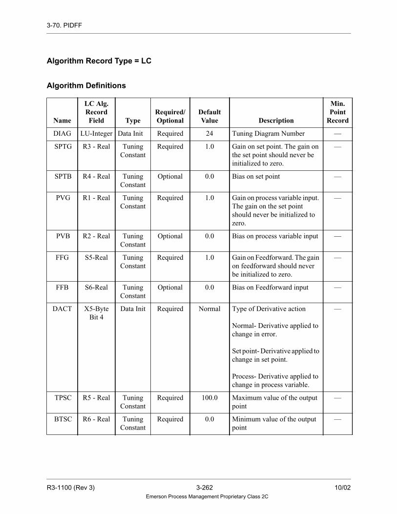
3-70. PIDFF
Algorithm Record Type = LC
Algorithm Definitions
Name
LC Alg.RecordField Type
Required/Optional
DefaultValue Description
Min.Point
Record
DIAG LU-Integer Data Init Required 24 Tuning Diagram Number —
SPTG R3 - Real Tuning
Constant
Required 1.0 Gain on set point. The gain on
the set point should never be
initialized to zero.
—
SPTB R4 - Real Tuning
Constant
Optional 0.0 Bias on set point —
PVG R1 - Real Tuning
Constant
Required 1.0 Gain on process variable input.
The gain on the set point
should never be initialized to
zero.
—
PVB R2 - Real Tuning
Constant
Optional 0.0 Bias on process variable input —
FFG S5-Real Tuning
Constant
Required 1.0 Gain on Feedforward. The gain
on feedforward should never
be initialized to zero.
—
FFB S6-Real Tuning
Constant
Optional 0.0 Bias on Feedforward input —
DACT X5-Byte
Bit 4
Data Init Required Normal Type of Derivative action
Normal- Derivative applied to
change in error.
Set point- Derivative applied to
change in set point.
Process- Derivative applied to
change in process variable.
—
TPSC R5 - Real Tuning
Constant
Required 100.0 Maximum value of the output
point
—
BTSC R6 - Real Tuning
Constant
Required 0.0 Minimum value of the output
point
—
R3-1100 (Rev 3) 3-262 10/02Emerson Process Management Proprietary Class 2C

3-70. PIDFF
TYPE X5 - Byte
Bits 0 and
1
Data Init. Required NORMAL Type of PID controller:
NORMAL: Regular PID
control
ESG: PID control with error
squared on the proportional
gain term
ESI: PID control with error
squared on the integral term
—
ACTN X5 - Byte
Bit 2
Data Init. Required INDIRECT Direction Flag:
INDIRECT: Error = Set point -
process variable
DIRECT: Error = Process
variable - set point
—
CASC X5-Byte
Bit 3
Data Init Required NORMAL Controller is downstream in a
cascaded configuration.
NORMAL: Normal PID
action.
CASCADED: See description
of cascaded mode and
conditional tracking.
—
DBND S3 - Real Tuning
Constant
Required 0.0 PID error deadband —
ERRD S4 - Real Tuning
Constant
Required 0.0 PID error deadband gain —
PGAIN R8 - Real Selectable Required 1.0 PID proportional gain. If the
proportional gain equals zero,
the proportional part will not
be included in the output.
—
INTG R9 - Real Selectable Required 10.0 PID integral time in seconds
per repeat. If the integral time
equals zero, the integral part
will not be included in the
output.
—
Name
LC Alg.RecordField Type
Required/Optional
DefaultValue Description
Min.Point
Record
10/02 3-263 R3-1100 (Rev 3)Emerson Process Management Proprietary Class 2C

3-70. PIDFF
DGAIN S1 - Real Selectable Required 0.0 PID derivative gain. If the
derivative gain equals zero, the
derivative part will not be
included in the output.
—
DRAT S2 - Real Selectable Required 0.0 PID derivative rate decay
constant in seconds
—
TRAT R7 - Real Tuning
Constant
Required 2.5 Track ramp rate (units per
second)
—
PV — Variable Required — Process variable analog input. LA
FF — Variable Required — Feedforward Input LA
STPT — Variable Required — Set point. LA
TOUT — Variable Required — Track output value LA
OUT — Variable Required — Analog output variable LA
TRIN — Variable Optional — Tracking analog input variable LA
Name
LC Alg.RecordField Type
Required/Optional
DefaultValue Description
Min.Point
Record
R3-1100 (Rev 3) 3-264 10/02Emerson Process Management Proprietary Class 2C

3-70. PIDFF
The error input to the PID controller is calculated as either:
ProcessVariable
DIRECT ActionINDIRECT Action
Set Point Error-
+
ProcessVariable
Set Point Error+
-
where:
Process Variable = (IN2 x IN2 GAIN) + IN2 BIASSet Point = (IN1 x IN1 GAIN) + IN1 BIAS;
The PID controller is defined by the equation:
This equation may be represented in LaPlace Transform structure as:
OUT K p Error×( ) 1sτ i------ Error dt∫ Kd
d din( )dt
----------------× + +=
where:
Kp
Kdτds
=
===
Proportional gain (PGAIN)
Derivative gain (DGAIN)Derivative rate time constant (DRATE)LaPlace operator
Error
or
Kp
1sτ i------
Kds
sτd 1+-----------------
τi = Reset time (INTG)
+
++
This is the value ofthe deviation point
This is the value ofthe deviation point
din can be:1. Error2. Set point3. Process Variable
Normalized feed-forward input = (FFINPUT x FFGAIN)+FF BIAS
Note:The Final output value islimited by the output limits ofthe PDIFF algorithm
+Normalized feed-forward input
Normalizedfeed-forward input
+OutputFinal
ActualPID Output
∗
∗
Functional Operation of PIDFF
AlgorithmLimits
10/02 3-265 R3-1100 (Rev 3)Emerson Process Management Proprietary Class 2C

3-70. PIDFF
Feed-Forward Control Example
Refer to the “Functional Operation of PIDFF” diagram for the following example.
Consider the case where the output limits on the PIDFF algorithm are 0-100%, the
external feed-forward input has a normalized value of 75%, the actual PID output
is 50% and the error between process variable and set point causes the PID output
to increase. This condition would require that the final output be 125%, which
violates the algorithm’s high limit of 100%. The final PIDFF output will be clipped
at 100%. If the error between the process variable and the set point were to change
direction, the PID output would have to move 25% before it had any effect on the
final control output and thus the process variable. Depending on the tuning
parameters, the time that this takes can be significant.
By incorporating the feed-forward input into the PIDFF algorithm, this direction
change in the error between the process variable and set point will have an
immediate effect on the final control output.
The PIDFF will begin integrating from the high limit of 100% and thus will have
immediate influence on the final control output and subsequently on the process
variable.
R3-1100 (Rev 3) 3-266 10/02Emerson Process Management Proprietary Class 2C

3-70. PIDFF
Cascaded Mode and Conditional Tracking
Conditional tracking is a scheme which allows tighter control of the process
variable when the control strategy is implemented using cascaded Controllers.
Essentially, the conditional tracking scheme allows the upstream Controller to have
immediate influence on the final output when the error between the process variable
and the setpoint changes direction while the downstream controller is in a saturation
condition. Conditional tracking is incorporated when the downstream Controller
(Controller “B” in figure) operates in cascaded mode.
The purpose of cascaded mode is to allow two PID algorithms to be used in a
cascaded configuration where the output of one PID is the set point for another.
When the user desires to arrange two PID Controllers in this configuration, the type
parameter should be set to cascaded in the downstream Controller only. It is not
necessary to configure the upstream Controller in the cascaded configuration.
PID
PID
STPT PV
PV
Out
Controller “B”
TRKOUT “B”
Controller “A”
RAI
Action = IndirectType = cascadedSTPT Gain › 0
Equation 1:
IndirectControllerA.) TRKOUT =
(PV)∗ PVGAIN-PVBIAS+SPBIAS
SPGAIN
B.)TRKOUT =(PV)∗ PVGAIN-PVBIAS-SPBIAS
SPGAIN
STPT
DirectController
10/02 3-267 R3-1100 (Rev 3)Emerson Process Management Proprietary Class 2C

3-70. PIDFF
When the downstream controller is configured in the cascaded mode, the Controller
operates as a conventional PIDFF Controller so long as the Controller is not in a
saturation condition. However, if the controller output is saturated at the HI or LO
limit or if the Controller receives an inhibit signal from a downstream algorithm, the
behavior of the cascaded pair is as follows:
The downstream Controller (Controller “B” in figure) will assert the conditional
track signal in its output tracking point along the applicable limit or inhibit bit.
The downstream Controller will also calculate a track output value that if
applied as a set point input, will yield a Controller error of zero (see the previous
Equation 1).
When the upstream Controller sees the conditional track bit set it will adjust its
output as follows: If the error signal causes the Controller output to move
against the inhibit signal (for example, output attempts to increase when the
algorithm is receiving a raise inhibit), then the algorithm will set its output equal
to the track input received from downstream.
If the error signal is such as to cause the output to move away from the inhibit
signal, the algorithm will set its output equal to the track input and begin
controlling.
Without this mode, the upstream Controller would first have to move enough to
zero the error on the downstream Controller before having any effect on the
process. This would introduce additional dead-time in the Controller response
and in the case of processes with slow dynamics (for example, temperature
control) this additional deadtime may be significant.
Only the PIDFF algorithm configured to be in cascaded mode will assert the
conditional track bit. The upstream Controller (Controller “A” in figure) will not
pass the conditional track bit in its track output.
R3-1100 (Rev 3) 3-268 10/02Emerson Process Management Proprietary Class 2C

3-71. PNTSTATUS
3-71. PNTSTATUS
Description
The PNTSTATUS algorithm outputs the states of two specified bits of the point
record’s status word. When the ENBL input is TRUE, the states of BITA and BITB
of the point record’s status word are output to OUTA and OUTB, respectively. For
example, if the bit specified by BITA is a one, then OUTA is TRUE. Conversely, if
the bit specified by BITA is a zero, then OUTA is FALSE. This example also holds
TRUE for BITB and OUTB.
For analog and digital records, the valid range for BITA and BITB is 0 through 31.
When the ENBL input is TRUE and either the BITA or BITB operand contains an
invalid bit number, no operation occurs and the BITA and BITB outputs are FALSE.
Functional Symbol
Algorithm Record Type = LC
PNTSTATOUTA
ENBL OUTB
IN1
10/02 3-269 R3-1100 (Rev 3)Emerson Process Management Proprietary Class 2C

3-71. PNTSTATUS
Algorithm Definitions
Name
LC Alg.RecordField Type
Required/Optional
DefaultValue Description
Min.Point
Record
DIAG LU-Integer Data Init. Required 86 Tuning Diagram number —
STAT X1 - Byte Data Init. Required 1W Status word 1W, 2W, 3W —
BITA X2 - Byte Data Init. Optional 0 Which bit in the point record’s
status word is output to OUTA
—
BITB X3 - Byte Data Init. Optional 0 Which bit in the point record’s
status word is output to OUTB
—
ENBL — Variable Required — Enable Input Flag (digital) LD, LP
IN1 — Variable Required — Input LA, LD
OUTA — Variable Optional — When the ENBL input is TRUE,this output reflects the state of thebit specified by BITA.
LD, LP
OUTB — Variable Optional — When the ENBL input is TRUE,this output reflects the state of thebit specified by BITB.
LD, LP
R3-1100 (Rev 3) 3-270 10/02Emerson Process Management Proprietary Class 2C

3-72. POLYNOMIAL
3-72. POLYNOMIAL
Description
The POLYNOMIAL algorithm performs a mathematical fifth order polynomial
function. The output of the POLYNOMIAL algorithm is the result of a fifth order
polynomial equation of the input using the coefficients listed in this description.
Invalid Numbers and Quality
The quality of the analog input is propagated to the output. However, if the
algorithm calculates an invalid value for the output, the quality of the output is set
to BAD, and the output value is invalid.
Functional Symbol
Algorithm Record Type = LC
IN1
OUT
POLY
10/02 3-271 R3-1100 (Rev 3)Emerson Process Management Proprietary Class 2C

3-72. POLYNOMIAL
Algorithm Definitions
Function
OUT = CX0 (IN1)0 + CX1 (IN1)1 + CX2 (IN1)2 + CX3 (IN1)3 + CX4 (IN1)4 +
CX5 (IN1)5
Name
LC Alg.RecordField Type
Required/Optional
DefaultValue Description
Min.Point
Record
DIAG LU-Integer Data Init. Required 7 Tuning Diagram Number —
CX0 R1 - Real Tuning
Constant
Required 0.0 Zero coefficient of the polynomial
equation
—
CX1 R2 - Real Tuning
Constant
Required 0.0 First coefficient of the polynomial
equation
—
CX2 R3 - Real Tuning
Constant
Required 0.0 Second coefficient of the polynomial
equation
—
CX3 R4 - Real Tuning
Constant
Required 0.0 Third coefficient of the polynomial
equation
—
CX4 R5 - Real Tuning
Constant
Required 0.0 Fourth coefficient of the polynomial
equation
—
CX5 R6 - Real Tuning
Constant
Required 0.0 Fifth coefficient of the polynomial
equation
—
IN1 — Variable Required — Input (analog) LA
OUT — Variable Required — Output (analog) LA
R3-1100 (Rev 3) 3-272 10/02Emerson Process Management Proprietary Class 2C

3-73. PREDICTOR
3-73. PREDICTOR
Description
This algorithm can be utilized to implement a standard Smith Predictor control
system structure in processes that are characterized by dynamics that include a
deadtime. The advantage of using a Smith Predictor is that the Controller (typically
a PID) tuning can be performed as if no dead time exists in the process, and hence
a relatively high gain can be applied to expedite the response.
The output of the PREDICTOR is the result of the summation of the actual process
variable and a no-delay model output minus the with-delay model output. This is
illustrated mathematically in the functional diagram. The process input to the
algorithm is gain and biased. The algorithm output directly connects to the
downstream PID algorithm process input. When no dead time is present in the process
(and the model), the process variable input to the PREDICTOR directly passes
through unmodified to the downstream PID process input. The user has the option to
configure the algorithm to use either a first or second order model of the plant.
Since the internal memory size for each algorithm is limited, a long dead time must
be realized by an internal time delay plus a chain of cascaded external delays
(implemented by TRANSPORT algorithm).
The plant model dead time is realized by storing N samples of the process variable.
The value of N is a function of the Process dead-time and the control area loop time.
The value of N is calculated as follows:
N = (dead time (secs)) * (loop time (secs))
Due to memory limitations, the PREDICTOR algorithm can store up to eight
samples. If the value of N is greater than eight, the remainder of the samples can be
realized by using Transport Delay algorithms as shown in the configuration
example of the PREDICTOR.
If the algorithm receives an invalid value as the input, or if it calculates an invalid
value as the output, the drop is placed into alarm and the output is set to the last
GOOD value with quality set to BAD. Under normal operation, the output will
propagate the quality of the PV input.
10/02 3-273 R3-1100 (Rev 3)Emerson Process Management Proprietary Class 2C

3-73. PREDICTOR
Functional Symbol
Algorithm Tuning
Algorithm Definitions listed as Tuning Constants for this algorithm are monitored and
modified with the Tuning Diagrams. Parameters for the process model (gain, 1st and
2nd time constants) can also be modified by outside algorithms through selectable
pins. The guideline for tuning is that the model gain and time constants should be set
as close as possible to the parameters reflecting the real process. Tuning for the length
of dead time can be implemented by modifying the internal time delay (in T3 field)
and/or the number of samples in the TRANSPORT algorithms.
If a first order model of the plant is desired, the FOTC field of the algorithm is
initialized to the value of the time constant (in seconds) of the 1st order model. The
SOTC field should be set to a value of zero. Here the time constant refers to the time
(in seconds) that is required for the Step response of the process to achieve 66% of
its final value.
If a second order model of the plant is desired, more advanced system identification
methods can be used to determine the values of the FOTC and the SOTC.
Both the gain and the dead time can be calculated by applying a step input to the
control output (output of M/A in the configuration example) of the Control Loop.
The time (in seconds) that it takes for the process variable to begin to respond is the
dead time. The gain value is calculated by taking the ratio of the change in the
output divided by the change in input (change in control output divided by change
in the process variable).
OU
T
DO
UT
DLI
N
CT
RL
PV
PREDICTOR
GA
IN
FO
TC
SO
TC
R3-1100 (Rev 3) 3-274 10/02Emerson Process Management Proprietary Class 2C

3-73. PREDICTOR
Algorithm Record Type = LC
Algorithm Definitions
NameLC Alg.RecordField
TypeRequired/Optional
DefaultValue
DescriptionMin.Point
Record
DIAG LU-Integer Data Init Required 106 Tuning diagram number —
PVG R1 -Real Tuning
Constant
Required 1.0 Gain on process input. The gain on
the input should never be initial-
ized to zero; if it is, the drop is
placed into alarm.
—
PVB R2 -Real Tuning
Constant
Required 0.0 Bias on process variable input —
TPSC R3 -Real Tuning
Constant
Required 100.0 Output top of scale —
BTSC R4-Real Tuning
Constant
Required 0.0 Output bottom of scale —
TDLY T3-Real Tuning
Constant
Required 0.0 Process time delay —
PV — Variable Required — Process variable analog input LA
CTRL — Variable Required — Down stream PID control output LA
DLIN — Variable Optional — Output of the TRANSPORT algo-
rithm(s)
LA
GAIN T4 - Real Selectable Required 1.0 Gain on process MODEL LA
FOTC T1- Real Selectable Required 10.0 The 1st time constant in the model. LA
SOTC T2 - Real Selectable Required 0.0 The 2nd time constant LA
OUT — Variable Required — Analog output variable LA
DOUT — Variable Required — Input to the downstream TRANS-
PORT. Analog output variable
LA
10/02 3-275 R3-1100 (Rev 3)Emerson Process Management Proprietary Class 2C

3-73. PREDICTOR
The control system structure can be illustrated by the following diagram. The
dashed line box contains the Predictor.
where:
= process variable
= control output
= set point
= dead time.
In the ideal case , and the closed-loop
transfer function is:
Process
G s( ) PID ( )C s( ) r(s) y(s)
+-
u(s)
G0 s( ) 1 eτs–
–( )+
+x(s)
Plant model with no dead time
Plant model with dead time.
Functional Diagram
y s( )
u s( )
r s( )
τ
G s( ) G0 s( )eτs– K e⋅ τs–
T 2s2
T 1s 1+ +------------------------------------= =
Gc s( ) y s( )r s( )----------
C s( )G0 s( )eτs–
1 C s( )G0 s( )+------------------------------------= =
R3-1100 (Rev 3) 3-276 10/02Emerson Process Management Proprietary Class 2C

3-73. PREDICTOR
PREDICTOR
TRANSPORT
TRANSPORT
PID
M/A
Setpoint
(Optional)
Process
DLIN
Typical configuration for Predictor and associate PID
Transport Delay algorithms
are only required when the
number of samples required
to realize the model dead
time is >8.
CTRL
OUTDOUT
PV
Variable
Control
Output
10/02 3-277 R3-1100 (Rev 3)Emerson Process Management Proprietary Class 2C

3-74. PSLT
3-74. PSLT
Description
PSLT calculates Pressure of Saturated Liquid given its Temperature. It is one of the
functions of the STEAMTABLE algorithm. See Section 3-103 for more information.
Functional Symbol
PRES
FLAGSTM-TBL
TEMP
SL
R3-1100 (Rev 3) 3-278 10/02Emerson Process Management Proprietary Class 2C

3-75. PSVS
3-75. PSVS
Description
PSVS calculates Pressure of Saturated Vapor given its Entropy (S). It is one of the
functions of the STEAMTABLE algorithm. See Section 3-103 for more information.
Functional Symbol
PRES
FLAGSTM-TBL
ENTROPY
SV
10/02 3-279 R3-1100 (Rev 3)Emerson Process Management Proprietary Class 2C

3-76. PULSECNT
3-76. PULSECNT
Description
The PULSECNT algorithm counts the number of FALSE to TRUE transitions of
the digital input point. If the Reset flag is TRUE, the output count is set to zero
before the digital value is checked.
Functional Symbol
Algorithm Record Type = LC
Algorithm Definitions
Function
IF RSET
THEN OUT = 0
IF IN1 = TRUE AND OLDIN = FALSE
THEN OUT = OUT + 1
where:
NameLC Alg.
Record Field TypeRequired/Optional Description
Min. PointRecord
RSET — Variable Required Input (digital); reset flag LD, LP
IN1 — Variable Required Input (digital signal) LD, LP
OUT — Variable Required Output (analog); count LA
OLDIN = locally retained variable
OUTIN1CNT
RSET
R3-1100 (Rev 3) 3-280 10/02Emerson Process Management Proprietary Class 2C

3-77. QAVERAGE
3-77. QAVERAGE
Description
The QAVERAGE algorithm output is the unweighted average of the N inputs.
Analog inputs whose quality is BAD, or whose value is not being updated, are
excluded from the average calculation so that only the remaining inputs are
averaged. The quality of the output equals the worst quality of all the input values
averaged. If all points have BAD quality, the old output value is retained, and the
quality of the output is set BAD.
Invalid Numbers and Quality
The values of the analog inputs to the algorithm are checked for invalid real
numbers. If the value of an input is invalid, that input is considered to have BAD
quality.
Functional Symbol
OUT
IN4IN3
IN1IN2
IN5IN6
IN8IN7
N
∑Q
10/02 3-281 R3-1100 (Rev 3)Emerson Process Management Proprietary Class 2C

3-77. QAVERAGE
Algorithm Record Type = LC
Algorithm Definitions
Function
If the quality is GOOD for all points, and the points are being updated,
THEN OUT = (IN1 + ...INN)/N
Any point with BAD quality is excluded from the average. If all points have BAD
quality,
THEN OUT = OLDOUT
and the quality is BAD.
Name
LC Alg.RecordField Type
Required/Optional
DefaultValue Description
Min. PointRecord
IN1
•
•
•
IN8
— Variable Optional — Input (analog) LA
OUT — Variable Required — Output (analog) LA
R3-1100 (Rev 3) 3-282 10/02Emerson Process Management Proprietary Class 2C

3-78. QUALITYMON
3-78. QUALITYMON
Description
The QUALITYMON algorithm sets the digital output signal (OUT) TRUE if the
input value (IN1) has the same quality as selected in the quality type field(X1). IN1
can be either an analog or digital variable.
Invalid Numbers and Quality
The value of the input (IN1) to the algorithm is checked for invalid real numbers. If
the input value is invalid, that input is considered to have BAD quality, and the
digital output (OUT) is set TRUE.
Functional Symbol
Algorithm Record Type = LC
OUT
IN1
QUALITYMONORQUALITYMONIN1 OUT
10/02 3-283 R3-1100 (Rev 3)Emerson Process Management Proprietary Class 2C

3-78. QUALITYMON
Algorithm Definitions
Function
If the quality of IN1 is the selected quality type, or if its value is not being updated,
THEN OUT = TRUE
ELSE
OUT = FALSE
Name
LC Alg.RecordField Type
Required/Optional
DefaultValue Description
Min.Point
Record
DIAG LU-Integer Data Init Required 92 Tuning diagram number —
CHK X1-Byte Data Init Required BAD Quality check type:
BAD, FAIR, Not GOOD, GOOD
—
IN1 — Variable Required — Input (analog or digital) LA, LD
OUT — Variable Required — Output (digital) LD, LP
R3-1100 (Rev 3) 3-284 10/02Emerson Process Management Proprietary Class 2C

3-79. RATECHANGE
3-79. RATECHANGE
Description
The RATECHANGE algorithm computes the output analog value (OUT) as a
measure of the rate of change or velocity of the smoothed input (IN1). IN1 is
sampled every loop.
OUT, which is calculated every loop, is expressed as a rate of change in units of the
input variable per second. OUT is positive if IN1 is increasing, and negative if IN1
is decreasing. If the smoothing time constant is less than or equal to zero, the output
is equal to the rate of change of the actual output. If the smoothing time constant is
less than zero, or if the output is invalid, the quality of the output is set to BAD.
Otherwise, the quality of the input is propagated to the output.
The value of IN1 is checked for an invalid real number. If the calculated value of the
output is invalid, the quality of OUT is set to BAD; otherwise, the quality of IN1 is
propagated to the output.
Note
Algorithm record fields that contain real number
values are not updated if the new value is an invalid
real number.
Functional Symbol
Algorithm Record Type = LC
OUTIN1
OR
IN1
OUT
SMTH
SMTH
10/02 3-285 R3-1100 (Rev 3)Emerson Process Management Proprietary Class 2C

3-79. RATECHANGE
Algorithm Definitions
Function
where:
Name
LC Alg.RecordField Type
Required/Optional
DefaultValue Description
Min.Point
Record
DIAG LU-Integer Data Init. Required 71 Tuning Diagram Number —
SMTH R1 - Real Selectable Required 0.0 Smoothing time constant in
seconds
NoteThis is approximately 1/5 of
the total time to settle. For
example, for 1 minute total,
set SMTH to 12 seconds.
LA
IN1 — Variable Required — Input (analog) LA
OUT — Variable Required — Output (analog) LA
S(N) = smoothed value of the analog variable
(alpha x IN1) + (beta x old smoothed value)
SS(N) = double smoothed value of the analog variable
(alpha x S(N)) + (beta x old double smoothed value)
alpha = 1 - E(-loop time/SMTH)
beta = E(-loop time/SMTH)
loop time = sampling time (loop time)
OUTS N( ) SS N( )–
loop time----------------------------------
alphabeta
---------------×=
R3-1100 (Rev 3) 3-286 10/02Emerson Process Management Proprietary Class 2C
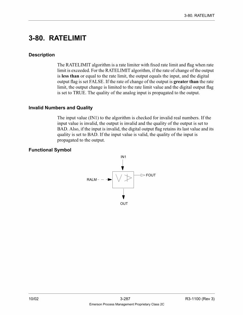
3-80. RATELIMIT
3-80. RATELIMIT
Description
The RATELIMIT algorithm is a rate limiter with fixed rate limit and flag when rate
limit is exceeded. For the RATELIMIT algorithm, if the rate of change of the output
is less than or equal to the rate limit, the output equals the input, and the digital
output flag is set FALSE. If the rate of change of the output is greater than the rate
limit, the output change is limited to the rate limit value and the digital output flag
is set to TRUE. The quality of the analog input is propagated to the output.
Invalid Numbers and Quality
The input value (IN1) to the algorithm is checked for invalid real numbers. If the
input value is invalid, the output is invalid and the quality of the output is set to
BAD. Also, if the input is invalid, the digital output flag retains its last value and its
quality is set to BAD. If the input value is valid, the quality of the input is
propagated to the output.
Functional SymbolIN1
OUT
FOUTRALM
10/02 3-287 R3-1100 (Rev 3)Emerson Process Management Proprietary Class 2C

3-80. RATELIMIT
Algorithm Record Type = LC
Algorithm Definitions
Function
PLR = RALM * (TS/1000)
TEMP = (IN1 - OLDOUT)
IF ABS(TEMP) < PLR
THEN OUT = IN1
FOUT = FALSE
ELSE
IF TEMP > 0.0
THEN OUT = OLDOUT + RALM
ELSE
OUT = OLDOUT - RALM
FOUT = TRUE
where:
Name
LC Alg.RecordField Type
Required/Optional
DefaultValue Description
Min.Point
Record
DIAG LU-Integer Data Init. Required 20 Tuning Diagram Number —
RALM R1 - Real Selectable Required 0.0 Rate of change limit in units per
second
LA
IN1 — Variable Required — Input (analog) LA
OUT — Variable Required — Output (analog) LA
FOUT — Variable Required — Output (digital) LD, LP
PLR = rate per loop
OLDOUT = locally retained variable
TEMP = local, temporary variable
TS = sampling time (loop time)
R3-1100 (Rev 3) 3-288 10/02Emerson Process Management Proprietary Class 2C

3-81. RATEMON
3-81. RATEMON
Description
The RATEMON algorithm is a rate of change monitor with reset deadband and
fixed/variable rate limit. For the RATEMON algorithm, if the input value (IN1)
increases at a rate faster then the user-specified rate of change limit in the positive
direction, or decreases at a rate faster than the user-specified rate of change limit in
the negative direction, the digital output flag (OUT) is set TRUE. To reset the output
flag, the input value must increase at a rate slower than the rate of change limit in
the positive direction minus the deadband on the positive rate of change limit, or
decrease at a rate slower than the rate of change limit in the negative direction minus
the deadband on the negative rate of change limit.
Invalid Numbers and Quality
The input value (IN1) is checked for invalid real numbers. If IN1 is invalid, the
digital flag retains its last value and its quality is set to BAD.
Functional SymbolIN1
OUT
V
NRAT
PRAT
H
10/02 3-289 R3-1100 (Rev 3)Emerson Process Management Proprietary Class 2C

3-81. RATEMON
Algorithm Record Type = LC
Algorithm Definitions
Function
RATE = (IN1 - OLDIN)/TS
IF (RATE > PRAT)
OR (RATE < (0 - NRAT))
THEN OUT = TRUE
ELSE
IF (RATE < (PRAT - PDB))
AND (RATE > (0 - (NRAT - NDB)))
THEN OUT = FALSE
where:
Name
LC Alg.RecordField Type
Required/Optional
DefaultValue Description
Min.Point
Record
DIAG LU-Integer Data Init. Required 75 Tuning Diagram Number —
PRAT R1 - Real Selectable Required 0.0 Rate of change limit in the positive
direction (absolute value)
LA
PDB R2 - Real Tuning
Constant
Optional 0.0 Deadband on the positive rate of
change limit (absolute value)
—
NRAT R3 - Real Selectable Required 0.0 Rate of change limit in the negative
direction (absolute value)
LA
NDB R4 - Real Tuning
Constant
Optional 0.0 Deadband on the negative rate of
change limit (absolute value)
—
IN1 — Variable Required — Input (analog) LA
OUT — Variable Required — Output (digital) LD, LP
RATE = local, temporary, variable
OLDIN = locally retained, real variable
TS = sampling time (control task loop time)
R3-1100 (Rev 3) 3-290 10/02Emerson Process Management Proprietary Class 2C

3-82. RESETSUM
3-82. RESETSUM
Description
The RESETSUM algorithm accumulates until told to reset. For the RESETSUM
algorithm, if the Run flag is TRUE, the output value (OUT) is the sum of the gained
input value (IN1) and the old output value. If the Freeze flag is TRUE, the output
value is also stored in the frozen output (FOUT). As OUT continues to totalize IN1,
the value in FOUT is frozen when the Freeze flag reverts back to FALSE. If the
Reset flag is TRUE, OUT is set to the reset count stored in the R1 field of the
algorithm record. If the Run flag is FALSE, the algorithm will do nothing. The user
may tune the output value anytime by setting the R3 field of the algorithm record to
some non-zero value. The R3 value is checked first; then, the Reset flag is checked
before the summation is made.
Functional Symbol
The quality of the input is propagated to the output points (OUT and FOUT) under
the following conditions:
1. The RUN flag is TRUE.
2. The outputs are not scan-removed.
3. The values of the inputs and outputs are valid real numbers.
4. The RSET flag must be FALSE for the quality of the output (OUT) to be
updated. However, if the RSET flag is TRUE, the output retains its last quality
value.
5. The freeze flag (FFLG) must be TRUE for the quality of the frozen point
(FOUT) to be updated. However, if the freeze flag is FALSE, the frozen output
(FOUT) retains its last quality value.
IN1
RESET
FFLG
RSET
RUN
OUT
SUM
FOUT
10/02 3-291 R3-1100 (Rev 3)Emerson Process Management Proprietary Class 2C

3-82. RESETSUM
The quality of the output is not affected by any requests to tune the value of the
output through the use of the R3 record field or by setting the RSET flag to TRUE.
Quality propagation is overruled by invalid real numbers. If the input (IN1) contains
an invalid real number, the quality of the output (OUT) is set to BAD, providing that
the point is not scan-removed and that the RUN flag is TRUE. The quality of the
frozen output point (FOUT) is also set to BAD if the point is not scan-removed and
the freeze flag (FFLG) is TRUE.
Invalid Numbers and Quality
The value of the input (IN1) is checked for invalid real numbers. If the input value
is invalid, the output (OUT) retains its last valid value. If the input value is valid, the
quality of IN1 is propagated to OUT.
If the FFLG flag is TRUE and the input is invalid, the value of the frozen output
(FOUT) is equal to the output (OUT).
If the input is invalid, any requests to digitally reset the output value (OUT) through
the use of the RSET flag are ignored.
R3-1100 (Rev 3) 3-292 10/02Emerson Process Management Proprietary Class 2C

3-82. RESETSUM
Algorithm Record Type = LC
Algorithm Definitions
Function
IF R3 ≠ 0THEN OUT = R3
IF RUN = TRUE
THEN TEMP = OUT + (GAIN x IN1)
IF FFLG = TRUE
THEN FOUT = TEMP
IF RSET = TRUE
THEN OUT = R1
ELSE
OUT = TEMP
where:
Name
LC Alg.RecordField Type
Required/Optional
DefaultValue Description
Min.Point
Record
DIAG LU-Integer Data Init. Required 4 Tuning Diagram Number —
RCNT R1 - Real Tuning
Constant
Required 0.0 Reset count —
GAIN R2 - Real Tuning
Constant
Required 0.0 Gain on the input —
TRST R3 - Real Tuning
Constant
Optional 0.0 Tuning reset count —
IN1 — Variable Required — Input (analog) LA
FFLG — Variable Required — Input (digital); Freeze flag LD, LP
RSET — Variable Required — Input (digital); Reset flag LD, LP
RUN — Variable Required — Input (digital); Run flag LD, LP
OUT — Variable Required — Output (analog) LA
FOUT — Variable Required — Output (analog); frozen value LA
TEMP = local, temporary, real variable
10/02 3-293 R3-1100 (Rev 3)Emerson Process Management Proprietary Class 2C

3-83. RPACNT
3-83. RPACNT
Description
The RPACNT algorithm will read the pulse count from the Ovation Pulse
Accumulator card. The algorithm will use the hardware address in the OUT point
to access the Ovation Pulse Accumulator card.
When IN1 is TRUE, the algorithm will read the pulse count from the card, reset the
counter to zero and store the pulse counts in OUT. Conversion may be done on the
pulse value before the pulse count is stored in the OUT point. A linear conversion,
if chosen, is taken from the CV, 1V and 2V of the OUT point.
For example, consider the case in which the input is a count of contact closures from
a watthour meter. The number of megawatt hours per pulse can be accounted for in
the coefficients that are calculated as part of the point record. For example, to get
the megawatt hours per hour, rate would be:
The FOUT point will contain accumulated pulse count until the reset flag (RSET)
is TRUE. If IN1 and RSET are TRUE, then FOUT will contain the pulse count read
from the card.
Functional Symbol
# pulses/
minutes
* 10 kilowatt hours/
pulse
* megawatt hour/
kilowatt hour
* min/hr = megawatt hours
per hour
3 *10 *.001 *60 = 1.80
OUTIN1RPACNT
RSET FO UT
R3-1100 (Rev 3) 3-294 10/02Emerson Process Management Proprietary Class 2C

3-83. RPACNT
Algorithm Record Type = None
Algorithm Definitions
Name
Alg.RecordField Type
Required/Optional
DefaultValue Description
Min.Point
Record
IN1 — Variable Required — Input, read trigger of the RPA card
(digital)
LD, LP
RSET — Variable Optional — Input to reset count (digital) LD, LP
OUT — Variable Required — Output value from RPA card (analog) LA
FOUT — Variable Optional — Accumulated count output value
(analog)
LA
10/02 3-295 R3-1100 (Rev 3)Emerson Process Management Proprietary Class 2C

3-84. RPAWIDTH
3-84. RPAWIDTH
Description
The RPAWIDTH algorithm will read the pulse width from the Ovation Pulse
Accumulator card. For more information on the Pulse Accumulator Card, refer to
“Ovation I/O Reference Manual” (R3-1150). The algorithm uses the hardware
address in the OUT point to access the Ovation Pulse Accumulator card. If there is
a hardware error, the OUT is set to BAD quality.
Functional Symbol
Algorithm Record Type = None
Algorithm Definitions
Name
Alg.RecordField Type
Required/Optional
DefaultValue Description
Min.Point
Record
OUT — Variable Required — Pulse Width output (analog) LA
RPAWIDTH OUT
R3-1100 (Rev 3) 3-296 10/02Emerson Process Management Proprietary Class 2C

3-85. RUNAVERAGE
3-85. RUNAVERAGE
Description
The RUNAVERAGE algorithm performs a running average calculation on a
number of samples collected at a sampling interval time. The input (IN1) is sampled
periodically as specified by the user from the Number of Units and Units of Time
fields. Any decimal part in the Number of Units field is ignored. If the time specified
is less than the loop time, the input is sampled every loop. Otherwise, the input is
sampled on the first loop after the specified number of time boundaries have
elapsed.
The output, which is calculated every loop, is the average of the last N samples of
the input, where N is 8 or less. Thus, the time period for the average is the product
of the sampling interval time and the number of samples. If the quality of the input
is BAD, that value of the input is not included in the calculation. If the quality of
the samples for a given period is BAD, then the output value remains unchanged,
but the quality is set BAD. During initial operation before N samples exist, the
output that is calculated is based on the available samples.
The values of all IN1 samples are checked for invalid real numbers. If an IN1
sample value is invalid, the stored, internal quality of that IN1 is set to BAD. Only
sample values with GOOD, FAIR, and POOR quality are used to calculate the value
of OUT; the quality of OUT is set according to the rules listed in the Function
section of this description.
At any given time, the output is the average of N samples, made up of the most
current sample and the previous N-1 samples. Every sampling time, the oldest
sample is discarded and replaced with a new sample.
Functional Symbol
IN1
OUT
RUNAVERAGE
10/02 3-297 R3-1100 (Rev 3)Emerson Process Management Proprietary Class 2C

3-85. RUNAVERAGE
Algorithm Record Type = LC
Algorithm Definitions
Function
The quality of the output is as follows:
Name
LC Alg.RecordField Type
Required/Optional
DefaultValue Description
Min.Point
Record
DIAG LU-Integer Data Init. Required 61 Tuning Diagram Number —
TIME R1 - Real Tuning
Constant
Optional 0.0 Number of units —
UNIT X1 - Byte Data Init. Optional 0 Units of time
0 = tenths of a second
1 = seconds
2 = minutes
3 = hours
4 = days
—
NUM R2 - Real Tuning
Constant
Required 0 Number of samples to be averaged
(1 through 8)
—
IN1 — Variable Required — Input (analog) LA
OUT — Variable Required — Output (analog) LA
On the first pass: BAD
If all samples during the period are BAD: BAD
If less than half the samples are GOOD: POOR
If more than half the samples are GOOD: FAIR
If all samples during the period are
GOOD:
GOOD
OUTsum of last N values of input
number of samples to be included in the average--------------------------------------------------------------------------------------------------------------------------------------=
R3-1100 (Rev 3) 3-298 10/02Emerson Process Management Proprietary Class 2C
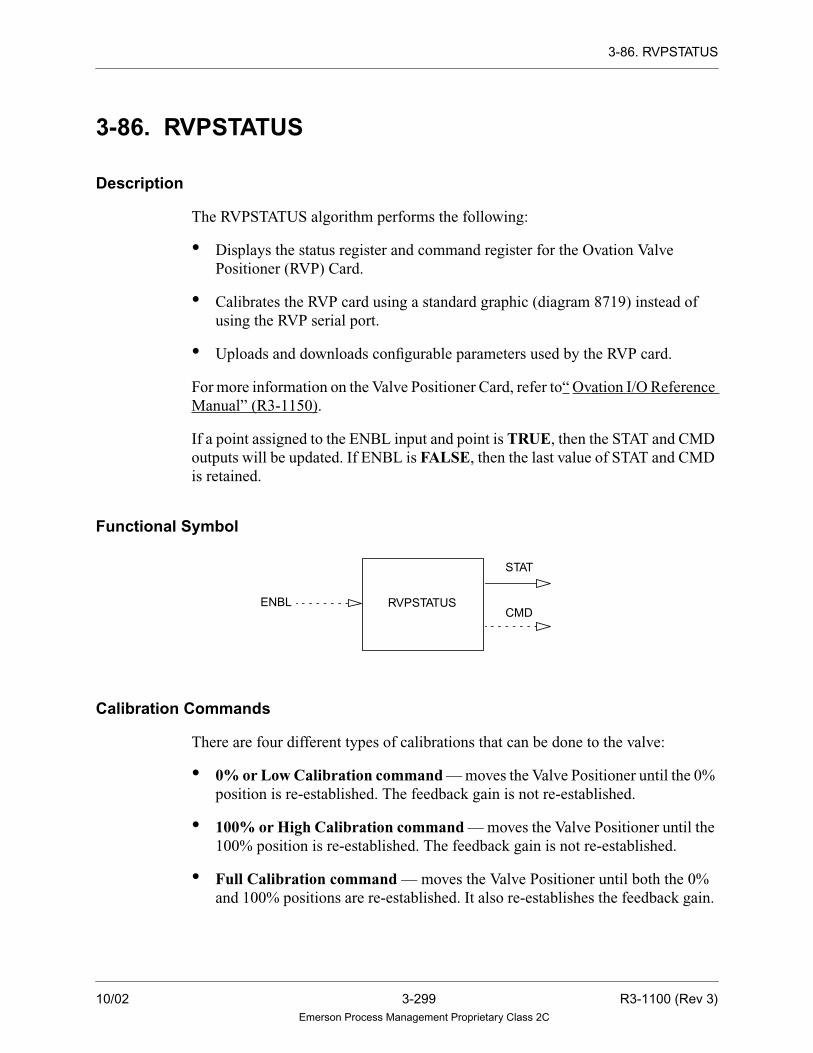
3-86. RVPSTATUS
3-86. RVPSTATUS
Description
The RVPSTATUS algorithm performs the following:
• Displays the status register and command register for the Ovation Valve
Positioner (RVP) Card.
• Calibrates the RVP card using a standard graphic (diagram 8719) instead of
using the RVP serial port.
• Uploads and downloads configurable parameters used by the RVP card.
For more information on the Valve Positioner Card, refer to“ Ovation I/O Reference
Manual” (R3-1150).
If a point assigned to the ENBL input and point is TRUE, then the STAT and CMD
outputs will be updated. If ENBL is FALSE, then the last value of STAT and CMD
is retained.
Functional Symbol
Calibration Commands
There are four different types of calibrations that can be done to the valve:
• 0% or Low Calibration command — moves the Valve Positioner until the 0%
position is re-established. The feedback gain is not re-established.
• 100% or High Calibration command — moves the Valve Positioner until the
100% position is re-established. The feedback gain is not re-established.
• Full Calibration command — moves the Valve Positioner until both the 0%
and 100% positions are re-established. It also re-establishes the feedback gain.
RVPSTATUSENBL
STAT
CMD
10/02 3-299 R3-1100 (Rev 3)Emerson Process Management Proprietary Class 2C

3-86. RVPSTATUS
• Null-Point Calibration command — moves the Valve Positioner to the
electrical null point of the LVDT. The Null-Point Calibration can be requested
at the same time as the Full Calibration. If this is done, the Positioner moves
through the sequences of the full calibration, but stops at the null point when
encountered.
When the calibration command is executed, the controlling MASTATION enters
manual mode and tracks the position demand feedback. During the travel sequence,
the Valve Positioner moves the valve at a programmable rate. While the Valve
Positioner is traveling, the graphic displays and continuously updates the current
voltage value based on the position. There is also a Clear Calibration command
that may be used if the calibration command is no longer desired.
Upload Command
The upload command is used to retrieve the constant values currently stored in the
RVP Card memory. When the upload command is executed, the X3 value is
changed and the RVP Card is commanded to send the current values stored in its
memory to the 32-bit real number fields of the algorithm record. The standard
graphic then displays the values in these selected algorithm record fields for the user
when the upload is finished. Note these values can only be uploaded when the RVP
card is in local or normal mode.
Download Command
The download command is used to update the constant values currently stored in
the RVP Card memory. When the download command is requested, X3 field is
changed, and the values entered into the graphic are stored in the 32-bit real number
fields of the algorithm record. Then the values in the selected fields of the algorithm
record are written to the RVP memory. Note these values can only be downloaded
when the RVP card is in local or normal mode.
R3-1100 (Rev 3) 3-300 10/02Emerson Process Management Proprietary Class 2C

3-86. RVPSTATUS
Interface Information
The calibration commands are sent to the X3 field in the algorithm record.
As the commands are being executed, messages are displayed on the graphic by
Status Value in the X5 field of the algorithm record.
Calibrate Command Command Description
0 No Command.
1 Calibrate 0%.
2 Calibrate 100%.
3 Full Calibration.
4 Go to Null Point Calibration.
7 Clear Calibration Request.
8 Upload Request.
9 Download Request.
Status Description
0 No Message.
1 Calibration in Progress.
2 Poor Calibration.
3 Calibration Time-out.
4 Upload Error.
5 Download in Progress.
6 Download Error
7 Download Time-out
8 RVP Card Not Ready.
10/02 3-301 R3-1100 (Rev 3)Emerson Process Management Proprietary Class 2C

3-86. RVPSTATUS
Algorithm Record Type = None
Algorithm Definitions
Name
Alg.RecordField Type
Required/Optional
DefaultValue Description
Min.Point
Record
DIAG LU-Integer Data Init. Required 116 Tuning Diagram Number —
PCI X4-Byte Data Init. Required 1 PCI Card Number (1 or 2) —
HWAD B2-Integer Data Init. Required 0 Card Hardware Address —
ENBL — Variable Optional — Enable Flag (digital) LD,LP
STAT — Variable Required — RVP Status register (packed) LP
CMD — Variable Optional — RVP Command register (packed) LP
R3-1100 (Rev 3) 3-302 10/02Emerson Process Management Proprietary Class 2C

3-87. SATOSP
3-87. SATOSP
Description
The SATOSP algorithm transfers one analog value to a packed point record for use by
programmable controllers.
The analog point record value field is converted to an integer and stored in the packed
digital value field. Conversion is done by rounding off fractional values less than 0.50 to
zero and fractional values greater than or equal to 0.50 to the next highest integer. If the
value of the analog point record is less than the smallest integer (-32767), or greater than
the largest integer (32767), the minimum or maximum integer value will be used.
The bit pattern used to store negative numbers is the two’s complement of the bit pattern
for the same positive number. A negative number always has a 1 for Bit 15.
If the quality of the analog point record is BAD, or if the value of the analog point is an
invalid number, then the packed point value remains at its last valid value. The quality
of the input is not propagated to the output.
Functional Symbol
Algorithm Record Type = None
Algorithm Definitions
NameAlg. Record
Field TypeRequired/Optional
DefaultValue Description
Min. PointRecord
IN — Variable Required — Input (analog) LA
PACK — Variable Required — Output (packed) LP
SATOSP
IN
PACK
10/02 3-303 R3-1100 (Rev 3)Emerson Process Management Proprietary Class 2C

3-88. SELECTOR
3-88. SELECTOR
Description
The SELECTOR algorithm transfers between N analog inputs. For the SELECTOR
algorithm, the output is equal to one of N analog inputs, where N is an integer less
than eight. The input selected is based on a binary address formed by three digital
inputs per the table. If address 000 or an address greater than N is selected, the
output signal will be zero.
Invalid Numbers and Quality
The value of the selected input is checked for invalid real numbers. If the input value
is invalid, the output value is invalid and the quality of the output is set to BAD.
Otherwise, the quality of the selected input is propagated to the output.
Selected Digital Input States
Input No. DIN1 DIN2 DIN3
None 0 0 0
1 1 0 0
2 0 1 0
3 1 1 0
4 0 0 1
5 1 0 1
6 0 1 1
7 1 1 1
R3-1100 (Rev 3) 3-304 10/02Emerson Process Management Proprietary Class 2C

3-88. SELECTOR
Functional Symbol
Algorithm Record Type = LC
Algorithm Definitions
Name
LC Alg.RecordField Type
Required/Optional
DefaultValue Description
Min.Point
Record
DIAG LU-Integer Data Init Required 89 Tuning Diagram number —
NMIN X1 - Byte Data Init. Required 0 Number of inputs —
IN1
•
•
•
IN7
— Variable Optional — Input (analog) LA
DIN1 — Variable Required — Input (digital); Input Address 1 LD, LP
DIN2 — Variable Required — Input (digital); Input Address 2 LD, LP
DIN3 — Variable Required — Input (digital); Input Address 3 LD, LP
OUT — Variable Required — Output (analog) LA
IN1IN2
DIN1
IN3IN4
IN6IN5
1 2 3 4 5 6 7
1 0 1 0 1 0 10 1 1 0 0 1 10 0 0 1 1 1 1
OUT
DIN2DIN3
IN7
10/02 3-305 R3-1100 (Rev 3)Emerson Process Management Proprietary Class 2C

3-89. SETPOINT
3-89. SETPOINT
Description
The SETPOINT algorithm performs a manual loader function. The algorithm
provides an interface to the Control Builder or Operator’s Station diagram. Interface
to the hard set point portion of the Ovation Loop Interface (LI) card may be
initialized. If the LI hardware address is initialized, the algorithm reads the set point
stored on the LI set point counter to use as its output value. If the LI or hardware
address is not initialized, the algorithm uses the last output value as its output value.
Functional Symbol
The output of this algorithm may be increased and/or decreased by the SLIM station
or the Operator’s Soft Station diagram.
It continually checks the Set Point Increase/Decrease function keys from the
Operator’s Station for increase/decrease requests for the setpoint output. If requests
are received from both the hard and soft stations at the same time, the station
contacts override the Operator’s Keyboard keys. On power-up or reset of the
controller, the output will be the initial value of the algorithms output (default value
= 0.0) if the LI is not initialized. Otherwise, the output will be the current value
stored on the LI set point counter.
If the LI card is selected in the TYPE algorithm field and the Controller is reset,
powered-up or fails, the set point is read from the LI card and used initially in the
OUT field of the algorithm. This reports the status of the field device before any
action is taken by either the algorithm or the operator.
.I A
TOUT OUT
TRIN
R3-1100 (Rev 3) 3-306 10/02Emerson Process Management Proprietary Class 2C

3-89. SETPOINT
The interface keys of the Operator’s Keyboard are:
Notes
1. If the top and bottom scales are equal, the
high limit flag is set and the output value
is equal to the top scale.
2. If the algorithm is told to track and the
track input is invalid, the track request is
ignored and the drop is placed into alarm.
If the LI hardware address is initialized, this value will be written to the set point
counter on the specified card.
If the algorithm is operating with an LI, and the LI card is in Local mode, the output
of the algorithm cannot be changed from the Operator’s Station. In this case, the
output of the algorithm can be changed from the SLIM station only.
If SETPOINT is to write the set point value to the LI card, then changes to the set
point value (that is, tracking, Control Builder or Operator’s Station raise/lower
requests, etc.) are implemented as described previously.
The SETPOINT algorithm monitors the LI card for any raise and lower requests from
the SLIM. Raise/lower requests from the SLIM override any other set point change
requests received by this algorithm (that is, tracking, Operator’s Station raise/lower
requests, etc.). If there are no SLIM requests, then the set point value is changed as
described previously. The set point value is only written to the output point.
Key Use
Set Point Increase Function Key
(Control Up Arrow)
Raise the output
Set Point Decrease Function Key
(Control Down Arrow)
Lower the output
10/02 3-307 R3-1100 (Rev 3)Emerson Process Management Proprietary Class 2C

3-89. SETPOINT
Tracking Signals
Tracking and limiting are done through signals passed in the upper 16 bits of the third
status word of the analog track point. This algorithm takes the action shown in the
following table in response to the information found in the analog input signal TRIN:
The high and low limit flags and tracking signals from the algorithm are output to
TOUT for display. If the LI hardware address is initialized, the quality of OUT is
BAD if there are any LI hardware errors. Otherwise, the quality of OUT is GOOD
when not tracking or set to the quality of the track input variable when tracking.
Bit Description Action TOUT Signal
16 Track Implemented Not used
17 Track if lower Ignored Not used
18 Track if higher Ignored Not used
19 Lower inhibit Ignored Not used
20 Raise inhibit Ignored Not used
21 Conditional Track No action Not used
22 Not used No action Not used
23 Deviation Alarm No action Not used
24 Local Manual mode No action Not used
25 Manual mode No action Not used
26 Auto mode No action Not used
27 Not Used No action Not used
28 Not Used No action Not used
29 Not Used No action Not used
30 Low limit reached No action Low limit reached
31 High limit reached No action High limit reached
R3-1100 (Rev 3) 3-308 10/02Emerson Process Management Proprietary Class 2C

3-89. SETPOINT
Algorithm Record Type = LC
Algorithm Definitions
Name
LC Alg.RecordField Type
Required/Optional
DefaultValue Description
Min.Point
Record
DIAG LU-Integer Data Init. Required 9 Tuning diagram number —
TPSC R2 - Real Tuning
Constant
Required 100.0 Maximum value of the point —
BTSC R3 - Real Tuning
Constant
Required 0.0 Minimum value of the point —
PCNT X1 - Byte Tuning
Constant
Required 4 Percent change of output in first four
seconds
—
TIME X2 - Byte Tuning
Constant
Required 25 Number of seconds remaining for
ramp to full scale
—
CARD X3 - Byte Data Init. Required SOFT Card type:
SOFT = No hardware interface
RLI = Ovation Loop Interface
card
—
CNUM X5-Byte Data Init Optional 1 PCI card number (1,2) —
HWAD B2-Integer Data Init Optional 0 Card Hardware Address
Refer to Section 2-2.
—
OUT — Variable Required — Analog output variable LA
TRIN — Variable Optional — Tracking & limiting mode signals and
tracking value; analog input variable
LA
TOUT — Variable Required — Mode and Status output signals LA
10/02 3-309 R3-1100 (Rev 3)Emerson Process Management Proprietary Class 2C

3-90. SINE
3-90. SINE
Description
The SINE algorithm performs a mathematical sine function. The SINE algorithm has
one input and one output analog point. Each time the algorithm is executed, if the output
is on scan, it is set to the SINE of the input. The input to this algorithm is in radians. If
an input is only available in degrees, multiply it by 0.01745329 to convert to radians.
Invalid Real Numbers and Quality
Analog input values are checked for invalid real numbers. If the input value is invalid,
the value of the output is invalid and its quality is set to BAD. If the input is valid, the
quality of the input is propagated to the output.
Functional Symbol
Algorithm Record Type = None
Algorithm Definitions
Function
OUT = SINE(IN1)
Name
Alg.RecordField Type
Required/Optional
DefaultValue Description
Min.Point
Record
IN1 — Variable Required — Input (analog) LA
OUT — Variable Required — Output (analog) LA
SINE
IN1
OUT
R3-1100 (Rev 3) 3-310 10/02Emerson Process Management Proprietary Class 2C

3-91. SLCAIN
3-91. SLCAIN
Description
The SLCAIN algorithm reads up to 16 analog values from a Group 1 QLC or
Ovation Link Controller (LC) card (or redundant pair of Group 1 QLC cards).
Functional Symbol
Primary and Secondary QLCs/LCs
The Hardware addresses of the primary and secondary QLC/LC cards are specified
by the PHW and SHW parameters (if no secondary QLC/LC is used, SHW is set to
zero).
Digital inputs PSTA and SSTA define whether the points are to be read from the
primary or secondary QLC/LC, as shown below:
• If PSTA = TRUE, the points are read from the primary QLC/LC (status of SSTA
does not matter).
• If PSTA = FALSE and SSTA = TRUE, the points are read from the secondary
QLC.
• If PSTA = FALSE and SSTA = FALSE, the point values are not updated and the
points are assigned BAD quality.
• If PSTA = FALSE and SSTA is not defined, the point values are not updated and
the points are assigned BAD quality.
• If PSTA and SSTA are not defined, the point values are not updated and the
points are assigned BAD quality.
SLCAIN
OU
T1
OU
T2
OU
T3
OU
T4
OU
T5
OU
T6
OU
T7
OU
T8
OU
T9
OU
T10
OU
T11
OU
T12
OU
T13
OU
T14
OU
T15
OU
T16
PSTA
SSTA
10/02 3-311 R3-1100 (Rev 3)Emerson Process Management Proprietary Class 2C

3-91. SLCAIN
Note
Although both PSTA and SSTA are optional
parameters, at least one must be defined for the points
to be updated.
Point Data Formats
The FRMT parameter is used to specify the format of the analog point data to be
read from the QLC/LC registers. The four available formats are as follows:
FRMT Format Description
0 Integer Integer value in the range +32767 to -32768. Each point occupies one data
register.
1 Intel Real Floating-point real number. Each point occupies two data registers.
2 Intel Real with
status
Status word followed by floating-point real number. Each point occupies
three data registers.
3 Intel Real with
quality
Status word followed by floating-point real number. Each point occupies
three data registers.
NotesWhen the FRMT = 2, the following bits will be placed into the 1W field of the analog point
record:
Bit 4 - Undefined
Bits 8 and 9 - Quality
Bit 12 - Limit checking off
Bit 13 - Alarm checking off
When the FRMT = 3, only the quality bits 8 and 9 of the 1W field of the analog point
record are updated.
The remaining bits of the 1W field are used for alarm status, operator entry, and Data
Highway status information. For additional details, see “Ovation Record Types Reference
Manual” (R3-1140).
R3-1100 (Rev 3) 3-312 10/02Emerson Process Management Proprietary Class 2C

3-91. SLCAIN
QLC/LC Data Registers
The point data is retrieved from consecutive QLC/LC data registers, starting at the
register specified by parameter REG1. Depending on the format selected, the total
area required for the 16 analog points could be 16, 32, or 48 registers.
The point parameters (OUT1 through OUT16) are associated with consecutive QLC/
LC data registers, even if some points are omitted from the argument list. For
example, if REG1 = 4, FRMT = 1, and point OUT1 is omitted, then OUT2 will be
read starting at data register 6 (no read will be performed from data registers 4 and 5).
The location from which a given point will be read can be calculated using the
following formula:
point_address = REG1 + (FRMT + 1) * (point_number - 1)
where:
Any point which lies (completely or partially) beyond the end of the 2048
QLC/LC data registers will be assigned BAD quality. For example, if REG1 = 2044
and FRMT = 2, only the first point value (parameter Al) can be obtained.
Analog Point Record Types
If alarm and/or limit checking are to be performed on points read from the QLC/LC,
use point record type Long Analog (LA).
point_address = QLC/LC data register containing the first word of data from
the point
point_number = 1 for parameter A1, 2 for parameter A2, and so on.
10/02 3-313 R3-1100 (Rev 3)Emerson Process Management Proprietary Class 2C

3-91. SLCAIN
Algorithm Record Type = LC
Algorithm Definitions
Name
LC Alg.RecordField Type
Required/Optional
DefaultValue Description
Min.Point
Record
DIAG LU-Integer Data Init Required 11 Tuning diagram number —
FRMT B0-Integer Data Init. Required 0 QLC/LC data format —
REG1 B1-Integer Data Init. Required 0 First QLC/LC data register —
PHW B2-Integer Data Init. Required 0 Primary QLC hardware address
or LC address
Refer to Section 2-2.
—
SHW YU-Integer Data Init. Required 0 Secondary QLC hardware address
or LC address
Refer to Section 2-2.
—
CARD X4-Byte Data Init. Required 1 PCI Card Number (1,2) —
TYPE X1-Byte Data Init Required QLC Interface Card Type:
QLC
RLC
—
OUT1
•
•
•
OUT16
— Variable Optional — Input from QLC/LC registers
(analog)
LA
PSTA — Variable Optional — Primary QLC/LC status input
(digital)
LD, LP
SSTA — Variable Optional — Secondary QLC/LC status input
(digital)
LD, LP
R3-1100 (Rev 3) 3-314 10/02Emerson Process Management Proprietary Class 2C

3-92. SLCAOUT
3-92. SLCAOUT
Description
The SLCAOUT algorithm writes up to 16 analog points to a Group 1 QLC or LC
card (or redundant pair of Group 1 QLC cards).
Functional Symbol
Primary and Secondary QLCs/LCs
The hardware addresses of the primary and secondary QLC/LC cards are specified by
the PHW and SHW parameters (if no secondary QLC/LC is used, SHW is set to zero).
Digital inputs PSTA and SSTA define whether the points are to be written to the
primary or secondary QLC/LC, as shown below:
• If PSTA = TRUE, the points are written to the primary QLC/LC (status of SSTA
does not matter).
• If PSTA = FALSE and SSTA = TRUE, the points are written to the secondary
QLC.
• If PSTA = FALSE and SSTA = FALSE, the points are not output.
• If PSTA = FALSE and SSTA is not defined, the points are not output.
• If PSTA and SSTA are not defined, the points are not output.
SLC
AO
UT
IN1
IN2
IN3
IN4
IN5
IN6
IN7
IN8
IN9
IN10
IN11
IN12
IN13
IN14
IN15
IN16
PSTA
SSTA
10/02 3-315 R3-1100 (Rev 3)Emerson Process Management Proprietary Class 2C

3-92. SLCAOUT
Note
Although both PSTA and SSTA are optional
parameters, at least one must be defined for the points
to be output.
Point Data Formats
The FRMT parameter is used to specify the format of the analog point data to be
written to the QLC/LC registers. The three available formats are as follows:
Note that depending on the format selected, each point value will occupy between
1 and 3 data registers.
QLC/LC Data Registers
The point data is written to consecutive QLC/LC data registers, starting at the
register specified by parameter REG1. Depending on the format selected, the total
area required for the 16 analog points could be 16, 32, or 48 registers.
The point parameters (A1 through A16) are associated with consecutive QLC/LC
data registers, even if some points are omitted from the argument list. For example,
if REG1 = 4, FRMT = 1, and point A1 is omitted, then A2 will be written starting
at data register 6 (no data will be written to registers 4 and 5).
FRMT Format Description
0 Integer Integer value in the range +32767 to -32768. Each point occupies one data
register.
1 Intel Real Floating-point real number. Each point occupies two data registers.
2 Intel Real with
status
Status word followed by floating-point real number. Each point occupies
three data registers.
R3-1100 (Rev 3) 3-316 10/02Emerson Process Management Proprietary Class 2C

3-92. SLCAOUT
The location to which a given point will be written can be calculated using the
following formula:
point_address = REG1 + (FRMT + 1) * (point_number - 1)
where:
No data will be written to registers beyond the valid range (0 through 2047). Points
which lie partially beyond the valid range of registers will be written to the extent
possible; points which lie completely beyond the valid range of registers will not be
written. For example, if REG1 = 2044 and FRMT = 2, only the first point value
(parameter Al) can be written.
Timed-Out Points
The TIME parameter determines what action is taken when a received point (to be
written to the QLC/LC) is timed-out. Depending on the selected TIME setting, the
point is either not written to the QLC/LC, or the last received value is written.
TIME is interpreted as a mask of bits to determine the selected setting for each
point, as shown below:
• For each point, a value of 0 (zero) in the corresponding bit indicates that the
point should not be written if it is timed-out.
• For each point, a value of 1(one) in the corresponding bit indicates that the last
received value should be written if the point is timed-out.
point_address = QLC/LC data register containing the first word of data from
the point.
point_number = 1 for parameter A1, 2 for parameter A2, and so on.
Point → IN16 IN15 IN14 IN13 IN12 IN11 IN10 IN9 IN8 IN7 IN6 IN5 IN4 IN3 IN2 IN1
TIME bit → 15 14 13 12 11 10 9 8 7 6 5 4 3 2 1 0
10/02 3-317 R3-1100 (Rev 3)Emerson Process Management Proprietary Class 2C
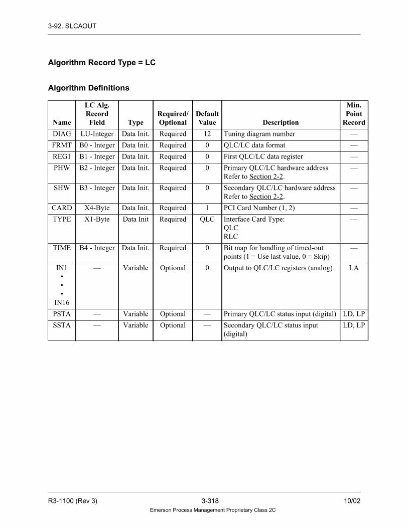
3-92. SLCAOUT
Algorithm Record Type = LC
Algorithm Definitions
Name
LC Alg.RecordField Type
Required/Optional
DefaultValue Description
Min.Point
Record
DIAG LU-Integer Data Init. Required 12 Tuning diagram number —
FRMT B0 - Integer Data Init. Required 0 QLC/LC data format —
REG1 B1 - Integer Data Init. Required 0 First QLC/LC data register —
PHW B2 - Integer Data Init. Required 0 Primary QLC/LC hardware address
Refer to Section 2-2.
—
SHW B3 - Integer Data Init. Required 0 Secondary QLC/LC hardware address
Refer to Section 2-2.
—
CARD X4-Byte Data Init. Required 1 PCI Card Number (1, 2) —
TYPE X1-Byte Data Init Required QLC Interface Card Type:
QLC
RLC
—
TIME B4 - Integer Data Init. Required 0 Bit map for handling of timed-out
points (1 = Use last value, 0 = Skip)
—
IN1
•
•
•
IN16
— Variable Optional 0 Output to QLC/LC registers (analog) LA
PSTA — Variable Optional — Primary QLC/LC status input (digital) LD, LP
SSTA — Variable Optional — Secondary QLC/LC status input
(digital)
LD, LP
R3-1100 (Rev 3) 3-318 10/02Emerson Process Management Proprietary Class 2C

3-93. SLCDIN
3-93. SLCDIN
Description
The SLCDIN algorithm reads up to 16 digital values from a Group 1 QLC or
Ovation Link Controller (LC) card (or redundant pair of Group 1 QLC cards).
Functional Symbol
Primary and Secondary QLCs/LCs
The Hardware addresses of the primary and secondary QLC cards are specified by
the PHW and SHW parameters (if no secondary QLC is used, SHW is set to zero).
Digital inputs PSTA and SSTA define whether the points are to be read from the
primary or secondary QLC/LC, as shown below:
• If PSTA = TRUE, the points are read from the primary QLC/LC (status of SSTA
does not matter).
• If PSTA = FALSE and SSTA = TRUE, the points are read from the secondary
QLC/LC.
• If PSTA = FALSE and SSTA = FALSE, the point values are not updated and the
points are assigned BAD quality.
SLCDIN
OUT1
OUT2
OUT3
OUT4
OUT5
OUT6
OUT7
OUT8
OUT9
OUT10
OUT11
OUT12
OUT13
OUT14
OUT15
OUT16
PSTASSTA
10/02 3-319 R3-1100 (Rev 3)Emerson Process Management Proprietary Class 2C

3-93. SLCDIN
• If PSTA = FALSE and SSTA is not defined, the point values are not updated and
the points are assigned BAD quality.
• If PSTA and SSTA are not defined, the point values are not updated and the
points are assigned BAD quality.
Note
Although both PSTA and SSTA are optional
parameters, at least one must be defined for the points
to be updated.
Point Data Format
Each digital point occupies one data register (equivalent to the 1W field of the point
data record).
The FRMT parameters is used to specify the format of the Digital point data to be
read from the QLC/LC register. The three available formats are as follows:
Note
The following bits will be placed into the 1W field
(no other bits cleared) of the digital point record:
The remaining bits of the 1W field are used for alarm
status, operator entry, and Data Highway status
information. For additional details, see“ Ovation
Record Types Reference” (R3-1140).
FRMT Description
0 Bit 0 - Digital value
Bits 8 and 9 - Quality
Bit 12 - Limit checking off
Bit 13 - Alarm checking off
1 Bit 0 - Digital value
Bits 8 and 9 - Quality
2 Bit 0 - Digital value
R3-1100 (Rev 3) 3-320 10/02Emerson Process Management Proprietary Class 2C

3-93. SLCDIN
QLC/LC Data Registers
The point data is retrieved from consecutive QLC/LC data registers, starting at the
register specified by parameter REG1. The total area required for the 16 digital
points is 16 registers.
The point parameters (OUT1 through OUT16) are associated with consecutive
QLC/LC data registers, even if some points are omitted from the argument list. For
example, if REG1 and point OUT1 is omitted, then OUT2 will be read from data
register 5 (no read will be performed from data register 4).
The location from which a given point will be read can be calculated using the
following formula:
point_address = REG1 + (point_number - 1)
where:
Any point which lies beyond the end of the 2048 QLC/LC data registers will be
assigned BAD quality. For example, if REG1 =2044, only the first three point values
(parameters OUT1, OUT2, and OUT3) can be obtained.
Digital Point Record Types
If alarm checking is to be performed on digital points read from the QLC/LC, use
point record type Long Digital.
point_address = QLC/LC data register containing the digital point
point_number = 1 for parameter OUT1, 2 for parameter OUT2, and so on.
10/02 3-321 R3-1100 (Rev 3)Emerson Process Management Proprietary Class 2C

3-93. SLCDIN
Algorithm Record Type = LC
Algorithm Definitions
Name
LC Alg.RecordField Type
Required/Optional
DefaultValue Description
Min.Point
Record
DIAG LU-Integer Data Init. Required 13 Tuning Diagram Number —
FRMT B0 - Integer Data Init. Required — Point Format —
REG1 B1 - Integer Data Init. Required 0 First QLC/LC data register —
PHW B2 - Integer Data Init. Required 0 Primary QLC/LC hardware
address.
Refer to Section 2-2.
—
SHW YU - Integer Data Init. Required 0 Secondary QLC/LC hardware
address.
Refer to Section 2-2.
—
CARD X4-Byte Data Init. Required 1 PCI Card Number (1,2) —
TYPE X1-Byte Data Init Required QLC Interface Card Type:
QLC
RLC
—
OUT1
•
•
•
OUT16
— Variable Optional — Input from QLC/LC registers
(digital)
LD
PSTA — Variable Optional — Primary QLC/LC status input
(digital)
LD, LP
SSTA — Variable Optional — Secondary QLC/LC status input
(digital)
LD, LP
R3-1100 (Rev 3) 3-322 10/02Emerson Process Management Proprietary Class 2C

3-94. SLCDOUT
3-94. SLCDOUT
Description
The SLCDOUT algorithm writes up to 16 digital points to a Group 1 QLC or
Ovation Link Controller (LC) card (or redundant pair of Group 1 QLC cards).
Functional Symbol
Primary and Secondary QLCs/LCs
The hardware addresses of the primary and secondary QLC/LC cards are specified by
the PHW and SHW parameters (if no secondary QLC/LC is used, SHW is set to zero).
Digital inputs PSTA and SSTA define whether the points are to be written to the
primary or secondary QLC/LC, as shown below:
• If PSTA = TRUE, the points are written to the primary QLC/LC (status of SSTA
does not matter).
• If PSTA = FALSE and SSTA = TRUE, the points are written to the secondary
QLC/LC.
• If PSTA = FALSE and SSTA = FALSE, the points are not output.
• If PSTA = FALSE and SSTA is not defined, the points are not output.
• If PSTA and SSTA are not defined, the points are not output.
SLCDOUT
IN1
IN2
IN3
IN4
IN5
IN6
IN7
IN8
IN9
IN10
IN11
IN12
IN13
IN14
IN15
IN16PSTASSTA
10/02 3-323 R3-1100 (Rev 3)Emerson Process Management Proprietary Class 2C

3-94. SLCDOUT
Note
Although both PSTA and SSTA are optional
parameters, at least one must be defined for the points
to be output.
Point Data Format
Each digital point occupies one data register (equivalent to the 1W field of the point
data record). For additional information on the 1W field, see“ Ovation Record
Types Reference Manual” (R3-1140).
QLC/LC Data Registers
The point data is written to consecutive QLC/LC data registers, starting at the
register specified by parameter REG1. The total area required for the 16 digital
points is 16 registers.
The point parameters (IN1 through IN16) are associated with consecutive QLC/LC
data registers, even if some points are omitted from the argument list. For example,
if REG1 = 4 and point IN1 is omitted, then IN2 will be written to data register 5
(no data will be written to register 4).
The location to which a given point will be written can be calculated using the
following formula:
point_address = REG1 + (point_number - 1)
where:
No data will be written to registers beyond the valid range (0 through 2047). For
example, if REG1 = 2044, only the first three point values (parameters IN1 through
IN3) can be written.
point_address = QLC/LC data register containing the digital point
point_number = 1 for parameter IN1, 2 for parameter IN2, and so on.
R3-1100 (Rev 3) 3-324 10/02Emerson Process Management Proprietary Class 2C
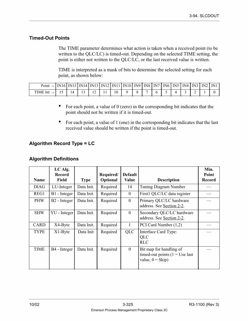
3-94. SLCDOUT
Timed-Out Points
The TIME parameter determines what action is taken when a received point (to be
written to the QLC/LC) is timed-out. Depending on the selected TIME setting, the
point is either not written to the QLC/LC, or the last received value is written.
TIME is interpreted as a mask of bits to determine the selected setting for each
point, as shown below:
• For each point, a value of 0 (zero) in the corresponding bit indicates that the
point should not be written if it is timed-out.
• For each point, a value of 1 (one) in the corresponding bit indicates that the last
received value should be written if the point is timed-out.
Algorithm Record Type = LC
Algorithm Definitions
Point → IN16 IN15 IN14 IN13 IN12 IN11 IN10 IN9 IN8 IN7 IN6 IN5 IN4 IN3 IN2 IN1
TIME bit → 15 14 13 12 11 10 9 8 7 6 5 4 3 2 1 0
Name
LC Alg.RecordField Type
Required/Optional
DefaultValue Description
Min.Point
Record
DIAG LU-Integer Data Init. Required 14 Tuning Diagram Number —
REG1 B1 - Integer Data Init. Required 0 First1 QLC/LC data register —
PHW B2 - Integer Data Init. Required 0 Primary QLC/LC hardware
address. See Section 2-2.
—
SHW YU - Integer Data Init. Required 0 Secondary QLC/LC hardware
address. See Section 2-2.
—
CARD X4-Byte Data Init. Required 1 PCI Card Number (1,2) —
TYPE X1-Byte Data Init Required QLC Interface Card Type:
QLC
RLC
—
TIME B4 - Integer Data Init. Required 0 Bit map for handling of
timed-out points (1 = Use last
value, 0 = Skip)
—
10/02 3-325 R3-1100 (Rev 3)Emerson Process Management Proprietary Class 2C

3-94. SLCDOUT
IN1
•
•
•
IN16
— Variable Optional — Output to QLC/LC register
(digital)
LD
PSTA — Variable Optional — Primary QLC/LC status input
(digital)
LD, LP
SSTA — Variable Optional — Secondary QLC/LC status input
(digital)
LD, LP
Name
LC Alg.RecordField Type
Required/Optional
DefaultValue Description
Min.Point
Record
R3-1100 (Rev 3) 3-326 10/02Emerson Process Management Proprietary Class 2C
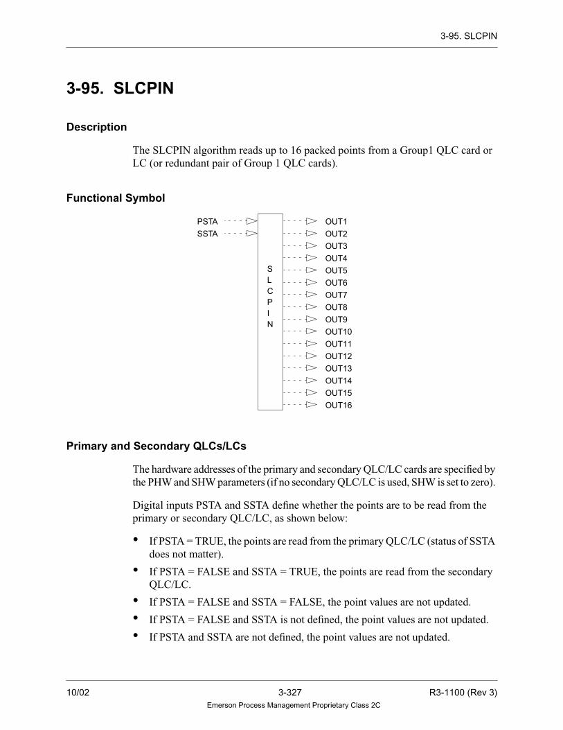
3-95. SLCPIN
3-95. SLCPIN
Description
The SLCPIN algorithm reads up to 16 packed points from a Group1 QLC card or
LC (or redundant pair of Group 1 QLC cards).
Functional Symbol
Primary and Secondary QLCs/LCs
The hardware addresses of the primary and secondary QLC/LC cards are specified by
the PHW and SHW parameters (if no secondary QLC/LC is used, SHW is set to zero).
Digital inputs PSTA and SSTA define whether the points are to be read from the
primary or secondary QLC/LC, as shown below:
• If PSTA = TRUE, the points are read from the primary QLC/LC (status of SSTA
does not matter).
• If PSTA = FALSE and SSTA = TRUE, the points are read from the secondary
QLC/LC.
• If PSTA = FALSE and SSTA = FALSE, the point values are not updated.
• If PSTA = FALSE and SSTA is not defined, the point values are not updated.
• If PSTA and SSTA are not defined, the point values are not updated.
OUT1
OUT2
OUT3
OUT4
OUT5
OUT6
OUT7
OUT8
OUT9
OUT10
OUT11
OUT12
OUT13
OUT14
OUT15
OUT16
PSTASSTA
SLCPIN
10/02 3-327 R3-1100 (Rev 3)Emerson Process Management Proprietary Class 2C

3-95. SLCPIN
Note
Although both PSTA and SSTA are optional
parameters, at least one must be defined for the points
to be updated.
Data Format
Each packed point value occupies one QLC/LC data register. For packed points, the
value is stored in the A2 field of the LP point data record. For additional information
on the packed record type, see“ Ovation Record Types Reference Manual”
(R3-1140).
QLC/LC Data Registers
The point data is retrieved from consecutive QLC/LC data registers, starting at the
register specified by parameter REG1. The total area required for the 16 packed
point values is 16 registers.
The point parameters (OUT1 through OUT16) are associated with consecutive
QLC/LC data registers. For example, if REG1 = 4, the value of OUT1 will be read
from register 4, OUT2 will be read from register 5, and so on. These point
parameters are required and may not be omitted from the argument list, regardless
of the number of points which will actually be used by the application.
The location from which a given point will be read can be calculated using the
following formula:
point_address = REG1 + (point_number - 1)
where:
Any value which lies beyond the end of the 2048 QLC data registers or 4096 LC
data register will not be read. For example, if REG1 = 2044, only the first three point
values (parameters OUT1, OUT2, and OUT3) can be obtained.
point_address = QLC/LC data register containing the packed value
point_number = 1 for parameter OUT1, 2 for parameter OUT2, and so on.
R3-1100 (Rev 3) 3-328 10/02Emerson Process Management Proprietary Class 2C

3-95. SLCPIN
Algorithm Record Type = LC
Algorithm Definitions
Name
LC Alg.RecordField Type
Required/Optional
DefaultValue Description
Min.Point
Record
DIAG LU-Integer Data Init. Required 13 Tuning Diagram Number —
REG1 B1 - Integer Data Init. Required 0 First QLC data register —
PHW B2 - Integer Data Init. Required 0 Primary QLC DIOB address or LC
address
—
SHW YU - Integer Data Init. Required 0 Secondary QLC DIOB address or
LC address
—
CARD X4 - Byte Data Init. Required 1 PCI Card Number (1,2) —
TYPE X1 - Byte Data Init. Required QLC Interface Card Type.
QLC
RLC
—
OUT1
•
•
•
OUT16
— Variable Optional — Input from QLC/LC register
(packed)
LP
PSTA — Variable Optional — Primary QLC/LC status input
(digital)
LD,LP
SSTA — Variable Optional — Secondary QLC/LC status input
(digital)
LD,LP
10/02 3-329 R3-1100 (Rev 3)Emerson Process Management Proprietary Class 2C

3-96. SLCPOUT
3-96. SLCPOUT
Description
The SLCPOUT algorithm writes up to 16 packed points to a Group 1 QLC card or
LC (or redundant pair of Group 1 QLC cards).
Functional Symbol
Primary and Secondary QLCs/LCs
The hardware addresses of the primary and secondary QLC/LC cards are specified by
the PHW and SHW parameters (if no secondary QLC/LC is used, SHW is set to zero).
Digital inputs PSTA and SSTA define whether the points are to be written to the
primary or secondary QLC/LC, as shown below:
• If PSTA = TRUE, the points are written to the primary QLC/LC (status of SSTA
does not matter).
• If PSTA = FALSE and SSTA = TRUE, the points are written to the secondary
QLC/LC.
• If PSTA = FALSE and SSTA = FALSE, the points are not output.
• If PSTA = FALSE and SSTA is not defined, the points are not output.
• If PSTA and SSTA are not defined, the points are not output.
IN1
IN2
IN3
IN4
IN5
IN6
IN7
IN8
IN9
IN10
IN11
IN12
IN13
IN14
IN15
IN16
PSTASSTA
SLCPOUT
R3-1100 (Rev 3) 3-330 10/02Emerson Process Management Proprietary Class 2C

3-96. SLCPOUT
Note
Although both PSTA and SSTA are optional
parameters, at least one must be defined for the points
to be output.
Data Format
Each packed group point value occupies one QLC/LC data register.
For packed points, the value is obtained from the A2 field of the LP point data
record. For additional information on the packed group record type, see “ Ovation
Record Types Reference Manual” (R3-1140).
QLC/LC Data Registers
The point data is written to consecutive QLC/LC data registers, starting at the
register specified by parameter REG1. The total area required for the 16 packed
point values is 16 registers.
The point parameters (IN1 through IN16) are associated with consecutive QLC/LC
data registers. For example, if REG1 = 4, the value of IN1 will be written to register
4, IN2 will be written to register 5, and so on. These point parameters are required
and may not be omitted from the argument list, regardless of the number of points
which will actually be used by the application.
The location to which a given point will be written can be calculated using the
following formula:
point_address = REG1 + (point_number - 1)
where:
No data will be written to registers beyond the valid range (0 through 2047 for QLC
and 0-4096 for LC). For example, if REG1 = 2044, only the first three point values
(parameters IN1 through IN3) can be written.
point_address = QLC/LC data register containing the packed group or
holding register value
point_number = 1 for parameter IN1, 2 for parameter IN2, and so on.
10/02 3-331 R3-1100 (Rev 3)Emerson Process Management Proprietary Class 2C

3-96. SLCPOUT
Timed-Out Points
The TIME parameter determines what action is taken when a received point (to be
written to the QLC/LC) is timed-out. Depending on the selected TIME setting, the
point is either not written to the QLC/LC, or the last received value is written.
TIME is interpreted as a mask of bits to determine the selected setting for each
point, as shown below:
• For each point, a value of 0 (zero) in the corresponding bit indicates that the
point should not be written if it is timed-out.
• For each point, a value of 1 (one) in the corresponding bit indicates that the last
received value should be written if the point is timed-out.
Algorithm Record Type = LC
Algorithm Definitions
Point → IN16 IN15 IN14 IN13 IN12 IN11 IN10 IN9 IN8 IN7 IN6 IN5 IN4 IN3 IN2 IN1
TIME bit → 15 14 13 12 11 10 9 8 7 6 5 4 3 2 1 0
Name
LC Alg.RecordField Type
Required/Optional
DefaultValue Description
Min.Point
Record
DIAG LU-Integer Data Init Required 14 Tuning diagram number —
REG1 B1-Integer Data Init. Required 0 First QLC/LC data register —
PHW B2-Integer Data Init. Required 0 Primary QLC/LC address —
SHW YU- Integer Data Init. Required 0 Secondary QLC/LC address —
CARD X4 - Byte Data Init. Required 1 PCI Card Number (1, 2) —
TYPE X1 - Byte Data Init. Required QLC Interface Card Type.
QLC
RLC
—
TIME B4 - Integer Data Init. Required 0 Bit map for handling of timed-out
points (1 = Use last value, 0 = Skip)
—
R3-1100 (Rev 3) 3-332 10/02Emerson Process Management Proprietary Class 2C

3-96. SLCPOUT
IN1
•
•
•
IN16
— Variable Optional — Output to QLC/LC register (packed) LP
PSTA — Variable Optional — Primary QLC/LC status input (digital) LD,LP
SSTA — Variable Optional — Secondary QLC/LC status input
(digital)
LD,LP
Name
LC Alg.RecordField Type
Required/Optional
DefaultValue Description
Min.Point
Record
10/02 3-333 R3-1100 (Rev 3)Emerson Process Management Proprietary Class 2C

3-97. SLCSTATUS
3-97. SLCSTATUS
Description
The SLCSTATUS algorithm reads hardware and user application status information
from a Group 1 QLC or Ovation Link Controller (LC) card (or redundant pair of
Group 1 QLC cards). The status information is placed in packed group points.
Functional Symbol
Primary and Secondary QLCs/LCs
The hardware addresses of the primary and secondary QLC/LC cards are specified
by the PHW and SHW parameters.
An additional parameter is also provided to indicate whether both QLC/LC are
present in the drop. Bits 0 and 1 of the AVBL parameter are used for the primary
and secondary QLC/LC, respectively. If the bit is set to 0, then that QLC/LC card is
not present. If the bit is set to 1, then that QLC/LC card is present.
SLCSTATUS
PFID
PPR1
PPR2
PAUX
PSTA
SFID
SPR1
SPR2
SAUX
SSTA
R3-1100 (Rev 3) 3-334 10/02Emerson Process Management Proprietary Class 2C

3-97. SLCSTATUS
QLC/LC Data Registers
The application status information is retrieved from four consecutive QLC/LC data
registers, starting at the register specified by parameter REG1. The integer values read
from these locations are stored in the user-initialized packed (LP) points, as follows:
The fault ID obtained from REG1 (PFID or SFID) is also used by SLCSTATUS to
place the drop into QLC/LC fault. If this value is non-zero, a fault is reported with
the following values:
Fault Code = 129
Fault ID = PFID/SFID
Fault Parameter 1 = PPR1/SPRl
Fault Parameter 2 = PPR2/SPR2
Note
Fault Code 129 is reported for either the primary or
secondary QLC/LC. The Fault ID or Fault
Parameter(s) must be appropriately defined to
indicate which QLC/LC is in fault.
The PAUX/SAUX parameters may be used to define additional information for use
by the application.
Data Register LP Points
REG1 PFID/SFID
REG1 + 1 PPR1/SPR1
REG1 + 2 PPR2/SPR2
REG1 + 3 PAUX/SAUX
10/02 3-335 R3-1100 (Rev 3)Emerson Process Management Proprietary Class 2C

3-97. SLCSTATUS
QLC Hardware Status Information
QLC hardware status information will be placed in the PSTA and SSTA variables
(for the primary and secondary QLCs, respectively). The bits in these parameters
are defined as follows:
Note
1. The term ‘configuration switch’ refers to
QLC DIP switch SW3. The switch
settings are defined as 0 = ON = closed;
1 = OFF = open.
2. The watchdog timer must be reset by the
user application. Otherwise, bit 0 of
PSTA/SSTA will always = 0.
For additional information on QLC switch settings and application programming,
refer to “QLC User Guide” (U0-1100).
Bit Definition
0 Watchdog timer:
0 = Timed-out
l = Not timed-out
1 SBX module:
0 = Module is attached
1 = Module is not attached
2 DRAM parity:
0 = No parity error
1 = Parity error
3 Configuration switch 6 setting:
0 = QLC boot from external disk
1 = QLC boot from flash memory
4 Configuration switch 5 setting:
0 = 80C187 installed
1 = 80C187 not installed
5 Configuration switch 4 setting (Baud rate for communication with external personal
computer)
6 Configuration switch 3 setting. (Baud rate for communication with external personal
computer)
7 Configuration switch 2 setting (user defined)
8 - 15 Undefined
R3-1100 (Rev 3) 3-336 10/02Emerson Process Management Proprietary Class 2C

3-97. SLCSTATUS
LC Hardware Status Information
LC Hardware Status information will be placed in the PSTA and STA variables (for
the primary and secondary LCs, respectively). The bits in these parameters are
defined as follows:
For additional information on Link Controller Configuration settings refer to
“Ovation Link Controller User’s Guide” (U3-1021).
Algorithm Record Type = LC
Algorithm Definitions
Bit Definition
0 Watchdog Timer:
0 - Timed- Out
1 - Not Timed -out
1-2 Personality Module Type:
0 - RS - 232 Applications Port
1 - RS - 485 Full Duplex Applications Port
3 Boot up Serial Link Controller from:
0 - External PC via Local Serial Port
1 Internal Flash Memory
5 BAUD RATE on Serial Port:
0 - Use 9600 BAUD RATE
1 - Use 19200 BAUD RATE
6-15 Undefined
Name
LC Alg.RecordField Type
Required/Optional
DefaultValue Description
Min.Point
Record
DIAG LU - Integer Data Init Required 15 Tuning diagram number —
REG1 B0 - Integer Data Init. Required 0 First QLC/LC status register —
AVBL B1 - Integer Data Init. Required 0 Bit mask for available QLCs/LCs —
PHW B2 - Integer Data Init. Required 0 Primary QLC/ LC hardware —
SHW YU - Integer Data Init. Required 0 Secondary QLC/ LC hardware —
CARD X4 - Byte Data Init. Required 1 PCI Card Number (1,2) —
PFID — Variable Required — Primary QLC/ LC fault ID (packed) LP
10/02 3-337 R3-1100 (Rev 3)Emerson Process Management Proprietary Class 2C

3-97. SLCSTATUS
PPR1 — Variable Required — Primary QLC/ LC fault parameter 1
(packed)
LP
PPR2 — Variable Required — Primary QLC/ LC fault parameter 2
(packed)
LP
PAUX — Variable Required — Primary QLC/ LC auxiliary fault
information (packed)
LP
PSTA — Variable Required — Primary QLC/ LC hardware status
information (packed)
LP
SFID — Variable Required — Secondary QLC/ LC fault ID
(packed)
LP
SPR1 — Variable Required — Secondary QLC/ LC fault
parameter 1(packed)
LP
SPR2 — Variable Required — Secondary QLC/ LC fault
parameter 2 (packed)
LP
SAUX — Variable Required — Secondary QLC/ LC auxiliary fault
information (packed)
LP
SSTA — Variable Required — Secondary QLC/ LC hardware
status information (packed)
LP
Name
LC Alg.RecordField Type
Required/Optional
DefaultValue Description
Min.Point
Record
R3-1100 (Rev 3) 3-338 10/02Emerson Process Management Proprietary Class 2C

3-98. SMOOTH
3-98. SMOOTH
Description
This algorithm “smooths” an analog input valve. Smoothing of an analog input
(sometimes referred to as digital filtering) consists of giving the most weight to the
most recent sample and the diminishing weight to all preceding readings. The
relative weight given to the most recent value is determined by the smoothing time
constant specified for input filtering. The input (IN1) is sampled each loop. If the
smoothing time constant is less than or equal to zero, the output is equal to the input
value. If the smoothing time constant is less than zero, the quality of the output is
set to BAD.
The value of IN1 is checked for an invalid real number. If the calculated value of the
output is invalid, the quality of OUT is set to BAD; otherwise, the quality of IN1 is
propagated to the output.
Note
Algorithm record fields that contain real number
values are not updated if the new value is an invalid
real number.
Functional Symbol
SMOOTH
IN1
OUT
10/02 3-339 R3-1100 (Rev 3)Emerson Process Management Proprietary Class 2C

3-98. SMOOTH
Algorithm Record Type = LC
Algorithm Definitions
Function
OUT = (alpha x IN1) + (beta x oldout)
where:
Name
LC Alg.RecordField Type
Required/Optional
DefaultValue Description
Min.Point
Record
DIAG LU-Integer Data Init. Required 67 Tuning Diagram Number —
SMTH R1 - Real Selectable Required 0.0 Smoothing time constant in seconds LA
IN1 — Variable Required — Input (analog) LA
OUT — Variable Required — Output (analog) LA
alpha = 1 - E(- loop time/SMTH)
beta = E(- loop time/SMTH)
loop time = sampling time (loop time)
oldout = locally retained, real variable
R3-1100 (Rev 3) 3-340 10/02Emerson Process Management Proprietary Class 2C

3-99. SPTOSA
3-99. SPTOSA
Description
The SPTOSA algorithm transfers a packed point record into an analog point record.
The packed digital value field is converted to a whole (real) number (for example, 4.0)
and stored in the analog point value field.
If Bit 15 is a zero, a positive number will result. If Bit 15 is a one, a negative number will
result. The bit pattern for each packed word will produce a real number between
-32767 and +32767. The method for converting bit patterns into negative numbers is the
two’s complement method.
Functional Symbol
Algorithm Record Type = None
Algorithm Definitions
NameAlg. Record
Field TypeRequired/Optional
DefaultValue Description
Min. PointRecord
PACK — Variable Required — Input (packed) LP
OUT — Variable Required — Output (analog) LA
SPTOSA
PACK
OUT
10/02 3-341 R3-1100 (Rev 3)Emerson Process Management Proprietary Class 2C

3-100. SQUAREROOT
3-100. SQUAREROOT
Description
The SQUAREROOT algorithm multiplies the analog input with an internal gain,
adds a bias and then takes the square root.
Note
If the algorithm receives an invalid value as an input,
or calculates an invalid value as the output, the drop
is placed into alarm.
Functional Symbol
Tracking Signals
Tracking and limiting are done through signals passed in the upper 16 bits of the
third status word of the analog track point. This algorithm takes the following action
in response to the information found in the analog input signal TRIN:
Bit Description Action TOUT Signal
16 Track Implemented Passed through
17 Track if lower No action Passed through*
18 Track if higher No action Passed through*
19 Lower inhibit No action Passed through**
20 Raise inhibit No action Passed through**
21 Conditional Track Implemented Passed through***
22 Not used No action Not used
23 Deviation Alarm No action Not used
IN1
OUT
TOUT
TRIN
R3-1100 (Rev 3) 3-342 10/02Emerson Process Management Proprietary Class 2C

3-100. SQUAREROOT
The high and low limit flags and the tracking signals from the algorithm are output
to TOUT to be used for display and by an upstream algorithm. If the output value
is invalid, the quality of OUT is set to BAD. Otherwise, the quality of OUT is set to
the quality of the input when not in tracking mode. When tracking, the quality is set
to the quality of the track input variable.
Note
If the algorithm generates an invalid track output
value, the IN1 input value is used as the track output,
unless it is invalid. The track output value is not
updated if both the calculated track output and IN1
input values are invalid.
Algorithm Record Type = LC
24 Local Manual mode No action Not used
25 Manual mode No action Not used
26 Auto mode No action Not used
27 Not Used No action Not used
28 Not Used No action Not used
29 Not Used No action Not used
30 Low limit reached No action Low limit reached
31 High limit reached No action High limit reached
* Only when the Track signal is not present.
** Only when the Track signal is not present; the signals are set according to the definitions given
in Setting Tracking Signals (Section 2-6).
*** If the algorithm is being told to track, then the Conditional track bit is ignored. Otherwise, the
value of the conditional track bit is transferred to all output track points. If the Conditional Track
bit is set in the track input point, the analog value of all output track points is calculated based
on the analog value of the track input point.
Bit Description Action TOUT Signal
10/02 3-343 R3-1100 (Rev 3)Emerson Process Management Proprietary Class 2C

3-100. SQUAREROOT
Algorithm Definitions
Function
IN1GB = (IN1 x IN1 GAIN) + IN1 BIAS
IF IN1GB > 0 THEN
OUT = SQUARE ROOT OF IN1GB
ELSE
OUT = 0
IF OUT ≥ TPSC THEN
OUT = TPSC
ELSE
IF OUT ≤ BTSC THEN
OUT = BTSC
Name
LC Alg.RecordField Type
Required/Optional
DefaultValue Description
Min.Point
Record
DIAG LU-Integer Data Init. Required 77 Tuning Diagram Number —
IN1G R1 - Real Tuning
Constant
Required 1.0 Gain on input. The gain on the input
should never be initialized to zero; if it
is, the drop is placed into alarm.
—
IN1B R2 - Real Tuning
Constant
Optional 0.0 Bias on input —
TPSC R3 - Real Tuning
Constant
Required 100.0 Maximum value of the output point —
BTSC R4 - Real Tuning
Constant
Required 0.0 Minimum value of the output point —
TRAT R5 - Real Tuning
Constant
Required 2.5 Track ramp rate (units per second) —
IN1 — Variable Required — Analog input LA
TOUT — Variable Required — Track output value, mode & status
signal for Input 1 variable
LA
OUT — Variable Required — Analog output variable LA
TRIN — Variable Optional — Tracking & limiting mode signals &
tracking value; analog input variable
LA
R3-1100 (Rev 3) 3-344 10/02Emerson Process Management Proprietary Class 2C

3-101. SSLT
3-101. SSLT
Description
SSLT calculates Entropy (S) of Saturated Liquid given its Temperature. It is one of
the functions of the STEAMTABLE algorithm. See Section 3-103 for more
information.
Functional Symbol
ENTROPY
FLAGSTM-TBL
TEMP
SL
10/02 3-345 R3-1100 (Rev 3)Emerson Process Management Proprietary Class 2C

3-102. STEAMFLOW
3-102. STEAMFLOW
Description
The STEAMFLOW algorithm performs a flow compensation based on a flow
measurement on an input as a differential pressure input or a flow input (IN1).
Correction is applied from specific volume (IN2), which comes from the output of
the STEAMTABLE algorithm.
Invalid Real Numbers and Quality
If the output value is invalid, the quality of OUT is set to BAD. Otherwise, the
quality of OUT is set to the worst quality of the two inputs.
Note
The user is responsible for the input’s units.
Functional Symbol
STEAMFLOW
IN2IN1
OUT
(from STEAMTABLE)SVDP
R3-1100 (Rev 3) 3-346 10/02Emerson Process Management Proprietary Class 2C

3-102. STEAMFLOW
Algorithm Record Type= LC
Algorithm Definitions
Function
DELTAP:
FLOW:
Name
LC Alg.RecordField Type
Required/Optional
DefaultValue Description
Min.Point
Record
DIAG LU-Integer Data Init. Required 22 Tuning Diagram Number —
TYPE X1 - Byte Data Init. Required DELTAP Input Type (Deltap or Flow) —
SCAL R1 - Real Tuning
Constant
Required 1.0 Scaling factor. —
BASE R2 - Real Tuning
Constant
Required 1.0 Base specific volume —
GAIN R3 - Real Tuning
Constant
Required 1.0 Gain on Specific Volume —
IN1 — Variable Required — Analog Flow Transmitter Delta
Pressure Input
LA
IN2 — Variable Required — Analog Specific Volume Input LA
OUT — Variable Required — Analog output variable LA
OUT SCAL≡ INIBASESV
IN2 GAIN×-------------------------------
OUT SCAL I×≡ N1BASESV
IN2 GAIN×-------------------------------
10/02 3-347 R3-1100 (Rev 3)Emerson Process Management Proprietary Class 2C

3-103. STEAMTABLE
3-103. STEAMTABLE
Description
The STEAMTABLE algorithm calculates thermodynamic properties of water and
steam. The STEAMTABLE algorithm supports both English or SI engineering
units. The inputs are checked to determine if they are in range. If they are not, the
output point is set to BAD, the last GOOD value is retained, and the Flag output is
set to TRUE. If more than one input is required, they are also checked to determine
if the combination of input is reasonable. If they are not reasonable, the output point
is set to BAD, the last GOOD value is retained, and the Flag output is set to TRUE.
Otherwise, the quality of the OUT is set to the worst quality among the inputs.
There are individual symbols for the eleven functions the STEAMTABLE
algorithm performs (refer to the Control Algorithm Symbol table for a definition of
each abbreviation). They are as follows:
RegionControl Builder
Algorithm Symbol Required Input Output
Compressed Liquid (CL) HSCLTP
(see Section 3-45 for
symbol)
Temperature (IN1)
Pressure (IN2)
Atm. Pressure (IN3)
Entropy (OUT)
Enthalpy (OUT1)
VCLTP
(see Section 3-118
for symbol)
Temperature (IN1)
Pressure (IN2)
Atm. Pressure (IN3)
Specific Volume
(OUT)
Saturated Liquid (SL) HSLT
(see Section 3-46 for
symbol)
Temperature (IN1) Enthalpy (OUT)
SSLT
(see Section 3-101
for symbol)
Temperature (IN1) Entropy (OUT)
VSLT
(see Section 3-119
for symbol)
Temperature (IN1) Specific Volume
(OUT)
PSLT
(see Section 3-74 for
symbol)
Temperature (IN1) Pressure (OUT)
TSLP
(see Section 3-116
for symbol)
Pressure (IN1)
Atm. Pressure (IN2)
Temperature (OUT)
R3-1100 (Rev 3) 3-348 10/02Emerson Process Management Proprietary Class 2C

3-103. STEAMTABLE
Control Builder Algorithm Symbol
Saturated Liquid (SL)
(Cont’d)
TSLH
(see Section 3-115
for symbol)
Enthalpy (IN1) Temperature (OUT)
Saturated Vapor (SV) PSVS
(see Section 3-75 for
symbol)
Entropy (IN1) Pressure (OUT)
HSTVSVP
(see Section 3-47 for
symbol)
Pressure (IN1)
Atm. Pressure (IN2)
Enthalpy (OUT)
Temperature (OUT1)
Entropy (OUT2)
Specific Volume
(OUT3)
Superheated Steam (SS) HSVSSTP
(see Section 3-48 for
symbol)
Temperature (IN1)
Pressure (IN2)
Atm. Pressure (IN3)
Entropy (OUT)
Enthalpy (OUT1)
Specific Volume
(OUT2)
Abbreviation Definition
CL Compressed Liquid
H Enthalpy
P Pressure
S Entropy
SL Saturated Liquid
SS Super Heated
SV Saturated Vapor
T Temperature
V Specific Volume
RegionControl Builder
Algorithm Symbol Required Input Output
10/02 3-349 R3-1100 (Rev 3)Emerson Process Management Proprietary Class 2C

3-103. STEAMTABLE
Functional Symbol
Algorithm Record Type= LC
Algorithm Definitions
Name
LC Alg.RecordField Type
Required/Optional
DefaultValue Description
Min. PointRecord
UNIT X1 - Byte Data Init Required 0.0 Engineering Units(0 - English
(Default), 1 - SI)
See Engineering Units Table
below.
—
PROQ X4 - Byte Data Init Required ON Quality is propagated:
ON
OFF
—
IN1 — Variable Required — Analog Input LA
IN2 — Variable Optional — Analog Input LA
IN3 — Variable Optional — Analog Input LA
OUT — Variable Required — Analog output variable LA
OUT1 — Variable Optional — Analog output variable LA
OUT2 — Variable Optional — Analog output variable LA
OUT3 — Variable Optional — Analog output variable LA
FLAG — Variable Optional — Digital output variable LD
IN1 IN2 IN3
OUT OUT1 OUT2 OUT3
FLAGSTEAMTABLE
R3-1100 (Rev 3) 3-350 10/02Emerson Process Management Proprietary Class 2C

3-103. STEAMTABLE
Engineering Units
Name SI English
Temperature (T) C (Celsius) F (Farenheit)
Pressure (P) BAR PSI
Specific Volume (V) M3/Kg FT3/LBM
Enthalpy (H) KJ/Kg BTU/LBM
Entropy (S) KJ/Kg x K BTU/LBM x R (Rankine)
10/02 3-351 R3-1100 (Rev 3)Emerson Process Management Proprietary Class 2C

3-104. STEPTIME
3-104. STEPTIME
Description
The STEPTIME algorithm is an automatic step timer. For the STEPTIME
algorithm, the output (STEP) is an analog real value that always equals an integer
from one through 50. The value increments after a predetermined time delay, which
may be different for each time interval. For example, STEP may stay at 1 for 10
seconds, and then stay at 2 for five minutes. The time intervals for each step are
initialized integers in the algorithm record. The units of time to be used for all the
time intervals must be the same. The X1 field of the algorithm record should be
initialized to indicate which units are to be used according to the table. When all
used steps are completed, the output reverts to Step 1. Steps that have a time interval
of zero are skipped.
Functional Symbol
The value of STEP will be tracked to the value of the track input (TRIN) when the
tracking request (TMOD) is TRUE. If the algorithm is told to track a step that has a
zero time interval, the value of STEP is the next step after this step that has a non-zero
time interval. If the algorithm is not tracking (TMOD = FALSE), the current time and
the current step will be held constant when the hold request (HOLD) is TRUE. The
time remaining in the timing cycle for the current step is output as hours (RHRS),
minutes (RMIN), and seconds (RSEC) with resolution down to a tenth of a second.
The hours (EHRS), minutes (EMIN), and seconds (ESEC) with resolution down to a
tenth of a second of the time elapsed in the timing cycle for the current step are also
available if the optional outputs are initialized by the user.
G0=G1=G2=G3=G4=
B0=B1=B2=YU=B4=
C0=C1=C2=C3=C4=
D0=D1=D2=YP=D4=
YM=YL=E2=E3=E4=
G5=G6=G7=G8=G9=
B5=B6=B7=B8=B9=
C5=C6=C7=C8=YT=
D5=D6=YN=D8=D9=
YC=Y9=E7=E8=Y8=
STEPTIME
HOLD
TMOD
TRIN
STEP
RHRS
RMIN
RSEC
EHRSEMINESEC
R3-1100 (Rev 3) 3-352 10/02Emerson Process Management Proprietary Class 2C

3-104. STEPTIME
Rules
1. The outputs are not scan-removable, but may be set to certain values using the
TMOD and TRIN inputs to track the algorithm to a particular step.
2. The track input and output values are checked for invalid real numbers. If a track
request is received and the track input is invalid, the tracking request is ignored.
If the algorithm calculates an invalid real number for the output, the quality of
the output is set to BAD and the output value is invalid. Otherwise, the quality
of the output is set to GOOD.
3. The algorithm is also reset to the first step if a drop failover occurs and the value
of the current step number is invalid. Otherwise, the algorithm remains in the
current step.
4. Controller loop time must be set to 100, 200, 500, or 1,000 milliseconds.
Algorithm Record Type = LC
Algorithm Definitions
Name
LC Alg.RecordField Type
Required/Optional
DefaultValue Description
Min.Point
Record
DIAG LU-Integer Data Init. Required 100 Tuning Diagram Number —
HOLD — Variable Required — Input (digital); hold request LD, LP
TMOD — Variable Required — Input (digital); tracking request LD, LP
TRIN — Variable Required — Input (analog); tracks the step to this
value
LA
UNIT X1 - Byte Data Init. Optional 0 Code number for the units of time to
be used.
Value Units of Time
0 0.1 seconds (default)
1 seconds
2 minutes
3 hours
—
T01 G0 -
Integer
Tuning
Constant
Optional 0 Time interval for Step 1 —
T02 G1 -
Integer
Tuning
Constant
Optional 0 Time interval for Step 2 —
10/02 3-353 R3-1100 (Rev 3)Emerson Process Management Proprietary Class 2C

3-104. STEPTIME
T03 G2 -
Integer
Tuning
Constant
Optional 0 Time interval for Step 3 —
T04 G3 -
Integer
Tuning
Constant
Optional 0 Time interval for Step 4 —
T05 G4 -
Integer
Tuning
Constant
Optional 0 Time interval for Step 5 —
T06 G5 -
Integer
Tuning
Constant
Optional 0 Time interval for Step 6 —
T07 G6 -
Integer
Tuning
Constant
Optional 0 Time interval for Step 7 —
T08 G7 -
Integer
Tuning
Constant
Optional 0 Time interval for Step 8 —
T09 G8 -
Integer
Tuning
Constant
Optional 0 Time interval for Step 9 —
T10 G9 -
Integer
Tuning
Constant
Optional 0 Time interval for Step 10 —
T11 B0 -
Integer
Tuning
Constant
Optional 0 Time interval for Step 11 —
T12 B1 -
Integer
Tuning
Constant
Optional 0 Time interval for Step 12 —
T13 B2 -
Integer
Tuning
Constant
Optional 0 Time interval for Step 13 —
T14 YU -
Integer
Tuning
Constant
Optional 0 Time interval for Step 14 —
T15 B4 -
Integer
Tuning
Constant
Optional 0 Time interval for Step 15 —
T16 B5 -
Integer
Tuning
Constant
Optional 0 Time interval for Step 16 —
T17 B6 -
Integer
Tuning
Constant
Optional 0 Time interval for Step 17 —
T18 B7 -
Integer
Tuning
Constant
Optional 0 Time interval for Step 18 —
T19 B8 -
Integer
Tuning
Constant
Optional 0 Time interval for Step 19 —
Name
LC Alg.RecordField Type
Required/Optional
DefaultValue Description
Min.Point
Record
R3-1100 (Rev 3) 3-354 10/02Emerson Process Management Proprietary Class 2C

3-104. STEPTIME
T20 B9 -
Integer
Tuning
Constant
Optional 0 Time interval for Step 20 —
T21 C0 -
Integer
Tuning
Constant
Optional 0 Time interval for Step 21 —
T22 C1 -
Integer
Tuning
Constant
Optional 0 Time interval for Step 22 —
T23 C2 -
Integer
Tuning
Constant
Optional 0 Time interval for Step 23 —
T24 C3 -
Integer
Tuning
Constant
Optional 0 Time interval for Step 24 —
T25 C4 -
Integer
Tuning
Constant
Optional 0 Time interval for Step 25 —
T26 C5 -
Integer
Tuning
Constant
Optional 0 Time interval for Step 26 —
T27 C6 -
Integer
Tuning
Constant
Optional 0 Time interval for Step 27 —
T28 C7 -
Integer
Tuning
Constant
Optional 0 Time interval for Step 28 —
T29 C8 -
Integer
Tuning
Constant
Optional 0 Time interval for Step 29 —
T30 YT -
Integer
Tuning
Constant
Optional 0 Time interval for Step 30 —
T31 D0 -
Integer
Tuning
Constant
Optional 0 Time interval for Step 31 —
T32 D1 -
Integer
Tuning
Constant
Optional 0 Time interval for Step 32 —
T33 D2 -
Integer
Tuning
Constant
Optional 0 Time interval for Step 33 —
T34 YP -
Integer
Tuning
Constant
Optional 0 Time interval for Step 34 —
T35 D4 -
Integer
Tuning
Constant
Optional 0 Time interval for Step 35 —
T36 D5 -
Integer
Tuning
Constant
Optional 0 Time interval for Step 36 —
Name
LC Alg.RecordField Type
Required/Optional
DefaultValue Description
Min.Point
Record
10/02 3-355 R3-1100 (Rev 3)Emerson Process Management Proprietary Class 2C

3-104. STEPTIME
T37 D6 -
Integer
Tuning
Constant
Optional 0 Time interval for Step 37 —
T38 YN -
Integer
Tuning
Constant
Optional 0 Time interval for Step 38 —
T39 D8 -
Integer
Tuning
Constant
Optional 0 Time interval for Step 39 —
T40 D9 -
Integer
Tuning
Constant
Optional 0 Time interval for Step 40 —
T41 YM -
Integer
Tuning
Constant
Optional 0 Time interval for Step 41 —
T42 YL -
Integer
Tuning
Constant
Optional 0 Time interval for Step 42 —
T43 E2 -
Integer
Tuning
Constant
Optional 0 Time interval for Step 43 —
T44 E3 -
Integer
Tuning
Constant
Optional 0 Time interval for Step 44 —
T45 E4 -
Integer
Tuning
Constant
Optional 0 Time interval for Step 45 —
T46 YC -
Integer
Tuning
Constant
Optional 0 Time interval for Step 46 —
T47 Y9 -
Integer
Tuning
Constant
Optional 0 Time interval for Step 47 —
T48 E7 -
Integer
Tuning
Constant
Optional 0 Time interval for Step 48 —
T49 E8 -
Integer
Tuning
Constant
Optional 0 Time interval for Step 49 —
T50 Y8 -
Integer
Tuning
Constant
Optional 0 Time interval for Step 50 —
STEP — Variable Required — Output (analog); the current step
number
LA
RHRS — Variable Required — Output (analog); the number of hours
for the time remaining in the current
timing cycle
LA
Name
LC Alg.RecordField Type
Required/Optional
DefaultValue Description
Min.Point
Record
R3-1100 (Rev 3) 3-356 10/02Emerson Process Management Proprietary Class 2C

3-104. STEPTIME
RMIN — Variable Required — Output (analog); the number of
minutes for the time remaining in the
current timing cycle
LA
RSEC — Variable Required — Output (analog); the number of
seconds for the time remaining in the
current timing cycle
LA
EHRS — Variable Optional — Output (analog); the number of hours
for the time elapsed in the current
timing cycle
LA
EMIN — Variable Optional — Output (analog); the number of
minutes for the time elapsed in the
current timing cycle
LA
ESEC — Variable Optional — Output (analog); the number of
seconds for the time elapsed in the
current timing cycle
LA
Name
LC Alg.RecordField Type
Required/Optional
DefaultValue Description
Min.Point
Record
10/02 3-357 R3-1100 (Rev 3)Emerson Process Management Proprietary Class 2C

3-105. SUM
3-105. SUM
Description
The output of the SUM algorithm is the sum of the four individually gained and
biased inputs.
Note
If the algorithm receives an invalid value as the input,
or if it calculates an invalid value as the output, the
drop is placed into alarm.
Functional Symbol
Tracking Signals
Tracking and limiting are done through signals passed in the upper 16 bits of the
third status word of the analog tracking point. Make sure to connect the upstream
algorithm which needs tracking to SUM’s IN1. This algorithm takes the following
action in response to the information found in the analog input signal TRIN:
Bit Description Action TOUT Signal
16 Track Implemented Passed through
17 Track if lower No action Passed through*
18 Track if higher No action Passed through*
19 Lower inhibit No action Passed through**
20 Raise inhibit No action Passed through**
21 Conditional Track Implemented Passed through***
22 Not used No action Not used
IN1 IN4IN2 IN3
OUT
Σ
TOUT
TRIN
R3-1100 (Rev 3) 3-358 10/02Emerson Process Management Proprietary Class 2C

3-105. SUM
The high and low limit flags and the tracking signals from the algorithm are output
to TOUT, to be used for display and by an upstream algorithm. If the output value
is invalid, the quality of OUT is set to BAD. Otherwise, the quality of OUT is set to
the worst quality of the two inputs when not in tracking mode. When tracking, the
quality is set to the quality of the track input variable.
Note
If the algorithm generates an invalid track output
value, the IN1 input value is used as the track output,
unless it is invalid. The track output value is not
updated if both the calculated track output and IN1
input values are invalid.
23 Deviation Alarm No action Not used
24 Local Manual mode No action Not used
25 Manual mode No action Not used
26 Auto mode No action Not used
27 Not Used No action Not used
28 Not Used No action Not used
29 Not Used No action Not used
30 Low limit reached No action Low limit reached
31 High limit reached No action High limit reached
* Only when the Track signal is not present.
** Only when the Track signal is not present; the signals are set according to the definitions given
in Setting Tracking Signals (Section 2-6).
*** If the algorithm is being told to track, then the Conditional track bit is ignored. Otherwise, the
value of the conditional track bit is transferred to all output track points. If the Conditional Track
bit is set in the track input point, the analog value of all output track points is calculated based
on the analog value of the track input point.
Bit Description Action TOUT Signal
10/02 3-359 R3-1100 (Rev 3)Emerson Process Management Proprietary Class 2C

3-105. SUM
Algorithm Record Type =LC
Algorithm Definitions
Name
LC Alg.RecordField Type
Required/Optional
DefaultValue Description
Min.Point
Record
DIAG LU-Integer Data Init Required 84 Tuning diagram number —
IN1G R3 - Real Tuning
Constant
Required 1.0 Gain on input 1. The gain on the input
1 should never be initialized to zero; if
it is, the drop is placed into alarm.
—
IN1B R4 - Real Tuning
Constant
Optional 0.0 Bias on input 1. The gain on the input
1 should never be initialized to zero; if
it is, the drop is placed into alarm.
—
IN2G R1 - Real Tuning
Constant
Required 1.0 Gain on input 2. The gain on the input
1 should never be initialized to zero; if
it is, the drop is placed into alarm.
—
IN2B R2 - Real Tuning
Constant
Optional 0.0 Bias on input 2. The gain on the input
1 should never be initialized to zero; if
it is, the drop is placed into alarm.
—
IN3G R8 - Real Tuning
Constant
Optional 1.0 Gain on Input 3. The gain on the input
1 should never be initialized to zero; if
it is, the drop is placed into alarm.
—
IN3B R9 - Real Tuning
Constant
Optional 0.0 Bias on Input 3. The gain on the input
1 should never be initialized to zero; if
it is, the drop is placed into alarm.
—
IN4G S1-Real Tuning
Constant
Optional 1.0 Gain on Input 4. The gain on the input
1 should never be initialized to zero; if
it is, the drop is placed into alarm.
—
IN4B S2-Real Tuning
Constant
Optional 0.0 Bias on Input 3 —
TPSC R5 - Real Tuning
Constant
Required 100.0 Maximum value of the output point —
BTSC R6 - Real Tuning
Constant
Required 0.0 Minimum value of the output point —
TRAT R7 - Real Tuning
Constant
Required 2.5 Track ramp rate (units per second) —
R3-1100 (Rev 3) 3-360 10/02Emerson Process Management Proprietary Class 2C

3-105. SUM
Function
IN1GB = (IN1 x IN1 GAIN) + IN1 BIAS
IN2GB = (IN2 x IN2 GAIN) + IN2 BIAS
IN3GB = (IN3 x IN3 GAIN) + IN3 BIAS
IN4GB = (IN4 x IN4 GAIN) + IN4 BIAS
OUT = IN1GB + IN2GB + IN3GB + IN4GB
IF OUT ≥ TPSC THEN
OUT = TPSC
ELSE
IF OUT ≤ BTSC THEN
OUT = BTSC
IN1 — Variable Required — Input 1 analog input LA
TRIN — Variable Optional — Tracking & Limiting mode signals &
tracking value; analog input variable
LA
IN2 — Variable Required — Input 2 analog input LA
IN3 — Variable Optional — Input 3 analog input LA
IN4 — Variable Optional — Input 4 analog input LA
OUT — Variable Required — Analog output variable LA
TOUT — Variable Required — Track output value, mode & status
signal for input 1 variable
LA
Name
LC Alg.RecordField Type
Required/Optional
DefaultValue Description
Min.Point
Record
10/02 3-361 R3-1100 (Rev 3)Emerson Process Management Proprietary Class 2C

3-106. SYSTEMTIME
3-106. SYSTEMTIME
Description
While the RUN flag is set, the SYSTEMTIME algorithm accesses the time from the
Contoller’s time (expressed in Universal Time Coordinates (UTC)) and stores it in the
separate, optional, analog outputs for seconds, minutes, hours, day, month, and year.
If the month value is zero (indicating that the time is not updated), or if the RUN
flag is FALSE, the optional Time Not Updated digital output is set.
Functional Symbol
SYSTEMTIME
TNUP
RUN
SEC
MIN
HOUR
DAYMMNTH
YEAR
R3-1100 (Rev 3) 3-362 10/02Emerson Process Management Proprietary Class 2C

3-106. SYSTEMTIME
Algorithm Record Type = None
Algorithm Definitions
Name
Alg.RecordField Type
Required/Optional
DefaultValue Description
Min.Point
Record
RUN — Variable Required — Input (digital); Run flag LD, LP
SEC — Variable Optional — Output (analog); seconds LA
MIN — Variable Optional — Output (analog); minutes LA
HOUR — Variable Optional — Output (analog); hours LA
DAYM — Variable Optional — Output (analog); day of the month LA
MNTH — Variable Optional — Output (analog); month LA
YEAR — Variable Optional — Output (analog); year LA
TNUP — Variable Optional — Output (digital); time not updated LD, LP
10/02 3-363 R3-1100 (Rev 3)Emerson Process Management Proprietary Class 2C

3-107. TANGENT
3-107. TANGENT
Description
The TANGENT algorithm performs a mathematical tangent function. TANGENT has
one input and one output analog point. Each time the algorithm is executed, if the output
is on scan, it is set to the TANGENT of the input. The input to this algorithm is in
radians. If an input is only available in degrees, multiply it by 0.01745329 to convert to
radians. If the input is +/- pi/2 or any integer multiple of pi, plus pi/2, the output is an
invalid number and the drop is placed into alarm.
Invalid Real Numbers and Quality
Analog input values are checked for invalid real numbers. If the input value is invalid,
the value of the output is invalid and its quality is set to BAD. If the input is valid, the
quality of the input is propagated to the output.
Functional Symbol
Algorithm Record Type = None
TANGENT
IN1
OUT
R3-1100 (Rev 3) 3-364 10/02Emerson Process Management Proprietary Class 2C

3-107. TANGENT
Algorithm Definitions
Function
OUT=TANGENT(IN1)
Name
Alg.RecordField Type
Required/Optional
DefaultValue Description
Min.Point
Record
IN1 — Variable Required — Input (analog) LA
OUT — Variable Required — Output (analog) LA
10/02 3-365 R3-1100 (Rev 3)Emerson Process Management Proprietary Class 2C

3-108. TIMECHANGE
3-108. TIMECHANGE
Description
The TIMECHANGE algorithm checks the Controller’s time (expressed in
Universal Time Coordinates (UTC)) against the old values of the time. If the hours,
minutes, or seconds have changed, the appropriate output digital flags are set;
otherwise, they are reset. Each output produces a one loop, one shot pulse when
hours, minutes, or seconds change from a previous value.
Functional Symbol
Algorithm Record Type = LC
Algorithm Definitions
Name
LC Alg.RecordField Type
Required/Optional
DefaultValue Description
Min.Point
Record
OLD H R1 - Real Data Init. Optional 0.0 Internal Data only. Not to be
initialized by user.
—
OLD M R2 - Real Data Init. Optional 0.0 Internal Data only. Not to be
initialized by user.
—
OLD S R3 - Real Data Init. Optional 0.0 Internal Data only. Not to be
initialized by user.
—
HCHG — Variable Required — Output (digital): Change in Hours
flag
LD, LP
MCHG — Variable Required — Output (digital); Change in Minutes
flag
LD, LP
SCHG — Variable Required — Output (digital); Change in Seconds
flag
LD, LP
HCHG
TIMECHANGE
MCHG
SCHG
R3-1100 (Rev 3) 3-366 10/02Emerson Process Management Proprietary Class 2C

3-109. TIMEDETECT
3-109. TIMEDETECT
Description
The TIMEDETECT algorithm checks the hour value from the Controller’s time
(expressed in Universal Time Coordinates (UTC)) against the old hour value for a
change. If the hour has changed, the current hour and day of the week are checked
against the hour for the change of day, the hours for the change of shift, and the day
and hour for the change of week. The flags are reset if the hour has not changed. If
a change has occurred for the day, shift, or week, the digital output for that change
will be TRUE for one loop.
Functional Symbol
Algorithm Record Type = LC
Algorithm Definitions
Name
LC Alg.RecordField Type
Required/Optional
DefaultValue Description
Min.Point
Record
DIAG LU-Integer Data Init. Required 87 Tuning diagram number —
SHF1 X1-Byte Tuning
Constant
Required 0 First shift hour/day hour (0 - 23) —
SHF2 X2-Byte Tuning
Constant
Optional 0 Second shift hour (0 - 23) —
SHF3 X3-Byte Tuning
Constant
Optional 0 Third shift hour (0 - 23) —
WEEK X4-Byte Tuning
Constant
Optional 0 Day of the week
(Day range. For example, 1 = Sunday)
—
DCHG — Variable Required — Output (digital); Change of Day flag LD, LP
SHFT — Variable Required — Output (digital); Change of Shift flag LD, LP
DCHG
TIMEDETECT SHFT
WCHG
10/02 3-367 R3-1100 (Rev 3)Emerson Process Management Proprietary Class 2C

3-109. TIMEDETECT
t
WCHG — Variable Required — Output (digital); Change of Week flag LD, LP
Note
SHF1 must be initialized. If SHF2 and SHF3 are not initialized or are initialized to zero, the
SHFT will not be updated. If WEEK is not initialized or is initialized to zero, WCHG will no
be updated. DCHG is always updated.
Name
LC Alg.RecordField Type
Required/Optional
DefaultValue Description
Min.Point
Record
R3-1100 (Rev 3) 3-368 10/02Emerson Process Management Proprietary Class 2C

3-110. TIMEMON
3-110. TIMEMON
Description
If the RUN flag is set, the TIMEMON algorithm provides the following functions:
• If the controller Date/Time is between the Date 1/Time 1 and Date 2/Time 2
tuning constants, the optional digital output flag, FLG1 is set TRUE.
• When the Date 2/Time 2 tuning constants are zero, FLG1 is pulsed when the
controller Date/Time is equal to Date 1/Time 1.
• The MON, DAY, DWK fields of the tuning constants are ignored if zero;
therefore, the tuning constants can represent time-into-year, time-into-month,
time-into-week, or time-into-day. (For example: if HR1 is set to 15.0 and no
other FLG1 tuning constants are specified, FLG1 will be pulsed every day at
3:00 p.m.)
• The optional digital output FLG2 is set when the controller time equals the Start
Time tuning constants, and at every following incremental boundary in the day,
as specified by the Incremental Time tuning constants.
For example: if SHR = 15, SMIN = 30, IMIN = 1, and ISEC = 30, FLG2 is
pulsed at 3:30 p.m. and at each following 90-sec interval until 23:59:59.
Note
Controller time is expressed in Universal Time
Coordinates (UTC).
Functional Symbol
Note
The Incremental Time constant should be at least
three times the Loop time for the FLG2 output to be
seen as a pulse.
TIME
FLG1
MONFLG2
RUN
10/02 3-369 R3-1100 (Rev 3)Emerson Process Management Proprietary Class 2C

3-110. TIMEMON
Algorithm Record Type = LC
Algorithm Definitions
Name
LC Alg.RecordField Type
Required/Optional
DefaultValue Description
Min.Point
Record
DIAG LU-Integer Data Init Required 88 Tuning diagram number —
RUN — Variable Required — Input (digital); RUN flag LD, LP
MON1 B1 - Integer Tuning
Constant
Optional 0 Date 1 month —
DAY1 B2 - Integer Tuning
Constant
Optional 0 Date 1 day —
DWK1 YU - Integer Tuning
Constant
Optional 0 Date 1 day of week —
HR1 B4 - Integer Tuning
Constant
Optional 0 Time 1 hour —
MIN1 B5 - Integer Tuning
Constant
Optional 0 Time 1 minute —
SEC1 B6 - Integer Tuning
Constant
Optional 0 Time 1 second —
MON2 B7 - Integer Tuning
Constant
Optional 0 Date 2 month —
DAY2 B8 - Integer Tuning
Constant
Optional 0 Date 2 day —
DWK2 B9 - Integer Tuning
Constant
Optional 0 Date 2 day of week —
HR2 C1 - Integer Tuning
Constant
Optional 0 Time 2 hour —
MIN2 C2 - Integer Tuning
Constant
Optional 0 Time 2 minute —
SEC2 C3 - Integer Tuning
Constant
Optional 0 Time 2 second —
SHR C4 - Integer Tuning
Constant
Optional 0 Start time hour —
SMIN C5 - Integer Tuning
Constant
Optional 0 Start time minute —
R3-1100 (Rev 3) 3-370 10/02Emerson Process Management Proprietary Class 2C

3-110. TIMEMON
SSEC C6 - Integer Tuning
Constant
Optional 0 Start time second —
IHR G3- Integer Tuning
Constant
Optional 0 Incremental time hour —
IMIN G4- Integer Tuning
Constant
Optional 0 Incremental time minute —
ISEC B0 - Integer Tuning
Constant
Optional 0 Incremental time second —
FLG1 — Variable Optional — Output (digital); FLG1 flag
output
LD, LP
FLG2 — Variable Optional — Output (digital); FLG2 flag
output
LD, LP
Name
LC Alg.RecordField Type
Required/Optional
DefaultValue Description
Min.Point
Record
10/02 3-371 R3-1100 (Rev 3)Emerson Process Management Proprietary Class 2C

3-111. TRANSFER
3-111. TRANSFER
Description
The TRANSFER algorithm performs a transfer between the two inputs. The output
is equal to the IN2 input if the digital input FLAG is TRUE, and the IN1 input if the
digital input FLAG is FALSE.
If the algorithm generates an invalid output value for the selected input, the other
input is selected, and the algorithm generates a valid output value if the input for the
other point is valid.
The algorithm automatically performs a bumpless transfer between the track input
and the selected input when a tracking request is removed. The algorithm ramps to
the selected input (IN1 or IN2) at the specified track ramp rate (TRR1 or TRR2).
Internal tracking may be selected to allow a bumpless transfer between IN1 and the
IN2 inputs. Individual track ramp rates may be initialized to ramp from the IN1 to
the IN2 and from the IN2 to the IN1.
Note
If the algorithm receives an invalid value as the
selected input, or calculates an invalid value as the
output, the drop is placed into alarm.
Functional Symbol
T
(IN1)
Y
FLAG
(IN2)
TRK1
TRIN OUT
TRK2
N
R3-1100 (Rev 3) 3-372 10/02Emerson Process Management Proprietary Class 2C

3-111. TRANSFER
Packed Digital Tracking Signals
Tracking and limiting are done through signals passed in the upper 16 bits of the
third status word of the analog point. This algorithm takes the following action in
response to the information found in the analog input signal TRIN:
Bit Description TRK1 Signal TRK2 Signal
16 Track Implemented and passed
through or set TRUE when IN1
input is not selected
Implemented and passed through or
set TRUE when IN2 input is not
selected
17 Track if lower Passed through* Passed through*
18 Track if higher Passed through* Passed through*
19 Lower inhibit Passed through** Passed through**
20 Raise inhibit Passed through*** Passed through***
21 Conditional Track No Action Not used
22 Not used Not used Not used
23 Deviation Alarm Not used Not used
24 Local Manual mode Not used Not used
25 Manual mode Not used Not used
26 Auto mode Not used Not used
27 Not used Not used Not used
28 Not used Not used Not used
29 Not used Not used Not used
30 Low limit reached Low limit reached Not used
31 High limit reached High limit reached Not used
* Only when the Track signal is not present.
** Only when the Track signal is not present; the signals are set according to the definitions given
in Setting Tracking Signals (Section 2-6).
*** If the algorithm is being told to track, then the Conditional track bit is ignored. Otherwise, the
value of the conditional track bit is transferred to all output track points. If the Conditional Track
bit is set in the track input point, the analog value of all output track points is calculated based on
the analog value of the track input point.
10/02 3-373 R3-1100 (Rev 3)Emerson Process Management Proprietary Class 2C

3-111. TRANSFER
The high and low limit flags, and the tracking signals from the algorithm are output
to, TRK1 and TRK2, to be used for display and by upstream algorithms. If the
output value is invalid, the quality of OUT is set to BAD. Otherwise, the quality of
OUT is set to the quality of the selected input. When tracking, the quality is set to
the quality of the track input variable.
Note
If the calculated track output is invalid, then the IN2
output is equal to the IN2 inputs, and the IN1 track
output is equal to the IN1 variable input, if the inputs
are valid. If the calculated track outputs and the input
values are invalid, then the IN2 and IN1 track outputs
are not updated.
Algorithm Record Type= LC
Algorithm Definitions
Name
LC Alg.RecordField Type
Required/Optional
DefaultValue Description
Min.Point
Record
DIAG LU-Integer Data Init Required 42 Tuning diagram number —
IN1G R3 - Real Tuning
Constant
Required 1.0 Gain on input1. The gain on the input1
should never be initialized to zero; if it
is, the drop is placed into alarm.
—
IN1B R4 - Real Tuning
Constant
Optional 0.0 Bias on input 1 —
IN2G R1 - Real Tuning
Constant
Required 1.0 Gain on input2. The gain on the input2
should never be initialized to zero; if it
is, the drop is placed into alarm.
—
IN2B R2 - Real Tuning
Constant
Optional 0.0 Bias on input2 —
TPSC R5 - Real Tuning
Constant
Required 100.0 Maximum value of the output point —
BTSC R6 - Real Tuning
Constant
Required - 100.0 Minimum value of the output point —
SLEW X1 - Byte
Bit 0
Data Init. Required OFF Internal tracking option:
OFF:No tracking during a transfer.
ON:Tracking is implemented during a
transfer.
—
R3-1100 (Rev 3) 3-374 10/02Emerson Process Management Proprietary Class 2C

3-111. TRANSFER
Function
IF FLAG = TRUE THEN
OUT = (IN2 x IN2 GAIN) + IN2 BIAS
ELSE
OUT = (IN1 x IN1 GAIN) + IN1 BIAS
IF OUT ≥ TPSC THEN
OUT = TPSC
ELSE
IF OUT ≤ BTSC THEN
OUT = BTSC
TRR1 R7 - Real Tuning
Constant
Required 2.5 Tracking ramp rate from input1 to
input2 or from the track input to the
input2 (units per second)
—
TRR2 R9 - Real Tuning
Constant
Required 2.5 Tracking ramp rate from input2 to
input1or from the track input to the
input1 (units per second)
—
OTRK X1- Byte
Bit 2
Data Init. Required ON Output Tracking Option:
OFF=output value does not track.
ON=output value tracks.
—
FLAG — Variable Required — Digital input signal to select output
(required); the user must enter the
name of a point.
LD, LP
IN2 — Variable Required — Input2 (analog) LA
TRK2 — Variable Required — Track output value, node & status
signals for Input 2 variable
LA
IN1 — Variable Required — Input1 (analog) LA
TRK1 — Variable Required — Track output value mode & status
signals for input 1 variable
LA
OUT — Variable Required — Analog output variable LA
TRIN — Variable Optional — Tracking & limiting mode signals and
tracking value; analog input variable
LA
Name
LC Alg.RecordField Type
Required/Optional
DefaultValue Description
Min.Point
Record
10/02 3-375 R3-1100 (Rev 3)Emerson Process Management Proprietary Class 2C

3-112. TRANSLATOR
3-112. TRANSLATOR
Description
The TRANSLATOR algorithm translates the output based on the input of a
predefined table. For the TRANSLATOR algorithm, the input value (IN1) is first
rounded to an integer value. This integer is then used as an index number to access
one of the 50 integers initialized in the algorithm record. The selected integer from
the algorithm record is output as a real number in the output record (OUT). If the
input value (when rounded to an integer) is less than one or greater than 50, no
action is taken and OUT is not changed.
If the input value selects an integer between 1 and 50 that has not been initialized,
then OUT will equal zero. The maximum integer number that can be initialized for
I01 through I50 is + 32,767.
If the input value (when rounded to an integer) is less than 1 or greater than 50, or
if the input value is invalid, no action is taken, and OUT is not changed. However,
if the input value is invalid, the quality of OUT is set to BAD.
The quality of the input is propagated to the output.
Functional Symbol
TRANSLATOR
B1 =B2 =YU =B4 =B5 =B6 =B7 =B8 =B9 =
IN1
OUT
B0 =C1 =C2 =C3 =C4 =C5 =C6 =C7 =C8 =YT =
C0 =YQ =D2 =YP =D4 =D5 =D6 =YN =D8 =D9 =
D0 =YL =E2 =E3 =E4 =YC =Y9 =E7 =E8 =Y8 =
YM =G1 =G2 =G3 =G4 =G5 =G6 =G7 =G8 =G9 =
G0 =
R3-1100 (Rev 3) 3-376 10/02Emerson Process Management Proprietary Class 2C
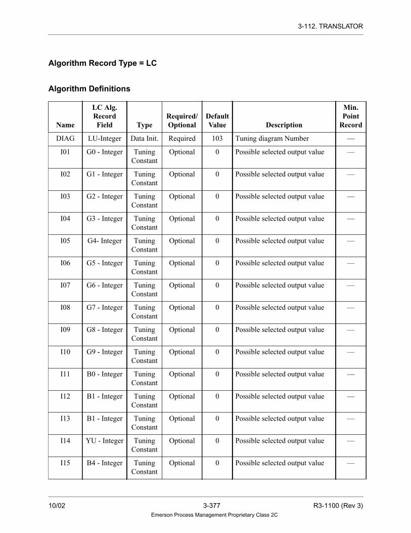
3-112. TRANSLATOR
Algorithm Record Type = LC
Algorithm Definitions
Name
LC Alg.RecordField Type
Required/Optional
DefaultValue Description
Min.Point
Record
DIAG LU-Integer Data Init. Required 103 Tuning diagram Number —
I01 G0 - Integer Tuning
Constant
Optional 0 Possible selected output value —
I02 G1 - Integer Tuning
Constant
Optional 0 Possible selected output value —
I03 G2 - Integer Tuning
Constant
Optional 0 Possible selected output value —
I04 G3 - Integer Tuning
Constant
Optional 0 Possible selected output value —
I05 G4- Integer Tuning
Constant
Optional 0 Possible selected output value —
I06 G5 - Integer Tuning
Constant
Optional 0 Possible selected output value —
I07 G6 - Integer Tuning
Constant
Optional 0 Possible selected output value —
I08 G7 - Integer Tuning
Constant
Optional 0 Possible selected output value —
I09 G8 - Integer Tuning
Constant
Optional 0 Possible selected output value —
I10 G9 - Integer Tuning
Constant
Optional 0 Possible selected output value —
I11 B0 - Integer Tuning
Constant
Optional 0 Possible selected output value —
I12 B1 - Integer Tuning
Constant
Optional 0 Possible selected output value —
I13 B1 - Integer Tuning
Constant
Optional 0 Possible selected output value —
I14 YU - Integer Tuning
Constant
Optional 0 Possible selected output value —
I15 B4 - Integer Tuning
Constant
Optional 0 Possible selected output value —
10/02 3-377 R3-1100 (Rev 3)Emerson Process Management Proprietary Class 2C

3-112. TRANSLATOR
I16 B5 - Integer Tuning
Constant
Optional 0 Possible selected output value —
I17 B6 - Integer Tuning
Constant
Optional 0 Possible selected output value —
I18 B7 - Integer Tuning
Constant
Optional 0 Possible selected output value —
I19 B8 - Integer Tuning
Constant
Optional 0 Possible selected output value —
I20 B9 - Integer Tuning
Constant
Optional 0 Possible selected output value —
I21 C0 - Integer Tuning
Constant
Optional 0 Possible selected output value —
I22 C1 - Integer Tuning
Constant
Optional 0 Possible selected output value —
I23 C2 - Integer Tuning
Constant
Optional 0 Possible selected output value —
I24 C3 - Integer Tuning
Constant
Optional 0 Possible selected output value —
I25 C4 - Integer Tuning
Constant
Optional 0 Possible selected output value —
I26 C5 - Integer Tuning
Constant
Optional 0 Possible selected output value —
I27 C6 - Integer Tuning
Constant
Optional 0 Possible selected output value —
I28 C7 - Integer Tuning
Constant
Optional 0 Possible selected output value —
I29 C8 - Integer Tuning
Constant
Optional 0 Possible selected output value —
I30 YT - Integer Tuning
Constant
Optional 0 Possible selected output value —
I31 D0 - Integer Tuning
Constant
Optional 0 Possible selected output value —
I32 YQ - Integer Tuning
Constant
Optional 0 Possible selected output value —
Name
LC Alg.RecordField Type
Required/Optional
DefaultValue Description
Min.Point
Record
R3-1100 (Rev 3) 3-378 10/02Emerson Process Management Proprietary Class 2C

3-112. TRANSLATOR
I33 D2 - Integer Tuning
Constant
Optional 0 Possible selected output value —
I34 YP - Integer Tuning
Constant
Optional 0 Possible selected output value —
I35 D4 - Integer Tuning
Constant
Optional 0 Possible selected output value —
I36 D5 - Integer Tuning
Constant
Optional 0 Possible selected output value —
I37 D6 - Integer Tuning
Constant
Optional 0 Possible selected output value —
I38 YN - Integer Tuning
Constant
Optional 0 Possible selected output value —
I39 D8 - Integer Tuning
Constant
Optional 0 Possible selected output value —
I40 D9 - Integer Tuning
Constant
Optional 0 Possible selected output value —
I41 YM - Integer Tuning
Constant
Optional 0 Possible selected output value —
I42 YL - Integer Tuning
Constant
Optional 0 Possible selected output value —
I43 E2 - Integer Tuning
Constant
Optional 0 Possible selected output value —
I44 E3 - Integer Tuning
Constant
Optional 0 Possible selected output value —
I45 E4 - Integer Tuning
Constant
Optional 0 Possible selected output value —
I46 YC - Integer Tuning
Constant
Optional 0 Possible selected output value —
I47 Y9 - Integer Tuning
Constant
Optional 0 Possible selected output value —
I48 E7 - Integer Tuning
Constant
Optional 0 Possible selected output value —
I49 E8 - Integer Tuning
Constant
Optional 0 Possible selected output value —
Name
LC Alg.RecordField Type
Required/Optional
DefaultValue Description
Min.Point
Record
10/02 3-379 R3-1100 (Rev 3)Emerson Process Management Proprietary Class 2C

3-112. TRANSLATOR
I50 Y8 - Integer Tuning
Constant
Optional 0 Possible selected output value —
IN1 — Variable Required — Input (analog) LA
OUT — Variable Required — Output (analog) LA
Name
LC Alg.RecordField Type
Required/Optional
DefaultValue Description
Min.Point
Record
R3-1100 (Rev 3) 3-380 10/02Emerson Process Management Proprietary Class 2C

3-113. TRANSPORT
3-113. TRANSPORT
Description
The TRANSPORT algorithm samples the analog input point and outputs the sample
value with a time delay. The sampling time (TSAM) and the number of samples
(NSAM) control the delay (DELAY = TSAM x NSAM). If TSAM is less than the
loop time of TRANSPORT, TSAM equals the loop time. The output is zero until
the number of samples have been collected. Additional TRANSPORT algorithms
can be strung together in series to obtain longer delay times, if required.
NSAM is continually limited to a range of 1 through 12. If NSAM is negative or
zero, then NSAM goes to 1. If NSAM is greater than 12, NSAM goes to 12.
Invalid Numbers and Quality
The value of the analog input (IN1) is checked for invalid real numbers. If the input
value is invalid, the output value is invalid and the quality of the output is set to
BAD. Otherwise, the quality of the output is set to GOOD.
Functional Symbol
Algorithm Record Type = LC
IN1
OUT
IN1 OUT~~OR
10/02 3-381 R3-1100 (Rev 3)Emerson Process Management Proprietary Class 2C

3-113. TRANSPORT
Algorithm Definitions
Name
LC Alg.RecordField Type
Required/Optional
DefaultValue Description
Min.Point
Record
DIAG LU-Integer Data Init Required 90 Tuning diagram number —
TSAM T9 - Real Data Init. Required 0 Sampling time in seconds —
NSAM G0 - Integer Data Init. Required 0 Number of samples (1 - 12) —
INIT X1 - Byte Data Init. Optional 0 Sample initialization
0 or 1 = Samples are initialized to
zero when the algorithm is first added
to the drop; samples are not changed
at power-up, reset, or failover, and
may contain old values.
2 = Samples are initialized to the
current value of the IN1 analog input
on power-up, reset, and failover (as
well as when the algorithm is first
added to the drop).
3 = Samples are initialized to the
current value of the OUT analog
output on power-up, reset, and
failover (as well as when the
algorithm is first added to the drop).
4 = Samples are initialized to zero on
power-up, reset, and failover (as well
as when the algorithm is first added
to the drop).
—
IN1 — Variable Required — Input (analog) LA
OUT — Variable Required — Output (analog) LA
R3-1100 (Rev 3) 3-382 10/02Emerson Process Management Proprietary Class 2C

3-114. TRNSFNDX
3-114. TRNSFNDX
Description
The TRNSFNDX algorithm will select the output analog value from up to 64
outputs which hold the input IN1. The number of outputs is determined by NMIN
which must be less than or equal to 64.The output selected is based on the index
which is the second analog input (IN2). If the index is less than or equal to 0, or if
an index greater than NMIN is selected, the input will not be stored.
10/02 3-383 R3-1100 (Rev 3)Emerson Process Management Proprietary Class 2C

3-114. TRNSFNDX
Functional SymbolO01
IN1
O02O03O04O05O06O07O08O09O10O11O12O13O14O15O16O17O18O19O20O21O22O23O24O25O26O27O28O29O30O31O32O33O34O35O36O37O38O39O40O41O42O43O44O45O46O47O48O49O50O51O52O53O54O55O56O57O58O59O60O61O62O63O64
IN2TRNSFNDX
(INDEX)
R3-1100 (Rev 3) 3-384 10/02Emerson Process Management Proprietary Class 2C

3-114. TRNSFNDX
Algorithm Definitions
Name
Alg.RecordField Type
Required/Optional
DefaultValue Description
Min.Point
Record
NMIN X1-Byte Data Init Required 1 Select maximum number —
IN1 — Variable Required — Analog input value LA
IN2 — Variable Required — Analog index value LA
O01
•
•
•
O64
— Variable Required — Analog output value LA
10/02 3-385 R3-1100 (Rev 3)Emerson Process Management Proprietary Class 2C
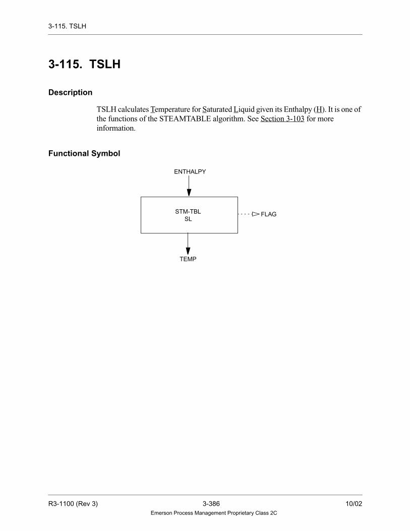
3-115. TSLH
3-115. TSLH
Description
TSLH calculates Temperature for Saturated Liquid given its Enthalpy (H). It is one of
the functions of the STEAMTABLE algorithm. See Section 3-103 for more
information.
Functional Symbol
FLAGSTM-TBL
ENTHALPY
SL
TEMP
R3-1100 (Rev 3) 3-386 10/02Emerson Process Management Proprietary Class 2C

3-116. TSLP
3-116. TSLP
Description
TSLP calculates Saturation Temperature of Saturated Liquid given its Pressure. It is
one of the functions of the STEAMTABLE algorithm. See Section 3-103 for more
information.
Functional Symbol
FLAGSTM-TBL
PRESATM
SL
PRES
TEMP
10/02 3-387 R3-1100 (Rev 3)Emerson Process Management Proprietary Class 2C

3-117. UNPACK16
3-117. UNPACK16
Description
The UNPACK16 algorithm specifies up to 16 optional, packed digital values in the
A2 record field of a packed LP point record as optional outputs of this algorithm.
These outputs may be initialized as any combination of LD and DD records. The bit
in the A2 record field that corresponds to the output digital point number is moved
to the output digital point record.
Functional Symbol
PBPT
UNPACK16
D0
D1
D2
D3
D4
D5
D6
D7D8
D9
D10
D11
D12
D13
D14
D15
R3-1100 (Rev 3) 3-388 10/02Emerson Process Management Proprietary Class 2C

3-117. UNPACK16
Algorithm Record Type = None
Algorithm Definitions
Name
Alg.RecordField Type
Required/Optional
DefaultValue Description
Min.Point
Record
PBPT — Variable Required — Input (packed point) LP
D0 — Variable Optional — Output (digital) for Bit 0 LD
D1 — Variable Optional — Output (digital) for Bit 1 LD
D2 — Variable Optional — Output (digital) for Bit 2 LD
D3 — Variable Optional — Output (digital) for Bit 3 LD
D4 — Variable Optional — Output (digital) for Bit 4 LD
D5 — Variable Optional — Output (digital) for Bit 5 LD
D6 — Variable Optional — Output (digital) for Bit 6 LD
D7 — Variable Optional — Output (digital) for Bit 7 LD
D8 — Variable Optional — Output (digital) for Bit 8 LD
D9 — Variable Optional — Output (digital) for Bit 9 LD
D10 — Variable Optional — Output (digital) for Bit 10 LD
D11 — Variable Optional — Output (digital) for Bit 11 LD
D12 — Variable Optional — Output (digital) for Bit 12 LD
D13 — Variable Optional — Output (digital) for Bit 13 LD
D14 — Variable Optional — Output (digital) for Bit 14 LD
D15 — Variable Optional — Output (digital) for Bit 15 LD
10/02 3-389 R3-1100 (Rev 3)Emerson Process Management Proprietary Class 2C

3-118. VCLTP
3-118. VCLTP
Description
VCLTP calculates Specific Volume of Compressed Liquid given its Temperature and
Pressure. It is one of the functions of the STEAMTABLE algorithm. See Section 3-
103 for more information.
Functional Symbol
SPECIFIC
FLAGSTM-TBL
TEMP
CL
PRES
VOLUME
ATMPRES
R3-1100 (Rev 3) 3-390 10/02Emerson Process Management Proprietary Class 2C

3-119. VSLT
3-119. VSLT
Description
VSLT calculates Specific Volume of Saturated Liquid given its Temperature. It is one
of the functions of the STEAMTABLE algorithm. See Section 3-103 for more
information.
Functional Symbol
FLAGSTM-TBL
TEMP
SL
SPECIFICVOLUME
10/02 3-391 R3-1100 (Rev 3)Emerson Process Management Proprietary Class 2C

3-120. XOR
3-120. XOR
Description
The XOR algorithm performs a mathematical exclusive OR function. For the XOR
algorithm, the output is the logical, exclusive “OR” of the two inputs (that is, if one
input is TRUE and the other input is FALSE, the output is TRUE; otherwise, the
output is FALSE).
Functional Symbol
Algorithm Record Type = None
Algorithm Definitions
Note
Output is required if connecting to anything other
than OR or AND.
Function
IF IN1 = IN2
THEN OUT = FALSE
ELSE
OUT = TRUE
NameAlg. Record
Field TypeRequired/Optional
DefaultValue Description
Min.PointRecord
IN1 — Variable Required — Input (digital) LD, LP
IN2 — Variable Required — Input (digital) LD, LP
OUT — Variable Required/
Optional
— Output (digital) LD, LP
IN1IN2
OUT OUTIN1IN2
OR
R3-1100 (Rev 3) 3-392 10/02Emerson Process Management Proprietary Class 2C

3-121. X3STEP
3-121. X3STEP
Description
The X3STEP algorithm controls devices that must be kept within a certain tolerance
and tuned by an operator. The algorithm receives the position feedback (IN2) of a
device (such as a valve). The position valve is subtracted from the Input demand
signal passed as the IN1 Input. The difference (Error), along with other user-entered
configuration parameters determine how the algorithm attempts to position the
equipment so that the error is zero.
The algorithm moves the equipment by energizing two digital outputs (DIG1 and
DIG2) associated with the device. The digital outputs may be energized in one of
three ways (thus the algorithm's name X3STEP) to move the device to the
demanded position:
• Maintained steadily ON
• Pulsed ON and OFF
• Maintained steadily OFF
Functional Symbol
IN1 IN2
X3STEP
OUT
S1=S2=S6=S7=S8=S9=
T1=T2=T4=T5=T6=T7=T9=
DIG1
DIG2
TOUT
DEVO
10/02 3-393 R3-1100 (Rev 3)Emerson Process Management Proprietary Class 2C
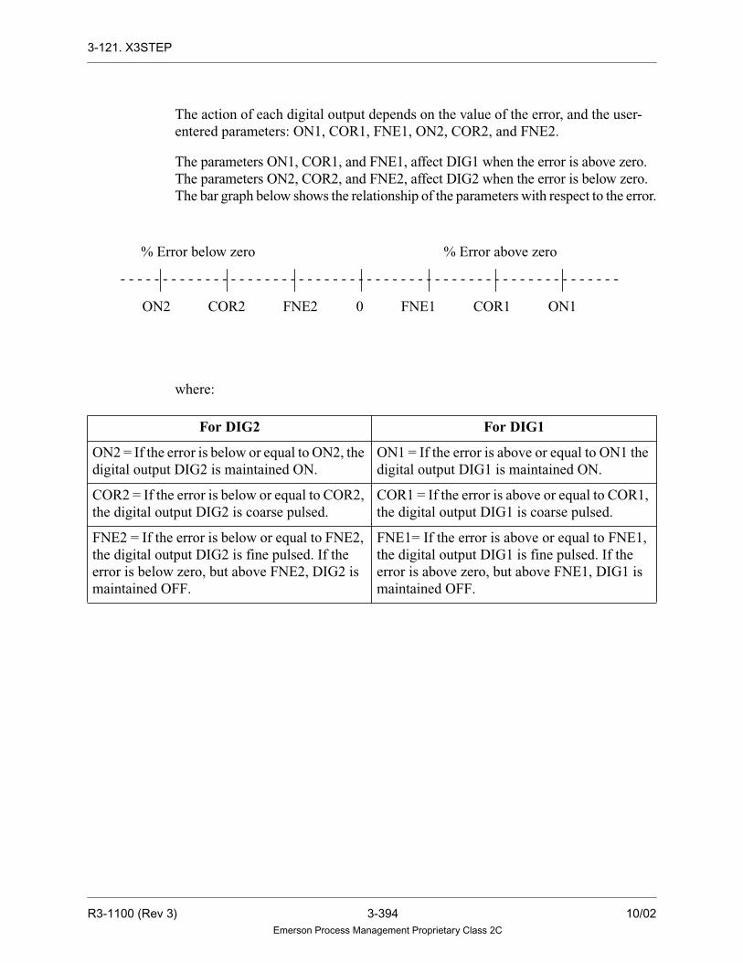
3-121. X3STEP
The action of each digital output depends on the value of the error, and the user-
entered parameters: ON1, COR1, FNE1, ON2, COR2, and FNE2.
The parameters ON1, COR1, and FNE1, affect DIG1 when the error is above zero.
The parameters ON2, COR2, and FNE2, affect DIG2 when the error is below zero.
The bar graph below shows the relationship of the parameters with respect to the error.
where:
For DIG2 For DIG1
ON2 = If the error is below or equal to ON2, the
digital output DIG2 is maintained ON.
ON1 = If the error is above or equal to ON1 the
digital output DIG1 is maintained ON.
COR2 = If the error is below or equal to COR2,
the digital output DIG2 is coarse pulsed.
COR1 = If the error is above or equal to COR1,
the digital output DIG1 is coarse pulsed.
FNE2 = If the error is below or equal to FNE2,
the digital output DIG2 is fine pulsed. If the
error is below zero, but above FNE2, DIG2 is
maintained OFF.
FNE1= If the error is above or equal to FNE1,
the digital output DIG1 is fine pulsed. If the
error is above zero, but above FNE1, DIG1 is
maintained OFF.
- - - - - - - - - - - - - - - - - - - - - - - - - - - - - - - - - - - - - - - - - - - - - - - - - - - - - - - - - - -
ON2 COR2 FNE2 0 FNE1 COR1 ON1
% Error below zero % Error above zero
R3-1100 (Rev 3) 3-394 10/02Emerson Process Management Proprietary Class 2C

3-121. X3STEP
Operation
Suppose an X3STEP algorithm had the following parameters:
If the initial error is above or equal to 15, the digital output (DIG1) is set ON. DIG1
is maintained on until the error falls below 15. At this point, the DIG1 output begins
and continues coarse pulsing until the error is below 12. Once this occurs, the DIG1
output begins and continues fine pulsing until the error is below 8. When this
occurs, DIG1 is set OFF. Please note that the converse of the above definitions are
TRUE when the error is below 0.
In general, X3STEP will turn off both its digital outputs when it detects errors in
configuration or operation. They remain off until the error conditions clear. Also,
when errors occur, OUT is not updated but retains its last valid value. The digital
outputs are both set off under any of the following conditions:
1. The IN1 input has BAD quality, is an invalid real number, or is not being
updated across the Ovation Highway.
2. The IN2 input has BAD quality, is an invalid real number, or is not being
updated across the Data Highway.
3. The digital input DEVO is set indicating that there is a problem with the device.
4. The error is zero or below FNE1 for DIG1. The error is zero or above FNE2 for
DIG2.
5. An on time span of 0 or less is invalid. This invalid configuration is reported by
setting the quality of OUT to BAD and setting bit 3 of its 1W field. This error
is reported at runtime.
- - - - - - - - - - - - - - - - - - - - - - - - - - - - - - - - - - - - - - - - - - - - - - - - - - - - - - - - - - -
ON2 COR2 FNE2 0 FNE1 COR1 ON1
-15 -12 -8 8 12 15
10/02 3-395 R3-1100 (Rev 3)Emerson Process Management Proprietary Class 2C

3-121. X3STEP
6. The algorithm has been incorrectly configured by setting ON1, COR1, FNE1,
or ON2, COR2, and FNE2 all to zero. This invalid configuration is reported by
setting the quality of OUT to BAD and bit 3 of its 1W field. This error is
reported at runtime.The outputs are set to 0 for one execution loop under any of
the following conditions:
— The Controller is reset (hardware or software reset).
— A failover occurs.
— The algorithm is modified and downloaded.
Tracking Signals
This algorithm ignores the TRIN tracking signals. During first pass after a reset, or
failover, and anytime the DEVO digital is TRUE, Bit 16 of TOUT is set TRUE
causing the upstream algorithm to track OUT. Bit 16 of TOUT is set FALSE at all
other times.
Bits 20 and 31 of TOUT are set ON when the IN2 value reaches 100 percent or
greater. This indicates the algorithm has reached the High Limit and requests the
upstream algorithm to inhibit raising the output.
Bits 19 and 30 of TOUT are set ON when the IN2 value reaches 0 percent or less.
This indicates that the algorithm has reached the Low Limit and requests the
upstream algorithm to inhibit lowering the output. All other bits (17-18 and 21-29)
of TOUT are not used.
The TOUT value output is set equal to OUT and its quality is always set to GOOD.
Algorithm Configurations
1. To maintain the digital outputs ON at all times when the error is not zero,
set the following:
ON1 or ON2 > 0 (Set ON1 or ON2 very close to zero)
FNE1 or FNE2 = 0
COR1 or COR2 = 0
2. This configuration causes DIG1 to be on when the error is above ON1. DIG2 is
onwhentheerror isbelowON2.Toeliminatecoarsepulsingofadigital, set:
COR1 or COR2 = 0
Assumes a non-zero value for ON1, ON2, FNE1, and FNE2. FNE1 is less than
ON1 and FNE2 is greater than ON2.
R3-1100 (Rev 3) 3-396 10/02Emerson Process Management Proprietary Class 2C

3-121. X3STEP
If the error is initially above ON1 (or below ON2), the digital remains on until
the error falls below ON1 (or above ON2). When this occurs and COR1 (or
COR2) equals zero, coarse pulsing is ignored and fine pulsing begins. Fine
pulsing continues until the error is below FNE1 (or above FNE2). At this point
the digital is maintained OFF.
3. To eliminate fine pulsing of a digital, set:
FNE1 or FNE2 = 0
Assumes a non-zero value for ON1, ON2, COR1, and COR2. COR1 is less than
ON1 and COR2 is greater than ON2.
If the error is initially above ON1 (or below ON2), the digital remains on until
the error falls below ON1 (or above ON2). At this point, coarse pulsing begins
and is maintained until the error falls below COR1 (or above COR2). When this
occurs and FNE1 (or FNE2) equals zero, fine pulsing is ignored and the digital
is maintained OFF.
4. To eliminate maintaining the digital outputs on steady when the error is not zero,
set:
ON1 or ON2 = 0
Assumes a non-zero value for COR1, COR2, FNE1, or FNE2. If the error is
initially above COR1 (or below COR2), the digital is pulsed coarsely until the
error is below COR1 or (COR2). When this occurs, fine pulsing begins and
continues until the error falls below FNE1 (or above FNE2). At this point the
digital is maintained OFF.
5. The ON and OFF times for the coarse and fine pulses are determined from the
user-entered off time and on time span tuning fields.
6. IN2 is the position feedback. In this case OUT is assigned the value of IN2. If
IN2 is less than zero, a value of zero is used for the position feedback.
10/02 3-397 R3-1100 (Rev 3)Emerson Process Management Proprietary Class 2C

3-121. X3STEP
If IN2 is greater than 100, a value of 100 is used. If IN2 has BAD quality, or is
an invalid real number, OUT will retain its last valid value. OUT's quality will
be set to BAD. The quality of OUT and its 1W field report algorithm error
conditions are described below:
Tuning Constants
1. COR1 must always be set less than ON1, and COR2 must always be set greater
than ON2 for proper operation. The algorithm does not check for this invalid
configuration.
2. FNE1 must always be set less than COR1, and FNE2 must always be set greater
than COR2 for proper operation. The algorithm does not check for this invalid
configuration.
3. Set CTM1, CTM2, FTM1, FTM2 (time spans for pulsing) in multiples of the
DPU's loop time.
If CTM1, CTM2, FTM1, and FTM2 and the accompanying ON and OFF times that
are less than one loop time, the algorithm assumes those times are equal to one loop
time.
Algorithm Record Type = LC
OUT Quality 1W Bit Set Description
GOOD NONE Normal Operation
BAD NONE The position feedback IN2 has BAD quality.
BAD Bit 3 Invalid configuration has been entered. BAD parameter (ON1,
COR1, FNE1, ON2, COR2, FNE2) or time span (CTM1, FTM1,
CTM2, FTM2) or on time/off time (FDY1, FDY2, CDY1, CDY2).
R3-1100 (Rev 3) 3-398 10/02Emerson Process Management Proprietary Class 2C

3-121. X3STEP
Algorithm Definitions
Name
LC Alg.RecordField Type
Required/Optional
DefaultValue Description
Min.Point
Record
DIAG LU-Integer Data Init. Required 58 Tuning Diagram. —
IN2 — Variable Optional — Analog Input - this is the positive
feedback from the device.
LA
IN1 — Variable Required — Analog Input in percent (0-100).
This is the demand value for the
device.
LA
TOUT — Variable Required — Bit 16 is set TRUE during the first
pass and when DEVO input is
TRUE. Typically used for initial-
izing upsteam PID algorithm to
accomplish bumpless transfer.
Bit 19 and 30 indicate POS is at
low limit
Bit 20 and 31 indicate POS
is at high limit.
Contains the value of the position
feedback signal. The quality of
TOUT is always GOOD; sensor
errors are not reported. Used to
initialize upsteam PID algorithms
with bumpless transfer.
LA
DEVO — Variable Optional — Packed Point; Bit 0 indicates the
operational state of the device
being controlled, where:
0 = operational
1 = non-operational
LP
ON1 T9-Real Tuning
Constant
— 10 Steady on limit (amount of error
above 0 at which DIG1 turns ON)
—
CON1 S1-Real Tuning
Constant
— 5 Coarse on limit (amount of error
above 0 at which DIG1 begins
coarse pulsing)
—
10/02 3-399 R3-1100 (Rev 3)Emerson Process Management Proprietary Class 2C

3-121. X3STEP
FNE1 T1-Real Tuning
Constant
— 2 Fine on limit (amount of error
above 0 at which DIG1 begins
fine pulsing)
—
ON2 U1-Real Tuning
Constant
— -10 Steady on limit (amount of error
above 0 at which DIG2 turns ON)
—
CON2 S2-Real Tuning
Constant
— -5 Coarse on limit (amount of error
above 0 at which DIG2 begins
coarse pulsing)
—
FNE2 T2-Real Tuning
Constant
— -2 Fine on limit (amount of error
above 0 at which DIG2 begins
fine pulsing)
—
CTM1 S6-Real Tuning
Constant
— 2000 Coarse on-time span in msec. for
DIG1.
—
CDY1 S7-Real Tuning
Constant
— 1000 Coarse off-time span in msec. for
DIG1.
—
CTM2 S8-Real Tuning
Constant
— 2000 Coarse on-time span in msec. for
DIG2.
—
CDY2 S9-Real Tuning
Constant
— 1000 Coarse off-time span in msec. for
DIG2.
—
FTM1 T4-Real Tuning
Constant
— 2000 Fine on-time span in msec. for
DIG1.
—
FDY1 T5-Real Tuning
Constant
— 1000 Fine off-time span in msec. for
DIG1.
—
FTM2 T6-Real Tuning
Constant
— 2000 Fine on-time span in msec. for
DIG2.
—
FDY2 T7-Real Tuning
Constant
— 1000 Fine off-time span in msec. for
DIG2.
—
OUT — Variable — — Contains the value of the position
feedback signal. The quality and
IN field of OUT are used to report
error conditions.
LA
TRIN — Variable Optional — Tracking and limiting mode.
Signals, tracking value, analog
input variable.
LA
Name
LC Alg.RecordField Type
Required/Optional
DefaultValue Description
Min.Point
Record
R3-1100 (Rev 3) 3-400 10/02Emerson Process Management Proprietary Class 2C

3-121. X3STEP
DIG1 — Variable Required — Digital Output1 LD
DIG2 — Variable Required — Digital Output2 LD
Name
LC Alg.RecordField Type
Required/Optional
DefaultValue Description
Min.Point
Record
10/02 3-401 R3-1100 (Rev 3)Emerson Process Management Proprietary Class 2C

3-122. 2XSELECT
3-122. 2XSELECT
Description
The 2XSELECT algorithm monitors two analog transmitter inputs for quality and
deviation from each other. The output is either one of the two input values; the
higher value, the lower value, or the average of the two values, depending on the
mode selected. The user selects the mode through the use of the TMOD and MODE
tracking inputs, the Operator’s Keyboard function keys, or the Control Builder.
Functional Symbol
The Control Indicator Word is used to specify which of the Average, Lower and
Higher modes are inhibited, and the type of quality of the input that sets the Quality
Alarm for that point.
The Average, Lower, and Higher modes cannot be selected if they are inhibited by
the Control Indicator Word, or when either of the transmitters is in Quality Alarm,
or when the deviation between the two transmitter values is greater then the Control
Deviation Deadband tuning constant (CNDB).
The Transmitter A mode cannot be selected when Transmitter A is in Quality Alarm
and Transmitter B is not in Quality Alarm. The algorithm goes to Transmitter A
mode when both transmitters are in Quality Alarm, or when Transmitter B is in
Quality Alarm.
The Transmitter B mode cannot be selected when Transmitter B is in Quality
Alarm. The algorithm goes to Transmitter B mode when Transmitter A is in Quality
Alarm and Transmitter B is not in Quality Alarm.
2XSELECT
XABQ
XBBQ
XALM
MRE
PBPT
XDEV
OUT
XA XB
MODE
TMOD
R3-1100 (Rev 3) 3-402 10/02Emerson Process Management Proprietary Class 2C

3-122. 2XSELECT
On the first pass of the algorithm, if the Tracking Input (MODE) is initialized by the
user, the mode is set according to the rounded value of the tracking input as follows:
If the rounded value of the tracking input is not 1 through 5, or if the tracking input
was not initialized, the mode is set to Average mode. If the mode selected on the
first pass is inhibited, or if it is blocked by a Quality Alarm or a Deviation Alarm,
as described above, the mode is set to the next lowest priority mode (where the
Average mode has the highest priority and Transmitter B mode has the lowest
priority) until a mode is selected that is not inhibited or blocked. If both transmitters
are in Quality Alarm, the output of the algorithm is zero and the mode is set to the
Transmitter A mode.
If the Tracking Mode Request digital input (TMOD) is initialized, the mode is set
according to the rounded value of the tracking input and the above table when the
Tracking Mode Request signal is TRUE and there are no Quality Alarms. The mode
remains unchanged if the rounded value of the tracking input is not 1 through 5
when the Tracking Mode Request signal is TRUE.
The user may select a different mode by using the function keys on the Operator’s
Keyboard when the Tracking Mode Request signal is FALSE.
The value of the analog output (OUT) is according to the mode of the algorithm:
MODE Value Mode Selected
1 Average
2 Lower
3 Higher
4 Transmitter A
5 Transmitter B
Mode Output Value
Average Average value of the two transmitter input values
Lower Lower value of the two transmitter input values
Higher Higher value of the two transmitter input values
Transmitter A Value of Transmitter A
Transmitter B Value of Transmitter B
10/02 3-403 R3-1100 (Rev 3)Emerson Process Management Proprietary Class 2C

3-122. 2XSELECT
The Transmitter Deviation Alarm digital output (XDEV) is set TRUE when the
deviation between the two transmitter values is greater than the Alarm Deviation
Deadband tuning constant (ALDB), or when one or both transmitters contain
invalid real numbers.
The Transmitter A Quality Alarm digital output (XABQ) is set TRUE when the
quality of the Transmitter A analog input goes BAD or NOT GOOD, depending on
the Quality Alarm Type flag. The Transmitter B Quality Alarm digital output
(XBBQ) is set TRUE when the quality of the Transmitter B analog input point goes
BAD or NOT GOOD, depending on the Quality Alarm Type flag.
The Transmitter Malfunction Alarm digital output (XALM) is set TRUE when there
is a Quality Alarm on either of the two signals, when one or both input points
contain invalid values, or when the deviation between the two transmitter values is
greater than the Control Deviation Deadband tuning constant (CNDB).
The Manual Reject digital output (MRE) is set TRUE when both transmitters are in
Quality Alarm, or when the deviation between the two transmitter values is greater
than the Control Deviation Deadband tuning constant (CNDB). The P3 function key
on the Operator’s Keyboard toggles the inhibiting of the deviation check. For
example, by pressing the P3 function key on the Operator’s Keyboard, the Manual
Reject output is only set TRUE when both transmitters are in Quality Alarm. Then,
by pressing the P3 function key again, the Manual Reject output is set TRUE when
both transmitters are in Quality Alarm or when the deviation is too large.
The packed digital output signal (PBPT) contains the Quality Alarms for both
transmitters, the Manual Reject output, the Transmitter Malfunction Alarm, the
Tracking Request signal, the mode of the algorithm, and the state of the Inhibit
Control Deviation Alarm Check for the MRE digital output feature.
Note
The information in the packed digital output signal is
also stored in the B7 field of the algorithm record.
R3-1100 (Rev 3) 3-404 10/02Emerson Process Management Proprietary Class 2C

3-122. 2XSELECT
When using the RATE or DBNB parameters, the following apply:
• 2XSELECT ramps at the user-entered rate (specified in Units/Sec. via the
RATE template parameter) during mode changes. If no entry is made in the
RATE parameter or a value of 0 is entered, 2XSELECT will change its output
value to the new value during mode changes.
• 2XSELECT returns from a deviation (XDEV) condition (that is, when the
absolute difference between the XA and XB inputs is greater than the ALDB
parameter) only when absolute difference between the XA and XB inputs return
to a value which is less than or equal to Alarm Limit Deadband (ALDB) minus
DBND. If no entry is made in the DBND parameter or a value of 0 is entered,
2XSELECT will return from an XDEV condition.
• 2XSELECT returns from a CNDB condition (that is, when the absolute
difference between the XA and XB inputs is greater than the CNDB parameter)
only when absolute difference between the XA and XB inputs return to a value
which is less than or equal to CNDB minus DBND. If no entry is made in the
DBND parameter or a value of 0 is entered, 2XSELECT will return from a
CNDB condition.
The interface keys on the Operator’s Keyboard are:
Function Key Use
P1 Transmitter A mode request
P2 Transmitter B mode request
P3 Toggle the inhibiting of the Control Deviation Alarm check on
the manual reject (MRE) output
P4 Average mode request
P5 Lower mode request
P6 Higher mode request
10/02 3-405 R3-1100 (Rev 3)Emerson Process Management Proprietary Class 2C

3-122. 2XSELECT
Invalid Numbers and Quality
The transmitter input values to the algorithm are checked for invalid real numbers. If
a transmitter contains an invalid value, its Quality Alarm digital output is set TRUE.
If both transmitters are in Quality Alarm, or contain invalid values, the value of the
algorithm output (OUT) quality is set to BAD.
If the algorithm calculates an invalid real number for the output, the quality of the
output is set to BAD and the output value is invalid.
Algorithm Record Type = LC
Algorithm Definitions
Name
LC Alg.RecordField Type
Required/Optional
DefaultValue Description
Min.Point
Record
DIAG LU-Integer Tuning
Constant
Required 99 Tuning diagram number —
MODE — Variable Optional — Input (analog); tracks the algorithm
to a mode on first pass and when
TMOD is TRUE. This point must
be initialized if the TMOD point is
initialized.
LA
TMOD — Variable Optional — Input (digital); request to track the
mode to the value of MODE. If this
point is initialized, the MODE point
must also be initialized.
LD, LP
R3-1100 (Rev 3) 3-406 10/02Emerson Process Management Proprietary Class 2C

3-122. 2XSELECT
CNTL C3 -
Integer
Data Init. Optional 0 Control Indicator Word
Bit Description
0 Average Selection
0 = Not allowed
1 = Allowed
1 Lower Selection
0 = Not allowed
1 = Allowed
2 Higher Selection
0 = Not allowed
1 = Allowed
3 Quality Alarm Type
0 = BAD Quality
Alarm
1 = NOT GOOD
Quality Alarm
—
ALDB R1 - Real Tuning
Constant
Required 0.0 Alarm Deviation Deadband —
CNDB R2 - Real Tuning
Constant
Required 0.0 Control Deviation Deadband —
RATE R3 - Real Tuning
Constant
Optional 0.0 Ramping rate parameter —
DBND R4 - Real Tuning
Constant
Optional 0.0 Deadband delta parameter —
XA — Variable Required — Input (analog); Transmitter A LA
XB — Variable Required — Input (analog); Transmitter B LA
XDEV — Variable Optional — Output (digital); Transmitter Alarm
Deviation signal
LD, LP
XABQ — Variable Optional — Output (digital); Quality Alarm for
Transmitter A
LD, LP
XBBQ — Variable Optional — Output (digital); Quality Alarm for
Transmitter B
LD, LP
XALM — Variable Optional — Output (digital); Transmitter
Malfunction Alarm
LD, LP
Name
LC Alg.RecordField Type
Required/Optional
DefaultValue Description
Min.Point
Record
10/02 3-407 R3-1100 (Rev 3)Emerson Process Management Proprietary Class 2C
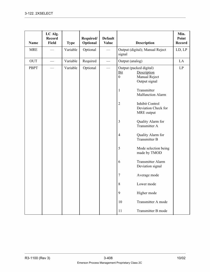
3-122. 2XSELECT
MRE — Variable Optional — Output (digital); Manual Reject
signal
LD, LP
OUT — Variable Required — Output (analog) LA
PBPT — Variable Optional — Output (packed digital)
Bit Description
0 Manual Reject
Output signal
1 Transmitter
Malfunction Alarm
2 Inhibit Control
Deviation Check for
MRE output
3 Quality Alarm for
Transmitter A
4 Quality Alarm for
Transmitter B
5 Mode selection being
made by TMOD
6 Transmitter Alarm
Deviation signal
7 Average mode
8 Lower mode
9 Higher mode
10 Transmitter A mode
11 Transmitter B mode
LP
Name
LC Alg.RecordField Type
Required/Optional
DefaultValue Description
Min.Point
Record
R3-1100 (Rev 3) 3-408 10/02Emerson Process Management Proprietary Class 2C

Section 4. Q-Line Algorithms
4-1. Section Overview
This section provides a description of algorithms to be used specifically with
Q-Line hardware.
CAUTION
BE SURE TO USE THE CORRECTALGORITHM WITH A PARTICULARCONTROLLER.
USING AN ALGORITHM NOTDESIGNED FOR A CONTROLLERWILL CAUSE THE CONTROLLER TOFAIL.
4-2. Reference Pages
The following algorithms are described in this section:
Refer to “Standard Control Algorithms User Guide” (U0-0106) for more
information on Q-Line algorithms. See Section 3-2 for a description of the reference
page format.
QPACMD
QPACMPAR
QPASTAT
QSDDEMAND
QSDMODE
QSRMA
QVP
XMA2
XML2
10/02 4-1 R3-1100 (Rev 3)Emerson Process Management Proprietary Class 2C
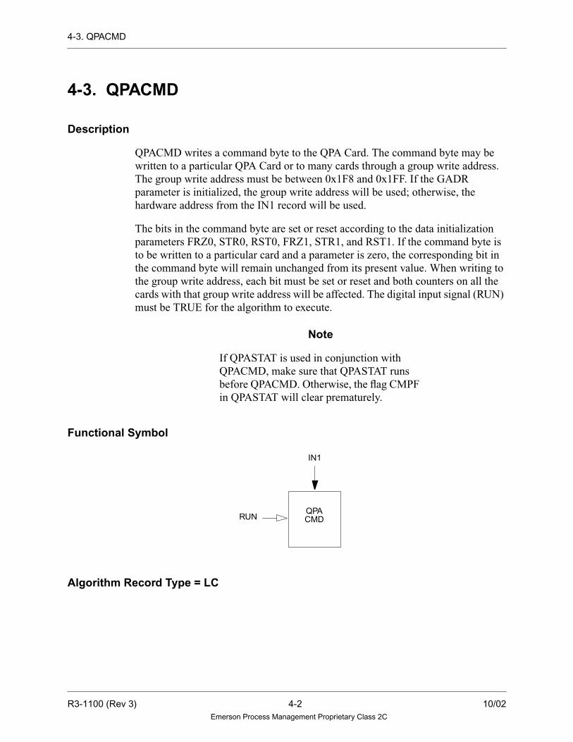
4-3. QPACMD
4-3. QPACMD
Description
QPACMD writes a command byte to the QPA Card. The command byte may be
written to a particular QPA Card or to many cards through a group write address.
The group write address must be between 0x1F8 and 0x1FF. If the GADR
parameter is initialized, the group write address will be used; otherwise, the
hardware address from the IN1 record will be used.
The bits in the command byte are set or reset according to the data initialization
parameters FRZ0, STR0, RST0, FRZ1, STR1, and RST1. If the command byte is
to be written to a particular card and a parameter is zero, the corresponding bit in
the command byte will remain unchanged from its present value. When writing to
the group write address, each bit must be set or reset and both counters on all the
cards with that group write address will be affected. The digital input signal (RUN)
must be TRUE for the algorithm to execute.
Note
If QPASTAT is used in conjunction with
QPACMD, make sure that QPASTAT runs
before QPACMD. Otherwise, the flag CMPF
in QPASTAT will clear prematurely.
Functional Symbol
Algorithm Record Type = LC
RUN
IN1
QPACMD
R3-1100 (Rev 3) 4-2 10/02Emerson Process Management Proprietary Class 2C

4-3. QPACMD
Algorithm Definitions
Name
LC Alg.RecordField Type
Required/Optional
DefaultValue Description
Min.Point
Record
GADR G0-Integer Data Init. Optional — Group Write Offset Write —
FRZ0 X1 - Byte Data Init. Optional — Freeze/unfreeze selector for - Counter 0
CNTR CNTR GADR
Selection Address Address
0 No Action Unfreeze
1 Freeze Freeze
2 Unfreeze Unfreeze
—
STR0 X2 - Byte Data Init. Optional — Start/Stop selector for Counter 0
CNTR CNTR GADR
Selection Address Address
0 No Action Stop
1 Start Start
2 Stop Stop
—
RST0 X3 - Byte Data Init. Optional — Reset selector for Counter 0
CNTR CNTR GADR
Selection Address Address
0 No Action No Action
1 Reset Reset
—
FRZ1 X4 - Byte Data Init. Optional — Freeze/unfreeze selector for - Counter 1
CNTR CNTR GADR
Selection Address Address
0 No Action Unfreeze
1 Freeze Freeze
2 Unfreeze Unfreeze
—
STR1 X5 - Byte Data Init. Optional — Start/Stop selector for Counter 1
CNTR CNTR GADR
Selection Address Address
0 No Action Stop
1 Start Start
2 Stop Stop
—
RST1 X6 - Byte Data Init. Optional — Reset selector for Counter 1
CNTR CNTR GADR
Selection Address Address
0 No Action No Action
1 Reset Reset
—
IN1 — Variable Required — Input (analog) LA
RUN — Variable Required — Input (digital) LD
10/02 4-3 R3-1100 (Rev 3)Emerson Process Management Proprietary Class 2C

4-3. QPACMD
Application Example
Three algorithms can access the QPA card: QPACMD, QPASTAT, and
QPACMPAR. This is one example of how to use the QPACMD command. (See
QPACMPAR for another example, and refer to “Q-Line Installation Manual”
(M0-0053) for other QPA card applications.)
In this example, a QPA card is used to count a pulsed input. The input is a count of
contact closures from a megawatt meter. The number of megawatts per pulse will
be accounted for in the coefficients that are calculated as part of the point record.
Be careful when selecting hardware addresses for QPA cards. They require four
consecutive addresses each, even though there are only two inputs for each card.
The extra two addresses are used for control and status word transfer. In this
example, the QPA card is located in the first slot of Q-crate 1 in a Controller (where:
half-shell = A1 and card hardware address = 0x80).
In this example, the input for Counter 1 (IN1) is assigned analog point EW1. This
is the second card input. Counter 0 uses the first card input. (See “Q-Line
Installation Manual” (M0-0053) for a layout of the QPA card.)
IN1 must be initialized as an analog input point in the Controller. The following is
an example of such a point (EW1).
Field Value
RT LA
EU ‘MWH’
ED ‘MWH To PHOSIE- ACBNO1’
CV 1
IV 0.6
2V 0.0
R3-1100 (Rev 3) 4-4 10/02Emerson Process Management Proprietary Class 2C

4-3. QPACMD
Other points needed by algorithms used in this example are added to the database.
EW1 may have non-zero values for parameters such as TOPBAR, BOTBAR, and
LIMITS, as desired, just as any other analog input point.
In this example, if one pulse from a megawatt meter equals 10 kilowatt hours, in
order to make EW1 equivalent to megawatt hours, a conversion coefficient must be
used on the point.
This means that if there were three pulses per minute in an one hour period, the
coefficient would calculate a value as follows:.
Point Name Type Frequency
HOUR LD 1.0
PMIN LD 1.0
SECND LD 1.0
EW1R LA 1.0
EW1TOT LA 1.0
DX1PASS LD 1.0
PULSES
MIN
KWH
PULSE
MWH
1000 KWH
MIN
HR
MWH
HR=lll3 10 60 1.8
10/02 4-5 R3-1100 (Rev 3)Emerson Process Management Proprietary Class 2C

4-3. QPACMD
Alternate Example
An alternate method of converting pulse counts into megawatts per hour is to leave
the CI and CV record fields blank so that the value of EW1 represents the actual
pulse count from the QPA card. A gain could be used in the RESETSUM algorithm
to calculate megawatts per hour.
The following application is used to control the QPA card in this example.
AlgorithmAlgorithmParameters Point/Values
TIMECHANGE
(110)
HCHG HOUR
SCHG SECND
MCHG PMIN
QPACMD
(111)
IN1 EW1
FRZ0 0
RST0 0
STR0 0
FRZ1 0
RST1 0
STR1 1
RUN DX1PASS
QPACMD
(112)
IN1 EW1
FRZ0 0
RST0 0
STR0 0
FRZ1 2
RST1 0
STR1 0
RUN PMIN
R3-1100 (Rev 3) 4-6 10/02Emerson Process Management Proprietary Class 2C

4-3. QPACMD
The execution of the example application is as follows:
1. Algorithm 110 (TIMECHANGE) generates PMIN and HOUR, which are flags
denoting a change in minutes and hours, respectively. These flags will be used
by the QPACMD and RESETSUM algorithms. HOUR, PMIN, and SECND
must be initialized as digital points.
2. Algorithm 111 (QPACMD) sends the control command START to Counter 1
(STR1 = 1) of the QPA card when the digital input DX1PASS point is set.
DX1PASS is a point from some control scheme, which is set to 1 only during
the first pass through the application. Therefore, the QPA starts collecting pulse
counts upon start-up, after a hardware reset, or Controller failover.
QPACMD
(113)
IN1 EW1
FRZ0 0
RST0 0
STR0 0
FRZ1 1
RST1 1
STR1 0
RUN PMIN
RESETSUM
(115)
IN1 EW1
FFLG HOUR
RSET HOUR
RUN PMIN
RCNT 0.0
GAIN 1.0
OUT EW1R
FOUT EW1T0T
AlgorithmAlgorithmParameters Point/Values
10/02 4-7 R3-1100 (Rev 3)Emerson Process Management Proprietary Class 2C

4-3. QPACMD
3. The algorithm pair of 112 and 113 reads the data from QPA Counter 1 (IN1 =
EW1). There are two counters working within the QPA card. One is an actual
counter linked directly with the pulse input, which is always accumulating data
unless reset. The other counter is Counter 1, which reads data from the actual
counter upon command.
4. Algorithm 112 unfreezes (FRZ = 2) Counter 1 so that the values in Counter 1
reflect the data in the actual counter. Algorithm 113 then freezes (FRZ = 1) the
value stored in Counter 1 and resets the actual counter to zero before
accumulating more pulse data. Only the reset operation (RST1 = 1) affects the
actual QPA count. The freeze/unfreeze operation only causes the current value
to be placed on the DIOB or removed from the DIOB.
These four algorithms (110, 111, 112, and 113) only run when the digital flag PMIN
is true. PMIN may be generated any number of ways, but in this application, PMIN
is set as an output flag from the TIMECHANGE algorithm every minute. By
holding the QPA Counter 1 value frozen for one minute, a valid QPA reading is
present on the DIOB during the entire one-minute period, allowing other algorithms
to access the data.
RESETSUM (115) totals the values read from the QPA over a period of time. The
values are summed, based on the state of the flags PMIN and HOUR. In this
example, EW1R contains the number of megawatts accumulated every minute for
an hour. Output EW1TOT is an hourly total of megawatts generated and is triggered
by HOUR. The value of EW1R is stored into EW1TOT on the hour and EW1R is
reset to zero, ready to accumulate the next hour’s information.
The commands START, STOP, FREEZE, and UNFREEZE may be hard-wired in
the field if the availability of the QPA count is to be controlled by hardware rather
than software. See “ Q-Line Installation Manual” (M0-0053) for wiring
information.
R3-1100 (Rev 3) 4-8 10/02Emerson Process Management Proprietary Class 2C

4-4. QPACMPAR
4-4. QPACMPAR
Description
QPACMPAR writes a comparator value (VALU) to a comparator register on a QPA
Card at the hardware address found in the counter input (IN1). If IN1 has a linear
conversion (to normalize its current value), the input VALUE is denormalized
before it is written to the QPA Card as the comparator value. If the conversion on
IN1 is not linear, the value of VALU is assumed to have been already denormalized.
The denormalized value of VALU is high and low limited between zero and 32767
so that it can be properly written to the QPA Card. The digital input signal (RUN)
must be TRUE for the algorithm to execute.
Invalid Numbers and Quality
The new value (VALU) to be written to the QPA card is checked for invalid real
numbers. If the new value is invalid, it is not written to the QPA card, and a
“Hardware Error” is reported in the second status work (2W record field) of the
analog input CNTR.
Functional Symbol
Algorithm Record Type = None
RUN
IN1
QPACMPAR
VALU
10/02 4-9 R3-1100 (Rev 3)Emerson Process Management Proprietary Class 2C

4-4. QPACMPAR
Algorithm Definitions
Application Example
This example describes one method of using the QPACMPAR, QPASTAT, and
QPACMD algorithms together to access the data stored on the QPA card.
1. Use QPACMPAR to write a comparator value to the QPA card. This value is
stored in a QPA hardware register (VALU). When the value stored in IN1 equals
the value stored in VALU, the QPA card automatically sets the CMPF flag (a bit
in the status register).
2. Use QPASTAT to read the status flags: CMPF, RUNF, and FRZ1. If CMPF is
set, use QPACMD to reset the QPA CNTR.
Caution
If both counters on the QPA card are beingused, reading the status of one Counter withQPASTAT clears the other Counter’s CMPFflag if that flag was set.
Name
Alg.Record
Field TypeRequired/Optional
DefaultValue Description
Min.Point
Record
IN1 — Variable Required — Input (analog) LA
VALU — Variable Required — Input (analog) LA
RUN — Variable Required — Input (digital) LD
R3-1100 (Rev 3) 4-10 10/02Emerson Process Management Proprietary Class 2C

4-5. QPASTAT
4-5. QPASTAT
Description
QPASTAT reads the status byte from a QPA card at the hardware address found in
the counter input (IN1). The hardware address is checked to determine which
counter on the card is used. The corresponding status flags are checked and output
as digital records.
Functional Symbol
Algorithm Record Type = None
Algorithm Definitions
Name
Alg.Record
Field TypeRequired/Optional
DefaultValue Description
Min.Point
Record
IN1 — Variable Required — Input (analog) LA
CMPF — Variable Optional — Output (digital); Comparator flag LD
RUNF — Variable Optional — Output (digital); Running flag LD
FRZF — Variable Optional — Output (digital); Frozen flag LP
CMPF
IN1
QPASTAT RUNF
FRZF
10/02 4-11 R3-1100 (Rev 3)Emerson Process Management Proprietary Class 2C

4-6. QSDDEMAND
4-6. QSDDEMAND
Description
The QSDDEMAND algorithm controls the servo driver card (QSD) demand signal
and controls the operation mode (Auto, Manual) of the QSD card. It also services
the watchdog timer by setting the keep alive bit upon each call. The algorithm
places the QSD in automatic if the auto request input (AREQ) is TRUE, the ready
bit read from the QSD card has been TRUE for the specified amount of time (RDY),
and the card in place bit read from the QSD is TRUE.
The algorithm rejects the QSD to local manual if the local manual request input
(LREQ) is TRUE, if the card in place bit from the QSD is FALSE, or if the demand
output to the QSD does not equal the value read back. The algorithm set the sensor
alarm bits if either the card in place bit is not set or the demand read back from the
QSD card does not equal the demand written to the card.
Note
The OUT point must contain the hardware
address for the QSD card.
Functional Symbol
QSDDEMAND
IN1 AREQ LREQ
ERRB OUT
R3-1100 (Rev 3) 4-12 10/02Emerson Process Management Proprietary Class 2C

4-6. QSDDEMAND
Algorithm Record Type= LC
Algorithm Definitions
Name
LC Alg.RecordField Type
Required/Optional
DefaultValue Description
Min.Point
Record
DIAG LU-Integer Data Init. Required 28 Tuning Diagram Number —
RDY R1-Real Tuning
Constant
Required 2 Ready Time —
IN1 — Variable Required — Analog Calculate Demand Input LA
LREQ — Variable Required — Digital Local Request Input LD
AREQ — Variable Required — Digital Auto Request Input LD
OUT — Variable Required — Analog output variable LA
ERRB — Variable Required — Digital Output LD
10/02 4-13 R3-1100 (Rev 3)Emerson Process Management Proprietary Class 2C

4-7. QSDMODE
4-7. QSDMODE
Description
The QSDMODE algorithm reads the mode in which the QSD card is operating. The
output is TRUE if the QSD card is in Auto Mode. The algorithm also checks the
card in place bit and if it is not set, the sensor alarm bit is set.
Note
The IN1 point must contain the hardware address
for the QSD card.
Functional Symbol
Algorithm Record Type= LC
Algorithm Definitions
Name
LC Alg.RecordField Type
Required/Optional
DefaultValue Description
Min.Point
Record
IN1 — Variable Required — Demand Output (analog) LA
OUT — Variable Required — Digital output variable (digital) LD
QSDMODE
OUT
IN1
R3-1100 (Rev 3) 4-14 10/02Emerson Process Management Proprietary Class 2C
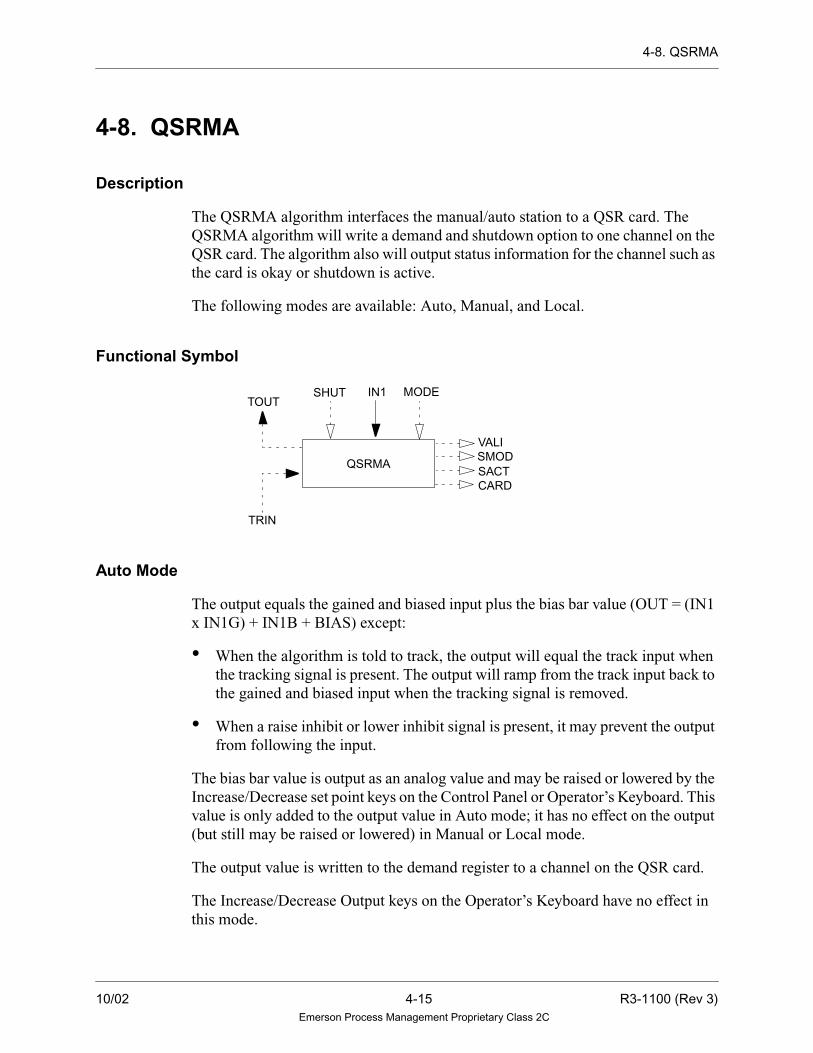
4-8. QSRMA
4-8. QSRMA
Description
The QSRMA algorithm interfaces the manual/auto station to a QSR card. The
QSRMA algorithm will write a demand and shutdown option to one channel on the
QSR card. The algorithm also will output status information for the channel such as
the card is okay or shutdown is active.
The following modes are available: Auto, Manual, and Local.
Functional Symbol
Auto Mode
The output equals the gained and biased input plus the bias bar value (OUT = (IN1
x IN1G) + IN1B + BIAS) except:
• When the algorithm is told to track, the output will equal the track input when
the tracking signal is present. The output will ramp from the track input back to
the gained and biased input when the tracking signal is removed.
• When a raise inhibit or lower inhibit signal is present, it may prevent the output
from following the input.
The bias bar value is output as an analog value and may be raised or lowered by the
Increase/Decrease set point keys on the Control Panel or Operator’s Keyboard. This
value is only added to the output value in Auto mode; it has no effect on the output
(but still may be raised or lowered) in Manual or Local mode.
The output value is written to the demand register to a channel on the QSR card.
The Increase/Decrease Output keys on the Operator’s Keyboard have no effect in
this mode.
QSRMA
IN1TOUT
TRIN
SHUT MODE
VALISMODSACTCARD
10/02 4-15 R3-1100 (Rev 3)Emerson Process Management Proprietary Class 2C

4-8. QSRMA
Manual Mode
The output is raised or lowered by using the Increase/Decrease Output requests. The
raise inhibit and lower inhibit signals override the Operator’s Keyboard Increase/
Decrease Output requests. The tracking signal will cause the output to equal the
track input, regardless of the raise/lower inhibit signals and the Increase/Decrease
Output key requests. The bias bar value has no effect on the output, but still may be
raised and lowered.
The output value is written to the demand register to a channel on the QSR card.
Local Mode
If the QSR card has any hardware error, then the algorithm will stay in Local Mode.
Mode Transfers
The algorithm transfers between the Auto, Manual, and Local modes as follows:
• The digital reject signal will reject the algorithm from Auto to Manual mode or
from Auto to Local mode (when the Manual Inhibit feature is ON).
• The Auto Request and Manual Request signals from the AUTO and MAN mode
request keys on the Control Panel or Operator’s Keyboard will switch the
algorithm to the desired mode if it is not in Local mode.
• If the QSR has hardware errors, the algorithm will reject to Local mode.
• If the Quality Reject (REJQ) feature is OFF, then the quality check is not
performed on the input when in Auto mode. If the algorithm is in Auto mode
and the quality of the input goes BAD or not GOOD depending on the Quality
Reject flag, then the algorithm rejects to Manual mode as long as the Manual
inhibit feature is OFF. If the Manual inhibit feature is on, the algorithm rejects
to Local mode.
• Regardless of the REJQ parameter, the input value will be checked for an invalid
value when the algorithm is in Auto mode. If the algorithm is in Auto mode and
the value of the input becomes invalid, the algorithm rejects to Manual mode,
providing the Manual Inhibit feature is OFF. If the Manual Inhibit feature is ON,
the algorithm rejects to Local mode if the QSR is selected. If the algorithm is
not in Auto mode and the operator tries to select Auto mode when the input
value is invalid, the algorithm remains in the same mode and does not reject to
Manual mode.
R3-1100 (Rev 3) 4-16 10/02Emerson Process Management Proprietary Class 2C

4-8. QSRMA
• The track input value will also be checked for invalid real numbers when the
algorithm is being told to track. While in Auto mode, if the algorithm is told to
track and the track input value is invalid, the algorithm rejects to Manual mode,
providing the Manual Inhibit feature is OFF. In all modes, the track request is
ignored when the track input value is invalid.
• On reset/power-up, the algorithm is in Local mode if a QSR interface is, then
the algorithm goes to the mode initialized by the Firstpass mode (FP) parameter
unless that mode is blocked by the Manual Inhibit feature.
Note
The Manual Inhibit feature prevents the
algorithm from entering Manual mode when it
is on.
The interface keys of the Control Panel and Operator’s Keyboard are:
Key Use
AUTO Function Key Auto mode request
MANUAL Function Key Manual mode request
Set Point Increase Function Key Raise the bias bar (↑ )
Set Point Decrease Function Key Lower the bias bar (↓ )
Output Increase Function Key Raise the output (∆)
Output Decrease Function Key Lower the output (∇ )
10/02 4-17 R3-1100 (Rev 3)Emerson Process Management Proprietary Class 2C

4-8. QSRMA
Tracking Signals
Tracking and limiting are done through signals passed in the upper 16 bits of the
third status word of the analog point. This algorithm takes the action shown in the
following table in response to the information found in the analog input signal
TRIN:
The high and low limit flags, the mode and the tracking signals from the algorithm
are output to TOUT, to be used for display and by an upstream algorithm. The
configuration of the use of this algorithm must be specified by the user for correct
implementation of the tracking features. The following hardware related errors are
set in the second status word of the analog output record and cause the analog output
to have BAD quality:
Bit Description Action TOUT Signal
16 Track Implemented Passed through, set TRUE on first pass to read the
hardware, or set TRUE when not in Auto mode.
17 Track if lower No action Passed through*
18 Track if higher No action Passed through*
19 Lower inhibit Implemented* Passed through*
20 Raise inhibit Implemented* Passed through*
21 Not used No action Not used
22 Not used No action Not used
23 Deviation Alarm No action Not used
24 Local Manual mode No action Local mode
25 Manual mode No action Manual mode
26 Auto mode No action Auto mode
27 Not used No action Not used
28 Not used No action Not used
29 Not used No action Not used
30 Low limit reached No action Low limit reached
31 High limit reached No action High limit reached
* Only when the Track signal is not present.
Bit Description
2 BAD hardware status. The Data Valid and Card OK bits on the QSR card.
R3-1100 (Rev 3) 4-18 10/02Emerson Process Management Proprietary Class 2C

4-8. QSRMA
If an invalid hardware address or BAD hardware status error caused the algorithm
to reject to Local, the quality will remain BAD on the output and the algorithm will
remain in Local mode until the error is cleared.
If there are no hardware errors, the quality of OUT is set to the quality of the track
input variable when tracking. Otherwise, the quality of OUT is GOOD when in
Manual mode or set to the quality of the input when in Auto mode.
If the algorithm calculates an invalid real number for the output in Auto mode, the
quality of OUT is set to BAD, the OUT value is invalid, and the drop is placed into
alarm.
Note
If the algorithm generates an invalid track output
value, the input value is used as the track output,
unless it is invalid. The track output value is not
updated if both the calculated track output and
input values are invalid.
Algorithm Record Type = LC
Algorithm Definitions
Name
LC Alg.RecordField Type
Required/Optional
DefaultValue Description
Min.Point
Record
DIAG LU-Integer Data Init Required 26 Tuning diagram number —
IN1G R5 - Real Tuning
Constant
Required 1.0 Gain on input. The gain should never
be initialized to zero; if it is, the drop
is placed into alarm.
—
IN1B R6 - Real Tuning
Constant
Required 0.0 Bias on input —
TPSC R7 - Real Tuning
Constant
Required 100.0 Maximum value of the output point —
BTSC R8 - Real Tuning
Constant
Required 0.0 Minimum value of the output point —
TPBS R2 - Real Tuning
Constant
Required 0.0 Maximum value of the bias bar —
BTBS R3 - Real Tuning
Constant
Required 0.0 Minimum value of the bias bar —
PCNT X1 - Byte Tuning
Constant
Required 4 Percent change in first four seconds —
10/02 4-19 R3-1100 (Rev 3)Emerson Process Management Proprietary Class 2C

4-8. QSRMA
TIME X2 - Byte Tuning
Constant
Required 25 Number of seconds remaining for
ramp to full scale
—
FP G0 - Integer
Bit 8
Data Init. Required MANUAL First pass mode. Algorithm goes to
this mode on reset/power-up:
MANUAL: Manual mode
AUTO: Auto mode
—
HWAD B2 - Integer Data Init. Required 0 Card address for any hardware
interface. Refer to Section 2-2.
—
PCI X5 - Byte Data Init. Required 1 PCI Card Number (1,2) —
CHNL X6 - Byte Data Init. Required 0 QSR Channel —
PRAR S1 - Real Tuning
Constant
Required 2.5 Priority Raise Rate —
PRAT S2 - Real Tuning
Constant
Required 100.0 Priority Raise Target —
PLWR S3 - Real Tuning
Constant
Required 2.5 Priority Lower Rate —
PLWT S4 - Real Tuning
Constant
Required 0.0 Priority Lower Target —
REJQ G0 - Integer
Bits 6 and 7
Data Init. Required BAD Quality reject type (only has meaning
if Manual Inhibit is OFF):
BAD:Algorithm rejects to Manual mode
when the quality of the IN1 input goes
BAD and the algorithm is in Auto mode.
NOTGOOD:Algorithmrejects toManual
mode when the quality of the IN1 input is
NOT GOOD and the algorithm is in Auto
mode.
OFF:The quality of the input is not
checked or used to reject the
algorithm to Manual mode when the
algorithm is in Auto mode.
—
TRAT R1 - Real Tuning
Constant
Required 2.5 Track ramp rate —
IN1 — Variable Required — Input variable analog input LA
Name
LC Alg.RecordField Type
Required/Optional
DefaultValue Description
Min.Point
Record
R3-1100 (Rev 3) 4-20 10/02Emerson Process Management Proprietary Class 2C

4-8. QSRMA
TOUT — Variable Optional — Track output value mode and Status
digital output signals for Input
variable
LA
MODE — Variable Optional — Input Mode Point LP
SHUT — Variable Optional — Shutdown signal to Card LD,LP
OUT — Variable Required — Analog output variable LA
TRIN — Variable Optional — Tracking and Limiting signals and
tracking value; analog input variable
LA
BIAS — Variable Optional — Analog bias bar variable output LA
VALI — Variable Optional — Data Valid (1-Valid 0-Invalid) LD, LP
SMOD — Variable Optional — Shutdown Mode(1-Open 0-Closed) LD, LP
SACT — Variable Optional — Shutdown Active LD, LP
CARD – Variable Optional — Card Okay (1-Okay 0-Not Okay) LD, LP
Name
LC Alg.RecordField Type
Required/Optional
DefaultValue Description
Min.Point
Record
10/02 4-21 R3-1100 (Rev 3)Emerson Process Management Proprietary Class 2C

4-9. QVP
4-9. QVP
Description
The QVP algorithm provides an interface to the Controller for communicating to
the QVP card. The algorithm will provide set point position information as well as
providing a calibration interface to the QVP card. See “QVP Servo Controller
User’s Guide” (U0-1125) for more information.
Normal Mode
The QVP algorithm provides an interface between the Ovation system and a QVP
card. It allows the user to input two digital command words to the QVP and receive
two digital status words in return. Also, the user may input and output analog utility
points (one in, one out) for use in conjunction with the command/status words.
Optionally, the user may output the internal working set point of the QVP.
Primarily, the algorithm’s function is to provide communication between a QVP
card and the Ovation system. However, it will also store certain card information
and may be called upon to configure a card as detailed below.
When the user initiates a request to change some of the QVP working values (gain,
reset, and so forth), this algorithm will intercept the value and wait for the QVP’s
response to the user. If the operation was successful, the algorithm will store that
information in the algorithm record. At next QVP startup, if the user has set a QVP
jumper (JS6) for “configure from controller,” the algorithm will send all
configuration information currently stored.
At the end of a QVP calibration sequence, if the card was calibrated properly, the
card will set a bit in the second status word indicating that the calibration is done.
If the algorithm sees this bit set, it will query the card for all calibration data and
store this information in the algorithm record. Again, at card startup, the algorithm
will attempt to send this information to the QVP if the jumper has been set to
warrant this operation.
The algorithm will also signal an error if it or the user has attempted to send a
command to the card and no response has been given.
R3-1100 (Rev 3) 4-22 10/02Emerson Process Management Proprietary Class 2C

4-9. QVP
Special Test Mode
The special test mode has the system set point input from the SPIN analog point and
the valve position output to the VPOT analog point. This way, all functions may be
tested without the need for adding any other algorithms. In order to execute the
special test mode, valid point names must be entered for the optional SPIN and
VPOT entry fields in the algorithm template, the algorithm must be made tunable,
and the U1 tuning constant must be set to 356.0 through a tuning diagram.
Registers
Each QVP card uses eight registers and each QVP algorithm interfaces to one QVP
card. With each scan of the Controller, the algorithm writes the appropriate value to
a register and waits for a response. If there is no response, it will set an error bit in
the status word for that card. The QVP will respond by putting a response value into
the same register, which will be read and processed by the algorithm. QVP registers
are defined below:
Register Written to QVP Returned from QVP
QVP Hardware Address Set Point in (real, 1st word) Position out (real, 1st word)
QVP Hardware Address + 1 Set Point in (real, 2nd word) Position out (real, 2nd word)
QVP Hardware Address + 2 Dummy input word 1 Digital status word 1
QVP Hardware Address + 3 Dummy input word 2 Digital status word 2
QVP Hardware Address + 4 Digital input word 1 Set point out (real, 1st word)
QVP Hardware Address + 5 Digital input word 2 Set point out (real, 2nd word)
QVP Hardware Address + 6 Analog utility input point
(real, 1st word)
Analog utility output point
(real, 1st word)
QVP Hardware Address + 7 Analog utility input point
(real, 2nd word)
Analog utility output point
(real, 2nd word)
10/02 4-23 R3-1100 (Rev 3)Emerson Process Management Proprietary Class 2C

4-9. QVP
Functional Symbol
Algorithm Record Type = LC
Algorithm Definitions
Name
LC Alg.RecordField Type
Required/Optional
DefaultValue Description
Min.Point
Record
DIAG LU-Integer Data Init Required 114 Tuning Diagram Number —
PCI X5-Byte Data Init Required 1 PCI Card Number (1,2) —
HWAD B2-Integer Data Init Required 0 Card Hardware address
Refer to Section 2-2.
—
DIN1 — Variable Required — Digital Input 1 LP
DIN2 — Variable Required — Digital Input 2 LP
DIN3 — Variable Required — Digital Input 3 LP
ANIN — Variable Required — Analog Input Value LA
SPNT — Variable Required — Setpoint Value LA
DST1 — Variable Required — Digital Output 1 LP
DST2 — Variable Required — Digital Output 2 LP
AOUT — Variable Required — Analog Output LA
SPIN — Variable Required — Analog Output LA
VPOT — Variable Required — Analog Output LA
QVP
DIN1DIN2DIN3
DST1
DST2
AOUT
SPIN
VPOT
ANINSPNT
R3-1100 (Rev 3) 4-24 10/02Emerson Process Management Proprietary Class 2C

4-10. XMA2
4-10. XMA2
Description
The XMA2 algorithm interfaces a CRT-based soft manual/auto station and an
optional QAM, QAA, QVP, QLI, or QLJ card with the functional processor.
The following modes are available: Auto, Manual, and Local.
The user selects one of the following interfaces with TYPE:
• SOFT - Soft manual/auto station only
• QAM - QAM card demand interface with soft manual/auto station
• QAA - QAA card demand interface with soft manual/auto station
• QLI - QLI or QLJ card interface
• QVP - QVP card interface
Functional Symbol
If QLI is set in TYPE and the controller is reset, powered-up or fails, the output is
read from the QLI or QLJ card and used initially in the OUT field of the algorithm.
This reports the status of the field device before any action is taken by either the
algorithm or the operator.
Note
The TPSC and BTSC parameters are used to limit the
output value of the algorithm. These values mustalways be 100% and 0%, respectively when a SLIM
interfaces to a QLI or QLJ card.
I A T A I
.
DIGOUT
REQALITEMLITE
OUT
.BIAS
TOUTIN1
REJ
TRIN
10/02 4-25 R3-1100 (Rev 3)Emerson Process Management Proprietary Class 2C

4-10. XMA2
Auto Mode
The output equals the gained and biased input plus the bias bar value (OUT= (IN1
x IN1G) + IN1G + IN1B) except:
• When the algorithm is told to track, the output will equal the track input when
the tracking signal is present. The output will ramp from the track input back to
the gained and biased input when the tracking signal is removed.
• When a raise inhibit or lower inhibit signal is present, it may prevent the output
from following the input.
The bias bar value is output as an analog value and may be raised or lowered by the
Increase/Decrease set point keys on the Operator’s Keyboard. This value is only
added to the output value in Auto mode; it has no effect on the output (but still may
be raised or lowered) in Manual or Local mode.
If a QAM or QAA interface is selected, the output value is written to the demand
counter on the QAM or QAA card. A digital signal may be written to a QBO card
as an optional indication of the Auto mode by using the ALITE point. This point
will have the hardware address for the QBO card.
The Increase/Decrease Output keys on the Operator’s Keyboard have no effect in
this mode.
Manual Mode
The output is raised or lowered by using the Increase/Decrease Output requests. The
raise inhibit and lower inhibit signals override the Operator’s Keyboard Increase/
Decrease Output requests. The tracking signal will cause the output to equal the
track input, regardless of the raise/lower inhibit signals and the Increase/Decrease
Output key requests. The bias bar value has no effect on the output, but still may be
raised and lowered.
If a QAM or QAA interface is selected, the output value is written to the demand
counter on the QAM or QAA card. A digital signal may be written to a QBO card
output as an optional indication of the Manual mode by using the MLITE point.
The output value may also be raised or lowered from the small Loop Interface
Module (SLIM) in this mode.
R3-1100 (Rev 3) 4-26 10/02Emerson Process Management Proprietary Class 2C

4-10. XMA2
Local Mode
This mode is only available if a QAM, QAA, QVP, QLI, or QLJ type interface has
been selected. The Increase/Decrease commands from the Operator Interface
Module (OIM) directly control the QAM or QAA card, which is in Manual. The
Increase/Decrease commands from the SLIM directly control the QLI card, which
is in Local mode. The algorithm either reads the demand counter on the QAM or
QLI, or the position feedback value on the QAA and causes its output to track the
card’s value. In this tracking mode, all directional commands inside the functional
processor (for example, Variable Input, Raise Inhibit and Lower Inhibit) and
directional commands from the Operator’s station (for example, Increase,
Decrease) have no effect on the algorithm.
The QAM card can be optionally put in Auto (Computer) mode when the algorithm
receives either a Manual or Auto mode request from the Operator’s Keyboard. This
Auto request is output as a signal to a QBO card by using the REQ Point.
Mode Transfers
The algorithm transfers between the Auto, Manual, and Local modes as follows:
• The digital reject signal will reject the algorithm from Auto to Manual mode or
from Auto to Local mode when the Manual Inhibit feature is ON.
• The Auto Request and Manual Request signals from the AUTO and MAN mode
request keys on the Operator’s Keyboard will switch the algorithm to the desired
mode if it is not in Local mode (or if the REQ point has been initialized for a
QAM card).
• If the QAM or QAA interface is selected, the OIM can reject the algorithm to
Local mode. The COMP (computer) pushbutton at the OIM causes the
algorithm to enter a previously-selected mode.
• If the QAM or QAA interface is selected and there are hardware errors, the
algorithm will reject to Local mode if the NO FAIL feature if OFF. If the QAM
interface is selected and the NO FAIL feature is on, then the algorithm remains
in the previous mode and continues to function normally. The quality of
OUTPUT is set to BAD when there are any QAM or QAA hardware errors.
• If the QLI or QLJ interface is selected, the SLIM can switch the algorithm
between Auto, Manual, and Local modes.
• If the QLI or QLJ interface is selected, and if there are hardware errors, the
algorithm will reject to Local mode. If the card determines that there is a SLIM
communications error while it is in Local mode, it will reject the card to Manual
mode. The algorithm will also go to Manual mode.
10/02 4-27 R3-1100 (Rev 3)Emerson Process Management Proprietary Class 2C

4-10. XMA2
• If the Quality Reject (REJQ) feature is OFF, then the quality check is not
performed on the input when in Auto mode. If the algorithm is in Auto mode
and the quality of the cascade input goes BAD or not GOOD depending on the
Quality Reject flag, then the algorithm rejects to Manual mode as long as the
Manual inhibit feature is OFF. If the Manual inhibit feature is on, the algorithm
rejects to Local mode.
• Regardless of the REJQ parameter, the input value will be checked for an invalid
value when the algorithm is in Auto mode. If the algorithm is in Auto mode and
the value of the input becomes invalid, the algorithm rejects to Manual mode,
providing the Manual Inhibit feature is OFF. If the Manual Inhibit feature is ON,
the algorithm rejects to Local mode if the QAM, QAA, QLI or QLJ interface is
selected. If the algorithm is not in Auto mode and the operator tries to select
Auto mode when the input value is invalid, the algorithm remains in the same
mode and does not reject to Manual mode.
• The track input value will also be checked for invalid real numbers when the
algorithm is being told to track. While in Auto mode, if the algorithm is told to
track and the track input value is invalid, the algorithm rejects to Manual mode,
providing the Manual Inhibit feature is OFF. In all modes, the track request is
ignored when the track input value is invalid.
• On reset/power-up, the algorithm is in Local mode if a QAM, QAA, QLI or QLJ
interface is selected. If a soft interface is selected, then the algorithm goes to the
mode initialized by the Firstpass mode (FP) parameter unless that mode is
blocked by the Manual Inhibit feature.
Note
The Manual Inhibit feature prevents the
algorithm from entering Manual mode when it
is on.
The interface keys of the Operator’s Keyboard are:
Key Use
AUTO Function Key Auto mode request
MANUAL Function Key Manual mode request
Set Point Increase Function Key Raise the bias bar (↑ )
Set Point Decrease Function Key Lower the bias bar (↓ )
R3-1100 (Rev 3) 4-28 10/02Emerson Process Management Proprietary Class 2C

4-10. XMA2
Tracking Signals
Tracking and limiting are done through signals passed in the upper 16 bits of the
third status word of the analog track point. This algorithm takes the action shown in
the following table in response to the information found in the input signal TRIN:.
Output Increase Function Key Raise the output (∆)
Output Decrease Function Key Lower the output (∇ )
Bit Description Action TOUT Signal
16 Track Implemented Passed through, set TRUE on first pass to read the
hardware, or set TRUE when not in Auto mode.
17 Track if lower No action Passed through*
18 Track if higher No action Passed through*
19 Lower inhibit Implemented* Passed through*
20 Raise inhibit Implemented* Passed through*
21 Not used No action Not used
22 Not used No action Not used
23 Deviation Alarm No action Not used
24 Local Manual mode No action Local mode
25 Manual mode No action Manual mode
26 Auto mode No action Auto mode
27 Not used No action Not used
28 Not used No action Not used
29 Not used No action Not used
30 Low limit reached No action Low limit reached
31 High limit reached No action High limit reached
* Only when the Track signal is not present.
Key Use
10/02 4-29 R3-1100 (Rev 3)Emerson Process Management Proprietary Class 2C

4-10. XMA2
The high and low limit flags, the mode and the tracking signals from the algorithm
are output, TOUT, to be used for display and by an upstream algorithm. The
configuration of the use of this algorithm must be specified by the user for correct
implementation of the tracking features. If the upstream algorithm is BALANCER,
then the configuration must indicate that this algorithm is being used with the
BALANCER algorithm. Otherwise, the configuration is specified as NORMAL. If
the QAM, QAA, QLI, or QLJ interface is selected, the following hardware related
errors are set in the second status word of the analog output record and cause the
analog output to have BAD quality:
If an invalid or BAD hardware status error caused the algorithm to reject to Local,
the quality will remain BAD on the output and the algorithm will remain in Local
mode until the error is cleared. The error bit in the second status word will remain
set in Local mode, even though the quality is GOOD, which will enable the user to
determine the cause of the reject.
If there are no hardware errors, the quality of OUT is set to the quality of the track
input variable when tracking. Otherwise, the quality of OUT is GOOD when in
Manual mode or set to the quality of the cascade input when in Auto mode.
If the algorithm calculates an invalid real number for the output in Auto mode, the
quality of OUT is set to BAD, the OUT value is invalid, and the drop is placed into
alarm.
Note
If the algorithm generates an invalid track
output value, the input value is used as the track
output, unless it is invalid. The track output
value is not updated if both the calculated track
output and input values are invalid.
The TPSC and BTSC parameters are used to limit the output value of the algorithm.
These values must always be 100% and 0%, respectively, when interfacing to a QLI
card which is connected to an SLIM.
Bit Description
2 BAD hardware status. The Power and Card OK bits on the QLI or QLJ card were not set.
R3-1100 (Rev 3) 4-30 10/02Emerson Process Management Proprietary Class 2C

4-10. XMA2
When the LI is configured as an electric drive card type, a difference between the
actual position and the demand value ≤ FINE will cause no raise or lower action to
be taken. A difference in CRSE will cause fast raise or lower action to be taken. The
slow rates specified by the ONOFF parameter will determine the raise or lower
action taken when the difference is between FINE and CRSE.
Any output raise or lower request, from Operator station, are sent directly to the QLI
configured as an electric drive card type when it is in Failed Local mode. The QLI
outputs any LIM raise or lower requests for the output, then outputs any Controller
raise or lower requests for the output to the digital raise or lower outputs.
When the position feedback signal of a QLI configured as an electric drive card type
fails, the QLI goes to Failed Local mode and the value of output point is the
feedback signal from the drive. The output bar LIM display will flash between 0 and
100% to indicate the Failed Local mode.
The Reverse (Inverse) voltage configuration parameter on the QLI or QLJ card
causes the output voltage to be zero for an output value of 100%. The default for
this configuration parameter is Normal Voltage (that is, the output voltage is full
voltage for an output of 100% and is zero volts for an output of 0%).
The options to have runbacks and/or interface to an electric drive on the QLI card
must be configured through the card-type jumpers on the QLI card.
Caution
When using the XMA2 algorithm with aBALANCER algorithm, follow theseguidelines.
1. If XMA2 precedes BALANCER, set theXMA2 CNFG parameter to NORMAL.
2. For all XMA2s that immediately followBALANCER, set XMA2’s CNFGparameter to BALANCER.
3. For XMA2s that follow XMA2s inguideline 2, set CNFG parameter toNORMAL.
10/02 4-31 R3-1100 (Rev 3)Emerson Process Management Proprietary Class 2C

4-10. XMA2
Algorithm Record Type = LC
Algorithm Definitions
Name
LC Alg.RecordField Type
Required/Optional
DefaultValue Description
Min.Point
Record
DIAG LU-Integer Data Init Required 110 Tuning diagram number —
IN1G R5 - Real Tuning
Constant
Required 1.0 Gain on input. The cascade gain
should never be initialized to zero; if
it is, the drop is placed into alarm.
—
IN1B R6 - Real Tuning
Constant
Required 0.0 Bias on input —
TPSC R7 - Real Tuning
Constant
Required 100.0 Maximum value of the output point —
BTSC R8 - Real Tuning
Constant
Required 0.0 Minimum value of the output point —
TPBS R2 - Real Tuning
Constant
Required 0.0 Maximum value of the bias bar —
BTBS R3- Real Tuning
Constant
Required 0.0 Minimum value of the bias bar —
PCNT X1 - Byte Tuning
Constant
Required 4 Percent change in first four seconds —
TIME X2 - Byte Tuning
Constant
Required 25 Number of seconds remaining for
ramp to full scale
—
TYPE G0 - Integer
Bits 0 and 1
Data Init. Required SOFT Algorithm type:
SOFT — Soft M/A only
QAM — QAM interface
QAA — QAA interface
QLI — QLI or QLJ interface
—
HWAD B2- Integer Data Init. Required 0 Card address for any hardware
interface. Refer to Section 2-2.
—
CARD X5-Byte Data Init Required 1 PCI Card Number (1, 2) —
FP G0 - Integer
Bit 8
Data Init. Required MANUAL First pass mode. Algorithm goes to
this mode on reset/power-up:
MANUAL: Manual mode
AUTO: Auto mode
—
QVP G0 - Integer
Bit 9
Data Init. Required NO Select QVP interface (NO, YES) —
R3-1100 (Rev 3) 4-32 10/02Emerson Process Management Proprietary Class 2C

4-10. XMA2
OIM G0 - Integer
Bit 2
Data Init. Required AUTO OIM computer push button action
(for QAM and QAA interface only)
AUTO — Algorithm goes from
Local to Auto mode when pushed.
MAN — Algorithm goes from
Local to Manual mode when
pushed.
—
FAIL G0 - Integer
Bit 3
Data Init. Required OFF No card failure option (for QAM
interface only)
OFF — Algorithm goes to local
mode upon power failure or loss of
the Keep Alive watchdog timer.
ON — Algorithm remains in the
previous mode upon loss of the card.
—
CHK G1 - Integer
Bit 4
Data Init. Required ON Check healthy bit for QAA card. —
REJQ G0 - Integer
Bits 6 and 7
Data Init. Required BAD Quality reject type (only has
meaning if Manual Inhibit is OFF):
BAD — Algorithm rejects to
Manual mode when the quality of
the CAS input goes BAD and the
algorithm is in Auto mode.
NOTGOOD — Algorithm rejects to
Manual mode when the quality of
the CAS input is NOT GOOD and
the algorithm is in Auto mode.
OFF — The quality of the cascade
input is not checked or used to reject
the algorithm to Manual mode when
the algorithm is in Auto mode.
—
Name
LC Alg.RecordField Type
Required/Optional
DefaultValue Description
Min.Point
Record
10/02 4-33 R3-1100 (Rev 3)Emerson Process Management Proprietary Class 2C

4-10. XMA2
INHB G0 - Integer
Bit 4
Data Init. Required OFF Manual inhibit:
OFF — Manual mode is allowed.
ON — Manual mode is not allowed.
The OIM pushbutton is set to
AUTO.
—
CNFG G0 - Integer
Bit 5
Data Init. Required NORMAL Configuration type:
NORMAL — Upstream algorithm
is not BALANCER.:
BALANCER — Upstream
algorithm is BALANCER.:
—
TRAT R1 - Real Tuning
Constant
Required 2.5 Track ramp rate —
INV X3-Byte Data Init Required NO Inverse voltage for the QLI card:
NO — Normal voltage
YES — Inverse voltage
—
Name
LC Alg.RecordField Type
Required/Optional
DefaultValue Description
Min.Point
Record
R3-1100 (Rev 3) 4-34 10/02Emerson Process Management Proprietary Class 2C

4-10. XMA2
ONOFF G3-Integer Data Init Required 771 Slow raise/lower pulse on/off times
for electric drive signals (low byte =
Off time; high byte = On time) in
units of 0.1 or 0.004 seconds. This
field is used only for the QLI card.
(Note: 771=0303H)
Two ranges of values (0.1 or 0.004
second resolution) are available for
the electric drive slow action pulse
on/off values (ONOFF TIME field):
For 0.1 second resolution, byte
values in the range 0 to 127 (00 to
7FH) are used. For example, 03H
represents a 0.3 second pulse time (3
* 0.1).
For 0.004 second resolution, byte
values in the range 128 to 255 (80 to
FFH) are used to represent the range
0 to 127. For example, 83H
represents a 0.012 second plus time
(3 * 0.004).
The second range of values (0.004
second resolution) is available only
with Group 3 QLI cards (3QLI31).
—
PRAT X6 -Byte Data Init Required 3 Priority runback rate in percent per
second for an electric drive QLI card
type.
—
FINE S9 - Real Data Init Required 1 Difference (in percent) between the
actual position and the demand
value below which no raise or lower
action is taken. Applicable only for a
QLI card configured for an electric
drive.
—
CRSE T1 - Real Data Init Required 5 Difference (in percent) between the
actual position and the demand
value above which fast raise or
lower action is taken. Applicable
only for a QLI card configured for
an electric drive.
—
Name
LC Alg.RecordField Type
Required/Optional
DefaultValue Description
Min.Point
Record
10/02 4-35 R3-1100 (Rev 3)Emerson Process Management Proprietary Class 2C

4-10. XMA2
IN1 — Variable Required — Variable analog input LA
TOUT — Variable Required — Mode and Status output signals LA
REJ — Variable Optional — Manual Reject digital input signal;
the user may enter the name of a
point.
LD, LP
OUT — Variable Required — Analog output variable LA
TRIN — Variable Optional — Tracking analog input variable LA
BIAS — Variable Optional — Analog bias bar variable output LA
REQ — Variable Optional — Auto Request output LD
ALITE — Variable Optional — Auto Light output LD
MLITE — Variable Optional — Manual Light output LD
Name
LC Alg.RecordField Type
Required/Optional
DefaultValue Description
Min.Point
Record
R3-1100 (Rev 3) 4-36 10/02Emerson Process Management Proprietary Class 2C

4-11. XML2
4-11. XML2
Description
The XML2 algorithm performs a manual loader function. The algorithm provides
an interface to the Operator’s soft station. Interfaces to the hard Operator Interface
Module (OIM) station and set point portion of the QAM, QLI or QLJ card may each
be initialized. If the QAM, QLI or QLJ hardware address is initialized, the
algorithm reads the set point stored on the QAM, QLI or QLJ set point counter to
use as its output value. This counter may be incremented/decremented at any time
by external Increase/Decrease contacts from an OIM station which is wired directly
to the QAM, QLI or QLJ card. If the QAM, QLI or QLJ hardware address is not
initialized, the algorithm uses the last output value as its output value.
Functional Symbol
The output of this algorithm may be increased and/or decreased by the hard OIM
station or the Operator’s soft station. If the hardware addresses of the Increase and
Decrease contacts from the hard OIM station are initialized, then the algorithm
monitors the contacts that it reads from the QCI or QBI inputs (which are connected
to the hard OIM station) for increase and/or decrease requests for the set point.
This initialization is typically used when a QAA card is used in place of the QAM
card and an OIM set point adjustment feature is desired. It continually checks the
Set Point Increase/Decrease function keys from the Operator’s station for increase/
decrease requests for the set point output. If requests are received from both the hard
and soft stations at the same time, the hard OIM station contacts override the
Operator’s Keyboard keys. On power-up or reset of the functional processor, the
output will be the initial value of the algorithms output (default value = 0.0) if the
QAM, QLI or QLJ interface is not initialized. Otherwise, the output will be the
current value stored on the QAM, QLI or QLJ set point counter.
DIGIN I A TOUT
.INCR
DECR
OUTTRIN
10/02 4-37 R3-1100 (Rev 3)Emerson Process Management Proprietary Class 2C

4-11. XML2
If the QLI card is selected in the CARD algorithm field and the controller is reset,
powered-up or fails, the set point is read from the QLI or QLJ card and used initially
in the OUT field of the algorithm. This reports the status of the field device before
any action is taken by either the algorithm or the operator. The interface keys of the
Operator’s Keyboard are:
Notes
1. If the top and bottom scales are equal, the
high limit flag is set and the output value
is equal to the top scale.
2. If the algorithm is told to track and the
track input is invalid, the track request is
ignored and the drop is placed into alarm.
If the QAM, QLI or QLJ hardware address is initialized, this value will be written
to the set point counter on the specified card.
If the algorithm is operating with a QLI or QLJ interface and the QLI or QLJ card
is in Local mode, the output of the algorithm cannot be changed from the Operator’s
station. In this case, the output of the algorithm can be changed from the SLIM
station only.
If a QLI or QLJ interface is selected and the QLI or QLJ hardware address is not
zero, the default configuration data for the set point section is written to the QLI or
QLJ card. If the switch on the QLI or QLJ card is not in the “Ignore EEPROM”
position, the data is saved in EEPROM on the QLI or QLJ card. The set point top
of scale, bottom of scale and units parameters for the configuration data are taken
from the top of bar, bottom of bar, and the first four characters of the engineering
units fields in the output record. The output record must be modified by the user to
contain the correct engineering units that will be displayed at the SLIM. The top of
bar and bottom of bar fields in the output record are initialized to the SCALE TOP
and SCALE BOT values by the algorithm.
If XML2 is to write the set point value to the QLI or QLJ card, then changes to the
set point value (that is, tracking, Operator’s station raise/lower requests, etc.) are
implemented as described previously. The top of bar, bottom of bar and engineering
units parameters of the output point are used to initialize the set point section of the
configuration data on the QLI or QLJ card.
Key Use
Set Point Increase Function Key Raise the output
Set Point Decrease Function Key Lower the output
R3-1100 (Rev 3) 4-38 10/02Emerson Process Management Proprietary Class 2C

4-11. XML2
However, if the QLI or QLJ set point value is being written to the QLI or QLJ card
by the PVSPSLI algorithm, then the set point value for this algorithm is not read
from the QLI or QLJ card, but is determined by the last output value. Under these
conditions, the XML2 algorithm monitors the QLI or QLJ card for any raise and
lower requests from the SLIM. Raise/lower requests from the SLIM override any
other set point change requests received by this algorithm (that is, tracking,
Operator’s station raise/lower requests, etc.). If there are no SLIM requests, then the
set point value is changed as described previously. The set point value is only
written to the output point. Neither the set point value nor the configuration data is
written to the QLI or QLJ card under these conditions.
If a card interface is specified, the following, hardware-related errors are set in the
second status word of the analog output record and cause the analog output to have
BAD quality:
Bit Description
2 BAD hardware status. The Power and Card OK bits on the QLI or QLJ card were not set or the
Power and Alive Bits on the QAM card were not set.
10/02 4-39 R3-1100 (Rev 3)Emerson Process Management Proprietary Class 2C

4-11. XML2
Tracking Signals
Tracking and limiting are done through signals passed in the upper 16 bits of the
third status word of the analog point. This algorithm takes the action shown in the
following table in response to the information found in the input signal TRIN:
The high and low limit flags are output to TOUT to be used for display. If the QAM,
QLI or QLJ hardware address is initialized, the quality of OUT is BAD if there are
any QAM, QLI or QLJ hardware errors. Otherwise, the quality of OUT is GOOD
when not tracking or set to the quality of the track input variable when tracking.
Bit Description Action TOUT Signal
16 Track Implemented Not used
17 Track if lower Ignored Not used
18 Track if higher Ignored Not used
19 Lower inhibit Ignored Not used
20 Raise inhibit Ignored Not used
21 Not used No action Not used
22 Not used No action Not used
23 Deviation Alarm No action Not used
24 Local Manual mode No action Not used
25 Manual mode No action Not used
26 Auto mode No action Not used
27 Not used No action Not used
28 Not used No action Not used
29 Not used No action Not used
30 Low limit reached No action Low limit reached
31 High limit reached No action High limit reached
R3-1100 (Rev 3) 4-40 10/02Emerson Process Management Proprietary Class 2C

4-11. XML2
Algorithm Record Type = LC
Algorithm Definitions
Name
LC Alg.RecordField Type
Required/Optional
DefaultValue Description
Min.Point
Record
DIAG LU-Integer Data Init Required 111 Tuning diagram number —
TPSC R2 - Real Tuning
Constant
Required 100.0 Maximum value of the point —
BTSC R1 - Real Tuning
Constant
Required - 100.0 Minimum value of the point —
PCNT X1-Byte Tuning
Constant
Required 4 Percent change in first four seconds —
TIME X2 - Byte Tuning
Constant
Required 25 Number of seconds remaining for
ramp to full scale
—
CARD X3 - Byte Data Init. Required SOFT Card type:
SOFT = No hardware interface
QLI = QLI or QLJ card
interface
QAM = QAM card interface
—
PCI X5-Byte Data Init Required 1 PCI Card Number (1, 2) —
HWAD B2 - Integer Data Init. Required 0 Hardware address of the QAM /
QLI/QLJ card. Refer to Section 2-2.
(Note: the QAM card hardware
address is the jumpered address plus
one)
—
INCR — Variable Optional — Hardware address of the Increase
contact (in decimal bytes).
Refer to Section 2-2.
LD
DECR — Variable Optional — Hardware address of the Decrease
contact. Refer to Section 2-2.
LD
OUT — Variable Required — Analog output variable LA
TRIN — Variable Optional — Tracking analog input variable LA
TOUT — Variable Required — Mode and Status output signals LA
10/02 4-41 R3-1100 (Rev 3)Emerson Process Management Proprietary Class 2C


Appendix A. Migrated Special Functions
A-1. Section Overview
This section is applicable for systems that have migrated control and databases from
a WDPF system to an Ovation system. It will provide an overview of the Special
Functions names and parameter interface.
Typically, ladders are used only by Migration projects. Migration refers to the
process of upgrading a system from WDPF to Ovation, while still using the original
Q-Line I/O cards. This method of upgrade can save a company time and money
since the existing field wiring does not have to be replaced.
After a system has been migrated, any ladder logic that was used in the original
system will be preserved in the new Ovation system, and may need to be edited.
Ladder control can be edited or built with a special user interface provided in the
Control Builder. The ladder control application contains a set of functions which
duplicates relay-type circuits, devices, and the operation sequence of a
conventional, electrical relay system.
A ladder is edited or built in a dialog box that consists of a 7 by 9 cell array. Each
cell can be edited to display a shape (such as a coil, contact, or special function) and
to store information about that shape.
These shapes or functions form a relay diagram that depicts the types of inputs,
controls, and outputs. The diagram shows how these user-selected inputs are
configured to cause an assigned device to operate in a desired manner.
The following table lists the original WDPF Special Function parameter and the
corresponding migrated Ovation Special Function parameter names. For
information on functionality for Special Functions, refer to the "Special Functions"
manual (U0-0133).
10/02 A-1 R3-1100 (Rev 3)Emerson Process Management Proprietary Class 2C

A-2. WPDF Special Functions to Ovation Algorithms
A-2. WPDF Special Functions to Ovation Algorithms
Table A-1. WDPF to Ovation Migration
WDPF SpecialFunction WDPF Parameters Ovation Algorithm Ovation Parameters
ADD REG 1
REG 2
RESULT
ADD REG1
REG2
RSLT
ALOG OUT SRCE REG
DEST REG
ALOGOUT SRCE
DEST
AND REGS REG 1
REG 2
RESULT
ANDREGS REG1
REG2
RSLT
AND TBLS TABLE 1
TABLE 2
LENGTH
DEST TBL
ANDTBLS TBL1
TBL2
LENG
DTBL
ANLOG IN SRCE REG
DEST REG
ANLOGIN SRCE
DEST
ASC_BIN SOURCE
TARGET
DEST REG
ASC_BIN SRCE
TRGT
DEST
BCD_BIN SRCE REG
DEST REG
BCD_BIN SRCE
DEST
BIN_ASC SOURCE
TARGET
BIN_ASC SRCE
TRGT
BIN_BCD SRCE REG
DEST REG
BIN_BCD SRCE
DEST
BITCLEAR REGISTER
BIT
BITCLEAR REG
BIT
BITL REGISTER
LENGTH
BITL REG
LENG
BITOP TABLE
LENGTH
BIT POS
BITOP TBLE
LENG
BITP
R3-1100 (Rev 3) A-2 10/02Emerson Process Management Proprietary Class 2C

A-2. WPDF Special Functions to Ovation Algorithms
BITR REGISTER
LENGTH
BITR REG
LENG
BITSET REGISTER
BIT
BITSET REG
BIT
BLK MOVE TABLE 1
TABLE 2
LENGTH
BLKMOVE TBL1
TBL2
LENG
BTFOLLOW REGISTER
BIT
BTFOLLOW REG
BIT
BYT MOVE SRCE REG
MOV PTRN
DEST REG
BYTMOVE SRCE
MOVE
DEST
COMP REG REGISTER
RESULT
COMPREG REG
RSLT
COMP TBL SRC TBL
DEST TBL
LENGTH
COMPTBL STBL
DTBL
LENG
COMPARE REG 1
REG 2
COMPARE IN1
IN2
DIVIDE REG 1
REG 2
WHOLE
REMAINDER
W2DIVIDE REG1
REG2
WHOL
RMDR
DN COUNT PRESET
ACTUAL
W2COUNT(DN) TARG
ACT
DRUM CTL SRC TABL
LENGTH
DEST REG
POINTER
DRUMCTL SRCE
LENG
DEST
PTR
FIRST IN SOURCE
TABLE
LENGTH
POINTER
FIRSTIN SRCE
TBLE
LENG
PTR
Table A-1. WDPF to Ovation Migration (Cont’d)
WDPF SpecialFunction WDPF Parameters Ovation Algorithm Ovation Parameters
10/02 A-3 R3-1100 (Rev 3)Emerson Process Management Proprietary Class 2C

A-2. WPDF Special Functions to Ovation Algorithms
FRST OUT TABLE
LENGTH
REGISTER
POINTER
FRSTOUT TBLE
LENG
REG
PTR
I DNCNT PRESET
ACTUAL
W2COUNT(DN) TARG
ACT
I ONESHT PRESET
ACTUAL
W2ONESHOT TARG
ACT
I TIMOFF PRESET
ACTUAL
TIMEBASE
W2IOFFDELAY TARG
ACT
BASE
I TIMON PRESET
ACTUAL
TIMEBASE
W2IONDELAY TARG
ACT
BASE
I UPCNT PRESET
ACTUAL
W2COUNT(UP) TARG
ACT
INVERTER Not Applicable INVERTER Not Applicable
LAST OUT TABLE
LENGTH
REGISTER
POINTER
LASTOUT TBLE
LENG
REG
PTR
LIMIT REGISTER
LOW
HIGH
LIMIT REG
LOW
HIGH
MULTIPLY REG 1
REG 2
RESULT
W2MULTIPLY REG1
REG2
RSLT
MULTSL STRT REG
LENGTH
DATA REG
COUNT
MULTSL STRT
LENG
DATA
CNT
MULTSR STRT REG
LENGTH
DATA REG
COUNT
MULTSR STRT
LENG
DATA
CNT
Table A-1. WDPF to Ovation Migration (Cont’d)
WDPF SpecialFunction WDPF Parameters Ovation Algorithm Ovation Parameters
R3-1100 (Rev 3) A-4 10/02Emerson Process Management Proprietary Class 2C

A-2. WPDF Special Functions to Ovation Algorithms
NEGATE REGISTER
RESULT
NEGATE REG
RSLT
ONE SHOT PRESET
ACTUAL
W2ONESHOT TARG
ACT
ONESHOTR PRESET
ACTUAL
W2ONESHOT TARG
ACT
OR REGS REG 1
REG 2
RESULT
ORREGS REG1
REG2
RSLT
OR TBLS TABLE 1
TABLE 2
LENGTH
DEST TBL
ORTBLS TBL1
TBL2
TENG
DTBL
PNT_STAT POINT
BITA
BITB
PNTSTAT PNT
BITA
BITB
PT SHF L POINT PTSHFL PNT
PT SHF R POINT PTSHFR PNT
RR COMP REG 1
REG 2
RRCOMP REG1
REG2
RR MOVE REG 1
REG 2
RRMOVE REG1
REG2
RT COMP REGISTER
TABLE
LENGTH
POINTER
RTCOMP REG
TBLE
LENG
PTR
RT MOVE REGISTER
TABLE
LENGTH
POINTER
RTMOVE REG
TBLE
LENG
PTR
SCALE HI LIM1
LO LIM1
DATA 1
HI LIM2
LO LIM2
DATA 2
SCALE HI1
LOW1
DAT1
HI2
LOW2
DAT2
Table A-1. WDPF to Ovation Migration (Cont’d)
WDPF SpecialFunction WDPF Parameters Ovation Algorithm Ovation Parameters
10/02 A-5 R3-1100 (Rev 3)Emerson Process Management Proprietary Class 2C

A-2. WPDF Special Functions to Ovation Algorithms
SEARCH 1 TABLE
LENGTH
POINTER
SEARCH1 TBLE
LENG
PTR
SEARCH E REF REG
TABLE
LENGTH
POINTER
SEARCHE REG
TBLE
LENG
PTR
SQROOT REGISTER
RESULT
SQROOT REG
RSLT
SRCH GE REF REG
TABLE
LENGTH
POINTER
SRCHGE REG
TBLE
LENG
PTR
SUBTRACT REG 1
REG 2
RESLUT
SUBTRACT REG1
REG2
RSLT
TIME OFF PRESET
ACTUAL
W2OFFDELAY TARG
ACT
TIMEOFFR PRESET
ACTUAL
W2OFFDELAY TARG
ACT
TIMEONR PRESET
ACTUAL
W2ONDELAY TARG
ACT
TIMER ON PRESET
ACTUAL
W2ONDELAY TARG
ACT
TR MOVE TABLE
POINTER
LENGTH
REGISTER
TRMOVE TBLE
PTR
LENG
REG
TRANSITN INPUT TRANSITN INST
TT COMP TABLE 1
TABLE 2
LENGTH
POINTER
TTCOMP TBL1
TBL2
LENG
PTR
Table A-1. WDPF to Ovation Migration (Cont’d)
WDPF SpecialFunction WDPF Parameters Ovation Algorithm Ovation Parameters
R3-1100 (Rev 3) A-6 10/02Emerson Process Management Proprietary Class 2C

A-2. WPDF Special Functions to Ovation Algorithms
TT MOVE TABLE 1
TABLE 2
LENGTH
POINTER
TTMOVE TBL1
TBL2
LENG
PTR
UP COUNT PRESET
ACTUAL
W2COUNT(UP) TARG
ACT
XOR REGS REG 1
REG 2
RESULT
XORREGS REG1
REG2
RSLT
XOR TBLS TABLE 1
TABLE 2
LENGTH
DEST TBL
XORTBLS TBL1
TBL2
LENG
DTBL
ZERO TBL TABLE
LENGTH
RESULT
ZEROTBL TBLE
LENG
RSLT
Table A-1. WDPF to Ovation Migration (Cont’d)
WDPF SpecialFunction WDPF Parameters Ovation Algorithm Ovation Parameters
10/02 A-7 R3-1100 (Rev 3)Emerson Process Management Proprietary Class 2C


Index
Numerics2XSELECT 2-24, 3-402
AAAFLIPFLOP 2-20, 3-4ABSVALUE 2-20, 3-6ALARMMON 2-20, 3-7Algorithms
functions 2-19, 2-20naming convention 2-4overview 1-1reference list (Q-Line) 4-1status and mode 2-15tracking signals 2-6
ANALOG DEVICE 2-20, 3-9ANALOGDRUM 2-20, 3-13AND 2-20, 3-17ANNUNCIATOR 2-20, 3-19ANTILOG 2-20, 3-21Anti-reset windup limiting 2-6ARCCOSINE 2-20, 3-23ARCSINE 2-20, 3-24ARCTANGENT 2-20, 3-25ASSIGN 2-20, 3-26ATREND 2-20, 3-27Auto Mode 2-15, 3-80, 3-199, 4-15AVALGEN 2-20, 3-29
BBALANCER 2-20, 3-30BCDNIN 2-20, 3-36BCDNOUT 2-20, 3-39BILLFLOW 2-20, 3-42Binary conversion 2-16Binary to Hexadecimal Conversion 2-16Blocking Tracking 2-11Bumpless transfer 2-6
CCALCBLOCK 2-20, 3-44CALCBLOCKD 2-20, 3-54COMPARE 2-20, 3-61COSINE 2-20, 3-63COUNTER 2-20, 3-64
DData initialization parameter 3-3DBEQUALS 2-20, 3-67Default Algorithm Naming Convention 2-4DEVICESEQ 2-20, 3-69DEVICEX 2-21, 3-74DIGCOUNT 2-21, 3-98DIGDRUM 2-21, 3-100DIGITAL DEVICE 2-21, 3-106
MOTOR 2-21, 3-113MOTOR 2-SPD 2-21, 3-116MOTOR 4-SPD 2-21, 3-120MOTOR NC 2-21, 3-111SAMPLER 2-21, 3-108VALVE 2-21, 3-125VALVE NC 2-21, 3-110
DIVIDE 2-21, 3-128DROPSTATUS 2-21, 3-132DRPI 2-21, 3-134DVALGEN 2-21, 3-136
EError Information Generated by Algorithms 2-
18
FFIELD 2-21, 3-137FIFO 2-21, 3-139FLIPFLOP 2-21, 3-142Flow 3-153Format for reference pages 3-2FUNCTION 2-21, 3-144Functional Symbol 3-2Functions of algorithms 2-19
GGAINBIAS 2-21, 3-149GASFLOW 2-21, 3-153General User Information 2-1
HHardware Addressing for Algorithms 2-2Hexadecimal conversion 2-16High Limit Reached signal 2-15
10/02 Index-1 R3-1100 (Rev 3)Emerson Process Management Proprietary Class 2C

Index
HIGHLOWMON 2-21, 3-159HIGHMON 2-21, 3-161HISELECT 2-21, 3-162HSCLTP 2-23, 3-167, 3-348HSLT 2-23, 3-168, 3-348HSTVSVP 2-23, 3-169, 3-349HSVSSTP 2-23, 3-170, 3-349
IIndefinite numbers 2-17INTERP 2-21, 3-171Invalid numbers
checking 2-17denormal 2-17indefinite 2-17NAN 2-17
KKEYBOARD 2-21, 3-175
LLATCHQUAL 2-21, 3-178LEADLAG 2-21, 3-180LEVELCOMP 2-21, 3-184Local Manual Mode 2-15Local Mode 3-83, 3-199, 4-16, 4-27Lock Out Mode 3-84LOG 2-21, 3-188LOSELECT 2-21, 3-190Low Limit Reached signal 2-15LOWMON 2-21, 3-195
MMAMODE 2-21, 3-196Manual Mode 2-15, 3-82, 3-199MASTATION 2-22, 3-198MASTERSEQ 2-22, 3-208MEDIANSEL 2-22, 3-219Migration A-1Mode Transfers 4-16, 4-27MOTOR 2-21, 3-113MOTOR 2-SPD 2-21, 3-116MOTOR 4-SPD 2-21, 3-120MOTOR NC 2-21, 3-111MULTIPLY 2-22, 3-227
NNaming Convention for Automatically Created
Points 2-4, 2-5NLOG 2-22, 3-231NOT 2-22, 3-233
OOFFDELAY 2-22, 3-234ONDELAY 2-22, 3-237ONESHOT 2-22, 3-240OR 2-22, 3-243Ovation Migration A-2Overview 1-1
PPACK16 2-22, 3-245Page format for algorithm reference 3-2PID 2-22, 3-247, 3-257PIDFF 2-22, 3-257PNTSTATUS 2-22, 3-269POLYNOMIAL 2-22, 3-271PREDICTOR 2-22, 3-273Propagation of Point Quality 2-3PSLT 2-23, 3-278, 3-348PSVS 2-23, 3-279, 3-349PULSECNT 2-22, 3-280Purpose of Tracking 2-6
QQAA card 4-25QAM card 4-25, 4-37QAVERAGE 2-22, 3-281QLC card 3-311, 3-315, 3-319, 3-323, 3-327,
3-330, 3-334QLI card 4-25, 4-37Q-Line Algorithms 4-1Q-line hardware addressing 2-2QLJ card 4-25, 4-37QPA card 4-2, 4-9, 4-11QPACMD 2-22, 4-1, 4-2QPACMPAR 2-22, 4-1, 4-9QPASTAT 2-22, 4-1, 4-11QSD card 4-12, 4-14QSDDEMAND 2-22, 4-1, 4-12QSDMODE 2-22, 4-1, 4-14
R3-1100 (Rev 3) Index-2 10/02Emerson Process Management Proprietary Class 2C

Index
QSR card 4-15QSRMA 2-22, 4-1, 4-15Quality Checking for Algorithms 2-17QUALITYMON 2-22, 3-283QVP algorithm 2-22, 4-1, 4-22QVP card 4-25
RRATECHANGE 2-22, 3-285RATELIMIT 2-22, 3-287RATEMON 2-23, 3-289Record Type (algorithm) 3-2Reference documents 1-3Reference list (algorithms) 2-20
Q-Line 4-1Reset windup 2-6RESETSUM 2-23, 3-291RPACNT 2-23, 3-294RPAWIDTH 2-23, 3-296RUNAVERAGE 2-23, 3-297RVPSTATUS 2-23, 3-299
SSAMPLER 2-21, 3-108SATOSP 2-23, 3-303Second status word 2-18Selectable parameter type 3-3SELECTOR 2-23, 3-304SETPOINT 2-23, 3-306Setting Tracking Signals for Algorithms 2-12SINE 2-23, 3-310SLCAIN 2-23, 3-311SLCAOUT 2-23, 3-315SLCDIN 2-23, 3-319SLCDOUT 2-23, 3-323SLCPIN 2-23, 3-327SLCPOUT 2-23, 3-330SLCSTATUS 2-23, 3-334SMOOTH 2-23, 3-339SPTOSA 2-23, 3-341SQUAREROOT 2-23, 3-342SSLT 2-23, 3-345, 3-348Status and Mode
auto mode 2-15high limit reached 2-15local manual mode 2-15low limit reached 2-15manual mode 2-15
Status checking 2-17error information 2-18invalid number checking 2-17quality checking 2-17
STEAMFLOW 2-23, 3-346STEAMTABLE 2-23, 3-348
HSCLTP 2-23, 3-167HSLT 2-23, 3-168HSTVSVP 2-23, 3-169HSVSSTP 2-23, 3-170PSLT 2-23, 3-278PSVS 2-23, 3-279SSLT 2-23, 3-345TSLH 2-23, 3-386TSLP 2-23, 3-387VCLTP 2-23, 3-390VSLT 2-23, 3-391
STEPTIME 2-23, 3-352SUM 2-23, 3-358SYSTEMTIME 2-23, 3-362
TTag Out Mode 3-84TANGENT 2-23, 3-364TIMECHANGE 2-23, 3-366TIMEDETECT 2-23, 3-367TIMEMON 2-23, 3-369Track Ramp Rate 2-3Tracking 2-6
algorithm summary 2-7anti-reset windup example 2-11approach 2-9blocking 2-11issues 2-8mode transition example 2-10PID algorithm example 2-10purpose 2-6reset windup example 2-11setting tracking signals 2-12signals 2-6SUM algorithm example 2-10
TRANSFER 2-23, 3-372TRANSLATOR 2-23, 3-376TRANSPORT 2-24, 3-381TRNSFNDX 2-24, 3-383TSLH 2-23, 3-349, 3-386TSLP 2-23, 3-348, 3-387Tuning constant 3-3
10/02 Index-3 R3-1100 (Rev 3)Emerson Process Management Proprietary Class 2C

Index
UUniversal Time Coordinates (UTC) 3-366UNPACK16 2-24, 3-388
VVALVE 2-21, 3-125VALVE NC 2-21, 3-110Variable 3-3VCLTP 2-23, 3-348, 3-390VSLT 2-23, 3-348, 3-391
WWDPF to Ovation Migration A-2
XX3STEP 2-24, 3-393XMA2 2-24, 4-1, 4-25XML2 2-24, 4-1, 4-37XOR 2-24, 3-392
R3-1100 (Rev 3) Index-4 10/02Emerson Process Management Proprietary Class 2C