
r-bbu battery back-up unit instruction manual
11
BATTERY BACK-UP UNIT R-BBU (V2) INSTRUCTION MANUAL
-
Upload
khangminh22 -
Category
Documents
-
view
3 -
download
0
Transcript of r-bbu battery back-up unit instruction manual

BATTERY BACK-UP UNIT
R-BBU (V2)
INSTRUCTION MANUAL

U.S. GEAR 11/2019
R-BBU BATTERY BACK-UP UNIT INSTRUCTION MANUAL
IMPORTANT INSTALLATION INSTRUCTIONS
WARNING – To reduce the risk of severe injury or death to persons.
1. READ AND FOLLOW ALL INSTALLATION INSTRUCTIONS.
2. Make sure the available power supply to be connected to the device is of the same voltage, frequency and phase as indicated on the nameplate of the device.
3. Read and understand the wiring diagram of the device and any other equipment to be connected to the device.
4. Always disconnect power whenever installing or servicing the device.
5. All wiring must be permanent and comply with National Electrical Code (NEC) and local code requirements.
6. For “Indoor Dry” location use only.
Disconnect power at the fuse box before proceeding with any wiring.
SPECIFICATIONS
ELECTRICAL
Input Power : 100~240 VAC , 50 / 60 Hz , 1.7A Max.
Battery :
Output Power :
24 VDC , 5AH
24 VDC , 1A Max.
NOTES:
1. This battery back-up device is for providing 24VDC power only, and is intended to be used with a
release device.
2. Device must be connected to power source for at least 8 hours to fully charge batteries.
WARNING
1

U.S. GEAR 11/2019
INSTALLATION INSTRUCTIONS
1. Structure supporting device must be adequate for weight of device.
2. Attach panel to wall using suitable fasteners for mounting conditions, such as
• expansion or sleeve anchors into concrete
• sleeve anchors into masonry
• self-tapping screws into steel framing
• lag screws into wood framing
On drywall construction, it may be necessary to bridge across studs with a suitable support system.
MAINTENANCE INSTRUCTIONS
1. Replace batteries with the same type every two years or less. [24VDC, 5AH X 1 set (battery X 2)]
2. Check and replace batteries if output voltage is below 19 volts. (Low battery may be indicated by an audible or visible warning).
WARNING SOUND
CONDITION SOUND PATTERN
AC Fail B----B.B., B----B.B.
No Battery B----B.B.B., B----B.B.B.
Battery Low B. ,B. ,B.
Battery Fail B.B.B.B.B.B.B.B.
Charging Fail B------,B------
Disconnect power supply to the device before servicing.
❖ Inspect and service whenever a malfunction of the device or equipment connected to it is observed
or suspected. ❖ Before servicing, always disconnect power supply to the device. ❖ Replace fuses only with those of the same type and rating. ❖ All replacement parts must be compatible with those originally provided. Consult manufacturer for
replacement parts. Do not place hands or tools in the device when the power is connected or when
testing the device or equipment connected to it. Always disconnect power before servicing or adjusting the device or other equipment connected to it.
WARNING
WARNING
2

U.S. GEAR 11/2019
R-BBU DIMENSIONS
U.S. Gear12/10
3

U.S. GEAR 11/2019
Alarm Dry Contact
TERMINAL PCB CN2(31, 32)
D-TYPE
R-BBU
24VDC
Output
Input
TERMINAL PCB
CN2(41, 42)
AC
Input
100~240VAC
24VDCOutput
VOICE WARNING MODULE
R-BBU Connections
FS-EP
(18, 19)
Input
MAINBOARD
Alarm Dry Contact
TERMINAL PCB CN2(11, 12)
24VDC
Output
VOICE WARNING MODULE
TERMINAL PCB
CN2(35, 36)TERMINAL PCB
CN2(10, 10A)
FTS
(18, 19)
Input
MAINBOARD
Alarm Dry Contact
TERMINAL PCB CN2(11, 12)
24VDCOutput
VOICE WARNING MODULE
TERMINAL PCB
CN2(10, 10A)
4

U.S. GEAR 11/2019
RBBU Data Sheet & Functional List Battery Backup Unit
RBBU
Data Sheet
Item Content Specification 1 Input Voltage 100~240 VAC
2 Input Frequency 50 / 60 Hz
3 Input Current 1.7 A
4 Output Voltage 24 VDC
5 Output Current 1 A
6 Battery Capacity 24 VDC, 5 AH X 1 set (battery X 2)
7 AC power present Dry Contact
8 Low Battery Warning Dry Contact and buzzer sound
9 Models to connect (standby Hrs) AR-D (up to 10 hours), AR-D2 (up to 12 hours), FS-EP
30~50 / FTS (up to 7 hours), FS-EP 70~150 / FTS (up to 3.3 hours)
10 Optional extra battery pack (to extend standby Hrs)
24 VDC 5AH X 2 sets (battery X 4)
AR-D (up to 30 hours), AR-D2 (up to 36 hours), FS-EP
30~50 / FTS (up to 21 hours), FS-EP 70~150 / FTS (up to 9.9 hours)
11 Net Weight (lbs/kgs) 7.7lbs / 3.5kgs (not including battery)
12 Gross Weight (lbs/kgs) 17.6lbs (8kgs) (including battery)
Function List 1 AC abnormal signal output contact 2 DC power output through AC or DC source independently 3 MAX 1 A charging current 4 Optional extra battery pack
2019.11.19
5

U.S. GEAR 11/2019
6

U.S. GEAR 11/2019
FS EP Board with YELLOW 18,19 Socket Pin FTS-N, M & MK Boards with GREEN 18,19 Connector
FS EP / FTS-X & XK Boards with GREEN 18,19 Connector
7
U.S. GEAR 11/2019
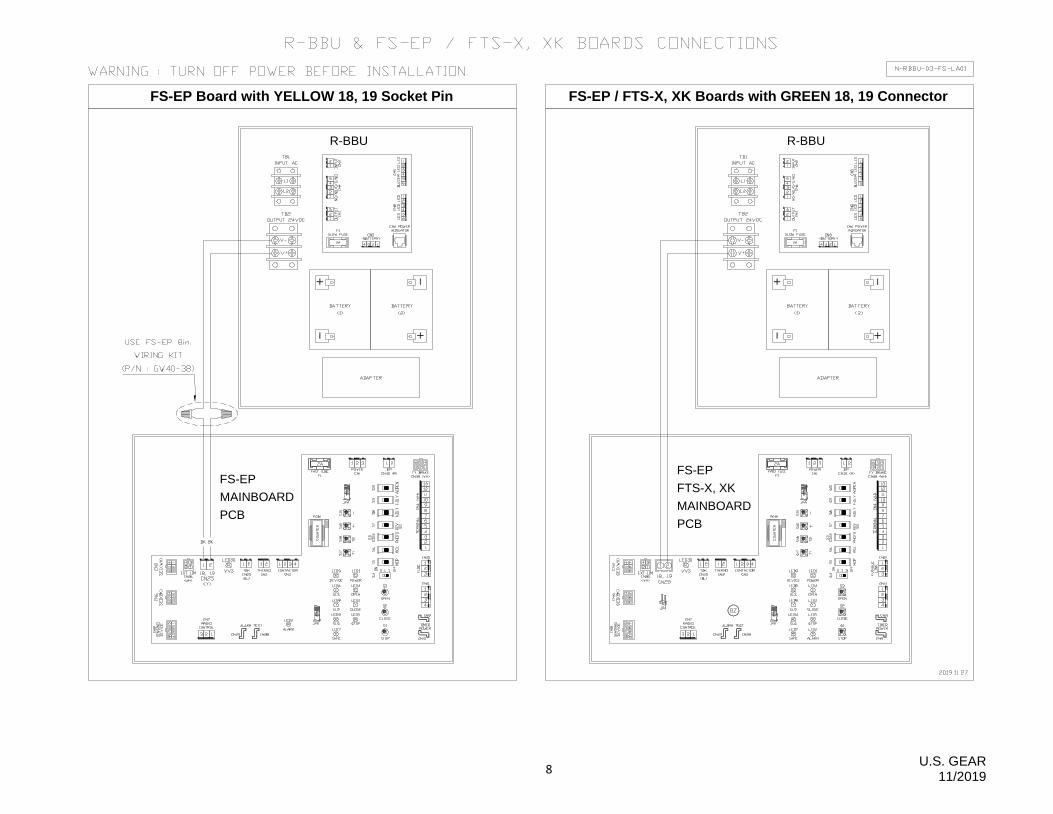
R-BBU
FS-EP
FTS-X, XK
MAINBOARD
PCB
FS-EP / FTS-X, XK Boards with GREEN 18, 19 Connector
R-BBU
FS-EP
MAINBOARD
PCB
FS-EP Board with YELLOW 18, 19 Socket Pin
8

U.S. GEAR 11/2019
R-BBU
FTS-N, M, MK
MAINBOARD PCBS
9

U.S. GEAR 11/2019
R-BBU
AR-D
AR-D2
10