Quasi-Linear Parameter Varying Modeling and Control of an ...
16
Citation: Bécsi, T. Quasi-Linear Parameter Varying Modeling and Control of an Electromechanical Clutch Actuator. Mathematics 2022, 10, 1473. https://doi.org/ 10.3390/math10091473 Academic Editors: Róbert Szabolcsi and Péter Gáspár Received: 30 March 2022 Accepted: 26 April 2022 Published: 27 April 2022 Publisher’s Note: MDPI stays neutral with regard to jurisdictional claims in published maps and institutional affil- iations. Copyright: © 2022 by the authors. Licensee MDPI, Basel, Switzerland. This article is an open access article distributed under the terms and conditions of the Creative Commons Attribution (CC BY) license (https:// creativecommons.org/licenses/by/ 4.0/). mathematics Article Quasi-Linear Parameter Varying Modeling and Control of an Electromechanical Clutch Actuator Tamás Bécsi Department of Control for Transportation and Vehicle Systems, Faculty of Transportation Engineering and Vehicle Engineering, Budapest University of Technology and Economics, M˝ uegyetem rkp. 3., H-1111 Budapest, Hungary; [email protected] Abstract: The paper presents the modeling and control design of an electromechanical heavy-duty clutch actuator using gain-scheduled MPC and grid-based Linear Parameter Varying approaches. First, the nonlinear model of the electromechanical actuator is presented, then a third order quasi- Linear Parameter Varying representation of the system is derived, which takes the nonlinear charac- teristic of the diaphragm spring into account. Using the control-oriented model, a Linear Parameter Varying controller and a gain-scheduled Model Predictive Controller are designed, the latter of which serves as benchmark. The controllers have been implemented and tested in a model in the loop environment, where their performances have been compared concerning their rise-time, steady-state error, over-and undershoots, and robustness to the changes of the touch-point. The validation results show that the difference between the model predictive controllers is negligible in most cases, and they surpass the linear parameter varying controller regarding the rise-time. On the other hand, the linear parameter varying approach has proven to be much more robust to the load force and the touch-point changes while also performing better concerning the under- and overshoots. Therefore, it is more suitable to achieve the position control of the actuator. Keywords: linear parameter varying system; model predictive control; clutch actuators; AMT; heavy-duty vehicles MSC: 37N35; 70Q05; 93B45 1. Introduction In recent years the demand for comfort, performance, and fuel efficiency has been sig- nificantly increased, thus they have been the key driving factors of the automotive industry. Besides the well-known trends, such as autonomous vehicles and electromobility [1,2], Automatic Transmission (AT) technologies have also started to spread, such as continuously variable transmissions (CVT), automated manual transmissions (AMT), and dual-clutch transmissions (DCT). The application of Automated Manual Transmissions became extremely popular in the Heavy-Duty Vehicle market. To fully utilize the advantages of AMT systems, the torque transmitted from the motor to the gearbox must be controlled with high accuracy. The transmitted torque is controlled by the position of the release bearing, which is actuated by the clutch actuator. It is well-known that the diaphragm spring used in clutches has a highly nonlinear characteristic, and it has a significant effect on the system’s response. Hence several researchers have been focusing on its estimation. Its force is often described as a function of the clutch position, such as in [3], where a new approach is presented to model the torque transmissibility of dry clutches. Ref. [4] mentions that the clutch characteristic can be estimated by a third-order polynomial of the clutch position. Due to the significant frictions of the system, the clutch characteristic is subject to hysteresis, hence in [5], it is estimated by Mathematics 2022, 10, 1473. https://doi.org/10.3390/math10091473 https://www.mdpi.com/journal/mathematics
-
Upload
khangminh22 -
Category
Documents
-
view
2 -
download
0
Transcript of Quasi-Linear Parameter Varying Modeling and Control of an ...
�����������������
Citation: Bécsi, T. Quasi-Linear
Parameter Varying Modeling and
Control of an Electromechanical
Clutch Actuator. Mathematics 2022,
10, 1473. https://doi.org/
10.3390/math10091473
Academic Editors: Róbert Szabolcsi
and Péter Gáspár
Received: 30 March 2022
Accepted: 26 April 2022
Published: 27 April 2022
Publisher’s Note: MDPI stays neutral
with regard to jurisdictional claims in
published maps and institutional affil-
iations.
Copyright: © 2022 by the authors.
Licensee MDPI, Basel, Switzerland.
This article is an open access article
distributed under the terms and
conditions of the Creative Commons
Attribution (CC BY) license (https://
creativecommons.org/licenses/by/
4.0/).
mathematics
Article
Quasi-Linear Parameter Varying Modeling and Control of anElectromechanical Clutch ActuatorTamás Bécsi
Department of Control for Transportation and Vehicle Systems, Faculty of Transportation Engineering and VehicleEngineering, Budapest University of Technology and Economics, Muegyetem rkp. 3., H-1111 Budapest, Hungary;[email protected]
Abstract: The paper presents the modeling and control design of an electromechanical heavy-dutyclutch actuator using gain-scheduled MPC and grid-based Linear Parameter Varying approaches.First, the nonlinear model of the electromechanical actuator is presented, then a third order quasi-Linear Parameter Varying representation of the system is derived, which takes the nonlinear charac-teristic of the diaphragm spring into account. Using the control-oriented model, a Linear ParameterVarying controller and a gain-scheduled Model Predictive Controller are designed, the latter of whichserves as benchmark. The controllers have been implemented and tested in a model in the loopenvironment, where their performances have been compared concerning their rise-time, steady-stateerror, over-and undershoots, and robustness to the changes of the touch-point. The validation resultsshow that the difference between the model predictive controllers is negligible in most cases, andthey surpass the linear parameter varying controller regarding the rise-time. On the other hand, thelinear parameter varying approach has proven to be much more robust to the load force and thetouch-point changes while also performing better concerning the under- and overshoots. Therefore,it is more suitable to achieve the position control of the actuator.
Keywords: linear parameter varying system; model predictive control; clutch actuators; AMT;heavy-duty vehicles
MSC: 37N35; 70Q05; 93B45
1. Introduction
In recent years the demand for comfort, performance, and fuel efficiency has been sig-nificantly increased, thus they have been the key driving factors of the automotive industry.Besides the well-known trends, such as autonomous vehicles and electromobility [1,2],Automatic Transmission (AT) technologies have also started to spread, such as continuouslyvariable transmissions (CVT), automated manual transmissions (AMT), and dual-clutchtransmissions (DCT).
The application of Automated Manual Transmissions became extremely popular inthe Heavy-Duty Vehicle market. To fully utilize the advantages of AMT systems, the torquetransmitted from the motor to the gearbox must be controlled with high accuracy. Thetransmitted torque is controlled by the position of the release bearing, which is actuated bythe clutch actuator.
It is well-known that the diaphragm spring used in clutches has a highly nonlinearcharacteristic, and it has a significant effect on the system’s response. Hence severalresearchers have been focusing on its estimation. Its force is often described as a function ofthe clutch position, such as in [3], where a new approach is presented to model the torquetransmissibility of dry clutches. Ref. [4] mentions that the clutch characteristic can beestimated by a third-order polynomial of the clutch position. Due to the significant frictionsof the system, the clutch characteristic is subject to hysteresis, hence in [5], it is estimated by
Mathematics 2022, 10, 1473. https://doi.org/10.3390/math10091473 https://www.mdpi.com/journal/mathematics
Mathematics 2022, 10, 1473 2 of 16
two six-order polynomials, which are then combined into a single function. The functioncan be divided into the medium curve and a switching part, which provides a smoothtransition between the polynomials. The characteristic is also divided into an empiricalcenter line and the hysteresis in [6]. More detailed (e.g., finite element) models are alsofound in the literature. Ref. [7] used the finite element method to analyze the behaviorof the diaphragm spring and to calculate the sensitivity of design parameters, which isthen used to design an optimal shape for the spring. In [8] the temperature dependence ofa diaphragm spring is analyzed using the finite element method. The results show thatbesides decreasing the stiffness of the spring, the touch-point of the clutch has also changeddue to the axial thermal expansion. A finite element analysis is also carried out in [9], inwhich the most influential geometrical parameters of the spring have been identified usingthe Design of Experiments method.
To control the torque transmitted through the clutch, heavy-duty AMT systems typi-cally use electropneumatic actuators, while in the last few years, electromechanical actuatorsare also started to spread. Controlling electropneumatic actuators is challenging due totheir nonlinear behavior and the significant dead times caused by the compressibility of theair. Therefore, it is a widely researched area in the literature. Proposed solutions include ad-vanced Proportional–Integral–Derivative (PID) controllers, such as the simplified advancednonlinear PID (sANPID)-based active model controller presented in [10], where an activeestimation-based control scheme has been proposed for pneumatic artificial muscles (PAM)to improve the performance of the nominal controller designed according to the simplifiedmodel. Based on the experimental results, the tracking error for sinusoidal reference signalshas been reduced to 4%. Ref. [11] proposes a fuzzy linearizing control scheme, whichconsists of a model-based and a servo-based controller. The model-based logic cancels thenonlinear dynamics of the system; therefore, the servo-based portion can be controlled bya simple linear PID algorithm. Post-modern control techniques are also widely applied.Ref. [12] deals with the control of an electropneumatic Clutch By Wire (CBW) system.The presented feedback controller has been combined with a feedforward algorithm tocontrol the on/off valves properly. To decrease the calculation cost, a simplified SMC hasbeen proposed by reducing the original controller. Ref. [13] proposes a multi-parametricNonlinear Programming approach to design an explicit MPC to enable online optimization.The controller’s performance is verified using a fifth-order model of the actuator dynamics.In [5] a nonlinear model-based control design for an electropneumatic clutch for heavytrucks is presented. The proposed feedback control represents an adaptive LQR designusing extended linearization techniques, where the controller gains are adapted by solvingnumerically the corresponding Riccati equation in real-time. Most of these techniquesare combined with Pulse-Width Modulation (PWM) to control the on/off solenoid valves,which limits their expected lifetime. Hence [14] presents a switched backstepping con-troller, which shows better performance compared to PWM-based methods and reduces thenumber of solenoid valve switches. In [15] the motion characteristics of a clutch actuatorfor a heavy-duty AMT gearbox are studied to improve the quality of the control.
In this aspect, electromechanical actuators can be controlled more precisely, resultingin stricter performance requirements. They have several advantages, such as high efficiency,which is presented in [16], where an AMT for agricultural tractors is developed usingelectric actuators. Electromechanical clutch actuators are also used in Hybrid ElectricVehicles (HEV). Ref. [17] deals with the control of the clutch of single-shaft parallel HEVs.Due to the strict requirements, researchers started working on more advanced, high-levelalgorithms to control these actuators. In [18], a parallel Adaptive Feedforward and Bang-Bang controller architecture is presented to handle the time-varying, nonlinear natureof the system. Gao [19] presents a triple-step nonlinear method, which consists of threeparts: a steady-state-like control, a feedforward control based on reference dynamics, andstate-dependent feedback control.
Another approach is to include the clutch force in the algorithm, which can increase thecontrol quality. Several methods are presented in the literature to deal with the nonlinear
Mathematics 2022, 10, 1473 3 of 16
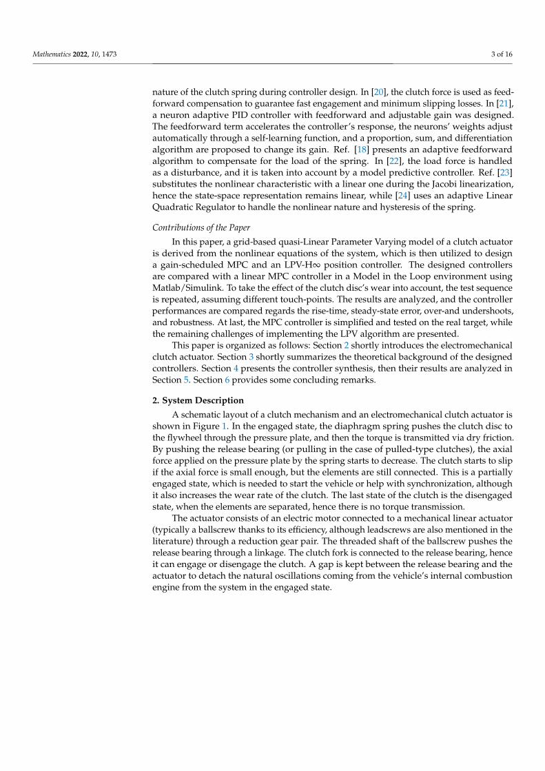
nature of the clutch spring during controller design. In [20], the clutch force is used as feed-forward compensation to guarantee fast engagement and minimum slipping losses. In [21],a neuron adaptive PID controller with feedforward and adjustable gain was designed.The feedforward term accelerates the controller’s response, the neurons’ weights adjustautomatically through a self-learning function, and a proportion, sum, and differentiationalgorithm are proposed to change its gain. Ref. [18] presents an adaptive feedforwardalgorithm to compensate for the load of the spring. In [22], the load force is handledas a disturbance, and it is taken into account by a model predictive controller. Ref. [23]substitutes the nonlinear characteristic with a linear one during the Jacobi linearization,hence the state-space representation remains linear, while [24] uses an adaptive LinearQuadratic Regulator to handle the nonlinear nature and hysteresis of the spring.
Contributions of the Paper
In this paper, a grid-based quasi-Linear Parameter Varying model of a clutch actuatoris derived from the nonlinear equations of the system, which is then utilized to designa gain-scheduled MPC and an LPV-H∞ position controller. The designed controllersare compared with a linear MPC controller in a Model in the Loop environment usingMatlab/Simulink. To take the effect of the clutch disc’s wear into account, the test sequenceis repeated, assuming different touch-points. The results are analyzed, and the controllerperformances are compared regards the rise-time, steady-state error, over-and undershoots,and robustness. At last, the MPC controller is simplified and tested on the real target, whilethe remaining challenges of implementing the LPV algorithm are presented.
This paper is organized as follows: Section 2 shortly introduces the electromechanicalclutch actuator. Section 3 shortly summarizes the theoretical background of the designedcontrollers. Section 4 presents the controller synthesis, then their results are analyzed inSection 5. Section 6 provides some concluding remarks.
2. System Description
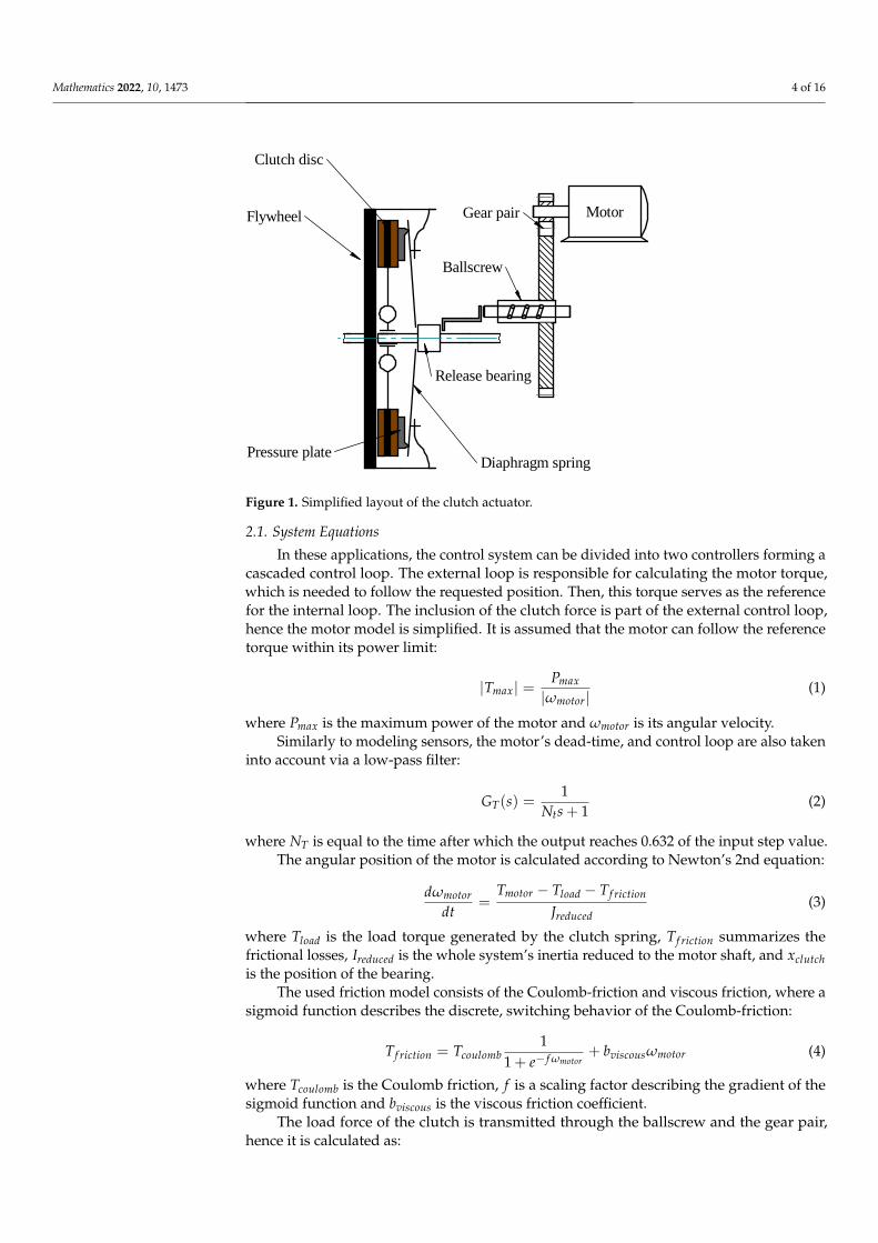
A schematic layout of a clutch mechanism and an electromechanical clutch actuator isshown in Figure 1. In the engaged state, the diaphragm spring pushes the clutch disc tothe flywheel through the pressure plate, and then the torque is transmitted via dry friction.By pushing the release bearing (or pulling in the case of pulled-type clutches), the axialforce applied on the pressure plate by the spring starts to decrease. The clutch starts to slipif the axial force is small enough, but the elements are still connected. This is a partiallyengaged state, which is needed to start the vehicle or help with synchronization, althoughit also increases the wear rate of the clutch. The last state of the clutch is the disengagedstate, when the elements are separated, hence there is no torque transmission.
The actuator consists of an electric motor connected to a mechanical linear actuator(typically a ballscrew thanks to its efficiency, although leadscrews are also mentioned in theliterature) through a reduction gear pair. The threaded shaft of the ballscrew pushes therelease bearing through a linkage. The clutch fork is connected to the release bearing, henceit can engage or disengage the clutch. A gap is kept between the release bearing and theactuator to detach the natural oscillations coming from the vehicle’s internal combustionengine from the system in the engaged state.
Mathematics 2022, 10, 1473 4 of 16
TERVEZ�Ellen�rizveENG APPRMGR APPR
ELTÉR� RENDELKEZÉS HIÁNYÁBANMÉRETEK MILLIMÉTERBEN ÉRTEND�K
SZÖGEK ± X. X °2 PL ± X. XX 3 PL ± X.XXX
NévAdam
Dátum2022/03/29 Solid Edge
Megnezvezés
Lap m.:A2
RAJZSZÁM REV
Fájlnév clutch.dftMéreta: Tömeg: Lapok 1 / 2
Revíziótörténet
REV Leírás Dátum Jóváhagyva
MotorFlywheel
Clutch disc
Ballscrew
Gear pair
Release bearing
Pressure plateDiaphragm spring
Figure 1. Simplified layout of the clutch actuator.
2.1. System Equations
In these applications, the control system can be divided into two controllers forming acascaded control loop. The external loop is responsible for calculating the motor torque,which is needed to follow the requested position. Then, this torque serves as the referencefor the internal loop. The inclusion of the clutch force is part of the external control loop,hence the motor model is simplified. It is assumed that the motor can follow the referencetorque within its power limit:
|Tmax| =Pmax
|ωmotor|(1)
where Pmax is the maximum power of the motor and ωmotor is its angular velocity.Similarly to modeling sensors, the motor’s dead-time, and control loop are also taken
into account via a low-pass filter:
GT(s) =1
Nts + 1(2)
where NT is equal to the time after which the output reaches 0.632 of the input step value.The angular position of the motor is calculated according to Newton’s 2nd equation:
dωmotor
dt=
Tmotor − Tload − Tf riction
Jreduced(3)
where Tload is the load torque generated by the clutch spring, Tf riction summarizes thefrictional losses, Ireduced is the whole system’s inertia reduced to the motor shaft, and xclutchis the position of the bearing.
The used friction model consists of the Coulomb-friction and viscous friction, where asigmoid function describes the discrete, switching behavior of the Coulomb-friction:
Tf riction = Tcoulomb1
1 + e− f ωmotor+ bviscousωmotor (4)
where Tcoulomb is the Coulomb friction, f is a scaling factor describing the gradient of thesigmoid function and bviscous is the viscous friction coefficient.
The load force of the clutch is transmitted through the ballscrew and the gear pair,hence it is calculated as:
Mathematics 2022, 10, 1473 5 of 16
Tload = Fclutchpballscrew
2πηballscrew
1kgear
(5)
where Fclutch is the force of the diaphragm spring, pballscrew is the ballscrew’s lead, ηballscrewis its efficiency and kgear is the torque ratio of the gears.
As the force of the diagram spring depends on the clutch position, the load torque willalso be a function of it:
Tload∼= Fclutch = f (xclutch) (6)
2.2. Clutch Characteristic Estimation
The clutch characteristic consists of a nominal force and a hysteresis generated byfriction. Using only the nominal value of the clutch force simplifies the design procedureat the expense of accuracy. On the other hand, the controllers should be robust enough tocompensate for the hysteresis effect.
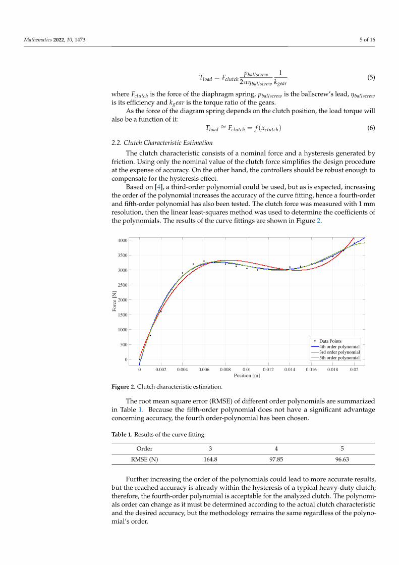
Based on [4], a third-order polynomial could be used, but as is expected, increasingthe order of the polynomial increases the accuracy of the curve fitting, hence a fourth-orderand fifth-order polynomial has also been tested. The clutch force was measured with 1 mmresolution, then the linear least-squares method was used to determine the coefficients ofthe polynomials. The results of the curve fittings are shown in Figure 2.
0 0.002 0.004 0.006 0.008 0.01 0.012 0.014 0.016 0.018 0.02
Position [m]
0
500
1000
1500
2000
2500
3000
3500
4000
Forc
e [N
]
Data Points
4th order polynomial
3rd order polynomial
5th order polynomial
Figure 2. Clutch characteristic estimation.
The root mean square error (RMSE) of different order polynomials are summarizedin Table 1. Because the fifth-order polynomial does not have a significant advantageconcerning accuracy, the fourth order-polynomial has been chosen.
Table 1. Results of the curve fitting.
Order 3 4 5
RMSE (N) 164.8 97.85 96.63
Further increasing the order of the polynomials could lead to more accurate results,but the reached accuracy is already within the hysteresis of a typical heavy-duty clutch;therefore, the fourth-order polynomial is acceptable for the analyzed clutch. The polynomi-als order can change as it must be determined according to the actual clutch characteristicand the desired accuracy, but the methodology remains the same regardless of the polyno-mial’s order.
Mathematics 2022, 10, 1473 6 of 16
Therefore, the clutch force is written as:
Fclutch = p1x4clutch + p2x3
clutch + p3x2clutch + p4xclutch + p5 (7)
where pi are the coefficients of the polynomial.
3. Methodology3.1. Model Predictive Control
The MPC aims to find a future trajectory of the input signal, which optimizes thefuture behavior of the plant. The model used in the design process, in this case, is thediscrete-time state-space representation of the system. To provide zero remaining error,the augmented state-space model is used, in which case the state vector is modified tocontain the state increment and the system’s output, hence the controller can eliminatesteady-state error.
Based on the state-space model, the predicted state variables are calculated sequentiallyusing the set of future control parameters, from which the predicted outputs are calculated.In a compact matrix form, the series of predicted outputs are written as:
Y = Fx(k) + Φ∆U(k) (8)
where x(k) is the state vector, ∆U(k) is the difference of the control variables, F and Φ arematrices describing the prediction.
Therefore ∆U that minimizes the following cost function must be calculated:
J = (Rsr(k)−Y)T(Rsr(k)−Y) + ∆UT R∆U (9)
where Rs is the data vector containing the setpoint information, and r(k) is the reference signal.The necessary condition of the minimum cost is obtained as:
∂J∂∆U
= −2ΦT(Rs − Fx(ki)) + 2(ΦTΦ + R)∆U = 0 (10)
where R is a diagonal matrix containing the tuning parameter of the cost function, F and Φare matrices combining the state and output equations for the whole prediction horizoninto a compact matrix form:
F =
CACA2
CA3
...CANp
(11)
Φ =
CB 0 0 · · · 0
CAB CB 0 · · · 0CA2B CAB CB · · · 0
......
......
...CANp−1B CANp−2B CANp−3B · · · CANp−Nc B
(12)
where A, B, and C are the matrices of the augmented state-space model, Np and Nc are theprediction and control horizons.
From which, the optimal control signal (∆U) is obtained as:
∆U = (ΦTΦ + R)−1ΦT Rs︸ ︷︷ ︸Ky
r(ki)− (ΦTΦ + R)−1ΦT F︸ ︷︷ ︸Kmpc
x(ki) (13)
where Kmpc is the MPC gain and Ky is the system output gain, which is equal to the lastelement of Kmpc.
Mathematics 2022, 10, 1473 7 of 16
Although, this solution still does not include any restrictions regarding the controlvariables, their gradient, or the output of the system. The cost function in the presence ofhard constraints is modified:
J = (Rsr(k)− Fx(ki))T(Rsr(k)Fx(ki))− 2∆UTΦT(Rsr(k)Fx(ki)) + ∆UT(ΦTΦ + R)∆U (14)
subject to the inequality constraints summarized as:
M∆U < γ (15)
where M and γ are a matrix pair describing the inequality constraints.Applying these constraints significantly increases the system’s performance. However,
minimizing the cost function, including the constraints, leads to Hildreth’s Quadratic Pro-gramming algorithm, which is difficult to solve in embedded applications. Consequently,in these applications, the unconstrained cost function is used, in which case the feedbackgain remains constant for Linear Time Invariant (LTI) systems, or it is described by a set ofconstant gains for gain-scheduled MPC algorithms.
3.2. Linear Parameter Varying Control
Linear Parameter-Varying systems are a class of nonlinear systems that are modeledas parametrized linear systems whose parameters change over time or with their states. Inthe literature, LPV systems are mostly described by using Linear Fractional Representation(LFR), polytopic models, and grid-based LPV models. LFR models use Linear FractionalTransformation (LFT) to separate the nonlinearities of the system from the nominal, LTIpart of the system. Such nonlinearities can be time-varying parameters and uncertainties,but they can be used only in the case of rational parameter dependence. Polytopic modelsare often used to describe affine LPV systems, where the vector of parameters evolvesinside a polytope, hence it is written as a convex combination of the polytope’s vertices.Grid-based LPV models divide the parameter domain into a grid of parameter values,then Jacobi linearization is applied to specify the linear dynamics at each grid point.They can handle any parameter representation, as they implicitly capture the system’sparameter dependence.
LPV systems are divided into two types based on the scheduling parameter vector. Ifthe parameters are external (exogenous) variables, then the system is non-stationary, whileif they are functions of the state variables (endogenous variables), then the system hasnonlinear dynamics. LPV systems with endogenous parameters are also called quasi-LPV(qLPV) systems.
This paper chooses the grid-based representation, as it is also needed to calculate thestate-dependent gains for the gain-scheduled MPC algorithm.
The state-space representation of a grid-based LPV model is written as:[x(t)y(t)
]=
[A(ρ(t)) B(ρ(t))C(ρ(t)) D(ρ(t))
][x(t)u(t)
](16)
where x(t) is the state vector, y(t) is the output vector, u(t) is the input vector, ρ(t) is thevector of scheduling parameters, and A, B, C, and D are parameter dependent matrices ofthe state-space representation.
3.3. State-Space Representation
While the nonlinear equations describing the system’s behavior have been reducedto the motor shaft, the state-space model has been written reduced to the release bearing.Under normal circumstances, these equations are proportional and differ only in a constantgain. As the aim is to include the diaphragm spring’s force in the state-space representation,it is more pragmatic to write the equations for linear movement. As the paper focuses onlyon position control, the state-space vector has been chosen as follows:
Mathematics 2022, 10, 1473 8 of 16
x =[xclutch, vclutch, Factual
]T (17)
where Factual is the force generated by the motor at the release bearing.The control signal is the force requested by the controller:
u =[Frequested
](18)
The output of the system is the position of the release bearing:
y =[xclutch
](19)
The general form of the given nonlinear system is formulated as:
x = f (x, d, u) (20)
y = h(x, d, u) (21)
where x is the state vector, y is the output vector, u is the input vector, d is the distur-bance vector.
From the nonlinear equations, the state matrices are obtained via linearization, as follows:
A =∂ f (x, d, r)
∂x
∣∣∣∣∣x=x0u=0
(22)
B =∂ f (x, d, r)
∂u
∣∣∣∣∣x=x0
(23)
C =∂h(x, d, u, r)
∂x
∣∣∣∣∣x=x0u=0
(24)
D =∂h(x, d, u, r)
∂u
∣∣∣∣∣x=x0
(25)
where A is the state matrix, B is the input matrix, C is the output matrix, and D is thefeedthrough matrix.
During Jacobi linearization, x0 is an equilibrium point of the system. Although, fromthe definition of the grid-based LPV model comes to the fact, that the model shouldbe linearized in several states. In this case, an equidistant division of the position hasbeen used.
The state-space representation takes the dead-time of the motor and the torque controlinto account through tdelay. Hence, after simplifying the friction force, the matrices of thestate-space representation are written as follows:
A(xclutch) =
0 1 0−dFclutch(xclutch)
dx−bviscousmreduced
1mreduced
0 0 −1tdelay
(26)
B =[0 0 1
tdelay
]T(27)
C =[1 0 0
](28)
D =[0]
(29)
Mathematics 2022, 10, 1473 9 of 16
As the state matrix is a function of the position, but it does not depend on anyexogenous parameters, the presented representation is a quasi-LPV model, where thescheduling parameter vector has only a single element:
ρ =[xclutch
](30)
4. Controller Synthesis4.1. Model Predictive Controller
Two MPC controllers have been designed to achieve the position control of the system.The first algorithm uses the linear state-space model of the actuator; therefore, the derivativeof the load force has been omitted from the state matrix. The second algorithm uses theqLPV description of the system; therefore, the applied controller gain Kmpc is a function ofthe clutch position:
Kmpc(xclutch) = (ΦT(xclutch)Φ(xclutch) + R)−1Φ(xclutch)T F(xclutch) (31)
While this paper focuses on the LPV representation, given the characteristics of thesystem, using nonlinear MPC (NMPC) could also be a sensible choice. Solving the nonlinearoptimization problem efficiently is a complicated task, although promising results havebeen presented recently. Such as [25], where the L1 norm is used as it gives better controlquality, but it can lead to a non-differentiable cost function. Hence, a neural approximator isused in place of the non-differentiable absolute value function, and an advanced trajectorylinearization is performed online.
First, the standard MPC has been tuned using a step request. The tuning of thecontroller has been completed by changing Rw. A higher weight means more expensivecontrol, thus higher weights cause slower reference tracking. The tuning aims to find atrade-off between the control cost, tracking accuracy and overshoots, which meets the giventime-domain requirements. To provide an accurate comparison, the determined weightshave been fixed and used also in case of the gain-scheduled MPC.
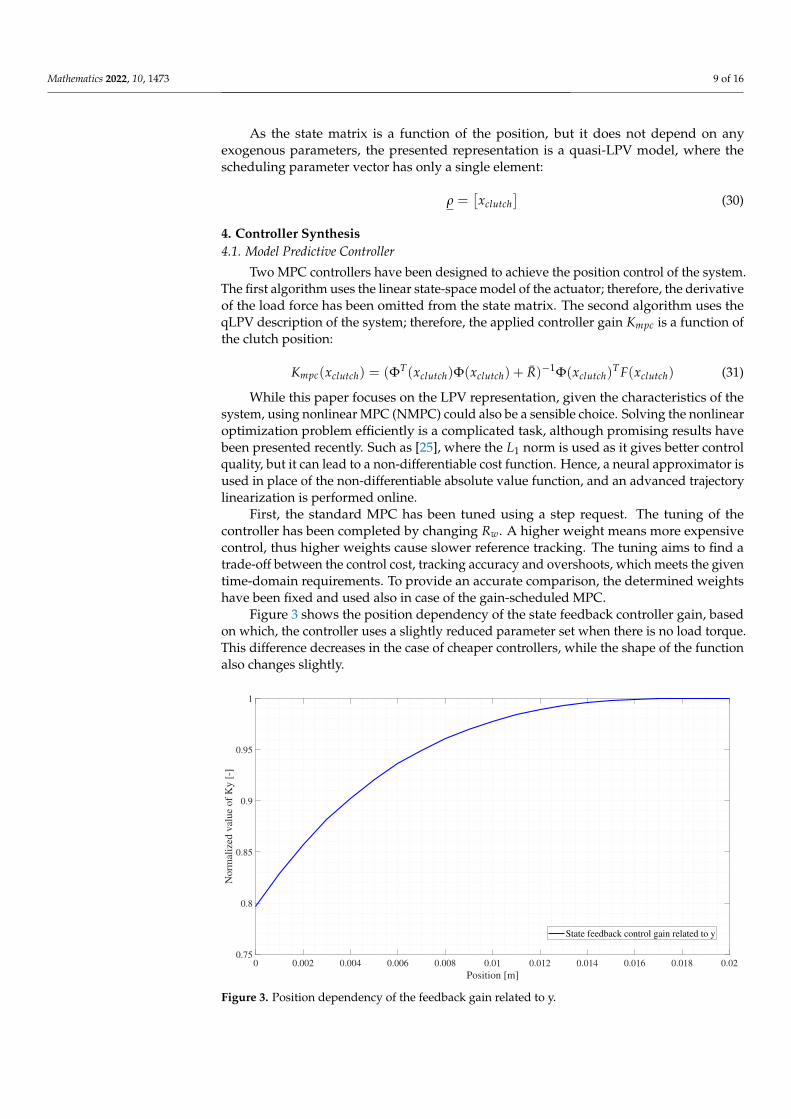
Figure 3 shows the position dependency of the state feedback controller gain, basedon which, the controller uses a slightly reduced parameter set when there is no load torque.This difference decreases in the case of cheaper controllers, while the shape of the functionalso changes slightly.
0 0.002 0.004 0.006 0.008 0.01 0.012 0.014 0.016 0.018 0.02
Position [m]
0.75
0.8
0.85
0.9
0.95
1
Norm
aliz
ed v
alue
of
Ky [
-]
State feedback control gain related to y
Figure 3. Position dependency of the feedback gain related to y.
Mathematics 2022, 10, 1473 10 of 16
Besides comparing the linear MPC and the gain-scheduling MPC with differentweights, these controllers could also be tested without constraints, while applying con-straints on the output, input, and gradient of input significantly increase the performanceand stability of the system, solving the optimization problem is not feasible in embeddedapplications. Hence, the next step of the research could be the analysis of the real-timeapplicability of the algorithms after which the needed limitations could be defined.
4.2. Linear Parameter Varying-H∞ Controller
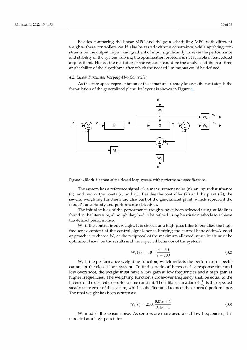
As the state-space representation of the actuator is already known, the next step is theformulation of the generalized plant. Its layout is shown in Figure 4.
GK
Wd
∑
∑
Wn
∑
Wu
We
M
r e+
-
++
+
-
d
n
u y
eu
ey
Figure 4. Block-diagram of the closed-loop system with performance specifications.
The system has a reference signal (r), a measurement noise (n), an input disturbance(d), and two output costs (eu and ey). Besides the controller (K) and the plant (G), theseveral weighting functions are also part of the generalized plant, which represent themodel’s uncertainty and performance objectives.
The initial values of the performance weights have been selected using guidelinesfound in the literature, although they had to be refined using heuristic methods to achievethe desired performance.
Wu is the control input weight. It is chosen as a high-pass filter to penalize the high-frequency content of the control signal, hence limiting the control bandwidth.A goodapproach is to choose Wu as the reciprocal of the maximum allowed input, but it must beoptimized based on the results and the expected behavior of the system.
Wu(s) = 10−5 s + 50s + 500
(32)
We is the performance weighting function, which reflects the performance specifi-cations of the closed-loop system. To find a trade-off between fast response time andlow overshoot, the weight must have a low gain at low frequencies and a high gain athigher frequencies. The weighting function’s cross-over frequency shall be equal to theinverse of the desired closed-loop time constant. The initial estimation of 1
Weis the expected
steady-state error of the system, which is the finetuned to meet the expected performance.The final weight has been written as:
We(s) = 25000.01s + 10.1s + 1
(33)
Wn models the sensor noise. As sensors are more accurate at low frequencies, it ismodeled as a high-pass filter:
Mathematics 2022, 10, 1473 11 of 16
Wn(s) = 10−5 0.01s + 10.0001s + 1
(34)
where the sensor’s accuracy is assumed to be 0.01 mm.Constant 500 N disturbance is assumed to be on the system’s input, hence Wd describ-
ing the input disturbance is written as:
Wd(s) = 500 (35)
Wr is utilized to include the time-domain requirements in the controller design. Tohave the expected disengagement time in case of a step request, the weight is formulated as:
Wr(s) =1
0.0172s2 + 0.017 · 1.7 · 2s + 1(36)
After the generalized plant is formulated, the controller can be developed. To providea robust solution, an LPV/H∞ controller is synthesized using LPVtools [26]. The H∞control design aims to minimize the induced ||L2|| norm of the closed-loop system.
The controller synthesis in LPVtools has five main steps:
1. Defining the scheduling parameters as pgrid objects;2. Defining the state matrices of the grid-based LPV model using the scheduling parame-
ters;3. Combining the state matrices to form the grid-based LPV model in pss data structure;4. Creating the generalized plant by defining the weighting functions and connecting
them using the sysic interconnection structure of Matlab Robust Control toolbox;5. Controller synthesis using LPVsyn function of LPVtools.
While there are general methods, which give a good initial value of the controllerparameters, the tuning of the controllers is an iterative process. The controllers have beentuned using heuristic algorithms on a step request, where the main goal was to find atrade-off between the rise time and overshoot.
5. Results
The applied test sequence consists of several parts: a disengagement of the clutch,holding the clutch in the disengaged position, engaging the clutch until reaching the touch-point, slipping the clutch to control the transmitted torque in partially engaged state, andthen finishing the engagement.
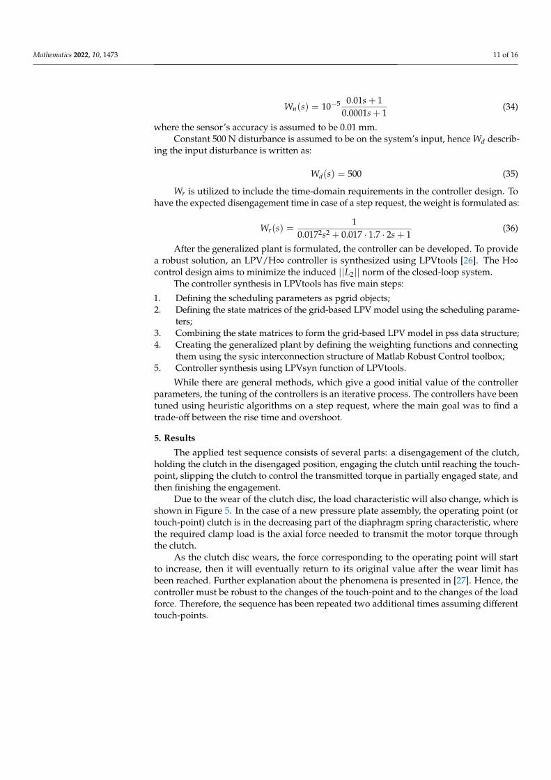
Due to the wear of the clutch disc, the load characteristic will also change, which isshown in Figure 5. In the case of a new pressure plate assembly, the operating point (ortouch-point) clutch is in the decreasing part of the diaphragm spring characteristic, wherethe required clamp load is the axial force needed to transmit the motor torque throughthe clutch.
As the clutch disc wears, the force corresponding to the operating point will startto increase, then it will eventually return to its original value after the wear limit hasbeen reached. Further explanation about the phenomena is presented in [27]. Hence, thecontroller must be robust to the changes of the touch-point and to the changes of the loadforce. Therefore, the sequence has been repeated two additional times assuming differenttouch-points.
Mathematics 2022, 10, 1473 12 of 16
Worn clutch disc New clutch disc
Release bearing travel
Load forc
e
Required clamp load
Wear capacity
Figure 5. Effects of the clutch disk’s wear on the load force.
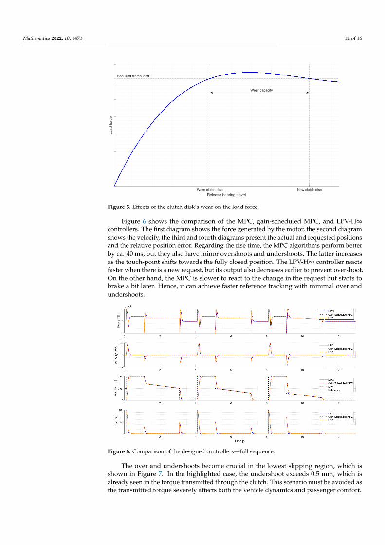
Figure 6 shows the comparison of the MPC, gain-scheduled MPC, and LPV-H∞controllers. The first diagram shows the force generated by the motor, the second diagramshows the velocity, the third and fourth diagrams present the actual and requested positionsand the relative position error. Regarding the rise time, the MPC algorithms perform betterby ca. 40 ms, but they also have minor overshoots and undershoots. The latter increasesas the touch-point shifts towards the fully closed position. The LPV-H∞ controller reactsfaster when there is a new request, but its output also decreases earlier to prevent overshoot.On the other hand, the MPC is slower to react to the change in the request but starts tobrake a bit later. Hence, it can achieve faster reference tracking with minimal over andundershoots.
Figure 6. Comparison of the designed controllers—full sequence.
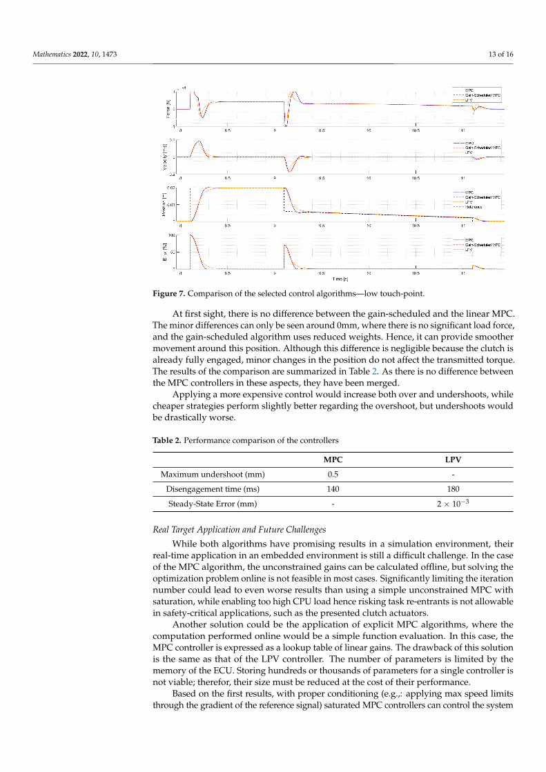
The over and undershoots become crucial in the lowest slipping region, which isshown in Figure 7. In the highlighted case, the undershoot exceeds 0.5 mm, which isalready seen in the torque transmitted through the clutch. This scenario must be avoided asthe transmitted torque severely affects both the vehicle dynamics and passenger comfort.
Mathematics 2022, 10, 1473 13 of 16
Figure 7. Comparison of the selected control algorithms—low touch-point.
At first sight, there is no difference between the gain-scheduled and the linear MPC.The minor differences can only be seen around 0mm, where there is no significant load force,and the gain-scheduled algorithm uses reduced weights. Hence, it can provide smoothermovement around this position. Although this difference is negligible because the clutch isalready fully engaged, minor changes in the position do not affect the transmitted torque.The results of the comparison are summarized in Table 2. As there is no difference betweenthe MPC controllers in these aspects, they have been merged.
Applying a more expensive control would increase both over and undershoots, whilecheaper strategies perform slightly better regarding the overshoot, but undershoots wouldbe drastically worse.
Table 2. Performance comparison of the controllers
MPC LPV
Maximum undershoot (mm) 0.5 -
Disengagement time (ms) 140 180
Steady-State Error (mm) - 2 × 10⁻³
Real Target Application and Future Challenges
While both algorithms have promising results in a simulation environment, theirreal-time application in an embedded environment is still a difficult challenge. In the caseof the MPC algorithm, the unconstrained gains can be calculated offline, but solving theoptimization problem online is not feasible in most cases. Significantly limiting the iterationnumber could lead to even worse results than using a simple unconstrained MPC withsaturation, while enabling too high CPU load hence risking task re-entrants is not allowablein safety-critical applications, such as the presented clutch actuators.
Another solution could be the application of explicit MPC algorithms, where thecomputation performed online would be a simple function evaluation. In this case, theMPC controller is expressed as a lookup table of linear gains. The drawback of this solutionis the same as that of the LPV controller. The number of parameters is limited by thememory of the ECU. Storing hundreds or thousands of parameters for a single controller isnot viable; therefor, their size must be reduced at the cost of their performance.
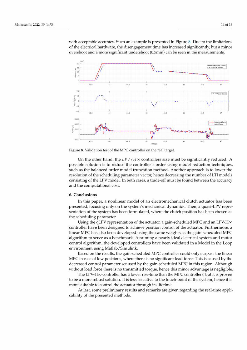
Based on the first results, with proper conditioning (e.g.,: applying max speed limitsthrough the gradient of the reference signal) saturated MPC controllers can control the system
Mathematics 2022, 10, 1473 14 of 16
with acceptable accuracy. Such an example is presented in Figure 8. Due to the limitationsof the electrical hardware, the disengagement time has increased significantly, but a minorovershoot and a more significant undershoot (0.5mm) can be seen in the measurements.
43.5 44 44.5 45 45.5 46 46.5 47
0
5
10
15
20
Positio
n [m
]
10-3
Requested Position
Actual Position
43.5 44 44.5 45 45.5 46 46.5 47-0.2
-0.1
0
0.1
0.2
Velo
city [m
/s]
Actual Speed
43.5 44 44.5 45 45.5 46 46.5 47
Time [s]
-5000
0
5000
10000
15000
Forc
e [N
]
Requested Force
Actual Force
Figure 8. Validation test of the MPC controller on the real target.
On the other hand, the LPV/H∞ controllers size must be significantly reduced. Apossible solution is to reduce the controller’s order using model reduction techniques,such as the balanced order model truncation method. Another approach is to lower theresolution of the scheduling parameter vector, hence decreasing the number of LTI modelsconsisting of the LPV model. In both cases, a trade-off must be found between the accuracyand the computational cost.
6. Conclusions
In this paper, a nonlinear model of an electromechanical clutch actuator has beenpresented, focusing only on the system’s mechanical dynamics. Then, a quasi-LPV repre-sentation of the system has been formulated, where the clutch position has been chosen asthe scheduling parameter.
Using the qLPV representation of the actuator, a gain-scheduled MPC and an LPV-H∞controller have been designed to achieve position control of the actuator. Furthermore, alinear MPC has also been developed using the same weights as the gain-scheduled MPCalgorithm to serve as a benchmark. Assuming a nearly ideal electrical system and motorcontrol algorithm, the developed controllers have been validated in a Model in the Loopenvironment using Matlab/Simulink.
Based on the results, the gain-scheduled MPC controller could only surpass the linearMPC in case of low positions, where there is no significant load force. This is caused by thedecreased control parameter set used by the gain-scheduled MPC in this region. Althoughwithout load force there is no transmitted torque, hence this minor advantage is negligible.
The LPV-H∞ controller has a lower rise-time than the MPC controllers, but it is provento be a more robust solution. It is less sensitive to the touch-point of the system, hence it ismore suitable to control the actuator through its lifetime.
At last, some preliminary results and remarks are given regarding the real-time appli-cability of the presented methods.
Mathematics 2022, 10, 1473 15 of 16
Funding: The research reported in this paper is part of project no. BME-NVA-02, implemented withthe support provided by the Ministry of Innovation and Technology of Hungary from the NationalResearch, Development and Innovation Fund, financed under the TKP2021 funding scheme. Theproject is also supported by the Hungarian Government and co-financed by the European Social Fund,EFOP-3.6.3-VEKOP-16-2017-00001: Talent management in autonomous vehicle control technologies.
Institutional Review Board Statement: Not applicable.
Informed Consent Statement: Not applicable.
Data Availability Statement: Not applicable.
Conflicts of Interest: The author declares no conflict of interest.
AbbreviationsThe following abbreviations are used in this manuscript:
AMT Automated Manual TransmissionCBW Clutch By WireCPU Central Processing UnitECU Electronic Control UnitHEV Hybrid Electric VehicleLFR Linear Fractional RepresentationLPV Linear Parameter VaryingLQR Linear Quadratic RegulatorLTI Linear Time InvariantMBD Model-Based DevelopmentMIL Model In the LoopMPC Model Predictive ControlNMPC Nonlinear Model Predictive ControlPID Proportional–Integral–DerivativePWM Pulse-Width ModulationqLPV quasi Linear Parameter VaryingRMSE Root Mean Square ErrorsANPID Simplified Advanced Nonlinear PIDSISO Single Input Single OutputSMC Sliding Mode Controller
References1. Szántó, A.; Hajdu, S.; Deák, K. Longitudinal Dynamic Modeling and Driving Cycle Tracking Control of an Electric-Driven Vehicle
by Means of MATLAB/Simulink/Simscape. Period. Polytech. Transp. Eng. 2022, 50, 146–152. [CrossRef]2. Rabhi, M.; Zsombók, I. Simulation Based Validation of Range Prediction of Electric Vehicles. Period. Polytech. Transp. Eng. 2022,
50, 136–141. [CrossRef]3. Vasca, F.; Iannelli, L.; Senatore, A.; Reale, G. Torque Transmissibility Assessment for Automotive Dry-Clutch Engagement.
IEEE/ASME Trans. Mechatronics 2011, 16, 564–573. [CrossRef]4. Dolcini, P.J.; Canudas-de Wit, C.; Béchart, H. Dry Clutch Control for Automotive Applications; Springer: Berlin/Heidelberg, Germany,
2010.5. Aschemann, H.; Schindele, D.; Prabel, R. Observer-based control of an electro-pneumatic clutch using extended linearisation
techniques. In Proceedings of the 2012 17th International Conference on Methods Models in Automation Robotics (MMAR),Miedzyzdroje, Poland, 27–30 August 2012; pp. 493–498. [CrossRef]
6. Szimandl, B.; Németh, H. Dynamic hybrid model of an electro-pneumatic clutch system. Mechatronics 2013, 23, 21–36. [CrossRef]7. Nam, W.h.; Lee, C.Y.; Kwon, J.D. Finite Element Analysis and Optimal Design of Automobile Clutch Diaphragm Spring; Technical
Report; SAE Technical Paper; 2000.8. Cappetti, N.; Pisaturo, M.; Senatore, A. Cushion spring sensitivity to the temperature rise in automotive dry clutch and effects on
the frictional torque characteristic. Mech. Test. Diagn. 2012, 2, 28.9. Sfarni, S.; Bellenger, E.; Fortin, J.; Malley, M. Numerical modeling of automotive riveted clutch disc for contact pressure
verification. In Proceedings of the 49th Scandinavian Conference on Simulation and Modeling, Oslo, Norway, 7–8 October 2008.10. Zhang, D.; Zhao, X.; Han, J. Active Model-Based Control for Pneumatic Artificial Muscle. IEEE Trans. Ind. Electron. 2017,
64, 1686–1695. [CrossRef]
Mathematics 2022, 10, 1473 16 of 16
11. Balasubramanian, K.; Rattan, K.S. Fuzzy logic control of a pneumatic muscle system using a linearing control scheme. In Proceed-ings of the 22nd International Conference of the North American Fuzzy Information Processing Society, NAFIPS 2003, Chicago,IL, USA , 24–26 July 2003; pp. 432–436. [CrossRef]
12. Szimandl, B.; Németh, H. Sliding Mode Position Control of an Electro-Pneumatic Clutch System. Ifac Proc. Vol. 2013, 46, 707–712.[CrossRef]
13. Grancharova, A.; Johansen, T.A. Explicit Model Predictive Control of an electropneumatic clutch actuator using on/off valvesand pulse-width modulation. In Proceedings of the 2009 European Control Conference (ECC), Budapest, Hungary, 23–26 August2009; pp. 4278–4283. [CrossRef]
14. Sande, H.; Johansen, T.A.; Kaasa, G.; Snare, S.R.; Bratli, C. Switched backstepping control of an electropneumatic clutch actuatorusing on/off valves. In Proceedings of the 2007 American Control Conference, New York, NY, USA, 9–13 July 2007; pp. 76–81.[CrossRef]
15. Li, Y.; Wang, Z. Motion Characteristics of a Clutch Actuator for Heavy-Duty Vehicles with Automated Mechanical Transmission.Actuators 2021, 10, 179. [CrossRef]
16. Kim, W.S.; Kim, Y.J.; Kim, Y.S.; Baek, S.Y.; Baek, S.M.; Lee, D.H.; Nam, K.C.; Kim, T.B.; Lee, H.J. Development of Control Systemfor Automated Manual Transmission of 45-kW Agricultural Tractor. Appl. Sci. 2020, 10, 2930. [CrossRef]
17. Ding, J.; Jiao, X. A Novel Control Method of Clutch During Mode Transition of Single-Shaft Parallel Hybrid Electric Vehicles.Electronics 2020, 9, 54. [CrossRef]
18. Temporelli, R.; Micheau, P.; Boisvert, M. Control of an electromechanical clutch actuator by a parallel Adaptive Feedforward andBang-Bang controller: Simulation and Experimental results. IFAC-PapersOnLine 2017, 50, 4787–4793. [CrossRef]
19. Gao, B.; Chen, H.; Liu, Q.; Chu, H. Position Control of Electric Clutch Actuator Using a Triple-Step Nonlinear Method. IEEETrans. Ind. Electron. 2014, 61, 6995–7003. [CrossRef]
20. Glielmo, L.; Vasca, F. Optimal Control of Dry Clutch Engagement. In SAE 2000 World Congress; SAE International: Warren, PA,USA, 2000. [CrossRef]
21. Wang, X.; Xie, X.; Wu, X.; Yu, T. Precise position tracking control based on adaptive neuron PID algorithm for automatic clutchdriven by DC motor. In Proceedings of the 2008 IEEE Vehicle Power and Propulsion Conference, Harbin, China, 3–5 September2008; pp. 1–4. [CrossRef]
22. Li, L.; Wang, X.; Qi, X.; Li, X.; Cao, D.; Zhu, Z. Automatic Clutch Control Based on Estimation of Resistance Torque for AMT.IEEE/ASME Trans. Mechatronics 2016, 21, 2682–2693. [CrossRef]
23. Szimandl, B.; Németh, H. Robust servo control design for an electro-pneumatic clutch system using the H-∞ method. In Proceed-ings of the 2014 IEEE/ASME 10th International Conference on Mechatronic and Embedded Systems and Applications (MESA),Senigallia, Italy, 10–12 September 2014; pp. 1–6. [CrossRef]
24. Aschemann, H.; Prabel, R.; Schindele, D. Hysteresis compensation and adaptive LQR design for an electro-pneumatic clutchfor heavy trucks. In Proceedings of the 2013 European Control Conference (ECC), Zurich, Switzerland, 17–19 July 2013; pp.1475–1480. [CrossRef]
25. Ławrynczuk, M.; Nebeluk, R. Computationally Efficient Nonlinear Model Predictive Control Using the L1 Cost-Function. Sensors2021, 21, 5835. [CrossRef] [PubMed]
26. Hjartarson, A.; Seiler, P.; Packard, A. LPVTools: A Toolbox for Modeling, Analysis, and Synthesis of Parameter Varying ControlSystems. IFAC-PapersOnLine 2015, 48, 139–145. [CrossRef]
27. Menday, M.; Rahnejat, H. Friction Lining Characteristics and The Clutch Take-Up Judder Phenomenon with Manual Transmission.Fundam. Appl. Future Trends 2010, 680–702. [CrossRef]