qo73i \J o - EPA WA
321
4Qr(94\) qo73i \J o LINV E:TL I JJT TT 1LTh YAKABINDIE NICKEL PROJECT FEASIBILITY STUDY CONSULTATIVE ENVIRONMENTAL REVIEW VOLUME 2 OF 2 Report prepared for: DOMINION MINING LIMITED 10 RICHARDSON STREET WEST PERTH WA 6005 PROJECT 14ANAGERS: MINPROC JR JOINT VENTURE 22 STIRLING HIGH14AY NEDLANDS WA 6009 Report prepared by: SOIL AND ROCK ENGINEERING PTY LTD CONSULTING GEOTECHNICAL ENGINEERS AND GEOLOGISTS 4TH FLOOR CENTREPOINT TOWER 123 COLIN STREET WEST PERTH WA 6005 Ref: 2488/00/E/CL/st Date: 20th April 1990 Copy: 03 of 30 Soil & Rock Engineering Pty. Ltd
-
Upload
khangminh22 -
Category
Documents
-
view
0 -
download
0
Transcript of qo73i \J o - EPA WA

4Qr(94\)
qo73i
\J o
LINV E:TL
I JJT TT 1LTh
YAKABINDIE NICKEL PROJECT
FEASIBILITY STUDY
CONSULTATIVE ENVIRONMENTAL REVIEW
VOLUME 2 OF 2
Report prepared for:
DOMINION MINING LIMITED
10 RICHARDSON STREET
WEST PERTH WA 6005
PROJECT 14ANAGERS:
MINPROC JR JOINT VENTURE
22 STIRLING HIGH14AY
NEDLANDS WA 6009
Report prepared by:
SOIL AND ROCK ENGINEERING PTY LTD
CONSULTING GEOTECHNICAL ENGINEERS
AND GEOLOGISTS
4TH FLOOR CENTREPOINT TOWER
123 COLIN STREET
WEST PERTH WA 6005
Ref: 2488/00/E/CL/st
Date: 20th April 1990
Copy: 03 of 30
Soil & Rock Engineering Pty. Ltd
TABLE OF CONTENTS
Volume 2
APPENDIX A
Guidelines for the Consultative Environmental Review (CER) on the
Proposal by Dominion Mining Limited for the Yakabindie Nickel Project
Location Plan
PLATE Bi
Location Plan
PLATE B2
Regional Setting Topographic Map
Drawing No. W1292-OO/G-004
Aerial Photographs
APPENDIX C2 - GEOLOGY
Kathleen Valley S.W Scale 1:25,000 3043-111
APPENDIX C3 - HYDROLOGY
Reports by Rockwater
APPENDIX C4 - CLIMATOLOGY
Climatic Data
APPENDIX C5 - FLORA AND FAUNA
Report by Ecologia

TABLE OF CONTENTS (contd)
Vol ume 2
APPENDIX U
APDVWflTY fli
Layout of Project Facilities PLATE Dl
Plant Layout PLATE 02
Creek Diversion Calculation Sheets PLATES 03 to D14
Creek Diversion Drawings -
Jones Creek Drawing No. W1292-OO/C-007
Western Tributary Drawing No. W1292-OO/C-008
Waste Dump Rehabilitation - Typical Section PLATE D15
Chemical Handling and Storage Details Drawing No. 108-1
Drawing No. 108-2
ADPINflTY 117
Tailings Dam
Detailed Design Document
Construction Document
Operations Manual Earthworks Stage I Plan
Earthworks Stages I to VI Sections
Decant Details
Return Water Sump, Ilnderdrainage
and Silt Trap Details
Earthworks Stage VI Plan
Acid Neutralization Performance
APPENDIX D3 - SUPPORT DETAILS
Layout of Village Facilities
Water and Power Supply Routes
APPENDIX 04 - WORKFORCE
Manning Schedule
APPENDIX E
Aboriginal Survey
* * *
Drawing No. W1292-0O/C/002
Drawing No. W1292-OO/C/003A
Drawing No. W1292-0O/C/003B
Drawing No. W1292-OO/C-004 Drawing No. W1292-OO/C-005
Drawing No. W1292-0O/C-006
PLATE 016
PLATES 017 to D21
PLATE 022
PLATES D23 to D24
* *

____________ :41

L. Project M DominIon to Rich WEST
AN ENYIROHMINT WO7H PRbTECtON ATT r
rger
Irng Ltd
()ir Ref: 103/74; 033341
Ison Street
EnquIriBs: Mr R Griffiths RTH WA 6005
lION: MR G BECKER
Dear Sir
YAKABINDIE NICKEL PROJECT
I attach for your Information a copy of the Guidelines for preparation of the Consultative Envlronrriental Review as issued by this Authority,
The Guidelines have been formulated in consultation with the Department of Mines.
Should you require any further information, please contact Mr Robert Griffiths on 222 7135.
Yours faithfully
R A D Sipe DIRECTOR EVALUATION DIVISION
6 March 1990
enc
cc: Mr G Cowe Minproc EnQineers Pty Ltd P0 Box 403 NEDLANDS WA 8009
Mr 1< Llndbeck - Department of Mines
Mr I Kealley - CALM, KaIoorIie
65RG YAK,ABINDIE:ma
r m I fl 4 J P tlun AuthflriI7
I Mjnt $t,,i Puh W,iiprn Al,aIi )(1
oq 222 icco aiim)c 409) 37 4393
-. t7t?zT LEE Ei X"ddHIL4 Tpi:cT E6.8E eN

GUIDELINES FOR THE CONSULTATIVE ENViRONMENTAL REVIEW (CER) ON THE PROPOSAL BY DOMINION MINING LIMITED
FOR THE YAKABINDIE NICKEL PROJECT
SUMMARY
The CER should Contain a brief summary of:
salient features of the proposal;
description of the local environment and analysis of potential Impacts and their significance;
envirnmentai monitoring and management programmes, safeguards and commitments; and
conclusions.
1. introductIon
1.1 ObJectives Bdef summary of the scale, type, and timing of operation planned eg to develop an open-cut nickel mine and associated infrastructure In the area etc.
1.2 Location A description of the location relative to the nearest town, existing or proposed mines and pastoral stations•
A plan to be provided showlg tenements and location of vaous facilities, an aerial photograph with overlay of proposed location of facilities should also be provided.
1.3 Ownership Lessees of all tenements covered by proposed operation, status on any joint ventures and name of managing/Operating company.
1.4 History Extent of previous mining activity in the area, amount of ground disturbance, exploration activities, etc. Outline of how the project has evolved to the point of seeking approval to mine.
1,5 Existing facilities Briei description of existing facilities at operating site, and planned use of any nearby facilities, including the use of public roads and other Infrastructure. The interaction with the Mt Keith Nickel Project should be discussed,
t't'Lt EBE E 30dNILJ 12:E1 06, 8i IJ

2. ExistIng Environment
2.1 Regional Setting General description of geology and geomorphology, including description of land units. A contour map should be included covering a 5 km radius from the centre of the open pit.
2.2 Geology Brlef description of geology specifIc to the area of Interest includIng a basic description of the mineralization and ore reserves.
2.3 Kydrology brief summary of surface and subsurface water flows and quality as they relate to the project and facilities. DetaIls of the project water requirements including the Source, quantities required and quality as well as detaIls of existing water use, water reserves and catchmen are-as must be Included. Any requirement for dewatering, proposed discharge poInt, quantity and quality. The development and extraction of groundwater usually requIres WA Water Authority's approval and licence, as does any dewatering discharge.
2.4 Climatology Regional weather patterns, average rainfall, average evaporation, prevailing winds, etc. Minimum draInage design should be based on the 50 year return rainfall event.
2.5 Flora and Fauna Sef description of flora and fauna in area and reference to any previously published studies. Specific reference should be made to to the proximity of Wanjarri Nature Reserve. A table Indicating rare and / or endangered species and their habitat requirements would be approprhate.
3. Project Description 3.1 MinIng OutlIne of proposed method of operation, pit design, waste dump design and location. Both a long term concept plan as well as detailed plans for the first few years of operation should be provided. Design sheets for for surface water diversions should be supplied.
3.2 Ore Processing A Description of the treatment plant and general arrangement plan should be supplied, Details of dust Control and chemical handling and storage safety measures should be provided. EPA Works Approval and Licence are required for all treatment plants.
3,3 Concentrate Handling Outline method of concentrate storage and transport,
3.4 Tailings Storage A description of the location, dimensions1 constructIon methods, and operation is required for the tailings dam. EPA Works Approval and Licence are required for all tailings clams.
- 588 50 DC'&NILi j:ET 05 88 èL

3.5 Support Facilities Location of on-site offices, workshops, power supply, accommodation policy, etc. This section should outline the potential for sharing 01 facilities with the Mt Keith Nickel Project,
3.8 Workiorce Number and classification of workers. Provisions of the Mines RegulatIon Act and Regulations in relation to certhication and working conditions should be acknowledged.
3.7 TransportatIon Corridors Location of main access1 power and water supply lines. The use, and maintenance of local roads to be agreed with Local Government, Use of highways for ore or concentrates haulage requires specific Main Roads Department approval,
3.8 Resource Requirements Any other details on resources required for the project.
3.9 HousIng and Accommodation
The housing and accommodation arrangements for the work force should be described,
it should be noted that the Government policy on accommodation on mine sites, in order of preference is: 1. Associated permanent accommodation ( not fly in fly out)
accommodation to be provided in the nearest estabilahed township with workers travelling to and from the mine site on a daIly basis;
accommodation to be provided In a new township that will seMce a number of nearby operations.
2. If '1 (a) and (b) are impractical and fly In - fly out operations are to be provided then such operations should be based on regional centres such as Kaigoorlie, and Geralclton, In general, the Government is opposed to fly In fly out operations based on centres outside the state.
4. EnvIronmental Impact and Management The aim of this section is to identify environmental impacts and make firm commitments to minimise disturbance and manage adverse Impacts. This section should reflect the degree of planning that has been directed at the identification and management of environmental impacts.
4.1 Water Water requirements for processing and domestic use, and the sources to be used.
Impact on CaI water resource and other users. Dewateng requirements, drainage control and Impact on regional drainage.
WA Water Authority approvals sought and those already obtained.
Diversion of surface water drainage lines.
4.2 Flora and Fauna Extent of area to be disturbed and whether any restricted, rare or endangered species are present In the area.
L/ 'd '2i E.EE EC 3 X'dHILJ :EI 80 èN'

4.3 Waste products Methods of management of wastes including domestic waste and seworaç;e. Commitment to waste dump and tailings dam management to minimise the environmental Impaci, of these structures during operation.
4.4 Hazardous Substances A brief description should be given of the range of hazardous substances used at the site and management of their transport, storage, use and disposal.
4.5 Dust Dust control methods for all phases of the operation, including rehabilitation. Both occupational health and environmental aspects must be addressed,
4.8 Noise
NoIse control procedures for both blasting and normal operations, Occupational noise levels and anticipated community or environmental levels should be covered.
4.7 Infrastructure The environmental impact of all Infrastructure not directly related to the mining operation such as; power gener&tion and supply, airstrips, and accommodatIon facilities should be outlined and the potential for reducing the Impact by combining some facilities with the Mt Peith operation should be discussed.
4,3 AdJacent Land Uses The Impact of the operation on adjacent land uses should be discussed especially conservation and pastoral aspects.
4.9 Environmental Management and Rehabilitation The management of the environmental Impacts identified earlier In this section should be described with appropriate commitments.
The objectives of the rehabilitation programme should be clearly stated in terms of the final land use for the site.
Methods and approximate timing of rehabilitation for waste dumps, tailings dams, pits, camp sites and all other disturbed areas should be stated, with a commitment to undertake progressive and final rehabilitation and site clean up.
5. Social Impacts 5.1 Aboriginal sites A commitment to abide by the provisIons of the Aboriginal Heritage Act, extent of ethnographic and archaeological surveys carried out (If any), commitment to Inform the WA Museum of any site of Aboriginal Heritage significance discovered in the course of the development.
5.2 Heritage Items of 5uropean heritage value should be defined and a commitment to record, relocate or preserve such Items as appropriate should be given.
CHIi.J :E 60 èL
5.3 Social environment Fositive and negative social lmpaCt8 of the project for the region and State/Local 0oYernment opportunities should be highlighted. A discussion of the potential Impacts on the townsites of Leonora and Leinster should be included In this section.
specific CommItments A summarised list of the proponents specific commitments for the protection of the envirQnment Is to be provided. Commitments should be referenced to a specific timetable and geographical area (where appropriate) defining who is responsible for which environmental Impact, how it will be ameliorated and to whose satisfaction.
Conclusions Outline conclusions Including likely overall environmental acceptability of the project.
APPENDIX 1 Include a copy of these guidelines as an appendix to the document.
0Th FIMISTONGI) ID E:fh
EEE E JC'-JdHILi E:ET 26 E0 èJL
Sod & Rock Engineenng Pty Ltd

P41 4d bupeeuI5u3 400M 9 uos
18 3lVld
V3V I33POid NOlJ.Y301
31VOS 0.1. ION
±oJroeid 31CINIOVAVA
avi O'776'75W'7 - - CÔVW O77b'JS
O'f
SPb'.? /IUPNAf7C
3/7Wc'0976')/
1' 6oleG'1VQ97 Q
/ y,vc'jccjv&'y
g7Ir/.'67s
\
/ 7/Y/ 0 Q7 717A 7 ze
cJb'7.1Y7G'G'H
1 -# dCU" c,v//v/wc e17\
4 77fV&j Y/O'/VfVb'),'b'A ) U,V177//7 QI
I, W
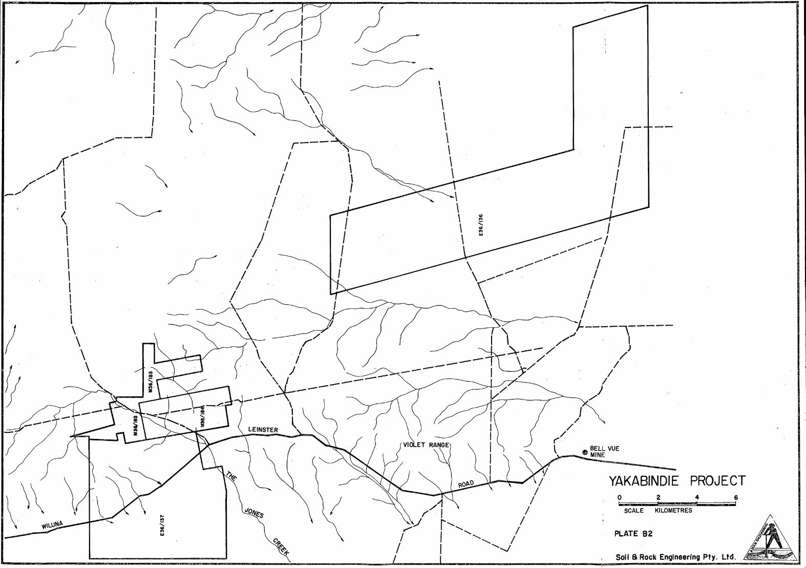
YAKABINDIE PROJECT 0 2 4 6
SCALE KILOMETRES

APPENDIX C
gti,rLO&W Fro Ihi

iJz *s 'i*: III
Soil & Rock Engineering Pty. Ltd.

16 lk
TT
- '; ;r•
:;; t
-
1!-
-, ..
' ,..
t!J
4
r
:-
• Ii. .-
. --
_'. ..-
_
---fr.,.f- 4-
,. 7
• s A
-;
l
2 Ir
Ij
lit
-
'•
?' • 41
ry
'4- -
- •.
JW

'It

§
Cl)
L) a- I
cfl iI (J)J IL
1t'I'idII 1 idi1)Eii .. CD
Ii 0 1 Lg a IC) 9 9 9
9 9 8 9 £
I i i J
1N3DO - AbV1AW31 NY3VHDSY
fil
9
I
U i I f I -°• I H
Cl)
—J —J
z w w -J I
Se
:
1tH LJj )
vc

___ ___ -.

MINIMA
Rockwater PROP I ETARY LIMITED
94 ROKEBY ROAD. SUBIACO, WESTERN AUSTRALIA 6008. P.O. 80X 237, SUBIACO. WESTERN AUSTRALIA 6008.
TELEPHONE; (09) 382 4922 INTERNATIONAL; 619 382 4922
FACSIMILE; (09) 381 3264
SOIL AND ROCK ENGINEERING PTY LTJ)
YAKAI3INDIE NICKEL PROJECT
JONES CREEK FLOODS
HARCH 1990
142.11901 1115 OW

TABLE OF CONTENTS
Page
INTRODUCTION 1
RAINFALL 1
SURFACE DRAINAGE 2
JANUARY 1990 FLOOD EVENT 2
FLOOD FORECASTS 4
COMPARISON OF FORECASTS WITH JANUARY 1990 FLOOD 5
WATER QUALITY 5
CONCLUSIONS 6
REFERENCE 6
1 AVERAGE RAINFALL AT YAKABINDIE 1
2 CHARACTERISTICS OF CATCHMENTS 3
3 FLOW CALCULATIONS (STORM IN JANUARY 1990) 3
4 FLOOD CALCULATIONS 5
FIGURES
1 GEOLOGICAL & LOCALITY MAP
2 DESIGN RAINFALL INTENSITY DIAGRAN
3 PHOTOGRAPH OF JONES CREEK AT SIX MILE PROSPECT, YAKABINDIE, IN FLOOD ON 23 JANUARY 1990
4 JONES CREEK CATCHNENTS & STREANLINES
5 CROSS SECTIONS OF CREEK BEDS

SOIL AND ROCK ENGINEERING PTY LTD
YAKABINDIE NICKEL PROJECT
JONES CREEK FLOODS
MARCH 1990
1. INTRODUCTION
Soil and Rock Engineering Pty Ltd have engaged Rockwater Pty Ltd to estimate
flood flows in Jones Creek which drains the area of Dominion Mining's Yakabindie
nickel project. This information is required for preparation of a document
meeting the requirements of the Environmental Protection Authority's Consultative
Environmental Review.
Yakabindie is located about 100 km south-east of Wiluna and 50 km north of
Leinster, as shown in Figure 1.
RAINFALL
Average rainfall at Yakabindie since 1931 has been 207 mm/yr. Table 1 shows
that, on average, most of the rain is in the first six months of the year.
TABLE 1
AVERAGE RAINFALL AT YAKABINDIE
(mm)
J F M A N J J A S 0 N D YEAR
27 28 29 19 21 21 16 11 6 8 8 13 207
A design rainfall intensity diagram for Yakabindie was prepared by the Bureau of
Meteorology using standard methods which are described in Australian Rainfall and
Runoff (1987). This diagram is presented as Figure 2.
1
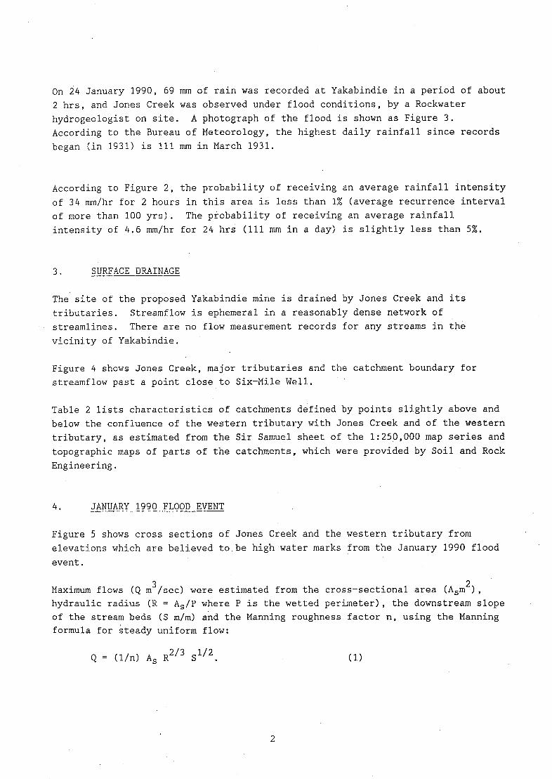
On 24 January 1990, 69 mm of rain was recorded at Yakabindie in a period of about
2 hrs, and Jones Creek was observed under flood conditions, by a Rockwater
hydrogeologist on site. A photograph of the flood is shown as Figure 3.
According to the Bureau of Meteorology, the highest daily rainfall since records
began (in 1931) is 111 mm in March 1931.
According to Figure 2, the probability of receiving an average rainfall intensity
of 34 mm/hr for 2 hours in this area is less than 1% (average recurrence interval
of more than 100 yrs). The probability of receiving an average rainfall
intensity of 4.6 mm/hr for 24 hrs (111 mm in a day) is slightly less than 5%.
SURFACE DRAINAGE
The site of the proposed Yakabindie mine is drained by Jones Creek and its
tributaries. Streamfiow is ephemeral in a reasonably dense network of
streamlines. There are no flow measurement records for any streams in the
vicinity of Yakabindie.
Figure 4 shows Jones Creek, major tributaries and the catchment boundary for
streamflow past a point close to Six-Mile Well.
Table 2 lists characteristics of catchments defined by points slightly above and
below the confluence of the western tributary with Jones Creek and of the western
tributary, as estimated from the Sir Samuel sheet of the 1:250,000 map series and
topographic maps of parts of the catchments, which were provided by Soil and Rock
Engineering.
JANUARY 1990 FLOOD EVENT
Figure 5 shows cross sections of Jones Creek and the western tributary from
elevations which are believed to be high water marks from the January 1990 flood
event.
Maximum flows (Q m3/sec) were estimated from the cross-sectional area (A5m2), hydraulic radius (R = A5/P where P is the wetted perimeter), the downstream slope
of the stream beds (S m/m) and the Manning roughness factor n, using the Manning
formula for steady uniform flow:
Q = (1/n) As R213 1/2
(1)
2

TABLE 2
CHARACTERISTICS OF CATCHMENTS
Catchment Area Ac Stream Length Average Stream
(km2) L (krn) Slope (m/km)
Jones Creek' 31.9 7.5 4.0
Jones Creek2 43 7.8 4.0
Western Tributary 4.8 2.5 12.4
Above confluence with Western Tributary 2
Calculated with Equation 1 and assuming n = 0.045.
The value n = 0.045 was used on advice from the Main Roads Department of W.A.
Table 3 presents the values of other terms used, and the calculated flow rates.
TABLE 3
FLOW CALCULATIONS
(STORM IN JANUARY 1990)
Catchment Cross-Section
A (m2)
1 Jones Creek 144
Western Tributary 64
Wetted Hydraulic Stream Flow
Perimeter Radius Slope Rate2
P (m) R (m) S(m/m) Q (ms/s)
107 1.35 0.0013 140
44 1.45 0.006 140
Above confluence with Western Tributary
2 Calculated with Equation 1 and assuming n = 0.045.
According to Australian Rainfall and Runoff (1987), the value of the Manning
Roughness Factor (n) for these streams should lie in the range of 0.035 to 0.100.
If the lowest value was appropriate, the calculated flow rate in each stream
would be increased by nearly 30%. If the highest value was appropriate, the
calculated flow rates would be reduced by 55%.
3

5. FLOOD FORECASTS
Flood flows in Jones Creek, both above and below 1he confluence with the western
tributary, and in the Western Tributary alone, were estimated using the Rational
Method formula (ARR, 1987):
Qy = 0.278 Cy x Iy x A (2)
where Qy (m 3Is) is the peak flow rate;
Cy (dimensionless) is the runoff coefficient for
an Average Recurrence Interval (ARl) of Y yrs;
Ac(km2) is catchment area; and
It y (mm/hr) is average rainfall intensity for design C
duration of tc hours and ARI of Y years.
Th time of concentration (tc mins) was computed using the Bransby Williams
formula (ARR 1987):
tc = 58LIAc0.1 0.2 x Se (3)
where L (km) is main-stream length to the catchment
divide and;
Se (m/kni) is the equal-area slope of the main-stream projected to
the catchment divide.
For each stream, the average slope was used as an approximation to Se, since
topographic maps of the whole of the catchments were not available.
There are no gauging stations in the vicinity of Yakabindie, and consequently
values of the runoff coefficient Cy for this region have not been determined. On
the basis of data from one catchment in the Eastern Goldfields, ARR (1987)
recommends use of the formula:
C10 = 0.346 x L 042.
For this catchment, with an area of 59 km 2 the frequency factor (ratio of peak
flow rate for an average recurrence interval of 50 years to that for 10 years) is
Q50/Q10 = 1.62. (4)
4

Table 4 presents the results of calculations of the 50-year recurrence interval
flood flows for the three catchments, using Equations (2), (3) and (4),
characteristics of the catchments from Table 2, and the design rainfall intensity
diagram (Figure 2).
TABLE4
FLOOD CALCULATIONS
Catchment t it 10 C10 Q1O Q50
(mm) (mm/hr) (m3/s) (m3/s)
Jones Creek1 233 12 0.15 16 26
Jones Creek2 235 12 0.15 21 34
Western Tributory 75 24 0.24 8 12
1 Above confluence with Western Tributary.
2 Below confluence with Western Tributary.
COMPARISON OF FORECASTS WITH JANUARY 1990 FLOOD
There is a large difference between the calculated 50-year floods and the flows
estimated from observations of the flood in January 1990. Part of the difference
is due to the exceptional intensity of rainfall in January 1990 (average
recurrence interval more than 100 yrs). Other possible factors are the assumed
value of the Manning Roughness Factor, and estimates of the stream slope and
runoff coefficient.
It is considered that the estimated flows in the January 1990 event are
conservative approximations to the 50-year flood events in Jones Creek near Six-
Mile Well, and the western tributary which joins Jones Creek a short distance
further downstream.
WATER QUALITY
There are no known records of streamwater quality at Yakabindie. Streamflow
during the January 1990 flood was described as carrying a moderate suspended
sediment load.
It can be assumed that the water is fresh, as the catchment contains no
recognisable saline ground.
6-1

8. CONCLUSIONS
Average rainfall at Yakabiridie is 207 mm/yr, and streamlines are normally dry.
In January 1990, a total of 69 mm of rain was recorded at Yalcabindie in about 2
hours. On the basis of the design rainfall intensity diagram.for the site, this
event had an average recurrence interval of more than 100 years (probability of
occurrence in any year, less than 1%).
Streamflows in the January 190 flood are estimated to have reached 140 m3/s in
both Jones Creek near Six-Mile Well, and in the western tributary which joins
Jones Creek a short distance further downstream. These flows are much greater
than the 50-year (average recurrence interval) floods estimated by conventional
means.
The January 1990 flood flows are considered to provide a conservative estimate to
the 50-year flood flows in these streams.
There are no records of the quality of water in Jones Creek.
DATED: 19 MARCH 1990
ROCKWATER PTY LTD
1
A. J. PECK
PRINCIPAL HYDROLOGIST
Australian Rainfall and Runoff (1987). A Guide to Flood Estimation, Volume 1.
The Institution of Engineers, Australia, Canberra.

1/- ,7/7 b' // FIGURE 1
JJ1 I ,ja B KatVally'abd) •.I/•f (a/.i
) M U R C Fl 4- /
OMINION
It
aAabi
(1 " MINING \ ,1 \\ - &aW TENEMENTS Ir
YAKABINDIE
' Yiw J~ A ' W L ER/SN DIS1 RICE
. IDONOUGHLDQQuT -,
SirSomueI L-J Qtm
ILI
Oil
L: (
- I a
zXsq
!, \I-' 71fton W\Vr I
'\ 11 •-J \ J it
I I \ inc:rcn q W - ..
iiij °. -wt
rP"A' -
- ,fl6
all
ERTS \A)4 N 0 000 I0000m Qql c
) Qps
L:unstero
Client DOMINION MINING N.L.
GEOLOGICAL & Project YAKABINDIE GROUNDWATER ASSESSMENT
LOCALITY MAP Dot. : March 1990 Org. No. 1421/90/I-I
NVWIIJ PJT LTD

DESIGN RAINIrALL INTEINSITY DhGRAM FIGURE 2
LOCAI1ON 27.125 S 120 575 E NEAR. YAK\IlINUII:
ri 11.1: flu: uun.uu: ,fi:i: in, : 1IIJP
!-M K L'\1A uuu• :;i'.'r ruth .ou,uu'
ISSUED 27TuI1.J,.j111j\11.
1990 REF. -II2i
R1 5II1 16.26. LIS. 0 ..i'J. 6.01, 1 'I. 0.F'0 1I
PREPARED BY -- IIYDROMETEOROLOCICAL ADVISORY SERVICE -- MELBOURNE
(C) COMMON1EALTII OF AUSTRALIA, BURLW OF 1LETEOROLOGY 1987
OW
SW- SW
4W -
3W
200 201
101 ID)
80 - 80
60 BOLl
50
40
30-
0
20 ILI
20
IL
10 - __________ ____________ _____________ _________ _________ ________ Jo
('1 S
hi
- s z
4- 1
3- 3
2
.6
-I __ ____ __ _____ SM 611 1011 2014 308 10 211 311 611 1211 2111 1811 1211
DURATION IN HOURS OR MINUTES
Client : SOIL B ROCK ENGINEERING PTY. LTD.
DESIGN RAINFALL Project : YAKABINDIE ENVIRONMENTAL STUDY INTENSITY DIAGRAM Dote : March 1990 Drg. No.1421/90/I —2
- .
Sy1uboI It II C B E F G
-
. .
-__ __-__---. ____•i
Averoge Recurrence -•--•..----.----.
lntervel (Years): 1 2 5 10 20 50 100
FIGURE 3
.--- -
01, — -%---" I
I .-
PHOTOGRAPH OF JONES CREEK AT SIX MILE PROSPECT, YAKABINDIE, IN FLOOD ON 23 JANUARY 1990
Client: DOMINION MINING Project: YAKABINDIE GROUNDWATER ASSESSMENT
Date: MARCH 1990 Drg. No. 142.1/90113

I /
/ / /
/ I
\
\
/ /
I I (
WES
-CATCHMENT BOUNDARY
EEK
FIGURE 4
0 1 2km
Scale :50000
Client : SOIL & ROCK ENGINEERING PlY. LTD.
JONES CREEK Project : YAKABINDIE ENVIRONMENTAL STUDY
CATCHMENTS 61 STREAMLINES Dote March 1990 Drg. No 1421/90/I-4
ROC'WIP PTI tJO

FIGURE 5
z. w EEY
>—
rt) O)C
I Z • I
Lijo r cCL
0. i
w
Zo U) 0
00 2: 0
cm
\
I
LD
I 0- If
/
(w) U014D3I 3
zw EE Oil-) cbco
O)C) I
0 0 0 0
± (w) UOUDA8I3
Client SOIL & ROCK ENGINEERING PTY. LTD.
CROSS SECTIONS OF Project : YAKABINDIE ENVIRONMENTAL STUDY CREEK BEDS
Lte : March 1990 Drq. No 1421/90/I 5

Rockwater PROPRIETARY LIMITED
94 ROKEBY ROAD, SUBIACO, WESTERN AUSTRALIA 6008. P.O. BOX 237, SUBIACO, WESTERN AUSTRALIA 6008.
TELEPHONE: (09) 382 4922 INTERNATIONAL: 619 382 4922
FACSIMILE: (09) 381 3264
DOMINION MINING NL
SOIL AND ROCK ENGINEERING
GROUNDWATER ENVIRONMENTAL ASSESSMENT
YAKABINDIE PROJECT
MARCH 1990
142.1/90/2 R16 GW

TABLE OF CONTENTS
Page
INTRODUCTION
1
1.1. PROJECT WATER REQUIREMENTS
1
1.1.1 Process Water - Saline
1
1.1.2 Process Water - Fresh
2
1.1.3 Domestic Water - Fresh
2
EXISTING GROUNDWATER CONDITIONS
2
2.1 BASINS
2
2.2 BEDROCK
3
PROPOSED BOREFIELD DEVELOPMENT
3
EFFECTS OF BOREFIELD OPERATION
4
4.1 WATER LEVELS
4
4.2 GROUNDWATER QUALITY
5
4.3 OTHER BOREFIELDS
5
MINE DEWATERING
5
ENVIRONMENTAL MANAGEMENT
6
REFERENCE
6
FIGURES
GEOLOGICAL & LOCALITY MAP
2 TOPOGRAPHIC LOCALITY MAP
3 PRODUCTION BOREFIELD LAYOUT & COMPUTED DRAWDO'ThT

DOMINION MINING NL SOIL AND ROCK ENGINEERING
GROUNDWATER ENVIRONMENTAL ASSESSMENT YAKABINDIE PROJECT
MARCH 1990
1. INTRODUCTION
Process water supplies for the Yakabindie Project are being developed from
groundwater sources in an alluvial basin located 12 to 30 kilometres south-west
of the mine site at Six Mile Well. Fresh water supplies for domestic use and
ore-concentrate washing will be taken from the same basin, or closer sources if
they can be located. The rates of supply required for the several uses are
given in Section 1.1, below.
The evaluation of the groundwater resources is partly complete. Stage I
comprised the drilling of 34 test holes and the construction and test-pumping of
five production bores on groundwater exploration Lease E361136. Further stages
have been recommended, to extend the area and detail of the investigation, and to
test for fresh groundwater.
This Environmental Assessment has the purpose of describing the groundwater
gime, outlining the proposed utilisation scheme, and estimating environmental
effects notably water-level reduction, that are expected to arise from the planned
extraction of groundwater.
A Geological Locality Map is presented as Figure 1, and a Topographic Locality
Plan is presented as Figure 2.
1.1 PROJECT WATER REQUIREMENTS
1.1.1 Process Water - Saline
The requirements for low-quality process water are 10,800 cu m/d (4 x 10 cu m/yr)
to support a projected throughput of 6 x 10⁶ mtpa. Salinities of about 20,000 mg/i
TDS are understood to be suitable. Water of higher salinity will probably be usable,
subject to the results of metallurgical test work.
1

1.1.2 Process Water - Fresh
r final washing of the ore concentrate, a fresh-water supply of 270 cu m/d
(0.1 x 10⁶ cu m/yr) is required. Such water needs to have low chloride content.
1.1.3 Domestic Water - Fresh
To support a camp of 200 - 220 eopie and 15 households, a domestic fresh-water
supply of 130 cu m/d (0.05 x 10 cu m/yr) is required. Such water needs to have
a salinity below 1,000 mg/i TDS, or at worst 1500 mg/l.
2. EXISTING GROUNDWATER CONDITIONS
The region has two types of groundwater domains: bedrock outcrop areas and
alluvial basins. Whereas the mine is located in a belt of mafic/ultramafic
bedrock, the main groundwater exploration area lies in a broad, shallow basin.
is shown in Figure 1.
2.1 BASINS
The basins in the Yakabindie area contain sedimentary deposits - alluvium,
caicrete, and eolian sands - to depths of up to 120 metres, generally overlying
granitic bedrock. Groundwater occurs in sandy alluvium, caicrete, and weathered
granite underlying the sedimentary strata. Aquifer intervals are commonly
separated by clayey alluvium of low permeability.
A programme of exploration drilling and test-pumping has identified two moderately-
productive aquifers on the lease. The major aquifer lies within a palaeochannel of
sand trending south-south-westwards from Dingo Creek to Townsend Well and may extend
to the eastern end of Lake Miranda. A second aquifer of shallow caicrete underlies
the east-west drainage through Townsend Well, Henry Well and Ingardella Bore.
Groundwater salinities range from fresh to saline. Values of salinity from stock
bores/wells and some groundwater exploration bores are shown in Figure 2. It is
seen that salinities are low in the higher parts of the catchments, and high in
the lower parts - reaching hypersaline in the sediments beneath Lake Miranda
(which is ephemeral, saline).
Groundwater is presently used for stock watering. Several bores and wells tap
both the shallow calcrete in the east-west drainage and alluvium/weathered
bedrock elsewhere in the basin. The waters are suitable for stock, ie. less than
about 8,000 mg/i. It is noted that the pastoralist's wells/bores in the east-
west drainage supply stock-quality water because they tap only the top of the
aquifer; there is saltier water at greater depths. Bores drilled in the east-
west drainage as part of the present investigation extended deeper into the
aquifer and yielded higher salinity water than the stock bores.
'iere is one major groundwater supply developed in the vicinity, for the Bellevue
2

Mine. The borefield produces about ?1,000 cu m/d (0.36 x 10⁶ cu m/yr) and is
located in alluvium, seven kilometres west of the western boundary of Lease
6/136.
The borefields for the Mount Keith nickel project are located several tens of
kilometres north of the present test area, from which they are separated by
impermeable bedrock highs. Their locations are shown in Figure 2.
2.2 BEDROCK
Bedrock contains modest supplies of groundwater locally, in fracture zones that
have adequate water storage capacity below the water table.
Mafic bedrock yields groundwater to Six Mile Well and bores/wells near Yakabindie
Homestead. There is known to be a significant quantity of groundwater in
mafic/ultramafic rocks at the Six Mile Prospect orebody, contained in fractured
rock; this source has not yet been evaluated in detail. On the whole, there has
en little development of mafic-bedrock groundwater for stock water supplies.
Granite bedrock such as that occurring east of the Prospect and north of the
groundwater lease apparently yields water to one or two bores. This rock type is
generally low-producing, and has essentially no significance in the present
context. Any permeable weathered granite encountered beneath the alluvial basin
will be evaluated in conjunction with the sedimentary aquifers.
In this area the bedrock groundwater is fresh to slightly saline. The
occurrences of fresh groundwater in bedroc, such as near Yakabindie Homestead,
are attributed to favourable local recharge conditions, elevated position, and
moderately high permeability.
3. PROPOSED BOREFIELD DEVELOPMENT
A borefield to provide the saline process water supply of 10,800 cu m/d (4 x 10
cu m/yr) is proposed to be constructed on Groundwater Exploration Lease E36/136 plus Area 2, which is an extension to the south-west (Fig. 2). A licence is
presently being sought for the additional area.
The preliminary design of the borefield is based on a drilling and test-pumping
programme followed by hydrogeological assessment and mathematical modelling of
the aquifer system. As the investigation programme covered only Area 1, the
treatment of Area 2 has required extrapolation of hydrogeological. information.
Accordingly, the final details of the borefield layout await the results of field
investigations in the extended area.
For planning purposes the borefield is designated to comprise 22 bores producing
at an average of 490 cu m/d. The layout will be approximately as shown in Figure
although the pattern shown is somewhat stylised to conform with the computer
3
model grid. Additional to the salinity process-water borefield, two bores are
nroposed to be drilled for the fresh-water supply. Potential sites, not yet
.?cided, are: (1) along the eastern margin of the greenstone belt south of Six
Mile Well, and (2) along Dingo Creek to the north-east of sites drilled to date.
4. EFFECTS OF BOREFIELD OPERATION
4.1 WATER LEVELS
The water-level drawdown resulting from borefield operation has been modelled,
where possible using aquifer parameters calculated from pumping tests in the
present aquifer system.
Simulation was effected with the program MODFLOW (McDonald and Harbaugh, 1984).
The grid size was 1 km x 1 km and the area covered was 15 km x 18 km.
Twenty two bores in Areas 1 and 2 (Fig. 3) were assigned the average pumping rate
of 490 cu m/d, giving a total production of 10,800 cu m/d. A pumping period of
two years was adopted, to indicate the long-term effects. Beyond that time, the
system is expected to reach more or less steady state, by the adjustment of
recharge and evapotranspiration rates. Annual recharge (to the aquifer system)
was assigned the value 18 mm per year over the borefield area; this is a
reasonably conservative value considering the average annual rainfall of 207 mm
and the fact that much of the area is low-lying and carries ponded surface water
after rainy periods. Significant recharge,was indicated by rises in groundwater
level of about 0.5 m, following heavy rainfall in January - February 1990.
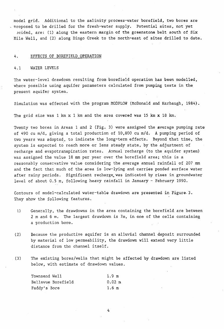
Contours of model-calculated water-table drawdown are presented in Figure. 3.
They show the following features.
1) Generally, the drawdowns in the area containing the borefield are between
2 m and 6 m. The largest drawdown is 7m, in one of the cells containing
a production bore.
Because the productive aquifer is an alluvial channel deposit surrounded
by material of low permeability, the drawdown will extend very little
distance from the channel itself.
The existing bores/wells that might be affected by drawdown are listed
below, with estimate of drawdown values.
Townsend Well 1.9 m
Bellevue Borefield 0.02 m
Paddy's Bore 1.6 m
4

Miranda Well 0.04 m
Henry Well 0
Ingardella Bore 0
The values are approximate, and will be modified by seasonal effects, especially
rainfall. They indicate that only Townsend Well and Paddy's Knob bore are likely
to be affected by significant drawdown. The productivity of these water sources
should be little affected by drawdown of this scale.
4.2 GROUNDWATER QUALITY
As described in Section 2.1, the stock wells in the east-west drainage draw from
a thin layer of brackish groundwater overlying saline groundwater. It is
possible, but not expected, that pumping from the Yakabindie Project Borefield
will cause a depletion of the freshwater at Miranda Paddy's Knob, Townsend, and
Henry wells. These water points will need to be sampled regularly during
operation of the borefield, to check for any such salinity increase.
The water produced from Area 1 of the Yakabindie Project borefield is expected to
have a salinity of about 20,000 mg/i TDS. That from Area 2 will be more saline,
probably in the range 20,000 to 80,000 mg/i. Because water might be drawn from
aquifers beneath Lake Miranda, there is a possibility that salinities may rise in
the long term. Any such effects will need to be monitored.
4.3 OTHER BOREFIELDS
The closest major borefield supplying the .ellevue Mine, is 4 km from the nearest
bore proposed for the Yakabindie Project. It is in a separate alluvial channel
to the latter, although the aquifers are likely to be connected hydraulically.
Simulation has indicated that there will be negligible drawdown interference
(0.02 m) caused by the proposed pumping. This prediction would be firmed-up
after the testing of Area 2, and checked by monitoring during borefield
eration.
The largest user of groundwater in the area is exected to be the Mount Keith
Project, whose demand is said to be up to 17 x 10 cu ni/yr. Three borefields
have been proposed (Fig. 2), the closest two being 12 km to the north and 17 km
to the north-west of the Yakabindie lease area. In addition to lying at large
distances, the Mount Keith borefields are separated from the present borefield by
bedrock ranges and surface-water divides. There is no possibility of drawdown
interference.
5. MINE DEWATERING
The mine at Six Mile Prospect is designed to be open-cut, and extend to 300 m
depth. There is local groundwater contained in fractured mafic and ultramafic
ick, at least in the upper levels to about 80 m depth.
5

Dewatering operations will be needed to control groundwater for mine workability
and pit-wall stability. They will entail either borehole or in-pit pumping (or
oth) depending on the aquifer geometry and the scale of water inflows.
The lowering of water levels at the mine will create a local cone of depression
in water levels in the adjacent bedrock. This is not seen to be a significant
environmental issue because:
local aquifers are relatively small and low-yielding, being restricted
to shear zones within the crystalline bedrock
the bedrock has low bulk permeability, therefore the cone of depression
will be steep-sided and localised. Unless a major permeable shear zone is
discovered in the vicinity of the mine, it is not likely that drawdown
effects would extend beyond one or two kilometres along strike, and to
much smaller distances across strike.
13) the only well that will be affected is Six Mile Well, which is expected to
become redundant because of the mining operations.
6. ENVIRONMENTAL MANAGEMENT
The environmental management procedures recommended herein are designed to:
measure the rates of groundwater extraction
evaluate the extent and depth of drawdowns in and around the borefield
monitor the quality of groundwater produced from the production bores and
stock bores/wells in the vicinity.
These procedures will allow identification of any impact on local water resources
with respect to other users and effects on vegetation. Remedial measures would
be taken to correct any significant adverse effects. These would include the
rovision of alternate water supplies to maintain stock watering points.
DATED: 29 MARCH 1990
ROCKWATER PTY LTD
J. R. PASSMORE
PRINCIPAL HYDROGEOLOGIST
REFERENCE
McDonald M.G. and Harbaugh, A.W., 1984, A modular three-dimensional finite-
difference groundwater flow model. USGS, National Center, Reston,
'ID Virginia.

517 Li1 ': 1. <r
Pa 5 1F,jJh ii I I,'iIk,, -- -. -• - Qf- ---
- A -
M V R C H I 0 N .S
,. KATHLEEN VALLEY V( -•- K:th ti
/
_; (\•-._ ii - - --
Sj .i4iTh-'
YAKA8INDiE-
ib LAWL E RS;
'Tlici S i r SamueI
Qrn, C'r
Bellevue
FIGURE 1 -,
fbA
Dr-
I
- c
Six Mile Well - -
ç li•' --: I - I - -
,J)
DOMINION !Y MINING
l IvLt TENEMENTS ' 1
I \•
- AREA j'
441T Idle II ('iII f ii (al,,)1 .
?X57
QQc I /IeIr
i
- - IN 5000 I0000m, 1
Sca'a 1.250000 - ('or,Ic ri
Client DOMINION MINING N.L.
GEOLOGICAL & Project YAKABINDIE ENVIRONMENTAL STUDY
LOCALITY MAP Date : March 1990 Drg. No. 1421/90/2-I
NULAWAItC PIT LID

FRURE 2:
fr 1' .
I /1 hed Well
I * 5 ONT KEITH 3L__J /8 'Albion Q/dHo lreedVbe// BRE EtO- Downs" r. ,i $ weii BORE FIELD
;,I,T
/ ( ow L MOUNT
II / We, FAtCOj R(P.D.)\\ \ pMcFar/anes Fm
8g,da Bore ' '( n Fife' rower Bore "
H - '"
K Veen \ ooiie.Sok ile Wel / "1.' ç alley"
DeèpBore 1SIX MILE PROSPECT IN iJYAKABINDIE PROJECT]
MOUNT 1
x MOUNT.KEITH PROJECT- Daglish wç
.1 MOUNTMNN( ,7 I' _________
BORE FID _
/
7
)( \ 2050
Well - II We/I \
- L " I 130011 —i;-- — -
- I Mered,t/Well "s's
1 'akab,nda Well 1 \' I,00we..Iar?\Rork I
HARRIS
NestYaWeI LJ L\ UNT OGOI~DE t
.1
A
'Yabindieg" 0
I -
'°°
SIedL opNr PASCO(PDJ—)/ -. AREA1 YAKABINDIE
N BELLEVUE MINE , )II J 7 PROJECT McDONOUGH
BOREFIELD '> 62200 BOREFIELD
000 00
/800
LEGEN K (
, / MJRANDA
2s) •
' / - -- 3'00 Salinity of Water
2b vOO - MO Nt SIR SAMUEL in milligrams per litre
Total Dissolved Solids
Ill ,56
II
510km
Scale
Client : DOMINION MINING N.L.
,Project : YAKABINDIE ENVIRONMENTAL STUDY TOPOGRAPHIC LOCALITY MAP
Date March 1990 Drg. No. 1421/90/2-2
'cOCKWATER PTY LTD /

Dingo Pool
/IJ) 71/17
\ / Dingo Bore
0CKWATER PTY LTD
To W flu no
Mount MarnrA
iv
cc
5'
l Henrysell !ngorde//o Bore
Bellevue Mine Sorefloid
/
I
Mun,a/ H/il
I
6
\j 0
/
\\ MeDonough Lookout 0
J\\ \\
\\
Jm
0 X ThWnO nd We9
AREA2 1
_1 0
- M/rood 0
0
We//
2 -
0/1
Moulif
0"
fr5amue! Bore
iN
LEGEND
0 Production bore
Drawdown of water table after 2177 after 2 years pumping at 10 800 Cu m/d
Margin of main aquifer channel
0 1 2 3 4 5km I II I I I
FIGURE 3
Client : DOMINION MINING N.L.
Project: YAKABINDIE ENVIRONMENTAL STUDY
PRODUCTION BOREFIELD LAYOUT & COMPUTED DRAWDOWN
Date : March 1990 Dwg. No. 142•I/90/2-3
"° Mount Harris
£MOw3l Goode
lr~lndependence 8oe
f
Cloypon We/I

PI2*IiJE.
Soil & Rock Engineering Pty. Ltd

16 120 28
800---- -------- 800
1000- - -- 141
c41Uu808U
DIAGRAM 3.3 WESTERN AUSTRALIA
0 1200---,
MEAN ANNUAL RAINFALL WVIIDRI
KUNUNUAS (llimetres)
600
BROOME
10
PORT 000LAND
300 DAMPIER
ONSLOW 300
CARNAR000 GASCOYNE JUNCTION ,_____20O___._.1R9R RIVERS GLEN
( / •
IIALBARRI
NORTHAMPTON
o
KALGOORLIE-
PERT00 D 50 RornElsTs._ç
N0RS8LAN
CLIMATE AND METEOROLOGY 37
UP
1200 tTTLER
OLE 1200 1 ALS- 000 SCALE
IIILOME806S
IIC 120 124 17R

46
CLIMATE AND METEOROLOGY
II3 II7
I 14* -
DIAGRAM 3.4 WESTERN AUSTRALIA
EVAPORATION ISOPLETH (millimetres)
II I
I I2$ I29
Tro:hn. 14,.
1%001--ee~~
Broome
3200--/
Port Hedland
orth West Cape
22
28
Wittenoom
S
win
I-26 '
• Wiluna
Geraldton
-30' 2o
/6Oo. Perth 1q7
ewagin
.-t6O0 -34' Cape Leeuwin • -1400
1200 Albany
113' 117' 121'
Halls Creek
s/2
26'-
30*
rlie est
/600
SCALE 34' —I
IOOSOO 100 200 300 400
KILOMETRES
123' 129

- 41
LEGEND (0-10) (11-30) (31-50) (51+)
SPEED RANGE (KPH)
PERCENTAGE FREO.UENCY i 19 15%
YAKABINDIE WIND ROSE

I OCCURRED BUT LESS THAN 0.5 PERCENT
PRODUCED BY 11.1.5.5., 29/ J9 • occu:
1 01
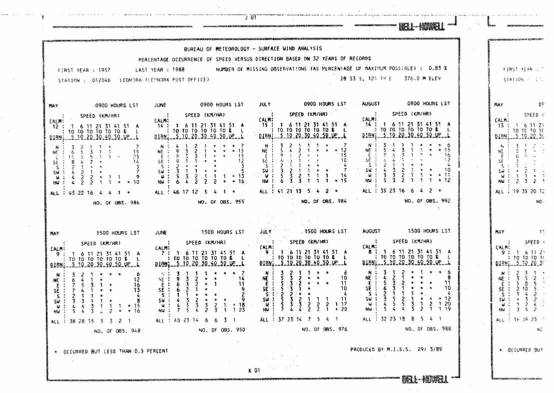
BUREAU OF METEOROLOGY - SURFACE WIPD ANALYSIS
PERCENTAGE OCCURRENCE OF SPFEE VERSUS DIRECTION BA5i 32 S OF RECORDS
FIRST YEAR : 1957 LAST YEAR 1988 NUMBER OF MISSING OBSERVATIONS (AS PERCENTAGE OF MAXIMUM POSSIBLE) : 0.83 %
R51
STATION : 012046 LEONORA (LEONORA POST OFFICE) 28 53 S. 121 19 E 376.0 14 ELEV
STAT 10
JANIJARY 0900 HOURS LST FEBRUARY 0900 HOURS LST MARCH 0900 HOURS LST APRIL 1 0900 HOURS LST I ANUARY
SPEED (KM/HR) CALM: 4 1 6 11 21 31 41 51 A
TO TO TO TO TO 10 & L
w: 1 Ii * * 3 NE 6 5 5 1 1 18
E 9 11 10 3 3 1 37 SE: 78621 * 25 s: 1 11 * * 4
su: 21* 4 * * I t 2
u: 1 1 1 * * 3
ALL 28 30 25 7 5 2
NO. OF 095. 990
JANUARY 1500 HOURS LST
SPEED (KM/HR) CALM:
9 1 6 11 21 31 41 51 A ITOTOTOTOTOTOg L
N: 2 1 1 * * a 4 NE: 631 a 9 E 87711 24
SE 11 7421 25 S 2 2 1 5
su: 31 1 1 * * 7 w: 222 1 1 • 9 u: 3 22 1 * * * 8
ALL: 38 24 19 6 3 1
SPEED (KM/HR) CALM: 5 1 1 6 11 21 31 41 51 A
TOTOT0TOTOTO & L
N: i i 1 * 3 NE : 6 5 4 1 1 17 E : 10 11 12 3 3 1 39
SE 8 8 7 2 1 * 26 s: 11 1 * 3
su: 11 * * 2 W 1 1 * 2 iu: 1 1 * a * *
ALL : 29 28 26 7 5 1
NO. OF (lBS. 902
FEBRUARY 1500 HOURS LST
SPEED (VJ4/HR), CALM: 7 : 1 6 11 21 31 41 51 A
TOTOTOTOTOTO& L
N 21 * * * * 4 NE 422* * 9 E 11 8 5 2 1 * 26
SE 12 10 4 1 1 • 29 5: 21 1 * 4
su: 321 * 1 7 WI 21 2 1 1 * * 7
NW 2 ? 2 * * 1 7
ALL : 38 27 18 5 4 1 *
SPEED (KM/HR) CALM: 4 : 1 6 11 21 31 41 51 A :TOTOTCTOTOTO& L
N: 21 1 * * 4 NE 7 6 4 1 1 * 18 E 10 11 9 4 4 1 38
SE 8 8 4 21 * •23 s: 1 1 1 a 3
SW : 1 1 1 • * 3 a 1 1 a 2
NW 2 1 1* * 4
ALL :312922 7 6 1 a
NO. OF OBS. 985
MARCH 1500 HOURS LST
SPEED (KM/HR) CALM: 7 : 1 6 11 21 31 41 51 A
TOTOTOTOTOTOI L
14 1 1 1 * * * 3 NE : S 3 1 * * * 10 E 9 8 6 2 1 * 25 SE : 10 8 4 1 1 24 s: 321 6
SW : 4 1 6 w 3221 1 9
NW t 4 3 1 1 1 a a 10
ALL :382916 6 3 1 *
SPEED (KM/HR) CALM:
6 1 1 6 11 21 31 41 51 A
TO TO TO TO TO TO 9 L
N 222 a a 6
NE 9731 * 20
E10 87 32 30
SE.: 7 6 4 1 * 19 s: 221 4 sw: 421 * 7
w: 1 1 1 * a a 4 wu: 22 1 * 6
ALL : 36 29 20 5 3 a a
NO. OF (lBS. 957
APRIL 1500 HOURS LST
SPEED (KM/HR) CALM:
6 : 1 6 11 21 31 41 51 A TO TOTOTOTOTO L
N 31 a a a 5
NE 8 4 1 a a 14 E 9641* 21
SE t 8 5 2 a a 16
s: 211 * a 5 sw: 4 1 21 a w : 3 3 3 1 12 NW : 4 3 3 1 1 a a 13
ALL 41 25 17 5 4 1 a
CAL 4 ,
N . I NE 1
2 SE 2 s; 1
SW : w
NW *
ALL 7
JANUARY
CALM: 5 1
TO
NI 2 NE 3 C: 3
SE : 3
s: 1 s : 1 w: 1
Nw 2
ALL 16
NO. OF (lBS. 988
NO. OF (lBS. 896
NO. OF 085. 984
NO. OF (lBS. 942
* OCCURRED BUT LESS THAN 0.5 PERCENT . PRODUCED BY M.1.S.S. 29/ 3/89 1 1 • 0CCU
MAY 1500 HOURS LST JUNE 1500 HOURS LST JULY 1500 HOURS LST AUGUST 1 1500 HOURS LST
SPEED KM/HR : SPEED (KM/AR) : - SPEED (kM/AR) SPEED (KM/AR)
CALM: 9 : 1 6 11 21 31 41 51 A
CALM: 7 : 1 6 11 21 31 41 51 A
CALM 9 : 1
. 6 11 -21 31 41 51 A
CALM 8 : 1 6 11 21 31 41 51 A
TDTOTOT0TOTO L :roloToyololog 1 TOTOTOTOIOTO& L :ToToToToToTo I
N: 321 **t 6 3111 **a7 N 3211*t 8 N312e1 a*6
NE : 6 4 1 a 12 '4E : 9 3 2 * a 14 NE 5 3 2 * * 10 NE 4 2 1 a * B
E 7531 * 16 E 632 * 1 11 E.5-3-2 * * * 11 E: 532 * a a 11 SE : 7 4 1 a * 13 SE 6 2 1 * 9 SE 5 3 1. * 10 SE 6 3 1 a - a a 10 5:211* 4 s:ii ea 2 S -22ea 4 s:2111a. A
Sw : 3 3 1 1 8 Sw : 4 3 2 * a * 9 SW 1 5 3 2 1 1 1 11 SW 3 5 2 1 a a 12
w : 4 4 3 1 1 1 • 15 w : 4 5 3 3 2 1 18 U 1 5 3 3 2 2 2 1 17 U : 4 5 5 3 1 2 1 20
NW 5 4 3 2 • *16 NW 7 5 4 2 3.1 123. NW 7 4 42 2 1 *20 NW: 5 4 4 3 2 1 119
ALL : 38 28 15 5 3 2 1
NO. OF 085. 948
ALL : 40 23 14 6 6 3 1
NO. OF 08S. 950
ALL : 37 23 14 7 5 4 1
NO. OF 085. 976
ALL : 32 23 18 8 5 4 1
NO. OF OBS. 968
BUREAU OF METEOROLOGY - SURFACE WIND ANALYSIS
PERCENTAGE OCCURRENCE OF SPEED VERSUS DIRECTION BASED ON 32 YEARS OF RECORDS
FIRST YEAR : 1957 LAST YEAR 1988 NUMBER OF MISSING OBSERVATIONS (AS PERCENIAGE OF IAXICJM POSI9LE) 0.83 -X
FIRST 1TR
STATION 012066 LEONTIPA 0. CONORA POST OFFICE) 28 53 S. 121 1 F 376.0 M ELEV STATiON
MAY 0900 HOURS LST
SPEED (KM/HR) CALM
12 1 6 11 21 31 41 51 A TOTOTOTOTOTO L
N: 321 1 * 7
NF 65311 15 11 5 5 1 1 23
SE 8 4 2 * 14 s: 21 • 3
SWI 421 * 7 w; 422 1 1 9
pw : 4 2 2 1 1 * * 10
ALL 43 22 16 4 4 1 *
NO. OF OBS. 986
JUNE 0900 HOURS LST
SPEED (KM/AR) CALM: 14 : 1 6 11 21 31 41 51 A
TOTOTOTOTOTOg 1
N: 4 1 2 1 * * 7 NE 9 3 2 1 * * 15 F 8 3 3 1 * 15 SE: 911 * 12 s: 2 * • 3
Sw : .3 1 1 * * 5 w : 5 3 2 1 1 1 * 13
NW : 6 4 2 2 2 * * 16
ALL 46 17 12 5 4 1
NO. OF 085. 955
JULY 0900 HOURS LST
SPEED (KM/AR) CALM! 15 : 1 6 11 21 31 41 51 A
TOTOTOTOTOTOt L
N: 3211 1 7 NE : s 4 2 1 * * 12
2 15 SE e, 1 - 10 s: 211 • 4 Sw: 321 1 a 7
- w: 5 32 1 1 1 14 NW 6 - 3 3 1 1 1 * 15
ALL: 41 21 13 5 4 2
NO. OF (185. 984
AUGUST 0900 HOURS LST
SPEED (KP4/HR) CALM: 14 : 1 6 11 21 31 41 51 A
TOTOTOTOTOTOI 1
N: 3 1 1 1 * 6 NE : 5 4 3 1 1 * 15
7 4 3 1 1 * 16 se: 41 -'2 -s: 21 1 * * 4 SW : 4 3 2 1 * * 10 U 3 3 2 1 1 a *11. NW 5 3 2 11 1 *12
ALL 35 23 16 6 4 2 *
NO. OF 095. 992
PRODUCED BY M.I.S.S. 29/ 3/89
MAY
SPEED CALM: 13 : 1 6 11 ?
TO 10 10 it
p.: 3 NE 3 E
E 6'.. st 3
S 1 Sw w: 1 1 •
NUI 232
ALL 19 35 20 12
MO,
MAY
SPEED CALM: 9 : 1 6 11 2
TO TO TO Ti
u: 231 NE : 3 5 2 t: 505
SE : 2 10 5 s : 1 4 2
su : * 3 2 WI 1 24
Nw 352
ALL 16 3 23
N:.
OCCURRED BUT OCCURRED BUT LESS THAN 0.5 PERCENT
KOl -

BUREAU OF METEOROLOGY - SURFACE WIND ANALYSIS
PERCENTAGE OCCURRENCE OF ::D VERSUS DIRECTION BASED ON 32 YEARS OF RECORDS
FIRST YEAR : 1957 LAST YEAR : 1988 NL-ER OF MISSING O8SERVATIONS (AS PERCENTAGE OF NAXI.1 POSSIBLE) 0.83 Z
FIRSI YEAR 1
STATION 012046 LEONORA (LEONORA POST OFFICE) 28 53 S. 121 19 E 376.0 i ELEV
ST#.T1OP
SEPTEER 0900 HOURS LST OCTOBER 0900 HOURS LST NOVEPER 0900 HOURS LST DECEFER 0900 HOURS LST SEPTEMBER
SPEED (KM/HR) CALM
9: 1 6 11 21 31 41 51 A TOTOTOTOIOTOI L
N 2121* 6 NE 4 6 3 1 15 [ 6 5 5 2 1 1 20
SE 7 4 3 1 * * 16 S 221 * 1 6
3321 • 9 2 2 2 2 1 1 • 10
NW 3 2 2 1 * * * 9
ALL 29 25 20 9 4 2 1
NO. OF 085. 959
SPEFD (KM/HR) CALM:
s: 1 61' 21 3141 51 A TOTO TOTOTOV. L
N 112* * 4 NE 4 7 4 1 1 * is
E 5 5 7 2 1 1 21 SE 6 6 6 2 * * 20
S 222 ..a 6 SW. 3231 1 • ii w: 2 1 3 1 i * *
NW : 1 2 1 1 1 * * 6
ALL : 25 27 27 9 5 2 1
NO. OF 085. 990
SPEED (KM/HR) CALM:
4 : 1 6 ' 21 31 41 51 A TOTO .. TOTOTOI I
.._1Q9__9i2_ --- L N 21111 6
NE 5 4 6 1 1 a 17 E 5 7 9 2 3 1 *27
SE 6 7 5.2 1 22 S 2.1 1 • a :
SW 3 3 2 1* 9 U 321 * 1 * 7
NW 1 1 1 1 * * 5
ALL 27 25 28 8 6 2 *
NO. OF 085. 958
SPEED (KJ4.IHR) CALM:
4 : 1 6 11 21 31 41 51 A TOTO ToToToTor I
w: 21 1 * * 4 NE : 5 7 6 1 1 * 20
E : 8 7 10 3 3 * 31 SE .: 7 8 6 1 * 22 s: 221* * 5 s': 31 1 1 6 w: 1 1 * • ,. 3
Nw: 21 2 * * 5
ALL : 30 28 27 6 5 1
NO. OF 085. 98
SPEED CALM
5 1 6 11 ?' 10 10 TO T(
N 1 4 2 1
NE 1 6 5
E 16 E
SE '. 5
F . 4..
U: . NW 1 3 1
ALL 830282(
NO
SEPTE?jBER 1500 HOURS LST OCTOBER 1500 HOURS LST NOVEPBER 1500 HOURS LST DECEPBER 1500 HOURS LST SEPTEMBER
SPEED (KM/HR) CALM
9 : 1 6 11 21 31 41 51 A TOTO TOTOTOTO& L
N 211 * 4 NE 422** 9
E 5 4 2 * * • 12 SE 5 4 2 * * 12
S 211 ' 4 SW 5 4 ' 1 1 1 13
W 4 3 5 3 2 1 1 19 rw 5 5 4 3 1 1 19
ALL .31 24 18 8 6 3 1
NO.. OF 085. 952
SPEED (KM/HR) CALM
6 1 6 11 21 31 41 51 A TO TO TO TO TO TO & I
N: 2 1 1 * * 4 NE: 332 * * 9
: 442 * 1 12 SE: 6521 * 15 s: 221 1 * 6
Sw 4 3 4 2 1 * 15 w : 3 3 4 2 2 1 1 15
NW : 3 5 5 3 2 1 1 19
ALL 28 25 21 9 6 3 2
NO. OF 085. 980
SPEED (KJ/HR) CALM:
7 1 6 11 21 31 41 51 A TDTOTOTOTOTO& I
QLf_i_19_9i9_2i2_Qe__L N: 1 1 1 a 3
NE: 4211* 8 E : 4 4 4 1. 1 a 14
SE: 76411 18 s: 221 *
SW 5 3 2 1 1 a *12 U 3 4 4.3 2 1 *16
NW t 4 5 3 2 1 a 16
ALL : 29 27 20 9 6 2
NO. OF OBS. 953
SPEED (VJVHR) CALM:
6 1 6 11 21 31 41 51 A TOTOTOTOTOTO& L
iB__12QQQQJ2C_...L N 1 1 1 * * 3 NE 442 * 10 (66611 19
SE 10 63 * 20 s: 31 1 * * 6
Sw : 5 2 3 * * * * 10 3 4 3 2 1 1 14
MW 3 4 2 1 1 * * 11
ALL : 35 29 20 6 3 1 a
NO. OF CBS. 980
PRODUCED BY M.I.S.S. 29/ 3/89
SPEED CALM:
5 : 1 6 11 2 10 10 10 1:
N: 1 22 NE : 2 4 2
i 74. SE 1 5 3 s: 232
SW : 1 2 2 w: 235
NW : 1 4 4
ALL 9 25 25 2i
NC
OCCURRED Bv1 a OCCURRED BUT LESS THAN 0.5 PERCENT
1 01
5J]

F 04
- H1
BUREAU OF METEOROLOGY - SURFACE WIPD ANALYSIS
PERCENTAGE OCCURRENCE OF SPEED VERSUS DIRECTION BASED ON 32 YEARS OF RECORDS ,l Z FiRS' YEAR : 1957 LAST YEAR 1988 NUrSER OF MISSING OBSERVATIONS (AS PERCENTAGE OF MAXIMUM POSSIBLE) 9.96 X
STLTION : 013012 WILUNA (.JLiNk 051 orr ICE) 26 35 5, 100 13 F 521.0 ft EL[V
JAJARY 0900 HOURS LST
SPEED (K.N/HR) CALR
1 6 11 21 31 41 51 A TOTOTOTOTOTOC I
N: 5 3 3 1 * •* 12 N5 699731 35
C 2 6 5 4 0 1 20 SE 3 5 3 4 2 1 18
22 * . 6 Sw: 2 1 1 * 4 MI 1 1 • 2 w: 1 1 1 a * 3
ALL 24 27 23 16 7 2 *
NO. OF 085. 851
FEBRUARY 0900 HOURS LST
SPEED (K4/NR) CALM:
1 1 6 11 21 31 41 51 A T0TOTOTOTOTO 9 I.
N 5 3 1 1 • 10 NE 8 9 11 5 1 • 33
C e, 6 10 5 1 1 a 26 SE 3 4 6 3 2 • 18 s: 21 1 1
SWI 1 • 2 w: 1 1
NM 2 1 1 a * a 4
ALL :26233014 4 1 •
NO. OF 085. 835
MARCH 0900 HOURS LST
SPEED (K.)R/HR) CALM:
1 : 1 6 11 21 31 41 51 A ITOTOTOTOTOT0I I
N 7 3 2 1 * * 14 8 11 51 33
E : 0 7 6 3 1 * 23 SE : 4 4 5 2 1 * 17 s: 311 1 a 5
su: 21 a * 2 W 1 a 1
NW 211a a 4
ALL 32252512 4 1 a
NO. OF O8S. 879
APRIL 0900 HOURS LST
1 SPEED (Ku/HR)
2 1 6 11 21 31 41 51 A TO TO TO TO TO TO & I
NIlO 341 * 18 NE 11 6 8 5 1. • 31 E 5 4 3 1 16
SE : 4 3 4 2 1 15 5: 41 a * * 5
SW. 1 1 1 1 * * a 4 Ml 1 a a a 2 MW 4 2 1 1 7
ALL 1 40 21 22 12 3 1
NO. OF 085. 825
LST
1 A 1
9 36 13 21 5
6
208
LST JkN'J.&RY 1500 HOURS LST
SPEED (YJI/HR) CALM:
a 1 6 11 21 31 41 51 A T0T0T0T0T0T0 9 I
NI 4 3 1 1 a 9 1 5 5 2 2 1 • 15
f 45332 17 SE 4 7 5 5 1 23
4 4 2 i * • 11 SU 4 32 1 a 10 WI 1 1 1 • 4
NW 4 3 2 1 1 11
ALL 30 31 18 14 6 1
NO. OF 085. 833
FE8RUARY 1500 HOURS LST
SPEED (KM/HR) CALM:
1 1 6 11 21 31 41 51 A :ToToTororoToL 1
_1Q.2Q.JQ.h9iQ_e__L
N: 5 2 1 * a t a 9 NE 1 6 6 3 1 a a 17
E 5 6 5 3 1 * a 20 SE 1 6 8 8 3 2 * a 27 5:521 a. 9
sw: 2 2 1 a a 6 WI 21 1 1
NW 4 22 a 8
ALL : 34 28 22 9 3 1
NO. OF 085. 827
MARCH 1500 HOURS LST
SPEED (Kfl/HR) CALM
3 1 1 6 11 21 31 41 51 A TOT0TOT0TOTO 9 I
QL..i.. 1Q__Q..2i2_ve_L NI 6 3 1 1 10
MEl 6441 15 E I 7 5 .5 2 1 a 20
SE : 6 7 6 2 1 a 22 SI 4221 a 9
SWI 321 1 7 WI 121 a a 4
NWI 5321 a 10
ALL 38 27 22 8 2 a
NO. OF 085. 864
APRIL 1500 HOURS 151
SPEED (K14./HR) CALM:
1 1 1 6 11 21 31 41 51 A I TO TOTOTOTOTD & I
8 3 1 1 a a 13 NE 8341 * 16 €: 63421 16
SE 54511. 16 SI 521 a a a 8
Sw 1 4 3 2 1 a 10 WI 1 21 1 a a 5
NW 6 3 4 1 a • is ALL 42 24 22 7 2 1
NO. OF OBS. 816
1 A I
5 23 11 26
5
c 10
190
OCCURRED OUT LESS THAN 0.5 PERCENT
PRODUCED BY M.I.S.S. 29/ 3/69
6 04

LST
238
uJ
6 04
BUREAU OF METEOROLOGY - SURFACE WIND AMALYSIS
PERCEtTAGE OCCUP.REHCE OF SPEED VEBSIJS DIRECTION BASED N 32 VEfr.RS OF RECORDS
FIRST Et'P 1957 LAST YEAR : 1988 NLJER OF MISSING O8SERVATIONS (AS PERCENTAGE OF MAXIMUM POSSIBLE) 9.96
STATION 013012 WILUr4A (WILUN.A POST OFFICE) 26 35 S. 120 13 E 52i.0 ? LLV
MAY 0900 HOURS LST
SPEED (rJ4/HR)
1 1 611 21 31 41 51 A TO TO 10 TO TO TO t L
N L 3 1 18 NE 7 3 28
E 7331 • 14 SE 6 3 3 1 12 SI 311 • 5
: 4 1 1 * • 6 W 3 1 • •* • 4
: 622 1 1 11
ALL : 46 22 19 83 *
NO. OF OBS. 915
JUNE 0900 HOURS LST
SPEED (K!'L/HR) CALM:
2 1 1 6 11 21 31 41 51 TO TO TO TO TO TO t L
L
N 11 3 2 1 * 18 NE 10 6 5 1 1, * • 23 El 531 • 1 10 SE 6 3 2 1 12 SI 41 • • 6
SW : 421 1 • * 7 U: 41 1 • • 7 Nw: 82 2 1 • 14
ALL 1 51 22 16 6 3 t
NO. OF 08S. 902
JULY 0900 HOURS LST
SPEED (CI4/HR) CALM
2 1 6 11 21 31 41 51 A ToroToTOlorog L
N 8 3 3 2 1 * * 15 NE 94631 El 7321* 12
SE 8 3 2 1 15 51411 * * * 6
SW 1 5 3 1 1 1 10 4 3 2 1 * 7
NW 73.1 1 1 •12
ALL i 50 21 15 8 3 1
NO. OF CBS. 914
AUGUST 0900 HOURS LST
SPEED (KIVHR) CALM
1 1 1 6 11 21 31 41 51 A TO TO TO TO TO TO I. L
NI 7421 1 15 3 7 5 3 1
E 34321 131 SE 5 6 4 2 1 * 17 51 3121 * 7
sw: 3221' • 9 WI 32 1 * • 6
NlW 4 2 1 1 1 • 9
ALL 35 27 20 11 5 1
NO. OF CBS. 945
LST
1 A L
12 23 10 20
8 14
4 9
268
rAY 1500 HOURS LST
SPEED (Kftl/HR) CAU4:
: 1 6 11 21 31 41 51 A TOTOTOTOTOTO 9 I
N• 732 1 • .13 : 7331. 15
El 7441'. 17 1 6 4 2 1 • * 13
51421 * 7 SW 1 3 4 2 1 * 10 WI 2221 • 7 w: 733,11 '16
ALL 42 26 21 8.3 1
NO. Of 065. 905
JUNf 1500 HOURS LST
SPEED (JVHR) CALM 1
1 : 1 6 11 21 31 41 51 A T0T0TOTOTDT0 9 L
N 8 3 2 1 • 14 NE 8 4 4 2 1 17
E 5 3 2 1 • • 11 SE 4 3 4 1 • * 12 SI 421 * 6
SW 1 3 3 5 1 1 • 11 WI 3222 .. 10
NW 6 4 3 3 1 • 17
ALL 41 23 21 9 3 1
NO. OF CBS. 889
JULY 1500 HOURS LST
SPEED (KIJHR) CALM
1 : 1 6 11 21 31 41 51 A TO1OTOT0TOTO I.
N 1 6 3 3 1 1 • 13 NE 6431k 15 El 5231' • 11 SE54 32 * 14 s: 521 e 8
SW 5 3 3 2 1 15 W 2 3 2 * 1 1 9
NW 7 3 3 1 1 1 15
ALL 1 41 25 20 8 4 2
NO. OF OBS. 898
AUGUST . 1500 HOURS 151
SPEED (KM/KR) CALM
* : 1 6 11 21 31 41 51 A TO TO TO TOTOTOI I
N 431 1' * 9 NE 5351 • is El 35221 10
SE 1 6 5 4 2 * • 16 SI 3211 6
SW 4 4 4 2 1 • 16 U 3 3 3 1 1 1 • 13
NW 5 3 4 2 1 • 16
ALL 33 26 22 12 5 2
NO. OF CBS. 930
OCCURRED RUT LESS THAN 0.5 PERCENT
PRODUCED BY M.I.S.S. 29/ 3/89
H04 ,. ...................... ..-., ................ ,*

* OCCURRED BUT LESS THAN 0.5 PERCENT PRODUCED BY M.I.S.S. 29/ 3/89
H 04
BUREAU OF NETEDROLOG, - SL1RFACE IIIME) PALCS
PERCENTAGE OCCURRENCE OF SPEED VERSUS DIRECTION BASED ON 32 YEARS OF RECORDS
.61 1 FIRST YEAR 1957 LAST YEAR : 1988 NLER OF MiSSING OBSERVATIONS (AS PERCENTAGE OF ?AXIM1 POSSIBLE) 9.96 L LEV STATION : 013012 wILUt.ZA (WILIJNA POST OFFICE) 26 35 S. 120 13 E 521.0 F CLEV
'R5. LST SEPTEF&RER 0900 HOURS LST
SPEED (KM/HR)
5 11 21 31 41 51 t
10 IC 10 10 10 TO g L
Ni 4 321 1 10 5 5 74 2 1 26
E 1. 4 4 2 1 * 16 : 5 4 6 3 1 8 8 20
s: 4521 • .9 sw: 3 3 32 1 • 11
2 • • • . 4
.: 51111 6
ALL : 29 23 25 14 7 2
NO. OF 095. 880
OCTOBER 0900 HOURS LST
SPEED (N/HR) CALM
1 6 11 21 31 41 51 A TO TO TO TO TO TO t L
4 2 3 1 • * * 11 NE : 4 6 7 4 2 1 * 25 E 455218 17
SE 446218 18 s: 3321 • 9
sw: 32 32 • 10 u: 1 1 1 * • 4
tw: 2 1 1 1 . • 6
ALL : 26 25 27 13 6 2
NO. OF asS. 936
NOVE'BER 0900 HOURS LST
SPEED (./HR) CALM
6 11 21 31 41 51 /. TO TO 10 TO 10 10 I L
N 4 3.3 1 1 * •11 NE 1 1. 6 7 5 4 1 • 28 E : 3 3 4 3 2 * • 15
SE 46531 * 19 :S 1321 * 7 sw: 332 1 1 10 w: 1 11 • 4
: 21 1 . . * 5
ALL: 23 26 24 14 9 3 *
NO. OF 08S. 857
DECE.BER 0900 HOURS LST
SPEED (KM/HR)
6 11 1 Z1 1 51 O 10 10 TO 10 TO t L
N 1 3 3 3 1 1 * 12 MEl 4810521 31 E 24541 • 18
SE 1 4 5 S 4 2 20 5: 2221k * 8
sw: 2 3 1 * 5 w: 1 1 e 2
NU 22 1 * * 5
ALL 21 28 26 17 6 1 *
NO. OF OBS. 872
9 25 16 27 8
6
S. 238
.EPTE?t3ER 1500 J'40JR5 LST
SPEED (rJ4/HR)
1 6 11 21 31 41 51 A :TOTOTOTOTOTOg L
N: 4 22 1 * . * 9 HE 352188 10
£ 3 3 1 2 1 • 10 SE 5 1. 4 2 1 1 16 S 3221. • 8 SW: 344221 15
3 3 N 3 2 • • 14 mW 5 4 4 2 1 1 1 17
ALL 29 24 22 13 7 3 1
NO. OF 085. 562
OCTOBER 1500 HOURS LST
SPEED (RJVHR) CALM:
1 6 11 21 31 41 51 A TOT0TOT0TOTO 9 I
7 NE 4 2 1 1 • S 10 E 4 4 2 1 • • 11
SE 3 4 3 2 1 • 12 s: 532.8 10
SW 4 6 5 2 1 1 19 1' 1 2 3 4 2 1 1 .13
NW 4 4 4 3 2 1 • 18
ALL. 1 31 26 21 13 6 3 *
NO. QF 085. 923
NOVEI3ER 1500 HOURS LST
SPEED (tcJVHR) CALM:
1 6 11 21 31 41 51 A IOTOTQTOTOTo& I
N 3221 1 9 NE 3 3 2 2 1 . . 11 E 3 3 2 2 1 a • 11
SE 5 5 4 2 1 a • 14 5152218. 8
SW : 4 6, 3 2 1 8 18 U 2 5 3 1 2 ' 13
Nw 5 3 4 2 i • 16
ALL. 27 2823 12 7 2 1
NO. OF 055. 843
DECEMBER 1500 HOURS LST
SPEED (/HR) CALM
: 1 6 11 21 31 41 51 A TQTOTQTOTQTO I
MI 4321 *10 NE 1 3 4 3 1 • 11 El 4432 13
SE 3 5 6 3 1 * 18 s: S 4 3 * ••'. 13
SW 2 5 3 1 • 12 WI 232 1• 9
NW: 4 531 • 14
ALLI 27332510 3 1 *
NO. OF OBS. 846
'IS LST
51 A I L
S 14 11 24
13
9
;. 252
O(CURPUD BUT LESS THAN 0.5 PERCENT F'RcINJq ç ç , q

1 VAPc)2I3flDt'.k -zrAN '

v i0NrjjLY VU )II !O
APPROXIMATE HEIGHTS
OVER 900 I
(
_t ---H---- - - - - - -t - L1111 150-300w -
-- [] 0-150w - . ___-------- .•
- ... ( •
,
FEB
CEAN
pIAN -- -
-• --- - 3 - -, • - - -. -' -
U.
fl; -
H , )
H c d - - -
1p
H - H - • U. - -- . -
-.
- - -' -•' - 2P- - - • -
-: - S - 0
- - - -J
K
i' K.•'Z± 3511..
5----- __/
j -7•_ --•-H—
.
... o 0
2
..L S;..!2I •1> 0 -'\--- •
- .0.
n•'o'1--- TTT
• I r - - - r- - - -
''FEB •, -- ••..•••••-
C; .,
- •_ 5.. 1 - -
'. ';' ° GREAT AUSTRALIA. 01,
ocz

17
i\L
q
- '\
-
1
_.\ I / . • e
- ( - - a-
B
0
ILLU - z ---- -- - - - cr
--
-....-

.-+eF\lLY OA110 _ -
APPROXIMATE HEIGUTS
0VER950m\ . . 1 6m
33-63m
LIII] 150 - m
0-150w
-
L--.----- (I I I..:.,
':?°
OCEANIA ,
., - ...•. ç H..
_
el
I -- . -- __- ., -- \
4O' . .
". ...••\*,
.
- I
- I •'- :. . , . . - I.) . . ,.
--
(-S
-'
_.
lid •I•II' .'&k -.
*11) '--. -- - .
iau
010
ZL
jl I ) -- .- •... w•.s..- . —
- . •. . ,. . -- / . I • it1i -_ - I I —
.5 .r'•: S ... I -
' 0
U — ——
GREAT AUSTRALIA.
.5 .—.--
S /1 • . '-.1 C...,-, . -#-. --- 1 - .'•--•. - •- - •.. 4. . I
\\L..I.._U . *FL:r. •
5

Lk- ----b-.
r\ \
- .jio
/ 17
117,
i,r r \
f Y? ( I I .-•-- I.. . - i - j- CO t- -s .•_)

IN \74-
INJ
IL LL
34
jr
r ck
- -- -
I
!\\ - IT Z -
Ii
,
- - - - /
I \)
\ /
F]Enn .
: -

__-4------- r' i--' U fII 'L,.-/ / Yl / If ,-/T I c-tLc>, '' -'• ."-'''•
\i
-
--------- . V
V -
V

VR \(E MON t \ O i U. - I - - -
APPROXIMATE HEIGHTS --
OVER 900 m
600
I
-- :j::• \ — ----H- .
ISO-3COm .
0—I50m
- - -
15
I - I
- :-f f I I
0CiANDfA
- - R.I7 %K..I' - -. •. C.k• /
---.—.-
..
-1.14 -- - -
/ / • .- I --- --. .
- - •. -., .
- * ... 4• . /
&L -- • —
I'
I, - - . • ,.
' I .•-. - -
- 5 - -.• .
—
\. 0
- — _*_c_•. \ . .'-
0 - --
- •, I *•__ -. - /
• I —
'j-
100 --
* I
GREAT AUSTRALIJ
: — L
k\ 'I _1


ItOOGY
— AVERA E MONTI LY p -
TThOR I .•i•• .
•
-
. -
,_ J ..
•
-
I, II... — '
_LIIII1 .
5O-3OOm
I 50 O - Im • - —, 6•... ,-• -.
.
$." R.
- - - -- - -- - ---- 1
L; - -
Od.1 .I1 -
OCEAN
piAN &
-- c / . .. _.:I•.
3 -' :-
I - \ 0
• - .. -
- • -- 2 - - • • ••
—.. -
l.1
..4I -. - - -
0
••• • .1 • a --
' .
— 0
• • 13 /
r° 0F••o •
-(
14
.
•
- • - —
,- .• -- -•-
p .\
I - -I, '.. '—. V
:-
-. -- • •
17 .
\\
/ \ -.•• o- -
— . •
J
.. °
- - . . S • i.--
.a.*l0*
S L.*•
. P0
-- -- 0.1 17• ' O
0
0.l. • v
-
•
0 — - - -\ — -- —.
-
- -r 1< . p..-..
— — . dl..0lt 1 • C — —
GEAT AUSTRALIA]
-
-

APPROXIMATE HEIGHTS VERAGE MONTIiLY EVPOTION - \N0v12F
- ova 900 :
- -. I50-300m
0-ISOm .
Nov
..
ipIAN OCEAN
II
rl
9
I
/ -
'I .)
I
' -
: \ 0 0
-
- -,
K
-
K 0 -
UOV9 -- - - -- -- GREAT AUSTRALIA
50

\U1111
- ------------- APPROXIMATE HEIGHTS \
_----r - -
OVER 900 m J • - •6O0-900m
\ __-- 300 -
-- \ a::: -- - -j
o- 50 m -
..... • •'' k.
- (- - - .-- •• ••""
- -I - - • \ ,/• _ ••
L OE.G ••' (__
\ ''i" o :° -
- •
OCA
3-- •i-t y- ( a.•,
\ •• •• I., .•
••••--c•.•' \i•ç
-- /
- - - 0
_- •' - - -' •••,
•
- /
- .- 2 • ----.----- -Z
- -••-•-.' -- I -•----- ,-• •:s•
',
.•-- ••••,. . \ ••' - / -
\••
J j -- • - - I • --
5, ---
, \
- I c. -. H.•. • . _i__S
DEC
- • ••.•_.I' • II9
• --
- I - - _--- - ---- -
Ia10
S.1...G GREAT AUSTRALIA.
-- '1-
_4 ' • . _ -- :-- - - -' • • I 7/ P.
\
-\L: • •

IH1 . 5
-4 .
L' .-m4 •H: -
E
I -- - -
--
1
•- ___
. I
-- c
S - - -
. jJ / )C ,-..( ;"
,_-• _
;-- --
/' X-11
---5-s
---'
ED1

Our ref: 2488/E/OO/CL/st st of 2 C248BAiCHA
PROJECT 'K3 I I'J) I E N I(CKEL F1&)JRT - FEASIBILITY STWY
SIB JECT: WEA11-fR RLXJDS, LEC(EPt (LE0IA R)ST (FF ICE) C(WEtCEI) 1898 WES1U1N AUSTRALIA
PLunber 012046 Latitude 28 Decj 53 Mm n S lcngltude 121 Dog 19 Mm n E ElevatIon 376.0 M .1N FEB MAR Ni MAY JUNE JILY AUGSEP OCT NOV EE YEAR
n Mean Teratures (C) and Mean Relative Rinidity (%) 32 Years of Record
Dry Bulb 27.7 26.0 24.1 20.4 1 15.2 11.7 10.5 12.7 16.7 20.8 23.9 26.5 19.7 Wet Bulb 17.4 17.6 16.5 14.2 11.1 9.0 7.7 8.9 11.0 13.0 14.8 16.5 13.1 [wPoint 9 11 11 9 7 6 4 5 5 7 7 8 7 Humidity 32 40 43 47 58 68 66 58 46 36 33 32 47
3pn Mean Ta,erafures (C) and Mean Relative Humidity (%) 32 Years of Record
Dry Bulb 36.0 34.0 31.8 27.2 21.8 18.5 17.6 19.6 23.7 27.9 31.1 34.1 26.9 WetBuib 19.9 20.0 18.9 16.5 13.6 11.9 11.0 11.7 13.5 15.2 16.9 18.7 15.7 Dow Point 8 10 9 8 6 5 4 3 3 3 4 6 6 Humidity 18 23 25 29 35 41 40 33 26 19 18 18 27
Doily Maximun Tenperature (C) 32 bars of Record
Mean 37.2 35.2 32.8 28.2 22.8 19.2 18.4 20.4 24.6 28.9 32.3 35.4 28.0 86 Percentile 42.2. 40.7 38.4 33.8 27.8 22.8 22.2 24.8 30.0 34.9 37.8 40.2 14 Percentile 32.0 29.4 26.7 22.2 18.3 15.8 15.1 16.2 19.5 23.3 27.0 30.6
Bally Minlmtei Tanperaturè (C) 32 Years of Record
Mean 21.8 20.8 18.7 14.9 10.1 7.6 6.0 7.0 9.9 13.7 17.2 20.2 14.0 86 Percentile 25.6 24.9 22.7 19.2 14.4 11.4 9.8 10.8 13.5 17.8 21.5 24.0 14 Percentile 18.0 16.7 15.0 10.4 6.0 3.9 2.5 3.3 6.1 9.5 13.4 16.2
Rainfall (inn) 91 Years of Record
Mean 23 25 28 20 25 25 18 16 10 7 11 15 223 Median 10 11 11 8 19 20 16 11 4 4 6 7 211
Raindays (Pb.) 91 Years of Record
Mean 3 3 4 3 4 5 5 4 2 2 3 3 41

Our ref: 2488/E/00,'CL/st SI 2 of 2 C2488A,tHA
PROJECT 'KPfllM)lE NICKEL F1flJHT - FEASIBILITY STWY
SIB JECT: WEATI-LR FXI, WI LIJNPt (WI LWA POST (FF ICE) 00)44E?'CED 1898 WES1BI AUS1RPtLIA
Fkanber 013012 LatItude 26 Dog 35 M in S Lonqltude 120 Dog 13 Mi n E Elevat ion 521.0 M
JAN FEB MAR AER MAY JIJIE JULY AUG SEP OCT M)V DECYEAR
9an Mean Tenerahres (C) and Mean Relative I&inidiiy () 30 Years of Record
Dry Bulb 30.2 28.0 25.9 21.6 16.1 12.6 11.5 13.7 17.8 22.4 26.2 29.0 21.3 Wet Bulb 18.5 18.6 17.3 14.8 11.1 9.5 8.0 9.0 10.9 13.1 15.4 17.2 13.6 DowPolnt 10 12 11 9 6 6 4 4 3 4 6 8 7 Htsnldity 28 37 39 45 51 65 59 50 38 29 27 26 41
3pm Mean Tenperatures (C) and Mean Relative I4inidlty () 30 Years of Record
Dry Bulb 37.0 34.9 33.3 28.7 23.1 19.5 18.8 21.1 25.5 29.5 32.9 35.5 28.3 Wet Bulb 20.3 20.4 19.4 17.2 13.8 12.3 11.3 12.1 13.6 15.3 17.3 18.9 16.0 DewPoint 8 10 9 8 5 5 3 2 1 1 3 5 5 Humidity 17 23 23 27 31 39 35 29 20 16 15 15 24
Doily Maximtin Tea,erature (C) 31 Years of Record
Mean 38.3 36.1 34.4 29.4 23.9 20.4 19.5 21.8 26.2 30.5 34.0 36.9 29.3 86 Percentile 42.2 41.0 38.9 34.5 28.4 23.9 23.3 26.5 31.2 35.7 38.4 40.5 14 Percentile 34.4 31.6 29.4 23.9 19.4 16.7 15.8 17.6 21.4 25.0 29.4 33.2
DollyMinlmueTenperature (C) 31 Years of Record
Mean 23.5 22.2 19.9 15.6 10.1 7.5 5.9 7.0 10.2 14.2 18.0 21.4 14.6 86 Percentile 26.7 25.6 23.6 19.5 14.8 12.0 10.5 11.1 14.1 18.5 22.2 25.0 14 Percentile 20.0 18.9 16.0 11.1 5.6 3.3 1.7 3.0 6.2 10.0 13.9 18.0
Rainfall (m) 90 Years of Record
Mean 34 33 36 25 26 24 15 10 4 7 9 19 242 Median 17 15 13 11 16 13 9 4 1 1 3 8 206
Raindays (No.) 90 Years of Record
Mean 4 4 4 3 4 5 4 3 2 2 2 3 40

~Ctil & Rock Engineering Pty. Ltd

DOMINION MINING LIMITED
YAKABINDIE NICKEL MINE PROJECT
CONSULTATIVE ENVIRONMENTAL REVIEW:
FLORA AND FAUNA SURVEY
MARCH 1990
I
Prepared by
ecologia ECOLOGICAL CONSULTANTS

2
CONTENTS 2
SUMMARY 5
1
INTRODUCTION 6
1.1 Previous Biological Studies 6
1.2 Wanjarri Nature Reserve 9
1.3 Land-use History 10
PHYSICAL ENVIRONMENT 10
2.1 Climate 10
2.2 Geology and Soils 10
2.3 Landforms 10
SURVEY METHODOLOGY 13
3.1 Flora 13
3.2 Fauna 13
VEGETATION AND FLORA 15
4.1 Vegetation Associations 15
4.2 Flora 18
4.3 Wanjarri Nature Reserve 19
5
FAUNA 19
5.1 Mammals 20
5.2 Birds 20
5.3 Reptiles and Amphibians 24
5.4 Faunal Habitats 24
5.5 Wanjarri Nature Reserve 26
ECOLOGICAL SIGNIFICANCE 26
ecologia

3
7. ENVIRONMENTAL IMPACT AND MANAGEMENT 27
7.1 Pit Area 27
7.2 Tailings Dam 28
7.3 Waste Dumps and Plant 28
7.4 Support Facilities 28
7.5 Dust 28
7.6 Noise 28
7.7 Feral Animal Eradication 29
8. REHABILITATION
29
8.1 Site Preparation 30
8.2 Species Selection 30
8.3 Seed Pretreatment 31
8.4 Irrigation 31
8.5 Monitoring 31
9. RECOMMENDATIONS 32
CONTRIBUTORS TO PREPARATION OF REPORT 33
ABBREVIATIONS 34
REFERENCES . 35
APPENDICES
A Flora Species List 37
B Description of Vegetation Sites 40
C Yakabindie Nickel Project Area Fauna Species List 53
D Wanjarri Nature Reserve Fauna Species List 60
ecologia

ru
TABLES
1 Landform habitat units in Yakabindie Nickel project area with 11
approximate percent occurrence.
2 Mammals recorded in habitats of the proposed project area. 21
3 Birds recorded in habitats of the proposed project area. 22
4 Herpetofauna recorded in habitats of the proposed project area. 25
FIGURES
1 Location map 7
2 Project layout 8
3 Map of landform - habitat units 12
4 Map of flora and fauna survey sites 14
PLATES
1 Breakaway habitat on southern-edge of northern waste dump 17
2 Granite hills, overlooking tailings dam. 17
3 Airstrip and village site, low open shrubland, heavily grazed. 17
4 River Red Gums, Jones Creek, S.E. corner of pit area. 17
5 Mulga Acacia aneura woodland. 17
ecologia

5
SUMMARY
The project area encompasses landforms and vegetation associations which are widely distributed in the Northern Goldfields region. The area is characterised by the north-south greenstone belt, the granite hill complex to the west and The Jones Creek drainage system. Vegetation is largely Acacia and chenopod woodlands and shrublands dominated by Mulga Acacia aneura. Historical land use practices have resulted in a severe environmental impact with almost complete degradation of the understorey. However the extremely limited representation within conservation areas in the region of the project ares landform habitats is significant.
Previous biological knowledge of the region is limited to broad-scale vegetation mapping (Beard,1976; Carnahan,1976), the Biological Surveys Committee survey (McKenzie eta!, in press) and a long term systematic account of the birds of Wanjarri Station (Moriarty,1972). In addition some opportunistic collecting has been carried out by CALM officers and amateur naturalists. In all cases, virtually no details specific to the project area were available.
An intensive field survey of the project area was carried out by ecologia Ecological Consultants in early February 1990. The principle aim was to document the existing biota, delineate the main ecological units, map the area and integrate previously published and unpublished information.
Based on the BSC Goldfields habitat landform classification system five landform habitat units and sub-units occur in the project area. Physiography is weakly correlated to underlying rock type.Seventy one vascular plant species were collected from the area. No "Declared Rare Flora" were present, although three species of uncertain status may require further investigation or special protection within specific localities. Faunal habitats are closely aligned with landform vegetation associations. The project area may support 101 bird, 15 native and 7 introduced mammal, 48 reptile and 7 amphibian species. Evidence of three species gazetted as "rare or other wise in need of special protection" is present. They are the Lesser stick Nest Rat (extinct), Peregrine Falcon and Alexandra Parrot. None of the proposed developments will adversely affect these species.
The adjacent Wanjarri Nature Reserve is of major significance, being the only conservation area within the Northern Goldfields Region. The region is ecologically diverse, encompassing biotic assemblages which do not occur, elsewhere and is an overlap zone between and northern and mesic southern elements of both flora and fauna. Recognition of the biological importance of Wanjarri led to the EPA and State Cabinet endorsement of the area as a Class A Nature Reserve in 1975. The close proximity of the proposed developments to the reserve is a major consideration in any perceived environmental impacts and subsequent management recommendations.
The principle environmental impacts arising from the proposed project will be the loss of vegetated area, reduction in area of breakaway habitat and the impositions on the Jones Creek drainage system. The area loss from the developments (990 ha) is insignificant in comparison to the ecological landform units represented. The impact on the fauna is generally secondary. There will be major local impacts initially with destruction of habitat and relocation of mobile species into adjacent habitats. Impacts can be minimised by staging clearing, limiting clearing to absolute essential minimum, fencing off dangerous areas and limiting road and track development.
The only factors which have the potential to impact the biota of Wanjarri Nature Reserve are dust, erosional runoff from the eastern waste dump and increased visitation by the public. The subsequent localised mortality of adjacent vegetation within the reserve resulting from excessive dust and erosion can be minimised by appropriate management methods. Employee education programmes and liaison with CALM will reduce the potential for adverse impacts associated with any increased visitation to the reserve. No other environmental impacts are perceived to impinge upon the integrity of the reserve.
ecologia

19
1. INTRODUCTION
The Yakabindie Nickel Mine proposed by Dominion Mining Ltd. is located at Six Mile Well (27025' S,120035'E) adjacent to the south-western corner of Wanjarri Nature Reserve #A 30897 in the Northern Goldfields, 65 km north of Leinster, Western Australia (Fig. 1.). The proposed development includes an open-cut pit mine, tailings dam, plant, waste dumps, air strip and camp site covering 5,000 ha (Fig. 2.) within 11 mining tenements P36/973, P36/976, P36/978, M36/57, E36/137, P36/632-633, P36/856-857, P36/906-907. In accordance with Environmental Protection Authority requirements the project feasibility study will be formally assessed at the level of Consultative Environmental Review. The guidelines for the CER require the documentation of the existing biota of the project area, an assessment of the potential impacts with recommendations for management and rehabilitation. To fulfil these objectives ecologia Ecological Consultants carried out a biological survey of the project area in February 1990. The survey provides baseline information on the flora and vertebrate fauna of the project area. Additionally this report, which documents the survey undertaken, will detail;
An inventory of; Flora
-vegetation associations/communities. -species lists including declared rare flora.
Fauna -vertebrate species list including recent published and unpublished records. -valuable faunal habitats and critical resources. -records of species which might be expected to occur but whose presence is as yet unrecorded.
A review of; Flora
-biologically significant species including declared rare flora -environmental impacts and recommendations for species and or associations
requiring special management.
Fauna -biologically significant species including rare fauna. -introduced exotic or declared pest species and their impact. -environmental impacts and recommendations for fauna management.
An assessment of; -the regional and local conservational value of the flora and fauna of the intended development area.
1.1 Previous Biological Studies
The Northern Goldfields Region is of considerable environmental significance, lying on the northern limits of the "South West lnterzone" (Burbidge, 1960; Beard, 1979) to which the goldfields woodlands are largely confined. This region includes species from both the south-west, a region of high species endemism (Marchant, 1973; Hopper, 1979), and the arid interior, as well as numerous species which are either endemic to the goldfields or have restricted geographic distributions (BSC, 1984). Little previous biological research has been carried out in the northern goldfields despite the importance of the regiqn. Beard (1976) details previous exploration in the area, while broad scale vegetation mapping was first carried out by Burbidge (1960) and later refined by Carnahan (1976) and Beard (1979). Early flora survey work was carried out by Burbidge (1943), Mabbutt eta! (1963) and Kenneally (1968). However it was not until the Biological Survey of the Eastern Goldfields program conducted by the BSC of the late 1970's and early 1980's that any detailed flora surveys were conducted (Mckenzie eta!, in press).
ecologia

rcrvb's
Sb'
1i7W67,'
3/7W97W/
S7,7/
CjDf O7717SWt7 --C( op
CcVJ..977
7 Pfl 44:66004 6 3 4308 9 nOs
I) 3Ifl9Ld
V38V 133POèId NOILVOO1
31V3S 01 ION
IaJroeId 310N19V>IVA
I C 9 7J 0'
0 'NJHfV&'WX
1 -
dW cwc'/,v/cvqa f/ \
2 771Vb'd Y//V6',4 ) b','V77 7/17 01
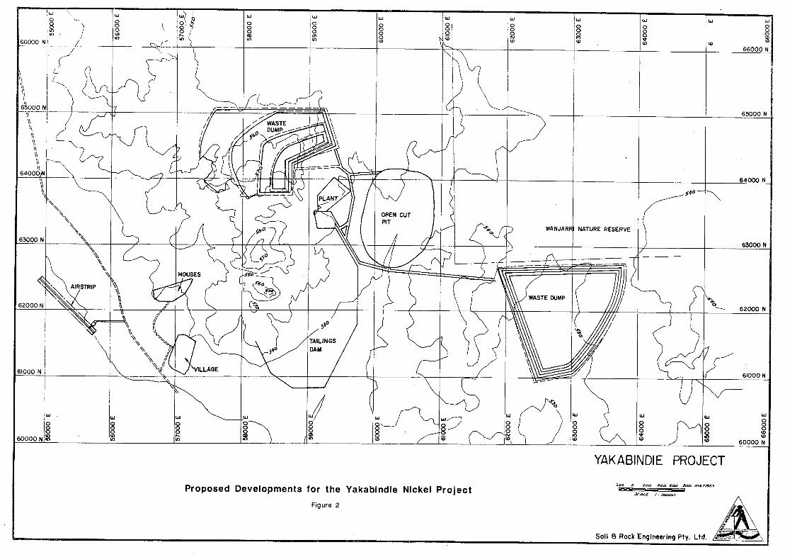
.L
LLJ
65000 N
/ I \\
WASTE DU
' —
- I
oo
i1 64000 N
PLANT
OPEN CUT
/ PIT
1 \J ) WANJARI NATURE RESERVE 63000 N 7 1 OOO N
HOUSES
AIRSTRIP
6:000N
VILLAGE
TAILINGS
60000N in 60000N
YI4KABINDIE PROJECT
Proposed Developments for the Yakabindie Nickel Project —444
Figure 2
- Soil 8 Rock Engineering Pty. Ltd.

we
The vegetation was classified into types on the basis of structure, species composition of upper stratum and landform. In general low woodlands and shrublands dominated by acacias predominate in the region. The density and height of vegetation reflects the moisture content of the soils, with low vegetation being recorded on skeletal, shallow, saline or impermeable soils, especially those associated with granite exposures and salt lakes (Keighery and Milewski, in press). The flora contains a large number of elements not penetrating further south. These are mainly species with and tropical affinities, particularly the grasses. Correspondingly southern elements such as the Proteaceae and Myrteaceae are very impoverished. Prior to the BSC survey the regions flora had not been systematically recorded and documented. However there is still scope for intensive botanical investigation of particular habitats which were under sampled, and groups of plants that have been inadequately explored. One such group is the "fire weeds" (Beard, 1976).
Knowledge of the region's fauna reflects that of the flora being very incomplete. Prior to the BSC fauna survey the only detailed study undertaken was a long term systematic account of the birds of Wanjarri Station, Kathleen Valley, now Wanjarri Nature Reserve, by Moriarty (1972). The BSC fauna survey work was confined to Wanjarri Nature Reserve and sampled all major habitats and all vertebrate groups. The biogeographic patterns of the fauna parallel those of the flora with the area being an overlap zone between groups with predominantly northern or southern distributions, resulting in a high species richness (Mckenzie and Rolf, in press). Continued sporadic information on the region's fauna arises from EIA's of proposed mining developments, such as the Mt. Keith project, CALM research projects and opportunistic collecting by amateur naturalists. However given the diversity of landforms (all recognised goldilelds landform units occur within the region (Milewski, in press) and the paucity of biological survey work, the region is undoubtedly richer in fauna than currently known. Numerous species with their known distributions and habitats encompassing the region have yet to be recorded..
1.2 Wanjarri Nature Reserve
The only conservation area which exists in the Northern Goldfields region is Wanjarri Nature Reserve, situated adjacent to the project area and 53,248 ha in area (EPA, 1975). Historically Wanjarri station was owned by Tom Moriarty who was a keen amateur naturalist. During the late 1960's the property was deemed nonviable as a pastoral area and offered to the then W.A. Dept. Fisheries and Fauna as a nature reserve. The area was subsequently purchased and gazetted as a Class A Nature Reserve (A30897) for the purpose of Conservation of Flora and Fauna on July 18th 1971 and vested in the National Parks and Nature Conservation Authority. Currently the reserve is administered and managed by CALM. The status of Wanjarri as a reserve (A30897) for the purpose of Conservation of Flora and Fauna was endorsed by the EPA in 1975 and the State Cabinet in 1976 (EPA, 1975). The landforms conserved in Wanjarri are predominately Broad Valleys with minor areas of Granite Exposures, Hills, Breakaways, Sandplains and Dunefields. However whilst rich in flora and fauna, the conservation status of the reserve is poor. Much of the mulga vegetation is in a degraded condition and although no known species is known to be threatened with extinction, the composition and resilience of the biological communities has been changed dramatically (Mckenzie èt a!, in press). Nonetheless Wanjarri Nature Reserve remains critical by virtue of being the sole conservation area in the region. Due to the severe degradation of the environment over the whole of the region, particularly on Undulating Plains and Broad Valleys (section 1.3), Keighery and Milewski (in press) recommended that Wanjarri Nature Reserve:
Be enlarged to the north-west to include a greater area of granite exposures, hills and breakaways. These key habitats are very poorly conserved within Wanjarri.
Be greatly enlarged to ensure effective conservation of the biota since the vertebrate populations in the goldfields are scattered and at very low densities.
ecologia

10
1.3 Land-use History
The first exploration of the Northern Goldfields was undertaken by Austin, who reported the area to be "the finest goldfields in the world", although the gold rush occurred more than 30 years later. By the early 1890's extensive development associated with mining had occurred with rail lines and towns established at Leonora, Laverton and Wiluna. By the 1930's pastoral settlement had spread eastwards to all suitable land up to the ecological boundary represented by the edge of the Austin Botanical District. Beyond this point the vegetation is unsuitable and no successful pastoral settlement has occurred (Beard, 1976). During the mining boom extensive tracts of timber were taken for mine construction and building. The impact has been greatest on the Undulating Plains and Broad Valleys where; (i) palatable plants previously occurred and (ii) soils are shallow, fragile and easily compacted (Mckenzie eta!, in press).
The project area occurring on the Yakabindie Station pastoral area is typical of the northern goldfields in having a severely degraded under-storey. This has arisen from historical pastoral practices and little present regeneration, particularly of the mulgas, due to increasing populations of feral herbivores.
2 PHYSICAL ENVIRONMENT
2.1 Climate
The Northern Goldfields region has been classified as a Hot Arid Desert (Dick, 1975) and has an and climate deficient in rainfall in all seasons while possessing a bimodal rainfall distribution (Beard, 1976). Light rainfalls in winter are associated with southerly low pressure systems while summer rain is derived from thunderstorms associated with northerly weather systems. Average annual. rainfall is 210 mm.. A major feature of the rainfall is the unreliability and variation in annual recordings (Newbey, 1984). The nature of the rainfall is of biological significance. While the sporadic summer rainstorms are intense, prolonged and efficient for plant growth, the light regular winter rains are ineffective for growth other than of herbs and grasses (Milewski, 1981). The region experiences hot, dry summers alternating with cool winters. Mean annual temperature is 29° C with average maximum temperatures ranging from 370C (Jan.) to 180 C (July) (Milewski, in press). Frosts occur in winter.
2.2 Geology and Soils
The Northern Goldfields region lies in the north-eastern corner of the Archaean Yilgarn Block consisting of predominately gneisses and granites. Sequences of metamorphosed sedimentary volcanic and intrusive rocks from linear greenstone belts separated by large areas of granitoid rocks (Bunting and Williams,1979). The project area is dominated by a north-south greenstone band, with a large block of granite adamellite to the west and tertiary laterite to the east. The physiognomy is weakly correlated to underlying rock type (section 2.3).
Soils are generally skeletal sandy barns and shallow stony earthy barns on hills and ridges (Beard, 1976). These soils are relictual and unfavourable for plant growth due to low moisture and nutrient status (Milewski, 1981).
2.3 Landforms
For the biological survey of the eastern goldfields carried out by BSC, Newbey and Milewski developed a landform classification system with 10 major units and a series of sub-units (Newbey, 1984). Within the project area 5 units and sub-units are present (Fig. 3).
ecologia

11
Breakaway (B): A series of breakaways occur in the western third of the project area associated with granite. Bluffs are 3-4 m high with a free face, have scree slopes of 120-1 50 and are partially covered with shallow gravelly barns. Numerous small caves and overhangs occur, particularly on the south-facing side of the escarpment.
Hills (H): Hills rise more than 30m above the surrounding plains and have slopes ranging from 50 to 200. The surface is largely covered with skeletal and well-drained soils, with substantial areas of exposed rock.
Hills, granite (HG): the western third is comprised largely of granite and Adamelite hill country (Geol. Survey, 1987) with gravelly soils and is typical of this sub-category.
Undulating Plain (U): Differential weathering of bedrock resulting in low hills ridges and joining colluvial flats and slopes of 50 to 100. This unit was subdivided on the basis of bedrock type.
Undulating Plain, greenstone (UN): within the project are the north-south greenstone belt consists of undulating plain of Komalite and basalt with eroded ridges of Chert 2-3m high.
Drainage Lines (D): Drainage lines are uncommon in the region being confined to areas immediately surrounding undulating plains and hills. There are generally eroded earth banks 1-3m high with a sandy or gravelly wash line. The Jones Creek, which flows through Wanjarri Nature Reserve and Six Mile Prospect is atypically large with semi-permanent water present.
Broad Valley (V): Overlying granite are well drained valleys with slopes rarely exceeding 20 and relief less than 20m. In the project area this Iandform only occurs west of the granite hills and the Wiluna - Leinster road and has an overlying colluvium of quartzfeldspar with sand and silt.
Landform Code Description Percent
Breakaway B bluffs 3-4 m high,gravelby barns 7 on scree slope slopes 120-1 5°
Hills, granite I-3 greater than 30 m high, gravelly 35 skeletal soils, exposed rock
Undulating Plain,green stone UN greenstone belt and joining 28 colluvial flats with chert ridges 2-3 m high
Drainage Line D The Jones Creek, eroded earth 10 banks 1-3m high, sandy-gravel bed, semi-permenant water
Broad Valley V relief less 20m, sandy colluvium 20 overlying granite
TABLE 1 Landform habitat units In Yakabindie Nickel Project Area with approximate percent occurrence.
ecologia
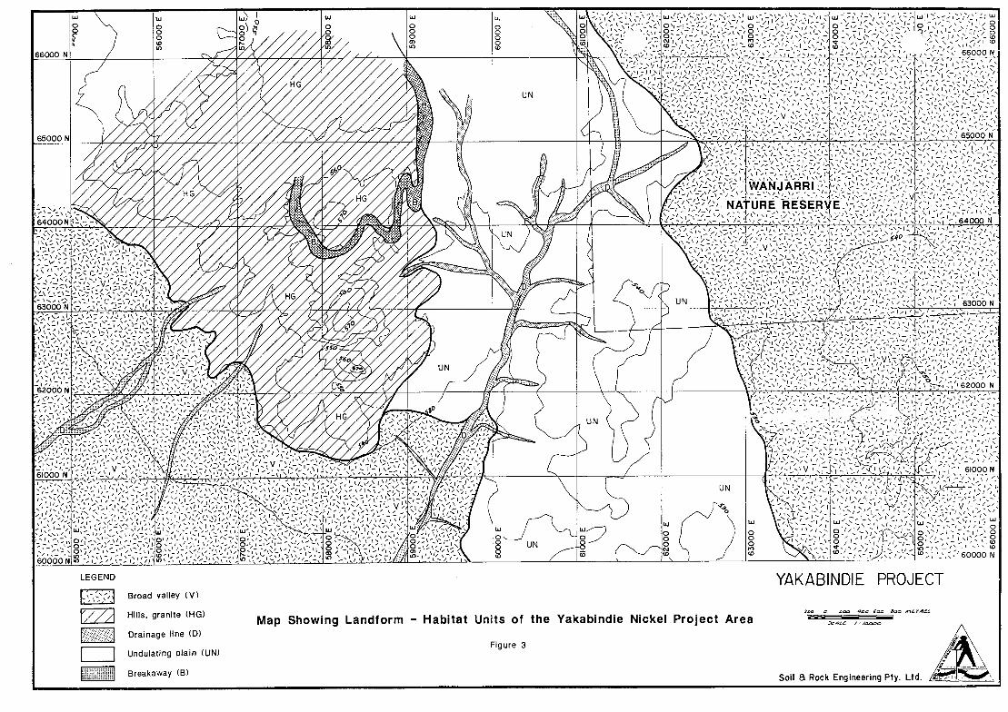
w LU UJ W
660N?____
UN
65000 N
-,64000
11 HG / / I
63000 N I \1/fl \ _________________________________________ _______ UN i
g I I I I J I 63000 N ___________________
UN
-:
UN
( fI
o Lcc) '
I
ç',1 i
I ID
LEGEND YIAKABINDIE PROJECT Broad valley (V)
I Hills ranite (HG) 2o
1/_/_ Map Showing Landform - Habitat Units of the Yakabindie Nickel Project Area Drainage line (D)
Figure 3 Undulating plain (UN)
Breakaway (B) Soil B Rock Engineering Ply. Ltd.

13
3. SURVEY METHODOLOGY
3.1 Flora
The flora of the area was surveyed on February 5-7, and on March 12-13, 1990. Plant species were identified in the field or specimens were collected for later identification and verification. Plotless sampling sites were chosen by means of aerial photographs and field observations so that the array of vegetation types were represented. Vegetation type, life-form strata, percentage cover, surface soil type, drainage, and litter cover were recorded at 35 sites. The positions of the sites are shown in Figure 2. The dimensions of each site varied somewhat according to the nature of the site, e.g. the dimensions of creek bank sites, breakaways and outcrops were defined by topography and changes in vegetation type. The sites situated in broad valleys and plains were approximately 100 m square, and the data collected at each one was generally representative of a much larger surrounding area. The site data was later examined and grouped into defined associations according to habitats, which were then mapped.
The time of year, late summer, was not suitable for the observation and identification of ephemeral species, likely to be found in large numbers in August to October. Several species of winter or spring-flowering perennial grasses and herbs were also impossible to identify, as vegetative parts were poorly developed and flower and fruit material was not present. The main plant families thus affected were Poaceae (grasses) and Asteraceae (daisies). It is likely that if such plants were to be included in the species lists for each site, the total number of species recorded would be doubled or even tripled.
The presence and depth of leaf litter on the soil surface was recorded at all sites. However, in all cases where litter was present, it appeared to have been deposited by the recent unusually heavy rains on and around the bases of plants, and was largely absent from the open ground. The litter depth as recorded, therefore may not necessarily represent that which would normally be found in a drier season.
Nomenclature and taxonomy is based on Green (1985,1988).
3.2 Fauna
An intensive five day field survey was carried out in the project area from 5 th to 9 th February 1990. Assessment of the vertebrate fauna was carried out using a variety of trapping, searching and observation techniques. During the field work all fauna and secondary evidence of fauna, such as tracks, diggings and scats were recorded.
Ten trapping areas (Fig 2) were chosen as being; (I) representative of major habitat landforms and (ii) areas of major environmental impact from proposed development. Trapping methods employed were;
Pit-trap drift fence - two lines of five PVC (16cm diam., 40cm deep)pits, 30m apart with 1 Om flywire drift fence (30cm high) were dug in the 'ground and baited with universal bait (rolled oats, peanut paste, honey, sardines).
Elliot box traps - eight lines of 10 medium box traps 20m apart, baited with universal bait.
Quantitative assessment of bird habitat utilization centred on 200m x 200m Bird Observation Quadrats located at nine sites (Fig 2). Bird observations were collected between 0700hr and 1700hr by systematic foot traversing through the Quadrats for 30 minutes. Total species and number of each species present were recorded for each quadrat.
ecologia

UJ \) 0 0 -_0'
0
Ui
0 0
Ui
0 0 0
0
Ui1
0 01 0
Si 0 0 0
Si
0 0
Si Si Si 0
0 0 0 0 0 0 / 0 0
0 N (0
66000 N _______________ 66000 N _____________
65000 N 7 16 12 65000 N
WANJ AR RI b0
RESERVE
7
0
64000 N 64000 N 18
40 MA
U
1J) 63000 N 63000 N ______________
19 ________________
_ /
_____________
_______________ _________________________________
____________________________ ______________
\-733 32 276 28 76 550 22 \2
—20/ 21 23
62000 N
a
0 - 62000 N
34
,V_______ 61000 N _______________ _______________ 26 __________ _______________ _______________ __________ _______________ __________ _______________ __________ _______________ __________
j Si Si Ui Si
0 0 0 0 0
0 0 :
0 8 0 0 0 0
co g o 0
0 0
0 0 0 N
60000N J (0 (0 60000 N
LEGEND YAKABINDIE PROJECT 2 Flora survey sites Map Showing Flora and Fauna Survey Sites
Soc SOc tOo nt r4t3
Fauna Elliot trap lines of the Yakabindie Nickel Project Area *0t4
U Fauna pit trap lines Figure 4 Bird observation quadrats //61
Soil 8 Rock Engineering Pty. Ltd.

15
Opportunistic fauna sightings were recorded while searching or travelling. All major habitats were searched for cryptic species and nocturnal species were assessed by spot-lighting and head-torch searching.
Nomenclature is based on; Birds - Pizzey (1983), Mammals - Strahan (1983), Amphibians - Tyler eta! (1984), Reptiles - Storr eta! (1981,1983,1986,1990).
4. VEGETATION AND FLORA
The proposed Yakabindie Nickel Project falls within the Wiluna Sub-region of the Austin Botanical District of the Eremean Botanical Province. A broad scale survey of the vegetation of the region was carried out by Beard (1976), in which three general vegetation types were recognised, (1) 'mulga' shrubland and low woodland, which was associated with lower plains, granite hills and rocky ranges; (2) 'steppe', associated with sandplains and sand-ridges, which included hummock grassland (spinifex) communities with scattered trees and shrubs of various mallee Eucalyptus and Acacia species; and (3) 'halophyte communities' which included Acacia, Eremophila, and Cassia chenopodiaceous woodland and shrubland vegetation associated with greenstone hills, salt flats and playa lakes. A more detailed survey of the vegetation and flora of the Sandstone-Sir Samuel area, and in particular the Wanjarri Nature Reserve, the western and southern boundaries of which adjoin the project area, was carried out by Keighery and Milewski (in press). These authors categorised various observed vegetation types according to the landforms with which they were associated. Ten categories were used: breakaways, drainage lines, dunefields, granite exposures,'hills, salt-lake features, calcareous plains, sandplains, undulating plains and broad valleys (Newbey,1984) (section 2.3). For the present survey, the same classification method and set of names was used where appropriate so that comparisons could be made between the project area vegetation and that which is found in the Nature Reserve.
4.1 Vegetation Associations
All the areas sampled appear to fit Beard's categories 'mulga' and 'halophyte communities'. Of the 10 vegetation landform classifications recognised and described by Keighery and Milewski, dunefields, salt-lakes,' calcareous plains and sandplains were not represented within the Yakabindie project area. The vegetation associated with the five landform habitats occurring in the project area is described below (Appendix B).
Breakaways (B): Sites 15 and 35 were situated on or adjacent to hills composed of heavily eroded weathered granitic materials. Site 35 included the whole of a small steep rocky hill, where the taller species which dominated the vegetation of the surrounding plain were absent from all but the lowest fringes, and the vegetation consisted principally of low shrubs of Dodonaea, Eremo phi/a, Cassia and chenopods. All species observed at this site were also present as understorey species at other sites, apart from Eremophi/a 'pungens' and Frankenia sp., which were otherwise only found in the more exposed, rocky areas of site 15. Site 15 was situated in a broad gully between two weathered granite ridges, which formed a natural drainage basin. Although no water was visible at the ground surface, the presence of Eucalyptus lucasii and Brachychiton gregorii in the lower parts of the site indicated a moist environment similar to some of the creek sites e.g. site 17. In the flattish but drier areas of the site was Acacia woodland very similar to many of the 'undulating plain' areas. Higher up, on the rocky, exposed slopes the vegetation resembled that of site 35. Around the upper edges of the area the gymnosperm Ca/lit ris glaucophylla was observed, a species otherwise not found in the survey area. Site 24 was unique amongst the areas inspected, in that it consisted of an exposed chert ridge which rose sharply above the su.rrounding undulating plain. The soil was restricted to shallow deposits in crevices, which undoubtedly was the reason for the almost complete lack of plants taller than 0.5m. Most of the species recorded there were not recorded at other sites, although none were considered to be rare or of particular taxonomic interest (R. Cranfield pers. comm.).
ecologia

16
Hills, granite (HG): Sampling sites 13, 14, 29 and 30 were associated with granite hills which rise above the surrounding plains. At these sites the vegetation was dominated by a tall shrub layer of Acacia quadrimarginea, with a lower shrub understorey dominated by species of Eremophila (E. exihfolia at 13, 14 and 29, E. latrobei at 30), Dodonaea and Cassia. Below these was evidence of a stratum of ephemerals including grasses and herbs, of which in most cases only vegetative parts were seen, and could not therefore be identified. A maidenhair' fern, Cheilanthes tenuifolia was present at all these sites, and some unidentified lichen species on exposed rock surfaces were also observed.
Drainage lines (D): The Jones' Creek, which runs north-south through the proposed site for the main pit, is the largest drainage line in the area, and most other significant drainage lines form its tributaries. Vegetation was sampled at 3 sites (sites 2, 4 and 21) and found to consist of a tall woodland dominated by Eucalyptus camaldulensis, with a relatively dense, unstructured shrub understorey provided by mainly Acacia aneura, and A. buikitti. Three other creek sites showed many similarities to the Jones' Creek sites in vegetation physiognomy. The vegetation at site 28, on a creekline well removed from Jones' Creek, was also dominated by E. camaldulensis, with an Acacia understorey of similar structure. The vegetation at sites 5 and 17, each located on different tributaries of Jones' Creek, showed similarities to the above sites in their overall structures, densities and understorey flora. However, the dominant tree species differed, these being E. striaticalyx at site 5, and E. lucasiiat site 17. As mentioned above, the time of year was not ideal for the identification of ephemeral species. However, between the first and second visits to the site, there had been a considerable amount of rainfall, and this produced a flush of growth of such plants, mainly grasses, particularly along the creek banks. Several species had grown to heights of 0.5-1 m in a period of 5 weeks. Although time did not permit a complete collection of ephemerals, a number of species collected on 13-3-90, approximately 100 m downstream from site 4, were identified, at least to the level of genus, and these have been listed in Appendix B below the species list for site 4.
Undulating Plains (UN): Most of the sampling sites were situated on undulating plains which were of two types, which could be differentiated by their colour in aerial photographs, (1) greenstone/ironstone plains and (2) granite/quartz plains. The propdsed site for the main open-cut pit encompasses most of the greenstone plain area, and it was therefore in this area that attention was concentrated, hence the relatively high density of sampling sites. Greenstone plains: Sites 3, 6, 7, 8, 11, 16, 22, 23, 25, 26. The vegetation at all of these sites consisted of Acacia woodland, in which the dominant species was Acacia aneura. This species was present as trees and shrubs of 2 to 4m in height. Other species commonly present in the upper stratum were Santalum spicatum, Hakea preissll and H. suberea. The canopy cover density varied from about 10% in the flat areas to over 70% in some small thickets, such as that at site 22 which was associated with a broad drainage line. Acacia pruinocarpa trees up to lOm tall were very sparsely scattered through most of these areas. The understorey consisted of a shrub layer of variable height and density, commonly consisting of A. tetragonophylla, Scaevola spinescens, and various species of Eremophila and Cassia. The lowest stratum consisted almost invariably of Ptilotus obovatus, Solanum lasiophyllum and various chenopods, the most common being Maireana triptera and Sclerolaena sp. Quartz plains: At sites 9, 10 and 12, the ground was strewn with quartz gravel and rocks up to 10cm diameter. In these areas the dominant tall shrub species was Hakea preissii, although Acacia aneura and other Acacia species were also present. Shrubs of Eremophila oldfieldll and E. scoparia were common, and in some areas this shrub layer was of greater density than the upper stratum. Beneath these shrubs, the vegetation was generally the same as that of the ironstone plains, i.e. Ptilotus obovatus, Solanum lasiophyllum and chenopods. Sites 32, 33 and 34 were difficult to categorize. At these sites both quartz and ironstone rocks were abundant on the soil surface, and the vegetation showed similarities to both the quartz and greenstone plains described above. Acacia aneura was dominant at all three sites, with Hakea preissii also fairly common at 33 and 34. Acacia coolgardiensis and Eremophila freelingii were observed at site 32 and were not seen elsewhere during this survey, although they are both widespread species. The middle and lower strata at all three sites were similar to those of other plains sites.
ecologia

Broad valleys (V): Sites 18, 19, and 20 were all situated in a broad valley situated between a low ridge of granite and the main creek area. The vegetation was Acacia aneura low woodland, with emergent trees of A. pruinocarpa. The tall shrub stratum included, in addition to A. aneura, the species A. craspedocarpa, A. quadrirnarginea, A. tetragonophylla, Santa/urn lanceolatum and Eremophila oldfieldii. Scaevola spinescens and Eremophila fraseri were the commonest members of shrub strata of 0.5-2m, while Ptilotus obovatus, Solanum lasiophy/lum and chenopods were again present in the third and lowest stratum. Site 27 was situated on a particularly flat and sparsely vegetated part of a very broad valley, which includes the site for the proposed airfield. The dominant stratum was provided by shrubs of Eremophila fraseri ranging in height from 0.5 to 2m. Other species in that stratum, although much rarer were Eremophila latrobei and Cassia desolata. Taller plants of Acacia aneura, Hakea suberea and A. tetragonophylla were present, but extremely sparsely distributed. Low shrubs, where present were the same species as those of the plains sites, with the addition of Cassia helmsll and Podolepis capi/laris. Site 31 was situated on a broad plain not far from site 27, and was chosen to represent a broad area which extends from the Leinster-Wiluna road, to the foot of the granite hills situated to the east. The vegetation in this area was a low shrubland dominated by Eremophila exilifolia, with occasional emergent shrubs of A. tetragonophylla and Eremophila fraseri. The lowest shrub layer was virtually identical to the other plains and broad valley sites.
4.2 Flora
In total, 71 vascular plant species were identified to species level, with an additional 7 species determined to genus level only, owing to the lack of flowers or fruits necessary to enable a complete identification. No introduced weed species or cultivated plants were observed. Plants identified in this survey included members of 28 families, 16 of which were represented by only a single species (Appendix A). The genera most well represented in the area were Acacia (11 species found), Eremophila (11 species) and Cassia (5 species). By far the most common species in the area was Mulga Acacia aneura which was present at all but five sites. The genus Eucalyptus was notably rare in the area, represented only by 3 species, all of which were associated with creeks or major drainage lines. No species of Casuarina or Allocasuarina were observed.
None of the plant species identified in this survey were listed in the CALM Declared Rare Flora Schedule, 1989. However some undescribed or imperfectly known species are known from the area of the proposed mine site, and details are given below.
Eremophila pungens' - This taxon, found at sites 15 and 35 is an unpublished species commonly associated with laterite breakaways in the Wiluna-Laverton area. It is one of a group of taxa related to E. georgeifor which the formal taxonomy is yet to be finalised. (R.J. Chinnock, pers. comm.).
Gre villea inconspicua - This species is on the C.A.L.M. reserve list of rare and endangered species. The W.A. Herbarium contains a specimen collected by R. Cranfield a short distance outside the south-western boundary of the Wanjarri Nature Reserve near Six Mile Well, and it appears likely that this locality is inside the S.E. edge of the proposed pit area (R. Cranfield, pers. comm.). Several hours of searching the area on 12-3-90 and 13-3-90 failed to reveal any Gre vil/ea species. It is possible that heavy grazing by sheep, goats etc. has caused the species to disappear or become unrecognisable, or that the search location was incorrect.
Acacia aff. cit rinoviridis - This species, fairly abundant at site 26 is an imperfectly known taxon, for which the geographic distribution and the taxonomic status are not known. Specimens collected on 6-2-90 and 12-3-90 were inspected by Mr. B.R. Maslin, and were considered to be similar to two or three specimens in the W.A. Herbarium, the nearest being one collected from Windidda Station, 200 km to the north-east. Until further taxonomic studies are completed, it is impossible to say whether or not the plants on the Yakabindie prospect are deserving of particular conservation attention.
ecologia
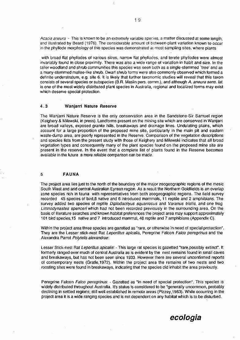
19
Acacia aneura - This is known to be an extremely variable species, a matter discussed at some length, and illustrated by Beard (1976). The considerable amount of between-plant variation known to occur in the phyllode morphology of this species was demonstrated at most sampling sites, where plants
with broad flat phyllodes of various sizes, narrow flat phyllodes, and terete phyllodes were almost invariably found in close proximity. There was also a wide range of variation in habit and size. In the taller woodland and shrub communities this species was seen both as a single-stemmed 'tree' and as a many-stemmed mallee-like shrub. Dwarf shrub forms were also commonly observed which formed a definite understratum, e.g. site 6. It is likely that further taxonomic studies will reveal that this taxon consists of several species or subspecies (B.R. Maslin pers. comm.), and although A. aneura sens. lat is one of the most widely distributed plant species in Australia, regional and localized forms may exist which deserve special protection.
4.3 Wanjarri Nature Reserve
The Wanjarri Nature Reserve is the only conservation area in the Sandstone-Sir Samuel region (Keighery & Milewski, in press). Landforms present on the mining site which are conserved in Wanjarn are broad valleys, exposed granite hills, breakaways and drainage lines. Undulating plains, which account for a large proportion of the proposed mine site, particularly in the main pit and eastern waste-dump area, are poorly represented in the Reserve. Comparison of the vegetation descriptions and species lists from the present study with those of Keighery and Milewski indicates that all broad vegetation types and consequently many of the plant species found on the proposed mine site are present in the reserve. In the event that a complete list of plants found in the Reserve becomes available in the future a more reliable comparison can be made.
5 FAUNA
The project area lies just to the north of the boundary of the major zoogeographic regions of the mesic South West and and central Australian Eyrean region. As a result the Northern Goldfields is an overlap zone species rich in fauna with representatives from both zoogeographic regions. The field survey recorded 45 species of bird,8 native and 6 introduced mammals, 11 reptile and 2 amphibians. The survey added two species of reptile Diplodactlyus squarrosus and Varanus tristis, and one frog Limnodynastes Spenceri which had not been recorded previously in the surrounding area. On the basis of literature searches and known habitat preferences the project area may support approximately 101 bird species, 15 native and 7 introduced mammal, 48 reptile and 7 amphibians (Appendix C).
Within the project area three species are gazetted as "rare, or otherwise in need of special protection". They are the Lesser stick-nest Rat Leporilus apicalis, Peregrine Falcon Falco peregrinus and the Alexandra Parrot Polytelis alexandrae:
Lesser Stick-nest Rat Leporillus apicalis: - This large rat species is gazetted "rare,possibly extinct". It formerly ranged over much of central Australia as is evident by the nest remains found in small caves and breakaways, but has not been seen since 1933. However there are several unconfirmed reports of contemporary nests (Gratle,1972). Within the project area the remains of two nests and two roosting sites were found in breakaways, indicating that the species did inhabit the area previously.
Peregrine Falcon Falco peregr!nus: - Gazetted as "in need of special protection". This species is widely distributed throughout Australia. It's status is considered to be "generally uncommon, probably declining in settled regions; still well established in remote areas (Pizzey,1983); While occurring in the project area it is a wide ranging species and is not dependent on any habitat which is to be disturbed.
ecologia
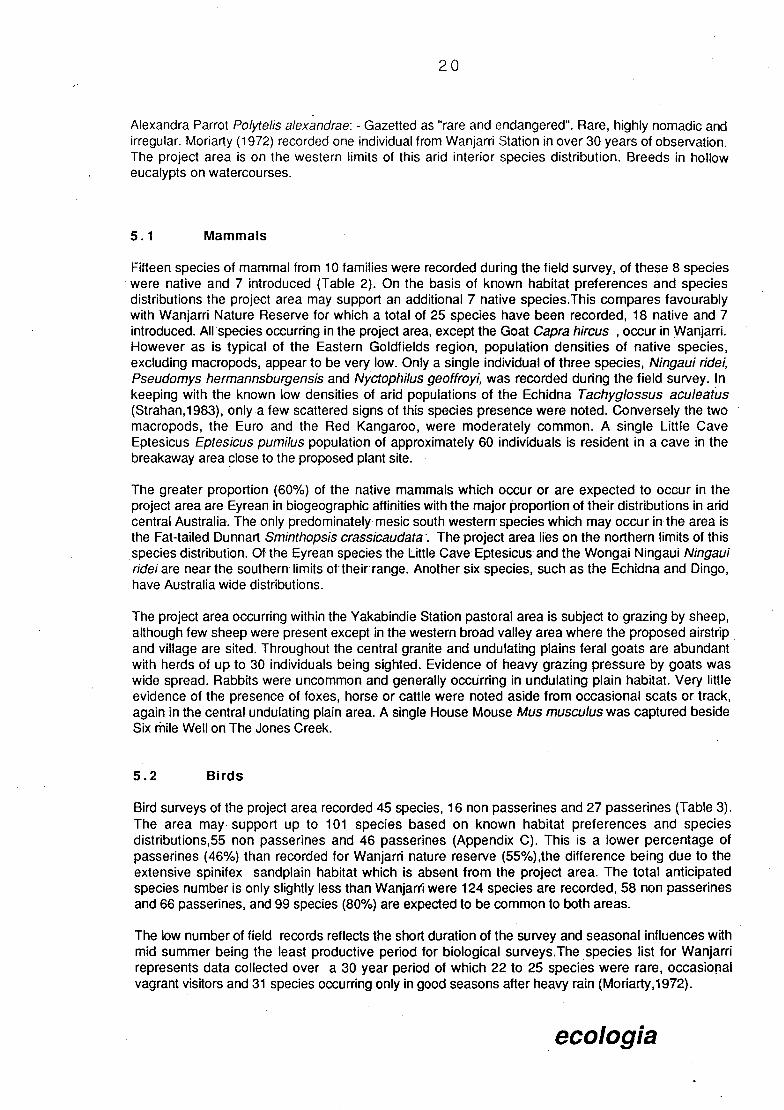
s]
Alexandra Parrot Polytelis alexandrae: - Gazetted as "rare and endangered'. Rare, highly nomadic and irregular. Moriarty (1972) recorded one individual from Wanjarri Station in over 30 years of observation. The project area is on the western limits of this and interior species distribution. Breeds in hollow eucalypts on watercourses.
5.1 Mammals
Fifteen species of mammal from 10 families were recorded during the field survey, of these 8 species were native and 7 introduced (Table 2). On the basis of known habitat preferences and species distributions the project area may support an additional 7 native species.This compares favourably with Wanjarri Nature Reserve for which a total of 25 species have been recorded, 18 native and 7 introduced. AlIspecies occurring in the project area, except the Goat Capra hircus , occur in Wanjarri. However as is typical of the Eastern Goldfields region, population densities of native species, excluding macropods, appear to be very low. Only a single individual of three species, Ningaui ridei, Pseudomys hermannsburgensis and Nyctophilus geoffroyi, was recorded during the field survey. In keeping with the known low densities of and populations of the Echidna Tachyglossus aculeatus (Strahan,1983), only a few scattered signs of this species presence were noted. Conversely the two macropods, the Euro and the Red Kangaroo, were moderately common. A single Little Cave Eptesicus Eptesicus pumilus population of approximately 60 individuals is resident in a cave in the breakaway area close to the proposed plant site.
The greater proportion (60%) of the native mammals which occur or are expected to occur in the project area are Eyrean in biogeographic affinities with the major proportion of their distributions in and central Australia. The only predominately mesic south western species which may occur in the area is the Fat-tailed Dunnart Sminthopsis crassicaudata. The project area lies on the northern limits of this species distribution. Of the Eyrean species the Little Cave Eptesicus and the Wongai Ningaui Ningaui ridei are near the southern limits oftheirrange. Another six species, such as the Echidna and Dingo, have Australia wide distributions.
The project area occurring within the Yakabindie Station pastoral area is subject to grazing by sheep, although few sheep were present except in the western broad valley area where the proposed airstrip and village are sited. Throughout the central granite and undulating plains feral goats are abundant with herds of up to 30 individuals being sighted. Evidence of heavy grazing pressure by goats was wide spread. Rabbits were uncommon and generally occurring in undulating plain habitat. Very little evidence of the presence of foxes, horse or cattle were noted aside from occasional scats or track, again in the central undulating plain area. A single House Mouse Mus musculus was captured beside Six mile Well on The Jones Creek.
5.2 BIrds
Bird surveys of the project area recorded 45 species, 16 non passerines and 27 passerines (Table 3). The area may support up to 101 species based on known habitat preferences and species distributions,55 non passerines and 46 passerines (Appendix C). This is a lower percentage of passerines (46%) than recorded for Wanjarri nature reserve (55%),the difference being due to the extensive spinifex sandplain habitat which is absent from the project area. The total anticipated species number is only slightly less than Wanjarri were 124 species are recorded, 58 non passerines and 66 passerines, and 99 species (80%) are expected to be common to both areas.
The low number of field records reflects the short duration of the survey and seasonal influences with mid summer being the least productive period for biological surveys.The species list for Wanjarri represents data collected over a 30 year period of which 22 to 25 species were rare, occasional vagrant visitors and 31 species occurring only in good seasons after heavy rain (Moriarty,1972).
ecologia

21
In contrast to the mainly arid Eyrean mammals, the project area lies in a zone in which the ranges of species with predominately southern or northern distributions overlap. Numerous mesic southern species such as Splendid Blue Wren, Regent Parrot, Western Magpie and Grey Currawong are at the northern limit of their range. While arid northern species such as Bourke's parrot, Spotted Bowerbird and Grey Honeyeater are at their western or south western distribution limits.
Within the project area the passerines predominate in abundance (55%), particularly the honeyeaters and thornbills, with large numbers of Chestnut-rumped Thornbills and Yellow-throated Miners being present. Among the non passerines the granivorous parrots make up 91% with the Galah, Cockatiel and Budgerigar being the most common.
Landform Code
MONOTREMATA TACHYGLOSSI DAE
Tachyglossus aculeatus Echidna
MARSUPIALIA DASYURIDAE
Ningaui ridei Wongai Ningaui MACROPODI DAE
Macropus robustus Euro Macropusrufus Red Kangaroo
CHIROPTERA VERSPERTILIONIDAE
Eptesicuspumilus Little Cave Eptesicus Nyctophilus geoffroyi Lesser Long-eared Bat
RODENTIA HYDROMYINAE
Leporillus apicalis Stkk nest rat MURIDAE
Pseudomys hermannsburgensis Sandy Inland Mouse
INTRODUCED MAMMALS
Mus musculus House Mouse Bos taurus Cow Ovisaries Sheep Capra hircus Goat Equs caballus Horse Oryctolagus cunicu/us Rabbit Vulpes vulpes Fox
HG D UN B V
x x x
x
KI
old nests
rN
x x
x x x x x x x
x x x x x
species richness 3 9 8 5 4
Key: HG - Hills,granite; D - Drainage Line; UN - Undulating Plain, greenstone; B - Breakaway; V - Broad Valley.
TABLE 2: Mammals recorded in habitats of the proposed Yakabindie Nickel project area.
ecologia

22
Landform Code
CASUARIDAE Dromaius novaehollandiae Emu
ANATI DAE Anas supernillosus Black Duck.
ACCIPITRIDAE Aquila audax Wedge-tailed Eagle
FALCON I DAE Falco berigora Brown Falcon Falco cenchroides Nankeen Kestrel
OTIDIDAE Eupodotis australis Bustard
COLUMBIDAE Ocyphaps lophotes Crested Pigeon Phas chalcoptera Common Bronzewing
PSITTAC I DAE Barnardius zonarius Port Lincoln Parrot Cacatua roseicapilla Galah Melopsittacus undulatus Budgerigar Nymphicus hollandicus Cockatiel Psephotus varius Mulga Parrot
CULIDAE Chrysococcyx basa/is Horsefields Bronze Cuckoo
STRIGIDAE Ninox novaesee/andiae Boobook Owl
AEGOTHELIDAE Aegot he/es cristatus Australian Owlet-nightjar
CAMPEPHAGIDAE Coracina novaehollandiae Black-faced Cuckoo-shrike
PACHYCEPHALI DAE Oreocica gutturalis Crested Bellbird Pachycephalus rufiventris Rufous Whistler Petroica goodenovii Red-capped Robin
MONARCHIDAE Rhipidura Ieucophrys Willie Wagtail
ORTHONYCHIDAE Pomatostomus superciliosus Whité-browed Babbler
ACANTHIZIDAE Acanthiza apicalis Broad-tailed Thornbill Acanthiza chrysorrhoa Yellow-rumped Thornbill Acanthiza uropygialis Chestnut-rumped Thornbill Smicrornis brevirostris Weebill
HG D UN B V
X 2 11
3
nest
x 1
1
5 2 X 2
10 2 90 50 22 X
15 4 x
x
1
1
6 X
2 2 2 2
4
8 X
2 2
x X 1
21 38 20
1 2
2 4
3
6
1
TABLE 3: BIrds recorded in habitats of the proposed Yakabindie Nickel project area.
ecologia

23
Landform Code HG D UN B V
DAPHOENOSITTIDAE Daphoenositta chrysoptera Australian Sittella 4 X
MELIPHAGIDAE Acanthagenys rufogularis Spiny-cheeked Honeyeater 1 Certhionyx variegatus Pied Honeyeater 12 5 Manorina flavigula Yellow-throated Miner 66 3 1 Meliphaga ornata Yellow-plumed Honeyeater 19 Meliphaga penicillata White-plumed Honeyeater 3 Meliphaga virescens Singing Honeyeater 4 1 2
PLOCEIDAE Poephila guttata Zebra Finch 8
GRALLINIDAE Grallina cycanoleuca Magpie-lark X 13 X
ARTAMIDAE Artamus cinereus Black-faced Woodswallow 1 X 6 Artamus minor Little Woodswallow 4 Artamus personatus Masked Woodswallow 1
CRACTICIDAE Cracticus nigrolgularis Pied Butcherbird 9 2 Cracticus torquatus Grey Butcherbird X 3 3 1 Gymnorhina dorsalis Western Magpie X 2
PARADISAEIDAE Ptilonorhynchus maculatus- Spotted Bowerbird - 2 X
CORVIDAE Corvus bennetti Little Crow 1 10
species richness 5 33 24 11 10 abundance/transect 77 28 15 30 #of transects 0 4 3 2 1
Key: HG - Hills,granite; D - Drainage Line; UN - Undulating Plain, greenstone; B - Breakaway; V - BrOad Valley.
TABLE 3 cont: Birds recorded in habitats of the proposed Yakabindie Nickel project area.
ecologia

24
5.3 Reptiles and Amphibians
Pit trapping and opportunistic collecting yielded 11 reptile and 2 amphibian species from the project area (Table 4). With examination of known species distributions and habitat preferences it is expected that up to 48 reptile and 7 amphibians may occur in the area. The survey added two species of reptile Diplodactlyus squarrosus and Varanus tristis, and one frog Limnodynastes spenceri which had not been recorded previously in the surrounding area. However similar to the birds, the limited survey duration and seasonal timing resulted in a low number of records. Wanjarri Nature Reserve with a recorded 52 reptile and 3 frog species has a richer herpetofauna, even though the area is currently under collected for snakes and amphibians. It is expected that the actual species number is higher. The increased species richness over the project area is a direct result of the presence of extensive spinifex sandplains with 38% of Wanjarri reptiles being sandplain specialists (Section 5.5). However 38 species present within Wanjarri occur or are expected to occur in the project area.
The largely and Eyrean component of the mammal fauna is repeated in the herpetofauna. Twenty two species (45%) have Eyrean biogeographic affinities only, while a further 9 species (19%) such as Morelia stimsoni and Varanus gouldii have a predominately and distribution with range extension into the South West. Three species Gehyra variegata, Heteronotia binoei and Lialis burtonis have Australia wide distributions occurring mainly in and and semi-arid habitats. Only three species, Neobatrachus kunapalari, N. wi/smorci and Ctenophorus ornatus, are mesic Southwestern in their distribution, with the project area being on the northern limits of their range. Within the frogs Cyclorana maini and C. platycephalus are at their southern limits, while Neobatrachus centralis is at the southeastern extremity of it's range. Similarly Diplodactlyus strophurus and Varanus caudolineatus are near their southeastern distribution limits.
in terms of abundance, the arboreal skink Egernia depressa was common among dead Acacia trunks in Undulating Plainareas along with Gehyra variegata. This gecko was also the most abundant reptile to be found in the granite hilt and breakaway area. Also widespread and common over the project area was the monitor Varanus panoptes Numerous individuals were captured during the survey while fresh diggings and tracks were ubiquitous. Notably absent were the terrestrial skinks, particularly of the genus Cfenotus, due in part to the absence of sandplain habitat and also undoubtedly the degraded nature of the understorey.
5.4 Faunal Habitats
Faunal habitats are closely aligned with landform - vegetation associations. The Drainage line habitat produced the richest faunat assemblages with 49 species (9 mammal, 33 bird, 7 reptile/amphibian). additionally the quantitative bird survey revealed that this habitat was the most heavily utilised with 51% of all individuals recorded (Table 3). The Jones Creek system provides a centre for resources for many nomadic and resident bird species. The tall River Red Gums contain numerous hollows for nesting and the upper storey is utilised for foraging by birds and bats. The dense understorey vegetation and aquatic environment provides niches for many species of invertebrate, frog, reptile and small mammals. Although a distinctive faunal assemblage occurs in the granite hill area ,with rock inhabiting geckos, Euros and Echidnas, this habitat is the poorest with only 12 species recorded (3 mammal, 5 bird, 4 reptile) and few individuals. Within the breakaway habitat the small caves and overhangs provide refuge for Euros, Echidnas, bats, cave crickets and Goats. The widely occurring low open Acacia woodland and shrublands of the undulating plain are dominated by a highly mobile avian community and arboreal lizards. This landform - habitat is the next richest after the drainage line habitat with a total of 40 species (8 mammal, 24 bird, 8 reptile).
ecologia

25
Ländform Code HG D UN B V
HYLIDAE Cyclorana platycephalus Water-holding Frog X
LEPTODACTYLI DAE Limnodynastes spenceri X
GEKKONIDAE Diplodactylus squarrosus X Gehyra variegata Tree Dtella X X Heteronotia binoei Bynoe's Gecko X X X
AGAMIDAE
Ctenophorus. sp. X
SCINCIDAE
Egernia depressa Pygmy Spiny-tailed Skink X X Eremiascincus nchardsonll Broad-banded Sand Swimmer X X X Lerista desertorum X Lerista mueller! X
VARANIDAE
Varanus caudolineatus X Varanus gouidii Gould's Monitor X X Varanus panoptes rubidus X X X X Varanus tristis X
species richness 4 7 8 1 3
Key: HG - Hills,granite; D - Drainage Line; UN - Undulating Plain, greenstone; B - Breakaway; V - Broad Valley.
TABLE 4: Herpetofauna recorded In habitats of the proposed Yakabindie Nickel project area.
ecologia

Ut
5.5 Wanjarri Nature Reserve
The project lies on the immediate south-western corner of Wanjarri Nature Reserve. This reserve exhibits a high species richness with 124 bird, 18 native and 7 introduced mammal, 3 frog and 52 reptile species being recorded (Appendix D). The occurrence of spinifex-sandplains, a landform-habitat absent from the project area, on Wanjarri is a significant factor in this richness (Monarty,1972) This is reflected in the reptiles with 38% of the species recorded from Wanjarri occurring on this habitat. Additionally the area is an overlap zone between species which have predominately and northern or mesic southern distributions, resulting in in a species richness higher than adjacent regions. The relative richness of the area compared to other and regions is illustrated by the avifauna with 124 species recorded on Wanjarri as against only 88 species at Mileura Station 320 km to the north-west (Davies,1970).
6. ECOLOGICAL SIGNIFICANCE
The project area encompasses landform and vegetation associations which are widespread throughout the Northern Goldfields Region. Despite this only a small area representative of these associations is conserved within Wanjarri Nature Reserve, the only conservation area in the region.Thus the habitats which support the greatest biodiversity, such as the Jones Creek drainage system, or which are refugia for specialist species, eg breakaways, remain of ecological significance. The Jones Creek drainage system is of particular value for breeding and aquatic species. While no aquatic invertebrate survey was undertaken, Jones Creek being the largest watercourse in the region with semi-permenant water provides a refuge for many aquatic species during summer from which dispersal to other ephemeral drainage systems occurs during wetter periods.
The Drainage- Line and Breakaway landform habitats are in relatively good condition and most closely represent pre-pastoral settlement status, whereas the other habitats have been severely affected by disturbance. The conditions are a reflection of historical pastoral practices and timber cutting during the mining boom in the early 1900's. The result is a severely degraded understorey with evidence of little regeneration due to grazing pressures from feral herbivores, particularly goats.
The landform - vegetation type present in the area of the project area which is least well conserved in the Wanjarri Nature Reserve is the greenstone Undulating Plain. Such areas where they occur in the goldfields region of Western Australia are often associated with mineral deposits and are commonly mined. It is therefore of great importance that some such areas are set aside for flora and fauna conservation. Although the present survey revealed very few plant taxa which were restricted to the greenstone plains, further studies, which must be carried out during a season when the ephemeral flora becomes apparent and identifiable, will almost undoubtedly reveal significant peculiarities associated with the flora of such areas.
Biota of significance which occur within the project area are the three plant species of uncertain status which MAY require further investigation (Section 4.2). With confirmation of status, these species may require special protection at specific localities within the area.
Wanjarri Nature Reserve is of critical significance as a conservation area within the Northern Goldfields Region. The region is ecologically diverse, encompassing biotic assemblages which do not occur elsewhere and is an overlap zone between and northern and mesic southern elements of both flora and fauna. Recognition of the biological importance of Wanjarri lead to the EPA and State Cabinet endorsement of the current reservation conservation status (EPA,1975).
ecologia

WA
7. ENVIRONMENTAL IMPACT AND MANAGEMENT
The principle impacts from the construction of the proposed developments will be the loss of vegetated area, reduction in area of breakaway habitat and the impositions on the Jones Creek drainage system. The area loss from the developments (990 ha) is insignificant in comparison to the ecological landform units represented. The area is already of a degraded nature due to historical pastoral practices.
The Jones Creek drainage system is the only ecological unit which may undergo significant alteration from the proposed developments due to siltation and leaching from waste dumps.
The impact on the fauna is generally secondary. There will be major local impacts initially with destruction of habitat and relocation of mobile species into adjacent habitats. Impacts will be minimised by staging cJearing, limiting clearing to absolute essential minimum, fencing off dangerous areas and limiting road and track development. Some bird mortality may occur during the project life as a result of birds gaining access to open water surfaces on the tailings dam. Increased traffic may cause localised death of larger mobile species, predominately kangaroos and monitor lizards.
The only perceived factors which may impact the biota of Wanjarri Nature Reserve are dust and increased visitation by the public. The subsequent localised mortality of adjacent vegetation within the reserve through excessive dust will be minimised by dust inhibition methods. Public education programmes and liaison with CALM will reduce the potential for adverse impacts associated with any increased visitation to the reserve. No other environmental impacts are perceived to impinge upon the integrity of the reserve.
7.1 Pit Area
All vegetation will be cleared from, the, pitarea.Reductibn in size of pit to minimum essential will minimise impact to the undulating plain greenstone Acacia woodland in this area. Major impact will occur locally to the Jones Creek drainage system involving the removal of approximately 3 km of the main creek bed and 4 km of the western tributaries. The Jones Creek bundwall and spill way diversion will cut through adjacent laterite plain with low open Acacia woodland. Severe local environmental impacts in the pit area will occur. However the impacts are deemed not significant for these widely distributed vegetation associations. Modification to the Jones Creek while extreme is of significance only at the local level. No fauna species will be adversely affected by this development. Only a single plants species, Grevillea inconspicua, currently on the CALM reserve "rare and Endangered" list may be affected by the pit and creek diversion. This species was reported by CALM Herbarium officers to occur on the south-eastern edge of the pit approximately 100 m south of Six Mile Bore. Despite an intensive survey of the location the species was not found. Further consultation and or field survey to ascertain the exact distribution of the species may be required.
7.2 Tailings Dam
This area encompasses low open acacia woodland on the lower slopes of granite hills and undulating granite plain. Vegetation will be removed from the embankment area while left in situ within the impoundment area allowing progressive relocation of fauna as material accumulates. With decommissioning the impoundment will be rehabilitated. Impact of this development is limited to an abundant habitat with no flora or fauna of significance being adversely affected.
ecologia

7.3 Waste Dumps and Plant
Two waste dumps are proposed, a northern and eastern;
the eastern dump will involve the removal of low open Acacia woodland and the interruption of some minor drainage lines, no significant impact will occur other than the removal of local vegetation. A major consideration regarding the location of the dump is the close proximity to Wanjarri Nature Reserve. Potential impacts to the reserve include dust, leaching and erosional runoff. It is widely recognised that erosional runoff material has a drastic adverse effect on adjacent native vegetation.
northern waste dump and plant - these two development sites will impinge upon an area of breakaway habitat for approximately 1.5 km. Degradation to this habitat will occur on a local scale and may impact the only known population of the Little Cave Eptesicus (bat) Eptesicus pumilus within the project area. However this will not affect the status of this common widespread species regionally. The shrub Eremophila 'pun gens' with uncertain conservation status, occurs on these sites may be reduced in local population size. Further field survey may be required to determine the extent of the Yakabindie population. removal of the chenopod shrubland will not significantly affect any other flora or fauna.
7.4 Support Facilities
The campsite and airstrip are situated within a severely degraded low shrubland. Past intensive grazing has reduced the vegetation to predominately unpalatable Eremophila species with little or no understorey. No flora or fauna of significance occurs in this area and it is considered the developments will make little impact to the environment other than local vegetation removal. Development of an extensive vegetation community surrounding the campsite may actually enhance the attractiveness of the area for the fauna, particularly birds.
7.5 Dust
The close proximity of the project site to Wanjarri Nature Reserve and the predominate east-west wind patterns, dictates the control of dust generation in order to protect the integrity of the reserve. The duration of potential dust generation from the waste dumps will be minimised under the progressive rehabilitation strategy outlined in section 8, whereby top soil, is spread over the terraces and revegetated progressively as the waste dumps are raised. Additionally dust inhibition measures would minimise dust production on site to ensure no impact to Wanjarri occurs.
7.6 NoIse
The only fauna which will respond to noise are large mobile species of macropods and birds where it may act as a deterrent a local scale adjacent to the developments. The result of localised noise would be the avoidance of the noise origin area. This behaviour would be beneficial to the fauna by avoiding potentially hazardous areas. Monitoring fauna response to noise is confounded by other factors such as habitat disturbance, mining activities and continual human presence. It is considered that no significant impact will occur to the biota through noise.
ecologia

29
7.7 Feral Animal Eradication
The eradication of feral grazing animals from the project area will significantly enhance vegetation rehabilitation of disturbed areas and the remaining natural vegetation. Eradication would thus benefit the surrounding environment, as well as being a cost effective method for reducing damage to revegetation areas, as opposed to other methods such as fencing. An eradication program can be devised in consultation with CALM and the APB. Specific target species will be; - Goats - Rabbits - any other feral herbivores - any feral predators, Foxes and Cats. Eradication of feral goat populations will be undertaken by a controlled shooting program while local rabbit populations may be poisoned with 1080 in accordance with APB guidelines.
8. REHABILITATION
Rehabilitation of mined pit sites with indigenous flora is a necessary part of mining operations. Many ecological and aesthetic benefits result from such treatment while good planning and careful implementation of the work should reduce the cost and time involved. Rehabilitation of mine sites in and areas has been successfully carried out at a number of operations in the Pilbara and Goldfields and new techniques are regularly being developed. The objectives of a rehabilitation program should include:
Slope stabilisation Dust suppression Aesthetic improvement Social and legal responsibility
The return of mined and otherwise detrimentally impacted areas to near-natural conditions would satisfy the objectives mentioned. A revegetation program should be aimed at establishing plant cover including a range of species which is self-sustaining and similar to that in surrounding areas. A self-sustaining community is desirable to reduce long term cost and time commitments and to create a suitable environment for local fauna. The reintroduction and establishment of local native flora aids in minimising the visual impact of mining works as well as providing suitable faunal habitat. Revegetation of and areas is made more difficult than that of wetter areas by a number of factors. These include:
Low and uncertain rainfall Sparse and often species-poor natural vegetation Poor soils The effect of seed and seedling predators and grazers.
Site conditions at waste dumps vary further from those applicable in the general area. The height and slope of the dump provides an exposed and generally unfavourable habitat for plant growth due to the difficulties in water harvesting and, conversely, possible problems with erosion after seasonal heavy rainfall. Slopes on the leeward side of prevailing hot easterly and northerly winds may be more favourable for plant establishment. A rehabilitation programme which incorporates latest developments and appropriate techniques for the project area will be developed in consultation with CALM and other relevant authorities.
ecologia

30
8.1 Site Preparation
Compacted terraces and slopes should be ripped to a depth of 30cm and, where possible, windrowed along the contour into mounds of no less than 20cm. Windrowing is necessary to collect water from the sparse rainfall and to prevent erosion down the slopes. Ideally, terrace slopes should be at a steepness of no more than 200. If windrowing cannot be achieved on slopes, it is recommended that small scale surface irregularity be achieved in some way. The presence of any depressions, mounds, shrub or log litter aids in collecting water and protecting seeds and seedlings and has been found to be a significant factor in successful minesite rehabilitation (E. M. Mattiske, personal communication).
In all areas to be disturbed all vegetation, litter and topsoil to a depth of 15 cm should be salvaged. This material provides a mulch of crushed vegetation and topsoil which will greatly assist later revegetation programmes. The topsoil/vegetation material should be removed progressively in front of advancing overburden dumps and be immediately redeployed where possible and reapplied to conform to natural thickness. Immediate redeployment ensures maximum benefit from seed, nutrients and soil bacteria contained within the material. Where this is not possible the material needs to be stockpiled for minimum time periods in shallow piles which are surfaced ripped, seeded and fertilised. This will assist in maintaining biological activity within the soil. Subsequent plant growth produces a seed store and reduces wind and water erosion. Stockpiles should be located in areas specifically reserved for this purpose or immediately adjacent to redeployment areas for short term storage.
8.2 Species Selection
Species used in revegetation should include as many species which are adapted to the local conditions as is possible. A range of species from tall shrubs to annuals herbs and grasses should be suitable with tree species confined to the base of the dump where the run-off is likely to be greatest.
Selection has often been subject to availability and condition of seed. Some seed may be obtained through larger seed merchants but ideally should be provided by local collectors. This may be achieved by purchasing supplies fromknown nurserymen or collectors in Kalgoorlie or engaging contractors under supervision to collect from the areas around the minesite. The latter method is often more suitable as seed is fresh and plants are well adapted to local conditions and soil types. Suggested species are:
SHRUBS Acacia kepeana Acacia quadrimarginea Acacia tetragonophylla Cassia spp. Santa/urn spicatum Hakea arida Hakea suberea Dodonaea spp. Hibiscus leptocladus Sida calyxhymenia Maireana spp. Scaevola spinescens
HERBS AND GRASSES Pti/otus spp. Podo/epis capil/aris Sclero/aena spp. Cymbopogon arnbiguus Eragrostis sp.
The above list includes species and genera which are generally known to regenerate easily from seed. Many of the grass and herb species are disturbance opportunists which easily re-establish in cleared areas. However, as the area to be revegetated will have been long altered from its original state and seed supply from natural vectors such as wind and animals is less likely, seeding will be required.
ecologia

31
Tree species such as Eucalyptus camaldulensis (Red River Gum), E. intertexta, E. striaticalyx, Callitris column, Brachychiton gregorll (Kurrajong)and Pittosporum phylliraeoides (Desert Oak) may be suitable for areas at the base of the waste dump or in other disturbed areas near drainage lines where they can be watered until established.
8.3 Seed Pretreatment
Hard-seeded species such as Cassia and some Acacia species require boiling to assist germination. Good results have been shown in and area rehabilitation when seeds are pretreated in this way. Other methods include seedcoat scarification and acid treatment but boiling is the easiest and most effective treatment in most cases. Experimentation could be carried out with the species to be used.
8.4 Irrigation
Studies on sprinkler irrigation of seeded areas in and land revegetation have shown that watering causes more rapid establishment of species, but favours early-colonising plants, thus reducing the overall range of species established. It is believed that although irrigation is necessary for establishing planted nursery stock and particularly trees, its use in seeded areas is not essential over the long-term. If a quick result is required this technique may be employed.
8.5 Monitoring
Monitoring of revegetated sites is useful to gain further knowledge of the success of techniques- and species, whichcan then.be applied to further rehabiltation work. Monitoring of seeded areas should be carried out at regular intervals of approximately 6 months over a period of not less than-3 years. Such a time scale- is necessary to account for variable-seasonal rain- and- the -effects of drought periods on established seedlings.
Follow-up work may include the addition of soil-stabilising litter where necessary, re-seeding of failed areas and further ripping or other soil disturbance to recreate suitable conditions.
ecologia

32
9. RECOMMENDATIONS
In order to reduce impact to the biota of the project area, it is recommended that the proponent;
- Minimise clearing of land to essential minimum consistent with safe and efficient operations.
- Minimise impact and encroachment to The Jones Creek drainage system and breakaway habitat.
- Carry out progressive rehabilitation of waste dumps, tailings dam embankment and other developments to the level of existing land use in accordance with the rehabilitation programme devised in consultation with CALM and other relevant authorities.
- Install silt traps to collect run-off and prevent sediment from entering the drainage systems
- Cap all boreholes and pipes, backfill costeans when no longer required.
- Control dust in the project area.
- Restrict non avian faunal access to potentially hazardous areas, by fencing if required.
- Establish feral animal eradication programme.
- Prohibit domestic pets in the project area.
- Prohibit off road driving and shooting in the project area.
- Maintain strict fire control procedures.
- Set up an educational programme for employees which enhances awareness of the conservation value of both the project area and Wanjarri Nature Reserve.
- Ensure that employees and sub contractors are made aware of any environmental restrictions placed on the project by the EPA.
In order to adequately assess environmental impact arising from the project and to develop appropriate techniques which will ensure successful rehabilitation and minimal impact, it is additionally recommended that the proponent;
- Establish fauna monitoring programme developed in consultation with CALM.
- Carry out base line survey of The Jones Creek aquatic environment, including water quality and biota, prior to project construction and establish periodic monitoring.
- Keep abreast of developments in rehabilitation, monitoring techniques and environmental management procedures.
Upon decommissioning the proponent should remove all structures and equipment and rehabilitate all disturbed areas.
ecologia

33
CONTRIBUTORS TO PREPARATION OF REPORT
The Yakabindie Nickel Mine Project flora and fauna survey described in this document was planned, coordinated and executed by;
ecologia Ecological Consultants 120 McKenzie St., Wembley W.A. 6014
Project staff
G. W. Connell BSc. (Hons) (Zool) P. Grayling BSc. Grad. Dip. (Bot) A.C. Napier BSc(Biol)(Hons)(Soil Sc) C.M. Majors BSc(Hons)(Zool)
Principal Flora Vegetation Rehabilitation Field Assistant, fauna
In addition;
Mr N.L. Mckenzie, CALM Research Woodvale, and Mr A. Chapman, CALM kalgoorlie, kindly provided.access and permission to use unpublished data for Wanjarri Nature Reserve.
Mr L.A. Smith, Western Australian Museum Perth, supplied reptile and amphibian collection records for the Northern Goldfields from the Museum's collection databases
Mr. R. Cranfield, Mr. P.G. Wilson and Mr. B.R. Maslin, CALM W.A. Herbarium, and Dr. R.J. Chinnock, State Herbarium of South Australia, kindly assisted with current taxonomic and conservation status information for some plant specimens.
ecologia

34
ABBREVIATIONS
APB Agriculture Protection Board
BSC Biological Surveys Committee
CALM Department of Conservation and Land Management, Western Australia.
CER Consultative Environmental Review
CTRC Conservation Through Reserves Committee
DMWA Department of Mines Western Australia
EPA Environmental Protection Authority
ha hectares
km kilometres
WAM Western Australian Museum
ecologia

•), . .
.L
A.* - *-:
Plate 2: Granite hills, overlooking tailings dam.
iII. •,.. ..,
j..
.J. t.•.*4 ..
Plate 5: Mulga Acacia aneura woodland.
14 40
-
r -
, •!. •_ •-:'
.-
Plate 1: Breakaway habitat on southern edge of northern waste dump.
-, •-
Plate 4: River Red Gums, Jones Creek,
S.E. corner of pit area.
Plate 3: Airstrip and village site, low open shrubland, heavily grazed.

35
REFERENCES
Beard,J.S. (1976) Murchison. Explanatory notes to Sheet 6, 1:1,000,000 Series Vegetation Survey of Western Australia. Univ. of W.A.. Press: Nedlands.
Beard,J.S. (1979) A New Phytogeographic Map of Western Australia. West. Aust. Herb. Res. Notes. No.3, pp 37-58.
BSC (1984) The Biological Survey of the Eastern Goldfields of Western Australia. Part 1 Introduction and Methods. Rec. W.A. Mus. Suppl. #18.
Bunting, J.A. and Williams,S.J. (1979) Sir Samuel, Western Australia. Geological Survey of Western Australia 1:250,000 Geological Series Explanatory Notes. Geol. Surv. West. Aust.
Burbidge, N.T. (1960) The Phytogeography of the Australian Region. Aust. J. Bot. 8: 75-211.
Carnahan,J.A. (1976) Natural Vegetation. Map Sheet and Commentary. In: Atlas of Australian Resources. 2nd Series. Geographic Series. Div. Nat. Mapping Dept. Nat. Res., Canberra.
Davies, S.J.J.F. (1970) A List of Plants and Animals found on Mileura station W.A. (26022'S,l 17020'E). Tech. Mem. Div. Wildl. Res. CSIRO
Dick,R.S.(1975) A Map of the Climate of Australia: According to Koppens Principles of Definition. Old. J. Geogr. 3rd Series 3:33-69.
EPA (1975) Conservation Reserves for Western- Australia-. Systems 4,88,9,10,11,12. Dept. Cons. Env. Perth
Gratte,S. (1972) The Stick-nest Rat Leporillus conditorin the Gibson Desert. W.A. Nats 12:50-51
Green, J.W. (1985) Census of Vascular Plants of Western Australia. 2nd ed. W.A. Herb. Dept. Ag.
Green,J.W. (1988) Census of Vascular Plants of Western Australia. Suppl. 6 W.A. Herb. Dept. Ag.
Hopper,S.D. (1979) Biogeographic aspects of speciation in the South-west Australian flora. Ann. Rev. Ecol. Syst. 10: 182-189.
Keighery,G.J. and Milewski, A.V. (in press) Vegetation and Flora. In McKenzie, N.L. et a! The Biological Survey of the Eastern Goldfields of Western Australia. Part : Sandstone - Sir Samuel Area. CALM Report.
Kenneally, K.F. (1968) An Annotated list of Angiosperms of Lakeside Station Cue, Western Australia. W.A. Nats 10: 182-189.
Mabbutt.J.A. etal(1963) Land of the Wiluna-Meekathara Area, Western Australia, 1958, CSIRO Land Research Series No. 7.
Marchant,N.G. (1973) Species Diversity in the South-western Flora. J. Roy. Soc. W.A. 56: 23-30.
Mckenzie, N.L. ; Keighery, G.J. and Milewski, A.V. (in press)) The Biological Survey of the Eastern Goldfields of Western Australia Part: Sandstone - Sir Samuel Area CALM Report.
McKenzie,N.L. and Rolfe, J.K. (in press) Vertebrate Fauna. In Mckenzie, N.L. et a! The Biological Survey of the Eastern Goldfields of Western Australia. Part: Sandstone - Sir Samuel Area. CALM Report:
Milewski,A.V. (1981) A Comparison of Vegetation height in relation to the effectiveness of rainfall in the Mediterranean and adjacent and parts of Australia and South Africa. J. Biogeog. 8:107-116
ecologia

36
Milewski, A.V. (in press) Physical Environment. In Mckenzie, N.L. et a! The Biological Survey of the Eastern Goldfields of Western Australia. Part: Sandstone - Sir Samuel Area. CALM Report.
Mitchell, A.A. & Wilcox, D.G. (1988). 'Plants of the Arid Shrublands of Western Australia' U.W.A. Press, Perth.
Moriarty, T.K. (1972) Birds of Wanjarri, W.A. (27125'S,120040'E). Emu 72:1-7.
Neweby, K.R. (1984)11 Physical Environment. In Biological Survey of the Eastern Goldfields of Western Australia Part 2. Widigemooltha - Zanthus Area. Rec. W.A. Mus Suppl. 18.
Pizzey, G. (1983) A Field Guide to the Birds of Australia. Collins. Sydney.
Storr,G.M.; Smith,L.A. and Johnstone,R.E. (1981) Lizards of Western Australia. I. Skinks. U.W.A. Press.
Storr,G.M.; Smith,L.A. and Johnstone,R.E. (1983) Lizards of Western Australia. II. Dragons and Monitors. U.W.A.Press.
Storr,G.M.; Smith,L.A. and Johnstone,R.E. (1986) Snakes of Western Australia. U.A.W. Press.
Storr,G.M.; Smith,L.A. and Johnstone,R.E. (1990) Lizards of Western Australia. Ill. Geckos and Pygopods. U.W.A. Press.
Strahan,R. (1983) Complete Book of Australian Mammals. Angus Robertson. Sydney.
Tyler,M.J.;Smith,L.A. and Johnstone,R.E. (1984) Frogs of Western Australia. U.WA. Press.
ecologia

37
APPENDIX A
Flora Species List
ecologia

ci
APPENDIX A
LIST OF PLANT SPECIES COLLECTED AT YAKABINDIE NICKEL PROJECT AREA
Classification and nomenclature according to J.W. Green, 'Census of the Vascular Plants of Western Australia', 2nd ed.(1985) and supplement no. 6 (1988).
PETRIDOPHYTA Adiantaceae
Cheilanthes tenuifolia
SPERMATOPHYTA Asclepiadaceae
Leichardtia australis Amaranthaceae
Amaranthus mitchellii Ptilotus exaltatus Ptiotus heliptero ides Ptiotus obovatus
Asteraceae Cratystylis subspinescens Podolepis capillaris Pluchea sp.
Chenopodiaceae Maireana p!anifolia Maireana triptera Maireana villosa Salsola kaY Sclerolaena diacantha Sclerolaena fusiformis Sclerolaena sp.
Cucurbitaceae Cucumis sp.
Cupressaceae Callitris glaucophylla
Cyperaceae Cyperus sp.
Frankeniaceae Frankenia sp.
Goodeniaceae Scaevola spinescens
Juncaceae Juncus gymnocalus
Leguminosae (Subfamily Caesalpinioideae)
Cassia arlemisioides Cassia helmsii Cassia nemophila Cassia sturtll Cassia desolata
(Subfamily Mimosoideae) Acacia aneura A. burkittii A. aft. citrinoviridis A. coolgardiensis A. craspedocarpa A. kempeana A. pruinocarpa
ecologia

A. quadrimarginea A. rigens A. sessiliceps A. tetragonophylla
Lobeliaceae Isotoma petraea
Malvaceae Abution sp. Hibiscus leptocladus Sida calyxhymenia
Myoporaceae Eremophila aff. glutinosa Eremophila exilifolia Eremophila fraser! Eremophila freelingii Eremophila georgei Eremophila latobei Eremophila longifolia Eremophila oldfieldii Eremophila oppositifolia Eremophila scoparia Eremophila 'pungens
Myrtaceae Eucalyptus camaldulensis Eucalyptus lucas!! Eucalyptus striaticalyx
Oleaceae Jasminumcalcareum
Pittosporaceae P!ttosporum phylliraeo!des
Poaceae Aristida contorta Cymbopogon amb!guus Eragrostis sp. Monachather paradoxa Themeda australis
Proteaceae Hakea ark/a Hakea preissll Hakea suberea
Rubiaceae Canthium lat!folium Canthium attenuatum
Santalaceae Exocarpus aphyllus Santalum sp!catum
Sapinidaceae Brachychiton gregori!
Solanaceae Solanum lasiophyllum
Sterculiaceae Brachychiton gregorll
Thymelaeaceae Pimelea m!crocephala
Violaceae Hybanthus flor!bundus
Zygophyllaceàe Tribulus hirsutus
39
ecologia
Em
APPENDIX B
Description of Vegetation Sites
ecologia

41
APPENDIX B
Listed below are descriptions of vegetation sites including data on landforms, topography, drainage and soils. Vegetation types are separated by structure and life form into broad classes based on Muir's (1977) notation.
Site No.1 Date sampled: 5-2-90 Landform: Broad valley Topography: Flat sloping plain Drainage: Poor to moderate. Surface soil: Red sandy loam, with ironstone gravel only under shrubs.
Vegetation: Acacia aneura low woodland
Litter layer: Negligible. Less than 1 cm depth,
Stratum 1: Trees & shrubs 2-6m. 2-10% cover. Acacia kempeana, Acacia aneura
Stratum 2: Shrubs 1 -2m. 2-10% cover. Acacia aneura, Acacia tetragonophylla, Acacia rigens, Eremophila fraseri
Stratum 3: Shrubs 0.2-0.5m. 2-10% cover. Solanum lasiophyllum, Eremophila latrobei, Sida calyxhymenia, Eremophila georgei
Stratum 4: Herbs <0.2m. <2% cover. Podolepis capilaris
Site No.2 Date sampled: 5-2-90 Landform: Drainage line. Topography: Creek bed & banks Drainage: Good Surface soil: Coarse sandy loam. Red on banks, paler in creek bed. Litter layer: Negligible.
Vegetation: Eucalyptus camaldulensis woodland.
Stratum 1: Trees 5-8m. 10-30% cover. Eucalyptus camaldulensis
Stratum 2: Trees & shrubs 2-5m. 10-30% cover. Acacia aneura
Stratum 3: Shrubs 1 -2m. 2-10% cover. Acacia quadrimarginea, Acacia burkittil, Cassia artemisioides, Acacia tetragonophylla, Eremophila exihfolia
Stratum 4: Herbs etc. <0.5m. <2% cover. Perennial grass sp., moss sp.
Site No.3 Date sampled: 5-2-90 Landform: Undulating plain ;greenstone Topography: Plain, sloping towards Jones' Creek. Ironstone/quartz. Drainage: Good. Surface soil: Red gravelly loam. Litter layer: Negligible. Less than 1 cm depth, only under shrubs.
Vegetation: Acacia aneura open woodland.
Stratum 1: Trees 2-4m. 10-30% cover. Acacia aneura, Canthium latifolium
Stratum 2: Shrubs 1 -2m. 2-10% cover. Acacia tetragonophylla
ecologia

42
Stratum 3: Shrubs 0.5-1 m. 10-30% cover. Cratystylis subspinescens, Scaevola spinescens, Eremophila latrobei
Stratum 4: Shrubs & herbs <0.5m. 2-10% cover. Hibiscus leptocladus, Sida calyxhymenia, Tribulus hirsutus, Ptiotus obovatus, Solanum lasiophyllum
Site No.4 Date sampled: 5-2-90 Landform: Drainage line Topography: Creek bed & bank.. Drainage: Excellent. Surface soil: Red sandy loam. Quartz gravel in creek bed. Litter layer: Negligible. Less than 1 cm depth, only under shrubs.
Vegetation: Eucalyptus camaldulensis woodland.
Stratum 1: Trees & shrubs 5-8m. 30-70% cover. Eucalyptus camaldulensis, Acacia burkittli
Stratum 2: Trees & shrubs 2-4m. 30-70% cover. Acacia aneura, Acacia kempeana, Brachychiton gregoril, Acacia craspedocarpa, Pimelea microcephala
Stratum 3: Shrubs 1 -2m. 2-10% cover. Acacia tetragonophylla, Exocarpus aphyllus, Cassia artemislo ides
Stratum 4: Shrubs & herbs <0.5m. 2-10% cover, grass sp., Ptiotus obovatus, AbutiIonsp.
Grasses (collected 13-3-90, see text): Aristida contorta, Cyperussp., Eragrostis sp., Juncus gymnocalus, Monachather paradoxa, Themeda australis
Site No.5 Date sampled: 5-2-90 Landform: Undulating Plain; greenstone. Topography: Flat, with drainage line to Jones Creek. Drainage: Moderate Surface soil: Red/brown clay/loam, much ironstone gravel. Litter layer: Negligible. Less than 1 cm depth, only under trees.
Vegetation: Eucalyptus striaticalyx woodland.
Stratum 1: Trees 4-8m. 30-70% cover. Eucalyptus striaticalyx, Acacia pruinocarpa
Stratum 2: Shrubs 2-4m. 30-70% cover. Acacia burkittil, A. aneura
Stratum 3: Shrubs 1 -2m. 10-30% cover. Eremophila scoparia, Acacia burkitti Eremophila oldfieldii, Scaevo!a spinescens
Site No.6 Date sampled: 5-2-90 Landform: Undulating plain; greenstone. Topography: Rocky, quartz/ironstone Drainage: Poor. Surface soil: Red sandy loam. Litter layer: Negligible. Less than 1 cm depth, only under shrubs.
ecologia

091
Vegetation: Acacia aneura open shrubland.
Stratum 1: Shrubs 3-4m. 2-10% cover. Acacia aneura
Stratum 2: Shrubs 1 -2m. 2-10% cover. Hakea preissii, Scaevoia spinescens
Stratum 3: Shrubs 0.5-1 m. 2-10% cover. Cassia desolata, Eremophila fraseri, Acacia aneura
Stratum 4: 0.1-0.4m. 2-10% cover. Maireana triptera, Cheilanthes tenuifolia, Solanum lasiophyllum
Lichen sp. on ground and on some rocks
Site No.7 Date sampled: 5-2-90 Topography: Undulating plain. Site includes chert/ironstone rise. Drainage: Moderate Surface soil: Red loam. Litter layer: Slight. 2 cm depth, only under shrubs.
Vegetation: Acacia shrubland
Stratum 1: Shrubs 0.5-3m. 10-30% cover. Acacia burkittii, A. aneura, Erernophila oppositifolia, Acacia tetragonophylla
Stratum 2: Shrubs 0.5-1 m. 2-10% cover. Scaevola spinescens, Hybanthus floribundus,. Cassia arternis io ides
Stratum 3: Shrubs 0.2-0.5rn. 2-10% cover. Hibiscus leptocladus, Ptilotus obovatus
Site No.8 Date sampled: 5-2-90 Landform: Undulating plain; greenstone. Topography: Site includes rocky rise. Drainage: Moderate Surface soil: Red loam Litter layer: Depth 1 cm, patchy.
Vegetation: Acacia aneura open shrubland
Stratum 1: Trees & shrubs 2-4m. 10-30% cover. Acacia aneura, Hakea preissii, Acacia sessiiceps, Santa/urn /anceo/atum
Stratum 2: Shrubs 1 -2m 2-10% cover. Acacia aneura
Stratum 3: Shrubs 0.5-1 m. 1 0-30%.cover. Cassia deso/ata
Stratum 4: Shrubs <0.5m. 2-10% cover. Ptilotus obovatus
Site No.9 Date sampled: 5-2-90 Landform: Undulating plain. Topography: Flat plain between low ridge and minor drainage line Drainage: Poor Surface soil: Red sandy loam. Quartz and ironstone rocks (up to 10 cm diameter) on surface. Litter layer: Negligible.
Vegetation: Erernophila scoparia shrubland.
ecologia

Stratum 1: Trees 2-3m. <2% cover. Hakea preissii
Stratum 2: Shrubs 1 -2m. 30-70% cover. Eremophila scoparia
Stratum 3: Shrubs 0.2-0.5m. Sclerolaena sp., Solanum lasiophyllum
Site No.10 Date sampled: 5-2-90 Landform: Undulating plain. Topography: Flat plain Drainage: Poor to moderate; some minor drainage lines. Surface soil: Red sandy loam, hard surface. Quartz and ironstone rocks (up to 10 cm diameter) on surface. Litter layer: Negligible.
Vegetation: Eremophila scoparia/Acacia shrubland.
Stratum 1: Shrubs 2-3m. 2-10% cover. Hakea preissii, Eremophila oldfieldii, Acacia aneura
Stratum 2: Shrubs 1 .5-2m. 10-30% cover. Eremophila scoparia, Acacia burkitti A. aneura, A. sessiliceps
Stratum 3: Shrubs .5-1 m. <2% cover. Cassia nemophila
Stratum 4: 0.1 -0.5m. 2-10% cover. Solanum lasiophyllum, Ptilotus exaltatus
Site No.11 Date sampled: 5-2-90 Landform: Undulating plain; greenstone. Topography:. Gentle slope to creek. Drainage: Poor Surface soil: Red sandy loam. Ironstone and some quartz on surface. Litter layer: Up to 15 cm depth, very patchy.
Vegetation: Acacia aneura woodland
Emergent trees 1 Om. <2% cover. Acacia pniinocarpa
Stratum 1: Trees & shrubs 1.5-3m. 10-30% cover. Acacia aneura, Acacia tetragonophylla, Eremophila fraseri, Eremophila oldfieldii
Stratum 2: Shrubs & herbs <0.5m. 2-10% cover. Solanum lasiophyllum, Cassia helmsii, Ptiotus obovatus, Eragrostis sp., Sclerolaena sp.
Site No.12 Date sampled: 5-2-90 Landform: Undulating plain Topography: sloping plain Drainage: Moderate Surface soil: Fine sandy loam. Rocky surface (ironstone and quartz). Litter layer: Negligible.
Vegetation: Open shrubland.
Stratum 1: Shrubs 2-4m. 10-30% cover. Hakea preissii, Acacia aneura, A. craspedocarpa
ecologia
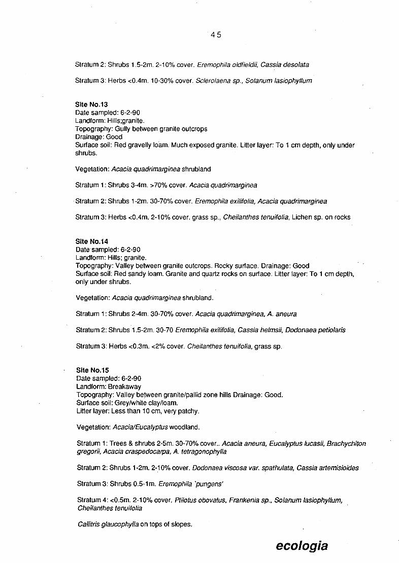
45
Stratum 2: Shrubs 1 .5-2m. 2-10% cover. Eremophila oldfieldii, Cassia desolata
Stratum 3: Herbs <0.4m. 10-30% cover. Sciero/aena sp., Solanum lasiophyllum
Site No.13 Date sampled: 6-2-90 Landform: Hills;granite. Topography: Gully between granite outcrops Drainage: Good Surface soil: Red gravelly loam. Much exposed granite. Litter layer: To 1 cm depth, only under shrubs.
Vegetation: Acacia quadrimarginea shrubland
Stratum 1: Shrubs 3-4m. >70% cover. Acacia quadrimarginea
Stratum 2: Shrubs 1 -2m. 30-70% cover. Eremophila exilifolia, Acacia quadrimarginea
Stratum 3: Herbs <0.4m. 2-10% cover, grass sp., Cheilanthes tenuifolia, Lichen sp. on rocks
Site No.14 Date sampled: 6-2-90 Landform: Hills; granite. Topography: Valley between granite outcrops. Rocky surface. Drainage: Good Surface soil: Red sandy loam. Granite and quartz rocks on surface. Litter layer: To 1 cm depth, only, under shrubs.
Vegetation: Acacia quadrimarginea shrubland.
Stratum 1: Shrubs 2-4m. 30-70% cover. Acacia quadrimarginea, A. ancura
Stratum 2: Shrubs 1 .5-2m. 30-70 Eremophila exilifolia, Cassia helms!!, Dodonaea petiolar!s
Stratum 3: Herbs <0.3m. <2% cover. Cheilanthes tenuifolia, grass sp.
Site No.15 Date sampled: 6-2-90 Landform: Breakaway Topography: Valley between granite/pallid zone hills Drainage: Good. Surface soil: Grey/white clay/loam. Litter layer: Less than 10 cm, very patchy.
Vegetation: AcacialEucalyptus woodland.
Stratum 1: Trees & shrubs 2-5m. 30-70% cover.. Acacia aneura, Eucalyptus !ucasii, Brachychiton gregorii, Acacia craspedocarpa, A. tetragonophylla
Stratum 2: Shrubs 1 -2m. 2-10% cover. Dodonaea viscosa var. spathulata, Cassia artemisio!des
Stratum 3: Shrubs 0.5-1 m. Eremophila 'pungens'
Stratum 4: <0.5m. 2-10% cover. Ptiotus obova (us, Frankenia sp., Solanum lasiophyllum, Cheilanthes tenuifolia
Callitris glaucophylla on tops of slopes.
ecologia

Site No.16 Dates sampled: 6-2-90 and 13-2-90 Landform:Undulating plain. Topography: Sloping plain. Site includes minor drainage line. Drainage: Moderate Surface soil: Red sandy loam, very rocky (ironstone, quartz, chert) Litter layer: To 5 cm depth patchy.
Vegetation: Acacia open woodland
Stratum 1: Trees & shrubs 2-4 m. 30-70% cover. Acacia aneura, A. burkittii, A. quadrimarginea
Stratum 2: Shrubs 1-2 m. 2-10% cover. Hakea arida, Erernophilascoparia, Acacia tetragonophylla, A. aneura, Eremophila fraseri
Stratum 3: Shrubs 0.5-1 m. 2-10% cover. Scaevola spinescens, Cassia heimsil,
Stratum 4: <30cm. <2% cover. Sciero/aena diacantha, Sclero/aena fusiformis
Site No.17 Date sampled: 6-2-90 Landform: Drainage line. Topography: Shallow creek bed & banks Drainage: Good Surface soil: Red sandy loam; Litter layer: Patchy, from 0-20 cm, deposited around plant bases by recent flooding.
Vegetation: Eucalyptus/A cacia woodland;
Stratum 1: Trees 5-8m. 30-70% cover. Eucalyptus lucasii, Acacia aneura, A. burkittii
Stratum 2: Trees & shrubs 2-4m 2-10% cover. Santa/urn lanceolatum, Acacia aneura, Jasminurn caicaréum, A. tetragonophylla, Exocarpus aphyllus
Stratum 3: Shrubs 0.5-1 m. <2% cover. Cassia arternisioides
Site No.18 Date sampled: 6-2-90 Landform: Undulating plain Topography: Flat plain between granite rise and creek. Includes minor drainage line. Drainage: Moderate Surface soil: Red gravelly loam. Surface boulders of granite and quartz. Litter layer: Less than 1 cm, patchy.
Vegetation: Open Acacia aneura woodland.
Stratum 1: Emergent trees >5m. <2% cover. Acacia pruinocarpa
Stratum 2: Trees & shrubs 2-4m. 2-10% cover. Acacia aneura, A. quadrimarginea, Eremophila oldfieldii, A. craspedocarpa, Santa/urn lanceolatum
Stratum 3: Shrubs 0.5-2m. 2-10% cover. Acacia tetragonophylia, A. burkittil, Scaevola spinescens, Eremophila fraseri
Stratum 4: Shrubs <0.5m. 2-10% cover. Sida calyxhyrnenia.
ecologia

47
Site No.19 Date sampled: 6-2-90 Landform: Undulating plain. Topography: Rocky sloping plain Drainage: Poor. Surface soil: Gravelly sand/clay. Quartz rocks <10cm. Litter layer: Negligible
Vegetation: Acacia open woodland
Stratum 1: Trees & shrubs 2-4m. 2-10% cover. Acacia aneura, A. craspedocarpa, A. pruinocarpa
Stratum 2: Shrubs 1 -2m. 2-10% cover. Acacia tetragonophylla
Stratum 3: Shrubs 0.5-1m. 2-10% cover. Eremophila fraseri
Stratum 4: Shrubs <0.5m. 2-10% cover. Solanum lasiophyllum, Sclero!aena sp.
Site No.20 Date sampled: 6-2-90 Landform: Undulating plain Topography: Rocky sloping plain. Drainage: Poor. Surface soil: Red gravelly loam. Much quartz on surface, up to 10cm. diameter. Litter layer: Negligible
Vegetation: Acacia open woodland;
Stratum 1: Trees & shrubs 24m. 2-10% cover. Acacia aneura, A. craspedocarpa, A. tetragonophylla, Santalum lanceolatum
Stratum 2: Shrubs 0.5-1 .5m. 2-10% cover. Scaevola spinescens, Hakea preissll
Stratum 3: Shrubs <0.5m. 2-10% cover. Solanum lasiophyllum, Sclerolaena sp.
Site No.21 Date sampled: 6-2-90 Landform: Drainage line Topography: Creek bed and banks Drainage: Good. Surface soil: Red silt and clay. Very rocky (quartz) Litter layer: Litter deposited up tree trunks to 2 m. Mostly absent from ground surface.
Vegetation: Eucalyptus camaldulensis woodland.
Stratum 1: Trees 5-1 Om. 30-70% cover. Eucalyptus camaldulensis
Stratum 2: Shrubs 2-4m. 2-10% cover. Exocarpus aphyllus, Acacia aneura, A. burkittii, Santalurn lanceolá turn
Stratum 3: Shrubs 0.5-1 m. 2-10% cover. Cassia artemisioides
Stratum 4: <0.5m. 2-10% cover. Grass sp., Solanum lasiophyllum, Maireana planifolia
ecologia
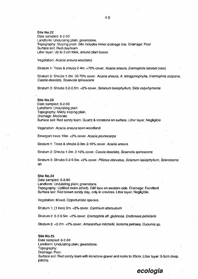
UK
Site No.22 Date sampled: 6-2-90 Landform: Undulating plain; greenstone. Topography: Sloping plain. Site includes minor drainage line. Drainage: Poor Surface soil: Red clay/loam. Litter layer: Up to 3 cm thick, around plant bases.
Vegetation: Acacia aneura woodland.
Stratum 1: Trees & shrubs 2-4m. >70% cover. Acacia aneura, Eremophila Iatrobei (rare)
Stratum 2: Shrubs 1 -2m. 30-70% cover. Acacia aneura, A. tetragonophylla, Eremophila scoparia, Cassia desolata, Scaevola spinescens
Stratum 3: Shrubs 0.2-0.5m. <2% cover. Solanum lasiophyllum, Sida calyxhymenia
Site No.23 Date sampled: 6-2-90 Landform: Undulating plain Topography: Mildly sloping plain. Drainage: Moderate. Surface soil: Red sandy loam. Quartz & ironstone on surface. Litter layer: Negligible
Vegetation: Acacia aneura open woodland
Emergent irees 1 Om. <2% cover. Acacia prunocarpa
Stratum 1: Trees & shrubs 2-3m; 2-10% cover. Acacia. aneura
Stratum 2: Shrubs 1 -2m. 2-10% cover. Gassia desolata, Scaevola spinescens
Stratum 3: Shrubs 0.2-0.5m. <2% cover. Ptilotus obovatus, Solanum lasiophyllum, Sclerolaena sp.
Site No.24 Date sampled: 6-2-90 Landform: Undulating plain; greenstone. Topography: Uplifted rocks (chert). Cliff face on western side. Drainage: Excellent Surface soil: Red-brown sandy clay, only in crevices. Litter layer: Negligible.
Vegetation: Mixed. Opportunistic species.
Stratum 1: (1 tree) 3m. <2% cover. Canthium attenuatum
Stratum 2: 0.2-0.5m. <2% cover. Eremophila aff. glutinosa, Dodonaea petiolaris
Stratum 3: <0.2m. <2% cover. Amaranthus mitchellii, Isotoma petraea, Cucumis sp.
Site No.25 Date sampled: 6-2-90 Landform: Undulating plain; greenstone. Topography: Drainage: Poor. Surface soil: Red sandy loam with ironstone gravel and rocks to 20cm. Litter layer: 0-5cm deep, patchy.
ecologia

SPO
Vegetation: Acacia aneura open shrubland
Stratum 1: Emergent trees 6m. <2% cover. Acacia pruinocarpa
Stratum 2: Shrubs 3-4m. 10-30% cover. Acacia aneura
Stratum 3: Shrubs 1 -2m. 2-10% cover. Cassia helmsii, Scaevola spinéscens
Stratum 4: Shrubs 0.2-0.5m. 2-10% cover. Solanurn lasiophyllurn, Scleroiaena sp.
Site No.26 Dates sampled: 6-2-90 and 12-3-90 Landform: Undulating plain; greenstone. Topography: Low hilV undulating plain. Drainage: Moderate Surface soil: Red clay/loam. Very rocky. Litter layer: Negligible
Vegetation: Acacia woodland
Stratum 1: Trees and shrubs 2-4m. 3070% cover. Acacia aneura, Acacia aft. citrinoviridis, Hakea suberea, Hakea preissii Santa/urn spicatum, Pittospo rum phylliraeoides, Leichardtia australis (creeper)
Stratum 2: Shrubs 1 -2m. <2% cover. Cassia desolata, Eremophila fraseri, Acacia tetragonophylla; Scaevola spinescens, Cassia helmsii
Stratum 3: Shrubs <0.5m. <2%.cover. So/anum /asiophyl/um, Sc/ero/aena sp., Pti/otus obovatus
Site No.27 Date sampled: 7-2-9 0 Landform:Broad valley. Topography: Flat plain. Drainage: Poor. Surface soil: Red sand with quartz gravel. Litter layer: Negligible
Vegetation: Eremophila fraseri open shrubland.
Stratum 1: Trees & shrubs 1 .5-4m. <2% cover. Hakea suberea, Acacia aneura, A. tetragonophylla
Stratum 2: Shrubs 052m. 2-10% cover. Eremophila fraseri (dominant), Eremophila Iatrobei, Cassia deso/ata -
Stratum 3: Shrubs 0.2-0.5m. 2-10% cover. Ptiotus obovatus, Solanum /asiophyl/um, Sc/erolaena sp., Cassia helmsii, Podo/epis capillaris
Site No.28 Date sampled: 7-2-90 Landform: Drainage line. Topography: Creekline. Drainage: Good. Surface soil: Red/brown coarse sand. Litter layer: Up to 10 cm deep under eucalypts, very variable.
ecologia
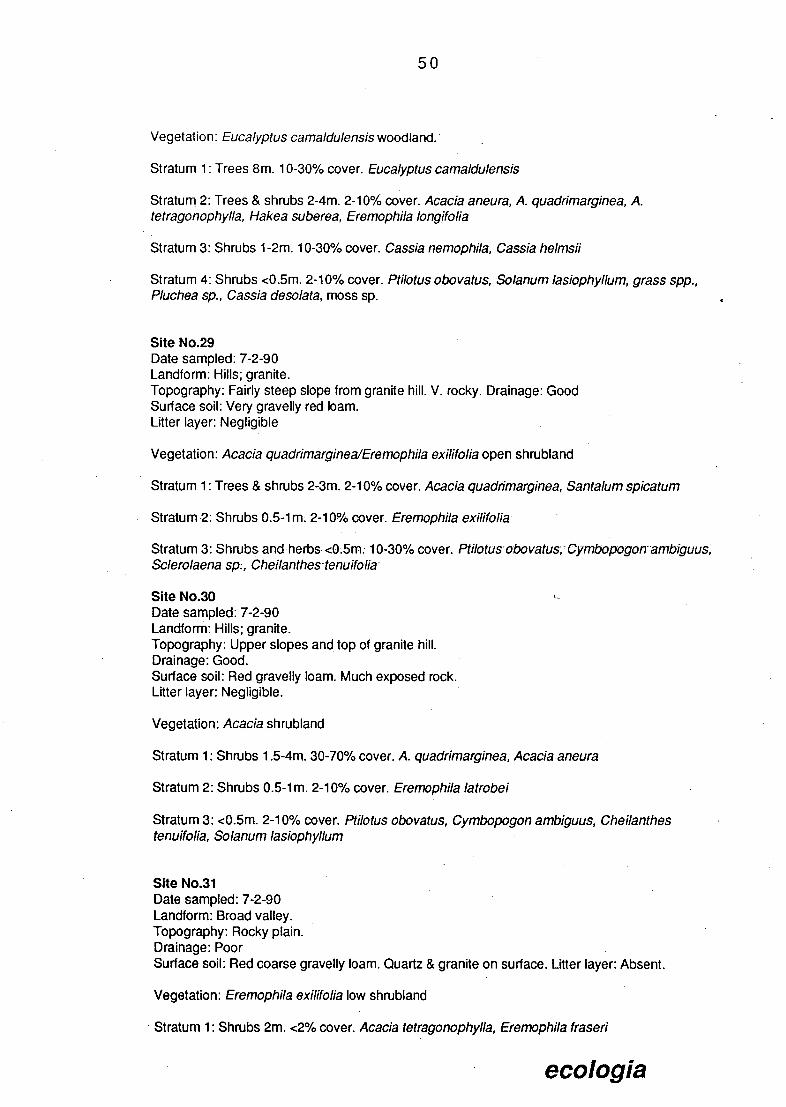
50
Vegetation: Eucalyptus camaldulensis woodland.
Stratum 1: Trees 8m. 10-30% cover. Eucalyptus camaldulensis
Stratum 2: Trees & shrubs 2-4m. 2-100/6 cover. Acacia aneura, A. quadrirnarginea, A. tetragonophylla, Hakea suberea, Eremophila long/folia
Stratum 3: Shrubs 1 -2m. 10-30% cover. Cassia nemophila, Cassia he!rnsii
Stratum 4: Shrubs <0.5m. 2-10% cover. Pt/lotus obovatus, Solanum lasiophyllum, grass spp., Pluchea sp., Cassia deso/ata, moss sp.
Site No.29 Date sampled: 7-2-90 Landform: Hills; granite. Topography: Fairly steep slope from granite hill. V. rocky. Drainage: Good Surface soil: Very gravelly red loam. Litter layer: Negligible
Vegetation: Acacia quadrimarginea/Eremophila exilifolia open shrubland
Stratum 1: Trees & shrubs 2-3m. 2-10% cover. Acacia quadrirnarginea, Santa/urn spicaturn
Stratum 2: Shrubs 0.5-1m. 2-10% cover. Eremophila exilifo/ia
Stratum 3: Shrubs and herbs <0;5rn; 10-30% cover. Ptilotusobovatus; Cymbopogonarnbiguus, Sciero/aena 5;, Cheilanthes-tenuifolia
Site No.30 L
Date sampled: 7-2-90 Landform: Hills; granite. Topography: Upper slopes and top of granite hill. Drainage: Good. Surface soil: Red gravelly loam. Much exposed rock. Litter layer: Negligible.
Vegetation: Acacia shrubland
Stratum 1: Shrubs 1 .5-4m. 30-70% cover. A. quadrimarginea, Acacia aneura
Stratum 2: Shrubs 0.5-1 m. 2-10% cover. Eremophila latrobei
Stratum 3: <0.5m. 2-10% cover. Pti/otus obovatus, Cyrnbopogon arnbiguus, Cheilanthes tenuifolia, Solanum lasiophy//um
Site No.31 Date sampled: 7-2-90 Landform: Broad valley. Topography: Rocky plain. Drainage: Poor Surface soil: Red coarse gravelly loam. Quartz & granite on surface. Litter layer: Absent.
Vegetation: Eremophila exilifolia low shrubland
Stratum 1: Shrubs 2m. <2% cover. Acacia tetragonophylla, Eremophila fraseri
ecologia

51
Stratum 2: Shrubs 0.5m. 2-10% cover. Eremophila exilifolia (dominant), Cassia heImsi Cassia sturti Eremophila fraseri
Stratum 3: 0.2-0.5m. <2% cover. Ptiotus obovatus, Solanum lasiophyllum, Podolepis capillaris, grass sp.
Site No.32 Date sampled 13-3-90 Landform: Broad valley. Topography: Broad plain, with minor drainage line. Drainage: Moderate. Surface soil: Red loam with ironstone and quartz gravel. Litter layer: Negligible
Vegetation: Acacia open woodland
Stratum 1: Trees & shrubs 2-4m. 10-30% cover. Acacia aneura, A. pruinocarpa, Canthium attenuatum, A. craspedocarpa, Acacia coolgardiensis
Stratum 2: shrubs 1 -2m. 10-30% cover. Acacia quadrimarginea, A. aneura, Eremophila Iatrobei, Eremophila fraseri
Stratum 3: 0.5-1 m. 2-10% cover. Eremophila freelingii
Stratum 4: <0.5m. 2-10% cover. Ptilotus obovatus, Maireana triptera, Maireana villosa, Sida calyxhymenia, Solanum lasiophyllum
Site No.33 Date sampled: 13-3-90. Landform: Undulating plain. Topography: Very rocky laterite rise. Drainage: Good Surface soil: Red gravelly loam. Ironstone & quartz on surface Litter layer: Negligible
Vegetation: Acacia open woodland.
Stratum 1: Trees & shrubs 2-3m. 2-10% cover. Acacia aneura, A. quadrimarginea, Eremophila oppositifolia, Eremophila o!dfieIdi Hakea preissll
Stratum 2: Shrubs 1 -2m. 2-10% cover. Eremophila scoparia (dominant), Cassia desolata, Acacia craspedocarpa, Hakea preissil, Cratystylis subspinescens
Stratum 3: Shrubs <0.5m. 2-10% cover. Maireana triptera, Ptiotus obovatus, Solanum lasiophyllum, Podolepis capillaris.
Site No.34 Date sampled: 13-3-90 Landform: Undulating plain. Topography: Broad plain. Drainage: Poor Surface soil: Red gravelly loam. Very rocky surface, ironstone & quartz. Litter layer: Negligible
Vegetation: Acacia aneura open woodland
Stratum 1: Trees & shrubs 2-4m. <2% cover. Acacia aneura, A. burkitti Hakea preissñ.
Stratum 2: 0.5-2m. 2-10% cover. Acacia burkitti4 Cassia desolata, Eremophila fraser4 Scaevola spinescens, Cratystylis subspinescens, Cassia helmsii, Cassia nemophila
ecologia

52
Stratum 3: Shrubs and herbs <0.2m. 10% cover. Chenopods dominant md. Maireana tomentosa, Sclerolaena sp., Salsola kali, also Pt/lotus obovatus, Solanum lasiophyllum, Ptilotus helipteroides
Site No.35 Date sampled: 13-3-90 Landform: Breakaway. Topography: Granite/ weathered granite breakaway. Drainage: Good. Surface soil: Very gravelly red-brown loam. Rocky surface. Litter layer: Negligible
Vegetation: Mixed shrubland
Stratum 1: Trees & shrubs 3-5m. 2-10% cover. Acacia aneura (dominant), A. quadrimarginea, Exocarpus aphyllus
Stratum 2: Shrubs 1 -2m. 2-10% cover. Hakeá arida, Acacia tetragonophylla
Stratum 3: Shrubs 0.3-1 m. 10-30% cover. Scaevola spinescens, Eremophila 'pungens', Cassia desolafa, Ptiotus obovatus, Eremophila exilifolia, Eremophila oppositifolia, Dodonaea viscosa var. spathulata Stratum 4: Shrubs <0.3m. 2-10% cover. Maireana triptera, Sclerolaena diacantha, Sclerolaena sp., Frankenia sp., Pt/lotus obovatus, Sida calyxhymenia, Eremophila latrobei
ecologia

53
APPENDIX C
Yakabindie Nickel Project Area Fauna Species List
ecologia

54
APPENDIX C: MAMMAL SPECIES WHICH OCCUR OR ARE EXPECTED TO OCCUR IN THE YAKABINDIE NICKEL PROJECT AREA.
MONOTREMATA TACHYGLOSSI DAE
Tachyglossus aculeatus Echidna
MARSUPIALIA DASYURIDAE
Antechinomys laniger Kultarr Ningauiridei Wongai Ningaui Pseudantechinus macdonnellensis Fat-tailed Antechinus Sminthopsis crassicaudata Fat-tailed Dunnart Sminthopsis hirtipes Hairy-tooted Dunnart Sminthopsis macroura Stnpe-faced Dunnart
MACROPODIDAE Macropus robustus Euro Macropus rufus Red Kangaroo
CHIROPTERA MOLOSSIDAE
Mormopterus planiceps Little Mastif Bat Tadarida australls White-striped Mastiff Bat
VERSPERTILIONIDAE Chalinolobus gouldll Gould Wattled Bat Eptesicus pumilus Little Cave Eptesicus Nycticeius baistoni Western Broad-nosed Bat Nycticeiusgreyii Little Broad-nosed Bat Nyctophilus geoffroyi Lesser Long-eared Bat
RODENTIA HYDROMYINAE
Leporillus apicalis Stick nest rat MURIDAE
Pseudomys hermannsburgensis Sandy Inland Mouse
CARNIVORA CANIDAE
Canis familiaris dingo Dingo
extinct- old nests only
INTRODUCED MAMMALS
Mus musculus House Mouse Bos taurus Cow Ovisaries Sheep Capra hircus Goat Equs cabal/us Horse Oryctolagus cuniculus Rabbit Vulpes vu/pes Fox Fells catus Cat
ecologia

55
APPENDIX C: BIRD SPECIES WHICH OCCUR OR ARE EXPECTED TO OCCUR IN THE YAKABINDIE NICKEL PROJECT AREA.
CASUARI DAE Dromaius novaehollandiae Emu
PODICIPEDIDAE Prodiceps novaehollandiae Little Grebe Prodiceps poliocephalus Hoary-headed Grebe
AREIDAE Ardae novaehollandiae White-faced Heron Egretta a/ba White Egret
ANATIDAE Anas gibberifrons Grey Teal Anas superci/iosus Black Duck Bizira lobata Musk Duck Cygnus atratus Black Swan Tadoma tadornoides Mountain Duck
ACCIPITRIDAE Accipter cirrhocephalus Collared Sparrowhawk Accipter fasciatus Australian Goshawk Aqulla auda.x Wedge-tailed Eagle Circus assimi/is Spotted Harrier Elanus rotatus Black-shouldered Kite Hamirostra melanosternon BlaOk-breasted Buzzard Heraaetus morphnoides Little Eagle Lophoictiniaisura Square-tailed Kite Milvus migrans Fork-tailed Kite
FALCON I DAE Falco berigora Brown Falcon Falco cenchroides Nankeen Kestrel Falco longipennis Little Falcon Falco peregrinus Peregrine Falcon
M EGAPODI IAE Leipoa ocel/ata Mallee Fowl
TURNICIDAE Turnix velox Little Button-quail
RALLIDAE Gal/mu/a venfralis Black-tailed Native Hen Porzana tabuensis Spotless Crake
OTIDIDAE Eupodotis australis Bustard
BURHINIDAE Burhinus magnirostris Southern Stone Curlew
CHARADRIIDAE Vane//us tricolor Banded Plover Peltohyas australis Australian Dotterel
COLUMBIDAE Geopelia cuneata Diamond Dove Ocyphaps lophotes Crested Pigeon Phas chalcoptera Common Bronzewing
PSI1TACIDAE Barnardius zonarius Port Lincoln Parrot Cacafua roseicapilla Galah Melopsittacus undulatus Budgerigar Neophema bourkii Bourke's Parrot Neophema elegans Elegant Parrot Neophema splendida Scarlet Breasted Parrot Nymphicus hollandicus Cockatiel
ecologia

56
Polyte/is alexandrae Alexandra Parrot Polytelis antho pep/us Regent Parrot Psephotus varius Mulga Parrot
CUCULIDAE Chrysococcyx basalis Horse1ields Bronze Cuckoo Chrysococcyx osculans Black-eared Cuckoo Cuculus pallidus Pallid Cuckoo
STRIGIDAE Ninox novaeseelandiae Boobook Owl Tyto A/ba Barn Owl Tyto novaehollandiae Masked Owl
PODARGIDAE Podargus strigoides Tawny Frogmouth
AEGOTHELIDAE Aegotheles cristatus Australian Owlet-nightjar
CAPRIMULGIDAE Euro Stopodus argus Spotted Nightjar
ALCEDINIDAE Halcyon pyrrhopygia Red Backed Kingfisher
MEROPIDAE Merops ornatus Rainbow Bee-eater
HIRUNDINIDAE Hirundo ariel Fairy Martin
MOTACILLIDAE Anthus novaeseelandiae Richards Pipit
CAMPEPHAGIDAE Coracina. maxima. Ground Cuckoo-shrike. Coracina novaehollandiae Black-faced Cuckoo-shnke Lalagesueurll White Winged Triller
PACHYCEPHALIDAE Oreocica gutturalis Crested Beilbird Pachycephalus rufiventris Rufous Whistler Petroica goodenovll Red-capped Robin Petroica cucullata Hooded Robin
MONARCHIDAE Rhipidura ieucophrys Willie Wagtail
ORTHONYCH I DAE Cinclosoma castanotum Chestnut Quail-thrush Cinclosoma cinnamomeum Cinnamon Quail-thrush Pomatostomus superciliosus White-browed Babbler Pomatostomus temporalis Grey-crowned Babbler
ACANTHIZIDAE Acanthiza apicalis Broad-tailed Thornbill Acanthiza chrysorrhoa Yellow-rumped Thornbill Acanthiza uropygialis Chestnut-ru mped Thornbill Aphelocephala leucopsis Southern White-face Aphelocephala nigricincta Banded White-face Calamanthus fuliginosus Fieldwren Smicrornis brevirostris Weebill
MALURIDAE Amytornis striatus Straited Grass Wren Amytornis textilis Western Grass Wren Malurus Iambertll Variegated Wren Malurus leucopterus Blue and White Wren Malurus splendens Splendid Fairy-wren Stipiturus ruficeps Rufous-crowned Emu-wren
SYLVIIDAE Cincloramphus cruralis Brown Songlark Eremiornis carteri Spinifexbird
ecologia

57
DAPHOENOSITTIDAE Daphoenositta chrysoptera Australian Sittella
CLIMACTERIDAE Climacteris affinis White-browed Tree Creeper
DICAEIDAE Dicaeum hirundinaceum Mistletoe Bird
PAR DALOTI DAE Pardalotus rubricatus Red-browed Pardalote Pardalotus striatus Striated Pardalote
MELIPHAGIDAE Acanthagenys rufogularis Spiny-cheeked Honeyeater Conopophila whitei Grey Honeyeater Certhionyx variegatus Pied Honeyeater Ephithianura aurifrons Orange Chat Ephthianura tricolor Crimson Chat Manorina flavigula Yellow-throated Miner Meliphaga cratitia White-gaped Honeyeater Meliphaga ornata Yellow-plumed Honeyeater Meliphaga penicillata White-plumed Honeyeater Meliphaga plumula Yellow-fronted Honeyeater Meliphaga virescens Singing Honeyeater Phylidonyris albifrons White-fronted Honeyeater
PLOCEIDAE Poephila guttata Zebra Finch
GRALLINIDAE Grallina cycanoleuca Magpie-lark
ARTAM IDAE Artamus cinereus Black-faced Woodswallow Artamus minor Little Woodswallow Artamus personatus Masked Woodswallow
CRACTICIDAE Cracticus nigrolgularis Pied Butcherbird Cracticus torquatus Grey Butcherbird Gymnorhina dorsalis Western Magpie Gymnorhina tibicen Black-backed Magpie Strepera versicolor Grey Currawong
PARADISAEI DAE Pti!onorhynchus maculatus Spotted Bowerbird
CORVIDAE Corvus bennett! Little Crow Corvus orru Australian Crow
ecologia

Fiore Mue
APPENDIX C: REPTILES AND AMPHIBIANS WHICH OCCUR OR ARE EXPECTED TO OCCUR IN THE YAKABINDIE NICKEL PROJECT AREA.
Frogs
HYLIDAE Cyclorana maini Cyclorana plafycephalus
LEPTODACTYLIDAE Neobatrachus centralis Neobatrachus kunapalari Neobatrachus wilsmorei Pseudophryne occidentalis
Lizards
GEKKONIDAE Diplodactylus conspicillatus Diplodactlyus granariensis Diplodactylus puicher Diplodactylus strophurus Diplodactylus wellingfoniae Gehyra purpurascens Gehyra variegata Heteronotia binoei Nephurus vertebralis Rhynchoedura ornata
PYGOPODIDAE De/manasuta Lialis burtonis
AGAMIDAE Caimanops amphiboluroides Ctenophorus caudicinctus Ctenophorus inermis Ctenophorus ornatus Ctenophorus reticulatus Ctenophorus scutulatus Gemmatophora longirostris Moloch horridus Pogona minor Tympanocryptis cephala
SCINCIDAE Gtenotus Ieonhardii Ctenotus pantherinus Egernia depressa Eremiascincus richardsonii Lerista desertorum Menetia greyll Morethia butleri Tiliqua multifasciata
VARANIDAE Varanus caudolineatus Varanus gouldll Varanus panoptes Varanus tristis
Water-holding Frog
Fat-tailed Gecko
Tree Otella Bynoe's Gecko
Beaked Gecko
Burtons Snake Lizard
Ring-tailed Dragon
Ornate Dragon
Lozenge-marked Dragon
Thorny Devil Bearded Dragon
Pygmy Spiny-tailed Skink Broad-banded Sand Swimmer
Centralian Blue-tongued Lizard
Gould's Monitor
ecologia

59
Snakes
TYPHLOPI DAE Rhamphotyph/ops hamatus
BOIDAE More/ia stimsoni Stimson's Python
ELAPIDAE Acanthophis pyrrhus Desert Death-Adder Densionia fasciata Rosen's Snake Furina ornata Pseudechis austra/is Mulga Snake Pseudechis but/en Pseudonaja modesta Ringed Brown Snake Pseudonaja nuchalis Gwartlar Rhinoplocepha (us monachus Monk Snake Vermicella fasciolata
ecologia

mul
APPENDIX D
Wanjarri Nature Reserve Fauna Species List
ecoloqia

61
APPENDIX D: MAMMALS OF WANJARRI NATURE RESERVE
MONOTREMATA TACHYGLOSSI DAE
Tachyglossus aculeatus Echidna
MARSUPIALIA DASYURIDAE
Antechinomys laniger Kultarr Ningauiridei Wongai Ningaui Pseudantechinus macdonnellensis Fat-tailed Antechinus Sminthopsis hirtipes Hairy-footed Dunnart Sminthopsis macroura Stripe-faced Du nnart
MACROPODI DAE Macropus robustus Euro Macropus rufus Red Kangaroo
CHIROPTERA MOLOSSI DAE
Mormopterus planiceps Little Mastif Bat Tadarida australis White-striped Mastiff Bat
VERSPERTILIONIDAE Chailnolobus gouldll Gould Wattled Bat Eptesicus pumilus Little Cave Eptesicus Nycticeius balstoni Western Broad-nosed Bat Nyctophilus geoffroyi Lesser Long-eared Bat
RODENTIA HYDROMYINAE
Leporillus apicalis Stick nest rat MURIDAE
Notomys alexis Spinifex Hopping Mouse Pseudomys hermannsburgensis Sandy Inland Mouse
CARNIVORA CANIDAE
Canis famillaris dingo Dingo
extinct- old nests only
INTRODUCED MAMMALS Mus musculus House Mouse Bos taurus Cow Ovisaries Sheep Camelus dromedarius Camel Equs caballus Horse Oryctolagus cuniculus Rabbit Vulpes vulpes Fox
SOURCES
1 Mckenzie,N.L. and Rotfe,J.K. (in press) Vertebrate Fauna. In Mckenzie,N.L. eta! 'The Biological Survey Of The Eastern Goldfields of Western Australia: Sandstone - Sir Samuel Area.
2 Mr A. Chapman, Department of Conservation and Land Management. Kalgoorlie.
ecologia

MIA
APPENDIX D: BIRDS OF WANJARRI NATURE RESERVE
CASUARI DAE Dromaius novaehollandiae Emu
PODICIPEDIDAE Prodiceps novaehollandiae Little Grebe Prodiceps poliocephalus Hoary-headed Grebe
AREIDAE Ardae novaehollandiae White-faced Heron Egretta alba White Egret
ANATIDAE Anas gibberifrons Grey Teal Anas superciliosus Black Duck Bizira lobata Musk Duck Cygnus atratus Black Swan Tadorna tadornoides Mountain Duck
ACCIPITRIDAE Accipter cirrhocephalus Collared Sparrowhawk Accipter fasciatus Australian Goshawk Aqulla audax Wedge-tailed Eagle Circus assimills Spotted Harrier Elanus rotatus Black-shouldered Kite Hamirostra melanosternon Black-breasted Buzzard Heraaetus morphnoides Little Eagle Lophoictinia isura Square-tailed Kite Milvus migrans Fork-tailed Kite
FALCONIDAE Falco berigora Brown Falcon Falco cenchroides Nankeen Kestrel Falco longipennis Little Falcon Falco peregrinus Peregrine Falcon
MEGAPODIIAE Leipoa ocellata Mallee Fowl
TURNICIDAE Turnix velox Little Button-quail
RALLI DAE Gal/mu/a ventralis Black-tailed Native Hen Porzana tabuensis Spotless Crake
OTIDIDAE Eupodotis australis Bustard
BURHINIDAE Burhinus magnirostris Southern Stone Curlew
CHARADRIIDAE Vane//us tricolor Banded Plover Pe/tohyas australis Australian Dotterel
RECURVIROSTRIDAE Recurvirostra novaehollandiae Red-necked Avocet
COLUMBIDAE Geopelia cuneata Diamond Dove Ocyphaps lophotes Crested Pigeon Phas chalcoptera Common Bronzewing
PSITACIDAE Barnardius zonarius Port Lincoln Parrot Cacatua roseicapilla Gaiah Melopsittacus undu/atus Budgerigar Neophema bourkii Bourke's Parrot Neophema elegans Elegant Parrot Neophema sp!endida Scarlet Breasted Parrot
ecologia

Nymphicus hollandicus Cockatiel Polyte Ifs alexandrae Alexandra Parrot Polytelis anthopeplus Regent Parrot Psephotus varius Mulga Parrot
CUCULIDAE Chrysococcyx basalis Horsefield's Bronze Cuckoo Chrysococcyx osculans Black-eared Cuckoo Cuculus pallidus Pallid Cuckoo
STRIGIDAE Ninox novaeseelandiae Boobook Owl Tyto A/ba Barn Owl Tyto novaehollandiae Masked Owl
PODARGI DAE Podargus strigoides Tawny Frogmouth
AEGOTH ELI DAE Aegotheles cristatus Australian Owlet-nightjar
CAPRIMULGIDAE Eurostopodus argus Spotted Nightjar
ALCEDINIDAE Halcyon pyrrhopygia Red Backed Kingfisher
MEROPIDAE Merops ornatus Rainbow Bee-eater
HIRUNDINIDAE Hinindo ariel Fairy Martin
MOTACILLIDAE Anthus novaeseelandiae Richards Pipit
CAMPEPHAGIDAE Coracina maxima Ground Cuckoo-shrike Coracina novaehollandiae Black-faced Cuckoo-shrike Lalage sueurii White Winged Trifler
PACHYCEPHALIDAE Oreocica gutturalis Crested Beilbird Pachycephalus rufiventris Rufous Whistler Petroica goodenovii Red-capped Robin Petroica cucullata Hooded Robin
MONARCHIDAE Rhipidura leucophrys Willie Wagtail
ORTHONYCHIDAE Cinclosoma castanotum Chestnut Quail-thrush Cinclosoma cinnamomeum Cinnamon Quail-thrush Pomatostomus superciliosus White-browed Babbler Pomatostomus temporalis Grey-crowned Babbler
ACANTHIZIDAE Acanthiza apicalis Broad-tailed Thornbill Acanthiza chrysorrhoa Yellow-rumped Thornbill Acanthiza uropygialis Chestnut-rumped Thornbill Aphelocephala leucopsis Southern White-face Aphelocephala nigricincta Banded White-face Calamanthus fuliginosus Fieldwren Smicrornis brevirostris Weebill
MALURIDAE Amytornis striatus Straited Grass Wren Amytornis textilis Western Grass Wren Malurus lambertii Variegated Wren Malurus leucopterus Blue and White Wren Malurus splendens Splendid Fairy-wren Stipiturus ruficeps Rufous-crowned Emu-wren
SYLVIIDAE Cincloramphus cruralis Brown Songlark
ecologia

Eremiornjs carteri DAPHOENOSITTIDAE
Daphoenositta chrysoptera CLIMACTERIDAE
Climacteris affinis DICAEIDAE
Dicaeum hirundinaceum PARDALOTIDAE
Pardalotus rubricatus Pardalotus striatus
MELIPHAGIDAE Acanthagenys rufogularis Conopophila whitei Ephithianura aurifrons Ephthianura tricolor Manorina flavigula Meliphaga cratitia Meliphaga ornata Meliphaga penicillata Meliphaga plumula Meliphaga virescens Phylidonyris albifrons
PLOCEIDAE Poephila guttata
GRALLINIDAE Gra/lina cycanoleuca
ARTAMIDAE Artamus cinereus Artamus minor Artamus personatus
CRACTICIDAE Cracticus nigrolgularis Cracticus torquatus Gymnorhina dorsalis Gymnorhina tibicen Strepera versicolor
PARADISAEIDAE Ptilonorhynchus maculatus
CORVIDAE Corvus bennetti Corvus OITU
Spinifexbird
Australian Sittella
White-browed Tree Creeper
Mistletoe Bird
Red-browed Pardalote Striated Pardalote
Spiny-cheeked Honeyeater Grey Honeyeater Orange Chat Crimson Chat Yellow-throated Miner White-gaped Honeyeater Yellow-plumed Honeyeater White-plumed Honeyeater Yellow-fronted Honeyeater Singing Honeyeater White-fronted Honeyeater
Zebra Finch
Magpie-lark
Black-faced Woodswallow Little Woodswallow Masked Woodswallow
Pied Butcherbird Grey Butcherbird Western Magpie Black-backed Magpie Grey Currawong
Spotted Bowerbird
Little Crow Australian Crow
SOURCES
1 Moriarty,T.K. (1972) Birds of Wanjarri, W.A. EMU 72:1-7
2 Mckenzie,N.L. and Rolfe,J.K. (in press) Vertebrate Fauna. In Mckenzie,N.L. et a! 'The Biological Survey Of The Eastern Goldfields of Western Australia: Sandstone - Sir Samuel Area.
3 Mr A. Chapman, Department of Conservation and Land Management, Kalgoorlie.
ecologia

65
APPENDIX D: REPTILES AND AMPHIBIANS OF WANJARRI NATURE RESERVE
HYLI DAE
Cyclorana main! Cyclorana platycephalus Water-holding Frog
LEPTODACTYLIDAE
Neobatrachus sp.
GEKKONIDAE
D!plodactylus conspidilatus Fat-tailed Gecko Diplodactylus elder! Diplodactylus pulcher D!plodactylus strophurus Diplodactylus wel/ingtoniae Gehyra var!egata Tree DteIIa Heteronot!a binoei Bynoes Gecko Nephurus vertebra/is Rhynchoedura ornata Beaked Gecko
PYGOPODIDAE
Delma butler! De/ma grayii De/ma fraseri Pygopus nigriceps nigriceps
AGAMIDAE
Caimanops amphiboluroides Ctenophorus caudicinctus Ring-tailed Dragon Ctenophorus inermis Ctenophorus iso/epis Military Dragon Ctenophorus ornatus Ornate Dragon Ctenophorus salinarum Salt Lake Dragon Ctenophorus scutulatus Lozenge-marked Dragon Gemmatophora longirostris Moloch horridus Thorny Devil Pogona m!nor Bearded Dragon Tympanocryptis cephala
SCINCIDAE
Ctenotus ariadne Ctenotus calurus Ctenotus grandis Ctenotus helenae Ctenotus leonhard!! Ctenotus pantherinus Ctenotus quattuordec!m/ineatus Ctenotus schomburgk!mi Egern!a depressa Pygmy Spiny-tailed Skink Egern!a formosa Egernia inornata Desert Skink Eremiasc!ncus r!chardsonii Broad-banded Sand Swimmer Ler!sta bipes
ecologia

Lerista desertorum Menetia greyii Morethia but/en Ti/iqua mu/tifasciata
VARANIDAE
Varanus caudolineatus Varanus gouldii Varanus panoptes
TYPHLOPIDAE
Rhamphotyphiops hamatus
ELAPIDAE
Densionia fasciata Pseudechis australis Pseudonaja modesta Pseudonaja nuchalis Rhinoplocepha (us monachus Vermicella bertholdi Vermicella semifasciata
Centralian Blue-tongued Lizard
Gould's Monitor
Rosen's Snake Mulga Snake Ringed Brown Snake Gwattjar Monk Snake Jan's Banded Snake Southern Shovel-nosed Snake
SOURCES
1 Mckenzie,N.L. and Rolfe,J.K. (in press) Vertebrate Fauna. In Mckenzie,N.L. et a! 'The Biological Survey Of The Eastern Goldfields of Western Australia: Sandstone - Sir Samuel Area.
2 Mr A. Chapman, Department of Conservation and Land Management. Kalgoorlie.
3 Mr L.A. Smith, Reptile Department Western Australian Museum. Perth. Museum collection database.
ecologia

APPENDIX D

APPENDIX Dl
SoilIZIRock Engineering

0
wo
>C14 Cl
D
CC
co
Is
ui
I CD
i
Lj CD
CX
••
CD CD
Jw öOö


Our ref: 2488/00/IG/jb
Sheet 1 of 12 12488 D /REP
PROJECT YAKABINDIE FEASIBILITY STUDY
CLIENT: MINPROC ENGINEERS PTY LTD
PROJECT MINPROC JR JOINT VENTURE n.-.nr.
lOCATION: YAKABINDIE VIA LEINSTER
SUBJECT: DESIGN CALCULATIONS, CREEK DIVERSIONS
1.0 SUMMARY OF FLOWS
Q=VA Circulated for comment only
Flow in all channels:
PP JM1ARy Q = 140 rn3/sec Not Approved for Construction
1.1 Jones Creek
Slope 1:322.9
Base width 20m
Average depth of flow = 2.25m
Velocity = 2.8 rn/sec
Base width 30m
Average depth of flow = 1.70rn
Velocity = 2.6 rn/sec
Soil & Rock Engineering Pty. Ltd. PLATE D3

Circulated for comment only
Not Approved for Construction
Our ref: 2488/00/IG/jb Sheet 2 of 12 12488/REP
SUBJECT: DESIGN CALCULATIONS, CREEK DIVERSIONS (cont)
1.2 Jones Creek Western Tributar
Slopes 1:150 and 1:283
Base width 20m
Average depth of flow = 1.80m
Velocity = 3.6 rn/sec
Base width 30m
Average depth of flow = 1.70m
Velocity = 2.6 rn/sec
2.0 DESIGN FOR YAKAJ3INDIE CREEK DIVERSIONS
Given:
Stream flow calculations determined using Mannings formula
(reference Australian Rainfall and Runoff);
Q = AR066 S°5 or A' 66 s05
n n
where Q = flow m3/sec
A = flow c/s'al area m2
S = slope rn/rn
n = Mannings No.
p = wetted perimeter m
Diversions are designed to cater for January 1990 estimated flows.
Q = 140 m3/sec .........................(Rockwater, 1990)
n = 0.030 (channel excavated rock) .... (Australian Rainfall
and Runoff)
Soil & Rock Engineering Pty. Ltd. PLATE 1)4

Circulated for comment only
i 3.
Not Approved for Construction
Our ref: 2488/00/IG/jb Sheet 3 of 12 12488D/REP
SUBJECT: DESIGN CALCULATIONS, CREEK DIVERSIONS (cont)
2.1 Jones Creek Western Tributar
Q = 140 rn3/sec
n = 0.030
S = Ornto 660m
660m to 760m
760m to 1610m
1:150
1:150 to 1:283
1:283
ie. 4.4m fall
ie. 0.6rn fall
ie. 3.Orn fall
at chainage Urn IL = 526m
1610rn IL = 518m
fall = 8.Om
S = 4.4 = 0.00667 upper section 1:150
660 - 0
S = 3.0 = 0.0035 lower section 1:283
1610 - 760
Check flow depth for channels, channel profile to he trapezoidal
upper section w = 20m
lower section w = 30m
Soil & Rock Engineering Pty. Ltd. PLATE D5

Circulated for comment only
r"t IRj1 1'
Not Approved for Construction
Our ref: 2488/00/IG/jb Sheet 4 of 12 1248 8/REP
SUBJECT: DESIGN CALCULATIONS, CREEK DIVERSIONS (cont)
Check flow depth
2.1.1 Upper Section
Q = A166 s05 O•66
.'. 140.00 = A' 66 0.0816
0.03 x p°•66
. 51.50 = ALO6
p0.66
Q = 140 m3/sec S = 0.00667
n = 0.030 = 0.816
A = dw + 1.5 d 2 x 2 2
p = w + ( 1.5 d2 + d2 ) x 2
Given base width = 20m, determine depth
Tryd=1.8m .. A 40.86m2
A166 = 472.88
= A' 66 p = 26.49 m
p066 = 8.69
= 472.88 = 54.4 (need 51.5) .. lower
8.69
Soil & Rock Engineering Pty. Ltd. PLATE D6

Circulated for comment only
rm , tf
Not Approved for Construction
Our ref: 2488/00/IG/jb Sheet 5 of 12 12488/REP
SUBJECT: DESIGN CALCULATIONS, CREEK DIVERSIONS (cont)
Tryd=1.7m .. A =38.33m2
A1.66 = 425.37
A166 p = 26.13 m
0.66 p066 = 8.62
= 425.37 = 49.3 (need 51.5) .. higher
8.62 * for upper section assume flow to be 1.8 m deep
2.1.2 Lower Section
Q = A166S 0.5
Q = 140 rn3/sec S = 0.0035
n fl = 0.03 SO.5 = 0.059
. 140.00 = AL 6G 0.059
0.03 x
71.20 = A' 66 0.66
A = dw + 1.5 d2 x 2 2
pw+( 1.5d2 +d2 )x2
Soil & Rock Engineering Pty. Ltd. PLATED7 .

Circulated for comment only
q, i
Not Approved for Construction
Our ref: 2488/00/IGIjb Sheet 6 of 12 12488/REP
SUBJECT: DESIGN CALCULATIONS, CREEK DIVERSIONS (cont)
Base width now 30m, determine depth
Tryd=1.8rn ..A =58.86m2
A166 = 866.76
= A166 p 36.49 m
0•66 = 10.74
= 866.76 = 80.7 .. lower
10.74
Trydl.7m .. A 55.33m2
A166 = 782.19
= A166 p = 36.13 m
p°66 p066 = 10.67
= 782.19 = 73.3 (need 71.2) . • assume depth is 1.7m
10.67
* for lower section assume flow to be 1.7m deep.
Soil & Rock Engineering Pty. Ltd. PLATE D8

Circulated for comment only
Not Approved for Construction
Our ref: 2488/00/IG/jb Sheet 7 of 12 12488/REP
SUBJECT: DESIGN CALCULATIONS, CREEK DIVERSIONS (cont)
Lowest freeboard is at chainage 560m (creek crossing).
IL = 522.27 GL 524
channel depth = 1.7m
.. channel will overtop at 140 rn3/sec flow (depth of flow 18m)
Install gabion reventment to RL 526 in this area.
2.1.3 Summary
Chainage
Urn to 660m (660)
660m to 760m (100)
760m to 1610m (850)
Slope IL
1:150 526.0 to 521.6
variable 521.6 to 521.0
1:283 521.0 to 518.0
Between 660m and 760m:
Invert grade changes at a rate of 1:12 every lOm over lOOm.
At the same time the invert width increases at a rate of lm every lOm
or deflection angle 9 = 2.87°
Soil & Rock Engineering Pty. Ltd.
PLATE 1)9

Cftcutated for comment only
&1JL Mh ' - ['lot Approved for Construction
Our ref: 2488100/IG/jb Sheet 8 of 12 12488/REP
SUBJECT: DESIGN CALCULATIONS, CREEK DIVERSIONS (cont)
2.2 Jones Creek Diversion
2.2.1 Upper Section
Om to 1700m, invert width 20m.
Q = AL66 SO.5 Q = 140 rn3/sec S = 0.00310
p0.66 n = 0.030
0.5 = 0.05565
(Slope: 7m drop over 2260m = 1:322.9)
. 140.00 = A166 0.05565
0.03 x p°• 66
.. 75.47 = AL 6 0.66
Design parameters for channel as before, ie. trapezoidal.
••. AL66 = 75.47 0.66
Soil & Rock Engineering Pty. Ltd. PLATE JJ1O

Circulated for comment only
/ot Approved for Construction
Our ref: 2488/00/IG/jb Sheet 9 of 12 1248 8/REP
SUBJECT: DESIGN CALCULATIONS, CREEK DIVERSIONS (cont)
For 20m width, check 2.2m depth
Try d = 2.2m .. A = 51.26 m2
A166 = 689.02
= A166 p = 26.60 m
0.66 p0•66 = 8.72
= 689.02 = 79.02 .. try lower depth
8.72
Tryd2.lm .. A = 48.62m2
A166 = 631.00 = AL 66 p = 27.57 m
0.66 0.66 = 8.93
= 631.00 = 70.66
8.93 * for upper section flow will be approximately 2.15m deep.
4
Soil & Rock Engineering Pty. Ltd. PLATE Dli -

Circulated for comment only
ç- r 77.
J Not Approved for Construction
Our ref: 2488/00/IG/jb
Sheet 10 of 12 1248 8/REP
SUBJECT: DESIGN CALCULATIONS, CREEK DIVERSIONS (cont)
2.2.2 Lower Section
Lower section channel width increases to 30m
determine flow depth.
From above A166 = 75.47, try flow depth of 1.7m.
p0.66
Trydl.7m .. A =55.33m2
A166 = 782.31 = AL 66 p = 36.13 m
pO•66 p06 = 10.67
= 782.31 = 73.32 .. flow is higher
10.67
Trydl.9m .. A 62.41m2
A186 = 955.38
= A166 p = 36.85 m
0.66 0.66 = 10.81
= 955.38 = 88.38 .. flow is lower
10.81
* for lower section flow will be approximately 1.75m deep.
Soil & Rock Engineering Pty. Ltd. PLATE D12

Circulated for comment only
L.J i - i
Not Approved for Construct/on
Our ref: 2488/00/IG/jb Sheet 11 of 12 12488/REP
SUBJECT: DESIGN CALCULATIONS, CREEK DIVERSIONS (cont)
3.0 RADIUS CALCULATIONS
3.1 Jones Creek
Circumference = IY D
= ir 2r
Chainages
Radius
Bend 1, G= 49°, radius = 664m
length of arc
arc = il2r
360
= c'rir 9 v AA4 Y 4
360
= 567.9m
Bend 2, 140 , radius = 520m
. length of arc
arc lix 2 x 520 x 14
360
= 127.Om
Bend 3, 9 160 , radius = 441m
. length of arc
arc = 1x 2 x 442 x 16
360
=
1.23.4m
Soil & Rock Engineering Pty. Ltd.
PLATE D13

Circulated for comment only
i 1• 'Vot Approved for Construction
Our ref: 2488/00/IG/jb Sheet 12 of 12
12488 /REP
SUBJECT: DESIGN CALCULATIONS, CREEK DIVERSIONS (cont)
4.0 HYDRAULIC JUMP
4.1 Jones Creek
Base 20m to 30m with no change in slope, .. small hydraulic jump.
Given Fr12 = 1y ( y +1) Yi = 2.25
2 Yi ( Y ) Y2 = 1.7
= lx 1.7x C 1.7 +1)
2 2.25 ( 2.25
= 0.378 x 1.755
= 0.66
Typically for Froude numbers below 1.7, little energy loss occurs,
so no jump form.
4.2 Jones Creek Western Tributar
Fr12 = lx 1.7x ( 1.7 +1) YJ = 1.8
2 1.8 ( 1.8 ) y2 = 1.7
= 0.47 x 1.94
= 0.91
Fr less than 1.7, so no hydraulic jump will occur.
Soil & Rock Engineering Pty. Ltd.
PLATE D14

Wl7W/fvw /f40'70 w4w Por w O'J7( 79' c7i d"
73c6" ,'o Jtvp c'pioj OQZ 1•" / VaNJ 5?7 10/V Ib'
o0.v7ç
c"7OWQ"
HIOW, MAC/I? fV/CAJ ,v,w
icxroi TN3IN IGNI8V>IVA NOII3S 1VIdAI — NOIIVIflI9VH dLAJflG 31SVM
• 76'7/L.VW c6' ivooç 6, IC7 O'P/S'b'6'2 JWIç, rV0fJ6./ P99A$'( O'IVÔ' 9/WW&7?2 £"d a'4qJ%( /vQ/Jo7p4 Q.,Y6, 7/0cscI .fc' 9Wa&P,dS fr1I'' 5/c6'P 9111 c53b'9c'fr'd of ivc' 3(70 (7P/'V6' r CV f"0/I&'I,'7/g6'N9b'
SP/6fb'A p.2ofg.'7ç ave7Qgp 4'&'? 16" o'Ct"i7' '(tVp ccva'r'j csPv9Q's',' o',•v6' cv 737761b'Vô&' AW9J.7/1 7717.,' qE yo'si"c' ct•r POW t4'61P 1X-s7vr -
/ t4'ç Q'fV(79 /'9'/4' C4.'/
.cz ~- ,r7
?6/ 7 r7 936b'/ tYb' P'Q' E °1 9/v1d&'SW0C7" a/va'
jva,co,' .I/VPAP'o' / N1/17 / a'Jg2A G'7 RO 17.1 J.7b'"1mflc 7-75Oa'XJ

M I N E S EDG DI'\.N T E L : 0Q-723525 30 ,03 90 14:05 No .013 P .01/1
OEPAflTMENT OF MINES WESTERN AUSTRALIA
EXPLOSIVES AND DANGEROUS GOODS DIVISION MINERAL HOUSE 100 PLAIN $TRET PEFTH WESTERN AUSTRALIA 5000 JEL. (0) 222 3333
FACSIMILE TRANSMISSION
FAX No. (09) 222 3525
DATE: (/I)A( O . . -
TO; - tf /OC. 14?7.
ATTNTION: tfff --
FROM /C//4b - ..
No. of pages including this page• ..............
AJ5/(7Q/ o(
SBOULD ANY FAULTS OCCUR WI'E TBIS TRANSMISSION PLEASE PEON
(.09) 222 3379

MINES EDG DI'N TEL: 09-2223525 30 .03 .90 14:05 No .013 P.02
- E8 317
DEPARTMENT OF MINES WESTERN AUSTRALIA
EXPLOSIVES AND DANGEROUS GOODS DI VISION •
MINERAL HOUSE• 100 PLAIN STREETS EAST PERTH WESTERN AUSTRALIA' 6004 . TEL. (09) 222 3333
FLAMMABLE LIQUIDS RGULA1ION5 1967 -
GUIDE TO DRUM DEPOTS CONSTRUCTION AND LOCATION
Explanatory Notes
1.1 Flernmrbie Liquids (i.e. Class 3 products)
Al I liquid substances havIng a flash point below 150'C.
SubC IeF,S
3.1 Flamrrablo liquids h.ovirig a flash point 1 4 s s ihan 2 3 ' C (e.g. pt'.trol, acetcne)
3,2 Flanimbie I lquid s having a flash point loss than 61C but not less
than 230 (e.g. kerosene , white spirits)
3.3 Flammable ilgids having a flash point less than 10C but not less than 61'C (e.g. diesel, distillate).
1.2 Drum Depoi
A p1 ace wtore flammable I iqu Ids are stored in drums or any ether approved
conalnors each less than 250 litres capacity.
Type A — Crtim ramp, platform or other opec. place - may have roof cover.
Type - Closed bui idlng with lockable doer bu t detached from
ether build ings,
Type C - Fully OClCio5ed, wI I ventilated room, within a factory or
worehouse bul ding,
". .3 Ound; an embankment of earth, or a well of brick, stone, cnerete etc. so
constructed as to retain any spIll or leek with In a drum depot. For bund cCpoc ty , 1 CubiC metre = I ki I el li- re In volume, I'41n mum bund ho ight — 150 mm,
1.4 For use of power operated mechines (e.g. forki I fts) In bunded areas refer to Document ES 307.
LlcenslogC
Any person wishIng to store fuel (urIess exempted as below) must first apply
to the Chief Inspector for a Licence to Store Flammable Liquids, An
appi icaion form Is attached to this document.
Not
1 I ) A 1 I Can Ce to store f I amne b I e I i q, t o Id s may be I s sued by the C h I a I n 5 ,-~ecT ur subjct to the proposal complying with 'the requirements of
the Regulations as outlined In this document.

MINES E811G DicN TEL l)l-2223525 30,03,90 14 :05 No .013 P .03
-2-
(I ) Ti s Department will advise the Loc&i Authority of all successful
licence applications, The Lcai Aul-hority may then make additional
requirements to ensure compliance with local zoning by-laws.
3. exemptions:
The storage of flammable liquids Is exempt f rQm the requirements of the
Flammable Liquids Regulations If:
3.1 The total quantity of all flammable iquids:
Where subclass 3.1 is stored, does not exceed 230 I.
Where subclass 3.1 Is not stored, does not exceed 1 200 I; or,
3.2 All the flammable IiQvlds are stored in tins or bottles each of capacity ,not greater than 4 ; or,
3,3 They are industrial product5 (i.e. paint, enamel, insecticide, etc.) In
packages each of capacity not exceedIng 23 I and stored in a maorer
approved by the Chief Officer of the Western Australian Fire ri9ade; or,
3.4 The flarnmoble liquids are being stored by a primary producer on (and
exceeding 4 hectares and the total quan+i1- y of each subclass Is not greeter than 5 klloiitres.,
4. Location;
Depots of lype "A" or B" must be separated from all boundaries, protected
works such as dwe I I I ogs, work and recreat Ion areas by the distances
1ndicted on Tables I and 2 (See page 8)
Where the w I is of a Type E depot are 2 hour fire rated (i.e. of cement
rendered single brick) the wails may be considered as IntervenIng screen
walls and the locat ion may be determined us log column 2 in tables 1 and 2.
A depot may be built adjoining a protected work where the adjoining wall
of the protected work Is 4 hour rated to above the roof line and, the
distance from the depot along the wall to any opening to the bul Iding
equal5 the separation dstnce as indicated in column 1 of tables I and 2.
5. Construction and Design of Depots;
5.1 The external Surface of any depot wall or roof shal I be masonry,
concrete or a framed Structure with non combustible sheetin9. (10% of the roof may be of PVC or glass fibre reinforced plastics)
5.2 Floors may be of earth, masonry or concrete,
5.3 Flatforyn may be
1) Concrete deck on solid fill or on concrete supports;
1) ardwood timber deck on hardwood timber, steel, concrete or masonry
posts or tram wk.

MINES E8DG DIN TEL: 09-2223525 30 03,90 14:05 No .013 P.04/i
-3-
5.4 The underdeck space of the pItform shall be throuh -ventIiatcj, if the S pace i S not ft I I ad with a $01 I d ma tar I a I • . con Crete, said, earth )
5,5 Any ? I mber deck 1 nc sha II be I a 1 d with a 5 mm gap between p1 a nks or a ha I I I ncorporatc equiva lent drainage holes.
5.5 A security fence around the depot is required.
5.7 Approval must be obtained before storing any other goods in the depot.
5,8 RestraIning devices or other features must be provided when drums are
stacked more than 1 drum hlQh so as to retain any spi lied product within the bunded area.
- 6. Type A bepots
TheSe depots must have a bund with a liquid holding capacity of at least
25% of the liquid stored.
e.g.
iip1 fcrrA Cite
Type A depot.
inpte druo pLatorin
Uiubcr
flooring pCLt*d itt
5-50mm
vented IYALF of brick or sLouc ou 4 sic1e,-

0 cr
Ui
• _-( ---4 rx•J
(/1 ... L'4 J1r
iF
- vo
a. 4- c 01 -
i
EL
I jcrJ
-J LiJ H-
-
-

c t' >
-. -n - 4. U
ci-
C. t
-ti > -'-3 - 4'
/ o '-- - .) ----- / _.L I e - •
I. - ••u—. ii -'-I V
4-
r-)
tI (P >
C
cr
Ic
10 KDI
to
CO 40

MINES EDG tjIN TEL: 09-2223525 30,03,90 14:05 No .013 P .07/1
-6-
8. Type C Depot.
8,1 Tlese depots h,ust have e bund with a liquid holding capacity of at iest ICO% of the liquId stored; and,
8.2 The maximum storage Is:
a, For sub-01a55 3.1 or a cc.,mblnatlQn of 3.1 and 3.2 or 3,3 - 2.5 kI
For sub-class 3.2 or a combinai- ion of 3.2 and 3.3 - 5 kI
For sub-class 3.3 alone ID ki
8.3 Construct Ion.
a. All walls to be 4 hour rated e.g, double brlçc walls)
b, The floors to be 3 hour rated reinforced concrete
c• The cal I log to be 3 hour rated concrete or masonry unless the wel is are taken through the main roof.
Where possible, a door opening to the outside of the bul ding and to open air must be provided
Any door leading inside to be 2 hour rated.
8.4 VentilatIon.
, Ventilation shaft to be of fire resistant materIal and to extend from 75 mm above bund floor level to above the highest parl of the bui ding or any building within 6 M.
b, The shaft to be not less than ISO mm diameter.
c. The shaft must nt pass through any part of the mel n bul ding, It shall be designed to pass dIrectly from the depot to the open a i r,
d, The disch.rge 5hail be fitted with an approved cowl,
e.g. --
v
concrete slab roof -
. brick 'ails
r ii 4hr Lire ___ jJ raWig

MINES E8.L'13 EII'N TEL: 0-2223525
300390 14:05 No.013 P.08/i
- 7 -
Fire ProtectIon
9.1 CombustIbles to be cleard from both und€*rneh and for 3 rr around all depots.
9.2 Fire !xtIngul$hers
Depots of Type 'A' or Type at for each 20 m, shil be provlded wlth
2 F 1 re Ex ngu I s h o r s either 2 x 9 kq Dry Cnoml cal
Powder type or 1 x 9 kg Dry Chemico I powder type and
1 x 9 1 foam type.
II) 45 1 of dry send In bins with scoop or shovels for d F str i but i ng 1..
Dpts of Type 'C' shall be provided with I Fire Extinguisher being 4.5 kç Dry Chemical Powder type.
Al I fire xtl r19L; Ishors must be kept and maIntp.1 nod in good workIng order and are To bi3 located In Ihe vicirily of the depot as approved by the inspector. Ext'l ngu i shers a I ready kept on the premises nay serve tre purpose if they are within convenient
distance of the depot and If they are of 5uitable type and Oepcity.
Arranqemonrs must be trade with the Weslern Autrslian Fire Brigedo or scne nter approved euthoriy for maintenance and service of a i I f ire ext nu I
WarnIng $Ign;
Al I F lcerse.d premi see sha ii dl ep lay one or more s19n5
"Cgvr, No Smokinp, No Nkd Ltghrs" (r lettering on white background) in 1- he vicinIty of the flammabie Hquids run !tOr'ge areas,
H Douglas
DI ECT0
D8 29 Augurt 19E6
Reference Dacumo'ts
EB307 - Power operated machires In Ha.rdous Locations
Application for LIcns to $tre Flenrnabie Liquids

MINES E R, D 13, D I V N TEL: 0-2223525 30 03 90 14:05 No .013 P .09i1
-8-TA8LE 1.
Separation distnces from Protected iorks
Storage of Sub-class 3.1 or of Sub-class 3.1 with any of Sub-
class 3.2 or Sub-class 3,3 in the Same Depot
Distance not I 2 I ess than No Screen Will Screen Wa I intervening
Metres - Ki iI itres K! lol Itres
3 1 4
4 2 8
5 4 16
6 7 28
10 40
B 14 56
9 20 80
0 25 104
ii 34 136
12 42 168
13 52 208
14 64 256
15 77 308
20 170 680
25 310 1 240
30 500 2 000 and Over
35 750
40 1 100
45 1 500
so 2 000 and Over
Provided that the distences shen above may be altered proportionately fr intermediate Quantities.
TABLE 2,
Separation dstances from PrOtected Works Storage of Sub-class 3.2 or of Sub-class 3.2 and Sub-class 3.3
In the Some Depot
Distance not 1 2 lees than No Screen Wall Screen Wail ln+erven1ri
Ki ii itres Ki lot itres
3 4 . 8
4 . 8 16
5 16 32
6 28 56
7 40 80
8 56 112
9 80 160
10 104 208
15 308 616
20 680 1 360
25 1 240 2 480 and over
30 2 000 and over
ProvIded that the distonces shown above may be a Itered proportional- ely for intermediate quantities,

MINES EDG DIUN TEL: 00-22352 30,03 ,90 14:05 No .013 P. 10/1
EB311
DEPARTMENT OF MINES WESTERN AUSTRALIA
EXPLOSIVES AND DANGEROUS GOODS DIVISION MINERAL HOUSE . 100 PLAIN STREET EAST PERTH WESTERN AUSTRALIA '6004' TEL, (09) 222 3333
EXTRACT FROM THE DANGEROUS GOODS (ROAD TRANSPORT) REGULATIONS, 1983
REQUtREMENTS FOR TRANSPORTING PACKAGEDFLAZ'jMABLE LIQUIDS - FOR EXAMPLE_PETROL
U.N. NO. 1203' CLASS 3.1 'T;p 3 Y E PACKAGING GROUP II
The vehicle is not required to be placarded if conveying less than or up to 2000 litres. (Reg. 313). However. Req. 307*, 502* and 607(2)* still apply.
For conveyance of greater than 2000 litres of packaged flammable liquids the following requirements will apply
Regulations
307* - All packaged dangerous goods for transport must be suitably marked. (See sample label page 2.)
311(1)(2) - Flamma'1e liquid Class label to be displayed front/rear of the vehicle. (250 mm square). Packaging and labelling informtion, see page 2.
403 Minimuit $500 000 Public Liability insurance,
406(2) Roadworthiness inspection by Police within 12 months - prior to use as a dangerous goods vehicle,
428(1) E-nergency Procedure Guides for vehicle and product fires.
428(2)(3,) - Fire extingulshers with 1oads up to 10,000 litres - one 9 kg 603 Dry Chemical Powder (DCP) extinguisher. exceeding 10,000 litres - two 9 kg GOB DCP extinguishers.
In every cabir
One lOB halon (e.g. BCE) or DCP• extinguisher not less than 2.25 kg capacity.
428(4) - Reflective road triangles, torch (flarneproofed), toolbox with r1evant tools to be carried on each vehicle.
428(4) - If not fitted with spring brakes, two wheel chocks requ red -
502* - Load to be well secured.
511 .- Flammable liquids are not to bc transported with poison gases, spontaneously combustible materials, oxidi.sing agents and radioactive substances.
607(2)* - Shipping document to be carried in the cab - the doument sha)) ccritain technical details and quantity of dangerous goods.beng carried, for example:
./2.

MINES EDG DI'N T E L : 09-2223525 30 ,03 ,90 14:05 No .013 P. 1l
2 .
(i) Name of consignor, name of dangerous goods and U.N. number,
'ii) Class or Sub-class of dangerous goods, (iii) Packaging Group and type of container, 'iv) Quantity to be carried.
Packaging Information:
All packages used for the transport of dangerous goods shall be of an approved type. (peg. 202).
Labelling Information:
All packages of flammable liquids must be marked with: (i) Class 3 label of size:
- package capacity up to S litres - 20 mm square. - package capacity up to 20 litres - 30 mm square. - package capacity greater than 20 litres - 100 mm square.
Name of dangerous goods and identification number.
Name and address of consignor or igent.
SAMPLE LABEL
SUPERFUEL UN NO. 1203
Nc,rop,
ABC REFINERY COMPANY AUSTRALIA
In,
H Douglas CHIEF INSPECTOR
15 June 1984

MINES E8DG E'ION TEL: 09-2223525 30 03 ,90 14:05 Nc' .013 F. 12/i
E8013
DEPARTMENT OF MINES WESTERN AUSTRALIA
EXPLOSIVES AND DANGEROUS GOODS DIVISION MINERAL HOUSES 100 PLAIN STREET' EAST PERTH WESTERN AUSTRALIA' 6004' TEL, (09) 222 3333
DANGQuS GOODS IN PACKAGES
Defjnjticn of Packages:
Generally refers to containers in which dangerous goods are packed which:
(a) have a water capacity less than 500 litres for gases,
have a water Capacity less than 250 litres for liquids,
Contain less than 400 kg for 501 ids.
Package Marking:
Packages containing dangerous goods are to be marked with the informatjn listed below. Where packges are contained within
an outer package only item (a) Is required to be marked on the indivjduaL inner packagos; items (a), (b) and (c) being applicable to the outer package.
the correct size class diamond (and subsidiary risk diamond where applicable).
the correct technical name and identification number of the dangerous goods,
the name and address of the manufacturer or distributor in Austra is.
MINIMUM LABEr SIZES
ccy of Packs in, - Class Label ! i Ze(rT
S L/kg or less ........................20 mm 20 L/kg or less down to 5 L/kg .......30 mm more than 20 L/kg ...................100 mm

MINES E&DG DIcN TEL: 09-2223525 30 9 03 ,90 14:05 No .013 P. 13.'
2.
Exemption:
The above marking requirements apply to allpackages Containing Packaging Group I dangerous goods and for all other Cases not exempted in the following table.
Class, or Sub-class Pac e_cpacity not requiring mrk (mill ______ rams -
8 9.2
6.1
5.1 5.2
4.3 4.2 4.1
3.1 3.2
2000
2000
1000
500
150 500
150 500
150 300
Note 1: Information relating to the Class Identification Number and Packaging group of dangerous goods is detailed in the Dangerous Goods (Road Transport) Regulations 1983 and is consistent with the Australian Code for the Transport of Dangerous Coød by Road and Rail.
Note 2: A recent amendment to the marking requirements. makes it necessary to include the following information on Packaging Group I dangerous goods greater than 5 litres/kg and Packaging Groups ii and iii dangerous goods greater than 20 litres/kg.
'In a Transport Emergency Dial: 000, Police, or Fire Brigade".
Note 3; Certain specific exemptions from marking requirements apply to some sterns such as
aerosols, disposable lighters and Packaging Group iii resins and waxes etc.
Please contact this Division for more $pCcjfjc details.
Package Standards:
all dangerous goods of Packaging Group I are to be packed in aproved containers (APPrOVed contaers will
display approval markings), all dangerous goods of
Packaging Groups ii and Iii are to be packed in approved Containers when the contajne-e (inner or cuter) exceed 5 litres water capacit for ll1d or 3 kg for solids.
y

MINES E&DG DIt'N TEL: 09-2223525
30,03,90 14:05 N0.013 P.14/
3.
Shipping Docurnent
Shipping documents containing details as specified in Document EB 008 are to be given to the Prima Contractor/ Driver transporting your dangerous goods.
One exemjmtion from the requirement to provide a shipping
document is where all the dangerous goods are of Packaging Groups TI or III, in packages not exceeding 5 litres/kg CapEicity and total quantity not exceeding 2000 litres/kg.
A further exemntlon relates only to where all the dangerous
goods are owned by the driver of the vehicle and where the quantity being carried is less than that which would require the vehicle to display marking.
Vehicle Reuirernerits;
Vehicle requirements are generally similar for all cargoes of paQkages but can very slightly with the Class(es) of dangerous goods carried.
It is the responsibility of the Prime Contractor or where
no Primo Contractor exists, the Consignor, to ensure that all vehicle recujrements are met.
In brief i;hese are:
- the owner must hoJd a $500 000 public liability insurance policy,
-
the vehicle must have been inspected by the Police and been g.ven
a roadworthiness certificate not more than 12 months prior to Its use to convey dangerous goods,
- the vehicle must carry Emergency Procedure Guides for the vehicle and product fires; fire extinguishers; reflective road triangles; a torch; a tool box with relevant tools.
- the vehicle must be fitted with spring brakes or wheel ChOCkS. and,
- the load most he well sccured and kept away from any Cource of heat.
Further, more specific details are available from the EXploIv5 & Dangeoous Goods Division for specific cargoes.
,? '1:~V-4
H Douols< DIRLCTOR
21 January 1986

Department of Occupational Health. Safety and Welfare of U)etern flurtralio
YourRef:2488/00/E Our Ref:501/87/V2
Enquiries: Dr Jeff Langley Date: 19 March 1990
Mr Chris Lane Soil and Rock Engineering Pty Ltd 123 Cohn Street WEST PERTH WA 6005
T. •.. 'L)2 2 MPP 1990
: __
Dear Mr Lane
REGULATIONS GOVERNING THE HANDLING OF CHEMICALS
The handling of,methy1-j-butylcarbinol and sodium ethylxanthate is discussed in the enclosed information. Both carboxy methyl cellulose and polyacrylamide come in many different forms and you should thus source handling information from your supplier.
In the workplace the use of chemicals must conform to the Occupational Health, Safety and Welfare Act (1984) and Regulations (1988). In particular, Section 19 fo the Act stipulates a duty of care on employers to provide a safe and healthy workplace. Further to this, employers must provide adequate information and training to their employees so that chemicals can be used without risk to safety or health.
All chemicals used in a workplace should be accompanied by a Material Safety Data Sheet (MSDS) which should be obtained from the supplier. These MSDSs should be readily available to employees who use the chemicals and to their representatives (eg Health and Safety Representative).
The MSDS can be used to determine what plant and work procedures are adopted to minimise worker exposure to hazardous chemicals.
The concerns of the environment are covered by the Environmental Protection Act (1986) which is administered by the EPA. Disposal of waste materials is administered by the Health Department.
If you have any further queries about the above matter, please do not hesitate to contact the Department.
Yours sincerely
Dr Jeff Langley SCIENTIFIC OFFICER OCCUPATIONAL HYGIENE BRANCH
j10053(dj)
WILLMAR HOUSE, 600 MURRAY STREET, (P.O. BOX 294), WEST PERTH 6005, WESTERN AUSTRALIA TELEPHONE (09) 327 8777. TELEX 'DOSHWA" AA93346, TELEGRAPHIC ADDRESS1JOSHWA" PERTH

H
VIVO 084ZVH i.. './ .1 r '1 \.. 1 1'
I- .- I_..J -
iNcN 150TWEH3 SH003

Li . rj
...
ii r1
-
- LJ
fl .--.
U
L.
r.. C
i w
U
L
Ii
I I
Ei ii
r.71I
LiJ
2
f-I 'I
I II
C:--iL
.
ij
--I--I•-I
Ii
I ii
ç r
Li
0
I --
i E
li
III
Iij
_..i I.
IT
II fri
ri
_I [ ii
U.J.
i. .-
E.i 10
U
Ti
cilC
i ..>.
II III
I I
II
I E
liIL
I -
Ii I
I II
I 1
I
i
II ,
Ii
I
I I
II II
-. I
I, T
i liii
Ii IIc
V
ill I
-
I I
II I
'I Lj
til lI
I... I
II I
1I
I •
I -
1
I I
I
Cr:
III 1
1 a
i
I
I a
( I
I -
I III
I I
I OJ
I III
I
ij I
I
I I
I I
III
I fl
I. J
II Ci
II r
r I
ii I
I I
I I
I -
r i
I r
f-I I
-
1 -
I II
I rj
"Ll ir
I -I
I ii
- IIij
Ti
II Cl
I I
I II -
II
-. i
Ti
I -
I -
II I
I I
I -
I
.II I
I II
I I
I I
Ii i I
1 U.
II Ii
i II
I
I
__ ..
I_ III
-

0
C.
3
13 CE
C: iiI
1:1. 1:1
CII
Ii 13
II 41
:: 4.1
c:. C
! CL!
ti CL
0
_L_. i_' I
C.
i.j •...'
.0
C. K
IT
I
i_i I.
i_I -U
1_i
CCI I.!
(Ci C_I
,>..
(II 117:1
i::
'Li
i: r:i
-i- C::i.
16 13
--1 153
U
C:! 4
C. i:i
Ci
1._i Ut
I- III
C:'.. C
.kLi
C..
4-' 13
c: Ur i
iE.
C I
LtJ
fri
CL ICC
CCC CCI
1J-i
C. '3
C
Iii at.'
ti :1
13
13 1:1
CII * _
C
CE
-U
CII Iii
CLI (CC
CU CII
IC! lii! 0
F.. C_I
-F-' 4
. ::
13 0
III F..
CLI 4-
i__I
rI C
I i'
_c: 1:'
31 42
C:i U
I C_i
C:i C.
Cii CLI
L[l LH
I1.1 ii
L J I
LI. LL
III 1:1
3.
>1
C
i
(Ii Cii
Li. CI.I
CII C_I
. Cli
UI
CLI Ci
w
CII C
I 1
C:L Cii
CC. '
CE
Iii i'
31 31111
(3, 1...
U .........
153. 1:1
'3
0
0
4-
CII
C..
. -i
Lii ....I
-'
CLI C_I
CI 'ii
CII II
ill_I..:: III
j::: U
:3 I_IC
.3 c.:
CLI ::I
1,4
..,.:
ICC l:i
UI
C......1
- CI
iC
1ij
Ci ."- [C
I U
i C_I
I_I C_i
13
r-I
Cii 1_I
- 1Ii
ICC 0
'IC 13
::i
CII Cii
CC
I _F.J 'Ii
C:4
0
ii
CL --
IC: C.
ICC
'CC C
LI 7
1 i-- C
i Il'
Ci 5
- i- _
i:.
C'
F ......
:5:1 -I
I.!.! 16
it I...!
I C
E IJ M
CI 1
.11
III 1._I
3.1 UI
4-' C.
It C.
0
4 1
3
C. 4.1
0
ij'i I
ti I
'II
CI Ci
-•-
Ii O
li if!
fil C
l UJ
Ci -tj
I
Li F
II
I
lu L
i f::
::i 4jiii I
(II E
i- -
LI
F'
I II
-C
F ,
i fa. I
I I
TI
I It
I I
I OU
I I
C I
I I
II Ii
II I
-
I II
I I
'II
I I
LH ilti
1 tj
iIr I:
ir:.: ::
-• 1.1
13 i
I. L
ij
Ii I
I F
I I I
I I
ft i U
3
I _
I rti
II I..
I 1
F It
il Iii
it -I
F 1*6
I Iti
i.f! Lij
II LI
I ii
Cl
F.. [
IC
l
II I
CI 1.1
Ii I,
I Ii
I I
ririH
iii
IT A
j III
I II
I II
I I
'I I
I II,
i' 'Ii
I III
I
I
4-1 II
III II
I_ i
I III
F II
1 II
I II
CI
I i
I Cl
C III
I j
13 f
II
I I
'I LT
I
I C
F i
Ii
I IF
'
CA it
I 'j
3 IjIC
-
::: LU
II I
- I LI I.:.
iii.
C
A...... -
I L
ij-
:51
FIi.
F Lj
I
11.1

I I
1ijij
II
iri i.f!
I L
I 1
c"L I
l LI
11 II
7i
1 L
141 I
L.
CL. fA
. Ii
I li-
1_I
I LI'I
II 4,
II
C
CL
41 II
II I,
I 4
III
V 0
-
4I
L I
I 4
II
Iii
I
I II
14 II
4 44
I 1
fo
cp T
c
111 I
c
1141
II
I I
I 1,11i
I I
II
I I
I
I II
_. 4 J
I I
I L
I I
I -
LI I
14 I
I I
LIII
LI
I I II
I LII
1
, I
4 III
II I
I I
1 1
3
1I.J
1
I 1
I L
II
I j
4 I
II II
IC
I I
I 1
11
14
III
I IlLt
I II
I f
II J
-
41
I
II II
I
III I_I
IC
r,I
Ili 411
III I
II
I 41
0
I 14
L L
I 41
11 1
i II
41 41
11
4
7I1
.
I co
I
III II
4 1
If I
- r
' L
LI
I I I
I LII
I I
III , I
I I
I
II
I 4I
(LI FP
I
1 1
14
I
-
I '
'l I
II
-
_.I
14
I u
l i. ,
4 1
4 Ii
I 4
III
I I
I I
-
I I
(IJ
I
II I
I IL
-
I I
II I
4 II
- -_
4 I
I I
C 11
Ii... II
I I
III --
-
I Ir
1
1
4 .1
l I
I 4
4 I
Cr" ILI
11
Q
i L
T
I 11111
4 II
I1I L
I
I I
GI
_LI ,
4 II
171 III
1 I
I 4
I I4
I I
I II
4 II
I 4
1
I LI
I L
i I
1 41
I I
I I
(I 4
4 I
II C
L I
4 4
4 I
l[ 4I
4' 1
III I
1 1
41
II
I -
4 I
41
1 -
I II
I I
I
I ifi
I:: "k
u j4
1 I
L I
I
I -
I IL
I
I I
I 1
I IU
1,
4JI
I I
W
-- 1
LA —
1 0
-
-
L I
II
44 I
4
EiJ Lj
1 II
r I
I 4
I 1
1 41
I 4
1 I
I
4 I
EE
-
I I
-
I II
4j
4 1
I L
I
I I
.4 IL
II
IIII
I I
-
II L
I
E E
D
L3
r I
.11 ED
E
i 4
4 I
r(i IL
l
1 i >
P q
1
La
W4
0
Q M
LI III II
- I
44
:
i
I -
It
I.--; o:i
*
• r.::i
ED
II..
4-- 4-_i
II I
-_ U
L
I c:
Li_I I C
I w
--
4--.
44
U
it
Li
Ul
cc <
1 I....
cc. C
I 0
II 0 C
I I
II 4
114 L
d
II II I
C
T 0
K
i_
i Li
I I
I
IL.
Lid
II
IL.
I
Ui
I
7L Li
-ITI._
i i-I
. F III

Li Li
:ur
r..
f I.
il 1.1
1
Lii
-
Ii
L 1
I r
I I
C 4_I
I
I r
Cj
C I
I I
ij kJ I
1 1
r CI
- I
H.
i II
ii II
6.4 II
I' l
I Ii
III C
Ii I
I I
ill IL
r C
I I
C I
I r
I j
CIii
C i
II
II I
I I
II
I. I
lI
II
-
C C
fI
S..
I -
— I
C I
1
il
a li_ri
-II:r:
i_ri >
111
r::r
iJ.II_
icI
-1:i.:I
Li I
C ri
C II
Ii il'
C C
-i__i -.-
i c:C
___i_
L._
IIu
C:I(._Iir
.C.IC
1.II4
J
I r:.r
C I
L
I _U1
4 Lii
Ii Ii
.1 III
I I
I I C
l1 fU
Ii
I I
I_I ii
C i ill
CI1
I
C -
I C
II U
I
I
-
II ill
Fl
-
__.I I
Ci
I
LI II
II I
I
I II
I I
I I
C II
C II
I I
CII II
I CC
I ill
I I
I I
I I.
I I
Ii II
II ii
I I
I I
I III
III I
I C
I i
f I
1 II
- I
I I
1 I
Iii
III
i1L
I
I C
IIIin
II
I
I -
II CI
C IIij
I I
Il
4_11:L. Ir
III1iiir
::IEIr
ii.iiI(ii.n
uiii_
i::irC
irri>
::r:4
_I+
_.
-
II
4 - ---
Ii
II
ii iJ
ii) CL.
II
C.
C
-_ III
II
i__i -
Li_. C
i C
JJIJ.JLJL
IJ

ij
F .1
H!
III ..sJ
•H.
51
5..:
I. LU
:1: i
UI LU
::: .:
1:5::::... •••- .
UI
s.. 11
1: .
I:: i
LU ..:
LU
II
LU
(I III
U
U
. I
N:
1:: 1.
c: 0
0
Iu
Eli
iU
I
c N
I U
. ::
4.1
no
-I 11
.1.2
. H
r 11
rij I.
I
1:1 I
--!
IN
4
N
ED i_I
L_i
.1!. fl
-- LU
w7.
III LU
U.
LU I
Ii II
I -
III
I -. I
I I
5 I I I
I
4 5 .1
ii 31:
s.f
EJJ
UI.
.........
I
I.L.
I:..............
I D LI.
Ui
I 5
1.....c
:: L
O i: H
C
U
<1.
00 A
CU
it it
HI
31 >
Di U
I F
- is
1
1:3 U::
UI' ::::
..L
,
I
F-
Iii .
. ',
:R
;..
U
U
.13 -I
4- LU
F6
I F
I II
III
I .-
— I
S I
I I
I I
Li I
I III
LI:: U. I
3:: 0
.1_I5_. 111--i.
iJ U
51!
I ;:s•..
F
II LI
I ii
I I
ill I I
I I
I Ea
F F
I I
0
LIII--
0133
iji-
:: I
-nil:
Lii
-
111 L
I I
II
5 II
I I
I III
1 I
II I I
I I
iLii--!
I:) --':--
:::L_
II:i'If:U ........ I—
I..... I
I -
I j n
o
I I
F (
I II
S I
I F
I II
II Ir
. I
I —
I
.
II 1
1 t
I I
II II
II
S S
— j
ED -
I ,.v
a S
5 I
I I
I I
-. 1I
- F
I —
I I
... S
j P
I ED
iI I
01 'I III 110
>
I I
I W
10
S F
I I
I
ED I K
13
I) N.
A 0
5
ED
J U
ED
—
J
I ...
I I
I LIII
I 1
fI It -
I
I I Q
01
X 6
L
I *
I —
1 I
0, 0
1
— I
I
II 0 P
II
I
ED
ul W
1. ED
- '-
:1
ifs... noI:.L
I:3E
LIIL
.__
-0U
3LI1
.J!::IF
UU
ULLI
I.:I33
-II!.'.: ..!..!I!'!'
I II I I
lU's
U
I I
II LU
s--
it. it. U
.. C..
U:: s--I
1:3 1,.,
i--1
It
I 113
1.13
I........ IIJ
Ili_I ..............
I LU
23 I 0!
s-- i
III III
1 c.:.
pa :
[0 I--
Ii
CU c:::
1.1
lU
so
1.13


.: Ci
:: r
LIT;
'U :'
I_i T:.
c:: c::
I L
ii
.c:
ci s
III I
II
-I' I
4.'
ii I
1 ri
I-. 4..
_..U
.. 1 u_!
._.-
,r,
r IT
_I..'
H
_r:
Ipq
i.(t
ri4
i.iti.:L
i'4.._
izi
ci c:
Li
1l
iii iL
i,
lj
ii:it_.
cci -'1
c.:&. Iti
Li.
Ii
LIT' 1
1.
0
ui w
0
c:
4_i_
I 4-1
i cli
Ilu 5
at ci
cE:
c:I. C.
:..
Itj .i: i..
ri
TTL c_c' u_i
I I
_0 i Ii
u.1 ::i
c:i Ui
Fi
II '
ii I I
II I
I II
ii II
III I'
'II I
I I
"I I
I' I
1 I
II ii
1_i Ii C.
I_••I_I c:
=m C
It
<C
C
4
r:: II
C
(Ii "t"
.4
"I T
I 0
f:: I
i I
I 1.3
II I,,
I II
c_TI A
:T.:c:I_.c__.IJ.._u_
......
r.:)
Ui
CD
TI
Ii H
'
ij
[jJ i
.i..j..
UJ C..!
[IT:

F I
III
II
ij
IT
A
I II
13
-
I II
I I_I
I
Li.
u II
I LI
II
rzi II
F tE
_._Il
IL
I
L tIl
L i
II
-
I L
rI II
L I
JII01.1
C I
i
-I 1
f
II
10.1 I
-
r F
Il
-I
II
1111
III
I IOJ
i
III III
ill Ii
III II
I II
C LI
II III
F I
L I
..- II
13 IT
I
-
I F
- -
D. II
I
I I
1 1
-
I I
I t 0 0,
M
CA II
:> L
I J w
r 1
F U_i
I -
1 iD
0 4
- I
CA C
I
oy
LIII
I L
LIII
I
II II
-I
I I
CA II
I....I -I F.j•
- tl
I L
ii I
I
I __
I I
c'f I
jlj
II
Al L
i <I.
I L
i c:
:t
-
.._ I I
il I
I II
o.. L
jj 1,j.! -,
LI
FT
.
.
-
LI
-
I I
ilJ
CA
Liri
to U
L
i "--i
Lii iii
U::: c
- i
1
Li
ii 1
ii
I r
ii
II
so
l L
I f'
I
U
IL I
_- 'IL
L
II-
II (ij
I
L.
u
U
.
I I,..
L
21 I,
I 03
I
ri
r(
CA
<E
L
1,i
3
-
_.jl
i.iE.
Li
CA I
L c: 4-1
iL
Li
Li U
i_i
1i
OffJ
_i
:.. U:.
Lii L
i Q
L
i
F--
i::: ..... to
i_ F:
L.
Lii Lii
U
Li
ii FD
ii II
i-- Li 1::
in
I (D
II
il_i
IF:
LC
JIL
i Ci
Li '--
i'-i IIU
" Lfi
I---
Ij LIII
iEi
c
I Li
in --
ci -
II i-
..........
II I
to .
:i -H
I_
S_IS
. 'I
Ifl II
I
LI fl
I' I
I'! i
I
Ii
I I
II
1.1 I
! II:
'P-I L:I'ifL
•I
I_i C
I
I ,i::
i, )
_L '•L..'
Li
ii .--'. U
H
U
CII
5 -U
C.
--III --
:i Ii:I
'--s4 U
i II
I II
P, 73H
I, I
'i Ff1 _:U
!.:i F:
--' CU
F ..
--i 1
i.i,i 0-
11111
! f.A
i I
ri ' -
-iii
'''I -i..' --i
IE 4.-n
s..I
U
Lii Ii
I:! I4i
1)
_, II
C. 1
I I
Lii
EL :i
III I
- Li iii
I_L IL, In
ci
! i H
-I-'
Ii U
i:I 4-1 I
VA
u
Q
Ii LI
I it L
Q
! II
1:1 C.
ii I I
:-._
_c!
I "--S
i!I"-C
IiI_iII:.::L
Ii s -IU
iLIIC
! -I
I!'
LIII Li!
ii
.1_I F::
ILL i:ci
C:! Iii
ii I__i f-4
i_i
ii
0
Li_i
C
Iii I_
i_C
:s-'
LI 1
II' ILL
_:
iii '-I
'Ii s-I
ILL rIIIi
LU 'L
in U
Lii
-i
43 _Ci
I II Li. ::
Li
I! F
ILL!
--i ii
rij Lii
Li
Iii II....
ILL I
I _i
I'LL Li
LU F:
F: FE
>
'Ti
7-4 i_i
(II i: Li
IFs FE Ci
'U
L:•: I...
IL
Li UI
Li 'H
iii
4
(U FE
ILL ii!
5 LiiI
LU CI III

<j) Chemical & Mining Services Pty. Ltd. O O.\ 59 WIIO.i9b'i NSV 2O3 Astrth.
Te:;one (02) ?03 . 72 F: (O2
CMS - MINING CHEMICALS
TECH1TCL & SAFETY DATA INFOR1ATIO
SENFROTH TES CFOTEERS
CHEMICAL. NIAME t1 13 TETHOXYBUTE)
TEB conits entillY f an e.lkoxv hydroc.rbofl Thj t'p f
lrother djffiir rrke.1Y from ot other t3'es in hving no
h>-d001 grc.0 or ';h !olecu19
TEB frothe' i a thti reagent rrufctUred under controlled
cotditicrs CIfiCJ for fltatiOri we and doe not vr'/ in
lotatr beravlOU. fAOUred from rw teris that
are not r3ed ptrr.urri drivat±v,
USE IN C0LJUNCTIOt' iT'H OTiEP.. REAGENTS
These reaert are coAtible with all knOwn reaSentz used in
1otat ion.
PH?SICAL ?R0?ERTIES
FCrTD: Yellow to light brown liquids,
enity: 0. .gi'li.r approx1
SolubiltY e Solubl tO the e.tent of aPPrOximat^ly 1.4% in water.
?ACKAGIG: 200 tee1 dru or bulk.
ELLTH HAZARD DAT.
TLV: o data .:ailab1e but as with all organic ciem.cal
adequate ventilation Is recordcd,
Xnhalticn High ccertr&tiOfl of vapour or 'ist may jrritticir of eyes and respiratorI tract,
Eyes: $tcn jitant, may .caue burns.
Skin: efat.tic Agent
a I I f ar r a ar,N I h IT I• i rn i n. T NI

K Chemical & Mihkig Services Ply. Ltd., P0. 9O.< 158 W.''UQIt. N.S W 2068 Ais.ra
N
ThephQr; (02) 4 49 . 75 F (02) 9 s19
CMS - MINNO CHEMICALS - 2 -
SFTY DATA INFORRATION CCQNT]
SENFROTH TEB CFR0THEIS1
EMZRGECY & FIRST AID
Inhalaticfl Move vitjTfl to fresh air1 i exosurC s servere
cygefl may be reded.
Eyes Flu;h imeditCJ'/ with water for at 1et 16 mins,
irrittiOr to hyici. refer ny ridue
Ssb '.!el with cp and water.
IrgetiO titieG of wter d .nduc vomiting. Copiu que.n ..
patitt vorrit. Stk Do not make an uncon5icus
d.ca1 ttenti.
FiRE & EXPLOSION HAZAF.D DATA
Hazrds point 26 Deg, C. Ue dry powder, foam or In cPacefl,
crbor dioxide extinuiSrG, ec1od rtridge
ue eif-corit&ined or chmil
reirtOr.
SPECIAL PRCAUTI04S
cccl, wil_vrtilted ares. Bulk Stor' g £tcr
tairles stl, alUrnin.Um or ctcrage should .n
j1d steel,
e &iove ar:d hcct .f age s
i likely ue lik:r. If xp,$Ure to vapUr
ar.
RACT1V IT? m.riera1
Gerierl; VOC. ccritct with trCri ôxjcL.nts rornatibiiltY :ith some synthetic
rubbr y occur. Swel).ing my occur.
3
+-'=)T rL8ITI,I=1 IT ( TT '1J

(b)' Chemical & Mining Services P1.y, Ltd. P.C. pkax 15 ~Iouqjn * SV: 233 Asi
Teep!'ore O2) 49 D 73F F... ((2) 449 8190
CMS MINING CHEMICALS
-3-
SAFETY DATA INFORMATION fCONT3:
EFROTH TB FROTHERS]
S?ILL OR LE?K PROCEDURES
Erivironer1t: t'orrn&1 eflunt from tailings daos is con&dered safe.
Aoticjri Flush refiidue with lsrge volume of water and
rLure that it is well d1lted, before dichare. Cortairted clothitg and equipment Gh1d be well whed before re-use.
eutra1iirig: No neutraliing reagentg needed.
Disol: Aquous dilutions should he well diluted &nd thj djchare cnroiled, preferably into a tailings d am.
I r CI Cfl flr\ I IL Pr I I I r I-Sr T T 'i _IL_J

- rACSIMILE
TO
AT: MrPJ -
FROM: MYNJJ?J
DATE: •Jj44/.. WIOF PAGES: .A REF: rcar
n
101 Induitrlal Ch.mIcaI9
85 Pull Streer North Frmart6WA 6159 PC Box U 1996 Perth WA 6001 Tetephorle (09) 336 8900 Tetox AA9 2880 Facsirnle (09) 336 2760
PLEASE FZND FQLLGW180 SAFZ1Y DATA £IIET AS PEOURSTED FOR SODZr.?M
ETHL XANTKATTh
/C -4 t't) I RPR ct n;-*..]TL1 i T 2 . IT L-H

1' •
nneet 1 Nicholson BtreQt, Mslbourne,3000 e1 0-5 711L 1JsrQency 008'033111 AU Hours
SODIUM ETHYL XANTH.A'rE
Product Name I9S(.IO: 12/87
U.N. NO: 2013 hAZARD : 4.3 DANCEROUS WHEN WET KAZCHXM4 4WE 6.1A POiSONOUS ('IOXIO)
ID!N?IFICMION & P11YICALDATA
OTUER NAMES SEX Carbonodithicic acid, 0-ethyl estersodium fialt
CAS NUMB 140-90-9
MOtECUC,M FOkMULA C3-XS'0-82 ,Na
US ES Ore flotition agent
PWHCM. PRQPERZES
yellow delique3cent pøwder with a pug.nt odour. Readily soluble in waterl alcohol and acetone. Insoluble in hydcocartiona and ether.
Reacts with water to give carbon disuphtde (toxic, rmabiC) and other sulphur compouids.
EAtTH }IAZAD INFORMATION ---------------------------------------------------------------
hEALTH EFCTS Cønider.d to be harmful by ingetion. Contact with okin may reault in irritation, A mild to moderate eye irritant. Inhalation of dust may result in raspiratory irritation. If xsnth*tes are wetted or heated to above ISO C oarbOn dllulphlde vapour is evolved, Thia Is an eye irritant. InhattScn of high concentrtiOn$ of this vapour can produce central nervouS system depression and symptome such ail rest1e$ne69, Irritation of the mucous membranee, blurred vision, nL6ea and vomltinQ, headache and UneOnICIOUBne&5S
FIRST AID SKIN: Wash contaminated skin with plenty of leap and water. Remove contaminated clothing and with before re-use. EYESt Irrigate with Copious quantities of water for 15 guns, Seek Mdia1 assistance if effect persilts, INKALAT1ON Renove victim from exposure - avoid becoming a casualty. Remove contaminated clothing and loOsen remaining clothing, Allow ptlent to assume most comfortable poaltion and keep iwam. Keep at rest until fully recovered. Seek medical Advice, INGESTION: Give plenty of water to drink. If vomiting occurs give further water to ahi*v* effective dilution, Seek imm2diate medical

- SObT.(rrHYL XANTHATE
Product t4ms IS8UO: 12/87
ADVICE TO OOCTOR Treat aymptomaticafly. Cns1de: expoaure to carbon diilphida.
TOXICI'DY No 6pecific LDSO data 4velAb1e for this material. Mow.eV p0t&*51.Lri ethyl xarithate haS Oril 30(rst) 700 ag/k;.
Eyes: Mild to moderate .irrltant.
Skin: May cause irritation.
PRECAUTIONS POR USE
XPOSURE LIMITS No value assigned for this specific material by the National Health
Medical Research Council.
Xowever, Threghold Limit Vslu(TLV) for product of thermal decomposition
or water contact Carbon Diu1phida: 10 ppm skin
30 mg/m3
As puiahed by National Health & Medical Research Council.
A 'skin' notation indlcatea that this stsnce will also be readily
absOrbed through tho akin, which may be by airborne material or direct contact, The TLV is Obviously Invalidated if such contact Should occur.
TIN is the time weighted average concantrt1on of the work atmoaphere
to: a normal 8-hour work day And a 40-høvr work week, to which nearly 811 workerS can be repeatedly exposed, day after day, wYchout adyor4e
effect.
These TINs are i*ued as guldelinee for good practice. All atmospheric
contamination should be kept to as low a level to is pzactic&lly
possible. These TLV levels should not be used as fine lines between safe and dangerous concentrations.
VENTILATION Avoid generating and inhaling dU$t6-
PERSONAL ?RO'PCP1ON ICI Protective Equipment Code : Avoid skin and eye contact. Wear impervious (PVC) gloves, chemical gggiee and overalls. Use with adequate ventiltiofl. Avoid generating and InhalIng dusts. Always wash hands before smoking, eating, drinking
or using the toilet,
FLAtMA8S IT? Combustible solid.
./3
O;pyrih

Aft 1 Nicho1ir Street., - Ma1biurne,3000 Ts3t 03-665 72.1 ,JD#4Qff&v eet VZ $MOM RP J1erencyt 008-033111 (AU. Hours
SODiUM 1YL XANMAT
Product Name ISSUED: 12/87
'. SAPE HANDIUC INFORMATiON
S1'ORAOE MD TRAHSPOR UN Nci 282.3 Packainç Group: 2
a. a 4.2 AW0ou WHEN WET) and (POZgiØ3 ( 1T'OXiC)) Dangeroua 9ubste for the prpoe of transport, Rer to State egu1atior. for storage and transport requirements,
NOt to be loaded with P2.armable (2a5e8 class 2.2.), P1iaIable Liquids (alaa fl where the flammabla liquid Is nitromethan, Oxidizing Agents (class ), Corroivai (c2.ggs 8) or foodituff. geep containers clo.ad at All times. Keep dry. RUo:s with w&tar to vo2.ve a flammable and txlc gsa.
SPILLS Wr full protective eqLpment to prevent akin and eye contamination, Sweep up with swesping powder or dry sand, Collect and &@&I in drums for dig;oaaj. DO NOT dilute with water.
DIaPOSAL,
Ilafer to State Land Waate Management Authority, ROZMAlly suItable for dipoaai at approvad land wate site.
riRE/EXpLosIoN HAZAADS Will burn if involved in a fire. On burning will •mi toxic and t1anmala Nmea/vapours iclud1ng carbon disuiphlde (flash point -2 C).
Fire fighters to wear self-cor.tained breathing apparatus if risk of exposure to vapour or products of combustion,
EXTiNCtJISING MEDIA; Cabon dioxide, dry chemical powder, BCF
OTHER INFORMATION & REFRNCS ---------• ----------------------------------------------------
'Copyrlçht

300mm TEfiCK GALVANISED REND MATTRESS
SURFACE RENDERED IMPERMEABLE BY APPLICATION OF 'SHOICRETE' SPRAYED CONCRETE 15
CHANNEL EXCAVATED IN ROCK INVERT A.L. 518.0m
CREST R.L. 521.6m —. - a a •_
,. CONPACTED::::::.:..,,
i.Omxl.Om BOX GABLC)N
' GEOTEXILE
I .•. _______
1. Length of bund apprCx. 430m according to Info, supplied
CREST R.L.!28,2m 2. HeIght of bund varies from 0,0m to 4.2m
1.0 — JONES CREEK DIVERSION BUND
SURFACE RENDERED 1MPERMEA 4 GEOTEXILE BAAC FILL VALLEY WEST OF PROPOSED INVERT CHAINAGE 0 Om
SPRAYED CONCRETE 300mm THICK GAL VA W1Ffl RFfl MaTThES COMPACTE1IJ EMBANKMENT FILL
CUT-OFF TOE - 1.0mx1,0m BOX GABION
VARIES NOMINALLY 1.0m.DEEP —.
RENDERED. WITH 'SHOICRETE'
SCALE 1:100
R.L. 524Mm
I. Length of bund apprcix. 70m according to Info, supplied 2. Height of bund var1e from O.Om to 1.6m
BACKFILL VALLEY WITH WASTE MATERIAL i mortflm
JONES CREEK PROTECTIVE BUND WESTERN CHANNEL BANK AT CHAINAGE 1885.0m
CUTOFF TOE NOMINALLY LOin DEEP
RENDERED '1ITI4 SHOTCRETE'
SCALE 1: 100
AN ALTERNATIVE TO 'SHOTCIRETE' WOULD BE THE USE OF AN IMRMEABLE UNER SUCH AS HOPE BENEATH THE GEOTEXTILE. THE GEOTEXTILE WOULD THEN ACT AS A BLINDING LAYER TO PROTECT THE LINER FROM PUNCTURE DURING CONSTRUCTION. THIS METHOD WOULD HAVE THE ADVANTAGE OF MAINTAINING THE NORMAL FLEXIBILITY OF THE REND MATTRESS AND GAEIONS.
- _,. - • --:.r' rnlrfl. .C"C' -..*m..-an.nt. n . •.- rec...w.aa- .-nrn - .. - - _.n.
MACCAFERRI GABIONS SOUTH PACIFIC PTY. LTD. JONES CREEK TRIBUTARY BUND PROTECTION DATE : APRIL 1990 P.O. BOX 283 ALEXANDRIA N.S.W. 2015 Ph. (02)50371 Fax. (O2)59242 PREPARED FOR: SOIL ROCK ENGINEEFUNG DRAWING No,: 108-1
A

CREST R.L.528.Om i. Length of bund approx. Born according to info, supplied 2 Height of bund varies from O.Om to 1.Om
op :CPACTEDFILL
- _• S. - P
VARIES _____
NOMINALLY 1.0m DEEP WITH WASTE MATERIAL CUT-OFF TOE BACKFILL VALLEY
RENDERED WITH SHOTCIRETE'
300mm THICK GALVANISED RENp MATTRESS
SURFACE RENDERED IMPERMEABLE BY APPUCATION OF '5HOTCRETE SF'RAYED CONCRETE
CHANNEL EXCAVATED IN ROCK INVERT R.L. 522.2m
JONES CREEK TRIBUTARY BUND WESTERN CHANNEL BANK AT CHAINAGE 265.Om
SCALE I : 100
300mm THICK GALVANISED PENO MATTRESS CREST R,L.,528.Em
SURFACE RENDERED IMPERMEABLE - > : BY APPUCATIC)N OF SHO1CRETE' 2.0 SPRAYED CONCRETE ,•:-:: COMPACTED
.:..4BANKMENT F1LL.::•:•. * -........................................... INVERT R.L. 526Mm
CUT-OFF TOE > L NOMINALLY LOm DEEP
RENDERED WITH 'SHOTCRE1E
Length of bund approx. lOOm according to into. supplied HeIght of bund varies from O.O m to 25m
BACKFILL VALLEY JONES CREEK TRIBUTARY BUND WITH WASTE MATERIAL>< WESTERN CHANNEL BANK AT CHAINAGE O.Om
R.L. 526.Om K~<
-
SCALE 1 :100 k--- i.Omxl.Om BOX GABJON
CHANNEL EXCAVATED IN ROCK INVERT R.L. 522,2m -
-
1..Length of bund approx. 70m according to info. supplied
CREST R.L. 526.0m 2. HeIflLof bund varies from O.Om to 2Mm
TILE' BACKFILL VALLEY
VARIES
1,Omxl.Om BOX GABION
JONES CREEK TRIBUTARY BUND WESTERN CHANNEL BANK AT CHAINAGE 5650m
SCALE I :.ioo
300mm 1}Cnl< GALVANISED REND MATTRESS
SURFACE RENDERED IMPERMEABLE BY APPLICATION OF 'SHOTCPETE' SPRAYED CONCRETE
1.5 7. 1.0
CUT-OFF TOE NOMINALLY i.Om CEP RENDERED WITH !SHOTCPETE
CUTTOFF TO BE LOCATED IN ROCK, EXTEND MATTRESS AS REQUIRED, TYPICAL ALL SECTIONS
MACCAFERRI GABIONS SOUTH PACIFIC PTY. LTD. c;:ES CREEK & TRIBUTARY BUND PROTECTION DATE : APRIL 1990 P.O. BOX 263 ALEXANDRIA N.S.W. 2016 Ph. 102),9503711 Fax, 10215192452 PREPARED FOR : SOIL & ROCK ENGINEERING I DRAWING No.: 108 -2

APPENDIX D2

Circu'ated for comment only
P 4
ii NolApprbvecj for Construct/or?
YAKABINDIE NICKEL PROJECT
TAILINGS DAM
DESIGN
Report prepared for:
DOMINION MINING LTD
10 Richardson Street
WEST PERTH WA 6005
Report prepared by:
SOIL AND ROCK ENGINEERING PTY LTD
CONSULTING GEOTECHNICAL ENGINEERS
AND GEOLOGISTS
4TH FLOOR CENTREPOINT TOWER
123 COLIN STREET
WEST PERTH WA 6005
Ref: 2488T/0.1/CL/jb
Date: 20th April 1990
Soil & Rock Engineering Pty. Ltd.

TABLE OF CONTENTS
page no.
1.0 INTRODUCTION
1
2.0 ENVIRONMENTAL CONSIDERATIONS 2
3.0 DESIGN CONCEPT
3
4.0 FINAL DESIGN AND SPECIFICATION 4
4.1 Water Recovery System
4
4.1.1 Decant Design and Operations 4
4.1.2 Decent Pipework 7
4.1.2.1 Staged Construction,
Stage I 7
4.1.2.2 Staged Construction,
Stage II to VI 7
4.1.3 External Lined Sump 8
4.1.4 Tailings Dam Start Up 8
4.2 Embankment Construction
9
4.3 Instrumentation
10
4.4 Stability Analysis
11
4.4.1 Method of Stability Analysis 11
4.4.2 Results of Stability Analysis 12
Circuiated for comment only
9n,
ti Not Approved for Construction
Soil & Rock Engineering Pty. Ltd.
TABLE OF CONTENTS (contd)
page no.
5.0 MANAGEMENT, INSPECTION AND MAINTENANCE 13
5.1 Management
13
5.1.1 Quantity of Tailings 13
5.1.2 Physical Properties of Tailings 13
5.2 Inspection
14
5.2.1 Daily Inspections 14
5.2.2 Two Yearly Inspection 14
6.0 DRAWINGS AND PLATES 16
Circulated for comment only
P Not Approved for Construct/on

Circulated for comment only
Not Approved for Construj01-,
Our ref: 2488T/0.1/CL/jb 20th April 1990 C 2488 A / SUM
PROJECT YAKABINDIE NICKEL PROJECT
FEASIBILITY STUDY
CLIENT: DOMINION MINING LIMITED
PROJECT MINPROC JR JOINT VENTURE
LOCATION: YAKABINDIE VIA LEINSTEB
SUFJECT: DETAILED DESIGN - TAILINGS DAM
1.0 INTRODUCTION
This report and the associated drawings (numbers 1111292-00/C-002 to
006) provide a detailed design for the tailings darn for the
Yakabindie Nickel Project.
The tailings darn has been designed incorporating a water recovery
system. The recovery system utilises decant structures to feed
external sumps, allowing water to be returned to the processing
plant. The design adopted for staged heightening of the embankments
utiises compacted waste rock.
The design objectives are as follows:
maxirnise water return from the tailings;
minimise the environmental impact of the tailings
disposal;

Circulated for Comment Only
4 C
Nt 2/
Approved for Construction
(iii) maxirnise storage capacity of the tailings darn; arid
to allow the tailings darn to function with minimal daily
input, while maintaining stability of the structure.
A. separate Operations Manual ref 2488T/0. 3/CL/jb has been prepared as
a guide for the use of plant staff in the operation arid management of
the tailings darn.
Beference should be made to both documents to ensure that the design
concepts arid management requirements are fully understood in order
that the design objectives may be attained.
2.0 ENVIRONMENTAL CONSIDERATIONS
The following environmental considerations have been incorporated
into the tailings darn design.
Tailings in the form of a slurry should be discharged
subaerially into the darn in thin discrete layers, not
exceeding 300mm thick. This method of deposition allows
the tailings to gain higher densities and strength if
each layer is subjected to a drying cycle;
Deposition of tailings in thin discrete layers which are
allowed to dry will help to reduce seepage losses. Some
seepage losses into regolith will be apparent during
initial filling of the darn. Vertical seepage will be
negligible due to the underlying granite rock layer which
is of low permeability. Lateral seepage will be
contained by the embankment foundations, which will be
taken to refusal on rock. Upstream arid downstream toe
drains will intercept arid collect any seepage which may
occur arid redirect it into the return water sump;
SoilIi uI;I

Circulated for comrnen.t only
3/ APPrOved for Construction
The storage area of the Tailings Darn will assume the form
of a truncated prism with a depressed cone in the top
surface. This central area could contain a considerable
body of water during a rainstorm, and an adequate
freeboard (0.5m) must always be available to store 1 in
100 year or greater rainfall events;
On decommissioning, the tailings dam will remain as a
permanent feature of the landscape. It will drain to an
increasingly stable mass. The top surface will be
covered by a layer of waste rock to prevent wind erosion,
and side slopes will have rehabilitation carried out as
the dam is raised; arid
The operational design of the dam has been aimed at:
minirnising water losses by both evaporation arid
seepage
providing maximum return water to the plant
increasing tailings storage capacity.
3.0 DESIGN CONCEPT
The final design adopted was formulated to meet both the general
requirements of the mine and the general parameters discussed in the
previous sections. The final concept is shown on Drawing No. W1292-
00/C-003 and W1292-00/C-006. The design concept (Plate 1) for
operating the tailings dam contains the following features:
(1) the water recovered from the decant system will be piped
into a lined sump, from where the water will be pumped to
the plant. To allow for maintenance or. shut-down, the
decant overflow pipes feeding the sump are valved to
allow water flow to be halted;
Monazihi

Ch-cu;afed for comment onl
Ail L .1 ' 4/ Not Approved for Construction
the decant system will operate to remove free slurry
water from the darn with the objective of providing
reliability, safety of operation, arid mthiriisation of
evaporation losses. The tailings darn will be divided
into two ponds by a central pervious mullock embankment
with each pond partially divided by pervious mullock
embankmerits (decant access way). The embankments
surrounding the decant structures will consist of clean
waste rock.
The objectives of the mullock embankment is two-fold.
Firstly, it will provide safe access to the decant
structure for maintenance arid extension (heightening) as
the mass of tailings rises with time. Secondly, it will
form a primary filter for the tailings;
embankment construction will be carried out using run of
mine waste. Stage I construction will be to RL 530
providing approximately 3 years storage. Stage II
construction is to RL 535 and construction will continue
to RL 555 at this level embankrnenits will partially
enclOse the tailings darn area.
4.0 FINAL DESIGN AND SPECIFICATION
4.1 Water Iecovery System
4.1.1 Decant Design and Operation
The decant system and pipes were designed using the following
parameters:
Soil & Rock Engineering Pty. Ltd.

Circuiated for comment oniy 0 r-'
OM 'L4
5/ Not ApQroved for Construct/np
(I) a tailings output from the mill of approximately 1400
tonnes per hour or 12 x 106 million torines per annum;
and
a water component of approximately 700 m3 per hour, 6
million rn 3 per annum i.e. percents solids 50% by
weight.
The decant system consists of a vertical internal riser which is
cor]rlected to an external sump. The 300mm diameter internal riser
pipe contains 80mm diameter holes at 150mm intervals spiralled round
the pipe. The outer pipe is built up of 1.22 m diameter by 1.8m long
precast slotted concrete pipe cylinders. These cylinders contain
louvered slots nominally 30mm wide by 200mm long with a total of 18
slots per cylinder section.
The decant systems located within the storage area so that the pond,
if present, is situated in the area of the waste rock mound which
surrounds the decant structure. As the surface of the tailings
rises, the internal riser pipe is closed off by placing 300mm
diameter decant pipe sleeves (closing collars) over the internal
riser. This action prevents water and any tailings which have
penetrated the rock mound from gaining direct access to the internal
riser pipe and thus the return water sump.
Tailings ingress into the pipework or sump is a major problem, arid
for this reason the collaring operation is a very important aspect of
the overall operation.
The addition of too many sleeves above the tailings level will result
in a corresponding increase in water depth. If taken to the extreme,
flooding (inundation) of the tailings beaches could occur resulting
in saturated tailings of Jower strength.
qt:I:4q rra

Circufd fo - cc•mmeni on!v
'-.- f , 1
Not ApprQ'e 6/ for Construction
Infihing of the decant annulus with sand or gravels is recommended
to give added stability to the vertical internal riser. Infihirig
also inhibits the ingress of tailings into this area (Plate 2).
.A disadvantage is that it prevents the easy inspection of the
internal portion of the decant structure when the decant is
inoperative.
Decant earthworks and raising is diagrammatically represented on
Drawing No.'s W1292-00/0-003A, W1292-00/C-003B and W1292-00/C-004.
As the tailings surface rises, the entire decant offtake system is
raised to maintain a minimum freeboard over the top of the pond of
about 2m. This means that the decant pipes are added to arid the waste
rock mound raised as the perimeter embankments are being raised.
The internal offtake pipes are contained entirely in the central
decant structures which are surrounded by coarse run-of-mine muhlock
containing no fines. This embankment allows access to the decant
structure and pipework at all times. The rock surround is also
designed to act as a clear water connection to the intakes, the waste
rock will partially restrict the entry of tailings to the decant
structure. Details of the decant systems are shown on Drawing No.
W1292-00/C-004
The decant outfall pipe from the decant consist of 300mm diameter
uPVC pipe with rubber ring joints.. The uPVC pipes will be laid in
the trenches in accordance with the details on the drawings and
attached construction documentation (ref. 2488T/0.2/CL/jb, dated 20th
April 1990), ensuring even grades and levels are maintained. Return
water will pass via the pipes to the lined sump. As the dam fills,
the soil arid tailings surrounding this pipe will be slowly
Soil & Rock Engineering Pty. Ltd

Circu;atod forIV
cQmn- r,t
[ flT
7/ Not Approved for Construction
consolidated shedding overburden loading away from the pipe into the
surrounding materials. The pipeline is quite flexible and no
distortion problems are considered likely provided the pipe is laid,
bedded, backfilled and tested to the manufacturer's specification.
4.1.2 Decant Pipework
4.1.2.1 Staged Construction, Stage I
Pipe work requirements for Stage I (8 decants) will comprise 27 No.
1.8m NP standard decant pipe,' with 3 rows of slots; 29m, internal
riser (300 uPVC Class 6 with 80 mm diameter holes) and 200 NO. 150mm
decant collars.
4.1.2.2 Staged Construction, Stage II to VI
Ongoing pipe work requirements for Stage II to VI (8 decants)
construction of the decant will be; 144 No. 1.8m NP standard decant
pipes, with 3 rows of slots; 187 rn, internal riser (300mm uPVC Class
6 with 80mm diameter holes) and the 1250 No. 150mm decant collars.
The availability of these items should be assessed to ensure that
decant raising can continue without interruption, it may be more
economical to order several items due to special requirements (i.e.
internal risers).
Another alternative is to raise the decant strl4cture and accessway in
lifts in excess of the external embankments.
Soil & Rock Engineering Pty. Ltd.

Circ1a te' for commeflt Op,
8/ Not ApprOVe fir
4.1.3 External Lined Sum
Water collected from the decant system will be discharged via a
300mm NP uPVC pipe into a lined sump. Water collected in the sump
will then be returned to the plant. Details of the sump are shown on
Drawing No.s 171292-00/C-002 and W1292-00/C-005.
The sump has a design storage capacity of approximately 3000 m3 to
RL 515.2m and BL 520.Om respectively.
Each sump will be fed by one 300 NB uPVC Class 12 pipe and one 150 NB
uPVC Class 6 pipe. All pipes will be valved to allow closure of
pipework in case of maintenance or emergency. Under normal operating
procedures no piping is to be closed.
4.1.4 Tailings Dam Start Up
During the period of initial deposition into the tailings darn, a
temporary mobile pump will be required to collect surface water and
discharge it into the decant systems. The level at which water can
enter the decant systems is approximately 4.5m and 6.2m higher than
the lowest ground level of each storage area.
This pump should be positioned such that it will not be subjected to
either water or tailings inundation as deposition continues and will
allow routine maintenance to be undertaken with out danger to service
personnel.
The pump discharge is to be fed directly into the return water sump.
Once the tailings water has reached the decant arid enters the
interiial risers, the valves on the decant outfall may be gradually
opened.
UJ1

Circuted for Con1n- nf ony 51
b i r r
Not Approved for Construction 9/
It has been estimated that this arrangement will be required for a
period of approximately 12 weeks from commencement of tailings
deposition to the southern storage area before return water will
enter decant no 1; (and period of approximately 10 weeks from
commencement of tailings deposition to the northern storage area
before return water will enter decant no 5).
4.2 Embankment Construction
The embankment alignment has been designed to partially enclose a
storage area of approximately 310 hectares. This will be
accomplished by constructing the starter wall, and progressively
raising the wall by upstream construction methods.
The Stage I embankment is to be constructed to RL 530m. This means
the embankment will initially have a maximum height of 12m in the
south eastern corner of the darn. The maximum base width is
approximately 82m, the crest is 15m wide with 1 to 1.7 upstream
slopes and 1 to 2.75/2.25 downstream slopes. The embankment volume
of this construction including the central accessway and decant
accessway, is approximately 2,000,000rn3. The extent of Stage I
earthworks are shown on Drawing No. s W1292-00/C-002 and
W 1292-00 / C -00 3A.
Stages II and III embankment construction crest RL's are 535m, and
540m respectively, having a maximum wall height of approximately 22m
in the south eastern corner of the dam. The crest is 15m wide with
slopessimilar to those of Stage 1. Stages II and III construction is
shown on Drawings No.s W1292-00/C-003A and W1292-00/C-006.
Construction is by the upstream method. Stages IV, V and VI
construction are by the upstream method, Stage VI construction will
take the crest to RL 555m.
Soil & Rock Engineering Pty. Ltd
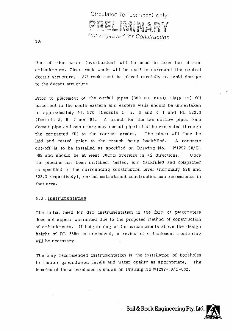
Circulated Icr conmnt cn!y
! L t *1
A, r Construction 10/
Pun of mine waste (overburden) will be used to form the starter
ernbarikments. Clean rock waste will be used to surround the central
decant structure. All rock must be placed carefully to avoid damage
to the decant structure.
Prior to placement of the outfall pipes (300 NB uPVC Class 12) fill
placement in the south eastern arid eastern walls should be undertaken
to approximately RL 520 (Decants 1, 2, 3 and 4 ) and RL 523.3
(Decants 5, 6, 7 and 8). A trench for the two outflow pipes (one
decant pipe and one emergency decant pipe) shall be excavated through
the compacted fill to the correct grades. The pipes will then be
laid and tested prior to the trench being backfffled. A concrete
cut-off is to be installed as specified on Drawing No. W1292-00/C-
005 and should be at least 300mm oversize in all directions. Once
the pipeline has been installed, tested, arid backfiled and compacted
as specified to the surrounding construction level (nominally 520 and
523.3 respectively), normal embankment construction can recommence in
that area.
4.3 Instrumentation
The initial need for dam instrumentation in the form of piezometers
does not appear warranted due to the proposed method of construction
of embarikments. If heightening of the embanikrnerits above the design
height of P1 555m is envisaged, a review of embankment monitoring
will be necessary.
The only recommended instrumentation is the installation of boreholes
to monitor groundwater levels arid water quality as appropriate. The
location of these boreholes is shown on Drawing No W1292-00/C-002.

Circulated for comment oniy
., F
:ved fcr Construction 11/
These monitoring holes would consist of slotted PVC inserted down a
large diameter borehole to allow water samples to be taken. The use
of any existing boreholes may be feasible if they are deep enough arid
still open.
In the deepest section of the embankment (south eastern corner), it
is suggested a level control point be established to enable regular
(six monthly) monitoring of the embankment to be undertaken. A line
of pegs should be installed on each successive berm.
4.4 Stability Analysis
4.4.1 Method of Stability Analysis
A stability analysis of the proposed construction method has been
carried out using a computer model which analyses the stability of
potential circular slip planes within the mass of the tailings dam by
both the Swedish method and Bishop's simplified methods.
The following range of parameters have been utiised in the model for
each of the separate tailings dam components.
Mullock Starter Embankment
Cohesion (c) = 5 to 0 kPa
Angle of internal friction (1p'' = 33 to 380
Bulk density (g) = 2. 0 to2. 3 t/m3
Tailings Contained Within the Dam
Cohesion (c) 5 to 10 kPa
Angle of internal friction = 28 to 180
Bulk density (a') = 1.4 to 1.85 t/m3
EngineeringjPty. ,; U411

Circulated for comment only
L
L I
12/
Not 'ppro'ed for COnStr/jct!.r.
Parameters (ii) and (ii) have been selected from experience and are
believed to be conservative. It is recommended that the
appropriateness of these parameters be checked during construction.
The phreatic surface used in the analysis was the surface of the top
layer of the dam, extending through the embankments to the ground
surface.
The total number of potential slip circles analysed was 200 with 50
slices being analysed in each circle. A copy of the computer
printouts showing results of the analysis are included in this report
as Plate 6 to 11.
4.4.2 Results of Stability Analysis
Results of the analysis indicate that safety factor against a deep
seated failure through the tailings embankments and deposited
tailings in excess of 1.9. A minimum factor of safety of 1.5 is
recommended for these structures.
With a reduced phreatic surface, factors of safety could be
increased. The tailings dam management contributes significantly to
the stability of the structure. Details of appropriate management
practices are provided in the document Yakabindie Nickel Project
Tailings Dam Operations Manual.
Soil & Rock Engineering Pty. Ltd.

Circulated for
No /T LT
OT7.Srrjj - -. 13/ 110,,
5.0 MANAGEMENT. INSPECTION AND MAINTENANCE
5.1 Management
The active life of the tailings darn is advised to be at least
15 years.
During this time many changes can take place in the materials being
placed which effect the stability of the embankment. The quantity
and physical properties of the tailings placed in the darn may change
over the years for many reasons. Such changes may alter the
stability of an embankment, resulting in variations in the factor of
safety.
5.1.1 Quantity of Tailings
Increased tonnage from the mill without a commensurate increase in
the area available to store tailings is one of the most common
changes. This results in an increase in the annual rise of the
tailings and reducing the factor of safety.
5.1.2 Physical Properties of Tailings
A change in grind with an increase in the minus 75 micron fraction
can cause a higher phreatic surface, a possible decrease in the
efficiency of the drains, and increased seepage through the starter
dam fill.

Jrcu!ad 1o1- COmmt Onl
ki
71M-
;\ T,
'1pproved for Constructic 14/
Any one or a combination of these changes can result in a reduced
stability of the embankment. It is therefore important that a
continuous programme of inspection and maintenance of the
embankment, the decant system and central sump be started
at the beginning and maintained throughout the life and
even after the abandonment of the storage. The embankrnents should
be thoroughly inspected by an experienced Engineer at least once
every two years or for a 5m rise, whichever is the sooner, during the
active life of the darn.
5.2 Inspection
5.2.1 Daily Inspections
Daily inspection should be made of the spigots, the position of the
water pond in relation to the decant or the tailings area boundary,
the decant system and central sump. The quality and quantity of
water returns should be checked daily.
5.2.2 Two Yearly Inspection
The objectives of the two yearly inspection programme should be to
answer the following questions:
Are there any major changes in the foundation or the
embankment that were not anticipated in the design such
as heaving of the foundation at the toe, longitudinal or
transverse cracks in the crest, or excessive seepage ?
Have the material characteristics changed; and if so,
how will these changes affect the stability ?

Ci1CUfrtOt for comrt ony H
7
I I
7/ L;L
15/ !Vøt Aperovd for Construct!0,7
Is the distribution of the material into the pond as
called for in the design; and if not, how will it affect
stability ?
Are the slime and water pond where they should be in
relation to the perimeter embankment ?
Is the dam construction rapid enough to keep the slimes
and water well back from the embankments ?
Can the decants handle the storm runoff in addition to
the reclaim water ?
Is there seepage on the downstream face of the
embankment wall?
Are the decant lines intact and free of cracks that
could allow sand to pipe into the lines and cause a
total failure ?
Is the phreatic surface (within the dam) as planned; or
is there excess pore water pressure from within the
foundation or perched water tables ?
Have there been variations in the water levels or a
sudden rise in the water level in the monitoring
boreholes, the appearance of any new springs, or new
seepage on the face of the embankments or foundation ? CD
Has there been an increase in embankment movement as
indicated by the surface control points or slope
indicator ?
Soil & Rock Engineering Pty. Ltd.

CircLjtted for comme only
16/
Not Approvc for Constructjo,
Is there evidence of borrow from the toe or, any other
area of the embankments that might affect stability ?
Is the embankment steeper than planned ?
6.0 DRAWINGS AND PLATES
The following list is a summary of drawings and plates provided for
the construction of the decant structure and peripheral embankments
as well as continued raising (heightening) of the decant.
Drawing No. W1292-OO/C-002 Plan - Stage I Earthworks
W1292-0O/C-003A ) Embankment Sections and Details
W1292-OO/C-003B
W1292-OO/C-004 Decant Details
W1292--OO/C-005 Upstream Toe Drain, Downstream Toe
Drain, Return Water Sump and Silt
Trap Details
W1292/00/C-006 Plan Stages II to VI Earthworks
Plate 1 Design Concept
Plate 2 Detail of Decant Water Intake
Plates 3 to 5 Graphs o Storage Volume vs Height
Storage Life vs Height
Storage Volume vs Embankment Volume
Plates 6 to 10 o Stability Analysis

Crcuated for comment ony
r i Not Approved for ConstrLlCtioi
C:
\1 ci ci
I I I I
Soil & Rock Engineering Pty. Ltd
PLATE I

/A172,t/4 5/Sc Ov5rIZZ-6,0 A/,7W
feJ-i/d n' 1117ef ivsY' 11,04A
It gm
a (b -
o C) Q
50770 C2A 67 --'"• I
p01'
oA n',Yh Y'i/,y.c ,'/riJ
/j/7p4•7 7ç sjj,rn /ri,/ ,-,..res
YIAKABINDIE NICKEL PROJECT JOB No.: 2488/00
CENTRAL DECANT WHEN OPERATING N.T.S.

Circulated for comment only
nv F g;L1flIg4ni
-c------
Ec) (9UJ
'U LU
U)O-. > —J LULLI
'0
LU 0 (9
az(
><
Soil & Rock Engineering Pty. Ltd
FLATE3

N
\
F- 0 uJ
Ir 0 LU
.1.1_I ell
(I)
>0
LL N
LLJ 0
1
Circulated for comment only
L EA 1 . Not Approved for Construct,r;
t'.
Soil & Rock Engineering Pty. Ltd.
PLATE 4
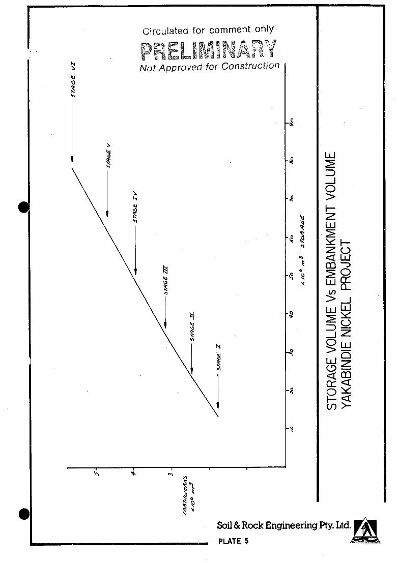
L I Pin, 1 471'' Y or Construction
Soil & Rock Engineering Pty. Ltd.
PLATE 5
Ctrculated for comment only

Our ref: 2488/00/T/CL/jb' Sheet 1 of 6 C2488T/LOG
PROJECT YAKABINDIE NICKEL PROJECT
FEASIBILITY STUDY
Circulated for comment only CLIENT: DOMINION MINING LIMITED
PROJECT MINPROC JR JOINT VENTURE Not Approved for Construct/or, IA WTA fC'T C'
LOCATION: YAKABINDIE VIA LEINSTER
SUBJECT: SLOPE STABILITY ANALYSIS
Soil & Rock Engineering Pty. Ltd. PLATE6

Our ref: 2488/00/T/CL/jb C2488T/LOG
PROJECT YAKABINDIE NICKEL PROJECT
FEASIBILITY STUDY
CLIENT: DOMINION MINING LIMITED
PROJECT MINPROC JR JOINT VENTURE ff A ?T A ('TT C
Sheet 2 of 6
Circulated for comment oni
D j
Not Approved for Construct,o
LOCATION: YAKABINDIE VIA LEINSTER
SUBJECT: SLOPE STABILITY ANALYSIS
Soil & Rock Engineering Ply. Ltd. PLATE7

Our ref: 2488/00/T/CL/jb
Sheet 3 of 6 C2488T/LOG
PROJECT
CLIENT:
PIROJECT
MANAGERS
YAKABINDIE NICKEL PROJECT
FEASIBILITY STUDY Circulated for comment only
if-, RV DOMINION MINING LIMITED Z" L Not Approved for Construction
MINPROC JR JOINT VENTURE
LOCATION: YAKABINDIE VIA LEINSTER
SUBJECT: SLOPE STABILITY ANALYSIS
Soil & Rock Engineering Pty. Ltd. PLATE 8
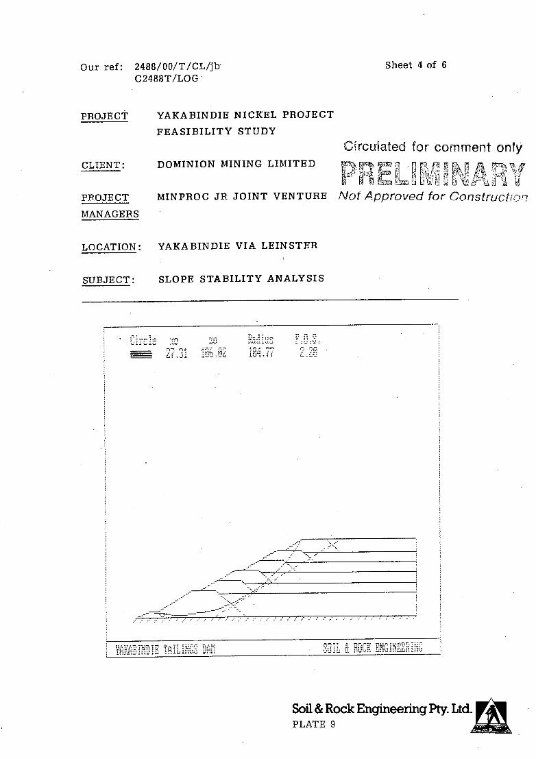
Our ref: 2488/00/T/CL/jb
Sheet 4 of 6
C2488T/LOG
PROJECT YAKABINDIE NI CKEL PROJECT
FEASIBILITY STUDY
Cfrcuiated for comment only CLIENT: DOMINION MINING LIMITED
c •a v PPOJECT MINPROC JR JOINT VENTURE Not Approved for Construction
LOCATION: YAKABINDIE VIA LEINSTER
SUBJECT: SLOPE STABILITY ANALYSIS
Soil & Rock Engineering Pty. Ltd PLATE 9

Our ref: 2488/00/T/CL/jb
Sheet 5 of 6
C2488T/LOG
PROJECT YAKABINDIE NI CKEL PROJECT
FEASIBILITY STUDY
Circulated for comment only CLIENT: DOMINION MINING LIMITED
: b PROJECT MINPROC JR JOINT VENTURE Not Approved for Construction
LOCATION: YAKABINDIE VIA LEINSTER
SUBJECT: SLOPE STABILITY ANALYSIS
Soil & Rock Engineering Pty Ltd. PLATE 10

Our ref: 2488/00/T/CL/jb C2488T/LOG
PROJECT YAKABINDIE NICKEL PROJECT
FEASIBILITY STUDY
CLIENT: DOMINION MINING LIMITED
PROJECT MINPROC JR JOINT VENTURE
Sheet 6 of 6
Circulated for comment only r-g4
L v An Not Approved for Constructjo
LOCATION: YAKABINDIE VIA LEINSTER
SUBJECT: SLOPE STABILITY ANALYSIS
Soil & Rock Engineering Pty. Ltd. PLATE 11

drcuted for comment only
. r
Not Approv for Construction
YAKABINDIE NICKEL PBOJECT
TAILINGS DAM
CONSTRUCTION DOCUMENTATION
Report prepared for:
DOMINION MINING LIMITED
10 Richardson Street
WEST PERTH WA 6005
Report prepared by:
SOIL AND ROCK ENGINEERING PTY LTD
CONSULTING GEOTECHNICAL ENGINEERS
AND GEOLOGISTS
4TH FLOOR CENTREPOINT TOWER
123 COLIN STREET
WEST PERTH WA 6005
Ref: 2488T/0.2/CL/jb
Date: 20th April 1990

Cftcu!ated for comment only ,.
F I
Ci
Not Approved for Construction
TABLE OF CONTENTS
page no.
1.0 INTRODUCTION
1
2.0 ATTACHMENTS
3.0 GENERAL
3.1 Scope 3.2 Code of Practice
3.3 Site Inspection
3.4 Safety
3.5 Site Description
4.0 SITE PREPARATION
4.1 Site Clearance
4.2 Blasting
4.3 IJewateririg
4.4 Excavation - General
4.5 Excavation - Trenches
5.0 SURVEY
5.1 Setting Out
5.2 Measurement - General
6.0 MATERIALS
6.1 General
6.2 Material Quality
1
2
2
2
2
3
3
4
4
4
4
5
5
6
6
6
7
7
7
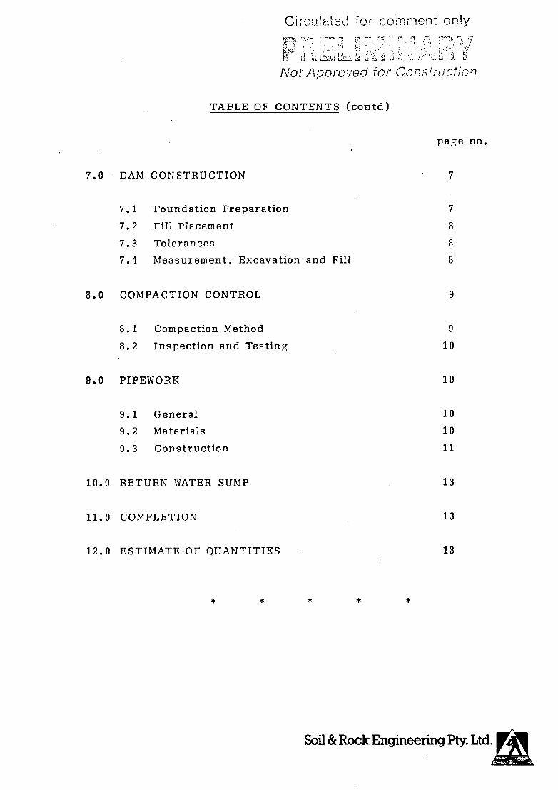
Circ.flated f o r comment only
)i Not Approved for Construction
TABLE OF CONTENTS (contd)
page no.
7
7
8
8
8
7.0 DAM CONSTRUCTION
7.1 Foundation Preparation
7.2 Fill Placement
7.3 Tolerances
7.4 Measurement, Excavation and Fill
8.0 COMPACTION CONTROL
8.1 Compaction Method
8.2 Inspection and Testing
9.0 PIPEWORK
9.1 General
9.2 Materials
9.3 Construction
10.0 RETURN WATER SUMP
11.0 COMPLETION
12.0 ESTIMATE OF QUANTITIES
* * *
9
9
10
10
10
10
11
13
13
13
11! II4441

Cftc:Lac'1 foi comment only - .- :. -j
j 82
Not Approved for Cons truce/on
Our ref: 2488T/0.2/CL/jh
20th April 1990
C 2488 P / SUM
PROJECT YAKABINDIE NICKEL PROJECT
FEASIBILITY STUDY
CLIENT: DOMINION MINING LIMITED
PROJECT MINPROC JR JOINT VENTURE
MANAGERS
LOCATION: YAKABINDIE VIA LEINSTER
SUBJECT: CONSTRUCTION DOCUMENTATION
TAILINGS DAM EMBANKMENT CONSTRUCTION
STAGED CONSTRUCTION (I TO VI.)
1.0 INTRODUCTION
This specification covers all stages of construction for the tailings
darn ernbarikrnents and is to be read in conjunction with the drawings.
2.0 ATTACHMENTS
The following attachments complete this specification:
Construction Drawings for Stage I
W1292-00/C-002 Plan - Stage I Earthworks
W1292-00/C-003A & 003B Embankment Sections and Details
W1292-00/C-004 Decant Details
1111292-00/C-005 . Upstream Toe Drain, Downstream Toe
Drain, Return Water Sump and Silt
Trap Petails
W1292-00/C-006 Plan Stages II to VI Earthworks
Soil & Rock Engineering Pty. Ltd.

ccmrnont only
2/
Not Approved for Construct/or,
3.0 GENERAL
3.1 Scope
The Contract shall include the provision of all necessary materials,
labour, plant, ecuipment and cartage to complete the works shown on
the drawings and described in this Specification. All works shown on
the drawings but riot referred to in this Specification, or referred
to in this Specification but not shown on the drawings, shall be
included. The majority of preparatory work will be completed under
Stage I. Stages II to VI works will mainly involve bulk earthworks
to extend and raise the embarikments.
3.2 Code of Practice
Unless otherwise specified, or shown on the drawings, the Contractor
is to provide all materials and carry out all the work in accordance
with the latest revisions of the relevant Australian Standard Codes.
3.3 Site Inspection
The Contractor shall inspect the site and must allow for the
following factors in his price:
(i) the nature and requirements of the work to be done;
(II) all conditions on and adjacent to the site;
(iii) access to the site;
a0 . . 0 D 0 zManin,

O-; T COfli C:nly
3/
iVor Aoprcvecj for Construction
the types of soil and vegetation to be dealt with;
the expected or known water table;
NO the nearest source of any suitable fill material which
complies with this Specification; and
(vii) the nearest source of water for construction purposes.
3.4 Safety
The Contractor shall:
(i) carry out the works in a safe manner; and
(II) conform to all relevant Acts or Statutes of Parliament,
Pegulations, By-Laws or Orders relating to the safety of
persons and property on or about the site.
3.5 Site Description
The site is approximately 310 hectares in total area and is located
adjacent to the proposed nickel plant of Dominion Mining Limited at
Yakahindie.
The area has an overall fall to the east and is covered with sparse
vegetation, the ground surface covered by rocks and soil.
gt1)

Circulated for comment only
- 4/
Not Approvecy for COPStrUCtI
4.0 SITE PREPARATION
4.1 Site Clearance
Bemove all vegetable matter and scrub from beneath the embankment
limits of the proposed tailings embankmerits. The area to be cleared
shall extend approximately 2m past the toe of the embankment.
Remove all solid obstructions, tree stumps, roots arid logs from
beneath the area of the works. Water and compact the area prior to
fill placement. Foundation preparation is detailed in clause 7.1.
4.2 Blasting
Some blasting is anticipated and hard ripping may be encountered.
Excavation for the return water sump is approximately 3.5m below
existing ground level. If hard rock is encountered, it is suggested
that the shape of the excavation be changed to maintain the same
capacity rather than blast to the specified P.L.
Excavation for the decant structures is approximately lm for each
decant. If hard rock is encountered, it is suggested that hydraulic
or pneumatic rock breaking equipment is used, to minimise
overexcavation and subsequent backfillinig.
4.3 Dewatering
Allow for keeping water from excavations by pumping, dewatering, or
other suitable means, and adequately dispose of it clear of the
works.

Circu!ated for comment oHv
r
':i t
5/ f'Iot ArjprOVd for ConSiTuC'
4.4 Excavation - General
All excavations shall be to the minimum lines and grades shown on the
drawings or as required by the Engineer as work progresses.
During the progress of the works, the Engineer may find it necessary
to revise the lines, levels arid grades of any part of the excavations
because of the conditions revealed by the works.
The Contractor shall accept reasonable delays due to inspection and
checking of any part of the excavations to determine grades and
levels.
The Contractor shall riot excavate beyond the lines and grades shown
without the prior written approval of the Engineer.
Excess excavations shall be backfilled with approved material to the
satisfaction of the Engineer.
4.5 Excavation - Trenches
The excavation of any trenches, especially those to take pipework
shall be to a regular finish, with no sudden changes in direction.
Excavation shall be to an even grade with no abrupt slope changes
unless specified in the specification or on the drawings.

Circulated for comment only
6/ LJ
•4
Not Approved for Conruction
5.0 SUBVEY
5.1 Setting Out
The Contractor shall be wholly responsible for the setting out of his
works in accordance with the terms of the specification. Although
the Engineer will cause such setting out to be checked from time to
time, such checking will not relieve the Contractor of full
responsibility for the accuracy of such setting out.
The Contractor shall be responsible for the protection of all
permanent and temporary beacons or bench marks.
5.2 Measurement - General
The Contractor shall perform all ground surveys using conventional
and agreed surveying techniques. The surveys shall be carried out
prior to the commencement of the item of work and at the completion
of the item of work. The Contractor shall submit his survey data arid
calculations to the Engineer.
The Engineer may undertake his own survey of any item, either in
conjunction with the Contractor, or separately. The Contractor and
Engineer shall agree on the results of measurement surveys that are
carried out prior to any works being covered up or within seven (7)
days of a survey being undertaken. Should agreement riot be reached,
the difference shall be documented such that the matter can be later
decided without disruption to the Contractor's programme.

Circulated for comment only
7/
tiot Appr v1 jor
6.0 MATERIALS
6.1 General
All materials shall be stockpiled, transported and placed in such a
manner as to minimise segregation.
6.2 Material Quality
All material used to construct the embankments of the tailings dam
shall be impermeable, well graded overburden waste material. The
Engineer will direct the Contractor to a suitable source of clayey
material.
Sand for pipe bedding shall be clean free-draining material with a
maximum size of 5mm or as otherwise specified by the Engineer.
7.0 DAM CONSTRUCTION
7.1 Foundation Preparation
Excavation of the foundation area of the tailings dam embankment
shall be carried out such that the base of the embankment as shown on
the drawings is embedded into the stratum by not less than 1000mm, or
to refusal. All areas to receive fill shall be left in a clean and
suitable condition to allow the easy placement of fill.
tI) !

CrCLflEJe,d for comment only
; L L
Not Approved for Const , ti0 8/
7.2 Fill Placement
All fill material shall be placed in approximately horizontal layers
not exceeding 500mm loose lift thickness. Each lift shall be
compacted by a minimum of 8 passes of a heavy duty roller. Placement
should be continuous. If a break in fill placement allows the
exposed surface to dry, it should be lightly tyried, watered and
compacted prior to fill placement recommericing. No oversize rock is
to be placed into the embankments. Largest size should be 150mm.
Drawing Nos. W1292-00/C-003A and W1292-00/C-00313 outline the grades
and lines to which the embankments are to be constructed.
7.3 Tolerances
The maximum permissible horizontal deviation from the finished lines
or zone boundaries shall be -Om to +0.5m.
Vertical deviation shall be -Om to +0.2m, provided no abrupt changes
in slope or level are present on any finished surface.
7.4 Measurement. Excavation and Fill
Refer also to Section 5.2.
No payment shall be made for over-excavation unless prior written
approval has been supplied and granted by the Engineer.
Measurement for payment of all embankment fill material shall be made
for the volume in cubic metres of compacted material, measured in
place and only to the lines arid grades required.

CircñatGd cr comment oniy
iI Li VI
Not Approved for Construction
9/
Initial and/or final surveys must be undertaken and approved by the
Engineer prior to the removal or placement of any material,
especially where such action will destroy or cover the surface just
surveyed.
All survey checks or quantity measurements must be supplied to the
Engineer, suitable time must be given to the Engineer to allow such
calculations to be checked and approved prior to the works being
covered or removed.
8.0 COMPACTION CONTROL
8.1 Compaction Method
8.1.1 The moisture content of the embankment construction material,
approved for use in embankment construction, shall be within
2% of the optinium moisture content as determined from
laboratory test E1.1 of AS 1289 (1976).
8 • 1 • 2 The material should be placed in loose layer thicknesses not
exceeding 500mm. Each layer shall be compacted with 8 passes
of a CP35 or equivalent.
8.1.3 After the construction of the first metre of embankment, 6
test pits shall each be excavated to 500mm. Each pit shall be
filled with water and the the shall be measured for the water
to drain away.
8.1.4 A. Geotechriicai Engineer shall nominate locations of the pits
arid shall be present during the initial construction stages
arid during the percolation testing.
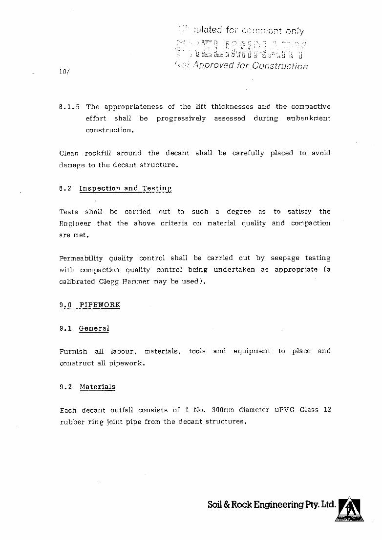
'uated for comment ony
U
10/ '• Approved for Co!7structior1
8.1.5 The appropriateness of the lift thicknesses and the compactive
effort shall be progressively assessed during embankment
construction.
Clean rockfill around the decant shall be carefully placed to avoid
damage to the decant structure.
8.2 Inspection and Testing
Tests shall be carried out to such a degree as to satisfy the
Engineer that the above criteria on material quality and compaction
are met.
Permeability quality control shall be carried out by seepage testing
with compaction quality control being undertaken as appropriate (a
calibrated Clegg Hammer may be used).
9.0 PIPEWORK
9.1 General
Furnish all labour, materials, tools and equipment to place and
construct all pipework.
9 • 2 Materials
Each decant outfall consists of 1 No. 300mm diameter uPVC Class 12
rubber ring joint pipe from the decant structures.

r fated for commEnt ony
11/ '
r)Qeq for Oil
9.3 Construction
The decant pipes shall be laid at an even grade between the central
decants and the return water sump. Pipes will be laid predominantly
on the natural ground surface, which shall be free of all stumps,
cobbles, boulders, rocks or any other irregularity, arid laid to the
appropriate manufacturers specification.
Where bedding is required adjacent to the decant structures, the
pipes shall be laid on cement stabilised compacted sand complying
with the requirements of Section 6.2
The pipes will be placed through the southern embankment, at two
locations.
The trench through the southern embankment for the 1 No. 300mm decant
pipes and 1 No. 150mm upstream toe drain pipe shall have an
approximate width of 2000mm and shall be excavated when the fill
levels are at FL 520m (Decants 1 to 4) and EL 523.3. (Decant 5 to 8).
Material excavated from the trench shall be stockpiled for re-use in
the construction of the dam wall.
Once excavated, clean sand shall then be placed in a compacted layer
of 50mm and shaped to provide full support for the barrel of the
pipe.
Prior to backfillirig, the pipe shall be tested for leaks. Any such
occurrence shall be rectified and then re-tested.
Prior to trench backfilling, a concrete cut-off is to be installed to
reduce seepage losses through the trench. The cut-off is to be formed
against arid into either natural ground or well compacted fill.
A Ari& IBM

? .
culat for comment ony
12/ otApprcv for Cc pstri;ci/ r;,
Once the pipes are tested, and the concrete cut off installed
backfilling with overburden waste shall be undertaken, with 100mm
thick layers being hand tamped from the pipe invert level to 100mm
above the top of the pipe around the pipe, and small plate compactors
used in the area between the pipes and trench sides as appropriate.
The remainder of the trench shall be carefully backfilled with
overburden waste to the surrounding ground level. Extreme care shall
be taken to avoid any damage to the installed pipework when
backfilling and compacting around and above the pipes.
Normal embankment construction can recommence once the trench has
been hackfilled to the surrounding construction level.
Any pipes which are riot laid to line, level or grade, or are damaged
or displaced during backfilling or other operations by the Contractor
in the course of his work, shall be removed and replaced by the
Contractor at his expense. The Contractor shall be responsible for
any excavation of backfilling necessary for the removal and
replacement of any pipe.
The contractor shall ensure that all other pipework is placed in
accordance with the appropriate recommendations of the manufacturer.
On completion of pipe laying and testing, the decant lines shall
either be individually staked and tied at each joint or covered with
im of sandy soil which is free of cobbles, boulders or rocks. The
valves near the return water sump should be closed and the decant
pipes filled with water to prevent floating during initial tailings
deposition.
Soil & Rock Engineering Pty. Ltd.

T -:z
for CC f or,
13/
Not Approved for CQflsrHc 'a'n
10.0 RETURN WATER SUMP
Construct the return water sump in the location and to the details
shown on the drawings. The shape of the sump may vary on site, as
directed by the Engineer, so as to suit rock excavation. All surplus
excavated material shall be removed to spoil.
The excavated slopes of the sump are to be left smooth and regular to
allow placement of a clay or polyethylene liner as appropriate.
11.0 COMPLETION
Clean up all rubbish, remove all plant and supply materials, trim all
banks neatly, spread all excavated material riot specified to be
removed from the site and leave the site in a clean and tidy
condition.
12.0 ESTIMATE OF QUANTITIES
A preliminary estimate of quantities has been provided to allow
material requirements to be gauged for Stage I Construction. The
figures have not been calculated by a Quantity Surveyor arid are
provided as preliminary information only.

Cftcuft'ted for comment only -'
Not Approved for Construction
ESTIMATE OF QUANTITIES
STAGE 1 CONSTRUCTION
1.0 EARTHWORKS
1.1 Embankment Construction
Borrow, Moisture Condition, Transport, Place and Compact Eartlifil
Main Embankments 1,780,000m 3
Central Accessway 71,500m 3
Decant Accessway 200,000m 3
Return Water Sump Fund 3,000m3
Downstream Fund/Road 17,000m 3
(assume 6.Om width and 0.6m minimum height)
1.2 Excavate and remove to spoil
Decant (5.5rn3) 44m 3
Return Water Sump 10, 000m 3
Downstream Toe Drain (Vee Drain) (linear metres) 4,565m
2.0 PIPEWORK
2.,1 Decant Outfall
300 NB uPVC Class 12 5,675m
Concrete. Cut-off (2 No @ 1.40m3 each) 2.80m 3
Excavate to place pipe through 700m 3
embankments to form concrete cut off
Backfill around pipes through 700m3
ii I I) ! IT

Crced for comment oniy
4IA
Not Approved for Construction 2/
ESTIMATE OF QUANTITIES (contd)
STAGE 1 CONSTRUCTION
2.2 Decant Structure
Reinforced Concrete Base for 8 no Decants (5.2m3 each) 42ni 3
1.8m NB Class x concrete pipe internal flush joints 27 No.
(Standard Decant Pipe with three rows of slots)
300mm NB uPVC Lobster Back 900 Elbow male and female ends 8 No.
300mm NP uPVC Class 12 pipe straight section no sockets
300mm NB FRC Decant Sleeves 150mm long
300mm Nfl uPVC Class 6 solvent weld socket with 80mm
holes as per Drawing No. W1292-00/C-004
Locating Spider as per Drawing No W1292-00/C-004
Clean Bock Fill around Decant Structures
Concrete plugs in base of Decant (0.6m3 each)
1 6m
200 No.
29m
8 No.
15,000m3
5.0 m3
2.3 Upstream Toe Drain
Excavate Toe Drain (linear metres)
150mm uPVC Class 6 Slotted Pipe
150mm uPVC Class 6 Pipe
150mm uPVC Class 6 Elbows
150mm uPVC Class 6 Tee Pieces
Filter Sand and Gravel
Filter Cloth (linear metres)
4, 750m
4,750m
200m
6 No.
1 No.
3, 000m3
15, 000m 2
M0 . . 0
a 0 acas, 97q

Circulated for comment only
'- Not Approvod for, Construction
YAKABINDIE NICKEL PROJECT
TAILINGS DAM
OPERATIONS MANUAL
Report prepared for:
DOMINION MINING LIMITED
10 Richardson Street
WEST PERTH WA 6005
Report prepared by:
SOIL AND ROCK ENGINEERING PTY LTD
CONSULTING GEOTECHNICAL ENGINEERS
AND GEOLOGISTS
4TH FLOOR CENTREPOINT TOWER
123 COLIN STREET
WEST PERTH WA 6005
Ref: 2488T/0.3/CL/jb
Date: 20th April 1990
OftOulated for comment only
i 4
Not Apov-3 for Construct/On
TABLE OF CONTENTS
page no.
1.0 INTRODUCTION 1
2.0 SUMMARY OF OPEBATIONAL PROCEDURES 2
3.0 TAILINGS DAM START UP 3
4.0 COMPONENTS OF TAILINGS DAM OPERATIONS 4
4.1 Deposition of Tailings 4
4.1.1 Spigotting 5
4.2 Control of the Position of the Phreatic Surface 6
4.2.1 Decant
7
4.3 Management, Inspection and Maintenance
8
4.3.1 Management
8
4.3.2 Quantity of Tailings
8
4.3.3 Physical Properties of Tailings
8
4.3.4 Inspection
9
4.3.4.1 Daily Inspections
9
4.3.4.2 Engineering Inspection
10
5.0 RAISING THE EMBANKMENTS
11
5.1 Embankment Construction (Staged
12
Construction)
*

Cict.ftd or comment only
ii Not Approved for Construct/or
Our ref: 2488T/0. 3/CL/jb 20th April 1990 C 2488 C / SUM
PBOJECT YAKABINDIE NICKEL PROJECT
FEASIBILITY STUDY
CLIENT: DOMINION MINING LIMITED
PROJECT MINPROC JR JOINT VENTURE
MANAGERS
LOCATION: YAKAPINDIE VIA LEINSTER
SUBJECT: OPERATIONS MANUAL
1.0 INTRODUCTION
This operations manual has been prepared as a guide to plant staff
in the operation and management of the tailings dam. Reference
should be made to the report titled "Yakabiridie Nickel Project
Tailings Dam Design", reference 2488T/0.1/CL/jb, dated 20th April
1990 arid to the associated drawings 111292-00/C-002 to W1292-00/C-006,
to ensure that the design concepts arid management requirements are
fully understood in order to achieve the design objectives, which
are:
allow the tailings dam to function with minimal
daily input, while maintaining stability of the tailings
dam;
maximise water return from the tailings; and
maximise storage capacity of the tailings dam.
SoiliiRock Engineering r. Nil

Cc ci rrrprf oniy
jj
Not Appiv:ri for Constiucijor,
2/
2.0 SUMMARY OF OPERATIONAL PROCEDURES
The following is a summary of operational procedures:
The tailings will be deposited subaerially (exposed to
air) and spirally around the darn in discrete layers. Each
layer should not exceed 0.3m in thickness. The length of
time between successive depositions (i.e. drying tirne) on
any one area should be maxirnised.
Tailings should be discharged at a low velocity
through numerous spigot locations and never from a
single point discharge of high flow.
The free water pond should always be kept centrally
located around the nearest decant structure. This is
achieved by regularly altering the spigot locations
around the perimeter of the dam.
Frequent inspections (on a daily basis) should be made of
the spigots, tailings lines, water return lines, the
position of the pond in relation to the decant arid the
darn walls. The return water sump arid return lines should
be checked regularly for quantity and quality.
Only by regular inspection and appropriate remedial
action can the performance of the decant system be
optirnised and environmental and operational
problems be avoided.
Soil & Rock Engineering Pty. Ltd.

Circulated for comment only
Not Aporcved Ior Construction
3/
(v) Operation, safety and environmental aspects should
be periodically reviewed during an inspection
by an experienced Engineer. The inspection should be
done every two years or when the dam has been raised 5m,
whichever is the sooner.
3.0 TAILINGS DAM START UP
During the period of initial deposition into the tailings dam, a
temporary mobile pump is recommended to collect surface water and
discharge it into the return water sump. The level at which water
can enter the first decant system in each area is approximately 4.5m
and 6.2m higher than the lowest ground level of each storage area.
It should be noted that although the upstream toe drain will function
well during this early period, it is not possible to recover all free
water through this system.
The temporary pump should therefore be positioned such that it will
not be subjected to either water or tailings inundation as deposition
continues and will allow routine maintenance to be undertaken without
danger to service personnel.
All decant outfall pipes should be checked during this phase to
ensure the pipe anchorage is adequate. To prevent decant pipe
floatation, all decant pipes should remain full of water with control
valves closed, unless the water recovered by the pump is being
discharged into the decant.
It has been estimated that this arrangement will be required for a
period of approximately 12 weeks from commencement of tailings
deposition in the southern storage area before return water will
enter decant no 1; (and a period of approximately 10 weeks from
commencement of tailings deposition in the northern storage area
before return water will enter decant no. 5).
Soil & Rock Engineering Pty. Ltd.

Cftculated for comment only 7& ::
Not Apprcied for Construction
4/
Normal spigotting procedures, as detailed in Section 4.1.1, can be
carried out during this initial deposition period.
4.0 COMPONENTS OF TAILINGS DAM OPERATIONS
Successful management of the tailings dam to achieve the design
objectives requires a thorough understanding of three major
components in the operation of the tailings dam. These components
are:
Deposition of tailings;
Control of the phreatic surface within the tailings; and
Poutine inspection and maintenance.
These components are described in detail below.
4.1 Deposition of Tailings
The following details are provided as a guide to an efficient
tailings disposal system that will maximise water recovery arid
storage volume whilst reducing environmental and stability
considerations:
the tailings should be deposited subaerially and spirally
(in a sequential manner around the dam perimeter) in
layers not exceeding 0.3m. The tailings will then be
allowed to drain and desiccate (dry) before being covered
with the next layer;
at any one time tailings deposition into the storage
should be from numerous adjacent spigot locations. This
Soil & Rock Engineering Pty. Ltd.

C,rr
5/
Not Approvo' for Construct/on
enables low velocity discharge of the tailings into the
storage. Low velocity discharge promotes the deposition
of the coarser fraction of the slurry adjacent to the
discharge point, with finer material progressively
deposited towards the centre of the storage area. The
finest material is deposited when the flow meets the
central water pond;
Tailings discharged at a high velocity, (ie. from one or
two points), erodes both embankment material and
previously deposited tailings by forming a channel as it
flows to the centre of the storage;
initially the tailings will be discharged and dried in
discrete layers from the perimeter of the dam until the
tailings approach the level of the starter embankment,
nominally within 500mm of the crest; arid
the embankments around the perimeter of the dam and the
access causeways should be raised, whilst simultaneously
raising the decants. The decant structures will be
raised progressively with the access way. Decant raising
must always be kept in advance of the rising tailings and
water level. Plate 1 shows the design concept.
4.1.1 Spigotting
This method is provided as a guide only.
The deposition of tailings into the storage is one of the controlling
factors in achieving higher in situ densities and corresponding
higher water returns.

rcuftItd for co, mment or
L
fj Ap 6/
f)rove for Gonstru
Tailings should be deposited over the exposed beaches, at a low
velocity. This is best achieved by discharging the tailings through
numerous pipes (spigots). A typical discharge arrangement is shown
on Plate 2. The most economical method would be the use of reducer
tees, fitted with flexible mining hose (no valves) at 20m centres
(nominally). Tailings should not be discharged so as to erode the
soil embankments. During the initial start up period, conductor
pipes (solid or slotted) into which the flexible hose must be
inserted will be required to ensure the tailings are deposited at the
toe of the embankment. Other forms of embankment protection are
available (e.g. flexible hose laid on old conveyor mat).
These spigots are very easy to operate, and are opened and closed by
unfolding the flexible pipe to open the spigot or folding the
flexible pipe back on itself and tying it together to close the
spigot (Plate 2). Consecutive groups of spigots are operated. New
spigots are opened in succession around the dam to build up the
tailings beaches to ensure the water pond is located around the
nearest decant.
Some experimentation will be required during the early period of
operation to determine the optimum number of spigots to be opened, to
achieve low velocity discharge, whilst still maintaining sufficient
pressure from the tailings pipeline to ensure the spigots are
discharging uniformly.
4.2 Control of the Position of the Phreatic Surface
The position of the phreatic surface in the tailings dam will be
governed by three main factors:
(i) the location and the size of the water pond;
Soil & Rock Engineering Ny. Ltd

CT::i':ci CT;fl?1: onv
j
7/ tot \proved for Construcion
the efficiency of the decant operation; and
the placing of tailings in thin discrete layers that are
allowed to dry prior to inundation.
4.2.1 Decant
The location of the water pond will be largely governed by the
spigotting sequence employed. The process of tailings deposition is
aimed at ensuring that the pond is positioned around the nearest
decant structure and that the pond is maintained in that position.
The pond is positioned by altering, in a regular mariner, the location
of opened spigot points around the perimeter of the embankment.
The main feature of the decant system is that the decant pond is
maintained at the smallest practical size, and most of the free water
is recovered through the decant for recycling to the process plant.
The size of the decant pond is the most important controlling
influence on the water level and thus the phreatic surface within the
body of the tailings, the smaller the decant pond, the higher the
water recovery.
By adopting the approach of maintaining a small decant pond the
stability of the dam should riot be significantly reduced by the
formation of a temporary hhlake?T caused by maintenance requirements
or by storm flooding of the tailings beaches.
The size of the pond will be largely governed by the efficiency of
the offtake or internal riser pipe in removing water from the
tailings storage. Other controlling factors will be:
(i) evaporation from the surface of the pond;
Soil & Rock Engineering Pty. Ltd.

Crcuated for comment ony
8/ :O[ APPIOVCO 1O! Consrrucrion
the input of tailings water (percent solids);
the rainfall;
the difference in permeability between the tailings and
the underlying soil types; and
the ratio of horizontal to vertical permeability of the
tailings.
Plate 3 shows a section of the central decant when operating.
A water balance for this tailings dam is attached. The water balance
shows the potential water return as a percentage of inflow.
(raphical presentations show the monthly water balance; the design
storm event (based ori the month with lowest evaporation, and a storm
event with an average recurrence interval of more than 100 years);
and water management (estimated average water return versus area of
pool and running beaches).
4.3 Management, Inspection and Maintenance
4 • 3. 1 Management
The active life of the tailings dam is advised to be at least
15 years.
During this time manly changes can take place in the materials being
placed which effect the stability of the embankment. The quantity
arid physical properties of the tailings placed in the dam may change
over the years for many reasons. Such changes may alter the
stability of an embankment, resulting iii variations in the factor of
safety.

Circuate for comment only
-
9/ Not Approved for ConStrUCrIOfl
4.3.2 Quantity of Tailings
Increased tonnage from the mill without a commensurate increase in
the area available to store tailings is one of the most common
changes. This results in an increase in the annual rise of the
tailings and reduces the factor of safety.
4.3.3 Physical Properties of Tailings
A change in grind with an increase in the minus 75 micron fraction
can cause a higher phreatic surface, a possible decrease in the
efficiency of the drains, and increased seepage through the starter
dam fill.
Any one or a combination of these changes can result in a reduced
stability of the embankment. It is therefore important that a
continuous programme of inspection and maintenance of the
embankment, the decant systems and return water sump be
started at the beginning and maintained throughout the life
and even after the abandonment of the storage. The embankments
should be thoroughly inspected by an experienced Engineer at least
once every two years or for a 5m rise, whichever is the sooner,
during the active life of the dam.
4.3.4 Inspection
4.3.4.1 Daily Inspections
Daily inspection should be made of the spigots, the position of the
water pond in relation to the decant or the tailings area boundary,
the decant system and return water sump and all pipelines. The
quality and quantity of water returns should be checked daily.

Circu1aed for comment only
' 7 r 1 AoDroved for Cnstructjon
10/
4.3.4.2 Engineering Inspection
An inspection should be carried out every two years, or when the dam
has been raised 5m, whichever is the sooner. The objectives of this
inspection programme should be to answer the following questions:
Are there any major changes in the foundation or the
embankment that were not anticipated in the design, such
as heaving of the foundation at the toe, longitudinal or
transverse cracks in the crest, or excessive seepage ?
Have the material characteristics changed ? and if so,
how will these changes affect the stability ?
Is the distribution of the material into the pond as
called for in the design; and if not, how will it affect
stability ?
Is the slime and water pond where it should be in
relation to the decants and perimeter embankment ?
Is the dam construction rapid enough to keep the slimes
and water well back from the dam wall ?
Can the decants handle any storm runoff in addition to
the reclaim water and how efficiently ?
Is there seepage on the downstream face of the embankment
wall?
tI) !1j Fro

CL C(
11/
for Construction
Are the decant lines intact and free of cracks that could
allow sand to pipe into the lines and cause a total
failure ?
Is the phreatic surface (within the dam) as planned ? or
is there excess pore water pressure from within the
foundation or perched water tables ?
Have there been variations in the water levels or a
sudden rise in the water level of the monitoring
boreholes; the appearance of any new springs, or new
seepage on the face of the embankments or foundation ?
Has there been any embankment movement ?
Is the embankment steeper than planned ?
Is there evidence of borrow from the toe or any other
area of the embankments that might affect stability?
All of the above points are critical for the stability
of the structure and each item must be investigated closely
and checked during the life of the structure. If problems are
encountered, a thorough investigation must be made.
5.0 RAISING THE EMBANKMENTS
The design concept provides for the raising of the tailings dam
embankment by upstream construction methods using waste rock from the
pit.
The following procedure is therefore recommended:
Soil & Rock Engineering Pty. Ltd
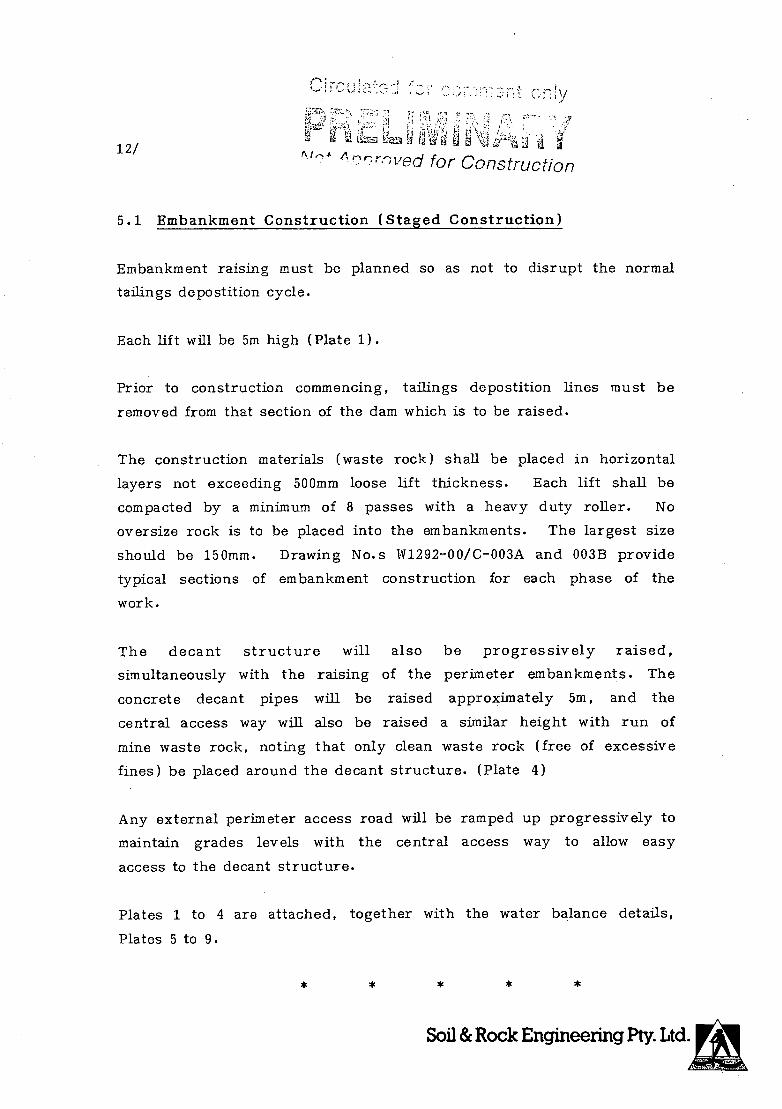
'-, -: ly
-
12/ rt!edforCo,7struct/Q
5.1 Embankment Construction (Staged Construction)
Embankment raising must be planned so as not to disrupt the normal
tailings depostition cycle.
Each lift will be 5m high (Plate 1).
Prior to construction commencing, tailings depostition lines must be
removed from that section of the dam which is to be raised.
The construction materials (waste rock) shall be placed in horizontal
layers not exceeding 500mm loose lift thickness. Each lift shall be
compacted by a minimum of 8 passes with a heavy duty roller. No
oversize rock is to be placed into the embankments. The largest size
should be 150mm. Drawing No.s W1292-00/C-003A and 003B provide
typical sections of embankment construction for each phase of the
work.
The decant structure will also be progressively raised,
simultaneously with the raising of the perimeter embankments. The
concrete decant pipes will be raised approximately 5m, and the
central access way will also be raised a similar height with run of
mine waste rock, noting that only clean waste rock (free of excessive
fines) be placed around the decant structure. (Plate 4)
Any external perimeter access road will be ramped up progressively to
maintain grades levels with the central access way to allow easy
access to the decant structure.
Plates 1 to 4 are attached, together with the water balance details,
Plates 5 to 9.
Soil & Rock Engineering Pty. Ltd.

Circulated for comment only
Pu-, Ui"&--URY Not Approved for ConstructiOfl
A
F- 0 LU -D 0 0
Soil & Rock Engineering Pty. Ltd
PLATE I

Circulatea TOt
£U1mPit iARY Not Approved for ConstrUCtiOl
Soil & Rock Engineering Pty Ltd.
PLATE 2

Circulated for comment on1y
L I
N A Y Not Approved for Construction
\ \
L1
r
H 0 uJ 0 0
z uJ
z
a —J
F- z w 0
Soil & Rock Engineering Pty. Ltd.
PLATE 3

Circuiated for comment on
FHL
Not Approved for ContwctiOfl
0 0
F-LU
LU z -J LU
H z LU 0
QD z -= (1)"
LU—i
cy
0U)
Wu
Zc,u UJ Ooz
0 a-
Soil & Rock Engineering Pty. Ltd
PLATE 4

05-Apr-90 001L & R(XK ENGINEERING FFf LTD
PIalJEtr: YAKPBINDIE NICKEL MINE
CLIENE: MINPI8JU ENGINEERS FE? LTD
I.00ATIaJ: YAXABINDIE, W.A.
JOB NO: 2488/00
DATE: 05-Apr-90
SUBJEXJT: ('8BThLY WATER BALANCE YA1ABINDIE NICEEL NINE
I
TAILINGS DAM BALANCE
INFILV
RPJ]dFAIL Monthly Rainfall (ran) Average Daily Rainfall (nin) Tailinqs Storage Area (rn'2) Runoff Coefficient Tailings Catc(arant Area (rn2) Runoff Coefficient Catc1nt Pool Area (nf 2) Running Beaches (m2)
STERN IOIENE Design Stone Intensity (sin/hour) Design Storni Duration (hours)
Daily Inflow Volri (in/3)
SUJRRY WATER Tailings Output solids, (txI) Volum of Water (rr3Iday)
solids= 50
PROCEES WATER Pumped from river m')/day) Process Water Requirenent Clean Water Requirnt Total Requirsoient
7OTAL T)IFLUN
' not included in inflow calculation
JAN. FEB. MAR. APRIL MAY JUNE JULY AUG. SEFE. OCT. NOV. DEC.
28.5 29 32 22.5 25.5 24.5 16.5 13 7 :3.5 10 17 0.92 1.04 1.03 0.75 0.82 0.82 0.53 0.42 0.23 0.11 0.33 0.55
3300000 3300000 33000130 3300000 3300000 330000 3300000 3300000 3300000 :3300000 3300000 3300000 0.40 0.40 0.40 0.40 0.40 0.40 0.40 0.40 0.40 0.40 0.40 0.40
1000000 100001)0 10130000 1001)000 1000000 1000000 1000000 1000000 1.000000 1000000 1000000 1000000 0.90 0.90 0.90 0.90 0.90 0.90 0.90 0.90 0.90 0.90 0.90 0.90
140000 140000 140000 [40000 140000 140000 140000 140000 140000 140000 140000 140001) 700000 700000 700000 700000 700000 700000 700000 700000 700000 700000 700000 700000
0 0 0 0. 0 0 0 0 0 0 0 0 0 0 0 0 0 0 0 0 0 0 0 0
2504 2821 2812 2043 2241 2225 1450 1142 636 308 908 1494
16500 16500 16500 16500 16500 165013 16500 16500 16500 16500 16500 16501) 16500 16500 16500 16500 16500 16500 16500 16500 16500 16500 16500 16500
0 0 0 0 0 0 0 0 0 0 0 0 0 0 0 0 0 1 0 0 0 0 0 0 0 0 () 0 0 0 0 0 0 0 0 0 0
19004 19321 19312 18543 18741 18725 17950 17642 17136 16908 17405 17994
C
a -
o C)
o $ 0 3
Zj 3 CD
,..-. -.. -

Return Water tran [lam (m3/day) 5800 58(100 5800 5800 5800 5400 5800 5800 5800 5800 5800 5800
'A00RA1TC(1 (fran pond & rrsarring beaches) Monthly Pan Evaporation Rate (ran) 550.0 460.0 419.0 263.0 1800 115.0 130.0 170.0 240.0 360.0 425.0 525.0 Pan Factor 0.67 0.67 0.67 0.67 0.67 0.67 0.67 0.67 0.67 0.67 0.67 0.67 Monthly Dam Evaporation Rate ((an) 368.5 308.2 280.7 176.2 12().6 79.7 37.1 113.9 160.5 241.2 284.8 351.8 Average Daily Evaporation Rate (sin) 11.9 13.0 9.1 5.9 3.9 2.7 2.5 3.7 5.4 7.8 9.5 11.3 Pool Area + Running Beaches (nn2) 340000 840000 240000 ((40000 84000)) 840000 840000 840000 840000 840000 840000 840000 Daily Evaporation Loss (rn3/day) 9985 9246 7607 4934 3268 2232 2360 3086 4502 6536 7973 9531
EVA O-TRANSPIRATtON (tran drying tailings) Monthly Pan Evaporation Rate (nan) 550 460 419 263 18)) 119 13)) 170 240 360 425 525 Evapotranspiration Rate (Pan/3) 0.22 0.22 0.22 0.22 0.22 0.22 0.22 0.22 ((.22 0.21 0.22 0.22 Monthly Transpiration Rate (sin) 123 103 94 59 40 27 29 38 54 80 95 117 Average Daily Transpiration Rate (ran) 4.0 3.7 3.0 2.0 1.3 0.9 0.9 3.2 1.8 1.6 3.2 3.9 Area Transpiring (m'2) 1155000 1155000 1155000 1155000 1155000 1155000 1155000 1155000 1155000 1155000 1155000 1155000 Daily Transpiration Loss (rn'3/day) 4577 4238 3486 2261 1498 1023 1092 1415 2064 2996 3654 4365;
SEEPAGE Downstream I3nbanlarmnt (rn'3/day) [00 100 100 10)) 100 100 [00 100 10)) 100 100 100 Upstream E)rminlsrannt (s(3/day) 0 0 0 0 0 0 0 0 0 0 0 0 Dam floor (ra3/day) 1000 1000 1000 1000 1000 1000 1000 1000 1000 1000 1(99) 1000
'VIFAL SEEPAGE 1100 1100 1100 1100 1100 1100 1100 110)) 1100 1100 1100 1100 °6 INFIL% F,% 6% 65 6% 6% 6% 6% 6% 6% 7% 6% 6%
REFENFICR1 Tailinos 0(itput (txl) 16500 1650)) 16500 16500 16500 16500 165000 16500 16500 16500 16500 1650)) Volume Retained in Tailinqs (m3/day) 6600 6600 6600 660') 66(6) 6600 6600 6600 6600 6600 6600 6600 assume wt water/soil= 0.4
70FAL WFFILiW 22262 21184 18793 14895 12466 10956 11142 12201 14266 17231 19327 21600
BAIANE (D(FU8( - (RJTFWW) (m3/day( -3257 -1862 519 3648 6275 7769 6808 5441 2870 -424 -1919 -3606
SUJ4Y OF 5 RE7MNS ON MOnUY BASIC
809131 JAN. FEB. MA)). APRIL MAY JUNE JULY AUG. CCVI. 001'. 80V. DEC.
Potential Max. Water Return (m3/day) 2543 3938 6319 9448 12075 13569 12609 11241 8670 5376 3981 2194 Potential Water Return (5 inflow) 15.5 24% 355 455 455 4506 454 45% 455 33% 24% 13% (upper limit of 45.5)
CD
Q 6n:N:ry' 7 -*8
Er::a8 c )S
CD
05-Apr-90 k**** OGIL & 9YJU EEGINEEPIIJG VT? Ii'))

DNVJVH
iO2OHd 1JNOtN DICINIOV>IVA
jg AON J20 LdS 0flV KInr Nflf Avw iflidY NVJA 94 NVI
f -77
ri rs' /
Y)y5\)ç y
I r> vi
01
I,-
a) Q
E EQ
o C) 0
: 0
0 a cz
I' h
9
r

> 0 z
0 0
LL
SpI'f101U
(Mp/ , w) (Ao'iano -. MO1:INI) IVJQJ.
CirctiiTd for comment niy f
l ji Its iH 1fl I
Not Approved for Construction
Soil & Rock Engineering Pty. Ltd. PLATE 8

('I
NUftUflI ULLVM 90VNRAV UVL1S
Circulated for comment only
r Not Approved for Construction
Soil & Rock Engineering Pty. Ltd. PLATE 9

Y.AXABINDIE TAILINGS ACID NEUTRALISATION PEFORMACE
sample of tailings from the pilot plant testwork was assayed as follows:
The assay was as follows:
Ni 0.188X
Fe 4.17% Cu 1:4 ppm Pb 10 ppm Zn 29 ppm Cd <lppm As <100 ppm Se 0.2 ppm Te <0.1 ppm Ag <0.005 ppm
$ total 0.4891 S as Suiphide 0.416% MgO 39.1%
(Ref. Anmtec facsimile 0600, 12/4/90)
The suiphide content of the tailings is of importance since this could potentially be converted to sulphuric acid by natural ociclation processes. 3aed on stoichiometry and assuming 100% conversion of sulphide sulphur, the maximum production of acid is 12.74 kg H2SO4/tonne of tailings.
A neutralisation test has been carried out by Antec (r::f. fax of 30,3.90) to measure the neutralising capability of the tailings. This test indicated that the tailings has the ability to neutralise 14.3 kg H2504/tonne over a
24 hour period. This exceeds the maximum theoretic.1 acid generating
potential.
Further testwork is planned to determine the acidibase characterisation of
ta1ings. This work will determine the actual conversion of sulphides to acid over a 1oner time period and the neutralisatian potuntial.
yaka/propHal ings
Soil & Rock Engineering Pty. Ltd. PLATE 016
APPENDIX D3
Soil & Rock Engineering Pty. Ltd.

PLATE 017

EEL
PLAN 1,50
j "l VEP,0,ILth( TO WE;T Ag&AwiA
TYPICAL INTERNAL WALL DETAIL
GYPROC.I cLOf,O V'CZIMP TIM.P, URAM 5HE-r--rING
0A3N1,JC. .D,LUMIEJIUM / W1 I'JcoN FgAM&
I STEEl... /
uc 75, 5lUDWORI, Wrfl.1 75 IP.A110IJ
IT4TSEAU CYPOO, LINIEJG
AECIITAV.
TYPICAL WINDOW/SUBFRAME LINING DETAIL
LCOT.JO V. CIMP W.ILL 5j.l5TIp4G TO
J3n'n C(PP,0O, E. .'P,PJAL- lt iEJTEML-
STUOWO SISAI..AT IOTJ 455
N_I
7Snwi IPJ5LJLATt0NJ
TYPICAL EXTERNAL
WALL DETAIL
ELECTRICAL LEGEND
l—1 0,00 FrLU09rv5C.EA,4T TUS.. All, Dou0,LE, Powe4-1 P01147
0IT4C.IE ptS1WE.P, PONT
çWALA, 5AC4&T UC.14T
0 CE.ILIP,JC IUCAEJOElC,&l.jT LJC.1-JT
EXI.IALJ57 PA14 tWITC14ED TPJITI4 LIGWT
U
ELEVATION
ELEVATION ©
CLIENT APPROVED for CON ST-R UCTON
DATE S SlOtS
SIZE SCAII
Bi 1.50
I I I I W1292- OO/A-002
PLATE D18
COPTEIGAT
MINPROC ENGINEERS PTY. LTD. I
I rD LTD I
I I
I —
I
22 STIRLING HIGHWAY. NEOLANOS. W.A. 6009 TELEPI4ONE' 369 1655
a nv.
DOMINION MINING LIMITED
I1I YAKABINDIE NICKEL PROJECT VILLAGE UNITS

- - 7000 2000
o INM 02, 55PNICE, yw COMPR5S.0
8 0
0 TAPFJ FgE.E7-f 1 oQ'( TOE-
p1 Ac.COM [II HID n GAITS
7500 09 L0m -
°°°r
'°°
—
i" —
4.. 14 OXIT
EVEPT' 44 uc F-
6c(5' &4iJACe& V40AD V5RAPA4 8 -
i'L :L TRAYS CTSOEOCM i
F r D1DA5l€L I - OP/C EFAAL. 6l0RE-
8 [ T.V.900M
8 - — [ —
,AP, cow po.js
• L FEM.4J
MicJc 0 £XFCJB ROOM
7 < =00 II t'ACE' DI.
• N N cc -
VE4Ai4C'AI-4 V&RAUD4I-(
— tt -
- 54000 - - - - 2:000 - 9000 -
CLIENT APPROVED for
CONSTRUCTION DATE: SIGNED
COTEDIGAIT
MINPROC ENGINEERS PTY. LTD.
22 sTIRUNG HIGHWAY. NEOLANDS. W.A. 6009 TELEPHONE 389 1655
= = = ___________J P.0,EcT B' DATE cue" DOMINION MINING LIMITED
SIZE
Bi
SCAA.E 1:100
- — - — - — _ — Tm6
YAKABINOIE NICKEL PROJECT VILLAGE AMENITIES BUILDING
I
-- - — — - - _____________________ -
W1292-OO/A-003 -
DV DATE NEV Q ANEA - NV DATE NERSON
- . - PLATE D19

OOmN
62 ISO mN
FF
S5
/
(TYPICAL)
A
JCLIENT APPROVED CONSTRUCTION
DATE SIGNED
for
MINPROC ENGINEERS PTY. LTD.
TELEPHONE 389 1655
o DY DATE
VT OTT OTTO NORTH
CliENT
DOMINION MINING LIMITED SIZE
BI
SCALI
750 = Jf 22 STIRLING HIGHWAY, NEOLANOS. W.A. 6009
YAKASINOIE NICKEL PROJECT HOUSING LAYOUT
-
TO I I CIYECDED
W1292-OO/A-004 DpAwwo= THAWN
I
DATE DEN — c&AZR0RTf NV DATE YEHTTTTN QWENEOTADHNOT
PLATE D20

PLAN
HOUSE TYPE A IlOO
HOIIIIIIIIIIIIIlflhIIIIIIIIIIIIfIIIIIIIIlIIIIIIIIIIIIIIIIItIIIIIIIIflIflhIIIItIIIIIIIIIlIIII
tLPT1!D VIEW VIEW
0
PLAN
øi III ii'iiiii
VIEW VIEW ©
HOUSE TYPE 'B' 1:75
C0TW T ® __
LLL
I I I -.*.,... I MINPROC ENGINEERS PTY. LTD.
I 8 ..ITDOC I I ETWt6 Pr, T0 I
- E - I ,i
____
l fl Lii111
22 STIRUNG HIGHWAY. NEOLAJHOS. W.A. 6009
TELEPHONE 389 1655
'i
DOMINION MINING LIMITED
If
YAKABINDIE NICKEL PROJECT HOUSE PLANS
CLIENT APPROVED for CONSTRUCTION
DATE SIGHED
SIZE ScAa
B I 1:100 :75
I I I I W1292 - 00/A - 005
PLATE D21

• /
WANJARR NATURE RESERVE L
:•_ _
YTT •
WASTE DUMP \\ / \ /
___. _ — --- —
PIT_
' OAM
AST A
-
DUMP
PLANT
-
-
---
•
\ -
- CLIENT APPROVED for CONSTRUCTION
MINPROC ENGINEERS PTY LTD STJRtI#G HtGWAY. NEDLANOS.WA• 6009
TEIEPtIOdE 3891655
l__.__,,
-"
OMINION MINING LIMITED B11 50000
I I '- I - I YAKABINDIE NICKEL PROJECT I I
BOREFIELD AND POWER LINE LAYOUT IW1292 — 00/6 -005
-__ __- i
j J
PLATE D22

APPENDIX D4
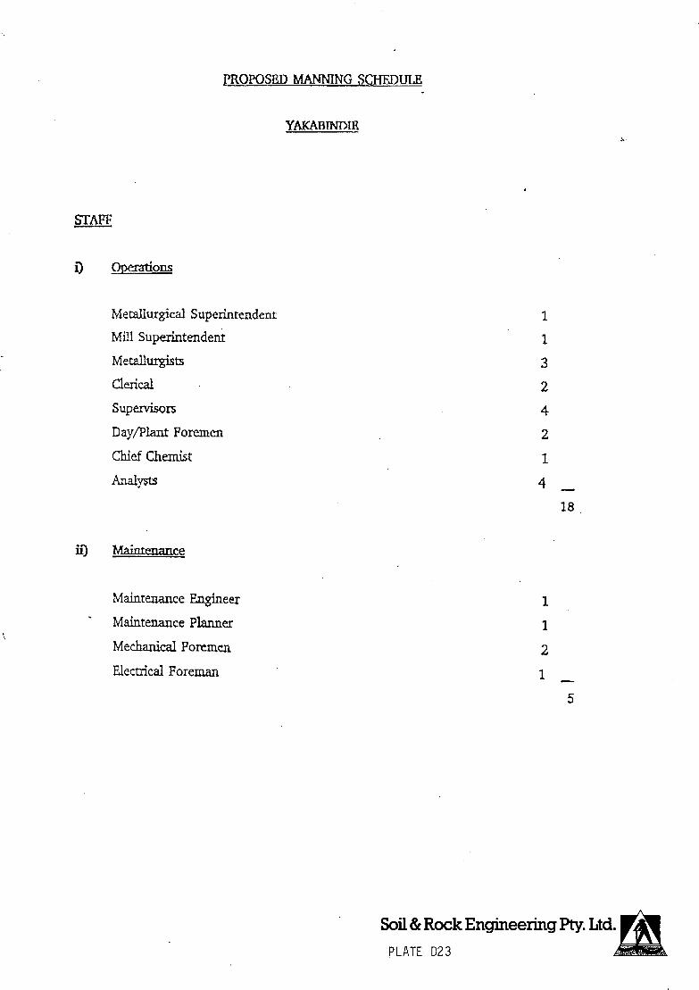
PROPOSED MANNING SHEDULE
STAFF
Metallurgical Superintendent
Mill Superintendent
Metallurgists
clerical
Supervisors
Day/Plant Foremen
Chief Chemist
Analysts
ii) Maintenance
Maintenance Engineer
Maintenance Planner
Mechanical Foremen
Edectrical Foreman
I
1.
3
2
4
2
1
4
18
1
1
2
1
Soil & Rock Engineering Pty. Ltd. PLATE D23

AWARD
-2-
i) Pit Operators
Shift Workers:
- Control Room
- Mills
- 1otatjo
- Thikening/Concentrate Handling
- Spare Operators
Day Workers:
Crusher
- Reagents/Steel
- Traüing
- Cleaning
- Sample Preparation
li Maintenance
Electiiciais
Instrument Fitters
?itter,fWelders
Crane Drivers
Rubber Workers
Trade Assistants
4
4
4
4
4
20
3
2
4
3
S
17
4
2
6
2
2
5
21
Shift Fitters 4
4
Soil & Rock Engineering Pty. Ltd. PLATE D24


! [Ci I YAi U IIVIM
REPORT ON A SURVEY FOR ABORIGINAL SITES: YAKABINDIE FEASIBILITY STUDY
Prepared for Soil and Rock Engineering Pty. Ltd. By Rory O'Connor and Gary Quartermaine
MARCH, 1990

REPORT ON A SURVEY FOR ABORIGINAL SITES :
YAKABINDIE FEASIBILITY STUDY
Prepared for Soil and Rock Engineering Pty Ltd
By Rory O'Connor and Gary Quartermaine
March, 1990

ABSTRACT
A survey for Aboriginal sites in the vicinity of the proposed mining development at Yakabindie Station, 65 kilometres north of Leinster, was commissioned by Soil and Rock Engineering Pty Ltd and executed in March, 1990. The survey incorporated ethnographic and archaeological components conducted by R. O'Connor and G. Quartermaine, which are reported upon in this document.
The Aboriginal people consulted in the course of the ethnographic component were satisfied that the proposed work would not impact any sites of significance.
As a result of the archaeological survey, four newly recorded sites, as well as four Isolated Finds, were located in the designated survey area. Two of these sites are likely to be affected by the proposed development. Recommendations are included in this report.


PART ONE - ETHNOGRAPHY
TABLE OF CONTENTS Page No.
1.0 INTRODUCTION 1
1.1 Background to Report 1 1.2 Research Brief 1 1.3 Acknowledgements 1 1.4 Format of Report 2
2.0 ABORIGINAL HISTORY IN SURVEY AREA 3
2.1 Linguistic Groups 3 2.2 Post Contact History 3
3.0 THE SURVEY .5
3.1 Methodology 5 3.2 Ethnographic Data Base 5 3.3 Newly Recorded Sites of Significance 5 3.4 Previously Recorded Sites 5
4.0 CONCLUSIONS 7
5.0 REFERENCES 8
6.0 APPENDICES 24
6.1 Obligations Under the Act 6.2 Notes on the Recognition of Aboriginal Sites
FIGURE 1 Location of Project Area 11
FIGURE 2 : Location of Ethnographic Sites 12
FIGURE 3 Tribal Boundaries

1.0 INTRODUCTION
1.1 Background to Report
This report is based on a period of field research carried out in March 1990. The aim of the research was to identify and delineate any areas of Aboriginal significance in the vicinity of the proposed mining development at Yakabindie Station, 65 kilometres north of Leinster, and thus enable the developers, Dominion Mining Pty Ltd, to fulfil their obligations under the Aboriginal Heritage Act (1972-1980)
The proposed development is located near Six Mile Well, approximately seventeen kilometres (17 kms) north of Yakabindie Homestead (see Figure One for location of the survey area)
In the course of the survey, Aboriginal people who have long—term association with the survey region were consulted by the author. At the same time, in recognition of the possible archaeological significance of the area to be impacted by the proposed development, an archaeological survey was conducted by G. Quartermaine. The results of this latter survey are detailed in Part Two of this report.
1.2 Research Brief
The research brief required the author to conduct an Aboriginal site survey and produce a report which will enable the W.A. Museum to consider whether the proposed mining development at Yakabindie Station will affect any Aboriginal sites. The survey area is defined as the proposed open cut area in M 36/57 and P 36/973, together with the newly proposed waste dumps and tailings dam. In addition, the author was required to consider any sites of religious significance in the near vicinity of the survey area, to ensure accurate mapping and description.
1.3 Acknowledgements
The author gratefully acknowledges the assistance and advice given by Bill Wesley, Paddy Walker, Donald Stokes, Willy Hill, Harvey Willabone and Shirley Willabone.
1

1.4 Format of Report
The conduct of the field survey and format of this report are based Upon:
(I) Guidelines for Developers and Consultants previously issued by the Department of Aboriginal Sites, Western Australian Museum;
discussions with senior officers of that Department;
research brief issued by the developer (see 1.2 above)
requirements of the W.A. Aboriginal Heritage Act;
procedures standardised by the author in a large number of similar exercises, which have been acceptable to that Department in the past.
2

2.0 REGIONAL FRAMEWORK
2.1 Linguistic Groups
The area of the proposed development is located within the traditional lands of members of the Western Desert social and cultural bloc (Berndt, 1959:104), which stretches in a broad sweep from Oodnadatta in South Australia, through the Great Victoria, Gibson and Great Sandy Deserts to the Southern Kimberly. A high degree of cultural and linguistic homogeneity exists throughout this region, although dialectual variation occurs (Douglas, 1964; Wurm 1972; Yallop, 1982) . The distribution of these linguistic groups in the survey region, as mapped by Tindale (1974), is reproduced in Figure 3 and, in the authors opinion, represents a reasonably accurate depiction of the pre-contact situation. These groups, it should be noted, were speech communities and not political entities. Rights to land and its spiritual associations, and other political loyalties were framed and expressed at a lower numerical level. However, the spread of these linguistic groups can be used to paint the political scene in broad brush strokes, and thus gain an overall view of the region's traditional political geography.
2.2 Post Contact History
Aboriginal history in the survey region, following European contact, has been described in O'Connor and Quartermaine (1984 and 1986a), O'Connor and Veth (1984a) and O'Connor and Christensen (1986). It can be summarised briefly as follows:
2.2.1 Meekatharra/Wiluna Region
Large population of gold miners move into the region in the late 1890's.
Indigenous people die out from violence and introduced diseases.
A process of Aboriginal migration from the north-east begins and the newcomers take over "custodianship" or "trusteeship" of local Aboriginal law, including protection of religious sites.
Many of these migrants intermarry and settle on the newly formed pastoral stations: older linguistic and other distinctions to dull and a population of "Wangkayis" a regional collective Aboriginal identity, begins to develop.
Following adoption of the Pastoral Award for Aborigines in 1968, permanent residence and employment on the station becomes scarce and movement to central locations such as Wiluna accelerates.
(iv) These central areas become melting pots where "tribal" differences finally collapse through inter-marriage and new collectivities arise: collectivities of persons made up of many local descent groups, many hordes and usually a number of different linguistic groups. They see themselves, and are seen by others as having a common identity, expressed usually in terms of the mission or settlement where they live, although frequent movement between groups continues. In many cases, migrants to these "mobs" retain rights of
3

ownership over sites in their ancestral estates, while exercising custodial roles in their new areas.
In 1956, Pastor Vaughan sets up a mission in Wiluna with the aid of grants from the Native Welfare Department and the Western Australia Conference of the Seventh Day Adventist Church.
Thus, the development of the Wiluna Mob led to the foundation of a Seventh Day Adventist Mission, which in turn has led to the incorporation of Nganganawili Community and the recent move to outstations such as Mangkilli Claypan.
Through all these developments, however, the sacred associations of land in this region have been retained.
2.2.2 Leonora/Laverton Region
As with the Meekatharra/Wiluna region, the first contacts between Europeans and Aborigines occurred within the framework of the 1890-1910 goldrush years, a volatile period with large numbers of rootless single men converged on the goldfields.
Violent reaction to the "invasion leads to violent reprisals.
Once again, as the pastoral industry develops, the scattered remnants of the local tribes settle on stations or on the fringes of the many mining areas.
Aboriginal migration from the north-east and east commences, following a traditional trade route though Tjirrkarli (N-W of Warburton), Pirlpirr (Minnie Creek near Yamarna) to Laverton. The attraction of introduced foodstuffs and tobacco was a magnetic force which radiated Eastwards into the sandhill country.
In 1921, Willie Ross and Harry Axford take up Cosmo Newberry Station, which in due course becomes the site of a large Aboriginal camp.
In 1921 also, Roderick Schenk sets up an Aboriginal mission some six kilometres north of the then partially abandoned Mt Margaret Goldfield; a mission which spearheaded a sustained attack on traditional religion and traditional relationships with land.
These traditional relationships are retained, however, as a regular infusion of tradition - oriented people from the Desert continues.
In 1927, all Aboriginal ration stations in this region other than Cosmo Newberry and Mt Margaret are closed thus centralising Aborigines into these two settlements.
Today, therefore, traditional Aboriginal religion, including the specific associations of religious sites, has survived in both centres.

3.0 THE SURVEY
3.1 Methodology
The survey was comprised of four separate stages, as follows:
examination of existing ethnographic data base; consultation with Aboriginal elders; visits to the study area with Aboriginal elders; report preparation.
3.2 Ethnographic Data Base
Among the more important published sources dealing with Aboriginal sacred and mundane associations with land in the general survey region are the following:
Berndt (1959; 1972; 1976; 1979), Layton (1983), Palmer(1983a, ;1983b;1984), Stanton (1983; 1984), Tonkinson (1978), Elkin (1939-40), Sackett (1977), Douglas (1964), Kingsford (1982) and Tindale (1974).
In addition, numerous unpublished works now exist, including the extended discussions in : Muir and Pukungka (1985), Christensen (1983), O'Connor (1983), O'Connor and Veth (1984a;1984b;1984c), O'Connor and Quartermaine (1984; 1985; 1986a; 1986b; 1986c; 1987) and O'Connor and Christensen (1986).
Also, valuable information is available in local historical texts, including:Powell (1932), Bennett (1935), Vindin (1929), Topperwien (n.d.), Doughty (1977), Pinnock (1959), Reid (1933), Forrest (1875), Palmer (1985) and Gregory (1884).
Finally, a wealth of information is stored in scattered references and private papers held in the Battye Library of Western Australian History. Many of these have been consulted by the author, are mentioned in the texts cited above, and have been used to form the summarised statement in 2.2.1 and 2.2.2 above.
3.3 Newly Recorded Sites
The conclusion reached as a result of the surv.eyis that no sites of significance to Aboriginal people will be affected by the proposed deve 1 opment.
3.4 Previously Recorded Sites
Two sites of religious significance have been previously recorded in the near vicinity of the proposed development. Details and new information regarding these sites are as follows.
3.4.1 Tjulypu (W0911, 1:250,000 grid ref 325 595).
There are a number of errors in the official record regarding this site, which was recorded originally in 1976 by the then registrar of Aboriginal Sites. Its location is recorded as "in the vicinity of Mail Change Well". However, the site, whose name should be Tjulypunya, is actually Mail Change Well itself. This site is well constructed on a rockhole, which was an important water source for Aborigines in Pre-contact times. A further error arises from the fact that Mail Change Well is incorrectly mapped in the "Sir Samuel" 1:250,000 mapsheet. It is shown as being 2.6
5

kilometres to the north of the Six Mile Well turnoff, and 100 metres to the east of the Wiluna-Agnew Road. In fact, Mail Change Well is 5.1 kilometres north of this turnoff, and 200 metres to the east of the road (distances not surveyed, but calculated from odometer of rented vehicle). Its grid reference should therefore be TK556 641. Its location is shown in Figure Two. Its religious significance relates to its creation by Wanarmpi, the regional variant of mythic water snake, who also created the important site at Yandal Lagoon and the Lake Darlot and Lake Maitland systems.
3.4.2 Tjinkuna (W0510, 1:250,000 grid ref. 352 595).
This site is part of the dragon - fly dreaming, which passes through Yakabindie and Albion Downs (the local name for udragon fly is "Tjinkun&', also known in English to local Aborigines as "horse stinger"). All previous manifestations of this myth encountered by the author have been either hills or rocky outcrops; this site replicates that pattern. The hill, which is shown in Figure Two, is located to the east of Tjulypunya.
2.1

4.0 CONCLUSIONS
Human interference with Aboriginal sites in this State is an offence unless authorised as outlined in Section 17 of the Aboriginal Heritage Act.
No further action is required of the developer with regard to the ethnographic component of this survey, as no sites of significance will be impacted by the proposed development. No specific recommendations for protection or management of Tjulypunya or Tjinkuna are incorporated into this report, as they are outside the area of proposed development.
7

5.0 REFERENCES
Bardon, G. 1979. Aboriginal Art of the Western Desert. Melbourne: Rigby.
Bennett, M. 1935. Teaching the Aborigines. Perth: City and Suburban Printers.
Berndt, R. 1959. "The Concept of the Tribe in the Western Desert of Australia". Oceania 30(2).
Berndt, R. 1972. "The Walmadjeri and Gugadja", in Bicchieri, M.G. (ed), Hunters and Gatherers Today. New York, Holt, Rinchart and Winston.
Berndt, R. 1976. Territoriality and the Problem of Demarcating Sociocultural Space. N. Peterson (ed.) Tribes and Boundaries in Australia. Canberra:A. I.A.S.
Berndt, R & C. Berndt. 1977. The World of the First Australians. Sydney : Ure Smith
Berndt, R & C. Berndt. 1978. Pioneers and Settlers, Victoria Pitman.
Berndt, R. 1979. "Mystic Shapes of the Desert Culture", in Tauchmann, K (ed), Festschrift Fur Helmut Petri. Koin, Bohland Veglag.
Bindon. P & Robinson, M. (n.d.) ASurvey for Aboriginal Sites near Lake Way, Wiluna, W.A. Museum Report.
Christensen, W. 1983, Preliminary Anthropological Survey of the Balgo, Billiluna and Mt Bannerman Areas of the east Kimberleys. Report prepared for Ranger Oil (Australia) Ltd, DAS.(signifies that a copy is available for perusal at the Dept. of Aboriginal Sites (WA Museum), subject to the approval of the registrar of Aboriginal Sites).
Douglas, W. 1964. An Introduction to the Western Desert Language. Oceania Linguistic Monographs, University of Sydney.
Doughty, J. 1977. Gold in the Blood. Adelaide, Rigby.
Elkin, A. 1939. The Australian Aborigines. Sydney: Angus and Robertson.
Gregory, A. 1884. Journals of Australian Explorations. Beal, Brisbane.
Forrest, J. 1875. Explorations inAustralia. New York: Greenwood Press.
Keefe, A. n.d. Conflict South of Mullewa. Mullewa Shire Library.
Kingsford, R. 1982. Yamadyi Law: the Continuing Significance of Traditional Aboriginal Culture in the Murchison Region. Unpublished M.A. Thesis, The University of Western Australia.
Layton, R. 1983. "Ambilineal descent and traditional Pit jantjatiara rights to land", in Peterson, N and M. Langton (eds), Aborigines. Land and Land Rights. Canberra: A.I .A.S.
O'Connor R. 1983. Report of a Survey for Aboriginal Sites in the Vicinity of the Harbour Lights Prospect, Leonora. Copy lodged at Western Australian Museum.
O'Connor, P. & W Christensen, 1986, Cosmo Newberry Inquiry. Unpublished report prepared for Aboriginal Affairs Planning Authority of W.A.
O'Connor, R. and P. Veth. 1983. Report of the Anthropological and Archaeological Survey on the UO.D.C. Corporation's Mount Weld Exploration Site. Copy lodged at Western Australian Museum.
O'Connor, R. & Quartermaine, G. 1984. Report of the Survey for Aboriginal Sites in the Vicinity of DRCS Repeaters, Meekatharra and Mt Magnet, Stage Two, and Gasgoyne Junction. Report to Telecom Australia.
O'Connor, P. & Quartermaine, G. 1986a. Aboriginal Site Survey:Reedy North D.A.S
O'Connor, R. & Quartermaine, G. 1986b. Aboriginal Site Survey Mertondale. D.A.S.
O'Connor, P. & Quartermaine, G. 1986c. Report on the Survey for Aboriginal Sites at Sundowner Minerals N.L. Mt Fisher Joint Venture, East of Wiluna, D.A.S.
O'Connor, P. & Quartermaine, G. 1987. Report on the Survey of Aboriginal Heritage for two Repeater Sites. Leonora - Laverton, D.A.S.
O'Connor, P. & Veth, P. 1984a. Report on a Survey for Aboriginal Sites at the Asarco (Aust) Pty Ltd Gold Exploration Wiluna, D.A.S.
O'Connor, P. & Veth, P. 1984b. Report on a Survey for Aboriginal Sites at DRCS Repeaters in Mount Magnet Area. Unpublished Report prepared for Telecom Australia.
O'Connor, P. & Veth, P. 1984c. Report on the Survey for Aboriginal Sites at the Alakane - Golden Plateau Joint Venture, Mt Margaret WA. D.A.S.
Palmer, K. 1983. Migration and rights to land in the Pilbara, in Peterson, N and MLangton (eds) op cit.
Palmer, K. 1984. Aboriginal Land Ownership among the Southern Pitjantjatjara of the Great Victoria Desert, in Hiatt, L (ed), Aboriginal Landowners. Oceania Monograph No.4 University of Sydney.
Palmer, A. 1985. Yalgoo. Lap Industries, Fremantle.

Peterson, N. 1970. Buluwardi ; a Central Australian Ceremony for Resolution of Conflict, in R. Berndt (ed.) Australian Aboriginal Anthropology. Perth:U.W.A Press.
Pinnock, M. 1959. The Golden Decade: A Historical Survey of Meekatharra. Perth: Claremont Teachers' College.
Powell, R. 1932, The First Ten Years of Mt Margaret. Melbourne: V.A.M.
Pukungka and P Muir, 1984. Genealogy of a Ngalia Family. Limited Ed i t ion.
Radcliffe - Brown, A. 1952. Structure and Function in Primitive Society. London:Cohen and West.
Reid, A. 1933. Those were the days. Perth: Barclay and Sharland.
Sackett, L. 1977. "Liquor and the Law: Wiluna, Western Australia', in R. Berndt (ed.) Aborigines and Change. Canberra A.I.A.S.
Stanner, W. 1965. Aboriginal Territorial Organisation:Estate, Range, Domain and Regime. Oceania 36 (1)
Stanton, J. 1984. Conflict, Change and Stability in a small Aboriginal Community. Unpublished PhD Thesis. The University of W.A.
Tindale, N. 1974. Aboriginal Tribes of Australia. California: University of California Press.
Tonkinson, R. 1978. The Mandudjara Aboriginals. New York : Holt, Rinehart and Winston
Topperwein, N. (n.d.) A History of Wiluna. Typescript:Battye Library of Western Australian History.
Vindin, D. 1929. 'Australia's greatest goldmine', British Australian and New Zealander Journal.
Wurm, S. 1972. Languages of Australia and Tasmania. The Hague: Mouton and Co.
Yallop, C. 1982. Australian Aboriginal Languages. London:Deutsch.
10

P41 4d 5ulJ99ul5u3 430 JO
1 3eIflOId
V38V 133(OeId NOLLVOO1
31'OS 01 ION
I33rOId IQNI8V>IVA
C9' 0776'yr/vrF - - - CbVW 07 7b'7c
0pV7977
,WQP'b'7Af
95b' 7 Jvb'94'Ar7a5,
w0wv,
3/7!97b'.V N
6''0iVQ970 r £3N57 VU' 2U'
2fvc71 s-ctYb'S
• Y7JY/iI77N
I 0' 7O7 • 7'A 7 7PV
I I) 0
dW N/fWQ
27VVd 7/0"Y/V66V6' )blIV177117 QI
$

: PROJECT 4 6
TR ES
HNOGRAPHIC SITES
'eerIng Pfy. Ltd

2•
2 -,
DIM -
-, I I '4 ' S
I , r a Mo.d —
\ -Do( SD Co—o No-"f,y
TJALKADJARA MARA P,,,,,c1eS S
/
/ 1•
pMt RkIsffe
/ 1890 s, .dss•. Wh. & l.sIga O*"t /
t / U
C-'
"S
Ica ViJlet. St .4dow ' f I W IJ
'oo/
- T o.k. g*,et .
Gi - \\ S
Cop rf,&d -Mt KSd,
- \
rJURLU Bo I
KOOk fl -U 1N Si"'-'
'-"• 4,,, - .P, 1322 ' '.-•
S / - - /••. \
I sQ,te,t,J.
Ealuan
nGA
I, KALG2Q1RLI
øutong0
Mt B.Fle,( S 5r• J;d,"—'\ js-
St—
-
Queen V-Cbs-S Spnng 's.c ft
1kAAI 0çundeoe.
or
5,rnIIe •t -
Cc.r5noI~\
M.
W dV -
'0000
QJ S II
I
TRIBAL BOUNDARIES
Fleure 3 (SOURCE: TINDALE. 1974)
'U- -
fitrI .s I
'.5.


PART TWO - ARCHAEOLOGY
TABLE OF CONTENTS
Page No. 1.0 INTRODUCTION 13
1.1 Background to Survey 1.2 Location 1.3 Environment 1.4 Previous Archaeological Research
2.0 METHODS 15
2.1 Obligations under the Act 2.2 Survey Design 2.3 Site Definitions
3.0 RESULTS 17
4.0 CONCLUSIONS 19
4.1 Discussion 4.2 Recommendations
5.0 REFERENCES 21
6.0 APPENDICES 24
6.1 Obligations Under the Act 6.2 Notes on the Recognition of Aboriginal Sites 6.3 Archaeological Site Details
FIGURE 1 : Location of Project Area 22
FIGURE 2 : Location of Aboriginal Sites 23
TABLE 1 : Aboriginal Sites in the Vicinity of the Project Area 14
PLATE 1 Field Site 1, from north-west
PLATE 2 Field Site 1, artefacts
PLATE 3 : Field Site 2, from.north
PLATE 4 : Field Site 2, artefacts
PLATE 5 : Field Site 3, from north-east
PLATE 6 : Field Site 3, artefacts
PLATE 7 : Field Site 4, from north-west
PLATE 8 : Field Site 4, artefacts

1.0 INTRODUCTION
1.1 Background to Eurvey
An Aboriginal site survey of a proposed mining development, near Yakabindie, 65 kilometres north of Leinster and 955km north-east of Perth by road, was commissioned by Soil and Rock Engineering Pty Ltd on behalf of Dominion Mining Limited and executed in March, 1990. Gary Quartermaine conducted the archaeological component of the survey in conjunction with Rory O'Connor, who undertook the ethnographic investigation.
The objectives of the archaeological survey were as follows:
The assembly of data from previous work in the region,including information from W.A. Museum Aboriginal site files, previous survey reports, maps and environmental information.
A sample survey of the project area.
The location and recording of archaeological sites within the designated survey area.
1.2 Location
The proposed mining development is situated 65 km north of Leinster and 955 km north-east of Perth by road (see Figure 1) .The survey area is designated as an area of disturbance for a mine pit (1.4 sq km), waste dumps (1.5 and 1.9 sq kms) and tailings site (2.5 sq km - see Figure 2). The direct impact area, containing the proposed open-cut mine, waste dumps, and tailings site, takes up a total of approx. 7.3 sq. km in area.
1.3 Environment
The, climate of the project area is classified as Desert, characterised by warm winters and hot summers. Mean annual rainfall is between 175 - 225 mm, and is unimodal (Bureau of Meteorology data).
The project area is part of the Archaean area, with granite and gneiss, and includes metamorphic rocks. It is gently undulating terrain with extensive mulga plains. There are low ranges of Archaean rocks and a few greenstone hills.
The chief soils are shallow acid or neutral red earths, each occurring with shallow earthy barns in intimate micro-association, with a scatter of surface gravel.
The vegetation is shrubby mulga (Acacia aneura) low woodland with mulga as almost the only tree. Occasionally, specimens of A. quadrirnaginea, A. grashyl and Hakea suberea may be seen.. On stoney ridges, the mulga is lower, more open and is joined by other species, mainly Cassia and Eremophila undershrubs (Beard, 1974).
13

1.4 Previous Archaeological Research
As a result of previous surveys and independent research, nine Aboriginal sites have been recorded and registered with the W.A. Museum in the general area of the project (see Table 1).
The nearest recorded archaeological site, W0048, is a stone arrangement and is situated ten kilometres to the east. Two ethnographic sites are recorded immediately west of the project area.
The other archaeological sites, previously recorded within 20 kilometres of the proposed development, are an engraving and artefact site (W0047) and artefact sites (W0478 and W0907)
The earliest occupation dates for inland Western Australia are in the order of 20,000 years ago and these were obtained from rockshelter deposits near Newman (Maynard, 1980; and Troilett. 1982). A 10,000 year old occupation of a rockshelter site, Puntutiarpa, near Warburton, has been described by Gould (1977), with continuous occupation into the present.
Prehistoric stone tool industries in the South-West have been classified into earlier and later phases (Dortch, 1977). The early phase industries have only been documented from a few well-dated sites. They include small thick flake scrapers, bipolar cores, notched-denticulated pieces, flakes from discoidal cores, and single and multi-platform cores. These artefacts have been manufactures from a range of lithic materials, including silicified sediments, quartz, chert, jasper, silcrete and chalcedony.
Later phase stone industries, generally found in archaeological contexts dating from 4,000 years ago, include the addition of geometric microliths, backed blades, and a variety of adze flakes, which are part of the Australian "small tool tradition" (Dortch, 1977; Mulvaney, 1975)
TABLE 1 ABORIGINAL SITES IN THE VICINITY OF THE PROJECT AREA
SGS1-13 Site 250,000 Site Type Site No. Grid Ref. Name
W0511 33-.61- ETH.ARC.C.M.S. Yirltji W0907 344.608 ARC.M.A. Tjiwal W0482 346.569 0. Tjampuwa W0509 34-. 56- 0. Yakamunti WOSlO 352.595 0. T.jinkuna W0911 352.595 ARC.M.A. Tjulypu W0047 356.607 ARC.E.A.O. Waniarri/Kathleen Valley W0048 365.598 ARC.S. Wanjarri Station W0478 369.584 ARC.A.O. Dingo Pool
Eth = Ethnographic, Arc = Archaeological M = Mythological, C = Ceremonial S = Stone structure, A = Artefacts, E = Engravings, 0 = Other
14

2.0 METHODS
2.1 Obligations under the Act
The Western Australian Aboriginal Heritage Act, 1972-1980, makes provision for the recording and preservation of places and objects customarily used by, or traditional to, the original settlers of Australia. The Act defines the obligations of the community relating to sites (Sections 15-18)
The archaeological survey should identify the effects of the proposed disturbance of the physical environment on any Aboriginal archaeological sites. In recognition of the possible significance of this area to living Aboriginal people, consultations with Aboriginal people identified as having an interest in the area were conducted by Rory O'Connor, in conjunction with the archaeological survey.
The consultants are obliged to submit site documentation for any newly recorded sites on appropriate forms for registration with the W.A. Museum.
2.2 Survey Design
The survey design involved the following stages of operation.
Background research - this involved familiarisation with W.A. Museum site files, survey reports, plus maps and environmental information for the area to be surveyed. Previously recorded Aboriginal sites, registered with the W.A. Museum, are listed in Table 1.
Survey strategy - this consisted of a systematic sample survey of the designated survey areas.
The survey was completed using 1:50,00 aerial photos, and 1:5,000 and 1:20,000 plans of the development plus a 1:250,000 topographic map.
There has been considerable disturbance to the environment of the pit area. The other areas are relatively undisturbed. Surface visibility was good on the lateritic ground which had no ground cover vegetation between the trees and bushes. Access was possible to all parts of the survey area by use of a 4 wheel drive vehicle and on foot.
The field survey was completed on foot in a series of E/W and N/S transects from baseline tracks running N/S and E/W through the leases. These transects were spaced at 200m intervals using the extant grid system and a compass which provided an adequate degree of accuracy for the purpose of this survey. The pit area, which is already gridded, was surveyed in a more intensive pattern at 100 metre intervals. This allowed a sample of, at least, 25 % of each area surveyed.
061

2.3 Site Definitions
Aboriginal material culture is based, to a large extent, on non-durable materials, such as wood, bark, fibre and skins, that have a limited life in the archaeological record. Stone tools, conversely, remain as often the only evidence of prehistoric activity. Bone, either as a tool, as refuse, or as a burial, falls, somewhere between these extremes. Lofgren (1975:7) describes spears, spear-throwers and clubs for men, and digging sticks, wooden carrying dishes and grindstones for women, as the basic implements of Aboriginal life.
Therefore, stone artefact sites reflect only one aspect of Aboriginal material culture which utilised a wide range of materials from the natural environment.
For the purpose of this survey, a site was defined as any material evidence of prehistoric Aboriginal activity.' This is manifested in a number of different site components which may occur singularly or with one or more of the others to form an archaeological site. The most common of these are surface artefact scatters, quarries, art sites, stone arrangements, rockshelters with evidence of occupation, grinding patches, burials, and marked trees. An artefact scatter will be recorded as a site if it contains two or more artefacts in association. Solitary artefacts will be recorded as Isolated Finds but will not be registered as sites.
As samples will not be collected in the field, it is important to standardise a recording format that will be of use for analysis and have relevance for other researchers. Categories under which site data will be recorded are as follows:
Site dimensions - extent and type:
Artefact assemblage - number, type, lithic material, and dimensions of artefact;
Environmental setting - vegetation, soil, drainage and proximity to water, surface visibility and disturbance.
Stratigraphy - assessment of potential.
Site significance, in this report, is based on recognising that a body of archaeological data can answer regional research questions, as well as those concerning a particular sites attributes. Sites have been placed in the following catagories on the basis of uniqueness/representativeness, capacity to provide further scientific information, particularly potential stratified deposits, and need for protection because of danger of disturbance.
High - important sites that could be preserved; High-Moderate - sites from which more information
may be obtained by collection or excavation but which do not rate preservation if application for site disturbance is made for them; (C) Low-Moderate - similar to above but less follow-- - up required; (d) Low - sites with limited potential to yield further archaeological information.
16

3.0 RESULTS
Four newly recorded archaeological sites and four Isolated Finds were located as a result of this investigation. The sites are all surface artefact scatters, three small and one medium in size. Details are as follows. See Appendix Three for data sheets and Figure 2 for locations.
Field Site 1
1:250,000 Map Ref. SG 51-13 354.596
Description : This site is an artefact scatter/core reduction/ quarry area situated on the western margin of Jones Creek in the proposed pit area. The grid peg 19680N /9650E is near the site boundary. It is 200 metres north of a major creek junction and 50 metres west of the creek. The rocky laterite surface is open with sparse scattered shrub and denser and larger trees along the creek line (see Plate 1)
The site dimensions are 50 by 20 metres. Twelve artefacts were recorded as the total visible surface assemblage. These were mainly chert from a silica cap on the laterite at this location plus a quartzite and silcrete piece (see Plate 2). Two cores and ten flakes were recorded. There is only a very low potential for the presence of sub-surface archaeological material.
Discussion: This site is a minor site of low archaeological significance because of its small size, low number of artefacts and lack of stratigraphic potential. It is in the area of the proposed pit and will be affected if the development proceeds.
Field Site 2
1:250,000 Map Ref. SG51-13 353.595
Description : This site is an extensive artefact scatter situated on the west side of Jones Creek. It is located 100 metres west of the creek and 300 metres south-west of Six Mile Well. There is little vegetation, apart from scattered mulga, on the flat laterite surface (see Plate 3)
The site dimensions are 150 by 100 metres. There is an estimated 2,000 stone artefacts present in. this area based on a 10 by 10 metre sample square from which 14 artefacts were recorded. The artefacts were all flakes, including one retouched piece, made from chert, silcrete, quartzite, quartz and silicified sediment (see Plate 4 which also includes a retouched blade not in the sample). There is only a low potential for the presence of stratified archaeological material at this site.
Discussion: This site is considered to be of moderate significance because of its extensive area, number of artefacts and stratigraphic potential. It can be avoided by the present development since it is outside the tailings area.
17

Field Site 3
1:250,000 Map Ref. SG51-13 356.594
Description : This site is a small, low density artefact scatter situated on the east margin of a small ephemeral drainage area. It is located 2.5 kilometres east of Jones Creek and 400 metres east from the north-west corner of mining lease P36/976. There is some salt bush ground cover with moderate mulga scrub along the drainage (see Plate 5)
The site dimensions are five by five metres. Only four artefacts were located in this area. These were three flakes and a core made from chert, silcrete and silicified sediment (see Plate 6). There is only a very low possibility that sub-surface archaeological material may be present.
Discussion: This site is a minor site of low archaeological significance because of its small size, low number of artefacts and lack of stratigraphic potential. It is in the middle of one waste dump area and will be affected if the development proceeds.
Field Site 4
1:250,000 Map Ref. 5G51-13 356.594
Description : This site is a small, low density surface artefact scatter, situated near a granite exposure to the north of a creek. It is located 300 metres west of the south-east corner of the P36/976 lease area and 100 metres north of the creek. Vegetation is sparse with occasional low trees on a flat, lateritic surface (see Plate 7)
The site dimensions are 20 by 10 metres. There were seven stone artefacts in the total visible surface assemblage. These were all flakes made from slicrete, chert, quartzite, silicified sediment and silicified mudstone (see Plate 8). There is only a low potential for stratified archaeological material at this site.
Discussion: This site is a minor site of low archaeological significance because of its small size, low, number of artefacts and lack of stratigraphic potential. It will not be affected by the present development.
Details of Isolated Finds are as follows.
IF1 Mudstone flake, 48 x 27mm, creek margin. 1F2 Silicified sediment backed blade, 26 x 6mm, plain. 1F3 Chert flake, 42 x 27mm, creek margin. 1F4 Quartzite flake, 27 x 33mm, plain.

4.0 CONCLUSIONS
4.1 Discussion
The proposed development involves an open—cut mine, waste dump sites and tailings site. These encompass an area of approx. 7.3 square kilometres. The development is situated near Yakabindie, 65 km north of Leinster and 955km north east of Perth.
The archaeological field survey involved a systematic sample survey of the designated survey area. The terrain of the proposed area is mainly flat with a mulga low woodland vegetation on a lateritic soil with some low granite hills.
Access was possible to all parts of the survey area by the use of a 4WD vehicle. Surface visibility was good because of the absence of ground cover vegetation. However, there was considerable disturbance at the mine site due to previous mining activity.
As a result of the field survey, four newly recorded archaeological sites and four Isolated Finds were located. No other sites are expected in the development area based on the results of the survey.
The newly recorded sites were all surface artefact scatters situated in the vicinity of watersources, such as creeks and ephemeral drainages. Artefacts were made from a variety of lithic materials, including chert, banded ironstone, quartz, quartzite, silicified sediment and silicified mudstone, and silcrete. Artefact types recorded included a retouched flake, flakes and cores.
The most likely site locations, water courses, were where archaeological sites were recorded during this survey. This fits the pattern of site distribution in arid environments.
19

4.2 Recommendations
The recommendations which follow are based on field observations and investigations of previously recorded sites in the area.
Field Site 1 is situated in the proposed pit area and Field Site 3 in a proposed waste dump area. Permission to disturb these sites is required under Section 18 of the W.A. Aboriginal Heritage Act, 1972-1980. This is obtained by written application to the Trustees of the WA Museum for permission to use the land under Section 18 of the Act. It is recommended that such permission be granted.
Field Sites 1 - 4 have been recorded, mapped and flagged in the field. If any of these sites is likely to be disturbed by future development, permission to disturb the site should be obtained from the W.A. Museum. Permission to disturb an Aboriginal site is required under Section 18 of the W.A. Aboriginal Heritage Act, 1972-1980. This is obtained by written application by the owner of the land to the Trustees of the WA Museum for permission to use the land under Section 18 of the Act.
Field Site 2 will not be affected by the proposed development. If this site is likely to be affected by any future disturbance, it is recommended that further archaeological recording be undertaken.
It is pointed out that human interference to Aboriginal sites is an offence, unless authorised under the Act, as outlined in Section 17 of the W.A. Aboriginal Heritage Act, 1972 - 1980. Therefore, it is recommended that the Developers take adequate measures to inform any project personnel of this requirement.
Acknowledgements
The information and assistance provided by Dominion Mining staff at Yakabindie, Chris Lane, Emma Quartermaine and Caroline Heine is gratefully acknowledged.
20

5.0 REFERENCES
Beard, J.S. 1974. Vegetation Survey of Western Australia, Great Victoria Desert. Vegmap. U.W.A. Press, Perth.
Dortch, C.E. 1977. "Early and late stone industrial phases in Western Australia", in R.V.S. Wright (ed.), Stone Tools as Cultural Markers. Canberra: A.I.A.S., pp. 104-132.
Gould, R.A. 1977. Puntutiarpa Rockshelter and Desert Culture. Anthropological Papers of the American Museum of Natural History, 54(1)
Lofgren, M. E. 1975. Patterns of Life. Western Australian Museum. Information Series No. 6.
Maynard, L. 1980. "A Pleistocene date from an occupation deposit in the Australian Archaeology," 10: 3-8.
Mulvaney, D.J. 1975. The Prehistory of Australia. Penguin, Melbourne.
O'Connor, R. Kee, S. and Quartermaine, G. 1985. Report on the Survey for Aboriginal Sites at the Chevron Exploration Corporation Project, Wiluna, W.A.
O'Connor. R. and Quartermaine, G. 1987. Report on the Survey of Aboriginal Heritage Significance at Telecom DRCS Repeaters in the Wiluna and Leonora Systems.
Troilett, C. 1982. Report on Ethel Gorge Salvage Project. Unpublished Report, Western Australian Museum.
Williams, I.R. 1975. "Southwest Province", in G'eologyof Western Australia: West Australian Geological Survey, Memoir 2, pp.65-70.
21


APPENDIX 1
OBLIGATIONS RELATING TO SITES UNDER THE ABORIGINAL HERITAGE ACT, 1972-1980
Report of Findings
Any person who has knowledge of the existance of anything in the nature of Aboriginal burial grounds, symbols or objects of sacred, ritual of ceremonial significance, cave or rock paintings or engravings, stone structures or arranged stones, carved trees, or of any other place or thing to which this Act applies or to which this Act might reasonably be suspected to apply shall report its existance to the Trustees, or to a police officer, unless he has reasonable cause to believe the existance of the thing or place in question to be already known to the Trustees."
Excavation of Aboriginal Sites
(1) Subject to Section 18, the right to excavate or to remove any thing from an Aboriginal site is reserved to the Trustees.
(2) The Trustees may authorise the entry upon and excavating of an Aboriginal site and the and the examination or removal of any thing on or under the site in such manner and subject to such conditions as they may direct."
Offences Relating to Aboriginal Sites
A person who—
Excavates, destroys, damages, conceals or in any way alters any Aboriginal site; or
In any way alters, damages, removes, destroys, conceals, or who deals with in a manner not sanctioned by relevant custom, or assumes the possession, custody or control of, any object on or under an Aboriginal site, commits an offence unless he is acting with the authorisation of the Trustees under Section 16 or the consent of the Minister under Section 18."
Consent to Certain Uses
1118. (1) For the purposes of this section, the expression "the owner of any land" includes a lessee from the Crown, and the holder of any mining tenement or mining privilege, or of any right or privilege under the Petroleum Act, 1967, in relation to the land.
(2) Where the owner of any land gives to the Trustees notice in writing that he requires to use the land for a purpose which, unless the Minister gives his consent in this Section, would be likely to result in a breach of Section 17 in respect of any Aboriginal site that might be on the land, the Trustees shall, as soon as they are reasonably able, form an opinion as to whether there is any Aboriginal site on the land, evaluate the importance and significance of any such site, and submit the notice to the Minister together with their recommendations in writing as to whether or not the Minister should consent to the use of the land for that purpose, and, where applicable, the extent to which and the conditions upon which his consent should be given.

(3) When the Trustees submit a notice to the Minister under subsection (2) of this section he shall consider their recommendation and having regard to the general interest of the community shall either -
(a) Consent to the use of the land the subject of the notice, or a specified part of the land, for the purpose required, subject to such conditions, if any, as he may specify;
or
(b) Wholly decline to consent to the use of the land the subject of the notice for the purpose required,
and shall forthwith inform the owner in writing of his decision.
Where the owner of any land has given to the Trustees notice pursuant to the subsection (2) of this section and the Trustees have not submitted it with their recommendation to the Minister in accordance with that subsection the Minister may require the Trustees to do so within a specified time, or may require the Trustees to take such other action as the Minister considers necessary in order to expedite the matter, and the Trustees shall comply with any such requirement.
Where the owner of any land is aggrieved by a decision of -the Minister made under subsection (3) of this section he may, within the time and in the manner prescribed by the rules of court, appeal from the decision of the Minister to the Supreme Court which may hear and determine an appeal.
In determining an appeal under subsection (5) of this section the Judge hearing the appeal may confirm or vary the decision of the Minister against which the appeal has been made or quash the decision of the Minister, and may make such order as to the costs of the appeal as he sees fit. -
Where the owner of the any -land gives notice to the Trustees under subsection (2) of this section, the Trustees may if they are satisfied that it is practicable to do so, direct the removal of any object to which this Act applies from the land to a place of safe custody. -
Where consent has been given under this section to a person to use any land for a particular purpose nothing done by or on behalf of that person pursuant to, and in accordance with any conditions attached to, the consent constitute an offence against the Act."

APPENDIX 2
Notes on the Recognition of Aboriginal Sites
There are various types of Aboriginal Sites, and these notes have been prepared as a guide to the recognition of those types likely to be located in the survey area.
An Aboriginal Site is defined in the Aboriginal Heritage Act, 1972-1980, in Section 5 as:
(a) Any place of importance and significance where persons of Aboriginal descent have, or appear to have, left any object, natural or artificial, used for, or made for or adapted for use for, any purpose connected,with the traditional cultural life of the Aboriginal people, past or present;
(b) Any sacred, ritual or ceremonial site, which is of importance and special significance to persons of Aboriginal descent;
(c) Any place which, in the opinion of the Trustees is or was associated with the Aboriginal people and which is of historical, anthropological, archaeological or ethnographical interest and should be preserved because of its importance and significance to the cultural heritage of the state;
(d) Any place where objects to this Act applies are traditionally stored, or to which, under the provisions of this Act, such objects have been taken or removed."
Habitation Sites
These are commonly found throughout Western Australia and usually contain evidence of tool-making, seed grinding and other food processing, cooking, painting, engraving or numerous other activities. The archaeological evidence for some of these activities is discussed in details under the appropriate heading below.
Habitation sites are usually found near an existing or former water source such as a gnamma hole, rock pool, spring or soak. They are generally in the open, but they sometimes occur in shallow rock shelters or caves. It is particularly important that none of these sites be disturbed as the stratified deposits which may be found at such sites can yield valuable information about the inhabitants when excavated by archaeologists.
Seed Grinding
Polished or smoothed areas are sometimes noticed on/near horizontal rock surfaces. The smooth areas are usually 25cm wide and 40 or 50cm long. They are the result of seed grinding by the Aboriginal women and indicate aspects of past economy.

Habitation Structures
Aboriginal people sheltered in simple ephemeral structures, generally made of branches and sometimes of grass. These sites are rarely preserved for more than one occupation period. Occasionally rocks were pushed aside or used to stabilise other building materials. When these rocks patterns are located they provide evidence for former habitation sites.
Middens
When a localised source of shellfish and other foods has been exploited from a favoured camping place, the accumulated ashes, hearth stones, shells, bones and other refuse can form mounds at times several metres high and many metres in diameter. Occasionally these refuse mounds or middens contain stone, shell or bone tools. These are most common near the coast, but examples on inland lake and river banks are not unknown.
Stone Artefact Factory Sites
Pieces of rock from which artefacts could be made were often carried to camp sites or other places for final productionS. Such sites are usually easily recognisable because the manufacturing process produces quantities of flakes and waste material which are clearly out of context when compared with the surrounding rocks. All rocks found on the sandy coastal plain , for example, must have been transported by human agencies. These sites are widely distributed throughout the State.
Quarries
When outcrops of rock suitable for the manufacture of stone tools were quarried by the Aborigines, evidence of the flaking and chipping of the source material can usually be seen in situ and nearby. Ochre and other mineral pigments used in painting rock surfaces, artefacts and in body decoration are mined from naturally occurring seams, bands and other deposits. This activity can sometimes be recognised by the presence of wooden digging sticks or the marks made by these implements.
Marked Trees
Occasionally trees are located that have designs in the bark which have been incised by Aborigines. Toeholds, to assist the climber, were sometimes cut into the bark and sapwood of trees in the hollow limbs of which possums and other arboreal animals sheltered. Some tree trunks bear scars where section of bark or wood have been removed and which would have been used to make dishes, shield, spearthrowers and other wooden artefacts. In some parts of the state wooden platforms were built in trees to accommodate a corpse during complex rituals folloiing death.
Burials
ifl the north of the state it was formerly the custom to place the bones of the dead on a ledge in a cave after certain rituals were completed. The bones were wrapped in sheets of bark and the skull placed beside this. In other parts of Western Australia the dead were buried, the burial position varying aëcording to the customs of the particular area and time. Natural erosion, or mechanical earthmoving equipment occasionally exposes these burial sites.

Stone Structures
If one or more stone are found partly buried or wedged into a position which is not likely to be the result of natural forces, then it is probable that the place is an Aboriginal site and that possibly there are other important sites nearby. There are several different types of stone arrangements ranging simple cairns or piles of stones to more elaborate designs. Low weirs which detain fish when tides fall are found in coastal ares. Some rivers contain similar structures that trap fish against the current. It seems likely that low stone slab structures in the south west jarrah forests were built to provide suitable environments in which to trap some small animals. Low walls or pits were sometimes made to provide a hide or shelter for a hunter.
Elongated rock fragments are occasionally erected as a sign or warning that a special area is being approached. Heaps or alignments of stones may be naturalistic or symbolic representations of animals, people or mythological figures.
Paintings
These usually occur in rock shelters, caves or other sheltered situations which offer a certain degree of protection from the weather. The best known examples in Western Australia occur in the Kimberley region but paintings are also found through most of the states. One of several coloured ochres as well as other coloured pigments may have been used at a site. Stencilling was a common painting technique used throughout the state. The negative image of an object was created by spraying pigment over the object which was held against the wall.
Engravings
This term described designs which have been carved, pecked or pounded into a rock surface. They form the predominant art form of the Pilbara region but are known to occur in the Kimberleys in the north to about Toodyay in the south. Most engravings occur in the open, but some are situated in rock shelters.
Caches
It was the custom to hide ceremonial objects in niches and other secluded places. The removal of objects from these places, or photography of the places or objects or any other interference with these places is not permitted.
Ceremonial Grounds
At some sites the ground has been modified in some way by the removal of surface pebbles, or the modeling of the soil, or the digging of pits and trenches. In other places there is not noticeable alteration of the ground surface and Aborigines familiar with the site must be consulted concerning its location.

Mythological Sites
Most sites already described have a place in Aboriginal mythology. In addition there are many Aboriginal sites with no man-made features which enable them to be recognised. They are often natural features in the landscape linked to the Aboriginal Account of the formation of the world during the creative Dreaming" period in the distant past. Many such sites are located at focal points in the creative journeys of mythological spirit beings of the Dreaming. Such sites can only be identified by the Aboriginal people who are familiar with the associated traditions.

APPENDIX THREE
ARCHAEOLOGICAL SITE DETAILS

rULUOICL Iii JR'1Y 3tL2
SURLY
DJLT - 39Q
FILD SII t'T JL\..L .L
PHOTOS te -Iw M 1:250,000 S& 57 I-I3 5!-,
aA-fCtJ.S 1:100,000 '4) Other
HNVIRONILNT
landform: geology vegetation: type .... t ....... over... .'°-'...........
species ....................................... water :type...' ........ distance ... . ......... disturbance:type. . ..... amount..
SITE DESCRIPTION
site type : dimensions:-NS ........................... 2Q'i .
boundaries: n4al/artificial . discrete/d-i-ffu-se c o mp one nt s: S -6a AQ4X(t
stratification: no. of artefacts: approx. total ........ L 2
density ....... . ..... sample ............. 0 j S I
Recorded by : SQ
Date :
Client :

h
IIIIIIIIIIIIIIIIIIII Ln
IIIIIIIIII

rOLLJCIJL iL 5URVEY
UREY Y flJTE
FIiLD öIii NC. 2 0-RID REF.
PHOTOS c j 1:250,000 535 1:100,000
Other
ENVIRONI'I\T
landform: +fOOCLpLRA1 geology :
vegetation:
species........................................ water :,type...kQ441tQi ....... distance ..........
disturbance:type ..... ............. amount ....................
SITE DESCRIPTION
site type : arC(t aMv' dimensions:- NS ....... 1.-Q.......... ........................ IC) . boundaries: na-t-ral/artificial . discrete/d±4--ge components: ç-(- vx5j
stratification: lo p*iC no. of artefacts: approx. total .......
d e n s i t y .......... ..
sam p1 e . . . ........ I __.
Recorded by :
Date : 3-9O -
Client :

U U)
I I
Ii-
__ r -
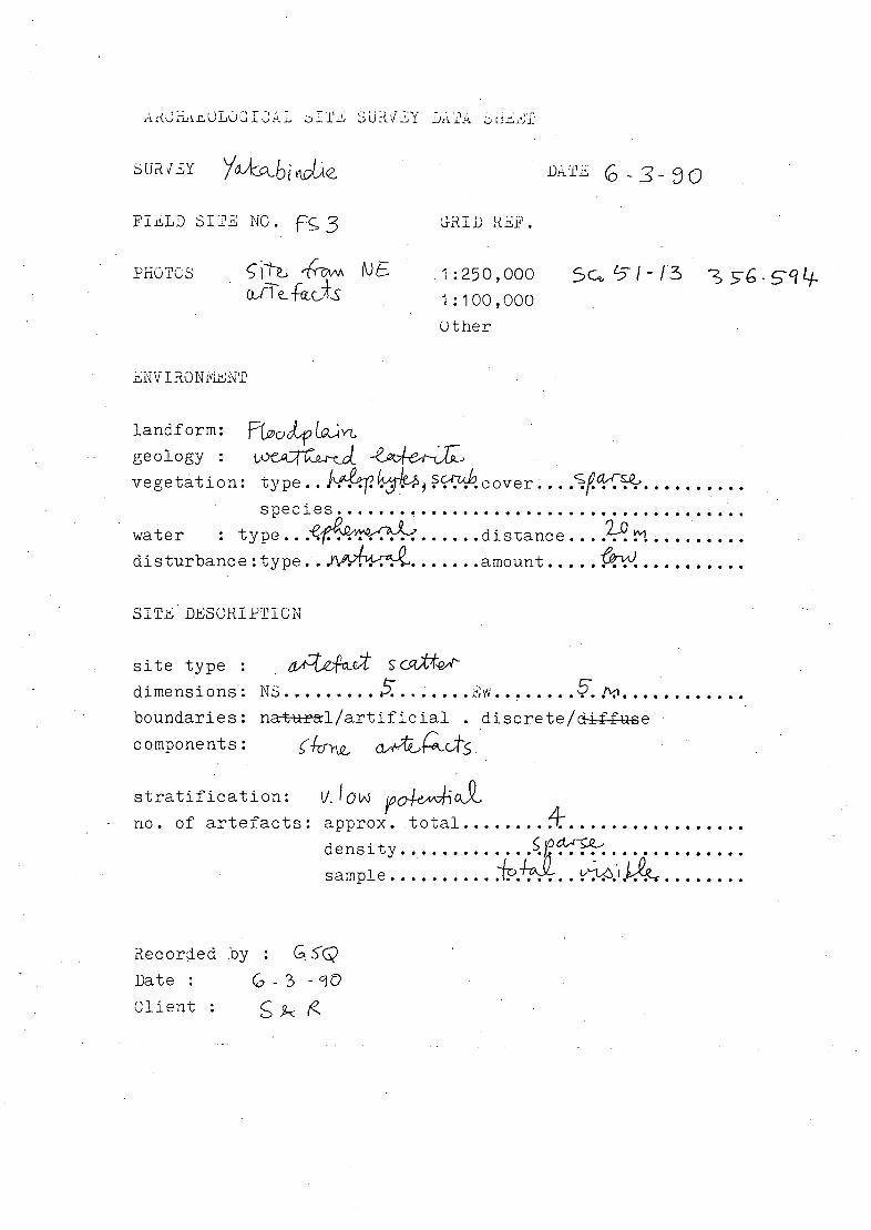
IJ 3UdvY tr
SURL1
FIiL.D SITE NO. Fc,3 RIjj REF.
PHOTOS N E .1:250,000 1:100,000 Other
DTI
Sc5/I3
.NVIRONivLNT
landf arm: geology vegetation: type..! 10 •1 4kcover..../4-Q'..........
species ........................................ water : type.. ....... distance .... ......... dis turbanc e :type. . W. amount ..... . SITE DESCRIPTION
site type : S Gtt*&4'
dime n s i a ris : N 3 .................. . ................
boundaries: na±ai/artificial . discrete/d-e
components:
stratification: no. of artefacts: approx.total
density..............i°"-"......... sam p1 e ............4..... . .
Recorded by :
Date : cj
Client:

IVA
114
jI J I
1lIIlI
]IIIIIIIIIIIIIIIIIII
I I

AUiirOLiOIjj. UHv Y iif- tLii
URLY flT -3-3o
FIiLD SIE NO. GRIn RHF.
PHOTOS Fc 1:250,000 5 GA H35-9 1:100,000 Other
HNVIRONivLNT
landf arm: c po geology : vegetation: type ... .........over... .........
s pecj..es ....................................... water :type..h - '-.......distance....?P. p ......... disturbance:type. . -- --- ......amount.. ...............
SITE DiSCRIPTIGN
site type : S
dimensions: N5 ........ . ....... .. ...... JOvvt..
boundaries: na#al/artificial . discrete/-e components: 5 ft2AgQ -f-ooLs
stratification: no. of artefacts: approx. total .........................
d e n s I t y . . . . sample ........ viJ ..............
ecorded by : Date : Client : S4R

CO
_ H I T
I 00 ('r

b'fQJVO97
p47 L4d UJJØQUbU3 )$3OJ iios
\/ 1 3èIflOI.d
V38V .Lo3roeId NOIIVOO1
21VOS 01 ION
J3JOed 31C1NleVAVX
I G' 77 7'7A 7 7J
I cJb'21YJG"W J/cilfve"hvA
, \ VP tv 71 dCU N//WQC
.1 ) /7 QI

w w w w w Lu
w
w w Lai 8
—
o o 0' o 0
0 0
o 0
0 0
o 0
o 0 0
0 0
0 0
0
0 8 - p... ' 0 OD
0 a) IC)
0 0 CD
0 - 0 "4
CD r()
CD 66000N (C) (C) < U)
WASTE DUMP
65000 N 65000 N _______ ______________ ______________ ________________ ________________ ________________
PLANT SITE
64000 N
-
64000 N
-
5.4
FS I OPEN CUT PIT
ACCOMODATION AREA 2 63000 N
63000 N 2 WASTE DUM P
TAIL INDAM AIRSTRIP .co FS3
'- 62000 N 620OON ____________________
650 ACCOMOD ATION
1 AREAI
FS4 61000 N
61000 N
I Lu Lu Lu Lu Lu 0
Lu W
8 0 / 0 ) 0 0 0 0
8 o 0
0 0 oN 0 0 8 8 / 0 .
0 'C) 'C) C CD (0 60000 N 60000 N
YAKIABINDIE PROJECT
2O 4-00 00 SOC JQL /
LOCATION OF ABORIGINAL SITES,,I4 FIGURE 2.
Soil 8 Rock Engineering Pty. Ltd.

2
. - - .i-_. .,-• ...4' •.(_•-
l p••
PLATE 1 : Field Site 1, from north - west
14
4 J L: :--• ii
00 4 1. ,
At
CENTIMETRE
INCH
IL Ii
PLATE 2 : Field Site 1, artefacts

.:.. J_,. ..J
1•. - - - -.. --- - • - --.-,.......
- •AdL
- -:- - • • -.4 .. . .-.-'.--.. .
a- •-. .•:•.• :._. --
_L- - -. -..- •. 1 •• .• •-• . .4 :_•-'... -
- .14- _• - • . ..: . - •_•• a -
- - -.
-
.. . - . - . .., •• ,. . . . - ... . -.. .. . - .
4. .. -,___, -. . . - .. •. ••.. '- - . . - ,r-:-.,'
- . .. :._•.•_•• -
PLATE 3 : Field Site 2, from north - east
PLATE 4 : Field Site 2, artefacts

- :-
i4is.
A- Milt '7-
W.
(.
PLATE 5 : Field Site 3, from north - east
11
PLATE 6 : Field Site 3, artefacts

'4
J4 TT1 r ' - ..-';
PLATE 7 : Field Site 4, from north - west
PLATE 8 : Field Site 4, artefacts
LISAWIV pT'C'flCJ jmcTY
I STET P2Th