QNAP Security - The Legacy Product FAQ / Tutorial
440
QNAP Security - The Legacy Product FAQ / Tutorial Menu If you have installed the latest version of Qmon.exe but still see the download page, it means your browser environment requires you to make this following change. 2016/07/19 Can I still use Qstart normally with a compatible switch when setting every IP camera to use static IPs? 2015/07/14 Why I can’t use the “Monitor” and “Playback” functions with my Chrome browser? 2015/05/18 QNAP surveillance products supports smart recording feature. Which camera models are supported? 2015/05/14 Why I can't have the updated NVR/camera settings in CMS server after I adjust NVR info? 2013/09/25 When I do the "Quick Configuration," why the hard disk initiating progress is stucking? 2013/09/23 If by all means, the CMS server can't be connected via web broswer, what should I do? 2013/09/11 Why I can connect to the CMS server via CMS client, while fail to connect to the CMS server using web browser? 2013/09/11 Why the multi-monitor doesn't function? 2013/09/11 Why when I finish the Quick Configuration, the UI just stop running? 2015/04/07 When I connect a high megapixel camera from CMS live view, why I don't seem to have high megapixel quality? 2013/09/11 VioStor NVRs have been certified with ImmerVision Enables. What are VioStor NVR-compatible panomorph cameras? 2013/03/08 When I go to NVR playback page to play the recording files, I found some frames are skipped. How can I playback all the frames? 2013/02/19 Set up the QNAP VioStor NVR to record and monitor fisheye network cameras 2015/05/18 When I use 'convert to AVI file' on playback and the snapshot function in Windows Vista or above, I cannot save the files in the specified folder. Why? 2013/02/05
-
Upload
khangminh22 -
Category
Documents
-
view
5 -
download
0
Transcript of QNAP Security - The Legacy Product FAQ / Tutorial

QNAP Security - The Legacy Product FAQ / Tutorial
Menu
If you have installed the latest version of Qmon.exe but still see the download page, itmeans your browser environment requires you to make this following change.
2016/07/19
Can I still use Qstart normally with a compatible switch when setting every IP camera to usestatic IPs?
2015/07/14
Why I can’t use the “Monitor” and “Playback” functions with my Chrome browser? 2015/05/18
QNAP surveillance products supports smart recording feature. Which camera models aresupported?
2015/05/14
Why I can't have the updated NVR/camera settings in CMS server after I adjust NVR info? 2013/09/25
When I do the "Quick Configuration," why the hard disk initiating progress is stucking? 2013/09/23
If by all means, the CMS server can't be connected via web broswer, what should I do? 2013/09/11
Why I can connect to the CMS server via CMS client, while fail to connect to the CMSserver using web browser?
2013/09/11
Why the multi-monitor doesn't function? 2013/09/11
Why when I finish the Quick Configuration, the UI just stop running? 2015/04/07
When I connect a high megapixel camera from CMS live view, why I don't seem to havehigh megapixel quality?
2013/09/11
VioStor NVRs have been certified with ImmerVision Enables. What are VioStorNVR-compatible panomorph cameras?
2013/03/08
When I go to NVR playback page to play the recording files, I found some frames areskipped. How can I playback all the frames?
2013/02/19
Set up the QNAP VioStor NVR to record and monitor fisheye network cameras 2015/05/18
When I use 'convert to AVI file' on playback and the snapshot function in Windows Vista orabove, I cannot save the files in the specified folder. Why?
2013/02/05

When I choose stream from camera on monitoring UI, which cameras whose multi-streamfeature are supported?
2011/10/03
For streaming from camera feature of QNAP NVR, which camera brands and models aresupported?
2011/10/03
How to use ONVIF-compliant cameras on VioStor NVR? 2011/09/13
How to enable real-time digital watermarking on NVR? What's the limitation? 2011/09/13
Why the motion detection of VIVOTEK cameras on VioStor NVR fail? 2011/08/29
How to Update Your VioStor (or NVR) System? 2011/03/04
How to use Remote Replication in VioStor NVR? 2010/11/08
Why I cannot received Alert Notification via Email? 2010/07/01
In playback mode, why we sometimes could view the playback of one channel but not withanother channel at specific time?
2010/03/31
In playback mode, QNAP multi-channels playback support up to four channels playback atthe same time. However, we found the playback view time of four channels are notsynchronized. Why?
2010/03/31
When I use AVTECH cameras and choose wrong model on camera configuration page, thetest result is still ok. Why?
2010/03/31
When I use Sanyo cameras and choose wrong model on camera configuration page, thetest result is still ok. Why?
2010/03/31
When I use Messoa cameras and choose wrong model on camera configuration page, thetest result is still ok. Why?
2010/03/31
When I use Internet Explorer 8 on Windows PC, I find the UI issue on monitoring andplayback page. How can I solve it?
2010/03/31
After I enable H.264 recording of an AXIS M7001 camera on two NVR servers, when I clicktest button on camera configuration page, NVR will return "MJPEG Test OK but MPEG-4Failed when trying RTSP protocol. Why?
2010/03/31
When I use Etrovision cameras, why I cannot connect the cameras from WAN? 2010/03/31

When I use Mobotix cameras, the image size doesn't match the resolution setting on NVR.Why?
2010/03/31
I cannot login the VioStor by Internet Explorer after installing Kaspersky anti-virus software.What should I do?
2010/03/16
When I use Mobotix cameras, I can't use motion detection recording. Why? 2010/03/11
How can I play the recording files of QNAP NVR on Mac OS? 2010/02/06
What is the difference between stream from the network camera and server? 2010/01/22
When I connect the NVR to ACTi speed dome, CAM-6500 and CAM-6600 series, bychoosing get video from server and get video from camera, both the NVR can't control thePan, Tilt and Zoom functions. What should I do to active the PTZ funciton in NVR?
2010/01/07
When I enter preset point name in far east languages, it will show scrambled characters.What should I do?
2009/12/18
What is the recording size limitation of VioStor NVR? 2009/12/18
For some cameras, such as Axis, D-link, GANZ, LevelOne, or Vivotek, I have to configurethe RTP ports on the router and the NVR so that the NVR can save the recording data fromthe IP cameras. What is the corresponding RTP port of VioStor series?
2009/12/02
My VioStor, IP cameras, and the PC are all in the same LAN, and some IP cameras areinstalled in remote location with Public IP. I want to allow users to connect the NVR fromremote PC over the Internet. how to install the NVR in different network environment forremote monitoring?
2009/12/02
If I enable MxPEG recording of MOBOTIX cameras on VioStor NVR, when I playback therecording files, the picture displayed is containing some large gray blocks hiding a large partof the picture. How to solve it?
2009/11/26
When I enable MxPEG recording of Mobotix cameras on VioStor NVR, I can't use VSMobileto see the live view of cameras. Why?
2009/11/26
How to convert VioGate-100 video file of IVG ext. to format that can be play by WindowsMedia Player?
2015/04/23
To use multi-ser monitoring feature, I click "Server List" icon, why do you not see the "AutoDetect" button?
2009/11/04

For VioStor NVR, after formatting USB driver, why the lost and found folders appear? 2009/11/04
After updating my NVR system, I can not use my local language, what can I do? 2009/10/29
How to remove the ActiveX of VioStor manually? 2009/10/29
In the monitoring page of VioStor, if I unable to view live video on one of the cameras, whatshould I do?
2009/09/10
After I enter a correct user name and password to access the VioStor NVR, if themonitoring screen did not display, what should I do?
2009/09/10
Do QNAP NVR support Apple Safari or other browser than Internet Explorer? 2009/09/03
When I connect the NVR to ACTi video server, ACD-2X00 series and SED-21X0 series, bychoosing get video from server and get video from camera, both the NVR can't control thePan, Tilt and Zoom functions. What should I do to active the PTZ funciton in NVR?
2009/08/25
How to configure the frame rate AXIS P3301 and Q7401 cameras? 2009/06/22
After setting the Network Settings as Standalone, the LAN2 port does not take effect. Why? 2009/06/22
Why can not use "auto search server" on monitor and playback? 2009/06/22
Why can't I upgrade the VioStor NVR? 2009/06/22
In playback page, when I click "web file manager" icon, why the window shows "no accessto this file or floder..."?
2009/06/22
After adding two VIVOTEK IP-7142 cameras, it will crash on the live view page. Why? 2009/06/22
Why there are mis-encoded characters in the cvs log file? 2009/06/22
How to update the VioStor-101/ VioStor-201 series to use the new web multi-channelplayback interface?
2009/06/22
There is a large number of "Re-launch process [upnpd]" logs in the Event Logs. Why? 2009/06/22
How to use FTP within Microsoft® Internet Explorer 7®? 2009/06/22

The monitoring image of the Toshiba IK-WB 21 network camera is upside down. Whatshould I do?
2009/06/22
A colon “:” appears in the NVR name and the firmware version on the monitoring page but Ididn’t set the server name as that. Why?
2009/06/22
I cannot find the NVR by QNAP Finder. The network connection is normal. What should Ido?
2009/06/22
I tried to login NVR by Finder. After entering the user name and password, an errormessage was shown and the login failed. Why?
2009/06/22
My VioStor, IP cameras, and the PC are all in the same LAN (Local Area Network). How toinstall the NVR in different network environment for remote monitoring?
2009/06/22
My VioStor, IP cameras, and the PC are all in the same LAN, and I want to allow users toconnect the NVR from remote PC over the Internet. How to install the NVR in differentnetwork environment for remote monitoring?
2009/06/22
My VioStor, IP cameras, and the PC are in LAN A, and some IP cameras are installed inLAN B behind a different router in a remote location. I want to allow the users to connect theNVR from remote PC over the Internet. How to install the NVR in different networkenvironment for remote monitoring?
2009/06/22
Why the recording is paused for a while and restarted after I applied changes to VioStor? 2009/06/22
Why the screen turns black when playing back the video? 2009/06/22
How to check your firmware Version? 2009/06/22
How to use the front video backup button of the VioStor? 2009/06/22
Is domain name supported in WAN IP and LAN IP fields? 2009/06/22
Does VioStor support hot swapping? 2009/06/22
Why there are only English logs in Event Logs? 2009/06/22
When I cannot access VioStor via the default IP or the IP shown in Quick Setup Wizard,what should I do?
2009/06/22
I've installed the camera but the distant object is unclear. How to solve this problem? 2009/06/22

Why the actual monitoring quality is worse than the configuration? 2009/06/22
Why the user with the administrator authority can’t delete the files on the NVR via FTP? 2009/06/22
When I monitored the image on the NVR for a while, my PC did not respond until I closedthe IE browser. Why?
2009/06/22
I've installed Sony cameras behind the router, and the NVR couldn’t detect any motiondetection from the cameras. Why?
2009/06/22
How to configure the resolution, frame rate, and quality of Linksys WVC54GCA? 2009/06/22
I use NVR to connect to eight Sony cameras with MPEG4 compression. However, theframe rate of recordings does not follow my settings and there is audio delay, why?
2009/06/22
I use sequential mode to monitor Panasonic BLC111 & BLC131 cameras, why the camerasare disconnected at short intervals?
2009/06/22
What should I do if there is loss of picture when monitoring or playing back video of DlinkDCS 2120?
2009/06/22
I've set the video file length of Vivotek cameras on VioStor NVR as 1 minute and the framerate as 1 fps. Why the recording files are all 2 minutes long?
2009/06/22
When I select a camera in camera configuration page and change Panasonic networkcamera to Canon camera, why there are logs "Set video quality on Camera 1 failed"?
2009/06/22
I can manually specify the FTP server address of the camera in alarm settings page;however, the function does not work after entering a domain name. How to solve theproblem?
2009/06/22
I have a Vivotek camera and set the advanced configuration of motion detection in camera'sweb UI manually, such as sensitivity and percentage setting. Why the advancedconfiguration of motion detection does not work?
2009/06/22
How to expand the storage capacity of VioStor-101 and NVR-104 by the eSATA port? 2009/06/22
What is FTP passive mode? 2009/06/22
I've installed the VioStor behind the router or firewall and set up port mapping (virtualserver) on the router. However, I still couldn’t access the VioStor. What should I do?
2009/06/22

Why can't I login the administration page of the VioStor? 2009/06/22
About ICS-1013, when I monitor the plants outdoor, the green leaves appear to be lightpurple. Why?
2009/06/22
Why can't I use the SMB, FTP and Web File Manager in VioStor? 2009/06/22
Why VioStor takes too long to restart? 2009/06/22
Why can't the monitoring page be fully displayed in Internet Explorer? 2009/06/22
Why can't I find my VioStor in QNAP Finder? 2009/06/22
Why can't the changes to the system configurations take effect? 2009/06/22
Why can't the E-map be displayed correctly? 2009/06/22
Why the estimated storage space for recording displayed in Recording Settings page isdifferent from the actual value?
2009/06/22
Why the screen is displayed abnormally with strange horizontal lines when the resolution ofPanasonic BB-HCM381 camera is set as 640x480?
2009/06/22
Why the live video of VioStor is not clear or smooth sometimes? 2009/06/22
If the alarm recording of VioStor does not function, what should I do? 2009/06/22
If the recording function of VioStor is not working properly, what should I do? 2009/06/22
How to evaluate the bandwidth usage of VioGate to avoid network congestion? 2009/06/22
Can I have different bitrate for viewing and different for recording? 2009/06/22
Will VioGate Master 32 support 16 Viocard-300 where only one video channel is used? 2009/06/22
May I change the video signal standard of VioGate-100/120 and VioCard-100 when theyare in use?
2009/06/22
Why all alarm recordings would be removed by overwriting process? 2009/06/22
Do VioGate-100/120 and VioCard-100 support NTSC and PAL signals? 2009/06/22
What resolution does VioGate support? 2009/06/22

Is any control device needed to remote control camera? 2009/06/22
Why PTZ camera cannot work for VioCard/ VioGate? 2009/06/22
Why I cannot use my DynaColor camera with VioGate? 2009/06/22
How to calculate the file size of recording by VioGate-100/120 and VioCard-100? 2009/06/22
Why the size of recorded files is different? 2009/06/22
Why I can’t configure VioGate when entering IP address in storage settings on Windows98?
2009/06/22
Can the files of multiple VioGate-100/120 and VioCard-100 be saved to the same NASsimultaneously?
2009/06/22
Can a snapshot be saved in different locations at the same time on VioCard and VioGateseries?
2009/06/19
Are the files recorded by VioGate-100/120 or VioCard-100 saved by file size or time? 2009/06/19
What format should the files recorded by VioGate be converted to for playing by WindowsMedia Player?
2009/06/19
How to calculate the storage needed for recording by VioGate? 2009/06/19
Why IE browser cannot display the screen when logging in VioGate-100/120 orVioCard-100?
2009/06/19
Why the screen is black when I login VioGate? 2009/06/19
How is the performance of different fps settings differing from the others? 2009/06/19
If I adjust the fps of each channel as max, can the channels achieve 30 fps? 2009/06/19
How long is the transfer distance of network cable in general? 2009/06/19
Q111.What is the bandwidth occupied by VioCard-100? 2009/06/19
How many frames per second do VioGate-100/120 or VioCard-100 record? 2009/06/19
How many fps does Max refer to on the monitoring screen? 2009/06/19
How to determine if two network devices are in the same LAN? 2009/06/19

How long is the transfer distance of coaxial cable in general? 2009/06/19
Why VioCard 30/300 log in screen show 2009/06/19
Why the hardware key cannot be found when running VioGate Master after updating it toV1.3.3623?
2009/06/19
What are the default network settings of VioGate-100/120 or VioCard-100? 2009/06/19
Why I cannot connect VioGate-100/120 or VioCard-100 while I can find them via QNAPFinder?
2009/06/19
Q120.How to view and change the network settings of PC? 2009/06/19
[Tutorial] How to use Qstart? 2015/07/22
[Tutorial] Flexibly monitor multiple focused areas on a camera by using ROI (Region ofInterest) Mode
2015/07/23
[Tutorial] Use full fisheye camera functions by Qdewarp for various monitoring applicationsand post-alarm diagnosis
2015/08/28
[Tutorial] Customize your own layouts and views 2015/07/23
[Tutorial] Use virtual cameras to maximize the usage of megapixel cameras 2015/07/22
[Video] QNAP Professional Video Management System - QVR 5.0 2015/07/06
[Guide] Scenario 4: Configure NVR, IP cameras and the PC in different routers and accessNVR from remote PC
2015/07/22
[Guide] Scenario 3: Install IP camera with Public IP and access NVR from remote PC 2015/07/22
[Guide] Scenario 2: Access the NVR from remote PC 2015/07/22
[Guide] Scenario 1: Local Area Network 2015/07/22
[Tutorial] How to use Vmobile 3 to monitor and play recordings on a VioStor NVR? 2015/07/22
[Tutorial] How to Use User-defined Multi-streaming for Multiple Applications? 2015/07/22
[Tutorial] Set up the QNAP VioStor NVR to record and monitor the network cameras withPanomorph lenses
2015/08/27
[Tutorial] How to use Smart stream on VIVOTEK cameras to intelligently allocate morebandwidth to streaming moving objects or Regions of Interest?
2015/07/22
[Tutorial] If a camera loses its connection with the NVR, does QNAP NVR support EdgeRecording to provide redundancy by backing up footage from a camera-based SD card?
2015/07/22
[Tutorial] How to Configure Storage Expansion for Long-term Recording? 2015/07/22
[Tutorial] Set up the QNAP VioStor NVR to record and monitor fisheye network cameras 2015/07/22

[Tutorial] Generic Methods to Add IP Cameras 2015/07/22
[Tutorial] Does QNAP NVR support real-time transcoding for smooth video playback whenusers are in low bandwidth environments or remote locations?
2015/07/22
[Tutorial] To use two-way audio to receive and transmit audio, what should I do? 2015/07/22
[Tutorial] How to install QSCM Lite App? 2015/07/22
[Tutorial] Protect QNAP NVR Data with Real-time Remote Replication (RTRR) 2015/07/22
[Tutorial] How to use Vcam? 2015/07/22
[Tutorial] How to Add Recording Channels? 2015/07/22
[Tutorial] How to update the NVR BIOS? 2015/07/22
[Tutorial] How to Enable Smart Recording to Maximize Storage Efficiency and Boost AlarmRecording?
2015/07/22
[Tutorial] PC-less Network Surveillance by HD Local Display via VGA Connector 2015/07/22
[Tutorial] How to Use E-map? 2015/07/22
[Tutorial] Advanced Event Management 2015/07/22
[Tutorial] How to Use Auto Cruising of Preset Positions? 2015/07/22
[Tutorial] How to Use Intelligent Video Analytics (IVA) on Playback? 2015/07/22
[Tutorial] Setup SMS and Email Alert Notifications 2015/07/22
[Tutorial] How to Use Digital Watermarking to Protect the Videos and Snapshots fromUnauthorized Modification?
2015/07/22
[Tutorial] How to use Remote Replication on VioStor NVR to QNAP Turbo NAS? 2015/07/22
[Tutorial] How to Expand the Storage Capacity and Upgrade the RAID Level of the VioStorNVR by Online RAID Capacity Expansion & RAID Level Migration?
2015/07/22
[Tutorial] How to Install the VioStor Series NVR in Different Network Environment forStandalone Use?
2015/07/22
[Tutorial] How to Use Multi-server Monitoring? 2015/07/22
[Video] QNAP VioStor NVR (Network Video Recorder) 2015/07/06
[Video] A reliable surveillance solution - QNAP VioStor NVR 2015/07/06

FAQ
Q1. If you have installed the latest version of Qmon.exe but still see thedownload page, it means your browser environment requires you to makethis following change.
Applied Models:
● All VS NVR Series
Answer:
Go to “Control Panel” > “Security” > “Local Intranet”, click on "Sites" and uncheck "Include all local(intranet) sites not listed in other zones". When finished, restart your browser.
Q2. Can I still use Qstart normally with a compatible switch when setting everyIP camera to use static IPs?
Applies to:
● Applies to: QVR 5.0.3 or later.
Answer:
For some switch brands (like ZyXEL) Qstart can only work while all devices are set to DHCP.
Although Switch Control can be used in Eten and EtherWAN switches for static IP cases,auto-detection and auto-configuration will not work.
Q3. Why I can’t use the “Monitor” and “Playback” functions with my Chromebrowser?
Applies to:
● QVR 5.0.3 or earlier.
Answer:
Google Chrome no longer supports NPAPI functionality following version 42.xx. This means users mustenable the NPAPI function to use the “Monitor” and “Playback” functions.
How to enable NPAPI:

1. To enable the necessary setting in your Google Chrome browser, type“chrome://flags/#enable-npapi” (without quotation marks) in the address bar.
2. Click the “enable” button.3. Restart the browser.
Before Enabling:
After Enabling:
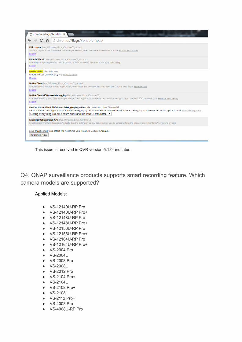
This issue is resolved in QVR version 5.1.0 and later.
Q4. QNAP surveillance products supports smart recording feature. Whichcamera models are supported?
Applied Models:
● VS-12140U-RP Pro● VS-12140U-RP Pro+● VS-12148U-RP Pro● VS-12148U-RP Pro+● VS-12156U-RP Pro● VS-12156U-RP Pro+● VS-12164U-RP Pro● VS-12164U-RP Pro+● VS-2004 Pro● VS-2004L● VS-2008 Pro● VS-2008L● VS-2012 Pro● VS-2104 Pro+● VS-2104L● VS-2108 Pro+● VS-2108L● VS-2112 Pro+● VS-4008 Pro● VS-4008U-RP Pro

● VS-4012 Pro● VS-4012U-RP Pro● VS-4016 Pro● VS-4016U-RP● VS-4016U-RP Pro● VS-4016U-SP● VS-4108 Pro+● VS-4108U-RP Pro+● VS-4112 Pro+● VS-4112U-RP Pro+● VS-4116 Pro+● VS-4116U-RP Pro+● VS-6012 Pro● VS-6016 Pro● VS-6020 Pro● VS-6112 Pro+● VS-6116 Pro+● VS-6120 Pro+● VS-8124 Pro+● VS-8124U-RP Pro● VS-8124U-RP Pro+● VS-8132 Pro+● VS-8132U-RP Pro● VS-8132U-RP Pro+● VS-8140 Pro+● VS-8140U-RP Pro● VS-8140U-RP Pro+● VS-8148 Pro+● VS-8148U-RP Pro● VS-8148U-RP Pro+
Answer:
As of the publication of this document, the cameras that have been tested for Smart Recording are:
ACTi B97, E34, E54, E84
AXIS M1011, M1054, M1103, M1104, M1113, M1114, M3006, M3011, M3014,M3026, M3113, M3114, M3204, M5013, M5014, M5014-V, M7010, M7014,P1204, P1214, P1214-E, P1353, P1354, P1355, P1357, P3301, P3304,P3344, P3346, P3353, P3354, P3363, P3364, P3364-LV/-LVE, P3367,P3384, P5414, P5512, P5522, P5532, P5534, P5544, P7210, P7214,P7224, P8513, P8514, Q1602, Q1604, Q1755, Q1765, Q1910, Q1921,Q1922, Q6032, Q6034, Q6035, Q6042, Q6044, Q6045, Q7401, Q7411

Sony SNC-CX600, SNC-CX600W, SNC-EB600, SNC-EB600B, SNC-EB630,SNC-EB630B, SNC-EM600, SNC-EM601, SNC-EM602R, SNC-EM630,SNC-EM631, SNC-EM632R, SNC-VB600, SNC-VB600B, SNC-VB630,SNC-VB635, SNC-VM600, SNC-VM601, SNC-VM601B, SNC-VM630,SNC-VM631, SNC-VM632R, SNC-WR600, SNC-WR602, SNC-WR630,SNC-XM632
VIVOTEK CC8130, FD8131, FD8131V, FD8134, FD8136, FD8137H, FD8137HV,FD8151V, FD8163, FD8164, FD8164V, FD8166, FD8355EHV, FD8363,FD8371EV, FE8173, FE8174, IP8131W, IP8132, IP8133, IP8152-F4,IP8335, IP8355EH, IP8364-C, IP8371-E, PZ81X1, SD81X1, SD8314E,SD8316E, SD8324E, SD8326E, SD8363E
To see the latest list of compatible cameras, please visit our compatibility list.
Q5. Why I can't have the updated NVR/camera settings in CMS server after Iadjust NVR info?
Applied Models:
● VSM-2000● VSM-4000U-RP
Answer:
Please synchronize the information between NVR & CMS:
1. Go to "Configuration --> Server --> Synchronize,"

OR
2. Check if the NVR password is changed. If the NVR password is changed, edit the NVR login password via"Configuration --> Server --> Edit Server"
2013/09/25

Q6. When I do the "Quick Configuration," why the hard disk initiatingprogress is stucking?
Applied Models:
● VSM-2000● VSM-4000U-RP
Answer:
Please check the hard disk condition:
1. It's suggested to use the brand new hard disk.
2. If the hard disk isn't brand new, please format the hard disk before inserting into CMS server.
3. If the hard disk isn't formatted, please insert it into the CMS server after the CMS server iscompletely turned on, instead of inserting the hard disk into the CMS server in the first beginning.
Q7. If by all means, the CMS server can't be connected via web browser, whatshould I do?
Applied Models:
● VSM-2000● VSM-4000U-RP
Answer:
You can use "Qnap Finder --> Configuration" to log in, and adjust the CMS server's IP address, orpassword, etc.
Q8. Why I can connect to the CMS server via CMS client, while fail to connectto the CMS server using a web browser?
Applied Models:
● VSM-2000● VSM-4000U-RP
Answer:
Please check if you have the web broswer settings connected with the proxy server, which may not beable to detect the CMS server.

Q9. Why the multi-monitor doesn't function?
Applied Models:
● VSM-2000● VSM-4000U-RP
Answer:
Please finish configuring the multi-monitor settings before opening up the CMS client software.
Q10. Why when I finish the Quick Configuration, the UI just stop running?
Applied Models:
● VSM-2000● VSM-4000U-RP
Answer:
Please update your CMS client software to 1.0.1.0902 or above.
Q11. When I connect a high megapixel camera from CMS live view, why I don'tseem to have high megapixel quality?
Applied Models:
● VSM-2000● VSM-4000U-RP
Answer:
1. CMS receives and displays the streams sent from NVR. Right-click on each camera channel at CMSlive view page, and choose "Quality Priority" to get the highesr resolution stream. (refer the snapshot)
2. If the “quality priority” stream can't fulfill the CMS display quality requirement, go to select higherresolution recording stream at the NVR side (refer the snapshot).

3. Then back to the CMS live view page, right-click on each camera channel, choose “RecordingStream,” and the CMS live view will show a higher display quality (refer to the snapshot).
Q12. VioStor NVRs have been certified with ImmerVision Enables. What areVioStor NVR-compatible panomorph cameras?
Applied Models:
● VS-12140U-RP Pro● VS-12148U-RP Pro● VS-12156U-RP Pro● VS-12164U-RP Pro● VS-2004 Pro● VS-2004L● VS-2008 Pro● VS-2008L● VS-2012 Pro● VS-2104 Pro+● VS-2108 Pro+● VS-2112 Pro+● VS-4008 Pro● VS-4008U-RP Pro● VS-4012 Pro● VS-4012U-RP Pro● VS-4016 Pro● VS-4016U-RP Pro● VS-4108 Pro+● VS-4112 Pro+● VS-4116 Pro+● VS-6012 Pro● VS-6016 Pro● VS-6020 Pro● VS-6112 Pro+● VS-6116 Pro+● VS-6120 Pro+● VS-8124 Pro+● VS-8124U-RP Pro● VS-8132 Pro+● VS-8132U-RP Pro● VS-8140 Pro+● VS-8140U-RP Pro● VS-8148 Pro+● VS-8148U-RP Pro
Answer:
Axis 223M, P1347, Q1602, Q1604
Basler BIP2-2500c-dn
LG LW332/335
Panasonic i-Pro NP1000/ 1004, WV-SP508E (resolution: 2048*1536), SP304, NP244
Samsung SNB-7000/SND-7080/SNV-7080R
StarDot SDH130VN
Vivotek IP8151
Q13. When I go to NVR playback page to play the recording files, I found someframes are skipped. How can I playback all the frames?
Applied Models:
● VS-12140U-RP Pro● VS-12148U-RP Pro● VS-12156U-RP Pro● VS-12164U-RP Pro● VS-2004 Pro● VS-2004L● VS-2008 Pro● VS-2008L● VS-2012 Pro● VS-4008 Pro● VS-4008U-RP Pro● VS-4012 Pro● VS-4012U-RP Pro● VS-4016 Pro● VS-4016U-RP Pro● VS-4108 Pro+● VS-4112 Pro+● VS-4116 Pro+● VS-6012 Pro● VS-6016 Pro● VS-6020 Pro● VS-6112 Pro+● VS-6116 Pro+● VS-6120 Pro+● VS-8024● VS-8024U-RP

● VS-8032● VS-8032U-RP● VS-8040● VS-8040U-RP● VS-8124 Pro+● VS-8124U-RP Pro● VS-8132 Pro+● VS-8132U-RP Pro● VS-8140 Pro+● VS-8140U-RP Pro● VS-8148 Pro+● VS-8148U-RP Pro
Answer:
1. Please go to playback page.2. Click "Options."
3. Change to "Play all frames."Note: Default option is to "Skip expired video frames when necessary, and make playback assmooth as possible."
4.
Q14. Set up the QNAP VioStor NVR to record and monitor fisheye networkcameras
Applied Models:
● VS-12140U-RP Pro+● VS-12148U-RP Pro+● VS-12156U-RP Pro+● VS-12164U-RP Pro+● VS-12140U-RP Pro● VS-12148U-RP Pro● VS-12156U-RP Pro● VS-12164U-RP Pro● VS-2004 Pro● VS-2008 Pro● VS-2012 Pro● VS-4008 Pro

● VS-4008U-RP Pro● VS-4108U-RP Pro+● VS-4012 Pro● VS-4012U-RP Pro● VS-4112U-RP Pro+● VS-4016 Pro● VS-4016U-RP Pro● VS-4116U-RP Pro+● VS-4108 Pro+● VS-4112 Pro+● VS-4116 Pro+● VS-6012 Pro● VS-6016 Pro● VS-6020 Pro● VS-6112 Pro+● VS-6116 Pro+● VS-6120 Pro+● VS-8124 Pro+● VS-8124U-RP Pro● VS-8124U-RP Pro+● VS-8132 Pro+● VS-8132U-RP Pro● VS-8132U-RP Pro+● VS-8140 Pro+● VS-8140U-RP Pro● VS-8140U-RP Pro+● VS-8148 Pro+● VS-8148U-RP Pro● VS-8148U-RP Pro+
Applied firmware:
● QVR 5.0.3 or above
Answer:
QNAP's VioStor network video recorder (NVR) series is among the first Linux-embedded standalonedevice provider to support fisheye cameras. Users can also view a complete scene unfold withoutobstruction while simultaneously displaying multiple independent dewarped views using fisheyecameras.
This article will guide you to configure the VioStor NVR to record videos from fisheye cameras and todewarp fisheye images for live monitoring.
Applicable camera models:
● AXIS M3007 (Please select AXIS M3007-dewarp model in our camera model list)● Dynacolor NA083● Oncam Grandeye EVO-05NMD● VIVOTEK FE 8172/8172/8174 (camera firmware version should be v0100h or above)

Prerequisites:
● The firmware version of the VioStor NVR must be QVR 5.0 or above. You can download thelatest firmware from here.
● The fisheye camera must be mounted in a proper position.
A. Set up the VioStor NVR
Follow the below steps to configure the VioStor NVR.

1. Run the "QNAP Finder" on a Windows PC to find the NVR. Double click the NVR name toconnect to the login page via web browser.
2. Login to the NVR as "admin".
3. To enter the surveillance settings page, click .
4. Go to “Camera Settings” > "Camera Configuration". Click or select a channel for
the camera and click to add a camera.

5. Click “Next” to use auto search to find the fisheye camera.
When it is found, choose the camera and click “OK”.
Enter the camera’s IP address, username and password.

Or manually add the camera brand and model.6. Specify the video and schedule settings.
Please note: To use the dewarping function, please select a resolution that includes (fisheye).7. Click "Apply".8. Now return to the live view window of the VioStor NVR. You can now view the live image of the
fisheye camera.
Fisheye view without dewarping.
B. Configure the live view settings

1. Move the mouse cursor over a camera channel and the supported function buttons (InteractiveControl Buttons) of the camera will show up for quick access.
2. Click “Camera information” in the Interactive Control Buttons and select “Properties”from the list.
Icon Description
Camera information:
1. Properties: Configure other monitoring options.2. Locate in E-map: Highlight camera icon on E-map.3. Visit the camera homepage.
3.
Select "Fixed resolution" under "Video Resolution".

Choose the video stream you want to see in the live view.
C. Dewarp fisheye images of the fisheye camera in live view
Icon Description
Dewarp fisheye images:
For specific fisheye cameras and camera models with panomorph lenses,you can toggle the dewarping function. After enabling this function, youcan then select the mount type and dewarping mode.
1. To dewarp the fisheye images of the fisheye camera, click “Dewarp fisheye images” in theInteractive Control Buttons to enable fisheye dewarping function.
2. Click “Dewarp fisheye images” in the Interactive Control Buttons to select the "Mount type" (Wall, Ceiling, or Floor) according to your setup environment and specify the "Dewarping mode".
○ Example 1. Select "Ceiling" for the mount type.

○ Note: For Ceiling and Floor Mount type, FullView will display 360 degrees of viewingangle.
○ Example 2. Select “Rectangle” for the dewarping mode.
D. Dewarp fisheye images of the fisheye camera in playback
1. Click to enter the playback page.2. To dewarp the fisheye images of the fisheye camera, click “Dewarp fisheye images” in the
Interactive Control Buttons to enable fisheye dewarping function.3. Click “Dewarp fisheye images” in the Interactive Control Buttons and select the "Mount type"
(Wall, Ceiling, or Floor) according to your setup environment and specify the "Dewarpingmode".
Q15. When I use 'convert to AVI file' on playback and the snapshot function inWindows Vista or above, I cannot save the files in the specified folder. Why?
Applied Models:
● VS-2004L● VS-2008L● VS-2004 Pro● VS-2008 Pro● VS-2012 Pro● VS-4008 Pro● VS-4012 Pro● VS-4016 Pro● VS-4108 Pro+● VS-4112 Pro+● VS-4116 Pro+● VS-4008U-RP Pro● VS-4012U-RP Pro● VS-4016U-RP Pro● VS-4016U-SP● VS-6012 Pro● VS-6016 Pro● VS-6020 Pro● VS-6112 Pro+● VS-6116 Pro+● VS-6120 Pro+

● VS-8024● VS-8032● VS-8040● VS-8024U-RP● VS-8032U-RP● VS-8040U-RP● VS-8124 Pro+● VS-8132 Pro+● VS-8140 Pro+● VS-8148 Pro+● VS-8124U-RP Pro● VS-8132U-RP Pro● VS-8140U-RP Pro● VS-8148U-RP Pro● VS-12140U-RP Pro● VS-12148U-RP Pro● VS-12156U-RP Pro● VS-12164U-RP Pro
Answer:

User Account Control (UAC) on Windows Vista/7/8
The UAC prohibits ActiveX controls from accessing the hard drives and the files required byActiveX are saved in the temporary folder. To resolve this problem, please follow the stepsbelow to turn User Account Control off:
1. Go to 'Control Panel'.
2. Click 'User Accounts'.
3. Click 'Turn User Account Control on or off'.

4. Uncheck the UAC option. Click 'OK'.
Trusted Sites on Internet Explorer
If you don't want to Turn User Account Control off, please add the IP address of NVR totrusted sites on Internete explorer.
1. Open Internet Explorer by clicking the Start button . In the search box, type InternetExplorer, and then, in the list of results, click Internet Explorer.
2. Click the Tools button, and then click Internet options.
3. Click the Security tab.
4. Now click on Trusted sites and then click on the sites button.
5. Enter the Website URL and click on Add.

6. When you are finished, click on Close.
You can now use the 'convert to AVI file' and snapshot functions.
Q16. When I choose stream from camera on monitoring UI, which cameraswhose multi-stream feature are supported?
Applied Models:
● VS-2004 Pro● VS-2004L● VS-2008● VS-2008 Pro● VS-2008L● VS-2012● VS-2012 Pro● VS-4008 Pro● VS-4008U-RP Pro● VS-4012 Pro● VS-4012U-RP Pro● VS-4016 Pro● VS-4016U-RP Pro● VS-6012 Pro● VS-6016 Pro● VS-6020 Pro● VS-8024● VS-8024U-RP● VS-8032● VS-8032U-RP● VS-8040● VS-8040U-RP● VS-8124 Pro+● VS-8132 Pro+● VS-8140 Pro+● VS-8148 Pro+
Answer:
QNAP NVR supports streaming from network camera for the following camera models whosemulti-stream feature are supported. You can configure multiple resolution settings for those cameras.
1. Arecont VisionThe supported resolution settings are full size and half size. It will show full size image onmonitoring page only when digital zoom is enabled.
2. Axis (all excluding 212)
○ Q7401, Q7404, Q6032: One resolution option only○ 223M: 320x240, 640x480, 1280x960, 1600x1200○ M7001, P5532: CIF, 4CIF○ 207M, 211M, 216M, AMTK_AM9060, AMTK_9730: 320x240, 640x480, 1280x1024○ Q1755, P1346: 320x240, 640x480, 1920x1080○ P3304, M1104, P1344, M1114, M3204: 320x240, 640x480, 1280x800○ Others (default): 320x240, 640x480
3. Canon
○ VB-M40: The same as recording settings○ Others (default): 320x240, 640x480
4. IQinVision (all excluding IQ732N)320x240, 640x480, maximum resolution supported by the cameras
5. Panasonic BB/BL
○ BB-HCM515: 320x240, 640x480, 1280x1024○ Others: 320x240, 640x480
6. If the recording format is MPEG4 and 1280x1024, the resolution on monitoring page is always320x240.
7. Panasonic i-Pro
○ NP1000, NP502, SP304: 320x240, 640x480, 1280x1024○ Others: 320x240, 640x480
8. Sanyo HD series camerasThe resolution settings available vary depending on the resolutions supported by the cameras
9. TOA320x240, 720x480
10. VIVOTEKThe resolution settings available vary depending on the resolutions supported by the cameras
Q17. For streaming from camera feature of QNAP NVR, which camera brandsand models are supported?
Applied Models:
● VS-2004 Pro● VS-2004L● VS-2008 Pro● VS-2008L● VS-2012 Pro● VS-4008 Pro● VS-4008U-RP Pro

● VS-4012 Pro● VS-4012U-RP Pro● VS-4016 Pro● VS-4016U-RP Pro● VS-6012 Pro● VS-6016 Pro● VS-6020 Pro● VS-8024● VS-8024U-RP● VS-8032● VS-8032U-RP● VS-8040● VS-8040U-RP● VS-8124 Pro+● VS-8132 Pro+● VS-8140 Pro+● VS-8148 Pro+
Answer:
1. QNAP NVR supports streaming from camera for the following camera brandsACTi, Arecont Vision, Canon, Edimax, iPUX, Linksys, MOBOTIX, Panasonic BB/BL/i-Proseries, TOA, TRENDnet, Vivotek, Y-CAM
2. QNAP NVR supports streaming from camera for the following camera models○ Axis: All excluding 212○ Cisco: Only CIVS-IPC-2500(W), WVC-210, PVC-2300/ WVC-2300○ D-Link: DCS-900(A), DCS-900(B1/B2), DCS-920, DCS-2121, DCS-3410○ ELMO: All excluding PTC-401C-IP, SN2230-IPW, SN2230-IP2, TD4114-IP2○ Etrovision: Only General, EV3130, EV6531, EV6552, EV6551A, EV6250A, EV6356A,
EV3151, EV6150A, EV3151A, EV6151A, EV6153A, EV6156A○ IQinVision: All excluding IQ732N○ LevelOne: FCS-0010/ WCS-0010, FCS-0020/ WCS-0020, FCS-1091/ WCS-1091○ Messoa: All excluding NCB855, NDR890, NIC930○ Sanyo: HD series○ SONY: All excluding CH and DH series○ Toshiba: CI-8110-D, CI8210-D, IK-WB12, IK-WB21
Q18. How to use ONVIF-compliant cameras on VioStor NVR?
Applied Models:
● VS-2004 Pro● VS-2004L● VS-2008● VS-2008 Pro● VS-2008L● VS-2012● VS-2012 Pro

● VS-4008 Pro● VS-4008U-RP Pro● VS-4012 Pro● VS-4012U-RP Pro● VS-4016 Pro● VS-4016U-RP● VS-4016U-RP Pro● VS-4016U-SP● VS-5012● VS-5020● VS-6012 Pro● VS-6016 Pro● VS-6020 Pro● VS-8024● VS-8024U-RP● VS-8032● VS-8032U-RP● VS-8040● VS-8040U-RP● VS-8124 Pro+● VS-8132 Pro+● VS-8140 Pro+● VS-8148 Pro+
Answer:
For the ONVIF-compliant cameras what are not in QNAP’s compatibility list, please kindly use ONVIF toenable monitoring, recording and playback of this camera at this moment. Please make sure your NVRfirmware is v3.5.0 build 4321 or later.
1. Camera Settings -> Camera Configuration2. Add camera as “ONVIF”3. If you use Axis cameras (take Axis P1344 for example), please enable web service.
Q19. How to enable real-time digital watermarking on NVR? What's thelimitation?
Applied Models:
● VS-2004 Pro● VS-2004L● VS-2008● VS-2008 Pro● VS-2008L● VS-2012● VS-2012 Pro● VS-4008 Pro● VS-4008U-RP Pro

● VS-4012 Pro● VS-4012U-RP Pro● VS-4016 Pro● VS-4016U-RP● VS-4016U-RP Pro● VS-4016U-SP● VS-5012● VS-5020● VS-6012 Pro● VS-6016 Pro● VS-6020 Pro● VS-8024● VS-8024U-RP● VS-8032● VS-8032U-RP● VS-8040● VS-8040U-RP● VS-8124 Pro+● VS-8132 Pro+● VS-8140 Pro+● VS-8148 Pro+
Answer:
To enable real-time digital watermarking, please follow these steps.
1. Camera Settings -> Recording Settings2. Enable "Enable real-time digital watermarking"
If real-time digital watermarking has been enabled, performance of VioStorNVR will be seriously affected, depending on your configuration.
For real-time digital watermarking, QNAP NVR currently supports following brands: Axis, Panasonicand Sony.
Q20. Why the motion detection of VIVOTEK cameras on VioStor NVR fail?
Applied Models:
● NVR-104V● VS-101V● VS-201V● VS-2004 Pro● VS-2004L● VS-2008● VS-2008 Pro

● VS-2008L● VS-2012● VS-2012 Pro● VS-4008 Pro● VS-4008U-RP Pro● VS-4012 Pro● VS-4012U-RP Pro● VS-4016 Pro● VS-4016U-RP● VS-4016U-RP Pro● VS-4016U-SP● VS-5012● VS-5020● VS-6012 Pro● VS-6016 Pro● VS-6020 Pro● VS-8024● VS-8024U-RP● VS-8032● VS-8032U-RP● VS-8040● VS-8040U-RP
Answer:
To use motion detection function of VIVOTEK cameras on VioStor NVR, please follow the steps below.
1. Connect to the web page of Vivotek's camera.2. Add a window for motion detection first.
Please note that first added motion detection window cannot be deleted.3. Enable motion detection function in alarm settings page.
Q21. How to Update Your VioStor (or NVR) System?
Applied Models:
● NVR-101● NVR-1012● NVR-104P● NVR-104V● VS-101P● VS-101V● VS-2004 Pro● VS-2004L● VS-2008● VS-2008 Pro● VS-2008L● VS-2012

● VS-2012 Pro● VS-201P● VS-201V● VS-4008 Pro● VS-4008U-RP Pro● VS-4012 Pro● VS-4012U-RP Pro● VS-4016 Pro● VS-4016U-RP● VS-4016U-RP Pro● VS-4016U-SP● VS-5012● VS-5020● VS-6012 Pro● VS-6016 Pro● VS-6020 Pro● VS-8024● VS-8024U-RP● VS-8032● VS-8032U-RP● VS-8040● VS-8040U-RP
Answer:

Before updating system firmware, please make sure the product model and firmwareversion are correct. Follow the steps below to update firmware:
Update by QNAP VioStor (or NVR)
1. Download the release notes of the same version as the firmware from QNAPSecurity website http://www.qnapsecurity.com/. Read the release notes carefully tomake sure you need to upgrade the firmware.
2. Before upgrading system firmware, back up all disk data on the server to avoid anypotential data loss during system update.
3. Login your VioStor (NVR) system configuration page.4. Click "System Tools" -> "System Update".5. Click the [Browse…] button to select the correct firmware image for system
update. Click [Update System] to update the firmware.
Update by QNAP Finder
1. Download the release notes of the same version as the firmware from QNAPSecurity website http://www.qnapsecurity.com/. Read the release notes carefully tomake sure you need to upgrade the firmware.
2. Before upgrading system firmware, back up all disk data on the server to avoid anypotential data loss during system update.

3. Click "Tools" > "Update Firmware".
4. Enter the administrator name and password.
5. You can upgrade the firmware of one to multiple servers simultaneously.

System update may take several minutes to complete depending on the networkconnection status. Please wait patiently. The system will inform you when system update iscompleted.
When performing system update, please make sure the power supply is at steady state.Failed to do so may cause the system unable to start up.
Note: If the system is running properly, you do not need to update the firmware.
QNAP is not responsible for any forms of data loss caused by improper or illegal systemupdate.

Q22. How to use Remote Replication in VioStor NVR?Applied Models:
● NVR-104P● NVR-104V● VS-101P● VS-101V● VS-2004 Pro● VS-2008● VS-2008 Pro● VS-2012● VS-2012 Pro● VS-201P● VS-201V● VS-4008 Pro● VS-4008U-RP Pro● VS-4012 Pro● VS-4012U-RP Pro● VS-4016 Pro● VS-4016U-RP● VS-4016U-RP Pro● VS-4016U-SP● VS-5012● VS-5020● VS-6012 Pro● VS-6016 Pro● VS-6020 Pro● VS-8024● VS-8024U-RP● VS-8032● VS-8032U-RP● VS-8040● VS-8040U-RP
Answer:

Remote Replication
You can use the remote replication feature to copy the recording data ofthe local VioStor to a remote QNAP network attached storage (NAS) inthe local network. The remote QNAP NAS is hereafter referred to as "theremote storage device".
Note:
1. Remote Replication is limited to the local network.2. Before using this function, please make sure the Microsoft
networking service of the remote storage device is enabled, andthe corresponding path and user access right have been correctlyconfigured.
Login VioStor and enter "System Tools" > "Remote Replication".
Configure the backup data, remote backup server settings, and backupschedule of the remote storage device in sequential order.
Enable remote replication (support multiple choices)

In the above example, the system only copies the alarm recording data ofthe latest 3 days to the remote storage device.
● Check the box "Enable remote replication" to activate this feature.The system executes automatic backup of recording data to theremote storage device according to the settings.
● When you select "Back up alarm recordings only (instead of allrecordings)", the system will only copy alarm recording data to theremote storage device. If this option is unchecked, the system willbackup all recording data to the remote storage device.
● When you select "Back up the recordings of the latest…day(s)only" and enter the number of days, the system will back up thelatest recording data to the remote storage device automaticallyaccording to your settings. If this option is unchecked, the systemwill copy all recording data to the remote storage device.
Configure your remote storage server
Note: It is recommended to execute the "Remote host testing" function toverify the connection to the remote storage device is successful.
Configure the remote replication schedule

For example, to enable the system to copy recording data automatically toremote storage device at 01:15 every Monday, please do the following:
Check the box "Replication Schedule", select "Weekly", enter 01 Hour: 15minute, and select "Monday".
Backup Options
Select "Replication Now", the system backs up recording data to remotestorage device immediately.
● Select "Overwrite the oldest recordings when the availablestorage on the remote host is less than 4GB"; the systemoverwrites the oldest recording data when the free space on theserver is less than 4GB.
● Select "Perform mirroring replication by deleting extra files on theremote replication", the system syncs the recording data betweenVioStor and the remote storage device and delete any extra fileson the remote destination.
● When the above options are all checked, the system executesremote replication immediately. It first judges if there are extrafiles on the remote location that are different from the localsource. If yes, the extra files will be removed. After that, thesystem executes recording data backup and verifies if the freespace of the internal hard disk drive is less than 4GB. If the freestorage capacity is larger than 4GB, remote replication will beexecuted immediately. If the free storage space is less than 4GB,the system deletes the recording data of the oldest day andexecutes remote replication.
● The system displays the latest 10 remote replication records foryou to analyze the status and troubleshooting.

In the above example:
1. When the status is shown as "Failed (Remote access error)": You cancheck the remote storage device is running or the network settings arecorrect.
2. When the status is shown as "Failed (An internal error occurred)": Youcan check the hard drive status of VioStor or check the Event Logs.
Note:
The time required by VioStor to replicate data toremote storage device varies to the networkenvironment. If the remote replication time is too long,some recording files may be overwritten by thesystem. To avoid this, it is recommended to refer to thestatus messages to analyze the time needed forremote replication and adjust the replication scheduleaccordingly.
Q23. Why I cannot received Alert Notification via Email?
Applied Models:
● VS-2008● VS-2012● VS-4016U-RP● VS-5012● VS-5020● VS-8024

● VS-8024U-RP● VS-8032● VS-8032U-RP● VS-8040● VS-8040U-RP
Answer:
Please follow the steps for trouble shooting,
Step1. Send a test Email, and see if you can receive it or not
1. If error message pop out, please double check SMTP Serveraddress, user name and password.
2. Check if the Server need use SSL/TLS connect, if so please clickit.
3. Check the DNS Server at Network Settings. A wrong DNS servermay cause failed to send the email.
4. If you have firewall server, please check if it block the application.
Step2. If there is no error message during the test mail, but you still notget the mail.
1. Check your spam mail folder to see if it is there.2. Check your SMTP server to see the mail it be blocked.
Step3. Try other SMTP server and Email recipient.
Q24. In playback mode, why we sometimes could view theplayback of one channel but not with another channel atspecific time?
Applied Models:
● NVR-104P● NVR-104V● VS-101P● VS-101V● VS-2008● VS-2012● VS-201P● VS-201V● VS-4016U-RP● VS-5012● VS-5020● VS-8024● VS-8024U-RP

● VS-8032● VS-8032U-RP● VS-8040● VS-8040U-RP
Answer:
The possible reasons could be:
1. If one of channel was not recording, you could not able to viewthat channel when playback.
2. The limited network bandwidth when the playbacks are viewedfrom Internet, especially the device is also in handling streamrecording and file-sending for playback view.
3. The performance of client PC when decoding.
Q25. When I use AVTECH cameras and choose wrongmodel on camera configuration page, the test result is stillok. Why?
Applied Models:
● NVR-104P● NVR-104V● VS-101P● VS-101V● VS-2008● VS-2012● VS-201P● VS-201V● VS-4016U-RP● VS-5012● VS-5020● VS-8024● VS-8024U-RP● VS-8032● VS-8032U-RP● VS-8040● VS-8040U-RP
Answer:
It's the camera's limitation. Because AVTECH camera doesn't support modelcheck function, NVR cannot detect camera model of AVTECH cameras.

Q26. When I use Sanyo cameras and choose wrongmodel on camera configuration page, the test result is stillok. Why?
Applied Models:
● NVR-104P● NVR-104V● VS-101P● VS-101V● VS-2008● VS-2012● VS-201P● VS-201V● VS-4016U-RP● VS-5012● VS-5020● VS-8024● VS-8024U-RP● VS-8032● VS-8032U-RP● VS-8040● VS-8040U-RP
Answer:
It's the camera's limitation. Because Sanyo VCC-400N camera doesn't supportmodel check function, NVR cannot detect camera model of Sanyo VCC-400N.
Q27. When I use Messoa cameras and choose wrongmodel on camera configuration page, the test result is stillok. Why?
Applied Models:
● NVR-104P● NVR-104V● VS-101P● VS-101V● VS-2008● VS-2012● VS-201P● VS-201V● VS-4016U-RP● VS-5012● VS-5020● VS-8024● VS-8024U-RP

● VS-8032● VS-8032U-RP● VS-8040● VS-8040U-RP
Answer:
It's the camera's limitation. Because Messoa camera doesn't support model checkfunction, NVR cannot detect camera model of Messoa cameras.
Q28. When I use Internet Explorer 8 on Windows PC, Ifind the UI issue on monitoring and playback page. Howcan I solve it?
Applied Models:
● NVR-104P● NVR-104V● VS-101P● VS-101V● VS-2008● VS-2012● VS-201P● VS-201V● VS-4016U-RP● VS-5012● VS-5020● VS-8024● VS-8024U-RP● VS-8032● VS-8032U-RP● VS-8040● VS-8040U-RP
Answer:
Please try to restore the Internet Explorer 8 to default.
Q29. After I enable H.264 recording of an AXIS M7001camera on two NVR servers, when I click test button oncamera configuration page, NVR will return "MJPEG TestOK but MPEG-4 Failed when trying RTSP protocol. Why?
Applied Models:

● NVR-104P● NVR-104V● VS-101P● VS-101V● VS-2008● VS-2012● VS-201P● VS-201V● VS-4016U-RP● VS-5012● VS-5020● VS-8024● VS-8024U-RP● VS-8032● VS-8032U-RP● VS-8040● VS-8040U-RP
Answer:
When multiple NVRs send connection requests, AXIS M7001 cameras willsometimes return MSB_RET_HTTP_REQUEST_FAILED.
Please try to reboot AXIS M7001 to solve the issue. Otherwise, please make surethat AXIS M7001 camera is only connected by one NVR.
Q30. When I use Etrovision cameras, why I cannotconnect the cameras from WAN?
Applied Models:
● NVR-104P● NVR-104V● VS-101P● VS-101V● VS-2008● VS-2012● VS-201P● VS-201V● VS-4016U-RP● VS-5012● VS-5020● VS-8024● VS-8024U-RP● VS-8032● VS-8032U-RP● VS-8040● VS-8040U-RP
Answer:
Please go to camera's page to modify the Security Level as Medium or Low.
Q31. When I use Mobotix cameras, the image size doesn'tmatch the resolution setting on NVR. Why?
Applied Models:
● NVR-104P● NVR-104V● VS-101P● VS-101V● VS-2008● VS-2012● VS-201P● VS-201V● VS-4016U-RP● VS-5012● VS-5020● VS-8024● VS-8024U-RP● VS-8032● VS-8032U-RP● VS-8040● VS-8040U-RP
Answer:
Situation: When setting resolution setting of Mobotix cameras as 2048 x 1536,1280 x 960, 1024 x 768 and 800 x 600, the image size will become 768 x 576.When setting resolution setting of Mobotix cameras as 704 x 756, the image sizewill become 704 x 528. When setting resolution setting of Mobotix cameras as 352x 288, the image size will become 352 x 264.
Solution: Please go to camera' page to set QuickControl value as "Full Image".The issue will be solved.
Q32. I cannot login the VioStor by Internet Explorer afterinstalling Kaspersky anti-virus software. What should I do?
Applied Models:
● NVR-101● NVR-1012● NVR-104P

● NVR-104V● VS-101P● VS-101V● VS-2008● VS-2012● VS-201P● VS-201V● VS-4016U-RP● VS-5012● VS-5020● VS-8024● VS-8024U-RP● VS-8032● VS-8032U-RP● VS-8040● VS-8040U-RP
Answer:
Please follow the steps below to adjust the Kaspersky settings.
1. Open the application settings window of Kaspersky.
2. Click “Threats and exclusions” and click “Settings” under “Exclusions”.
3. On the “Trusted applications” tab, click “Add”.
4. Find and select “iexplore”.
Normally you can find it under C:/Program Files/Internet Explorer
5. Check the option “Do not scan network traffic” and click “OK”.
6. Click “specify any” following “remote IP addresses”. Then input the NVRIP address.
Q33. When I use Mobotix cameras, I can't use motiondetection recording. Why?
Applied Models:
● NVR-101● NVR-1012● NVR-104P● NVR-104V● VS-101P● VS-101V● VS-2008● VS-2012● VS-201P

● VS-201V● VS-4016U-RP● VS-5012● VS-5020● VS-8024● VS-8024U-RP● VS-8032● VS-8032U-RP● VS-8040● VS-8040U-RP● VSMobile
Answer:
To use motion detection recording of MOBOTIX cameras on VioStor NVR, pleaseset the video compression of MOBOTIX cameras as M-JPEG.
Q34. How can I play the recording files of QNAP NVR onMac OS?
Applied Models:
● NVR-101● NVR-1012● NVR-104P● NVR-104V● VS-101P● VS-101V● VS-2008● VS-2012● VS-201P● VS-201V● VS-4016U-RP● VS-5012● VS-5020● VS-8024● VS-8024U-RP● VS-8032● VS-8032U-RP● VS-8040● VS-8040U-RP
Answer:
You can go to playback page or use VioStor Player to convert multiple recordingfiles to AVI file.
After converted, you can play the recording file of QNAP NVR on Mac OS.

Please check the video from 3:24 to 3:47.
And you can play the converted video on Mac OS.
Q35. What is the difference between stream from thenetwork camera and server?
Applied Models:
● NVR-104P● NVR-104V● VS-101P● VS-101V● VS-2008● VS-2012● VS-201P● VS-201V● VS-4016U-RP● VS-5012● VS-5020● VS-8024● VS-8024U-RP● VS-8032● VS-8032U-RP● VS-8040● VS-8040U-RP
Answer:
● Stream from the network cameraThe monitoring screens are streamed from the network cameras. Whenyour network surveillance system (VioStor NVR), IP cameras, and PC areinstalled behind the router, virtual server, or firewall, you will have toconfigure port forwarding (port mapping) for some of the IP cameras.Please refer to
T10.[Guide] Scenario 1: Local Area NetworkT9.[Guide] Scenario 2: Access the NVR from remote PCT8.[Guide] Scenario 3: Install IP camera with Public IP and access NVRfrom remote PCT7.[Guide] Scenario 4: Configure NVR, IP cameras and the PC in differentrouters and access NVR from remote PC

● Stream from the serverThe monitoring screens are streamed from the video server. There is noneed to configure port mapping. However, the VioStor NVR performancemay be affected. You may have to adjust the recording settings accordingto the real performance.
Q36. When I connect the NVR to ACTi speed dome,CAM-6500 and CAM-6600 series, by choosing get videofrom server and get video from camera, both the NVRcan't control the Pan, Tilt and Zoom functions. Whatshould I do to active the PTZ funciton in NVR?
Applied Models:
● NVR-104P● NVR-104V● VS-101P● VS-101V● VS-2008● VS-2012● VS-201P● VS-201V● VS-4016U-RP● VS-5012● VS-5020● VS-8024● VS-8024U-RP● VS-8032● VS-8032U-RP● VS-8040● VS-8040U-RP
Answer:
Currently, if you want to use PTZ function of the ACTi CAM-6500 and CAM-6600series cameras, please check that the protocol of the camera is DynaColor, BaudRate: 9600. Please refer to the camera's manual for detailed information.
Q37. When I enter preset point name in far eastlanguages, it will show scrambled characters. What shouldI do?
Applied Models:
● NVR-104P● NVR-104V● VS-101P

● VS-101V● VS-2008● VS-2012● VS-201P● VS-201V● VS-4016U-RP● VS-5012● VS-5020● VS-8024● VS-8024U-RP● VS-8032● VS-8032U-RP● VS-8040● VS-8040U-RP
Answer:
If you enter preset point name in far east language, please select UTF-8 oncharacter encoding.
Q38. What is the recording size limitation of VioStor NVR?
Applied Models:
● NVR-101● NVR-1012● NVR-104P● NVR-104V● VS-101P● VS-101V● VS-2008● VS-2012● VS-201P● VS-201V● VS-4016U-RP● VS-5012● VS-5020● VS-8024● VS-8024U-RP● VS-8032● VS-8032U-RP● VS-8040● VS-8040U-RP
Answer:
The file size limitation is 1G. If the file size is larger than 1G, the file will be cutted.

Q39. For some cameras, such as Axis, D-link, GANZ,LevelOne, or Vivotek, I have to configure the RTP ports onthe router and the NVR so that the NVR can save therecording data from the IP cameras. What is thecorresponding RTP port of VioStor series?
Applied Models:
● NVR-101● NVR-1012● NVR-104P● NVR-104V● VS-101P● VS-101V● VS-2008● VS-2012● VS-201P● VS-201V● VS-4016U-RP● VS-5012● VS-5020● VS-8024● VS-8024U-RP● VS-8032● VS-8032U-RP● VS-8040● VS-8040U-RP
Answer:
1. 4-channel NVR
1. Camera 1: video-6100~6103; audio: 6132~61352. Camera 2: video-6104~6107; audio: 6136~61393. Camera 3: video-6108~6111; audio: 6140~61434. Camera 4: video-6112~6115; audio: 6144~6147
2. 8-channel NVR1. Camera 1: video-6100~6103; audio: 6132~61352. Camera 2: video-6104~6107; audio: 6136~61393. Camera 3: video-6108~6111; audio: 6140~61434. Camera 4: video-6112~6115; audio: 6144~61475. Camera 5: video-6116~6119; audio: 6148~61516. Camera 6: video-6120~6123; audio: 6152~61557. Camera 7: video-6124~6127; audio: 6156~61598. Camera 8: video-6128~6131; audio: 6160~6163
3. 12-channel NVR1. Camera 1: video-6100~6103; audio: 6148~61512. Camera 2: video-6104~6107; audio: 6152~61553. Camera 3: video-6108~6111; audio: 6156~61594. Camera 4: video-6112~6115; audio: 6160~61635. Camera 5: video-6116~6119; audio: 6164~61676. Camera 6: video-6120~6123; audio: 6168~61717. Camera 7: video-6124~6127; audio: 6172~61758. Camera 8: video-6128~6131; audio: 6176~61799. Camera 9: video-6132~6135; audio: 6180~6183

10. Camera10: video-6136~6139; audio: 6184~618711. Camera11: video-6140~6143; audio: 6188~619112. Camera12: video-6144~6147; audio: 6192~6195
4. 16-channel NVR1. Camera 1: video-6100~6103; audio: 6164~61672. Camera 2: video-6104~6107; audio: 6168~61713. Camera 3: video-6108~6111; audio: 6172~61754. Camera 4: video-6112~6115; audio: 6176~61795. Camera 5: video-6116~6119; audio: 6180~61836. Camera 6: video-6120~6123; audio: 6184~61877. Camera 7: video-6124~6127; audio: 6188~61918. Camera 8: video-6128~6131; audio: 6192~61959. Camera 9: video-6132~6135; audio: 6196~619910. Camera10: video-6136~6139; audio: 6200~620311. Camera11: video-6140~6143; audio: 6204~620712. Camera12: video-6144~6147; audio: 6208~621113. Camera13: video-6148~6151; audio: 6212~621514. Camera14: video-6152~6155; audio: 6216~621915. Camera15: video-6156~6159; audio: 6220~622316. Camera16: video-6160~6163; audio: 6224~6227
5. 20-channel NVR1. Camera 1: video-6100~6103; audio: 6180~61832. Camera 2: video-6104~6107; audio: 6184~61873. Camera 3: video-6108~6111; audio: 6188~61914. Camera 4: video-6112~6115; audio: 6192~61955. Camera 5: video-6116~6119; audio: 6196~61996. Camera 6: video-6120~6123; audio: 6200~62037. Camera 7: video-6124~6127; audio: 6204~62078. Camera 8: video-6128~6131; audio: 6208~62119. Camera 9: video-6132~6135; audio: 6212~621510. Camera10: video-6136~6139; audio: 6216~621911. Camera11: video-6140~6143; audio: 6220~622312. Camera12: video-6144~6147; audio: 6224~622713. Camera13: video-6148~6151; audio: 6228~623114. Camera14: video-6152~6155; audio: 6232~623515. Camera15: video-6156~6159; audio: 6236~623916. Camera16: video-6160~6163; audio: 6240~624317. Camera17: video-6164~6167; audio: 6244~624718. Camera18: video-6168~6171; audio: 6248~625119. Camera19: video-6172~6175; audio: 6252~625520. Camera20: video-6176~6179; audio: 6256~6259
6. 24-channel NVR1. Camera 1: video-6100~6103; audio: 6196~61992. Camera 2: video-6104~6107; audio: 6200~62033. Camera 3: video-6108~6111; audio: 6204~62074. Camera 4: video-6112~6115; audio: 6208~62115. Camera 5: video-6116~6119; audio: 6212~62156. Camera 6: video-6120~6123; audio: 6216~62197. Camera 7: video-6124~6127; audio: 6220~62238. Camera 8: video-6128~6131; audio: 6224~62279. Camera 9: video-6132~6135; audio: 6228~623110. Camera10: video-6136~6139; audio: 6232~623511. Camera11: video-6140~6143; audio: 6236~623912. Camera12: video-6144~6147; audio: 6240~624313. Camera13: video-6148~6151; audio: 6244~624714. Camera14: video-6152~6155; audio: 6248~625115. Camera15: video-6156~6159; audio: 6252~625516. Camera16: video-6160~6163; audio: 6256~6259

17. Camera17: video-6164~6167; audio: 6260~626318. Camera18: video-6168~6171; audio: 6264~626719. Camera19: video-6172~6175; audio: 6268~627120. Camera20: video-6176~6179; audio: 6272~627521. Camera21: video-6180~6183; audio: 6276~627922. Camera22: video-6184~6187; audio: 6280~628323. Camera23: video-6188~6191; audio: 6284~628724. Camera24: video-6192~6195; audio: 6288~6291
7. 32-channel NVR1. Camera 1: video-6100~6103; audio: 6228~62312. Camera 2: video-6104~6107; audio: 6232~62353. Camera 3: video-6108~6111; audio: 6236~62394. Camera 4: video-6112~6115; audio: 6240~62435. Camera 5: video-6116~6119; audio: 6244~62476. Camera 6: video-6120~6123; audio: 6248~62517. Camera 7: video-6124~6127; audio: 6252~62558. Camera 8: video-6128~6131; audio: 6256~62599. Camera 9: video-6132~6135; audio: 6260~626310. Camera10: video-6136~6139; audio: 6264~626711. Camera11: video-6140~6143; audio: 6268~627112. Camera12: video-6144~6147; audio: 6272~627513. Camera13: video-6148~6151; audio: 6276~627914. Camera14: video-6152~6155; audio: 6280~628315. Camera15: video-6156~6159; audio: 6284~628716. Camera16: video-6160~6163; audio: 6288~629117. Camera17: video-6164~6167; audio: 6292~629518. Camera18: video-6168~6171; audio: 6296~629919. Camera19: video-6172~6175; audio: 6300~630320. Camera20: video-6176~6179; audio: 6304~630721. Camera21: video-6180~6183; audio: 6308~631122. Camera22: video-6184~6187; audio: 6312~631523. Camera23: video-6188~6191; audio: 6316~631924. Camera24: video-6192~6195; audio: 6320~632325. Camera25: video-6196~6199; audio: 6324~632726. Camera26: video-6200~6203; audio: 6328~633127. Camera27: video-6204~6207; audio: 6332~633528. Camera28: video-6208~6211; audio: 6336~633929. Camera29: video-6212~6215; audio: 6340~634330. Camera30: video-6216~6219; audio: 6344~634731. Camera31: video-6220~6223; audio: 6348~635132. Camera32: video-6224~6227; audio: 6352~6355
8. 40-channel NVR1. Camera 1: video-6100~6103; audio: 6260~62632. Camera 2: video-6104~6107; audio: 6264~62673. Camera 3: video-6108~6111; audio: 6268~62714. Camera 4: video-6112~6115; audio: 6272~62755. Camera 5: video-6116~6119; audio: 6276~62796. Camera 6: video-6120~6123; audio: 6280~62837. Camera 7: video-6124~6127; audio: 6284~62878. Camera 8: video-6128~6131; audio: 6288~62919. Camera 9: video-6132~6135; audio: 6292~629510. Camera10: video-6136~6139; audio: 6296~629911. Camera11: video-6140~6143; audio: 6300~630312. Camera12: video-6144~6147; audio: 6304~630713. Camera13: video-6148~6151; audio: 6308~631114. Camera14: video-6152~6155; audio: 6312~631515. Camera15: video-6156~6159; audio: 6316~631916. Camera16: video-6160~6163; audio: 6320~6323

17. Camera17: video-6164~6167; audio: 6324~632718. Camera18: video-6168~6171; audio: 6328~633119. Camera19: video-6172~6175; audio: 6332~633520. Camera20: video-6176~6179; audio: 6336~633921. Camera21: video-6180~6183; audio: 6340~634322. Camera22: video-6184~6187; audio: 6344~634723. Camera23: video-6188~6191; audio: 6348~635124. Camera24: video-6192~6195; audio: 6352~635525. Camera25: video-6196~6199; audio: 6356~635926. Camera26: video-6200~6203; audio: 6360~636327. Camera27: video-6204~6207; audio: 6364~636728. Camera28: video-6208~6211; audio: 6368~637129. Camera29: video-6212~6215; audio: 6372~637530. Camera30: video-6216~6219; audio: 6376~637931. Camera31: video-6220~6223; audio: 6380~638332. Camera32: video-6224~6227; audio: 6384~638733. Camera33: video-6228~6231; audio: 6388~639134. Camera34: video-6232~6235; audio: 6392~639535. Camera35: video-6236~6239; audio: 6396~639936. Camera36: video-6240~6243; audio: 6400~640337. Camera37: video-6244~6247; audio: 6404~640738. Camera38: video-6248~6251; audio: 6408~641139. Camera39: video-6252~6255; audio: 6412~641540. Camera40: video-6256~6259; audio: 6416~6419
Q40. My VioStor, IP cameras, and the PC are all in thesame LAN, and some IP cameras are installed in remotelocation with Public IP. I want to allow users to connect theNVR from remote PC over the Internet. how to install theNVR in different network environment for remotemonitoring?
Applied Models:
● NVR-101● NVR-1012● NVR-104P● NVR-104V● VS-101P● VS-101V● VS-2008● VS-2012● VS-201P● VS-201V● VS-4016U-RP● VS-5012● VS-5020● VS-8024● VS-8024U-RP● VS-8032

● VS-8032U-RP● VS-8040● VS-8040U-RP
Answer:
1. The VioStor, IP cameras, and the PC are all in the same LAN.2. Some IP cameras are installed in remote location with Public IP.3. Allow users to connect the NVR from remote PC over the Internet.
Please follow the steps below to install the NVR.
1. Plan the IP address and port of the NVR, the camera, and the PC.
LAN Device IP Address/Port
Mapped Port on theRouter
A Public IP of therouter
219.87.144.205
VioStor 192.168.1.100:80
219.87.144.205:8000
Camera 1 192.168.1.101:80
219.87.144.205:8001
Camera 2 192.168.1.102:80
219.87.144.205:8002
Camera 3 192.168.1.103:80
219.87.144.205:8003
Camera 4 192.168.1.103:80
219.87.144.205:8004

PC 192.168.1.200
B Camera 5 205.234.170.165
Camera 6 205.234.170.166
C Remote PC 10.8.10.123
2.3. Install the IP camera. Please refer to the user guide of the IP camera for
the network configuration.4. Configure the router/ virtual server/ firewall
In this application, you have to configure the port mapping or virtual serverof the router and forward the ports to the corresponding LAN IP so thatthe NVR can save the recording data from the remote IP camera and theremote PC can access the monitoring page over the Internet.Note:
1. Some IP cameras delivers MPEG4 image via the RTSP or RTPports. If the IP camera is installed outside the router, you have toconfigure the RTSP and RTP ports on the router and the NVR sothat the NVR can save the recording data from the IP cameras,e.g. Vivotek, Axis, D-link, GANZ, or LevelOne cameras thatsupport MPEG4 streaming.
2. In this sample, you must configure the RTP port setting on therouter of LAN A and the RTSP port setting on the router of LAN B.
3. RTP (Real-time Transport Protocol): The protocol for deliveringvideo or audio data.
4. RTSP (Real-Time Streaming Protocol): The protocol forcontrolling video or audio streaming media.
5. Configure the port mapping or virtual server on the router:HTTP port:
From Forward to
219.87.144.205:8000
192.168.1.100:80

219.87.144.205:8001
192.168.1.101:80
219.87.144.205:8002
192.168.1.102:80
219.87.144.205:8003
192.168.1.103:80
219.87.144.205:8004
192.168.1.104:80
6. RTP port: (Configure the port for NVR to receive remote video data fromthe IP camera)
From Forward to
219.87.144.205:6100
192.168.1.100:6100
219.87.144.205:6101
192.168.1.100:6101
219.87.144.205:6102
192.168.1.100:6102
219.87.144.205:6103
192.168.1.100:6103
: :

:
:
::
219.87.144.205:6199
192.168.1.100:6199
7. Note: To know the default RTP (Real-time Transport Protocol) port rangeof the Viostor NVR, please refer to FAQ.
8. Install and configure the VioStor NVREnter the IP address of the camera in the “IP address” field of the“Camera Settings” page of the VioStor. Then enter the Public IP and theport number of the camera configured on the router in “WAN IP” and“Port” fields respectively on the “Camera Settings” page of the VioStor.Note: The LAN IP and the WAN IP of the IP camera must be entered.
Note:
1. The “IP address” is for the VioStor to acquire the streaming from theVioStor directly and for browsing by LAN users.
2. The “WAN IP Address” is for remote access to the monitoring page of theVioStor over the Internet. If your IP camera is installed behind the NATrouter, enter the public IP address (or URL) and configure the portforwarding correctly.
● The port 21 must be forwarded on the router in the following twosituations:
1. When you use the alarm function of the remote IP camera (thealarm between the NVR and the camera is delivered by FTP).
2. When you need to login the VioStor by FTP (port 21).
From Forward to
219.87.144.205:21
192.168.1.100:21
● After changing the settings, enter the address in the browser to accessthe VioStor over the Internet: http:// 219.87.144.205:8000/
● If you have configured port 80 to VioStor, enter the address to access theVioStor (the default port of HTTP is 80): http:// 219.87.144.205/
● To use DDNS if this network environment, enter the DDNS settings on therouter, but not on the VioStor.

Q41. If I enable MxPEG recording of MOBOTIX camerason VioStor NVR, when I playback the recording files, thepicture displayed is containing some large gray blockshiding a large part of the picture. How to solve it?
Applied Models:
● VS-2008● VS-2012● VS-4016U-RP● VS-5012● VS-5020● VS-8024● VS-8024U-RP● VS-8032● VS-8032U-RP● VS-8040● VS-8040U-RP
Answer:
If gray blocks shown on image in recorded files, please select "Image Quality" as"Fast" in camera home page to reduce the phenomenon.
Q42. When I enable MxPEG recording of Mobotixcameras on VioStor NVR, I can't use VSMobile to see thelive view of cameras. Why?
Applied Models:
● NVR-101● NVR-1012● NVR-104P● NVR-104V● VS-101P● VS-101V● VS-2008● VS-2012● VS-201P● VS-201V● VS-4016U-RP● VS-5012● VS-5020● VS-8024● VS-8024U-RP● VS-8032

● VS-8032U-RP● VS-8040● VS-8040U-RP● VSMobile
Answer:
MxPEG video compression of Mobotix cameras are not supported by VSMobile.
1. Connect to NVR server.2. Go to Camera Settings -> Recording Settings3. Change the video compression of Mobotix cameras to M-JPEG.
Q43. How to convert VioGate-100 video file of IVG ext. toformat that can be play by Windows Media Player?
Applied Models:
● VioCard-100● VioCard-300● VioGate-140● VioGate-340(340A)
Answer:
1. You could save the file to AVI format after playback.2. Download it from Download Center.
http://www.mmnt.net/db/0/0/ftp.qnap.com/SURVEILLANCE/VioGate-100The file name is IVG2AVI.exeUse IVG2AVI.exe to convert IVG to AVI format.
3. You could play the files by Windows Media Player.
Q44. To use multi-ser monitoring feature, I click "ServerList" icon, why do you not see the "Auto Detect" button?
Applied Models:
● NVR-104P● NVR-104V● VS-101P● VS-101V● VS-2008● VS-2012● VS-201P● VS-201V● VS-4016U-RP● VS-5012● VS-5020● VS-8024● VS-8024U-RP● VS-8032

● VS-8032U-RP● VS-8040● VS-8040U-RP
Answer:
Please go to playback page to install the ActiveX or visithttp://www.qnapsecurity.com/n/en/product_x_down/ to download and installVioStor Player utility. Then you can use auto detect function on monitoring page.
Q45. For VioStor NVR, after formatting USB driver, whythe lost and found folders appear?
Applied Models:
● NVR-101● NVR-1012● NVR-104P● NVR-104V● VS-101P● VS-101V● VS-2008● VS-2012● VS-201P● VS-201V● VS-4016U-RP● VS-5012● VS-5020● VS-8024● VS-8024U-RP● VS-8032● VS-8032U-RP● VS-8040● VS-8040U-RP
Answer:
If you choose EXT3 to format USB driver, the lost and found folders will becreated.
It is normal and won’t affect Viostor’s function.

Q46. After updating my NVR system, I can not use mylocal language, what can I do?
Applied Models:
● NVR-101● NVR-1012● NVR-104P● NVR-104V● VioStor-101A● VioStor-101P● VioStor-101V● VioStor-2008● VioStor-2012● VioStor-201A● VioStor-201P● VioStor-201V● VioStor-5012● VioStor-5020● VioStor-8040● VioStor-8040U-RP
Answer:
1. Delete X86VCHS.dll, X86VCHT.dll, ..., X86VSVF.dll files on the system32folder.
2. Delete X86VMon on the C:WINDOWSDownloaded Program Files.3. Login the NVR without opening other IE window to re-install activeX.
Q47. How to remove the ActiveX of VioStor manually?
Applied Models:
● NVR-104P● NVR-104V● VS-101P● VS-101V● VS-2008● VS-2012● VS-201P● VS-201V● VS-4016U-RP● VS-5012● VS-5020● VS-8024● VS-8024U-RP● VS-8032● VS-8032U-RP● VS-8040

● VS-8040U-RP
Answer:

Please follow the steps below to remove the ActiveX.
1. Windows Vista users:Open an IE browser. Go to "Tools" > "Manage Add-ons" → "Enable or disableAdd-ons".
2. Select "Downloaded ActiveX Controls" from the drop-down menu.Select the ActiveX control to remove and click "Delete".
Windows XP users:

1. Open an IE browser. Go to "Tools"→ "Internet Options".
In the "General" tab, click "Settings" under "Browsing history". Then click"View objects".

Select the ActiveX control to remove.
Q48. In the monitoring page of VioStor, if I unable to viewlive video on one of the cameras, what should I do?Applied Models:
● NVR-101● NVR-1012● NVR-104P● NVR-104V● VioStor-101A● VioStor-101P● VioStor-101V● VioStor-2008● VioStor-2012● VioStor-201A● VioStor-201P● VioStor-201V● VioStor-5012● VioStor-5020● VioStor-8040● VioStor-8040U-RP
Answer:
1. If the IP address, name and password entered in the camera configurationpage are correct, You could use the Test function to verify the connection.
2. When the PC and the network camera are in the same subnet, whileVioStor is in another one, you cannot view the monitoring screen from thePC. You can solve the problems by the following methods
○ Method 1: Enter the IP address of the network camera as theWAN IP in VioStor.
○ Method 2: Configure the router to allow internal access to thepublic IP address and the mapped ports of the network cameras.
You could refer to the NVR Installation Guide.T10.[Guide] Scenario 1: Local Area NetworkT9.[Guide] Scenario 2: Access the NVR from remote PCT8.[Guide] Scenario 3: Install IP camera with Public IP and access NVR fromremote PCT7.[Guide] Scenario 4: Configure NVR, IP cameras and the PC in different routersand access NVR from remote PC
Q49. After I enter a correct user name and password toaccess the VioStor NVR, if the monitoring screen did notdisplay, what should I do?
Applied Models:
● NVR-101● NVR-1012● NVR-104P

● NVR-104V● VS-101P● VS-101V● VS-2008● VS-2012● VS-201P● VS-201V● VS-5012● VS-5020● VS-8040● VS-8040U-RP
Answer:
1. Check if you have installed ActiveX when logging in the monitoring page.Set the security level to “Medium” or lower in Internet Options of IEbrowser.
2. Make sure VioStor is turned on and the network is correctly connected.3. The IP address of VioStor does not conflict with other devices in the same
subnet.4. Check the IP address settings of VioStor and your computer. Make sure
they are in the same subnet.5. Make sure the IP address of the network camera does not conflict with
other devices in the same subnet.6. Make sure the IP address, name and password entered in the camera
configuration page are correct. You can use the Test function to verify theconnection.
7. When the PC and the network camera are in the same subnet, whileVioStor is in another one, you cannot view the monitoring screen from thePC. You can solve the problems by the following methods:
● Method 1: Enable “loopback” in the router or allow internalaccess from the mapped ports of the network cameras.
● Method 2: Enter the IP address of the network camera asthe WAN IP in VioStor.
For more information about NVR Installation Guide, please refer toT10.[Guide] Scenario 1: Local Area NetworkT9.[Guide] Scenario 2: Access the NVR from remote PCT8.[Guide] Scenario 3: Install IP camera with Public IP and accessNVR from remote PCT7.[Guide] Scenario 4: Configure NVR, IP cameras and the PC indifferent routers and access NVR from remote PC
Note: Some anti-virus softwares take ActiveX as dangerous program. Pleaseclose the anti-virus temporarily.

Q50. Do QNAP NVR support Apple Safari or otherbrowser than Internet Explorer?
Applied Models:
● ICS-1013● NVR-101● NVR-1012● NVR-104P● NVR-104V● VS-101P● VS-101V● VS-2008● VS-2012● VS-201P● VS-201V● VS-4016U-RP● VS-5012● VS-5020● VS-8024● VS-8024U-RP● VS-8032● VS-8032U-RP● VS-8040● VS-8040U-RP
Answer:
Currently QNAP NVR supports Internet Explorer by using ActiveX plug in to view the IPstreaming. Other browser such as Apple Safari, Opera, Firefox and other Java-script typebrowsers are not supported yet.
Q51. When I connect the NVR to ACTi video server,ACD-2X00 series and SED-21X0 series, by choosing getvideo from server and get video from camera, both theNVR can't control the Pan, Tilt and Zoom functions. Whatshould I do to active the PTZ funciton in NVR?
Applied Models:
● NVR-104P● NVR-104V● VS-101P● VS-101V● VS-2008● VS-2012● VS-201P● VS-201V

● VS-4016U-RP● VS-5012● VS-5020● VS-8024● VS-8024U-RP● VS-8032● VS-8032U-RP● VS-8040● VS-8040U-RP
Answer:
Currently, if you want to use PTZ function of the ACD-2X00 series and SED-21X0series video servers, please modify the protocol of analog cameras to Pelco-D,and Baud Rate setting of analog cameras should be the same with the videoserver. Please refer to the video server's manual for detailed information.
Q52. How to configure the frame rate AXIS P3301 andQ7401 cameras?
Applied Models:
● NVR-101● NVR-1012● NVR-104P● NVR-104V● VioStor-101A● VioStor-101P● VioStor-101V● VioStor-2008● VioStor-2012● VioStor-201A● VioStor-201P● VioStor-201V● VioStor-5012● VioStor-5020● VioStor-8040● VioStor-8040U-RP
Answer:
NVR does not support AXIS P3301 and Q7401 camera settings. Please login thecamera settings page to configure the settings.

Q53. After setting the Network Settings as Standalone, theLAN2 port does not take effect. Why?
Applied Models:
● VioStor-2008● VioStor-2012● VioStor-5012● VioStor-5020● VioStor-8040● VioStor-8040U-RP
Answer:
Restart the system after setting to standalone mode when do LAN setting.
Q54. Why can not use "auto search server" on monitorand playback?
Applied Models:
● NVR-101● NVR-1012● NVR-104P● NVR-104V● VioStor-101A● VioStor-101P● VioStor-101V● VioStor-2008● VioStor-2012● VioStor-201A● VioStor-201P● VioStor-201V● VioStor-5012● VioStor-5020● VioStor-8040● VioStor-8040U-RP
Answer:

It is technical limitation.
Please close QNAP Finder when you want to use "auto search server" on monitorand playback.
Q55. Why there are mis-encoded characters in the cvs logfile?
Applied Models:
● VioStor-2008● VioStor-2012● VioStor-5012● VioStor-5020● VioStor-8040● VioStor-8040U-RP
Answer:
The logs are encoded as Unicode (UTF-8) in the cvs file. To read the logsproperly, please open the file with any text editor or program which supportsUnicode encoding.
Q56. How to update the VioStor-101/ VioStor-201 series touse the new web multi-channel playback interface?
Applied Models:
● VioStor-101A● VioStor-101P● VioStor-101V● VioStor-201A● VioStor-201P● VioStor-201V
Answer:
Notice: If the system is running properly, you do not need to update the firmware.QNAP is not responsible for any forms of data loss caused by improper or illegalsystem update.

Before updating the system firmware, please do the following:
1. Back up all the disk data on the server to avoid any potential data lossduring the system update.
2. Download the release notes of the same version as the firmware fromQNAP Security websitehttp://www.qnapsecurity.com/n/en/product_x_down/. Read the releasenotes carefully to make sure you need to upgrade the firmware.
3. Make sure the product model and the firmware version are correct.
To use the new web multi-channel playback interface, you need to update theVioStor firmware to version 2.7.0 first. Follow the steps below to update thefirmware:
1. If you have installed the hard drive(s) in the VioStor, you are suggested toupdate the system with the firmware that includes playback.
1. Update the system with the firmware that does not includeplayback. You can download the firmware that does not includeplayback from QNAP Security websitehttp://www.qnapsecurity.com/n/en/product_x_down/.
2. Update playbackBy FirmwareUpdate the system with the firmware that includes playback.After updating the firmware, you can use the new web multi-channel playbackinterface. You can download the firmware that includes playback from QNAPSecurity website http://www.qnapsecurity.com/n/en/product_x_down/.
By QNAP Finder1. Run the Finder.2. Click "Settings" > "Run Quick Configuration Wizard".3. Enter the administrator name and password.
Default administrator name: administratorPassword: admin

4. The Quick Configuration Wizard will be shown. Click "Next" to continue.
5. In Step 7, click "Browse…" to select the correct package file of the ActiveXPlayer for update. You can download the correct package file of the ActiveXPlayer from QNAP Security websitehttp://www.qnapsecurity.com/n/en/product_x_down/.

6. Confirm the changes.
7. After applying the changes, the server will restart. Click "Finish" to exit thewizard.
8. To use new multi-channel playback interface, you must install the ActiveXcontrol. Follow the instructions to install it.

9. After that, you can use new web multi-channel playback interface.
2. If you have not installed any hard drives in the VioStor, you must updatethe system with the firmware that does not include playback.After updating, follow the steps below to use the new web multi-channelplayback interface.
1. Install the hard disk(s) in the VioStor.2. Update Playback
By QNAP Finder
1. Run the Finder.2. Click "Settings" > "Run Quick Configuration Wizard".3. Enter the administrator name and password.
Default administrator name: administratorPassword: admin
Q57. There is a large number of "Re-launch process[upnpd]" logs in the Event Logs. Why?
Applied Models:
● NVR-101● NVR-1012● NVR-104P● NVR-104V● VioStor-101A● VioStor-101P● VioStor-101V● VioStor-2008● VioStor-2012● VioStor-201A● VioStor-201P

● VioStor-201V● VioStor-5012● VioStor-5020● VioStor-8040● VioStor-8040U-RP
Answer:
The gateway setting is incorrect and the UPNPd process cannot be startedcorrectly.
4. The Quick Configuration Wizard will be shown. Click "Next" to continue.
5. In Step 7, click "Browse…" to select the correct package file of the ActiveXPlayer for update. You can download the correct package file of the ActiveXPlayer from QNAP Security website

http://www.qnapsecurity.com/n/en/product_x_down/.
6. Confirm the changes.

7. After applying the changes, the server will restart. Click "Finish" to exit thewizard.
8. To use new multi-channel playback interface, you must install the ActiveXcontrol. Follow the instructions to install it.
9. After that, you can use new web multi-channel playback interface.
3. By VioStor1. Connect to the VioStor.2. Click the playback button on the monitoring page.

3. Click "Install" to install the ActiveX control from the Internet.
Note: Make sure that the VioStor is connected to the Internet.4. After that, you can use new web multi-channel playback interface.
Q58. How to use FTP within Microsoft® Internet Explorer7®?
Applied Models:

● ICS-1013● NVR-101● NVR-1012● NVR-104P● NVR-104V● VioCard-100● VioCard-300● VioGate Master● VioGate-140● VioGate-340(340A)● Vioserver-10● Vioserver-5● VioStor-101A● VioStor-101P● VioStor-101V● VioStor-2008● VioStor-2012● VioStor-201A● VioStor-201P● VioStor-201V● VioStor-5012● VioStor-5020● VioStor-8040● VioStor-8040U-RP
Answer:
1. Open Internet Explorer 7.2. In the address bar, enter the following address
“ftp://username:password@viostor_ip_address/” to connect.3. IE 7 will display a list of files and folders from the FTP domain.
Q59. The monitoring image of the Toshiba IK-WB 21network camera is upside down. What should I do?
Applied Models:
● NVR-101● NVR-1012● NVR-104P● NVR-104V● VioStor-101A

● VioStor-101P● VioStor-101V● VioStor-2008● VioStor-2012● VioStor-201A● VioStor-201P● VioStor-201V● VioStor-5012● VioStor-5020● VioStor-8040● VioStor-8040U-RP
Answer:
The Toshiba IK-WB 21 network camera is designed to be mounted on the ceiling.Please make sure it is installed in a correct location.
Q60. A colon “:” appears in the NVR name and thefirmware version on the monitoring page but I didn’t set theserver name as that. Why?
Applied Models:
● NVR-101● NVR-1012● NVR-104P● NVR-104V● VioStor-101A● VioStor-101P● VioStor-101V● VioStor-2008● VioStor-2012● VioStor-201A● VioStor-201P● VioStor-201V● VioStor-5012● VioStor-5020● VioStor-8040● VioStor-8040U-RP
Answer:
This is caused by AVAST anti-virus software and will not affect the server’soperation.
Q61. I cannot find the NVR by QNAP Finder. The networkconnection is normal. What should I do?
Applied Models:
● NVR-101● NVR-1012● NVR-104P● NVR-104V● VioStor-101A● VioStor-101P● VioStor-101V● VioStor-2008● VioStor-2012● VioStor-201A● VioStor-201P● VioStor-201V● VioStor-5012● VioStor-5020● VioStor-8040● VioStor-8040U-RP
Answer:
This may be caused by NOD ESET SMART SECURITY antivirus software. Thefirewall of the software blocks the port used by Finder. To resolve this error, pleasefollow the steps below:
1. Click “Setup” > “Advanced Personal firewall setup”.2. Select “Interactive mode” for Filtering mode and click “OK”.3. After finishing the settings, you can start to use QNAP Finder correctly.
Q62. I tried to login NVR by Finder. After entering the username and password, an error message was shown andthe login failed. Why?
Applied Models:
● NVR-101● NVR-1012● NVR-104P● NVR-104V● VioStor-101A

● VioStor-101P● VioStor-101V● VioStor-2008● VioStor-2012● VioStor-201A● VioStor-201P● VioStor-201V● VioStor-5012● VioStor-5020● VioStor-8040● VioStor-8040U-RP
Answer:
This is caused by the IE plugin installed by Skype. Please uninstall Skype andreinstall it according to the steps below.
1. Click “Options” at the bottom left.2. Disable “Install Skype Plugin for Internet Explorer”.3. Finish the Skype installation and try to use the Finder again.
Q63. My VioStor, IP cameras, and the PC are all in thesame LAN (Local Area Network). How to install the NVR indifferent network environment for remote monitoring?
Applied Models:
● NVR-101● NVR-1012● NVR-104P● NVR-104V● VioStor-101A● VioStor-101P● VioStor-101V● VioStor-2008● VioStor-2012● VioStor-201A● VioStor-201P● VioStor-201V● VioStor-5012● VioStor-5020● VioStor-8040● VioStor-8040U-RP
Answer:
The VioStor, IP cameras, and the PC are all in the same LAN (Local AreaNetwork).

Please follow the steps below to install the NVR.
1. Plan the IP address and port of the NVR and the camera.
Device IP Address
VioStor 192.168.1.100
Camera1
192.168.1.101
Camera2
192.168.1.102
Camera3
192.168.1.103
Camera4
192.168.1.104
PC 192.168.1.200
2. Install the IP camera. Please refer to the user guide of the IP camera forthe network configuration.
3. Install and configure the NVR.When the NVR (VioStor) and the IP cameras are in the same LAN, youcan use the default port settings.
Note:
1. The “IP address” is for the VioStor to acquire the streaming from theVioStor directly and for browsing by LAN users.
2. The “WAN IP Address” is for remote access to the monitoring page of theVioStor over the Internet. If your IP camera is installed behind the NAT

router, enter the public IP address (or URL) and configure the portforwarding correctly.
Q64. After adding two VIVOTEK IP-7142 cameras, it willcrash on the live view page. Why?
Applied Models:
● NVR-101● NVR-1012● NVR-104V● VioStor-101V● VioStor-2008● VioStor-2012● VioStor-201V● VioStor-5012● VioStor-5020● VioStor-8040● VioStor-8040U-RP
Answer:
Please upgrade to 3.0.0 or above, the issue will be solved.
http://www.qnapsecurity.com/n/en/product_x_down/
Q65. Why can't I upgrade the VioStor NVR?
Applied Models:
● NVR-101● NVR-1012● NVR-104P● NVR-104V● VioStor-101A● VioStor-101P● VioStor-101V● VioStor-201A● VioStor-201P● VioStor-201V
Answer:

If you use NVR-104, VioStor-101 or VioStor-201 and want to upgrade to 2.8.0 orabove, please install the hard disk in advance.
Q66. In playback page, when I click "web file manager"icon, why the window shows "no access to this file orfloder..."?
Applied Models:
● VioStor-2008● VioStor-2012● VioStor-5012● VioStor-5020
Answer:
eSATA port of VioStor-2008/ 2012/ 5012/ 5020 is reserved.
Please do not use eSATA on VioStor-2008/ 2012/ 5012/ 5020.
Q67. My VioStor, IP cameras, and the PC are all in thesame LAN, and I want to allow users to connect the NVRfrom remote PC over the Internet. How to install the NVRin different network environment for remote monitoring?
Applied Models:
● NVR-101● NVR-1012● NVR-104P● NVR-104V● VioStor-101A● VioStor-101P● VioStor-101V● VioStor-2008● VioStor-2012● VioStor-201A● VioStor-201P● VioStor-201V
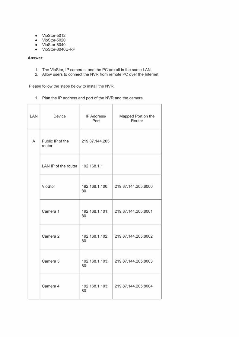
● VioStor-5012● VioStor-5020● VioStor-8040● VioStor-8040U-RP
Answer:
1. The VioStor, IP cameras, and the PC are all in the same LAN.2. Allow users to connect the NVR from remote PC over the Internet.
Please follow the steps below to install the NVR.
1. Plan the IP address and port of the NVR and the camera.
LAN Device IP Address/Port
Mapped Port on theRouter
A Public IP of therouter
219.87.144.205
LAN IP of the router 192.168.1.1
VioStor 192.168.1.100:80
219.87.144.205:8000
Camera 1 192.168.1.101:80
219.87.144.205:8001
Camera 2 192.168.1.102:80
219.87.144.205:8002
Camera 3 192.168.1.103:80
219.87.144.205:8003
Camera 4 192.168.1.103:80
219.87.144.205:8004

PC 192.168.1.200
B Remote PC 10.8.10.123
2. Install the IP camera. Please refer to the user guide of the IP camera forthe network configuration.
3. Configure the router/ virtual server/ firewallTo allow remote PC to access the VioStor and the IP cameras, you must configurethe port mapping or virtual server of the router. The sample settings are as below:HTTP port:
From Forward to
219.87.144.205:8000
192.168.1.100:80
219.87.144.205:8001
192.168.1.101:80
219.87.144.205:8002
192.168.1.102:80
219.87.144.205:8003
192.168.1.103:80
219.87.144.205:8004
192.168.1.104:80
4.5. Install and configure the NVR (VioStor)
Enter the IP address of the camera in the “IP address” field of the“Camera Settings” page of the VioStor. Then enter the Public IP and theport number of the camera configured on the router in “WAN IP” and

“Port” fields on the “Camera Settings” page of the VioStor.Note: The LAN IP and the WAN IP of the IP camera must be entered.
Note:
1. The “IP address” is for the VioStor to acquire the streaming from theVioStor directly and for browsing by LAN users.
2. The “WAN IP Address” is for remote access to the monitoring page of theVioStor over the Internet. If your IP camera is installed behind the NATrouter, enter the public IP address (or URL) and configure the portforwarding correctly.
● To access the VioStor remotely by FTP (port 21), configure the followingsettings:
From Forward to
219.87.144.205:21
192.168.1.100:21
● After changing the settings, enter the address in the browser to accessthe VioStor over the Internet: http:// 219.87.144.205:8000/
● If you have configured port 80 to VioStor, enter the address to access theVioStor (the default port of HTTP is 80): http:// 219.87.144.205/
● To use DDNS if this network environment, enter the DDNS settings on therouter, but not on the VioStor.
Q68. My VioStor, IP cameras, and the PC are in LAN A,and some IP cameras are installed in LAN B behind adifferent router in a remote location. I want to allow theusers to connect the NVR from remote PC over theInternet. How to install the NVR in different networkenvironment for remote monitoring?
Applied Models:
● NVR-101● NVR-1012● NVR-104P● NVR-104V● VioStor-101A

● VioStor-101P● VioStor-101V● VioStor-2008● VioStor-2012● VioStor-201A● VioStor-201P● VioStor-201V● VioStor-5012● VioStor-5020● VioStor-8040● VioStor-8040U-RP
Answer:
1. The VioStor, IP cameras, and the PC are in LAN A.2. Some IP cameras are installed in LAN B behind a different router in a
remote location.3. Allow the users to connect the NVR from remote PC over the Internet.
1. Plan the IP address and port of the NVR, the camera, and the PC.
LAN
Device IP Address/Port
Mapped Port (HTTP) on theRouter
A Public IP of therouter
219.87.144.205
VioStor 192.168.1.1
Camera 1 192.168.1.100:80
219.87.144.205:8000
Camera 2 192.168.1.101:80
219.87.144.205:8001
Camera 3 192.168.1.102:80
219.87.144.205:8002

Camera 4 192.168.1.103:80
219.87.144.205:8003
PC 192.168.1.103:80
219.87.144.205:8004
Public IP of therouter
192.168.1.200
B Router’s Public IP 205.234.170.160
Router’s LAN IP 172.17.1.1
Camera 5 172.17.1.11 205.234.170.160:8005
Camera 6 172.17.1.12 205.234.170.160:8006
C Remote PC 10.8.10.123
2. Install the IP camera. Please refer to the user guide of the IP camera forthe network configuration.
3. Configure the router/ virtual server/ firewallIn this application, you have to configure the port mapping or virtual serverof the routers in LAN A and LAN B; and forward the ports to thecorresponding LAN IP by the NAT router so that the NVR can save therecording data from the remote IP camera and the remote PC can accessthe monitoring page over the Internet.Note:
1. Some IP cameras delivers MPEG4 image via RTSP or RTP ports.If the IP camera is installed outside the router, you have toconfigure the RTSP and RTP ports on the router and the NVR sothat the NVR can save the recording data from the IP cameras,e.g. Vivotek, Axis, D-link, GANZ, or LevelOne cameras thatsupport MPEG4 streaming.
2. In this sample, you must configure the RTP port setting on therouter of LAN A and the RTSP port setting on the router of LAN B.

3. RTP (Real-time Transport Protocol): The protocol for deliveringvideo or audio data.
4. RTSP (Real-Time Streaming Protocol): The protocol forcontrolling video or audio streaming media.
4. Configure the port mapping or virtual server on the router:
1. (a-1) Configure the port mapping on the router in LAN AHTTP port:
From Forward to
219.87.144.205:8000
192.168.1.100:80
219.87.144.205:8001
192.168.1.101:80
219.87.144.205:8002
192.168.1.102:80
219.87.144.205:8003
192.168.1.103:80
219.87.144.205:8004
192.168.1.104:80
2. RTP port: (Configure the port for NVR to receive remote video data fromthe IP camera)
From Forward to
219.87.144.205:6100
192.168.1.100:6100

219.87.144.205:6101
192.168.1.100:6101
219.87.144.205:6102
192.168.1.100:6102
219.87.144.205:6103
192.168.1.100:6103
:
:
:
:
::
219.87.144.205:6199
192.168.1.100:6199
3. Note: The default RTP port range of the NVR (VioStor) is6100~6199.
4. Configure the port mapping on the router in LAN BHTTP port:
From Forward to
205.234.170.160:8005
172.17.1.11:80
205.234.170.160:8006
172.17.1.12:80

5. RTSP port: Configure the protocol for controlling video or audio streamingmedia.
From Forward to
205.234.170.160:5001
172.17.1.11:554
205.234.170.160:5002
172.17.1.12:554
6. Note:Please check the RTSP (Real-Time Streaming Protocol) port ofthe IP camera before configuring the port mapping on the router.Please refer to the user guide of the IP camera for its RTSP portsettings.
5. Install and configure the NVR (VioStor)Enter the IP address of the camera in the “IP address” field of the“Camera Settings” page of the VioStor. Then enter the Public IP and theport number of the camera configured on the router in “WAN IP” and“Port” fields on the “Camera Settings” page of the VioStor.
1. Enter the settings of the IP cameras in LAN A.Camera 1 “IP Address”: 192.168.1.101 port 80“WAN IP Address”: 219.87.144.205 port 8001Camera 2 “IP Address”: 192.168.1.102 port 80“WAN IP Address”: 219.87.144.205 port 8002Camera 3 “IP Address”: 192.168.1.103 port 80“WAN IP Address”: 219.87.144.205 port 8003Camera 4 “IP Address”: 192.168.1.104 port 80“WAN IP Address”: 219.87.144.205 port 8004Note:
1. The “IP address” is for the VioStor to acquire thestreaming from the VioStor directly and for browsing byLAN users.
2. The “WAN IP Address” is for remote access to themonitoring page of the VioStor over the Internet. If your IPcamera is installed behind the NAT router, enter thepublic IP address (or URL) and configure the portforwarding correctly.
2. Enter the settings of the IP cameras in LAN B.Camera 5 “IP Address”: 205.234.170.160 port 8005/5001Camera 6 “IP Address”: 205.234.170.160 port 8006/5002Note: The “Port” field refers to the HTTP and RTSP port. Thedefault number of HTTP port: 80. To specify the RTSP port of theIP camera, add a slash (/) and RTSP port number after the HTTPport number.

● The port 21 must be forwarded on the router in the following twosituations:
1. When you use the alarm function of the remote IP camera (thealarm between the NVR and the camera is delivered by FTP).
2. When you need to login the VioStor by FTP (port 21).
From Forward to
219.87.144.205:21
192.168.1.100:21
● After changing the settings, enter the address in the browser to accessthe VioStor over the Internet: http:// 219.87.144.205:8000/
● If you have configured port 80 to VioStor, enter the address to access theVioStor (the default port of HTTP is 80): http:// 219.87.144.205/
● To use DDNS if this network environment, enter the DDNS settings on therouter, but not on the VioStor.
Q69. Why the recording is paused for a while andrestarted after I applied changes to VioStor?
Applied Models:
● NVR-101● NVR-1012● NVR-104P● NVR-104V● VioStor-101A● VioStor-101P● VioStor-101V● VioStor-2008● VioStor-2012● VioStor-201A● VioStor-201P● VioStor-201V● VioStor-5012● VioStor-5020● VioStor-8040● VioStor-8040U-RP
Answer:
After applying changes to VioStor, the camera will restart for the changes to takeeffect. Therefore, recording will stop for a while.

Q70. Why there are only English logs in Event Logs?
Applied Models:
● NVR-101● NVR-1012● NVR-104P● NVR-104V● VioStor-101A● VioStor-101P● VioStor-101V● VioStor-2008● VioStor-2012● VioStor-201A● VioStor-201P● VioStor-201V● VioStor-5012● VioStor-5020● VioStor-8040● VioStor-8040U-RP
Answer:
Only English logs are supported currently.
Q71. Does VioStor support hot swapping?
Applied Models:
● NVR-101● NVR-1012● NVR-104P● NVR-104V● VioStor-101A● VioStor-101P● VioStor-101V● VioStor-2008● VioStor-2012● VioStor-201A● VioStor-201P● VioStor-201V● VioStor-5012● VioStor-5020● VioStor-8040● VioStor-8040U-RP
Answer:
Yes. However, if the hard disks are working properly and recording is in process,do not hot swap the disks to avoid damage to the disks or recording files. Hotswapping can only be performed when a single disk crashes and there is no needto stop the recording.
Q72. Is domain name supported in WAN IP and LAN IPfields?
Applied Models:
● NVR-101● NVR-1012● NVR-104P● NVR-104V● VioStor-101A● VioStor-101P● VioStor-101V● VioStor-2008● VioStor-2012● VioStor-201A● VioStor-201P● VioStor-201V● VioStor-5012● VioStor-5020● VioStor-8040● VioStor-8040U-RP
Answer:
The domain name is supported in the WAN IP field only.
Q73. How to use the front video backup button of theVioStor?
Applied Models:
● NVR-101

● NVR-1012● NVR-104P● NVR-104V● VioStor-101A● VioStor-101P● VioStor-101V● VioStor-2008● VioStor-2012● VioStor-201A● VioStor-201P● VioStor-201V● VioStor-5012● VioStor-5020● VioStor-8040● VioStor-8040U-RP
Answer:
1. Login the VioStor. Go to “System Tools”-> “Hardware Settings” and enable“front video backup button”.
2. Initialize the external disk: You can go to “Device Configuration” -> “USBDisk” to initialize the external disk. The VioStor supports hard disks in FATformat.
3. The external disk must be larger than 10GB. VioStor supports externaldisks that are larger than 10GB currently.
4. Make sure the external hard disk is correctly connected to the “front” USBport of VioStor; this function will not work if the disk is connected to therear USB port.
5. When the external disk is connected to the front USB port, wait until theUSB LED glows in blue and then press the copy button. The data will becopied to the external disk immediately. The USB LED will blink in blueduring the copying process. When the USB LED is off, copying iscompleted; you can safely remove the disk.
6. If the storage capacity of the external disk is insufficient, the log will berecorded in “Logs & Statistics” page.
7. As the backup file size can be very large, please wait patiently until theUSB LED is off (backup completed), and then remove the external disk.
Note: If you use VioStor-2008, 2012, 5012, 5020, 8040, 8040U-RP, please pressand hold one touch auto backup button for 3 sec.
Q74. How to check your firmware Version?
Applied Models:
● NVR-101● NVR-1012● NVR-104P● NVR-104V● VioStor-101A● VioStor-101P

● VioStor-101V● VioStor-2008● VioStor-2012● VioStor-201A● VioStor-201P● VioStor-201V● VioStor-5012● VioStor-5020● VioStor-8040● VioStor-8040U-RP
Answer:
You can check your firemware version from the following pages:
1.Open QNAP Finder, and the version information will be shown.
2.When you have successfully logged in VioStor, the version information will beappeared at the left-bottom corner of Monitoring Page.

3.You could check your firmware version by "System Settings"->"Server Name"or "System Settings"->"View System Settings".
4.Another firmware version will be display in system update page. The page willshow the current version information.
Q75. Why the screen turns black when playing back thevideo?
Applied Models:
● NVR-101● NVR-1012● NVR-104P● NVR-104V● VioStor-101A● VioStor-101P● VioStor-101V● VioStor-2008● VioStor-2012● VioStor-201A● VioStor-201P● VioStor-201V● VioStor-5012● VioStor-5020● VioStor-8040● VioStor-8040U-RP
Answer:

Check if the media playing program supports avi format. If not, the screen willbecome black.
Q76. When I cannot access VioStor via the default IP orthe IP shown in Quick Setup Wizard, what should I do?
Applied Models:
● NVR-101● NVR-1012● NVR-104P● NVR-104V● VioStor-101A● VioStor-101P● VioStor-101V● VioStor-2008● VioStor-2012● VioStor-201A● VioStor-201P● VioStor-201V● VioStor-5012● VioStor-5020● VioStor-8040● VioStor-8040U-RP
Answer:
Please follow the steps below.
1. Check if the VioStor is turned on.2. Check the network connection of the computer and the VioStor.3. Check the IP address settings of the VioStor and the connected computer.
Make sure they are in the same subnet.4. Refresh Quick Setup Wizard and check the IP address of the VioStor.5. Enter http://169.254.100.100 in the IE browser to connect to the VioStor.
Q77. I've installed the camera but the distant object isunclear. How to solve this problem?
Applied Models:
● ICS-1013● NVR-101● NVR-1012

Answer:
After setting up the camera, you can use rotate the lens of the camera (circled bythe LED) to adjust the focus. Rotate the lens clockwise to focus on the closeobjects; rotate the lens anti-clockwise to focus on the distant objects.
Adjust the focal length (inside theLED)
Rotate clockwise to focus on closeobject
Rotate anti-clockwise to focus ondistant object
Q78. Why the actual monitoring quality is worse than theconfiguration?
Applied Models:
● NVR-101● NVR-1012● NVR-104P● NVR-104V● VioStor-101A

● VioStor-101P● VioStor-101V● VioStor-2008● VioStor-2012● VioStor-201A● VioStor-201P● VioStor-201V● VioStor-5012● VioStor-5020● VioStor-8040● VioStor-8040U-RP
Answer:
1. The image quality may be restricted and interfered by the networkbandwidth.
2. The network connection is not purely independent; it is often shared byother network devices which will occupy the bandwidth.
3. Network cameras do not support high performance quality.4. When there are multiple accesses to the monitoring page, the image
quality will be reduced. (It is recommended to have three simultaneousconnections to the monitoring page at maximum.)
5. The same camera may be shared by multiple NVR for recording at thesame time.
6. For the best recording performance, please do not open too many IEbrowsers to access the monitoring page.
Q 79. Why the user with the administrator authority can’tdelete the files on the NVR via FTP?Applied Models:
● NVR-101● NVR-1012● NVR-104P● NVR-104V● VioStor-101A● VioStor-101P● VioStor-101V● VioStor-2008● VioStor-2012● VioStor-201A● VioStor-201P● VioStor-201V● VioStor-5012● VioStor-5020● VioStor-8040● VioStor-8040U-RP

Answer:
Currently, the NVR only allows the administrator to delete or change the files onthe NVR via FTP.
Q80. When I monitored the image on the NVR for a while,my PC did not respond until I closed the IE browser. Why?
Applied Models:
● NVR-101● NVR-1012● NVR-104P● NVR-104V● VioStor-101A● VioStor-101P● VioStor-101V● VioStor-2008● VioStor-2012● VioStor-201A● VioStor-201P● VioStor-201V● VioStor-5012● VioStor-5020● VioStor-8040● VioStor-8040U-RP
Answer:
Please make sure your PC meets the following requirements.
VioStor-101/ NVR-104/ NVR-101
● CPU: Pentium 4 (2GHz)● Memory: 512MB or above● Operation system: Windows XP or Vista (32-bit)● Browser: IE6 or later
VioStor-2008/ 201
● CPU:* Motion-JPEG format (up to 8 channels): Pentium 4 CPU 2.2 GHz orabove* MPEG-4/ H.264 format (up to 8 channels): Dual core CPU 2.2 GHz orabove
● Memory: 1GB or above● Operation system: Windows XP or Vista (32-bit)● Browser: IE6 or later
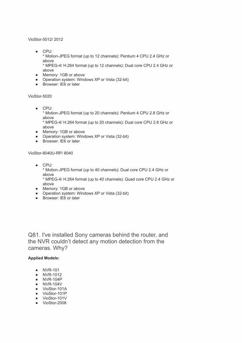
VioStor-5012/ 2012
● CPU:* Motion-JPEG format (up to 12 channels): Pentium 4 CPU 2.4 GHz orabove* MPEG-4/ H.264 format (up to 12 channels): Dual core CPU 2.4 GHz orabove
● Memory: 1GB or above● Operation system: Windows XP or Vista (32-bit)● Browser: IE6 or later
VioStor-5020
● CPU:* Motion-JPEG format (up to 20 channels): Pentium 4 CPU 2.8 GHz orabove* MPEG-4/ H.264 format (up to 20 channels): Dual core CPU 2.8 GHz orabove
● Memory: 1GB or above● Operation system: Windows XP or Vista (32-bit)● Browser: IE6 or later
VioStor-8040U-RP/ 8040
● CPU:* Motion-JPEG format (up to 40 channels): Dual core CPU 2.4 GHz orabove* MPEG-4/ H.264 format (up to 40 channels): Quad core CPU 2.4 GHz orabove
● Memory: 1GB or above● Operation system: Windows XP or Vista (32-bit)● Browser: IE6 or later
Q81. I've installed Sony cameras behind the router, andthe NVR couldn’t detect any motion detection from thecameras. Why?
Applied Models:
● NVR-101● NVR-1012● NVR-104P● NVR-104V● VioStor-101A● VioStor-101P● VioStor-101V● VioStor-2008

● VioStor-2012● VioStor-201A● VioStor-201P● VioStor-201V● VioStor-5012● VioStor-5020● VioStor-8040● VioStor-8040U-RP
Answer:
Sony cameras deliver alarm by FTP port, but they do not support FTP portmapping. Therefore, your NVR cannot detect any alarm from the cameras if theyare installed behind the router.
Q82. I've installed Sony cameras behind the router, andthe NVR couldn’t detect any motion detection from thecameras. Why?
Applied Models:
● NVR-101● NVR-1012● NVR-104P● NVR-104V● VioStor-101A● VioStor-101P● VioStor-101V● VioStor-2008● VioStor-2012● VioStor-201A● VioStor-201P● VioStor-201V● VioStor-5012● VioStor-5020● VioStor-8040● VioStor-8040U-RP
Answer:
Sony cameras deliver alarm by FTP port, but they do not support FTP portmapping. Therefore, your NVR cannot detect any alarm from the cameras if theyare installed behind the router.

Q83. How to configure the resolution, frame rate, andquality of Linksys WVC54GCA?
Applied Models:
● NVR-101● NVR-1012● NVR-104P● NVR-104V● VioStor-101A● VioStor-101P● VioStor-101V● VioStor-2008● VioStor-2012● VioStor-201A● VioStor-201P● VioStor-201V● VioStor-5012● VioStor-5020● VioStor-8040● VioStor-8040U-RP
Answer:
NVR does not support Linksys camera setting. Please login the camera settingspage to configure the settings.
Q84. I use NVR to connect to eight Sony cameras withMPEG4 compression. However, the frame rate ofrecordings does not follow my settings and there is audiodelay, why?
Applied Models:
● NVR-101● NVR-1012● NVR-104P● NVR-104V● VioStor-101A● VioStor-101P● VioStor-101V● VioStor-2008● VioStor-2012● VioStor-201A● VioStor-201P● VioStor-201V● VioStor-5012● VioStor-5020● VioStor-8040● VioStor-8040U-RP

Answer:
Please keep the default value of Sony camera with MPEG4 compression.
Q85. I use sequential mode to monitor Panasonic BLC111& BLC131 cameras, why the cameras are disconnected atshort intervals?
Applied Models:
● NVR-101● NVR-1012● NVR-104P● VioStor-101A● VioStor-101P● VioStor-2008● VioStor-2012● VioStor-201A● VioStor-201P● VioStor-5012● VioStor-5020● VioStor-8040● VioStor-8040U-RP
Answer:
This is a limitation of Panasonic BLC111 & BLC131 cameras. If you connect thecameras persistently, they will be disconnected easily. You may set the sequentialdisplay time longer to improve this situation.
Q86. What should I do if there is loss of picture whenmonitoring or playing back video of Dlink DCS 2120?
Applied Models:
● NVR-101● NVR-1012● NVR-104P● NVR-104V● VioStor-101A● VioStor-101P● VioStor-101V● VioStor-2008● VioStor-2012● VioStor-201A● VioStor-201P

● VioStor-201V● VioStor-5012● VioStor-5020● VioStor-8040● VioStor-8040U-RP
Answer:
Please login the camera page and go to [setting]->[audio & video]->[key frame].Configure the key frame as 10, and this should solve the problem.
Q87. I've set the video file length of Vivotek cameras onVioStor NVR as 1 minute and the frame rate as 1 fps. Whythe recording files are all 2 minutes long?
Applied Models:
● NVR-101● NVR-1012● NVR-104V● VioStor-101V● VioStor-2008● VioStor-2012● VioStor-201V● VioStor-5012● VioStor-5020● VioStor-8040● VioStor-8040U-RP
Answer:
This is a camera limitation. Vivotek camera uses MPEG4 technology (group ofpicture) and the smallest unit of the video recording file is 120 frames. Therefore, ifthe frame rate setting is 1 fps, the video recording files are 2 minutes.
Q88. When I select a camera in camera configurationpage and change Panasonic network camera to Canoncamera, why there are logs "Set video quality on Camera1 failed"?
Applied Models:
● NVR-101● NVR-1012● NVR-104P● VioStor-101A● VioStor-101P● VioStor-2008

● VioStor-2012● VioStor-201A● VioStor-201P● VioStor-5012● VioStor-5020● VioStor-8040● VioStor-8040U-RP
Answer:
To change the camera to a different brand, please remove the old camera andthen add the new camera.
Q89. I can manually specify the FTP server address of thecamera in alarm settings page; however, the function doesnot work after entering a domain name. How to solve theproblem?
Applied Models:
● NVR-101● NVR-1012● NVR-104P● NVR-104V● VioStor-101A● VioStor-101P● VioStor-101V● VioStor-2008● VioStor-2012● VioStor-201A● VioStor-201P● VioStor-201V● VioStor-5012● VioStor-5020● VioStor-8040● VioStor-8040U-RP
Answer:
1. For Panasonic cameras, you can configure DNS in Setup → Static IPAddress Configuration → DNS configuration.
2. For Canon cameras, you can configure DNS in Miscellaneous → DNSconfiguration.
3. For Axis cameras, you can configure DNS in Setup → advanced TCP/IPsettings → DNS configuration.

4. For Vivotek cameras, you can configure DNS in Configurations →Network → DNS configuration.
Q90. Can the files of multiple VioGate-100/120 andVioCard-100 be saved to the same NAS simultaneously?
Applied Models:
● VioCard-100● VioCard-300● VioGate-140● VioGate-340(340A)
Answer:
Yes, but note the disk number restriction. VioGate-100/120 and VioCard-100are built in with continuously recording function. Old files will be overwrittenwhen disk space is not enough. When QNAP NAS-2108R is in use, as only twodisks are supported, only two VioGate servers or VioCard can be used. Notethat the disks have to be configured as two single disk volumes.
Q91. Can a snapshot be saved in different locations atthe same time on VioCard and VioGate series?
Applied Models:
● VioCard-100● VioCard-300● VioGate-140● VioGate-340(340A)
Answer:
No. You can copy the file to another location.

Q92. Are the files recorded by VioGate-100/120 orVioCard-100 saved by file size or time?
Applied Models:
● VioCard-100● VioCard-300● VioGate-140● VioGate-340(340A)
Answer:
The recording files of VioGate are saved by time (one minute one file) by eachchannel.
Q93. What format should the files recorded by VioGatebe converted to for playing by Windows Media Player?
Applied Models:
● VioCard-100● VioCard-300● VioGate-140● VioGate-340(340A)
Answer:
The files can be saved as ivg or avi format.
Q94. How to calculate the storage needed for recordingby VioGate?
Applied Models:

● VioCard-100● VioCard-300● VioGate-140● VioGate-340(340A)
Answer:
The storage needed varies to the recording image. It is recommended to testdirectly. Suppose 640x480 is selected with 3fps, each channel needs 6.2Gstorage space every day for recording. A total of 24.8G will be needed for4-channel recording. If using QNAP NAS-4300 that supports 2T storage (250GHDD x 8), about 8 VioGate servers of 32-channel recording can be supportedfor 10-day recording.
When using 320x240, you can count the amount by one fourth of 640x480.
Q95. Why IE browser cannot display the screen whenlogging in VioGate-100/120 or VioCard-100?
Applied Models:
● VioCard-100● VioCard-300● VioGate-140● VioGate-340(340A)
Answer:
The screen resolution required by VioGate-100/ 120 and VioCard-100 is1024x768. Please adjust your screen settings.
Q96. Why the screen is black when I login VioGate?
Applied Models:

● VioCard-100● VioCard-300● VioGate-140● VioGate-340(340A)
Answer:
Please check the following:
1. IE version is 5.0 or above.2. Check the security settings of IE in Tools/ Internet Options select it as
Medium or lower.3. Virus scan program is turned off.4. If you are using Windows 2000 or XP, make sure your user account has
authority to install software.5. Clear the cookies in your IE.
Q97. How is the performance of different fps settingsdiffering from the others?
Applied Models:
● ICS-1013● NVR-101● NVR-1012● NVR-104P● NVR-104V● VioCard-100● VioCard-300● VioGate Master● VioGate-140● VioGate-340(340A)● Vioserver-10● Vioserver-5● VioStor-101A● VioStor-101P● VioStor-101V● VioStor-2008● VioStor-2012● VioStor-201A● VioStor-201P● VioStor-201V

● VioStor-5012● VioStor-5020● VioStor-8040● VioStor-8040U-RP
Answer:
Generally human beings can identify 15~20 fps image playing. When fps is over20, difference can hardly be told. When fps is 15~30, the playing will be seen ascontinuous playing. When fps is 1~10, image playing will be seen asinterrupted.
Q98. If I adjust the fps of each channel as max, can thechannels achieve 30 fps?
Applied Models:
● VioCard-100● VioCard-300● VioGate-140● VioGate-340(340A)
Answer:
No. The maximum fps VioGate-100/120, and VioCard-100 support is 50fps for4-channel monitoring. When setting each channel’s fps as max, the maximumfps (50fps) will be shared by the four channels and each channel will achieve10~15 fps.

Q99. How long is the transfer distance of network cablein general?
Applied Models:
● ICS-1013● NVR-101● NVR-1012● NVR-104P● NVR-104V● VioCard-100● VioCard-300● VioGate Master● VioGate-140● VioGate-340(340A)● Vioserver-10● Vioserver-5● VioStor-101A● VioStor-101P● VioStor-101V● VioStor-2008● VioStor-2012● VioStor-201A● VioStor-201P● VioStor-201V● VioStor-5012● VioStor-5020● VioStor-8040● VioStor-8040U-RP
Answer:
About 100M.

Q100. May I change the video signal standard ofVioGate-100/120 and VioCard-100 when they are inuse?
Applied Models:
● VioCard-100● VioCard-300● VioGate-140● VioGate-340(340A)
Answer:
Yes, but you have to restart the system to apply the changes.
Q101. Why all alarm recordings would be removed byoverwriting process?
Applied Models:
● NVR-101● NVR-1012● NVR-104P● NVR-104V● VioStor-101A● VioStor-101P● VioStor-101V● VioStor-2008● VioStor-2012● VioStor-201A● VioStor-201P● VioStor-201V● VioStor-5012● VioStor-5020● VioStor-8040● VioStor-8040U-RP
Answer:
Current overwriting policy is shown as below.
If disk free space reaches the lower bound, the system would dothe following steps.

1. Delete alarm recordings older than the preserved days (ifyou did not set yet, thevalue is 0) utill space becomes enough.
2. If not enough, delete normal recordings until spacebecome enough.
So, if you did not set reserved days of alarm recordings, all alarmrecordings would be almost deleted after overwriting.
Q102. Do VioGate-100/120 and VioCard-100 supportNTSC and PAL signals?
Applied Models:
● VioCard-100● VioCard-300● VioGate-140● VioGate-340(340A)
Answer:
Yes. VioGate-100/120 and VioCard-100 will detect and apply thecorrect signal standard every time they are turned on.
Q103. What resolution does VioGate support?
Applied Models:
● VioCard-100● VioCard-300● VioGate-140● VioGate-340(340A)
Answer:
VioGate supports 160x120, 320x240, 640x240 and 640x480.

Q104. Is any control device needed to remote controlcamera?
Applied Models:
● VioCard-100● VioCard-300● VioGate-140● VioGate-340(340A)
Answer:
No. QNAP VioGate series are purely network products which canbe managed and controlled by connecting to the network via PC.If you need to establish different monitoring centers, all you needare extra computers and connect them to the network ofVioGate.
Q105. Why PTZ camera cannot work for VioCard/VioGate?
Applied Models:
● VioCard-100● VioCard-300● VioGate-140● VioGate-340(340A)
Answer:
Please make sure the PTZ model is supported by VioCard/VioGate. Check if the baud rate settings of the camera are thesame. If the camera cannot be used or you need to supportspecific camera, please contact QNAP technical support.
Q106. Why I cannot use my DynaColor camera withVioGate?
Applied Models:

● VioCard-100● VioCard-300● VioGate-140● VioGate-340(340A)
Answer:
When using the protocol of DynaColor, the models supported areD7720 and D7721. If these models are not used, you can selectthe protocol of Pelco to test. The pins S1 & S2 of DynaColorcamera must be set as D protocol to be controlled by VioGate.However, as Pelco D does not support auto mode, DynaColorcamera can only be used with manual or preset mode.
Q107. How to calculate the file size of recording byVioGate-100/120 and VioCard-100?
Applied Models:
● VioCard-100● VioCard-300● VioGate-140● VioGate-340(340A)
Answer:
The file size depends on the variables of the cameras likeresolution, compression rate and fps.
Resolution: The higher the resolution, the smaller the file size.The file size of resolution 640x480 is two times larger than that of640x240, and four times larger than that of 320x240.
Compression rate: The higher the compression rate, the smallerand the less clear the file size is, vice versa.
FPS: FPS refers to frame shown on screen per second. Thelarger the number of fps, the smoother the image displayed butthe larger the file size. Then using 320x240 and medium isselected as compression rate by VioGate, each frame size willbe 5~10KB.

Q108. Why the size of recorded files is different?
Applied Models:
● VioCard-100● VioCard-300● VioGate-140● VioGate-340(340A)
Answer:
The files recorded by VioGate-100/120 and VioCard-100 aresaved in JPEG format. The file size depends on the complexityof image recorded. The simpler the image, the smaller the filesize is, vice versa.
Q109. Why I can’t configure VioGate when entering IPaddress in storage settings on Windows 98?
Applied Models:
● VioCard-100● VioCard-300● VioGate-140● VioGate-340(340A)
Answer:
On Windows 98 OS, enter the PC name but not the IP address.
Q110. What is the bandwidth occupied by VioCard-100?
Applied Models:
● VioCard-100● VioCard-300
● VioGate-140● VioGate-340(340A)
Answer:
When using 320x240 resolution, a frame recorded by VioCard-100 will occupy10 Kbytes.
Q111. How many frames per second doVioGate-100/120 or VioCard-100 record?
Applied Models:
● VioCard-100● VioCard-300● VioGate-140● VioGate-340(340A)
Answer:
The maximum frames per second VioGate-100/120 or VioCard-100 can recordare 50 fps if using 320x240 for monitoring. That 50fps have to be shared by4-channel monitoring. Each channel can achieve 30fps (real time recording).That is, if a channel is adjusted for 30 fps real time monitoring, the other threechannels will share 20fps as the example below.
● Channel 1= 30 fps● Channel 2 = 10 fps● Channel 3 = 5 fps● Channel 4 = 5 fps
Q112. How many fps does Max refer to on themonitoring screen?
Applied Models:
● VioCard-100● VioCard-300

● VioGate-140● VioGate-340(340A)
Answer:
Max refers to 30 fps for real time monitoring. However, when playing images onPC via the Internet, the image displayed will be affected by network transferspeed and may not be the same as 30 fps as displayed on screen.
Q113. How to determine if two network devices are inthe same LAN?
Applied Models:
● ICS-1013● NVR-101● NVR-1012● NVR-104P● NVR-104V● VioCard-100● VioCard-300● VioGate Master● VioGate-140● VioGate-340(340A)● Vioserver-10● Vioserver-5● VioStor-101A● VioStor-101P● VioStor-101V● VioStor-2008● VioStor-2012● VioStor-201A● VioStor-201P● VioStor-201V● VioStor-5012● VioStor-5020● VioStor-8040● VioStor-8040U-RP
Answer:
Example 1.
Assume that there is a PC A with IP: 192.168.1.10 and subnet mask:255.255.255.0. PC A wants to connect PC B with IP: 192.123.2.3. Multiply IPof PC A by the 4 digits of subnet mask A (convert 255 as 1). Then multiply the

4 digits of PC B’s IP by the 4 digits of PC A’s subnet mask (convert 255 as 1). Ifthe sum is the same, they are in the same LAN. If not, they aren’t.
IP (PC A): 192.168.1.10 <--192.168.1.10
Subnet mask (PC A): 255.255.255.0 <--1.1.1.0
Result: 192.168.1.0
IP (PC B): 192.123.2.3 <--192.123.2.3
Subnet mask (PC A): 255.255.255.0 <--1.1.1.0
Result: 192.123.2.0
As 192.168.1.0 192.124.2.0, PC A and PC B are not in the same LAN.
Example 2.
PC A with IP: 192.168.1.10 and subnet mask: 255.255.255.0; PC B with IP192.168.1.39.
IP (PC A): 192.168.1.10 <-- 192.168.1.10
SM (PC A): 255.255.255.0 <-- 1.1.1.0
Result: 192.168.1.0
IP (PC B): 192.168.1.39 <-- 192.168.1.39
SM (PC A): 255.255.255.0 <-- 1.1.1.0
Result: 192.168.1.0
As 192.168.1.0=192.168.1.0, PC A and PC B are in the same LAN.
Q114. How long is the transfer distance of coaxial cable ingeneral?
Applied Models:

● ICS-1013● NVR-101● NVR-1012● NVR-104P● NVR-104V● VioCard-100● VioCard-300● VioGate Master● VioGate-140● VioGate-340(340A)● Vioserver-10● Vioserver-5● VioStor-101A● VioStor-101P● VioStor-101V● VioStor-2008● VioStor-2012● VioStor-201A● VioStor-201P● VioStor-201V● VioStor-5012● VioStor-5020● VioStor-8040● VioStor-8040U-RP
Answer:
Generally it should be 250M, but may vary to the quality.
Q115. Why VioCard 30/300 log in screen show
Applied Models:
● VioCard-100● VioCard-300● VioGate-140● VioGate-340(340A)
Answer:
Please check the jumper of flash.
If the jumper is losed, please insert the jumper to 3,4 site(master).
Q116. Why the hardware key cannot be found whenrunning VioGate Master after updating it to V1.3.3623?
Applied Models:
● VioGate Master
Answer:
Please run "SPNComboInst1.0.5" by Keypro Driver in VioGate Master folder.
Q117. What are the default network settings ofVioGate-100/120 or VioCard-100?
Applied Models:
● VioCard-100● VioCard-300● VioGate-140● VioGate-340(340A)
Answer:
When DHCP server is available, VioGate-100/120 and VioCard-100 will acquire IPaddress automatically. If no DHCP server is available, the default settings are: IP(192.168.0.1); Subnet mask (255.255.255.0).

Q118. Why I cannot connect VioGate-100/120 orVioCard-100 while I can find them via QNAP Finder?
Applied Models:
● VioCard-100● VioCard-300● VioGate-140● VioGate-340(340A)
Answer:
Please check if the PC you are using and VioGate are in the same LAN area.
Q119. How to view and change the network settings ofPC?
Applied Models:
● ICS-1013● NVR-101● NVR-1012● NVR-104P● NVR-104V● VioCard-100● VioCard-300● VioGate Master● VioGate-140● VioGate-340(340A)● Vioserver-10● Vioserver-5● VioStor-101A● VioStor-101P● VioStor-101V● VioStor-2008● VioStor-2012● VioStor-201A● VioStor-201P● VioStor-201V● VioStor-5012● VioStor-5020● VioStor-8040● VioStor-8040U-RP
Answer:
1. Windows 2000, XP & Vista: Right click My Network Places and selectProperties. Right click the network connection in use and select

Properties. Choose Internet Protocol (TCP/IP) and select Properties. Ifyou are using fixed IP, you can view and change the network settingshere. If your PC acquires IP automatically.
2. Run ipconfig in the command prompt to check the network settings of yourPC.
Q120. I have a Vivotek camera and set the advancedconfiguration of motion detection in camera's web UImanually, such as sensitivity and percentage setting. Whythe advanced configuration of motion detection does notwork?Applied Models:
● NVR-101● NVR-1012● NVR-104V● VioStor-101V● VioStor-2008● VioStor-2012● VioStor-201V● VioStor-5012● VioStor-5020● VioStor-8040● VioStor-8040U-RP
Answer:
Please do the following:
1. Disable the motion detection on NVR’s setting page. Apply the settingsand enable the function again.
2. Restart the VioStor.

Q121. How to expand the storage capacity of VioStor-101and NVR-104 by the eSATA port?
Applied Models:
● NVR-101● NVR-1012● NVR-104P● NVR-104V● VioStor-101A● VioStor-101P● VioStor-101V
Answer:
You may refer to the steps below:
1. Back up the data on the VioStor to an external storage device.2. Connect an eSATA disk to the eSATA port of the VioStor-101 and
NVR-104.3. Login the administration page and go to “Device Configuration”.4. Create a RAID 0 disk volume or linear disk volume with the internal hard
drive of the VioStor and the eSATA disk.
Warning: To create a RAID 0 disk volume or linear disk volume, the drives must beformatted and all the data will be cleared. Make sure you have backed up therecording data before formatting the drives.
Q122. What is FTP passive mode?
Applied Models:
● ICS-1013● NVR-101● NVR-1012● NVR-104P● NVR-104V● VioCard-100● VioCard-300● VioGate Master● VioGate-140● VioGate-340(340A)

● Vioserver-10● Vioserver-5● VioStor-101A● VioStor-101P● VioStor-101V● VioStor-2008● VioStor-2012● VioStor-201A● VioStor-201P● VioStor-201V● VioStor-5012● VioStor-5020● VioStor-8040● VioStor-8040U-RP
Answer:
FTP supports two modes, Standard (or PORT or Active) and Passive (or PASV).
Compared with the Standard mode, the FTP clients of the Passive mode also startby establishing a connection to TCP port 21 on the FTP server to create thecontrol channel. When the client sends a PASV command over the commandchannel, the FTP server opens an ephemeral port (between 1024 and 5000) andinforms the FTP client to connect to that port before requesting data transfer. As inStandard mode, the FTP client must send a new PASV command prior to eachnew transfer, and the FTP server will await a connection at a new port for eachtransfer.
Q123. I've installed the VioStor behind the router orfirewall and set up port mapping (virtual server) on therouter. However, I still couldn’t access the VioStor. Whatshould I do?
Applied Models:
● NVR-101● NVR-1012● NVR-104P● NVR-104V● VioStor-101A● VioStor-101P● VioStor-101V● VioStor-2008● VioStor-2012● VioStor-201A

● VioStor-201P● VioStor-201V● VioStor-5012● VioStor-5020● VioStor-8040● VioStor-8040U-RP
Answer:
Please follow the steps below:
1. Open the Internet Explorer browser.2. On the “Tools” menu, click “Internet Options”.3. Click the “Advanced” tab.4. Under “Browsing”, uncheck the option “Enable folder view for FTP sites”.5. Check the box “Use Passive FTP (for firewall and DSL modem
compatibility)”.6. Click “OK”.
After changing the above settings, try to access your VioStor again. If failed,please contact our technical support.
Q124. Why can't I login the administration page of theVioStor?
Applied Models:
● NVR-101● NVR-1012● NVR-104P● NVR-104V● VioStor-101A● VioStor-101P● VioStor-101V● VioStor-2008● VioStor-2012● VioStor-201A● VioStor-201P● VioStor-201V● VioStor-5012● VioStor-5020● VioStor-8040

● VioStor-8040U-RP
Answer:
Please check if you have the administrator access right to the server. Onlyadministrators are allowed to login the VioStor.
Q125. About ICS-1013, when I monitor the plants outdoor,the green leaves appear to be light purple. Why?
Applied Models:
● ICS-1013● NVR-101● NVR-1012
Answer:
The camera is equipped with infrared night view function that the filter on thecamera absorbs infrared in the light and may cause color shift. This is a commonfeature of general CMOS cameras with infrared function which is designed forclear monitoring at night.
Q126. Why can't I use the SMB, FTP and Web FileManager in VioStor?
Applied Models:
● NVR-101● NVR-1012● NVR-104P● NVR-104V● VioStor-101A● VioStor-101P● VioStor-101V● VioStor-2008● VioStor-2012● VioStor-201A● VioStor-201P● VioStor-201V● VioStor-5012

● VioStor-5020● VioStor-8040● VioStor-8040U-RP
Answer:
1. Please go to Network Settings-File Services page and check if these threefunctions are enabled.
2. When VioStor is installed behind a router and the access to VioStor isoutside the router, you will not be able to use SMB and FTP services.
Q127. Why VioStor takes too long to restart?
Applied Models:
● NVR-101● NVR-1012● NVR-104P● NVR-104V● VioStor-101A● VioStor-101P● VioStor-101V● VioStor-2008● VioStor-2012● VioStor-201A● VioStor-201P● VioStor-201V● VioStor-5012● VioStor-5020● VioStor-8040● VioStor-8040U-RP
Answer:
When the server has been restarting for more than 5 minutes, please turn off thepower and turn on the server again. If the problem persists, please contact thetechnical support.
Q128. Why can't the monitoring page be fully displayed inInternet Explorer?
Applied Models:

● NVR-101● NVR-1012● NVR-104P● NVR-104V● VioStor-101A● VioStor-101P● VioStor-101V● VioStor-2008● VioStor-2012● VioStor-201A● VioStor-201P● VioStor-201V● VioStor-5012● VioStor-5020● VioStor-8040● VioStor-8040U-RP
Answer:
If you are using the zooming function of Internet Explorer 7, the page may not bedisplayed properly. Please click F5 to refresh the page.
Q129. Why can't I find my VioStor in QNAP Finder?
Applied Models:
● NVR-101● NVR-1012● NVR-104P● NVR-104V● VioStor-101A● VioStor-101P● VioStor-101V● VioStor-2008● VioStor-2012● VioStor-201A● VioStor-201P● VioStor-201V● VioStor-5012● VioStor-5020● VioStor-8040● VioStor-8040U-RP
Answer:
Please do the following:

1. Check if the VioStor is turned on.2. Make sure the PC and the NVR(VioStor) are in the same subnet.3. Check the network connection of the computer and the VioStor.4. Refresh QNAP Finder and check the IP address of the VioStor. Make sure
you have turned off all firewall on your computer.
Q130. Why can't the changes to the system configurationstake effect?Applied Models:
● NVR-101● NVR-1012● NVR-104P● NVR-104V● VioStor-101A● VioStor-101P● VioStor-101V● VioStor-2008● VioStor-2012● VioStor-201A● VioStor-201P● VioStor-201V● VioStor-5012● VioStor-5020● VioStor-8040● VioStor-8040U-RP
Answer:
After changing the settings in administration page, click the Apply button to applythe changes.
Q131.Why can't the E-map be displayed correctly?Applied Models:
● NVR-101● NVR-1012● NVR-104P● NVR-104V● VioStor-101A● VioStor-101P● VioStor-101V● VioStor-2008● VioStor-2012● VioStor-201A● VioStor-201P● VioStor-201V● VioStor-5012

● VioStor-5020● VioStor-8040● VioStor-8040U-RP
Answer:Please check the file format. VioStor supports E-map in JPEG only.
Q132. Why the estimated storage space for recordingdisplayed in Recording Settings page is different from theactual value?Applied Models:
● NVR-101● NVR-1012● NVR-104P● NVR-104V● VioStor-101A● VioStor-101P● VioStor-101V● VioStor-2008● VioStor-2012● VioStor-201A● VioStor-201P● VioStor-201V● VioStor-5012● VioStor-5020● VioStor-8040● VioStor-8040U-RP
Answer:
This estimated value is for reference only. The actual disk space may varyaccording to the image contents, network environment and the performance of thecameras.
Q133. Why the screen is displayed abnormally withstrange horizontal lines when the resolution of PanasonicBB-HCM381 camera is set as 640x480?Applied Models:
● NVR-101● NVR-1012● NVR-104P● NVR-104V● VioStor-101A

● VioStor-101P● VioStor-101V● VioStor-2008● VioStor-2012● VioStor-201A● VioStor-201P● VioStor-201V● VioStor-5012● VioStor-5020● VioStor-8040● VioStor-8040U-RP
Answer:
This is due to the interlaced scanning design of the camera. Please login thecamera’s configuration page and go to Setup->Camera->Vertical Resolution. Thenconfigure the setting as 240.
Q134.Why the live video of VioStor is not clear or smoothsometimes?Applied Models:
● NVR-101● NVR-1012● NVR-104P● NVR-104V● VioStor-101A● VioStor-101P● VioStor-101V● VioStor-2008● VioStor-2012● VioStor-201A● VioStor-201P● VioStor-201V● VioStor-5012● VioStor-5020● VioStor-8040● VioStor-8040U-RP
Answer:
1. The image quality may be restricted and interfered by the actual networktraffic.
2. When there are multiple accesses to the camera or the VioStor server, theimage quality will be reduced. And it is recommended to have threesimultaneous connections to the monitoring page at maximum. For better

recording performance, please do not open too many IE browsers to viewthe live video.
3. The same camera may be shared by multiple VioStors for recording at thesame time. Please use dedicated cameras.
Q135.If the alarm recording of VioStor does not function,what should I do?Applied Models:
● NVR-101● NVR-1012● NVR-104P● NVR-104V● VioStor-101A● VioStor-101P● VioStor-101V● VioStor-2008● VioStor-2012● VioStor-201A● VioStor-201P● VioStor-201V● VioStor-5012● VioStor-5020● VioStor-8040● VioStor-8040U-RP
Answer:
1. Please login the administration page and go to Camera Settings-AlarmSettings. Make sure alarm recording is enabled for the camera.
2. When using Panasonic BB-HCM311 cameras, the camera firmware mustbe upgraded to v1.3 for alarm recording to work properly.
3. If VioStor is installed behind the router, VioStor would not receive theimages to start alarm recording until you set up port mapping (virtualserver) on the router and manually specify the alarm FTP server addressof the camera in alarm settings page.
4. When alarm recording is enabled, make sure you have configured thenumber of days that alarm recordings will be retained in Camera Settings-Advanced Settings. Otherwise, the recordings may be overwritten.

Q136.If the recording function of VioStor is not workingproperly, what should I do?Applied Models:
● NVR-101● NVR-1012● NVR-104P● NVR-104V● VioStor-101A● VioStor-101P● VioStor-101V● VioStor-2008● VioStor-2012● VioStor-201A● VioStor-201P● VioStor-201V● VioStor-5012● VioStor-5020● VioStor-8040● VioStor-8040U-RP
Answer:
1. Make sure the hard disk tray is correctly locked in VioStor.2. When only one hard disk is installed, make sure the disk is installed in the
tray of HDD1 (two-bay model). The HDD1 should be installed on top ofthe HDD2.
3. Check if the recording function is enabled in “Camera Configuration” page(the function is enabled by default). Make sure the IP address, name andpassword are correct.
4. If the above items are verified to work properly while the status LEDflashes green, the hard disk(s) may be damaged or cannot be detected.Please turn off the server and install a new hard disk.
Note: If you have updated the configurations of VioStor, recording will be stoppedtemporarily and restart again shortly.
Q137.How to evaluate the bandwidth usage of VioGate toavoid network congestion?Applied Models:
● VioCard-100● VioCard-300● VioGate-140

● VioGate-340(340A)
Answer:
Content: It is evaluated that the actual bandwidth required by VioGate is as below:
Gigabit network: 15~16 Mbyte/s
100M network: 5~8 Mbyte/s
If the resolution is 640x480 with 3fps, each VioGate with 4-channel recording willoccupy 360K/s.
360x16 VioGate=4.7M/s
As 4.7M/s < 5M/s (100M is the actual network bandwidth). Therefore, a 100Mnetwork cable can allow 16 VioGate servers for transfer. It is recommended touse 8 VioGate.
Q138.Can I have different bitrate for viewing and differentfor recording?Applied Models:
● VioCard-100● VioCard-300● VioGate-140● VioGate-340(340A)
Answer:
You could do it by channel.
Q139. Will VioGate Master 32 support 16 Viocard-300where only one video channel is used?Applied Models:
● VioGate Master
Answer:
No.

Because VioGate Master 32 support 8 VioCard-300 at most. If you want to use 16Viocard-30, you would better to buy VioGate Master 64.

TutorialT1. [Tutorial] How to use Qstart?
Introduction
Qstart brings two leading-edge innovative features: system initialization and network switch control. Itsimplifies system initialization through automatically assigning default settings with just a single click.By integrating supported switches, Qstart provides comprehensive network topology and a device listfor users to fully manage the network health and device status. Qstart integrates the major functionsof PoE switches so users can easily setup camera IPs, manage PoE status and monitor traffic flowfrom the VioStor software (QVR). The intuitive GUI also allows for precise failure detection andefficient troubleshooting. Qstart provides users with a refreshing experience when installing andremotely maintaining NVRs.
Check the compatibility list
Initialization1. Connect to the QVR webpage and select Qstart. Please ensure you use a supported switch and a
VioStor model.
2. VioStor will detect if there is a DHCP server on the same LAN.
i. If a DHCP server is detected, it will proceed to the Quick Setup page.

ii. If a DHCP server is not detected, users will be asked to enable the NVR’s DHCP server.

● A. Users can enable the DHCP server by clicking Yes.

● B. Clicking No will return to the initial page.
3. The Quick Setup page includes basic information for both the NVR and devices connected to theswitch (including the time zone, name, IP, Disk configuration, and more.) Confirm that these arecorrect and proceed to complete the initialization.
Please note:i. Users cannot modify network settings (DHCP/Static) in Qstart mode.ii. The channel number is based on the port number of the switch.(For example, if a VS-2112 Pro+ connects to a 24-port switch, the table will showchannel 1 to channel 24 regardless of the NVR's supported channels.)iii. Default settings:
● Selects all supported cameras that are connected to the switch.● Auto configure


4. Enter the QVR desktop. The camera overview page and QVR introduction page will appearsimultaneously. (Camera overview is in front, and QVR introduction behind it.)
Qstart mode: Surveillance Settings ->Advance Settings-> Qstart Settings:

1. Use supported switches to enable Qstart mode. The brand and model name will be shown andusers can test the connection.
2. Switch between Qstart mode and traditional mode:i. Qstart mode is enabled by default if users select Qstart during initialization. Otherwiseit will be disabled.ii. If you enable Qstart mode again, all of your camera settings will be erased.
3. Intuitive channel mapping:The video shown on channel 1 represents the recording view of port 1 to the switch.
4. Camera configuration limitations:In Qstart mode, you cannot add cameras to specific channels. To get around this limitation, you willneed to disable Qstart in Advanced Settings.
5. Port setting behaviors:i. Add a supported camera to the port:If it is a new camera, the NVR will automatically add it using default settings.If it is a camera that has been used before, the NVR will use its previous settings.
ii. Removing the camera from the port will clear the camera settings.iii. Any port changes will be saved in the system log page.

Switch Control (embedded)1. Topology: Show the switch's complete connection relationship
i. The diagram will display supported switches, cameras, VioStor NVR, and other devices(including PCs, laptops, unsupported switches, and other unknown devices.)
Switch Camera QNAP NVR Other Device
ii. Users can choose different ways to display the topology (top/right/left/bottom).iii. Clicking the device's IP address will open that IP address in your browser.iv. Clicking on a camera will open the camera's settings page.
2. Switch Control Chart:
i. Complete switch information table:Firmware version, IP address, MAC, total power, and remaining power.ii. Complete port information:Device IP, MAC, TX/RX, power consumption, PoE ability, Network ability.

iii. Corresponding switch status types:(Network, P: PoE, L: Link, Only N is on, then L can be detected as on/off.)
NLP_off P_on_NL_off N_on_LP_off NP_on_L_off NL_on_P_off NLP_on
3. Event Notification: show detailed logs relevant to the switch
Switch Compatibility ListSupported NVR
Brand Model FW Version
QNAP VS-2104 Pro+/2108 Pro+/2112 Pro+ QVR5.0.3
VS-4108 Pro+/4112Pro+/4116 Pro+ QVR5.0.3
VS-6112 Pro+/6116Pro+/6120 Pro+ QVR5.0.3
Switch Compatibility
Brand Model FW Version
eten PSG-6010VM 101140715
PSG-6018VM 101140715
PSG-7026VM 101140715
EtherWAN EX76402 1.94.2-beta5
EX24402 1.94.2-beta5
ZyXEL GS2210-24HP V4.10 (AANE.3)

08/20/2014
Supported Camera Brands: AXIS, ACTi , SONY, Panasonic, VIVOTEKIP Camera Compatibility ListBrand Model Camera Firmware
ACTi B21 A1D-500-V6.03.07-AC
ACTi B25 A1D-500-V6.03.07-AC
ACTi B27 A1D-500-V6.03.08-AC
ACTi B41 A1D-500-V6.03.09-AC
ACTi B45 A1D-500-V6.03.10-AC
ACTi B47 A1D-500-V6.03.11-AC
ACTi B51 A1D-500-V6.03.12-AC
ACTi B53 A1D-500-V6.03.13-AC
ACTi B54 A1D-500-V6.03.14-AC
ACTi B55 A1D-500-V6.03.15-AC
ACTi B56 A1D-500-V6.03.16-AC
ACTi B61 A1D-500-V6.03.17-AC
ACTi B65 A1D-500-V6.03.18-AC
ACTi B67 A1D-500-V6.03.19-AC
ACTi B81 A1D-500-V6.03.20-AC
ACTi B85 A1D-500-V6.03.21-AC
ACTi B87 A1D-500-V6.03.22-AC
ACTi B92 A1D-500-V6.05.23-AC
ACTi B93 A1D-500-V6.03.07-AC
ACTi B94 A1D-500-V6.05.23-AC
ACTi B95 A1D-500-V6.05.23-AC
ACTi B96 A1D-500-V6.05.23-AC
ACTi B97 A1D-500-V6.05.23-AC
ACTi D11 A1D-500-V6.01.03-AC
ACTi D12 A1D-500-V6.01.06-AC
ACTi D21 A1D-500-V6.01.06-AC
ACTi D22 A1D-500-V6.01.06-AC

ACTi D31 A1D-500-V6.01.06-AC
ACTi D32 A1D-500-V6.01.06-AC
ACTi D41 A1D-500-V6.01.06-AC
ACTi D42 A1D-500-V6.01.06-AC
ACTi D51 A1D-500-V6.01.06-AC
ACTi D52 A1D-500-V6.01.06-AC
ACTi D54 A1D-500-V6.01.06-AC
ACTi D55 A1D-500-V6.01.06-AC
ACTi D61 A1D-500-V6.01.06-AC
ACTi D62 A1D-500-V6.03.07-AC
ACTi D64 A1D-500-V6.01.06-AC
ACTi D65 A1D-500-V6.01.06-AC
ACTi D71 A1D-500-V6.01.06-AC
ACTi D72 A1D-500-V6.01.06-AC
ACTi D81 A1D-500-V6.01.06-AC
ACTi D82 A1D-500-V6.01.06-AC
ACTi D91 A1D-500-V6.01.06-AC
ACTi D92 A1D-500-V6.01.06-AC
ACTi E11 A1D-500-V6.01.06-AC
ACTi E12 supported by design
ACTi E13 A1D-500-V6.01.06-AC
ACTi E21 A1D-500-V6.01.06-AC
ACTi E22 A1D-500-V6.01.06-AC
ACTi E23 A1D-500-V6.03.07-AC
ACTi E24 A1D-500-V6.01.06-AC
ACTi E25 A1D-500-V6.01.06-AC
ACTi E270 A1D-500-V6.05.16-AC
ACTi E271 A1D-500-V6.05.16-AC
ACTi E31 A1D-500-V6.01.06-AC
ACTi E32 A1D-500-V6.01.06-AC
ACTi E33 A1D-500-V6.01.06-AC

ACTi E34 A1D-500-V6.01.06-AC
ACTi E37 A1D-500-V6.05.16-AC
ACTi E41 A1D-500-V6.01.06-AC
ACTi E42 A1D-500-V6.01.06-AC
ACTi E43 A1D-500-V6.01.06-AC
ACTi E44 A1D-500-V6.03.07-AC
ACTi E45 A1D-500-V6.01.06-AC
ACTi E46 A1D-500-V6.01.06-AC
ACTi E47 A1D-500-V6.01.06-AC
ACTi E51 A1D-500-V6.01.06-AC
ACTi E52 A1D-500-V6.01.06-AC
ACTi E53 A1D-500-V6.01.06-AC
ACTi E54 A1D-500-V6.01.06-AC
ACTi E57 A1D-500-V6.01.06-AC
ACTi E58 A1D-500-V6.03.07-AC
ACTi E59 A1D-500-V6.05.16-AC
ACTi E61 A1D-500-V6.01.06-AC
ACTi E610 A1D-500-V6.05.16-AC
ACTi E62 A1D-500-V6.01.06-AC
ACTi E63 A1D-500-V6.01.06-AC
ACTi E64 A1D-500-V6.01.06-AC
ACTi E65 A1D-500-V6.01.06-AC
ACTi E66 A1D-500-V6.01.06-AC
ACTi E67 A1D-500-V6.03.07-AC
ACTi E68 A1D-500-V6.01.06-AC
ACTi E69 A1D-500-V6.03.07-AC
ACTi E71 A1D-500-V6.01.06-AC
ACTi E72 A1D-500-V6.01.06-AC
ACTi E73 A1D-500-V6.01.06-AC
ACTi E74 A1D-500-V6.01.06-AC
ACTi E75 A1D-500-V6.01.06-AC

ACTi E76 A1D-500-V6.03.07-AC
ACTi E77 A1D-500-V6.03.07-AC
ACTi E81 A1D-500-V6.01.06-AC
ACTi E82 A1D-500-V6.01.06-AC
ACTi E83 A1D-500-V6.01.06-AC
ACTi E84 A1D-500-V6.03.07-AC
ACTi E85 A1D-500-V6.01.06-AC
ACTi E86 A1D-500-V6.01.06-AC
ACTi E88 A1D-500-V6.01.06-AC
ACTi E89 A1D-500-V6.05.16-AC
ACTi E91 A1D-500-V6.01.06-AC
ACTi E919 A1D-500-V6.07.23-AC
ACTi E92 A1D-500-V6.01.06-AC
ACTi E923M A1D-500-V6.07.10-AC
ACTi E93 A1D-500-V6.01.06-AC
ACTi E94 A1D-500-V6.01.06-AC
ACTi E95 A1D-500-V6.03.07-AC
ACTi E96 A1D-500-V6.05.16-AC
ACTi E97 A1D-500-V6.05.16-AC
ACTi I71 A1D-500-V6.07.10-AC
ACTi I91 A1D-500-V6.05.22-AC
ACTi I92 A1D-500-V6.05.22-AC
ACTi I93 A1D-500-V6.05.22-AC
ACTi I94 A1D-500-V6.05.22-AC
ACTi I95 A1D-500-V6.05.22-AC
ACTi I96 A1D-500-V6.05.22-AC
ACTi KCM-5511 A1D-311-V5.08.06-AC
ACTi KCM-5611 A1D-311-V5.10.02-AC
ACTi KCM-7911 A1D-311-V5.06.01-AC
ACTi KCM-8111 A1D-311-V5.09.04-AC
ACTi KCM-8211 A1D-311-V5.09.04-AC

ACTi TCM-6630 A1D-310-V4.12.02-AC
AXIS M1013 5.40.5.4
AXIS M1014 5.40.5.1
AXIS M1033-(W) 5.40.5.1
AXIS M1034-(W) 5.40.5.1
AXIS M1143-L supported by design
AXIS M1144-L 5.40.10.4
AXIS M3004 supported by design
AXIS M3005 5.40.5.3
AXIS M3006 5.40.13.1
AXIS M3007 5.55.1.2
AXIS M3007 5.55.1.2
AXIS M3024 5.40.5.4
AXIS M3025 5.40.5.5
AXIS M3026 supported by design
Axis M3027 5.55.1.2
AXIS M5014-V supported by design
AXIS P1204 5.40.12
AXIS P1214 5.40.12
AXIS P1214-E 5.40.12
AXIS P1353 supported by design
AXIS P1354 5.4.0.18
AXIS P1355 5.4.0.19
AXIS P1357 5.4.0.19
AXIS P3353 Supported by design
AXIS P3354 5.40.10.2
AXIS P3363(-V/-VE) supported by design
AXIS P3364(-V/-VE) v1.03.02
AXIS P3384-V/-VE 5.40.11
AXIS P5414 supported by design
AXIS P5415-E ver. 5.55.1.2

AXIS P5544 5.41.2.1
AXIS P8513 5.21
AXIS P8514 5.21
AXIS Q1614(-E) ver. 5.55.1.1
AXIS Q1765(-E) 5.55.1
AXIS Q1922(-E) 5.25.3
AXIS Q1931(-E) ver. 5.55.4
AXIS Q6042 Supported by design
AXIS Q6044 Supported by design
AXIS Q6045 Supported by design
Panasonic BB-ST162 1:1.43 2:1.03
Panasonic BB-ST165 supported by design
Panasonic BB-SW172 supported by design
Panasonic BB-SW174 supported by design
Panasonic BL-VP101 suported by design
Panasonic BL-VP104 suported by design
Panasonic BL-VT164 suported by design
Panasonic DG/WV-SC384 supported by design
Panasonic DG/WV-SC386 supported by design
Panasonic DG/WV-SC588 1.9
Panasonic WV-SF138 1.52
Panasonic DG/WV-SF332 supported by design
Panasonic DG/WV-SF342 supported by design
Panasonic DG/WV-SF346 1.04
Panasonic DG/WV-SF438 supported by design
Panasonic DG/WV-SF538 supported by design
Panasonic DG/WV-SF539 supported by design
Panasonic DG/WV-SF548 supported by design
Panasonic DG/WV-SF549 supported by design
Panasonic DG/WV-SP105 V.2.01
Panasonic DG/WV-SP302 supported by design

Panasonic DG/WV-SP508 1 Application : 1.07,2 Image data : 2.11
Panasonic DG/WV-SP509 1:1.06 2:2.08
Panasonic DG/WV-ST162 supported by design
Panasonic DG/WV-ST165 supported by design
Panasonic DG/WV-SW155 supported by design
Panasonic DG/WV-SW158 1.04
Panasonic DG/WV-SW172 supported by design
Panasonic DG/WV-SW174 supported by design
Panasonic DG/WV-SW314 supported by design
Panasonic DG/WV-SW316 1:1.46 2:2.03
Panasonic DG/WV-SW352 supported by design
Panasonic 1.04
Panasonic DG/WV-SW558 supported by design
Panasonic DG/WV-SW559 supported by design
SONY SNC-CX600 1.9.0
SONY SNC-CX600W 1.9.0
SONY SNC-DH210 1.82.01
SONY SNC-EB600 1.9.0
SONY SNC-EB600B 1.9.0
SONY SNC-EB630
SONY SNC-EB630B
SONY SNC-EB632R 2.1.2
SONY SNC-EM600 1.6.0
SONY SNC-EM601 1.6.0
SONY SNC-EM602R 1.6.0
SONY SNC-EM630 1.6.0
SONY SNC-EM631
SONY SNC-EM632R
SONY SNC-EP550 1.70.00
SONY SNC-ER550 1.70.00
SONY SNC-HM662 1.1.1

SONY SNC-VB600 1.3.0
SONY SNC-VB600B 1.3.0
SONY SNC-VB630 1.3.0
SONY SNC-VM600 1.3.0
SONY SNC-VM600B 1.3.0
SONY SNC-VM601 1.3.0
SONY SNC-VM601B 1.3.0
SONY SNC-VM630 1.3.0
SONY SNC-VM631 1.3.0
SONY SNC-VM632R 1.8.0
SONY SNC-WR600
SONY SNC-WR602
SONY SNC-WR630 1.10.0
SONY SNC-XM632 1.12.0
SONY SNC-ZB550 1.72.01
SONY SNC-ZM550 1.72.01
SONY SNC-ZP550 1.76.00
SONY SNC-ZR550
VIVOTEK BD5115 supported by design
VIVOTEK CC8130 v0100c
VIVOTEK FD8131 v0100a
VIVOTEK FD8131V 0300d
VIVOTEK FD8134(V) 0301c
VIVOTEK FD8135H 0101a
VIVOTEK FD8136 0100e
VIVOTEK FD8137H(V) 0101a
VIVOTEK FD8151V 0103a
VIVOTEK FD8163(V) 0101b
VIVOTEK FD8164(V) 0100d
VIVOTEK FD8166 0100g
VIVOTEK FD8171 0101e

VIVOTEK FD8355EHV 0100e
VIVOTEK FD8365EHV 0101i
VIVOTEK FD8363 0101b
VIVOTEK FD8371EV 0100i
VIVOTEK FD8372 0100f
VIVOTEK FE8172 0100d
VIVOTEK FE8173 0100c
VIVOTEK FE8174 0100a
VIVOTEK IP8130 0100b
VIVOTEK IP8131W 0100e
VIVOTEK IP8152-F(4) 0100e
VIVOTEK IP8172 0100d
VIVOTEK IP8332C 0200c
VIVOTEK IP8336W 0102B
VIVOTEK IP8337H-C 0101a
VIVOTEK IP8355EH 0100b
VIVOTEK IP8361 0100c
VIVOTEK IP8364C 0100d
VIVOTEK IP8371-E 0100g
VIVOTEK IP8372 0100e
VIVOTEK MD8531H 0101h
VIVOTEK FE8181 0100h
VIVOTEK IP8173H 0100i
VIVOTEK PD8136 0100e
VIVOTEK PT7135/ 0400a
VIVOTEK SD8314E 0200c
VIVOTEK SD8316E 0200c
VIVOTEK SD8324E 0200c
VIVOTEK SD8326E 0200c
VIVOTEK SD8363E 0200d
2015/07/22

T2.[Tutorial] Flexibly monitor multiple focused areas on a camera byusing ROI (Region of Interest) Mode
Prerequisites:● VioStor NVR running QVR 5.1.0 or a higher version● Operating System: Microsoft Windows 7/ 8● Web Browser: Google Chrome 43.0.2357.130 m (Windows PC), Microsoft Internet Explorer
10/11 (Windows PC, desktop mode, 32-bit), Mozilla Firefox 39.0 (Windows PC)Note:The feature is not supported on local display and QVR Client for Mac.High-megapixel cameras and fisheye cameras have a larger coverage area. If you only want tomonitor one focused region on a camera, you can use the digital zoom. When you want to monitormultiple regions of interest on a single camera, ROI mode is a unique and excellent solution for you tosee multiple focused regions and the larger view at once. No additional camera licenses are required.Before you configure the ROI, we strongly recommend using a video stream with at least megapixel
resolution. In the monitoring page, you can click the interactive control button on the cameraand select Properties. On the popup window, please choose Fixed resolution under Video Resolutionoption and select the highest resolution from the dropdown list.
Please follow the below steps to configure the ROI.

1. ROI monitoring mode provides 2 monitoring layouts. In the monitoring page, click the interactive
control button on the camera. Select (5 Split) or (7 Split), then the system willautomatically go into the ROI mode.
2. You can drag an area to define the region of interest on the camera’s field of view. The system willautomatically show the regions on the side grid. You can also use the mouse to define regions,drag it to change its location, or to adjust its size.
Note:
You can remove specific regions by clicking .3. If the camera is a fisheye camera, draw regions of interest on the main channel and they will be
reflected in the inset windows. You can see the original image and multiple dewarped images in
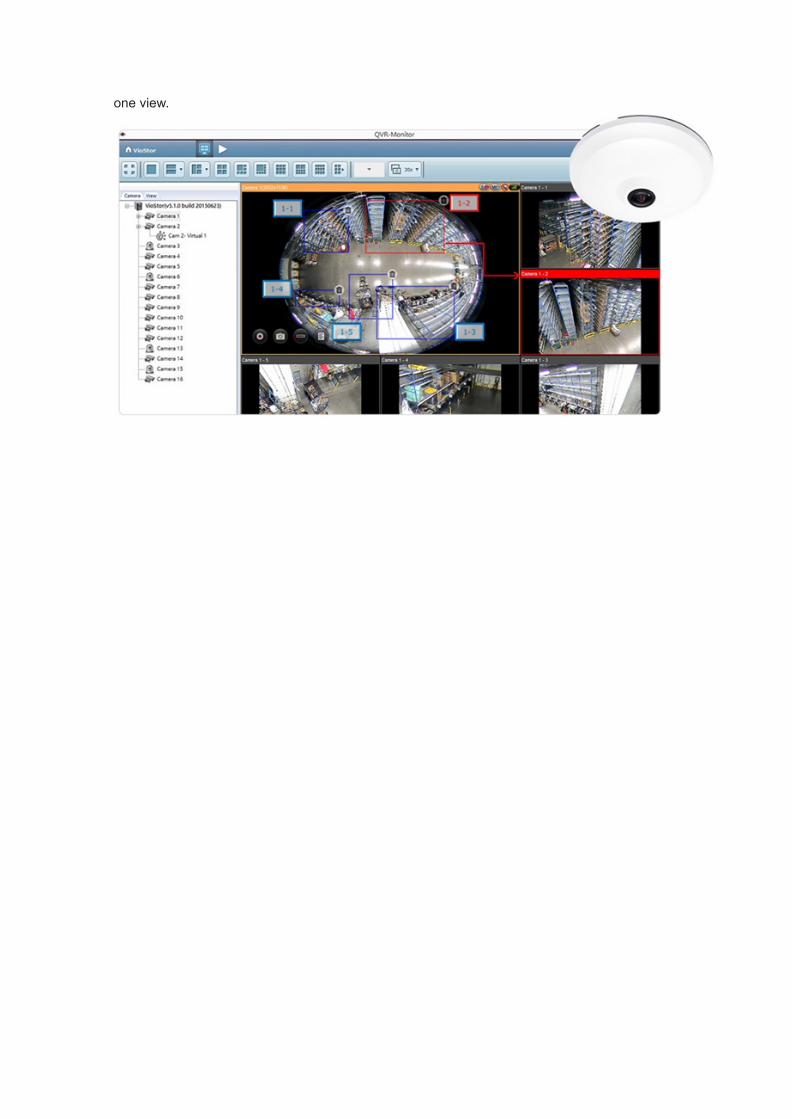
one view.

T3.[Tutorial] Use full fisheye camera functions by Qdewarp for variousmonitoring applications and post-alarm diagnosis
Key Benefits:Fisheye cameras are widely used to monitor larger areas. QNAP’s Qdewarp is a generic fisheyedewarp technology that works without affecting original recordings. With Qdewarp, if the fisheyecamera is on our capability list, you can choose from full dewarping modes in the remote monitoringand playback page and are not limited to vendor-specific dewarping modes.Prerequisites:
● VioStor NVR running QVR 5.1.0 or a higher version● Operating System: Microsoft Windows 7/ 8● Web Browser: Google Chrome 43.0.2357.132 m (Windows PC), Microsoft Internet Explorer
10/11 (Windows PC, desktop mode, 32-bit), Mozilla Firefox 39.0 (Windows PC)Note: The feature is not supported on local display and QVR Client for Mac.Applicable camera models:
Camera Brand Camera Models
3S N9018
ACTi B55, B56, E16, E919, E923, E923M, E927, E96, E98, I51, I71, KCM3911,KCM7911
Axis M3007, M3027
DAHUA IPC-EB5400, IPC-EBW81200, IPC-EBW8600
D-Link DCS-6010L
DynaColor NA083, Z4SA-D
Eneo PXD-5360F01IR
Etrovision N53U-FL, N50U-FL, N51U-FL, N53F-F, EFN3320C
Hikvision DS-2CD6332FWD, DS-2CD6362F
Hunt HLC-1NCF/360
Panasonic i-Pro SW458, SF438, SFV481
Lilin FD2452E
Mobotix c25, i25, Q25MSECD12, T25MSECD12PW, Q22M-BASIC, Q22M-Sec,Q24M-Sec
Pixord PD636E, PB670E, ND736E
Samsung SNF-7010VP
SONY SNC-HM662
Tamron 300QV-P-CM
VIVOTEK FE8180, FE8181, FE8391-V, SF8174, VC8201-M13
How it works?1. Add the applicable camera model into the VioStor NVR.2. Go to the live view page or playback page of the VioStor NVR. You can now see the 360°
surround view of the fisheye camera.

3. Click the Interactive Control Buttons on specific channels to enable fisheye dewarping.
Icon Description
Dewarp fisheye images:For specific fisheye cameras and camera models with panomorph lenses, you
can toggle dewarping. After enabling this function, you can then select themount type and dewarping mode.
4.
5. Click ‘Mount type’ to select the fisheye camera’s installation location (ceiling, wall, or floor).6. Click ‘Quick Qdewarp’ to select the dewarping modes you want. There are 11 ways to monitor
the focused region.

Qdewarp modeIcon Function Description
1O3R Provides the original screen, and 3 regional screens
1O8R Provides the original screen in the central grid, and 8 regionalscreens around the center
1P2R Provides 2 regional screens at the top of the screen, and onepanorama screen at the bottom

1P3R Provides 3 regional screens at the top of the screen, and onepanorama screen at the bottom
1P6R Provides 3 regional screens at the top and bottom of the screen,with one panorama screen in the center
4R Provides 4 regional screens
9R Provides 9 regional screens
Dual Panorama Provides 2 panorama screens
Full Panorama Provides one panorama screen
ORP Provides one original screen one regional screen, and onepanorama screen
R Provides one regional screen
2015/08/28

T4.[Tutorial] Customize your own layouts and views
View Management on QVRPrerequisites:
● VioStor NVR running QVR 5.1.0 or a higher version● Operating System: Microsoft Windows 7/ 8● Web Browser: Google Chrome 43.0.2357.130 m (Windows PC), Microsoft Internet Explorer
10/11 (Windows PC, desktop mode, 32-bit), Mozilla Firefox 39.0 (Windows PC)Note:The feature is not supported on local display and QVR Client for Mac.Fisheye cameras provide 360° surround views with a 1:1 aspect ratio. Different megapixel camerascan support different resolutions and aspect ratios, such as Full HD (16:9), QXGA (4:3), and corridorformat (9:16). You may want to define view layouts to suit your needs. View Management allows youto customize view layouts, and to assign cameras to specific windows.
View Management provides two modes: normal mode and fisheye mode.Button Description
Add: Add view
Edit: Edit view
Remove: Remove view
View thumbnail:When you hover over , it will show thumbnails for yourcustomized view.
Normal ModeThere are many pre-defined views in the monitoring page. If you want to create a customized view tobe shown in the left view tree list in the monitoring page, click ‘Add’ in [Surveillance Settings] ->[Camera Settings] -> [View Management].Add View
1. If you want to choose customized layout, please refer to here to create your own layout.

2. To add a camera to a view, drag a physical/virtual camera from the left list to the right channelscreen.
3. To remove a camera from a view, you can double click on a camera snapshot or drag it to theleft camera tree list. You can also click ‘Restore’ to remove all of the cameras.
Customized layoutWe support some pre-defined layouts. If you want to add a customized layout as a new layout or edityour defined layout, click ‘Layout Management’ in ‘Add View’ or ‘Edit View’ window first. You can thenclick ‘Add’ to add the layout or choose the layout to edit the layout in the right zone.
1. Choose a type of pre-defined layout.2. To customize the layout, click a square and draw a larger rectangle to combine the squares.
And you can double click the combined region to restore it. Or you can click ‘Restore’ to
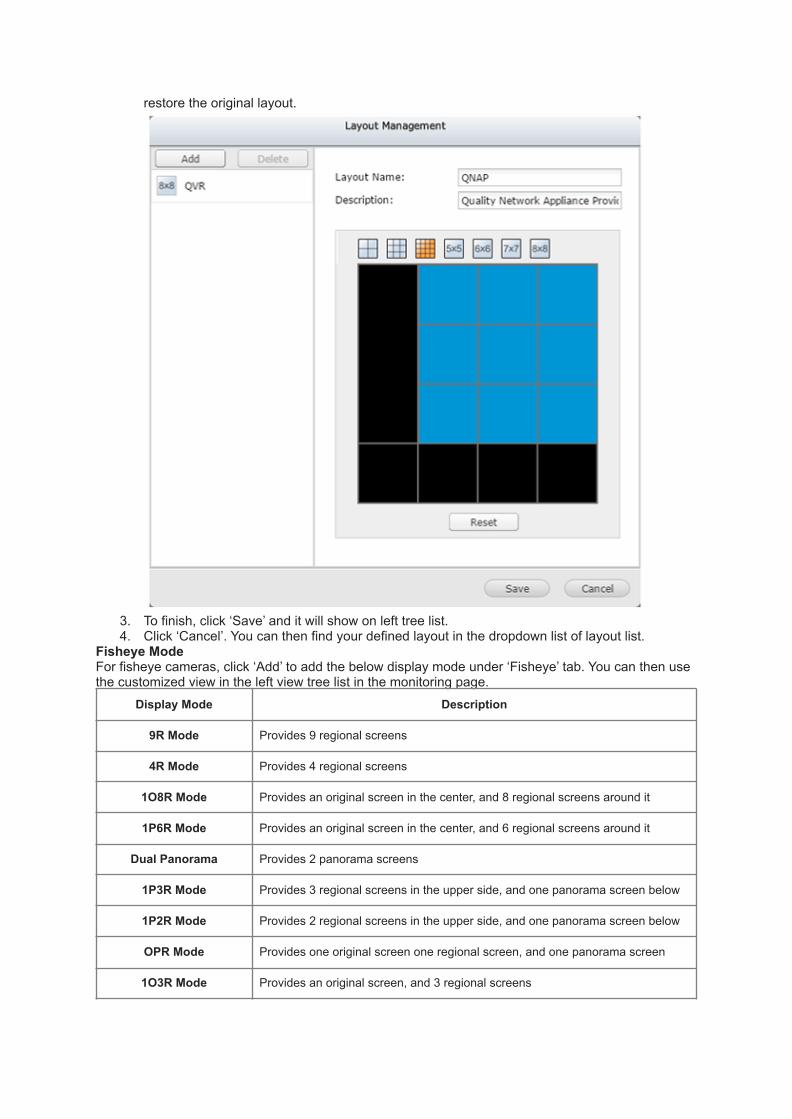
restore the original layout.
3. To finish, click ‘Save’ and it will show on left tree list.4. Click ‘Cancel’. You can then find your defined layout in the dropdown list of layout list.
Fisheye ModeFor fisheye cameras, click ‘Add’ to add the below display mode under ‘Fisheye’ tab. You can then usethe customized view in the left view tree list in the monitoring page.
Display Mode Description
9R Mode Provides 9 regional screens
4R Mode Provides 4 regional screens
1O8R Mode Provides an original screen in the center, and 8 regional screens around it
1P6R Mode Provides an original screen in the center, and 6 regional screens around it
Dual Panorama Provides 2 panorama screens
1P3R Mode Provides 3 regional screens in the upper side, and one panorama screen below
1P2R Mode Provides 2 regional screens in the upper side, and one panorama screen below
OPR Mode Provides one original screen one regional screen, and one panorama screen
1O3R Mode Provides an original screen, and 3 regional screens

R Mode Provides one regional screen
Full Panorama Provides one panorama screen
Add View1. Select a fisheye camera.2. Choose a display mode.3. To alter the size/ drag position in preview, use the mouse wheel to zoom in/out. Then you can
see the view.
View management’s applicationYou can choose the view mode in the left tree’s view tab on the monitor.

2015/07/23

T5.[Tutorial] Use virtual cameras to maximize the usage of megapixelcameras
Prerequisites:● VioStor NVR running QVR 5.1.0 or a higher version● Operating System: Microsoft Windows 7/ 8● Web Browser: Google Chrome 43.0.2357.130 m (Windows PC), Microsoft Internet Explorer
10/11 (Windows PC, desktop mode, 32-bit), Mozilla Firefox 39.0 (Windows PC)Note:The feature is not supported on local display and QVR Client for Mac.As high-megapixel cameras become more mainstream, it not only means clearer and higher-qualityvideos, but also a larger coverage area for cameras. You can select an area of a camera’s field ofview as a virtual camera, and also view physical and virtual cameras from the view management pagefor easier monitoring.To add a virtual camera, go to QVR desktop > “Surveillance Settings” > “Camera Settings” > “Camera
Configuration”. Click after adding a physical camera.
Virtual camera settingsYou can define the virtual camera’s area and its size by dragging the area on the “Edit Virtual CameraArea” window, or by entering values for its area and size.

Please note:You can add up to 4 virtual cameras for a physical camera without needing an additional channellicense.
After adding a virtual camera, you can click to see its information. You can also click to edit
the virtual camera settings or to delete it.
Virtual camera’s application

1. In the view management page, you can add a virtual camera to a grid.
2. In the monitor page, you can drag virtual cameras into any window to monitor it.
2015/07/22

T6.[Video] QNAP Professional Video Management System - QVR 5.0
Applied to QVR 5.0.xQVR 5.0 redefines Video Management Software (VMS) with its next-generation interface. Bringing theintuitive GUI, easy-to-use, and versatile QVR software that allows real-time monitoring, recording,playback, alarm notifications, and other management tools to safeguard assets and property when usedwith supported IP cameras.For more information, please refer to http://www.qnapsecurity.com/feature/qvr/en/?qvr=main&hf=new.
2015/07/06

T7.[Guide] Scenario 4: Configure NVR, IP cameras and the PC indifferent routers and access NVR from remote PC
Scenario 41. The VioStor, IP cameras, and the PC are in LAN A.2. Some IP cameras are installed in LAN B behind a different router in a remote
location.3. Allow the users to connect the NVR from remote PC over the Internet.
Please follow the steps below to install the NVR.Streaming from the network cameras:1. Plan the IP address and port of the NVR, the camera, and the PC.
LAN Device IP Address/ Port Mapped Port (HTTP) on the Router
A
Public IP of the router 219.87.144.205
VioStor 192.168.1.100:80 219.87.144.205:8000
Camera 1 192.168.1.101:80 219.87.144.205:8001
Camera 2 192.168.1.102:80 219.87.144.205:8002
Camera 3 192.168.1.103:80 219.87.144.205:8003
Camera 4 192.168.1.104:80 219.87.144.205:8004
PC 192.168.1.200
BRouter's Public IP 205.234.170.160

Router's LAN IP 172.17.1.1
Camera 5 172.17.1.11 205.234.170.160:8005
Camera 6 172.17.1.12 205.234.170.160:8006
C Remote PC 89.97.5.123
2. Install the IP camera. Please refer to the user guide of the IP camera for the network configuration.3. Configure the router/ virtual server/ firewall
In this application, you have to configure the port mapping or virtual server of the routers in LAN A and LAN B;and forward the ports to the corresponding LAN IP by the NAT router so that the NVR can save the recordingdata from the remote IP camera and the remote PC can access the monitoring page over the Internet.Note:a. Some IP cameras delivers MPEG4 image via RTSP or RTP ports. If the IP camera is installed outside the
router, you have to configure the RTSP and RTP ports on the router and the NVR so that the NVR cansave the recording data from the IP cameras, e.g. Axis, D-link, GANZ, LevelOne or Vivotek cameras thatsupport MPEG4 streaming.
b. In this sample, you must configure the RTP port setting on the router of LAN A and the RTSP port settingon the router of LAN B. Please refer to FAQ.
c. RTP (Real-time Transport Protocol): The protocol for delivering video or audio data.d. RTSP (Real-Time Streaming Protocol): The protocol for controlling video or audio streaming media.
Configure the port mapping or virtual server on the router:a. (a-1) Configure the port mapping on the router in LAN A
HTTP port:
From Forward to
219.87.144.205:8000 192.168.1.100:80
219.87.144.205:8001 192.168.1.101:80
219.87.144.205:8002 192.168.1.102:80
219.87.144.205:8003 192.168.1.103:80
219.87.144.205:8004 192.168.1.104:80
RTP port: (Configure the port for NVR to receive remote video data from the IP camera)
From Forward to
219.87.144.205:6100 192.168.1.100:6100
219.87.144.205:6101 192.168.1.100:6101

219.87.144.205:6102 192.168.1.100:6102
219.87.144.205:6103 192.168.1.100:6103
:::
:::
219.87.144.205:6259 192.168.1.100:6259
Note:The default RTP port range of the NVR (VioStor) is 6100~6259. Please refer toFAQ.b. (a-2) Sample of the router's port mapping in LAN A:
c. (b-1) Configure the port mapping on the router in LAN BHTTP port:
From Forward to
205.234.170.160:8005 172.17.1.11:80
205.234.170.160:8006 172.17.1.12:80

RTSP port: Configure the protocol for controlling video or audio streaming media.
Note:Please check the RTSP (Real-Time Streaming Protocol) port of the IP camera before configuring the portmapping on the router.Please refer to the user guide of the IP camera for its RTSP port settings.
d. (b-2) Sample of the router's port mapping in LAN B:
4. Install and configure the VS-NVREnter the IP address of the camera in the "IP address" field of the "Camera Settings" page of the VioStor.Then enter the Public IP and the port number of the camera configured on the router in "WAN IP" and "Port"fields on the "Camera Settings" page of the VioStor.a. Enter the settings of the IP cameras in LAN A.
Camera 1 "IP Address": 192.168.1.101 port 80"WAN IP Address": 219.87.144.205 port 8001Camera 2 "IP Address": 192.168.1.102 port 80"WAN IP Address": 219.87.144.205 port 8002Camera 3 "IP Address": 192.168.1.103 port 80"WAN IP Address": 219.87.144.205 port 8003Camera 4 "IP Address": 192.168.1.104 port 80"WAN IP Address": 219.87.144.205 port 8004

Note:● The "IP address" is for the VioStor to acquire the streaming from the VioStor directly and for
browsing by LAN users.● The "WAN IP Address" is for remote access to the monitoring page of the VioStor over the Internet. If
your IP camera is installed behind the NAT router, enter the public IP address (or URL) and configurethe port forwarding correctly.
b. Enter the settings of the IP cameras in LAN B.Camera 5 "IP Address": 205.234.170.160 port 8005/5001Camera 6 "IP Address": 205.234.170.160 port 8006/5002

Note:The "Port" field refers to the HTTP and RTSP port. The default number of HTTP port: 80. To specify theRTSP port of the IP camera, add a slash (/) and RTSP port number after the HTTP port number.
● The port 21 must be forwarded on the router in the following two situations:a. When you use the alarm function of the remote IP camera (the alarm between the NVR and the
camera is delivered by FTP).b. When you need to login the VioStor by FTP (port 21).
From Forward to
219.87.144.205:21 192.168.1.100:21
● After changing the settings, enter the address in the browser to access the VioStor over the Internet:http:// 219.87.144.205:8000/
● If you have configured port 80 to VioStor, enter the address to access the VioStor (the default port ofHTTP is 80): http:// 219.87.144.205/
● To use DDNS if this network environment, enter the DDNS settings on the router, but not on the VioStor.Configure the port mapping or virtual server on the router:a. (a-1) Configure the port mapping on the router in LAN A
HTTP port:
From Forward to
219.87.144.205:8000 192.168.1.100:80
b. (a-2) Sample of the router's port mapping in LAN A:

c. (b-1) Configure the port mapping on the router in LAN BHTTP port :
From Forward to
205.234.170.160:8005 172.17.1.11:80
205.234.170.160:8006 172.17.1.12:80
d. RTSP port: Configure the protocol for controlling video or audio streaming media.
From Forward to
205.234.170.160:5001 172.17.1.11:554
205.234.170.160:5002 172.17.1.12:554
Note:Please check the RTSP (Real-Time Streaming Protocol) port of the IP camera before configuring the portmapping on the router.Please refer to the user guide of the IP camera for its RTSP port settings.
e. (b-1) Configure the port mapping on the router in LAN BHTTP port :
From Forward to
205.234.170.160:8005 172.17.1.11:80
205.234.170.160:8006 172.17.1.12:80

f. RTSP port: Configure the protocol for controlling video or audio streaming media.
From Forward to
205.234.170.160:5001 172.17.1.11:554
205.234.170.160:5002 172.17.1.12:554
Note:Please check the RTSP (Real-Time Streaming Protocol) port of the IP camera before configuring the portmapping on the router.Please refer to the user guide of the IP camera for its RTSP port settings.
g. (b-2) Sample of the router's port mapping in LAN B:
h. Install and configure the NVR (VioStor)i. Enter the IP address of the camera in the "IP address" field of the "Camera Settings" page of the VioStor.

Note:● The "IP address" is for the VioStor to acquire the streaming from the VioStor directly and for browsing
by LAN users.● The "WAN IP Address" is for remote access to the monitoring page of the VioStor over the Internet. If
your IP camera is installed behind the NAT router, enter the public IP address (or URL) and configurethe port forwarding correctly.
i. Enter the settings of the IP cameras in LAN B.

Note:The "Port" field refers to the HTTP and RTSP port. The default number of HTTP port: 80. To specify theRTSP port of the IP camera, add a slash (/) and RTSP port number after the HTTP port number.
The port 21 must be forwarded on the router in the following two situations:● When you use the alarm function of the remote IP camera (the alarm between the NVR and the
camera is delivered by FTP).● When you need to login the VioStor by FTP (port 21).
From Forward to
219.87.144.205:21 192.168.1.100:21
After changing the settings, enter the address in the browser to access the VioStor over the Internet:http:// 219.87.144.205:8000/
If you have configured port 80 to VioStor, enter the address to access the VioStor (the default port ofHTTP is 80) : http:// 219.87.144.205/To use DDNS if this network environment, enter the DDNS settings on the router, but not on the VioStor.
2015/07/22
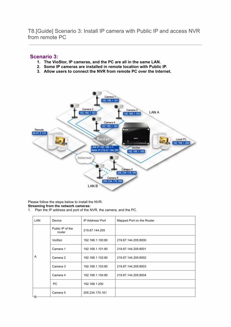
T8.[Guide] Scenario 3: Install IP camera with Public IP and access NVRfrom remote PC
Scenario 3:1. The VioStor, IP cameras, and the PC are all in the same LAN.2. Some IP cameras are installed in remote location with Public IP.3. Allow users to connect the NVR from remote PC over the Internet.
Please follow the steps below to install the NVR.Streaming from the network cameras:1. Plan the IP address and port of the NVR, the camera, and the PC.
LAN Device IP Address/ Port Mapped Port on the Router
A
Public IP of therouter 219.87.144.205
VioStor 192.168.1.100:80 219.87.144.205:8000
Camera 1 192.168.1.101:80 219.87.144.205:8001
Camera 2 192.168.1.102:80 219.87.144.205:8002
Camera 3 192.168.1.103:80 219.87.144.205:8003
Camera 4 192.168.1.104:80 219.87.144.205:8004
PC 192.168.1.200
BCamera 5 205.234.170.161

Camera 6 205.234.170.162
C Remote PC 89.97.5.123
2. Install the IP camera. Please refer to the user guide of the IP camera for the network configuration.3. Configure the router/ virtual server/ firewall
In this application, you have to configure the port mapping or virtual server of the router and forward theports to the corresponding LAN IP so that the NVR can save the recording data from the remote IP cameraand the remote PC can access the monitoring page over the Internet.Note:
a. Some IP cameras delivers MPEG4 image via the RTSP or RTP ports. If the IP camera isinstalled outside the router, you have to configure the RTSP and RTP ports on the router andthe NVR so that the NVR can save the recording data from the IP cameras, e.g. Vivotek, Axis,D-link, GANZ, or LevelOne cameras that support MPEG4 streaming.
b. In this sample, you must configure the RTP port setting on the router of LAN A. Please refer toFAQ.
c. RTP (Real-time Transport Protocol): The protocol for delivering video or audio data.d. RTSP (Real-Time Streaming Protocol): The protocol for controlling video or audio streaming
media.
Configure the port mapping or virtual server on the router:HTTP port:
From Forward to
219.87.144.205:8000 192.168.1.100:80
219.87.144.205:8001 192.168.1.101:80
219.87.144.205:8002 192.168.1.102:80
219.87.144.205:8003 192.168.1.103:80
219.87.144.205:8004 192.168.1.104:80
RTP port: (Configure the port for NVR to receive remote video data from the IP camera)From Forward to
219.87.144.205:6100 192.168.1.100:6100
219.87.144.205:6101 192.168.1.100:6101
219.87.144.205:6102 192.168.1.100:6102
219.87.144.205:6103 192.168.1.100:6103
:::
:::

219.87.144.205:6259 192.168.1.100:6259
Note:The default RTP (Real-time Transport Protocol) port range of the NVR(VioStor) is 6100~6259. Please refer toFAQ.The router's port forwarding:
4. Install and configure the NVR (VioStor)Enter the IP address of the camera in the "IP address" field of the "Camera Settings" page of the VioStor.Then enter the Public IP and the port number of the camera configured on the router in "WAN IP" and "Port"fields respectively on the "Camera Settings" page of the VioStor.

Note: The LAN IP and the WAN IP of the IP camera must be entered.Streaming from the server:1. Plan the IP address and port of the NVR, the camera, and the PC.
LAN Device IP Address/ Port Mapped Port on the Router
A
Public IP of the router 219.87.144.205
VioStor 192.168.1.100:80 219.87.144.205:8000
Camera 1 192.168.1.101
Camera 2 192.168.1.102
Camera 3 192.168.1.103
Camera 4 192.168.1.104
PC 192.168.1.200
BCamera 5 205.234.170.161
Camera 6 205.234.170.162
C Remote PC 89.97.5.123
2. Install the IP camera. Please refer to the user guide of the IP camera for the network configuration.

3. Configure the router/ virtual server/ firewallIn this application, you have to configure the port mapping or virtual server of the router and forward the portsto the corresponding LAN IP so that the NVR can save the recording data from the remote IP camera and theremote PC can access the monitoring page over the Internet.Configure the port mapping or virtual server on the router:HTTP port:
From Forward to
219.87.144.205:8000 192.168.1.100:80
4. The router's port forwarding:

5. Install and configure the VioStor NVREnter the IP address of the camera in the "IP address" field of the "Camera Settings" page of the VioStor.

Note:a. The "IP address" is for the VioStor to acquire the streaming from the VioStor directly and for
browsing by LAN users.b. The "WAN IP Address" is for remote access to the monitoring page of the VioStor over the
Internet. If your IP camera is installed behind the NAT router, enter the public IP address (orURL) and configure the port forwarding correctly.
● The port 21 must be forwarded on the router in the following two situations:i. When you use the alarm function of the remote IP camera (the alarm between the NVR and
the camera is delivered by FTP).ii. When you need to login the VioStor by FTP (port 21).
From Forward to
219.87.144.205:21 192.168.1.100:21
● After changing the settings, enter the address in the browser to access the VioStor over theInternet: http:// 219.87.144.205:8000/
● If you have configured port 80 to VioStor, enter the address to access the VioStor (the defaultport of HTTP is 80): http:// 219.87.144.205/
● To use DDNS if this network environment, enter the DDNS settings on the router, but not on theVioStor.
2015/07/22
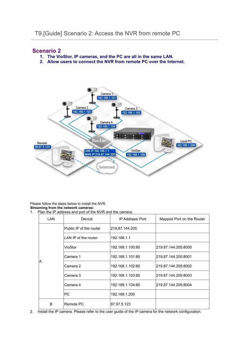
T9.[Guide] Scenario 2: Access the NVR from remote PC
Scenario 21. The VioStor, IP cameras, and the PC are all in the same LAN.2. Allow users to connect the NVR from remote PC over the Internet.
Please follow the steps below to install the NVR.Streaming from the network cameras:1. Plan the IP address and port of the NVR and the camera.
LAN Device IP Address/ Port Mapped Port on the Router
A
Public IP of the router 219.87.144.205
LAN IP of the router 192.168.1.1
VioStor 192.168.1.100:80 219.87.144.205:8000
Camera 1 192.168.1.101:80 219.87.144.205:8001
Camera 2 192.168.1.102:80 219.87.144.205:8002
Camera 3 192.168.1.103:80 219.87.144.205:8003
Camera 4 192.168.1.104:80 219.87.144.205:8004
PC 192.168.1.200
B Remote PC 87.97.5.123
2. Install the IP camera. Please refer to the user guide of the IP camera for the network configuration.

3. Configure the router/ virtual server/ firewallTo allow remote PC to access the VioStor and the IP cameras, you must configure the port mapping orvirtual server of the router. The sample settings are as below:HTTP port:
From Forward to
219.87.144.205:8000 192.168.1.100:80
219.87.144.205:8001 192.168.1.101:80
219.87.144.205:8002 192.168.1.102:80
219.87.144.205:8003 192.168.1.103:80
219.87.144.205:8004 192.168.1.104:80
4. An example of router port forwarding
5. Install and configure the NVR (VioStor)Enter the IP address of the camera in the "IP address" field of the "Camera Settings" page of the VioStor.Then enter the Public IP and the port number of the camera configured on the router in "WAN IP" and "Port"fields on the "Camera Settings" page of the VioStor.


Note: The LAN IP and the WAN IP of the IP camera must be entered.Streaming from the server:1. Plan the IP address and port of the NVR and the camera.
LAN Device IP Address/ Port Mapped Port on the Router
A
Public IP of the router 219.87.144.205
LAN IP of the router 192.168.1.1
VioStor 192.168.1.100:80 219.87.144.205:8000
Camera 1 192.168.1.101
Camera 2 192.168.1.102
Camera 3 192.168.1.103
Camera 4 192.168.1.104
PC 192.168.1.200
B Remote PC 87.97.5.123
2. Install the IP camera. Please refer to the user guide of the IP camera for the network configuration.

3. Configure the router/ virtual server/ firewallTo allow remote PC to access the VioStor and the IP cameras, you must configure the port mapping orvirtual server of the router. The sample settings are as below:HTTP port:
From Forward to
219.87.144.205:8000 192.168.1.100:80
4. An example of router port forwarding

5. Install and configure the NVR (VioStor)Enter the IP address of the camera in the "IP address" field of the "Camera Settings" page of the VioStor.
Note:● The "IP address" is for the VioStor to acquire the streaming from the VioStor directly and for
browsing by LAN users.● The "WAN IP Address" is for remote access to the monitoring page of the VioStor over the
Internet. If your IP camera is installed behind the NAT router, enter the public IP address (orURL) and configure the port forwarding correctly.
● To access the VioStor remotely by FTP (port 21), configure the following settings:
From Forward to
219.87.144.205:21 192.168.1.100:21
● After changing the settings, enter the address in the browser to access the VioStor over theInternet: http:// 219.87.144.205:8000/
● If you have configured port 80 to VioStor, enter the address to access the VioStor (the defaultport of HTTP is 80): http:// 219.87.144.205/
● To use DDNS if this network environment, enter the DDNS settings on the router, but not on theVioStor.
2015/07/22

T10.[Guide] Scenario 1: Local Area Network
Scenario 1● The VioStor, IP cameras, and the PC are all in the same LAN (Local Area
Network).

Please follow the steps below to install the NVR.Both streaming from the network cameras and server:1. Plan the IP address and port of the NVR and the camera.
Device IP Address
VioStor 192.168.1.100
Camera 1 192.168.1.101
Camera 2 192.168.1.102
Camera 3 192.168.1.103
Camera 4 192.168.1.104
PC 192.168.1.200
2. Install the IP camera. Please refer to the user guide of the IP camera for the networkconfiguration.
3. Install and configure the NVR.When the NVR (VioStor) and the IP cameras are in the same LAN, you can use thedefault port settings.
Note:● The "IP address" is for the VioStor to acquire the streaming from the VioStor directly
and for browsing by LAN users.● The "WAN IP Address" is for remote access to the monitoring page of the VioStor
over the Internet. If your IP camera is installed behind the NAT router, enter thepublic IP address (or URL) and configure the port forwarding correctly.

2015/07/22

T11.[Tutorial] How to use Vmobile 3 to monitor and play recordings on aVioStor NVR?
VMobile is a mobile app for video surveillance provided by QNAP that allows you to use your mobiledevice to remotely monitor IP cameras, play recorded videos, and manage your video surveillancesystem anytime, anywhere. VMobile supports monitoring several servers/channels from thousands ofnetwork cameras across different brands by simply connecting to any available VioStor NVR or TurboNAS (with Surveillance Station enabled) on the network.
● Installing VMobile 3:

1. Please note that this app requires a VioStor NVR with QVR 5.0.1 or Turbo NAS withSurveillance Station 5.0.1 (or above).
2. Make sure your mobile device can access the VioStor NVR or Turbo NAS via a networkconnection.
3. If using an iOS device, you must be using iOS 7 (or above).
4. Install VMobile from the App Store (iOS) or Google Play (Android) depending on your mobiledevice. Please note: the Android version will be available from the end of October 2014.
This tutorial will use the iOS version of VMobile 3 as an example.
Starting using VMobile 3
● Adding a new server for monitoring
When you start VMobile for the first time, it will lead you through the tutorial.

After reading the tutorial, select “Start” to configure VMobile.
If you cannot find a Turbo NAS or VioStor NVR, please check their status or your networkconnection. You can also select “Add Server Manually ” to add your Turbo NAS or VioStor NVR.

Please enter your server information.

After adding a new server, all of your server's cameras will be added to “All cameras”.
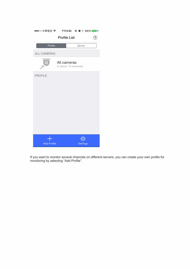
If you want to monitor several channels on different servers, you can create your own profile formonitoring by selecting “Add Profile”.

Enter a Profile Name before choosing what servers and channels you want to monitor, beforeselecting “Done”.

You can then adjust the order by dragging & dropping channels.

Then select the profile to start monitoring.

Select the channel you want to monitor.

You can find more advanced options by selecting the upper-right button.

Button/Function Description
Pause /resume
Pause and resume the video stream.
Snapshot
Take a snapshot of the current channel (only available insingle-channel view.)
Channel View
Change the channel view or enable “Sequential mode”.1, 2, 3, 4, 6, 8 and 9 channels view are available.
PTZEnable the PTZ function (only available for PTZ cameras.)
Preset Point
Select the camera preset point (only available in supported andconfigured cameras.)

Video CompressionChange the compression of the video stream
ShareShare a snapshot

● Playback on VMobile 3

Select “ ” to use the Playback function.
Select the server, camera, date/time, and then select “Play”.


● Check the surveillance log on VMobile
You can also check detailed logs on “ Logs”.
2015/07/22

T12.[Tutorial] How to Use User-defined Multi-streaming for MultipleApplications?
In the past, digital surveillance systems users were forced to make a tradeoff between the videoquality of a camera stream and required bandwidth. The same camera stream was used for both liveview and recording, and more bandwidth was required if a high-quality camera stream was selected.Fortunately, with the introduction of multi-stream technology, users now can choose the main streamfor recording files and the sub stream for live viewing.
Multi-stream technology is already supported by VioStor NVR, but properties such as resolution,frame rate, video quality and codec could not be changed by users. With new enhancements made toVioStor NVR, users can now choose streaming properties based on their needs.
Applicable models:
ACTi B97, E34, E54, E84
AXIS M1011, M1054, M1103, M1104, M1113, M1114, M3006, M3011, M3014,M3026, M3113, M3114, M3204, M5013, M5014, M5014-V, M7010, M7014,P1204, P1214, P1214-E, P1353, P1354, P1355, P1357, P3301, P3304, P3344,P3346, P3353, P3354, P3363, P3364, P3364-LV/-LVE, P3367, P3384, P5414,P5512, P5522, P5532, P5534, P5544, P7210, P7214, P7224, P8513, P8514,Q1602, Q1604, Q1755, Q1765, Q1910, Q1921, Q1922, Q6032,Q6034, Q6035, Q6042, Q6044, Q6045, Q7401, Q7411
Sony SNC-CX600, SNC-CX600W, SNC-EB600, SNC-EB600B, SNC-EB630, SNC-EB630B,SNC-EM600, SNC-EM601, SNC-EM602R, SNC-EM630, SNC-EM631, SNC-EM632R,SNC-VB600, SNC-VB600B, SNC-VB630, SNC-VB635, SNC-VM600, SNC-VM601,SNC-VM601B, SNC-VM630, SNC-VM631, SNC-VM632R, SNC-WR600, SNC-WR602,SNC-WR630, SNC-XM632
VIVOTEK CC8130, FD8131, FD8131V, FD8134, FD8136, FD8137H, FD8137HV, FD8151V,FD8163, FD8164, FD8164V, FD8166, FD8355EHV, FD8363, FD8371EV, FE8173,FE8174, IP8131W, IP8132, IP8133, IP8152-F4, IP8335, IP8355EH, IP8364-C,IP8371-E, PZ81X1, SD81X1, SD8314E, SD8316E, SD8324E, SD8326E, SD8363E

Please follow these steps to enable user-defined multi-stream settings:


1. Go to the QVR desktop as an administrator and click “Surveillance
Settings” .
2. Go to “Camera Settings” -> “Camera Configuration”.
3. Click to add a camera.
4. Select the camera you wish to apply these settings to.Please refer to the latest list of compatible cameras.
5. The default Multi-stream Profile setting is “System-Configured”. You need to change this to“User defined” using the dropdown list.
6. Modify the settings of each stream according to your needs.
There are now two recording mode supported:
1. Round-the-clock RecordingSimilar with standard recording, this uses the same stream for regular and alarm recording.However, you can define a specific video stream to record.
● Please select the video stream from the “Regular Recording” dropdown list.

2. Smart RecordingSupports different streams for regular and alarm recording.
● A. Select one camera stream from the “Regular Recording” dropdown list.
● B. Select a different camera stream from the “Alarm Recording” dropdown list.(Scheduled Recording and Alarm Recording must be enabled before using “AlarmRecording”.)
3. For more information, please refer to Smart Recording tutorial.
Note:Required NVR CPU loading for system-configured multi-stream is higher than it for user definedmulti-stream.
2015/07/22

T13.[Tutorial] Set up the QNAP VioStor NVR to record and monitorthe network cameras with Panomorph lenses
Panomorph lenses can be adapted to compatible cameras to have 360 degree coverage with
enhanced resolutions and adjusted pixel density in predefined zones of interest. With the lenses and
the integrated client software, users can watch a complete scene unfold without obstruction while
simultaneously displaying multiple independent dewarped views using fisheye cameras.
This will guide you to configure the VioStor NVR to record videos from the camera with panomorph
lenses and to dewarp 360-degree panoramic images for live monitoring and playback.
Prerequisites:
● VioStor NVR running QVR 5.1.0 or a higher version
● Operating System: Microsoft Windows 7/ 8
● Web Browser: Google Chrome 43.0.2357.130 m (Windows PC), Microsoft Internet Explorer
10/11 (Windows PC, desktop mode, 32-bit), Mozilla Firefox 39.0 (Windows PC)
Note: The feature is not supported on local display and QVR Client for Mac.
Applicable cameras:
Arecont Vision AV5245DN-01-A
AXIS M3007
Brickcom CB-500Ap-360P, MD-300AP-360P, MD-300NP-360P, MD-500AP-360P
LINKSYS LCAM0336OD
SONY SNC-HM662
Compatible camera models with panamorph lenses, including
AXIS 223M, P1347, Q1602, Q1604
Basler BIP2-2500c-dn
LG LW332/335
Panasonic i-Pro WV-NP1000/ 1004, WV-NP244, WV-SP304, WV-SP508E (resolution: 2048*1536)
Samsung SNB-7000, SND-7080, SNV-7080R
StarDot SDH130VN

VIVOTEKIP8151
A. Set up the VioStor NVR
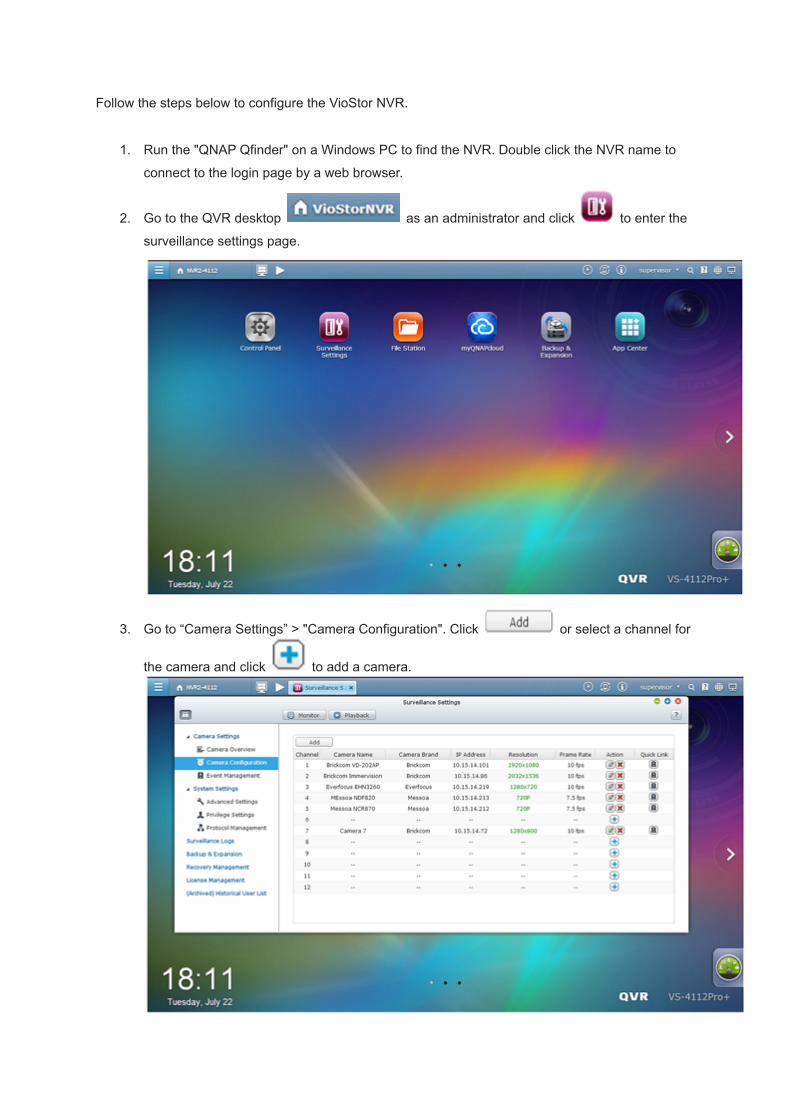
Follow the steps below to configure the VioStor NVR.
1. Run the "QNAP Qfinder" on a Windows PC to find the NVR. Double click the NVR name to
connect to the login page by a web browser.
2. Go to the QVR desktop as an administrator and click to enter the
surveillance settings page.
3. Go to “Camera Settings” > "Camera Configuration". Click or select a channel for
the camera and click to add a camera.

4. Click “Next” to auto search for the camera.
5. When it is found, select the camera and click “OK”.
Enter the IP address, username and password of the camera.
Or manually add the camera.
Click “Next” for video settings.

6. Configure the video settings.
For compatible camera models with panamorph lenses, please enable panomorph support.
Click “Next” for schedule settings.
7. Click and drag on the schedule table to enable scheduled recording for that period of
time. Click and drag on the schedule table to disable schedule recording for that period
of time.
Click “Next” to confirm the settings.

8. Now return to the VioStor NVR’s live view. You can now view the live image of the camera.
Panoramic view without dewarping
B. Configure live view settings
1. Move the mouse cursor over a camera channel, the supported function buttons (Interactive
Control Buttons) of the camera will show up for quick access.
2. Click “Camera information” in the Interactive Control Buttons and select “Properties” from the
list.
Icon Description
Camera information:
1. Properties: Configure other monitoring options.
2. Locate in E-map: Highlight the camera icon on the E-map.
3. Connect to camera homepage.

3. Select "Fixed resolution" under "Video Resolution".
Because the limitations of the ImmerVision SDK, the dewarping function is only availablewhen the resolution of the video stream is higher than 640x480 on the monitoring page.Please choose a video stream where the resolution is higher than 640x480.
C. Dewarp 360-degree panoramic images of the camera in live view
1. To dewarp the panoramic images of the camera, click “Dewarp fisheye images” in the Interactive
Control Buttons to enable the fisheye dewarping function.
Icon Description
Camera information:
For specific fisheye cameras and specific camera models with panomorph lens,you can enable/disable the dewarping function. After enabling the function, you canthen select the mount type and dewarping mode.

2. Click “Dewarp fisheye images” in the Interactive Control Buttons and set the "Mount type" to Wall,
Ceiling, or Ground according to your setup. Then specify the "Dewarping mode".
● Example 1. Select "Ceiling" for the mount type.
Note: For Ceiling and Ground Mount type, FullView will display 360 degrees of viewing
angle.
● Example 2. Select “PTZ mode” for the dewarping mode.
D. Dewarp 360-degree panoramic images of the camera in playback
1. Click to enter the playback page.
2. To dewarp fisheye images of the camera, click “Dewarp fisheye images” in the Interactive
Control Buttons to enable the fisheye dewarping function.
3. Click “Dewarp fisheye images” in the Interactive Control Buttons and set the "Mount type" to
Wall, Ceiling, or Ground according to your setup. Then specify the "Dewarping mode".
2015/08/27

T14.[Tutorial] How to use Smart stream on VIVOTEK cameras tointelligently allocate more bandwidth to streaming moving objects orRegions of Interest?
What is Smart stream?
Smart stream intelligently allocates more bandwidth to streaming moving objects or Regions of
Interest in surveillance scenarios, resulting in optimized resource usage.
Applicable Camera Models:
VIVOTEK FD8371, IP8371, FD8171
How to enable smart stream function?
1. On the CameraVisit the camera’s page. Find the settings of Smart stream in Configuration
->Video->Stream->Any stream->H.264, and set up the video quality for your foreground,
background, and start enjoying the benefit of a Smart stream.

2. On the NVRYou do not need to make any changes. Just add the camera in your NVR and configure
recording settings.
For more information, please refer to
http://www.vivotek.com/pressroom/feature_article/20140128_smart_stream_en.html.
2015/07/22

T15.[Tutorial] If a camera loses its connection with the NVR, does QNAPNVR support Edge Recording to provide redundancy by backing upfootage from a camera-based SD card?
QNAP NVR supports Edge Recording to reinforce your surveillance system by recording both to the
NVR and to an SD card located on the camera. If there is a network disruption, the camera will
continue to record to its SD card and the NVR will automatically recover missing footage once the
connection is reestablished.
Insert picture:
http://www.qnap.com/static/landing/2014/EN-edge-Recording/images/image_02.gif
Applicable models: AXIS M3005, M3025, M5013, P1343 (-E), P1344 (-E), P3343 (-V/-VE), P3346
(-V/-VE), P3367-V/-VE, P5414, P5534 (-E), Q6034 (-E), Q1602, Q6042, Q6044, Q6045
How to configure Edge Recording?

1. Go to the camera page.
Before adding this camera to the NVR, please ensure that the camera’s date & time is synchronized
with that of the NVR.
The NVR will automatically apply the settings in the edge profile to the AXIS camera.
Videos recovered from Edge Recording use the H.264 codec. This option cannot be changed.
After enabling Edge Recording, check if the camera is recording videos. If not, enable “Continuous
Recording” and ensure the SD card is not full or damaged.

After enabling Edge Recording, ensure that "Recording Settings" have been enabled on the camera
page and select “NVRedgeProfile” as the stream profile.
Configure the “Remove recordings older than” settings to optimize the capacity usage of the SD card.
2. Go to the NVR page.

Go to “Surveillance Settings” > “Camera Configuration” to enable Edge Recording under “Video
Settings”.
Go to “Surveillance Settings” >“Recovery Management” to configure the recovery schedule, and
check the recovery status and the status of Edge Recording attempts.
Applicable cameras: AXIS P1343, P1344, P3343, P5534, M5013, Q1602
Limitations and Restrictions:
1. Audio recording is not supported by Edge Recording.
2. The camera’s date & time must be synchronized with the NVR time for Edge Recording to work.
3. Please refer to your cameras’ user manuals to configure settings on the camera page.
4. Edge Recording settings cannot be modified when using local display.
5. Ensure that the SD card is formatted to VFAT and is fully functional with enough free space for
recording videos.
6. Videos recovered from Edge Recording use the H.264 codec. This setting cannot be changed.
7. Edge Recording will only check and recover recording files within the scheduled period.
8. Please refer to our list of compatible cameras:
http://www.qnapsecurity.com/n/en/product_z_g_qvr/cat_intro.php
2015/07/22
[Tutorial] How to Configure Storage Expansion for Long-termRecording?
Key Benefits:
After installing the Storage Expansion App (QPKG) on the QNAP NAS and enabling the storage
expansion to the QNAP NAS on the NVR, the QNAP NAS will frequently ask the NVR if it has new
recording files. If the NVR has new recording files and the backup buffer meets your defined
threshold, the QNAP NAS will then download the recordings from the NVR. Under our testing, this
method largely improves file backup throughput, with some processes offloaded to the QNAP NAS
CPU.
Key features:
VioStor NVR + QNAP NAS + REXP for long-term recording

1. Addressing user needs: Users can expand their storage capacity based on their needs.
2. Reduces expenses: This is a cost-effective choice to expand storage.
3. Highly scalable for storage expansion in the future.
Storage Expansion - Introduction
http://eu1.qnap.com/Surveillance/presentation/Storage_Expansion-Introduction.pdf
Storage Expansion - Selection guide
http://eu1.qnap.com/Surveillance/presentation/Storage_Expansion-Guide.pdf
QNAP RAID Expansion Enclosures
http://files.qnap.com/news/pressresource/product/Use_QNAP_RAID_Expansion_Enclosure_to_Expa
nd_Storage_Capacity_en.pdf
How it works?

Suppose the NVR only has enough space for storing 5 days of recording files, and the QNAP NAS
only has enough space for storing 7 days of backup files.
The backup buffer on the NVR is set to 48 hours.
The recording files are set to be backed up to the QNAP NAS.
After the settings are applied, the QNAP NAS will check and download the earliest 48 hours of
recording files from the NVR. So, the first two days of recording files will be downloaded and stored on
the QNAP NAS.

As time passes, the NVR storage space will be full by the 5th day. As the earliest 48 hours of
recording files are the same as before, no more recording files are downloaded and stored on the
QNAP NAS..
On the 6th day, to store new recording files, the NVR will delete the first day's recording files. Now the
earliest 48 hours are the second and third days. So, the recording files of the third day will be
downloaded to the QNAP NAS.

Based on these settings, the QNAP NAS will keep downloading recording files until it is full, and a
total of 10 days of recording files will be kept (the earliest 5 days on the QNAP NAS and latest 5 days
on the NVR.)
To store new recording files, the NVR will delete the recording files of the sixth day, and the eighth
day's recording files (the new, earliest 48 hours) will be downloaded to the QNAP NAS. As the QNAP
NAS is full, it will delete the first day's recording files.

The total hours of recording files = total hours of recording files on the NVR + total hours of recording
files on the NAS – Backup buffer.
Please note:
In order to ensure that the Storage Expansion can be executed whilst recording, please calculate the
bandwidth requirements for specific VioStor NVR models.
The following is estimated bandwidth requirements for specific NVR models:
VS-8100 Pro+, 8100U-RP Pro(+), 12100U-RP Pro(+) series: 360 Mbps.
VS-2200 Pro+, 2100 Pro+, 4100 Pro+, 6100 Pro+, 4100U-RP Pro+ series: 160 Mbps.
VS-2000 Pro, VS-4000 Pro, VS-6000 Pro, 4000U-RP Pro series: 90 Mbps.
Limitations and Restrictions:

1. Storage Expansion is currently supported by the VioStor Pro(+) series (running QVR v5.1.0 or
higher version) and QNAP NAS TVS-ECx80, x71U, x71, x70, x63 series and TS-x79U, ECx80,
ECx80U, x53U, x53 Pro, x51 series (running QTS v4.1.4 or higher version), and they must be set
on the same LAN.
For VS-12100U-RP Pro(+), 8100U-RP Pro(+), 8100 Pro+ series, it is recommended to configure
up to 3 NAS servers for storage expansion.
For VS-2200 Pro+, 4100U-RP Pro+, 6100 Pro+, 4100 Pro+, VS-2100 Pro+ series, it is
recommended to configure up to 2 NAS servers for storage expansion.
For VS-4000U-RP Pro, 6000 Pro, 4000 Pro, 2000 Pro series, it is recommended to configure up
to 1 NAS server for storage expansion.
2. A gigabit switch is required for this application.
3. All QNAP NVR and NAS units are required to use fixed IP addresses and be under same subnet
mask & gateway.
4. Storage expansion related settings cannot be modified using local display.
5. The file transfer process between the QNAP NVR and NAS will be completed even if it is
suddenly interrupted (for example, the destination folder is deleted.) For example, the cache
count is set to six hours. The destination is changed to none in the middle of processing. When
this happens, the NVR will still move recording files to the QNAP NAS until the entire process is
finished.
How to configure storage expansion?

Step 1: Install the StorageExpansion App (QPKG) on the QNAP NAS
Please note: Download the app from the QTS App Center. Before installing the app, please ensure
the app is correct, carefully read the instructions, and back up the important data on the QNAP NAS.
● Download and install the StorageExpansion package.
● To install the app, click “Add to QTS”.
Step 2: Configure Storage Expansion on the NVR

1. Go to "Backup & Expansion" → "Storage Expansion" to configure relevant settings.
2. Click “Add” in “NAS List” table under “Overview”.
3. Please enter the QNAP NAS/destination settings.
A. Enter NAS IP, port, and user credentials.
B. Enter the destination name (the name cannot be used same as any folder under root.).
C. Select the volume.
D. Enter a value for the backup buffer.
If you want to configure storage expansion to a REXP Expansion Enclosure, please select the
right volume on REXP to enable storage expansion to REXP.
Please note:Destination: The folder created on the QNAP NAS to save recording files.
Volume: The volume assigned for storage expansion.

Backup buffer: As an example, if you configure the backup buffer as 6, the latest six hours of
recordings will be copied to the QNAP NAS. The maximum value is 48.

4. You can enable a QNAP NAS and modify its settings on this page.
5. Click “Storage Expansion Assignment” to choose a QNAP NAS as the storage unit for each
channel.

6. Review all of the configured settings and recording storage details under “Overview”.
This page will automatically refresh every fifteen minutes.
QNAP NAS models are an ideal solution for expanding the storage capacity of the NVR to save more
recording files. Integration of both QNAP devices can help users to save recording files more flexibly
and efficiently.
Step 3: Check available NVRs on the list and their status on the QNAP NAS
1. Click “Open” on StorageExpansion.
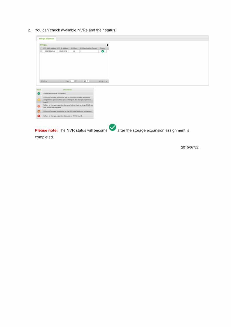
2. You can check available NVRs and their status.
Please note: The NVR status will become after the storage expansion assignment is
completed.
2015/07/22

[Tutorial] Set up the QNAP VioStor NVR to record and monitor fisheyenetwork cameras
QNAP's VioStor network video recorder (NVR) series is among the first Linux-embedded standalone
device provider to support fisheye cameras. Users can also view a complete scene unfold without
obstruction while simultaneously displaying multiple independent dewarped views using fisheye
cameras.
This article will guide you to configure the VioStor NVR to record videos from fisheye cameras and to
dewarp fisheye images for live monitoring.
Applicable camera models:
● AXIS M3007 (Please select AXIS M3007-dewarp model in our camera model list)
● Dynacolor NA083
● Oncam Grandeye EVO-05NMD
● VIVOTEK FE 8172/8172/8174 (camera firmware version should be v0100h or above)
Prerequisites:
● The firmware version of the VioStor NVR must be QVR 5.0 or above. You can download the
latest firmware from here.
● The fisheye camera must be mounted in a proper position.
A. Set up the VioStor NVR

Follow the below steps to configure the VioStor NVR.

1. Run the "QNAP Finder" on a Windows PC to find the NVR. Double click the NVR name to
connect to the login page via web browser.
2. Login to the NVR as "admin".
3. To enter the surveillance settings page, click .
4. Go to “Camera Settings” > "Camera Configuration". Click orselect a channel for the
camera and click to add a camera.
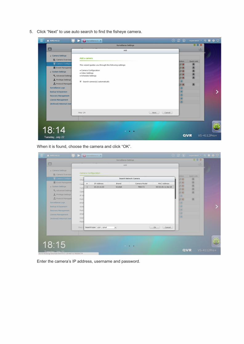
5. Click “Next” to use auto search to find the fisheye camera.
When it is found, choose the camera and click “OK”.
Enter the camera’s IP address, username and password.

Or manually add the camera brand and model.
6. Specify the video and schedule settings.
Please note: To use the dewarping function, please select a resolution that includes (fisheye).
7. Click "Apply".
8. Now return to the live view window of the VioStor NVR. You can now view the live image of the
fisheye camera.
Fisheye view without dewarping.
B. Configure the live view settings

1. Move the mouse cursor over a camera channel and the supported function buttons (Interactive
Control Buttons) of the camera will show up for quick access.
2. Click “Camera information” in the Interactive Control Buttons and select “Properties” from the list.
Icon Description
Camera information:
1. Properties: Configure other monitoring options.
2. Locate in E-map: Highlight camera icon on E-map.
3. Visit the camera homepage.

3. Select "Fixed resolution" under "Video Resolution".
Choose the video stream you want to see in the live view.
C. Dewarp fisheye images of the fisheye camera in live view
Icon Description
Dewarp fisheye images:
For specific fisheye cameras and camera models with panomorph lenses, you can
toggle the dewarping function. After enabling this function, you can then select the
mount type and dewarping mode.

1. To dewarp the fisheye images of the fisheye camera, click “Dewarp fisheye images” in the
Interactive Control Buttons to enable fisheye dewarping function.
2. Click “Dewarp fisheye images” in the Interactive Control Buttons to select the "Mount type" ( Wall,
Ceiling, or Floor) according to your setup environment and specify the "Dewarping mode".
● Example 1. Select "Ceiling" for the mount type.
● Note: For Ceiling and Floor Mount type, FullView will display 360 degrees of viewing angle.
● Example 2. Select “Rectangle” for the dewarping mode.
D. Dewarp fisheye images of the fisheye camera in playback
1. Click to enter the playback page.
2. To dewarp the fisheye images of the fisheye camera, click “Dewarp fisheye images” in the
Interactive Control Buttons to enable fisheye dewarping function.
3. Click “Dewarp fisheye images” in the Interactive Control Buttons and select the "Mount type"
(Wall, Ceiling, or Floor) according to your setup environment and specify the "Dewarping mode".
2015/07/22

T16.[Tutorial] How to Configure Storage Expansion for Long-termRecording?
Key Benefits:
After installing the Storage Expansion App (QPKG) on the QNAP NAS and enabling the storage
expansion to the QNAP NAS on the NVR, the QNAP NAS will frequently ask the NVR if it has new
recording files. If the NVR has new recording files and the backup buffer meets your defined
threshold, the QNAP NAS will then download the recordings from the NVR. Under our testing, this
method largely improves file backup throughput, with some processes offloaded to the QNAP NAS
CPU.
Key features:
VioStor NVR + QNAP NAS + REXP for long-term recording

1. Addressing user needs: Users can expand their storage capacity based on their needs.
2. Reduces expenses: This is a cost-effective choice to expand storage.
3. Highly scalable for storage expansion in the future.
Storage Expansion - Introduction
http://eu1.qnap.com/Surveillance/presentation/Storage_Expansion-Introduction.pdf
Storage Expansion - Selection guide
http://eu1.qnap.com/Surveillance/presentation/Storage_Expansion-Guide.pdf
QNAP RAID Expansion Enclosures
http://files.qnap.com/news/pressresource/product/Use_QNAP_RAID_Expansion_Enclosure_to_Expa
nd_Storage_Capacity_en.pdf
How it works?

Suppose the NVR only has enough space for storing 5 days of recording files, and the QNAP NAS
only has enough space for storing 7 days of backup files.
The backup buffer on the NVR is set to 48 hours.
The recording files are set to be backed up to the QNAP NAS.
After the settings are applied, the QNAP NAS will check and download the earliest 48 hours of
recording files from the NVR. So, the first two days of recording files will be downloaded and stored on
the QNAP NAS.
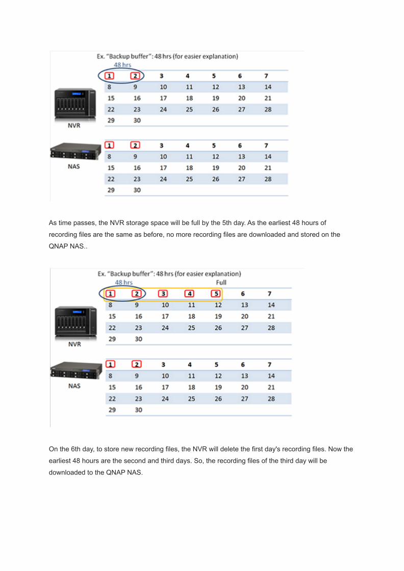
As time passes, the NVR storage space will be full by the 5th day. As the earliest 48 hours of
recording files are the same as before, no more recording files are downloaded and stored on the
QNAP NAS..
On the 6th day, to store new recording files, the NVR will delete the first day's recording files. Now the
earliest 48 hours are the second and third days. So, the recording files of the third day will be
downloaded to the QNAP NAS.

Based on these settings, the QNAP NAS will keep downloading recording files until it is full, and a
total of 10 days of recording files will be kept (the earliest 5 days on the QNAP NAS and latest 5 days
on the NVR.)
To store new recording files, the NVR will delete the recording files of the sixth day, and the eighth
day's recording files (the new, earliest 48 hours) will be downloaded to the QNAP NAS. As the QNAP
NAS is full, it will delete the first day's recording files.

The total hours of recording files = total hours of recording files on the NVR + total hours of recording
files on the NAS – Backup buffer.
Please note:
In order to ensure that the Storage Expansion can be executed whilst recording, please calculate the
bandwidth requirements for specific VioStor NVR models.
The following is estimated bandwidth requirements for specific NVR models:
VS-8100 Pro+, 8100U-RP Pro(+), 12100U-RP Pro(+) series: 360 Mbps.
VS-2200 Pro+, 2100 Pro+, 4100 Pro+, 6100 Pro+, 4100U-RP Pro+ series: 160 Mbps.
VS-2000 Pro, VS-4000 Pro, VS-6000 Pro, 4000U-RP Pro series: 90 Mbps.
Limitations and Restrictions:

1. Storage Expansion is currently supported by the VioStor Pro(+) series (running QVR v5.1.0 or
higher version) and QNAP NAS TVS-ECx80, x71U, x71, x70, x63 series and TS-x79U, ECx80,
ECx80U, x53U, x53 Pro, x51 series (running QTS v4.1.4 or higher version), and they must be set
on the same LAN.
For VS-12100U-RP Pro(+), 8100U-RP Pro(+), 8100 Pro+ series, it is recommended to configure
up to 3 NAS servers for storage expansion.
For VS-2200 Pro+, 4100U-RP Pro+, 6100 Pro+, 4100 Pro+, VS-2100 Pro+ series, it is
recommended to configure up to 2 NAS servers for storage expansion.
For VS-4000U-RP Pro, 6000 Pro, 4000 Pro, 2000 Pro series, it is recommended to configure up
to 1 NAS server for storage expansion.
2. A gigabit switch is required for this application.
3. All QNAP NVR and NAS units are required to use fixed IP addresses and be under same subnet
mask & gateway.
4. Storage expansion related settings cannot be modified using local display.
5. The file transfer process between the QNAP NVR and NAS will be completed even if it is
suddenly interrupted (for example, the destination folder is deleted.) For example, the cache
count is set to six hours. The destination is changed to none in the middle of processing. When
this happens, the NVR will still move recording files to the QNAP NAS until the entire process is
finished.
How to configure storage expansion?

Step 1: Install the StorageExpansion App (QPKG) on the QNAP NAS
Please note: Download the app from the QTS App Center. Before installing the app, please ensure
the app is correct, carefully read the instructions, and back up the important data on the QNAP NAS.
● Download and install the StorageExpansion package.
● To install the app, click “Add to QTS”.
Step 2: Configure Storage Expansion on the NVR

1. Go to "Backup & Expansion" → "Storage Expansion" to configure relevant settings.
2. Click “Add” in “NAS List” table under “Overview”.
3. Please enter the QNAP NAS/destination settings.
A. Enter NAS IP, port, and user credentials.
B. Enter the destination name (the name cannot be used same as any folder under root.).
C. Select the volume.
D. Enter a value for the backup buffer.
If you want to configure storage expansion to a REXP Expansion Enclosure, please select the
right volume on REXP to enable storage expansion to REXP.
Please note:Destination: The folder created on the QNAP NAS to save recording files.
Volume: The volume assigned for storage expansion.
Backup buffer: As an example, if you configure the backup buffer as 6, the latest six hours of
recordings will be copied to the QNAP NAS. The maximum value is 48.
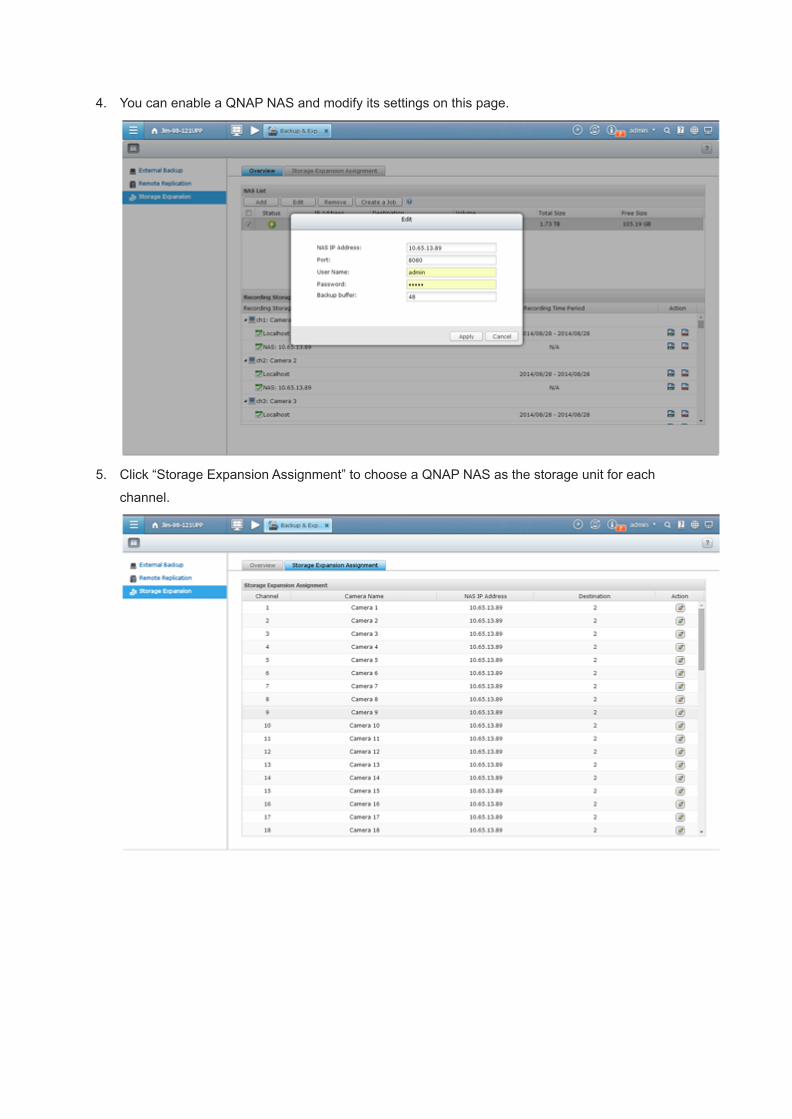
4. You can enable a QNAP NAS and modify its settings on this page.
5. Click “Storage Expansion Assignment” to choose a QNAP NAS as the storage unit for each
channel.

6. Review all of the configured settings and recording storage details under “Overview”.
This page will automatically refresh every fifteen minutes.
QNAP NAS models are an ideal solution for expanding the storage capacity of the NVR to save more
recording files. Integration of both QNAP devices can help users to save recording files more flexibly
and efficiently.
Step 3: Check available NVRs on the list and their status on the QNAP NAS
1. Click “Open” on StorageExpansion.

2. You can check available NVRs and their status.
Please note: The NVR status will become after the storage expansion assignment is
completed.
2015/07/2

T17.[Tutorial] Set up the QNAP VioStor NVR to record and monitorfisheye network cameras
QNAP's VioStor network video recorder (NVR) series is among the first Linux-embedded standalone
device provider to support fisheye cameras. Users can also view a complete scene unfold without
obstruction while simultaneously displaying multiple independent dewarped views using fisheye
cameras.
This article will guide you to configure the VioStor NVR to record videos from fisheye cameras and to
dewarp fisheye images for live monitoring.
Applicable camera models:
● AXIS M3007 (Please select AXIS M3007-dewarp model in our camera model list)
● Dynacolor NA083
● Oncam Grandeye EVO-05NMD
● VIVOTEK FE 8172/8172/8174 (camera firmware version should be v0100h or above)
Prerequisites:
● The firmware version of the VioStor NVR must be QVR 5.0 or above. You can download the latest
firmware from here.
● The fisheye camera must be mounted in a proper position.
A. Set up the VioStor NVR

Follow the below steps to configure the VioStor NVR.

1. Run the "QNAP Finder" on a Windows PC to find the NVR. Double click the NVR name to
connect to the login page via web browser.
2. Login to the NVR as "admin".
3. To enter the surveillance settings page, click .
4. Go to “Camera Settings” > "Camera Configuration". Click orselect a channel for the
camera and click to add a camera.

5. Click “Next” to use auto search to find the fisheye camera.
When it is found, choose the camera and click “OK”.
Enter the camera’s IP address, username and password.

Or manually add the camera brand and model.
6. Specify the video and schedule settings.
Please note: To use the dewarping function, please select a resolution that includes (fisheye).
7. Click "Apply".
8. Now return to the live view window of the VioStor NVR. You can now view the live image of the
fisheye camera.
Fisheye view without dewarping.
B. Configure the live view settings

1. Move the mouse cursor over a camera channel and the supported function buttons (Interactive
Control Buttons) of the camera will show up for quick access.
2. Click “Camera information” in the Interactive Control Buttons and select “Properties” from the list.
Icon Description
Camera information:
1. Properties: Configure other monitoring options.
2. Locate in E-map: Highlight camera icon on E-map.
3. Visit the camera homepage.

3. Select "Fixed resolution" under "Video Resolution".
Choose the video stream you want to see in the live view.
C. Dewarp fisheye images of the fisheye camera in live view
Icon Description
Dewarp fisheye images:
For specific fisheye cameras and camera models with panomorph lenses, you can
toggle the dewarping function. After enabling this function, you can then select the
mount type and dewarping mode.

1. To dewarp the fisheye images of the fisheye camera, click “Dewarp fisheye images” in the
Interactive Control Buttons to enable fisheye dewarping function.
2. Click “Dewarp fisheye images” in the Interactive Control Buttons to select the "Mount type" ( Wall,
Ceiling, or Floor) according to your setup environment and specify the "Dewarping mode".
● Example 1. Select "Ceiling" for the mount type.
● Note: For Ceiling and Floor Mount type, FullView will display 360 degrees of viewing angle.
● Example 2. Select “Rectangle” for the dewarping mode.
D. Dewarp fisheye images of the fisheye camera in playback
1. Click to enter the playback page.
2. To dewarp the fisheye images of the fisheye camera, click “Dewarp fisheye images” in the
Interactive Control Buttons to enable fisheye dewarping function.
3. Click “Dewarp fisheye images” in the Interactive Control Buttons and select the "Mount type"
(Wall, Ceiling, or Floor) according to your setup environment and specify the "Dewarping mode".
2015/07/22

T18.[Tutorial] Generic Methods to Add IP Cameras
QNAP NVR supports some generic methods to add IP cameras to enhance its compatibility and
expandability. Please see the below tutorials for more details.
Please note: Even by using these methods, we cannot guarantee universal compatibility with every IP
camera. Please see the following URL for IP cameras that have been tested and are fully compatible
with QNAP NVR:
http://www.qnapsecurity.com/n/en/product_z_g_qvr/cat_intro.php
1. Generic JPEG
QNAP NVR provides an interface for the users to enter the JPEG CGI command of IP cameras to use
them with the NVR. This feature largely enhances the compatibility and expandability of the NVR.
A. Select "Generic Model" for the camera brand.
B. Select "Generic JPEG" for the camera model.
C. Enter the camera’s cgi path in the "HTTP URL" field (e.g. "/video.cgi").
D. Enter the camera’s name.

E. Enter the camera’s IP address.
F. Enter the camera’s user name and password.
G. Enable recording on the camera.
H. Configure all other settings.
2. Generic RTSP
QNAP NVR provides an interface for the users to enter the RTSP path of IP cameras to use them with
the NVR.
A. Select "Generic Model" for the camera brand.
B. Select "Generic RTSP" for the camera model.
C. Enter the camera’s URL in the "HTTP URL" field (e.g. "/axis-media/media.amp").
D. Enter the camera’s name.
E. Enter the camera’s IP address.
F. Enter the camera’s user name and password.
G. Enable recording on the camera.
H. Configure all other settings.
3. ONVIF

QNAP NVR provides an interface for the users to enter the RTSP path of IP to use them with the
NVR.
A. Select "ONVIF" for the camera brand.
B. Select a camera model.
i. For cameras listed in the following URL, please use “ONVIF Profile S Cameras”:
http://www.onvif.org/FindaProduct/ProfileProducts.aspx.
ii. If your camera’s manufacturer is listed, then please select that option.
iii. For ONVIF 1.0.2-compatible cameras, please use “ONVIF Cameras”.
C. Enter the camera’s name.
D. Enter the camera’s IP address.
E. Enter the camera’s user name and password.
F. Enable recording on the camera.
G. Configure all other settings.
2015/07/22
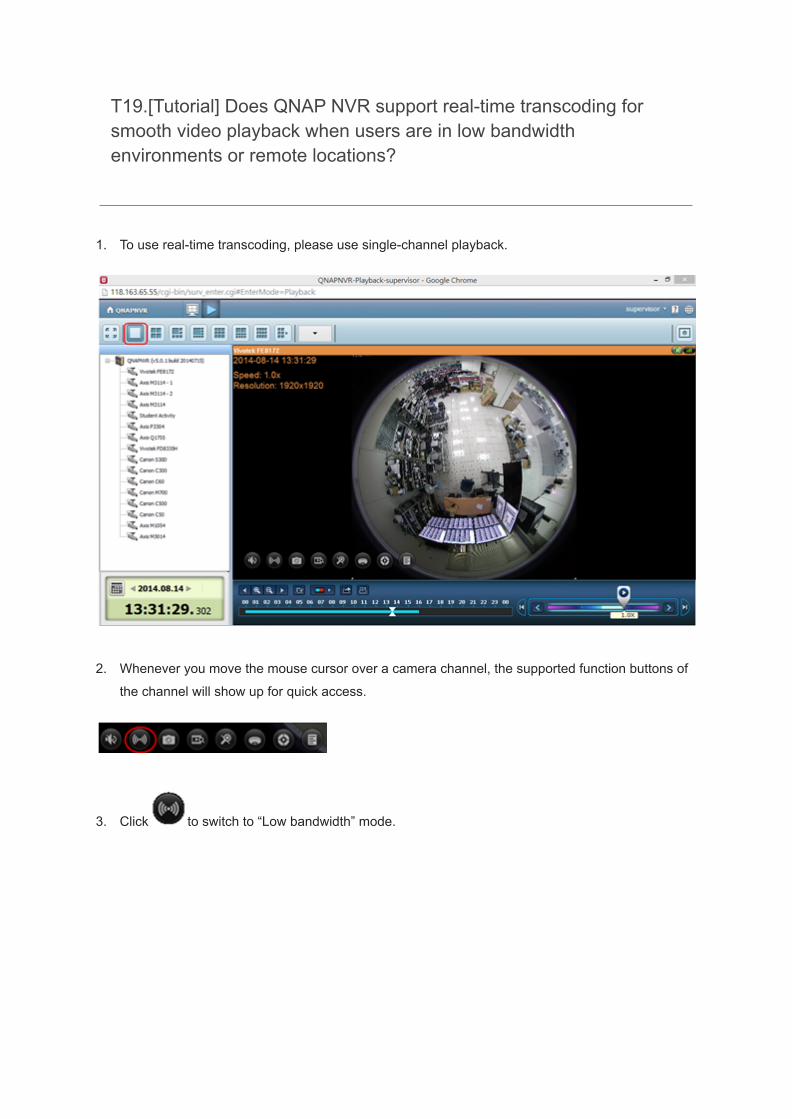
T19.[Tutorial] Does QNAP NVR support real-time transcoding forsmooth video playback when users are in low bandwidthenvironments or remote locations?
1. To use real-time transcoding, please use single-channel playback.
2. Whenever you move the mouse cursor over a camera channel, the supported function buttons of
the channel will show up for quick access.
3. Click to switch to “Low bandwidth” mode.
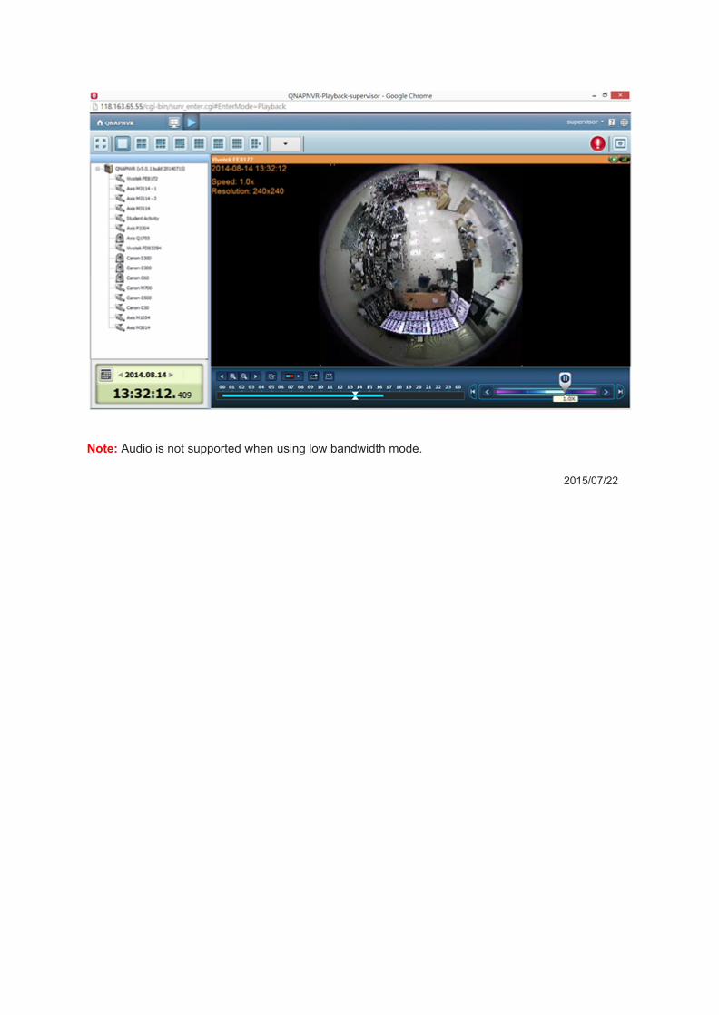
Note: Audio is not supported when using low bandwidth mode.
2015/07/22

T20.[Tutorial] To use two-way audio to receive and transmit audio,what should I do?
Applicable firmware: QVR 5.0 and above.
Camera models: AXIS Q6035(-E), Q6034(-E), Q6032(-E), Q1921(-E), Q1910(-E), Q1765(-E),
Q1755(-E), Q1604(-E), Q1602(-E), P8221, P5544, P5534(-E), P5532(-E), P5522(-E), P5512(-E),
P3384-V/-VE, P3367-V/-VE, P3364(-V/-VE), P3363(-V/-VE), P3346(-V/-VE), P3304(-V), P3301(-V),
P1357, P1355, P1354, ,P1353, P1347(-E), P1346(-E), P1344(-E), P1343(-E), M1054, M1034-(W),
M1033-(W), 214PTZ
1. Upon logging in, click on the QVR desktop to go to the monitoring page.
2. Whenever you move the mouse cursor over a camera channel, the supported function buttons of
the camera will show up for quick access.
3. Click to enable two-way audio.
Icon Description

Two-way audio (optional):Toggles two-way audio support on the monitoring page. To learn more
about the compatibility of this feature, please visit
http://www.qnap.com/NVR/CompatibilityX01.html. Please note: the
two-way audio function is currently only supported by Internet
Explorer 11.
Please note : Please ensure you have set up your microphone.
2015/07/22

T21.[Tutorial] How to install QSCM Lite App?
Introduction
QNAP Surveillance Central Management Lite (QSCM Lite) is a powerful and free app supported by
QVR 5.0 (and above) that allows you to easily manage up to 16 QNAP NVRs and 256 cameras. No
extra hardware or software is required to add the CMS server function to a NVR – all you have to do
is install the QSCM Lite App from the App Center.
QSCM Lite can manage NVRs that are in the same private LAN with QSCM Lite.
Install QSCM Lite to NVR Server
Online installation

To install QSCM Lite, please download it from the QVR 5.0 App Center. Your NVR must be connected
to the Internet to use the App Center. For more information about the App Center, please refer to the
VioStor NVR (version 5.0.0.) user manual Section 10.3 App Center.
1. Go to the App Center on the desktop of QVR 5.0.
2. Go to All Apps.

3. Click “Add QSCM Lite to QVR”
4. Start downloading QSCM Lite

5. After QSCM Lite has been downloaded, the system will automatically install QSCM Lite.
6. When the option to “Open” appears, QSCM Lite has been successfully installed.

7. QSCM Lite will now be listed in My Apps, with the default Open status. QVR 5.0 is now a CMS
server.
8. Click on the QSCM Lite icon to go to the QSCM Lite login page

9. The system will automatically redirect to the QSCM Lite login page, and you can log in by using
the default username/password (admin/admin).
If needed, QSCM Lite can be turned off to disable the CMS server function.
Offline installation
If the NVR is not connected to the Internet, an offline installation is available.

1. Download QSCM Lite from the QNAP Security website
(http://www.qnapsecurity.com/n/en/product_x_down/).
2. Unzip the files
3. Return to the NVR and enter the App Center
4. Click "Install Manually"

5. Find the unzipped QSCM Lite, and click [Install]
6. Click OK

7. The NVR will then install QSCM Lite
8. Click OK
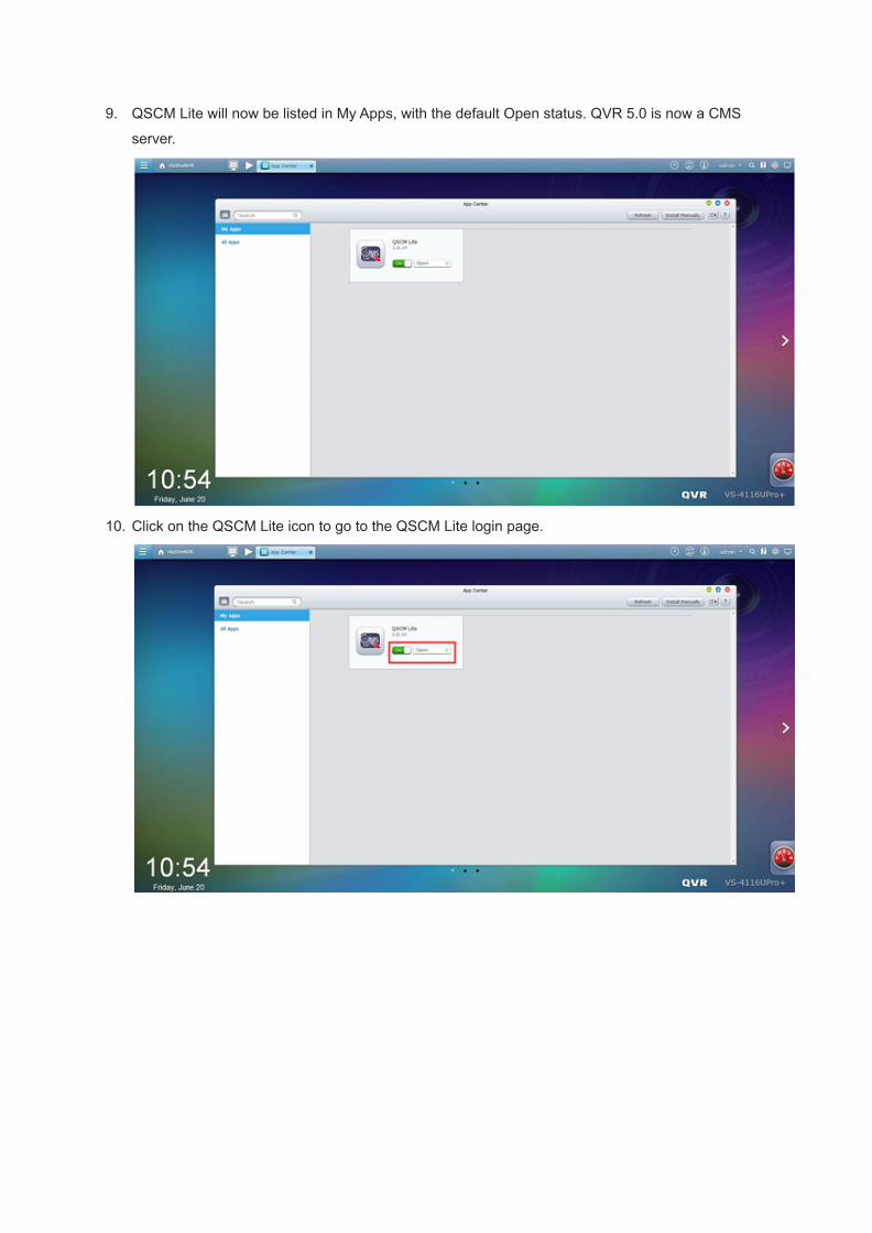
9. QSCM Lite will now be listed in My Apps, with the default Open status. QVR 5.0 is now a CMS
server.
10. Click on the QSCM Lite icon to go to the QSCM Lite login page.

11. The system will automatically redirect to the QSCM Lite login page, and you can log in by using
the default username/password (admin/admin).
If needed, QSCM Lite can be turned off to disable the CMS server function.
2015/07/22
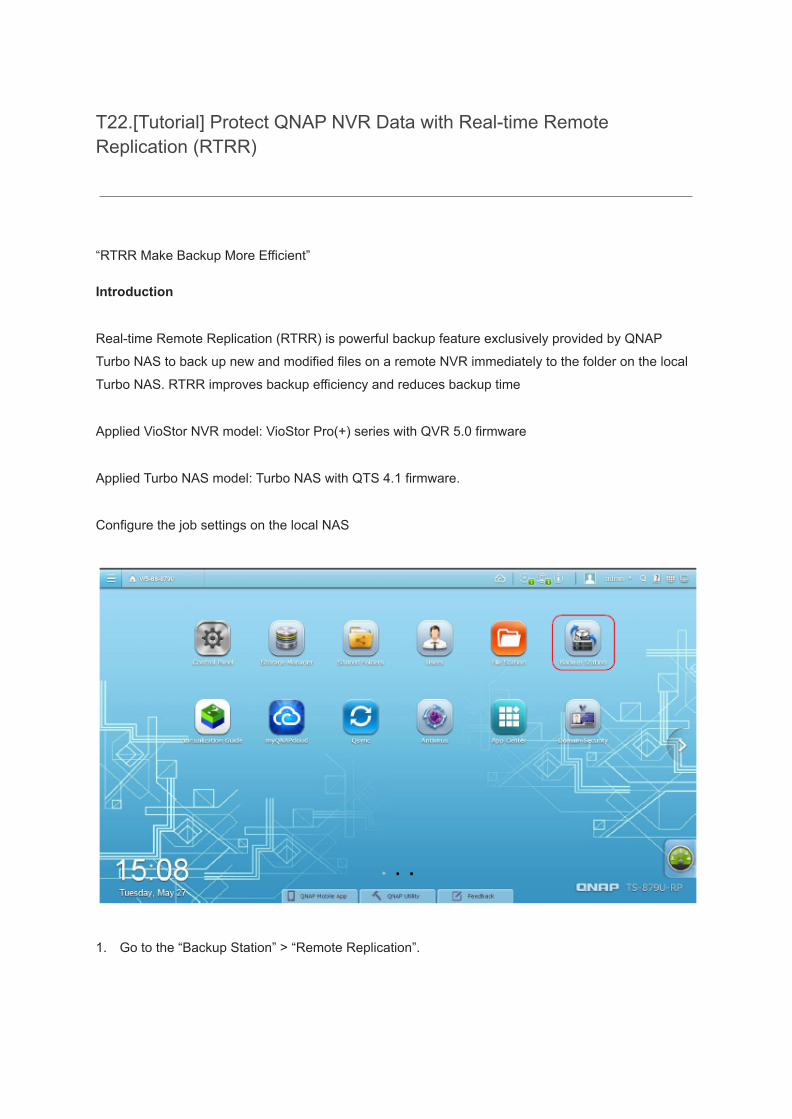
T22.[Tutorial] Protect QNAP NVR Data with Real-time RemoteReplication (RTRR)
“RTRR Make Backup More Efficient”
Introduction
Real-time Remote Replication (RTRR) is powerful backup feature exclusively provided by QNAP
Turbo NAS to back up new and modified files on a remote NVR immediately to the folder on the local
Turbo NAS. RTRR improves backup efficiency and reduces backup time
Applied VioStor NVR model: VioStor Pro(+) series with QVR 5.0 firmware
Applied Turbo NAS model: Turbo NAS with QTS 4.1 firmware.
Configure the job settings on the local NAS
1. Go to the “Backup Station” > “Remote Replication”.

2. Under the “RTRR” tab click “Create a Replication Job” to open the wizard.
3. Click “Next”.
4. Select the sync locations. You can choose to back up data from:
(1) Local folder to remote folder
(2) Remote folder to local folder
(3) Local folder to local folder or external drive
Please select “Remote folder to local folder” to replicate files from the remote NVR to the local

Turbo NAS. Click “Next” to continue.
5. Enter the IP address of the remote NVR and select FTP server service. Enter the user
name/password of the remote NVR. Click “Next” to continue.

6. Select the source folder for the backup and target folders. To add more folder pairs for backup,
select “Add More Folder Pairs”. Click “Next”.
7. Select “Schedule” and configure the backup schedule. To configure the backup policy and filter to
increase data transmission efficiency, click “Configure policy and filter”.
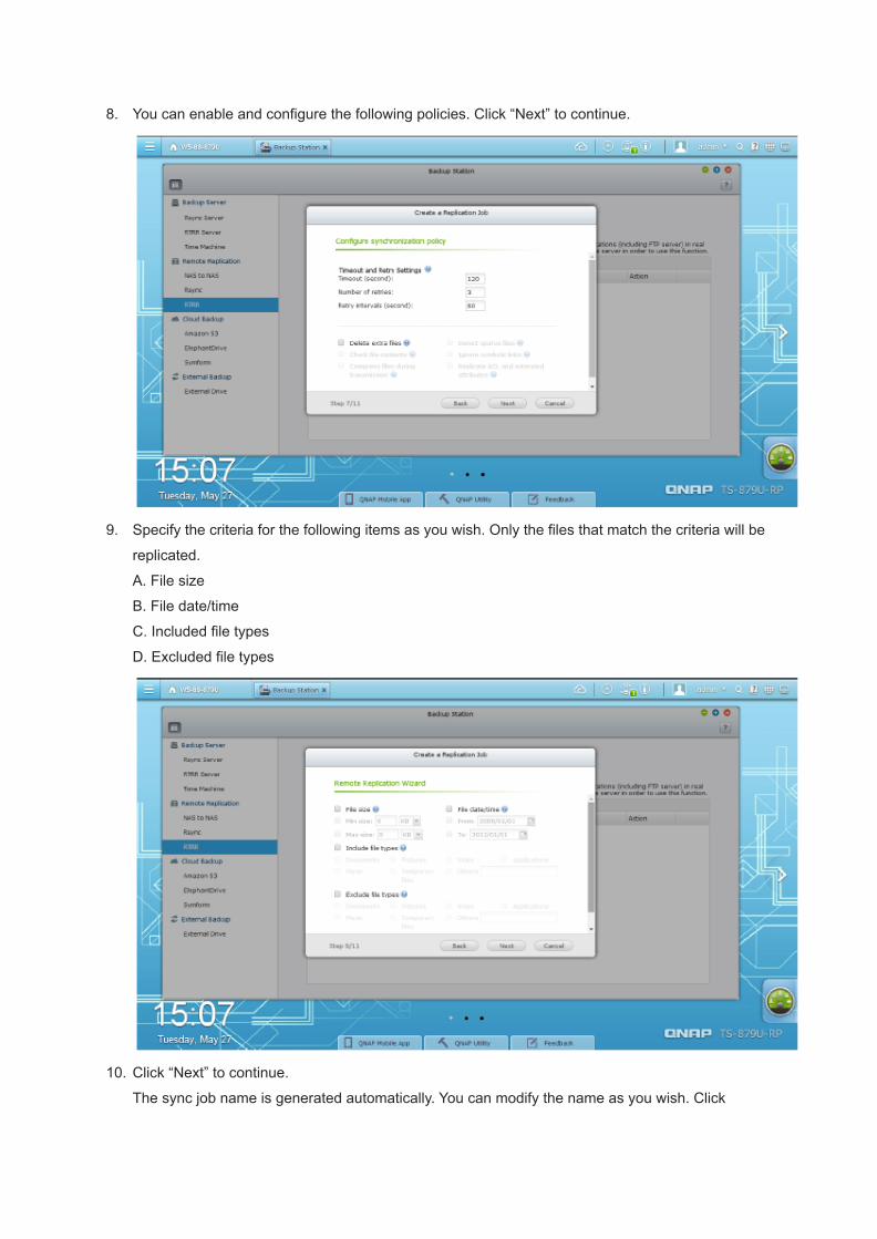
8. You can enable and configure the following policies. Click “Next” to continue.
9. Specify the criteria for the following items as you wish. Only the files that match the criteria will be
replicated.
A. File size
B. File date/time
C. Included file types
D. Excluded file types
10. Click “Next” to continue.
The sync job name is generated automatically. You can modify the name as you wish. Click
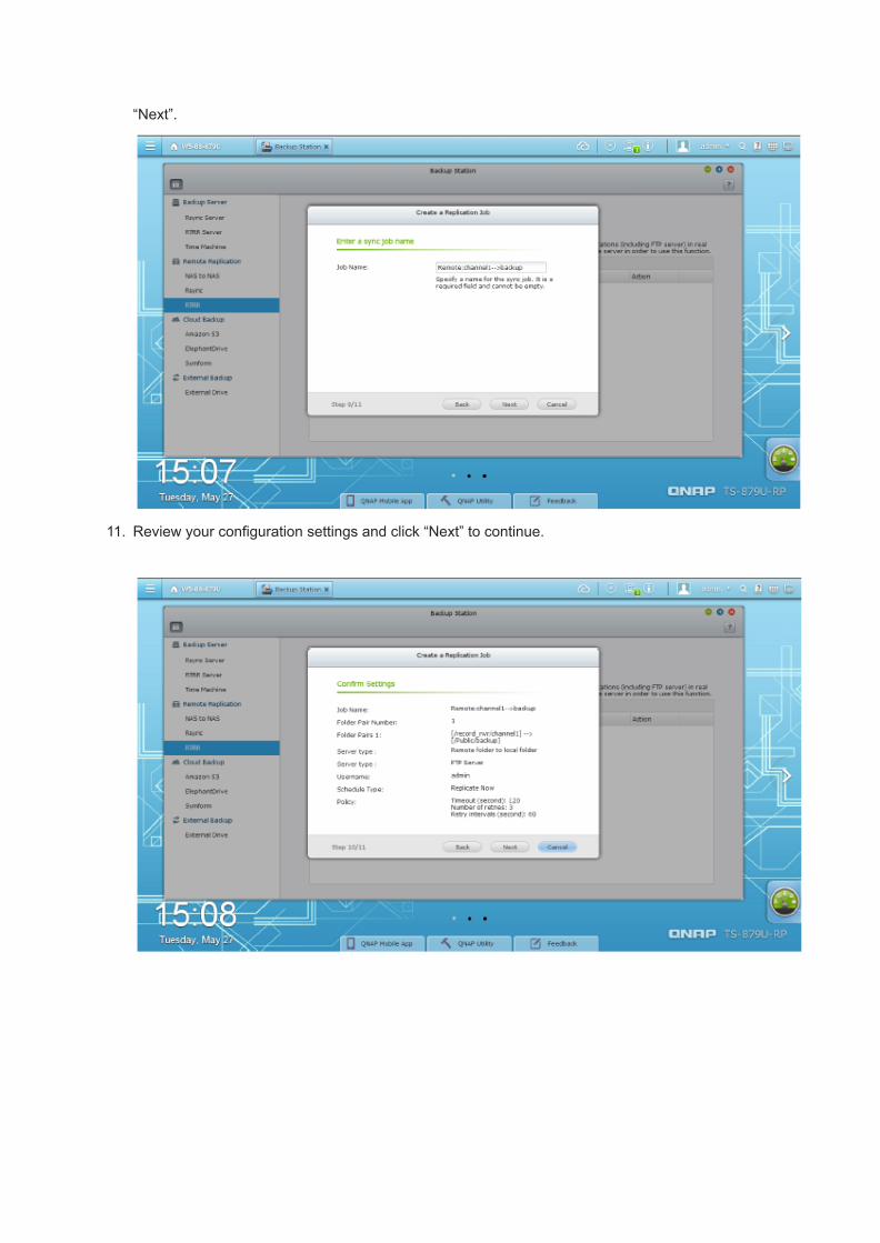
“Next”.
11. Review your configuration settings and click “Next” to continue.

12. Click “Finish” to close the wizard.
The target host and the replication job name will be shown on the list. The status column will display
“Standby”, meaning the folder is being monitored. Any changes to the source folder will be replicated
to the remote server immediately.
2015/07/22

T23.[Tutorial] How to use Vcam?
Overview
The Vcam mobile app can turn your mobile device into a network camera. With the Vcam mobile app, you can
record any moment around you to your VioStor NVR. The Vcam solution provides a great way to deploy a home
surveillance system without purchasing expensive IP cameras.
Starting Vcam
Please make sure Vcam is installed on your mobile device. You can install the QNAP mobile app “Vcam” from
Google Play or the Apple App Store.
Please click “Setup Wizard” to enter the Vcam quick setup wizard.
Please enter the “Port number”, “User Name” and “Password”. Then click “Next” to go to the next page. The port
number must be within range of “1025 ~ 65535”.

You can configure the Connectivity and Video Streaming here. You can choose “WiFi only” or “3G and WiFi”. We
recommend that you choose “WiFi only” here. Vcam will use only mobile devices that have WiFi connectivity.
After you finish configuration, please click “Start” to Vcam.

Press the Blue Button to enable recording. If the button turns red then it is ready to record.

Please go to “Surveillance Settings” > “Camera Settings” > “Camera Configuration” > “Add” or click the “ ” to
add the Vcam camera.
Please uncheck the option “Search camera(s) automatically” and click “Next”.
Please enter the camera configurations as followed, then click test to check the connection between the camera
and Surveillance Station.
● Camera brand : QNAP
● Camera model : QNAP VCAM
● Camera Name : You can set the camera as you want.
● IP Address : Please set the IP Address of your mobile device. You can check the IP Address in the
upper-right corner (check the picture below). If your mobile device does not get a IP Address, please check
your network environment again.
● Port : Please configure the Port number you set for Vcam.

● User Name : Please configure the user name you set for Vcam.
● Password : Please configure the password you set for Vcam.

Overview
The Vcam mobile app can turn your mobile device into a network camera. With the Vcam
mobile app, you can record any moment around you to your VioStor NVR. The Vcam
solution provides a great way to deploy a home surveillance system without purchasing
expensive IP cameras.
Starting Vcam
Please make sure Vcam is installed on your mobile device. You can install the QNAP
mobile app “Vcam” from Google Play or the Apple App Store.
Please click “Setup Wizard” to enter the Vcam quick setup wizard.

Please enter the “Port number”, “User Name” and “Password”. Then click “Next” to go to
the next page. The port number must be within range of “1025 ~ 65535”.
You can configure the Connectivity and Video Streaming here. You can choose “WiFi
only” or “3G and WiFi”. We recommend that you choose “WiFi only” here. Vcam will use
only mobile devices that have WiFi connectivity.
After you finish configuration, please click “Start” to Vcam.

Press the Blue Button to enable recording. If the button turns red then it is ready to record.

Please go to “Surveillance Settings” > “Camera Settings” > “Camera Configuration” >
“Add” or click the “ ” to add the Vcam camera.
Please uncheck the option “Search camera(s) automatically” and click “Next”.

Please enter the camera configurations as followed, then click test to check the
connection between the camera and Surveillance Station.
● Camera brand : QNAP
● Camera model : QNAP VCAM
● Camera Name : You can set the camera as you want.
● IP Address : Please set the IP Address of your mobile device. You can check the IP
Address in the upper-right corner (check the picture below). If your mobile device
does not get a IP Address, please check your network environment again.
● Port : Please configure the Port number you set for Vcam.
● User Name : Please configure the user name you set for Vcam.
● Password : Please configure the password you set for Vcam.


If connection test passes, you can click “Next” to configure the Video Settings. Please
configure the Video Compression settings here and click “Next” to configure the recording
schedule.

On this page, you will see the “Schedule Settings.” On the table, 0~23 represents the time period.
For example, 0 means 00:00~01:00, 1 means 01:00~02:00. You can set a continuous recording in
any period that you want.
Then you will be able to confirm the settings on the next page.

After you have added the network cameras to the NVR, you can check the monitoring screen in. You
can observe that the NVR IP Address is shown on the upper-left side. If the NVR IP address is not
shown, this means that the connection has not been successfully established.
Please go to the “Monitor” page. Then you can start monitoring & playback the recordings
Surveillance Station.
Camera function:
You can click the button shown in the below picture to adjust the camera function that your mobile
device provides. Please note that some functions may not be supported by your mobile device.

Icon Function Description
Anti-banding Adjust the frequency of display
panel.
Color Effect Adjust the color effect.
Flash Mode Enable/Disable flash.
Focus Mode Switch focus mode.
Scene Mode Switch scene

White Balance Switch white balance.
Exposure Compensation Adjust exposure
compensation.
Screen Rotation Rotate screen.
Black Screen Turn on/off black screen to
save power.
Limitation:
1. Vcam is only supported by QVR5.0 or on newer firmware versions.
2. It is possible that power will be consumed faster than charging when the video stream is set to
compression H.264 and resolution 1280*720.
3. Due to hardware & network limitations, the real “Frame rate” and “Bit rate” may not reach the
number you set on your mobile device.
4. Both the mobile device and NVR must be on the same LAN.
5. Video Compression H.264 is currently not supported in the iOS version.
6. Video Compression H.264 may not work on some mobile devices due to hardware limitations.
The following are the mobile devices that have passed our lab testing:
Vendor Product Android version Test result
Acer Iconia B1-A71 4.1.2 Pass
LG Nexus 4 4.2.2 Pass
Samsung Galaxy Nexus 4.2.2 Pass
Samsung Galaxy Note 10.1 4.1.1 Pass
Asus Padfone infinity 4.1.2 Pass

T24.[Tutorial] How to Add Recording Channels?
Based on the model, the VioStor NVR comes with a different number of base channels. To addextra recording channels, please contact authorized distributors for detail. Or, you can contactQNAP Security (http://www.qnapsecurity.com/SalesInquiry) for information on authorizeddistributors.
How to activate licenses
Please select the “Install License” button to begin the process of activating a license. If your VioStorNVR is connected to the Internet, please select “Online activation”. If not, please select “Offlineactivation”.
Online License Activation
Step 1: If your VioStor NVR is connected to the Internet, please select “Online Activation”.

Step 2: Enter your Product Authorization Key (PAK) code to activate the license.
Step 3: Your license has now been activated. Please click [FINISH] button to close the window.

Step 4: This additional camera license will be displayed in the license management list after thelicense activation.
Offline License Activation
Step 1: If the VioStor NVR is behind a firewall or does not have an Internet connection, pleaseselect “Offline Activation”.

Step 2: Please copy the system UDI and go to the License Store for offline license activation.
Step 3: Please login to the License Store with your registered account.

Step 4: On the Offline Activation page, please fill out your UDI and PAK information, and then clickthe [Activate] button.
Step 5: You will receive an email with an attached Permission File after your offline activation isverified.

Step 6: Please check your email and download the Permission File. This file can only be used onthe VioStor NVR with the UDI you specified. Do not decompress the permission file.
Step 7: Please go back to the offline activation page on your VioStor NVR. You will need to importthe permission file to activate the license.

Step 8: Your license has now been activated.
2015/07/22

T25.[Tutorial] How to update the NVR BIOS?
This document has two parts and will instruct you how to update the BIOS of a NVR in local displaymode.
Part A: Making a bootable USB drive
Part B: Entering DOS mode with the USB drive
Requirement:
1. USB drive *12. Windows-based computer3. “UNetbootin” software for making a bootable USB drive
(download from http://unetbootin.sourceforge.net/ )4. BIOS upgrade package5. NVR *16. Keyboard *17. Monitor *1
Part A: Making a bootable USB drive

Please note: If the next step fails to download FreeDOS, please import the ISO file directly. You candownload the FreeDOS ISO file from here: http://www.freedos.org/download/

1. Please plug the USB drive into the computer, and then run “UNetbootin”.2. Please select the “FreeDos” mode3. Please select the USB drive.4. Please click “OK”.

5. “UNetbootin” will now create a bootable USB drive. Once this process is completed, please select“Exit”.
Part B: Entering DOS mode with the USB drive
Connect the Keyboard and monitor to NVR Total view


1. Copy the BIOS update package to the USB drive.2. Remove the USB drive from the computer and plug it into the NVR.3. Please connect a keyboard and monitor to the NVR.4. Power on the NVR.5. After the NVR boots up, press “F7” on the keyboard to enter the BIOS. Please select the boot
device as your USB drive and press Enter.6. Please select “win98”.7. Please select the option “FreeDOS Safe Mode”.8. Switch the directory to “C:” by using command “C:”. (Please refer to the picture in step 9)9. Enter the folder that the BIOS update package is located in by using the command “cd folder
name” (for example if the folder name is “QV61AR64” you would enter: “cd QV61AR64”).10. Execute the .bat file entering the filename. (for example: “QV61AR64.BAT”)11. After a short period of time, the BIOS will be updated.12. After you have finished, please follow these steps:
● Power off the NVR● Disconnect the power cord● Wait for 10 seconds● Reconnect in the power cord● Remove the USB drive● Power on the NVR● Check if the BIOS version is updated or not.● If the BIOS version has been updated (as in the picture below) then you have successfully
updated the BIOS. If not, then please contact QNAP for further assistance.
2015/07/22

T26.[Tutorial] How to Enable Smart Recording to Maximize StorageEfficiency and Boost Alarm Recording?
Smart Recording is a powerful digital surveillance feature that provides high-quality videos during
unexpected events, and standard-quality videos for regular happenings. This can be extremely
beneficial in providing detailed footage during potentially-important events while conserving storage
space during routine/normal activities in 24/7 recording.
As of the publication of this document, the cameras that have been tested for Smart Recording are:
ACTi B97, E34, E54, E84
AXIS M1011, M1054, M1103, M1104, M1113, M1114, M3006, M3011, M3014, M3026, M3113, M3114,
M3204, M5013, M5014, M5014-V, M7010, M7014, P1204, P1214, P1214-E, P1353, P1354,
P1355, P1357, P3301, P3304, P3344, P3346, P3353, P3354, P3363, P3364, P3364-LV/-LVE,
P3367, P3384, P5414, P5512, P5522, P5532, P5534, P5544, P7210, P7214, P7224, P8513,
P8514, Q1602, Q1604, Q1755, Q1765, Q1910, Q1921, Q1922, Q6032, Q6034, Q6035, Q6042,
Q6044, Q6045, Q7401, Q7411
Sony SNC-CX600, SNC-CX600W, SNC-EB600, SNC-EB600B, SNC-EB630, SNC-EB630B,
SNC-EM600, SNC-EM601, SNC-EM602R, SNC-EM630, SNC-EM631, SNC-EM632R,
SNC-VB600, SNC-VB600B, SNC-VB630, SNC-VB635, SNC-VM600, SNC-VM601,
SNC-VM601B, SNC-VM630, SNC-VM631, SNC-VM632R, SNC-WR600, SNC-WR602,
SNC-WR630, SNC-XM632
VIVOTEK CC8130, FD8131, FD8131V, FD8134, FD8136, FD8137H, FD8137HV, FD8151V, FD8163,
FD8164, FD8164V, FD8166, FD8355EHV, FD8363, FD8371EV, FE8173, FE8174, IP8131W,
IP8132, IP8133, IP8152-F4, IP8335, IP8355EH, IP8364-C, IP8371-E, PZ81X1, SD81X1,
SD8314E, SD8316E, SD8324E, SD8326E, SD8363E
To see the latest list of compatible cameras, please visit our compatibility list.
To enable Smart Recording, please follow the below steps:
1. Access the QVR desktop as an administrator and click “Surveillance
Settings” .
2. Go to “Camera Settings” -> “Camera Configuration”.
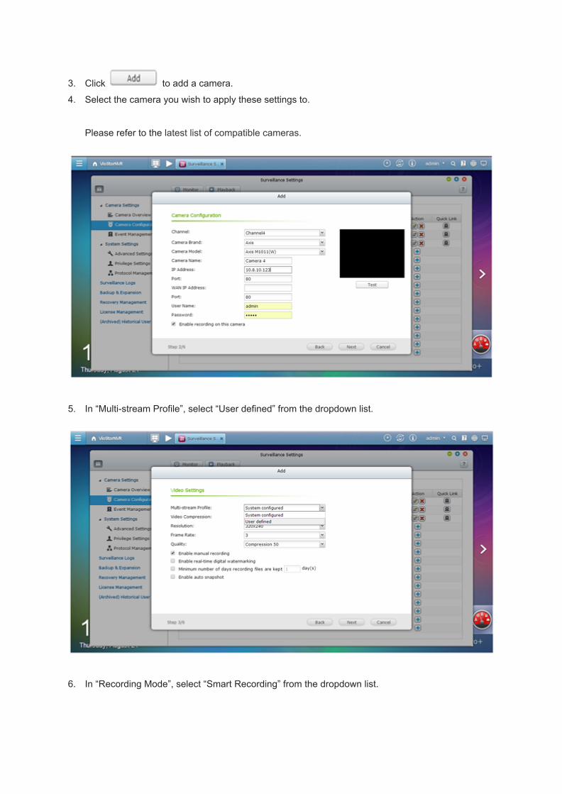
3. Click to add a camera.
4. Select the camera you wish to apply these settings to.
Please refer to the latest list of compatible cameras.
5. In “Multi-stream Profile”, select “User defined” from the dropdown list.
6. In “Recording Mode”, select “Smart Recording” from the dropdown list.

7. Adjust the settings for each stream to fit your requirements.
8. In “Regular Recording”, select one camera stream from the dropdown list.
9. Select a different camera stream from the “Alarm Recording” dropdown list.
(Please remember to enable Scheduled Recording and Alarm Recording beforehand.)
Limitations and Restrictions:
1. A camera stream can only be selected as Regular Recording or Alarm Recording.
2. The number of streams supported and streaming properties (including codec, resolution, frame
rate and quality) may vary or be limited by the camera, and the same property value may not be
available on different cameras. For example: if H.264 or Full HD is selected as the video
compression setting for Stream 1, users may only be able to select M-JPEG or VGA for Stream 2.
3. Please refer to the our camera compatibility list and occasionally check our website for updates.
4. More bandwidth is required for Smart Recording. Carefully calculate your bandwidth usage before
using this feature. For example: A VIVOTEK IP8132 offers three streams. Stream 1 uses
663Kbps, Stream 2 uses 1000Kbps and Stream 3 uses 3000Kbps – leading to a total bandwidth
requirement of 4663Kbps per camera. If 30 VIVOTEK IP8132 cameras are connected to a NVR
for live view and Smart Recording is used, they would require a minimum of 139,890Kbps.
5. Required NVR CPU loading for smart recording is higher than it for only standard recording.
2015/07/22

T27.[Tutorial] PC-less Network Surveillance by HD Local Display viaVGA Connector
Diversified Monitoring Modes
● 1/4/6/8/9/10/12-channel display mode● Sequential display mode
High Resolution Local Display
VioStor NVR supports widescreen VGA monitor or TV of different resolutions, up to full HD (1920 x1080).
Convenient Control of PTZ and Speed Dome Cameras
You can adjust the PTZ cameras directly and view the preset positions of the IP cameras on the localdisplay interface of VioStor NVR.
Digital Zoom
You can zoom in or zoom out the video image on the monitoring and playback interfaces.
On-screen Event Alert
When an event occurs, an alert icon will be shown instantly on local monitoring page. You can clickthe icon to view the alert details.
Video Search
VioStor NVR supports convenient video search by date and time on the local playback interface.
Local Video Playback on VGA Monitor or TV

VioStor NVR supports video playback on a VGA monitor or TV.
Quick System Setup
You can set up VioStor NVR in simple steps on the local display interface.
Intuitive Local Display Interface
All quick configurations, monitoring, and playback can be managed by the local display via a USBmouse, a USB keyboard, and a monitor connected to VioStor NVR via the VGA connector.
* For VioStor Pro series only
2015/07/22

T28.[Tutorial] How to Use E-map?
Applied Firmware Version: VioStor NVR Firmware v3.5.0 or above
The VioStor NVR's electronic map (E-map) feature is to provide graphic map information for users tooverview entire CCTV layout. Enable users to upload digital maps desired, pinpoint the position of allconnected IP cameras and GPI devices of a monitoring location or region to ensure efficient
management. To activate e-map function of VioStor NVR,please click on the upper right cornerof remote monitoring page.An E-map window will pop up on your screen as below.
To upload a digital map of the monitoring location, follow these steps:
Click to enter edit mode. The icon will change to accordingly.

Click to enter the name of the E-map then browse to upload the map file in JPG graphicformat.
* Note: E-map only support JPG format.
Add IP camera
● First, select the E-map that you would like to edit from the map tree located on the upper leftcolumn.
●
Secondly, highlight an IP camera from the camera tree in the column just below the map treeand drag the camera icon onto the selected E-map.
●
Right click on the camera icon to adjust the direction of the camera in the E-map.

To enable event notification, please click so that event alerts from the IP cameras areshown in the E-Map.
When an event is triggered, the map with that specific camera on it will pop up. The original
camera icon will automatically change into a particular alert icon
according to status once trigger is sensed.

2015/07/22

T29.[Tutorial] Advanced Event Management
When it comes to a critical event having a smart and responsive event management in place isessential for video surveillance system. The VioStor NVR offers advanced event managementfunction polished with intuitive AJAX Web interface. The VioStor NVR is equipped withenterprise-level alarm-triggering mechanism and supports various alerts and abnormal event. Thisfeature greatly strengthens the security, management efficiency, and compatibility of the VioStorNVR systems.
Example:
When a moving object is detected by IP camera 1, the NVR triggers the alarm sensor connected to IPcamera 1, adjusts the monitoring angle of IP camera 2 to the specified preset position, enables alarmrecording on both cameras, and delivers email and SMS alert instantly to the administrator.
Advanced event management can be divided into two parts:
● EventsSupports more event types, e.g. motion detection, alarm input, connection failure, recordingfailure, and user-defined event to trigger follow-up actions.
● ActionsMore actions can be activated when an event is triggered, such as multi-channel recording,adjusting the PTZ camera to the preset position, alarm output, built-in buzzer, email & SMSalert, and user-defined action.
Events Overview
Camera Events

● Motion DetectionWhen the camera detects the movement, the defined actions will be activated to notify relatedperson to look over the monitoring area.
● Alarm InputWhen the Viostor NVR receives the signal from the IP camera’s alarm input connecting toother alert devices, the defined actions will be activated to notify related person to deal withthis event immediately.
● Connection FailureWhen the VioStor NVR fails to connect to the IP camera, the defined actions will be triggeredto notify related person to check the status of the camera.
NVR Events
● Recording FailureWhen the VioStor NVR fails to record due to hard drive failure or system crash, the definedactions will be triggered to notify related person to examine the VioStor NVR.
External Events
● User-defined EventThe VioStor NVR supports user-defined event. After applying the settings, you can enter theCGI command in the browser to trigger the event, and the defined actions will be activated.
Note: You can enter the following URL in the browser to trigger the event: http://NVRIP/cgi-bin/logical_input.cgi?name=User-defined Event Name
Actions Overview
Recording

When an event is triggered, the VioStor NVR starts recording one or more channels at the same time.
Camera Control
When an event occurs, the PTZ camera will be adjusted to the specified preset position formonitoring and recording. Also, you can use HTTP URL to activate further action.
Alarm Output
When an event occurs, the alarm output from the IP cameras will trigger other alert systems, such aslighting system, auto phone dialing system, security system and so on.
Note: The AXIS, Panasonic, SONY, ACTi, VIVOTEK camera models of which the alarm output issupported by the NVR will be listed.
When an event occurs, the VioStor NVR sends email to notify the specified recipients.
SMS
It will send the SMS message to inform the related persons when event happened. This will allowthose persons to get the information and deal with it promptly.
Buzzer
The buzzer in the VioStor NVR will sound when an event occurs.

User-defined Action
The VioStor NVR supports user-defined actions. You can enter the HTTP URL from other surveillancesystems. When an alert occurs, the NVR will activate other systems, such as extinguishing system,electronic control system, air-conditioning control system.
2015/07/22
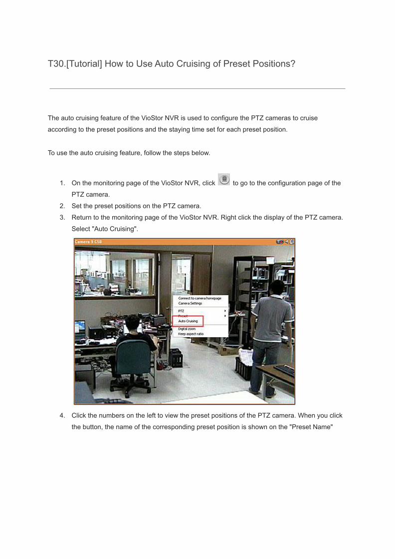
T30.[Tutorial] How to Use Auto Cruising of Preset Positions?
The auto cruising feature of the VioStor NVR is used to configure the PTZ cameras to cruise
according to the preset positions and the staying time set for each preset position.
To use the auto cruising feature, follow the steps below.
1. On the monitoring page of the VioStor NVR, click to go to the configuration page of the
PTZ camera.
2. Set the preset positions on the PTZ camera.
3. Return to the monitoring page of the VioStor NVR. Right click the display of the PTZ camera.
Select "Auto Cruising".
4. Click the numbers on the left to view the preset positions of the PTZ camera. When you click
the button, the name of the corresponding preset position is shown on the "Preset Name"

drop down menu.
5. Add: To add a setting for auto cruising, select the "Preset Name" from the drop down menu
and enter the staying time (interval, in seconds). Click "Add".

6. Update: To change a setting on the list, highlight the selection. Select another preset position
from the drop down menu and/or change the staying time (interval). Click "Update".
7. Delete: To delete a setting, highlight a selection on the list and click "Delete". To delete more
than one setting, press and hold the Ctrl key and click the settings. Then click "Delete".
8. After configuring the auto cruising settings, check the box "Enable auto cruising" and click
"OK". The system will start auto cruising according to the settings.
Note:
1. The default staying time (interval) of the preset position is 5 seconds. You can enter 5-999
seconds for this setting.

2. The system supports up to 10 preset positions (the first 10) configured on the PTZ cameras.
You can configure up to 20 settings for auto cruising on the NVR. In other words, the NVR
supports maximum 10 selections on the drop down menu and 20 settings on the auto cruising
list.
2015/07/22

T31.[Tutorial] How to Use Intelligent Video Analytics (IVA) on Playback?
Intelligent video analytics (IVA)
QNAP NVR supports intelligent video analytics to allow the users to search the video files efficiently.
The time and effort for video search are largely reduced.
The following features are supported for video analytics:
1. Motion detection: Detects movement of objects in the video.
2. Foreign object: Detects new object in the video.
3. Missing object: Detects missing object in the video.
4. Out of focus: Detects out of focus of the camera in the video.
5. Camera occlusion: Detects if the IP camera is obstructed.
To use this function, follow the steps below:
For NVR FW v5.x
Note: The intelligent video analytics support video search on one IP camera channel only.
Other options:
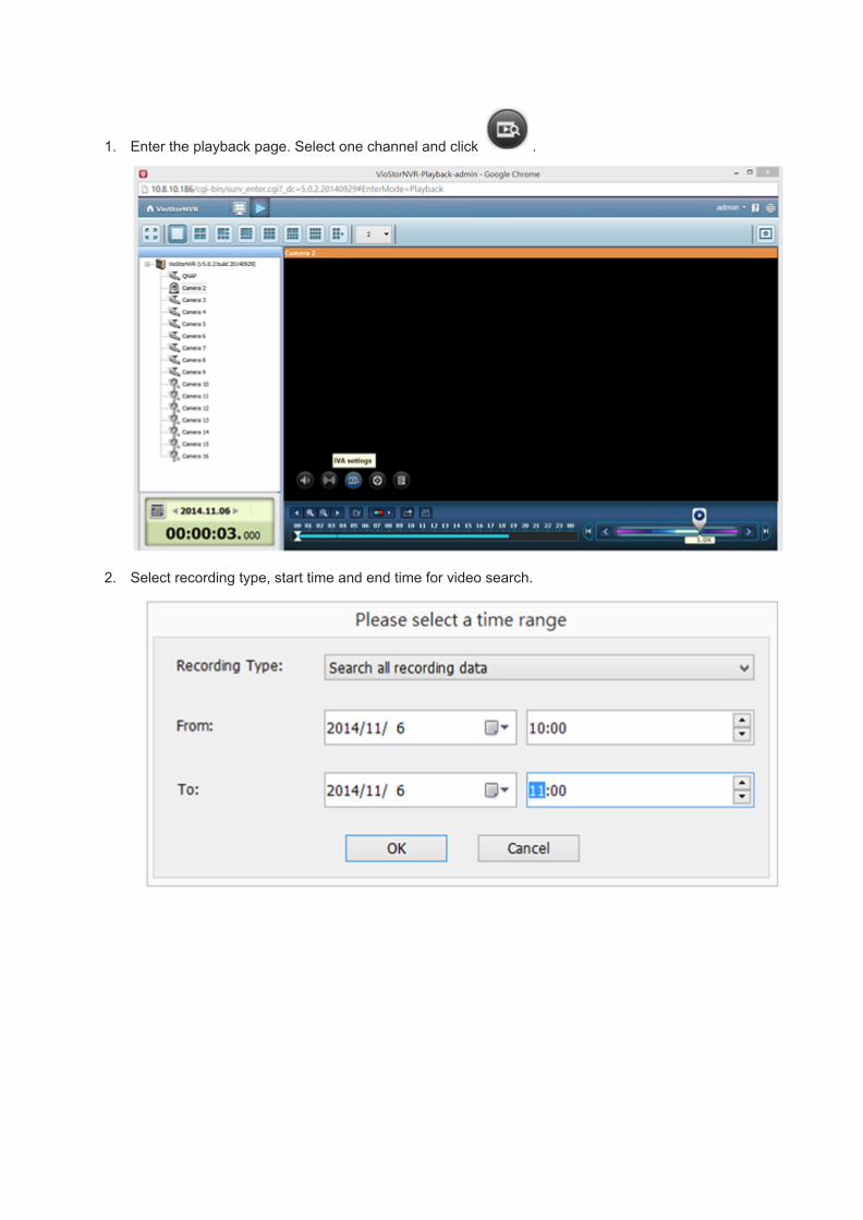
1. Enter the playback page. Select one channel and click .
2. Select recording type, start time and end time for video search.

3. Configure the IVA settings for video search.
Note: The Interval slide bar appears only when ‘Foreign object’ or ‘Missing object’ is selected.
● Select the detection mode: Motion detection, Foreign object, Missing object, Out of
focus, or Camera occlusion. Multiple options can be selected.
● Adjust the sensitivity for object detection.

● Adjust the time interval for detecting the foreign objects and missing objects. If a
foreign object appears or a missing object disappears for a period of time which is
longer than the time interval, the NVR will record the event.
● Define the detection zone. Mouse over the edge of the red zone and use the mouse
to define the detection zone. Click ‘Select all’ to highlight the entire area.
● Define the object size for detection. Use the mouse to drag the yellow zone to define
the minimum object size for detection.
Ignore objects with width or height less than this setting: Enable this option to ignore
all the objects smaller than the yellow zone.
● Enable/Disable other options for video search.
■ Pause when found: Enable this option and the video search will stop when a
video file matching the search criteria is found.
■ Highlight the detection zone: The moving objects detected in the video will be
highlighted in red boxes; the foreign or missing objects will be highlighted in
yellow boxes; the video which is out of focus or obstructed will be displayed in
transparent red.
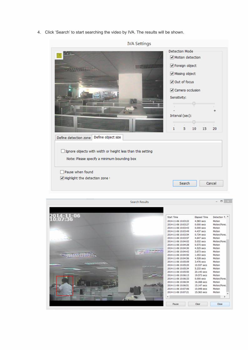
4. Click ‘Search’ to start searching the video by IVA. The results will be shown.

● Double click an entry on the search result dialog to play the video. The player will
play the video starting from 15 seconds before the event to 15 seconds after the
event.
● Right click an entry on the search result dialog to export the video (AVI format) and
save it to the computer. The exported video starts from 15 seconds before the event
to 15 seconds after the event.
For NVR FW v4.x
Note: The intelligent video analytics support video search on one IP camera channel only.

1. Enter the playback page. Select one channel and click .
2. Select recording type, start time and end time for video search.

3. Configure the IVA settings for video search.
Note: The Interval slide bar appears only when ‘Foreign object’ or ‘Missing object’ is selected.
● Select the detection mode: Motion detection, Foreign object, Missing object, Out of
focus, or Camera occlusion. Multiple options can be selected.
● Adjust the sensitivity for object detection.
● Adjust the time interval for detecting the foreign objects and missing objects. If a
foreign object appears or a missing object disappears for a period of time which is

longer than the time interval, the NVR will record the event.
● Define the detection zone. Mouse over the edge of the red zone and use the mouse
to define the detection zone. Click ‘Select all’ to highlight the entire area.
● Define the object size for detection. Use the mouse to drag the yellow zone to define
the minimum object size for detection.

Ignore objects with width or height less than this setting: Enable this option to ignore
all the objects smaller than the yellow zone.
● Enable/Disable other options for video search.
■ Pause when found: Enable this option and the video search will stop when a
video file matching the search criteria is found.
■ Highlight the detection zone: The moving objects detected in the video will be
highlighted in red boxes; the foreign or missing objects will be highlighted in
yellow boxes; the video which is out of focus or obstructed will be displayed
in transparent red.

4. Click ‘Search’ to start searching the video by IVA. The results will be shown.
Other options:● Double click an entry on the search result dialog to play the video. The player will
play the video starting from 15 seconds before the event to 15 seconds after the
event.
● Right click an entry on the search result dialog to export the video (AVI format) and
save it to the computer. The exported video starts from 15 seconds before the event
to 15 seconds after the event.

For NVR FW v3.6.1 or below
1. Go to Playback page of the NVR. Add files to the playlist.
Note: Intelligent video analytics support video search on one channel .
2. On the playback window, click

Note:● When you check the option "Pause when found", the data search stops when a video file
which matches the search criteria is found.
● When you enable "Highlight the detection zone", the moving objects will be highlighted in
red brackets; the foreign or missing objects will be highlighted in yellow brackets; out of
focus and camera occlusion will be displayed in transparent red.
3. Select the detection mode: motion detection, foreign object, missing object, out of focus, or
camera occlusion. You can select multiple options.
4. Adjust the sensitivity for object detection.
5. Adjust the time interval for foreign object and missing object. If a foreign
object appears or a missing object disappears for a time period longer than the time interval, the
system will record an event.
Note: The interval slide bar appears only when "foreign object" or "missing object" is checked.

6. Define detection zone. Mouse over the edge of the red zone and use the mouse to define the
detection zone. Click "Select all" to highlight all the area for detection.
7. Define object size for the detection. You can use the mouse the drag the yellow zone to highlight
the minimum object size for detection.

Note: After enabling this option, all the objects smaller than the yellow zone will be ignored for
detection
8. Click "Search" to start searching the video by IVA. The results and will be shown.
Note:
● You can double click an entry on the search result dialog to play the video. The player will
play the video starting from 15 seconds before the event to 15 seconds after the event.

● You can also right click an entry on the search result dialog to export the video and save it on
your computer. The exported video starts from 15 seconds before the event to 15 seconds
after the event.
2015/07/22

T32. [Tutorial] Setup SMS and Email Alert Notifications
"Never miss an important event from your QNAP VioStor NVR"
What is SMS and email alert?
QNAP VioStor NVR supports SMS and email alert to inform the users about system error or warning.
SMS is the abbreviation of Short Message Service which is known for the mobile text message
service. By subscribing with the SMS service providers you are able to setup QNAP VioStor NVR to
send SMS to the designated mobile phones in the event of system warning or errors. This
demostration will show you how to setup both the SMS and Email alert notification on your QNAP
VioStor NVR. See below for the usage diagram.
Step 1

Sign up and setup a SMS service account
In this demostration I will use Clickatell simply because it offers 10 free SMS after the registration.
Now go to Clickatell's website http://www.clickatell.com/login.php under the 'New Customers' setion
select 'Clickatell Central (API)'
Fill out your personal information then click on 'Continue'.
Upon successful registration you should receive an email containing the account activation link. You
may now check your inbox to complete your account activation. By following the activation link you will
be brought to the login screen as the image show below. Type in the password and click on 'Login' to
proceed.
Next you will need to verify your mobile number by entering an activation code sent by Clickatell after
you enter your mobile phone number and click on 'SEND ACTIVATION CODE'
While still logged in with Clickatell, go to 'Manage my Products' and select 'HTTP from 'MyConnections dropdown list.

Set up the 'HTTP API' by entering the minimum required information, the 'Name', 'Dial Prefix' and
'Callback Type' as the image shown below. Click on 'Submit' once done.
You should now obtain an 'API ID' that is required before using the SMS service. Write this down
somewhere as we will need it for the setup in the NAS administration in the next step.
Up to this point you have completed the account registration and mobile number verfications with
Clickatell and have successfully obtained an 'API ID'. You may now proceed to step 2.
Step 2

Set up the SMSC and alert notification by SMS on the NAS
Go to 'System Administration' > 'Notification' > 'Configure SMSC server' and enter the information
we got from step 1 to configure the SMSC server and cell phone number, you can send the SMS text
message when the different events were chosen, such as Motion detection is detected on an IP
camera, Alarm input is triggered on an IP camera as the image shown below.

Congratulations it's all setup and now you may wanna test if your have configure the SMS notification
properly by clicking on the 'SEND A TEST SMS MESSAGE ' button. If nothing goes wrong you should
be able to receive it in less than 10 seconds.

Step 3
Setup the SMTP server and alert notification by Email
Go to 'System Administration' > 'Notification' > 'Configure SMTP server' and enter the e-mail
address of the administrator and the IP address of the SMTP server. In case of warning or
malfunction, e.g. power outage, a drive is unplugged, an e-mail will be sent to the administrator
automatically. You can go to Event Logs to check the details of all errors and warnings. You also get
to test if the email sending process works by clicking on the 'SEND A TEST E-MAIL ' button.
Now no matter if you are out at work or away from home you will still be notified of the status and the
condition of your QNAP right away by either a SMS sent to your mobile or a letter to your inbox and
be able to act in case of any unexpected events.
2015/07/22

T33. [Tutorial] How to Use Digital Watermarking to Protect the Videosand Snapshots from Unauthorized Modification?
The VioStor NVR supports digital watermarking to protect the videos and snapshots from
unauthorized modification. You can select to add digital watermark on the exported video and
snapshot on the VioStor Player. A permanent digital signal will be added to the exported files which
are selected for digital watermarking. The watermark cannot be removed and is only visible by using
watermark proof software.
Step 1
Digital Watermark
To use digital watermarking by VioStor Player, follow the steps below.
1. Click "Playback" to open the VioStor Player.
2. Click "Settings" .

3. Select to add digital watermark in the exported snapshot or video.
Step 2
Watermark Proof
To use Watermark Proof, follow the steps below:
1. After installing the VioStor Player, Watermark Proof will be installed. From the Windows Start
menu, select "All Programs" > "QNAP" > "Player" to locate "Watermark Proof".

2. Run Watermark Proof. The following window will be shown.
3. Click to browse and locate the files. You can select more than one file at one time.
4. The Watermark proof program will start checking the files and show the proof result. If you check
the option "Stop when watermark error is detected", the checking procedure will stop if a failed file
is detected. Otherwise the program will check all the files you have selected.
If a file is modified, the proof result will be shown as "Failed".
5.
2015/07/22
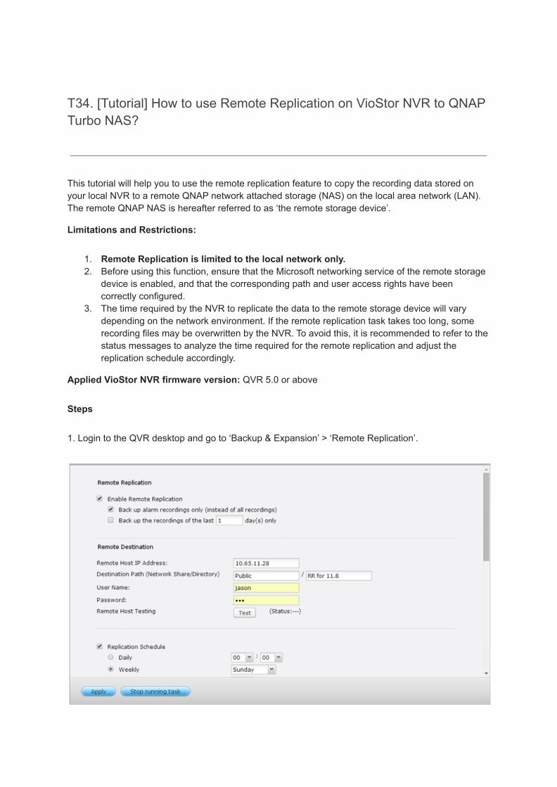
T34. [Tutorial] How to use Remote Replication on VioStor NVR to QNAPTurbo NAS?
This tutorial will help you to use the remote replication feature to copy the recording data stored onyour local NVR to a remote QNAP network attached storage (NAS) on the local area network (LAN).The remote QNAP NAS is hereafter referred to as ‘the remote storage device’.
Limitations and Restrictions:
1. Remote Replication is limited to the local network only.2. Before using this function, ensure that the Microsoft networking service of the remote storage
device is enabled, and that the corresponding path and user access rights have beencorrectly configured.
3. The time required by the NVR to replicate the data to the remote storage device will varydepending on the network environment. If the remote replication task takes too long, somerecording files may be overwritten by the NVR. To avoid this, it is recommended to refer to thestatus messages to analyze the time required for the remote replication and adjust thereplication schedule accordingly.
Applied VioStor NVR firmware version: QVR 5.0 or above
Steps
1. Login to the QVR desktop and go to ‘Backup & Expansion’ > ‘Remote Replication’.

2. Enable remote replication (supports multiple choices)
In the above example, the NVR only copies the alarm recording data of the latest 3 days to the remotestorage device.
● Select ‘Enable remote replication’ to activate this feature. The NVR will execute an automaticbackup of the recording data to the remote storage device according to the settings.
● Select ‘Back up alarm recordings only (instead of all recordings)’, the NVR will only copy thealarm recording data to the remote storage device. If this option is unselected, the NVR willback up all of the recording data to the remote storage device.
● Select ‘Back up the recordings of the latest…day(s) only’ and enter the number of days, theNVR will back up the latest recording data to the remote storage device automaticallyaccording to the settings. If this option is unselected, the NVR will copy all of the recordingdata to the remote storage device.
3. Configure the remote storage server
Enter the IP address, path, user name and password of the remote storage device.
4. Configure the remote replication schedule

For example, to enable the NVR to copy the recording data automatically to the remote storagedevice at 01:15 every Monday, please do the following:
Select ‘Replication Schedule’, select ‘Weekly’, enter 01 Hour: 15 minute, and select ‘Monday’.
5. Select the backup options
● Select ‘Replication Now’, the NVR will back up the recording data to the remote storagedevice immediately.
● Select ‘Overwrite the oldest recordings when the available storage on the remote host is lessthan 4GB’; the NVR will overwrite the oldest recording data when the free space on the serveris less than 4GB.
● Select ‘Perform mirroring replication by deleting extra files on the remote replication’, the NVRwill synchronize the recording data between itself and the remote storage device and deleteany extra files on the remote storage device.
When the above options are all selected and remote replication is executed, the NVR will do thefollowing:
i) The NVR checks if there are files on the remote storage device that are different from thelocal source. If yes, the differentiated files will be deleted.
ii) Next, the NVR checks the free space of remote storage device. If the free space is larger than4GB, the remote replication will be executed immediately.
iii) If the free space of the remote storage device is less than 4GB, the NVR will overwrite therecording data of the oldest day and then executes the remote replication.
6.The NVR displays the latest 10 remote replication records.

In the above example:
● When the status is shown as ‘Failed (Remote access error)’: Check to see if the remotestorage device is running and if the network settings are correct.
● When the status is shown as ‘Failed (An internal error occurred)’: Check the hard drive statusof the NVR and view the Event Logs.
Applied VioStor NVR firmware version: NVR FW v4.2.0 or below
Steps
1. Login to the NVR and go to ‘System Administration’ -> ‘System Tools’ > ‘Remote Replication’.
2. Enable remote replication (supports multiple choices)

In the above example, the NVR only copies the alarm recording data of the last 3 days to the remotestorage device.
● Select ‘Enable Remote Replication’ to activate this feature. The NVR will carry out automaticbackups of the recording data to the remote storage device according to the settings chosen.
● Select ‘Back up alarm recordings only (instead of all recordings)’, the NVR will only copy thealarm recording data to the remote storage device. If this option is unselected, the NVR willback up all of the recording data to the remote storage device.
● Select ‘Back up the recordings of the last…day(s) only’ and enter the number of days, theNVR will back up the latest recording data to the remote storage device automaticallyaccording to the settings. If this option is unselected, the NVR will copy all of the recordingdata to the remote storage device.
3. Configure the remote storage server
Enter the IP address, path, user name and password of the remote storage device.
4. Configure the remote replication schedule
For example, to enable the NVR to copy the recording data automatically to the remote storagedevice at 00:00 every Monday, please set the following:

Select ‘Replication Schedule’, select ‘Weekly’, and enter 00 Hour: 00 minute, and select ‘Monday’.
5. Select the backup options
● Select ‘Replication Now’, the NVR will immediately back up the recording data to the remotestorage device.
● Select ‘Overwrite the oldest recordings when the available storage on the remote host is lessthan 4GB’; the NVR will overwrite the oldest recording data when the free space on the serveris less than 4GB.
● Select ‘Perform mirroring replication by deleting extra files on the remote replication’, the NVRwill synchronize the recording data between itself and the remote storage device and deleteany extra files on the remote storage device.
When the above options are all selected and remote replication is executed, the NVR will do thefollowing:
i. The NVR checks if there are extra files on the remote storage device that are different fromthe local source. If yes, the extra files will be deleted.
ii. Next, the NVR checks the free space of the remote storage device. If the free space is largerthan 4GB, the remote replication task will be immediately carried out.
iii. If the free space of the remote storage device is less than 4GB, the NVR will overwrite theoldest recording data and then carry out the remote replication task.
6. The NVR will display the latest 10 remote replication records.
In the above example:
● When the status is shown as ‘Failed (Remote access error)’: Check if the remote storagedevice is running and that the network settings are correct.
● When the status is shown as ‘Failed (An internal error occurred)’: View the hard drive statusof the NVR or view the Event Logs.
2015/07/22

T35. [Tutorial] How to Expand the Storage Capacity and Upgrade theRAID Level of the VioStor NVR by Online RAID Capacity Expansion& RAID Level Migration?
The VioStor NVR is a high performance network video surveillance system for high-end, convenient,and reliable IP-based real-time monitoring and video recording. It is also an expansible system thatusers can expand the storage capacity of RAID volume and upgrade the RAID configuration.
This tutorial demonstrates how to use Online RAID Capacity Expansion and Online RAID LevelMigration of the VioStor to expand the storage capacity and upgrade the RAID configuration level ofthe system respectively. Furthermore, you can use Online RAID Capacity Expansion and Online RAIDLevel Migration together.
Case 1: Online RAID Capacity Expansion
Online RAID Capacity Expansion enables users to expand the storage capacity of RAID withoutturning off the server. Andrew can expand the current logical volume of RAID 5 from 750GB storagecapacity to 3TB.
1. Execute the RAID Expansion function. Replace the 250GB hard drives with 1TB ones step bystep.
2. Expand the capacity of the logical volume.
Operation Procedure:
Step 1
In Device Configuration/ RAID Management tool page, select the drive volume and click Expandcapacity.

Step 2
Click [Replace] so that the first hard drive can be replaced. Follow the instructions to proceed.
Tips: After replacing the hard drives, the description field shows "You can replace this drive". Thismeans you can replace the hard drive to a larger one or skip this step if the hard drives have beenreplaced already.
Caution: When the hard drive synchronization is in process, do NOT turn off the NVR or plug/unplug the hard drives.
Step 3
When the description displays "Please remove this drive", remove the hard drive from the NVR. Waitfor the NVR to beep twice after removing the hard drive.

Step 4
When the description displays "Please insert the new drive", insert the new drive to the drive slot.
Step 5

After inserting the hard drive, wait for the NVR to beep. The system starts rebuilding.
Step 6
After rebuilding finishes, follow steps 2-5 to replace other hard drive(s).
Step 7
After changing the hard drives and rebuilding completes, click [Expand capacity] to execute RAIDexpansion.
Click OK to proceed.

The NVR beeps and starts to expand the capacity.
Step 8
The process may take from hours to tens of hours depending on the drive size. Please wait patientlyfor the process to finish. Do NOT turn off the NVR during the process.
Step 9
After RAID capacity expansion is finished, the new capacity is shown and the status is Ready. Youcan start to use the server.

Tips: The description still shows "You can replace this hard drive". If the drive volume is Ready, youcan perform RAID expansion.
Case 2: Online RAID Level Migration
Online RAID Level Migration enables upgrade the RAID configuration level of the VioStor withoutturning off the server or losing any data. The following example shows you how to migrate the systemfrom single disk volume (1TB) to RAID 5 (3TB).

1. Prepare hard drives of the same or larger capacity as an existing drive in the RAIDconfiguration.
2. Execute RAID Migration (Migrate the system from Single Disk mode to RAID 5 with 4 harddrives).
Step 1
Go to Device Configuration/ SATA Disk page. The current disk volume configuration displayed onthe page is Single Disk (the capacity is 1TB).
Step 2
Insert the new hard drives of 1TB capacity to drive slots 2, 3, and 4 of NVR. The NVR system detectsthe new hard disks. The status of the new disks is "Unmounted".

Step 3
On Device Configuration/ RAID Management Tool page, select the drive configuration and clickMigrate.
Step 4
Select one or more available drives and the migration method. The drive capacity after migration isshown. Click Migrate.
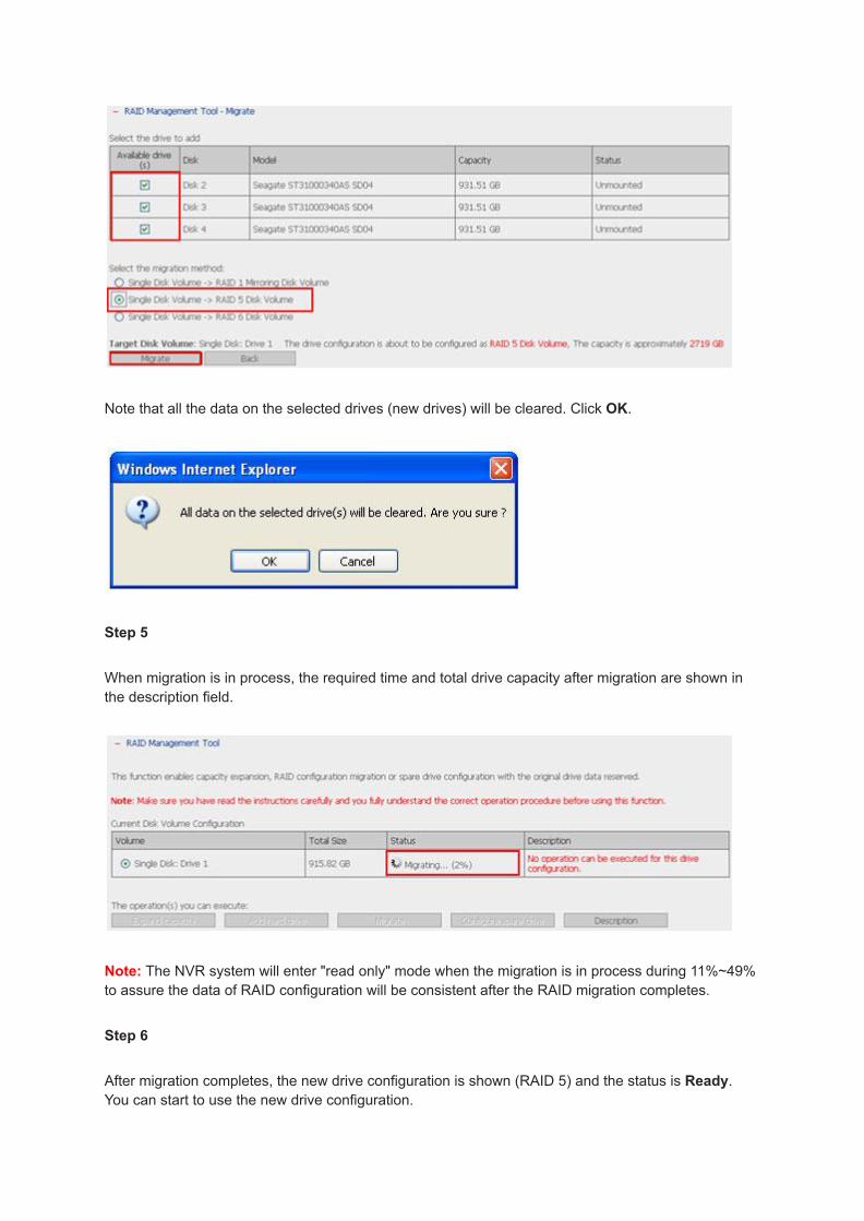
Note that all the data on the selected drives (new drives) will be cleared. Click OK.
Step 5
When migration is in process, the required time and total drive capacity after migration are shown inthe description field.
Note: The NVR system will enter "read only" mode when the migration is in process during 11%~49%to assure the data of RAID configuration will be consistent after the RAID migration completes.
Step 6
After migration completes, the new drive configuration is shown (RAID 5) and the status is Ready.You can start to use the new drive configuration.

The process may take from hours to tens of hours to finish depending on the drive size. You canconnect to the web page of NVR to check the status later.
Case 3: Online RAID Capacity Expansion and Online RAID Level Migration together
To migrate the disk configuration of the VioStor from single disk volume (250GB) to RAID 5 andexpand the storage capacity to 3TB. Follow the steps below.
1. Execute Online RAID Level Migration to migrate the system from Single Disk to RAID 5.The total storage capacity will be 750GB of RAID 5. (With one 250GB drive and three 1TBdrives, the disk usage will be 250GB*4 for RAID 5.)PS: You can refer to the Case 2 for detailed operation procedure.
2. Execute Online RAID Capacity Expansion, to replace the 250GB drive with a new 1TBdrive, and then expand the logical volume from 750GB to 3TB of RAID 5.PS: You can refer to the Case 1 for detailed operation procedure.
The VioStor NVR is an ideal end-to-end network surveillance system for system integrators, SMB,and enterprise. For more information about VioStor NVR, please refer to QNAP Security Products.
2015/07/22

T36. [Tutorial] How to Install the VioStor Series NVR in Different NetworkEnvironment for Standalone Use?
The VioStor series NVR provides two ports that you can configure failover, load balancing, orstandalone functions. If you want to assign different IP settings for each network port, you can login"Network settings-> TCP/IP Configuration" page to configure standalone option. When your networksurveillance system VioStor NVR, IP cameras, and PCs are installed behind the router, virtual server, orfirewall, you will have to configure port forwarding (port mapping) for some of the IP cameras that useparticular ports for MPEG4 image compression. This article demonstrates a few examples aboutinstalling the VioStor in different network environment for standalone use.
Note: In standalone mode, the LAN 2 is provided for internal connection among the NVR client,NVR server, and the network cameras. It does not support connection beyond the router.
Application 1:
1. The IP camera and the PC are in LAN 1.2. The IP camera and the PC are in LAN 2.

Situation:
LAN 1:
Router 1 -> Camera 1, Local PC 1, VioStor
LAN 2:
Router 2 -> Camera 2, Local PC 2, VioStor
Please follow the steps below to install the VioStor.
1. Plan the IP address and the port of the VioStor, the camera, and the PC.
Network Device IP Address/ Port
LAN 1 LAN IP of the router 1 192.168.1.1
VioStor 192.168.1.100
Camera 1 192.168.1.101
Local PC 1 192.168.1.200
LAN 2 LAN IP of the router 2 172.17.1.1
VioStor 172.17.1.11
Camera 2 172.17.1.12
Local PC 2 172.17.1.100
2. Install the IP camera. Please refer to the user guide of the IP camera for the network configuration.
Conclusion:

Local PC 1:
Live View Function -
Status Camera
OK Camera 1
Failed Camera 2
Recording Function - Successful for all cameras.
Local PC 2:
Live View Function -
Status Camera
OK Camera 2
Failed Camera 1
Recording Function - Successful for all cameras.
Application 2:
1. Some IP cameras and the PCs are in LAN 1.2. The IP camera and the PC are in LAN 2.3. The IP camera is installed in remote location with Public IP.4. Allow users to connect the VioStor from remote PC over the Internet.

Situation:
LAN 1:
Router 1-> Camera 1, Local PC 1, VioStor
Router 3-> Camera 3, Local PC 3
LAN 2:
Router 2-> Camera 2, Local PC 2, VioStor
WAN:
Camera 4, Remote PC
Please follow the steps below to install the VioStor.
1. Plan the IP address and the port of the VioStor, the camera, and the PC.
Configure the port mapping or virtual server on the Router 1 in LAN 1:HTTP port:
From Forward to
219.87.144.205:8000 192.168.1.100:80

219.87.144.205:8001 192.168.1.101:80
2. RTP port: Configure the port for VioStor to receive remote video data from the Camera 4
From Forward to
219.87.144.205:6100 192.168.1.100:6100
219.87.144.205:6101 192.168.1.100:6101
219.87.144.205:6102 192.168.1.100:6102
:::
:::
219.87.144.205:6259 192.168.1.100:6259
3. Note: The default RTP (Real-time Transport Protocol) port range of the VioStor is 6100~6259.Please refer to FAQ.
4. The router's port forwarding:
5.

6.7. Configure the port mapping on the Router 3 in LAN 1HTTP port:
From Forward to
192.168.1.150:8002 89.97.5.101:80
8. RTSP port: Configure the protocol for controlling video or audio streaming media from theCamera 3
From Forward to
192.168.1.150:5001 89.97.5.101:554
9. Note:Please check the RTSP (Real-Time Streaming Protocol) port of the IP camera beforeconfiguring the port mapping on the router.Please refer to the user guide of the IP camera for its RTSP port settings.
10. Install and configure the VioStorEnter the IP address of the camera in the "IP address" field of the "Camera Settings" page ofthe VioStor. Then enter the Public IP and the port number of the camera configured on therouter in "WAN IP" and "Port" fields respectively on the "Camera Settings" page of the VioStor.
1. Enter the settings of the IP cameras in LAN 1.Camera 1 "IP Address": 192.168.1.101 port 80"WAN IP Address": 219.87.144.205 port 8001

Camera 3 "IP Address": 192.168.1.150 port 8002/5001"WAN IP Address": 10.8.12.101 port 80
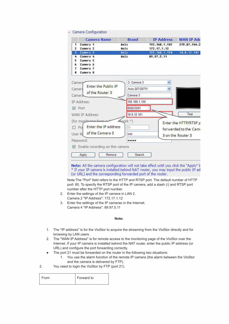
Note:The "Port" field refers to the HTTP and RTSP port. The default number of HTTPport: 80. To specify the RTSP port of the IP camera, add a slash (/) and RTSP portnumber after the HTTP port number.
2. Enter the settings of the IP camera in LAN 2.Camera 2 "IP Address": 172.17.1.12
3. Enter the settings of the IP cameras in the Internet.Camera 4 "IP Address": 89.97.5.11
Note:
1. The "IP address" is for the VioStor to acquire the streaming from the VioStor directly and forbrowsing by LAN users.
2. The "WAN IP Address" is for remote access to the monitoring page of the VioStor over theInternet. If your IP camera is installed behind the NAT router, enter the public IP address (orURL) and configure the port forwarding correctly.
● The port 21 must be forwarded on the router in the following two situations:1. You use the alarm function of the remote IP camera (the alarm between the VioStor
and the camera is delivered by FTP).2. You need to login the VioStor by FTP (port 21).
From Forward to
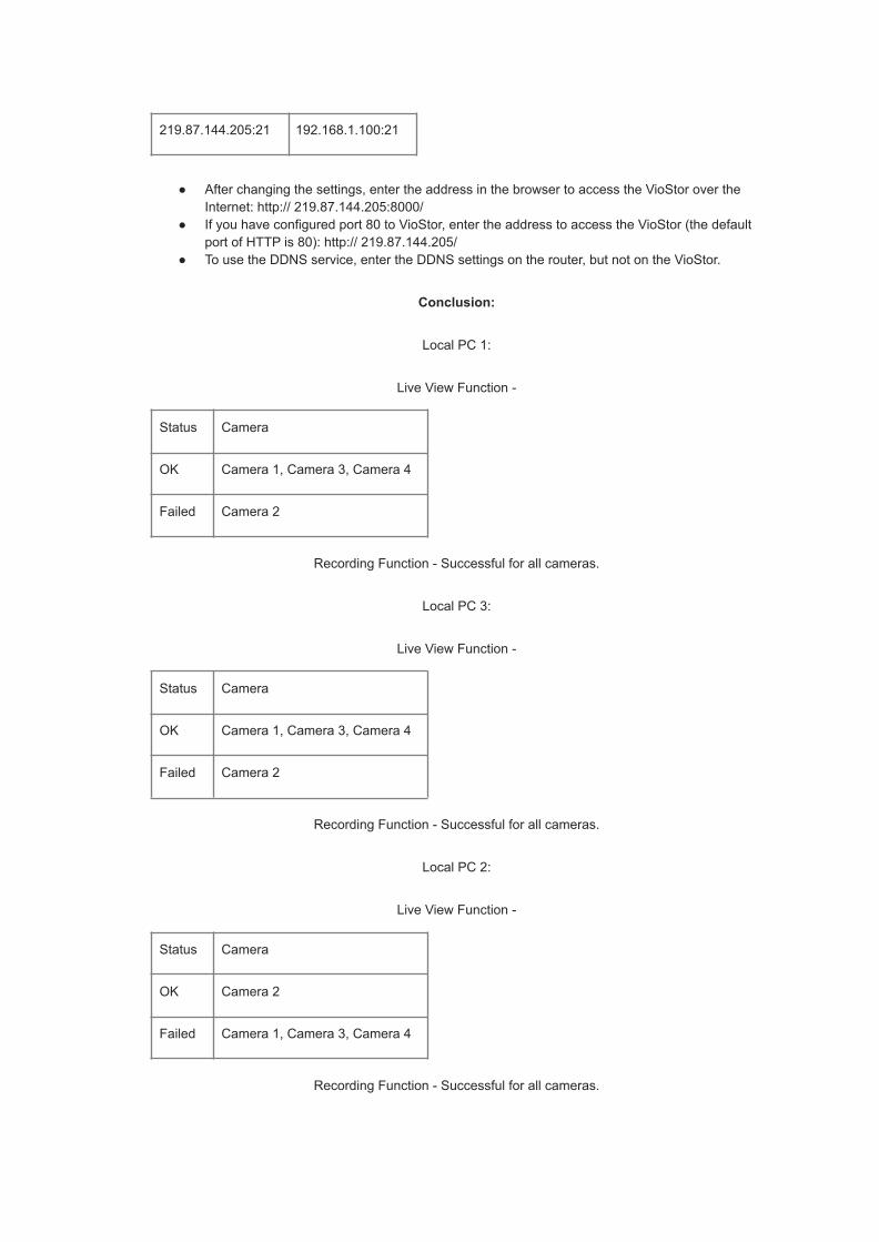
219.87.144.205:21 192.168.1.100:21
● After changing the settings, enter the address in the browser to access the VioStor over theInternet: http:// 219.87.144.205:8000/
● If you have configured port 80 to VioStor, enter the address to access the VioStor (the defaultport of HTTP is 80): http:// 219.87.144.205/
● To use the DDNS service, enter the DDNS settings on the router, but not on the VioStor.
Conclusion:
Local PC 1:
Live View Function -
Status Camera
OK Camera 1, Camera 3, Camera 4
Failed Camera 2
Recording Function - Successful for all cameras.
Local PC 3:
Live View Function -
Status Camera
OK Camera 1, Camera 3, Camera 4
Failed Camera 2
Recording Function - Successful for all cameras.
Local PC 2:
Live View Function -
Status Camera
OK Camera 2
Failed Camera 1, Camera 3, Camera 4
Recording Function - Successful for all cameras.

Remote PC:
Live View Function -
Status Camera
OK Camera 1, Camera 4
Failed Camera 2, Camera 3
Recording Function - Successful for all cameras.
Application 3:
1. Some IP cameras and the PCs are in LAN 1.2. The IP camera and the PC are in LAN 2.3. The IP camera is installed behind a different router in a remote location.4. Allow users to connect the VioStor from remote PC over the Internet.

Situation:
LAN 1:
Router 1 -> Camera 1, Local PC 1
Router 3 -> Camera 3, Local PC 3, VioStor
LAN 2:
Router 2 -> Camera 2, Local PC 2, VioStor
WAN:
Router 4 -> Camera 4, Remote PC
Please follow the steps below to install the VioStor.
1. Plan the IP address and the port of the VioStor, the cameras, and the PCs.
Network
Device IP Address/Port
Mapped Port (HTTP) onthe Router
LAN 1 Public IP of therouter 1
219.87.144.205
LAN IP of therouter 1
192.168.1.1
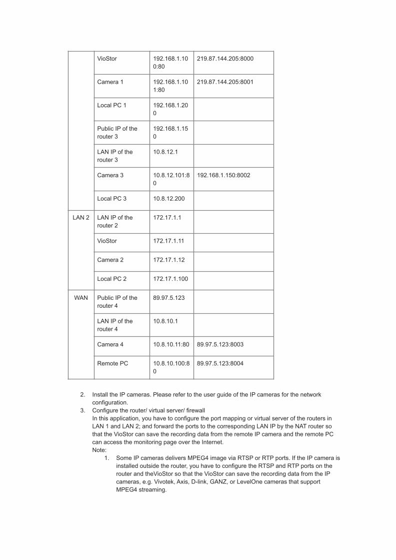
VioStor 192.168.1.100:80
219.87.144.205:8000
Camera 1 192.168.1.101:80
219.87.144.205:8001
Local PC 1 192.168.1.200
Public IP of therouter 3
192.168.1.150
LAN IP of therouter 3
10.8.12.1
Camera 3 10.8.12.101:80
192.168.1.150:8002
Local PC 3 10.8.12.200
LAN 2 LAN IP of therouter 2
172.17.1.1
VioStor 172.17.1.11
Camera 2 172.17.1.12
Local PC 2 172.17.1.100
WAN Public IP of therouter 4
89.97.5.123
LAN IP of therouter 4
10.8.10.1
Camera 4 10.8.10.11:80 89.97.5.123:8003
Remote PC 10.8.10.100:80
89.97.5.123:8004
2. Install the IP cameras. Please refer to the user guide of the IP cameras for the networkconfiguration.
3. Configure the router/ virtual server/ firewallIn this application, you have to configure the port mapping or virtual server of the routers inLAN 1 and LAN 2; and forward the ports to the corresponding LAN IP by the NAT router sothat the VioStor can save the recording data from the remote IP camera and the remote PCcan access the monitoring page over the Internet.Note:
1. Some IP cameras delivers MPEG4 image via RTSP or RTP ports. If the IP camera isinstalled outside the router, you have to configure the RTSP and RTP ports on therouter and theVioStor so that the VioStor can save the recording data from the IPcameras, e.g. Vivotek, Axis, D-link, GANZ, or LevelOne cameras that supportMPEG4 streaming.

2. In this sample, you must configure the RTP port setting on the router of LAN 1 andthe RTSP port setting on the router of the internet. Please refer to FAQ.
3. RTP (Real-time Transport Protocol): The protocol for delivering video or audio data.4. RTSP (Real-Time Streaming Protocol): The protocol for controlling video or audio
streaming media.
4. Configure the port mapping or virtual server on the Router 1 in LAN 1HTTP port:
From Forward to
219.87.144.205:8000 192.168.1.100:80
219.87.144.205:8001 192.168.1.101:80
5. RTP port: Configure the port for VioStor to receive remote video data from the Camera 4
From Forward to
219.87.144.205:6100 192.168.1.100:6100
219.87.144.205:6101 192.168.1.100:6101
219.87.144.205:6102 192.168.1.100:6102
:::
:::
219.87.144.205:6259 192.168.1.100:6259
6. Note: The default RTP (Real-time Transport Protocol) port range of the VioStor is 6100~6259.Please refer to FAQ.
7. The router's port forwarding:

8.
9.10. Configure the port mapping on the Router 3 in LAN 1HTTP port:
From Forward to
192.168.1.150:8002 89.97.5.101:80
11. RTSP port: Configure the protocol for controlling video or audio streaming media from theCamera 3
From Forward to
192.168.1.150:5001 89.97.5.101:554
12. Note:Please check the RTSP (Real-Time Streaming Protocol) port of the IP camera beforeconfiguring the port mapping on the router.Please refer to the user guide of the IP camera for its RTSP port settings.
13. Configure the port mapping on the Router 4 in WANHTTP port:

From Forward to
67.52.84.200:8003 10.8.10.11:80
67.52.84.200:8004 10.8.10.100:80
14. RTSP port: Configure the protocol for controlling video or audio streaming media from theCamera 4
From Forward to
67.52.84.200:5002 10.8.10.11:554
15. Note:Please check the RTSP (Real-Time Streaming Protocol) port of the IP camera beforeconfiguring the port mapping on the router.Please refer to the user guide of the IP camera for its RTSP port settings.
16. Install and configure the VioStorEnter the IP address of the camera in the "IP address" field of the "Camera Settings" page ofthe VioStor. Then enter the Public IP and the port number of the camera configured on therouter in "WAN IP" and "Port" fields respectively on the "Camera Settings" page of the VioStor.
1. Enter the settings of the IP cameras in LAN 1.Camera 1 "IP Address": 192.168.1.101 port 80"WAN IP Address": 219.87.144.205 port 8001

Camera 3 "IP Address": 192.168.1.150 port 8002/5001"WAN IP Address": 10.8.12.101 port 80

Note:The "Port" field refers to the HTTP and RTSP port. The default number of HTTP port: 80. Tospecify the RTSP port of the IP camera, add a slash (/) and RTSP port number after the HTTP portnumber.
2. Enter the settings of the IP camera in LAN 2.Camera 2 "IP Address": 172.17.1.12
3. Enter the settings of the IP camera in the Internet.Camera 4 "IP Address": 89.97.5.123 port 8003/5002"WAN IP Address": 10.8.10.11 port 80

Note:The "Port" field refers to the HTTP and RTSP port. The default number of HTTP port: 80. Tospecify the RTSP port of the IP camera, add a slash (/) and RTSP port number after the HTTP portnumber.
Note:
1. The "IP address" is for the VioStor to acquire the streaming from the VioStor directly and forbrowsing by LAN users.
2. The "WAN IP Address" is for remote access to the monitoring page of the VioStor over theInternet. If your IP camera is installed behind the NAT router, enter the public IP address (orURL) and configure the port forwarding correctly.
● The port 21 must be forwarded on the router in the following two situations:1. You use the alarm function of the remote IP camera (the alarm between the VioStor
and the camera is delivered by FTP).2. You need to login the VioStor by FTP (port 21).
From Forward to
219.87.144.205:21 192.168.1.100:21
● After changing the settings, enter the address in the browser to access the VioStor over theInternet: http:// 219.87.144.205:8000/

● If you have configured port 80 to VioStor, enter the address to access the VioStor (the defaultport of HTTP is 80): http:// 219.87.144.205/
● To use the DDNS service, enter the DDNS settings on the router, but not on the VioStor.
Conclusion:
Local PC 1:
Live View Function -
Status Camera
OK Camera 1, Camera 3, Camera 4
Fail Camera 2
Recording Function - Successful for all cameras.
Local PC 3:
Live View Function -
Status Camera
OK Camera 1, Camera 3, Camera 4
Failed Camera 2
Recording Function - Successful for all cameras.
Local PC 2:
Live View Function -
Status Camera
OK Camera 2
Failed Camera 1, Camera 3, Camera 4
Recording Function - Successful for all cameras.
Remote PC:
Live View Function -

Status Camera
OK Camera 1, Camera 4
Failed Camera 2, Camera 3
Recording Function - Successful for all cameras.
2015/07/22

T37. [Tutorial] How to Use Multi-server Monitoring?
There're 2 ways to centrally monitor multiple servers at one VioStor NVR client.
1. QSCM Lite: QSCM Lite is a free app provided by QVR 5.0 that allows you to easily manage up to16 QNAP NVRs and 256 cameras. This pioneering, powerful and free App can be directlydownloaded from QNAP NVR UI. For more information about QSCM Lite, please refer:
QSCM Lite tutorial:T21.[Tutorial] How to install QSCM Lite App?
2. Embedded multi-server monitoring:
All VioStor NVR series support the stunning multi-server monitoring feature which allows 128-channelmonitoring from multiple NVR servers. To use multi-server monitoring, please just follow these steps.
Step 1.When you have successfully logged in the VioStor, the monitoring page is shown.
Step 2.Click "Server List" on the live view page.

a.Click "Auto Detect" to search for the QNAP NVR in the LAN and add the server to the server list.
b.Click "Add" to add the QNAP NVR to the server list.
Up to 128 channels from different NVR servers can be added for monitoring.
Such embedded system is, in the mean time, the most recognized and reliable surveillancedeployment and a breakthrough which has never seen in the surveillance industry.
2015/07/22

T38. [Video] QNAP VioStor NVR (Network Video Recorder)
https://www.youtube.com/watch?v=IIOd8_Rek84
Applied to NVR FW v3.6.x
● H.264, MxPEG, MPEG-4 and M-JPEG recording● Video search by intelligent video analytics (IVA)● Digital watermark● SMS and email alert● Complete recording features● Multi-server monitoring● Multi-channel playback● Simple installation● Supports multi-display mode● Advanced RAID feature with hot-swap hard drive design● Energy-saving design

T39. [Video] A reliable surveillance solution - QNAP VioStor NVR
https://www.youtube.com/watch?v=buwwfDlTseE
Applied to NVR FW v4.x
QNAP Security, a professional Linux-embedded standalone NVR provider, offers quality surveillance solutionswith remarkable stability on remote monitoring, recording, HD local display and surveillance tasks under diverseenvironments. QNAP VioStor NVR delivers powerful surveillance features, including live-view, recording (variousmodes including motion detection and contiguous etc.), multi-server monitoring, PTZ control, preset positioncontrol and auto cruising, E-map, advanced event management, and intelligent video analytics, etc.
QNAP CMS supports centralized management of different NVRs and IP cameras at different locations. Incombination with QNAP Turbo NAS, QNAP VioStor NVR offers a total storage expansion solution.
See how QNAP Security helps protect things you value.
2015/07/0