PW4G-100-73-48 ENGINE FUEL AND CONTROL
63
SERVICE BULLETIN REVISION NOTICE ENGINE FUEL AND CONTROL — MANIFOLD ASSEMBLY, SUPPLY, FUEL NOZZLE (FS01 THRU FS08) — REPLACE THE MANIFOLD ASSEMBLIES AND INSTALL NEW HARDWARE FOR IMPROVED DURABILITY Turbojet Engine Service Bulletin No.PW4G-100-73-48 Revision No. 1 dated April 24, 2018. Revision History Original Issue March 14, 2018 Revision 1 April 24, 2018 Reason for the Revision To update the Disposition Code for Clamp PN ST1540-05. Effect of Revision on Prior Compliance None. This is a Complete Revision (Not Applicable to the SGML version) The contents are in accordance with the list of effective pages. All pages have the current revision number. Technical changes are marked with black bars. MODEL APPLICATION PW4164, PW4164-1D, PW4168, PW4168-1D, PW4168A, PW4168A-1D, PW4170 BULLETIN ISSUE SEQUENCE PW4G-100 Series 73-48 Page Revision No. Date 1 thru 62 1 April 24/18 A copy of this Revision Notice and any future revision notices must be filed as a permanent record with your copy of the subject bulletin. P&W Distribution Code 2639 PW4G-100-73-48 Page 1 of 1 Published in United States of America Not subject to the EAR per 15 C.F.R. Chapter 1, Part 734.3(b)(3).
-
Upload
khangminh22 -
Category
Documents
-
view
1 -
download
0
Transcript of PW4G-100-73-48 ENGINE FUEL AND CONTROL

SERVICE BULLETIN REVISION NOTICE
ENGINE FUEL AND CONTROL — MANIFOLD ASSEMBLY, SUPPLY, FUEL NOZZLE (FS01 THRUFS08) — REPLACE THE MANIFOLD ASSEMBLIES AND INSTALL NEW HARDWARE FOR
IMPROVED DURABILITYTurbojet Engine Service Bulletin No.PW4G-100-73-48 Revision No. 1 dated April 24, 2018.
Revision HistoryOriginal Issue March 14, 2018Revision 1 April 24, 2018
Reason for the Revision
To update the Disposition Code for Clamp PN ST1540-05.
Effect of Revision on Prior Compliance
None.
This is a Complete Revision (Not Applicable to the SGML version)
The contents are in accordance with the list of effective pages. All pages have the current revisionnumber. Technical changes are marked with black bars.
MODEL APPLICATIONPW4164, PW4164-1D, PW4168, PW4168-1D, PW4168A, PW4168A-1D, PW4170
BULLETIN ISSUE SEQUENCEPW4G-100 Series 73-48
Page Revision No. Date
1 thru 62 1 April 24/18
A copy of this Revision Notice and any future revision notices must be filed as a permanentrecord with your copy of the subject bulletin.
P&W Distribution Code2639 PW4G-100-73-48
Page 1 of 1Published in United States of America
Not subject to the EAR per 15 C.F.R. Chapter 1, Part 734.3(b)(3).

SERVICE BULLETIN
ENGINE FUEL AND CONTROL — MANIFOLD ASSEMBLY, SUPPLY, FUEL NOZZLE(FS01 THRU FS08) — REPLACE THE MANIFOLD ASSEMBLIES AND INSTALL
NEW HARDWARE FOR IMPROVED DURABILITY
MODEL APPLICATIONPW4164, PW4164-1D, PW4168, PW4168-1D, PW4168A, PW4168A-1D, PW4170
BULLETIN ISSUE SEQUENCE
PW4G-100 Series 73-48
ATA NUMBER
73-11-00
UTC/P&W PROPRIETARY INFORMATIONThis document is the property of United Technologies Corporation — Pratt & Whitney (UTC/P&W). You may not possess,use, copy or disclose this document or any information in it, for any purpose, including without limitation to design,manufacture, or repair parts, or obtain FAA or other government approval to do so, without UTC/P&W's express writtenpermission. Neither receipt nor possession of this document alone, from any source, constitutes such permission.Possession, use, copying or disclosure by anyone without UTC/P&W's express written permission is not authorizedand may result in criminal and/or civil liability.
Export Classification: Not subject to the EAR per 15 C.F.R. Chapter 1, Part 734.3(b)(3).
Compliance Category
5
P&W Distribution Code
2639
lMarch 14/18 PW4G-100-73-48REVISION NO. 1 - April 24/18 Page 1 of 62
Published in United States of America

Summary
The purpose of this Service Bulletin is to replace the fuel nozzle supply manifold assemblies (FSmanifolds) (FS01 thru FS08) and install new brackets and clamps on the FS manifolds. This changeadds sufficient dampening to shift the natural frequency outside of the acoustic frequency rangeidentified during an investigation. This change only applies to the PW4000-100” engines with theTalon IIA and Talon IIB combustion chamber configurations.
NOTE: The FS manifolds (FS01 thru FS08) can be repaired as specified in Reference 4, CIRManual, Chapter/Section 72-41-40 Repair-03.
Planning Information
Effectivity Data
Engine Models Applicable
PW4164, PW4168, PW4168AEngine Serial No. — All engines that have incorporated Reference 5, Service BulletinPW4G-100-72-214, or Reference 7, Service Bulletin PW4G-100-72-219, or Reference 9,Service Bulletin PW4G-100-72-253 incorporating the Talon IIB Outer Combustion ChamberAssembly, PN 51J500 or PN 51J381
PW4168AEngine Serial No. — All engines that incorporate the Talon IIA Outer Combustion ChamberAssembly, PN 51J100 or PN 51J382
PW4168A-1D, PW4170Engine Serial Nos. P735001 thru P735190*
* This estimate of engine serial numbers will be revised, if necessary, when parts areinstalled in engines at Pratt & Whitney.
NOTE: The engine serial number effectivity data and its related engine modelidentification contained in this Service Bulletin are taken from the records ofpart(s) incorporation during initial manufacture.
After initial engine manufacture, but before final delivery, P&W may changepart(s) in the engine or change the model identification of the engine. Suchaction is recorded on FAA337 forms.
To find Service Bulletin PW4G-100-73-48 models that are applicable, theowner/operator of the engine must compare the Service Bulletin List suppliedwith the engine as sent from P&W and the List of Changes incorporated at theAirframer from FAA337 forms to the Service Bulletin PW4G-100-73-48 Effectivitysection.
This Service Bulletin also applies to engines converted to the PW4164-1D, PW4168-1D,PW4168A-1D, PW4170 models by Service Bulletin PW4G-100-72-220.
Concurrent Requirements
There are no concurrent requirements.
Reason
1. Problem: On three occasions cracks and fuel leaks were discovered on the FSmanifolds installed on PW4000-94” engines with the Talon II combustion chamberconfiguration. Some PW4000-100” engines utilize a version of the Talon II combustion
lMarch 14/18 PW4G-100-73-48REVISION NO. 1 - April 24/18 Page 2
UTC/P&W PROPRIETARY INFORMATIONNot subject to the EAR per 15 C.F.R. Chapter 1, Part 734.3(b)(3).

chamber configuration similar to the PW4000-94” engines Talon II combustionchamber configuration.
2. Cause: High vibration stresses observed due to coupling of the acoustic combustormode and the FS manifold structural mode.
3. Solution: Replace the FS manifolds and install new brackets and clamps to reducethe stresses. The FS manifolds will be dampened to shift the natural frequencyoutside the acoustic frequency range.
Description
Replace the FS manifolds and install the new clamps and brackets.
Compliance
NOTE: Service Bulletin incorporation on engines installed on aircraft may be desirableand should be individually evaluated.
Category 5
Do when the engine is disassembled sufficiently to give access to the changedsubassembly (i.e., module, accessories, components, build groups) and to all changedspare subassemblies.
Approval Data
The part number changes and/or part changes specified in the Material Information sectionand Accomplishment Instructions of this Service Bulletin agree with the applicable FederalAviation Regulations and are FAA-Approved for the engine model(s) given.
The aircraft Type Certificate (TC) holder has been informed of this change.
Manpower
The estimate of man-hours of labor directly necessary to do the intent of this ServiceBulletin are as follows:
For Engines Installed On Aircraft
1. Necessary to Open and Close the Cowl Doors and Deactivate/ReactivateThrust Reversers ............................................................................................... 1.0
2. Remove Necessary Hardware using the AMM .................................................11.0
3. Necessary to Replace the FS Manifolds ............................................................ 6.0
4. Necessary to Install new Hardware ................................................................. 10.0
5. Re-install Necessary Hardware that was Removed using the AMM ................ 12.0
6. Total Necessary Man-hours ............................................................................. 40.0
For Engines Not Installed On Aircraft
1. Necessary to Replace the FS Manifolds ............................................................ 6.0
2. Necessary to Install new Hardware ................................................................. 10.0
3. Total Necessary Man-hours ............................................................................. 16.0
Weight Data
+ 2.4 Pound(s) (+ 1.09 kg).
lMarch 14/18 PW4G-100-73-48REVISION NO. 1 - April 24/18 Page 3
UTC/P&W PROPRIETARY INFORMATIONNot subject to the EAR per 15 C.F.R. Chapter 1, Part 734.3(b)(3).

Electrical Load Data
Not Applicable.
Software Accomplishment Summary
Not Applicable.
References
1. Turbojet Engine Standard Practices Manual, Part No. 585005.
2. PW4164, PW4168, PW4168A, PW4170 Turbofan Engines, Illustrated Parts Catalog,Part No. 51A343.
3. PW4164, PW4164-1D, PW4164C, PW4164C-1D, PW4164C/B, PW4164C/B-1D, PW4168,PW4168-1D, PW4168A, PW4168A-1D, PW4170 Turbofan Engines, Engine Manual, PartNo. 51A342.
4. PW4000 Series Turbofan Engines, Engine Cleaning, Inspection And Repair (CIR) Manual,Part No. 51A357.
5. Airbus A330 Aircraft Maintenance Manual.
6. Service Bulletin No. PW4G-100-72-214; Engine — Chamber Assemblies, Inner And OuterCombustion — Introduction Of The Talon IIB To Reduce Combustor Exit Temperature AtThe Outer Diameter. Issue Sequence 72-214, PW4G-100 Series.
7. Service Bulletin No. PW4G-100-72-219; Engine — Modification Of, To Incorporate TheAdvantage70™ Performance And Durability Upgrade Kit To Improve Engine Reliability AndReduce Thrust Specific Fuel Consumption. Issue Sequence 72-219, PW4G-100 Series.
8. Service Bulletin No. PW4G-100-72-220; Engine — Conversion Of A PW4164, PW4168,Or PW4168A Engine To A PW4164-1D, PW4168-1D, PW4168A-1D, Or PW4170 Engine.Issue Sequence 72-220, PW4G-100 Series.
9. Service Bulletin No. PW4G-100-72-253; Engine — Nuts, Chamber Assembly, OuterCombustion — Replacement Of, With Waspaloy Nuts To Reduce Nut Liberation. IssueSequence 72-253, PW4G-100 Series.
NOTE: References 6, 7, and 9, are shown to help find configurations in relation to thisbulletin.
NOTE: Reference 8 is shown to help find non-production configurations that mayincorporate this bulletin.
Publications Changed
PW4164, PW4168, PW4168A, PW4170 Turbofan Engines, Illustrated Parts Catalog,Part No. 51A343
73-11-00, Figure 5
73-11-00, Figure 6
73-11-00, Figure 7
PW4164, PW4164-1D, PW4164C, PW4164C-1D, PW4164C/B, PW4164C/B-1D, PW4168,PW4168A, PW4168A-1D, PW4170 Turbofan Engines, Engine Manual, Part No. 51A342.
73-11-15
lMarch 14/18 PW4G-100-73-48REVISION NO. 1 - April 24/18 Page 4
UTC/P&W PROPRIETARY INFORMATIONNot subject to the EAR per 15 C.F.R. Chapter 1, Part 734.3(b)(3).

Interchangeability
Partial incorporation of this Service Bulletin is permitted by fuel nozzle supply manifoldassembly (FS manifold) position as needed for engines installed on aircraft maintenance.During shop visit, full incorporation is recommended in accordance with the ServiceBulletin Compliance Category.
Information in the Appendix
Alternate Accomplishment Instructions (No)
Progression Charts (No)
Added Data (Yes)
Revision to Table of Limits (No)
Inspection Procedures (No)
lMarch 14/18 PW4G-100-73-48REVISION NO. 1 - April 24/18 Page 5
UTC/P&W PROPRIETARY INFORMATIONNot subject to the EAR per 15 C.F.R. Chapter 1, Part 734.3(b)(3).

Material Information
Material — Cost and Availability
1. Part prices were not available at the time of Service Bulletin publication. Contact Pratt &Whitney Spares Management & Logistics for firm quotations.
2. There is no kit provided to do this Service Bulletin.
3. Part availability information is provided in material data Instructions — Disposition.
Industry Support Program
Not Applicable.
The material data that follows is for each engine.
NOTE: It is possible to use the Chapter/Section and Figure/Item reference numbershown below the old part number to find the part in the Illustrated Parts Catalog.
Because there are many different configurations used, it is frequently necessaryto show more than one group of parts. When this occurs, parts that areinterchangeable are shown line-by-line only, unless this is shown differently.
CAUTION: THE FOLLOWING MATERIAL DATA TABLE(S) ARE ORGANIZED BYILLUSTRATED PARTS CATALOG. ALL PARTS IN THE TABLE(S) MAY ORMAY NOT BE APPLICABLE TO ALL THE ENGINE MODELS SHOWNIN THE TABLE HEADING. YOU MUST REFER TO THE APPROPRIATEILLUSTRATED PARTS CATALOG FOR ENGINE MODEL APPLICABILITYUSING THE OLD PART NUMBER (PN) AND CATALOG SEQUENCENUMBER. FAILURE TO INSTALL THE PART(S) IN THE CORRECTENGINE MODEL MAY RESULT IN A CONFIGURATION THAT IS NOT FAAAPPROVED.
The material data that follows is for each engine.
For PW4164, PW4164-1D, PW4168, PW4168-1D, PW4168A, PW4168A-1D, PW4170 Engines:
New PN Qty Estimate of UnitPrice ($)
Keyword Old PN Instructions —Disposition
15 * BOLT MS9715-14(73-11-00-5-260)
(C)
MS9715-16 14 * BOLT (A)
MS9715-18 1 * BOLT (A)
53U193 1 * BRACKET (A)
53U194 1 * BRACKET (A)
53U195 1 * BRACKET (A)
53U196 1 * BRACKET (A)
53U197 1 * BRACKET (A)
53U198 2 * BRACKET (A)
53U199 2 * BRACKET (A)
53U201 2 * BRACKET (A)
lMarch 14/18 PW4G-100-73-48REVISION NO. 1 - April 24/18 Page 6
UTC/P&W PROPRIETARY INFORMATIONNot subject to the EAR per 15 C.F.R. Chapter 1, Part 734.3(b)(3).

New PN Qty Estimate of UnitPrice ($)
Keyword Old PN Instructions —Disposition
53U202 1 * BRACKET (A)
53U203 1 * BRACKET (A)
53U206 1 * HEAT SHIELD (A)
53U207-01 1 * HEAT SHIELD (A)
53U208-01 1 * HEAT SHIELD (A)
53U210-01 1 * BRACKET (A)
AN123470 2 * .RIVET (D)
53U211-01 1 * BRACKET (A)
53U212 2 * WASHER (A)
53U213 2 * SPACER (A)
ST1557-05 16 * CLAMP (A)
AS3413-08 15 * BOLT (A)
776440 15 * NUT OPTION (A)(O1)
ST5141-09 15 * WASHER (A)
5311624 13 * WASHER (A)
1 * MANIFOLD —SUPPLY, FUELNOZZLE (FS04),ASSEMBLY OF
50J958-01(73-11-00-6-20 A)
(C)(R)
7 * MANIFOLD— SUPPLY,FUEL NOZZLE(FS01 THRUFS03, FS05THRU FS08),ASSEMBLY OF
50J959-01(73-11-00-6-10 A)
(C)(R)
1 * CLAMP ST1540-05(73-11-00-6-90)
(C1)
5 * BOLT MS9715-14(73-11-00-5-260)
(E)
16 * PACKING ST1946-012(73-11-00-7-1 C)
(E)
24 * PACKING ST1946-010(73-11-00-6-1 B)
(E)
AR * TUBE —TRANSFER
50J500(73-11-00-7-10)
(E)
lMarch 14/18 PW4G-100-73-48REVISION NO. 1 - April 24/18 Page 7
UTC/P&W PROPRIETARY INFORMATIONNot subject to the EAR per 15 C.F.R. Chapter 1, Part 734.3(b)(3).

New PN Qty Estimate of UnitPrice ($)
Keyword Old PN Instructions —Disposition
AR * SAFETY CABLE 56T581 (E)
AR * FERRULE 56T582 (E)
Modification and Spares Information
Estimated part prices are provided when they are available at time of publication. TheEstimate of Unit Price is only for planning purposes and does not constitute a firmquotation. An asterisk (*) is shown where part pricing information was unavailable. In eithercase, contact Pratt & Whitney Spares Management & Logistics for firm quotations.
Parts Modification Conditions
Not Applicable.
Spare Parts Availability
(A) The new part is available.(C) The old part will continue to be supplied.(C1) The old part will continue to be supplied for use at other locations.(D) The new part is a detail of the assembly. It is available as a replacement part.(E) The old part is an expendable item necessary to do this bulletin.(O1) Nut Option, PN 776440, consists of a Nut, PN AS3066-09, PN AS3067-09, PNAS3068-09, PN AS3069-09 or PN AS3070-09.(R) The part can be replaced with a new part or the old part can be repaired asspecified in Reference 4, CIR Manual, Chapter/Section 72-41-40 Repair-03.
Vendor Services or Special Components/Materials
Special Components/Materials — Consumable Materials
P&W Designation Qty Name
P03-001 AR Engine Oil
P06-021 (PWA 550-3) AR Anti-gallant Compound
P06-053 AR Sealing Ring Lubricant
NOTE: EXCEPT FOR WORK OR SUPPLIES TO BE PERFORMED OR FURNISHEDBY PRATT & WHITNEY, IT IS UNDERSTOOD THAT PRATT & WHITNEYDOES NOT ENDORSE THE WORK PERFORMED BY THE COMPANY ORCOMPANIES NAMED HEREIN OR ANY OTHER COMPANY AND DOES NOTACCEPT RESPONSIBILITY TO ANY DEGREE FOR THE SELECTION OFSUCH COMPANY OR COMPANIES FOR THE PERFORMANCE OF ANYWORK OR PROCUREMENT OF SUPPLIES.
Material Data for Each Spare Engine
The material for each spare engine is as stated in the preceding material informationsection.
Reidentified Parts
Not Applicable.
lMarch 14/18 PW4G-100-73-48REVISION NO. 1 - April 24/18 Page 8
UTC/P&W PROPRIETARY INFORMATIONNot subject to the EAR per 15 C.F.R. Chapter 1, Part 734.3(b)(3).

Necessary Tools
No more Support Equipment is necessary.
Other Material Information Data
Not Applicable.
lMarch 14/18 PW4G-100-73-48REVISION NO. 1 - April 24/18 Page 9
UTC/P&W PROPRIETARY INFORMATIONNot subject to the EAR per 15 C.F.R. Chapter 1, Part 734.3(b)(3).

Accomplishment Instructions
NOTE: Service Bulletin incorporation on engines installed on aircraft may be desirable andshould be individually evaluated.
NOTE: Partial incorporation of this Service Bulletin is permitted by fuel nozzle supplymanifold assembly (FS manifold) position as needed for engines installed on aircraftmaintenance. During shop visit, full incorporation is recommended in accordance withthe Service Bulletin Compliance Category.
For Engines Installed On Aircraft
1. Open the fan cowl doors as specified in Reference 5, AMM.
WARNING: DO THE THRUST REVERSER DEACTIVATION PROCEDURE TOPREVENT THE OPERATION OF THE THRUST REVERSER. ACCIDENTALOPERATION OF THE THRUST REVERSER CAN CAUSE INJURY TOPERSONS OR DAMAGE TO EQUIPMENT.
2. Do the deactivation procedure for the thrust reversers doors as specified in Reference5, AMM.
3. Open the cowl doors as specified in Reference 5, AMM.
WARNING: OBEY THE INSTRUCTIONS IN THE PROCEDURE TO OPEN THE THRUSTREVERSERS. IF YOU DO NOT OBEY THE INSTRUCTIONS, INJURIES TOPERSONNEL, AND DAMAGE TO EQUIPMENT CAN OCCUR.
4. Open the thrust reverser doors as specified in Reference 5, AMM.
5. Remove any hardware as required for access to the FS manifolds as specified inReference 5, AMM.
6. Locate the FS manifold (FS04) and remove and retain the Bolt, PN ST1411-05 from theClamp, PN ST1540-05. See Figure 1, Sheet 1 and Figure 1, Sheet 2.
7. Remove and discard the Clamp, PN ST1540-05.
WARNING: DO NOT ALLOW ENGINE FUEL TO REMAIN ON YOUR SKIN FOR APERIOD OF TIME. FLUSH FUEL FROM SKIN WITH WATER. THE FUEL ISPOISONOUS AND CAN GO THROUGH SKIN AND INTO YOUR BODY.
CAUTION: DO NOT ALLOW ENGINE FUEL TO LEAK ON THE ENGINE. UNWANTEDFUEL MUST BE REMOVED IMMEDIATELY WITH A CLEAN LINT-FREECLOTH. FUEL CAN CAUSE DAMAGE TO OTHER PARTS ON THEENGINE.
CAUTION: TUBE DAMAGE MAY OCCUR IF BACKUP WRENCH IS NOT PROPERLYUSED.
8. Disconnect all of the coupling nuts that attach the FS manifolds to the Fuel Nozzles (F/N).Use a backup wrench on the wrenching flats. See Figure 1, Sheet 2 and Figure 3.
9. Disconnect all of the coupling nuts that attach the FS manifolds to the fuel supply tubeassemblies (FM tubes). Use a backup wrench on the wrenching flats. See Figure 3 andFigure 4.
lMarch 14/18 PW4G-100-73-48REVISION NO. 1 - April 24/18 Page 10
UTC/P&W PROPRIETARY INFORMATIONNot subject to the EAR per 15 C.F.R. Chapter 1, Part 734.3(b)(3).

10. Remove the FS Manifold (FS04), PN 50J958-01 and seven FS Manifolds (FS01 thru FS03,FS05 thru FS08), PN 50J959-01. See Figure 1, Sheet 2.
NOTE: FM tube clamps near the FS manifolds may need to be removed prior to theremoval of the FS manifolds.
s
11. Remove the Transfer Tubes, PN 50J500 and two Packings, PN ST1946-012, from theeight FM tubes as follows. See Figure 4.
A. Remove and discard the 16 Packings, PN ST1946-012.
B. Wipe clean the transfer tubes as specified in Reference 1, Standard Practices Manual,Chapter/Section 72-21-00, SPOP 208.
C. Inspect the transfer tubes for signs of damage.
(1) If there are no signs of damage, retain the transfer tube for reuse.
(2) If there are signs of damage, discard the Transfer Tube, PN 50J500.
12. Remove and discard the 24 Packings, PN ST1946-010, from the FS manifolds and F/Npads. See Figure 1, Sheet 1.
13. Wipe clean the threads of the conical seats at F/N interface as specified in Reference 1,Standard Practices Manual, Chapter/Section 72-21-00, SPOP 208.
14. Remove and discard the two Bolts, PN MS9715-14, on F/N 17. See Figure 5.
15. Position the Heat Shield, PN 53U207-01, at the appropriate location on F/N 17 as shown inFigure 5.
16. Apply Engine Oil (P03-001), to the threads and bearing surface contact of the two newBolts, PN MS9715-14.
17. Install the Heat Shield, PN 53U207-01, on F/N 17 with two Bolts, PN MS9715-14, fingertight.
18. Torque the two Bolts, PN MS9715-14, to 75 – 85 lbf-in (8.47 – 9.60 N.m).
19. Install the new or repaired FS Manifold (FS04), PN 50J958-01, that has new tube detailsinstalled as specified in Reference 4, CIR Manual, Chapter/Section 72-41-40 Repair-03,and install seven new or repaired FS Manifolds (FS01 thru FS03, FS05 thru FS08), PN50J959-01, that have new tube details installed as specified in Reference 4, CIR Manual,Chapter/Section 72-41-40 Repair-03 as follows:
A. Remove the protective covers from the new FS manifold fittings.
CAUTION: TORQUE LIMITS GIVEN IN THIS DOCUMENT FOR OIL LUBRICATEDPARTS APPLY SPECIFICALLY TO THE USE OF ENGINE OIL OREQUIVALENT. UNLESS OTHERWISE SPECIFIED, TORQUES GIVENIN THIS DOCUMENT APPLY WHEN LUBRICATION IS APPLIEDTO AT LEAST ONE OF THE PAIR OF SURFACES THAT WILLEXPERIENCE RUBBING CONTACT; WHERE ANTI GALLANT ISWORN, REAPPLY ANTI GALLANT. THE APPLICATION OF BOTH OILAND ANTI GALLANT ON THE SAME PAIR OF SURFACES SHALLNOT BE USED.
B. Re-apply anti-gallant on FM tubes at interface with FS manifolds if required. SeeFigure 24.
lMarch 14/18 PW4G-100-73-48REVISION NO. 1 - April 24/18 Page 11
UTC/P&W PROPRIETARY INFORMATIONNot subject to the EAR per 15 C.F.R. Chapter 1, Part 734.3(b)(3).

(1) If necessary, re-apply Anti-gallant Compound (P06-021 (PWA 550-3)) asspecified in Reference 1, Standard Practices Manual, Chapter/Section 72-41-03,SPOP 156.
C. Lubricate the FM tubes and FS manifolds. See Figure 3, Figure 4, and Figure 25.
(1) Apply Lubricant (P06-053), to the eight Transfer Tubes, PN 50J500, and 16Packings, PN ST1946-012. Install the transfer tube and packing to the FM tubeends.
(2) Apply Lubricant (P06-053), to the 24 Packings, PN ST1946-010. Install the 24packings to the previously cleaned and lubricated F/N pads.
(3) Apply a light film of Engine Oil (P03-001), between thrust wire and tube ferruleinterface, and to the threads on all eight FS manifolds. Try to distribute drops ofengine oil evenly around the circular device and do not spray on lubricant.
NOTE: Rotate coupling nuts to distribute lubrication.
(4) Remove any excess lubricant from the F/Ns, coupling nut threads, and theconical seat surfaces.
D. Attach the FS Manifold (FS04), PN 50J958-01 and seven FS Manifolds (FS01 thruFS03, FS05 thru FS08), PN 50J959-01, coupling nuts to the F/Ns and FM tubes,finger tight. See Figure 1, Sheet 2, Figure 3, and Figure 4.
NOTE: If the FM tube clamps were previously removed, they must be reinstalled.
FS manifolds are numbered clockwise (aft looking forward) from the TopDead Center (TDC) starting with FS manifold (FS01) and ending with FSmanifold (FS08).
FS manifold (FS04) is an unique manifold PN 50J958-01, all other FSmanifolds are PN 50J959-01.
E. Ensure all tube coupling nuts are finger tight and that the tube conical seat is fullyagainst the adapter/fitting conical seat.
F. Ensure that the FM tube and FS manifold conical seats are fully against the conicalseat fittings, hand tighten the FM tube/FS manifold coupling nuts until you feel theseats contact and then loosen the coupling nuts ¼ turn.
G. Leak test the FM tubes (FM01 thru FM08) and FS manifolds (FS01 thru FS08)as specified in Reference 5, AMM, Chapter/Section 73-11-15 (Installation of FuelSupply Manifold).
CAUTION: TUBE DAMAGE MAY OCCUR IF BACKUP WRENCH IS NOTPROPERLY USED.
H. Torque the eight FS manifolds as follows. Use a backup wrench at wrenching flatsshown in Figure 3.
(1) Install the eight center coupling nuts by holding the center fittings with a backupwrench and torque the coupling nuts to 250 – 270 lbf-in (28.25 – 30.51 N.m).
(2) Install the eight left (forward view) FS manifold coupling nuts by holding the leftelbows with a backup wrench and torque the coupling nuts to 250 – 270 lbf-in(28.25 – 30.51 N.m).
lMarch 14/18 PW4G-100-73-48REVISION NO. 1 - April 24/18 Page 12
UTC/P&W PROPRIETARY INFORMATIONNot subject to the EAR per 15 C.F.R. Chapter 1, Part 734.3(b)(3).

(3) Install the eight right (forward view) FS manifold coupling nuts by holding theright elbows with a backup wrench and torque the coupling nuts to 250 – 270lbf-in (28.25 – 30.51 N.m).
(4) Install the eight FM tubes coupling nuts by holding the center fittings with abackup wrench and torque the coupling nuts to 275 – 325 lbf-in (31.07 – 36.72N.m).
(5) Examine the tube ends for evidence of tube twist or damage adjacent to thebrazed fittings and replace if necessary.
20. Apply Engine Oil (P03-001), to the threads and bearing surface contact of the Bolt, PNST1411-05. See Figure 1, Sheet 1.
21. Replace Clamp, PN ST1540-05 with PN ST1557-05, and install on FS manifold (FS04)with Bolt, PN ST1411-05.
22. Torque the Bolt, PN ST1411-05, to 36 – 40 lbf-in (4.07 – 4.52 N.m).
23. Obtain parts shown in Table 1 for installing the FS manifold support brackets, clamps,and heat shields.
Table 1. Brackets And Heat Shields Used At FS Manifold Locations
FS Manifold Location Tube Attached To PN (Bracket/Heat Shield)
TU1 53U193FS01
TU2 53U194
TU3 53U195/53U206FS02
TU4 53U196
TU5 53U197FS03
TU6 53U198
FS04 TU7 53U201
TU9 53U210-01FS05
TU10 53U199
TU11 53U211-01/53U207-01FS06
TU12 53U198
TU13 53U201FS07
TU14 53U202/53U208-01
TU15 53U203FS08
TU16 53U199
NOTE: F/Ns are numbered clockwise (aft looking forward) F/N 1 starting at TDC andending with F/N 24.
24. Ensure that the brackets are installed in the correct location and that they have the correctorientation. See Figure 6.
lMarch 14/18 PW4G-100-73-48REVISION NO. 1 - April 24/18 Page 13
UTC/P&W PROPRIETARY INFORMATIONNot subject to the EAR per 15 C.F.R. Chapter 1, Part 734.3(b)(3).
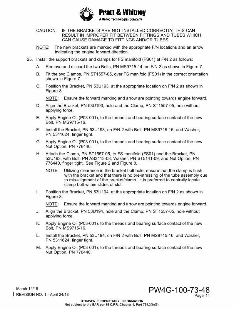
CAUTION: IF THE BRACKETS ARE NOT INSTALLED CORRECTLY, THIS CANRESULT IN IMPROPER FIT BETWEEN FITTINGS AND TUBES WHICHCAN CAUSE DAMAGE TO FITTINGS AND/OR TUBES.
NOTE: The new brackets are marked with the appropriate F/N locations and an arrowindicating the engine forward direction.
25. Install the support brackets and clamps for FS manifold (FS01) at F/N 2 as follows:
A. Remove and discard the two Bolts, PN MS9715-14, on F/N 2 as shown in Figure 7.
B. Fit the two Clamps, PN ST1557-05, over FS manifold (FS01) in the correct orientationshown in Figure 7.
C. Position the Bracket, PN 53U193, at the appropriate location on F/N 2 as shown inFigure 8.
NOTE: Ensure the forward marking and arrow are pointing towards engine forward.
D. Align the Bracket, PN 53U193, hole and the Clamp, PN ST1557-05, hole withoutapplying force.
E. Apply Engine Oil (P03-001), to the threads and bearing surface contact of the newBolt, PN MS9715-16.
F. Install the Bracket, PN 53U193, on F/N 2 with Bolt, PN MS9715-16, and Washer,PN 5311624, finger tight.
G. Apply Engine Oil (P03-001), to the threads and bearing surface contact of the newNut Option, PN 776440.
H. Attach the Clamp, PN ST1557-05, to FS manifold (FS01) and the Bracket, PN53U193, with Bolt, PN AS3413-08, Washer, PN ST5141-09, and Nut Option, PN776440, finger tight. See Figure 2 and Figure 8.
NOTE: Utilizing clearance in the bracket bolt hole, ensure that the clamp is flushwith the bracket and that there is no pre-stressing of the tube assembly dueto mis-alignment of the bracket/clamp. It is preferred to centrally locateclamp bolt within slides of slot.
I. Position the Bracket, PN 53U194, at the appropriate location on F/N 2 as shown inFigure 8.
NOTE: Ensure the forward marking and arrow are pointing towards engine forward.
J. Align the Bracket, PN 53U194, hole and the Clamp, PN ST1557-05, hole withoutapplying force.
K. Apply Engine Oil (P03-001), to the threads and bearing surface contact of the newBolt, PN MS9715-16.
L. Install the Bracket, PN 53U194, on F/N 2 with Bolt, PN MS9715-16, and Washer,PN 5311624, finger tight.
M. Apply Engine Oil (P03-001), to the threads and bearing surface contact of the newNut Option, PN 776440.
lMarch 14/18 PW4G-100-73-48REVISION NO. 1 - April 24/18 Page 14
UTC/P&W PROPRIETARY INFORMATIONNot subject to the EAR per 15 C.F.R. Chapter 1, Part 734.3(b)(3).

N. Attach the Clamp, PN ST1557-05, to FS manifold (FS01) and the Bracket, PN53U194, with Bolt, PN AS3413-08, Washer, PN ST5141-09, and Nut Option, PN776440, finger tight. See Figure 2 and Figure 8.
NOTE: Utilizing clearance in the bracket bolt hole, ensure that the clamp is flushwith the bracket and that there is no pre-stressing of the tube assembly dueto mis-alignment of the bracket/clamp. It is preferred to centrally locateclamp bolt within slides of slot.
26. Install the heat shield, support brackets, and clamps for FS manifold (FS02) at F/N 4and F/N 5 as follows:
A. Remove and discard the three Bolts, PN MS9715-14, on F/N 4 and F/N 5 as shown inFigure 9.
B. Fit the two Clamps, PN ST1557-05, over FS manifold (FS02) in the correct orientationshown in Figure 9.
C. Position the Heat Shield, PN 53U206, on the aft two bolt holes of F/N 4 as shownin Figure 10.
NOTE: Ensure the forward marking and arrow are pointing towards engine forward.
D. Apply Engine Oil (P03-001), to the threads and bearing surface contact of the newBolts, PN MS9715-14.
E. Attach the Bolt, PN MS9715-14, to the left bolt hole (forward view) of the Heat Shield,PN 53U206, and F/N 4, finger tight.
F. Position the Bracket, PN 53U195, on Heat Shield, PN 53U206 at the appropriatelocation at F/N 4 as shown in Figure 10.
NOTE: Ensure the forward marking and arrow are pointing towards engine forward.
G. Align the Bracket, PN 53U195, hole and the Clamp, PN ST1557-05, hole withoutapplying force.
H. Apply Engine Oil (P03-001), to the threads and bearing surface contact of the newBolt, PN MS9715-16.
I. Install the Bracket, PN 53U195, on F/N 4 with Bolt, PN MS9715-16, and Washer,PN 5311624, finger tight.
J. Apply Engine Oil (P03-001), to the threads and bearing surface contact of the newNut Option, PN 776440.
K. Attach the Clamp, PN ST1557-05, to FS manifold (FS02) and the Bracket, PN53U195, with Bolt, PN AS3413-08, Washer, PN ST5141-09, and Nut Option, PN776440, finger tight. See Figure 2 and Figure 10.
NOTE: Utilizing clearance in the bracket bolt hole, ensure that the clamp is flushwith the bracket and that there is no pre-stressing of the tube assembly dueto mis-alignment of the bracket/clamp. It is preferred to centrally locateclamp bolt within slides of slot.
L. Position the Bracket, PN 53U196, at the appropriate location on F/N 5 as shownin Figure 10.
NOTE: Ensure the forward marking and arrow are pointing towards engine forward.
M. Align the Bracket, PN 53U196, hole and the Clamp, PN ST1557-05, hole withoutapplying force.
lMarch 14/18 PW4G-100-73-48REVISION NO. 1 - April 24/18 Page 15
UTC/P&W PROPRIETARY INFORMATIONNot subject to the EAR per 15 C.F.R. Chapter 1, Part 734.3(b)(3).

N. Apply Engine Oil (P03-001), to the threads and bearing surface contact of the newBolt, PN MS9715-16.
O. Install the Bracket, PN 53U196, on F/N 5 with Bolt, PN MS9715-16, and Washer,PN 5311624, finger tight.
P. Apply Engine Oil (P03-001), to the threads and bearing surface contact of the newNut Option, PN 776440.
Q. Attach the Clamp, PN ST1557-05, to FS manifold (FS02) and the Bracket, PN53U196, with Bolt, PN AS3413-08, Washer, PN ST5141-09, and Nut Option, PN776440, finger tight. See Figure 2 and Figure 10.
NOTE: Utilizing clearance in the bracket bolt hole, ensure that the clamp is flushwith the bracket and that there is no pre-stressing of the tube assembly dueto mis-alignment of the bracket/clamp. It is preferred to centrally locateclamp bolt within slides of slot.
27. Install the support brackets and clamps for FS manifold (FS03) at F/N 8 as follows:
A. Remove and discard the two Bolts, PN MS9715-14, on F/N 8 as shown in Figure 11.
B. Fit the two Clamps, PN ST1557-05, over FS manifold (FS03) in the correct orientationshown in Figure 11.
C. Position the Bracket, PN 53U197, at the appropriate location on F/N 8 as shownin Figure 12.
NOTE: Ensure the forward marking and arrow are pointing towards engine forward.
D. Align the Bracket, PN 53U197, hole and the Clamp, PN ST1557-05, hole withoutapplying force.
E. Apply Engine Oil (P03-001), to the threads and bearing surface contact of the newBolt, PN MS9715-16.
F. Install the Bracket, PN 53U197, on F/N 8 with Bolt, PN MS9715-16, and Washer,PN 5311624, finger tight.
G. Apply Engine Oil (P03-001), to the threads and bearing surface contact of the newNut Option, PN 776440.
H. Attach the Clamp, PN ST1557-05, to FS manifold (FS03) and the Bracket, PN53U197, with Bolt, PN AS3413-08, Washer, PN ST5141-09, and Nut Option, PN776440, finger tight. See Figure 2 and Figure 12.
NOTE: Utilizing clearance in the bracket bolt hole, ensure that the clamp is flushwith the bracket and that there is no pre-stressing of the tube assembly dueto mis-alignment of the bracket/clamp. It is preferred to centrally locateclamp bolt within slides of slot.
I. Position the Bracket, PN 53U198, at the appropriate location on F/N 8 as shownin Figure 12.
NOTE: Ensure the forward marking and arrow are pointing towards engine forward.
J. Align the Bracket, PN 53U198, hole and the Clamp, PN ST1557-05, hole withoutapplying force.
K. Apply Engine Oil (P03-001), to the threads and bearing surface contact of the newBolt, PN MS9715-16.
lMarch 14/18 PW4G-100-73-48REVISION NO. 1 - April 24/18 Page 16
UTC/P&W PROPRIETARY INFORMATIONNot subject to the EAR per 15 C.F.R. Chapter 1, Part 734.3(b)(3).

L. Install the Bracket, PN 53U198, on F/N 8 with Bolt, PN MS9715-16, and Washer,PN 5311624, finger tight.
M. Apply Engine Oil (P03-001), to the threads and bearing surface contact of the newNut Option, PN 776440.
N. Attach the Clamp, PN ST1557-05, to FS manifold (FS03) and the Bracket, PN53U198, with Bolt, PN AS3413-08, Washer, PN ST5141-09, and Nut Option, PN776440, finger tight. See Figure 2 and Figure 12.
NOTE: Utilizing clearance in the bracket bolt hole, ensure that the clamp is flushwith the bracket and that there is no pre-stressing of the tube assembly dueto mis-alignment of the bracket/clamp. It is preferred to centrally locateclamp bolt within slides of slot.
28. Install the support bracket and clamp for FS manifold (FS04) at F/N 11 as follows:
A. Remove and discard the aft left Bolt, PN MS9715-14, on F/N 11 as shown in Figure 13.
B. Fit the Clamp, PN ST1557-05, over FS manifold (FS04) in the correct orientationshown in Figure 13.
C. Position the Bracket, PN 53U201, at the appropriate location on F/N 11 as shownin Figure 14.
NOTE: Ensure the forward marking and arrow are pointing towards engine forward.
D. Align the Bracket, PN 53U201, hole and the Clamp, PN ST1557-05, hole withoutapplying force.
E. Apply Engine Oil (P03-001), to the threads and bearing surface contact of the newBolt, PN MS9715-16.
F. Install the Bracket, PN 53U201, on F/N 11 with Bolt, PN MS9715-16, and Washer,PN 5311624, finger tight.
G. Apply Engine Oil (P03-001), to the threads and bearing surface contact of the newNut Option, PN 776440.
H. Attach the Clamp, PN ST1557-05, to FS manifold (FS04) and the Bracket, PN53U201, with Bolt, PN AS3413-08, Washer, PN ST5141-09, and Nut Option, PN776440, finger tight. See Figure 2 and Figure 14.
NOTE: Utilizing clearance in the bracket bolt hole, ensure that the clamp is flushwith the bracket and that there is no pre-stressing of the tube assembly dueto mis-alignment of the bracket/clamp. It is preferred to centrally locateclamp bolt within slides of slot.
29. Install the support brackets, and clamps for FS manifold (FS05) at F/N 13 and F/N 14as follows:
A. Remove and discard the two Bolts, PN MS9715-14, on F/N 13 as shown in Figure 15.
B. Fit the Clamp, PN ST1557-05, over FS manifold (FS05) in the correct orientationshown in Figure 15.
C. Apply Engine Oil (P03-001), to the threads and bearing surface contact of the newBolt, PN MS9715-14, and new Bolt, MS9715-16.
D. Position the Bracket, PN 53U210-01, on F/N 13 as shown in Figure 16.
lMarch 14/18 PW4G-100-73-48REVISION NO. 1 - April 24/18 Page 17
UTC/P&W PROPRIETARY INFORMATIONNot subject to the EAR per 15 C.F.R. Chapter 1, Part 734.3(b)(3).

E. Align the Bracket, PN 53U210-01, hole and the Clamp, PN ST1557-05, hole withoutapplying force.
F. Install the Bracket, PN 53U210-01, on F/N 13 with Bolt, PN MS9715-14, Bolt, PNMS9715-16, Washer, PN 53U212, and two Spacers, PN 53U213, finger tight.
G. Apply Engine Oil (P03-001), to the threads and bearing surface contact of the newNut Option, PN 776440.
H. Attach the Clamp, PN ST1557-05, to FS manifold (FS05) and the Bracket, PN53U210-01, with Bolt, PN AS3413-08, Washer, PN ST5141-09, and Nut Option, PN776440, finger tight. See Figure 2 and Figure 16.
NOTE: Utilizing clearance in the bracket bolt hole, ensure that the clamp is flushwith the bracket and that there is no pre-stressing of the tube assembly dueto mis-alignment of the bracket/clamp. It is preferred to centrally locateclamp bolt within slides of slot.
I. Remove and discard the aft right Bolt, PN MS9715-14, on F/N 14 as shown in Figure15.
J. Fit the Clamp, PN ST1557-05, over FS manifold (FS05) in the correct orientationshown in Figure 15.
K. Position the Bracket, PN 53U199, at the appropriate location on F/N 14 as shownin Figure 16.
NOTE: Ensure the forward marking and arrow are pointing towards engine forward.
L. Align the Bracket, PN 53U199, hole and the Clamp, PN ST1557-05, hole withoutapplying force.
M. Apply Engine Oil (P03-001), to the threads and bearing surface contact of the newBolt, PN MS9715-16.
N. Install the Bracket, PN 53U199, on F/N 14 with Bolt, PN MS9715-16, and Washer,PN 5311624, finger tight.
O. Apply Engine Oil (P03-001), to the threads and bearing surface contact of the newNut Option, PN 776440.
P. Attach the Clamp, PN ST1557-05, to FS manifold (FS05) and the Bracket, PN53U199, with Bolt, PN AS3413-08, Washer, PN ST5141-09, and Nut Option, PN776440, finger tight. See Figure 2 and Figure 16.
NOTE: Utilizing clearance in the bracket bolt hole, ensure that the clamp is flushwith the bracket and that there is no pre-stressing of the tube assembly dueto mis-alignment of the bracket/clamp. It is preferred to centrally locateclamp bolt within slides of slot.
30. Install the support brackets, and clamps for FS manifold (FS06) at F/N 16 and F/N 17as follows:
A. Remove and discard the aft right Bolt, PN MS9715-14, on F/N 16 as shown in Figure17.
B. Fit the Clamp, PN ST1557-05, over FS manifold (FS06) in the correct orientationshown in Figure 17.
C. Position the Bracket, PN 53U211-01, on F/N 16 as shown in Figure 18.
NOTE: Ensure the forward marking and arrow are pointing towards engine forward.
lMarch 14/18 PW4G-100-73-48REVISION NO. 1 - April 24/18 Page 18
UTC/P&W PROPRIETARY INFORMATIONNot subject to the EAR per 15 C.F.R. Chapter 1, Part 734.3(b)(3).

D. Align the Bracket, PN 53U211-01, hole and the Clamp, PN ST1557-05, hole withoutapplying force.
E. Apply Engine Oil (P03-001), to the threads and bearing surface contact of the newBolt, PN MS9715-18.
F. Install the Bracket, PN 53U211-01, on F/N 16 with Bolt, PN MS9715-18, and Washer,PN 53U212, finger tight.
G. Apply Engine Oil (P03-001), to the threads and bearing surface contact of the newNut Option, PN 776440.
H. Attach the Clamp, PN ST1557-05, to FS manifold (FS06) and the Bracket, PN53U211-01, with Bolt, PN AS3413-08, Washer, PN ST5141-09, and Nut Option, PN776440, finger tight. See Figure 2 and Figure 18.
NOTE: Utilizing clearance in the bracket bolt hole, ensure that the clamp is flushwith the bracket and that there is no pre-stressing of the tube assembly dueto mis-alignment of the bracket/clamp. It is preferred to centrally locateclamp bolt within slides of slot.
I. Remove and discard the aft right Bolt, PN MS9715-14, on F/N 17 as shown in Figure17.
J. Fit the Clamp, PN ST1557-05, over FS manifold (FS06) in the correct orientationshown in Figure 17.
K. Position the Bracket, PN 53U198, at the appropriate location on F/N 17 as shownin Figure 18.
NOTE: Ensure the forward marking and arrow are pointing towards engine forward.
L. Align the Bracket, PN 53U198, hole and the Clamp, PN ST1557-05, hole withoutapplying force.
M. Apply Engine Oil (P03-001), to the threads and bearing surface contact of the newBolt, PN MS9715-16.
N. Install the Bracket, PN 53U198, on F/N 17 with Bolt, PN MS9715-16, and Washer,PN 5311624, finger tight.
O. Apply Engine Oil (P03-001), to the threads and bearing surface contact of the newNut Option, PN 776440.
P. Attach the Clamp, PN ST1557-05, to FS manifold (FS06) and the Bracket, PN53U198, with Bolt, PN AS3413-08, Washer, PN ST5141-09, and Nut Option, PN776440, finger tight. See Figure 2 and Figure 18.
NOTE: Utilizing clearance in the bracket bolt hole, ensure that the clamp is flushwith the bracket and that there is no pre-stressing of the tube assembly dueto mis-alignment of the bracket/clamp. It is preferred to centrally locateclamp bolt within slides of slot.
31. Install the heat shield, support brackets, and clamps for FS manifold (FS07) at F/N 20 andF/N 21 as follows:
A. Remove and discard the three Bolts, PN MS9715-14, on F/N 20 and F/N 21 as shownin Figure 19.
B. Fit the two Clamps, PN ST1557-05, over FS manifold (FS07) in the correct orientationshown in Figure 19.
lMarch 14/18 PW4G-100-73-48REVISION NO. 1 - April 24/18 Page 19
UTC/P&W PROPRIETARY INFORMATIONNot subject to the EAR per 15 C.F.R. Chapter 1, Part 734.3(b)(3).

C. Position the Heat Shield, PN 53U208-01, on the aft two bolt holes of F/N 21 as shownin Figure 20.
NOTE: Ensure the forward marking and arrow are pointing towards engine forward.
D. Apply Engine Oil (P03-001), to the threads and bearing surface contact of the newBolts, PN MS9715-14.
E. Attach the Bolt, PN MS9715-14, to the right bolt hole (forward view) of the HeatShield, PN 53U208-01, and F/N 21, finger tight.
F. Position the Bracket, PN 53U202, on Heat Shield, PN 53U208-01 at the appropriatelocation at F/N 21 as shown in Figure 20.
NOTE: Ensure the forward marking and arrow are pointing towards engine forward.
G. Align the Bracket, PN 53U202, hole and the Clamp, PN ST1557-05, hole withoutapplying force.
H. Apply Engine Oil (P03-001), to the threads and bearing surface contact of the newBolt, PN MS9715-16.
I. Install the Bracket, PN 53U202, on F/N 21 with Bolt, PN MS9715-16, and Washer,PN 5311624, finger tight.
J. Apply Engine Oil (P03-001), to the threads and bearing surface contact of the newNut Option, PN 776440.
K. Attach the Clamp, PN ST1557-05, to FS manifold (FS07) and the Bracket, PN53U202, with Bolt, PN AS3413-08, Washer, PN ST5141-09, and Nut Option, PN776440, finger tight. See Figure 2 and Figure 20.
NOTE: Utilizing clearance in the bracket bolt hole, ensure that the clamp is flushwith the bracket and that there is no pre-stressing of the tube assembly dueto mis-alignment of the bracket/clamp. It is preferred to centrally locateclamp bolt within slides of slot.
L. Position the Bracket, PN 53U201, at the appropriate location on F/N 20 as shownin Figure 20.
NOTE: Ensure the forward marking and arrow are pointing towards engine forward.
M. Align the Bracket, PN 53U201, hole and the Clamp, PN ST1557-05, hole withoutapplying force.
N. Apply Engine Oil (P03-001), to the threads and bearing surface contact of the newBolt, PN MS9715-16.
O. Install the Bracket, PN 53U201, on F/N 20 with Bolt, PN MS9715-16, and Washer,PN 5311624, finger tight.
P. Apply Engine Oil (P03-001), to the threads and bearing surface contact of the newNut Option, PN 776440.
Q. Attach the Clamp, PN ST1557-05, to FS manifold (FS07) and the Bracket, PN53U201, with Bolt, PN AS3413-08, Washer, PN ST5141-09, and Nut Option, PN776440, finger tight. See Figure 2 and Figure 20.
NOTE: Utilizing clearance in the bracket bolt hole, ensure that the clamp is flushwith the bracket and that there is no pre-stressing of the tube assembly dueto mis-alignment of the bracket/clamp. It is preferred to centrally locateclamp bolt within slides of slot.
lMarch 14/18 PW4G-100-73-48REVISION NO. 1 - April 24/18 Page 20
UTC/P&W PROPRIETARY INFORMATIONNot subject to the EAR per 15 C.F.R. Chapter 1, Part 734.3(b)(3).

32. Install the support brackets and clamps for FS manifold (FS08) at F/N 23 as follows:
A. Remove and discard the two Bolts, PN MS9715-14, on F/N 23 as shown in Figure 21.
B. Fit the two Clamps, PN ST1557-05, over FS manifold (FS08) in the correct orientationshown in Figure 21.
C. Position the Bracket, PN 53U203, at the appropriate location on F/N 23 as shownin Figure 22.
NOTE: Ensure the forward marking and arrow are pointing towards engine forward.
D. Align the Bracket, PN 53U203, hole and the Clamp, PN ST1557-05, hole withoutapplying force.
E. Apply Engine Oil (P03-001), to the threads and bearing surface contact of the newBolt, PN MS9715-16.
F. Install the Bracket, PN 53U203, on F/N 23 with Bolt, PN MS9715-16, and Washer,PN 5311624, finger tight.
G. Apply Engine Oil (P03-001), to the threads and bearing surface contact of the newNut Option, PN 776440.
H. Attach the Clamp, PN ST1557-05, to FS manifold (FS08) and the Bracket, PN53U203, with Bolt, PN AS3413-08, Washer, PN ST5141-09, and Nut Option, PN776440, finger tight. See Figure 2 and Figure 22.
NOTE: Utilizing clearance in the bracket bolt hole, ensure that the clamp is flushwith the bracket and that there is no pre-stressing of the tube assembly dueto mis-alignment of the bracket/clamp. It is preferred to centrally locateclamp bolt within slides of slot.
I. Position the Bracket, PN 53U199, at the appropriate location on F/N 23 as shownin Figure 22.
NOTE: Ensure the forward marking and arrow are pointing towards engine forward.
J. Align the Bracket, PN 53U199, hole and the Clamp, PN ST1557-05, hole withoutapplying force.
K. Apply Engine Oil (P03-001), to the threads and bearing surface contact of the newBolt, PN MS9715-16.
L. Install the Bracket, PN 53U199, on F/N 23 with Bolt, PN MS9715-16, and Washer,PN 5311624, finger tight.
M. Apply Engine Oil (P03-001), to the threads and bearing surface contact of the newNut Option, PN 776440.
N. Attach the Clamp, PN ST1557-05, to FS manifold (FS08) and the Bracket, PN53U199, with Bolt, PN AS3413-08, Washer, PN ST5141-09, and Nut Option, PN776440, finger tight. See Figure 2 and Figure 22.
NOTE: Utilizing clearance in the bracket bolt hole, ensure that the clamp is flushwith the bracket and that there is no pre-stressing of the tube assembly dueto mis-alignment of the bracket/clamp. It is preferred to centrally locateclamp bolt within slides of slot.
33. Hand tighten all of the bolts that attach the new brackets and heat shields with a straightwrench extension. If the straight wrench driver clashes with the new clamps, perform thefollowing steps to tighten bolts:
lMarch 14/18 PW4G-100-73-48REVISION NO. 1 - April 24/18 Page 21
UTC/P&W PROPRIETARY INFORMATIONNot subject to the EAR per 15 C.F.R. Chapter 1, Part 734.3(b)(3).
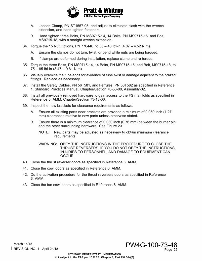
A. Loosen Clamp, PN ST1557-05, and adjust to eliminate clash with the wrenchextension, and hand tighten fasteners.
B. Hand tighten three Bolts, PN MS9715-14, 14 Bolts, PN MS9715-16, and Bolt,MS9715-18, with a straight wrench extension.
34. Torque the 15 Nut Options, PN 776440, to 36 – 40 lbf-in (4.07 – 4.52 N.m).
A. Ensure the clamps do not turn, twist, or bend while nuts are being torqued.
B. If clamps are deformed during installation, replace clamp and re-torque.
35. Torque the three Bolts, PN MS9715-14, 14 Bolts, PN MS9715-16, and Bolt, MS9715-18, to75 – 85 lbf-in (8.47 – 9.61 N.m).
36. Visually examine the tube ends for evidence of tube twist or damage adjacent to the brazedfittings. Replace as necessary.
37. Install the Safety Cables, PN 56T581, and Ferrules, PN 56T582 as specified in Reference1, Standard Practices Manual, Chapter/Section 70-53-00, Assembly-02.
38. Install all previously removed hardware to gain access to the FS manifolds as specified inReference 5, AMM, Chapter/Section 73-13-06.
39. Inspect the new brackets for clearance requirements as follows:
A. Ensure all existing parts near brackets are provided a minimum of 0.050 inch (1.27mm) clearances relative to new parts unless otherwise stated.
B. Ensure there is a minimum clearance of 0.030 inch (0.76 mm) between the burner pinand the other surrounding hardware. See Figure 23.
NOTE: New parts may be adjusted as necessary to obtain minimum clearancerequirements.
WARNING: OBEY THE INSTRUCTIONS IN THE PROCEDURE TO CLOSE THETHRUST REVERSERS. IF YOU DO NOT OBEY THE INSTRUCTIONS,INJURIES TO PERSONNEL, AND DAMAGE TO EQUIPMENT CANOCCUR.
40. Close the thrust reverser doors as specified in Reference 6, AMM.
41. Close the cowl doors as specified in Reference 6, AMM.
42. Do the activation procedure for the thrust reversers doors as specified in Reference6, AMM.
43. Close the fan cowl doors as specified in Reference 6, AMM.
lMarch 14/18 PW4G-100-73-48REVISION NO. 1 - April 24/18 Page 22
UTC/P&W PROPRIETARY INFORMATIONNot subject to the EAR per 15 C.F.R. Chapter 1, Part 734.3(b)(3).

For Engines Not Installed On Aircraft
1. Remove any hardware as required for access to the fuel nozzle supply manifold assemblies(FS manifolds) as specified in Reference 5, Engine Manual, Chapter/Section 73-11-15.
2. Locate the FS manifold (FS04) and remove and retain the Bolt, PN ST1411-05 from theClamp, PN ST1540-05. See Figure 1, Sheet 1 and Figure 2.
3. Remove and discard the Clamp, PN ST1540-05.
WARNING: DO NOT ALLOW ENGINE FUEL TO REMAIN ON YOUR SKIN FOR APERIOD OF TIME. FLUSH FUEL FROM SKIN WITH WATER. THE FUEL ISPOISONOUS AND CAN GO THROUGH SKIN AND INTO YOUR BODY.
CAUTION: DO NOT ALLOW ENGINE FUEL TO LEAK ON THE ENGINE. UNWANTEDFUEL MUST BE REMOVED IMMEDIATELY WITH A CLEAN LINT-FREECLOTH. FUEL CAN CAUSE DAMAGE TO OTHER PARTS ON THEENGINE.
CAUTION: TUBE DAMAGE MAY OCCUR IF BACKUP WRENCH IS NOT PROPERLYUSED.
4. Disconnect all of the coupling nuts that attach the FS manifolds to the Fuel Nozzles (F/N).Use a backup wrench on the wrenching flats. See Figure 1, Sheet 2 and Figure 3.
5. Disconnect all of the coupling nuts that attach the FS manifolds to the fuel supply tubeassemblies (FM tubes). Use a backup wrench on the wrenching flats. See Figure 3 andFigure 4.
6. Remove the FS Manifold (FS04), PN 50J958-01 and seven FS Manifolds (FS01 thru FS03,FS05 thru FS08), PN 50J959-01. See Figure 1, Sheet 2.
NOTE: FM tube clamps near the FS manifolds may need to be removed prior to theremoval of the FS manifolds.
7. Remove the Transfer Tubes, PN 50J500 and two Packings, PN ST1946-012, from theeight FM tubes as follows. See Figure 4.
A. Remove and discard the 16 Packings, PN ST1946-012.
B. Clean the transfer tubes as specified in Reference 4, CIR Manual, Chapter/Section72-41-00 Cleaning-01 or hand wipe as specified in Reference 1, Standard PracticesManual, Chapter/Section 72-21-00, SPOP 208.
C. Inspect the transfer tubes for signs of damage.
(1) If there are no signs of damage, retain the transfer tube for reuse.
(2) If there are signs of damage, discard the Transfer Tube, PN 50J500.
8. Remove and discard the 24 Packings, PN ST1946-010, from the FS manifolds and F/Npads. See Figure 1, Sheet 1.
9. Wipe clean the threads of the conical seats at F/N interface as specified in Reference 1,Standard Practices Manual, Chapter/Section 72-21-00, SPOP 208.
10. Remove and discard the two Bolts, PN MS9715-14, on F/N 17. See Figure 5.
11. Position the Heat Shield, PN 53U207-01, at the appropriate location on F/N 17 as shown inFigure 5.
lMarch 14/18 PW4G-100-73-48REVISION NO. 1 - April 24/18 Page 23
UTC/P&W PROPRIETARY INFORMATIONNot subject to the EAR per 15 C.F.R. Chapter 1, Part 734.3(b)(3).

12. Apply Engine Oil (P03-001), to the threads and bearing surface contact of the twonew Bolts, PN MS9715-14 as specified in Reference 1, Standard Practices Manual,Chapter/Section 70-00-00.
13. Install the Heat Shield, PN 53U207-01, on F/N 17 with two Bolts, PN MS9715-14, fingertight.
14. Torque the two Bolts, PN MS9715-14, to 75 – 85 lbf-in (8.47 – 9.60 N.m) as specified inReference 1, Standard Practices Manual, Chapter/Section 70-52-00.
15. Install the new or repaired FS Manifold (FS04), PN 50J958-01, that has new tube detailsinstalled as specified in Reference 4, CIR Manual, Chapter/Section 72-41-40 Repair-03,and install seven new or repaired FS Manifolds (FS01 thru FS03, FS05 thru FS08), PN50J959-01, that have new tube details installed as specified in Reference 4, CIR Manual,Chapter/Section 72-41-40 Repair-03 as follows:
A. Remove the protective covers from the new FS manifold fittings.
CAUTION: TORQUE LIMITS GIVEN IN THIS DOCUMENT FOR OIL LUBRICATEDPARTS APPLY SPECIFICALLY TO THE USE OF ENGINE OIL OREQUIVALENT. UNLESS OTHERWISE SPECIFIED, TORQUES GIVENIN THIS DOCUMENT APPLY WHEN LUBRICATION IS APPLIEDTO AT LEAST ONE OF THE PAIR OF SURFACES THAT WILLEXPERIENCE RUBBING CONTACT; WHERE ANTI GALLANT ISWORN, REAPPLY ANTI GALLANT. THE APPLICATION OF BOTH OILAND ANTI GALLANT ON THE SAME PAIR OF SURFACES SHALLNOT BE USED.
B. Re-apply anti-gallant on FM tubes at interface with FS manifolds if required. SeeFigure 24.
(1) If necessary, re-apply Anti-gallant Compound (P06-021 (PWA 550-3)) asspecified in Reference 1, Standard Practices Manual, Chapter/Section 72-41-03,SPOP 156.
C. Lubricate the FM tubes and FS manifolds. See Figure 3, Figure 4, and Figure 25.
(1) Apply Lubricant (P06-053), to the eight Transfer Tubes, PN 50J500, and 16Packings, PN ST1946-012. Install the transfer tube and packing to the FM tubeends.
(2) Apply Lubricant (P06-053), to the 24 Packings, PN ST1946-010. Install the 24packings to the previously cleaned and lubricated F/N pads.
(3) Apply a light film of Engine Oil (P03-001), between thrust wire and tube ferruleinterface, and to the threads on all eight FS manifolds. Try to distribute drops ofengine oil evenly around the circular device and do not spray on lubricant.
NOTE: Rotate coupling nuts to distribute lubrication.
(4) Remove any excess lubricant from the F/Ns, coupling nut threads, and theconical seat surfaces.
D. Attach the FS Manifold (FS04), PN 50J958-01 and seven FS Manifolds (FS01 thruFS03, FS05 thru FS08), PN 50J959-01, coupling nuts to the F/Ns and FM tubes,finger tight. See Figure 1, Sheet 2, Figure 3, and Figure 4.
NOTE: If the FM tube clamps were previously removed, they must be reinstalled.
lMarch 14/18 PW4G-100-73-48REVISION NO. 1 - April 24/18 Page 24
UTC/P&W PROPRIETARY INFORMATIONNot subject to the EAR per 15 C.F.R. Chapter 1, Part 734.3(b)(3).

FS manifolds are numbered clockwise (aft looking forward) from the TopDead Center (TDC) starting with FS manifold (FS01) and ending with FSmanifold (FS08).
FS manifold (FS04) is an unique manifold PN 50J958-01, all other FSmanifolds are PN 50J959-01.
E. Ensure all tube coupling nuts are finger tight and that the tube conical seat is fullyagainst the adapter/fitting conical seat.
F. Ensure that the FM tube and FS manifold conical seats are fully against the conicalseat fittings, hand tighten the FM tube/FS manifold coupling nuts until you feel theseats contact and then loosen the coupling nuts ¼ turn.
G. Leak test the FM tubes (FM01 thru FM08) and FS manifolds (FS01 thru FS08) asspecified in Reference 5, Engine Manual, Chapter/Section 71-00-73 Installation-15.
CAUTION: TUBE DAMAGE MAY OCCUR IF BACKUP WRENCH IS NOTPROPERLY USED.
H. Torque the eight FS manifolds as follows. Use a backup wrench at wrenching flatsshown in Figure 3.
(1) Install the eight center coupling nuts by holding the center fittings with a backupwrench and torque the coupling nuts to 250 – 270 lbf-in (28.25 – 30.51 N.m) asspecified in Reference 1, Standard Practices Manual, Chapter/Section 70-52-00.
(2) Install the eight left (forward view) FS manifold coupling nuts by holding the leftelbows with a backup wrench and torque the coupling nuts to 250 – 270 lbf-in(28.25 – 30.51 N.m) as specified in Reference 1, Standard Practices Manual,Chapter/Section 70-52-00.
(3) Install the eight right (forward view) FS manifold coupling nuts by holding theright elbows with a backup wrench and torque the coupling nuts to 250 – 270lbf-in (28.25 – 30.51 N.m) as specified in Reference 1, Standard PracticesManual, Chapter/Section 70-52-00.
(4) Install the eight FM tubes coupling nuts by holding the center fittings with abackup wrench and torque the coupling nuts to 275 – 325 lbf-in (31.07 – 36.72N.m) as specified in Reference 1, Standard Practices Manual, Chapter/Section70-52-00.
(5) Examine the tube ends for evidence of tube twist or damage adjacent to thebrazed fittings and replace if necessary.
16. Apply Engine Oil (P03-001), to the threads and bearing surface contact of the Bolt, PNST1411-05, as specified in Reference 1, Standard Practices Manual, Chapter/Section70-00-00. See Figure 1, Sheet 1.
17. Replace Clamp, PN ST1540-05 with PN ST1557-05, and install on FS manifold (FS04)with Bolt, PN ST1411-05.
18. Torque the Bolt, PN ST1411-05, to 36 – 40 lbf-in (4.07 – 4.52 N.m) as specified inReference 1, Standard Practices Manual, Chapter/Section 70-52-00.
19. Obtain parts shown in Table 1 for installing the FS manifold support brackets, clamps,and heat shields.
lMarch 14/18 PW4G-100-73-48REVISION NO. 1 - April 24/18 Page 25
UTC/P&W PROPRIETARY INFORMATIONNot subject to the EAR per 15 C.F.R. Chapter 1, Part 734.3(b)(3).

Table 1. Brackets And Heat Shields Used At FS Manifold Locations
FS Manifold Location Tube Attached To PN (Bracket/Heat Shield)
TU1 53U193FS01
TU2 53U194
TU3 53U195/53U206FS02
TU4 53U196
TU5 53U197FS03
TU6 53U198
FS04 TU7 53U201
TU9 53U210-01FS05
TU10 53U199
TU11 53U211-01/53U207-01FS06
TU12 53U198
TU13 53U201FS07
TU14 53U202/53U208-01
TU15 53U203FS08
TU16 53U199
NOTE: F/Ns are numbered clockwise (aft looking forward) F/N 1 starting at TDC andending with F/N 24.
20. Ensure that the brackets are installed in the correct location and that they have the correctorientation. See Figure 6.
CAUTION: IF THE BRACKETS ARE NOT INSTALLED CORRECTLY, THIS CANRESULT IN IMPROPER FIT BETWEEN FITTINGS AND TUBES WHICHCAN CAUSE DAMAGE TO FITTINGS AND/OR TUBES.
NOTE: The new brackets are marked with the appropriate F/N locations and an arrowindicating the engine forward direction.
21. Install the support brackets and clamps for FS manifold (FS01) at F/N 2 as follows:
A. Remove and discard the two Bolts, PN MS9715-14, on F/N 2 as shown in Figure 7.
B. Fit the two Clamps, PN ST1557-05, over FS manifold (FS01) in the correct orientationshown in Figure 7.
C. Position the Bracket, PN 53U193, at the appropriate location on F/N 2 as shown inFigure 8.
NOTE: Ensure the forward marking and arrow are pointing towards engine forward.
D. Align the Bracket, PN 53U193, hole and the Clamp, PN ST1557-05, hole withoutapplying force.
lMarch 14/18 PW4G-100-73-48REVISION NO. 1 - April 24/18 Page 26
UTC/P&W PROPRIETARY INFORMATIONNot subject to the EAR per 15 C.F.R. Chapter 1, Part 734.3(b)(3).

E. Apply Engine Oil (P03-001), to the threads and bearing surface contact of the newBolt, PN MS9715-16, as specified in Reference 1, Standard Practices Manual,Chapter/Section 70-00-00.
F. Install the Bracket, PN 53U193, on F/N 2 with Bolt, PN MS9715-16, and Washer,PN 5311624, finger tight.
G. Apply Engine Oil (P03-001), to the threads and bearing surface contact of the newNut Option, PN 776440 as specified in Reference 1, Standard Practices Manual,Chapter/Section 70-00-00.
H. Attach the Clamp, PN ST1557-05, to FS manifold (FS01) and the Bracket, PN53U193, with Bolt, PN AS3413-08, Washer, PN ST5141-09, and Nut Option, PN776440, finger tight. See Figure 2 and Figure 8.
NOTE: Utilizing clearance in the bracket bolt hole, ensure that the clamp is flushwith the bracket and that there is no pre-stressing of the tube assembly dueto mis-alignment of the bracket/clamp. It is preferred to centrally locateclamp bolt within slides of slot.
I. Position the Bracket, PN 53U194, at the appropriate location on F/N 2 as shown inFigure 8.
NOTE: Ensure the forward marking and arrow are pointing towards engine forward.
J. Align the Bracket, PN 53U194, hole and the Clamp, PN ST1557-05, hole withoutapplying force.
K. Apply Engine Oil (P03-001), to the threads and bearing surface contact of the newBolt, PN MS9715-16, as specified in Reference 1, Standard Practices Manual,Chapter/Section 70-00-00.
L. Install the Bracket, PN 53U194, on F/N 2 with Bolt, PN MS9715-16, and Washer,PN 5311624, finger tight.
M. Apply Engine Oil (P03-001), to the threads and bearing surface contact of the newNut Option, PN 776440, as specified in Reference 1, Standard Practices Manual,Chapter/Section 70-00-00.
N. Attach the Clamp, PN ST1557-05, to FS manifold (FS01) and the Bracket, PN53U194, with Bolt, PN AS3413-08, Washer, PN ST5141-09, and Nut Option, PN776440, finger tight. See Figure 2 and Figure 8.
NOTE: Utilizing clearance in the bracket bolt hole, ensure that the clamp is flushwith the bracket and that there is no pre-stressing of the tube assembly dueto mis-alignment of the bracket/clamp. It is preferred to centrally locateclamp bolt within slides of slot.
22. Install the heat shield, support brackets, and clamps for FS manifold (FS02) at F/N 4and F/N 5 as follows:
A. Remove and discard the three Bolts, PN MS9715-14, on F/N 4 and F/N 5 as shown inFigure 9.
B. Fit the two Clamps, PN ST1557-05, over FS manifold (FS02) in the correct orientationshown in Figure 9.
C. Position the Heat Shield, PN 53U206, on the aft two bolt holes of F/N 4 as shownin Figure 10.
NOTE: Ensure the forward marking and arrow are pointing towards engine forward.
lMarch 14/18 PW4G-100-73-48REVISION NO. 1 - April 24/18 Page 27
UTC/P&W PROPRIETARY INFORMATIONNot subject to the EAR per 15 C.F.R. Chapter 1, Part 734.3(b)(3).

D. Apply Engine Oil (P03-001), to the threads and bearing surface contact of the newBolts, PN MS9715-14, as specified in Reference 1, Standard Practices Manual,Chapter/Section 70-00-00.
E. Attach the Bolt, PN MS9715-14, to the left bolt hole (forward view) of the Heat Shield,PN 53U206, and F/N 4, finger tight.
F. Position the Bracket, PN 53U195, on Heat Shield, PN 53U206 at the appropriatelocation at F/N 4 as shown in Figure 10.
NOTE: Ensure the forward marking and arrow are pointing towards engine forward.
G. Align the Bracket, PN 53U195, hole and the Clamp, PN ST1557-05, hole withoutapplying force.
H. Apply Engine Oil (P03-001), to the threads and bearing surface contact of the newBolt, PN MS9715-16, as specified in Reference 1, Standard Practices Manual,Chapter/Section 70-00-00.
I. Install the Bracket, PN 53U195, on F/N 4 with Bolt, PN MS9715-16, and Washer,PN 5311624, finger tight.
J. Apply Engine Oil (P03-001), to the threads and bearing surface contact of the newNut Option, PN 776440, as specified in Reference 1, Standard Practices Manual,Chapter/Section 70-00-00.
K. Attach the Clamp, PN ST1557-05, to FS manifold (FS02) and the Bracket, PN53U195, with Bolt, PN AS3413-08, Washer, PN ST5141-09, and Nut Option, PN776440, finger tight. See Figure 2 and Figure 10.
NOTE: Utilizing clearance in the bracket bolt hole, ensure that the clamp is flushwith the bracket and that there is no pre-stressing of the tube assembly dueto mis-alignment of the bracket/clamp. It is preferred to centrally locateclamp bolt within slides of slot.
L. Position the Bracket, PN 53U196, at the appropriate location on F/N 5 as shownin Figure 10.
NOTE: Ensure the forward marking and arrow are pointing towards engine forward.
M. Align the Bracket, PN 53U196, hole and the Clamp, PN ST1557-05, hole withoutapplying force.
N. Apply Engine Oil (P03-001), to the threads and bearing surface contact of the newBolt, PN MS9715-16, as specified in Reference 1, Standard Practices Manual,Chapter/Section 70-00-00.
O. Install the Bracket, PN 53U196, on F/N 5 with Bolt, PN MS9715-16, and Washer,PN 5311624, finger tight.
P. Apply Engine Oil (P03-001), to the threads and bearing surface contact of the newNut Option, PN 776440, as specified in Reference 1, Standard Practices Manual,Chapter/Section 70-00-00.
Q. Attach the Clamp, PN ST1557-05, to FS manifold (FS02) and the Bracket, PN53U196, with Bolt, PN AS3413-08, Washer, PN ST5141-09, and Nut Option, PN776440, finger tight. See Figure 2 and Figure 10.
NOTE: Utilizing clearance in the bracket bolt hole, ensure that the clamp is flushwith the bracket and that there is no pre-stressing of the tube assembly due
lMarch 14/18 PW4G-100-73-48REVISION NO. 1 - April 24/18 Page 28
UTC/P&W PROPRIETARY INFORMATIONNot subject to the EAR per 15 C.F.R. Chapter 1, Part 734.3(b)(3).

to mis-alignment of the bracket/clamp. It is preferred to centrally locateclamp bolt within slides of slot.
23. Install the support brackets and clamps for FS manifold (FS03) at F/N 8 as follows:
A. Remove and discard the two Bolts, PN MS9715-14, on F/N 8 as shown in Figure 11.
B. Fit the two Clamps, PN ST1557-05, over FS manifold (FS03) in the correct orientationshown in Figure 11.
C. Position the Bracket, PN 53U197, at the appropriate location on F/N 8 as shownin Figure 12.
NOTE: Ensure the forward marking and arrow are pointing towards engine forward.
D. Align the Bracket, PN 53U197, hole and the Clamp, PN ST1557-05, hole withoutapplying force.
E. Apply Engine Oil (P03-001), to the threads and bearing surface contact of the newBolt, PN MS9715-16, as specified in Reference 1, Standard Practices Manual,Chapter/Section 70-00-00.
F. Install the Bracket, PN 53U197, on F/N 8 with Bolt, PN MS9715-16, and Washer,PN 5311624, finger tight.
G. Apply Engine Oil (P03-001), to the threads and bearing surface contact of the newNut Option, PN 776440, as specified in Reference 1, Standard Practices Manual,Chapter/Section 70-00-00.
H. Attach the Clamp, PN ST1557-05, to FS manifold (FS03) and the Bracket, PN53U197, with Bolt, PN AS3413-08, Washer, PN ST5141-09, and Nut Option, PN776440, finger tight. See Figure 2 and Figure 12.
NOTE: Utilizing clearance in the bracket bolt hole, ensure that the clamp is flushwith the bracket and that there is no pre-stressing of the tube assembly dueto mis-alignment of the bracket/clamp. It is preferred to centrally locateclamp bolt within slides of slot.
I. Position the Bracket, PN 53U198, at the appropriate location on F/N 8 as shownin Figure 12.
NOTE: Ensure the forward marking and arrow are pointing towards engine forward.
J. Align the Bracket, PN 53U198, hole and the Clamp, PN ST1557-05, hole withoutapplying force.
K. Apply Engine Oil (P03-001), to the threads and bearing surface contact of the newBolt, PN MS9715-16, as specified in Reference 1, Standard Practices Manual,Chapter/Section 70-00-00.
L. Install the Bracket, PN 53U198, on F/N 8 with Bolt, PN MS9715-16, and Washer,PN 5311624, finger tight.
M. Apply Engine Oil (P03-001), to the threads and bearing surface contact of the newNut Option, PN 776440, as specified in Reference 1, Standard Practices Manual,Chapter/Section 70-00-00.
lMarch 14/18 PW4G-100-73-48REVISION NO. 1 - April 24/18 Page 29
UTC/P&W PROPRIETARY INFORMATIONNot subject to the EAR per 15 C.F.R. Chapter 1, Part 734.3(b)(3).

N. Attach the Clamp, PN ST1557-05, to FS manifold (FS03) and the Bracket, PN53U198, with Bolt, PN AS3413-08, Washer, PN ST5141-09, and Nut Option, PN776440, finger tight. See Figure 2 and Figure 12.
NOTE: Utilizing clearance in the bracket bolt hole, ensure that the clamp is flushwith the bracket and that there is no pre-stressing of the tube assembly dueto mis-alignment of the bracket/clamp. It is preferred to centrally locateclamp bolt within slides of slot.
24. Install the support bracket and clamp for FS manifold (FS04) at F/N 11 as follows:
A. Remove and discard the aft left Bolt, PN MS9715-14, on F/N 11 as shown in Figure 13.
B. Fit the Clamp, PN ST1557-05, over FS manifold (FS04) in the correct orientationshown in Figure 13.
C. Position the Bracket, PN 53U201, at the appropriate location on F/N 11 as shownin Figure 14.
NOTE: Ensure the forward marking and arrow are pointing towards engine forward.
D. Align the Bracket, PN 53U201, hole and the Clamp, PN ST1557-05, hole withoutapplying force.
E. Apply Engine Oil (P03-001), to the threads and bearing surface contact of the newBolt, PN MS9715-16, as specified in Reference 1, Standard Practices Manual,Chapter/Section 70-00-00.
F. Install the Bracket, PN 53U201, on F/N 11 with Bolt, PN MS9715-16, and Washer,PN 5311624, finger tight.
G. Apply Engine Oil (P03-001), to the threads and bearing surface contact of the newNut Option, PN 776440, as specified in Reference 1, Standard Practices Manual,Chapter/Section 70-00-00.
H. Attach the Clamp, PN ST1557-05, to FS manifold (FS04) and the Bracket, PN53U201, with Bolt, PN AS3413-08, Washer, PN ST5141-09, and Nut Option, PN776440, finger tight. See Figure 2 and Figure 14.
NOTE: Utilizing clearance in the bracket bolt hole, ensure that the clamp is flushwith the bracket and that there is no pre-stressing of the tube assembly dueto mis-alignment of the bracket/clamp. It is preferred to centrally locateclamp bolt within slides of slot.
25. Install the support brackets, and clamps for FS manifold (FS05) at F/N 13 and F/N 14as follows:
A. Remove and discard the two Bolts, PN MS9715-14, on F/N 13 as shown in Figure 15.
B. Fit the Clamp, PN ST1557-05, over FS manifold (FS05) in the correct orientationshown in Figure 15.
C. Apply Engine Oil (P03-001), to the threads and bearing surface contact of thenew Bolt, PN MS9715-14, and new Bolt, MS9715-16, as specified in Reference 1,Standard Practices Manual, Chapter/Section 70-00-00.
D. Position the Bracket, PN 53U210-01, on F/N 13 as shown in Figure 16.
E. Align the Bracket, PN 53U210-01, hole and the Clamp, PN ST1557-05, hole withoutapplying force.
lMarch 14/18 PW4G-100-73-48REVISION NO. 1 - April 24/18 Page 30
UTC/P&W PROPRIETARY INFORMATIONNot subject to the EAR per 15 C.F.R. Chapter 1, Part 734.3(b)(3).

F. Install the Bracket, PN 53U210-01, on F/N 13 with Bolt, PN MS9715-14, Bolt, PNMS9715-16, Washer, PN 53U212, and two Spacers, PN 53U213, finger tight.
G. Apply Engine Oil (P03-001), to the threads and bearing surface contact of the newNut Option, PN 776440, as specified in Reference 1, Standard Practices Manual,Chapter/Section 70-00-00.
H. Attach the Clamp, PN ST1557-05, to FS manifold (FS05) and the Bracket, PN53U210-01, with Bolt, PN AS3413-08, Washer, PN ST5141-09, and Nut Option, PN776440, finger tight. See Figure 2 and Figure 16.
NOTE: Utilizing clearance in the bracket bolt hole, ensure that the clamp is flushwith the bracket and that there is no pre-stressing of the tube assembly dueto mis-alignment of the bracket/clamp. It is preferred to centrally locateclamp bolt within slides of slot.
I. Remove and discard the aft right Bolt, PN MS9715-14, on F/N 14 as shown in Figure15.
J. Fit the Clamp, PN ST1557-05, over FS manifold (FS05) in the correct orientationshown in Figure 15.
K. Position the Bracket, PN 53U199, at the appropriate location on F/N 14 as shownin Figure 16.
NOTE: Ensure the forward marking and arrow are pointing towards engine forward.
L. Align the Bracket, PN 53U199, hole and the Clamp, PN ST1557-05, hole withoutapplying force.
M. Apply Engine Oil (P03-001), to the threads and bearing surface contact of the newBolt, PN MS9715-16, as specified in Reference 1, Standard Practices Manual,Chapter/Section 70-00-00.
N. Install the Bracket, PN 53U199, on F/N 14 with Bolt, PN MS9715-16, and Washer,PN 5311624, finger tight.
O. Apply Engine Oil (P03-001), to the threads and bearing surface contact of the newNut Option, PN 776440, as specified in Reference 1, Standard Practices Manual,Chapter/Section 70-00-00.
P. Attach the Clamp, PN ST1557-05, to FS manifold (FS05) and the Bracket, PN53U199, with Bolt, PN AS3413-08, Washer, PN ST5141-09, and Nut Option, PN776440, finger tight. See Figure 2 and Figure 16.
NOTE: Utilizing clearance in the bracket bolt hole, ensure that the clamp is flushwith the bracket and that there is no pre-stressing of the tube assembly dueto mis-alignment of the bracket/clamp. It is preferred to centrally locateclamp bolt within slides of slot.
26. Install the support brackets, and clamps for FS manifold (FS06) at F/N 16 and F/N 17as follows:
A. Remove and discard the aft right Bolt, PN MS9715-14, on F/N 16 as shown in Figure17.
B. Fit the Clamp, PN ST1557-05, over FS manifold (FS06) in the correct orientationshown in Figure 17.
lMarch 14/18 PW4G-100-73-48REVISION NO. 1 - April 24/18 Page 31
UTC/P&W PROPRIETARY INFORMATIONNot subject to the EAR per 15 C.F.R. Chapter 1, Part 734.3(b)(3).

C. Position the Bracket, PN 53U211-01, on F/N 16 as shown in Figure 18.
NOTE: Ensure the forward marking and arrow are pointing towards engine forward.
D. Align the Bracket, PN 53U211-01, hole and the Clamp, PN ST1557-05, hole withoutapplying force.
E. Apply Engine Oil (P03-001), to the threads and bearing surface contact of the newBolt, PN MS9715-18, as specified in Reference 1, Standard Practices Manual,Chapter/Section 70-00-00.
F. Install the Bracket, PN 53U211-01, on F/N 16 with Bolt, PN MS9715-18, and Washer,PN 53U212, finger tight.
G. Apply Engine Oil (P03-001), to the threads and bearing surface contact of the newNut Option, PN 776440, as specified in Reference 1, Standard Practices Manual,Chapter/Section 70-00-00.
H. Attach the Clamp, PN ST1557-05, to FS manifold (FS06) and the Bracket, PN53U211-01, with Bolt, PN AS3413-08, Washer, PN ST5141-09, and Nut Option, PN776440, finger tight. See Figure 2 and Figure 18.
NOTE: Utilizing clearance in the bracket bolt hole, ensure that the clamp is flushwith the bracket and that there is no pre-stressing of the tube assembly dueto mis-alignment of the bracket/clamp. It is preferred to centrally locateclamp bolt within slides of slot.
I. Remove and discard the aft right Bolt, PN MS9715-14, on F/N 17 as shown in Figure17.
J. Fit the Clamp, PN ST1557-05, over FS manifold (FS06) in the correct orientationshown in Figure 17.
K. Position the Bracket, PN 53U198, at the appropriate location on F/N 17 as shownin Figure 18.
NOTE: Ensure the forward marking and arrow are pointing towards engine forward.
L. Align the Bracket, PN 53U198, hole and the Clamp, PN ST1557-05, hole withoutapplying force.
M. Apply Engine Oil (P03-001), to the threads and bearing surface contact of the newBolt, PN MS9715-16, as specified in Reference 1, Standard Practices Manual,Chapter/Section 70-00-00.
N. Install the Bracket, PN 53U198, on F/N 17 with Bolt, PN MS9715-16, and Washer,PN 5311624, finger tight.
O. Apply Engine Oil (P03-001), to the threads and bearing surface contact of the newNut Option, PN 776440, as specified in Reference 1, Standard Practices Manual,Chapter/Section 70-00-00.
P. Attach the Clamp, PN ST1557-05, to FS manifold (FS06) and the Bracket, PN53U198, with Bolt, PN AS3413-08, Washer, PN ST5141-09, and Nut Option, PN776440, finger tight. See Figure 2 and Figure 18.
NOTE: Utilizing clearance in the bracket bolt hole, ensure that the clamp is flushwith the bracket and that there is no pre-stressing of the tube assembly dueto mis-alignment of the bracket/clamp. It is preferred to centrally locateclamp bolt within slides of slot.
lMarch 14/18 PW4G-100-73-48REVISION NO. 1 - April 24/18 Page 32
UTC/P&W PROPRIETARY INFORMATIONNot subject to the EAR per 15 C.F.R. Chapter 1, Part 734.3(b)(3).

27. Install the heat shield, support brackets, and clamps for FS manifold (FS07) at F/N 20 andF/N 21 as follows:
A. Remove and discard the three Bolts, PN MS9715-14, on F/N 20 and F/N 21 as shownin Figure 19.
B. Fit the two Clamps, PN ST1557-05, over FS manifold (FS07) in the correct orientationshown in Figure 19.
C. Position the Heat Shield, PN 53U208-01, on the aft two bolt holes of F/N 21 as shownin Figure 20.
NOTE: Ensure the forward marking and arrow are pointing towards engine forward.
D. Apply Engine Oil (P03-001), to the threads and bearing surface contact of the newBolts, PN MS9715-14, as specified in Reference 1, Standard Practices Manual,Chapter/Section 70-00-00.
E. Attach the Bolt, PN MS9715-14, to the right bolt hole (forward view) of the HeatShield, PN 53U208-01, and F/N 21, finger tight.
F. Position the Bracket, PN 53U202, on Heat Shield, PN 53U208-01 at the appropriatelocation at F/N 21 as shown in Figure 20.
NOTE: Ensure the forward marking and arrow are pointing towards engine forward.
G. Align the Bracket, PN 53U202, hole and the Clamp, PN ST1557-05, hole withoutapplying force.
H. Apply Engine Oil (P03-001), to the threads and bearing surface contact of the newBolt, PN MS9715-16, as specified in Reference 1, Standard Practices Manual,Chapter/Section 70-00-00.
I. Install the Bracket, PN 53U202, on F/N 21 with Bolt, PN MS9715-16, and Washer,PN 5311624, finger tight.
J. Apply Engine Oil (P03-001), to the threads and bearing surface contact of the newNut Option, PN 776440, as specified in Reference 1, Standard Practices Manual,Chapter/Section 70-00-00.
K. Attach the Clamp, PN ST1557-05, to FS manifold (FS07) and the Bracket, PN53U202, with Bolt, PN AS3413-08, Washer, PN ST5141-09, and Nut Option, PN776440, finger tight. See Figure 2 and Figure 20.
NOTE: Utilizing clearance in the bracket bolt hole, ensure that the clamp is flushwith the bracket and that there is no pre-stressing of the tube assembly dueto mis-alignment of the bracket/clamp. It is preferred to centrally locateclamp bolt within slides of slot.
L. Position the Bracket, PN 53U201, at the appropriate location on F/N 20 as shownin Figure 20.
NOTE: Ensure the forward marking and arrow are pointing towards engine forward.
M. Align the Bracket, PN 53U201, hole and the Clamp, PN ST1557-05, hole withoutapplying force.
N. Apply Engine Oil (P03-001), to the threads and bearing surface contact of the newBolt, PN MS9715-16, as specified in Reference 1, Standard Practices Manual,Chapter/Section 70-00-00.
lMarch 14/18 PW4G-100-73-48REVISION NO. 1 - April 24/18 Page 33
UTC/P&W PROPRIETARY INFORMATIONNot subject to the EAR per 15 C.F.R. Chapter 1, Part 734.3(b)(3).

O. Install the Bracket, PN 53U201, on F/N 20 with Bolt, PN MS9715-16, and Washer,PN 5311624, finger tight.
P. Apply Engine Oil (P03-001), to the threads and bearing surface contact of the newNut Option, PN 776440, as specified in Reference 1, Standard Practices Manual,Chapter/Section 70-00-00.
Q. Attach the Clamp, PN ST1557-05, to FS manifold (FS07) and the Bracket, PN53U201, with Bolt, PN AS3413-08, Washer, PN ST5141-09, and Nut Option, PN776440, finger tight. See Figure 2 and Figure 20.
NOTE: Utilizing clearance in the bracket bolt hole, ensure that the clamp is flushwith the bracket and that there is no pre-stressing of the tube assembly dueto mis-alignment of the bracket/clamp. It is preferred to centrally locateclamp bolt within slides of slot.
28. Install the support brackets and clamps for FS manifold (FS08) at F/N 23 as follows:
A. Remove and discard the two Bolts, PN MS9715-14, on F/N 23 as shown in Figure 21.
B. Fit the two Clamps, PN ST1557-05, over FS manifold (FS08) in the correct orientationshown in Figure 21.
C. Position the Bracket, PN 53U203, at the appropriate location on F/N 23 as shownin Figure 22.
NOTE: Ensure the forward marking and arrow are pointing towards engine forward.
D. Align the Bracket, PN 53U203, hole and the Clamp, PN ST1557-05, hole withoutapplying force.
E. Apply Engine Oil (P03-001), to the threads and bearing surface contact of the newBolt, PN MS9715-16, as specified in Reference 1, Standard Practices Manual,Chapter/Section 70-00-00.
F. Install the Bracket, PN 53U203, on F/N 23 with Bolt, PN MS9715-16, and Washer,PN 5311624, finger tight.
G. Apply Engine Oil (P03-001), to the threads and bearing surface contact of the newNut Option, PN 776440, as specified in Reference 1, Standard Practices Manual,Chapter/Section 70-00-00.
H. Attach the Clamp, PN ST1557-05, to FS manifold (FS08) and the Bracket, PN53U203, with Bolt, PN AS3413-08, Washer, PN ST5141-09, and Nut Option, PN776440, finger tight. See Figure 2 and Figure 22.
NOTE: Utilizing clearance in the bracket bolt hole, ensure that the clamp is flushwith the bracket and that there is no pre-stressing of the tube assembly dueto mis-alignment of the bracket/clamp. It is preferred to centrally locateclamp bolt within slides of slot.
I. Position the Bracket, PN 53U199, at the appropriate location on F/N 23 as shownin Figure 22.
NOTE: Ensure the forward marking and arrow are pointing towards engine forward.
J. Align the Bracket, PN 53U199, hole and the Clamp, PN ST1557-05, hole withoutapplying force.
lMarch 14/18 PW4G-100-73-48REVISION NO. 1 - April 24/18 Page 34
UTC/P&W PROPRIETARY INFORMATIONNot subject to the EAR per 15 C.F.R. Chapter 1, Part 734.3(b)(3).

K. Apply Engine Oil (P03-001), to the threads and bearing surface contact of the newBolt, PN MS9715-16, as specified in Reference 1, Standard Practices Manual,Chapter/Section 70-00-00.
L. Install the Bracket, PN 53U199, on F/N 23 with Bolt, PN MS9715-16, and Washer,PN 5311624, finger tight.
M. Apply Engine Oil (P03-001), to the threads and bearing surface contact of the newNut Option, PN 776440, as specified in Reference 1, Standard Practices Manual,Chapter/Section 70-00-00.
N. Attach the Clamp, PN ST1557-05, to FS manifold (FS08) and the Bracket, PN53U199, with Bolt, PN AS3413-08, Washer, PN ST5141-09, and Nut Option, PN776440, finger tight. See Figure 2 and Figure 22.
NOTE: Utilizing clearance in the bracket bolt hole, ensure that the clamp is flushwith the bracket and that there is no pre-stressing of the tube assembly dueto mis-alignment of the bracket/clamp. It is preferred to centrally locateclamp bolt within slides of slot.
29. Hand tighten all of the bolts that attach the new brackets and heat shields with a straightwrench extension. If the straight wrench driver clashes with the new clamps, perform thefollowing steps to tighten bolts:
A. Loosen Clamp, PN ST1557-05, and adjust to eliminate clash with the wrenchextension, and hand tighten fasteners.
B. Hand tighten three Bolts, PN MS9715-14, 14 Bolts, PN MS9715-16, and Bolt,MS9715-18, with a straight wrench extension.
30. Torque the 15 Nut Options, PN 776440, to 36 – 40 lbf-in (4.07 – 4.52 N.m) as specified inReference 1, Standard Practices Manual, Chapter/Section 70-52-00.
A. Ensure the clamps do not turn, twist, or bend while nuts are being torqued.
B. If clamps are deformed during installation, replace clamp and re-torque.
31. Torque the three Bolts, PN MS9715-14, 14 Bolts, PN MS9715-16, and Bolt, MS9715-18, to75 – 85 lbf-in (8.47 – 9.61 N.m) as specified in Reference 1, Standard Practices Manual,Chapter/Section 70-52-00.
32. Visually examine the tube ends for evidence of tube twist or damage adjacent to the brazedfittings. Replace as necessary.
33. Install the Safety Cables, PN 56T581, and Ferrules, PN 56T582 as specified in Reference1, Standard Practices Manual, Chapter/Section 70-53-00, Assembly-02.
34. Install all previously removed hardware to gain access to the FS manifolds as specified inReference 5, Engine Manual, Chapter/Section 73-13-06.
35. Inspect the new brackets for clearance requirements as follows:
A. Ensure all existing parts near brackets are provided a minimum of 0.050 inch (1.27mm) clearances relative to new parts unless otherwise stated.
B. Ensure there is a minimum clearance of 0.030 inch (0.76 mm) between the burner pinand the other surrounding hardware. See Figure 23.
NOTE: New parts may be adjusted as necessary to obtain minimum clearancerequirements.
lMarch 14/18 PW4G-100-73-48REVISION NO. 1 - April 24/18 Page 35
UTC/P&W PROPRIETARY INFORMATIONNot subject to the EAR per 15 C.F.R. Chapter 1, Part 734.3(b)(3).

LOCATION OF THE FS MANIFOLDS73-11-00
FIGURE 1, SHEET 1
lMarch 14/18 PW4G-100-73-48REVISION NO. 1 - April 24/18 Page 36
UTC/P&W PROPRIETARY INFORMATIONNot subject to the EAR per 15 C.F.R. Chapter 1, Part 734.3(b)(3).

LOCATION OF THE FS MANIFOLDS, FUEL NOZZLES (F/N) AND FUEL METERING (FM) TUBESFIGURE 1, SHEET 2
lMarch 14/18 PW4G-100-73-48REVISION NO. 1 - April 24/18 Page 37
UTC/P&W PROPRIETARY INFORMATIONNot subject to the EAR per 15 C.F.R. Chapter 1, Part 734.3(b)(3).

LOCATION OF THE FS MANIFOLDS BRACKETS AND HEAT SHIELDSFIGURE 2
lMarch 14/18 PW4G-100-73-48REVISION NO. 1 - April 24/18 Page 38
UTC/P&W PROPRIETARY INFORMATIONNot subject to the EAR per 15 C.F.R. Chapter 1, Part 734.3(b)(3).

LOCATION OF THE COUPLING NUTS, WRENCH FLATS, AND FITTINGS ONFM TUBES AND FS MANIFOLDS
FIGURE 3
lMarch 14/18 PW4G-100-73-48REVISION NO. 1 - April 24/18 Page 39
UTC/P&W PROPRIETARY INFORMATIONNot subject to the EAR per 15 C.F.R. Chapter 1, Part 734.3(b)(3).

INTERFACE OF THE FM TUBES WITH FS MANIFOLD (FS08) SHOWNFIGURE 4
lMarch 14/18 PW4G-100-73-48REVISION NO. 1 - April 24/18 Page 40
UTC/P&W PROPRIETARY INFORMATIONNot subject to the EAR per 15 C.F.R. Chapter 1, Part 734.3(b)(3).

LOCATION OF THE HEAT SHIELD, PN 53U207-01FIGURE 5
lMarch 14/18 PW4G-100-73-48REVISION NO. 1 - April 24/18 Page 41
UTC/P&W PROPRIETARY INFORMATIONNot subject to the EAR per 15 C.F.R. Chapter 1, Part 734.3(b)(3).
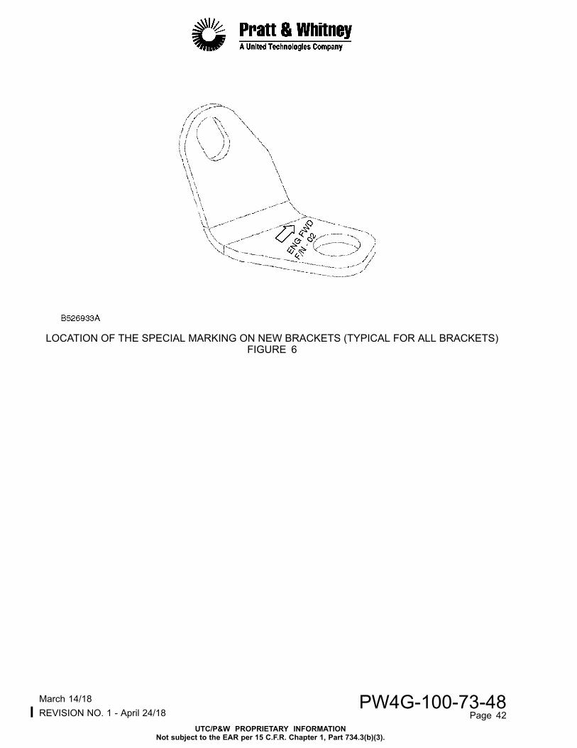
LOCATION OF THE SPECIAL MARKING ON NEW BRACKETS (TYPICAL FOR ALL BRACKETS)FIGURE 6
lMarch 14/18 PW4G-100-73-48REVISION NO. 1 - April 24/18 Page 42
UTC/P&W PROPRIETARY INFORMATIONNot subject to the EAR per 15 C.F.R. Chapter 1, Part 734.3(b)(3).

LOCATION OF THE BOLTS REMOVED AND NEW CLAMPS AT FS MANIFOLD (FS01)FIGURE 7
lMarch 14/18 PW4G-100-73-48REVISION NO. 1 - April 24/18 Page 43
UTC/P&W PROPRIETARY INFORMATIONNot subject to the EAR per 15 C.F.R. Chapter 1, Part 734.3(b)(3).
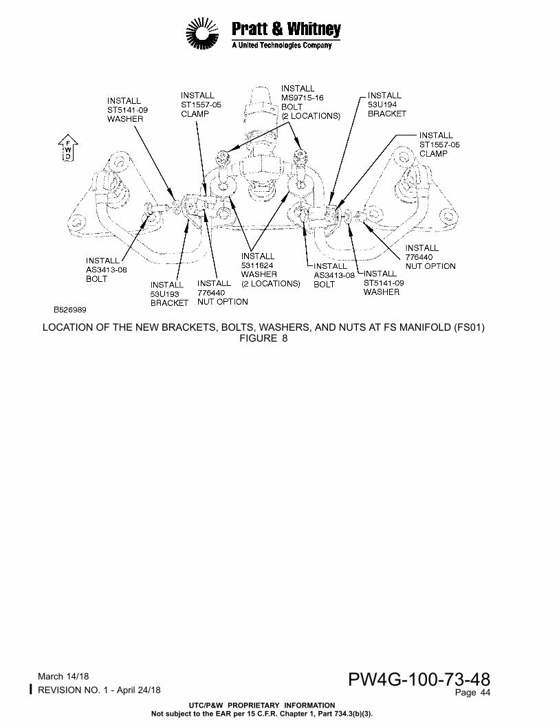
LOCATION OF THE NEW BRACKETS, BOLTS, WASHERS, AND NUTS AT FS MANIFOLD (FS01)FIGURE 8
lMarch 14/18 PW4G-100-73-48REVISION NO. 1 - April 24/18 Page 44
UTC/P&W PROPRIETARY INFORMATIONNot subject to the EAR per 15 C.F.R. Chapter 1, Part 734.3(b)(3).
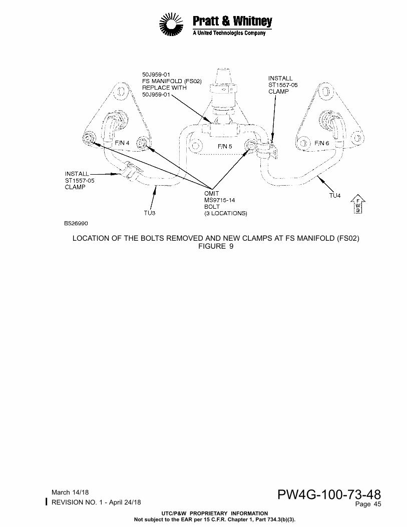
LOCATION OF THE BOLTS REMOVED AND NEW CLAMPS AT FS MANIFOLD (FS02)FIGURE 9
lMarch 14/18 PW4G-100-73-48REVISION NO. 1 - April 24/18 Page 45
UTC/P&W PROPRIETARY INFORMATIONNot subject to the EAR per 15 C.F.R. Chapter 1, Part 734.3(b)(3).

LOCATION OF THE NEW BRACKETS, HEAT SHIELD, BOLTS, WASHERS,AND NUTS AT FS MANIFOLD (FS02)
FIGURE 10
lMarch 14/18 PW4G-100-73-48REVISION NO. 1 - April 24/18 Page 46
UTC/P&W PROPRIETARY INFORMATIONNot subject to the EAR per 15 C.F.R. Chapter 1, Part 734.3(b)(3).

LOCATION OF THE BOLTS REMOVED AND NEW CLAMPS AT FS MANIFOLD (FS03)FIGURE 11
lMarch 14/18 PW4G-100-73-48REVISION NO. 1 - April 24/18 Page 47
UTC/P&W PROPRIETARY INFORMATIONNot subject to the EAR per 15 C.F.R. Chapter 1, Part 734.3(b)(3).

LOCATION OF THE NEW BRACKETS, BOLTS, WASHERS, AND NUTS AT FS MANIFOLD (FS03)FIGURE 12
lMarch 14/18 PW4G-100-73-48REVISION NO. 1 - April 24/18 Page 48
UTC/P&W PROPRIETARY INFORMATIONNot subject to the EAR per 15 C.F.R. Chapter 1, Part 734.3(b)(3).
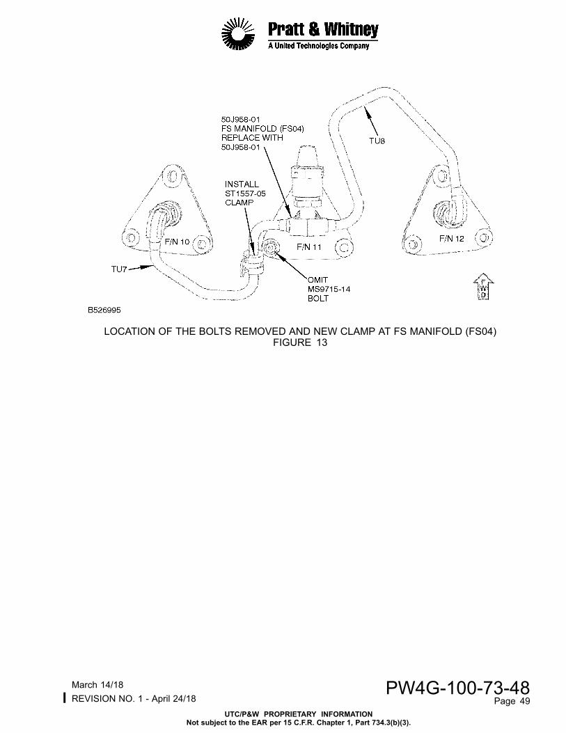
LOCATION OF THE BOLTS REMOVED AND NEW CLAMP AT FS MANIFOLD (FS04)FIGURE 13
lMarch 14/18 PW4G-100-73-48REVISION NO. 1 - April 24/18 Page 49
UTC/P&W PROPRIETARY INFORMATIONNot subject to the EAR per 15 C.F.R. Chapter 1, Part 734.3(b)(3).
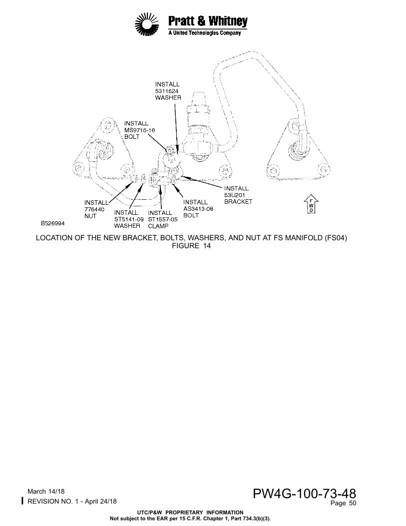
LOCATION OF THE NEW BRACKET, BOLTS, WASHERS, AND NUT AT FS MANIFOLD (FS04)FIGURE 14
lMarch 14/18 PW4G-100-73-48REVISION NO. 1 - April 24/18 Page 50
UTC/P&W PROPRIETARY INFORMATIONNot subject to the EAR per 15 C.F.R. Chapter 1, Part 734.3(b)(3).

LOCATION OF THE BOLTS REMOVED AND NEW CLAMPS AT FS MANIFOLD (FS05)FIGURE 15
lMarch 14/18 PW4G-100-73-48REVISION NO. 1 - April 24/18 Page 51
UTC/P&W PROPRIETARY INFORMATIONNot subject to the EAR per 15 C.F.R. Chapter 1, Part 734.3(b)(3).

LOCATION OF THE NEW BRACKETS, SPACERS, BOLTS, WASHERS, ANDNUTS AT FS MANIFOLD (FS05)
FIGURE 16
lMarch 14/18 PW4G-100-73-48REVISION NO. 1 - April 24/18 Page 52
UTC/P&W PROPRIETARY INFORMATIONNot subject to the EAR per 15 C.F.R. Chapter 1, Part 734.3(b)(3).

LOCATION OF THE BOLTS REMOVED AND NEW CLAMPS AT FS MANIFOLD (FS06)FIGURE 17
lMarch 14/18 PW4G-100-73-48REVISION NO. 1 - April 24/18 Page 53
UTC/P&W PROPRIETARY INFORMATIONNot subject to the EAR per 15 C.F.R. Chapter 1, Part 734.3(b)(3).

LOCATION OF THE NEW BRACKETS, HEAT SHIELD, BOLTS, WASHERS,AND NUTS AT FS MANIFOLD (FS06)
FIGURE 18
lMarch 14/18 PW4G-100-73-48REVISION NO. 1 - April 24/18 Page 54
UTC/P&W PROPRIETARY INFORMATIONNot subject to the EAR per 15 C.F.R. Chapter 1, Part 734.3(b)(3).

LOCATION OF THE BOLTS REMOVED AND NEW CLAMPS AT FS MANIFOLD (FS07)FIGURE 19
lMarch 14/18 PW4G-100-73-48REVISION NO. 1 - April 24/18 Page 55
UTC/P&W PROPRIETARY INFORMATIONNot subject to the EAR per 15 C.F.R. Chapter 1, Part 734.3(b)(3).

LOCATION OF THE NEW BRACKETS, HEAT SHIELD, BOLTS, WASHERS,AND NUTS AT FS MANIFOLD (FS07)
FIGURE 20
lMarch 14/18 PW4G-100-73-48REVISION NO. 1 - April 24/18 Page 56
UTC/P&W PROPRIETARY INFORMATIONNot subject to the EAR per 15 C.F.R. Chapter 1, Part 734.3(b)(3).

LOCATION OF THE BOLTS REMOVED AND NEW CLAMP AT FS MANIFOLD (FS08)FIGURE 21
lMarch 14/18 PW4G-100-73-48REVISION NO. 1 - April 24/18 Page 57
UTC/P&W PROPRIETARY INFORMATIONNot subject to the EAR per 15 C.F.R. Chapter 1, Part 734.3(b)(3).

LOCATION OF THE NEW BRACKETS, BOLTS, WASHERS, AND NUTS AT FS MANIFOLD (FS08)FIGURE 22
lMarch 14/18 PW4G-100-73-48REVISION NO. 1 - April 24/18 Page 58
UTC/P&W PROPRIETARY INFORMATIONNot subject to the EAR per 15 C.F.R. Chapter 1, Part 734.3(b)(3).

CLEARANCE REQUIREMENTS BETWEEN BRACKET AND BURNER PINFIGURE 23
lMarch 14/18 PW4G-100-73-48REVISION NO. 1 - April 24/18 Page 59
UTC/P&W PROPRIETARY INFORMATIONNot subject to the EAR per 15 C.F.R. Chapter 1, Part 734.3(b)(3).

FM TUBES ANTI-GALLANT TREATMENT LOCATIONSFIGURE 24
lMarch 14/18 PW4G-100-73-48REVISION NO. 1 - April 24/18 Page 60
UTC/P&W PROPRIETARY INFORMATIONNot subject to the EAR per 15 C.F.R. Chapter 1, Part 734.3(b)(3).

VIEW OF THE THRUST WIRE AND FERRULE INTERFACE (TYPICAL AT 8 LOCATIONS)FIGURE 25
lMarch 14/18 PW4G-100-73-48REVISION NO. 1 - April 24/18 Page 61
UTC/P&W PROPRIETARY INFORMATIONNot subject to the EAR per 15 C.F.R. Chapter 1, Part 734.3(b)(3).

Appendix
Added Data
Internal Reference Information
Revision No. ReferenceDocument Origination
Original EC 16KA078 RC/RCM
1 EC 16KA078 NC/MAS
Number values shown in parentheses adjacent to U.S. values are International System ofunits (SI) equivalents.
lMarch 14/18 PW4G-100-73-48REVISION NO. 1 - April 24/18 Page 62
UTC/P&W PROPRIETARY INFORMATIONNot subject to the EAR per 15 C.F.R. Chapter 1, Part 734.3(b)(3).