PVSS-S7driver_configuration.pdf - Read The Docs
15
LHC Project Document No. PVSS S7 driver configuration CERN Div./Group or Supplier/Contractor Document No. AB/CO EDMS Document No. Date: 2004-10-17 the Large Hadron Collider project CERN CH-1211 Geneva 23 Switzerland INSTALLATION SPECIFICATION INSTALLATION AND CONFIGURATION PROCEDURE OF A PVSS-S7 DRIVER Abstract This document details the procedure to set up a PVSS S7 native driver for both, windows and Linux, and configure it to: (1) writing data to the PLC and (2) polling data from the PLC. There is a third case, the TSPP (time stamped protocol) where the PLC push TSPP frames which includes data and its time stamp. This case remains outside of this procedure. Prepared by: Enrique Blanco AB/CO Checked by: Approved by:
-
Upload
khangminh22 -
Category
Documents
-
view
7 -
download
0
Transcript of PVSS-S7driver_configuration.pdf - Read The Docs

LHC Project Document No.
PVSS S7 driver configuration CERN Div./Group or Supplier/Contractor Document No.
AB/CO
EDMS Document No.
Date: 2004-10-17
the Large Hadron Collider project
CERN CH-1211 Geneva 23 Switzerland
INSTALLATION SPECIFICATION
INSTALLATION AND CONFIGURATION PROCEDURE OF A PVSS-S7 DRIVER
Abstract This document details the procedure to set up a PVSS S7 native driver for both, windows and Linux, and configure it to: (1) writing data to the PLC and (2) polling data from the PLC. There is a third case, the TSPP (time stamped protocol) where the PLC push TSPP frames which includes data and its time stamp. This case remains outside of this procedure.
Prepared by:
Enrique Blanco AB/CO
Checked by:
Approved by:

LHC Project Document No.
PVSS S7 driver configuration
Page 2 of 15
History of Changes
Rev. No. Date Pages Description of Changes
1.0 20/Oct/05 - Rack/Slot settings of the S7-300 are different depending of the Step 7 version.
- The JCOP panel and functions to set and get a S7 periph address configuration are introduced
LHC Project Document No.
PVSS S7 driver configuration
Page 3 of 15
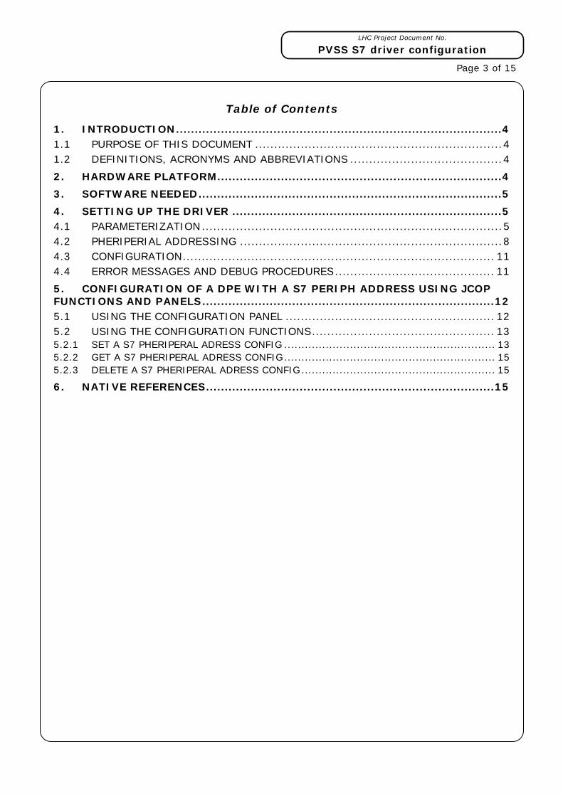
Table of Contents
1. INTRODUCTION.......................................................................................4 1.1 PURPOSE OF THIS DOCUMENT .................................................................4 1.2 DEFINITIONS, ACRONYMS AND ABBREVIATIONS ........................................4 2. HARDWARE PLATFORM............................................................................4 3. SOFTWARE NEEDED.................................................................................5 4. SETTING UP THE DRIVER ........................................................................5 4.1 PARAMETERIZATION...............................................................................5 4.2 PHERIPERIAL ADDRESSING .....................................................................8 4.3 CONFIGURATION.................................................................................. 11 4.4 ERROR MESSAGES AND DEBUG PROCEDURES.......................................... 11 5. CONFIGURATION OF A DPE WITH A S7 PERIPH ADDRESS USING JCOP FUNCTIONS AND PANELS..............................................................................12 5.1 USING THE CONFIGURATION PANEL ....................................................... 12 5.2 USING THE CONFIGURATION FUNCTIONS................................................ 13 5.2.1 SET A S7 PHERIPERAL ADRESS CONFIG ............................................................. 13 5.2.2 GET A S7 PHERIPERAL ADRESS CONFIG............................................................. 15 5.2.3 DELETE A S7 PHERIPERAL ADRESS CONFIG........................................................ 15 6. NATIVE REFERENCES.............................................................................15

LHC Project Document No.
PVSS S7 driver configuration
Page 4 of 15
1. INTRODUCTION
1.1 PURPOSE OF THIS DOCUMENT
This document details the step by step procedure on how to set up a PVSS S7 native driver and connect it to a real PLC to poll and write data to a Siemens S7 PLC.
This document does not pretend to explain the procedure to establish a redundant driver configuration but only the procedure to set up a simple polling/writing connection to one Siemens S7 PLC. The TSPP protocol is not included neither in this procedure.
This procedure and a general explanation of how the driver works (parameters, DPE, DPT…) is using extensively the ETM document called: “PVSS II Native driver for S7-300/S7-400” which is provided by ETM as the main documentation for the S7 driver. Also the help from PVSS includes relevant information about the S7 driver configuration and setting up.
1.2 DEFINITIONS, ACRONYMS AND ABBREVIATIONS
From this point onwards, the following acronyms will be used:
DS: PVSS Data Server.
DPT: PVSS data point type
DPE: PVSS data point element
JCOP: Joint Controls Project
S7-300: PLC family Siemens.
S7-400: PLC family Siemens.
TSAP: Transport Service Access Point
2. HARDWARE PLATFORM
For the setting up of the PVSS S7 native driver the following hardware will be needed:
Windows (NT, 2000 or XP) or Linux computer with minimum 800Mhz Pentium III CPU, 256Mb of RAM
S7 PLCs compatible with the S7 driver:
S7-300: 315-2DP and 318-2 with CP 343-1,
S7-400: 414-3 and 416-2 with CP 443-1 and CP 443-1 IT
During the evaluation of the S7 driver at CERN by the UNICOS team (AB/CO) the S7 PLCs tested were:
S7-300: 315-2DP with CP 343-1
S7-400: 414-2, 414-2 and 416-2 with CPs: 443-1, 443-1 IT and 443-1 advanced
Note that the communication cards CP 443-1 must have a recently firmware or they must be updated to the latest firmware from Siemens. An old firmware may prevent the driver to work properly.

LHC Project Document No.
PVSS S7 driver configuration
Page 5 of 15
3. SOFTWARE NEEDED
The following software must be installed:
PVSS 3.0.1 and the latest patches installed
4. SETTING UP THE DRIVER
4.1 PARAMETERIZATION
The communication with the S7 PLC is made by TCP/IP using the S7 messaging protocol. There is no special configuration needed on the S7 PLC side when using this protocol.
There is a main panel used to configure the S7 PLC in PVSS. To set up this panel you need to open it using the system management (Figure 1)
Figure 1 - System management: S7 driver
The opened panel (Figure 2) allows the parameterization of a S7 PLC in PVSS.
LHC Project Document No.
PVSS S7 driver configuration
Page 6 of 15
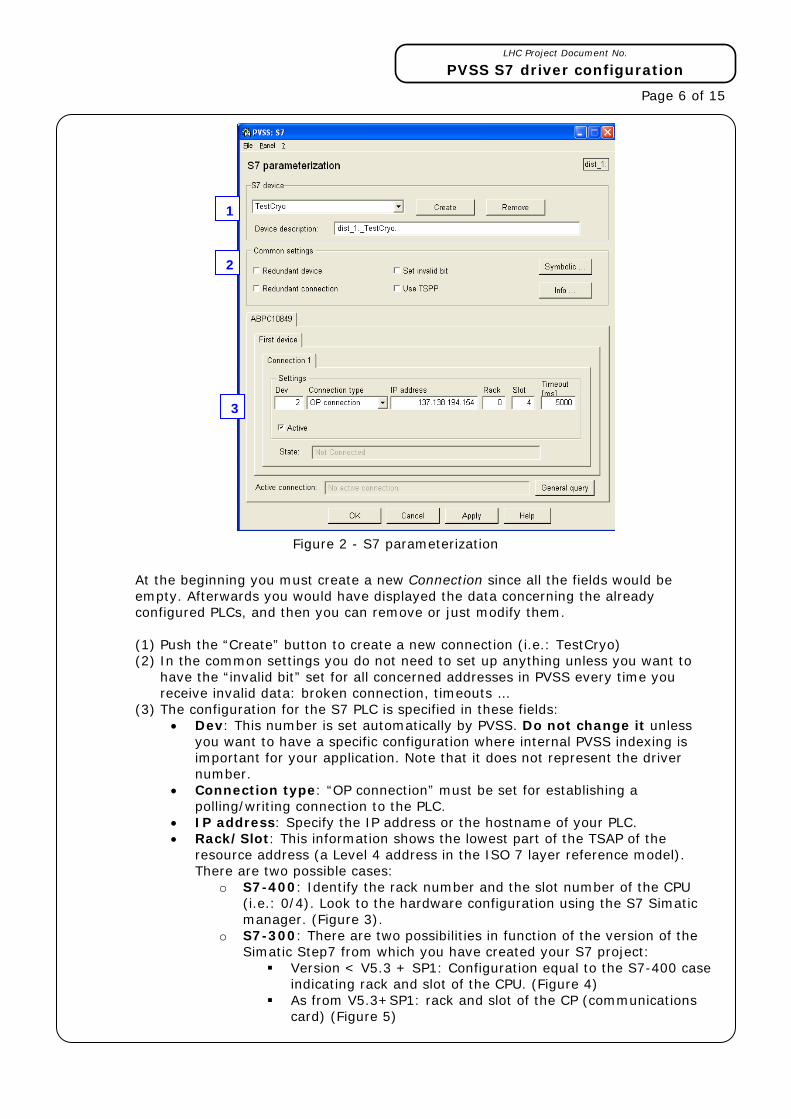
Figure 2 - S7 parameterization
At the beginning you must create a new Connection since all the fields would be empty. Afterwards you would have displayed the data concerning the already configured PLCs, and then you can remove or just modify them. (1) Push the “Create” button to create a new connection (i.e.: TestCryo) (2) In the common settings you do not need to set up anything unless you want to
have the “invalid bit” set for all concerned addresses in PVSS every time you receive invalid data: broken connection, timeouts …
(3) The configuration for the S7 PLC is specified in these fields: • Dev: This number is set automatically by PVSS. Do not change it unless
you want to have a specific configuration where internal PVSS indexing is important for your application. Note that it does not represent the driver number.
• Connection type: “OP connection” must be set for establishing a polling/writing connection to the PLC.
• IP address: Specify the IP address or the hostname of your PLC. • Rack/Slot: This information shows the lowest part of the TSAP of the
resource address (a Level 4 address in the ISO 7 layer reference model). There are two possible cases:
o S7-400: Identify the rack number and the slot number of the CPU (i.e.: 0/4). Look to the hardware configuration using the S7 Simatic manager. (Figure 3).
o S7-300: There are two possibilities in function of the version of the Simatic Step7 from which you have created your S7 project:
Version < V5.3 + SP1: Configuration equal to the S7-400 case indicating rack and slot of the CPU. (Figure 4)
As from V5.3+SP1: rack and slot of the CP (communications card) (Figure 5)
1
2
3

LHC Project Document No.
PVSS S7 driver configuration
Page 7 of 15
Figure 3 - Simatic S7 manager: Hardware configuration
Figure 4 –
version < V5.1+SP1
Figure 5 –
version >= V5.1+SP1
• Timeout: Sets the allowed time for establishing the connection by PVSS,
otherwise an error will occur.
Additional information coming from the Parameterization window gives:
• Active: this checkbox is used to activate/deactivate the connection. Please activate this option to have the driver operative. A connection which has been already created can be deactivated and it can be reactivated at any time.
• State: shows the status of the connection at any time. Four possibilities could happen: Not connected, connected, general query and not active. Please note that when you apply the settings you have set up in the S7 parameterization window the state will be “Not connected”. This is normal because you have not assigned any driver to this PLC connection. Only at the time of defining a DPE S7 periphery address configuration you will specify the S7 connection and the driver number and you will get the status value to “connected”
Rack
Slot
Rack: 0 Slot: 4
Rack: 0 Slot: 2
Rack: 0 Slot: 4

LHC Project Document No.
PVSS S7 driver configuration
Page 8 of 15
4.2 PHERIPERIAL ADDRESSING
Once the S7 PLC has been defined and properly set up in PVSS, the next step is to define a peripheral address using the S7 native driver DPE parameterization.
(1) Create a new DPE (Figure 6) using the PARA module (i.e.: float number)
Figure 6 - PARA module: new DPE
(2) Add a simulation manager or the S7 driver manager in your PVSS project console in order to be able to define the S7 address configuration (Figure 7). Run the chosen manager.
Figure 7 - PVSS console: adding new S7 manager
LHC Project Document No.
PVSS S7 driver configuration
Page 9 of 15
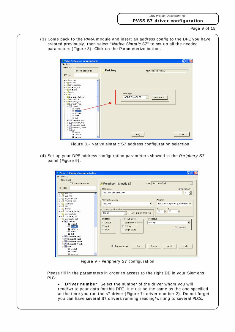
(3) Come back to the PARA module and insert an address config to the DPE you have created previously, then select “Native Simatic S7” to set up all the needed parameters (Figure 8). Click on the Parameterize button.
Figure 8 - Native simatic S7 address configuration selection
(4) Set up your DPE address configuration parameters showed in the Periphery S7 panel (Figure 9).
Figure 9 - Periphery S7 configuration
Please fill in the parameters in order to access to the right DB in your Siemens PLC:
• Driver number: Select the number of the driver whom you will read/write your data for this DPE. It must be the same as the one specified at the time you run the s7 driver (Figure 7: driver number 2). Do not forget you can have several S7 drivers running reading/writing to several PLCs.
LHC Project Document No.
PVSS S7 driver configuration
Page 10 of 15
• Connection name: Select the PLC defined previously (i.e.: TestCryo).
• Address: Introduce the format of the data you want to read from the PLC. In the example you must read a float number since the definition of the DPE was a float number (i.e.: float datacomponent). In other cases you have other possibilities as Booleans, integers, words, timer, counters, …
• x,y: select the DB number and the offset position within the DB. This will give the total S7 address: (i.e.: x=60 and y=30) DB60.DBD30). Please be sure that you have this DB defined in your PLC and also that the DB size contains the defined offset.
Note that if other address format is specified you will have more parameters appearing in your window (i.e.: Boolean access would have: x, y and z to fill in)
• Type of transformation: if the default value is specified the driver determines automatically the transformation type in function of the already defined address format. Otherwise select the case you want (i.e.: float). Select the low level comparison if you want to have this feature done in the driver. If it is selected data are sent only when there are changes. The comparison is based on raw data without any conversion. The low level comparison is an old/new comparison and is executed already with the data received from the periphery.
• Direction: Defines whether the values of a DPE are sent in the send direction (output), in the receive direction (input) or in both directions (In/Out).
Let’s assume you want to read/write the same variable in the PLC DB, then select “in/out” direction.
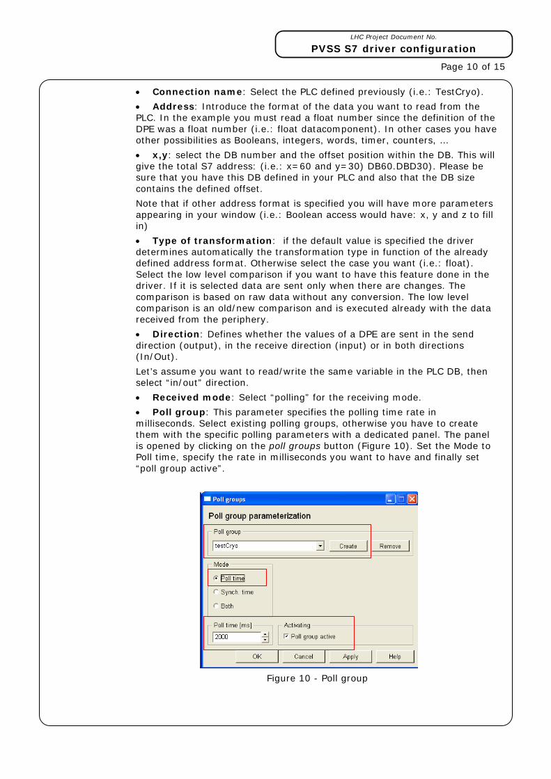
• Received mode: Select “polling” for the receiving mode.
• Poll group: This parameter specifies the polling time rate in milliseconds. Select existing polling groups, otherwise you have to create them with the specific polling parameters with a dedicated panel. The panel is opened by clicking on the poll groups button (Figure 10). Set the Mode to Poll time, specify the rate in milliseconds you want to have and finally set “poll group active”.
Figure 10 - Poll group

LHC Project Document No.
PVSS S7 driver configuration
Page 11 of 15
Before you apply the settings to your DPE address config, please be sure that you set up the “active” field. Then push on the apply button.
Once you apply your settings and provided the S7 driver manager is still running (if you have the simulator just kill it and run the s7 driver with the same number of the one you specified in the address configuration) in your PVSS console you should be connected to your defined PLC. Reading by polling must be operative and values read every defined poll group time.
Figure 11 - Polling S7 variable
4.3 CONFIGURATION
There are some variables which you can tune in the config file of your PVSS project:
The S7 driver may not start a request for every single PVSS address for which the type is “polling”. The driver groups the request to be within the MaxGap according to the poll group they belong to. Please tune this variable to allow the maximum efficiency of the S7 driver when reading.
There is a time variable, AliveInternal, which represents the time after which a status check is sent to the PLC via all connections. This could be deactivated specifying 0 and then the check will be done once at the connection initiation time.
Polling and writing from the PLC are parallelized. There are two queues for the read request and one different queue for the writing requests. This allows a fast writing in case of need.
4.4 ERROR MESSAGES AND DEBUG PROCEDURES
In order to detect possible source of errors several command line options are allowed (from the manager in the PVSS console, right click and “activate debug flags” :
-dbg 2: describes in detail what the driver does.
-dbg 25: debug low level functions
-dbg 26: debug outputs of read/write data traffic at write requests
LHC Project Document No.
PVSS S7 driver configuration
Page 12 of 15
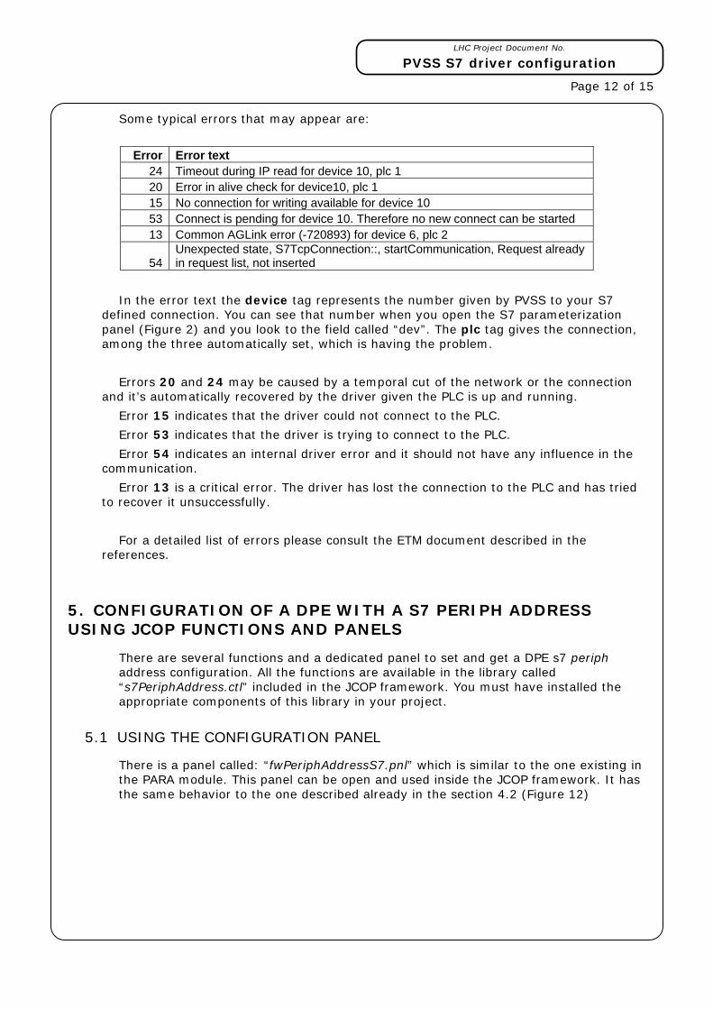
Some typical errors that may appear are:
Error Error text
24 Timeout during IP read for device 10, plc 1 20 Error in alive check for device10, plc 1 15 No connection for writing available for device 10 53 Connect is pending for device 10. Therefore no new connect can be started 13 Common AGLink error (-720893) for device 6, plc 2
54 Unexpected state, S7TcpConnection::, startCommunication, Request already in request list, not inserted
In the error text the device tag represents the number given by PVSS to your S7 defined connection. You can see that number when you open the S7 parameterization panel (Figure 2) and you look to the field called “dev”. The plc tag gives the connection, among the three automatically set, which is having the problem.
Errors 20 and 24 may be caused by a temporal cut of the network or the connection and it’s automatically recovered by the driver given the PLC is up and running.
Error 15 indicates that the driver could not connect to the PLC.
Error 53 indicates that the driver is trying to connect to the PLC.
Error 54 indicates an internal driver error and it should not have any influence in the communication.
Error 13 is a critical error. The driver has lost the connection to the PLC and has tried to recover it unsuccessfully.
For a detailed list of errors please consult the ETM document described in the references.
5. CONFIGURATION OF A DPE WITH A S7 PERIPH ADDRESS USING JCOP FUNCTIONS AND PANELS
There are several functions and a dedicated panel to set and get a DPE s7 periph address configuration. All the functions are available in the library called “s7PeriphAddress.ctl” included in the JCOP framework. You must have installed the appropriate components of this library in your project.
5.1 USING THE CONFIGURATION PANEL
There is a panel called: “fwPeriphAddressS7.pnl” which is similar to the one existing in the PARA module. This panel can be open and used inside the JCOP framework. It has the same behavior to the one described already in the section 4.2 (Figure 12)
LHC Project Document No.
PVSS S7 driver configuration
Page 13 of 15
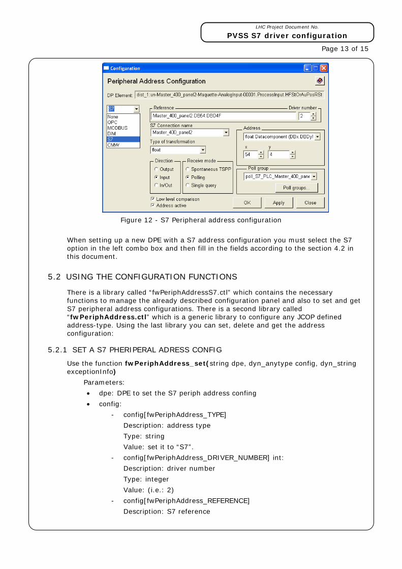
Figure 12 - S7 Peripheral address configuration
When setting up a new DPE with a S7 address configuration you must select the S7 option in the left combo box and then fill in the fields according to the section 4.2 in this document.
5.2 USING THE CONFIGURATION FUNCTIONS
There is a library called “fwPeriphAddressS7.ctl” which contains the necessary functions to manage the already described configuration panel and also to set and get S7 peripheral address configurations. There is a second library called “fwPeriphAddress.ctl” which is a generic library to configure any JCOP defined address-type. Using the last library you can set, delete and get the address configuration:
5.2.1 SET A S7 PHERIPERAL ADRESS CONFIG
Use the function fwPeriphAddress_set(string dpe, dyn_anytype config, dyn_string exceptionInfo)
Parameters:
• dpe: DPE to set the S7 periph address confing
• config:
- config[fwPeriphAddress_TYPE]
Description: address type
Type: string
Value: set it to “S7”.
- config[fwPeriphAddress_DRIVER_NUMBER] int:
Description: driver number
Type: integer
Value: (i.e.: 2)
- config[fwPeriphAddress_REFERENCE]
Description: S7 reference

LHC Project Document No.
PVSS S7 driver configuration
Page 14 of 15
Type: string
Value: (i.e.: PLCconnectionName.DBx.DBDyF in case of a float number)
- config[fwPeriphAddress_DIRECTION]
Description: mode and direction (input, output) of the address
Type: integer
Value: 1 Output
2 Input spontaneous (TSPP)
3 Input single query
4 Input polling
5 Output single
6 Input/Output spontaneous (TSPP)
7 Input/Output polling
8 Input/Output SQ
Normally you should select values 1, 3, 4, 5, 7 or 8.
- config[fwPeriphAddress_DATATYPE]
Description: data type
Type: integer
Value: 700 default
701 integer 16 bits
702 integer 32 bits
703 unsigned integer 16 bits
704 byte
705 float
706 boolean
707 string
708 unsigned integer 32
- config[fwPeriphAddress_ACTIVE]
Description: address activation. If not set the driver does not use it
Type: boolean
Value: set it to TRUE
- config[fwPeriphAddress_S7_LOWLEVEL]
Description: sets the lowlevel filter bit
Type: boolean
Value: (i.e.: TRUE)
- config[fwPeriphAddress_S7_POLL_GROUP]
Description: assigns an existing poll group (in case of polling)
Type: string
Value: (i.e.: “_”+myAlreadyDefinedPollGroupName) Do not forget the prefix “_” before the poll group name
• exceptionInfo: error information

LHC Project Document No.
PVSS S7 driver configuration
Page 15 of 15
5.2.2 GET A S7 PHERIPERAL ADRESS CONFIG
Use the function fwPeriphAddress_get(string dpe, bool configExists, dyn_anytype config, bool isActive, dyn_string exceptionInfo)
Parameters:
• dpe: DPE from which you will get its address configuration
• configExists: indicates if the address configuration is defined or not
• config: Exactly the same parameters you have from the ”fwPeriphAdress_set” function described above.
• isActive: Indicates if the address is active or not (Boolean)
• exceptionInfo: error information
5.2.3 DELETE A S7 PHERIPERAL ADRESS CONFIG
Use the function fwPeriphAddress_delete(string dpe).
Parameters:
• dpe: DPE which you will deleted its address configuration
6. REFERENCES
Native Driver for S7-300 / S7-400 (PVSS II documentation)